JP6861469B2 - Quantitative X-ray analysis and matrix thickness correction method - Google Patents
Quantitative X-ray analysis and matrix thickness correction method Download PDFInfo
- Publication number
- JP6861469B2 JP6861469B2 JP2016039688A JP2016039688A JP6861469B2 JP 6861469 B2 JP6861469 B2 JP 6861469B2 JP 2016039688 A JP2016039688 A JP 2016039688A JP 2016039688 A JP2016039688 A JP 2016039688A JP 6861469 B2 JP6861469 B2 JP 6861469B2
- Authority
- JP
- Japan
- Prior art keywords
- ray
- sample
- measurement
- intensity
- fluorescent
- Prior art date
- Legal status (The legal status is an assumption and is not a legal conclusion. Google has not performed a legal analysis and makes no representation as to the accuracy of the status listed.)
- Active
Links
- GCBDJHQUBANAEH-UHFFFAOYSA-N CC(C)C(C)=N Chemical compound CC(C)C(C)=N GCBDJHQUBANAEH-UHFFFAOYSA-N 0.000 description 1
Images


Classifications
-
- G—PHYSICS
- G01—MEASURING; TESTING
- G01N—INVESTIGATING OR ANALYSING MATERIALS BY DETERMINING THEIR CHEMICAL OR PHYSICAL PROPERTIES
- G01N23/00—Investigating or analysing materials by the use of wave or particle radiation, e.g. X-rays or neutrons, not covered by groups G01N3/00 – G01N17/00, G01N21/00 or G01N22/00
- G01N23/22—Investigating or analysing materials by the use of wave or particle radiation, e.g. X-rays or neutrons, not covered by groups G01N3/00 – G01N17/00, G01N21/00 or G01N22/00 by measuring secondary emission from the material
- G01N23/2206—Combination of two or more measurements, at least one measurement being that of secondary emission, e.g. combination of secondary electron [SE] measurement and back-scattered electron [BSE] measurement
-
- G—PHYSICS
- G01—MEASURING; TESTING
- G01B—MEASURING LENGTH, THICKNESS OR SIMILAR LINEAR DIMENSIONS; MEASURING ANGLES; MEASURING AREAS; MEASURING IRREGULARITIES OF SURFACES OR CONTOURS
- G01B15/00—Measuring arrangements characterised by the use of electromagnetic waves or particle radiation, e.g. by the use of microwaves, X-rays, gamma rays or electrons
- G01B15/02—Measuring arrangements characterised by the use of electromagnetic waves or particle radiation, e.g. by the use of microwaves, X-rays, gamma rays or electrons for measuring thickness
- G01B15/025—Measuring arrangements characterised by the use of electromagnetic waves or particle radiation, e.g. by the use of microwaves, X-rays, gamma rays or electrons for measuring thickness by measuring absorption
-
- G—PHYSICS
- G01—MEASURING; TESTING
- G01N—INVESTIGATING OR ANALYSING MATERIALS BY DETERMINING THEIR CHEMICAL OR PHYSICAL PROPERTIES
- G01N23/00—Investigating or analysing materials by the use of wave or particle radiation, e.g. X-rays or neutrons, not covered by groups G01N3/00 – G01N17/00, G01N21/00 or G01N22/00
- G01N23/20—Investigating or analysing materials by the use of wave or particle radiation, e.g. X-rays or neutrons, not covered by groups G01N3/00 – G01N17/00, G01N21/00 or G01N22/00 by using diffraction of the radiation by the materials, e.g. for investigating crystal structure; by using scattering of the radiation by the materials, e.g. for investigating non-crystalline materials; by using reflection of the radiation by the materials
- G01N23/20083—Investigating or analysing materials by the use of wave or particle radiation, e.g. X-rays or neutrons, not covered by groups G01N3/00 – G01N17/00, G01N21/00 or G01N22/00 by using diffraction of the radiation by the materials, e.g. for investigating crystal structure; by using scattering of the radiation by the materials, e.g. for investigating non-crystalline materials; by using reflection of the radiation by the materials by using a combination of at least two measurements at least one being a transmission measurement and one a scatter measurement
-
- G—PHYSICS
- G01—MEASURING; TESTING
- G01N—INVESTIGATING OR ANALYSING MATERIALS BY DETERMINING THEIR CHEMICAL OR PHYSICAL PROPERTIES
- G01N23/00—Investigating or analysing materials by the use of wave or particle radiation, e.g. X-rays or neutrons, not covered by groups G01N3/00 – G01N17/00, G01N21/00 or G01N22/00
- G01N23/22—Investigating or analysing materials by the use of wave or particle radiation, e.g. X-rays or neutrons, not covered by groups G01N3/00 – G01N17/00, G01N21/00 or G01N22/00 by measuring secondary emission from the material
- G01N23/223—Investigating or analysing materials by the use of wave or particle radiation, e.g. X-rays or neutrons, not covered by groups G01N3/00 – G01N17/00, G01N21/00 or G01N22/00 by measuring secondary emission from the material by irradiating the sample with X-rays or gamma-rays and by measuring X-ray fluorescence
-
- G—PHYSICS
- G01—MEASURING; TESTING
- G01N—INVESTIGATING OR ANALYSING MATERIALS BY DETERMINING THEIR CHEMICAL OR PHYSICAL PROPERTIES
- G01N2223/00—Investigating materials by wave or particle radiation
- G01N2223/40—Imaging
- G01N2223/401—Imaging image processing
Landscapes
- Chemical & Material Sciences (AREA)
- Physics & Mathematics (AREA)
- General Physics & Mathematics (AREA)
- Biochemistry (AREA)
- Life Sciences & Earth Sciences (AREA)
- Analytical Chemistry (AREA)
- Health & Medical Sciences (AREA)
- General Health & Medical Sciences (AREA)
- Immunology (AREA)
- Pathology (AREA)
- Crystallography & Structural Chemistry (AREA)
- Electromagnetism (AREA)
- Analysing Materials By The Use Of Radiation (AREA)
Description
本発明は、定量X線分析とその装置に関する。 The present invention relates to quantitative X-ray analysis and its apparatus.
X線を使用する材料分析は多くの応用分野や産業において正確なデータを提供している。蛍光X線測定は試料中の組成元素の決定を可能にする。しかしながら、ある応用分野においては、これは十分でなく、また、単に組成元素を決定するだけでなく、試料の結晶相のような構造パラメータを決定する要請が存在し、これらではX線回折が使用される。 Material analysis using X-rays provides accurate data in many application fields and industries. X-ray fluorescence measurement allows the determination of constituent elements in a sample. However, in some application areas, this is not sufficient, and there is a need to determine structural parameters such as the crystal phase of the sample, not just the constituent elements, in which X-ray diffraction is used. Will be done.
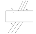
代表的には、高い解像度のX線回折測定が反射モードで実施され、ここではX線の入射ビームが試料の第1の面に入射し、次いで、試料の同じ面で回折角2θで回折されたX線が検出器により検出される。 Typically, high resolution X-ray diffraction measurements are performed in reflection mode, where an incident beam of X-rays is incident on the first plane of the sample and then diffracted on the same plane of the sample at a diffraction angle of 2θ. X-rays are detected by the detector.
ある応用分野においては、X線回折測定を透過モードで行うようにすることが有用であり、このモードでは、X線は試料の第1の面に入射し、第1の面から第2の面に試料を通過した後、回折角2θで回折したX線が測定される。 In some application areas, it is useful to have X-ray diffraction measurements performed in transmission mode, in which X-rays are incident on the first plane of the sample and from the first plane to the second plane. After passing through the sample, X-rays diffracted at a diffraction angle of 2θ are measured.
この透過ジオメトリ(幾何学的構造)での測定に伴う問題は、試料そのものがX線を吸収することである。したがって、試料中のX線の吸収は通常は知られていないので、試料の与えられたいかなる相における量を決定するための回折X線の正確な定量分析を行うことは困難である。試料中の種々の成分の濃度の僅かな変化は吸収に大きな変化をもたらす。成分がわかってなく、吸収に影響を与えるため、これが試料中の与えられた成分の量を測定するように設計されたX線定量分析の問題点である。 The problem with this transmission geometry measurement is that the sample itself absorbs X-rays. Therefore, since the absorption of X-rays in a sample is usually unknown, it is difficult to perform an accurate quantitative analysis of diffracted X-rays to determine the amount of the sample in any given phase. A slight change in the concentration of various components in the sample causes a large change in absorption. This is a problem with X-ray quantitative analysis designed to measure the amount of a given component in a sample, as the components are unknown and affect absorption.
圧縮された粉体の試料を測定するときの更なる問題点は、圧縮されたペレットの厚さdと密度ρ、即ちより一般的に使用される積x=rd(“質量厚み”“mass thickness”又は“表面密度”(“surface density”)として知られている)が通常は正確に知られていないことである。質量厚みの値はペレットの重量とその面の面積に対する割合として直接に得られる。しかしながら、その結果得られる数値は十分に正確でなく、透過測定の質に大きな誤差を生じる。 A further problem when measuring compressed powder samples is the thickness d and density ρ of the compressed pellets, the more commonly used product x = rd (“mass thickness” ”” mass thickness. "Or" surface density "(known as" surface density ") is usually not known exactly. The mass-thickness value is directly obtained as a percentage of the pellet weight and its surface area. However, the resulting values are not accurate enough and cause large errors in the quality of transmission measurements.
更に、工業利用においては、圧縮粉末試料を作り、できるだけ早く測定することが望まれている。X線測定を行う前に質量厚みの測定を正確に行うことは一般的に好ましくない。 Further, in industrial use, it is desired to prepare a compressed powder sample and measure it as soon as possible. It is generally not preferable to accurately measure the mass thickness before performing the X-ray measurement.
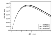
これらの考慮すべきことは、図1を参照することによりわかるが、図1は、0%、10%、20%及び30%の種々のバインダーパーセントでワックスバインダーが混合された標準のセメントクリンカー材料(ポートランド セメント クリンカー:Portland cement clinker)の3つの試料の試料厚みの関数としての理論的に計算されたフリーライム(遊離CaO:遊離酸化カルシウム)の回折強度を示している。 These considerations can be seen by referring to FIG. 1, which is a standard cement clinker material mixed with wax binder in various binder percentages of 0%, 10%, 20% and 30%. It shows the diffraction intensity of theoretically calculated free lime (free CaO: free calcium oxide) as a function of the sample thickness of the three samples of (Portland cement clinker).
厚みのより大きい試料はより大きい回折の材料を含む、-2倍の厚みの試料は2倍の量のフリーライムを持つ-にもかかわらず、実際、回折強度は小さいといことを留意されたい。 It should be noted that, despite the fact that the thicker sample contains the larger diffraction material-the double thickness sample has twice the amount of free lime-in fact, the diffraction intensity is low.
工業利用において頑丈な試料を保証する現実的な試料の厚み(3mmより大きい)と希釈割合(10%-20%)は、かなりの非線形レジームとなる。これは、小さい厚みの偏差が測定された、或いは計算された強度に大きな影響を及ぼすことを意味する。これが、質量厚みの推定が質の悪い結果を生じる主たる理由である。 Realistic sample thickness (greater than 3 mm) and dilution ratio (10% -20%), which guarantee a robust sample for industrial use, results in a fairly non-linear regime. This means that small thickness deviations have a large effect on the measured or calculated strength. This is the main reason why mass thickness estimation produces poor results.
更に、図2に示すうように、回折強度は、また、正確な組成に依存する。 Moreover, as shown in FIG. 2, the diffraction intensity also depends on the exact composition.
図2は、ポートランド セメント クリンカーの3個の異なる試料についての3つのグラフを示している。これらの試料の間では全体的に類似しているものの、回折強度は試料の間で異なっており、このことは、吸収の影響が試料間で異なる正確な組成の関数であることを示すものである。約3mmの厚みにおいては、約8%の回折強度の差が現れている。このことが、また、フリーライムの濃度の定量測定を回折測定から計算することを困難にしている。 FIG. 2 shows three graphs for three different samples of Portland cement clinker. Although generally similar between these samples, the diffraction intensity is different between the samples, indicating that the effect of absorption is a function of the exact composition that differs between the samples. is there. At a thickness of about 3 mm, a difference in diffraction intensity of about 8% appears. This also makes it difficult to calculate quantitative measurements of free lime concentration from diffraction measurements.
定量測定についての変化する組成の効果は、測定される試料、即ち、マトリックス、の組成に依存するため、マトリックス補正として知られている。マトリックス補正を計算することは、一般的に難しい。したがって、この困難を避ける測定方法に対する要請がある。 The effect of varying compositions on quantitative measurements is known as matrix correction because it depends on the composition of the sample being measured, i.e. the matrix. Calculating the matrix correction is generally difficult. Therefore, there is a demand for a measurement method that avoids this difficulty.
回折することなしに媒体を直接に通過する電磁波の吸収は、ビア-ランバート(Beer-Lambert)の法則により、以下の式で与えられる。 The absorption of electromagnetic waves that pass directly through the medium without diffraction is given by the following equation according to Beer-Lambert's law.
![]()
![]()
X線定量測定における吸収の影響の計算は、多くの理由により上記簡単な式が示すよりさらに複雑である。第1に、ある試料は厚さに制限がある。圧縮粉末試料では、十分に長い時間取り扱うことができ、また、測定できるような試料の好適な厚さは、少なくとも2mm、好ましくは3mmである。 The calculation of the effects of absorption in X-ray quantitative measurements is more complicated than the simple formula above shows for many reasons. First, some samples have a limited thickness. The compressed powder sample can be handled for a sufficiently long time, and a suitable thickness of the sample that can be measured is at least 2 mm, preferably 3 mm.
しかしながら、これらの厚さにおいては多くの場合に必要となる代表的なX線エネルギーにとって、試料中の厚みにおけるX線の吸収は50%より高い。 However, for the typical X-ray energy often required at these thicknesses, the absorption of X-rays at the thickness in the sample is greater than 50%.
このことは、吸収の影響は大きく、単純なビア-ランバートの法則からのずれがかなりのものとなることを意味している。大きな吸収は、測定の強度と試料中の特定の成分の濃度との間の関係が直線的とはならないことを意味している。 This means that the effect of absorption is large and the deviation from the simple Via-Lambert law is considerable. Large absorption means that the relationship between the intensity of the measurement and the concentration of a particular component in the sample is not linear.
単純なビア-ランバートの法則を使用することにより、単一の値、積μρdにより単純に測定されたX線強度への吸収の影響を導き出すことが可能である。 By using the simple Via-Lambert law, it is possible to derive the effect of absorption on the X-ray intensity simply measured by a single value, the product μρd.
しかしながら、厚さとマトリックスの変動について測定された回折強度を補正するために、積μρdと質量吸収係数μが必要となる。同じ積μρdを持つが、(例えば)異なるμを持つ2つの試料は、単純にビア-ランバートの法則によれば同じ減衰が現れるであろうが、この応用では測定される回折の強度は同じとはならない。 However, a product μρd and a mass absorption coefficient μ are required to correct the measured diffraction intensity for thickness and matrix variation. Two samples with the same product μρd but different (for example) μ will simply show the same attenuation according to Via-Lambert's law, but the measured diffraction intensities are the same in this application. Must not be.
したがって、X線回折の厚みとマトリックス補正を量的に実行する方法への要求が存在している。 Therefore, there is a demand for a method of quantitatively performing X-ray diffraction thickness and matrix correction.
本発明の第1の態様によると、X線分析の方法が提供され、この方法は;
試料の組成元素を決定するために蛍光X線分析を実行し;
前記試料を偏りなく直接に透過するエネルギーEにおける透過X線の強度を測定することにより、X線の補正測定を行い;
X線源から出るエネルギーEのX線を試料に角度ψ1で照射し、所定の組成のX線回折ピークに対応する出口角度ψ2におけるエネルギーEの回折されたX線の測定強度Id(θfl)をX線検出器により測定し;
X線回折測定により測定されたX線強度、補正測定、組成元素と前記元素の質量減衰係数から計算される前記試料の質量減衰係数を使用してマトリックス補正されたX線強度を計算する、ことを含む。
According to the first aspect of the present invention, a method of X-ray analysis is provided, which method;
X-ray fluorescence analysis is performed to determine the constituent elements of the sample;
Corrective measurement of X-rays is performed by measuring the intensity of transmitted X-rays at the energy E that directly transmits the sample without bias;
The sample is irradiated with X-rays of energy E emitted from the X-ray source at an angle ψ 1 , and the measured intensity of the diffracted X-rays of energy E at the exit angle ψ 2 corresponding to the X-ray diffraction peak of a predetermined composition I d ( θ fl ) was measured by an X-ray detector;
Calculate the matrix-corrected X-ray intensity using the X-ray intensity measured by the X-ray diffraction measurement, the correction measurement, and the mass attenuation coefficient of the sample calculated from the composition element and the mass attenuation coefficient of the element. including.
このように測定を実施することにより、試料を通過するX線の吸収の影響について回折X線強度を補正することが可能となり、したがって、透過モードにおいても量的な測定が可能となる。この補正の理論は以下に示す。 By carrying out the measurement in this way, it is possible to correct the diffracted X-ray intensity with respect to the influence of absorption of X-rays passing through the sample, and therefore, quantitative measurement is possible even in the transmission mode. The theory of this correction is shown below.
補正測定を行うステップと蛍光X線測定を行うステップは同時に行われる。これにより、試料の測定を完了させるための時間は可能な限り短縮される。 The step of performing the correction measurement and the step of performing the fluorescent X-ray measurement are performed at the same time. This reduces the time to complete the measurement of the sample as much as possible.
積μρdは、補正測定からビア-ランバート(Beer-Lambert law)の法則を使用して計算することができ、ここで、μ(E)は質量減衰係数、ρは試料密度、dは試料の厚さである。 The product μρd can be calculated from the corrected measurement using the Beer-Lambert law, where μ (E) is the mass damping coefficient, ρ is the sample density, and d is the sample thickness. That's right.
試料の質量減衰係数μ(E)は試料の全ての成分について合計により求められる。 The mass attenuation coefficient μ (E) of the sample is calculated by summing up all the components of the sample.

マトリックス補正される測定強度Idcは以下の式により計算することができる。 The matrix-corrected measured intensity I dc can be calculated by the following formula.
この方法は、校正のステップを含んでいる。この方法は以下のステップを含む。:
既知の濃度を持つ予め定めた成分を持つ複数の試料について、上述の方法を実施して校正線を得る、及び
未知の試料について、上述の方法を実施して未知の試料の所定の成分の量を測定する。
This method involves a calibration step. This method involves the following steps: :
For a plurality of samples having a predetermined component having a known concentration, the above method is performed to obtain a calibration line, and for an unknown sample, the above method is performed to obtain a predetermined amount of the component of the unknown sample. To measure.
上記校正は、既知の濃度を持つ所定の成分の複数の試料の濃度を関数として補正された強度に直線を当てはめることを含むことができる。 The calibration can include fitting a straight line to the corrected intensity as a function of the concentrations of a plurality of samples of a given component having a known concentration.
他の態様は、本発明はX線装置であり、当該X線装置は;
実質的に水平に延在する試料を支持する試料台と;
前記試料台の一方の側に位置するX線源と;
蛍光X線検出器と;
透過ジオメトリでX線回折を行うための前記試料台の他方の側に位置する蛍光X線検出器と;
制御装置とを備え、
前記制御装置は、前記X線装置に上記の方法を実行させるようにされている。
In another aspect, the present invention is an X-ray apparatus, and the X-ray apparatus is;
With a sample table that supports a sample that extends substantially horizontally;
With an X-ray source located on one side of the sample table;
With a fluorescent X-ray detector;
With a fluorescent X-ray detector located on the other side of the sample table for performing X-ray diffraction on transmitted geometry;
Equipped with a control device
The control device is adapted to cause the X-ray device to perform the above method.
このような装置は、上述のような測定を行うことができる。 Such a device can make the measurements as described above.
上記X線装置は、前記X線源から射出され、回折することなしに前記試料を透過するX線の強度を測定するため、前記試料台の上に位置する透過X線検出器を含む。この透過X線検出器は、上記回折X線検出器とは異なるように、例えば、異なるフィルタと異なるコリメータ装置を備え、回折測定と透過測定が同時に分離して最適に行えるようにされている。 The X-ray apparatus includes a transmitted X-ray detector located on the sample table in order to measure the intensity of X-rays emitted from the X-ray source and transmitted through the sample without being diffracted. This transmitted X-ray detector is different from the above-mentioned diffracted X-ray detector, and is provided with, for example, a different filter and a different collimator device so that the diffraction measurement and the transmission measurement can be optimally separated at the same time.
X線源はAgKa放射線の線源である。 The X-ray source is the source of AgKa radiation.
前記試料台と透過X線検出器との間に設けられ、このフィルタはAgKb放射線を濾過する。 Provided between the sample table and the transmitted X-ray detector, this filter filters AgKb radiation.
このフィルタは、チューブス(X線管)ペクトルの連続放射線を濾過するための(a)Rh又はPd及び(b)Ag又は原子番号が47より大きい他の元素の積み重ねとするこができる。 This filter can be a stack of (a) Rh or Pd and (b) Ag or other elements with an atomic number greater than 47 for filtering continuous radiation in tubes (X-ray tubes).
X線源と蛍光X線検出器は、試料台の下に設けることができ、回折X線検出器は試料台の上部に設けられる。 The X-ray source and the fluorescent X-ray detector can be provided below the sample table, and the diffracted X-ray detector is provided above the sample table.
以下に図面を参照して本発明の実施例を述べる。 Examples of the present invention will be described below with reference to the drawings.
本発明は、試料の厚みに明確な知見無しに透過形態におけるX線回折における測定される光子強度の補正に適用できる方法に関する。 The present invention relates to a method applicable to the correction of measured photon intensities in X-ray diffraction in transmitted form without clear knowledge of sample thickness.
理論
透過ジオメトリで実行されるX線回折測定は、測定される試料片が、生成された光子が背面側から一定の出口角度で逃げることができるように限定された厚みを持つことを必要としている。理論的計算は、測定される光子強度は試料の厚さと共に組成の両方に依存するであろうことを予見している。
X-ray diffraction measurements performed on theoretical transmission geometry require that the sample piece being measured have a limited thickness to allow the generated photons to escape from the back side at a constant exit angle. .. Theoretical calculations predict that the measured photon intensity will depend on both the composition as well as the thickness of the sample.
この意味において、試料の調整に関しての測定の再現性は、試料の調整中に異なる希釈割合(バインダー/材料)が適用されることを前提とすると、単一の試料から調整された試料片においてさえもかなりの影響を受ける。 In this sense, the reproducibility of measurements with respect to sample preparation is even for sample pieces prepared from a single sample, given that different dilution ratios (binders / materials) are applied during sample preparation. Is also significantly affected.
X線が試料を通過する吸収は以下により決定される:
この式及びこの書類の他の式で使用される関連する記号の定義をここでまとめておく。 The definitions of related symbols used in this formula and other formulas in this document are summarized here.
ここで、数学の理解のために例を示す。
この例では、測定を通じて、特定の(予め定めた)成分はフリーライムであるが、他の成分についても適用可能である。
Here is an example for understanding mathematics.
In this example, through the measurements, the particular (predetermined) ingredient is free lime, but other ingredients are also applicable.
入射線はAG-Kaであるとすると、第1次回折は回折角2θ=13.3°であると想定される。したがって、この例では、入射角ψ1=57°とすると、出射角ψ2=57°+13.3°=70.3°となる。 Assuming that the incident line is AG-Ka, the first diffraction is assumed to have a diffraction angle of 2θ = 13.3 °. Therefore, in this example, if the incident angle ψ 1 = 57 °, the exit angle ψ 2 = 57 ° + 13.3 ° = 70.3 °.
この回折ピークに対応する出射角において、シンチレーション検出器により観察される強度は、以下の式により与えられる。 At the emission angle corresponding to this diffraction peak, the intensity observed by the scintillation detector is given by the following equation.
![]()
![]()
σflは、回折ピークにおける測定された所定の成分の散乱断面積であり、σothlは他の全ての成分の散乱断面積であることを留意されたい。 Note that σ fl is the scattering cross section of the measured component at the diffraction peak and σ oth l is the scattering cross section of all other components.
そこで、以下のように書くことができる。 Therefore, it can be written as follows.
第2の部分は2つの項の和である。1つはフリーライム相から出た回折信号であり、他の項は他の結晶及びアモルファス相の影響を示すものである。 The second part is the sum of the two terms. One is the diffraction signal from the free lime phase and the other term shows the effect of other crystalline and amorphous phases.
クリンーカータイプの限られた範囲内においては、このファクターは一定のバックグランドとみなすことができ、式(7)は以下のように書き直すことができる。 Within the limited range of the cleaner type, this factor can be regarded as a constant background, and equation (7) can be rewritten as follows.
![]()
![]()
一般的に、評価式(6)は、直線からはかなりかけ離れている。しかしながら、本発明者は、ある試料は、組成元素を決定することができる蛍光X線分析により十分に良好に特徴づけられることを認識している。したがって、吸収μは単純に吸収の合計で、試料中に存在する既知の化合物により決定されるため、式(2)を使用することができる。これは、μの値に通ずるものである。 In general, the evaluation formula (6) is far from the straight line. However, the inventor recognizes that certain samples are well characterized by X-ray fluorescence analysis, which can determine the constituent elements. Therefore, formula (2) can be used because absorption μ is simply the sum of absorptions and is determined by the known compounds present in the sample. This leads to the value of μ.
試料中の直接の透過を測定し、式(1)のビア・ランバートの法則を使用して積μρdを計算することも可能である。 It is also possible to measure the direct permeation in the sample and calculate the product μρd using Via Lambert's law in Eq. (1).
これらの2つの情報により、マトリックス強度補正M,即ち、試料中の他の元素の吸収の影響に対する測定値を、式(6)のそれらの値と置換えることにより補正すること、により、X線回折の測定強度を補正することも可能である。 Based on these two pieces of information, the matrix intensity correction M, that is, the measurement value for the influence of absorption of other elements in the sample, is corrected by replacing those values in the formula (6), thereby X-ray. It is also possible to correct the measured intensity of diffraction.
したがって、特定の成分に対応する蛍光X線分析ラインについて機器の校正を行った後、試料中の吸収を補正し、式(7)からIdc(θfl)を得ることが可能である。この値から、また、校正曲線を使用して、特定の成分の重量割合が決定される。 Therefore, after calibrating the equipment for the fluorescent X-ray analysis line corresponding to a specific component, it is possible to correct the absorption in the sample and obtain I dc (θ fl) from the equation (7). From this value, and also using the calibration curve, the weight percentage of a particular component is determined.
実施例
X線装置2は、試料6を支持する試料台4を有する。
Example
The
実際、この装置2は試料台4の下に設けられるX線源10を備える通常の蛍光X線分析装置である。この実施例においては試料台4の下に蛍光X線を測定するための蛍光X線検出器12が存在する。蛍光X線検出器は、X線をエネルギーの関数としてX線強度を測定するエネルギー分散型X線検出器であるか、或いは特定の波長のX線のみを選別する結晶を備える波長分散型X線検出器とすることができる。この結晶は、異なる波長を選別するように可動とされるか、或いは、関心のある特定の波長を選別するように固定することができる。
In fact, this
通常の蛍光X線分析装置に、ゴニオメータ上の試料台4の上部に設けられる透過X線検出器14が加えられ、角度の関数として回折X線を検出できるようにしている。
A transmitted
下記に説明するように、補正X線検出器30が透過X線検出器に隣接して設けられている。コリメータ16及びフィルタ18を含む他の多くの要素が設けられる。
As described below, a
この装置は、メモリ22とプロセッサ24を含む制御装置20により制御される。
This device is controlled by a
図示された実施例では、X線源10はAg-Ka線を出射し、Ag-Kb線及び連続放射線を濾過するようにされている。フィルタはAg-Kb線を濾過するRH又はPdの層と連続線を濾過する他の層を含む多層フィルタとすることができる。他の大きい原子番号の層も、Ag或いは他の元素がAgに加えて使用することができる。
In the illustrated embodiment, the
単純なピンホール光学系がコリメーションに使用することができる。 Simple pinhole optics can be used for collimation.
使用に際し、試料6が圧縮粉末法により調整される。粉末は、試料台の上に載せられるようにリングの形状でワックスと共に圧縮される。特定の例では、試料はクリンカー試料で、測定されるべき予め定めた成分はフリーライム(free lime)である。
Upon use,
測定の第1段階において、X線源が(シャッタを除くことにより)起動され、X線が試料に入射される。この場合、蛍光X線測定が蛍光X線検出器により行われる。 In the first stage of measurement, the X-ray source is activated (by removing the shutter) and X-rays are incident on the sample. In this case, the fluorescent X-ray measurement is performed by the fluorescent X-ray detector.
補正X線検出器30が、入射X線と直接に線上に、即ち、直接に透過するX線を検出するように設けられている。補正X線検出器は試料を透過するX線の強度、したがって、試料中の吸収を測定する。
The
検出器が重複するのを避けるため、また、検出器30によって記録される放射線が回折測定のためのものと同じでることを確保するため、適度の厚みを持つAgフィルタ32が試料と検出器との間に配置され、Ag-Kb線を濾過し、また、可能のある連続線を濾過するようにしている。
In order to avoid duplication of detectors and to ensure that the radiation recorded by the
このフィルタは、Ag-Kb線を濾過するPh或いはPdの層と、連続線を濾過するAgのような他の層を含む多層フィルタとすることができる。 The filter can be a multi-layer filter containing a layer of Ph or Pd that filters Ag-Kb rays and another layer such as Ag that filters continuous rays.
次に、入射角ψ=57°を与える位置の線源と出射角ψ=57°+13.3°を与える位置の透過X線検出器により通過する回折ピーク2θfl=13.3°における強度の測定が測定される。 Next, the intensity measurement at the diffraction peak 2θ fl = 13.3 ° passed by the radiation source at the position giving the incident angle ψ = 57 ° and the transmitted X-ray detector at the position giving the exit angle ψ = 57 ° + 13.3 ° is measured. Be measured.
この情報は、前記式(1)、(2)、(5)及び(6)を使用して合体し、(蛍光X線分析により得られる)特定の元素についての情報だけでなく、(X線回折だけにより得られる)1又は複数の相についての情報を得ることができる。 This information is coalesced using the formulas (1), (2), (5) and (6), and not only information about a particular element (obtained by X-ray fluorescence analysis), but also (X-ray). Information about one or more phases (obtained only by diffraction) can be obtained.
これらの測定と校正は、全て、測定を実行するために装置を制御する制御装置20のプロセッサ22を制御するメモリ24内に記憶されるコードにより制御されて実行される。
All of these measurements and calibrations are controlled by code stored in the
当業者であれば、この装置と方法は、利用できる特定の装置に適合するように変更することができることを理解できるであろう。例えば、異なる放射線スペクトルを持つ異なるX線源が使用できる。回折測定と透過測定を検出器14,30に同じ検出器を使用することもできる。
Those skilled in the art will appreciate that this device and method can be modified to suit the particular device available. For example, different X-ray sources with different radiation spectra can be used. The same detector can be used for the
実験例
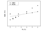
本方法の適用性と共に、実施される近似の有効性をテストするために実験例が実施された。圧縮ペレットの組が、0%、0.5%、1%、1.5%、2%、3%、4%及び5%に等しい最終FL(フリーライム)濃度を生成する適宜のフリーライム量を混入したクリンカーマトリックスから製造された。
Experimental Examples Experimental examples were conducted to test the applicability of this method as well as the effectiveness of the approximations performed. Appropriate amount of free lime from which the set of compressed pellets produces a final FL (free lime) concentration equal to 0%, 0.5%, 1%, 1.5%, 2%, 3%, 4% and 5%. Manufactured from a clinker matrix mixed with.
式(8)によれば、FLの濃度と補正された回折強度との関係を示す補正ラインを形成することが可能である。結果が図5に示されている。 According to the equation (8), it is possible to form a correction line showing the relationship between the FL concentration and the corrected diffraction intensity. The results are shown in FIG.
比較のため、補正されない強度もFL濃度の関数としてプロットされている。この補正の適用は、補正線の質を顕著に改善することに留意されたい。変動が少なく、直線の勾配が急であることが示され、このことは、正確な強度測定を可能とするものである。 For comparison, the uncorrected intensity is also plotted as a function of FL concentration. It should be noted that the application of this correction significantly improves the quality of the correction line. It has been shown that there is little variation and the slope of the straight line is steep, which allows accurate intensity measurements.
2 X線装置
4 試料台
6 試料
10 X線源
12 蛍光X線検出装置
14 透過X線検出装置
16 ゴニオメータ
18 フィルタ
20 制御装置
22 メモリ
24 プロセッサ
2
Claims (13)
試料の元素組成を決定するために蛍光X線測定を行うステップと;
前記試料を偏向することなく直接に透過するエネルギーEの透過X線の強度を測定することによりX線の補正測定を行うステップと;
前記エネルギーEのX線源からのX線を、前記試料の表面に入射角度ψ1で照射することにより、透過型のX線回折測定を行い、予め定められた成分のX線回折ピークに対応する出口角ψ2におけるX線検出器により、前記エネルギーEにおける回折X線の測定強度Id(θfl)を測定するステップと;
X線回折測定における測定されたX線強度と、前記補正測定と、前記蛍光X線測定によって決定された元素組成と組成元素の質量減衰係数から計算された試料の質量減衰係数とを使用してマトリックス補正されたX線強度を演算するステップ;
を有しており、
前記マトリックス補正の測定の強度I dc は、以下の式(3)により計算され、
X線分析方法。
With the steps of performing X-ray fluorescence measurements to determine the elemental composition of the sample;
A step of performing X-ray correction measurement by measuring the intensity of transmitted X-rays of energy E that directly transmits the sample without deflecting the sample;
By irradiating the surface of the sample with X-rays from the X-ray source of energy E at an incident angle of ψ 1 , transmission type X-ray diffraction measurement is performed, and it corresponds to the X-ray diffraction peak of a predetermined component. The step of measuring the measured intensity I d (θ fl ) of the diffracted X-ray at the energy E by the X-ray detector at the exit angle ψ 2;
Using the measured X-ray intensity in the X-ray diffraction measurement, the correction measurement, and the mass decay coefficient of the sample calculated from the elemental composition determined by the fluorescent X-ray measurement and the mass decay coefficient of the constituent elements. Steps to calculate matrix-corrected X-ray intensity;
And have a,
The intensity I dc of the measurement of the matrix correction is calculated by the following equation (3).
X-ray analysis method.
ここで、μ(E)は質量減衰係数、ρは試料密度、dは試料の厚さである。 The method of claim 1 or 2, comprising the step of calculating the product μρd from the corrected measurement using Via-Lambert's law.
Here, μ (E) is the mass attenuation coefficient, ρ is the sample density, and d is the sample thickness.
未知の試料について請求項1の方法を行うことにより、未知の試料中の予め定められた成分の量を測定するステップ、
を有する方法。 A step of obtaining a calibration line by carrying out a method according to any one of claims 1 to 5 for a plurality of samples having a known concentration of the predetermined component;
A step of measuring the amount of a predetermined component in an unknown sample by performing the method of claim 1 on an unknown sample.
Method to have.
前記試料台の一方の側に位置するX線源と;
蛍光X線検出器と;
透過型幾何でX線回折を実施するための、前記試料台の他方の側に位置する回折X線検出器と;
制御装置とを有するX線装置であって、
前記制御装置は、当該X線装置に、請求項1乃至7のいずれかの方法を実施させるように構成される、
X線装置。 With a sample table that supports a sample that stretches substantially horizontally;
With an X-ray source located on one side of the sample table;
With a fluorescent X-ray detector;
With a diffracted X-ray detector located on the other side of the sample table for performing X-ray diffraction in transmissive geometry;
An X-ray device having a control device
Wherein the control device, to the X-ray device, configured to implement the method of any of claims 1 to 7,
X-ray equipment.
Applications Claiming Priority (2)
| Application Number | Priority Date | Filing Date | Title |
|---|---|---|---|
| US14/636,950 US9784699B2 (en) | 2015-03-03 | 2015-03-03 | Quantitative X-ray analysis—matrix thickness correction |
| US14/636,950 | 2015-03-03 |
Publications (2)
| Publication Number | Publication Date |
|---|---|
| JP2016161577A JP2016161577A (en) | 2016-09-05 |
| JP6861469B2 true JP6861469B2 (en) | 2021-04-21 |
Family
ID=55451117
Family Applications (1)
| Application Number | Title | Priority Date | Filing Date |
|---|---|---|---|
| JP2016039688A Active JP6861469B2 (en) | 2015-03-03 | 2016-03-02 | Quantitative X-ray analysis and matrix thickness correction method |
Country Status (4)
| Country | Link |
|---|---|
| US (1) | US9784699B2 (en) |
| EP (1) | EP3064931B1 (en) |
| JP (1) | JP6861469B2 (en) |
| CN (1) | CN105937890B (en) |
Families Citing this family (18)
| Publication number | Priority date | Publication date | Assignee | Title |
|---|---|---|---|---|
| JP6232568B2 (en) * | 2015-08-28 | 2017-11-22 | 株式会社リガク | X-ray fluorescence analyzer |
| JP6614740B2 (en) * | 2017-03-15 | 2019-12-04 | 株式会社リガク | X-ray fluorescence analysis method, X-ray fluorescence analysis program, and fluorescence X-ray analyzer |
| US11435300B2 (en) | 2017-05-16 | 2022-09-06 | Fct Actech Pty Ltd. | Method and apparatus for analysing particulate material |
| CN107247061A (en) * | 2017-06-02 | 2017-10-13 | 中国工程物理研究院核物理与化学研究所 | Neutron powder diffractometer detector Zero calibration method |
| KR20190071111A (en) | 2017-12-14 | 2019-06-24 | 삼성전자주식회사 | An apparatus for x-ray inspection, and a method for manufacturing a semiconductor device using the same |
| JP2019158725A (en) * | 2018-03-15 | 2019-09-19 | 株式会社アースニクスエム | X-ray composite type measurement device |
| CN109668920B (en) * | 2019-02-18 | 2022-03-11 | 上海精谱科技有限公司 | Detection method for liquid sample element analysis by upper liquid surface irradiation mode X fluorescence analysis technology |
| CN109945783B (en) * | 2019-03-13 | 2020-11-17 | 北京交通大学 | Micro-distance measuring method based on Fraunhofer diffraction |
| CN110132188B (en) * | 2019-06-19 | 2020-11-10 | 中国人民解放军空军工程大学 | Coating permeation layer thickness calculation method based on multi-element X-ray characteristic spectrum comprehensive analysis |
| CN112461876B (en) * | 2019-09-06 | 2022-10-28 | 余姚舜宇智能光学技术有限公司 | Method and system for detecting parameters of sample to be detected based on energy dispersion fluorescence X spectrometer |
| CN111693403A (en) * | 2020-06-02 | 2020-09-22 | 河南省计量科学研究院 | Checking and detecting method for black and white density sheet |
| US20240019386A1 (en) * | 2020-11-24 | 2024-01-18 | Bly Ip Inc. | X-ray fluorescence with heavy element target and methods of use thereof |
| CN113008170B (en) * | 2021-03-19 | 2022-08-19 | 长江存储科技有限责任公司 | Thickness measurement method and system |
| CN114113184B (en) * | 2021-11-29 | 2023-11-03 | 南京航空航天大学 | Scattering correction method for X fluorescence thin layer analysis of tailing pulp |
| JP7687681B2 (en) * | 2021-12-21 | 2025-06-03 | 株式会社リガク | Information processing device, information processing method, program, and X-ray analysis device |
| CN115096756B (en) * | 2022-07-27 | 2022-11-22 | 浙江双元科技股份有限公司 | Self-calibration surface density detector and calibration method thereof |
| CN116230129B (en) * | 2022-12-29 | 2025-10-31 | 中国科学院福建物质结构研究所 | Gaussian correction method for light source intensity uniformity of X-ray diffraction experiment |
| CN115954070B (en) * | 2022-12-29 | 2024-03-29 | 中国科学院福建物质结构研究所 | Correction method for diffraction intensity of high-angle X-ray twin diffraction point |
Family Cites Families (25)
| Publication number | Priority date | Publication date | Assignee | Title |
|---|---|---|---|---|
| JPS6110749A (en) * | 1984-06-25 | 1986-01-18 | Kawasaki Steel Corp | Apparatus for measuring surface and internal characteristics of running plate material |
| US4803715A (en) * | 1986-10-10 | 1989-02-07 | Process Automation Business, Inc. | Thickness measurement with automatic correction for changes in composition |
| JPH04355313A (en) * | 1991-06-03 | 1992-12-09 | Nkk Corp | Method for measuring thickness of paint film on metal |
| DK171492B1 (en) * | 1994-06-20 | 1996-11-25 | Wesser & Dueholm | Method for determining density profile in a plate-shaped material |
| GB9613922D0 (en) | 1996-07-03 | 1996-09-04 | Oxford Analytical Instr Ltd | X-ray fluorescence analysis |
| US6829327B1 (en) * | 2000-09-22 | 2004-12-07 | X-Ray Optical Systems, Inc. | Total-reflection x-ray fluorescence apparatus and method using a doubly-curved optic |
| GB0411401D0 (en) * | 2004-05-21 | 2004-06-23 | Tissuomics Ltd | Penetrating radiation measurements |
| JP4900660B2 (en) * | 2006-02-21 | 2012-03-21 | 独立行政法人物質・材料研究機構 | X-ray focusing element and X-ray irradiation apparatus |
| US7646847B2 (en) * | 2008-05-01 | 2010-01-12 | Bruker Axs Inc. | Handheld two-dimensional X-ray diffractometer |
| CN102187208B (en) * | 2009-09-07 | 2013-12-04 | 株式会社理学 | Fluorescent x-ray analysis method |
| US7978820B2 (en) * | 2009-10-22 | 2011-07-12 | Panalytical B.V. | X-ray diffraction and fluorescence |
| GB2476255B (en) | 2009-12-17 | 2012-03-07 | Thermo Fisher Scient Ecublens Sarl | Method and apparatus for performing x-ray analysis of a sample |
| EP2377467A1 (en) | 2010-04-08 | 2011-10-19 | CSEM Centre Suisse d'Electronique et de Microtechnique SA - Recherche et Développement | System and method for determining the composition of an object |
| JP5838109B2 (en) * | 2011-05-13 | 2015-12-24 | 株式会社リガク | Compound X-ray analyzer |
| KR101181845B1 (en) * | 2011-12-22 | 2012-09-11 | 주식회사 쎄크 | Automatic x-ray inspection apparatus for surface mount technology in-line |
| JP6020785B2 (en) * | 2011-12-26 | 2016-11-02 | 三菱マテリアル株式会社 | Cement clinker production system |
| CN102980903B (en) * | 2012-12-04 | 2015-08-19 | 中国科学院上海硅酸盐研究所 | A kind of synchrotron radiation X ray device for analyzing electrode material electrochemical performance and application thereof |
| KR20140084659A (en) * | 2012-12-27 | 2014-07-07 | 삼성전자주식회사 | Apparatus and method for enhancing energy difference in multi-energy x-ray images |
| JP5914381B2 (en) * | 2013-02-19 | 2016-05-11 | 株式会社リガク | X-ray data processing apparatus, X-ray data processing method, and X-ray data processing program |
| JP2014185951A (en) * | 2013-03-25 | 2014-10-02 | Hitachi High-Tech Science Corp | X-ray fluorescence analyzer |
| CN105247354A (en) * | 2013-05-27 | 2016-01-13 | 株式会社岛津制作所 | X-ray fluorescence analyzer |
| US20140369476A1 (en) * | 2013-06-14 | 2014-12-18 | Morpho Detection, Inc. | Device for generating x-rays having a liquid metal anode |
| US9448190B2 (en) * | 2014-06-06 | 2016-09-20 | Sigray, Inc. | High brightness X-ray absorption spectroscopy system |
| CN104020276B (en) * | 2014-06-24 | 2015-08-12 | 中国石油大学(北京) | The defining method of transverse isotropy shale reservoir rock mechanics parameter |
| CN104215489B (en) * | 2014-09-19 | 2017-12-01 | 上海材料研究所 | A kind of high-carbon-chromium bearing steel retained austenite standard specimen preparation method |
-
2015
- 2015-03-03 US US14/636,950 patent/US9784699B2/en active Active
-
2016
- 2016-03-02 EP EP16158314.1A patent/EP3064931B1/en active Active
- 2016-03-02 JP JP2016039688A patent/JP6861469B2/en active Active
- 2016-03-03 CN CN201610119027.1A patent/CN105937890B/en active Active
Also Published As
| Publication number | Publication date |
|---|---|
| EP3064931B1 (en) | 2021-05-05 |
| JP2016161577A (en) | 2016-09-05 |
| US9784699B2 (en) | 2017-10-10 |
| EP3064931A1 (en) | 2016-09-07 |
| US20160258890A1 (en) | 2016-09-08 |
| CN105937890B (en) | 2018-12-28 |
| CN105937890A (en) | 2016-09-14 |
Similar Documents
| Publication | Publication Date | Title |
|---|---|---|
| JP6861469B2 (en) | Quantitative X-ray analysis and matrix thickness correction method | |
| Sitko et al. | Quantification in X-ray fluorescence spectrometry | |
| Kalnicky et al. | Field portable XRF analysis of environmental samples | |
| JP2003050115A (en) | X-ray film thickness meter | |
| JP6232568B2 (en) | X-ray fluorescence analyzer | |
| JPH03505251A (en) | Methods for measuring thickness and composition of films on substrates | |
| US8942344B2 (en) | Method for determining the concentration of an element in a material | |
| CN113748333B (en) | Fluorescent X-ray analyzer | |
| JP3889187B2 (en) | X-ray fluorescence analysis method and apparatus | |
| JP6762734B2 (en) | Quantitative X-ray analysis and ratio correction method | |
| Glinsman | The practical application of air-path X-ray fluorescence spectrometry in the analysis of museum objects | |
| JP3965173B2 (en) | X-ray fluorescence analyzer and program used therefor | |
| JP5337832B2 (en) | X-ray analysis method and apparatus | |
| JP4523958B2 (en) | X-ray fluorescence analyzer and program used therefor | |
| JP4834613B2 (en) | X-ray fluorescence analyzer and method | |
| JPS61210932A (en) | Method and instrument for fluorescent x-ray analysis of laminated body | |
| JP3399861B2 (en) | X-ray analyzer | |
| WO2017169247A1 (en) | X-ray fluorescence analyzer and x-ray fluorescence analysis method | |
| Guimarães et al. | Radioisotope-based XRF instrumentation for determination of lead in paint: an assessment of the current accuracy and reliability of portable analyzers used in New York State | |
| JP7653718B2 (en) | X-ray fluorescence analyzer | |
| JP7497058B2 (en) | X-ray fluorescence analyzer | |
| RU2375703C1 (en) | Method of evaluating value of relative error of experimentally obtained percentage content of element to certified percentage content of said element through x-ray fluorescence analysis | |
| JP5043387B2 (en) | Film analysis method and apparatus by fluorescent X-ray analysis | |
| Mauser | 5.7 Standardless Methods | |
| JPH08201319A (en) | Fluorescent x-ray analyzing method |
Legal Events
| Date | Code | Title | Description |
|---|---|---|---|
| A621 | Written request for application examination |
Free format text: JAPANESE INTERMEDIATE CODE: A621 Effective date: 20181018 |
|
| A977 | Report on retrieval |
Free format text: JAPANESE INTERMEDIATE CODE: A971007 Effective date: 20190830 |
|
| A131 | Notification of reasons for refusal |
Free format text: JAPANESE INTERMEDIATE CODE: A131 Effective date: 20191001 |
|
| A521 | Request for written amendment filed |
Free format text: JAPANESE INTERMEDIATE CODE: A523 Effective date: 20191223 |
|
| A131 | Notification of reasons for refusal |
Free format text: JAPANESE INTERMEDIATE CODE: A131 Effective date: 20200609 |
|
| A521 | Request for written amendment filed |
Free format text: JAPANESE INTERMEDIATE CODE: A523 Effective date: 20200908 |
|
| TRDD | Decision of grant or rejection written | ||
| A01 | Written decision to grant a patent or to grant a registration (utility model) |
Free format text: JAPANESE INTERMEDIATE CODE: A01 Effective date: 20210302 |
|
| A61 | First payment of annual fees (during grant procedure) |
Free format text: JAPANESE INTERMEDIATE CODE: A61 Effective date: 20210330 |
|
| R150 | Certificate of patent or registration of utility model |
Ref document number: 6861469 Country of ref document: JP Free format text: JAPANESE INTERMEDIATE CODE: R150 |
|
| R250 | Receipt of annual fees |
Free format text: JAPANESE INTERMEDIATE CODE: R250 |
|
| R250 | Receipt of annual fees |
Free format text: JAPANESE INTERMEDIATE CODE: R250 |