JP6860656B2 - Dynamic stead LIDAR adapted to the shape of the vehicle - Google Patents
Dynamic stead LIDAR adapted to the shape of the vehicle Download PDFInfo
- Publication number
- JP6860656B2 JP6860656B2 JP2019513740A JP2019513740A JP6860656B2 JP 6860656 B2 JP6860656 B2 JP 6860656B2 JP 2019513740 A JP2019513740 A JP 2019513740A JP 2019513740 A JP2019513740 A JP 2019513740A JP 6860656 B2 JP6860656 B2 JP 6860656B2
- Authority
- JP
- Japan
- Prior art keywords
- laser
- vehicle
- lidar
- fov
- range finder
- Prior art date
- Legal status (The legal status is an assumption and is not a legal conclusion. Google has not performed a legal analysis and makes no representation as to the accuracy of the status listed.)
- Active
Links
Images


Classifications
-
- G—PHYSICS
- G01—MEASURING; TESTING
- G01S—RADIO DIRECTION-FINDING; RADIO NAVIGATION; DETERMINING DISTANCE OR VELOCITY BY USE OF RADIO WAVES; LOCATING OR PRESENCE-DETECTING BY USE OF THE REFLECTION OR RERADIATION OF RADIO WAVES; ANALOGOUS ARRANGEMENTS USING OTHER WAVES
- G01S7/00—Details of systems according to groups G01S13/00, G01S15/00, G01S17/00
- G01S7/48—Details of systems according to groups G01S13/00, G01S15/00, G01S17/00 of systems according to group G01S17/00
- G01S7/481—Constructional features, e.g. arrangements of optical elements
- G01S7/4817—Constructional features, e.g. arrangements of optical elements relating to scanning
-
- G—PHYSICS
- G01—MEASURING; TESTING
- G01S—RADIO DIRECTION-FINDING; RADIO NAVIGATION; DETERMINING DISTANCE OR VELOCITY BY USE OF RADIO WAVES; LOCATING OR PRESENCE-DETECTING BY USE OF THE REFLECTION OR RERADIATION OF RADIO WAVES; ANALOGOUS ARRANGEMENTS USING OTHER WAVES
- G01S17/00—Systems using the reflection or reradiation of electromagnetic waves other than radio waves, e.g. lidar systems
- G01S17/02—Systems using the reflection of electromagnetic waves other than radio waves
- G01S17/04—Systems determining the presence of a target
-
- G—PHYSICS
- G01—MEASURING; TESTING
- G01S—RADIO DIRECTION-FINDING; RADIO NAVIGATION; DETERMINING DISTANCE OR VELOCITY BY USE OF RADIO WAVES; LOCATING OR PRESENCE-DETECTING BY USE OF THE REFLECTION OR RERADIATION OF RADIO WAVES; ANALOGOUS ARRANGEMENTS USING OTHER WAVES
- G01S17/00—Systems using the reflection or reradiation of electromagnetic waves other than radio waves, e.g. lidar systems
- G01S17/02—Systems using the reflection of electromagnetic waves other than radio waves
- G01S17/06—Systems determining position data of a target
- G01S17/08—Systems determining position data of a target for measuring distance only
- G01S17/10—Systems determining position data of a target for measuring distance only using transmission of interrupted, pulse-modulated waves
-
- G—PHYSICS
- G01—MEASURING; TESTING
- G01S—RADIO DIRECTION-FINDING; RADIO NAVIGATION; DETERMINING DISTANCE OR VELOCITY BY USE OF RADIO WAVES; LOCATING OR PRESENCE-DETECTING BY USE OF THE REFLECTION OR RERADIATION OF RADIO WAVES; ANALOGOUS ARRANGEMENTS USING OTHER WAVES
- G01S17/00—Systems using the reflection or reradiation of electromagnetic waves other than radio waves, e.g. lidar systems
- G01S17/02—Systems using the reflection of electromagnetic waves other than radio waves
- G01S17/06—Systems determining position data of a target
- G01S17/08—Systems determining position data of a target for measuring distance only
- G01S17/32—Systems determining position data of a target for measuring distance only using transmission of continuous waves, whether amplitude-, frequency-, or phase-modulated, or unmodulated
- G01S17/36—Systems determining position data of a target for measuring distance only using transmission of continuous waves, whether amplitude-, frequency-, or phase-modulated, or unmodulated with phase comparison between the received signal and the contemporaneously transmitted signal
-
- G—PHYSICS
- G01—MEASURING; TESTING
- G01S—RADIO DIRECTION-FINDING; RADIO NAVIGATION; DETERMINING DISTANCE OR VELOCITY BY USE OF RADIO WAVES; LOCATING OR PRESENCE-DETECTING BY USE OF THE REFLECTION OR RERADIATION OF RADIO WAVES; ANALOGOUS ARRANGEMENTS USING OTHER WAVES
- G01S17/00—Systems using the reflection or reradiation of electromagnetic waves other than radio waves, e.g. lidar systems
- G01S17/02—Systems using the reflection of electromagnetic waves other than radio waves
- G01S17/06—Systems determining position data of a target
- G01S17/42—Simultaneous measurement of distance and other co-ordinates
-
- G—PHYSICS
- G01—MEASURING; TESTING
- G01S—RADIO DIRECTION-FINDING; RADIO NAVIGATION; DETERMINING DISTANCE OR VELOCITY BY USE OF RADIO WAVES; LOCATING OR PRESENCE-DETECTING BY USE OF THE REFLECTION OR RERADIATION OF RADIO WAVES; ANALOGOUS ARRANGEMENTS USING OTHER WAVES
- G01S17/00—Systems using the reflection or reradiation of electromagnetic waves other than radio waves, e.g. lidar systems
- G01S17/88—Lidar systems specially adapted for specific applications
- G01S17/89—Lidar systems specially adapted for specific applications for mapping or imaging
-
- G—PHYSICS
- G01—MEASURING; TESTING
- G01S—RADIO DIRECTION-FINDING; RADIO NAVIGATION; DETERMINING DISTANCE OR VELOCITY BY USE OF RADIO WAVES; LOCATING OR PRESENCE-DETECTING BY USE OF THE REFLECTION OR RERADIATION OF RADIO WAVES; ANALOGOUS ARRANGEMENTS USING OTHER WAVES
- G01S17/00—Systems using the reflection or reradiation of electromagnetic waves other than radio waves, e.g. lidar systems
- G01S17/88—Lidar systems specially adapted for specific applications
- G01S17/93—Lidar systems specially adapted for specific applications for anti-collision purposes
- G01S17/931—Lidar systems specially adapted for specific applications for anti-collision purposes of land vehicles
-
- G—PHYSICS
- G01—MEASURING; TESTING
- G01S—RADIO DIRECTION-FINDING; RADIO NAVIGATION; DETERMINING DISTANCE OR VELOCITY BY USE OF RADIO WAVES; LOCATING OR PRESENCE-DETECTING BY USE OF THE REFLECTION OR RERADIATION OF RADIO WAVES; ANALOGOUS ARRANGEMENTS USING OTHER WAVES
- G01S7/00—Details of systems according to groups G01S13/00, G01S15/00, G01S17/00
- G01S7/003—Transmission of data between radar, sonar or lidar systems and remote stations
-
- G—PHYSICS
- G01—MEASURING; TESTING
- G01S—RADIO DIRECTION-FINDING; RADIO NAVIGATION; DETERMINING DISTANCE OR VELOCITY BY USE OF RADIO WAVES; LOCATING OR PRESENCE-DETECTING BY USE OF THE REFLECTION OR RERADIATION OF RADIO WAVES; ANALOGOUS ARRANGEMENTS USING OTHER WAVES
- G01S7/00—Details of systems according to groups G01S13/00, G01S15/00, G01S17/00
- G01S7/48—Details of systems according to groups G01S13/00, G01S15/00, G01S17/00 of systems according to group G01S17/00
- G01S7/4802—Details of systems according to groups G01S13/00, G01S15/00, G01S17/00 of systems according to group G01S17/00 using analysis of echo signal for target characterisation; Target signature; Target cross-section
-
- G—PHYSICS
- G01—MEASURING; TESTING
- G01S—RADIO DIRECTION-FINDING; RADIO NAVIGATION; DETERMINING DISTANCE OR VELOCITY BY USE OF RADIO WAVES; LOCATING OR PRESENCE-DETECTING BY USE OF THE REFLECTION OR RERADIATION OF RADIO WAVES; ANALOGOUS ARRANGEMENTS USING OTHER WAVES
- G01S7/00—Details of systems according to groups G01S13/00, G01S15/00, G01S17/00
- G01S7/48—Details of systems according to groups G01S13/00, G01S15/00, G01S17/00 of systems according to group G01S17/00
- G01S7/481—Constructional features, e.g. arrangements of optical elements
- G01S7/4811—Constructional features, e.g. arrangements of optical elements common to transmitter and receiver
- G01S7/4813—Housing arrangements
-
- G—PHYSICS
- G01—MEASURING; TESTING
- G01S—RADIO DIRECTION-FINDING; RADIO NAVIGATION; DETERMINING DISTANCE OR VELOCITY BY USE OF RADIO WAVES; LOCATING OR PRESENCE-DETECTING BY USE OF THE REFLECTION OR RERADIATION OF RADIO WAVES; ANALOGOUS ARRANGEMENTS USING OTHER WAVES
- G01S7/00—Details of systems according to groups G01S13/00, G01S15/00, G01S17/00
- G01S7/48—Details of systems according to groups G01S13/00, G01S15/00, G01S17/00 of systems according to group G01S17/00
- G01S7/483—Details of pulse systems
- G01S7/484—Transmitters
-
- G—PHYSICS
- G01—MEASURING; TESTING
- G01S—RADIO DIRECTION-FINDING; RADIO NAVIGATION; DETERMINING DISTANCE OR VELOCITY BY USE OF RADIO WAVES; LOCATING OR PRESENCE-DETECTING BY USE OF THE REFLECTION OR RERADIATION OF RADIO WAVES; ANALOGOUS ARRANGEMENTS USING OTHER WAVES
- G01S7/00—Details of systems according to groups G01S13/00, G01S15/00, G01S17/00
- G01S7/48—Details of systems according to groups G01S13/00, G01S15/00, G01S17/00 of systems according to group G01S17/00
- G01S7/483—Details of pulse systems
- G01S7/486—Receivers
- G01S7/4865—Time delay measurement, e.g. time-of-flight measurement, time of arrival measurement or determining the exact position of a peak
-
- G—PHYSICS
- G06—COMPUTING; CALCULATING OR COUNTING
- G06T—IMAGE DATA PROCESSING OR GENERATION, IN GENERAL
- G06T2207/00—Indexing scheme for image analysis or image enhancement
- G06T2207/10—Image acquisition modality
- G06T2207/10028—Range image; Depth image; 3D point clouds
Description
本発明は、車両の形状に適応したダイナミックステアドLIDARに関する。 The present invention relates to a dynamic stead LIDAR adapted to the shape of a vehicle.
デジタル写真撮影において、電荷結合素子CCDセンサーは詳細な画像を作成するために数百万の特定の方向から同時に光を集めることができる。対照的に、光検出と測距システム(LIDAR)のような大部分のレーザーレンジファインダーにおいてはレーザー光線を走査や回転させ、より少ない方向での光の飛行時間(TOF)を測定する。この順次的な測定方法は一秒間の測距の総数を限定する。従って、視野(FOV)を均一で決定的に走査する手法のLIDARは角度分解能が貧弱になりうる。例えば、仰角40度で方位角360度の角度領域が10Hzで回転し、1秒間に百万回のレーザー測定をするLIDARを検討する。測定がFOV(例えば40x360度)内に均一に分散するならば角度分解能は仰角と方位角共に0.38度になる。このような角度分解能ではLIDARから50mの領域において30cmの間隔を持つ測距を作り出す。この測定間隔(すなわち角度分解能)は、物体の詳細な境界を区別するのに不十分となり得る。 In digital photography, charge-coupled device CCD sensors can simultaneously collect light from millions of specific directions to create detailed images. In contrast, most laser rangefinders, such as photodetectors and rangefinders (LIDAR), scan or rotate a laser beam to measure the flight time (TOF) of light in fewer directions. This sequential measurement method limits the total number of distance measurements per second. Therefore, lidar, a technique that scans the field of view (FOV) uniformly and decisively, can have poor angular resolution. For example, consider a lidar in which an angular region with an elevation angle of 40 degrees and an azimuth angle of 360 degrees rotates at 10 Hz and performs laser measurements one million times per second. If the measurements are uniformly dispersed within the FOV (eg 40x360 degrees), the angular resolution will be 0.38 degrees for both elevation and azimuth. With such angular resolution, distance measurement with an interval of 30 cm is created in a region of 50 m from LIDAR. This measurement interval (ie, angular resolution) can be inadequate to distinguish the detailed boundaries of an object.
テンプルトンのUS9,383,753には、動的に調整可能な角度分解能を持つLIDARが開示されているが、LIDARを回転するための単軸における動的な角速度を記述するのみである。さらにUS9,383,753では回転式LIDARを想定しており、一回の走査中の任意の方向のレーザーについては提供されていない。US9,383,753では、開示されたLIDARの角速度は早い方向反転や変化を除外するため、後続する走査の角度分解能を前の走査に基づいて部分的に修正する。従って、FOV内での物体境界探知の正確さを向上させるため、LIDARの一回の走査内での測定密度を動的に適応させることは課題として残っている。 US9,383,753 of Templeton discloses LIDAR with dynamically adjustable angular resolution, but only describes the dynamic angular velocity in a single axis for rotating the LIDAR. Further, US9,383,753 assumes rotary lidar and does not provide a laser in any direction during a single scan. In US 9,383,753, the disclosed angular velocities of LIDAR partially modify the angular resolution of subsequent scans based on previous scans to exclude fast directional inversions and changes. Therefore, it remains a challenge to dynamically adapt the measurement density within a single scan of LIDAR in order to improve the accuracy of object boundary detection within the FOV.
本発明は、上記従来技術の課題を解決するためになされたものである。 The present invention has been made to solve the above problems of the prior art.
本開示の実施形態はレーザーステアリングパラメータsに基づきFOVを非均一的に走査する1個またはそれ以上の操縦可能なレーザーからなるレーザーレンジファインダー(例えば LIDAR)を提供する。第一の実施形態のグループではセンサーデータに基づいて動的に操縦されるLIDARでFOVを非均一的に走査する方法を提供する。レーザーステアリングパラメータs(例えば 指示)が局地的な環境からのセンサーデータを用いて生成される。レーザーステアリングパラメータsはLIDARの操縦可能なレーザーを、動的な角速度でFOVを走査するよう設定または指示を出し、それによって、レーザーパルス密度を増加させたまたは非均一にした複雑な形状の領域を走査中に作成するよう機能することができる。LIDARのFOV中の複数の重要な領域を多様なタイプや様相のセンサーデータ(例えば 以前のレーザー測距データや、カメラ映像、天気、GPSや車両間の通信データなどの外部データ)に基づいて区別することができる。これらの領域は物体の境界に関する情報を含むため重要になり得る。いくつかの実施形態は、動的に操縦されたレーザー走査の過程で、増加させたレーザーパルス密度でのこれらの重要な領域の走査を提供する。ひとつの様態では、向上された解像度でのレーザー走査を必要とする重要な物体がFOV内の多種多様な場所に存在し得る制御されていない環境で、しばしば使用される自動運転車両に搭載のLIDARにとって、提案される技術は特に有用である。一例として、局地的な環境からの第1のデータが、第2の車両のLIDARに一連のレーザーステアリングパラメータsを取得または生成させ、LIDARのレーザーがFOVを非均一的に走査するよう動的に操縦または設定させる、第1の車両からの車両間通信データとなり得るのである。 The embodiments of the present disclosure provide a laser range finder (eg, lidar) consisting of one or more maneuverable lasers that scan the FOV non-uniformly based on the laser steering parameters s. The group of the first embodiment provides a method of non-uniformly scanning the FOV with a dynamically steered lidar based on sensor data. Laser steering parameters (eg, instructions) are generated using sensor data from the local environment. Laser steering parameters s set or instruct LIDAR's maneuverable lasers to scan the FOV at dynamic angular velocities, thereby creating areas of complex shape with increased or non-uniform laser pulse densities. It can function to create during scanning. Distinguish between multiple important areas in a lidar FOV based on sensor data of various types and aspects (eg, previous laser ranging data, camera footage, weather, external data such as GPS and vehicle-to-vehicle communication data). can do. These areas can be important as they contain information about the boundaries of the object. Some embodiments provide scanning of these critical regions with increased laser pulse densities in the process of dynamically maneuvering laser scanning. In one aspect, lidar onboard self-driving vehicles often used in uncontrolled environments where critical objects requiring laser scanning at improved resolution can be present in a wide variety of locations within the FOV. The proposed technique is particularly useful for. As an example, the first data from the local environment causes the lidar of the second vehicle to acquire or generate a series of laser steering parameters s, which is dynamic so that the lidar laser scans the FOV non-uniformly. It can be inter-vehicle communication data from the first vehicle that is steered or set by.
関連する第二の実施形態のグループでは、動的に操縦されたLIDARのFOVの走査が、目標時間内に完了する方法が開示される。LIDARがFOVの操作を完了する目標時間は、LIDARをレーザー測距の過程でレーザー光を動的に操縦するよう設定可能なレーザーステアリングパラメータsを生成できるように、局地的な環境からのセンサーデータと組み合わせることができる。このように、走査の目標時間に一部基づいたレーザーステアリングパラメータsは、全FOVまたはFOVの規定された部分の走査を目標時間内に確実に行うためにレーザー測距の密度を調整するよう機能できる。FOVの最初の走査中にFOVの領域を区別することができる。区別された領域はFOVの第二の走査中に平均の間隔よりも狭い間隔で高密度な走査を受けることができる。領域の形状と走査密度は操作を適切な時間(例えば 目標時間)に完了させるための要件に基づいた選択が可能である。 In a related second embodiment group, a method is disclosed in which a scan of a dynamically maneuvered LIDAR FOV is completed within a target time. The target time for the lidar to complete the operation of the FOV is a sensor from the local environment so that the lidar can generate laser steering parameters s that can be set to dynamically steer the laser beam during the laser ranging process. Can be combined with data. Thus, the laser steering parameter s, which is based in part on the target time of scanning, functions to adjust the density of laser ranging to ensure scanning of the entire FOV or a defined portion of the FOV within the target time. it can. Regions of the FOV can be distinguished during the first scan of the FOV. The distinguished regions can undergo a dense scan at intervals narrower than the average interval during the second scan of the FOV. The shape of the area and the scan density can be selected based on the requirements for completing the operation in an appropriate time (eg, target time).
関連する第三の実施形態のグループでは、LIDARが、FOV内の注意を引く物体や領域を区別すること及びLIDARリソース(例えば レーザーパルスの数や密度)を動的に分配することによって、LIDARを動的に設定する方法が開示されている。 In a related third embodiment group, lidar can be used by distinguishing attention-grabbing objects or regions within the FOV and by dynamically distributing lidar resources (eg, the number and density of laser pulses). A method of dynamically setting is disclosed.
実施形態の例示的な一例では、レーザー測距システムはLIDARに特有な環境からのセンサーデータを取得しそれにより複数の物体を区別する。そしてレーザー測距システムは複数の物体のそれぞれに一つまたはそれ以上の重要度を割り当て、重要度はLIDARのFOV内のレーザー測距を非均一的に分配するよう機能する。レーザー測距システムは、レーザーステアリングパラメータs(例えば LIDARの動的操縦可能なレーザーを設定するための指示)を生成し、LIDARの操縦可能なレーザーをレーザーステアリングパラメータsにより動的に操縦するよう、重要度を利用する。これにより、この方法は、発見された物体の数や相対的な重要度に基づいたレーザー測距の非均一な密度のパターンを生成するようLIDARを動的に操縦することを可能にする。 In an exemplary example of an embodiment, the laser ranging system acquires sensor data from a lidar-specific environment, thereby distinguishing a plurality of objects. The laser ranging system then assigns one or more importance to each of the objects, and the importance functions to non-uniformly distribute the laser ranging within the lidar's FOV. The laser ranging system generates laser steering parameters s (eg, instructions for setting the LIDAR's dynamically steerable laser) so that the LIDAR's maneuverable laser is dynamically steered by the laser steering parameters s. Use importance. This method allows the lidar to be dynamically steered to generate a non-uniform density pattern of laser ranging based on the number of objects found and their relative importance.
第四の実施形態のグループでは、局所的環境のタイプ(例えば 区分)に基づいて、動的に操縦されるLIDARを設定できる。局所的環境からのセンサーデータは、LIDARに区分や位置(例えば 自転車が多いと知られているGPS位置やたくさんのランナーがいることを示すカメラデータの風景)を提供できる。センサーデータ(例えば GPSデータやカメラデータ)は局所的環境を区分することに利用できる。このようにして、局所的な環境の区分(例えば 都会の道路に対して郊外のハイウェイ)を用いて、特定の危険や発生の可能性の変化に対しレーザー操縦が修正や適応ができるようLIDARの動的操縦可能なレーザーを設定することができる。GPSデータは位置データを提供するために用いることができる。部分的なFOVのレーザーステアリングパラメータsは、ホスト車の地理的位置に基づいて選ばれる。例えば、GPSデータによって都会環境(例えば 都市)と示された中では、レーザーステアリングパラメータsは、横断歩道や曲がり角といった、歩行者事故を避けることが重要とされる領域のFOVに操縦可能なレーザーを操縦することができる。同様に、狭い道でのサイドミラー、郊外での鹿や踏切での列車など位置特有の危険があると知られている特定の高度では、レーザーポイント密度の増加が可能である。他の例では、落石があると知られている地理的位置を示すGPSデータは、岩があるかもしれない領域(例えば 道路の縁や曲がり角)のFOVでレーザーポイント密度を増加させるようレーザーレンジファインダー内の操縦可能なレーザーを操縦するために用いることができる。 In the group of the fourth embodiment, a dynamically steered lidar can be set based on the type of local environment (eg, compartment). Sensor data from the local environment can provide lidar with divisions and locations (eg GPS locations known to have many bicycles and landscapes of camera data indicating that there are many runners). Sensor data (eg GPS data and camera data) can be used to segment the local environment. In this way, using local environmental divisions (eg, suburban highways relative to urban roads), lidar allows laser maneuvers to modify and adapt to changes in specific hazards and potential occurrences. A dynamically steerable laser can be set. GPS data can be used to provide location data. The partial FOV laser steering parameters s are selected based on the geographic location of the host vehicle. For example, in an urban environment (eg, a city) indicated by GPS data, the laser steering parameter s provides a maneuverable laser to the FOV in areas where it is important to avoid pedestrian accidents, such as pedestrian crossings and corners. Can be steered. Similarly, increased laser point density is possible at certain altitudes known to be position-specific hazards, such as side mirrors on narrow roads, deer in the suburbs and trains at railroad crossings. In another example, GPS data showing the geographic location known to have rockfalls is a laser range finder to increase the laser point density in the FOV of areas where rocks may be (eg road edges and corners). It can be used to steer the maneuverable laser inside.
本開示の第五の実施形態のグループは、LIDARのレーザーを動的に操縦しそれによりFOV内の物体の境界を漸進的に限定する方法を提供する。この方法は、飛行時間の境界(例えば 物体の縁)を含むと推定された領域にレーザーをより小さい間隔で繰り返し走査し、それにより連続する走査で境界が推定される小領域を繰り返し生成する。レーザー測距データ(例えば 飛行時間)は解析され(例えば TOF境界を特定する処理)、処理されたレーザー測距データは、いくつかの走査点が更に情報を含むと推定された領域(例えば 縁、境界、特色のある特徴)に非均一的に分布するよう操縦可能なレーザーを動的に動かすまたは設定するために用いられる。他の例では、動的に操縦されるレーザーレンジファインダーが、最後の二つのレーザー反射間でのTOFの大きな変化のような直近のデータに反応でき、二つの走査点間の領域の間隔の非均一な走査を実行するようこのデータを用いることができる。このように、開示されたシステムはTOFが傾きを示す領域を二等分するようレーザーを配置できる。間隔とレーザーの位置は、TOFの傾きが十分に限定されるか繰り返し数が最大数に到達するまで領域を調査するよう、動的に操縦できる。従って、この実施形態は一回の走査または数回の操作にわたって境界の検知を改良できる。他の実施例では、コンピュータが走査からのいくつかまたは全てのデータを解析し、増加した走査点密度あるいは小さなレーザースポットサイズを後続する繰り返しで受ける一つまたはそれ以上の領域を特定することができる。 The group of fifth embodiments of the present disclosure provides a method of dynamically manipulating a lidar laser, thereby progressively limiting the boundaries of objects within the FOV. This method repeatedly scans the laser at smaller intervals in a region estimated to contain a flight time boundary (eg, the edge of an object), thereby repeatedly generating a small region where the boundary is estimated in a continuous scan. The laser ranging data (eg, flight time) is analyzed (eg, the process of identifying the TOF boundary), and the processed laser ranging data is the region where some scanning points are estimated to contain more information (eg, the edge, etc.). It is used to dynamically move or set a maneuverable laser to be non-uniformly distributed at boundaries (characteristic features). In another example, a dynamically steered laser rangefinder can react to recent data such as large changes in TOF between the last two laser reflections, and the non-space spacing between the two scan points. This data can be used to perform a uniform scan. In this way, the disclosed system can arrange the laser to bisect the region where the TOF exhibits tilt. The spacing and laser position can be dynamically steered to explore the area until the TOF tilt is sufficiently limited or the number of iterations reaches the maximum. Therefore, this embodiment can improve boundary detection over a single scan or several operations. In another embodiment, the computer can analyze some or all of the data from the scan to identify one or more areas that will receive an increased scan point density or a small laser spot size in subsequent iterations. ..
本開示の第六の実施形態のグループは、コンピュータがいくつかまたは全てのFOVの物体を推定または区分でき、非均一な走査点の分布(例えば 複雑な形をした領域内での高密度)を物体の区分に基づいて選択することができる。レーザーは非均一な走査のパターンを実行するよう、動的に操縦されることができ、そして実際に戻るレーザー反射の期待される値との合致に基づいて物体はさらに特定できる。例えば、電子的に操縦されたレーザーLIDARはFOVの1000ポイントの走査を実行することができる。走査は、最初にそれぞれの掃引が100点の格子状の10のFOVの掃引に分割でき、掃引は最後の点群を生成するよう設定できる。10の掃引のひとつにおいて、電子的に操縦されるLIDAR内に連動または合体されたコンピュータはFOVの一部を動く物体を特定し、物体がFOVの一部に位置する車両(すなわち 『車両』の物体区分)だと推定することができる。コンピュータは物体の区分に基づいて非均一な点の分布を選択でき(例えば 一連のレーザーステアリングパラメータsに基づく、非均一な間隔の一連のレーザー測定)、非均一な一連のレーザーパルスからの反射データを車両区分の仮定を検証するために用いることができる。開示された区分方法は、残りの走査の間レーザーを非均一な走査ポイントパターンを実行するよう動的に操縦することができる。例えば、物体の特定と区分の推定において(例えば 区分=車両)8、9、10のFOVの掃引を動的に操縦された非均一な走査部分の実行に充てることができる。
A group of sixth embodiments of the present disclosure allows a computer to estimate or classify some or all FOV objects to provide a non-uniform distribution of scan points (eg, high density within a complex shaped region). It can be selected based on the classification of the object. The laser can be dynamically steered to perform a non-uniform scanning pattern, and the object can be further identified based on a match with the expected value of the laser reflection that actually returns. For example, an electronically steered laser LIDAR can perform a 1000 point scan of the FOV. The scan can initially be divided into 10 grid-like FOV sweeps of 100 points for each sweep, and the sweeps can be configured to produce a final point cloud. In one of the ten sweeps, a computer interlocking or coalescing within an electronically steered lidar identifies an object moving part of the FOV and of a vehicle (ie, a "vehicle") where the object is located part of the FOV. It can be estimated that it is an object classification). The computer can select a non-uniform point distribution based on the object's compartment (eg, a series of non-uniformly spaced laser measurements based on a series of laser steering parameters s), and reflection data from a non-uniform series of laser pulses. Can be used to verify the vehicle classification assumptions. The disclosed classification method can dynamically steer the laser to perform a non-uniform scan point pattern for the rest of the scan. For example, in object identification and classification estimation (eg classification = vehicle), sweeping of
本開示のいくつかの実施例はFOVから生成されたセンサーデータを、操縦可能なレーザーを大部分のデータを含む場所と領域に誘導するために用いる方法を提供する。例には、物体区分と推定される物体配置に基づき、推定される物体の速度をもとにして今後の走査パターンを設定する(例えば 今後のFOV走査で、高密度で走査する領域をどこに生成するか)レーザーステアリングパラメータsを含む。さらなるFOVの局地的領域のためのレーザーステアリングパラメータs生成(例えば 高密度走査領域)の例は、カメラからの物体検知または縁の検知を含む。 Some embodiments of the present disclosure provide methods of using sensor data generated from FOV to guide a maneuverable laser to a location and region containing most of the data. In the example, the future scanning pattern is set based on the estimated velocity of the object based on the object classification and the estimated object arrangement (for example, in the future FOV scanning, where to generate the region to be scanned at high density. Includes laser steering parameter s. Examples of laser steering parameter s generation (eg, high density scanning region) for additional FOV local regions include object detection or edge detection from the camera.
第七の実施形態のグループでは、LIDARはFOVのいくつかの最小角度間隔内にて飛行時間(TOF)の境界の位置を決定する漸進的境界限定法(PBL)を実行する(すなわち LIDARに局所的な環境の中で漸進的に物体の境界を決定する)。この方法は一連のレーザーパルスを生成し、対応する一連のレーザー反射を測定し、それぞれのレーザーパルスに対応する飛行時間と方向を測定できる。TOFの差がTOFの閾値より大きい方向の領域内の隣接する1ペアのレーザーパルスを特定することに反応して、少なくとも1つの隣接する1ペアのレーザーパルス方向をもとにした方向に、1つまたはそれ以上の連続するレーザーパルスを生成するようLIDARを動的に操縦する。この方法は、全てのTOFの差がTOFの閾値より大きい隣接するペアが、方向閾値(例えば 0.5度未満の方向差)より小さい角度分離(すなわち それぞれのペアにおけるレーザーパルスの方向の差)になるまで続けることができる。このようにして、PBL法はTOFの大きな変化が起こった領域の角距離をその距離が十分に小さくなるまで精密化することにより境界を限定することができる。 In the group of seventh embodiments, lidar performs a gradual boundary limiting method (PBL) that determines the position of the time-of-flight (TOF) boundary within some minimum angular spacing of the FOV (ie, local to lidar). Determining the boundaries of objects in a gradual environment). This method can generate a series of laser pulses, measure the corresponding series of laser reflections, and measure the flight time and direction corresponding to each laser pulse. 1 in a direction based on the direction of at least one adjacent pair of laser pulses in response to identifying an adjacent pair of laser pulses in the region where the difference in TOF is greater than the threshold of TOF. Dynamically steer the lidar to generate one or more continuous laser pulses. In this method, the difference in all TOFs is greater than the threshold of TOF. Adjacent pairs have an angular separation smaller than the directional threshold (eg, directional difference less than 0.5 degrees) (ie, the difference in the direction of the laser pulse in each pair). You can continue until In this way, the PBL method can limit the boundary by refining the angular distance of the region where a large change in TOF has occurred until the distance becomes sufficiently small.
第八の実施形態のグループでは、LIDARで外挿的漸進的境界限定法(EPBL)を実行する方法が開示されている。この方法はFOV内の境界の最初の一部を発見するようLIDARを用い、境界の方向を外挿し、それによりFOVの第二の領域を、境界に走査をするようLIDARを動的に操縦することができる。従って、LIDARを境界に走査させるよう動的に操縦するために、連続そして“直線”という物体境界の特質を用いることができる。同様に、区分された物体(例えば バン)が持ちうる、物体の一部分の発見と物体境界の第二部分の外挿または予測(例えば 区分または特定された方向の直線の縁に基づく)のような予測境界を、LIDAR走査を動的に操縦することに用いる。一例では、LIDARはFOV内の最初の捜索領域を走査し、位置の第一の集合体か、境界(例えば 物体の縁)が交わるか位置している最初の捜索領域の副領域を特定する。例示的なEPBL法は、続いて、位置の第一の集合体または副領域に基づいて推定された境界の位置を最初の捜索領域の外側に外挿する。続いてLIDARは推定された境界の位置を、第二の捜索領域内でレーザーを設定または動的な操縦をするのに用いる。続いてLIDARは、推定された境界の位置に境界が存在するかどうかを判定するために第二の捜索領域からの反射の処理を行うことができる。 The group of eighth embodiments discloses a method of performing extrapolated gradual demarcation method (EPBL) in lidar. This method uses lidar to find the first part of the boundary within the FOV, extrapolates the direction of the boundary, thereby dynamically manipulating the lidar to scan the second region of the FOV into the boundary. be able to. Therefore, the continuous and "straight line" object boundary property can be used to dynamically steer the lidar to scan the boundary. Similarly, such as the discovery of a part of an object and the extrapolation or prediction of a second part of an object boundary (eg, based on the edge of a straight line in a segmented or specified direction) that a segmented object (eg van) can have. Predicted boundaries are used to dynamically steer lidar scans. In one example, lidar scans the first search area in the FOV to identify the first aggregate of positions or a sub-region of the first search area where boundaries (eg, edges of objects) intersect or are located. An exemplary EPBL method subsequently extrapolates the location of the boundary estimated based on the first aggregate or subregion of positions outside the first search region. LIDAR then uses the estimated boundary position to set or dynamically steer the laser within the second search area. The lidar can then process the reflection from the second search area to determine if a boundary is present at the estimated boundary position.
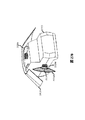
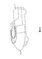
第九の実施形態のグループは、車両に統合されたレーザー分配システムを持つロープロファイルLIDARシステムを提供する。LIDARからのレーザー光は、車両の車体外板の下部の空洞領域内に送信可能であり、それにより車体外板(例えば ルーフ)の下を、車両周囲を被覆するカーテンの内部に光を送信または屈折させることができるレンズに誘導することが可能である。内部の反射体とレンズはレーザー光ガイドを形成することができる。レーザー光ガイドは、全体的または部分的にLIDARに組み込まれた限られた直接視野を、十分に制御された間接的な光路(例えば いくつかの反射を必要とする)を提供することにより増大させることができる。光ガイドからのレーザー出力角はLIDARからの入力角の関数である。このようにして、光ガイドは車両デザインに共通する外板の後方に存在する空洞を、レーザー光を測距のために誘導し分配するように利用および改良することができる。光ガイドは、LIDARがロープロファイルなまま、または車両構造に組み込まれたままで、LIDARの対象範囲をFOVの到達が困難な部分(例えば FOVの車両のルーフや側面によって隠される部分)に拡張することができる。 The group of ninth embodiments provides a low profile lidar system with a laser distribution system integrated into the vehicle. Laser light from LIDAR can be transmitted into the cavity area below the vehicle body skin, thereby transmitting light under the vehicle body skin (eg roof) into the interior of the curtain covering the vehicle body or. It is possible to guide to a lens that can be refracted. The internal reflector and lens can form a laser beam guide. Laser light guides increase the limited direct field of view, wholly or partially incorporated into lidar, by providing a well-controlled indirect optical path (eg, requiring some reflection). be able to. The laser output angle from the light guide is a function of the input angle from LIDAR. In this way, the light guide can utilize and improve the cavity behind the skin, which is common in vehicle design, to guide and distribute the laser light for distance measurement. Optical guides extend the scope of LIDAR to areas where the FOV is difficult to reach (eg, areas hidden by the roof or sides of the FOV vehicle) while the LIDAR remains low profile or incorporated into the vehicle structure. Can be done.
第十の実施形態のグループでは、LIDARはFOV内で起こる重要な変化(例えば 前方車両の車線変更)の早めの兆候を提供可能な複数のスマートテストベクタを選択し評価することにより、FOVを迅速に評価することができる。実施例は、FOVの走査の早期に動的にレーザー光を操縦し初めに複数のテストベクタと関連する一連の検証位置にレーザー走査を行うことにより、改善された反応時間を提供する。レーザーの動的制御に基づく早期の走査は、FOV全体の均一的(すなわち 非動的)な走査の過程で一連の検証ポイントを段階的に走査することの代わりとなる。一つまたはそれ以上のテストベクタの結果は非均一なレーザーパルス密度で視野を動的に走査する一連のレーザーステアリングパラメータsの取得に用いられる。従って、テストベクタはレーザー測距の空間的分布を設計することに用いることができ、それにより次の走査の非均一な測定密度の複雑なパターンを生成する。テストベクタはドアミラーの位置、縁、または車両の車線位置の変化のような決定的な特徴に基づくことができる。いくつかの実施例では、検証位置からのデータを再取得しテストベクタの再評価と更新をするために、走査は周期的に中断される。 In a group of tenth embodiments, lidar accelerates FOV by selecting and evaluating multiple smart test vectors that can provide early signs of significant changes occurring within the FOV (eg, lane change of the vehicle ahead). Can be evaluated. The examples provide improved reaction times by dynamically manipulating the laser light early in the scan of the FOV and initially performing the laser scan on a series of verification positions associated with multiple test vectors. Early scanning based on the dynamic control of the laser is an alternative to stepwise scanning a series of verification points in the process of uniform (ie, non-dynamic) scanning of the entire FOV. The results of one or more test vectors are used to obtain a series of laser steering parameters s that dynamically scan the field of view with non-uniform laser pulse densities. Therefore, the test vector can be used to design the spatial distribution of laser ranging, thereby producing a complex pattern of non-uniform measurement densities for the next scan. The test vector can be based on critical features such as changes in door mirror position, edges, or vehicle lane position. In some embodiments, the scan is periodically interrupted in order to reacquire the data from the verification position and re-evaluate and update the test vector.
本明細書に記載された技術は以下に例示する優位性の達成のために実施できる。 The techniques described herein can be implemented to achieve the advantages illustrated below.
FOV全般にわたって均一的なレーザーパルス密度を生成する代わりに、開示された技術は、FOV内の重要な特徴の位置(例えば 物体の境界、デジタル画像に認識された人物)を示すデータに基づいてレーザーを動的に操縦することで非均一なレーザーパルス密度を提供する。このデータ主導型の非均一なレーザーパルス間隔には、さらに重要な特徴を限定するという、さらなる利点がある。別の優位性としては、FOVの領域内のレーザーステアリングパラメータsを精密化することによってFOV内の物体の境界が漸進的に限定されうる。 Instead of producing a uniform laser pulse density across the FOV, the disclosed technology is based on data indicating the location of key features within the FOV (eg, the boundaries of an object, a person recognized in a digital image). Provides non-uniform laser pulse density by dynamically manipulating. This data-driven, non-uniform laser pulse interval has the additional advantage of limiting more important features. Another advantage is that the boundaries of objects within the FOV can be progressively limited by refining the laser steering parameters s within the region of the FOV.
別の優位性では、レーザーパルス密度はレーザーレンジファインダーの位置の様相(例えば 地形、GPS位置、時刻または都市部や郊外といった場所タイプの区分)に基づいてFOVの多様な部分(例えば 左側、右側、または―20度と―30度の間)から選択できる。 In another advantage, the laser pulse density is based on the aspect of the position of the laser rangefinder (eg, terrain, GPS position, time or location type division such as urban or suburbs) and various parts of the FOV (eg left, right, etc.) Or you can choose between -20 degrees and -30 degrees).
関連性のある優位性では、開示された技術はレーザーステアリングパラメータsが多様な所定の高密度レーザーパターンをエンコードすることを可能にする。そのようなレーザーステアリングパラメータsで操縦可能なレーザーを指示または設定することで、操縦可能なレーザーは対応する非均一パルス密度の領域をFOVに作り出すことができる。例えば、動的に操縦されるレーザーレンジファインダーが付いたモデルAの車両は、モデルBの車両がFOV内にいるという仮説の検証に有効なレーザーポイントパターンのライブラリを、開発または共有することが可能である。開示された方法の一つまたはそれ以上を用いてモデルAの車両はモデルBの車両がFOVに存在するかを推定し、FOV内の車両はモデルBという仮説を検証するよう設計されたレーザーステアリングパラメータsのデータベースにアクセスし、車両がモデルBという仮説を検証するのに最良の一連の非均一なレーザーパルスを作り出すよう動的操縦可能なレーザーを設定できる。従って、開示された技術はカスタマイズされたレーザーパルスを作成、共有そして操縦可能なレーザーレンジファインダーの誘導に用いることを可能にする。レーザーパルスのパターンは車両モデルAの形状と動的に操縦されるレーザーレンジファインダーの配置に合わせてカスタマイズすることができる。動的に操縦される距離計は、それが搭載されている車両と車両での配置に対応するレーザーパルスパターンのライブラリでプリプログラムされることができる。 In a relevant advantage, the disclosed technology allows the laser steering parameters s to encode a variety of predetermined high density laser patterns. By pointing or setting a steerable laser with such laser steering parameters s, the steerable laser can create a region of corresponding non-uniform pulse density in the FOV. For example, a model A vehicle with a dynamically steered laser range finder can develop or share a library of laser point patterns that are useful in testing the hypothesis that the model B vehicle is in the FOV. Is. Using one or more of the disclosed methods, the model A vehicle estimates whether the model B vehicle is in the FOV, and the vehicle in the FOV is a laser steering designed to test the model B hypothesis. A database of parameters can be accessed to configure the dynamically steerable laser to produce the best set of non-uniform laser pulses for the vehicle to test the model B hypothesis. Therefore, the disclosed technology allows customized laser pulses to be created, shared and used to guide a maneuverable laser range finder. The laser pulse pattern can be customized to match the shape of the vehicle model A and the placement of the dynamically steered laser rangefinder. The dynamically steered rangefinder can be preprogrammed with a library of laser pulse patterns that correspond to the vehicle on which it is mounted and its placement.
開示された技術は、レーザーレンジファインダーのコスト効果を改善できる。より低価格のレーザーレンジファインダーはレーザーの数が少なかったり、レーザーパルス速度が遅いことがあり得る。開示された技術により、1秒当たりのレーザーパルス総数が少ないレーザーレンジファインダーがそれらのレーザーパルスを動的かつ賢明に選択された方法で配分することを可能にする。同様に、電子的に制御されたLIDARはしばしば回転式LIDARよりも1秒当たりより少ないポイントを走査することができる。開示された技術は、データ主導による方法で、電子的に操縦されるLIDARをもっとも情報を含む領域に動的に操縦することを提供する。 The disclosed technology can improve the cost effectiveness of the laser range finder. Lower cost laser rangefinders can have a small number of lasers or a slow laser pulse rate. The disclosed technology allows a laser range finder with a low total number of laser pulses per second to distribute those laser pulses in a dynamic and wisely selected way. Similarly, electronically controlled lidar can often scan fewer points per second than rotary lidar. The disclosed technology provides a data-driven method for dynamically maneuvering an electronically steered lidar into the most informative area.
開示された技術はFOV内の物体の速度検知を改善できる。レーザー測距での速度検知の精度はそれぞれの走査中に物体の境界を正確に判定する性能に関係する。開示された技術は、境界の位置を推定し境界の位置を捜索するようレーザーを動的に操縦することができる。開示された技術は、境界限定法と動的なレーザーパルス密度の選択を用いて物体区分の速度を向上させる。 The disclosed technology can improve the velocity detection of objects in the FOV. The accuracy of speed detection in laser ranging is related to the ability to accurately determine the boundaries of an object during each scan. The disclosed technology can dynamically steer the laser to estimate the position of the boundary and search for the position of the boundary. The disclosed technique uses a demarcation method and dynamic laser pulse density selection to improve the speed of object classification.
デジタル写真の光は、ローカル環境における様々な点から一度にセンサーで受信されます。それに対してレーザーレンジファインダーは、多数を順次に狙うことができるレーザパルスを生成する(例:100,000)ことで比較的少ないレーザー数(例: 1―64)でのレーザー測距のFOVスキャンの実行を可能にします。したがって、レーザーパルス(例:離散方向の飛行測定に対応する時間)は希少な資源であり、FOVはローカル環境でのオブジェクト詳細の境界感知に関しては多くの場合がアンダーサンプリングであると言えます。多くのライダーは、一定またはほぼ一定の角速度で機械的に回転します。このような回転ライダーは、1つ以上のレーザーを決定可能方向の範囲(例:360度の方位角範囲を通る各レーザー掃引)を通してスイープすることができます。このタイプの操作は、LIDAR内のレーザーを動的操作するものではありません。機械仕掛けライダーの回転部分の角運動量は角速度の急激な変化を防ぎます。機械仕掛けライダー内各レーダーは、1次元の角度範囲内であれば均一に間隔をあけたレーザーパルスの生成を可能にします。多くの機会仕掛けライダーに対する角速度の選択が可能です(例:カリフォルニアのモーガン ヒルのベロダイン社からのHDL―64Eにおける5―20Hzなど)が、フォームは一定の1回転になります。 The light of a digital photograph is received by a sensor at once from various points in the local environment. On the other hand, the laser range finder generates a laser pulse that can aim at a large number of laser pulses in sequence (example: 100,000), so that the FOV scan of laser ranging with a relatively small number of lasers (example: 1-64) Allows execution of. Therefore, laser pulses (eg, time corresponding to discrete flight measurements) are a scarce resource, and FOVs are often undersampled when it comes to boundary sensing of object details in the local environment. Many riders rotate mechanically at constant or near constant angular velocities. Such a rotating rider can sweep one or more lasers through a range of determinable directions (eg, each laser sweep through a 360 degree azimuth range). This type of operation is not a dynamic operation of the laser in the lidar. The angular momentum of the rotating part of the mechanical rider prevents sudden changes in angular velocity. Each radar in the mechanical rider allows the generation of evenly spaced laser pulses within a one-dimensional angular range. You can choose the angular velocity for many occasional riders (eg 5-20Hz on HDL-64E from Velodyne, Morgan Hill, California), but the foam will be a constant rev.
FOV全体のユニフォームスキャンはシンプルなため回転ライダーに固有のものになりがちですが、FOVから最も多くの情報を収集するためには次善策だと考えられます。例えば、FOVの大部分(例: 壁や道路)は予測可能で時間不変な均質的な応答を返すことができます。最新のライダーは、毎秒200万ポイント以上のスキャンが可能です。したがって、現代技術の実施形態ではダイナミックな方法でレーザーを操縦することによる、200万のスキャンポイントと最も多くの情報(例:エッジや境界)の同時選択を試しているのです。 Uniform scanning of the entire FOV tends to be unique to rotating riders due to its simplicity, but it is considered the next best thing to collect the most information from the FOV. For example, the majority of FOVs (eg walls and roads) can return a predictable, time-invariant, homogeneous response. The latest riders can scan over 2 million points per second. Therefore, modern technology embodiments are experimenting with simultaneous selection of 2 million scanpoints and the most information (eg edges and boundaries) by manipulating the laser in a dynamic way.
最近では、電子走査レーザーとフェーズドアレイレーザービームフォーミングの進歩により、FOV内でのレーザーの動的操縦が可能になりました。A操縦可能なレーザーは機械的操縦が可能(例:レーザーをリダイレクトするための移動部品を含む)または、電子的な操縦が可能(例:多方向のうちの一点でビームを作る選択的フェーズドアレイを含む)になります。この操縦可能なレーザーの開示目的は、操縦可能なレーザーがレーザービームの軌跡やパワーレベルを変更することができるレーザーの集合体(例えば、ポジショニングコンポーネントを含む)であるということです。この操縦可能なレーザーの開示目的は、操縦可能なレーザーがインプット(例:ユーザーコマンドも含む)できる場合は、FOVスキャンのコース内でのレーザービームのパワーレベルまたは軌道の変化に応答できる場合の動的操作が可能であるというこです。この動的操作レーザーの開示目的は、動的操作レーザーがFOVスキャン中にレーザービームのパワーや軌道の動的調節を引き起こす操縦可能なレーザーへの入力データ(例:レーザーステアリングパラメータsなどの指示)の提供のプロセスです。例えば、一定のスキャンレート(例えば10度/秒)、パルスレート数(例えば10パルス/秒)でのFOVのラスタースキャンを行うように設計されたレーザー集合体は動的操縦ではありません。別の例では、過去のレーザー集合体は入力信号(例:それによるFOV内表面でのイメージ生成をする)を基にしたFOV内の不均一レーザーパルスの生成をするレーザー集合体の角速度を力学的に変更する入力信号や回路を供給することで動的操作されることができます。軌道の変化は、方向の変化(複数のパルスによって形成される方向)または速度の変化(すなわち、レーザーがFOVの反対側へ向かって進む速さ)です。例えば、動的に角速度を変化させる一定の方向へのパルスレーザーのFOVはパルス間隔の増減により力学的に定義されたレーザーパルス密度を生成します。
Recently, advances in electron scanning lasers and phased array laser beamforming have enabled dynamic control of lasers within FOVs. A Maneuverable laser can be mechanically steered (eg, including moving parts to redirect the laser) or electronically steered (eg, a selective phased array that creates a beam in one of multiple directions) Including). The purpose of disclosing this maneuverable laser is that the maneuverable laser is a collection of lasers (eg, including positioning components) that can change the trajectory and power level of the laser beam. The purpose of disclosing this maneuverable laser is to behave when the maneuverable laser can respond to changes in the power level or trajectory of the laser beam within the course of the FOV scan if it can be input (eg, including user commands). It is possible to perform specific operations. The purpose of disclosing this dynamically manipulated laser is to input data to a maneuverable laser that causes the dynamically manipulated laser to dynamically adjust the power and trajectory of the laser beam during a FOV scan (eg, instructions such as laser steering parameters s). Is the process of providing. For example, a laser assembly designed to perform a FOV raster scan at a constant scan rate (eg 10 degrees / sec) and pulse rate number (
現在の開示における多数の回転ライダーは、1回のスキャンではレーザービームのパワーも軌道も力学的な制御ができないことから動的操縦可能なレーザーを構成していません。しかしながら、回転または機械仕掛けライダーの場合には動的操作が可能です。例えば、最終結果がFOVの特定部分での不均一な密度レーザーパルスパターンを生成のガイドまたは操縦ができるシステムであることで、入力データの提供がFOVのスキャン内で力学的にレーザーパルスレートを変化させる原因となる場合があります。 Many rotating riders in the current disclosure do not constitute a dynamically steerable laser because neither the power nor the trajectory of the laser beam can be mechanically controlled in a single scan. However, dynamic operation is possible in the case of rotating or mechanical riders. For example, the end result is a system that can guide or steer the generation of non-uniform density laser pulse patterns at specific parts of the FOV, so that the input data provision dynamically changes the laser pulse rate within the FOV scan. It may cause the pulse.
最近では、カリフォルニア州サニーベイルのQuanergy社のS3モデルのような電子的スキャンがされたライダーの開発がされています。これらのソリッドステート電子スキャンライダーは可動部品を含んでいません。可動部には角運動量がないため、電子スキャンされたソリッドステートライダーシステムによる1つ以上のレーザーの動的操作が可能になります。 Recently, electronically scanned riders such as the Quantergy S3 model in Sunnyvale, California have been developed. These solid-state electronic scan riders do not contain moving parts. The moving parts have no angular momentum, allowing the dynamic operation of one or more lasers with an electronically scanned solid-state rider system.
レーザー範囲検出システムの多くでは、レーザーの定期的な脈動がFOV内で正確なパルス位置の操作に影響を与えます。しかし、このような周期パルスレーザーは現在開示と用いることで、領域内のレーザー滞在時間の増幅による領域周囲よりも高いパルス密度の複雑形状領域の提供が可能になります。このような方法で、周期的にパルスされたレーザーはFOVにより高密度で複雑な形状領域のパルスを生成します。この複雑な形状の領域の情報開示の目的は、4つ以上の直線エッジを持つ境界や、一つ以上の湾曲した部分と2つ以上の異なる曲率の半径を持つ複雑な形状の領域が挙げられます。典型的な複合領域の例としては、五角形の境界を持つ領域、楕円の周囲または車の詳細な輪郭を捉えたような六角形の境界線が挙げられます。その他のレーザー範囲検出システムは、連続的なレーザー信号の送信やレーザー光の強度を変調・検出することによって測距を行います。連続的なレーザー光線システムでの飛行時間は受信および送信されたレーザー信号間の位相差に直接比例しています。 In many laser range detection systems, the periodic pulsation of the laser affects the correct operation of the pulse position within the FOV. However, such periodic pulsed lasers can now be used with disclosure to provide complex shaped regions with higher pulse densities than around the region by amplifying the laser dwell time within the region. In this way, the periodically pulsed laser produces high-density, complex-shaped regions of pulse with FOV. The purpose of information disclosure of this complex-shaped region is to include a boundary having four or more straight edges, or a complex-shaped region having one or more curved portions and two or more different radii of curvature. I will. Examples of typical composite areas are areas with pentagonal boundaries, hexagonal boundaries that capture the perimeter of an ellipse or the detailed contours of a car. Other laser range detection systems perform distance measurement by transmitting continuous laser signals and modulating and detecting the intensity of laser light. Flight time in a continuous laser beam system is directly proportional to the phase difference between the received and transmitted laser signals.
1つの側面としては、動的に操縦されたレーザーレンジファインダーはFOVのオブジェクト関連の境界の調査に使用が可能です。例えば、ライダーレーザーの位置に小さな変化を加えることで100フィート離れたTOFのオブジェクト境界に大きな変化を確認することができます。それに対してレーダーは、はるかに大きなビーム発散力を持っており、それゆえ、はるかに広い領域内でもオブジェクトに影響を与えます(多くの場合、オブジェクトのサイズは何倍にもなる)。したがって、ビームスキャンされたレーダーからの反射はオブジェクトからの反射を意味しており、それによってビーム操縦レーダーはオブジェクトの検出に有用にはなるものの、詳細な境界局在化を実行するためには実用的でないと考えられます。したがって、ライダービームによる大規模なビーム発散で起こるレーダー反射方向の小さな変化が、オブジェクトエッジに関する任意の実用的情報のほとんどを提供していることになります。しかしながら、対照的にレーザーのスポットサイズの多くの主要オブジェクト(人、犬、縁石)の境界は小さいままになります。本技術は、電子操縦ライダーの走査点を反復的に精製するプロセスによって、対象境界(例えば エッジ)の力学的識別が可能になります。例えば、ライダーは二分アルゴリズムアプローチを使用して、FOV内に存在する歩行者の境界を反復的に検索することができます。ライダーはポイント・クラウド内のポイントP1が歩行者との間に一貫性のあるTOFを持つことができ、また歩行者と周辺環境の境界の正確な位置を推定するための角度範囲の減少(例えば、二分のアプローチで)をP1の左右の反復的なスキャンにより示すことが可能になります。一般的には、この手法により、ライダー内にあるレーザーの力学的構成によるポイントクラウドのTOFの変化の調査、また境界定義を反復的に向上させることが可能になります。 On one side, the dynamically steered laser rangefinder can be used to investigate object-related boundaries in the FOV. For example, by making a small change in the position of the rider laser, you can see a large change in the object boundary of the TOF 100 feet away. Radar, on the other hand, has a much larger beam divergence and therefore affects objects even within a much larger area (often many times the size of the object). Therefore, reflections from beam-scanned radar mean reflections from objects, which makes beam-steering radar useful for detecting objects, but practical for performing detailed boundary localization. It is considered to be off-target. Therefore, the small changes in radar cross section caused by the large beam divergence by the rider beam provide most of any practical information about the object edge. However, in contrast, the boundaries of many major objects (humans, dogs, curbs) of laser spot size remain small. The technology enables mechanical identification of target boundaries (eg edges) through the process of iteratively refining the scanning points of an electronically piloted rider. For example, a rider can use a dichotomous algorithm approach to iteratively search for pedestrian boundaries within the FOV. The rider can have a consistent TOF between point P1 in the point cloud and the pedestrian, and a reduction in the angular range to estimate the exact location of the boundary between the pedestrian and the surrounding environment (eg). , With a bisected approach) can be shown by iterative scans to the left and right of P1. In general, this technique makes it possible to investigate changes in the TOF of the point cloud due to the mechanical configuration of the laser in the rider and to iteratively improve the boundary definition.
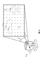
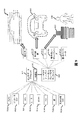
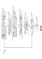
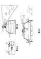
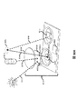
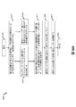
図1Aは、操縦可能なレーザアセンブリ115を構成するレーザーレンジファインダーシステム105(例:ライダーなど)を示しています。操縦可能なレーザアセンブリ115は、視野FOV130内の1つ以上のレーザー(例:操縦可能なレーザー121)をスキャンします。視野130は、方位角(例:水平)角度範囲140と標高(例:垂直)の角度範囲145によって定義することができます。操縦可能なレーザー121は、FOV130をスキャンし、連続方向内で複数存在する、または連続するレーザーパルス(例えばレーザーパルス150a、150bと150c)を生成します。FOV方向内の各レーザーパルスは、大概の場合「+」記号で例示される。レーザーパルス(例:150aと150b)の一部は、オブジェクトによって反射されます(例:人160と車両170)。図1Aの実施形態では、レーザーパルスはFOV内で等間隔に配置されており、隣接するレーザーパルス間の角度分離は水平方向と垂直のどちらか一方または両方において一定値となっています。従って、いくつかのレーザーパルス(例:5―6パルス)のみが、FOVを通したある程度に不均等なレーザーパレスの人口密度内でオブジェクト160と170から反映されることになります。この開示の目的のためにFOVレーザーレンジファインダーの110は、レーザーレンジファインダーがレーザー測距測定を行うことができるすべての方向(例:標高と方位角の組み合わせ)の組み合わせとして定義することができます。
FIG. 1A shows a laser rangefinder system 105 (eg, rider, etc.) that constitutes a
図1Bはレーザーレンジファインダー110が、FOV内の130の操縦可能なレーザー121をスキャンした操縦可能なレーザアセンブリ120とほぼ同じ数のレーザーパルスを生成していることを示しています。図1Bの例では操縦可能なレーザーは境界180と190、または人160と車両170を囲む非一様で高いレーザーパルス密度を発生させるため動的に操縦(非一様でも非動的な操縦でもない)されています。操縦可能なレーザアセンブリ120は動的に操作されているレーザー集合体の一例であり、力学的指示を受ける回路(例:レーザーステアリングパラメータ)を含むレーザービームの方向またはパルスレートの急速に変更をするレーザー121を構成します。現在の技術は、レーザーステアリングパラメータの動的操縦、ガイド、指導、または増加したレーザーパルス密度または不均一なパルス密度の領域を生成するための操縦可能なレーザー(例:電子レーザーレンジファインダー)設計のための技術のいくつかの例を提供しています。レーザーレンジファインダー110は、レーザーパルスからの反射を検出するためのレーザー検出器122のさらなる設備が可能です。
FIG. 1B shows that the
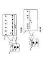
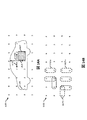
図2Aは、動的操縦されていない回転ライダーの特徴と特性の一部を示しています(例えば、ベロダイン社のHDL―64eまたはカリフォルニア、モーガンヒル)。215aand215b.回転LIDAR205には、それぞれ固定対応の仰角215aと215bを持つ2つのレーザー210aと210bがあります。レーザーは方位角方向218で機械的に回転されます(すなわち、方位角0―360度をスイープします)。レーザー210aと210bは一定の角速度で回転し、一定のパルスレートを保ちます。各レーザーは、それによって一定の仰角と共に非一様で連続的なレーザーパルス(例えばシーケンス222)を生成します。レーザーは、方位角の一定の角度の分離によって直前のレーザーパルスから離れた方向性を有する配列の各レーザーパルスによる予測可能な方法でFOV220を横断して進みます。特に、これらのレーザーは、各スキャン間で動的に角速度または脈拍数を変えるような再構成がされることはありません。例えば、シーケンス222の各レーザーパルスは、仰角(極角とも呼ばれる)と方位角によって球面座標上で一意に定義することができます。シーケンス222の場合には、各レーザーパルスは一定の仰角215bと等間隔の方位角を有する。図2Aの場合には、1つのレーザーパルスから次(例えば角度分離223)までの方位角の分離の範囲は単一値になります。
Figure 2A shows some of the characteristics and characteristics of non-dynamically piloted rotating riders (eg Velodyne HDL-64e or Morgan Hill, CA). 215and215b. The
対照的に、図2Bでは、レーザーを一定の角速度で回転させながらレーザのパルス周波数を変調することによって動的操縦されるLIDAR207を示しています。パルス周波数を動的に変調するようにレーザー210aを構成した結果により、レーザーパルス224のシーケンスでは各種量より異なる1次元範囲の方向を持つということになります。なお、図2Bの場合には、1つのレーザーパルスから次の方向への分離(例えば角度分離223)には1次元範囲となり、それゆえLIDAR207は1次元で動的に操縦される事になります。シーケンス224の方向は1次元範囲に及びます。
In contrast, FIG. 2B shows the
図2Cの電子的操作されたライダー230は、パルスレートを一定に保つ間はレーザ−235の変調角度により動的操作されています。変化量によって異なる1次元範囲の方向を持つレーザーパルスのシーケンス238が、電子的操縦可能なレーザーを動的に角速度(または視野236のレーザーの位置)を調節するために構成した結果です。図2Cでは密接的パルスのグループ化のためにレーザー軌跡を減速した後、初期の通常スピードによるレーザーパルスの分離のためのスピード加速が通常分離以上になることをFOVの単掃引のコースが示しています。
The electronically manipulated
図2Dは、2次元レーザーを動的操作することで二次元の角度範囲にまたがるレーザーパルスのシーケンスを生成することを示しています。結果のシーケンスは、1つのレーザーから2次元の角度範囲を持っており、また各レーザーは1次元の角度範囲を持つシーケンスを生成する回転ライダdーとは対照的になります。ライダーは、レーザーの角速度または位置を2次元(例:方位角と標高)で動的操作することで、シーケンス240の生成が可能なレーザーの動的操縦を構成できるようになります。このようなシーケンスは旋回する部品の角運動量により方位角上下の仰角の高速変調を防止しているため、回転ライダーによる実行は不可能になります。
Figure 2D shows that a two-dimensional laser is dynamically manipulated to generate a sequence of laser pulses across a two-dimensional angular range. The resulting sequence has a two-dimensional angular range from one laser, and each laser is in contrast to a rotating rider d that produces a sequence with a one-dimensional angular range. By dynamically manipulating the angular velocity or position of the laser in two dimensions (eg azimuth and elevation), the rider will be able to configure the dynamic maneuvering of the laser capable of generating
図2Eは、シーケンス中で複数の方向反転を含むレーザーパルスを生成する為のレーザーの動的操作を示しています。例えば、レーザーパルスシーケンス242は、FOV244を横切って左から右へのレーザープログレスによって開始されます。レーザーパルス245の後はレーザーは、正のx方向から負のx方向にレーザーの方向のx成分を反転するように再構成されます。レーザーパルス246の後には、レーザーは再び方向転換するように構成されています(すなわち、正のX方向に戻る)。速度を正のX方向に変調するだけのレーザー235とは対照的に、方向転換により検出された境界を越えて走査を有効にするようにレーザーを動的操作します。また、FOV244スキャンの過程で方向転換と組み合わせた2次元動的操作は、レーザー235がオブジェクトの複雑な形状の境界に沿った動的スキャンを可能にします。
Figure 2E shows the dynamic manipulation of the laser to generate a laser pulse containing multiple direction reversals in the sequence. For example, the
図2Fは、動的に操縦可能なレーザー(例:図2Eの電子的操縦可能なレーザー235)を操作することで、複雑な(例:スパイラル)形状を生成するレーザーパルス250のシーケンスを生成することを示しています。複雑なシーケンス250は、動的操縦されていないライダーとの使用ができません(例:単軸を中心に回転するライダーなど)。不均一な間隔で複雑な形状のシーケンスを生成する利点は、FOV255でスキャンされた部分の順序を決定する機能があるということです。例えば、シーケンス250は最終的に回転ライダーと同様密度の領域をスキャンすることができますが、最初に周囲境界を操作して徐々にFOV255の中心に向かって進むことができるという利点があります。
FIG. 2F produces a sequence of
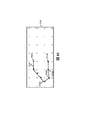
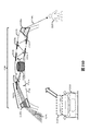
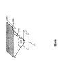
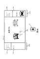
図3は、FOV130の残りの平均パルス密度に対してレーザーパルス密度を増加させた(例:レーザーパルス150d)2つの高密度スキャン領域310aと310bの生成に伴うFOV130で動的操作のレーザー121を示しています。他の実施例では、動的操作によりレーザーパルス密度の大きい高密度スキャン領域(すなわち、レーザー測定の数または単位のソリッド角度あたりのパルス)を、直ちに周囲の面積、FOVに対する平均レーザーパルス密度、或いは同じまたは類似の領域の前のスキャンを基準に対して相対的な生成が可能です。ソリッドステートLIDAR305は、FOVで最初に識別されたオブジェクトによってFOVの動的操縦されたスキャンの実行を可能にします。(例:FOVの均一な低密度スキャンに基づく)。第二に、操縦可能なレーザアセンブリ120は検出されたオブジェクトを囲む領域(例えば310a)で増加したレーザーパルス密度生成の操作が可能なレーザーステアリングパラメータs(例:命令または構成パラメータ)を受け取ることができます。レーザーステアリングパラメータは正方形、長方形または円のような均一に定形密集したスキャン領域(例えば310a)の生成が可能です。またレーザーステアリングパラメータは、より複雑な形状の高密度スキャン領域(310bなど)の生成もできます。310aなどの均一な形状の定形密集した領域を生成するレーザーステアリングパラメータは、物体の境界が不明な場合に有用です。(例:図1Bの人160の境界180)
FIG. 3 shows a dynamically manipulated
逆に、オブジェクトの境界位置がある程度の精度で知られている場合、レーザーステアリングパラメータのセットを選択することにより、操縦可能なレーザーへより複雑な高密度スキャン領域(310bなど)を生成する指示または設定が可能になりますがこの時点ではまだ境界が含まれている状態になります。たとえば、図1Bの車両170の境界190は、前回のレーザースキャンデータから、外周320と内側の境界330の間にあると推定することができます。レーザーステアリングパラメータは、介在領域310bで走査線密度の実行が可能な操縦可能なレーザー121の設計として選択されることができます。310aと310bの境界を包含する高密度スキャン領域の利点は、反射検出器によって容易に検証され、反射パルスの飛行時間またはレーザー強度の様相を測定するが可能な点です。ある実施形態では、ライダー305によるFOX130のスキャンが、FOV平均レーザーパルス密度内で動的操縦する操縦可能なレーザーの設計によりFOVの一部または全てをカバーする部分を含むことで、更に大きなレーザーパルス密度での複数の高密度領域内スキャンを可能にします。動的操作は、2次元方向の変化と方向転換を含む各高密度スキャン領域内のレーザーパルスシーケンスの生成が可能です。
Conversely, if the boundary position of the object is known with some accuracy, selecting a set of laser steering parameters will instruct the maneuverable laser to generate a more complex high density scan area (such as 310b). It can be set, but at this point the boundary is still included. For example, the
動的操縦 レーザーレンジファインダー
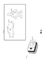
図4Aは、この開示の実施の形態に従って動的操縦されたレーザーレンジファインダー405の代表的な幾つかの構成要素を例示しています。レーザーレンジファインダー405は操縦可能なレーザアセンブリ406を含んでいることとします。レーザーレンジファインダー405は、センサーデータを受信し、そのセンサーデータに基づいてレーザーステアリングパラメータを生成するレーザーステアリングパラメータジェネレータ410を含むこととします。センサーデータは、センサーデータ処理機475またはセンサーから直接受信されます。センサーデータは、ローカル環境の複数の側面を示すことができます。レーザーステアリングパラメータ発電機410は、レーザーステアリングパラメータ(例:命令)生成された情報を操縦可能なレーザアセンブリ406にパラメータ送信する機能にもなります。レーザーステアリングパラメータ発電機410は、各レーザーステアリングパラメータを受信した際に操縦可能なレーザアセンブリ406がレーザーステアリングパラメータの受信に対して適切な実行または反応するように、パラメータを適時に送信する設定が可能です。また、レーザーステアリングパラメータは操縦可能なレーザアセンブリ406の使用により、一定期間にわたって実行されるひとまとまりの命令ファイルの送信が可能です。
Dynamically Manipulated Laser Range Finder Figure 4A illustrates some typical components of a dynamically maneuvered
操縦可能レーザーアセンブリ406は、1つまたは複数のレーザー発電機420およびレーザーポジショナー430の設備が可能です。複数のレーザー発電機420(多くの場合は”レーザー”に短縮)は、レーザーポジショナー430によって調節されたFOV内の複数の場所にて複数のレーザービームを生成する(例:ビーム435)レーザーダイオードが可能です。レーザーポジショナー430は、レーザーステアリングパラメータに基づいて複数のレーザービーム(例:ビーム435)を操縦する機能を果たします。レーザーポジショナー430は、レーザー発電機420から機械的にレーザービームを操縦することができます。回転ライダーは、通常機械的に操縦されたレーザーポジショナーを使用します。模範的な機械的に操縦されたレーザーポジショナー430は、複数のレーザー発電機に対する光学部品の移動をするステッピングモーターや誘導電動機などの機械的な手段を含みます。模範的な機械レーザーポジショナーの光学部品としては、複数のミラー、ジンバル、プリズム、レンズおよび回折格子が挙げられます。音響および温度は、複数のレーザー発生器420に相対的なレーザーポジショナー430の光学素子の位置をコントロールするためにも用いられています。レーザーポジショナー430はまた、ソリッドステートのレーザーポジショナーとしての機動が可能で可動品もなく操縦可能な入射光レーザービームの代わりにFOV内でのアウトプット方向へ操縦可能な電子的手段のレーザービームを使用できます。例えば、電子操縦可能なレーザアセンブリは入射したレーザビームを多数の部分へと分割するための複数の光学スプリッタ(例:分岐、方向性結合器、またはマルチモード干渉カプラー)のソリッドステートレーザーポジションを確保することが可能です。その後その入射されたレーザビームは、各部分が選択可能量に従って遅延になったとして(例:波長の一部分で部分が遅れたなど)遅延線データに送信されます。また、遅延線データは波長調整の提供(例:入射レーザビームからわずかに異なる波長の識別)が可能です。入射したレーザービームの可変遅延部分を組み合わせることで複数の遅延線によって創られた遅延のパターンが確認でき、それによって、少なくとも部分的に定義した角度からの出力レーザビームの作成ができるようになります。複数の遅延線データの作動機構としては、熱光学作動、電気光学作動、電気吸収作動、磁気光学作動または液晶作動が可能です。レーザーポジショナー430は、国防高等研究計画局の短距離で広い視野のある非常に機敏な電子的操縦のフォトニックエミッター(掃除機)のようなチップスケールの光走査システム上の複数のレーザー発電機420と組み合わせることができます。レーザーポジショナー430はまた、米国特許9128190でウルリッヒらに開示された電気機械ミラーの配列のような一つ以上の電気機械ミラーにもなりえます。この開示の目的は。操縦可能なレーザアセンブリ(例:図4aの406)は、レーザーポジショナー(例:ポジショナー430)が視野のスキャンコース内でレーザーパルスを動的操縦することができる場合にのみ、動的操縦が可能なレーザーアセンブリーと見なされます。ある実施形態では、動的操縦レーザーアセンブリーは、FOVのスキャン中に命令を処理する回路(例:レーザーステアリングパラメータ)に加え、スキャン中の1つ以上のレーザーパルスへの指示の再構成が可能な機械的または電子チューニング部分を備えたレーザーポジショナー回路も備えています。たとえば、操縦可能なレーザアセンブリは64のレーザーと単純回転のミラーを含むレーザーポジショナーの装備が可能です。対照的に動的操縦レーザーアセンブリーは、64のレーザーを持つことは可能ですが、光ビームステアリング配列によりFOVのスキャン中に提供される命令構成(例:レーザーステアリングパラメータ)に基づいたレーザーの各々からのレーザパルス操縦になります。
The
レーザーレンジファインダー405は、標的サブアセンブリ438のさらなる装備が可能です。標的サブアセンブリ438は、光検出器450(例:フォトダイオード、アバランシェフォトダイオード、ピンダイオードまたは電荷結合デバイスCCDs、単一光子アバランシェ検出器(SPADs)、ストリークカメラ)を含む光検出器440の装備ができます。光検出器450は、CCD配列やInGaAs配列などの2D光検出配列にすることも可能です。検出器440は、光電流を電圧信号に変換するための信号増幅器および調節装置452(例:オペアンプまたはトランスコンダクタンスアンプ)をさらに生成します。標的サブアセンブリ438は飛行計算回路455(例:位相コンパレータ)や強度電卓460のような回路生成が可能です。操縦可能なレーザアセンブリ406は、出射レーザービームの方向内で指摘され、反射光が来ることが予想されるFOV狭い部分に焦点を当てることができるような探知機440やTA406との同一場所への設計が可能です。
The
操縦可能レーザーアセンブリ406は飛行計算機455の時間を含むことで、レーザーパルスに関連付けられる物体への飛行とリターンにかかった時間の計算が可能です。また飛行計算機455の時間は発信レーザービームの位相と反射波の位相角を比較し、飛行時間を推定するためにも機能することができます。さらに飛行計算機455は、反射光子から生じるアナログ信号をデジタル信号に変換するためのアナログ―ディジタルコンバータを含むことも可能です。レーザーレンジファインダー405には、反射光の強度を計算する強度計算機460の装備が可能です。レーザーレンジファインダー407は、レーザー反射445に関連付けられた3d位置を計算するための3D位置計算機464のさらなる設備が可能になります。
The
レーザーレンジファインダー405は、飛行計算機455と強度計算機460または3D位置計算機464の時間からデジタル化されたデータ収集のためのデータアグリゲータ465を含むことができます。データアグリゲータ465は、発信機470またはセンサーデータプロセッサー475のパケットへのデータのグループ化が可能です。レーザーレンジファインダー405はデータパケットを送信する送信機470を含むことができます。発信機470は、イーサネット、RS232、802.11などのさまざまな有線またはワイヤレスプロトコルを使用して、データを処理サブアセンブリ(コンピューターやリモートのセンサーデータプロセッサーなど)に送信し、さらに分析することができます。
The
レーザーレンジファインダー405はセンサーデータの処理、またFOV内の一部またはすべての特徴あるいは分類の識別のためのセンサーデータプロセッサー475の装備が可能です。たとえば、データプロセッサ475は特徴識別子480の使用による、FOV内のオブジェクトの境界やエッジなどの特徴識別が可能です。データプロセッサ475は、特長識別子485を使用した境界あるいはエッジがある領域の識別ができるようになります。同様に、分類器490はセンサーデータのパターンを使用したFOV内のオブジェクトの分類識別ができます。たとえば、分類子490は、オブジェクトメモリ495に格納されている以前に記憶したオブジェクトや特性のデータベースを使用して、車両、歩行者、または建物などからのデータの一部を反射パルスから分類することができます。図4Aの実施例では、センサーデータプロセッサー475が操縦可能なレーザアセンブリの近く(例:同じ包囲の中)に位置する場合には有線または無線リンクを介して反射データの送信無しでのセンサーデータ(反射範囲など)処理が可能になります。図4Aは、距離データをセンサーデータプロセッサーに送信する際の長距離通信リンク(例:イーサネット)に潜伏関連する埋め込み型プロセスアーキテクチャの一例です。
The
図4は、この開示の実施形態に従って動的操縦されたレーザーレンジファインダー407の構成要素を示しています。本実施例では、データ処理およびレーザーステアリングパラメータ生成コンポーネントは、その操縦可能なレーザアセンブリ406から離れた場所に配置しています。操縦可能なレーザアセンブリ406は、1つまたは複数のレーザー(例:レーザー発生器420)、およびポジショナー430を含むことができ、またこの場合レーザーステアリングパラメータの処理に基づくレーザー光発電機からの動的操縦するレーザービームの回路は含まれます。レーザーレンジファインダー407は、離れた場所に配置するレーザーステアリングパラメータジェネレータ410からレーザーステアリングパラメータを受信する受信機415を含みます。受信機415は、有線または無線受信機とイーサネット、RS232または802.11などの様々な通信プロトコルの実施が可能です。送信機470は、飛行計算機455の時間、強度電卓や3次元位置計算機464(図4aA)から遠隔地データアグリゲーター465にデータを送信することができます。
FIG. 4 shows the components of a
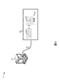
図5は、本開示の幾つかの具体例に基づくレーザーレンジファインダー510のある構成要素を示しています。レーザーレンジファインダー510はプロセスと操縦可能なレーザーアセンブリを連結するため、処理サブアセンブリ520、動的操縦のレーザアセンブリ505、また通信リンク530を含みます。処理サブアセンブリ520は1つ以上のプロセッサー(図4Aおよび4Bのセンサーデータプロセッサー475など)や、イーサネット、RS485、光ファイバー、wifi、Bluetooth、CANBUSまたはUSBなどの1つ以上のトランシーバ(受信機415および送信機470を含むトランシーバなど)を含むことができます。サブアセンブリ520の処理には、コンピューターで読み取り可能なストレージメディア(フラッシュメモリやハードディスクドライブなど)を使用したリモートミラー(例:道路反射鏡)の検出と利用の方法の格納も可能です。動的操縦可能なレーザーアセンブリ505は、レーザー発電機420およびレーザーポジショナー430のレーザーステアリングパラメータに基づいた視野の中の1つ以上の地点でレーザー光線の操縦を含んでいます。レーザーポジショナー430は、1つ以上の光遅延線や音響または熱ベースのレーザーステアリング要素を含むことができます。ソリッドステート操縦可能なレーザアセンブリレーザーポジショナー430は指示(例えば、レーザーステアリングパラメータ)を受け取る機能があり、それによりレーザービームの一部分を遅らす(すなわち、レーザービームをコピーする際に位相差を作成する)ことで、そのレーザービーム部分とFOV内に位置された出力ビームを組み合わせます。メカニカルレーザーポジショナー430は、レーザーステアリングパラメータに基づいた入力信号(ステッパーモーターのPWM入力など)を受信することで、ミラーをFOV方向にレーザーを標的にし、Tミラーまたはミラーの位置操作可能要素となることができます。操縦可能なレーザアセンブリ505もまた、光センサー(複数)450のような成分を含む検出器440、飛行計算機455、光強度算出部460及び3D位置を含むことができます。操縦可能なレーザアセンブリ505は、イーサネット、RS485、光ファイバー、Wi―Fi、Bluetooth、CANBUS、またはUSBトランシーバなどのトランシーバ(受信器415や送信機470など)を含むことができます。通信リンク530は、有線リンク(イーサネット、USBまたは光ファイバーケーブルなど)またはワイヤレスリンク(Bluetooth トランシーバのペアなど)にすることができます。通信リンク530は、処理サブアセンブリ520から操縦可能なレーザアセンブリ505へのレーザーステアリングパラメータまたは同等の命令の転送が可能です。通信リンク530は、操縦可能なレーザアセンブリから処理サブアセンブリ520への転送が可能です。
FIG. 5 shows some components of the
図6Aは、技術面によるレーザーステアリングパラメータの模範例を示しています。レーザーステアリングパラメータ601のセットには、602が示すような一つ以上のレーザーステアリングパラメータ適用開始位置を含みます。開始位置602は、関連する測定単位を持つデカルト座標系の点(例:右に20mm、視野の左下隅の右下隅より20mm)とします。この場合複数のレーザーレンジファインダーFOVは、FOVの原点に相対する角度位置の点と説明されています。たとえば、始点を水平方向に+30度、垂直方向に10度にするとFOV内の点が示されます。
Figure 6A shows a technical example of laser steering parameters. The set of
レーザーステアリングパラメータは領域幅604または領域の高さ606が可能です。その幅と高さは、FOV内の度数で表されます。レーザーステアリングパラメータの模範的なセットは開始位置、領域の幅および領域の高さの4つの側面のFOV内での領域定義が含まれています。レーザーステアリングパラメータの他の模範的なレーザースキャンスピード614、レーザーパルスサイズ616(例:ライダー出口におけるレーザーパルスの横断区域、レーザーパルス618の数、またはパルス強度といったような領域内でのスキャン適応方法を含みます。
Laser steering parameters can be area width 604 or area height 606. Its width and height are expressed in degrees within the FOV. An exemplary set of laser steering parameters includes a region definition within the FOV on the four sides of the starting position, region width and region height. Other exemplary laser scan speeds of laser steering parameters, such as
レーザーステアリングパラメータは、領域の境界を定義する1つ以上の領域境界608とします。例えば、図6Bの領域620は、アウトバウンド320とインナーバウンド330とすることで定義できます。A操縦可能なレーザーは、領域の境界608によって定義された領域620内で密度の増加(例:低速のスキャン速度と一定のパルスレート)を利用したスキャンの指示が可能です。
The laser steering parameter is one or more region boundaries 608 that define the region boundaries. For example,
レーザーステアリングパラメータは、1つ以上のレーザーパルス位置610であるとします。パルス位置610は、FOV内の対向位置に移動することで操縦可能なレーザーへの指示の提供が可能になルコとで1つ以上のレーザーパルスを生成します。このような例では、レーザーはある場所から別の場所へと操縦される間にレーザービームを生成し、またレーザーパルスの位置する場所で一定期間留まることも可能になります。他の実施形態では操縦可能なレーザーはこれらの位置610を使用することで、定義された位置への離散パルスの生成が可能です。このような実施形態では、レーザービームを離散パルス位置で生成することで、一定期間のパルス位置への滞留が可能になります。図6Cでは、複数のレーザーパルス位置がパルス630のパターンを形成しています。レーザーステアリングパラメータは、方向変化の実践ができる操縦可能なレーザー(例:図1Aの115)のようにFOVでポイントを定義することができる1つ以上のパスウェイポイント612の機能となることも可能です。図6Dは、パスウェイポイント(例:ウェイポイント612)によって定義され、操縦可能なレーザー110の指示に使用される2つの典型的なパス640と650を示しています。この技術を持つ人々にとっては、レーザーステアリングパラメータが不均一なパルス密度に同等またはほぼ同等の領域を生成することができる技術を保有していることは明らかです。たとえば、以下のようにレーザーステアリングパラメータの異なる条件を組み合わせてみると、図6Bの領域620、図6Cのパルス630のパターン、パス640と650ではレーザーパルス密度の増加または不均一領域が生成されます。
The laser steering parameter is assumed to be one or more laser pulse positions 610. The pulse position 610 generates one or more laser pulses with Luco, which can provide instructions to the maneuverable laser by moving to the opposite position in the FOV. In such an example, the laser can generate a laser beam while maneuvering from one location to another, and can also stay at the location of the laser pulse for a period of time. In other embodiments, the steerable laser can use these positions 610 to generate discrete pulses to defined positions. In such an embodiment, the laser beam is generated at discrete pulse positions, which allows it to stay at the pulse positions for a period of time. In FIG. 6C, multiple laser pulse positions form a
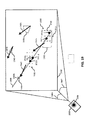
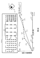
図7は、レーザーステアリングパラメータの精緻化を反復して行い、それによって視野内に存在する物体の境界線を段階的に局所化するプロセスを示す。初期レーザーステアリングパラメータセットはレーザパルス分布702aを生成するために使用される。図7は、繰り返し境界特定(IBL)の例を示し、FOVの走査を数回実施するにしたがい、物体(例えば、車両170の境界線190)の境界線が、FOVの一部の範囲に、より小さく、もしくは、より絞り込まれて局在化する。飛行時間演算処理装置455および反射強度演算処理装置460を含む反射光検出装置(例えば、図4の450)によって測定された反射光の特性に基づいて反射光のデータセット705aが収集される。図7の実施形態では、車両170の境界線の外側に位置する反射に対しては、「0」を反射光のデータセットに与え、境界線220の内側に所在を示すTOFを記録したレーザパルスに対しては、「1」を与え簡素化する。この開示の目的のために、境界領域はFOV内に存在する物体の境界線を包囲する視野領域とすることができる。例えばレーザ測距データが物体(例えば、車両170)と一致するTOFに明瞭な変化を示す場合、前記物体の境界線を含むすべての計測点を包囲する境界領域710aを算出することができる。この場合、境界領域は、FOV内に存在する物体境界線のすべての可能な計測点を包囲することができる。反射光データセット705aに基づいて、境界領域710aを決めることができ、境界線190を含む判明している複数の計測点の周囲に基づいて境界領域を選択することができる。境界領域705aは前記レーザパルス分布によって生成された第の高密度走査領域よりも縮小できる。この高密度走査領域に対する境界領域の縮小は、反射光データ点703のように、いくつかの反射光データ点が車両170の境界線190に近接しないことに起因する。境界領域710aはレーザパルス分布702bを生成するために、操縦可能なレーザーを誘導するレーザーステアリングパラメータの生成に使用できる。第2のレーザパルスセット702bによって生成された高密度走査領域310dは境界領域710aと同様な形状を有することがある。このプロセスは、第2のレーザパルスセット702bを使用して繰り返され、第2の反射光データセット705bを得ることができる。第2の反射光データセット705bは、さらに小さな境界領域710bを示し、レーザーステアリングパラメータを精緻化するのに使用され、それによって第3のレーザパルスセット702cを生成することができる。レーザパルス分布702cは、高密度走査領域310eの外周の内側に位置することができる。このプロセスを繰り返し、N番目の反射光データのセット(例えば、第3の反射光データセット705c)から物体の境界線720(例えば、車170)を推定することが可能となる。図7の例では、最終的な推定境界線は、物体の境界線の内側にある計測点と物体の境界線の外側にある計測点との中間に位置する外周を選択することによって得ることができる。レーザーステアリングパラメータの精緻化は、境界線の外側と内側にある計測点間の距離が距離要件を満たすまで(例えば、すべての位置で境界線は50mm以内に局在化される)繰り返すことができる。
FIG. 7 shows the process of iterative refinement of laser steering parameters, thereby stepwise localizing the boundaries of objects present in the field of view. The initial laser steering parameter set is used to generate the
1つの実施形態では、最後に取得した反射光データセットをそれ以前に取得した1つまたは複数の反射光データセットと統合して、統合した反射光データセットを生成することができる。前記統合した反射光データセットに基づいてレーザーステアリングパラメータセットを修正または選択することができる。同様に、前記統合した反射光データセットは、物体の境界線を含む領域の識別を果たす修正境界領域を判定するために処理できる。次に前記修正境界領域を使用してレーザーステアリングパラメータを生成又は精緻化し、レーザーステアリングパラメータはレーザビームを動的に誘導し、修正境界領域の形状及び位置を有する高密度走査領域を生成する(例えば、操縦可能なレーザーを構成する)。 In one embodiment, the last acquired reflected light data set can be integrated with one or more previously acquired reflected light data sets to generate an integrated reflected light data set. The laser steering parameter set can be modified or selected based on the integrated reflected light data set. Similarly, the integrated reflected light data set can be processed to determine a modified boundary region that identifies the region containing the boundary of the object. The modified boundary region is then used to generate or refine the laser steering parameter, which dynamically guides the laser beam to generate a high density scanning region with the shape and position of the modified boundary region (eg,). , Consists of a maneuverable laser).
図8は、第1のデータセット705aおよび第3のデータセット705cに対して、推定境界線を得るために共通の基準の適用を示し、それによって推定境界線810および720を各々得る。レーザーステアリングパラメータを繰り返し精緻化することにより、最初に得る推定境界線810に対してより精密な推定境界線720を得ることができることが理解できる。
FIG. 8 shows the application of common criteria to obtain estimated boundaries for the first and
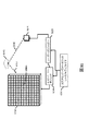
図9は機能図を示し、様々なソースのうち1つまたは複数のセンサデータを使用して、操縦可能なレーザー用のレーザーステアリングパラメータを生成する。FOV130内の均一なレーザ走査パターンは、周辺の環境から、もしくは周辺環境に関するセンサデータに基づいて、1つまたは複数のレーザーステアリングパラメータセットによって拡張、絞り込み、または置き換えることができる。例としてカメラ910aから得られる画像データを処理、分類装置490で人物として検出、それによってレーザーステアリングパラメータ601cを生成するなどの事象駆動によるレーザーステアリングパラメータの選択を含むことができる。レーザーステアリングパラメータ601cは、人物の輪郭に対応した走査経路950を含み1回目のデータによって示されるFOV130内の部分的にまたは位置に適用することができる。またレーザーステアリングパラメータは、事象が発生する確率に基づくこともできる。例えば、GPS受信機910から得られるGPSセンサデータを利用すれば、前記のレーダ測距システム(例えば、図1Bの110)は市街地に位置していることがわかる。前記システム(例えば、図1Bの110)は、歩行者、交差点、障害物のある通り、狭い通りなど市街地における、危険な事態が発生する確率を考慮し、動的にレーザを誘導することができる特定のレーザーステアリングパラメータセット(例えば、都市レーザーステアリングパラメータs601d)を保存および導入できるようプログラム化できる。同様に、センサデータ処理装置475は、気象センサ(例えば、降雨センサまたは温度センサ)または照度センサから気象データを受信することができる。センサデータ処理装置475またはクラス分類処理装置490は、前記気象データを処理し、その気象データに基づいて昼/夜のパラメータ601eなどのレーザーステアリングパラメータセットを生成するようにレーザーステアリングパラメータ生成装置410に処理命令を出すことができる。例えば、路面が濡れている状況では、車の停止距離の増加を考慮して、遠方の障害物を検出するように作られたFOVの領域にレーザパルスの照射を集中させることができる。
FIG. 9 shows a functional diagram using one or more sensor data from various sources to generate laser steering parameters for a maneuverable laser. The uniform laser scanning pattern within the
一般的に、広範囲なセンサデータをカメラ910a、車間トランシーバ910b、GPS受信機910c、RADAR910d、LIDAR910e、赤外線センサ(PIR)910f、音検出センサ910gおよび気象・環境センサ910hなどの様々なソースから収集することができる。このセンサデータは、データ処理装置475で処理後、クラス分類処理装置490で分類され、レーザーステアリングパラメータ生成装置410に与えられる。レーザーステアリングパラメータ生成装置/修正装置410は、601aのような車両の側面を示す分類に対応して既定義されたレーザパルス点のパターン(例えば、パターン920)を含むセンサデータに基づいて多くのレーザーステアリングパラメータセットを生成することができる。別の例示としてレーザーステアリングパラメータセット601bは、乗用車の後部を示す分類またはセンサデータに対応する領域940を定義することができる。前記乗用車の後部に関連する特徴が存在するか否かを判定するために、高密度レーザパルスのパターンで領域940を走査することができる。
オペレーション
Generally, a wide range of sensor data is collected from various sources such as
operation
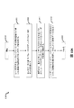
図10Aは本開示の実施形態にしたがって、センサデータに基づいてレーザーステアリングパラメータを選択し、前記レーザーステアリングパラメータに基づいて動的にレーザを誘導するプロセス1000のフロー図である。ブロック1010において、方法1000が開始する。ブロック1020において、周囲の環境に関して、1つまたは複数の特性を示すレーザを有するレーザーレンジファインダーのセンサデータを得る。ブロック1030において、センサデータに基づいてレーザーステアリングパラメータセットを得る。ブロック1040において、レーザをレーザーステアリングパラメータセットにしたがって動的に誘導し、視野内の方向の順番にレーザパルスセットを生成する。ブロック1050において、レーザーレンジファインダーは、レーザパルスセットに対する反射光から得る1つまたは複数の特性を測定し、それによって反射光データを生成する。ブロック1060において、方法1000が終了する。
FIG. 10A is a flow chart of a
図10Bは本開示の実施形態にしたがって、データに基づいてレーザーステアリングパラメータを選択し、前記レーザーステアリングパラメータに基づいて動的にレーザを誘導するプロセス1001のフロー図である。ブロック1015において、1つもしくは複数の操縦可能なレーザーを有するレーザーレンジファインダーが視野内の最初のセットの方向に対して第1のレーザパルスセットを生成する。ブロック1025において、レーザーレンジファインダーは、第1のレーザパルスセットに対する反射光から得る1つもしくは複数の特性を測定する。ブロック1035において、レーザーレンジファインダーは、少なくとも部分的に最初のデータに基づいてレーザーステアリングパラメータセットを生成する。ブロック1045において、レーザーステアリングパラメータセットに基づいてレーザーレンジファインダーは、少なくとも1つもしくは複数の操縦可能なレーザーを動的に誘導し、それによって、視野内の第2の1つもしくは複数の位置に向けて、第2の1つもしくは複数のレーザパルスを生成する。ブロック1055において、レーザーレンジファインダーは、第2の1つもしくは複数のレーザパルスに対する反射光から得る1つもしくは複数の特性を測定し、第2のデータを生成する。1つの例では、周囲の環境から得られるセンサデータは、第1の車両からの車々間通信データでも良い、この車々間通信データは第2の車両に設置したLIDARにレーザーステアリングパラメータセットを取得または生成させ、LIDARのレーザを動的に誘導または配置して、不均一にFOVを走査する。
FIG. 10B is a flow chart of
関連する第2の実施形態のグループでは、FOVに対して動的に誘導した不均一なLIDAR走査をターゲット時間内に完了する方法を開示する。FOVのLIDAR走査を完了するための時間ターゲットは周囲の環境から得られるセンサデータと統合することができ、LIDARを動的に誘導可能に設定できるTIを生成する。レーザーステアリングパラメータ(例えば、レーザへの命令)は周囲の環境から得られる情報ならびに、少なくとも部分的には走査を完了させる時間ターゲットに基づいて選択される。このようにして、レーザ測距測定の密度を調整して、FOV全体またはFOV内で指定した範囲をターゲット時間内に確実に走査できるようにする。第1のFOV走査中に、FOVの領域が特定できる。第2のFOV走査の間、前記特定された領域に対して、平均レーザパルス間隔よりも短い点間距離で高密度での走査を実行できる。領域の形状および走査点密度は、適正な時間内に走査を完了するための要件に基づいて選択することができる。 A related group of second embodiments discloses a method of completing a dynamically induced non-uniform lidar scan for a FOV within a target time. The time target for completing the lidar scan of the FOV can be integrated with sensor data obtained from the surrounding environment to generate a TI in which the lidar can be dynamically guided. Laser steering parameters (eg, commands to the laser) are selected based on information obtained from the surrounding environment and, at least in part, the time target at which the scan is completed. In this way, the density of the laser ranging measurement is adjusted to ensure that the entire FOV or a specified range within the FOV can be scanned within the target time. During the first FOV scan, the FOV region can be identified. During the second FOV scan, a high density scan can be performed on the identified region at a point-to-point distance shorter than the average laser pulse interval. The shape of the region and the density of scan points can be selected based on the requirements for completing the scan in a reasonable amount of time.
レーザーステアリングパラメータ値(例えば、レーザへの命令)は周囲の環境から得られる情報ならびに、少なくとも部分的には走査を完了させる時間ターゲットに基づいて選択される。このようにして、レーザーステアリングパラメータはLIDARを設定し、レーザパルスのシーケンスを生成し(例えば、分類、判明した物体の境界線もしくは位置に基づいて)かつ走査がターゲット時間内もしくは目標とするレーザパルスのターゲット回数内で確実に完了することができる。FOVの1回目の走査中に、FOVの領域を特定することができる。レーザーステアリングパラメータは少なくとも部分的には、ターゲット時間かつ部分的に特定された領域に基づいて生成される。第2の走査中に、レーザーステアリングパラメータにしたがってレーザを動的に誘導し、平均レーザパルス間隔よりも短い点間距離で高密度走査を実行する。 Laser steering parameter values (eg, commands to the laser) are selected based on information obtained from the surrounding environment and, at least in part, the time target at which the scan is completed. In this way, the laser steering parameters set the lidar, generate a sequence of laser pulses (eg, based on classification, identified object boundaries or positions) and scan the laser pulses within or at the target time. It can be completed within the target number of times. During the first scan of the FOV, the area of the FOV can be identified. Laser steering parameters are generated, at least in part, based on the target time and partly identified area. During the second scan, the laser is dynamically guided according to the laser steering parameters to perform a high density scan at a point-to-point distance shorter than the average laser pulse interval.
関連する実施形態では、レーザーレンジファインダーの処理サブアセンブリ(例えば、図5の520)により得られた1回目のデータはFOV内に存在する1つまたは複数の注目する物体(例えば、車両、自転車を運転している人、歩行者)の領域を識別することができる。前記処理サブアセンブリは、FOVの不均一なレーザ測距走査を完了するためのターゲット時間に基づいて操縦可能なレーザアセンブリを構成することができる。場合によっては、1回目のデータは高密度走査領域を特定することができ、各領域に対してレーザパルス密度(角度範囲当たりのパルス数)、走査速度、ドエルタイムを制御する高密度走査領域用のレーザーステアリングパラメータを生成するためにターゲート時間を使用することができる。 In a related embodiment, the first data obtained by the processing subassembly of the laser range finder (eg, 520 in FIG. 5) includes one or more objects of interest (eg, vehicle, bicycle) present in the FOV. Areas of drivers (people driving, pedestrians) can be identified. The processing subassembly can constitute a maneuverable laser assembly based on the target time to complete the non-uniform laser ranging scan of the FOV. In some cases, the first data can identify high-density scanning regions, for high-density scanning regions that control the laser pulse density (number of pulses per angular range), scanning speed, and dwell time for each region. The targate time can be used to generate the laser steering parameters of the.
1つの例では、レーザ測距システム(例えば、LIDAR)は、レーザ反射光に基づいて飛行時間境界線(例えば、物体の輪郭)を識別し、その境界線を調べるために複雑なレーザの軌跡を用いてレーザーステアリングパラメータセットを生成する。レーザーステアリングパラメータは、動的に誘導する追加のレーザパルスを用いて、境界線の局在化作業の停止をするタイミングを決める基準となるが、それを生成するのにターゲット時間を使用することができる。例えば、100ミリ秒でレーザ測距スキャンを完了するために、レーザーレンジファインダーシステムは、境界線が0.5度の方位角範囲にある時、その境界線の局在化は十分であると命令するレーザーステアリングパラメータを生成することができる。レーザーステアリングパラメータが、ターゲット時間の存在または値に基づいて演算処理、選択、設定されている場合、レーザーステアリングパラメータはターゲット時間に基づくことができる。 In one example, a laser ranging system (eg, LIDAR) identifies a flight time boundary (eg, the contour of an object) based on the reflected light of a laser and traverses a complex laser to examine that boundary. Use to generate a laser steering parameter set. Laser steering parameters are the basis for deciding when to stop the boundary localization work with additional dynamically guided laser pulses, but the target time can be used to generate it. it can. For example, to complete a laser ranging scan in 100 milliseconds, the laser rangefinder system commands that the boundary is sufficiently localized when it is in the azimuth range of 0.5 degrees. Laser steering parameters can be generated. If the laser steering parameters are arithmetically processed, selected and set based on the presence or value of the target time, the laser steering parameters can be based on the target time.
1つの実施形態において、レーザ測距システムによって実行される方法は以下の構成となる。まず、周辺の環境に1つまたは複数の特性を示す第1のデータを、レーザを有するレーザーレンジファインダーから取得し、2に、レーザ測距走査を完了させる時間ターゲットを得る。第3に、本方法は、第1のデータ及び少なくとも部分的に時間ターゲットに基づいてレーザーステアリングパラメータを得る。第4に、本方法は、レーザーステアリングパラメータセットにしたがってレーザ動的に誘導することにより、視野内の走査を実行し、方向の順番にレーザパルスセットを生成する。第5に、この方法は、レーザパルスセット対する反射光から得る1つまたは複数の特性を測定しそれによって反射光データを生成する。最後に、この方法は、ターゲット時間内にレーザ測距走査を完了させる。 In one embodiment, the method performed by the laser ranging system has the following configuration: First, first data showing one or more characteristics to the surrounding environment is obtained from a laser range finder having a laser, and 2 obtains a time target to complete the laser ranging scan. Third, the method obtains laser steering parameters based on the first data and at least in part a time target. Fourth, the method performs in-field scanning by laser-dynamically guiding according to a laser steering parameter set to generate a laser pulse set in directional order. Fifth, this method measures one or more properties obtained from reflected light relative to a laser pulse set, thereby generating reflected light data. Finally, this method completes the laser ranging scan within the target time.
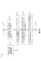
図10Cは方法1002のフロー図を示し、本開示の実施形態にしたがって、走査を完了するためにセンサデータと時間ターゲットに基づいてレーザーステアリングパラメータを選択し、そのレーザーステアリングパラメータに基づいて動的にレーザを誘導するものである。 FIG. 10C shows a flow diagram of method 1002, selecting laser steering parameters based on sensor data and time targets to complete the scan and dynamically based on the laser steering parameters according to embodiments of the present disclosure. It guides the laser.
ブロック1020において、周囲の環境の1つまたは複数の特性を示す、レーザを有するレーザーレンジファインダーのセンサデータを得る。このセンサデータは、ワイヤレス信号(例えば、他の車両から)で取得することができ、レーザーレンジファインダーを設置する同じ車両上のセンサから得てもよく、レーザーレンジファインダーによって、またセンサデータを含むメモリから取得してもよい。ブロック1023において、少なくとも視野の一部領域を走査するための時間ターゲットを得る。時間ターゲットは、FOV全体の走査の合計時間(例えば、100ms)とすることができる。ブロック1033において、センサデータおよびターゲット時間に基づいてレーザーステアリングパラメータセットを得ることができる。レーザーステアリングパラメータセットは、演算処理、選択、またはメモリアクセスによって得ることができる。例えば、図1Aの人物160と車両170の識別に応じかつ、FOVを0.1秒で走査する時間ターゲットの取得に応じるのに、レーザーレンジファインダーは、図1Bの人物160および車両170を取り囲む2つの高密度走査領域を走査するレーザパルス密度および軌道を決定することができる。1つの例では、FOV内に注目する物体があることを示すセンサデータを使用して、高密度走査領域のサイズを定義するレーザーステアリングパラメータを生成することができる。さらに、時間ターゲットは、高密度走査領域内での角速度(したがって、レーザパルス密度)を定義するレーザーステアリングパラメータを生成するために使用することができる。
At
ブロック1043において、レーザーステアリングパラメータセットにしたがって、レーザを動的に誘導し、ターゲット時間内に視野を走査する方向の順番にレーザパルスセットを生成する。ブロック1050において、レーザパルスセットに対する反射光から得る1つもしくは複数の特性を測定して、反射光データを生成する。
At
関連する第3の実施形態のグループでは、FOV内の注目する物体や領域を識別し、識別された物体の相対的な重要度によって動的にLIDARリソース(例えば、レーザパルス数または密度)を割り当てることにより動的にLIDARを設定する方法を開示する。1つの実施形態では、レーザ測距システムは、LIDARで周辺の環境からのセンサデータを取得し、それにより、複数の物体を識別する。次にレーザ測距システムは複数の物体それぞれに、1つもしくは複数の重みを割り当て、その重みはLIDARのFOVのレーザ距離測定値を不均一に配分するように機能する。レーザ測距システムはレーザーステアリングパラメータ(例えば、LIDAR内の操縦可能なレーザーを動的に設定する処理命令)を生成するために、重みを使用し、レーザーステアリングパラメータに従って、LIDAR内の操縦可能なレーザーを動的に誘導する。それによって、本方法は動的にLIDARを誘導して、識別された物体の相対的重要度に基づいてレーザ測距測定の不均一な密度のパターンを生成することができる。 A related group of third embodiments identifies objects or regions of interest within the FOV and dynamically allocates lidar resources (eg, laser pulse count or density) according to the relative importance of the identified objects. This discloses a method of dynamically setting the lidar. In one embodiment, the laser ranging system acquires sensor data from the surrounding environment with lidar, thereby identifying multiple objects. The laser ranging system then assigns one or more weights to each of the objects, the weights functioning to non-uniformly distribute the LIDAR FOV laser distance measurements. The laser ranging system uses weights to generate laser steering parameters (eg, processing instructions that dynamically set the maneuverable laser in the lidar) and according to the laser steering parameters, the maneuverable laser in the lidar. Is dynamically induced. Thereby, the method can dynamically guide the lidar to generate a non-uniform density pattern of laser ranging measurements based on the relative importance of the identified object.
1つの例では、動的T3を有するLIDARは、1つの重要な物体を示し、他に重要な物体は示さないFOVからセンサデータを収集してもよい。FOV内で前記物体を囲む領域内に水平掃引0.2度当たり1つのレーザパルスの密度で、物体を含む領域の外側は水平掃引1度当たり1パルスの密度のレーザを誘導するためのレーザーステアリングパラメータを生成することができる。後で同等の重要度を有する3つ物体(例えば重み付け)がFOV内で検出された場合、レーザーステアリングパラメータは、前記3つの各物体を囲む領域に対して水平掃引0.5度当たり1つのパルスを生成するように変更することができる。したがって、本開示の実施形態は、の割り当て優先順位または重みに基づいてレーザパルスを配分することができる。重みは相対的な重であり、第1の物体に割り当てられた重みは少なくとも部分的に第2の物体に割り当てられた重みに基づいている。例えば、重みは、最初に各物体に重みを割り当て、複数の物体を作成し、その後、各物体の重みを複数の各物体の重みの合計で除算することにより、正規化することができる。関心を引く、または動作の変化を示す物体(例えば、動き、FOVに出現、関心を引く分類)には高い重みを割り当てることができ、したがってレーザーステアリングパラメータセットに基づいて、より高いレーザ測距測定の密度を割り当てることができる。FOV内の複数の物体または領域にそれぞれに割り当てられた重みを使用して、個別に設定した密度、高密度走査領域形状、レーザビーム軌道、強度、スポットサイズまたはLIDAR内の操縦可能なレーザーが再走査する領域または物体と、その周期を有するレーザーステアリングパラメータセットを生成することができる。 In one example, a lidar with dynamic T3 may collect sensor data from a FOV that shows one important object and no other important object. Laser steering to guide a laser with a density of one laser pulse per 0.2 degree horizontal sweep within the area surrounding the object in the FOV and one pulse density per degree horizontal sweep outside the area containing the object. Parameters can be generated. If three objects of equal importance (eg, weighting) are later detected in the FOV, the laser steering parameter will be one pulse per 0.5 degree horizontal sweep for the area surrounding each of the three objects. Can be modified to generate. Accordingly, embodiments of the present disclosure can distribute laser pulses based on allocation priority or weight. The weights are relative weights, and the weights assigned to the first object are at least partially based on the weights assigned to the second object. For example, weights can be normalized by first assigning weights to each object, creating multiple objects, and then dividing the weights of each object by the sum of the weights of each of the plurality of objects. Higher weights can be assigned to objects that are of interest or show a change in behavior (eg, movement, appearance in FOV, interesting classification), and therefore higher laser ranging measurements based on the laser steering parameter set. Density can be assigned. With the weights assigned to each of multiple objects or regions in the FOV, the individually set density, high density scan region shape, laser beam trajectory, intensity, spot size or maneuverable laser in lidar is regenerated. A laser steering parameter set with a region or object to scan and its period can be generated.
図10Dは本開示の実施形態にしたがって、識別された物体に割り当てられた1つもしくは複数の重みに基づいてレーザーステアリングパラメータを選択し、そのレーザーステアリングパラメータに基づいて動的にレーザを誘導する方法1003のフロー図である。 FIG. 10D shows a method of selecting laser steering parameters based on one or more weights assigned to an identified object and dynamically guiding the laser based on the laser steering parameters according to an embodiment of the present disclosure. It is a flow chart of 1003.
ブロック1020において、周囲の環境の1つまたは複数の特性を示す、レーザを有するレーザーレンジファインダーのセンサデータを得る。センサデータは、レーザーレンジファインダーにより検出、共通の車両上にある他のセンサにより検出もしくは、センサデータのデータベースから車両の位置に基づいてルックアップをすることができ、ワイヤレス信号で受信することができる。
At
ブロック1024において、センサデータは、周囲の環境にある複数の物体を識別するように処理される。ブロック1026において、複数の個別の識別物体に対して、1つもしくは複数の重みを割り当てる。重みの割り当ては、動き、物体の分類、物体の軌道を識別するセンサデータの処理に基づいて行うことができる。重みの割り当てはルックアップ作業(例えば、レーザーレンジファインダーから10メートル以内の範囲にある、すべての物体に5の重みを割り当てるなど)に基づいて行うことができる。別の例では、第1の物体は、車両として識別ができ、センサデータは、車車間(V―V)通信信号でもよく、車車間通信信号を処理した結果、物体(すなわち車両)には、10の重みが割り当てられる。別の物体(例えば、歩行者)には15の重みを割り当てることができる、これは車両と相対的に正規化された重み、歩行者の存在を示す車車間(V―V)通信信号の内容、FOV内で新たな歩行者の出現、歩行者の軌跡(例えば、方法1003を実行中のレーザーレンジファインダーの走査経路に出現)移動に基づくものである。
At
ブロック1028において、複数の物体のうち、第1の物体に対応する第1の重みに少なくとも部分的に基づいてレーザーステアリングパラメータのセットを得る。いくつかの実施形態では、レーザーステアリングパラメータは、複数の識別された物体に対応する重みを処理することによって演算処理できる。例えば、高いレーザパルス密度を必要とする特定の対応する物体を識別するために、重みに対して正規化、優先順位付け、またはランク付けの処理を実施することができる。ブロック1040において、レーザを、レーザーステアリングパラメータセットにしたがって動的に誘導し、視野内の方向の順番にレーザパルスセットを生成する。ブロック1050において、レーザーレンジファインダーはレーザパルスセットに対する反射光から得る1つもしくは複数の特性を測定し、反射光データを生成する。ブロック1060において、方法1003が終了する。
At
図11は本開示の実施形態にしたがって、測定データに基づいてレーザーステアリングパラメータセットを精緻化するプロセス1100のフロー図を示す。ブロック1110において、方法1100が開始する。ブロック1120において、操縦可能なレーザーのセット中の少なくとも1つのレーザに対するレーザーステアリングパラメータセットを得る。ブロック1130において、レーザーステアリングパラメータセットに基づいて、操縦可能なレーザーのセット中の少なくとも1つのレーザを動的に誘導し、それにより、視野内の最初の1つもしくは複数の計測点に対する、最初の1つもしくは複数のレーザパルスを生成する。ブロック1140において、1つもしくは複数の第1のレーザパルスに対する反射光から得る1つもしくは複数の特性を測定し、それにより最初のデータを生成する。ブロック1150において、方法1100は、最初のデータから得る特徴が十分に局在化されているかどうかを評価する。第1データにおいて、境界線または輪郭などの特徴が十分に局在化されていると判定した場合、方法1100はステップ1170で終了する。それ以外の場合、方法1100はブロック1160に進み、そこで第1のデータに基づくレーザーステアリングパラメータセットを精緻化し、領域内のレーザパルス密度を増加させ、特徴を取り込めるようにする。
FIG. 11 shows a flow diagram of
図12Aは、本開示の実施形態にしたがって、周囲の環境に存在する物体の分類に基づいてレーザーステアリングパラメータセットを選択するコンピュータ実装型方法1200のフロー図を示す。ブロック1205において、周囲の環境からのセンサデータに基づく物体の分類を生成する。ブロック1210において、物体の分類に基づくレーザーステアリングパラメータセットを得る。例えば、周囲の環境内の物体が車両として分類された場合、レーザーステアリングパラメータのセットは、演算処理するか、もしくはメモリから取得する。ブロック1215において、方法1200は、レーザーステアリングパラメータに基づいて操縦可能なレーザアセンブリに誘導するよう処理命令し、それにより、視野内の最初の計測点セットに対する、最初のレーザパルスセットを生成する。ブロック1227において、最初のレーザパルスに対する反射光から得る1つもしくは複数の特性を示す最初のデータを測定する。
FIG. 12A shows a flow diagram of a computer-mounted
図12Bは物体の分類に応じてレーザーレンジファインダーを誘導し、得られた距離データに対して分類テストを実施してレーザ反射光データ(及び物体)が物体の分類テストを満たすか否かを判定する方法のフロー図を示す。ブロック1204において、操縦可能なレーザアセンブリを有するレーザーレンジファインダーの視野内に存在する対応する物体の分類を得る。物体の分類は、レーザーレンジファインダーの周囲の環境からのセンサデータに基づく。ブロック1210において、物体の分類結果に基づいて、レーザーステアリングパラメータセットを得る。ブロック1215において、方法1200は、レーザーステアリングパラメータに基づいて、操縦可能なレーザアセンブリに誘導するよう処理命令し、視野内に存在する最初のセットの計測点に対する最初のレーザパルスセットを生成する。ブロック1220において、レーザパルスの第1のセットに対する反射光から得る1つもしくは複数の特性を示す第1のデータを得る。ブロック1225で、分類テストを取得し、第1のデータに適用する。分類テストは、物体の分類(例えば、自動車、人物、または建物の特徴)の特徴に関するテストベクタを有することができる。
FIG. 12B guides the laser range finder according to the classification of the object, performs a classification test on the obtained distance data, and determines whether or not the laser reflected light data (and the object) satisfies the classification test of the object. The flow diagram of the method of doing is shown. At
ブロック1230で、第1のデータについて分類テストを評価する。第1のデータが分類テストの方法を満たす場合、方法1200は1235で終了する。それ以外の場合、方法1201はブロック1204に戻り、別の分類を生成する。方法1201は、さらに詳細な分類テストを用いて複数回実施し、物体のより詳細なタイプやモデル(例えば、車両の分類)を識別することができる。
繰り返し境界線局在化
At
Repeated border localization
図13、14A、14B、15および16に繰り返し境界線局在化(PBL)法のいくつかの実施形態を示す。PBL法は、飛行時間差を有する領域(例えば、物体の境界を示す)を示す距離データに部分的に基づいて動的にレーザーレンジファインダーを誘導し、それにより前記領域内に追加のレーザパルス生成させることにより境界線位置の精度を高めることができる。 13, 14A, 14B, 15 and 16 show some embodiments of the Iterative Boundary Localization (PBL) method. The PBL method dynamically guides the laser rangefinder based in part on distance data indicating a region with a flight time difference (eg, indicating the boundaries of an object), thereby generating additional laser pulses within said region. As a result, the accuracy of the boundary line position can be improved.
第1のPBL実施形態では、飛行時間(TOF)境界線を局在化しながら、ある方向の範囲のレーザ走査を実施する方法は以下の工程を含む。レーザパルスのシーケンスを照射しながら、ある方向の範囲にLIDAR装置を誘導し、LIDAR装置でレーザパルスのシーケンスに応答する反射光のセットを受光そして各レーザパルスのシーケンスに対して、対応するTOFおよび対応する方向を測定する。この方法はさらに、最近傍であって対応するTOFがTOF閾値よりも大きな値を有するレーザパルスの対を特定することに応じて、レーザ走査中に1回または複数回、LIDAR装置を誘導し、少なくとも前記レーザパルスの対のうち、1つのレーザパルスの方向に基づく新たな方向のシーケンスを持つ新たなレーザパルスを生成し、かつ生成後は、最近傍になるように止まる工程を含む。この方法はさらにレーザ測距走査を完了し、かつ完了後、レーザパルスのシーケンス内の最近傍であって対応するTOF値がTOF閾値よりも大きな値を有する全てのレーザパルスの対は、最低間隔の値よりも、小さな方向差を有する工程を含むことができる。 In the first PBL embodiment, the method of performing laser scanning in a range in a certain direction while localizing the time-of-flight (TOF) boundary includes the following steps. While irradiating a sequence of laser pulses, the lidar device is guided in a range in a certain direction, the lidar device receives a set of reflected light in response to the sequence of laser pulses, and for each sequence of laser pulses, the corresponding TOF and Measure the corresponding direction. The method further guides the lidar device one or more times during the laser scan, depending on identifying the pair of laser pulses that are closest and the corresponding TOF has a value greater than the TOF threshold. It includes a step of generating at least a new laser pulse having a sequence of a new direction based on the direction of one laser pulse among the pair of laser pulses, and after the generation, stopping so as to be in the nearest vicinity. This method also completes the laser ranging scan, and after completion, all laser pulse pairs that are closest in the sequence of laser pulses and have a corresponding TOF value greater than the TOF threshold have the lowest spacing. It is possible to include a step having a direction difference smaller than the value of.
図13を参照すると、PBL法の1つの実施形態では、レーザーレンジファインダー110は1つもしくは複数の動的な操縦可能なレーザー(例えば、レーザ121)を含み、方位角範囲1315および仰角範囲1320からなるFOV1310を走査することができる。動的操縦可能なレーザー121は、複数のレーザーステアリングパラメータを受光、処理して、FOV1310内の走査経路1325によって示される複数の方向全体をレーザビームで掃引することができる。走査経路1325を掃引する間、操縦可能なレーザー121は、それぞれ図13の“+”で示される対応する方向を有するレーザパルスセットもしくはシーケンスを生成することができる。いくつかのレーザパルス(例えば、パルス1330)は物体(例えば、境界線190によって示される車両170)と交差することができる。他のパルス(例えば、パルス1335)は、車両と交差しない。
Referring to FIG. 13, in one embodiment of the PBL method, the
図14Aを参照するとレーザーレンジファインダーは、レーザパルスのシーケンスに対応するレーザ反射光のセットを受光でき、レーザパルスのシーケンスの各レーザパルスに対して、対応する方向、対応する飛行時間(例えば、100nS)または範囲(例えば、30m)を計測できる。レーザパルスのシーケンスに対応するTOFのセットおよび方向のセットは、データマトリックス1405として示される。またデータマトリックス1405はレーザパルスのシーケンスの各レーザパルスに対して方向と対応するTOFのリストとして保存することもできる。説明の目的のため、車両170からのレーザ反射光のTOFは3を有し、車両170の境界線190の外側からのレーザ反射光のTOFは9を有する。課題は、データマトリックス1405から、境界線190の位置を特定することである。1つの方法として、各レーザ反射に対して最近傍を特定し、最近傍の対の間にTOF境界線があるかどうかを特定することである。各レーザパルス(例えば、データポイント1410により示されるレーザパルス)は複数の方向または複数の方向範囲(例えば、方向1415および1420)において複数の最近傍を有することができる。
With reference to FIG. 14A, the laser range finder can receive a set of laser reflected light corresponding to the sequence of laser pulses, and for each laser pulse in the sequence of laser pulses, the corresponding direction and the corresponding flight time (eg, 100 nS). ) Or range (eg, 30 m) can be measured. The set of TOFs and the set of directions corresponding to the sequence of laser pulses are shown as
図14Bを参照すると、各レーザーパルス対間のTOF値の差が閾値よりも大きくなるような、いくつかのレーザパルスの対(例えば、対1424a―c)を特定することができる。例えば、対1425aでは、車両境界内にTOFが3である第1のレーザパルスを含み、車両境界外にTOFが9である第2のレーザパルスを含む。TOF値の差は、TOF閾値5よりも大きくなることがあり、それによって各対のレーザパルスのそれぞれに関連する方向との間の角度範囲内にTOF境界線(例えば、車両の輪郭)の存在を示す。
With reference to FIG. 14B, it is possible to identify several laser pulse pairs (eg, pairs 1424ac) such that the difference in TOF values between each laser pulse pair is greater than the threshold. For example,
図15に、第1のFOV1310および第1のレーザパルスシーケンスを示す。TOF値の差が閾値よりも大きな対(例えば、図14Bの対1425a―c)を識別したことに応じて、走査経路1520に沿って操縦可能なレーザーを誘導する1つまたは複数の第2のレーザーステアリングパラメータを動的に生成することができ、レーザーステアリングパラメータは各対に対応する中間の空間に追加のレーザパルスを生成する。例えば、レーザパルス1510a―bは、操縦可能なレーザーが走査経路1520に沿って移動するときに生成される。走査経路1520は、複雑な形状(例えば、車両170の境界線190周辺のおおよその輪郭)となり得る。1つの側面においては、走査経路1520を生成する第2のレーザーステアリングパラメータセットは隣接するレーザパルス1510dと1510eとの間で同時に2つの角速度を変化させることができる。別の側面では、走査経路1520は、操縦可能なレーザーに対してレーザパルス1510cの前までは負の方位角速度、レーザパルス1510cの後正の方位角速度へと方向の変更を引き起こさせることができる。PBL法では、FOV1310内に物体の境界線を含むと推定される(すなわち、TOF閾値より大きいTOF差を有する)部分に介在レーザパルス1510―eを配置することができる。
FIG. 15 shows the
介在レーザパルス1510―eの各方向は、FOV1310内の2次元位置によって示される。介在パルス1510aの方向は、対応するレーザパルス対1425aの1つまたは複数の方向に基づくことができる。例えば、走査経路1520を、レーザパルス対1425aの中間にパルス1510aを配置するように設計することができる。経路1520は、TOF差を有する各レーザパルス対の1つのパルスに対して特定の角度方向に介在レーザパルス1510a―eを配置することができる。例えば、図13の走査経路1325に沿ってLIDAR110を誘導して生成される最初のレーザパルスのシーケンスは仰角が1度、方位角が1度の角度間隔を持つことができる。介在レーザパルス1510a―eは、対応するレーザパルス対の内、1つのレーザパルスの方向から0.3度から0.5度の間隔を持つようにFOV1310の方向内に配置することができる。介在レーザパルス1510a―eは、対応するレーザーパルス対の第1パルスから定義された角度間隔で、かつ、その対の第2パルスの方向に向かって配置することができ、これにより、各介在レーザパルスが対応するレーザパルス対(例えば、図14Bの1425a)が有する最近傍の関係を確実に解消するようにする。このようにして、TOF値の差がTOF閾値よりも大きな最近傍の対1425a―cは、介在レーザパルスが生成されたときには、もはや最近傍の対とはならない。
Each direction of the intervening laser pulse 1510-e is indicated by a two-dimensional position within the
介在レーザパルス(例えば、パルス1510a―b)をレーザパルスのシーケンスに加えることができる。1つの側面において、介在レーザパルス1510aにより、もはや図14Bのレーザパルス対1425aは最近傍の対とはならなくなる。したがって、介在レーザパルスがレーザパルスのシーケンスに追加されると最近接のパルスの対は、新たな介在レーザパルスによって修正される。
Intervening laser pulses (eg, pulses 1510ab) can be added to the sequence of laser pulses. On one side, the intervening
図16を参照すると、レーザ測距システムは、介在レーダパルスの各々についてTOF1610a―hを演算処理することができる。図17A―Eは、PBL法の実施形態を示し、LIDARはFOVを走査し、飛行時間境界線を段階的に局在化させる距離測定値のシーケンスを生成する。図17A―Eの実施形態では、最近傍のレーザパルスの各対をなすパルス間のTOF値の差がTOF閾値よりも大きくなるような最近傍のレーザパルスの対がレーザパルスのシーケンスで特定され、その後、対応するレーザパルスの対の最近傍の関係が解消する方向に、繰り返し介在レーザパルスを追加する。LIDARは動的に介在レーザパルスを誘導し生成することができ、それによってTOFの閾値より大きいTOF差を有する各最近傍ペアが閾値距離(例えば、0.5未満の方向差)まで、離れるまで(例えば、0.5度以下の方向差)、TOF境界線の精緻化をおこなう。
With reference to FIG. 16, the laser ranging system can compute the
図17Aにおいて、レーダー測距システムはレーザパルス1705のシーケンスを生成しながら、2次元(高度、方位角)方向の範囲を走査することができる。図17Bでは、レーザパルス1705のシーケンスに対応するレーザ反射光1707のシーケンスを受光でき、レーザパルスの出力シーケンスそれぞれに対応する方向およびTOFを計測または演算処理することができる。レーザーレンジファインダーシステムは最近傍のパルスに対してTOF値の差が閾値よりも大きい1つもしくは複数のレーザパルスのシーケンス(例えば、図17Aのパルス1709)を特定することができる。例えば車両170の内側にあるレーザパルス1708と、車両の境界線の外側にある最近傍のパルス1709a―c間のTOF値の差は閾値(例えば、TOFの閾値5)よりも大きくなり得る。図17Bに、TOF値の差(すなわち、対の第1パルスのTOF値と対の第2パルスのTOF値との差)が閾値より大きいレーザ反射光の3つの対1710a―cを示す。
In FIG. 17A, the radar ranging system can scan a range in the two-dimensional (altitude, azimuth) direction while generating a sequence of
図17Cに示すように、レーザーレンジファインダーシステムは、レーザーステアリングパラメータのセットを生成し、これらを使用して経路1712に沿ってシステムを誘導し、介在するレーザパルスを生成する。介在するレーザパルスおよび経路1712は、レーザパルス対1710a〜1710cのうちの1つまたは複数のレーザパルスに基づいてFOV内に方向を有することができる。図1図17Dの飛行時間データは、介在するレーザパルスについて測定することができ、それらをレーザパルス列1705に加えることができる。TOFテストは、TOF差がTOF閾値。TOF閾値は、より小さいTOF差を反復的に定めるために、TOF試験が実行されるたびに変更され得る。図1図17Dでは、TOF試験に合格しない(すなわち、TOF閾値より大きいTOF差を有する)3つの新しいレーザパルス対1720a―cが生成される。いくつかの実施形態の1つの態様では、介在パルスの位置は、TOF試験のその後の適用中に元のレーザパルス対1710a〜1710cが再発生することを防止し、それによって境界(例えば、図17Aの境界190)がTOFテストの連続反復でより小さな領域にローカライズされます。図1図17Eでは、レーザーレンジファインダーシステムは、識別されたレーザパルス対を使用して、より介在するレーザパルス(例えば、1727)を有する新しい経路1725を生成する。イチジク。図17Fは、TOF境界190が存在する最近接レーザパルス対(1730a―c)を識別するためにTOF試験を再び適用できることを示す。TOF試験に不合格である最近傍パルスの各対が角度の分離を有するまで、TOF試験を適用することができる。閾値間隔または距離(例えば、0.5°未満の各対の点間の角度間隔)よりも小さい。
As shown in FIG. 17C, the laser rangefinder system produces a set of laser steering parameters that are used to guide the system along
いくつかの実施形態では、LIDARは、境界方向定位試験を、対応する方向およびTOF値を有するレーザパルスの既存の組の各点に適用することができる。ローカリゼーションテストでは、いくつかの角度範囲を定義できます。図14のレーザ反射1410が、図14Aは、0度の仰角および0度の方位角に位置することができる。角度範囲は、方向1415に沿ったすべての負の仰角であってもよい。点1410に対する2次元角度範囲の例は、0―1度の範囲の仰角と0―1度の範囲の方位角であり、定位試験は、各レーザパルスについて、TOF差がTOF閾値よりも大きく、角間隔(例えば、仰角および方位角軸の各々に沿った角間隔の2乗)が閾値分離よりも大きい。このような最近傍が存在するとき、シーケンス内のレーザパルスは定位試験に失敗し、PBL方法はレーザパルスと最近傍との間の領域に介在するレーザパルスを配置し、その介在するレーザパルスをシーケンスに加え、レーザパルスと元々の最も近い隣接物との間の関係。一態様では、PBL法は、介在するレーザパルスを生成した直後に、LIDARが新しい介在レーザパルスに定位試験を適用することができる。このようにして、LIDARはTOF境界を反復的に定位することができ、その間にTOF境界が存在するレーザパルスのすべての対が閾値角度分離だけで分離される。
In some embodiments, lidar can apply a boundary orientation test to each point in an existing set of laser pulses with corresponding directions and TOF values. Localization tests allow you to define several angular ranges. The
図18は、LIDARがFOV内のTOF境界の第1の部分を識別し、LIDARが第2の領域を探索するサーチゾーン(例えば、角度範囲)に達する方向(すなわち、FOVの角度オフセット)を推定するPBL方法を示す。TOF境界の一部分である。 FIG. 18 estimates the direction (ie, the angular offset of the FOV) in which the lidar identifies the first portion of the TOF boundary within the FOV and the lidar reaches the search zone (eg, angular range) in search of the second region. The PBL method to be performed is shown. It is part of the TOF boundary.
別ウィンドウ(タブ)の大きな表示で見る18は、外挿法に基づくプログレッシブ境界定位(EPBL)法と考えることができる。EPBLを使用して、FOV内の第1の探索領域内のLIDARによって識別されるTOF境界上の1つまたは複数の位置を使用して、第1の探索領域外の推定境界位置を推定または予測することができる。次いで、LIDARは、推定された境界位置に基づいて第2の探索領域を生成するように動的に調整することができる。推定された境界位置の外挿は、境界上で識別された1つ以上の位置(例えば、2つの位置を通る直線フィットまたは3つ以上の位置を通る曲線)を通る線の形状に基づくことができる。他の実施形態では、第1の探索領域外の予測または推定境界位置の外挿は、境界の種類の分類に基づくことができる。例えば、自律型車両上のLIDARが遭遇することができる多くのオブジェクトは、一般道路交差パターン、トラック形状、陸橋、歩行者、サイクリストまたは建物などの様々なオブジェクト分類内の共通の形状特性を有する。推定された境界位置の外挿は、1つ以上の予測されたオブジェクト分類の文脈における1つ以上の既知の境界位置の処理に基づくことができる。例えば、新たに発見されたTOF境界は、1つまたは複数のオブジェクトタイプ(例えば、道路交差点の隅にある樹木または歩行者)であってもよい。例示的なEPBL実施形態は、境界が樹木の幹である確率50%、境界が人体である確率50%を適用し、混合分類に基づいて第1の探索領域外の境界位置を推定することができる。1つまたは複数の既知の境界位置。推定された境界位置に基づいて生成された後続の探索領域は、予測された分類をツリーまたは人のいずれかに優先させ、推定された境界位置の将来の外挿を、既知の境界位置のセットおよび更新された分類重みに従って重み付けすることができる。
The
様々な実施形態は、方向(すなわち、推定された境界位置またはベクトルによって定義される新しいサーチゾーンに到達するための角度オフセット)に関連する信頼値または標準偏差を計算することを提供する。例えば、毎日のオブジェクトは、単純な形状(直線または単純な曲線)の境界またはエッジを観測点に対する方向に並べることができます。したがって、回転するLIDARが任意の向きで物体の境界を動的に追跡して走査しようとするのは実用的ではないかもしれないが、動的に操縦可能なLIDARを使用する方が現実的かもしれない。開示されたPBL方法は、1つのスキャンから別のスキャンへのオブジェクトの動きを追跡し、オブジェクトの方向を予測することができる操舵可能なレーダと比較して、エッジの第1の部分を見つけ出し、エッジの方向(カーブフィッティング、オブジェクトの分類または外挿に基づく)。この方法は、次に、FOVにおける境界の予測された方向に沿っていくらかの距離の第2の位置のパターンでレーザビームを走査することができる。図1に戻る。図18では、LIDAR1805は、第1の2D角度範囲1815(例えば、仰角範囲1830および方位角範囲1825によって画定される)で動的に操縦可能なレーザー1806を走査することができる。LIDAR1805の全FOVは、道路エッジ1810,1811,1812などのいくつかの境界を含むことができる。LIDAR1805は、2次元角度範囲内の一連の方向を含む経路を走査することができる。経路を走査している間、LIDAR1805は一連のレーザパルスを生成し、レーザ反射の対応するシーケンスを測定することができる。LIDAR1805は、TOF(例えば、TOF1820)または出射レーザパルスのシーケンスのそれぞれに対応する距離を計算することができる。TOF値(例えば、TOF1820)は、境界1810の一部を包含する角度領域1835a―bを示すことができる。一実施形態では、LIDAR1805は、境界と交差する角度範囲1815内の1つ以上の領域を計算することができる。他の実施形態では、LIDAR1805は、境界1810上の点の1つ以上の位置推定値を計算することができる。例えば、PBL法は、境界1810上の点が、TOF境界に対して反対側にあることを示す最近傍点TOFの違いに基づいています。境界1810上の1つ以上の第1の位置または領域は、境界1810の第2の部分に重なると推定される第2の領域にLIDAR1805を誘導するために使用されるベクトル1840または1841を計算するためにLIDARによって使用され得る。操縦可能なレーザー1806の向きを第1の角度範囲1815から第2の角度範囲1846に変更するための2―D方向シフト(例えば、10度の仰角シフトおよび―10度の方位角シフト)を含む。一態様では、シフトベクトル1841は、この場合、探索領域(例えば、レーザパルス1850を含む領域1847)が境界を含まないことの識別に応答して、新たなより大きな探索領域1855が、境界1810に広がっていない探索領域1847に定義される。境界1810を再獲得するための努力を必要とする。図18のEPBL方法の1つの利点は、第2の探索領域は、第1の探索領域を囲む必要はない。代わりに、第1の探索領域は、TOF境界の方向を識別することができる。この方向は、LIDAR1805を新しいサーチ位置にシフトするように機能するベクトル1840(すなわち、1次元または2次元の角度シフト)を生成するために使用することができる。関連する実施形態では、第1の探索領域から計算された境界の第1の部分上のいくつかの位置を使用して、境界の形状および方向(例えば、線または曲線)を補間することができる。例えば、レーザパルス1820を含むレーザパルスの第1のシーケンスから境界1810上で識別される3つの位置は、境界1810の他の部分が存在すると予想される曲線または円弧1857を画定するために使用され得る。
Various embodiments provide for calculating confidence values or standard deviations associated with a direction (ie, an angular offset to reach a new search zone defined by an estimated boundary position or vector). For example, a daily object can align the boundaries or edges of a simple shape (straight line or simple curve) in the direction of the observation point. Therefore, it may not be practical for a rotating lidar to dynamically track and scan the boundaries of an object in any orientation, but it may be more realistic to use a dynamically steerable lidar. unknown. The disclosed PBL method finds a first part of an edge as compared to a steerable radar that can track the movement of an object from one scan to another and predict the direction of the object. Edge orientation (based on curve fitting, object classification or extrapolation). This method can then scan the laser beam with a pattern of a second position at some distance along the predicted direction of the boundary in the FOV. Return to FIG. In FIG. 18, the
関連する実施形態では、LIDARは、FOVの第1の2―D探索領域1860において一連の方向付けを含む経路を走査することができる。経路を走査する間に、LIDARは、複数のレーザパルスを生成し、レーザ反射の対応するシーケンスを受信し、各出力レーザパルスに対応するTOFを計算することができる。LIDARは、TOF差がTOF閾値より大きい1つ以上の最近のレーザ反射の対を特定することによって、TOF境界の存在(例えば、車両のエッジまたは道路のエッジ1811)を識別することができる。LIDARは、第1の探索領域1860からのTOF測定値に基づいて境界位置のセット(例えば、位置1862aおよび1862b)を計算することができる。LIDARは、境界位置のセット(例えば、位置1862aおよび1862b)の1つまたは複数の位置を、第1の探索領域の外側に位置する推定境界位置1863aを予測する。LIDARは、推定された境界位置に基づいて1組のレーザーステアリングパラメータを生成し、第2の探索領域に第2の複数のレーザパルス(例えば、レーザパルス1870を含む)を生成するために、レーザーステアリングパラメータに基づいてレーザ1806を動的に操縦する。このようにして、LIDAR走査は、TOF境界上にあるFOV(例えば、FOV内の位置)の方向を特定して追加すること、第1の探索領域外の予測境界位置を予測し、第2探索領域をレーザパルスで走査すること予測されたTOF境界の軌跡に基づいて決定する。この方法は、確認された境界位置の集合を構築し、推定された境界位置を予測し、推定された境界位置の周りの第2の探索領域を走査することによって、1回のスキャンの間に反復して実行することができる。EPBL法の一実施形態では、図18に示すように、第1の探索領域1860は境界位置1862a―bを生成するために使用され、第2の探索領域を指す推定境界位置1863aまたはベクトル1865aを外挿するために使用される。LIDARは、境界位置のセットに追加される別の境界位置1862cを識別するために第2の探索領域を走査する。境界位置の更新されたセットは、新しい推定境界位置1863bまたは関連するベクトル1865bを外挿して、経路1864によって定義することができる第3の探索領域に導くことができる。経路1864は、多数の直角回転またはFOVと方向反転することにより、LIDARの動的ステアリングが必要となる。図1例えば、経路1864に沿ったすべてのレーザパルスは、境界1811の一方または他方の側に関連する共通TOFを示す反射を有することができる。図18では、第3の探索領域(例えば、経路1864によって定義される)は、TOF境界1811と交差しないか、1つの態様では、探索領域が境界位置を含まない(すなわち、TOF境界と交差しない)ことに応答して、EPBL方法は、新しい推定境界位置1863cを生成し、レーザ1806を動的に操縦して新しい探索領域1872新しい探索領域1872は、新しい推定境界位置1863cを取り囲む境界位置を再獲得するように設計されたより広い角度範囲を有することができる。新たに推定された境界位置1863cは、境界位置の組の1つ、いくつか又は全て、及び新たな境界位置を生成することができなかった推定境界位置1863bに基づくことができる。探索領域1872は、TOF境界の発散または分割を示す反射を生成することができる。このようなTOF境界分割は、オブジェクトがLIDAR1805のFOV内で重なり合っているところで発生することができる。車両ベースのLIDARが遭遇する可能性のある多くの共通オブジェクトは、一連の交差する直線または曲線境界、高架または高速道路の出口。LIDARは、探索領域1872内の2つの交差境界または発散境界(例えば、境界位置1862dおよび1862eによって示される)を識別することに応答して、複数の異なるTOF境界1811および1811について個別の推定境界位置1863dおよび1863e(またはベクトル1865dおよび1865e)1812。
In a related embodiment, the lidar can scan a path involving a series of orientations in the first 2-
EPBL法の別の実施形態では、LIDAR1805は、いくつかのTOF境界1810および1811を同時にいくつかの異なる境界位置のセットによって追跡し、新しい外挿推定境界位置に基づいてそれぞれの新しい探索領域を周期的に生成する。一度にいくつかの境界を追跡するEPBL方法は、第2境界のための新しい探索領域を走査しながら、第1境界の推定境界位置を外挿するなど、異なる機能を並行して実行することができる。同様に、EPBL法は、新しいTOF境界を探索し、境界位置を外挿し、以前に発見された1つ以上の境界を追跡するために、FOVの広角2―Dスキャンを実行することができる。
In another embodiment of the EPBL method, LIDAR1805 tracks
図19は、角度範囲1930が、境界位置1911aおよび1911bのセットから外挿されたベクトル1925に関連する実施形態を示している。この角度範囲または信頼値は、境界位置がどのように特定の形状にどのくらいフィットするかに基づくことができる。例えば、角度範囲または信頼値は、ベクトル1925または推定された境界位置1912aを生成するために使用される境界位置のセットに対する線または曲線当てはめの平均二乗誤差に基づくことができる。
FIG. 19 shows an embodiment in which the
詳細に図1を参照する。図19に示すように、LIDAR1805は、可能な仰角1906の範囲および可能な方位角1907の範囲を含む2次元角度範囲を含むFOV1905を有することができる。LIDARによって実行されるEPBL方法は、仰角範囲1910および方位角範囲1911を有し、第1の組のレーザパルスを生成する。LIDARは、レーザパルスの出力シーケンスに対応する一組の反射1915を測定することができ、シーケンス内の各レーザパルスに対応するTOF(例えば、1920)を測定することができる。LIDARは、TOF境界1908上の位置の組(例えば、位置1911aおよび1911b)を計算することができ、ベクトル1925(および信頼範囲1930)を推定境界位置1912aにさらに外挿することができる。LIDARは、ベクトル1925または推定された境界位置1912aに基づいてレーザパルス1935の第2のセットを生成するように、レーザ1806を動的に操縦することができる。例えば、境界位置のセットを処理することが、小さな平均二乗誤差線の当てはめを有する直線境界を示す場合、角度範囲または信頼度値は、信頼限界値1930に基づいて決定することができる。ベクトル1930に関連付けられた第2の組のレーザパルス1935は小さくてもよく、その結果、第2の組のレーザパルス1935のサイズは小さくてもよい。逆に、境界位置の組が複雑な形状(例えば樹木)との境界を示す場合、角度範囲1930は高く保つことができ、または推定境界位置1912aに関連する信頼値は低く留まることができ、それによりレーザ1805は、時間の経過とともに、境界位置の組が1911cおよび1911dを含むように成長するにつれて、次の推定境界位置1912bの位置を示す後続ベクトル1940に関連する角度範囲1945は、TOF境界1908の全体形状が明らか。したがって、後続の探索領域1950のサイズは、推定された境界位置1912b内のLIDARの信頼水準に従ってサイズ決定することができる。一態様では、動的に操縦されるLIDARは、少なくとも2つの寸法(例えば、仰角によって示される仰角寸法および方位角によって示される方位角寸法)を有するFOVを有することができる。
See FIG. 1 in detail. As shown in FIG. 19, the
図20は、2つのレーザ測距システム2010a及び2010bを示す。各レーザレンジ検出システムは、レーザーステアリングパラメータに従ってレーザビームを動的に操縦するように動作可能な操縦可能なレーザアセンブリ2020aおよび2020bを含む。レーザ測距システム(例えば、LIDAR)は、パルスレーザまたは連続レーザを有することができる。レーザーレンジファインダー020aは、パルスレーザを有し、グラフ2025aに示される離散的な時系列のレーザパルス(例えば、2030aおよび2030b)を生成する。例えば、パルスは持続時間が5ナノ秒であり、1ミリ秒ごとに発生する。レーザーレンジファインダー020bは連続レーザであり、グラフ2025bに示す連続波を生成する。連続レーザ測距システムは、連続レーザの振幅(例えば、正弦波変調)を変調し、視野内の位置(例えば、方向)の範囲を計算するために反射波の位相を測定することが多い。振幅変調波の振幅ピークはレーザ光のパルスと考えることができる2025bの波形を見ると分かるだろう。本開示の目的のために、連続波レーザは、連続振幅変調レーザのピークに対応する1つ以上のパルス(例えば、2030c)を生成する。操縦可能なレーザアセンブリ2020bは、特定の位置にいくつかのパルスを生成することができる。例えば、パルス2030cおよび2030dは、システム2010bの視野内の第1の位置(例えば、方向)に生成され得、パルス2030eおよび2030fは、後続の時間および位置において生成され得る。
ロープロファイル車両統合LIDAR
FIG. 20 shows two
Low profile vehicle integration LIDAR
LIDARは、多くの場合、対象となるオブジェクトを直接視認する必要があります。この理由から、LIDARはしばしば車両の上方に取り付けられ、障害のない視界を得る。本開示のいくつかの実施形態は、車両一体型レーザ分配システムを有する低プロファイルLIDARシステムを提供するために使用され得る。LIDARからのレーザビームは、車両の車体パネルの下の空洞領域に伝達され、それにより車体パネル(例えば屋根)の下に、車両の周りのカバレッジカーテンにビームを透過または屈折させるレンズに導かれる。内部のリフレクターとレンズはレーザービームガイドを作ることができます。レーザビームガイドは、十分に制御された間接ビーム経路(例えば、いくつかの反射を必要とする)を提供することによって、完全にまたは部分的に埋め込まれたLIDARの限定された直接視野を増強することができる。ビームガイドからの出力レーザ角度は、LIDARからの入力ビーム角度の関数である。このようにして、ビームガイドは、自動車設計において一般的なボディパネルの背後にある既存のキャビティを利用して修正して、レーザ測距のためのレーザビームを案内し、分配することができる。ビームガイドは、LIDARを低姿勢のまままたは車両構造内に埋め込むことを可能にしながら、FOVの部分に到達しにくい(例えば、屋根または車両の側面によって覆われたFOVの部分)までLIDARカバレッジを拡張することができる。 LIDAR often needs to see the object of interest directly. For this reason, LIDAR is often mounted above the vehicle for unobstructed visibility. Some embodiments of the present disclosure can be used to provide a low profile lidar system with a vehicle-integrated laser distribution system. The laser beam from LIDAR is transmitted to a cavity area under the vehicle body panel, which guides it under the vehicle body panel (eg, the roof) to a lens that transmits or refracts the beam through a coverage curtain around the vehicle. The internal reflector and lens can make a laser beam guide. Laser beam guides enhance the limited direct field of view of fully or partially embedded lidar by providing a well-controlled indirect beam path (eg, requiring some reflection). be able to. The output laser angle from the beam guide is a function of the input beam angle from lidar. In this way, the beam guide can be modified by utilizing the existing cavity behind the body panel, which is common in automotive design, to guide and distribute the laser beam for laser ranging. The beam guide extends lidar coverage to less reachable parts of the FOV (eg, parts of the FOV covered by the roof or sides of the vehicle) while allowing the lidar to remain low or embedded within the vehicle structure. can do.
第1の実施形態では、薄いレーザビームガイドは、車両ルーフパネルの下に収容され、狭いエアギャップと、実質的に水平で対向する1組の光学反射器とを備えることができる。レーザビームガイドは、1つ以上の方向に細長くすることができ、それにより、典型的な車両ルーフパネルの下の形状に輪郭を描く。LIDARは、ルーフパネルの下に位置することができ(それによって視界から外れる)、レーザビームガイドによって屋根の端に向かって案内されるレーザビームを生成することができる。車両屋根の端部に来ると、レーザビームは、LIDARによって生成されたビームの入力角度によって部分的に決定された出力角度で視野内に入射することができる。第1の実施形態では、レーザビームガイドは、レーザビームを下方に屈折させ、車両に近い領域に対してレーザカバレッジを提供するように機能するビームガイドの外側エッジに出力レンズをさらに備えることができる。 In a first embodiment, the thin laser beam guide is housed under the vehicle roof panel and can include a narrow air gap and a set of opposition optical reflectors that are substantially horizontal. The laser beam guide can be elongated in one or more directions, thereby contouring the shape under the typical vehicle roof panel. The lidar can be located under the roof panel (thus out of sight) and can generate a laser beam guided towards the edge of the roof by a laser beam guide. Upon reaching the edge of the vehicle roof, the laser beam can enter the field of view at an output angle partially determined by the input angle of the beam generated by lidar. In a first embodiment, the laser beam guide may further include an output lens at the outer edge of the beam guide that functions to refract the laser beam downwards and provide laser coverage for areas closer to the vehicle. ..
第2の実施形態では、ビームガイドは、車両屋根の周囲に配置されたプリズムレンズを備えることができる。第2の実施形態では、LIDARは、1つまたは複数の反射器およびプリズムレンズを含む光ガイドにレーザビームを送信することができる。リフレクタは、ルーフパネルの外側に配置され、車両天井の平面に平行なレーザビームを、レーザビームの初期角度によって決定されるプリズムレンズ上の位置に導くように働くことができる。第3の実施形態では、限定された視野(例えば、50度)を有する固体状態のLIDARを備えた車両は、FOVの一部からレーザビームを導くための車両一体型レーザ分配システムを使用することができ、単一のLIDAR。 In a second embodiment, the beam guide can include prism lenses arranged around the vehicle roof. In a second embodiment, the lidar can transmit the laser beam to an optical guide that includes one or more reflectors and prism lenses. The reflector is located outside the roof panel and can act to guide the laser beam parallel to the plane of the vehicle ceiling to a position on the prism lens determined by the initial angle of the laser beam. In a third embodiment, a vehicle with solid state lidar with a limited field of view (eg, 50 degrees) uses a vehicle-integrated laser distribution system to guide a laser beam from a portion of the FOV. Can be a single LIDAR.
いくつかの態様は、直接視野を越えて物体にレーザビームを反射および/または透過させるための間接的な経路を提供することによって、LIDAR FOVの閉塞部分を最小化するシステムを提供する。物体は、車体パネルのような障害物または直接視界の設計上の制限のために、直接的な視野の外にある可能性がある。1つの態様では、レーザ分配システム内の1つまたは複数の反射器またはレンズを再配置可能(たとえば、モータ駆動)にすることができる。これは、駐車や逆転などのタスクのために、レーザー配信がLIDARのリソースを再分配することを可能にする。
車両に組み込まれたレーザーレンジファインダーの利点
Some embodiments provide a system that minimizes obstruction in a lidar FOV by providing an indirect path for reflecting and / or transmitting a laser beam to an object directly beyond the field of view. The object may be out of direct field of view due to obstacles such as body panels or design limitations of direct field of view. In one aspect, one or more reflectors or lenses in the laser distribution system can be repositionable (eg, motor driven). This allows laser delivery to redistribute lidar resources for tasks such as parking and reversal.
Benefits of a laser rangefinder built into the vehicle
いくつかの実施形態では、屋根の端部のレンズを使用してレーザ光を屈折させることにより、ルーフィングラインの水平線より下の領域でレーザ測距能力を維持しながら、LIDARのプロファイル(例えば、車両ルーフの高さ)を低減することができる。いくつかの実施形態では、LIDARをルーフパネルの下に完全に隠すことができる。LIDARを車両ルーフパネルの下に部分的または完全に配置すると、燃費が向上し、審美的な魅力があり、ルーフラックのオプションが制限されません。 In some embodiments, a lens at the edge of the roof is used to refract the laser light to maintain the laser ranging capability in the area below the horizon of the roofing line while profiling the lidar (eg, vehicle). The height of the roof) can be reduced. In some embodiments, the lidar can be completely hidden under the roof panel. Placing LIDAR partially or completely under the vehicle roof panel improves fuel economy, has an aesthetic appeal, and does not limit roof rack options.
開示された技術は、LIDARが車体パネルの後ろに完全にまたは部分的に埋め込まれることを可能にし、それによって損傷または盗難のリスクを低減する。 The disclosed technology allows the lidar to be completely or partially embedded behind the body panel, thereby reducing the risk of damage or theft.
別の利点では、開示された技術を実装して、固体状態のLIDARのFOVを拡張することができる。ソリッドステートLIDARは、機械的または回転するLIDAR(例えば、360度)に対してより小さい視野(例えば、水平または方位面において40〜60度)を有することができる。本開示の実施形態は、レーザ光を、車両の部品によって隠された位置に、およびLIDARのFOVに案内することができる。LIDARの遮られていないFOVを超える場所にレーザビームを導くことで、LIDARの利用率が向上し、車両の周りを完全にカバーするために必要なLIDARの総数を減らすことができます。提案された技術は、レーザ光が身体パネルの後ろの薄い層(例えば、ビームガイド)に導かれることを可能にする。ビームガイドは、光コンポーネント(例えば、反射器、レンズ、およびLIDAR)を清潔な(例えば、ほこりのない)専用の隠れた環境に保つ利点を有する。提案された技術は、単一のLIDARをより有効に活用し、潜在的に他のLIDARの必要性を排除することができます。 Another advantage is that the disclosed technology can be implemented to extend the lidar FOV in the solid state. Solid-state lidar can have a smaller field of view (eg, 40-60 degrees in a horizontal or azimuth plane) with respect to mechanical or rotating lidar (eg, 360 degrees). The embodiments of the present disclosure can guide the laser beam to a position hidden by a vehicle component and to a lidar FOV. By directing the laser beam beyond the unobstructed FOV of the lidar, the utilization of the lidar can be improved and the total number of lidar required to completely cover the surroundings of the vehicle can be reduced. The proposed technique allows the laser beam to be directed to a thin layer behind the body panel (eg, beam guide). Beam guides have the advantage of keeping optical components (eg, reflectors, lenses, and lidar) in a clean (eg, dust-free) dedicated hidden environment. The proposed technology can make better use of a single lidar and potentially eliminate the need for other lidars.
別の利点では、本技術は、レーザビームの輸送領域としてリフレクタおよび既存の空洞の基体として既存のパネルを利用し、それによって最小の追加重量または複雑な光伝導媒体でレーザ誘導および方向変更を提供することができる。別の利点では、開示された技術は、本体パネルの後ろの狭い領域にレーザービームを閉じ込める手段を提供し、レーザービームを本体パネルの端部に向けて案内し、レーザービームを出力水平LIDARにおける初期ビームの水平角に基づく角度。入力角度に基づいてレーザの出力角度を選択するこの能力は、LIDARの遮られていない視野を増大させるために使用することができる第2の視野を生成するのに有利である。これに対して、光ファイバコアの狭い性質は、光ファイバケーブルの出力における入力角度の回復を実質的に不可能にする。 Another advantage is that the technology utilizes an existing panel as a reflector and an existing cavity substrate as a transport region for the laser beam, thereby providing laser guidance and reorientation with minimal additional weight or complex photoconducting media. can do. In another advantage, the disclosed technology provides a means of confining the laser beam in a narrow area behind the body panel, directing the laser beam towards the edge of the body panel and outputting the laser beam early in horizontal lidar. An angle based on the horizontal angle of the beam. This ability to select the output angle of the laser based on the input angle is advantageous in generating a second field of view that can be used to increase the unobstructed field of view of the lidar. In contrast, the narrow nature of the fiber optic core makes it virtually impossible to recover the input angle at the output of the fiber optic cable.
別の利点では、ビームガイドを形成するリフレクタおよびレンズを成形ストリップの従来の位置または後部ブレーキライトの位置に配置することができる。別の利点では、レーザ分配システムは、レーザ強度が眼の安全限界(例えば、ANSI―Z136)よりも大きくなるように、制御された(例えば密封された)環境において車両の周囲にレーザ光を分配し、より低い、眼に安全な強度(例えば、拡大されたビーム)を周囲の環境に放出する。 Another advantage is that the reflectors and lenses that form the beam guides can be placed in the conventional position on the molded strip or in the position of the rear brake lights. Another advantage is that the laser distribution system distributes the laser light around the vehicle in a controlled (eg sealed) environment such that the laser intensity is greater than the eye safety limit (eg ANSI-Z136). And emits a lower, eye-safe intensity (eg, a magnified beam) to the surrounding environment.
別の利点では、開示されたレーザ分配システムは、2つの異なる方向からの共通物体の測距を提供する間接FOVおよび直接FOVを提供し、それによってシャドウイングを低減し、物体認識を改善することができる。例えば、車両バンパーの後ろに取り付けられたレーザー分配システムは、車両前方に直接視界を持ち、バンパー内部のリフレクターアセンブリを使用して車両の側面のレンズにFOVの一部からのレーザービームを導くことができ、これにより、2つの異なる視点から、直接視野内の車両の前方の領域の一部の範囲が提供される。 In another advantage, the disclosed laser distribution system provides indirect FOV and direct FOV that provide ranging of common objects from two different directions, thereby reducing shadowing and improving object recognition. Can be done. For example, a laser distribution system mounted behind the vehicle bumper has a direct field of view in front of the vehicle and can use the reflector assembly inside the bumper to direct the laser beam from part of the FOV to the lens on the side of the vehicle. It can, which provides a portion of the area in front of the vehicle in direct field of view from two different perspectives.
別の利点では、開示された技術は、LIDARからレンズへのビームガイド内のレーザ測距のためにレーザビームを導くことを提供する。ビームガイドは空洞とすることができ、空洞は、車両の周囲に(すなわち、ビームガイドが空調ダクトであり得るように)加熱された空気または冷却された空気を運ぶなど、複数の代替車両機能を果たすことができる。例えば、レーザ分配システムは、ダクトと一体化されて、空気を車両のフロントまたはリアのフロントガラスに分配することができる。 In another advantage, the disclosed technique provides to guide the laser beam for laser ranging in the beam guide from LIDAR to the lens. The beam guide can be a cavity, which provides multiple alternative vehicle functions, such as carrying heated or cooled air around the vehicle (ie, so that the beam guide can be an air conditioning duct). Can be fulfilled. For example, a laser distribution system can be integrated with a duct to distribute air to the front or rear windshield of a vehicle.
別の利点では、本開示の実施形態は、車両の周囲に配置された複数の比較的安価なレーザからレーザパルスを生成し、レーザ反射をレーザ測距を行うことができる集中型レーザ検出器(例えば、光検出器)に導くビームガイドを使用する。このようにして、より高価なレーザ検出器アレイ(例えば、アバランシェフォトダイオードアレイまたはシングルフォトンアバランシェ検出器アレイ)は、車体パネルの後ろの反射を導くプロセスによって、いくつかの遠隔FOVからの反射を受け取ることができる。 In another advantage, an embodiment of the present disclosure is a centralized laser detector capable of generating laser pulses from a plurality of relatively inexpensive lasers located around a vehicle and performing laser ranging of laser reflections. For example, a beam guide leading to a photodetector) is used. In this way, more expensive laser detector arrays (eg, avalanche photodiode arrays or single photon avalanche detector arrays) receive reflections from several remote FOVs by a process that guides reflections behind the body panel. be able to.
本開示の目的のための車両は、それ自体を輸送する力を生成するように動作可能な機械である。例示的な車両には、車、ミニバン、バス、オートバイ、トラック、列車、ロボット、フォークリフト、農業用機器、ボート、無人機および飛行機が含まれるが、これらに限定されない。 A vehicle for the purposes of the present disclosure is a machine capable of operating to generate a force to transport itself. Exemplary vehicles include, but are not limited to, cars, minivans, buses, motorcycles, trucks, trains, robots, forklifts, agricultural equipment, boats, unmanned aircraft and airplanes.
乗用車は、1人または複数の人々を運ぶように設計された車両のサブセットである。例示的な乗用車には、車、ミニバン、バス、オートバイ、トラック、列車、フォークリフト、農業用機器、ボート、および飛行機が含まれるが、これらに限定されない。イチジク。図21Aは、LIDAR2120a(例えば、カリフォルニア州モーガンヒルのVelodyne LIDARsから入手可能なモデルHDL―64E)が、LIDARがレーザを放出することができるすべての方向のセットを含むFOV2115を有することができることを示す。FOV2115は、垂直面内の角度範囲2116(例えば、水平面に対する仰角範囲または角度)および方位面内の角度範囲2118によって記述することができる。したがって、LIDAR2120aのFOV2115は、LIDARがレーザビームを生成することができる全ての可能な方向のセット(すなわち、仰角と方位角の組み合わせ)である。角度範囲2116及び2118は、LIDAR2120aの回転軸線に対して可能である。
Passenger cars are a subset of vehicles designed to carry one or more people. Exemplary passenger cars include, but are not limited to, cars, minivans, buses, motorcycles, trucks, trains, forklifts, agricultural equipment, boats, and planes. FIG. FIG. 21A shows that LIDAR2120a (eg, model HDL-64E available from Velodyne LIDARs in Morgan Hill, CA) can have a FOV2115 containing a set of all directions in which LIDAR can emit a laser. .. FOV2115 can be described by an
図2を参照する。図21Bに示すように、LIDAR2120aは、車両2110の上方に取り付けることができる。LIDARは、車両の境界を越えて直線状に走行する多くの方向の1つにレーザビームまたはパルスを発生させることができる。遮られていない方向に放射されたレーザは、車両を越えて物体に直線的に移動することができ、同じ直線経路に沿って反射することができる。図1図21Bに示すように、角度範囲2127aによって特徴付けられるFOVの大きな部分2125aで放射されるレーザは、車両を越えた対象物(例えば、人2130)への直接のサイトラインを有する。LIDAR FOVは、遮蔽された部分2128a(例えば、角度範囲2129aにより特徴付けられる)を有することもできる。例えば、車両の屋根は、仰角範囲2129a内の対象物への直接的な視線を遮ることによって、LIDARの人工的地平線を形成することができる。遮蔽された方向に沿って放射されるレーザビームは、車両の境界を越えて物体に直線的に進むことができない。図2に示すLIDAR2120aの場合、図21Bでは、仰角範囲2129aによって特徴付けられるFOVの一部2128aは、車両2110によって遮られる。
See FIG. As shown in FIG. 21B, the
LIDARは、レーザビームまたはパルスを送信するように動作可能な1つまたは複数のレーザと、1つまたは複数の反射検出器(たとえば、光検出器)とを備えることができる。いくつかのLIDAR設計では、レーザと反射検出器が共に配置され(例えば、Velodyne LIDARSのモデルHDL―64E)、共通の視野を共有する。この開示の目的のために、FOVの妨げられないFOVまたは妨げられない部分は、FOVにおけるすべての妨げられない方向のセット(例えば、範囲2127a内の角度と図21Aの範囲2118)。妨げられない方向は、放射されたレーザビームまたは受信されたレーザ反射が車両の境界を越えて進むことができるLIDARのFOVの方向であり得る。逆に、本開示の目的のために、遮蔽されたFOVは、レーザビームが車両の境界を越えて延在することができないFOV内の全方向のセットである(例えば、図21Aの範囲2129aおよび2118)。
Lidar can include one or more lasers capable of transmitting a laser beam or pulse and one or more reflection detectors (eg, photodetectors). In some LIDAR designs, the laser and reflection detector are placed together (eg, Velodyne LIDARS model HDL-64E) and share a common field of view. For the purposes of this disclosure, the unhindered FOV or unhindered portion of the FOV is a set of all unhindered directions in the FOV (eg, angles within range 2127a and range 2118 in FIG. 21A). The unobstructed direction can be the direction of the lidar's FOV where the emitted laser beam or the received laser reflection can travel beyond the boundaries of the vehicle. Conversely, for the purposes of the present disclosure, a shielded FOV is an omnidirectional set within the FOV in which the laser beam cannot extend beyond the boundaries of the vehicle (eg,
他のLIDAR設計(例えば、バイスタティックLIDAR)では、レーザ(1つまたは複数)が分離され(例えば、レーザが車両の外側にあり、反射検出器が屋根上に配置されている車両の)。この状況では、LIDARは別個のレーザFOVと反射検出器FOVを有することができる。レーザFOVは、LIDARのレーザがレーザビームを送信することができるすべての方向のセットと考えることができる。あるいは、LIDAR測距領域は、各レーザがレーザビームを透過することができるLIDARを取り囲む3D空間の一部と考えることができる。バイスタティックLIDARの場合、レーザ(例えば、レーザ送信機)FOVは、レーザが車両の境界を越えて伸びることができないことができ、伸びることができない方向を含む遮られていない部分と妨げられない部分とに分けることができる。同様に、バイスタティックLIDARの場合、反射検出器FOVは、遮られた遮られていない部分を含むことができる。反射検出器FOVの遮蔽された部分は、車両の外側からのレーザ反射が不明瞭である検出器FOV内のすべての方向のサブセット(例えば、車両または車両に取り付けられた物体)であってよく、したがって反射検出器。逆に、反射検出器FOVの障害のない部分は、反射検出器FOV内の全方向のサブセットであってもよく、それにより、車両を越えたレーザ反射は妨げられず、反射位置から直線状に反射検出器に到達することができる。 In other LIDAR designs (eg, bistatic lidar), the lasers (s) are separated (eg, for vehicles where the laser is on the outside of the vehicle and the reflection detector is located on the roof). In this situation, the lidar can have a separate laser FOV and a reflection detector FOV. A laser FOV can be thought of as a set of all directions in which a lidar laser can transmit a laser beam. Alternatively, the lidar ranging region can be considered as part of the 3D space surrounding the lidar through which each laser can transmit the laser beam. In the case of bistatic lidar, the laser (eg, laser transmitter) FOV can be unobstructed and unobstructed, including directions in which the laser can not extend beyond the boundaries of the vehicle. It can be divided into. Similarly, in the case of bistatic lidar, the reflection detector FOV can include an blocked and unobstructed portion. The shielded portion of the reflection detector FOV may be a subset of all directions within the detector FOV (eg, the vehicle or an object attached to the vehicle) where the laser reflection from the outside of the vehicle is obscured. Therefore a reflection detector. Conversely, the unobstructed portion of the reflection detector FOV may be a subset of the reflection detector FOV in all directions so that laser reflection across the vehicle is unimpeded and linear from the reflection position. The reflection detector can be reached.
効果的であるためには、多くのLIDARは、FOVの大きな部分を妨害する必要がない。図21Bでは、車両の屋根の上にLIDAR2120aを配置することにより、遮られていないFOVが閉塞されたFOVより大きい(例えば、角度範囲2127aが2129aより大きい)ことが保証され、したがって人2130が車両に接近し、水平線に対して相対的に低い角度で現れる(例えば、水平線に対して―50度、または水平線より50度下にある)。
To be effective, many lidars do not need to interfere with a large portion of the FOV. In FIG. 21B, placing the
図21Cは、車両2110の屋根上に直接位置するLIDAR2120aを示し、それによって障害のないFOVを減少させ、障害のあるFOVを増加させる。車両2110の屋根により近いLIDARを下げることにより、角度範囲2129bによって特徴付けられる遮蔽部分2128bは、角度範囲2127bによって特徴付けられるFOV2125bの妨げられない部分よりも大きくなる。したがって、LIDAR2120aの低プロファイル配置は、大きな遮蔽されたFOV(すなわち、死角)に寄与し、それによって人2130を検出することができない。車両設計者にとっての課題は、競合する要件(例えば、風の抵抗、人間工学、乗り物の美学、そしてLIDARの摩耗)を可能にします。
FIG. 21C shows LIDAR2120a located directly on the roof of
図21Aでは、LIDAR2120aのFOV2115は、LIDAR2120aがレーザビームまたはパルスを放出または受信することができるすべての方向のセットとすることができる。図2のFOV2115。図21Aは、FOV2115(すなわち、LIDARからのレーザビームが通過することができるLIDARを取り囲む空間の3次元領域)によって取り囲まれた対応するレーザ測定領域を有する。本開示の文脈において、レーザ測定領域は、FOV内に放射されるレーザがレーザ距離測定を提供することができる空間内の全ての位置の組である。従って、レーザ測定領域は、FOV内で放出されたレーザが、レーザビームに対して非透過性であるように動作可能な表面に達するまで移動する場所のセットとすることができる。車両の外側のレーザ測定領域を通過した後、LIDAR2120aレーザビームからのレーザビームは、反射位置のセットに衝突することができる。 In FIG. 21A, the FOV2115 of the LIDAR2120a can be a set of all directions in which the LIDAR2120a can emit or receive a laser beam or pulse. FOV2115 in FIG. FIG. 21A has a corresponding laser measurement region surrounded by FOV2115 (ie, a three-dimensional region of space surrounding lidar through which a laser beam from lidar can pass). In the context of the present disclosure, a laser measurement region is a set of all positions in space in which a laser emitted within the FOV can provide laser distance measurements. Thus, the laser measurement region can be a set of locations where the laser emitted within the FOV travels until it reaches an operable surface that is opaque to the laser beam. After passing through the laser measurement area outside the vehicle, the laser beam from the LIDAR2120a laser beam can collide with a set of reflection positions.
LIDAR2120aは、車両の境界を越えて直線状に走行する多くの方向の1つにレーザを発生させることができると考えられる。しかしながら、LIDAR2120aは、LIDARを出た後の少なくとも1つの方向の変化を含む、車両の境界を越えた間接的な経路を走行するFOVの方向にレーザビームを放出することもできる。間接的に照明された物体からの反射光は、同じ間接的な経路に沿ってLIDARによって受光されることができる。 It is believed that the LIDAR2120a can generate a laser in one of many directions traveling linearly across the boundaries of the vehicle. However, the LIDAR2120a can also emit a laser beam in the direction of the FOV traveling an indirect path across the boundaries of the vehicle, including at least one directional change after leaving the LIDAR. Reflected light from an indirectly illuminated object can be received by lidar along the same indirect path.
本開示の目的のために、遮られていないFOVは2つの方向のサブセットに分割することができる。間接的なFOVおよび直接的なFOVを含む。本開示の目的のために、直接FOVは、レーザビームが車両の境界を越える点(すなわち、直接経路)まで直線的に移動することができるFOV内の全方向の集合として定義される。 For the purposes of the present disclosure, the unobstructed FOV can be divided into subsets in two directions. Includes indirect FOV and direct FOV. For the purposes of the present disclosure, a direct FOV is defined as an omnidirectional set within the FOV in which the laser beam can travel linearly to a point (ie, a direct path) that crosses the boundaries of the vehicle.
本開示の目的のために、間接FOVは、レーザビームが車両の境界を越えて空間内の或る場所へ又はそこから間接的な経路で移動することができるFOV内の全ての方向のセットとして定義される屈折の反射のような少なくとも1つの方向変化)。妨げられないFOVは、直接FOVと間接FOVとの和集合(すなわち、組み合わせ)であり得ることが理解されよう。さらに、慎重な設計では、LIDARを車両に密接に統合することができ(例えば、図21Cに示すように屋根の近く)、本開示の様々な実施形態を使用して、FOVの閉塞部分の一部または全部を間接的なFOVを生成し、それによって障害のないFOVを増加させる。 For the purposes of the present disclosure, an indirect FOV is as a set of all directions within the FOV in which the laser beam can travel beyond the boundaries of the vehicle to or from a location in space by an indirect path. At least one directional change, such as the reflection of a defined refraction). It will be appreciated that an unimpeded FOV can be the union (ie, combination) of a direct FOV and an indirect FOV. Moreover, with careful design, the lidar can be tightly integrated into the vehicle (eg, near the roof as shown in FIG. 21C), and using various embodiments of the present disclosure, one of the closures of the FOV. Part or all generate indirect FOV, thereby increasing unimpaired FOV.
FOVの直接的および間接的部分と同様に、レーザービームが進むLIDARを取り囲むレーザー測定領域は、直接測定領域と間接測定領域に分けることができる。本開示の文脈において、直接レーザ領域は、LIDARにおけるレーザの直接FOVによって包含される車両を越えた3次元空間の領域である。直接測定領域は、LIDARの目に見えない線の中にあります。例えば、図21の人2130は、図21Bは、LIDAR2120aの直接FOV2125a内にある。したがって、人2130は、LIDAR2120aを取り囲む3次元空間の直接測定領域に位置する。同様に、間接測定領域は、FOVの間接部分のレーザビームがレーザ測定を行うことができる車両を越えた3次元空間の測定領域である。例えば、LIDARから放射され、車両2110の縁にあるレンズによって回折され、それによって、図21Cの人2130を含む間接測定領域を通って進むレーザを考える。
Similar to the direct and indirect parts of the FOV, the laser measurement area surrounding the lidar through which the laser beam travels can be divided into a direct measurement area and an indirect measurement area. In the context of the present disclosure, the direct laser region is a region of three-dimensional space beyond the vehicle contained by the direct FOV of the laser in lidar. The direct measurement area is within the invisible line of LIDAR. For example, the
本開示の文脈では、直接反射位置のセットは、LIDARにおけるレーザFOVの直接的な部分(すなわち、レーザ光線が直線的に例えば、図21Bにおいて、直接測距位置の組の中のいくつかの位置は、人2130上の位置を含む。図21Cの別の例では、FOVの方向は、車両2110の屋根が人2130をFOVから遮断するので、人2130上の位置がLIDAR2120aの直接反射位置の組内にないことを示す。したがって、図21Cでは、FOV内で直線方向に移動するレーザ本開示のいくつかの実施形態では、車両一体型レーザ分配システムは、間接反射位置(すなわち、pのセットを超える点)から反射を提供することができるFOVに包含されるoint)。
In the context of the present disclosure, a set of direct reflection positions is a direct portion of a laser FOV in a lidar (ie, the laser beam is linear, eg, in FIG. 21B, some positions within a set of direct ranging positions. Includes a position on the
ソリッドステートLIDARは、狭いFOV(例えば、50度の方位角範囲)を有することができ、それによって、局所環境における方向および反射の適切な被覆を提供するために、いくつかの(6〜8)LIDARを必要とする。本開示の実施形態は、ビームガイドを使用して狭いFOV内の点を広げることを提供し、それによって直接測距範囲の範囲外のより広い範囲の反射位置を提供する。 Solid-state lidar can have a narrow FOV (eg, a 50 degree azimuth range), thereby providing a proper coverage of direction and reflection in the local environment, some (6-8). Requires LIDAR. The embodiments of the present disclosure provide the use of beam guides to widen points within a narrow FOV, thereby providing a wider range of reflection positions outside the direct ranging range.
本開示のいくつかの実施形態は、車両パネルまたはフレームの上または後ろに埋め込まれたレーザビームガイドを使用して間接FOVを増加させる車両一体型レーザ分配システムを提供する。このアプローチは、間接的なFOVを形成する専用かつ時には複雑な間接レーザ経路を提供することによって、LIDARがより密接に統合される場合に生じる直接FOVの減少を相殺することができる。いくつかの場合において、間接FOVは、放出されたレーザビームをより広い遮られないFOVを有するレンズに導くことによって増加させることができ、他の実施形態では、レンズはレーザビームを屈折させることによって間接FOVを増加させる。 Some embodiments of the present disclosure provide a vehicle-integrated laser distribution system that increases indirect FOV using a laser beam guide embedded above or behind a vehicle panel or frame. This approach can offset the reduction in direct FOV that occurs when lidar is more closely integrated by providing a dedicated and sometimes complex indirect laser path to form the indirect FOV. In some cases, indirect FOV can be increased by directing the emitted laser beam to a lens with a wider unobstructed FOV, in other embodiments the lens refracting the laser beam. Increase indirect FOV.
一態様では、ソリッドステートLIDARはより限定された視界を有することができ、本開示の実施形態は、車両の遠隔部分との間でレーザビームを導き、それによってLIDARのFOVを超えてレーザパルスを分配する。例えば、FOVからの小さな範囲の角度は、統合されたレーザ分配システムにより広い範囲の出力角度に分配され、遠隔位置(例えば、ホイールアーチのエッジ)でレンジングを実行するために使用される車両。広範囲の出力角度は、より大きいレーザパルス間隔を提供し、これは、物体検出が高密度物体プロファイリングよりも好ましい場合に有用であり得る。例えば、このような車両一体型レーザ分配システムは、車輪アーチ領域内の物体検出器(例えば、縁石、車線マーカー)として機能するために、LIDAR FOVのいくつかの小さな部分を配備するために使用することができる。 In one aspect, the solid-state lidar can have a more limited field of view, and embodiments of the present disclosure guide a laser beam to and from a remote portion of the vehicle, thereby transmitting a laser pulse beyond the lidar's FOV. Distribute. For example, a vehicle in which a small range of angles from the FOV is distributed over a wide range of output angles by an integrated laser distribution system and used to perform rangeing at remote locations (eg, the edge of the wheel arch). A wide range of output angles provides a larger laser pulse interval, which can be useful when object detection is preferred over high density object profiling. For example, such a vehicle-integrated laser distribution system is used to deploy some small pieces of lidar FOV to act as object detectors (eg, curbs, lane markers) within the wheel arch region. be able to.
図21D―F車両一体型レーザ測距システムの様々な実施形態を示している。一般に、車両一体型レーザ測距システムは、LIDARによって使用されるレーザビームの少なくともいくつかを案内するように機能する車両に一体化されるように設計された光検出および測距システム(例えば、LIDAR)およびビームガイドを備えることができる。ビームガイドの効果は、LIDARをより統合された、目立たない、保護された多機能位置(例えば、相互に排他的なFOV部分を処理する位置)に配置することを可能にすることができる。LIDARはレーザービームを送受信することができます。車両一体型レーザ測距システムの1つのサブセットは、車両一体型レーザ分配システムであってもよく、その場合、LIDARによって送信されたレーザビームは、車両統合ビームガイドを介して分配され得る。車両一体型レーザ測距システムの第2のサブセットは、局所環境の反射位置からLIDARへのレーザ反射が、車両一体型ビームガイドによってLIDARのレーザ検出器に導かれる、車両一体型レーザ反射取得システムとすることができる。車両一体型レーザ測距システムのLIDARは、スキャンされたLIDAR(例えば、カリフォルニア州モーガンヒルのVelodyne Inc. of Morgan Hill, CA),フラッシュLIDAR、モノスタティックLIDARまたはバイスタティックLIDARであってもよい。いくつかの実施形態では、ビームガイドは、ビームガイドの光透過領域(例えば、完全にまたは部分的に閉じ込められた空洞、または、空洞の所定部分にある狭い範囲の角度(例えば、10°の仰角)LIDARからビームガイドの遠隔端のレンズ(例えば、車両の屋根の端部)のレンズまでの距離(例えば、車両の外側)を決定する。遠隔端では、ビームガイドは、狭い角度範囲をLIDARの入力角度範囲よりも広いまたは大きい角度範囲に広げるレンズを有することができる。このようにして、車両一体型レーザ分配システムのビームガイドは3つの機能を果たすことができる。第1に狭い範囲の角度でレーザービームを受け入れる;第2に、レーザビームを狭い角度範囲を保ちながらビームガイドの出力端に案内し、第3に、より広い出力角度範囲でレーザビームを透過させる。いくつかの実施形態は、LIDARだけでアクセス可能なレーザ測距領域から排他的なレーザ測距領域にレーザビームを送信するようにも機能する。 FIG. 21DF shows various embodiments of the vehicle-integrated laser ranging system. In general, a vehicle-integrated laser ranging system is a photodetection and ranging system (eg, lidar) designed to be integrated into a vehicle that functions to guide at least some of the laser beams used by lidar. ) And a beam guide can be provided. The effect of the beam guide can allow the lidar to be placed in a more integrated, unobtrusive, protected multifunctional position (eg, a position that processes mutually exclusive FOV portions). LIDAR can send and receive laser beams. One subset of the vehicle-integrated laser ranging system may be a vehicle-integrated laser distribution system, in which case the laser beam transmitted by lidar may be distributed via the vehicle integrated beam guide. The second subset of the vehicle-integrated laser ranging system is a vehicle-integrated laser reflection acquisition system in which the laser reflection from the reflection position in the local environment to the lidar is guided to the lidar laser detector by the vehicle-integrated beam guide. can do. The LIDAR of the vehicle-integrated laser ranging system may be a scanned LIDAR (eg, Velodyne Inc. of Morgan Hill, CA, Morgan Hill, CA), flash LIDAR, monostatic LIDAR or bistatic LIDAR. In some embodiments, the beam guide is a light-transmitting region of the beam guide (eg, a completely or partially confined cavity, or a narrow range of angles within a predetermined portion of the cavity (eg, an elevation angle of 10 °). ) Determine the distance (eg, outside the vehicle) from the lidar to the lens at the remote end of the beam guide (eg, the edge of the roof of the vehicle). At the remote end, the beam guide covers a narrow angular range of the lidar. It is possible to have a lens that extends over an angle range that is wider or larger than the input angle range. In this way, the beam guide of the vehicle-integrated laser distribution system can perform three functions. First, a narrow range of angles. Accepts the laser beam at; second, guides the laser beam to the output end of the beam guide while maintaining a narrow angle range, and third, transmits the laser beam over a wider output angle range. It also functions to transmit a laser beam from a laser ranging region accessible only by LIDAR to an exclusive laser ranging region.
逆に、車両一体型レーザ反射取得システムにおけるビームガイドは、3つの機能を果たすことができる。第1に、LIDARから離れた第1の端部(例えば、ルーフパネルの端部にあるレンズ)の広い第1の角度範囲のレーザビームを受け入れる。第2に、レーザビームをより狭い角度範囲に集束させ、レーザビームをビームガイドのLIDAR端部に案内すること。第3に、第1端の広角範囲におけるレーザビーム角度の方向とLIDARにおける狭い角度範囲の方向との間の関係を維持しながら、レーザビームを狭い角度範囲でLIDARに供給する。 Conversely, the beam guide in the vehicle-integrated laser reflection acquisition system can perform three functions. First, it accepts a laser beam over a wide first angular range at the first end (eg, a lens at the end of the roof panel) away from lidar. Second, focus the laser beam over a narrower angular range and guide the laser beam to the lidar end of the beam guide. Third, the laser beam is supplied to the lidar over a narrow angle range while maintaining the relationship between the direction of the laser beam angle in the wide-angle range at the first end and the direction of the narrow angle range in the lidar.
一実施形態では、車両一体型レーザ測距システムは、複数のレーザビームを生成するように構成されたレーザと、車両に配置された光検出及び測距システム(LIDAR)と、前記複数のレーザビームを検出し、前記ビームガイドは、前記レーザ検出器とは別体であり、前記複数のレーザビームの少なくとも一部を、前記第1の端部と第2の端部との間で案内する少なくとも1つの光学素子と、ビームガイド;前記複数のレーザビームのうちの少なくともいくつかのレーザビームに対して対応するビーム方向を変更する少なくとも1つの光学素子とを含む。本開示の目的のために、光学素子は、レーザビームの態様を変化させながら入射レーザビームを透過または反射するように設計された固体部品である。入射レーザビームを透過する典型的な光学部品は、レンズ、部分的に透明なミラー、プリズム、フレネルレンズ、光学ディフューザ、光学スプリッタ、光学遅延線を含む。レーザビームを透過させる光学素子はまた、レーザビームを屈折させる(例えば、方向を変える)ことができる。入射レーザビームを反射する典型的な光学部品には、反射器、部分的に透明な鏡、金属化されたポリマー表面、研磨された金属表面、粗面化されたまたは面取りされた反射表面および電気活性化されたミラーが含まれる。光学素子によって変更することができるレーザビームの例示的な態様は、ビーム方向、ビーム強度、ビーム軌道、ビーム発散角および構成電磁周波数(例えば、プリズムが異なる量だけ異なる周波数を屈折させる)を含む。LIDARのレーザは、一定の仰角でレーザを配置し、レーザ軌道の角速度を設定し、レーザパルスレート、持続時間または強度を設定することによって構成することができる。 In one embodiment, the vehicle-integrated laser ranging system comprises a laser configured to generate a plurality of laser beams, a light detection and ranging system (LIDAR) arranged in the vehicle, and the plurality of laser beams. The beam guide is separate from the laser detector and guides at least a part of the plurality of laser beams between the first end and the second end. It includes one optical element and a beam guide; at least one optical element that changes the corresponding beam direction for at least some of the plurality of laser beams. For the purposes of the present disclosure, an optical element is a solid component designed to transmit or reflect an incident laser beam while varying the mode of the laser beam. Typical optics that transmit an incident laser beam include a lens, a partially transparent mirror, a prism, a Fresnel lens, an optical diffuser, an optical splitter, and an optical delay line. An optical element that transmits a laser beam can also refract (eg, change the direction) the laser beam. Typical optics that reflect an incident laser beam include reflectors, partially transparent mirrors, metallized polymer surfaces, polished metal surfaces, roughened or chamfered reflective surfaces and electricity. Includes activated mirrors. Illustrative aspects of a laser beam that can be modified by optics include beam direction, beam intensity, beam trajectory, beam divergence angle and constitutive electromagnetic frequencies (eg, the prism refracts different frequencies by different amounts). A lidar laser can be configured by arranging the laser at a constant elevation angle, setting the angular velocity of the laser trajectory, and setting the laser pulse rate, duration or intensity.
図21Dは、車両2110の屋根部2135に埋め込まれた車両一体型レーザ分配システム2140の例示的な図である。車両一体型レーザ分配システム2140は、レーザーレンジファインダーからのレーザビーム(例えば、2145a)を、(例えば、LIDAR2120a)。図21Dの屋根に取り付けられたレーザ分配システムは、光透過領域2152a内に配置された反射器のセット(例えば、2150a、2150b、2150c、2150dおよび2150e)を使用して、LIDAR2120aから放出された入力レーザビーム(例えば2145a)光透過領域は、ビームガイドの一部であり、レーザビームは、ビームガイドの一端から他端に導かれることができる。屋根の縁に位置する1組のレンズ(例えば、2160aおよび2160b)に、入力ビーム(例えば、2145a)を誘導して、ビームを透過、拡大または屈折させることができる(例えば、屈折ビーム2180a)。ビームガイド(例えば、2141a)は、1つまたは複数の反射器を、離れた場所(例えば、屋根パネルまたは後部ブレーキライトアセンブリの周囲)にレーザビームおよびレンズを運ぶためのキャビティで構成することができる。一般に、入力ビーム角度2190の範囲は、LIDARの直接視野の外側の領域に、出力ビーム角度2195の対応するセットを形成するように(例えば、2150eで)反射され、屈折されるか、または(例えば、レンズ2160bにおいて)。図21Dの実施形態では、レーザビームからの反射光は、逆方向経路に沿って進むことができ、それによって間接FOVをLIDAR2120aに提供することができる。図21Dの屋根に取り付けられたレーザ分配システム2140は、乗用車の既存の車体構造のいくつかの態様を利用することができる。例えば、リフレクタ(例えば、2150aおよび2150b)をボディパネル2155および2156の平らな対向面に取り付けることができる。レンズ2160aおよび2160bは、多くの車両が既にリアライトまたはモールディングストリップを有する屋根の縁に配置することができる。屋根パネルの継ぎ目を隠すための、しばしば黒いストリップ)。LIDAR2120aは、ルーフパネル2155の下に埋め込むことができる。いくつかの実施形態では、LIDAR2120aは、埋め込まれたときに直接FOVをほとんどまたは全く有さず、レーザ分配システム2140が間接FOVを提供する。図1は、図21Eは、本開示の一実施形態による、LIDAR2120aおよびビームガイド2141bを含む、車両の屋根の頂部に取り付けられた車両一体型レーザ分配システム2140を示す。ビームガイド2141bは、光透過領域2152bと、レンズ2160bと、LIDARからレンズまでの光透過領域のレーザ光を導くためのリフレクタ2150bとを備えている。別ウィンドウ(タブ)の大きな表示で見る図21Eの入力レーザビームまたはパルス2145bは、レンズ2160aによって屈折されて出力ビーム2180bを形成する。出力ビーム2180bは、(例えば、LIDAR FOVの設計上の制約のために)LIDAR2120aの直接FOVからアクセス可能な領域の範囲を超えている領域2198aを通って進む。入力ビーム2145cは反射器2150bで反射され、次に出力ビーム2180cとしてレンズ2160bを透過する。出力ビーム2180cは、(例えば、屋根パネル2155によって形成された人工的な水平線に起因して)LIDAR2120aの直接測距領域の外、またはLIDAR2120aの直接FOVの外側にある領域2198bを通って進む。
FIG. 21D is an exemplary view of the vehicle-integrated
図21Eは、本開示の一実施形態による、LIDAR2120aおよびビームガイド2141bを含む、車両の屋根の上部に取り付けられた車両一体型レーザ分配システム2140を示す。ビームガイド2141bは、光透過領域2152bと、レンズ2160bと、LIDARからレンズまでの光透過領域のレーザ光を導くためのリフレクタ2150bとを備えている。図21Eの実施形態では、入力レーザビームまたはパルス2145bは、レンズ2160aによって屈折されて出力ビーム2180bを形成する。出力ビーム2180bは、(例えば、LIDAR FOVの設計上の制約のために)LIDAR2120aの直接FOVからアクセス可能な領域の範囲を超えている領域2198aを通って進む。入力ビーム2145cは反射器2150bで反射され、次に出力ビーム2180cとしてレンズ2160bを透過する。出力ビーム2180cは、(例えば、屋根パネル2155によって形成された人工的な水平線に起因して)LIDAR2120aの直接測距領域の外、またはLIDAR2120aの直接FOVの外側にある領域2198bを通って進む。
FIG. 21E shows a vehicle-integrated
図21Fは、車両2110の屋根部2135に埋め込まれた車両一体型レーザ反射取得システム2142の例示的な図である。車両一体型レーザ反射捕捉システム2142は、レーザ反射(例えば、レーザ反射2146a)を車両周囲の物体から除去する。一実施形態では、車両一体型レーザ反射取得システム2142は、LIDAR2120bおよびビームガイド2141cを備える。LIDAR2120bは、レーザ検出器がレーザ反射を検出することができる1組の方向を含むFOV2137を有するレーザ検出器2121を含む。LIDAR2120bは、車両2110上に配置され、FOV2137は、FOV2138の直接的な部分と、車両を越えてレーザ反射を直接受けることから(例えば屋根パネルによって)遮られる間接部分2139とを含む。
FIG. 21F is an exemplary view of the vehicle-integrated laser
LIDAR2120bは、2つの静的なLIDARであり、検出器2121から遠隔に配置された1つ以上のレーザ2143aおよび2143bをさらに備え、レーザパルスを車両を超えて複数の反射位置に送信する。このバイスタティック配置は、異なるFOVを有する車両上の様々な点に1つまたは複数のレーザを搭載することを可能にする。レーザは、車両周囲の様々な重なり合った反射位置または相互に排他的な反射位置に到達することができ、それによって様々な目的(例えば、駐車)または危険場所(例えば、盲点)に適応可能なカバレージを提供する。図21Fにおいて、ビームガイド2141cは、レーザ検出器2121とは別個に車両上に配置され、反射からのレーザパルスに対応するレーザ反射(例えば、反射2180a)を受信するように(例えば、反射器2150a―dおよびレンズ2160a―bを用いて)対応する入力方向(例えば、入力仰角)を変更し、それにより、FOVの間接部分のレーザ検出器における出力方向を有するレーザ検出器2121にレーザ反射を導く。
LIDAR2120b is two static LIDARs, further comprising one or
したがって、間接部分(図21F)で受信されたレーザ反射は、外部からのレーザ反射からのレーザ反射の間接反射経路を提供し、LIDAR2120bのFOV2138に向かう。3D位置計算機2191のような回路は、入力2141の角度変換器2192において、FOV2137の/出力(例えば、位置2139)がレーザ検出器2121に到達する。レーザ反射に対応する反射位置の3次元座標.3D位置計算器2191は、(例えば、レンズ2160aにおける)レーザ反射の入射角または入射角を、間接的なポルの角度または方向へと変化させる、FOVの間接部分における方向によるレーザ反射の間接的なサブセットの同定(すなわち、3次元反射位置の3次元座標2193を点群として表示することができる。
Therefore, the laser reflection received at the indirect portion (FIG. 21F) provides an indirect reflection path for the laser reflection from the external laser reflection and heads towards the FOV2138 of the
いくつかの実施形態では、ビームガイド内の光学素子は、車両の位置(例えば、都市の通りまたは駐車場)などの様々な要因に基づいて再構成することができる。ビームガイドは、第1の端部(例えば、レンズ2160a)および第2の端部(例えば、検出器2121)におけるレーザビームの入力角度間の関係を変更するように再構成することができる。車両一体型レーザ分配システムでは、ビームガイドを再構成して、送信レーザのレーザFOVにおける方向の関係を変化させることができる。3―D位置計算機は、ビームガイドの再構成に応答して伝達関数を再構成し、反射位置の3次元座標2193に応じてビームガイド内の1組の反射器を再構成して、自律車両がガレージに駐車している間に障害物回避を提供することができる。別の実施形態では、再構成されたビームガイドの反射位置の3次元座標にレーザ反射を関連付けるために使用される伝達関数を再構成するためにデータを転送するための伝達関数がある。3次元位置計算機は、再構成されたビームガイドの新しい状態を示すデータに基づいて、計算によって獲得された新しい伝達関数またはメモリから置き換えることができる。別ウィンドウ(タブ)の大きな表示で見る22Cの自動車製造業者は、リフレクタとレンズとを含む密封されたヘッドライトユニットをますます実現している。ビームガイド2141dは、2つ以上の非透過面2225および2226、レンズ2160a、および基板2230上に配置された1つまたは複数の反射器(例えば、2150aおよび2150d)を含む密封または半密封されたビームガイドを示す。1つまたは複数の基板2230(例えば、成形ポリマーまたは成形金属)の一部とすることができる。基板2230は、封止されたヘッドライトと同様にレンズに封止され、それにより、密閉されたビームガイド2141dに塵や水分が侵入するのを防ぐように設計された防水シールを提供する。ビームガイドの入口で、LIDAR2120aは、基板2230と密接に接触することができる。基板2230は、様々な取り付け技術(例えば、リベット、ねじ、スペーサ)を使用して車両フレーム(例えば2240)に取り付けることができる。一例では、密封されたビームガイド2141dは、ヘッドライトリフレクタと同様の単一の金属化ポリマー基板とすることができ、入射レーザビームをレンズに導くように設計されている。
In some embodiments, the optics in the beam guide can be reconfigured based on various factors such as the location of the vehicle (eg, city streets or parking lots). The beam guide can be reconfigured to change the relationship between the input angles of the laser beam at the first end (eg,
図22Aは、入射方向(例えば、2145b)のレーザビームをレンズ2160aに導き、レンズから出力ビーム2180bを送信するように機能するビームガイド2141bを示す。ビームガイド2141bは、ビーム2180bがダイレクトレンジング領域の外側であるが間接レンジング領域の内側にある間接反射位置に当たるような方向に出力ビーム2180bを生成するようにさらに機能することができる(すなわち、LIDARは、FOVを形成する一連の方向において直線方向に移動する)。この開示のために、レーザビーム(例えば、2145b)がLIDAR(例えば、2120a)からレンズから送信される点までの直線距離は、誘導距離(例えば、距離2210)。いくつかの実施形態では、ビームガイドは、案内された距離2210に沿ってレーザビームを案内するために囲まれた領域または半密閉された領域を提供するように機能する。ビームガイドは、密閉された光アセンブリ(例えば、乗用車のヘッドライトまたは後部ブレーキライト)(例えば、30センチメートル、1メートルまたは車両の前部から車両の後部へ)レーザビームは、車両の周りの大きな案内距離にわたって広がる。同様に、ビームガイドは、集中源からのレーザビームを分配するか、または車両の大きく多様な部分の周辺からのレーザビームを集めるように機能することができる。別ウィンドウ(タブ)の大きな表示で見るレンズ2160aを有する図22Aのビームガイド2141bは、基板2220に取り付けられている。入射レーザビームは、基板に近接してまたは平行に移動することができる。基材2220は、車両の外部パネル(例えば、図21Eの屋根パネル2155)とすることができる。図22Bにおいて、ビームガイド2141cは、2つの車両パネル(例えば、パネル2156および屋根パネル2155)、反射器2150aおよびレンズ2160aを備える。図22Bのビームガイドでは、固体LIDAR2120cからの入射レーザビーム2145bは、本体パネル(例えば、2155)の前面2227の後ろを進む。車体パネルの前面は、車両と車両周囲の環境との間の面として定義することができる。別の態様では、少なくとも1つの非光透過性内面(例えば、不透明または反射面2225)が、身体パネル(例えば、2155)の前面(例えば、2227)の後ろに配置される。ビームガイド2141cにおいて、反射器は、前面2227の内側の内面2225に取り付けられ、または内面2225に埋め込まれる。反射器2150aは、入射角度の範囲を有する入力ビームの範囲を誘導する働きをする。出力ビーム角度の対応する範囲を形成する。レンズ2160aは、レーザビーム2180bを屈折させるか、または単に透過することができる。レンズ2160aは、ビームガイドの端部でパネル2156と2155との間の間隙を封止するように機能することができる。パネル2155および反射器2150aの内面2225は、不透明または反射コーティングまたはテープでパネル2155を機能化することによって形成することができる。空洞2152aは、本体パネル2155の外面2227の背後に位置する内面2255と2226との間の空間または領域として定義することができる。ビームガイド2141cの実施形態では、空洞は、レーザビームの経路に沿ってLIDARにおけるレーザ入力点とレンズにおける出力点との間の線によって形成される方向)を有する。空洞は、内面2225に垂直な方向に薄く(例えば、1mmから10cmまで)することができ、表面2225および2226がレーザビームの進行方向に沿って平行に保たれる場合、実質的に均一な厚さを有することができる。キャビティ2152aは、本体パネル2155および2156によって少なくとも部分的に囲まれ、それにより、キャビティが汚れないようにすることができ、またはレーザの分布または集まりを妨げる障害物を排除することができる。例えば、LIDAR2120bをキャビティ2152aに封入することにより、車両の寿命を通してレーザ分配経路(例えば、ビーム2145c用)にほこり及び異物がないようにすることができる。レンズ2160aは、LIDAR2120bの開口部よりも大きな表面積を有する本体パネル2155の縁部にある細長いストリップとすることができ、それによって、レンズの外面に蓄積する汚れおよび破片からの耐性を高めることができる。図1は、図23は、本開示の一実施形態による車両一体型レーザ分配システムの様々な構成要素の分解図である。4つの細長いレンズ2160a、2160b、2160cおよび2160dが、車両ルーフの縁部に配置されている。レンズは、車両の窓またはフロントガラスの後ろに一体化することができる。例えば、多くの車両は、フロントガラスによって保護されているリアウインドシールドの内側に、第3のリアブレーキライト用のレンズを組み込んでいる。レンズ2160dは同様にフロントガラスの後ろに配置することができる。一実施形態では、1つまたは複数のレンズを、ブレーキライトまたはヘッドライト用の既存のレンズとすることができる。1組の反射器は、狭い(例えば、1インチ)キャビティの反対側に配置された2つの実質的に対向するサブセット(例えば、2150fおよび2150g)に配置することができる。リフレクタサブセット2150fおよび2150gは、ヘッドライトリフレクタに使用されるのと同様のメタリックプラスチックとすることができる。リフレクタサブセット2150fおよび2150gは、車体の研磨された金属部分(例えばパネル)であってもよく、または、リフレクタサブセット2150fを屋根パネル2155fに取り付けてもよい。またはフレーム(例えば、ピラーまたはBピラー)。空洞2152aは、金属屋根支持体2310のような広範囲の伝統的な構造支持要素を含むことができる。一態様において、車両屋根支持体(例えば2310)の穴または開口部2320は、レーザビームがレーザ分配システム。
FIG. 22A shows a
図22Cを参照すると、自動車製造業者は、リフレクタおよびレンズを含む密封されたヘッドライトユニットをますます実装している。ビームガイド2141dは、2つ以上の非透過面2225および2226、レンズ2160a、および基板2230上に配置された1つまたは複数の反射器(例えば、2150aおよび2150d)を含む密封または半密封されたビームガイドを示す。1つまたは複数の基板2230(例えば、成形ポリマーまたは成形金属)の一部とすることができる。基板2230は、封止されたヘッドライトと同様にレンズに封止され、それにより、密閉されたビームガイド2141dに塵や水分が侵入するのを防ぐように設計された防水シールを提供する。ビームガイドの入口で、LIDAR2120aは、基板2230と密接に接触することができる。基板2230は、様々な取り付け技術(例えば、リベット、ねじ、スペーサ)を使用して車両フレーム(例えば2240)に取り付けることができる。一例では、密封されたビームガイド2141dは、ヘッドライトリフレクタと同様の単一の金属化ポリマー基板とすることができ、入射レーザビームをレンズに導くように設計されている。
With reference to FIG. 22C, automakers are increasingly implementing sealed headlight units that include reflectors and lenses. The
いくつかの実施形態では、ビームガイドは、光が移動することができるキャビティを備え、キャビティは、車体パネルの前面の背後に位置する2つ以上の実質的に対向する非光透過面の間に配置される。ビームガイドは、入力角度を有するレーザビームを受け入れるための第1の端部と、レーザビームを透過させるための第2の端部のレンズとをさらに備え、レンズからレーザビームを送信すると、レーザビームは、入力方向(例えば、ビーム2145cの方向)に基づいて、直接測距点のセットの外側の点に当たる方向(例えば、ビーム2180bの方向)に移動する。レーザビームは、2つ以上の実質的に対向する非光透過面の1つ以上の反射部分によってキャビティに沿って案内され得る。
In some embodiments, the beam guide comprises a cavity through which light can travel, the cavity between two or more substantially opposed non-light transmitting surfaces located behind the front surface of the body panel. Be placed. The beam guide further includes a first end portion for receiving the laser beam having an input angle and a lens at the second end portion for transmitting the laser beam, and when the laser beam is transmitted from the lens, the laser beam is transmitted. Moves in a direction that directly hits a point outside the set of AF points (eg, the direction of the
図23は、本開示の一実施形態による車両一体型レーザ分配システムの様々な構成要素の分解図である。4つの細長いレンズ2160a、2160b、2160cおよび2160dが、車両ルーフの縁部に配置されている。レンズは、車両の窓またはフロントガラスの後ろに一体化することができる。例えば、多くの車両は、フロントガラスによって保護されているリアウインドシールドの内側に、第3のリアブレーキライト用のレンズを組み込んでいる。レンズ2160dは同様にフロントガラスの後ろに配置することができる。一実施形態では、1つまたは複数のレンズを、ブレーキライトまたはヘッドライト用の既存のレンズとすることができる。1組の反射器は、狭い(例えば、1インチ)キャビティの反対側に配置された2つの実質的に対向するサブセット(例えば、2150fおよび2150g)に配置することができる。リフレクタサブセット2150fおよび2150gは、ヘッドライトリフレクタに使用されるのと同様のメタリックプラスチックとすることができる。リフレクタサブセット2150fおよび2150gは、車体の研磨された金属部分(例えばパネル)であってもよく、または、リフレクタサブセット2150fを屋根パネル2155fに取り付けてもよい。またはフレーム(例えば、ピラーまたはBピラー)。空洞2152aは、金属屋根支持体2310のような広範囲の伝統的な構造支持要素を含むことができる。一態様において、車両屋根支持体(例えば2310)の穴または開口部2320は、レーザビームがレーザ分配システム。
FIG. 23 is an exploded view of various components of the vehicle-integrated laser distribution system according to one embodiment of the present disclosure. Four
図24Aは、複数の面(例えば、2410a、2410b、2410c、2410d、2410e、2410f)を示し、それぞれが、レーザLIDAR2120aの直接FOVの外にある物体からの間接反射が、本開示の一実施形態による車両一体型レーザ分配システムの様々な構成要素を使用してLIDARに提供されてもよい。各平面(例えば、2410a)は、方位平面内の様々な角度での複数の出力方向と、高さ平面内の一定の角度とを含む。平面2410a〜fは、レーザーパルス及び反射が車両を越えて測距位置へ及びそこから移動することができる測距領域(即ち、3次元空間)の部分も示している。図24Bは、車両の前方の低仰角でレーザ反射を提供するように動作可能な追加の平面2410hと、車両の後ろの低い仰角からの反射を提供するように動作可能な平面2410gとを示す。これらの低い仰角面(例えば、2410a)は、駐車(例えば、ガレージ及びコンパクト駐車場)に特に有益であり得る。低仰角面(例えば、2410a)はまた、高い点から発散し、したがって、側面に取り付けられたLIDARが行うように広い弧を張る必要なしに、全面を地面に結像することができるという利点を有する。
FIG. 24A shows a plurality of surfaces (eg, 2410a, 2410b, 2410c, 2410d, 2410e, 2410f), each of which indirect reflection from an object outside the direct FOV of the laser LIDAR2120a is an embodiment of the present disclosure. It may be provided to lidar using various components of the vehicle-integrated laser distribution system according to. Each plane (eg, 2410a) includes a plurality of output directions at various angles in the azimuth plane and a constant angle in the height plane.
図25は、LIDARおよび細長いレンズを含む車両一体型レーザ分配システムのいくつかの構成要素を示す。細長いレンズ2160aは、車体パネル(例えば、2155)の縁部に配置することができる。乗用車では、ルーフパネル2155とサイドパネル2510との間の接合部に成形ストリップを有し、パネル間の接合部を覆うことが一般的である。細長いレンズ2160aは、ルーフパネル2155とサイドパネル2510との間の接合領域2520内に配置することができる。この配置の選択により、レーザ光線を屋根パネルの上に、または屋根パネルの下に、またはルーフパネルの下に(例えば21D)。図25および図26を参照すると、レンズ2160aは、様々な方法でレーザビームを送信するように動作可能な様々な特徴を有することができる。例えば、平坦部分2510は、同じ方向を有する出力ビーム2180eとして入力レーザビーム2145bを送信し、それによって直接FOVに寄与することができる。入力レーザビーム2145dは、レンズ2160aのセクション2520によって拡大され、それにより、より大きなレーザスポットサイズ2180dを生成することができる。より大きいスポットサイズ2180dは、小さなスポットサイズよりも多くの物体からの反射を提供することによって物体検出に有用であり得る。入力レーザビーム2145cは、反射器2150bによって反射され、レンズ2160aの部分2530によって屈折され、出力ビーム2180cを生成することができる。図26は、レンズ、LIDAR、およびルーフパネル2155に組み込まれたリフレクタ2150bを含む車両一体型レーザ分配システムを示す。図26において、出力ビーム2180cは、ダイレクトFOVの外側の間接レーザ測定領域2610を通って進み、間接反射位置(例えば、2620)。このようにして、車両2160aに一体化されたレンズ2160aは、反射位置の範囲をLIDAR2120aのFOV外の位置に広げることができ、または車両によって覆い隠されたFOVの一部分を補償することができる。このようにして、レンズ2160aは、レーザ反射のための間接的な経路を提供することによって、遮光されていない部分にFOVの他の部分を遮ることができる。入力ビーム2145eは、車両を越えて直接FOV内を移動することができる。図26のレーザ分配システムの一実施形態では、FOVの大部分は、従来の回転LIDARと同様の直接FOVから構成することができる。1つまたは複数の仰角では、方位角の範囲(例えば、図25の2190)が車両一体化レーザ分配システムと相互作用し、それによって車両形状に適合するように複雑な方法で分散させることができる(例えば、ブラインドスポットなどの特定の領域で解像度を向上させるために角度分解能を集中させるか、または拡大する)。
FIG. 25 shows some components of a vehicle-integrated laser distribution system including lidar and elongated lenses. The
図27Aは車両一体型レーザ分配システムが車両に組み込まれたものを図形化、現時点での実施形態においてそれは車両の天井に装着され、レーザーレンジファインダーとビームガイドが搭載されている。カルフォル二ア州サニーヴエールはQuanergy社のLIDAR S3モデルと違い、LIDAR2120bはソリッドステート型で有りながら可動部を有していない。主にソリッドステート型LIDARは視野方位角範囲に制限(例:前方方向より+25度と―25度)がある事が多い。その結果、LIDAR2120bは直接視野において2110車両後方範囲をカバーしきれない恐れがある。LIDAR2120bは直接視野を測距定し、2125cは平面オブジェクトでの間接測距、さらに2410gと2410hは直接視野を超えた重要な盲点(例:車両の車線変更のため)に役立たせる。車両一体型レーザ分配システムはLIDAR2120bで構成される:2150gと2150fであるリフレクター、そしてレンズ2160eを曲げる。リフレクター2150gはLIDAR2120bの視野を幾ばくか反射する事でレーザービームを車両パネル2156に実質並行及び近くにガイドし、レンズ2160eを経由し平面2410gに伝道される。例えば、特定の方位角(例:LIDAR2120b前方方向からみて20―25度)と一つまたは複数の仰角(例:地面より+20度)はリフレクター2150gによって反射され、レンズ2160eによって屈折し間接レーザー測距平面2410gが作成される。これによりビームガイドは車両内での狭い角度範囲(例:5―10度)からレーザーパルスをより広域角度範囲(例:30―60度)に車両周辺の間接レーザー測距範囲を拡大する事が可能である。
FIG. 27A is a graphic representation of a vehicle-integrated laser distribution system built into a vehicle, which in the current embodiment is mounted on the ceiling of the vehicle and is equipped with a laser range finder and a beam guide. Unlike the LIDAR S3 model from Quantergy, Sunnyve Ale, Arkansas, the
いくつかの実施形態では一つまたは複数のリフレクターは再配置可能(例:電動化)である。様々なLIDARは方位角を作成するための高速回転鏡を搭載しているが、車両一体型レーザ分配システムの鏡はレーザー測定範囲または間接視野の平面(例:2410g)を変更するために再配置が可能だ。リフレクターは車両の状態変化(例:バックに入れる、基準スピードを超えて走行する)に対応して再配置する事が可能である。位置情報やセンサーデータ(例:カメラ映像またはレーダーデータ)、特定の動作(例:駐車動作)または危険(例:縁石や他車両のサイドミラー)に対する反応をリフレクターの再配置をする事で対応可能である。例えば、車両2110が駐車しようとしているデータに対応して車両一体型レーザ分配システムはリフレクター2150gを駐車目的のために再配置する。リフレクター2150gの再配置はインプットレーザービームをある配置(例:2530)のレンズ2160eを通じて低い仰角(例:地面に向けて)に向けてレーザーを屈折する事ができる。これにより車両一体型レーザ分配システムは様々な危険(例:駐車中におけるガレージ内の障害物等)に対して柔軟に対応可能。同車両一体型レーザ分配システムはリフレクター(例:2150g 2150h)を車両2110の高速道路走行に対応するため、仰角2410gと2410hを上げてより長距離における盲点検知を可能とする。また、平面2410gと2410hは背面検知拡張のためにも用いられる。
In some embodiments, one or more reflectors are repositionable (eg, electrified). While various lidars are equipped with high-speed rotating mirrors to create azimuths, the mirrors in vehicle-integrated laser distribution systems are rearranged to change the laser measurement range or the plane of the indirect field of view (eg 2410 g). Is possible. The reflector can be rearranged in response to changes in the state of the vehicle (eg, putting it in the back, traveling beyond the reference speed). Responses to position information, sensor data (eg camera footage or radar data), specific movements (eg parking movements) or dangers (eg curbs and side mirrors of other vehicles) can be addressed by rearranging the reflectors. Is. For example, the vehicle-integrated laser distribution system rearranges the
図27BはLIDAR2120a及びレンズ2160eを搭載した車両一体型レーザ分配システムを図に表したものである。レンズ2160eはLIDAR2198aの視野からカーテン状の平面2410iに対し光を狭い仰角に屈折する。カーテン状の平面2410iはインプット角度範囲(例:2190)に対応するように狭いアウトプット角度範囲(例:2195)を定めてレンズ2160eに照射する事ができる。なお、レンズ2160eは広い範囲の方位角(例:図27Bに示される通り2180°)も照射可能である。この方法を用いると平面2410iは非常に車両2110に近い障害物を狭い仰角で効率的に探知する事ができる。仰角範囲は視野閉塞された部分()から選択可能だ。そのため、図27Bに示されるデザインなら視野閉塞が起きている部分を用いて車両2110に近い障害物(例:通行人、縁石、乱雑なガレージ内の置物等)のイメージング目的で効率よく再利用できる。それに比べ、サイドマウント型LIDAR(例:2120d)は広い仰角範囲(例:2116)を必要とし、車両2110と同じ領域(例:2125d)の測距をするために広い方位角(図解無し)を必要とする。
FIG. 27B is a diagram showing a vehicle-integrated laser distribution system equipped with a
図27Cは車両一体型レーザ分配システムの別実施形態で車両2110天井下の部分的にLIDAR2120aを搭載、さらにレンズ2160fはLIDARの直接視野より広い平面2410iにレーザー測距をする。実施形態図27Cのレンズ2160fとLIDAR直接視野の一部は車両2110の天井の下に埋め込まれている。このデザインはレンズ2160fをルーフラインの下(例:背面ガラスの裏)に搭載する事ができる。また、このデザインなら車両一体型レーザ分配システムがブレーキライトに関連するレンズを一部または全てをレンズ2160iとして使用可能である。LIDAR2120aの一部視野は車両2110ルーフパネルの下にレンズ2160fのために割り振る事も可能である。もう一部のLIDAR視野はルーフパネルの上で直接視野を網羅する。
FIG. 27C shows another embodiment of the vehicle-integrated laser distribution system in which the LIDAR2120a is partially mounted under the ceiling of the
図28はLIDARの間接視野を網羅するためにフロントパネル(例:バンパー、フードとグリル)の裏に車両一体型レーザ分配システムを搭載した車両の模範的な図である。ソリッドステート型LIDAR2120bの視野は方位角面の角度範囲2118と仰角面角度範囲(図28に図解無し)から成立する。角度範囲2127cによって成立する直接視野は障害物の直接測距をレーザー測定範囲2125cで達成する。角度範囲2118のサブセット(例:サブセット2820)は直接視野(市販のLIDARが検知できる角度範囲)が検知できない一つまたは複数の間接レーザー測定範囲(例:2810)の間接測距に特化する。また、間接視野は様々な方角、範囲2820にある方位角、そしてLIDAR2120b視野の仰角(例:地面より+20°と―20°)によって成立する。図28の実施形態では車両2110のフロントパネル2805(例:フロントバンパー)の裏に設置されたリフレクター(例:2150h、2150i、2150j、2150k及び2150l)によって方位角2820のレーザーが反射される。方位角2820にあるレーザービームはフロントパネル2805と実質平行に反射する。そのリフレクターのセットはヘッドライト構成に似たプラスチック基板にマウントされている。図28の実施形態において方位角範囲2820から反射されたレーザーは最終リフレクター2150mとレンズ2160fによってアウトプット仰角範囲2830を経て領域2810に反射する。この時リフレクターを(例:2150h、2150i、2150j、2150k及び2150l)固定配置する事で車両の組み立て時に固定的に設置する事も可能である。例えば、リフレクターを車両バンパーの発泡衝撃吸収材(例:フォームブロック)に埋め込む等ができる。他のリフレクター、例えばインプットまたはアウトプット側のビームガイド2150mは再配置(例:手動または電動配置)をする事も可能である。この可動あるいは電動リフレクターは角度範囲2830を動的に再構成し続ける事で様々な領域2810を作成する。複数の実施形態では領域2810は直接視野(角度範囲2127cから成立)から探知できる範囲(例:2125c)より独立、なお一部のケースでLIDAR2120bの直接視野(角度範囲2118から成立)から完全に外れた領域を指す。他の実施形態では連続リフレクター2150o及び2150nをボディーパネル2805配下の細い空間に対角する様に設置し、レーザービームをレンズ2160gに反射するように設計されている。
FIG. 28 is a exemplary view of a vehicle equipped with a vehicle-integrated laser distribution system behind a front panel (eg, bumper, hood and grille) to cover the indirect field of view of LIDAR. The field of view of the solid-
図29は車両マウント型ビームガイドを用いて拡大測距レーザーレンジファインダー(合計レーザー測定範囲または閉塞されていない直接視野の拡大)を達成するためのプロセス2900を表している。
FIG. 29 illustrates the
ブロック2910にてLIDARの設置及び車両に取り付けによるLIDARの視野が設定される。ブロック2920にてアダプターが設置され、多少LIDARの視野範囲に収まる場所にアダプターを設置する。アダプターは視野の一部からレーザービームを車両に設置されたビームガイドに伝導する役割を果たす。
ブロック2930にて、LIDARが照射するレーザーのインプット方角は視野の範囲内に設定される。
At
ブロック2940にてレーザービームはビームガイドに伝導されるが、ビームガイドはレンズ及びリフレクター2セットによって構成され、LIDARから離れている。
At
ブロック2950にてレーザービームは車両ボディーパネル裏で2対のリフレクターの間にあるレーザー伝導媒体によって伝導される。実施形態によっては手法2900のリフレクターセットはそれぞれ一つのリフレクターから構成される。また他の実施形態では最初のセットにある各リフレクターは平面状態で基盤(例:ポリマーあるいは金属)に張り付いており、各自同じ設計となっている。さらに別の実施形態では2セットあるリフレクターの各リフレクターは一つの基盤の一部、あるいは張り付いている設計だ(例:一体型ポリマー基盤に各リフレクターセットが対面に張り付いている)。実施形態によってリフレクターセットは各セットにリフレクターが一つずつしかない状態で一つの基盤の一部になっている、あるいは張り付いている設計もある(例:一体型ポリマーあるいは金属基盤に付いた二つの細長い反射体を用いてレーザービームを伝導)。また、一部の実施形態は2つのリフレクターセットの間にレーザービームを伝導する際、最低50cm相当の距離をボディーパネルから伝導する事ができる。
At
ブロック2960にてレーザービームはレンズを通じてアウトプットされるが、インプット方向によってアウトプットの向きが決定し、ビームガイドによってレーザービームの反射位置を車両の直接反射位置の境目より遠方に伝導する(すなわち、LIDARの直線照射方向から測定できる直接測距レーザー測定範囲を除いた測定位置)。
At
図29Bは車両マウント型ビームガイドを用いた拡大測距レーザーレンジファインダーを実現する別手段2905を表している。 FIG. 29B shows another means 2905 that realizes a magnifying distance measuring laser range finder using a vehicle mount type beam guide.
ブロック2945にてレーザービームはビームガイドに伝導されるが、LIDARから独立しているビームガイドはレンズ付属がかつ車両に搭載されている。そのビームガイドはLIDARに向けられるインプットレーザービーム角度範囲をレンズによってアウトプットレーザービーム角度範囲に変換する。これはレンズがビームガイドにおけるリフレクターの役割を果たし、レンズがレーザービームの屈折、複数のリフレクター、レンズまたはプリズムでもある。
ブロック2965にてレーザービームは車両に取りつけられたレンズを通じてアウトプットされるが、インプット方向によってアウトプットの向きが決定し、アウトプット方向によってレーザービームが車両視野の直線照射方向の境目より遠方に伝導する。
At
At
図38AはLIDAR電子回路3820、アダプター3810及びリアハウジング3830から構成するLIDAR3801を図に表したものである。LIDAR3801の視野はレーザービームが照射できる方向全てを網羅する。アダプター3810はLIDAR電子回路3820の前方に設置する事でLIDAR3801の役割を特定のビームガイド向けに対応・設定・カスタマイズ(例:特定のモデル、型の車両に設置されたビームガイド)された車両搭載型車両一体型レーザ分配システム、または車両搭載型レーザー反射収集システムに設定する事ができる。LIDAR電子回路3820は光フェーズドアレイ(OPA)を組み込めばレーザービームを様々な方向に照射し視野を構成する事が可能である。LIDAR3801は最初のサブセットレーザービームを直接周辺に照射する事で障害物の直接レーザー測距をLIDAR電子回路3820の前方で可能とする。アダプター3820全面3835の一部をLIDAR電子回路3820の照射するレーザービームが通過する事で直接レーザー測距を補助する役割を果たす。
FIG. 38A is a diagram showing a
アダプター3810は一つまたは複数のレーザービームガイドに二つ目のレーザーサブセットを伝導する役割を持つ。一つまたはそれ以上の窓口あるいは透明窓3840a―cはレーザービームを通過する事で(例:ガラス製)一つまたは複数のビームガイドにレーザービームを伝導する事が可能である(例:図21Dのビームガイド2141aまたは図22Aのビームガイド2141b)。なお、アダプター3810の利点は車両メーカーは数ある標準またはカスタム型アダプターを選択でき、その数と配置を搭載型車両一体型レーザ分配システムのレーザービームガイドに合わせる事が可能である。LIDAR電子回路3820に合わせて標準またはカスタム型アダプター集合体のデザインが可能である。そうする事で、LIDARメーカーはLIDAR電子回路体を開発・改良し、車両メーカーはLIDAR電子回路3820(例:一度のスキャンで計測できるポイント数、視野の方位角と仰角範囲)の視野に関する基礎的知識を以ってしてアダプター3810を開発あるいは選択する事ができる。同じく、車両メーカーはアダプター3810を元にアダプター3810からレーザービームを収集するビームガイドのデザイン(例:図28の21510lに見られるようなリフレクターの配置)を開発する事が可能である。アダプター3810は高周波やマイクロ波のガイドをするRFコネクタに似た機能を有している。アダプターの特徴の一つで、コネクタシェルをビームガイドの配置場所のガイドライン及び車両・LIDARへの設置ポイントとして使用される。
The
図38BはLIDARアダプター3810の表面3850から直接視野内の複数箇所(例:3860a及び3860b)にレーザービームを伝導し、レーザービーム3870をアウトプット方向3875を経てビームガイドに反射または屈折する様子を図に表している。
FIG. 38B shows how a laser beam is conducted directly from the
図38Cはアダプター3810が視野3880の直接領域と視野の間接領域3890a及び3890bの表面(例:図38Bにおける3860a及び3860b)で反射・屈折し、最終的に角度範囲3895a及び3895bを形成した後にレーザービームガイドに伝導される様子を図で表している。
38C shows the laser after the
図39は車両LIDAR視程の測距範囲外から複数方面より反射されるレーザーによってもたらされた直接視野及び間接視野を含むLIDARの視野を図で表している。LIDAR110から照射されるレーザービームは直接視野3980方面に伝導され、直接測距ポイントの集合体内のポイント(例:150dあるいは150e)に直線で伝導される。また、LIDAR110の視野3910は領域3890a及び3890bにガイドされたレーザービームによって構成された間接視野を含んでいる。例えば、図39では方位角の範囲0―10°と50―60°は順番にリフレクター(例:図38Bにおける3860a及び3860b)に飛ばされ、アダプターの窓口(例:図38Aにおける3840a)を通り抜けてレーザービームガイドに到達する。直接測距ポイント集合体を外れたポイントからの反射(レーザーが直線で反射されるポイントの集合体の事)は3920a及び3920bの様な盲点、前方低地上高3920cや背面反射3920dなどを含む間接測距領域を構成する。間接領域3890aや3890bは搭載されたLIDARの閉塞された部分にオーバーラップするように選択する事が可能である。そのため、図38Aに見られるアダプター3810はLIDARの閉塞された一部視野を効果的に再利用できるため、車両の視野範囲を網羅するために必要なLIDARの数を減らす事ができる。
FIG. 39 graphically represents a lidar field of view, including a direct field of view and an indirect field of view brought about by lasers reflected from multiple directions from outside the range of the vehicle lidar field of view. The laser beam emitted from the
レーザーレンジファインダー付属ダイナミック計測開口
図30Aでは動的操縦されたレーザーレンジファインダー3010(例:LIDARまたは3Dレーザースキャナ)が空間光変調器3030を用いて電子制御開口(例:窓口)をレーザー受信部の視野に作り、その開口の位置は対応する操縦可能なレーザーの位置情報を元に電子的に設定されたものである事に関連した技術を図で表している。LIDARにおける一つの課題はレーザー検知器視野にある様々な発光あるいは明度の高い障害物からレーザー反射を識別する事にある。機械式操縦LIDAR(例:カルフォル二ア州Velodyne LIDARsまたはMorgan Hill社製HDL―64E)はレーザー送信機(例:レーザーダイオード)をレーザー受信機(例:PINフォトダイオード)のレーザー導線に沿った小さな領域に焦点を合わせるように向ける事ができる。これによりLIDARレーザー検知器をレーザー送信機への方向に対して効率的に焦点を合わせる事が可能である。機械式LIDAR送信機とレーザー検知器は機軸を元に360°視野が達成可能となる。この方式の利点はレーザー検知器が常にレーザー反射を受信できる方向に向けられている事にある。それにより、機械式LIDARのレーザー検知器は検知器が瞬間的に向いている方向の外にある眩しい光源(例:太陽や車両ヘッドライト)に対抗できるデザインとなっている。
Dynamic measurement aperture attached to laser range finder In FIG. 30A, a dynamically steered laser range finder 3010 (eg, LIDAR or 3D laser scanner) uses a
それに比べて、ソリッドステート型LIDAR(例:カルフォル二ア州サニーヴエールQuanergy社のS3モデル)のレーザー検知器は幅広い視野から光を受信可能である。例えば、方位角面に50°視野を持つソリッドステート型LIDARはレーザービームを視野内で操縦できるが同時に視野内の全ポイントから光を受信する事もある。この場合レーザー検知器は視野内にある光源の影響を一度に受けてしまう事がある。これは電荷飽和状態を招き、電荷結合素子(CCD)アレイの様なよりコストパフォーマンスの高いレーザー検知器電子回路の利用を妨げる恐れがある。CCDはとりわけ飽和電荷量が低いとされているがそのため、飽和電荷量が小さいCCDは飽和状態に達した時光量が飽和する。フォトダイオードアレイ(PDA)はCCDに比べ電荷飽和量が多いため多くのLIDARに利用されている。自動車両の多くにLIDARは利用され、LIDARレーザー検知器における明るい光源(例:ヘッドライトや太陽等)や他レーザー供給源(例:他LIDARやDoS攻撃)への耐久性を大幅に改善できるとされている。 In comparison, solid-state LIDAR (eg, S3 model from Sunnyveère, Arkansas) laser detectors can receive light from a wide field of view. For example, a solid-state LIDAR having a 50 ° field of view on the azimuth plane can steer a laser beam in the field of view, but at the same time may receive light from all points in the field of view. In this case, the laser detector may be affected by the light source in the field of view at once. This can lead to charge saturation and hinder the use of more cost-effective laser detector electronics such as charge-coupled device (CCD) arrays. A CCD is said to have a particularly low saturation charge amount. Therefore, a CCD having a small saturation charge amount saturates when it reaches a saturated state. Photodiode arrays (PDAs) are used in many lidars because they have a higher charge saturation than CCDs. LIDAR is used in many automatic vehicles, and it can significantly improve the durability of LIDAR laser detectors to bright light sources (eg headlights, sun, etc.) and other laser sources (eg, other LIDAR and DoS attacks). Has been done.
ある実施形態では現存技術と電子操縦開口によりLIDARレーザー検知器は動的に推定されるレーザー位置情報から受信可能な光量を制限する事で視野をコントロールする事が可能である。電子操縦開口は空間光変調器(SLM)の複数のセグメントを以ってして光透過性を電子的に制御(例:液晶アレイセグメント)する事が可能である。セグメントのサブセットを暗色化する事でレーザー検知器に到達する予想されたレーザー反射光の範囲外から来た光を遮断する。図30A及び図30Bに戻るが、動的操縦型レーザーレンジファインダー3010は操縦可能なレーザー送信機3015の様な光フェーズドアレー(OPA)を利用する事ができる。操縦可能なレーザー送信機3015はレーザー、レーザースプリッター、多モード干渉カプラ、光移相器(例:線形抵抗加熱電極)、スプリットを結合するための面外光結合器、位相シフトビームをアウトプットレーザービームとして操縦方向に向けると言った要素で構成されている。動的操縦レーザーレンジファインダー3010は光検出器3020(例:PINフォトダイオード、アバランシェフォトダイオードまたはCCDアレイ)を含んでいる。空間光変調器(SLM)は光検出器3020の前方(例:光検出器3020の視野内)に設置する事ができる。またSLMは光透過性を電子制御できる複数のセグメント(例:セグメント3032)で出来ている。模範的なSLMはセグメントの中に複数のコンポーネントを持っており、それはLCDアレイの様な酸化インジウムスズを含むガラス基板を用いて各セグメントの境目を作り、液晶レイヤー、レーザー波長を含む波長範囲を選別する偏光板と色フィルタで構成されている。動的操縦レーザーレンジファインダー3010は周辺の光を光検出器3020に焦点を合わせるレンズを含んでいる。また、動的操縦レーザーレンジファインダー3010は制御回路3025も含んでいる。制御回路3025はレーザーステアリングパラメータを作成または受信する事でレーザーをどうステアリング(例:方向、軌道、またはレーザースキャンするべき領域)するべきかを決定する。制御回路3025はさらにコマンドや信号を操縦可能なレーザー送信機3015に転送し操縦可能なレーザー送信機からレーザービームを照射する。また、制御回路3025はSLM3030に開口3060aを作成する事も制御する。開口は非ゼロサブセットセグメント(例:3032)を以ってして光検出器3020視野から到達する最初の光を遮断し、次に視野から到達するレーザー照射方向データから発生したと思われる小さい光を伝導する。図30Aの実施形態にて遮断された視野は電子制御セグメントの非ゼロサブセットに電圧をかける事で液晶を一つまたは複数の偏光板に対して回転させた上でセグメントに光を通過させない状態を発生させる。すなわち、多くのセグメントサブセットは視野から届く光を電子的に遮光(例:3070)し、さらに車両3075や太陽3080からも遮光する事ができる。
In certain embodiments, existing technology and electronically controlled apertures allow the lidar laser detector to control the field of view by limiting the amount of light that can be received from dynamically estimated laser position information. The electronically controlled aperture can electronically control light transmission (eg, liquid crystal array segment) with multiple segments of the Spatial Light Modulator (SLM). By darkening a subset of segments, it blocks light coming from outside the expected range of reflected laser light that reaches the laser detector. Returning to FIGS. 30A and 30B, the dynamically steered
図30Bは光検出器3020とSLM3030を図で表している。光検出器3020の一部視野は角度範囲3085で表現されているが、SLMの開口3060aを通じて光を受信する。光検出器3020のもう一部の視野は角度範囲3090の構成によって遮断されており、開口3060a送信部周辺のセグメントサブセットが暗色化されている。
FIG. 30B illustrates the
図31は動的操縦レーザーレンジファインダー3010の複数コンポーネントを図で表している。制御回路3025はレーザーステアリングパラメータ生成・変更器3110を用いて操縦可能なレーザー送信機3015のためにレーザーステアリングパラメータを受信または生成する。例えば、レーザーステアリングパラメータ生成器3110は10ミルビーム発散相当のレーザービームを高頻度で出力し、スポットサイズが半径5ミリのレーザーを送信機視野にて左右上下10Hzスキャンレートでスキャンする命令を受信することもある。あるいは、レーザーステアリングパラメータ生成・変更器3110はレーザーステアリングパラメータのレーザースキャン軌道を生成・変更し、直列軌道ポイント、直列レーザーパルスの位置を用いてレーザー送信機が特定のポイント密度・スキャンレートでレーザースキャンを送信機視野の領域で行う。有る一面ではレーザーステアリングパラメータ生成・変更器は高度な命令(例:任意のレーザースキャンパターン)を生成または受信する事ができ、その任意レーザースキャンパラメータをレーザーポジショナ回路3120に転送し、任意の場所にレーザービームを照射するための信号を送信する。もう一つの特徴は操縦可能なレーザーの現在または近未来方向の情報をSLM開口ポジショナ回路3130に転送する事が可能である。SLM開口ポジショナ回路3130はSLM3030の複数電子制御セグメントの駆動回路として機能する。SLM開口ポジショナ回路3130は一つまたは複数のトランジスタ、あるいは集積回路を有する。SLM開口ポジショナ回路3130の数ある実施形態の特徴としてレーザーポジショナ3120またはパラメータ生成器3110から届く視野内レーザー位置、レーザー検出器3020に届く光量(例:電荷飽和の度合い)を結合する事ができる。こうする事で、周辺光が眩しい時にはSLM開口ポジショナは開口部を狭くする事でレーザービーム3040からの反射を高い確率で含んでいる領域の視野のみを通す。ある実施形態では制御回路3025はレーザーステアリングパラメータ生成・変更器3110、レーザーポジショナ3120とSLM開口ポジショナ3130を含んでいる。また、ある実施形態では制御回路3025はSLM開口を簡便的な開口位置(例:3060a)ルックアップテーブルを用いて対応するレーザービーム方向(例:レーザー視野内のビーム方向3040)を制御する事が可能である。
FIG. 31 graphically illustrates a plurality of components of the dynamically controlled
図32は他の開口形状を図で表している。図31の開口3060bは3060aより広いため、より広範囲の角度3085にある光がレーザー検知器に到達する。開口3060bは反射されたレーザーパルス3050の方向付けに役立つが、おおよその位置の把握またはレーザービーム3040が広いビーム発散をした時に役立つ。開口3060cはスロット開口を表しており、特にレーザーがレーザー検知器視野の左右を一定の仰角でスキャンされた場合に役立つ。開口3060dは超解放開口であり非ゼロサブセットを5つセグメント3210で構成しており、それらは視野の小さい部分から届く光を電子制御で遮断する。開口3060dはSLM3030が特定視野の光(例:太陽は対向車のヘッドライト)を遮断するときに役立つ。
FIG. 32 graphically represents another opening shape. Since the
図33はこの実施形態における模範的なレーザーレンジファインダー3010の複数コンポーネントを図で表している。レーザーレンジファインダー3010はセンサーデータプロセッサ3375のデータを元にレーザーステアリングパラメータを生成するためにレーザーステアリングパラメータ生成・変更器3110を含んでいる。レーザーレンジファインダー3010はレーザーポジショナ3120をレーザーパルス生成またはレーザービームステアリングをレーザーステアリングパラメータに基づいた視野の一つまたは複数位置をするために含まれる。電子操縦レーザーポジショナ3120は一つまたは複数の光遅延線、音響性または熱性レーザーステアリング要素を含んでいる。レーザーレンジファインダー3010はレーザー送信機3015を含むが、一つまたは複数のレーザービーム2440をレーザーポジショナ3110によって検知された視野内にある一つまたは複数の位置に照射する。レーザー生成器は一つまたは複数のレーザーダイオード、近赤外レーザーを生成する事ができる。レーザーポジショナ3120及びレーザー送信機3015はアメリカ国防高等研究計画局のSWEEPERの様なチップスケール光学走査システムと結合する事が可能である。レーザーレンジファインダー3010は一つまたは複数のパルスを入射レーザービーム3040から生成できる。また、レーザーレンジファインダー3010は一つまたは複数のレーザー反射3050を入射レーザービーム3040から受信する事ができる。SLM開口ポジショナはレーザーステアリングパラメータ生成器3110からレーザービーム3040の方向データを受信する事ができる。様々な実施形態においてレーザービーム3040の位置データはこれから来る未来のレーザーパルスであり、それは特定視野にレーザーを向けるべき未来の位置であったり、開口をどこに向けて配置するかの情報でもある。レーザーレンジファインダー3010は光検知器3020を含み、それは反射された光及び連続レーザービームを検知する。光検知器3020は一つまたは複数のフォトダイオード、アバランシェフォトダイオード、PINダイオード、電荷結合素子(CCD)アレイ、増幅器やレンズを用いて反射された光が予想される狭い視野から入射する光の焦点を合わせる。
FIG. 33 illustrates the plurality of components of the exemplary
レーザーレンジファインダー3010は飛行時間計算器3355を用いてレーザーパルスが物体に照射し反射する飛行時間を計測する。飛行時間計算器3355は反射された波と照射されたレーザービーム位相の位相角を比較する事で飛行時間を推定する。飛行時間計算器はアナログ・デジタル変換器を含み、それは反射された光子のアナログ信号をデジタル信号に変換する。レーザーレンジファインダー3010は光量計3360を有しており、反射された光の強度を計算する。飛行時間計算器はアナログ・デジタル変換器を含み、それは反射された光子のアナログ信号をデジタル信号に変換する。
The
レーザーレンジファインダー3010はデータアグリゲーター3365を用いて飛行時間計算器3355と光量計2460から集めたデジタル化データを収集する。データアグリゲーターはデータをパケット単位で収集し、送信機3370またはデータプロセッサ3175に転送する。レーザーレンジファインダー3010には送信機3370を含む事でデータを転送する。送信機3370はデータを有線またはイーサネットの様なワイヤレスプロトコル、RS232または802.11を用いて様々な分析を行うコンピュータに転送する。
The
レーザーレンジファインダー3010はセンサーデータプロセッサ3375を含み、それはセンサーデータを用いて視野の特徴や分類を判別するために用いる。例えば、データプロセッサ3375は特徴判定器3380を用いて障害物の境界線や縁等の視野の特徴を判定する。データプロセッサ2475は特徴ローカライザ3385を用いてどの領域に境界線や縁があるかを判定する。同じく、分類器3390はセンサーデータのパターンを分析し視野内にある障害物を分類する。例えば、分類器3390はデーターベースにある障害物メモリ3395に保存された過去分類済みの障害物や特徴を呼び出し、車両・通行人・建物から反射されたパルスのデータを分類する。
The
図34は空間光変調器3030を用いてレーザーレンジファインダー3010の視野から反射されたレーザービーム反射の位置情報及び光検知器3020の視野を利用して開口を作成するプロセス3400を図に表したものである。ブロック3410では光検知器3020は視野を持つ(例:光検知器が受信する光の方向の集合体)。空間光変調器は視野の一部分に重なる場所に配置される。また、空間光変調器は複数の透過性が電子制御可能なセグメント(例:LCDセクション)を含んでいる。
FIG. 34 illustrates the
ブロック3420では取得データはレーザービームの方向を指す。レーザービームは光フェーズドアレー(OPA)の様な操縦可能なレーザー送信器によって電子的に生成される。ブロック3430では非ゼロサブセットの複数セグメントがレーザービームの方向データによって選択される。ブロック3440では選択されたセグメントのサブセットの透過性は電子制御されている。ブロック3450では空間光変調器の開口はレーザービームの反射を含む視野から生成される。開口は空間光変調器にある透明なセクションであり、少なくとも一部は一つまたは複数の非光透過性セグメントに囲まれている。
立ち入り禁止マスクエリア
At
Off-limits mask area
類似技術で図35はレーザーレンジファインダー110は体、頭、目、一人または複数人存在する視野へのレーザービーム照射を動的操縦によって避ける様子を図で表している。レーザーレンジファインダー(例:LIDARと3Dスキャナは近年自動車両のリアルタイム深度マップ作製用途のために人気を博している。LIDARはスマートビルディングにおける人口動態や人物の位置情報の推定に利用できると言われている。それによりこれから多くの人が眼球に向けて突発的にレーザー照射される現象が発生すると思われる(例:インドアLIDARシステム搭載のビル内に人が座っている時)。自動車両においてはレーザー強度を上げる事でLIDAR範囲(例:100mから200m)を拡大する事に関心が寄せられている)。
In a similar technique, FIG. 35 graphically illustrates how the
近年、電子的操縦可能レーザー及びフェイズドアレーレーザビームフォーミングの進歩により、FOV以内でレーザを動的に操縦することが可能になっている。操縦可能なレーザーは、機械的に操縦可能であり(例えば、レーザを方向転換するために、可動部分を含む)、または電子的に操縦可能である(例えば、多くの方向の1つにビームを形成するために、光フェーズドアレーを含む)。本開示の目的のために、操縦可能なレーザーは、レーザビームの軌道またはパワーレベルを変更することができるレーザアセンブリ(例えば、位置決めコンポーネントを含む)である。この開示の目的のために、入力(例えば、ユーザコマンド)に応答し、それによってFOVの走査中にレーザビームのパワーまたは軌道を動的に変更することができる場合、操縦可能なレーザーは動的に操縦可能である。本開示の目的のために、レーザを動的に操縦することは、FOVの走査中にレーザがレーザビームのパワーまたは軌道を動的に変調するように、入力データを操縦可能なレーザーに提供するプロセスである。例えば、一定の走査速度およびパルスレートでFOVをラスタスキャンするように設計されたレーザアセンブリは、操縦可能なレーザーとして動作しているが、動的に操縦されていない。別の例では、操縦可能なレーザーは、入力信号に基づいて例えば、FOV内の表面上に画像を生成する)、操縦可能なレーザーにFOV内の位置で可変のレーザ出力を生成させる入力信号を提供することによって、動的に操縦される。軌道の変化は、方向変化(すなわち、複数のパルスによって形成される方向)または速度変化(すなわち、レーザがFOVを横切って単一方向にどのくらい速く上進しているか)であり得る。例えば、パルスレーザのFOVを一定の方向に横切って角速度を動的に変化させることにより、インターパルス間隔を増加または減少させ、それによって動的に画定されたレーザパルス密度が生成される。 In recent years, advances in electronically steerable lasers and phased array laser beamforming have made it possible to dynamically steer lasers within the FOV. A steerable laser is either mechanically steerable (eg, including moving parts to redirect the laser) or electronically steerable (eg, beaming in one of many directions). Includes optical phased array to form). For the purposes of the present disclosure, a maneuverable laser is a laser assembly (including, for example, a positioning component) capable of varying the trajectory or power level of the laser beam. For the purposes of this disclosure, maneuverable lasers are dynamic if they can respond to inputs (eg, user commands) and thereby dynamically change the power or trajectory of the laser beam during FOV scanning. It is maneuverable. For the purposes of the present disclosure, dynamically manipulating a laser provides the maneuverable laser with input data such that the laser dynamically modulates the power or trajectory of the laser beam during FOV scanning. It is a process. For example, a laser assembly designed to raster scan an FOV at a constant scan rate and pulse rate is operating as a maneuverable laser, but not dynamically maneuvered. In another example, a maneuverable laser produces an image based on the input signal, eg, on a surface in the FOV), causing the maneuverable laser to generate a variable laser output at a position in the FOV. By providing, it is dynamically steered. The orbital change can be a directional change (ie, the direction formed by multiple pulses) or a velocity change (ie, how fast the laser is moving up in a single direction across the FOV). For example, by dynamically changing the angular velocity across the FOV of a pulsed laser in a certain direction, the interpulse interval is increased or decreased, thereby producing a dynamically defined laser pulse density.
本開示の文脈では、レーザビームのパワーも軌道も単一スキャン以内で動的に制御することができないので、多くの回転LIDARは動的に操縦可能なレーザーsを含まない。ところが、回転式または機械式のLIDARを動的に操作することができる。例えば、FOVのスキャン以内でレーザーパルスレートを動的に変化させる入力データを提供することによって、純結果は、レーザーを誘導または操縦して不均一な密度のレーザーパルスパターンをFOVの特定の部分の中で生成することができるシステムである。 In the context of the present disclosure, many rotating lidars do not include dynamically steerable lasers, as neither the power nor the trajectory of the laser beam can be dynamically controlled within a single scan. However, rotary or mechanical LIDAR can be dynamically manipulated. For example, by providing input data that dynamically changes the laser pulse rate within a scan of the FOV, the net result is to guide or steer the laser to produce a laser pulse pattern of non-uniform density in a particular part of the FOV. It is a system that can be generated inside.
最近、カリフォルニア州サニーベールのQuanergy Inc.からのS3モデルのような電子的に走査されたLIDARは開発されていた。これらのソリッドステートの電子的に走査されたLIDARは可動部分を含まない。可動部分に伴う角運動量の不在は、電子的に走査されたソリッドステートLIDARシステムにおける1つ以上のレーザの動的操縦を可能にする。 Recently, Quanergy Inc. of Sunnyvale, California. Electronically scanned lidar, such as the S3 model from. These solid-state electronically scanned LIDARs do not contain moving parts. The absence of angular momentum associated with moving parts allows dynamic maneuvering of one or more lasers in an electronically scanned solid-state lidar system.
多くのレーザ測距システムでは、レーザは周期的にパルスされ、FOVの中での正確なパルス位置を制御することはできません。それにもかかわらず、周期的パルスレーザは、本開示と使用され、領域内のレーザ滞留時間を増加させることによって、領域を囲むエリアよりも高いパルス密度の複雑な形状の領域を生成する。このようにして、周期的にパルスレーザは、複雑な形状の領域においてより大きな密度のパルスを生成する。他のレーザ測距システムは、連続レーザ信号を送信し、測距は、レーザ光の強度の変化を変調して検波することによって実行される。連続レーザビームシステムでは、飛行時間は、受信されたレーザ信号及び送信されたレーザ信号との間の位相差に正比例する。 In many laser ranging systems, the laser is pulsed periodically and it is not possible to control the exact pulse position in the FOV. Nonetheless, periodic pulsed lasers are used with the present disclosure to generate complex shaped regions with higher pulse densities than the surrounding area by increasing the laser residence time within the region. In this way, the pulsed laser periodically produces higher density pulses in areas of complex shape. Other laser ranging systems transmit continuous laser signals, and ranging is performed by modulating and detecting changes in the intensity of the laser beam. In a continuous laser beam system, flight time is directly proportional to the phase difference between the received laser signal and the transmitted laser signal.
この技術の1つの形相では、動的に操縦可能なレーザーレンジファインダーは、低仰角(例えば、地平線より20度下)で、ほとんどの人々の目の高さよりも低いFOVの走査を開始することができる。動的に操縦されるレーザーレンジファインダーは、方位角範囲を走査しながら(例えば、横に掃引しながらゆっくりと上昇する)仰角をゆっくりと増加させることができる。スキャンのある点で、センサデータプロセッサは、スキャンからの初期データに基づいて(例えば、プロセス初期データに基づいて人の脚および胴体を見る)人を含むと推定されるFOVの領域を識別することができる。センサデータプロセッサは、人の頭の推定位置に対応するキープアウト領域を定義することができる。回路(例えば、データプロセッサまたはレーザーステアリングパラメータ発生器または遠隔プロセッサに動作可能に結合されたレーザ検出器)は、キープアウト領域位置に少なくとも部分的に基づて、命令を生成することができて、一つ以上の定義された人々の頭におけてレーザパルスを送信することを避けるために命令に基づいて操縦可能なレーザーを動的に操縦する。1つの代替実施形態では、1つ以上のセンサ技術(例えば、カメラ、超音波またはレーダ)を使用して、LIDARのFOV内の人物の存在および位置を推定し、推定位置を使用してキープアウト領域を生成することができる。レーザーステアリングパラメータs(例えば、命令)は、キープアウト領域の位置に基づいてレーザーステアリングパラメータを生成または変更することができる。別の代替実施形態では、LIDARは、前のスキャンに基づいて人物の位置を推定することができる。別の実施形態では、特定することができるFOV内の位置は、人間の頭部または目(例えば、車のフロントガラスの背後または目の高さ)を含むことができる。一実施形態では、1つまたは複数のプロセッサが、人々の頭部および目を含む可能性が高い領域の指標に基づいて、1つまたは複数のキープアウト領域を計算することができる。 In one aspect of this technology, a dynamically steerable laser rangefinder can start scanning FOVs at low elevation angles (eg, 20 degrees below the horizon) and below eye level for most people. it can. The dynamically steered laser rangefinder can slowly increase the elevation angle while scanning the azimuth range (eg, slowly ascending while sweeping sideways). At some point in the scan, the sensor data processor identifies an area of FOV that is presumed to contain a person based on initial data from the scan (eg, looking at a person's legs and torso based on process initial data). Can be done. The sensor data processor can define a keepout area that corresponds to the estimated position of the human head. A circuit (eg, a laser detector operably coupled to a data processor or laser steering parameter generator or remote processor) can generate instructions, at least partially based on the keepout region position. Dynamically steer a maneuverable laser on a command basis to avoid sending laser pulses in the minds of one or more defined people. In one alternative embodiment, one or more sensor techniques (eg, camera, ultrasound or radar) are used to estimate the presence and position of a person in the lidar's FOV, and the estimated position is used to keep out. Regions can be generated. Laser steering parameters (eg, instructions) can generate or change laser steering parameters based on the position of the keepout region. In another alternative embodiment, the lidar can estimate the position of the person based on the previous scan. In another embodiment, the identifiable location within the FOV can include the human head or eyes (eg, behind the windshield of a car or at eye level). In one embodiment, one or more processors can calculate one or more keepout areas based on indicators of areas that are likely to include people's heads and eyes.
この技術は、例えば次のような目的に使われる。頭や目へレーザが当たるのを減らすことができる。人や動物がいないと判断された場所では、レーザを強めることができる。より安全な環境を提供するために、レーザを大きく動かすことができる。 This technique is used, for example, for the following purposes. It is possible to reduce the laser hitting the head and eyes. Lasers can be intensified where it is determined that there are no humans or animals. The laser can be moved significantly to provide a safer environment.
図15を参照すると、レーザ測距装置システムは、視野FOV内で操縦可能なレーザを走査することができる。視野角は、水平掃引角および垂直掃引角によって定義することができる。操縦可能なレーザは、FOVを走査し、複数のレーザパルスを生成する。いくつかのレーザーパルスは物体から反射することがある。図13の実施形態では、レーザパルスはFOV内で均等に間隔を置かれている。数レーザ点(5―6)は、FOV全体にわたる均一なレーザパルス密度に起因する各対象物から反射する。 Referring to FIG. 15, the laser ranging system can scan a maneuverable laser within the field of view FOV. The viewing angle can be defined by the horizontal and vertical sweep angles. The steerable laser scans the FOV and produces multiple laser pulses. Some laser pulses may be reflected from the object. In the embodiment of FIG. 13, the laser pulses are evenly spaced within the FOV. Several laser points (5-6) are reflected from each object due to the uniform laser pulse density throughout the FOV.
図16は、同じ数のレーザパルスを有する同じFOVを示しているが、レーザが動的に操縦されて、物体の境界を囲む不均一な密度の高パルスパターンを生成する点が異なる。本技術のいくつかの実施形態は、動作可能なレーザステアリングパラメータを規定して、操縦可能なレーザ(例えば、電子的に操縦可能なレーザ)を誘導して、増加したレーザパルス密度または不均一なパルス密度の領域を生成する。 FIG. 16 shows the same FOV with the same number of laser pulses, except that the lasers are dynamically steered to produce a high pulse pattern of non-uniform density surrounding the boundaries of the object. Some embodiments of the technique define operable laser steering parameters to guide a maneuverable laser (eg, an electronically maneuverable laser) with increased laser pulse density or non-uniformity. Generate a region of pulse density.
図35は、2つの異なる不均一な密度のレーザパルスパターン3505および3510を示す。不均一な密度パルスパターン3505は、人160の頭部を目標とするいくつかのレーザパルス(例えば、150a)を含む。不均一な密度パルスパターン3510は、部分的にキープアウト領域3520に基づく。不均一なパルス密度パターン3510のレーザパルスが生成されて、キープアウト領域3520への方向付けられたパルスを回避する。この開示のために、キープアウト領域はレーザのFOVの一部である。キープアウト領域は、キープアウト領域に基づくFOVの領域内でパルスを生成することを避けるために、操縦可能なレーザーへの命令を生成するように使用することができる。キープアウト領域は、境界座標(例えば、X=10、Y=20などのFOV定義コーナー3530内の点)によって定義することができる。キープアウト領域は、FOV内の角度範囲のセットと表現される(例えば、方位角平面では+15度から+10度、仰角平面では+0度から+5度までの角度範囲のセットとして表すことができ、それにより正方形領域を定義する)。キープアウト領域は、予め定義された形状の形(例えば、ヘッド形状のキープアウト領域)からの形状とすることができる。これらの予め定義された形状は、スケール(例えば、もっと大きくされる)であり得、FOV内の人または動物の存在を示すセンサデータに基づいてFOV内に位置決めされる。
FIG. 35 shows two different non-uniform density
キープアウト領域3520は、人の頭部の現在の推定位置または頭部の将来の予想される位置に基づいて、サイズを決めて配置することができる。例えば、図33のセンサデータプロセッサ3375は、いくつかのカメラ画像からデータを受信し、画像の前景内を移動する人を識別することができる。図33のセンサデータプロセッサ3375は、その人の軌道(例えば歩行速度)を推定し、将来のある時点で人頭を含む可能性のあるFOVの領域を包含するように設計されたキープアウト領域を生成することができる。図33のセンサデータプロセッサ3375は、キープアウト領域をレーザーステアリングパラメータ発生器/変更器3110に送信して、キープアウト領域を動的に操縦可能な操縦可能なレーザー3015に動作可能な命令セットに変換することができる。命令により、操縦可能なレーザーはキープアウト領域またはキープアウト領域に基づく同様の形状の領域を回避し、それによって人の頭部でレーザを送信することを回避することができる。一実施形態では、図33のセンサデータプロセッサ3375は、計算された基準の集合に基づいて、センサデータを処理し、レーザ命令のリストにアクセスし、レーザ命令を直接修正することができる。このようにして、キープアウト領域は、命令生成中に明示的に定義される必要はないが、キープアウト領域を有するレーザ走査パターンを生成する命令を生成するために使用される基準のセットによって暗黙的に定義されることができる。例えば、図33のセンサデータプロセッサ3375は、カメラからのセンサデータを処理することができ、それによって、不均一密度レーザパルスパターン3510からポイントのリストを削除してパターン3520を生成するようにレーザーステアリングパラメータ発生器に指示することができる(例えば、ゼロレーザーエネルギーを定義するか、またはレーザーに電力を供給しないように指示するか、またはFOV内の特定の位置でレーザー増幅器をマスクする)。レーザーステアリングパラメータs結果(例えば、命令)は、特定の領域(すなわち、暗黙的に定義されたキープアウト領域)を回避する不均一密度レーザパルスパターン(例えば3510)を生成することがで切るにもかかわらず、キープアウト領域の境界が図33のセンサデータプロセッサ3375によって明示的に識別されない。別の代替実施形態では、操縦可能なレーザーを制御するために提案された方法を使用して、多種多様な識別されたオブジェクト(例えば、人、動物、車両フロントガラス、家の窓)に基づいてキープアウト領域を定義することができる。
The
図36Aは、回避すべき物体に基づいてレーザパルスを操縦するように動作可能な方法3600を示す。ブロック3610において、方法3600が開始する。ブロック3620において、動的ステアリング機能を備えた操縦可能なレーザーの視野内の環境の1つ以上の態様を示すセンサデータが取得される。ブロック3630において、物体の少なくとも一部分の位置が、センサデータに基づいて推定される。ブロック3640において、T3のキープアウト領域が、物体の少なくとも1つの部分の推定位置に基づいて決定される。ブロック3650において、キープアウト領域に基づいて命令セットが生成される。ブロック3655において、操縦可能なレーザーは命令セットを使用して操縦される。ブロック3660において、方法3600が終了する。
FIG. 36A shows a
図36Bは、回避すべき物体に基づいてレーザを操縦する方法3601を示す。ブロック3610において、方法3600が開始する。ブロック3620において、動的ステアリング機能を備えた操縦可能なレーザーの視野内の環境の1つ以上の態様を示すセンサデータが取得される。ブロック3630において、物体の少なくとも一部分の位置が、センサデータに基づいて推定される。ブロック3635において、物体の物体分類が、センサデータに基づいて決定される。例示的な分類には、人物、動物、車両、または建物が含まれ得る。ブロック3645において、T3のキープアウト領域が、物体の少なくとも1つの部分の推定位置および物体の分類に基づいて決定される。例えば、キープアウト領域は、人または車両の予想される形状に合わせることができる。関連する実施形態では、分類は、都市環境または農村環境などの環境分類であり得る。例えば、環境分類は都市設定であり、センサデータは車両の進行方向またはヘディングを示すことができる。都市分類と旅行のヘディングの組み合わせは、歩道に歩行者を含むと予想されるFOVの部分にキープアウト領域を生成するために使用することができる。ブロック3650において、キープアウト領域に基づいて命令セットが生成される。ブロック3655において、操縦可能なレーザーは命令セットを使用して操縦される。一例では、キープアウト領域は、物体の将来または予想される位置を組み込むために、移動する物体の軌跡に基づいている。別の例では、キープアウト領域は、検出された物体の速度に基づいて計算される。
FIG. 36B shows how to steer a laser based on an object to avoid. At
図36Cは、回避すべき物体に基づいてレーザを操縦する方法3602を示す。ブロック3610において、方法3600が開始する。ブロック3620において、動的ステアリング機能を備えた操縦可能なレーザーの視野内の環境の1つ以上の態様を示すセンサデータが取得される。ブロック3633において、物体の少なくとも一部分の位置が、センサデータに基づいて推定される。ブロック3643において、センサデータが処理され、視野内の物体の位置を識別し、物体の特定された位置に少なくとも部分的に基づいてレーザーステアリングパラメータsのセットを生成する。ブロック3653において、操縦可能なレーザーはレーザーステアリングパラメータsのセットを使用して操縦され、キープアウト領域を回避する視野内の方向でのレーザパルスのセットを生成する。ブロック3660において、方法3602が終了する。関連する実施形態では、センサデータ(例えば、レーザレンジ測定)は、物体までの距離を示すことができる。方法3600,3601または3602は、さらに、視野内の物体までの距離を決定するためにセンサデータを処理するステップを含むことができる。少なくとも部分的に物体までの距離に基づいてレーザーステアリングパラメータsのセットを生成して、その結果レーザーステアリングパラメータs機能のセットが物体の距離に少なくとも部分的に基づいてキープアウト領域のサイズを定義するステップを含む。例えば、センサデータがLIDARから20mの人物を示す場合、キープアウト領域は、FOV内の人の位置を中心に、それぞれ5度および10度の仰角および方位角範囲によって定義することができるその人が後でLIDARから10mの距離に移動すると、キープアウト領域をそれぞれ仰角方向と方位角方向に10度と25度に増加させることができる。
FIG. 36C shows a method of maneuvering a laser based on an object to avoid. At
図37は一つ以上のキープアウト領域に基づいて信号を受信し、マスクされた入力信号をレーザ送信機に提供するように動作可能なキープアウトマスク回路を示す。典型的な回転LIDARでは、レーザ生成信号3710がレーザ送信機/発生器3015に供給される。レーザ生成信号は、レーザ送信機3015に1つ以上のレーザパルス3705を生成させるように機能することができる。レーザ生成信号は、レーザ送信機をオン/オフするために使用されるスイッチを閉じることによって生成される低電力信号(例えば、5V)であり得る。低出力レーザ生成信号は、レーザ送信器3015で増幅器への入力として使用され、それによりレーザパルスを生成するように動作可能のもっと強力な電気信号を生成する。レーザパルス3705は、光学系3730(例えば、ミラー、リフレクタまたはプリズム)を含む回転LIDARヘッド3720内に移動することができる。回転LIDARヘッド3720の角度位置は、位置センサ3740によって測定されることができる。図37の実施形態では、キープアウトマスク回路3760は、マスク信号に基づいてレーザ生成信号を動的にマスクし、それによってLIDARの送信されたFOV内にキープアウト領域を生成するように機能することができる。位置センサ3740は、LIDARヘッド位置の指示をキープアウト領域メモリに供給することができる。キープアウト領域メモリは、LIDARヘッド位置を使用してマスク信号3755を生成することができるプロセッサの一部とすることができる。一実施形態では、各位置センサ値は、対応するマスク信号値(例えば、マスクされた場合は「0」、マスクされていない場合は「1」)を有することができる。
FIG. 37 shows a keepout masking circuit that can operate to receive a signal based on one or more keepout regions and provide a masked input signal to the laser transmitter. In a typical rotating lidar, a
キープアウト領域メモリは、いくつかまたはすべての可能な位置センサ値に対応するマスク信号値を格納することができる。キープアウト領域メモリ3750は、図33のレーザーステアリングパラメータ発生器/修飾器3110またはセンサデータプロセッサ3375によって更新することができる。キープアウトマスク回路3760は、キープアウトマスク信号3755およびレーザ生成信号3710を受信し、マスクされたレーザ生成信号3765を生成することができる。マスキングされたレーザ生成信号3765は、位置センサが、LIDARヘッド3720が特定のキープアウト領域の外側に向けられていることを示すとき、レーザ送信器3015にレーザパルスを送信させ、逆にLIDARヘッドがキープアウト領域を指しているとき、レーザーパルスを止めさせることができる。システム3700は、回転するLIDARヘッドを有する場合のように、FOVへのレーザパルスの分配が動的に制御可能でない状況において特に有用である。その代わりに、LIDARヘッド位置が検知され、レーザ送信機は、キープアウトマスク回路3760によって動的にゲート制御される。関連する実施形態では、ソリッドステートLIDARは、シーンを分析し、シーン内の人物を識別し、複雑な形状の2―Dキープアウト領域を生成することができる。例えば、車両の前方を歩いている人の周りに安全マージンを提供するように設計されたFOV内の複雑な形状の2―D形状の領域では、ソリッドステートLIDARは、FOVの走査における対応する間に、レーザ発生器にキープアウトマスク信号を提供することができる。
The keepout area memory can store mask signal values corresponding to some or all possible position sensor values. The keepout
方向フィードバック付きLIDAR
図40を参照すると、方向検出ソリッドステートLIDAR4000は、共通エンクロージャLIDAR4002に光位相配列(OPA)4005および方向フィードバック部分組立体4010を備えることができる。ほとんどの状況において、LIDAR内のレーザ検出器は、エンクロージャLIDAR4002の外側の物体からのレーザ反射を受信する。方向フィードバック部分組立体4010は、1つまたは複数の校正方向で出力レーザビームを直接検出するように機能することができる。いくつかの実施形態では、方向フィードバック部分組立体4010は、OPAを調整し、それによって自己校正フィードバックに基づくソリッドステートLIDARを提供する制御回路を含むことができる。方向フィードバック部分組立体回路は、1つ以上の校正方向におけるレーザ強度を直接検出し、出力レーザ方向を変更するようにOPAを調整することができる。一態様では、フィードバック回路は、温度または湿度などの環境要因ならびに製造ばらつきを補償するために、電気信号をOPAの位相シフタに調整することができる。別の態様では、電子回路は、回路内のOPAおよびレーザ検出器が、1つまたは複数の校正方向でレーザビームを送信したり、レーザビームを受信することができることを確認するように機能することができる。
LIDAR with directional feedback
With reference to FIG. 40, the directional detection solid-
図40を参照すると、OPA4005は、レーザダイオードなどのレーザ発生器4015と、レーザビームを複数のサブビームに分割する動作可能なレーザスプリッタ4020を備えることができる。複数の位相シフタ4025(例えば、液晶、熱位相シフタまたは位相シフタまたはインジウムリン化物位相シフタ)は、量を変化させることによって各サブビームを遅延させることができる。合力位相シフトされたサブビームは、一連の導波路またはアンテナ4030を介して結合されて、一次遠方場ローブ4040ともに指向性レーザビームを生成することができる。一態様では、方向フィードバック部分組立体4010は、特定の校正方向4045にOPA4005によって送信されたレーザビームを反射するための反射器4050を備えることができる。他には、複数の反射器4060は、レーザビームを複数の校正方向に反射することができる。反射型の液晶材料の最近の進歩は、電子的に切り替え可能ミラーが可能になったことを作った(例えば、ニューヨークのHopewell JunctionのKent Optoelectronicsから入手可能なe― Transflector製品ライン)。一態様では、1つの反射器4050または反射器アレイ4060は、電子的に切り替え可能なミラーとすることができる。これらの電子的に切り替え可能なミラーは、スイッチがオンのときに反射器4065に向かってレーザビームを反射するように機能し、オフにされたときにレーザビーム(例えば方向4045に)に透明になり、それによってエンクロージャ4002を越えてレーザビームを通過する。このようにして、電子的に切り替え可能なミラーと共に方向フィードバック部分組立体4010の実施形態は、切り替え可能なミラー4050または4060の反射状態(すなわちON状態)におけるOPAの方向精度を測定するように機能することができる。レーザ検出器4065は、専用のフォトダイオード、またはLIDAR4000のレーザ検出器の少なくとも一部であってもよい。レーザ検出器4065は、反射レーザビームを受け取り、レーザ反射の強度を示す反射信号4080を生成することができる。レーザ反射の強度及び反射信号は、制御回路4070によって期待値と比較することができる。代替制御回路4070は、位相シフタ4025に摂動信号4085を生成することができ、そのためその位相シフタは主ローブ方向4040を変化、それによって校正方向4045における最大強度を引き起こすオフセット調整信号4072を識別し、それによって主ローブ4040が校正方向4045に向けられていることを示す。関連する実施形態では、レーザ検出器4065は、校正方向におけるおよび同じような方向にレーザの強度を直接的に検出することができる。オフセット調整信号4072は、LIDARの温度または経年変化による変動を考慮に入れるOPAを調整するように機能することができる。
With reference to FIG. 40, the OPA4005 can include a
同様に、制御回路は、対応入力校正信号4075が校正方向4045を指すようにOPAを指揮するとき、校正方向に最大強度を提供するようのOPAを調整するよう機能することができる。一実施形態では、制御回路4070は、OPAが入力校正信号4075に応答し、レーザビームを較正方向4045に向ける場合、障害インジケータ信号4085(例えば、0―12V値)をアサートすることができる。障害インジケータ信号4085は、制御回路またはレーザ検出器4065を、LIDAR4000のエンクロージャ4002上の障害インジケータピン4090に接続することができる。一実施形態では、入力校正信号4075とオフセット調整信号の両方は、制御回路4070によって生成されることがある。
Similarly, the control circuit can function to adjust the OPA to provide maximum intensity in the calibration direction when directing the OPA so that the corresponding
図41は、エンクロージャ4102内のソリッドステートLIDAR4100を示す。OPA4110は、ビーム幅4117で近接場ビームパターンおよび一次遠距離場ローブ4115を生成することができる。LIDAR4100は、4130および4125などのピクセルを選択的に透明および不透明にすることができるLCDアレイなどのような選択光変調器(SLM)4120をさらに備えることができる。SLM4120は、遠距離場ローブ4115のビーム幅をコリメートまたは狭め、コリメートされたビーム4140を生成するように機能することができる。コリメートされたレーザビーム4140は、コリメートされていない遠方場ローブ4117より小さいスポットサイズを有することがあり、したがって、反射ターゲット4150の別個の領域から反射することができる。レーザ検出器4160は、反射レーザパルス4155を受け取り、反射信号4165を生成することができる。一態様では、制御回路4170は、OPA4110を制御して、特定のアパーチャ(例えば、SLMの4130のような透明ピクセルのサブセット)に対して最大レーザ強度を生成するために、遠距離場ローブ方向を調整することができる。別の態様では、SLMの開口は変えて、所定のOPA設定が全遠視野ビーム幅のサブセットを選択的に送信することに対して、レーザ分解能を高めることを取得することができる。例えば、OPAは、10000の異なるレーザビーム方向を生成することができる。SLMは、400×600のLCDピクセルを含むことがあり、それにより240000個の異なるコリメートされたレーザビーム4140を提供することができる。一実施形態では、OPAは特定のレーザ方向に調整され、一連のSLM開口形状は遠距離場レーザ断面のサブセットを送信し、それによりレーザ分解能を向上させる。
スマート・テストベクトルでのレーザ走査の計画
FIG. 41 shows the
Laser scanning planning with smart test vector
レーザ測距システムは、1秒当たり限定的な数のレーザパルスを生成する。しばしば、多くのパルスがFOVの日常的な部分(例えば道路の空の部分)に向けられ、同時にFOVの別の部分が重要な変化を受けている。多くのLIDARによって実行される方法的なスキャンパターンは、FOVの興味深く、重要で、または非常に指示的な部分がしばしば不均一に分布し、よく知られていることを考慮すると、損気である。他の場合では、FOV内の興味深い物体(例えば、トラック)は、有り触れ、予測され、または変更されない方法(例えば、一定の相対的な位置)で行動することができる。動的に操縦されるレーザ測距システム(例えば、固体状態のLIDAR)は、対象物を識別し、物体が大きく変化しない方法で動作しているにも関わらず、関心のある物体(例えば、レーザ測距位置のもっと高い密度)に不均等な数のレーザ走査位置を繰り返し捧げる。例えば、高密度の測定位置を有するFOV内の10台の車両を連続的に走査することは、利用可能な走査時間の大部分を消費することができる。1つの態様では、各10台の車両の現在位置を表すいくつかの位置を特定し、各車両の密集した走査が必要であるかどうかを識別するための簡単なテストベクトルまたは規則を適用する方が良い。開示された方法のいくつかの実施形態は、以前に識別された重要な位置のセットを最初にテストすることに基づいて、レーザ測距計測の不均一な間隔のセット(例えば、FOVの主走査)を計画したり、実行することを提供する。テスト位置のセットからの測距計測データの特性は、場合によっては視野の走査中にしばしば早期に評価されることがある。テスト位置のセットからの測距測定データの特性は、場合によっては視野の走査中にしばしば早期に評価されることがある。 The laser ranging system produces a limited number of laser pulses per second. Often, many pulses are directed at the everyday part of the FOV (eg, the empty part of the road), while at the same time another part of the FOV undergoes significant changes. The methodical scan patterns performed by many lidars are detrimental given that the interesting, important, or very directive parts of the FOV are often unevenly distributed and well known. In other cases, interesting objects in the FOV (eg, tracks) can behave in ways that are touched, predicted, or unaltered (eg, constant relative positions). A dynamically steered laser ranging system (eg, a solid state lidar) identifies an object and is operating in a way that does not change significantly, but the object of interest (eg, a laser). An uneven number of laser scanning positions are repeatedly dedicated to (higher densities of distance measurement positions). For example, continuously scanning 10 vehicles in an FOV with high density measurement positions can consume most of the available scanning time. In one aspect, one who identifies several positions representing the current position of each of the 10 vehicles and applies a simple test vector or rule to identify whether a dense scan of each vehicle is required. Is good. Some embodiments of the disclosed method are based on first testing a previously identified set of important positions, with a set of non-uniform intervals for laser ranging measurements (eg, the main scan of the FOV). ) To plan or execute. The characteristics of ranging measurement data from a set of test positions can often be evaluated early during a field of view scan. The characteristics of ranging measurement data from a set of test positions can often be evaluated early during a field of view scan.
本開示のいくつかの実施形態は、FOV内のオ物体を特徴付けるために使用され、それによって規則のセット(例えば、小さなテスト領域内の物体エッジの存在を示すように動作可能なテストベクトル)を生成し、後で規則を評価する その結果に基づいてより大きなレーザ測距走査を計画する。本技術のいくつかの実施形態では、重要な(すなわち、高度に指標となる)テスト位置の小さなセットからのレーザ反射が、FOVの走査で早期に収集され、FOVのより大きな走査のためのパラメータ(例えば、高いパルス密度のパターンおよび領域)を決定するために評価される。 Some embodiments of the present disclosure are used to characterize an object within an FOV, thereby providing a set of rules (eg, a test vector that can operate to indicate the presence of an object edge within a small test area). Generate and later evaluate the rules Plan a larger laser ranging scan based on the results. In some embodiments of the technique, laser reflections from a small set of important (ie, highly indexable) test positions are collected early in the FOV scan and are parameters for a larger scan of the FOV. Evaluated to determine (eg, patterns and regions of high pulse density).
いくつかの実施形態の4つの態様は以下の通りである。最初に、反射されたレーザパルスが重要な物体の位置を非常に表すところで(すなわち、代表的)、FOVの小さなテストサブセット(例えば100つのテスト位置のセット)を特定する。次に、FOVの小さなテストサブセットをスキャンで早期にレーザ走査することである。3つ目に、一つの規則セット(例えば、試験ベクトルまたは基準)は、テスト位置のセットからの反射を使用して評価されることがある。最後に、FOVのより大きな部分のより大きな主走査は、規則のセットの結果に基づいて計画されることがある。 Four aspects of some embodiments are as follows. First, a small test subset of the FOV (eg, a set of 100 test positions) is identified where the reflected laser pulse is very representative of the position of the important object (ie, representative). Next is an early laser scan of a small test subset of the FOV. Third, one rule set (eg, test vector or reference) may be evaluated using reflections from the set of test positions. Finally, a larger main scan of the larger portion of the FOV may be planned based on the results of a set of rules.
いくつかの実施形態の重要な有益な側面は、操縦可能なレーザアセンブリを使用して次々にテスト位置のセットを動的に走査し、それによりスキャンの早期にテストデータを収集し、それに応じてスキャンの残りを計画する。同様に、操縦可能なレーザアセンブリは、テスト位置からの学習を使用して、テストデータに基づいて可変レーザパルス密度の複雑な形状の領域を生成する能力を提供する。対照的に、従来の非動的操縦可能なレーザーレンジファインダー(例えば、カリフォルニア州モーガンヒルのVelodyne LIDARからのHDL―64E)は、所定のスキャンパターンを実行する。非動的スキャンパターンは、日常的なレーザスキャン位置(例えば、地面または建物の側面)の以上のテストベクトル(例えば、自動車のエッジまたは歩行者の腕と足の配置)に関連する重要な位置を好むように調整することができない。しかし、動的に操縦されるレーザシステムは、まず、テストベクトルに関連するテスト位置のセットを走査し、その後、結果に基づいて不均一な方法で視野のスキャンを計画することができる。 An important beneficial aspect of some embodiments is the use of maneuverable laser assemblies to dynamically scan a set of test positions one after the other, thereby collecting test data early in the scan and correspondingly. Plan the rest of the scan. Similarly, steerable laser assemblies provide the ability to use learning from test positions to generate complex shaped regions of variable laser pulse densities based on test data. In contrast, conventional non-dynamically steerable laser rangefinders (eg, HDL-64E from Veloodyne LIDAR in Morgan Hill, CA) perform a given scan pattern. The non-dynamic scan pattern determines important positions associated with more test vectors (eg, car edges or pedestrian arm and foot placement) over routine laser scan positions (eg, ground or sides of a building). I can't adjust it to my liking. However, a dynamically steered laser system can first scan a set of test positions associated with a test vector and then plan a field of view scan in a non-uniform manner based on the results.
一実施形態では、レーザ測距システムは、コンピュータプロセッサと、コンピュータプロセッサからレーザーステアリングパラメータsを受信し、それに応じて1つ以上のレーザビームを操縦できる操縦可能なレーザアセンブリを備える。レーザ測距システムは、以前のレーザ測距スキャンに基づいて、複数のテストベクトルを生成する。レーザ測距システムは、以前のレーザ測距スキャンに基づいて、複数のテストベクトルを生成する。各テストベクトルは、テスト位置のセット内の1つ以上の位置からのレーザー反射(例えば、飛行時間)の態様によって満たすことができる基準である。例えば、テストベクトルは、物体のエッジ(例えば、飛行時間のずれ)がテスト位置のセットの2つの位置の間に位置する場合に満たされる基準であってもよい。別の例では、テストベクトルは、テスト領域内の物体の境界のある程度早い時期の存在に部分的に基づいて、小さなテスト領域(例えば、仰角が39〜41度、標高が9〜11度)に対して策定されることがある。テストベクトルは、テスト領域内のテスト位置からの少なくとも1つの反射が物体からの反射を示す一方、テスト領域内のテスト位置の少なくともいくつかからの反射がバックグラウンドからの反射(すなわち、物体を越えた反射)を示す場合に満たされる基準であり得る。 In one embodiment, the laser ranging system comprises a computer processor and a maneuverable laser assembly capable of receiving laser steering parameters s from the computer processor and maneuvering one or more laser beams accordingly. The laser ranging system generates multiple test vectors based on previous laser ranging scans. The laser ranging system generates multiple test vectors based on previous laser ranging scans. Each test vector is a criterion that can be met by the mode of laser reflection (eg, flight time) from one or more positions within the set of test positions. For example, the test vector may be a criterion that is satisfied when the edge of the object (eg, the flight time lag) is located between two positions in the set of test positions. In another example, the test vector is based in part on the existence of some early boundaries of objects within the test area, with a small test area (eg, 39 〜 41 degrees elevation, 9 〜 elevation). It may be formulated for 11 degrees). The test vector shows that at least one reflection from the test position in the test area indicates reflection from the object, while reflection from at least some of the test positions in the test area reflects from the background (ie, crosses the object). It can be a criterion that is met when showing a reflection.
レーザ測距システムは、最初に、操縦可能なレーザアセンブリを用いて1つ以上のレーザを操縦して、テスト位置のセットでレーザパルスを生成し、反射レーザパルスの態様に基づいてのテストベクトルを評価し、結果のセットを生成する(例えば、各テストベクトルに対してTRUEまたはFALSE)。次いで、レーザ測距システムは、テストベクトルのセットを評価することによって集められた結果セットに基づいて、FOVのより大きなスキャン(例えば100,000ポイントのスキャン)を計画する例えば、レーザ測距システムのコンピュータプロセッサは、結果セット(例えば、位置が変化し、もはやテストベクトルを満足しない自動車タイヤ)から故障したテストベクトルを識別し、FOV内の特徴(例えば、自動車タイヤの新しい位置)を探索するように動作可能である密集したスキャン領域を含むため、より大きなスキャンを計画する。 The laser ranging system first steers one or more lasers with a maneuverable laser assembly to generate a laser pulse at a set of test positions and then generate a test vector based on the aspect of the reflected laser pulse. Evaluate and generate a set of results (eg TRUE or FALSE for each test vector). The laser ranging system then plans a larger scan of the FOV (eg a scan of 100,000 points) based on the result set collected by evaluating a set of test vectors, eg, a laser ranging system. The computer processor now identifies the failed test vector from the result set (eg, a car tire that has changed position and no longer satisfies the test vector) and searches for features within the FOV (eg, a new position in the car tire). Plan for a larger scan because it contains a dense scan area that is operational.
いくつかの実施形態では、テスト位置のセットおよび関連する規則のセット(例えば、テストベクトル)は、FOVの以前のスキャンによって提供されたレーザ測距データからを生成されることがある。他の実施形態では、テスト位置は、カメラのような他のセンサにおけて部分的に基づいて選択されることがある。最初にテスト位置のセットを走査し、規則のセット(例えば、テストベクトル)を評価することにより、FOVの新しいレーザ走査を事前に計画されることがある。いくつかの実施形態では、走査の開始時に、動的に操縦可能なレーザアセンブリ(例えば、光学フェーズドアレイまたは機械的レーザビームステアリング光学系に基づく)は、レーザーステアリングパラメータsの最初のセットに従ってレーザビームを操縦して、テスト位置のセットにおけるテストデータを生成することができる。所定のテストベクトルのセットが評価され、それにより、各テストベクトルがTRUE(すなわちテストベクトルが満たされる)またはFALSE(テストベクトルが満たされない)のいずれかであることを示すテスト結果のセットを生成することができる。 In some embodiments, a set of test positions and a set of associated rules (eg, test vectors) may be generated from the laser ranging data provided by previous scans of the FOV. In other embodiments, the test position may be selected based in part on another sensor, such as a camera. A new laser scan of the FOV may be pre-planned by first scanning a set of test positions and evaluating a set of rules (eg, test vectors). In some embodiments, at the start of the scan, the dynamically steerable laser assembly (eg, based on an optical phased array or mechanical laser beam steering optics) follows the first set of laser steering parameters s. Can be steered to generate test data for a set of test positions. A set of predetermined test vectors is evaluated, thereby generating a set of test results indicating that each test vector is either TRUE (ie, the test vector is satisfied) or FALSE (the test vector is not satisfied). be able to.
テストベクトルは、ある前の時間(例えば、以前のレーザスキャンの間)における視野内の様々な物体の位置または向きを示すレーザ測距ポイントクラウドの態様を識別することができる。例えば、自律車両上のレーザ測距システムは、近くの車に関連する複数のエッジおよび頂点を識別することができる。テストベクトルは、近くの車のエッジと頂点の位置に基づいて生成されることがある。同様に、テストベクトルは、車線マーカー(例えば、車線ディバイダストライプ)に対して、近くの車にタイヤのエッジを配置することに基づいて生成されることができる。 The test vector can identify an aspect of a laser ranging point cloud that indicates the position or orientation of various objects in the field of view at a previous time (eg, during a previous laser scan). For example, a laser ranging system on an autonomous vehicle can identify multiple edges and vertices associated with nearby vehicles. The test vector may be generated based on the position of the edges and vertices of nearby cars. Similarly, a test vector can be generated based on placing the edge of a tire on a nearby car relative to a lane marker (eg, a lane divider stripe).
1つの例示的な実施形態では、テストベクトルが失敗したことを識別すると(例えば、FALSEと評価する)、レーザーステアリングパラメータのセットを生成して、FOVの探索領域内でレーザスキャンを実行することができ、それにより、レーザ測距スキャンに基づいての置換または更新されたテストベクトルを生成する。探索領域のレーザ走査は、FOVの他の領域に関連して不均一な間隔(例えば、FOV内の1つ以上の方向での角度分離を減少し、それによってより高密度の測定方向のを生成する)を有することができる。例えば、レーザ測距システムが、近くの車の側面に関連するエッジがもはやテスト位置の組の1つ以上の位置によって包含されないことを識別する場合、システムは、探索領域を識別し、探索領域の高密度レーザスキャンを実行して、エッジ位置を再獲得して、更新されたテストベクトルを生成することができる。 In one exemplary embodiment, once the test vector has been identified as failing (eg, evaluated as FALSE), a set of laser steering parameters can be generated to perform a laser scan within the FOV's search area. It can, thereby generating a replacement or updated test vector based on a laser ranging scan. Laser scanning of the search area reduces angular separation in one or more directions within the FOV with non-uniform spacing associated with other areas of the FOV, thereby producing a denser measurement direction. Can have). For example, if the laser ranging system identifies that the edges associated with the sides of a nearby vehicle are no longer included by one or more positions in the set of test positions, the system identifies the search area and the search area. A high density laser scan can be performed to reacquire the edge position and generate an updated test vector.
スキャン計画方法の別の実施形態では、FOVのスキャンは、FOV内の操縦可能なレーザアセンブリを移動させるように機能するレーザーステアリングパラメータの第1のセットから開始し、それによってテスト位置のセットでテストデータのセットを生成することができる。テスト位置のセットは、FOV内で均一または不均一に離間することができる。このテスト位置のセットは、FOVのより大きな主走査をシードするように機能する。規則の一つのセットは選択され、テストデータと、主走査を実行するために操縦可能なレーザアセンブリでレーザビームを動的に操縦するように動作可能なレーザーステアリングパラメータsの第2セットの中で伝達関数として機能する。1つの簡単な例では、検査位置のセットは、視野内の10×10グリッド内に配置された100個の位置とすることができる。主走査は、いくつかの以前の測定値と比較して大きな変化を示す試験位置になるように計画することができ、または隣接するテスト位置に関連して、主走査の間に対応する位置の点のより高い密度を引き起こす。 In another embodiment of the scan planning method, scanning the FOV begins with a first set of laser steering parameters that function to move the maneuverable laser assembly within the FOV, thereby testing with a set of test positions. A set of data can be generated. The set of test positions can be uniformly or non-uniformly spaced within the FOV. This set of test positions serves to seed a larger main scan of the FOV. One set of rules is selected in the test data and a second set of laser steering parameters s that can be operated to dynamically steer the laser beam with a maneuverable laser assembly to perform the main scan. Functions as a transfer function. In one simple example, the set of inspection positions can be 100 positions arranged in a 10x10 grid in the field of view. The main scan can be designed to be a test position that shows significant changes compared to some previous measurements, or in relation to the adjacent test position, the corresponding position during the main scan Causes a higher density of dots.
別の例では、コンピュータ実装方法は、視野内のテスト位置のセットからのレーザ反射の1つまたは複数の態様を示すテストデータの少なくとも一つのセットを使用して評価されるテストのセットを取得することから開始することができる。次いで、レーザーレンジファインダーは、一つ以上のテストレーザパルスを生成、1つ以上のレーザパルスからレーザ反射の一つ以上の態様を測定することによって、テストデータのセットを生成することができる。次いで、コンピュータ実装の方法は、テストデータの少なくともいくつかのセットを使用してテストセットのそれぞれを評価することに少なくとも部分的に基づいて、レーザーステアリングパラメータの走査セットを生成することができる。次いで、本方法は、レーザーステアリングパラメータsの走査セットに基づいて、レーザーレンジファインダー内の操縦可能なレーザアセンブリを使用して少なくとも一つのレーザビームを操縦し、それにより、視野内の走査位置のセットでレーザパルスの走査セットを生成する。 In another example, a computer implementation method obtains a set of tests that are evaluated using at least one set of test data that indicates one or more aspects of laser reflection from a set of test positions in the field of view. You can start from that. The laser range finder can then generate a set of test data by generating one or more test laser pulses and measuring one or more aspects of laser reflection from the one or more laser pulses. Computer-implemented methods can then generate a scan set of laser steering parameters, at least in part, based on evaluating each of the test sets using at least some set of test data. The method then steers at least one laser beam using a maneuverable laser assembly in the laser range finder based on the scan set of laser steering parameters s, thereby setting the scan position in the field of view. Generates a scanning set of laser pulses.
本明細書に記載された技術は、次の例示的な利点を達成するために実施することができる。レーザ測距システムの性能は、最新のテスト位置の小さなセットに基づいて、視野の不均一に分布したスキャンを計画することによって改善することができる。走査位置の不均一な分布は、新しい物体を探索し、変化を示す物体の分解能を高めるために使用することがある。 The techniques described herein can be implemented to achieve the following exemplary advantages. The performance of laser ranging systems can be improved by planning non-uniformly distributed scans of the field of view based on a small set of modern test positions. The non-uniform distribution of scan positions may be used to search for new objects and improve the resolution of objects showing changes.
レーザー測距システムの性能は重要な検証位置の最新リストの特定と保持を行うことにより改良することができる。対応するルールのセットは保持が可能であり、それによって新しい検証データと以前の測距との比較のための迅速な基準を提供する。開示された走査設計法はまた、特性付けが必要なFOV内の重要な位置を特定するための他の検知技術(例えば カメラと超音波)の利用を提供する。したがって、提案された走査設計法は、FOV内の物体の複雑な振る舞いを、非均一なレーザー測距を設計するための迅速な基準を提供する、検証位置とルールの小さなセットへと抽出する。 The performance of laser ranging systems can be improved by identifying and maintaining an up-to-date list of important verification locations. The corresponding set of rules can be retained, thereby providing a quick reference for comparing new validation data with previous distance measurements. The disclosed scan design method also provides the use of other detection techniques (eg, cameras and ultrasound) to identify critical locations within the FOV that need to be characterized. Therefore, the proposed scanning design method extracts the complex behavior of objects in the FOV into a small set of validation positions and rules that provide a rapid reference for designing non-uniform laser ranging.
走査設計法の実施例は、LIDARシステムの効率性を改良できる。現行のレーザー測距システムは平凡な場所(例えば 開けた道路)を系統的に走査するためにかなりのリソースを費やす。既存の動的に操縦されるレーザー測距システムは絶え間なく物体の特定を続けてかなりの時間とレーザーのリソースを変化のない物体を繰り返し走査することに充当しかねない。開示された技術の実施例は、関心を引く物体または領域が、後続する主走査の設計の一部として高密度走査が必要かを決定するため、検証位置の小さなセットを迅速に検証する。 Examples of scanning design methods can improve the efficiency of lidar systems. Current laser ranging systems consume considerable resources to systematically scan mediocre locations (eg open roads). Existing dynamically maneuvered laser ranging systems can be devoted to continuous object identification and considerable time and laser resources to repeatedly scan unchanged objects. An embodiment of the disclosed technique rapidly validates a small set of validation positions to determine if an object or region of interest requires a high density scan as part of the design of the subsequent main scan.
走査設計法の実施例は、検証位置のセットから検証データを収集するのに先立ってテストベクタを生成することにより、レーザー測距走査のより早い設計を可能にする。例えば、物体の一般的な縁に沿った多数のテストベクタを設けることができ、それによって方向変換の迅速な判断の基準を提供する。 An embodiment of the scan design method allows for faster design of laser ranging scans by generating test vectors prior to collecting validation data from a set of validation positions. For example, a large number of test vectors can be provided along the general edges of an object, thereby providing a criterion for rapid determination of direction changes.
開示された技術は、レーザー測距システムに依存するシステムの反応時間(例えば ブレーキやハンドル操作)を改善することが可能である。検証位置のセットとルールのセットを走査開始の前に生成することで、FOV内でどこを最重要な位置とするかの先行情報を提供する。いくつかの実施例ではこれらの検証位置を最初に走査することを提供する。例えば、10Hzで回転する機械式走査型LIDARは100ms毎にFOVを走査する。したがって、テストベクタの検証位置のセットが機械式LIDAR走査の最後になるといった最悪のシナリオでは、テストベクタのセットの評価に必要な時間はデータ取得時間部分の100msを含むことになる。対照的に、開示された技術は検証位置のセットを最初に走査を提供でき、それによってテストベクタを評価する時間(例えば 他車両による迅速な方向変換への反応)をほぼ100ms減少させる。ちなみに、人間の平均的な資格反応時間は250msになることがある。 The disclosed technology can improve the reaction time (eg, braking and steering wheel operation) of a system that relies on a laser ranging system. By generating a set of verification positions and a set of rules before the start of scanning, it provides advance information on where to place the most important position in the FOV. Some embodiments provide that these verification positions be scanned first. For example, a mechanical scanning LIDAR rotating at 10 Hz scans the FOV every 100 ms. Therefore, in the worst case scenario where the set of test vector verification positions is at the end of a mechanical lidar scan, the time required to evaluate the set of test vectors will include 100 ms of the data acquisition time portion. In contrast, the disclosed technique can provide a scan of the set of verification positions first, thereby reducing the time it takes to evaluate the test vector (eg, response to a rapid turnaround by another vehicle) by approximately 100 ms. By the way, the average qualification reaction time for humans can be 250 ms.
開示されたシステムはFOVの一度の走査を通してテストベクタに関連するポイントを複数回走査し、結果に照らし合わせてレーザーステアリングパラメータsを調整することができる。関心のある物体を特定しその物体を高頻度で走査するシステムと異なり、開示された技術はFOVの走査の過程を通して、より小さなテストベクタのセットの、より計算的な効率化された評価を複数回実行する。例えば、例示的なレーザー測距システムは360度の100msの走査の過程で200,000の走査ができる。もしもレーザー測距システムが速く動く車両を特定しその車両に10ms毎に10,000点の走査を試みるとしたら、当該車両の走査の目的に全体の走査ポイントの半分を充当しなければならない。開示された技術は、その代わりに、10ms毎に検証位置のセットを走査し、テストベクタが位置や進路からの逸脱の兆候を見せたときにだけ車両の走査を行うようにする。 The disclosed system can scan the points associated with the test vector multiple times through a single scan of the FOV and adjust the laser steering parameters s against the results. Unlike systems that identify objects of interest and scan them frequently, the disclosed technology allows multiple, more computationally efficient evaluations of a smaller set of test vectors throughout the scanning process of the FOV. Execute once. For example, an exemplary laser ranging system can scan 200,000 in the process of scanning 360 degrees for 100 ms. If the laser ranging system identifies a fast-moving vehicle and attempts to scan 10,000 points on that vehicle every 10 ms, half of the total scanning points must be devoted to the scanning purpose of the vehicle. The disclosed technique instead scans the set of verification positions every 10 ms so that the vehicle is scanned only when the test vector shows signs of deviation from position or course.
別の優位性として、複数のテストベクタを物体の区分と関連づけることができる。例えば、自動運転車両が個別のタイプの車両(例えば スクールバス)を特定することができ、複数のテストベクタを関連するレーザー測距システムに提供することができる。 Another advantage is that multiple test vectors can be associated with object compartments. For example, a self-driving vehicle can identify an individual type of vehicle (eg, a school bus) and provide multiple test vectors to the associated laser ranging system.
走査設計法の実施例の重要な優位性は、移動中の物体の動きの結果の影響を減少させることである。LIDARを均一または非動的に走査することにおける課題は、移動する物体の様々な部分が様々な時間に走査中の至る所で走査されることである。左から右、そして上から下へのFOVの100ms以上の均一的走査は、車両のルーフを最初に走査しタイヤを最後に走査することになると考察する。車両は走査の過程で著しく移動してしまうことができる(例えば 30mphの車両は走査の間に1.3m移動する)。開示された技術は、移動する物体を特定するためにテストベクタのセットを用い、それによりレーザーを動的に操作して移動する物体上の全てのポイントを短い時間内(例えば 連続的に)で走査することを提供する。これは動きの結果の減少をもたらす。 An important advantage of the scanning design embodiment is that it reduces the effect of the result of the movement of the moving object. The challenge in scanning lidar uniformly or dynamically is that different parts of the moving object are scanned everywhere during the scan at different times. It is considered that a uniform scan of FOV of 100 ms or more from left to right and from top to bottom will scan the roof of the vehicle first and the tires last. Vehicles can move significantly during the scan (eg, a 30 mph vehicle moves 1.3 m during the scan). The disclosed technique uses a set of test vectors to identify a moving object, thereby dynamically manipulating the laser to reach all points on the moving object in a short amount of time (eg continuously). Provides scanning. This results in a diminished outcome of the movement.
開示された技術の別の優位性は、最大の変化を示した領域に基づき、FOVのどの部分が走査されるかの順序の優先順位付けを提供することである。例えば、レーザー測距システムは100個のテストベクタを持ち、そのうちの未充足の10個が、FOVの第一の部分と関連した9個の未充足のテストベクタとFOVの第二の部分と関連した1個の未充足のテストベクタであってもよい。開示された技術は、非均一なレーザーパルス密度での走査をFOVの第一の部分内に実行した後に第二の部分に行えるよう、FOVの第一の部分(すなわち 更新がより必要とされる領域)を優先順位付けするレーザーステアリングパラメータsの生成を可能にする。 Another advantage of the disclosed technology is that it provides prioritization of the order of which parts of the FOV are scanned based on the area showing the greatest change. For example, a laser ranging system has 100 test vectors, of which 10 are associated with 9 unsatisfied test vectors associated with the first part of the FOV and the second part of the FOV. It may be one unsatisfied test vector. The disclosed technique requires more updating of the first part of the FOV (ie, updating) so that scanning at a non-uniform laser pulse density can be performed within the first part of the FOV and then into the second part. Allows the generation of laser steering parameters s to prioritize regions).
開示された技術はレーザーレンジファインダーのコスト効果を改善できる。より低価格のレーザーレンジファインダーはレーザーの数が少ないまたは、レーザーパルス速度が遅いことがあるかもしれない。開示された技術により、1秒当たりのレーザーパルス総数が少ないレーザーレンジファインダーが動的かつ合理的に選択された方法でそれらのレーザーパルスを配分することを可能にする。 The disclosed technology can improve the cost effectiveness of the laser range finder. Lower cost laser rangefinders may have fewer lasers or slower laser pulse rates. The disclosed technology allows laser rangefinders with a low total number of laser pulses per second to distribute their laser pulses in a dynamic and reasonably selected way.
図42は動的に操縦可能なレーザー組立体120からなるレーザーレンジファインダー110を示す。動的操縦可能なレーザー組立体120はレーザーステアリングパラメータsに基づいた指示を受けることができ、それによりレーザー光を視野FOV4230内の複雑な非線形パターンに移動させる。いくつかの応用例(例えば 自動運転車両)では、関心を引く物体(例えば 象4240)の位置の追跡をレーザーレンジファインダー110の目標とすることができる。レーザーレンジファインダー110は動的レーザー操作を用いて象に関連する複雑な形状の走査領域(例えば 4250)内でのレーザー測距を実行する。このようにして、レーザー走査位置の密度(例えば ラジアン毎に4走査位置というような、視野の角度単位毎の数)は象4240のような関心を引く物体のためには増加させ、象の周辺の地面のような平凡な領域には減少させることができる。背景に比較して独特な境界(例えば 象4240)を示すFOVの領域に基づいてレーザーパルスの密度を増加させることをレーザーレンジファインダー110の操作方法のひとつとすることができる。この手法の不都合な点は、象4240がFOV内に動かずに留まることがあり、増加した測距密度で領域4250を繰り返し走査する過程で多数のレーザー測距が費やされる点である。
FIG. 42 shows a
テストの場所
いくつかの応用例では、レーザーレンジファインダー110(例えば ロボットの誘導)は、象の全てのポイントを後続の走査で確認するよりも、待ち時間を最も少なくできそうないつ象が位置を変更するかという点により関心を持つ。この、「待ち時間の少ない移動検知」という方針は、象の位置と方向に関する高い予測力によって、小さな検証ポイントのセットを特定することでより効果的に実行できる。この開示のいくつかの実施例の基本の様態は、予測度の高い検証位置の最新のセットを特定することである。検証位置のセット(例えば 象の鼻先に近い4270a)は指紋のような役割を果たすことにより、はるかに規模の大きいポイントのセット(例えば 象の胴体上)を高度に示唆する反射データ(例えば 相関関係の高い要因)を提供する。FOV内の検証位置は走査され、測距データはFOVの本走査の前に収集される。指紋が特徴の基準のセットを満たすことにより特定される方法と同様の手法で、検証位置のセットに対応したルールのセットが取得できる。いくつかの場合では、検証ポイントのセットを収集する前にルールのセットが取得できる。結果のセットを生成するために、検証位置のセットからの検証データに基づいて、ルールのセットを評価することが可能である。結果のセットはより大規模の走査(例えば FOVの残りの部分またはより高密度なレーザーパルスでのFOVの一部の走査)の設計のために用いることができる。
Test location In some applications, the laser range finder 110 (eg, robot guidance) positions the elephant, which is unlikely to have the least latency than checking all points of the elephant in subsequent scans. I am more interested in whether to change it. This policy of "movement detection with low waiting time" can be implemented more effectively by identifying a small set of verification points with high predictive power regarding the position and direction of the elephant. The basic mode of some embodiments of this disclosure is to identify the latest set of predictable verification positions. A set of validation positions (eg, 4270a near the tip of an elephant's nose) acts like a fingerprint, thereby highly suggesting a much larger set of points (eg, on the elephant's torso), reflection data (eg, correlation). High factor). The verification position in the FOV is scanned and the ranging data is collected prior to the main scan of the FOV. A set of rules corresponding to a set of verification positions can be obtained in a manner similar to the method identified by fingerprints satisfying a set of feature criteria. In some cases, you can get a set of rules before collecting a set of validation points. To generate a set of results, it is possible to evaluate a set of rules based on the validation data from the set of validation positions. The resulting set can be used for the design of larger scans (eg, scans of the rest of the FOV or parts of the FOV with higher density laser pulses).
一つの例では、操縦可能なレーザアセンブリ120は最初はレーザーステアリングパラメータsの第一のセットにより操縦され、検証領域のセット4260aと4260b内の検証位置のセット(例えば 4270aと4270b)での検証レーザーパルスのセットを生成する。検証データは、検証位置のセットでの反射の様態から収集でき、ルールのセットを検証データに適用することができる。検証結果では象4240が前回の走査から動かなかったと示され、したがって象に関連する走査領域の高密度測定を行わないよう本走査を設計できる。その後、検証位置のセットは再測定が可能で、検証位置4270aと4270bからの更新された検証データが象が移動したと示すことができ、象の探索を実行する(例えば 領域4250を高密度で)ようレーザーステアリングパラメータsの第二のセットを生成することができる。
In one example, the
カリフォルニア州モーガン・ヒルのVelodyne LIDARs社製の例示的なLIDAR HD―64Eが1秒あたり2百2十万のレーザーパルスを生成すると考察する。FOVの一度の走査(例えば 本走査)に100ミリ秒かかり、220,000の位置を含む。HDL―64Eは動的に操縦できないが、当走査設計法の実施例を利用できる動的操縦可能な類似のLIDARは:1000の重要な検証位置のセットの第一の走査を0.5ミリ秒未満で行い、それからより合理的かつ非均一な手法でFOVの残りの走査を設計し実行することができる。 Consider that an exemplary LIDAR HD-64E from Velodyne LIDARs, Morgan Hill, California, produces 2.2 million laser pulses per second. A single scan of the FOV (eg, the main scan) takes 100 ms and contains 220,000 positions. Although HDL-64E cannot be dynamically steered, a similar dynamically manipulable LIDAR available in this scan design embodiment is: 0.5 ms for the first scan of a set of 1000 critical verification positions. Less than, and then the remaining scans of the FOV can be designed and performed in a more rational and non-uniform manner.
データのより大規模な部分に相互関係あるいは予測力を提供するといった合理的な手法によって画像処理の関連した分野(例えば 顔認識)の特性を画像から引き出すことができる。顔認識は、顔を区別する役割において、関連性が最大で不要性が最小となる特徴をしばしば選択する。象の場合は、物体を象と特定する、または象を他の象と区別する特徴はなおさら重要ではないかもしれない。その代わり、測距の役割においては;より広く明確に定義されたFOVでの距離の変化には、有効な特徴は高い相互関係と特異性を持つことができる。特徴は、測距データのパターン(例えば 象の鼻に関連した測距データのパターン)とすることができる。一つまたはそれ以上のテストベクタがその特徴と関連づけられる。それぞれのテストベクタは、その特徴が検証領域に存在するかどうかの検証として機能できる。例えば、象の密な走査を実行した後、レーザーレンジファインダー110はその特徴を特定する(例えば 鼻と尾の先端)。後続の走査開始の際にシステム110は最初に特定された小さな検証領域4260aと4260b内を走査し、検証領域からの検証データを処理することによって象の位置を確認する。
Properties of related areas of image processing (eg, face recognition) can be derived from images by rational techniques such as providing interrelationships or predictive power to larger parts of the data. Face recognition often selects features that are most relevant and least unnecessary in the role of distinguishing faces. In the case of elephants, the characteristics that identify an object as an elephant or distinguish an elephant from other elephants may not be even more important. Instead, in the role of ranging; for more broadly and well-defined distance changes in FOV, valid features can have high interrelationships and specificity. The feature can be a pattern of ranging data (eg, a pattern of ranging data related to the nose of an elephant). One or more test vectors are associated with the feature. Each test vector can function as a verification of whether or not the feature exists in the verification area. For example, after performing a dense scan of an elephant, the
しばらくの間、象は特徴と検証領域に関連するテストベクタを充足させる。その後に特徴はFOV内の位置を移動し、一つまたはそれ以上のテストベクタを充足させられないかもしれない。一つまたはそれ以上の検証領域は、象が移動するに伴い更新が可能である。特徴は、変化を経ることがある(例えば 象がレーザー測距システムに向けて向きを変えた場合、特徴の全体像は変化し得る)。この場合、特徴の様態および関連するテストベクタの様態は更新が可能である。
検証領域/検証位置
For some time, the elephant fills the test vector associated with the feature and validation area. The feature then moves in position within the FOV and may not be able to fill one or more test vectors. One or more verification areas can be updated as the elephant moves. Features can change (for example, if an elephant turns towards a laser ranging system, the overall picture of the feature can change). In this case, the features and associated test vector modes can be updated.
Verification area / verification position
図42を綿密に参照すると、検証領域(例えば 4260a)や検証位置(例えば 4270a)を合理的に選択することは、より大規模な走査の設計における最初の段階とすることができる。いくつかの実施例では、検証位置は一部または全部のFOV4230を通して均一に分散させることができる。その他の実施例では、検証領域または検証位置は非均一に分散させることができ、また、検証位置のセットの外側での多数の中間の測定を実行する必要なく検証位置に到達する動的な操縦の恩恵を受けられる。いくつかの実施例では検証位置のセットを指定し操縦可能なレーザアセンブリに提供することができる。他の実施例では、操縦可能なレーザアセンブリはレーザーを進路に沿って掃引し、パルスを絶え間なく生成する。したがって、継続的なレーザーパルス生成機構と掃引レーザー保定機構では、検証パルスのための正確な位置を特定するのは難しいか、または実用的でないかもしれない。この理由から、レーザー光をその内部へ操作させる検証領域を特定し、それにより検証レーザーパルスを検証位置のセット(例えば 4270aと4270b)に生成することは、より好都合といえる。この場合、レーザー光を検証領域のセットに動的に操作する際に、正確な検証位置のセットが明らかになる。 With close reference to FIG. 42, rational selection of verification regions (eg 4260a) and verification positions (eg 4270a) can be the first step in the design of larger scans. In some embodiments, the verification positions can be uniformly dispersed throughout some or all of the FOV4230. In other embodiments, the verification region or verification position can be non-uniformly dispersed, and dynamic maneuvering to reach the verification position without having to perform a number of intermediate measurements outside the set of verification positions. Can benefit from. In some embodiments, a set of verification positions can be specified and provided for a maneuverable laser assembly. In another embodiment, the maneuverable laser assembly sweeps the laser along its path, constantly generating pulses. Therefore, with continuous laser pulse generation and sweep laser retention mechanisms, it may be difficult or impractical to pinpoint the exact location for the verification pulse. For this reason, it is more convenient to identify a verification region for manipulating the laser beam into it and thereby generate verification laser pulses in a set of verification positions (eg 4270a and 4270b). In this case, when the laser beam is dynamically manipulated into a set of verification regions, the exact set of verification positions becomes apparent.
有効な検証領域(例えば 4260a)または検証位置(例えば 4270a)は、FOVのより大きな部分(例えば 物体)の予測度の高い測距データ(例えば 距離と反射率)を提供する。いくつかの実施例の目的は、FOV内の物体と高い相互関係にある、これらいくつかの位置を発見することである。検証領域と検証位置は境界検知、画像処理または特徴認識のような多様な技術を用いて選択が可能である。境界検知は物体の境界の検出に基づいて検証領域と検証位置を選択するシンプルな方法である。象の境界4240をカメラ画像から認識でき、検証領域4260cを象の頭部の境界上に設けることができる。特徴認識は機械学習において画像内の物体を区分するのにしばしば用いられる。画像処理と機械学習では、最も高度な特異性(例えば 象と馬を区別する)の提供のため、特徴が頻繁に予測される。検証領域は、特定された特徴(例えば 象の鼻と尾)に基づいて選択することができる。検証領域は、例えばレーザーレンジファインダー110が特定の特徴(例えば 自動車のバンパーの角や象の鼻)を認識するよう訓練され、それに応じて検証領域を配置するといった、教師あり機械学習に基づいて選択することができる。興味深いことに、レーザーレンジファインダー110は特徴を生成し検証領域を配置するのに教師なし学習を用いることもできる。例えば、検証領域(または検証領域内の検証位置のセット)が位置(すなわち 距離)と物体の方向(すなわち FOV内に存在する物体の断面の変化から方向が推定できる)をどの程度満足に予測するかの尺度を特定するといった報酬機能を設置することができる。数秒間の間にレーザーレンジファインダー110は変化を経る多様な物体についての報酬機能を最大化する検証領域を割り出すことができる。例えば、象の中央部の検証領域4260dは象の距離の変化とは高い相互関係を持つかもしれないが、象の左から右への小さな移動との相互関係は低いであろう。したがって領域4260dは検証領域の選択としては下手であるといえる。検証領域4260aと4260bは決定的な特徴(例えば 鼻と尾)を含んでいるかもしれないが、鼻と尾の動きは象の全体的な位置の変化とは相互関係のない距離の変化を引き起こすかもしれない。検証領域4260cは、距離の変化と横方向の動き(左、右)と相互関係があるので検証領域の選択としてはいい選択(例えば 高い報酬価値を持つ)かもしれない。検証領域4260cは象の頭部上の位置でもあり、それにより頭部が動いたことに続いて方向変換が起きるかもしれないという早い兆候を提供できる。検証領域4260cを選択する最善の方法は、より大きな領域内での変化と最も相互関係を持つFOV内のポイントの教師なし機械学習を通してかもしれない。一つの例では、レーザーレンジファインダー110は教師なし機械学習を用いて検証領域4260cと操作領域4250間の相互関係を特定でき、続いて、走査領域4250の密度が検証領域4260cに適用したルールの少なくとも一部の結果に基づくようFOVの走査を実行する。
A valid verification area (eg, 4260a) or verification position (eg, 4270a) provides predictive ranging data (eg, distance and reflectance) for a larger portion of the FOV (eg, an object). The purpose of some examples is to discover some of these positions that are highly interrelated with the objects in the FOV. The verification area and verification position can be selected using a variety of techniques such as boundary detection, image processing or feature recognition. Boundary detection is a simple method of selecting a verification area and verification position based on the detection of the boundary of an object. The
検証領域や検証位置を選択するもう一つの手法は、履歴学習を用いることである。例えば、レーザーレンジファインダーシステム110は類似した以前の例(例えば コンピュータ視覚システムが象がFOV内にいると知らせた場合)を、検証位置を選択し配置するのに利用することができる。さらに別の手法は、検証位置または検証領域をレーザーレンジファインダーシステム110の地理的位置に基づいて選択することである。例えば、GPSシステムはレーザーレンジファインダー110に、所有者の自宅のガレージにいると知らせることができる。この情報は履歴による特徴(例えば 自転車、作業台およびガレージドアの境界)に対応した検証領域を選択するのに利用できる。このようにしてレーザーレンジファインダー110は検証位置のセットと一般的な地理的位置(例えば GPS位置や、位置を示すWi―Fiシグナル)に関連したルールを発展させることができる。他の例では、地理的位置はレーザーレンジファインダー110に場所の区分(例えば 都会)を選択させ、それにより検証領域のセット(例えば 横断歩道を渡るのを待つ歩行者に通常関係する場所)の選択を行うことができる。検証領域(例えば 4260aと4260b)と検証位置(例えば 4270a)のセットはレーザーステアリングパラメータsの第一のセットを用いて操縦可能なレーザアセンブリ120に伝達できる。検証位置または検証位置を生成するのに用いられるその他の状況には;盲点の障害物、別の車両の車線逸脱、FOV内の新しい車両、交通の流れの突然の変化、交差点で接近してくる車両、渋滞時に接近する障害物、道路上の瓦礫、穴、亀裂や凸凹を含む危険な道路状況や危険な気象状況を含むことができる。
Another method for selecting the verification area and verification position is to use history learning. For example, the laser
図43はテストベクタに基づいた走査設計法の例示的な実施例によって生成され利用される、データのいくつかの例示的なセットを示す。図44は走査設計法の例示的な実施例を実行しているレーザーレンジファインダー110のFOV内のいくつかの車両を示す。図43は例示的なレーザーステアリングパラメータsの第一のセット4310を示す。レーザーステアリングパラメータsの第一のセット4310は操縦可能なレーザアセンブリ120に一つまたはそれ以上のレーザー光を動的に操作しそれにより検証位置のセット4320または検証領域のセット内において測距を行う指示をするよう機能できる。レーザーステアリングパラメータsの第一のセット4310のレーザーステアリングパラメータ(例えば 4316)は一つまたはそれ以上の検証位置(例えば X1,X2)を指定できる。他のレーザーステアリングパラメータs(例えば 4317)は検証領域の境界を指定でき、それにより一つまたはそれ以上のポイントを検証領域(例えば 検証位置のセット4320内の位置X11)内に生成する。レーザーステアリングパラメータsの第一のセット4310は図6Aの開始位置602、領域幅604、領域高さ606、走査進路ウェイポイント例えば612、レーザー走査速度例えば614、レーザーパルスサイズ例えば616、そして図6Aのパルス数618を含むことができる。レーザーステアリングパラメータsの第一のセットは図4Aのレーザーステアリングパラメータジェネレーター410のようなコンピュータプロセッサによって生成することができる。代案として、レーザーステアリングパラメータsの第一のセット(例えば 4310)はレーザーレンジファインダー内のメモリ(例えば 均一な10x10の格子内に100の検証位置を生成可能なレーザーステアリングパラメータsを格納する不揮発性メモリ)に保存できる。レーザーステアリングパラメータsの第一のセットの全体的な機能は検証位置のセット4320にて測距する(例えば 飛行時間と反射パルスの強さ)ことといえる。検証位置のセットから迅速に測定を収集するため、レーザーステアリングパラメータsの第一のセットは図42の操縦可能なレーザアセンブリ120を動的そして非均一な手法で操縦できる。図42のレーザーレンジファインダーシステム110は図4Aの飛行時間計算機445と強度計算機460を一つまたはそれ以上の検証位置のセット4320からの反射レーザーパルスの一つまたはそれ以上の様態を測定するために用いることができ、それにより距離のセット4333と反射強度のセット4436を含む検証データのセット4330を生成する。
FIG. 43 shows some exemplary sets of data generated and utilized by exemplary examples of scan design methods based on test vectors. FIG. 44 shows some vehicles in the FOV of the
走査設計法のいくつかの実施例では、ルールのセット(例えば 4340)が検証データのサブセットに基づいて選択され評価される。ルールのセット4340は検証データ4330を二進値(例えば 充足、不充足、正か誤)またはアナログ値(例えば 一つまたはそれ以上の検証位置での前回に相対する変化の測定、または近隣の検証位置間での距離の違いの測定)のような結果のセット4360に変換するよう機能できる。
いくつかのルール(例えば 4351,4352,4355)はテストベクタ;検証位置のセットのサブセットからのレーザーパルスからの反射の一つまたはそれ以上の様相に基づいて、充足か不充足(すなわち 正誤の判定)とする基準にすることができる。例えば、ルール4351は検証位置X1での距離が10メートル未満であれば充足となるテストベクタである。同様に、ルール4352は検証データのセットのエントリーがX1での距離が9メートルを超える場合、充足となるテストベクタである。位置X1は図44Aの車両4420のリアバンパー上にあり、ルール4351と4352は9―10メートルの距離内に物体がある場合だけ、同時に充足できる。したがって、テストベクタ4351と4352は、充足が車両4420が図42のシステム110の9―10メートル以内にいることを示す場合、検証として機能することが可能である。例えば、本走査中の第一の領域内の密度は、頂点X7、X8、X9とX10によって定義された領域内の測距の変化の二倍と同等とする、とルール4357は提示している。したがって、頂点X7―X10で区切られた領域内の距離の変化が小さければ、レーザーステアリングパラメータsのセットによる、後続する本走査中の選択された測距の密度もまた低くなる。
In some embodiments of the scan design method, a set of rules (eg 4340) is selected and evaluated based on a subset of validation data. The set of
Some rules (eg, 4351, 4352, 4355) are test vectors; satisfying or unsatisfied (ie, correct / incorrect) based on one or more aspects of reflection from a laser pulse from a subset of a set of verification positions. ) Can be used as the standard. For example, rule 4351 is a test vector that is satisfied if the distance at the verification position X1 is less than 10 meters. Similarly, Rule 4352 is a test vector that satisfies if the entry to the set of validation data exceeds a distance of 9 meters at X1. Position X1 is on the rear bumper of
いくつかのルールのサブセットは特徴(例えば図44Aの第一の車両4420の境界を限定する特徴4350aと図44Aの第二の車両4420の境界を限定する特徴4350b)の位置を検証できる。ルールは検証データのサブセットとレーザーステアリングパラメータsの第二のセット間の関係を定義し、入力する伝達機能(例えば 4357)にできる。例示的なレーザーステアリングパラメータsの第二のセット4370は第二の領域(例えば レーザーステアリングパラメータ4380bにより生成された普通の密度の領域)よりも密度の高いレーザーパルス領域を生成するパラメータ4380aを含むことができる。
A subset of some rules can verify the location of features (eg,
図44Aは操縦可能なレーザアセンブリ120がレーザーステアリングパラメータsの第一のセット(例えば 図43の4310)により動的にレーザービームを操作し、4410a、4410b、4410c、4410d、4410e、4410f、4410gを含む検証位置のセットから検証データを生成する例示的な実施例を示す。レーザーレンジファインダー110は隣接する車線内の車両4420と4425に対し、相対的に一定の速度で移動する車両に乗せることができる。いくつかの位置(例えば 4410cと4410d)は車線境界線4430で示された車線の横側と相対する車両4420の位置を検証するのに用いることができる。したがって、車両4420が車線の端に極端に近づくような移動をしたか判定するためにテストベクタ(例えば 図43の4355)の評価をすることができる。
In FIG. 44A, the
図44Bで、および図43の参照から、車両4420は車線変更の途上にある。位置に基づいた例示的な測距走査設計法は、検証位置からの検証データ(例えば 4330)を生成するため、走査の初期に検証位置のセットでのレーザー測距を第一に実行できる。図44Bの実施例では、車両4420の境界特徴4350aと関連するいくつかのテストベクタ(例えば 4351と4352)が評価され、不充足となり、それにより車両4420がFOV内で移動したとの速い兆候を提供する。図44Bの例示的な走査設計法は、を検証位置からの検証データに基づいてレーザーステアリングパラメータsの第二のセット(例えば 4370)を生成することができる。レーザーステアリングパラメータsの第二のセットは車両4420を位置付け可能な高密度走査領域(例えば 4440)を含むことができ、検証位置、検証領域のセットとルールの(例えば 4340)セット更新のための基準を提供できる。図44Bの実施例では、車両4425はレーザーレンジファインダー110に相対的に一定の位置を保ち、そのため関連するルール(例えば 4350b)が充足している。レーザーステアリングパラメータsの第二のセットは、関連するルールが充足している場合、車両4425を囲むより低密度のレーザーパルスを生成することができる。例えば、走査領域4450はレーザーステアリングパラメータsの第二のセットに応じて走査されるFOVの一部にできる。走査領域4450は車両4425のいくつかの特徴と関連を持つことができ、検証データ(例えば 4330)を評価するためにルールのセット4340のサブセット(例えば 4350b)と関連させることができる。したがって、ルールのセットのサブセット4350bが充足した時、レーザーステアリングパラメータsの第二のセットは対応する走査領域4450に、より低密度のレーザー測距位置(例えば レーザーパルス)を作り出すことができる。
In FIG. 44B and with reference to FIG. 43,
図45A―Eは例示的な実施例によるレーザー走査設計法の多様な様相を示す。図45Aと45Bを参照すると、操縦可能なレーザアセンブリは一つまたはそれ以上のレーザー光をFOV4520内の進路4505と4510に沿って動的に操作できる。レーザー光はレーザーステアリングパラメータsの第一のセットにより進路4505と4510に沿って進むよう操作が可能である。進路4505と4510は検証領域(例えば 図45Bの内側境界4530と外側境界4535間の領域)にレーザー測距(例えば 個別のレーザーパルス)を実行するよう選択ができる。進路4505と4510は検証位置のセットからのレーザー反射データを生成するよう選択することができる。検証位置のセット(例えば図45Bの4540aと4540bを含む)は操縦可能なレーザアセンブリが走査をする前に正確にわかっていなくてもよい。しかしながら進路4505と4510は、初期にルールのセットを充足する確率の高い検証ポイントのセットを生成するように選択が可能である。図45A―Eの例では車両4515は左から右にFOV4520を横切って移動をしている。平均的または瞬間的な車両の速度は推測可能で、車両4515のその後予測される位置に基づいたルールのセットの充足が可能である、図45Bの検証位置のセットからの検証データのセットを生成するために、進路4505と4510の選択が可能である。例えば、ルールのセットのテストベクタは、検証位置4540bの距離は車両4515のフロントバンパーまでの距離に一致するべきとする一方で、検証位置4540aはより長い、車両を囲む背景と一致する距離であるべきとすることができる。したがって、ポイント4540aと4540bに車両4515の境界と一致する距離に関して違いがある場合、テストベクタは充足できる。このようにして、レーザーステアリングパラメータsの第一のセットは車両4515の予想される位置に基づいて検証位置の小さな最新のセット(例えば 1000位置)を生成するよう修正される。そして、レーザーステアリングパラメータsの第二のセットを用いてより大規模の走査を設計するよう対応するルールのセットが評価される。
45A-E show various aspects of the laser scanning design method according to exemplary examples. With reference to FIGS. 45A and 45B, the steerable laser assembly can dynamically manipulate one or more laser beams along
図45Cでは車両4515が速度の変更をしている。したがって検証位置のセットに対応する検証データ(すなわち 車両の予想速度に基づいたもの)は多数の対応するルールを充足させることができない。例えば、ポイント4540と4540b間の距離の差を必要とする先のテストベクタは充足されないであろう。検証位置のセットからの検証データの生成に先立ってテストベクタの取得が可能であり、テストベクタを充足しようとして後からいくつかの検証データのサブセットに適用されると理解できる。例えば、走査設計法の一つの実施例では、検証データの収集の前にルールのセットを取得し、検証位置のセットのサブセットのいずれか二つのレーザー測距位置が、一つまたはそれ以上のテストベクタを充足できるかどうかを後で判定することができる。例えば、車両4515のフロントバンパーでの距離の変化を規定するテストベクタは、車両の境界の内側と予想される検証領域からの第一の位置と車両の境界の外側と予想される検証領域からの第二の位置で数回にわたって評価され得る。
In FIG. 45C, the
図45Dは密な方法(例えば 領域4550をより遅い速度でレーザー光描画、またはより高速のレーザーパルスの生成)で走査される走査領域4550を示す。走査領域4550はレーザーステアリングパラメータsの第二のセットにより生成できる。走査領域4550は、図45Cの検証位置のセット(例えば 4540aと4540b)からのデータに適用されるルールのセット中の、特定の充足されないルールに対応ができる。このようにして、動的な操作により走査される検証位置の小さなセットが、後続する領域(例えば領域4550)の密なスキャンを部分的に決定できる。
FIG. 45D shows a
いくつかの実勢例の一つの様態では、走査領域4550は車両4515の位置と相関関係を持つことができ、それによって車両と関係する視野内の位置(すなわち 方向)を迅速に次々と走査できる。車両4515と関連するポイントを、均一な走査の過程でそれらのポイントを分散させるのではなく、集中的に走査することは走査データ上の車両の動きの影響を低下させる。これらの、視野内の移動する物体の走査と関連する動きの結果は、非動的に操作されるレーザー走査において位置エラーの大きな原因の一つである。例えば、車両4515が時速30マイルで左から右へ視野を横切って移動していると考える。10Hz(すなわち 100ms)でFOVの均一的走査を行う間に、車両4515は1.4メートル移動を完了する。この位置エラーは車両4515の正確な境界の推測を困難にする。提案される走査設計法の実施例では、部分的に検証データに基づいて車両に関連する位置のサブセットを特定し、それらを順次に走査することができる。そのため開示された手法の実施例は一般的にテストベクタの評価に基づいて移動する物体を特定することができ、それによって移動の結果(例えば 走査する物体の動きに起因する歪み)を低減するよう順番に走査位置のセットの測距を実行するようなレーザーステアリングパラメータsの第二のセットを生成する。走査領域4550の外側の場所はより低密度のレーザー測距位置(例えば 4540c)で走査ができる。図45Eは走査領域4550の高密度走査に続いて、新しく更新された検証位置のセット4550が生成される様子を示す。いくつかの実施例では、ルールのセットのそれぞれのルールを評価するために用いられた検証位置のサブセットを更新することで、更新された検証位置のセットからの検証データに多数の同じルールを適用できる。
In one aspect of some practical examples, the
図46Aは、操縦可能なレーザアセンブリが均一なパターンにレーザー光を走査しFOV内に検証位置の10x10格子を生成する簡潔な例を示す。100の検証位置それぞれで測定された距離4610は、以前の走査(例えば 200,000ポイントの大規模な走査)での同等の位置との比較が可能である。それぞれの検証位置(例えば 位置4620)の距離の変化は算出が可能で、後に続く非均一密度の走査においてレーザー走査位置を分散する指針として用いられる。例えば、検証位置4620は以前の走査に比較して距離の大きな変化を示し、したがって検証位置(例えば4640)がほとんど変化を示さない領域と比較してより高密度のレーザー測距を受ける。
FIG. 46A shows a concise example where a maneuverable laser assembly scans the laser light into a uniform pattern to generate a 10x10 grid of verification positions in the FOV. The
図46Bは検証位置のセットに関して距離の変化が算出され、ルールのセットがより大規模な走査の指針に用いられるという、より簡潔な状況を示す。図46Bでは、検証位置(例えば 検証位置4620)は、図46Aでの均一な操作と比較して動的な操作で走査される。図46Aと図46Bの両方において検証データのセットは大規模な走査の前に少ない数の検証ポイント(例えば 図46Aでは100そして図46Bでは11)から収集され、大規模な走査をより生産的に設計するために用いることができる。 FIG. 46B shows a more concise situation in which distance changes are calculated for a set of verification positions and a set of rules is used as a guide for larger scans. In FIG. 46B, the verification position (eg, verification position 4620) is scanned by a dynamic operation as compared to the uniform operation in FIG. 46A. In both FIGS. 46A and 46B, the set of validation data is collected from a small number of validation points (eg 100 in FIG. 46A and 11 in FIG. 46B) prior to the large scan, making the large scan more productive. It can be used for designing.
図47は少なくとも一部の検証位置に基づいた、レーザー測距測定が非均一な空間分布であるレーザー測距の走査を生成する方法を示す。ステップ4710で、操縦可能なレーザアセンブリはレーザーステアリングパラメータsの第一のセットにより視野内で一つまたはそれ以上のレーザー光を操作し、そしてそれにより検証位置のセットの検証データを生成する。 FIG. 47 shows how a laser ranging measurement produces a laser ranging scan with a non-uniform spatial distribution, based on at least some of the verification positions. At step 4710, the steerable laser assembly manipulates one or more laser beams in the field of view with the first set of laser steering parameters s, thereby generating validation data for the set of validation positions.
検証データは検証位置のセットからの反射レーザー光の一つまたはそれ以上の様態に基づいている。ステップ4720で検証データはルールのセットにより処理され、それによりレーザーステアリングパラメータsの第二のセットが生成される。ステップ4730で操縦可能なレーザアセンブリは、少なくとも一部はレーザーステアリングパラメータsの第二のセットに基づいて少なくとも一つのレーザー光を動的に操作し、それによりレーザーパルスの走査のセットを生成する。
The validation data is based on one or more aspects of the reflected laser light from the set of validation positions. At
図48Aは、レーザ測距走査(例えば 主走査)を実施するための方法4800を示すが、このレーザ測距走査は、少なくとも一部は、テスト計測用位置のセットから得られたレーザ反射光の分析結果に基づいて空間上に不均一に分布するレーザ測距測定位置を走査する。ステップ4805において、テストを実施する機能のセットを選択する。ステップ4810において、テスト用の領域のセットを選択する。ステップ4815において第1のレーザーステアリングパラメータセットを選択する。ステップ4820においてレーザ光は前記第1のレーザーステアリングパラメータセットに従って動的に誘導され、テスト計測用位置のセットに対して、テスト用レーザパルスのセットを生成する。ステップ4825において、テスト計測用位置のセットから得られた1つまたは複数の反射光レーザパルスの属性に対応する、テストデータを得る。ステップ4830において、テストベクタのセットを選択する。ステップ4835で、テスト計測用位置のセットから得られた、前記テストデータに基づいて前記テストベクタのセットを評価し、それにより、テスト結果のセットを生成する。ステップ4840では、この後続くレーザ測距走査で、より高い密度の走査計測位置を有するように1つまたは複数の高密度走査領域を選択する。ステップ4845では、少なくとも一部は前記テスト結果のセットに基づいて、第2のレーザーステアリングパラメータセットを生成する。ステップ4850において前記レーザ光は前記第2のレーザーステアリングパラメータセットに従って動的に誘導され、それにより走査位置のセットに対して走査するレーザパルスのセットを生成する。ステップ4855では、前記テストを実施する機能のセット内容を更新する。ステップ4860では、前記テストベクタのセットを更新する。ステップ4865で、前記テスト用領域のセットを更新する。
FIG. 48A shows
図48Bは、レーザ測距走査(例えば主走査)を実施するための方法4802を示すが、このレーザ測距走査は、少なくとも一部は、テスト計測用位置のセットから得られたレーザ反射光の分析結果に基づいて空間上に不均一に分布するレーザ測距測定位置を走査する。方法4800と比較して、方法4802は割り込みの条件が満たされたときに、主走査(すなわち、前記第2のレーザーステアリングパラメータセットに基づく走査)を一時中断するため、および、前記第1のレーザーステアリングパラメータセットに従って前記テスト計測用位置を再計測するために用いられる。それにより方法4802により、前記走査位置のセットを主走査する間にわたって、前記テスト計測用位置のセットの走査と計測を数回実施することが可能となる。例えば、方法4802は、あまり注意を引かない空間領域(例えば、人気のない道路)の走査過程の間に、定期的に重要地点を繰り返し見直し、テストベクタのセットを再評価することができる。従って、方法4802は、迅速に重要地点で発生する変化を識別しながら、多くの注意を引かない領域を含むFOV全体を走査して新たな重要な物体、地点の兆候を見つけるという競合する目的を実施する方法を提供する。1つの側面において、方法4802は包括的な主走査を実施する最中に、一方で、「単刀直入に」、重要な変化を見つけ出すという前記競合する目的を仲介する手段を提供する。
FIG. 48B shows a
ステップ4854において、割込みの条件が満たされ、既に進行中の主走査は一時中断する。この割込みの条件は割り込みタイマーによる数値の到達(例えば、タイマーによる割り込みの条件は20ミリ秒毎に満たす)か、もしくは最後の一時中断からの走査地点数(例えば主走査中に、20,000走査パルス生成毎に割り込みを発生)とすることができる。さらに前記割り込みの条件は主走査中に得たデータの属性に基づく場合もある。例えば、主走査は前記第2のレーザーステアリングパラメータセットに従って、開始することができる。
At
前記主走査中に得られる初期の測距データは、その前に実施した走査の測距データと比較してかなりの変化量を示すことがある。それにより、ステップ4854において、変動の測定結果に基づき、割込みの条件を満たした結果、方法4802で前記テスト用計測位置の再測定をすみやかに実施し、前記第2のレーザーステアリングパラメータセットの更新を行うようにする。
The initial ranging data obtained during the main scan may show a considerable amount of change as compared to the ranging data of the previous scan. As a result, as a result of satisfying the interrupt condition based on the fluctuation measurement result in
ステップ4847において、評価後のテストベクタから得られるテスト結果のセットに基づいて前記第2のレーザーステアリングパラメータセットを更新することができる。ステップ4852において、視野の主走査は、前記第2のレーザーステアリングパラメータセットに基づいて開始または再開することができる。例えば、前記第2のレーザーステアリングパラメータセットは、図44A内の操縦可能なレーザアセンブリ120が動的に誘導されて走査する経路(例えば、図45A内の4505)を定義することができる。この全経路の走査を実施するのに50ミリ秒かかるとする。ステップ4852において、最初の経路の20%を走査した主走査は、ステップ4854で中断して、テスト計測用位置のセットからの最新のレーザ反射光を得る前に、前記第2のレーザーステアリングパラメータセットで定義された経路の走査を再開し、次の20%の走査を終了することができる。
At
自律自動車(例えば自動運転車)上に設置されるレーザ測距システムの1つの課題は遠方までレーザ測距を実施する必要性があることである。例えば、図44A内のレーザ測距システム110によって生成されたレーザパルスは、200メートル離れた物体からの反射光を得るのに約1.3マイクロ秒かかる。従って、動的に誘導されないレーザは、毎秒75万点の測距測定値しか生成できない。このような10Hzの走査速度(例えば、FOV全体を毎秒10回走査する)を有する動的に誘導されないレーザは、毎秒75,000回の測距測定値を生成するに過ぎない。
One issue with laser ranging systems installed on autonomous vehicles (eg, self-driving cars) is the need to perform laser ranging over long distances. For example, the laser pulse generated by the
方法4802は、最大測定距離200mを維持しながら測距測定の数を増加させることができる。距離測定値が200mまたはそれを超える反射を示す場合、方法4802はステップ4854で主走査を一時中断させることができる。方法4802は、前記テスト測定用位置セットから得たテストデータを再評価することができ、それにより、ステップ4847で第2のレーザーステアリングパラメータセットを更新して、レーザ光をより速く移動させることができ、結果、変更後の走査密度(例えば、より低い密度の)を有する測距測定位置を生成することができる。このようにして、方法4802(可変パルス発生率と組み合わす場合もある)は、前記主走査の速度を増減することができる。例えば、図44A内のシステム110は、主走査で100ミリ秒以内に10万の測定値の生成を目標とすることがきる。システム110の検知範囲の最端に存在する物体からの反射を得るのに、長時間がかかることがある。従って、方法4802は、予定時間より遅れた場合は、前記第2のレーザーステアリングパラメータセットを一時中断して変更することができる。
図5は、走査プランニング方法のいくつかの実施形態を実行させるためのレーザーレンジファインダー510の構成要素を示す。システム110は、処理サブアセンブリ510と、操縦可能なレーザアセンブリサブアセンブリ505と、処理アセンブリと操縦可能なレーザーアセンブリをリンクするためのコミュニケーションリンク530を含めることができる。処理サブアセンブリ520は、1つまたは複数のプロセッサー(例えば、図内のセンサデータプロセッセー475)、イーサネット、RS485、光ファイバー、Wi―Fi、Bluetooth CANBUSまたはUSBトランシーバ等の1つまたは複数のトランシーバ(例えば、受信機415および送信機470を含む)を含めることができる。処理サブアセンブリ520はまた、図47内の方法4700,図48A内の方法4800もしくは、図48B内の方法4802の1つまたは複数の実施形態を実行するための命令の保存が可能な、コンピュータ読み取り可能な記憶媒体(例えば、フラッシュメモリまたはハードディスクドライブ)を含めることができる。操縦可能なレーザアセンブリ505は、レーザーステアリングパラメータに基づいてFOV内の1つまたは複数の地点でレーザ光を誘導するために、1つまたは複数のレーザ発振器420およびレーザポジショナ430を含めることができる。レーザポジショナ430は、1つまたは複数の光遅延線、音響または熱ベースのレーザ誘導素子を含むことができる。電子制御された個体レーザ測距サブアセンブリでは、レーザポジショナは、レーザーステアリングパラメータに基づいて命令を受け取り、それによってレーザ光の対象となる部分を遅延させる(すなわち、レーザ光のコピー間に位相差を生成する)ように機能し、次いで、レーザ光の対象となる部分を組み合わせ、FOV内のある方向に配置する出力ビームを形成する。機械式レーザポジショナ430は、レーザーステアリングパラメータに基づいて入力(例えば、ステッピングモータへのPWMの入力)を受け取り、それによってミラーを操向してレーザをFOV内のある方向に配置できるようにするミラーおよびミラー配置構成要素とすることができる。操縦可能なレーザアセンブリ505はまた、図4A内の反射検出装置450、飛行時間演算処理装置455および反射強度演算処理装置460のようなデータ収集構成要素540を含むことができる。操縦可能なレーザアセンブリ505は、1つまたは複数のイーサネット、RS485、光ファイバー、Wi―Fi、Bluetooth CANBUSまたはUSBトランシーバ等のトランシーバ(例えば、図4A内の受信機415および送信機470を含む)を含めることができる。コミュニケーションリンク530は、有線接続(例えば、イーサネット、USBまたは光ファイバケーブル)または無線接続でもよい。コミュニケーションリンク530は、処理サブアセンブリ520からのレーザーステアリングパラメータまたは同等の命令を操縦可能なレーザアセンブリ505に転送することができる。コミュニケーションリンクは、操縦可能なレーザアセンブリで得た距離データを処理サブアセンブリ520に転送することができる。
FIG. 5 shows the components of the
操縦可能なレーザアセンブリ505へのリンクができるようになると、処理サブアセンブリ520は、本開示における、測距走査プランニング法の1つまたは複数の実施形態を実行することができる。具体的には、処理サブアセンブリ510により、第1のT1セットが生成し、操縦可能なレーザアセンブリ505に送信することができ、そこで前記第1のT1セットは、操縦可能なレーザアセンブリ505が視野内で、レーザ光を動的に誘導できるようにさせる、それによって視野内のテスト計測点用位置セットに対するレーザパルスのテストセットを生成する。第2に、処理サブアセンブリ520は、テスト計測用位置セットにおけるレーザパルスから得られる1つまたは複数の反射光の属性から構成される操縦可能なレーザアセンブリテストデータを受け取ることができる。第3に、処理サブアセンブリ520は、テストベクタのセットを選択することができ、テストベクタのセットを構成する各テストベクタは、評価することができる基準であり、テスト計測用地点のセットのサブセットから得られる1つもしくは複数の反射したレーザパルスの属性に基づいている。第4に、処理サブアセンブリ520は、少なくとも部分的にテストデータに基づいてテストベクタのセットを構成する各テスベクタを評価することができる、それによってテストベクタのセットに対応するテスト結果のセットを少なくとも部分的に生成することができる。最後に、処理サブアセンブリ520は、テスト結果のセットに基づいて第2のレーザーステアリングパラメータセットを生成することができ、これにより、操縦可能なレーザアセンブリに主走査を実行するように指示する、これには操縦可能なレーザアセンブリを用いて動的にレーザ光を誘導し少なくとも部分的にテスターベクタの結果に基づいて、不均等な間隔に配置された走査用のレーザパルスのセットを生成することを含む。
タイムオブフライトに基づく適応型レーザ走査プランニング
Once the link to the
Adaptive laser scanning planning based on time of flight
LIDARを適用できる成長分野は自律走行車である(例えば、自動走行車、自動走行トラック)。高速道路走行上の一般的な走行速度(例えば時速65マイル)においては、車両前方200mまでの距離測定値を提供する必要がある。LIDARシステムの最大測定距離は、一部は図4A内の反射光検出器450の感度及び一部はLIDARが許容できる反射光を受光するまでの時間によって決定される。最大測定距離200mで設計されたLIDARは、レーザパルスが最大測定距離地点にある物体まで反射して、往復400mの距離を進むのに、最大1.3マイクロ秒の間待機する必要がある。1組のレーザと検出器の組み合わせで、最大測定距離200mの地点において、1秒間に最大75万点の測定数を得ることができる。中には、複数のレーザと検出器のペアを使用して、各ペアを特定の水平角に焦点を合わせるように設置し、より多くの測定数を得るLIDARモデル(例えば、カリフォルニア州Morgan Hillを拠点とするVelodyne LIDAR社のHDL―64E)もある。
Growth areas to which LIDAR can be applied are autonomous vehicles (eg, autonomous vehicles, autonomous trucks). At typical driving speeds on highways (eg, 65 mph), it is necessary to provide distance measurements up to 200 m in front of the vehicle. The maximum measurement distance of the LIDAR system is determined in part by the sensitivity of the reflected
最大測定距離(例えば、200m)を維持しながら測定レート(例えばFOVの1走査あたりの測定数)を増加させる別の方法として、周期レーザパルス列の代わりに不規則レーザパルス列を使用する方法がある。例えば、最大測定距離200mで設計されたLIDARシステムは1.3マイクロ秒の最大パルス幅を有するが、最大測定距離よりも近い地点に位置する物体においては、照射されたレーザパルスの多くは、より早く反射することができる。従って、前記レーザは、a)1.3マイクロ秒毎、またはb)反射が検出された時の、どちらか小さい時点で、新しいレーザパルスを生成するように設定することができる。不規則レーザパルス列はFOV内のオブジェクトの配置に基づいてLIDARが確実に最低75万回、最大未知数の測定数が得られるようにできる。これは改善ではあるが、不規則レーザパルス列を有するLIDARは、FOV内の大部分に対象物体が存在しない領域の測定を実施するときには、依然として測定数が少なくなるという問題を抱える可能性がある。動的に誘導をしないLIDAR(例えば、一定の角速度を保って回転するLIDAR)はFOV内の所定の経路を走査し、FOV内の大部分に対象物体が存在しない領域に直面する際、測定数が減少してしまう前記問題に対する解決法はほとんどない。 Another method of increasing the measurement rate (eg, the number of measurements per scan of the FOV) while maintaining the maximum measurement distance (eg, 200 m) is to use an irregular laser pulse train instead of the periodic laser pulse train. For example, a LIDAR system designed with a maximum measurement distance of 200 m has a maximum pulse width of 1.3 microseconds, but for objects located closer than the maximum measurement distance, many of the irradiated laser pulses are more. It can be reflected quickly. Therefore, the laser can be set to generate a new laser pulse at a) every 1.3 microseconds or b) at the time when reflection is detected, whichever is smaller. The irregular laser pulse train can ensure that the lidar obtains a minimum of 750,000 measurements and a maximum unknown number of measurements based on the placement of the objects in the FOV. Although this is an improvement, lidar with an irregular laser pulse train may still have the problem of a small number of measurements when performing measurements in areas within the FOV where most of the object is absent. A non-dynamically guided lidar (eg, a lidar that rotates at a constant angular velocity) scans a predetermined path in the FOV and measures when facing a region in the FOV where most of the object is absent. There are few solutions to the above-mentioned problems that reduce.
動的に誘導可能なLIDAR(例えば、電子的に誘導可能なLIDAR)に関する最近の技術進歩により、FOV内で動的に測定位置を分散配置させることが可能となった。例えばFOV内のある領域に対して、最大測定距離に近く、もしくはそれを超える反射を得た時、測定地点の密度を下げることができ、これによりLIDARが妥当な時間内(例えば、ターゲット時間)に走査を完了または、FOV内の部分的もしくは全ての領域において、目標とする測定数の計測を達成することができるようになる。従って、動的な誘導は、LIDARが確実にサービスレベル(例えば1秒当たりにFOVを10回走査する、もしくは1回の走査当たり最低10万の測定値を得る)を維持するための基盤を提供する。
Recent technological advances in dynamically inducible lidar (eg, electronically inducible lidar) have made it possible to dynamically disperse measurement positions within a FOV. For example, when reflections are obtained near or above the maximum measurement distance for a region in the FOV, the density of the measurement points can be reduced, which allows the lidar to be within a reasonable time (eg, target time). The scan can be completed or the target number of measurements can be achieved in some or all areas within the FOV. Therefore, dynamic guidance provides the basis for ensuring that lidar maintains service levels (eg, scanning
動的に誘導ができないLIDARは、均一のサービスレベル(例えば、毎100ミリ秒毎にFOVを1回走査)を提供する。動的に誘導可能なLIDARは、費用対効果の高いハードウェアを動的に誘導することで、より低いコストで同等もしくは、より高いレベルのサービスを提供することができる。1つの実施形態では、レーザ測距走査を実施する方法を開示し、走査から得るタイムオブフライト計測値に基づいて、ターゲット時間内に走査を完了させるために、レーザの動的な誘導を適用した方法である。 LIDAR, which cannot be dynamically guided, provides a uniform level of service (eg, scan the FOV once every 100 milliseconds). Dynamically navigable lidar can provide equal or higher levels of service at a lower cost by dynamically guiding cost-effective hardware. In one embodiment, a method of performing a laser ranging scan was disclosed and dynamic guidance of the laser was applied to complete the scan within the target time based on the time-of-flight measurements obtained from the scan. The method.
他の実施形態では、コンピュータを実装した方法により、FOVのある部分を測距走査するためのサービス基準を選択することができる。このサービル基準は、走査を完了するための時間ターゲットまたは走査で得る目標測定値数でも良い。前記方法は、レーザーステアリングパラメータセットに基づいてレーザ測距走行を開始することができる。走査開始後のある時点で、前記方法は、走査から得たタイムオブフライト測定値に基づいてレーザーステアリングパラメータセットを修正し、走査完了後にはサービスレベル基準を満たしているように、変更後のレーザーステアリングパラメータセットに従って走査を継続することがでる。 In another embodiment, a computer-implemented method allows the selection of service criteria for ranging scanning a portion of the FOV. The service reference may be a time target to complete the scan or a target number of measurements obtained in the scan. The method can initiate laser ranging travel based on the laser steering parameter set. At some point after the start of the scan, the method modifies the laser steering parameter set based on the time-of-flight measurements obtained from the scan and changes the laser to meet service level criteria after the scan is complete. Scanning can be continued according to the steering parameter set.
さらに他の実施形態では、前記方法は、レーザーレンジファインダーによって提供されるサービスレベル(例えば、最大走査完了時間または最小測定値数)を示すサービス基準を選択することができ、また走査の完了基準(例えば、レーザが特定の経路を横切った時、もしくはFOVの一部または全部領域の掃引が完了した時)も選択することができる。適応型レーザ走査プランニング方法では、レーザ走査全行程中において、レーザーステアリングパラメータの初期セットを変更することができる。これは、前記受け取る測距データに基づいて、レーザ走査が確実に完了基準を満たし、同時にある時点(例えば、ターゲット時間でもしくはその前で)でサービスレベル基準も満たすように変更するものとする。 In yet another embodiment, the method can select a service criterion indicating the service level provided by the laser range finder (eg, maximum scan completion time or minimum number of measurements), and also scan completion criteria (eg, maximum number of measurements). For example, when the laser crosses a particular path, or when the sweep of part or all of the FOV area is complete) can also be selected. In the adaptive laser scanning planning method, the initial set of laser steering parameters can be changed during the entire laser scanning process. This shall be modified to ensure that the laser scan meets the completion criteria and at the same time (eg, at or before the target time) the service level criteria, based on the ranging data received.
例示的な適応型LIDAR(例えば、適応型レーザ走査プランニング法を実施するレーザーレンジファインダー)は、動的に誘導が可能であり、FOVの走査を完了するための時間ターゲットを有することができる。走査の過程で、適応型LIDARは時間ターゲットを達成するために周辺からのタイムオブフライトデータに部分的に基づいて測定位置の分布を適応させることができる。例えば、ある適応型LIDARは、FOV(例えば、単一の仰角で方位角360度)を走査するために100msの時間ターゲットを有することができる。走査の中間点(例えば、180度)で、前記適応型LIDARは、時間ターゲットの達成に対して、予定より遅れていることを識別する。これは、最大測定時間(例えば、最長測定距離200mに対応する1.3マイクロ秒)に近いかそれを超えて到着する反射光の原因となるFOVの一部の領域に起因している場合がある。これにより、前記例示的な適応型LIDARは、時間ターゲットを達成するために既に計画されていた、走査をしていない部分の測定位置の分布を変更することができる。 An exemplary adaptive LIDAR (eg, a laser range finder performing an adaptive laser scanning planning method) can be dynamically guided and can have a time target to complete the scanning of the FOV. In the process of scanning, adaptive lidar can adapt the distribution of measurement positions based in part on time of flight data from the periphery to achieve a time target. For example, one adaptive lidar can have a time target of 100 ms to scan the FOV (eg, 360 degrees azimuth with a single elevation angle). At the midpoint of the scan (eg, 180 degrees), the adaptive lidar identifies that it is behind schedule for achieving the time target. This may be due to some areas of the FOV causing reflected light arriving near or beyond the maximum measurement time (eg, 1.3 microseconds corresponding to a maximum measurement distance of 200 m). is there. This allows the exemplary adaptive lidar to change the distribution of measurement positions in the non-scanned portion already planned to achieve the time target.
多くのタスク(例えば、ビル建設または統一テストの終了)に関連して、完了基準およびサービスレベル基準が設定されることよくある。完了基準は、あるタスクが完了したかどうかを判断するテスト(たとえば、テストのすべての質問に回答していますか?)である。サービスレベル基準は、完了したタスクに関連するサービスレベルのテスト(例えば、割り当てられた時間内にテストが完了したか、または回答した質問のうち、少なくとも80%は正解か?)である。 Completion and service level criteria are often set in connection with many tasks (eg, building construction or completion of unified testing). A completion criterion is a test that determines whether a task has been completed (for example, have you answered all the questions in the test?). The service level criterion is a service level test associated with the completed task (eg, is the test completed within the allotted time, or is at least 80% of the questions answered correct?).
動的に誘導可能なレーザーレンジファインダーは、不均一に分布した測定位置に基づいて、FOVの一部分に関して、インテリジェントで徹底的に精査を実施するために、動的にレーザ光を配置することができる。しかしながら、動的に誘導可能なレーザーレンジファインダーは、物体の境界や遠方にある物体の調査(例えば、長い測定時間を要する)に必要以上の時間がかかると、使用が制限され、その結果走査を完了しない(例えば、FOVの一部分の走査に失敗する)。走査を完了するのに時間がかかりすぎるためである。 The dynamically inducible laser range finder can dynamically place the laser beam for intelligent and thorough scrutiny of parts of the FOV based on unevenly distributed measurement positions. .. However, dynamically navigable laser rangefinders are restricted in their use if it takes longer than necessary to investigate the boundaries of objects or objects in the distance (eg, long measurement times), resulting in scanning. Does not complete (eg, scan a portion of the FOV fails). This is because it takes too long to complete the scan.
いくつかの実施形態では、コンピュータを実装した方法を提供する。この方法は、レーザ測距システムによって実行され、走査の全過程において、レーザーステアリングパラメータを修正し、走査が完了した時(例えば、完了基準を満たす)にサービスレベル基準を満たすように、以後の測定ポイントの分布を適応させることを可能とする。 In some embodiments, a computer-implemented method is provided. This method is performed by a laser ranging system to modify the laser steering parameters during the entire scanning process so that subsequent measurements meet the service level criteria when the scanning is complete (eg, meet the completion criteria). It makes it possible to adapt the distribution of points.
図49を参照すると、レーザーレンジファインダー110はFOV4910内で動的にレーザ光を誘導できるよう動作可能にする操縦可能なレーザアセンブリ120を含む。適応型レーザ走査プランニング方法の1実施形態によれば、完了目標または基準を選択することができる(例えば、方位角を0度で開始し、完了目標は方位角180度までの経路の走査を終了させる)。またサービスレベル基準も選択することもできる、例えば走査は100ミリ秒以内に完了もしくは測定値数100,000以上で完了するように選択することができる。さらにサービスレベル基準は最小要求密度を指定しておこなうこともできる(例えば、方位角および水平角面に対しての単位角度当たりの測定値数)。FOV4910は、人物4915および車両4920などのいくつかの注意をひく物体を含む。前記注意をひく物体との間の空間には、レーダ反射が生じない大きな領域があり、それによってシステム110の性能は、返ってこない反射を待つことで、影響を受ける。適応型レーザ走査プランニング方法の実施形態に従って、レーザーレンジファインダー110は経路(例えば4925)に沿ってレーザ光を走査させ(4925)、それによって複数のレーザ測距測定値を生成することができる。動的に誘導可能な操縦可能なレーザアセンブリ120の性質を使用することで、高密度のレーザパルス(例えば、レーザパルス4930および4940)を有する領域および低密度のレーザパルス例えば4937を有する領域ができるようになる。レーザパルスは、動的に選択されたスポットサイズ(例えば、大きなスポットサイズ4935)を有することができる。適応型レーザ走査プランニング方法の特徴1つの例として、経路4925の特定の属性が走査の開始時には不明であることである(例えば、正確なレーザパルス密度、スポットサイズまたはパルスサイズ)。これらの属性は走査完了時にサービスレベル基準を満たしているよう適応的に選択される。例えば、走査中のある測定地点においての、正確なレーザパルス密度は、ターゲットの完了時間に対して走査が先行しているか、遅行しているかに基づいて選択することができる。
Referring to FIG. 49, the
グラフ4942は、走査開始から、経過時間に対する走査の進行(すなわち、開始時の方位角0度から完了時180度までのレーザ光の方位角位置)を示す。経過時間に対する走査の進行(すなわち、開始点0度から終了点まで180度スキャンするときのレーザ光の方位角位置)を示す。グラフ線4943は、完了基準(例えば、方位角180度に達する)が満たされた時に、サービスレベル基準(例えば、ターゲット時間4945以内で走査を実行)も満たされるようにFOVを均一に走査したときの経過時間を示す。グラフ線4944は、サービスレベル基準を満たしつつ、走査を完了させるためにレーザーステアリングパラメータのセットを変更して、FOVを走査したときのレーザーレンジファインダー110の実際の性能を示す。走査は方位角4946で開始する。方位角4946と4950との間では、走査により車両を検知し、最初のT1のセットを使用して操縦可能なレーザアセンブリ120にレーザパルスの初期設定密度(例えば、レーザパルス4930)を生成するように指示する。経過時間4955において、ターゲット時間からわずかに遅れている(すなわち進行を示すグラフ線4944はグラフ線4943の上に位置している)。方位角4950と4960との間では、レーザパルスは、レーザーレンジファインダー110の最大測定距離内において、物体からの反射を受けない。従って、4950から4960間の範囲の測定時間は遅くなり、経過時間4965で示されるように走査はターゲット時間から、さらに遅れる。適応型レーザ走査プランニング方法の例では、レーザーステアリングパラメータセットの変更に応じて、経路4925に沿っての走査スピードを増加、方位角方向へのステップサイズの増加、スポットサイズの増加をはかる。速度およびステップサイズの増加は、中央領域4937における測定位置密度の減少に効果を有する。スポットサイズを大きくすることで、より多くのレーザエネルギーを照射でき、最大測定距離に近い物体からの反射の識別に役立つ。操縦可能なレーザアセンブリ120は変更後の前記レーザーステアリングパラメータのセットに従って、1つまたは複数のレーザ光を誘導し、方位角4960と4970との間では、走査は地点4975で予定よりも先行するように早く進む。方位角4970と完了角4980(例えば180度)間では、レーザーレンジファインダー110は別の注意をひく物体、人物4915を検知する。システム110は、走査は予定より先行し、走査完了前であることを識別し、従って、レーザーステアリングパラメータの2回目の変更を実施し、計測位置(例えば、レーザパルス4940)の密度を上げることができる。それによって、サービスレベル基準を満たしながら、走査を完了させることができる。
別の実施形態では、レーザーステアリングパラメータのセットは、測距走査開始後、ターゲット時間に基づいて生成または変更することができる。例えば、レーザーステアリングパラメータは、100ミリ秒で走査完了という、時間ターゲットに基づいて、最初は、高密度走査領域においては、角度範囲1度当たり1レーザパルスという密度を算出する。前記走査中に、前記レーザーレンジファインダーは走査が予定より遅行していることを識別すると、ターゲット時間内にレーザ測距走査を完了させるために、前記レーザーステアリングパラメータを変更して2度毎に1レーザパルスの照射の密度に設定し直すことができる。 In another embodiment, the set of laser steering parameters can be generated or modified based on the target time after the distance measurement scan has started. For example, the laser steering parameter initially calculates a density of 1 laser pulse per degree in the high density scanning region, based on a time target of scanning complete in 100 milliseconds. During the scan, the laser range finder determines that the scan is behind schedule and changes the laser steering parameter to 1 every 2 degrees to complete the laser ranging scan within the target time. The laser pulse irradiation density can be reset.
図50は例示的な適応型レーザ走査プランニング方法5000を示す。ステップ5010において、方法5000が開始する。ステップ5020で、視野内の少なくとも一部の範囲をレーザ測距走査するためのサービス基準を選択する。ステップ5020で、走査の完了基準も選択することができる。サービスレベル基準の例として、走査を完了するためのターゲット時間、目標とする測定値数、目標とするレーザパルスの密度(例えば、FOV内における単位角度当たりの測定値数)を含む。完了基準の例としては、経路の終点に到達すること(例えば、最初のレーザーステアリングパラメータのセットで定義された経路)、FOV内の端点位置に到達すること、FOV内の定義された範囲の走査の完了を含む。ステップ5030では、レーザーステアリングパラメータのセットを選択する。ステップ5040において、前記レーザーステアリングパラメータのセットに従って、操縦可能なレーザアセンブリで、少なくとも1つのレーザ光が動的に誘導され、それによって、視野内に最初のセットのレーザパルスを生成する。ステップ5050において、最初のロケーションのセットに対して1つまたは複数のレーザパルスから得られる1つまたは複数の反射光のタイムオブフライトを測定する。ステップ5060において、1つもしくは複数のレーザパルスから得られる1つもしくは複数の反射光に対応するタイムオブフライトに少なくとも部分的に基づいて前記レーザーステアリングパラメータセットの変更を行い、変更した前記レーザーステアリングパラメータセットはレーザ測距走査の完了時に確実にサービスレベル基準を満たすよう機能するものとする。ステップ5070において、変更した前記レーザーステアリングパラメータのセットに従って、操縦可能なレーザアセンブリで、少なくとも1つのレーザ光が動的に誘導され、それによって走査完了時には、サービスレベル基準を満たしているようにレーザ測距走査を完了する。
FIG. 50 shows an exemplary adaptive laser
上記の記載は多くの具体例を含んでいるが、これらはいずれの実施形態の範囲に対する制限として解釈されるべきではなく、その様々な、その実施形態の例示として解釈されるべきである。様々な実施形態の教示の範囲で、その他の多くの派生形態や変形形態が可能である。従って、本発明の範囲は、添付の特許請求の範囲およびその法的効力に基づいて定められるべきであり、説明した実施例によって定められるべきではない。 Although the above description contains many examples, they should not be construed as a limitation on the scope of any embodiment, but as an example of its various embodiments. Many other derivatives and variants are possible within the teachings of the various embodiments. Therefore, the scope of the present invention should be determined based on the appended claims and their legal effect, not by the embodiments described.
本明細書で説明する、いずれの方法(ユーザーインターフェイスを含む)はソフトウェア、ハードウェアまたはファームウェアとして実装されてもよく、プロセッサーによって実行可能な命令のセットを記憶した非一時的コンピュータ可読記憶媒体(例えば、コンピュータ、タブレット、スマートフォンなど)として説明でき、プロセッサーによって実行されると、プロセッサーは、任意のステップを実行するように制御することができる。この任意のステップには表示、ユーザとの通信、解析、パラメータの変更(タイミング、周波数、強度などを含む)、決定、警告などが挙げられるが、これらに限定されない。 Any method (including the user interface) described herein may be implemented as software, hardware or firmware, and is a non-temporary computer-readable storage medium (eg,) that stores a set of instructions that can be executed by the processor. , Computers, tablets, smartphones, etc.), and when executed by a processor, the processor can be controlled to perform any step. This optional step includes, but is not limited to, display, communication with the user, analysis, parameter changes (including timing, frequency, intensity, etc.), determination, warning, and the like.
ある機能または要素が、別の機能または要素の「上に」ある、と以下記載される場合、それは他の特徴または要素上に直接存在することができ、または介在する機能および/または要素も存在することができる。対照的に、ある機能または要素が別の機能または要素の「直接上にある」記載される場合、介在する機能または要素は存在しない。さらに、ある機能または要素が他の機能または要素に「接続された」、「取り付けられた」または「結合された」と記載される場合、それは他の機能または要素に直接的に接続、取り付け、または結合され得ること、もしくは介在する機能または要素が存在することも理解されるべきである。対照的にある機能または要素が他の機能または要素に「直接接続された」、「直接取り付けられた」または「直接結合された」と記載される場合、介在する機能または要素は存在しない。1つの実施形態に関して機能および要素が記載または図示されているが、そのように記載または図示された機能および要素は、他の実施形態にも適用することができる。 If one function or element is described below as "above" another function or element, it can be directly on top of other features or elements, or there are also intervening functions and / or elements. can do. In contrast, when one function or element is described "directly above" another function or element, there is no intervening function or element. In addition, when one function or element is described as "connected," "attached," or "combined" to another function or element, it is directly connected to, attached to, another function or element. It should also be understood that there are functions or elements that can be combined or intervene. In contrast, if one function or element is described as "directly connected," "directly attached," or "directly coupled" to another function or element, there is no intervening function or element. Functions and elements are described or illustrated for one embodiment, but the functions and elements so described or illustrated can also be applied to other embodiments.
当業者であれば、別の機能に「隣接して」配置される構造または機能の言及は、隣接する機能と重なるか、その根拠をなす部分を有してもよいことが理解されよう。本明細書で使用する用語は、特定の実施形態のみを説明するためのものであり、本発明を限定するものではない。本明細書中で使用される単数形「a」、「an」および「the」は、文脈上明らかに別の意味をしていると判断されない限り、複数形も含むことを意図している。本明細書で、「含む」および/もしくは「含んでいる」という用語が使用される場合、記載された機能、工程、工程、要素および/もしくはコンポーネントを特定するが、1つまたは複数の他の機能、工程、操作、要素、コンポーネントおよび/もくはそのグループの存在または追加を排除しない。本明細書中で使用される場合、「および/または」という用語は、言及されている関連事項のそれぞれ、単独あるいはそれらあらゆる形態の組み合わせを含み、「/」と省略することができる。 Those skilled in the art will appreciate that references to structures or functions that are placed "adjacent" to another function may overlap or have a basis for the adjacent function. The terms used herein are for the purpose of describing only specific embodiments and are not intended to limit the present invention. As used herein, the singular forms "a," "an," and "the" are intended to include the plural unless the context clearly determines that they have different meanings. When the terms "contains" and / or "contains" are used herein, they identify the features, processes, processes, elements and / or components described, but one or more other. It does not preclude the existence or addition of functions, processes, operations, elements, components and / or their groups. As used herein, the term "and / or" may include each of the relevant matters referred to alone or in any combination thereof and may be abbreviated as "/".
「下に」、「下向き」、「下方」、「上に」、「上向き」、「上方」などのような空間上の相対的な位置を表す用語は、図面に例示されているように、ある要素もしくは機能とその他の要素(複数可)もしくは機能(複数可)との関係を容易に説明するために用いられる。空間上の相対的な位置を表す用語は、図面に例示されている向きに加えて、使用中または動作中の装置の異なる向きが含まれるものとする。例えば、図面中の装置が反対向きになる場合、他の要素または機能の「下に」または「下向き」と記述された要素は、従ってその他の要素または機能の「上に」と反対に記述される。従って、例として記述した「下に」という用語は、上および下の両方向を含むことができる。この装置は、そうでない場合は他の方向に向いていてもよく(90度回転または他の方向へ向く)、本明細書で記述される空間上の相対的な位置はそれに従って解釈される。同様に、特に記述がない限り、「上向き」、「下向き」、「垂直」、「水平」などの用語は説明の目的でのみ使用される。 Terms that describe relative positions in space, such as "down," "down," "down," "up," "up," and "up," are as illustrated in the drawings. It is used to easily explain the relationship between an element or function and another element (s) or function (s). The term for relative position in space shall include different orientations of the device in use or in operation, in addition to the orientations exemplified in the drawings. For example, if the device in the drawing is oriented in the opposite direction, the element described as "down" or "down" for another element or function is therefore described as opposed to "up" for the other element or function. To. Therefore, the term "below" described as an example can include both up and down directions. The device may otherwise be oriented in the other direction (rotate 90 degrees or in the other direction), and the relative positions in space described herein are interpreted accordingly. Similarly, terms such as "upward", "downward", "vertical", and "horizontal" are used for explanatory purposes only, unless otherwise stated.
本明細書中において、様々な機能/要素(ステップを含む)を記述するにあたって「第1の」、「第2の」という用語を用いる場合があるが、特に記述がない限りこれらの機能/要素をその用語によって制限的に解釈すべきではない。これらの用語は、ある機能/要素を他の機能/要素から識別する目的で使われている。従って、以下の記述において第1の機能/要素は第2の機能/要素と言い換えることができ、また同様に第2の機能/要素は本発明の趣旨から離れることなく、第1の機能/要素と言い換えることができる。 In the present specification, the terms "first" and "second" may be used to describe various functions / elements (including steps), but these functions / elements are not specified unless otherwise specified. Should not be construed as restrictive by the term. These terms are used to distinguish one function / element from another. Therefore, in the following description, the first function / element can be paraphrased as the second function / element, and similarly, the second function / element is the first function / element without departing from the gist of the present invention. In other words.
本明細書および以下に続く、特許請求の範囲を通して、文脈上明白に他の意味に解すべき場合を除き、「含む」およびその変形である「有する」や「含んでいる」という語は、様々なコンポーネントが方法や物品(例えば、装置および方法を含む組成物や装置の集合体)の中で一緒に使用できることを意味する。例えば、「含んでいる」という語は、記述された、いずれの要素もしくはステップを含むものであるが、他の要素もしくはステップを除外するものではないと理解される。 Throughout the present specification and the claims that follow, the terms "contain" and its variants "have" and "contain" vary, except as expressly understood in other senses in the context. It means that various components can be used together in a method or an article (for example, a device and a composition or a collection of devices including the method). For example, it is understood that the word "contains" includes any of the described elements or steps, but does not exclude other elements or steps.
一般に、本明細書に記載された装置および方法のいずれも包括的であると理解されるべきであるが、コンポーネントおよび/ステップのすべて、またはサブセットは代替的に排他的であっても良く、様々なコンポーネント、ステップ、サブコンポーネントまたはサブステップの「からなる」または「から実質的になる」と表現してもよい。 In general, any of the devices and methods described herein should be understood to be inclusive, but all or a subset of components and / steps may be alternative and exclusive and vary. It may be expressed as "consisting of" or "consisting of" of a component, step, subcomponent or substep.
実施例も含む、本明細書および特許請求の範囲で記述されている、すべての数字は特に明記しない限り、あたかも「約」や「おおよそ」という語句が、明確に記述されていない場合でも、数字の前についているように解釈することができる。「約」や「おおよそ」という語句は、記述された値および/または位置が、値および/または位置の予想される合理的な範囲にあることを示すために用いられる。例えば、ある値は記述された数値(もしくは数値の範囲)の+/―0.1%の値、記述された数値+/―2%(もしくは数値の範囲)、記述された数値(もしくは数値の範囲)の+/―5%、記述された数値(もしくは数値の範囲)の+/―10%などの範囲の値を有してもよい。また、本明細書に記述される、いかなる数値は、文脈上明白に他の意味に解すべき場合を除き、約またはおおよその値を含むと理解されるべきである。例えば、値として「10」が開示されている場合、「約10」も開示される。本明細書に記載されているあらゆる数値範囲は、それらの範囲に包含されるすべての部分範囲を包含するものと理解すべきである。さらに、数値が開示されている場合、数値「以下」、数値「以上」そして数値間の可能性のある範囲もあわせて開示されるものと理解すべきである。例えば、値「X」が開示されている場合、X「以下」またはX「以上」(例えばXは数値とする)も合わせて開示される。本出願全体を通して、データは多数の異なるフォーマットで提供され、このデータは終点、開始点およびデータポイントの任意の組合みあわせの範囲を表すものと理解すべきである。例えば、特定のデータポイント「10」と特定のデータポイント「15」が開示されている場合、10と15に対して、超過、以上、未満、以下、同等の数値そして、10から15の間の数値が開示されていると理解すべきである。さらに、2つの特定単位間の各単位も開示されていると理解されるべきである。例えば、10と15が開示されている場合、11、12、13および14も開示されている。 Unless otherwise stated, all numbers described herein and in the claims, including examples, are numbers, even if the words "about" and "approximate" are not explicitly stated. It can be interpreted as if it were in front of. The terms "about" and "approximate" are used to indicate that the value and / or position described is within the expected reasonable range of the value and / or position. For example, a value is +/- 0.1% of the stated number (or range of numbers), the stated number +/- 2% (or range of numbers), the described number (or range of numbers). It may have a value in the range such as +/- 5% of the range) and +/- 10% of the described numerical value (or the range of the numerical value). Also, any numerical value described herein should be understood to include about or approximate values, unless the context clearly expresses it in another sense. For example, when "10" is disclosed as a value, "about 10" is also disclosed. It should be understood that all numerical ranges described herein include all subranges contained within those ranges. Furthermore, when numerical values are disclosed, it should be understood that numerical values "less than or equal to", numerical values "greater than or equal to", and possible ranges between numerical values are also disclosed. For example, when the value "X" is disclosed, X "less than or equal to" or X "greater than or equal to" (for example, X is a numerical value) is also disclosed. Throughout this application, the data is provided in a number of different formats, and it should be understood that this data represents the extent of any combination of endpoints, origins and data points. For example, if a particular data point "10" and a particular data point "15" are disclosed, then for 10 and 15, excess, greater than, less than, less than or equal to, equivalent numbers, and between 10 and 15. It should be understood that the numbers are disclosed. Furthermore, it should be understood that each unit between the two specific units is also disclosed. For example, if 10 and 15 are disclosed, then 11, 12, 13 and 14 are also disclosed.
以上、様々な実施形態について説明したが、特許請求の範囲に記載された本発明の範囲から逸脱することなく、様々な実施形態に変更を加えることができる。例えば、様々な方法を説明したステップを実行する順序は、代替実施形態において変更されることが多く、別の代替実施形態においては、ひとつもしくは複数のステップが同時に省かれることもある。さまざまな装置およびシステム実施形態の任意選択の機能は、ある実施形態には含まれ、他の実施形態には含まれない場合がある。従って、前述の説明は、主に例示的な目的として提供され、特許請求の範囲に記載される本発明の範囲を限定するものと解釈されるべきではない。 Although various embodiments have been described above, changes can be made to various embodiments without departing from the scope of the present invention described in the claims. For example, the order in which the steps described in the various methods are performed is often changed in the alternative embodiment, and in another alternative embodiment, one or more steps may be omitted at the same time. The optional features of various device and system embodiments may be included in some embodiments and not in other embodiments. Therefore, the above description is provided primarily for illustrative purposes and should not be construed as limiting the scope of the invention described in the claims.
本明細書に含まれる実施例および図は、本発明を実施することができる特定の実施形態を、限定するものではなく説明するものとして示す。上述したように、本開示の範囲から逸脱することなく、構造的および論理的な代替および変更が実施できるように、他の実施形態を利用したり、そこから導き出すことができる。本発明の主題のそのような実施形態は、便宜上かつ、2つ以上開示されている場合、任意の単一の発明または発明の概念に自発的に限定しようしないで、単に「発明」という用語によって個々にまたは集合的に、言及されてもよい。従って、本明細書では具体的な実施形態を例示し説明したが、同じ目的を達成するために計算された任意の構成を、例示した具体的な実施形態の代替として用いることができる。この開示は、様々な実施形態のすべての適応形または変形を包含することを意図している。上記実施形態、および本明細書に具体的に説明されていないその他の実施形態の組み合わせは上記の説明を検討することによって、当業者には明らかとなろう。
〔付記1〕
車両一体型レーザ測距システムであって、
車両に配置された光検出及び測距システム(LIDAR)であって、前記LIDARは、
複数のレーザビームを生成するように構成されたレーザと、
前記複数のレーザビームを検出するレーザ検出器と、そして
前記ビームガイドは、前記レーザ検出器とは別体であり、前記ビームガイドは、
前記複数のレーザビームを前記ビームガイド内に導く少なくとも1つの光学素子と、そして複数のレーザビームの対応するビーム方向を変更するための少なくとも1つの光学素子を含む。
〔付記2〕
前記ビームガイドは、前記車両のボディパネルの後ろに配置されることを特徴とする付記1に記載の車両一体型レーザ測距システム。
〔付記3〕
前記ビームガイドは、車両のボディパネルの後ろの前記レーザビームの少なくとも一部を案内するように、前記車両上に配置される、付記1に記載の車両一体型レーザ測距システム。
〔付記4〕
車両一体型レーザ測距システムであって、
車両に配置された光検出及び測距システム(LIDAR)であって、前記LIDARは、
複数のレーザビームを生成するレーザと、
前記複数のレーザビームを検出するレーザ検出器と、そして
車両のボディパネルの下方に配置され、LIDARからの複数のレーザビームを車両のボディパネルの周囲に案内するビームガイドであって、
光透過領域と、
前記複数のレーザビームを前記光透過領域に反射させ、前記複数のレーザビームを前記ボディパネルの外周に導く対向する2組の反射器と、そして
複数のレーザビームを透過させるレンズとを備えている。
〔付記5〕
前記ビームガイドは、前記複数のレーザビームのそれぞれについて、前記LIDARにおける前記ビームガイドの第1の端部における入力角度範囲内の対応する入力角度を対応する前記レーザビームの対応する対応するものに変換するように構成され、前記レンズにおける前記ビームガイドの第2の端部における出力角度範囲内の出力角度を有する。
〔付記6〕
前記レーザ検出器に結合され、前記ビームガイドの構成に基づく伝達関数で構成され、前記ビーム検出器を通過する複数の3次元反射位置を計算する回路をさらに備えた付記5に記載の車両一体型レーザ測距システム前記複数のレーザビームからの反射を検出することに応答して。
〔付記7〕
前記ビームガイドは、入力角度と出力角度との間の関係を変更するように再構成可能であり、前記回路は、前記ビームガイドの再構成に応答して前記伝達関数を再構成するように機能し、それにより、ビームガイドの再構成に応答して車両を越える反射位置を表す複数の3次元座標を生成する。
〔付記8〕
車両一体型レーザー測距システムであって、
光検出及び測距システム(LIDAR)は、
視野(FOV)を有するレーザ検出器であって、前記FOVは、前記レーザ検出器がレーザ反射を検出することができる1組の方向を含み、
前記FOVの前記第1の部分内の複数の方向について、前記レーザ検出器が前記車両を超えて前記レーザ反射を直接受け取ることができないように、前記LIDARが前記車両上に配置され、
車両を超えた複数の反射位置にレーザパルスを送信するレーザと、
前記複数の反射位置から前記レーザパルスに対応するレーザ反射を受信し、各レーザ反射に対して対応する入力方向を変えて前記レーザビームを導くように構成されたビームガイドと、
第1部分のレーザ検出器の方向にレーザ検出器へのレーザ反射を検出する。
〔付記9〕
車両に組み込まれたレーザ測距システムであって、
車両上に位置するLIDARと、光検出及び測距システム(LIDAR)とを備え、
前記LIDARは、
視野(FOV)を有するレーザ検出器であって、前記FOVは、前記レーザ検出器がレーザ反射を検出することができる1組の方向を含み、
前記LIDARは、
前記車両を越えた複数の反射位置が前記レーザ検出器の直接的な視線から遮られるように、前記FOVの第1の部分が遮られるように前記車両上に配置され、車両を越えて複数の反射位置にレーザパルスを送信するためのレーザと、
前記レーザ・パルスに応答して、前記複数の反射位置から対応する反射方向を有するレーザ反射を受信するように構成されたビーム・ガイドとを備え、
前記ビーム・ガイドは、ビームガイドは、FOVの第1の部分における入力方向を対応する出力方向に変化させるための少なくとも1つの光学素子を含み、それにより、レーザ反射をレーザ検出器に導き、FOV。
〔付記10〕
システムであって、
視野(FOV)を有するレーザレンジファインダと、車両に取り付けられたレーザレンジファインダと、
1つまたは複数のビームガイドであって、
レーザレンジファインダから入力方向にレーザビームを受ける第1の端部と、
前記ビームガイドの第2端に位置し、前記入力方向に基づく出力方向で前記車両から前記レーザビームを透過するレンズと、
前記キャビティ内で前記ビームガイドの前記第1の端部から前記第2の端部まで前記レーザビームが移動する、付記1に記載のシステム。
〔付記11〕
前記ビームガイドの前記第1および第2の端部は、少なくとも30センチメートル離れていることを特徴とする付記10に記載のシステム。
〔付記12〕
前記レーザビームが前記キャビティ内で前記第1の端部から前記第2の端部まで移動した後、前記対象物からの前記レーザビームの反射が、前記キャビティ内を移動する、付記10に記載のシステム。
〔付記13〕
前記1つまたは複数のビームガイドは、前記1つまたは複数の内部表面のうちの少なくとも1つに取り付けられて前記レーザビームを反射する1つまたは複数の反射器をさらに備える、付記10に記載のシステム。
〔付記14〕
少なくとも2つのビームガイドをさらに備え、前記少なくとも2つのビームガイドの各ビームガイドは、共通レーザレンジファインダから別個のレーザビームを受け取る、付記10に記載のシステム。
〔付記15〕
レーザレンジファインダの遮られていない視界を増加させる方法であって、
LIDAR(Light Detection and Ranging System)を用いて、車両に搭載されたLIDARと、視界を有するLIDARとを入力方向に生成し、
前記LIDARから分離されたビームガイドとを備え、
前記ビームガイドは、前記車両に取り付けられたレンズを備え、前記LIDARにおける入力レーザビーム角度の範囲を対応するレンズにおける出力ビーム角度の範囲、
前記出力方向は、前記入力方向に基づいており、前記出力方向は、前記レーザビームを、前記セットから排他的な前記車両の限界を超えた点を通って移動させる視野内の方向を有するレーザビームにより直線的に到達可能な点の数である。
〔付記16〕
前記ビームガイド内の第1および第2の組の反射器の間のギャップに前記レーザビームを導くステップをさらに含む、付記15に記載の方法。
〔付記17〕
本体パネルの後ろに位置する非光透過面を提供することをさらに含み、前記非光透過面は、前記LIDARと前記レンズとの間に前記レーザビームの経路を少なくとも部分的に囲む、付記15に記載の方法。
〔付記18〕
車両の境界を越える点は、LIDARから直線状に走行するレーザが衝突することができるすべての点の集合から排他的である、付記15に記載の方法。
〔付記19〕
車載レーザ配信システムであって、
視野(FOV)内の入力角度でレーザビームを生成するように車両に取り付けられるように構成された光検出及び測距システム(LIDAR)と、
ビームガイドは、
車両を越えた領域にレーザビームを透過させるための細長いレンズであって、レンズから出力角度で送信され、出力角度は入力角度に基づいており、
前記ビームガイドは、前記ビームガイドを出るときに、前記レーザビームが前記LIDARの前記FOVによって囲まれていない領域を通過するように、前記レーザビームの方向を変更する。
〔付記20〕
車載用レーザ分配システムであって、
視野(FOV)内の入力角度でレーザビームを生成するように車両に取り付けられるように構成され、前記レーザビームからの反射を検出するレーザ検出器を備える光検出測距システム(LIDAR)と、
ビームガイドは、
車両を越えた領域にレーザビームを透過させるための細長いレンズであって、レンズから出力角度で送信され、出力角度は入力角度に基づいており、
前記ビームガイドは、前記ビームガイドを出るときに、前記レーザビームが前記LIDARの前記FOVによって囲まれていない領域を通過するように、前記レーザビームの方向を変更する。
〔付記21〕
前記LIDARは、前記LIDARの前記FOVによって包含されない領域内の3次元反射位置を計算するように構成された回路を備え、
伝達関数は、車両のアスペクトを示す車両データに少なくとも部分的に基づいており、入力角度と出力角度との間の関係に少なくとも部分的に基づいている。
〔付記22〕
前記回路は、前記LIDARの前記FOVによって包含されない領域内の3次元反射位置を計算するための伝達関数で構成され、前記伝達関数は、
前記伝達関数は、前記ビームガイドの構成を示すデータに少なくとも部分的に基づいて選択される。
〔付記23〕
レーザレンジファインダであって、
一組のレーザステアリングパラメータを受信し、一組のレーザステアリングパラメータに基づく方向にレーザビームを生成するように構成された操縦可能なレーザ送信機と、
前記レーザ光の反射光を受光するレーザ検出器と、そして
前記電子制御可能セグメントの少なくとも1つは、前記1組のレーザステアリングパラメータからの少なくとも1つのレーザステアリングパラメータに基づいて電子制御される、付記1に記載の方法。
〔付記24〕
レーザレンジファインダであって、
1組のレーザステアリングパラメータを用いて構成され、1組のレーザステアリングパラメータに基づいて1組のレーザパルスをセットオフ方向に生成するように構成された操縦可能なレーザトランスミッタと、
1組のレーザパルスからレーザ反射を受信するように構成されたレーザ検出器と、そして前記電子制御可能セグメントの少なくとも1つは、前記1組のレーザステアリングパラメータからの少なくとも1つのレーザステアリングパラメータに基づいて電子制御される付記1に記載の方法。
〔付記25〕
レーザレンジファインダであって、
レーザステアリングパラメータのセットを受け取り、レーザステアリングパラメータのセットに基づく方向にレーザビームを生成するための操縦可能なレーザトランスミッタと、
前記レーザ光の反射光を受光するレーザ検出器と、
前記レーザ検出器の前に配置され、一組の電子的に制御可能なセグメントを含む空間光変調器と、
電子的に制御可能なセグメントの第1の非ゼロサブセットが、光がレーザ検出器に到達するのをブロックし、電子的に制御可能なセグメントの第2の非ゼロのサブセットが光をレーザ検出器に送信し、
第1および第2のサブセットは電子的に制御可能なアパーチャを形成し、アパーチャの位置はレーザステアリングパラメータのセットからの少なくとも1つのレーザステアリグパラメータに少なくとも部分的に基づいている。
〔付記26〕
電子的に制御可能なアパーチャを有するレーザ検出器であって、
視野を有する光レーザー検出器と、そして
電子的に制御可能な透過性を有する複数のセグメントを含む空間光変調器であって、反射レーザビームの視野内の位置を示すデータを受信すると、前記空間光変調器は、前記複数のセグメントの非ゼロのサブセットを電子的に制御する視野の第1の部分から光を遮断し、それにより視野の第2の部分を通って光を透過させ、第2の部分はその位置を含む。
〔付記27〕
電子的に制御可能なアパーチャを有するレーザ検出器であって、
視野を有する光レーザー検出器と、そして
視野内の反射位置を示すデータを受信すると、空間光変調器は、複数のセグメントの非ゼロのサブセットを電子的に制御して、光の形態をブロックするように電子的に制御可能な透明性を有する複数のセグメントを含む空間光変調器視野の第1の部分を有し、それによって視野の第2の部分を通って光を透過し、第2の部分は反射位置を含む。
〔付記28〕
電子的に制御可能なアパーチャを有するレーザ検出器であって、
視野を有する光レーザー検出器と、
電子的に制御可能な透明性を有する複数のセグメントと、そして
反射レーザビームの視野内の位置を示すデータを受信するアパーチャポジショナであって、前記アパーチャポジショナは、前記複数のセグメントの非ゼロサブセットを制御して前記視野の第1の部分から光をブロックし、光が透過する視野の第2の部分を提供し、第2の部分はその位置を含む。
〔付記29〕
方法であって、
動的操縦能力を有する操縦可能レーザの視野内の環境の1つ以上の態様を示すセンサデータを取得するステップと、
前記センサデータに基づいて物体の少なくとも一部分の位置を推定するステップと、
前記物体の前記少なくとも一部分の前記推定された位置に基づいて前記操縦可能レーザのためのキープアウト領域を決定するステップと、
前記キープアウト領域に基づいて一組の命令を生成するステップと、そして
命令セットを用いて操縦可能なレーザを操縦する。
〔付記30〕
方法であって、
動的操縦能力を有する操縦可能レーザの視野内の環境の1つ以上の態様を示すセンサデータを取得するステップと、
前記センサデータに基づいて物体の少なくとも一部分の位置を推定するステップと、
前記オブジェクトの前記少なくとも1つの部分の前記位置に少なくとも部分的に基づいて命令セットを生成することと、そして
オブジェクトの少なくとも一部分を包含するキープアウト領域を回避する視野内の方向を有するレーザパルスのセットを生成するために、命令セットを使用して操縦可能なレーザを操縦する。
〔付記31〕
コンピュータにより実施される方法であって、
動的操縦能力を有する操縦可能なレーザアセンブリの視野内の環境の1つ以上の態様を示すセンサデータを取得するステップと、
前記センサデータに基づいて人の位置を推定するステップと、
前記人の推定位置に基づいて前記操縦可能なレーザアセンブリのキープアウト領域を生成するステップと、そして
キープアウト領域に基づく命令セットを使用して操縦可能なレーザを操縦するステップとを含む。
〔付記32〕
前記1組の命令を使用して前記操縦可能なレーザを操縦することは、前記操縦可能なレーザを動的に操縦することを含む、付記29に記載の方法。
〔付記33〕
前記1組の命令を使用して前記操縦可能なレーザを操縦することは、操縦可能なレーザを動的に操向して少なくとも1つの方向の逆転を実行することを含む、付記29に記載の方法。
〔付記34〕
前記1組の命令を用いて前記操縦可能なレーザを操縦することは、前記操縦可能なレーザが2次元のレーザビームの角速度を変化させ、それにより前記レーザビームを前記キープアウト領域の周りに導くことを特徴とする付記29に記載の方法。
〔付記35〕
前記命令セットを使用して前記操縦可能なレーザを操縦することは、操縦可能なレーザの角速度を2次元で変化させ、それにより前記操縦可能なレーザを前記キープアウト領域の周りに導く、付記29に記載の方法。
〔付記36〕
コンピュータによって実施される方法であって、
動的操縦能力を有する操縦可能なレーザアセンブリの視野内の環境の1つ以上の態様を示すセンサデータを取得するステップと、
前記センサデータに基づいて物体の位置を推定するステップと、
前記視野内の物体の位置を識別するように前記センサデータを処理し、前記操縦可能なレーザアセンブリでレーザパルスを生成することを回避するように機能する、前記物体の位置に少なくとも部分的に基づいてレーザ操縦パラメータのセットを生成するステップと、キープアウト領域内で;そして
キープアウト領域を回避する視野内の方向を有するレーザパルスのセットを生成するために、操縦可能なレーザを操縦パラメータのセットを用いて操縦する。
〔付記37〕
前記処理が前記物体の分類を決定し、前記レーザ操舵パラメータの前記組が、前記物体の位置および前記物体の分類に少なくとも部分的に基づいている、付記36に記載のコンピュータ実装方法。
〔付記38〕
前記一組のレーザステアリングパラメータは、前記キープアウト領域の形状を規定するように機能し、前記キープアウト領域の形状は、前記対象の前記分類に少なくとも部分的に基づいている、付記36に記載のコンピュータ実装方法。
〔付記39〕
前記1組のレーザステアリングパラメータは、前記キープアウト領域のサイズを定義するように機能し、前記キープアウト領域のサイズは、前記対象の分類に少なくとも部分的に基づいていることを特徴とする付記38に記載のコンピュータ実装方法。
〔付記40〕
前記処理は、前記視野内の前記対象物までの距離を決定し、前記レーザ操縦パラメータの前記セットは、前記対象物までの距離に少なくとも部分的に基づいている、付記36に記載のコンピュータ実装方法。
〔付記41〕
付記36に記載のコンピュータにより実施される方法であって、
視界内の物体までの距離を決定するためにセンサデータを処理するステップと、前記対象物までの距離に少なくとも部分的に基づいて、前記対象物までの距離に少なくとも部分的に基づいて前記レーザ操舵パラメータのセットを生成するステップと、を含むことを特徴とする方法。
〔付記42〕
方法であって、
レーザを有するレーザレンジファインダの局所環境の1つまたは複数の態様を示すセンサデータを取得するステップと、
前記センサデータに基づいて一組のレーザステアリングパラメータを取得するステップと、
視野内の一連の方向にレーザパルスのセットを生成するために、レーザステアリングパラメータのセットに従ってレーザを動的に操縦するステップと、そして
レーザレンジファインダを用いて、レーザパルスのセットからの反射光の1つ以上の態様を測定し、それにより反射データを生成する。
〔付記43〕
前記1組のレーザパルスは、前記センサデータに少なくとも部分的に基づいて、視野内の不均一な間隔の分布を有する、付記42に記載の方法。
〔付記44〕
前記動的ステアリングは、前記一連の方向を2次元の角度範囲にすることを特徴とする付記42に記載の方法。
〔付記45〕
レーザステアリングパラメータは、方向のシーケンスに少なくとも1つの方向反転を含むようにさせる、付記42に記載の方法。
〔付記46〕
前記レーザステアリングパラメータは、前記一連の方向により前記センサデータによって示される物体の境界を描写することを特徴とする付記42に記載の方法。
〔付記47〕
前記方法は、第1の車両において実行され、前記センサデータが、第2の車両から前記第1の車両に送信される無線車間通信信号を処理することによって取得される、付記42に記載の方法。
〔付記48〕
前記レーザは、固体状態の電気的に操縦可能なレーザである、付記42に記載の方法。
〔付記49〕
付記42に記載の方法であって、
前記センサデータに少なくとも部分的に基づいて前記レーザレンジファインダの前記局所環境内の物体の分類を取得するステップと、
レーザステアリングパラメータは、少なくとも部分的には、
オブジェクト。
〔付記50〕
付記42に記載の方法であって、
前記センサデータは、前記レーザレンジファインダのローカルローカル環境内のオブジェクトの分類を含み、
レーザステアパラメータは、レーザを動的に操縦してスキャンするように機能する
視野内の領域、
領域はオブジェクトの分類に基づいて複雑な形状を有する。
〔付記51〕
前記センサデータに基づいて前記視野内の物体を識別するステップと、
識別された物体に基づいてレーザステアリングパラメータを生成するステップとを含む。
〔付記52〕
前記1つ以上の第2のレーザパルスは、不均一なレーザポイント分布を生成し、前記1つ以上の第2のレーザパルスの前記外周囲は、前記視野の複雑な形状の領域を形成する、付記42に記載の方法。
〔付記53〕
付記42に記載の方法であって、
オブジェクトの境界、オブジェクトの特徴的な特徴、および前記センサの少なくとも一部に少なくとも部分的に基づいて特徴を識別するステップと、
識別された特徴に少なくとも部分的に基づいてレーザステアリングパラメータを生成するステップとを含む。
〔付記54〕
前記視野の少なくとも一部の走査を完了するための目標時間を取得するステップと、
センサデータと目標時間とを用いてレーザステアリングパラメータのセットを生成するステップとを含む。
〔付記55〕
前記1組のレーザステアリングパラメータに従って前記レーザを動的に操縦することは、前記ターゲット時間内の前記視野内の前記一連の方向の前記レーザパルスのセットを生成する、付記54に記載の方法。
〔付記56〕
前記ローカル環境内の複数のオブジェクトを識別するために前記センサデータを処理するステップをさらに含み、
複数の識別されたオブジェクトのそれぞれに1つ以上の重みを割り当て、レーザステアリングパラメータのセットは、複数のオブジェクトの少なくとも1つに割り当てられた重みの少なくとも1つに少なくとも部分的に基づいている。
〔付記57〕
前記ローカル環境内の複数のオブジェクトを識別するために前記センサデータを処理するステップをさらに含み、
複数の識別されたオブジェクトのそれぞれに1つ以上の重みを割り当てることは、
前記複数の物体からの第1の物体に対応する第1の重みに少なくとも部分的に基づいて前記レーザ操舵パラメータの組を生成するステップと、
前記第1の重みは、前記第1の重みが、前記複数のオブジェクト内の第2のオブジェクトに対応する第2の重みに少なくとも部分的に基づいているような相対重み付けである、付記1に記載の方法。
〔付記58〕
方法であって、
1つ以上の操縦可能なレーザを有するレーザレンジファインダで、視野内の第1の組の方向に第1の組のレーザパルスを発生させ、
レーザレンジファインダを用いて、第1の組のレーザパルスからの反射光の1つ以上の態様を測定し、それによって第1のデータを生成するステップと、
第1のデータに少なくとも部分的に基づいて1組のレーザステアリングパラメータを生成するステップと、
視野内の1つまたは複数の第2の位置で1つまたは複数の第2のレーザパルスを生成するステップと、前記1つまたは複数の第2のレーザパルスを生成するステップと、
第2のデータを生成するために、1つ以上の第2のレーザパルスからの反射光の1つ以上の態様を測定することとを含む。
〔付記59〕
付記58に記載の方法であって、
視野内の物体の境界位置を第1のデータに基づいて推定するステップと、
前記物体の前記推定された境界位置に少なくとも部分的に基づいてレーザステアリングパラメータのセットを生成するステップとを含む方法。
〔付記60〕
付記58に記載の方法であって、
視界内の第1のオブジェクトの境界領域を識別するために第1のデータのセットを処理するステップであって、境界領域は第1のオブジェクトの境界の少なくとも一部を包含し、
前記レーザステアリングパラメータは、前記視野内の平均レーザパルス密度よりも大きなレーザパルス密度で前記境界領域の少なくとも一部を走査するように前記操縦可能なレーザを構成する。
〔付記61〕
前記レーザステアリングパラメータは、前記1つ以上の操縦可能なレーザに、前記視野内の不均一な方向間隔を有する前記レーザパルスの前記第2のセットを生成させる、付記58に記載の方法。
〔付記62〕
付記58に記載の方法であって、
視野内の物体を識別し、
前記操縦パラメータに少なくとも部分的に基づいて前記操縦可能なレーザを動的に操舵すると、前記生成された1つ以上の第2レーザパルスの少なくとも一部が、前記領域内の境界領域の周辺を画定するように、オブジェクトの境界の少なくとも一部を包含するビュー。
〔付記63〕
付記58に記載の方法であって、
視野内の物体の境界の少なくとも一部を描写する高密度スキャン領域を1つ以上の第2のレーザパルスで生成するステップと、第1のレーザパルスセットの密度よりも大きなレーザパルス密度を含む高密度スキャン領域とを生成するステップ。
〔付記64〕
前記レーザステアリングパラメータの組は、少なくとも1つの経路を含み、前記少なくとも1つの経路は、前記第1のデータに少なくとも部分的に基づいて選択される、付記58に記載の方法。
〔付記65〕
前記1組のレーザステアリングパラメータは、少なくとも1つのレーザスポットサイズを含み、前記少なくとも1つのスポットサイズは、前記第1のデータに少なくとも部分的に基づいて選択される、付記58に記載の方法。
〔付記66〕
前記1組のレーザステアリングパラメータは、少なくとも1つのレーザパルス間隔を含み、
〔付記67〕
以下を含む方法:
操縦可能なレーザを有するレーザ距離計を用いて、第1の一連の方向に第1の組のレーザパルスを発生させるステップと、
第1の組のレーザパルスからの反射光の1つ以上の態様を測定して第1のデータを生成するステップと、
第1のデータに少なくとも部分的に基づいてレーザステアリングパラメータのセットを取得するステップと、
パルスレーザビームを動的に操縦し、それによって第2の一連の方向に第2のレーザパルスを生成するように、前記1組のレーザステアリングパラメータに従って前記操縦可能なレーザを構成するステップと、そして
1つ以上の第2のレーザパルスから反射された光の1つ以上の態様を測定し、それによって第2のデータを生成するステップとを含む。
〔付記68〕
前記第1の組のレーザパルスにおける連続するレーザパルスは、第1の平均角度間隔を有し、前記第2の組のレーザパルスにおける連続するレーザパルスは、第2の平均角度間隔を有し、第1のレーザステアリングパラメータは、第2の平均角度間隔を第1の平均角度間隔より小さくするように機能する。
〔付記69〕
前記ステアリングパラメータは、少なくとも1つの領域を含み、前記少なくとも1つの領域は、前記第1のデータに少なくとも部分的に基づいて選択される、付記67に記載の方法。
〔付記70〕
前記方法は、前記FOVの単一走査の過程で実行される、付記67に記載の方法。
〔付記71〕
付記67に記載の方法であって、
前記第1のデータに基づいてオブジェクトのオブジェクト分類を生成し、前記オブジェクト分類に少なくとも部分的に基づいて前記レーザステアリングパラメータを生成するステップと、を含む方法。
〔付記72〕
前記1組のレーザステアリングパラメータにおける少なくとも1つのレーザステアリングパラメータが、前記視野内の局在領域を規定し、前記1組のレーザステアリングパラメータ内の少なくとも1つの他のレーザステアリングパラメータが操舵に適用される、付記67に記載の方法。電子制御されたレーザ。
〔付記73〕
前記1組のレーザステアリングパラメータ内の少なくとも1つのレーザステアリングパラメータは、前記1組のレーザステアリングパラメータ内の少なくとも1つの他のレーザステアリングパラメータについて視野内の基準位置を画定する、付記67に記載の方法。
〔付記74〕
方法であって、
レーザを有するレーザレンジファインダの局所環境の1つまたは複数の態様を示すセンサデータを取得するステップと、
前記センサデータに基づいて一組のレーザステアリングパラメータを計算するステップと、
視野内の一連の方向にレーザパルスのセットを生成するために、レーザステアリングパラメータのセットに従ってレーザを操縦するステップと、そして
レーザレンジファインダを用いて、レーザパルスのセットからの反射光の1つ以上の態様を測定し、それにより反射データを生成する。
〔付記75〕
コンピュータにより実施される方法であって、
操縦可能なレーザアセンブリを含む装置のためのレーザステアリングパラメータのセットを生成するステップと、
反復的に以下のステップを実行する:
レーザステアリングの組に従って操縦可能なレーザアセンブリを構成するステップ
視野内の1つ以上の第1の位置で1つ以上のレーザパルスを生成するためのパラメータであって、前記1つ以上の第1の位置は、少なくとも部分的に前記レーザステアリングパラメータに基づいており、
前記1つ以上の第1の点位置における前記1つ以上のレーザパルスからの反射光の1つ以上の態様を測定し、それにより第1のデータを生成するステップと、
第1のデータに少なくとも部分的に基づいてステアリングパラメータの組を精緻化するステップとを含む。
〔付記76〕
レーザレンジファインダの視野内の物体の境界を漸進的に定位させる方法であって、
視野内にレーザパルスの第1のセットを生成するために、レーザステアリングパラメータのセットに従って、レーザレンジファインダ内の操縦可能なレーザを動的に操縦すること
第1の組のレーザパルスからの反射をレーザレンジファインダで測定することによって第1の組の反射データを生成するステップとを含む。
前記視界内のオブジェクトの境界を包含するように機能する境界領域を決定するために、前記第1の反射データセットを処理するステップと、
境界領域に少なくとも部分的に基づいてレーザステアリングパラメータのセットを修正するステップと、
視野内の第2の組のレーザパルスを生成するために、変更された組のレーザ操縦パラメータに従ってレーザレンジファインダ内の操縦可能なレーザを動的に操縦するステップと、
前記レーザレンジファインダを用いて、前記第2の組のレーザパルスからの反射を測定することによって反射データの第2のセットを生成するステップと、そして
第2の反射データセットの処理に少なくとも部分的に基づいて、視野内のオブジェクトの境界を包含するように機能する修正された境界領域を生成するステップとを含む。
〔付記77〕
付記76に記載の方法であって、
第2の反射データセットに少なくとも部分的に基づいて、視野内のオブジェクトの境界を推定するステップとを含む。
〔付記78〕
前記第1の組のレーザパルスは、前記視野内の高密度スキャン領域内に形成され、前記高密度スキャン領域は、前記視野内の平均レーザパルス密度よりも高いレーザパルス密度を有する、付記76に記載の方法。
〔付記79〕
前記第1の組のレーザパルスは、前記視野内に高密度スキャン領域を形成し、
前記反射データの前記第1のセットを処理する際に、前記境界領域が前記高密度走査領域内にあることを特徴とする方法。
〔付記80〕
レーザレンジファインダの視野内の物体の境界を次第に定位させる方法であって、
反復的に以下のステップを実行する:
視野の高密度スキャン領域内にレーザパルスのセットを生成するために、レーザステアリングパラメータのセットに従って、レーザレンジファインダ内の操縦可能なレーザを動的に操縦すること
前記レーザパルスセットからの前記レーザレンジファインダ反射による測定によって反射データを生成するステップと、
視野内の物体の境界を包含するように機能する境界領域を生成するために前記反射データを処理し、前記境界領域は前記密集走査領域よりも小さく包囲され、
境界領域に少なくとも部分的に基づいてレーザステアリングパラメータのセットを変更するステップとを含む方法。
〔付記81〕
前記視野内の前記物体の前記境界を推定することをさらに含む、付記80に記載の方法。
〔付記82〕
方法であって、
視界からのセンサデータに基づいてオブジェクト分類を生成するステップと、
前記物体分類に基づいてレーザステアリングパラメータのセットを生成するステップと、そして
レーザ・ステアリング・パラメータのセットを使用して、レーザ・レンジ・ファインダ内の操縦可能なレーザを構成して、レーザ・ビームを動的に操縦し、それによって、視野内の第1の組の位置にレーザ・パルスの第1セットを生成する。
〔付記83〕
方法であって、
視界からのセンサデータに基づいてオブジェクト分類を生成するステップと、
前記オブジェクト分類に基づいて1組のステアリングパラメータを生成するステップと、そして
ステアリングパラメータに基づいて電子操縦レーザを操縦し、それにより、視野内の第1の組の位置にレーザパルスの第1のセットを生成するステップとを含む。
〔付記84〕
方法であって、
レーザを有するレーザレンジファインダの局所環境の1つまたは複数の態様を示すセンサデータを取得するステップと、
前記センサデータを処理してオブジェクト分類を生成するステップと、
前記物体分類に少なくとも部分的に基づいて1組のレーザステアリングパラメータを生成するステップと、
視野内の一連の方向にレーザパルスのセットを生成するために、レーザステアリングパラメータのセットに従ってレーザを動的に操縦するステップと、そして
レーザレンジファインダを用いて、レーザパルスのセットからの反射光の1つ以上の態様を測定し、それにより反射データを生成するステップとを含む。
〔付記85〕
付記43に記載の方法であって、
前記センサデータを処理して、前記オブジェクトに対応するオブジェクト位置を生成するステップ
分類と
対象物に少なくとも部分的に基づいてレーザステアリングパラメータのセットを生成するステップ
オブジェクトの位置に少なくとも部分的に基づいている。
〔付記86〕
付記85に記載の方法であって、
分類テストを取得し、
反射データに分類テストを適用して、分類データが反射データによって満たされているかどうかの判定を生成し、
分類データが反射データによって満たされているかどうかの判定に少なくとも部分的に基づいてレーザステアリングパラメータを修正するステップとを含む。
〔付記87〕
コンピュータによって実施される方法であって、
それぞれ対応する方向の複数のレーザパルスを送信するステップと、
前記複数のレーザパルスのそれぞれについて、対応する飛行時間(TOF)を検出するステップと、
前記複数のレーザパルスのうちの第2のレーザパルスが第1の角度範囲内の最近隣であり、かつ前記第1のレーザパルスに対応する第1のTOFと第2のレーザパルスに対応する第2のTOFとが、第2のレーザパルスに対応する第2のレーザパルスは、TOF閾値よりも大きな差を有する。そして
第1または第2のレーザパルスに対応する方向に少なくとも部分的に基づいて第3の方向の第3のレーザパルスを生成するようにレーザを操縦し、第3のレーザパルスが第1のレーザパルスの第1の角度範囲。
〔付記88〕
付記87に記載の方法であって、レーザのセットを生成するステップ
第1のレーザパルスに対応する方向に基づくステアリングパラメータと、
レーザステアリングパラメータのセットに従って第3のレーザパルスを生成するようにレーザを動的に操縦する。
〔付記89〕
飛行時間(TOF)境界を局在化しながらある範囲の配向のレーザ走査を行う方法であって、
各方向を含む一連のレーザパルスを放射しながら、方向の範囲内で光検出及び測距(LIDAR)装置を操縦するステップと、
LIDARデバイスで、レーザパルスのシーケンスに対応する1組の反射を受信し、対応するTOFのレーザパルスのシーケンスの各々について計算するステップと、
レーザースキャンの間に1回または複数回、対応するTOFがTOF閾値より大きい差を有する最近傍である一対のレーザーパルスを特定するステップと、
一対のレーザパルス中の少なくとも1つのレーザパルスの方向に基づいて新しい方向のレーザパルスのシーケンス内に新しいレーザパルスを発生させるようにLIDAR装置を操縦し、その発生の際に一対のパルスが最近接;そして
レーザ測距走査の完了時に、対応するTOFがTOF閾値より大きい差を有する最近傍であるレーザパルスのシーケンスにおけるレーザパルスの全ての対が最小値よりも小さい方向の差を有するようにレーザ測距走査を完了する分離。
〔付記90〕
前記新しいレーザパルスの生成時に、前記レーザパルス対はもはや最近接特性を有さない、付記89に記載の方法。
〔付記91〕
付記89に記載の方法であって、前記レーザ走査の完了は、最も近い近傍であって閾値より大きいTOF差を有するレーザパルスの各対が、閾値距離未満の距離だけ分離される方法。
〔付記92〕
コンピュータによって実施される方法であって、
複数のレーザパルスのそれぞれについて、対応する飛行時間(TOF)および対応する方向を検出するステップと、
反復的に以下のステップを実行する:
第1のレーザパルスを識別するステップと、第2のレーザパルスが
第2のレーザパルスに対応する第1のTOFおよびTOFに対応するTOFがTOF閾値よりも大きな差を有するように、そして
新しい方向の新しいレーザパルスを生成するようにレーザを操縦するステップとを含み、新しい方向は、第1および第2の方向の少なくとも1つに少なくとも部分的に基づいており、生成時に新しいレーザパルスが第1のレーザ第1の角度範囲内のパルスである。
〔付記93〕
コンピュータによって実施される方法であって、
対応する飛行時間(TOF)および対応する方向を、複数のレーザパルスのそれぞれについて検出するステップと、
反復的に以下のステップを実行する:
対応する方向に基づいて最近傍である複数のレーザパルスの対を特定し、対応するTOFがTOF閾値より大きな差を有するようにするステップと、
前記複数のレーザパルスの対の中の少なくとも1つのレーザパルスの方向に基づく方向でレーザを操縦して新たなレーザパルスを発生させるステップと、
対応するTOFを新しいレーザパルスについて測定するステップと、そして
新しいレーザパルスを複数のレーザパルスに加える。
〔付記94〕
付記93に記載の方法であって、前記新しいレーザパルスの生成時に、前記レーザパルス対はもはや最近接特性を有さない、方法。
〔付記95〕
付記93に記載の方法であって、前記方法は、最近接であり且つ閾値より大きいTOF差を有するレーザパルスの各対を、閾値距離未満の距離だけ分離する方法。
〔付記96〕
以下を含む方法:
処理に応答して、光検出及び測距システム(LIDAR)を用いて、視野内の第1の探索領域の走査からの複数のレーザ反射が、視野内の飛行時間境界の一部の推定境界位置を決定する。最初の探索領域。
推定された境界位置に従って、LIDAR内の操縦可能なレーザを操縦してレーザパルスのセットで第2の探索領域を走査するステップと、
処理レーザ反射がレーザパルスの組を形成して、飛行時間境界の部分が第2の探索領域に存在するかどうかを決定する。
〔付記97〕
前記第2の探索領域は、前記第1の探索領域から排他的である、付記96に記載の方法。
〔付記98〕
以下を含む方法:
視野内の第1の探索領域である光検出及び測距システム(LIDAR)を用いて走査するステップと、
前記第1の探索領域内の飛行時間(TOF)境界の第1の部分を包含する第1の探索領域内の位置の第1のセットを識別するステップと、
第1の探索領域の外側にあるTOF境界の第2の部分の推定境界位置を推定するステップと、
視野内の第2の探索領域内の方向を有するレーザパルスのセットを生成するために、推定された境界位置に少なくとも部分的に基づいて、LIDAR内の操縦可能なレーザを動的に操縦するステップと、そして
処理レーザ反射がレーザパルスの組を形成して、飛行時間境界の少なくともいくつかが第2の探索領域に存在するかどうかを決定する。
〔付記99〕
方法であって、
(LIDAR)を用いて、視野内の第1探索領域のスキャンからのレーザ反射を処理し、第1探索領域外の飛行時間境界の第1部分の推定境界位置を決定する;
飛行時間境界の第1の部分の推定された境界位置に従って、LIDAR内の操縦可能なレーザを動的に操縦して第1の組のレーザパルスで第2の探索領域を走査するステップと、そして
飛行時間境界の第1の部分が第2の探索領域に存在するかどうかを判定するために、第1のレーザパルスセットを形成する少なくともいくつかのレーザ反射を使用して境界検出基準を評価する。
〔付記100〕
操縦可能なレーザを操縦するステップをさらに含む、付記99に記載の方法
境界検出基準が、レーザ反射の少なくとも一部によって満たされているかどうかに応じて、第1の組のレーザパルスを形成する。
〔付記101〕
前記操縦可能なレーザを操縦するステップをさらに含む、付記99に記載の方法
飛行時間境界の部分が第2の探索領域内に存在するかどうかの判定に基づいて決定される。
〔付記102〕
付記99に記載の方法であって、
それに応答して、戦闘境界の時間の第1の部分が
第2の探索領域外の飛行時間境界の第2の部分の推定境界位置を決定するステップと、そして
飛行時間境界の第2の部分の推定された境界位置に従って、第2の組のレーザパルスで第3の探索領域を走査するために、LIDARの操縦可能なレーザを操縦する。
〔付記103〕
方法であって、
視野内のテスト位置のセットからのレーザ反射の1つまたは複数の態様を示す1組のテストデータの少なくとも一部を使用して評価される1組のテストを取得するステップと、
1つ以上のテストレーザパルスを生成するステップと、
1つ以上のレーザパルスからのレーザ反射の1つまたは複数の態様を測定することによって試験データのセットを生成するステップと、
前記一組の試験データの少なくとも一部を使用して前記一組の試験のそれぞれを評価することに少なくとも部分的に基づいて、レーザ操縦パラメータの走査セットを生成するステップと、そして
操縦可能なレーザアセンブリを用いて、レーザステアリングパラメータのスキャンセットに基づいて少なくとも1つのレーザビームを操縦し、それによって、視野内のスキャン位置のセットでレーザパルスのスキャンセットを生成する。
〔付記104〕
前記レーザステアリングパラメータのスキャンセットは、前記少なくとも1つのレーザビームを操縦するように前記操縦可能レーザアセンブリに指示するように機能する、付記103に記載の方法。
〔付記105〕
前記レーザステアリングパラメータのスキャンセットは、前記少なくとも1つのレーザビームを操縦するように前記操縦可能なレーザアセンブリを動的に構成するように機能する、付記103に記載の方法。
〔付記106〕
付記103に記載の方法であって、前記レーザステアリングパラメータのスキャンセットは、操縦可能なレーザアセンブリを構成して、少なくとも1つのレーザビームを動的に操縦して、走査位置の組における不均一なレーザパルス密度の1つ以上の領域を生成する。
〔付記107〕
方法であって、
第1組のレーザステアリングパラメータに従って、視野内の1つ以上のレーザビームを操縦可能なレーザアセンブリで操縦し、それにより、テスト位置のセットからテストデータを生成するステップであって、前記テストデータは、または1組の試験位置からの反射レーザパルス(レーザ反射)のより多くの態様、
ルールセットに従って前記テストデータを処理し、それによって第2の組のレーザステアリングパラメータを生成するステップと、そして
第2の組のレーザ操縦パラメータに少なくとも部分的に基づいて、操縦可能なレーザアセンブリによって少なくとも1つのレーザビームを動的に操縦し、それによりレーザパルスの走査セットを生成するステップとを含み、少なくとも部分的にテストデータに基づいて、視野の少なくとも1つの他の領域よりも高い密度のレーザパルスを有する視野を提供する。
〔付記108〕
付記107に記載の方法であって、
第1の組のステアリングパラメータを生成するように第1のデータを処理し、第1の組のレーザステアリングパラメータが1つ以上の関心対象の位置を表すテストセットを生成するように第1の組のレーザステアリングパラメータを生成するように機能するFOVで
〔付記109〕
付記107に記載の方法であって、前記方法は、単一スキャン
視野の走査の第1の部分における第1の組のレーザ操縦パラメータに従って1つ以上のレーザビームを操縦可能なレーザアセンブリで動的に操舵し、その後操縦可能なもので動的に操舵する生成された第2の組のレーザステアリングパラメータに従って、視野のスキャンの第2の部分に1つ以上のレーザビームをレーザアセンブリする。
〔付記110〕
付記107に記載の方法であって、
a。第1の領域からのレーザ反射を処理し、それによって第1の組のレーザステアリングパラメータを更新するステップと、
b。更新された第1の組のレーザ操縦パラメータに従って、操縦可能なレーザアセンブリで1つまたは複数のレーザビームを動的に操縦し、それにより更新されたテスト位置のセットでレーザ測距を行う。
〔付記111〕
付記107に記載の方法であって、前記第1の組のレーザステアリングパラメータは、
操縦可能なレーザの物理的位置に少なくとも部分的に依存する。
〔付記112〕
前記第1の組のレーザステアリングパラメータは、
視野内のオブジェクトの分類に少なくとも部分的に基づいている。
〔付記113〕
付記107に記載の方法であって、前記ルールの組のうちの少なくとも1つのルールは、少なくとも
視野内のオブジェクトの分類に関わる部分。
〔付記114〕
方法であって、
視野内のテスト位置のセットからのレーザ反射の1つまたは複数の態様を示す1組のテストデータの少なくとも一部に基づいて評価されるように動作可能な基準であるテストベクトルのセットを取得するステップと、
操縦可能なレーザアセンブリを用いて、視野内のテスト位置のセットにおいてレーザパルスのテストセットを生成するステップと、
レーザ反射の1つまたは複数の態様を測定して、レーザパルスのテストセットを形成し、それによってテストデータのセットを生成するステップと、
テスト・セットのセットの少なくとも一部に基づいてテスト・ベクトルのセット内の各テスト・ベクトルを評価し、それによって少なくとも1組のテスト結果を生成するステップと、
前記1組のテスト結果に基づいてレーザステアリングパラメータのスキャンセットを生成するステップと、
操縦可能なレーザアセンブリを用いて、レーザステアリングパラメータのスキャンセットに基づいて少なくとも1つのレーザビームを動的に操舵し、それにより、視野内のスキャン位置のセットでレーザパルスのスキャンセットを生成する。
〔付記115〕
前記レーザパルスの前記テストセットを生成する前に、
視野内の1つまたは複数のフィーチャを示すデータを取得するステップと、
テストベクトルのセットは、1つまたは複数のフィーチャを示すデータを処理することによって少なくとも部分的に得られる。
〔付記116〕
付記114に記載の方法であって、
レーザパルスのテストセットを生成する前に、操舵可能なレーザアセンブリの近傍のローカル環境からセンサデータを取得し、一組のテストベクトルは、センサデータを処理することによって少なくとも部分的に得られる。
〔付記117〕
付記114に記載の方法であって、
視野に関連する1つまたは複数のフィーチャを取得するレーザパルスのテストセットを生成する前に、
前記1つまたは複数のフィーチャに基づいて、前記1組のテスト位置において前記レーザパルスの前記テストセットを生成するように動作可能な第1の組のレーザステアリングパラメータを生成するステップとを含む方法。
〔付記118〕
付記114に記載の方法であって、前記レーザパルスの前記テストセットと前記レーザのスキャンセットパルスは視野の単一走査内で生成される。
〔付記119〕
付記114に記載の方法であって、視野のスキャンの
〔付記120〕
付記114に記載の方法であって、前記テスト位置の組における前記テスト位置の数
1組の走査位置における走査位置の数よりも少ない。
〔付記121〕
付記114に記載の方法であって、前記レーザの走査セット内のレーザパルスの数
パルスは、レーザパルスのテストセット内のレーザパルスの数の少なくとも4倍であり、それにより、レーザパルスのテストセットを、レーザパルスのスキャンセットより短い時間で集めることが可能になる。
〔付記122〕
付記114に記載の方法であって、前記レーザパルスの前記テストセットは、操縦可能なレーザアセンブリで第1のレーザビームを操縦する。
〔付記123〕
付記114に記載の方法であって、
第1の組のレーザステアリングパラメータを取得し、第1の組のレーザステアリングパラメータに従って第1のレーザビームを操縦可能なレーザアセンブリで動的に操縦するように構成された操縦可能なレーザアセンブリと、
〔付記124〕
付記114に記載の方法であって、前記レーザステアリングパラメータのスキャンセットは、
少なくとも部分的に、視野のスキャン領域内の走査レーザパルスの稠密なセットを、検査ベクトルのセットからの故障した検査ベクトルを示す検査結果のセットからの1つ以上の検査結果に基づいて生成する。
〔付記125〕
第1の組のレーザを取得するステップをさらに含む、付記114に記載の方法
操縦可能なレーザアセンブリを操縦して、視野内の試験位置の組においてレーザパルスの試験セットを生成するように動作可能な操縦パラメータとを含む。
〔付記126〕
付記125記載の方法において、
レーザパルスのスキャンセットを生成しながら、レーザパルスのスキャンセットの生成を1回以上中断して、第1のレーザパラメータセットに従って操縦可能なレーザアセンブリを動的に操縦し、それにより、テスト場所のセット。
〔付記127〕
付記114に記載の方法であって、
前記テストベクトルの組の各々から前記テスト位置の少なくともいくつかを収集することによって前記テスト位置のセットを生成するステップと、
レーザステアリングパラメータの第1のセットを生成するステップと、
操縦可能なレーザアセンブリで少なくとも1つのレーザビームをステアリングパラメータの第1のセットに従ってステアリングして、操縦可能なレーザアセンブリによってレーザパルスのテストセットを生成するステップを実行する。
〔付記128〕
付記114に記載の方法であって、前記走査位置の組は、
視野の少なくとも一部分を含み、不均一な間隔は、レーザ操縦パラメータのスキャンセットに少なくとも部分的に基づく。
〔付記129〕
付記114に記載の方法であって、前記テストベクトルのセット内の少なくとも1つのテストベクトル
オブジェクトが少なくとも1組のテスト位置のサブセットによって包含されているかどうかを識別する機能を有する。
〔付記130〕
付記114に記載の方法であって、前記テストベクトルのセット内の少なくとも1つのテストベクトル
オブジェクトのエッジが1組のテスト位置のサブセットによって包含されるかどうかを識別する機能を有する。
〔付記131〕
前記テストベクトルのセット内の少なくとも1つのテストベクトルが、
オブジェクトのコーナーがテスト位置の組のサブセットによって包含されるかどうかを識別する機能を有する。
〔付記132〕
方法であって、
操縦可能なレーザアセンブリに第1の組のレーザステアリングパラメータを提供するステップと、
第1のレーザステアリングパラメータセットは、操縦可能なレーザアセンブリに、視野内の1つ以上の第1のレーザビームを動的に操舵させ、それにより、視野内のテスト位置のセットにおいてレーザパルスのテストセットを生成する。
操縦可能なレーザアセンブリから、レーザパルスの試験セット内の各レーザパルスからの反射光の1つ以上の態様を含む試験データを受け取るステップと、
テストベクトルのセットを取得するステップであって、テストベクトルのセット内の各テストベクトルは、テスト位置のセットのサブセットからの反射レーザパルスの1つ以上の態様に基づいて評価されるように動作可能な基準であり、
テストベクトルのセットのうちの少なくともいくつかに基づいてテストベクトルのセット内の各テストベクトルを評価し、それによってテストベクトルのセットに対応するテスト結果のセットを少なくとも部分的に生成するステップと、
前記1組の試験結果に基づいてレーザ操縦パラメータの第2の組を生成するステップと、そして
操縦可能なレーザアセンブリに、第2の組のレーザステアリングパラメータに従って1つ以上の第2のレーザビームを動的に操縦するように指示するステップとを含む。
〔付記133〕
方法であって、
操縦可能なレーザアセンブリに第1の組のレーザステアリングパラメータを提供するステップと、
第1のレーザステアリングパラメータセットは、操縦可能なレーザアセンブリに、視野内の1つ以上の第1のレーザビームを動的に操舵させ、それにより、視野内のテスト位置のセットにおいてレーザパルスのテストセットを生成する。
操縦可能なレーザアセンブリから、レーザパルスの試験セット内の各レーザパルスからの反射光の1つ以上の態様を含む試験データを受け取るステップと、
テストベクトルのセットを取得するステップであって、テストベクトルのセット内の各テストベクトルは、テスト位置のセットのサブセットからの反射レーザパルスの1つ以上の態様に基づいて評価されるように動作可能な基準であり、
テストベクトルのセットのうちの少なくともいくつかに基づいてテストベクトルのセット内の各テストベクトルを評価し、それによってテストベクトルのセットに対応するテスト結果のセットを少なくとも部分的に生成するステップと、
前記1組の試験結果に基づいてレーザ操縦パラメータの第2の組を生成するステップと、そして
第2の組のレーザステアリングパラメータに従って、操縦可能なレーザアセンブリを用いて1つ以上の第2のレーザビームを操縦する。
〔付記134〕
方法であって、
複数のテストベクトルを取得するステップであって、前記複数のテストベクトル内の各テストベクトルは、視野内の1つ以上の対応するテスト位置における反射光の1つまたは複数のアスペクトに関する基準を含むステップと、
a。前記複数のテストベクトルの各々について、前記1つ以上の対応するテスト位置に応じて1つ以上のレーザビームを操縦し、それにより、前記1つ以上の対応するテスト位置のそれぞれにおいてレーザパルスを生成するステップと、
b。前記1つまたは複数の対応するテスト位置での前記レーザパルスからの反射光の1つまたは複数の態様に基づいて、前記複数のテストベクトルのそれぞれについて前記対応する基準を評価するステップと、そして
対応する基準を満たすことに応答して、1つ以上の対応する試験位置の少なくとも1つに基づいて、複数の試験ベクトルから第1の試験ベクトルについて1つ以上のレーザビームを操縦するステップとを含む。
〔付記135〕
命令を格納する非一時的なコンピュータ可読媒体であって、
コンピュータ・プロセッサに、視野の動的操縦レーザ測距走査を実行するように操縦可能なレーザに指示させることであって、前記命令は、前記プロセッサに、
第1の組のレーザステアリングパラメータに従って視野内の1つまたは複数の第1のレーザビームを操縦するように操縦可能なレーザに指示し、それにより、第1の組のレーザステアリングパラメータの組のテスト方向からの反射レーザパルスの1つ以上の態様を測定することによって、視野;
ルールのセットに従って前記テストデータを処理し、それによって第2の組のレーザステアリングパラメータを生成するステップと、
少なくとも1つのレーザビームを、操縦可能なレーザアセンブリによって第2の組のレーザ操縦パラメータに基づいて操縦し、それにより、レーザパルスの走査セットを生成するステップと、少なくとも部分的にテストデータに基づいて、視野の少なくとも1つの他の領域よりも大きい。
〔付記136〕
方法であって、
第1の組のレーザステアリングパラメータに基づいて視野内の1つ以上のレーザビームを動的に操縦するように構成されたレーザポジショナを備え、操縦可能なレーザ測距アセンブリは、 :
処理サブアセンブリから命令を受け取り、それにより、第1組のレーザステアリングパラメータに従って操縦可能なレーザを操向して、テスト位置の組においてテストレーザパルスのセットを生成する。
テスト位置の組におけるテストレーザパルスのセットからの反射光の1つ以上の態様に基づいてテストデータを生成するステップと、
前記試験データを前記処理サブアセンブリに送信するステップと、
前記処理サブアセンブリから第2の組のレーザステアリングパラメータを受信し、それによりレーザポジショナで1つ以上のレーザビームを動的に操縦してレーザパルスのスキャンセットを生成し、前記動的ステアリングは、前記視野内の少なくとも1つの他の領域と、そして
前記処理サブアセンブリは、
ルールのセットに従って前記テストデータを処理し、それによって前記レーザステアリングパラメータの前記第2のセットを生成し、
前記ルールセット内の各ルールは、前記テストデータの少なくとも一部に少なくとも部分的に基づいて評価されるように動作可能であり、そして
第2の組のレーザステアリングパラメータを操縦可能なレーザアセンブリに送信する。
〔付記137〕
方法であって、
視野の少なくともいくつかのレーザ測距走査のための時間目標を選択することと、
操縦可能なレーザアセンブリを有する少なくとも1つのレーザビームを、レーザステアリングパラメータのセットに従って動的に操縦し、それによって視野の少なくとも一部における第1の組の位置でレーザパルスを生成するステップと、
1つまたは複数のレーザパルスからの1つまたは複数のレーザ反射の飛行時間を測定することに応答して、時間ターゲット内でレーザ測距スキャンを完了するように機能する修正された1組のレーザステアリングパラメータを生成するステップと、
変更されたレーザステアリングパラメータのセットに従って、少なくとも1つのレーザビームを操縦可能なレーザアセンブリで動的に操縦し、それにより、時間目標内の視野の少なくともいくつかのレーザ測距スキャンを完了する。
〔付記138〕
方法であって、
視野の第1の部分のレーザ測距走査のための時間目標を選択することと、
レーザステアリングパラメータのセットを選択するステップと、
操縦可能なレーザアセンブリを有する少なくとも1つのレーザビームを、レーザステアリングパラメータのセットに従って動的に操縦し、それにより、レーザ測距走査の一部として視野の第1の部分の第1の組の位置にレーザパルスを生成するステップと、
前記第1の組の位置における第1の位置における1つ以上のレーザパルスからの1つ以上の反射の飛行時間を測定するステップと、
第1の位置での1つ以上のレーザパルスの1つ以上の反射の飛行時間に少なくとも部分的に基づいてレーザステアリングパラメータのセットを修正するステップであって、修正されたレーザステアリングパラメータのセットがレーザ測距スキャンを完了するように機能する時間目標内にある。そして
変更されたレーザステアリングパラメータセットに従って、少なくとも1つのレーザビームを操縦可能なレーザアセンブリで動的に操縦し、それによって、時間目標内の視野の第1の部分のレーザ測距走査を完了する。
〔付記139〕
方法であって、
視野の第1の部分のレーザ測距走査のためのサービスレベル基準を選択することと、
レーザステアリングパラメータのセットを選択するステップと、
レーザ操縦パラメータの組に従って操縦可能なレーザアセンブリを有する少なくとも1つのレーザビームを操縦し、それによって視野内の第1の組の位置にレーザパルスを発生させるステップと、
第1の組の位置における第1の位置における1つ以上のレーザパルスからの1つ以上の反射の飛行時間を測定するステップと、
第1の位置での1つ以上のレーザパルスの1つ以上の反射の飛行時間に少なくとも部分的に基づいてレーザステアリングパラメータのセットを修正するステップであって、修正されたレーザステアリングパラメータのセットは、レーザ測距走査が完了したときのサービスレベル基準の値。修正されたレーザステアリングパラメータの組に従って、少なくとも1つのレーザビームを操縦可能なレーザアセンブリで動的に操縦し、それによってレーザ測距スキャンが完了したときにサービスレベル基準が満たされるようにレーザ測距スキャンを完了する。
〔付記140〕
フィードバック較正を備えたレーザレンジファインダであって、
レーザ光を発生させるレーザ
複数の出射方向に出射レーザパルスを配置するレーザポジショナ
方向フィードバックサブアセンブリであって、
較正方向における第1の出射レーザパルスを検出し、第1の出射レーザパルスの1つ以上の態様を測定するための1つ以上の光学素子であって、
前記1つ以上の光学素子のうちの少なくとも1つに結合され、前記レーザポジショナに動作可能に結合され、前記第1の出射レーザパルスの前記1つ以上の態様に少なくとも部分的に基づいて前記レーザ位置を調整する制御回路。
〔付記141〕
フィードバック較正を備えたレーザレンジファインダであって、
レーザ光を発生させるレーザ
複数の出射方向に出射レーザパルスを配置するレーザポジショナ
前記複数の出射レーザビームのうちの少なくともいくつかをコリメートするために、前記出射レーザビームの少なくとも一部の経路に配置された選択的光変調器。
〔付記142〕
前記第1の組のレーザパルスは、
ビュー、
前記第2の組のレーザパルスは視野内に第2の密度を有し、
第2の密度は第1の密度よりも大きい。
The examples and figures contained herein are shown as, but not limited to, specific embodiments in which the present invention can be practiced. As mentioned above, other embodiments may be utilized or derived so that structural and logical substitutions and modifications can be made without departing from the scope of the present disclosure. Such embodiments of the subject matter of the present invention, for convenience and when disclosed more than once, do not voluntarily limit themselves to any single invention or concept of the invention, simply by the term "invention". It may be mentioned individually or collectively. Therefore, although specific embodiments have been exemplified and described herein, any configuration calculated to achieve the same object can be used as an alternative to the exemplary embodiments. This disclosure is intended to include all adaptive forms or variations of various embodiments. A combination of the above embodiments and other embodiments not specifically described herein will be apparent to those skilled in the art by examining the above description.
[Appendix 1]
A vehicle-integrated laser ranging system
A light detection and ranging system (LIDAR) installed in a vehicle, said LIDAR.
With lasers configured to generate multiple laser beams,
A laser detector that detects the plurality of laser beams, and
The beam guide is separate from the laser detector, and the beam guide is
It includes at least one optical element that guides the plurality of laser beams into the beam guide, and at least one optical element for changing the corresponding beam direction of the plurality of laser beams.
[Appendix 2]
The vehicle-integrated laser ranging system according to
[Appendix 3]
The vehicle-integrated laser ranging system according to
[Appendix 4]
A vehicle-integrated laser ranging system
A light detection and ranging system (LIDAR) installed in a vehicle, said LIDAR.
Lasers that generate multiple laser beams and
A laser detector that detects the plurality of laser beams, and
A beam guide that is located below the vehicle body panel and guides multiple laser beams from LIDAR around the vehicle body panel.
Light transmission area and
Two sets of opposing reflectors that reflect the plurality of laser beams to the light transmission region and guide the plurality of laser beams to the outer periphery of the body panel, and
It is equipped with a lens that transmits a plurality of laser beams.
[Appendix 5]
The beam guide converts, for each of the plurality of laser beams, the corresponding input angle within the input angle range at the first end of the beam guide in the lidar into the corresponding corresponding one of the corresponding laser beam. It is configured to have an output angle within the output angle range at the second end of the beam guide in the lens.
[Appendix 6]
The vehicle-integrated type according to
[Appendix 7]
The beam guide can be reconfigured to change the relationship between the input angle and the output angle, and the circuit functions to reconfigure the transfer function in response to the reconfiguration of the beam guide. And thereby, in response to the reconstruction of the beam guide, it generates a plurality of three-dimensional coordinates representing the reflection position beyond the vehicle.
[Appendix 8]
A vehicle-integrated laser ranging system
The photodetection and distance measurement system (LIDAR) is
A laser detector having a field of view (FOV), said FOV comprising a set of directions in which the laser detector can detect laser reflections.
The lidar is placed on the vehicle so that the laser detector cannot directly receive the laser reflection beyond the vehicle in a plurality of directions within the first portion of the FOV.
A laser that transmits laser pulses to multiple reflection positions beyond the vehicle,
A beam guide configured to receive the laser reflection corresponding to the laser pulse from the plurality of reflection positions and guide the laser beam by changing the input direction corresponding to each laser reflection.
The laser reflection to the laser detector is detected in the direction of the laser detector of the first part.
[Appendix 9]
A laser ranging system built into the vehicle
It is equipped with a lidar located on the vehicle and a photodetection and ranging system (lidar).
The LIDAR is
A laser detector having a field of view (FOV), said FOV comprising a set of directions in which the laser detector can detect laser reflections.
The LIDAR is
A plurality of reflection positions beyond the vehicle are arranged on the vehicle so that the first portion of the FOV is blocked so that the direct line of sight of the laser detector is blocked, and a plurality of reflection positions beyond the vehicle are blocked. A laser for transmitting a laser pulse to the reflection position,
A beam guide configured to receive laser reflections having corresponding reflection directions from the plurality of reflection positions in response to the laser pulse.
The beam guide includes at least one optical element for changing the input direction in the first portion of the FOV to the corresponding output direction, whereby the laser reflection is guided to the laser detector and the FOV. ..
[Appendix 10]
It ’s a system,
A laser range finder with a field of view (FOV) and a laser range finder mounted on a vehicle
One or more beam guides
The first end that receives the laser beam from the laser range finder in the input direction, and
A lens located at the second end of the beam guide and transmitting the laser beam from the vehicle in an output direction based on the input direction.
The system according to
[Appendix 11]
The system according to
[Appendix 12]
10. The
[Appendix 13]
10. The
[Appendix 14]
10. The system of
[Appendix 15]
A way to increase the unobstructed view of the laser rangefinder,
Using LIDAR (Light Detection and Langing System), a LIDAR mounted on a vehicle and a LIDAR having a field of view are generated in the input direction.
With a beam guide separated from the LIDAR
The beam guide comprises a lens mounted on the vehicle and has a range of input laser beam angles in the lidar and a range of output beam angles in the corresponding lens.
The output direction is based on the input direction, and the output direction is a direction in the field of view that moves the laser beam from the set through a point beyond the vehicle's exclusive limit. Is the number of points that can be reached linearly.
[Appendix 16]
25. The method of Appendix 15, further comprising guiding the laser beam into a gap between a first and second set of reflectors in the beam guide.
[Appendix 17]
Note 15 which further comprises providing a non-light transmitting surface located behind the body panel, wherein the non-light transmitting surface at least partially surrounds the path of the laser beam between the LIDAR and the lens. The method described.
[Appendix 18]
25. The method of Appendix 15, wherein the points that cross the boundaries of the vehicle are exclusive from the set of all points that the laser traveling linearly from the lidar can collide with.
[Appendix 19]
In-vehicle laser distribution system
A light detection and ranging system (LIDAR) configured to be mounted on a vehicle to generate a laser beam at an input angle within the field of view (FOV).
Beam guide
An elongated lens that allows a laser beam to pass through a region beyond the vehicle, transmitted from the lens at an output angle, and the output angle is based on the input angle.
The beam guide redirects the laser beam so that as it exits the beam guide, the laser beam passes through a region of the lidar that is not surrounded by the FOV.
[Appendix 20]
In-vehicle laser distribution system
A photodetection ranging system (LIDAR) that is configured to be mounted on a vehicle to generate a laser beam at an input angle in the field of view (FOV) and includes a laser detector that detects reflections from the laser beam.
Beam guide
An elongated lens that allows a laser beam to pass through a region beyond the vehicle, transmitted from the lens at an output angle, and the output angle is based on the input angle.
The beam guide redirects the laser beam so that as it exits the beam guide, the laser beam passes through a region of the lidar that is not surrounded by the FOV.
[Appendix 21]
The lidar comprises a circuit configured to calculate a three-dimensional reflection position within a region of the lidar not covered by the FOV.
The transfer function is at least partially based on vehicle data indicating the aspect of the vehicle and at least partially based on the relationship between the input and output angles.
[Appendix 22]
The circuit is composed of a transfer function for calculating a three-dimensional reflection position in a region not included by the FOV of the lidar.
The transfer function is selected at least in part based on data indicating the configuration of the beam guide.
[Appendix 23]
It ’s a laser range finder,
A maneuverable laser transmitter configured to receive a set of laser steering parameters and generate a laser beam in a direction based on the set of laser steering parameters.
A laser detector that receives the reflected light of the laser light, and
The method of
[Appendix 24]
It ’s a laser range finder,
A maneuverable laser transmitter configured with a set of laser steering parameters and configured to generate a set of laser pulses in the set-off direction based on the set of laser steering parameters.
A laser detector configured to receive laser reflections from a set of laser pulses, and at least one of the electronically controllable segments, is based on at least one laser steering parameter from the set of laser steering parameters. The method according to
[Appendix 25]
It ’s a laser range finder,
A maneuverable laser transmitter for receiving a set of laser steering parameters and generating a laser beam in a direction based on the set of laser steering parameters,
A laser detector that receives the reflected light of the laser light and
A spatial light modulator that is placed in front of the laser detector and contains a set of electronically controllable segments.
A first non-zero subset of the electronically controllable segment blocks the light from reaching the laser detector, and a second non-zero subset of the electronically controllable segment laser detectors the light. Send to
The first and second subsets form an electronically controllable aperture, the position of the aperture being at least partially based on at least one laser steering parameter from the set of laser steering parameters.
[Appendix 26]
A laser detector with an electronically controllable aperture
With an optical laser detector with a field of view, and
Spatial light modulators that include a plurality of electronically controllable transmissive segments that, upon receiving data indicating the position of the reflected laser beam in the field of view, the spatial light modulators of the plurality of segments. It blocks light from a first portion of the field of view that electronically controls a non-zero subset, thereby allowing light to pass through a second portion of the field of view, the second portion containing that position.
[Appendix 27]
A laser detector with an electronically controllable aperture
With an optical laser detector with a field of view, and
Upon receiving data indicating the location of reflection in the field, the spatial light modulator electronically controls a non-zero subset of multiple segments, electronically controllable transparency to block the morphology of the light. Spatial light modulator with a plurality of segments having a first portion of the visual field thereby transmitting light through a second portion of the visual field, the second portion comprising a reflection position.
[Appendix 28]
A laser detector with an electronically controllable aperture
An optical laser detector with a field of view,
With multiple segments with electronically controllable transparency, and
An aperture positioner that receives data indicating the position of the reflected laser beam in the field of view, the aperture positioner controlling a non-zero subset of the plurality of segments to block light from a first portion of the field of view. It provides a second portion of the field of view through which light passes, the second portion including its position.
[Appendix 29]
It's a method
Steps to acquire sensor data indicating one or more aspects of the environment in the field of view of a maneuverable laser with dynamic maneuverability, and
A step of estimating the position of at least a part of an object based on the sensor data,
A step of determining a keepout region for the steerable laser based on the estimated position of at least a portion of the object.
A step to generate a set of instructions based on the keepout area, and
Maneuver a maneuverable laser with an instruction set.
[Appendix 30]
It's a method
Steps to acquire sensor data indicating one or more aspects of the environment in the field of view of a maneuverable laser with dynamic maneuverability, and
A step of estimating the position of at least a part of an object based on the sensor data,
Generating an instruction set based at least in part on the position of the at least one part of the object, and
Maneuver a maneuverable laser using an instruction set to generate a set of laser pulses with directions in the field of view that avoid a keepout region that contains at least a portion of the object.
[Appendix 31]
A method implemented by a computer
Steps to acquire sensor data indicating one or more aspects of the environment in the field of view of a maneuverable laser assembly with dynamic maneuverability, and
The step of estimating the position of a person based on the sensor data,
Steps to generate a keepout area for the maneuverable laser assembly based on the person's estimated position, and
Includes steps to steer a maneuverable laser using an instruction set based on the keepout area.
[Appendix 32]
29. The method of Appendix 29, wherein manipulating the maneuverable laser using the set of instructions comprises dynamically manipulating the maneuverable laser.
[Appendix 33]
29. The maneuvering of the steerable laser using the set of instructions comprises dynamically steering the maneuverable laser to perform a reversal of at least one direction. Method.
[Appendix 34]
Maneuvering the maneuverable laser with the set of instructions causes the maneuverable laser to change the angular velocity of the two-dimensional laser beam, thereby directing the laser beam around the keepout region. The method according to Appendix 29, characterized in that.
[Appendix 35]
Manipulating the maneuverable laser using the instruction set changes the angular velocity of the maneuverable laser in two dimensions, thereby guiding the maneuverable laser around the keepout region, Appendix 29. The method described in.
[Appendix 36]
A method implemented by a computer
Steps to acquire sensor data indicating one or more aspects of the environment in the field of view of a maneuverable laser assembly with dynamic maneuverability, and
The step of estimating the position of the object based on the sensor data,
Based on the position of the object, at least in part, processing the sensor data to identify the position of the object in the field of view and functioning to avoid generating laser pulses in the maneuverable laser assembly. And within the keepout area with the steps to generate a set of laser maneuvering parameters;
A steerable laser is steered with a set of maneuvering parameters to generate a set of laser pulses with directions in the field of view that avoid the keepout region.
[Appendix 37]
36. The computer implementation method according to Appendix 36, wherein the process determines the classification of the object and the set of laser steering parameters is at least partially based on the position of the object and the classification of the object.
[Appendix 38]
The set of laser steering parameters function to define the shape of the keepout region, the shape of the keepout region is at least partially based on the classification of the subject, according to Appendix 36. Computer implementation method.
[Appendix 39]
Addendum 38, wherein the set of laser steering parameters functions to define the size of the keepout region, and the size of the keepout region is at least partially based on the classification of the subject. Computer mounting method described in.
[Appendix 40]
The computer mounting method according to Appendix 36, wherein the process determines the distance to the object in the field of view, and the set of laser maneuvering parameters is at least partially based on the distance to the object. ..
[Appendix 41]
A method performed by the computer according to Appendix 36, wherein the method is performed.
The laser steering step based on processing sensor data to determine the distance to an object in the field of view and at least partially based on the distance to the object and at least partially based on the distance to the object. A method characterized by including, and a step of generating a set of parameters.
[Appendix 42]
It's a method
A step of acquiring sensor data indicating one or more aspects of the local environment of a laser range finder with a laser, and
A step of acquiring a set of laser steering parameters based on the sensor data,
Steps to dynamically steer the laser according to a set of laser steering parameters to generate a set of laser pulses in a series of directions in the field of view, and
A laser range finder is used to measure one or more aspects of reflected light from a set of laser pulses, thereby generating reflected data.
[Appendix 43]
42. The method of Appendix 42, wherein the set of laser pulses has a non-uniformly spaced distribution in the field of view, at least partially based on the sensor data.
[Appendix 44]
The method according to Appendix 42, wherein the dynamic steering is a two-dimensional angular range of the series of directions.
[Appendix 45]
42. The method of Appendix 42, wherein the laser steering parameter causes the sequence of directions to include at least one direction reversal.
[Appendix 46]
42. The method of Appendix 42, wherein the laser steering parameters depict the boundaries of an object indicated by the sensor data in the series of directions.
[Appendix 47]
The method according to Appendix 42, wherein the method is performed in a first vehicle and the sensor data is acquired by processing a wireless inter-vehicle communication signal transmitted from the second vehicle to the first vehicle. ..
[Appendix 48]
42. The method of Appendix 42, wherein the laser is an electrically steerable laser in a solid state.
[Appendix 49]
The method described in Appendix 42.
The step of acquiring the classification of an object in the local environment of the laser range finder based on the sensor data at least in part.
Laser steering parameters, at least in part,
object.
[Appendix 50]
The method described in Appendix 42.
The sensor data includes classification of objects in the local environment of the laser range finder.
Laser steer parameters act to dynamically steer and scan the laser
Area in the field of view,
Regions have complex shapes based on the classification of objects.
[Appendix 51]
A step of identifying an object in the field of view based on the sensor data,
Includes a step of generating laser steering parameters based on the identified object.
[Appendix 52]
The one or more second laser pulses generate a non-uniform laser point distribution, and the outer periphery of the one or more second laser pulses forms a complex shaped region of the field of view. The method according to Appendix 42.
[Appendix 53]
The method described in Appendix 42.
The steps of identifying features based on the boundaries of the object, the characteristic features of the object, and at least a portion of the sensor.
Includes a step of generating laser steering parameters based at least in part on the identified features.
[Appendix 54]
A step of obtaining a target time to complete scanning at least a part of the field of view, and
It includes a step of generating a set of laser steering parameters using sensor data and a target time.
[Appendix 55]
The method of Appendix 54, wherein dynamically maneuvering the laser according to the set of laser steering parameters produces a set of the laser pulses in the series of directions in the field of view within the target time.
[Appendix 56]
It further includes a step of processing the sensor data to identify multiple objects in the local environment.
Each of the identified objects is assigned one or more weights, and the set of laser steering parameters is at least partially based on at least one of the weights assigned to at least one of the objects.
[Appendix 57]
It further includes a step of processing the sensor data to identify multiple objects in the local environment.
Assigning one or more weights to each of multiple identified objects
A step of generating the set of laser steering parameters based at least in part on a first weight corresponding to a first object from the plurality of objects.
The first weight is a relative weight such that the first weight is at least partially based on the second weight corresponding to the second object in the plurality of objects. the method of.
[Appendix 58]
It's a method
A laser range finder with one or more maneuverable lasers that generates a first set of laser pulses in the direction of the first set in the field of view.
A step of measuring one or more aspects of reflected light from a first set of laser pulses using a laser range finder, thereby generating first data.
A step of generating a set of laser steering parameters based at least in part on the first data,
A step of generating one or more second laser pulses at one or more second positions in the field of view, and a step of generating the one or more second laser pulses.
In order to generate the second data, it involves measuring one or more aspects of the reflected light from the one or more second laser pulses.
[Appendix 59]
The method described in Appendix 58.
The step of estimating the boundary position of an object in the field of view based on the first data,
A method comprising the step of generating a set of laser steering parameters based at least in part on the estimated boundary position of the object.
[Appendix 60]
The method described in Appendix 58.
The step of processing the first set of data to identify the boundary area of the first object in the field of view, the boundary area containing at least a portion of the boundary area of the first object.
The laser steering parameters constitute the steerable laser to scan at least a portion of the boundary region with a laser pulse density greater than the average laser pulse density in the field of view.
[Appendix 61]
58. The method of Appendix 58, wherein the laser steering parameter causes the one or more steerable lasers to generate said second set of said laser pulses having non-uniform directional spacing in the field of view.
[Appendix 62]
The method described in Appendix 58.
Identify objects in the field of view
When the steerable laser is dynamically steered based on the maneuvering parameters, at least in part, at least a portion of the one or more generated second laser pulses demarcate the periphery of the boundary region within the region. A view that contains at least part of the boundaries of the object so that it does.
[Appendix 63]
The method described in Appendix 58.
A high density that includes a step of generating a high density scan region with one or more second laser pulses that depicts at least a portion of the boundary of an object in the field of view, and a laser pulse density greater than the density of the first laser pulse set. Steps to generate a density scan area.
[Appendix 64]
58. The method of Appendix 58, wherein the set of laser steering parameters comprises at least one path, the at least one path being selected at least partially based on the first data.
[Appendix 65]
58. The method of Appendix 58, wherein the set of laser steering parameters comprises at least one laser spot size, the at least one spot size being selected at least partially based on the first data.
[Appendix 66]
The set of laser steering parameters includes at least one laser pulse interval.
[Appendix 67]
Methods including:
A step of generating a first set of laser pulses in a first series of directions using a laser rangefinder with a maneuverable laser.
A step of measuring one or more aspects of reflected light from a first set of laser pulses to generate first data,
The step of obtaining a set of laser steering parameters based at least in part on the first data,
Steps to configure the steerable laser according to the set of laser steering parameters so that the pulsed laser beam is dynamically steered and thereby generate a second laser pulse in a second series of directions, and
It comprises the step of measuring one or more aspects of light reflected from one or more second laser pulses and thereby generating second data.
[Appendix 68]
The continuous laser pulses in the first set of laser pulses have a first average angular spacing, and the continuous laser pulses in the second set of laser pulses have a second average angular spacing. The first laser steering parameter functions to make the second average angular spacing smaller than the first average angular spacing.
[Appendix 69]
67. The method of Appendix 67, wherein the steering parameter comprises at least one region, the at least one region being selected at least partially based on the first data.
[Appendix 70]
The method of Appendix 67, wherein the method is performed in the process of a single scan of the FOV.
[Appendix 71]
The method described in Appendix 67.
A method comprising the steps of generating an object classification of an object based on the first data and generating the laser steering parameters based on the object classification at least in part.
[Appendix 72]
At least one laser steering parameter in the set of laser steering parameters defines a localized region in the field, and at least one other laser steering parameter in the set of laser steering parameters is applied to steering. , The method according to Appendix 67. Electronically controlled laser.
[Appendix 73]
The method of Appendix 67, wherein the at least one laser steering parameter in the set of laser steering parameters defines a reference position in the field of view for at least one other laser steering parameter in the set of laser steering parameters. ..
[Appendix 74]
It's a method
A step of acquiring sensor data indicating one or more aspects of the local environment of a laser range finder with a laser, and
A step of calculating a set of laser steering parameters based on the sensor data,
Steps to steer the laser according to a set of laser steering parameters to generate a set of laser pulses in a series of directions in the field of view, and
A laser range finder is used to measure one or more aspects of reflected light from a set of laser pulses, thereby generating reflected data.
[Appendix 75]
A method implemented by a computer
Steps to generate a set of laser steering parameters for the device, including a maneuverable laser assembly,
Perform the following steps iteratively:
Steps to construct a maneuverable laser assembly according to a set of laser steering
A parameter for generating one or more laser pulses at one or more first positions in the field of view, wherein the one or more first positions are at least partially based on the laser steering parameters. Ori,
A step of measuring one or more aspects of reflected light from the one or more laser pulses at the one or more first point positions, thereby generating first data.
It includes a step of refining the set of steering parameters based at least in part on the first data.
[Appendix 76]
It is a method of gradually localizing the boundary of an object in the field of view of the laser range finder.
Dynamically maneuvering a steerable laser in a laser range finder according to a set of laser steering parameters to generate a first set of laser pulses in the field of view.
It includes the step of generating the first set of reflection data by measuring the reflection from the first set of laser pulses with a laser range finder.
A step of processing the first reflection dataset to determine a boundary region that functions to include the boundaries of the objects in the field of view.
With the steps to modify the set of laser steering parameters based at least in part on the boundary area,
Steps to dynamically steer the steerable laser in the laser rangefinder according to the modified set of laser maneuvering parameters to generate a second set of laser pulses in the field of view.
A step of generating a second set of reflection data by measuring the reflections from the second set of laser pulses using the laser range finder, and
It includes, at least in part, based on the processing of the second reflection dataset, to generate a modified boundary region that functions to include the boundaries of the objects in the field of view.
[Appendix 77]
The method described in Appendix 76.
Includes a step of estimating the boundaries of objects in the field of view, at least partially based on the second reflection dataset.
[Appendix 78]
The first set of laser pulses is formed in the high density scan region in the field of view, and the high density scan region has a laser pulse density higher than the average laser pulse density in the field of view, see Appendix 76. The method described.
[Appendix 79]
The first set of laser pulses forms a high density scan region in the field of view.
A method characterized in that the boundary region is within the high density scanning region when processing the first set of reflection data.
[Appendix 80]
It is a method of gradually localizing the boundaries of objects in the field of view of the laser range finder.
Perform the following steps iteratively:
Dynamically maneuvering a steerable laser in a laser range finder according to a set of laser steering parameters to generate a set of laser pulses within the high density scan area of the field of view.
A step of generating reflection data by measurement by the laser range finder reflection from the laser pulse set, and
The reflection data is processed to generate a boundary region that functions to include the boundary of the object in the field of view, and the boundary region is enclosed smaller than the dense scanning region.
A method that includes a step of changing the set of laser steering parameters based at least in part on the boundary area.
[Appendix 81]
80. The method of Appendix 80, further comprising estimating the boundaries of the object in the field of view.
[Appendix 82]
It's a method
Steps to generate object classification based on sensor data from the field of view,
Steps to generate a set of laser steering parameters based on the object classification, and
A set of laser steering parameters is used to configure a steerable laser in the laser range finder to dynamically steer the laser beam, thereby positioning the first set in the field of view. Generates the first set of laser pulses.
[Appendix 83]
It's a method
Steps to generate object classification based on sensor data from the field of view,
A step to generate a set of steering parameters based on the object classification, and
It comprises maneuvering an electronically steered laser based on steering parameters, thereby generating a first set of laser pulses at a position of the first set in the field of view.
[Appendix 84]
It's a method
A step of acquiring sensor data indicating one or more aspects of the local environment of a laser range finder with a laser, and
A step of processing the sensor data to generate an object classification,
A step of generating a set of laser steering parameters based at least in part on the object classification.
Steps to dynamically steer the laser according to a set of laser steering parameters to generate a set of laser pulses in a series of directions in the field of view, and
It comprises the step of measuring one or more aspects of reflected light from a set of laser pulses using a laser range finder and thereby generating reflected data.
[Appendix 85]
The method described in Appendix 43.
A step of processing the sensor data to generate an object position corresponding to the object.
Classification and
Steps to generate a set of laser steering parameters based on the object at least partially
It is at least partially based on the position of the object.
[Appendix 86]
The method according to Appendix 85.
Get a classification test,
Apply a classification test to the reflection data to generate a determination as to whether the classification data is filled with the reflection data.
Includes a step of modifying the laser steering parameters based at least in part on determining if the classification data is filled with reflection data.
[Appendix 87]
A method implemented by a computer
A step of transmitting multiple laser pulses in each corresponding direction,
For each of the plurality of laser pulses, a step of detecting a corresponding time-of-flight (TOF) and
The second laser pulse of the plurality of laser pulses is the nearest neighbor in the first angle range, and the first TOF corresponding to the first laser pulse and the second laser pulse corresponding to the second laser pulse correspond to each other. The second laser pulse in which the TOF of 2 corresponds to the second laser pulse has a difference larger than the TOF threshold. And
The laser is steered to generate a third laser pulse in the third direction, at least partially based on the direction corresponding to the first or second laser pulse, and the third laser pulse is the first laser pulse. First angle range of.
[Appendix 88]
The step of generating a set of lasers, according to the method of Appendix 87.
Steering parameters based on the direction corresponding to the first laser pulse,
The laser is dynamically steered to generate a third laser pulse according to a set of laser steering parameters.
[Appendix 89]
A method of performing laser scanning of a range of orientations while localizing time-of-flight (TOF) boundaries.
A step of maneuvering a photodetector and lidar (LIDAR) device within a range of directions while emitting a series of laser pulses, including in each direction.
A step in which a lidar device receives a set of reflections corresponding to a sequence of laser pulses and calculates for each of the corresponding sequences of TOF laser pulses.
One or more times during the laser scan, the step of identifying the nearest pair of laser pulses whose corresponding TOFs have a difference greater than the TOF threshold.
The lidar device is steered to generate a new laser pulse in a sequence of laser pulses in the new direction based on the direction of at least one laser pulse in the pair of laser pulses, and the pair of pulses are in close contact at the time of generation. And
At the completion of the laser ranging scan, laser ranging so that all pairs of laser pulses in the nearest nearest laser pulse sequence with a difference greater than the TOF threshold have a directional difference less than the minimum value. Separation to complete the scan.
[Appendix 90]
The method of Appendix 89, wherein when the new laser pulse is generated, the laser pulse pair no longer has the closest property.
[Appendix 91]
The method according to Appendix 89, wherein the completion of the laser scan is a method in which each pair of laser pulses having a TOF difference larger than the threshold value in the nearest neighborhood is separated by a distance less than the threshold value.
[Appendix 92]
A method implemented by a computer
Steps to detect the corresponding time-of-flight (TOF) and corresponding direction for each of the multiple laser pulses,
Perform the following steps iteratively:
The step of identifying the first laser pulse and the second laser pulse
So that the first TOF corresponding to the second laser pulse and the TOF corresponding to the TOF have a greater difference than the TOF threshold, and
The new direction is at least partially based on at least one of the first and second directions, including the step of maneuvering the laser to generate a new laser pulse in the new direction, and the new laser pulse is generated at the time of generation. The first laser is a pulse within the first angle range.
[Appendix 93]
A method implemented by a computer
A step of detecting the corresponding time of flight (TOF) and the corresponding direction for each of the multiple laser pulses, and
Perform the following steps iteratively:
A step of identifying a pair of nearest neighbor laser pulses based on the corresponding direction so that the corresponding TOFs have a difference greater than the TOF threshold.
A step of maneuvering a laser in a direction based on the direction of at least one laser pulse in the plurality of laser pulse pairs to generate a new laser pulse.
Steps to measure the corresponding TOF for a new laser pulse, and
Add a new laser pulse to multiple laser pulses.
[Appendix 94]
The method according to Appendix 93, wherein the laser pulse pair no longer has close contact characteristics when the new laser pulse is generated.
[Appendix 95]
The method according to Appendix 93, wherein the method separates each pair of laser pulses that are closest to each other and have a TOF difference larger than the threshold value by a distance less than the threshold distance.
[Appendix 96]
Methods including:
In response to processing, using a photodetection and range-finding system (LIDAR), multiple laser reflections from a scan of the first search area in the field of view are estimated boundary positions of some of the flight time boundaries in the field of view. To determine. First search area.
A step of maneuvering a maneuverable laser in a lidar to scan a second search area with a set of laser pulses according to an estimated boundary position.
The processed laser reflections form a set of laser pulses to determine if a portion of the flight time boundary is in the second search region.
[Appendix 97]
The method according to Appendix 96, wherein the second search area is exclusive from the first search area.
[Appendix 98]
Methods including:
A step of scanning using a photodetection and distance measurement system (LIDAR), which is the first search area in the field of view.
A step of identifying a first set of positions within a first search area that includes a first portion of a time-of-flight (TOF) boundary within the first search area.
A step of estimating the estimated boundary position of the second part of the TOF boundary outside the first search area, and
The step of dynamically maneuvering a maneuverable laser in a lidar, at least partially based on an estimated boundary position, to generate a set of laser pulses with directions within a second search area in the field of view. And then
The processed laser reflections form a set of laser pulses to determine if at least some of the flight time boundaries are in the second search region.
[Appendix 99]
It's a method
(LIDAR) is used to process the laser reflections from the scan of the first search area in the field of view to determine the estimated boundary position of the first part of the flight time boundary outside the first search area;
A step of dynamically maneuvering a maneuverable laser in a lidar to scan a second search area with a first set of laser pulses according to the estimated boundary position of the first part of the flight time boundary, and
Evaluate the boundary detection criteria using at least some laser reflections that form the first laser pulse set to determine if the first portion of the flight time boundary is in the second search region. ..
[Appendix 100]
The method of
A first set of laser pulses is formed, depending on whether the boundary detection criteria are met by at least a portion of the laser reflection.
[Appendix 101]
99. The method of
It is determined based on the determination of whether or not the part of the flight time boundary exists in the second search area.
[Appendix 102]
The method described in
In response, the first part of the battle boundary time
The step of determining the estimated boundary position of the second part of the flight time boundary outside the second search area, and
According to the estimated boundary position of the second part of the flight time boundary, the lidar's maneuverable laser is steered to scan the third search area with the second set of laser pulses.
[Appendix 103]
It's a method
A step of obtaining a set of tests to be evaluated using at least a portion of a set of test data showing one or more aspects of laser reflection from a set of test positions in the field of view.
With the step of generating one or more test laser pulses,
A step of generating a set of test data by measuring one or more aspects of laser reflection from one or more laser pulses.
With the step of generating a scan set of laser maneuvering parameters, and based at least in part on evaluating each of the sets of tests using at least a portion of the set of test data.
A maneuverable laser assembly is used to steer at least one laser beam based on a scan set of laser steering parameters, thereby generating a scan set of laser pulses with a set of scan positions in the field of view.
[Appendix 104]
The method of Appendix 103, wherein the scan set of laser steering parameters functions to instruct the steerable laser assembly to steer the at least one laser beam.
[Appendix 105]
The method of Appendix 103, wherein the scan set of laser steering parameters functions to dynamically configure the steerable laser assembly to steer the at least one laser beam.
[Appendix 106]
The method of Appendix 103, wherein the laser steering parameter scan set constitutes a maneuverable laser assembly and dynamically steers at least one laser beam to result in non-uniformity in the set of scan positions. Generate one or more regions of laser pulse density.
[Appendix 107]
It's a method
A step of maneuvering one or more laser beams in a field with a maneuverable laser assembly according to a set of laser steering parameters, thereby generating test data from a set of test positions, said test data. , Or more aspects of reflected laser pulses (laser reflection) from a set of test positions,
The steps of processing the test data according to the ruleset, thereby generating a second set of laser steering parameters, and
At least including the step of dynamically maneuvering at least one laser beam by a maneuverable laser assembly, thereby generating a scanning set of laser pulses, at least in part based on a second set of laser maneuvering parameters. Partially based on test data, it provides a field with laser pulses with a higher density than at least one other area of the field.
[Appendix 108]
The method according to Appendix 107.
The first set processes the first data to generate the first set of steering parameters and the first set of laser steering parameters to generate a test set representing one or more positions of interest. In a FOV that functions to generate laser steering parameters for
[Appendix 109]
The method according to Appendix 107, wherein the method is a single scan.
Generated to dynamically steer one or more laser beams with a maneuverable laser assembly according to the first set of laser maneuvering parameters in the first part of the field of view scan, and then dynamically steer with the maneuverable one. In addition, one or more laser beams are laser-assembled in the second part of the field of view scan according to the second set of laser steering parameters.
[Appendix 110]
The method according to Appendix 107.
a. The step of processing the laser reflection from the first region and thereby updating the first set of laser steering parameters,
b. According to the updated first set of laser maneuvering parameters, the maneuverable laser assembly dynamically steers one or more laser beams, thereby performing laser ranging with the updated set of test positions.
[Appendix 111]
The method according to Appendix 107, wherein the laser steering parameter of the first set is
It depends at least in part on the physical position of the maneuverable laser.
[Appendix 112]
The first set of laser steering parameters
It is at least partially based on the classification of objects in the field of view.
[Appendix 113]
The method according to Appendix 107, wherein at least one rule in the set of rules is at least.
The part related to the classification of objects in the field of view.
[Appendix 114]
It's a method
Obtain a set of test vectors that are operational criteria to be evaluated based on at least a portion of a set of test data showing one or more aspects of laser reflection from a set of test positions in the field of view. Steps and
Steps to generate a test set of laser pulses in a set of test positions in the field of view using a maneuverable laser assembly,
A step of measuring one or more aspects of laser reflection to form a test set of laser pulses, thereby generating a set of test data.
A step that evaluates each test vector in a set of test vectors based on at least a portion of the set of test sets, thereby producing at least one set of test results.
A step of generating a scan set of laser steering parameters based on the above set of test results,
A maneuverable laser assembly is used to dynamically steer at least one laser beam based on a scan set of laser steering parameters, thereby generating a scan set of laser pulses with a set of scan positions in the field of view.
[Appendix 115]
Before generating the test set of the laser pulses,
The step of retrieving data showing one or more features in the field of view,
A set of test vectors is obtained at least partially by processing data showing one or more features.
[Appendix 116]
The method described in Appendix 114.
Before generating a test set of laser pulses, sensor data is taken from the local environment in the vicinity of the steerable laser assembly, and a set of test vectors is obtained at least in part by processing the sensor data.
[Appendix 117]
The method described in Appendix 114.
Before generating a test set of laser pulses to capture one or more features related to the field of view
A method comprising the step of generating a first set of laser steering parameters that can operate to generate the test set of the laser pulses at the set of test positions based on the one or more features.
[Appendix 118]
In the method of Appendix 114, the test set of the laser pulses and the scan set pulse of the laser are generated within a single scan of the field of view.
[Appendix 119]
The method described in Appendix 114, which scans the field of view.
[Appendix 120]
The number of test positions in the set of test positions according to the method described in Appendix 114.
Less than the number of scanning positions in a set of scanning positions.
[Appendix 121]
The method according to Appendix 114, the number of laser pulses in the scanning set of the laser.
The pulses are at least four times the number of laser pulses in the laser pulse test set, which allows the laser pulse test set to be collected in a shorter time than the laser pulse scan set.
[Appendix 122]
The method of Appendix 114, the test set of said laser pulses, steers the first laser beam with a steerable laser assembly.
[Appendix 123]
The method described in Appendix 114.
A maneuverable laser assembly configured to acquire a first set of laser steering parameters and dynamically steer the first laser beam with a maneuverable laser assembly according to the first set of laser steering parameters.
[Appendix 124]
The method described in Appendix 114, wherein the laser steering parameter scan set is
At least in part, a dense set of scanning laser pulses within the scanning area of the field of view is generated based on one or more inspection results from a set of inspection results indicating the failed inspection vector from the set of inspection vectors.
[Appendix 125]
The method of Appendix 114, further comprising the step of acquiring a first set of lasers.
Includes maneuverable parameters that can maneuver the maneuverable laser assembly to produce a test set of laser pulses in a set of test positions in the field of view.
[Appendix 126]
In the method described in Appendix 125,
While generating the laser pulse scan set, the generation of the laser pulse scan set is interrupted one or more times to dynamically steer the maneuverable laser assembly according to the first laser parameter set, thereby at the test site. set.
[Appendix 127]
The method described in Appendix 114.
A step of generating the set of test positions by collecting at least some of the test positions from each of the sets of test vectors.
The steps to generate the first set of laser steering parameters,
The steerable laser assembly steers at least one laser beam according to the first set of steering parameters, and the steerable laser assembly performs the steps of generating a test set of laser pulses.
[Appendix 128]
The method according to Appendix 114, wherein the set of scanning positions is
The non-uniform spacing, including at least a portion of the field of view, is at least partially based on the scan set of laser maneuvering parameters.
[Appendix 129]
The method according to Appendix 114, at least one test vector in the set of test vectors.
It has the ability to identify whether an object is contained by a subset of at least one set of test positions.
[Appendix 130]
The method according to Appendix 114, at least one test vector in the set of test vectors.
It has the ability to identify whether the edges of an object are contained by a subset of test positions.
[Appendix 131]
At least one test vector in the set of test vectors
It has the ability to identify whether the corners of an object are contained by a subset of test position pairs.
[Appendix 132]
It's a method
A step that provides a first set of laser steering parameters for a maneuverable laser assembly,
The first laser steering parameter set causes a maneuverable laser assembly to dynamically steer one or more first laser beams in the field of view, thereby testing the laser pulse in a set of test positions in the field of view. Generate a set.
A step of receiving test data from a maneuverable laser assembly, including one or more aspects of reflected light from each laser pulse in the laser pulse test set.
A step in obtaining a set of test vectors, each test vector within the set of test vectors can be operated to be evaluated based on one or more aspects of reflected laser pulses from a subset of the set of test positions. Standard
A step that evaluates each test vector in a set of test vectors based on at least some of the set of test vectors, thereby at least partially generating a set of test results that corresponds to the set of test vectors.
A step of generating a second set of laser maneuvering parameters based on the one set of test results, and
The steerable laser assembly includes a step of instructing the maneuverable laser assembly to dynamically steer one or more second laser beams according to a second set of laser steering parameters.
[Appendix 133]
It's a method
A step that provides a first set of laser steering parameters for a maneuverable laser assembly,
The first laser steering parameter set causes a maneuverable laser assembly to dynamically steer one or more first laser beams in the field of view, thereby testing the laser pulse in a set of test positions in the field of view. Generate a set.
A step of receiving test data from a maneuverable laser assembly, including one or more aspects of reflected light from each laser pulse in the laser pulse test set.
A step in obtaining a set of test vectors, each test vector within the set of test vectors can be operated to be evaluated based on one or more aspects of reflected laser pulses from a subset of the set of test positions. Standard
A step that evaluates each test vector in a set of test vectors based on at least some of the set of test vectors, thereby at least partially generating a set of test results that corresponds to the set of test vectors.
A step of generating a second set of laser maneuvering parameters based on the one set of test results, and
One or more second laser beams are steered using a steerable laser assembly according to a second set of laser steering parameters.
[Appendix 134]
It's a method
A step of acquiring a plurality of test vectors, wherein each test vector in the plurality of test vectors includes a reference regarding one or more aspects of reflected light at one or more corresponding test positions in the field of view. When,
a. For each of the plurality of test vectors, one or more laser beams are steered according to the one or more corresponding test positions, thereby generating laser pulses at each of the one or more corresponding test positions. Steps to do and
b. A step of evaluating the corresponding criteria for each of the plurality of test vectors, and a step of evaluating the corresponding criteria for each of the plurality of test vectors, based on one or more aspects of the reflected light from the laser pulse at the one or more corresponding test positions.
A step of maneuvering one or more laser beams from a plurality of test vectors to a first test vector based on at least one of the one or more corresponding test positions in response to meeting the corresponding criteria. Including.
[Appendix 135]
A non-transitory computer-readable medium that stores instructions
Instructing a computer processor to instruct a maneuverable laser to perform a dynamic maneuvering laser ranging scan of the field of view.
Direct the steerable laser to steer one or more first laser beams in the field of view according to the first set of laser steering parameters, thereby testing the first set of laser steering parameter sets. A field of view by measuring one or more aspects of a reflected laser pulse from a direction;
A step of processing the test data according to a set of rules, thereby generating a second set of laser steering parameters.
At least one laser beam is steered by a steerable laser assembly based on a second set of laser maneuvering parameters, thereby generating a scanning set of laser pulses, and at least in part based on test data. , Larger than at least one other area of the field of view.
[Appendix 136]
It's a method
A maneuverable laser ranging assembly with a laser positioner configured to dynamically steer one or more laser beams in the field of view based on the first set of laser steering parameters:
It receives instructions from the processing subassembly to steer the steerable laser according to the first set of laser steering parameters and generate a set of test laser pulses in the set of test positions.
A step of generating test data based on one or more aspects of reflected light from a set of test laser pulses in a set of test positions.
The step of transmitting the test data to the processing subassembly and
A second set of laser steering parameters is received from the processing subassembly, whereby one or more laser beams are dynamically steered by the laser positioner to generate a scan set of laser pulses. With at least one other region in the field of view, and
The processing subassembly
Process the test data according to a set of rules, thereby generating the second set of laser steering parameters.
Each rule in the ruleset can behave so that it is evaluated at least in part based on at least a portion of the test data, and
A second set of laser steering parameters is transmitted to the steerable laser assembly.
[Appendix 137]
It's a method
Choosing a time target for at least some laser ranging scans of the field of view,
A step of dynamically maneuvering at least one laser beam having a maneuverable laser assembly according to a set of laser steering parameters, thereby generating laser pulses at a first set of positions in at least a portion of the field of view.
A modified set of lasers that functions to complete a laser ranging scan within a time target in response to measuring the flight time of one or more laser reflections from one or more laser pulses. Steps to generate steering parameters and
According to the modified set of laser steering parameters, at least one laser beam is dynamically steered with a maneuverable laser assembly, thereby completing at least some laser ranging scans of the field of view within the time target.
[Appendix 138]
It's a method
Choosing a time target for laser ranging scanning of the first part of the field of view,
Steps to select a set of laser steering parameters and
At least one laser beam with a maneuverable laser assembly is dynamically steered according to a set of laser steering parameters, thereby positioning the first set of first parts of the field of view as part of the laser ranging scan. And the step of generating a laser pulse
A step of measuring the flight time of one or more reflections from one or more laser pulses at the first position in the first set of positions.
A step of modifying a set of laser steering parameters based at least in part on the flight time of one or more reflections of one or more laser pulses in a first position, the modified set of laser steering parameters. It is within the time target that functions to complete the laser ranging scan. And
According to the modified laser steering parameter set, at least one laser beam is dynamically steered by the maneuverable laser assembly, thereby completing the laser ranging scan of the first part of the field of view within the time target.
[Appendix 139]
It's a method
Choosing a service level criterion for laser ranging scanning of the first part of the field of view,
Steps to select a set of laser steering parameters and
A step of maneuvering at least one laser beam having a maneuverable laser assembly according to a set of laser maneuvering parameters, thereby generating a laser pulse at a position in the first set of positions in the field of view.
A step of measuring the flight time of one or more reflections from one or more laser pulses in the first position in the first set of positions, and
A step of modifying a set of laser steering parameters based at least in part on the flight time of one or more reflections of one or more laser pulses in a first position, the modified set of laser steering parameters. , The value of the service level reference when the laser ranging scan is completed. According to a modified set of laser steering parameters, at least one laser beam is dynamically steered in a maneuverable laser assembly, thereby laser ranging so that service level criteria are met when the laser ranging scan is complete. Complete the scan.
[Appendix 140]
A laser range finder with feedback calibration,
Laser that generates laser light
Laser positioner that arranges emission laser pulses in multiple emission directions
Directional feedback subassembly
One or more optics for detecting a first emitted laser pulse in the calibration direction and measuring one or more aspects of the first emitted laser pulse.
The laser is coupled to at least one of the one or more optics, operably coupled to the laser positioner, and at least partially based on the one or more aspects of the first emitted laser pulse. A control circuit that adjusts the position.
[Appendix 141]
A laser range finder with feedback calibration,
Laser that generates laser light
Laser positioner that arranges emission laser pulses in multiple emission directions
A selective light modulator arranged in at least a part of the path of the emitted laser beam in order to collimate at least some of the plurality of emitted laser beams.
[Appendix 142]
The first set of laser pulses
View,
The second set of laser pulses has a second density in the field of view.
The second density is higher than the first density.
Claims (20)
ビームガイドと、 Beam guide and
を備えるシステムであって、 It is a system equipped with
前記ビームガイドは、 The beam guide
前記レーザレンジファインダから入力方向にレーザビームを受ける第1の端部と、 The first end that receives the laser beam in the input direction from the laser range finder, and
前記入力方向に基づいた出力方向を有するレーザビームを前記車両を越えて送るために、前記ビームガイドの第2の端部に配置されたレンズと、を備え、 A lens provided at the second end of the beam guide for sending a laser beam having an output direction based on the input direction across the vehicle.
前記レンズと前記レーザレンジファインダは、ボディパネルの背後にあるキャビティの少なくとも一部によって分離されており、 The lens and the laser range finder are separated by at least a portion of the cavity behind the body panel.
前記ビームガイドが、前記車両の前記ボディパネルの後方に位置する前記キャビティ内に少なくとも部分的に延びており、 The beam guide extends at least partially into the cavity located behind the body panel of the vehicle.
前記レーザビームが、前記キャビティ内で前記ビームガイドの前記第1の端部から前記第2の端部まで移動する、 The laser beam moves within the cavity from the first end of the beam guide to the second end.
システム。 system.
前記レーザビームを可変量で反射し、それによってレーザビームの出力方向を少なくとも一部決定するための、位置変更可能な電動リフレクタと、 A repositionable electric reflector for reflecting the laser beam in a variable amount and thereby determining at least a part of the output direction of the laser beam.
前記電動リフレクタの位置を制御するための制御部と、 A control unit for controlling the position of the electric reflector,
を更に備える、請求項1に記載のシステム。 The system according to claim 1, further comprising.
前記レーザーの反射に基づいて、前記反射位置を示す3次元位置を計算するための回路と、 A circuit for calculating a three-dimensional position indicating the reflection position based on the reflection of the laser, and
を更に備える、請求項1に記載のシステム。 The system according to claim 1, further comprising.
ビームガイドと、 Beam guide and
を備えるシステムであって、 It is a system equipped with
前記ビームガイドは、 The beam guide
前記レーザレンジファインダから入力角度範囲内の対応する入力方向を持つ複数のレーザビームを受ける第1の端部と、 A first end that receives a plurality of laser beams having corresponding input directions within an input angle range from the laser range finder, and a first end.
前記レーザレンジファインダから分離されており、前記ビームガイドの第2の端部に配置されたレンズと、を備え、 A lens that is separated from the laser range finder and is located at the second end of the beam guide.
前記レンズは、前記複数のレーザビームの各々を、前記入力方向に基づいた対応する出力方向で前記車両を越えて送るように機能し、 The lens functions to send each of the plurality of laser beams across the vehicle in a corresponding output direction based on the input direction.
前記レンズと前記レーザレンジファインダは、ボディパネルの背後にあるキャビティの少なくとも一部によって分離されており、 The lens and the laser range finder are separated by at least a portion of the cavity behind the body panel.
前記複数のレーザビームを前記第1の端部から前記第2の端部まで導くために、前記ビームガイドが、前記車両の前記ボディパネルの後方に位置する前記キャビティ内に少なくとも部分的に延びている、 In order to guide the plurality of laser beams from the first end to the second end, the beam guide extends at least partially into the cavity located behind the body panel of the vehicle. Yes,
システム。 system.
前記アダプタは、 The adapter
前記複数のレーザビームのうちのゼロではない第1のサブセットを、前記入力角範囲の第1のサブセットに対応する方向を有する前記ビームガイドの各々に送るように機能する第1の開口部と、 A first aperture that functions to send a non-zero first subset of the plurality of laser beams to each of the beam guides having a direction corresponding to the first subset of the input angle range.
前記複数のレーザビームのうちのゼロではない第2のサブセットを、前記入力角範囲の前記第1のサブセットから排他的である前記入力角範囲の前記第2のサブセットに対応する方向を有する前記ビームガイドの各々に送るように機能する第2の開口部と、 The beam having a direction corresponding to the second subset of the input angle range, which is exclusive from the first subset of the input angle range, the second non-zero subset of the plurality of laser beams. A second opening that acts to feed each of the guides,
請求項8に記載のシステム。 The system according to claim 8.
前記アダプタは、 The adapter
前記レーザレンジファインダに取り付けられると共に、前記ビームガイドに取り付けられており、 It is attached to the laser range finder and is attached to the beam guide.
前記レーザレンジファインダの前記視野内に少なくとも部分的に配置されたミラーを備える、 A mirror that is at least partially located in the field of view of the laser range finder.
請求項8に記載のシステム。 The system according to claim 8.
前記レーザレンジファインダが、 The laser range finder
前記車両を越えて前記視野の前記直接部分の外側にある複数の反射位置からの、複数のレーザビームに対応する複数のレーザ反射、を検出するレーザ検出器と、 A laser detector that detects a plurality of laser reflections corresponding to a plurality of laser beams from a plurality of reflection positions beyond the vehicle and outside the direct portion of the field of view.
前記複数のレーザ反射を用いて、前記複数の反射位置を示す複数の3次元位置を計算する回路と、を備える、 A circuit for calculating a plurality of three-dimensional positions indicating the plurality of reflection positions by using the plurality of laser reflections is provided.
請求項8に記載のシステム。 The system according to claim 8.
レーザレンジファインダを用いてレーザビームを発生させるステップと、 Steps to generate a laser beam using a laser range finder,
第1の端部と、レンズを有する第2の端部と、車両の前記ボディパネルの後方に位置する前記キャビティを備えるビームガイドにおいて、第1の端部において入力方向のレーザビームを受けるステップであって、前記レンズと前記レーザレンジファインダは、前記ボディパネルの背後にあるキャビティの少なくとも一部によって分離されている、ステップと、 In a beam guide with a first end, a second end with a lens, and the cavity located behind the body panel of the vehicle, in the step of receiving a laser beam in the input direction at the first end. The lens and the laser range finder are separated by at least a portion of the cavity behind the body panel, with the step.
前記車両の前記ボディパネルの後方に延びる前記キャビティ内の前記レーザビームを前記第2の端部に導くステップと、 A step of guiding the laser beam in the cavity extending behind the body panel of the vehicle to the second end.
前記レンズを用いて、前記レーザビームを、前記車両の境界を越えて、前記入力方向の少なくとも一部に基づく出力方向に、送るステップと、 A step of sending the laser beam across the boundary of the vehicle into an output direction based on at least a part of the input direction using the lens.
を含む方法。 How to include.
前記レーザレンジファインダで、前記ビームガイドを介して、前記レーザビームに対応する前記物体からのレーザ反射を受けるステップと、 A step of receiving laser reflection from the object corresponding to the laser beam in the laser range finder via the beam guide.
前記レーザレンジファインダを用いて、前記レーザ反射を用いて前記物体の少なくとも一部の3次元位置を計算するステップと、 Using the laser range finder, the step of calculating the three-dimensional position of at least a part of the object using the laser reflection, and
を更に含む、請求項15に記載の方法。 15. The method of claim 15, further comprising.
Applications Claiming Priority (9)
| Application Number | Priority Date | Filing Date | Title |
|---|---|---|---|
| US201662337867P | 2016-05-18 | 2016-05-18 | |
| US62/337,867 | 2016-05-18 | ||
| US201662350670P | 2016-06-15 | 2016-06-15 | |
| US62/350,670 | 2016-06-15 | ||
| US201762441492P | 2017-01-02 | 2017-01-02 | |
| US62/441,492 | 2017-01-02 | ||
| US201762441563P | 2017-01-03 | 2017-01-03 | |
| US62/441,563 | 2017-01-03 | ||
| PCT/US2017/032585 WO2017200896A2 (en) | 2016-05-18 | 2017-05-15 | A dynamically steered lidar adapted to vehicle shape |
Publications (3)
| Publication Number | Publication Date |
|---|---|
| JP2019526056A JP2019526056A (en) | 2019-09-12 |
| JP2019526056A5 JP2019526056A5 (en) | 2020-06-25 |
| JP6860656B2 true JP6860656B2 (en) | 2021-04-21 |
Family
ID=60325525
Family Applications (1)
| Application Number | Title | Priority Date | Filing Date |
|---|---|---|---|
| JP2019513740A Active JP6860656B2 (en) | 2016-05-18 | 2017-05-15 | Dynamic stead LIDAR adapted to the shape of the vehicle |
Country Status (4)
| Country | Link |
|---|---|
| US (5) | US20180074175A1 (en) |
| JP (1) | JP6860656B2 (en) |
| GB (1) | GB2570791B (en) |
| WO (1) | WO2017200896A2 (en) |
Cited By (1)
| Publication number | Priority date | Publication date | Assignee | Title |
|---|---|---|---|---|
| JP7467562B1 (en) | 2022-10-07 | 2024-04-15 | 本田技研工業株式会社 | External Recognition Device |
Families Citing this family (146)
| Publication number | Priority date | Publication date | Assignee | Title |
|---|---|---|---|---|
| US11609336B1 (en) | 2018-08-21 | 2023-03-21 | Innovusion, Inc. | Refraction compensation for use in LiDAR systems |
| CA2892885C (en) | 2015-02-20 | 2020-07-28 | Tetra Tech, Inc. | 3d track assessment system and method |
| CN108496060B (en) * | 2016-01-14 | 2020-12-04 | 索尤若驱动有限及两合公司 | System comprising a first component and a second component |
| WO2018128655A2 (en) | 2016-09-25 | 2018-07-12 | Okeeffe James | Distributed laser range finder with fiber optics and micromirrors |
| US11340338B2 (en) | 2016-08-10 | 2022-05-24 | James Thomas O'Keeffe | Distributed lidar with fiber optics and a field of view combiner |
| US10578719B2 (en) | 2016-05-18 | 2020-03-03 | James Thomas O'Keeffe | Vehicle-integrated LIDAR system |
| JP6860656B2 (en) | 2016-05-18 | 2021-04-21 | オキーフェ, ジェームスO’KEEFEE, James | Dynamic stead LIDAR adapted to the shape of the vehicle |
| WO2018031830A1 (en) | 2016-08-10 | 2018-02-15 | Okeeffe James | Laser range finding with enhanced utilization of a remotely located mirror |
| WO2018126248A1 (en) | 2017-01-02 | 2018-07-05 | Okeeffe James | Micromirror array for feedback-based image resolution enhancement |
| WO2018044958A1 (en) | 2016-08-29 | 2018-03-08 | Okeeffe James | Laser range finder with smart safety-conscious laser intensity |
| US20180113216A1 (en) * | 2016-10-25 | 2018-04-26 | Innoviz Technologies Ltd. | Methods Circuits Devices Assemblies Systems and Functionally Associated Machine Executable Code for Active Optical Scanning of a Scene |
| WO2018055449A2 (en) | 2016-09-20 | 2018-03-29 | Innoviz Technologies Ltd. | Lidar systems and methods |
| US10408940B2 (en) | 2016-09-25 | 2019-09-10 | James Thomas O'Keeffe | Remote lidar with coherent fiber optic image bundle |
| DE102016220468A1 (en) * | 2016-10-19 | 2018-04-19 | Robert Bosch Gmbh | Lidar sensor for detecting an object |
| EP3340603B1 (en) * | 2016-12-22 | 2018-12-19 | Axis AB | Focusing of a camera monitoring a scene |
| JP7088937B2 (en) | 2016-12-30 | 2022-06-21 | イノビュージョン インコーポレイテッド | Multi-wavelength rider design |
| US10942257B2 (en) | 2016-12-31 | 2021-03-09 | Innovusion Ireland Limited | 2D scanning high precision LiDAR using combination of rotating concave mirror and beam steering devices |
| US10969475B2 (en) | 2017-01-05 | 2021-04-06 | Innovusion Ireland Limited | Method and system for encoding and decoding LiDAR |
| US11009605B2 (en) | 2017-01-05 | 2021-05-18 | Innovusion Ireland Limited | MEMS beam steering and fisheye receiving lens for LiDAR system |
| US10527728B2 (en) * | 2017-01-27 | 2020-01-07 | Samsung Electronics Co., Ltd | Apparatus and method for range measurement |
| WO2018144873A1 (en) * | 2017-02-02 | 2018-08-09 | Convida Wireless, Llc | Apparatuses for transmission of paging blocks in swept downlink beams |
| US10641874B2 (en) * | 2017-03-29 | 2020-05-05 | Luminar Technologies, Inc. | Sizing the field of view of a detector to improve operation of a lidar system |
| US10594942B2 (en) * | 2017-04-01 | 2020-03-17 | Intel Corporation | Delineated monitoring for ubiquitous computing |
| US10397554B2 (en) * | 2017-05-16 | 2019-08-27 | Samsung Electronics Co., Ltd. | Time-resolving sensor using shared PPD+SPAD pixel and spatial-temporal correlation for range measurement |
| US10116925B1 (en) * | 2017-05-16 | 2018-10-30 | Samsung Electronics Co., Ltd. | Time-resolving sensor using shared PPD + SPAD pixel and spatial-temporal correlation for range measurement |
| US10698108B2 (en) * | 2017-05-25 | 2020-06-30 | Texas Instruments Incorporated | Receive signal beam steering and detector for an optical distance measurement system |
| WO2018218003A1 (en) * | 2017-05-25 | 2018-11-29 | Ours Technology, Inc. | Solid-state light detection and ranging (lidar) system with real-time self-calibration |
| IL253769B (en) * | 2017-07-31 | 2022-03-01 | Israel Aerospace Ind Ltd | Path planning within a traversed area |
| US10746858B2 (en) * | 2017-08-17 | 2020-08-18 | Uatc, Llc | Calibration for an autonomous vehicle LIDAR module |
| US11353559B2 (en) | 2017-10-09 | 2022-06-07 | Luminar, Llc | Adjustable scan patterns for lidar system |
| US11415675B2 (en) | 2017-10-09 | 2022-08-16 | Luminar, Llc | Lidar system with adjustable pulse period |
| US10895642B2 (en) | 2017-10-18 | 2021-01-19 | Tdk Taiwan Corp. | Distance measuring device |
| WO2019079642A1 (en) | 2017-10-19 | 2019-04-25 | Innovusion Ireland Limited | Lidar with large dynamic range |
| US10838068B2 (en) * | 2017-11-07 | 2020-11-17 | Textron Innovations, Inc. | Obstacle avoidance system for aircraft |
| US11029713B2 (en) * | 2017-11-27 | 2021-06-08 | Liberty Reach Inc. | Method and system for expanding the range of working environments in which a 3-D or depth sensor can operate without damaging or degrading the measurement performance of the sensor |
| US10545224B2 (en) | 2017-12-06 | 2020-01-28 | Samsung Electronics Co., Ltd. | Time-resolving sensor using SPAD + PPD or capacitors in pixel for range measurement |
| US10768304B2 (en) | 2017-12-13 | 2020-09-08 | Luminar Technologies, Inc. | Processing point clouds of vehicle sensors having variable scan line distributions using interpolation functions |
| EP3726249A4 (en) * | 2017-12-15 | 2021-06-30 | NEC Corporation | Range finding device and control method |
| US11493601B2 (en) | 2017-12-22 | 2022-11-08 | Innovusion, Inc. | High density LIDAR scanning |
| US11675050B2 (en) | 2018-01-09 | 2023-06-13 | Innovusion, Inc. | LiDAR detection systems and methods |
| WO2019139895A1 (en) | 2018-01-09 | 2019-07-18 | Innovusion Ireland Limited | Lidar detection systems and methods that use multi-plane mirrors |
| EP3508882A1 (en) * | 2018-01-09 | 2019-07-10 | Vivior AG | An apparatus and a method for passive scanning of an object or a scene |
| KR102441589B1 (en) * | 2018-01-12 | 2022-09-07 | 삼성전자주식회사 | LiDAR system and method of driving the same |
| EP4321898A3 (en) * | 2018-01-17 | 2024-04-24 | Hesai Technology Co., Ltd. | Detection device and method for adjusting parameter thereof |
| WO2019164961A1 (en) | 2018-02-21 | 2019-08-29 | Innovusion Ireland Limited | Lidar systems with fiber optic coupling |
| US11391823B2 (en) | 2018-02-21 | 2022-07-19 | Innovusion, Inc. | LiDAR detection systems and methods with high repetition rate to observe far objects |
| WO2020013890A2 (en) | 2018-02-23 | 2020-01-16 | Innovusion Ireland Limited | Multi-wavelength pulse steering in lidar systems |
| US20190265339A1 (en) | 2018-02-23 | 2019-08-29 | Innovusion Ireland Limited | Distributed lidar systems |
| WO2019245614A2 (en) | 2018-03-09 | 2019-12-26 | Innovusion Ireland Limited | Lidar safety systems and methods |
| US20190293795A1 (en) * | 2018-03-21 | 2019-09-26 | Visteon Global Technologies, Inc. | Light modulating lidar system |
| WO2019199775A1 (en) | 2018-04-09 | 2019-10-17 | Innovusion Ireland Limited | Lidar systems and methods for exercising precise control of a fiber laser |
| US11789132B2 (en) | 2018-04-09 | 2023-10-17 | Innovusion, Inc. | Compensation circuitry for lidar receiver systems and method of use thereof |
| US10807623B2 (en) | 2018-06-01 | 2020-10-20 | Tetra Tech, Inc. | Apparatus and method for gathering data from sensors oriented at an oblique angle relative to a railway track |
| US10730538B2 (en) | 2018-06-01 | 2020-08-04 | Tetra Tech, Inc. | Apparatus and method for calculating plate cut and rail seat abrasion based on measurements only of rail head elevation and crosstie surface elevation |
| US11377130B2 (en) | 2018-06-01 | 2022-07-05 | Tetra Tech, Inc. | Autonomous track assessment system |
| DE102018113848A1 (en) * | 2018-06-11 | 2019-12-12 | Sick Ag | Optoelectronic sensor and method for acquiring three-dimensional image data |
| US20210072398A1 (en) * | 2018-06-14 | 2021-03-11 | Sony Corporation | Information processing apparatus, information processing method, and ranging system |
| CN112585492A (en) | 2018-06-15 | 2021-03-30 | 图达通爱尔兰有限公司 | LIDAR system and method for focusing a range of interest |
| US11366230B2 (en) | 2018-06-21 | 2022-06-21 | Oyla, Inc | Device and method of optical range imaging |
| DE102018115452A1 (en) * | 2018-06-27 | 2020-01-02 | Carl Zeiss Ag | Method and device for scanning the distance of an object |
| GB2579689A (en) * | 2018-08-07 | 2020-07-01 | Cambridge Mechatronics Ltd | Improved 3D sensing |
| JP7379339B2 (en) * | 2018-08-07 | 2023-11-14 | 株式会社小糸製作所 | sensor system |
| US10782689B2 (en) * | 2018-08-10 | 2020-09-22 | Pony Ai Inc. | Systems and methods for selectively capturing sensor data of an autonomous vehicle using a sensor guide rail |
| US11860316B1 (en) | 2018-08-21 | 2024-01-02 | Innovusion, Inc. | Systems and method for debris and water obfuscation compensation for use in LiDAR systems |
| US11579300B1 (en) | 2018-08-21 | 2023-02-14 | Innovusion, Inc. | Dual lens receive path for LiDAR system |
| US11614526B1 (en) | 2018-08-24 | 2023-03-28 | Innovusion, Inc. | Virtual windows for LIDAR safety systems and methods |
| US11796645B1 (en) | 2018-08-24 | 2023-10-24 | Innovusion, Inc. | Systems and methods for tuning filters for use in lidar systems |
| JP7099180B2 (en) * | 2018-08-28 | 2022-07-12 | トヨタ自動車株式会社 | Arrangement structure of peripheral information detection sensor |
| US11579258B1 (en) | 2018-08-30 | 2023-02-14 | Innovusion, Inc. | Solid state pulse steering in lidar systems |
| WO2020056108A1 (en) * | 2018-09-12 | 2020-03-19 | Brain Corporation | Systems and methods for detecting blind spots for robots |
| DE102018123298A1 (en) * | 2018-09-21 | 2020-03-26 | Valeo Schalter Und Sensoren Gmbh | Method for operating an optoelectronic sensor for a motor vehicle, computer program product, optoelectronic sensor and motor vehicle |
| US11513196B2 (en) | 2018-09-28 | 2022-11-29 | Waymo Llc | Terrain adaptive pulse power in a scanning LIDAR |
| US20200110160A1 (en) * | 2018-10-08 | 2020-04-09 | Quanergy Systems, Inc. | Lidar with dynamically variable resolution in selected areas within a field of view |
| DE102018124974B4 (en) * | 2018-10-10 | 2021-08-12 | Sick Ag | Optoelectronic sensor for the detection of objects and an autonomous vehicle with such a sensor |
| CN109188451A (en) | 2018-10-15 | 2019-01-11 | 北京径科技有限公司 | A kind of laser radar system |
| EP3867668A2 (en) | 2018-10-19 | 2021-08-25 | Innoviz Technologies Ltd. | Lidar systems and methods |
| WO2020086906A1 (en) * | 2018-10-24 | 2020-04-30 | Red Leader Technologies, Inc. | Lidar system and method of operation |
| WO2020086903A1 (en) | 2018-10-24 | 2020-04-30 | Red Leader Technologies, Inc. | Lidar system and method of operation |
| US10656252B1 (en) | 2018-10-25 | 2020-05-19 | Aeye, Inc. | Adaptive control of Ladar systems using spatial index of prior Ladar return data |
| PL3742883T3 (en) * | 2018-11-13 | 2022-12-05 | Mycionics Inc. | System and method for autonomous harvesting of mushrooms |
| DE112019005684T5 (en) | 2018-11-14 | 2021-08-05 | Innovusion Ireland Limited | LIDAR SYSTEMS AND METHODS USING A MULTI-FACET MIRROR |
| US11543528B2 (en) | 2018-11-30 | 2023-01-03 | University Of South Florida | System and method of dynamic light source control |
| DE102018133193A1 (en) * | 2018-12-20 | 2020-06-25 | Valeo Schalter Und Sensoren Gmbh | Optical detection device for detecting objects and method for operating a detection device |
| US11709231B2 (en) | 2018-12-21 | 2023-07-25 | Infineon Technologies Ag | Real time gating and signal routing in laser and detector arrays for LIDAR application |
| CN111369780B (en) * | 2018-12-26 | 2021-09-03 | 北京图森智途科技有限公司 | Accurate parking method, equipment and system for truck in shore crane area |
| WO2020146493A1 (en) | 2019-01-10 | 2020-07-16 | Innovusion Ireland Limited | Lidar systems and methods with beam steering and wide angle signal detection |
| US11486970B1 (en) | 2019-02-11 | 2022-11-01 | Innovusion, Inc. | Multiple beam generation from a single source beam for use with a LiDAR system |
| EP3699636A1 (en) * | 2019-02-20 | 2020-08-26 | Melexis Technologies NV | Method for light ranging system control in a vehicle |
| KR20210121280A (en) * | 2019-02-26 | 2021-10-07 | 메타웨이브 코포레이션 | Switchable reflective phase shifter for millimeter wave applications |
| US10523342B1 (en) * | 2019-03-12 | 2019-12-31 | Bae Systems Information And Electronic Systems Integration Inc. | Autonomous reinforcement learning method of receiver scan schedule control |
| EP3936884A4 (en) * | 2019-03-28 | 2022-03-16 | Huawei Technologies Co., Ltd. | Radar power control method and device |
| US11709227B2 (en) | 2019-04-02 | 2023-07-25 | Ford Global Technologies, Llc | Beam distribution adjustment for a sensor |
| US11698641B2 (en) * | 2019-04-26 | 2023-07-11 | GM Global Technology Operations LLC | Dynamic lidar alignment |
| DE102019112339A1 (en) * | 2019-05-10 | 2020-11-12 | Bircher Reglomat Ag | Identification of an object based on recognition of a part of the object and on description data from a reference object |
| US11493931B2 (en) | 2019-05-14 | 2022-11-08 | Lg Electronics Inc. | Method of extracting feature from image using laser pattern and device and robot of extracting feature thereof |
| US10908291B2 (en) | 2019-05-16 | 2021-02-02 | Tetra Tech, Inc. | System and method for generating and interpreting point clouds of a rail corridor along a survey path |
| US10732268B1 (en) | 2019-05-21 | 2020-08-04 | Pony Ai Inc. | Systems and methods for enclosure alignment |
| US11279035B1 (en) * | 2019-05-23 | 2022-03-22 | Amazon Technologies, Inc. | LIDAR safely rings |
| US20200394804A1 (en) * | 2019-06-17 | 2020-12-17 | Guard, Inc. | Analysis and deep learning modeling of sensor-based object detection data in bounded aquatic environments |
| US11835627B2 (en) * | 2019-07-05 | 2023-12-05 | WeRide Corp. | Image capturing method and device |
| JP6685569B1 (en) * | 2019-07-10 | 2020-04-22 | Dolphin株式会社 | Optical scanning device, object detection device, optical scanning method, object detection method, and program |
| US11506502B2 (en) * | 2019-07-12 | 2022-11-22 | Honda Motor Co., Ltd. | Robust localization |
| DE102019122230A1 (en) * | 2019-08-19 | 2021-02-25 | Webasto SE | Roof module to form a vehicle roof |
| US11556000B1 (en) | 2019-08-22 | 2023-01-17 | Red Creamery Llc | Distally-actuated scanning mirror |
| US11320517B2 (en) * | 2019-08-22 | 2022-05-03 | Qualcomm Incorporated | Wireless communication with enhanced maximum permissible exposure (MPE) compliance |
| US11229002B2 (en) | 2019-09-05 | 2022-01-18 | Apple Inc. | Ranging with a mobile cellular device |
| JPWO2021044792A1 (en) * | 2019-09-05 | 2021-03-11 | ||
| US11536807B2 (en) * | 2019-09-13 | 2022-12-27 | Waymo Llc | Systems and methods for modifying LIDAR field of view |
| EP4034914A4 (en) * | 2019-09-27 | 2022-11-23 | Pointcloud Inc. | Dynamic reconfiguration of lidar regions |
| DE102019126400A1 (en) * | 2019-09-30 | 2021-04-01 | Ford Global Technologies, Llc | Method for operating a motor vehicle with a LIDAR sensor |
| DE102019128661A1 (en) * | 2019-10-23 | 2021-04-29 | Valeo Schalter Und Sensoren Gmbh | Processing of measurement data from an active optical sensor system |
| WO2021085125A1 (en) * | 2019-10-28 | 2021-05-06 | ソニーセミコンダクタソリューションズ株式会社 | Ranging system, drive method, and electronic device |
| JP7457115B2 (en) * | 2019-11-14 | 2024-03-27 | アナログ フォトニクス エルエルシー | Apparatus and method for optical communication with remote nodes |
| US11584377B2 (en) * | 2019-11-21 | 2023-02-21 | Gm Cruise Holdings Llc | Lidar based detection of road surface features |
| US11579272B2 (en) | 2019-12-23 | 2023-02-14 | Toyota Motor Engineering & Manufacturing North America, Inc. | Method and reflect array for alignment calibration of frequency modulated LiDAR systems |
| IL272450B (en) | 2020-02-03 | 2021-10-31 | Elbit Systems Ltd | System and method for generating a three-dimensional (3d) map based on mapping designation information |
| US11698458B2 (en) * | 2020-02-04 | 2023-07-11 | Caterpillar Inc. | Method and system for performing dynamic LIDAR scanning |
| CN111252010B (en) * | 2020-02-21 | 2021-06-01 | 南京朗禾智能控制研究院有限公司 | Vehicle-mounted radar system for automatic driving of automobile |
| CN113466877B (en) * | 2020-03-30 | 2024-03-01 | 北京轻舟智航智能技术有限公司 | Real-time object detection method and device and electronic equipment |
| WO2021231559A1 (en) | 2020-05-13 | 2021-11-18 | Luminar, Llc | Lidar system with high-resolution scan pattern |
| GB2598078B (en) * | 2020-06-17 | 2022-12-21 | Jaguar Land Rover Ltd | Vehicle control system using a scanning system |
| US11263357B2 (en) * | 2020-06-22 | 2022-03-01 | Beijing Voyoager Technology Co., Ltd. | Systems and methods for designing MEMS scanning mirrors involving finite element analysis model |
| US10963804B1 (en) * | 2020-07-01 | 2021-03-30 | Sas Institute Inc. | Analytic system with extrapolation control in interactive graphical prediction evaluation |
| FR3113739B1 (en) * | 2020-09-02 | 2023-06-09 | Arianegroup Sas | Method and device for adaptive tracking of an object based on LIDAR technology |
| CN112268519B (en) * | 2020-09-27 | 2022-04-19 | 西北工业大学宁波研究院 | Spectral imaging target detection method and system based on DMD |
| JP7452374B2 (en) * | 2020-10-20 | 2024-03-19 | 株式会社Soken | Object detection device and object detection program |
| US20220187463A1 (en) * | 2020-12-14 | 2022-06-16 | Luminar, Llc | Generating Scan Patterns Using Cognitive Lidar |
| US20220206119A1 (en) * | 2020-12-28 | 2022-06-30 | Beijing Voyager Technology Co., Ltd. | Mems actuated alvarez lens for tunable beam spot size in lidar |
| US11921234B2 (en) | 2021-02-16 | 2024-03-05 | Innovusion, Inc. | Attaching a glass mirror to a rotating metal motor frame |
| US11422267B1 (en) | 2021-02-18 | 2022-08-23 | Innovusion, Inc. | Dual shaft axial flux motor for optical scanners |
| EP4260086A1 (en) | 2021-03-01 | 2023-10-18 | Innovusion, Inc. | Fiber-based transmitter and receiver channels of light detection and ranging systems |
| US20220329737A1 (en) * | 2021-04-13 | 2022-10-13 | Okibo Ltd | 3d polygon scanner |
| US11555895B2 (en) | 2021-04-20 | 2023-01-17 | Innovusion, Inc. | Dynamic compensation to polygon and motor tolerance using galvo control profile |
| US11614521B2 (en) | 2021-04-21 | 2023-03-28 | Innovusion, Inc. | LiDAR scanner with pivot prism and mirror |
| EP4305450A1 (en) | 2021-04-22 | 2024-01-17 | Innovusion, Inc. | A compact lidar design with high resolution and ultra-wide field of view |
| EP4314885A1 (en) | 2021-05-12 | 2024-02-07 | Innovusion, Inc. | Systems and apparatuses for mitigating lidar noise, vibration, and harshness |
| EP4314884A1 (en) | 2021-05-21 | 2024-02-07 | Innovusion, Inc. | Movement profiles for smart scanning using galvonometer mirror inside lidar scanner |
| US11768294B2 (en) | 2021-07-09 | 2023-09-26 | Innovusion, Inc. | Compact lidar systems for vehicle contour fitting |
| TWI762387B (en) * | 2021-07-16 | 2022-04-21 | 台達電子工業股份有限公司 | Time of flight devide and inspecting method for the same |
| KR20230016487A (en) * | 2021-07-26 | 2023-02-02 | 현대자동차주식회사 | Apparatus for estimating obstacle shape and method thereof |
| TWI800287B (en) | 2022-03-03 | 2023-04-21 | 緯創資通股份有限公司 | Radar detection system and radar field of view adjustment method |
| US11871130B2 (en) | 2022-03-25 | 2024-01-09 | Innovusion, Inc. | Compact perception device |
| CN115318762A (en) * | 2022-09-14 | 2022-11-11 | 江苏大学 | Laser cleaning method and cleaning device for complex structure surface |
| WO2024081233A1 (en) * | 2022-10-14 | 2024-04-18 | Motional Ad Llc | 360 degree lidar cropping |
| CN116884250B (en) * | 2023-07-12 | 2024-01-26 | 凉山州交通运输应急指挥中心 | Early warning method based on laser radar and expressway early warning system |
| CN117554926B (en) * | 2024-01-11 | 2024-03-15 | 日照大象房屋建设有限公司 | Laser scanning mapping device |
Family Cites Families (77)
| Publication number | Priority date | Publication date | Assignee | Title |
|---|---|---|---|---|
| US3927402A (en) | 1974-12-09 | 1975-12-16 | Maytronics Inc | Audio responsive light display system |
| GB2112241B (en) | 1981-12-23 | 1985-04-03 | Detras Training Aids Ltd | Pulsed laser range finder training or test device |
| US4627734A (en) | 1983-06-30 | 1986-12-09 | Canadian Patents And Development Limited | Three dimensional imaging method and device |
| DE3404496A1 (en) | 1984-02-09 | 1985-08-14 | Gewerkschaft Eisenhütte Westfalia, 4670 Lünen | METHOD AND DEVICE FOR MONITORING AND / OR CONTROLLING A DRIVING MACHINE, IN PARTICULAR A PARTIAL CUTTING MACHINE |
| JPS62121855U (en) * | 1986-01-23 | 1987-08-03 | ||
| US4943157A (en) | 1989-05-18 | 1990-07-24 | Corning Incorporated | Fiber optic triangulation gage |
| US5231401A (en) * | 1990-08-10 | 1993-07-27 | Kaman Aerospace Corporation | Imaging lidar system |
| IL110611A (en) * | 1994-08-09 | 1997-01-10 | Israel State | Apparatus and method for laser imaging |
| US5871086A (en) | 1997-07-23 | 1999-02-16 | Bp Holdings, Llc. | Miniature momentary contact sliding switch |
| US5914826A (en) | 1996-07-24 | 1999-06-22 | Logic Laboratories, Inc. | Light switch cover plate with audio recording and playback feature |
| EA003175B1 (en) | 1998-03-27 | 2003-02-27 | Оптуэр Корпорейшн | Three-dimensional image display |
| US6055490A (en) | 1998-07-27 | 2000-04-25 | Laser Technology, Inc. | Apparatus and method for determining precision reflectivity of highway signs and other reflective objects utilizing an optical range finder instrument |
| JP2002323565A (en) * | 2001-04-27 | 2002-11-08 | Denso Corp | Obstacle recognition device |
| US7089114B1 (en) | 2003-07-03 | 2006-08-08 | Baojia Huang | Vehicle collision avoidance system and method |
| US7064810B2 (en) | 2003-09-15 | 2006-06-20 | Deere & Company | Optical range finder with directed attention |
| US7064817B1 (en) * | 2003-11-04 | 2006-06-20 | Sandia Corporation | Method to determine and adjust the alignment of the transmitter and receiver fields of view of a LIDAR system |
| US20050237218A1 (en) | 2004-04-01 | 2005-10-27 | Sondpex Corp Of America | An audio speaker system and method containing led lights |
| US7299892B2 (en) | 2004-09-20 | 2007-11-27 | International Automotive Components Group North America, Inc. | Door trim speaker grille with electroluminescent lamp and injection molding method of making same |
| JP2008517579A (en) | 2004-10-14 | 2008-05-22 | ラゴテック・コーポレーション | Distributed wireless home and commercial electrical automation system |
| KR100651560B1 (en) | 2004-11-16 | 2006-11-29 | 삼성전자주식회사 | Planar lightwave circuit and fabrication method thereof |
| WO2006077588A2 (en) | 2005-01-20 | 2006-07-27 | Elbit Systems Electro-Optics Elop Ltd. | Laser obstacle detection and display |
| US7359039B2 (en) | 2005-07-13 | 2008-04-15 | Mariusz Kloza | Device for precise distance measurement |
| US20090147239A1 (en) * | 2005-09-02 | 2009-06-11 | Neptec | Apparatus and method for tracking an object |
| US9002511B1 (en) | 2005-10-21 | 2015-04-07 | Irobot Corporation | Methods and systems for obstacle detection using structured light |
| US7855543B2 (en) | 2006-06-20 | 2010-12-21 | Lutron Electronics Co., Inc. | Force invariant touch sensitive actuator |
| US7608948B2 (en) | 2006-06-20 | 2009-10-27 | Lutron Electronics Co., Inc. | Touch screen with sensory feedback |
| JP4116052B2 (en) | 2006-09-14 | 2008-07-09 | 北陽電機株式会社 | Ranging device |
| WO2008089791A1 (en) * | 2007-01-26 | 2008-07-31 | Trimble Jena Gmbh | Optical instrument and method for obtaining distance and image information |
| US8752969B1 (en) | 2007-10-15 | 2014-06-17 | Arete Associates | Method of operating a fast scanning mirror |
| US8203698B2 (en) | 2008-02-28 | 2012-06-19 | B.E. Meyers & Co. Inc. | Control modules for laser systems having auto-ranging and control capability |
| US20090273770A1 (en) | 2008-04-30 | 2009-11-05 | Honeywell International Inc. | Systems and methods for safe laser imaging, detection and ranging (lidar) operation |
| US8290208B2 (en) | 2009-01-12 | 2012-10-16 | Eastman Kodak Company | Enhanced safety during laser projection |
| DE102009009698B4 (en) | 2009-02-19 | 2010-11-18 | Eads Deutschland Gmbh | A method for eye-safe operation of a pulsed noise laser in a DIRCM system |
| US8666104B2 (en) | 2009-04-02 | 2014-03-04 | Mitek Corp., Inc. | Lighting and audio communication system |
| US8452969B2 (en) | 2009-09-16 | 2013-05-28 | GM Global Technology Operations LLC | Flexible broadcast authentication in resource-constrained systems: providing a tradeoff between communication and computational overheads |
| US20110181201A1 (en) | 2010-01-27 | 2011-07-28 | Dale Hollis | LED Display System and Method for Use with an Audio System |
| EP2378310B1 (en) | 2010-04-15 | 2016-08-10 | Rockwell Automation Safety AG | Time of flight camera unit and optical surveillance system |
| US8619265B2 (en) | 2011-03-14 | 2013-12-31 | Faro Technologies, Inc. | Automatic measurement of dimensional data with a laser tracker |
| US9069059B2 (en) | 2010-05-13 | 2015-06-30 | Laser Lions LLC | Concealed light detection and ranging system |
| CN102300133B (en) | 2010-06-23 | 2015-02-04 | 深圳市三诺数字科技有限公司 | Wireless illuminating sound box system |
| CN103053167B (en) | 2010-08-11 | 2016-01-20 | 苹果公司 | Scanning projector and the image capture module mapped for 3D |
| US9279796B1 (en) | 2011-04-29 | 2016-03-08 | Energy Research Company | Laser eye-safety method and apparatus |
| DE112012004255T5 (en) * | 2011-10-14 | 2014-07-10 | Iee International Electronics & Engineering S.A. | Spatially selective recognition using a dynamic mask in an image plane |
| US20150185246A1 (en) * | 2011-12-23 | 2015-07-02 | Optical Air Data Systems, Llc | Laser Doppler Velocimeter With Intelligent Optical Device |
| US9651417B2 (en) | 2012-02-15 | 2017-05-16 | Apple Inc. | Scanning depth engine |
| US8786835B1 (en) | 2012-03-26 | 2014-07-22 | Lockheed Martin Corporation | System, apparatus and method for detecting presence and range of an object |
| US9383753B1 (en) | 2012-09-26 | 2016-07-05 | Google Inc. | Wide-view LIDAR with areas of special attention |
| US9097800B1 (en) | 2012-10-11 | 2015-08-04 | Google Inc. | Solid object detection system using laser and radar sensor fusion |
| US10012474B2 (en) | 2012-10-22 | 2018-07-03 | Wilcox Industries Corp. | Combined laser range finder and sighting apparatus having dual function laser and method |
| CN103108454A (en) | 2013-01-14 | 2013-05-15 | 浙江生辉照明有限公司 | Multifunctional wireless light-emitting diode (LED) device and multifunctional wireless loud speaker box system |
| CN103108453B (en) | 2013-01-14 | 2016-05-11 | 浙江生辉照明有限公司 | A kind of Multifunctional LED device and multifunctional sound box system |
| US9285477B1 (en) * | 2013-01-25 | 2016-03-15 | Apple Inc. | 3D depth point cloud from timing flight of 2D scanned light beam pulses |
| US9128190B1 (en) | 2013-03-06 | 2015-09-08 | Google Inc. | Light steering device with an array of oscillating reflective slats |
| US9069080B2 (en) * | 2013-05-24 | 2015-06-30 | Advanced Scientific Concepts, Inc. | Automotive auxiliary ladar sensor |
| US9121703B1 (en) | 2013-06-13 | 2015-09-01 | Google Inc. | Methods and systems for controlling operation of a laser device |
| WO2015024871A1 (en) * | 2013-08-19 | 2015-02-26 | Basf Se | Optical detector |
| US9821708B2 (en) | 2013-11-21 | 2017-11-21 | Ford Global Technologies, Llc | Illuminated exterior strip |
| US20150192677A1 (en) | 2014-01-03 | 2015-07-09 | Quanergy Systems, Inc. | Distributed lidar sensing system for wide field of view three dimensional mapping and method of using same |
| CA2941250A1 (en) | 2014-03-19 | 2015-09-24 | Neurala, Inc. | Methods and apparatus for autonomous robotic control |
| WO2015199736A1 (en) | 2014-06-27 | 2015-12-30 | Hrl Laboratories, Llc | Compressive scanning lidar |
| EP3172084B1 (en) | 2014-07-25 | 2023-12-13 | Transoft Technologies Inc. | Onboard traffic and pedestrian warning system and method |
| KR20230042386A (en) | 2014-08-15 | 2023-03-28 | 에이아이, 아이엔씨. | Methods and systems for ladar transmission |
| US9199643B1 (en) | 2014-09-25 | 2015-12-01 | GM Global Technology Operations LLC | Sensor odometry and application in crash avoidance vehicle |
| US9409529B2 (en) * | 2014-10-06 | 2016-08-09 | GM Global Technology Operations LLC | Camera system and vehicle |
| US10107914B2 (en) | 2015-02-20 | 2018-10-23 | Apple Inc. | Actuated optical element for light beam scanning device |
| US9625582B2 (en) | 2015-03-25 | 2017-04-18 | Google Inc. | Vehicle with multiple light detection and ranging devices (LIDARs) |
| JP6852085B2 (en) | 2015-11-30 | 2021-03-31 | ルミナー テクノロジーズ インコーポレイテッド | Photodetection and ranging systems with distributed lasers and multiple sensor heads, and pulsed lasers for photodetection and ranging systems |
| US9946259B2 (en) | 2015-12-18 | 2018-04-17 | Raytheon Company | Negative obstacle detector |
| WO2017147206A1 (en) * | 2016-02-22 | 2017-08-31 | Lasermotive, Inc. | Remote power safety system |
| US10345576B2 (en) | 2016-04-07 | 2019-07-09 | Arizona Board Of Regents On Behalf Of The University Of Arizona | Diffraction-based light beam scanner |
| US20170328990A1 (en) | 2016-05-11 | 2017-11-16 | Texas Instruments Incorporated | Scalable field of view scanning in optical distance measurement systems |
| JP6860656B2 (en) | 2016-05-18 | 2021-04-21 | オキーフェ, ジェームスO’KEEFEE, James | Dynamic stead LIDAR adapted to the shape of the vehicle |
| US10203408B2 (en) | 2016-07-29 | 2019-02-12 | Faraday & Future Inc. | Method and apparatus for detection and ranging fault detection and recovery |
| WO2018031830A1 (en) | 2016-08-10 | 2018-02-15 | Okeeffe James | Laser range finding with enhanced utilization of a remotely located mirror |
| WO2018044958A1 (en) | 2016-08-29 | 2018-03-08 | Okeeffe James | Laser range finder with smart safety-conscious laser intensity |
| WO2018126248A1 (en) | 2017-01-02 | 2018-07-05 | Okeeffe James | Micromirror array for feedback-based image resolution enhancement |
| US10408940B2 (en) | 2016-09-25 | 2019-09-10 | James Thomas O'Keeffe | Remote lidar with coherent fiber optic image bundle |
-
2017
- 2017-05-15 JP JP2019513740A patent/JP6860656B2/en active Active
- 2017-05-15 WO PCT/US2017/032585 patent/WO2017200896A2/en active Application Filing
- 2017-05-15 GB GB1820531.0A patent/GB2570791B/en not_active Expired - Fee Related
- 2017-10-18 US US15/787,675 patent/US20180074175A1/en not_active Abandoned
- 2017-11-01 US US15/801,285 patent/US10969474B2/en active Active
- 2017-12-28 US US15/856,637 patent/US10302746B2/en active Active
- 2017-12-29 US US15/858,174 patent/US11137481B2/en active Active
- 2017-12-29 US US15/858,216 patent/US10928487B2/en active Active
Cited By (1)
| Publication number | Priority date | Publication date | Assignee | Title |
|---|---|---|---|---|
| JP7467562B1 (en) | 2022-10-07 | 2024-04-15 | 本田技研工業株式会社 | External Recognition Device |
Also Published As
| Publication number | Publication date |
|---|---|
| US20180059248A1 (en) | 2018-03-01 |
| US10302746B2 (en) | 2019-05-28 |
| US10969474B2 (en) | 2021-04-06 |
| GB2570791B (en) | 2021-10-27 |
| JP2019526056A (en) | 2019-09-12 |
| US11137481B2 (en) | 2021-10-05 |
| US20180074175A1 (en) | 2018-03-15 |
| US20180120440A1 (en) | 2018-05-03 |
| GB2570791A (en) | 2019-08-07 |
| WO2017200896A2 (en) | 2017-11-23 |
| US10928487B2 (en) | 2021-02-23 |
| WO2017200896A3 (en) | 2018-03-15 |
| US20190120939A1 (en) | 2019-04-25 |
| GB201820531D0 (en) | 2019-01-30 |
| US20180156896A1 (en) | 2018-06-07 |
Similar Documents
| Publication | Publication Date | Title |
|---|---|---|
| JP6860656B2 (en) | Dynamic stead LIDAR adapted to the shape of the vehicle | |
| US10578719B2 (en) | Vehicle-integrated LIDAR system | |
| JP7241223B2 (en) | LIDAR system and method | |
| JP7256920B2 (en) | LIDAR system and method | |
| US10908264B2 (en) | LIDAR with an adaptive high-intensity zone | |
| US20210109197A1 (en) | Lidar with guard laser beam and adaptive high-intensity laser beam | |
| US20220018961A1 (en) | Lidar with adaptive laser point density | |
| US20200025887A1 (en) | Ladar System with Intelligent Selection of Shot List Frames Based on Field of View Data | |
| CN109307869A (en) | For increasing the equipment and lighting device of the visual field of laser radar detection device | |
| KR20240051293A (en) | Lidar systems and methods |
Legal Events
| Date | Code | Title | Description |
|---|---|---|---|
| A521 | Request for written amendment filed |
Free format text: JAPANESE INTERMEDIATE CODE: A523 Effective date: 20200513 |
|
| A621 | Written request for application examination |
Free format text: JAPANESE INTERMEDIATE CODE: A621 Effective date: 20200513 |
|
| A977 | Report on retrieval |
Free format text: JAPANESE INTERMEDIATE CODE: A971007 Effective date: 20210208 |
|
| TRDD | Decision of grant or rejection written | ||
| A01 | Written decision to grant a patent or to grant a registration (utility model) |
Free format text: JAPANESE INTERMEDIATE CODE: A01 Effective date: 20210302 |
|
| A61 | First payment of annual fees (during grant procedure) |
Free format text: JAPANESE INTERMEDIATE CODE: A61 Effective date: 20210326 |
|
| R150 | Certificate of patent or registration of utility model |
Ref document number: 6860656 Country of ref document: JP Free format text: JAPANESE INTERMEDIATE CODE: R150 |