JP6859297B2 - Game machine - Google Patents
Game machine Download PDFInfo
- Publication number
- JP6859297B2 JP6859297B2 JP2018154437A JP2018154437A JP6859297B2 JP 6859297 B2 JP6859297 B2 JP 6859297B2 JP 2018154437 A JP2018154437 A JP 2018154437A JP 2018154437 A JP2018154437 A JP 2018154437A JP 6859297 B2 JP6859297 B2 JP 6859297B2
- Authority
- JP
- Japan
- Prior art keywords
- game
- state
- setting
- value
- effect
- Prior art date
- Legal status (The legal status is an assumption and is not a legal conclusion. Google has not performed a legal analysis and makes no representation as to the accuracy of the status listed.)
- Active
Links
Images


Landscapes
- Pinball Game Machines (AREA)
- Display Devices Of Pinball Game Machines (AREA)
Description
本発明は、パチンコ遊技機等の遊技機に関する。 The present invention relates to a gaming machine such as a pachinko gaming machine.
遊技機として、遊技媒体である遊技球を発射装置によって遊技領域に発射し、遊技領域
に設けられている入賞口などの入賞領域に遊技球が入賞すると、所定の入賞価値を遊技者
に与えるように構成されたものがある。さらに、識別情報を可変表示(「変動」ともいう
。)可能な可変表示手段が設けられ、可変表示手段において識別情報の可変表示の表示結
果が特定表示結果となった場合に、所定の遊技価値を遊技者に与えるように構成されたも
のがある(いわゆるパチンコ機)。
As a game machine, a game ball, which is a game medium, is launched into a game area by a launching device, and when the game ball wins a prize area such as a prize opening provided in the game area, a predetermined prize value is given to the player. There is one configured in. Further, a variable display means capable of variable display (also referred to as “variation”) of the identification information is provided, and when the display result of the variable display of the identification information becomes the specific display result in the variable display means, a predetermined game value. There is something that is configured to give the player a (so-called pachinko machine).
なお、入賞価値とは、入賞領域への遊技球の入賞に応じて賞球を払い出したり得点や景
品を付与したりすることである。また、遊技価値とは、特定表示結果となった場合に遊技
機の遊技領域に設けられた可変入賞球装置の状態が打球が入賞しやすい遊技者にとって有
利な状態になることや、遊技者にとって有利な状態になるための権利を発生させたりする
ことや、賞球払出の条件が成立しやすくなる状態になることである。
The winning value is to pay out the winning ball or give a score or a prize according to the winning of the game ball in the winning area. Further, the game value means that the state of the variable winning ball device provided in the game area of the game machine becomes an advantageous state for the player who is likely to win a prize when a specific display result is obtained, or for the player. It is to generate the right to be in an advantageous state and to be in a state where the conditions for paying out prize balls are easily satisfied.
パチンコ遊技機では、始動入賞口に遊技球が入賞したことにもとづいて可変表示手段に
おいて開始される特別図柄(識別情報)の可変表示の表示結果として、あらかじめ定めら
れた特定の表示態様が導出表示された場合に、「大当り(有利状態)」が発生する。なお
、導出表示とは、図柄を停止表示させることである。大当りが発生すると、例えば、大入
賞口が所定回数開放して打球が入賞しやすい大当り遊技状態に移行する。そして、各開放
期間において、所定個(例えば10個)の大入賞口への入賞があると大入賞口は閉成する
。そして、大入賞口の開放回数は、所定回数(例えば16ラウンド)に固定されている。
なお、各開放について開放時間(例えば29秒)が決められ、入賞数が所定個に達しなく
ても開放時間が経過すると大入賞口は閉成する。以下、各々の大入賞口の開放期間をラウ
ンドということがある。
In the pachinko gaming machine, as a display result of the variable display of the special symbol (identification information) started by the variable display means based on the winning of the game ball in the starting winning opening, a predetermined specific display mode is derived and displayed. If this is done, a "big hit (advantageous state)" will occur. The derivation display is to stop and display the symbol. When a big hit occurs, for example, the big winning opening is opened a predetermined number of times to shift to a big hit game state in which a hit ball is easy to win. Then, in each opening period, if a predetermined number (for example, 10) is won in the large winning opening, the large winning opening is closed. The number of times the large winning opening is opened is fixed to a predetermined number of times (for example, 16 rounds).
An opening time (for example, 29 seconds) is determined for each opening, and even if the number of winnings does not reach a predetermined number, the large winning opening is closed when the opening time elapses. Hereinafter, the opening period of each large winning opening may be referred to as a round.
そのような遊技機において、通常状態よりも特殊状態(小当り遊技状態)により遊技価
値が付与されやすい特別状態(例えば、小当りRUSH)に制御可能に構成されたものが
ある。例えば、特許文献1には、高確率状態かつ時短状態となる確変モードにおいて規定
回数の可変表示が行われると、小当りを高頻度で発生させる小当りRUSHモードに移行
させることが記載されている。
Some such game machines are configured to be controllable in a special state (for example, small hit RUSH) in which a game value is more likely to be given by a special state (small hit game state) than in a normal state. For example,
しかしながら、特許文献1に記載された遊技機では、確変モードであれば規定回数の可
変表示が行われることにより小当りRUSHモードに移行することが明らかであるため、
遊技興趣を十分に向上させることができない。
However, in the gaming machine described in
It is not possible to sufficiently improve the game entertainment.
そこで、本発明は、遊技興趣を向上させることができる遊技機を提供することを目的と
する。
Therefore, an object of the present invention is to provide a game machine capable of improving the game entertainment.
(A) 遊技を行うことが可能な遊技機であって、
遊技の進行を制御する遊技制御手段と、
演出を実行可能な演出実行手段と、を備え、
前記遊技制御手段は、
遊技状態を、遊技者にとって有利な有利状態と、該有利状態とは異なる特殊状態と、該特殊状態により遊技価値が付与され易い特別状態と、該特別状態とは異なる特定状態とに制御可能であり、
前記特定状態に制御しているときに、所定条件が成立したことに基づいて、該特定状態から前記特別状態に移行させることが可能であり、
前記演出実行手段は、
遊技状態が前記特定状態から前記特別状態に移行することを示唆する示唆演出を実行可能であり、
前記示唆演出として、第1演出態様と該第1演出態様よりも前記所定条件が成立する割合が高い第2演出態様とを含む複数種類の演出態様の前記示唆演出を実行可能であり、
前記所定条件として、第1所定条件と該第1所定条件よりも成立し難い第2所定条件とを含み、
前記演出実行手段は、
前記第1所定条件が成立するときと前記第2所定条件が成立するときとで異なる割合で前記第2演出態様の前記示唆演出を実行可能であり、
前記特定状態に制御されているときに、前記所定条件が成立することを示唆する特定示唆演出を実行可能であり、
前記特定示唆演出が所定態様で実行されたときに前記所定条件が成立することが報知され、
前記特定示唆演出が前記所定態様とは異なる特定態様で実行されたときに前記所定条件が成立することなく前記特定状態が継続することが報知されることを特徴とする。
(1)上記目的を達成するため、本願発明に係る遊技機は、遊技を行うことが可能な遊技機(例えば、遊技を行うことが可能なパチンコ遊技機1)であって、遊技の進行を制御する遊技制御手段(例えば、CPU103)と、演出を実行可能な演出実行手段(演出制御用CPU120)と、を備え、前記遊技制御手段は、遊技状態を、遊技者にとって有利な有利状態(例えば、大当り遊技状態)と、該有利状態とは異なる特殊状態(例えば、小当り遊技状態)と、該特殊状態により遊技価値が付与され易い特別状態(例えば、第2KT状態)と、該特別状態とは異なる特定状態(例えば、第1KT状態)と、に制御可能であり、前記特定状態に制御しているときに、所定条件が成立したこと(例えば、確変大当りB〜Dの大当り遊技後に所定回数の変動表示が実行されること)に基づいて、該特定状態から前記特別状態に移行させることが可能であり(例えば、CPU103がステップ014IWS001B〜008Bを実行)、前記演出実行手段は、遊技状態が前記特定状態から前記特別状態に移行することを示唆する示唆演出(例えば、ステージ演出やゾーンチャレンジ演出等)を実行可能(例えば、演出制御用CPU120がステップ012SHS102〜S108を実行すること、演出制御用CPU120がステップ012SHS162〜S167を実行すること等)であり、前記演出実行手段は、前記示唆演出として、態様が異なる複数種類の示唆演出(例えば、複数種類のステージを有するステージ演出や、ゾーンごとにゲージ増加演出が行われるゾーンチャレンジ演出)を実行可能であることを特徴とする。
このような構成によれば、特別状態への移行を示唆することができるため、遊技の興趣を向上させることができる。
(A) A gaming machine capable of playing games
A game control means that controls the progress of the game,
Equipped with a production execution means that can execute the production,
The game control means
The gaming state can be controlled into an advantageous state that is advantageous to the player, a special state that is different from the advantageous state, a special state in which the game value is easily given by the special state, and a specific state that is different from the special state. Yes,
While controlling to the specific state, it is possible to shift from the specific state to the special state based on the fact that a predetermined condition is satisfied.
The effect executing means is
It is possible to execute a suggestion effect suggesting that the gaming state shifts from the specific state to the special state.
As the suggestion effect, it is possible to execute the suggestion effect of a plurality of types of effect modes including the first effect mode and the second effect mode in which the predetermined condition is more likely to be satisfied than the first effect mode.
The predetermined condition includes a first predetermined condition and a second predetermined condition that is less likely to be satisfied than the first predetermined condition.
The effect executing means is
The suggestion effect of the second effect mode can be executed at different ratios when the first predetermined condition is satisfied and when the second predetermined condition is satisfied.
When controlled to the specific state, it is possible to execute a specific suggestion effect suggesting that the predetermined condition is satisfied.
It is notified that the predetermined condition is satisfied when the specific suggestion effect is executed in the predetermined mode.
It is characterized in that when the specific suggestion effect is executed in a specific mode different from the predetermined mode, it is notified that the specific state continues without satisfying the predetermined condition.
(1) In order to achieve the above object, the gaming machine according to the present invention is a gaming machine capable of playing a game (for example, a
According to such a configuration, it is possible to suggest a transition to a special state, so that the interest of the game can be improved.
(2)上記(1)の遊技機において、前記演出実行手段は、前記示唆演出として、態様
が異なる複数種類の示唆演出(例えば、複数種類のステージを有するステージ演出や、ゾ
ーンごとにゲージ増加演出が行われるゾーンチャレンジ演出)を実行可能であり、いずれ
の種類の前記示唆演出が実行されるかによって、遊技状態が前記特定状態から前記特別状
態に移行する割合が異なる(例えば、強ステージの場合には小当たりRUSHへ移行する
割合が高い(図19−3〜図19−5のステージ演出決定テーブル012SH20)、ゲ
ージが増加した場合には小当たりRUSHへ移行する割合が高い(図19−15のゲージ
増加演出決定テーブル))ようにしてもよい。
このような構成によれば、実行される示唆演出の種類によって、特定状態から特別状態
に移行する可能性を示唆することができるため、示唆演出の演出態様に注目させることが
でき、遊技の興趣を向上させることができる。
(2) In the game machine of the above (1), the effect executing means has, as the suggestion effect, a plurality of types of suggestion effects having different modes (for example, a stage effect having a plurality of types of stages, or a gauge increase effect for each zone). (Zone challenge effect) in which is performed is possible, and the rate at which the gaming state shifts from the specific state to the special state differs depending on which type of suggestive effect is executed (for example, in the case of a strong stage). Has a high rate of transition to small hit RUSH (stage production determination table 012SH20 in FIGS. 19-3 to 19-5), and a high rate of transition to small hit RUSH when the gauge increases (Fig. 19-15). Gauge increase production decision table)) may be done.
According to such a configuration, it is possible to suggest the possibility of shifting from a specific state to a special state depending on the type of suggestion effect to be executed. Can be improved.
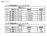
(3)上記(1)または(2)の遊技機において、前記遊技制御手段は、前記有利状態
として、遊技者にとっての有利度合いが異なる複数種類の有利状態(例えば、確変大当り
B〜D、通常大当りA〜C:図19−1、図19−2の大当り種別判定テーブル012S
H10)に制御可能であり、前記有利状態の種類に応じて、遊技状態が前記特定状態から
前記特別状態に移行するか否か(例えば、確変大当りB〜Dの場合は特別状態へ移行し、
通常大当りA〜Cの場合は特別状態へ移行しない)と、前記所定条件の種類とが異なる(
例えば、確変大当りBの場合は特定状態における90回の変動回数の実行であり、確変大
当りCの場合は特定状態における65回の変動回数の実行である等)ようにしてもよい。
このような構成によれば、特別状態に移行するための条件に多様性を持たせることがで
きるため、いずれの種類の有利状態であるかを注目させることができ、遊技の興趣を向上
させることができる。
(3) In the game machine according to (1) or (2), the game control means has, as the advantageous state, a plurality of types of advantageous states having different degrees of advantage for the player (for example, probabilistic jackpots B to D, usually Big hits A to C: Big hit type determination table 012S in FIGS. 19-1 and 19-2
It is controllable to H10), and whether or not the gaming state shifts from the specific state to the special state according to the type of the advantageous state (for example, in the case of probability variation jackpots B to D, the game state shifts to the special state.
Normally, in the case of big hits A to C, it does not shift to the special state), and the type of the predetermined condition is different (normally).
For example, in the case of the probability variation jackpot B, 90 fluctuations are executed in the specific state, and in the case of the probability variation jackpot C, 65 fluctuations are executed in the specific state, etc.).
According to such a configuration, it is possible to give diversity to the conditions for transitioning to the special state, so that it is possible to pay attention to which kind of advantageous state it is, and to improve the interest of the game. Can be done.
(4)上記(1)から(3)のいずれかの遊技機において、前記演出実行手段は、前記
示唆演出として、演出の態様が変化する特定示唆演出(例えば、ステージ演出)を実行可
能であり、前記特定示唆演出の態様(例えば、ステージの態様)によって、遊技状態が前
記特定状態から前記特別状態に移行する期待度と、前記特定状態の残りの期間の長さとが
示唆される(例えば、ステージの態様によって小当たりRUSHへ移行する期待度と、第
1KT状態の残り期間の長さとを示唆する)ようにしてもよい。
このような構成によれば、特定示唆演出の演出態様に注目させることができ、遊技の興
趣を向上させることができる。
(4) In any of the game machines (1) to (3) above, the effect executing means can execute a specific suggestion effect (for example, a stage effect) in which the mode of the effect changes as the suggestion effect. , The mode of the specific suggestion effect (for example, the mode of the stage) suggests the degree of expectation that the gaming state shifts from the specific state to the special state and the length of the remaining period of the specific state (for example). Depending on the mode of the stage, the degree of expectation of transition to the small hit RUSH and the length of the remaining period of the first KT state may be suggested).
According to such a configuration, it is possible to pay attention to the production mode of the specific suggestion effect, and it is possible to improve the interest of the game.
(5)上記(1)から(4)のいずれかの遊技機において、前記演出実行手段は、遊技
状態が前記特定状態から前記特別状態に移行することを報知する報知演出(例えば、小当
たりRUSHへの移行を報知する分岐演出)を実行可能であり、前記特定状態において、
所定回数(例えば、90回、65回または45回)の可変表示が実行されたことに応じて
、前記報知演出を実行可能であるようにしてもよい。
(5) In any of the game machines (1) to (4), the effect executing means notifies that the game state shifts from the specific state to the special state (for example, a small hit RUSH). It is possible to execute a branch effect) to notify the transition to, and in the specific state,
The notification effect may be made executable according to the execution of the variable display a predetermined number of times (for example, 90 times, 65 times, or 45 times).
このような構成によれば、報知演出に注目させることができ、遊技の興趣を向上させる
ことができる。
With such a configuration, it is possible to draw attention to the notification effect and improve the interest of the game.
(基本説明)
まず、パチンコ遊技機1の基本的な構成及び制御(一般的なパチンコ遊技機の構成及び
制御でもある。)について説明する。
(Basic explanation)
First, the basic configuration and control of the pachinko gaming machine 1 (also the configuration and control of a general pachinko gaming machine) will be described.
(パチンコ遊技機1の構成等)
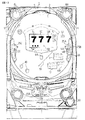
図1は、パチンコ遊技機1の正面図であり、主要部材の配置レイアウトを示す。パチン
コ遊技機(遊技機)1は、大別して、遊技盤面を構成する遊技盤(ゲージ盤)2と、遊技
盤2を支持固定する遊技機用枠(台枠)3とから構成されている。遊技盤2には、遊技領
域が形成され、この遊技領域には、遊技媒体としての遊技球が、所定の打球発射装置から
発射されて打ち込まれる。
(Configuration of
FIG. 1 is a front view of the
遊技盤2の所定位置(図1に示す例では、遊技領域の右側方)には、複数種類の特別識
別情報としての特別図柄(特図ともいう)の可変表示(特図ゲームともいう)を行う第1
特別図柄表示装置4A及び第2特別図柄表示装置4Bが設けられている。これらは、それ
ぞれ、7セグメントのLEDなどからなる。特別図柄は、「0」〜「9」を示す数字や「
−」などの点灯パターンなどにより表される。特別図柄には、LEDを全て消灯したパタ
ーンが含まれてもよい。
At a predetermined position of the game board 2 (in the example shown in FIG. 1, the right side of the game area), a variable display (also referred to as a special figure game) of a special symbol (also referred to as a special figure) as a plurality of types of special identification information is displayed. First to do
A special
It is represented by a lighting pattern such as "-". The special symbol may include a pattern in which all the LEDs are turned off.
なお、特別図柄の「可変表示」とは、例えば、複数種類の特別図柄を変動可能に表示す
ることである(後述の他の図柄についても同じ)。変動としては、複数の図柄の更新表示
、複数の図柄のスクロール表示、1以上の図柄の変形、1以上の図柄の拡大/縮小などが
ある。特別図柄や後述の普通図柄の変動では、複数種類の特別図柄又は普通図柄が更新表
示される。後述の飾り図柄の変動では、複数種類の飾り図柄がスクロール表示又は更新表
示されたり、1以上の飾り図柄が変形や拡大/縮小されたりする。なお、変動には、ある
図柄を点滅表示する態様も含まれる。可変表示の最後には、表示結果として所定の特別図
柄が停止表示(導出又は導出表示などともいう)される(後述の他の図柄の可変表示につ
いても同じ)。なお、可変表示を変動表示、変動と表現する場合がある。
The "variable display" of the special symbol is, for example, to display a plurality of types of special symbols in a variable manner (the same applies to other symbols described later). Fluctuations include update display of a plurality of symbols, scroll display of a plurality of symbols, deformation of one or more symbols, enlargement / reduction of one or more symbols, and the like. When the special symbol or the ordinary symbol described later is changed, a plurality of types of special symbols or ordinary symbols are updated and displayed. In the variation of the decorative symbols described later, a plurality of types of decorative symbols are scrolled or updated, and one or more decorative symbols are deformed or enlarged / reduced. The variation also includes a mode in which a certain symbol is blinked and displayed. At the end of the variable display, a predetermined special symbol is stopped (also referred to as derivation or derivation display) as a display result (the same applies to the variable display of other symbols described later). The variable display may be expressed as a variable display or a variable display.
なお、第1特別図柄表示装置4Aにおいて可変表示される特別図柄を「第1特図」とも
いい、第2特別図柄表示装置4Bにおいて可変表示される特別図柄を「第2特図」ともい
う。また、第1特図を用いた特図ゲームを「第1特図ゲーム」といい、第2特図を用いた
特図ゲームを「第2特図ゲーム」ともいう。なお、特別図柄の可変表示を行う特別図柄表
示装置は1種類であってもよい。
The special symbol variably displayed on the first special
また、第1特別図柄表示装置4A及び第2特別図柄表示装置4Bの下方には、遊技領域
の右方を狙って発射操作を行う右打ち操作を促すための右打ち表示器26が設けられてい
る。なお、右打ち表示器26は、例えば、LEDによって構成され、主基板11に搭載さ
れた遊技制御用マイクロコンピュータ100(具体的には、CPU103)によって点灯
制御される(図2参照)。
Further, below the first special
遊技盤2における遊技領域の中央付近には画像表示装置5が設けられている。画像表示
装置5は、例えばLCD(液晶表示装置)や有機EL(Electro Luminescence)等から構
成され、各種の演出画像を表示する。画像表示装置5は、プロジェクタ及びスクリーンか
ら構成されていてもよい。画像表示装置5には、各種の演出画像が表示される。
An
例えば、画像表示装置5の画面上では、第1特図ゲームや第2特図ゲームと同期して、
特別図柄とは異なる複数種類の装飾識別情報としての飾り図柄(数字などを示す図柄など
)の可変表示が行われる。ここでは、第1特図ゲーム又は第2特図ゲームに同期して、「
左」、「中」、「右」の各飾り図柄表示エリア5L、5C、5Rにおいて飾り図柄が可変
表示(例えば上下方向のスクロール表示や更新表示)される。なお、同期して実行される
特図ゲーム及び飾り図柄の可変表示を総称して単に可変表示ともいう。
For example, on the screen of the
Variable display of decorative symbols (such as symbols indicating numbers) as a plurality of types of decorative identification information different from special symbols is performed. Here, in synchronization with the first special figure game or the second special figure game, "
The decorative symbols are variably displayed (for example, scroll display in the vertical direction or update display) in the decorative
また、例えば、画像表示装置5の画面上には、実行が保留されている可変表示に対応す
る保留表示を表示するための表示エリアが設けられている。本例では、第1特図の可変表
示に対応する保留表示を表示するための第1保留表示領域5Aと、第2特図の可変表示に
対応する保留表示を表示するための第2保留表示領域5Bとが設けられている。なお、画
像表示装置5の画面上には、実行中の可変表示に対応するアクティブ表示を表示するため
の表示エリアが設けられていてもよい。保留表示及びアクティブ表示を総称して可変表示
に対応する可変表示対応表示ともいう。
Further, for example, on the screen of the
また、画像表示装置5の右方には、右打ち操作を促すための右打ち報知用LED37が
設けられている。なお、右打ち報知用LED37は、演出制御基板12に搭載された演出
制御用CPU120によって点灯制御される(図2参照)。
Further, on the right side of the
保留されている可変表示の数は保留記憶数ともいう。第1特図ゲームに対応する保留記
憶数を第1保留記憶数、第2特図ゲームに対応する保留記憶数を第2保留記憶数ともいう
。また、第1保留記憶数と第2保留記憶数との合計を合計保留記憶数ともいう。
The number of variable displays on hold is also called the number of stored items on hold. The number of reserved storage corresponding to the first special figure game is also referred to as the first reserved storage number, and the number of reserved storage corresponding to the second special figure game is also referred to as the second reserved storage number. Further, the total of the first reserved storage number and the second reserved storage number is also referred to as a total reserved storage number.
また、遊技盤2の所定位置には、複数のLEDを含んで構成された第1保留表示器25
Aと第2保留表示器25Bとが設けられ、第1保留表示器25Aは、LEDの点灯個数に
よって、第1保留記憶数を表示し、第2保留表示器25Bは、LEDの点灯個数によって
、第2保留記憶数を表示する。
In addition, a
A and a
画像表示装置5の下方には、第1始動入賞口を有する入賞球装置6Aが設けられている
。第1始動入賞口に入賞した遊技球は、遊技盤2の背面に導かれ、第1始動口スイッチ2
2Aによって検出される。第1始動口スイッチ22Aによって遊技球が検出された場合に
は、この検出情報に基づき、所定個数(1個)の遊技球が賞球として払い出される。
Below the
Detected by 2A. When a game ball is detected by the first
また、第1始動入賞口の右方には、釘の列19が設けられており、遊技領域の右方から
流下した遊技球が第1始動入賞口が設けられた領域に進入しないように構成されている。
このように、遊技領域の右方から流下した遊技球が進入することを防止する釘の列19が
設けられていることによって、遊技領域の左方を狙って遊技球を発射操作(いわゆる左打
ち操作)した場合にのみ第1始動入賞口に遊技球が入賞可能に構成されている。
Further, a row of
In this way, by providing the row of
なお、本例では、釘の列19が設けられていることにより左打ち操作した場合にのみ第
1始動入賞口に遊技球が入賞可能に構成される場合を示しているが、そのような態様にか
ぎられない。例えば、第1始動入賞口が遊技領域の左方に設けられていることによって左
打ち操作した場合にのみ第1始動入賞口に遊技球が入賞可能に構成してもよいし、第1始
動入賞口が遊技領域の左方に設けられているとともに釘の列19も設けることによって左
打ち操作した場合にのみ第1始動入賞口に遊技球が入賞可能に構成してもよい。
In this example, since the row of
画像表示装置5の右方には、通過ゲート41が設けられている。通過ゲート41を通過
した遊技球は、ゲートスイッチ21によって検出される。
A passing
通過ゲート41の下方には、大入賞口を形成する特別可変入賞球装置7が設けられてい
る。特別可変入賞球装置7は、やや傾斜した状態で左右方向に延在し、遊技球が流下する
流路の底面として形成される板状の底面部材を、前後方向に進退移動させることにより、
底面部材の下方に位置する大入賞口に遊技球が入賞可能な開状態(開放状態ともいう)と
遊技球が入賞不能な閉状態(閉鎖状態ともいう)とに変化させる。特別可変入賞球装置7
は、第1特別図柄表示装置4Aまたは第2特別図柄表示装置4Bに特定表示結果(大当り
図柄)が導出表示されたときに生起する大当り遊技状態において、底面部材を前方に向け
て前進移動させた閉状態から底面部材を後方に向けて後退移動させ、入賞領域となる大入
賞口を開状態とする開放制御を実行する。
Below the
The large winning opening located below the bottom member is changed into an open state in which the game ball can win a prize (also referred to as an open state) and a closed state in which the game ball cannot win a prize (also referred to as a closed state). Special variable winning
Moved the bottom member forward in the jackpot game state that occurs when the specific display result (big hit symbol) is derived and displayed on the first special
特別可変入賞球装置7の下方には、小当り用の特殊入賞口を形成する特殊可変入賞球装
置17と、第2始動入賞口を有する可変入賞球装置6Bとが設けられており、図1に示す
ように、左側に特殊可変入賞球装置17が配置され、その右側に隣り合うように可変入賞
球装置6Bが配置されている。これら特殊可変入賞球装置17および可変入賞球装置6B
は、やや傾斜した状態で左右方向に延在し、遊技球が流下する流路の底面として形成され
る板状の底面部材を、前後方向に進退移動させることにより、底面部材の下方に位置する
特殊入賞口や第2始動入賞口に遊技球が入賞可能な開状態(開放状態ともいう)と遊技球
が入賞不能な閉状態(閉鎖状態ともいう)とに変化させる。特殊可変入賞球装置17は、
第1特別図柄表示装置4Aまたは第2特別図柄表示装置4Bに所定表示結果(小当り図柄
)が導出表示されたときに生起する小当り遊技状態において、底面部材を前方に向けて前
進移動させた閉状態から底面部材を後方に向けて後退移動させ、入賞領域となる特殊入賞
口を開状態とする開放制御を実行する。また、可変入賞球装置6Bは、普通図柄表示器2
0に当り図柄が導出表示されたときに、底面部材を前方に向けて前進移動させた閉状態か
ら底面部材を後方に向けて後退移動させ、入賞領域となる第2始動入賞口を開状態とする
開放制御を実行する。
Below the special variable winning
Is located below the bottom member by moving the plate-shaped bottom member, which extends in the left-right direction in a slightly inclined state and is formed as the bottom surface of the flow path through which the game ball flows, in the front-rear direction. The special winning opening and the second starting winning opening are changed into an open state in which the game ball can win a prize (also referred to as an open state) and a closed state in which the game ball cannot win a prize (also referred to as a closed state). The special variable winning
In the small hit game state that occurs when a predetermined display result (small hit symbol) is derived and displayed on the first special
When the symbol hits 0 and the symbol is derived and displayed, the bottom member is moved backward from the closed state in which the bottom member is moved forward, and the second start winning opening, which is the winning area, is opened. Execute open control.
なお、本例では、特別可変入賞球装置7と特殊可変入賞球装置17と可変入賞球装置6
Bとは、同様の構造を有するように形成されている。また、図1に示すように、特別可変
入賞球装置7は底面部材が左上から右下に向けてやや傾斜する態様で形成されているので
、特別可変入賞球装置7上に落下した遊技球は、特別可変入賞球装置7が閉状態であれば
特別可変入賞球装置7上を左上から右下に向けて移動して行き、その下の可変入賞球装置
6B上に落下する。
In this example, the special variable winning
B is formed so as to have a similar structure. Further, as shown in FIG. 1, since the bottom member of the special variable winning
また、本例では、可変入賞球装置6Bと比較して特殊可変入賞球装置17の方が若干大
きい。また、図1に示すように、特殊可変入賞球装置17および可変入賞球装置6Bは底
面部材が右上から左下に向けてやや傾斜する態様で形成されているので、特殊可変入賞球
装置17や可変入賞球装置6B上の遊技球は、特殊可変入賞球装置17や可変入賞球装置
6Bが閉状態であれば特殊可変入賞球装置17や可変入賞球装置6B上を右上から左下に
向けて移動して行く。また、図1に示すように、特殊可変入賞球装置17と可変入賞球装
置6Bとは隣り合うように配置されているので、特別可変入賞球装置7に入賞することな
く可変入賞球装置6B上に落下した遊技球は、可変入賞球装置6Bの底面部材が後退移動
されて第2始動入賞口が開状態となっていれば、遊技球は第2始動入賞口に入賞し、特殊
可変入賞球装置17の方には遊技球は流れて行かない。一方、第2始動入賞口が開状態と
なっていなければ、遊技球は可変入賞球装置6Bの底面部材の上を移動して特殊可変入賞
球装置17の方に導かれる。この際に特殊可変入賞球装置17の底面部材が後退移動され
て特殊入賞口が開状態となっていれば、遊技球は特殊入賞口に入賞する。さらに、特殊入
賞口も開状態となっていなければ、遊技球は特殊可変入賞球装置17の底面部材の上を移
動して、そのままアウト口の方へ落下することになる。
Further, in this example, the special variable winning
また、本例では、特別可変入賞球装置7、特殊可変入賞球装置17および可変入賞球装
置6Bには、底面部材上を流下する遊技球の流下速度を低下させる複数の規制片が形成さ
れている。本例では、特別可変入賞球装置7、特殊可変入賞球装置17および可変入賞球
装置6Bにおいて規制片が設けられていることによって、左上から右下方向または右上か
ら左下方向に向けて流下する遊技球を前後方向成分の動きをもって蛇行するように、遊技
球の流下方向を変更させて、その流下にかかる時間を、規制片がない場合よりも遅延させ
る。
Further, in this example, the special variable winning
なお、本例では、図1に示すように、特殊可変入賞球装置17が左側に配置され、可変
入賞球装置6Bが右側に配置されているのであるが、特殊可変入賞球装置17および可変
入賞球装置6Bの底面部材が右上方から左下方に緩やかに傾斜するように形成され、底面
部材が後退しておらず閉状態である場合には可変入賞球装置6Bの方から特殊可変入賞球
装置17の方に向かって遊技球が流れるように構成されているので、この意味で、可変入
賞球装置6Bの方が上流側に設けられ、特殊可変入賞球装置17の方が下流側に設けられ
ているといえる。
In this example, as shown in FIG. 1, the special variable winning
大入賞口内には、大入賞口内に入賞した遊技球を検出可能なスイッチ(第1カウントス
イッチ23)が設けられている。第1カウントスイッチ23によって遊技球が検出された
場合には、この検出情報に基づき、所定個数(例えば15個)の遊技球が賞球として払い
出される。従って、特別可変入賞球装置7が開放制御されて大入賞口が開状態となれば、
遊技者にとって有利な状態となる。その一方で、特別可変入賞球装置7が閉鎖制御されて
大入賞口が閉状態となれば、大入賞口に遊技球を通過(進入)させて賞球を得ることがで
きないため、遊技者にとって不利な状態となる。
A switch (first count switch 23) capable of detecting a winning game ball in the large winning opening is provided in the large winning opening. When a game ball is detected by the
It will be in an advantageous state for the player. On the other hand, if the special variable winning
特殊入賞口内には、特殊入賞口内に入賞した遊技球を検出可能なスイッチ(第2カウン
トスイッチ24)が設けられている。第2カウントスイッチ24によって遊技球が検出さ
れた場合には、この検出情報に基づき、所定個数(例えば10個)の遊技球が賞球として
払い出される。ここで、特殊可変入賞球装置17において開状態となった特殊入賞口を遊
技球が通過(進入)したときには、大入賞口に遊技球が入賞したときと比較すると賞球の
数が少ないものの、例えば第1始動入賞口1や第2始動入賞口といった、他の入賞口を遊
技球が通過(進入)したときよりも多くの賞球が払い出されるようになっている。従って
、特殊可変入賞球装置17が開放制御されて特殊入賞口が開状態となれば、遊技者にとっ
て有利な状態となる。その一方で、特殊可変入賞球装置17が閉鎖制御されて特殊入賞口
が閉状態となれば、特殊入賞口に遊技球を通過(進入)させて賞球を得ることができない
ため、遊技者にとって不利な状態となる。
A switch (second count switch 24) capable of detecting a winning game ball in the special winning opening is provided in the special winning opening. When a game ball is detected by the
また、第2始動入賞口内には、第2始動入賞口内に入賞した遊技球を検出可能な第2始
動口スイッチ22Bが設けられている。第2始動口スイッチ22Bによって遊技球が検出
された場合には、この検出情報に基づき、所定個数(1個)の遊技球が賞球として払い出
される。
Further, in the second start winning opening, a second starting opening switch 22B capable of detecting a winning game ball in the second starting winning opening is provided. When a game ball is detected by the second start port switch 22B, a predetermined number (1 piece) of game balls are paid out as prize balls based on this detection information.
以下、第1始動入賞口と第2始動入賞口とを総称して始動入賞口または始動口というこ
とがある。
Hereinafter, the first start winning opening and the second starting winning opening may be collectively referred to as a starting winning opening or a starting opening.
なお、このパチンコ遊技機1では、通過ゲート41、特別可変入賞球装置7(大入賞口
)、可変入賞球装置6B(第2始動入賞口)、および特殊可変入賞球装置17(特殊入賞
口)が遊技領域の右方に設けられているので、大当り遊技中やKT状態(いわゆる小当り
タイム)中である場合には、遊技者は遊技領域の右方を狙って発射操作(いわゆる右打ち
操作)を行う。
In this
遊技盤2の所定位置(図1に示す例では、遊技領域の左右下方4箇所)には、所定の玉
受部材によって常に一定の開放状態に保たれる一般入賞口10が設けられる。この場合に
は、一般入賞口10のいずれかに進入したときには、所定個数(例えば10個)の遊技球
が賞球として払い出される。
At predetermined positions of the game board 2 (in the example shown in FIG. 1, four locations on the lower left and right sides of the game area), general winning
一般入賞口10を含む各入賞口に遊技球が進入することを「入賞」ともいう。特に、始
動口(第1始動入賞口、第2始動入賞口始動口)への入賞を始動入賞ともいう。
The entry of a game ball into each winning opening including the general winning
遊技盤2の所定位置(図1に示す例では、遊技領域の左側方)には、普通図柄表示器2
0が設けられている。一例として、普通図柄表示器20は、7セグメントのLEDなどか
らなり、特別図柄とは異なる複数種類の普通識別情報としての普通図柄の可変表示を行う
。普通図柄は、「0」〜「9」を示す数字や「−」などの点灯パターンなどにより表され
る。普通図柄には、LEDを全て消灯したパターンが含まれてもよい。このような普通図
柄の可変表示は、普図ゲームともいう。
At a predetermined position of the game board 2 (in the example shown in FIG. 1, the left side of the game area), the
0 is provided. As an example, the
普通図柄表示器20の上方には、普図保留表示器25Cが設けられている。普図保留表
示器25Cは、例えば4個のLEDを含んで構成され、実行が保留されている普図ゲーム
の数である普図保留記憶数をLEDの点灯個数により表示する。
A
なお、このパチンコ遊技機1では、通過ゲート41を遊技球が通過したことにもとづい
て普通図柄の変動表示が実行されることから、通過ゲート41は普通始動領域としての役
割を担っているのであるが、大当り図柄が導出表示された場合にも通過ゲート41を遊技
球が通過したことにもとづいて大当り遊技状態に移行するので、通過ゲート41は作動領
域としての役割も担っている。従って、通過ゲート41は、普通始動領域と作動領域との
両方の役割を担う兼用ゲートとして構成されている。
In the
遊技盤2の表面には、上記の構成以外にも、遊技球の流下方向や速度を変化させる風車
及び多数の障害釘が設けられている。遊技領域の最下方には、いずれの入賞口にも進入し
なかった遊技球が取り込まれるアウト口が設けられている。
In addition to the above configuration, the surface of the
遊技機用枠3の左右上部位置には、効果音等を再生出力するためのスピーカ8L、8R
が設けられており、さらに遊技領域周辺部には、遊技効果用の枠LED9が設けられてい
る。
Is provided, and a
遊技盤2の所定位置(図1では図示略)には、演出に応じて動作する可動体32が設け
られている。
At a predetermined position of the game board 2 (not shown in FIG. 1), a
遊技機用枠3の右下部位置には、遊技球を打球発射装置により遊技領域に向けて発射す
るために遊技者等によって操作される打球操作ハンドル(操作ノブ)30が設けられてい
る。
At the lower right position of the
遊技領域の下方における遊技機用枠3の所定位置には、賞球として払い出された遊技球
や所定の球貸機により貸し出された遊技球を、打球発射装置へと供給可能に保持(貯留)
する打球供給皿(上皿)が設けられている。上皿の下方には、上皿満タン時に賞球が払い
出される打球供給皿(下皿)が設けられている。
At a predetermined position of the
A hitting ball supply plate (upper plate) is provided. Below the upper plate, a hit ball supply plate (lower plate) is provided, in which prize balls are paid out when the upper plate is full.
遊技領域の下方における遊技機用枠3の所定位置には、遊技者が把持して傾倒操作が可
能なスティックコントローラ31Aが取り付けられている。スティックコントローラ31
Aには、遊技者が押下操作可能なトリガボタンが設けられている。スティックコントロー
ラ31Aに対する操作は、コントローラセンサユニット35A(図2参照)により検出さ
れる。
A
A is provided with a trigger button that can be pressed and operated by the player. The operation on the
遊技領域の下方における遊技機用枠3の所定位置には、遊技者が押下操作などにより所
定の指示操作を可能なプッシュボタン31Bが設けられている。プッシュボタン31Bに
対する操作は、プッシュセンサ35B(図2参照)により検出される。
A
パチンコ遊技機1では、遊技者の動作(操作等)を検出する検出手段として、スティッ
クコントローラ31Aやプッシュボタン31Bが設けられるが、これら以外の検出手段が
設けられていてもよい。
The
(遊技の進行の概略)
このパチンコ遊技機1では、遊技状態が通常状態である場合には、遊技者は遊技領域の
左方を狙って発射操作(いわゆる左打ち操作)を行うのが有利である。パチンコ遊技機1
が備える打球操作ハンドル30への遊技者による回転操作により、左打ち操作を行い、入
賞球装置6Aに形成された第1始動入賞口に遊技球が進入すると、第1特別図柄表示装置
4Aによる第1特図ゲームが開始される。
(Outline of the progress of the game)
In the
When the game ball enters the first starting winning opening formed in the winning
なお、特図ゲームの実行中の期間や、後述する大当り遊技状態や小当り遊技状態に制御
されている期間に、遊技球が始動入賞口へ進入(入賞)した場合(始動入賞が発生したが
当該始動入賞に基づく特図ゲームを直ちに実行できない場合)には、当該進入に基づく特
図ゲームは所定の上限数(例えば4)までその実行が保留される。
In addition, when the game ball enters (wins) the start winning opening during the period during which the special figure game is being executed or during the period controlled by the big hit game state or the small hit game state described later (the start prize has occurred). If the special figure game based on the start winning cannot be executed immediately), the execution of the special figure game based on the approach is suspended up to a predetermined upper limit (for example, 4).
第1特図ゲームにおいて、確定特別図柄として特定の特別図柄(大当り図柄、例えば「
7」、後述の大当り種別に応じて実際の図柄は異なる。)が停止表示されれば、「大当り
」となる。また、大当り図柄とは異なる特別図柄(ハズレ図柄、例えば「−」)が停止表
示されれば「ハズレ」となる。なお、第1特図ゲームであっても、極低い割合で小当り図
柄が停止表示され、「小当り」となる場合があるように構成してもよい。
In the first special symbol game, a specific special symbol (big hit symbol, for example, "
7 ”, the actual design differs depending on the jackpot type described later. ) Is stopped and displayed, it becomes a "big hit". In addition, if a special symbol (missing symbol, for example, "-") different from the jackpot symbol is stopped and displayed, it becomes "missing". Even in the first special figure game, the small hit symbol may be stopped and displayed at an extremely low rate, resulting in a "small hit".
第1特図ゲームでの表示結果が「大当り」になった後には、遊技球が通過ゲート41を
通過したことを条件として、遊技者にとって有利な有利状態として大当り遊技状態に制御
される。
After the display result in the first special figure game becomes "big hit", the big hit game state is controlled as an advantageous state advantageous to the player on condition that the game ball has passed through the passing
大当り遊技状態では、特別可変入賞球装置7により形成される大入賞口が所定の態様で
開放状態となる。当該開放状態は、所定期間(例えば29秒間や1.8秒間)の経過タイ
ミングと、大入賞口に進入した遊技球の数が所定個数(例えば9個)に達するまでのタイ
ミングと、のうちのいずれか早いタイミングまで継続される。前記所定期間は、1ラウン
ドにおいて大入賞口を開放することができる上限期間であり、以下、開放上限期間ともい
う。このように大入賞口が開放状態となる1のサイクルをラウンド(ラウンド遊技)とい
う。大当り遊技状態では、当該ラウンドが所定の上限回数(15回や2回)に達するまで
繰り返し実行可能となっている。
In the big hit game state, the big winning opening formed by the special variable winning
大当り遊技状態においては、遊技者は、遊技球を大入賞口に進入させることで、賞球を
得ることができる。従って、大当り遊技状態は、遊技者にとって有利な状態である。大当
り遊技状態におけるラウンド数が多い程、また、開放上限期間が長い程遊技者にとって有
利となる。
In the big hit game state, the player can obtain the prize ball by letting the game ball enter the big prize opening. Therefore, the jackpot gaming state is an advantageous state for the player. The larger the number of rounds in the jackpot game state and the longer the open upper limit period, the more advantageous it is for the player.
なお、「大当り」には、大当り種別が設定されている。例えば、大入賞口の開放態様(
ラウンド数や開放上限期間)や、大当り遊技状態後の遊技状態(通常状態、確変状態(高
確率状態)、KT状態、高ベース状態など)を複数種類用意し、これらに応じて大当り種
別が設定されている。大当り種別として、多くの賞球を得ることができる大当り種別や、
賞球の少ない又はほとんど賞球を得ることができない大当り種別が設けられていてもよい
。
A jackpot type is set for "big hit". For example, how to open the big prize opening (
Multiple types of game states (normal state, probability change state (high probability state), KT state, high base state, etc.) after the big hit game state (number of rounds and open upper limit period) are prepared, and the big hit type is set according to these. Has been done. As a big hit type, a big hit type that can get many prize balls,
A jackpot type with few or few prize balls may be provided.
大当り遊技状態が終了した後は、上記大当り種別に応じて、確変状態やKT状態、高ベ
ース状態に制御されることがある。
After the jackpot game state is completed, it may be controlled to a probability variation state, a KT state, or a high base state according to the jackpot type.
確変状態(確率変動状態)では、表示結果が「大当り」となる確率が通常状態よりも高
くなる確変制御が実行される。確変状態は、特別図柄の変動効率が向上することに加えて
「大当り」となりやすい状態であるので、遊技者にとってさらに有利な状態である。
In the probability variation state (probability fluctuation state), the probability variation control in which the probability that the display result becomes a "big hit" is higher than in the normal state is executed. The probabilistic state is a state that is more advantageous for the player because it is a state in which a “big hit” is likely to occur in addition to improving the fluctuation efficiency of the special symbol.
KT状態では、通常状態よりも小当りになりやすいKT制御が実行される。このパチン
コ遊技機1では、小当り遊技状態でもある程度の賞球を得ることができるので、大当り遊
技状態と比べると得られる賞球が少ないが遊技者にとって有利な状態である。
In the KT state, KT control is executed, which is more likely to be a small hit than in the normal state. In this
高ベース状態では、平均的な特図変動時間(特図を変動させる期間)を通常状態よりも
短縮させる制御(時短制御)が実行され(時短状態)、普図ゲームで「普図当り」となる
確率を通常状態よりも向上させる等により、第2始動入賞口に遊技球が進入しやすくなる
制御(高開放制御、高ベース制御)も実行される。高ベース状態は、特別図柄(特に第2
特別図柄)の変動効率が向上する状態であるので、遊技者にとって有利な状態である。
In the high base state, the control (time reduction control) that shortens the average special figure fluctuation time (period in which the special figure is changed) is shorter than the normal state is executed (time reduction state). Control (high opening control, high base control) that makes it easier for the game ball to enter the second starting winning opening is also executed by improving the probability of becoming the game ball from the normal state. High base state is a special symbol (especially the second
Since the fluctuation efficiency of the special symbol) is improved, it is an advantageous state for the player.
確変状態やKT状態、高ベース状態は、所定回数の特図ゲームが実行されたことと、次
回の大当り遊技状態が開始されたこと等といった、いずれか1つの終了条件が先に成立す
るまで継続する。所定回数の特図ゲームが実行されたことが終了条件となるものを、回数
切り(回数切り確変等)ともいう。
The probabilistic state, KT state, and high base state continue until any one of the end conditions such as the execution of the special figure game a predetermined number of times and the start of the next big hit game state are satisfied first. To do. A game whose end condition is that the special figure game has been executed a predetermined number of times is also called a number cut (number cut probability change, etc.).
通常状態とは、遊技者にとって有利な大当り遊技状態等の有利状態、確変状態、KT状
態、高ベース状態等の特別状態以外の遊技状態のことであり、特図ゲームにおける表示結
果が「大当り」となる確率などのパチンコ遊技機1が、パチンコ遊技機1の初期設定状態
(例えばシステムリセットが行われた場合のように、電源投入後に所定の復帰処理を実行
しなかったとき)と同一に制御される状態である。
The normal state is a gaming state other than a special state such as an advantageous state such as a jackpot gaming state that is advantageous for the player, a probability variation state, a KT state, and a high base state, and the display result in the special figure game is "big hit". The
大当り遊技を終了し、遊技状態が確変状態やKT状態、高ベース状態に制御されると、
遊技者は遊技領域の右方を狙って発射操作(右打ち操作)を行うのが有利である。パチン
コ遊技機1が備える打球操作ハンドル30への遊技者による回転操作により、右打ち操作
を行い、遊技球が通過ゲート41を通過すると、普通図柄表示器20による普図ゲームが
開始される。なお、前回の普図ゲームの実行中の期間等に遊技球が通過ゲート41を通過
した場合(遊技球が通過ゲート41を通過したが当該通過に基づく普図ゲームを直ちに実
行できない場合)には、当該通過に基づく普図ゲームは所定の上限数(例えば4)まで保
留される。
When the jackpot game is finished and the game state is controlled to the probability change state, the KT state, or the high base state,
It is advantageous for the player to perform a firing operation (right-handed operation) aiming at the right side of the game area. When the player performs a right-handed strike operation on the ball striking operation handle 30 included in the
この普図ゲームでは、特定の普通図柄(普図当り図柄)が停止表示されれば、普通図柄
の表示結果が「普図当り」となる。その一方、確定普通図柄として、普図当り図柄以外の
普通図柄(普図ハズレ図柄)が停止表示されれば、普通図柄の表示結果が「普図ハズレ」
となる。「普図当り」となると、可変入賞球装置6Bを所定期間開放状態とする開放制御
が行われる(第2始動入賞口が開放状態になる)。
In this normal symbol game, if a specific normal symbol (design per normal symbol) is stopped and displayed, the display result of the normal symbol becomes "per normal symbol". On the other hand, if a normal symbol other than the normal symbol (normal symbol lost symbol) is stopped and displayed as a confirmed normal symbol, the display result of the normal symbol is "normal symbol lost".
Will be. When it becomes "per normal drawing", the opening control is performed so that the variable winning
可変入賞球装置6Bに形成された第2始動入賞口に遊技球が進入すると、第2特別図柄
表示装置4Bによる第2特図ゲームが開始される。
When the game ball enters the second starting winning opening formed in the variable winning
第2特図ゲームにおいて、確定特別図柄として特定の特別図柄(大当り図柄、例えば「
7」、後述の大当り種別に応じて実際の図柄は異なる。)が停止表示されれば、「大当り
」となり、大当り図柄とは異なる所定の特別図柄(小当り図柄、例えば「2」)が停止表
示されれば、「小当り」となる。また、大当り図柄や小当り図柄とは異なる特別図柄(ハ
ズレ図柄、例えば「−」)が停止表示されれば「ハズレ」となる。
In the second special symbol game, a specific special symbol (big hit symbol, for example, "
7 ”, the actual design differs depending on the jackpot type described later. ) Is stopped and displayed, it becomes a "big hit", and when a predetermined special symbol (small hit symbol, for example, "2") different from the big hit symbol is stopped and displayed, it becomes a "small hit". Further, if a special symbol (missing symbol, for example, "-") different from the big hit symbol or the small hit symbol is stopped and displayed, it becomes "missing".
第2特図ゲームでの表示結果が「大当り」になった後には、遊技球が通過ゲート41を
通過したことを条件として、遊技者にとって有利な有利状態として大当り遊技状態に制御
される。第2特図ゲームでの表示結果が「小当り」になった後には、小当り遊技状態に制
御される。
After the display result in the second special figure game becomes "big hit", the big hit game state is controlled as an advantageous state advantageous to the player on condition that the game ball has passed through the passing
小当り遊技状態では、特殊可変入賞球装置17により形成される特殊入賞口が所定の開
放態様で開放状態となる。なお、大当り種別と同様に、「小当り」にも小当り種別を設け
てもよい。
In the small hit game state, the special winning opening formed by the special variable winning
小当り遊技状態が終了した後は、遊技状態の変更が行われず、特図ゲームの表示結果が
「小当り」となる以前の遊技状態に継続して制御される(但し、「小当り」発生時の特図
ゲームが、上記回数切りにおける上記所定回数目の特図ゲームである場合には、当然遊技
状態が変更される)。
After the small hit game state ends, the game state is not changed, and the game state is continuously controlled to the game state before the display result of the special figure game becomes "small hit" (however, "small hit" occurs. If the special figure game at the time is the special figure game of the predetermined number of times in the above number of times cut, the game state is naturally changed).
なお、遊技状態は、大当り遊技状態中に遊技球が特定領域(例えば、大入賞口内の特定
領域)を通過したことに基づいて、変化してもよい。例えば、遊技球が特定領域を通過し
たとき、その大当り遊技状態後に確変状態に制御してもよい。
The game state may change based on the fact that the game ball has passed through a specific area (for example, a specific area in the big winning opening) during the big hit game state. For example, when the game ball passes through a specific area, it may be controlled to a probabilistic state after the big hit game state.
(演出の進行など)
パチンコ遊技機1では、遊技の進行に応じて種々の演出(遊技の進行状況を報知したり
、遊技を盛り上げたりする演出)が実行される。当該演出について以下説明する。なお、
当該演出は、画像表示装置5に各種の演出画像を表示することによって行われるが、当該
表示に加えて又は代えて、スピーカ8L、8Rからの音声出力、及び/又は、枠LED9
の点等/消灯、可動体32の動作等により行われてもよい。
(Progress of production, etc.)
In the
The effect is performed by displaying various effect images on the
It may be performed by turning off the points and the like, operating the
遊技の進行に応じて実行される演出として、画像表示装置5に設けられた「左」、「中
」、「右」の飾り図柄表示エリア5L、5C、5Rでは、第1特図ゲーム又は第2特図ゲ
ームが開始されることに対応して、飾り図柄の可変表示が開始される。第1特図ゲームや
第2特図ゲームにおいて表示結果(確定特別図柄ともいう。)が停止表示されるタイミン
グでは、飾り図柄の可変表示の表示結果となる確定飾り図柄(3つの飾り図柄の組合せ)
も停止表示(導出)される。
As an effect executed according to the progress of the game, in the decorative
Is also stopped and displayed (derived).
飾り図柄の可変表示が開始されてから終了するまでの期間では、飾り図柄の可変表示の
態様が所定のリーチ態様となる(リーチが成立する)ことがある。ここで、リーチ態様と
は、画像表示装置5の画面上にて停止表示された飾り図柄が後述の大当り組合せの一部を
構成しているときに未だ停止表示されていない飾り図柄については可変表示が継続してい
る態様などのことである。
In the period from the start to the end of the variable display of the decorative symbol, the variable display mode of the decorative symbol may be a predetermined reach mode (reach is established). Here, the reach mode is a variable display of a decorative symbol that has not yet been stopped and displayed when the decorative symbol that has been stopped and displayed on the screen of the
また、飾り図柄の可変表示中に上記リーチ態様となったことに対応してリーチ演出が実
行される。パチンコ遊技機1では、演出態様に応じて表示結果(特図ゲームの表示結果や
飾り図柄の可変表示の表示結果)が「大当り」となる割合(大当り信頼度、大当り期待度
とも呼ばれる。)が異なる複数種類のリーチ演出が実行される。リーチ演出には、例えば
、ノーマルリーチと、ノーマルリーチよりも大当り信頼度の高いスーパーリーチと、があ
る。
In addition, the reach effect is executed in response to the above-mentioned reach mode during the variable display of the decorative symbol. In the
特図ゲームの表示結果が「大当り」となるときには、画像表示装置5の画面上において
、飾り図柄の可変表示の表示結果として、予め定められた大当り組合せとなる確定飾り図
柄が導出される(飾り図柄の可変表示の表示結果が「大当り」となる)。一例として、「
左」、「中」、「右」の飾り図柄表示エリア5L、5C、5Rにおける所定の有効ライン
上に同一の飾り図柄(例えば、「7」等)が揃って停止表示される。
When the display result of the special figure game is "big hit", a fixed decorative symbol that is a predetermined jackpot combination is derived as a display result of variable display of the decorative symbol on the screen of the image display device 5 (decoration). The display result of the variable display of the symbol is "big hit"). As an example,"
The same decorative symbols (for example, "7") are aligned and stopped and displayed on predetermined effective lines in the decorative
大当り遊技状態の終了後に確変状態に制御される「確変大当り」である場合には、奇数
の飾り図柄(例えば、「7」等)が揃って停止表示され、大当り遊技状態の終了後に確変
状態に制御されない「非確変大当り(通常大当り)」である場合には、偶数の飾り図柄(
例えば、「6」等)が揃って停止表示されるようにしてもよい。この場合、奇数の飾り図
柄を確変図柄、偶数の飾り図柄を非確変図柄(通常図柄)ともいう。非確変図柄でリーチ
態様となった後に、最終的に「確変大当り」となる昇格演出を実行するようにしてもよい
。
In the case of a "probability change jackpot" that is controlled to a probability change state after the end of the jackpot game state, an odd number of decorative symbols (for example, "7") are aligned and displayed as a stop, and the probability change state is entered after the end of the jackpot game state. In the case of an uncontrolled "non-probability variable jackpot (normal jackpot)", an even number of decorative symbols (
For example, "6" etc.) may be displayed together as a stop. In this case, the odd-numbered decorative symbol is also referred to as a probabilistic symbol, and the even-numbered decorative symbol is also referred to as a non-probable variable symbol (normal symbol). After the non-probability change symbol becomes the reach mode, the promotion effect that finally becomes the "probability change jackpot" may be executed.
特図ゲームの表示結果が「小当り」となるときには、画像表示装置5の画面上において
、飾り図柄の可変表示の表示結果として、予め定められた小当り組合せとなる確定飾り図
柄(例えば、「1 3 5」等)が導出される(飾り図柄の可変表示の表示結果が「小当
り」となる)。一例として、「左」、「中」、「右」の飾り図柄表示エリア5L、5C、
5Rにおける所定の有効ライン上にチャンス目を構成する飾り図柄が停止表示される。な
お、特図ゲームの表示結果が、一部の大当り種別(小当り遊技状態と同様の態様の大当り
遊技状態の大当り種別)の「大当り」となるときと、「小当り」となるときとで、共通の
確定飾り図柄が導出表示されてもよい。
When the display result of the special figure game is "small hit", a fixed decorative symbol (for example, "for example,""is a predetermined small hit combination as a display result of variable display of the decorative symbol on the screen of the
The decorative symbols constituting the chance eyes are stopped and displayed on the predetermined effective line in 5R. In addition, when the display result of the special figure game becomes "big hit" of some big hit types (big hit type of the big hit game state in the same mode as the small hit game state), and when it becomes "small hit". , A common fixed decorative pattern may be derived and displayed.
特図ゲームの表示結果が「ハズレ」となる場合には、飾り図柄の可変表示の態様がリー
チ態様とならずに、飾り図柄の可変表示の表示結果として、非リーチ組合せの確定飾り図
柄(「非リーチハズレ」ともいう。)が停止表示される(飾り図柄の可変表示の表示結果
が「非リーチハズレ」となる)ことがある。また、表示結果が「ハズレ」となる場合には
、飾り図柄の可変表示の態様がリーチ態様となった後に、飾り図柄の可変表示の表示結果
として、大当り組合せでない所定のリーチ組合せ(「リーチハズレ」ともいう)の確定飾
り図柄が停止表示される(飾り図柄の可変表示の表示結果が「リーチハズレ」となる)こ
ともある。
When the display result of the special figure game is "missing", the variable display mode of the decorative symbol is not the reach mode, and the variable display result of the decorative symbol is a fixed decorative symbol of a non-reach combination ("" (Also referred to as "non-reach loss") may be stopped and displayed (the display result of the variable display of the decorative pattern may be "non-reach loss"). In addition, when the display result is "missing", after the variable display mode of the decorative symbol becomes the reach mode, the display result of the variable display of the decorative symbol is a predetermined reach combination ("reach loss") that is not a jackpot combination. The fixed decorative symbol (also referred to as) may be stopped and displayed (the display result of the variable display of the decorative symbol may be "reach loss").
パチンコ遊技機1が実行可能な演出には、上記の可変表示対応表示(保留表示やアクテ
ィブ表示)を表示することも含まれる。また、他の演出として、例えば、大当り信頼度を
予告する予告演出等が飾り図柄の可変表示中に実行される。予告演出には、実行中の可変
表示における大当り信頼度を予告する予告演出や、実行前の可変表示(実行が保留されて
いる可変表示)における大当り信頼度を予告する先読み予告演出がある。先読み予告演出
として、可変表示対応表示(保留表示やアクティブ表示)の表示態様を通常とは異なる態
様に変化させる演出が実行されるようにしてもよい。
The effect that the
また、画像表示装置5において、飾り図柄の可変表示中に飾り図柄を一旦仮停止させた
後に可変表示を再開させることで、1回の可変表示を擬似的に複数回の可変表示のように
見せる擬似連演出を実行するようにしてもよい。
Further, in the
大当り遊技状態中にも、大当り遊技状態を報知する大当り中演出が実行される。大当り
中演出としては、ラウンド数を報知する演出や、大当り遊技状態の価値が向上することを
示す昇格演出が実行されてもよい。また、小当り遊技状態中にも、小当り遊技状態を報知
する小当り中演出が実行される。なお、小当り遊技状態中と、一部の大当り種別(小当り
遊技状態と同様の態様の大当り遊技状態の大当り種別で、例えばその後の遊技状態を高確
状態とする大当り種別)での大当り遊技状態とで、共通の演出を実行することで、現在が
小当り遊技状態中であるか、大当り遊技状態中であるかを遊技者に分からないようにして
もよい。そのような場合であれば、小当り遊技状態の終了後と大当り遊技状態の終了後と
で共通の演出を実行することで、高確状態であるか低確状態であるかを識別できないよう
にしてもよい。
Even during the big hit game state, the big hit middle effect that notifies the big hit game state is executed. As the big hit middle effect, an effect of notifying the number of rounds and a promotion effect indicating that the value of the big hit gaming state is improved may be executed. Further, even during the small hit game state, the small hit medium effect for notifying the small hit game state is executed. It should be noted that the big hit game during the small hit game state and in some big hit types (the big hit type in the big hit game state in the same mode as the small hit game state, for example, the big hit type in which the subsequent game state is a highly accurate state). By executing a common effect depending on the state, the player may not know whether the player is currently in the small hit game state or the big hit game state. In such a case, by executing a common effect after the end of the small hit game state and after the end of the big hit game state, it is not possible to distinguish between the high accuracy state and the low accuracy state. You may.
また、例えば特図ゲーム等が実行されていないときには、画像表示装置5にデモ(デモ
ンストレーション)画像が表示される(客待ちデモ演出が実行される)。
Further, for example, when a special figure game or the like is not executed, a demo (demonstration) image is displayed on the image display device 5 (a customer waiting demo effect is executed).
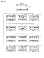
(基板構成)
パチンコ遊技機1には、例えば図2に示すような主基板11、演出制御基板12、音声
制御基板13、LED制御基板14、中継基板15などが搭載されている。その他にも、
パチンコ遊技機1の背面には、例えば払出制御基板、情報端子基板、発射制御基板、電源
基板などといった、各種の基板が配置されている。
(Board configuration)
For example, the
On the back surface of the
主基板11は、メイン側の制御基板であり、パチンコ遊技機1における上記遊技の進行
(特図ゲームの実行(保留の管理を含む)、普図ゲームの実行(保留の管理を含む)、大
当り遊技状態、小当り遊技状態、遊技状態など)を制御する機能を有する。主基板11は
、遊技制御用マイクロコンピュータ100、スイッチ回路110、ソレノイド回路111
などを有する。
The
And so on.
主基板11に搭載された遊技制御用マイクロコンピュータ100は、例えば1チップの
マイクロコンピュータであり、ROM(Read Only Memory)101と、RAM(Random A
ccess Memory)102と、CPU(Central Processing Unit)103と、乱数回路10
4と、I/O(Input/Output port)105とを備える。
The
ccess Memory) 102, CPU (Central Processing Unit) 103, and
4 and an I / O (Input / Output port) 105.
CPU103は、ROM101に記憶されたプログラムを実行することにより、遊技の
進行を制御する処理(主基板11の機能を実現する処理)を行う。このとき、ROM10
1が記憶する各種データ(後述の変動パターン、後述の演出制御コマンド、後述の各種決
定を行う際に参照される各種テーブルなどのデータ)が用いられ、RAM102がメイン
メモリとして使用される。RAM102は、その一部または全部がパチンコ遊技機1に対
する電力供給が停止しても、所定期間記憶内容が保存されるバックアップRAMとなって
いる。なお、ROM101に記憶されたプログラムの全部又は一部をRAM102に展開
して、RAM102上で実行するようにしてもよい。
The
Various data stored in 1 (data such as a fluctuation pattern described later, an effect control command described later, and various tables referred to when making various decisions described later) are used, and the
乱数回路104は、遊技の進行を制御するときに使用される各種の乱数値(遊技用乱数
)を示す数値データを更新可能にカウントする。遊技用乱数は、CPU103が所定のコ
ンピュータプログラムを実行することで更新されるもの(ソフトウェアで更新されるもの
)であってもよい。
The
I/O105は、例えば各種信号(後述の検出信号)が入力される入力ポートと、各種
信号(第1特別図柄表示装置4A、第2特別図柄表示装置4B、普通図柄表示器20、第
1保留表示器25A、第2保留表示器25B、普図保留表示器25Cなどを制御(駆動)
する信号、ソレノイド駆動信号)を伝送するための出力ポートとを含んで構成される。
The I /
It is configured to include an output port for transmitting (a signal to be used, a solenoid drive signal).
スイッチ回路110は、遊技球検出用の各種スイッチ(ゲートスイッチ21、始動口ス
イッチ(第1始動口スイッチ22Aおよび第2始動口スイッチ22B)、カウントスイッ
チ(第1カウントスイッチ23および第2カウントスイッチ24))からの検出信号(遊
技球が通過又は進入してスイッチがオンになったことを示す検出信号など)を取り込んで
遊技制御用マイクロコンピュータ100に伝送する。検出信号の伝送により、遊技球の通
過又は進入が検出されたことになる。
The
ソレノイド回路111は、遊技制御用マイクロコンピュータ100からのソレノイド駆
動信号(例えば、ソレノイド81やソレノイド82、ソレノイド83をオンする信号など
)を、普通電動役物用のソレノイド81や大入賞口扉用のソレノイド82、特殊入賞口用
のソレノイド83に伝送する。
The solenoid circuit 111 transmits a solenoid drive signal (for example, a
主基板11(遊技制御用マイクロコンピュータ100)は、遊技の進行の制御の一部と
して、遊技の進行に応じて演出制御コマンド(遊技の進行状況等を指定(通知)するコマ
ンド)を演出制御基板12に供給する。主基板11から出力された演出制御コマンドは、
中継基板15により中継され、演出制御基板12に供給される。当該演出制御コマンドに
は、例えば主基板11における各種の決定結果(例えば、特図ゲームの表示結果(大当り
種別を含む。)、特図ゲームを実行する際に使用される変動パターン(詳しくは後述))
、遊技の状況(例えば、可変表示の開始や終了、大入賞口の開放状況、入賞の発生、保留
記憶数、遊技状態)、エラーの発生等を指定するコマンド等が含まれる。
The main board 11 (
It is relayed by the
, The game status (for example, the start and end of the variable display, the opening status of the large winning opening, the occurrence of the winning, the number of stored memories, the game status), the occurrence of an error, and the like are included.
演出制御基板12は、主基板11とは独立したサブ側の制御基板であり、演出制御コマ
ンドを受信し、受信した演出制御コマンドに基づいて演出(遊技の進行に応じた種々の演
出であり、可動体32の駆動、エラー報知、電断復旧の報知等の各種報知を含む)を実行
する機能を有する。
The
演出制御基板12には、演出制御用CPU120と、ROM121と、RAM122と
、表示制御部123と、乱数回路124と、I/O125とが搭載されている。
The
演出制御用CPU120は、ROM121に記憶されたプログラムを実行することによ
り、表示制御部123とともに演出を実行するための処理(演出制御基板12の上記機能
を実現するための処理であり、実行する演出の決定等を含む)を行う。このとき、ROM
121が記憶する各種データ(各種テーブルなどのデータ)が用いられ、RAM122が
メインメモリとして使用される。
The
Various data (data such as various tables) stored in 121 is used, and
演出制御用CPU120は、コントローラセンサユニット35Aやプッシュセンサ35
Bからの検出信号(遊技者による操作を検出したときに出力される信号であり、操作内容
を適宜示す信号)に基づいて演出の実行を表示制御部123に指示することもある。
The
The
表示制御部123は、VDP(Video Display Processor)、CGROM(Character G
enerator ROM)、VRAM(Video RAM)などを備え、演出制御用CPU120からの演
出の実行指示に基づき、演出を実行する。
The
It is equipped with enerator ROM), VRAM (Video RAM), etc., and executes the effect based on the effect execution instruction from the
表示制御部123は、演出制御用CPU120からの演出の実行指示に基づき、実行す
る演出に応じた映像信号を画像表示装置5に供給することで、演出画像を画像表示装置5
に表示させる。表示制御部123は、さらに、演出画像の表示に同期した音声出力や、枠
LED9および右打ち報知用LED37の点灯/消灯を行うため、音指定信号(出力する
音声を指定する信号)を音声制御基板13に供給したり、LED信号(LEDの点灯/消
灯態様を指定する信号)をLED制御基板14に供給したりする。また、表示制御部12
3は、可動体32を動作させる信号を当該可動体32又は当該可動体32を駆動する駆動
回路に供給する。
The
To display. The
3 supplies a signal for operating the
音声制御基板13は、スピーカ8L、8Rを駆動する各種回路を搭載しており、当該音
指定信号に基づきスピーカ8L、8Rを駆動し、当該音指定信号が指定する音声をスピー
カ8L、8Rから出力させる。
The
LED制御基板14は、枠LED9や右打ち報知用LED37を駆動する各種回路を搭
載しており、当該LED信号に基づき枠LED9や右打ち報知用LED37を駆動し、当
該LED信号が指定する態様で枠LED9や右打ち報知用LED37を点灯/消灯する。
このようにして、表示制御部123は、音声出力、LEDの点灯/消灯を制御する。
The
In this way, the
なお、音声出力、LEDの点灯/消灯の制御(音指定信号やLED信号の供給等)、可
動体32の制御(可動体32を動作させる信号の供給等)は、演出制御用CPU120が
実行するようにしてもよい。
The
乱数回路124は、各種演出を実行するために使用される各種の乱数値(演出用乱数)
を示す数値データを更新可能にカウントする。演出用乱数は、演出制御用CPU120が
所定のコンピュータプログラムを実行することで更新されるもの(ソフトウェアで更新さ
れるもの)であってもよい。
The
Numerical data indicating is counted up to date. The effect random number may be one that is updated (updated by software) when the
演出制御基板12に搭載されたI/O125は、例えば主基板11などから伝送された
演出制御コマンドを取り込むための入力ポートと、各種信号(映像信号、音指定信号、L
ED信号)を伝送するための出力ポートとを含んで構成される。
The I /
It is configured to include an output port for transmitting an ED signal).
演出制御基板12、音声制御基板13、LED制御基板14といった、主基板11以外
の基板をサブ基板ともいう。パチンコ遊技機1のようにサブ基板が機能別に複数設けられ
ていてもよいし、1のサブ基板が複数の機能を有するように構成してもよい。
Boards other than the
(動作)
次に、パチンコ遊技機1の動作(作用)を説明する。
(motion)
Next, the operation (action) of the
(主基板11の主要な動作)
まず、主基板11における主要な動作を説明する。パチンコ遊技機1に対して電力供給
が開始されると、遊技制御用マイクロコンピュータ100が起動し、CPU103によっ
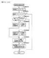
て遊技制御メイン処理が実行される。図3は、主基板11におけるCPU103が実行す
る遊技制御メイン処理を示すフローチャートである。
(Main operation of main board 11)
First, the main operations on the
図3に示す遊技制御メイン処理では、CPU103は、まず、割込禁止に設定する(ス
テップS1)。続いて、必要な初期設定を行う(ステップS2)。初期設定には、スタッ
クポインタの設定、内蔵デバイス(CTC(カウンタ/タイマ回路)、パラレル入出力ポ
ート等)のレジスタ設定、RAM102をアクセス可能状態にする設定等が含まれる。
In the game control main process shown in FIG. 3, the
次いで、クリアスイッチからの出力信号がオンであるか否かを判定する(ステップS3
)。クリアスイッチは、例えば電源基板に搭載されている。クリアスイッチがオンの状態
で電源が投入されると、出力信号(クリア信号)が入力ポートを介して遊技制御用マイク
ロコンピュータ100に入力される。クリアスイッチからの出力信号がオンである場合(
ステップS3;Yes)、初期化処理(ステップS8)を実行する。初期化処理では、C
PU103は、RAM102に記憶されるフラグ、カウンタ、バッファをクリアするRA
Mクリア処理を行い、作業領域に初期値を設定する。
Next, it is determined whether or not the output signal from the clear switch is ON (step S3).
). The clear switch is mounted on the power supply board, for example. When the power is turned on with the clear switch turned on, an output signal (clear signal) is input to the
Step S3; Yes), the initialization process (step S8) is executed. In the initialization process, C
The
Perform M clear processing and set the initial value in the work area.
また、CPU103は、初期化を指示する演出制御コマンドを演出制御基板12に送信
する(ステップS9)。演出制御用CPU120は、当該演出制御コマンドを受信すると
、例えば画像表示装置5において、遊技機の制御の初期化がなされたことを報知するため
の画面表示を行う。
Further, the
クリアスイッチからの出力信号がオンでない場合には(ステップS3;No)、RAM
102(バックアップRAM)にバックアップデータが保存されているか否かを判定する
(ステップS4)。不測の停電等(電断)によりパチンコ遊技機1への電力供給が停止し
たときには、CPU103は、当該電力供給の停止によって動作できなくなる直前に、電
源供給停止時処理を実行する。この電源供給停止時処理では、RAM102にデータをバ
ックアップすることを示すバックアップフラグをオンする処理、RAM102のデータ保
護処理等が実行される。データ保護処理には、誤り検出符号(チェックサム、パリティビ
ット等)の付加、各種データをバックアップする処理が含まれる。バックアップされるデ
ータには、遊技を進行するための各種データ(各種フラグ、各種タイマの状態等を含む)
の他、前記バックアップフラグの状態や誤り検出符号も含まれる。ステップS4では、バ
ックアップフラグがオンであるか否かを判定する。バックアップフラグがオフでRAM1
02にバックアップデータが記憶されていない場合(ステップS4;No)、初期化処理
(ステップS8)を実行する。
If the output signal from the clear switch is not on (step S3; No), the RAM
It is determined whether or not the backup data is stored in 102 (backup RAM) (step S4). When the power supply to the
In addition, the state of the backup flag and the error detection code are also included. In step S4, it is determined whether or not the backup flag is on. RAM1 with backup flag off
If the backup data is not stored in 02 (step S4; No), the initialization process (step S8) is executed.
RAM102にバックアップデータが記憶されている場合(ステップS4;Yes)、
CPU103は、バックアップしたデータのデータチェックを行い(誤り検出符号を用い
て行われる)、データが正常か否かを判定する(ステップS5)。ステップS5では、例
えば、パリティビットやチェックサムにより、RAM102のデータが、電力供給停止時
のデータと一致するか否かを判定する。これらが一致すると判定された場合、RAM10
2のデータが正常であると判定する。
When the backup data is stored in the RAM 102 (step S4; Yes),
The
It is determined that the data of 2 is normal.
RAM102のデータが正常でないと判定された場合(ステップS5;No)、内部状
態を電力供給停止時の状態に戻すことができないので、初期化処理(ステップS8)を実
行する。
If it is determined that the data in the
RAM102のデータが正常であると判定された場合(ステップS5;Yes)、CP
U103は、主基板11の内部状態を電力供給停止時の状態に戻すための復旧処理(ステ
ップS6)を行う。復旧処理では、CPU103は、RAM102の記憶内容(バックア
ップしたデータの内容)に基づいて作業領域の設定を行う。これにより、電力供給停止時
の遊技状態に復旧し、特別図柄の変動中であった場合には、後述の遊技制御用タイマ割込
み処理の実行によって、復旧前の状態から特別図柄の変動が再開されることになる。
When it is determined that the data in the
The U103 performs a restoration process (step S6) for returning the internal state of the
そして、CPU103は、電断からの復旧を指示する演出制御コマンドを演出制御基板
12に送信する(ステップS7)。これに合わせて、バックアップされている電断前の遊
技状態を指定する演出制御コマンドや、特図ゲームの実行中であった場合には当該実行中
の特図ゲームの表示結果を指定する演出制御コマンドを送信するようにしてもよい。これ
らコマンドは、後述の特別図柄プロセス処理で送信設定されるコマンドと同じコマンドを
使用できる。演出制御用CPU120は、電断からの復旧時を特定する演出制御コマンド
を受信すると、例えば画像表示装置5において、電断からの復旧がなされたこと又は電断
からの復旧中であることを報知するための画面表示を行う。演出制御用CPU120は、
前記演出制御コマンドに基づいて、適宜の画面表示を行うようにしてもよい。
Then, the
An appropriate screen display may be performed based on the effect control command.
復旧処理または初期化処理を終了して演出制御基板12に演出制御コマンドを送信した
後には、CPU103は、乱数回路104を初期設定する乱数回路設定処理を実行する(
ステップS10)。そして、所定時間(例えば2ms)毎に定期的にタイマ割込がかかる
ように遊技制御用マイクロコンピュータ100に内蔵されているCTCのレジスタの設定
を行い(ステップS11)、割込みを許可する(ステップS12)。その後、ループ処理
に入る。以後、所定時間(例えば2ms)ごとにCTCから割込み要求信号がCPU10
3へ送出され、CPU103は定期的にタイマ割込み処理を実行することができる。
After the restoration process or the initialization process is completed and the effect control command is transmitted to the
Step S10). Then, the CTC register built in the
It is sent to No. 3, and the
こうした遊技制御メイン処理を実行したCPU103は、CTCからの割込み要求信号
を受信して割込み要求を受け付けると、図4のフローチャートに示す遊技制御用タイマ割
込み処理を実行する。図4に示す遊技制御用タイマ割込み処理を開始すると、CPU10
3は、まず、所定のスイッチ処理を実行することにより、スイッチ回路110を介してゲ
ートスイッチ21、第1始動口スイッチ22A、第2始動口スイッチ22B、第1カウン
トスイッチ23、第2カウントスイッチ24といった各種スイッチからの検出信号の受信
の有無を判定する(ステップS21)。続いて、所定のメイン側エラー処理を実行するこ
とにより、パチンコ遊技機1の異常診断を行い、その診断結果に応じて必要ならば警告を
発生可能とする(ステップS22)。この後、所定の情報出力処理を実行することにより
、例えばパチンコ遊技機1の外部に設置されたホール管理用コンピュータに供給される大
当り情報(大当りの発生回数等を示す情報)、始動情報(始動入賞の回数等を示す情報)
、確率変動情報(確変状態となった回数等を示す情報)などのデータを出力する(ステッ
プS23)。
When the
First, by executing a predetermined switch process, the
, Data such as probability fluctuation information (information indicating the number of times the probability variation state has occurred) is output (step S23).
情報出力処理に続いて、主基板11の側で用いられる遊技用乱数の少なくとも一部をソ
フトウェアにより更新するための遊技用乱数更新処理を実行する(ステップS24)。こ
の後、CPU103は、第1特別図柄プロセス処理を実行する(ステップS25A)。C
PU103がタイマ割込み毎に第1特別図柄プロセス処理を実行することにより、第1特
図ゲームの実行及び保留の管理などが実現される(詳しくは後述)。また、CPU103
は、第2特別図柄プロセス処理を実行する(ステップS25B)。CPU103がタイマ
割込み毎に第2特別図柄プロセス処理を実行することにより、第2特図ゲームの実行及び
保留の管理などが実現される。なお、このパチンコ遊技機1では、第1特別図柄の変動表
示と第2特別図柄の変動表示とを同時に並行して実行することが可能である。
Following the information output process, a game random number update process for updating at least a part of the game random numbers used on the
When the
Executes the second special symbol process process (step S25B). When the
第1特別図柄プロセス処理および第2特別図柄プロセス処理に続いて、CPU103は
、役物制御プロセス処理を実行する(ステップS25C)。CPU103がタイマ割込み
毎に役物制御プロセス処理を実行することにより、大当り遊技状態や小当り遊技状態の制
御、遊技状態の制御などが実現される(詳しくは後述)。
Following the first special symbol process process and the second special symbol process process, the
役物制御プロセス処理に続いて、普通図柄プロセス処理が実行される(ステップS26
)。CPU103がタイマ割込み毎に普通図柄プロセス処理を実行することにより、ゲー
トスイッチ21からの検出信号に基づく(通過ゲート41に遊技球が通過したことに基づ
く)普図ゲームの実行及び保留の管理や、「普図当り」に基づく可変入賞球装置6Bの開
放制御などを可能にする。普図ゲームの実行は、普通図柄表示器20を駆動することによ
り行われ、普図保留表示器25Cを点灯させることにより普図保留数を表示する。
Following the accessory control process process, the normal symbol process process is executed (step S26).
). By executing the normal symbol process processing for each timer interrupt, the
普通図柄プロセス処理を実行した後、遊技制御用タイマ割込み処理の一部として、電断
が発生したときの処理、賞球を払い出すための処理等などが行われてもよい。その後、C
PU103は、コマンド制御処理を実行する(ステップS27)。CPU103は、上記
各処理にて演出制御コマンドを送信設定することがある。ステップS27のコマンド制御
処理では、送信設定された演出制御コマンドを演出制御基板12などのサブ側の制御基板
に対して伝送させる処理が行われる。コマンド制御処理を実行した後には、割込みを許可
してから、遊技制御用タイマ割込み処理を終了する。
After executing the normal symbol process process, as a part of the game control timer interrupt process, a process when a power failure occurs, a process for paying out a prize ball, and the like may be performed. After that, C
The
また、図4では記載を省略しているが、遊技制御用タイマ割込み処理では、遊技機の制
御状態を遊技機外部で確認できるようにするための試験信号を出力するための処理である
試験端子処理も実行される。試験端子処理では、CPU103は、右打ち操作を行う期間
であることを特定可能な試験信号(右打ち試験信号)も出力する制御を行う。具体的には
、試験端子処理において、CPU103は、大当り遊技中や、第2特別図柄の変動表示に
もとづく小当り遊技中、KT状態中に右打ち試験信号を出力する制御を行う。一方、試験
端子処理において、CPU103は、第1特別図柄の変動表示にもとづく小当り遊技中に
は右打ち試験信号を出力する制御を行わない。
Further, although the description is omitted in FIG. 4, in the game control timer interrupt process, a test terminal is a process for outputting a test signal so that the control state of the game machine can be confirmed outside the game machine. Processing is also executed. In the test terminal processing, the
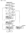
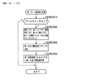
図5は、第1特別図柄プロセス処理として、図4に示すステップS25Aにて実行され
る処理の一例を示すフローチャートである。この第1特別図柄プロセス処理において、C
PU103は、まず、第1始動入賞判定処理を実行する(ステップS101A)。
FIG. 5 is a flowchart showing an example of the process executed in step S25A shown in FIG. 4 as the first special symbol process process. In this first special symbol process process, C
The
第1始動入賞判定処理では、第1始動入賞口への始動入賞の発生を検出し、RAM10
2の所定領域に保留情報を格納し第1保留記憶数を更新する処理が実行される。第1始動
入賞口への始動入賞が発生すると、表示結果(大当り種別を含む)や変動パターンを決定
するための乱数値が抽出され、保留情報としてRAM102に設けられた第1保留記憶バ
ッファに記憶される。また、抽出した乱数値に基づいて、表示結果や変動パターンを先読
み判定する処理が実行されてもよい。保留情報や第1保留記憶数を記憶した後には、演出
制御基板12に始動入賞の発生、第1保留記憶数、先読み判定等の判定結果を指定するた
めの演出制御コマンドを送信するための送信設定が行われる。こうして送信設定された始
動入賞時の演出制御コマンドは、例えば第1特別図柄プロセス処理が終了した後、図4に
示すステップS27のコマンド制御処理が実行されることなどにより、主基板11から演
出制御基板12に対して伝送される。
In the first start winning determination process, the occurrence of a start winning in the first starting winning opening is detected, and the
The process of storing the hold information in the predetermined area of 2 and updating the first hold storage number is executed. When a start prize is generated in the first start prize opening, a random value for determining a display result (including a jackpot type) and a fluctuation pattern is extracted and stored as hold information in the first hold storage buffer provided in the
S101にて第1始動入賞判定処理を実行した後、CPU103は、RAM102に設
けられた第1特図プロセスフラグの値に応じて、ステップS110A〜S113Aの処理
のいずれかを選択して実行する。なお、第1特別図柄プロセス処理の各処理(ステップS
110A〜S113A)では、各処理に対応した演出制御コマンドを演出制御基板12に
送信するための送信設定が行われる。
After executing the first start winning determination process in S101, the
In 110A to S113A), a transmission setting for transmitting an effect control command corresponding to each process to the
ステップS110Aの第1特別図柄通常処理は、第1特図プロセスフラグの値が“0”
(初期値)のときに実行される。この第1特別図柄通常処理では、保留情報の有無などに
基づいて、第1特図ゲームを開始するか否かの判定が行われる。また、第1特別図柄通常
処理では、表示結果決定用の乱数値に基づき、第1特別図柄や飾り図柄の表示結果を「大
当り」または「小当り」とするか否かや「大当り」とする場合の大当り種別を、その表示
結果が導出表示される以前に決定(事前決定)する。さらに、第1特別図柄通常処理では
、決定された表示結果に対応して、第1特図ゲームにおいて停止表示させる確定特別図柄
(大当り図柄や小当り図柄、ハズレ図柄のいずれか)が設定される。その後、第1特図プ
ロセスフラグの値が“1”に更新され、第1特別図柄通常処理は終了する。
In the first special symbol normal processing in step S110A, the value of the first special symbol process flag is "0".
It is executed when (initial value). In this first special symbol normal processing, it is determined whether or not to start the first special symbol game based on the presence or absence of reserved information and the like. Further, in the first special symbol normal processing, whether or not the display result of the first special symbol or the decorative symbol is set as "big hit" or "small hit" or "big hit" is set based on the random value for determining the display result. The jackpot type of the case is determined (predetermined) before the display result is derived and displayed. Further, in the first special symbol normal processing, a definite special symbol (either a big hit symbol, a small hit symbol, or a lost symbol) to be stopped and displayed in the first special symbol game is set according to the determined display result. .. After that, the value of the first special symbol process flag is updated to "1", and the first special symbol normal processing ends.
乱数値に基づき各種の決定を行う場合には、ROM101に格納されている各種のテー
ブル(乱数値と比較される決定値が決定結果に割り当てられているテーブル)が参照され
る。主基板11における他の決定、演出制御基板12における各種の決定についても同じ
である。演出制御基板12においては、各種のテーブルがROM121に格納されている
。
When making various determinations based on the random number value, various tables stored in the ROM 101 (a table in which the determination value to be compared with the random number value is assigned to the determination result) are referred to. The same applies to other decisions on the
ステップS111Aの第1変動パターン設定処理は、第1特図プロセスフラグの値が“
1”のときに実行される。この第1変動パターン設定処理には、表示結果を「大当り」ま
たは「小当り」とするか否かの事前決定結果等に基づき、変動パターン決定用の乱数値を
用いて変動パターンを複数種類のいずれかに決定する処理などが含まれている。第1変動
パターン設定処理では、変動パターンを決定したときに、第1特図プロセスフラグの値が
“2”に更新され、第1変動パターン設定処理は終了する。
In the first variation pattern setting process of step S111A, the value of the first special figure process flag is ".
It is executed when "1". In this first fluctuation pattern setting process, a random number value for determining the fluctuation pattern is determined based on a preliminary determination result of whether or not the display result is "big hit" or "small hit". It includes a process of determining one of a plurality of types of fluctuation patterns using. In the first variation pattern setting process, when the variation pattern is determined, the value of the first special figure process flag is updated to "2", and the first variation pattern setting process ends.
変動パターンは、特図ゲームの実行時間(特図変動時間)(飾り図柄の可変表示の実行
時間でもある)や、飾り図柄の可変表示の態様(リーチの有無等)、飾り図柄の可変表示
中の演出内容(リーチ演出の種類等)を指定するものであり、可変表示パターンとも呼ば
れる。
The fluctuation pattern includes the execution time of the special symbol game (special symbol fluctuation time) (which is also the execution time of the variable display of the decorative symbol), the mode of the variable display of the decorative symbol (presence or absence of reach, etc.), and the variable display of the decorative symbol. It specifies the content of the effect (type of reach effect, etc.), and is also called a variable display pattern.
ステップS112Aの第1特別図柄変動処理は、第1特図プロセスフラグの値が“2”
のときに実行される。この第1特別図柄変動処理には、第1特別図柄表示装置4Aにおい
て第1特別図柄を変動させるための設定を行う処理や、その第1特別図柄が変動を開始し
てからの経過時間を計測する処理などが含まれている。また、計測された経過時間が変動
パターンに対応する特図変動時間に達したか否かの判定も行われる。そして、第1特別図
柄の変動を開始してからの経過時間が特図変動時間に達したときには、第1特図プロセス
フラグの値が“3”に更新され、第1特別図柄変動処理は終了する。
In the first special symbol variation process in step S112A, the value of the first special symbol process flag is "2".
Is executed when. In this first special symbol variation process, the process of setting the first special symbol to be varied in the first special
なお、本例では、第1特別図柄の変動表示と第2特別図柄の変動表示とは並行して実行
可能であるので、例えば、第1特別図柄変動処理(ステップS112A)に移行して第1
特別図柄の変動表示中であるときに、第2特別図柄の変動表示において小当りとなり小当
り遊技に制御される場合がある。この場合、遊技制御用マイクロコンピュータ100(具
体的には、CPU103)は、小当り遊技中であるか否かを判定し(具体的には、第2特
図プロセスフラグの値が小当り開放前処理〜小当り終了処理に相当する値であるか否かを
判定し)、小当り遊技中であれば、第1特図プロセスフラグの値を第1特別図柄変動処理
に相当する値から変更しないようにし、小当り遊技中でなければ、第1特図プロセスフラ
グの値を次の第1特別図柄停止処理に相当する値に更新可能としている。そのような制御
を行うことにより、第2特別図柄の変動表示にもとづく小当り遊技中では第1特別図柄の
変動表示を中断し、その小当り遊技の終了後に第1特別図柄の変動表示を再開するように
制御している。なお、そのような制御にかぎらず、例えば、第2特別図柄の変動表示にも
とづく小当り遊技中は、第1特別図柄が変動を開始してからの経過時間を計測する処理を
中断(タイマの更新を中断)するように構成してもよい。
In this example, since the variation display of the first special symbol and the variation display of the second special symbol can be executed in parallel, for example, the first special symbol variation process (step S112A) is performed.
When the variation display of the special symbol is in progress, the variation display of the second special symbol may result in a small hit and be controlled by the small hit game. In this case, the game control microcomputer 100 (specifically, CPU 103) determines whether or not the small hit game is in progress (specifically, the value of the second special figure process flag is before the small hit is released. (Determine whether or not the value corresponds to the processing to the small hit end processing), and if the small hit game is in progress, the value of the first special figure process flag is not changed from the value corresponding to the first special symbol variation processing. As a result, the value of the first special symbol process flag can be updated to a value corresponding to the next first special symbol stop process unless the small hit game is in progress. By performing such control, the variation display of the first special symbol is interrupted during the small hit game based on the variation display of the second special symbol, and the variation display of the first special symbol is restarted after the end of the small hit game. It is controlled to do. Not limited to such control, for example, during the small hit game based on the fluctuation display of the second special symbol, the process of measuring the elapsed time from the start of the fluctuation of the first special symbol is interrupted (timer). It may be configured to suspend the update).
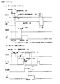
また、例えば、小当り終了処理期間としての小当りエンディング期間を遊技状態によっ
て異ならせるように構成してもよい。例えば、通常状態において、第1特別図柄の変動表
示を中断するように構成すると、第1特別図柄の変動表示の中断期間が長くなり、第1特
別図柄の変動表示の実行期間と中断期間との差が大きくなると飾り図柄の揺れ停止などに
より中断期間を吸収する必要があり、遊技者に違和感を与える演出になってしまう。その
ため、通常状態では、小当りエンディング期間をKT状態(第1KT状態、第2KT状態
)よりも短くすることが望ましい。この場合、例えば、通常状態では小当りエンディング
期間が0.5秒であるのに対して、KT状態では小当りエンディング期間が3秒であるよ
うに構成してもよい。
Further, for example, the small hit ending period as the small hit end processing period may be configured to be different depending on the game state. For example, in the normal state, if the variation display of the first special symbol is configured to be interrupted, the interruption period of the variation display of the first special symbol becomes long, and the execution period and the interruption period of the variation display of the first special symbol become longer. If the difference becomes large, it is necessary to absorb the interruption period by stopping the shaking of the decorative pattern, which gives the player a sense of discomfort. Therefore, in the normal state, it is desirable to make the small hit ending period shorter than the KT state (first KT state, second KT state). In this case, for example, the small hit ending period may be 0.5 seconds in the normal state, whereas the small hit ending period may be 3 seconds in the KT state.
また、上記のように構成する場合、例えば、第1KT状態では、小当り制御において実
質的に遊技球が入賞困難であり特に演出を行わないので、第2KT状態に比べて小当りエ
ンディング期間を短くするように構成してもよい。一方、第2KT状態では、小当り制御
において遊技球が入賞容易であり小当り制御を強調する演出を実行するので、第1KT状
態に比べて小当りエンディング期間を長くするように構成してもよい。この場合、例えば
、第1KT状態では小当りエンディング期間が0.5秒であるのに対して、第2KT状態
では小当りエンディング期間が3秒であるように構成してもよい。
Further, in the case of the above configuration, for example, in the first KT state, it is practically difficult for the game ball to win a prize in the small hit control, and no particular effect is performed. Therefore, the small hit ending period is shorter than in the second KT state. It may be configured to do so. On the other hand, in the second KT state, since the game ball is easy to win in the small hit control and the effect of emphasizing the small hit control is executed, the small hit ending period may be longer than in the first KT state. .. In this case, for example, the small hit ending period may be 0.5 seconds in the first KT state, whereas the small hit ending period may be 3 seconds in the second KT state.
さらに、小当り開放前処理期間としての小当りファンファーレ期間についても、上記の
小当りエンディング期間と同様に、遊技状態によって期間の長さを異ならせてもよい。
Further, as for the small hit fanfare period as the small hit opening pretreatment period, the length of the period may be different depending on the game state, as in the above-mentioned small hit ending period.
ステップS113Aの第1特別図柄停止処理は、第1特図プロセスフラグの値が“3”
のときに実行される。この第1特別図柄停止処理には、第1特別図柄表示装置4Aにて第
1特別図柄の変動を停止させ、第1特別図柄の表示結果となる確定特別図柄を停止表示(
導出)させるための設定を行う処理が含まれている。そして、表示結果が「大当り」であ
る場合には、大当り遊技を開始するための設定処理が行われる。その一方で、大当りフラ
グがオフであり、表示結果が「小当り」である場合には、小当り遊技を開始するための処
理が行われる。そして、第1特図プロセスフラグの値が“0”に更新される。表示結果が
「小当り」又は「ハズレ」である場合、確変状態やKT状態、高ベース状態に制御されて
いるときであって、回数切りの終了成立する場合には、遊技状態も更新される。第1特図
プロセスフラグの値が更新されると、第1特別図柄停止処理は終了する。
In the first special symbol stop process of step S113A, the value of the first special symbol process flag is "3".
Is executed when. In this first special symbol stop process, the first special
It includes a process to make settings for (deriving). Then, when the display result is "big hit", the setting process for starting the big hit game is performed. On the other hand, when the big hit flag is off and the display result is "small hit", a process for starting the small hit game is performed. Then, the value of the first special figure process flag is updated to "0". When the display result is "small hit" or "loss", the game state is also updated when the probability change state, the KT state, or the high base state is controlled and the end of the number of cuts is established. .. When the value of the first special symbol process flag is updated, the first special symbol stop process ends.
なお、第2特別図柄プロセス処理(ステップS25B)において実行される処理は、第
1特別図柄プロセス処理(ステップS25A)において実行される処理と同様である。す
なわち、図5で説明した第1特別図柄プロセス処理において、「第1」を「第2」と読み
替えれば、第2特別図柄プロセス処理が説明されることになる。また、第2特別図柄プロ
セス処理(ステップS25B)の第1始動入賞判定処理で抽出された各乱数値は、保留情
報としてRAM102に設けられた第2保留記憶バッファに記憶される。
The process executed in the second special symbol process process (step S25B) is the same as the process executed in the first special symbol process process (step S25A). That is, in the first special symbol process process described with reference to FIG. 5, if "first" is read as "second", the second special symbol process process will be explained. Further, each random number value extracted in the first start winning determination process of the second special symbol process process (step S25B) is stored in the second hold storage buffer provided in the
なお、本例では、第1特別図柄の変動表示と第2特別図柄の変動表示とは並行して実行
可能であるので、例えば、第2特別図柄変動処理に移行して第2特別図柄の変動表示中で
あるときに、第1特別図柄の変動表示において小当りとなり小当り遊技に制御される場合
もある。この場合、遊技制御用マイクロコンピュータ100(具体的には、CPU103
)は、小当り遊技中であるか否かを判定し(具体的には、第1特図プロセスフラグの値が
小当り開放前処理〜小当り終了処理に相当する値であるか否かを判定し)、小当り遊技中
であれば、第2特図プロセスフラグの値を第2特別図柄変動処理に相当する値から変更し
ないようにし、小当り遊技中でなければ、第2特図プロセスフラグの値を次の第2特別図
柄停止処理に相当する値に更新可能としている。そのような制御を行うことにより、第1
特別図柄の変動表示にもとづく小当り遊技中では第2特別図柄の変動表示を中断し、その
小当り遊技の終了後に第2特別図柄の変動表示を再開するように制御している。なお、そ
のような制御にかぎらず、例えば、第1特別図柄の変動表示にもとづく小当り遊技中は、
第2特別図柄が変動を開始してからの経過時間を計測する処理を中断(タイマの更新を中
断)するように構成してもよい。
In this example, the variation display of the first special symbol and the variation display of the second special symbol can be executed in parallel. Therefore, for example, the transition to the second special symbol variation process is performed to change the second special symbol. When the display is in progress, a small hit may occur in the variable display of the first special symbol, and the game may be controlled by a small hit game. In this case, the game control microcomputer 100 (specifically, CPU 103).
) Determines whether or not the small hit game is in progress (specifically, whether or not the value of the first special figure process flag corresponds to the small hit opening pre-processing to the small hit end processing). Judgment), if the small hit game is in progress, the value of the second special figure process flag is not changed from the value corresponding to the second special symbol variation process, and if it is not in the small hit game, the second special figure process The value of the flag can be updated to a value corresponding to the next second special symbol stop process. By performing such control, the first
During the small hit game based on the variable display of the special symbol, the variable display of the second special symbol is interrupted, and the variable display of the second special symbol is restarted after the end of the small hit game. Not limited to such control, for example, during the small hit game based on the variable display of the first special symbol,
The process of measuring the elapsed time since the second special symbol starts to fluctuate may be interrupted (timer update is interrupted).
なお、第2特別図柄の変動表示にもとづく小当り制御に関しても、遊技状態によって小
当りファンファーレ期間や小当りエンディング期間の長さを異ならせるように構成しても
よい。
Regarding the small hit control based on the variation display of the second special symbol, the length of the small hit fanfare period and the small hit ending period may be different depending on the game state.
図6は、役物制御プロセス処理として、図4に示すステップS25Cにて実行される処
理の一例を示すフローチャートである。この役物制御プロセス処理において、CPU10
3は、RAM102に設けられた役物制御プロセスフラグの値に応じて、ステップS12
0〜S128の処理のいずれかを選択して実行する。なお、役物制御プロセス処理の各処
理(ステップS120〜S128)では、各処理に対応した演出制御コマンドを演出制御
基板12に送信するための送信設定が行われる。
FIG. 6 is a flowchart showing an example of the process executed in step S25C shown in FIG. 4 as the accessory control process process. In this accessory control process processing, the
In
One of the
ステップS120の役物制御通常処理は、役物制御プロセスフラグの値が“0”のとき
に実行される。この役物制御通常処理では、大当り遊技を開始するための設定が行われた
か否かを監視し、大当り遊技を開始するための設定が行われれば、大当り遊技を開始する
ための処理が行われ、役物制御プロセスフラグの値が“1”に更新される。
The bonus control normal process in step S120 is executed when the value of the bonus control process flag is “0”. In this bonus control normal process, it is monitored whether or not the setting for starting the big hit game is made, and if the setting for starting the big hit game is made, the process for starting the big hit game is performed. , The value of the accessory control process flag is updated to "1".
ステップS121のゲート通過待ち処理は、役物制御プロセスフラグの値が“1”のと
きに実行される。このゲート通過待ち処理では、通過ゲート41への遊技球の通過を待機
する制御を行う。通過ゲート41への遊技球の通過を検知したときには役物制御プロセス
フラグの値が“2”に更新される。
The gate passage waiting process in step S121 is executed when the value of the accessory control process flag is “1”. In this gate passage waiting process, control is performed to wait for the game ball to pass through the passing
ステップS122の大当り開放前処理は、役物制御プロセスフラグが“2”のときに実
行される。この大当り開放前処理には、表示結果が「大当り」となったことなどに基づき
、大当り遊技状態においてラウンドの実行を開始して大入賞口を開放状態とするための設
定を行う処理などが含まれている。大入賞口を開放状態とするときには、大入賞口扉用の
ソレノイド82に対してソレノイド駆動信号を供給する処理が実行される。このときには
、例えば大当り種別がいずれであるかに対応して、大入賞口を開放状態とする開放上限期
間や、ラウンドの上限実行回数を設定する。これらの設定が終了すると、役物制御プロセ
スフラグの値が“3”に更新され、大当り開放前処理は終了する。
The jackpot release preprocessing in step S122 is executed when the accessory control process flag is “2”. This big hit pre-opening process includes a process of setting to start the execution of the round in the big hit game state and open the big winning opening based on the display result being "big hit". It has been. When the large winning opening is opened, a process of supplying a solenoid drive signal to the
ステップS123の大当り開放中処理は、役物制御プロセスフラグの値が“3”のとき
に実行される。この大当り開放中処理には、大入賞口を開放状態としてからの経過時間を
計測する処理や、その計測した経過時間や第1カウントスイッチ23によって検出された
遊技球の個数などに基づいて、大入賞口を開放状態から閉鎖状態に戻すタイミングとなっ
たか否かを判定する処理などが含まれている。そして、大入賞口を閉鎖状態に戻すときに
は、大入賞口扉用のソレノイド82に対するソレノイド駆動信号の供給を停止させる処理
などを実行した後、役物制御プロセスフラグの値が“4”に更新し、大当り開放中処理を
終了する。
The process of opening the jackpot in step S123 is executed when the value of the accessory control process flag is “3”. This big hit opening process is based on the process of measuring the elapsed time since the big winning opening is opened, the measured elapsed time, the number of game balls detected by the
ステップS124の大当り開放後処理は、役物制御プロセスフラグの値が“4”のとき
に実行される。この大当り開放後処理には、大入賞口を開放状態とするラウンドの実行回
数が設定された上限実行回数に達したか否かを判定する処理や、上限実行回数に達した場
合に大当り遊技状態を終了させるための設定を行う処理などが含まれている。そして、ラ
ウンドの実行回数が上限実行回数に達していないときには、役物制御プロセスフラグの値
が“3”に更新される一方、ラウンドの実行回数が上限実行回数に達したときには、役物
制御プロセスフラグの値が“5”に更新される。役物制御プロセスフラグの値が更新され
ると、大当り開放後処理は終了する。
The jackpot release post-processing in step S124 is executed when the value of the accessory control process flag is “4”. In this post-opening process of the jackpot, a process of determining whether or not the number of executions of the round that opens the jackpot has reached the set maximum number of executions, and a jackpot game state when the maximum number of executions is reached. It includes processing to make settings to terminate. Then, when the number of round executions has not reached the upper limit execution number, the value of the accessory control process flag is updated to "3", while when the number of round executions reaches the upper limit execution number, the accessory control process The value of the flag is updated to "5". When the value of the accessory control process flag is updated, the post-processing after opening the jackpot ends.
ステップS125の大当り終了処理は、役物制御プロセスフラグの値が“5”のときに
実行される。この大当り終了処理には、大当り遊技状態の終了を報知する演出動作として
のエンディング演出が実行される期間に対応した待ち時間が経過するまで待機する処理や
、大当り遊技状態の終了に対応して確変制御やKT制御、高ベース制御を開始するための
各種の設定を行う処理などが含まれている。こうした設定が行われたときには、役物制御
プロセスフラグの値が“0”に更新され、大当り終了処理は終了する。
The jackpot end processing in step S125 is executed when the value of the accessory control process flag is “5”. In this jackpot end process, there is a process of waiting until the waiting time corresponding to the period in which the ending effect as an effect action for notifying the end of the jackpot game state is executed, and a probability change corresponding to the end of the jackpot game state. It includes processing for performing various settings for starting control, KT control, and high-base control. When such a setting is made, the value of the accessory control process flag is updated to "0", and the jackpot end process ends.
ステップS126の小当り開放前処理は、役物制御プロセスフラグの値が“6”のとき
に実行される。この小当り開放前処理には、表示結果が「小当り」となったことに基づき
、小当り遊技状態において特殊入賞口を開放状態とするための設定を行う処理などが含ま
れている。このときには、役物制御プロセスフラグの値が“7”に更新され、小当り開放
前処理は終了する。
The small hit release preprocessing in step S126 is executed when the value of the accessory control process flag is “6”. This pre-opening process for small hits includes a process for setting the special winning opening to be open in the small hit game state based on the display result being "small hit". At this time, the value of the accessory control process flag is updated to "7", and the small hit release preprocessing ends.
ステップS127の小当り開放中処理は、役物制御プロセスフラグの値が“7”のとき
に実行される。この小当り開放中処理には、特殊入賞口を開放状態としてからの経過時間
を計測する処理や、その計測した経過時間などに基づいて、特殊入賞口を開放状態から閉
鎖状態に戻すタイミングとなったか否かを判定する処理などが含まれている。特殊入賞口
を閉鎖状態に戻して小当り遊技状態の終了タイミングとなったときには、役物制御プロセ
スフラグの値が“8”に更新され、小当り開放中処理は終了する。
The small hit opening process in step S127 is executed when the value of the accessory control process flag is “7”. In this small hit opening process, it is the timing to return the special winning opening from the open state to the closed state based on the process of measuring the elapsed time since the special winning opening is opened and the measured elapsed time. It includes processing to determine whether or not it is. When the special winning opening is returned to the closed state and the end timing of the small hit game state is reached, the value of the accessory control process flag is updated to "8", and the small hit opening process ends.
ステップS128の小当り終了処理は、役物制御プロセスフラグの値が“8”のときに
実行される。この小当り終了処理には、小当り遊技状態の終了を報知する演出動作が実行
される期間に対応した待ち時間が経過するまで待機する処理などが含まれている。ここで
、小当り遊技状態が終了するときには、小当り遊技状態となる以前のパチンコ遊技機1に
おける遊技状態を継続させる。小当り遊技状態の終了時における待ち時間が経過したとき
には、役物制御プロセスフラグの値が“0”に更新され、小当り終了処理は終了する。
The small hit end process in step S128 is executed when the value of the accessory control process flag is “8”. The small hit end process includes a process of waiting until a waiting time corresponding to a period in which the effect operation for notifying the end of the small hit game state is executed has elapsed. Here, when the small hit gaming state ends, the gaming state in the
(演出制御基板12の主要な動作)
次に、演出制御基板12における主要な動作を説明する。演出制御基板12では、電源
基板等から電源電圧の供給を受けると、演出制御用CPU120が起動して、図7のフロ
ーチャートに示すような演出制御メイン処理を実行する。図7に示す演出制御メイン処理
を開始すると、演出制御用CPU120は、まず、所定の初期化処理を実行して(ステッ
プS71)、RAM122のクリアや各種初期値の設定、また演出制御基板12に搭載さ
れたCTC(カウンタ/タイマ回路)のレジスタ設定等を行う。また、初期動作制御処理
を実行する(ステップS72)。初期動作制御処理では、可動体32を駆動して初期位置
に戻す制御、所定の動作確認を行う制御といった可動体32の初期動作を行う制御が実行
される。
(Main operation of the effect control board 12)
Next, the main operation of the
その後、タイマ割込みフラグがオンとなっているか否かの判定を行う(ステップS73
)。タイマ割込みフラグは、例えばCTCのレジスタ設定に基づき、所定時間(例えば2
ミリ秒)が経過するごとにオン状態にセットされる。このとき、タイマ割込みフラグがオ
フであれば(ステップS73;No)、ステップS73の処理を繰り返し実行して待機す
る。
After that, it is determined whether or not the timer interrupt flag is turned on (step S73).
). The timer interrupt flag is set for a predetermined time (for example, 2) based on the CTC register setting, for example.
It is set to the on state every time (milliseconds) elapses. At this time, if the timer interrupt flag is off (step S73; No), the process of step S73 is repeatedly executed and waits.
また、演出制御基板12の側では、所定時間が経過するごとに発生するタイマ割込みと
は別に、主基板11からの演出制御コマンドを受信するための割込みが発生する。この割
込みは、例えば主基板11からの演出制御INT信号がオン状態となることにより発生す
る割込みである。演出制御INT信号がオン状態となることによる割込みが発生すると、
演出制御用CPU120は、自動的に割込み禁止に設定するが、自動的に割込み禁止状態
にならないCPUを用いている場合には、割込み禁止命令(DI命令)を発行することが
望ましい。演出制御用CPU120は、演出制御INT信号がオン状態となることによる
割込みに対応して、例えば所定のコマンド受信割込み処理を実行する。このコマンド受信
割込み処理では、I/O125に含まれる入力ポートのうちで、中継基板15を介して主
基板11から送信された制御信号を受信する所定の入力ポートより、演出制御コマンドを
取り込む。このとき取り込まれた演出制御コマンドは、例えばRAM122に設けられた
演出制御コマンド受信用バッファに格納する。その後、演出制御用CPU120は、割込
み許可に設定してから、コマンド受信割込み処理を終了する。
Further, on the
The
ステップS73にてタイマ割込みフラグがオンである場合には(ステップS73;Ye
s)、タイマ割込みフラグをクリアしてオフ状態にするとともに(ステップS74)、コ
マンド解析処理を実行する(ステップS75)。コマンド解析処理では、例えば主基板1
1の遊技制御用マイクロコンピュータ100から送信されて演出制御コマンド受信用バッ
ファに格納されている各種の演出制御コマンドを読み出した後に、その読み出された演出
制御コマンドに対応した設定や制御などが行われる。例えば、どの演出制御コマンドを受
信したかや演出制御コマンドが特定する内容等を演出制御プロセス処理等で確認できるよ
うに、読み出された演出制御コマンドをRAM122の所定領域に格納したり、RAM1
22に設けられた受信フラグをオンしたりする。また、演出制御コマンドが遊技状態を特
定する場合、遊技状態に応じた背景の表示を表示制御部123に指示してもよい。
If the timer interrupt flag is turned on in step S73 (step S73; Ye
s), the timer interrupt flag is cleared to turn it off (step S74), and the command analysis process is executed (step S75). In the command analysis process, for example, the
After reading various effect control commands transmitted from the
The reception flag provided in 22 is turned on. Further, when the effect control command specifies the game state, the
ステップS75にてコマンド解析処理を実行した後には、演出制御プロセス処理を実行
する(ステップS76)。演出制御プロセス処理では、例えば画像表示装置5の表示領域
における演出画像の表示動作、スピーカ8L、8Rからの音声出力動作、枠LED9及び
装飾用LEDといった装飾発光体における点灯動作、可動体32の駆動動作といった、各
種の演出装置を動作させる制御が行われる。また、各種の演出装置を用いた演出動作の制
御内容について、主基板11から送信された演出制御コマンド等に応じた判定や決定、設
定などが行われる。
After executing the command analysis process in step S75, the effect control process process is executed (step S76). In the effect control process processing, for example, the effect image display operation in the display area of the
ステップS76の演出制御プロセス処理に続いて、演出用乱数更新処理が実行され(ス
テップS77)、演出制御基板12の側で用いられる演出用乱数の少なくとも一部がソフ
トウェアにより更新される。その後、ステップS73の処理に戻る。ステップS73の処
理に戻る前に、他の処理が実行されてもよい。
Following the effect control process process in step S76, the effect random number update process is executed (step S77), and at least a part of the effect random numbers used on the
図8は、演出制御プロセス処理として、図7のステップS76にて実行される処理の一
例を示すフローチャートである。図8に示す演出制御プロセス処理において、演出制御用
CPU120は、まず、先読予告設定処理を実行する(ステップS161)。先読予告設
定処理では、例えば、主基板11から送信された始動入賞時の演出制御コマンドに基づい
て、先読み予告演出を実行するための判定や決定、設定などが行われる。また、当該演出
制御コマンドから特定される保留記憶数に基づき保留表示を表示するための処理が実行さ
れる。
FIG. 8 is a flowchart showing an example of the process executed in step S76 of FIG. 7 as the effect control process process. In the effect control process process shown in FIG. 8, the
ステップS161の処理を実行した後、演出制御用CPU120は、例えばRAM12
2に設けられた演出プロセスフラグの値に応じて、以下のようなステップS170〜S1
77の処理のいずれかを選択して実行する。
After executing the process of step S161, the
Depending on the value of the effect process flag provided in 2, the following steps S170 to S1
One of the 77 processes is selected and executed.
ステップS170の可変表示開始待ち処理は、演出プロセスフラグの値が“0”(初期
値)のときに実行される処理である。この可変表示開始待ち処理は、主基板11から可変
表示の開始を指定するコマンドなどを受信したか否かに基づき、画像表示装置5における
飾り図柄の可変表示を開始するか否かを判定する処理などを含んでいる。画像表示装置5
における飾り図柄の可変表示を開始すると判定された場合、演出プロセスフラグの値を“
1”に更新し、可変表示開始待ち処理を終了する。
The variable display start waiting process in step S170 is a process executed when the value of the effect process flag is “0” (initial value). This variable display start waiting process is a process of determining whether or not to start the variable display of the decorative symbol on the
If it is determined that the variable display of the decorative pattern in is started, the value of the effect process flag is set to ".
Update to 1 ”and end the variable display start waiting process.
ステップS171の可変表示開始設定処理は、演出プロセスフラグの値が“1”のとき
に実行される処理である。この可変表示開始設定処理では、演出制御コマンドにより特定
される表示結果や変動パターンに基づいて、飾り図柄の可変表示の表示結果(確定飾り図
柄)、飾り図柄の可変表示の態様、リーチ演出や各種予告演出などの各種演出の実行の有
無やその態様や実行開始タイミングなどを決定する。そして、その決定結果等を反映した
演出制御パターン(表示制御部123に演出の実行を指示するための制御データの集まり
)を設定する。その後、設定した演出制御パターンに基づいて、飾り図柄の可変表示の実
行開始を表示制御部123に指示し、演出プロセスフラグの値を“2”に更新し、可変表
示開始設定処理を終了する。表示制御部123は、飾り図柄の可変表示の実行開始の指示
により、画像表示装置5において、飾り図柄の可変表示を開始させる。
The variable display start setting process in step S171 is a process executed when the value of the effect process flag is “1”. In this variable display start setting process, the display result of the variable display of the decorative symbol (fixed decorative symbol), the mode of the variable display of the decorative symbol, the reach effect, and various types are based on the display result and the variation pattern specified by the effect control command. It is determined whether or not various effects such as a notice effect are executed, their modes, and the execution start timing. Then, an effect control pattern (a collection of control data for instructing the
ステップS172の可変表示中演出処理は、演出プロセスフラグの値が“2”のときに
実行される処理である。この可変表示中演出処理において、演出制御用CPU120は、
表示制御部123を指示することで、ステップS171にて設定された演出制御パターン
に基づく演出画像を画像表示装置5の表示画面に表示させることや、可動体32を駆動さ
せること、音声制御基板13に対する指令(効果音信号)の出力によりスピーカ8L、8
Rから音声や効果音を出力させること、LED制御基板14に対する指令(電飾信号)の
出力により枠LED9や装飾用LEDを点灯/消灯/点滅させることといった、飾り図柄
の可変表示中における各種の演出制御を実行する。こうした演出制御を行った後、例えば
演出制御パターンから飾り図柄の可変表示終了を示す終了コードが読み出されたこと、あ
るいは、主基板11から確定飾り図柄を停止表示させることを指定するコマンドを受信し
たことなどに対応して、飾り図柄の表示結果となる確定飾り図柄を停止表示させる。確定
飾り図柄を停止表示したときには、演出プロセスフラグの値が“3”に更新され、可変表
示中演出処理は終了する。
The variable display effect process in step S172 is a process executed when the value of the effect process flag is “2”. In this variable display effect processing, the
By instructing the
Various types of decorative symbols are displayed during variable display, such as outputting voice and sound effects from R, and turning on / off / blinking the
ステップS173の特図当り待ち処理は、演出プロセスフラグの値が“3”のときに実
行される処理である。この特図当り待ち処理において、演出制御用CPU120は、主基
板11から大当り遊技状態又は小当り遊技状態を開始することを指定する演出制御コマン
ドの受信があったか否かを判定する。そして、大当り遊技状態又は小当り遊技状態を開始
することを指定する演出制御コマンドを受信したきに、そのコマンドが大当り遊技状態の
開始を指定するものであれば、演出プロセスフラグの値を“6”に更新する。これに対し
て、そのコマンドが小当り遊技状態の開始を指定するものであれば、演出プロセスフラグ
の値を小当り中演出処理に対応した値である“4”に更新する。また、大当り遊技状態又
は小当り遊技状態を開始することを指定するコマンドを受信せずに、当該コマンドの受信
待ち時間が経過したときには、特図ゲームにおける表示結果が「ハズレ」であったと判定
して、演出プロセスフラグの値を初期値である“0”に更新する。演出プロセスフラグの
値を更新すると、特図当り待ち処理を終了する。
The special figure hit waiting process in step S173 is a process executed when the value of the effect process flag is “3”. In this special figure hit waiting process, the
ステップS174の小当り中演出処理は、演出制御プロセスフラグの値が“4”のとき
に実行される処理である。この小当り中演出処理において、演出制御用CPU120は、
例えば小当り遊技状態における演出内容に対応した演出制御パターン等を設定し、その設
定内容に基づく小当り遊技状態における各種の演出制御を実行する。また、小当り中演出
処理では、例えば主基板11から小当り遊技状態を終了することを指定するコマンドを受
信したことに対応して、演出プロセスフラグの値を小当り終了演出に対応した値である“
5”に更新し、小当り中演出処理を終了する。
The small hit medium effect process in step S174 is a process executed when the value of the effect control process flag is “4”. In this small hit medium effect process, the
For example, an effect control pattern or the like corresponding to the effect content in the small hit game state is set, and various effect controls in the small hit game state are executed based on the set content. Further, in the small hit middle effect processing, for example, in response to receiving a command from the
Update to 5 ”and end the small hit medium production process.
ステップS175の小当り終了演出処理は、演出制御プロセスフラグの値が“5”のと
きに実行される処理である。この小当り終了演出処理において、演出制御用CPU120
は、例えば小当り遊技状態の終了などに対応した演出制御パターン等を設定し、その設定
内容に基づく小当り遊技状態の終了時における各種の演出制御を実行する。その後、演出
プロセスフラグの値を初期値である“0”に更新し、小当り終了演出処理を終了する。
The small hit end effect process in step S175 is a process executed when the value of the effect control process flag is “5”. In this small hit end effect process, the
Sets, for example, an effect control pattern or the like corresponding to the end of the small hit game state, and executes various effect controls at the end of the small hit game state based on the set contents. After that, the value of the effect process flag is updated to the initial value "0", and the small hit end effect process is terminated.
ステップS176の大当り中演出処理は、演出プロセスフラグの値が“6”のときに実
行される処理である。この大当り中演出処理において、演出制御用CPU120は、例え
ば大当り遊技状態における演出内容に対応した演出制御パターン等を設定し、その設定内
容に基づく大当り遊技状態における各種の演出制御を実行する。また、大当り中演出処理
では、例えば主基板11から大当り遊技状態を終了することを指定するコマンドを受信し
たことに対応して、演出制御プロセスフラグの値をエンディング演出処理に対応した値で
ある“7”に更新し、大当り中演出処理を終了する。
The jackpot effect process in step S176 is a process executed when the value of the effect process flag is “6”. In this big hit middle effect processing, the
ステップS177のエンディング演出処理は、演出プロセスフラグの値が“7”のとき
に実行される処理である。このエンディング演出処理において、演出制御用CPU120
は、例えば大当り遊技状態の終了などに対応した演出制御パターン等を設定し、その設定
内容に基づく大当り遊技状態の終了時におけるエンディング演出の各種の演出制御を実行
する。その後、演出プロセスフラグの値を初期値である“0”に更新し、エンディング演
出処理を終了する。
The ending effect process of step S177 is a process executed when the value of the effect process flag is “7”. In this ending effect processing, the
Sets, for example, an effect control pattern or the like corresponding to the end of the jackpot game state, and executes various effect controls of the ending effect at the end of the jackpot game state based on the set contents. After that, the value of the effect process flag is updated to the initial value "0", and the ending effect process ends.
(基本説明の変形例)
この発明は、上記基本説明で説明したパチンコ遊技機1に限定されず、本発明の趣旨を
逸脱しない範囲で、様々な変形及び応用が可能である。
(Modified example of basic explanation)
The present invention is not limited to the
上記基本説明のパチンコ遊技機1は、入賞の発生に基づいて所定数の遊技媒体を景品と
して払い出す払出式遊技機であったが、遊技媒体を封入し入賞の発生に基づいて得点を付
与する封入式遊技機であってもよい。
The
特別図柄の可変表示中に表示されるものは1種類の図柄(例えば、「−」を示す記号)
だけで、当該図柄の表示と消灯とを繰り返すことによって可変表示を行うようにしてもよ
い。さらに可変表示中に当該図柄が表示されるものも、可変表示の停止時には、当該図柄
が表示されなくてもよい(表示結果としては「−」を示す記号が表示されなくてもよい)
。
What is displayed during the variable display of a special symbol is one type of symbol (for example, a symbol indicating "-").
However, the variable display may be performed by repeating the display and extinguishing of the symbol. Further, even if the symbol is displayed during the variable display, the symbol may not be displayed when the variable display is stopped (the symbol indicating "-" may not be displayed as the display result).
..
上記基本説明では、遊技機としてパチンコ遊技機1を示したが、メダルが投入されて所
定の賭け数が設定され、遊技者による操作レバーの操作に応じて複数種類の図柄を回転さ
せ、遊技者によるストップボタンの操作に応じて図柄を停止させたときに停止図柄の組合
せが特定の図柄の組み合わせになると、所定数のメダルが遊技者に払い出されるゲームを
実行可能なスロット機(例えば、ビッグボーナス、レギュラーボーナス、RT、AT、A
RT、CZ(以下、ボーナス等)のうち1以上を搭載するスロット機)にも本発明を適用
可能である。
In the above basic explanation, the
The present invention can also be applied to a slot machine equipped with one or more of RT and CZ (hereinafter, bonus, etc.).
本発明を実現するためのプログラム及びデータは、パチンコ遊技機1に含まれるコンピ
ュータ装置などに対して、着脱自在の記録媒体により配布・提供される形態に限定される
ものではなく、予めコンピュータ装置などの有する記憶装置にインストールしておくこと
で配布される形態を採っても構わない。さらに、本発明を実現するためのプログラム及び
データは、通信処理部を設けておくことにより、通信回線等を介して接続されたネットワ
ーク上の、他の機器からダウンロードすることによって配布する形態を採っても構わない
。
The program and data for realizing the present invention are not limited to the form of being distributed and provided by the detachable recording medium to the computer device included in the
そして、ゲームの実行形態も、着脱自在の記録媒体を装着することにより実行するもの
だけではなく、通信回線等を介してダウンロードしたプログラム及びデータを、内部メモ
リ等に一旦格納することにより実行可能とする形態、通信回線等を介して接続されたネッ
トワーク上における、他の機器側のハードウェア資源を用いて直接実行する形態としても
よい。さらには、他のコンピュータ装置等とネットワークを介してデータの交換を行うこ
とによりゲームを実行するような形態とすることもできる。
The game can be executed not only by attaching a detachable recording medium, but also by temporarily storing the programs and data downloaded via the communication line or the like in the internal memory or the like. It may be a form of direct execution using hardware resources on the other device side on a network connected via a communication line or the like. Further, the game can be executed by exchanging data with another computer device or the like via a network.
なお、本明細書において、演出の実行割合などの各種割合の比較の表現(「高い」、「
低い」、「異ならせる」などの表現)は、一方が「0%」の割合であることを含んでもよ
い。例えば、一方が「0%」の割合で、他方が「100%」の割合又は「100%」未満
の割合であることも含む。
In addition, in this specification, the expression ("high", "high", "high", "high", "high"
Expressions such as "low" and "differentiate") may include that one is in the proportion of "0%". For example, one may have a proportion of "0%" and the other may have a proportion of "100%" or less than "100%".
[特徴部21TMに関する説明]
次に、特徴部21TMに関して説明する。パチンコ遊技機1には、例えば図9−1に示
すような主基板11、演出制御基板12、ターミナル基板(情報出力基板)21TM01
6といった、各種の制御基板が搭載されている。また、パチンコ遊技機1には、主基板1
1と演出制御基板12との間で伝送される各種の制御信号を中継するための中継基板15
なども搭載されている。その他にも、パチンコ遊技機1における遊技盤2などの背面には
、例えば払出制御基板、発射制御基板、インタフェース基板などといった、各種の基板が
配置されている。
[Explanation of feature 21TM]
Next, the feature unit 21TM will be described. The
Various control boards such as No. 6 are mounted. Further, the
Etc. are also installed. In addition, various boards such as a payout control board, a launch control board, and an interface board are arranged on the back surface of the
なお、前述した図2に示すように、主基板11には、第1始動口スイッチ22A及び第
2始動口スイッチ22B、並びに、第1特別図柄表示装置4A及び第2特別図柄表示装置
4B等の各種部品が接続されており、演出制御基板12には、スピーカ8L、8R、枠L
ED9等の各種演出装置が接続されているが、図9−1では、これらを省略している。
As shown in FIG. 2 described above, the
Various production devices such as the ED9 are connected, but these are omitted in FIG. 9-1.
主基板11は、メイン側の制御基板であり、図9−3に示すように、基板ケース21T
M201に収納された状態でパチンコ遊技機1の背面に搭載され、パチンコ遊技機1にお
ける遊技の進行を制御するための各種回路が搭載されている。主基板11は、主として、
特図ゲームにおいて用いる乱数の設定機能、所定位置に配設されたスイッチ等からの信号
の入力を行う機能、演出制御基板12などからなるサブ側の制御基板に宛てて、指令情報
の一例となる制御コマンドを制御信号として出力して送信する機能、ホールの管理コンピ
ュータに対して各種情報を出力する機能などを備えている。また、主基板11は、第1特
別図柄表示装置4Aと第2特別図柄表示装置4Bを構成する各LED(例えばセグメント
LED)などの点灯/消灯制御を行って第1特図や第2特図の変動表示を制御することや
、普通図柄表示器20の点灯/消灯/発色制御などを行って普通図柄表示器20による普
通図柄の変動表示を制御することといった、所定の表示図柄の変動表示を制御する機能も
備えている。
The
It is mounted on the back surface of the
It is an example of command information addressed to a control board on the sub side consisting of a random number setting function used in a special figure game, a function of inputting a signal from a switch or the like arranged at a predetermined position, and an
また、主基板11には、図9−3に示すように、パチンコ遊技機1の背面側から視認可
能な表示モニタ21TM029が設けられており、該表示モニタ21TM029に、入賞
に関する各種の入賞情報を表示する機能も備えている。尚、表示モニタ21TM029の
左側方には表示切替スイッチ21TM030が設けられており、該表示切替スイッチ21
TM030の操作によって表示モニタ21TM029に表示されている情報を切り替える
ことが可能となっている。
Further, as shown in FIG. 9-3, the
It is possible to switch the information displayed on the display monitor 21TM029 by operating the TM030.
主基板11には、例えば遊技制御用マイクロコンピュータ100や、遊技球検出用の各
種スイッチからの検出信号の他、電源断信号、クリア信号、リセット信号等の各種信号を
取り込んで遊技制御用マイクロコンピュータ100に伝送するスイッチ回路110、ター
ミナル基板21TM016からセキュリティ信号等の各種の信号の出力を行うための情報
出力回路112が搭載されている。
The
また、図9−1に示す主基板11は、図9−3に示すように、透過性を有する合成樹脂
材からなる基板ケース21TM201に封入されており、主基板11の中央には表示モニ
タ21TM029(例えば、7セグメント)が配置され、表示モニタ21TM029の右
側には表示切替スイッチ21TM030が配置されている。表示モニタ21TM029及
び表示切替スイッチ21TM030は、主基板11を視認する際の正面に配置されている
。主基板11の背面中央下部には、後述する設定変更モードまたは設定確認モードに切り
替えるための錠スイッチ21TM051(図9−1参照)が設けられている。主基板11
は、遊技機用枠3を開放していない状態では視認できないので、主基板11を視認する際
の正面とは、遊技機用枠3を開放した状態における遊技盤2の裏面側を視認する際の正面
であり、パチンコ遊技機1の正面とは異なる。ただし、主基板11を視認する際の正面と
パチンコ遊技機1の正面とが共通するようにしてもよい。
Further, as shown in FIG. 9-3, the
Is not visible when the
また、主基板11(遊技制御用マイクロコンピュータ100)は、各入賞口(大入賞口
、第2始動入賞口、第1始動入賞口、第1〜第4一般入賞口、以下、「進入領域」ともい
う)への遊技球の進入数の集計を行い、該集計による連比、役比などの各種の入賞情報が
表示モニタ21TM029に表示されるようになっており、これら入賞情報が表示される
ことで、遊技場に設置後における連比、役比などの各種の入賞情報を確認できる。つまり
、パチンコ遊技機1のメーカ側においては、予め定められた頻度で一般入賞口に遊技球が
進入するように(試験を通過するように)遊技盤面を設計することが通常である。また、
試験を行う際には、あらかじめ定められた頻度で一般入賞口に遊技球が進入しているかが
確認される。さらに、パチンコ遊技機1を設置した後においても、どのような調整が行わ
れているか、その調整の結果、設計どおりの頻度で一般入賞口に遊技球が進入しているか
が確認される。そこで、本実施例のパチンコ遊技機1では、当該パチンコ遊技機1におい
て、設置後にどのような調整を加えられたかを認識できるようになっている。
Further, the main board 11 (
When conducting the test, it is confirmed whether or not the game ball has entered the general winning opening at a predetermined frequency. Further, even after the
また、電源基板は、透過性を有する合成樹脂材からなる基板ケースに封入されており、
電源基板の背面右側下部には、後述する大当りの当選確率(出玉率)等の設定値を変更す
るための設定スイッチとして機能するクリアスイッチ(設定切替スイッチ)21TM05
2と、電源スイッチ21TM055が設けられている。遊技場の店員等が、パチンコ遊技
機1に電源電圧が供給されていない状態で、電源スイッチ21TM055を操作すること
で、主基板11、演出制御基板12、払出制御基板21TM037等の各基板に所定の動
作電圧が供給される。さらに、電源スイッチ21TM055が操作されるタイミングで、
クリアスイッチ(設定切替スイッチ)21TM052が操作されていれば、遊技制御用マ
イクロコンピュータ100にクリア信号が入力され、後述する初期化処理(RAMクリア
)が実行される。同じ電源基板上において、電源スイッチ21TM055とクリアスイッ
チ(設定切替スイッチ)21TM052を近くに配置することで、電源投入操作及び初期
化操作を行い易いようにしている。
In addition, the power supply board is enclosed in a board case made of a transparent synthetic resin material.
On the lower right side of the back of the power supply board, there is a clear switch (setting changeover switch) 21TM05 that functions as a setting switch for changing the setting values such as the jackpot winning probability (ball output rate) described later.
2 and a power switch 21TM055 are provided. By operating the power switch 21TM055 while the power supply voltage is not supplied to the
If the clear switch (setting changeover switch) 21TM052 is operated, a clear signal is input to the
尚、錠スイッチ21TM051及びクリアスイッチ(設定切替スイッチ)21TM05
2は、パチンコ遊技機1の背面側に設けられており、所定のキー操作により開放可能な遊
技機用枠3を開放しない限り操作不可能とされており、所定のキーを所持する店員のみが
操作可能となる。また、錠スイッチ21TM051はキー操作を要することから、遊技店
の店員のなかでも、錠スイッチ21TM051の操作を行うキーを所持する店員のみ操作
が可能とされている。また、錠スイッチ21TM051は、所定のキーによってONとO
FFの切替操作を実行可能なスイッチであるが、該切替操作を実行可能であると共に該切
替操作とは異なる操作(例えば、押込み操作)を実行可能なスイッチであっても良い。
The lock switch 21TM051 and the clear switch (setting changeover switch) 21TM05
2 is provided on the back side of the
Although it is a switch capable of executing the switching operation of the FF, it may be a switch capable of executing the switching operation and performing an operation different from the switching operation (for example, a pushing operation).
なお、錠スイッチ21TM051は、ON状態又はOFF状態を維持可能である。即ち
、遊技場の店員等により力を加えられなくても、錠スイッチ21TM051は、ON状態
又はOFF状態を維持可能である。また、錠スイッチ21TM051は、OFF状態での
みキーを挿抜可能な構成とする。このような構成によれば、遊技場の店員等は、キーを回
収するために錠スイッチ21TM051をOFF状態としなければならないので、遊技場
の店員等が錠スイッチ21TM051をON状態としたまま放置してしまうことを防ぐこ
とができる。
The lock switch 21TM051 can maintain an ON state or an OFF state. That is, the lock switch 21TM051 can maintain the ON state or the OFF state even if no force is applied by the clerk of the amusement park or the like. Further, the lock switch 21TM051 has a configuration in which the key can be inserted and removed only in the OFF state. According to such a configuration, the clerk of the game hall must turn off the lock switch 21TM051 in order to collect the key, so that the clerk of the game hall or the like leaves the lock switch 21TM051 in the ON state. It can be prevented from being lost.
尚、図9−3に示すように、パチンコ遊技機1の背面側の下部には、各入賞口に入賞し
た遊技球やアウト口に進入した遊技球をパチンコ遊技機1外に排出するためのノズル(排
出口)が設けられており、該ノズル内には、パチンコ遊技機1内から排出される遊技球を
検出する(発射された遊技球を検出する)ための排出口スイッチ21TM070が設けら
れている。該排出口スイッチ21TM070は、スイッチ回路110に接続されている。
As shown in FIG. 9-3, at the lower part of the back side of the
主基板11から演出制御基板12に向けて伝送される制御信号は、中継基板15によっ
て中継される。中継基板15を介して主基板11から演出制御基板12に対して伝送され
る制御コマンドは、例えば電気信号として送受信される演出制御コマンドである。演出制
御コマンドには、例えば画像表示装置5における画像表示動作を制御するために用いられ
る表示制御コマンドや、スピーカ8L、8Rからの音声出力を制御するために用いられる
音声制御コマンド、枠LED9や装飾用LEDの点灯動作などを制御するために用いられ
るLED制御コマンドが含まれている。
The control signal transmitted from the
図9−2は、払出制御基板21TM037および球払出装置21TM097などの払出
に関連する構成要素を示すブロック図である。図9−2に示すように、払出制御基板21
TM037には、払出制御用CPU21TM371を含む払出制御用マイクロコンピュー
タ21TM370が搭載されている。この実施の形態では、払出制御用マイクロコンピュ
ータ21TM370は、1チップマイクロコンピュータであり、少なくともRAMが内蔵
されている。払出制御用マイクロコンピュータ21TM370、RAM(図示せず)、払
出制御用プログラムを格納したROM(図示せず)およびI/Oポート等は、払出制御基
板21TM037を構成する。すなわち、払出制御基板21TM037は、払出制御用C
PU21TM371、RAMおよびROMを有する払出制御用マイクロコンピュータ21
TM370と、I/Oポートとで実現される。また、I/Oポートは、払出制御用マイク
ロコンピュータ21TM370に内蔵されていてもよい。
FIG. 9-2 is a block diagram showing components related to payout, such as the payout control board 21TM037 and the ball payout device 21TM097. As shown in FIG. 9-2, the
The TM037 is equipped with a payout control microcomputer 21TM370 including a payout control CPU 21TM371. In this embodiment, the payout control microcomputer 21TM370 is a one-chip microcomputer, and at least a RAM is built in. The payout control microcomputer 21TM370, RAM (not shown), ROM (not shown) containing the payout control program, the I / O port, and the like constitute the payout control board 21TM037. That is, the payout control board 21TM037 is a payout control C.
It is realized by TM370 and I / O port. Further, the I / O port may be built in the payout control microcomputer 21TM370.
球切れスイッチ21TM187、満タンスイッチ21TM048および払出個数カウン
トスイッチ21TM301からの検出信号は、中継基板21TM072を介して払出制御
基板21TM037のI/Oポート21TM372fに入力される。なお、この実施の形
態では、払出個数カウントスイッチ21TM301からの検出信号は、払出制御用マイク
ロコンピュータ21TM370に入力されたあと、I/Oポート21TM372aおよび
出力回路21TM373Bを介して主基板11に出力される。
The detection signals from the ball-out switch 21TM187, the full tank switch 21TM048, and the payout number count switch 21TM301 are input to the I / O port 21TM372f of the payout control board 21TM037 via the relay board 21TM072. In this embodiment, the detection signal from the payout number count switch 21TM301 is input to the payout control microcomputer 21TM370 and then output to the
また、払出制御基板21TM037には、図9−2に示すように、遊技盤2を支持固定
する遊技機用枠3の開放を検知する遊技機枠開放センサと、遊技盤2の前面を開閉可能に
覆うガラス扉枠3aの開放を検知する扉枠開放センサと、を備える遊技機枠・扉枠開放セ
ンサ21TM300が接続されており、これらのセンサから出力される検知信号に基づい
て、各種の異常(エラー)の発生を判定する機能も備えている。なお、遊技機用枠3の開
放が検知されたときの検知信号と、ガラス扉枠3aの開放が検知されたときの検出信号と
は、異なる端子に入力されることにより、払出制御用マイクロコンピュータ21TM37
0は、遊技機用枠3の開放状態と、ガラス扉枠3aの開放状態とを、区別して認識可能と
なっている。
Further, as shown in FIG. 9-2, the payout control board 21TM037 has a game machine frame opening sensor that detects the opening of the
0 makes it possible to distinguish between the open state of the
また、払出モータ位置センサ21TM295からの検出信号は、中継基板21TM07
2を介して払出制御基板21TM037のI/Oポート21TM372eに入力される。
払出モータ位置センサ21TM295は、払出モータ21TM289の回転位置を検出す
るための発光素子(LED)と受光素子とによるセンサであり、遊技球が詰まったこと、
すなわちいわゆる球噛みを検出するために用いられる。払出制御基板21TM037に搭
載されている払出制御用マイクロコンピュータ21TM370は、球切れスイッチ21T
M187からの検出信号が球切れ状態を示していたり、満タンスイッチ21TM048か
らの検出信号が満タン状態を示していると、球払出処理を停止する。
Further, the detection signal from the payout motor position sensor 21TM295 is the relay board 21TM07.
It is input to the I / O port 21TM372e of the payout control board 21TM037 via 2.
The payout motor position sensor 21TM295 is a sensor consisting of a light emitting element (LED) and a light receiving element for detecting the rotational position of the payout motor 21TM289, and the game ball is clogged.
That is, it is used to detect so-called ball biting. The payout control microcomputer 21TM370 mounted on the payout control board 21TM037 is a ball-out switch 21T.
If the detection signal from M187 indicates a ball out state or the detection signal from the full tank switch 21TM048 indicates a full tank state, the ball payout process is stopped.
さらに、満タンスイッチ21TM048からの検出信号が満タン状態を示していると、
払出制御用マイクロコンピュータ21TM370は、打球発射装置からの球発射を停止さ
せるために、発射基板21TM090に対してローレベルの満タン信号を出力する。発射
基板21TM090のAND回路21TM091が出力する発射モータ21TM094へ
の発射モータ信号は、発射基板21TM090から発射モータ21TM094に伝えられ
る。払出制御用マイクロコンピュータ21TM370からの満タン信号は、発射基板21
TM090に搭載されたAND回路21TM091の入力側の一方に入力され、駆動信号
生成回路21TM092からの駆動信号(発射モータ21TM094を駆動するための信
号であって、電源基板からの電源を供給する役割を果たす信号である。)は、AND回路
21TM091の入力側の他方に入力される。そして、AND回路21TM091の発射
モータ信号が発射モータ21TM094に入力される。すなわち、払出制御用マイクロコ
ンピュータ21TM370が満タン信号を出力している間は、発射モータ21TM094
への発射モータ信号の出力が停止される。
Further, when the detection signal from the full tank switch 21TM048 indicates the full tank state,
The payout control microcomputer 21TM370 outputs a low-level full tank signal to the launching board 21TM090 in order to stop the ball launching from the ball launching device. The launch motor signal to the launch motor 21TM094 output by the AND circuit 21TM091 of the launch board 21TM090 is transmitted from the launch board 21TM090 to the launch motor 21TM094. The full tank signal from the payout control microcomputer 21TM370 is the
It is input to one of the input sides of the AND circuit 21TM091 mounted on the TM090, and is a drive signal from the drive signal generation circuit 21TM092 (a signal for driving the launch motor 21TM094, which serves to supply power from the power supply board. The signal to be fulfilled) is input to the other side of the input side of the AND circuit 21TM091. Then, the launch motor signal of the AND circuit 21TM091 is input to the launch motor 21TM094. That is, while the payout control microcomputer 21TM370 outputs a full tank signal, the launch motor 21TM094
The output of the launch motor signal to is stopped.
払出制御用マイクロコンピュータ21TM370には、遊技制御用マイクロコンピュ
ータ100とシリアル通信で信号を入出力(送受信)するためのシリアル通信回路21T
M380が内蔵されている。この実施の形態では、遊技制御用マイクロコンピュータ10
0と 払出制御用マイクロコンピュータ21TM370とは、シリアル通信回路21TM
505,21TM380を介して、遊技制御用マイクロコンピュータ100と 払出制御
用マイクロコンピュータ21TM370との間の接続確認を行うために、一定の間隔(例
えば1秒)で信号(賞球要求信号、受信ACK信号)をやり取り(送受信)している。す
なわち、遊技制御用マイクロコンピュータ100は、シリアル通信回路21TM505を
介して、一定の間隔で接続確認を行うための信号(この実施の形態における賞球要求信号
)を送信し、 払出制御用マイクロコンピュータ21TM370は、遊技制御用マイクロ
コンピュータ100からの賞球要求信号を受信した場合、その旨を通知する信号(受信A
CK信号)を遊技制御用マイクロコンピュータ100に送信する。この実施の形態では、
賞球要求信号や受信ACK信号に特定のデータを乗せることにより、賞球要求信号や受信
ACK信号を送受信するタイミングにおいて、遊技制御用マイクロコンピュータ100と
払出制御用マイクロコンピュータ21TM370との間で特定のデータをやり取りするよ
うに構成している。例えば、入賞が発生した場合には、遊技制御用マイクロコンピュータ
100は、払い出すべき賞球個数を示すデータを、賞球要求信号の所定ビットを異ならせ
ることにより設定し、当該設定がなされた賞球要求信号を 払出制御用マイクロコンピュ
ータ21TM370に送信する。そして、 払出制御用マイクロコンピュータ21TM3
70は、賞球払出動作が終了すると、賞球終了を示すデータを、受信ACK信号の所定ビ
ットを異ならせることにより設定し、当該設定がなされた受信ACK信号を遊技制御用マ
イクロコンピュータ100に送信する。また、所定のエラー(球貸し、満タン、球切れな
どのエラー)が発生した場合には、エラーの内容を示すデータを、受信ACK信号の所定
ビットを異ならせることにより設定し、当該設定がなされた受信ACK信号を遊技制御用
マイクロコンピュータ100に送信する。
The payout control microcomputer 21TM370 has a serial communication circuit 21T for inputting / outputting (transmitting / receiving) a signal through serial communication with the
M380 is built-in. In this embodiment, the
0 and the payout control microcomputer 21TM370 are serial communication circuits 21TM.
Signals (prize ball request signal, received ACK signal) at regular intervals (for example, 1 second) to confirm the connection between the
The CK signal) is transmitted to the
By superimposing specific data on the prize ball request signal and the received ACK signal, the
When the prize ball payout operation is completed, the 70 sets data indicating the end of the prize ball by changing a predetermined bit of the received ACK signal, and transmits the set received ACK signal to the
払出制御用マイクロコンピュータ21TM370は、出力ポート21TM372bを
介して、賞球払出数を示す賞球情報信号および貸し球数を示す球貸し個数信号をターミナ
ル基板(枠用外部端子基板と盤用外部端子基板とを含む)21TM160に出力する。な
お、出力ポート21TM372bの外側に、ドライバ回路が設置されているが、図9−2
では記載省略されている。
The payout control microcomputer 21TM370 transmits a prize ball information signal indicating the number of prize balls to be paid out and a ball rental number signal indicating the number of balls to be rented to a terminal board (external terminal board for frame and external terminal board for board) via the output port 21TM372b. (Including and) Output to 21TM160. Although the driver circuit is installed outside the output port 21TM372b, FIG. 9-2
Is omitted.
また、 払出制御用マイクロコンピュータ21TM370は、出力ポート21TM37
2cを介して、7セグメントLEDによるエラー表示用LED21TM374にエラー信
号を出力する。さらに、出力ポート21TM372bを介して、点灯/消灯を指示するた
めの信号を賞球LED21TM053および球切れLED21TM054に出力する。な
お、払出制御基板21TM037の入力ポート21TM372fには、エラー状態を解除
するためのエラー解除スイッチ21TM375からの検出信号が入力される。エラー解除
スイッチ21TM375は、ソフトウェアリセットによってエラー状態を解除するために
用いられる。
Further, the payout control microcomputer 21TM370 has an output port 21TM37.
An error signal is output to the error display LED 21TM374 by the 7-segment LED via 2c. Further, a signal for instructing lighting / extinguishing is output to the prize ball LED21TM053 and the ball-out LED 21TM054 via the output port 21TM372b. A detection signal from the error release switch 21TM375 for canceling the error state is input to the input port 21TM372f of the payout control board 21TM037. The error release switch 21TM375 is used to release the error state by software reset.
さらに、 払出制御用マイクロコンピュータ21TM370からの払出モータ21TM
289への駆動信号は、出力ポート21TM372aおよび中継基板21TM072を介
して球払出装置21TM097の払出機構部分における払出モータ21TM289に伝え
られる。なお、出力ポート21TM372aの外側に、ドライバ回路(モータ駆動回路)
が設置されているが、図9−3では記載省略されている。
Furthermore, the payout motor 21TM from the payout control microcomputer 21TM370
The drive signal to 289 is transmitted to the payout motor 21TM289 in the payout mechanism portion of the ball payout device 21TM097 via the output port 21TM372a and the relay board 21TM072. A driver circuit (motor drive circuit) is provided outside the output port 21TM372a.
Is installed, but the description is omitted in FIG. 9-3.
遊技機に隣接して設置されているカードユニット21TM050には、カードユニット
制御用マイクロコンピュータが搭載されている。また、カードユニット21TM050に
は、使用可表示ランプ、連結台方向表示器、カード投入表示ランプおよびカード挿入口が
設けられている。インタフェース基板(中継基板)21TM066には、度数表示LED
21TM060、球貸し可LED21TM061、球貸スイッチ21TM062および返
却スイッチ21TM063が接続される。
A card unit control microcomputer is mounted on the card unit 21TM050 installed adjacent to the game machine. Further, the card unit 21TM050 is provided with a usable indicator lamp, a connecting stand direction indicator, a card insertion indicator lamp, and a card insertion slot. The interface board (relay board) 21TM066 has a frequency display LED.
21TM060, ball lending possible LED 21TM061, ball lending switch 21TM062 and return switch 21TM063 are connected.
インタフェース基板21TM066からカードユニット21TM050には、遊技者の
操作に応じて、球貸スイッチ21TM062が操作されたことを示す球貸スイッチ信号お
よび返却スイッチ21TM063が操作されたことを示す返却スイッチ信号が与えられる
。また、カードユニット21TM050からインタフェース基板21TM066には、プ
リペイドカードの残高を示すカード残高表示信号および球貸し可表示信号が与えられる。
カードユニット21TM050と払出制御基板21TM037の間では、接続信号(VL
信号)、ユニット操作信号(BRDY信号)、球貸し要求信号(BRQ信号)、球貸し完
了信号(EXS信号)およびパチンコ機動作信号(PRDY信号)が入力ポート21TM
372fおよび出力ポート21TM372dを介して送受信される。カードユニット21
TM050と払出制御基板21TM037の間には、インタフェース基板21TM066
が介在している。よって、接続信号(VL信号)等の信号は、図9−2に示すように、イ
ンタフェース基板21TM066を介してカードユニット21TM050と払出制御基板
21TM037の間で送受信されることになる。
From the interface board 21TM066 to the card unit 21TM050, a ball lending switch signal indicating that the ball lending switch 21TM062 has been operated and a return switch signal indicating that the return switch 21TM063 has been operated are given to the card unit 21TM050. .. Further, the card unit 21TM050 gives the interface board 21TM066 a card balance display signal indicating the balance of the prepaid card and a ball lending availability display signal.
A connection signal (VL) between the card unit 21TM050 and the payout control board 21TM037.
Signal), unit operation signal (BRDY signal), ball lending request signal (BRQ signal), ball lending completion signal (EXS signal) and pachinko machine operation signal (PRDY signal) are input ports 21TM.
It is transmitted and received via the 372f and the output port 21TM372d.
Between TM050 and the payout control board 21TM037, the interface board 21TM066
Is intervening. Therefore, as shown in FIG. 9-2, signals such as the connection signal (VL signal) are transmitted and received between the card unit 21TM050 and the payout control board 21TM037 via the interface board 21TM066.
パチンコ遊技機1の電源が投入されると、払出制御基板21TM037に搭載されてい
る 払出制御用マイクロコンピュータ21TM370は、カードユニット21TM050
にPRDY信号を出力する。また、カードユニット制御用マイクロコンピュータは、電源
が投入されると、VL信号を出力する。 払出制御用マイクロコンピュータ21TM37
0は、VL信号の入力状態によってカードユニット21TM050の接続状態/未接続状
態を判定する。カードユニット21TM050においてカードが受け付けられ、球貸スイ
ッチが操作され球貸スイッチ信号が入力されると、カードユニット制御用マイクロコンピ
ュータは、払出制御基板21TM037にBRDY信号を出力する。この時点から所定の
遅延時間が経過すると、カードユニット制御用マイクロコンピュータは、払出制御基板2
1TM037にBRQ信号を出力する。
When the power of the
Outputs a PRDY signal to. Further, the card unit control microcomputer outputs a VL signal when the power is turned on. Payout control microcomputer 21TM37
0 determines the connected / unconnected state of the card unit 21TM050 according to the input state of the VL signal. When the card is accepted by the card unit 21TM050, the ball lending switch is operated and the ball lending switch signal is input, the card unit control microcomputer outputs the BRDY signal to the payout control board 21TM037. When a predetermined delay time elapses from this point, the card unit control microcomputer uses the
The BRQ signal is output to 1TM037.
そして、 払出制御用マイクロコンピュータ21TM370は、カードユニット21T
M050に対するEXS信号を立ち上げ、カードユニット21TM050からのBRQ信
号の立ち下がりを検出すると、払出モータ21TM289を駆動し、所定個の貸し球を遊
技者に払い出す。そして、払出が完了したら、 払出制御用マイクロコンピュータ21T
M370は、カードユニット21TM050に対するEXS信号を立ち下げる。その後、
カードユニット21TM050からのBRDY信号がオン状態でないことを条件に、遊技
制御用マイクロコンピュータ100から払出指令信号を受けると賞球払出制御を実行する
。
Then, the payout control microcomputer 21TM370 is a card unit 21T.
When the EXS signal for M050 is raised and the fall of the BRQ signal from the card unit 21TM050 is detected, the payout motor 21TM289 is driven to pay out a predetermined number of rental balls to the player. Then, when the payout is completed, the payout control microcomputer 21T
The M370 lowers the EXS signal for the card unit 21TM050. afterwards,
On condition that the BRDY signal from the card unit 21TM050 is not in the ON state, the prize ball payout control is executed when the payout command signal is received from the
カードユニット21TM050で用いられる電源電圧AC24Vは払出制御基板21T
M037から供給される。すなわち、カードユニット21TM050に対する電源基板か
らの電力供給は、払出制御基板21TM037およびインタフェース基板21TM066
を介して行われる。この例では、インタフェース基板21TM066内に配されているカ
ードユニット21TM050に対するAC24Vの電源供給ラインに、カードユニット2
1TM050を保護するためのヒューズが設けられ、カードユニット21TM050に所
定電圧以上の電圧が供給されることが防止される。
The power supply voltage AC24V used in the card unit 21TM050 is the payout control board 21T.
It is supplied from M037. That is, the power supply from the power supply board to the card unit 21TM050 is the payout control board 21TM037 and the interface board 21TM066.
It is done through. In this example, the
A fuse for protecting 1TM050 is provided to prevent the card unit 21TM050 from being supplied with a voltage equal to or higher than a predetermined voltage.
本実施例のパチンコ遊技機1は、設定値に応じて大当りの当選確率(出玉率)が変わる
構成とされている。詳しくは、後述する特別図柄プロセス処理の特別図柄通常処理におい
て、設定値に応じた表示結果判定テーブル(当選確率)を用いることにより、大当りの当
選確率(出玉率)が変わるようになっている。設定値は1〜6の6段階からなり、6が最
も出玉率が高く、6,5,4,3,2,1の順に値が小さくなるほど出玉率が低くなる。
すなわち、設定値として6が設定されている場合には遊技者にとって最も有利度が高く、
5,4,3,2,1の順に値が小さくなるほど有利度が段階的に低くなる。
The
That is, when 6 is set as the set value, it is most advantageous for the player.
The smaller the value is in the order of 5, 4, 3, 2, 1, the lower the advantage is.
図9−4(A)〜(F)は、各設定値に対応する表示結果判定テーブルを示す説明図で
ある。表示結果判定テーブルとは、ROM101に記憶されているデータの集まりであっ
て、MR1と比較される当り判定値が設定されているテーブルである。各表示結果判定テ
ーブルは、変動特図指定バッファが1(第1)である、つまり、第1特別図柄が変動表示
の対象とされている場合と、変動特図指定バッファが2(第2)である、つまり、第2特
別図柄が変動表示の対象とされている場合のそれぞれについて、大当りとする判定値が設
定されている。
9-4 (A) to 9-4 (F) are explanatory views showing a display result determination table corresponding to each set value. The display result determination table is a collection of data stored in the
図9−4(A)に示すように、設定値1に対応する表示結果判定テーブルを用いるとき
に、変動特図指定バッファが第1である場合、つまり、第1特別図柄が変動表示の対象と
されている場合には、設定値が「2」、「3」、「4」、「5」、「6」である場合より
も低い確率(1/300)で大当りに当選するようになっている。また、変動特図指定バ
ッファが第2である場合には、大当りに対応する判定値として、変動特図指定バッファが
第1である場合と同様の判定値が設定されており、第2特別図柄が変動表示の対象とされ
ている場合にも、第1特別図柄が変動表示の対象とされている場合と同じ確率(1/30
0)で大当りに当選するようになっている。
As shown in FIG. 9-4 (A), when the display result determination table corresponding to the
You will win a big hit at 0).
また、図9−4(B)に示すように、設定値2に対応する表示結果判定テーブルを用い
るときに、変動特図指定バッファが第1である場合には、設定値が「1」である場合より
も高い確率(1/280)で大当りに当選するようになっている。また、変動特図指定バ
ッファが第2である場合には、大当りに対応する判定値として、変動特図指定バッファが
第1である場合と同様の判定値が設定されており、第2特別図柄が変動表示の対象とされ
ている場合にも、第1特別図柄が変動表示の対象とされている場合と同じ確率(1/28
0)で大当りに当選するようになっている。
Further, as shown in FIG. 9-4 (B), when the display result determination table corresponding to the
You will win a big hit at 0).
また、図9−4(C)に示すように、設定値3に対応する表示結果判定テーブルを用い
るときに、変動特図指定バッファが第1である場合には、設定値が「1」、「2」である
場合よりも高い確率(1/280)で大当りに当選するようになっている。また、変動特
図指定バッファが第2である場合には、大当りに対応する判定値として、変動特図指定バ
ッファが第1である場合と同様の判定値が設定されており、第2特別図柄が変動表示の対
象とされている場合にも、第1特別図柄が変動表示の対象とされている場合と同じ確率(
1/280)で大当りに当選するようになっている。
Further, as shown in FIG. 9-4 (C), when the display result determination table corresponding to the
1/280) to win the big hit.
また、図9−4(D)に示すように、設定値4に対応する表示結果判定テーブルを用い
るときに、変動特図指定バッファが第1である場合には、設定値が「1」、「2」、「3
」である場合よりも高い確率(1/250)で大当りに当選するようになっている。また
、変動特図指定バッファが第2である場合には、大当りに対応する判定値として、変動特
図指定バッファが第1である場合と同様の判定値が設定されており、第2特別図柄が変動
表示の対象とされている場合にも、第1特別図柄が変動表示の対象とされている場合と同
じ確率(1/250)で大当りに当選するようになっている。
Further, as shown in FIG. 9-4 (D), when the display result determination table corresponding to the
The jackpot is won with a higher probability (1/250) than in the case of. Further, when the variable special figure designation buffer is the second, the same judgment value as when the variable special figure designation buffer is the first is set as the judgment value corresponding to the big hit, and the second special symbol is set. Is targeted for variable display, the jackpot is won with the same probability (1/250) as when the first special symbol is targeted for variable display.
また、図9−4(E)に示すように、設定値5に対応する表示結果判定テーブルを用い
るときに、変動特図指定バッファが第1である場合には、設定値が「1」、「2」、「3
」、「4」である場合よりも高い確率(1/235)で大当りに当選するようになってい
る。また、変動特図指定バッファが第2である場合には、大当りに対応する判定値として
、変動特図指定バッファが第1である場合と同様の判定値が設定されており、第2特別図
柄が変動表示の対象とされている場合にも、第1特別図柄が変動表示の対象とされている
場合と同じ確率(1/235)で大当りに当選するようになっている。
Further, as shown in FIG. 9-4 (E), when the display result determination table corresponding to the
, "4", the jackpot is won with a higher probability (1/235). Further, when the variable special figure designation buffer is the second, the same judgment value as when the variable special figure designation buffer is the first is set as the judgment value corresponding to the big hit, and the second special symbol is set. Is targeted for variable display, the jackpot is won with the same probability (1/235) as when the first special symbol is targeted for variable display.
また、図9−4(F)に示すように、設定値5に対応する表示結果判定テーブルを用い
るときに、変動特図指定バッファが第1である場合には、設定値が「1」、「2」、「3
」、「4」、「5」である場合よりも高い確率(1/220)で大当りに当選するように
なっている。また、変動特図指定バッファが第2である場合には、大当りに対応する判定
値として、変動特図指定バッファが第1である場合と同様の判定値が設定されており、第
2特別図柄が変動表示の対象とされている場合にも、第1特別図柄が変動表示の対象とさ
れている場合と同じ確率(1/220)で大当りに当選するようになっている。
Further, as shown in FIG. 9-4 (F), when the display result determination table corresponding to the
, "4", "5", the jackpot is won with a higher probability (1/220) than in the case of "5". Further, when the variable special figure designation buffer is the second, the same judgment value as when the variable special figure designation buffer is the first is set as the judgment value corresponding to the big hit, and the second special symbol is set. Is targeted for variable display, the jackpot is won with the same probability (1/220) as when the first special symbol is targeted for variable display.
つまり、CPU103は、その時点で設定されている設定値に対応する表示結果判定テ
ーブルを参照して、MR1の値が図9−4(A)〜(F)に示す大当りに対応するいずれ
かの当り判定値に一致すると、特別図柄に関して大当り(大当りA〜大当りF)とするこ
とを決定する。すなわち、設定値に応じた確率で大当りの当選を決定する。尚、図9−4
(A)〜(F)に示す「確率」は、大当りになる確率(割合)を示す。また、大当りにす
るか否か決定するということは、大当り遊技状態に制御するか否か決定するということで
あるが、第1特別図柄表示装置4Aまたは第2特別図柄表示装置4Bにおける停止図柄を
大当り図柄にするか否か決定するということでもある。
That is, the
The "probability" shown in (A) to (F) indicates the probability (ratio) of becoming a big hit. Further, determining whether or not to make a big hit means determining whether or not to control the big hit game state, but the stop symbol in the first special
また、本実施例では、CPU103は、図9−4(A)〜(F)に示す表示結果判定テ
ーブルを用いて大当りとするか否かを判定するようになっているが、大当り判定テーブル
を別個に設け、大当りの判定は、変動特図指定バッファによらず第1特別図柄の変動表示
である場合と第2特別図柄の変動表示である場合とで共通のテーブルを用いて行うように
してもよい。
Further, in this embodiment, the
尚、本実施例では、パチンコ遊技機1に設定可能な設定値として1〜6の計6個の設定
値を設けているが、本発明はこれに限定されるものではなく、パチンコ遊技機1に設定可
能な設定値は、2個、3個、4個、5個、または7個以上であってもよい。
In the present embodiment, a total of 6 setting values, 1 to 6, are provided as setting values that can be set in the
(設定示唆演出)
設定コマンドを受信した演出制御用CPU120は、設定コマンドが指定する設定値に
応じた演出を実行することにより、設定値を示唆することが可能である。例えば、大当り
遊技状態が終了したときに実行されるエンディング演出の態様を、指定された設定値に応
じて異ならせることで、遊技者に設定値を示唆することが可能である。図9−5(1)、
(2)、及び(3)は、設定示唆演出の例を示している。図9−5(1)は、大当り終了
画面において「晴れ」態様のエンディング画像が選択された例、図9−5(2)は、大当
り終了画面において「曇り」態様のエンディング画面が選択された例、図9−5(3)は
、大当り終了画面において「雨」態様のエンディング画像が選択された例を示している。
また、図9−5(4)は、設定示唆演出の態様を、設定コマンドが指定した設定値に基づ
いて決定するためのテーブルの具体例を示す説明図である。
(Setting suggestion production)
The
(2) and (3) show an example of setting suggestion effect. FIG. 9-5 (1) shows an example in which the ending image in the "sunny" mode is selected on the jackpot end screen, and FIG. 9-5 (2) shows an example in which the ending screen in the "cloudy" mode is selected on the jackpot end screen. For example, FIG. 9-5 (3) shows an example in which the ending image of the "rain" mode is selected on the jackpot end screen.
Further, FIG. 9-5 (4) is an explanatory diagram showing a specific example of a table for determining the mode of the setting suggestion effect based on the set value specified by the setting command.
CPU103は、設定値を指定する設定コマンドを演出制御用CPU120に送信して
いる。また、CPU103は、大当り遊技状態が終了したときに、画像表示装置5におい
てエンディング演出を実行するための演出制御用コマンドを演出制御用CPU120に送
信する。演出制御用CPU120は、受信した設定コマンドにより指定された設定値をR
AM102に記憶することにより、記憶した設定値に基づいてエンディング演出の態様を
決定可能である。例えば、大当り遊技状態が終了したときに送信される演出制御用コマン
ドに基づいて、画像表示装置5に、大当り遊技状態が終了したことを報知する文字(「B
ONUS終了」の文字)と共に、記憶している設定値に基づいて決定された態様(晴れの
態様、曇りの態様、雨の態様)のエンディング画像を表示することが可能となる。
The
By storing in AM102, the mode of the ending effect can be determined based on the stored set value. For example, a character (“B”) that notifies the
Along with the characters "ONUS end"), it is possible to display the ending image of the mode (sunny mode, cloudy mode, rain mode) determined based on the stored set value.
図9−5(4)に示すテーブルには、設定コマンドで指定された設定値が「1,2」で
ある場合、「3,4」である場合、及び「5,6」である場合について、それぞれ、設定
示唆演出の態様を、図9−5(1)に示す「晴れ」態様に決定する場合、図9−5(2)
に示す「曇り」態様に決定する場合、及び図9−5(3)に示す「雨」態様に決定する場
合、の判定値が割り振られている。
In the table shown in FIG. 9-5 (4), the setting values specified by the setting command are "1, 2", "3, 4", and "5, 6". , Each of the cases where the mode of the setting suggestion effect is determined to be the “sunny” mode shown in FIG. 9-5 (1), FIG. 9-5 (2).
When determining the "cloudy" mode shown in FIG. 9-5 (3) and when determining the "rainy" mode shown in FIG. 9-5 (3), determination values are assigned.
演出制御用CPU120は、受信した設定コマンドで指定された設定値が「1」又は「
2」である場合には、低い割合(例えば20%)で(1)に示す「晴れ」態様の設定示唆
演出(エンディング演出)を実行することに決定し、中程度の割合(例えば40%)で(
2)に示す「曇り」態様の設定示唆演出(エンディング演出)を実行することに決定し、
中程度の割合(例えば40%)で(3)に示す「雨」態様の設定示唆演出(エンディング
演出)を実行することに決定する。また、演出制御用CPU120は、受信した設定コマ
ンドで指定された設定値が「3」又は「4」である場合には、低い割合(例えば20%)
で(1)に示す「晴れ」態様の設定示唆演出(エンディング演出)を実行することに決定
し、高い割合(例えば50%)で(2)に示す「曇り」態様の設定示唆演出(エンディン
グ演出)を実行することに決定し、中程度の割合(例えば30%)で(3)に示す「雨」
態様の設定示唆演出(エンディング演出)を実行することに決定する。また、演出制御用
CPU120は、受信した設定コマンドで指定された設定値が「5」又は「6」である場
合には、高い割合(例えば50%)で(1)に示す「晴れ」態様の設定示唆演出(エンデ
ィング演出)を実行することに決定し、低い割合(例えば20%)で(2)に示す「曇り
」態様の設定示唆演出(エンディング演出)を実行することに決定し、中程度の割合(例
えば30%)で(3)に示す「雨」態様の設定示唆演出(エンディング演出)を実行する
ことに決定する。
In the
In the case of "2", it is decided to execute the setting suggestion effect (ending effect) of the "sunny" mode shown in (1) at a low ratio (for example, 20%), and a medium ratio (for example, 40%). so(
Decided to execute the setting suggestion effect (ending effect) of the "cloudy" mode shown in 2).
It is decided to execute the setting suggestion effect (ending effect) of the "rain" mode shown in (3) at a moderate ratio (for example, 40%). Further, the
It was decided to execute the setting suggestion effect (ending effect) of the "sunny" mode shown in (1), and the setting suggestion effect (ending effect) of the "cloudy" mode shown in (2) was performed at a high rate (for example, 50%). ), And at a moderate rate (eg 30%) the "rain" shown in (3)
It is decided to execute the setting suggestion effect (ending effect) of the aspect. Further, when the set value specified by the received setting command is "5" or "6", the
このように、設定値に応じて設定示唆演出の各態様の決定割合を異ならせることにより
、遊技者は設定示唆演出がどのような態様で実行されるかに関心を抱くことになり、設定
示唆演出の興趣を向上させることができる。本例では、遊技者は、大当り遊技状態が終了
したときに実行されるエンディング演出がどのような態様で実行されるかに関心を抱くこ
とになり、特に、「晴れ」態様でエンディング演出が実行されることに期待することにな
る。
In this way, by making the determination ratio of each mode of the setting suggestion effect different according to the set value, the player becomes interested in how the setting suggestion effect is executed, and the setting suggestion is performed. It is possible to improve the interest of the production. In this example, the player becomes interested in how the ending effect executed when the jackpot game state ends is executed, and in particular, the ending effect is executed in the "sunny" mode. You will expect it to be done.
(電源投入時処理)
次に、電源投入時処理について説明する。
図9−6〜図9−8は、パチンコ遊技機1の電源投入時に遊技制御用マイクロコンピュ
ータ100において実行される処理の一例を示す図である。
(Processing when power is turned on)
Next, the power-on processing will be described.
9-6 to 9-8 are diagrams showing an example of processing executed by the
図9−6に示すように、遊技制御用マイクロコンピュータ100のCPU103は、電
源が投入された後に、バックアップRAM領域のデータチェックを行う(ステップS21
TM4010)。この処理は、データチェックとしてパリティチェックを行う。
As shown in FIG. 9-6, the
TM4010). This process performs a parity check as a data check.
チェック結果が正常であれば(ステップS21TM4010でYES)、CPU103
は、RAM102の設定値格納領域に格納されている設定値が、正規の値、例えば、0〜
5の何れかに合致するか否かを確認する(ステップS21TM4020)。本例では設定
値格納領域に格納されている設定値として、0、1、2、3、4、及び5の6つの数字を
正規の値としており、大当り確率が異なる6段階の設定値を設けている。本例における設
定値0は前述した図9−4等で示す設定値1に相当し、本例における設定値1は前述した
図9−4等で示す設定値2に相当し、本例における設定値2は前述した図9−4等で示す
設定値3に相当し、本例における設定値3は前述した図9−4等で示す設定値4に相当し
、本例における設定値4は前述した図9−4等で示す設定値5に相当し、本例における設
定値5は前述した図9−4等で示す設定値6に相当する。
If the check result is normal (YES in step S21TM4010), CPU103
Is that the set value stored in the set value storage area of the
It is confirmed whether or not any of 5 is met (step S21TM4020). In this example, as the setting values stored in the setting value storage area, 6 numbers of 0, 1, 2, 3, 4, and 5 are set as regular values, and 6 levels of setting values having different jackpot probabilities are provided. ing. The setting
ここで、本例では、パチンコ遊技機1が遊技機メーカから出荷される際(遊技場に設置
される前)には、設定値格納領域に、上記正規の値のうち最も大当り確率が低い値(本例
では0)が記憶されているものとする。なお、設定値格納領域のデータが壊れている場合
には、正規の値となっていない場合がある。設定値が正規の値であれば(ステップS21
TM4020でYES)、設定変更中フラグがセットされているか否かを確認する(ステ
ップS21TM4030)。設定変更中フラグは、後述する設定変更モードに移行したと
きにセットされ(ステップS21TM4580)、錠スイッチ21TM051がOFF状
態に切り替えられたときにクリアされる(ステップS21TM4720)。
Here, in this example, when the
YES in TM4020), and confirm whether or not the setting changing flag is set (step S21TM4030). The setting changing flag is set when the mode shifts to the setting change mode described later (step S21TM4580), and is cleared when the lock switch 21TM051 is switched to the OFF state (step S21TM4720).
設定変更中フラグがセットされていなければ(ステップS21TM4030でNO)、
CPU103は、クリアスイッチ(設定切替スイッチ)21TM052がON状態である
か否かを確認する(ステップS21TM4040)。
If the setting changing flag is not set (NO in step S21TM4030),
The
クリアスイッチ(設定切替スイッチ)21TM052がON状態であれば(ステップS
21TM4040でYES)、CPU103は、RAMクリアフラグを1に設定する(ス
テップS21TM4050)。RAMクリアフラグの値は、RAMクリア(遊技状態の初
期化)が実行されることに決定されたか否かを示す値であり、値が1である場合にはRA
Mクリアが実行されることに決定されたことを示している。本例では、RAMクリアフラ
グが1にセットされた時点では実際にRAMクリアは実行されておらず、設定変更モード
に制御される場合には、設定変更モードに関する処理が終了した後にRAMクリアが実行
されることになる。
If the clear switch (setting changeover switch) 21TM052 is in the ON state (step S)
21TM4040 YES), the
It indicates that it has been decided that M clear will be performed. In this example, the RAM clear is not actually executed when the RAM clear flag is set to 1, and when the setting change mode is controlled, the RAM clear is executed after the processing related to the setting change mode is completed. Will be done.
RAMクリアフラグの値が格納される領域は、バックアップRAM領域には含まれない
。そのため電源断が発生した場合にはRAMクリアフラグの値は保持されず、電源復旧時
のRAMクリアフラグの値は0(初期値が非セット状態)となっている。なお、遊技状態
が初期化されることの報知は、設定変更モード又は設定確認モードに制御される前に行わ
れるようにしても良く、後述するように、設定変更モード又は設定確認モードの終了後に
行われるようにしても良い。
The area where the value of the RAM clear flag is stored is not included in the backup RAM area. Therefore, when the power is cut off, the value of the RAM clear flag is not retained, and the value of the RAM clear flag at the time of power restoration is 0 (the initial value is not set). Note that the notification that the game state is initialized may be performed before being controlled to the setting change mode or the setting confirmation mode, and as will be described later, after the setting change mode or the setting confirmation mode is completed. It may be done.
一方、クリアスイッチ(設定切替スイッチ)21TM052がOFF状態であれば(ス
テップS21TM4040でNO)、CPU103は、ステップS21TM4060に移
行する。
On the other hand, if the clear switch (setting changeover switch) 21TM052 is in the OFF state (NO in step S21TM4040), the
次いで、CPU103は、遊技機用枠3又はガラス扉枠3aが開放状態となっているか
否かを確認する(ステップS21TM4060)。ここで、前述したように、遊技機用枠
3の開放状態、ガラス扉枠3aの開放状態は、遊技機枠・扉枠開放センサ21TM300
により検出可能となっており、遊技機枠・扉枠開放センサ21TM300から払出制御用
マイクロコンピュータ21TM370に、遊技機用枠3の開放状態が検出されたことを示
す検出信号、ガラス扉枠3aの開放状態が検出されたことを示す検出信号が出力される。
払出制御用マイクロコンピュータ21TM370が、遊技機用枠3の開放状態が検出され
たことを認識すると、遊技制御用マイクロコンピュータ100に、遊技機用枠3の開放状
態が検出された旨を通知し、ガラス扉枠3aの開放状態が検出されたことを認識すると、
遊技制御用マイクロコンピュータ100に、ガラス扉枠3aの開放状態が検出された旨を
通知することで、遊技制御用マイクロコンピュータ100側で、遊技機用枠3の開放状態
と、ガラス扉枠3aの開放状態とを、個別に認識可能となっている。
Next, the
The detection signal indicating that the opening state of the
When the payout control microcomputer 21TM370 recognizes that the open state of the
By notifying the
なお、遊技機枠・扉枠開放センサ21TM300から遊技制御用マイクロコンピュータ
100に対して、遊技機用枠3の開放状態が検出されたことを示す検出信号、ガラス扉枠
3aの開放状態が検出されたことを示す検出信号が出力される構成とした場合(即ち、遊
技制御用マイクロコンピュータ100が遊技機枠・扉枠開放センサ21TM300を備え
る場合)には、遊技制御用マイクロコンピュータ100は、これらの検出信号の入力によ
って、遊技機用枠3の開放状態と、ガラス扉枠3aの開放状態とを、個別に認識可能とな
る。
The game machine frame / door frame opening sensor 21TM300 detects the open state of the glass door frame 3a, which is a detection signal indicating that the open state of the
CPU103が、遊技機用枠3の開放状態又はガラス扉枠3aの開放状態を認識した場
合には(ステップS21TM4060でYES)、錠スイッチ21TM051がON状態
であるか否かを確認する(ステップS21TM4070)。そして、錠スイッチ21TM
051がON状態であれば(ステップS21TM4070でYES)、図9−7に示す、
設定変更モード又は設定確認モードに関連したステップS21TM4510以降の処理、
に移行する。設定変更モードに移行した場合には設定値の確認及び変更が可能となり、設
定確認モードに移行した場合には設定値の確認が可能となる。
When the
If 051 is in the ON state (YES in step S21TM4070), it is shown in FIG. 9-7.
Processing after step S21TM4510 related to setting change mode or setting confirmation mode,
Move to. When the mode is changed to the setting change mode, the set value can be confirmed and changed, and when the mode is changed to the setting confirmation mode, the set value can be confirmed.
即ち、バックアップRAM領域のデータチェック結果が正常であり(ステップS21T
M4010でYES)、設定値が正規の値であり(ステップS21TM4020でYES
)、設定変更中に電源断が発生していない場合には(ステップS21TM4030でNO
)、遊技機用枠3が開放状態であり(ステップS21TM4060でYES)、且つ、錠
スイッチ21TM051がON状態である(ステップS21TM4070でYES)こと
を条件として、設定値の変更及び/又は確認が可能となる。一方、遊技機用枠3が閉鎖状
態であるか(ステップS21TM4060でNO)、又は、錠スイッチ21TM051が
OFF状態である(ステップS21TM4070でNO)場合には、設定変更モード及び
設定確認モードの何れのモードにも制御されることなく、後述するステップS21TM4
760(設定コマンドの送信)に移行する。
That is, the data check result of the backup RAM area is normal (step S21T).
YES in M4010), and the set value is a normal value (YES in step S21TM4020).
), If the power is not cut off during the setting change (NO in step S21TM4030)
), The set value can be changed and / or confirmed on condition that the
Move to 760 (send setting command).
本実施形態では、設定値の変更を許可しないものの設定値を確認することが可能な状態
(設定確認モード)とするためには、(1)遊技機用枠3が開放状態であり、(2)錠ス
イッチ21TM051がON状態である、という2つの条件が必要となっている。CPU
103は、ステップS21TM4060及びステップS21TM4070の判定処理によ
って、これら(1)及び(2)の条件が何れも成立していることを確認したときに、設定
値を確認することが可能な状態(設定確認モード)に移行可能としている。また、これら
(1)及び(2)の条件に加えて、さらに、(3)クリアスイッチ(設定切替スイッチ)
21TM052がON状態である(YES)と判定されたことに基づいてRAMクリアフ
ラグがセットされていることを条件として、後述するように、設定値を変更することが可
能な状態(設定変更モード)に移行可能となっている。
In the present embodiment, in order to make it possible to confirm the set value (setting confirmation mode) although the change of the set value is not permitted, (1) the
In 103, when it is confirmed by the determination processing of step S21TM4060 and step S21TM4070 that all of the conditions (1) and (2) are satisfied, the set value can be confirmed (setting confirmation). It is possible to shift to mode). In addition to these conditions (1) and (2), (3) clear switch (setting changeover switch)
A state in which the set value can be changed (setting change mode) as described later, provided that the RAM clear flag is set based on the determination that 21TM052 is in the ON state (YES). It is possible to move to.
前述したように、設定値を確認又は変更するために操作しなければならない錠スイッチ
21TM051は、遊技盤2の裏面側に設けられており、遊技機用枠3を開放状態としな
ければ操作することができない。仮に、遊技機用枠3が開放状態となっていないにもかか
わらず、錠スイッチ21TM051が操作されたということは、遊技機枠・扉枠開放セン
サ21TM300に異常があるか、又は、何らかの不正な手段で設定値の確認又は変更が
行われようとしている可能性がある。このような状態で、設定値の確認又は変更を許可す
ることは不適切であるため、本実施形態では、遊技機用枠3が開放状態となっていないと
きには、パチンコ遊技機1を設定確認モード及び設定変更モードの何れにも制御させない
ようにしている。
As described above, the lock switch 21TM051 that must be operated to confirm or change the set value is provided on the back side of the
なお、本実施形態では、(1)の条件として、遊技機用枠3又はガラス扉枠3aの何れ
か一方が開放状態となっているときには、パチンコ遊技機1を設定確認モード又は設定変
更モードに制御可能としているが、このような形態に限らず、仮に、ガラス扉枠3aが開
放状態となっていても、遊技機用枠3が開放状態となっていなければ、設定確認モード及
び設定変更モードの何れにも制御させないようにしても良い。
In the present embodiment, as the condition of (1), when either the
一方、ステップS21TM4060で、遊技機用枠3の開放状態又はガラス扉枠3aの
開放状態を認識しなかった場合(ステップS21TM4060でNO)、即ち、遊技機用
枠3及びガラス扉枠3aが何れも閉鎖状態となっている場合には、設定変更モード及び設
定確認モードの何れのモードにも制御されることなく、後述するステップS21TM47
60(設定コマンドの送信)に移行する。また、ステップS21TM4070で、錠スイ
ッチ21TM051がOFF状態であることが確認されると(ステップS21TM407
0でNO)、設定変更モード及び設定確認モードの何れのモードにも制御されることなく
、後述するステップS21TM4760(設定コマンドの送信)に移行する。
On the other hand, when the open state of the
Move to 60 (send setting command). Further, when it is confirmed in step S21TM4070 that the lock switch 21TM051 is in the OFF state (step S21TM407).
0), without being controlled by any of the setting change mode and the setting confirmation mode, the process proceeds to step S21TM4760 (transmission of setting command) described later.
バックアップRAM領域のデータチェックにおいて(ステップS21TM4010)、
チェック結果が異常であれば(ステップS21TM4010でNO)、CPU103は、
ステップS21TM4120に移行する。また、設定値格納領域に格納されている値のチ
ェックにおいて(ステップS21TM4020)、設定値格納領域に正規の値(0〜5)
が格納されていない場合には(ステップS21TM4020でNO)、CPU103は、
ステップS21TM4120に移行する。また、設定変更中フラグのチェックにおいて(
ステップS21TM4030)、設定変更中フラグがセットされていることが確認された
場合には(ステップS21TM4030でYES)、CPU103は、ステップS21T
M4120に移行する。
In the data check of the backup RAM area (step S21TM4010),
If the check result is abnormal (NO in step S21TM4010), the
The process proceeds to step S21TM4120. Further, in checking the value stored in the set value storage area (step S21TM4020), a regular value (0 to 5) is stored in the set value storage area.
If is not stored (NO in step S21TM4020), the
The process proceeds to step S21TM4120. Also, in checking the setting changing flag (
In step S21TM4030), if it is confirmed that the setting changing flag is set (YES in step S21TM4030), the
Move to M4120.
ここで、仮に、設定値格納領域に正規の値(0〜5)が格納されている場合であっても
、バックアップRAM領域の一部が壊れている場合には、ステップS21TM4010で
NOと判定されて、ステップS21TM4120に移行する。即ち、設定値格納領域に格
納されている値が不適切である可能性がある場合には、設定変更モード移行条件(後述す
るステップS21TM4120〜ステップS21TM4140)が成立していることに基
づいて設定変更モードに制御されることになる。また、仮に、バックアップRAM領域の
データチェックにおいて(ステップS21TM4010)、チェック結果が正常であって
も(ステップS21TM4010でYES)、設定値格納領域に正規の値(0〜5)が格
納されていない場合には(ステップS21TM4020でNO)、設定変更モード移行条
件(後述するステップS21TM4120〜ステップS21TM4140)が成立してい
ることに基づいて設定変更モードに制御されることになる。また、前回の電源断発生時に
設定変更モードに制御されていた場合には、設定変更モード移行条件(後述するステップ
S21TM4120〜ステップS21TM4140)が成立していることに基づいて設定
変更モードに制御されることになる。
Here, even if a regular value (0 to 5) is stored in the set value storage area, if a part of the backup RAM area is damaged, it is determined as NO in step S21TM4010. Then, the process proceeds to step S21TM4120. That is, if there is a possibility that the value stored in the set value storage area is inappropriate, the setting is changed based on the setting change mode transition condition (step S21TM4120 to step S21TM4140 described later) being satisfied. It will be controlled by the mode. Further, even if the check result is normal (YES in step S21TM4010) in the data check of the backup RAM area (YES in step S21TM4010), the regular value (0 to 5) is not stored in the set value storage area. (NO in step S21TM4020), the setting change mode is controlled based on the condition that the setting change mode transition condition (step S21TM4120 to step S21TM4140 described later) is satisfied. Further, when the setting change mode is controlled when the power is cut off last time, the setting change mode is controlled based on the condition of the setting change mode transition condition (step S21TM4120 to step S21TM4140 described later) is satisfied. It will be.
ステップS21TM4120において、CPU103は、遊技機用枠3又はガラス扉枠
3aが開放状態となっているか否かを確認する(ステップS21TM4120)。CPU
103が、遊技機用枠3の開放状態又はガラス扉枠3aの開放状態を認識した場合には(
ステップS21TM4120でYES)、錠スイッチ21TM051がON状態であるか
否かを確認する(ステップS21TM4130)。
In step S21TM4120, the
When 103 recognizes the open state of the
YES in step S21TM4120), confirming whether or not the lock switch 21TM051 is in the ON state (step S21TM4130).
錠スイッチ21TM051がON状態であれば(ステップS21TM4130でYES
)、CPU103は、クリアスイッチ(設定切替スイッチ)21TM052がON状態で
あるか否かを確認する(ステップS21TM4140)。
If the lock switch 21TM051 is in the ON state (YES in step S21TM4130)
), The
クリアスイッチ(設定切替スイッチ)21TM052がON状態であれば(ステップS
21TM4140でYES)、CPU103は、RAMクリアフラグを1に設定する(ス
テップS21TM4150)。そして、図9−7に示す、設定変更モードに関連したステ
ップS21TM4510以降の処理が実行される。
If the clear switch (setting changeover switch) 21TM052 is in the ON state (step S)
21TM4140 YES), the
一方、ステップS21TM4120で、遊技機用枠3の開放状態又はガラス扉枠3aの
開放状態を認識しなかった場合(ステップS21TM4120でNO)、即ち、遊技機用
枠3及びガラス扉枠3aが何れも閉鎖状態となっている場合、ステップS21TM413
0で、錠スイッチ21TM051がON状態となっていない場合(ステップS21TM4
130でNO)、ステップS21TM4140において、クリアスイッチ(設定切替スイ
ッチ)21TM052がON状態となっていない場合(ステップS21TM4140でN
O)には、CPU103は、設定変更モードに関連したステップS21TM4510以降
の処理を実行することなく、設定値格納領域に格納されている設定値が異常である可能性
があることを示す設定値異常エラーコマンドを演出制御用CPU120に送信する。
On the other hand, when the open state of the
At 0, when the lock switch 21TM051 is not in the ON state (step S21TM4).
NO in 130), when the clear switch (setting changeover switch) 21TM052 is not in the ON state in step S21TM4140 (N in step S21TM4140)
In O), the
演出制御用CPU120は、設定値異常エラーコマンドを受信すると、画像表示装置5
において、設定値が異常である可能性があることを報知する。例えば「設定値が異常であ
る可能性があります」というメッセージを表示する。さらに、演出制御用CPU120は
、画像表示装置5において、一旦は電源断の状態(電源スイッチ21TM055をOFF
)にした後、電源再投入時(電源スイッチ21TM055をON時)に設定変更モードに
移行させて設定値を変更するための操作を行う(設定値を確定させる)ように促す報知を
行う。例えば「電源断後に電源を再投入して設定変更モードに移行させて下さい」という
メッセージを表示する。なお、スピーカ8L、8Rからの音声出力により、同様の報知を
行うようにしても良い。
When the
Notifies that the set value may be abnormal. For example, the message "The setting value may be abnormal" is displayed. Further, the
), Then when the power is turned on again (when the power switch 21TM055 is turned on), the mode is changed to the setting change mode and an operation for changing the set value is performed (the set value is fixed). For example, the message "Please turn on the power again after the power is turned off to shift to the setting change mode" is displayed. It should be noted that the same notification may be performed by the voice output from the
次いで、演出制御用CPU120は、電源断となるまで所定のループ処理(ステップS
21TM4200〜ステップS21TM4220の繰り返し)を実行する。
Next, the
21TM420-Repeat step S21TM4220) is executed.
このループ処理では、CPU103が、4msのウエイト(ステップS21TM420
0)を行った後に、表示モニタ21TM029に「E」の文字を表示すること等により、
「設定値が正規の値(0〜5)ではない可能性があるにもかかわらず設定変更モードに制
御するための移行条件(ステップS21TM4120〜ステップS21TM4140で全
てYESと判定されること)が成立しておらず設定変更モードに移行していないこと」を
報知する(ステップS21TM4210)。そして、セキュリティ信号線の一端が接続さ
れている出力端子(端子番号10)からセキュリティ信号を出力する(ステップS21T
M4220)。セキュリティ信号はセキュリティ信号線の他端が接続されている外部装置
(例えば、複数の遊技機の情報を管理するホールコンピュータ、当該遊技機に対応して設
けられるカードユニット又は呼出ランプ装置等)に入力される。
In this loop processing, the
After performing 0), by displaying the letter "E" on the display monitor 21TM029, etc.
"The transition condition for controlling the setting change mode (determined as YES in steps S21TM4120 to S21TM4140) is satisfied even though the set value may not be a normal value (0 to 5). It has not changed to the setting change mode. ”(Step S21TM4210). Then, the security signal is output from the output terminal (terminal number 10) to which one end of the security signal line is connected (step S21T).
M4220). The security signal is input to an external device to which the other end of the security signal line is connected (for example, a hall computer that manages information on a plurality of game machines, a card unit or a ring lamp device provided corresponding to the game machine, etc.). Will be done.
ループ処理の期間は、表示モニタ21TM029が備える7セグメント表示器に、4m
s毎に「E」の文字が表示されることになる。4msのウエイトを設けることで7セグメ
ント表示器に過度の熱が滞留して表示器にダメージを及ぼすことを防止するようにしてい
る。また、ループ処理の期間はセキュリティ信号が継続して出力されている。セキュリテ
ィ信号を外部出力することで、ホールコンピュータ等の外部装置において、セキュリティ
信号が入力されたことに基づいて当該パチンコ遊技機1で所定事象(本例では、設定値が
正規の値(0〜5)ではない可能性があるにもかかわらず設定変更モードに制御するため
の移行条件が成立しておらず設定変更モードに移行していないこと)が発生した可能性を
特定可能となる。
The loop processing period is 4 m on the 7-segment display provided in the display monitor 21TM029.
The letter "E" will be displayed for each s. By providing a weight of 4 ms, it is possible to prevent excessive heat from staying in the 7-segment display and damaging the display. In addition, the security signal is continuously output during the loop processing period. By outputting the security signal to the outside, a predetermined event (in this example, the set value is a normal value (0 to 5)) in the
ステップS21TM4200〜ステップS21TM4220のループ処理は、電力供給
が停止するまで(電源スイッチ21TM055がOFFとされるまで)継続されることに
なる。
The loop processing in steps S21TM420 to S21TM4220 is continued until the power supply is stopped (until the power switch 21TM055 is turned off).
即ち、バックアップRAM領域のデータチェック結果が異常である場合(ステップS2
1TM4010でNO)、設定値が正規の値ではない場合(ステップS21TM4020
でNO)、及び、設定変更中に電源断が発生した場合(即ち、電源投入時に設定変更中フ
ラグがセットされていた場合であり、ステップS21TM4030でYESと判定される
場合)、のいずれかに該当する場合には、この状態で遊技を行わせるべきではなく、通常
遊技処理(例えば、賞球処理や特別図柄プロセス処理等を含む遊技制御用タイマ割込処理
)に移行する前に、設定値格納領域の設定値を正規の値に確定させる必要がある。そのた
め、RAMクリアフラグをセットして設定変更モードに移行させるようにしている。
That is, when the data check result of the backup RAM area is abnormal (step S2).
1TM4010 NO), if the set value is not a regular value (step S21TM4020)
NO) or when the power is cut off during the setting change (that is, when the setting changing flag is set when the power is turned on and YES is determined in step S21TM4030). If applicable, the game should not be played in this state, and the set value is set before shifting to the normal game processing (for example, the game control timer interrupt processing including the prize ball processing, the special symbol process processing, etc.). It is necessary to confirm the setting value of the storage area to a regular value. Therefore, the RAM clear flag is set to shift to the setting change mode.
本実施形態では、設定値の変更が可能な状態(設定変更モード)とするためには、(1
)遊技機用枠3が開放状態であり、(2)錠スイッチ21TM051がON状態であり、
(3)クリアスイッチ(設定切替スイッチ)21TM052がON状態である、という3
つの条件が必要となっている。CPU103は、ステップS21TM4120、ステップ
S21TM4130、及びステップS21TM4140の判定処理によって、これら(1
)〜(3)の条件が何れも成立していることを確認したときに、設定値の変更が可能な状
態(設定変更モード)に移行可能としている。
In the present embodiment, in order to make the setting value changeable (setting change mode), (1)
) The
(3) The clear switch (setting changeover switch) 21TM052 is in the ON state. 3
Two conditions are required. The
) To (3), it is possible to shift to a state where the set value can be changed (setting change mode) when it is confirmed that all of the conditions are satisfied.
仮に、(1)〜(3)の条件のうち何れかの条件が成立していなければ、設定値の変更
が許可されないため、設定値格納領域の設定値を正規の値に確定させることができず、通
常遊技処理に移行させることができない。そのため、ステップS21TM4120、ステ
ップS21TM4130、及びステップS21TM4140の判定処理のうち、何れかで
NOと判定された場合には、前述したループ処理(ステップS21TM4200〜ステッ
プS21TM4220)に移行する。
If any of the conditions (1) to (3) is not satisfied, the change of the set value is not permitted, so that the set value of the set value storage area can be fixed to a regular value. Therefore, it is not possible to shift to normal game processing. Therefore, if NO is determined in any of the determination processes of step S21TM4120, step S21TM4130, and step S21TM4140, the process proceeds to the loop process (step S21TM4200 to step S21TM4220) described above.
ループ処理(ステップS21TM4200〜ステップS21TM4220)に移行して
しまうと通常遊技処理に移行することができなくなるため、遊技場の店員等は、一旦パチ
ンコ遊技機1を電源断として再度電源を投入しなければならない。このように、設定変更
モードに移行するための条件が成立していない場合には、一旦は電源断を行わせて、次の
電源投入時に(1)〜(3)の条件を全て成立させるようにして、設定変更モードに移行
させ、設定値格納領域の設定値を正規の値に確定させるようにしている。
If the process shifts to the loop process (step S21TM4200 to step S21TM4220), the normal game process cannot be performed. Therefore, the clerk at the game hall must temporarily turn off the
なお、CPU103は、(1)〜(3)の条件のうち何れかの条件が成立していない場
合には、第1特別図柄表示装置4Aや第2特別図柄表示装置4Bを、予め定められた電源
断指示態様で発光させることにより、電源をOFF状態とするように促すようにしても良
い。
When any of the conditions (1) to (3) is not satisfied, the
本実施形態では、設定変更中フラグがセットされていない場合(ステップS21TM4
030でNO)、設定値の変更を許可しないものの、設定値を確認することが可能な状態
(設定確認モード)とするために、(1)遊技機用枠3が開放状態であり(ステップS2
1TM4060でYES)、(2)錠スイッチ21TM051がON状態である(ステッ
プS21TM4070でYES)、という2つの条件が必要となっている。
In the present embodiment, when the setting changing flag is not set (step S21TM4).
(NO at 030), although the change of the set value is not permitted, in order to make it possible to confirm the set value (setting confirmation mode), (1) the
Two conditions are required: (YES in 1TM4060) and (2) the lock switch 21TM051 is in the ON state (YES in step S21TM4070).
しかしながら、設定変更中フラグがセットされている場合には(ステップS21TM4
030でYES)、(1)遊技機用枠3が開放状態であり(ステップS21TM4120
でYES)、(2)錠スイッチ21TM051がON状態である(ステップS21TM4
130でYES)、という2つの条件が成立している場合であっても、設定確認モードに
制御されることはない。これら(1)及び(2)の条件が成立している場合であっても、
(3)ステップS21TM4140でクリアスイッチ(設定切替スイッチ)21TM05
2がON状態でない(NO)と判定された場合には、設定変更モード及び設定確認モード
の何れのモードにも制御されることなく遊技停止状態(ステップS21TM4200〜ス
テップS21TM4220のループ処理)に制御されることになる。
However, if the setting changing flag is set (step S21TM4).
030 YES), (1) The
Yes), (2) The lock switch 21TM051 is in the ON state (step S21TM4).
Even when the two conditions of YES) in 130 are satisfied, the setting confirmation mode is not controlled. Even when these conditions (1) and (2) are satisfied
(3) Clear switch (setting changeover switch) 21TM05 in step S21TM4140
When it is determined that 2 is not in the ON state (NO), it is controlled to the game stop state (loop processing in steps S21TM4200 to step S21TM4220) without being controlled in either the setting change mode or the setting confirmation mode. Will be.
次に、設定変更モード及び設定確認モードに関連する処理について、図9−7及び図9
−8を用いて説明する。図9−7の処理において、CPU103は、RAM102の設定
値格納領域に格納されている設定値が、正規の値(本例では0〜5の何れか)に合致する
か否かを確認する(ステップS21TM4510)。設定値格納領域に正規の値(0〜5
)が格納されている場合には(ステップS21TM4510でYES)、ステップS21
TM4530に移行する。設定値格納領域に正規の値(0〜5)が格納されていない場合
には(ステップS21TM4510でNO)、CPU103は、設定値格納領域に、正規
の値として、最も大当り確率が低い「0」を格納する(ステップS21TM4520)。
そして、ステップS21TM4530に移行する。
Next, with respect to the processing related to the setting change mode and the setting confirmation mode, FIGS. 9-7 and 9
This will be described using -8. In the process of FIG. 9-7, the
) Is stored (YES in step S21TM4510), step S21
Move to TM4530. When a regular value (0 to 5) is not stored in the set value storage area (NO in step S21TM4510), the
Then, the process proceeds to step S21TM4530.
次いで、CPU103は、4msのウエイト(ステップS21TM4530)を行った
後に、電源断用処理を実行する(ステップS21TM4540)。電源断用処理において
、CPU103は、不測の停電等を含む電源断に基づく電源断信号が入力されているか否
かを確認して、電源断信号が入力されている場合には、当該電力供給の停止によって動作
できなくなる直前に、電源供給停止時処理を実行する。この電源供給停止時処理では、R
AM102にデータをバックアップすることを示すバックアップフラグをオンする処理、
RAM102のデータ保護処理等が実行される。データ保護処理には、誤り検出符号(チ
ェックサム、パリティビット等)の付加、各種データをバックアップする処理が含まれる
。バックアップされるデータには、遊技を進行するための各種データ(各種フラグ、各種
タイマの状態等を含む)の他、前記バックアップフラグの状態や誤り検出符号も含まれる
。即ち、電源断用処理では所定のバックアップ領域にチェックデータを格納する。
Next, the
Processing to turn on the backup flag indicating that data will be backed up to AM102,
Data protection processing of the
これにより、設定変更モード又は設定確認モードに制御されているときに(ステップS
21TM4530〜ステップS21TM4620の繰返し処理、又は、ステップS21T
M4530〜ステップS21TM4570及びステップS21TM4650の繰返し処理
が行われているときに)、電源断が発生した場合、電源復旧後のステップS21TM40
10で適切にデータチェックが実行されることになる。
As a result, when the mode is controlled to the setting change mode or the setting confirmation mode (step S).
Repeated processing of 21TM4530 to step S21TM4620 or step S21T
If a power failure occurs during the iterative processing of M4530 to step S21TM4570 and step S21TM4650), step S21TM40 after the power is restored.
At 10, the data check will be executed appropriately.
次いで、CPU103は、設定値格納領域に格納されている設定値(本例では0〜5)
に対応した値を、表示モニタ21TM029に表示させる(ステップS21TM4550
)。ここで、表示モニタ21TM029に表示される値は、設定値格納領域に格納されて
いる値(0〜5)に1を加算した値(1〜6)である。遊技場の店員は通常、設定値の範
囲を1〜6と認識しているため、設定値格納領域に格納されている値をそのまま表示モニ
タ21TM029に表示させてしまうと、遊技場の店員が実際の設定値を誤って認識して
しまうおそれがある。従って、本例では[設定値格納領域に格納されている値+1]を、
設定値として表示モニタ21TM029に表示させるようにしている。次いで、CPU1
03は、セキュリティ信号を出力する(ステップS21TM4560)。
Next, the
The value corresponding to is displayed on the display monitor 21TM029 (step S21TM4550).
). Here, the value displayed on the display monitor 21TM029 is a value (1 to 6) obtained by adding 1 to the value (0 to 5) stored in the set value storage area. Since the clerk of the game hall usually recognizes the range of the set value as 1 to 6, if the value stored in the set value storage area is displayed as it is on the display monitor 21TM029, the clerk of the game hall actually displays it. There is a risk of erroneously recognizing the set value of. Therefore, in this example, [value stored in the set value storage area + 1] is set to
It is set to be displayed on the display monitor 21TM029 as a set value. Then CPU1
03 outputs a security signal (step S21TM4560).
次いで、CPU103は、RAMクリアフラグが0であるか否かを確認する(ステップ
S21TM4570)。RAMクリアフラグが0であれば(ステップS21TM4570
でYES)、即ち、モード(ここでは設定確認モード)終了後にRAMクリアが実行され
ない場合には、CPU103は、設定確認モードに制御されたことを指定する設定確認モ
ードコマンドを送信し(ステップS21TM4650)、ステップS21TM4680に
移行する。演出制御用CPU120は、設定確認モードコマンドを受信したことに基づい
て、遊技制御用マイクロコンピュータ100が設定確認モードに移行したことを特定可能
である。従って、画像表示装置5やスピーカ8L、8Rにより、当該遊技機が設定確認モ
ードに制御されていることを報知することが可能となる。
Next, the
Yes), that is, when the RAM clear is not executed after the mode (here, the setting confirmation mode) is completed, the
一方、RAMクリアフラグが1であれば(ステップS21TM4570でNO)、即ち
、モード(ここでは設定変更モード)終了後にRAMクリアが実行される場合には、CP
U103は、設定値の変更が行われている可能性があることを示す設定変更中フラグをセ
ットする(ステップS21TM4580)。設定変更中フラグの値が格納される領域は、
バックアップRAM領域に含まれるため、電源断の状態となっても、設定変更中フラグの
値は保持される。そのため設定変更モードに制御されているときに電源断が発生した場合
には、次回の電源投入時に設定変更中フラグの値が1の状態(セット状態)となっている
。
On the other hand, if the RAM clear flag is 1 (NO in step S21TM4570), that is, if the RAM clear is executed after the mode (here, the setting change mode) is completed, the CP
The U103 sets a setting changing flag indicating that the setting value may have been changed (step S21TM4580). The area where the value of the setting changing flag is stored is
Since it is included in the backup RAM area, the value of the setting changing flag is retained even when the power is turned off. Therefore, if a power failure occurs while the setting change mode is being controlled, the value of the setting changing flag is 1 (set state) when the power is turned on next time.
次いで、CPU103は、設定変更モードに制御されたことを指定する設定変更モード
コマンドを送信する(ステップS21TM4590)。演出制御用CPU120は、設定
変更モードコマンドを受信したことに基づいて、遊技制御用マイクロコンピュータ100
が設定変更モードに移行したことを特定可能である。従って、画像表示装置5やスピーカ
8L、8Rにより、当該遊技機が設定変更モードに制御されていることを報知することが
可能となる。
Next, the
Can be identified as having transitioned to the setting change mode. Therefore, it is possible to notify that the game machine is controlled to the setting change mode by the
次いで、CPU103は、設定切替スイッチ(クリアスイッチ)21TM052が操作
されたか否かを示す設定切替スイッチ情報を入力し(ステップS21TM4600)、設
定切替スイッチ(クリアスイッチ)21TM052が操作されたか否かを確認する(ステ
ップS21TM4610)。
Next, the
設定切替スイッチ(クリアスイッチ)21TM052が操作されていなければ(ステッ
プS21TM4610でNO)、CPU103は、ステップS21TM4680に移行す
る。設定切替スイッチ(クリアスイッチ)21TM052が操作された場合には(ステッ
プS21TM4610でYES)、CPU103は、RAM102の設定値格納領域に格
納されている設定値を更新して(ステップS21TM4620)、ステップS21TM4
680に移行する。更新された設定値は次回のステップS21TM4550で表示モニタ
21TM029に表示される。
If the setting changeover switch (clear switch) 21TM052 is not operated (NO in step S21TM4610), the
Move to 680. The updated set value is displayed on the display monitor 21TM029 in the next step S21TM4550.
遊技場の店員が、設定切替スイッチ(クリアスイッチ)21TM052を操作する(ス
テップS21TM4610でYES)毎に、設定値格納領域に格納されている設定値が更
新される(ステップS21TM4620)。例えば、正規の設定値が0〜5の範囲であり
、設定変更モードに制御されたとき(電源投入時、前回の電源断発生時)に設定値格納領
域に格納されていた設定値が3であったとすると、設定変更操作毎に、設定値格納領域に
格納される設定値が、3→4→5→0→1→2→3の順序で更新され、これに応じて、表
示モニタ21TM029に表示される情報が、4→5→6→1→2→3→4の順序で更新
されることになる。
Each time the clerk of the amusement park operates the setting changeover switch (clear switch) 21TM052 (YES in step S21TM4610), the set value stored in the set value storage area is updated (step S21TM4620). For example, the regular setting value is in the range of 0 to 5, and the setting value stored in the setting value storage area when the setting change mode is controlled (when the power is turned on or when the power is cut off last time) is 3. If there is, the setting value stored in the setting value storage area is updated in the order of 3 → 4 → 5 → 0 → 1 → 2 → 3 for each setting change operation, and the display monitor 21TM029 responds accordingly. The displayed information will be updated in the order of 4 → 5 → 6 → 1 → 2 → 3 → 4.
ここで、現在の設定値の表示(ステップS21TM4550)及びセキュリティ信号の
出力(ステップS21TM4560)、並びに設定確認モードコマンドの送信(ステップ
S21TM4650)を実行可能であるが、設定変更モードコマンドの送信(ステップS
21TM4590)及び設定値の更新(ステップS21TM4620)を実行できない状
態は、設定値の確認は可能であるか設定値の変更はできない設定確認モードに相当する。
設定確認モードに制御されている期間は、ステップS21TM4530〜ステップS21
TM4570及びステップS21TM4650の処理が繰り返し実行されることになる。
Here, the display of the current setting value (step S21TM4550), the output of the security signal (step S21TM4560), and the transmission of the setting confirmation mode command (step S21TM4650) can be executed, but the setting change mode command is transmitted (step S21TM4650).
21TM4590) and the state in which the update of the set value (step S21TM4620) cannot be executed corresponds to the setting confirmation mode in which the set value can be confirmed or the set value cannot be changed.
The period controlled in the setting confirmation mode is from step S21TM4530 to step S21.
The processes of TM4570 and step S21TM4650 will be repeatedly executed.
設定確認モードには、錠スイッチ21TM051がON状態であり(ステップS21T
M4070でYESと判定され)、クリアスイッチ(設定切替スイッチ)21TM052
がOFF状態であること(ステップS21TM4040でNOと判定されてRAMクリア
フラグが0のままであること)に基づいて制御される。
In the setting confirmation mode, the lock switch 21TM051 is in the ON state (step S21T).
M4070 is judged as YES), clear switch (setting changeover switch) 21TM052
Is in the OFF state (NO is determined in step S21TM4040 and the RAM clear flag remains 0).
また、現在の設定値の表示(ステップS21TM4550)及びセキュリティ信号の出
力(ステップS21TM4560)を実行可能であると共に、設定変更モードコマンドの
送信(ステップS21TM4590)及び設定値の更新(ステップS21TM4620)
を実行可能な状態は、設定値の確認及び変更が可能な設定変更モードに相当する。
In addition, the current set value can be displayed (step S21TM4550) and the security signal can be output (step S21TM4560), and the setting change mode command can be transmitted (step S21TM4590) and the set value can be updated (step S21TM4620).
The state in which the above can be executed corresponds to the setting change mode in which the setting value can be confirmed and changed.
設定変更モードには、錠スイッチ21TM051がON状態であり(ステップS21T
M4070又はステップS21TM4130でYESと判定され)、クリアスイッチ(設
定切替スイッチ)21TM052がON状態であること(ステップS21TM4040又
はステップS21TM4140でYESと判定されて、ステップS21TM4050又は
ステップS21TM4150でRAMクリアフラグが1に設定されていること)に基づい
て制御される。
In the setting change mode, the lock switch 21TM051 is in the ON state (step S21T).
M4070 or step S21TM4130 determines YES), clear switch (setting changeover switch) 21TM052 is ON (step S21TM4040 or step S21TM4140 determines YES), and step S21TM4050 or step S21TM4150 sets the RAM clear flag to 1. It is controlled based on what is set).
なお、設定確認モードコマンドに関しては、設定確認モード制御時に1回のみ送信され
るコマンドである。そのため、CPU103は、設定確認モードコマンドを送信したとき
に、設定確認モードコマンドを送信したことを特定可能であり電源断時のバックアップ記
憶が不要な設定確認モードコマンド送信フラグをセットするようにしておき、設定変更中
フラグがクリアされたとき(ステップS21TM4720)に、設定確認モードコマンド
送信フラグをクリアするようにしても良い。そして、設定確認モードコマンド送信フラグ
がセットされていない場合にのみ、設定確認モードコマンドを送信可能としても良い。同
様に、設定変更モードコマンドに関しては、設定変更モード制御時に1回のみ送信される
コマンドである。そのため、CPU103は、設定変更モードコマンドを送信したときに
、設定変更モードコマンドを送信したことを特定可能であり電源断時のバックアップ記憶
が不要な設定変更モードコマンド送信フラグをセットするようにしておき、設定変更中フ
ラグがクリアされたとき(ステップS21TM4720)に、設定変更モードコマンド送
信フラグをクリアするようにしても良い。そして、設定変更モードコマンド送信フラグが
セットされていない場合にのみ、設定変更モードコマンドを送信可能としても良い。
The setting confirmation mode command is a command that is transmitted only once when the setting confirmation mode is controlled. Therefore, when the
CPU103は、ステップS21TM4680において、錠スイッチ21TM051が
OFF状態であるか否かを確認する。そして、錠スイッチ21TM051がON状態であ
れば(ステップS21TM4680でNO)、再び4msのウエイト(ステップS21T
M4530)を行った後にステップS21TM4540以降の処理を繰り返す。即ち、R
AMクリアフラグの値が0であれば設定確認モードの制御を継続し、RAMクリアフラグ
の値が1であれば設定変更モードの制御を継続する。
In step S21TM4680, the
After performing M4530), the processes after step S21TM4540 are repeated. That is, R
If the value of the AM clear flag is 0, the control of the setting confirmation mode is continued, and if the value of the RAM clear flag is 1, the control of the setting change mode is continued.
ステップS21TM4680において、錠スイッチ21TM051がOFF状態であれ
ば(ステップS21TM4680でYES)、CPU103は、設定変更モード又は設定
確認モードを終了させて、セキュリティ信号タイマの値として1000msを設定する(
ステップS21TM4710)。セキュリティ信号タイマの値として所定時間が設定され
ることで、その後、通常遊技処理に移行した際の情報出力処理において、セキュリティ信
号タイマの値が所定時間から0msになるまでセキュリティ信号が継続して出力されるこ
とになる。例えば、遊技制御用タイマ割込処理が2ms毎に実行される場合には、セキュ
リティ信号タイマの値が2msずつ減算され、0msになった時点でセキュリティ信号の
出力が停止される。従って、ステップS21TM4710の時点では、設定変更モードが
終了したのか、あるいは、設定確認モードが終了したのかにかかわらず、セキュリティ信
号の残り出力期間が1000msに設定されていることになる。
If the lock switch 21TM051 is in the OFF state in step S21TM4680 (YES in step S21TM4680), the
Step S21TM4710). By setting a predetermined time as the value of the security signal timer, the security signal is continuously output until the value of the security signal timer changes from the predetermined time to 0 ms in the information output process when the normal game processing is started. Will be done. For example, when the game control timer interrupt process is executed every 2 ms, the value of the security signal timer is subtracted by 2 ms, and the output of the security signal is stopped when the value reaches 0 ms. Therefore, at the time of step S21TM4710, the remaining output period of the security signal is set to 1000 ms regardless of whether the setting change mode has ended or the setting confirmation mode has ended.
即ち、図9−9(1)に示すように、設定変更モード及び設定確認モードの何れかの制
御の開始に対応してセキュリティ信号の出力を開始し(ステップS21TM4560)、
設定変更モード及び設定確認モードの何れかの制御の終了に対応して、設定変更モード及
び設定確認モードの何れかの制御の終了から少なくとも1secが経過するまでセキュリ
ティ信号を継続して出力するようにセキュリティ信号タイマの値をセットする(ステップ
S21TM4710)。
That is, as shown in FIG. 9-9 (1), the output of the security signal is started corresponding to the start of the control of either the setting change mode or the setting confirmation mode (step S21TM4560).
Corresponding to the end of the control in either the setting change mode or the setting confirmation mode, the security signal is continuously output until at least 1 sec has elapsed from the end of the control in either the setting change mode or the setting confirmation mode. Set the value of the security signal timer (step S21TM4710).
ここで、ステップS21TM4560でセキュリティ信号の出力を開始する処理は、設
定変更モードに制御されるか、あるいは設定確認モードに制御されるかにかかわらず(何
れのモードに制御されるかの判定を行うことなく)共通の処理として実行されている。ま
た、ステップS21TM4710においてセキュリティ信号の残り出力期間をセットする
処理も、設定変更モードに制御されたのか、あるいは設定確認モードに制御されたのかに
かかわらず(何れのモードに制御されたかの判定を行うことなく)共通の処理として実行
されている。このように、設定変更モードに制御される場合と、設定確認モードに制御さ
れる場合とで、セキュリティ信号の出力開始制御及び出力終了制御を共通化することによ
り、セキュリティ信号の出力制御を簡素化し、制御負担を軽減させることができる。
Here, the process of starting the output of the security signal in step S21TM4560 determines whether it is controlled in the setting change mode or the setting confirmation mode (which mode is controlled). It is being executed as a common process (without). Further, in step S21TM4710, the process of setting the remaining output period of the security signal is also determined regardless of whether it is controlled in the setting change mode or the setting confirmation mode (which mode is controlled). It is being executed as a common process. In this way, the security signal output control is simplified by sharing the security signal output start control and output end control between the case of being controlled in the setting change mode and the case of being controlled in the setting confirmation mode. , The control burden can be reduced.
また、設定変更モード及び設定確認モードの何れかの制御の開始に対応してセキュリテ
ィ信号の出力を開始し、設定変更モード及び設定確認モードの何れかの制御の終了に対応
してセキュリティ信号の出力を停止することにより、ホールコンピュータ等の外部装置に
対して、当該遊技機が設定変更モード又は設定確認モードに制御された可能性があること
を適切に通知することができる。
In addition, the output of the security signal is started in response to the start of control in either the setting change mode or the setting confirmation mode, and the security signal is output in response to the end of control in either the setting change mode or the setting confirmation mode. By stopping, it is possible to appropriately notify an external device such as a hall computer that the game machine may have been controlled to the setting change mode or the setting confirmation mode.
ここで、設定変更モード又は設定確認モードの制御が終了した直後のステップS21T
M4710では、設定変更モードに制御された場合と、設定確認モードに制御された場合
とで共通の値(1000ms)をセキュリティ信号タイマにセットしている。しかしなが
ら、設定変更モードに制御された場合と、設定変更モードに制御された場合とで、セキュ
リティ信号の出力開始制御及び出力終了制御を両方とも共通化してしまうと、外部装置側
で何れのモードに制御されたのかを把握することが困難となってしまう。
Here, step S21T immediately after the control of the setting change mode or the setting confirmation mode is completed.
In M4710, a common value (1000 ms) is set in the security signal timer when controlled in the setting change mode and when controlled in the setting confirmation mode. However, if both the output start control and the output end control of the security signal are shared between the case where the setting change mode is controlled and the case where the setting change mode is controlled, which mode is used on the external device side. It becomes difficult to grasp whether it is controlled.
そこで、本実施形態では、図9−9(2)に示すように、設定変更モードに制御された
場合、即ちRAMクリアフラグが1にセットされている場合には、一旦はステップS21
TM4710でセキュリティ信号タイマの値として1000msをセットした後に、後述
するステップS21TM4770でNOと判定されたことに基づいて、RAMクリア後の
ステップS21TM1465でセキュリティ信号タイマの値として30000msを再セ
ットする(上書きする)ようにしている。即ち、セキュリティ信号の残り出力期間を一旦
は1secにセットした後に、セキュリティ信号の残り出力期間を30secに再セット
する(上書きする)ようにしている。
Therefore, in the present embodiment, as shown in FIG. 9-9 (2), when the setting change mode is controlled, that is, when the RAM clear flag is set to 1, step S21 is once performed.
After setting 1000 ms as the value of the security signal timer in TM4710, reset (overwrite) 30000 ms as the value of the security signal timer in step S21TM1465 after clearing the RAM based on the determination of NO in step S21TM4770 described later. ) That is, after the remaining output period of the security signal is once set to 1 sec, the remaining output period of the security signal is reset (overwritten) to 30 sec.
以上に示した信号出力制御を行った場合、セキュリティ信号の最終的な出力停止タイミ
ングは、図9−9(2)に示すように、設定確認モードに制御されていた場合には設定確
認モード終了から1secが経過したタイミングとなり、設定変更モードに制御されてい
た場合には設定変更モード終了から30secが経過したタイミングとなる。
When the signal output control shown above is performed, the final output stop timing of the security signal is as shown in FIG. 9-9 (2), and when the setting confirmation mode is controlled, the setting confirmation mode ends. It is the timing when 1 sec has elapsed from the above, and when the setting change mode is controlled, the timing is 30 sec after the end of the setting change mode.
具体的には、設定確認モードに制御されていた場合(RAMクリアが行われず、セキュ
リティ信号タイマの値が1秒から変更されなかった場合)には、割込許可後の遊技制御用
タイマ割込処理(例えば、情報出力処理)において、セキュリティ信号タイマの値が10
00msから0msになるまでセキュリティ信号の出力を継続し、設定変更モードに制御
されていた場合(RAMクリアが行われた場合であり、セキュリティ信号タイマの値が1
秒から30秒に変更された場合)には、割込許可後の遊技制御用タイマ割込処理(例えば
、情報出力処理)において、セキュリティ信号タイマの値が30000msから0msに
なるまでセキュリティ信号の出力を継続することになる。なお、設定確認モードに制御さ
れていた場合、設定変更モードに制御されていた場合に、遊技制御用タイマ割込処理に移
行する前のタイミングで、セキュリティ信号タイマの値が所定時間(1000ms又は3
0000ms)から0msになるまでセキュリティ信号の出力を継続するようにして、セ
キュリティ信号の出力終了後に遊技制御用タイマ割込処理に移行するようにしても良い。
Specifically, when the setting confirmation mode is controlled (RAM is not cleared and the value of the security signal timer is not changed from 1 second), the game control timer interrupt after the interrupt is permitted is interrupted. In processing (for example, information output processing), the value of the security signal timer is 10.
The output of the security signal is continued from 00 ms to 0 ms, and when the setting change mode is controlled (when the RAM is cleared, the value of the security signal timer is 1).
(When changed from seconds to 30 seconds), the security signal is output until the value of the security signal timer changes from 30000 ms to 0 ms in the game control timer interrupt process (for example, information output process) after the interrupt is permitted. Will be continued. In addition, when it is controlled to the setting confirmation mode, when it is controlled to the setting change mode, the value of the security signal timer is set for a predetermined time (1000 ms or 3) at the timing before shifting to the game control timer interrupt process.
The output of the security signal may be continued from (0000 ms) to 0 ms, and the process may shift to the game control timer interrupt process after the output of the security signal is completed.
このように、設定確認モードの制御が終了した場合と、設定変更モードの制御が終了し
た場合とで、少なくとも1secはセキュリティ信号が継続して出力されることになり、
設定変更モードに制御された場合には、設定変更モードの制御が終了してから30sec
が経過するまでセキュリティ信号が継続して出力されることになる。このような構成によ
り、セキュリティ信号の出力制御を共通化しつつ、設定確認モードに制御された場合と、
設定変更モードに制御された場合とで、セキュリティ信号の出力期間を異ならせることが
できる。
In this way, the security signal is continuously output for at least 1 sec depending on whether the control of the setting confirmation mode is finished or the control of the setting change mode is finished.
When controlled to the setting change mode, 30 seconds after the control of the setting change mode is completed.
The security signal will continue to be output until the elapse of. With such a configuration, when the security signal output control is standardized and the setting confirmation mode is controlled,
The output period of the security signal can be different depending on whether the setting change mode is controlled.
その結果、外部装置においては、初期化処理が実行されずに設定確認モードに制御され
たのか、又は、初期化処理が実行されて設定変更モードに制御されたのかを把握すること
も可能となる。例えば、セキュリティ信号の出力期間が30秒未満であれば初期化処理が
実行されることなく設定確認モードに制御されたことを特定可能であり、セキュリティ信
号の出力期間が30秒以上であれば初期化処理が実行されて設定変更モードに制御された
可能性があることを推定可能となる。
As a result, it is also possible to grasp whether the external device is controlled to the setting confirmation mode without executing the initialization process, or is controlled to the setting change mode by executing the initialization process. .. For example, if the output period of the security signal is less than 30 seconds, it can be specified that the setting confirmation mode is controlled without executing the initialization process, and if the output period of the security signal is 30 seconds or more, the initial setting is performed. It is possible to estimate that there is a possibility that the conversion process is executed and the setting change mode is controlled.
なお、磁気異常等の遊技停止対象エラーが異常検出センサにより検出された場合にも、
セキュリティ信号が出力されることになる。この場合のセキュリティ信号は、遊技機の電
源がOFFとなるまで継続して出力される。また、CPU103は、異常検出センサによ
り異常が検出されたことに基づいてRAM102のバックアップ領域(ただし初期化処理
によりクリアされる領域)に異常検出フラグをセットする。そして、電源復旧時に異常検
出フラグがセットされていることに基づいて、セキュリティ信号を4分間出力するものと
する。
In addition, even when a game stop target error such as a magnetic abnormality is detected by the abnormality detection sensor,
A security signal will be output. The security signal in this case is continuously output until the power of the game machine is turned off. Further, the
ここで、電源復旧時に設定確認モードに制御された場合には、RAMクリアが実行され
ないため、信号出力処理において異常検出フラグの値が初期化されずにセットされたまま
の状態となっており、セキュリティ信号を電源ONから4分間継続して出力することが可
能である。即ち、セキュリティ信号の出力期間を、設定確認モードの制御終了から1秒が
経過するまでの期間に限定させないことが可能となる。一方で、電源復旧時に設定変更モ
ードに制御された場合には、RAMクリアが実行されることになるため、その後の信号出
力処理において異常検出フラグがクリアされた状態となっており(電源断発生時に異常が
検出されていたか否かが不明な状態となっており)、結果として、セキュリティ信号の出
力期間は、設定変更モードの終了から30秒が経過するまでの期間(RAMクリアの実行
に応じた期間)となる。
Here, when the setting confirmation mode is controlled at the time of power restoration, the RAM clear is not executed, so that the value of the abnormality detection flag is not initialized in the signal output processing and remains set. It is possible to continuously output the security signal for 4 minutes after the power is turned on. That is, it is possible not to limit the output period of the security signal to the period from the end of the control of the setting confirmation mode to the elapse of one second. On the other hand, if the setting change mode is controlled when the power is restored, the RAM is cleared, so the abnormality detection flag is cleared in the subsequent signal output processing (power off occurs). Sometimes it is unclear whether or not an error has been detected), and as a result, the security signal output period is the period from the end of the setting change mode until 30 seconds have passed (depending on the execution of RAM clear). Period).
なお、図9−7のステップS21TM4710に示す例では、セキュリティ信号タイマ
の値として1秒を設定するようにしているが、このような形態に限らず、設定変更モード
又は設定確認モードの終了後に最初に設定するセキュリティ信号タイマの値は、少なくと
もセキュリティ信号が出力されたことを外部装置側で認識可能な期間であれば良く、例え
ば50ms以上であれば良い。即ち、設定変更モードが終了した場合と設定確認モードが
終了した場合とで、共通の50msをセキュリティ信号タイマの値として設定しても良い
。
In the example shown in step S21TM4710 of FIG. 9-7, 1 second is set as the value of the security signal timer, but the present invention is not limited to this mode and is the first after the setting change mode or the setting confirmation mode is completed. The value of the security signal timer set to is at least a period during which the external device can recognize that the security signal has been output, and may be, for example, 50 ms or more. That is, a common 50 ms may be set as the value of the security signal timer when the setting change mode ends and when the setting confirmation mode ends.
ステップS21TM4710の処理の後、CPU103は、設定変更中フラグをクリア
する(ステップS21TM4720)。ここで、設定変更中フラグがクリアされたことに
より、これ以降に電源断が発生した場合には、電源復旧時に設定変更中フラグがセットさ
れていない(ステップS21TM4030でNO)と判定されることになる。
After the process of step S21TM4710, the
次いで、CPU103は、表示モニタ21TM029に表示している設定値を消去する
(ステップS21TM4730)。そして、設定値格納領域に格納されている設定値(0
〜5の何れか)を設定コマンドにセットして、その設定コマンドを送信する(ステップS
21TM4760)。なお、電源投入時に設定変更モード及び設定確認モードの何れのモ
ードにも制御されない場合であっても、ステップS21TM4760の処理は実行される
ことになり、設定コマンドが送信される。
Next, the
(Any of 5) is set in the setting command, and the setting command is transmitted (step S).
21TM4760). Even if neither the setting change mode nor the setting confirmation mode is controlled when the power is turned on, the process of step S21TM4760 will be executed and the setting command will be transmitted.
ここで、遊技者は通常、設定値の範囲を1〜6と認識しており、演出制御用CPU12
0側で、設定コマンドが指定する値(設定値格納領域に格納されている値)をそのまま画
像表示装置5に表示してしまうと、遊技者が設定値を誤って理解してしまうおそれがある
。そこで、本実施形態では、演出制御用CPU120側で、設定コマンドにより指定され
る値(0〜5)に1を加算した値を設定値(1〜6)として認識し、設定値1〜6の範囲
で、設定値を示唆する演出を実行するようにしている。
Here, the player usually recognizes that the range of the set value is 1 to 6, and the
If the value specified by the setting command (the value stored in the setting value storage area) is displayed on the
なお、このような形態に限らず、CPU103が、設定値格納領域に格納されている設
定値(0〜5)に1を加算した値(1〜6)を設定コマンドにセットして、演出制御用C
PU120に送信するようにしても良い。これにより、設定コマンドが指定する設定値の
範囲は1〜6となり、遊技者が通常認識している範囲と合致することになる。演出制御用
CPU120側では、設定コマンドが指定する設定値(1〜6)をそのまま画像表示装置
5に表示したり、あるいは、設定コマンドが指定する設定値(1〜6)を示唆する演出を
実行することで、適切に設定値を報知又は示唆することができる。また、演出制御用CP
U120側で、受信した設定コマンドが指定する設定値に対して加算処理を行うことも不
要となり、演出制御用CPU120側の制御負担を軽減できる。
Not limited to such a form, the
It may be transmitted to PU120. As a result, the range of the set value specified by the setting command becomes 1 to 6, which matches the range normally recognized by the player. On the
It is not necessary for the U120 side to perform addition processing on the set value specified by the received setting command, and the control load on the
前述したように、演出制御用CPU120は、設定コマンドの受信により、設定確認モ
ード又は設定変更モードが終了したことを特定可能である。また、設定コマンドが指定す
る設定値に応じた演出を実行することにより、設定値を示唆することが可能である。例え
ば、大当り遊技状態が終了したときに実行されるエンディング演出の態様を、指定された
設定値に応じて異ならせることで、遊技者に設定値を示唆することが可能である。
As described above, the
次いで、CPU103は、RAMクリアフラグの値が0であるか否かを確認する(ステ
ップS21TM4770)。
Next, the
ここで、RAMクリアフラグの値が0である(ステップS21TM4770でYES)
ということは、バックアップRAM領域のデータチェック結果が正常であり(ステップS
21TM4010でYES)、設定値が正規の値である(ステップS21TM4020で
YES)、と判定され、且つ、設定変更中に電源断が発生しておらず(ステップS21T
M4030でNO)、さらに、クリアスイッチ(設定切替スイッチ)21TM052がO
FF状態である(ステップS21TM4040でNO)ということであるから、RAMク
リアを伴わない電源断復旧時の処理を実行すれば良い。
Here, the value of the RAM clear flag is 0 (YES in step S21TM4770).
That is, the data check result of the backup RAM area is normal (step S).
It is determined that the set value is a normal value (YES in step S21TM4020), and the power is not cut off during the setting change (step S21T).
M4030 NO), and clear switch (setting changeover switch) 21TM052 is O
Since it is in the FF state (NO in step S21TM4040), it is sufficient to execute the process at the time of power failure recovery without clearing the RAM.
CPU103は、RAMクリアフラグの値が0である場合、電源投入時にバックアップ
RAM領域のデータチェック結果が正常であった場合の処理を実行して、割込許可後に遊
技制御用タイマ割込処理(特別図柄プロセス処理等を含む)に移行すれば良い。即ち、設
定変更モード及び設定確認モードの何れにも制御されなかった場合、又は、設定確認モー
ドの制御が終了した場合には、CPU103は、RAMクリアフラグの値が0であること
に基づいてRAMクリアを実行することなく、電源断復旧時のコマンドとしてバックアッ
プコマンドを送信して、通常遊技処理に移行することになる。
When the value of the RAM clear flag is 0, the
演出制御用CPU120では、このバックアップコマンド(復旧時のコマンド)を受信
したことに基づいて、電力供給停止時のデータに基づいて電源断からの復旧が行われたこ
と(RAMクリアは行われてないこと)を認識する。演出制御用CPU120は、バック
アップコマンドを受信すると、例えば画像表示装置5、スピーカ8L、8R、枠LED9
等の演出装置において、電力供給停止時のデータに基づいて電源断からの復旧が行われた
こと(RAMクリアは行われてないこと)を報知することが可能である。
In the
It is possible to notify that the recovery from the power failure has been performed (RAM clearing has not been performed) based on the data at the time when the power supply is stopped.
一方、RAMクリアフラグの値が1である(ステップS21TM4770でNO)とい
うことは、ステップS21TM4050又はステップS21TM4150で、RAMクリ
アが1に設定されており、RAMクリアを実行することに決定されているということであ
るから、RAMクリアを伴う電源投入時の処理を実行すれば良い。
On the other hand, the fact that the value of the RAM clear flag is 1 (NO in step S21TM4770) means that the RAM clear is set to 1 in step S21TM4050 or step S21TM4150, and it is determined to execute the RAM clear. Therefore, it is sufficient to execute the process at the time of turning on the power accompanied by clearing the RAM.
CPU103は、RAMクリアフラグの値が1である場合、セキュリティ信号タイマの
値として30秒を設定する処理、及び電源投入時にバックアップRAM領域のデータチェ
ック結果が異常であった場合の処理を実行して、割込許可後に遊技制御用タイマ割込処理
(特別図柄プロセス処理等を含む)に移行すれば良い。
When the value of the RAM clear flag is 1, the
図9−8に示すように、CPU103は、RAMクリアフラグが1であることに基づい
てRAMクリア処理を行う(ステップS21TM1410)。RAMクリア処理では、R
AM102の遊技状態情報格納領域に格納されている電力供給停止前の遊技状態を示すデ
ータ(特別図柄プロセスフラグ、確変フラグ、時短フラグ、保留記憶等)はクリアされて
、初期値が設定されるが、RAM102の設定値格納領域に格納されている設定値はクリ
アされず、RAMクリア処理の前から変更されない。また、設定値毎に、連比、役比、及
びベース等の各集計値(表示モニタ21TM029に表示可能な遊技情報)が記憶されて
いる領域も、クリアされず、これら設定値毎の各集計値は、RAMクリア処理の前から変
更されない。そして、表示モニタ21TM029に「C」の文字を表示すること等により
、遊技状態が初期化されたことを報知する(ステップS21TM1420)。なお、RA
Mクリア処理によって、所定のデータ(例えば、普通図柄当り判定用乱数を生成するため
のカウンタのカウント値のデータ)は0に初期化されるが、任意の値またはあらかじめ決
められている値に初期化するようにしてもよい。また、RAM102の全領域を初期化せ
ず、所定のデータ(例えば、普通図柄当り判定用乱数を生成するためのカウンタのカウン
ト値のデータ)をそのままにしてもよい。
As shown in FIG. 9-8, the
The data indicating the game state (special symbol process flag, probability change flag, time saving flag, hold storage, etc.) stored in the game state information storage area of AM102 before the power supply is stopped is cleared and the initial value is set. , The set value stored in the set value storage area of the
By the M clear processing, predetermined data (for example, data of the count value of the counter for generating a random number for determining a normal symbol hit) is initialized to 0, but is initially set to an arbitrary value or a predetermined value. It may be changed. Further, the entire area of the
このRAMクリア処理において設定値格納領域に格納されている設定値をクリアさせな
い理由は、(a)設定変更モードに制御されなかった場合には、電源投入時に設定値格納
領域には正規の値が格納されていたことになり(ステップS21TM4020でYES)
、(b)設定変更モードに制御された場合には、設定値格納領域の値が0に設定されたか
(ステップS21TM4520)又は設定変更モード中の操作によって正規の値が格納さ
れている(ステップS21TM4610及びステップS21TM4620)ためである。
さらに、RAMクリア処理以降は、設定変更モードに制御することができず、設定値格納
領域に格納されている値を変更する機会がないためである。
The reason why the set value stored in the set value storage area is not cleared in this RAM clear process is as follows: (a) If the setting change mode is not controlled, a regular value is set in the set value storage area when the power is turned on. It means that it was stored (YES in step S21TM4020).
, (B) When the setting change mode is controlled, the value of the setting value storage area is set to 0 (step S21TM4520), or the regular value is stored by the operation in the setting change mode (step S21TM4610). And step S21TM4620).
Further, after the RAM clear processing, the setting change mode cannot be controlled, and there is no opportunity to change the value stored in the setting value storage area.
次いで、CPU103は、ROM101に格納されている初期化時設定テーブルの先頭
アドレスをポインタに設定し(ステップS21TM1430)、初期化時設定テーブルの
内容を順次作業領域に設定する(ステップS21TM1440)。ステップS21TM1
430およびステップS21TM1440の処理によって、例えば、普通図柄当り判定用
乱数カウンタ、特別図柄バッファ、総賞球数格納バッファ、特別図柄プロセスフラグなど
制御状態に応じて選択的に処理を行うためのフラグに初期値が設定される。
Next, the
By the processing of 430 and step S21TM1440, for example, a random number counter for determining a normal symbol hit, a special symbol buffer, a total prize ball number storage buffer, a special symbol process flag, and other flags for selectively processing according to the control state are initially set. The value is set.
ステップS21TM1430、ステップS21TM1440の実行後、CPU103は
、RAM102の設定値格納領域に格納されている設定値を読み出す(ステップS21T
M1450)。後述する遊技制御用タイマ割込処理では、ここで読み出された設定値に基
づいて特別図柄プロセス処理における大当り判定が実行される。次いで、CPU103は
、電源投入時(あるいは設定変更モードの終了時)に初期化処理が行われたことを指定す
る初期化コマンドを送信する(ステップS21TM1460)。演出制御用CPU120
では、この初期化コマンドを受信したことに基づいて、初期化処理が行われたこと(電力
供給停止時のデータに基づいて電源断からの復旧が行われずに、RAMクリアが行われた
こと)を認識する。演出制御用CPU120は、初期化コマンドを受信すると、例えば画
像表示装置5、スピーカ8L、8R、枠LED9等の演出装置において、遊技状態等の初
期化が行われたこと(電力供給停止時のデータに基づいて電源断からの復旧が行われずに
、RAMクリアが行われたこと)を報知することが可能である。
After executing step S21TM1430 and step S21TM1440, the
M1450). In the game control timer interrupt process, which will be described later, the jackpot determination in the special symbol process process is executed based on the set value read here. Next, the
Then, the initialization process was performed based on the reception of this initialization command (the RAM was cleared without recovery from the power failure based on the data when the power supply was stopped). Recognize. When the
次いで、CPU103は、セキュリティ信号タイマの値として30秒を設定する(ステ
ップS21TM1465)。これにより、設定変更モード終了後のステップS21TM4
710で設定されていたセキュリティ信号タイマの値(1秒)が、RAMクリアが実行さ
れたことに対応した値(30秒)に変更(上書き)されることになる。また、設定変更モ
ード及び設定確認モードの何れのモードにも制御されることなくRAMクリアが実行され
た場合には、ステップS21TM4710が実行されることなく(セキュリティ信号タイ
マの値として1秒が設定されることなく)、セキュリティ信号タイマの値が、RAMクリ
アが実行されたことに対応した30秒に設定される。一方、RAMクリアが実行されなか
った場合(設定確認モードに制御された場合を含む)には、このステップS21TM14
65の処理は実行されないので、セキュリティ信号タイマの値はステップS21TM47
10で設定された1秒のままである。
Next, the
The value (1 second) of the security signal timer set in 710 is changed (overwritten) to the value (30 seconds) corresponding to the execution of RAM clear. Further, when the RAM clear is executed without being controlled by either the setting change mode or the setting confirmation mode, step S21TM4710 is not executed (1 second is set as the value of the security signal timer). Without), the value of the security signal timer is set to 30 seconds, which corresponds to the RAM clear being executed. On the other hand, when the RAM clear is not executed (including the case where the setting confirmation mode is controlled), this step S21TM14
Since the process of 65 is not executed, the value of the security signal timer is set to step S21TM47.
It remains 1 second set at 10.
このステップS21TM1465又は前述したステップS21TM4710で、セキュ
リティ信号タイマの値が設定されたことにより、割込許可後の遊技制御用タイマ割込処理
においてセキュリティ信号が出力されることになり(情報出力処理)、その後、割込許可
により遊技制御用タイマ割込処理が実行される毎に、セキュリティ信号タイマの値が2m
sずつ減算され、セキュリティ信号タイマの値が0となったタイミングでセキュリティ信
号の出力が停止されることになる。
Since the value of the security signal timer is set in step S21TM1465 or step S21TM4710 described above, the security signal is output in the game control timer interrupt process after the interrupt is permitted (information output process). After that, each time the game control timer interrupt process is executed by the interrupt permission, the value of the security signal timer is 2 m.
It is subtracted by s, and the output of the security signal is stopped at the timing when the value of the security signal timer becomes 0.
そして、CPU103は、シリアル通信回路21TM505の設定処理を実行する(ス
テップS21TM1480)。この設定処理では、主基板11の出力回路21TM067
から払出制御基板21TM037の入力回路21TM373Aに接続確認信号が出力され
る。また、遊技制御用マイクロコンピュータ100のシリアル通信回路21TM505と
、払出制御用マイクロコンピュータ21TM370のシリアル通信回路21TM380と
の通信を実行可能な状態に設定する。
Then, the
A connection confirmation signal is output to the input circuit 21TM373A of the payout control board 21TM037. Further, the serial communication circuit 21TM505 of the
次に、CPU103は、乱数回路104を初期設定する乱数回路設定処理を実行する(
ステップS21TM1490)。CPU103は、例えば、乱数回路設定プログラムに従
って処理を実行することによって、乱数回路104に特図表示結果判定用の乱数値MR1
の値を更新させるための設定を行う。
Next, the
Step S21TM1490). The
Make settings to update the value of.
そして、ステップS21TM1500において、CPU103は、所定時間(例えば2
ms)毎に定期的にタイマ割込がかかるように遊技制御用マイクロコンピュータ100に
内蔵されているCTCのレジスタの設定を行う。すなわち、初期値として例えば2msに
相当する値が所定のレジスタ(時間定数レジスタ)に設定される。この実施例では、2m
s毎に定期的にタイマ割込がかかるとする。
Then, in step S21TM1500, the
ms) The CTC register built in the
It is assumed that a timer interrupt is periodically applied every s.
次いで、CPU103は、表示用乱数更新処理(ステップS21TM1520)および
初期値用乱数更新処理(ステップS21TM1530)を繰返し実行する。表示用乱数更
新処理および初期値用乱数更新処理を実行するときには割込禁止状態に設定し(ステップ
S21TM1510)、表示用乱数更新処理および初期値用乱数更新処理の実行が終了す
ると割込許可状態に設定する(ステップS21TM1540)。これにより、遊技制御用
タイマ割込み処理を実行可能な通常遊技処理に移行する。本実施例では、表示用乱数とは
、大当りとしない場合の特別図柄の停止図柄を決定するための乱数や大当りとしない場合
にリーチとするか否かを決定するための乱数であり、表示用乱数更新処理とは、表示用乱
数を発生するためのカウンタのカウント値を更新する処理である。また、初期値用乱数更
新処理とは、初期値用乱数を発生するためのカウンタのカウント値を更新する処理である
。この実施例では、初期値用乱数とは、普通図柄に関して当りとするか否か決定するため
の乱数を発生するためのカウンタ(普通図柄当り判定用乱数発生カウンタ)のカウント値
の初期値を決定するための乱数である。後述する遊技の進行を制御する遊技制御処理(遊
技制御用マイクロコンピュータ100が、遊技機に設けられている演出表示装置、可変入
賞球装置、球払出装置等の遊技用の装置を、自身で制御する処理、または他のマイクロコ
ンピュータに制御させるために指令信号を送信する処理、遊技装置制御処理ともいう)に
おいて、普通図柄当り判定用乱数のカウント値が1周(普通図柄当り判定用乱数の取りう
る値の最小値から最大値までの間の数値の個数分歩進したこと)すると、そのカウンタに
初期値が設定される。
Next, the
なお、本例では、CPU103は、ステップS21TM4770でRAMクリアフラグ
が0である(YES)と判定された場合、遊技機用枠3及びガラス扉枠3aが何れも閉鎖
状態となっているか否かを確認することなく(遊技機用枠3又はガラス扉枠3aの状態に
よらず)、電源断復旧時の処理に移行しているが、このような形態に限らず、ステップS
21TM4770でRAMクリアフラグが0である(YES)と判定された場合、遊技機
用枠3及びガラス扉枠3aが何れも閉鎖状態となっていることを条件として(遊技機用枠
3又はガラス扉枠3aの状態に応じて)、電源断復旧時の処理に移行しても良い。
In this example, when the RAM clear flag is determined to be 0 (YES) in step S21TM4770, the
When the RAM clear flag is determined to be 0 (YES) in 21TM4770, the
また、本例では、CPU103は、ステップS21TM4770でRAMクリアフラグ
が1である(NO)と判定された場合、遊技機用枠3及びガラス扉枠3aが何れも閉鎖状
態となっているか否かを確認することなく(遊技機用枠3又はガラス扉枠3aの状態によ
らず)、電源投入時の処理(ステップS21TM1410(RAMクリア)以降の処理)
に移行しているが、このような形態に限らず、ステップS21TM4770でRAMクリ
アフラグが1である(NO)と判定された場合、遊技機用枠3及びガラス扉枠3aが何れ
も閉鎖状態となっていることを条件として(遊技機用枠3又はガラス扉枠3aの状態に応
じて)、電源投入時の処理(ステップS21TM1410(RAMクリア)以降の処理)
に移行しても良い。
Further, in this example, when the
However, not limited to such a form, when the RAM clear flag is determined to be 1 (NO) in step S21TM4770, both the
You may move to.
以上に示したように、遊技場の店員等は、電源投入時に錠スイッチ21TM051をO
N状態とし、クリアスイッチ(設定切替スイッチ)21TM052をON状態とすること
で、パチンコ遊技機1を設定変更モードに制御させることが可能であると共に、遊技状態
等を初期化させること(RAMクリアを実行させること)ことが可能となる。また、電源
投入時に錠スイッチ21TM051をON状態とし、クリアスイッチ(設定切替スイッチ
)21TM052をOFF状態とすることで、パチンコ遊技機1を設定確認モードに制御
させることが可能であると共に、遊技状態等を初期化させない(ステップS21TM40
40又はステップS21TM4140でNOと判定させてRAMクリアフラグを1に設定
させないこと)ことが可能となる。このように、遊技場の店員は、パチンコ遊技機1を設
定変更モード及び設定確認モードの何れに制御させるのかを選択可能であると共に、遊技
状態等を初期化させるか否かも選択可能となっている。
As shown above, the clerk of the amusement park, etc., turns on the lock switch 21TM051 when the power is turned on.
By setting the N state and turning the clear switch (setting changeover switch) 21TM052 to the ON state, it is possible to control the
40 or step S21TM4140 to determine NO and not set the RAM clear flag to 1). In this way, the clerk of the game hall can select whether to control the
前述したように、電源投入時に設定変更中フラグがセットされている場合には、電源断
発生時に設定変更モードに制御されていたことになるため、設定値が不安定な状態となっ
ており、遊技場側で確定させようとしている設定値が設定値格納領域に格納されていない
可能性がある。図9−6〜図9−8に示した例では、CPU103は、設定変更中フラグ
がセットされていること(ステップS21TM4030でYES)に基づいて、通常遊技
処理に移行させず遊技停止状態(ステップS21TM4200〜ステップS21TM42
20のループ処理)に制御可能なようにしており、遊技停止状態への制御に対応してセキ
ュリティ信号を出力するようにしている(ステップS21TM4220)。
As described above, if the setting changing flag is set when the power is turned on, it means that the setting change mode was controlled when the power was turned off, so the setting value is in an unstable state. There is a possibility that the set value to be confirmed on the playground side is not stored in the set value storage area. In the examples shown in FIGS. 9-6 to 9-8, the
20 loop processing) can be controlled, and a security signal is output in response to the control to the game stop state (step S21TM4220).
このような構成とすることにより、設定値が不安定な状態で遊技が開始される(遊技制
御用タイマ割込処理が実行される)ことを防止するとともに、電源が投入されたときに、
電源断発生時に設定変更モードに制御されていたことを外部装置に通知可能としている。
With such a configuration, it is possible to prevent the game from being started in a state where the set value is unstable (the game control timer interrupt process is executed), and when the power is turned on, the game is prevented from being executed.
It is possible to notify the external device that the setting change mode was controlled when the power was cut off.
また、図9−6〜図9−8に示した例では、CPU103は、設定変更中フラグがセッ
トされていること(ステップS21TM4030でYES)に基づいて、設定変更モード
に移行するための条件(ステップS21TM4120〜ステップS21TM4140が全
てYESであること)が成立していない場合に、設定値異常エラーコマンドを送信する(
ステップS21TM4190)とともに、遊技停止状態(ステップS21TM4200〜
ステップS21TM4220のループ処理)において表示モニタ21TM029に「E」
の文字を表示するエラー表示を行う(ステップS21TM4210)。
Further, in the examples shown in FIGS. 9-6 to 9-8, the
Along with step S21TM4190), the game is stopped (step S21TM4200-
In step S21TM4220 loop processing), "E" is displayed on the display monitor 21TM029.
An error display for displaying the characters of (step S21TM4210) is performed.
図9−10に示す例では、表示モニタ21TM029を構成する各7セグメント表示器
21TM029A〜21TM029Dに、それぞれ「E」の文字を表示することで、遊技
場の店員に異常の発生(設定変更モードに制御されていた状態で電源断が発生した可能性
があること)を明確に報知するようにしている。また、設定値異常エラーコマンドを受信
した演出制御用CPU120は、画像表示装置5に「電源断後に電源を再投入して設定変
更モードに移行させて下さい」というメッセージを表示することにより、遊技場の店員等
に、一旦は電源断の状態(電源スイッチ21TM055をOFF)にした後、電源再投入
時(電源スイッチ21TM055をON時)に設定変更モードに移行させて設定値を変更
するための操作を行う(設定値を確定させる)ように促す報知を行う。
In the example shown in FIG. 9-10, by displaying the letter "E" on each of the 7-segment displays 21TM029A to 21TM029D constituting the display monitor 21TM029, an abnormality occurs in the clerk of the amusement park (in the setting change mode). (There is a possibility that the power supply was cut off while it was being controlled) is clearly notified. In addition, the
本例では、(a)電源投入時に設定変更中フラグがセットされていた場合において、設
定変更モードに制御するための移行条件が成立している場合、即ち、(i)遊技機用枠3
が開放状態であり(ステップS21TM4120でYES)、(ii)錠スイッチ21T
M051がON状態であり(ステップS21TM4130でYES)、且つ、(iii)
クリアスイッチ(設定切替スイッチ)21TM052がON状態である(ステップS21
TM4140でYES)、と判定された場合には、設定変更モードに制御される。その結
果、主基板11側でのエラー表示(ステップS21TM4210:表示モニタ21TM0
29における「E」の表示)は実行されず、演出制御基板12側でのメッセージ表示(「
電源断後に電源を再投入して設定変更モードに移行させて下さい」)も行われないことに
なる。
In this example, (a) when the setting changing flag is set when the power is turned on, and the transition condition for controlling the setting change mode is satisfied, that is, (i) the
Is in the open state (YES in step S21TM4120), and (ii) lock switch 21T.
M051 is in the ON state (YES in step S21TM4130), and (iii).
The clear switch (setting changeover switch) 21TM052 is in the ON state (step S21).
If it is determined to be YES) in TM4140, the setting change mode is controlled. As a result, an error display on the
The display of "E" in 29) is not executed, and the message display ("Display") on the
After turning off the power, turn the power on again to shift to the setting change mode. ") Will not be performed either.
ここで、設定変更モードコマンド(ステップS21TM4590)を受信した演出制御
用CPU120では、画像表示装置5に設定変更モードに制御されたこと、即ち、設定変
更操作(設定切替スイッチ(クリアスイッチ)21TM052の操作)に応じて設定値の
変更が可能であることを報知できる。例えば、「設定変更モード中です」というメッセー
ジや、「設定変更操作を行って設定値を変更して下さい」というメッセージを画像表示装
置5に表示させることができる。これにより、遊技場の店員等は、設定変更モードに制御
されていることを把握可能であり、設定切替スイッチ(クリアスイッチ)21TM052
を操作することで、設定値格納領域に格納されている設定値を、予定していた設定値に変
更した後に、錠スイッチ21TM051をOFF状態に切り替えることで、設定値を確定
させてパチンコ遊技機1を通常遊技処理に移行させることができる。
Here, in the
By operating, after changing the set value stored in the set value storage area to the planned set value, by switching the lock switch 21TM051 to the OFF state, the set value is confirmed and the
一方で、(b)電源投入時に設定変更中フラグがセットされていた場合において、設定
変更モードに制御するための移行条件が成立していない場合、即ち、上記(i)〜(ii
i)のうちの何れかの条件が不成立の場合には、設定変更モードに制御されることなく、
設定値異常エラーコマンド送信(ステップS21TM4190)後に遊技停止状態(ステ
ップS21TM4200〜ステップS21TM4220のループ処理)に制御される。そ
の結果、主基板11側でのエラー表示(ステップS21TM4210:表示モニタ21T
M029における「E」の表示)が実行されるとともに、演出制御基板12側でのメッセ
ージ表示(「電源断後に電源を再投入して設定変更モードに移行させて下さい」)も行わ
れることになる。
On the other hand, (b) when the setting changing flag is set when the power is turned on, and the transition condition for controlling the setting change mode is not satisfied, that is, the above (i) to (ii).
If any of the conditions in i) is not satisfied, the setting change mode is not controlled.
After the set value abnormality error command is transmitted (step S21TM4190), the game is controlled to the game stop state (loop processing in steps S21TM4200 to step S21TM4220). As a result, an error display on the
(Display of "E" in M029) is executed, and a message is displayed on the
このように、主基板11側でのエラー表示(ステップS21TM4210:表示モニタ
21TM029における「E」の表示)が実行されるとともに、演出制御基板12側での
メッセージ表示(「電源断後に電源を再投入して設定変更モードに移行させて下さい」)
も行われる場合には、遊技機の状態として、設定変更モード中に電源断が発生したにもか
かわらず電源復旧後に設定変更モードへの移行条件が成立していない状態であることが報
知されることになる。この場合には、遊技場の店員等は、設定変更モードに制御されてお
らず、遊技停止状態となっていること(電源を再投入して設定変更モードに制御させる必
要があること)を把握可能である。従って、一端電源をOFFにした後に、設定変更モー
ドへの移行条件(i)〜(iii)が全て成立するように操作して電源を再投入する。そ
して、設定変更モードにおいて、設定切替スイッチ(クリアスイッチ)21TM052を
操作することで、設定値格納領域に格納されている設定値を、予定していた設定値に変更
した後に、錠スイッチ21TM051をOFF状態に切り替えることで、設定値を確定さ
せてパチンコ遊技機1を通常遊技処理に移行させることができる。
In this way, the error display on the
If this is also performed, it is notified that the game machine is in a state in which the transition condition to the setting change mode is not satisfied after the power is restored even though the power is cut off during the setting change mode. It will be. In this case, the clerk of the game hall, etc. knows that the game is not controlled in the setting change mode and is in the game stop state (it is necessary to turn on the power again to control the setting change mode). It is possible. Therefore, after the power is turned off once, the power is turned on again by operating so that all the conditions (i) to (iii) for shifting to the setting change mode are satisfied. Then, in the setting change mode, by operating the setting changeover switch (clear switch) 21TM052, the setting value stored in the setting value storage area is changed to the planned setting value, and then the lock switch 21TM051 is turned off. By switching to the state, the set value can be fixed and the
このように、設定変更モードにおいて電源断が発生した場合には、電源復旧時に遊技機
の状態を適切に報知することができる。
In this way, when the power is cut off in the setting change mode, the state of the game machine can be appropriately notified when the power is restored.
ここで、電源復旧時に設定変更モードへの移行条件が成立している(a)の場合には、
主基板11側でのエラー表示(ステップS21TM4210:表示モニタ21TM029
における「E」の表示)が行われることなく自動的に設定変更モードに移行されることに
なり、不要なエラー表示を回避して適切に設定値の変更を促すことができる。
Here, if the condition for shifting to the setting change mode is satisfied when the power is restored (a),
Error display on the
(Display of "E" in) is not performed, and the mode is automatically shifted to the setting change mode, so that unnecessary error display can be avoided and the setting value can be appropriately changed.
一方で、電源復旧時に設定変更モードへの移行条件が成立していない(b)の場合には
、設定変更モード中に電源断が発生したにもかかわらず、電源復旧時に設定変更モードに
移行できない状態となっているため、強制的に遊技停止状態(ステップS21TM420
0〜ステップS21TM4220のループ処理)に制御され、主基板11側でのエラー表
示(ステップS21TM4210:表示モニタ21TM029における「E」の表示)が
行われることになる。これにより、設定値が確定していない不安定な状態での遊技の進行
を制限することができ、適切な遊技制御を実現できる。
On the other hand, if the condition for shifting to the setting change mode is not satisfied when the power is restored (b), the mode cannot be switched to the setting change mode when the power is restored even though the power is cut off during the setting change mode. Since it is in a state, the game is forcibly stopped (step S21TM420).
It is controlled by 0 to step S21TM4220 (loop processing), and an error display (step S21TM4210: display of "E" in the display monitor 21TM029) is performed on the
なお、設定変更中フラグがセットされている場合に(ステップS21TM4030でY
ES)、設定変更モードに移行するための移行条件(i)〜(iii)が全て成立してい
る場合と、移行条件(i)〜(iii)の何れかが成立していない場合とで、設定値が異
常である可能性があることを示すコマンドとして異なるコマンドを送信するようにしても
良い。
When the setting changing flag is set (Y in step S21TM4030).
ES), depending on whether all the transition conditions (i) to (iii) for shifting to the setting change mode are satisfied, or if any of the transition conditions (i) to (iii) is not satisfied. A different command may be sent as a command indicating that the set value may be abnormal.
例えば、移行条件が成立している場合には、設定値が異常である可能性があることを示
すコマンドであり且つ設定変更モードに移行されたこと(あるいは移行する条件が成立し
ていること)を示すコマンドを送信し、このコマンドを受信した演出制御用CPU120
では、「設定値が異常である可能性があります」というメッセージ及び「自動的に設定変
更モードに制御されます」というメッセージを画像表示装置5に表示させるようにすると
良い。一方、移行条件が成立していない場合には、前述したようにステップS21TM4
190の設定値異常エラーコマンドを送信すると良い。
For example, if the transition condition is satisfied, it is a command indicating that the set value may be abnormal, and the mode has been changed to the setting change mode (or the condition for transition is satisfied). The
Then, it is advisable to display the message "the setting value may be abnormal" and the message "automatically controlled to the setting change mode" on the
It is advisable to send a 190 setting value error error command.
設定変更モード又は設定確認モードが終了して通常遊技処理へ移行した後は、遊技機用
枠3及びガラス扉枠3aが何れも閉鎖状態となっているときに、(1)錠スイッチ21T
M051が操作されたこと(OFF状態からON状態となったこと)に応じて、遊技制御
用マイクロコンピュータ100から演出制御用CPU120に対して、錠スイッチ操作コ
マンドが送信され、(2)設定切替スイッチ(クリアスイッチ)21TM052が操作さ
れたこと(OFF状態からON状態となったこと)に応じて、遊技制御用マイクロコンピ
ュータ100から演出制御用CPU120に対して、設定切替スイッチ操作コマンドが送
信されることになる。
After the setting change mode or setting confirmation mode is completed and the normal game processing is started, when both the
In response to the operation of M051 (from the OFF state to the ON state), the
そして、演出制御基板12(演出制御用CPU120)は、錠スイッチ操作コマンド、
及び/又は、設定切替スイッチ操作コマンドを受信したことに基づいて、設定変更モード
及び設定確認モードの何れにも制御されていないにもかかわらず、設定値を変更させるた
めの操作が行われたことを特定して、その旨を報知可能である。例えば、錠スイッチ操作
コマンドを受信したことに基づいて、画像表示装置5において「錠スイッチの操作を検出
しました。」の文字を表示する異常操作警告報知を実行する。また、設定切替スイッチ操
作コマンドを受信したことに基づいて、「設定切替スイッチの操作を検出しました。」の
文字を表示する異常操作警告報知を実行する。これにより、遊技場の店員等は、設定変更
モード及び設定確認モードの何れにも制御されていないにもかかわらず設定値を変更させ
るための操作が行われたことを明確に把握して、不正が行われていないか等を確認するこ
とができる。
Then, the effect control board 12 (effect control CPU 120) receives a lock switch operation command.
And / or, based on the reception of the setting changeover switch operation command, the operation for changing the setting value was performed even though neither the setting change mode nor the setting confirmation mode was controlled. Can be specified and notified to that effect. For example, based on the reception of the lock switch operation command, the
なお、このような形態に限らず、遊技制御用マイクロコンピュータ100は、設定変更
モード又は設定確認モードが終了して通常遊技処理へ移行した後は、錠スイッチ21TM
051が操作されたか否か、及び、設定切替スイッチ(クリアスイッチ)21TM052
が操作されたか否か、を確認することなく、錠スイッチ操作コマンド及び設定切替スイッ
チ操作コマンドを送信しないようにしても良い。このように、通常遊技処理(遊技制御用
タイマ割込処理)が実行されている期間は、設定値を変更するための操作及び設定値を確
認するための操作の実行状況を確認しないようにすることで、遊技制御用マイクロコンピ
ュータ100の制御負担を軽減することが可能になる。
Not limited to such a form, the
Whether or not 051 was operated, and the setting changeover switch (clear switch) 21TM052
The lock switch operation command and the setting changeover switch operation command may not be transmitted without confirming whether or not the operation has been performed. In this way, during the period during which the normal game process (game control timer interrupt process) is being executed, the execution status of the operation for changing the set value and the operation for confirming the set value is not confirmed. This makes it possible to reduce the control load on the
(電源投入時処理の変形例)
図9−6に示した例では、電源投入時に設定変更中フラグがセットされていた場合には
(ステップS21TM4030でYES)、(i)遊技機用枠3が開放状態であり(ステ
ップS21TM4120でYES)、(ii)錠スイッチ21TM051がON状態であ
り(ステップS21TM4130でYES)、且つ、(iii)クリアスイッチ(設定切
替スイッチ)21TM052がON状態である(ステップS21TM4140でYES)
、という3条件が成立していることを確認した場合にのみ、RAMクリアフラグを1に設
定して(ステップS21TM4150)、設定変更モードに移行した(ステップS21T
M4570でNO)。
(Modified example of processing at power-on)
In the example shown in FIG. 9-6, when the setting changing flag is set when the power is turned on (YES in step S21TM4030), (i) the
Only when it is confirmed that the three conditions of ,, are satisfied, the RAM clear flag is set to 1 (step S21TM4150), and the mode shifts to the setting change mode (step S21T).
NO with M4570).
このような形態に限らず、図9−11に示すように、電源投入時に設定変更中フラグが
セットされていた場合には(ステップS21TM4030でYES)、(i)〜(iii
)の3条件が成立しているか否かを確認することなく、RAMクリアフラグを1に設定し
て(ステップS21TM4150)、設定変更モードに移行する(ステップS21TM4
570でNO)ようにしても良い。
Not limited to such a form, as shown in FIG. 9-11, when the setting changing flag is set when the power is turned on (YES in step S21TM4030), (i) to (iii).
) Is set to 1 (step S21TM4150) and the mode shifts to the setting change mode (step S21TM4) without confirming whether or not the three conditions of) are satisfied.
NO) may be set at 570.
図9−11に示す処理では、バックアップRAM領域のデータチェック結果が異常であ
る場合(ステップS21TM4010でNO)、設定値が正規の値ではない場合(ステッ
プS21TM4020でNO)、設定変更中フラグがセットされている場合(ステップS
21TM4030でYES)に、(i)〜(iii)の条件が成立しているか否かを判定
することなく、RAMクリアフラグを1に設定して(ステップS21TM4150)、設
定変更モードに制御され(ステップS21TM4570でNO)、遊技停止状態(ステッ
プS21TM4200〜ステップS21TM4220のループ処理に相当する処理)には
制御されない部分が、図9−6に示した処理と異なる。それ以外の部分は、図9−6〜図
9−8に示した処理と同様である。
In the process shown in FIG. 9-11, when the data check result of the backup RAM area is abnormal (NO in step S21TM4010) and the set value is not a normal value (NO in step S21TM4020), the setting changing flag is set. If it is (step S)
The RAM clear flag is set to 1 (step S21TM4150) without determining whether or not the conditions (i) to (iii) are satisfied in (YES) of 21TM4030, and the mode is controlled to the setting change mode (step S21TM4150). The process is different from the process shown in FIG. 9-6 in that it is not controlled in the game stopped state (process corresponding to the loop process in step S21TM4200 to step S21TM4220) (NO in S21TM4570). The other parts are the same as the processes shown in FIGS. 9-6 to 9-8.
このような形態とした場合であっても、電源投入時に設定変更中フラグがセットされて
いることに基づいて、RAMクリアフラグが1に設定されて設定変更モードに移行される
ことになり、設定変更中に電源断が発生した場合の遊技機の状態を適切に定めることがで
きる。
Even in such a form, the RAM clear flag is set to 1 and the setting is changed to the setting change mode based on the setting changing flag being set when the power is turned on. It is possible to appropriately determine the state of the game machine when the power is cut off during the change.
図9−11に示す例では、設定変更中フラグがセットされていない場合には(ステップ
S21TM4030でNO)、(i)遊技機用枠3が開放状態であり、(ii)錠スイッ
チ21TM051がON状態であり、且つ、(iii)クリアスイッチ(設定切替スイッ
チ)21TM052がON状態である、という3条件が成立していることに基づいて、設
定変更モードに制御される(ステップS21TM4570でNOと判定されて、設定値格
納領域の設定値を変更可能な状態となる)のに対して、設定変更中フラグがセットされて
いる場合(ステップS21TM4030でYES)には、(i)〜(iii)の3条件が
成立しているか否かにかかわらず、強制的に設定変更モードに制御されることになる。
In the example shown in FIG. 9-11, when the setting changing flag is not set (NO in step S21TM4030), (i) the
このように、設定変更モードに制御されているときに電源断が発生した場合には、電源
復旧時に設定変更中フラグが設定されていることに基づいて、(i)〜(iii)の3条
件が成立しているか否かにかかわらず自動的に設定変更モードに制御されることにより、
設定値を確定させるための作業性を向上させることができる。
In this way, if a power failure occurs while the setting change mode is being controlled, the three conditions (i) to (iii) are based on the fact that the setting changing flag is set when the power is restored. By automatically controlling to the setting change mode regardless of whether or not is established,
Workability for fixing the set value can be improved.
ここで、設定変更中フラグがセットされている場合(ステップS21TM4030でY
ES)には、(ii)錠スイッチ21TM051がON状態である(ステップS21TM
4130でYES)という条件が成立していない場合でも、設定変更モードに制御される
ことになる。その結果、設定変更モードにおいては、錠スイッチ21TM051がOFF
状態のままで、設定切替スイッチ(クリアスイッチ)21TM052を操作することで、
設定値格納領域に格納されている設定値が変更されることになる(図9−7のステップS
21TM4610〜ステップS21TM4620)。
Here, when the setting changing flag is set (Y in step S21TM4030).
In ES), the (ii) lock switch 21TM051 is in the ON state (step S21TM).
Even if the condition of YES) in 4130 is not satisfied, the setting change mode is controlled. As a result, the lock switch 21TM051 is turned off in the setting change mode.
By operating the setting changeover switch (clear switch) 21TM052 in this state,
The set value stored in the set value storage area will be changed (step S in FIG. 9-7).
21TM461-10 step S21TM4620).
前述したように、設定変更モードを終了させる条件は、錠スイッチ21TM051をO
N状態からOFF状態に切り替えることである(ステップS21TM4680でYESと
判定させることである)。そのため、設定値の変更操作を行った遊技場の店員は、設定値
を確定して設定変更モードを終了させるために、錠スイッチ21TM051がOFF状態
であれば、一旦、錠スイッチ21TM051をOFF状態からON状態に切り替えた後に
、錠スイッチ21TM051をON状態からOFF状態に切り替える(ステップS21T
M4680でYESと判定させる)ことになる。
As described above, the condition for terminating the setting change mode is to set the lock switch 21TM051 to O.
Switching from the N state to the OFF state (determining YES in step S21TM4680). Therefore, in order to confirm the set value and end the setting change mode, the clerk of the amusement park who has performed the operation of changing the set value temporarily turns the lock switch 21TM051 from the OFF state if the lock switch 21TM051 is in the OFF state. After switching to the ON state, the lock switch 21TM051 is switched from the ON state to the OFF state (step S21T).
It will be judged as YES by M4680).
このように、設定変更中フラグがセットされていない場合と(ステップS21TM40
30でNO)、設定変更中フラグがセットされている場合とで(ステップS21TM40
30でYES)、設定変更モードの制御を開始させる条件を異ならせる一方で、設定変更
モードの制御を終了させる条件(錠スイッチ21TM051をON状態からOFF状態に
切り替える操作)は共通化することで、設定変更モードの制御を終了させる条件を明確に
して、適切に通常遊技処理に移行させるようにしている。
In this way, when the setting changing flag is not set (step S21TM40)
NO in 30), depending on whether the setting changing flag is set (step S21TM40)
30), the conditions for starting the control of the setting change mode are different, while the conditions for ending the control of the setting change mode (the operation of switching the lock switch 21TM051 from the ON state to the OFF state) are standardized. The conditions for terminating the control of the setting change mode are clarified so that the normal game processing can be appropriately performed.
ここで、設定変更中フラグがセットされている(ステップS21TM4030でYES
)ことに基づいて設定変更モードに制御された場合に、錠スイッチ21TM051をON
状態にするように促す報知を行うようにしても良い。例えば、CPU103は、設定変更
中フラグがセットされている場合に(ステップS21TM4030でYES)、ステップ
S21TM4150でRAMクリアフラグを1に設定するとともに、設定値異常エラーコ
マンドを送信する(前述したステップS21TM4190に相当する処理を実行する)よ
うにしておき、設定値異常エラーコマンド(ステップS21TM4110)を受信した演
出制御用CPU120が、「錠スイッチを一旦ONにして、設定値変更後にOFFに切り
替えて下さい」というメッセージを画像表示装置5に表示するようにしても良い。
Here, the setting changing flag is set (YES in step S21TM4030).
), The lock switch 21TM051 is turned on when the setting change mode is controlled.
It is also possible to give a notification prompting the state. For example, when the setting changing flag is set (YES in step S21TM4030), the
なお、図9−6〜図9−8、並びに図9−11に示した処理においては、設定変更中フ
ラグがセットされている状態では通常遊技処理に移行できないようになっている。そのた
め、遊技機メーカーが、パチンコ遊技機1を出荷する際(遊技場への設置前)に、予め設
定変更中フラグをセットさせておくことで、その後、遊技場側では、設定変更モードを経
て設定値を変更し、設定変更モードを終了させなければ、当該パチンコ遊技機1での遊技
を行わせることができなくなる。これにより、遊技場でパチンコ遊技機1を設置する際に
、確実に設定変更モードに制御させて設定変更操作を行わせ、設定値を確定させる措置を
とるようにすることができる。
In the processes shown in FIGS. 9-6 to 9-8 and 9-11, it is not possible to shift to the normal game process when the setting changing flag is set. Therefore, when the pachinko machine maker ships the pachinko machine 1 (before installation in the game hall), the setting changing flag is set in advance, and then the game hall side goes through the setting change mode. Unless the set value is changed and the setting change mode is terminated, the
(設定値変更中に電源断が発生した場合の設定値記憶制御)
次に、設定値変更中に電源断が発生した場合の設定値記憶制御に関して、図9−12を
用いて説明する。図9−7に示した例では、設定変更モードにおいて、設定切替スイッチ
(クリアスイッチ)21TM052が操作されることで、設定値格納領域に格納されてい
る設定値自体が変更されることになる。
(Set value storage control when the power is cut off while changing the set value)
Next, the set value storage control when a power failure occurs while changing the set value will be described with reference to FIGS. 9-12. In the example shown in FIG. 9-7, the setting value itself stored in the setting value storage area is changed by operating the setting changeover switch (clear switch) 21TM052 in the setting change mode.
まず、設定変更モード中に設定値の変更操作が行われて、錠スイッチ21TM051が
ON状態からOFF状態に切り替えられる前(設定変更モード終了前)に電源断が発生し
た場合の制御に関して、図9−12(1)を用いて説明する。
First, regarding the control when the power is cut off before the lock switch 21TM051 is switched from the ON state to the OFF state (before the end of the setting change mode) by the operation of changing the set value during the setting change mode, FIG. This will be described with reference to -12 (1).
順番1に示すように、電源投入時に錠スイッチ21TM051をON状態として(クリ
アスイッチ21TM052もON状態として)設定変更モードに制御させるものとする。
本例では、この電源投入時において、RAM102の設定値格納領域に設定値として「0
」が格納されている。次いで、順番2に示すように、設定変更モードが開始されたことに
伴い、RAM102の設定値格納領域に格納されている設定値「0」が読み出されて、読
み出された設定値に1を加算した「1」が表示モニタ21TM029に表示されることに
なる。この時点で錠スイッチ21TM051はON状態のままである。
As shown in
In this example, when the power is turned on, the set value is set to "0" in the set value storage area of the
Is stored. Next, as shown in
次いで、順番3に示すように、設定変更モードにおいて、1回目の設定切替スイッチ(
クリアスイッチ)21TM052の操作が行われたことに基づいて、設定値格納領域に格
納される設定値が「0」から「1」に変更され、変更後の設定値に1を加算した「2」が
表示モニタ21TM029に表示されることになる。この時点で錠スイッチ21TM05
1はON状態のままである。さらに、順番4に示すように、設定変更モードにおいて、2
回目の設定切替スイッチ(クリアスイッチ)21TM052の操作が行われたことに基づ
いて、設定値格納領域に格納される設定値が「1」から「2」に変更され、変更後の設定
値に1を加算した「3」が表示モニタ21TM029に表示されることになる。この時点
で錠スイッチ21TM051はON状態のままである。
Next, as shown in
Clear switch) Based on the operation of 21TM052, the setting value stored in the setting value storage area is changed from "0" to "1", and 1 is added to the changed setting value "2". Will be displayed on the display monitor 21TM029. Lock switch 21TM05 at this point
1 remains in the ON state. Further, as shown in
Based on the operation of the second setting changeover switch (clear switch) 21TM052, the setting value stored in the setting value storage area is changed from "1" to "2", and the changed setting value is 1 "3" is displayed on the display monitor 21TM029. At this point, the lock switch 21TM051 remains ON.
次いで、順番5に示すように、設定変更モードにおいて、錠スイッチ21TM051が
ON状態のままで、即ち、設定変更モードを終了させる操作が行われる前に、電源断が発
生したものとする。このとき、設定値格納領域には、2回目の設定切替スイッチ(クリア
スイッチ)21TM052の操作が行われた後の設定値「2」が格納された状態である。
電源断の状態では、RAM102のバックアップ領域に形成された設定値格納領域に格納
されている設定値「2」がそのまま保持されることになる。
Next, as shown in
In the power off state, the set value "2" stored in the set value storage area formed in the backup area of the
次いで、順番6に示すように、電源投入時に錠スイッチ21TM051をON状態とし
て(クリアスイッチ21TM052もON状態として)設定変更モードに制御させるもの
とする。この電源投入時において、RAM102の設定値格納領域に設定値として「2」
が格納されている。この設定値「2」は、前回の設定変更モード中の電源断発生時に設定
値格納領域に格納されていた値である。
Next, as shown in
Is stored. This set value "2" is a value stored in the set value storage area when the power is cut off during the previous setting change mode.
次いで、順番7に示すように、設定変更モードが開始されたことに伴い、RAM102
の設定値格納領域に格納されている設定値「2」が読み出されて、読み出された設定値に
1を加算した「3」が表示モニタ21TM029に表示されることになる。この時点で錠
スイッチ21TM051はON状態のままである。
Next, as shown in
The set value "2" stored in the set value storage area of is read, and "3" obtained by adding 1 to the read set value is displayed on the display monitor 21TM029. At this point, the lock switch 21TM051 remains ON.
なお、順番6の電源投入時には、設定変更中フラグがセットされた状態であるため、前
述した図9−11に示した制御を適用する場合、錠スイッチ21TM051がOFF状態
であっても(又はクリアスイッチ21TM052がOFF状態であっても)、自動的に設
定変更モードに制御されることになる。そのため、順番6及び順番7における錠スイッチ
21TM051の状態は、OFF状態である場合がある。
Since the setting changing flag is set when the power is turned on in
このように、設定変更モードにおいて設定値の変更が行われて、錠スイッチ21TM0
51がOFF状態とされることなく(設定変更モードを終了させることなく)電源断が発
生した場合には、電源復旧時に、前回の設定変更モードにおける変更後の設定値が設定値
格納領域に保持された状態となっている。従って、電源復旧時には、既に予定していた設
定値が設定されている場合もあり、この場合には、遊技場の店員は改めて設定値を変更す
る操作を行わずとも、設定変更モードを終了させて遊技機を通常遊技処理に移行させれば
良いため、作業性を向上させることができる。
In this way, the set value is changed in the setting change mode, and the lock switch 21TM0
If the power is cut off without turning off 51 (without terminating the setting change mode), the changed setting value in the previous setting change mode is retained in the setting value storage area when the power is restored. It is in the state of being done. Therefore, when the power is restored, the set value that has already been planned may have been set. In this case, the clerk at the amusement park terminates the setting change mode without performing an operation to change the set value again. Since the game machine may be shifted to the normal game processing, the workability can be improved.
次に、設定変更モード中に設定値の変更操作が行われて、錠スイッチ21TM051が
ON状態からOFF状態に切り替えられた後(設定変更モード終了後)に電源断が発生し
た場合の制御に関して、図9−12(2)を用いて説明する。
Next, regarding the control when the power is cut off after the lock switch 21TM051 is switched from the ON state to the OFF state (after the setting change mode ends) by the operation of changing the set value during the setting change mode. This will be described with reference to FIG. 9-12 (2).
順番1〜順番4に関しては、図9−12(1)に示した例と同様であり、説明を省略す
る。次いで、順番5に示すように、設定変更モードにおいて、錠スイッチ21TM051
がON状態からOFF状態に切り替えられたことにより、設定変更モードが終了する。こ
れにより、2回目の設定切替スイッチ(クリアスイッチ)21TM052の操作が行われ
た後の設定値「2」が、最終的な設定値として確定する。このとき設定値格納領域には設
定値として「2」が格納されており、表示モニタ21TM029には、確定した設定値に
1を加算した「3」が表示されている。
The
The setting change mode ends when is switched from the ON state to the OFF state. As a result, the set value "2" after the operation of the second setting changeover switch (clear switch) 21TM052 is performed is fixed as the final set value. At this time, "2" is stored as a set value in the set value storage area, and "3" is displayed on the display monitor 21TM029 by adding 1 to the confirmed set value.
その後に、順番6に示すように、電源スイッチ21TM055をOFF状態とする操作
が行われて、電力供給が停止された状態となったものとする。この電源断の状態では、R
AM102のバックアップ領域に形成された設定値格納領域に格納されている設定値「2
」がそのまま保持されることになる。
After that, as shown in
The setting value "2" stored in the setting value storage area formed in the backup area of AM102.
Will be retained as it is.
次いで、順番7に示すように、電源投入時に錠スイッチ21TM051をON状態とし
て(クリアスイッチ21TM052もON状態として)設定変更モードに制御させるもの
とする。この電源投入時において、RAM102の設定値格納領域に設定値として「2」
が格納されている。この設定値「2」は、前回の設定変更モード終了時に最終的に設定値
格納領域に格納されていた値である。
Next, as shown in
Is stored. This setting value "2" is a value finally stored in the setting value storage area at the end of the previous setting change mode.
次いで、順番8に示すように、設定変更モードが開始されたことに伴い、RAM102
の設定値格納領域に格納されている設定値「2」が読み出されて、読み出された設定値に
1を加算した「3」が表示モニタ21TM029に表示されることになる。この時点で錠
スイッチ21TM051はON状態のままである。
Next, as shown in
The set value "2" stored in the set value storage area of is read, and "3" obtained by adding 1 to the read set value is displayed on the display monitor 21TM029. At this point, the lock switch 21TM051 remains ON.
図9−12(1)及び(2)に示すように、設定変更モードに制御されているときに電
源断が発生した場合と、設定変更モードの制御が終了した後に電力供給が停止された場合
とで、何れの場合にも、電源復旧時には、前回の設定変更モードにおける設定変更操作に
応じて変更された後の設定値、即ち電源断直前に設定値格納領域に格納されていた設定値
が、有効な設定値(電源復旧時に設定格納領域に格納されている設定値)となっている。
As shown in FIGS. 9-12 (1) and 9-12, when the power supply is cut off while the setting change mode is controlled, and when the power supply is stopped after the setting change mode control is completed. In either case, when the power is restored, the set value after being changed according to the setting change operation in the previous setting change mode, that is, the set value stored in the set value storage area immediately before the power is turned off, is displayed. , It is a valid setting value (setting value stored in the setting storage area when the power is restored).
なお、図9−12に示した設定値の記憶制御に限られない。即ち、設定変更モードに制
御されたときに設定値格納領域に格納されている設定値を設定情報一時記憶領域にコピー
して、設定変更モードに制御されているときに設定切替スイッチ(クリアスイッチ)21
TM052が操作された場合には、設定値格納領域の設定値を変更せずに設定情報一時記
憶領域に記憶されている設定値を変更し、設定変更モードを終了させる操作(錠スイッチ
21TM051をON状態からOFF状態に切り替える操作)が行われたことに基づいて
、設定情報一時記憶領域に記憶されている設定値を設定値格納領域に格納して(上書きし
て)設定値を確定させるようにしても良い。なお、この場合に表示モニタ21TM029
に表示させる設定値は、設定情報一時記憶領域に記憶されている設定値(0〜5)に1を
加算した値(1〜6)となり、設定情報一時記憶領域に記憶されている設定値が変更され
ることに応じて、表示モニタ21TM029に表示される設定値も変化することになる。
It is not limited to the storage control of the set value shown in FIG. 9-12. That is, the setting value stored in the setting value storage area when controlled in the setting change mode is copied to the setting information temporary storage area, and the setting changeover switch (clear switch) is used when the setting change mode is controlled. 21
When TM052 is operated, the setting value stored in the setting information temporary storage area is changed without changing the setting value in the setting value storage area, and the setting change mode is terminated (lock switch 21TM051 is turned on). Based on the operation of switching from the state to the OFF state), the setting value stored in the setting information temporary storage area is stored (overwritten) in the setting value storage area to confirm the setting value. You may. In this case, the display monitor 21TM029
The setting value to be displayed in is the value (1 to 6) obtained by adding 1 to the setting value (0 to 5) stored in the setting information temporary storage area, and the setting value stored in the setting information temporary storage area is The set value displayed on the display monitor 21TM029 also changes according to the change.
このような構成とすることで、電源投入に伴い設定変更モードに制御され、設定変更操
作が行われた場合(表示モニタ21TM029に表示される設定値が変更された場合)で
あっても、設定変更モードを終了させる操作が完了することなく(錠スイッチ21TM0
51がOFF状態に切り替えられることなく)、電源断が発生した場合には、RAM10
2の設定値格納領域に格納されている設定値は、電源投入時(設定変更モードにおいて設
定変更操作が行われる前)から変更されていないことになる。即ち、電力供給停止状態で
は、前回の電源投入時に設定値格納領域に格納されていた設定値が引き続き保持されてい
ることになる。従って、電源復旧後に設定変更モード又は設定確認モードに制御されたと
きに表示モニタ21TM029(第1表示部21TM029A)に表示される設定値は、
前回の電源投入時にRAM102の設定値格納領域に格納されていた設定値に応じた値と
なる。
With such a configuration, the setting is controlled even when the setting change mode is performed when the power is turned on and the setting change operation is performed (when the setting value displayed on the display monitor 21TM029 is changed). Without completing the operation to end the change mode (lock switch 21TM0
If the power is cut off without the 51 being switched to the OFF state), the
The set value stored in the set value storage area of 2 has not been changed since the power was turned on (before the setting change operation was performed in the setting change mode). That is, in the power supply stop state, the set value stored in the set value storage area at the time of the previous power-on is still held. Therefore, the set value displayed on the display monitor 21TM029 (first display unit 21TM029A) when controlled to the setting change mode or the setting confirmation mode after the power is restored is
The value corresponds to the set value stored in the set value storage area of the
このように、設定変更モードに制御されているときに電源断が発生した場合の設定値を
適切に定めることができる。また、設定変更モードが終了していない不安定な状態におい
て電力供給が停止された場合に、設定値の変更を制限することができる。
In this way, it is possible to appropriately set the setting value when the power is cut off while the setting change mode is controlled. Further, when the power supply is stopped in an unstable state in which the setting change mode is not ended, the change of the setting value can be restricted.
上記の実施形態に示した設定変更モード及び設定確認モードに関連した制御は、複数の
設定値(例えば0〜5)が設けられており、設定値に応じて大当り確率が異なる遊技機に
対して適用可能であるが、これに限らず、複数の設定値(例えば0〜5)が設けられてい
るものの、設定値によらず大当り確率は共通である(例えば、設定値0〜5の全てに関し
て大当り確率が300分の1である)遊技機に対しても適用可能である。
The control related to the setting change mode and the setting confirmation mode shown in the above embodiment is provided with a plurality of setting values (for example, 0 to 5), and the jackpot probability differs depending on the setting values. It is applicable, but not limited to this, although a plurality of set values (for example, 0 to 5) are provided, the jackpot probability is common regardless of the set values (for example, for all of the set values 0 to 5). It can also be applied to a game machine (with a jackpot probability of 1/300).
また、本特徴部21TMでは、以下に示す発明が開示されている。 Further, the present feature section 21TM discloses the following inventions.
特開2010−200902号公報(段落0007)に示すように、複数段階の設定値
を外部からの設定変更操作に基づいて変更する設定変更手段を備える遊技機が提案されて
いる。また、特開2014−200506号公報(段落0102)に示すように、主制御
基板の外部出力端子から、「大当たり信号」等が出力される遊技機が提案されている。特
開2010−200902号公報(段落0007)に記載されたような遊技機に関しては
、設定値の変更等の際に、設定に関連する制御状態を外部装置側で把握することが必要と
なる場合があるが、特開2014−200506号公報(段落0102)に記載されてい
る従来の遊技機の信号出力技術を適用しても、外部装置側でこれを把握することが困難で
あるという課題がある。手段O1〜手段O4に係る発明は、上記の実状に鑑みてなされた
ものであり、設定に関連する制御状態を遊技機外部に適切に通知可能な遊技機を提供する
ことにある。
As shown in Japanese Patent Application Laid-Open No. 2010-200902 (paragraph 0007), a gaming machine including a setting changing means for changing a setting value in a plurality of stages based on a setting changing operation from the outside has been proposed. Further, as shown in Japanese Patent Application Laid-Open No. 2014-200506 (paragraph 0102), a gaming machine has been proposed in which a "big hit signal" or the like is output from an external output terminal of a main control board. Regarding a gaming machine as described in Japanese Patent Application Laid-Open No. 2010-200902 (paragraph 0007), when it is necessary for an external device to grasp the control state related to the setting when changing the setting value or the like. However, even if the signal output technique of the conventional gaming machine described in Japanese Patent Application Laid-Open No. 2014-500206 (paragraph 0102) is applied, there is a problem that it is difficult for the external device to grasp the signal output technique. is there. The invention according to the means O1 to the means O4 is made in view of the above-mentioned actual conditions, and an object of the present invention is to provide a game machine capable of appropriately notifying the outside of the game machine of a control state related to the setting.
手段O1の遊技機は、
設定値(大当り判定用乱数の範囲が異なる設定値0〜5の6段階)に応じた制御(特別
図柄プロセス処理における大当り判定処理等)を実行可能な遊技機(パチンコ遊技機1)
であって、
設定値を変更可能な設定変更モードに制御可能な設定変更モード制御手段(ステップS
21TM4530〜ステップS21TM4620を実行可能な遊技制御用マイクロコンピ
ュータ100)と、
設定値を確認可能な設定確認モードに制御可能な設定確認モード制御手段(ステップS
21TM4530〜ステップS21TM4570及びステップS21TM4650を実行
可能な遊技制御用マイクロコンピュータ100)と、
前記設定変更モード及び前記設定確認モードの何れかの制御の開始に対応して特定信号
(セキュリティ信号)を出力する特定信号出力手段(ステップS21TM4560でセキ
ュリティ信号を出力する遊技制御用マイクロコンピュータ100)と、
特定信号が出力される期間に関する値(セキュリティ信号タイマの値)を設定する設定
手段(セキュリティ信号タイマの値をセットする遊技制御用マイクロコンピュータ100
)と、を備え、
前記設定手段は、前記設定変更モードに制御される場合と前記設定確認モードに制御さ
れる場合とで共通の所定値を設定可能であり(ステップS21TM4710でセキュリテ
ィ信号タイマの値として1秒を設定し)、
前記特定信号出力手段は、前記設定変更モード及び前記設定確認モードの何れかの制御
の終了に対応して、少なくとも前記所定値に対応した期間が経過するまで特定信号を出力
する(設定確認モードの終了に伴い設定確認モードの終了から1秒が経過するまでセキュ
リティ信号を継続して出力し、設定変更モードの終了に伴い設定変更モードの終了から3
0秒が経過するまでセキュリティ信号を継続して出力する)
ことを特徴とする。
これによれば、設定に関連する遊技機の状態を外部装置に適切に通知できる。
The game machine of means O1
A gaming machine (pachinko gaming machine 1) capable of executing control (big hit determination processing in special symbol process processing, etc.) according to a set value (six stages of
And
Setting change mode control means (step S) that can control the setting change mode in which the setting value can be changed.
21TM4530 to game control microcomputer 100) capable of executing step S21TM4620, and
Setting confirmation mode control means (step S) that can control the setting confirmation mode in which the set value can be confirmed.
21TM4530 to step S21TM4570 and a game control microcomputer 100) capable of executing step S21TM4650, and
With a specific signal output means (
Setting means for setting a value (value of a security signal timer) for a period during which a specific signal is output (a
) And
The setting means can set a predetermined value common to the case where the setting change mode is controlled and the case where the setting confirmation mode is controlled (1 second is set as the value of the security signal timer in step S21TM4710). ),
The specific signal output means outputs a specific signal in response to the end of control of either the setting change mode or the setting confirmation mode until at least a period corresponding to the predetermined value elapses (in the setting confirmation mode). With the end, the security signal is continuously output until 1 second has passed from the end of the setting confirmation mode, and with the end of the setting change mode, 3 from the end of the setting change mode.
The security signal is continuously output until 0 seconds have passed.)
It is characterized by that.
According to this, the state of the gaming machine related to the setting can be appropriately notified to the external device.
手段O2の遊技機は、
手段O1の遊技機であって、
遊技状態を初期化する初期化手段(ステップS21TM4050、ステップS21TM
4150でRAMクリアフラグがセットされていることに基づいてRAMクリア(ステッ
プS21TM1410)を実行する遊技制御用マイクロコンピュータ100)を備え、
前記初期化手段は前記設定変更モードの制御に伴い遊技状態を初期化し(設定変更モー
ドに制御される場合には、設定変更モードに制御された後にRAMクリアが実行されてお
り)、
前記設定手段は、前記所定値を設定した後(ステップS21TM4710でセキュリテ
ィ信号タイマの値として1秒を設定した後)に、前記所定値に対応した期間よりも長い期
間に対応した特定値を設定可能であり(RAMクリアが実行される場合にはステップS2
1TM1465でセキュリティ信号タイマの値として30秒を設定可能であり)、
前記特定信号出力手段は、前記設定変更モードの制御の終了に対応して、前記特定値に
対応した期間が経過するまで特定信号を出力する(設定変更モードの終了に伴い設定変更
モードの終了から30秒が経過するまでセキュリティ信号を継続して出力する)
ことを特徴とする。
これによれば、設定変更モードの制御が終了した場合及び設定確認モードの制御が終了
した場合の何れの場合にも少なくとも所定値に対応した期間は特定信号が出力されること
になり、設定変更モードに制御された場合には所定値に対応した期間よりも長い期間、特
定信号が出力されることになるため、設定手段による設定処理を共通化しつつ設定変更モ
ードと設定確認モードとで異なる出力期間を設定することが可能となる。
The game machine of means O2 is
It is a game machine of means O1
Initialization means for initializing the game state (step S21TM4050, step S21TM)
A
The initialization means initializes the game state according to the control of the setting change mode (when the setting change mode is controlled, the RAM clear is executed after the setting change mode is controlled).
After setting the predetermined value (after setting 1 second as the value of the security signal timer in step S21TM4710), the setting means can set a specific value corresponding to a period longer than the period corresponding to the predetermined value. (If RAM clear is executed, step S2
30 seconds can be set as the value of the security signal timer in 1TM1465),
The specific signal output means outputs a specific signal until a period corresponding to the specific value elapses in response to the end of the control of the setting change mode (from the end of the setting change mode with the end of the setting change mode). Continuously output security signals until 30 seconds have passed)
It is characterized by that.
According to this, in both cases when the control of the setting change mode is finished and when the control of the setting confirmation mode is finished, a specific signal is output at least for a period corresponding to a predetermined value, and the setting is changed. When controlled to a mode, a specific signal is output for a period longer than the period corresponding to the predetermined value. Therefore, the setting process by the setting means is standardized and the output is different between the setting change mode and the setting confirmation mode. It is possible to set the period.
手段O3の遊技機は、
手段O1又は手段O2の遊技機であって、
前記設定変更モードにおいて、前記設定変更モードを終了させるための特定操作(ステ
ップS21TM4680で錠スイッチ21TM051がOFFとされたことの検出)が行
われることなく当該遊技機への電力供給が停止された場合に特定情報(設定変更中フラグ
)を記憶する特定情報記憶手段(RAM102のバックアップ領域において、設定変更モ
ードに移行したことに基づいてステップS21TM4580で設定変更中フラグをセット
し、設定変更モードが終了したことに基づいてステップS21TM4720で設定変更中
フラグをクリアする遊技制御用マイクロコンピュータ100)を備え、
当該遊技機への電力供給が開始された場合に前記特定情報記憶手段に前記特定情報が記
憶されているときに(電源復旧時のステップS21TM4030で設定変更中フラグがセ
ットされていると判定された場合に)、遊技停止状態とするとともに特定信号を出力する
(設定変更モードに移行するための条件が成立していないことに基づいてステップS21
TM4200〜ステップS21TM4220の処理を電源断まで繰り返し実行する)こと
が可能である
ことを特徴とする。
これによれば、設定変更モードの制御中に電力供給が停止された場合に、電力供給再開
時に遊技機の状態を外部装置に適切に通知することができる。
The gaming machine of means O3 is
A gaming machine of means O1 or means O2,
In the setting change mode, when the power supply to the game machine is stopped without performing a specific operation for ending the setting change mode (detection that the lock switch 21TM051 is turned off in step S21TM4680). In step S21TM4580, the setting change flag is set based on the shift to the setting change mode in the backup area of the specific information storage means (
When the power supply to the game machine is started and the specific information is stored in the specific information storage means (it is determined in step S21TM4030 at the time of power restoration that the setting changing flag is set). (In some cases), the game is stopped and a specific signal is output (based on the condition for shifting to the setting change mode not being satisfied, step S21).
The process of TM4200 to step S21TM4220 is repeatedly executed until the power is turned off).
According to this, when the power supply is stopped during the control of the setting change mode, the state of the game machine can be appropriately notified to the external device when the power supply is restarted.
手段O4の遊技機は、
手段O1〜手段O3から選択される何れかの遊技機であって、
遊技の進行を制御する遊技制御手段(遊技制御用タイマ割込処理を実行する遊技制御用
マイクロコンピュータ100)と、
演出の実行を制御する演出制御手段(演出制御用CPU120)と、を備え、
前記遊技制御手段は、
表示手段(表示モニタ21TM029)と、
前記設定変更モード制御手段(ステップS21TM4530〜ステップS21TM46
20の処理を実行する遊技制御用マイクロコンピュータ100)と、
前記設定変更モードにおいて、前記設定変更モードを終了させるための特定操作が行わ
れることなく(ステップS21TM4680で錠スイッチ21TM051がOFFとされ
る操作が検出されることなく)当該遊技機への電力供給が停止された場合に特定情報を記
憶する特定情報記憶手段(RAM102のバックアップ領域において、設定変更モードに
移行したことに基づいてステップS21TM4580で設定変更中フラグをセットし、設
定変更モードが終了したことに基づいてステップS21TM4720で設定変更中フラグ
をクリアする遊技制御用マイクロコンピュータ100)と、を有し、
当該遊技機への電力供給が開始された場合に前記特定情報記憶手段に前記特定情報が記
憶されているときに(電源復旧時のステップS21TM4030で設定変更中フラグがセ
ットされていると判定された場合に)、前記表示手段においてエラー報知を実行するとと
もに前記演出制御手段にエラーコマンドを送信することが可能であり(ステップS21T
M4190で設定値異常エラーコマンドを送信し、ステップS21TM4210のエラー
表示において表示モニタ21TM029に「E」の文字を表示することが可能であり)、
前記演出制御手段は、前記エラーコマンドを受信したことに応じて、設定値を変更する
ための操作を促す報知を行う(画像表示装置5に「電源断後に電源を再投入して設定変更
モードに移行させて下さい」というメッセージを表示する)
ことを特徴とする。
これによれば、遊技場の店員に対して遊技機の状態を適切に報知できるとともに、設定
値を変更するための操作を促すことができる。
The game machine of means O4
Any gaming machine selected from means O1 to means O3.
A game control means for controlling the progress of the game (a
It is equipped with an effect control means (
The game control means
Display means (display monitor 21TM029) and
The setting change mode control means (step S21TM4530 to step S21TM46)
A game control microcomputer 100) that executes 20 processes, and
In the setting change mode, power is supplied to the game machine without performing a specific operation for ending the setting change mode (without detecting an operation in which the lock switch 21TM051 is turned off in step S21TM4680). Specific information storage means for storing specific information when stopped (in the backup area of the
When the power supply to the game machine is started and the specific information is stored in the specific information storage means (it is determined in step S21TM4030 at the time of power restoration that the setting changing flag is set). (In some cases), it is possible to execute the error notification in the display means and send an error command to the effect control means (step S21T).
It is possible to send a set value error error command on the M4190 and display the letter "E" on the display monitor 21TM029 in the error display in step S21TM4210).
In response to receiving the error command, the effect control means notifies the
It is characterized by that.
According to this, the state of the game machine can be appropriately notified to the clerk of the game hall, and the operation for changing the set value can be urged.
また、特開2010−200902号公報(段落0007)に示すように、複数段階の
設定値を外部からの設定変更操作に基づいて変更する設定変更手段を備える遊技機が提案
されている。特開2010−200902号公報(段落0007)に記載されたような遊
技機では、設定値を変更する際に電力供給が停止された場合に、遊技機の状態を適切に報
知する必要がある。手段P1〜手段P4に係る発明は、上記の実状に鑑みてなされたもの
であり、設定値を変更する際に電力供給が停止された場合に、遊技機の状態を適切に報知
する遊技機を提供することにある。
Further, as shown in Japanese Patent Application Laid-Open No. 2010-200902 (paragraph 0007), a gaming machine including a setting changing means for changing a setting value in a plurality of stages based on a setting changing operation from the outside has been proposed. In a gaming machine as described in Japanese Patent Application Laid-Open No. 2010-200902 (paragraph 0007), it is necessary to appropriately notify the state of the gaming machine when the power supply is stopped when the set value is changed. The inventions relating to the means P1 to the means P4 have been made in view of the above-mentioned actual conditions, and provide a gaming machine that appropriately notifies the state of the gaming machine when the power supply is stopped when the set value is changed. To provide.
手段P1の遊技機は、
設定値(大当り判定用乱数の範囲が異なる設定値0〜5の6段階)に応じた制御(特別
図柄プロセス処理における大当り判定処理等)を実行可能な遊技機(パチンコ遊技機1)
であって、
設定値を変更可能な設定変更モードに制御可能な設定変更モード制御手段(ステップS
21TM4530〜ステップS21TM4620を実行可能な遊技制御用マイクロコンピ
ュータ100)と、
前記設定変更モードに制御されたことを特定可能な特定情報を記憶する特定情報記憶手
段(設定変更モードに移行したことに基づいてステップS21TM4580で設定変更中
フラグをセットし、設定変更モードが終了したことに基づいてステップS21TM472
0で設定変更中フラグをクリアする遊技制御用マイクロコンピュータ100)と、を備え
、
前記特定情報記憶手段は、当該遊技機への電力供給が停止された後も前記特定情報を記
憶可能であり(設定変更中フラグの値はRAM102のバックアップ領域に格納されてお
り)、
当該遊技機への電力供給が開始された場合に前記特定情報記憶手段に前記特定情報が記
憶されているときに(電源復旧時のステップS21TM4030で設定変更中フラグがセ
ットされていると判定された場合に)、エラー報知を実行可能なエラー報知手段(設定変
更モードへの移行条件が成立していない場合にステップS21TM4210でエラー表示
を行う遊技制御用マイクロコンピュータ100)をさらに備える
ことを特徴とする。
これによれば、設定変更モードにおいて電力供給が停止された場合に遊技機の状態を適
切に報知することができる。
The game machine of means P1
A gaming machine (pachinko gaming machine 1) capable of executing control (big hit determination processing in special symbol process processing, etc.) according to a set value (six stages of
And
Setting change mode control means (step S) that can control the setting change mode in which the setting value can be changed.
21TM4530 to game control microcomputer 100) capable of executing step S21TM4620, and
Specific information storage means for storing specific information that can be identified as being controlled in the setting change mode (the setting change flag is set in step S21TM4580 based on the transition to the setting change mode, and the setting change mode is terminated. Based on step S21TM472
It is equipped with a game control microcomputer 100) that clears the setting changing flag at 0.
The specific information storage means can store the specific information even after the power supply to the game machine is stopped (the value of the setting changing flag is stored in the backup area of the RAM 102).
When the power supply to the game machine is started and the specific information is stored in the specific information storage means (it is determined in step S21TM4030 at the time of power restoration that the setting changing flag is set). In some cases), it is further provided with an error notification means capable of executing error notification (a
According to this, when the power supply is stopped in the setting change mode, the state of the game machine can be appropriately notified.
手段P2の遊技機は、
手段P1の遊技機であって、
前記設定変更モード制御手段は、設定変更条件が成立していること(電源投入時に、遊
技機用枠3が開放状態となっており、錠スイッチ21TM051がON状態であり、且つ
、クリアスイッチ(設定切替スイッチ)21TM052がON状態であること)に基づい
て前記設定変更モードに制御可能であり、
当該遊技機への電力供給が開始された場合に前記特定情報記憶手段に前記特定情報が記
憶されているときに(電源復旧時のステップS21TM4030で設定変更中フラグがセ
ットされていると判定された場合に)、前記設定変更条件が成立していることに基づいて
、前記エラー報知を実行することなく前記設定変更モードに制御可能である(電源投入時
に、ステップS21TM4120、ステップS21TM4130、ステップS21TM4
140ですべてYESと判定されたことに基づいて、ステップS21TM4200〜ステ
ップS21TM4220のループ処理に移行することなく設定変更モードに移行する)
ことを特徴とする。
これによれば、設定変更モードに制御される条件が成立しているときにはエラー報知を
実行することなく設定変更モードに制御されることになり、不要なエラー報知を回避して
適切に設定値の変更を促すことができる。
The game machine of means P2 is
It is a game machine of means P1
The setting change mode control means satisfies the setting change condition (when the power is turned on, the
When the power supply to the game machine is started and the specific information is stored in the specific information storage means (it is determined in step S21TM4030 at the time of power restoration that the setting changing flag is set). (In some cases), based on the fact that the setting change condition is satisfied, it is possible to control the setting change mode without executing the error notification (step S21TM4120, step S21TM4130, step S21TM4 at the time of power-on).
Based on the fact that all the results are determined to be YES in 140, the mode shifts to the setting change mode without shifting to the loop processing of steps S21TM420 to step S21TM4220).
It is characterized by that.
According to this, when the condition to be controlled in the setting change mode is satisfied, the setting change mode is controlled without executing the error notification, and the setting value is appropriately set while avoiding unnecessary error notification. You can encourage changes.
手段P3の遊技機は、
手段P1又は手段P2の遊技機であって、
当該遊技機への電力供給が開始された場合に前記特定情報記憶手段に前記特定情報が記
憶されているときに(電源復旧時のステップS21TM4030で設定変更中フラグがセ
ットされていると判定された場合に)、前記エラー報知を実行するとともに遊技停止状態
とすることが可能である(電源投入時に、設定変更モードへの移行条件が成立していない
場合には(ステップS21TM4120〜ステップS21TM4140の何れかでNOと
判定された場合には)、設定変更モードに移行することなくステップS21TM4200
〜ステップS21TM4220のループ処理に移行する)
ことを特徴とする。
これによれば、設定値が不安定な状態での遊技の進行を制限することができ、適切な遊
技制御を実現できる。
The game machine of means P3 is
A gaming machine of means P1 or means P2,
When the power supply to the game machine is started and the specific information is stored in the specific information storage means (it is determined in step S21TM4030 at the time of power restoration that the setting changing flag is set). If the error notification is executed and the game is stopped (when the power is turned on, if the condition for shifting to the setting change mode is not satisfied (step S21TM4120 to step S21TM4140). If NO is determined in step S21TM4200 without shifting to the setting change mode)
-Transition to the loop processing of step S21TM4220)
It is characterized by that.
According to this, it is possible to limit the progress of the game in a state where the set value is unstable, and it is possible to realize appropriate game control.
手段P4の遊技機は、
手段P1〜手段P3から選択される何れかの遊技機であって、
遊技の進行を制御する遊技制御手段(遊技制御用タイマ割込処理を実行する遊技制御用
マイクロコンピュータ100)と、
演出の実行を制御する演出制御手段(演出制御用CPU120)と、を備え、
前記遊技制御手段は、
表示手段(表示モニタ21TM029)と、
前記設定変更モード制御手段(ステップS21TM4530〜ステップS21TM46
20の処理を実行する遊技制御用マイクロコンピュータ100)と、
前記特定情報記憶手段と、を有し、
当該遊技機への電力供給が開始された場合に前記特定情報記憶手段に前記特定情報が記
憶されているときに(電源復旧時のステップS21TM4030で設定変更中フラグがセ
ットされていると判定された場合に)、前記表示手段において前記エラー報知を実行する
とともに前記演出制御手段にエラーコマンドを送信することが可能であり(ステップS2
1TM4190で設定値異常エラーコマンドを送信し、ステップS21TM4210のエ
ラー表示において表示モニタ21TM029に「E」の文字を表示することが可能であり
)、
前記演出制御手段は、前記エラーコマンドを受信したことに応じて、設定値を変更する
ための操作を促す報知を行う(画像表示装置5に「電源断後に電源を再投入して設定変更
モードに移行させて下さい」というメッセージを表示する)
ことを特徴とする。
これによれば、遊技場の店員に対して遊技機の状態を適切に報知できるとともに、設定
値を変更するための操作を促すことができる。
The game machine of means P4
Any gaming machine selected from means P1 to means P3.
A game control means for controlling the progress of the game (a
It is equipped with an effect control means (
The game control means
Display means (display monitor 21TM029) and
The setting change mode control means (step S21TM4530 to step S21TM46)
A game control microcomputer 100) that executes 20 processes, and
With the specific information storage means,
When the power supply to the game machine is started and the specific information is stored in the specific information storage means (it is determined in step S21TM4030 at the time of power restoration that the setting changing flag is set). (In some cases), it is possible to execute the error notification in the display means and send an error command to the effect control means (step S2).
It is possible to send a set value error error command at 1TM4190 and display the letter "E" on the display monitor 21TM029 in the error display of step S21TM4210).
In response to receiving the error command, the effect control means notifies the
It is characterized by that.
According to this, the state of the game machine can be appropriately notified to the clerk of the game hall, and the operation for changing the set value can be urged.
また、特開2010−200902号公報(段落0007)に示すように、複数段階の
設定値を外部からの設定変更操作に基づいて変更する設定変更手段を備える遊技機が提案
されている。特開2010−200902号公報(段落0007)に記載されたような遊
技機では、設定値を変更する際に電力供給が停止された場合に、遊技機の状態を適切に定
める必要がある。手段Q1〜手段Q5に係る発明は、上記の実状に鑑みてなされたもので
あり、設定値を変更する際に電力供給が停止された場合に、遊技機の状態を適切に定める
遊技機を提供することにある。
Further, as shown in Japanese Patent Application Laid-Open No. 2010-200902 (paragraph 0007), a gaming machine including a setting changing means for changing a setting value in a plurality of stages based on a setting changing operation from the outside has been proposed. In a gaming machine as described in Japanese Patent Application Laid-Open No. 2010-200902 (paragraph 0007), it is necessary to appropriately determine the state of the gaming machine when the power supply is stopped when the set value is changed. The inventions according to the means Q1 to the means Q5 have been made in view of the above-mentioned actual conditions, and provide a game machine that appropriately determines the state of the game machine when the power supply is stopped when the set value is changed. To do.
手段Q1の遊技機は、
設定値(大当り判定用乱数の範囲が異なる設定値0〜5の6段階)に応じた制御(特別
図柄プロセス処理における大当り判定処理等)を実行可能な遊技機(パチンコ遊技機1)
であって、
設定値を変更可能な設定変更モードに制御可能な設定変更モード制御手段(ステップS
21TM4530〜ステップS21TM4620を実行可能な遊技制御用マイクロコンピ
ュータ100)と、
前記設定変更モードに制御されたことを特定可能な特定情報を記憶する特定情報記憶手
段(設定変更モードに移行したことに基づいてステップS21TM4580で設定変更中
フラグをセットし、設定変更モードが終了したことに基づいてステップS21TM472
0で設定変更中フラグをクリアする遊技制御用マイクロコンピュータ100)と、を備え
、
前記特定情報記憶手段は、当該遊技機への電力供給が停止された後も前記特定情報を記
憶可能であり(設定変更中フラグの値はRAM102のバックアップ領域に格納されてお
り)、
前記設定変更モード制御手段は、当該遊技機への電力供給が開始された場合に前記特定
情報記憶手段に前記特定情報が記憶されているときに(電源復旧時のステップS21TM
4030で設定変更中フラグがセットされていると判定された場合に)、前記設定変更モ
ードに制御する(電源投入時に、遊技機用枠3が開放状態となっており、錠スイッチ21
TM051がON状態であり、且つ、クリアスイッチ(設定切替スイッチ)21TM05
2がON状態である、という設定変更モードに移行するための条件が成立しているか否か
にかかわらず、自動的に設定変更モードに制御する)
ことを特徴とする。
これによれば、遊技状態の初期化を伴う設定変更モードにおいて電力供給が停止された
場合に遊技機の状態を適切に定めることができる。
なお、手段Q1の遊技機が、前記設定変更モードの制御に対応して遊技状態を初期化す
る初期化手段(例えば、ステップS21TM4050、ステップS21TM4150でR
AMクリアフラグがセットされていることに基づいてRAMクリア(ステップS21TM
1410)を実行する遊技制御用マイクロコンピュータ100)を更に備えていても良い
。
The game machine of means Q1
A gaming machine (pachinko gaming machine 1) capable of executing control (big hit determination processing in special symbol process processing, etc.) according to a set value (six stages of
And
Setting change mode control means (step S) that can control the setting change mode in which the setting value can be changed.
21TM4530 to game control microcomputer 100) capable of executing step S21TM4620, and
Specific information storage means for storing specific information that can be identified as being controlled in the setting change mode (the setting change flag is set in step S21TM4580 based on the transition to the setting change mode, and the setting change mode is terminated. Based on step S21TM472
It is equipped with a game control microcomputer 100) that clears the setting changing flag at 0.
The specific information storage means can store the specific information even after the power supply to the game machine is stopped (the value of the setting changing flag is stored in the backup area of the RAM 102).
The setting change mode control means is used when the specific information is stored in the specific information storage means when the power supply to the game machine is started (step S21TM at the time of power restoration).
When it is determined in 4030 that the setting changing flag is set), the setting change mode is controlled (when the power is turned on, the
TM051 is in the ON state, and the clear switch (setting changeover switch) 21TM05
Automatically controls to the setting change mode regardless of whether or not the condition for shifting to the setting change mode that 2 is in the ON state is satisfied)
It is characterized by that.
According to this, the state of the game machine can be appropriately determined when the power supply is stopped in the setting change mode accompanied by the initialization of the game state.
It should be noted that the gaming machine of the means Q1 initializes the gaming state in response to the control of the setting change mode (for example, R in step S21TM4050 and step S21TM4150).
RAM clear based on the AM clear flag set (step S21TM)
A game control microcomputer 100) that executes 1410) may be further provided.
手段Q2の遊技機は、
手段Q1の遊技機であって、
前記設定変更モード制御手段は、当該遊技機への電力供給が開始された場合に、前記特
定情報記憶手段に前記特定情報が記憶されていないときには設定変更条件が成立している
ことに基づいて前記設定変更モードに制御し(電源投入時に、設定変更中フラグがセット
されていない場合には(ステップS21TM4030でNO)、遊技機用枠3が開放状態
となっており、錠スイッチ21TM051がON状態であり、且つ、RAMクリアフラグ
が1である(クリアスイッチ(設定切替スイッチ)21TM052がON状態であったこ
とにより設定変更モード終了後にRAMクリアが実行される)、という設定変更モードに
移行するための条件が成立していることに基づいて設定変更モードに移行し)、前記特定
情報記憶手段に前記特定情報が記憶されている場合には前記設定変更条件が成立している
か否かにかかわらず前記設定変更モードに制御する(電源投入時に、設定変更中フラグが
セットされている場合には(ステップS21TM4030でYES)、設定変更モードに
移行するための条件が成立しているか否かにかかわらず、自動的に設定変更モードに制御
する)
ことを特徴とする。
これによれば、設定変更モード制御中に電源断が発生した場合には、電源復旧時に特定
情報が記憶されていることに基づいて、設定変更条件が成立していないときにも設定変更
モードに制御されることになるため、作業性を向上させることができる。
The game machine of means Q2 is
It is a game machine of means Q1
The setting change mode control means is based on the fact that the setting change condition is satisfied when the specific information is not stored in the specific information storage means when the power supply to the game machine is started. Controlled to the setting change mode (when the power is turned on, if the setting changing flag is not set (NO in step S21TM4030), the
It is characterized by that.
According to this, when the power is cut off during the setting change mode control, the setting change mode is set even when the setting change condition is not satisfied based on the specific information stored at the time of power restoration. Since it will be controlled, workability can be improved.
手段Q3の遊技機は、
手段Q1又は手段Q2の遊技機であって、
前記設定変更モード制御手段は、当該遊技機への電力供給が開始された場合の移行操作
(電源投入時に、設定変更中フラグがセットされていないときには(ステップS21TM
4030でNO)、遊技機用枠3が開放状態となっており、錠スイッチ21TM051が
ON状態であり、且つ、RAMクリアフラグが1である(クリアスイッチ(設定切替スイ
ッチ)21TM052がON状態であったことにより設定変更モード終了後にRAMクリ
アが実行される)、という設定変更モードに移行するための条件が成立していること)に
基づいて前記設定変更モードに制御することが可能であり、前記設定変更モードに制御さ
れているときの特定操作(ステップS21TM4680で錠スイッチ21TM051がO
FFになったことが確認されたこと)に基づいて前記設定変更モードを終了させることが
可能であり、
前記特定情報記憶手段は、前記設定変更モードに制御されるときに前記特定情報を記憶
し(設定変更モードの制御が開始されたステップS21TM4580のタイミングで設定
変更中フラグをセットし)、前記特定操作に基づいて前記設定変更モードが終了するとき
に前記特定情報を消去し(設定変更モードの制御が終了したステップS21TM4720
のタイミングで設定変更中フラグをクリアし)、
前記設定変更モード制御手段は、当該遊技機への電力供給が開始された場合に、前記特
定情報記憶手段に前記特定情報が記憶されているときには前記移行操作が行われたか否か
にかかわらず前記設定変更モードに制御し(電源投入時に、設定変更中フラグがセットさ
れている場合には(ステップS21TM4030でYES)、設定変更モードに移行する
ための条件が成立しているか否かにかかわらず、自動的に設定変更モードに制御し)、前
記特定操作に基づいて前記設定変更モードを終了させる(ステップS21TM4680で
錠スイッチ21TM051がOFFになったことが確認されたことに基づいて設定変更モ
ードを終了させる)
ことを特徴とする。
これによれば設定変更モードの制御を終了させる条件を適切に定めることができる。
The game machine of means Q3 is
A gaming machine of means Q1 or means Q2,
The setting change mode control means is a transition operation when the power supply to the game machine is started (when the setting change flag is not set at the time of turning on the power (step S21TM).
4030 NO), the
It is possible to terminate the setting change mode based on the fact that it has become FF).
The specific information storage means stores the specific information when it is controlled to the setting change mode (sets the setting changing flag at the timing of step S21TM4580 when the control of the setting change mode is started), and the specific operation. When the setting change mode ends based on
Clear the setting changing flag at the timing of),
The setting change mode control means said, when the power supply to the game machine is started, when the specific information is stored in the specific information storage means, regardless of whether or not the transition operation is performed. Controlled to the setting change mode (when the setting changing flag is set when the power is turned on (YES in step S21TM4030), regardless of whether or not the conditions for shifting to the setting change mode are satisfied. The setting change mode is automatically controlled), and the setting change mode is terminated based on the specific operation (the setting change mode is terminated based on the confirmation that the lock switch 21TM051 is turned off in step S21TM4680. Let)
It is characterized by that.
According to this, the conditions for terminating the control of the setting change mode can be appropriately determined.
手段Q4の遊技機は、
手段Q1〜手段Q3から選択される何れかの遊技機であって、
設定値(大当り判定用乱数の範囲が異なる設定値0〜5の6段階)を記憶する設定値記
憶手段(設定値が格納されるRAM102の設定値格納領域)を備え、
前記設定値記憶手段に記憶されている設定値に応じた制御(特別図柄プロセス処理にお
ける大当り判定処理等)を実行可能であり、
前記設定変更モードに制御されているときの変更操作に基づいて前記設定値記憶手段に
記憶されている設定値を変更し(ステップS21TM4610で設定切替スイッチ(クリ
アスイッチ)21TM052が操作された場合には設定値格納領域に格納されている設定
値を変更し)、
前記設定変更モード制御手段は、前記設定変更モードに制御されているときの特定操作
に基づいて前記設定変更モードを終了させ(ステップS21TM4680で錠スイッチ2
1TM051がOFFになったことが確認されたことに基づいて設定変更モードを終了さ
せ)、
前記設定値記憶手段は、前記設定変更モードに制御されている場合に前記特定操作が行
われることなく当該遊技機への電力供給が停止されたときに、前記設定変更モードにおい
て前記変更操作により変更された後の設定値を継続して記憶する(設定値格納領域はRA
M102のバックアップ領域に形成されており、設定変更モード中に設定切替スイッチ(
クリアスイッチ)21TM052が操作されると設定値格納領域に格納されている設定値
自体が変更されることになるため、設定変更モード中に電源断が発生した場合でも変更操
作により変更された後の設定値が保持される)
ことを特徴とする。
これによれば、電力供給が再開されたときに、電源断発生前の設定変更モードにおいて
変更操作により変更された後の設定値が設定値記憶手段に記憶されており、当該設定値に
応じた制御が実行されることになるため作業性を向上できる。
The game machine of means Q4 is
Any gaming machine selected from means Q1 to means Q3.
It is equipped with a set value storage means (a set value storage area of the
It is possible to execute control according to the set value stored in the set value storage means (big hit determination process in the special symbol process process, etc.).
The set value stored in the set value storage means is changed based on the change operation when the setting change mode is controlled (when the setting changeover switch (clear switch) 21TM052 is operated in step S21TM4610). Change the setting value stored in the setting value storage area),
The setting change mode control means terminates the setting change mode based on a specific operation when the setting change mode is controlled (lock
(End the setting change mode based on the confirmation that 1TM051 is turned off),
The set value storage means is changed by the change operation in the setting change mode when the power supply to the game machine is stopped without performing the specific operation when controlled in the setting change mode. The set value after it is set is continuously stored (the set value storage area is RA).
It is formed in the backup area of M102 and is a setting changeover switch (setting changeover switch) during the setting change mode.
Clear switch) When 21TM052 is operated, the set value itself stored in the set value storage area will be changed, so even if the power is cut off during the setting change mode, it will be changed by the change operation. The set value is retained)
It is characterized by that.
According to this, when the power supply is restarted, the set value after being changed by the change operation in the setting change mode before the power failure occurs is stored in the set value storage means, and the set value corresponds to the set value. Workability can be improved because control is executed.
手段Q5の遊技機は、
手段Q1〜手段Q3から選択される何れかの遊技機であって、
設定値(大当り判定用乱数の範囲が異なる設定値0〜5の6段階)を記憶する設定値記
憶手段(設定値が格納されるRAM102の設定値格納領域)を備え、
前記設定値記憶手段に記憶されている設定値に応じた制御(特別図柄プロセス処理にお
ける大当り判定処理等)を実行可能であり、
前記設定変更モード制御手段は、前記設定変更モードに制御されているときの変更操作
と(設定変更モードにおいて設定切替スイッチ(クリアスイッチ)21TM052が操作
された場合には設定値格納領域に格納されている設定値ではなく設定情報一時記憶領域に
記憶されている設定値のみを変更し)、該変更操作後の特定操作とに基づいて前記設定値
記憶手段に記憶されている設定値を変更するとともに前記設定変更モードを終了させ(設
定変更モードにおいて錠スイッチ21TM051がOFFになったことが確認されたこと
に基づいてそのとき設定情報一時記憶領域に記憶されている設定値を設定値格納領域に格
納して有効な設定値として確定させるとともに設定変更モードを終了させ)、
前記設定値記憶手段は、前記設定変更モードに制御されている場合に前記特定操作が行
われることなく当該遊技機への電力供給が停止されたときに、前記設定変更モードにおい
て前記変更操作が行われる前の設定値を記憶する(設定変更モード中に設定切替スイッチ
(クリアスイッチ)21TM052が操作された場合でも錠スイッチ21TM051がO
FFに切り替えられなければ設定値格納領域に格納されている設定値自体は変更されない
ため、設定変更モード中に電源断が発生した場合には設定変更モードに制御される前の設
定値が保持される)
ことを特徴とする。
これによれば、設定変更モードが終了していない不安定な状態において電力供給が停止
された場合に、設定値の変更を制限することができる。
The game machine of means Q5 is
Any gaming machine selected from means Q1 to means Q3.
It is equipped with a set value storage means (a set value storage area of the
It is possible to execute control according to the set value stored in the set value storage means (big hit determination process in the special symbol process process, etc.).
The setting change mode control means is stored in the setting value storage area when the change operation when the setting change mode is controlled and (when the setting changeover switch (clear switch) 21TM052 is operated in the setting change mode). (Change only the setting value stored in the setting information temporary storage area, not the existing setting value), and change the setting value stored in the setting value storage means based on the specific operation after the change operation. The setting value stored in the setting information temporary storage area at that time is stored in the setting value storage area based on the confirmation that the lock switch 21TM051 is turned off in the setting change mode. To confirm it as a valid setting value and exit the setting change mode),
When the setting value storage means is controlled in the setting change mode and the power supply to the game machine is stopped without performing the specific operation, the change operation is performed in the setting change mode. The set value before being set is memorized (the lock switch 21TM051 is O even when the setting changeover switch (clear switch) 21TM052 is operated during the setting change mode.
Since the setting value itself stored in the setting value storage area is not changed unless it is switched to FF, if a power failure occurs during the setting change mode, the setting value before being controlled to the setting change mode is retained. Ru)
It is characterized by that.
According to this, when the power supply is stopped in an unstable state in which the setting change mode is not ended, the change of the setting value can be restricted.
(特徴部044IWに関する説明)
次に、特徴部044IWについて説明する。まず、本特徴部044IWにおける遊技状
態について説明する。まず、本特徴部044IWにおける遊技状態には、通常状態(低確
率/非KT状態)と、通常状態よりも小当りになりやすいKT状態(いわゆる小当りタイ
ム)とがある。さらに、KT状態には第1KT状態と第2KT状態との2種類があり、こ
の特徴部044IWでは、遊技状態には、低確率状態且つ非KT状態(低確率/非KT状
態:通常状態)に制御されている場合と、低確率且つ第1KT状態(低確率/第1KT状
態)に制御されている場合と、高確率且つ第1KT状態(高確率/第1KT状態)に制御
されている場合と、高確率且つ第2KT状態(高確率/第2KT状態)に制御されている
場合とがある。
(Explanation of feature 044IW)
Next, the feature unit 044IW will be described. First, the gaming state in the feature unit 044IW will be described. First, the gaming state in the feature unit 044IW includes a normal state (low probability / non-KT state) and a KT state (so-called small hit time) in which a small hit is more likely to occur than in the normal state. Further, there are two types of KT states, a first KT state and a second KT state, and in this feature unit 044IW, the gaming state is set to a low probability state and a non-KT state (low probability / non-KT state: normal state). When it is controlled, when it is controlled to the first KT state (low probability / first KT state) with low probability, and when it is controlled to the first KT state (high probability / first KT state) with high probability. , High probability and may be controlled to the second KT state (high probability / second KT state).
KT状態のうち第1KT状態は、後述するように、小当りが発生しやすく特殊可変入賞
球装置17が開状態となりやすいものの、上流側の可変入賞球装置6Bの開放時間が極め
て長く、小当りが発生しても下流側の特殊可変入賞球装置17に遊技球が入賞するケース
は極めて少ない(例えば、100変動するごとに1球程度)。具体的には、第1KT状態
では、小当りが発生しやすい状態に制御されるとともに高ベース状態に制御されて可変入
賞球装置6Bの開放時間が長くなるように制御される。また、KT状態のうち第2KT状
態は、後述するように、上流側の可変入賞球装置6Bの開放時間が短く、小当りが発生し
た場合に下流側の特殊可変入賞球装置17に遊技球が入賞しやすい。具体的には、第2K
T状態では、小当りが発生しやすい状態に制御されるとともに低ベース状態に制御されて
可変入賞球装置6Bの開放時間が短くなるように制御される。
In the first KT state, as will be described later, a small hit is likely to occur and the special variable winning
In the T state, it is controlled so that a small hit is likely to occur and is controlled to a low base state so that the opening time of the variable winning
また、KT状態は、通常状態(低確率/非KT状態)よりも小当りになりやすい遊技状
態である。具体的には、この特徴部044IWでは、普図当りとなって可変入賞球装置6
Bが開状態となる確率はKT状態の方が通常状態より高くなっている。そして、第1特別
図柄の変動時には小当りと決定される割合が低いのに対して、第2特別図柄の変動時には
小当りと決定される割合が高くなるよう構成されている(ただし、後述する強制はずれの
場合を除く)ため、KT状態を、通常状態よりも小当りになりやすい遊技状態としている
。これにより、KT状態では、主に第2特別図柄の変動を行わせることにより小当りを頻
繁に発生させ、遊技者に有利な遊技状態となっている。
In addition, the KT state is a gaming state in which a small hit is more likely to occur than in the normal state (low probability / non-KT state). Specifically, in this feature unit 044IW, the variable winning
The probability that B will be in the open state is higher in the KT state than in the normal state. When the first special symbol fluctuates, the proportion determined as a small hit is low, whereas when the second special symbol fluctuates, the proportion determined as a small hit is high (however, it will be described later). (Except in the case of forced loss), the KT state is set to a gaming state in which a small hit is more likely to occur than in the normal state. As a result, in the KT state, small hits are frequently generated by mainly changing the second special symbol, which is advantageous to the player.
なお、KT状態を、通常状態よりも小当りになりやすい遊技状態とするための構成とし
ては、これに限るものではない。例えば、KT状態であっても普図当りとなって可変入賞
球装置6Bが開状態となる確率は通常状態と同じ(例えば、10%または100%)であ
るが、第2特別図柄の変動時に選択する変動パターンの有する変動時間が、KT状態の方
が通常状態よりも短く構成することにより、KT状態の方が通常状態よりも一定時間に対
する変動回数の割合が高くなり、KT状態を通常状態よりも小当りになりやすい遊技状態
とするものであってもよい。
The configuration for setting the KT state to a gaming state in which a small hit is more likely to occur than in the normal state is not limited to this. For example, even in the KT state, the probability that the variable winning
また、本特徴部044IWでは、遊技球が通過ゲート41を通過してから可変入賞球装
置6Bに到達するまでの所要時間が0.6秒以上になるよう構成されている。具体的には
、通過ゲート41および可変入賞球装置6Bの設置位置や、遊技球の流下経路を形成する
釘群により調整されている。詳しくは後述するが、本特徴部044IWでは遊技球が通過
ゲート41を通過したことにもとづいて可変入賞球装置6Bが開放状態に制御され得る構
成であり、後述する第1KT状態では遊技球が通過ゲート41を通過してから可変入賞球
装置6Bが開放状態に制御されるまでの時間が0.5秒となっており、遊技球が通過ゲー
ト41を通過してから可変入賞球装置6Bに到達するまでの所要時間である0.6秒より
も短いことから、第1KT状態において一の遊技球が通過ゲート41を通過した場合に可
変入賞球装置6Bが開放状態に制御された場合、該一の遊技球がそのまま可変入賞球装置
6Bに入賞可能となっている。
Further, the feature unit 044IW is configured so that the time required for the game ball to reach the variable winning
(特別可変入賞球装置)
図10−1は、本特徴部044IWにおける特別可変入賞球装置7の構成例を示す説明
図である。図10−1に示すように、特別可変入賞球装置7には、遊技球が流下する流路
の底面として形成される板状の底面部材044IW108が設けられ、大当り遊技状態に
おいて、底面部材044IW108を前方に向けて前進移動させた閉状態から底面部材0
44IW108を後方に向けて後退移動させることにより、入賞領域となる大入賞口が開
状態とされる。大入賞口内に入賞した遊技球は、第1カウントスイッチ23によって検出
される。
(Special variable winning ball device)
FIG. 10-1 is an explanatory diagram showing a configuration example of the special variable winning
By moving the 44IW108 backward, the large winning opening, which is the winning area, is opened. The game ball that has won a prize in the large winning opening is detected by the
本特徴部044IWでは、図10−1に示すように、大入賞口内に入賞した遊技球は、
さらに特別可変入賞球装置7の右方に設けられた誘導経路044IW100に導かれる。
誘導経路044IW100は、さらに2つの経路044IW102,103に分岐してお
り、誘導経路044IW100に導かれた遊技球は、左側経路044IW102または右
側経路044IW103に導かれる。左側経路044IW102に導かれた場合には、遊
技球はV領域044IW104に進入し、V領域スイッチ044IW106によって検出
される。右側経路044IW103に導かれた場合には、遊技球は排出領域044IW1
05に進入し、排出領域スイッチ044IW107によって検出される。
In this feature unit 044IW, as shown in FIG. 10-1, the game ball that has won a prize in the large winning opening is
Further, it is guided to the guidance path 044IW100 provided on the right side of the special variable winning
The guidance path 044IW100 is further branched into two paths 044IW102,103, and the game ball guided to the guidance path 044IW100 is guided to the left side path 044IW102 or the right side path 044IW103. When guided to the left path 044IW102, the game ball enters the V-region 044IW104 and is detected by the V-region switch 044IW106. When guided to the right path 044IW103, the game ball is in the discharge area 044IW1.
It enters 05 and is detected by the discharge area switch 044IW107.
図10−1に示すように、左側経路044IW102の入口付近には、V領域開閉板0
44IW101が設けられており、V領域開閉板044IW101が開状態であるときに
、誘導経路044IW100に導かれた遊技球が左側経路044IW102に進入し、V
領域044IW104に進入可能である。また、V領域開閉板044IW101が閉状態
であるときには、誘導経路044IW100に導かれた遊技球が右側経路044IW10
3に進入し、排出領域044IW105から遊技領域の裏側に排出される。
As shown in FIG. 10-1, the V region opening /
When the 44IW101 is provided and the V region opening / closing plate 044IW101 is in the open state, the game ball guided by the guidance path 044IW100 enters the left side path 044IW102 and V.
Area 044IW104 can be entered. Further, when the V region opening / closing plate 044IW101 is in the closed state, the game ball guided by the guidance path 044IW100 is on the right side path 044IW10.
It enters 3 and is discharged from the discharge area 044IW105 to the back side of the game area.
なお、V領域開閉板044IW101は、遊技制御用マイクロコンピュータ100(具
体的には、CPU103)によって、ソレノイド044IW109が駆動されることによ
って閉状態から開状態に制御される。
The V region opening / closing plate 044IW101 is controlled from the closed state to the open state by driving the solenoid 044IW109 by the game control microcomputer 100 (specifically, the CPU 103).
また、本特徴部044IWでは、大当り遊技に制御されると、その大当り遊技中に遊技
球がV領域044IW104に進入し、V領域スイッチ044IW106によって検出さ
れたことを条件として、その大当り遊技の終了後に確変状態に制御される。
Further, in the present feature unit 044IW, when controlled by the big hit game, the game ball enters the V area 044IW104 during the big hit game, and is detected by the V area switch 044IW106 after the end of the big hit game. It is controlled to a probabilistic state.
なお、1ラウンド中にV領域スイッチ044IW106によって検出された遊技球数と
排出領域スイッチ044IW107によって検出された遊技球数との合計数は、第1カウ
ントスイッチ23によって検出された遊技球数と一致する筈である。そのため、1ラウン
ド中にV領域スイッチ044IW106によって検出された遊技球数と排出領域スイッチ
044IW107によって検出された遊技球数との合計数が、第1カウントスイッチ23
によって検出された遊技球数と一致しない場合には、大入賞口入排出不一致エラーと判定
し、エラー報知するように構成してもよい。この場合、特別可変入賞球装置7が閉状態と
なる直前に入賞した遊技球がV領域044IW104や排出領域044IW105に到達
するまでにはある程度時間がかかることから、特別可変入賞球装置7が閉状態となってか
ら所定時間(例えば、30秒)が経過するまでに遊技球数が一致しなければ、大入賞口入
排出不一致エラーと判定するように構成すればよい。
The total number of game balls detected by the V area switch 044IW106 and the number of game balls detected by the discharge area switch 044IW107 during one round matches the number of game balls detected by the
If it does not match the number of game balls detected by, it may be determined that a large winning opening / discharge mismatch error is made, and the error may be notified. In this case, since it takes some time for the winning game ball to reach the V region 044IW104 and the discharge region 044IW105 immediately before the special variable winning
(制御基板の構成)
図10−2は、本特徴部044IWにおける各種の制御基板などを示す構成図である。
本特徴部044IWでは、図10−2に示すように、スイッチ回路110は、ゲートスイ
ッチ21、始動口スイッチ(第1始動口スイッチ22Aおよび第2始動口スイッチ22B
)、カウントスイッチ(第1カウントスイッチ23および第2カウントスイッチ24))
からの検出信号に加えて、V領域スイッチ044IW106および排出領域スイッチ04
4IW107からの検出信号を取り込んで遊技制御用マイクロコンピュータ100に伝送
する。
(Structure of control board)
FIG. 10-2 is a configuration diagram showing various control boards and the like in the feature unit 044IW.
In this feature unit 044IW, as shown in FIG. 10-2, the
), Count switch (
In addition to the detection signal from, V region switch 044IW106 and discharge region switch 04
4 The detection signal from the IW107 is taken in and transmitted to the
また、本特徴部044IWでは、図10−2に示すように、ソレノイド回路111は、
遊技制御用マイクロコンピュータ100からのソレノイド駆動信号を、普通電動役物用の
ソレノイド81や大入賞口扉用のソレノイド82、特殊入賞口用のソレノイド83に加え
て、V領域開閉板044IW101用のソレノイド044IW109に伝送する。
Further, in the main feature unit 044IW, as shown in FIG. 10-2, the solenoid circuit 111 has a solenoid circuit 111.
Solenoid drive signals from the
(大当り確率、小当り確率)
図10−3および図10−4は、設定値ごとの大当り確率および小当り確率を説明する
ための説明図である。このうち、図10−3は、第1特別図柄の変動表示が実行される場
合の大当り確率および小当り確率を示している。また、図10−4は、第2特別図柄の変
動表示が実行される場合の大当り確率および小当り確率を示している。また、図10−3
および図10−4に示すように、本例では、設定値「1」〜「6」の6段階に設定変更可
能に構成する場合が示されている。なお、6段階に設定変更可能である場合にかぎらず、
例えば、2〜5段階に設定変更可能に構成したり、7段階以上に設定変更可能に構成した
りしてもよい。
(Big hit probability, small hit probability)
10-3 and 10-4 are explanatory diagrams for explaining the jackpot probability and the small hit probability for each set value. Of these, FIG. 10-3 shows the jackpot probability and the small hit probability when the variation display of the first special symbol is executed. Further, FIG. 10-4 shows the big hit probability and the small hit probability when the variation display of the second special symbol is executed. In addition, FIG. 10-3
And as shown in FIG. 10-4, in this example, a case is shown in which the setting can be changed in 6 stages of the setting values "1" to "6". Not only when the setting can be changed in 6 steps
For example, the setting may be changed in 2 to 5 steps, or the setting may be changed in 7 or more steps.
まず、図10−3を用いて、第1特別図柄の変動表示が実行される場合の大当り確率お
よび小当り確率について説明する。図10−3(A)に示す例では、非確変状態(低確率
状態)では、設定値「1」の場合が大当り確率「205/65536」と最も低く、遊技
者にとって最も不利な設定となっている。そして、設定値「2」、設定値「3」、設定値
「4」、設定値「5」の順に大当り確率が高くなり、設定値「6」の場合が大当り確率「
247/65536」と最も高く、遊技者にとって最も有利な設定となっている。また、
図10−3(B)に示す例では、確変状態(高確率状態)では、非確変状態(低確率状態
)と比較して全体に大当りの当選確率が10倍となっており、設定値「1」の場合が大当
り確率「2050/65536」と最も低く、遊技者にとって最も不利な設定となってい
る。そして、設定値「2」、設定値「3」、設定値「4」、設定値「5」の順に大当り確
率が高くなり、設定値「6」の場合が大当り確率「2470/65536」と最も高く、
遊技者にとって最も有利な設定となっている。
First, the jackpot probability and the small hit probability when the variation display of the first special symbol is executed will be described with reference to FIG. 10-3. In the example shown in FIG. 10-3 (A), in the non-probability state (low probability state), the setting value "1" has the lowest jackpot probability "205/65536", which is the most disadvantageous setting for the player. ing. Then, the jackpot probability increases in the order of the set value "2", the set value "3", the set value "4", and the set value "5", and the jackpot probability "6" is the case of the set value "6".
It is the highest at 247/65536, which is the most advantageous setting for the player. Also,
In the example shown in FIG. 10-3 (B), in the probabilistic state (high probability state), the overall jackpot winning probability is 10 times higher than in the non-probability state (low probability state), and the set value " The case of "1" is the lowest with the jackpot probability "2050/65536", which is the most disadvantageous setting for the player. Then, the jackpot probability increases in the order of the set value "2", the set value "3", the set value "4", and the set value "5", and the jackpot probability "2470/65536" is the highest when the set value is "6". high,
This is the most advantageous setting for the player.
一方で、小当りに関しては、図10−3(A),(B)に示すように、設定値「1」〜
「6」のいずれであるかに関係なく、また、非確変状態(低確率状態)と確変状態(高確
率状態)とのいずれであるかに関係なく、小当り確率が「6298/65536」と一定
である。すなわち、本例では、小当り判定用の判定値は、設定値によらず共通であり、か
つ非確変状態と確変状態とで共通である。このように設定値に応じて大当り確率を異なら
せる一方で小当り確率は一定となるように構成する場合であっても、図10−3(A),
(B)に示すように、はずれ確率を設定値「1」〜「6」で異ならせることによって、設
定値ごとの判定値数が整合するように構成すればよい。
On the other hand, regarding small hits, as shown in FIGS. 10-3 (A) and 10-3 (B), the set values "1" to
Regardless of which of "6", and regardless of whether it is a non-probability state (low probability state) or a probability change state (high probability state), the small hit probability is "6298/65536". It is constant. That is, in this example, the determination value for small hit determination is common regardless of the set value, and is common to the non-probability change state and the probability change state. In this way, even when the jackpot probability is configured to be constant while the jackpot probability is different depending on the set value, FIG. 10-3 (A),
As shown in (B), the number of determination values for each set value may be matched by making the probability of loss different between the set values "1" to "6".
次に、図10−4を用いて、第2特別図柄の変動表示が実行される場合の大当り確率お
よび小当り確率について説明する。図10−4(A)に示す例では、非確変状態(低確率
状態)では、設定値「1」の場合が大当り確率「205/65536」と最も低く、遊技
者にとって最も不利な設定となっている。そして、設定値「2」、設定値「3」、設定値
「4」、設定値「5」の順に大当り確率が高くなり、設定値「6」の場合が大当り確率「
247/65536」と最も高く、遊技者にとって最も有利な設定となっている。また、
図10−4(B)に示す例では、確変状態(高確率状態)では、非確変状態(低確率状態
)と比較して全体に大当りの当選確率が10倍となっており、設定値「1」の場合が大当
り確率「2050/65536」と最も低く、遊技者にとって最も不利な設定となってい
る。そして、設定値「2」、設定値「3」、設定値「4」、設定値「5」の順に大当り確
率が高くなり、設定値「6」の場合が大当り確率「2470/65536」と最も高く、
遊技者にとって最も有利な設定となっている。
Next, the jackpot probability and the small hit probability when the variation display of the second special symbol is executed will be described with reference to FIGS. 10-4. In the example shown in FIG. 10-4 (A), in the non-probability state (low probability state), the setting value "1" has the lowest jackpot probability "205/65536", which is the most disadvantageous setting for the player. ing. Then, the jackpot probability increases in the order of the set value "2", the set value "3", the set value "4", and the set value "5", and the jackpot probability "6" is the case of the set value "6".
It is the highest at 247/65536, which is the most advantageous setting for the player. Also,
In the example shown in FIG. 10-4 (B), in the probabilistic state (high probability state), the overall jackpot winning probability is 10 times higher than in the non-probability state (low probability state), and the set value " The case of "1" is the lowest with the jackpot probability "2050/65536", which is the most disadvantageous setting for the player. Then, the jackpot probability increases in the order of the set value "2", the set value "3", the set value "4", and the set value "5", and the jackpot probability "2470/65536" is the highest when the set value is "6". high,
This is the most advantageous setting for the player.
一方で、小当りに関しては、図10−4(A),(B)に示すように、設定値「1」〜
「6」のいずれであるかに関係なく、また、非確変状態(低確率状態)と確変状態(高確
率状態)とのいずれであるかに関係なく、小当り確率が「62986/65536」と一
定である。すなわち、本例では、小当り判定用の判定値は、設定値によらず共通であり、
かつ非確変状態と確変状態とで共通である。ただし、本例では、第2特別図柄の変動表示
の場合(図10−4参照)には、第1特別図柄の変動表示を実行する場合(図10−3参
照)と比較すると、小当りの当選確率が約10倍になっている(すなわち、第2特別図柄
の変動表示を実行する場合の小当り判定用の判定値の数は、第1特別図柄の変動表示を実
行する場合の小当り判定用の判定値の数よりも多い)。このように設定値に応じて大当り
確率を異ならせる一方で小当り確率は一定となるように構成する場合であっても、図10
−4(A),(B)に示すように、はずれ確率を設定値「1」〜「6」で異ならせること
によって、設定値ごとの判定値数が整合するように構成すればよい。
On the other hand, regarding small hits, as shown in FIGS. 10-4 (A) and 10-4 (B), the set values "1" to
Regardless of which of "6", and regardless of whether it is a non-probability state (low probability state) or a probability change state (high probability state), the small hit probability is "62986/65536". It is constant. That is, in this example, the judgment value for small hit judgment is common regardless of the set value.
Moreover, it is common to the non-probable state and the probable state. However, in this example, in the case of the variable display of the second special symbol (see FIG. 10-4), the small hit is compared with the case of executing the variable display of the first special symbol (see FIG. 10-3). The winning probability is about 10 times (that is, the number of judgment values for small hit determination when executing the variable display of the second special symbol is the small hit when executing the variable display of the first special symbol. More than the number of judgment values for judgment). Even in the case where the jackpot probability is made different according to the set value while the small hit probability is constant in this way, FIG.
As shown in -4 (A) and -4 (B), the number of determination values for each set value may be matched by making the deviation probabilities different between the set values "1" to "6".
なお、本例では、図10−3および図10−4に示すように、はずれに対応する判定値
は、全ての設定値「1」〜「6」に対応する判定値に含まれる(図10−3および図10
−4に示すように、はずれ確率が0となる設定値はない)。そして、はずれに対応する判
定値は、設定値に応じて異なっている(図10−3および図10−4に示すように、設定
値「1」〜「6」のいずれであるかに応じて、はずれ確率が異なっている)。
In this example, as shown in FIGS. 10-3 and 10-4, the determination values corresponding to the deviations are included in the determination values corresponding to all the set values "1" to "6" (FIG. 10). -3 and Figure 10
As shown in -4, there is no set value at which the probability of loss is 0). Then, the determination value corresponding to the deviation differs depending on the set value (as shown in FIGS. 10-3 and 10-4, depending on which of the set values "1" to "6". , The probability of loss is different).
なお、本例で示した態様にかぎらず、例えば、はずれ確率が0となる場合(すなわち、
はずれに対応する判定値が含まれない設定値)があるように構成してもよい。例えば、有
利度が最も高い(大当り確率が最も高い)設定値「6」では、はずれ確率が0となり、は
ずれに対応する判定値が含まれないように構成してもよい。
Not limited to the mode shown in this example, for example, when the probability of loss is 0 (that is,).
It may be configured so that there is a set value) that does not include the determination value corresponding to the deviation. For example, at the set value "6" having the highest advantage (highest jackpot probability), the loss probability may be 0, and the determination value corresponding to the loss may not be included.
また、本例で示した態様にかぎらず、例えば、小当り確率が0となる場合(すなわち、
小当りに対応する判定値が含まれない判定値)があるように構成してもよい。例えば、第
1特別図柄の変動表示を実行する場合(図10−3)には、一律に小当り確率が0となる
ようにして、小当りに対する判定値が含まれないように構成してもよい。
Further, not limited to the mode shown in this example, for example, when the small hit probability becomes 0 (that is, when it becomes 0 (that is,).
It may be configured so that there is a determination value) that does not include the determination value corresponding to the small hit. For example, when executing the variable display of the first special symbol (FIG. 10-3), the small hit probability may be uniformly set to 0 so that the judgment value for the small hit is not included. Good.
なお、図10−3(A),(B)および図10−4(A),(B)では、確変状態(高
確率状態)と非確変状態(低確率状態)とで小当り確率を一致させはずれ確率を異ならせ
ているが、確変状態(高確率状態)では非確変状態(低確率状態)に対して大当り確率が
上昇した分、非確変状態(低確率状態)よりも小当り確率を低下させ、はずれ確率を一致
させてもよい。さらに、設定値が例えば「1」及び「2」で異なる値であっても、大当り
確率及び小当り確率のそれぞれを一致させてもよい。これにより、実質的な設定可能段階
数が6段階未満の遊技機又は設定変更機能による有利度の差がない遊技機において、6段
階の設定変更機能を有する種別の遊技機とハードウェア・ソフトウェア構成の共通化を図
ることができ、製造コストを低減できる。
In addition, in FIG. 10-3 (A), (B) and FIGS. 10-4 (A), (B), the small hit probability is the same between the probabilistic state (high probability state) and the non-probability state (low probability state). Although the probability of losing is different, in the probabilistic state (high probability state), the jackpot probability is higher than in the non-probability state (low probability state), so the small hit probability is higher than in the non-probability state (low probability state). It may be lowered to match the probability of loss. Further, even if the set values are different in, for example, "1" and "2", the big hit probability and the small hit probability may be matched respectively. As a result, in a game machine in which the number of stages that can be substantially set is less than 6 or a game machine in which there is no difference in advantage due to the setting change function, a type of game machine having a setting change function in 6 stages and a hardware / software configuration. Can be standardized and the manufacturing cost can be reduced.
(大当り種別判定テーブル)
図10−5(A),(B)は、ROM101に記憶されている大当り種別判定テーブル
を示す説明図である。大当り種別判定テーブルは、可変表示結果を大当り図柄にする旨の
判定がなされたときに、当り種別判定用の乱数にもとづいて、大当りの種別を「2R通常
大当り」、「2R確変大当り」、「6R通常大当り」、「6R確変大当り」、または「1
0R確変大当り」のいずれかに決定するために参照されるテーブルである。
(Big hit type judgment table)
10-5 (A) and 10-5 (B) are explanatory views showing a jackpot type determination table stored in the
It is a table referred to for determining one of "0R probability variation jackpot".
図10−5(A)に示すように、この特徴部044IWでは、設定値「1」〜「6」の
いずれであるかに関係なく、第1特別図柄の変動表示を実行する場合には、9%の確率で
「10R確変大当り」と決定され、56%の確率で「6R確変大当り」と決定され、35
%の確率で「6R通常大当り」と決定される。また、図10−5(B)に示すように、こ
の特徴部044IWでは、設定値「1」〜「6」のいずれであるかに関係なく、第2特別
図柄の変動表示を実行する場合には、10%の確率で「10R確変大当り」と決定され、
50%の確率で「6R確変大当り」と決定され、5%の確率で「2R確変大当り」と決定
され、35%の確率で「2R通常大当り」と決定される。
As shown in FIG. 10-5 (A), in the feature unit 044IW, when the variable display of the first special symbol is executed regardless of any of the set values "1" to "6", the variation display is performed. 9% chance of being determined as "10R probability variation jackpot", 56% probability of being determined as "6R probability variation jackpot", 35
It is determined as "6R normal jackpot" with a probability of%. Further, as shown in FIG. 10-5 (B), in this feature unit 044IW, when the variation display of the second special symbol is executed regardless of any of the set values "1" to "6". Is determined to be a "10R probability variation jackpot" with a 10% probability,
There is a 50% chance that it will be a "6R probability variation jackpot", a 5% chance that it will be a "2R probability variation jackpot", and a 35% chance that it will be a "2R normal jackpot".
「10R確変大当り」とは、16ラウンドの大当り遊技状態に制御し、その大当り遊技
状態の終了後に高確率状態に移行させる大当りである。また、「6R確変大当り」とは、
6ラウンドの大当り遊技状態に制御し、その大当り遊技状態の終了後に高確率状態に移行
させる大当りである。また、「2R確変大当り」とは、2ラウンドの大当り遊技状態に制
御し、その大当り遊技状態の終了後に高確率状態に移行させる大当りである。
The "10R probability variation jackpot" is a jackpot that is controlled to a jackpot gaming state of 16 rounds and shifts to a high probability state after the jackpot gaming state ends. In addition, "6R probability change jackpot" is
It is a jackpot that controls the jackpot game state of 6 rounds and shifts to the high probability state after the end of the jackpot game state. Further, the "2R probability variation jackpot" is a jackpot that is controlled to a jackpot gaming state of two rounds and shifts to a high probability state after the end of the jackpot gaming state.
「6R通常大当り」とは、6ラウンドの大当り遊技状態に制御し、その大当り遊技状態
の終了後に低確率状態に移行させる大当りである。また、「2R通常大当り」とは、2ラ
ウンドの大当り遊技状態に制御し、その大当り遊技状態の終了後に低確率状態に制御され
る大当りである。
The "6R normal jackpot" is a jackpot that is controlled to a jackpot gaming state of 6 rounds and shifts to a low probability state after the jackpot gaming state ends. Further, the "2R normal jackpot" is a jackpot that is controlled to a jackpot gaming state of two rounds and is controlled to a low probability state after the end of the jackpot gaming state.
この特徴部044IWでは、「10R確変大当り」、「6R確変大当り」、および「6
R通常大当り」となる場合には、その大当り遊技の各ラウンドにおいて所定期間(本例で
は、30秒間)が経過するか所定数(本例では、10個)の遊技球が入賞するまで大入賞
口が開放状態に制御され、ラウンドごとに最大で10個の大入賞口への入賞が可能である
。これに対して、「2R確変大当り」および「2R通常大当り」となる場合には、その大
当り遊技の各ラウンドにおいて短い期間(本例では、1.8秒間)のみ大入賞口が開放状
態に制御され、ラウンドごとに入賞可能な大入賞口への入賞数は2〜3個程度である。
In this feature part 044IW, "10R probability variation jackpot", "6R probability variation jackpot", and "6
In the case of "R normal big hit", a big prize is won until a predetermined period (30 seconds in this example) elapses in each round of the big hit game or a predetermined number (10 in this example) of game balls are won. The mouth is controlled to be open, and a maximum of 10 large winning mouths can be won in each round. On the other hand, in the case of "2R probability variation big hit" and "2R normal big hit", the big winning opening is controlled to be open only for a short period (1.8 seconds in this example) in each round of the big hit game. The number of winnings to the large winning openings that can be won in each round is about 2 to 3.
また、この特徴部044IWでは、大当り遊技を終了するときに、大当り遊技前の遊技
状態および大当り種別に応じて第1KT状態、第2KT状態または非KT状態のいずれか
に制御されるのであるが、大当り遊技後の遊技状態の遷移の仕方については後述する(図
10−29参照)。
Further, in this feature unit 044IW, when the big hit game is finished, it is controlled to either the first KT state, the second KT state, or the non-KT state according to the game state before the big hit game and the big hit type. The method of transitioning the gaming state after the jackpot game will be described later (see FIGS. 10-29).
(小当り種別判定テーブル)
図10−6(A),(B)は、ROM101に記憶されている小当り種別判定テーブル
を示す説明図である。小当り種別判定テーブルは、可変表示結果を小当り図柄にする旨の
判定がなされたときに、当り種別判定用の乱数にもとづいて、小当りの種別を「小当りA
」、「小当りB」、または「小当りC」のいずれかに決定するために参照されるテーブル
である。
(Small hit type judgment table)
10-6 (A) and 10-6 (B) are explanatory views showing a small hit type determination table stored in the
, "Small hit B", or "Small hit C".
図10−6(A)に示すように、この特徴部044IWでは、設定値「1」〜「6」の
いずれであるかに関係なく、第1特別図柄の変動表示を実行する場合には、100%の確
率で「小当りA」と決定される。また、図10−6(B)に示すように、この特徴部04
4IWでは、設定値「1」〜「6」のいずれであるかに関係なく、第2特別図柄の変動表
示を実行する場合には、70%の確率で「小当りB」と決定され、30%の確率で「小当
りC」と決定される。
As shown in FIG. 10-6 (A), in the feature unit 044IW, when the variable display of the first special symbol is executed regardless of any of the set values "1" to "6", the variation display is performed. It is determined as "small hit A" with a 100% probability. Further, as shown in FIG. 10-6 (B), this feature portion 04
In 4IW, regardless of which of the set values "1" to "6", when executing the variable display of the second special symbol, it is determined as "small hit B" with a probability of 70%, and 30 It is determined as "small hit C" with a probability of%.
本例では、後述するように、「小当りA」の場合には、その小当り遊技中に特殊入賞口
が極めて短い0.2秒間しか開放されず(図10−12参照)、小当り遊技中に特殊入賞
口への遊技球の入賞を殆ど期待できない。また、「小当りB」の場合には、その小当り遊
技中に特殊入賞口が0.8秒間開放され(図10−13参照)、小当り遊技中に特殊入賞
口への遊技球の入賞をある程度期待できる。また、「小当りC」の場合には、その小当り
遊技中に特殊入賞口が1.8秒間開放され(図10−14参照)、小当り遊技中に特殊入
賞口への遊技球の入賞を最も期待できる。
In this example, as will be described later, in the case of "small hit A", the special winning opening is opened only for 0.2 seconds, which is extremely short during the small hit game (see FIG. 10-12), and the small hit game. You can hardly expect a game ball to win a special prize inside. In the case of "small hit B", the special winning opening is opened for 0.8 seconds during the small hit game (see FIG. 10-13), and the game ball is won in the special winning opening during the small hit game. Can be expected to some extent. In the case of "small hit C", the special winning opening is opened for 1.8 seconds during the small hit game (see Fig. 10-14), and the game ball is won in the special winning opening during the small hit game. Can be expected most.
(変動パターンテーブル)
図10−7〜図10−9は、この特徴部044IWで用いられる特別図柄および飾り図
柄の変動パターン(変動時間)を示す説明図である。図10−7〜図10−9に示すEX
Tとは、それぞれの変動パターンに対応した演出制御コマンド(2バイト構成)の2バイ
ト目のデータである。
(Variation pattern table)
10-7 to 10-9 are explanatory views showing a variation pattern (variation time) of the special symbol and the decorative symbol used in the feature portion 044IW. EX shown in FIGS. 10-7 to 10-9
T is the second byte data of the effect control command (2-byte configuration) corresponding to each fluctuation pattern.
図10−7〜図10−9に示す例では、第1特別図柄および飾り図柄についての第1変
動パターン#01〜#09の9種類と、第2特別図柄および飾り図柄についての第2変動
パターン#01〜#34の34種類とが用いられる。以下、例えば変動パターン#n(n
=01〜09または01〜34)というときには、第1変動パターン#nと第2変動パタ
ーン#nの双方を意味する。
In the examples shown in FIGS. 10-7 to 10-9, nine types of first variation patterns # 01 to # 09 for the first special symbol and decorative symbol, and a second variation pattern for the second special symbol and decorative symbol. 34 types of # 01 to # 34 are used. Hereinafter, for example, the fluctuation pattern #n (n)
= 01 to 09 or 01 to 34) means both the first fluctuation pattern #n and the second fluctuation pattern #n.
第1特別図柄の変動表示を実行する場合、非KT状態(低確率/非KT状態)である場
合には、図10−7(A)に示す非KT時用の第1特別図柄用変動パターンテーブルが選
択されて変動パターンが決定される。図10−7(A)に示すように、非KT状態におい
て第1特別図柄の変動表示が実行される場合には、第1変動パターン#01〜#06のい
ずれかに決定される。
When executing the variation display of the first special symbol, in the non-KT state (low probability / non-KT state), the variation pattern for the first special symbol for non-KT shown in FIG. 10-7 (A). The table is selected and the variation pattern is determined. As shown in FIG. 10-7 (A), when the variation display of the first special symbol is executed in the non-KT state, it is determined to be one of the first variation patterns # 01 to # 06.
第1特別図柄の変動表示を実行する場合、KT状態(低確率/第1KT状態、高確率/
第1KT状態、高確率/第2KT状態)である場合には、図10−7(B)に示すKT時
用の第1特別図柄用変動パターンテーブルが選択されて変動パターンが決定される。図1
0−7(B)に示すように、KT状態において第1特別図柄の変動表示が実行される場合
には、第1変動パターン#07〜#09のいずれかに決定される。
When executing the variable display of the first special symbol, the KT state (low probability / first KT state, high probability /
In the case of the first KT state, high probability / second KT state), the variation pattern table for the first special symbol for KT shown in FIG. 10-7 (B) is selected and the variation pattern is determined. Figure 1
As shown in 0-7 (B), when the variation display of the first special symbol is executed in the KT state, it is determined to be one of the first variation patterns # 07 to # 09.
第2特別図柄の変動表示を実行する場合、非KT状態(低確率/非KT状態)である場
合には、図10−8(C)に示す非KT時用の第2特別図柄用変動パターンテーブルが選
択されて変動パターンが決定される。図10−8(C)に示すように、非KT状態におい
て第2特別図柄の変動表示が実行される場合には、第2変動パターン#01〜#03のい
ずれかに決定される。具体的には、はずれと決定する場合には第2変動パターン#01が
決定されて、15分間の長期間にわたって第2特別図柄の変動表示が実行される。また、
小当りと決定する場合にも第2変動パターン#02が決定されて、15分間の長期間にわ
たって第2特別図柄の変動表示が実行される。また、大当りと決定する場合にも第2変動
パターン#03が決定されて、5分間というある程度長期間にわたって第2特別図柄の変
動表示が実行される。
When executing the variation display of the second special symbol, in the non-KT state (low probability / non-KT state), the variation pattern for the second special symbol for non-KT shown in FIG. 10-8 (C). The table is selected and the variation pattern is determined. As shown in FIG. 10-8 (C), when the variation display of the second special symbol is executed in the non-KT state, it is determined to be one of the second variation patterns # 01 to # 03. Specifically, when it is determined to be out of alignment, the second variation pattern # 01 is determined, and the variation display of the second special symbol is executed for a long period of 15 minutes. Also,
The second variation pattern # 02 is also determined when it is determined to be a small hit, and the variation display of the second special symbol is executed for a long period of 15 minutes. Also, when the jackpot is determined, the second variation pattern # 03 is determined, and the variation display of the second special symbol is executed for a certain long period of 5 minutes.
この特徴部044IWでは、非KT状態中であっても第2特別図柄の変動表示が実行さ
れて小当りとなると、特殊入賞口への遊技球の入賞によりある程度の賞球を期待できる状
況が生じてしまう。そこで、この特徴部044IWでは、図10−8(C)に示すように
、非KT状態中に第2特別図柄の変動表示が実行されても、変動時間を極端に長くし変動
表示の実行頻度を低下させることによって却って小当りの発生頻度を低下させるようにし
、非KT状態中であるにもかかわらず小当りによる賞球の獲得を狙われてしまう事態を防
止している。なお、この特徴部044IWにおいて、「小当りの発生頻度」とは、例えば
、単位時間(例えば、1分)あたりの小当りの発生割合であり、KT状態では、例えば、
単位時間あたりの小当りの発生割合が通常状態よりも高い状態となっている。
In this feature unit 044IW, even in the non-KT state, when the variation display of the second special symbol is executed and a small hit occurs, a situation occurs in which a certain amount of prize balls can be expected due to the winning of the game ball to the special winning opening. I will end up. Therefore, in this feature unit 044IW, as shown in FIG. 10-8 (C), even if the fluctuation display of the second special symbol is executed during the non-KT state, the fluctuation time is made extremely long and the execution frequency of the fluctuation display is executed. By lowering the number of small hits, the frequency of small hits is reduced, and it is possible to prevent a situation in which a prize ball is targeted by a small hit even in a non-KT state. In the feature unit 044IW, the "small hit occurrence frequency" is, for example, the small hit occurrence rate per unit time (for example, 1 minute), and in the KT state, for example,
The rate of small hits per unit time is higher than in the normal state.
なお、この特徴部044IWでは、図10−8(C)に示すように、非KT状態中に第
2特別図柄の変動表示が実行される場合には、大当りとなる場合であっても変動時間を5
分と比較的長くすることによって、非KT状態中に不当に特殊入賞口への入賞による賞球
を狙う行為を防止するようにしている。ただし、大当りとなる場合には、小当りとなる場
合と比較して第1保留記憶の消化を長くしなくてもよいので、小当りとなる場合よりも短
い変動時間となるように構成している。
In addition, in this feature part 044IW, as shown in FIG. 10-8 (C), when the variation display of the 2nd special symbol is executed in the non-KT state, the variation time even if it becomes a big hit. 5
By making it relatively long, it is possible to prevent the act of aiming for the prize ball by unreasonably winning a prize in the special winning opening during the non-KT state. However, in the case of a big hit, it is not necessary to lengthen the digestion of the first reserved memory as compared with the case of a small hit, so the fluctuation time is configured to be shorter than in the case of a small hit. There is.
第2特別図柄の変動表示を実行する場合、低確率/第1KT状態である場合には、その
低確率/第1KT状態の契機となった6R通常大当りや2R通常大当りにもとづく大当り
遊技を終了してからの変動回数に応じて、変動パターンテーブルを選択する。この場合、
1変動目の変動表示を実行する場合であれば、図10−8(D)に示す低確率/第1KT
時且つ1変動目用の第2特別図柄変動パターンテーブルが選択されて変動パターンが決定
される。図10−8(D)に示すように、低確率/第1KT状態の1変動目として第2特
別図柄の変動表示が実行される場合には、第2変動パターン#04〜#06のいずれかに
決定される。
When executing the variable display of the second special symbol, if it is in the low probability / first KT state, the jackpot game based on the 6R normal jackpot or the 2R normal jackpot that triggered the low probability / first KT state is terminated. The fluctuation pattern table is selected according to the number of fluctuations since then. in this case,
When executing the fluctuation display of the first fluctuation, the low probability shown in FIG. 10-8 (D) / the first KT
The second special symbol variation pattern table for the first variation is selected and the variation pattern is determined. As shown in FIG. 10-8 (D), when the variation display of the second special symbol is executed as the first variation in the low probability / first KT state, any one of the second variation patterns # 04 to # 06. Will be decided.
なお、図10−8(D)に示すように、低確率/第1KT状態の1変動目としてはずれ
と決定する場合には、変動時間が5秒と短い短縮変動の第2変動パターン#04に決定さ
れる。また、低確率/第1KT状態の1変動目として小当りと決定する場合には、小当り
としては比較的長めの7秒の変動時間である第2変動パターン#05(第2始動入賞口開
放準備用の変動パターン)に決定される。この特徴部044IWでは、既に説明したよう
に、第1KT状態に制御される場合には、小当りの頻度が高くなるものの可変入賞球装置
6Bの開放時間を長くすることによって実際には特殊可変入賞球装置17内の特殊入賞口
には滅多に入賞しないように設定されている。しかしながら、低確率/第1KT状態に移
行した直後の状態では可変入賞球装置6Bや特殊可変入賞球装置17の底面部材上にある
程度の遊技球が溜まっている可能性があり、直ちに特殊可変入賞球装置17を開状態に制
御してしまったのでは、相当数の遊技球が特殊入賞口に入賞してしまう可能性がある。そ
こで、この特徴部044IWでは、第1KT状態の1変動目では、少なくとも7秒の変動
時間を確保することによって、第1KT状態に移行する前から可変入賞球装置6Bや特殊
可変入賞球装置17の底面部材上に溜まっている遊技球が全て落下するまでに十分な時間
が経過してから特殊可変入賞球装置17を開状態に制御して特殊入賞口への入賞を可能と
することにより、第1KT状態において想定以上の賞球が得られるような事態が生じるこ
とを防止している。また、低確率/第1KT状態の1変動目として大当りと決定する場合
には第2変動パターン#06が決定されて、2分間にわたって第2特別図柄の変動表示が
実行される。
As shown in FIG. 10-8 (D), when it is determined that the first fluctuation in the low probability / first KT state is out of order, the second fluctuation pattern # 04 of the shortened fluctuation with a short fluctuation time of 5 seconds is used. It is determined. In addition, when it is determined that a small hit is the first fluctuation in the low probability / first KT state, the second fluctuation pattern # 05 (opening of the second start winning opening), which is a relatively long fluctuation time of 7 seconds as a small hit. It is determined by the fluctuation pattern for preparation). In this feature unit 044IW, as described above, when the first KT state is controlled, the frequency of small hits increases, but by lengthening the opening time of the variable winning
また、低確率/第1KT状態の契機となった6R通常大当りや2R通常大当りにもとづ
く大当り遊技を終了してから2〜49変動目の変動表示を実行する場合であれば、図10
−8(E)に示す低確率/第1KT時且つ2〜49変動目用の第2特別図柄変動パターン
テーブルが選択されて変動パターンが決定される。図10−8(E)に示すように、低確
率/第1KT状態の2〜49変動目として第2特別図柄の変動表示が実行される場合には
、第2変動パターン#07〜#13のいずれかに決定される。また、図10−8(E)に
示すように、低確率/第1KT状態の2〜49変動目としてはずれと決定する場合には、
変動時間が5秒と短い短縮変動の第2変動パターン#07や、変動時間が1秒とさらに短
い短縮変動の第2変動パターン#08に決定される場合がある。一方で、低確率/第1K
T状態の2〜49変動目としてはずれと決定する場合には、リーチを伴う第2変動パター
ン#09に決定される場合がある。また、低確率/第1KT状態の2〜49変動目として
小当りと決定する場合には、変動時間が5秒と短い短縮変動の第2変動パターン#10や
、変動時間が1秒とさらに短い短縮変動の第2変動パターン#11に決定される場合があ
る。一方で、低確率/第1KT状態の2〜49変動目として小当りと決定する場合には、
リーチを伴う第2変動パターン#12に決定される場合がある。第2変動パターン#07
,#10は第2保留記憶が記憶されていないときのみ選択され得る変動パターンであり、
第2変動パターン#08,#11は第2保留記憶が1個以上記憶されているときのみ選択
され得る変動パターンである。これにより、保留記憶の消化を早め稼働率を高める構成と
している。また、低確率/第1KT状態の2〜49変動目として大当りと決定する場合に
は、リーチを伴う第2変動パターン#13に決定される。
Further, if the fluctuation display of the 2nd to 49th fluctuations is executed after the jackpot game based on the 6R normal jackpot or the 2R normal jackpot that triggered the low probability / 1st KT state is completed, FIG.
The second special symbol fluctuation pattern table for the low probability / first KT and the 2nd to 49th fluctuations shown in -8 (E) is selected to determine the fluctuation pattern. As shown in FIG. 10-8 (E), when the fluctuation display of the second special symbol is executed as the 2nd to 49th fluctuations in the low probability / first KT state, the second fluctuation patterns # 07 to # 13 It is decided to be either. Further, as shown in FIG. 10-8 (E), when it is determined that the second to 49th fluctuations in the low probability / first KT state are out of order,
The second
When it is determined that the 2nd to 49th fluctuations in the T state are out of alignment, the second
The second
, # 10 are fluctuation patterns that can be selected only when the second hold memory is not stored.
The second
また、低確率/第1KT状態の契機となった6R通常大当りや2R通常大当りにもとづ
く大当り遊技を終了してから50変動目の変動表示(すなわち、低確率/第1KT状態に
おける最終変動)を実行する場合であれば、図10−8(F)に示す低確率/第1KT時
且つ50変動目用の第2特別図柄変動パターンテーブルが選択されて変動パターンが決定
される。図10−8(F)に示すように、低確率/第1KT状態の50変動目として第2
特別図柄の変動表示が実行される場合には、第2変動パターン#14〜#16のいずれか
に決定される。
In addition, the 50th variation display (that is, the final variation in the low probability / 1st KT state) is executed after the jackpot game based on the 6R normal jackpot or the 2R normal jackpot that triggered the low probability / 1st KT state is completed. If this is the case, the second special symbol variation pattern table for the low probability / first KT and 50th variation shown in FIG. 10-8 (F) is selected and the variation pattern is determined. As shown in FIG. 10-8 (F), the second is the 50th variation in the low probability / first KT state.
When the variation display of the special symbol is executed, it is determined to be one of the second variation patterns # 14 to # 16.
この特徴部044IWでは、低確率/第1KT状態に制御されている場合には、例えば
、画像表示装置5において「チャンスタイム中」などの文字表示が表示される。図10−
8(F)に示すように、低確率/第1KT状態の50変動目としてはずれや小当りと決定
する場合には、画像表示装置5において「チャンスタイム終了!!」などの文字表示を行
う終了表示を伴う第2変動パターン#14や第2変動パターン#15に決定される。また
、図10−8(F)に示すように、低確率/第1KT状態の50変動目として大当りと決
定する場合には、画像表示装置5において「チャンスタイム終了!!」などの文字表示を
行う終了表示の後に所定の復活表示を伴う第2変動パターン#16に決定される。
In the feature unit 044IW, when the low probability / first KT state is controlled, for example, the
As shown in 8 (F), when it is determined that the 50th variation in the low probability / 1st KT state is a miss or a small hit, the
なお、この特徴部044IWでは、図10−7に示すように、KT状態中に第1特別図
柄の変動表示で大当りとなった場合には、変動時間が10秒の第1変動パターン#07を
決定するように構成されている。これは、第2KT状態に移行した直後に第1特別図柄の
変動表示で直ちに大当りが発生してしまったようなケースで、第1特別図柄の大当り変動
の変動時間を長い変動時間としてしまうと、該第1特別図柄の大当り変動中に実行される
第2特別図柄の変動は強制はずれとされる構成であるため、第2KT状態であるにもかか
わらず強制はずれが頻発して遊技者が小当りによる利益を一切受けられないこととなる。
そのため、この特徴部044IWでは、第1特別図柄の大当り変動の変動時間を短い変動
時間とすることにより、強制はずれが頻発する前に第1特別図柄の変動にもとづく大当り
遊技状態に移行するように構成されている。
As shown in FIG. 10-7, in the feature unit 044IW, when a big hit is obtained in the fluctuation display of the first special symbol during the KT state, the first
Therefore, in this feature unit 044IW, by setting the fluctuation time of the jackpot fluctuation of the first special symbol to a short fluctuation time, it is possible to shift to the jackpot gaming state based on the fluctuation of the first special symbol before the forced loss occurs frequently. It is configured.
なお、本特徴部044IWとは異なり、第1特別図柄の大当り変動中に第2特別図柄の
変動を開始した場合にも、該第2特別図柄の変動を強制はずれとしない構成(例えば、第
1特別図柄の大当り図柄停止時に第2特別図柄の変動中であるときは、第2特別図柄を強
制はずれとする構成)の遊技機であれば、KT状態中の第1特別図柄の大当りの変動時間
を長い変動時間(例えば、1分)としてもよい。これは、第2KT状態に移行した直後に
第1特別図柄の変動表示で直ちに大当りが発生してしまったようなケースで、大当りの変
動時間をはずれと同じ短い変動時間としてしまうと、遊技者が小当りによる利益を一切受
けられなくなる。そのため、KT状態中の第1特別図柄の大当りの変動時間を長い変動時
間(例えば、1分)とすれば、そのようなケースであっても、少なくとも複数回小当りが
発生可能な十分な時間(例えば、1分)が確保されるように構成される。
In addition, unlike the present feature unit 044IW, even if the fluctuation of the second special symbol is started during the jackpot fluctuation of the first special symbol, the fluctuation of the second special symbol is not forcibly missed (for example, the first). If the game machine has a configuration in which the second special symbol is forcibly removed when the second special symbol is changing when the special symbol jackpot symbol is stopped), the fluctuation time of the jackpot of the first special symbol in the KT state May be a long fluctuation time (for example, 1 minute). This is a case where a jackpot occurs immediately on the fluctuation display of the first special symbol immediately after shifting to the second KT state, and if the fluctuation time of the jackpot is set to the same short fluctuation time as the outlier, the player You will not be able to receive any profit from small hits. Therefore, if the fluctuation time of the big hit of the first special symbol in the KT state is a long fluctuation time (for example, 1 minute), even in such a case, a sufficient time that a small hit can occur at least a plurality of times. (For example, 1 minute) is configured to be secured.
第2特別図柄の変動表示を実行する場合、高確率/第1KT状態である場合には、その
高確率/第1KT状態の契機となった6R確変大当りにもとづく大当り遊技を終了してか
らの変動回数に応じて、変動パターンテーブルを選択する。この場合、1変動目の変動表
示を実行する場合であれば、図10−9(G)に示す高確率/第1KT時且つ1変動目用
の第2特別図柄変動パターンテーブルが選択されて変動パターンが決定される。図10−
9(G)に示すように、高確率/第1KT状態の1変動目として第2特別図柄の変動表示
が実行される場合には、第2変動パターン#17〜#21のいずれかに決定される。
When executing the variation display of the second special symbol, if it is in the high probability / first KT state, the variation after the jackpot game based on the 6R probability variation jackpot that triggered the high probability / first KT state is completed. Select the variation pattern table according to the number of times. In this case, if the fluctuation display of the first fluctuation is to be executed, the second special symbol fluctuation pattern table for the high probability / first KT and the first fluctuation shown in FIG. 10-9 (G) is selected and fluctuates. The pattern is determined. Figure 10-
As shown in 9 (G), when the fluctuation display of the second special symbol is executed as the first fluctuation of the high probability / first KT state, it is determined to be one of the second fluctuation patterns # 17 to # 21. To.
なお、低確率/第1KT状態の1変動目と同様に、図10−9(G)に示すように、高
確率/第1KT状態の1変動目としてはずれと決定する場合にも、変動時間が5秒と短い
短縮変動の第2変動パターン#17に決定される場合がある。一方で、高確率/第1KT
状態の1変動目としてはずれと決定する場合にも、リーチを伴う第2変動パターン#18
に決定される場合がある。また、高確率/第1KT状態の1変動目として小当りと決定す
る場合にも、第2始動入賞口開放準備用の変動パターン(第2変動パターン#19)に決
定される場合がある。一方で、高確率/第1KT状態の1変動目として小当りと決定する
場合にも、リーチを伴う第2変動パターン#20に決定される場合がある。また、図10
−9(G)に示すように、高確率/第1KT状態の1変動目として大当りと決定する場合
には、リーチを伴う第2変動パターン#21に決定される。
As in the case of the first fluctuation in the low probability / first KT state, as shown in FIG. 10-9 (G), the fluctuation time is also determined to be out of the first fluctuation in the high probability / first KT state. It may be determined by the second
The second
May be decided. Further, even when a small hit is determined as the first variation in the high probability / first KT state, the variation pattern for preparing to open the second starting winning opening (second variation pattern # 19) may be determined. On the other hand, even when a small hit is determined as the first variation in the high probability / first KT state, the second
As shown in -9 (G), when the jackpot is determined as the first variation in the high probability / first KT state, the second
また、高確率/第1KT状態の契機となった6R確変大当りにもとづく大当り遊技を終
了してから2変動目以降の変動表示を実行する場合であれば、図10−9(H)に示す高
確率/第1KT時且つ2変動目以降用の第2特別図柄変動パターンテーブルが選択されて
変動パターンが決定される。図10−9(H)に示すように、高確率/第1KT状態の2
変動目以降として第2特別図柄の変動表示が実行される場合には、第2変動パターン#2
2〜#28のいずれかに決定される。
Further, in the case of executing the variation display after the second variation after the jackpot game based on the 6R probability variation jackpot that triggered the high probability / first KT state is completed, the high shown in FIG. 10-9 (H) is executed. Probability / The second special symbol fluctuation pattern table for the first KT and the second and subsequent fluctuations is selected to determine the fluctuation pattern. As shown in FIG. 10-9 (H), 2 in the high probability / first KT state
When the fluctuation display of the second special symbol is executed after the fluctuation, the second
It is determined to be one of 2 to # 28.
なお、低確率/第1KT状態の2〜49変動目と同様に、図10−9(H)に示すよう
に、高確率/第1KT状態の2変動目以降としてはずれと決定する場合には、変動時間が
5秒と短い短縮変動の第2変動パターン#22や、変動時間が1秒とさらに短い短縮変動
の第2変動パターン#23に決定される場合がある。一方で、高確率/第1KT状態の2
変動目以降としてはずれと決定する場合には、リーチを伴う第2変動パターン#24に決
定される場合がある。また、高確率/第1KT状態の2変動目以降として小当りと決定す
る場合には、変動時間が5秒と短い短縮変動の第2変動パターン#25や、変動時間が1
秒とさらに短い短縮変動の第2変動パターン#26に決定される場合がある。一方で、高
確率/第1KT状態の2変動目以降として小当りと決定する場合には、リーチを伴う第2
変動パターン#27に決定される場合がある。第2変動パターン#22,#25は第2保
留記憶が記憶されていないときのみ選択され得る変動パターンであり、第2変動パターン
#23,#26は第2保留記憶が1個以上記憶されているときのみ選択され得る変動パタ
ーンである。これにより、保留記憶の消化を早め稼働率を高める構成としている。また、
高確率/第1KT状態の2変動目以降として大当りと決定する場合には、リーチを伴う第
2変動パターン#28に決定される。
As in the case of the 2nd to 49th fluctuations in the low probability / 1st KT state, as shown in FIG. 10-9 (H), when it is determined that the second and subsequent fluctuations in the high probability / 1st KT state are out of order, as shown in FIG. 10-9 (H). The second
When it is determined that the variation is out of line after the variation, the second
It may be determined by the second
When the jackpot is determined as the second and subsequent fluctuations in the high probability / first KT state, the second
第2特別図柄の変動表示を実行する場合、高確率/第2KT状態である場合には、図1
0−9(I)に示す高確率/第2KT時用の第2特別図柄用変動パターンテーブルが選択
されて変動パターンが決定される。図10−9(I)に示すように、高確率/第2KT状
態において第2特別図柄の変動表示が実行される場合には、第2変動パターン#29〜#
34のいずれかに決定される。
When executing the variable display of the second special symbol, if it is in the high probability / second KT state, FIG.
The variation pattern table for the second special symbol for high probability / second KT shown in 0-9 (I) is selected and the variation pattern is determined. As shown in FIG. 10-9 (I), when the variation display of the second special symbol is executed in the high probability / second KT state, the second variation patterns # 29 to #
It is determined to be one of 34.
なお、図10−9(I)に示すように、高確率/第2KT状態においてはずれと決定す
る場合には、変動時間が1.5秒と短い短縮変動の第2変動パターン#29に決定される
場合や、変動時間が5秒の通常変動の第2変動パターン#30に決定される場合がある。
一方で、高確率/第2KT状態においてはずれと決定する場合には、リーチを伴う第2変
動パターン#31に決定される場合がある。また、高確率/第2KT状態において小当り
と決定する場合には、変動時間が1.5秒と短い短縮変動の第2変動パターン#32に決
定される場合や、変動時間が5秒の通常変動の第2変動パターン#33に決定される場合
がある。また、高確率/第2KT状態において大当りと決定する場合には、リーチを伴う
第2変動パターン#34に決定される。
As shown in FIG. 10-9 (I), when the deviation is determined in the high probability / second KT state, the second fluctuation pattern # 29 of the shortened fluctuation with a short fluctuation time of 1.5 seconds is determined. In some cases, the fluctuation time is determined to be the second
On the other hand, when it is determined to be out of the high probability / second KT state, it may be determined to be the second
変動パターンを決定する場合には、より具体的には、第1特別図柄と第2特別図柄との
いずれの変動表示を実行する場合であるかや、現在の遊技状態、可変表示結果に応じた変
動パターンテーブルを用いて、変動パターン判定用の乱数にもとづいて抽選処理を行い、
いずれの変動パターンとするかが決定される。図10−10は、図10−9(I)に示す
高確率/第2KT時用の第2特別図柄用変動パターンテーブルのうち、可変表示結果が小
当りとなる場合の変動パターンを決定するための小当り用変動パターンテーブルの具体例
を示す説明図である。
When determining the variation pattern, more specifically, it depends on which of the first special symbol and the second special symbol is to be executed, the current gaming state, and the variable display result. Using the fluctuation pattern table, lottery processing is performed based on the random numbers for determining the fluctuation pattern.
Which fluctuation pattern is used is determined. FIG. 10-10 is for determining the fluctuation pattern when the variable display result is a small hit in the fluctuation pattern table for the second special symbol for high probability / second KT shown in FIG. 10-9 (I). It is explanatory drawing which shows the specific example of the variation pattern table for small hits.
図10−10に示すように、この特徴部044IWでは、高確率/第2KT状態中に第
2特別図柄の変動表示を実行する場合であって、小当りとなる変動表示を実行する場合に
は、設定値「1」〜「6」のいずれであるかに関係なく、70%の確率で第2変動パター
ン#32と決定され、30%の確率で第2変動パターン#33と決定される。従って、本
例では、第2KT状態の場合には、1.5秒の短縮変動の変動パターンが選択される確率
が高い。
As shown in FIG. 10-10, in this feature unit 044IW, when the variation display of the second special symbol is executed during the high probability / second KT state, and when the variation display which is a small hit is executed, the variation display is executed. , Regardless of which of the set values "1" to "6", the second
なお、図10−10では、一例として、高確率/第2KT状態中に第2特別図柄の小当
り変動を実行する場合の変動パターンテーブルを示したが、図10−7〜図10−9に示
した他の変動パターンテーブルも同様に構成され、設定値「1」〜「6」のいずれである
かに関係なく、同じ確率で各変動パターンが決定される。
In addition, in FIG. 10-10, as an example, a variation pattern table in the case of executing the small hit variation of the second special symbol during the high probability / second KT state is shown, but FIGS. 10-7 to 10-9 show. The other variation pattern tables shown are also configured in the same manner, and each variation pattern is determined with the same probability regardless of which of the set values "1" to "6".
なお、図10−8〜図10−10に示す例では、第1KT状態の場合に5秒または1秒
の短縮変動を実行し、第2KT状態の場合に1.5秒の短縮変動を高い確率で実行するよ
うに構成する場合を示しているが、そのような態様にかぎられない。例えば、低確率状態
の場合に5秒または1秒の短縮変動を実行し、高確率状態の場合に1.5秒の短縮変動を
実行するように構成してもよい。
In the examples shown in FIGS. 10-8 to 10-10, a shortening variation of 5 seconds or 1 second is executed in the case of the first KT state, and a shortening variation of 1.5 seconds is performed with a high probability in the case of the second KT state. It shows the case where it is configured to be executed in, but it is not limited to such a mode. For example, the shortening variation of 5 seconds or 1 second may be executed in the low probability state, and the shortening variation of 1.5 seconds may be executed in the high probability state.
次に、特別可変入賞球装置7の開放パターンについて説明する。図10−11は、特別
可変入賞球装置7の開放パターンを説明するための説明図である。まず、図10−11(
1)を用いて、10R確変大当り、6R確変大当り、および2R確変大当り(以下、単に
「確変大当り」ともいう)にもとづく大当り遊技に制御される場合の特別可変入賞球装置
7の開放パターンについて説明する。図10−11(1)に示すように、大当り遊技の第
1ラウンドが開始されると、大入賞口扉用のソレノイド82が駆動され、特別可変入賞球
装置7(大入賞口)が開状態に制御される。そして、大入賞口の開放中に遊技球が入賞す
ると、第1カウントスイッチ23によって検出される。
Next, the opening pattern of the special variable winning
Using 1), the opening pattern of the special variable winning
また、確変大当りにもとづく大当り遊技では、図10−11(1)に示すように、第1
ラウンドにおいて大入賞口への2つ目の遊技球の入賞を検出すると、ソレノイド044I
W109が駆動され、V領域開閉板044IW101が開状態に制御され、V領域044
IW104に遊技球が進入可能となる。そして、第1ラウンドにおいて所定期間(例えば
、29秒)を経過するか所定数(例えば、10個)の大入賞口への入賞を検出すると、図
10−11(1)に示すように、特別可変入賞球装置7(大入賞口)が再び閉状態に制御
され、大入賞口が閉状態に制御されると、V領域開閉板044IW101も閉状態に制御
される。
Further, in the jackpot game based on the probability variation jackpot, as shown in FIG. 10-11 (1), the first
When the winning of the second game ball to the big winning opening is detected in the round,
W109 is driven, V area opening / closing plate 044IW101 is controlled to be in the open state,
A game ball can enter the IW104. Then, when a predetermined period (for example, 29 seconds) elapses or a predetermined number (for example, 10) of winnings are detected in the large winning openings in the first round, as shown in FIG. 10-11 (1), special When the variable winning ball device 7 (large winning opening) is controlled to be closed again and the large winning opening is controlled to be closed, the V region opening / closing plate 044IW101 is also controlled to be closed.
V領域044IW104に遊技球が進入し、所定の検出有効期間内にV領域スイッチ0
44IW106によって検出されると、大当り遊技の終了後に遊技状態が確変状態に制御
される。図10−11(1)に示すように、確変大当りにもとづく大当り遊技では、所定
の検出有効期間は、V領域開閉板044IW101が開状態に制御されたタイミングで開
始され、V領域開閉板044IW101が再び閉状態に制御された後、所定期間(本例で
は、500ms)を経過するまでの期間とされている。
The game ball enters the V area 044IW104, and the
When detected by 44IW106, the game state is controlled to the probability change state after the end of the big hit game. As shown in FIG. 10-11 (1), in the jackpot game based on the probability variation jackpot, the predetermined detection valid period is started at the timing when the V region opening / closing plate 044IW101 is controlled to be in the open state, and the V region opening / closing plate 044IW101 It is a period from when the closed state is controlled again until a predetermined period (500 ms in this example) elapses.
次に、図10−11(2)を用いて、6R通常大当りおよび2R通常大当り(以下、単
に「通常大当り」ともいう)にもとづく大当り遊技に制御される場合の特別可変入賞球装
置7の開放パターンについて説明する。図10−11(2)に示すように、大当り遊技の
第1ラウンドが開始されると、大入賞口扉用のソレノイド82が駆動され、特別可変入賞
球装置7(大入賞口)が開状態に制御される。そして、大入賞口の開放中に遊技球が入賞
すると、第1カウントスイッチ23によって検出される。
Next, using FIG. 10-11 (2), opening of the special variable winning
また、通常大当りにもとづく大当り遊技では、図10−11(2)に示すように、第1
ラウンドにおいて大入賞口への1つ目の遊技球の入賞を検出すると、ソレノイド044I
W109が駆動され、V領域開閉板044IW101が極めて短い期間(本例では、0.
02秒間)開状態に制御される。そして、第1ラウンドにおいて所定期間(例えば、29
秒)を経過するか所定数(例えば、10個)の大入賞口への入賞を検出すると、図10−
11(2)に示すように、特別可変入賞球装置7(大入賞口)が再び閉状態に制御され、
大入賞口が閉状態に制御される。
Further, in the big hit game based on the normal big hit, as shown in FIG. 10-11 (2), the first
When the winning of the first game ball to the big winning opening is detected in the round,
W109 is driven, and the V region opening / closing plate 044IW101 is used for an extremely short period (in this example, 0.
It is controlled to the open state (for 02 seconds). Then, in the first round, a predetermined period (for example, 29)
When (seconds) have passed or a predetermined number (for example, 10) of winnings have been detected in the large winning openings, FIG. 10-
As shown in 11 (2), the special variable winning ball device 7 (large winning opening) is controlled to be closed again.
The big winning opening is controlled to be closed.
図10−11(2)に示すように、通常大当りにもとづく大当り遊技では、所定の検出
有効期間は、V領域開閉板044IW101の極めて短い開放期間(本例では、0.02
秒間)の後、所定期間(本例では、500ms)を経過するまでの期間とされている。
As shown in FIG. 10-11 (2), in the jackpot game based on the normal jackpot, the predetermined detection effective period is an extremely short opening period of the V region opening / closing plate 044IW101 (0.02 in this example).
After (seconds), it is set as the period until a predetermined period (500 ms in this example) elapses.
図10−11(1)に示すように、確変大当りにもとづく大当り遊技では、V領域開閉
板044IW101の開放期間が長い。そのため、所定の検出有効期間中にV領域044
IW104に遊技球が進入しやすく、大当り遊技の終了後に確変状態に制御されやすい。
一方、図10−11(2)に示すように、通常大当りにもとづく大当り遊技では、V領域
開閉板044IW101の開放期間が極めて短い。そのため、実質的に所定の検出有効期
間中にV領域044IW104に遊技球が進入することは困難であり、大当り遊技の終了
後に確変状態に制御されることは極めて稀である。従って、本例では、確変大当りにもと
づく大当り遊技では、通常大当りにもとづく大当り遊技と比較して、大当り遊技中に高い
割合によりV領域044IW104に遊技球が進入する。
As shown in FIG. 10-11 (1), in the jackpot game based on the probability variation jackpot, the opening period of the V region opening / closing plate 044IW101 is long. Therefore,
The game ball easily enters the IW104, and is easily controlled to a probabilistic state after the jackpot game is completed.
On the other hand, as shown in FIG. 10-11 (2), in the big hit game based on the normal big hit, the opening period of the V region opening / closing plate 044IW101 is extremely short. Therefore, it is practically difficult for the game ball to enter the V region 044IW104 during the predetermined detection effective period, and it is extremely rare that the game ball is controlled to the probabilistic state after the end of the big hit game. Therefore, in this example, in the jackpot game based on the probability variation jackpot, the game ball enters the V region 044IW104 at a higher rate during the jackpot game than in the jackpot game based on the normal jackpot.
次に、KT状態における可変入賞球装置6Bおよび特殊可変入賞球装置17の開放パタ
ーンについて説明する。図10−12〜図10−14は、KT状態における可変入賞球装
置6Bおよび特殊可変入賞球装置17の開放パターンを説明するための説明図である。こ
のうち、図10−12は、小当りAとなる場合の可変入賞球装置6Bおよび特殊可変入賞
球装置17の開放パターンを示している。また、図10−13は、小当りBとなる場合の
可変入賞球装置6Bおよび特殊可変入賞球装置17の開放パターンを示している。また、
図10−14は、小当りCとなる場合の可変入賞球装置6Bおよび特殊可変入賞球装置1
7の開放パターンを示している。また、図10−12(1)〜図10−14(1)は、そ
れぞれ、第1KT状態における可変入賞球装置6Bおよび特殊可変入賞球装置17の開放
パターンを示し、図10−12(2)〜図10−14(2)は、それぞれ、第2KT状態
における可変入賞球装置6Bおよび特殊可変入賞球装置17の開放パターンを示している
。
Next, the opening patterns of the variable winning
FIG. 10-14 shows a variable winning
The opening pattern of 7 is shown. Further, FIGS. 10-12 (1) to 10-14 (1) show the opening patterns of the variable winning
まず、図10−12(1)〜図10−14(1)を用いて、第1KT状態における可変
入賞球装置6Bおよび特殊可変入賞球装置17の開放パターンについて説明する。図10
−12(1)〜図10−14(1)に示すように、通過ゲート41を遊技球が通過してゲ
ートスイッチ21にて遊技球が検出されると、普通図柄表示器20において普通図柄の変
動表示が実行され、普図当りと決定された場合には普通図柄表示器20に当り図柄が導出
表示され、はずれと決定された場合には普通図柄表示器20にはずれ図柄が導出表示され
る。この特徴部044IWでは、図10−12(1)〜図10−14(1)に示すように
、普通図柄の変動時間は0.2秒とされ、当り図柄やはずれ図柄を導出表示する図柄確定
時間は0.2秒とされている。そして、当り図柄を導出表示した場合には、図10−12
(1)〜図10−14(1)に示すように、図柄確定時間0.2秒を経過した後、第2始
動入賞口開放処理前時間0.1秒を経過してから、可変入賞球装置6Bが5.5秒間にわ
たって開状態とされ、第2始動入賞口に遊技球が入賞可能となる。
First, the opening patterns of the variable winning
As shown in -12 (1) to 10-14 (1), when the game ball passes through the passing
As shown in (1) to 10-14 (1), after the symbol confirmation time of 0.2 seconds has elapsed and the time before the second start winning opening opening process has elapsed 0.1 seconds, the variable winning ball The
可変入賞球装置6Bが開状態となっているときに第2始動入賞口に遊技球が入賞すると
、第2特別図柄の変動表示が実行され、小当りとすることに決定された場合には、第2特
別図柄表示装置4Bに小当り図柄が導出表示される。そして、小当り図柄を導出表示した
場合には、小当りAである場合には、図10−12(1)に示すように、特殊可変入賞球
装置17が0.2秒間にわたって開状態とされ、小当りBである場合には、図10−13
(1)に示すように、特殊可変入賞球装置17が0.8秒間にわたって開状態とされ、小
当りCである場合には、図10−14(1)に示すように、特殊可変入賞球装置17が1
.8秒間にわたって開状態とされ、特殊入賞口に遊技球が入賞可能な状態となる(ただし
、小当りAの場合には、特殊可変入賞球装置17が極めて短い0.2秒間しか開放しない
ので、殆ど入賞は期待できない)。しかしながら、第1KT状態では、図10−12(1
)に示すように、下流側の特殊可変入賞球装置17の開放時間が0.2秒、0.8秒また
は1.8秒と短いのに対して、上流側の可変入賞球装置6Bの開放時間が5.5秒と長い
。従って、第1KT状態では、小当りが発生しやすい状態ではあるものの、特殊入賞口に
遊技球が入賞することは極めて稀である(例えば、100変動表示ごとに1球程度)。
If a game ball wins in the second starting winning opening while the variable winning
As shown in (1), when the special variable winning
.. It is opened for 8 seconds, and the game ball can be won in the special winning opening (however, in the case of small hit A, the special variable winning
), While the opening time of the special variable winning
なお、第1KT状態では、図10−12(1)〜図10−14(1)に示すように、可
変入賞球装置6Bの開放を終了した後、次の可変入賞球装置6Bの開放を行えるのは、次
の普通図柄の変動時間0.2秒と図柄確定時間0.2秒と第2始動入賞口開放前処理時間
0.1秒とを合計した少なくとも0.5秒を経過した後である。従って、この特徴部04
4IWでは、第1KT状態では、可変入賞球装置6Bの開放した後のインターバル期間と
して少なくとも0.5秒の閉鎖期間が設けられていることになる。
In the first KT state, as shown in FIGS. 10-12 (1) to 10-14 (1), after the opening of the variable winning
In the 4IW, in the first KT state, a closing period of at least 0.5 seconds is provided as an interval period after the variable winning
また、本特徴部044IWでは、第1KT状態では、普通図柄の変動が行われていない
状態で遊技球が通過ゲート41を通過した後、可変入賞球装置6Bが開放状態に制御され
るのは、普通図柄の変動時間0.2秒と図柄確定時間0.2秒と第2始動入賞口開放前処
理時間0.1秒とを合計した0.5秒を経過した後であるとともに、遊技球が通過ゲート
41を通過してから可変入賞球装置6Bに到達するまでの所要時間が約0.6秒であるよ
う構成されている。このように、第1KT状態では、普通図柄の変動が行われていない状
態で遊技球が通過ゲート41を通過してから可変入賞球装置6Bが開放状態に制御される
までの時間の方が、普通図柄の変動が行われていない状態で遊技球が通過ゲート41を通
過してから該遊技球が可変入賞球装置6Bに到達するまでの時間よりも短いため、可変入
賞球装置6Bが既に開放状態に制御されているときに遊技球が該可変入賞球装置6Bに到
達することとなる。従って、第1KT状態では、普通図柄の変動が行われていない状態で
通過ゲート41を通過した遊技球は、可変入賞球装置6Bに入賞しやすくなっている。
Further, in the feature unit 044IW, in the first KT state, the variable winning
次に、図10−12(2)〜図10−14(2)を用いて、第2KT状態における可変
入賞球装置6Bおよび特殊可変入賞球装置17の開放パターンについて説明する。図10
−12(2)〜図10−14(2)に示すように、通過ゲート41を遊技球が通過してゲ
ートスイッチ21にて遊技球が検出されると、普通図柄表示器20において普通図柄の変
動表示が実行され、普図当りと決定された場合には普通図柄表示器20に当り図柄が導出
表示され、はずれと決定された場合には普通図柄表示器20にはずれ図柄が導出表示され
る。この特徴部044IWでは、図10−12(2)〜図10−14(2)に示すように
、普通図柄の変動時間は1.0秒とされ、当り図柄やはずれ図柄を導出表示する図柄確定
時間は0.2秒とされている。そして、当り図柄を導出表示した場合には、図10−12
(2)〜図10−14(2)に示すように、図柄確定時間0.2秒を経過した後、第2始
動入賞口開放処理前時間2.6秒を経過してから、可変入賞球装置6Bが0.2秒間にわ
たって開状態とされ、第2始動入賞口に遊技球が入賞可能となる。
Next, the opening patterns of the variable winning
As shown in -12 (2) to 10-14 (2), when the game ball passes through the passing
As shown in (2) to 10-14 (2), after the symbol confirmation time of 0.2 seconds has elapsed and the time before the second start winning opening opening process has elapsed 2.6 seconds, the variable winning ball The
可変入賞球装置6Bが開状態となっているときに第2始動入賞口に遊技球が入賞すると
、第2特別図柄の変動表示が実行され、小当りとすることに決定された場合には、第2特
別図柄表示装置4Bに小当り図柄が導出表示される。そして、小当り図柄を導出表示した
場合には、小当りAである場合には、図10−12(2)に示すように、特殊可変入賞球
装置17が0.2秒間にわたって開状態とされ、小当りBである場合には、図10−13
(2)に示すように、特殊可変入賞球装置17が0.8秒間にわたって開状態とされ、小
当りCである場合には、図10−14(2)に示すように、特殊可変入賞球装置17が1
.8秒間にわたって開状態とされ、特殊入賞口に遊技球が入賞可能となる。
If a game ball wins in the second starting winning opening while the variable winning
As shown in (2), when the special variable winning
.. It is opened for 8 seconds, and a game ball can be won in the special winning opening.
第2KT状態では、第1KT状態とは異なり可変入賞球装置6Bの開放時間が0.2秒
と極めて短い。また、この特徴部044IWでは、第2KT状態では、可変入賞球装置6
Bの開放した後のインターバル期間(閉鎖期間)として少なくとも3.8秒(普通図柄の
変動時間1.0秒+図柄確定時間0.2秒+第2始動入賞口開放処理前時間2.6秒)と
いう比較的長い期間が確保されている。従って、第2KT状態では、図10−12(2)
〜図10−14(2)に示すように、上流側の可変入賞球装置6Bの開放時間が短いとと
もにインターバル期間(閉鎖期間)が長いので、第1KT状態と比較して下流側の特殊可
変入賞球装置17に遊技球が進入しやすく特殊入賞口に遊技球が入賞しやすい。ただし、
小当りAの場合には、特殊可変入賞球装置17が極めて短い0.2秒間しか開放しないの
で、第2KT状態であっても、特殊入賞口への遊技球の入賞は殆ど期待できない。
In the second KT state, unlike the first KT state, the opening time of the variable winning
The interval period (closing period) after opening B is at least 3.8 seconds (normal symbol fluctuation time 1.0 seconds + symbol confirmation time 0.2 seconds + time before the second start winning opening opening process 2.6 seconds ) Is secured for a relatively long period of time. Therefore, in the second KT state, FIG. 10-12 (2)
As shown in FIG. 10-14 (2), since the opening time of the variable winning
In the case of small hit A, since the special variable winning
なお、第2KT状態では、特殊入賞口に遊技球が入賞しやすく賞球が得られやすいこと
から、本例では「小当りRUSH」ともいい、第2KT状態中である場合には「小当りR
USH」などの文字表示が表示される。
In the second KT state, a game ball is easily won in the special winning opening and a prize ball is easily obtained. Therefore, in this example, it is also called "small hit RUSH", and in the second KT state, "small hit R".
A character display such as "USH" is displayed.
また、本例では、小当り種別が小当りA〜Cのいずれであるかに応じて特殊可変入賞球
装置17(特殊入賞口)の開放時間を異ならせる場合を示したが、そのような態様にかぎ
られない。例えば、小当り種別が小当りA〜Cのいずれであるかに応じて特殊可変入賞球
装置17の開放回数を異ならせるように構成してもよい。この場合、例えば、小当りAの
場合には小当り遊技中に特殊可変入賞球装置17を1回のみ開放するのに対して、小当り
Bや小当りCの場合には小当り遊技中に特殊可変入賞球装置17を2回〜11回開放する
ように構成してもよい。また、例えば、特殊可変入賞球装置17の開放時間はある程度短
くても、0.4秒間の特殊可変入賞球装置17の開放を4回実行することにより、特殊可
変入賞球装置17(特殊入賞口)にある程度遊技球が入賞可能な小当り種別を設けるよう
に構成してもよく、様々な態様が考えられる。また、本例では、小当り種別が小当りA〜
Cの3種類である場合を示したが、そのような態様にかぎらず、例えば、4種類以上の小
当り種別を設けるように構成してもよい。
Further, in this example, a case is shown in which the opening time of the special variable winning ball device 17 (special winning opening) is different depending on which of the small hit types A to C is used. I can't be limited. For example, the number of times the special variable winning
Although the case where there are three types of C is shown, the case is not limited to such a mode, and for example, four or more types of small hit types may be provided.
また、本特徴部044IWでは、第2KT状態では、普通図柄の変動が行われていない
状態で遊技球が通過ゲート41を通過した後、可変入賞球装置6Bが開放状態に制御され
るのは、普通図柄の変動時間1.0秒と図柄確定時間0.2秒と第2始動入賞口開放前処
理時間2.6秒とを合計した3.8秒を経過した後であるとともに、遊技球が通過ゲート
41を通過してから可変入賞球装置6Bに到達するまでの所要時間が約0.6秒であるよ
う構成されている。このように、第2KT状態では、普通図柄の変動が行われていない状
態で遊技球が通過ゲート41を通過してから可変入賞球装置6Bが開放状態に制御される
までの時間の方が、普通図柄の変動が行われていない状態で遊技球が通過ゲート41を通
過してから該遊技球が可変入賞球装置6Bに到達するまでの時間よりも長いため、可変入
賞球装置6Bが開放状態に制御される前に遊技球が該可変入賞球装置6Bに到達すること
となる。従って、第2KT状態では、普通図柄の変動が行われていない状態で通過ゲート
41を通過した遊技球は、可変入賞球装置6Bに入賞しにくくなっている。
Further, in the feature unit 044IW, in the second KT state, the variable winning
なお、この特徴部044IWでは、普通図柄の変動表示を実行したり可変入賞球装置6
Bを開放制御したりする処理は、遊技制御用マイクロコンピュータ100(具体的には、
CPU103)によって普通図柄プロセス処理(ステップS26参照)が実行されること
によって行われる。また、遊技制御用マイクロコンピュータ100は、ステップS26の
普通図柄プロセス処理において、遊技状態が確変状態(高確率状態)であるか否かや、非
KT状態、第1KT状態または第2KT状態のいずれであるか、大当り遊技状態であるか
否かに関係なく、同じ確率(例えば、10%または100%)により普図当りとするか否
かを決定する。
In addition, in this feature part 044IW, the variable display of a normal symbol is executed, and the variable winning
The process of opening and controlling B is performed by the game control microcomputer 100 (specifically, the game control microcomputer 100).
It is performed by executing the normal symbol process process (see step S26) by the CPU 103). Further, in the normal symbol process processing of step S26, the
なお、この特徴部044IWでは、第1KT状態と第2KT状態とで普通図柄の変動時
間と図柄確定時間とはそれぞれ0.2秒ずつで同じであり、第2始動入賞口開放処理前時
間が第1KT状態では0.1秒と短く第2KT状態では2.6秒と長くすることによって
、可変入賞球装置6Bの閉鎖期間(インターバル期間)を異ならせる場合を示したが、そ
のような態様にかぎられない。例えば、第1KT状態と第2KT状態とで変動時間や図柄
確定時間を異ならせることによって、可変入賞球装置6Bの閉鎖期間(インターバル期間
)を異ならせるように構成してもよい。また、例えば、可変入賞球装置6Bを閉鎖した後
の第2始動入賞口開放処理後時間を制御可能に構成し、第1KT状態と第2KT状態とで
第2始動入賞口開放処理後時間を異ならせることによって、可変入賞球装置6Bの閉鎖期
間(インターバル期間)を異ならせるように構成してもよい。特に、上記のいずれかの方
法により第1KT状態における可変入賞球装置6Bの閉鎖期間(インターバル期間)が短
くなるように構成すれば、第1KT状態における特殊入賞口への入賞を抑制することがで
きる。
In this feature unit 044IW, the fluctuation time of the normal symbol and the symbol confirmation time are the same for each of 0.2 seconds in the first KT state and the second KT state, and the time before the opening processing of the second start winning opening is the second. The case where the closing period (interval period) of the variable winning
この特徴部044IWでは、後述するように、第1KT状態では、高ベース状態である
ことを示す高ベースフラグをセットすることによって高ベース状態に制御することによっ
て、図10−12(1)〜図10−14(1)に示すように、可変入賞球装置6Bの開放
時間が長くなるように制御している。また、第2KT状態では、高ベースフラグをセット
せず低ベース状態に制御することによって、図10−12(2)〜図10−14(2)に
示すように、可変入賞球装置6Bの開放時間が短くなるように制御している。
As will be described later, in the feature unit 044IW, in the first KT state, by setting a high base flag indicating that the high base state is set, the high base state is controlled, so that FIGS. 10-12 (1) to FIGS. As shown in 10-14 (1), the opening time of the variable winning
なお、例えば、可変入賞球装置6Bの開放時間を延長することを示す特殊フラグ(開放
延長フラグ)を設けるようにし、その特殊フラグがセットされていれば図10−12(1
)〜図10−14(1)に示すような可変入賞球装置6Bを長時間開放する第1開放パタ
ーン(ロング開放)で制御し、特殊フラグがセットされていなければ図10−12(2)
〜図10−14(2)に示す可変入賞球装置6Bを短時間開放する第2開放パターン(シ
ョート開放)で制御するように構成してもよい。つまり、第1KT状態でのみ特殊フラグ
をセットし、大当り遊技状態を含む他の状態では、特殊フラグをセットしないように制御
するように構成してもよい。
For example, a special flag (opening extension flag) indicating that the opening time of the variable winning
) ~ The variable winning
~ The variable winning
また、第1KT状態であっても、低確率/第1KT状態中の最後の変動表示を実行する
場合には、可変入賞球装置6Bの開放時間を短くしてもよい。例えば、低確率/第1KT
状態の50回の特別図柄の短縮変動期間のうち、49回目の特別図柄の変動停止に応じて
、前述の特殊フラグを消去するように構成してもよい。そのように構成すれば、低確率/
第1KT状態の終了後に、左打ち報知を行うときに、可変入賞球装置6Bがロング開放し
ていることに対して遊技者に違和感を与えることを抑制することができる。
Further, even in the first KT state, the opening time of the variable winning
Of the 50 shortened fluctuation periods of the special symbol in the state, the above-mentioned special flag may be deleted in response to the 49th stop of the fluctuation of the special symbol. With such a configuration, low probability /
After the end of the first KT state, it is possible to suppress giving the player a sense of discomfort when the variable winning
なお、上記のように、可変入賞球装置6Bの開放制御用のフラグ(特殊フラグ)を用い
て可変入賞球装置6Bを構成する場合、さらに、特別図柄の変動表示の短縮変動用のフラ
グを用いて特別図柄の変動表示を制御するようにしてもよく、この場合、特殊フラグと短
縮変動用のフラグとを別々に管理して制御を行うように構成してもよい。
As described above, when the variable winning
また、低確率/非KT状態中においては可変入賞球装置6Bをショート開放するように
構成してもよい。そのように構成すれば、低確率/非KT状態(左打ち状態)である場合
に可変入賞球装置6Bの開放確率が高くなるように構成する場合には、遊技球を数個発射
操作しただけでは可変入賞球装置6Bに入賞しないようすることができ、低確率/非KT
状態中に右打ち操作が行われてしまうことを防止することができる。
Further, the variable winning
It is possible to prevent a right-handed operation from being performed during the state.
なお、この特徴部044IWでは、図10−12〜図10−14に示すように、普通図
柄の変動時間が0.2秒と短い時間に設定されている。これは、例えば、第1KT状態に
おいて比較的変動時間が長い第2特別図柄の変動表示が実行される場合に、普通図柄が変
動停止中であり且つ普通図柄の保留記憶がない状態では可変入賞球装置6Bが閉鎖状態と
なっており、第2特別図柄の変動停止タイミングを狙った攻略が可能となってしまうため
である(小当りとなった場合に、普通図柄の変動時間が長いと通過ゲート41を通過した
遊技球が可変入賞球装置6Bや特殊可変入賞球装置17に到達するまでに可変入賞球装置
6Bが開放せず、特殊入賞口の入賞が可能となってしまう)。これに対して、この特徴部
044IWでは、普通図柄の変動時間を短くすることにより、遊技球が通過ゲート41を
通過してから可変入賞球装置6Bに到達する前に可変入賞球装置6Bの開放が開始される
ように設定されているので、第1KT状態において第2特別図柄の変動表示にもとづく小
当り発生タイミングを狙った発射操作による攻略要素を排除することができる。
In this feature unit 044IW, as shown in FIGS. 10-12 to 10-14, the fluctuation time of the normal symbol is set to a short time of 0.2 seconds. This is, for example, when the fluctuation display of the second special symbol having a relatively long fluctuation time is executed in the first KT state, the fluctuation of the normal symbol is stopped and there is no hold memory of the normal symbol. This is because the
図10−15および図10−16は、演出制御用CPU120に送出される演出制御コ
マンドの内容の一例を示す説明図である。図10−15に示す例において、コマンド80
00(H)〜8009(H),8011(H)〜8032(H)は、特別図柄の可変表示
に対応して画像表示装置5において可変表示される飾り図柄の変動パターンを指定する演
出制御コマンド(変動パターンコマンド)である。なお、変動パターンを指定する演出制
御コマンドは、変動開始を指定するためのコマンドでもある。従って、演出制御用CPU
120は、コマンド8000(H)〜8009(H),8011(H)〜8032(H)
のいずれかを受信すると、画像表示装置5において飾り図柄の可変表示を開始するように
制御する。
10-15 and 10-16 are explanatory views showing an example of the contents of the effect control command sent to the
00 (H) to 8009 (H) and 8011 (H) to 8032 (H) are effect control commands for designating the variation pattern of the decorative symbol that is variably displayed on the
120 is a command 8000 (H) to 8009 (H), 8011 (H) to 8032 (H).
When any of the above is received, the
コマンド9001(H)は、変動パターンコマンドで指定する飾り図柄の可変表示の表
示結果をはずれとすることを指定する演出制御コマンド(表示結果1指定コマンド)(は
ずれ指定コマンド))である。コマンド9002(H)は、変動パターンコマンドで指定
する飾り図柄の可変表示の表示結果を10R確変大当りとすることを指定する演出制御コ
マンド(表示結果2指定コマンド(10R確変大当り指定コマンド))である。コマンド
9003(H)は、変動パターンコマンドで指定する飾り図柄の可変表示の表示結果を6
R確変大当りとすることを指定する演出制御コマンド(表示結果3指定コマンド(6R確
変大当り指定コマンド))である。コマンド9004(H)は、変動パターンコマンドで
指定する飾り図柄の可変表示の表示結果を6R通常大当りとすることを指定する演出制御
コマンド(表示結果4指定コマンド(6R通常大当り指定コマンド))である。コマンド
9005(H)は、変動パターンコマンドで指定する飾り図柄の可変表示の表示結果を2
R確変大当りとすることを指定する演出制御コマンド(表示結果5指定コマンド(2R確
変大当り指定コマンド))である。コマンド9006(H)は、変動パターンコマンドで
指定する飾り図柄の可変表示の表示結果を2R通常大当りとすることを指定する演出制御
コマンド(表示結果6指定コマンド(2R通常大当り指定コマンド))である。コマンド
9007(H)は、変動パターンコマンドで指定する飾り図柄の可変表示の表示結果を小
当りとすることを指定する演出制御コマンド(表示結果7指定コマンド(小当り指定コマ
ンド))である。
The command 9001 (H) is an effect control command (
This is an effect control command (
This is an effect control command (
以下、表示結果1指定コマンド〜表示結果7指定コマンドを、表示結果指定コマンドと
いうことがある。なお、この特徴部044IWでは、遊技制御用マイクロコンピュータ1
00は変動パターンコマンドの直前に表示結果指定コマンドを送信するので、演出制御用
CPU120が第1変動パターンコマンドの直前に受信した表示結果指定コマンドは第1
特別図柄についての表示結果指定コマンドであると判定でき、第2変動パターンコマンド
の直前に受信した表示結果指定コマンドは第2特別図柄についての表示結果指定コマンド
であると判定できるので、表示結果指定コマンドを第1特別図柄と第2特別図柄とについ
て兼用できるが、第1特別図柄についての表示結果指定コマンドと第2特別図柄について
の表示結果指定コマンドとを別にしてもよい。
Hereinafter, the
Since 00 transmits the display result specification command immediately before the fluctuation pattern command, the display result specification command received by the
Since it can be determined that the display result specification command is for the special symbol, and the display result specification command received immediately before the second variation pattern command is the display result specification command for the second special symbol, the display result specification command can be determined. Can be used for both the first special symbol and the second special symbol, but the display result specification command for the first special symbol and the display result specification command for the second special symbol may be separated.
また、遊技制御用マイクロコンピュータ100が表示結果指定コマンドを送信するので
はなく、10R確変大当り/6R確変大当り/6R通常大当り/2R確変大当り/2R通
常大当り/小当り/はずれのそれぞれに対応させて変動パターンコマンドを定め、演出制
御用CPU120は、受信した変動パターンコマンドにもとづいて飾り図柄の停止図柄を
決定するようにしてもよい。
In addition, the
コマンド9C00(H)は、右打ち表示器26の点灯を終了したことを指定する演出制
御コマンド(右打ち点灯終了指定コマンド)である。コマンド9C01(H)は、右打ち
表示器26の点灯を開始したことを指定する演出制御コマンド(右打ち点灯開始指定コマ
ンド)である。
The command 9C00 (H) is an effect control command (right-handed lighting end designation command) for designating that the lighting of the right-handed
コマンドA000(H)は、第1特別図柄の可変表示の停止を特定可能な演出制御コマ
ンド(第1図柄確定指定コマンド)である。コマンドA001(H)は、第2特別図柄の
可変表示の停止を特定可能な演出制御コマンド(第2図柄確定指定コマンド)である。
The command A000 (H) is an effect control command (first symbol confirmation designation command) capable of specifying the stop of the variable display of the first special symbol. The command A001 (H) is an effect control command (second symbol confirmation designation command) capable of specifying the stop of the variable display of the second special symbol.
コマンドA002(H)は、第1特別図柄の可変表示を強制停止することを特定可能な
演出制御コマンド(第1強制図柄確定指定コマンド)である。コマンドA003(H)は
、第2特別図柄の可変表示を強制停止することを特定可能な演出制御コマンド(第2強制
図柄確定指定コマンド)である。
The command A002 (H) is an effect control command (first forced symbol confirmation designation command) that can specify that the variable display of the first special symbol is forcibly stopped. The command A003 (H) is an effect control command (second forced symbol confirmation designation command) that can specify that the variable display of the second special symbol is forcibly stopped.
コマンドBXXX(H)(X=任意の16進数)は、大当り遊技開始から大当り遊技終
了までの間に送出される演出制御コマンドである。そのうち、B000(H)は、大当り
遊技の開始を指定する演出制御コマンド(大当り開始指定コマンド:ファンファーレ指定
コマンド)である。B001(H)は、大当り遊技の終了を指定する演出制御コマンド(
大当り終了指定コマンド:エンディング指定コマンド)である。B004(H)は、小当
り遊技の開始を指定する演出制御コマンド(小当り開始指定コマンド)である。B005
(H)は、小当り遊技の終了を指定する演出制御コマンド(小当り終了指定コマンド)で
ある。
The command BXXX (H) (X = arbitrary hexadecimal number) is an effect control command sent from the start of the big hit game to the end of the big hit game. Among them, B000 (H) is an effect control command (big hit start designation command: fanfare designation command) for designating the start of the jackpot game. B001 (H) is an effect control command that specifies the end of the jackpot game (
Big hit end specification command: Ending specification command). B004 (H) is an effect control command (small hit start designation command) for designating the start of the small hit game. B005
(H) is an effect control command (small hit end designation command) for designating the end of the small hit game.
コマンドB1XX(H)は、大当り遊技中のラウンド中の表示を指定する演出制御コマ
ンド(大入賞口開放中表示コマンド)である。なお、「XX」に表示するラウンド数が設
定される。コマンドB2XX(H)は、大当り遊技中のラウンド後の表示(ラウンド間の
インターバルの表示)を指定する演出制御コマンド(大入賞口開放後表示コマンド)であ
る。
The command B1XX (H) is an effect control command (display command during opening of the big winning opening) for designating the display during the round during the big hit game. The number of rounds to be displayed in "XX" is set. The command B2XX (H) is an effect control command (display command after opening the big winning opening) that specifies the display after the round (display of the interval between rounds) during the big hit game.
コマンドB400(H)は、大入賞口に遊技球が入賞したことを指定する演出制御コマ
ンド(大入賞口入賞指定コマンド)である。コマンドB401(H)は、特殊入賞口に遊
技球が入賞したことを指定する演出制御コマンド(特殊入賞口入賞指定コマンド)である
。
The command B400 (H) is an effect control command (a command for designating a prize in the prize opening) for designating that the game ball has won a prize in the prize opening. The command B401 (H) is an effect control command (special winning opening winning designation command) for designating that the game ball has won a prize in the special winning opening.
コマンドC000(H)は、第1保留記憶数が4に達していない状態で第1始動入賞口
に遊技球が入賞したことを示す演出制御コマンド(第1有効始動入賞指定コマンド)であ
る。コマンドC001(H)は、第2保留記憶数が4に達していない状態で第2始動入賞
口に遊技球が入賞したことを示す演出制御コマンド(第2有効始動入賞指定コマンド)で
ある。なお、第1有効始動入賞指定コマンドとして第1保留記憶数を示すコマンドを送信
し、第2有効始動入賞指定コマンドとして第2保留記憶数を示すコマンドを送信してもよ
いが、この特徴部044IWでは、第1有効始動入賞指定コマンドおよび第2有効始動入
賞指定コマンドは、始動入賞があったことを示すコマンドである。
The command C000 (H) is an effect control command (first effective start prize designation command) indicating that the game ball has won a prize in the first start winning opening in a state where the first reserved memory number has not reached 4. The command C001 (H) is an effect control command (second effective start prize designation command) indicating that the game ball has won a prize in the second start winning opening in a state where the second reserved memory number has not reached 4. It should be noted that a command indicating the first reserved storage number may be transmitted as the first valid start prize designation command, and a command indicating the second reserved storage number may be transmitted as the second valid start winning prize designation command. Then, the first effective start prize designation command and the second valid start prize designation command are commands indicating that there is a start prize.
コマンドC801(H)は、通過ゲート41を遊技球が通過したことを指定する演出制
御コマンド(ゲート通過指定コマンド)である。
The command C801 (H) is an effect control command (gate passage designation command) for designating that the game ball has passed through the
コマンドD000(H)は、第1客待ち状態(第1特別図柄の変動が行われておらず、
第1保留記憶が記憶されていない状態)であることを指定する演出制御コマンド(第1客
待ちデモ表示指定コマンド)である。コマンドD001(H)は、第2客待ち状態(第2
特別図柄の変動が行われておらず、第2保留記憶が記憶されていない状態)であることを
指定する演出制御コマンド(第2客待ちデモ表示指定コマンド)である。なお、第1客待
ちデモ表示指定コマンドは通常状態においてのみ送信され得るコマンドとしてもよい。ま
た、第2客待ちデモ表示指定コマンドはKT状態においてのみ送信され得るコマンドとし
てもよい。
Command D000 (H) is in the first customer waiting state (the first special symbol has not been changed, and the command D000 (H) has not been changed.
This is an effect control command (first customer waiting demo display designation command) that specifies that the first hold memory is not stored). Command D001 (H) is in the second customer waiting state (second).
This is an effect control command (second customer waiting demo display designation command) that specifies that the special symbol has not been changed and the second hold memory is not stored). The first customer waiting demo display designation command may be a command that can be transmitted only in the normal state. Further, the second customer waiting demo display designation command may be a command that can be transmitted only in the KT state.
コマンドE000(H)は、遊技状態が低確率/非KT状態であるときの背景表示を指
定する演出制御コマンド(低確/非KT背景指定コマンド)である。コマンドE001(
H)は、遊技状態が低確率/第1KT状態であるときの背景表示を指定する演出制御コマ
ンド(低確/第1KT背景指定コマンド)である。コマンドE002(H)は、遊技状態
が高確率/第1KT状態であるときの背景表示を指定する演出制御コマンド(高確/第1
KT背景指定コマンド)である。コマンドE003(H)は、遊技状態が高確率/第2K
T状態であるときの背景表示を指定する演出制御コマンド(高確/第2KT背景指定コマ
ンド)である。
The command E000 (H) is an effect control command (low probability / non-KT background designation command) for designating the background display when the game state is the low probability / non-KT state. Command E001 (
H) is an effect control command (low probability / first KT background designation command) for designating the background display when the game state is the low probability / first KT state. The command E002 (H) is an effect control command (high accuracy / first) that specifies the background display when the game state is the high probability / first KT state.
KT background specification command). Command E003 (H) has a high probability of playing / 2nd K
This is an effect control command (high accuracy / second KT background designation command) for designating the background display in the T state.
コマンドE1XX(H)は、現在設定されている設定値を指定する演出制御コマンド(
設定値コマンド)である。なお、「XX」に設定値が設定される。例えば、設定値「1」
に設定されている場合には、設定値コマンドとしてコマンドE101(H)が送信される
。また、例えば、設定値「6」に設定されている場合には、設定値コマンドとしてコマン
ドE106(H)が送信される。
The command E1XX (H) is an effect control command that specifies the currently set value (
Setting value command). A set value is set in "XX". For example, the set value "1"
If set to, command E101 (H) is transmitted as a set value command. Further, for example, when the set value is set to "6", the command E106 (H) is transmitted as the set value command.
演出制御基板12に搭載されている演出制御用CPU120(具体的には、演出制御用
CPU120)は、主基板11に搭載されている遊技制御用マイクロコンピュータ100
から上述した演出制御コマンドを受信すると図10−15および図10−16に示された
内容に応じて画像表示装置5の表示状態を変更するとともに、ランプの表示状態を変更し
、音声制御基板13に対して音番号データを出力する。なお、図10−15および図10
−16に示された演出制御コマンド以外の演出制御コマンドも主基板11から演出制御基
板12に送信される。例えば、大当り遊技に関するより詳細な演出制御コマンドや遊技状
態を示す演出制御コマンド(例えば、初期化コマンドを示す演出制御コマンド)も主基板
11から演出制御基板12に送信される。
The effect control CPU 120 (specifically, the effect control CPU 120) mounted on the
When the above-mentioned effect control command is received from, the display state of the
An effect control command other than the effect control command shown in -16 is also transmitted from the
図10−17は、第1特別図柄プロセス処理における第1特別図柄通常処理(ステップ
S110A)を示すフローチャートである。第1特別図柄通常処理が実行される状態は、
第1特図プロセスフラグの値がステップS110Aを示す値となっている場合である。な
お、第1特図プロセスフラグの値がステップS110Aを示す値となっている場合とは、
第1特別図柄表示装置4Aにおいて第1特別図柄の変動表示がなされていない状態である
。
FIG. 10-17 is a flowchart showing the first special symbol normal process (step S110A) in the first special symbol process process. The state in which the first special symbol normal processing is executed is
This is the case where the value of the first special figure process flag is a value indicating step S110A. When the value of the first special figure process flag is a value indicating step S110A,
In the first special
第1特別図柄通常処理において、遊技制御用マイクロコンピュータ100(具体的には
、CPU103)は、まず、役物制御プロセスフラグの値が役物制御通常処理(ステップ
S120)を示す値となっているか否かを確認する(ステップ044IWS50A)。な
お、役物制御プロセスフラグの値が役物制御通常処理(ステップS120)を示す値とな
っている場合とは、すなわち役物制御プロセスフラグの値がゲート通過待ち処理(ステッ
プS121)〜小当り終了処理(ステップS128)を示す値となっていない場合であり
、大当り遊技(特別可変入賞球装置7を所定回開放)中でも小当り遊技中(特殊可変入賞
球装置17を開放)中でもない場合である。
In the first special symbol normal process, the game control microcomputer 100 (specifically, the CPU 103) first determines whether the value of the bonus control process flag is a value indicating the bonus control normal process (step S120). Confirm whether or not (step 044IWS50A). When the value of the accessory control process flag is a value indicating the accessory control normal process (step S120), that is, the value of the accessory control process flag is from the gate passage waiting process (step S121) to the small hit. When the value does not indicate the end process (step S128), and neither the big hit game (the special variable winning
役物制御プロセスフラグの値が役物制御通常処理(ステップS120)を示す値となっ
ていれば、遊技制御用マイクロコンピュータ100は、第1保留記憶数の値を確認する(
ステップ044IWS51A)。具体的には、第1保留記憶数カウンタのカウント値を確
認する。第1保留記憶数が0であれば、第1客待ちデモ表示指定コマンドを演出制御用C
PU120に送信する(ステップ044IWS52A)。
If the value of the accessory control process flag is a value indicating the accessory control normal process (step S120), the
Step 044IWS51A). Specifically, the count value of the first hold storage counter is confirmed. If the first hold storage number is 0, the first customer waiting demo display designation command is used for effect control C.
It is transmitted to PU120 (step 044IWS52A).
第1保留記憶数が0でなければ、遊技制御用マイクロコンピュータ100は、RAM1
02の第1保留記憶数バッファにおける保留記憶数=1に対応する保存領域に格納されて
いる各乱数値を読み出してRAM102の第1乱数バッファ領域に格納するとともに(ス
テップ044IWS53A)、第1保留記憶数の値を1減らし(第1保留記憶数カウンタ
のカウント値を1減算し)、かつ、各保存領域の内容をシフトする(ステップ044IW
S54A)。すなわち、RAM102の第1保留記憶数バッファにおいて第1保留記憶数
=n(n=2,3,4)に対応する保存領域に格納されている各乱数値を、第1保留記憶
数=n−1に対応する保存領域に格納する。よって、各第1保留記憶数に対応するそれぞ
れの保存領域に格納されている各乱数値が抽出された順番は、常に、第1保留記憶数=1
,2,3,4の順番と一致するようになっている。すなわち、この例では、可変表示の開
始条件が成立する毎に、各保存領域の内容をシフトする構成としているので、各乱数値が
抽出された順番を特定することができる。なお、本例では、第1保留記憶数に対応するそ
れぞれの保存領域に格納されている各乱数値と、第2保留記憶数に対応するそれぞれの保
存領域に格納されている各乱数値とが抽出された順番についても特定可能に保存される。
If the first reserved storage number is not 0, the
Each random number value stored in the storage area corresponding to the number of reserved storage = 1 in the first reserved storage number buffer of 02 is read out and stored in the first random number buffer area of the RAM 102 (step 044IWS53A), and the first reserved storage. Decrease the number value by 1 (subtract the count value of the 1st reserved storage counter by 1) and shift the contents of each storage area (step 044IW).
S54A). That is, each random number value stored in the storage area corresponding to the first hold storage number = n (n = 2, 3, 4) in the first hold storage number buffer of the
, 2, 3, 4 are in order. That is, in this example, the contents of each storage area are shifted each time the start condition of the variable display is satisfied, so that the order in which each random value is extracted can be specified. In this example, each random number value stored in each storage area corresponding to the first reserved storage number and each random number value stored in each storage area corresponding to the second reserved storage number are The order of extraction is also stored so that it can be specified.
次いで、遊技制御用マイクロコンピュータ100は、RAM102に設定されている設
定値を示す設定値コマンドを演出制御基板12に送信する制御を行う(ステップ044I
WS55A)。なお、本例では、ステップ044IWS55Aの処理が実行されることに
よって、変動表示が開始されるごとに設定値コマンドが送信されるのであるが、電源投入
時に設定変更処理(設定値を変更する処理)を実行したときにも設定値コマンドが送信さ
れる。
Next, the
WS55A). In this example, by executing the process of step 044IWS55A, the setting value command is transmitted every time the fluctuation display is started, but the setting change process (process of changing the set value) when the power is turned on. The setting value command is also sent when is executed.
なお、設定値コマンドを送信するタイミングは、本例で示したものにかぎらず、例えば
、変動表示の終了ごとに設定値コマンドを送信するように構成したり、変動表示中に設定
値コマンドを送信するように構成したりしてもよい。
The timing of sending the setting value command is not limited to the one shown in this example. For example, the setting value command is configured to be transmitted at each end of the fluctuation display, or the setting value command is transmitted during the fluctuation display. It may be configured to do so.
その後、遊技制御用マイクロコンピュータ100は、現在の遊技状態に応じた背景指定
コマンドを演出制御用CPU120に送信する(ステップ044IWS56A)。具体的に
、確変フラグおよび高ベースフラグがオフである場合には低確率/非KT状態であると判
定して低確/非KT背景指定コマンドを、確変フラグがオフで高ベースフラグがオンであ
る場合には低確率/第1KT状態であると判定して低確/第1KT背景指定コマンドを、
確変フラグがオンおよび高ベースフラグがオンである場合には高確率/第1KT状態であ
ると判定して高確/第1KT背景指定コマンドを、確変フラグがオンで高ベースフラグが
オフである場合には高確率/第2KT状態であると判定して高確/第2KT背景指定コマ
ンドを、送信する。
After that, the
When the probability change flag is on and the high base flag is on, it is determined that the state is high probability / first KT, and the high probability / first KT background specification command is executed. When the probability change flag is on and the high base flag is off. Is determined to be in the high probability / second KT state, and a high accuracy / second KT background specification command is transmitted to.
次いで、遊技制御用マイクロコンピュータ100は、第2特別図柄の大当り変動中であ
るか否かを判定する(ステップ044IWS57A)。具体的に、第2特別図柄の変動表
示にもとづいて大当りとなることを示す第2大当りフラグがセットされている場合には第
2特別図柄の大当り変動中であると判定する。第2特別図柄の大当り変動中であると判定
した場合には、ステップ044IWS58A以降の処理を行うことなくステップ044I
WS69Aへ移行する。これにより、第2特別図柄の大当り変動中に第1特別図柄の変動
を開始する場合には、大当り判定値が記憶されているか否かにかかわらず強制的にはずれ
とする構成になっている。
Next, the
Move to WS69A. As a result, when the fluctuation of the first special symbol is started during the jackpot fluctuation of the second special symbol, the jackpot determination value is forcibly removed regardless of whether or not the jackpot determination value is stored.
なお、強制的にはずれとする方法については、上述したものに限られない。例えば、ス
テップ044IWS57Aにて第2特別図柄の大当り変動中である場合に、当り判定用乱
数としてはずれの乱数値(固定値)を設定する処理を行い、ステップ044IWS59A
へ移行することにより、始動入賞時にいずれの当り判定用乱数が取得されていたかにかか
わらず強制的にはずれとするものであってもよい。
It should be noted that the method of forcibly disengaging is not limited to the above-mentioned method. For example, when the jackpot fluctuation of the second special symbol is in progress in step 044IWS57A, a process of setting a random number value (fixed value) that is out of the range as a hit determination random number is performed, and step 044IWS59A
By shifting to, it may be forcibly removed regardless of which hit determination random number was acquired at the time of starting winning.
また、例えば、ステップ044IWS57Aにて第2特別図柄の大当り変動中である場
合に、ステップ044IWS58A〜S63Aの処理を行わずに、当り判定用乱数として
はずれの乱数値(固定値)を設定して小当り判定を行うことにより、始動入賞時にいずれ
の当り判定用乱数が取得されていたかにかかわらず強制的にはずれとするものであっても
よい。
Further, for example, when the big hit of the second special symbol is changing in step 044IWS57A, a random number value (fixed value) that is out of alignment is set as a random number for hit determination without performing the processing of steps 044IWS58A to S63A. By performing the hit determination, it may be forcibly removed regardless of which random number for the hit determination was acquired at the time of the start winning.
第2特別図柄の大当り変動中でない場合には、遊技制御用マイクロコンピュータ100
は、第1乱数格納バッファから当り判定用乱数を読み出し(ステップ044IWS58A
)、大当り判定モジュールを実行する(ステップ044IWS59A)。大当り判定モジ
ュールは、当り判定用乱数が、あらかじめ決められている大当り判定値と一致したら大当
りとすることに決定するプログラムである。大当りとすることに決定した場合には(ステ
ップ044IWS60A)、遊技制御用マイクロコンピュータ100は、第1特別図柄の
変動表示にもとづいて大当りとなることを示す第1大当りフラグをセットする(ステップ
044IWS61A)。そして、当り種別判定用乱数にもとづいて大当り種別が10R確
変大当り、6R確変大当り、および6R通常大当りのいずれであるかを判定し(ステップ
044IWS62A)、大当り種別を記憶し(ステップ044IWS63A)、ステップ
044IWS69Aへ移行する。
If the jackpot of the second special symbol is not changing, the
Reads a random number for hit determination from the first random number storage buffer (step 044IWS58A).
), The jackpot determination module is executed (step 044IWS59A). The jackpot determination module is a program that determines that a jackpot is determined when the hit determination random number matches a predetermined jackpot determination value. When it is decided to make a big hit (step 044IWS60A), the
また、ステップ044IWS60Aにおいて大当りとしない場合には、遊技制御用マイ
クロコンピュータ100は、小当り判定モジュールを実行する(ステップ044IWS6
4A)。小当り判定モジュールは、当り判定用乱数(小当り判定用の乱数でもよい)が、
あらかじめ決められている小当り判定値と一致したら小当りとすることに決定するプログ
ラムである。小当りとすることに決定した場合には(ステップ044IWS65A)、遊
技制御用マイクロコンピュータ100は、第1特別図柄の変動表示にもとづいて小当りと
なることを示す第1小当りフラグをセットする(ステップ044IWS66A)。また、
遊技制御用マイクロコンピュータ100は、当り種別判定用乱数にもとづいて小当り種別
を判定し(ステップ044IWS67A)、小当り種別を記憶する(ステップ044IW
S68A)。なお、本例では、第1特別図柄の変動表示を実行する場合には、小当り種別
として小当りAと決定される(図10−6(A)参照)。そして、ステップ044IWS
69Aへ移行する。
Further, when the big hit is not made in step 044IWS60A, the
4A). In the small hit judgment module, a random number for hit judgment (a random number for small hit judgment may be used),
It is a program that decides to make a small hit if it matches a predetermined small hit judgment value. When it is decided to make a small hit (step 044IWS65A), the
The
S68A). In this example, when the variable display of the first special symbol is executed, the small hit type is determined to be small hit A (see FIG. 10-6 (A)). And step 044IWS
Move to 69A.
次いで、遊技制御用マイクロコンピュータ100は、高ベース状態の残余回数を示す高
ベース回数カウンタの値が「0」であるか否かを判定し(ステップ044IWS69A)
、「0」である場合、ステップ044IWS75Aへ移行する。高ベース回数カウンタの
値が「0」でない場合、すなわち、低確率/第1KT状態である場合、遊技制御用マイク
ロコンピュータ100は、高ベース回数カウンタの値を「1」減算し(ステップ044I
WS70A)、「0」になったか否かを判定する(ステップ044IWS71A)。高ベ
ース回数カウンタの値が「0」にならない場合、ステップ044IWS75Aへ移行する
。高ベース回数カウンタの値が「0」になった場合、遊技制御用マイクロコンピュータ1
00は、高ベース状態であることを示す高ベースフラグをリセットする(ステップ044
IWS72A)とともに、特別図柄の変動表示の短縮制御中であることを示す特図時短フ
ラグをリセットする(ステップ044IWS73A)。また、遊技制御用マイクロコンピ
ュータ100は、右打ち表示器26の点灯を変動終了まで延長することを示す点灯延長フ
ラグ(状態延長フラグ)をセットする(ステップ044IWS74A)。そして、ステッ
プ044IWS75Aに移行する。
Next, the
, "0", the process proceeds to step 044IWS75A. If the value of the high base count counter is not "0", that is, in the low probability / first KT state, the
WS70A), it is determined whether or not it has become "0" (step 044IWS71A). If the value of the high base count counter does not become "0", the process proceeds to step 044IWS75A. When the value of the high base count counter becomes "0", the
00 resets the high base flag indicating that it is in the high base state (step 044).
Together with IWS72A), the special figure time reduction flag indicating that the shortening control of the variation display of the special symbol is being performed is reset (step 044IWS73A). Further, the
この特徴部044IWでは、後述するように、高ベースフラグがセットされて高ベース
状態における変動表示の実行回数が管理されるのは、6R通常大当りや2R通常大当りに
もとづく大当り遊技の終了時に低確率/高ベース状態(低確率/第1KT状態)に制御さ
れ50回の変動表示が実行される場合である。低確率/高ベース状態(低確率/第1KT
状態)である場合には、50回目の変動表示を開始するときに、ステップ044IWS7
1A,S71BでYと判定されてステップ044IWS72A,S72Bで高ベースフラ
グがリセットされるとともに、ステップ044IWS73A,S73Bで特図時短フラグ
もリセットされ、低確率/低ベース状態(通常状態(非KT状態))に移行することにな
る。
In this feature unit 044IW, as will be described later, it is highly probable that the high base flag is set and the number of executions of the fluctuation display in the high base state is managed at the end of the big hit game based on the 6R normal big hit or the 2R normal big hit. / High base state (low probability / 1st KT state) and 50 times of variation display is executed. Low probability / high base state (low probability / 1st KT)
In the case of (state), when the 50th variation display is started, step 044IWS7
It is determined as Y in 1A and S71B, the high base flag is reset in steps 044IWS72A and S72B, and the special time reduction flag is also reset in steps 044IWS73A and S73B. ).
なお、点灯延長フラグ(状態延長フラグ)は、右打ち報知を継続して右打ち状態を継続
するものであり、遊技状態としては高ベース状態が終了しているものの第1KT状態と共
通の変動短縮状態としつつ、第1KT状態と共通の演出背景とするためのフラグである。
The lighting extension flag (state extension flag) is for continuing the right-handed notification and continuing the right-handed state, and although the high base state has ended as the game state, the fluctuation reduction common to the first KT state is shortened. It is a flag for making the production background common to the first KT state while keeping the state.
そして、ステップ044IWS75Aにおいて、第1特図プロセスフラグの値を第1変
動パターン設定処理に対応した値に更新する(ステップ044IWS75A)。なお、図
示は省略したが、ステップ044IWS75Aの直前において停止する図柄の確定をして
いる。
Then, in step 044IWS75A, the value of the first special figure process flag is updated to a value corresponding to the first fluctuation pattern setting process (step 044IWS75A). Although not shown, the symbol to be stopped immediately before step 044IWS75A is confirmed.
なお、ステップ044IWS59Aでは、遊技状態を加味して、非確変時大当り判定テ
ーブルおよび確変時大当り判定テーブルのいずれかを用いて大当りとするか否かの判定を
行う。
In step 044IWS59A, it is determined whether or not to make a big hit by using either the non-probable change big hit determination table or the probable change big hit determination table in consideration of the gaming state.
図10−18は、第1特別図柄プロセス処理における第1変動パターン設定処理(ステ
ップS111A)を示すフローチャートである。第1変動パターン設定処理において、遊
技制御用マイクロコンピュータ100(具体的には、CPU103)は、まず、特別図柄
の変動表示の短縮制御中であることを示す特図時短フラグがセットされているか否かを確
認する(ステップ044IWS1700A)。なお、本例では、特図時短フラグがセット
され特別図柄の変動表示の短縮制御が行われることによって、第2特別図柄の変動表示を
実行させた方が有利な状態になり(図10−7〜図10−9参照)、小当りが発生しやす
い状態となるので、KT状態に制御されている状態となる。特図時短フラグがセットされ
ていなければ(すなわち、KT状態でなければ)、遊技制御用マイクロコンピュータ10
0は、変動パターンを決定するための変動パターンテーブルとして、図10−7(A)に
示す非KT時用の第1特別図柄用変動パターンテーブルを選択する(ステップ044IW
S1701A)。特図時短フラグがセットされていれば(すなわち、KT状態であれば)
、遊技制御用マイクロコンピュータ100は、変動パターンを決定するための変動パター
ンテーブルとして、図10−7(B)に示すKT時用の第1特別図柄用変動パターンテー
ブルを選択する(ステップ044IWS1702A)。
FIG. 10-18 is a flowchart showing the first variation pattern setting process (step S111A) in the first special symbol process process. In the first variation pattern setting process, first, whether or not the game control microcomputer 100 (specifically, the CPU 103) is set with the special figure time reduction flag indicating that the variation display of the special symbol is being shortened. (Step 044IWS1700A). In this example, it is more advantageous to execute the variation display of the second special symbol by setting the special symbol time reduction flag and performing the shortening control of the variation display of the special symbol (FIG. 10-7). (Refer to FIG. 10-9), since a small hit is likely to occur, the state is controlled to the KT state. If the special figure time reduction flag is not set (that is, if it is not in the KT state), the
0 selects the first special symbol variation pattern table for non-KT shown in FIG. 10-7 (A) as the variation pattern table for determining the variation pattern (step 044IW).
S1701A). If the special figure time reduction flag is set (that is, if it is in the KT state)
, The
次に、遊技制御用マイクロコンピュータ100は、ステップ044IWS1701A,
S1702Aにて使用することに決定した変動パターンテーブルと、第1特別図柄判定用
バッファに格納されている変動パターン決定用乱数とにもとづいて、図10−7に示した
変動パターンのいずれとするのかを決定する(ステップ044IWS1703A)。本例
では、変動パターンを決定することによって、第1特別図柄の変動時間が決定される。ま
た、変動時間を決定したあと、決定した変動時間が設定されている変動パターンを複数の
変動パターンの中から選択するようにしてもよい。
Next, the
Which of the fluctuation patterns shown in FIG. 10-7 is used based on the fluctuation pattern table decided to be used in S1702A and the fluctuation pattern determination random number stored in the first special symbol determination buffer. (Step 044IWS1703A). In this example, the fluctuation time of the first special symbol is determined by determining the fluctuation pattern. Further, after the fluctuation time is determined, the fluctuation pattern in which the determined fluctuation time is set may be selected from a plurality of fluctuation patterns.
変動パターンを決定すると、遊技制御用マイクロコンピュータ100は、決定した変動
パターンを示す変動パターンコマンドを演出制御用CPU120に送信する制御を行う(
ステップ044IWS1704A)。
When the variation pattern is determined, the
Step 044IWS1704A).
また、ステップ044IWS1703Aにて第1特別図柄の変動時間(変動パターン)
を決定すると、遊技制御用マイクロコンピュータ100は、決定した変動時間を示す変動
時間データを第1変動時間タイマに設定して変動時間の計測を開始するとともに(ステッ
プ044IWS1705A)、第1特別図柄表示装置4Aでの第1特別図柄の変動表示を
開始する(ステップ044IWS1706A)。そして、遊技制御用マイクロコンピュー
タ100は、第1特図プロセスフラグの値を第1特別図柄変動処理に対応した値に更新す
る(ステップ044IWS1707A)。
Further, in step 044IWS1703A, the fluctuation time (fluctuation pattern) of the first special symbol
When the determination is made, the
図10−19は、第1特別図柄プロセス処理における第1特別図柄変動処理(ステップ
S112A)を示すフローチャートである。第1特別図柄変動処理において、CPU10
3は、まず、役物制御プロセスフラグの値が役物制御通常処理(ステップS120)を示
す値となっているか否かを確認する(ステップ044IWS1120A)。なお、役物制
御プロセスフラグの値が役物制御通常処理(ステップS120)を示す値となっている場
合とは、すなわち役物制御プロセスフラグの値がゲート通過待ち処理(ステップS121
)〜小当り終了処理(ステップS128)を示す値となっていない場合であり、大当り遊
技(特別可変入賞球装置7を所定回開放)中でも小当り遊技中(特殊可変入賞球装置17
を開放)中でもない場合である。
FIG. 10-19 is a flowchart showing the first special symbol variation process (step S112A) in the first special symbol process process. In the first special symbol variation processing, the
In
) To the value indicating the small hit end process (step S128), and even during the big hit game (the special variable winning
Is not open).
役物制御プロセスフラグの値が役物制御通常処理(ステップS120)を示す値となっ
ていれば、CPU103は、まだ送信していなければ、大当りとするか否かの決定結果、
および大当り種別の決定結果にもとづいて、いずれかの表示結果指定コマンド(表示結果
1指定コマンド、表示結果2指定コマンド、表示結果3指定コマンド、表示結果4指定コ
マンド、表示結果7指定コマンド)を演出制御用CPU120に対して送信する制御を行
う(ステップ044IWS1121A)。
If the value of the accessory control process flag is a value indicating the accessory control normal process (step S120), the
And, based on the determination result of the jackpot type, one of the display result specification commands (
次いで、CPU103は、第1変動時間タイマを1減算し(ステップ044IWS11
22A)、第1変動時間タイマがタイムアウトしたら(ステップ044IWS1123A
)、演出制御用CPU120に第1図柄確定指定コマンドを送信する制御を行う(ステッ
プ044IWS1124A)。そして、CPU103は、第1特図プロセスフラグの値を
第1特別図柄停止処理(ステップS113A)に対応した値に更新する(ステップ044
IWS1130A)。
Next, the
22A), when the first variable time timer times out (step 044IWS1123A)
), Control to transmit the first symbol confirmation designation command to the effect control CPU 120 (step 044IWS1124A). Then, the
IWS1130A).
第1変動時間タイマがタイムアウトしていない場合には、CPU103は、第2特別図
柄表示装置4Bにて大当り図柄を導出表示しているか否かを確認する(ステップ044I
WS1125A)。なお、第2特別図柄表示装置4Bにて大当り図柄を導出表示している
か否かは、例えば、第2特図プロセスフラグの値が第2特別図柄停止処理に対応した値と
なっているとともに、第2特別図柄の変動表示にもとづいて大当りとなることを示す第2
大当りフラグがセットされているか否かを確認することにより判定できる。
If the first fluctuation time timer has not timed out, the
WS1125A). Whether or not the jackpot symbol is derived and displayed by the second special
It can be determined by checking whether or not the jackpot flag is set.
第2特別図柄表示装置4Bにて大当り図柄を導出表示していなければ、CPU103は
、第2特別図柄表示装置4Bにて小当り図柄を導出表示しているか否かを確認する(ステ
ップ044IWS1126A)。なお、第2特別図柄表示装置4Bにて小当り図柄を導出
表示しているか否かは、例えば、第2特図プロセスフラグの値が第2特別図柄停止処理に
対応した値となっているとともに、第2特別図柄の変動表示にもとづいて小当りとなるこ
とを示す第2小当りフラグがセットされているか否かを確認することにより判定できる。
第2特別図柄表示装置4Bにて小当り図柄を導出表示していなければ、そのまま処理を終
了する。
If the big hit symbol is not derived and displayed on the second special
If the small hit symbol is not derived and displayed on the second special
第2特別図柄表示装置4Bにて小当り図柄を導出表示していれば、CPU103は、実
行中の第1特別図柄の変動表示が大当りとなるものであるか否かを確認する(ステップ0
44IWS1127A)。なお、実行中の第1特別図柄の変動表示が大当りとなるもので
あるか否かは、例えば、第1大当りフラグがセットされているか否かを確認することによ
り判定できる。実行中の第1特別図柄の変動表示が大当りとなるものでなければ、そのま
ま処理を終了する。
If the small hit symbol is derived and displayed by the second special
44IWS1127A). It should be noted that whether or not the variable display of the first special symbol being executed is a big hit can be determined by checking, for example, whether or not the first big hit flag is set. If the variable display of the first special symbol being executed is not a big hit, the process is terminated as it is.
実行中の第1特別図柄の変動表示が大当りとなるものであれば、CPU103は、その
大当り種別が10R確変大当りまたは6R確変大当りであるか否かを確認する(ステップ
044IWS1128A)。なお、10R確変大当りまたは6R確変大当りであるか否か
は、例えば、ステップ044IWS63Aで記憶した大当り種別を確認することにより判
定できる。10R確変大当りまたは6R確変大当りであれば、そのまま処理を終了する。
If the variable display of the first special symbol being executed is a big hit, the
第2特別図柄表示装置4Bにて大当り図柄を導出表示した場合(ステップ044IWS
1125AのY)、または小当り図柄を導出表示した場合(ステップ044IWS112
6AのY)であって10R確変大当りおよび6R確変大当りのいずれともならない(すな
わち、6R通常大当りとなる)第1特別図柄の変動表示の実行中である場合(ステップ0
44IWS1127AのY、ステップ044IWS1128AのN)には、CPU103
は、演出制御用CPU120に第1強制図柄確定指定コマンドを送信する制御を行う(ス
テップ044IWS1129A)。なお、この場合、第1大当りフラグや第1小当りフラ
グがセットされていれば、CPU103は、それら第1大当りフラグや第1小当りフラグ
をリセットする。そして、CPU103は、第1特図プロセスフラグの値を第1特別図柄
停止処理(ステップS113A)に対応した値に更新する(ステップ044IWS113
0A)。
When the jackpot symbol is derived and displayed on the second special
1125A Y) or when the small hit symbol is derived and displayed (step 044IWS112)
When the variation display of the first special symbol is being executed (step 0), which is Y) of 6A and does not become either a 10R probability variation jackpot or a 6R probability variation jackpot (that is, a 6R normal jackpot).
In Y of 44IWS1127A, N of step 044IWS1128A), CPU103
Controls to send the first forced symbol confirmation designation command to the effect control CPU 120 (step 044IWS1129A). In this case, if the first big hit flag and the first small hit flag are set, the
0A).
ステップ044IWS1125A〜S1129Aの処理が実行されることによって、こ
の特徴部044IWでは、第1特別図柄の変動表示の実行中に第2特別図柄の変動表示が
大当りとなった場合や、小当りとなった場合であって通常大当り(本例では、6R通常大
当り)となる第1特別図柄の変動表示の実行中である場合に、第1特別図柄の変動表示は
強制的に停止され、第1特別図柄と第2特別図柄とで同時に大当りや小当りが発生する事
態が生じないようにしている。なお、この場合、演出制御用CPU120側では、第1特
別図柄の変動表示が強制はずれとされた場合には、ステップ044IWS1129Aで送
信された第2強制図柄確定指定コマンドにもとづいて、飾り図柄の変動表示結果として強
制的にはずれ図柄を停止表示するように制御する。
By executing the processes of steps 044IWS1125A to S1129A, in this feature unit 044IW, when the variation display of the second special symbol becomes a big hit or a small hit during the execution of the variation display of the first special symbol. In this case, when the variable display of the first special symbol, which is a normal jackpot (6R normal jackpot in this example), is being executed, the variable display of the first special symbol is forcibly stopped and the first special symbol is stopped. And the second special symbol do not cause a big hit or a small hit at the same time. In this case, on the
なお、本例では、第1特別図柄の変動表示の実行中に第2特別図柄の変動表示が小当り
となった場合であって、確変大当り(本例では、10R確変大当りまたは6R確変大当り
)となる第1特別図柄の変動表示の実行中である場合には、そのまま第1特別図柄変動処
理を終了するのであるが(ステップ044IWS1128AのY参照)、この場合、第2
特別図柄の変動表示が小当りとなったことにもとづいて、役物制御プロセスフラグの値が
小当り開放前処理(ステップS126)に対応した値に更新されて、小当り遊技に移行す
る。そのため、次回のタイマ割込以降では、ステップ044IWS1120AでNと判定
されてステップ044IWS1121A〜S1130Aの処理はスキップされ、ステップ
044IWS1122Aの第1変動時間タイマの更新も行われない。従って、第2特別図
柄の変動表示が小当りとなった場合であって確変大当りとなる第1特別図柄の変動表示の
実行中である場合には、小当り遊技中に、第1変動時間タイマの更新が中断され第1特別
図柄の変動表示が継続して実行される状態となる。そして、小当り遊技を終了すると、再
び役物制御プロセスフラグの値が役物制御通常処理(ステップS120)に対応した値に
更新され、第1変動時間タイマの更新が再開される。
In this example, the variation display of the second special symbol becomes a small hit during the execution of the variation display of the first special symbol, and the probability variation jackpot (in this example, the 10R probability variation jackpot or the 6R probability variation jackpot). If the variation display of the first special symbol is being executed, the first special symbol variation process is terminated as it is (see Y in step 044IWS1128A), but in this case, the second
Based on the fact that the variation display of the special symbol becomes a small hit, the value of the accessory control process flag is updated to the value corresponding to the small hit opening preprocessing (step S126), and the game shifts to the small hit game. Therefore, after the next timer interrupt, it is determined as N in step 044IWS1120A, the processing of steps 044IWS1121A to S1130A is skipped, and the first fluctuation time timer in step 044IWS1122A is not updated. Therefore, when the variation display of the second special symbol is a small hit and the variation display of the first special symbol, which is a probability variation big hit, is being executed, the first variation time timer is during the small hit game. The update of the first special symbol is interrupted, and the variable display of the first special symbol is continuously executed. Then, when the small hit game is completed, the value of the bonus control process flag is updated to the value corresponding to the bonus control normal process (step S120), and the update of the first variation time timer is restarted.
また、本例では、第1特別図柄の変動表示の実行中に第2特別図柄の変動表示が小当り
となった場合であって、はずれや小当りとなる第1特別図柄の変動表示中である場合にも
、そのまま第1特別図柄変動処理を終了する(ステップ044IWS1127AのN参照
)。従って、第2特別図柄の変動表示が小当りとなった場合であってはずれや小当りとな
る第1特別図柄の変動表示の実行中である場合にも、小当り遊技中に、第1変動時間タイ
マの更新が中断され第1特別図柄の変動表示が継続して実行される状態となり、小当り遊
技を終了すると、第1変動時間タイマの更新が再開される。
Further, in this example, the variation display of the second special symbol is a small hit during the execution of the variation display of the first special symbol, and the variation display of the first special symbol which is a miss or a small hit is being performed. Even if there is, the first special symbol variation processing is terminated as it is (see N in step 044IWS1127A). Therefore, even when the variation display of the second special symbol is a small hit and the variation display of the first special symbol which is a miss or a small hit is being executed, the first variation is performed during the small hit game. When the update of the time timer is interrupted and the variation display of the first special symbol is continuously executed and the small hit game is completed, the update of the first variation time timer is restarted.
図10−20は、第1特別図柄停止処理を示すフローチャートである。第1特別図柄停
止処理において、まず、CPU103は、点灯延長フラグがセットされているか否かを確
認する(ステップ044IWS2010A)。点灯延長フラグがセットされていれば、C
PU103は、セットされていた点灯延長フラグをリセットする(ステップ044IWS
2011A)。また、CPU103は、右打ち表示器26の点灯を終了する制御を行う(
ステップ044IWS2012A)とともに、演出制御用CPU120に対して右打ち点
灯終了指定コマンドを送信する制御を行う(ステップ044IWS2013A)。
FIG. 10-20 is a flowchart showing the first special symbol stop processing. In the first special symbol stop process, the
PU103 resets the set lighting extension flag (step 044IWS).
2011A). Further, the
In addition to step 044IWS2012A), control is performed to transmit a right-handed lighting end designation command to the effect control CPU 120 (step 044IWS2013A).
本例では、可変入賞球装置6B(第2始動入賞口)が遊技領域の右方に設けられている
ので、遊技状態がKT状態に制御されている場合には、右打ち操作を行った方が遊技者に
とって有利であり、右打ち表示器26が点灯される。従って、本例では、低確率/第1K
T状態中は右打ち表示器26が点灯されるのであるが、ステップ044IWS69A〜S
74A,S69B〜S74Bの処理が実行されることによって、50回目の変動表示を開
始するときに低確率/第1KT状態を終了して通常状態(非KT状態)に移行するととも
に、ステップ044IWS2010A〜S2013A,S2010B〜S2013Bの処
理が実行されることによって、50回目の変動表示を終了するときに右打ち表示器26が
消灯される。
In this example, since the variable winning
The right-
By executing the processes of 74A and S69B to S74B, when the 50th variation display is started, the low probability / first KT state is terminated and the normal state (non-KT state) is entered, and steps 044IWS2010A to S2013A are executed. , S2010B to S2013B are executed, so that the right-handed
次いで、CPU103は、第1特別図柄表示装置4Aにおいて第1特別図柄の停止図柄
を導出表示させる(ステップ044IWS2014A)。なお、この場合、第1特別図柄
変動処理のステップ044IWS1129Aで第1強制図柄確定指定コマンドを送信して
いた場合には、変動開始時の決定結果に関係なく、第1特別図柄の停止図柄として強制的
にはずれ図柄を導出表示させる。
Next, the
次いで、CPU103は、第1大当りフラグがセットされているか否かを判定する(ス
テップ044IWS2015A)。第1大当りフラグがセットされている場合、CPU1
03は、大当りを開始することを示す大当り開始フラグをセットする(ステップ044I
WS2016A)。また、CPU103は、第1大当りフラグをクリアする(ステップ0
44IWS2017A)。
Next, the
03 sets the jackpot start flag indicating that the jackpot is started (step 044I).
WS2016A). Further, the
44IWS2017A).
次いで、CPU103は、右打ち表示器26の点灯を開始する制御を行う(ステップ0
44IWS2018A)とともに、演出制御用CPU120に対して右打ち点灯開始指定
コマンドを送信する制御を行う(ステップ044IWS2019A)。そして、ステップ
044IWS2027Aに移行する。
Next, the
Along with 44IWS2018A), control is performed to transmit a right-handed lighting start designation command to the effect control CPU 120 (step 044IWS2019A). Then, the process proceeds to step 044IWS2027A.
ステップ044IWS2018A,S2019Aの処理が実行されることによって、本
例では、第1特別図柄の変動表示において大当りとなったときに右打ち表示器26の点灯
が開始される。すなわち、本例では、本例では、特別可変入賞球装置7(大入賞口)が遊
技領域の右方に設けられているので、大当り遊技中は右打ち操作を行った方が遊技者にと
って有利であり、右打ち表示器26が点灯される。
By executing the processes of steps 044IWS2018A and S2019A, in this example, the right-handed
なお、本例では、大当り図柄が導出表示された後、さらに通過ゲート41を遊技球が通
過したことにもとづいて大当り遊技が開始されるので、通過ゲート41を遊技球が通過し
たタイミングで右打ち表示器26の点灯を開始するように構成してもよい。
In this example, after the jackpot symbol is derived and displayed, the jackpot game is started based on the fact that the game ball has passed through the passing
第1大当りフラグがセットされていない場合には(ステップ044IWS2015Aの
N)、CPU103は、第1小当りフラグがセットされているか否かを判定する(ステッ
プ044IWS2020A)。第1小当りフラグがセットされている場合、演出制御用C
PU120に対して小当り開始指定コマンドを送信する制御を行う(ステップ044IW
S2021A)。また、CPU103は、第1小当りフラグをクリアする(ステップ04
4IWS2022A)。そして、CPU103は、役物制御プロセスフラグの値を小当り
開放前処理に対応した値に設定する(ステップ044IWS2026A)。そして、ステ
ップ044IWS2027Aに移行する。
When the first big hit flag is not set (N in step 044IWS2015A), the
Control is performed to send a small hit start designation command to the PU 120 (step 044IW).
S2021A). Further, the
4IWS2022A). Then, the
なお、本例では、特殊可変入賞球装置17(特殊入賞口)が遊技領域の右方に設けられ
ているので、小当り遊技中は右打ち操作を行った方が遊技者にとって本来有利であるが、
既に説明したように、第1特別図柄の変動表示において小当りとなる場合には小当り種別
が小当りAとなる場合しかなく、特殊入賞口への遊技球の入賞を殆ど期待できない。その
ため、本例では、第1特別図柄の変動表示において小当りとなる場合には、右打ち表示器
26を点灯せず、右打ち点灯開始指定コマンドの送信も行わない。
In this example, since the special variable winning ball device 17 (special winning opening) is provided on the right side of the game area, it is inherently advantageous for the player to perform the right-handed operation during the small hit game. But,
As described above, when a small hit is made in the variable display of the first special symbol, the small hit type is only small hit A, and it is almost impossible to expect the game ball to win the special winning opening. Therefore, in this example, when a small hit occurs in the variable display of the first special symbol, the right-handed
そして、CPU103は、第1特図プロセスフラグの値を第1特別図柄通常処理に対応
した値に設定する(ステップ044IWS2027A)。
Then, the
なお、本例では、第1特別図柄で大当り図柄を停止表示したときに、遊技者に対して遊
技領域の右方に遊技球を発射操作することを促す右打ち報知を実行可能に構成されている
。また、第1特別図柄で大当り図柄を停止表示したときに、右打ち報知として、遊技者に
対して通過ゲート41を狙って遊技球を発射操作することを促す発射促進報知を実行可能
に構成されていてもよい。
In this example, when the jackpot symbol is stopped and displayed in the first special symbol, the right-handed notification that urges the player to launch the game ball to the right of the game area can be executed. There is. In addition, when the jackpot symbol is stopped and displayed on the first special symbol, a launch promotion notification that urges the player to launch the game ball aiming at the passing
また、第2特別図柄で大当り図柄を停止表示した状態では右打ち報知や発射促進報知を
実行せず、その状態で第1始動入賞口に遊技球が入賞した場合に右打ち報知や発射促進報
知を実行する(この場合、ゲート通過待ち状態であるので、第1始動入賞口に遊技球が入
賞しても直ちには第1特別図柄の変動表示は開始されず、第1保留記憶となる)ように構
成してもよい。
In addition, when the jackpot symbol is stopped and displayed in the second special symbol, the right-handed notification or launch promotion notification is not executed, and when the game ball wins the first start winning opening in that state, the right-handed notification or launch promotion notification is executed. (In this case, since the gate is waiting to pass through, even if the game ball wins in the first start winning opening, the variation display of the first special symbol is not started immediately, and the first holding memory is set). It may be configured as.
また、逆に、通常状態(低確率/非KT状態)で通過ゲート41での遊技球の通過を検
出した場合には、認識度合いが低い態様(例えば、小音量の音出力や小画面表示)により
、遊技者に対して遊技領域の左方に遊技球を発射操作することを促す左打ち報知を行うよ
うに構成してもよい。一方で、通常状態(低確率/非KT状態)で第2始動入賞口や特殊
入賞口への遊技球の入賞を検出した場合には、認識度合いが高い態様(例えば、大音量の
音出力や大画面表示)により左打ち報知を行うように構成してもよい。そのように構成す
れば、的確に発射報知を行うことができる。特に、上記の構成により、偶発的に遊技領域
の右方に遊技球を発射操作した遊技者に対しては、遊技機の周囲への認識度合いが低い態
様により軽度な左打ち報知を行う一方で、右打ち操作を意図的に行う遊技者に対しては、
遊技機の周囲への認識度合いが高い態様により左打ち報知を行うように構成してもよい。
そのように構成すれば、意図的に右打ち操作を行う遊技者に対して、遊技店の店員から左
打ち操作に戻すように促すことができる。
On the contrary, when the passage of the game ball at the passing
It may be configured to give a left-handed notification according to a mode in which the degree of recognition to the surroundings of the game machine is high.
With such a configuration, it is possible to urge the player who intentionally performs the right-handed operation to return to the left-handed operation from the clerk of the game store.
また、上記の場合に、通過ゲート41や第2始動入賞口、特殊入賞口での遊技球の検出
数が一定数に達した場合に左打ち報知を行うように構成してもよい。また、通過ゲート4
1では所定期間内(例えば、1分間)に複数回(例えば、5回)遊技球を検知した場合に
左打ち報知を行い、第2始動入賞口や特殊入賞口では所定数よりも少ない特定数(例えば
、1個)以上遊技球を検出した場合に左打ち報知を行うように構成してもよい。
Further, in the above case, the left-handed notification may be performed when the number of detected game balls at the passing
In 1, when a game ball is detected multiple times (for example, 5 times) within a predetermined period (for example, 1 minute), a left-handed notification is given, and a specific number less than a predetermined number in the second start winning opening and the special winning opening. It may be configured to give a left-handed notification when (for example, one) or more game balls are detected.
なお、本特徴部044IWでは特定の条件が満たされたときにデモ表示を行うものであ
るが、通常状態においてデモ表示を行っているときに通過ゲート41、第2始動入賞口ま
たは特殊入賞口への遊技球の入賞を検出した場合には、実行していたデモ表示の実行を終
了して左打ち報知を行うものであってもよい。
In this feature unit 044IW, the demo display is performed when a specific condition is satisfied, but when the demo display is performed in the normal state, the
図10−21は、第2特別図柄プロセス処理における第2特別図柄通常処理を示すフロ
ーチャートである。第2特別図柄通常処理が実行される状態は、第2特図プロセスフラグ
の値が第2特別図柄通常処理を示す値となっている場合である。なお、第2特図プロセス
フラグの値が第2特別図柄通常処理を示す値となっている場合とは、第2特別図柄表示装
置4Bにおいて第2特別図柄の変動表示がなされていない状態ある。
FIG. 10-21 is a flowchart showing the second special symbol normal processing in the second special symbol process processing. The state in which the second special symbol normal processing is executed is when the value of the second special symbol process flag is a value indicating the second special symbol normal processing. When the value of the second special symbol process flag is a value indicating the second special symbol normal processing, there is a state in which the second special
第2特別図柄通常処理において、遊技制御用マイクロコンピュータ100(具体的には
、CPU103)は、まず、役物制御プロセスフラグの値が役物制御通常処理(ステップ
S120)を示す値となっているか否かを確認する(ステップ044IWS50B)。な
お、役物制御プロセスフラグの値が役物制御通常処理(ステップS120)を示す値とな
っている場合とは、すなわち役物制御プロセスフラグの値がゲート通過待ち処理(ステッ
プS121)〜小当り終了処理(ステップS128)を示す値となっていない場合であり
、大当り遊技(特別可変入賞球装置7を所定回開放)中でも小当り遊技中(特殊可変入賞
球装置17を開放)中でもない場合である。
In the second special symbol normal process, the game control microcomputer 100 (specifically, the CPU 103) first determines whether the value of the bonus control process flag is a value indicating the bonus control normal process (step S120). Confirm whether or not (step 044IWS50B). When the value of the accessory control process flag is a value indicating the accessory control normal process (step S120), that is, the value of the accessory control process flag is from the gate passage waiting process (step S121) to the small hit. When the value does not indicate the end process (step S128), and neither the big hit game (the special variable winning
役物制御プロセスフラグの値が役物制御通常処理(ステップS120)を示す値となっ
ていれば、遊技制御用マイクロコンピュータ100は、第2保留記憶数の値を確認する(
ステップ044IWS51B)。具体的には、第2保留記憶数カウンタのカウント値を確
認する。第2保留記憶数が0であれば、第2客待ちデモ表示指定コマンドを演出制御用C
PU120に送信する(ステップ044IWS52B)。
If the value of the accessory control process flag is a value indicating the accessory control normal process (step S120), the
Step 044IWS51B). Specifically, the count value of the second reserved storage counter is confirmed. If the second hold storage number is 0, the second customer waiting demo display specification command is used for effect control C.
It is transmitted to PU120 (step 044IWS52B).
第2保留記憶数が0でなければ、遊技制御用マイクロコンピュータ100は、RAM1
02の第2保留記憶数バッファにおける保留記憶数=1に対応する保存領域に格納されて
いる各乱数値を読み出してRAM102の第2乱数バッファ領域に格納するとともに(ス
テップ044IWS53B)、第2保留記憶数の値を1減らし(第2保留記憶数カウンタ
のカウント値を1減算し)、かつ、各保存領域の内容をシフトする(ステップ044IW
S54B)。すなわち、RAM102の第2保留記憶数バッファにおいて第2保留記憶数
=n(n=2,3,4)に対応する保存領域に格納されている各乱数値を、第2保留記憶
数=n−1に対応する保存領域に格納する。よって、各第2保留記憶数に対応するそれぞ
れの保存領域に格納されている各乱数値が抽出された順番は、常に、第2保留記憶数=1
,2,3,4の順番と一致するようになっている。すなわち、この例では、可変表示の開
始条件が成立する毎に、各保存領域の内容をシフトする構成としているので、各乱数値が
抽出された順番を特定することができる。
If the second reserved storage number is not 0, the
Each random number value stored in the storage area corresponding to the number of reserved storage = 1 in the second reserved storage number buffer of 02 is read out and stored in the second random number buffer area of the RAM 102 (step 044IWS53B), and the second reserved storage. Decrease the value of the number by 1 (subtract the count value of the second reserved storage counter by 1) and shift the contents of each storage area (step 044IW).
S54B). That is, each random number value stored in the storage area corresponding to the second reserved storage number = n (n = 2, 3, 4) in the second reserved storage number buffer of the
, 2, 3, 4 are in order. That is, in this example, the contents of each storage area are shifted each time the start condition of the variable display is satisfied, so that the order in which each random value is extracted can be specified.
次いで、遊技制御用マイクロコンピュータ100は、RAM102に設定されている設
定値を示す設定値コマンドを演出制御基板12に送信する制御を行う(ステップ044I
WS55B)。なお、本例では、ステップ044IWS55Bの処理が実行されることに
よって、変動表示が開始されるごとに設定値コマンドが送信されるのであるが、電源投入
時に設定変更処理(設定値を変更する処理)を実行したときにも設定値コマンドが送信さ
れる。
Next, the
WS55B). In this example, by executing the process of step 044IWS55B, the setting value command is transmitted every time the fluctuation display is started. However, the setting change process (process of changing the set value) when the power is turned on. The setting value command is also sent when is executed.
その後、遊技制御用マイクロコンピュータ100は、現在の遊技状態に応じた背景指定
コマンドを演出制御用CPU120に送信する(ステップ044IWS56B)。なお、具
体的な背景指定コマンドの送信の仕方は、第1特別図柄通常処理のステップ044IWS
56Aで示した処理と同様である。
After that, the
It is the same as the process shown in 56A.
次いで、遊技制御用マイクロコンピュータ100は、第1特別図柄の大当り変動中であ
るか否かを判定する(ステップ044IWS57B)。具体的に、第1特別図柄の変動表
示にもとづいて大当りとなることを示す第1大当りフラグがセットされている場合には第
1特別図柄の大当り変動中であると判定する。第1特別図柄の大当り変動中であると判定
した場合には、ステップ044IWS58B以降の処理を行うことなくステップ044I
WS69Bへ移行する。これにより、第1特別図柄の大当り変動中に第2特別図柄の変動
を開始する場合には、大当り判定値が記憶されているか否かにかかわらず強制的にはずれ
とする構成になっている。
Next, the
Move to WS69B. As a result, when the fluctuation of the second special symbol is started during the jackpot fluctuation of the first special symbol, the jackpot determination value is forcibly removed regardless of whether or not the jackpot determination value is stored.
なお、強制的にはずれとする方法については、上述したものに限られない。例えばステ
ップ044IWS57Bにて第1特別図柄の大当り変動中である場合に、当り判定用乱数
としてはずれの乱数値(固定値)を設定する処理を行い、ステップ044IWS59Bへ
移行することにより、始動入賞時にいずれの当り判定用乱数が取得されていたかにかかわ
らず強制的にはずれとするものであってもよい。
It should be noted that the method of forcibly disengaging is not limited to the above-mentioned method. For example, when the jackpot fluctuation of the first special symbol is in progress in step 044IWS57B, a process of setting a random number value (fixed value) that is out of order as a random number for hit determination is performed, and the process shifts to step 044IWS59B. It may be forcibly removed regardless of whether or not a random number for hit determination has been acquired.
また、例えば、ステップ044IWS57Bにて第1特別図柄の大当り変動中である場
合に、ステップ044IWS58B〜S63Bの処理を行わずに、当り判定用乱数として
はずれの乱数値(固定値)を設定して小当り判定を行うことにより、始動入賞時にいずれ
の当り判定用乱数が取得されていたかにかかわらず強制的にはずれとするものであっても
よい。
Further, for example, when the big hit of the first special symbol is changing in step 044IWS57B, a random number value (fixed value) that is out of alignment is set as a random number for hit determination without performing the processing of steps 044IWS58B to S63B. By performing the hit determination, it may be forcibly removed regardless of which random number for the hit determination was acquired at the time of the start winning.
第1特別図柄の大当り変動中でない場合には、遊技制御用マイクロコンピュータ100
は、第2乱数格納バッファから当り判定用乱数を読み出し(ステップ044IWS58B
)、大当り判定モジュールを実行する(ステップ044IWS59B)。大当り判定モジ
ュールは、当り判定用乱数が、あらかじめ決められている大当り判定値と一致したら大当
りとすることに決定するプログラムである。大当りとすることに決定した場合には(ステ
ップ044IWS60B)、遊技制御用マイクロコンピュータ100は、第2特別図柄の
変動表示にもとづいて大当りとなることを示す第2大当りフラグをセットする(ステップ
044IWS61B)。そして、当り種別判定用乱数にもとづいて大当り種別が10R確
変大当り、6R確変大当り、2R確変大当り、および2R通常大当りのいずれであるかを
判定し(ステップ044IWS62B)、大当り種別を記憶し(ステップ044IWS6
3B)、ステップ044IWS69Bへ移行する。
If the jackpot of the first special symbol is not changing, the
Reads a random number for hit determination from the second random number storage buffer (step 044IWS58B).
), The jackpot determination module is executed (step 044IWS59B). The jackpot determination module is a program that determines that a jackpot is determined when the hit determination random number matches a predetermined jackpot determination value. When it is decided to make a big hit (step 044IWS60B), the
3B), the process proceeds to step 044IWS69B.
また、ステップ044IWS60Bにおいて大当りとしない場合には、遊技制御用マイ
クロコンピュータ100は、小当り判定モジュールを実行する(ステップ044IWS6
4B)。小当り判定モジュールは、当り判定用乱数(小当り判定用の乱数でもよい)が、
あらかじめ決められている小当り判定値と一致したら小当りとすることに決定するプログ
ラムである。小当りとすることに決定した場合には(ステップ044IWS65B)、遊
技制御用マイクロコンピュータ100は、第2特別図柄の変動表示にもとづいて小当りと
なることを示す第2小当りフラグをセットする(ステップ044IWS66B)。また、
遊技制御用マイクロコンピュータ100は、当り種別判定用乱数にもとづいて小当り種別
を判定し(ステップ044IWS67B)、小当り種別を記憶する(ステップ044IW
S68B)。なお、本例では、第2特別図柄の変動表示を実行する場合には、小当り種別
として小当りBまたは小当りCと決定される(図10−6(B)参照)。そして、ステッ
プ044IWS69Bへ移行する。
Further, when the big hit is not made in step 044IWS60B, the
4B). In the small hit judgment module, a random number for hit judgment (a random number for small hit judgment may be used),
It is a program that decides to make a small hit if it matches a predetermined small hit judgment value. When it is decided to make a small hit (step 044IWS65B), the
The
S68B). In this example, when the variable display of the second special symbol is executed, the small hit type is determined to be small hit B or small hit C (see FIG. 10-6 (B)). Then, the process proceeds to step 044IWS69B.
次いで、遊技制御用マイクロコンピュータ100は、高ベース回数カウンタの値が「0
」であるか否かを判定し(ステップ044IWS69B)、「0」である場合、ステップ
044IWS75Bへ移行する。高ベース回数カウンタの値が「0」でない場合、すなわ
ち、低確率/第1KT状態である場合、遊技制御用マイクロコンピュータ100は、高ベ
ース回数カウンタの値を「1」減算し(ステップ044IWS70B)、「0」になった
か否かを判定する(ステップ044IWS71B)。高ベース回数カウンタの値が「0」
にならない場合、ステップ044IWS75Bへ移行する。高ベース回数カウンタの値が
「0」になった場合、遊技制御用マイクロコンピュータ100は、高ベース状態であるこ
とを示す高ベースフラグをリセットする(ステップ044IWS72B)とともに、特別
図柄の変動表示の短縮制御中であることを示す特図時短フラグをリセットする(ステップ
044IWS73B)。また、遊技制御用マイクロコンピュータ100は、点灯延長フラ
グ(状態延長フラグ)をセットする(ステップ044IWS74B)。そして、ステップ
044IWS75Bに移行する。
Next, in the
(Step 044IWS69B), and if it is "0", the process proceeds to step 044IWS75B. When the value of the high base count counter is not "0", that is, in the low probability / first KT state, the
If not, the process proceeds to step 044IWS75B. When the value of the high base count counter becomes "0", the
そして、ステップ044IWS75Bにおいて、第2特図プロセスフラグの値を第2変
動パターン設定処理に対応した値に更新する(ステップ044IWS75B)。なお、図
示は省略したが、ステップ044IWS75Bの直前において停止する図柄の確定をして
いる。
Then, in step 044IWS75B, the value of the second special figure process flag is updated to a value corresponding to the second fluctuation pattern setting process (step 044IWS75B). Although not shown, the symbol to be stopped immediately before step 044IWS75B is confirmed.
なお、ステップ044IWS59Bでは、遊技状態を加味して、非確変時大当り判定テ
ーブルおよび確変時大当り判定テーブルのいずれかを用いて大当りとするか否かの判定を
行う。
In step 044IWS59B, it is determined whether or not to make a big hit by using either the non-probable change big hit determination table or the probable change big hit determination table in consideration of the gaming state.
第2変動パターン設定処理は、図10−18に示した第1変動パターン設定処理(ステ
ップS111A)と同様である。すなわち、図10−18に示す第1変動パターン設定処
理において、「第1」を「第2」に読み替えれば、第2変動パターン処理が説明されたこ
とになる。ただし、第2変動パターン設定処理では、CPU103は、まず、ステップ0
44IWS1700Aと同様の処理を行い、特図時短フラグがセットされているか否かを
確認する。特図時短フラグがセットされていなければ(すなわち、KT状態でなければ)
、遊技制御用マイクロコンピュータ100は、変動パターンを決定するための変動パター
ンテーブルとして、図10−8(C)に示す非KT時用の第2特別図柄用変動パターンテ
ーブルを選択する。特図時短フラグがセットされていれば(すなわち、KT状態であれば
)、遊技制御用マイクロコンピュータ100は、確変フラグおよび高ベースフラグがセッ
トされているか否かや、変動回数に応じて、変動パターンを決定するための変動パターン
テーブルとして、図10−8(D)〜図10−9(I)に示すいずれかのKT時用の第2
特別図柄用変動パターンテーブルを選択する。例えば、確変フラグがオフで高ベースフラ
グがオンであれば(低確率/第1KT状態であれば)、1変動目であれば図10−8(D
)に示す第2特別図柄用変動パターンテーブルを選択し、2〜49変動目であれば図10
−8(E)に示す第2特別図柄用変動パターンテーブルを選択し、50変動目であれば図
10−8(F)に示す第2特別図柄用変動パターンテーブルを選択する。また、例えば、
確変フラグおよび高ベースフラグの両方がオンであれば(高確率/第1KT状態であれば
)、1変動目であれば図10−9(G)に示す第2特別図柄用変動パターンテーブルを選
択し、2変動目以降であれば図10−9(H)に示す第2特別図柄用変動パターンテーブ
ルを選択する。また、例えば、確変フラグがオンで高ベースフラグがオフであれば(高確
率/第2KT状態であれば)、図10−9(I)に示す第2特別図柄用変動パターンテー
ブルを選択する。
The second variation pattern setting process is the same as the first variation pattern setting process (step S111A) shown in FIG. 10-18. That is, in the first variation pattern setting process shown in FIG. 10-18, if "first" is read as "second", the second variation pattern process is explained. However, in the second variation pattern setting process, the
Perform the same processing as the 44IWS1700A, and confirm whether or not the special figure time reduction flag is set. If the special figure time reduction flag is not set (that is, if it is not in the KT state)
, The
Select the variable pattern table for special symbols. For example, if the probability variation flag is off and the high base flag is on (low probability / first KT state), the first variation is shown in FIG. 10-8 (D).
) Is selected for the second special symbol variation pattern table, and if it is the 2nd to 49th variation, FIG.
The second special symbol variation pattern table shown in -8 (E) is selected, and if it is the 50th variation, the second special symbol variation pattern table shown in FIG. 10-8 (F) is selected. Also, for example
If both the probability variation flag and the high base flag are on (high probability / first KT state), if it is the first variation, select the variation pattern table for the second special symbol shown in FIG. 10-9 (G). Then, if it is the second variation or later, the variation pattern table for the second special symbol shown in FIG. 10-9 (H) is selected. Further, for example, if the probability variation flag is on and the high base flag is off (in the high probability / second KT state), the second special symbol variation pattern table shown in FIG. 10-9 (I) is selected.
図10−22は、第2特別図柄プロセス処理における第2特別図柄変動処理を示すフロ
ーチャートである。第2特別図柄変動処理において、CPU103は、まず、役物制御プ
ロセスフラグの値が役物制御通常処理(ステップS120)を示す値となっているか否か
を確認する(ステップ044IWS1120B)。なお、役物制御プロセスフラグの値が
役物制御通常処理(ステップS120)を示す値となっている場合とは、すなわち役物制
御プロセスフラグの値がゲート通過待ち処理(ステップS121)〜小当り終了処理(ス
テップS128)を示す値となっていない場合であり、大当り遊技(特別可変入賞球装置
7を所定回開放)中でも小当り遊技中(特殊可変入賞球装置17を開放)中でもない場合
である。
FIG. 10-22 is a flowchart showing the second special symbol variation process in the second special symbol process process. In the second special symbol variation process, the
役物制御プロセスフラグの値が役物制御通常処理(ステップS120)を示す値となっ
ていれば、CPU103は、まだ送信していなければ、大当りとするか否かの決定結果、
および大当り種別の決定結果にもとづいて、いずれかの表示結果指定コマンド(表示結果
1指定コマンド、表示結果2指定コマンド、表示結果3指定コマンド、表示結果5指定コ
マンド、表示結果6指定コマンド、表示結果7指定コマンド)を演出制御用CPU120
に対して送信する制御を行う(ステップ044IWS1121B)。
If the value of the accessory control process flag is a value indicating the accessory control normal process (step S120), the
And, based on the determination result of the jackpot type, one of the display result specification commands (
Is controlled to be transmitted to (step 044IWS1121B).
次いで、CPU103は、第2変動時間タイマを1減算し(ステップ044IWS11
22B)、第2変動時間タイマがタイムアウトしたら(ステップ044IWS1123B
)、演出制御用CPU120に第2図柄確定指定コマンドを送信する制御を行う(ステッ
プ044IWS1124B)。そして、CPU103は、第2特図プロセスフラグの値を
第2特別図柄停止処理に対応した値に更新する(ステップ044IWS1130B)。
Next, the
22B), when the second fluctuation time timer times out (step 044IWS1123B)
), Control to transmit the second symbol confirmation designation command to the effect control CPU 120 (step 044IWS1124B). Then, the
第2変動時間タイマがタイムアウトしていない場合には、CPU103は、第1特別図
柄表示装置4Aにて大当り図柄を導出表示しているか否かを確認する(ステップ044I
WS1125B)。なお、第1特別図柄表示装置4Aにて大当り図柄を導出表示している
か否かは、例えば、第1特図プロセスフラグの値が第1特別図柄停止処理に対応した値と
なっているとともに、第1特別図柄の変動表示にもとづいて大当りとなることを示す第1
大当りフラグがセットされているか否かを確認することにより判定できる。
When the second fluctuation time timer has not timed out, the
WS1125B). Whether or not the jackpot symbol is derived and displayed by the first special
It can be determined by checking whether or not the jackpot flag is set.
第1特別図柄表示装置4Aにて大当り図柄を導出表示していなければ、CPU103は
、第1特別図柄表示装置4Aにて小当り図柄を導出表示しているか否かを確認する(ステ
ップ044IWS1126B)。なお、第1特別図柄表示装置4Aにて小当り図柄を導出
表示しているか否かは、例えば、第1特図プロセスフラグの値が第1特別図柄停止処理に
対応した値となっているとともに、第1特別図柄の変動表示にもとづいて小当りとなるこ
とを示す第1小当りフラグがセットされているか否かを確認することにより判定できる。
第1特別図柄表示装置4Aにて小当り図柄を導出表示していなければ、そのまま処理を終
了する。
If the big hit symbol is not derived and displayed on the first special
If the small hit symbol is not derived and displayed by the first special
第1特別図柄表示装置4Aにて小当り図柄を導出表示していれば、CPU103は、実
行中の第2特別図柄の変動表示が大当りとなるものであるか否かを確認する(ステップ0
44IWS1127B)。なお、実行中の第2特別図柄の変動表示が大当りとなるもので
あるか否かは、例えば、第2大当りフラグがセットされているか否かを確認することによ
り判定できる。実行中の第2特別図柄の変動表示が大当りとなるものでなければ、そのま
ま処理を終了する。
If the small hit symbol is derived and displayed by the first special
44IWS1127B). It should be noted that whether or not the variable display of the second special symbol being executed is a big hit can be determined by checking, for example, whether or not the second big hit flag is set. If the variable display of the second special symbol being executed is not a big hit, the process is terminated as it is.
実行中の第2特別図柄の変動表示が大当りとなるものであれば、CPU103は、その
大当り種別が10R確変大当り、6R確変大当り、または2R確変大当りであるか否かを
確認する(ステップ044IWS1128B)。なお、10R確変大当り、6R確変大当
り、または2R確変大当りであるか否かは、例えば、ステップ044IWS63Bで記憶
した大当り種別を確認することにより判定できる。10R確変大当り、6R確変大当り、
または2R確変大当りであれば、そのまま処理を終了する。
If the variable display of the second special symbol being executed is a big hit, the
Or, if it is a 2R probability variation jackpot, the process is terminated as it is.
第1特別図柄表示装置4Aにて大当り図柄を導出表示した場合(ステップ044IWS
1125BのY)、または小当り図柄を導出表示した場合(ステップ044IWS112
6BのY)であって10R確変大当り、6R確変大当り、および2R確変大当りのいずれ
ともならない(すなわち、2R通常大当りとなる)第2特別図柄の変動表示の実行中であ
る場合(ステップ044IWS1127BのY、ステップ044IWS1128BのN)
には、CPU103は、演出制御用CPU120に第2強制図柄確定指定コマンドを送信
する制御を行う(ステップ044IWS1129B)。なお、この場合、第2大当りフラ
グや第2小当りフラグがセットされていれば、CPU103は、それら第2大当りフラグ
や第2小当りフラグをリセットする。そして、CPU103は、第2特図プロセスフラグ
の値を第2特別図柄停止処理に対応した値に更新する(ステップ044IWS1130B
)。
When the jackpot symbol is derived and displayed on the first special
1125B Y) or when the small hit symbol is derived and displayed (step 044IWS112)
6B Y) and neither 10R probability variation jackpot, 6R probability variation jackpot, nor 2R probability variation jackpot (that is, 2R normal jackpot) is being executed (Y in step 044IWS1127B). , Step 044IWS1128B N)
The
).
ステップ044IWS1125B〜S1129Bの処理が実行されることによって、こ
の特徴部044IWでは、第2特別図柄の変動表示の実行中に第1特別図柄の変動表示が
大当りとなった場合や、小当りとなった場合であって通常大当り(本例では、2R通常大
当り)となる第2特別図柄の変動表示の実行中である場合に、第2特別図柄の変動表示は
強制的に停止され、第1特別図柄と第2特別図柄とで同時に大当りや小当りが発生する事
態が生じないようにしている。なお、この場合、演出制御用CPU120側では、第2特
別図柄の変動表示が強制はずれとされた場合には、ステップ044IWS1129Bで送
信された第2強制図柄確定指定コマンドにもとづいて、飾り図柄の変動表示結果として強
制的にはずれ図柄を停止表示するように制御する。
By executing the processes of steps 044IWS1125B to S1129B, in this feature unit 044IW, when the variation display of the first special symbol becomes a big hit or a small hit during the execution of the variation display of the second special symbol. In this case, when the variable display of the second special symbol, which is a normal jackpot (2R normal jackpot in this example), is being executed, the variable display of the second special symbol is forcibly stopped and the first special symbol is stopped. And the second special symbol do not cause a big hit or a small hit at the same time. In this case, on the
なお、本例では、第2特別図柄の変動表示の実行中に第1特別図柄の変動表示が小当り
となった場合であって、確変大当り(本例では、10R確変大当り、6R確変大当り、ま
たは2R確変大当り)となる第2特別図柄の変動表示の実行中である場合には、そのまま
第2特別図柄変動処理を終了するのであるが(ステップ044IWS1128BのY参照
)、この場合、第1特別図柄の変動表示が小当りとなったことにもとづいて、役物制御プ
ロセスフラグの値が小当り開放前処理(ステップS126)に対応した値に更新されて、
小当り遊技に移行する。そのため、次回のタイマ割込以降では、ステップ044IWS1
120BでNと判定されてステップ044IWS1121B〜S1130Bの処理はスキ
ップされ、ステップ044IWS1122Bの第2変動時間タイマの更新も行われない。
従って、第1特別図柄の変動表示が小当りとなった場合であって確変大当りとなる第2特
別図柄の変動表示の実行中である場合には、小当り遊技中に、第2変動時間タイマの更新
が中断され第2特別図柄の変動表示が継続して実行される状態となる。そして、小当り遊
技を終了すると、再び役物制御プロセスフラグの値が役物制御通常処理(ステップS12
0)に対応した値に更新され、第2変動時間タイマの更新が再開される。
In this example, the variation display of the first special symbol becomes a small hit during the execution of the variation display of the second special symbol, and the probability variation jackpot (in this example, the 10R probability variation jackpot, the 6R probability variation jackpot, Or, if the variation display of the second special symbol that becomes the 2R probability variation jackpot) is being executed, the second special symbol variation process is terminated as it is (see Y in step 044IWS1128B), but in this case, the first special symbol. Based on the fact that the fluctuation display of the symbol has become a small hit, the value of the accessory control process flag is updated to the value corresponding to the small hit release preprocessing (step S126).
Shift to a small hit game. Therefore, after the next timer interrupt, step 044IWS1
When it is determined to be N at 120B, the processing of steps 044IWS1121B to S1130B is skipped, and the second fluctuation time timer of step 044IWS1122B is not updated.
Therefore, when the variation display of the first special symbol is a small hit and the variation display of the second special symbol, which is a probability variation big hit, is being executed, the second variation time timer is during the small hit game. The update of the second special symbol is interrupted, and the variable display of the second special symbol is continuously executed. Then, when the small hit game is completed, the value of the bonus control process flag is again changed to the bonus control normal process (step S12).
The value corresponding to 0) is updated, and the update of the second fluctuation time timer is restarted.
また、本例では、第2特別図柄の変動表示の実行中に第1特別図柄の変動表示が小当り
となった場合であって、はずれや小当りとなる第2特別図柄の変動表示中である場合にも
、そのまま第2特別図柄変動処理を終了する(ステップ044IWS1127BのN参照
)。従って、第1特別図柄の変動表示が小当りとなった場合であってはずれや小当りとな
る第2特別図柄の変動表示の実行中である場合にも、小当り遊技中に、第2変動時間タイ
マの更新が中断され第2特別図柄の変動表示が継続して実行される状態となり、小当り遊
技を終了すると、第2変動時間タイマの更新が再開される。
Further, in this example, the variation display of the first special symbol is a small hit during the execution of the variation display of the second special symbol, and the variation display of the second special symbol which is a miss or a small hit is being performed. If there is, the second special symbol variation process is terminated as it is (see N in step 044IWS1127B). Therefore, even when the variation display of the first special symbol is a small hit and the variation display of the second special symbol, which is a miss or a small hit, is being executed, the second variation is performed during the small hit game. The update of the time timer is interrupted, the variation display of the second special symbol is continuously executed, and when the small hit game is completed, the update of the second variation time timer is restarted.
上記のように構成することによって、第1KT状態終了後(時短状態終了後)の通常状
態において、残りの第2保留記憶を消化することができ、遊技者不在の意図しないタイミ
ングでの大当りの発生を抑制することができる。
By configuring as described above, in the normal state after the end of the first KT state (after the end of the time saving state), the remaining second hold memory can be digested, and a big hit occurs at an unintended timing when the player is absent. Can be suppressed.
また、入賞球装置6A(第1始動入賞口)の下方に第1特別図柄用の可変入賞球装置を
設けるように構成するとともに、遊技領域の右方に第2特別図柄用の入賞球装置(可変入
賞球装置ではない始動入賞口)を設けるように構成し、第2KT状態(小当りRUSH)
終了後に第1特別図柄の時短状態を経由して通常状態に移行するように構成した遊技機に
おいて、上記のように第2特別図柄の変動表示を強制はずれとする構成を適用してもよい
。この場合、第1特別図柄の変動効率が高くなることにより第1特別図柄の変動表示にも
とづく小当り発生の頻度も高くなるのであるが、それに伴って第2特別図柄の変動表示を
強制はずれとする頻度も高めて、通常状態での第2保留記憶にもとづく第2特別図柄の変
動表示の発生を抑制することができ、遊技者不在の意図しないタイミングでの大当りの発
生をより一層抑制することができる。
Further, a variable winning ball device for the first special symbol is provided below the winning
In the gaming machine configured to shift to the normal state via the time saving state of the first special symbol after the end, the configuration in which the variation display of the second special symbol is forcibly removed may be applied as described above. In this case, as the fluctuation efficiency of the first special symbol increases, the frequency of small hits based on the fluctuation display of the first special symbol also increases, but the fluctuation display of the second special symbol is forcibly missed accordingly. By increasing the frequency of this, it is possible to suppress the occurrence of the fluctuation display of the second special symbol based on the second hold memory in the normal state, and further suppress the occurrence of the jackpot at the unintended timing when the player is absent. Can be done.
図10−23は、第2特別図柄停止処理を示すフローチャートである。第2特別図柄停
止処理において、まず、CPU103は、点灯延長フラグがセットされているか否かを確
認する(ステップ044IWS2010B)。点灯延長フラグがセットされていれば、C
PU103は、セットされていた点灯延長フラグをリセットする(ステップ044IWS
2011B)。また、CPU103は、右打ち表示器26の点灯を終了する制御を行う(
ステップ044IWS2012B)とともに、演出制御用CPU120に対して右打ち点
灯終了指定コマンドを送信する制御を行う(ステップ044IWS2013B)。
FIG. 10-23 is a flowchart showing the second special symbol stop process. In the second special symbol stop process, the
PU103 resets the set lighting extension flag (step 044IWS).
2011B). Further, the
In addition to step 044IWS2012B), control is performed to transmit a right-handed lighting end designation command to the effect control CPU 120 (step 044IWS2013B).
次いで、CPU103は、第2特別図柄表示装置4Bにおいて第2特別図柄の停止図柄
を導出表示させる(ステップ044IWS2014B)。なお、この場合、第2特別図柄
変動処理のステップ044IWS1129Bで第2強制図柄確定指定コマンドを送信して
いた場合には、変動開始時の決定結果に関係なく、第2特別図柄の停止図柄として強制的
にはずれ図柄を導出表示させる。
Next, the
次いで、CPU103は、第2大当りフラグがセットされているか否かを判定する(ス
テップ044IWS2015B)。第2大当りフラグがセットされている場合、CPU1
03は、大当り開始フラグをセットする(ステップ044IWS2016B)。また、C
PU103は、第2大当りフラグをクリアする(ステップ044IWS2017B)。
Next, the
03 sets the jackpot start flag (step 044IWS2016B). Also, C
PU103 clears the second jackpot flag (step 044IWS2017B).
次いで、CPU103は、右打ち表示器26の点灯を開始する制御を行う(ステップ0
44IWS2018B)とともに、演出制御用CPU120に対して右打ち点灯開始指定
コマンドを送信する制御を行う(ステップ044IWS2019B)。そして、ステップ
044IWS2027Bに移行する。
Next, the
In addition to 44IWS2018B), control is performed to transmit a right-handed lighting start designation command to the effect control CPU 120 (step 044IWS2019B). Then, the process proceeds to step 044IWS2027B.
ステップ044IWS2018B,S2019Bの処理が実行されることによって、本
例では、第2特別図柄の変動表示において大当りとなったときに右打ち表示器26の点灯
が開始される。すなわち、本例では、本例では、特別可変入賞球装置7(大入賞口)が遊
技領域の右方に設けられているので、大当り遊技中は右打ち操作を行った方が遊技者にと
って有利であり、右打ち表示器26が点灯される。
By executing the processing of step 044IWS2018B and S2019B, in this example, the right-handed
第2大当りフラグがセットされていない場合には(ステップ044IWS2015Bの
N)、CPU103は、第2小当りフラグがセットされているか否かを判定する(ステッ
プ044IWS2020B)。第2小当りフラグがセットされている場合、演出制御用C
PU120に対して小当り開始指定コマンドを送信する制御を行う(ステップ044IW
S2021B)。また、CPU103は、第2小当りフラグをクリアする(ステップ04
4IWS2022B)。
If the second big hit flag is not set (N in step 044IWS2015B), the
Control is performed to send a small hit start designation command to the PU 120 (step 044IW).
S2021B). Further, the
4IWS2022B).
次いで、CPU103は、特図時短フラグがセットされているか否かを確認する(ステ
ップ044IWS2023B)。特図時短フラグがセットされていなければ(すなわち、
KT状態でなければ)、CPU103は、右打ち表示器26の点灯を開始する制御を行う
(ステップ044IWS2024B)とともに、演出制御用CPU120に対して右打ち
点灯開始指定コマンドを送信する制御を行う(ステップ044IWS2025B)。
Next, the
(If not in the KT state), the
そして、CPU103は、役物制御プロセスフラグの値を小当り開放前処理に対応した
値に設定する(ステップ044IWS2026B)。そして、ステップ044IWS20
27Bに移行する。
Then, the
Move to 27B.
ステップ044IWS2024B,S2025Bの処理が実行されることによって、本
例では、第2特別図柄の変動表示において小当りとなったときに右打ち表示器26の点灯
が開始される。すなわち、本例では、本例では、特殊可変入賞球装置17(特殊入賞口)
が遊技領域の右方に設けられているので、小当り遊技中は右打ち操作を行った方が遊技者
にとって有利であり、右打ち表示器26が点灯される。
By executing the processing of step 044IWS2024B and S2025B, in this example, the right-handed
Is provided on the right side of the game area, so that it is advantageous for the player to perform the right-handed operation during the small hit game, and the right-handed
ただし、本例では、第2特別図柄の変動表示において小当りとなる場合であっても、K
T状態中である場合には既に右打ち表示器26の点灯中である筈である。従って、本例で
は、ステップ044IWS2023Bの判定処理を行うことによって、KT状態中に第2
特別図柄の変動表示において小当りとなった場合には、重複して右打ち表示器26の点灯
を開始したり右打ち点灯開始指定コマンドを送信したりする処理を行わないようにしてい
る。
However, in this example, even if it is a small hit in the variable display of the second special symbol, K
If it is in the T state, the right-
When a small hit occurs in the variable display of the special symbol, the process of starting the lighting of the right-handed
そして、CPU103は、第2特図プロセスフラグの値を第2特別図柄通常処理に対応
した値に設定する(ステップ044IWS2027B)。
Then, the
図10−24は、役物制御プロセス処理における役物制御通常処理(ステップS120
)を示すフローチャートである。役物制御通常処理において、CPU103は、まず、大
当り開始フラグがセットされているか否かを確認する(ステップ044IWS2101)
。大当り開始フラグがセットされていなければ、そのまま処理を終了する。
FIG. 10-24 shows the accessory control normal process (step S120) in the accessory control process process.
) Is a flowchart showing. In the accessory control normal process, the
.. If the jackpot start flag is not set, the process ends as it is.
大当り開始フラグがセットされていれば、CPU103は、その大当り開始フラグをリ
セットする(ステップ044IWS2102)。次いで、CPU103は、大入賞口開放
前タイマを設定し(ステップ044IWS2103)、大当り種別に応じたラウンド1用
開放パターンデータをセットし(ステップ044IWS2104)、大当りのラウンド数
を示すラウンド数カウンタに「1」をセットする(ステップ044IWS2105)。
If the jackpot start flag is set, the
そして、CPU103は、役物制御プロセスフラグの値をゲート通過待ち処理に対応し
た値に設定する(ステップ044IWS2106)。
Then, the
図10−25は、役物制御プロセス処理におけるゲート通過待ち処理(ステップS12
1)を示すフローチャートである。ゲート通過待ち処理において、CPU103は、ゲー
トスイッチ21からの検出信号を入力したか否かを確認する(ステップ044IWS25
01)。ゲートスイッチ21からの検出信号を入力していなければ、そのまま処理を終了
する。ゲートスイッチ21からの検出信号を入力していれば、CPU103は、セットさ
れていれば、確変フラグや、高ベースフラグ、特図時短フラグをリセットし、高ベース回
数カウンタの値を0クリアする(ステップ044IWS2502)。次いで、CPU10
3は、大当り開始指定コマンドを送信し(ステップ044IWS2503)、役物制御プ
ロセスフラグの値を大当り開放前処理に対応した値に設定する(ステップ044IWS2
504)。
FIG. 10-25 shows a gate passage waiting process (step S12) in the accessory control process process.
It is a flowchart which shows 1). In the gate passage waiting process, the
01). If the detection signal from the
In
504).
この特徴部044IWでは、ゲート通過待ち処理が実行されることによって、第2特別
図柄の変動表示結果として大当り図柄が導出表示されると直ちに大当り遊技が開始される
のではなく、通過ゲート41を遊技球が通過し、ゲートスイッチ21で検出されたことを
条件として、大当り遊技に移行するように構成されている。
In this feature unit 044IW, the jackpot game is not started as soon as the jackpot symbol is derived and displayed as the variation display result of the second special symbol by executing the gate passage waiting process, but the
図10−26は、役物制御プロセス処理における大当り開放中処理(ステップS123
)を示すフローチャートである。大当り開放中処理において、CPU103は、第1カウ
ントスイッチ23がオン状態となっているか否かを確認する(ステップ044IWS24
01)。第1カウントスイッチ23がオン状態となっていれば、すなわち大入賞口に入賞
した遊技球を検出していれば、CPU103は、大入賞口に入賞した遊技球の数をカウン
トするための入賞個数カウンタの値を1加算する(ステップ044IWS2402)。そ
して、CPU103は、大入賞口入賞指定コマンドを演出制御用CPU120に対して送
信する制御を行う(ステップ044IWS2403)。
FIG. 10-26 shows the jackpot opening process (step S123) in the accessory control process process.
) Is a flowchart showing. In the process of opening the jackpot, the
01). If the
次いで、CPU103は、V領域スイッチ044IW106がオン状態となっているか
否かを確認する(ステップ044IWS2404)。V領域スイッチ044IW106が
オン状態となっていれば、すなわちV領域044IW104に進入した遊技球を検出して
いれば、CPU103は、V領域044IW104に遊技球が進入したことを示すV入賞
フラグをセットする(ステップ044IWS2405)。
Next, the
次いで、CPU103は、入賞個数カウンタの値が10となっているか否かを確認する
(ステップ044IWS2406)。入賞個数カウンタの値が10となっていれば、ステ
ップ044IWS2409に移行する。入賞個数カウンタの値が10となっていなければ
、CPU103は、大入賞口の開放時間を計測するための開放時間タイマの値を1減算し
(ステップ044IWS2407)、減算後の開放時間タイマがタイムアウトしたか否か
を確認する(ステップ044IWS2408)。開放時間タイマがタイムアウトしていな
ければ、そのまま処理を終了する。
Next, the
入賞個数カウンタの値が10となっている場合(ステップ044IWS2406のY)
、または開放時間タイマがタイムアウトした場合(ステップ044IWS2408のY)
には、CPU103は、大入賞口扉用のソレノイド82の駆動を停止して、大入賞口を閉
鎖状態に制御する(ステップ044IWS2409)。また、CPU103は、大入賞口
開放後表示コマンドを演出制御用CPU120に対して送信する制御を行う(ステップ0
44IWS2410)。また、CPU103は、ラウンド数カウンタの値を1減算する(
ステップ044IWS2411)。
When the value of the winning number counter is 10 (Y in step 044IWS2406)
, Or when the open time timer times out (Y in step 044IWS2408)
The
44IWS2410). Further, the
Step 044IWS2411).
そして、CPU103は、役物制御プロセスフラグの値を大当り開放後処理に対応した
値に設定する(ステップ044IWS2412)。
Then, the
図10−27は、役物制御プロセス処理における大当り終了処理(ステップS125)
を示すフローチャートである。大当り終了処理において、CPU103は、大当り終了表
示タイマが設定されているか否か確認し(ステップ044IWS2200)、大当り終了
表示タイマが設定されている場合には、ステップ044IWS2202に移行する。大当
り終了表示タイマが設定されていない場合には、CPU103は、大当り終了表示タイマ
に、画像表示装置5において大当り終了表示が行われている時間(大当り終了表示時間)
に対応する表示時間に相当する値を設定し(ステップ044IWS2201)、処理を終
了する。
FIG. 10-27 shows the jackpot end process (step S125) in the accessory control process process.
It is a flowchart which shows. In the jackpot end processing, the
A value corresponding to the display time corresponding to (step 044IWS2201) is set, and the process ends.
ステップ044IWS2202では、大当り終了表示タイマの値を1減算する(ステッ
プ044IWS2202)。そして、CPU103は、大当り終了表示タイマの値が0に
なっているか否か、すなわち大当り終了表示時間が経過したか否か確認する(ステップ0
44IWS2203)。経過していなければ処理を終了する。
In step 044IWS2202, the value of the jackpot end display timer is subtracted by 1 (step 044IWS2202). Then, the
44IWS2203). If it has not passed, the process ends.
大当り終了表示時間を経過していれば(ステップ044IWS2203のY)、CPU
103は、V入賞フラグがセットされているか否かを確認する(ステップ044IWS2
204)。V入賞フラグがセットされていれば、CPU103は、そのV入賞フラグをク
リアし(ステップ044IWS2205)、確変フラグをセットして確変状態(高確率状
態)に移行する(ステップ044IWS2206)。
If the jackpot end display time has passed (Y in step 044IWS2203), the CPU
103 confirms whether or not the V winning flag is set (step 044IWS2).
204). If the V winning flag is set, the
次いで、CPU103は、今回終了した大当りの種別が10R確変大当りまたは2R確
変大当りであるか否かを確認する(ステップ044IWS2207)。なお、10R確変
大当りまたは2R確変大当りであるか否かは、例えば、第1特別図柄通常処理のステップ
044IWS63Aや第2特別図柄通常処理のステップ044IWS63Bで記憶した大
当り種別を確認することにより判定できる。10R確変大当りまたは2R確変大当りであ
れば、CPU103は、特図時短フラグをセットしてKT状態に移行する(ステップ04
4IWS2208)。そして、ステップ044IWS2215に移行する。なお、10R
確変大当りまたは2R確変大当りであった場合には、高ベースフラグのセットは行われな
いので、大当り遊技中にV領域044IW104に遊技球が進入すれば、高確率/低ベー
ス状態(高確率/第2KT状態)に制御されることになる。
Next, the
4IWS2208). Then, the process proceeds to step 044IWS2215. In addition, 10R
In the case of a probability variation jackpot or a 2R probability variation jackpot, the high base flag is not set. Therefore, if the game ball enters the V region 044IW104 during the jackpot game, the probability / low base state (high probability / first). It will be controlled to 2KT state).
10R確変大当りおよび2R確変大当りのいずれでもなければ、CPU103は、今回
終了した大当りの種別が6R確変大当りであるか否かを確認する(ステップ044IWS
2209)。なお、6R確変大当りであるか否かは、例えば、第1特別図柄通常処理のス
テップ044IWS63Aや第2特別図柄通常処理のステップ044IWS63Bで記憶
した大当り種別を確認することにより判定できる。6R確変大当りであれば、CPU10
3は、高ベースフラグをセットして高ベース状態に移行し(ステップ044IWS221
0)、さらに特図時短フラグをセットしてKT状態に移行する(ステップ044IWS2
211)。そして、ステップ044IWS2215に移行する。従って、6R確変大当り
であった場合には、大当り遊技中にV領域044IW104に遊技球が進入すれば、高確
率/高ベース状態(高確率/第1KT状態)に制御されることになる。
If it is neither a 10R probability variation jackpot nor a 2R probability variation jackpot, the
2209). Whether or not it is a 6R probability variation jackpot can be determined by checking, for example, the jackpot type stored in step 044IWS63A of the first special symbol normal processing or step 044IWS63B of the second special symbol normal processing. If it is a 6R probability variation jackpot, CPU10
In
0), and further set the special figure time reduction flag to shift to the KT state (step 044IWS2).
211). Then, the process proceeds to step 044IWS2215. Therefore, in the case of a 6R probability variation jackpot, if the game ball enters the V region 044IW104 during the jackpot game, it will be controlled to a high probability / high base state (high probability / first KT state).
なお、6R確変大当りである場合には、高ベースフラグをセットするだけで高ベース回
数カウンタのセットは行わない。この場合、高ベース回数カウンタは大当り遊技を開始す
るときに0にリセットされているので(ゲート通過待ち処理のステップ044IWS25
02参照)、高ベース回数カウンタの値は0のままである。従って、6R確変大当りにも
とづく大当り遊技の終了後は、高確率/高ベース状態(高確率/第1KT状態)に制御さ
れ、その後の変動表示において高ベース回数カウンタの値が0であることから、第1特別
図柄通常処理のステップ044IWS69Aや第2特別図柄通常処理のステップ044I
WS69BでYと判定されてステップ044IWS70Aやステップ044IWS70B
の高ベース回数カウンタの減算処理は行われない。そして、次回の大当りが発生するまで
高確率/高ベース状態(高確率/第1KT状態)が維持されることになる。
In the case of a 6R probability variation jackpot, the high base number counter is not set only by setting the high base flag. In this case, since the high base number counter is reset to 0 when the jackpot game is started (step 044IWS25 of the gate passage waiting process).
(See 02), the value of the high base count counter remains 0. Therefore, after the jackpot game based on the 6R probability variation jackpot is completed, the high probability / high base state (high probability / first KT state) is controlled, and the value of the high base count counter is 0 in the subsequent fluctuation display. Step 044IWS69A of the first special symbol normal processing and
It is judged as Y by WS69B and step 044IWS70A or step 044IWS70B.
The subtraction process of the high base count counter of is not performed. Then, the high probability / high base state (high probability / first KT state) is maintained until the next big hit occurs.
6R確変大当りでもなければ(すなわち、6R通常大当りまたは2R通常大当りであれ
ば)、CPU103は、高ベースフラグをセットして高ベース状態に移行する(ステップ
044IWS2212)とともに、特図時短フラグをセットしてKT状態に移行する(ス
テップ044IWS2213)。また、CPU103は、高ベース回数カウンタに「50
」をセットする(ステップ044IWS2214)。そして、ステップ044IWS22
15に移行する。従って、6R通常大当りまたは2R通常大当りであった場合には、低確
率/高ベース状態(低確率/第1KT状態)に制御されることになる。
If it is not a 6R probability variation jackpot (that is, if it is a 6R normal jackpot or a 2R normal jackpot), the
"(Step 044IWS2214). And step 044IWS22
Move to 15. Therefore, in the case of a 6R normal jackpot or a 2R normal jackpot, it is controlled to a low probability / high base state (low probability / first KT state).
そして、CPU103は、役物制御プロセスフラグの値を役物制御通常処理に対応した
値に更新する(ステップ044IWS2215)。
Then, the
図10−28は、役物制御プロセス処理における小当り終了処理(ステップS128)
を示すフローチャートである。小当り終了処理において、CPU103は、小当り終了表
示タイマが設定されているか否か確認し(ステップ044IWS2300)、小当り終了
表示タイマが設定されている場合には、ステップ044IWS2302に移行する。小当
り終了表示タイマが設定されていない場合には、CPU103は、小当り終了表示タイマ
に、画像表示装置5において小当り終了表示が行われている時間(小当り終了表示時間)
に対応する表示時間に相当する値を設定し(ステップ044IWS2301)、処理を終
了する。
FIG. 10-28 shows the small hit end process (step S128) in the accessory control process process.
It is a flowchart which shows. In the small hit end process, the
A value corresponding to the display time corresponding to (step 044IWS2301) is set, and the process ends.
ステップ044IWS2302では、小当り終了表示タイマの値を1減算する(ステッ
プ044IWS2302)。そして、CPU103は、小当り終了表示タイマの値が0に
なっているか否か、すなわち小当り終了表示時間が経過したか否か確認する(ステップ0
44IWS2303)。経過していなければ処理を終了する。
In step 044IWS2302, the value of the small hit end display timer is subtracted by 1 (step 044IWS2302). Then, the
44IWS2303). If it has not passed, the process ends.
小当り終了表示時間を経過していれば(ステップ044IWS2303のY)、CPU
103は、特図時短フラグがセットされているか否かを確認する(ステップ044IWS
2304)。特図時短フラグがセットされていなければ(すなわち、KT状態でなければ
)、CPU103は、右打ち表示器26の点灯中であるか否かを確認する(ステップ04
4IWS2305)。右打ち表示器26の点灯中であれば、CPU103は、右打ち表示
器26の点灯を終了する制御を行う(ステップ044IWS2306)とともに、演出制
御用CPU120に対して右打ち点灯終了指定コマンドを送信する制御を行う(ステップ
044IWS2307)。
If the small hit end display time has passed (Y in step 044IWS2303), the CPU
103 confirms whether or not the special figure time reduction flag is set (step 044IWS).
2304). If the special figure time reduction flag is not set (that is, if it is not in the KT state), the
4IWS2305). If the right-handed
本例では、非KT状態中に第2特別図柄の変動表示が小当りとなった場合には小当り遊
技の開始時に右打ち表示器26の点灯が開始されるのであるが(ステップ044IWS2
023B〜S2025B参照)、ステップ044IWS2304〜S2307の処理が実
行されることによって、その小当り遊技の終了時に右打ち表示器26の点灯が終了する。
In this example, when the fluctuation display of the second special symbol becomes a small hit during the non-KT state, the right-handed
(See 023B to S2025B), the processing of steps 044IWS2304 to S2307 is executed, so that the right-handed
そして、CPU103は、役物制御プロセスフラグの値を役物制御通常処理に対応した
値に更新する(ステップ044IWS2308)。
Then, the
ここで、この特徴部044IWにおける遊技状態の遷移について説明する。図10−2
9は、この特徴部044IWにおける遊技状態の遷移の仕方を説明するための説明図であ
る。まず、この特徴部044IWでは、低確率/低ベース状態(通常状態(非KT状態)
)では、遊技者は遊技領域の左方を狙って遊技球の発射操作(左打ち)を行う。そのため
、通常状態では、主として第1始動入賞口への始動入賞が発生し、主として第1特別図柄
の変動表示が実行される。また、主として第1特別図柄の変動表示が実行されることから
、低確率/低ベース状態において大当りが発生した場合には、主として10R確変大当り
、6R確変大当り、または6R通常大当りが発生する。
Here, the transition of the gaming state in the feature unit 044IW will be described. Figure 10-2
9 is an explanatory diagram for explaining how to transition the gaming state in the feature unit 044IW. First, in this feature unit 044IW, low probability / low base state (normal state (non-KT state))
In), the player performs a launch operation (left-handed) of the game ball aiming at the left side of the game area. Therefore, in the normal state, the starting prize is mainly generated in the first starting winning opening, and the variable display of the first special symbol is mainly executed. Further, since the variation display of the first special symbol is mainly executed, when a big hit occurs in a low probability / low base state, a 10R probability variable big hit, a 6R probability variable big hit, or a 6R normal big hit mainly occurs.
図10−29に示すように、低確率/低ベース状態において10R確変大当りが発生し
た場合には、大当り遊技中にV領域044IW104に遊技球が進入すれば、その大当り
遊技の終了後に高確率/低ベース状態(高確率/第2KT状態)に移行し、次の大当りが
発生するまで高確率/低ベース状態が維持される(ステップ044IWS2204〜S2
208参照)。ただし、大当り遊技中にV領域044IW104に遊技球が進入しなけれ
ば、高確率状態には制御されない場合もある。また、低確率/低ベース状態において6R
確変大当りが発生した場合には、大当り遊技中にV領域044IW104に遊技球が進入
すれば、その大当り遊技の終了後に高確率/高ベース状態(高確率/第1KT状態)に移
行し、次の大当りが発生するまで高確率/高ベース状態が維持される(ステップ044I
WS2204〜S2206,S2209〜S2211参照)。ただし、大当り遊技中にV
領域044IW104に遊技球が進入しなければ、高確率状態には制御されない場合もあ
る。また、低確率/低ベース状態において6R通常大当りが発生した場合には、その大当
り遊技の終了後に低確率/高ベース状態(低確率/第1KT状態)に移行し、次の大当り
が発生するか50回の変動表示を終了するまで低確率/高ベース状態が維持される(ステ
ップ044IWS2212〜S2214参照)。
As shown in FIG. 10-29, when a 10R probability variation big hit occurs in a low probability / low base state, if a game ball enters the V region 044IW104 during the big hit game, the high probability / after the end of the big hit game It shifts to the low base state (high probability / second KT state), and the high probability / low base state is maintained until the next big hit occurs (steps 044IWS2204 to S2).
208). However, if the game ball does not enter the V region 044IW104 during the big hit game, it may not be controlled to the high probability state. Also, 6R in low probability / low base state
When a probability variation jackpot occurs, if a game ball enters the V region 044IW104 during the jackpot game, it shifts to a high probability / high base state (high probability / first KT state) after the jackpot game ends, and the next High probability / high base state is maintained until a jackpot occurs (
WS2204 to S2206, S2209 to S2211). However, V during the jackpot game
If the game ball does not enter the area 044IW104, it may not be controlled to the high probability state. In addition, when a 6R normal jackpot occurs in a low probability / low base state, it shifts to a low probability / high base state (low probability / first KT state) after the end of the jackpot game, and whether the next jackpot occurs. The low probability / high base state is maintained until the 50th variation display is completed (see steps 044IWS2212 to S2214).
KT状態(高確率/高ベース状態、低確率/高ベース状態、高確率/低ベース状態)に
移行した後である場合には、この特徴部044IWでは、遊技者は遊技領域の右方を狙っ
て遊技球の発射操作(右打ち)を行う。そのため、KT状態では、主として第2始動入賞
口への始動入賞が発生し、主として第2特別図柄の変動表示が実行される。また、主とし
て第2特別図柄の変動表示が実行されることから、KT状態において大当りが発生した場
合には、主として10R確変大当り、6R確変大当り、2R確変大当り、または2R通常
大当りが発生する。
After shifting to the KT state (high probability / high base state, low probability / high base state, high probability / low base state), in this feature 044IW, the player aims at the right side of the game area. And perform the firing operation (right-handed) of the game ball. Therefore, in the KT state, the start winning is mainly generated in the second starting winning opening, and the variable display of the second special symbol is mainly executed. Further, since the variation display of the second special symbol is mainly executed, when a big hit occurs in the KT state, a 10R probability variation jackpot, a 6R probability variation jackpot, a 2R probability variation jackpot, or a 2R normal jackpot occurs mainly.
図10−29に示すように、高確率/高ベース状態(高確率/第1KT状態)において
10R確変大当りまたは2R確変大当りが発生した場合には、大当り遊技中にV領域04
4IW104に遊技球が進入すれば、その大当り遊技の終了後に高確率/低ベース状態(
高確率/第2KT状態)に移行し、次の大当りが発生するまで高確率/低ベース状態が維
持される(ステップ044IWS2204〜S2208参照)。ただし、大当り遊技中に
V領域044IW104に遊技球が進入しなければ、高確率状態には制御されない場合も
ある。また、高確率/高ベース状態(高確率/第1KT状態)において6R確変大当りが
発生した場合には、大当り遊技中にV領域044IW104に遊技球が進入すれば、その
大当り遊技の終了後に高確率/高ベース状態(高確率/第1KT状態)に移行し、次の大
当りが発生するまで高確率/高ベース状態が維持される(ステップ044IWS2204
〜S2206,S2209〜S2211参照)。ただし、大当り遊技中にV領域044I
W104に遊技球が進入しなければ、高確率状態には制御されない場合もある。なお、こ
の特徴部044IWでは、第2特別図柄の変動表示が実行される場合には、6R確変大当
りとなる確率が合計で50%であるので(図10−5参照)、一旦高確率/高ベース状態
となると50%の割合で高確率/高ベース状態がループすることになる。また、高確率/
高ベース状態(高確率/第1KT状態)において2R通常大当りが発生した場合には、そ
の大当り遊技の終了後に低確率/高ベース状態(低確率/第1KT状態)に移行し、次の
大当りが発生するか50回の変動表示を終了するまで低確率/高ベース状態が維持される
(ステップ044IWS2212〜S2214参照)。
As shown in FIG. 10-29, when a 10R probability variation jackpot or a 2R probability variation jackpot occurs in a high probability / high base state (high probability / first KT state), the V region 04 during the jackpot game.
If a game ball enters 4IW104, a high probability / low base state (high probability / low base state) after the end of the big hit game.
The high probability / second KT state) is entered, and the high probability / low base state is maintained until the next big hit occurs (see steps 044IWS2204 to S2208). However, if the game ball does not enter the V region 044IW104 during the big hit game, it may not be controlled to the high probability state. In addition, when a 6R probability variation jackpot occurs in a high probability / high base state (high probability / first KT state), if a game ball enters the V region 044IW104 during the jackpot game, the probability is high after the jackpot game ends. / High probability / 1st KT state (high probability / 1st KT state), and high probability / high base state is maintained until the next big hit occurs (step 044IWS2204)
-S2206, S2209 to S2211). However, during the jackpot game,
If the game ball does not enter W104, it may not be controlled to the high probability state. In this feature unit 044IW, when the variation display of the second special symbol is executed, the probability of becoming a 6R probability variation jackpot is 50% in total (see FIG. 10-5), so that the probability is once high / high. In the base state, the high probability / high base state loops at a rate of 50%. Also, high probability /
When a 2R normal jackpot occurs in a high base state (high probability / first KT state), it shifts to a low probability / high base state (low probability / first KT state) after the end of the jackpot game, and the next jackpot is The low-probability / high-base state is maintained until it occurs or the 50-fold variation display is completed (see steps 044IWS2212-S2214).
図10−29に示すように、低確率/高ベース状態(低確率/第1KT状態)において
10R確変大当りまたは2R確変大当りが発生した場合には、大当り遊技中にV領域04
4IW104に遊技球が進入すれば、その大当り遊技の終了後に高確率/低ベース状態(
高確率/第2KT状態)に移行し、次の大当りが発生するまで高確率/低ベース状態が維
持される(ステップ044IWS2204〜S2208参照)。ただし、大当り遊技中に
V領域044IW104に遊技球が進入しなければ、高確率状態には制御されない場合も
ある。また、低確率/高ベース状態(低確率/第1KT状態)において6R確変大当りが
発生した場合には、大当り遊技中にV領域044IW104に遊技球が進入すれば、その
大当り遊技の終了後に高確率/高ベース状態(高確率/第1KT状態)に移行し、次の大
当りが発生するまで高確率/高ベース状態が維持される(ステップ044IWS2204
〜S2206,S2209〜S2211参照)。ただし、大当り遊技中にV領域044I
W104に遊技球が進入しなければ、高確率状態には制御されない場合もある。また、低
確率/高ベース状態(低確率/第1KT状態)において2R通常大当りが発生した場合に
は、その大当り遊技の終了後に低確率/高ベース状態(低確率/第1KT状態)に移行し
、次の大当りが発生するか50回の変動表示を終了するまで低確率/高ベース状態が維持
される(ステップ044IWS2212〜S2214参照)。なお、この特徴部044I
Wでは、第2特別図柄の変動表示が実行される場合には、2R通常大当りとなる確率が3
5%であるので(図10−5(D),(E)参照)、一旦低確率/高ベース状態となると
35%の割合で低確率/高ベース状態がループすることになる。なお、6R通常大当りや
2R通常大当りが発生して低確率/高ベース状態となった後、次の大当りが発生すること
なく、50回の変動表示が終了した場合には、図10−29に示すように、低確率/低ベ
ース状態(通常状態(非KT状態))に移行する(ステップ044IWS69A〜S73
A,S69B〜S73B参照)。
As shown in FIG. 10-29, when a 10R probability variation jackpot or a 2R probability variation jackpot occurs in a low probability / high base state (low probability / first KT state), the V region 04 during the jackpot game.
If a game ball enters 4IW104, a high probability / low base state (high probability / low base state) after the end of the big hit game.
The high probability / second KT state) is entered, and the high probability / low base state is maintained until the next big hit occurs (see steps 044IWS2204 to S2208). However, if the game ball does not enter the V region 044IW104 during the big hit game, it may not be controlled to the high probability state. In addition, when a 6R probability variation jackpot occurs in a low probability / high base state (low probability / first KT state), if a game ball enters the V region 044IW104 during the jackpot game, the probability is high after the jackpot game ends. / High probability / 1st KT state (high probability / 1st KT state), and high probability / high base state is maintained until the next big hit occurs (step 044IWS2204)
-S2206, S2209 to S2211). However, during the jackpot game,
If the game ball does not enter W104, it may not be controlled to the high probability state. In addition, when a 2R normal jackpot occurs in a low probability / high base state (low probability / first KT state), it shifts to a low probability / high base state (low probability / first KT state) after the jackpot game ends. , The low probability / high base state is maintained until the next jackpot occurs or the 50 fluctuation display is completed (see steps 044IWS2212 to S2214). In addition, this
In W, when the fluctuation display of the second special symbol is executed, the probability of becoming a 2R normal jackpot is 3
Since it is 5% (see FIGS. 10-5 (D) and (E)), once the low probability / high base state is reached, the low probability / high base state loops at a rate of 35%. If a 6R normal jackpot or a 2R normal jackpot occurs and the probability / high base state is reached, and then 50 fluctuation displays are completed without the next jackpot occurring, FIG. 10-29 shows. As shown, it shifts to a low probability / low base state (normal state (non-KT state)) (steps 044IWS69A to S73).
A, see S69B to S73B).
図10−29に示すように、高確率/低ベース状態(高確率/第2KT状態)において
10R確変大当りまたは2R確変大当りが発生した場合には、大当り遊技中にV領域04
4IW104に遊技球が進入すれば、その大当り遊技の終了後に高確率/低ベース状態(
高確率/第2KT状態)に移行し、次の大当りが発生するまで高確率/低ベース状態が維
持される(ステップ044IWS2204〜S2208参照)。ただし、大当り遊技中に
V領域044IW104に遊技球が進入しなければ、高確率状態には制御されない場合も
ある。なお、この特徴部044IWでは、第2特別図柄の変動表示が実行される場合には
、第2特別図柄の変動表示が実行される場合には、10R確変大当りまたは2R確変大当
りとなる確率が15%であるので(図10−5(D),(E)参照)、一旦高確率/低ベ
ース状態となると15%の割合で高確率/低ベース状態がループすることになる。また、
高確率/低ベース状態(高確率/第2KT状態)において6R確変大当りが発生した場合
には、大当り遊技中にV領域044IW104に遊技球が進入すれば、その大当り遊技の
終了後に高確率/高ベース状態(高確率/第1KT状態)に移行し、次の大当りが発生す
るまで高確率/高ベース状態が維持される(ステップ044IWS2204〜S2206
,S2209〜S2211参照)。ただし、大当り遊技中にV領域044IW104に遊
技球が進入しなければ、高確率状態には制御されない場合もある。また、高確率/低ベー
ス状態(高確率/第2KT状態)において2R通常大当りが発生した場合には、その大当
り遊技の終了後に低確率/高ベース状態(低確率/第1KT状態)に移行し、次の大当り
が発生するか50回の変動表示を終了するまで低確率/高ベース状態が維持される(ステ
ップ044IWS2212〜S2214参照)。
As shown in FIG. 10-29, when a 10R probability variation jackpot or a 2R probability variation jackpot occurs in a high probability / low base state (high probability / second KT state), the V region 04 during the jackpot game.
If a game ball enters 4IW104, a high probability / low base state (high probability / low base state) after the end of the big hit game.
The high probability / second KT state) is entered, and the high probability / low base state is maintained until the next big hit occurs (see steps 044IWS2204 to S2208). However, if the game ball does not enter the V region 044IW104 during the big hit game, it may not be controlled to the high probability state. In this feature unit 044IW, when the variation display of the second special symbol is executed, the probability of becoming a 10R probability variation jackpot or a 2R probability variation jackpot is 15 when the variation display of the second special symbol is executed. Since it is% (see FIGS. 10-5 (D) and (E)), once the high probability / low base state is reached, the high probability / low base state loops at a rate of 15%. Also,
When a 6R probability variation jackpot occurs in a high probability / low base state (high probability / second KT state), if a game ball enters the V region 044IW104 during the jackpot game, the high probability / high after the jackpot game ends. It shifts to the base state (high probability / first KT state), and the high probability / high base state is maintained until the next big hit occurs (steps 044IWS2204 to S2206).
, S2209 to S2211). However, if the game ball does not enter the V region 044IW104 during the big hit game, it may not be controlled to the high probability state. In addition, when a 2R normal jackpot occurs in a high probability / low base state (high probability / second KT state), it shifts to a low probability / high base state (low probability / first KT state) after the jackpot game ends. , The low probability / high base state is maintained until the next jackpot occurs or the 50 fluctuation display is completed (see steps 044IWS2212 to S2214).
なお、図10−29では、低確率/低ベース状態(通常状態(非KT状態))では第1
特別図柄の変動表示が実行される場合について説明したが、低い割合で第2特別図柄の変
動表示が実行される可能性もありうる。この場合、10R確変大当りまたは2R確変大当
りが発生した場合には、大当り遊技中にV領域044IW104に遊技球が進入すれば、
高確率/低ベース状態(高確率/第2KT状態)に移行することになる。また、6R確変
大当りが発生した場合には、大当り遊技中にV領域044IW104に遊技球が進入すれ
ば、高確率/高ベース状態(高確率/第1KT状態)に移行することになる。また、2R
通常大当りが発生した場合には、低確率/高ベース状態(低確率/第1KT状態)に移行
し、次の大当りが発生するか50回の変動表示を終了するまで低確率/高ベース状態が維
持されることになる。
In addition, in FIG. 10-29, in the low probability / low base state (normal state (non-KT state)), the first
Although the case where the variable display of the special symbol is executed has been described, there is a possibility that the variable display of the second special symbol is executed at a low rate. In this case, if a 10R probability variation jackpot or a 2R probability variation jackpot occurs, if the game ball enters the V region 044IW104 during the jackpot game,
It will shift to a high probability / low base state (high probability / second KT state). Further, when a 6R probability variation jackpot occurs, if the game ball enters the V region 044IW104 during the jackpot game, the state shifts to a high probability / high base state (high probability / first KT state). Also, 2R
When a normal big hit occurs, it shifts to a low probability / high base state (low probability / first KT state), and the low probability / high base state remains until the next big hit occurs or the 50 fluctuation display is completed. Will be maintained.
また、図10−29では、高確率/高ベース状態(高確率/第1KT状態)では第2特
別図柄の変動表示が実行される場合について説明したが、低い割合で第1特別図柄の変動
表示が実行される可能性もありうる。この場合、10R確変大当りが発生した場合には、
大当り遊技中にV領域044IW104に遊技球が進入すれば、高確率/低ベース状態(
高確率/第2KT状態)に移行することになる。また、6R確変大当りが発生した場合に
は、大当り遊技中にV領域044IW104に遊技球が進入すれば、高確率/高ベース状
態(高確率/第1KT状態)に移行することになる。また、6R通常大当りが発生した場
合には、低確率/高ベース状態(低確率/第1KT状態)に移行し、次の大当りが発生す
るか50回の変動表示を終了するまで低確率/高ベース状態が維持されることになる。
Further, in FIG. 10-29, the case where the variation display of the second special symbol is executed in the high probability / high base state (high probability / first KT state) has been described, but the variation display of the first special symbol is performed at a low rate. May be executed. In this case, if a 10R probability variation jackpot occurs,
If a game ball enters the V area 044IW104 during a jackpot game, a high probability / low base state (
It will shift to high probability / second KT state). Further, when a 6R probability variation jackpot occurs, if the game ball enters the V region 044IW104 during the jackpot game, the state shifts to a high probability / high base state (high probability / first KT state). In addition, when a 6R normal jackpot occurs, it shifts to a low probability / high base state (low probability / first KT state), and the low probability / high until the next jackpot occurs or the 50-time fluctuation display is completed. The base state will be maintained.
また、図10−29では、低確率/高ベース状態(低確率/第1KT状態)では第2特
別図柄の変動表示が実行される場合について説明したが、低い割合で第1特別図柄の変動
表示が実行される可能性もありうる。この場合、10R確変大当りが発生した場合には、
大当り遊技中にV領域044IW104に遊技球が進入すれば、高確率/低ベース状態(
高確率/第2KT状態)に移行することになる。また、6R確変大当りが発生した場合に
は、大当り遊技中にV領域044IW104に遊技球が進入すれば、高確率/高ベース状
態(高確率/第1KT状態)に移行することになる。また、6R通常大当りが発生した場
合には、低確率/高ベース状態(低確率/第1KT状態)に移行し、次の大当りが発生す
るか50回の変動表示を終了するまで低確率/高ベース状態が維持されることになる。
Further, in FIG. 10-29, the case where the variation display of the second special symbol is executed in the low probability / high base state (low probability / first KT state) has been described, but the variation display of the first special symbol is performed at a low rate. May be executed. In this case, if a 10R probability variation jackpot occurs,
If a game ball enters the V area 044IW104 during a jackpot game, a high probability / low base state (
It will shift to high probability / second KT state). Further, when a 6R probability variation jackpot occurs, if the game ball enters the V region 044IW104 during the jackpot game, the state shifts to a high probability / high base state (high probability / first KT state). In addition, when a 6R normal jackpot occurs, it shifts to a low probability / high base state (low probability / first KT state), and the low probability / high until the next jackpot occurs or the 50-time fluctuation display is completed. The base state will be maintained.
また、図10−29では、高確率/低ベース状態(高確率/第2KT状態)では第2特
別図柄の変動表示が実行される場合について説明したが、低い割合で第1特別図柄の変動
表示が実行される可能性もありうる。この場合、10R確変大当りが発生した場合には、
大当り遊技中にV領域044IW104に遊技球が進入すれば、高確率/低ベース状態(
高確率/第2KT状態)に移行することになる。また、6R確変大当りが発生した場合に
は、大当り遊技中にV領域044IW104に遊技球が進入すれば、高確率/高ベース状
態(高確率/第1KT状態)に移行することになる。また、6R通常大当りが発生した場
合には、低確率/高ベース状態(低確率/第1KT状態)に移行し、次の大当りが発生す
るか50回の変動表示を終了するまで低確率/高ベース状態が維持されることになる。
Further, in FIG. 10-29, the case where the variation display of the second special symbol is executed in the high probability / low base state (high probability / second KT state) has been described, but the variation display of the first special symbol is performed at a low rate. May be executed. In this case, if a 10R probability variation jackpot occurs,
If a game ball enters the V area 044IW104 during a jackpot game, a high probability / low base state (
It will shift to high probability / second KT state). Further, when a 6R probability variation jackpot occurs, if the game ball enters the V region 044IW104 during the jackpot game, the state shifts to a high probability / high base state (high probability / first KT state). In addition, when a 6R normal jackpot occurs, it shifts to a low probability / high base state (low probability / first KT state), and the low probability / high until the next jackpot occurs or the 50-time fluctuation display is completed. The base state will be maintained.
次に、遊技制御用マイクロコンピュータ100が実行する普通図柄プロセス処理(ステ
ップS29)について説明する。図10−30は、普通図柄プロセス処理の一例を示すフ
ローチャートである。普通図柄プロセス処理では、遊技制御用マイクロコンピュータ10
0(具体的には、CPU103)は、通過ゲート41を遊技球が通過してゲートスイッチ
21がオン状態となったことを検出すると(ステップ044IWS5111)、ゲート通
過指定コマンドを演出制御用CPU120に対して送信する制御を行う(ステップ044
IWS5112)。そして、CPU103は、ゲートスイッチ通過処理(ステップ044
IWS5113)を実行する。
Next, a normal symbol process process (step S29) executed by the
When 0 (specifically, CPU 103) detects that the game ball has passed through the passing
IWS5112). Then, the
IWS5113) is executed.
この特徴部044IWでは、ステップ044IWS5111〜S5113の処理が実行
されることによって、通過ゲート41への遊技球の通過を検出した場合には、ゲート通過
指定コマンドが送信される。なお、この特徴部044IWでは、通過ゲート41は兼用ゲ
ートとして構成され作動領域の役割も担っているのであるが、大当り図柄を停止表示した
後大当り遊技を開始する前のゲート通過待ち状態であるか否かには関係なく、ゲート通過
指定コマンドが送信される。
In this feature unit 044IW, when the process of steps 044IWS5111 to S5113 is executed and the passage of the game ball to the passing
そして、CPU103は、普通図柄プロセスフラグの値に応じてステップ044IWS
5100〜S5104に示された処理のうちのいずれかの処理を実行する。
Then, the
One of the processes shown in 5100 to S5104 is executed.
なお、この特徴部044IWでは、ゲート通過待ち状態であるか否かに関係なく、ステ
ップ044IWS5111で通過ゲート41への遊技球の通過を検出した場合にはステッ
プ044IWS5113のゲートスイッチ通過処理が実行されて普通図柄の変動表示が実
行されるのであるが、そのような態様にかぎられない。例えば、ゲート通過待ち状態でな
いときに通過ゲート41を遊技球が通過した場合にのみ普通図柄の変動表示を実行するよ
うにし、ゲート通過待ち状態では通過ゲート41を遊技球が通過しても普通図柄の変動表
示を実行しないように構成してもよい。
In addition, in this feature unit 044IW, when the passage of the game ball to the passing
また、この特徴部044IWでは、通過ゲート41は普通始動領域と作動領域との兼用
ゲートとして用いられているのであるが、タイマ割込処理内において特別図柄プロセス処
理(ステップS25A,S25B参照)は普通図柄プロセス処理(ステップS26参照)
よりも先に実行されるので、作動領域としての通過ゲート41の遊技球の通過の検出処理
を行った後に普通始動領域としての通過ゲート41の遊技球の通過の検出処理が行われる
。そのため、大当り遊技の開始のための処理を早く実行することができる。
Further, in this feature unit 044IW, the passing
Since it is executed before, the passage of the game ball of the passing
ゲートスイッチ通過処理(ステップ044IWS5113):CPU103は、ゲート
通過記憶カウンタ(通過ゲート41を通過した遊技球数をカウントするためのカウンタ)
のカウント値(ゲート通過記憶数)が最大値(この例では「4」)に達しているか否か確
認する。最大値に達していなければ、ゲート通過記憶カウンタのカウント値を+1する。
なお、ゲート通過記憶カウンタの値に応じて普図保留表示器25CのLEDが点灯される
。そして、CPU103は、普通図柄当り判定用乱数の値を抽出し、ゲート通過記憶数の
値に対応した保存領域(普通図柄判定用バッファ)に格納する処理を行う。
Gate switch passage processing (step 044IWS5113): The
It is confirmed whether or not the count value (the number of memory passing through the gate) has reached the maximum value (“4” in this example). If the maximum value has not been reached, the count value of the gate passage storage counter is incremented by +1.
The LED of the normal
普通図柄通常処理(ステップ044IWS5100):CPU103は、普通図柄の変
動を開始することができる状態(例えば普通図柄プロセスフラグの値がステップ044I
WS5100を示す値となっている場合、具体的には、普通図柄表示器20において普通
図柄の変動表示がなされておらず、かつ、普通図柄表示器20に当たり図柄が導出表示さ
れたことにもとづく可変入賞球装置6Bの開閉動作中でもない場合)には、ゲート通過記
憶数の値を確認する。具体的には、ゲート通過記憶数カウンタのカウント値を確認する。
ゲート通過記憶数が0でなければ、当りとするか否か(普通図柄の停止図柄を当り図柄と
するか否か)を決定する。そして、普通図柄プロセスタイマに普通図柄の変動時間をセッ
トし、タイマをスタートさせる。そして、普通図柄プロセスフラグの値を普通図柄変動処
理(ステップ044IWS5101)を示す値(具体的には「1」)に更新する。
Normal symbol normal processing (step 044IWS5100): The
When the value indicates WS5100, specifically, it is variable based on the fact that the
If the number of stored gates is not 0, it is determined whether or not to win (whether or not the stop symbol of the normal symbol is the hit symbol). Then, the fluctuation time of the normal symbol is set in the normal symbol process timer, and the timer is started. Then, the value of the normal symbol process flag is updated to a value (specifically, "1") indicating the normal symbol variation processing (step 044IWS5101).
普通図柄変動処理(ステップ044IWS5101):CPU103は、普通図柄プロ
セスタイマがタイムアウトしたか否か確認し、タイムアウトしていたら、普通図柄プロセ
スタイマに普通図柄停止図柄表示時間をセットし、タイマをスタートさせる。そして、普
通図柄プロセスフラグの値を普通図柄停止処理(ステップ044IWS5102)を示す
値(具体的には「2」)に更新する。
Normal symbol variation processing (step 044IWS5101): The
普通図柄停止処理(ステップ044IWS5102):CPU103は、普通図柄プロ
セスタイマがタイムアウトしたか否かを確認し、タイムアウトしていたら、普通図柄の停
止図柄が当り図柄であるかどうかを確認する。当り図柄でなければ(はずれ図柄であれば
)、普通図柄プロセスフラグの値を普通図柄通常処理(ステップ044IWS5100)
を示す値(具体的には「0」)に更新する。一方、普通図柄の停止図柄が当り図柄であれ
ば、普通図柄プロセスタイマに普通電動役物開放前時間をセットし、タイマをスタートさ
せる。そして、普通図柄プロセスフラグの値を普通電動役物開放前処理(ステップ044
IWS5103)を示す値(具体的には「3」)に更新する。
Normal symbol stop processing (step 044IWS5102): The
Is updated to a value indicating (specifically, "0"). On the other hand, if the stop symbol of the normal symbol is a hit symbol, the time before opening the normal electric accessory is set in the normal symbol process timer, and the timer is started. Then, the value of the normal symbol process flag is processed before opening the normal electric accessory (step 044).
Update to a value (specifically, "3") indicating IWS5103).
普通電動役物開放前処理(ステップ044IWS5103):CPU103は、普通図
柄プロセスタイマがタイムアウトしたか否かを確認し、タイムアウトしていたら、普通図
柄プロセスタイマに普通電動役物作動時間をセットし、タイマをスタートさせ、可変入賞
球装置6Bの開放を開始する。そして、普通図柄プロセスフラグの値を普通電動役物作動
処理(ステップ044IWS5104)を示す値(具体的には「4」)に更新する。
Pre-processing for opening the normal electric accessory (step 044IWS5103): The
普通電動役物作動処理(ステップ044IWS5104):CPU103は、普通図柄
プロセスタイマを計測し、普通図柄プロセスタイマがタイムアウトすると、可変入賞球装
置6Bを閉鎖する。そして、普通図柄プロセスフラグの値を普通図柄通常処理(ステップ
044IWS5100)を示す値(具体的には「0」)に更新する。
Normal electric accessory operation process (step 044IWS5104): The
図10−31は、普通図柄通常処理(ステップ044IWS5100)を示すフローチ
ャートである。普通図柄通常処理において、CPU103は、ゲート通過記憶数カウンタ
のカウント値を確認することにより、ゲート通過記憶数が0であるか否かを確認する(ス
テップ044IWS5121)。ゲート通過記憶数が0であれば(ステップ044IWS
5121のY)、そのまま処理を終了する。ゲート通過記憶数が0でなければ(ステップ
044IWS5121のN)、CPU103は、ゲート通過記憶数=1に対応する保存領
域に格納されている普通図柄当り判定用乱数値を読み出す(ステップ044IWS512
2)。そして、CPU103は、ゲート通過記憶数カウンタの値を1減らし、かつ、各保
存領域の内容をシフトする(ステップ044IWS5123)。すなわち、ゲート通過記
憶数=n(n=2,3,4)に対応する保存領域に格納されている普通図柄当り判定用乱
数値を、ゲート通過記憶数=n−1に対応する保存領域に格納する。よって、各ゲート通
過記憶数に対応するそれぞれの保存領域に格納されている普通図柄当り判定用乱数値が抽
出された順番は、常に、ゲート通過記憶数=1,2,3,4の順番と一致するようになっ
ている。
FIG. 10-31 is a flowchart showing a normal symbol normal process (step 044IWS5100). In the normal symbol normal processing, the
5121 Y), the process ends as it is. If the gate-passing memory number is not 0 (N in step 044IWS5121), the
2). Then, the
次いで、CPU103は、普通図柄当りとするか否かを決定するための普通図柄判定テ
ーブルを用いて、乱数(普通図柄当り判定用乱数値)にもとづく抽選処理を行い、普通図
柄当りとするか否かを決定する(ステップ044IWS5127)。なお、この特徴部0
44IWでは、ステップ044IWS5127において、CPU103は、確変状態であ
るか否かや、KT状態であるか否か、高ベース状態であるか否かに関係なく、一律に99
/100の確率で普通図柄当りとすることに決定する。
Next, the
In 44IW, in step 044IWS5127, the
It is decided that the probability of hitting a normal symbol is / 100.
ステップ044IWS5127において、読み出した普通図柄当り判定用乱数値が当り
の範囲内である場合(当りである場合)、CPU103は、表示結果として当り図柄を設
定し(ステップ044IWS5128)、ステップ044IWS5130へ移行する。ま
た、ステップ044IWS5127において、読み出した普通図柄当り判定用乱数値が当
りの範囲内でない場合(はずれである場合)、CPU103は表示結果としてはずれ図柄
を設定し(ステップ044IWS5129)、ステップ044IWS5130へ移行する
。
In step 044IWS5127, when the read normal symbol hit determination random value is within the hit range (when it is a hit), the
ステップ044IWS5130において、CPU103は、高ベースフラグがセットさ
れていれば、普通図柄変動時間として0.2秒を普通図柄プロセスタイマにセットする(
ステップ044IWS5130のY,S5131)。また、高ベースフラグがセットされ
ていなければ、すなわち通常状態または第2KT状態であれば、普通図柄変動時間として
1.0秒を普通図柄プロセスタイマにセットする(ステップ044IWS5130のN,
S5132)。
In step 044IWS5130, the
S5132).
そして、遊技制御用マイクロコンピュータ100は、普通図柄プロセスフラグの値を普
通図柄変動処理(ステップ044IWS5101)を示す値(具体的には「1」)に更新
する(ステップ044IWS5133)。
Then, the
図10−32は、普通図柄停止処理(ステップ044IWS5102)を示すフローチ
ャートである。普通図柄停止処理において、CPU103は、普通図柄プロセスタイマの
値を−1する(ステップ044IWS3701)。そして、CPU103は、普通図柄プ
ロセスタイマの値が0になったかどうか、すなわち、普通図柄プロセスタイマがタイムア
ウトしたかどうかを確認する(ステップ044IWS3702)。普通図柄プロセスタイ
マがタイムアウトしていなければ(ステップ044IWS3702のN)、そのまま処理
を終了する。
FIG. 10-32 is a flowchart showing a normal symbol stop process (step 044IWS5102). In the normal symbol stop process, the
普通図柄プロセスタイマがタイムアウトしたとき、すなわち、普通図柄停止図柄表示時
間が経過したときは(ステップ044IWS3702のY)、CPU103は、普通図柄
の停止図柄が当り図柄であるかどうか(ステップ044IWS5127にて当りと判定さ
れたかどうか)を確認する(ステップ044IWS3703)。なお、普通図柄の停止図
柄が当り図柄かどうかは、例えば、ステップ044IWS5127にて当りと判定された
ときに普通図柄当り判定フラグをセットすることとして、そのフラグがセットされている
かどうかによって確認することができる。
When the normal symbol process timer times out, that is, when the normal symbol stop symbol display time has elapsed (Y in step 044IWS3702), the
普通図柄の停止図柄が当り図柄でなく、はずれ図柄であると判定されたときは(ステッ
プ044IWS3703のN)、CPU103は、普通図柄プロセスフラグの値を普通図
柄通常処理(ステップ044IWS5100)を示す値(具体的には「0」)に更新する
(ステップ044IWS3708)。
When it is determined that the stop symbol of the normal symbol is not a hit symbol but a missed symbol (N in step 044IWS3703), the
ステップ044IWS3703において、普通図柄の停止図柄が当り図柄であるときは
(ステップ044IWS3703のY)、CPU103は、高ベースフラグがセットされ
ているか否かを判定し(ステップ044IWS3704)、セットされている場合、すな
わち、第1KT状態である場合には、普通電動役物開放前時間として0.1秒を普通図柄
プロセスタイマにセットする(ステップ044IWS3706)。また、高ベースフラグ
がセットされていない場合、すなわち、通常状態または第2KT状態である場合には、普
通電動役物開放前時間として2.6秒を普通図柄プロセスタイマにセットする(ステップ
044IWS3705)。
In step 044IWS3703, when the stop symbol of the normal symbol is a hit symbol (Y in step 044IWS3703), the
次いで、CPU103は、特図プロセスフラグの値を、普通電動役物開放前処理(ステ
ップ044IWS5103)に対応した値(具体的には「3」)に更新する(ステップ0
44IWS3707)
Next, the
44IWS3707)
図10−33は、普通電動役物開放前処理(ステップ044IWS5103)を示すフ
ローチャートである。普通電動役物開放前処理において、CPU103は、普通図柄プロ
セスタイマの値を−1する(ステップ044IWS3801)。そして、CPU103は
、普通図柄プロセスタイマの値が0になったかどうか、すなわち、普通図柄プロセスタイ
マがタイムアウトしたかどうかを確認する(ステップ044IWS3802)。普通図柄
プロセスタイマがタイムアウトしていなければ(ステップ044IWS3802のN)、
そのまま処理を終了する。
FIG. 10-33 is a flowchart showing a normal electric accessory opening pretreatment (step 044IWS5103). In the normal electric accessory release preprocessing, the
The process ends as it is.
普通図柄プロセスタイマがタイムアウトしたとき、すなわち、普通電動役物開放前時間
が経過したときは(ステップ044IWS3802のY)、CPU103は、高ベースフ
ラグがセットされているか否かを判定し(ステップ044IWS3803)、セットされ
ている場合、すなわち、第1KT状態である場合には、普通電動役物開放時間として5.
5秒を普通図柄プロセスタイマにセットする(ステップ044IWS3805)。また、
高ベースフラグがセットされていない場合、すなわち、通常状態または第2KT状態であ
る場合には、普通電動役物開放時間として0.2秒を普通図柄プロセスタイマにセットす
る(ステップ044IWS3804)。
When the normal symbol process timer times out, that is, when the time before opening the normal electric accessory has elapsed (Y in step 044IWS3802), the
Set 5 seconds to the normal symbol process timer (step 044IWS3805). Also,
When the high base flag is not set, that is, in the normal state or the second KT state, 0.2 seconds is set in the normal symbol process timer as the normal electric accessory opening time (step 044IWS3804).
このように、本特徴部044IWでは、第1KT状態では普通電動役物開放時間として
5.5秒をセットするとともに、通常状態または第2KT状態では普通電動役物開放時間
として0.2秒をセットすることにより、第1KT状態は通常状態または第2KT状態よ
りも第2始動入賞口に始動入賞しやすい状態としている。したがって、第1KT状態は通
常状態または第2KT状態よりも、可変入賞球装置6Bの下流に設けられている特殊可変
入賞球装置17に遊技球が達しにくく構成されている。
In this way, in this feature unit 044IW, 5.5 seconds is set as the normal electric accessory opening time in the first KT state, and 0.2 seconds is set as the normal electric accessory opening time in the normal state or the second KT state. By doing so, the first KT state is in a state in which it is easier to win a start prize in the second start winning opening than in the normal state or the second KT state. Therefore, in the first KT state, the game ball is less likely to reach the special variable winning
なお、遊技状態が第1KT状態である場合に第2始動入賞口に始動入賞しやすくなるよ
うにする制御の仕方は、この特徴部044IWで示したものにかぎられない。例えば、第
1KT状態である場合には、通常状態または第2KT状態である場合と比較して、可変入
賞球装置6Bを多くの回数開放する(例えば、通常状態または第2KT状態では可変入賞
球装置6Bの開放回数として1回をセットするのに対して、第1KT状態では可変入賞球
装置6Bの開放回数として2回をセットする)ように制御してもよい。そのようにすれば
、第1KT状態である場合には、可変入賞球装置6Bの開放回数を多くすることによって
、第2始動入賞口に始動入賞しやすくすることができる。
It should be noted that the control method for facilitating the start winning in the second starting winning opening when the gaming state is the first KT state is not limited to that shown in the feature unit 044IW. For example, in the case of the first KT state, the variable winning
また、例えば、第1KT状態である場合には、通常状態または第2KT状態である場合
と比較して、上記に示した可変入賞球装置6Bの開放時間を長くする制御と、可変入賞球
装置6Bの開放回数を多くする制御とを組み合わせて実行してもよい。
Further, for example, in the case of the first KT state, the control for lengthening the opening time of the variable winning
次いで、CPU103は、可変入賞球装置6Bを開放状態に制御する(ステップ044
IWS3806)。具体的には、ソレノイド81を駆動して可変入賞球装置6Bを開状態
にする。
Next, the
IWS3806). Specifically, the
そして、CPU103は、特図プロセスフラグの値を、普通電動役物作動処理(ステッ
プ044IWS5104)に対応した値(具体的には「4」)に更新する(ステップ04
4IWS3807)。
Then, the
4IWS3807).
次に、演出制御手段の動作について説明する。図10−34〜図10−36は、コマン
ド解析処理(ステップS75)の具体例を示すフローチャートである。主基板11から受
信された演出制御コマンドは受信コマンドバッファに格納されるが、コマンド解析処理で
は、演出制御用CPU120は、コマンド受信バッファに格納されているコマンドの内容
を確認する。
Next, the operation of the effect control means will be described. 10-34 to 10-36 are flowcharts showing a specific example of the command analysis process (step S75). The effect control command received from the
コマンド解析処理において、演出制御用CPU120は、まず、コマンド受信バッファ
に受信コマンドが格納されているか否か確認する(ステップ044IWS611)。格納
されているか否かは、コマンド受信個数カウンタの値と読出ポインタとを比較することに
よって判定される。両者が一致している場合が、受信コマンドが格納されていない場合で
ある。コマンド受信バッファに受信コマンドが格納されている場合には、演出制御用CP
U120は、コマンド受信バッファから受信コマンドを読み出す(ステップ044IWS
612)。なお、読み出したら読出ポインタの値を+2しておく(ステップ044IWS
613)。+2するのは2バイト(1コマンド)ずつ読み出すからである。
In the command analysis process, the
U120 reads the received command from the command receive buffer (step 044IWS).
612). After reading, the value of the read pointer is set to +2 (step 044IWS).
613). The reason for +2 is that it reads 2 bytes (1 command) at a time.
受信した演出制御コマンドが設定値コマンドであれば(ステップ044IWS614)
、演出制御用CPU0120は、受信した設定値コマンドで示される設定値を、RAM1
22に形成されている設定値格納領域に格納する(ステップ044IWS615)。
If the received effect control command is a set value command (step 044IWS614)
, The effect control CPU 0120 sets the set value indicated by the received set value command to the RAM1.
It is stored in the set value storage area formed in 22 (step 044IWS615).
受信した演出制御コマンドが変動パターンコマンドであれば(ステップ044IWS6
16)、演出制御用CPU120は、受信した変動パターンコマンドを、RAM122に
形成されている変動パターンコマンド格納領域に格納する(ステップ044IWS617
)。そして、変動パターンコマンド受信フラグをセットする(ステップ044IWS61
8)。
If the received effect control command is a variation pattern command (step 044IWS6)
16) The
). Then, the variation pattern command reception flag is set (step 044IWS61).
8).
受信した演出制御コマンドが表示結果指定コマンドであれば(ステップ044IWS6
19)、演出制御用CPU120は、受信した表示結果指定コマンドを、RAM122に
形成されている表示結果指定コマンド格納領域に格納する(ステップ044IWS620
)。
If the received effect control command is a display result specification command (step 044IWS6)
19) The
).
受信した演出制御コマンドがいずれかの図柄確定指定コマンド(第1図柄確定指定コマ
ンド、第2図柄確定指定コマンド、第1強制図柄確定指定コマンド、第2強制図柄確定指
定コマンド)であれば(ステップ044IWS621)、演出制御用CPU120は、受
信した図柄確定指定コマンドに応じた確定コマンド受信フラグをセットする(ステップ0
44IWS622)。例えば、第1図柄確定指定コマンドを受信した場合には、第1確定
コマンド受信フラグをセットする。また、例えば、第2図柄確定指定コマンドを受信した
場合には、第2確定コマンド受信フラグをセットする。また、例えば、第1強制図柄確定
指定コマンドを受信した場合には、第1強制確定コマンド受信フラグをセットする。また
、例えば、第2強制図柄確定指定コマンドを受信した場合には、第2強制確定コマンド受
信フラグをセットする。
If the received effect control command is one of the symbol confirmation command (1st symbol confirmation command, 2nd symbol confirmation command, 1st forced symbol confirmation command, 2nd forced symbol confirmation command) (step 044IWS621) ), The
44IWS622). For example, when the first symbol confirmation command is received, the first confirmation command reception flag is set. Further, for example, when the second symbol confirmation designation command is received, the second confirmation command reception flag is set. Further, for example, when the first compulsory symbol confirmation designation command is received, the first compulsory confirmation command reception flag is set. Further, for example, when the second compulsory symbol confirmation designation command is received, the second compulsory confirmation command reception flag is set.
受信した演出制御コマンドが大当り開始指定コマンドであれば(ステップ044IWS
623)、演出制御用CPU120は、画像表示装置5の表示画面において右打ち表示の
表示を開始する制御を行う(ステップ044IWS624)。また、演出制御用CPU1
20は、大当り開始指定コマンド受信フラグをセットする(ステップ044IWS625
)。
If the received production control command is a jackpot start designation command (step 044IWS)
623), the
20 sets the jackpot start designation command reception flag (step 044IWS625).
).
受信した演出制御コマンドが大当り終了指定コマンドであれば(ステップ044IWS
626)、演出制御用CPU120は、画像表示装置5の表示画面において右打ち表示の
表示を終了する制御を行う(ステップ044IWS627)。また、演出制御用CPU1
20は、大当り終了指定コマンド受信フラグをセットする(ステップ044IWS628
)。
If the received production control command is a jackpot end specification command (step 044IWS)
626), the
20 sets the jackpot end designation command reception flag (step 044IWS628).
).
なお、本例では、ステップ044IWS624,S627の処理が実行されることによ
って、大当り遊技中に画像表示装置5の表示画面において右打ち表示が表示される。
In this example, by executing the processes of steps 044IWS624 and S627, the right-handed display is displayed on the display screen of the
受信した演出制御コマンドが小当り開始指定コマンドであれば(ステップ044IWS
629)、演出制御用CPU120は、小当り開始指定コマンド受信フラグをセットする
(ステップ044IWS630)。
If the received effect control command is a small hit start designation command (step 044IWS)
629), the
受信した演出制御コマンドが小当り終了指定コマンドであれば(ステップ044IWS
631)、演出制御用CPU120は、小当り終了指定コマンド受信フラグをセットする
(ステップ044IWS632)。
If the received effect control command is a small hit end specification command (step 044IWS)
631), the
受信した演出制御コマンドが右打ち点灯開始指定コマンドであれば(ステップ044I
WS633)、演出制御用CPU120は、右打ち報知用LED37の点灯を開始する制
御を行う(ステップ044IWS634)。
If the received effect control command is a right-handed lighting start specification command (
WS633), the
受信した演出制御コマンドが右打ち点灯終了指定コマンドであれば(ステップ044I
WS635)、演出制御用CPU120は、右打ち報知用LED37の点灯を終了する制
御を行う(ステップ044IWS636)。
If the received effect control command is a right-handed lighting end specification command (
WS635), the
受信した演出制御コマンドが低確/非KT背景指定コマンドであれば(ステップ044
IWS637)、演出制御用CPU120は、画像表示装置5における背景画像を低確率
/非KT状態に応じた背景画像(例えば、青色の背景画像)で表示する制御を行う(ステ
ップ044IWS638)。また、演出制御用CPU120は、セットされていれば、第
1KT状態であることを示す第1KT状態フラグをリセットする(ステップ044IWS
639)。
If the received effect control command is a low-accuracy / non-KT background specification command (step 044)
IWS637), the
639).
受信した演出制御コマンドが低確/第1KT背景指定コマンドであれば(ステップ04
4IWS640)、演出制御用CPU120は、画像表示装置5における背景画像を低確
率/第1KT状態に応じた背景画像(例えば、緑色の背景画像)で表示する制御を行う(
ステップ044IWS641)。また、演出制御用CPU120は、第1KT状態フラグ
をセットする(ステップ044IWS642)とともに、セットされていれば、高確率状
態であることを示す高確率状態フラグや、第2KT状態であることを示す第2KT状態フ
ラグをリセットする(ステップ044IWS643)。
If the received effect control command is a low accuracy / first KT background specification command (step 04)
4IWS640), the
Step 044IWS641). Further, the
受信した演出制御コマンドが高確/第1KT背景指定コマンドであれば(ステップ04
4IWS644)、演出制御用CPU120は、画像表示装置5における背景画像を高確
率/第1KT状態に応じた背景画像(例えば、黄色の背景画像)で表示する制御を行う(
ステップ044IWS645)。また、演出制御用CPU120は、高確率状態フラグお
よび第1KT状態フラグをセットする(ステップ044IWS646)とともに、セット
されていれば、第2KT状態フラグをリセットする(ステップ044IWS647)。
If the received effect control command is a high-accuracy / first KT background specification command (step 04)
4IWS644), the
Step 044IWS645). Further, the
受信した演出制御コマンドが高確/第2KT背景指定コマンドであれば(ステップ04
4IWS648)、演出制御用CPU120は、画像表示装置5における背景画像を高確
率/第2KT状態に応じた背景画像(例えば、赤色の背景画像)で表示する制御を行う(
ステップ044IWS649)。また、演出制御用CPU120は、高確率状態フラグお
よび第2KT状態フラグをセットする(ステップ044IWS650)とともに、セット
されていれば、第1KT状態フラグをリセットする(ステップ044IWS651)。
If the received effect control command is a high-accuracy / second KT background specification command (step 04)
4IWS648), the
Step 044IWS649). Further, the
受信した演出制御コマンドが大入賞口入賞指定コマンドであれば(ステップ044IW
S652)、演出制御用CPU120は、第2KT状態中で小当りが連続して発生してい
る期間に発生した賞球をカウントするための小当り連続中賞球数カウンタの値を15加算
する(ステップ044IWS653)。次いで、演出制御用CPU120は、加算後の小
当り連続中賞球数カウンタの値にもとづいて、画像表示装置5において、第2KT状態中
で小当りが連続して発生している期間に発生した賞球数を示す小当り連続中賞球数表示1
が表示されていれば、小当り連続中賞球数表示1を更新する制御を行う(ステップ044
IWS654)。
If the received production control command is a large winning opening winning designation command (step 044IW)
S652), the
If is displayed, control is performed to update the small hit continuous middle prize ball number display 1 (step 044).
IWS654).
なお、本例では、小当り連続中賞球数表示1は、通常状態や第1KT状態中に10R確
変大当りや2R確変大当りが発生したときに表示が開始され、10R確変大当りや2R確
変大当り以外の大当りが発生したとき(すなわち、第2KT状態を終了するとき)に表示
が終了される。
In this example, the small hit continuous middle prize
次いで、演出制御用CPU120は、加算後の小当り連続中賞球数カウンタの値がいず
れかの閾値以上となっているか否かを確認する(ステップ044IWS655)。加算後
の小当り連続中賞球数カウンタの値がいずれかの閾値以上となっていれば、演出制御用C
PU120は、画像表示装置5において、加算後の小当り連続中賞球数カウンタの値に応
じた小当り連続中賞球数表示2を表示する制御を行う(ステップ044IWS656)。
例えば、加算後の小当り連続中賞球数カウンタの値が1000や、1005、1010と
なっていれば、今回の大入賞口への入賞で賞球数が1000個に達したことを意味してい
るので、閾値「1000」に到達したと判定し、賞球数が1000個に達した旨の小当り
連続中賞球数表示2を表示する。例えば、画像表示装置5において、小当り連続中賞球数
表示2として「1000OVER」などの文字表示を表示する。
Next, the
The
For example, if the value of the small hit continuous middle prize ball counter after addition is 1000 or 1005, 1010, it means that the number of prize balls has reached 1000 by winning the big prize opening this time. Therefore, it is determined that the threshold value "1000" has been reached, and the small hit continuous middle prize
受信した演出制御コマンドが特殊入賞口入賞指定コマンドであれば(ステップ044I
WS657)、演出制御用CPU120は、小当り連続中賞球数カウンタの値を10加算
する(ステップ044IWS658)。次いで、演出制御用CPU120は、加算後の小
当り連続中賞球数カウンタの値にもとづいて、画像表示装置5において、小当り連続中賞
球数表示1が表示されていれば、小当り連続中賞球数表示1を更新する制御を行う(ステ
ップ044IWS659)。
If the received production control command is a special winning opening winning designation command (
WS657), the
次いで、演出制御用CPU120は、加算後の小当り連続中賞球数カウンタの値がいず
れかの閾値以上となっているか否かを確認する(ステップ044IWS660)。加算後
の小当り連続中賞球数カウンタの値がいずれかの閾値以上となっていれば、演出制御用C
PU120は、画像表示装置5において、加算後の小当り連続中賞球数カウンタの値に応
じた小当り連続中賞球数表示2を表示する制御を行う(ステップ044IWS661)。
例えば、加算後の小当り連続中賞球数カウンタの値が1000や、1005となっていれ
ば、今回の大入賞口への入賞で賞球数が1000個に達したことを意味しているので、閾
値「1000」に到達したと判定し、賞球数が1000個に達した旨の小当り連続中賞球
数表示2を表示する。例えば、画像表示装置5において、小当り連続中賞球数表示2とし
て「1000OVER」などの文字表示を表示する。
Next, the
The
For example, if the value of the small hit continuous middle prize ball counter after addition is 1000 or 1005, it means that the number of prize balls has reached 1000 by winning the big prize opening this time. Therefore, it is determined that the threshold value "1000" has been reached, and the small hit continuous middle prize
なお、本例では、大入賞口や特殊入賞口への入賞にもとづいて小当り連続中賞球数表示
1を更新したり小当り連続中賞球数表示2を表示したりする場合を示したが、そのような
態様にかぎられない。例えば、第2KT状態中の小当り連続中に一般入賞口10への入賞
が発生した場合にも、その一般入賞口10への入賞に対する賞球数に相当する値を小当り
連続中賞球数カウンタに加算し、小当り連続中賞球数表示1を更新したり小当り連続中賞
球数表示2を表示したりしてもよい。
In this example, the case where the small hit continuous middle prize
受信した演出制御コマンドがその他のコマンドであれば、演出制御用CPU120は、
受信した演出制御コマンドを記憶したり、受信した演出制御コマンドに応じたフラグをセ
ットしたりする処理を実行する(ステップ044IWS662)。そして、ステップ04
4IWS611に移行する。
If the received effect control command is another command, the
A process of storing the received effect control command and setting a flag corresponding to the received effect control command is executed (step 044IWS662). And step 04
Move to 4IWS611.
図10−37は、可変表示開始待ち処理(ステップS170)を示すフローチャートで
ある。可変表示開始待ち処理において、演出制御用CPU120は、変動パターンコマン
ドを受信しているか否か確認する(ステップ044IWS811)。なお、変動パターン
コマンドを受信しているか否かは、例えば、コマンド解析処理(ステップS75)におい
て、変動パターンコマンドを受信した場合に、変動パターンコマンドを受信したことを示
す変動パターンコマンド受信フラグをセットするようにし、ステップ044IWS811
では、その変動パターンコマンド受信フラグがセットされているか否かを確認するように
すればよい。
FIG. 10-37 is a flowchart showing the variable display start waiting process (step S170). In the variable display start waiting process, the
Then, it is sufficient to confirm whether or not the fluctuation pattern command reception flag is set.
変動パターンコマンドを受信していれば、演出制御用CPU120は、第1KT状態フ
ラグまたは第2KT状態フラグがセットされているか否かを確認する(ステップ044I
WS812)。第1KT状態フラグおよび第2KT状態フラグのいずれもセットされてい
なければ(すなわち、非KT状態であれば)、演出制御用CPU120は、第1特別図柄
の変動表示を実行する場合であるか否かを確認する(ステップ044IWS813)。な
お、第1特別図柄の変動表示を実行する場合であるか否かは、例えば、受信した変動パタ
ーンコマンドで示される変動パターンが第1変動パターン#01〜#09を指定するもの
であるか否かを確認することにより判定できる。第1特別図柄の変動表示を実行する場合
でなければ(すなわち、第2特別図柄の変動表示を実行する場合であれば)、そのまま処
理を終了する。第1特別図柄の変動表示を実行する場合であれば、演出制御用CPU12
0は、演出制御プロセスフラグの値を可変表示開始設定処理(ステップS171)に対応
した値に更新する(ステップ044IWS815)。
If the variation pattern command is received, the
WS812). If neither the first KT state flag nor the second KT state flag is set (that is, if it is in the non-KT state), whether or not the
0 updates the value of the effect control process flag to a value corresponding to the variable display start setting process (step S171) (step 044IWS815).
第1KT状態フラグまたは第2KT状態フラグがセットされていなければ(すなわち、
KT状態であれば)、演出制御用CPU120は、第2特別図柄の変動表示を実行する場
合であるか否かを確認する(ステップ044IWS814)。なお、第2特別図柄の変動
表示を実行する場合であるか否かは、例えば、受信した変動パターンコマンドで示される
変動パターンが第2変動パターン#01〜#34を指定するものであるか否かを確認する
ことにより判定できる。第2特別図柄の変動表示を実行する場合でなければ(すなわち、
第1特別図柄の変動表示を実行する場合であれば)、そのまま処理を終了する。第2特別
図柄の変動表示を実行する場合であれば、演出制御用CPU120は、演出制御プロセス
フラグの値を可変表示開始設定処理(ステップS171)に対応した値に更新する(ステ
ップ044IWS816)。
If the 1st KT state flag or the 2nd KT state flag is not set (ie,
(If it is in the KT state), the
(If the variable display of the first special symbol is executed), the process is terminated as it is. When executing the variable display of the second special symbol, the
ステップ044IWS812〜S815の処理が実行されることによって、この特徴部
044IWでは、非KT状態である場合には、第1特別図柄の変動表示に対応して画像表
示装置5において飾り図柄の変動表示が実行され、KT状態である場合には、第2特別図
柄の変動表示に対応して画像表示装置5において飾り図柄の変動表示が実行される。言い
換えれば、第1特別図柄の変動表示が実行される場合であってもKT状態である場合や、
第2特別図柄の変動表示が実行される場合であっても非KT状態である場合には、飾り図
柄の変動表示は実行されない。
By executing the process of steps 044IWS812 to S815, in the feature unit 044IW, in the non-KT state, the variable display of the decorative symbol is displayed on the
Even when the variation display of the second special symbol is executed, the variation display of the decorative symbol is not executed in the non-KT state.
図10−38は、可変表示開始設定処理(ステップS171)を示すフローチャートで
ある。可変表示開始設定処理において、演出制御用CPU120は、第1特別図柄の変動
表示を実行する場合であるか否かを確認する(ステップ044IWS920)。なお、第
1特別図柄の変動表示を実行する場合であるか否かは、例えば、変動パターンコマンド格
納領域に格納されている変動パターンコマンドが第1変動パターン#01〜#09を指定
するものであるか否かを確認することにより判定できる。第1特別図柄の変動表示を実行
する場合であれば、演出制御用CPU120は、今回の変動表示が小当りとなるものであ
るか否かを確認する(ステップ044IWS921)。なお、今回の変動表示が小当りと
なるものであるか否かは、例えば、表示結果指定コマンド格納領域に格納されている表示
結果指定コマンドが表示結果7指定コマンドであるか否かを確認することにより判定でき
る。小当り変動であれば、演出制御用CPU120は、飾り図柄の停止図柄として非リー
チはずれ図柄を決定する(ステップ044IWS922)。
FIG. 10-38 is a flowchart showing the variable display start setting process (step S171). In the variable display start setting process, the
既に説明したように、本例では、第1特別図柄の変動表示が実行されて小当りとなる場
合には、小当りAとなる場合しかなく、小当り遊技中に特殊入賞口への遊技球の入賞を殆
ど期待できない。そのため、ステップ044IWS920〜S922の処理が実行される
ことによって、本例では、第1特別図柄の変動表示が実行されて小当りとなる場合には、
強制的に非リーチはずれ図柄を停止表示することにより、遊技者に過度の期待を抱かせな
いようにしている。
As already explained, in this example, when the variable display of the first special symbol is executed and a small hit is obtained, there is only a case where the small hit is A, and the game ball to the special winning opening during the small hit game. You can hardly expect a prize. Therefore, in this example, when the processing of steps 044IWS920 to S922 is executed and the variation display of the first special symbol is executed and a small hit is obtained,
By forcibly stopping and displaying the non-reach out-of-reach symbol, the player is prevented from having excessive expectations.
第2特別図柄の変動表示を実行する場合(ステップ044IWS920のN)や、小当
り変動でない場合(ステップ044IWS921のN)には、演出制御用CPU120は
、変動表示結果に応じた飾り図柄の停止図柄を決定する(ステップ044IWS923)
。ステップ044IWS923では、演出制御用CPU120は、表示結果1指定コマン
ドを受信した場合(はずれと決定されている場合)には、左中右の飾り図柄が全く不一致
のはずれ図柄または左右の飾り図柄のみが一致したリーチはずれ図柄の組み合わせを決定
する。また、表示結果2指定コマンドを受信した場合(10R確変大当りと決定されてい
る場合)には、左中右の飾り図柄が奇数図柄のうち図柄「7」で揃った図柄の組み合わせ
を決定する。また、表示結果3指定コマンドを受信した場合(6R確変大当りと決定され
ている場合)には、左中右の飾り図柄が「7」以外の奇数図柄で揃った図柄の組み合わせ
を決定する。また、表示結果5指定コマンドを受信した場合(2R確変大当りと決定され
ている場合)には、中の飾り図柄が特殊図柄(本例では、図柄「R」)を含む図柄の組み
合わせを決定する。また、表示結果4指定コマンドや表示結果6指定コマンドを受信した
場合(6R通常大当りや2R通常大当りと決定されている場合)には、左中右の飾り図柄
が偶数図柄で揃った図柄の組み合わせを決定する。また、表示結果7指定コマンドを受信
した場合(小当りと決定されている場合)には、小当り図柄(例えば、「135」)の飾
り図柄の組み合わせを決定する。
When executing the variation display of the second special symbol (N in step 044IWS920) or when there is no small hit variation (N in step 044IWS921), the
.. In step 044IWS923, when the
次いで、演出制御用CPU120は、今回の変動表示がはずれとなるものであるか否か
を確認する(ステップ044IWS924)。なお、今回の変動表示がはずれとなるもの
であるか否かは、例えば、表示結果指定コマンド格納領域に格納されている表示結果指定
コマンドが表示結果1指定コマンドであるか否かを確認することにより判定できる。はず
れ変動でなければ、そのままステップ044IWS928に移行する。はずれ変動であれ
ば(ステップ044IWS924のY)、演出制御用CPU120は、現在設定されてい
る設定値を示唆する設定値示唆演出の有無および種類を決定するための設定値示唆演出設
定処理を実行する(ステップ044IWS925)。
Next, the
ステップ044IWS925では、演出制御用CPU120は、設定値格納領域(ステ
ップ044IWS615参照)に格納されている設定値を特定する。そして、演出制御用
CPU120は、設定値示唆演出の有無および種類を決定するための設定値示唆演出決定
テーブルとして、特定した設定値に対応するテーブルを用いて、乱数にもとづく抽選処理
を行い、設定値示唆演出の有無および種類を決定する。
In step 044IWS925, the
図10−39は、設定値示唆演出決定テーブルの具体例を説明するための説明図である
。図10−39に示すように、設定値示唆演出決定テーブルには、設定値示唆演出なし、
設定値示唆演出A、設定値示唆演出B、設定値示唆演出C、設定値示唆演出D、設定値示
唆演出E、および設定値示唆演出Fに対して、それぞれ判定値が割り振られている。
FIG. 10-39 is an explanatory diagram for explaining a specific example of the set value suggestion effect determination table. As shown in FIG. 10-39, there is no set value suggestion effect in the set value suggestion effect determination table.
Judgment values are assigned to the set value suggestion effect A, the set value suggestion effect B, the set value suggestion effect C, the set value suggestion effect D, the set value suggestion effect E, and the set value suggestion effect F, respectively.
設定値示唆演出Aは、例えば、画像表示装置5において青色の表示色で所定のキャラク
タ画像を表示する態様により実行される演出であり、図10−39に示すように、設定値
「1」である場合に最も実行割合が高い。また、設定値示唆演出Bは、例えば、画像表示
装置5において緑色の表示色で所定のキャラクタ画像を表示する態様により実行される演
出であり、図10−39に示すように、設定値「2」である場合に最も実行割合が高い。
また、設定値示唆演出Cは、例えば、画像表示装置5において黄色の表示色で所定のキャ
ラクタ画像を表示する態様により実行される演出であり、図10−39に示すように、設
定値「3」である場合に最も実行割合が高い。また、設定値示唆演出Dは、例えば、画像
表示装置5において橙色の表示色で所定のキャラクタ画像を表示する態様により実行され
る演出であり、図10−39に示すように、設定値「4」である場合に最も実行割合が高
い。また、設定値示唆演出Eは、例えば、画像表示装置5において赤色の表示色で所定の
キャラクタ画像を表示する態様により実行される演出であり、図10−39に示すように
、設定値「5」である場合に最も実行割合が高い。また、設定値示唆演出Fは、例えば、
画像表示装置5において虹色の表示色で所定のキャラクタ画像を表示する態様により実行
される演出であり、図10−39に示すように、設定値「6」である場合に最も実行割合
が高い。
The set value suggestion effect A is, for example, an effect executed by displaying a predetermined character image in a blue display color on the
Further, the set value suggestion effect C is, for example, an effect executed by displaying a predetermined character image in a yellow display color on the
This is an effect executed by displaying a predetermined character image in a rainbow-colored display color on the
次いで、演出制御用CPU120は、第2KT状態フラグがセットされているか否かを
確認する(ステップ044IWS926)。第2KT状態フラグがセットされていなけれ
ば(すなわち、第2KT状態でなければ)、そのままステップ044IWS928に移行
する。第2KT状態フラグがセットされていれば(ステップ044IWS926のY)、
すなわち、第2KT状態であれば、演出制御用CPU120は、第2KT状態(小当りR
USH)が継続することを示唆する小当りRUSH継続示唆演出の有無および種類を決定
するための小当りRUSH継続示唆演出設定処理を実行する(ステップ044IWS92
7)。
Next, the
That is, in the second KT state, the
The small hit RUSH continuation suggestion effect setting process for determining the presence / absence and type of the small hit RUSH continuation suggestion effect suggesting that USH) continues is executed (step 044IWS92).
7).
図10−40は、小当りRUSH継続示唆演出決定テーブルの具体例を説明するための
説明図である。図10−40に示すように、小当りRUSH継続示唆演出決定テーブルに
は、小当りRUSH継続示唆演出なし、小当りRUSH継続示唆演出A、および小当りR
USH継続示唆演出Bに対して、それぞれ判定値が割り振られている。小当りRUSH継
続示唆演出Aは、例えば、画像表示装置5において青色の表示色で所定の演出画像を表示
する態様により実行される演出である。また、小当りRUSH継続示唆演出Bは、例えば
、画像表示装置5において赤色の表示色で所定の演出画像を表示する態様により実行され
る演出である。
FIG. 10-40 is an explanatory diagram for explaining a specific example of the small hit RUSH continuation suggestion effect determination table. As shown in FIG. 10-40, in the small hit RUSH continuation suggestion effect determination table, there is no small hit RUSH continuation suggestion effect, small hit RUSH continuation suggestion effect A, and small hit R.
Judgment values are assigned to each of the USH continuation suggestion effect B. The small hit RUSH continuation suggestion effect A is, for example, an effect executed by displaying a predetermined effect image in a blue display color on the
図10−40に示すように、本例では、設定値「1」である場合に小当りRUSH継続
示唆演出の実行割合が最も高く、設定値「2」である場合に小当りRUSH継続示唆演出
の実行割合が次に高く、設定値「3」である場合に小当りRUSH継続示唆演出の実行割
合がさらに次に高く、設定値「4」である場合に小当りRUSH継続示唆演出の実行割合
がさらに次に高く、設定値「5」である場合に小当りRUSH継続示唆演出の実行割合が
さらに次に高く、設定値「6」である場合に小当りRUSH継続示唆演出の実行割合が最
も低くなっている。
As shown in FIG. 10-40, in this example, when the set value is "1", the execution rate of the small hit RUSH continuation suggestion effect is the highest, and when the set value is "2", the small hit RUSH continuation suggestion effect is produced. The execution rate of the small hit RUSH continuation suggestion effect is the next highest when the setting value is "3", and the execution rate of the small hit RUSH continuation suggestion effect is the next highest when the setting value is "4". Is the next highest, and when the set value is "5", the execution rate of the small hit RUSH continuation suggestion effect is the next highest, and when the setting value is "6", the execution rate of the small hit RUSH continuation suggestion effect is the highest. It's getting low.
また、図10−40に示すように、設定値「1」である場合に小当りRUSH継続示唆
演出Aの実行割合が最も高く、設定値「6」である場合に小当りRUSH継続示唆演出B
の実行割合が最も高くなっている。
Further, as shown in FIG. 10-40, the execution rate of the small hit RUSH continuation suggestion effect A is the highest when the set value is "1", and the small hit RUSH continuation suggestion effect B is when the set value is "6".
Execution rate is the highest.
本例では、設定値「1」の場合に大当り確率が最も低く設定値「6」の場合に大当り確
率が最も高くなっているのであるが、第2KT状態中である場合には大当りの発生を契機
として第2KT状態が終了する場合があるのであるから、設定値「1」である場合が最も
第2KT状態が継続しやすい(継続期待度が高い)設定状態であり、設定値「6」である
場合が最も第2KT状態が継続しにくい(継続期待度が低い)設定状態であるといえる。
従って、本例では、設定値「1」である場合に小当りRUSH継続示唆演出の実行割合が
最も高く、設定値「6」である場合に小当りRUSH継続示唆演出の実行割合が最も低く
なっているのであるから、小当りRUSH継続示唆演出が実行されることによって、第2
KT状態(小当りRUSH)が継続することに対する期待感を高めることができる。
In this example, the jackpot probability is the lowest when the set value is "1", and the jackpot probability is the highest when the set value is "6". Since the second KT state may end as an opportunity, the setting value "1" is the setting state in which the second KT state is most likely to continue (the probability of continuation is high), and the setting value "6" is set. In some cases, it can be said that the second KT state is the setting state in which it is most difficult to continue (the degree of continuation expectation is low).
Therefore, in this example, when the set value is "1", the execution rate of the small hit RUSH continuation suggestion effect is the highest, and when the set value is "6", the execution rate of the small hit RUSH continuation suggestion effect is the lowest. Therefore, by executing the small hit RUSH continuation suggestion effect, the second
It is possible to raise the expectation that the KT state (small hit RUSH) will continue.
なお、上記に説明したように、第2KT状態(小当りRUSH)の継続期待度とは、大
当りが発生せずに第2KT状態への制御期間が長くなることに対する期待度である。
As described above, the continuation expectation of the second KT state (small hit RUSH) is the expectation that the control period to the second KT state becomes longer without the occurrence of a big hit.
また、本例では、設定値「1」である場合に小当りRUSH継続示唆演出Aの実行割合
が最も高くなっているのであるから、特に小当りRUSH継続示唆演出Aが実行されるこ
とによって、第2KT状態(小当りRUSH)が継続することに対する期待感をさらに高
めることができる。
Further, in this example, when the set value is "1", the execution rate of the small hit RUSH continuation suggestion effect A is the highest. Therefore, especially when the small hit RUSH continuation suggestion effect A is executed, the small hit RUSH continuation suggestion effect A is executed. It is possible to further increase the expectation that the second KT state (small hit RUSH) will continue.
次いで、演出制御用CPU120は、受信した変動パターンコマンドで示される変動パ
ターンにもとづいて、使用する飾り図柄の変動パターン、および設定値示唆演出や小当り
RUSH継続示唆演出の実行を決定している場合には、設定値示唆演出や小当りRUSH
継続示唆演出に応じたプロセステーブルを選択する(ステップ044IWS928)。
Next, when the
The process table according to the continuation suggestion effect is selected (step 044IWS928).
次いで、演出制御用CPU120は、ステップ044IWS928で選択したプロセス
テーブルにおけるプロセスデータ1のプロセスタイマ設定値をプロセスタイマに設定して
プロセスタイマをスタートさせる(ステップ044IWS929)。次いで、演出制御用
CPU120は、プロセスデータ1の内容(表示制御実行データ1、ランプ制御実行デー
タ1、音番号データ1)に従って演出装置(画像表示装置5、各種ランプ、スピーカ8L
,8R)の制御を実行する(ステップ044IWS930)。例えば、画像表示装置5に
おいて変動パターンに応じた画像を表示させるために、VDPに制御信号(表示制御実行
データ)を出力する。また、各種ランプを点灯/消灯制御を行わせるために、LED制御
基板14に対して制御信号(ランプ制御実行データ)を出力する。また、スピーカ8L,
8Rからの音声出力を行わせるために、音声制御基板13に対して制御信号(音番号デー
タ)を出力する。
Next, the
, 8R) (step 044IWS930). For example, the
A control signal (sound number data) is output to the
なお、設定値示唆演出の実行を決定した場合には、ステップ044IWS928で選択
した設定値示唆演出を含むプロセステーブルに従ってステップ044IWS930おおよ
び可変表示中演出処理(ステップS172)が実行されることによって、飾り図柄の変動
表示中(はずれ変動中)に設定値示唆演出が実行される。
When it is decided to execute the set value suggestion effect, step 044IWS930 and the variable display effect process (step S172) are executed according to the process table including the set value suggestion effect selected in step 044IWS928. The set value suggestion effect is executed during the fluctuation display of the symbol (during the deviation fluctuation).
また、小当りRUSH継続示唆演出の実行を決定した場合には、ステップ044IWS
928で選択した小当りRUSH継続示唆演出を含むプロセステーブルに従ってステップ
044IWS930おおよび可変表示中演出処理(ステップS172)が実行されること
によって、飾り図柄の変動表示中(第2KT状態中のはずれ変動中)に小当りRUSH継
続示唆演出が実行される。
If it is decided to execute the small hit RUSH continuation suggestion effect, step 044IWS
By executing step 044IWS930 and the variable display effect processing (step S172) according to the process table including the small hit RUSH continuation suggestion effect selected in 928, the decorative symbol is being displayed in a variable manner (during the out-of-order fluctuation in the second KT state). ), The small hit RUSH continuation suggestion effect is executed.
次いで、演出制御用CPU120は、変動時間に応じた値を飾り図柄変動時間タイマに
設定して飾り図柄変動時間タイマをスタートさせる(ステップ044IWS931)。そ
して、演出制御プロセスフラグを、可変表示中演出処理(ステップS172)に応じた値
に更新する(ステップ044IWS932)。
Next, the
図10−41は、演出制御プロセス処理における可変表示中演出処理(ステップS17
2)を示すフローチャートである。可変表示中演出処理において、演出制御用CPU12
0は、まず、プロセスタイマの値を1減算するとともに(ステップ044IWS8101
)、飾り図柄変動時間タイマの値を1減算する(ステップ044IWS8102)。プロ
セスタイマがタイムアウトしたら(ステップ044IWS8103)、プロセスデータの
切替を行う。すなわち、プロセステーブルにおける次に設定されているプロセスタイマ設
定値をプロセスタイマに設定する(ステップ044IWS8104)。また、その次に設
定されている表示制御実行データ、ランプ制御実行データおよび音番号データにもとづい
て演出装置に対する制御状態を変更する(ステップ044IWS8105)。
FIG. 10-41 shows the variable display during effect processing (step S17) in the effect control process process.
It is a flowchart which shows 2). In the effect processing during variable display, the
For 0, first, the value of the process timer is subtracted by 1 (step 044IWS8101).
), The value of the decorative symbol fluctuation time timer is subtracted by 1 (step 044IWS8102). When the process timer times out (step 044IWS8103), the process data is switched. That is, the next set process timer setting value in the process table is set in the process timer (step 044IWS8104). Further, the control state for the effect device is changed based on the display control execution data, the lamp control execution data, and the sound number data set next (step 044IWS8105).
次いで、演出制御用CPU120は、第1KT状態フラグまたは第2KT状態フラグが
セットされているか否かを確認する(ステップ044IWS8106)。第1KT状態フ
ラグおよび第2KT状態フラグのいずれもセットされていなければ(すなわち、非KT状
態であれば)、演出制御用CPU120は、第1図柄確定指定コマンドを受信したか否か
(例えば、第1確定コマンド受信フラグがセットされているか否か)を確認する(ステッ
プ044IWS8107)。第1図柄確定指定コマンドを受信していれば、演出制御用C
PU120は、演出制御プロセスフラグの値を特図当り待ち処理(ステップS173)に
応じた値に更新する(ステップ044IWS8110)。
Next, the
The
第1図柄確定指定コマンドを受信していなければ、演出制御用CPU120は、第1強
制図柄確定指定コマンドを受信したか否か(例えば、第1強制確定コマンド受信フラグが
セットされているか否か)を確認する(ステップ044IWS8108)。第1強制図柄
確定指定コマンドを受信していれば、演出制御用CPU120は、可変表示開始設定処理
のステップ044IWS923で決定した飾り図柄の停止図柄を、はずれ図柄に差し替え
る処理を行う(ステップ044IWS8109)。そして、演出制御用CPU120は、
演出制御プロセスフラグの値を特図当り待ち処理(ステップS173)に応じた値に更新
する(ステップ044IWS8110)。
If the first symbol confirmation command has not been received, the
The value of the effect control process flag is updated to a value corresponding to the special figure hit waiting process (step S173) (step 044IWS8110).
ステップ044IWS8106で第1KT状態フラグまたは第2KT状態フラグがセッ
トされていれば(すなわち、KT状態であれば)、演出制御用CPU120は、第2図柄
確定指定コマンドを受信したか否か(例えば、第2確定コマンド受信フラグがセットされ
ているか否か)を確認する(ステップ044IWS8111)。第2図柄確定指定コマン
ドを受信していれば、演出制御用CPU120は、演出制御プロセスフラグの値を特図当
り待ち処理(ステップS173)に応じた値に更新する(ステップ044IWS8114
)。
If the first KT state flag or the second KT state flag is set in step 044IWS8106 (that is, if it is in the KT state), whether or not the
).
第2図柄確定指定コマンドを受信していなければ、演出制御用CPU120は、第2強
制図柄確定指定コマンドを受信したか否か(例えば、第2強制確定コマンド受信フラグが
セットされているか否か)を確認する(ステップ044IWS8112)。第2強制図柄
確定指定コマンドを受信していれば、演出制御用CPU120は、可変表示開始設定処理
のステップ044IWS923で決定した飾り図柄の停止図柄を、はずれ図柄に差し替え
る処理を行う(ステップ044IWS8113)。そして、演出制御用CPU120は、
演出制御プロセスフラグの値を特図当り待ち処理(ステップS173)に応じた値に更新
する(ステップ044IWS8114)。
If the second symbol confirmation designation command has not been received, the
The value of the effect control process flag is updated to a value corresponding to the special figure hit waiting process (step S173) (step 044IWS8114).
ステップ044IWS8108で第1強制図柄確定指定コマンドも受信していなかった
場合、またはステップ044IWS8112で第2強制図柄確定指定コマンドも受信して
いなかった場合には、演出制御用CPU120は、飾り図柄変動時間タイマがタイムアウ
トしたか否かを確認する(ステップ044IWS8115)。飾り図柄変動時間タイマが
タイムアウトしていれば、演出制御用CPU120は、待機演出用のプロセスデータに切
り替える(ステップ044IWS8116)。そして、演出制御用CPU120は、プロ
セスタイマを再スタートさせる(ステップ044IWS8117)。
If the first compulsory symbol confirmation designation command is not received in step 044IWS8108, or the second compulsory symbol confirmation designation command is not received in step 044IWS8112, the
本例では、既に説明したように、第2特別図柄の変動表示が小当りとなった場合であっ
て、はずれや小当り、確変大当りとなる第1特別図柄の変動表示の実行中である場合には
、小当り遊技中に、第1変動時間タイマの更新が中断され第1特別図柄の変動表示が継続
して実行される状態となる。また、第1特別図柄の変動表示が小当りとなった場合であっ
て、はずれや小当り、確変大当りとなる第2特別図柄の変動表示の実行中である場合には
、小当り遊技中に、第2変動時間タイマの更新が中断され第2特別図柄の変動表示が継続
して実行される状態となる。いずれかの図柄確定指定コマンドを受信することなく、ステ
ップ044IWS8115で飾り図柄変動時間タイマがタイムアウトしたということは、
このように第1変動時間タイマまたは第2変動時間タイマの更新が中断され、第1特別図
柄または第2特別図柄の変動表示が継続して実行されている場合である。この場合、本例
では、ステップ044IWS8116,S8117の処理が実行されることによって、待
機演出に切り替えられ、その後、第1変動時間タイマまたは第2変動時間タイマの更新が
再開され、最終的に1特別図柄または第2特別図柄の変動表示が終了するまで、待機演出
が継続される。なお、「待機演出」は、例えば、画像表示装置5において左中右の飾り図
柄を揺れ変動または微変動させた状態で仮停止状態とする演出である。
In this example, as described above, the case where the variation display of the second special symbol is a small hit, and the variation display of the first special symbol, which is a miss, a small hit, or a probabilistic big hit, is being executed. In the small hit game, the update of the first fluctuation time timer is interrupted, and the fluctuation display of the first special symbol is continuously executed. In addition, when the variation display of the first special symbol is a small hit and the variation display of the second special symbol, which is a miss, a small hit, or a probability variation big hit, is being executed, during the small hit game. , The update of the second fluctuation time timer is interrupted, and the fluctuation display of the second special symbol is continuously executed. The fact that the decorative symbol variation time timer timed out in step 044IWS8115 without receiving any of the symbol confirmation designation commands means that
In this case, the update of the first fluctuation time timer or the second fluctuation time timer is interrupted, and the fluctuation display of the first special symbol or the second special symbol is continuously executed. In this case, in this example, the processing of steps 044IWS8116 and S8117 is executed to switch to the standby effect, and then the update of the first fluctuation time timer or the second fluctuation time timer is restarted, and finally one special The standby effect is continued until the variable display of the symbol or the second special symbol is completed. The "standby effect" is, for example, an effect in which the
なお、例えば、画像表示装置5において、例えば、システム小図柄や第4図柄などの変
動表示も実行する場合には、第1変動時間タイマまたは第2変動時間タイマの更新が中断
され、第1特別図柄または第2特別図柄の変動表示が継続して実行されている場合におい
て、これらシステム小図柄や第4図柄の変動表示も継続して実行される。そして、第1変
動時間タイマまたは第2変動時間タイマの更新が再開され、第1特別図柄または第2特別
図柄の変動表示が最終的に停止表示されると、これらシステム小図柄や第4図柄の変動表
示も停止表示される。
For example, in the
図10−42および図10−43は、演出制御プロセス処理における特図当り待ち処理
(ステップS173)を示すフローチャートである。特図当り待ち処理において、演出制
御用CPU120は、まず、飾り図柄の停止図柄として大当り図柄を表示していることを
示す停止図柄表示フラグ1がセットされているか否かを確認する(ステップ044IWS
9701)。停止図柄表示フラグ1がセットされていれば、ステップ044IWS970
6に移行する。この特徴部044IWでは、飾り図柄の停止図柄として大当り図柄を表示
した場合には、ステップ044IWS9705で停止図柄表示フラグ1がセットされる。
そして、大当り中演出を実行するときに停止図柄表示フラグ1がリセットされる。従って
、停止図柄表示フラグ1がセットされているということは、大当り図柄を確定表示したが
大当り中演出をまだ実行していない段階であるので、ステップ044IWS9703の飾
り図柄の停止図柄を表示する処理を実行することなく、ステップ044IWS9706に
移行する。
10-42 and 10-43 are flowcharts showing a special figure hit waiting process (step S173) in the effect control process process. In the special symbol hit waiting process, the
9701). If the stop
Move to 6. In the feature unit 044IW, when the big hit symbol is displayed as the stop symbol of the decorative symbol, the stop
Then, the stop
停止図柄表示フラグ1がセットされていなければ、演出制御用CPU120は、飾り図
柄の停止図柄として小当り図柄を表示していることを示す停止図柄表示フラグ2がセット
されているか否かを確認する(ステップ044IWS9702)。停止図柄表示フラグ2
がセットされていれば、ステップ044IWS9716に移行する。この特徴部044I
Wでは、飾り図柄の停止図柄として小当り図柄を表示した場合には、ステップ044IW
S9715で停止図柄表示フラグ2がセットされる。そして、小当り中演出を実行すると
きに停止図柄表示フラグ2がリセットされる。従って、停止図柄表示フラグ2がセットさ
れているということは、小当り図柄を確定表示したが小当り中演出をまだ実行していない
段階であるので、ステップ044IWS9703の飾り図柄の停止図柄を表示する処理を
実行することなく、ステップ044IWS9716に移行する。
If the stop
If is set, the process proceeds to step 044IWS9716. This
In W, when the small hit symbol is displayed as the stop symbol of the decorative symbol, step 044IW
The stop
停止図柄表示フラグ1および停止図柄表示フラグ2のいずれもセットされていなければ
、演出制御用CPU120は、画像表示装置5において停止表示中の左中右の飾り図柄の
停止図柄(はずれ図柄、大当り図柄、小当り図柄)を確定表示させる制御を行う(ステッ
プ044IWS9703)。なお、第1強制図柄確定指定コマンドや第2強制図柄確定指
定コマンドを受信し、ステップ044IWS8109,S8113ではずれ図柄に差し替
える処理を実行した場合には、ステップ044IWS9703において、演出制御用CP
U120は、はずれ図柄を確定表示させる制御を行う。
If neither the stop
The U120 controls the definite display of the out-of-order symbols.
ステップ044IWS9703の処理で大当り図柄を確定表示した場合には(ステップ
044IWS9704のY)、演出制御用CPU120は、停止図柄表示フラグ1をセッ
トする(ステップ044IWS9705)。
When the jackpot symbol is confirmed and displayed in the process of step 044IWS9703 (Y in step 044IWS9704), the
次いで、演出制御用CPU120は、大当り開始指定コマンドを受信したか否かを確認
する(ステップ044IWS9706)。大当り開始指定コマンドを受信している場合に
は、演出制御用CPU120は、停止図柄表示フラグ1をリセットする(ステップ044
IWS9707)。
Next, the
IWS9707).
次いで、演出制御用CPU120は、今回発生した大当りの大当り種別が10R確変大
当りまたは2R確変大当りであるか否かを確認する(ステップ044IWS9708)。
なお、大当り種別が10R確変大当りまたは2R確変大当りであるか否かは、例えば、受
信した表示結果指定コマンドが表示結果2指定コマンドまたは表示結果5指定コマンドで
あるか否かを確認することにより判定できる。10R確変大当りまたは2R確変大当りで
あれば、そのままステップ044IWS9710に移行する。
Next, the
Whether or not the jackpot type is a 10R probability variation jackpot or a 2R probability variation jackpot is determined by, for example, confirming whether or not the received display result designation command is a
10R確変大当りおよび2R確変大当りのいずれでもなければ、第2KT状態中であっ
た場合には今回の大当り遊技の終了後に第2KT状態が終了することを意味している。こ
の場合、演出制御用CPU120は、第2KT状態中に小当りが連続して発生した回数を
カウントするための小当り連続数カウンタ、および小当り連続中賞球数カウンタの値を0
クリアする(ステップ044IWS9709)。
If it is neither a 10R probability variation jackpot nor a 2R probability variation jackpot, it means that the second KT state ends after the end of the current jackpot game if it is in the second KT state. In this case, the
Clear (step 044IWS9709).
次いで、演出制御用CPU120は、大当り中演出に応じたプロセステーブルを選択す
る(ステップ044IWS9710)。次いで、演出制御用CPU120は、プロセスタ
イマ設定値をプロセスタイマに設定することによってプロセスタイマをスタートさせ(ス
テップ044IWS9711)、プロセスデータ1の内容(表示制御実行データ1、ラン
プ制御実行データ1、音番号データ1)に従って演出装置(演出用部品としての画像表示
装置5、演出用部品としての各種ランプ、および演出用部品としてのスピーカ8L,8R
)の制御を実行する(ステップ044IWS9712)。
Next, the
) Is executed (step 044IWS9712).
その後、演出制御用CPU120は、演出制御プロセスフラグの値を大当り中演出処理
(ステップS176)に応じた値に更新する(ステップ044IWS9713)。
After that, the
ステップ044IWS9703の処理で大当り図柄を確定表示していなければ(ステッ
プ044IWS9704のN)、ステップ044IWS9703の処理で小当り図柄を確
定表示した場合には(ステップ044IWS9714のY)、演出制御用CPU120は
、停止図柄表示フラグ2をセットする(ステップ044IWS9715)。
If the big hit symbol is not confirmed and displayed in the process of step 044IWS9703 (N in step 044IWS9704), and if the small hit symbol is confirmed and displayed in the process of step 044IWS9703 (Y in step 044IWS9714), the
次いで、演出制御用CPU120は、小当り開始指定コマンドを受信したか否かを確認
する(ステップ044IWS9716)。小当り開始指定コマンドを受信している場合に
は、演出制御用CPU120は、停止図柄表示フラグ2をリセットする(ステップ044
IWS9717)。
Next, the
IWS9717).
次いで、演出制御用CPU120は、小当り連続数カウンタの値を1加算する(ステッ
プ044IWS9718)。また、演出制御用CPU120は、更新後の小当り連続数カ
ウンタの値にもとづいて、画像表示装置5において、第2KT状態中における小当りの連
続回数を示す小当り連続数表示1が表示されていれば、小当り連続数表示1を更新する制
御を行う(ステップ044IWS9719)。
Next, the
なお、本例では、小当り連続数表示1は、通常状態や第1KT状態中に10R確変大当
りや2R確変大当りが発生したときに表示が開始され、10R確変大当りや2R確変大当
り以外の大当りが発生したとき(すなわち、第2KT状態を終了するとき)に表示が終了
される。
In this example, the small hit
次いで、演出制御用CPU120は、加算後の小当り連続数カウンタの値がいずれかの
閾値となっているか否かを確認する(ステップ044IWS9720)。加算後の小当り
連続数カウンタの値がいずれかの閾値となっていれば、演出制御用CPU120は、画像
表示装置5において、加算後の小当り連続数カウンタの値に応じた小当り連続数表示2を
表示する制御を行う(ステップ044IWS9721)。例えば、加算後の小当り連続数
カウンタの値が10となっていれば、今回の小当り発生で小当り連続数が10回に達した
ことを意味しているので、閾値「10」に到達したと判定し、小当り連続数が10回に達
した旨の小当り連続数表示2を表示する。例えば、画像表示装置5において、小当り連続
数表示2として「10COMBO」などの文字表示を表示する。
Next, the
次いで、演出制御用CPU120は、小当り中演出に応じたプロセステーブルを選択す
る(ステップ044IWS9722)。次いで、演出制御用CPU120は、プロセスタ
イマ設定値をプロセスタイマに設定することによってプロセスタイマをスタートさせ(ス
テップ044IWS9723)、プロセスデータ1の内容(表示制御実行データ1、ラン
プ制御実行データ1、音番号データ1)に従って演出装置(演出用部品としての画像表示
装置5、演出用部品としての各種ランプ、および演出用部品としてのスピーカ8L,8R
)の制御を実行する(ステップ044IWS9724)。
Next, the
) Is executed (step 044IWS9724).
そして、演出制御用CPU120は、演出制御プロセスフラグの値を小当り中演出処理
(ステップS174)に応じた値に更新する(ステップ044IWS9725)。
Then, the
ステップ044IWS9703の処理で大当り図柄や小当り図柄を表示しなかった場合
(すなわち、はずれ図柄を表示した場合)には(ステップ044IWS9704のN、且
つステップ044IWS9714のN)、演出制御用CPU120は、演出制御プロセス
フラグの値を可変表示開始待ち処理(ステップS170)に応じた値に更新する(ステッ
プ044IWS9726)。
When the big hit symbol or the small hit symbol is not displayed in the process of step 044IWS9703 (that is, when the missed symbol is displayed) (N of step 044IWS9704 and N of step 044IWS9714), the
次に、本特徴部044IWにおいて実行される演出の演出態様について説明する。まず
、設定値示唆演出の演出態様について説明する。図10−44は、設定値示唆演出の演出
態様を説明するための説明図である。本例では、はずれとなる飾り図柄の変動表示におい
て設定値示唆演出を実行可能である。図10−44(A)に示すように、画像表示装置5
において左中右の飾り図柄の変動表示を実行しているときに、設定値示唆演出の実行タイ
ミングとなると、図10−44(B1)〜(B3)に示すように、飾り図柄の変動表示中
に設定値示唆演出が実行される。
Next, an effect mode of the effect executed in the feature unit 044IW will be described. First, an effect mode of the set value suggestion effect will be described. FIG. 10-44 is an explanatory diagram for explaining an effect mode of the set value suggestion effect. In this example, it is possible to execute the setting value suggestion effect in the variable display of the decorative pattern that is out of alignment. As shown in FIG. 10-44 (A), the
In, when the variable display of the decorative symbol on the left, middle, and right is being executed, when the execution timing of the set value suggestion effect is reached, as shown in FIGS. 10-44 (B1) to (B3), the variable display of the decorative symbol is being displayed. The set value suggestion effect is executed.
本例では、図10−44(B1)〜(B3)に示すように、画像表示装置5において所
定のキャラクタ画像044IW001,044IW002,044IW003を表示する
態様により設定値示唆演出が実行される。この場合、例えば、設定値示唆演出Aを実行す
る場合には、図10−44(B1)に示すように、画像表示装置5において青色の表示色
で所定のキャラクタ画像044IW001を表示する態様により設定値示唆演出が実行さ
れる。また、例えば、設定値示唆演出Cを実行する場合には、図10−44(B2)に示
すように、画像表示装置5において黄色の表示色で所定のキャラクタ画像044IW00
2を表示する態様により設定値示唆演出が実行される。また、例えば、設定値示唆演出E
を実行する場合には、図10−44(B3)に示すように、画像表示装置5において赤色
の表示色で所定のキャラクタ画像044IW003を表示する態様により設定値示唆演出
が実行される。
In this example, as shown in FIGS. 10-44 (B1) to (B3), the set value suggestion effect is executed by displaying the predetermined character image 044IW001,044IW002,044IW003 on the
The set value suggestion effect is executed according to the mode of displaying 2. Further, for example, the setting value suggestion effect E
When the above is executed, as shown in FIG. 10-44 (B3), the set value suggestion effect is executed according to the mode in which the predetermined character image 044IW003 is displayed in the red display color on the
なお、図10−44に示す例では、設定値示唆演出Aや、設定値示唆演出C、設定値示
唆演出Eを実行する場合を示したが、例えば、設定値示唆演出Bを実行する場合には緑色
の表示色で所定のキャラクタ画像が表示され、設定値示唆演出Dを実行する場合には橙色
の表示色で所定のキャラクタ画像が表示され、設定値示唆演出Fを実行する場合には虹色
の表示色で所定のキャラクタ画像が表示される。
In the example shown in FIGS. 10-44, the case where the set value suggestion effect A, the set value suggestion effect C, and the set value suggestion effect E are executed is shown. Is displayed with a predetermined character image in a green display color, a predetermined character image is displayed with an orange display color when the set value suggestion effect D is executed, and a rainbow is displayed when the set value suggestion effect F is executed. A predetermined character image is displayed in the color display color.
本例では、はずれとなる飾り図柄の変動表示中に異なる表示色のキャラクタ画像が表示
されて設定値示唆演出が実行されるかによって、遊技者に対して現在いずれの設定値に設
定されているかに対して期待感をもたせることができる。
In this example, which setting value is currently set for the player depending on whether a character image having a different display color is displayed during the variable display of the decorative pattern that is out of alignment and the setting value suggestion effect is executed. You can have a sense of expectation for it.
次に、小当りRUSH継続示唆演出の演出態様について説明する。図10−45は、小
当りRUSH継続示唆演出の演出態様を説明するための説明図である。本例では、第2K
T状態中(小当りRUSH中)のはずれとなる飾り図柄の変動表示において小当りRUS
H継続示唆演出を実行可能である。
Next, the production mode of the small hit RUSH continuation suggestion effect will be described. FIG. 10-45 is an explanatory diagram for explaining an effect mode of the small hit RUSH continuation suggestion effect. In this example, the second K
Small hit RUS in the variable display of the decorative pattern that is out of the T state (small hit RUSH)
H Continuation suggestion effect can be executed.
本例では、第2KT状態中である場合には、図10−45(A)に示すように、例えば
、画像表示装置5において「小当りRUSH」などの文字表示044IW004が表示さ
れ、第2KT状態中であることが認識可能に表示される。そして、図10−45(A)に
示すように、第2KT状態中に画像表示装置5において左中右の飾り図柄の変動表示を実
行しているときに、小当りRUSH継続示唆演出の実行タイミングとなると、図10−4
5(B1)〜(B3)に示すように、飾り図柄の変動表示中に小当りRUSH継続示唆演
出が実行される。
In this example, in the second KT state, as shown in FIG. 10-45 (A), for example, the
As shown in 5 (B1) to (B3), the small hit RUSH continuation suggestion effect is executed during the variable display of the decorative symbol.
本例では、図10−45(B1),(B2)に示すように、画像表示装置5において所
定の演出画像044IW005,044IW006を表示する態様により小当りRUSH
継続示唆演出が実行される。なお、本例では、所定の演出画像044IW005,044
IW006として、レーシングカーの画像が表示される場合が示されている。この場合、
例えば、小当りRUSH継続示唆演出Aを実行する場合には、図10−45(B1)に示
すように、画像表示装置5において青色の表示色で所定の演出画像044IW005を表
示する態様により小当りRUSH継続示唆演出が実行される。また、例えば、小当りRU
SH継続示唆演出Bを実行する場合には、図10−45(B2)に示すように、画像表示
装置5において赤色の表示色で所定の演出画像044IW005を表示する態様により小
当りRUSH継続示唆演出が実行される。
In this example, as shown in FIGS. 10-45 (B1) and 10-45 (B2), the small hit RUSH is configured to display a predetermined effect image 044IW005,044IW006 on the
The continuation suggestion effect is executed. In this example, the predetermined production image 044IW005,044
As IW006, a case where an image of a racing car is displayed is shown. in this case,
For example, when executing the small hit RUSH continuation suggestion effect A, as shown in FIG. 10-45 (B1), the small hit is displayed in the
When the SH continuation suggestion effect B is executed, as shown in FIG. 10-45 (B2), the small hit RUSH continuation suggestion effect is produced by displaying a predetermined effect image 044IW005 in a red display color on the
本例では、第2KT状態中のはずれとなる飾り図柄の変動表示中に、小当りRUSH継
続示唆演出が実行されることによって、あるいはいずれの表示色の演出画像が表示されて
小当りRUSH継続示唆演出が実行されるかによって、遊技者に対して第2KT状態(小
当りRUSH)が継続することに対して期待感をもたせることができる。
In this example, the small hit RUSH continuation suggestion effect is executed by executing the small hit RUSH continuation suggestion effect during the variable display of the decorative pattern that is out of the second KT state, or the effect image of any display color is displayed to suggest the small hit RUSH continuation. Depending on whether the effect is executed, the player can be expected to continue the second KT state (small hit RUSH).
次に、右打ち報知の表示態様について説明する。図10−46は、右打ち報知の表示態
様を説明するための説明図である。本例では、第1特別図柄の変動表示で大当りとなった
場合であるか第2特別図柄の変動表示が実行されて大当りとなった場合であるかに関係な
く、大当り遊技中である場合には、図10−46(1)に示すように、遊技制御用マイク
ロコンピュータ100(具体的には、CPU103)によって、右打ち表示器26が点灯
される(ステップ044IWS2018A,S2018B参照)。また、右打ち点灯開始
指定コマンドを受信したことにもとづいて、図10−46(1)に示すように、演出制御
用CPU120によって、右打ち報知用LED37が点灯される(ステップ044IWS
2019A,S2019B,S634参照)。さらに、図10−46(1)に示すように
、演出制御用CPU120によって、画像表示装置5の表示画面において右打ち表示04
4IW007が表示される(ステップ044IWS624参照)。
Next, the display mode of the right-handed notification will be described. FIG. 10-46 is an explanatory diagram for explaining a display mode of the right-handed notification. In this example, regardless of whether the variable display of the first special symbol is a big hit or the variable display of the second special symbol is executed and a big hit is performed, the jackpot game is in progress. As shown in FIG. 10-46 (1), the right-handed
See 2019A, S2019B, S634). Further, as shown in FIG. 10-46 (1), the
4IW007 is displayed (see step 044IWS624).
また、本例では、第2特別図柄の変動表示で小当りとなった場合には、小当り遊技中に
、図10−46(2)に示すように、遊技制御用マイクロコンピュータ100(具体的に
は、CPU103)によって、右打ち表示器26が点灯される(ステップ044IWS2
024B参照)。また、右打ち点灯開始指定コマンドを受信したことにもとづいて、図1
0−46(2)に示すように、演出制御用CPU120によって、右打ち報知用LED3
7が点灯される(ステップ044IWS2025B,S634参照)。ただし、大当り遊
技中とは異なり、図10−46(2)に示すように、画像表示装置5の表示画面における
右打ち表示044IW007の表示は行われない。
Further, in this example, when a small hit is obtained in the variable display of the second special symbol, the game control microcomputer 100 (specifically, as shown in FIG. 10-46 (2)) during the small hit game. The right-handed
See 024B). In addition, based on the reception of the right-handed lighting start designation command, FIG.
As shown in 0-46 (2), the right-handed notification LED3 is operated by the
7 is lit (see steps 044IWS2025B, S634). However, unlike during the jackpot game, as shown in FIG. 10-46 (2), the right-handed display 044IW007 is not displayed on the display screen of the
一方、本例では、第1特別図柄の変動表示で小当りとなった場合には、図10−46(
3)に示すように、小当り遊技中に、右打ち表示器26の点灯および右打ち報知用LED
37の点灯は行われず、画像表示装置5の表示画面における右打ち表示044IW007
の表示も行われない。
On the other hand, in this example, when a small hit is obtained in the variable display of the first special symbol, FIG. 10-46 (
As shown in 3), during the small hit game, the right-handed
No. 37 is not lit, and the right-handed display 044IW007 on the display screen of the
Is not displayed either.
次に、一方の特別図柄の変動表示の実行中に他方の特別図柄の変動表示において小当り
となった場合の変動表示の制御について説明する。図10−47は、一方の特別図柄の変
動表示の実行中に他方の特別図柄の変動表示において小当りとなった場合の変動表示の制
御を説明するための説明図である。
Next, the control of the variation display when a small hit occurs in the variation display of the other special symbol while the variation display of one special symbol is being executed will be described. FIG. 10-47 is an explanatory diagram for explaining the control of the variation display when a small hit occurs in the variation display of the other special symbol during the execution of the variation display of one special symbol.
大当りとなる第1特別図柄の変動表示中に、第2特別図柄の変動表示において小当り図
柄が停止表示された場合には、第1特別図柄の変動表示が確変大当り(本例では、10R
確変大当りまたは6R確変大当り)となる大当り変動であった場合には、図10−47(
A)に示すように、小当り図柄が停止表示されても第1特別図柄の変動表示が継続される
。具体的には、小当り遊技中に、第1変動時間タイマの更新が中断され第1特別図柄の変
動表示が継続して実行される状態となる。そして、小当り遊技を終了すると、再び役物制
御プロセスフラグの値が役物制御通常処理(ステップS120)に対応した値に更新され
、第1変動時間タイマの更新が再開される(ステップ044IWS1120A、ステップ
044IWS1128AのY参照)。
If the small hit symbol is stopped and displayed in the fluctuation display of the second special symbol during the fluctuation display of the first special symbol that becomes a big hit, the fluctuation display of the first special symbol is a probable variable jackpot (10R in this example).
In the case of a jackpot fluctuation that results in a probability variation jackpot or a 6R probability variation jackpot), FIG. 10-47 (Fig. 10-47)
As shown in A), even if the small hit symbol is stopped and displayed, the variable display of the first special symbol is continued. Specifically, during the small hit game, the update of the first fluctuation time timer is interrupted, and the fluctuation display of the first special symbol is continuously executed. Then, when the small hit game is completed, the value of the bonus control process flag is updated to the value corresponding to the bonus control normal process (step S120), and the update of the first fluctuation time timer is restarted (step 044IWS1120A, step 044IWS1120A, See step 044IWS1128A Y).
一方、第1特別図柄の変動表示が通常大当り(本例では、6R通常大当り)となる大当
り変動であった場合には、図10−47(B)に示すように、小当り図柄が停止表示され
たときに、第1特別図柄の変動表示もはずれ図柄で強制的に停止表示される(ステップ0
44IWS1128AのN、ステップ044IWS1129A参照)。
On the other hand, when the fluctuation display of the first special symbol is a jackpot fluctuation that is a normal jackpot (6R normal jackpot in this example), the small hit symbol is stopped and displayed as shown in FIG. 10-47 (B). When this is done, the fluctuation display of the first special symbol is also forcibly stopped and displayed as an off symbol (step 0).
44IWS1128A N, see step 044IWS1129A).
なお、はずれや小当りとなる第1特別図柄の変動表示中に、第2特別図柄の変動表示に
おいて小当り図柄が停止表示された場合には、図10−47(C)に示すように、小当り
図柄が停止表示されても第1特別図柄の変動表示が継続される。具体的には、小当り遊技
中に、第1変動時間タイマの更新が中断され第1特別図柄の変動表示が継続して実行され
る状態となる。そして、小当り遊技を終了すると、再び役物制御プロセスフラグの値が役
物制御通常処理(ステップS120)に対応した値に更新され、第1変動時間タイマの更
新が再開される(ステップ044IWS1120A、ステップ044IWS1127Aの
N参照)。
If the small hit symbol is stopped and displayed in the variation display of the second special symbol during the variation display of the first special symbol that becomes a miss or a small hit, as shown in FIG. 10-47 (C). Even if the small hit symbol is stopped and displayed, the variable display of the first special symbol is continued. Specifically, during the small hit game, the update of the first fluctuation time timer is interrupted, and the fluctuation display of the first special symbol is continuously executed. Then, when the small hit game is completed, the value of the bonus control process flag is updated to the value corresponding to the bonus control normal process (step S120), and the update of the first fluctuation time timer is restarted (step 044IWS1120A, step 044IWS1120A, See step 044IWS1127A N).
大当りとなる第2特別図柄の変動表示中に、第1特別図柄の変動表示において小当り図
柄が停止表示された場合には、第2特別図柄の変動表示が確変大当り(本例では、10R
確変大当り、6R確変大当り、または2R確変大当り)となる大当り変動であった場合に
は、図10−47(D)に示すように、小当り図柄が停止表示されても第2特別図柄の変
動表示が継続される。具体的には、小当り遊技中に、第2変動時間タイマの更新が中断さ
れ第2特別図柄の変動表示が継続して実行される状態となる。そして、小当り遊技を終了
すると、再び役物制御プロセスフラグの値が役物制御通常処理(ステップS120)に対
応した値に更新され、第2変動時間タイマの更新が再開される(ステップ044IWS1
120B、ステップ044IWS1128BのY参照)。
If the small hit symbol is stopped and displayed in the variable display of the first special symbol during the variable display of the second special symbol that becomes a big hit, the variable display of the second special symbol is a probable variable jackpot (10R in this example).
In the case of a jackpot fluctuation that is a probability variation jackpot, a 6R probability variation jackpot, or a 2R probability variation jackpot), as shown in FIG. 10-47 (D), even if the small hit symbol is stopped and displayed, the fluctuation of the second special symbol The display continues. Specifically, during the small hit game, the update of the second fluctuation time timer is interrupted, and the fluctuation display of the second special symbol is continuously executed. Then, when the small hit game is completed, the value of the bonus control process flag is updated again to the value corresponding to the bonus control normal process (step S120), and the update of the second fluctuation time timer is restarted (step 044IWS1).
120B, see Y in step 044IWS1128B).
一方、第2特別図柄の変動表示が通常大当り(本例では、2R通常大当り)となる大当
り変動であった場合には、図10−47(E)に示すように、小当り図柄が停止表示され
たときに、第2特別図柄の変動表示もはずれ図柄で強制的に停止表示される(ステップ0
44IWS1128BのN、ステップ044IWS1129B参照)。
On the other hand, when the fluctuation display of the second special symbol is a jackpot fluctuation that is a normal jackpot (2R normal jackpot in this example), the small hit symbol is stopped and displayed as shown in FIG. 10-47 (E). When this is done, the fluctuation display of the second special symbol is also forcibly stopped and displayed as an off symbol (step 0).
44IWS1128B N, see step 044IWS1129B).
なお、はずれや小当りとなる第2特別図柄の変動表示中に、第1特別図柄の変動表示に
おいて小当り図柄が停止表示された場合には、図10−47(F)に示すように、小当り
図柄が停止表示されても第2特別図柄の変動表示が継続される。具体的には、小当り遊技
中に、第2変動時間タイマの更新が中断され第2特別図柄の変動表示が継続して実行され
る状態となる。そして、小当り遊技を終了すると、再び役物制御プロセスフラグの値が役
物制御通常処理(ステップS120)に対応した値に更新され、第2変動時間タイマの更
新が再開される(ステップ044IWS1120B、ステップ044IWS1127Bの
N参照)。
In addition, when the small hit symbol is stopped and displayed in the fluctuation display of the first special symbol during the variation display of the second special symbol which is a miss or a small hit, as shown in FIG. 10-47 (F). Even if the small hit symbol is stopped and displayed, the variable display of the second special symbol is continued. Specifically, during the small hit game, the update of the second fluctuation time timer is interrupted, and the fluctuation display of the second special symbol is continuously executed. Then, when the small hit game is completed, the value of the bonus control process flag is updated again to the value corresponding to the bonus control normal process (step S120), and the update of the second fluctuation time timer is restarted (step 044IWS1120B, step 044IWS1120B, See step 044IWS1127B N).
一方の特別図柄の変動表示の実行中に他方の特別図柄の変動表示において小当りとなっ
た場合の制御方法は、本例で示した態様にかぎられない。以下、一方の特別図柄の変動表
示の実行中に他方の特別図柄の変動表示において小当りとなった場合の制御方法の変形例
について説明する。
The control method when a small hit occurs in the variable display of the other special symbol while the variable display of one special symbol is being executed is not limited to the mode shown in this example. Hereinafter, a modified example of the control method when a small hit occurs in the variable display of the other special symbol while the variable display of one special symbol is being executed will be described.
(変形例1)
図10−48は、変形例1における第1特別図柄変動処理(ステップS112A)を示
すフローチャートである。図10−48において、ステップ044IWS1120A〜S
1127Aの処理は、図10−19に示したそれらの処理と同様であるが、変形例1では
、図10−19に示したステップ044IWS1128Aの判定処理が存在しない。
(Modification example 1)
FIG. 10-48 is a flowchart showing the first special symbol variation process (step S112A) in the first modification. In FIGS. 10-48, steps 044IWS1120A-S
The processing of 1127A is the same as those processing shown in FIG. 10-19, but in the first modification, the determination processing of step 044IWS1128A shown in FIG. 10-19 does not exist.
変形例1では、実行中の第1特別図柄の変動表示が大当りとなるものであれば、CPU
103は、そのままステップS1129Aの処理に移行し、演出制御用CPU120に第
1強制図柄確定指定コマンドを送信する制御を行う(ステップ044IWS1129A)
。なお、図10−48において、ステップ044IWS1130Aの処理は、図10−1
9に示した処理と同様である。
In the first modification, if the variable display of the first special symbol being executed is a big hit, the CPU
The 103 directly proceeds to the process of step S1129A, and controls to transmit the first forced symbol confirmation designation command to the effect control CPU 120 (step 044IWS1129A).
.. In addition, in FIG. 10-48, the process of step 044IWS1130A is shown in FIG. 10-1.
This is the same as the process shown in 9.
図10−49は、変形例1における第2特別図柄変動処理を示すフローチャートである
。図10−49において、ステップ044IWS1120B〜S1127Bの処理は、図
10−22に示したそれらの処理と同様であるが、変形例1では、図10−22に示した
ステップ044IWS1128Bの判定処理が存在しない。
FIG. 10-49 is a flowchart showing the second special symbol variation processing in the first modification. In FIG. 10-49, the processing of steps 044IWS1120B to S1127B is the same as those processing shown in FIG. 10-22, but in the first modification, the determination processing of step 044IWS1128B shown in FIG. 10-22 does not exist. ..
変形例1では、実行中の第2特別図柄の変動表示が大当りとなるものであれば、CPU
103は、そのままステップS1129Bの処理に移行し、演出制御用CPU120に第
2強制図柄確定指定コマンドを送信する制御を行う(ステップ044IWS1129B)
。なお、図10−49において、ステップ044IWS1130Bの処理は、図10−2
2に示した処理と同様である。
In the first modification, if the variable display of the second special symbol being executed is a big hit, the CPU
The 103 directly proceeds to the process of step S1129B, and controls to transmit the second forced symbol confirmation designation command to the effect control CPU 120 (step 044IWS1129B).
.. In addition, in FIG. 10-49, the process of step 044IWS1130B is shown in FIG. 10-2.
It is the same as the process shown in 2.
図10−50は、変形例1における一方の特別図柄の変動表示の実行中に他方の特別図
柄の変動表示において小当りとなった場合の変動表示の制御を説明するための説明図であ
る。
FIG. 10-50 is an explanatory diagram for explaining the control of the variation display when a small hit occurs in the variation display of the other special symbol during the execution of the variation display of one special symbol in the first modification.
大当りとなる第1特別図柄の変動表示中に、第2特別図柄の変動表示において小当り図
柄が停止表示された場合には、第1特別図柄の変動表示が確変大当りとなる大当り変動で
あるか通常大当りとなる大当り変動であるかに関係なく、図10−50(A)に示すよう
に、小当り図柄が停止表示されたときに、第1特別図柄の変動表示もはずれ図柄で強制的
に停止表示される(ステップ044IWS1127AのN、ステップ044IWS112
9A参照)。
If the small hit symbol is stopped and displayed in the fluctuation display of the second special symbol during the fluctuation display of the first special symbol that becomes a big hit, is the fluctuation display of the first special symbol a jackpot fluctuation that becomes a probability variation jackpot? As shown in FIG. 10-50 (A), when the small hit symbol is stopped and displayed, the fluctuation display of the first special symbol is also forcibly missed, regardless of whether the jackpot fluctuation is a normal jackpot. Stop is displayed (N of step 044IWS1127A, step 044IWS112
See 9A).
一方、はずれや小当りとなる第1特別図柄の変動表示中に、第2特別図柄の変動表示に
おいて小当り図柄が停止表示された場合には、図10−50(B)に示すように、小当り
図柄が停止表示されても第1特別図柄の変動表示が継続される。具体的には、小当り遊技
中に、第1変動時間タイマの更新が中断され第1特別図柄の変動表示が継続して実行され
る状態となる。そして、小当り遊技を終了すると、再び役物制御プロセスフラグの値が役
物制御通常処理(ステップS120)に対応した値に更新され、第1変動時間タイマの更
新が再開される(ステップ044IWS1120A、ステップ044IWS1127Aの
N参照)。
On the other hand, if the small hit symbol is stopped and displayed in the variation display of the second special symbol during the variation display of the first special symbol that is a miss or a small hit, as shown in FIG. 10-50 (B), Even if the small hit symbol is stopped and displayed, the variable display of the first special symbol is continued. Specifically, during the small hit game, the update of the first fluctuation time timer is interrupted, and the fluctuation display of the first special symbol is continuously executed. Then, when the small hit game is completed, the value of the bonus control process flag is updated to the value corresponding to the bonus control normal process (step S120), and the update of the first fluctuation time timer is restarted (step 044IWS1120A, step 044IWS1120A, See step 044IWS1127A N).
大当りとなる第2特別図柄の変動表示中に、第1特別図柄の変動表示において小当り図
柄が停止表示された場合には、第2特別図柄の変動表示が確変大当りとなる大当り変動で
あるか通常大当りとなる大当り変動であるかに関係なく、図10−50(C)に示すよう
に、小当り図柄が停止表示されたときに、第2特別図柄の変動表示もはずれ図柄で強制的
に停止表示される(ステップ044IWS1127BのN、ステップ044IWS112
9B参照)。
If the small hit symbol is stopped and displayed in the fluctuation display of the first special symbol during the fluctuation display of the second special symbol that becomes a big hit, is the fluctuation display of the second special symbol a jackpot fluctuation that becomes a probability variation jackpot? As shown in FIG. 10-50 (C), when the small hit symbol is stopped and displayed, the fluctuation display of the second special symbol is also forcibly missed, regardless of whether the jackpot fluctuation is a normal jackpot. Stop is displayed (N in step 044IWS1127B, step 044IWS112)
See 9B).
一方、はずれや小当りとなる第2特別図柄の変動表示中に、第1特別図柄の変動表示に
おいて小当り図柄が停止表示された場合には、図10−50(D)に示すように、小当り
図柄が停止表示されても第2特別図柄の変動表示が継続される。具体的には、小当り遊技
中に、第2変動時間タイマの更新が中断され第2特別図柄の変動表示が継続して実行され
る状態となる。そして、小当り遊技を終了すると、再び役物制御プロセスフラグの値が役
物制御通常処理(ステップS120)に対応した値に更新され、第2変動時間タイマの更
新が再開される(ステップ044IWS1120B、ステップ044IWS1127Bの
N参照)。
On the other hand, if the small hit symbol is stopped and displayed in the variable display of the first special symbol during the variable display of the second special symbol which is a miss or a small hit, as shown in FIG. 10-50 (D). Even if the small hit symbol is stopped and displayed, the variable display of the second special symbol is continued. Specifically, during the small hit game, the update of the second fluctuation time timer is interrupted, and the fluctuation display of the second special symbol is continuously executed. Then, when the small hit game is completed, the value of the bonus control process flag is updated again to the value corresponding to the bonus control normal process (step S120), and the update of the second fluctuation time timer is restarted (step 044IWS1120B, step 044IWS1120B, See step 044IWS1127B N).
(変形例2)
図10−51は、変形例2における第1特別図柄変動処理(ステップS112A)を示
すフローチャートである。図10−51において、ステップ044IWS1120A〜S
1126Aの処理は、図10−19に示したそれらの処理と同様であるが、変形例2では
、図10−19に示したステップ044IWS1127A,S1128Aの判定処理に代
えて、ステップ044IWS1127Cの処理を含む。
(Modification 2)
FIG. 10-51 is a flowchart showing the first special symbol variation process (step S112A) in the second modification. In FIGS. 10-51, steps 044IWS1120A-S
The processing of 1126A is the same as those processing shown in FIG. 10-19, but in the modified example 2, the processing of step 044IWS1127C is included instead of the determination processing of steps 044IWS1127A and S1128A shown in FIG. 10-19. ..
変形例2では、実行中の第1特別図柄の変動表示が大当りとなるものであれば、そのま
ま処理を終了する。一方、実行中の第1特別図柄の変動表示が大当りとなるものでなけれ
ば、CPU103は、演出制御用CPU120に第1強制図柄確定指定コマンドを送信す
る制御を行う(ステップ044IWS1129A)。なお、図10−51において、ステ
ップ044IWS1130Aの処理は、図10−19に示した処理と同様である。
In the second modification, if the variation display of the first special symbol being executed is a big hit, the process is terminated as it is. On the other hand, if the variable display of the first special symbol being executed is not a big hit, the
図10−52は、変形例2における第2特別図柄変動処理を示すフローチャートである
。図10−52において、ステップ044IWS1120B〜S1126Bの処理は、図
10−22に示したそれらの処理と同様であるが、変形例2では、図10−22に示した
ステップ044IWS1127B,S1128Bの判定処理に代えて、ステップ044I
WS1127Dの処理を含む。
FIG. 10-52 is a flowchart showing the second special symbol variation processing in the second modification. In FIG. 10-52, the processing of steps 044IWS1120B to S1126B is the same as those processing shown in FIG. 10-22, but in the modified example 2, the determination processing of steps 044IWS1127B and S1128B shown in FIG. Instead, step 044I
Includes processing of WS1127D.
変形例2では、実行中の第2特別図柄の変動表示が大当りとなるものであれば、そのま
ま処理を終了する。一方、実行中の第2特別図柄の変動表示が大当りとなるものでなけれ
ば、CPU103は、演出制御用CPU120に第2強制図柄確定指定コマンドを送信す
る制御を行う(ステップ044IWS1129B)。なお、図10−52において、ステ
ップ044IWS1130Bの処理は、図10−22に示した処理と同様である。
In the second modification, if the variation display of the second special symbol being executed is a big hit, the process is terminated as it is. On the other hand, if the variable display of the second special symbol being executed is not a big hit, the
図10−53は、変形例2における一方の特別図柄の変動表示の実行中に他方の特別図
柄の変動表示において小当りとなった場合の変動表示の制御を説明するための説明図であ
る。
FIG. 10-53 is an explanatory diagram for explaining the control of the variation display when a small hit occurs in the variation display of the other special symbol during the execution of the variation display of one special symbol in the modified example 2.
大当りとなる第1特別図柄の変動表示中に、第2特別図柄の変動表示において小当り図
柄が停止表示された場合には、第1特別図柄の変動表示が確変大当りとなる大当り変動で
あるか通常大当りとなる大当り変動であるかに関係なく、図10−53(A)に示すよう
に、小当り図柄が停止表示されても第1特別図柄の変動表示が継続される。具体的には、
小当り遊技中に、第1変動時間タイマの更新が中断され第1特別図柄の変動表示が継続し
て実行される状態となる。そして、小当り遊技を終了すると、再び役物制御プロセスフラ
グの値が役物制御通常処理(ステップS120)に対応した値に更新され、第1変動時間
タイマの更新が再開される(ステップ044IWS1120A、ステップ044IWS1
127CのY参照)。
If the small hit symbol is stopped and displayed in the fluctuation display of the second special symbol during the fluctuation display of the first special symbol that becomes a big hit, is the fluctuation display of the first special symbol a jackpot fluctuation that becomes a probability variation jackpot? As shown in FIG. 10-53 (A), the fluctuation display of the first special symbol is continued even if the small hit symbol is stopped and displayed, regardless of whether the jackpot fluctuation is usually a jackpot. In particular,
During the small hit game, the update of the first fluctuation time timer is interrupted, and the fluctuation display of the first special symbol is continuously executed. Then, when the small hit game is completed, the value of the bonus control process flag is updated to the value corresponding to the bonus control normal process (step S120), and the update of the first fluctuation time timer is restarted (step 044IWS1120A, step 044IWS1120A, Step 044 IWS1
See Y in 127C).
一方、はずれや小当りとなる第1特別図柄の変動表示中に、第2特別図柄の変動表示に
おいて小当り図柄が停止表示された場合には、図10−53(B)に示すように、小当り
図柄が停止表示されたときに、第1特別図柄の変動表示もはずれ図柄で強制的に停止表示
される(ステップ044IWS1127CのN、ステップ044IWS1129A参照)
。
On the other hand, if the small hit symbol is stopped and displayed in the variation display of the second special symbol during the variation display of the first special symbol that is a miss or a small hit, as shown in FIG. 10-53 (B), When the small hit symbol is stopped and displayed, the fluctuation display of the first special symbol is also forcibly stopped and displayed as a missed symbol (see step 044IWS1127C N, step 044IWS1129A).
..
大当りとなる第2特別図柄の変動表示中に、第1特別図柄の変動表示において小当り図
柄が停止表示された場合には、第2特別図柄の変動表示が確変大当りとなる大当り変動で
あるか通常大当りとなる大当り変動であるかに関係なく、図10−53(C)に示すよう
に、小当り図柄が停止表示されても第2特別図柄の変動表示が継続される。具体的には、
小当り遊技中に、第2変動時間タイマの更新が中断され第2特別図柄の変動表示が継続し
て実行される状態となる。そして、小当り遊技を終了すると、再び役物制御プロセスフラ
グの値が役物制御通常処理(ステップS120)に対応した値に更新され、第2変動時間
タイマの更新が再開される(ステップ044IWS1120B、ステップ044IWS1
127DのY参照)。
If the small hit symbol is stopped and displayed in the fluctuation display of the first special symbol during the fluctuation display of the second special symbol that becomes a big hit, is the fluctuation display of the second special symbol a jackpot fluctuation that becomes a probability variation jackpot? As shown in FIG. 10-53 (C), the fluctuation display of the second special symbol is continued even if the small hit symbol is stopped and displayed, regardless of whether the jackpot fluctuation is usually a jackpot. In particular,
During the small hit game, the update of the second fluctuation time timer is interrupted, and the fluctuation display of the second special symbol is continuously executed. Then, when the small hit game is completed, the value of the bonus control process flag is updated again to the value corresponding to the bonus control normal process (step S120), and the update of the second fluctuation time timer is restarted (step 044IWS1120B, step 044IWS1120B, Step 044 IWS1
See Y in 127D).
一方、はずれや小当りとなる第2特別図柄の変動表示中に、第1特別図柄の変動表示に
おいて小当り図柄が停止表示された場合には、図10−53(D)に示すように、小当り
図柄が停止表示されたときに、第2特別図柄の変動表示もはずれ図柄で強制的に停止表示
される(ステップ044IWS1127DのN、ステップ044IWS1129B参照)
。
On the other hand, if the small hit symbol is stopped and displayed in the variable display of the first special symbol during the variable display of the second special symbol that becomes a miss or a small hit, as shown in FIG. 10-53 (D). When the small hit symbol is stopped and displayed, the fluctuation display of the second special symbol is also forcibly stopped and displayed as a missed symbol (see step 044IWS1127D N, step 044IWS1129B).
..
また、一方の特別図柄の変動表示の実行中に他方の特別図柄の変動表示において小当り
となった場合の制御方法として、変形例1や変形例2で示したもの以外にも、例えば、は
ずれとなる第1特別図柄の変動表示中に第2特別図柄の変動表示において小当り図柄が停
止表示された場合には強制はずれ停止する一方で、小当りとなる第1特別図柄の変動表示
中に第2特別図柄の変動表示において小当り図柄が停止表示された場合には変動継続する
ように構成してもよい。
Further, as a control method when a small hit occurs in the variation display of the other special symbol during the execution of the variation display of one special symbol, other than those shown in the
また、例えば、10R確変大当りとなる第1特別図柄の変動表示中に第2特別図柄の変
動表示において小当り図柄が停止表示された場合には強制はずれ停止する一方で、2R確
変大当りとなる第1特別図柄の変動表示中に第2特別図柄の変動表示において小当り図柄
が停止表示された場合には変動継続するように構成してもよい。
Further, for example, if the small hit symbol is stopped and displayed in the fluctuation display of the second special symbol during the fluctuation display of the first special symbol which is the 10R probability variation jackpot, the small hit symbol is forcibly stopped and stopped, while the 2R probability variation jackpot is obtained. If the small hit symbol is stopped and displayed in the variation display of the second special symbol during the variation display of the first special symbol, the variation may be continued.
また、例えば、通常状態(低確率/低ベース状態)中に、第1特別図柄の変動表示にお
いて小当り図柄が停止表示されたときに、実行中の第2特別図柄の変動表示がはずれ変動
、小当り変動、または大当り変動のいずれであっても強制はずれ停止するように構成して
もよい。そのように構成すれば、本例では、低確率/高ベース状態において50回の変動
表示を終了すれば低確率/低ベース状態に移行するのであるが(図10−29参照)、5
0回の変動表示を終了して低確率/低ベース状態に移行したときに第2保留記憶が1〜4
個溜まっており、その中に大当りとなる第2保留記憶がある場合に、強制はずれ停止とす
ることによって、意図しないタイミングで大当りとなることを防止することができる。ま
た、特に、本例のようにKT状態に制御可能に構成した遊技機では、通常状態(低確率/
低ベース状態)において右打ち操作を行うことにより、始動入賞しやすい第2始動入賞口
に始動入賞させて第2特別図柄の変動表示を行わせながら、第1始動入賞口に始動入賞さ
せて第1特別図柄の変動表示を行わせるような攻略方法も可能であることころ、そのよう
な攻略方法の防止対策として有効である。
Further, for example, when the small hit symbol is stopped and displayed in the fluctuation display of the first special symbol during the normal state (low probability / low base state), the fluctuation display of the second special symbol being executed is off and fluctuates. Either the small hit fluctuation or the big hit fluctuation may be configured to stop forcibly. With such a configuration, in this example, when the fluctuation display of 50 times is completed in the low probability / high base state, the transition to the low probability / low base state is performed (see FIG. 10-29).
The second hold memory is 1 to 4 when the variable display of 0 times is completed and the state shifts to the low probability / low base state.
When there is a second hold memory that becomes a big hit in the accumulated pieces, it is possible to prevent a big hit at an unintended timing by forcibly stopping the game. Further, in particular, in a game machine configured to be controllable to a KT state as in this example, a normal state (low probability /
By performing a right-handed operation in the low base state), the second start winning opening, which is easy to start winning, is made to start winning, and the first starting winning opening is made to start winning while the second special symbol is displayed in a variable manner. 1 It is also possible to have a strategy that allows the special symbol to be displayed in a variable manner, which is effective as a preventive measure for such a strategy.
上記のように、一方の特別図柄の変動表示の実行中に他方の特別図柄の変動表示におい
て小当りとなった場合の制御方法として様々な態様が考えられる。
As described above, various modes can be considered as a control method when a small hit occurs in the variable display of the other special symbol while the variable display of one special symbol is being executed.
(変形例3)
また、本特徴部044IWでは、第1特別図柄の変動表示を実行する場合と第2特別図
柄の変動表示を実行する場合とで、同様の制御により強制的にはずれ図柄を停止表示させ
る制御を行う場合(図10−47参照)を示したが、異なる制御としてもよい。図10−
54は、変形例3における第2特別図柄変動処理を示すフローチャートである。なお、変
形例3において、第1特別図柄変動処理は、図10−19に示した処理と同様である。図
10−54において、ステップ044IWS1120B〜S1125Bの処理は、図10
−22に示したそれらの処理と同様であるが、変形例3では、図10−22に示したステ
ップ044IWS1126B〜S1128Bの判定処理が存在しない。従って、変形例3
では、第1特別図柄表示装置4Aにて大当り図柄を導出表示していなければ(ステップ0
44IWS1125BのN)、CPU103は、そのまま処理を終了する。
(Modification example 3)
Further, the feature unit 044IW controls to forcibly stop and display the out-of-order symbol by the same control in the case of executing the variable display of the first special symbol and the case of executing the variable display of the second special symbol. Although the case (see FIG. 10-47) is shown, different controls may be used. Figure 10-
54 is a flowchart showing the second special symbol variation processing in the modified example 3. In the modified example 3, the first special symbol variation process is the same as the process shown in FIGS. 10-19. In FIGS. 10-54, the processing of steps 044IWS1120B to S1125B is shown in FIG.
It is the same as those processes shown in -22, but in the modified example 3, the determination process of steps 044IWS1126B to S1128B shown in FIG. 10-22 does not exist. Therefore,
Then, unless the jackpot symbol is derived and displayed by the first special
44IWS1125B N),
図10−55は、変形例3における一方の特別図柄の変動表示の実行中に他方の特別図
柄の変動表示において小当りとなった場合の変動表示の制御を説明するための説明図であ
る。
FIG. 10-55 is an explanatory diagram for explaining the control of the variation display when a small hit occurs in the variation display of the other special symbol during the execution of the variation display of one special symbol in the modified example 3.
図10−55(A),(C)に示すように、変形例3では、はずれや小当り、確変大当
りとなる第1特別図柄の変動表示中に、第2特別図柄の変動表示において小当り図柄が停
止表示された場合には、図10−47(A),(C)と同様に、小当り図柄が停止表示さ
れても第1特別図柄の変動表示が継続される。また、図10−55(D),(F)に示す
ように、はずれや小当り、確変大当りとなる第2特別図柄の変動表示中に、第1特別図柄
の変動表示において小当り図柄が停止表示された場合には、図10−47(D),(F)
と同様に、小当り図柄が停止表示されても第2特別図柄の変動表示が継続される。
As shown in FIGS. 10-55 (A) and 10-55 (C), in the modified example 3, a small hit is displayed in the variation display of the second special symbol during the variation display of the first special symbol, which is a miss, a small hit, or a probability variation big hit. When the symbol is stopped and displayed, the variation display of the first special symbol is continued even if the small hit symbol is stopped and displayed, as in FIGS. 10-47 (A) and 10-47 (C). Further, as shown in FIGS. 10-55 (D) and (F), the small hit symbol is stopped in the fluctuation display of the first special symbol during the fluctuation display of the second special symbol which is a miss, a small hit, or a probabilistic big hit. If displayed, FIGS. 10-47 (D), (F)
Similarly, even if the small hit symbol is stopped and displayed, the variable display of the second special symbol is continued.
また、図10−55(B)に示すように、変形例3では、通常大当りとなる第1特別図
柄の変動表示中に、第2特別図柄の変動表示において小当り図柄が停止表示された場合に
は、図10−47(B)と同様に、小当り図柄が停止表示されたときに、第1特別図柄の
変動表示もはずれ図柄で強制的に停止表示される。
Further, as shown in FIG. 10-55 (B), in the modified example 3, when the small hit symbol is stopped and displayed in the variation display of the second special symbol during the variation display of the first special symbol which is usually a big hit. In the same manner as in FIG. 10-47 (B), when the small hit symbol is stopped and displayed, the variation display of the first special symbol is also forcibly stopped and displayed as an off symbol.
一方、図10−55(E)に示すように、変形例3では、通常大当りとなる第2特別図
柄の変動表示中に、第1特別図柄の変動表示において小当り図柄が停止表示された場合に
は、図10−47(E)とは異なり、小当り図柄が停止表示されても第2特別図柄の変動
表示が継続される。
On the other hand, as shown in FIG. 10-55 (E), in the modified example 3, the small hit symbol is stopped and displayed in the variation display of the first special symbol during the variation display of the second special symbol which is usually a big hit. In, unlike FIG. 10-47 (E), the variation display of the second special symbol is continued even if the small hit symbol is stopped and displayed.
図10−55に示すように、変形例3では、第1特別図柄の変動表示を実行する場合と
第2特別図柄の変動表示を実行する場合とで、特別図柄の変動表示をはずれ図柄で強制的
に停止表示する制御が異なっている。
As shown in FIGS. 10-55, in the modified example 3, the variation display of the special symbol is forcibly removed and forced by the symbol when the variation display of the first special symbol is executed and the variation display of the second special symbol is executed. The control to display the stop is different.
なお、変形例3では、通常大当りとなる第1特別図柄の変動表示の実行中に第2特別図
柄の変動表示で小当り図柄が停止表示された場合には強制はずれ停止する一方で、通常大
当りとなる第2特別図柄の変動表示の実行中に第1特別図柄の変動表示で小当り図柄が停
止表示された場合には変動表示を継続する場合を示したが、そのような態様にかぎられな
い。例えば、逆に、通常大当りとなる第1特別図柄の変動表示の実行中に第2特別図柄の
変動表示で小当り図柄が停止表示された場合には変動表示を継続する一方で、通常大当り
となる第2特別図柄の変動表示の実行中に第1特別図柄の変動表示で小当り図柄が停止表
示された場合には強制はずれ停止するように構成してもよい。また、例えば、(確変大当
りか通常大当りかは関係なく)大当りとなる第1特別図柄の変動表示の実行中に第2特別
図柄の変動表示で小当り図柄が停止表示された場合には強制はずれ停止する一方で、(確
変大当りか通常大当りかは関係なく)大当りとなる第2特別図柄の変動表示の実行中に第
1特別図柄の変動表示で小当り図柄が停止表示された場合には変動表示を継続するように
構成してもよい。そのように何らかの形式で、第1特別図柄の変動表示を実行する場合と
第2特別図柄の変動表示を実行する場合とで、強制はずれ停止とする制御を異ならせても
よい。
In the third modification, if the small hit symbol is stopped and displayed in the fluctuation display of the second special symbol during the execution of the fluctuation display of the first special symbol, which is a normal jackpot, the small hit symbol is forcibly stopped and stopped, while the normal jackpot is normally hit. When the small hit symbol is stopped and displayed in the variable display of the first special symbol during the execution of the variable display of the second special symbol, the variable display is continued, but it is limited to such a mode. Absent. For example, conversely, if the small hit symbol is stopped and displayed in the fluctuation display of the second special symbol during the execution of the fluctuation display of the first special symbol, which is a normal jackpot, the fluctuation display is continued, while the normal jackpot is displayed. If the small hit symbol is stopped and displayed in the variation display of the first special symbol during the execution of the variation display of the second special symbol, it may be configured to forcibly stop. Also, for example, if the small hit symbol is stopped and displayed in the fluctuation display of the second special symbol during the execution of the fluctuation display of the first special symbol that is a big hit (regardless of whether it is a probabilistic jackpot or a normal jackpot), it is forcibly removed. On the other hand, if the small hit symbol is stopped and displayed in the fluctuation display of the first special symbol during the execution of the fluctuation display of the second special symbol that becomes a big hit (regardless of whether it is a probabilistic jackpot or a normal jackpot), it fluctuates. It may be configured to continue the display. In this way, the control for forced loss stop may be different depending on whether the variable display of the first special symbol is executed or the variable display of the second special symbol is executed in some form.
(変形例4)
図10−56は、変形例4における第1特別図柄変動処理(ステップS112A)を示
すフローチャートである。図10−56において、ステップ044IWS1120A〜S
1128Aの処理は、図10−19に示したそれらの処理と同様である。
(Modification example 4)
FIG. 10-56 is a flowchart showing the first special symbol variation process (step S112A) in the modified example 4. In FIGS. 10-56, steps 044IWS1120A-S
The processing of 1128A is similar to those processing shown in FIG. 10-19.
変形例4では、ステップ044IWS1128Aで10R確変大当りおよび6R確変大
当りのいずれともならない(すなわち、6R通常大当りとなる)第1特別図柄の変動表示
の実行中である場合には、CPU103は、確変フラグがセットされているか否かを確認
する(ステップ044IWS1131A)。確変フラグがセットされていなければ(すな
わち、確変状態でなければ)、そのまま処理を終了する。確変フラグがセットされていれ
ば(すなわち、確変状態であれば)、CPU103は、演出制御用CPU120に第1強
制図柄確定指定コマンドを送信する制御を行う(ステップ044IWS1129A)。な
お、ステップ044IWS1130Aの処理は、図10−19に示した処理と同様である
。
In the fourth modification, when the variation display of the first special symbol that is neither the 10R probability variation jackpot nor the 6R probability variation jackpot (that is, the 6R normal jackpot) is being executed in step 044IWS1128A, the
変形例4では、ステップ044IWS1131Aの判定処理が実行されることによって
、通常大当りとなる第1特別図柄の変動表示中に、第2特別図柄の変動表示において小当
り図柄が停止表示された場合に、一律に第1特別図柄の変動表示がはずれ図柄で強制的に
停止表示されるのではなく、確変状態中である場合に第1特別図柄の変動表示がはずれ図
柄で強制的に停止表示される。一方、通常大当りとなる第1特別図柄の変動表示中であっ
ても、確変状態中でなければ、小当り図柄が停止表示されても第2特別図柄の変動表示が
継続される。
In the fourth modification, when the determination process of step 044IWS1131A is executed, the small hit symbol is stopped and displayed in the variation display of the second special symbol during the variation display of the first special symbol which is usually a big hit. The variation display of the first special symbol is not uniformly stopped and displayed with the missing symbol, but the variation display of the first special symbol is forcibly stopped and displayed with the missing symbol when the probability change state is in progress. On the other hand, even during the variable display of the first special symbol, which is usually a big hit, the variable display of the second special symbol is continued even if the small hit symbol is stopped and displayed, unless it is in the probability variation state.
図10−57は、変形例4における第2特別図柄変動処理を示すフローチャートである
。図10−57において、ステップ044IWS1120B〜S1128Bの処理は、図
10−22に示したそれらの処理と同様である。
FIG. 10-57 is a flowchart showing the second special symbol variation processing in the modified example 4. In FIG. 10-57, the processes of steps 044IWS1120B to S1128B are similar to those processes shown in FIGS. 10-22.
変形例4では、ステップ044IWS1128Bで10R確変大当り、6R確変大当り
、および2R確変大当りのいずれともならない(すなわち、2R通常大当りとなる)第1
特別図柄の変動表示の実行中である場合には、CPU103は、確変フラグがセットされ
ているか否かを確認する(ステップ044IWS1131B)。確変フラグがセットされ
ていなければ(すなわち、確変状態でなければ)、そのまま処理を終了する。確変フラグ
がセットされていれば(すなわち、確変状態であれば)、CPU103は、演出制御用C
PU120に第2強制図柄確定指定コマンドを送信する制御を行う(ステップ044IW
S1129B)。なお、ステップ044IWS1130Bの処理は、図10−22に示し
た処理と同様である。
In the fourth modification, step 044IWS1128B does not result in any of 10R probability variation jackpot, 6R probability variation jackpot, and 2R probability variation jackpot (that is, 2R normal jackpot).
When the variation display of the special symbol is being executed, the
Control is performed to send the second forced symbol confirmation specification command to the PU 120 (step 044IW).
S1129B). The process of step 044IWS1130B is the same as the process shown in FIG. 10-22.
変形例4では、ステップ044IWS1131Bの判定処理が実行されることによって
、通常大当りとなる第2特別図柄の変動表示中に、第1特別図柄の変動表示において小当
り図柄が停止表示された場合に、一律に第2特別図柄の変動表示がはずれ図柄で強制的に
停止表示されるのではなく、確変状態中である場合に第2特別図柄の変動表示がはずれ図
柄で強制的に停止表示される。一方、通常大当りとなる第2特別図柄の変動表示中であっ
ても、確変状態中でなければ、小当り図柄が停止表示されても第1特別図柄の変動表示が
継続される。
In the fourth modification, when the determination process of step 044IWS1131B is executed, the small hit symbol is stopped and displayed in the variation display of the first special symbol during the variation display of the second special symbol which is usually a big hit. The variation display of the second special symbol is not uniformly stopped and displayed with the missing symbol, but the variation display of the second special symbol is forcibly stopped and displayed with the missing symbol when the probability change state is in progress. On the other hand, even during the variable display of the second special symbol, which is usually a big hit, the variable display of the first special symbol is continued even if the small hit symbol is stopped and displayed, unless it is in the probability variation state.
なお、変形例4では、確変フラグがセットされているか否か(確変状態であるか否か)
によって強制的にはずれ図柄で停止表示させる制御を行う場合を示したが、そのような態
様にかぎられない。例えば、特図時短フラグがセットされているか否かによって強制的に
はずれ図柄で停止表示させる制御を行うように構成してもよい。また、例えば、高確率/
低ベース状態(高確率フラグがオン、高ベースフラグがオフ)のときだけ、強制的にはず
れ図柄で停止表示させる制御を行うように構成してもよい。そのように何らかの形式で、
現在の遊技状態に応じて強制的にはずれ図柄で停止表示させる制御を行うように構成され
たものであればよい。
In the modified example 4, whether or not the probability change flag is set (whether or not it is in the probability change state).
Although the case where the control for forcibly stopping and displaying the display with the out-of-order symbol is performed is shown, the present invention is not limited to such a mode. For example, it may be configured to control to forcibly stop and display the out-of-order symbol depending on whether or not the special figure time reduction flag is set. Also, for example, high probability /
Only in the low base state (high probability flag is on, high base flag is off), the control to forcibly stop and display the off symbol may be performed. In some way like that
Anything may be used as long as it is configured to control the stop display with a symbol that is forcibly removed according to the current game state.
なお、上記のように高確率/低ベース状態のときだけ強制的にはずれ図柄で停止表示さ
せる制御を行うように構成した場合、一方の識別情報の変動表示で通常大当りとなること
を防止し、第2KT状態(小当りRUSH)が途切れることを防止することができる。
In addition, when the control is configured to forcibly stop and display the out-of-order symbol only in the high probability / low base state as described above, it is possible to prevent a normal big hit in the variable display of one of the identification information. It is possible to prevent the second KT state (small hit RUSH) from being interrupted.
以上に説明したように、本特徴部044IWによれば、第1識別情報(例えば、第1特
別図柄)の可変表示と第2識別情報(例えば、第2特別図柄)の可変表示とを並行して実
行可能であり、可変表示の表示結果として特定表示結果(例えば、大当り図柄)が導出表
示されたときに遊技者にとって有利な有利状態(例えば、大当り遊技状態)に制御可能で
あり、可変表示の表示結果として特殊表示結果(例えば、小当り図柄)が導出表示された
ときに有利状態とは異なる特殊状態(例えば、小当り遊技状態)に制御可能である。また
、特定表示結果には、第1特定表示結果(例えば、確変大当り図柄)と第2特定表示結果
(例えば、通常大当り図柄)とがあり、第1特定表示結果が導出表示される方が、第2特
定表示結果が導出表示されるよりも、遊技者にとっての有利度が高い(例えば、大当り遊
技終了後に確変状態に制御される)。また、第1識別情報および第2識別情報のうちの一
方の識別情報の可変表示であって第1特定表示結果に対応する可変表示の実行中に、他方
の識別情報の可変表示において特殊表示結果を導出表示したことにもとづいて、該一方の
識別情報の可変表示の表示結果を導出表示しない(例えば、第1変動時間タイマまたは第
2変動時間タイマの更新が中断され、第1特別図柄または第2特別図柄の変動表示が継続
して実行される)。また、第1識別情報および第2識別情報のうちの一方の識別情報の可
変表示であって第2特定表示結果に対応する可変表示の実行中に、他方の識別情報の可変
表示において特殊表示結果を導出表示したことにもとづいて、該一方の識別情報の可変表
示を所定表示結果(例えば、はずれ図柄)で導出表示する(例えば、第1特別図柄または
第2特別図柄の変動表示がはずれ図柄で強制的に停止表示される)。そのため、可変表示
の表示結果の有利度合いを考慮した制御を実現できる。
As described above, according to the feature unit 044IW, the variable display of the first identification information (for example, the first special symbol) and the variable display of the second identification information (for example, the second special symbol) are performed in parallel. When a specific display result (for example, a jackpot symbol) is derived and displayed as a variable display display result, it is possible to control an advantageous state (for example, a jackpot game state) that is advantageous to the player, and the variable display is possible. When a special display result (for example, a small hit symbol) is derived and displayed as a display result of, it is possible to control a special state (for example, a small hit game state) different from the advantageous state. Further, the specific display result includes a first specific display result (for example, a probability variation jackpot symbol) and a second specific display result (for example, a normal jackpot symbol), and the first specific display result is derived and displayed. It is more advantageous for the player than the second specific display result is derived and displayed (for example, it is controlled to a probabilistic state after the big hit game is completed). Further, during execution of the variable display corresponding to the first specific display result, which is the variable display of one of the first identification information and the second identification information, the special display result is displayed in the variable display of the other identification information. Is not derived and displayed (for example, the update of the first fluctuation time timer or the second fluctuation time timer is interrupted, and the first special symbol or the first special symbol or the first 2 The variable display of the special symbol is continuously executed). Further, during execution of the variable display corresponding to the second specific display result, which is the variable display of one of the first identification information and the second identification information, the special display result in the variable display of the other identification information. Based on the derivation display, the variable display of the identification information of one of them is derived and displayed with a predetermined display result (for example, an outlier symbol) (for example, the variable display of the first special symbol or the second special symbol is an outlier symbol). Forcibly stopped and displayed). Therefore, it is possible to realize control in consideration of the degree of advantage of the display result of the variable display.
具体的には、第2KT状態(小当りRUSH)または確変状態に移行したにもかかわら
ず、一方の識別情報の残り保留に対応する変動表示で通常大当り(非確変大当り)となる
場合には、第2KT状態(小当りRUSH)または確変状態が直ぐに終了してしまうこと
になり、遊技に対する興趣が低下してしまうおそれがある。一方で、その一方の識別情報
の残り保留に対応する変動表示で一律に強制的にはずれ図柄を停止表示(強制はずれ)さ
せてしまうと、確変大当りとなる変動表示であっても強制はずれとすることになり、有利
状態(大当り遊技状態)において遊技者に付与される遊技価値が減少してしまい好ましく
ない。そこで、本特徴部044IWでは、通常大当り(非確変大当り)となる変動表示を
対象に強制はずれとする一方で、確変大当りとなる変動表示については変動延長(変動時
間の計測を中断)することにより、遊技者に付与される遊技価値の減少を抑えつつ、遊技
に対する興趣を向上できるようにしている。
Specifically, when the variable display corresponding to the remaining hold of one of the identification information is a normal big hit (non-probable variable big hit) even though the state has shifted to the second KT state (small hit RUSH) or the probable change state, The second KT state (small hit RUSH) or the probability change state will end immediately, and there is a risk that the interest in the game will decline. On the other hand, if the variable display corresponding to the remaining hold of the identification information on one side is forcibly forcibly removed and the symbol is stopped and displayed (forced off), even if the variable display is a probable change jackpot, it will be forcibly removed. Therefore, the game value given to the player in the advantageous state (big hit game state) is reduced, which is not preferable. Therefore, in this feature unit 044IW, while the fluctuation display that is a normal jackpot (non-probability variation jackpot) is forcibly removed, the fluctuation display that is a probability variation jackpot is extended (interruption of measurement of fluctuation time). , While suppressing the decrease in the game value given to the player, it is possible to improve the interest in the game.
なお、本例では、「一方の識別情報の可変表示を停止しない」態様として、第1変動時
間タイマまたは第2変動時間タイマの更新を中断し、第1特別図柄または第2特別図柄の
変動表示を継続して実行する場合を示したが、そのような態様にかぎられない。例えば、
第1特別図柄や第2特別図柄の変動表示を中断(一時停止)し、小当り遊技終了後に中断
していた第1特別図柄や第2特別図柄の変動表示を再開するように構成してもよい。その
ように何らかの形式で可変表示を完全には停止しないものであればよい。
In this example, as an aspect of "not stopping the variable display of one of the identification information", the update of the first variable time timer or the second variable time timer is interrupted, and the variable display of the first special symbol or the second special symbol is performed. Has been shown, but is not limited to such a mode. For example
Even if it is configured to suspend (pause) the variable display of the first special symbol or the second special symbol and resume the variable display of the first special symbol or the second special symbol that was interrupted after the end of the small hit game. Good. Anything that does not completely stop the variable display in some form is sufficient.
また、本特徴部044IWによれば、特殊状態による遊技価値(例えば、賞球)が付与
されやすい特別状態(例えば、第2KT状態)に制御可能である。そのため、特殊状態に
よる遊技価値が付与されやすい状況を設けることにより、遊技に対する興趣を向上させる
ことができる。
Further, according to the feature unit 044IW, it is possible to control a special state (for example, a second KT state) in which a game value (for example, a prize ball) due to the special state is easily given. Therefore, it is possible to improve the interest in the game by providing a situation in which the game value is easily given by the special state.
また、本特徴部044IWによれば、有利状態とは異なる状態であって、非特定状態(
例えば、低確率状態)と比較して有利状態に制御されやすい特定状態(例えば、高確率状
態(確変状態))に制御可能である。また、第1特定表示結果が導出表示されたことにも
とづいて特定状態に制御し(例えば、確変大当りにもとづく大当り遊技の終了後に確変状
態に制御する)、第2特定表示結果が導出表示されたことにもとづいて非特定状態に制御
する(例えば、通常大当りにもとづく大当り遊技の終了後に確変状態に制御しない)。そ
のため、特定状態に制御されるか否かを考慮した制御を実現できる。
Further, according to the present feature unit 044IW, it is a state different from the advantageous state and is a non-specific state (
For example, it is possible to control a specific state (for example, a high probability state (probability change state)) that is more likely to be controlled to an advantageous state than a low probability state). Further, the first specific display result is controlled to a specific state based on the derivation display (for example, the probability change state is controlled after the end of the big hit game based on the probability change big hit), and the second specific display result is derived and displayed. Based on this, it is controlled to a non-specific state (for example, it is not controlled to a probabilistic state after the end of a big hit game based on a normal big hit). Therefore, it is possible to realize control considering whether or not it is controlled to a specific state.
また、本特徴部044IWによれば、有利状態とは異なる状態であって、非特定状態(
例えば、低確率状態)と比較して有利状態に制御されやすい特定状態(例えば、高確率状
態(確変状態))に制御可能である。また、有利状態に制御されているときに特定領域(
例えば、V領域044IW104)を遊技媒体(例えば、遊技球)が通過したことにもと
づいて、特定状態に制御可能である。そして、第1特定表示結果が導出表示された場合に
、第2特定表示結果が導出表示された場合と比較して、有利状態に制御されているときに
高い割合により特定領域を遊技媒体が通過する(図10−11参照)。そのため、特定領
域を遊技媒体が通過しやすいか否かを考慮した制御を実現できる。
Further, according to the present feature unit 044IW, it is a state different from the advantageous state and is a non-specific state (
For example, it is possible to control a specific state (for example, a high probability state (probability change state)) that is more likely to be controlled to an advantageous state than a low probability state). Also, when controlled in an advantageous state, a specific area (
For example, it is possible to control a specific state based on the passage of the game medium (for example, a game ball) through the V region 044IW104). Then, when the first specific display result is derived and displayed, the game medium passes through the specific area at a higher rate when the second specific display result is derived and displayed, as compared with the case where the second specific display result is derived and displayed. (See Fig. 10-11). Therefore, it is possible to realize control in consideration of whether or not the game medium easily passes through the specific area.
また、本特徴部044IWによれば、第1識別情報の可変表示を実行する場合と第2識
別情報の可変表示を実行する場合のいずれであっても、特殊表示結果を導出表示可能であ
る(図10−3、図10−4参照)。また、第1識別情報の可変表示であって第2特定表
示結果に対応する可変表示の実行中に、第2識別情報の可変表示において特殊表示結果を
導出表示したことにもとづいて、第1識別情報の可変表示を所定表示結果で導出表示する
(図10−55(B)参照)。また、第2識別情報の可変表示であって第2特定表示結果
に対応する可変表示の実行中に、第1識別情報の可変表示において特殊表示結果を導出表
示した場合には、第2識別情報の可変表示を所定表示結果で導出表示する制御を行わない
(図10−55(E)参照)。そのため、可変表示の表示結果の有利度合いに加えて、第
1識別情報の可変表示であるか第2識別情報の可変表示であるかを考慮した制御を実現で
きる。
Further, according to the feature unit 044IW, the special display result can be derived and displayed regardless of whether the variable display of the first identification information is executed or the variable display of the second identification information is executed (). See FIGS. 10-3 and 10-4). Further, the first identification is based on the fact that the special display result is derived and displayed in the variable display of the second identification information during the execution of the variable display corresponding to the second specific display result, which is the variable display of the first identification information. The variable display of information is derived and displayed with a predetermined display result (see FIG. 10-55 (B)). Further, when the special display result is derived and displayed in the variable display of the first identification information during the execution of the variable display corresponding to the second specific display result in the variable display of the second identification information, the second identification information is displayed. Control is not performed to derive and display the variable display of the above with a predetermined display result (see FIG. 10-55 (E)). Therefore, in addition to the degree of advantage of the display result of the variable display, it is possible to realize the control considering whether the first identification information is the variable display or the second identification information is the variable display.
また、本特徴部044IWによれば、有利状態とは異なる状態であって、非特定状態(
例えば、低確率状態)と比較して有利状態に制御されやすい特定状態(例えば、高確率状
態(確変状態))に制御可能である。また、可変表示実行手段は、特定状態に制御されて
いるときに、第1識別情報および第2識別情報のうちの一方の識別情報の可変表示であっ
て第2特定表示結果に対応する可変表示の実行中に、他方の識別情報の可変表示において
特殊表示結果を導出表示したことにもとづいて、該一方の識別情報の可変表示を所定表示
結果で導出表示する(図10−56、図10−57参照)。また、非特定状態に制御され
ているときに、第1識別情報および第2識別情報のうちの一方の識別情報の可変表示であ
って第2特定表示結果に対応する可変表示の実行中に、他方の識別情報の可変表示におい
て特殊表示結果を導出表示した場合には、該一方の識別情報の可変表示を所定表示結果で
導出表示する制御を行わない(図10−56、図10−57参照)。そのため、可変表示
の表示結果の有利度合いに加えて、特定状態に制御されているか否かを考慮した制御を実
現できる。
Further, according to the present feature unit 044IW, it is a state different from the advantageous state and is a non-specific state (
For example, it is possible to control a specific state (for example, a high probability state (probability change state)) that is more likely to be controlled to an advantageous state than a low probability state). Further, the variable display executing means is a variable display of one of the first identification information and the second identification information when controlled to a specific state, and is a variable display corresponding to the second specific display result. Based on the derivation display of the special display result in the variable display of the other identification information during the execution of, the variable display of the one identification information is derived and displayed with the predetermined display result (FIGS. 10-56, 10-). 57). Further, when controlled to the non-specific state, during execution of the variable display corresponding to the second specific display result, which is the variable display of one of the first identification information and the second identification information, When the special display result is derived and displayed in the variable display of the other identification information, the control for deriving and displaying the variable display of the other identification information with the predetermined display result is not performed (see FIGS. 10-56 and 10-57). ). Therefore, in addition to the degree of advantage of the display result of the variable display, it is possible to realize the control considering whether or not the control is performed in a specific state.
また、本特徴部044IWによれば、第1始動領域(例えば、第1始動入賞口)を遊技
媒体(例えば、遊技球)が進入したことにもとづいて第1識別情報(例えば、第1特別図
柄)の可変表示を実行可能であり、第2始動領域(例えば、第2始動入賞口)を遊技媒体
が進入したことにもとづいて第2識別情報(例えば、第2特別図柄)の可変表示を実行可
能である。また、遊技媒体が進入可能な第1状態(例えば、開状態)と遊技媒体が進入困
難または進入不可能な第2状態(例えば、閉状態)とに変化可能な可変手段(例えば、特
殊可変入賞球装置17)を備える。また、第1識別情報および第2識別情報のいずれかの
可変表示が実行された後に、遊技者にとって有利な有利状態(例えば、大当り遊技状態)
と該有利状態よりも有利度が低い特殊状態(例えば、小当り遊技状態)とのいずれかに制
御可能であり、特殊状態に制御されているときに可変手段を第1状態に制御する。また、
第1始動領域は、遊技媒体が移動可能な移動経路のうち所定経路(例えば、遊技領域の左
方領域)を移動する遊技媒体が進入可能に設けられ、可変手段は、移動経路のうち特定経
路(例えば、遊技領域の右方領域)を移動する遊技媒体が進入可能に設けられている。ま
た、特定経路への遊技媒体の発射を促進するための特定報知(例えば、図10−46(1
),(2)に示す右打ち報知)を実行可能であり、第1識別情報の可変表示が実行された
後に特殊状態に制御されるときには、特定報知を実行しない(例えば、図10−46(3
)参照)。そのため、遊技媒体の発射の促進について適切な報知を行うことができる。
Further, according to the feature unit 044IW, the first identification information (for example, the first special symbol) is based on the fact that the game medium (for example, the game ball) has entered the first start area (for example, the first start winning opening). ) Can be variably displayed, and the second identification information (for example, the second special symbol) is variably displayed based on the entry of the game medium into the second starting area (for example, the second starting winning opening). It is possible. Further, a variable means (for example, a special variable prize) that can be changed into a first state in which the game medium can enter (for example, an open state) and a second state in which the game medium cannot enter or cannot enter (for example, a closed state). A ball device 17) is provided. Further, after the variable display of either the first identification information or the second identification information is executed, an advantageous state advantageous to the player (for example, a big hit game state).
It is possible to control either a special state (for example, a small hit game state) having a lower advantage than the advantageous state, and the variable means is controlled to the first state when the special state is controlled. Also,
The first starting area is provided so that the game medium moving on a predetermined path (for example, the left area of the game area) can enter the moving path in which the game medium can move, and the variable means is a specific path among the moving paths. A game medium that moves (for example, the area to the right of the game area) is provided so as to be accessible. In addition, a specific notification for promoting the launch of the game medium to a specific route (for example, FIG. 10-46 (1).
), (Right-handed notification shown in (2)) can be executed, and when the variable display of the first identification information is executed and then controlled to a special state, the specific notification is not executed (for example, FIG. 10-46 (for example, FIG. 10-46). 3
)reference). Therefore, it is possible to appropriately notify the promotion of the launch of the game medium.
具体的には、本特徴部044IWに示したように、第1特別図柄の変動表示と第2特別
図柄の変動表示とが並行して実行可能であり、第1特別図柄側の小当り種別の方が第2特
別図柄側の小当り種別よりも特殊入賞口への入賞割合(有利度)が低くなるように構成さ
れ、第1特別図柄の変動表示において小当りとなったときに第2特別図柄の変動表示を強
制的にはずれ停止させるように構成した場合に、入賞割合(有利度)が低い第1特別図柄
側の小当りに対して右打ち報知を実行してしまうと、実質的に殆ど特殊入賞口への入賞が
期待できないのに遊技者が遊技球を無駄打ちすることになり、却って不利な発射促進報知
を行うことになってしまい好ましくない。そこで、本例では、第2特別図柄側の小当りに
対しては右打ち報知を実行する一方で、第1特別図柄側の小当りに対しては右打ち報知を
実行しないようにすることにより、遊技者の無駄打ちによる不利益の発生を抑制すること
ができ、適切な報知を実現することができる。
Specifically, as shown in the feature unit 044IW, the variation display of the first special symbol and the variation display of the second special symbol can be executed in parallel, and the small hit type on the first special symbol side can be executed. It is configured so that the winning ratio (advantage) to the special winning opening is lower than the small hit type on the 2nd special symbol side, and when the small hit is made in the variable display of the 1st special symbol, the 2nd special When the variable display of the symbol is forcibly removed and stopped, if the right-handed notification is executed for the small hit on the side of the first special symbol with a low winning rate (advantage), it is practically Although it is almost impossible to expect a prize in the special winning opening, the player wastes the game ball, and on the contrary, a disadvantageous launch promotion notification is given, which is not preferable. Therefore, in this example, the right-handed notification is executed for the small hit on the second special symbol side, while the right-handed notification is not executed for the small hit on the first special symbol side. , It is possible to suppress the occurrence of disadvantages due to the player's wasteful hitting, and it is possible to realize appropriate notification.
また、本特徴部044IWによれば、第1識別情報の可変表示に関する情報を、保留記
憶として記憶可能な第1保留記憶手段(例えば、第1保留記憶バッファ)と、第2識別情
報の可変表示に関する情報を、保留記憶として記憶可能な第2保留記憶手段(例えば、第
2保留記憶バッファ)とを備える。また、第1識別情報の可変表示の表示結果または第2
識別情報の可変表示の表示結果として特定表示結果(例えば、大当り図柄)が導出表示さ
れたときに有利状態(例えば、大当り遊技状態)に制御可能であるとともに、第1識別情
報の可変表示の表示結果または第2識別情報の可変表示の表示結果として特殊表示結果(
例えば、小当り図柄)が導出表示されたときに特殊状態(例えば、小当り遊技状態)に制
御可能である。また、第2識別情報の可変表示の表示結果が特殊表示結果となる頻度を高
めた特別状態(例えば、KT状態)に制御可能である。また、第1識別情報の可変表示と
第2識別情報の可変表示とを並行して実行しているときに、一方の可変表示の表示結果と
して特殊表示結果を導出表示させたことにもとづいて、他方の可変表示の表示結果として
特定表示結果および特殊表示結果とは異なる所定表示結果(例えば、はずれ図柄)を導出
表示させる。そのため、可変表示を強制的に終了させることができ、保留記憶を円滑に消
化することができる。
Further, according to the feature unit 044IW, the first reserved storage means (for example, the first reserved storage buffer) that can store the information related to the variable display of the first identification information as the reserved storage and the variable display of the second identification information. The information is provided as a second hold storage means (for example, a second hold storage buffer) that can be stored as hold storage. In addition, the display result of the variable display of the first identification information or the second
When a specific display result (for example, a jackpot symbol) is derived and displayed as a display result of the variable display of the identification information, it is possible to control the advantageous state (for example, the jackpot game state) and display the variable display of the first identification information. Special display result as the result or the display result of the variable display of the second identification information (
For example, it is possible to control a special state (for example, a small hit game state) when a small hit symbol) is derived and displayed. Further, it is possible to control to a special state (for example, a KT state) in which the frequency at which the display result of the variable display of the second identification information becomes the special display result is increased. Further, based on the fact that the special display result is derived and displayed as the display result of one of the variable displays when the variable display of the first identification information and the variable display of the second identification information are executed in parallel. As the display result of the other variable display, a predetermined display result (for example, an outlier symbol) different from the specific display result and the special display result is derived and displayed. Therefore, the variable display can be forcibly terminated, and the reserved memory can be smoothly digested.
また、本特徴部044IWによれば、特殊状態に制御されたときに所定価値を付与可能
(例えば、特殊入賞口への遊技球の入賞にもとづき10個の賞球を払い出す)であるとと
もに、有利状態に制御されたときに所定価値よりも高い価値を付与可能(例えば、大入賞
口への遊技球の入賞にもとづき15個の賞球を払い出す)である。また、特定報知として
、第1特定報知(例えば、図10−46(1),(2)に示す右打ち表示器26および右
打ち報知用LED37の点灯)と、該第1特定報知よりも視認性が高い第2特定報知(例
えば、図10−46(1)に示す右打ち表示044IW007の表示)とを実行可能であ
る。また、有利状態に制御されるときには、第1特定報知および第2特定報知を実行し(
図10−46(1)参照)、第2識別情報の可変表示が実行された後に特殊状態に制御さ
れるときには、第1特定報知を実行し、第2特定報知を実行しない(図10−46(2)
参照)。そのため、付与可能な価値に対応した報知を実現することができる。
Further, according to the feature unit 044IW, a predetermined value can be given when the special state is controlled (for example, 10 prize balls are paid out based on the winning of the game ball to the special winning opening). It is possible to give a value higher than a predetermined value when controlled to an advantageous state (for example, 15 prize balls are paid out based on the winning of a game ball to the large winning opening). Further, as the specific notification, the first specific notification (for example, the right-handed
(See FIG. 10-46 (1)), when the variable display of the second identification information is executed and then controlled to a special state, the first specific notification is executed and the second specific notification is not executed (FIG. 10-46). (2)
reference). Therefore, it is possible to realize the notification corresponding to the value that can be given.
また、本特徴部044IWによれば、複数種類の特殊状態(例えば、小当りA〜C)に
制御可能である。また、第1識別情報の可変表示が実行された後に特殊状態に制御される
ときには、第2識別情報の可変表示が実行された後に特殊状態に制御されるときと比較し
て、高い割合により有利度が低い種類の特殊状態(例えば、小当りA)に制御する。また
、第2識別情報の可変表示が実行された後に特殊状態に制御されるときに、特定報知を実
行する(図10−46(2),(3)参照)。そのため、遊技者の有利度を考慮した適切
な報知を実現することができる。
Further, according to the feature unit 044IW, it is possible to control a plurality of types of special states (for example, small hits A to C). Further, when the variable display of the first identification information is executed and then controlled to the special state, a higher ratio is more advantageous than when the variable display of the second identification information is executed and then controlled to the special state. It is controlled to a special state of a low degree (for example, small hit A). Further, when the variable display of the second identification information is executed and then the special state is controlled, the specific notification is executed (see FIGS. 10-46 (2) and (3)). Therefore, it is possible to realize appropriate notification in consideration of the player's advantage.
また、本特徴部044IWによれば、少なくとも第1識別情報の可変表示に対応して可
変表示演出(例えば、飾り図柄の変動表示)を実行可能である。また、特殊状態に制御さ
れるときと特殊状態に制御されないときとで共通態様の可変表示演出を実行可能である(
例えば、第1特別図柄の変動表示が実行されて小当りとなる場合には、強制的に非リーチ
はずれ図柄を停止表示する)。そのため、第1識別情報の可変表示が実行された後に特殊
状態に制御されることに対する遊技者への認識性を低下させることができる。また、その
上で、第2保留記憶手段が記憶する保留記憶を円滑に消化することができる。
Further, according to the feature unit 044IW, it is possible to execute a variable display effect (for example, a variable display of a decorative pattern) at least corresponding to the variable display of the first identification information. In addition, it is possible to execute a variable display effect in a common mode depending on whether the state is controlled by the special state or not (they are not controlled by the special state).
For example, when the variable display of the first special symbol is executed and a small hit is obtained, the non-reach out-of-reach symbol is forcibly stopped and displayed). Therefore, it is possible to reduce the player's recognition of being controlled to a special state after the variable display of the first identification information is executed. On top of that, the reserved memory stored by the second reserved storage means can be smoothly digested.
また、本特徴部044IWによれば、特定経路における可変手段の上流側に、遊技媒体
の移動を遅延させるための遅延手段(例えば、可変入賞球装置6Bに設けられた規制片)
を備える。そのため、通常時に第2識別情報の可変表示が実行された後の特殊状態への制
御が実行されるタイミングに対して狙い打ちされることを防止することができる。従って
、遊技機に対する攻略対策を強化することができる。
Further, according to the feature unit 044IW, a delay means for delaying the movement of the game medium on the upstream side of the variable means in the specific route (for example, a regulation piece provided in the variable winning
To be equipped. Therefore, it is possible to prevent the second identification information from being targeted at the timing when the control to the special state is executed after the variable display of the second identification information is executed at the normal time. Therefore, it is possible to strengthen the capture measures against the game machine.
なお、遅延手段は、本例で示した態様にかぎられない。例えば、遊技領域の右方に設け
られた可変入賞球装置6Bや特殊可変入賞球装置17の上流側に、遅延手段として、遊技
球が左右に蛇行するように移動させる通路部材を設けるように構成してもよい。
The delay means is not limited to the mode shown in this example. For example, a passage member for moving the game ball so as to meander left and right is provided as a delay means on the upstream side of the variable winning
また、本特徴部044IWによれば、遊技の進行を制御する遊技制御手段(例えば、遊
技制御用マイクロコンピュータ100(具体的には、CPU103))と、遊技制御手段
からの情報にもとづいて演出を制御する演出制御手段(例えば、演出制御用CPU120
)とを備える。また、遊技制御手段は、所定の報知を行う報知手段(例えば、右打ち表示
器26)による報知の実行を制御する。また、演出制御手段は、報知手段による報知に対
応して特定報知(例えば、右打ち報知用LED37の点灯)を実行する。そのため、演出
制御手段の処理負担を軽減しつつ、適切な報知を実現することができる。
Further, according to the feature unit 044IW, the effect is produced based on the game control means for controlling the progress of the game (for example, the game control microcomputer 100 (specifically, the CPU 103)) and the information from the game control means. Effect control means to control (for example,
) And. Further, the game control means controls the execution of the notification by the notification means (for example, the right-handed display 26) that performs a predetermined notification. Further, the effect control means executes a specific notification (for example, lighting of the right-handed notification LED 37) in response to the notification by the notification means. Therefore, it is possible to realize appropriate notification while reducing the processing load of the effect control means.
なお、本例では、第1特別図柄の変動表示が実行された場合であるか第2特別図柄の変
動表示が実行された場合であるかに関係なく、大当り遊技中に右打ち報知を実行する場合
を示しているが、そのような態様にかぎられない。例えば、遊技領域の左方に特別可変入
賞球装置(左大入賞口)が設けられているとともに遊技領域の右方にも特別可変入賞球装
置(右大入賞口)が設けられ、第1特別図柄の変動表示で大当りとなった場合には大当り
遊技中に左大入賞口を開放し、第2特別図柄の変動表示で大当りとなった場合には大当り
遊技中に右大入賞口を開放するように構成された遊技機に適用する場合には、第2特別図
柄の変動表示で大当りとなった場合には大当り遊技中に右打ち報知を実行する一方で、第
1特別図柄の変動表示で大当りとなった場合には大当り遊技中に右打ち報知を実行しない
ように構成してもよい。また、このように構成した場合には、第1特別図柄の変動表示で
大当りとなった場合には大当り遊技中に左打ち報知を実行するように構成してもよい。す
なわち、特定報知実行手段は、可変手段(この例では、右大入賞口)を制御対象とした種
別の有利状態に制御されるときに、特定報知を実行するように構成してもよい。そのよう
に構成すれば、第1特別図柄の変動表示で大当りとなった場合には大当り遊技中に左打ち
報知を実行することにより、遊技者が誤って右打ち操作を行うことを抑制することができ
、遊技者の不利益の発生を抑えることができる。
In this example, right-handed notification is executed during the jackpot game regardless of whether the variable display of the first special symbol is executed or the variable display of the second special symbol is executed. The case is shown, but it is not limited to such an aspect. For example, a special variable winning ball device (left large winning opening) is provided on the left side of the game area, and a special variable winning ball device (right large winning opening) is also provided on the right side of the game area. If a big hit is made by the variable display of the symbol, the left big winning opening is opened during the big hit game, and if a big hit is made by the variable display of the second special symbol, the right big winning opening is opened during the big hit game. When applied to a gaming machine configured as described above, if a jackpot is achieved in the variable display of the second special symbol, a right-handed notification is executed during the jackpot game, while the variable display of the first special symbol is used. If a big hit occurs, the right-handed notification may not be executed during the big hit game. Further, in the case of such a configuration, if a jackpot is obtained in the variable display of the first special symbol, the left-handed notification may be executed during the jackpot game. That is, the specific notification executing means may be configured to execute the specific notification when the variable means (in this example, the right-handed winning opening) is controlled to an advantageous state of the type to be controlled. With such a configuration, when a big hit occurs in the variable display of the first special symbol, the left-handed notification is executed during the big-hit game to prevent the player from accidentally performing the right-handed operation. It is possible to suppress the occurrence of disadvantages for the player.
また、本例では、可変入賞球装置6B(第2始動入賞口)が遊技領域の右方に設けられ
ていることから、KT状態中も右打ち報知を実行する場合を示したが、そのような態様に
かぎられない。例えば、第2始動入賞口が遊技領域の左方に設けられた遊技機に適用する
場合には、KT状態中や高ベース状態中、時短状態中に右打ち報知を実行しないように構
成してもよい。
Further, in this example, since the variable winning
また、本例では、大当り遊技中のみ右打ち表示器26および右打ち報知用LED37の
点灯の点灯に加えて画像表示装置5の表示画面において右打ち表示044IW007を表
示することにより右打ち報知を実行する場合を示したが、そのような態様にかぎられない
。例えば、第2KT状態中(小当りRUSH中)であっても、大当り遊技終了後の最初の
変動表示を実行する場合には、右打ち表示器26および右打ち報知用LED37の点灯の
点灯に加えて画像表示装置5の表示画面において右打ち表示044IW007を表示する
ことにより右打ち報知を実行するように構成してもよい。または、この場合、例えば、大
当り遊技終了時のエンディング期間において、右打ち表示器26および右打ち報知用LE
D37の点灯の点灯に加えて画像表示装置5の表示画面において右打ち表示044IW0
07を表示することにより右打ち報知を実行するように構成してもよい。
Further, in this example, in addition to lighting the right-handed
Right-handed display 044IW0 on the display screen of the
It may be configured to execute the right-handed notification by displaying 07.
また、本例では、画像表示装置5の表示画面において表示する右打ち表示は、本例で示
した態様にかぎられない。例えば、図10−46(1)で示したような比較的大きなサイ
ズの右打ち表示044IW007とは別に、画像表示装置5において右打ちを示す記号表
示(例えば、右向きの三角形表示)を表示することにより、右打ち報知を実行可能に構成
してもよい。
Further, in this example, the right-handed display displayed on the display screen of the
また、小当り制御の仕方は、本例で示した態様にかぎられない。例えば、複数の特殊可
変入賞球装置を備え、小当り種別に応じて開放対象となる特殊可変入賞球装置(特殊入賞
口)が異なるように構成し、第1特別図柄の変動表示で小当りとなる場合と第2特別図柄
の変動表示で小当りとなる場合とで小当り種別の選択割合が異なるように構成してもよい
。この場合、第1特別図柄の変動表示を実行する場合には、賞球数が少ない特殊可変入賞
球装置が開放する小当り種別(または入賞率が低い開放態様の小当り種別)が選択されや
すく、第2特別図柄の変動表示を実行する場合には、賞球数が多い特殊可変入賞球装置が
開放する小当り種別(または入賞率が高い開放態様の小当り種別)が選択されやすくなる
ように構成してもよい。
Further, the method of small hit control is not limited to the mode shown in this example. For example, a plurality of special variable winning ball devices are provided, and the special variable winning ball device (special winning opening) to be opened is configured to be different depending on the small hit type. The selection ratio of the small hit type may be different depending on whether the case is a small hit or a small hit is obtained by the variable display of the second special symbol. In this case, when executing the variable display of the first special symbol, it is easy to select the small hit type (or the small hit type in the open mode with a low winning rate) opened by the special variable winning ball device having a small number of prize balls. , When executing the variable display of the second special symbol, the small hit type (or the small hit type in the open mode with a high winning rate) opened by the special variable winning ball device having a large number of prize balls can be easily selected. It may be configured as.
また、本例では、第2特別図柄の変動表示において小当りが発生した場合には小当り遊
技中に右打ち報知を行い(図10−46(2)参照)、第1特別図柄の変動表示において
小当りが発生した場合には小当り遊技中に右打ち報知を行わない(図10−46(3)参
照)場合を示したが、第2特別図柄の変動表示において小当りが発生した場合にも右打ち
報知を行わない場合があるように構成してもよい。例えば、通常状態中であり左打ち操作
を行うべき状況において第2特別図柄の変動表示が実行されて小当りが発生した場合には
、その小当り遊技中に右打ち報知を行わないように構成してもよい。
Further, in this example, when a small hit occurs in the variation display of the second special symbol, a right-handed notification is given during the small hit game (see FIG. 10-46 (2)), and the variation display of the first special symbol is performed. In the case where a small hit occurs, the right-handed notification is not performed during the small hit game (see FIG. 10-46 (3)), but when a small hit occurs in the variation display of the second special symbol. It may be configured so that the right-handed notification may not be performed. For example, if a small hit occurs when the second special symbol variation display is executed in a situation where a left-handed operation should be performed in a normal state, the right-handed notification is not performed during the small hit game. You may.
また、本特徴部044IWによれば、可変表示の表示結果として特定表示結果(例えば
、大当り図柄)が導出表示されたときに、遊技者にとって有利な有利状態(例えば、大当
り遊技状態)に制御可能である。また、可変表示の表示結果として特定表示結果とは異な
る特殊表示結果(例えば、小当り図柄)が導出表示されたときに、有利状態とは異なる特
殊状態(例えば、小当り遊技状態)に制御可能である。また、可変表示の表示結果を決定
するための判定値(例えば、大当り判定用の判定値、小当り判定用の判定値)を用いて、
可変表示の表示結果を決定する。また、非特定状態(例えば、非確変状態)と該非特定状
態よりも有利状態に制御されやすい特定状態(例えば、確変状態)とに制御可能である。
また、判定値には、可変表示の表示結果として特定表示結果を導出表示することを決定す
るための特定判定値(例えば、大当り判定用の判定値)と、可変表示の表示結果として特
殊表示結果を導出表示することを決定するための特殊判定値(例えば、小当り判定用の判
定値)とが含まれる。また、特定判定値の数が異なる複数の設定値(例えば、設定値「1
」〜「6」)のうちのいずれかの設定値に設定可能である。また、特殊判定値の数は、設
定値によらず共通であり、かつ非特定状態に制御されているときと特定状態に制御されて
いるときとで共通である(図10−3および図10−4参照)。そのため、適切な遊技性
を実現することができる。
Further, according to the present feature unit 044IW, when a specific display result (for example, a big hit symbol) is derived and displayed as a variable display display result, it is possible to control an advantageous state (for example, a big hit game state) that is advantageous to the player. Is. Further, when a special display result (for example, a small hit symbol) different from the specific display result is derived and displayed as the display result of the variable display, it is possible to control the special state (for example, the small hit game state) different from the advantageous state. Is. In addition, using the determination value for determining the display result of the variable display (for example, the determination value for the big hit determination, the determination value for the small hit determination),
Determine the display result of the variable display. Further, it is possible to control a non-specific state (for example, a non-probable change state) and a specific state (for example, a probable change state) that is more likely to be controlled in an advantageous state than the non-specific state.
In addition, the judgment values include a specific judgment value (for example, a judgment value for jackpot judgment) for deciding to derive and display a specific display result as a variable display display result, and a special display result as a variable display display result. Is included as a special determination value (for example, a determination value for small hit determination) for determining to derive and display. In addition, a plurality of set values (for example, set value "1") having different numbers of specific determination values
It can be set to any of the setting values of "" to "6"). Further, the number of special determination values is common regardless of the set value, and is common when controlled to the non-specific state and when controlled to the specific state (FIGS. 10-3 and 10). See -4). Therefore, appropriate playability can be realized.
具体的には、設定値によって大当り当選確率以外の抽選確率や種別振り分けが変化する
と、設定値によって有利度合いの差(出玉性能の差)が顕著になりすぎ、射幸性が過度に
高くなるおそれがある。そこで、本特徴部044IWでは、特殊判定値の数を設定値によ
らず共通とする(小当り当選確率を共通とする)ことにより、設定値によって有利度合い
の差が過度に大きくなることを防止し、射幸性が過度に高くなることを防止している。
Specifically, if the lottery probability other than the jackpot winning probability and the type distribution change depending on the set value, the difference in the degree of advantage (difference in ball ejection performance) becomes too remarkable depending on the set value, and the gambling may become excessively high. There is. Therefore, in this feature unit 044IW, by making the number of special judgment values common regardless of the set value (the small hit winning probability is common), it is possible to prevent the difference in the degree of advantage from becoming excessively large depending on the set value. However, it prevents the gambling from becoming excessively high.
また、本特徴部044IWによれば、第1識別情報の可変表示と第2識別情報の可変表
示とを並行して実行可能(例えば、第1特別図柄の変動表示と第2特別図柄の変動表示と
を並行して実行可能である)である。また、第2識別情報の可変表示の表示結果が特殊表
示結果(例えば、小当り図柄)となる頻度を高めた特別状態(例えば、KT状態)に制御
可能である。そのため、特別状態に制御可能な遊技機において、適切な遊技性を実現する
ことができる。
Further, according to the feature unit 044IW, the variable display of the first identification information and the variable display of the second identification information can be executed in parallel (for example, the variable display of the first special symbol and the variable display of the second special symbol). Can be executed in parallel). Further, it is possible to control the display result of the variable display of the second identification information to a special state (for example, KT state) in which the frequency of becoming a special display result (for example, a small hit symbol) is increased. Therefore, it is possible to realize appropriate game playability in a game machine that can be controlled to a special state.
また、本特徴部044IWによれば、特別状態として、第1特別状態(例えば、第1K
T状態)と該第1特別状態よりも有利度が高い第2特別状態(例えば、第2KT状態)と
に制御可能である。そのため、第2特別状態に制御可能な遊技機において、適切な遊技性
を実現することができる。
Further, according to the feature unit 044IW, as a special state, the first special state (for example, the first K)
It is possible to control a T state) and a second special state (for example, a second KT state) having a higher advantage than the first special state. Therefore, it is possible to realize appropriate game playability in the game machine that can be controlled to the second special state.
また、本特徴部044IWによれば、特別状態の有利度に対応した特別示唆演出(例え
ば、図10−45に示す小当りRUSH継続示唆演出)を実行可能である。そのため、特
別状態の有利度が示唆されることにより、遊技に対する興趣を向上させることができる。
Further, according to the feature unit 044IW, it is possible to execute a special suggestion effect (for example, a small hit RUSH continuation suggestion effect shown in FIGS. 10-45) corresponding to the advantage of the special state. Therefore, by suggesting the advantage of the special state, it is possible to improve the interest in the game.
また、本特徴部044IWによれば、可変表示の表示結果として特定表示結果(例えば
、大当り図柄)および特殊表示結果(例えば、小当り図柄)とは異なる所定表示結果(例
えば、はずれ図柄)が導出表示される可変表示が実行されるときに、設定値を示唆する設
定値示唆演出(例えば、図10−44に示す設定値示唆演出)を実行可能である。そのた
め、設定値示唆演出を実行することにより、遊技に対する興趣を向上させることができる
。
Further, according to the present feature unit 044IW, a predetermined display result (for example, a missed symbol) different from the specific display result (for example, a big hit symbol) and the special display result (for example, a small hit symbol) is derived as the display result of the variable display. When the variable display to be displayed is executed, the set value suggestion effect suggesting the set value (for example, the set value suggestion effect shown in FIGS. 10-44) can be executed. Therefore, it is possible to improve the interest in the game by executing the set value suggestion effect.
なお、本例では、はずれとなる変動表示において小当りRUSH継続示唆演出や設定値
示唆演出を実行する場合を示したが、そのような態様にかぎられない。例えば、大当り遊
技中や小当り遊技中に小当りRUSH継続示唆演出や設定値示唆演出を実行するように構
成してもよく、様々な態様が考えられる。
In this example, the case where the small hit RUSH continuation suggestion effect and the set value suggestion effect are executed in the variable display that is out of the way is shown, but the present invention is not limited to such an aspect. For example, it may be configured to execute the small hit RUSH continuation suggestion effect or the set value suggestion effect during the big hit game or the small hit game, and various aspects are conceivable.
また、本特徴部044IWによれば、複数種類の特殊状態(例えば、小当りA〜C)に
制御可能である。また、特殊状態の種類を決定するための特殊種類判定値(例えば、小当
り種別判定値)を用いて、特殊状態の種類を決定する。また、特殊種類判定値の数は、設
定値によらず共通である(図10−6参照)。そのため、より適切な遊技性を実現するこ
とができる。
Further, according to the feature unit 044IW, it is possible to control a plurality of types of special states (for example, small hits A to C). Further, the type of the special state is determined by using the special type determination value (for example, the small hit type determination value) for determining the type of the special state. Further, the number of special type determination values is the same regardless of the set value (see FIG. 10-6). Therefore, more appropriate playability can be realized.
具体的には、本特徴部044IWでは、特殊種類判定値の数を設定値によらず共通とす
る(小当り種別の振り分けを共通とする)ことにより、設定値によって有利度合いの差が
過度に大きくなることを防止し、射幸性が過度に高くなることを防止している。
Specifically, in this feature unit 044IW, the number of special type determination values is common regardless of the set value (the distribution of small hit types is common), so that the difference in the degree of advantage is excessive depending on the set value. It prevents it from growing and prevents it from becoming excessively gambling.
なお、本例では、図10−6に示すように、設定値「1」〜「6」のいずれであるかに
関係なく、小当り種別の割り振りが同じである場合を示したが、そのような態様にかぎら
れない。例えば、設定値「1」〜「6」のいずれであるかに応じて小当り種別の決定割合
を異ならせて、設定値によって有利度に差が出るように構成してもよい。
In this example, as shown in FIG. 10-6, the case where the small hit type allocation is the same regardless of which of the set values "1" to "6" is set is shown. It is not limited to any aspect. For example, the small hit type determination ratio may be different depending on which of the set values "1" to "6", and the advantage may be different depending on the set value.
また、本特徴部044IWによれば、複数種類の有利状態(例えば、10R確変大当り
、6R確変大当り、6R通常大当り、2R確変大当り、2R通常大当り)に制御可能であ
る。また、有利状態の種類を決定するための有利種類判定値(例えば、大当り種別判定値
)を用いて、有利状態の種類を決定する。また、有利種類判定値の数は、設定値によらず
共通である(図10−5参照)。そのため、より適切な遊技性を実現することができる。
Further, according to this feature unit 044IW, it is possible to control a plurality of types of advantageous states (for example, 10R probability variation jackpot, 6R probability variation jackpot, 6R normal jackpot, 2R probability variation jackpot, 2R normal jackpot). In addition, the type of advantageous state is determined by using the advantageous type determination value (for example, the jackpot type determination value) for determining the type of advantageous state. Further, the number of advantageous type determination values is the same regardless of the set value (see FIG. 10-5). Therefore, more appropriate playability can be realized.
具体的には、本特徴部044IWでは、有利種類判定値の数を設定値によらず共通とす
る(大当り種別の振り分けを共通とする)ことにより、設定値によって有利度合いの差が
過度に大きくなることを防止し、射幸性が過度に高くなることを防止している。
Specifically, in this feature unit 044IW, the number of advantageous type determination values is common regardless of the set value (the distribution of the jackpot type is common), so that the difference in the degree of advantage is excessively large depending on the set value. It prevents it from becoming excessively high in gambling.
なお、本例では、図10−5に示すように、設定値「1」〜「6」のいずれであるかに
関係なく、大当り種別の割り振りが同じである場合を示したが、そのような態様にかぎら
れない。例えば、設定値「1」〜「6」のいずれであるかに応じて大当り種別の決定割合
を異ならせて、設定値によって有利度に差が出るように構成してもよい。
In this example, as shown in FIG. 10-5, the case where the jackpot type allocation is the same regardless of which of the set values "1" to "6" is set is shown. It is not limited to the aspect. For example, the determination ratio of the jackpot type may be different depending on which of the set values "1" to "6", and the advantage may be different depending on the set value.
また、本特徴部044IWによれば、可変表示態様を決定するための可変表示態様判定
値(例えば、変動パターン判定値)を用いて、可変表示態様を決定する。また、可変表示
態様判定値の数は、設定値によらず共通である(図10−10参照)。そのため、より適
切な遊技性を実現することができる。
Further, according to the feature unit 044IW, the variable display mode is determined by using the variable display mode determination value (for example, the variable pattern determination value) for determining the variable display mode. Further, the number of variable display mode determination values is the same regardless of the set value (see FIG. 10-10). Therefore, more appropriate playability can be realized.
具体的には、本特徴部044IWでは、可変表示態様判定値の数を設定値によらず共通
とする(変動パターンの振り分けを共通とする)ことにより、設定値によって有利度合い
の差が過度に大きくなることを防止し、射幸性が過度に高くなることを防止している。
Specifically, in the feature unit 044IW, the number of variable display mode determination values is common regardless of the set value (the distribution of the fluctuation pattern is common), so that the difference in the degree of advantage is excessive depending on the set value. It prevents it from growing and prevents it from becoming excessively gambling.
特に、変動パターンの選択割合が設定値によって異なると、1の小当り制御から次の小
当り制御までの期間が変化することになり、小当り当選確率を共通としても大当り抽選以
外の要素で有利度合い(出玉性能の差)が大きく異なってしまい、好ましくないが、本特
徴部044IWでは、設定値によらず変動パターンの選択割合を共通とすることにより、
そのような問題が生じないようにしている。
In particular, if the selection ratio of the fluctuation pattern differs depending on the set value, the period from one small hit control to the next small hit control will change, and even if the small hit winning probability is common, it is advantageous in factors other than the big hit lottery. It is not preferable because the degree (difference in ball ejection performance) is greatly different, but in this feature unit 044IW, by making the selection ratio of the fluctuation pattern common regardless of the set value,
We try to prevent such problems from occurring.
なお、本例では、図10−10に示すように、設定値「1」〜「6」のいずれであるか
に関係なく、変動パターンの割り振りが同じである場合を示したが、そのような態様にか
ぎられない。例えば、設定値「1」〜「6」のいずれであるかに応じて変動パターンの決
定割合を異ならせて、変動時間の差を設けることにより、設定値によって変動効率を異な
らせるようにし、設定値によって有利度に差が出るように構成してもよい。
In this example, as shown in FIG. 10-10, the case where the fluctuation pattern allocation is the same regardless of which of the set values "1" to "6" is set is shown. It is not limited to the aspect. For example, the fluctuation efficiency is set to be different depending on the set value by making the determination ratio of the fluctuation pattern different depending on which of the set values "1" to "6" and providing a difference in the fluctuation time. It may be configured so that the advantage varies depending on the value.
また、本特徴部044IWによれば、可変表示の表示結果として特定表示結果(例えば
、大当り図柄)が導出表示されたときに、遊技者にとって有利な有利状態(例えば、大当
り遊技状態)に制御可能である。また、可変表示の表示結果として特定表示結果とは異な
る特殊表示結果(例えば、小当り図柄)が導出表示されたときに、有利状態とは異なる特
殊状態(例えば、小当り遊技状態)に制御可能である。また、可変表示の表示結果を決定
するための判定値(例えば、大当り判定用の判定値、小当り判定用の判定値)を用いて、
可変表示の表示結果を決定する。また、判定値には、可変表示の表示結果として特定表示
結果を導出表示することを決定するための特定判定値(例えば、大当り判定用の判定値)
と、可変表示の表示結果として特殊表示結果を導出表示することを決定するための特殊判
定値(例えば、小当り判定用の判定値)と、可変表示の表示結果として特定表示結果およ
び特殊表示結果とは異なる所定表示結果とすることを決定するための所定判定値(例えば
、はずれ判定用の判定値)とが含まれる。また、特定判定値の数が異なる複数の設定値(
例えば、設定値「1」〜「6」)のうちのいずれかの設定値に設定可能である。また、特
殊判定値の数は、設定値によらず共通である(図10−3および図10−4参照)。また
、所定判定値は、全ての設定値に対応する判定値に含まれ、所定判定値の数は、設定値に
応じて異なる(図10−3および図10−4参照)。そのため、設定値の推測の困難性を
高めて、遊技に対する興趣を向上させることができる。
Further, according to the present feature unit 044IW, when a specific display result (for example, a big hit symbol) is derived and displayed as a variable display display result, it is possible to control an advantageous state (for example, a big hit game state) that is advantageous to the player. Is. Further, when a special display result (for example, a small hit symbol) different from the specific display result is derived and displayed as the display result of the variable display, it is possible to control the special state (for example, the small hit game state) different from the advantageous state. Is. In addition, using the determination value for determining the display result of the variable display (for example, the determination value for the big hit determination, the determination value for the small hit determination),
Determine the display result of the variable display. Further, the determination value includes a specific determination value for determining to derive and display a specific display result as a variable display display result (for example, a determination value for jackpot determination).
And a special judgment value (for example, a judgment value for small hit judgment) for deciding to derive and display a special display result as a variable display display result, and a specific display result and a special display result as a variable display display result. A predetermined determination value (for example, a determination value for determination of loss) for determining that the predetermined display result is different from the above is included. In addition, multiple setting values with different numbers of specific judgment values (
For example, it can be set to any of the set values "1" to "6"). Further, the number of special determination values is the same regardless of the set value (see FIGS. 10-3 and 10-4). Further, the predetermined determination value is included in the determination values corresponding to all the set values, and the number of the predetermined determination values differs depending on the set values (see FIGS. 10-3 and 10-4). Therefore, it is possible to increase the difficulty of guessing the set value and improve the interest in the game.
また、本特徴部044IWによれば、非特定状態(例えば、非確変状態)と該非特定状
態よりも有利状態に制御されやすい特定状態(例えば、確変状態)とに制御可能である。
また、所定判定値は、全ての設定値の特定状態に対応する判定値に含まれる(図10−3
および図10−4参照)。そのため、特定状態中における設定値の推測の困難性を高める
ことができる。
Further, according to the present feature unit 044IW, it is possible to control a non-specific state (for example, a non-probable change state) and a specific state (for example, a probable change state) which is more likely to be controlled to an advantageous state than the non-specific state.
Further, the predetermined determination value is included in the determination value corresponding to the specific state of all the set values (FIG. 10-3).
And see Figure 10-4). Therefore, it is possible to increase the difficulty of estimating the set value in the specific state.
また、本特徴部044IWによれば、第1識別情報の可変表示と第2識別情報の可変表
示とを並行して実行可能である(例えば、第1特別図柄の変動表示と第2特別図柄の変動
表示とを並行して実行可能である)。また、第2識別情報の可変表示に対応する特殊判定
値の数は、第1識別情報の可変表示に対応する特殊判定値の数よりも多く、特定状態中の
第2識別情報の可変表示に対応する判定値には、所定判定値が含まれる(図10−3およ
び図10−4参照)。そのため、特定状態中の第2識別情報の可変表示の表示結果を用い
た設定値の推測の困難性を高めることができる。
Further, according to the feature unit 044IW, the variable display of the first identification information and the variable display of the second identification information can be executed in parallel (for example, the variable display of the first special symbol and the variable display of the second special symbol). It can be executed in parallel with the variable display). Further, the number of special determination values corresponding to the variable display of the second identification information is larger than the number of special determination values corresponding to the variable display of the first identification information, and the second identification information in the specific state can be displayed in a variable manner. The corresponding determination value includes a predetermined determination value (see FIGS. 10-3 and 10-4). Therefore, it is possible to increase the difficulty of estimating the set value using the display result of the variable display of the second identification information in the specific state.
また、本特徴部044IWによれば、第2識別情報の可変表示の表示結果が特殊表示結
果となる頻度を高めた特別状態(例えば、KT状態)に制御可能である。また、特別状態
に制御され、所定表示結果(例えば、はずれ図柄)が導出表示される可変表示が実行され
るときに、設定値を示唆する設定値示唆演出(例えば、図10−44に示す設定値示唆演
出)を実行可能である。そのため、設定値示唆演出を実行することにより、遊技に対する
興趣を向上させることができる。
Further, according to the feature unit 044IW, it is possible to control the display result of the variable display of the second identification information to a special state (for example, a KT state) in which the frequency of the special display result is increased. Further, when a variable display that is controlled to a special state and a predetermined display result (for example, an outlier symbol) is derived and displayed is executed, a set value suggestion effect (for example, the setting shown in FIG. 10-44) that suggests a set value is executed. Value suggestion effect) can be executed. Therefore, it is possible to improve the interest in the game by executing the set value suggestion effect.
また、本特徴部044IWによれば、第1識別情報(例えば、第1特別図柄)の可変表
示および第2識別情報(例えば、第2特別図柄)の可変表示を行うことが可能である。ま
た、可変表示の表示結果として特定表示結果(例えば、大当り図柄)が導出表示されたと
きに、遊技者にとって有利な有利状態(例えば、大当り遊技状態)に制御可能である。ま
た、可変表示の表示結果として特定表示結果とは異なる特殊表示結果(例えば、小当り図
柄)が導出表示されたときに、有利状態とは異なる特殊状態(例えば、小当り遊技状態)
に制御可能である。また、可変表示の表示結果を決定するための判定値(例えば、大当り
判定用の判定値、小当り判定用の判定値)を用いて、可変表示の表示結果を決定する。ま
た、判定値には、可変表示の表示結果として特定表示結果を導出表示することを決定する
ための特定判定値(例えば、大当り判定用の判定値)と、可変表示の表示結果として特殊
表示結果を導出表示することを決定するための特殊判定値(例えば、小当り判定用の判定
値)とが含まれる。また、特定判定値の数が異なる複数の設定値(例えば、設定値「1」
〜「6」)のうちのいずれかの設定値に設定可能である。また、第2識別情報の可変表示
に対応する判定値のうち特殊判定値の数は、設定値によらず共通であり(図10−4参照
)、第1識別情報の可変表示に対応する判定値と第2識別情報の可変表示に対応する判定
値とで、特殊判定値の数が異なる(図10−3および図10−4参照)。そのため、適切
な遊技性を実現しつつ、遊技の単調さを解消することができる。
Further, according to the feature unit 044IW, it is possible to perform variable display of the first identification information (for example, the first special symbol) and variable display of the second identification information (for example, the second special symbol). Further, when a specific display result (for example, a big hit symbol) is derived and displayed as a display result of the variable display, it is possible to control the advantageous state (for example, the big hit game state) which is advantageous for the player. Further, when a special display result (for example, a small hit symbol) different from the specific display result is derived and displayed as the display result of the variable display, a special state different from the advantageous state (for example, a small hit game state)
Is controllable. Further, the display result of the variable display is determined by using the determination value for determining the display result of the variable display (for example, the determination value for the big hit determination and the determination value for the small hit determination). In addition, the judgment values include a specific judgment value (for example, a judgment value for jackpot judgment) for deciding to derive and display a specific display result as a variable display display result, and a special display result as a variable display display result. Is included as a special determination value (for example, a determination value for small hit determination) for determining to derive and display. In addition, a plurality of set values having different numbers of specific determination values (for example, set value "1""
It can be set to any of the setting values of ~ "6"). Further, among the judgment values corresponding to the variable display of the second identification information, the number of special judgment values is common regardless of the set value (see FIG. 10-4), and the judgment corresponding to the variable display of the first identification information. The number of special judgment values differs between the value and the judgment value corresponding to the variable display of the second identification information (see FIGS. 10-3 and 10-4). Therefore, it is possible to eliminate the monotony of the game while realizing appropriate game playability.
なお、特許文献1(特開2017−148127号公報)に記載された遊技機では、識
別情報の可変表示を所定表示結果で導出表示(強制はずれ停止)する制御に関して、可変
表示の表示結果の有利度合いを考慮した制御を実現できなかった。そこで、本特徴部04
4IWには、可変表示の表示結果の有利度合いを考慮した制御を実現できる遊技機を提供
することを目的として、以下に示す(手段A1)〜(手段A6)に示す遊技機の特徴的構
成も開示されている。
In the gaming machine described in Patent Document 1 (Japanese Unexamined Patent Publication No. 2017-148127), the variable display display result is advantageous with respect to the control of deriving and displaying the variable display of the identification information with a predetermined display result (forced loss stop). It was not possible to realize control considering the degree. Therefore, this feature unit 04
The 4IW also includes the characteristic configurations of the gaming machines shown in the following (means A1) to (means A6) for the purpose of providing a gaming machine capable of realizing control in consideration of the degree of advantage of the display result of the variable display. It is disclosed.
(手段A1)本発明による遊技機は、遊技を行うことが可能な遊技機であって、第1識別
情報(例えば、第1特別図柄)の可変表示と第2識別情報(例えば、第2特別図柄)の可
変表示とを並行して実行可能な可変表示実行手段(例えば、遊技制御用マイクロコンピュ
ータ100(具体的には、CPU103)におけるステップS25A,S25Bを実行す
る部分)と、可変表示の表示結果として特定表示結果(例えば、大当り図柄)が導出表示
されたときに遊技者にとって有利な有利状態(例えば、大当り遊技状態)に制御可能な有
利状態制御手段(例えば、遊技制御用マイクロコンピュータ100(具体的には、CPU
103)におけるステップS122〜S125を実行する部分)と、可変表示の表示結果
として特殊表示結果(例えば、小当り図柄)が導出表示されたときに有利状態とは異なる
特殊状態(例えば、小当り遊技状態)に制御可能な特殊状態制御手段(例えば、遊技制御
用マイクロコンピュータ100(具体的には、CPU103)におけるステップS126
〜S128を実行する部分)とを備え、可変表示実行手段は、第1識別情報および第2識
別情報のうちの一方の識別情報の可変表示の実行中に、他方の識別情報の可変表示におい
て特殊表示結果を導出表示したことにもとづいて、該一方の識別情報の可変表示の表示結
果を導出表示しない第1制御(例えば、第1変動時間タイマまたは第2変動時間タイマの
更新が中断され、第1特別図柄または第2特別図柄の変動表示が継続して実行される)と
、該一方の識別情報の可変表示を所定表示結果(例えば、はずれ図柄)で導出表示する第
2制御(例えば、はずれ図柄を表示して停止する(例えば、第1特別図柄または第2特別
図柄の変動表示がはずれ図柄で強制的に停止表示される))とを実行可能であり、一方の
識別情報の可変表示において導出表示される表示結果によって第1制御と第2制御とのい
ずれが実行されるかが異なる(例えば、遊技制御用マイクロコンピュータ100(具体的
には、CPU103)は、ステップ044IWS1128A,S1128Bの判定結果に
よってステップ044IWS1129A,S1130A,S1129B,S1130Bを
実行する。例えば、変形例1において、遊技制御用マイクロコンピュータ100(具体的
には、CPU103)は、ステップ044IWS1127A,S1127Bの判定結果に
よってステップ044IWS1129A,S1130A,S1129B,S1130Bを
実行する。例えば、変形例2において、遊技制御用マイクロコンピュータ100(具体的
には、CPU103)は、ステップ044IWS1130C,S1130Dの判定結果に
よってステップ044IWS1129A,S1130A,S1129B,S1130Bを
実行する。)ことを特徴とする。そのような構成によれば、可変表示の表示結果の有利度
合いを考慮した制御を実現できる。
(Means A1) The gaming machine according to the present invention is a gaming machine capable of playing a game, and has a variable display of first identification information (for example, a first special symbol) and a second identification information (for example, a second special symbol). A variable display execution means (for example, a portion for executing steps S25A and S25B in the game control microcomputer 100 (specifically, CPU 103)) capable of executing the variable display of the symbol) in parallel, and a display of the variable display. As a result, when a specific display result (for example, a jackpot symbol) is derived and displayed, an advantageous state control means (for example, a game control microcomputer 100) that can be controlled to an advantageous state (for example, a jackpot game state) that is advantageous to the player (for example, a game control microcomputer 100) Specifically, the CPU
A special state (for example, a small hit game) different from the advantageous state when the special display result (for example, a small hit symbol) is derived and displayed as the display result of the variable display (the part where steps S122 to S125 are executed) in 103). Step S126 in the special state control means (for example, the game control microcomputer 100 (specifically, CPU 103)) that can be controlled by the state).
The variable display executing means is special in the variable display of the other identification information during the execution of the variable display of one of the first identification information and the second identification information. Based on the derivation display of the display result, the update of the first control (for example, the first fluctuation time timer or the second fluctuation time timer) that does not derive and display the display result of the variable display of the identification information of one of them is interrupted, and the second A second control (for example, a missed symbol) that derives and displays a variable display of one special symbol or a second special symbol (variable display of the first special symbol or the second special symbol is continuously executed) and a variable display of one of the identification information with a predetermined display result (for example, a missed symbol). It is possible to display and stop the symbol (for example, the variable display of the first special symbol or the second special symbol is forcibly stopped and displayed with the missing symbol), and in the variable display of one of the identification information. Which of the first control and the second control is executed differs depending on the display result derived and displayed (for example, the game control microcomputer 100 (specifically, the CPU 103) determines the determination result of step 044IWS1128A, S1128B. Step 044IWS1129A, S1130A, S1129B, S1130B are executed by , S1130B. For example, in the second modification, the game control microcomputer 100 (specifically, the CPU 103) executes steps 044IWS1129A, S1130A, S1129B, and S1130B according to the determination results of steps 044IWS1130C and S1130D.) It is characterized by that. According to such a configuration, control can be realized in consideration of the degree of advantage of the display result of the variable display.
(手段A2)手段A1において、特殊状態による遊技価値(例えば、賞球)が付与されや
すい特別状態(例えば、第2KT状態)に制御可能な特別状態制御手段(例えば、遊技制
御用マイクロコンピュータ100(具体的には、CPU103)におけるステップ044
IWS2208を実行する部分)を備えるように構成されていてもよい。そのような構成
によれば、特殊状態による遊技価値が付与されやすい状況を設けることにより、遊技に対
する興趣を向上させることができる。
(Means A2) In the means A1, a special state control means (for example, a game control microcomputer 100) that can be controlled to a special state (for example, a second KT state) in which a game value (for example, a prize ball) due to the special state is likely to be given. Specifically,
It may be configured to include a portion that executes IWS2208). According to such a configuration, it is possible to improve the interest in the game by providing a situation in which the game value is easily given by the special state.
(手段A3)手段A1または手段A2において、特定表示結果には、第1特定表示結果(
例えば、確変大当り図柄)と第2特定表示結果(例えば、通常大当り図柄)とがあり、有
利状態とは異なる状態であって、非特定状態(例えば、低確率状態)と比較して有利状態
に制御されやすい特定状態(例えば、高確率状態(確変状態))に制御可能な特定状態制
御手段(例えば、遊技制御用マイクロコンピュータ100(具体的には、CPU103)
におけるステップ044IWS2206を実行する部分)を備え、特定状態制御手段は、
第1特定表示結果が導出表示されたことにもとづいて特定状態に制御し(例えば、確変大
当りにもとづく大当り遊技の終了後に確変状態に制御する)、第2特定表示結果が導出表
示されたことにもとづいて非特定状態に制御する(例えば、通常大当りにもとづく大当り
遊技の終了後に確変状態に制御しない)ように構成されていてもよい。そのような構成に
よれば、特定状態に制御されるか否かを考慮した制御を実現できる。
(Means A3) In the means A1 or the means A2, the specific display result includes the first specific display result (means A3).
For example, there is a probability variation jackpot symbol) and a second specific display result (for example, a normal jackpot symbol), which is a state different from the advantageous state and is in an advantageous state as compared with a non-specific state (for example, a low probability state). Specific state control means (for example, game control microcomputer 100 (specifically, CPU 103)) that can be controlled to a specific state that is easy to control (for example, a high probability state (probability change state)).
The specific state control means is provided with a portion for executing step 044IWS2206 in the above.
Based on the fact that the first specific display result is derived and displayed, it is controlled to a specific state (for example, it is controlled to the probability change state after the end of the big hit game based on the probability change big hit), and the second specific display result is derived and displayed. It may be configured to be controlled to a non-specific state based on the original state (for example, it is not controlled to a probabilistic state after the end of a big hit game based on a normal big hit). According to such a configuration, it is possible to realize control in consideration of whether or not it is controlled to a specific state.
(手段A4)手段A1から手段A3のうちのいずれかにおいて、特定表示結果には、第1
特定表示結果(例えば、確変大当り図柄)と第2特定表示結果(例えば、通常大当り図柄
)とがあり、有利状態とは異なる状態であって、非特定状態(例えば、低確率状態)と比
較して有利状態に制御されやすい特定状態(例えば、高確率状態(確変状態))に制御可
能な特定状態制御手段(例えば、遊技制御用マイクロコンピュータ100(具体的には、
CPU103)におけるステップ044IWS2206を実行する部分)を備え、特定状
態制御手段は、有利状態に制御されているときに特定領域(例えば、V領域044IW1
04)を遊技媒体(例えば、遊技球)が通過したことにもとづいて、特定状態に制御可能
であり(例えば、遊技制御用マイクロコンピュータ100(具体的には、CPU103)
は、ステップ044IWS2404,S2405,S2204〜S2206を実行する)
、第1特定表示結果が導出表示された場合に、第2特定表示結果が導出表示された場合と
比較して、有利状態に制御されているときに高い割合により特定領域を遊技媒体が通過す
る(図10−11(1)に示すように、確変大当りにもとづく大当り遊技では、V領域開
閉板044IW101の開放期間が長い。一方、図10−11(2)に示すように、通常
大当りにもとづく大当り遊技では、V領域開閉板044IW101の開放期間が極めて短
い。)ように構成されていてもよい。そのような構成によれば、特定領域を遊技媒体が通
過しやすいか否かを考慮した制御を実現できる。
(Means A4) In any of the means A1 to the means A3, the specific display result is the first.
There is a specific display result (for example, a probability variation jackpot symbol) and a second specific display result (for example, a normal jackpot symbol), which is a state different from the advantageous state and compared with a non-specific state (for example, a low probability state). A specific state control means (for example, a game control microcomputer 100 (specifically, specifically, a game control microcomputer 100)) that can be controlled to a specific state (for example, a high probability state (probability change state)) that is easily controlled to an advantageous state.
The specific state control means includes a specific region (for example, V region 044IW1) when the specific state control means is controlled to an advantageous state.
04) can be controlled to a specific state based on the passage of the game medium (for example, a game ball) (for example, the game control microcomputer 100 (specifically, CPU 103)).
Executes steps 044IWS2404, S2405, S2204 to S2206)
, When the first specific display result is derived and displayed, the game medium passes through the specific area at a higher rate when the second specific display result is derived and displayed, as compared with the case where the second specific display result is derived and displayed. (As shown in FIG. 10-11 (1), in the jackpot game based on the probability variation jackpot, the opening period of the V region opening / closing plate 044IW101 is long. On the other hand, as shown in FIG. 10-11 (2), it is usually based on the jackpot. In the jackpot game, the opening period of the V region opening / closing plate 044IW101 may be extremely short.) According to such a configuration, it is possible to realize control in consideration of whether or not the game medium easily passes through the specific area.
(手段A5)手段A1から手段A4のうちのいずれかにおいて、特定表示結果には、第1
特定表示結果(例えば、確変大当り図柄)と第2特定表示結果(例えば、通常大当り図柄
)とがあり、第1特定表示結果が導出表示される方が、第2特定表示結果が導出表示され
るよりも、遊技者にとっての有利度が高く(例えば、大当り遊技終了後に確変状態に制御
される)、可変表示実行手段は、第1識別情報の可変表示を実行する場合と第2識別情報
の可変表示を実行する場合のいずれであっても、特殊表示結果を導出表示可能であり(例
えば、遊技制御用マイクロコンピュータ100(具体的には、CPU103)は、ステッ
プ044IWS64A,S64Bを実行する。図10−3、図10−4参照。)、第1識
別情報の可変表示であって第2特定表示結果に対応する可変表示の実行中に、第2識別情
報の可変表示において特殊表示結果を導出表示したことにもとづいて、第1識別情報の可
変表示を所定表示結果で導出表示し(例えば、変形例3において、遊技制御用マイクロコ
ンピュータ100(具体的には、CPU103)は、ステップ044IWS1128Aで
Nのときステップ044IWS1129A,S1130Aを実行する。図10−55(B
)参照。)、第2識別情報の可変表示であって第2特定表示結果に対応する可変表示の実
行中に、第1識別情報の可変表示において特殊表示結果を導出表示した場合には、第2識
別情報の可変表示を所定表示結果で導出表示する制御を行わない(例えば、変形例3にお
いて、遊技制御用マイクロコンピュータ100(具体的には、CPU103)は、ステッ
プ044IWS1126B〜S1128Bの処理を行わない。図10−54、図10−5
5(E)参照。)ように構成されていてもよい。そのような構成によれば、可変表示の表
示結果の有利度合いに加えて、第1識別情報の可変表示であるか第2識別情報の可変表示
であるかを考慮した制御を実現できる。
(Means A5) In any of the means A1 to the means A4, the specific display result is the first.
There are a specific display result (for example, a probability variation jackpot symbol) and a second specific display result (for example, a normal jackpot symbol), and the second specific display result is derived and displayed when the first specific display result is derived and displayed. The advantage for the player is higher than that (for example, it is controlled to the probabilistic state after the big hit game is completed), and the variable display executing means is a case where the variable display of the first identification information is executed and a case where the second identification information is variable. In any case of executing the display, the special display result can be derived and displayed (for example, the game control microcomputer 100 (specifically, the CPU 103) executes steps 044IWS64A and S64B. -3, see Fig. 10-4.), While the variable display corresponding to the second specific display result, which is the variable display of the first identification information, is being executed, the special display result is derived and displayed in the variable display of the second identification information. Based on the above, the variable display of the first identification information is derived and displayed with a predetermined display result (for example, in the
)reference. ), If the special display result is derived and displayed in the variable display of the first identification information during the execution of the variable display corresponding to the second specific display result in the variable display of the second identification information, the second identification information The variable display of the above is not controlled to be derived and displayed as a predetermined display result (for example, in the
See 5 (E). ) May be configured. According to such a configuration, in addition to the degree of advantage of the display result of the variable display, it is possible to realize the control considering whether the first identification information is the variable display or the second identification information is the variable display.
(手段A6)手段A1から手段A5のうちのいずれかにおいて、特定表示結果には、第1
特定表示結果(例えば、確変大当り図柄)と第2特定表示結果(例えば、通常大当り図柄
)とがあり、第1特定表示結果が導出表示される方が、第2特定表示結果が導出表示され
るよりも、遊技者にとっての有利度が高く(例えば、大当り遊技終了後に確変状態に制御
される)、有利状態とは異なる状態であって、非特定状態(例えば、低確率状態)と比較
して有利状態に制御されやすい特定状態(例えば、高確率状態(確変状態))に制御可能
な特定状態制御手段(例えば、遊技制御用マイクロコンピュータ100(具体的には、C
PU103)におけるステップ044IWS2206を実行する部分)を備え、可変表示
実行手段は、特定状態に制御されているときに、第1識別情報および第2識別情報のうち
の一方の識別情報の可変表示であって第2特定表示結果に対応する可変表示の実行中に、
他方の識別情報の可変表示において特殊表示結果を導出表示したことにもとづいて、該一
方の識別情報の可変表示を所定表示結果で導出表示し(例えば、変形例4において、遊技
制御用マイクロコンピュータ100(具体的には、CPU103)は、ステップ044I
WS1131A,S1131BでYのときステップ044IWS1129A,S1130
Aを実行する。図10−56、図10−57参照。)、非特定状態に制御されているとき
に、第1識別情報および第2識別情報のうちの一方の識別情報の可変表示であって第2特
定表示結果に対応する可変表示の実行中に、他方の識別情報の可変表示において特殊表示
結果を導出表示した場合には、該一方の識別情報の可変表示を所定表示結果で導出表示す
る制御を行わない(例えば、変形例4において、遊技制御用マイクロコンピュータ100
(具体的には、CPU103)は、ステップ044IWS1131A,S1131BでN
のときステップ044IWS1129A,S1129Bに移行しない。図10−56、図
10−57参照。)ように構成されていてもよい。そのような構成によれば、可変表示の
表示結果の有利度合いに加えて、特定状態に制御されているか否かを考慮した制御を実現
できる。
(Means A6) In any of the means A1 to the means A5, the specific display result is the first.
There are a specific display result (for example, a probability variation jackpot symbol) and a second specific display result (for example, a normal jackpot symbol), and the second specific display result is derived and displayed when the first specific display result is derived and displayed. It has a higher advantage for the player (for example, it is controlled to a probabilistic state after the big hit game ends), and is a state different from the advantageous state and compared with a non-specific state (for example, a low probability state). Specific state control means (for example, game control microcomputer 100 (specifically, C) that can be controlled to a specific state that is easily controlled to an advantageous state (for example, a high probability state (probability change state)).
PU103) includes a portion that executes step 044IWS2206), and the variable display executing means is a variable display of one of the first identification information and the second identification information when controlled to a specific state. During the execution of the variable display corresponding to the second specific display result,
Based on the derivation display of the special display result in the variable display of the other identification information, the variable display of the one identification information is derived and displayed with the predetermined display result (for example, in the
When WS1131A, S1131B is Y Step 044IWS1129A, S1130
Execute A. See FIGS. 10-56 and 10-57. ), When controlled to the non-specific state, during execution of the variable display corresponding to the second specific display result, which is the variable display of one of the first identification information and the second identification information. When the special display result is derived and displayed in the variable display of the other identification information, the control for deriving and displaying the variable display of the other identification information with the predetermined display result is not performed (for example, in the
(Specifically, CPU103) is N in steps 044IWS1131A and S1131B.
At this time, the process does not proceed to steps 044IWS1129A and S1129B. See FIGS. 10-56 and 10-57. ) May be configured. According to such a configuration, in addition to the degree of advantage of the display result of the variable display, it is possible to realize the control considering whether or not the control is performed in a specific state.
なお、特許文献1(特開2017−148127号公報)に記載された遊技機では、識
別情報の可変表示を所定表示結果で導出表示(強制はずれ停止)する制御に関して、可変
表示の表示結果の有利度合いを考慮した制御を実現できなかった。そこで、本特徴部04
4IWには、可変表示の表示結果の有利度合いを考慮した制御を実現できる遊技機を提供
することを目的として、以下に示す(手段B1)〜(手段B6)に示す遊技機の特徴的構
成も開示されている。
In the gaming machine described in Patent Document 1 (Japanese Unexamined Patent Publication No. 2017-148127), the variable display display result is advantageous with respect to the control of deriving and displaying the variable display of the identification information with a predetermined display result (forced loss stop). It was not possible to realize control considering the degree. Therefore, this feature unit 04
The 4IW also includes the characteristic configurations of the gaming machines shown in the following (means B1) to (means B6) for the purpose of providing a gaming machine capable of realizing control in consideration of the degree of advantage of the display result of the variable display. It is disclosed.
(手段B1)本発明による遊技機は、遊技を行うことが可能な遊技機であって、第1識別
情報(例えば、第1特別図柄)の可変表示と第2識別情報(例えば、第2特別図柄)の可
変表示とを並行して実行可能な可変表示実行手段(例えば、遊技制御用マイクロコンピュ
ータ100(具体的には、CPU103)におけるステップS25A,S25Bを実行す
る部分)と、可変表示の表示結果として特定表示結果(例えば、大当り図柄)が導出表示
されたときに遊技者にとって有利な有利状態(例えば、大当り遊技状態)に制御可能な有
利状態制御手段(例えば、遊技制御用マイクロコンピュータ100(具体的には、CPU
103)におけるステップS122〜S125を実行する部分)と、可変表示の表示結果
として特殊表示結果(例えば、小当り図柄)が導出表示されたときに有利状態とは異なる
特殊状態(例えば、小当り遊技状態)に制御可能な特殊状態制御手段(例えば、遊技制御
用マイクロコンピュータ100(具体的には、CPU103)におけるステップS126
〜S128を実行する部分)とを備え、可変表示実行手段は、第1識別情報の可変表示を
実行する場合と第2識別情報の可変表示を実行する場合のいずれであっても、特殊表示結
果を導出表示可能であり(例えば、遊技制御用マイクロコンピュータ100(具体的には
、CPU103)は、ステップ044IWS64A,S64Bを実行する。図10−3、
図10−4参照。)、第1識別情報および第2識別情報のうちの一方の識別情報の可変表
示の実行中に、他方の識別情報の可変表示において特殊表示結果を導出表示したことにも
とづいて、該一方の識別情報の可変表示の表示結果を導出表示しない第1制御(例えば、
第1変動時間タイマまたは第2変動時間タイマの更新が中断され、第1特別図柄または第
2特別図柄の変動表示が継続して実行される)と、該一方の識別情報の可変表示を所定表
示結果(例えば、はずれ図柄)で導出表示する第2制御(例えば、はずれ図柄を表示して
停止する(例えば、第1特別図柄または第2特別図柄の変動表示がはずれ図柄で強制的に
停止表示される)とを実行可能であり、一方の識別情報の可変表示において導出表示され
る表示結果によって第1制御と第2制御とのいずれが実行されるかが異なる(例えば、遊
技制御用マイクロコンピュータ100(具体的には、CPU103)は、ステップ044
IWS1128A,S1128Bの判定結果によってステップ044IWS1129A,
S1130A,S1129B,S1130Bを実行する。例えば、変形例1において、遊
技制御用マイクロコンピュータ100(具体的には、CPU103)は、ステップ044
IWS1127A,S1127Bの判定結果によってステップ044IWS1129A,
S1130A,S1129B,S1130Bを実行する。例えば、変形例2において、遊
技制御用マイクロコンピュータ100(具体的には、CPU103)は、ステップ044
IWS1130C,S1130Dの判定結果によってステップ044IWS1129A,
S1130A,S1129B,S1130Bを実行する。)ことを特徴とする。そのよう
な構成によれば、可変表示の表示結果の有利度合いを考慮した制御を実現できる。
(Means B1) The gaming machine according to the present invention is a gaming machine capable of playing a game, and has a variable display of first identification information (for example, a first special symbol) and a second identification information (for example, a second special symbol). A variable display execution means (for example, a portion for executing steps S25A and S25B in the game control microcomputer 100 (specifically, CPU 103)) capable of executing the variable display of the symbol) in parallel, and a display of the variable display. As a result, when a specific display result (for example, a jackpot symbol) is derived and displayed, an advantageous state control means (for example, a game control microcomputer 100) that can be controlled to an advantageous state (for example, a jackpot game state) that is advantageous to the player (for example, a game control microcomputer 100) Specifically, the CPU
A special state (for example, a small hit game) different from the advantageous state when the special display result (for example, a small hit symbol) is derived and displayed as the display result of the variable display (the part where steps S122 to S125 are executed) in 103). Step S126 in the special state control means (for example, the game control microcomputer 100 (specifically, CPU 103)) that can be controlled by the state).
The variable display executing means is provided with (a part for executing S128), and the special display result is obtained regardless of whether the variable display of the first identification information is executed or the variable display of the second identification information is executed. (For example, the game control microcomputer 100 (specifically, CPU 103) executes steps 044IWS64A and S64B. FIG. 10-3, FIG.
See Figure 10-4. ), The identification of one of the first identification information and the second identification information based on the derivation display of the special display result in the variable display of the other identification information during the execution of the variable display of the identification information. The first control that does not derive and display the display result of the variable display of information (for example,
The update of the first fluctuation time timer or the second fluctuation time timer is interrupted, and the fluctuation display of the first special symbol or the second special symbol is continuously executed), and the variable display of the identification information of one of them is predeterminedly displayed. The second control (for example, the out-of-order symbol is displayed and stopped) (for example, the variation display of the first special symbol or the second special symbol is forcibly stopped and displayed in the out-of-order symbol) The first control and the second control are executed depending on the display result derived and displayed in the variable display of one of the identification information (for example, the game control microcomputer 100). (Specifically, CPU 103) is
Step 044 IWS1129A, depending on the determination result of IWS1128A, S1128B,
Execute S1130A, S1129B, S1130B. For example, in the first modification, the game control microcomputer 100 (specifically, the CPU 103) is in
Step 044 IWS1129A, depending on the determination result of IWS1127A, S1127B,
Execute S1130A, S1129B, S1130B. For example, in the second modification, the game control microcomputer 100 (specifically, the CPU 103) is in
Step 044 IWS1129A, depending on the determination result of IWS1130C, S1130D,
Execute S1130A, S1129B, S1130B. ). According to such a configuration, control can be realized in consideration of the degree of advantage of the display result of the variable display.
(手段B2)手段B1において、特殊状態による遊技価値(例えば、賞球)が付与されや
すい特別状態(例えば、第2KT状態)に制御可能な特別状態制御手段(例えば、遊技制
御用マイクロコンピュータ100(具体的には、CPU103)におけるステップ044
IWS2208を実行する部分)を備えるように構成されていてもよい。そのような構成
によれば、特殊状態による遊技価値が付与されやすい状況を設けることにより、遊技に対
する興趣を向上させることができる。
(Means B2) In the means B1, a special state control means (for example, a game control microcomputer 100 (for example, a game control microcomputer 100) that can be controlled to a special state (for example, a second KT state) in which a game value (for example, a prize ball) due to a special state is easily given Specifically,
It may be configured to include a portion that executes IWS2208). According to such a configuration, it is possible to improve the interest in the game by providing a situation in which the game value is easily given by the special state.
(手段B3)手段B1または手段B2において、特定表示結果には、第1特定表示結果(
例えば、確変大当り図柄)と第2特定表示結果(例えば、通常大当り図柄)とがあり、有
利状態とは異なる状態であって、非特定状態(例えば、低確率状態)と比較して有利状態
に制御されやすい特定状態(例えば、高確率状態(確変状態))に制御可能な特定状態制
御手段(例えば、遊技制御用マイクロコンピュータ100(具体的には、CPU103)
におけるステップ044IWS2206を実行する部分)を備え、特定状態制御手段は、
第1特定表示結果が導出表示されたことにもとづいて特定状態に制御し(例えば、確変大
当りにもとづく大当り遊技の終了後に確変状態に制御する)、第2特定表示結果が導出表
示されたことにもとづいて非特定状態に制御する(例えば、通常大当りにもとづく大当り
遊技の終了後に確変状態に制御しない)ように構成されていてもよい。そのような構成に
よれば、特定状態に制御されるか否かを考慮した制御を実現できる。
(Means B3) In the means B1 or the means B2, the specific display result includes the first specific display result (means B3).
For example, there is a probability variation jackpot symbol) and a second specific display result (for example, a normal jackpot symbol), which is a state different from the advantageous state and is in an advantageous state as compared with a non-specific state (for example, a low probability state). Specific state control means (for example, game control microcomputer 100 (specifically, CPU 103)) that can be controlled to a specific state that is easy to control (for example, a high probability state (probability change state)).
The specific state control means is provided with a portion for executing step 044IWS2206 in the above.
Based on the fact that the first specific display result is derived and displayed, it is controlled to a specific state (for example, it is controlled to the probability change state after the end of the big hit game based on the probability change big hit), and the second specific display result is derived and displayed. It may be configured to be controlled to a non-specific state based on the original state (for example, it is not controlled to a probabilistic state after the end of a big hit game based on a normal big hit). According to such a configuration, it is possible to realize control in consideration of whether or not it is controlled to a specific state.
(手段B4)手段B1から手段B3のうちのいずれかにおいて、特定表示結果には、第1
特定表示結果(例えば、確変大当り図柄)と第2特定表示結果(例えば、通常大当り図柄
)とがあり、有利状態とは異なる状態であって、非特定状態(例えば、低確率状態)と比
較して有利状態に制御されやすい特定状態(例えば、高確率状態(確変状態))に制御可
能な特定状態制御手段(例えば、遊技制御用マイクロコンピュータ100(具体的には、
CPU103)におけるステップ044IWS2206を実行する部分)を備え、特定状
態制御手段は、有利状態に制御されているときに特定領域(例えば、V領域044IW1
04)を遊技媒体(例えば、遊技球)が通過したことにもとづいて、特定状態に制御可能
であり(例えば、遊技制御用マイクロコンピュータ100(具体的には、CPU103)
は、ステップ044IWS2404,S2405,S2204〜S2206を実行する)
、第1特定表示結果が導出表示された場合に、第2特定表示結果が導出表示された場合と
比較して、有利状態に制御されているときに高い割合により特定領域を遊技媒体が通過す
る(図10−11(1)に示すように、確変大当りにもとづく大当り遊技では、V領域開
閉板044IW101の開放期間が長い。一方、図10−11(2)に示すように、通常
大当りにもとづく大当り遊技では、V領域開閉板044IW101の開放期間が極めて短
い。)ように構成されていてもよい。そのような構成によれば、特定領域を遊技媒体が通
過しやすいか否かを考慮した制御を実現できる。
(Means B4) In any of the means B1 to the means B3, the specific display result is the first
There is a specific display result (for example, a probability variation jackpot symbol) and a second specific display result (for example, a normal jackpot symbol), which is a state different from the advantageous state and compared with a non-specific state (for example, a low probability state). A specific state control means (for example, a game control microcomputer 100 (specifically, specifically, a game control microcomputer 100)) that can be controlled to a specific state (for example, a high probability state (probability change state)) that is easily controlled to an advantageous state.
The specific state control means includes a specific region (for example, V region 044IW1) when the specific state control means is controlled to an advantageous state.
04) can be controlled to a specific state based on the passage of the game medium (for example, a game ball) (for example, the game control microcomputer 100 (specifically, CPU 103)).
Executes steps 044IWS2404, S2405, S2204 to S2206)
, When the first specific display result is derived and displayed, the game medium passes through the specific area at a higher rate when the second specific display result is derived and displayed, as compared with the case where the second specific display result is derived and displayed. (As shown in FIG. 10-11 (1), in the jackpot game based on the probability variation jackpot, the opening period of the V region opening / closing plate 044IW101 is long. On the other hand, as shown in FIG. 10-11 (2), it is usually based on the jackpot. In the jackpot game, the opening period of the V region opening / closing plate 044IW101 may be extremely short.) According to such a configuration, it is possible to realize control in consideration of whether or not the game medium easily passes through the specific area.
(手段B5)手段B1から手段B4のうちのいずれかにおいて、特定表示結果には、第1
特定表示結果(例えば、確変大当り図柄)と第2特定表示結果(例えば、通常大当り図柄
)とがあり、第1特定表示結果が導出表示される方が、第2特定表示結果が導出表示され
るよりも、遊技者にとっての有利度が高く(例えば、大当り遊技終了後に確変状態に制御
される)、可変表示実行手段は、第1識別情報の可変表示であって第2特定表示結果に対
応する可変表示の実行中に、第2識別情報の可変表示において特殊表示結果を導出表示し
たことにもとづいて、第1識別情報の可変表示を所定表示結果で導出表示し(例えば、変
形例3において、遊技制御用マイクロコンピュータ100(具体的には、CPU103)
は、ステップ044IWS1128AでNのときステップ044IWS1129A,S1
130Aを実行する。図10−55(B)参照。)、第2識別情報の可変表示であって第
2特定表示結果に対応する可変表示の実行中に、第1識別情報の可変表示において特殊表
示結果を導出表示した場合には、第2識別情報の可変表示を所定表示結果で導出表示する
制御を行わない(例えば、変形例3において、遊技制御用マイクロコンピュータ100(
具体的には、CPU103)は、ステップ044IWS1126B〜S1128Bの処理
を行わない。図10−54、図10−55(E)参照。)ように構成されていてもよい。
そのような構成によれば、可変表示の表示結果の有利度合いに加えて、第1識別情報の可
変表示であるか第2識別情報の可変表示であるかを考慮した制御を実現できる。
(Means B5) In any of the means B1 to the means B4, the specific display result is the first
There are a specific display result (for example, a probability variation jackpot symbol) and a second specific display result (for example, a normal jackpot symbol), and the second specific display result is derived and displayed when the first specific display result is derived and displayed. The variable display executing means is a variable display of the first identification information and corresponds to the second specific display result, which is more advantageous to the player (for example, is controlled to the probabilistic state after the big hit game is completed). During the execution of the variable display, the variable display of the first identification information is derived and displayed with a predetermined display result based on the derivation display of the special display result in the variable display of the second identification information (for example, in the modification 3). Game control microcomputer 100 (specifically, CPU 103)
Is N in step 044IWS1128A, and steps 044IWS1129A, S1
Execute 130A. See FIG. 10-55 (B). ), When the special display result is derived and displayed in the variable display of the first identification information during the execution of the variable display corresponding to the second specific display result in the variable display of the second identification information, the second identification information Control to derive and display the variable display of the above with a predetermined display result is not performed (for example, in the
Specifically, the CPU 103) does not perform the processes of steps 044IWS1126B to S1128B. See FIGS. 10-54 and 10-55 (E). ) May be configured.
According to such a configuration, in addition to the degree of advantage of the display result of the variable display, it is possible to realize the control considering whether the first identification information is the variable display or the second identification information is the variable display.
(手段B6)手段B1から手段B5のうちのいずれかにおいて、特定表示結果には、第1
特定表示結果(例えば、確変大当り図柄)と第2特定表示結果(例えば、通常大当り図柄
)とがあり、第1特定表示結果が導出表示される方が、第2特定表示結果が導出表示され
るよりも、遊技者にとっての有利度が高く(例えば、大当り遊技終了後に確変状態に制御
される)、有利状態とは異なる状態であって、非特定状態(例えば、低確率状態)と比較
して有利状態に制御されやすい特定状態(例えば、高確率状態(確変状態))に制御可能
な特定状態制御手段(例えば、遊技制御用マイクロコンピュータ100(具体的には、C
PU103)におけるステップ044IWS2206を実行する部分)を備え、可変表示
実行手段は、特定状態に制御されているときに、第1識別情報および第2識別情報のうち
の一方の識別情報の可変表示であって第2特定表示結果に対応する可変表示の実行中に、
他方の識別情報の可変表示において特殊表示結果を導出表示したことにもとづいて、該一
方の識別情報の可変表示を所定表示結果で導出表示し(例えば、変形例4において、遊技
制御用マイクロコンピュータ100(具体的には、CPU103)は、ステップ044I
WS1131A,S1131BでYのときステップ044IWS1129A,S1130
Aを実行する。図10−56、図10−57参照。)、非特定状態に制御されているとき
に、第1識別情報および第2識別情報のうちの一方の識別情報の可変表示であって第2特
定表示結果に対応する可変表示の実行中に、他方の識別情報の可変表示において特殊表示
結果を導出表示した場合には、該一方の識別情報の可変表示を所定表示結果で導出表示す
る制御を行わない(例えば、変形例4において、遊技制御用マイクロコンピュータ100
(具体的には、CPU103)は、ステップ044IWS1131A,S1131BでN
のときステップ044IWS1129A,S1129Bに移行しない。図10−56、図
10−57参照。)ように構成されていてもよい。そのような構成によれば、可変表示の
表示結果の有利度合いに加えて、特定状態に制御されているか否かを考慮した制御を実現
できる。
(Means B6) In any of the means B1 to the means B5, the specific display result is the first
There are a specific display result (for example, a probability variation jackpot symbol) and a second specific display result (for example, a normal jackpot symbol), and the second specific display result is derived and displayed when the first specific display result is derived and displayed. It has a higher advantage for the player (for example, it is controlled to a probabilistic state after the big hit game ends), and is a state different from the advantageous state and compared with a non-specific state (for example, a low probability state). Specific state control means (for example, game control microcomputer 100 (specifically, C) that can be controlled to a specific state that is easily controlled to an advantageous state (for example, a high probability state (probability change state)).
PU103) includes a portion that executes step 044IWS2206), and the variable display executing means is a variable display of one of the first identification information and the second identification information when controlled to a specific state. During the execution of the variable display corresponding to the second specific display result,
Based on the derivation display of the special display result in the variable display of the other identification information, the variable display of the one identification information is derived and displayed with the predetermined display result (for example, in the
When WS1131A, S1131B is Y Step 044IWS1129A, S1130
Execute A. See FIGS. 10-56 and 10-57. ), When controlled to the non-specific state, during execution of the variable display corresponding to the second specific display result, which is the variable display of one of the first identification information and the second identification information. When the special display result is derived and displayed in the variable display of the other identification information, the control for deriving and displaying the variable display of the other identification information with the predetermined display result is not performed (for example, in the
(Specifically, CPU103) is N in steps 044IWS1131A and S1131B.
At this time, the process does not proceed to steps 044IWS1129A and S1129B. See FIGS. 10-56 and 10-57. ) May be configured. According to such a configuration, in addition to the degree of advantage of the display result of the variable display, it is possible to realize the control considering whether or not the control is performed in a specific state.
なお、特許文献1(特開2017−148127号公報)に記載された遊技機では、識
別情報の可変表示を所定表示結果で導出表示(強制はずれ停止)する制御に関して、可変
表示の表示結果の有利度合いを考慮した制御を実現できなかった。そこで、本特徴部04
4IWには、可変表示の表示結果の有利度合いを考慮した制御を実現できる遊技機を提供
することを目的として、以下に示す(手段C1)〜(手段C6)に示す遊技機の特徴的構
成も開示されている。
In the gaming machine described in Patent Document 1 (Japanese Unexamined Patent Publication No. 2017-148127), the variable display display result is advantageous with respect to the control of deriving and displaying the variable display of the identification information with a predetermined display result (forced loss stop). It was not possible to realize control considering the degree. Therefore, this feature unit 04
The 4IW also includes the characteristic configurations of the gaming machines shown in the following (means C1) to (means C6) for the purpose of providing a gaming machine capable of realizing control in consideration of the degree of advantage of the display result of the variable display. It is disclosed.
(手段C1)本発明による遊技機は、遊技を行うことが可能な遊技機であって、第1識別
情報(例えば、第1特別図柄)の可変表示と第2識別情報(例えば、第2特別図柄)の可
変表示とを並行して実行可能な可変表示実行手段(例えば、遊技制御用マイクロコンピュ
ータ100(具体的には、CPU103)におけるステップS25A,S25Bを実行す
る部分)と、可変表示の表示結果として特定表示結果(例えば、大当り図柄)が導出表示
されたときに遊技者にとって有利な有利状態(例えば、大当り遊技状態)に制御可能な有
利状態制御手段(例えば、遊技制御用マイクロコンピュータ100(具体的には、CPU
103)におけるステップS122〜S125を実行する部分)と、可変表示の表示結果
として特殊表示結果(例えば、小当り図柄)が導出表示されたときに有利状態とは異なる
特殊状態(例えば、小当り遊技状態)に制御可能な特殊状態制御手段(例えば、遊技制御
用マイクロコンピュータ100(具体的には、CPU103)におけるステップS126
〜S128を実行する部分)とを備え、特定表示結果には、第1特定表示結果(例えば、
確変大当り図柄)と第2特定表示結果(例えば、通常大当り図柄)とがあり、第1特定表
示結果が導出表示される方が、第2特定表示結果が導出表示されるよりも、遊技者にとっ
ての有利度が高く(例えば、大当り遊技終了後に確変状態に制御される)、可変表示実行
手段は、第1識別情報および第2識別情報のうちの一方の識別情報の可変表示であって第
1特定表示結果に対応する可変表示の実行中に、他方の識別情報の可変表示において特殊
表示結果を導出表示したことにもとづいて、該一方の識別情報の可変表示の表示結果を導
出表示せず(例えば、遊技制御用マイクロコンピュータ100(具体的には、CPU10
3)は、ステップ044IWS1128A,S1128BでYのときステップ044IW
S1129A,S1129Bに移行しないことにより、第1変動時間タイマまたは第2変
動時間タイマの更新が中断され、第1特別図柄または第2特別図柄の変動表示が継続して
実行される)、第1識別情報および第2識別情報のうちの一方の識別情報の可変表示であ
って第2特定表示結果に対応する可変表示の実行中に、他方の識別情報の可変表示におい
て特殊表示結果を導出表示したことにもとづいて、該一方の識別情報の可変表示を所定表
示結果(例えば、はずれ図柄)で導出表示する(例えば、遊技制御用マイクロコンピュー
タ100(具体的には、CPU103)は、ステップ044IWS1128A,S112
8BでNのときステップ044IWS1129A,S1130A,S1129B,S11
30Bを実行することにより、はずれ図柄を表示して停止する(例えば、第1特別図柄ま
たは第2特別図柄の変動表示がはずれ図柄で強制的に停止表示される))ことを特徴とす
る。そのような構成によれば、可変表示の表示結果の有利度合いを考慮した制御を実現で
きる。
(Means C1) The gaming machine according to the present invention is a gaming machine capable of playing a game, and has a variable display of first identification information (for example, a first special symbol) and a second identification information (for example, a second special symbol). A variable display execution means (for example, a portion for executing steps S25A and S25B in the game control microcomputer 100 (specifically, CPU 103)) capable of executing the variable display of the symbol) in parallel, and a display of the variable display. As a result, when a specific display result (for example, a jackpot symbol) is derived and displayed, an advantageous state control means (for example, a game control microcomputer 100) that can be controlled to an advantageous state (for example, a jackpot game state) that is advantageous to the player (for example, a game control microcomputer 100) Specifically, the CPU
A special state (for example, a small hit game) different from the advantageous state when the special display result (for example, a small hit symbol) is derived and displayed as the display result of the variable display (the part where steps S122 to S125 are executed) in 103). Step S126 in the special state control means (for example, the game control microcomputer 100 (specifically, CPU 103)) that can be controlled by the state).
The specific display result includes the first specific display result (for example, the part that executes S128).
There are a probability variation jackpot symbol) and a second specific display result (for example, a normal jackpot symbol), and it is more for the player that the first specific display result is derived and displayed than the second specific display result is derived and displayed. (For example, it is controlled to a probabilistic state after the end of the big hit game), and the variable display executing means is a variable display of one of the first identification information and the second identification information. While the variable display corresponding to the specific display result is being executed, the display result of the variable display of the other identification information is not derived and displayed based on the derivation display of the special display result in the variable display of the other identification information ( For example, the game control microcomputer 100 (specifically, the CPU 10).
3) is step 044IWS1128A, S1128B in step 044IW when Y.
By not shifting to S1129A and S1129B, the update of the first fluctuation time timer or the second fluctuation time timer is interrupted, and the fluctuation display of the first special symbol or the second special symbol is continuously executed), the first identification. The special display result is derived and displayed in the variable display of the other identification information while the variable display corresponding to the second specific display result is being executed in the variable display of one of the information and the second identification information. Based on this, the variable display of the identification information of one of them is derived and displayed with a predetermined display result (for example, an out-of-order symbol) (for example, the game control microcomputer 100 (specifically, CPU 103) is set in steps 044IWS1128A, S112.
When 8B is N Step 044IWS1129A, S1130A, S1129B, S11
By executing 30B, the missing symbol is displayed and stopped (for example, the variable display of the first special symbol or the second special symbol is forcibly stopped and displayed by the missing symbol). According to such a configuration, control can be realized in consideration of the degree of advantage of the display result of the variable display.
(手段C2)手段C1において、特殊状態による遊技価値(例えば、賞球)が付与されや
すい特別状態(例えば、第2KT状態)に制御可能な特別状態制御手段(例えば、遊技制
御用マイクロコンピュータ100(具体的には、CPU103)におけるステップ044
IWS2208を実行する部分)を備えるように構成されていてもよい。そのような構成
によれば、特殊状態による遊技価値が付与されやすい状況を設けることにより、遊技に対
する興趣を向上させることができる。
(Means C2) In the means C1, a special state control means (for example, a game control microcomputer 100 (for example, a game control microcomputer 100) that can be controlled to a special state (for example, a second KT state) in which a game value (for example, a prize ball) due to a special state is likely to be given. Specifically,
It may be configured to include a portion that executes IWS2208). According to such a configuration, it is possible to improve the interest in the game by providing a situation in which the game value is easily given by the special state.
(手段C3)手段C1または手段C2において、有利状態とは異なる状態であって、非特
定状態(例えば、低確率状態)と比較して有利状態に制御されやすい特定状態(例えば、
高確率状態(確変状態))に制御可能な特定状態制御手段(例えば、遊技制御用マイクロ
コンピュータ100(具体的には、CPU103)におけるステップ044IWS220
6を実行する部分)を備え、特定状態制御手段は、第1特定表示結果が導出表示されたこ
とにもとづいて特定状態に制御し(例えば、確変大当りにもとづく大当り遊技の終了後に
確変状態に制御する)、第2特定表示結果が導出表示されたことにもとづいて非特定状態
に制御する(例えば、通常大当りにもとづく大当り遊技の終了後に確変状態に制御しない
)ように構成されていてもよい。そのような構成によれば、特定状態に制御されるか否か
を考慮した制御を実現できる。
(Means C3) In means C1 or means C2, a specific state (for example, a state different from the advantageous state) that is more likely to be controlled to an advantageous state as compared with a non-specific state (for example, a low probability state).
Step 044IWS220 in a specific state control means (for example, a game control microcomputer 100 (specifically, CPU 103)) that can be controlled to a high probability state (probability change state)).
The specific state control means controls the specific state based on the fact that the first specific display result is derived and displayed (for example, controls to the probable change state after the end of the big hit game based on the probable change big hit). The second specific display result may be controlled to a non-specific state based on the derivation display (for example, it may not be controlled to a probabilistic state after the end of a big hit game based on a normal big hit). According to such a configuration, it is possible to realize control in consideration of whether or not it is controlled to a specific state.
(手段C4)手段C1から手段C3のうちのいずれかにおいて、有利状態とは異なる状態
であって、非特定状態(例えば、低確率状態)と比較して有利状態に制御されやすい特定
状態(例えば、高確率状態(確変状態))に制御可能な特定状態制御手段(例えば、遊技
制御用マイクロコンピュータ100(具体的には、CPU103)におけるステップ04
4IWS2206を実行する部分)を備え、特定状態制御手段は、有利状態に制御されて
いるときに特定領域(例えば、V領域044IW104)を遊技媒体(例えば、遊技球)
が通過したことにもとづいて、特定状態に制御可能であり(例えば、遊技制御用マイクロ
コンピュータ100(具体的には、CPU103)は、ステップ044IWS2404,
S2405,S2204〜S2206を実行する)、第1特定表示結果が導出表示された
場合に、第2特定表示結果が導出表示された場合と比較して、有利状態に制御されている
ときに高い割合により特定領域を遊技媒体が通過する(図10−11(1)に示すように
、確変大当りにもとづく大当り遊技では、V領域開閉板044IW101の開放期間が長
い。一方、図10−11(2)に示すように、通常大当りにもとづく大当り遊技では、V
領域開閉板044IW101の開放期間が極めて短い。)ように構成されていてもよい。
そのような構成によれば、特定領域を遊技媒体が通過しやすいか否かを考慮した制御を実
現できる。
(Means C4) In any of means C1 to C3, a specific state (for example, a state different from the advantageous state) that is more likely to be controlled to an advantageous state as compared with a non-specific state (for example, a low probability state). , Step 04 in the specific state control means (for example, the game control microcomputer 100 (specifically, CPU 103)) that can be controlled to a high probability state (probability change state).
A portion that executes 4IWS2206), and the specific state control means uses a specific area (for example, V area 044IW104) as a game medium (for example, a game ball) when controlled in an advantageous state.
Can be controlled to a specific state based on the passage of (for example, the game control microcomputer 100 (specifically, CPU 103) is in step 044IWS2404.
(S2405, S2204 to S2206 are executed), when the first specific display result is derived and displayed, the ratio is higher when the second specific display result is controlled to an advantageous state than when the second specific display result is derived and displayed. (As shown in FIG. 10-11 (1), in the jackpot game based on the probability variation jackpot, the opening period of the V region opening / closing plate 044IW101 is long. On the other hand, in FIG. 10-11 (2). As shown in, in a jackpot game based on a normal jackpot, V
The opening period of the area opening / closing plate 044IW101 is extremely short. ) May be configured.
According to such a configuration, it is possible to realize control in consideration of whether or not the game medium easily passes through the specific area.
(手段C5)手段C1から手段C4のうちのいずれかにおいて、可変表示実行手段は、第
1識別情報の可変表示を実行する場合と第2識別情報の可変表示を実行する場合のいずれ
であっても、特殊表示結果を導出表示可能であり(例えば、遊技制御用マイクロコンピュ
ータ100(具体的には、CPU103)は、ステップ044IWS64A,S64Bを
実行する。図10−3、図10−4参照。)、第1識別情報の可変表示であって第2特定
表示結果に対応する可変表示の実行中に、第2識別情報の可変表示において特殊表示結果
を導出表示したことにもとづいて、第1識別情報の可変表示を所定表示結果で導出表示し
(例えば、変形例3において、遊技制御用マイクロコンピュータ100(具体的には、C
PU103)は、ステップ044IWS1128AでNのときステップ044IWS11
29A,S1130Aを実行する。図10−55(B)参照。)、第2識別情報の可変表
示であって第2特定表示結果に対応する可変表示の実行中に、第1識別情報の可変表示に
おいて特殊表示結果を導出表示した場合には、第2識別情報の可変表示を所定表示結果で
導出表示する制御を行わない(例えば、変形例3において、遊技制御用マイクロコンピュ
ータ100(具体的には、CPU103)は、ステップ044IWS1126B〜S11
28Bの処理を行わない。図10−54、図10−55(E)参照。)ように構成されて
いてもよい。そのような構成によれば、可変表示の表示結果の有利度合いに加えて、第1
識別情報の可変表示であるか第2識別情報の可変表示であるかを考慮した制御を実現でき
る。
(Means C5) In any of the means C1 to the means C4, the variable display executing means is either a case of executing the variable display of the first identification information or a case of executing the variable display of the second identification information. Also, the special display result can be derived and displayed (for example, the game control microcomputer 100 (specifically, the CPU 103) executes steps 044IWS64A and S64B. See FIGS. 10-3 and 10-4). , The first identification information is based on the fact that the special display result is derived and displayed in the variable display of the second identification information during the execution of the variable display corresponding to the second specific display result, which is the variable display of the first identification information. The variable display of is derived and displayed as a predetermined display result (for example, in the
PU103) is step 044IWS1128A when step 044IWS1128A is N.
29A and S1130A are executed. See FIG. 10-55 (B). ), When the special display result is derived and displayed in the variable display of the first identification information during the execution of the variable display corresponding to the second specific display result in the variable display of the second identification information, the second identification information (For example, in the
The processing of 28B is not performed. See FIGS. 10-54 and 10-55 (E). ) May be configured. According to such a configuration, in addition to the degree of advantage of the display result of the variable display, the first
It is possible to realize control in consideration of whether the identification information is variably displayed or the second identification information is variably displayed.
(手段C6)手段C1から手段C5のうちのいずれかにおいて、有利状態とは異なる状態
であって、非特定状態(例えば、低確率状態)と比較して有利状態に制御されやすい特定
状態(例えば、高確率状態(確変状態))に制御可能な特定状態制御手段(例えば、遊技
制御用マイクロコンピュータ100(具体的には、CPU103)におけるステップ04
4IWS2206を実行する部分)を備え、可変表示実行手段は、特定状態に制御されて
いるときに、第1識別情報および第2識別情報のうちの一方の識別情報の可変表示であっ
て第2特定表示結果に対応する可変表示の実行中に、他方の識別情報の可変表示において
特殊表示結果を導出表示したことにもとづいて、該一方の識別情報の可変表示を所定表示
結果で導出表示し(例えば、変形例4において、遊技制御用マイクロコンピュータ100
(具体的には、CPU103)は、ステップ044IWS1131A,S1131BでY
のときステップ044IWS1129A,S1130Aを実行する。図10−56、図1
0−57参照。)、非特定状態に制御されているときに、第1識別情報および第2識別情
報のうちの一方の識別情報の可変表示であって第2特定表示結果に対応する可変表示の実
行中に、他方の識別情報の可変表示において特殊表示結果を導出表示した場合には、該一
方の識別情報の可変表示を所定表示結果で導出表示する制御を行わない(例えば、変形例
4において、遊技制御用マイクロコンピュータ100(具体的には、CPU103)は、
ステップ044IWS1131A,S1131BでNのときステップ044IWS112
9A,S1129Bに移行しない。図10−56、図10−57参照。)ように構成され
ていてもよい。そのような構成によれば、可変表示の表示結果の有利度合いに加えて、特
定状態に制御されているか否かを考慮した制御を実現できる。
(Means C6) In any of the means C1 to the means C5, a specific state (for example, a state different from the advantageous state) that is more likely to be controlled to an advantageous state as compared with a non-specific state (for example, a low probability state). , Step 04 in the specific state control means (for example, the game control microcomputer 100 (specifically, CPU 103)) that can be controlled to a high probability state (probability change state).
The variable display executing means is a variable display of one of the first identification information and the second identification information and is a second identification when the variable display execution means is controlled to the specific state. While the variable display corresponding to the display result is being executed, the variable display of the other identification information is derived and displayed with the predetermined display result based on the derivation display of the special display result in the variable display of the other identification information (for example). In the fourth modification, the
(Specifically, CPU 103) is Y in steps 044IWS1131A and S1131B.
At this time, steps 044IWS1129A and S1130A are executed. 10-56, 1
See 0-57. ), When controlled to the non-specific state, during execution of the variable display corresponding to the second specific display result, which is the variable display of one of the first identification information and the second identification information. When the special display result is derived and displayed in the variable display of the other identification information, the control for deriving and displaying the variable display of the other identification information with the predetermined display result is not performed (for example, in the
When N in steps 044IWS1131A and S1131B Step 044IWS112
Does not shift to 9A and S1129B. See FIGS. 10-56 and 10-57. ) May be configured. According to such a configuration, in addition to the degree of advantage of the display result of the variable display, it is possible to realize the control considering whether or not the control is performed in a specific state.
なお、この特徴部044IWで示した構成は、特徴部21TMで示した構成と適宜組み
合わせて遊技機を構成することが可能である。例えば、特徴部21TMで示した設定値を
変更可能とする構成を本特徴部044IWに適用し、設定値示唆演出を実行可能に構成し
たり、小当りRUSH継続示唆演出を実行可能に構成したり、右打ち報知を実行可能に構
成したりしてもよい。また、例えば、特徴部21TMで示した設定値を変更可能とする構
成を本特徴部044IWに適用し、一方の特別図柄の変動表示の実行中に他方の特別図柄
の変動表示において小当りとなった場合に、その一方の特別図柄の変動表示をはずれ図柄
で強制的に停止表示させたり変動表示を継続させたりするように構成してもよい。
The configuration shown by the feature unit 044IW can be appropriately combined with the configuration shown by the feature unit 21TM to form a game machine. For example, a configuration in which the set value shown by the feature unit 21TM can be changed is applied to the feature unit 044IW to enable the set value suggestion effect, or the small hit RUSH continuation suggestion effect can be executed. , Right-handed notification may be configured to be executable. Further, for example, a configuration in which the set value indicated by the feature unit 21TM can be changed is applied to the feature unit 044IW, and a small hit is obtained in the variation display of the other special symbol while the variation display of one special symbol is being executed. In that case, the variable display of one of the special symbols may be forcibly stopped and displayed or the variable display may be continued by the symbol.
(基本説明)
まず、パチンコ遊技機1の基本的な構成及び制御(一般的なパチンコ遊技機の構成及び
制御でもある。)について説明する。
(Basic explanation)
First, the basic configuration and control of the pachinko gaming machine 1 (also the configuration and control of a general pachinko gaming machine) will be described.
(パチンコ遊技機1の構成等)
図11は、パチンコ遊技機1の正面図であり、主要部材の配置レイアウトを示す。パチ
ンコ遊技機(遊技機)1は、大別して、遊技盤面を構成する遊技盤(ゲージ盤)2と、遊
技盤2を支持固定する遊技機用枠(台枠)3とから構成されている。遊技盤2には、遊技
領域が形成され、この遊技領域には、遊技媒体としての遊技球が、所定の打球発射装置か
ら発射されて打ち込まれる。
(Configuration of
FIG. 11 is a front view of the
遊技盤2の所定位置(図11に示す例では、遊技領域の右側方)には、複数種類の特別
識別情報としての特別図柄(特図ともいう)の可変表示(特図ゲームともいう)を行う第
1特別図柄表示装置4A及び第2特別図柄表示装置4Bが設けられている。これらは、そ
れぞれ、7セグメントのLEDなどからなる。特別図柄は、「0」〜「9」を示す数字や
「−」などの点灯パターンなどにより表される。特別図柄には、LEDを全て消灯したパ
ターンが含まれてもよい。
At a predetermined position of the game board 2 (in the example shown in FIG. 11, on the right side of the game area), a variable display (also referred to as a special figure game) of a special symbol (also referred to as a special figure) as a plurality of types of special identification information is displayed. The first special
なお、特別図柄の「可変表示」とは、例えば、複数種類の特別図柄を変動可能に表示す
ることである(後述の他の図柄についても同じ)。変動としては、複数の図柄の更新表示
、複数の図柄のスクロール表示、1以上の図柄の変形、1以上の図柄の拡大/縮小などが
ある。特別図柄や後述の普通図柄の変動では、複数種類の特別図柄又は普通図柄が更新表
示される。後述の飾り図柄の変動では、複数種類の飾り図柄がスクロール表示又は更新表
示されたり、1以上の飾り図柄が変形や拡大/縮小されたりする。なお、変動には、ある
図柄を点滅表示する態様も含まれる。可変表示の最後には、表示結果として所定の特別図
柄が停止表示(導出又は導出表示などともいう)される(後述の他の図柄の可変表示につ
いても同じ)。なお、可変表示を変動表示、変動と表現する場合がある。
The "variable display" of the special symbol is, for example, to display a plurality of types of special symbols in a variable manner (the same applies to other symbols described later). Fluctuations include update display of a plurality of symbols, scroll display of a plurality of symbols, deformation of one or more symbols, enlargement / reduction of one or more symbols, and the like. When the special symbol or the ordinary symbol described later is changed, a plurality of types of special symbols or ordinary symbols are updated and displayed. In the variation of the decorative symbols described later, a plurality of types of decorative symbols are scrolled or updated, and one or more decorative symbols are deformed or enlarged / reduced. The variation also includes a mode in which a certain symbol is blinked and displayed. At the end of the variable display, a predetermined special symbol is stopped (also referred to as derivation or derivation display) as a display result (the same applies to the variable display of other symbols described later). The variable display may be expressed as a variable display or a variable display.
なお、第1特別図柄表示装置4Aにおいて可変表示される特別図柄を「第1特図」とも
いい、第2特別図柄表示装置4Bにおいて可変表示される特別図柄を「第2特図」ともい
う。また、第1特図を用いた特図ゲームを「第1特図ゲーム」といい、第2特図を用いた
特図ゲームを「第2特図ゲーム」ともいう。なお、特別図柄の可変表示を行う特別図柄表
示装置は1種類であってもよい。
The special symbol variably displayed on the first special
遊技盤2における遊技領域の中央付近には画像表示装置5が設けられている。画像表示
装置5は、例えばLCD(液晶表示装置)や有機EL(Electro Luminescence)等から構
成され、各種の演出画像を表示する。画像表示装置5は、プロジェクタ及びスクリーンか
ら構成されていてもよい。画像表示装置5には、各種の演出画像が表示される。
An
例えば、画像表示装置5の画面上では、第1特図ゲームや第2特図ゲームと同期して、
特別図柄とは異なる複数種類の装飾識別情報としての飾り図柄(数字などを示す図柄など
)の可変表示が行われる。ここでは、第1特図ゲーム又は第2特図ゲームに同期して、「
左」、「中」、「右」の各飾り図柄表示エリア5L、5C、5Rにおいて飾り図柄が可変
表示(例えば上下方向のスクロール表示や更新表示)される。なお、同期して実行される
特図ゲーム及び飾り図柄の可変表示を総称して単に可変表示ともいう。
For example, on the screen of the
Variable display of decorative symbols (such as symbols indicating numbers) as a plurality of types of decorative identification information different from special symbols is performed. Here, in synchronization with the first special figure game or the second special figure game, "
The decorative symbols are variably displayed (for example, scroll display in the vertical direction or update display) in the decorative
また、例えば、画像表示装置5の画面上には、実行が保留されている可変表示に対応す
る保留表示を表示するための表示エリアが設けられている。本例では、第1特図の可変表
示に対応する保留表示を表示するための第1保留表示領域5Aと、第2特図の可変表示に
対応する保留表示を表示するための第2保留表示領域5Bとが設けられている。なお、画
像表示装置5の画面上には、実行中の可変表示に対応するアクティブ表示を表示するため
の表示エリアが設けられていてもよい。保留表示及びアクティブ表示を総称して可変表示
に対応する可変表示対応表示ともいう。
Further, for example, on the screen of the
保留されている可変表示の数は保留記憶数ともいう。第1特図ゲームに対応する保留記
憶数を第1保留記憶数、第2特図ゲームに対応する保留記憶数を第2保留記憶数ともいう
。また、第1保留記憶数と第2保留記憶数との合計を合計保留記憶数ともいう。
The number of variable displays on hold is also called the number of stored items on hold. The number of reserved storage corresponding to the first special figure game is also referred to as the first reserved storage number, and the number of reserved storage corresponding to the second special figure game is also referred to as the second reserved storage number. Further, the total of the first reserved storage number and the second reserved storage number is also referred to as a total reserved storage number.
また、遊技盤2の所定位置には、複数のLEDを含んで構成された第1保留表示器25
Aと第2保留表示器25Bとが設けられ、第1保留表示器25Aは、LEDの点灯個数に
よって、第1保留記憶数を表示し、第2保留表示器25Bは、LEDの点灯個数によって
、第2保留記憶数を表示する。
In addition, a
A and a
画像表示装置5の下方には、第1始動入賞口を有する入賞球装置6Aが設けられている
。第1始動入賞口に入賞した遊技球は、遊技盤2の背面に導かれ、第1始動口スイッチ2
2Aによって検出される。第1始動口スイッチ22Aによって遊技球が検出された場合に
は、この検出情報に基づき、所定個数(1個)の遊技球が賞球として払い出される。
Below the
Detected by 2A. When a game ball is detected by the first
また、第1始動入賞口の右方には、釘の列19が設けられており、遊技領域の右方から
流下した遊技球が第1始動入賞口が設けられた領域に進入しないように構成されている。
このように、遊技領域の右方から流下した遊技球が進入することを防止する釘の列19が
設けられていることによって、遊技領域の左方を狙って遊技球を発射操作(いわゆる左打
ち操作)した場合にのみ第1始動入賞口に遊技球が入賞可能に構成されている。
Further, a row of
In this way, by providing the row of
なお、本例では、釘の列19が設けられていることにより左打ち操作した場合にのみ第
1始動入賞口に遊技球が入賞可能に構成される場合を示しているが、そのような態様にか
ぎられない。例えば、第1始動入賞口が遊技領域の左方に設けられていることによって左
打ち操作した場合にのみ第1始動入賞口に遊技球が入賞可能に構成してもよいし、第1始
動入賞口が遊技領域の左方に設けられているとともに釘の列19も設けることによって左
打ち操作した場合にのみ第1始動入賞口に遊技球が入賞可能に構成してもよい。
In this example, since the row of
画像表示装置5の右方には、通過ゲート41が設けられている。通過ゲート41を通過
した遊技球は、ゲートスイッチ21によって検出される。
A passing
通過ゲート41の下方には、大入賞口を形成する特別可変入賞球装置7が設けられてい
る。特別可変入賞球装置7は、やや傾斜した状態で左右方向に延在し、遊技球が流下する
流路の底面として形成される板状の底面部材を、前後方向に進退移動させることにより、
底面部材の下方に位置する大入賞口に遊技球が入賞可能な開状態(開放状態ともいう)と
遊技球が入賞不能な閉状態(閉鎖状態ともいう)とに変化させる。特別可変入賞球装置7
は、第1特別図柄表示装置4Aまたは第2特別図柄表示装置4Bに特定表示結果(大当り
図柄)が導出表示されたときに生起する大当り遊技状態において、底面部材を前方に向け
て前進移動させた閉状態から底面部材を後方に向けて後退移動させ、入賞領域となる大入
賞口を開状態とする開放制御を実行する。
Below the
The large winning opening located below the bottom member is changed into an open state in which the game ball can win a prize (also referred to as an open state) and a closed state in which the game ball cannot win a prize (also referred to as a closed state). Special variable winning
Moved the bottom member forward in the jackpot game state that occurs when the specific display result (big hit symbol) is derived and displayed on the first special
特別可変入賞球装置7の下方には、小当り用の特殊入賞口を形成する特殊可変入賞球装
置17と、第2始動入賞口を有する可変入賞球装置6Bとが設けられており、図11に示
すように、左側に特殊可変入賞球装置17が配置され、その右側に隣り合うように可変入
賞球装置6Bが配置されている。これら特殊可変入賞球装置17および可変入賞球装置6
Bは、やや傾斜した状態で左右方向に延在し、遊技球が流下する流路の底面として形成さ
れる板状の底面部材を、前後方向に進退移動させることにより、底面部材の下方に位置す
る特殊入賞口や第2始動入賞口に遊技球が入賞可能な開状態(開放状態ともいう)と遊技
球が入賞不能な閉状態(閉鎖状態ともいう)とに変化させる。特殊可変入賞球装置17は
、第1特別図柄表示装置4Aまたは第2特別図柄表示装置4Bに所定表示結果(小当り図
柄)が導出表示されたときに生起する小当り遊技状態において、底面部材を前方に向けて
前進移動させた閉状態から底面部材を後方に向けて後退移動させ、入賞領域となる特殊入
賞口を開状態とする開放制御を実行する。また、可変入賞球装置6Bは、普通図柄表示器
20に当り図柄が導出表示されたときに、底面部材を前方に向けて前進移動させた閉状態
から底面部材を後方に向けて後退移動させ、入賞領域となる第2始動入賞口を開状態とす
る開放制御を実行する。
Below the special variable winning
B extends in the left-right direction in a slightly inclined state, and is positioned below the bottom surface member by moving the plate-shaped bottom surface member formed as the bottom surface of the flow path through which the game ball flows down in the front-rear direction. The special winning opening and the second starting winning opening are changed into an open state in which the game ball can win a prize (also referred to as an open state) and a closed state in which the game ball cannot win a prize (also referred to as a closed state). The special variable winning
なお、本例では、特別可変入賞球装置7と特殊可変入賞球装置17と可変入賞球装置6
Bとは、同様の構造を有するように形成されている。また、図11に示すように、特別可
変入賞球装置7は底面部材が左上から右下に向けてやや傾斜する態様で形成されているの
で、特別可変入賞球装置7上に落下した遊技球は、特別可変入賞球装置7が閉状態であれ
ば特別可変入賞球装置7上を左上から右下に向けて移動して行き、その下の可変入賞球装
置6B上に落下する。
In this example, the special variable winning
B is formed so as to have a similar structure. Further, as shown in FIG. 11, since the special variable winning
また、本例では、可変入賞球装置6Bと比較して特殊可変入賞球装置17の方が若干大
きい。また、図11に示すように、特殊可変入賞球装置17および可変入賞球装置6Bは
底面部材が右上から左下に向けてやや傾斜する態様で形成されているので、特殊可変入賞
球装置17や可変入賞球装置6B上の遊技球は、特殊可変入賞球装置17や可変入賞球装
置6Bが閉状態であれば特殊可変入賞球装置17や可変入賞球装置6B上を右上から左下
に向けて移動して行く。また、図11に示すように、特殊可変入賞球装置17と可変入賞
球装置6Bとは隣り合うように配置されているので、特別可変入賞球装置7に入賞するこ
となく可変入賞球装置6B上に落下した遊技球は、可変入賞球装置6Bの底面部材が後退
移動されて第2始動入賞口が開状態となっていれば、遊技球は第2始動入賞口に入賞し、
特殊可変入賞球装置17の方には遊技球は流れて行かない。一方、第2始動入賞口が開状
態となっていなければ、遊技球は可変入賞球装置6Bの底面部材の上を移動して特殊可変
入賞球装置17の方に導かれる。この際に特殊可変入賞球装置17の底面部材が後退移動
されて特殊入賞口が開状態となっていれば、遊技球は特殊入賞口に入賞する。さらに、特
殊入賞口も開状態となっていなければ、遊技球は特殊可変入賞球装置17の底面部材の上
を移動して、そのままアウト口の方へ落下することになる。
Further, in this example, the special variable winning
The game ball does not flow toward the special variable winning
また、本例では、特別可変入賞球装置7、特殊可変入賞球装置17および可変入賞球装
置6Bには、底面部材上を流下する遊技球の流下速度を低下させる複数の規制片が形成さ
れている。本例では、特別可変入賞球装置7、特殊可変入賞球装置17および可変入賞球
装置6Bにおいて規制片が設けられていることによって、左上から右下方向または右上か
ら左下方向に向けて流下する遊技球を前後方向成分の動きをもって蛇行するように、遊技
球の流下方向を変更させて、その流下にかかる時間を、規制片がない場合よりも遅延させ
る。
Further, in this example, the special variable winning
なお、本例では、図11に示すように、特殊可変入賞球装置17が左側に配置され、可
変入賞球装置6Bが右側に配置されているのであるが、特殊可変入賞球装置17および可
変入賞球装置6Bの底面部材が右上方から左下方に緩やかに傾斜するように形成され、底
面部材が後退しておらず閉状態である場合には可変入賞球装置6Bの方から特殊可変入賞
球装置17の方に向かって遊技球が流れるように構成されているので、この意味で、可変
入賞球装置6Bの方が上流側に設けられ、特殊可変入賞球装置17の方が下流側に設けら
れているといえる。
In this example, as shown in FIG. 11, the special variable winning
大入賞口内には、大入賞口内に入賞した遊技球を検出可能なスイッチ(第1カウントス
イッチ23)が設けられている。第1カウントスイッチ23によって遊技球が検出された
場合には、この検出情報に基づき、所定個数(例えば15個)の遊技球が賞球として払い
出される。従って、特別可変入賞球装置7が開放制御されて大入賞口が開状態となれば、
遊技者にとって有利な状態となる。その一方で、特別可変入賞球装置7が閉鎖制御されて
大入賞口が閉状態となれば、大入賞口に遊技球を通過(進入)させて賞球を得ることがで
きないため、遊技者にとって不利な状態となる。
A switch (first count switch 23) capable of detecting a winning game ball in the large winning opening is provided in the large winning opening. When a game ball is detected by the
It will be in an advantageous state for the player. On the other hand, if the special variable winning
特殊入賞口内には、特殊入賞口内に入賞した遊技球を検出可能なスイッチ(第2カウン
トスイッチ24)が設けられている。第2カウントスイッチ24によって遊技球が検出さ
れた場合には、この検出情報に基づき、所定個数(例えば10個)の遊技球が賞球として
払い出される。ここで、特殊可変入賞球装置17において開状態となった特殊入賞口を遊
技球が通過(進入)したときには、大入賞口に遊技球が入賞したときと比較すると賞球の
数が少ないものの、例えば第1始動入賞口1や第2始動入賞口といった、他の入賞口を遊
技球が通過(進入)したときよりも多くの賞球が払い出されるようになっている。従って
、特殊可変入賞球装置17が開放制御されて特殊入賞口が開状態となれば、遊技者にとっ
て有利な状態となる。その一方で、特殊可変入賞球装置17が閉鎖制御されて特殊入賞口
が閉状態となれば、特殊入賞口に遊技球を通過(進入)させて賞球を得ることができない
ため、遊技者にとって不利な状態となる。
A switch (second count switch 24) capable of detecting a winning game ball in the special winning opening is provided in the special winning opening. When a game ball is detected by the
また、第2始動入賞口内には、第2始動入賞口内に入賞した遊技球を検出可能な第2始
動口スイッチ22Bが設けられている。第2始動口スイッチ22Bによって遊技球が検出
された場合には、この検出情報に基づき、所定個数(1個)の遊技球が賞球として払い出
される。
Further, in the second start winning opening, a second starting opening switch 22B capable of detecting a winning game ball in the second starting winning opening is provided. When a game ball is detected by the second start port switch 22B, a predetermined number (1 piece) of game balls are paid out as prize balls based on this detection information.
以下、第1始動入賞口と第2始動入賞口とを総称して始動入賞口または始動口というこ
とがある。
Hereinafter, the first start winning opening and the second starting winning opening may be collectively referred to as a starting winning opening or a starting opening.
なお、このパチンコ遊技機1では、通過ゲート41、特別可変入賞球装置7(大入賞口
)、可変入賞球装置6B(第2始動入賞口)、および特殊可変入賞球装置17(特殊入賞
口)が遊技領域の右方に設けられているので、大当り遊技中やKT状態(いわゆる小当り
タイム)中である場合には、遊技者は遊技領域の右方を狙って発射操作(いわゆる右打ち
操作)を行う。
In this
遊技盤2の所定位置(図11に示す例では、遊技領域の左右下方4箇所)には、所定の
玉受部材によって常に一定の開放状態に保たれる一般入賞口10が設けられる。この場合
には、一般入賞口10のいずれかに進入したときには、所定個数(例えば5個)の遊技球
が賞球として払い出される。
At predetermined positions of the game board 2 (in the example shown in FIG. 11, four locations on the lower left and right sides of the game area), general winning
一般入賞口10を含む各入賞口に遊技球が進入することを「入賞」ともいう。特に、始
動口(第1始動入賞口、第2始動入賞口始動口)への入賞を始動入賞ともいう。
The entry of a game ball into each winning opening including the general winning
遊技盤2の所定位置(図11に示す例では、遊技領域の左側方)には、普通図柄表示器
20が設けられている。一例として、普通図柄表示器20は、7セグメントのLEDなど
からなり、特別図柄とは異なる複数種類の普通識別情報としての普通図柄の可変表示を行
う。普通図柄は、「0」〜「9」を示す数字や「−」などの点灯パターンなどにより表さ
れる。普通図柄には、LEDを全て消灯したパターンが含まれてもよい。このような普通
図柄の可変表示は、普図ゲームともいう。
A
普通図柄表示器20の上方には、普図保留表示器25Cが設けられている。普図保留表
示器25Cは、例えば4個のLEDを含んで構成され、実行が保留されている普図ゲーム
の数である普図保留記憶数をLEDの点灯個数により表示する。
A
なお、このパチンコ遊技機1では、通過ゲート41を遊技球が通過したことにもとづい
て普通図柄の変動表示が実行されることから、通過ゲート41は普通始動領域としての役
割を担っているのであるが、大当り図柄が導出表示された場合にも通過ゲート41を遊技
球が通過したことにもとづいて大当り遊技状態に移行するので、通過ゲート41は作動領
域としての役割も担っている。従って、通過ゲート41は、普通始動領域と作動領域との
両方の役割を担う兼用ゲートとして構成されている。
In the
遊技盤2の表面には、上記の構成以外にも、遊技球の流下方向や速度を変化させる風車
及び多数の障害釘が設けられている。遊技領域の最下方には、いずれの入賞口にも進入し
なかった遊技球が取り込まれるアウト口が設けられている。
In addition to the above configuration, the surface of the
遊技機用枠3の左右上部位置には、効果音等を再生出力するためのスピーカ8L、8R
が設けられており、さらに遊技領域周辺部には、遊技効果用の遊技効果ランプ9が設けら
れている。遊技効果ランプ9は、LEDを含んで構成されている。
Is provided, and a
遊技盤2の所定位置(図11では図示略)には、演出に応じて動作する可動体32が設
けられている。
At a predetermined position of the game board 2 (not shown in FIG. 11), a
遊技機用枠3の右下部位置には、遊技球を打球発射装置により遊技領域に向けて発射す
るために遊技者等によって操作される打球操作ハンドル(操作ノブ)30が設けられてい
る。
At the lower right position of the
遊技領域の下方における遊技機用枠3の所定位置には、賞球として払い出された遊技球
や所定の球貸機により貸し出された遊技球を、打球発射装置へと供給可能に保持(貯留)
する打球供給皿(上皿)が設けられている。上皿の下方には、上皿満タン時に賞球が払い
出される打球供給皿(下皿)が設けられている。
At a predetermined position of the
A hitting ball supply plate (upper plate) is provided. Below the upper plate, a hit ball supply plate (lower plate) is provided, in which prize balls are paid out when the upper plate is full.
遊技領域の下方における遊技機用枠3の所定位置には、遊技者が把持して傾倒操作が可
能なスティックコントローラ31Aが取り付けられている。スティックコントローラ31
Aには、遊技者が押下操作可能なトリガボタンが設けられている。スティックコントロー
ラ31Aに対する操作は、コントローラセンサユニット35A(図12参照)により検出
される。
A
A is provided with a trigger button that can be pressed and operated by the player. The operation on the
遊技領域の下方における遊技機用枠3の所定位置には、遊技者が押下操作などにより所
定の指示操作を可能なプッシュボタン31Bが設けられている。プッシュボタン31Bに
対する操作は、プッシュセンサ35B(図12参照)により検出される。
A
パチンコ遊技機1では、遊技者の動作(操作等)を検出する検出手段として、スティッ
クコントローラ31Aやプッシュボタン31Bが設けられるが、これら以外の検出手段が
設けられていてもよい。
The
(遊技の進行の概略)
このパチンコ遊技機1では、遊技状態が通常状態である場合には、遊技者は遊技領域の
左方を狙って発射操作(いわゆる左打ち操作)を行うのが有利である。パチンコ遊技機1
が備える打球操作ハンドル30への遊技者による回転操作により、左打ち操作を行い、入
賞球装置6Aに形成された第1始動入賞口に遊技球が進入すると、第1特別図柄表示装置
4Aによる第1特図ゲームが開始される。
(Outline of the progress of the game)
In the
When the game ball enters the first starting winning opening formed in the winning
なお、特図ゲームの実行中の期間や、後述する大当り遊技状態や小当り遊技状態に制御
されている期間に、遊技球が始動入賞口へ進入(入賞)した場合(始動入賞が発生したが
当該始動入賞に基づく特図ゲームを直ちに実行できない場合)には、当該進入に基づく特
図ゲームは所定の上限数(例えば4)までその実行が保留される。
In addition, when the game ball enters (wins) the start winning opening during the period during which the special figure game is being executed or during the period controlled by the big hit game state or the small hit game state described later (the start prize has occurred). If the special figure game based on the start winning cannot be executed immediately), the execution of the special figure game based on the approach is suspended up to a predetermined upper limit (for example, 4).
第1特図ゲームにおいて、確定特別図柄として特定の特別図柄(大当り図柄、例えば「
7」、後述の大当り種別に応じて実際の図柄は異なる。)が停止表示されれば、「大当り
」となる。また、大当り図柄とは異なる特別図柄(ハズレ図柄、例えば「−」)が停止表
示されれば「ハズレ」となる。なお、第1特図ゲームであっても、極低い割合で小当り図
柄が停止表示され、「小当り」となる場合があるように構成してもよい。
In the first special symbol game, a specific special symbol (big hit symbol, for example, "
7 ”, the actual design differs depending on the jackpot type described later. ) Is stopped and displayed, it becomes a "big hit". In addition, if a special symbol (missing symbol, for example, "-") different from the jackpot symbol is stopped and displayed, it becomes "missing". Even in the first special figure game, the small hit symbol may be stopped and displayed at an extremely low rate, resulting in a "small hit".
第1特図ゲームでの表示結果が「大当り」になった後には、遊技球が通過ゲート41を
通過したことを条件として、遊技者にとって有利な有利状態として大当り遊技状態に制御
される。
After the display result in the first special figure game becomes "big hit", the big hit game state is controlled as an advantageous state advantageous to the player on condition that the game ball has passed through the passing
大当り遊技状態では、特別可変入賞球装置7により形成される大入賞口が所定の態様で
開放状態となる。当該開放状態は、所定期間(例えば29秒間や1.8秒間)の経過タイ
ミングと、大入賞口に進入した遊技球の数が所定個数(例えば9個)に達するまでのタイ
ミングと、のうちのいずれか早いタイミングまで継続される。前記所定期間は、1ラウン
ドにおいて大入賞口を開放することができる上限期間であり、以下、開放上限期間ともい
う。このように大入賞口が開放状態となる1のサイクルをラウンド(ラウンド遊技)とい
う。大当り遊技状態では、当該ラウンドが所定の上限回数(15回や2回)に達するまで
繰り返し実行可能となっている。
In the big hit game state, the big winning opening formed by the special variable winning
大当り遊技状態においては、遊技者は、遊技球を大入賞口に進入させることで、賞球を
得ることができる。従って、大当り遊技状態は、遊技者にとって有利な状態である。大当
り遊技状態におけるラウンド数が多い程、また、開放上限期間が長い程遊技者にとって有
利となる。
In the big hit game state, the player can obtain the prize ball by letting the game ball enter the big prize opening. Therefore, the jackpot gaming state is an advantageous state for the player. The larger the number of rounds in the jackpot game state and the longer the open upper limit period, the more advantageous it is for the player.
なお、「大当り」には、大当り種別が設定されている。例えば、大入賞口の開放態様(
ラウンド数や開放上限期間)や、大当り遊技状態後の遊技状態(通常状態、確変状態(高
確率状態)、KT状態、高ベース状態など)を複数種類用意し、これらに応じて大当り種
別が設定されている。大当り種別として、多くの賞球を得ることができる大当り種別や、
賞球の少ない又はほとんど賞球を得ることができない大当り種別が設けられていてもよい
。
A jackpot type is set for "big hit". For example, how to open the big prize opening (
Multiple types of game states (normal state, probability change state (high probability state), KT state, high base state, etc.) after the big hit game state (number of rounds and open upper limit period) are prepared, and the big hit type is set according to these. Has been done. As a big hit type, a big hit type that can get many prize balls,
A jackpot type with few or few prize balls may be provided.
大当り遊技状態が終了した後は、上記大当り種別に応じて、確変状態やKT状態、高ベ
ース状態に制御されることがある。
After the jackpot game state is completed, it may be controlled to a probability variation state, a KT state, or a high base state according to the jackpot type.
確変状態(確率変動状態)では、表示結果が「大当り」となる確率が通常状態よりも高
くなる確変制御が実行される。確変状態は、特別図柄の変動効率が向上することに加えて
「大当り」となりやすい状態であるので、遊技者にとってさらに有利な状態である。
In the probability variation state (probability fluctuation state), the probability variation control in which the probability that the display result becomes a "big hit" is higher than in the normal state is executed. The probabilistic state is a state that is more advantageous for the player because it is a state in which a “big hit” is likely to occur in addition to improving the fluctuation efficiency of the special symbol.
KT状態では、通常状態よりも小当りになりやすいKT制御が実行される。このパチン
コ遊技機1では、小当り遊技状態でもある程度の賞球を得ることができるので、大当り遊
技状態と比べると得られる賞球が少ないが遊技者にとって有利な状態である。
In the KT state, KT control is executed, which is more likely to be a small hit than in the normal state. In this
高ベース状態では、平均的な特図変動時間(特図を変動させる期間)を通常状態よりも
短縮させる制御(時短制御)が実行され(時短状態)、普図ゲームで「普図当り」となる
確率を通常状態よりも向上させる等により、第2始動入賞口に遊技球が進入しやすくなる
制御(高開放制御、高ベース制御)も実行される。高ベース状態は、特別図柄(特に第2
特別図柄)の変動効率が向上する状態であるので、遊技者にとって有利な状態である。
In the high base state, the control (time reduction control) that shortens the average special figure fluctuation time (period in which the special figure is changed) is shorter than the normal state is executed (time reduction state). Control (high opening control, high base control) that makes it easier for the game ball to enter the second starting winning opening is also executed by improving the probability of becoming the game ball from the normal state. High base state is a special symbol (especially the second
Since the fluctuation efficiency of the special symbol) is improved, it is an advantageous state for the player.
確変状態やKT状態、高ベース状態は、所定回数の特図ゲームが実行されたことと、次
回の大当り遊技状態が開始されたこと等といった、いずれか1つの終了条件が先に成立す
るまで継続する。所定回数の特図ゲームが実行されたことが終了条件となるものを、回数
切り(回数切り確変等)ともいう。
The probabilistic state, KT state, and high base state continue until any one of the end conditions such as the execution of the special figure game a predetermined number of times and the start of the next big hit game state are satisfied first. To do. A game whose end condition is that the special figure game has been executed a predetermined number of times is also called a number cut (number cut probability change, etc.).
通常状態とは、遊技者にとって有利な大当り遊技状態等の有利状態、確変状態、KT状
態、高ベース状態等の特別状態以外の遊技状態のことであり、特図ゲームにおける表示結
果が「大当り」となる確率などのパチンコ遊技機1が、パチンコ遊技機1の初期設定状態
(例えばシステムリセットが行われた場合のように、電源投入後に所定の復帰処理を実行
しなかったとき)と同一に制御される状態である。
The normal state is a gaming state other than a special state such as an advantageous state such as a jackpot gaming state that is advantageous for the player, a probability variation state, a KT state, and a high base state, and the display result in the special figure game is "big hit". The
大当り遊技を終了し、遊技状態が確変状態やKT状態、高ベース状態に制御されると、
遊技者は遊技領域の右方を狙って発射操作(右打ち操作)を行うのが有利である。パチン
コ遊技機1が備える打球操作ハンドル30への遊技者による回転操作により、右打ち操作
を行い、遊技球が通過ゲート41を通過すると、普通図柄表示器20による普図ゲームが
開始される。なお、前回の普図ゲームの実行中の期間等に遊技球が通過ゲート41を通過
した場合(遊技球が通過ゲート41を通過したが当該通過に基づく普図ゲームを直ちに実
行できない場合)には、当該通過に基づく普図ゲームは所定の上限数(例えば4)まで保
留される。
When the jackpot game is finished and the game state is controlled to the probability change state, the KT state, or the high base state,
It is advantageous for the player to perform a firing operation (right-handed operation) aiming at the right side of the game area. When the player performs a right-handed strike operation on the ball striking operation handle 30 included in the
この普図ゲームでは、特定の普通図柄(普図当り図柄)が停止表示されれば、普通図柄
の表示結果が「普図当り」となる。その一方、確定普通図柄として、普図当り図柄以外の
普通図柄(普図ハズレ図柄)が停止表示されれば、普通図柄の表示結果が「普図ハズレ」
となる。「普図当り」となると、可変入賞球装置6Bを所定期間開放状態とする開放制御
が行われる(第2始動入賞口が開放状態になる)。
In this normal symbol game, if a specific normal symbol (design per normal symbol) is stopped and displayed, the display result of the normal symbol becomes "per normal symbol". On the other hand, if a normal symbol other than the normal symbol (normal symbol lost symbol) is stopped and displayed as a confirmed normal symbol, the display result of the normal symbol is "normal symbol lost".
Will be. When it becomes "per normal drawing", the opening control is performed so that the variable winning
可変入賞球装置6Bに形成された第2始動入賞口に遊技球が進入すると、第2特別図柄
表示装置4Bによる第2特図ゲームが開始される。
When the game ball enters the second starting winning opening formed in the variable winning
第2特図ゲームにおいて、確定特別図柄として特定の特別図柄(大当り図柄、例えば「
7」、後述の大当り種別に応じて実際の図柄は異なる。)が停止表示されれば、「大当り
」となり、大当り図柄とは異なる所定の特別図柄(小当り図柄、例えば「2」)が停止表
示されれば、「小当り」となる。また、大当り図柄や小当り図柄とは異なる特別図柄(ハ
ズレ図柄、例えば「−」)が停止表示されれば「ハズレ」となる。
In the second special symbol game, a specific special symbol (big hit symbol, for example, "
7 ”, the actual design differs depending on the jackpot type described later. ) Is stopped and displayed, it becomes a "big hit", and when a predetermined special symbol (small hit symbol, for example, "2") different from the big hit symbol is stopped and displayed, it becomes a "small hit". Further, if a special symbol (missing symbol, for example, "-") different from the big hit symbol or the small hit symbol is stopped and displayed, it becomes "missing".
第2特図ゲームでの表示結果が「大当り」になった後には、遊技球が通過ゲート41を
通過したことを条件として、遊技者にとって有利な有利状態として大当り遊技状態に制御
される。第2特図ゲームでの表示結果が「小当り」になった後には、小当り遊技状態に制
御される。
After the display result in the second special figure game becomes "big hit", the big hit game state is controlled as an advantageous state advantageous to the player on condition that the game ball has passed through the passing
小当り遊技状態では、特殊可変入賞球装置17により形成される特殊入賞口が所定の開
放態様で開放状態となる。なお、大当り種別と同様に、「小当り」にも小当り種別を設け
てもよい。
In the small hit game state, the special winning opening formed by the special variable winning
小当り遊技状態が終了した後は、遊技状態の変更が行われず、特図ゲームの表示結果が
「小当り」となる以前の遊技状態に継続して制御される(但し、「小当り」発生時の特図
ゲームが、上記回数切りにおける上記所定回数目の特図ゲームである場合には、当然遊技
状態が変更される)。
After the small hit game state ends, the game state is not changed, and the game state is continuously controlled to the game state before the display result of the special figure game becomes "small hit" (however, "small hit" occurs. If the special figure game at the time is the special figure game of the predetermined number of times in the above number of times cut, the game state is naturally changed).
なお、遊技状態は、大当り遊技状態中に遊技球が特定領域(例えば、大入賞口内の特定
領域)を通過したことに基づいて、変化してもよい。例えば、遊技球が特定領域を通過し
たとき、その大当り遊技状態後に確変状態に制御してもよい。
The game state may change based on the fact that the game ball has passed through a specific area (for example, a specific area in the big winning opening) during the big hit game state. For example, when the game ball passes through a specific area, it may be controlled to a probabilistic state after the big hit game state.
(演出の進行など)
パチンコ遊技機1では、遊技の進行に応じて種々の演出(遊技の進行状況を報知したり
、遊技を盛り上げたりする演出)が実行される。当該演出について以下説明する。なお、
当該演出は、画像表示装置5に各種の演出画像を表示することによって行われるが、当該
表示に加えて又は代えて、スピーカ8L、8Rからの音声出力、及び/又は、遊技効果ラ
ンプ9の点等/消灯、可動体32の動作等により行われてもよい。
(Progress of production, etc.)
In the
The effect is performed by displaying various effect images on the
遊技の進行に応じて実行される演出として、画像表示装置5に設けられた「左」、「中
」、「右」の飾り図柄表示エリア5L、5C、5Rでは、第1特図ゲーム又は第2特図ゲ
ームが開始されることに対応して、飾り図柄の可変表示が開始される。第1特図ゲームや
第2特図ゲームにおいて表示結果(確定特別図柄ともいう。)が停止表示されるタイミン
グでは、飾り図柄の可変表示の表示結果となる確定飾り図柄(3つの飾り図柄の組合せ)
も停止表示(導出)される。
As an effect executed according to the progress of the game, in the decorative
Is also stopped and displayed (derived).
飾り図柄の可変表示が開始されてから終了するまでの期間では、飾り図柄の可変表示の
態様が所定のリーチ態様となる(リーチが成立する)ことがある。ここで、リーチ態様と
は、画像表示装置5の画面上にて停止表示された飾り図柄が後述の大当り組合せの一部を
構成しているときに未だ停止表示されていない飾り図柄については可変表示が継続してい
る態様などのことである。
In the period from the start to the end of the variable display of the decorative symbol, the variable display mode of the decorative symbol may be a predetermined reach mode (reach is established). Here, the reach mode is a variable display of a decorative symbol that has not yet been stopped and displayed when the decorative symbol that has been stopped and displayed on the screen of the
また、飾り図柄の可変表示中に上記リーチ態様となったことに対応してリーチ演出が実
行される。パチンコ遊技機1では、演出態様に応じて表示結果(特図ゲームの表示結果や
飾り図柄の可変表示の表示結果)が「大当り」となる割合(大当り信頼度、大当り期待度
とも呼ばれる。)が異なる複数種類のリーチ演出が実行される。リーチ演出には、例えば
、ノーマルリーチと、ノーマルリーチよりも大当り信頼度の高いスーパーリーチと、があ
る。
In addition, the reach effect is executed in response to the above-mentioned reach mode during the variable display of the decorative symbol. In the
特図ゲームの表示結果が「大当り」となるときには、画像表示装置5の画面上において
、飾り図柄の可変表示の表示結果として、予め定められた大当り組合せとなる確定飾り図
柄が導出される(飾り図柄の可変表示の表示結果が「大当り」となる)。一例として、「
左」、「中」、「右」の飾り図柄表示エリア5L、5C、5Rにおける所定の有効ライン
上に同一の飾り図柄(例えば、「7」等)が揃って停止表示される。
When the display result of the special figure game is "big hit", a fixed decorative symbol that is a predetermined jackpot combination is derived as a display result of variable display of the decorative symbol on the screen of the image display device 5 (decoration). The display result of the variable display of the symbol is "big hit"). As an example,"
The same decorative symbols (for example, "7") are aligned and stopped and displayed on predetermined effective lines in the decorative
大当り遊技状態の終了後に確変状態に制御される「確変大当り」である場合には、奇数
の飾り図柄(例えば、「7」等)が揃って停止表示され、大当り遊技状態の終了後に確変
状態に制御されない「非確変大当り(通常大当り)」である場合には、偶数の飾り図柄(
例えば、「6」等)が揃って停止表示されるようにしてもよい。この場合、奇数の飾り図
柄を確変図柄、偶数の飾り図柄を非確変図柄(通常図柄)ともいう。非確変図柄でリーチ
態様となった後に、最終的に「確変大当り」となる昇格演出を実行するようにしてもよい
。
In the case of a "probability change jackpot" that is controlled to a probability change state after the end of the jackpot game state, an odd number of decorative symbols (for example, "7") are aligned and displayed as a stop, and the probability change state is entered after the end of the jackpot game state. In the case of an uncontrolled "non-probability variable jackpot (normal jackpot)", an even number of decorative symbols (
For example, "6" etc.) may be displayed together as a stop. In this case, the odd-numbered decorative symbol is also referred to as a probabilistic symbol, and the even-numbered decorative symbol is also referred to as a non-probable variable symbol (normal symbol). After the non-probability change symbol becomes the reach mode, the promotion effect that finally becomes the "probability change jackpot" may be executed.
特図ゲームの表示結果が「小当り」となるときには、画像表示装置5の画面上において
、飾り図柄の可変表示の表示結果として、予め定められた小当り組合せとなる確定飾り図
柄(例えば、「1 3 5」等)が導出される(飾り図柄の可変表示の表示結果が「小当
り」となる)。一例として、「左」、「中」、「右」の飾り図柄表示エリア5L、5C、
5Rにおける所定の有効ライン上にチャンス目を構成する飾り図柄が停止表示される。な
お、特図ゲームの表示結果が、一部の大当り種別(小当り遊技状態と同様の態様の大当り
遊技状態の大当り種別)の「大当り」となるときと、「小当り」となるときとで、共通の
確定飾り図柄が導出表示されてもよい。
When the display result of the special figure game is "small hit", a fixed decorative symbol (for example, "for example,""is a predetermined small hit combination as a display result of variable display of the decorative symbol on the screen of the
The decorative symbols constituting the chance eyes are stopped and displayed on the predetermined effective line in 5R. In addition, when the display result of the special figure game becomes "big hit" of some big hit types (big hit type of the big hit game state in the same mode as the small hit game state), and when it becomes "small hit". , A common fixed decorative pattern may be derived and displayed.
特図ゲームの表示結果が「ハズレ」となる場合には、飾り図柄の可変表示の態様がリー
チ態様とならずに、飾り図柄の可変表示の表示結果として、非リーチ組合せの確定飾り図
柄(「非リーチハズレ」ともいう。)が停止表示される(飾り図柄の可変表示の表示結果
が「非リーチハズレ」となる)ことがある。また、表示結果が「ハズレ」となる場合には
、飾り図柄の可変表示の態様がリーチ態様となった後に、飾り図柄の可変表示の表示結果
として、大当り組合せでない所定のリーチ組合せ(「リーチハズレ」ともいう)の確定飾
り図柄が停止表示される(飾り図柄の可変表示の表示結果が「リーチハズレ」となる)こ
ともある。
When the display result of the special figure game is "missing", the variable display mode of the decorative symbol is not the reach mode, and the variable display result of the decorative symbol is a fixed decorative symbol of a non-reach combination ("" (Also referred to as "non-reach loss") may be stopped and displayed (the display result of the variable display of the decorative pattern may be "non-reach loss"). In addition, when the display result is "missing", after the variable display mode of the decorative symbol becomes the reach mode, the display result of the variable display of the decorative symbol is a predetermined reach combination ("reach loss") that is not a jackpot combination. The fixed decorative symbol (also referred to as) may be stopped and displayed (the display result of the variable display of the decorative symbol may be "reach loss").
パチンコ遊技機1が実行可能な演出には、上記の可変表示対応表示(保留表示やアクテ
ィブ表示)を表示することも含まれる。また、他の演出として、例えば、大当り信頼度を
予告する予告演出等が飾り図柄の可変表示中に実行される。予告演出には、実行中の可変
表示における大当り信頼度を予告する予告演出や、実行前の可変表示(実行が保留されて
いる可変表示)における大当り信頼度を予告する先読み予告演出がある。先読み予告演出
として、可変表示対応表示(保留表示やアクティブ表示)の表示態様を通常とは異なる態
様に変化させる演出が実行されるようにしてもよい。
The effect that the
また、画像表示装置5において、飾り図柄の可変表示中に飾り図柄を一旦仮停止させた
後に可変表示を再開させることで、1回の可変表示を擬似的に複数回の可変表示のように
見せる擬似連演出を実行するようにしてもよい。
Further, in the
大当り遊技状態中にも、大当り遊技状態を報知する大当り中演出が実行される。大当り
中演出としては、ラウンド数を報知する演出や、大当り遊技状態の価値が向上することを
示す昇格演出が実行されてもよい。また、小当り遊技状態中にも、小当り遊技状態を報知
する小当り中演出が実行される。なお、小当り遊技状態中と、一部の大当り種別(小当り
遊技状態と同様の態様の大当り遊技状態の大当り種別で、例えばその後の遊技状態を高確
状態とする大当り種別)での大当り遊技状態とで、共通の演出を実行することで、現在が
小当り遊技状態中であるか、大当り遊技状態中であるかを遊技者に分からないようにして
もよい。そのような場合であれば、小当り遊技状態の終了後と大当り遊技状態の終了後と
で共通の演出を実行することで、高確状態であるか低確状態であるかを識別できないよう
にしてもよい。
Even during the big hit game state, the big hit middle effect that notifies the big hit game state is executed. As the big hit middle effect, an effect of notifying the number of rounds and a promotion effect indicating that the value of the big hit gaming state is improved may be executed. Further, even during the small hit game state, the small hit medium effect for notifying the small hit game state is executed. It should be noted that the big hit game during the small hit game state and in some big hit types (the big hit type in the big hit game state in the same mode as the small hit game state, for example, the big hit type in which the subsequent game state is a highly accurate state). By executing a common effect depending on the state, the player may not know whether the player is currently in the small hit game state or the big hit game state. In such a case, by executing a common effect after the end of the small hit game state and after the end of the big hit game state, it is not possible to distinguish between the high accuracy state and the low accuracy state. You may.
また、例えば特図ゲーム等が実行されていないときには、画像表示装置5にデモ(デモ
ンストレーション)画像が表示される(客待ちデモ演出が実行される)。
Further, for example, when a special figure game or the like is not executed, a demo (demonstration) image is displayed on the image display device 5 (a customer waiting demo effect is executed).
(基板構成)
パチンコ遊技機1には、例えば図12に示すような主基板11、演出制御基板12、音
声制御基板13、ランプ制御基板14、中継基板15などが搭載されている。その他にも
、パチンコ遊技機1の背面には、例えば払出制御基板、情報端子基板、発射制御基板、電
源基板などといった、各種の基板が配置されている。
(Board configuration)
For example, the
主基板11は、メイン側の制御基板であり、パチンコ遊技機1における上記遊技の進行
(特図ゲームの実行(保留の管理を含む)、普図ゲームの実行(保留の管理を含む)、大
当り遊技状態、小当り遊技状態、遊技状態など)を制御する機能を有する。主基板11は
、遊技制御用マイクロコンピュータ100、スイッチ回路110、ソレノイド回路111
などを有する。
The
And so on.
主基板11に搭載された遊技制御用マイクロコンピュータ100は、例えば1チップの
マイクロコンピュータであり、ROM(Read Only Memory)101と、RAM(Random A
ccess Memory)102と、CPU(Central Processing Unit)103と、乱数回路10
4と、I/O(Input/Output port)105とを備える。
The
ccess Memory) 102, CPU (Central Processing Unit) 103, and
4 and an I / O (Input / Output port) 105.
CPU103は、ROM101に記憶されたプログラムを実行することにより、遊技の
進行を制御する処理(主基板11の機能を実現する処理)を行う。このとき、ROM10
1が記憶する各種データ(後述の変動パターン、後述の演出制御コマンド、後述の各種決
定を行う際に参照される各種テーブルなどのデータ)が用いられ、RAM102がメイン
メモリとして使用される。RAM102は、その一部または全部がパチンコ遊技機1に対
する電力供給が停止しても、所定期間記憶内容が保存されるバックアップRAMとなって
いる。なお、ROM101に記憶されたプログラムの全部又は一部をRAM102に展開
して、RAM102上で実行するようにしてもよい。
The
Various data stored in 1 (data such as a fluctuation pattern described later, an effect control command described later, and various tables referred to when making various decisions described later) are used, and the
乱数回路104は、遊技の進行を制御するときに使用される各種の乱数値(遊技用乱数
)を示す数値データを更新可能にカウントする。遊技用乱数は、CPU103が所定のコ
ンピュータプログラムを実行することで更新されるもの(ソフトウェアで更新されるもの
)であってもよい。
The
I/O105は、例えば各種信号(後述の検出信号)が入力される入力ポートと、各種
信号(第1特別図柄表示装置4A、第2特別図柄表示装置4B、普通図柄表示器20、第
1保留表示器25A、第2保留表示器25B、普図保留表示器25Cなどを制御(駆動)
する信号、ソレノイド駆動信号)を伝送するための出力ポートとを含んで構成される。
The I /
It is configured to include an output port for transmitting (a signal to be used, a solenoid drive signal).
スイッチ回路110は、遊技球検出用の各種スイッチ(ゲートスイッチ21、始動口ス
イッチ(第1始動口スイッチ22Aおよび第2始動口スイッチ22B)、カウントスイッ
チ(第1カウントスイッチ23および第2カウントスイッチ24))からの検出信号(遊
技球が通過又は進入してスイッチがオンになったことを示す検出信号など)を取り込んで
遊技制御用マイクロコンピュータ100に伝送する。検出信号の伝送により、遊技球の通
過又は進入が検出されたことになる。
The
ソレノイド回路111は、遊技制御用マイクロコンピュータ100からのソレノイド駆
動信号(例えば、ソレノイド81やソレノイド82、ソレノイド83をオンする信号など
)を、普通電動役物用のソレノイド81や大入賞口扉用のソレノイド82、特殊入賞口用
のソレノイド83に伝送する。
The solenoid circuit 111 transmits a solenoid drive signal (for example, a
主基板11(遊技制御用マイクロコンピュータ100)は、遊技の進行の制御の一部と
して、遊技の進行に応じて演出制御コマンド(遊技の進行状況等を指定(通知)するコマ
ンド)を演出制御基板12に供給する。主基板11から出力された演出制御コマンドは、
中継基板15により中継され、演出制御基板12に供給される。当該演出制御コマンドに
は、例えば主基板11における各種の決定結果(例えば、特図ゲームの表示結果(大当り
種別を含む。)、特図ゲームを実行する際に使用される変動パターン(詳しくは後述))
、遊技の状況(例えば、可変表示の開始や終了、大入賞口の開放状況、入賞の発生、保留
記憶数、遊技状態)、エラーの発生等を指定するコマンド等が含まれる。
The main board 11 (
It is relayed by the
, The game status (for example, the start and end of the variable display, the opening status of the large winning opening, the occurrence of the winning, the number of stored memories, the game status), the occurrence of an error, and the like are included.
演出制御基板12は、主基板11とは独立したサブ側の制御基板であり、演出制御コマ
ンドを受信し、受信した演出制御コマンドに基づいて演出(遊技の進行に応じた種々の演
出であり、可動体32の駆動、エラー報知、電断復旧の報知等の各種報知を含む)を実行
する機能を有する。
The
演出制御基板12には、演出制御用CPU120と、ROM121と、RAM122と
、表示制御部123と、乱数回路124と、I/O125とが搭載されている。
The
演出制御用CPU120は、ROM121に記憶されたプログラムを実行することによ
り、表示制御部123とともに演出を実行するための処理(演出制御基板12の上記機能
を実現するための処理であり、実行する演出の決定等を含む)を行う。このとき、ROM
121が記憶する各種データ(各種テーブルなどのデータ)が用いられ、RAM122が
メインメモリとして使用される。
The
Various data (data such as various tables) stored in 121 is used, and
演出制御用CPU120は、コントローラセンサユニット35Aやプッシュセンサ35
Bからの検出信号(遊技者による操作を検出したときに出力される信号であり、操作内容
を適宜示す信号)に基づいて演出の実行を表示制御部123に指示することもある。
The
The
表示制御部123は、VDP(Video Display Processor)、CGROM(Character G
enerator ROM)、VRAM(Video RAM)などを備え、演出制御用CPU120からの演
出の実行指示に基づき、演出を実行する。
The
It is equipped with enerator ROM), VRAM (Video RAM), etc., and executes the effect based on the effect execution instruction from the
表示制御部123は、演出制御用CPU120からの演出の実行指示に基づき、実行す
る演出に応じた映像信号を画像表示装置5に供給することで、演出画像を画像表示装置5
に表示させる。表示制御部123は、さらに、演出画像の表示に同期した音声出力や、遊
技効果ランプ9の点灯/消灯を行うため、音指定信号(出力する音声を指定する信号)を
音声制御基板13に供給したり、ランプ信号(ランプの点灯/消灯態様を指定する信号)
をランプ制御基板14に供給したりする。また、表示制御部123は、可動体32を動作
させる信号を当該可動体32又は当該可動体32を駆動する駆動回路に供給する。
The
To display. The
Is supplied to the
音声制御基板13は、スピーカ8L、8Rを駆動する各種回路を搭載しており、当該音
指定信号に基づきスピーカ8L、8Rを駆動し、当該音指定信号が指定する音声をスピー
カ8L、8Rから出力させる。
The
ランプ制御基板14は、遊技効果ランプ9を駆動する各種回路を搭載しており、当該ラ
ンプ信号に基づき遊技効果ランプ9を駆動し、当該ランプ信号が指定する態様で遊技効果
ランプ9を点灯/消灯する。このようにして、表示制御部123は、音声出力、ランプの
点灯/消灯を制御する。
The
なお、音声出力、ランプの点灯/消灯の制御(音指定信号やランプ信号の供給等)、可
動体32の制御(可動体32を動作させる信号の供給等)は、演出制御用CPU120が
実行するようにしてもよい。
The
乱数回路124は、各種演出を実行するために使用される各種の乱数値(演出用乱数)
を示す数値データを更新可能にカウントする。演出用乱数は、演出制御用CPU120が
所定のコンピュータプログラムを実行することで更新されるもの(ソフトウェアで更新さ
れるもの)であってもよい。
The
Numerical data indicating is counted up to date. The effect random number may be one that is updated (updated by software) when the
演出制御基板12に搭載されたI/O125は、例えば主基板11などから伝送された
演出制御コマンドを取り込むための入力ポートと、各種信号(映像信号、音指定信号、ラ
ンプ信号)を伝送するための出力ポートとを含んで構成される。
The I /
演出制御基板12、音声制御基板13、ランプ制御基板14といった、主基板11以外
の基板をサブ基板ともいう。パチンコ遊技機1のようにサブ基板が機能別に複数設けられ
ていてもよいし、1のサブ基板が複数の機能を有するように構成してもよい。
Boards other than the
(動作)
次に、パチンコ遊技機1の動作(作用)を説明する。
(motion)
Next, the operation (action) of the
(主基板11の主要な動作)
まず、主基板11における主要な動作を説明する。パチンコ遊技機1に対して電力供給
が開始されると、遊技制御用マイクロコンピュータ100が起動し、CPU103によっ
て遊技制御メイン処理が実行される。図13は、主基板11におけるCPU103が実行
する遊技制御メイン処理を示すフローチャートである。
(Main operation of main board 11)
First, the main operations on the
図13に示す遊技制御メイン処理では、CPU103は、まず、割込禁止に設定する(
ステップS1)。続いて、必要な初期設定を行う(ステップS2)。初期設定には、スタ
ックポインタの設定、内蔵デバイス(CTC(カウンタ/タイマ回路)、パラレル入出力
ポート等)のレジスタ設定、RAM102をアクセス可能状態にする設定等が含まれる。
In the game control main process shown in FIG. 13, the
Step S1). Subsequently, necessary initial settings are made (step S2). The initial settings include stack pointer settings, register settings for built-in devices (CTC (counter / timer circuit), parallel input / output ports, etc.), settings for making the
次いで、クリアスイッチからの出力信号がオンであるか否かを判定する(ステップS3
)。クリアスイッチは、例えば電源基板に搭載されている。クリアスイッチがオンの状態
で電源が投入されると、出力信号(クリア信号)が入力ポートを介して遊技制御用マイク
ロコンピュータ100に入力される。クリアスイッチからの出力信号がオンである場合(
ステップS3;Yes)、初期化処理(ステップS8)を実行する。初期化処理では、C
PU103は、RAM102に記憶されるフラグ、カウンタ、バッファをクリアするRA
Mクリア処理を行い、作業領域に初期値を設定する。
Next, it is determined whether or not the output signal from the clear switch is ON (step S3).
). The clear switch is mounted on the power supply board, for example. When the power is turned on with the clear switch turned on, an output signal (clear signal) is input to the
Step S3; Yes), the initialization process (step S8) is executed. In the initialization process, C
The
Perform M clear processing and set the initial value in the work area.
また、CPU103は、初期化を指示する演出制御コマンドを演出制御基板12に送信
する(ステップS9)。演出制御用CPU120は、当該演出制御コマンドを受信すると
、例えば画像表示装置5において、遊技機の制御の初期化がなされたことを報知するため
の画面表示を行う。
Further, the
クリアスイッチからの出力信号がオンでない場合には(ステップS3;No)、RAM
102(バックアップRAM)にバックアップデータが保存されているか否かを判定する
(ステップS4)。不測の停電等(電断)によりパチンコ遊技機1への電力供給が停止し
たときには、CPU103は、当該電力供給の停止によって動作できなくなる直前に、電
源供給停止時処理を実行する。この電源供給停止時処理では、RAM102にデータをバ
ックアップすることを示すバックアップフラグをオンする処理、RAM102のデータ保
護処理等が実行される。データ保護処理には、誤り検出符号(チェックサム、パリティビ
ット等)の付加、各種データをバックアップする処理が含まれる。バックアップされるデ
ータには、遊技を進行するための各種データ(各種フラグ、各種タイマの状態等を含む)
の他、前記バックアップフラグの状態や誤り検出符号も含まれる。ステップS4では、バ
ックアップフラグがオンであるか否かを判定する。バックアップフラグがオフでRAM1
02にバックアップデータが記憶されていない場合(ステップS4;No)、初期化処理
(ステップS8)を実行する。
If the output signal from the clear switch is not on (step S3; No), the RAM
It is determined whether or not the backup data is stored in 102 (backup RAM) (step S4). When the power supply to the
In addition, the state of the backup flag and the error detection code are also included. In step S4, it is determined whether or not the backup flag is on. RAM1 with backup flag off
If the backup data is not stored in 02 (step S4; No), the initialization process (step S8) is executed.
RAM102にバックアップデータが記憶されている場合(ステップS4;Yes)、
CPU103は、バックアップしたデータのデータチェックを行い(誤り検出符号を用い
て行われる)、データが正常か否かを判定する(ステップS5)。ステップS5では、例
えば、パリティビットやチェックサムにより、RAM102のデータが、電力供給停止時
のデータと一致するか否かを判定する。これらが一致すると判定された場合、RAM10
2のデータが正常であると判定する。
When the backup data is stored in the RAM 102 (step S4; Yes),
The
It is determined that the data of 2 is normal.
RAM102のデータが正常でないと判定された場合(ステップS5;No)、内部状
態を電力供給停止時の状態に戻すことができないので、初期化処理(ステップS8)を実
行する。
If it is determined that the data in the
RAM102のデータが正常であると判定された場合(ステップS5;Yes)、CP
U103は、主基板11の内部状態を電力供給停止時の状態に戻すための復旧処理(ステ
ップS6)を行う。復旧処理では、CPU103は、RAM102の記憶内容(バックア
ップしたデータの内容)に基づいて作業領域の設定を行う。これにより、電力供給停止時
の遊技状態に復旧し、特別図柄の変動中であった場合には、後述の遊技制御用タイマ割込
み処理の実行によって、復旧前の状態から特別図柄の変動が再開されることになる。
When it is determined that the data in the
The U103 performs a restoration process (step S6) for returning the internal state of the
そして、CPU103は、電断からの復旧を指示する演出制御コマンドを演出制御基板
12に送信する(ステップS7)。これに合わせて、バックアップされている電断前の遊
技状態を指定する演出制御コマンドや、特図ゲームの実行中であった場合には当該実行中
の特図ゲームの表示結果を指定する演出制御コマンドを送信するようにしてもよい。これ
らコマンドは、後述の特別図柄プロセス処理で送信設定されるコマンドと同じコマンドを
使用できる。演出制御用CPU120は、電断からの復旧時を特定する演出制御コマンド
を受信すると、例えば画像表示装置5において、電断からの復旧がなされたこと又は電断
からの復旧中であることを報知するための画面表示を行う。演出制御用CPU120は、
前記演出制御コマンドに基づいて、適宜の画面表示を行うようにしてもよい。
Then, the
An appropriate screen display may be performed based on the effect control command.
復旧処理または初期化処理を終了して演出制御基板12に演出制御コマンドを送信した
後には、CPU103は、乱数回路104を初期設定する乱数回路設定処理を実行する(
ステップS10)。そして、所定時間(例えば2ms)毎に定期的にタイマ割込がかかる
ように遊技制御用マイクロコンピュータ100に内蔵されているCTCのレジスタの設定
を行い(ステップS11)、割込みを許可する(ステップS12)。その後、ループ処理
に入る。以後、所定時間(例えば2ms)ごとにCTCから割込み要求信号がCPU10
3へ送出され、CPU103は定期的にタイマ割込み処理を実行することができる。
After the restoration process or the initialization process is completed and the effect control command is transmitted to the
Step S10). Then, the CTC register built in the
It is sent to No. 3, and the
こうした遊技制御メイン処理を実行したCPU103は、CTCからの割込み要求信号
を受信して割込み要求を受け付けると、図14のフローチャートに示す遊技制御用タイマ
割込み処理を実行する。図14に示す遊技制御用タイマ割込み処理を開始すると、CPU
103は、まず、所定のスイッチ処理を実行することにより、スイッチ回路110を介し
てゲートスイッチ21、第1始動口スイッチ22A、第2始動口スイッチ22B、第1カ
ウントスイッチ23、第2カウントスイッチ24といった各種スイッチからの検出信号の
受信の有無を判定する(ステップS21)。続いて、所定のメイン側エラー処理を実行す
ることにより、パチンコ遊技機1の異常診断を行い、その診断結果に応じて必要ならば警
告を発生可能とする(ステップS22)。この後、所定の情報出力処理を実行することに
より、例えばパチンコ遊技機1の外部に設置されたホール管理用コンピュータに供給され
る大当り情報(大当りの発生回数等を示す情報)、始動情報(始動入賞の回数等を示す情
報)、確率変動情報(確変状態となった回数等を示す情報)などのデータを出力する(ス
テップS23)。
When the
First, by executing a predetermined switch process, the 103 has a
情報出力処理に続いて、主基板11の側で用いられる遊技用乱数の少なくとも一部をソ
フトウェアにより更新するための遊技用乱数更新処理を実行する(ステップS24)。こ
の後、CPU103は、第1特別図柄プロセス処理を実行する(ステップS25A)。C
PU103がタイマ割込み毎に第1特別図柄プロセス処理を実行することにより、第1特
図ゲームの実行及び保留の管理や、大当り遊技状態や小当り遊技状態の制御、遊技状態の
制御などが実現される(詳しくは後述)。また、CPU103は、第2特別図柄プロセス
処理を実行する(ステップS25B)。CPU103がタイマ割込み毎に第2特別図柄プ
ロセス処理を実行することにより、第2特図ゲームの実行及び保留の管理や、大当り遊技
状態や小当り遊技状態の制御、遊技状態の制御などが実現される。なお、このパチンコ遊
技機1では、第1特別図柄の変動表示と第2特別図柄の変動表示とを同時に並行して実行
することが可能である。
Following the information output process, a game random number update process for updating at least a part of the game random numbers used on the
By executing the first special symbol process process for each timer interrupt by the
第1特別図柄プロセス処理および第2特別図柄プロセス処理に続いて、普通図柄プロセ
ス処理が実行される(ステップS26)。CPU103がタイマ割込み毎に普通図柄プロ
セス処理を実行することにより、ゲートスイッチ21からの検出信号に基づく(通過ゲー
ト41に遊技球が通過したことに基づく)普図ゲームの実行及び保留の管理や、「普図当
り」に基づく可変入賞球装置6Bの開放制御などを可能にする。普図ゲームの実行は、普
通図柄表示器20を駆動することにより行われ、普図保留表示器25Cを点灯させること
により普図保留数を表示する。
Following the first special symbol process process and the second special symbol process process, the normal symbol process process is executed (step S26). By executing the normal symbol process processing for each timer interrupt, the
普通図柄プロセス処理を実行した後、遊技制御用タイマ割込み処理の一部として、電断
が発生したときの処理、賞球を払い出すための処理等などが行われてもよい。その後、C
PU103は、コマンド制御処理を実行する(ステップS27)。CPU103は、上記
各処理にて演出制御コマンドを送信設定することがある。ステップS27のコマンド制御
処理では、送信設定された演出制御コマンドを演出制御基板12などのサブ側の制御基板
に対して伝送させる処理が行われる。コマンド制御処理を実行した後には、割込みを許可
してから、遊技制御用タイマ割込み処理を終了する。
After executing the normal symbol process process, as a part of the game control timer interrupt process, a process when a power failure occurs, a process for paying out a prize ball, and the like may be performed. After that, C
The
図15は、第1特別図柄プロセス処理として、図14に示すステップS25Aにて実行
される処理の一例を示すフローチャートである。この第1特別図柄プロセス処理において
、CPU103は、まず、第1始動入賞判定処理を実行する(ステップS101A)。
FIG. 15 is a flowchart showing an example of the process executed in step S25A shown in FIG. 14 as the first special symbol process process. In this first special symbol process process, the
第1始動入賞判定処理では、第1始動入賞口への始動入賞の発生を検出し、RAM10
2の所定領域に保留情報を格納し第1保留記憶数を更新する処理が実行される。第1始動
入賞口への始動入賞が発生すると、表示結果(大当り種別を含む)や変動パターンを決定
するための乱数値が抽出され、保留情報としてRAM102に設けられた第1保留記憶バ
ッファに記憶される。また、抽出した乱数値に基づいて、表示結果や変動パターンを先読
み判定する処理が実行されてもよい。保留情報や第1保留記憶数を記憶した後には、演出
制御基板12に始動入賞の発生、第1保留記憶数、先読み判定等の判定結果を指定するた
めの演出制御コマンドを送信するための送信設定が行われる。こうして送信設定された始
動入賞時の演出制御コマンドは、例えば第1特別図柄プロセス処理が終了した後、図14
に示すステップS27のコマンド制御処理が実行されることなどにより、主基板11から
演出制御基板12に対して伝送される。
In the first start winning determination process, the occurrence of a start winning in the first starting winning opening is detected, and the
The process of storing the hold information in the predetermined area of 2 and updating the first hold storage number is executed. When a start prize is generated in the first start prize opening, a random value for determining a display result (including a jackpot type) and a fluctuation pattern is extracted and stored as hold information in the first hold storage buffer provided in the
The command control process of step S27 shown in the above is executed, so that the transmission is transmitted from the
S101にて第1始動入賞判定処理を実行した後、CPU103は、RAM102に設
けられた第1特図プロセスフラグの値に応じて、ステップS110A〜S121Aの処理
のいずれかを選択して実行する。なお、第1特別図柄プロセス処理の各処理(ステップS
110A〜S121A)では、各処理に対応した演出制御コマンドを演出制御基板12に
送信するための送信設定が行われる。
After executing the first start winning determination process in S101, the
In 110A to S121A), a transmission setting for transmitting an effect control command corresponding to each process to the
ステップS110Aの第1特別図柄通常処理は、第1特図プロセスフラグの値が“0”
(初期値)のときに実行される。この第1特別図柄通常処理では、保留情報の有無などに
基づいて、第1特図ゲームを開始するか否かの判定が行われる。また、第1特別図柄通常
処理では、表示結果決定用の乱数値に基づき、第1特別図柄や飾り図柄の表示結果を「大
当り」または「小当り」とするか否かや「大当り」とする場合の大当り種別を、その表示
結果が導出表示される以前に決定(事前決定)する。さらに、第1特別図柄通常処理では
、決定された表示結果に対応して、第1特図ゲームにおいて停止表示させる確定特別図柄
(大当り図柄や小当り図柄、ハズレ図柄のいずれか)が設定される。その後、第1特図プ
ロセスフラグの値が“1”に更新され、第1特別図柄通常処理は終了する。
In the first special symbol normal processing in step S110A, the value of the first special symbol process flag is "0".
It is executed when (initial value). In this first special symbol normal processing, it is determined whether or not to start the first special symbol game based on the presence or absence of reserved information and the like. Further, in the first special symbol normal processing, whether or not the display result of the first special symbol or the decorative symbol is set as "big hit" or "small hit" or "big hit" is set based on the random value for determining the display result. The jackpot type of the case is determined (predetermined) before the display result is derived and displayed. Further, in the first special symbol normal processing, a definite special symbol (either a big hit symbol, a small hit symbol, or a lost symbol) to be stopped and displayed in the first special symbol game is set according to the determined display result. .. After that, the value of the first special symbol process flag is updated to "1", and the first special symbol normal processing ends.
乱数値に基づき各種の決定を行う場合には、ROM101に格納されている各種のテー
ブル(乱数値と比較される決定値が決定結果に割り当てられているテーブル)が参照され
る。主基板11における他の決定、演出制御基板12における各種の決定についても同じ
である。演出制御基板12においては、各種のテーブルがROM121に格納されている
。
When making various determinations based on the random number value, various tables stored in the ROM 101 (a table in which the determination value to be compared with the random number value is assigned to the determination result) are referred to. The same applies to other decisions on the
ステップS111Aの第1変動パターン設定処理は、第1特図プロセスフラグの値が“
1”のときに実行される。この第1変動パターン設定処理には、表示結果を「大当り」ま
たは「小当り」とするか否かの事前決定結果等に基づき、変動パターン決定用の乱数値を
用いて変動パターンを複数種類のいずれかに決定する処理などが含まれている。第1変動
パターン設定処理では、変動パターンを決定したときに、第1特図プロセスフラグの値が
“2”に更新され、第1変動パターン設定処理は終了する。
In the first variation pattern setting process of step S111A, the value of the first special figure process flag is ".
It is executed when "1". In this first fluctuation pattern setting process, a random number value for determining the fluctuation pattern is determined based on a preliminary determination result of whether or not the display result is "big hit" or "small hit". It includes a process of determining one of a plurality of types of fluctuation patterns using. In the first variation pattern setting process, when the variation pattern is determined, the value of the first special figure process flag is updated to "2", and the first variation pattern setting process ends.
変動パターンは、特図ゲームの実行時間(特図変動時間)(飾り図柄の可変表示の実行
時間でもある)や、飾り図柄の可変表示の態様(リーチの有無等)、飾り図柄の可変表示
中の演出内容(リーチ演出の種類等)を指定するものであり、可変表示パターンとも呼ば
れる。
The fluctuation pattern includes the execution time of the special symbol game (special symbol fluctuation time) (which is also the execution time of the variable display of the decorative symbol), the mode of the variable display of the decorative symbol (presence or absence of reach, etc.), and the variable display of the decorative symbol. It specifies the content of the effect (type of reach effect, etc.), and is also called a variable display pattern.
ステップS112Aの第1特別図柄変動処理は、第1特図プロセスフラグの値が“2”
のときに実行される。この第1特別図柄変動処理には、第1特別図柄表示装置4Aにおい
て第1特別図柄を変動させるための設定を行う処理や、その第1特別図柄が変動を開始し
てからの経過時間を計測する処理などが含まれている。また、計測された経過時間が変動
パターンに対応する特図変動時間に達したか否かの判定も行われる。そして、第1特別図
柄の変動を開始してからの経過時間が特図変動時間に達したときには、第1特図プロセス
フラグの値が“3”に更新され、第1特別図柄変動処理は終了する。
In the first special symbol variation process in step S112A, the value of the first special symbol process flag is "2".
Is executed when. In this first special symbol variation process, the process of setting the first special symbol to be varied in the first special
なお、本例では、第1特別図柄の変動表示と第2特別図柄の変動表示とは並行して実行
可能であるので、例えば、第1特別図柄変動処理(ステップS112A)に移行して第1
特別図柄の変動表示中であるときに、第2特別図柄の変動表示において小当りとなり小当
り遊技に制御される場合がある。この場合、遊技制御用マイクロコンピュータ100(具
体的には、CPU103)は、小当り遊技中であるか否かを判定し(具体的には、第2特
図プロセスフラグの値が第2小当り開放前処理〜第2小当り終了処理に相当する値である
か否かを判定し)、小当り遊技中であれば、第1特図プロセスフラグの値を第1特別図柄
変動処理に相当する値から変更しないようにし、小当り遊技中でなければ、第1特図プロ
セスフラグの値を次の第1特別図柄停止処理に相当する値に更新可能としている。そのよ
うな制御を行うことにより、第2特別図柄の変動表示にもとづく小当り遊技中では第1特
別図柄の変動表示を中断し、その小当り遊技の終了後に第1特別図柄の変動表示を再開す
るように制御している。なお、そのような制御にかぎらず、例えば、第2特別図柄の変動
表示にもとづく小当り遊技中は、第1特別図柄が変動を開始してからの経過時間を計測す
る処理を中断(タイマの更新を中断)するように構成してもよい。
In this example, since the variation display of the first special symbol and the variation display of the second special symbol can be executed in parallel, for example, the first special symbol variation process (step S112A) is performed.
When the variation display of the special symbol is in progress, the variation display of the second special symbol may result in a small hit and be controlled by the small hit game. In this case, the game control microcomputer 100 (specifically, the CPU 103) determines whether or not the small hit game is in progress (specifically, the value of the second special figure process flag is the second small hit). (Determining whether or not the value corresponds to the pre-opening process to the second small hit end process), and if the small hit game is in progress, the value of the first special figure process flag corresponds to the first special symbol variation process. The value is not changed, and the value of the first special symbol process flag can be updated to a value corresponding to the next first special symbol stop process if the small hit game is not in progress. By performing such control, the variation display of the first special symbol is interrupted during the small hit game based on the variation display of the second special symbol, and the variation display of the first special symbol is restarted after the end of the small hit game. It is controlled to do. Not limited to such control, for example, during the small hit game based on the fluctuation display of the second special symbol, the process of measuring the elapsed time from the start of the fluctuation of the first special symbol is interrupted (timer). It may be configured to suspend the update).
ステップS113Aの第1特別図柄停止処理は、第1特図プロセスフラグの値が“3”
のときに実行される。この第1特別図柄停止処理には、第1特別図柄表示装置4Aにて第
1特別図柄の変動を停止させ、第1特別図柄の表示結果となる確定特別図柄を停止表示(
導出)させるための設定を行う処理が含まれている。そして、表示結果が「大当り」であ
る場合には第1特図プロセスフラグの値が“4”に更新される。その一方で、大当りフラ
グがオフであり、表示結果が「小当り」である場合には、第1特図プロセスフラグの値が
“9”に更新される。また、表示結果が「ハズレ」である場合には、第1特図プロセスフ
ラグの値が“0”に更新される。表示結果が「小当り」又は「ハズレ」である場合、確変
状態やKT状態、高ベース状態に制御されているときであって、回数切りの終了成立する
場合には、遊技状態も更新される。第1特図プロセスフラグの値が更新されると、第1特
別図柄停止処理は終了する。
In the first special symbol stop process of step S113A, the value of the first special symbol process flag is "3".
Is executed when. In this first special symbol stop process, the first special
It includes a process to make settings for (deriving). Then, when the display result is "big hit", the value of the first special figure process flag is updated to "4". On the other hand, when the big hit flag is off and the display result is "small hit", the value of the first special figure process flag is updated to "9". If the display result is "missing", the value of the first special figure process flag is updated to "0". When the display result is "small hit" or "loss", the game state is also updated when the probability change state, the KT state, or the high base state is controlled and the end of the number of cuts is established. .. When the value of the first special symbol process flag is updated, the first special symbol stop process ends.
ステップS114Aの第1ゲート通過待ち処理は、第4特図プロセスフラグの値が“4
”のときに実行される。この第1ゲート通過待ち処理では、通過ゲート41への遊技球の
通過を待機する制御を行う。通過ゲート41への遊技球の通過を検知したときには第1特
図プロセスフラグの値が“5”に更新される。
In the process of waiting for the passage of the first gate in step S114A, the value of the fourth special figure process flag is "4".
In this first gate passage waiting process, control is performed to wait for the game ball to pass through the passing
ステップS115Aの第1大当り開放前処理は、第1特図プロセスフラグの値が“5”
のときに実行される。この第1大当り開放前処理には、表示結果が「大当り」となったこ
となどに基づき、大当り遊技状態においてラウンドの実行を開始して大入賞口を開放状態
とするための設定を行う処理などが含まれている。大入賞口を開放状態とするときには、
大入賞口扉用のソレノイド82に対してソレノイド駆動信号を供給する処理が実行される
。このときには、例えば大当り種別がいずれであるかに対応して、大入賞口を開放状態と
する開放上限期間や、ラウンドの上限実行回数を設定する。これらの設定が終了すると、
第1特図プロセスフラグの値が“6”に更新され、第1大当り開放前処理は終了する。
In the first jackpot opening preprocessing in step S115A, the value of the first special figure process flag is "5".
Is executed when. In this first big hit pre-opening process, based on the fact that the display result is "big hit", etc., the process of starting the execution of the round in the big hit game state and setting the big winning opening to be in the open state, etc. It is included. When opening the big prize opening
A process of supplying a solenoid drive signal to the
The value of the first special figure process flag is updated to "6", and the first jackpot release preprocessing ends.
ステップS116Aの第1大当り開放中処理は、第1特図プロセスフラグの値が“6”
のときに実行される。この第1大当り開放中処理には、大入賞口を開放状態としてからの
経過時間を計測する処理や、その計測した経過時間や第1カウントスイッチ23によって
検出された遊技球の個数などに基づいて、大入賞口を開放状態から閉鎖状態に戻すタイミ
ングとなったか否かを判定する処理などが含まれている。そして、大入賞口を閉鎖状態に
戻すときには、大入賞口扉用のソレノイド82に対するソレノイド駆動信号の供給を停止
させる処理などを実行した後、第1特図プロセスフラグの値が“7”に更新し、第1大当
り開放中処理を終了する。
In the process during the opening of the first jackpot in step S116A, the value of the first special figure process flag is "6".
Is executed when. In this first big hit opening process, the process of measuring the elapsed time since the big winning opening is opened, the measured elapsed time, the number of game balls detected by the
ステップS117Aの第1大当り開放後処理は、第1特図プロセスフラグの値が“7”
のときに実行される。この第1大当り開放後処理には、大入賞口を開放状態とするラウン
ドの実行回数が設定された上限実行回数に達したか否かを判定する処理や、上限実行回数
に達した場合に大当り遊技状態を終了させるための設定を行う処理などが含まれている。
そして、ラウンドの実行回数が上限実行回数に達していないときには、第1特図プロセス
フラグの値が“6”に更新される一方、ラウンドの実行回数が上限実行回数に達したとき
には、第1特図プロセスフラグの値が“8”に更新される。第1特図プロセスフラグの値
が更新されると、第1大当り開放後処理は終了する。
In the post-processing after opening the first jackpot in step S117A, the value of the first special figure process flag is "7".
Is executed when. In this first big hit post-opening process, there is a process of determining whether or not the number of executions of the round that opens the big winning opening has reached the set maximum number of executions, and a big hit when the maximum number of executions is reached. It includes processing to make settings for ending the game state.
Then, when the number of round executions has not reached the upper limit, the value of the first special figure process flag is updated to "6", while when the number of round executions reaches the upper limit, the first special figure Figure The value of the process flag is updated to "8". When the value of the first special figure process flag is updated, the post-processing after opening the first jackpot ends.
ステップS118Aの第1大当り終了処理は、第1特図プロセスフラグの値が“8”の
ときに実行される。この第1大当り終了処理には、大当り遊技状態の終了を報知する演出
動作としてのエンディング演出が実行される期間に対応した待ち時間が経過するまで待機
する処理や、大当り遊技状態の終了に対応して確変制御やKT制御、高ベース制御を開始
するための各種の設定を行う処理などが含まれている。こうした設定が行われたときには
、第1特図プロセスフラグの値が“0”に更新され、第1大当り終了処理は終了する。
The first jackpot end process of step S118A is executed when the value of the first special figure process flag is “8”. The first jackpot end process corresponds to a process of waiting until a waiting time corresponding to a period corresponding to a period in which the ending effect as an effect action for notifying the end of the jackpot game state is executed, and a process of waiting until the end of the jackpot game state is completed. It includes processing for performing various settings for starting probabilistic change control, KT control, and high-base control. When such a setting is made, the value of the first special figure process flag is updated to "0", and the first jackpot end process ends.
ステップS119Aの第1小当り開放前処理は、第1特図プロセスフラグの値が“9”
のときに実行される。この第1小当り開放前処理には、表示結果が「小当り」となったこ
とに基づき、小当り遊技状態において特殊入賞口を開放状態とするための設定を行う処理
などが含まれている。このときには、第1特図プロセスフラグの値が“10”に更新され
、第1小当り開放前処理は終了する。
In the first small hit release preprocessing in step S119A, the value of the first special figure process flag is "9".
Is executed when. This first small hit pre-opening process includes a process of setting the special winning opening to be open in the small hit game state based on the display result being "small hit". .. At this time, the value of the first special figure process flag is updated to "10", and the first small hit release preprocessing ends.
ステップS120Aの第1小当り開放中処理は、第1特図プロセスフラグの値が“10
”のときに実行される。この第1小当り開放中処理には、特殊入賞口を開放状態としてか
らの経過時間を計測する処理や、その計測した経過時間などに基づいて、特殊入賞口を開
放状態から閉鎖状態に戻すタイミングとなったか否かを判定する処理などが含まれている
。特殊入賞口を閉鎖状態に戻して小当り遊技状態の終了タイミングとなったときには、第
1特図プロセスフラグの値が“11”に更新され、第1小当り開放中処理は終了する。
In the process during the opening of the first small hit in step S120A, the value of the first special figure process flag is "10".
In this process during the opening of the first small hit, the special winning opening is opened based on the process of measuring the elapsed time since the special winning opening is opened and the measured elapsed time. It includes processing to determine whether or not it is time to return from the open state to the closed state. When the special winning opening is returned to the closed state and the end timing of the small hit game state is reached, the first special figure process The value of the flag is updated to "11", and the processing during the opening of the first small hit ends.
ステップS121Aの第1小当り終了処理は、第1特図プロセスフラグの値が“11”
のときに実行される。この第1小当り終了処理には、小当り遊技状態の終了を報知する演
出動作が実行される期間に対応した待ち時間が経過するまで待機する処理などが含まれて
いる。ここで、小当り遊技状態が終了するときには、小当り遊技状態となる以前のパチン
コ遊技機1における遊技状態を継続させる。小当り遊技状態の終了時における待ち時間が
経過したときには、第1特図プロセスフラグの値が“0”に更新され、第1小当り終了処
理は終了する。
In the first small hit end process of step S121A, the value of the first special figure process flag is "11".
Is executed when. The first small hit end process includes a process of waiting until a waiting time corresponding to a period in which the effect operation for notifying the end of the small hit game state is executed elapses. Here, when the small hit gaming state ends, the gaming state in the
なお、小当り終了処理の期間に相当する小当りエンディング期間が遊技状態によって異
なるように構成してもよい。例えば、通常状態では、第1特別図柄の変動表示の中断期間
が長くなり、第1特別図柄の変動表示に関する演出の実行期間と、第1特別図柄の変動表
示の中断期間との差が大きくなることが想定される。中断期間には飾り図柄の揺れ停止表
示等が行われることになるが、その期間が長くなると、遊技者に違和感を与える演出にな
ってしまうおそれがある。そこで、通常状態では、小当りエンディング期間をKT状態(
後述する第1KT状態および第2KT状態)よりも短くすることが好ましい。例えば、通
常状態では小当りエンディング期間を0.5秒とし、KT状態では小当りエンディング期
間を3秒としてもよい。また、本例では、第1KT状態では、小当り遊技状態において特
殊入賞口に遊技球が入賞しにくいため(詳細については後述する)、特に小当り遊技状態
に制御されていることを強調する演出を実行しない。そのため、第1KT状態では、第2
KT状態に比べて、小当りエンディング期間を短くするようにしてもよい。他方で、第2
KT状態では、小当り遊技状態において特殊入賞口に遊技球が入賞しやすいため(詳細に
ついては後述する)、小当り遊技状態に制御されていることを強調する演出を実行する(
例えば、小当り遊技中であることを示す画像を表示する)。そのため、第2KT状態では
、第1KT状態よりも小当りエンディング期間を長くするようにしてもよい。例えば、第
1KT状態では小当りエンディング期間を0.5秒とし、第2KT状態では小当りエンデ
ィング期間を3秒としてもよい。さらに、小当り終了処理の期間に相当する小当りエンデ
ィング期間に加えて、または代えて、第1小当り開放前処理期間に相当する小当りファン
ファーレ期間についても、小当りエンディング期間と同様に、遊技状態によって期間の長
さが異なるようにしてもよい。
The small hit ending period corresponding to the small hit end processing period may be configured to differ depending on the gaming state. For example, in the normal state, the suspension period of the variable display of the first special symbol becomes long, and the difference between the execution period of the effect related to the variable display of the first special symbol and the suspension period of the variable display of the first special symbol becomes large. Is assumed. During the suspension period, the decorative symbol will be displayed to stop shaking, but if the period is long, there is a risk that the player will feel uncomfortable. Therefore, in the normal state, the small hit ending period is set to the KT state (
It is preferable to make it shorter than the first KT state and the second KT state, which will be described later. For example, in the normal state, the small hit ending period may be 0.5 seconds, and in the KT state, the small hit ending period may be 3 seconds. Further, in this example, in the first KT state, it is difficult for the game ball to win a prize in the special winning opening in the small hit game state (details will be described later). Do not execute. Therefore, in the first KT state, the second
The small hit ending period may be shortened as compared with the KT state. On the other hand, the second
In the KT state, since it is easy for the game ball to win a prize in the special winning opening in the small hit game state (details will be described later), an effect emphasizing that the ball is controlled in the small hit game state is executed (details will be described later).
For example, an image indicating that a small hit game is in progress is displayed). Therefore, in the second KT state, the small hit ending period may be longer than in the first KT state. For example, in the first KT state, the small hit ending period may be 0.5 seconds, and in the second KT state, the small hit ending period may be 3 seconds. Further, in addition to or instead of the small hit ending period corresponding to the small hit end processing period, the small hit fanfare period corresponding to the first small hit opening pre-processing period is also the same as the small hit ending period. The length of the period may be different depending on the state.
なお、第2特別図柄プロセス処理(ステップS25B)において実行される処理は、第
1特別図柄プロセス処理(ステップS25A)において実行される処理と同様である。す
なわち、図15で説明した第1特別図柄プロセス処理において、「第1」を「第2」と読
み替えれば、第2特別図柄プロセス処理が説明されることになる。また、第2特別図柄プ
ロセス処理(ステップS25B)の第1始動入賞判定処理で抽出された各乱数値は、保留
情報としてRAM102に設けられた第2保留記憶バッファに記憶される。
The process executed in the second special symbol process process (step S25B) is the same as the process executed in the first special symbol process process (step S25A). That is, in the first special symbol process process described with reference to FIG. 15, if "first" is read as "second", the second special symbol process process will be explained. Further, each random number value extracted in the first start winning determination process of the second special symbol process process (step S25B) is stored in the second hold storage buffer provided in the
なお、本例では、第1特別図柄の変動表示と第2特別図柄の変動表示とは並行して実行
可能であるので、例えば、第2特別図柄変動処理に移行して第2特別図柄の変動表示中で
あるときに、第1特別図柄の変動表示において小当りとなり小当り遊技に制御される場合
もある。この場合、遊技制御用マイクロコンピュータ100(具体的には、CPU103
)は、小当り遊技中であるか否かを判定し(具体的には、第1特図プロセスフラグの値が
第1小当り開放前処理〜第1小当り終了処理に相当する値であるか否かを判定し)、小当
り遊技中であれば、第2特図プロセスフラグの値を第2特別図柄変動処理に相当する値か
ら変更しないようにし、小当り遊技中でなければ、第2特図プロセスフラグの値を次の第
2特別図柄停止処理に相当する値に更新可能としている。そのような制御を行うことによ
り、第1特別図柄の変動表示にもとづく小当り遊技中では第2特別図柄の変動表示を中断
し、その小当り遊技の終了後に第2特別図柄の変動表示を再開するように制御している。
なお、そのような制御にかぎらず、例えば、第1特別図柄の変動表示にもとづく小当り遊
技中は、第2特別図柄が変動を開始してからの経過時間を計測する処理を中断(タイマの
更新を中断)するように構成してもよい。
In this example, the variation display of the first special symbol and the variation display of the second special symbol can be executed in parallel. Therefore, for example, the transition to the second special symbol variation process is performed to change the second special symbol. When the display is in progress, a small hit may occur in the variable display of the first special symbol, and the game may be controlled by a small hit game. In this case, the game control microcomputer 100 (specifically, CPU 103).
) Determines whether or not the small hit game is in progress (specifically, the value of the first special figure process flag is a value corresponding to the first small hit opening preprocessing to the first small hit end processing). (Determine whether or not), if the small hit game is in progress, do not change the value of the 2nd special figure process flag from the value corresponding to the 2nd special symbol change processing, and if it is not in the small hit game, 2 The value of the special figure process flag can be updated to a value corresponding to the next second special symbol stop process. By performing such control, the variation display of the second special symbol is interrupted during the small hit game based on the variation display of the first special symbol, and the variation display of the second special symbol is restarted after the end of the small hit game. It is controlled to do.
Not limited to such control, for example, during the small hit game based on the fluctuation display of the first special symbol, the process of measuring the elapsed time from the start of the fluctuation of the second special symbol is interrupted (timer). It may be configured to suspend the update).
(演出制御基板12の主要な動作)
次に、演出制御基板12における主要な動作を説明する。演出制御基板12では、電源
基板等から電源電圧の供給を受けると、演出制御用CPU120が起動して、図16のフ
ローチャートに示すような演出制御メイン処理を実行する。図16に示す演出制御メイン
処理を開始すると、演出制御用CPU120は、まず、所定の初期化処理を実行して(ス
テップS71)、RAM122のクリアや各種初期値の設定、また演出制御基板12に搭
載されたCTC(カウンタ/タイマ回路)のレジスタ設定等を行う。また、初期動作制御
処理を実行する(ステップS72)。初期動作制御処理では、可動体32を駆動して初期
位置に戻す制御、所定の動作確認を行う制御といった可動体32の初期動作を行う制御が
実行される。
(Main operation of the effect control board 12)
Next, the main operation of the
その後、タイマ割込みフラグがオンとなっているか否かの判定を行う(ステップS73
)。タイマ割込みフラグは、例えばCTCのレジスタ設定に基づき、所定時間(例えば2
ミリ秒)が経過するごとにオン状態にセットされる。このとき、タイマ割込みフラグがオ
フであれば(ステップS73;No)、ステップS73の処理を繰り返し実行して待機す
る。
After that, it is determined whether or not the timer interrupt flag is turned on (step S73).
). The timer interrupt flag is set for a predetermined time (for example, 2) based on the CTC register setting, for example.
It is set to the on state every time (milliseconds) elapses. At this time, if the timer interrupt flag is off (step S73; No), the process of step S73 is repeatedly executed and waits.
また、演出制御基板12の側では、所定時間が経過するごとに発生するタイマ割込みと
は別に、主基板11からの演出制御コマンドを受信するための割込みが発生する。この割
込みは、例えば主基板11からの演出制御INT信号がオン状態となることにより発生す
る割込みである。演出制御INT信号がオン状態となることによる割込みが発生すると、
演出制御用CPU120は、自動的に割込み禁止に設定するが、自動的に割込み禁止状態
にならないCPUを用いている場合には、割込み禁止命令(DI命令)を発行することが
望ましい。演出制御用CPU120は、演出制御INT信号がオン状態となることによる
割込みに対応して、例えば所定のコマンド受信割込み処理を実行する。このコマンド受信
割込み処理では、I/O125に含まれる入力ポートのうちで、中継基板15を介して主
基板11から送信された制御信号を受信する所定の入力ポートより、演出制御コマンドを
取り込む。このとき取り込まれた演出制御コマンドは、例えばRAM122に設けられた
演出制御コマンド受信用バッファに格納する。その後、演出制御用CPU120は、割込
み許可に設定してから、コマンド受信割込み処理を終了する。
Further, on the
The
ステップS73にてタイマ割込みフラグがオンである場合には(ステップS73;Ye
s)、タイマ割込みフラグをクリアしてオフ状態にするとともに(ステップS74)、コ
マンド解析処理を実行する(ステップS75)。コマンド解析処理では、例えば主基板1
1の遊技制御用マイクロコンピュータ100から送信されて演出制御コマンド受信用バッ
ファに格納されている各種の演出制御コマンドを読み出した後に、その読み出された演出
制御コマンドに対応した設定や制御などが行われる。例えば、どの演出制御コマンドを受
信したかや演出制御コマンドが特定する内容等を演出制御プロセス処理等で確認できるよ
うに、読み出された演出制御コマンドをRAM122の所定領域に格納したり、RAM1
22に設けられた受信フラグをオンしたりする。また、演出制御コマンドが遊技状態を特
定する場合、遊技状態に応じた背景の表示を表示制御部123に指示してもよい。
If the timer interrupt flag is turned on in step S73 (step S73; Ye
s), the timer interrupt flag is cleared to turn it off (step S74), and the command analysis process is executed (step S75). In the command analysis process, for example, the
After reading various effect control commands transmitted from the
The reception flag provided in 22 is turned on. Further, when the effect control command specifies the game state, the
ステップS75にてコマンド解析処理を実行した後には、演出制御プロセス処理を実行
する(ステップS76)。演出制御プロセス処理では、例えば画像表示装置5の表示領域
における演出画像の表示動作、スピーカ8L、8Rからの音声出力動作、遊技効果ランプ
9及び装飾用LEDといった装飾発光体における点灯動作、可動体32の駆動動作といっ
た、各種の演出装置を動作させる制御が行われる。また、各種の演出装置を用いた演出動
作の制御内容について、主基板11から送信された演出制御コマンド等に応じた判定や決
定、設定などが行われる。
After executing the command analysis process in step S75, the effect control process process is executed (step S76). In the effect control process processing, for example, an effect image display operation in the display area of the
ステップS76の演出制御プロセス処理に続いて、演出用乱数更新処理が実行され(ス
テップS77)、演出制御基板12の側で用いられる演出用乱数の少なくとも一部がソフ
トウェアにより更新される。その後、ステップS73の処理に戻る。ステップS73の処
理に戻る前に、他の処理が実行されてもよい。
Following the effect control process process in step S76, the effect random number update process is executed (step S77), and at least a part of the effect random numbers used on the
図17は、演出制御プロセス処理として、図16のステップS76にて実行される処理
の一例を示すフローチャートである。図17に示す演出制御プロセス処理において、演出
制御用CPU120は、まず、先読予告設定処理を実行する(ステップS161)。先読
予告設定処理では、例えば、主基板11から送信された始動入賞時の演出制御コマンドに
基づいて、先読み予告演出を実行するための判定や決定、設定などが行われる。また、当
該演出制御コマンドから特定される保留記憶数に基づき保留表示を表示するための処理が
実行される。
FIG. 17 is a flowchart showing an example of the process executed in step S76 of FIG. 16 as the effect control process process. In the effect control process process shown in FIG. 17, the
この実施の形態では、第1始動入賞口Aへの有効始動入賞が発生すると、第1保留記憶
数が1増加したことを指定する演出制御コマンド(第1保留記憶数加算指定コマンド)が
送信され、第2始動入賞口への有効始動入賞が発生すると、第2保留記憶数が1増加した
ことを指定する演出制御コマンド(第2保留記憶数加算指定コマンド)が送信される。ま
た、いずれかの始動入賞口(本例では第1始動入賞口のみ)への有効始動入賞が発生する
と、特図ゲームにおける表示結果や変動パターン等の先読み判定が行われ、判定結果を指
定するための演出制御コマンド(入賞時判定結果指定コマンド)が送信される。なお、第
1特図ゲームが開始されるときに、第1保留記憶数が1減少したことを指定する演出制御
コマンド(第1保留記憶数減算指定コマンド)が送信され、第2特図ゲームが開始される
ときに、第2保留記憶数が1減少したことを指定する演出制御コマンド(第2保留記憶数
減算指定コマンド)が送信されるため、演出制御基板12側でも第1保留記憶数および第
2保留記憶数を把握することができる。ステップS161では、入賞時判定結果指定コマ
ンドに基づいて、先読み予告演出を実行するための判定や決定、設定などが行われ、第1
保留記憶数加算指定コマンドおよび第2保留記憶数加算指定コマンドから特定される保留
記憶数に基づいて、保留表示を表示するための処理が実行される。また、第1保留記憶数
減算指定コマンドおよび第2保留記憶数減算指定コマンドを受信したときにも、それらの
コマンドから特定される保留記憶数に基づいて、保留表示を表示するための処理が実行さ
れる。なお、この実施の形態では、第1特図ゲームに対する先読み予告演出のみ実行可能
としているが、このような構成に限らず、第2特図ゲームに対する先読み予告演出も実行
可能としてもよい。
In this embodiment, when an effective start winning prize is generated in the first starting winning opening A, an effect control command (first holding storage number addition designation command) for designating that the first reserved storage number has been increased by 1 is transmitted. When a valid start winning is generated in the second starting winning opening, an effect control command (second holding storage number addition designation command) for designating that the second reserved storage number has been increased by 1 is transmitted. In addition, when an effective start winning prize is generated for any of the starting winning openings (only the first starting winning opening in this example), a look-ahead determination of the display result, fluctuation pattern, etc. in the special figure game is performed, and the determination result is specified. The effect control command (command for specifying the judgment result at the time of winning) is transmitted. When the first special figure game is started, an effect control command (first reserved memory number subtraction designation command) for designating that the first reserved memory number has decreased by 1 is transmitted, and the second special figure game is started. When the game is started, an effect control command (second hold storage number subtraction specification command) is transmitted to specify that the second hold storage number has decreased by 1, so that the
A process for displaying the hold display is executed based on the number of hold storages specified from the hold storage number addition designation command and the second hold storage number addition designation command. Also, when the first hold storage number subtraction specification command and the second hold storage number subtraction specification command are received, the process for displaying the hold display is executed based on the hold storage number specified from those commands. Will be done. In this embodiment, only the look-ahead notice effect for the first special figure game can be executed, but the present invention is not limited to such a configuration, and the look-ahead notice effect for the second special figure game may also be executed.
ステップS161の処理を実行した後、演出制御用CPU120は、例えばRAM12
2に設けられた演出プロセスフラグの値に応じて、以下のようなステップS170〜S1
77の処理のいずれかを選択して実行する。
After executing the process of step S161, the
Depending on the value of the effect process flag provided in 2, the following steps S170 to S1
One of the 77 processes is selected and executed.
ステップS170の可変表示開始待ち処理は、演出プロセスフラグの値が“0”(初期
値)のときに実行される処理である。この可変表示開始待ち処理は、主基板11から可変
表示の開始を指定するコマンドなどを受信したか否かに基づき、画像表示装置5における
飾り図柄の可変表示を開始するか否かを判定する処理などを含んでいる。画像表示装置5
における飾り図柄の可変表示を開始すると判定された場合、演出プロセスフラグの値を“
1”に更新し、可変表示開始待ち処理を終了する。
The variable display start waiting process in step S170 is a process executed when the value of the effect process flag is “0” (initial value). This variable display start waiting process is a process of determining whether or not to start the variable display of the decorative symbol on the
If it is determined that the variable display of the decorative pattern in is started, the value of the effect process flag is set to ".
Update to 1 ”and end the variable display start waiting process.
ステップS171の可変表示開始設定処理は、演出プロセスフラグの値が“1”のとき
に実行される処理である。この可変表示開始設定処理では、演出制御コマンドにより特定
される表示結果や変動パターンに基づいて、飾り図柄の可変表示の表示結果(確定飾り図
柄)、飾り図柄の可変表示の態様、リーチ演出や各種予告演出などの各種演出の実行の有
無やその態様や実行開始タイミングなどを決定する。そして、その決定結果等を反映した
演出制御パターン(表示制御部123に演出の実行を指示するための制御データの集まり
)を設定する。その後、設定した演出制御パターンに基づいて、飾り図柄の可変表示の実
行開始を表示制御部123に指示し、演出プロセスフラグの値を“2”に更新し、可変表
示開始設定処理を終了する。表示制御部123は、飾り図柄の可変表示の実行開始の指示
により、画像表示装置5において、飾り図柄の可変表示を開始させる。
The variable display start setting process in step S171 is a process executed when the value of the effect process flag is “1”. In this variable display start setting process, the display result of the variable display of the decorative symbol (fixed decorative symbol), the mode of the variable display of the decorative symbol, the reach effect, and various types are based on the display result and the variation pattern specified by the effect control command. It is determined whether or not various effects such as a notice effect are executed, their modes, and the execution start timing. Then, an effect control pattern (a collection of control data for instructing the
ステップS172の可変表示中演出処理は、演出プロセスフラグの値が“2”のときに
実行される処理である。この可変表示中演出処理において、演出制御用CPU120は、
表示制御部123を指示することで、ステップS171にて設定された演出制御パターン
に基づく演出画像を画像表示装置5の表示画面に表示させることや、可動体32を駆動さ
せること、音声制御基板13に対する指令(効果音信号)の出力によりスピーカ8L、8
Rから音声や効果音を出力させること、ランプ制御基板14に対する指令(電飾信号)の
出力により遊技効果ランプ9や装飾用LEDを点灯/消灯/点滅させることといった、飾
り図柄の可変表示中における各種の演出制御を実行する。こうした演出制御を行った後、
例えば演出制御パターンから飾り図柄の可変表示終了を示す終了コードが読み出されたこ
と、あるいは、主基板11から確定飾り図柄を停止表示させることを指定するコマンドを
受信したことなどに対応して、飾り図柄の表示結果となる確定飾り図柄を停止表示させる
。確定飾り図柄を停止表示したときには、演出プロセスフラグの値が“3”に更新され、
可変表示中演出処理は終了する。
The variable display effect process in step S172 is a process executed when the value of the effect process flag is “2”. In this variable display effect processing, the
By instructing the
During variable display of decorative symbols, such as outputting voice or sound effect from R, and turning on / off / blinking the
For example, in response to reading an exit code indicating the end of variable display of the decorative symbol from the effect control pattern, or receiving a command from the
The effect processing during variable display ends.
ステップS173の特図当り待ち処理は、演出プロセスフラグの値が“3”のときに実
行される処理である。この特図当り待ち処理において、演出制御用CPU120は、主基
板11から大当り遊技状態又は小当り遊技状態を開始することを指定する演出制御コマン
ドの受信があったか否かを判定する。そして、大当り遊技状態又は小当り遊技状態を開始
することを指定する演出制御コマンドを受信したきに、そのコマンドが大当り遊技状態の
開始を指定するものであれば、演出プロセスフラグの値を“6”に更新する。これに対し
て、そのコマンドが小当り遊技状態の開始を指定するものであれば、演出プロセスフラグ
の値を小当り中演出処理に対応した値である“4”に更新する。また、大当り遊技状態又
は小当り遊技状態を開始することを指定するコマンドを受信せずに、当該コマンドの受信
待ち時間が経過したときには、特図ゲームにおける表示結果が「ハズレ」であったと判定
して、演出プロセスフラグの値を初期値である“0”に更新する。演出プロセスフラグの
値を更新すると、特図当り待ち処理を終了する。
The special figure hit waiting process in step S173 is a process executed when the value of the effect process flag is “3”. In this special figure hit waiting process, the
ステップS174の小当り中演出処理は、演出制御プロセスフラグの値が“4”のとき
に実行される処理である。この小当り中演出処理において、演出制御用CPU120は、
例えば小当り遊技状態における演出内容に対応した演出制御パターン等を設定し、その設
定内容に基づく小当り遊技状態における各種の演出制御を実行する。また、小当り中演出
処理では、例えば主基板11から小当り遊技状態を終了することを指定するコマンドを受
信したことに対応して、演出プロセスフラグの値を小当り終了演出に対応した値である“
5”に更新し、小当り中演出処理を終了する。
The small hit medium effect process in step S174 is a process executed when the value of the effect control process flag is “4”. In this small hit medium effect process, the
For example, an effect control pattern or the like corresponding to the effect content in the small hit game state is set, and various effect controls in the small hit game state are executed based on the set content. Further, in the small hit middle effect processing, for example, in response to receiving a command from the
Update to 5 ”and end the small hit medium production process.
ステップS175の小当り終了演出処理は、演出制御プロセスフラグの値が“5”のと
きに実行される処理である。この小当り終了演出処理において、演出制御用CPU120
は、例えば小当り遊技状態の終了などに対応した演出制御パターン等を設定し、その設定
内容に基づく小当り遊技状態の終了時における各種の演出制御を実行する。その後、演出
プロセスフラグの値を初期値である“0”に更新し、小当り終了演出処理を終了する。
The small hit end effect process in step S175 is a process executed when the value of the effect control process flag is “5”. In this small hit end effect process, the
Sets, for example, an effect control pattern or the like corresponding to the end of the small hit game state, and executes various effect controls at the end of the small hit game state based on the set contents. After that, the value of the effect process flag is updated to the initial value "0", and the small hit end effect process is terminated.
ステップS176の大当り中演出処理は、演出プロセスフラグの値が“6”のときに実
行される処理である。この大当り中演出処理において、演出制御用CPU120は、例え
ば大当り遊技状態における演出内容に対応した演出制御パターン等を設定し、その設定内
容に基づく大当り遊技状態における各種の演出制御を実行する。また、大当り中演出処理
では、例えば主基板11から大当り遊技状態を終了することを指定するコマンドを受信し
たことに対応して、演出制御プロセスフラグの値をエンディング演出処理に対応した値で
ある“7”に更新し、大当り中演出処理を終了する。
The jackpot effect process in step S176 is a process executed when the value of the effect process flag is “6”. In this big hit middle effect processing, the
ステップS177のエンディング演出処理は、演出プロセスフラグの値が“7”のとき
に実行される処理である。このエンディング演出処理において、演出制御用CPU120
は、例えば大当り遊技状態の終了などに対応した演出制御パターン等を設定し、その設定
内容に基づく大当り遊技状態の終了時におけるエンディング演出の各種の演出制御を実行
する。その後、演出プロセスフラグの値を初期値である“0”に更新し、エンディング演
出処理を終了する。
The ending effect process of step S177 is a process executed when the value of the effect process flag is “7”. In this ending effect processing, the
Sets, for example, an effect control pattern or the like corresponding to the end of the jackpot game state, and executes various effect controls of the ending effect at the end of the jackpot game state based on the set contents. After that, the value of the effect process flag is updated to the initial value "0", and the ending effect process ends.
(基本説明の変形例)
この発明は、上記基本説明で説明したパチンコ遊技機1に限定されず、本発明の趣旨を
逸脱しない範囲で、様々な変形及び応用が可能である。
(Modified example of basic explanation)
The present invention is not limited to the
上記基本説明のパチンコ遊技機1は、入賞の発生に基づいて所定数の遊技媒体を景品と
して払い出す払出式遊技機であったが、遊技媒体を封入し入賞の発生に基づいて得点を付
与する封入式遊技機であってもよい。
The
特別図柄の可変表示中に表示されるものは1種類の図柄(例えば、「−」を示す記号)
だけで、当該図柄の表示と消灯とを繰り返すことによって可変表示を行うようにしてもよ
い。さらに可変表示中に当該図柄が表示されるものも、可変表示の停止時には、当該図柄
が表示されなくてもよい(表示結果としては「−」を示す記号が表示されなくてもよい)
。
What is displayed during the variable display of a special symbol is one type of symbol (for example, a symbol indicating "-").
However, the variable display may be performed by repeating the display and extinguishing of the symbol. Further, even if the symbol is displayed during the variable display, the symbol may not be displayed when the variable display is stopped (the symbol indicating "-" may not be displayed as the display result).
..
上記基本説明では、遊技機としてパチンコ遊技機1を示したが、メダルが投入されて所
定の賭け数が設定され、遊技者による操作レバーの操作に応じて複数種類の図柄を回転さ
せ、遊技者によるストップボタンの操作に応じて図柄を停止させたときに停止図柄の組合
せが特定の図柄の組み合わせになると、所定数のメダルが遊技者に払い出されるゲームを
実行可能なスロット機(例えば、ビッグボーナス、レギュラーボーナス、RT、AT、A
RT、CZ(以下、ボーナス等)のうち1以上を搭載するスロット機)にも本発明を適用
可能である。
In the above basic explanation, the
The present invention can also be applied to a slot machine equipped with one or more of RT and CZ (hereinafter, bonus, etc.).
本発明を実現するためのプログラム及びデータは、パチンコ遊技機1に含まれるコンピ
ュータ装置などに対して、着脱自在の記録媒体により配布・提供される形態に限定される
ものではなく、予めコンピュータ装置などの有する記憶装置にインストールしておくこと
で配布される形態を採っても構わない。さらに、本発明を実現するためのプログラム及び
データは、通信処理部を設けておくことにより、通信回線等を介して接続されたネットワ
ーク上の、他の機器からダウンロードすることによって配布する形態を採っても構わない
。
The program and data for realizing the present invention are not limited to the form of being distributed and provided by the detachable recording medium to the computer device included in the
そして、ゲームの実行形態も、着脱自在の記録媒体を装着することにより実行するもの
だけではなく、通信回線等を介してダウンロードしたプログラム及びデータを、内部メモ
リ等に一旦格納することにより実行可能とする形態、通信回線等を介して接続されたネッ
トワーク上における、他の機器側のハードウェア資源を用いて直接実行する形態としても
よい。さらには、他のコンピュータ装置等とネットワークを介してデータの交換を行うこ
とによりゲームを実行するような形態とすることもできる。
The game can be executed not only by attaching a detachable recording medium, but also by temporarily storing the programs and data downloaded via the communication line or the like in the internal memory or the like. It may be a form of direct execution using hardware resources on the other device side on a network connected via a communication line or the like. Further, the game can be executed by exchanging data with another computer device or the like via a network.
なお、本明細書において、演出の実行割合などの各種割合の比較の表現(「高い」、「
低い」、「異ならせる」などの表現)は、一方が「0%」の割合であることを含んでもよ
い。例えば、一方が「0%」の割合で、他方が「100%」の割合又は「100%」未満
の割合であることも含む。
In addition, in this specification, the expression ("high", "high", "high", "high", "high"
Expressions such as "low" and "differentiate") may include that one is in the proportion of "0%". For example, one may have a proportion of "0%" and the other may have a proportion of "100%" or less than "100%".
(特徴部014IWに関する説明)
次に、特徴部014IWについて説明する。まず、本特徴部014IWにおける遊技状
態について説明する。まず、本特徴部014IWにおける遊技状態には、通常状態(低確
率/非KT状態)と、通常状態よりも小当りになりやすいKT状態(いわゆる小当りタイ
ム)とがある。さらに、KT状態には第1KT状態と第2KT状態との2種類があり、本
特徴部014IWでは、遊技状態には、低確率状態且つ非KT状態(低確率/非KT状態
:通常状態)に制御されている場合と、低確率且つ第1KT状態(低確率/第1KT状態
)に制御されている場合と、高確率且つ第1KT状態(高確率/第1KT状態)に制御さ
れている場合と、高確率且つ第2KT状態(高確率/第2KT状態)に制御されている場
合とがある。
(Explanation of feature section 014IW)
Next, the feature unit 014IW will be described. First, the gaming state in the feature unit 014IW will be described. First, the gaming state in the feature unit 014IW includes a normal state (low probability / non-KT state) and a KT state (so-called small hit time) in which a small hit is more likely to occur than in the normal state. Further, there are two types of KT states, a first KT state and a second KT state. In the feature unit 014IW, the gaming state is set to a low probability state and a non-KT state (low probability / non-KT state: normal state). When it is controlled, when it is controlled to the first KT state (low probability / first KT state) with low probability, and when it is controlled to the first KT state (high probability / first KT state) with high probability. , High probability and may be controlled to the second KT state (high probability / second KT state).
KT状態のうち第1KT状態は、後述するように、小当りが発生しやすく特殊可変入賞
球装置17が開状態となりやすいものの、上流側の可変入賞球装置6Bの開放時間が極め
て長く、小当りが発生しても下流側の特殊可変入賞球装置17に遊技球が入賞するケース
は極めて少ない(例えば、100変動するごとに1球程度)。具体的には、第1KT状態
では、小当りが発生しやすい状態に制御されるとともに高ベース状態に制御されて可変入
賞球装置6Bの開放時間が長くなるように制御される。また、KT状態のうち第2KT状
態は、後述するように、上流側の可変入賞球装置6Bの開放時間が短く、小当りが発生し
た場合に下流側の特殊可変入賞球装置17に遊技球が入賞しやすい。具体的には、第2K
T状態では、小当りが発生しやすい状態に制御されるとともに低ベース状態に制御されて
可変入賞球装置6Bの開放時間が短くなるように制御される。
In the first KT state, as will be described later, a small hit is likely to occur and the special variable winning
In the T state, it is controlled so that a small hit is likely to occur and is controlled to a low base state so that the opening time of the variable winning
また、KT状態は、通常状態(低確率/非KT状態)よりも小当りになりやすい遊技状
態である。具体的には、本特徴部014IWでは、普図当りとなって可変入賞球装置6B
が開状態となる確率はKT状態と通常状態とで同じ(例えば、100%。すなわち、状態
によらず100%普図当りとなる)であるが、第1特別図柄の変動時には小当りと決定さ
れる場合がないのに対して、第2特別図柄の変動時には小当りと決定される場合があるよ
う構成されている(ただし、後述する強制はずれの場合を除く)ため、KT状態を、通常
状態よりも小当りになりやすい遊技状態としている。これにより、KT状態では、主に第
2特別図柄の変動を行わせることにより小当りを頻繁に発生させ、遊技者に有利な遊技状
態となっている。
In addition, the KT state is a gaming state in which a small hit is more likely to occur than in the normal state (low probability / non-KT state). Specifically, in this feature unit 014IW, the variable winning
The probability that is in the open state is the same in the KT state and the normal state (for example, 100%, that is, 100% per normal symbol regardless of the state), but it is determined to be a small hit when the first special symbol fluctuates. However, it is configured so that it may be determined as a small hit when the second special symbol fluctuates (however, except for the case of forced loss described later), so the KT state is usually set to the KT state. It is in a gaming state where it is easier to hit a small hit than in the state. As a result, in the KT state, small hits are frequently generated by mainly changing the second special symbol, which is advantageous to the player.
なお、KT状態を、通常状態よりも小当りになりやすい遊技状態とするための構成とし
ては、これに限るものではない。例えば、KT状態であっても普図当りとなって可変入賞
球装置6Bが開状態となる確率は通常状態と同じ(例えば、100%)であるが、第2特
別図柄の変動時に選択する変動パターンの有する変動時間が、KT状態の方が通常状態よ
りも短く構成することにより、KT状態の方が通常状態よりも一定時間に対する変動回数
の割合が高くなり、KT状態を通常状態よりも小当りになりやすい遊技状態とするもので
あってもよい。また、本特徴部014IWでは、普図ゲームは必ず普図当りとなるように
構成されているが、このような構成に限らず、普図ハズレとなる場合があるようにすると
ともに、KT状態の方が通常状態より普図ハズレとなる割合が低くなるようにしてもよい
。
The configuration for setting the KT state to a gaming state in which a small hit is more likely to occur than in the normal state is not limited to this. For example, even in the KT state, the probability that the variable winning
また、本特徴部014IWでは、遊技球が通過ゲート41を通過してから可変入賞球装
置6Bに到達するまでの所要時間が0.6秒以上になるよう構成されている。具体的には
、通過ゲート41および可変入賞球装置6Bの設置位置や、遊技球の流下経路を形成する
釘群により調整されている。詳しくは後述するが、本特徴部014IWでは遊技球が通過
ゲート41を通過したことにもとづいて可変入賞球装置6Bが開放状態に制御され得る構
成であり、後述する第1KT状態では遊技球が通過ゲート41を通過してから可変入賞球
装置6Bが開放状態に制御されるまでの時間が0.5秒となっており、遊技球が通過ゲー
ト41を通過してから可変入賞球装置6Bに到達するまでの所要時間である0.6秒より
も短いことから、第1KT状態において一の遊技球が通過ゲート41を通過した場合に可
変入賞球装置6Bが開放状態に制御された場合、該一の遊技球がそのまま可変入賞球装置
6Bに入賞可能となっている。
Further, the feature unit 014IW is configured so that the time required from the game ball passing through the passing
図18−1(A)は、大当り判定テーブル138IW130aを示す説明図である。大
当り判定テーブル138IW130aとは、ROM101に記憶されているデータの集ま
りであって、当り判定用乱数と比較される大当り判定値が設定されているテーブルである
。大当り判定テーブル138IW130aには、非確変状態(低確率状態(低確率/非K
T状態、低確率/第1KT状態))において用いられる非確変時大当り判定テーブルと、
確変状態(高確率状態(高確率/第1KT状態、高確率/第2KT状態))において用い
られる確変時大当り判定テーブルとがある。非確変時大当り判定テーブルには、図18−
1(A)の左欄に記載されている各数値が設定され、確変時大当り判定テーブルには、図
18−1(A)の右欄に記載されている各数値が設定されている。図18−1(A)に記
載されている数値が大当り判定値である。
FIG. 18-1 (A) is an explanatory diagram showing a jackpot determination table 138IW130a. The jackpot determination table 138IW130a is a collection of data stored in the
T state, low probability / 1st KT state)) and the jackpot judgment table at the time of non-probability change,
There is a jackpot determination table at the time of probability change used in the probability change state (high probability state (high probability / first KT state, high probability / second KT state)). The jackpot judgment table at the time of non-probability change is shown in Fig. 18-
Each numerical value described in the left column of 1 (A) is set, and each numerical value described in the right column of FIG. 18-1 (A) is set in the jackpot determination table at the time of probability change. The numerical value shown in FIG. 18-1 (A) is the jackpot determination value.
図18−1(B),(C)は、小当り判定テーブル138IW130b,130cを示
す説明図である。このうち、図18−1(B)は、第1特別図柄の変動表示を実行する場
合に用いる第1特別図柄用の小当り判定テーブル138IW130bを示している。また
、図18−1(C)は、第2特別図柄の変動表示を実行する場合に用いる第2特別図柄用
の小当り判定テーブル138IW130cを示している。小当り判定テーブルとは、RO
M101に記憶されているデータの集まりであって、当り判定用乱数と比較される小当り
判定値が設定されているテーブルである。小当り判定テーブル138IW130b,13
0cには、それぞれ、非確変状態(低確率状態(低確率/非KT状態、低確率/第1KT
状態))において用いられる非確変時小当り判定テーブルと、確変状態(高確率状態(高
確率/第1KT状態、高確率/第2KT状態))において用いられる確変時小当り判定テ
ーブルとがある。非確変時小当り判定テーブルには、図18−1(B),(C)の左欄に
記載されている各数値が設定され、確変時小当り判定テーブルには、図18−1(B),
(C)の右欄に記載されている各数値が設定されている。また、図18−1(B),(C
)に記載されている数値が小当り判定値である。
18-1 (B) and 18-1 (C) are explanatory views showing the small hit determination tables 138IW130b and 130c. Of these, FIG. 18-1 (B) shows a small hit determination table 138IW130b for the first special symbol used when executing the variable display of the first special symbol. Further, FIG. 18-1 (C) shows a small hit determination table 138IW130c for the second special symbol used when executing the variation display of the second special symbol. The small hit judgment table is RO
It is a set of data stored in M101, and is a table in which a small hit determination value to be compared with a hit determination random number is set. Small hit judgment table 138IW130b, 13
0c is a non-probability state (low probability state (low probability / non-KT state, low probability / first KT), respectively.
There is a small hit determination table at the time of non-probability change used in the probability change state (state)) and a small hit determination table at the time of probability change used in the probability change state (high probability state (high probability / first KT state, high probability / second KT state)). Each numerical value shown in the left column of FIGS. 18-1 (B) and (C) is set in the non-probability change small hit determination table, and FIG. 18-1 (B) is set in the probability change small hit determination table. ),
Each numerical value described in the right column of (C) is set. In addition, FIGS. 18-1 (B) and (C)
) Is the small hit judgment value.
本例では、図18−1(B)に示すように、第1特別図柄用の小当り判定テーブル13
8IW130bには、小当り判定値が割り振られておらず、大当りと決定されなかった場
合には小当りとなる場合はない。すなわち、大当りと決定されなかった場合には全てはず
れとなり、小当り確率は0%である。また、図18−1(C)に示すように、第2特別図
柄用の小当り判定テーブル138IW130cには、非確変時小当り判定テーブルおよび
確変時小当り判定テーブルともに、判定値(32767〜65535)が小当り判定値と
して割り振られており、小当り確率は50%である。なお、本例の構成に限らず、第2特
別図柄の変動表示では、大当りと決定されなかった場合には必ず小当りとなり、小当り確
率が100%であるようにしてもよいし、確変状態のみ小当り確率が100%であるよう
にしてもよい。
In this example, as shown in FIG. 18-1 (B), the small hit determination table 13 for the first special symbol
A small hit determination value is not assigned to the 8IW130b, and if it is not determined to be a big hit, it may not be a small hit. That is, if it is not determined to be a big hit, all are missed, and the small hit probability is 0%. Further, as shown in FIG. 18-1 (C), in the small hit determination table 138IW130c for the second special symbol, both the non-probability change small hit determination table and the probability change small hit determination table have determination values (32767 to 65535). ) Is assigned as a small hit determination value, and the small hit probability is 50%. In addition, not limited to the configuration of this example, in the variable display of the second special symbol, if it is not determined to be a big hit, it is always a small hit, and the small hit probability may be 100%, or the probability variation state. Only the small hit probability may be set to 100%.
本例の構成に限らず、第1特別図柄の変動表示においても小当りが発生するように小当
り判定値が設定されていてもよい。この場合には、第1特別図柄の変動表示の小当り確率
は、第2特別図柄の変動表示の小当り確率と同程度または低いことが望ましい。また、前
回大当りの大当り種別が確変大当りEまたは確変大当りFの場合(図18−22参照)に
は、第1特別図柄の変動表示にもとづいて小当り遊技状態に制御されるときにも、後述す
る小当り回数カウンタの値が加算されるようにしてもよい。また、第1特別図柄と第2特
別図柄の同時変動表示中に、一方の特別図柄の変動表示結果として、小当り図柄が導出表
示されたことに対応して、他方の変動表示をハズレ図柄で強制的に停止させるようにして
もよい。
Not limited to the configuration of this example, the small hit determination value may be set so that a small hit occurs even in the variable display of the first special symbol. In this case, it is desirable that the small hit probability of the variable display of the first special symbol is the same as or lower than the small hit probability of the variable display of the second special symbol. Further, when the jackpot type of the previous jackpot is the probability variation jackpot E or the probability variation jackpot F (see FIG. 18-22), the small hit game state is also controlled based on the variation display of the first special symbol, which will be described later. The value of the small hit count counter may be added. In addition, during the simultaneous variation display of the first special symbol and the second special symbol, the variation display of one special symbol is derived and displayed as the variation display result of one special symbol, and the variation display of the other is lost. It may be forcibly stopped.
CPU103は、所定の時期に、乱数回路104のカウント値を抽出して抽出値を当り
判定用乱数の値とするのであるが、当り判定用乱数が図18−1(A)に示すいずれかの
大当り判定値に一致すると、特別図柄に関して大当りにすることに決定する。なお、図1
8−1(A)に示す「確率」は、大当りになる確率(割合)を示しており、確変状態(高
確率状態)では、非確変状態(低確率状態)と比較して、大当りになる確率が10倍にな
っている。また、図18−1(B),(C)に示す「確率」は、小当りになる確率(割合
)を示す。また、大当りにするか否か決定するということは、大当り遊技状態に移行させ
るか否か決定するということであるが、第1特別図柄表示装置4Aまたは第2特別図柄表
示装置4Bにおける停止図柄を大当り図柄にするか否か決定するということでもある。ま
た、小当りにするか否か決定するということは、小当り遊技状態に移行させるか否か決定
するということであるが、第2特別図柄表示装置4Bにおける停止図柄を小当り図柄にす
るか否か決定するということでもある。
The
The "probability" shown in 8-1 (A) indicates the probability (ratio) of becoming a big hit, and in the probabilistic state (high probability state), it becomes a big hit as compared with the non-probability state (low probability state). The probability is 10 times higher. Further, the "probability" shown in FIGS. 18-1 (B) and 18-1 (C) indicates the probability (ratio) of a small hit. Further, determining whether or not to make a big hit means determining whether or not to shift to the big hit game state, but the stop symbol in the first special
図18−1(D),(E)は、ROM101に記憶されている大当り種別判定テーブル
138IW131a,131bを示す説明図である。大当り種別判定テーブル138IW
131a,131bは、可変表示結果を大当り図柄にする旨の判定がなされたときに、当
り種別判定用乱数にもとづいて、大当りの種別を「確変大当りA」、「確変大当りB」、
「確変大当りC」、「確変大当りD」、「確変大当りE」、「確変大当りF」、「通常大
当りA」、「通常大当りB」および「通常大当りC」のいずれかに決定するために参照さ
れるテーブルである。以下、確変大当りA、確変大当りB、確変大当りC、確変大当りD
、確変大当りEおよび確変大当りFを総称して単に確変大当りともいう。また、通常大当
りA、通常大当りBおよび通常大当りCを総称して単に通常大当りともいう。
18-1 (D) and 18-1 (E) are explanatory views showing the jackpot type determination tables 138IW131a and 131b stored in the
When it is determined that the variable display result is a jackpot symbol, 131a and 131b set the jackpot type to "probability variation jackpot A", "probability variation jackpot B", based on the random number for determining the hit type.
Refer to "Probability change jackpot C", "Probability variation jackpot D", "Probability variation jackpot E", "Probability variation jackpot F", "Normal jackpot A", "Normal jackpot B" and "Normal jackpot C". It is a table to be done. Below, probabilistic jackpot A, probabilistic jackpot B, probabilistic jackpot C, probabilistic jackpot D
, Probabilistic jackpot E and probabilistic jackpot F are also collectively referred to as probabilistic jackpot. Further, the normal jackpot A, the normal jackpot B, and the normal jackpot C are collectively also simply referred to as a normal jackpot.
図18−1(D)に示すように、本特徴部014IWでは、第1特別図柄の変動表示を
実行する場合には、15%の確率で「確変大当りA」と決定され、15%の確率で「確変
大当りB」と決定され、15%の確率で「確変大当りC」と決定され、15%の確率で「
確変大当りD」と決定され、3%の確率で「確変大当りE」と決定され、2%の確率で「
確変大当りF」と決定され、15%の確率で「通常大当りA」と決定され、15%の確率
で「通常大当りB」と決定され、5%の確率で「通常大当りC」と決定される。
As shown in FIG. 18-1 (D), in the feature unit 014IW, when the variation display of the first special symbol is executed, it is determined as "probability variation jackpot A" with a probability of 15%, and a probability of 15% Is determined as "Probability change jackpot B", with a 15% probability of being determined as "Probability variation jackpot C", and with a 15% probability of "Probability variation jackpot C".
Probability change jackpot D is determined, 3% probability is determined as "Probability variation jackpot E", and 2% probability is "Probability variation jackpot E".
Probability variable jackpot F "is determined, 15% probability is determined as" normal jackpot A ", 15% probability is determined as" normal jackpot B ", and 5% probability is determined as" normal jackpot C ". ..
また、図18−1(E)に示すように、本特徴部014IWでは、第2特別図柄の変動
表示を実行する場合には、15%の確率で「確変大当りA」と決定され、15%の確率で
「確変大当りB」と決定され、15%の確率で「確変大当りC」と決定され、15%の確
率で「確変大当りD」と決定され、3%の確率で「確変大当りE」と決定され、2%の確
率で「確変大当りF」と決定され、35%の確率で「通常大当りA」と決定される。
Further, as shown in FIG. 18-1 (E), in the present feature unit 014IW, when the variation display of the second special symbol is executed, it is determined as "probability variation jackpot A" with a probability of 15%, and 15%. With a probability of "Probability change jackpot B", with a probability of 15%, "Probability change jackpot C" is determined, with a probability of 15%, "Probability variation jackpot D" is determined, and with a probability of 3%, "Probability variation jackpot E". With a probability of 2%, it is determined as "probability variation jackpot F", and with a probability of 35%, it is determined as "normal jackpot A".
図18−1(D),(E)に示すように、本特徴部014IWでは、第1特別図柄の変
動表示を実行する場合には、通常大当りのうち「通常大当りA」、「通常大当りB」およ
び「通常大当りC」に決定され得るように構成されているが、第2特別図柄の変動表示を
実行する場合には、通常大当りのうち「通常大当りB」および「通常大当りC」には決定
されず、「通常大当りB」および「通常大当りC」よりも有利度合いが高い「通常大当り
A」にのみ決定されるように構成されている。大当り種別ごとの有利度合いの違いについ
ては後述する。
As shown in FIGS. 18-1 (D) and 18-1 (E), in the present feature unit 014IW, when executing the variable display of the first special symbol, "normal jackpot A" and "normal jackpot B" among the normal jackpots are executed. "And" normal jackpot C "can be determined, but when executing the variable display of the second special symbol," normal jackpot B "and" normal jackpot C "of the normal jackpots It is not determined, and is configured to be determined only for "normal jackpot A", which has a higher degree of advantage than "normal jackpot B" and "normal jackpot C". The difference in the degree of advantage for each jackpot type will be described later.
本特徴部014IWでは、大当り種別に応じて、大当り遊技後に制御される遊技状態や
第2KT状態に移行するための条件が異なるが、大当り遊技状態における有利度合いは共
通である。すなわち、本特徴部014IWでは、いずれの大当り種別であっても、5ラウ
ンドの大当り遊技状態に制御されるように構成されている。なお、本特徴部014IWの
構成に限らず、大当り種別ごとに大当り遊技状態における有利度合い(例えば、ラウンド
数)が異なるようにしてもよい。
In the feature unit 014IW, the conditions for shifting to the game state controlled after the big hit game and the second KT state differ depending on the big hit type, but the degree of advantage in the big hit game state is the same. That is, the feature unit 014IW is configured to be controlled to a jackpot game state of 5 rounds regardless of the jackpot type. The configuration of the feature unit 014IW is not limited to this, and the degree of advantage (for example, the number of rounds) in the jackpot gaming state may be different for each jackpot type.
本特徴部014IWでは、大当り遊技の各ラウンドにおいて所定期間(本例では、30
秒間)が経過するか所定数(本例では、10個)の遊技球が入賞するまで大入賞口が開放
状態に制御され、ラウンドごとに最大で10個の大入賞口への入賞が可能である。なお、
本特徴部014IWで示す大当り種別の他に、例えば、「2R確変大当り」や「2R通常
大当り」を設け、「2R確変大当り」および「2R通常大当り」となる場合には、その大
当り遊技の各ラウンドにおいて短い期間(本例では、1.8秒間)のみ大入賞口が開放状
態に制御され、ラウンドごとに入賞可能な大入賞口への入賞数は2〜3個程度であるよう
にしてもよい。
In this feature unit 014IW, a predetermined period (30 in this example) in each round of the jackpot game.
The large winning openings are controlled to be open until a predetermined number (10 in this example) of game balls have passed, and up to 10 large winning openings can be won in each round. is there. In addition, it should be noted.
In addition to the jackpot type indicated by the feature unit 014IW, for example, "2R probability variation jackpot" and "2R normal jackpot" are provided, and when "2R probability variation jackpot" and "2R normal jackpot" are obtained, each of the jackpot games. Even if the large winning openings are controlled to be open only for a short period (1.8 seconds in this example) in the round, and the number of winnings in the large winning openings that can be won in each round is about 2-3. Good.
本特徴部014IWでは、大当り遊技を終了するときに、大当り種別に応じて高確率状
態と低確率状態とのいずれかに制御される。具体的には、確変大当りが発生すると、大当
り遊技状態の終了後に高確率状態に制御される。また、通常大当りが発生すると、大当り
遊技状態の終了後に低確率状態に制御される。
In the feature unit 014IW, when the big hit game is finished, it is controlled to either a high probability state or a low probability state according to the big hit type. Specifically, when a probability variation jackpot occurs, it is controlled to a high probability state after the jackpot gaming state ends. Further, when a normal big hit occurs, it is controlled to a low probability state after the end of the big hit game state.
また、本特徴部014IWでは、大当り遊技を終了するときに、大当り種別に応じて第
1KT状態と第2KT状態とのいずれかに制御される。具体的には、確変大当りAが発生
すると、大当り遊技状態の終了後に第2KT状態に制御される。また、確変大当りB〜F
および通常大当りA〜Cのいずれかが発生すると、大当り遊技状態の終了後に第1KT状
態に制御される。
Further, in the present feature unit 014IW, when the big hit game is finished, it is controlled to either the first KT state or the second KT state according to the big hit type. Specifically, when the probability variation jackpot A occurs, it is controlled to the second KT state after the jackpot gaming state ends. Also, the probability variation jackpot B to F
And when any of the normal jackpots A to C occurs, the first KT state is controlled after the jackpot gaming state ends.
また、本特徴部014IWでは、確変大当りB〜Fおよび通常大当りA〜Cのいずれか
が発生すると、大当り遊技状態の終了後に第1KT状態に制御されるが、第1KT状態に
おいて所定の移行条件が成立すると、第1KT状態から第2KT状態または非KT状態に
移行するように構成されている。
Further, in the feature unit 014IW, when any of the probabilistic jackpots B to F and the normal jackpots A to C occurs, the game is controlled to the first KT state after the end of the jackpot gaming state, but a predetermined transition condition is satisfied in the first KT state. When it is established, it is configured to shift from the first KT state to the second KT state or the non-KT state.
具体的には、確変大当りB、確変大当りCおよび確変大当りDのいずれかが発生すると
、大当り遊技状態の終了後に第1KT状態に移行し、次の大当りが発生するか、大当り種
別に応じた回数の変動表示の実行という第1移行条件が成立するまで、第1KT状態が維
持され、第1移行条件が成立すると第1KT状態から第2KT状態に移行する。
Specifically, when any of the probability variation jackpot B, the probability variation jackpot C, and the probability variation jackpot D occurs, the state shifts to the first KT state after the end of the jackpot game state, and the next jackpot occurs or the number of times according to the jackpot type. The first KT state is maintained until the first transition condition of executing the fluctuation display of is satisfied, and when the first transition condition is satisfied, the transition from the first KT state to the second KT state is performed.
本特徴部014IWでは、大当り種別に応じて複数種類の第1移行条件のいずれかが設
定されるように構成されており(例えば、後述するステップ014IWS104Aの処理
により実現される)、確変大当りBであれば、90回の変動表示の実行が第1移行条件(
以下、第1移行条件Aともいう)として設定され、確変大当りCであれば、65回の変動
表示の実行が第1移行条件(以下、第1移行条件Bともいう)として設定され、確変大当
りDであれば、40回の変動表示の実行が第1移行条件(以下、第1移行条件Cともいう
)として設定される。
In this feature unit 014IW, one of a plurality of types of first transition conditions is set according to the jackpot type (for example, it is realized by the processing of step 014IWS104A described later), and the probability variation jackpot B is used. If so, the execution of the
Hereinafter, it is also set as the first transition condition A), and if it is the probability variation jackpot C, the execution of the
そのため、確変大当りBが発生して第1KT状態に移行した場合には、次の大当りが発
生することなく、90回の変動表示回数を実行して第1移行条件(第1移行条件A)が成
立すると、第1KT状態から第2KT状態に移行する。また、確変大当りCが発生して第
1KT状態に移行した場合には、次の大当りが発生することなく、65回の変動表示を実
行して第1移行条件(第1移行条件B)が成立すると、第1KT状態から第2KT状態に
移行する。また、確変大当りCが発生して第1KT状態に移行した場合には、次の大当り
が発生することなく、40回の変動表示を実行して第1移行条件(第1移行条件C)が成
立すると、第1KT状態から第2KT状態に移行する。これらの制御は、例えば、後述す
るステップ014IWS001B〜014IWS008B、ステップ014IWS104
Aの処理によって実現される。
Therefore, when the probability variation jackpot B occurs and the state shifts to the first KT state, the first transition condition (first transition condition A) is executed by executing 90 fluctuation display times without the occurrence of the next jackpot. When it is established, the state shifts from the first KT state to the second KT state. Further, when the probability variation jackpot C occurs and the state shifts to the first KT state, the first transition condition (first transition condition B) is satisfied by executing the
It is realized by the process of A.
また、確変大当りEおよび確変大当りFのいずれかが発生すると、大当り遊技状態の終
了後に第1KT状態に移行し、次の大当りが発生するか、大当り種別に応じた回数の変動
表示の実行という第1移行条件と、大当り種別に応じた回数の小当り遊技状態の発生とい
う第2移行条件とのいずれか一方の移行条件が成立するまで、第1KT状態が維持され、
第1移行条件と第2移行条件とのいずれか一方の移行条件が成立すると第1KT状態から
第2KT状態に移行する。以下、第1移行条件および第2移行条件を総称して単に移行条
件ともいう。
Further, when either the probabilistic jackpot E or the probabilistic jackpot F occurs, the state shifts to the first KT state after the end of the jackpot gaming state, and the next jackpot occurs or the variable display of the number of times according to the jackpot type is executed. The first KT state is maintained until either the first transition condition or the second transition condition of the occurrence of the small hit game state of the number of times according to the big hit type is satisfied.
When either the first transition condition or the second transition condition is satisfied, the transition from the first KT state to the second KT state is performed. Hereinafter, the first transition condition and the second transition condition are collectively referred to simply as a transition condition.
本特徴部014IWでは、大当り種別に応じて複数種類の第2移行条件のいずれかが設
定されるように構成されており(例えば、後述するステップ014IWS107Aの処理
により実現される)、確変大当りEであれば、30回の小当り遊技状態の発生が第2移行
条件(以下、第2移行条件Aともいう)として設定され、確変大当りFであれば、70回
の小当り遊技状態の発生が第2移行条件(以下、第2移行条件Bともいう)として設定さ
れる。また、確変大当りEと確変大当りFとでは、いずれも90回の変動表示の実行が第
1移行条件として設定される。
In this feature unit 014IW, one of a plurality of types of second transition conditions is set according to the jackpot type (for example, it is realized by the processing of step 014IWS107A described later), and the probability variation jackpot E is used. If there is, the occurrence of 30 small hit game states is set as the second transition condition (hereinafter, also referred to as the second transition condition A), and if the probability variation big hit F, the occurrence of 70 small hit game states is the second. 2 It is set as a transition condition (hereinafter, also referred to as a second transition condition B). Further, in both the probabilistic jackpot E and the probabilistic jackpot F, the execution of the
そのため、確変大当りEが発生して第1KT状態に移行した場合には、次の大当りが発
生することなく、90回の変動表示の実行という第1移行条件(第1移行条件A)と、3
0回の小当り遊技状態の発生という第2移行条件(第2移行条件A)とのいずれか一方の
移行条件が成立すると、第1KT状態から第2KT状態に移行する。また、確変大当りF
発生して第1KT状態に移行した場合には、次の大当りが発生することなく、90回の変
動表示の実行という第1移行条件(第1移行条件A)と、70回の小当り遊技状態の発生
という第2移行条件(第2移行条件B)とのいずれか一方の移行条件が成立すると、第1
KT状態から第2KT状態に移行する。これらの制御は、例えば、後述するステップ01
4IWS001B〜014IWS008B、ステップ014IWS009B〜014IW
S015B、ステップ014IWS104A、ステップ014IWS107Aの処理によ
って実現される。なお、本特徴部014IWの構成に限らず、確変大当りEと確変大当り
Fとで、第1移行条件についてもそれぞれ異なる条件が設定されるようにしてもよい。
Therefore, when the probability variation jackpot E occurs and the state shifts to the first KT state, the first transition condition (first transition condition A) of executing the
When any one of the transition conditions of the second transition condition (second transition condition A) of the occurrence of the small hit game state of 0 times is satisfied, the transition from the first KT state to the second KT state is performed. Also, the probability change jackpot F
When it occurs and shifts to the first KT state, the first transition condition (first transition condition A) of executing the
It shifts from the KT state to the second KT state. These controls are, for example, step 01 described later.
4IWS001B to 014IWS008B, Step 014IWS009B to 014IW
It is realized by the processing of S015B, step 014IWS104A, and step 014IWS107A. Not limited to the configuration of the feature unit 014IW, different conditions may be set for the first transition condition for the probability variation jackpot E and the probability variation jackpot F.
また、通常大当りA、通常大当りBおよび通常大当りCのいずれかが発生すると、大当
り遊技後に第1KT状態に移行し、次の大当りが発生するか、大当り種別に応じた回数の
変動表示の実行という第1移行条件が成立するまで第1KT状態が維持され、第1移行条
件が成立すると、第1KT状態から非KT状態に移行する。
Further, when any of the normal jackpot A, the normal jackpot B, and the normal jackpot C occurs, the state shifts to the first KT state after the jackpot game, and the next jackpot occurs, or the variable display of the number of times according to the jackpot type is executed. The first KT state is maintained until the first transition condition is satisfied, and when the first transition condition is satisfied, the state shifts from the first KT state to the non-KT state.
本特徴部014IWでは、大当り種別に応じて複数種類の第1移行条件のいずれかが設
定されるように構成されており(例えば、ステップ014IWS110Aの処理によって
実現される)、通常大当りAであれば90回の変動表示の実行が第1移行条件(第1移行
条件A)として設定され、通常大当りBであれば65回の変動表示の実行が第1移行条件
(第1移行条件B)として設定され、通常大当りCであれば40回の変動表示の実行が第
1移行条件(第1移行条件C)として設定される。
The feature unit 014IW is configured to set any of a plurality of types of first transition conditions according to the jackpot type (for example, realized by the processing of step 014IWS110A), and if it is a normal jackpot A, 90 times of variable display execution is set as the first transition condition (first transition condition A), and if it is a normal jackpot B, 65 times of variable display execution is set as the first transition condition (first transition condition B). If it is a normal jackpot C, execution of the
そのため、通常大当りAが発生して第1KT状態に移行した場合には、次の大当りが発
生することなく、90回の変動表示の実行という第1移行条件(第1移行条件A)が成立
すると、第1KT状態から非KT状態に移行する。また、通常大当りBが発生して第1K
T状態に移行した場合には、次の大当りが発生することなく、65回の変動表示の実行と
いう第1移行条件(第1移行条件B)が成立すると、第1KT状態から非KT状態に移行
する。通常大当りCが発生して第1KT状態に移行した場合には、次の大当りが発生する
ことなく、40回の変動表示の実行という第1移行条件(第1移行条件C)が成立すると
、第1KT状態から非KT状態に移行する。これらの制御は、例えば、後述するステップ
014IWS001B〜014IWS007B、ステップ014IWS110Aの処理に
よって実現される。
Therefore, when a normal jackpot A occurs and the state shifts to the first KT state, the first transition condition (first transition condition A) of executing the
In the case of transitioning to the T state, if the first transition condition (first transition condition B) of executing the
以下、第1KT状態のうち、確変大当りB〜Dが発生し、その大当り遊技後に移行され
る第1KT状態を、第1KT状態Aとも称し、確変大当りE,Fが発生し、その大当り遊
技後に移行される第1KT状態を第1KT状態Bとも称し、通常大当りA〜Cが発生し、
その大当り遊技後に移行される第1KT状態を第1KT状態Cとも称する。すなわち、第
1KT状態Aは、第1移行条件が成立すると第2KT状態に移行する状態であり、第1K
T状態Bは、第1移行条件および第2移行条件のいずれか一方が成立すると第2KT状態
に移行する状態であり、第1KT状態Cは、第1移行条件が成立すると非KT状態に移行
する状態である。
Hereinafter, among the first KT states, the first KT states in which the probability variation jackpots B to D occur and are transferred after the jackpot game are also referred to as the first KT state A, and the probability variation jackpots E and F are generated and transition after the jackpot game. The first KT state to be performed is also referred to as the first KT state B, and usually jackpots A to C occur, and
The first KT state that is transferred after the jackpot game is also referred to as the first KT state C. That is, the first KT state A is a state in which the state shifts to the second KT state when the first transition condition is satisfied, and the first K
The T state B is a state in which the state shifts to the second KT state when either the first transition condition or the second transition condition is satisfied, and the first KT state C shifts to the non-KT state when the first transition condition is satisfied. It is in a state.
なお、確変大当りAが発生すると、大当り遊技後に第2KT状態に移行し、次の大当り
が発生するまで第2KT状態が維持される。すなわち、大当りが発生するまで高確率/低
ベース状態(高確率/第2KT状態)がループすることになる。
When the probability variation jackpot A occurs, the game shifts to the second KT state after the jackpot game, and the second KT state is maintained until the next jackpot occurs. That is, the high probability / low base state (high probability / second KT state) loops until a big hit occurs.
本特徴部014IWでは、第1移行条件が成立したことにもとづいて、第1KT状態(
例えば、第1KT状態A,B)から第2KT状態に移行させることが可能であるとともに
、第1移行条件と第2移行条件とのいずれか一方が成立したことにもとづいて、第1KT
状態(例えば、第1KT状態B)から第2KT状態に移行させることが可能であるように
構成されている。このような構成により、第2KT状態に移行するための条件に多様性を
持たせることができ、遊技興趣を向上させることができる。
In this feature unit 014IW, the first KT state (1st KT state (
For example, it is possible to shift from the first KT states A and B) to the second KT state, and the first KT is based on the fact that either the first transition condition or the second transition condition is satisfied.
It is configured so that it is possible to shift from the state (for example, the first KT state B) to the second KT state. With such a configuration, it is possible to give diversity to the conditions for shifting to the second KT state, and it is possible to improve the game entertainment.
また、本特徴部014IWでは、第1KT状態から第2KT状態に移行するための移行
条件として、所定回数の変動表示の実行という第1移行条件と、所定回数の小当り遊技状
態の発生という第2移行条件とを設定可能に構成されている。このような構成により、変
動回数や、小当り遊技状態の発生回数(すなわち小当り図柄が導出表示される回数)に注
目させることができ、遊技興趣を向上させることができる。
Further, in the feature unit 014IW, as transition conditions for transitioning from the first KT state to the second KT state, a first transition condition of executing a predetermined number of fluctuation displays and a second transition condition of generating a predetermined number of small hit game states. It is configured so that migration conditions can be set. With such a configuration, it is possible to pay attention to the number of fluctuations and the number of occurrences of the small hit game state (that is, the number of times the small hit symbol is derived and displayed), and it is possible to improve the game interest.
また、本特徴部014IWでは、第1KT状態A,Bのいずれかに制御されているとき
には、第1移行条件が成立すると第2KT状態に移行する一方、第1KT状態Cに制御さ
れているときには、第1移行条件が成立すると非KT状態に移行するように構成されてい
る。このような構成により、第1KT状態A〜Cのいずれに制御されているかに注目させ
ることができ、遊技興趣を向上させることができる。
Further, in the feature unit 014IW, when the control is performed in either the first KT state A or B, the state shifts to the second KT state when the first transition condition is satisfied, while when the control is performed in the first KT state C It is configured to shift to the non-KT state when the first transition condition is satisfied. With such a configuration, it is possible to pay attention to which of the first KT states A to C is controlled, and it is possible to improve the interest of the game.
また、本特徴部014IWでは、確変大当りB〜Fのいずれかの発生により第1KT状
態A,Bのいずれかに制御されているときには同時に高確率状態に制御され、第1移行条
件が成立すると第2KT状態に移行する一方、通常大当りA〜Cのいずれかの発生により
第1KT状態Cに制御されているときには同時に低確率状態に制御され、第1移行条件が
成立すると非KT状態に移行するように構成されている。そのため、高確率状態と低確率
状態とのいずれに制御されているかにも注目させることができ、遊技興趣を向上させるこ
とができる。
Further, in this feature unit 014IW, when any of the first KT states A and B is controlled by the occurrence of any of the probabilistic jackpots B to F, the state is controlled to a high probability state at the same time, and when the first transition condition is satisfied, the first While shifting to the 2KT state, when it is normally controlled to the first KT state C by the occurrence of any of the jackpots A to C, it is controlled to the low probability state at the same time, and when the first transition condition is satisfied, it shifts to the non-KT state. It is configured in. Therefore, it is possible to pay attention to which of the high-probability state and the low-probability state is controlled, and it is possible to improve the game interest.
また、本特徴部014IWでは、複数種類の第1移行条件が設けられ、それぞれ成立し
やすさが異なるように構成されている。すなわち、第1移行条件の種類に応じて、第2K
T状態または非KT状態への移行のしやすさが異なるため、有利度合いが異なるように構
成されている。例えば、移行条件が成立すると第2KT状態に移行する第1KT状態Aに
おいては、成立しやすい順(すなわち第2KT状態に移行しやすい順)に有利度合いが高
くなる。具体的には、第1移行条件C(40回)>第1移行条件B(65回)>第1移行
条件A(90回)の順に有利度合いが高くなる。一方、移行条件が成立すると非KT状態
に移行する第1KT状態Cにおいては、成立しにくい順(すなわち非KT状態に移行しに
くい順)に有利度合いが高くなる。具体的には、第1移行条件A(90回)>第1移行条
件B(65回)>第1移行条件C(40回)の順に有利度合いが高くなる。このような構
成により、遊技の多様性を高めるとともに、第1KT状態A〜Cのいずれの状態に制御さ
れているかということや、設定されている第1移行条件の種類に注目させることができ、
遊技興趣を向上させることができる。
Further, in the feature unit 014IW, a plurality of types of first transition conditions are provided, and each of them is configured so that the ease of establishment is different. That is, depending on the type of the first transition condition, the second K
Since the ease of transition to the T state or the non-KT state is different, the degree of advantage is different. For example, in the first KT state A that shifts to the second KT state when the transition condition is satisfied, the degree of advantage increases in the order in which the transition is likely to be established (that is, the order in which the transition to the second KT state is likely to occur). Specifically, the degree of advantage increases in the order of first transition condition C (40 times)> first transition condition B (65 times)> first transition condition A (90 times). On the other hand, in the first KT state C, which shifts to the non-KT state when the transition condition is satisfied, the degree of advantage increases in the order in which it is difficult to hold (that is, the order in which it is difficult to shift to the non-KT state). Specifically, the degree of advantage increases in the order of first transition condition A (90 times)> first transition condition B (65 times)> first transition condition C (40 times). With such a configuration, it is possible to increase the variety of games, and to pay attention to which of the first KT states A to C is controlled and the type of the first transition condition that has been set.
It is possible to improve the game entertainment.
また、本特徴部014IWでは、複数種類の第2移行条件が設けられ、それぞれ成立し
やすさが異なるように構成されている。すなわち、第2移行条件の種類に応じて、第2K
T状態への移行のしやすさが異なるため、有利度合いが異なるように構成されている。こ
のような構成により、遊技の多様性を高めるとともに、第2移行条件の種類に注目させる
ことができ、遊技興趣を向上させることができる。
Further, in the feature unit 014IW, a plurality of types of second transition conditions are provided, and the ease of establishment of each is different. That is, depending on the type of the second transition condition, the second K
Since the ease of transition to the T state is different, the degree of advantage is different. With such a configuration, it is possible to increase the variety of games, to pay attention to the type of the second transition condition, and to improve the interest of the game.
また、本特徴部014IWでは、複数の大当り種別が設けられ、大当り種別に応じて第
1KT状態から第2KT状態または非KT状態に移行するための移行条件が異なるように
構成されている。このような構成により、遊技の多様性を高めるとともに、大当り種別に
注目させることができ、遊技興趣を向上させることができる。
Further, the feature unit 014IW is provided with a plurality of jackpot types, and is configured so that the transition conditions for transitioning from the first KT state to the second KT state or the non-KT state differ depending on the jackpot type. With such a configuration, it is possible to increase the variety of games, pay attention to the jackpot type, and improve the game entertainment.
本特徴部014IWでは、第2KT状態>第1KT状態>非KT状態の順に有利度合い
が高い。そのため、確変大当りA〜Fおよび通常大当りA〜Cのうち、大当り遊技状態が
終了すると第2KT状態に制御される確変大当りAが、最も有利度合いが高い大当り種別
となる。また、確変大当りB〜Dでは、成立しやすい第1移行条件が設定される順(すな
わち第2KT状態に移行しやすい順)に有利度合いが高くなる。具体的には、確変大当り
D>確変大当りC>確変大当りBの順に有利度合いが高くなる。また、確変大当りE,F
では、第1移行条件が同じであるため、成立しやすい第2移行条件が設定される順(すな
わち第2KT状態に移行しやすい順)に有利度合いが高くなる。具体的には、確変大当り
E>確変大当りFの順に有利度合いが高くなる。また、通常大当りA〜Cでは、成立しに
くい第1移行条件が設定される順(すなわち非KT状態に移行しにくい順)に有利度合い
が高くなる。具体的には、通常大当りA>通常大当りB>通常大当りCの順に有利度合い
が高くなる。
In the feature unit 014IW, the degree of advantage is higher in the order of the second KT state> the first KT state> the non-KT state. Therefore, of the probabilistic jackpots A to F and the normal jackpots A to C, the probabilistic jackpot A, which is controlled to the second KT state when the jackpot gaming state ends, is the jackpot type with the highest degree of advantage. Further, in the probabilistic jackpots B to D, the degree of advantage increases in the order in which the first transition conditions that are likely to be satisfied are set (that is, the order in which the transition to the second KT state is easy). Specifically, the degree of advantage increases in the order of probabilistic jackpot D> probabilistic jackpot C> probabilistic jackpot B. In addition, probabilistic jackpot E, F
Then, since the first transition conditions are the same, the degree of advantage increases in the order in which the second transition conditions that are likely to be satisfied are set (that is, the order in which the transition to the second KT state is easy). Specifically, the degree of advantage increases in the order of probabilistic jackpot E> probabilistic jackpot F. Further, in the normal jackpots A to C, the degree of advantage increases in the order in which the first transition condition that is difficult to be satisfied is set (that is, the order in which the transition to the non-KT state is difficult). Specifically, the degree of advantage increases in the order of normal jackpot A> normal jackpot B> normal jackpot C.
図18−1(F)は、ROM101に記憶されている小当り種別判定テーブル138I
W131cを示す説明図である。小当り種別判定テーブル138IW131cは、可変表
示結果を小当り図柄にする旨の判定がなされたときに、当り種別判定用乱数にもとづいて
、小当りの種別を「小当りA」、「小当りB」および「小当りC」のいずれかに決定する
ために参照されるテーブルである。
FIG. 18-1 (F) shows the small hit type determination table 138I stored in the
It is explanatory drawing which shows W131c. In the small hit type determination table 138IW131c, when it is determined that the variable display result is a small hit symbol, the small hit type is set to "small hit A" or "small hit B" based on the random number for determining the hit type. It is a table referred to to determine either "small hit C" or "small hit C".
図18−1(F)に示すように、本特徴部014IWでは、第2特別図柄の変動表示を
実行する場合には、33%の確率で「小当りA」と決定され、33%の確率で「小当りB
」と決定され、34%の確率で「小当りC」と決定される。
As shown in FIG. 18-1 (F), in the present feature unit 014IW, when the variation display of the second special symbol is executed, it is determined as "small hit A" with a probability of 33%, and the probability of 33%. "Small hit B
Is determined, and there is a 34% chance that it will be determined as "small hit C".
「小当りA」とは、小当り遊技状態において特殊可変入賞球装置17が0.5秒間にわ
たって開放状態となる制御が3回行われる小当りであり、「小当りB」とは、小当り遊技
状態において特殊可変入賞球装置17が0.5秒間にわたって開放状態となる制御が2回
行われる小当りであり、「小当りC」とは、小当り遊技状態において特殊可変入賞球装置
17が0.5秒間にわたって開放状態となる制御が1回行われる小当りである。また、小
当り遊技状態において特殊可変入賞球装置17が複数回開放される場合には、特殊可変入
賞球装置17が開放された後のインターバル期間(開放間の閉鎖期間)として、1.8秒
間閉鎖状態となる期間が設けられている。本特徴部014IWでは、小当り種別に応じて
有利度合いが異なるように構成されているため、小当り種別ごとに小当り遊技中の開放演
出(例えば、特殊可変入賞球装置17が開放状態に制御されることを報知する演出)の演
出態様を異ならせる(または演出態様の選択割合を異ならせる)ようにしてもよい。例え
ば、3回開放状態となる(すなわち有利度合いが高い)小当りAの場合には、演出態様B
の開放演出よりも演出態様Aの開放演出が実行される割合が高く、1回しか開放状態とな
らない(すなわち有利度合いが低い)小当りCの場合には、演出態様Aの開放演出よりも
演出態様Bの開放演出が実行される割合が高くなるようにしてもよい。このように構成す
ることにより、開放演出の演出態様に注目させることができ、興趣を向上させることがで
きる。
The "small hit A" is a small hit in which the special variable winning
In the case of a small hit C in which the open effect of the effect mode A is executed more frequently than the open effect of, and the open state is only once (that is, the degree of advantage is low), the effect is higher than the open effect of the effect mode A. The rate at which the open effect of aspect B is executed may be increased. With such a configuration, it is possible to draw attention to the production mode of the open effect, and it is possible to improve the interest.
なお、本特徴部014IWでは、小当りA、小当りBおよび小当りCの3種類の小当り
種別が設けられているが、このような構成に限らず、1種類のみまたは2種類であっても
よいし、4種類以上であってもよい。また、例えば、第2KT状態であるときにのみ小当
り遊技中に開放演出を実行するように構成する場合には、第2KT状態においては、小当
りA、小当りBおよび小当りCのいずれかに小当り種別が決定され、開放演出が実行され
ない第1KT状態においては、小当りCに小当り種別が決定される(または決定される割
合が高い)ようにしてもよい。このような構成により、開放演出が実行されない第1KT
状態において、小当り遊技状態に制御される期間(すなわち第2特別図柄の変動停止期間
)が長くなってしまい、遊技者に違和感を与えてしまうことを防止することができる。
In this feature unit 014IW, three types of small hits, small hit A, small hit B, and small hit C, are provided, but the present invention is not limited to such a configuration, and only one type or two types are provided. It may be 4 or more types. Further, for example, when the open effect is executed during the small hit game only in the second KT state, any one of the small hit A, the small hit B, and the small hit C is configured in the second KT state. In the first KT state in which the small hit type is determined and the opening effect is not executed, the small hit type may be determined (or the rate of determination is high) in the small hit C. Due to such a configuration, the first KT in which the open effect is not executed
In the state, it is possible to prevent the period controlled by the small hit game state (that is, the period for stopping the fluctuation of the second special symbol) from becoming long, which gives the player a sense of discomfort.
図18−2〜図18−4は、本特徴部014IWで用いられる特別図柄および飾り図柄
の変動パターン(変動時間)を示す説明図である。図18−2〜図18−4に示すEXT
とは、それぞれの変動パターンに対応した演出制御コマンド(2バイト構成)の2バイト
目のデータである。
18-2 to 18-4 are explanatory views showing fluctuation patterns (variation times) of special symbols and decorative symbols used in the feature unit 014IW. EXT shown in FIGS. 18-2 to 18-4
Is the second byte data of the effect control command (2-byte configuration) corresponding to each fluctuation pattern.
図18−2〜図18−4に示す例では、第1特別図柄および飾り図柄についての第1変
動パターン#01〜#07の7種類と、第2特別図柄および飾り図柄についての第2変動
パターン#01〜#32の32種類とが用いられる。以下、例えば変動パターン#n(n
=01〜07または01〜32)というときには、第1変動パターン#nと第2変動パタ
ーン#nの双方を意味する。
In the examples shown in FIGS. 18-2 to 18-4, seven types of first variation patterns # 01 to # 07 for the first special symbol and decorative symbol, and a second variation pattern for the second special symbol and decorative symbol. 32 types of # 01 to # 32 are used. Hereinafter, for example, the fluctuation pattern #n (n)
= 01 to 07 or 01 to 32) means both the first fluctuation pattern #n and the second fluctuation pattern #n.
第1特別図柄の変動表示を実行する場合、非KT状態(低確率/非KT状態)である場
合には、図18−2(A)に示す非KT時用の第1特別図柄用変動パターンテーブルが選
択されて変動パターンが決定される。図18−2(A)に示すように、非KT状態におい
て第1特別図柄の変動表示が実行される場合には、第1変動パターン#01〜#05のい
ずれかに決定される。
When executing the variation display of the first special symbol, in the non-KT state (low probability / non-KT state), the variation pattern for the first special symbol for non-KT shown in FIG. 18-2 (A). The table is selected and the variation pattern is determined. As shown in FIG. 18-2 (A), when the variation display of the first special symbol is executed in the non-KT state, it is determined to be one of the first variation patterns # 01 to # 05.
第1特別図柄の変動表示を実行する場合、KT状態(低確率/第1KT状態、高確率/
第1KT状態、高確率/第2KT状態)である場合には、図18−2(B)に示すKT時
用の第1特別図柄用変動パターンテーブルが選択されて変動パターンが決定される。図8
−2(B)に示すように、KT状態において第1特別図柄の変動表示が実行される場合に
は、第1変動パターン#06〜#07のいずれかに決定される。
When executing the variable display of the first special symbol, the KT state (low probability / first KT state, high probability /
In the case of the first KT state, high probability / second KT state), the variation pattern table for the first special symbol for KT shown in FIG. 18-2 (B) is selected and the variation pattern is determined. FIG. 8
As shown in -2 (B), when the variation display of the first special symbol is executed in the KT state, it is determined to be one of the first variation patterns # 06 to # 07.
第2特別図柄の変動表示を実行する場合、非KT状態(低確率/非KT状態)である場
合には、図18−3(C)に示す非KT時用の第2特別図柄用変動パターンテーブルが選
択されて変動パターンが決定される。図18−3(C)に示すように、非KT状態におい
て第2特別図柄の変動表示が実行される場合には、第2変動パターン#01〜#03のい
ずれかに決定される。具体的には、はずれと決定する場合には第2変動パターン#01が
決定されて、10分間の長期間にわたって第2特別図柄の変動表示が実行される。また、
小当りと決定する場合にも第2変動パターン#02が決定されて、10分間の長期間にわ
たって第2特別図柄の変動表示が実行される。また、大当りと決定する場合にも第2変動
パターン#03が決定されて、5分間というある程度長期間にわたって第2特別図柄の変
動表示が実行される。
When executing the variation display of the second special symbol, in the non-KT state (low probability / non-KT state), the variation pattern for the second special symbol for non-KT shown in FIG. 18-3 (C). The table is selected and the variation pattern is determined. As shown in FIG. 18-3 (C), when the variation display of the second special symbol is executed in the non-KT state, it is determined to be one of the second variation patterns # 01 to # 03. Specifically, when it is determined to be out of alignment, the second variation pattern # 01 is determined, and the variation display of the second special symbol is executed for a long period of 10 minutes. Also,
Even when it is determined to be a small hit, the second variation pattern # 02 is determined, and the variation display of the second special symbol is executed for a long period of 10 minutes. Also, when the jackpot is determined, the second variation pattern # 03 is determined, and the variation display of the second special symbol is executed for a certain long period of 5 minutes.
本特徴部014IWでは、非KT状態中であっても第2特別図柄の変動表示が実行され
て小当りとなると、特殊入賞口への遊技球の入賞によりある程度の賞球を期待できる状況
が生じてしまう。そこで、本特徴部014IWでは、図18−3(C)に示すように、非
KT状態中に第2特別図柄の変動表示が実行されても、変動時間を極端に長くし変動表示
の実行頻度を低下させることによって却って小当りの発生頻度を低下させるようにし、非
KT状態中であるにもかかわらず小当りによる賞球の獲得を狙われてしまう事態を防止し
ている。なお、本特徴部014IWにおいて、「小当りの発生頻度」とは、例えば、単位
時間(例えば、1分)あたりの小当りの発生割合であり、KT状態では、例えば、単位時
間あたりの小当りの発生割合が通常状態よりも高い状態となっている。
In this feature unit 014IW, even in the non-KT state, when the variation display of the second special symbol is executed and a small hit is made, a situation occurs in which a certain amount of prize balls can be expected by winning a game ball to the special winning opening. I will end up. Therefore, in this feature unit 014IW, as shown in FIG. 18-3 (C), even if the fluctuation display of the second special symbol is executed during the non-KT state, the fluctuation time is made extremely long and the execution frequency of the fluctuation display is executed. By reducing the number of small hits, the frequency of small hits is reduced, and it is possible to prevent a situation in which a small hit is aimed at winning a prize ball even in a non-KT state. In the feature unit 014IW, the "frequency of small hits" is, for example, the rate of occurrence of small hits per unit time (for example, 1 minute), and in the KT state, for example, small hits per unit time. The rate of occurrence of is higher than in the normal state.
なお、本特徴部014IWでは、図18−3(C)に示すように、非KT状態中に第2
特別図柄の変動表示が実行される場合には、大当りとなる場合であっても変動時間を5分
と比較的長くすることによって、非KT状態中に不当に特殊入賞口への入賞による賞球を
狙う行為を防止するようにしている。ただし、大当りとなる場合には、小当りとなる場合
と比較して第1保留記憶の消化を長くしなくてもよいので、小当りとなる場合よりも短い
変動時間となるように構成している。
In this feature unit 014IW, as shown in FIG. 18-3 (C), the second feature unit is in the non-KT state.
When the variable display of the special symbol is executed, even if it is a big hit, by making the variable time relatively long as 5 minutes, the prize ball by winning the special winning opening unreasonably during the non-KT state. I try to prevent the act of aiming at. However, in the case of a big hit, it is not necessary to lengthen the digestion of the first reserved memory as compared with the case of a small hit, so the fluctuation time is configured to be shorter than in the case of a small hit. There is.
第2特別図柄の変動表示を実行する場合、低確率/第1KT状態である場合には、その
低確率/第1KT状態の契機となった通常大当りA〜Cのいずれかにもとづく大当り遊技
を終了してからの変動回数に応じて、変動パターンテーブルを選択する。この場合、1変
動目の変動表示を実行する場合であれば、図18−3(D)に示す低確率/第1KT時且
つ1変動目用の第2特別図柄変動パターンテーブルが選択されて変動パターンが決定され
る。図18−3(D)に示すように、低確率/第1KT状態の1変動目として第2特別図
柄の変動表示が実行される場合には、第2変動パターン#04〜#06のいずれかに決定
される。
When executing the variable display of the second special symbol, if it is in the low probability / first KT state, the jackpot game based on any of the normal jackpots A to C that triggered the low probability / first KT state is ended. The fluctuation pattern table is selected according to the number of fluctuations since then. In this case, when executing the fluctuation display of the first fluctuation, the second special symbol fluctuation pattern table for the low probability / first KT and the first fluctuation shown in FIG. 18-3 (D) is selected and fluctuates. The pattern is determined. As shown in FIG. 18-3 (D), when the variation display of the second special symbol is executed as the first variation in the low probability / first KT state, any one of the second variation patterns # 04 to # 06. Will be decided.
なお、図18−3(D)に示すように、低確率/第1KT状態の1変動目としてはずれ
と決定する場合には、変動時間が5秒と短い短縮変動の第2変動パターン#04に決定さ
れる。また、低確率/第1KT状態の1変動目として小当りと決定する場合には、小当り
としては比較的長めの7秒の変動時間である第2変動パターン#05(第2始動入賞口開
放準備用の変動パターン)に決定される。本特徴部014IWでは、既に説明したように
、第1KT状態に制御される場合には、小当りの頻度が高くなるものの可変入賞球装置6
Bの開放時間を長くすることによって実際には特殊可変入賞球装置17内の特殊入賞口に
は滅多に入賞しないように設定されている。しかしながら、低確率/第1KT状態に移行
した直後の状態では可変入賞球装置6Bや特殊可変入賞球装置17の底面部材上にある程
度の遊技球が溜まっている可能性があり、直ちに特殊可変入賞球装置17を開状態に制御
してしまったのでは、相当数の遊技球が特殊入賞口に入賞してしまう可能性がある。そこ
で、本特徴部014IWでは、第1KT状態の1変動目では、少なくとも7秒の変動時間
を確保することによって、第1KT状態に移行する前から可変入賞球装置6Bや特殊可変
入賞球装置17の底面部材上に溜まっている遊技球が全て落下するまでに十分な時間が経
過してから特殊可変入賞球装置17を開状態に制御して特殊入賞口への入賞を可能とする
ことにより、第1KT状態において想定以上の賞球が得られるような事態が生じることを
防止している。また、低確率/第1KT状態の1変動目として大当りと決定する場合には
第2変動パターン#06が決定されて、2分間にわたって第2特別図柄の変動表示が実行
される。
As shown in FIG. 18-3 (D), when it is determined that the first fluctuation in the low probability / first KT state is out of order, the second fluctuation pattern # 04 of the shortened fluctuation with a short fluctuation time of 5 seconds is used. It is determined. In addition, when it is determined that a small hit is the first fluctuation in the low probability / first KT state, the second fluctuation pattern # 05 (opening of the second start winning opening), which is a relatively long fluctuation time of 7 seconds as a small hit. It is determined by the fluctuation pattern for preparation). In the feature unit 014IW, as already described, when the first KT state is controlled, the frequency of small hits increases, but the variable winning
By lengthening the opening time of B, it is set so that the special winning opening in the special variable winning
また、低確率/第1KT状態の契機となった通常大当りA〜Cのいずれかにもとづく大
当り遊技を終了してから2〜39変動目の変動表示を実行する場合、41〜64変動目の
変動表示を実行する場合、または66〜89変動目の変動表示を実行する場合であれば、
図18−3(E)に示す低確率/第1KT時且つ2〜39、41〜64または66〜89
変動目用の第2特別図柄変動パターンテーブルが選択されて変動パターンが決定される。
図18−3(E)に示すように、通常大当りA〜Cのいずれかにもとづく大当り遊技を終
了してから低確率/第1KT状態の2〜39、41〜64または66〜89変動目として
第2特別図柄の変動表示が実行される場合には、第2変動パターン#07〜#13のいず
れかに決定される。また、図18−3(E)に示すように、通常大当りA〜Cのいずれか
にもとづく大当り遊技を終了してから低確率/第1KT状態の2〜39、41〜64また
は66〜89変動目としてはずれと決定する場合には、変動時間が5秒と短い短縮変動の
第2変動パターン#07や、変動時間が1秒とさらに短い短縮変動の第2変動パターン#
08に決定される場合がある。一方で、通常大当りA〜Cのいずれかにもとづく大当り遊
技を終了してから低確率/第1KT状態の2〜39、41〜64または66〜89変動目
としてはずれと決定する場合には、リーチを伴う第2変動パターン#09に決定される場
合がある。また、通常大当りA〜Cのいずれかにもとづく大当り遊技を終了してから低確
率/第1KT状態の2〜39、41〜64または66〜89変動目として小当りと決定す
る場合には、変動時間が5秒と短い短縮変動の第2変動パターン#10や、変動時間が1
秒とさらに短い短縮変動の第2変動パターン#11に決定される場合がある。一方で、通
常大当りA〜Cのいずれかにもとづく大当り遊技を終了してから低確率/第1KT状態の
2〜39、41〜64または66〜89変動目として小当りと決定する場合には、リーチ
を伴う第2変動パターン#12に決定される場合がある。第2変動パターン#07,#1
0は第2保留記憶が記憶されていないときのみ選択され得る変動パターンであり、第2変
動パターン#08,#11は第2保留記憶が1個以上記憶されているときのみ選択され得
る変動パターンである。これにより、保留記憶の消化を早め稼働率を高める構成としてい
る。また、通常大当りA〜Cのいずれかにもとづく大当り遊技を終了してから低確率/第
1KT状態の2〜39、41〜64または66〜89変動目として大当りと決定する場合
には、リーチを伴う第2変動パターン#13に決定される。
Further, when the fluctuation display of the 2nd to 39th fluctuations is executed after the jackpot game based on any of the normal jackpots A to C that triggered the low probability / 1st KT state is executed, the fluctuations of the 41st to 64th fluctuations are executed. If you want to execute the display, or if you want to execute the variable display of the 66th to 89th fluctuations,
Low probability shown in FIG. 18-3 (E) / at 1st KT and 2-39, 41-64 or 66-89
The second special symbol variation pattern table for the variation item is selected and the variation pattern is determined.
As shown in FIG. 18-3 (E), as the 2nd to 39th, 41st to 64th or 66th to 89th fluctuations in the low probability / first KT state after the jackpot game based on any of the normal jackpots A to C is completed. When the variation display of the second special symbol is executed, it is determined to be one of the second variation patterns # 07 to # 13. Further, as shown in FIG. 18-3 (E), the low probability / variation of 2 to 39, 41 to 64 or 66 to 89 in the first KT state after the jackpot game based on any of the normal jackpots A to C is completed. When it is determined that the fluctuation time is off, the second
It may be decided to be 08. On the other hand, if it is determined that the low probability /
It may be determined by the second
0 is a variation pattern that can be selected only when the second reserved storage is not stored, and second
また、低確率/第1KT状態の契機となった通常大当りA〜Cのいずれかにもとづく大
当り遊技を終了してから40、65または90変動目の変動表示を実行する場合を実行す
る場合であれば、図18−3(F)に示す低確率/第1KT時且つ40、65または90
変動目用の第2特別図柄変動パターンテーブルが選択されて変動パターンが決定される。
図18−3(F)に示すように、通常大当りA〜Cのいずれかにもとづく大当り遊技を終
了してから低確率/第1KT状態の40、65または90変動目として第2特別図柄の変
動表示が実行される場合には、第2変動パターン#14〜#16のいずれかに決定される
。
In addition, even if the case of executing the fluctuation display of the 40th, 65th, or 90th variation after the jackpot game based on any of the normal jackpots A to C that triggered the low probability / first KT state is executed. For example, the low probability shown in FIG. 18-3 (F) / at the first KT and 40, 65 or 90.
The second special symbol variation pattern table for the variation item is selected and the variation pattern is determined.
As shown in FIG. 18-3 (F), the variation of the second special symbol as the 40th, 65th, or 90th variation of the low probability / first KT state after the jackpot game based on any of the normal jackpots A to C is completed. When the display is executed, it is determined to be one of the second fluctuation patterns # 14 to # 16.
本特徴部014IWでは、低確率/第1KT状態に制御されている場合には、40、6
5および90変動目において、高ベース状態(第1KT状態)が継続されるか否かや、第
2KT状態に移行するか否かを示唆するバトル演出(詳細については後述する)が実行さ
れる。そこで、低確率/第1KT状態の40、65および90変動目には、図18−3(
F)に示す第2特別図柄用変動パターンテーブルを用いて、短縮変動を選択せず、バトル
演出を実行する期間を十分に確保できるようにしている。
In this feature unit 014IW, 40, 6 when controlled to the low probability / first KT state.
At the 5th and 90th fluctuations, a battle effect (details will be described later) that suggests whether or not the high base state (first KT state) is continued and whether or not to shift to the second KT state is executed. Therefore, in the 40th, 65th, and 90th fluctuations of the low probability / first KT state, FIG. 18-3 (
By using the variation pattern table for the second special symbol shown in F), it is possible to secure a sufficient period for executing the battle effect without selecting the shortened variation.
なお、本特徴部014IWでは、図18−2に示すように、KT状態中に第1特別図柄
の変動表示で大当りとなった場合には、変動時間が10秒の第1変動パターン#07を決
定するように構成されている。これは、第2KT状態に移行した直後に第1特別図柄の変
動表示で直ちに大当りが発生してしまったようなケースで、第1特別図柄の大当り変動の
変動時間を長い変動時間としてしまうと、該第1特別図柄の大当り変動中に実行される第
2特別図柄の変動は強制はずれとされる構成であるため、第2KT状態であるにもかかわ
らず強制はずれが頻発して遊技者が小当りによる利益を一切受けられないこととなる。そ
のため、本特徴部014IWでは、第1特別図柄の大当り変動の変動時間を短い変動時間
とすることにより、強制はずれが頻発する前に第1特別図柄の変動にもとづく大当り遊技
状態に移行するように構成されている。
In addition, in this feature unit 014IW, as shown in FIG. 18-2, when a big hit is made in the fluctuation display of the first special symbol during the KT state, the first
なお、本特徴部014IWとは異なり、第1特別図柄の大当り変動中に第2特別図柄の
変動を開始した場合にも、該第2特別図柄の変動を強制はずれとしない構成(例えば、第
1特別図柄の大当り図柄停止時に第2特別図柄の変動中であるときは、第2特別図柄を強
制はずれとする構成)の遊技機であれば、KT状態中の第1特別図柄の大当りの変動時間
を長い変動時間(例えば、1分)としてもよい。これは、第2KT状態に移行した直後に
第1特別図柄の変動表示で直ちに大当りが発生してしまったようなケースで、大当りの変
動時間をはずれと同じ短い変動時間としてしまうと、遊技者が小当りによる利益を一切受
けられなくなる。そのため、KT状態中の第1特別図柄の大当りの変動時間を長い変動時
間(例えば、1分)とすれば、そのようなケースであっても、少なくとも複数回小当りが
発生可能な十分な時間(例えば、1分)が確保されるように構成される。
In addition, unlike this feature unit 014IW, even if the fluctuation of the second special symbol is started during the jackpot fluctuation of the first special symbol, the fluctuation of the second special symbol is not forcibly missed (for example, the first). If the game machine has a configuration in which the second special symbol is forcibly removed when the second special symbol is changing when the special symbol jackpot symbol is stopped), the fluctuation time of the jackpot of the first special symbol in the KT state May be a long fluctuation time (for example, 1 minute). This is a case where a jackpot occurs immediately on the fluctuation display of the first special symbol immediately after shifting to the second KT state, and if the fluctuation time of the jackpot is set to the same short fluctuation time as the outlier, the player You will not be able to receive any profit from small hits. Therefore, if the fluctuation time of the big hit of the first special symbol in the KT state is a long fluctuation time (for example, 1 minute), even in such a case, a sufficient time that a small hit can occur at least a plurality of times. (For example, 1 minute) is configured to be secured.
第2特別図柄の変動表示を実行する場合、高確率/第1KT状態である場合には、その
高確率/第1KT状態の契機となった確変大当りB〜Fのいずれかにもとづく大当り遊技
を終了してからの変動回数に応じて、変動パターンテーブルを選択する。この場合、1変
動目の変動表示を実行する場合であれば、図18−4(G)に示す高確率/第1KT時且
つ1変動目用の第2特別図柄変動パターンテーブルが選択されて変動パターンが決定され
る。図18−4(G)に示すように、高確率/第1KT状態の1変動目として第2特別図
柄の変動表示が実行される場合には、第2変動パターン#17〜#21のいずれかに決定
される。
When executing the variable display of the second special symbol, if it is in the high probability / first KT state, the jackpot game based on any of the probabilistic jackpots B to F that triggered the high probability / first KT state is ended. The fluctuation pattern table is selected according to the number of fluctuations since then. In this case, if the fluctuation display of the first fluctuation is to be executed, the second special symbol fluctuation pattern table for the high probability / first KT and the first fluctuation shown in FIG. 18-4 (G) is selected and fluctuates. The pattern is determined. As shown in FIG. 18-4 (G), when the fluctuation display of the second special symbol is executed as the first fluctuation in the high probability / first KT state, any one of the second fluctuation patterns # 17 to # 21 Will be decided.
なお、低確率/第1KT状態の1変動目と同様に、図18−4(G)に示すように、高
確率/第1KT状態の1変動目としてはずれと決定する場合にも、変動時間が5秒と短い
短縮変動の第2変動パターン#17に決定される場合がある。一方で、高確率/第1KT
状態の1変動目としてはずれと決定する場合にも、リーチを伴う第2変動パターン#18
に決定される場合がある。また、高確率/第1KT状態の1変動目として小当りと決定す
る場合にも、第2始動入賞口開放準備用の変動パターン(第2変動パターン#19)に決
定される場合がある。一方で、高確率/第1KT状態の1変動目として小当りと決定する
場合にも、リーチを伴う第2変動パターン#20に決定される場合がある。また、図18
−4(G)に示すように、高確率/第1KT状態の1変動目として大当りと決定する場合
には、リーチを伴う第2変動パターン#21に決定される。
As in the case of the first fluctuation in the low probability / first KT state, as shown in FIG. 18-4 (G), the fluctuation time is also determined to be out of the first fluctuation in the high probability / first KT state. It may be determined by the second
The second
May be decided. Further, even when a small hit is determined as the first variation in the high probability / first KT state, the variation pattern for preparing to open the second starting winning opening (second variation pattern # 19) may be determined. On the other hand, even when a small hit is determined as the first variation in the high probability / first KT state, the second
As shown in -4 (G), when the jackpot is determined as the first variation in the high probability / first KT state, the second
また、高確率/第1KT状態の契機となった確変大当りB〜Fのいずれかにもとづく大
当り遊技を終了してから2〜39変動目の変動表示を実行する場合、41〜64変動目の
変動表示を実行する場合、または66〜89変動目の変動表示を実行する場合であれば、
図18−4(H)に示す高確率/第1KT時且つ2〜39、41〜64または66〜89
変動目用の第2特別図柄変動パターンテーブルが選択されて変動パターンが決定される。
図18−4(H)に示すように、高確率/第1KT状態の2変動目以降として第2特別図
柄の変動表示が実行される場合には、第2変動パターン#22〜#28のいずれかに決定
される。
In addition, when the fluctuation display of the 2nd to 39th fluctuations is executed after the jackpot game based on any of the probability variation jackpots B to F that triggered the high probability / 1st KT state is executed, the fluctuations of the 41st to 64th fluctuations are executed. If you want to execute the display, or if you want to execute the variable display of the 66th to 89th fluctuations,
High probability shown in FIG. 18-4 (H) / at 1st KT and 2-39, 41-64 or 66-89
The second special symbol variation pattern table for the variation item is selected and the variation pattern is determined.
As shown in FIG. 18-4 (H), when the fluctuation display of the second special symbol is executed as the second and subsequent fluctuations in the high probability / first KT state, any of the second fluctuation patterns # 22 to # 28 Is decided.
なお、低確率/第1KT状態の2〜39、41〜64または66〜89変動目と同様に
、図18−4(H)に示すように、高確率/第1KT状態の2〜39、41〜64または
66〜89変動目としてはずれと決定する場合には、変動時間が5秒と短い短縮変動の第
2変動パターン#22や、変動時間が1秒とさらに短い短縮変動の第2変動パターン#2
3に決定される場合がある。一方で、高確率/第1KT状態の2〜39、41〜64また
は66〜89変動目としてはずれと決定する場合には、リーチを伴う第2変動パターン#
24に決定される場合がある。また、高確率/第1KT状態の2〜39、41〜64また
は66〜89変動目として小当りと決定する場合には、変動時間が5秒と短い短縮変動の
第2変動パターン#25や、変動時間が1秒とさらに短い短縮変動の第2変動パターン#
26に決定される場合がある。一方で、高確率/第1KT状態の2〜39、41〜64ま
たは66〜89変動目として小当りと決定する場合には、リーチを伴う第2変動パターン
#27に決定される場合がある。第2変動パターン#22,#25は第2保留記憶が記憶
されていないときのみ選択され得る変動パターンであり、第2変動パターン#23,#2
6は第2保留記憶が1個以上記憶されているときのみ選択され得る変動パターンである。
これにより、保留記憶の消化を早め稼働率を高める構成としている。また、高確率/第1
KT状態の2変動目以降として大当りと決定する場合には、リーチを伴う第2変動パター
ン#28に決定される。
It should be noted that, as in the low probability /
It may be decided to be 3. On the other hand, when it is determined that the 2nd to 39th, 41st to 64th or 66th to 89th fluctuations in the high probability / first KT state are out of order, the second fluctuation pattern with reach #
It may be decided to be 24. Further, when the small hit is determined as the 2nd to 39th, 41st to 64th or 66th to 89th fluctuations in the high probability / first KT state, the second
It may be decided to be 26. On the other hand, when the small hit is determined as the 2nd to 39th, 41st to 64th or 66th to 89th variation of the high probability / first KT state, the second
As a result, the reserved memory is quickly digested and the operating rate is increased. Also, high probability / first
When the jackpot is determined as the second and subsequent fluctuations in the KT state, the second
また、高低確率/第1KT状態の契機となった確変大当りB〜Fのいずれかにもとづく
大当り遊技を終了してから40、65または90変動目の変動表示を実行する場合を実行
する場合であれば、図18−4(I)に示す高確率/第1KT時且つ40、65または9
0変動目用の第2特別図柄変動パターンテーブルが選択されて変動パターンが決定される
。図18−4(I)に示すように、確変大当りB〜Fのいずれかにもとづく大当り遊技を
終了してから高確率/第1KT状態の40、65または90変動目として第2特別図柄の
変動表示が実行される場合には、第2変動パターン#29〜#31のいずれかに決定され
る。
In addition, even if the case of executing the fluctuation display of the 40th, 65th, or 90th variation after the jackpot game based on any of the probability variation jackpots B to F that triggered the high-low probability / first KT state is executed. For example, the high probability shown in FIG. 18-4 (I) / at the first KT and 40, 65 or 9
The second special symbol variation pattern table for the 0th variation is selected and the variation pattern is determined. As shown in FIG. 18-4 (I), the variation of the second special symbol as the 40th, 65th, or 90th variation of the high probability / first KT state after the jackpot game based on any of the probability variation jackpots B to F is completed. When the display is executed, it is determined to be one of the second fluctuation patterns # 29 to # 31.
本特徴部014IWでは、高確率/第1KT状態に制御されている場合には、40、6
5および90変動目において、高ベース状態(第1KT状態)が継続されるか否かや、第
2KT状態に移行するか否かを示唆するバトル演出(詳細については後述する)が実行さ
れる。そこで、高確率/第1KT状態の40、65および90変動目には、図18−4(
I)に示す第2特別図柄用変動パターンテーブルを用いて、短縮変動を選択せず、バトル
演出を実行する期間を十分に確保できるようにしている。
In this feature unit 014IW, 40, 6 when controlled to the high probability / first KT state.
At the 5th and 90th fluctuations, a battle effect (details will be described later) that suggests whether or not the high base state (first KT state) is continued and whether or not to shift to the second KT state is executed. Therefore, in the 40th, 65th, and 90th fluctuations of the high probability / first KT state, FIG. 18-4 (
By using the variation pattern table for the second special symbol shown in I), it is possible to secure a sufficient period for executing the battle effect without selecting the shortened variation.
なお、本特徴部014では、低確率/第1KT状態または高確率/第1KT状態に制御
されている場合には、40、65および90変動目において、図18−4(F)に示す第
2特別図柄用変動パターンテーブルまたは図18−4(I)に示す第2特別図柄用変動パ
ターンテーブルを用いて、第2変動パターン#14〜#16または第2変動パターン#2
9〜#31のいずれかの変動パターンに決定するように構成されているが、このような構
成に限らず、40、65および90変動目において用いられる専用の変動パターンを設け
るようにしてもよい。この場合には、前回大当りが第1特図ゲームによる大当りであると
きと、第2特図ゲームによる大当りであるときとで、40、65および90変動目におい
て用いられる専用の変動パターンをそれぞれ設けるようにしてもよいし、前回大当りの大
当り種別に対応する40、65および90変動目において用いられる専用の変動パターン
をそれぞれ設けるようにしてもよい。
When the
Although it is configured to determine the fluctuation pattern of any of 9 to # 31, the fluctuation pattern is not limited to such a configuration, and a dedicated fluctuation pattern used in the 40th, 65th, and 90th fluctuations may be provided. .. In this case, dedicated fluctuation patterns used at the 40th, 65th, and 90th fluctuations are provided depending on whether the previous jackpot was a jackpot by the first special figure game or a jackpot by the second special figure game. Alternatively, dedicated fluctuation patterns used in the 40th, 65th, and 90th fluctuations corresponding to the jackpot type of the previous jackpot may be provided, respectively.
また、本特徴部014IWでは、低確率/第1KT状態、および高確率/第1KT状態
において、変動回数に応じた第2特別図柄変動パターンテーブルを用いるように構成され
ているが、このような構成に限らず、例えば、変動回数によらず共通の第2特別図柄変動
パターンテーブルを用いるようにしてもよい。
Further, the feature unit 014IW is configured to use the second special symbol fluctuation pattern table according to the number of fluctuations in the low probability / first KT state and the high probability / first KT state. For example, a common second special symbol variation pattern table may be used regardless of the number of variations.
第2特別図柄の変動表示を実行するときに、高確率/第2KT状態である場合には、図
18−4(j)に示す高確率/第2KT時用の第2特別図柄用変動パターンテーブルが選
択されて変動パターンが決定される。図18−4(j)に示すように、高確率/第2KT
状態において第2特別図柄の変動表示が実行される場合には、第2変動パターン#29〜
#32のいずれかに決定される。
When the variation display of the second special symbol is executed, if it is in the high probability / second KT state, the variation pattern table for the second special symbol for the high probability / second KT shown in FIG. 18-4 (j). Is selected to determine the variation pattern. High probability / 2nd KT as shown in FIG. 18-4 (j)
When the variation display of the second special symbol is executed in the state, the second variation pattern # 29 to
It is determined to be one of # 32.
なお、図18−4(j)に示すように、高確率/第2KT状態においてはずれと決定す
る場合には、変動時間が1.5秒と短い短縮変動の第2変動パターン#25に決定される
場合がある。一方で、高確率/第2KT状態においてはずれと決定する場合には、リーチ
を伴う第2変動パターン#30に決定される場合がある。また、高確率/第2KT状態に
おいて小当りと決定する場合には、変動時間が1.5秒と短い短縮変動の第2変動パター
ン#31に決定される。また、高確率/第2KT状態において大当りと決定する場合には
、リーチを伴う第2変動パターン#32に決定される。
As shown in FIG. 18-4 (j), when it is determined to be out of order in the high probability / second KT state, it is determined to be the second
なお、図18−3および図18−4に示す例では、第1KT状態の場合に5秒または1
秒の短縮変動を実行し、第2KT状態の場合に1.5秒の短縮変動を実行するように構成
する場合を示しているが、そのような態様にかぎられない。例えば、低確率状態の場合に
5秒または1秒の短縮変動を実行し、高確率状態の場合に1.5秒の短縮変動を実行する
ように構成してもよい。
In the example shown in FIGS. 18-3 and 18-4, 5 seconds or 1 in the case of the first KT state.
Although the case where the shortening variation of seconds is executed and the shortening variation of 1.5 seconds is executed in the case of the second KT state is shown, the present invention is not limited to such a mode. For example, the shortening variation of 5 seconds or 1 second may be executed in the low probability state, and the shortening variation of 1.5 seconds may be executed in the high probability state.
次に、KT状態における可変入賞球装置6Bおよび特殊可変入賞球装置17の開放パタ
ーンについて説明する。図18−5は、KT状態における可変入賞球装置6Bおよび特殊
可変入賞球装置17の開放パターンを説明するための説明図である。このうち、図18−
5(1)は、第1KT状態における可変入賞球装置6Bおよび特殊可変入賞球装置17の
開放パターンを示し、図18−5(2)は、第2KT状態における可変入賞球装置6Bお
よび特殊可変入賞球装置17の開放パターンを示している。
Next, the opening patterns of the variable winning
5 (1) shows the opening pattern of the variable winning
まず、図18−5(1)を用いて、第1KT状態における可変入賞球装置6Bおよび特
殊可変入賞球装置17の開放パターンについて説明する。図18−5(1)に示すように
、通過ゲート41を遊技球が通過してゲートスイッチ21にて遊技球が検出されると、普
通図柄表示器20において普通図柄の変動表示が実行され、普図当りと決定された場合に
は普通図柄表示器20に当り図柄が導出表示され、はずれと決定された場合には普通図柄
表示器20にはずれ図柄が導出表示される。本特徴部014IWでは、普図ゲームは遊技
状態に関わらず100%当りとなるため、普通図柄表示器20において普通図柄の変動表
示が実行され、当り図柄が導出表示されることになる。また、本特徴部014IWでは、
図18−5(1)に示すように、普通図柄の変動時間は0.2秒とされ、当り図柄を導出
表示する図柄確定時間は0.2秒とされている。そして、当り図柄を導出表示すると、図
18−5(1)に示すように、図柄確定時間0.2秒を経過した後、第2始動入賞口開放
処理前時間0.1秒を経過してから、可変入賞球装置6Bが5.5秒間にわたって開状態
とされ、第2始動入賞口に遊技球が入賞可能となる。
First, the opening patterns of the variable winning
As shown in FIG. 18-5 (1), the fluctuation time of the normal symbol is 0.2 seconds, and the symbol confirmation time for deriving and displaying the winning symbol is 0.2 seconds. Then, when the winning symbol is derived and displayed, as shown in FIG. 18-5 (1), after the symbol confirmation time of 0.2 seconds has elapsed, the time before the second start winning opening opening process of 0.1 seconds has elapsed. Therefore, the variable winning
可変入賞球装置6Bが開状態となっているときに第2始動入賞口に遊技球が入賞すると
、第2特別図柄の変動表示が実行され、小当りとすることに決定された場合には、第2特
別図柄表示装置4Bに小当り図柄が導出表示される。そして、小当り図柄を導出表示した
場合には、図18−5(1)に示すように、特殊可変入賞球装置17が0.5秒間にわた
って開状態とされ、特殊入賞口に遊技球が入賞可能となる。しかしながら、第1KT状態
では、図18−5(1)に示すように、下流側の特殊可変入賞球装置17の開放時間が0
.5秒と短いのに対して、上流側の可変入賞球装置6Bの開放時間が5.5秒と長い。従
って、第1KT状態では、小当りが発生しやすい状態ではあるものの、特殊入賞口に遊技
球が入賞することは極めて稀である(例えば、100変動表示ごとに1球程度)。
If a game ball wins in the second starting winning opening while the variable winning
.. While it is as short as 5 seconds, the opening time of the variable winning
なお、第1KT状態では、図18−5(1)に示すように、可変入賞球装置6Bの開放
を終了した後、次の可変入賞球装置6Bの開放を行えるのは、次の普通図柄の変動時間0
.2秒と図柄確定時間0.2秒と第2始動入賞口開放前処理時間0.1秒とを合計した少
なくとも0.5秒を経過した後である。従って、本特徴部014IWでは、第1KT状態
では、可変入賞球装置6Bの開放した後のインターバル期間として少なくとも0.5秒の
閉鎖期間が設けられていることになる。
In the first KT state, as shown in FIG. 18-5 (1), after the opening of the variable winning
.. It is after at least 0.5 seconds, which is the sum of 2 seconds, the symbol confirmation time of 0.2 seconds, and the processing time of 0.1 seconds before opening the second start winning opening, has elapsed. Therefore, in the feature unit 014IW, in the first KT state, a closing period of at least 0.5 seconds is provided as an interval period after the variable winning
また、本特徴部014IWでは、第1KT状態では、普通図柄の変動が行われていない
状態で遊技球が通過ゲート41を通過した後、可変入賞球装置6Bが開放状態に制御され
るのは、普通図柄の変動時間0.2秒と図柄確定時間0.2秒と第2始動入賞口開放前処
理時間0.1秒とを合計した0.5秒を経過した後であるとともに、遊技球が通過ゲート
41を通過してから可変入賞球装置6Bに到達するまでの所要時間が約0.6秒であるよ
う構成されている。このように、第1KT状態では、普通図柄の変動が行われていない状
態で遊技球が通過ゲート41を通過してから可変入賞球装置6Bが開放状態に制御される
までの時間の方が、普通図柄の変動が行われていない状態で遊技球が通過ゲート41を通
過してから該遊技球が可変入賞球装置6Bに到達するまでの時間よりも短いため、可変入
賞球装置6Bが既に開放状態に制御されているときに遊技球が該可変入賞球装置6Bに到
達することとなる。従って、第1KT状態では、普通図柄の変動が行われていない状態で
通過ゲート41を通過した遊技球は、可変入賞球装置6Bに入賞しやすくなっている。
Further, in the feature unit 014IW, in the first KT state, after the game ball passes through the passing
次に、図18−5(2)を用いて、第2KT状態における可変入賞球装置6Bおよび特
殊可変入賞球装置17の開放パターンについて説明する。図18−5(2)に示すように
、通過ゲート41を遊技球が通過してゲートスイッチ21にて遊技球が検出されると、普
通図柄表示器20において普通図柄の変動表示が実行され、普図当りと決定された場合に
は普通図柄表示器20に当り図柄が導出表示され、はずれと決定された場合には普通図柄
表示器20にはずれ図柄が導出表示される。本特徴部014IWでは、普図ゲームは遊技
状態に関わらず100%当りとなるため、普通図柄表示器20において普通図柄の変動表
示が実行され、当り図柄が導出表示されることになる。また、本特徴部014IWでは、
図18−5(2)に示すように、普通図柄の変動時間は1.0秒とされ、当り図柄を導出
表示する図柄確定時間は0.2秒とされている。そして、当り図柄を導出表示すると、図
18−5(2)に示すように、図柄確定時間0.2秒を経過した後、第2始動入賞口開放
処理前時間2.6秒を経過してから、可変入賞球装置6Bが0.2秒間にわたって開状態
とされ、第2始動入賞口に遊技球が入賞可能となる。
Next, the opening patterns of the variable winning
As shown in FIG. 18-5 (2), the fluctuation time of the normal symbol is 1.0 second, and the symbol confirmation time for deriving and displaying the winning symbol is 0.2 seconds. Then, when the winning symbol is derived and displayed, as shown in FIG. 18-5 (2), after the symbol confirmation time of 0.2 seconds has elapsed, the time before the second start winning opening opening process of 2.6 seconds has elapsed. Therefore, the variable winning
可変入賞球装置6Bが開状態となっているときに第2始動入賞口に遊技球が入賞すると
、第2特別図柄の変動表示が実行され、小当りとすることに決定された場合には、第2特
別図柄表示装置4Bに小当り図柄が導出表示される。そして、小当り図柄を導出表示した
場合には、図18−5(2)に示すように、特殊可変入賞球装置17が0.5秒間にわた
って開状態とされ、特殊入賞口に遊技球が入賞可能となる。
If a game ball wins in the second starting winning opening while the variable winning
第2KT状態では、第1KT状態とは異なり可変入賞球装置6Bの開放時間が0.2秒
と極めて短い。また、本特徴部014IWでは、第2KT状態では、可変入賞球装置6B
の開放した後のインターバル期間(閉鎖期間)として少なくとも3.8秒(普通図柄の変
動時間1.0秒+図柄確定時間0.2秒+第2始動入賞口開放処理前時間2.6秒)とい
う比較的長い期間が確保されている。従って、第2KT状態では、図18−5(2)に示
すように、上流側の可変入賞球装置6Bの開放時間が短いとともにインターバル期間(閉
鎖期間)が長いので、第1KT状態と比較して下流側の特殊可変入賞球装置17に遊技球
が進入しやすく特殊入賞口に遊技球が入賞しやすい。
In the second KT state, unlike the first KT state, the opening time of the variable winning
The interval period (closing period) after opening is at least 3.8 seconds (normal symbol fluctuation time 1.0 seconds + symbol confirmation time 0.2 seconds + time before the second start winning opening opening process 2.6 seconds) A relatively long period of time is secured. Therefore, in the second KT state, as shown in FIG. 18-5 (2), the opening time of the variable winning
なお、第2KT状態では、特殊入賞口に遊技球が入賞しやすく賞球が得られやすいこと
から、本例では「小当りRUSH」ともいい、第2KT状態中である場合には「小当りR
USH」などの文字表示が表示される。
In the second KT state, a game ball is easily won in the special winning opening and a prize ball is easily obtained. Therefore, in this example, it is also called "small hit RUSH", and in the second KT state, "small hit R".
A character display such as "USH" is displayed.
なお、本例では、第2特別図柄の変動表示を実行する場合にのみ小当りが発生し、KT
状態では第2特別図柄の変動表示の頻度を高くすることにより小当りが発生しやすい状態
とし、さらに賞球が得られにくい第1KT状態と賞球が得られやすい第2KT状態とを設
けることによって、特に小当りにより賞球が期待できる小当りRUSH(本例では、第2
KT状態)を実現する場合を示しているが、そのような態様にかぎれない。例えば、第1
特別図柄の変動表示を実行する場合と第2特別図柄の変動表示を実行する場合とのいずれ
であっても、大当りでなければ100%小当りとなるように構成し、第1特別図柄の変動
表示で小当りとなった場合には賞球が得られにくく、第2特別図柄の変動表示で小当りと
なった場合には賞球が得られやすくすることにより、小当りにより賞球が期待できる小当
りRUSH(第2特別図柄の変動表示での小当りによる遊技価値が増加しやすい遊技状態
)が実現されるように構成してもよい。そのように何らかの形式で、同じKT状態でも賞
球が期待できない状態がある一方で、賞球が期待できる小当りRUSHの状態が実現され
るように構成されていればよい。
In this example, a small hit occurs only when the variable display of the second special symbol is executed, and the KT
In the state, by increasing the frequency of the variation display of the second special symbol, a small hit is likely to occur, and further, by providing a first KT state in which it is difficult to obtain a prize ball and a second KT state in which a prize ball is easily obtained. In particular, a small hit RUSH where a prize ball can be expected by a small hit (in this example, the second
The case where the KT state) is realized is shown, but it is not limited to such a mode. For example, the first
Regardless of whether the variable display of the special symbol is executed or the variable display of the second special symbol is executed, it is configured so that if it is not a big hit, it will be a 100% small hit, and the variation of the first special symbol If it is a small hit on the display, it is difficult to get a prize ball, and if it is a small hit on the variable display of the second special symbol, it is easy to get a prize ball, so that a prize ball is expected by a small hit It may be configured to realize a small hit RUSH (a game state in which the game value is likely to increase due to the small hit in the variable display of the second special symbol). As such, while there is a state in which the prize ball cannot be expected even in the same KT state in some form, it is sufficient that the state of the small hit RUSH in which the prize ball can be expected is realized.
また、本特徴部014IWでは、第2KT状態では、普通図柄の変動が行われていない
状態で遊技球が通過ゲート41を通過した後、可変入賞球装置6Bが開放状態に制御され
るのは、普通図柄の変動時間1.0秒と図柄確定時間0.2秒と第2始動入賞口開放前処
理時間2.6秒とを合計した3.8秒を経過した後であるとともに、遊技球が通過ゲート
41を通過してから可変入賞球装置6Bに到達するまでの所要時間が約0.6秒であるよ
う構成されている。このように、第2KT状態では、普通図柄の変動が行われていない状
態で遊技球が通過ゲート41を通過してから可変入賞球装置6Bが開放状態に制御される
までの時間の方が、普通図柄の変動が行われていない状態で遊技球が通過ゲート41を通
過してから該遊技球が可変入賞球装置6Bに到達するまでの時間よりも長いため、可変入
賞球装置6Bが開放状態に制御される前に遊技球が該可変入賞球装置6Bに到達すること
となる。従って、第2KT状態では、普通図柄の変動が行われていない状態で通過ゲート
41を通過した遊技球は、可変入賞球装置6Bに入賞しにくくなっている。
Further, in the feature unit 014IW, in the second KT state, the variable winning
なお、本特徴部014IWでは、普通図柄の変動表示を実行したり可変入賞球装置6B
を開放制御したりする処理は、遊技制御用マイクロコンピュータ100(具体的には、C
PU103)によって普通図柄プロセス処理(ステップS26参照)が実行されることに
よって行われる。また、遊技制御用マイクロコンピュータ100は、ステップS26の普
通図柄プロセス処理において、遊技状態が確変状態(高確率状態)であるか否かや、非K
T状態、第1KT状態または第2KT状態のいずれであるか、大当り遊技状態であるか否
かに関係なく、同じ確率(例えば、100%)により普図当りとするか否かを決定する。
すなわち、本特徴部014IWでは、状態に関わらず100%普図当りと決定する。
In addition, in this feature unit 014IW, the variable display of a normal symbol is executed, and the variable winning
The process of opening control is the game control microcomputer 100 (specifically, C).
It is performed by executing the normal symbol process process (see step S26) by PU103). Further, in the
Regardless of whether it is in the T state, the first KT state or the second KT state, or in the jackpot game state, it is determined with the same probability (for example, 100%) whether or not the hit is a normal figure.
That is, in this feature unit 014IW, it is determined that it is 100% per normal drawing regardless of the state.
なお、本特徴部014IWでは、第1KT状態と第2KT状態とで普通図柄の変動時間
と図柄確定時間とはそれぞれ0.2秒ずつで同じであり、第2始動入賞口開放処理前時間
が第1KT状態では0.1秒と短く第2KT状態では2.6秒と長くすることによって、
可変入賞球装置6Bの閉鎖期間(インターバル期間)を異ならせる場合を示したが、その
ような態様にかぎられない。例えば、第1KT状態と第2KT状態とで変動時間や図柄確
定時間を異ならせることによって、可変入賞球装置6Bの閉鎖期間(インターバル期間)
を異ならせるように構成してもよい。また、例えば、可変入賞球装置6Bを閉鎖した後の
第2始動入賞口開放処理後時間を制御可能に構成し、第1KT状態と第2KT状態とで第
2始動入賞口開放処理後時間を異ならせることによって、可変入賞球装置6Bの閉鎖期間
(インターバル期間)を異ならせるように構成してもよい。特に、上記のいずれかの方法
により第1KT状態における可変入賞球装置6Bの閉鎖期間(インターバル期間)が短く
なるように構成すれば、第1KT状態における特殊入賞口への入賞を抑制することができ
る。
In this feature unit 014IW, the fluctuation time of the normal symbol and the symbol confirmation time are the same for each of 0.2 seconds in the first KT state and the second KT state, and the time before the opening processing of the second start winning opening is the second. By shortening it to 0.1 seconds in the 1KT state and lengthening it to 2.6 seconds in the second KT state,
Although the case where the closing period (interval period) of the variable winning
May be configured to be different. Further, for example, the time after the second start winning opening opening process after closing the variable winning
本特徴部014IWでは、後述するように、第1KT状態では、高ベース状態であるこ
とを示す高ベースフラグをセットすることによって高ベース状態に制御することによって
、図18−5(1)に示すように、可変入賞球装置6Bの開放時間が長くなるように制御
している。また、第2KT状態では、高ベースフラグをセットせず低ベース状態に制御す
ることによって、図18−5(2)に示すように、可変入賞球装置6Bの開放時間が短く
なるように制御している。
As will be described later, in the feature unit 014IW, in the first KT state, by setting a high base flag indicating that the high base state is set, the high base state is controlled, as shown in FIG. 18-5 (1). As described above, the variable winning
なお、例えば、可変入賞球装置6Bの開放時間を延長することを示す特殊フラグ(開放
延長フラグ)を設けるようにし、その特殊フラグがセットされていれば図18−5(1)
に示すような可変入賞球装置6Bを長時間開放する第1開放パターン(ロング開放)で制
御し、特殊フラグがセットされていなければ図18−5(2)に示す可変入賞球装置6B
を短時間開放する第2開放パターン(ショート開放)で制御するように構成してもよい。
つまり、第1KT状態でのみ特殊フラグをセットし、大当り遊技状態を含む他の状態では
、特殊フラグをセットしないように制御するように構成してもよい。
For example, a special flag (opening extension flag) indicating that the opening time of the variable winning
The variable winning
May be configured to be controlled by a second opening pattern (short opening) that opens for a short time.
That is, the special flag may be set only in the first KT state, and the special flag may not be set in other states including the big hit game state.
また、第1KT状態であっても、低確率/第1KT状態中の最後の変動表示を実行する
場合には、可変入賞球装置6Bの開放時間を短くしてもよい。例えば、低確率/第1KT
状態の40回の特別図柄の短縮変動期間のうち、39回目の特別図柄の変動停止に応じて
、前述の特殊フラグを消去するように構成してもよい。そのように構成すれば、低確率/
第1KT状態の終了後に、左打ち報知を行うときに、可変入賞球装置6Bがロング開放し
ていることに対して遊技者に違和感を与えることを抑制することができる。
Further, even in the first KT state, the opening time of the variable winning
Of the 40 shortened fluctuation periods of the special symbol in the state, the above-mentioned special flag may be deleted in response to the 39th stop of the fluctuation of the special symbol. With such a configuration, low probability /
After the end of the first KT state, it is possible to suppress giving the player a sense of discomfort when the variable winning
なお、上記のように、可変入賞球装置6Bの開放制御用のフラグ(特殊フラグ)を用い
て可変入賞球装置6Bを構成する場合、さらに、特別図柄の変動表示の短縮変動用のフラ
グを用いて特別図柄の変動表示を制御するようにしてもよく、この場合、特殊フラグと短
縮変動用のフラグとを別々に管理して制御を行うように構成してもよい。
As described above, when the variable winning
また、低確率/非KT状態中においては可変入賞球装置6Bをショート開放するように
構成してもよい。そのように構成すれば、低確率/非KT状態(左打ち状態)である場合
に可変入賞球装置6Bの開放確率が高くなるように構成する場合には、遊技球を数個発射
操作しただけでは可変入賞球装置6Bに入賞しないようすることができ、低確率/非KT
状態中に右打ち操作が行われてしまうことを防止することができる。
Further, the variable winning
It is possible to prevent a right-handed operation from being performed during the state.
なお、本特徴部014IWでは、図18−5に示すように、普通図柄の変動時間が0.
2秒と短い時間に設定されている。これは、例えば、第1KT状態において比較的変動時
間が長い第2特別図柄の変動表示が実行される場合に、普通図柄が変動停止中であり且つ
普通図柄の保留記憶がない状態では可変入賞球装置6Bが閉鎖状態となっており、第2特
別図柄の変動停止タイミングを狙った攻略が可能となってしまうためである(小当りとな
った場合に、普通図柄の変動時間が長いと通過ゲート41を通過した遊技球が可変入賞球
装置6Bや特殊可変入賞球装置17に到達するまでに可変入賞球装置6Bが開放せず、特
殊入賞口の入賞が可能となってしまう)。これに対して、本特徴部014IWでは、普通
図柄の変動時間を短くすることにより、遊技球が通過ゲート41を通過してから可変入賞
球装置6Bに到達する前に可変入賞球装置6Bの開放が開始されるように設定されている
ので、第1KT状態において第2特別図柄の変動表示にもとづく小当り発生タイミングを
狙った発射操作による攻略要素を排除することができる。
In this feature unit 014IW, as shown in FIG. 18-5, the fluctuation time of the normal symbol is 0.
It is set to a short time of 2 seconds. This is, for example, when the fluctuation display of the second special symbol having a relatively long fluctuation time is executed in the first KT state, the fluctuation of the normal symbol is stopped and there is no hold memory of the normal symbol. This is because the
図18−6および図18−7は、演出制御用CPU120に送出される演出制御コマン
ドの内容の一例を示す説明図である。図18−6に示す例において、コマンド8000(
H)〜8007(H),8011(H)〜8030(H)は、特別図柄の可変表示に対応
して画像表示装置5において可変表示される飾り図柄の変動パターンを指定する演出制御
コマンド(変動パターンコマンド)である。なお、変動パターンを指定する演出制御コマ
ンドは、変動開始を指定するためのコマンドでもある。従って、演出制御用CPU120
は、コマンド8000(H)〜8007(H),8011(H)〜8030(H)のいず
れかを受信すると、画像表示装置5において飾り図柄の可変表示を開始するように制御す
る。
18-6 and 18-7 are explanatory views showing an example of the contents of the effect control command sent to the
H) to 8007 (H) and 8011 (H) to 8030 (H) are effect control commands (variation) that specify a variation pattern of the decorative symbol that is variably displayed on the
Upon receiving any of the commands 8000 (H) to 8007 (H) and 8011 (H) to 8030 (H), controls the
コマンド9001(H)は、変動パターンコマンドで指定する飾り図柄の可変表示の表
示結果をはずれとすることを指定する演出制御コマンド(表示結果1指定コマンド)(は
ずれ指定コマンド))である。コマンド9002(H)は、変動パターンコマンドで指定
する飾り図柄の可変表示の表示結果を確変大当りAとすることを指定する演出制御コマン
ド(表示結果2指定コマンド(確変大当りA指定コマンド))である。コマンド9003
(H)は、変動パターンコマンドで指定する飾り図柄の可変表示の表示結果を確変大当り
Bとすることを指定する演出制御コマンド(表示結果3指定コマンド(確変大当りB指定
コマンド))である。コマンド9004(H)は、変動パターンコマンドで指定する飾り
図柄の可変表示の表示結果を確変大当りCとすることを指定する演出制御コマンド(表示
結果4指定コマンド(確変大当りC指定コマンド))である。コマンド9005(H)は
、変動パターンコマンドで指定する飾り図柄の可変表示の表示結果を確変大当りDとする
ことを指定する演出制御コマンド(表示結果5指定コマンド(確変大当りD指定コマンド
))である。コマンド9006(H)は、変動パターンコマンドで指定する飾り図柄の可
変表示の表示結果を確変大当りEとすることを指定する演出制御コマンド(表示結果6指
定コマンド(確変大当りE指定コマンド))である。コマンド9007(H)は、変動パ
ターンコマンドで指定する飾り図柄の可変表示の表示結果を確変大当りFとすることを指
定する演出制御コマンド(表示結果7指定コマンド(確変大当りF指定コマンド))であ
る。コマンド9008(H)は、変動パターンコマンドで指定する飾り図柄の可変表示の
表示結果を通常大当りAとすることを指定する演出制御コマンド(表示結果8指定コマン
ド(通常大当りA指定コマンド))である。コマンド9009(H)は、変動パターンコ
マンドで指定する飾り図柄の可変表示の表示結果を通常大当りBとすることを指定する演
出制御コマンド(表示結果9指定コマンド(通常大当りB指定コマンド))である。コマ
ンド9010(H)は、変動パターンコマンドで指定する飾り図柄の可変表示の表示結果
を通常大当りCとすることを指定する演出制御コマンド(表示結果10指定コマンド(通
常大当りC指定コマンド))である。コマンド9011(H)は、変動パターンコマンド
で指定する飾り図柄の可変表示の表示結果を小当りAとすることを指定する演出制御コマ
ンド(表示結果11指定コマンド(小当りA指定コマンド))である。コマンド9012
(H)は、変動パターンコマンドで指定する飾り図柄の可変表示の表示結果を小当りBと
することを指定する演出制御コマンド(表示結果12指定コマンド(小当りB指定コマン
ド))である。コマンド9013(H)は、変動パターンコマンドで指定する飾り図柄の
可変表示の表示結果を小当りCとすることを指定する演出制御コマンド(表示結果13指
定コマンド(小当りC指定コマンド))である。
The command 9001 (H) is an effect control command (
(H) is an effect control command (
(H) is an effect control command (
以下、表示結果1指定コマンド〜表示結果13指定コマンドを、表示結果指定コマンド
ということがある。なお、本特徴部014IWでは、遊技制御用マイクロコンピュータ1
00は変動パターンコマンドの直前に表示結果指定コマンドを送信するので、演出制御用
CPU120が第1変動パターンコマンドの直前に受信した表示結果指定コマンドは第1
特別図柄についての表示結果指定コマンドであると判定でき、第2変動パターンコマンド
の直前に受信した表示結果指定コマンドは第2特別図柄についての表示結果指定コマンド
であると判定できるので、表示結果指定コマンドを第1特別図柄と第2特別図柄とについ
て兼用できるが、第1特別図柄についての表示結果指定コマンドと第2特別図柄について
の表示結果指定コマンドとを別にしてもよい。
Hereinafter, the
Since 00 transmits the display result specification command immediately before the fluctuation pattern command, the display result specification command received by the
Since it can be determined that the display result specification command is for the special symbol, and the display result specification command received immediately before the second variation pattern command is the display result specification command for the second special symbol, the display result specification command can be determined. Can be used for both the first special symbol and the second special symbol, but the display result specification command for the first special symbol and the display result specification command for the second special symbol may be separated.
また、遊技制御用マイクロコンピュータ100が表示結果指定コマンドを送信するので
はなく、確変大当りA/確変大当りB/確変大当りC/確変大当りD/確変大当りE/確
変大当りF/通常大当りA/通常大当りB/通常大当りC/小当りA/小当りB/小当り
C/はずれのそれぞれに対応させて変動パターンコマンドを定め、演出制御用CPU12
0は、受信した変動パターンコマンドにもとづいて飾り図柄の停止図柄を決定するように
してもよい。
Further, the
0 may determine the stop symbol of the decorative symbol based on the received variation pattern command.
コマンドA000(H)は、第1特別図柄の可変表示の停止を特定可能な演出制御コマ
ンド(第1図柄確定指定コマンド)である。コマンドA001(H)は、第2特別図柄の
可変表示の停止を特定可能な演出制御コマンド(第2図柄確定指定コマンド)である。
The command A000 (H) is an effect control command (first symbol confirmation designation command) capable of specifying the stop of the variable display of the first special symbol. The command A001 (H) is an effect control command (second symbol confirmation designation command) capable of specifying the stop of the variable display of the second special symbol.
コマンドBXXX(H)(X=任意の16進数)は、大当り遊技開始から大当り遊技終
了までの間に送出される演出制御コマンドである。そのうち、B000(H)は、第1大
当り遊技の開始を指定する演出制御コマンド(第1大当り開始指定コマンド:第1ファン
ファーレ指定コマンド)である。B001(H)は、第1大当り遊技の終了を指定する演
出制御コマンド(第1大当り終了指定コマンド:第1エンディング指定コマンド)である
。B002(H)は、第2大当り遊技の開始を指定する演出制御コマンド(第2大当り開
始指定コマンド:第2ファンファーレ指定コマンド)である。B003(H)は、第2大
当り遊技の終了を指定する演出制御コマンド(第2大当り終了指定コマンド:第2エンデ
ィング指定コマンド)である。B004(H)は、小当り遊技の開始を指定する演出制御
コマンド(小当り開始指定コマンド)である。B005(H)は、小当り遊技の終了を指
定する演出制御コマンド(小当り終了指定コマンド)である。
The command BXXX (H) (X = arbitrary hexadecimal number) is an effect control command sent from the start of the big hit game to the end of the big hit game. Among them, B000 (H) is an effect control command (first jackpot start designation command: first fanfare designation command) for designating the start of the first jackpot game. B001 (H) is an effect control command (first jackpot end designation command: first ending designation command) for designating the end of the first jackpot game. B002 (H) is an effect control command (second jackpot start designation command: second fanfare designation command) for designating the start of the second jackpot game. B003 (H) is an effect control command (second jackpot end designation command: second ending designation command) for designating the end of the second jackpot game. B004 (H) is an effect control command (small hit start designation command) for designating the start of the small hit game. B005 (H) is an effect control command (small hit end designation command) for designating the end of the small hit game.
コマンドB1XX(H)は、大当り遊技中のラウンド中の表示を指定する演出制御コマ
ンド(大入賞口開放中表示コマンド)である。なお、「XX」に表示するラウンド数が設
定される。コマンドB2XX(H)は、大当り遊技中のラウンド後の表示(ラウンド間の
インターバルの表示)を指定する演出制御コマンド(大入賞口開放後表示コマンド)であ
る。
The command B1XX (H) is an effect control command (display command during opening of the big winning opening) for designating the display during the round during the big hit game. The number of rounds to be displayed in "XX" is set. The command B2XX (H) is an effect control command (display command after opening the big winning opening) that specifies the display after the round (display of the interval between rounds) during the big hit game.
コマンドB400(H)は、大入賞口に遊技球が入賞したことを指定する演出制御コマ
ンド(大入賞口入賞指定コマンド)である。コマンドB401(H)は、特殊入賞口に遊
技球が入賞したことを指定する演出制御コマンド(特殊入賞口入賞指定コマンド)である
。
The command B400 (H) is an effect control command (a command for designating a prize in the prize opening) for designating that the game ball has won a prize in the prize opening. The command B401 (H) is an effect control command (special winning opening winning designation command) for designating that the game ball has won a prize in the special winning opening.
コマンドC000(H)は、第1保留記憶数が4に達していない状態で第1始動入賞口
に遊技球が入賞したことを示す演出制御コマンド(第1有効始動入賞指定コマンド)であ
る。コマンドC001(H)は、第2保留記憶数が4に達していない状態で第2始動入賞
口に遊技球が入賞したことを示す演出制御コマンド(第2有効始動入賞指定コマンド)で
ある。なお、第1有効始動入賞指定コマンドとして第1保留記憶数を示すコマンドを送信
し、第2有効始動入賞指定コマンドとして第2保留記憶数を示すコマンドを送信してもよ
いが、本特徴部014IWでは、第1有効始動入賞指定コマンドおよび第2有効始動入賞
指定コマンドは、始動入賞があったことを示すコマンドである。
The command C000 (H) is an effect control command (first effective start prize designation command) indicating that the game ball has won a prize in the first start winning opening in a state where the first reserved memory number has not reached 4. The command C001 (H) is an effect control command (second effective start prize designation command) indicating that the game ball has won a prize in the second start winning opening in a state where the second reserved memory number has not reached 4. It should be noted that a command indicating the first reserved storage number may be transmitted as the first valid start winning prize designation command, and a command indicating the second reserved storage number may be transmitted as the second valid start winning prize designation command. Then, the first effective start prize designation command and the second valid start prize designation command are commands indicating that there is a start prize.
コマンドC801(H)は、通過ゲート41を遊技球が通過したことを指定する演出制
御コマンド(ゲート通過指定コマンド)である。
The command C801 (H) is an effect control command (gate passage designation command) for designating that the game ball has passed through the
コマンドD000(H)は、第1客待ち状態(第1特別図柄の変動が行われておらず、
第1保留記憶が記憶されていない状態)であることを指定する演出制御コマンド(第1客
待ちデモ表示指定コマンド)である。コマンドD001(H)は、第2客待ち状態(第2
特別図柄の変動が行われておらず、第2保留記憶が記憶されていない状態)であることを
指定する演出制御コマンド(第2客待ちデモ表示指定コマンド)である。なお、第1客待
ちデモ表示指定コマンドは通常状態においてのみ送信され得るコマンドとしてもよい。ま
た、第2客待ちデモ表示指定コマンドはKT状態においてのみ送信され得るコマンドとし
てもよい。
Command D000 (H) is in the first customer waiting state (the first special symbol has not been changed, and the command D000 (H) has not been changed.
This is an effect control command (first customer waiting demo display designation command) that specifies that the first hold memory is not stored). Command D001 (H) is in the second customer waiting state (second).
This is an effect control command (second customer waiting demo display designation command) that specifies that the special symbol has not been changed and the second hold memory is not stored). The first customer waiting demo display designation command may be a command that can be transmitted only in the normal state. Further, the second customer waiting demo display designation command may be a command that can be transmitted only in the KT state.
コマンドE000(H)は、遊技状態が低確率/非KT状態であるときの背景表示を指
定する演出制御コマンド(低確/非KT背景指定コマンド)である。コマンドE001(
H)は、遊技状態が低確率/第1KT状態であるときの背景表示を指定する演出制御コマ
ンド(低確/第1KT背景指定コマンド)である。コマンドE002(H)は、遊技状態
が高確率/第1KT状態であるときの背景表示を指定する演出制御コマンド(高確/第1
KT背景指定コマンド)である。コマンドE003(H)は、遊技状態が高確率/第2K
T状態であるときの背景表示を指定する演出制御コマンド(高確/第2KT背景指定コマ
ンド)である。
The command E000 (H) is an effect control command (low probability / non-KT background designation command) for designating the background display when the game state is the low probability / non-KT state. Command E001 (
H) is an effect control command (low probability / first KT background designation command) for designating the background display when the game state is the low probability / first KT state. The command E002 (H) is an effect control command (high accuracy / first) that specifies the background display when the game state is the high probability / first KT state.
KT background specification command). Command E003 (H) has a high probability of playing / 2nd K
This is an effect control command (high accuracy / second KT background designation command) for designating the background display in the T state.
演出制御基板12に搭載されている演出制御用CPU120(具体的には、演出制御用
CPU120)は、主基板11に搭載されている遊技制御用マイクロコンピュータ100
から上述した演出制御コマンドを受信すると図18−6および図18−7に示された内容
に応じて画像表示装置5の表示状態を変更するとともに、ランプの表示状態を変更し、音
声制御基板13に対して音番号データを出力する。なお、図18−6および図18−7に
示された演出制御コマンド以外の演出制御コマンドも主基板11から演出制御基板12に
送信される。例えば、大当り遊技に関するより詳細な演出制御コマンドや遊技状態を示す
演出制御コマンド(例えば、初期化コマンドを示す演出制御コマンド)も主基板11から
演出制御基板12に送信される。
The effect control CPU 120 (specifically, the effect control CPU 120) mounted on the
When the above-mentioned effect control command is received from the above, the display state of the
図18−8および図18−9は、第1特別図柄プロセス処理における第1特別図柄通常
処理(ステップS110A)を示すフローチャートである。第1特別図柄通常処理が実行
される状態は、第1特図プロセスフラグの値がステップS110Aを示す値となっている
場合である。なお、第1特図プロセスフラグの値がステップS110Aを示す値となって
いる場合とは、第1特別図柄表示装置4Aにおいて第1特別図柄の変動表示がなされてい
ない状態であって、かつ、第1大当り遊技(特別可変入賞球装置7を所定回開放)中でも
ない場合である。
18-8 and 18-9 are flowcharts showing the first special symbol normal process (step S110A) in the first special symbol process process. The state in which the first special symbol normal processing is executed is when the value of the first special symbol process flag is a value indicating step S110A. When the value of the first special symbol process flag is a value indicating step S110A, it means that the first special
第1特別図柄通常処理において、遊技制御用マイクロコンピュータ100(具体的には
、CPU103)は、まず、第1保留記憶数の値を確認する(ステップ138IWS51
A)。具体的には、第1保留記憶数カウンタのカウント値を確認する。
In the first special symbol normal processing, the game control microcomputer 100 (specifically, the CPU 103) first confirms the value of the first reserved storage number (step 138IWS51).
A). Specifically, the count value of the first hold storage counter is confirmed.
第1保留記憶数が0であれば、第1客待ちデモ表示指定コマンドを演出制御用CPU1
20に送信する(ステップ138IWS52A)。
If the first hold storage number is 0, the first customer waiting demo display specification command is issued to the effect control CPU1.
Twenty (step 138 IWS 52A).
第1保留記憶数が0でなければ、遊技制御用マイクロコンピュータ100は、RAM1
02の第1保留記憶数バッファにおける保留記憶数=1に対応する保存領域に格納されて
いる各乱数値を読み出してRAM102の第1乱数バッファ領域に格納するとともに(ス
テップ138IWS53A)、第1保留記憶数の値を1減らし(第1保留記憶数カウンタ
のカウント値を1減算し)、かつ、各保存領域の内容をシフトする(ステップ138IW
S54A)。すなわち、RAM102の第1保留記憶数バッファにおいて第1保留記憶数
=n(n=2,3,4)に対応する保存領域に格納されている各乱数値を、第1保留記憶
数=n−1に対応する保存領域に格納する。よって、各第1保留記憶数に対応するそれぞ
れの保存領域に格納されている各乱数値が抽出された順番は、常に、第1保留記憶数=1
,2,3,4の順番と一致するようになっている。すなわち、この例では、可変表示の開
始条件が成立する毎に、各保存領域の内容をシフトする構成としているので、各乱数値が
抽出された順番を特定することができる。なお、本例では、第1保留記憶数に対応するそ
れぞれの保存領域に格納されている各乱数値と、第2保留記憶数に対応するそれぞれの保
存領域に格納されている各乱数値とが抽出された順番についても特定可能に保存される。
If the first reserved storage number is not 0, the
Each random number value stored in the storage area corresponding to the number of reserved storages = 1 in the first reserved storage number buffer of 02 is read and stored in the first random number buffer area of the RAM 102 (step 138IWS53A), and the first reserved storage Decrease the number value by 1 (subtract the count value of the 1st reserved storage counter by 1) and shift the contents of each storage area (step 138IW).
S54A). That is, each random number value stored in the storage area corresponding to the first hold storage number = n (n = 2, 3, 4) in the first hold storage number buffer of the
, 2, 3, 4 are in order. That is, in this example, the contents of each storage area are shifted each time the start condition of the variable display is satisfied, so that the order in which each random value is extracted can be specified. In this example, each random number value stored in each storage area corresponding to the first reserved storage number and each random number value stored in each storage area corresponding to the second reserved storage number are The order of extraction is also stored so that it can be specified.
その後、遊技制御用マイクロコンピュータ100は、現在の遊技状態に応じた背景指定
コマンドを演出制御用CPU120に送信する(ステップ138IWS55A)。具体的に
、確変フラグおよび高ベースフラグがオフである場合には低確率/非KT状態であると判
定して低確/非KT背景指定コマンドを、確変フラグがオフで高ベースフラグがオンであ
る場合には低確率/第1KT状態であると判定して低確/第1KT背景指定コマンドを、
確変フラグがオンおよび高ベースフラグがオンである場合には高確率/第1KT状態であ
ると判定して高確/第1KT背景指定コマンドを、確変フラグがオンで高ベースフラグが
オフである場合には高確率/第2KT状態であると判定して高確/第2KT背景指定コマ
ンドを、送信する。
After that, the
When the probability change flag is on and the high base flag is on, it is determined that the state is high probability / first KT, and the high probability / first KT background specification command is executed. When the probability change flag is on and the high base flag is off. Is determined to be in the high probability / second KT state, and a high accuracy / second KT background specification command is transmitted to.
次いで、遊技制御用マイクロコンピュータ100は、第2特別図柄の大当り変動中であ
るか否かを判定する(ステップ138IWS56A)。具体的に、第2特別図柄の変動表
示にもとづいて大当りとなることを示す第2大当りフラグがセットされている場合には第
2特別図柄の大当り変動中であると判定する。第2特別図柄の大当り変動中であると判定
した場合には、ステップ138IWS57A以降の処理を行うことなくステップ014I
WS001Aへ移行する。これにより、第2特別図柄の大当り変動中に第1特別図柄の変
動を開始する場合には、大当り判定値が記憶されているか否かにかかわらず強制的にはず
れとする構成になっている。
Next, the
Move to WS001A. As a result, when the fluctuation of the first special symbol is started during the jackpot fluctuation of the second special symbol, the jackpot determination value is forcibly removed regardless of whether or not the jackpot determination value is stored.
なお、強制的にはずれとする方法については、上述したものに限られない。例えばステ
ップ138IWS56Aにて第2特別図柄の大当り変動中である場合に、当り判定用乱数
としてはずれの乱数値(固定値)を設定する処理を行い、ステップ138IWS58Aへ
移行することにより、始動入賞時にいずれの当り判定用乱数が取得されていたかにかかわ
らず強制的にはずれとするものであってもよい。
It should be noted that the method of forcibly disengaging is not limited to the above-mentioned method. For example, when the big hit of the second special symbol is fluctuating in step 138IWS56A, a process of setting a random number value (fixed value) that is out of order as a random number for hit determination is performed, and the process shifts to step 138IWS58A. It may be forcibly removed regardless of whether or not a random number for hit determination has been acquired.
また、大当り判定とは別に、小当りとするか否かを決定するための小当り判定を行う遊
技機では、ステップ138IWS56Aにて第2特別図柄の大当り変動中である場合に、
ステップ138IWS57A〜138IWS62Aの処理を行わずに、当り判定用乱数(
大当り判定に用いる当り判定用乱数と共通の乱数であってもよいし、全く異なる乱数であ
ってもよい)としてはずれの乱数値(固定値)を設定して小当り判定を行うことにより、
始動入賞時にいずれの当り判定用乱数が取得されていたかにかかわらず強制的にはずれと
するものであってもよい。
Further, in the game machine that performs the small hit determination for determining whether or not to make a small hit separately from the big hit determination, when the big hit of the second special symbol is changing in step 138IWS56A,
Random numbers for hit determination (random numbers for hit determination) without processing steps 138IWS57A to 138IWS62A
By setting a random number value (fixed value) that is out of the range (which may be a random number common to the hit judgment random number used for the big hit judgment or a completely different random number) and performing the small hit judgment.
Regardless of which hit determination random number was acquired at the time of starting winning, it may be forcibly removed.
第2特別図柄の大当り変動中でない場合には、遊技制御用マイクロコンピュータ100
は、第1乱数格納バッファから当り判定用乱数を読み出し(ステップ138IWS57A
)、大当り判定モジュールを実行する(ステップ138IWS58A)。大当り判定モジ
ュールは、当り判定用乱数が、あらかじめ決められている大当り判定値と一致したら大当
りとすることに決定するプログラムである。なお、ステップ138IWS58Aでは、遊
技状態を加味して、非確変時大当り判定テーブルおよび確変時大当り判定テーブルのいず
れかを用いて大当りとするか否かの判定を行う。大当りとすることに決定した場合には(
ステップ138IWS59A)、遊技制御用マイクロコンピュータ100は、第1特別図
柄の変動表示にもとづいて大当りとなることを示す第1大当りフラグをセットする(ステ
ップ138IWS60A)。そして、当り種別判定用乱数にもとづいて大当り種別が確変
大当りA〜Fおよび通常大当りA〜Cのいずれであるかを判定し(ステップ138IWS
61A)、大当り種別を記憶し(ステップ138IWS62A)、ステップ014IWS
001Aへ移行する。
If the jackpot of the second special symbol is not changing, the
Reads a random number for hit determination from the first random number storage buffer (step 138IWS57A).
), The jackpot determination module is executed (step 138IWS58A). The jackpot determination module is a program that determines that a jackpot is determined when the hit determination random number matches a predetermined jackpot determination value. In step 138IWS58A, it is determined whether or not to make a big hit by using either the non-probable change big hit determination table or the probable change big hit determination table in consideration of the gaming state. If you decide to make a big hit (
Step 138IWS59A), the
61A), memorize the jackpot type (step 138IWS62A), step 014IWS
Move to 001A.
また、ステップ138IWS59Aにおいて大当りとしない場合には、遊技制御用マイ
クロコンピュータ100は、小当り判定モジュールを実行する(ステップ138IWS6
3A)。小当り判定モジュールは、当り判定用乱数(小当り判定用の乱数でもよい)が、
あらかじめ決められている小当り判定値と一致したら小当りとすることに決定するプログ
ラムである。小当りとすることに決定した場合には(ステップ138IWS64A)、遊
技制御用マイクロコンピュータ100は、第1特別図柄の変動表示にもとづいて小当りと
なることを示す第1小当りフラグをセットする(ステップ138IWS65A)。また、
当り種別判定用乱数(大当り種別判定用の乱数とは異なる小当り種別判定用の乱数であっ
てもよい)にもとづいて小当り種別が小当りA、小当りBおよび小当りCのいずれである
かを判定し(ステップ138IWS66A)、小当り種別を記憶し(ステップ138IW
S67A)、ステップ014IWS001Aへ移行する。
Further, when the big hit is not made in step 138IWS59A, the
3A). In the small hit judgment module, a random number for hit judgment (a random number for small hit judgment may be used),
It is a program that decides to make a small hit if it matches a predetermined small hit judgment value. When it is decided to make a small hit (step 138IWS64A), the
The small hit type is either small hit A, small hit B, or small hit C based on a random number for determining the hit type (a random number for determining the small hit type different from the random number for determining the large hit type). Is determined (step 138IWS66A), and the small hit type is stored (step 138IW).
S67A), the process proceeds to step 014IWS001A.
なお、本例では、図18−1(B)に示したように、第1特別図柄用の小当り判定テー
ブル138IW130bには、小当り判定値が割り振られていないので、ステップ138
IWS63Aにおいて、遊技制御用マイクロコンピュータ100は、100%の確率で小
当りとしないこと(はずれとすること)に決定する。
In this example, as shown in FIG. 18-1 (B), since the small hit determination value is not assigned to the small hit determination table 138IW130b for the first special symbol,
In the IWS63A, the
なお、本例で示した処理態様にかぎらず、例えば、大当りとしないことに決定した場合
には、小当りとするか否かの抽選処理を行うことなく、そのまま無条件にステップ014
IWS001Aへ移行することにより、100%の確率ではずれとするように構成しても
よい。そのように構成すれば、ステップ138IWS63A〜S67Aの処理は不要とな
る。また、また、大当りとしないことに決定した場合に、低い確率で小当りとすることに
決定する場合があるように構成してもよい。
Not limited to the processing mode shown in this example, for example, when it is decided not to make a big hit,
By shifting to IWS001A, it may be configured so that there is a 100% probability of deviation. With such a configuration, the processing of steps 138IWS63A to S67A becomes unnecessary. Further, if it is decided not to make a big hit, it may be decided to make a small hit with a low probability.
ステップ014IWS001Aでは、CPU103は、高ベース状態の残余回数を示す
高ベース回数カウンタの値が「0」であるか否かを判定し、「0」である場合(ステップ
014IWS001AのY)、ステップ014IWS009Aへ移行する。高ベース回数
カウンタの値が「0」でない場合、すなわち、低確率/第1KT状態または高確率/第1
KT状態に制御され、第1移行条件が設定されている場合には、CPU103は、高ベー
ス回数カウンタの値を「1」減算し(ステップ014IWS002A)、「0」になった
か否かを判定する(ステップ014IWS003A)。高ベース回数カウンタの値が「0
」にならない場合には、ステップ014IWS009Aへ移行し、高ベース回数カウンタ
の値が「0」になった場合には、CPU103は、高ベース状態であることを示す高ベー
スフラグをリセットする(ステップ014IWS004A)。また、CPU103は、普
通電動役物に関して高ベース状態と同様の制御を延長することを示す延長フラグをセット
する(ステップ014IWS005A)。
In step 014IWS001A, the
When the KT state is controlled and the first transition condition is set, the
If it does not, the process proceeds to step 014IWS009A, and if the value of the high base count counter becomes "0", the
次いで、CPU103は、設定されている移行条件が成立すると第1KT状態から第2
KT状態に移行することを示す第2KT移行フラグがセットされているか否かを確認する
(ステップ014IWS006A)。第2KT移行フラグがセットされていない場合には
、CPU103は、特別図柄の変動表示の短縮制御中であることを示す特図時短フラグを
リセットする(ステップ014IWS007A)。そして、ステップ014IWS009
Aに移行する。一方、第2KT移行フラグがセットされている場合には、CPU103は
、第2KT移行フラグをリセットする(ステップ014IWS008A)。そして、ステ
ップ014IWS009Aに移行する。
Next, the
It is confirmed whether or not the second KT transition flag indicating the transition to the KT state is set (step 014IWS006A). If the second KT transition flag is not set, the
Move to A. On the other hand, when the second KT transition flag is set, the
本特徴部014IWでは、高ベースフラグがセットされて高ベース状態における変動表
示の実行回数が管理されるのは、通常大当りA〜Cのいずれかにもとづく大当り遊技の終
了時に低確率/高ベース状態(低確率/第1KT状態)に制御されて40回、65回また
は90回の変動表示が実行される場合と、確変大当りB〜Fのいずれかにもとづく大当り
遊技の終了時に高確率/高ベース状態(高確率/第1KT状態)に制御されて40回、6
5回または90回の変動表示が実行される場合とである。
In this feature unit 014IW, the high base flag is set and the number of executions of the fluctuation display in the high base state is managed by the low probability / high base state at the end of the big hit game based on any of the normal big hits A to C. High probability / high base when the fluctuation display is executed 40 times, 65 times or 90 times under the control of (low probability / 1st KT state) and at the end of the big hit game based on any of the probabilistic big hits B to F. Controlled by the state (high probability / 1st KT state) 40 times, 6
This is the case where the variable display is executed 5 times or 90 times.
そして、通常大当りAにもとづく大当り遊技の終了後に低確率/高ベース状態(低確率
/第1KT状態)に制御されている場合には90回目の変動表示を実行すると、通常大当
りBにもとづく大当り遊技の終了後に低確率/高ベース状態(低確率/第1KT状態)に
制御されている場合には65回目の変動表示を実行すると、通常大当りCにもとづく大当
り遊技の終了後に低確率/高ベース状態(低確率/第1KT状態)に制御されている場合
には40回目の変動表示を実行すると、ステップ014IWS003A,S003BでY
と判定されてステップ014IWS004A,S004Bで高ベースフラグがリセットさ
れるとともに、ステップ014IWS007A,S007Bで特図時短フラグもリセット
され、低確率/低ベース状態(通常状態(非KT状態))に移行することになる。
Then, when the low probability / high base state (low probability / first KT state) is controlled after the end of the big hit game based on the normal big hit A, when the 90th variation display is executed, the big hit game based on the normal big hit B is executed. If the 65th variation display is executed when the low probability / high base state (low probability / first KT state) is controlled after the end of the normal jackpot C, the low probability / high base state after the end of the jackpot game based on the normal jackpot C. When controlled to (low probability / first KT state), when the 40th fluctuation display is executed, Y is Y in steps 014IWS003A and S003B.
The high base flag is reset in steps 014IWS004A and S004B, and the special time reduction flag is also reset in steps 014IWS007A and S007B to shift to a low probability / low base state (normal state (non-KT state)). become.
また、確変大当りB,E,Fのいずれかにもとづく大当り遊技の終了後に高確率/高ベ
ース状態(高確率/第1KT状態)に制御されている場合には90回目の変動表示を実行
すると、確変大当りCにもとづく大当り遊技の終了後に高確率/高ベース状態(高確率/
第1KT状態)に制御されている場合には65回目の変動表示を実行すると、確変大当り
Dにもとづく大当り遊技の終了後に高確率/高ベース状態(高確率/第1KT状態)に制
御されている場合には40回目の変動表示を実行すると、ステップ014IWS003A
,S003BでYと判定されてステップ014IWS004A,S004Bで高ベースフ
ラグがリセットされる一方、特図時短フラグはリセットされず、高確率/低ベース状態(
高確率/第2KT状態)に移行することになる。
In addition, when the high probability / high base state (high probability / first KT state) is controlled after the big hit game based on any of the probability variation big hits B, E, and F is executed, the 90th variation display is executed. High probability / high base state (high probability / high probability / after the end of the big hit game based on the probability change big hit C
When controlled to the 1st KT state), when the 65th variation display is executed, it is controlled to a high probability / high base state (high probability / 1st KT state) after the end of the big hit game based on the probability variation big hit D. In this case, when the 40th variation display is executed, step 014IWS003A
, S003B determines Y and steps 014IWS004A, S004B reset the high base flag, while the special time reduction flag is not reset and the high probability / low base state (
It will shift to high probability / second KT state).
ステップ014IWS009Aでは、CPU103は、第1小当りフラグがセットされ
ている場合(ステップ014IWS009AのY)には、CPU103は、第2移行条件
の成立に要する小当り遊技状態の発生回数を示す小当り回数カウンタの値が「0」である
か否かを判定し(ステップ014IWS010A)、「0」である場合、すなわち、第2
移行条件が設定されていない場合には、ステップ138IWS68Aへ移行する。小当り
回数カウンタの値が「0」でない場合、すなわち、確変大当りE,Fのいずれかにもとづ
く大当り遊技の終了後に、高確率/第1KT状態(第1KT状態B)に制御され、第2移
行条件が設定されている場合には、CPU103は、小当り回数カウンタの値を「1」減
算し(ステップ014IWS011A)、「0」になったか否かを判定する(ステップ0
14IWS012A)。小当り回数カウンタの値が「0」にならない場合には、ステップ
138IWS68Aへ移行し、「0」になった場合には、CPU103は、高ベースフラ
グをリセットし(ステップ014IWS013A)、延長フラグをセットし(ステップ0
14IWS014A)、第2KT移行フラグをリセットする(ステップ014IWS01
5A)。そして、ステップ138IWS68Aに移行する。
In step 014IWS009A, when the first small hit flag is set in the CPU 103 (Y in step 014IWS009A), the
If the migration condition is not set, the process proceeds to step 138IWS68A. When the value of the small hit count counter is not "0", that is, after the big hit game based on either the probability variation big hit E or F is completed, the high probability / first KT state (first KT state B) is controlled and the second transition is made. When the condition is set, the
14IWS012A). If the value of the small hit count counter does not become "0", the process proceeds to step 138IWS68A, and if it becomes "0", the
14IWS014A), reset the 2nd KT transition flag (step 014IWS01)
5A). Then, the process proceeds to step 138IWS68A.
本特徴部014IWでは、高ベースフラグがセットされて高ベース状態における小当り
遊技状態の発生回数が管理されるのは、確変大当りE,Fのいずれかにもとづく大当り遊
技の終了時に高確率/高ベース状態(高確率/第1KT状態)に制御されている場合であ
る。
In this feature unit 014IW, the high base flag is set and the number of occurrences of the small hit game state in the high base state is managed with high probability / high at the end of the big hit game based on either the probability variation big hit E or F. This is the case where the control is performed in the base state (high probability / first KT state).
そして、確変大当りEのいずれかにもとづく大当り遊技の終了後に高確率/高ベース状
態(高確率/第1KT状態)に制御されている場合には、30回目の小当り遊技状態が発
生すると、確変大当りFにもとづく大当り遊技の終了後に高確率/高ベース状態(高確率
/第1KT状態)に制御されている場合には、70回目の小当り遊技状態が発生すると、
ステップ014IWS012A,S012BでYと判定されてステップ014IWS01
3A,S013Bで高ベースフラグがリセットされる一方、特図時短フラグはリセットさ
れず、高確率/低ベース状態(高確率/第2KT状態)に移行することになる。
Then, when the high probability / high base state (high probability / first KT state) is controlled after the end of the big hit game based on any of the probability change big hit E, the probability change occurs when the 30th small hit game state occurs. When the high probability / high base state (high probability / first KT state) is controlled after the end of the big hit game based on the big hit F, when the 70th small hit game state occurs,
Step 014IWS012A, S012B is determined to be Y, and step 014IWS01
While the high base flag is reset in 3A and S013B, the special figure time saving flag is not reset, and the state shifts to the high probability / low base state (high probability / second KT state).
そして、ステップ138IWS68Aにおいて、第1特図プロセスフラグの値を第1変
動パターン設定処理に対応した値に更新する(ステップ138IWS68A)。なお、図
示は省略したが、ステップ138IWS68Aの直前において停止する図柄の確定をして
いる。
Then, in step 138IWS68A, the value of the first special figure process flag is updated to a value corresponding to the first fluctuation pattern setting process (step 138IWS68A). Although not shown, the symbol to be stopped immediately before step 138IWS68A is confirmed.
本特徴部014IWでは、第1特別図柄通常処理におけるステップ014IWS001
A〜014IWS015Aの処理により、設定された第1移行条件に対応する回数目(4
0回目、65回目または90回目)の変動表示を開始するとき、または設定された第2移
行条件に対応する回数目(30回目または70回目)の小当りとなる変動表示を開始する
ときに、高ベースフラグがリセットされ、高ベース状態から低ベース状態に移行するよう
に構成されている。一方で、本特徴部014IWでは、高ベース状態における40、65
および90回目の変動表示中に、高ベース状態が継続されるか否かや、小当りRUSHに
移行するか否かを示唆するバトル演出(詳細については後述する)が実行されるように構
成されている。そのため、例えば、40、65および90回目の変動開始時に高ベースフ
ラグがリセットされ、普通電動役物の動作態様(具体的には開放前時間や開放時間)が変
化すると、バトル演出が終了する前に、高ベース状態が終了することを遊技者に把握され
てしまうおそれがある。そこで、本特徴部014IWでは、ステップ014IWS004
A,S013Aにおいて高ベースフラグをリセットするとともに、ステップ014IWS
005A,S014Aにおいて延長フラグをセットし、延長フラグがセットされている場
合には、後述する普通図柄停止処理のステップ138IWS3704〜S3706、およ
び普通電動役物開放前処理のステップ138IWS3803〜S3705において、普通
電動役物の開放に関して高ベース状態と同様の制御が行うように構成している。このよう
な構成により、高ベース状態が終了することを遊技者に把握されてしまうことを防止する
ことができる。なお、延長フラグは、第1特別図柄停止処理のステップ138IW201
4Aにおいてリセットされる。
In this feature unit 014IW, step 014IWS001 in the first special symbol normal processing
The number of times (4) corresponding to the first transition condition set by the processing of A to 014IWS015A.
When starting the variation display of the 0th, 65th or 90th time, or when starting the variation display which is the small hit of the number of times (30th or 70th time) corresponding to the set second transition condition. The high base flag is reset and configured to transition from the high base state to the low base state. On the other hand, in this feature unit 014IW, 40, 65 in the high base state.
And during the 90th fluctuation display, a battle effect (details will be described later) that suggests whether or not the high base state will continue and whether or not to shift to the small hit RUSH will be executed. ing. Therefore, for example, when the high base flag is reset at the start of the 40th, 65th, and 90th fluctuations and the operation mode (specifically, the opening time and the opening time) of the normal electric accessory changes, before the battle effect ends. In addition, there is a risk that the player will know that the high base state will end. Therefore, in this feature unit 014IW, step 014IWS004
A and S013A reset the high base flag and step 014IWS
The extension flag is set in 005A and S014A, and when the extension flag is set, in steps 138IWS3704 to S3706 of the normal symbol stop processing described later and steps 138IWS3803 to S3705 of the normal electric accessory opening pretreatment, the normal electric It is configured to perform the same control as in the high base state regarding the opening of the accessory. With such a configuration, it is possible to prevent the player from being aware that the high base state will end. The extension flag is set in step 138IW201 of the first special symbol stop processing.
It is reset at 4A.
なお、本特徴部014IWで示した構成に限らず、設定された第1移行条件に対応する
回数目(40回目、65回目または90回目)の変動表示を終了するとき、または設定さ
れた第2移行条件に対応する回数目(30回目または70回目)の小当りとなる変動表示
(もしくは小当り遊技状態)を終了するときに、高ベースフラグがリセットされ、高ベー
ス状態から低ベース状態に移行するように構成してもよい。
Not limited to the configuration shown by the feature unit 014IW, when the variable display of the number of times (40th, 65th, or 90th) corresponding to the set first transition condition is finished, or the set second When the variable display (or small hit game state) that is the small hit of the number of times (30th or 70th) corresponding to the transition condition is finished, the high base flag is reset and the state shifts from the high base state to the low base state. It may be configured to do so.
図18−10は、第1特別図柄プロセス処理における第1変動パターン設定処理(ステ
ップS111A)を示すフローチャートである。第1変動パターン設定処理において、遊
技制御用マイクロコンピュータ100(具体的には、CPU103)は、まず、特別図柄
の変動表示の短縮制御中であることを示す特図時短フラグがセットされているか否かを確
認する(ステップ138IWS1700A)。なお、本例では、特図時短フラグがセット
され特別図柄の変動表示の短縮制御が行われることによって、第2特別図柄の変動表示を
実行させた方が有利な状態になり(図18−2〜図18−4参照)、小当りが発生しやす
い状態となるので、KT状態に制御されている状態となる。特図時短フラグがセットされ
ていなければ(すなわち、KT状態でなければ)、遊技制御用マイクロコンピュータ10
0は、変動パターンを決定するための変動パターンテーブルとして、図18−2(A)に
示す非KT時用の第1特別図柄用変動パターンテーブルを選択する(ステップ138IW
S1701A)。特図時短フラグがセットされていれば(すなわち、KT状態であれば)
、遊技制御用マイクロコンピュータ100は、変動パターンを決定するための変動パター
ンテーブルとして、図18−2(B)に示すKT時用の第1特別図柄用変動パターンテー
ブルを選択する(ステップ138IWS1702A)。
FIG. 18-10 is a flowchart showing the first variation pattern setting process (step S111A) in the first special symbol process process. In the first variation pattern setting process, first, whether or not the game control microcomputer 100 (specifically, the CPU 103) is set with the special figure time reduction flag indicating that the variation display of the special symbol is being shortened. (Step 138IWS1700A). In this example, it is more advantageous to execute the variation display of the second special symbol by setting the special symbol time reduction flag and performing the shortening control of the variation display of the special symbol (Fig. 18-2). (Refer to FIG. 18-4), since a small hit is likely to occur, the state is controlled to the KT state. If the special figure time reduction flag is not set (that is, if it is not in the KT state), the
0 selects the first special symbol variation pattern table for non-KT shown in FIG. 18-2 (A) as the variation pattern table for determining the variation pattern (step 138IW).
S1701A). If the special figure time reduction flag is set (that is, if it is in the KT state)
, The
次に、遊技制御用マイクロコンピュータ100は、ステップ138IWS1701A,
S1702Aにて使用することに決定した変動パターンテーブルと、第1特別図柄判定用
バッファに格納されている変動パターン決定用乱数とにもとづいて、図18−2に示した
変動パターンのいずれとするのかを決定する(ステップ138IWS1703A)。本例
では、変動パターンを決定することによって、第1特別図柄の変動時間が決定される。ま
た、変動時間を決定したあと、決定した変動時間が設定されている変動パターンを複数の
変動パターンの中から選択するようにしてもよい。
Next, the
Which of the fluctuation patterns shown in FIG. 18-2 is used based on the fluctuation pattern table decided to be used in S1702A and the fluctuation pattern determination random number stored in the first special symbol determination buffer. (Step 138 IWS 1703A). In this example, the fluctuation time of the first special symbol is determined by determining the fluctuation pattern. Further, after the fluctuation time is determined, the fluctuation pattern in which the determined fluctuation time is set may be selected from a plurality of fluctuation patterns.
変動パターンを決定すると、遊技制御用マイクロコンピュータ100は、決定した変動
パターンを示す変動パターンコマンドを演出制御用CPU120に送信する制御を行う(
ステップ138IWS1704A)。
When the variation pattern is determined, the
Step 138 IWS1704A).
また、ステップ138IWS1703Aにて第1特別図柄の変動時間(変動パターン)
を決定すると、遊技制御用マイクロコンピュータ100は、決定した変動時間を示す変動
時間データを第1変動時間タイマに設定して変動時間の計測を開始するとともに(ステッ
プ138IWS1705A)、第1特別図柄表示装置4Aでの第1特別図柄の変動表示を
開始する(ステップ138IWS1706A)。そして、遊技制御用マイクロコンピュー
タ100は、第1特図プロセスフラグの値を第1特別図柄変動処理に対応した値に更新す
る(ステップ138IWS1707A)
Further, in step 138IWS1703A, the fluctuation time (fluctuation pattern) of the first special symbol
When the determination is made, the
図18−11は、第1特別図柄プロセス処理における第1特別図柄変動処理(ステップ
S112A)を示すフローチャートである。第1特別図柄変動処理において、CPU10
3は、まず、まだ送信していなければ、大当りとするか否かの決定結果、および大当り種
別の決定結果にもとづいて、いずれかの表示結果指定コマンドを演出制御用CPU120
に対して送信する制御を行う(ステップ138IWS1120A)。
FIG. 18-11 is a flowchart showing the first special symbol variation process (step S112A) in the first special symbol process process. In the first special symbol variation processing, the
First, if the command has not been transmitted yet, the
Is controlled to be transmitted to (step 138IWS1120A).
次いで、CPU103は、実行中の第1特別図柄の変動表示を中断(変動時間の計測を
中断)していることを示す変動中断フラグがセットされているか否かを確認し(ステップ
138IWS1121A)、セットされていなければ、第1変動時間タイマを1減算し(
ステップ138IWS1122A)、第1変動時間タイマがタイムアウトしたら(ステッ
プ138IWS1123A)、演出制御用CPU120に図柄確定指定コマンドを送信す
る制御を行う(ステップ138IWS1124A)。そして、CPU103は、第1特図
プロセスフラグの値を第1特別図柄停止処理(ステップS113A)に対応した値に更新
する(ステップ138IWS1125A)。
Next, the
In step 138IWS1122A), when the first fluctuation time timer times out (step 138IWS1123A), control is performed to send a symbol confirmation designation command to the effect control CPU 120 (step 138IWS1124A). Then, the
第1変動時間タイマがタイムアウトしていない場合には、CPU103は、第2特別図
柄表示装置4Bにて大当り図柄を導出表示しているか否かを確認する(ステップ138I
WS1126A)。なお、第2特別図柄表示装置4Bにて大当り図柄を導出表示している
か否かは、例えば、第2特図プロセスフラグの値が第2特別図柄停止処理に対応した値と
なっているとともに、第2特別図柄の変動表示にもとづいて大当りとなることを示す第2
大当りフラグがセットされているか否かを確認することにより判定できる。第2特別図柄
表示装置4Bにて大当り図柄を導出表示していれば、CPU103は、ステップ138I
WS1124Aに移行して演出制御用CPU120に図柄確定指定コマンドを送信する制
御を行う(ステップ138IWS1124A)とともに、第1特図プロセスフラグの値を
第1特別図柄停止処理(ステップS113A)に対応した値に更新する(ステップ138
IWS1125A)。
If the first fluctuation time timer has not timed out, the
WS1126A). Whether or not the jackpot symbol is derived and displayed by the second special
It can be determined by checking whether or not the jackpot flag is set. If the jackpot symbol is derived and displayed on the second special
The process shifts to WS1124A to control the transmission of the symbol confirmation designation command to the effect control CPU 120 (step 138IWS1124A), and the value of the first special symbol process flag is set to the value corresponding to the first special symbol stop process (step S113A). Update (step 138)
IWS1125A).
第2特別図柄表示装置4Bにて大当り図柄を導出表示していない場合には、CPU10
3は、第2特別図柄表示装置4Bにて小当り図柄を導出表示しているか否かを確認する(
ステップ138IWS1127A)。なお、第2特別図柄表示装置4Bにて小当り図柄を
導出表示しているか否かは、例えば、第2特図プロセスフラグの値が第2特別図柄停止処
理に対応した値となっているとともに、第2特別図柄の変動表示にもとづいて小当りとな
ることを示す第2小当りフラグがセットされているか否かを確認することにより判定でき
る。第2特別図柄表示装置4Bにて小当り図柄を導出表示していれば、CPU103は、
第1特別図柄の大当り変動中であるか否かを確認し(ステップ138IWS1128A)
、大当り変動中であれば、ステップ138IWS1124Aに移行して演出制御用CPU
120に図柄確定指定コマンドを送信する制御を行う(ステップ138IWS1124A
)とともに、第1特図プロセスフラグの値を第1特別図柄停止処理(ステップS113A
)に対応した値に更新する(ステップ138IWS1125A)。また、ステップ138
IWS1125Aの処理を実行する前に、CPU103は、第1大当りフラグをリセット
する。一方、第1特別図柄の大当り変動中でなければ、CPU103は、変動中断フラグ
をセットする(ステップ138IWS1129A)。
If the jackpot symbol is not derived and displayed on the second special
3 confirms whether or not the small hit symbol is derived and displayed by the second special
Step 138 IWS1127A). Whether or not the small hit symbol is derived and displayed by the second special
Confirm whether the jackpot of the first special symbol is changing (step 138IWS1128A).
If the jackpot is fluctuating, the process proceeds to step 138IWS1124A and the effect control CPU.
Control is performed to send a symbol confirmation designation command to 120 (step 138IWS1124A).
), And the value of the first special symbol process flag is set to the first special symbol stop processing (step S113A).
) Is updated (step 138IWS1125A). Also,
Before executing the process of IWS1125A, the
ステップ138IWS1121Aにて変動中断フラグがセットされている場合には、C
PU103は、第2特別図柄表示装置4Bにて小当り図柄を導出表示しているか否かを確
認し(ステップ138IWS1130A)、小当り図柄を導出表示していなければ、変動
中断フラグをリセットする(ステップ138IWS1131A)。
If the fluctuation interruption flag is set in step 138IWS1121A, C
The
ステップ138IWS1126Aの処理が実行されることによって、本特徴部014I
Wでは、第1特別図柄の変動表示の実行中に第2特別図柄の変動表示が大当りとなれば、
第1特別図柄の変動表示は強制的に停止され、第1特別図柄と第2特別図柄とで同時に大
当りが発生する事態が生じないようにしている。また、ステップ138IWS1127A
〜138IWS1128Aの処理が実行されることによって、大当りとなる第1特別図柄
の変動表示の実行中に第2特別図柄の変動表示が小当りとなれば、第1特別図柄の変動表
示は強制的に停止され、第2特別図柄の変動表示の表示結果として小当りが発生している
ときに、第1特別図柄の変動表示の表示結果として大当りが発生する事態が生じないよう
にしている。なお、この場合、演出制御用CPU120側では、第1特別図柄の変動表示
が強制はずれとされた場合には、ステップS111Aで送信された表示結果1指定コマン
ドにもとづいて、飾り図柄の変動表示結果として強制的にはずれ図柄を停止表示するよう
に制御する。
By executing the process of step 138IWS1126A, the
In W, if the fluctuation display of the second special symbol becomes a big hit during the execution of the fluctuation display of the first special symbol,
The variable display of the first special symbol is forcibly stopped so that a big hit does not occur at the same time between the first special symbol and the second special symbol. Also, step 138IWS1127A
By executing the process of ~ 138IWS1128A, if the variation display of the second special symbol becomes a small hit during the execution of the variation display of the first special symbol that becomes a big hit, the variation display of the first special symbol is forced. When it is stopped and a small hit occurs as a display result of the variation display of the second special symbol, a situation in which a big hit occurs as a display result of the variation display of the first special symbol is prevented from occurring. In this case, on the
また、ステップ138IWS1127A〜138IWS1129Aの処理が実行される
ことによって、本特徴部014IWでは、はずれとなる第1特別図柄の変動表示の実行中
に第2特別図柄の変動表示が小当りとなれば、実行中の第1特別図柄の変動表示を中断(
変動時間の計測を中断)するように構成されている。なお、第1特別図柄の変動表示の表
示結果として小当りが設けられている場合には、第2特別図柄の変動表示の実行中に第1
特別図柄の変動表示が大当りまたは小当りとなれば、第2特別図柄の変動表示は強制的に
停止される、または中断(変動時間の計測を中断)されるように構成してもよい。
Further, by executing the processes of steps 138IWS1127A to 138IWS1129A, the feature unit 014IW executes if the variation display of the second special symbol becomes a small hit during the execution of the variation display of the first special symbol which is out of order. Suspend the variable display of the 1st special symbol inside (
It is configured to interrupt the measurement of fluctuation time). If a small hit is provided as the display result of the variation display of the first special symbol, the first is performed during the execution of the variation display of the second special symbol.
If the variation display of the special symbol becomes a big hit or a small hit, the variation display of the second special symbol may be forcibly stopped or interrupted (measurement of the variation time is interrupted).
第2特別図柄表示装置4Bにて大当り図柄を導出表示していなければ(ステップ138
IWS1125AのN)、そのまま処理を終了する。
If the jackpot symbol is not derived and displayed on the second special
N) of IWS1125A, the process is terminated as it is.
図18−12は、第1特別図柄停止処理を示すフローチャートである。第1特別図柄停
止処理において、まず、CPU103は、延長フラグがセットされていればリセットし(
ステップ138IWS2014A)、第1特別図柄表示装置4Aにおいて第1特別図柄の
停止図柄を導出表示させる(ステップ138IWS2015A)。次いで、CPU103
は、第1大当りフラグがセットされているか否かを判定する(ステップ138IWS20
16A)。第1大当りフラグがセットされている場合、CPU103は、大当り信号1(
大当り遊技中であることを示す信号)および大当り信号2(連荘中であることを示す信号
)を外部出力することを示す大当り信号出力フラグをセットする(ステップ138IWS
2022A)。本特徴部014IWでは、ステップ138IWS2022Aで大当り信号
出力フラグがセットされたことにもとづいて、情報出力処理(ステップS23)が実行さ
れて、大当り信号1のホールコンピュータに対する外部出力が開始され、大当り信号2の
外部出力中でなければ、大当り信号2のホールコンピュータに対する外部出力が開始され
る。
FIG. 18-12 is a flowchart showing the first special symbol stop processing. In the first special symbol stop process, the
Step 138IWS2014A), the stop symbol of the first special symbol is derived and displayed in the first special
Determines whether or not the first jackpot flag is set (step 138IWS20).
16A). When the first jackpot flag is set, the
Set the jackpot signal output flag indicating that the jackpot signal 2 (signal indicating that the jackpot game is in progress) and the jackpot signal 2 (signal indicating that the jackpot game is in progress) are output externally (step 138IWS).
2022A). In this feature unit 014IW, based on the fact that the jackpot signal output flag is set in step 138IWS2022A, the information output process (step S23) is executed, the external output of the
次いで、CPU103は、大入賞口開放前タイマを設定し(ステップ138IWS20
24A)、大当り種別に応じたラウンド1用開放パターンデータをセットし(ステップ1
38IWS2025A)、大当りのラウンド数を示すラウンド数カウンタに「1」をセッ
トし(ステップ138IWS2026A)、第1特図プロセスフラグの値を第1ゲート通
過待ち処理に対応した値に設定する(ステップ138IWS2027A)。
Next, the
24A), set the open pattern data for
38IWS2025A), set "1" to the round number counter indicating the number of jackpot rounds (step 138IWS2026A), and set the value of the first special figure process flag to a value corresponding to the first gate passage waiting process (step 138IWS2027A). ..
第1大当りフラグがセットされていない場合には(ステップ138IWS2016Aの
N)、CPU103は、第1小当りフラグがセットされているか否かを判定する(ステッ
プ014IWS050A)。
When the first big hit flag is not set (N in step 138IWS2016A), the
第1小当りフラグがセットされている場合には(ステップ014IWS050AのY)
、CPU103は、特殊入賞口開放前タイマを設定し(ステップ014IWS051A)
、小当り種別に応じた特殊入賞口開放パターンデータをセットし(ステップ014IWS
052A)、小当り開始指定コマンドを送信し(ステップ014IWS053A)、第1
特図プロセスフラグの値を第1小当り開放前処理に対応した値に設定する(ステップ01
4IWS054A)。
When the first small hit flag is set (Y in step 014IWS050A)
,
, Set the special winning opening opening pattern data according to the small hit type (step 014IWS)
052A), the small hit start designation command is transmitted (step 014IWS053A), and the first
Set the value of the special figure process flag to the value corresponding to the first small hit release preprocessing (step 01).
4IWS054A).
第1小当りフラグがセットされていない場合には(ステップ014IWS050AのN
)、CPU103は、第1特図プロセスフラグの値を第1特別図柄通常処理に対応した値
に設定する(ステップ138IWS2028A)。
If the first small hit flag is not set (N in step 014IWS050A)
), The
なお、本例では、第1特別図柄で大当り図柄を停止表示したときに、遊技者に対して遊
技領域の右方に遊技球を発射操作することを促す右打ち報知を実行可能に構成されている
。また、第1特別図柄で大当り図柄を停止表示したときに、右打ち報知として、遊技者に
対して通過ゲート41を狙って遊技球を発射操作することを促す発射促進報知を実行可能
に構成されている。
In this example, when the jackpot symbol is stopped and displayed in the first special symbol, the right-handed notification that urges the player to launch the game ball to the right of the game area can be executed. There is. In addition, when the jackpot symbol is stopped and displayed on the first special symbol, a launch promotion notification that urges the player to launch the game ball aiming at the passing
ただし、本例では、第2特別図柄で大当り図柄を停止表示した状態では右打ち報知や発
射促進報知を実行せず、その状態で第1始動入賞口に遊技球が入賞した場合に右打ち報知
や発射促進報知を実行する(この場合、ゲート通過待ち状態であるので、第1始動入賞口
に遊技球が入賞しても直ちには第1特別図柄の変動表示は開始されず、第1保留記憶とな
る)。
However, in this example, the right-handed notification and the launch promotion notification are not executed when the jackpot symbol is stopped and displayed in the second special symbol, and the right-handed notification is given when the game ball wins the first start winning opening in that state. Or launch promotion notification (in this case, since the gate is waiting to pass, even if the game ball wins the first start winning opening, the variation display of the first special symbol is not started immediately, and the first hold memory is stored. Will be).
また、逆に、通常状態(低確率/非KT状態)で通過ゲート41での遊技球の通過を検
出した場合には、認識度合いが低い態様(例えば、小音量の音出力や小画面表示)により
、遊技者に対して遊技領域の左方に遊技球を発射操作することを促す左打ち報知を行うよ
うに構成してもよい。一方で、通常状態(低確率/非KT状態)で第2始動入賞口や特殊
入賞口への遊技球の入賞を検出した場合には、認識度合いが高い態様(例えば、大音量の
音出力や大画面表示)により左打ち報知を行うように構成してもよい。そのように構成す
れば、的確に発射報知を行うことができる。特に、上記の構成により、偶発的に遊技領域
の右方に遊技球を発射操作した遊技者に対しては、遊技機の周囲への認識度合いが低い態
様により軽度な左打ち報知を行う一方で、右打ち操作を意図的に行う遊技者に対しては、
遊技機の周囲への認識度合いが高い態様により左打ち報知を行うように構成してもよい。
そのように構成すれば、意図的に右打ち操作を行う遊技者に対して、遊技店の店員から左
打ち操作に戻すように促すことができる。
On the contrary, when the passage of the game ball at the passing
It may be configured to give a left-handed notification according to a mode in which the degree of recognition to the surroundings of the game machine is high.
With such a configuration, it is possible to urge the player who intentionally performs the right-handed operation to return to the left-handed operation from the clerk of the game store.
また、上記の場合に、通過ゲート41や第2始動入賞口、特殊入賞口での遊技球の検出
数が一定数に達した場合に左打ち報知を行うように構成してもよい。また、通過ゲート4
1では所定期間内(例えば、1分間)に複数回(例えば、5回)遊技球を検知した場合に
左打ち報知を行い、第2始動入賞口や特殊入賞口では所定数よりも少ない特定数(例えば
、1個)以上遊技球を検出した場合に左打ち報知を行うように構成してもよい。
Further, in the above case, the left-handed notification may be performed when the number of detected game balls at the passing
In 1, when a game ball is detected multiple times (for example, 5 times) within a predetermined period (for example, 1 minute), a left-handed notification is given, and a specific number less than a predetermined number in the second start winning opening and the special winning opening. It may be configured to give a left-handed notification when (for example, one) or more game balls are detected.
例えば、演出制御用CPU120が、通常状態(低確率状態)においてゲート通過指定
コマンドを受信すると、左打ち報知処理を実行し、大当り図柄が停止表示された状態にお
いて第1有効始動A入賞指定コマンドや一般入賞口入賞指定コマンドを受信すると、右打
ち報知処理を実行するようにしてもよい。
For example, when the
また、例えば、通過ゲート41での遊技球の検出では外部信号の出力を行わない一方で
、第2始動入賞口や特殊入賞口での遊技球の検出では外部信号の出力を行うように構成し
てもよい。
Further, for example, the detection of the game ball at the passing
なお、本特徴部014IWでは特定の条件が満たされたときにデモ表示を行うものであ
るが、通常状態においてデモ表示を行っているときに通過ゲート41、第2始動入賞口ま
たは特殊入賞口への遊技球の入賞を検出した場合には、実行していたデモ表示の実行を終
了して左打ち報知を行うものであってもよい。
In this feature unit 014IW, the demo display is performed when a specific condition is satisfied, but when the demo display is performed in the normal state, the
図18−13は、第1特別図柄プロセス処理における第1ゲート通過待ち処理(ステッ
プS114A)を示すフローチャートである。第1ゲート通過待ち処理において、CPU
103は、ゲートスイッチ21からの検出信号を入力したか否かを確認する(ステップ1
38IWS2501A)。ゲートスイッチ21からの検出信号を入力していなければ、そ
のまま処理を終了する。ゲートスイッチ21からの検出信号を入力していれば、CPU1
03は、セットされていれば、確変状態であることを示す確変フラグや、高ベースフラグ
、特図時短フラグ、第2KT移行フラグをリセットし、高ベース回数カウンタや小当り回
数カウンタの値を0クリアする(ステップ138IWS2504A)。次いで、CPU1
03は、第1大当り開始指定コマンドを送信し(ステップ138IWS2505A)、第
1特図プロセスフラグの値を第1大当り開放前処理に対応した値に設定する(ステップ1
38IWS2506A)。
FIG. 18-13 is a flowchart showing a first gate passage waiting process (step S114A) in the first special symbol process process. In the process of waiting for passing through the first gate, the CPU
103 confirms whether or not the detection signal from the
38IWS2501A). If the detection signal from the
If set, 03 resets the probability change flag indicating that it is in the probability change state, the high base flag, the special figure time reduction flag, and the second KT transition flag, and sets the values of the high base count counter and the small hit count counter to 0. Clear (step 138IWS2504A). Then CPU1
03 transmits a first jackpot start designation command (step 138IWS2505A), and sets the value of the first special figure process flag to a value corresponding to the first jackpot release preprocessing (step 1).
38IWS2506A).
本特徴部014IWでは、第1ゲート通過待ち処理が実行されることによって、第1特
別図柄の変動表示結果として大当り図柄が導出表示されると直ちに大当り遊技が開始され
るのではなく、通過ゲート41を遊技球が通過し、ゲートスイッチ21で検出されたこと
を条件として、大当り遊技に移行するように構成されている。
In the feature unit 014IW, the jackpot game is not started as soon as the jackpot symbol is derived and displayed as the variation display result of the first special symbol by executing the first gate passage waiting process, but the
図18−14および図18−15は、第1特別図柄プロセス処理における第1大当り終
了処理(ステップS118A)を示すフローチャートである。第1大当り終了処理におい
て、CPU103は、大当り終了表示タイマが設定されているか否か確認し(ステップ1
38IWS2200A)、大当り終了表示タイマが設定されている場合には、ステップ1
38IWS2204Aに移行する。大当り終了表示タイマが設定されていない場合には、
第1大当りフラグをリセットし(ステップ138IWS2201A)、第1大当り終了指
定コマンドを送信する制御を行う(ステップ138IWS2202A)。そして、大当り
終了表示タイマに、画像表示装置5において大当り終了表示が行われている時間(大当り
終了表示時間)に対応する表示時間に相当する値を設定し(ステップ138IWS220
3A)、処理を終了する。
18-14 and 18-15 are flowcharts showing a first jackpot end process (step S118A) in the first special symbol process process. In the first jackpot end process, the
38IWS2200A), if the jackpot end display timer is set,
Shift to 38IWS2204A. If the jackpot end display timer is not set,
The first jackpot flag is reset (step 138IWS2201A), and control is performed to send the first jackpot end designation command (step 138IWS2202A). Then, a value corresponding to the display time corresponding to the time during which the jackpot end display is performed on the image display device 5 (big hit end display time) is set in the jackpot end display timer (step 138IWS220).
3A), the process is completed.
ステップ138IWS2204Aでは、大当り終了表示タイマの値を1減算する(ステ
ップ138IWS2204A)。そして、CPU103は、大当り終了表示タイマの値が
0になっているか否か、すなわち大当り終了表示時間が経過したか否か確認する(ステッ
プ138IWS2205A)。経過していなければ処理を終了する。
In step 138IWS2204A, the value of the jackpot end display timer is subtracted by 1 (step 138IWS2204A). Then, the
大当り終了表示時間を経過していれば(ステップ138IWS2205AのY)、CP
U103は、今回終了した大当りの種別が確変大当りAであるか否かを確認する(ステッ
プ138IWS2206A)。なお、確変大当りAであるか否かは、例えば、第1特別図
柄通常処理のステップ138IWS62Aで記憶した大当り種別を確認することにより判
定できる。確変大当りAであれば、CPU103は、確変状態であることを示す確変フラ
グをセットして確変状態(高確率状態)に移行する(ステップ138IWS2207A)
とともに、特別図柄の変動表示の短縮制御中であることを示す特図時短フラグをセットし
てKT状態に移行する(ステップ138IWS2208A)。そして、ステップ138I
WS2223Aに移行する。なお、確変大当りAであった場合には、高ベースフラグのセ
ットは行われないので、高確率/低ベース状態(高確率/第2KT状態)に制御されるこ
とになる。
If the jackpot end display time has passed (Y in step 138IWS2205A), CP
U103 confirms whether or not the type of jackpot that has ended this time is probabilistic jackpot A (step 138IWS2206A). Whether or not the probability variation jackpot A is determined can be determined, for example, by confirming the jackpot type stored in step 138IWS62A of the first special symbol normal processing. If it is a probability change jackpot A, the
At the same time, the special symbol time reduction flag indicating that the variation display of the special symbol is being shortened is set to shift to the KT state (step 138IWS2208A). And step 138I
Move to WS2223A. In the case of the probability variation jackpot A, since the high base flag is not set, it is controlled to the high probability / low base state (high probability / second KT state).
確変大当りAでなければ、CPU103は、今回終了した大当りの種別が確変大当りB
〜Fのいずれかであるか否かを確認する(ステップ014IWS100A)。なお、確変
大当りB〜Fのいずれかであるか否かは、例えば、第1特別図柄通常処理のステップ13
8IWS62Aで記憶した大当り種別を確認することにより判定できる。確変大当りB〜
Fのいずれかであれば、CPU103は、確変フラグをセットして確変状態(高確率状態
)に移行する(ステップ014IWS101A)とともに、高ベースフラグをセットして
高ベース状態に移行し(ステップ014IWS102A)、さらに特図時短フラグをセッ
トしてKT状態に移行する(ステップ014IWS103A)。従って、確変大当りB〜
Fのいずれかであった場合には、高確率/高ベース状態(高確率/第1KT状態)に制御
されることになる。
If it is not the probability variation jackpot A, the
It is confirmed whether or not it is any of ~ F (step 014IWS100A). Whether or not it is any of the probabilistic jackpots B to F is determined by, for example, step 13 of the first special symbol normal processing.
It can be determined by confirming the jackpot type stored in 8IWS62A. Probability change jackpot B ~
If it is any of F, the
If it is any of F, it will be controlled to a high probability / high base state (high probability / first KT state).
また、CPU103は、大当り種別に応じて高ベース回数カウンタに90、65または
40の値をセットする(ステップ014IWS104A)。具体的には、確変大当りB,
E,Fのいずれかの場合には、高ベース回数カウンタに「90」をセットし、確変大当り
Cの場合には、高ベース回数カウンタに「65」をセットし、確変大当りDの場合には、
高ベース回数カウンタに「40」をセットする。また、CPU103は、第2KT移行フ
ラグをセットする(ステップ014IWS015A)。
Further, the
In either case of E or F, "90" is set in the high base count counter, in the case of probability variation jackpot C, "65" is set in the high base count counter, and in the case of probability variation jackpot D, "65" is set. ,
Set "40" to the high base count counter. Further, the
さらに、CPU103は、今回終了した大当りの種別が確変大当りE,Fのいずれかで
ある場合(ステップ014IWS106AのY)には、大当り種別に応じて小当り回数カ
ウンタに30または70の値をセットする(ステップ014IWS107A)。具体的に
は、確変大当りEの場合には、小当り回数カウンタに「30」をセットし、確変大当りF
の場合には、小当り回数カウンタに「70」をセットする。そして、ステップ138IW
S2223Aに移行する。
Further, when the type of the jackpot completed this time is either the probability variation jackpot E or F (Y in step 014IWS106A), the
In the case of, "70" is set in the small hit count counter. And step 138 IW
Shift to S2223A.
ステップ014IWS100A〜S105Aの処理により、確変大当りB〜Fのいずれ
かである場合には、高ベース回数カウンタおよび第2KT移行フラグのセットが行われる
。すなわち、第1移行条件の設定が行われる。従って、確変大当りB〜Fのいずれかにも
とづく大当り遊技の終了後は、高確率/高ベース状態(高確率/第1KT状態)に制御さ
れ、その後の変動表示において高ベース回数カウンタの値が0ではないことから、第1特
別図柄停止処理のステップ014IWS001AでNと判定されてステップ014IWS
002Aの高ベース回数カウンタの減算処理が行われる。そして、次回の大当りが発生す
るか、設定された第1移行条件が成立するまで、高確率/高ベース状態(高確率/第1K
T状態)が維持されることになる。また、設定された第1移行条件が成立した場合には、
第1KT状態から第2KT状態に移行することになる。
Step 014 By the processing of IWS100A to S105A, when any of the probability variation jackpots B to F, the high base number counter and the second KT transition flag are set. That is, the first transition condition is set. Therefore, after the jackpot game based on any of the probabilistic jackpots B to F is completed, the high probability / high base state (high probability / first KT state) is controlled, and the value of the high base count counter is 0 in the subsequent fluctuation display. Therefore, it is determined as N in step 014IWS001A of the first special symbol stop processing, and step 014IWS.
The subtraction process of the high base number counter of 002A is performed. Then, until the next big hit occurs or the set first transition condition is satisfied, the high probability / high base state (high probability / first K)
(T state) will be maintained. In addition, when the set first transition condition is satisfied,
The transition from the first KT state to the second KT state will occur.
また、ステップ014IWS106A〜S107Aの処理により、確変大当りE,Fの
いずれかである場合には、さらに小当り回数カウンタのセットが行われる。すなわち、第
2移行条件の設定も行われる。従って、確変大当りB〜Fのうち、確変大当りE,Fの場
合には、大当り遊技の終了後に高確率/高ベース状態(高確率/第1KT状態)に制御さ
れ、その後の小当り発生時において小当り回数カウンタの値が0ではないことから、第1
特別図柄停止処理のステップ014IWS010AでNと判定されてステップ014IW
S011Aの小当り回数カウンタの減算処理が行われる。そして、次回の大当りが発生す
るか、設定された第1移行条件および第2移行条件のいずれか一方の移行条件が成立する
まで、高確率/高ベース状態(高確率/第1KT状態)が維持されることになる。また、
第1移行条件および第2移行条件のいずれか一方が成立した場合には、第1KT状態から
第2KT状態に移行することになる。このような構成により、確変大当りB〜Dのいずれ
かであった場合には、第1KT状態Aに制御され、確変大当りE,Fのいずれかであった
場合には、第1KT状態Bに制御されることになる。
Further, by the processing of steps 014IWS106A to S107A, if any of the probabilistic big hits E and F, the small hit count counter is further set. That is, the second transition condition is also set. Therefore, among the probabilistic jackpots B to F, in the case of the probabilistic jackpots E and F, the probability / high base state (high probability / first KT state) is controlled after the jackpot game is completed, and when a small hit occurs thereafter. Since the value of the small hit count counter is not 0, the first
Step 014IWS010A of special symbol stop processing determines N and step 014IW
The subtraction process of the small hit count counter of S011A is performed. Then, the high probability / high base state (high probability / first KT state) is maintained until the next big hit occurs or one of the set transition conditions of the first transition condition and the second transition condition is satisfied. Will be done. Also,
When either the first transition condition or the second transition condition is satisfied, the transition from the first KT state to the second KT state is performed. With such a configuration, if it is any of the probability variation jackpots B to D, it is controlled to the first KT state A, and if it is any of the probability variation jackpots E and F, it is controlled to the first KT state B. Will be done.
確変大当りB〜Fのいずれでもなければ(すなわち、通常大当りA〜Cのいずれかであ
れば)、CPU103は、高ベースフラグをセットして高ベース状態に移行する(ステッ
プ014IWS108A)とともに、特図時短フラグをセットしてKT状態に移行する(
ステップ014IWS109A)。また、CPU103は、大当り種別に応じて高ベース
回数カウンタに90、65または40の値をセットする(ステップ014IWS110A
)。具体的には、通常大当りAの場合には、高ベース回数カウンタに「90」をセットし
、通常大当りBの場合には、高ベース回数カウンタに「65」をセットし、通常大当りC
の場合には、高ベース回数カウンタに「40」をセットする。そして、ステップ138I
WS2223Aに移行する。従って、通常大当りA〜Cのいずれかであった場合には、低
確率/高ベース状態(低確率/第1KT状態)に制御されることになる。また、通常大当
りA〜Cのいずれかであった場合には、高ベース回数カウンタに値がセットされ(すなわ
ち、第1移行条件の設定が行われる)、その後の変動表示において高ベース回数カウンタ
の値が0ではないことから、第1特別図柄停止処理のステップ014IWS001AでN
と判定されてステップ014IWS002Aの高ベース回数カウンタの減算処理が行われ
る。そして、次回の大当りが発生するか、第1移行条件が成立するまで、低確率/高ベー
ス状態(低確率/第1KT状態)が維持されることになる。また、第1移行条件が成立し
た場合には、第1KT状態から非KT状態に移行することになる。
If it is neither of the probabilistic jackpots B to F (that is, if it is any of the normal jackpots A to C), the
Step 014 IWS109A). Further, the
). Specifically, in the case of normal jackpot A, "90" is set in the high base count counter, and in the case of normal jackpot B, "65" is set in the high base count counter, and normal jackpot C is set.
In the case of, "40" is set in the high base number counter. And step 138I
Move to WS2223A. Therefore, in the case of any of the normal jackpots A to C, the control is performed in a low probability / high base state (low probability / first KT state). Further, in the case of any of the normal jackpots A to C, the value is set in the high base count counter (that is, the first transition condition is set), and the high base count counter is displayed in the subsequent fluctuation display. Since the value is not 0, N in step 014IWS001A of the first special symbol stop processing.
Is determined, and the subtraction process of the high base number counter in step 014IWS002A is performed. Then, the low probability / high base state (low probability / first KT state) is maintained until the next big hit occurs or the first transition condition is satisfied. Further, when the first transition condition is satisfied, the transition from the first KT state to the non-KT state is performed.
そして、CPU103は、第1特図プロセスフラグの値を第1特別図柄通常処理(ステ
ップS110A)に対応した値に更新する(ステップ138IWS2223A)。
Then, the
図18−16および図18−17は、第2特別図柄プロセス処理における第2特別図柄
通常処理を示すフローチャートである。第2特別図柄通常処理が実行される状態は、第2
特図プロセスフラグの値が第2特別図柄通常処理を示す値となっている場合である。なお
、第2特図プロセスフラグの値が第2特別図柄通常処理を示す値となっている場合とは、
第2特別図柄表示装置4Bにおいて第2特別図柄の変動表示がなされていない状態であっ
て、かつ、第2大当り遊技(特別可変入賞球装置7を所定回開放)中でも小当り遊技中(
特殊可変入賞球装置17を開放)中でもない場合である。
18-16 and 18-17 are flowcharts showing the second special symbol normal processing in the second special symbol process processing. The state in which the second special symbol normal processing is executed is the second.
This is the case where the value of the special figure process flag is a value indicating the second special symbol normal processing. When the value of the second special symbol process flag is a value indicating the second special symbol normal processing,
In the second special
This is the case when the special variable winning
第2特別図柄通常処理において、遊技制御用マイクロコンピュータ100(具体的には
、CPU103)は、まず、第2保留記憶数の値を確認する(ステップ138IWS51
B)。具体的には、第2保留記憶数カウンタのカウント値を確認する。
In the second special symbol normal processing, the game control microcomputer 100 (specifically, the CPU 103) first confirms the value of the second reserved storage number (step 138IWS51).
B). Specifically, the count value of the second reserved storage counter is confirmed.
第2保留記憶数が0であれば、第2客待ちデモ表示指定コマンドを演出制御用CPU1
20に送信する(ステップ138IWS52B)。
If the second hold storage number is 0, the second customer waiting demo display specification command is issued to the effect control CPU1.
Twenty (step 138 IWS 52B).
第2保留記憶数が0でなければ、遊技制御用マイクロコンピュータ100は、RAM1
02の第2保留記憶数バッファにおける保留記憶数=1に対応する保存領域に格納されて
いる各乱数値を読み出してRAM102の第2乱数バッファ領域に格納するとともに(ス
テップ138IWS53B)、第2保留記憶数の値を1減らし(第2保留記憶数カウンタ
のカウント値を1減算し)、かつ、各保存領域の内容をシフトする(ステップ138IW
S54B)。すなわち、RAM102の第2保留記憶数バッファにおいて第2保留記憶数
=n(n=2,3,4)に対応する保存領域に格納されている各乱数値を、第2保留記憶
数=n−1に対応する保存領域に格納する。よって、各第2保留記憶数に対応するそれぞ
れの保存領域に格納されている各乱数値が抽出された順番は、常に、第2保留記憶数=1
,2,3,4の順番と一致するようになっている。すなわち、この例では、可変表示の開
始条件が成立する毎に、各保存領域の内容をシフトする構成としているので、各乱数値が
抽出された順番を特定することができる。
If the second reserved storage number is not 0, the
Each random number value stored in the storage area corresponding to the number of reserved storages = 1 in the second reserved storage number buffer of 02 is read out and stored in the second random number buffer area of the RAM 102 (step 138IWS53B), and the second reserved storage. Decrease the value of the number by 1 (subtract the count value of the second reserved storage counter by 1) and shift the contents of each storage area (step 138 IW).
S54B). That is, each random number value stored in the storage area corresponding to the second reserved storage number = n (n = 2, 3, 4) in the second reserved storage number buffer of the
, 2, 3, 4 are in order. That is, in this example, the contents of each storage area are shifted each time the start condition of the variable display is satisfied, so that the order in which each random value is extracted can be specified.
その後、遊技制御用マイクロコンピュータ100は、現在の遊技状態に応じた背景指定
コマンドを演出制御用CPU120に送信する(ステップ138IWS55B)。なお、具
体的な背景指定コマンドの送信の仕方は、第1特別図柄通常処理のステップ138IWS
55Aで示した処理と同様である。
After that, the
It is the same as the process shown in 55A.
次いで、遊技制御用マイクロコンピュータ100は、第1特別図柄の大当り変動中であ
るか否かを判定する(ステップ138IWS56B)。具体的に、第1特別図柄の変動表
示にもとづいて大当りとなることを示す第1大当りフラグがセットされている場合には第
1特別図柄の大当り変動中であると判定する。第1特別図柄の大当り変動中であると判定
した場合には、ステップ138IWS57B以降の処理を行うことなくステップ014I
WS001Bへ移行する。これにより、第1特別図柄の大当り変動中に第2特別図柄の変
動を開始する場合には、大当り判定値が記憶されているか否かにかかわらず強制的にはず
れとする構成になっている。
Next, the
Move to WS001B. As a result, when the fluctuation of the second special symbol is started during the jackpot fluctuation of the first special symbol, the jackpot determination value is forcibly removed regardless of whether or not the jackpot determination value is stored.
なお、強制的にはずれとする方法については、上述したものに限られない。例えばステ
ップ138IWS56Bにて第1特別図柄の大当り変動中である場合に、当り判定用乱数
としてはずれの乱数値(固定値)を設定する処理を行い、ステップ138IWS58Bへ
移行することにより、始動入賞時にいずれの当り判定用乱数が取得されていたかにかかわ
らず強制的にはずれとするものであってもよい。
It should be noted that the method of forcibly disengaging is not limited to the above-mentioned method. For example, when the jackpot fluctuation of the first special symbol is in progress in step 138IWS56B, a process of setting a random number value (fixed value) that is out of order as a random number for hit determination is performed, and the process shifts to step 138IWS58B. It may be forcibly removed regardless of whether or not a random number for hit determination has been acquired.
また、ステップ138IWS56Bにて第1特別図柄の大当り変動中である場合に、ス
テップ138IWS57B〜S62Bの処理を行わずに、当り判定用乱数(大当り判定に
用いる当り判定用乱数と共通の乱数であってもよいし、全く異なる乱数であってもよい)
としてはずれの乱数値(固定値)を設定して小当り判定を行うことにより、始動入賞時に
いずれの当り判定用乱数が取得されていたかにかかわらず強制的にはずれとするものであ
ってもよい。
Further, when the jackpot fluctuation of the first special symbol is in progress in step 138IWS56B, the hit determination random number (a random number common to the hit determination random number used for the jackpot determination) without performing the processes of steps 138IWS57B to S62B. It may be a completely different random number)
By setting a random number value (fixed value) of the deviation and performing a small hit judgment, it may be forcibly removed regardless of which hit judgment random number was acquired at the time of the start winning. ..
第1特別図柄の大当り変動中でない場合には、遊技制御用マイクロコンピュータ100
は、第2乱数格納バッファから当り判定用乱数を読み出し(ステップ138IWS57B
)、大当り判定モジュールを実行する(ステップ138IWS58B)。大当り判定モジ
ュールは、当り判定用乱数が、あらかじめ決められている大当り判定値と一致したら大当
りとすることに決定するプログラムである。なお、ステップ138IWS58Bでは、遊
技状態を加味して、非確変時大当り判定テーブルおよび確変時大当り判定テーブルのいず
れかを用いて大当りとするか否かの判定を行う。大当りとすることに決定した場合には(
ステップ138IWS59B)、遊技制御用マイクロコンピュータ100は、第2特別図
柄の変動表示にもとづいて大当りとなることを示す第2大当りフラグをセットする(ステ
ップ138IWS60B)。そして、当り種別判定用乱数にもとづいて大当り種別が確変
大当りA〜Fおよび通常大当りA〜Cのいずれであるかを判定し(ステップ138IWS
61B)、大当り種別を記憶し(ステップ138IWS62B)、ステップ014IWS
001Bへ移行する。
If the jackpot of the first special symbol is not changing, the
Reads a random number for hit determination from the second random number storage buffer (step 138IWS57B).
), The jackpot determination module is executed (step 138IWS58B). The jackpot determination module is a program that determines that a jackpot is determined when the hit determination random number matches a predetermined jackpot determination value. In step 138IWS58B, it is determined whether or not to make a big hit by using either the non-probable change big hit determination table or the probable change big hit determination table in consideration of the gaming state. If you decide to make a big hit (
Step 138IWS59B), the
61B), memorize the jackpot type (step 138IWS62B), step 014IWS
Move to 001B.
また、ステップ138IWS59Bにおいて大当りとしない場合には、遊技制御用マイ
クロコンピュータ100は、小当り判定モジュールを実行する(ステップ138IWS6
3B)。小当り判定モジュールは、当り判定用乱数(小当り判定用の乱数でもよい)が、
あらかじめ決められている小当り判定値と一致したら小当りとすることに決定するプログ
ラムである。小当りとすることに決定した場合には(ステップ138IWS64B)、遊
技制御用マイクロコンピュータ100は、第2特別図柄の変動表示にもとづいて小当りと
なることを示す第2小当りフラグをセットする(ステップ138IWS65B)。また、
当り種別判定用乱数(大当り種別判定用の乱数とは異なる小当り種別判定用の乱数であっ
てもよい)にもとづいて小当り種別が小当りA、小当りBおよび小当りCのいずれである
かを判定し(ステップ138IWS66B)、小当り種別を記憶し(ステップ138IW
S67B)、そして、ステップ014IWS001Bへ移行する。
If the big hit is not made in step 138IWS59B, the
3B). In the small hit judgment module, a random number for hit judgment (a random number for small hit judgment may be used),
It is a program that decides to make a small hit if it matches a predetermined small hit judgment value. When it is decided to make a small hit (step 138IWS64B), the
The small hit type is either small hit A, small hit B, or small hit C based on a random number for determining the hit type (a random number for determining the small hit type different from the random number for determining the large hit type). Is determined (step 138IWS66B), and the small hit type is stored (step 138IW).
S67B), and the process proceeds to step 014IWS001B.
なお、本例では、図18−1(C)に示したように、第2特別図柄用の小当り判定テー
ブル138IW130cには、大当りと決定されなかった場合には、小当りと決定される
場合の他に、はずれとなる場合もあるように構成されているが、大当りと決定されなかっ
た場合には、100%の確率で小当りとすることに決定するようにしてもよい。この場合
には、本例で示した処理態様にかぎらず、例えば、大当りとしないことに決定した場合に
は、小当りとするか否かの抽選処理を行うことなく、そのまま無条件に第2小当りフラグ
をセットすることにより、100%の確率で小当りとするように構成してもよい。そのよ
うに構成すれば、ステップ138IWS63B〜S67Bの処理は不要となる。また、大
当りとしないことに決定した場合に、低い確率ではずれとすることに決定する場合がある
ように構成してもよい。
In this example, as shown in FIG. 18-1 (C), when the small hit determination table 138IW130c for the second special symbol is not determined to be a large hit, it is determined to be a small hit. In addition to this, it is configured so that it may be out of order, but if it is not determined to be a big hit, it may be decided to make a small hit with a 100% probability. In this case, not limited to the processing mode shown in this example, for example, when it is decided not to make a big hit, the second unconditionally as it is without performing a lottery processing as to whether or not to make a small hit. By setting the small hit flag, it may be configured to be a small hit with a 100% probability. With such a configuration, the processing of steps 138IWS63B to S67B becomes unnecessary. Further, if it is decided not to make a big hit, it may be decided to make a deviation with a low probability.
ステップ014IWS001Bでは、CPU103は、高ベース回数カウンタの値が「
0」であるか否かを判定し、「0」である場合(ステップ014IWS001BのY)、
ステップ014IWS009Bへ移行する。高ベース回数カウンタの値が「0」でない場
合、すなわち、低確率/第1KT状態または高確率/第1KT状態に制御され、第1移行
条件が設定されている場合には、CPU103は、高ベース回数カウンタの値を「1」減
算し(ステップ014IWS002B)、「0」になったか否かを判定する(ステップ0
14IWS003B)。高ベース回数カウンタの値が「0」にならない場合には、ステッ
プ014IWS009Bへ移行し、高ベース回数カウンタの値が「0」になった場合には
、CPU103は、高ベースフラグをリセットし(ステップ014IWS004B)、延
長フラグをセットする(ステップ014IWS005B)。
In step 014IWS001B, the
It is determined whether or not it is "0", and if it is "0" (Y in step 014IWS001B),
Step 014 Transition to IWS009B. When the value of the high base count counter is not "0", that is, when it is controlled to the low probability / first KT state or the high probability / first KT state and the first transition condition is set, the
14IWS003B). If the value of the high base count counter does not become "0", the process proceeds to step 014IWS009B, and if the value of the high base count counter becomes "0", the
次いで、CPU103は、第2KT移行フラグがセットされているか否かを確認する(
ステップ014IWS006B)。第2KT移行フラグがセットされていない場合には、
CPU103は、特図時短フラグをリセットする(ステップ014IWS007B)。そ
して、ステップ014IWS009Bに移行する。一方、第2KT移行フラグがセットさ
れている場合には、CPU103は、第2KT移行フラグをリセットする(ステップ01
4IWS008B)。そして、ステップ014IWS009Bに移行する。
Next, the
Step 014IWS006B). If the 2nd KT transition flag is not set,
The
4IWS008B). Then, the process proceeds to step 014IWS009B.
ステップ014IWS009Bでは、CPU103は、第1小当りフラグがセットされ
ている場合(ステップ014IWS009BのY)には、CPU103は、小当り回数カ
ウンタの値が「0」であるか否かを判定し(ステップ014IWS010B)、「0」で
ある場合、すなわち、第2移行条件が設定されていない場合には、ステップ138IWS
68Bへ移行する。小当り回数カウンタの値が「0」でない場合、すなわち、確変大当り
E,Fのいずれかにもとづく大当り遊技の終了後に、高確率/第1KT状態(第1KT状
態B)に制御され、第2移行条件が設定されている場合には、CPU103は、小当り回
数カウンタの値を「1」減算し(ステップ014IWS011B)、「0」になったか否
かを判定する(ステップ014IWS012B)。小当り回数カウンタの値が「0」にな
らない場合には、ステップ138IWS68Bへ移行し、「0」になった場合には、CP
U103は、高ベースフラグをリセットし(ステップ014IWS013B)、延長フラ
グをセットし(ステップ014IWS014B)、第2KT移行フラグをリセットする(
ステップ014IWS015B)。そして、ステップ138IWS68Bに移行する。
In step 014IWS009B, when the first small hit flag is set (Y in step 014IWS009B), the
Move to 68B. When the value of the small hit count counter is not "0", that is, after the big hit game based on either the probability variation big hit E or F is completed, the high probability / first KT state (first KT state B) is controlled and the second transition is made. When the condition is set, the
The U103 resets the high base flag (step 014IWS013B), sets the extension flag (step 014IWS014B), and resets the second KT transition flag (step 014IWS014B).
Step 014IWS015B). Then, the process proceeds to step 138IWS68B.
そして、ステップ138IWS68Bにおいて、第2特図プロセスフラグの値を第2変
動パターン設定処理に対応した値に更新する(ステップ138IWS68B)。なお、図
示は省略したが、ステップ138IWS68Bの直前において停止する図柄の確定をして
いる。
Then, in step 138IWS68B, the value of the second special figure process flag is updated to a value corresponding to the second fluctuation pattern setting process (step 138IWS68B). Although not shown, the symbol to be stopped immediately before step 138IWS68B is confirmed.
第2変動パターン設定処理は、図18−10に示した第1変動パターン設定処理(ステ
ップS111A)と同様である。すなわち、図18−10に示す第1変動パターン設定処
理において、「第1」を「第2」に読み替えれば、第2変動パターン処理が説明されたこ
とになる。ただし、第2変動パターン設定処理では、CPU103は、まず、ステップ1
38IWS1700Aと同様の処理を行い、特図時短フラグがセットされているか否かを
確認する。特図時短フラグがセットされていなければ(すなわち、KT状態でなければ)
、遊技制御用マイクロコンピュータ100は、変動パターンを決定するための変動パター
ンテーブルとして、図18−3(C)に示す非KT時用の第2特別図柄用変動パターンテ
ーブルを選択する。特図時短フラグがセットされていれば(すなわち、KT状態であれば
)、遊技制御用マイクロコンピュータ100は、確変フラグおよび高ベースフラグがセッ
トされているか否かや、変動回数に応じて、変動パターンを決定するための変動パターン
テーブルとして、図18−3(D)〜図18−4(j)に示すいずれかのKT時用の第2
特別図柄用変動パターンテーブルを選択する。例えば、確変フラグがオフで高ベースフラ
グがオンであれば(低確率/第1KT状態であれば)、1変動目であれば図18−3(D
)に示す第2特別図柄用変動パターンテーブルを選択し、通常大当りA〜Cのいずれかに
もとづく大当り遊技を終了してから2〜39、41〜64または66〜89変動目であれ
ば図18−3(E)に示す第2特別図柄用変動パターンテーブルを選択し、通常大当りA
〜Cのいずれかにもとづく大当り遊技を終了してから40、65または90変動目であれ
ば図18−3(F)に示す第2特別図柄用変動パターンテーブルを選択する。また、例え
ば、確変フラグおよび高ベースフラグの両方がオンであれば(高確率/第1KT状態であ
れば)、1変動目であれば図18−4(G)に示す第2特別図柄用変動パターンテーブル
を選択し、2〜39、41〜64または66〜89変動目であれば図18−4(H)に示
す第2特別図柄用変動パターンテーブルを選択し、40、65または90変動目であれば
図18−4(I)に示す第2特別図柄用変動パターンテーブルを選択する。また、例えば
、確変フラグがオンで高ベースフラグがオフであれば(高確率/第2KT状態であれば)
、図18−4(j)に示す第2特別図柄用変動パターンテーブルを選択する。
The second variation pattern setting process is the same as the first variation pattern setting process (step S111A) shown in FIG. 18-10. That is, in the first variation pattern setting process shown in FIG. 18-10, if "first" is read as "second", the second variation pattern process is explained. However, in the second variation pattern setting process, the
Perform the same processing as the 38IWS1700A, and confirm whether or not the special figure time reduction flag is set. If the special figure time reduction flag is not set (that is, if it is not in the KT state)
The
Select the variable pattern table for special symbols. For example, if the probability variation flag is off and the high base flag is on (low probability / first KT state), the first variation is shown in FIG. 18-3 (D).
) Is selected, and if the variation is 2-39, 41-64 or 66-89 after the jackpot game based on any of the normal jackpots A to C is completed, FIG. Select the variation pattern table for the second special symbol shown in -3 (E), and usually jackpot A
If it is the 40th, 65th, or 90th variation after the jackpot game based on any of 1 to C is completed, the variation pattern table for the second special symbol shown in FIG. 18-3 (F) is selected. Further, for example, if both the probability variation flag and the high base flag are on (high probability / first KT state), the first variation is the variation for the second special symbol shown in FIG. 18-4 (G). Select the pattern table, and if the variation is 2-39, 41-64 or 66-89, select the variation pattern table for the second special symbol shown in FIG. 18-4 (H), and select the
, The second special symbol variation pattern table shown in FIG. 18-4 (j) is selected.
第2特別図柄変動処理は、図18−11に示した第1特別図柄変動処理(ステップS1
12A)と同様である。すなわち、図18−11に示す第1特別図柄変動処理において、
「第1」を「第2」に読み替えれば、第2特別図柄変動処理が説明されたことになる。な
お、本特徴部014IWでは、第1特別図柄の変動表示の表示結果として小当りが設けら
れていないため、第2特別図柄変動処理では、図18−11に示す第1特別図柄変動処理
のうち、ステップ138IW1121A、ステップ138IW1127A〜ステップ13
8IW1131Aに相当する処理を省略するようにしてもよい。
The second special symbol variation process is the first special symbol variation process (step S1) shown in FIGS. 18-11.
It is the same as 12A). That is, in the first special symbol variation processing shown in FIGS. 18-11,
If "first" is read as "second", it means that the second special symbol variation processing has been explained. Since the feature unit 014IW does not provide a small hit as a display result of the variation display of the first special symbol, in the second special symbol variation process, among the first special symbol variation processes shown in FIGS. 18-11. , Step 138IW1121A, Step 138IW1127A ~
The process corresponding to 8IW1131A may be omitted.
図18−18は、第2特別図柄停止処理を示すフローチャートである。第2特別図柄停
止処理において、まず、CPU103は、延長フラグがセットされていればリセットし(
ステップ138IWS2014B)、第2特別図柄表示装置4Bにおいて第2特別図柄の
停止図柄を導出表示させる(ステップ138IWS2015B)。次いで、CPU103
は、第2大当りフラグがセットされているか否かを判定する(ステップ138IWS20
16B)。第2大当りフラグがセットされている場合、CPU103は、特図時短フラグ
がセットされているか否かを確認する(ステップ138IWS2021B)。特図時短フ
ラグがセットされていなければ(すなわち、KT状態でなければ)、そのままステップ1
38IWS2024Bに移行する。
FIG. 18-18 is a flowchart showing the second special symbol stop processing. In the second special symbol stop process, the
Step 138IWS2014B), the second special
Determines whether or not the second jackpot flag is set (step 138IWS20).
16B). When the second jackpot flag is set, the
Shift to 38IWS2024B.
特図時短フラグがセットされていれば(すなわち、KT状態中であれば)、CPU10
3は、大当り信号出力フラグをセットする(ステップ138IWS2022B)。本特徴
部014IWでは、ステップ138IWS2022Bで大当り信号出力フラグがセットさ
れたことにもとづいて、情報出力処理(ステップS23)が実行されて、大当り信号1の
ホールコンピュータに対する外部出力が開始され、大当り信号2の外部出力中でなければ
、大当り信号2のホールコンピュータに対する外部出力が開始される。
If the special figure time reduction flag is set (that is, if it is in the KT state), the
3 sets the jackpot signal output flag (step 138IWS2022B). In this feature unit 014IW, based on the fact that the jackpot signal output flag is set in step 138IWS2022B, the information output process (step S23) is executed, the external output of the
次いで、CPU103は、大入賞口開放前タイマを設定し(ステップ138IWS20
24B)、大当り種別に応じたラウンド1用開放パターンデータをセットし(ステップ1
38IWS2025B)、ラウンド数カウンタに「1」をセットし(ステップ138IW
S2026B)、第2特図プロセスフラグの値を第2ゲート通過待ち処理に対応した値に
設定する(ステップ138IWS2027B)。
Next, the
24B), set the open pattern data for
38IWS2025B), set "1" to the round number counter (step 138IW)
S2026B), the value of the second special figure process flag is set to a value corresponding to the second gate passage waiting process (step 138IWS2027B).
第2大当りフラグがセットされていない場合には(ステップ138IWS2016Bの
N)、CPU103は、第2小当りフラグがセットされているか否かを判定する(ステッ
プ014IWS050B)。
When the second big hit flag is not set (N in step 138IWS2016B), the
第2小当りフラグがセットされている場合には(ステップ014IWS050BのY)
、CPU103は、特殊入賞口開放前タイマを設定し(ステップ014IWS051B)
、小当り種別に応じた特殊入賞口開放パターンデータをセットし(ステップ014IWS
052B)、小当り開始指定コマンドを送信し(ステップ014IWS053B)、第2
特図プロセスフラグの値を第2小当り開放前処理に対応した値に設定する(ステップ01
4IWS054B)。
When the second small hit flag is set (Y in step 014IWS050B)
,
, Set the special winning opening opening pattern data according to the small hit type (step 014IWS)
052B), the small hit start designation command is transmitted (step 014IWS053B), and the second
Set the value of the special figure process flag to the value corresponding to the second small hit release preprocessing (step 01).
4IWS054B).
第2小当りフラグがセットされていない場合には(ステップ014IWS050BのN
)、CPU103は、第2特図プロセスフラグの値を第2特別図柄通常処理に対応した値
に設定する(ステップ138IWS2028B)。
If the second small hit flag is not set (N in step 014IWS050B)
), The
図18−19は、第2特別図柄プロセス処理における第2ゲート通過待ち処理を示すフ
ローチャートである。第2ゲート通過待ち処理において、CPU103は、ゲートスイッ
チ21からの検出信号を入力したか否かを確認する(ステップ138IWS2501B)
。ゲートスイッチ21からの検出信号を入力していなければ、そのまま処理を終了する。
ゲートスイッチ21からの検出信号を入力していれば、CPU103は、特図時短フラグ
がセットされているか否かを確認する(ステップ138IWS2502B)。特図時短フ
ラグがセットされていれば(すなわち、KT状態であれば)、そのままステップ138I
WS2504Bに移行する。
FIG. 18-19 is a flowchart showing a second gate passage waiting process in the second special symbol process process. In the second gate passage waiting process, the
.. If the detection signal from the
If the detection signal from the
Move to WS2504B.
特図時短フラグがセットされていなければ(すなわち、KT状態中でなければ)、CP
U103は、大当り信号出力フラグをセットする(ステップ138IWS2503B)。
特徴部014IWでは、ステップ138IWS2503Bで大当り信号出力フラグがセッ
トされたことにもとづいて、情報出力処理(ステップS23)が実行されて、大当り信号
1のホールコンピュータに対する外部出力が開始され、大当り信号2の外部出力中でなけ
れば、大当り信号2のホールコンピュータに対する外部出力が開始される。
If the special time reduction flag is not set (that is, unless it is in the KT state), CP
U103 sets the jackpot signal output flag (step 138IWS2503B).
In the feature unit 014IW, the information output process (step S23) is executed based on the fact that the jackpot signal output flag is set in step 138IWS2503B, the external output of the
次いで、CPU103は、セットされていれば、確変フラグや、高ベースフラグ、特図
時短フラグ、第2KT移行フラグをリセットし、高ベース回数カウンタや小当り回数カウ
ンタの値を0クリアする(ステップ138IWS2504B)。次いで、CPU103は
、第2大当り開始指定コマンドを送信し(ステップ138IWS2505B)、第2特図
プロセスフラグの値を第2大当り開放前処理に対応した値に設定する(ステップ138I
WS2506B)。
Next, if set, the
WS2506B).
本特徴部014IWでは、第2ゲート通過待ち処理が実行されることによって、第2特
別図柄の変動表示結果として大当り図柄が導出表示されると直ちに大当り遊技が開始され
るのではなく、通過ゲート41を遊技球が通過し、ゲートスイッチ21で検出されたこと
を条件として、大当り遊技に移行するように構成されている。
In the feature unit 014IW, the jackpot game is not started as soon as the jackpot symbol is derived and displayed as the variation display result of the second special symbol by executing the second gate passage waiting process, but the
図18−20および図18−21は、第2特別図柄プロセス処理における第2大当り終
了処理を示すフローチャートである。第2大当り終了処理において、CPU103は、大
当り終了表示タイマが設定されているか否か確認し(ステップ138IWS2200B)
、大当り終了表示タイマが設定されている場合には、ステップ138IWS2204Bに
移行する。大当り終了表示タイマが設定されていない場合には、第2大当りフラグをリセ
ットし(ステップ138IWS2201B)、第2大当り終了指定コマンドを送信する制
御を行う(ステップ138IWS2202B)。そして、大当り終了表示タイマに、画像
表示装置5において大当り終了表示が行われている時間(大当り終了表示時間)に対応す
る表示時間に相当する値を設定し(ステップ138IWS2203B)、処理を終了する
。
18-20 and 18-21 are flowcharts showing the second big hit end process in the second special symbol process process. In the second big hit end process, the
If the jackpot end display timer is set, the process proceeds to step 138IWS2204B. If the jackpot end display timer is not set, the second jackpot flag is reset (step 138IWS2201B), and control is performed to transmit the second jackpot end designation command (step 138IWS2202B). Then, a value corresponding to the display time corresponding to the time during which the jackpot end display is being performed in the image display device 5 (big hit end display time) is set in the jackpot end display timer (step 138IWS2203B), and the process is terminated.
ステップ138IWS2204Bでは、大当り終了表示タイマの値を1減算する(ステ
ップ138IWS2204B)。そして、CPU103は、大当り終了表示タイマの値が
0になっているか否か、すなわち大当り終了表示時間が経過したか否か確認する(ステッ
プ138IWS2205B)。経過していなければ処理を終了する。
In step 138IWS2204B, the value of the jackpot end display timer is subtracted by 1 (step 138IWS2204B). Then, the
大当り終了表示時間を経過していれば(ステップ138IWS2205BのY)、CP
U103は、今回終了した大当りの種別が確変大当りAであるか否かを確認する(ステッ
プ138IWS2206B)。なお、確変大当りAであるか否かは、例えば、第2特別図
柄通常処理のステップ138IWS62Bで記憶した大当り種別を確認することにより判
定できる。確変大当りAであれば、CPU103は、確変フラグをセットして確変状態(
高確率状態)に移行する(ステップ138IWS2207B)とともに、特図時短フラグ
をセットしてKT状態に移行する(ステップ138IWS2208B)。そして、ステッ
プ138IWS2223Bに移行する。なお、確変大当りAであった場合には、高ベース
フラグのセットは行われないので、高確率/低ベース状態(高確率/第2KT状態)に制
御されることになる。
If the jackpot end display time has passed (Y in step 138IWS2205B), CP
U103 confirms whether or not the type of jackpot that has ended this time is probabilistic jackpot A (step 138IWS2206B). Whether or not the probability variation jackpot A is determined can be determined, for example, by confirming the jackpot type stored in step 138IWS62B of the second special symbol normal processing. If it is the probability change jackpot A, the
Along with the transition to the high probability state (step 138IWS2207B), the special figure time reduction flag is set to shift to the KT state (step 138IWS2208B). Then, the process proceeds to step 138 IWS2223B. In the case of the probability variation jackpot A, since the high base flag is not set, it is controlled to the high probability / low base state (high probability / second KT state).
確変大当りAでなければ、CPU103は、今回終了した大当りの種別が確変大当りB
〜Fのいずれかであるか否かを確認する(ステップ014IWS100B)。なお、確変
大当りB〜Fのいずれかであるか否かは、例えば、第2特別図柄通常処理のステップ13
8IWS62Bで記憶した大当り種別を確認することにより判定できる。確変大当りB〜
Fのいずれかであれば、CPU103は、確変フラグをセットして確変状態(高確率状態
)に移行する(ステップ014IWS101B)とともに、高ベースフラグをセットして
高ベース状態に移行し(ステップ014IWS102B)、さらに特図時短フラグをセッ
トしてKT状態に移行する(ステップ014IWS103B)。従って、確変大当りB〜
Fのいずれかであった場合には、高確率/高ベース状態(高確率/第1KT状態)に制御
されることになる。
If it is not the probability variation jackpot A, the
It is confirmed whether or not it is any of ~ F (step 014IWS100B). Whether or not it is any of the probabilistic jackpots B to F is determined by, for example, step 13 of the second special symbol normal processing.
It can be determined by confirming the jackpot type stored in 8IWS62B. Probability change jackpot B ~
If it is any of F, the
If it is any of F, it will be controlled to a high probability / high base state (high probability / first KT state).
また、CPU103は、大当り種別に応じて高ベース回数カウンタに90、65または
40の値をセットする(ステップ014IWS104B)。具体的には、確変大当りB,
E,Fのいずれかの場合には、高ベース回数カウンタに「90」をセットし、確変大当り
Cの場合には、高ベース回数カウンタに「65」をセットし、確変大当りDの場合には、
高ベース回数カウンタに「40」をセットする。また、CPU103は、第2KT移行フ
ラグをセットする(ステップ014IWS015B)。
Further, the
In either case of E or F, "90" is set in the high base count counter, in the case of probability variation jackpot C, "65" is set in the high base count counter, and in the case of probability variation jackpot D, "65" is set. ,
Set "40" to the high base count counter. Further, the
さらに、CPU103は、今回終了した大当りの種別が確変大当りE,Fのいずれかで
ある場合(ステップ014IWS106BのY)には、大当り種別に応じて小当り回数カ
ウンタに30または70の値をセットする(ステップ014IWS107B)。具体的に
は、確変大当りEの場合には、小当り回数カウンタに「30」をセットし、確変大当りF
の場合には、小当り回数カウンタに「70」をセットする。そして、ステップ138IW
S2223Bに移行する。
Further, when the type of the jackpot completed this time is either the probability variation jackpot E or F (Y in step 014IWS106B), the
In the case of, "70" is set in the small hit count counter. And step 138 IW
Move to S2223B.
ステップ014IWS100B〜S105Bの処理により、確変大当りB〜Fのいずれ
かである場合には、高ベース回数カウンタおよび第2KT移行フラグのセットが行われる
。すなわち、第1移行条件の設定が行われる。従って、確変大当りB〜Fのいずれかにも
とづく大当り遊技の終了後は、高確率/高ベース状態(高確率/第1KT状態)に制御さ
れ、その後の変動表示において高ベース回数カウンタの値が0ではないことから、第2特
別図柄停止処理のステップ014IWS001BでNと判定されてステップ014IWS
002Bの高ベース回数カウンタの減算処理が行われる。そして、次回の大当りが発生す
るか、設定された第1移行条件が成立するまで、高確率/高ベース状態(高確率/第1K
T状態)が維持されることになる。また、設定された第1移行条件が成立した場合には、
第1KT状態から第2KT状態に移行することになる。
Step 014 By the processing of IWS100B to S105B, when any of the probability variation jackpots B to F, the high base number counter and the second KT transition flag are set. That is, the first transition condition is set. Therefore, after the jackpot game based on any of the probabilistic jackpots B to F is completed, the high probability / high base state (high probability / first KT state) is controlled, and the value of the high base count counter is 0 in the subsequent fluctuation display. Therefore, it is determined as N in step 014IWS001B of the second special symbol stop processing, and step 014IWS.
The subtraction process of the high base number counter of 002B is performed. Then, until the next big hit occurs or the set first transition condition is satisfied, the high probability / high base state (high probability / first K)
(T state) will be maintained. In addition, when the set first transition condition is satisfied,
The transition from the first KT state to the second KT state will occur.
また、ステップ014IWS106B〜S107Bの処理により、確変大当りE,Fの
いずれかである場合には、さらに小当り回数カウンタのセットが行われる。すなわち、第
2移行条件の設定が行われる。従って、確変大当りB〜Fのうち、確変大当りE,Fの場
合には、大当り遊技の終了後に高確率/高ベース状態(高確率/第1KT状態)に制御さ
れ、その後の小当り発生時において小当り回数カウンタの値が0ではないことから、第2
特別図柄停止処理のステップ014IWS010BでNと判定されてステップ014IW
S011Bの小当り回数カウンタの減算処理が行われる。そして、次回の大当りが発生す
るか、設定された第1移行条件および第2移行条件のいずれかの移行条件が成立するまで
、高確率/高ベース状態(高確率/第1KT状態)が維持されることになる。また、設定
された第1移行条件および第2移行条件のいずれか一方が成立した場合には、第1KT状
態から第2KT状態に移行することになる。従って、確変大当りB〜Dのいずれかであっ
た場合には、第1KT状態Aに制御され、確変大当りE,Fのいずれかであった場合には
、第1KT状態Bに制御されることになる。
Further, by the processing of steps 014IWS106B to S107B, if any of the probabilistic big hits E and F, the small hit count counter is further set. That is, the second transition condition is set. Therefore, among the probabilistic jackpots B to F, in the case of the probabilistic jackpots E and F, the probability is controlled to a high probability / high base state (high probability / first KT state) after the end of the jackpot game, and when a small hit occurs thereafter. Since the value of the small hit count counter is not 0, the second
It is determined as N in step 014IWS010B of the special symbol stop processing, and step 014IW
The subtraction process of the small hit count counter of S011B is performed. Then, the high probability / high base state (high probability / first KT state) is maintained until the next big hit occurs or one of the set transition conditions of the first transition condition and the second transition condition is satisfied. Will be. Further, when either one of the set first transition condition and the second transition condition is satisfied, the transition from the first KT state to the second KT state is performed. Therefore, if it is any of the probabilistic jackpots B to D, it is controlled to the first KT state A, and if it is any of the probabilistic jackpots E and F, it is controlled to the first KT state B. Become.
確変大当りB〜Fのいずれでもなければ(すなわち、第2特別図柄の変動表示では通常
大当りB,Cとはならないため、通常大当りAであれば)、CPU103は、高ベースフ
ラグをセットして高ベース状態に移行する(ステップ014IWS108B)とともに、
特図時短フラグをセットしてKT状態に移行する(ステップ014IWS109B)。ま
た、CPU103は、高ベース回数カウンタに90の値をセットする(ステップ014I
WS110B)。そして、ステップ138IWS2223Aに移行する。従って、通常大
当りAであった場合には、低確率/高ベース状態(低確率/第1KT状態)に制御される
ことになる。また、通常大当りAであった場合には、高ベース回数カウンタに値がセット
され(すなわち第1移行条件が設定され)、その後の変動表示において高ベース回数カウ
ンタの値が0ではないことから、第2特別図柄停止処理のステップ014IWS001B
でNと判定されてステップ014IWS002Bの高ベース回数カウンタの減算処理が行
われる。そして、次回の大当りが発生するか、設定された第1移行条件が成立するまで、
低確率/高ベース状態(低確率/第1KT状態)が維持されることになる。また、設定さ
れた第1移行条件が成立した場合には、第1KT状態から非KT状態に移行することにな
る。
If it is neither of the probabilistic jackpots B to F (that is, it is not a normal jackpot B or C in the variation display of the second special symbol, so if it is a normal jackpot A), the
The special figure time reduction flag is set to shift to the KT state (step 014IWS109B). Further, the
WS110B). Then, the process proceeds to step 138IWS2223A. Therefore, in the case of a normal jackpot A, it is controlled to a low probability / high base state (low probability / first KT state). Further, in the case of a normal jackpot A, a value is set in the high base count counter (that is, the first transition condition is set), and the value of the high base count counter is not 0 in the subsequent fluctuation display. Step 014IWS001B of the second special symbol stop processing
Is determined to be N, and the subtraction process of the high base number counter in step 014IWS002B is performed. Then, until the next big hit occurs or the set first transition condition is satisfied.
The low probability / high base state (low probability / first KT state) will be maintained. Further, when the set first transition condition is satisfied, the transition from the first KT state to the non-KT state is performed.
そして、CPU103は、第2特図プロセスフラグの値を第2特別図柄通常処理に対応
した値に更新する(ステップ138IWS2223B)。
Then, the
ここで、本特徴部014IWにおける遊技状態の遷移について説明する。図18−22
は、本特徴部014IWにおける遊技状態の遷移の仕方を説明するための説明図である。
図18−22では、遊技状態の遷移を示す矢印のうち、実線の矢印は、対応する大当り種
別の大当り遊技が終了したことを契機とする遊技状態の遷移を示すものである。また、破
線の矢印は、第1KT状態Aまたは第1KT状態Cにおける所定回の変動表示の実行とい
う第1移行条件の成立を契機とする遊技状態の遷移を示すものである。また、点線の矢印
は、第1KT状態Bにおける所定回の変動表示の実行という第1移行条件と所定回の小当
り遊技状態の発生という第2移行条件とのいずれか一方の移行条件の成立を契機とする遊
技状態の遷移を示すものである。
Here, the transition of the gaming state in the feature unit 014IW will be described. Figure 18-22
Is an explanatory diagram for explaining how to transition the gaming state in the feature unit 014IW.
In FIG. 18-22, among the arrows indicating the transition of the gaming state, the solid line arrow indicates the transition of the gaming state triggered by the end of the jackpot game of the corresponding jackpot type. Further, the broken line arrow indicates the transition of the gaming state triggered by the establishment of the first transition condition of executing the variation display a predetermined time in the first KT state A or the first KT state C. Further, the dotted arrow indicates the establishment of either the first transition condition of executing the fluctuation display of a predetermined time in the first KT state B and the second transition condition of generating the small hit game state of a predetermined time. It shows the transition of the gaming state as an opportunity.
まず、本特徴部014IWでは、低確率/低ベース状態(通常状態(非KT状態))で
は、遊技者は遊技領域の左方を狙って遊技球の発射操作(左打ち)を行う。そのため、通
常状態では、主として第1始動入賞口への始動入賞が発生し、主として第1特別図柄の変
動表示が実行される。また、主として第1特別図柄の変動表示が実行されることから、低
確率/低ベース状態において大当りが発生した場合には、主として確変大当りA〜Fおよ
び通常大当りA〜Cが発生する。
First, in the feature unit 014IW, in the low probability / low base state (normal state (non-KT state)), the player performs a game ball launch operation (left-handed) aiming at the left side of the game area. Therefore, in the normal state, the starting prize is mainly generated in the first starting winning opening, and the variable display of the first special symbol is mainly executed. Further, since the variation display of the first special symbol is mainly executed, when a big hit occurs in the low probability / low base state, the probabilistic big hits A to F and the normal big hits A to C are mainly generated.
図18−22に示すように、低確率/低ベース状態において確変大当りAが発生した場
合には、その大当り遊技の終了後に高確率/低ベース状態(高確率/第2KT状態)に移
行し、次の大当りが発生するまで高確率/低ベース状態が維持される(ステップ138I
WS2206A〜S2208A等参照)。
As shown in FIG. 18-22, when the probability variation jackpot A occurs in the low probability / low base state, it shifts to the high probability / low base state (high probability / second KT state) after the end of the jackpot game. High probability / low base state is maintained until the next jackpot occurs (step 138I)
WS2206A-S2208A etc.).
また、低確率/低ベース状態において確変大当りB〜Dのいずれかが発生した場合には
、その大当り遊技の終了後に高確率/高ベース状態(高確率/第1KT状態)に移行し、
次の大当りが発生するか、大当り種別に応じた回数の変動表示の実行という第1移行条件
が成立するまで高確率/高ベース状態が維持される(ステップ014IWS001B〜0
14IWS008B、ステップ014IWS100A〜014IWS105A等参照)。
In addition, when any of the probability variation jackpots B to D occurs in the low probability / low base state, the game shifts to the high probability / high base state (high probability / first KT state) after the end of the jackpot game.
The high probability / high base state is maintained until the next big hit occurs or the first transition condition of executing the variable display of the number of times according to the big hit type is satisfied (steps 014IWS001B to 0).
See 14IWS008B, steps 014IWS100A-014IWS105A, etc.).
また、低確率/低ベース状態において確変大当りE,Fのいずれかが発生した場合には
、その大当り遊技の終了後に高確率/高ベース状態(高確率/第1KT状態)に移行し、
次の大当りが発生するか、大当り種別に応じた回数の変動表示の実行という第1移行条件
と、大当り種別に応じた回数の小当り遊技状態の発生という第2移行条件とのいずれか一
方の移行条件が成立するまで高確率/高ベース状態が維持される(ステップ014IWS
001B〜014IWS015B、ステップ014IWS100A〜014IWS107
A等参照)。
In addition, when either the probability variation jackpot E or F occurs in the low probability / low base state, it shifts to the high probability / high base state (high probability / first KT state) after the end of the jackpot game.
Either the next big hit occurs or the first transition condition of executing the variable display of the number of times according to the big hit type and the second transition condition of generating the small hit gaming state of the number of times according to the big hit type. High probability / high base state is maintained until the transition condition is met (step 014IWS)
001B to 014IWS015B, Step 014IWS100A to 014IWS107
See A etc.).
また、低確率/低ベース状態において通常大当りA〜Cのいずれかが発生した場合には
、その大当り遊技の終了後に低確率/高ベース状態(低確率/第1KT状態)に移行し、
次の大当りが発生するか、大当り種別に応じた回数の変動表示の実行という第1移行条件
が成立するまで低確率/高ベース状態が維持される(ステップ014IWS001B〜0
14IWS007B、ステップ014IWS109A〜014IWS110A等参照)。
In addition, when any of the normal jackpots A to C occurs in the low probability / low base state, the mode shifts to the low probability / high base state (low probability / first KT state) after the end of the jackpot game.
The low probability / high base state is maintained until the next big hit occurs or the first transition condition of executing the variable display of the number of times according to the big hit type is satisfied (steps 014IWS001B to 0).
See 14IWS007B, steps 014IWS109A-014IWS110A, etc.).
KT状態(高確率/高ベース状態、低確率/高ベース状態、高確率/低ベース状態)に
移行した後である場合には、本特徴部014IWでは、遊技者は遊技領域の右方を狙って
遊技球の発射操作(右打ち)を行う。そのため、KT状態では、主として第2始動入賞口
への始動入賞が発生し、主として第2特別図柄の変動表示が実行される。また、主として
第2特別図柄の変動表示が実行されることから、KT状態において大当りが発生した場合
には、主として確変大当りA〜Fおよび通常大当りAが発生する。
After shifting to the KT state (high probability / high base state, low probability / high base state, high probability / low base state), in this feature unit 014IW, the player aims at the right side of the game area. To launch the game ball (right-handed). Therefore, in the KT state, the start winning is mainly generated in the second starting winning opening, and the variable display of the second special symbol is mainly executed. Further, since the variation display of the second special symbol is mainly executed, when a big hit occurs in the KT state, the probabilistic big hits A to F and the normal big hit A mainly occur.
図18−22に示すように、高確率/高ベース状態(高確率/第1KT状態)において
確変大当りAが発生した場合には、その大当り遊技の終了後に高確率/低ベース状態(高
確率/第2KT状態)に移行し、次の大当りが発生するまで高確率/低ベース状態が維持
される(ステップ138IWS2206B〜S2208B等参照)。
As shown in FIG. 18-22, when the probability variation jackpot A occurs in the high probability / high base state (high probability / first KT state), the high probability / low base state (high probability / high probability /) occurs after the jackpot game ends. The second KT state) is entered, and the high probability / low base state is maintained until the next big hit occurs (see steps 138IWS2206B to S2208B, etc.).
また、高確率/高ベース状態(高確率/第1KT状態)において確変大当りB〜Dのい
ずれかが発生した場合には、その大当り遊技の終了後に高確率/高ベース状態(高確率/
第1KT状態)に移行し、次の大当りが発生するか、大当り種別に応じた回数の変動表示
の実行という第1移行条件が成立するまで高確率/高ベース状態が維持される(ステップ
014IWS001B〜014IWS008B、ステップ014IWS100B〜014
IWS105B等参照)。
In addition, when any of the probability variation jackpots B to D occurs in the high probability / high base state (high probability / first KT state), the high probability / high base state (high probability / high probability / high probability / high base state) after the end of the jackpot game.
The high probability / high base state is maintained until the transition to the first KT state) and the first transition condition of executing the variation display of the number of times according to the jackpot type is satisfied (step 014IWS001B ~). 014IWS008B, Step 014IWS100B-014
IWS105B etc.).
また、高確率/高ベース状態(高確率/第1KT状態)において確変大当りE,Fのい
ずれかが発生した場合には、その大当り遊技の終了後に高確率/高ベース状態(高確率/
第1KT状態)に移行し、次の大当りが発生するか、大当り種別に応じた回数の変動表示
の実行という第1移行条件と、大当り種別に応じた回数の小当り遊技状態の発生という第
2移行条件とのいずれか一方の移行条件が成立するまで高確率/高ベース状態が維持され
る(ステップ014IWS001B〜014IWS015B、ステップ014IWS10
0B〜014IWS107B等参照)。なお、本特徴部014IWでは、第2特別図柄の
変動表示が実行される場合には、確変大当り(すなわち確変大当りB〜Fのいずれか)と
なる確率が合計で50%であるので(図18−1(E)参照)、一旦高確率/高ベース状
態となると50%の割合で高確率/高ベース状態がループすることになる。
In addition, when either the probability variation jackpot E or F occurs in the high probability / high base state (high probability / first KT state), the high probability / high base state (high probability / high probability /) occurs after the jackpot game ends.
(1st KT state), the next big hit occurs, or the first transition condition is to execute the variable display of the number of times according to the big hit type, and the second is the occurrence of the small hit game state of the number of times according to the big hit type. The high probability / high base state is maintained until one of the transition conditions is satisfied (steps 014IWS001B to 014IWS015B, step 014IWS10).
0B to 014IWS107B and the like). In this feature unit 014IW, when the variation display of the second special symbol is executed, the probability of becoming a probabilistic jackpot (that is, any of the probabilistic jackpots B to F) is 50% in total (FIG. 18). -1 (Refer to (E)), once the high probability / high base state is reached, the high probability / high base state loops at a rate of 50%.
また、高確率/高ベース状態(高確率/第1KT状態)において通常大当りA(第2特
別図柄の変動表示が実行される場合には通常大当りB,Cは発生しない)が発生した場合
には、その大当り遊技の終了後に低確率/高ベース状態(低確率/第1KT状態)に移行
し、次の大当りが発生するか、90回の変動表示の実行という第1移行条件が成立するま
で低確率/高ベース状態が維持される(ステップ014IWS001B〜014IWS0
07B、ステップ014IWS108B〜014IWS110B等参照)。
In addition, when a normal jackpot A (normal jackpots B and C do not occur when the fluctuation display of the second special symbol is executed) occurs in a high probability / high base state (high probability / first KT state). , After the end of the big hit game, it shifts to the low probability / high base state (low probability / first KT state), and it is low until the next big hit occurs or the first transition condition of executing the
07B, see steps 014IWS108B to 014IWS110B, etc.).
また、本特徴部014IWでは、確変大当りB〜Dのいずれかが発生して、大当り遊技
後に高確率/高ベース状態(高確率/第1KT状態)に移行した場合には、次の大当りが
発生することなく、大当り種別に応じた回数の変動表示の実行という第1移行条件が成立
すると、高確率/低ベース状態(高確率/第2KT状態)に移行する(ステップ014I
WS001B〜014IWS008B、ステップ014IWS100B〜014IWS1
05B等参照)。具体的には、図18−22に示すように、確変大当りBが発生して、大
当り遊技後に高確率/高ベース状態(高確率/第1KT状態)に移行した場合には、次の
大当りが発生することなく90回の変動表示を実行すると、高確率/低ベース状態(高確
率/第2KT状態)に移行する。また、確変大当りCが発生して、大当り遊技後に高確率
/高ベース状態(高確率/第1KT状態)に移行した場合には、次の大当りが発生するこ
となく65回の変動表示を実行すると、高確率/低ベース状態(高確率/第2KT状態)
に移行する。また、確変大当りDが発生して、大当り遊技後に高確率/高ベース状態(高
確率/第1KT状態)に移行した場合には、次の大当りが発生することなく65回の変動
表示を実行すると、高確率/低ベース状態(高確率/第2KT状態)に移行する。
Further, in this feature unit 014IW, when any of the probabilistic big hits B to D occurs and the game shifts to the high probability / high base state (high probability / first KT state) after the big hit game, the next big hit occurs. If the first transition condition of executing the variable display of the number of times according to the jackpot type is satisfied, the transition to the high probability / low base state (high probability / second KT state) is performed (step 014I).
WS001B to 014IWS008B, Step 014IWS100B to 014IWS1
See 05B etc.). Specifically, as shown in FIG. 18-22, when the probability variation jackpot B occurs and the game shifts to the high probability / high base state (high probability / first KT state) after the jackpot game, the next jackpot will be When the fluctuation display is executed 90 times without occurring, the state shifts to the high probability / low base state (high probability / second KT state). In addition, when the probability variation jackpot C occurs and the game shifts to the high probability / high base state (high probability / first KT state) after the jackpot game, the fluctuation display of 65 times is executed without the next jackpot occurring. , High probability / low base state (high probability / second KT state)
Move to. In addition, when the probability variation jackpot D occurs and the game shifts to the high probability / high base state (high probability / first KT state) after the jackpot game, the variation display is executed 65 times without the next jackpot occurring. , High probability / low base state (high probability / second KT state).
また、本特徴部014IWでは、確変大当りE,Fのいずれかが発生して、大当り遊技
後に高確率/高ベース状態(高確率/第1KT状態)に移行した場合には、次の大当りが
発生することなく、大当り種別に応じた回数の変動表示の実行という第1移行条件と、大
当り種別に応じた回数の小当り遊技状態の発生という第2移行条件とのいずれか一方の移
行条件が成立すると、高確率/低ベース状態(高確率/第2KT状態)に移行する(ステ
ップ014IWS001B〜014IWS015B、ステップ014IWS100B〜0
14IWS107B等参照)。具体的には、図18−22に示すように、確変大当りEが
発生して、大当り遊技後に高確率/高ベース状態(高確率/第1KT状態)に移行した場
合には、次の大当りが発生することなく、90回の変動表示の実行という第1移行条件と
、30回の小当り遊技状態の発生という第2移行条件とのいずれか一方の移行条件が成立
すると、高確率/低ベース状態(高確率/第2KT状態)に移行する。また、確変大当り
Fが発生して、大当り遊技後に高確率/高ベース状態(高確率/第1KT状態)に移行し
た場合には、次の大当りが発生することなく、90回の変動表示の実行という第1移行条
件と、70回の小当り遊技状態の発生という第2移行条件とのいずれか一方の移行条件が
成立すると、高確率/低ベース状態(高確率/第2KT状態)に移行する。
Further, in this feature unit 014IW, when either the probability variation jackpot E or F occurs and the game shifts to the high probability / high base state (high probability / first KT state) after the jackpot game, the next jackpot occurs. Without doing so, either the first transition condition of executing the variable display of the number of times according to the jackpot type and the second transition condition of generating the small hit game state of the number of times according to the jackpot type are satisfied. Then, it shifts to the high probability / low base state (high probability / second KT state) (steps 014IWS001B to 014IWS015B, steps 014IWS100B to 0).
See 14IWS107B and the like). Specifically, as shown in FIG. 18-22, when the probability variation big hit E occurs and the game shifts to the high probability / high base state (high probability / first KT state) after the big hit game, the next big hit is High probability / low base if either the first transition condition of executing the
なお、本特徴部014IWに示す確変大当りA〜Fに加えて、例えば、確変大当りGを
設け、確変大当りGが発生すると、大当り遊技後に第1KT状態に移行し、次の大当りが
発生するまで第1KT状態が維持されるようにしてもよい。すなわち、確変大当りGが発
生すると、第1移行条件および第2移行条件が設定されず、次の大当りが発生するまで高
確率/高ベース状態(高確率/第1KT状態)がループするようにしてもよい。また、こ
の場合、確変大当りGと、他の種別の確変大当りとで、各種演出(例えば、後述するバト
ルラッシュ演出やチャンスバトル演出のバトル演出、継続示唆演出など)の実行の有無や
、演出パターンの割合が異なるようにしてもよい。
In addition to the probabilistic jackpots A to F shown in the feature unit 014IW, for example, a probabilistic jackpot G is provided, and when a probabilistic jackpot G occurs, the game shifts to the first KT state after the jackpot game, and the next jackpot is generated. The 1KT state may be maintained. That is, when the probability variation jackpot G occurs, the first transition condition and the second transition condition are not set, and the high probability / high base state (high probability / first KT state) loops until the next jackpot occurs. May be good. Further, in this case, with the probability variation jackpot G and other types of probability variation jackpot G, whether or not various effects (for example, battle effect of battle rush effect and chance battle effect described later, continuous suggestion effect, etc.) are executed and the effect pattern The proportions of may be different.
図18−22に示すように、低確率/高ベース状態(低確率/第1KT状態)において
確変大当りAが発生した場合には、その大当り遊技の終了後に高確率/低ベース状態(高
確率/第2KT状態)に移行し、次の大当りが発生するまで高確率/低ベース状態が維持
される(ステップ138IWS2206B〜S2208B等参照)。
As shown in FIG. 18-22, when the probability variation jackpot A occurs in the low probability / high base state (low probability / first KT state), the high probability / low base state (high probability / high probability /) occurs after the jackpot game ends. The second KT state) is entered, and the high probability / low base state is maintained until the next big hit occurs (see steps 138IWS2206B to S2208B, etc.).
また、低確率/高ベース状態(低確率/第1KT状態)において確変大当りB〜Dのい
ずれかが発生した場合には、その大当り遊技の終了後に高確率/高ベース状態(高確率/
第1KT状態)に移行し、次の大当りが発生するか、大当り種別に応じた回数の変動表示
の実行という第1移行条件が成立するまで高確率/高ベース状態が維持される(ステップ
014IWS001B〜014IWS008B、ステップ014IWS100B〜014
IWS105B等参照)。
In addition, when any of the probability variation jackpots B to D occurs in the low probability / high base state (low probability / first KT state), the high probability / high base state (high probability / high probability / high probability / high base state) after the end of the jackpot game.
The high probability / high base state is maintained until the transition to the first KT state) and the first transition condition of executing the variation display of the number of times according to the jackpot type is satisfied (step 014IWS001B ~). 014IWS008B, Step 014IWS100B-014
IWS105B etc.).
また、低確率/高ベース状態(低確率/第1KT状態)において確変大当りE,Fのい
ずれかが発生した場合には、その大当り遊技の終了後に高確率/高ベース状態(高確率/
第1KT状態)に移行し、次の大当りが発生するか、大当り種別に応じた回数の変動表示
の実行という第1移行条件と、大当り種別に応じた回数の小当り遊技状態の発生という第
2移行条件とのいずれか一方の移行条件が成立するまで高確率/高ベース状態が維持され
る(ステップ014IWS001B〜014IWS015B、ステップ014IWS10
0B〜014IWS107B等参照)。
In addition, when either the probability variation jackpot E or F occurs in the low probability / high base state (low probability / first KT state), the high probability / high base state (high probability / high probability /) occurs after the jackpot game ends.
(1st KT state), the next big hit occurs, or the first transition condition is to execute the variable display of the number of times according to the big hit type, and the second is the occurrence of the small hit game state of the number of times according to the big hit type. The high probability / high base state is maintained until one of the transition conditions is satisfied (steps 014IWS001B to 014IWS015B, step 014IWS10).
0B to 014IWS107B and the like).
また、低確率/高ベース状態(低確率/第1KT状態)において通常大当りA(第2特
別図柄の変動表示が実行される場合には通常大当りB,Cは発生しない)が発生した場合
には、その大当り遊技の終了後に低確率/高ベース状態(低確率/第1KT状態)に移行
し、次の大当りが発生するか、90回の変動表示の実行という第1移行条件が成立するま
で低確率/高ベース状態が維持される(ステップ014IWS001B〜014IWS0
08B、ステップ014IWS108B〜014IWS110B等参照)。なお、本特徴
部014IWでは、第2特別図柄の変動表示が実行される場合には、通常大当りAとなる
確率が35%であるので(図18−1(E)参照)、一旦低確率/高ベース状態となると
35%の割合で低確率/高ベース状態がループすることになる。
In addition, when a normal jackpot A (normal jackpots B and C do not occur when the fluctuation display of the second special symbol is executed) occurs in a low probability / high base state (low probability / first KT state). , After the end of the big hit game, it shifts to the low probability / high base state (low probability / first KT state), and it is low until the next big hit occurs or the first transition condition of executing the
08B, steps 014IWS108B to 014IWS110B, etc.). In this feature unit 014IW, when the variation display of the second special symbol is executed, the probability of becoming a big hit A is usually 35% (see FIG. 18-1 (E)), so that the probability is once low / In the high base state, the low probability / high base state loops at a rate of 35%.
また、本特徴部014IWでは、通常大当りA〜Cのいずれかが発生して、大当り遊技
後に低確率/高ベース状態(低確率/第1KT状態)に移行した場合には、次の大当りが
発生することなく、大当り種別に応じた回数の変動表示の実行という第1移行条件が成立
すると、低確率/低ベース状態(通常状態(非KT状態))に移行する(ステップ014
IWS001B〜014IWS008B、ステップ014IWS108B〜014IWS
110B等参照)。具体的には、図18−22に示すように、通常大当りAが発生して、
大当り遊技後に低確率/高ベース状態(低確率/第1KT状態)に移行した場合には、次
の大当りが発生することなく90回の変動表示を実行すると、低確率/低ベース状態(通
常状態(非KT状態))に移行する。また、通常大当りBが発生して、大当り遊技後に低
確率/高ベース状態(低確率/第1KT状態)に移行した場合には、次の大当りが発生す
ることなく65回の変動表示を実行すると、低確率/低ベース状態(通常状態(非KT状
態))に移行する。また、通常大当りCが発生して、大当り遊技後に低確率/高ベース状
態(低確率/第1KT状態)に移行した場合には、次の大当りが発生することなく40回
の変動表示を実行すると、低確率/低ベース状態(通常状態(非KT状態))に移行する
。
Further, in this feature unit 014IW, when any of the normal jackpots A to C occurs and the game shifts to the low probability / high base state (low probability / first KT state) after the jackpot game, the next jackpot occurs. If the first transition condition of executing the variable display of the number of times according to the jackpot type is satisfied without doing so, the transition to the low probability / low base state (normal state (non-KT state)) is made (step 014).
IWS001B to 014IWS008B, Step 014IWS108B to 014IWS
See 110B etc.). Specifically, as shown in FIG. 18-22, a normal jackpot A occurs,
In the case of shifting to the low probability / high base state (low probability / first KT state) after the big hit game, if the fluctuation display is executed 90 times without the next big hit occurring, the low probability / low base state (normal state) is executed. (Non-KT state)). In addition, when a normal jackpot B occurs and the game shifts to a low probability / high base state (low probability / first KT state) after the jackpot game, the fluctuation display of 65 times is executed without the next jackpot occurring. , Low probability / low base state (normal state (non-KT state)). In addition, when a normal jackpot C occurs and the game shifts to a low probability / high base state (low probability / first KT state) after the jackpot game, if the fluctuation display is executed 40 times without the next jackpot occurring. , Low probability / low base state (normal state (non-KT state)).
図18−22に示すように、高確率/低ベース状態(高確率/第2KT状態)において
確変大当りAが発生した場合には、その大当り遊技の終了後に高確率/低ベース状態(高
確率/第2KT状態)に移行し、次の大当りが発生するまで高確率/低ベース状態が維持
される(ステップ138IWS2206B〜S2208B等参照)。なお、本特徴部01
4IWでは、第2特別図柄の変動表示が実行される場合には、第2特別図柄の変動表示が
実行される場合には、確変大当りAとなる確率が15%であるので(図18−1(E)参
照)、一旦高確率/低ベース状態となると15%の割合で高確率/低ベース状態がループ
することになる。
As shown in FIG. 18-22, when the probability variation jackpot A occurs in the high probability / low base state (high probability / second KT state), the high probability / low base state (high probability / high probability /) occurs after the jackpot game ends. The second KT state) is entered, and the high probability / low base state is maintained until the next big hit occurs (see steps 138IWS2206B to S2208B, etc.). This feature unit 01
In 4IW, when the variation display of the second special symbol is executed, the probability of becoming a probability variation jackpot A is 15% when the variation display of the second special symbol is executed (FIG. 18-1). (See (E)), once the high probability / low base state is reached, the high probability / low base state loops at a rate of 15%.
また、高確率/低ベース状態(高確率/第2KT状態)において確変大当りB〜Dのい
ずれかが発生した場合には、その大当り遊技の終了後に高確率/高ベース状態(高確率/
第1KT状態)に移行し、次の大当りが発生するか、大当り種別に応じた回数の変動表示
の実行という第1移行条件が成立するまで高確率/高ベース状態が維持される(ステップ
014IWS001B〜014IWS008B、ステップ014IWS100B〜014
IWS105B等参照)。
In addition, when any of the probability variation jackpots B to D occurs in the high probability / low base state (high probability / second KT state), the high probability / high base state (high probability / high probability /) occurs after the end of the jackpot game.
The high probability / high base state is maintained until the transition to the first KT state) and the first transition condition of executing the variation display of the number of times according to the jackpot type is satisfied (step 014IWS001B ~). 014IWS008B, Step 014IWS100B-014
IWS105B etc.).
また、高確率/低ベース状態(高確率/第2KT状態)において確変大当りE,Fのい
ずれかが発生した場合には、その大当り遊技の終了後に高確率/高ベース状態(高確率/
第1KT状態)に移行し、次の大当りが発生するか、大当り種別に応じた回数の変動表示
の実行という第1移行条件と、大当り種別に応じた回数の小当り遊技状態の発生という第
2移行条件とのいずれか一方の移行条件が成立するまで高確率/高ベース状態が維持され
る(ステップ014IWS001B〜014IWS015B、ステップ014IWS10
0B〜014IWS107B等参照)。
If either the probability variation jackpot E or F occurs in the high probability / low base state (high probability / second KT state), the high probability / high base state (high probability / high probability /) occurs after the jackpot game ends.
(1st KT state), the next big hit occurs, or the first transition condition is to execute the variable display of the number of times according to the big hit type, and the second is the occurrence of the small hit game state of the number of times according to the big hit type. The high probability / high base state is maintained until one of the transition conditions is satisfied (steps 014IWS001B to 014IWS015B, step 014IWS10).
0B to 014IWS107B and the like).
また、高確率/低ベース状態(高確率/第2KT状態)において通常大当りA(第2特
別図柄の変動表示が実行される場合には通常大当りB,Cは発生しない)が発生した場合
には、その大当り遊技の終了後に低確率/高ベース状態(低確率/第1KT状態)に移行
し、次の大当りが発生するか、90回の変動表示の実行という第1移行条件が成立するま
で低確率/高ベース状態が維持される(ステップ014IWS001B〜014IWS0
07B、ステップ014IWS108B〜014IWS110B等参照)。
In addition, when a normal jackpot A (normal jackpots B and C do not occur when the fluctuation display of the second special symbol is executed) occurs in a high probability / low base state (high probability / second KT state), , After the end of the big hit game, it shifts to the low probability / high base state (low probability / first KT state), and it is low until the next big hit occurs or the first transition condition of executing the
07B, see steps 014IWS108B to 014IWS110B, etc.).
なお、図18−22では、低確率/低ベース状態(通常状態(非KT状態))では第1
特別図柄の変動表示が実行される場合について説明したが、低い割合で第2特別図柄の変
動表示が実行される可能性もありうる。この場合、確変大当りAが発生した場合には、高
確率/低ベース状態(高確率/第2KT状態)に移行することになる。また、確変大当り
B〜Dのいずれかが発生した場合には、高確率/高ベース状態(高確率/第1KT状態)
に移行し、次の大当りが発生するか、90回、65回または40回の変動表示の実行とい
う第1移行条件が成立するまで高確率/高ベース状態が維持されることになる。また、確
変大当りE,Fのいずれかが発生した場合には、高確率/高ベース状態(高確率/第1K
T状態)に移行し、次の大当りが発生するか、90回の変動表示の実行という第1移行条
件と、30回または70回の小当り遊技状態の発生という第2移行条件とのいずれか一方
の移行条件が成立するまで高確率/高ベース状態が維持されることになる。また、通常大
当りAが発生した場合には、低確率/高ベース状態(低確率/第1KT状態)に移行し、
次の大当りが発生するか、90回の変動表示を実行するまで低確率/高ベース状態が維持
されることになる。
In addition, in FIG. 18-22, in the low probability / low base state (normal state (non-KT state)), the first
Although the case where the variable display of the special symbol is executed has been described, there is a possibility that the variable display of the second special symbol is executed at a low rate. In this case, when the probability variation jackpot A occurs, the state shifts to the high probability / low base state (high probability / second KT state). In addition, when any of the probability variation jackpots B to D occurs, the high probability / high base state (high probability / first KT state)
The high probability / high base state will be maintained until the next big hit occurs or the first transition condition of executing the
Either the first transition condition of 90 times of variable display execution and the second transition condition of 30 or 70 small hit game states are generated after the transition to the T state). The high probability / high base state will be maintained until one of the transition conditions is satisfied. In addition, when a normal jackpot A occurs, it shifts to a low probability / high base state (low probability / first KT state).
The low probability / high base state will be maintained until the next jackpot occurs or the fluctuation display is executed 90 times.
また、図18−22では、高確率/高ベース状態(高確率/第1KT状態)では第2特
別図柄の変動表示が実行される場合について説明したが、低い割合で第1特別図柄の変動
表示が実行される可能性もありうる。この場合、確変大当りAが発生した場合には、高確
率/低ベース状態(高確率/第2KT状態)に移行することになる。また、確変大当りB
〜Dのいずれかが発生した場合には、高確率/高ベース状態(高確率/第1KT状態)に
移行し、次の大当りが発生するか、90回、65回または40回の変動表示の実行という
第1移行条件が成立するまで高確率/高ベース状態が維持されることになる。また、確変
大当りE,Fのいずれかが発生した場合には、高確率/高ベース状態(高確率/第1KT
状態)に移行し、次の大当りが発生するか、90回の変動表示の実行という第1移行条件
と、30回または70回の小当り遊技状態の発生という第2移行条件とのいずれか一方の
移行条件が成立するまで高確率/高ベース状態が維持されることになる。また、通常大当
りA〜Cのいずれかが発生した場合には、低確率/高ベース状態(低確率/第1KT状態
)に移行し、次の大当りが発生するか、90回、65回または40回の変動表示の実行と
いう第1移行条件が成立するまで低確率/高ベース状態が維持されることになる。
Further, in FIG. 18-22, the case where the variation display of the second special symbol is executed in the high probability / high base state (high probability / first KT state) has been described, but the variation display of the first special symbol is performed at a low rate. May be executed. In this case, when the probability variation jackpot A occurs, the state shifts to the high probability / low base state (high probability / second KT state). Also, the probability change jackpot B
When any of ~ D occurs, it shifts to the high probability / high base state (high probability / first KT state), and the next big hit occurs, or the fluctuation display of 90 times, 65 times, or 40 times is displayed. The high probability / high base state will be maintained until the first transition condition of execution is satisfied. In addition, when either the probability variation jackpot E or F occurs, the high probability / high base state (high probability / 1st KT)
Either the first transition condition of 90 times of variable display execution and the second transition condition of 30 or 70 small hit game states are generated. The high probability / high base state will be maintained until the transition condition of is satisfied. In addition, when any of the normal jackpots A to C occurs, the state shifts to a low probability / high base state (low probability / first KT state), and the next jackpot occurs, or 90 times, 65 times, or 40 times. The low probability / high base state will be maintained until the first transition condition of executing the variable display of times is satisfied.
また、図18−22では、低確率/高ベース状態(低確率/第1KT状態)では第2特
別図柄の変動表示が実行される場合について説明したが、低い割合で第1特別図柄の変動
表示が実行される可能性もありうる。この場合、確変大当りAが発生した場合には、高確
率/低ベース状態(高確率/第2KT状態)に移行することになる。また、確変大当りB
〜Dのいずれかが発生した場合には、高確率/高ベース状態(高確率/第1KT状態)に
移行し、次の大当りが発生するか、90回、65回または40回の変動表示の実行という
第1移行条件が成立するまで高確率/高ベース状態が維持されることになる。また、確変
大当りE,Fのいずれかが発生した場合には、高確率/高ベース状態(高確率/第1KT
状態)に移行し、次の大当りが発生するか、90回の変動表示の実行という第1移行条件
と、30回または70回の小当り遊技状態の発生という第2移行条件とのいずれか一方の
移行条件が成立するまで高確率/高ベース状態が維持されることになる。また、通常大当
りA〜Cのいずれかが発生した場合には、低確率/高ベース状態(低確率/第1KT状態
)に移行し、次の大当りが発生するか、90回、65回または40回の変動表示の実行と
いう第1移行条件が成立するまで低確率/高ベース状態が維持されることになる。
Further, in FIG. 18-22, the case where the variation display of the second special symbol is executed in the low probability / high base state (low probability / first KT state) has been described, but the variation display of the first special symbol is performed at a low rate. May be executed. In this case, when the probability variation jackpot A occurs, the state shifts to the high probability / low base state (high probability / second KT state). Also, the probability change jackpot B
When any of ~ D occurs, it shifts to the high probability / high base state (high probability / first KT state), and the next big hit occurs, or the fluctuation display of 90 times, 65 times, or 40 times is displayed. The high probability / high base state will be maintained until the first transition condition of execution is satisfied. In addition, when either the probability variation jackpot E or F occurs, the high probability / high base state (high probability / 1st KT)
Either the first transition condition of 90 times of variable display execution and the second transition condition of 30 or 70 small hit game states are generated. The high probability / high base state will be maintained until the transition condition of is satisfied. In addition, when any of the normal jackpots A to C occurs, the state shifts to a low probability / high base state (low probability / first KT state), and the next jackpot occurs, or 90 times, 65 times, or 40 times. The low probability / high base state will be maintained until the first transition condition of executing the variable display of times is satisfied.
また、図18−22では、高確率/低ベース状態(高確率/第2KT状態)では第2特
別図柄の変動表示が実行される場合について説明したが、低い割合で第1特別図柄の変動
表示が実行される可能性もありうる。この場合、確変大当りAが発生した場合には、高確
率/低ベース状態(高確率/第2KT状態)に移行することになる。また、確変大当りB
〜Dのいずれかが発生した場合には、高確率/高ベース状態(高確率/第1KT状態)に
移行し、次の大当りが発生するか、90回、65回または40回の変動表示の実行という
第1移行条件が成立するまで高確率/高ベース状態が維持されることになる。また、確変
大当りE,Fのいずれかが発生した場合には、高確率/高ベース状態(高確率/第1KT
状態)に移行し、次の大当りが発生するか、90回の変動表示の実行という第1移行条件
と、30回または70回の小当り遊技状態の発生という第2移行条件とのいずれか一方の
移行条件が成立するまで高確率/高ベース状態が維持されることになる。また、通常大当
りA〜Cのいずれかが発生した場合には、低確率/高ベース状態(低確率/第1KT状態
)に移行し、次の大当りが発生するか、90回、65回または40回の変動表示の実行と
いう第1移行条件が成立するまで低確率/高ベース状態が維持されることになる。
Further, in FIG. 18-22, the case where the variation display of the second special symbol is executed in the high probability / low base state (high probability / second KT state) has been described, but the variation display of the first special symbol is performed at a low rate. May be executed. In this case, when the probability variation jackpot A occurs, the state shifts to the high probability / low base state (high probability / second KT state). Also, the probability change jackpot B
When any of ~ D occurs, it shifts to the high probability / high base state (high probability / first KT state), and the next big hit occurs, or the fluctuation display of 90 times, 65 times, or 40 times is displayed. The high probability / high base state will be maintained until the first transition condition of execution is satisfied. In addition, when either the probability variation jackpot E or F occurs, the high probability / high base state (high probability / 1st KT)
Either the first transition condition of 90 times of variable display execution and the second transition condition of 30 or 70 small hit game states are generated. The high probability / high base state will be maintained until the transition condition of is satisfied. In addition, when any of the normal jackpots A to C occurs, the state shifts to a low probability / high base state (low probability / first KT state), and the next jackpot occurs, or 90 times, 65 times, or 40 times. The low probability / high base state will be maintained until the first transition condition of executing the variable display of times is satisfied.
図18−23は、パチンコ遊技機1が出力する外部出力信号を説明するための説明図で
ある。外部出力端子板の端子01には、賞球信号が割り当てられている。賞球信号とは、
賞球を所定個数(本例では、10個)払い出すごとに外部出力される信号である。また、
外部出力端子板の端子05には、大当り信号1が割り当てられている。大当り信号1は、
全ての大当り遊技の期間中にわたって連続して外部出力される信号(すなわち、大当り遊
技中であることを示す信号)である。また、外部出力端子板の端子06には、大当り信号
2が割り当てられている。大当り信号2は、全ての大当り遊技の期間中およびKT状態中
にわたって連続して外部出力される信号(すなわち、連荘中であることを示す信号)であ
る。また、外部出力端子坂の端子07には、特殊入賞口信号が割り当てられている。特殊
入賞口入賞信号は、特殊入賞口への遊技球の入賞を検出したことにもとづいて外部出力さ
れる信号である。また、外部出力端子板の端子09には、賞球予定数信号が割り当てられ
ている。賞球予定数信号とは、賞球の払出予定数が所定個数(本例では、10個)になる
ごとに外部出力される信号である。
18-23 is an explanatory diagram for explaining an external output signal output by the
This is a signal that is output externally every time a predetermined number of prize balls (10 in this example) are paid out. Also,
A
It is a signal that is continuously output to the outside during the entire jackpot game (that is, a signal indicating that the jackpot game is in progress). Further, a
なお、図18−23に示す各外部信号は、例えば、賞球を10個払い出したタイミング
や、大当り発生のタイミング、特殊入賞口への入賞発生のタイミング、賞球予定数が10
個に達したタイミングで外部信号の出力に対応したフラグ(例えば、ステップ138IW
S2021A,S2023A,S2022B,S2023B,S2503B参照)やタイ
マがセットされ、それらのフラグやタイマがセットされたことにもとづいて、情報出力処
理(ステップS23)が実行されることによってホールコンピュータなどに外部出力され
る。
In addition, each external signal shown in FIG. 18-23 has, for example, the timing when 10 prize balls are paid out, the timing when a big hit occurs, the timing when a prize is generated at a special winning opening, and the planned number of prize balls is 10.
A flag corresponding to the output of an external signal at the timing when the number is reached (for example,
S2021A, S2023A, S2022B, S2023B, S2503B) and timers are set, and based on the fact that those flags and timers are set, the information output process (step S23) is executed to output externally to the hall computer or the like. Will be done.
次に、外部出力信号のうち大当り信号1および大当り信号2の出力タイミングについて
説明する。図18−24は、大当り信号1および大当り信号2の出力タイミングを説明す
るための説明図である。本例では、遊技状態が通常状態であるときにステップ138IW
S2022A,S2503Bで大当り信号出力フラグがセットされたことにもとづいて、
情報出力処理(ステップS23)が実行されて、大当り信号1および大当り信号2の外部
出力が開始される。その後、情報出力処理(ステップS23)において、大当り遊技を終
了したタイミングで大当り信号1の外部出力が停止される。また、情報出力処理(ステッ
プS23)において、KT状態を終了したタイミングで大当り信号2の外部出力が停止さ
れる。一方、遊技状態がKT状態であるときにステップ138IWS2022A,S20
22Bで大当り信号出力フラグがセットされたことにもとづいて、情報出力処理(ステッ
プS23)が実行されて、大当り信号1の外部出力が開始される。なお、この場合、KT
状態中であるので、大当り信号2は継続して外部出力されている。その後、情報出力処理
(ステップS23)において、大当り遊技を終了したタイミングで大当り信号1の外部出
力が停止される。
Next, the output timings of the
Based on the fact that the jackpot signal output flag was set in S2022A and S2503B,
The information output process (step S23) is executed, and the external output of the
Based on the fact that the jackpot signal output flag is set in 22B, the information output process (step S23) is executed, and the external output of the
Since it is in the state, the
まず、図18−24(1)を用いて、遊技状態が通常状態(低確率/非KT状態)であ
る場合の大当り信号1および大当り信号2の出力タイミングを説明する。図18−24(
1)に示すように、遊技状態が通常状態である場合、第1特別図柄の変動表示が実行され
て大当り図柄が導出表示された場合には、その大当り図柄が導出表示されたタイミングで
大当り信号1の外部出力が開始されるとともに、大当り信号2の外部出力が開始される(
ステップ138IWS2022A参照)。一方、遊技状態が通常状態である場合、第2特
別図柄の変動表示が実行されて大当り図柄が導出表示された場合には、大当り図柄が導出
表示されたタイミングでは大当り信号1および大当り信号2の外部出力は開始されず、通
過ゲート41を遊技球が通過したいタイミングで大当り信号1の外部出力が開始されると
ともに大当り信号2の外部出力が開始される(ステップ138IWS2503B参照)。
First, the output timings of the
As shown in 1), when the game state is the normal state, when the variation display of the first special symbol is executed and the jackpot symbol is derived and displayed, the jackpot signal is transmitted at the timing when the jackpot symbol is derived and displayed. At the same time as the external output of 1 is started, the external output of the
次に、図18−24(2)を用いて、遊技状態がKT状態(低確率/第1KT状態、高
確率/第1KT状態、高確率/第2KT状態)である場合の大当り信号1および大当り信
号2の出力タイミングを説明する。図18−24(2)に示すように、遊技状態がKT状
態である場合、第1特別図柄の変動表示が実行されて大当り図柄が導出表示された場合に
は、その大当り図柄が導出表示されたタイミングで大当り信号1の外部出力が開始される
(ステップ138IWS2022A参照)。また、遊技状態がKT状態である場合、第2
特別図柄の変動表示が実行されて大当り図柄が導出表示された場合にも、その大当り図柄
が導出表示されたタイミングで大当り信号1の外部出力が開始される(ステップ138I
WS2022B参照)。なお、図18−24(2)に示すように、KT状態中である場合
には、大当り信号2は継続して外部出力されている。
Next, using FIG. 18-24 (2), the
Even when the variable display of the special symbol is executed and the jackpot symbol is derived and displayed, the external output of the
WS2022B). As shown in FIG. 18-24 (2), the
次に、遊技制御用マイクロコンピュータ100が実行する普通図柄プロセス処理(ステ
ップS29)について説明する。図18−25は、普通図柄プロセス処理の一例を示すフ
ローチャートである。普通図柄プロセス処理では、遊技制御用マイクロコンピュータ10
0(具体的には、CPU103)は、通過ゲート41を遊技球が通過してゲートスイッチ
21がオン状態となったことを検出すると(ステップ138IWS5111)、ゲート通
過指定コマンドを演出制御用CPU120に対して送信する制御を行う(ステップ138
IWS5112)。そして、CPU103は、ゲートスイッチ通過処理(ステップ138
IWS5113)を実行する。
Next, a normal symbol process process (step S29) executed by the
When 0 (specifically, CPU 103) detects that the game ball has passed through the passing
IWS5112). Then, the
IWS5113) is executed.
本特徴部014IWでは、ステップ138IWS5111〜S5113の処理が実行さ
れることによって、通過ゲート41への遊技球の通過を検出した場合には、ゲート通過指
定コマンドが送信される。なお、本特徴部014IWでは、通過ゲート41は兼用ゲート
として構成され作動領域の役割も担っているのであるが、大当り図柄を停止表示した後大
当り遊技を開始する前のゲート通過待ち状態であるか否かには関係なく、ゲート通過指定
コマンドが送信される。
In the feature unit 014IW, when the process of steps 138IWS5111 to S5113 is executed and the passage of the game ball to the
そして、CPU103は、普通図柄プロセスフラグの値に応じてステップ138IWS
5100〜S5104に示された処理のうちのいずれかの処理を実行する。
Then, the
One of the processes shown in 5100 to S5104 is executed.
なお、本特徴部014IWでは、ゲート通過待ち状態であるか否かに関係なく、ステッ
プ138IWS5111で通過ゲート41への遊技球の通過を検出した場合にはステップ
138IWS5113のゲートスイッチ通過処理が実行されて普通図柄の変動表示が実行
されるのであるが、そのような態様にかぎられない。例えば、ゲート通過待ち状態でない
ときに通過ゲート41を遊技球が通過した場合にのみ普通図柄の変動表示を実行するよう
にし、ゲート通過待ち状態では通過ゲート41を遊技球が通過しても普通図柄の変動表示
を実行しないように構成してもよい。
In addition, in this feature unit 014IW, when the passage of the game ball to the
また、本特徴部014IWでは、通過ゲート41は普通始動領域と作動領域との兼用ゲ
ートとして用いられているのであるが、タイマ割込処理内において特別図柄プロセス処理
(ステップS25A,S25B参照)は普通図柄プロセス処理(ステップS26参照)よ
りも先に実行されるので、作動領域としての通過ゲート41の遊技球の通過の検出処理を
行った後に普通始動領域としての通過ゲート41の遊技球の通過の検出処理が行われる。
そのため、大当り遊技の開始のための処理を早く実行することができる。
Further, in the feature unit 014IW, the passing
Therefore, the process for starting the jackpot game can be executed quickly.
ゲートスイッチ通過処理(ステップ138IWS5113):CPU103は、ゲート
通過記憶カウンタ(通過ゲート41を通過した遊技球数をカウントするためのカウンタ)
のカウント値(ゲート通過記憶数)が最大値(この例では「4」)に達しているか否か確
認する。最大値に達していなければ、ゲート通過記憶カウンタのカウント値を+1する。
なお、ゲート通過記憶カウンタの値に応じて普図保留表示器25CのLEDが点灯される
。そして、CPU103は、普通図柄当り判定用乱数の値を抽出し、ゲート通過記憶数の
値に対応した保存領域(普通図柄判定用バッファ)に格納する処理を行う。
Gate switch passing process (step 138IWS5113): The
It is confirmed whether or not the count value (the number of memory passing through the gate) has reached the maximum value (“4” in this example). If the maximum value has not been reached, the count value of the gate passage storage counter is incremented by +1.
The LED of the normal
普通図柄通常処理(ステップ138IWS5100):CPU103は、普通図柄の変
動を開始することができる状態(例えば普通図柄プロセスフラグの値がステップ138I
WS5100を示す値となっている場合、具体的には、普通図柄表示器20において普通
図柄の変動表示がなされておらず、かつ、普通図柄表示器20に当たり図柄が導出表示さ
れたことにもとづく可変入賞球装置6Bの開閉動作中でもない場合)には、ゲート通過記
憶数の値を確認する。具体的には、ゲート通過記憶数カウンタのカウント値を確認する。
ゲート通過記憶数が0でなければ、当りとするか否か(普通図柄の停止図柄を当り図柄と
するか否か)を決定する。そして、普通図柄プロセスタイマに普通図柄の変動時間をセッ
トし、タイマをスタートさせる。そして、普通図柄プロセスフラグの値を普通図柄変動処
理(ステップ138IWS5101)を示す値(具体的には「1」)に更新する。
Normal symbol normal processing (step 138IWS5100): The
When the value indicates WS5100, specifically, it is variable based on the fact that the
If the number of stored gates is not 0, it is determined whether or not to win (whether or not the stop symbol of the normal symbol is the hit symbol). Then, the fluctuation time of the normal symbol is set in the normal symbol process timer, and the timer is started. Then, the value of the normal symbol process flag is updated to a value (specifically, "1") indicating the normal symbol variation processing (step 138IWS5101).
普通図柄変動処理(ステップ138IWS5101):CPU103は、普通図柄プロ
セスタイマがタイムアウトしたか否か確認し、タイムアウトしていたら、普通図柄プロセ
スタイマに普通図柄停止図柄表示時間をセットし、タイマをスタートさせる。そして、普
通図柄プロセスフラグの値を普通図柄停止処理(ステップ138IWS5102)を示す
値(具体的には「2」)に更新する。
Normal symbol variation processing (step 138IWS5101): The
普通図柄停止処理(ステップ138IWS5102):CPU103は、普通図柄プロ
セスタイマがタイムアウトしたか否かを確認し、タイムアウトしていたら、普通図柄の停
止図柄が当り図柄であるかどうかを確認する。当り図柄でなければ(はずれ図柄であれば
)、普通図柄プロセスフラグの値を普通図柄通常処理(ステップ138IWS5100)
を示す値(具体的には「0」)に更新する。一方、普通図柄の停止図柄が当り図柄であれ
ば、普通図柄プロセスタイマに普通電動役物開放前時間をセットし、タイマをスタートさ
せる。そして、普通図柄プロセスフラグの値を普通電動役物開放前処理(ステップ138
IWS5103)を示す値(具体的には「3」)に更新する。
Normal symbol stop processing (step 138IWS5102): The
Is updated to a value indicating (specifically, "0"). On the other hand, if the stop symbol of the normal symbol is a hit symbol, the time before opening the normal electric accessory is set in the normal symbol process timer, and the timer is started. Then, the value of the normal symbol process flag is processed before opening the normal electric accessory (step 138).
Update to a value (specifically, "3") indicating IWS5103).
普通電動役物開放前処理(ステップ138IWS5103):CPU103は、普通図
柄プロセスタイマがタイムアウトしたか否かを確認し、タイムアウトしていたら、普通図
柄プロセスタイマに普通電動役物作動時間をセットし、タイマをスタートさせ、可変入賞
球装置6Bの開放を開始する。そして、普通図柄プロセスフラグの値を普通電動役物作動
処理(ステップ138IWS5104)を示す値(具体的には「4」)に更新する。
Pre-processing for opening the normal electric accessory (step 138IWS5103): The
普通電動役物作動処理(ステップ138IWS5104):CPU103は、普通図柄
プロセスタイマを計測し、普通図柄プロセスタイマがタイムアウトすると、可変入賞球装
置6Bを閉鎖する。そして、普通図柄プロセスフラグの値を普通図柄通常処理(ステップ
138IWS5100)を示す値(具体的には「0」)に更新する。
Normal electric accessory operation process (step 138IWS5104): The
図18−26は、普通図柄通常処理(ステップ138IWS5100)を示すフローチ
ャートである。普通図柄通常処理において、CPU103は、ゲート通過記憶数カウンタ
のカウント値を確認することにより、ゲート通過記憶数が0であるか否かを確認する(ス
テップ138IWS5121)。ゲート通過記憶数が0であれば(ステップ138IWS
5121のY)、そのまま処理を終了する。ゲート通過記憶数が0でなければ(ステップ
138IWS5121のN)、CPU103は、ゲート通過記憶数=1に対応する保存領
域に格納されている普通図柄当り判定用乱数値を読み出す(ステップ138IWS512
2)。そして、CPU103は、ゲート通過記憶数カウンタの値を1減らし、かつ、各保
存領域の内容をシフトする(ステップ138IWS5123)。すなわち、ゲート通過記
憶数=n(n=2,3,4)に対応する保存領域に格納されている普通図柄当り判定用乱
数値を、ゲート通過記憶数=n−1に対応する保存領域に格納する。よって、各ゲート通
過記憶数に対応するそれぞれの保存領域に格納されている普通図柄当り判定用乱数値が抽
出された順番は、常に、ゲート通過記憶数=1,2,3,4の順番と一致するようになっ
ている。
FIG. 18-26 is a flowchart showing a normal symbol normal process (step 138 IWS5100). In the normal symbol normal processing, the
5121 Y), the process ends as it is. If the gate-passing memory number is not 0 (N in step 138IWS5121), the
2). Then, the
次いで、CPU103は、普通図柄当りとするか否かを決定するための普通図柄判定テ
ーブルを用いて、乱数(普通図柄当り判定用乱数値)にもとづく抽選処理を行い、普通図
柄当りとするか否かを決定する(ステップ138IWS5127)。なお、本特徴部01
4IWでは、ステップ138IWS5127において、CPU103は、確変状態である
か否かや、KT状態であるか否か、高ベース状態であるか否かに関係なく、一律に100
%の確率で普通図柄当りとすることに決定する。
Next, the
In 4IW, in step 138IWS5127, the
It is decided that the probability of hitting a normal symbol is%.
ステップ138IWS5127において、読み出した普通図柄当り判定用乱数値が当り
の範囲内である場合(当りである場合)、CPU103は、表示結果として当り図柄を設
定し(ステップ138IWS5128)、ステップ138IWS5130へ移行する。ま
た、ステップ138IWS5127において、読み出した普通図柄当り判定用乱数値が当
りの範囲内でない場合(はずれである場合)、CPU103は表示結果としてはずれ図柄
を設定し(ステップ138IWS5129)、ステップ138IWS5130へ移行する
。なお、本特徴部014IWでは、普図ゲームは遊技状態に関わらず100%当りとなる
ように構成されているため、ステップ138IWS5127の処理を省略してステップ1
38IWS5128の処理を実行するようにしてもよい。
In step 138IWS5127, when the read normal symbol hit determination random value is within the hit range (when it is a hit), the
The process of 38IWS5128 may be executed.
ステップ138IWS5130において、CPU103は、高ベースフラグがセットさ
れていれば、普通図柄変動時間として0.2秒を普通図柄プロセスタイマにセットする(
ステップ138IWS5130のY,S5131)。また、高ベースフラグがセットされ
ていなければ、すなわち通常状態または第2KT状態であれば、普通図柄変動時間として
1.0秒を普通図柄プロセスタイマにセットする(ステップ138IWS5130のN,
S5132)。
In
Step 138 IWS5130 Y, S5131). If the high base flag is not set, that is, in the normal state or the second KT state, 1.0 second is set in the normal symbol process timer as the normal symbol fluctuation time (N, in step 138IWS5130).
S5132).
そして、遊技制御用マイクロコンピュータ100は、普通図柄プロセスフラグの値を普
通図柄変動処理(ステップ138IWS5101)を示す値(具体的には「1」)に更新
する(ステップ138IWS5133)。
Then, the
図18−27は、普通図柄停止処理(ステップ138IWS5102)を示すフローチ
ャートである。普通図柄停止処理において、CPU103は、普通図柄プロセスタイマの
値を−1する(ステップ138IWS3701)。そして、CPU103は、普通図柄プ
ロセスタイマの値が0になったかどうか、すなわち、普通図柄プロセスタイマがタイムア
ウトしたかどうかを確認する(ステップ138IWS3702)。普通図柄プロセスタイ
マがタイムアウトしていなければ(ステップ138IWS3702のN)、そのまま処理
を終了する。
FIG. 18-27 is a flowchart showing a normal symbol stop process (step 138 IWS 5102). In the normal symbol stop process, the
普通図柄プロセスタイマがタイムアウトしたとき、すなわち、普通図柄停止図柄表示時
間が経過したときは(ステップ138IWS3702のY)、CPU103は、普通図柄
の停止図柄が当り図柄であるかどうか(ステップ138IWS5127にて当りと判定さ
れたかどうか)を確認する(ステップ138IWS3703)。なお、普通図柄の停止図
柄が当り図柄かどうかは、例えば、ステップ138IWS5127にて当りと判定された
ときに普通図柄当り判定フラグをセットすることとして、そのフラグがセットされている
かどうかによって確認することができる。
When the normal symbol process timer times out, that is, when the normal symbol stop symbol display time has elapsed (Y in step 138IWS3702), the
普通図柄の停止図柄が当り図柄でなく、はずれ図柄であると判定されたときは(ステッ
プ138IWS3703のN)、CPU103は、普通図柄プロセスフラグの値を普通図
柄通常処理(ステップ138IWS5100)を示す値(具体的には「0」)に更新する
(ステップ138IWS3708)。
When it is determined that the stop symbol of the normal symbol is not a hit symbol but a missed symbol (N in
ステップ138IWS3703において、普通図柄の停止図柄が当り図柄であるときは
(ステップ138IWS3703のY)、CPU103は、高ベースフラグまたは延長フ
ラグがセットされているか否かを判定し(ステップ138IWS3704)、高ベースフ
ラグがセットされている場合、すなわち第1KT状態である場合、または延長フラグがセ
ットされている場合には、普通電動役物開放前時間として0.1秒を普通図柄プロセスタ
イマにセットする(ステップ138IWS3706)。また、高ベースフラグがセットさ
れていない場合、すなわち、通常状態または第2KT状態である場合には、普通電動役物
開放前時間として2.6秒を普通図柄プロセスタイマにセットする(ステップ138IW
S3705)。なお、本特徴部014IWでは、普図ゲームは遊技状態に関わらず100
%当りとなるように構成されているため、ステップ138IWS3703の処理を省略し
てステップ138IWS3704の処理を実行するようにしてもよい。
In step 138IWS3703, when the stop symbol of the normal symbol is a hit symbol (Y in step 138IWS3703), the
S3705). In addition, in this feature unit 014IW, the normal figure game is 100 regardless of the game state.
Since it is configured to be per%, the process of
次いで、CPU103は、特図プロセスフラグの値を、普通電動役物開放前処理(ステ
ップ138IWS5103)に対応した値(具体的には「3」)に更新する(ステップ1
38IWS3707)
Next, the
38IWS3707)
図18−28は、普通電動役物開放前処理(ステップ138IWS5103)を示すフ
ローチャートである。普通電動役物開放前処理において、CPU103は、普通図柄プロ
セスタイマの値を−1する(ステップ138IWS3801)。そして、CPU103は
、普通図柄プロセスタイマの値が0になったかどうか、すなわち、普通図柄プロセスタイ
マがタイムアウトしたかどうかを確認する(ステップ138IWS3802)。普通図柄
プロセスタイマがタイムアウトしていなければ(ステップ138IWS3802のN)、
そのまま処理を終了する。
FIG. 18-28 is a flowchart showing a normal electric accessory opening pretreatment (step 138 IWS 5103). In the normal electric accessory release preprocessing, the
The process ends as it is.
普通図柄プロセスタイマがタイムアウトしたとき、すなわち、普通電動役物開放前時間
が経過したときは(ステップ138IWS3802のY)、CPU103は、高ベースフ
ラグまたは延長フラグがセットされているか否かを判定し(ステップ138IWS380
3)、高ベースフラグがセットされている場合、すなわち第1KT状態である場合、また
は延長フラグがセットされている場合には、普通電動役物開放時間として5.5秒を普通
図柄プロセスタイマにセットする(ステップ138IWS3805)。また、高ベースフ
ラグがセットされていない場合、すなわち、通常状態または第2KT状態である場合には
、普通電動役物開放時間として0.2秒を普通図柄プロセスタイマにセットする(ステッ
プ138IWS3804)。
When the normal symbol process timer times out, that is, when the time before opening the normal electric accessory has elapsed (Y in step 138IWS3802), the
3) When the high base flag is set, that is, when the first KT state is set, or when the extension flag is set, 5.5 seconds is set as the normal symbol process timer as the normal electric accessory opening time. Set (step 138IWS3805). When the high base flag is not set, that is, in the normal state or the second KT state, 0.2 seconds is set in the normal symbol process timer as the normal electric accessory opening time (step 138IWS3804).
このように、本特徴部014IWでは、第1KT状態では普通電動役物開放時間として
5.5秒をセットするとともに、通常状態または第2KT状態では普通電動役物開放時間
として0.2秒をセットすることにより、第1KT状態は通常状態または第2KT状態よ
りも第2始動入賞口に始動入賞しやすい状態としている。したがって、第1KT状態は通
常状態または第2KT状態よりも、可変入賞球装置6Bの下流に設けられている特殊可変
入賞球装置17に遊技球が達しにくく構成されている。
In this way, in this feature unit 014IW, 5.5 seconds is set as the normal electric accessory opening time in the first KT state, and 0.2 seconds is set as the normal electric accessory opening time in the normal state or the second KT state. By doing so, the first KT state is in a state in which it is easier to win a start prize in the second start winning opening than in the normal state or the second KT state. Therefore, in the first KT state, the game ball is less likely to reach the special variable winning
なお、遊技状態が第1KT状態である場合に第2始動入賞口に始動入賞しやすくなるよ
うにする制御の仕方は、本特徴部014IWで示したものにかぎられない。例えば、第1
KT状態である場合には、通常状態または第2KT状態である場合と比較して、可変入賞
球装置6Bを多くの回数開放する(例えば、通常状態または第2KT状態では可変入賞球
装置6Bの開放回数として1回をセットするのに対して、第1KT状態では可変入賞球装
置6Bの開放回数として2回をセットする)ように制御してもよい。そのようにすれば、
第1KT状態である場合には、可変入賞球装置6Bの開放回数を多くすることによって、
第2始動入賞口に始動入賞しやすくすることができる。
It should be noted that the control method for facilitating the start winning of the second starting winning opening when the gaming state is the first KT state is not limited to that shown in the feature unit 014IW. For example, the first
In the KT state, the variable winning
In the first KT state, by increasing the number of times the variable winning
It is possible to make it easier to win a start prize in the second start prize opening.
また、例えば、第1KT状態である場合には、通常状態または第2KT状態である場合
と比較して、上記に示した可変入賞球装置6Bの開放時間を長くする制御と、可変入賞球
装置6Bの開放回数を多くする制御とを組み合わせて実行してもよい。
Further, for example, in the case of the first KT state, the control for lengthening the opening time of the variable winning
次いで、CPU103は、可変入賞球装置6Bを開放状態に制御する(ステップ138
IWS3806)。具体的には、ソレノイド81を駆動して可変入賞球装置6Bを開状態
にする。
Next, the
IWS3806). Specifically, the
そして、CPU103は、特図プロセスフラグの値を、普通電動役物作動処理(ステッ
プ138IWS5104)に対応した値(具体的には「4」)に更新する(ステップ13
8IWS3807)。
Then, the
8IWS3807).
次に、演出制御手段の動作について説明する。 Next, the operation of the effect control means will be described.
本特徴部014IWでは、遊技状態に応じて複数の演出モードのいずれかに制御される
ように構成されている。具体的には、非KT状態(すなわち、通常状態(低確率/低ベー
ス状態))に制御されているときには、演出モードは通常モードに制御される。また、第
2KT状態(すなわち、高確率/低ベース状態(高確率/第2KT状態))に制御されて
いるときには、演出モードは、小当りRUSHモードに制御される。
The feature unit 014IW is configured to be controlled to one of a plurality of effect modes according to the game state. Specifically, when controlled to the non-KT state (that is, the normal state (low probability / low base state)), the effect mode is controlled to the normal mode. Further, when controlled in the second KT state (that is, high probability / low base state (high probability / second KT state)), the effect mode is controlled to the small hit RUSH mode.
また、第1特図ゲームによる大当り遊技後に第1KT状態(すなわち、低確率/高ベー
ス状態(低確率/第1KT状態)または高確率/高ベース状態(高確率/第1KT状態)
)に制御されているときには、演出モードは、バトルチャレンジ演出が実行されるバトル
チャレンジモードに制御される。
In addition, the first KT state (that is, low probability / high base state (low probability / first KT state) or high probability / high base state (high probability / first KT state)) after the big hit game by the first special figure game.
), The effect mode is controlled to the battle challenge mode in which the battle challenge effect is executed.
また、第2特図ゲームによる大当り遊技後に第1KT状態(すなわち、低確率/高ベー
ス状態(低確率/第1KT状態)または高確率/高ベース状態(高確率/第1KT状態)
)に制御されているときには、演出モードは、チャンスバトル演出が実行されるチャンス
バトルモードに制御される。
In addition, the first KT state (that is, low probability / high base state (low probability / first KT state) or high probability / high base state (high probability / first KT state)) after the big hit game by the second special figure game.
), The effect mode is controlled to the chance battle mode in which the chance battle effect is executed.
すなわち、低確率状態および高確率状態のいずれに制御されているか、また、第1KT
状態A、第1KT状態Bおよび第1KT状態Cのいずれに制御されているかに関わらず、
第1特図ゲームによる大当り遊技後に第1KT状態に制御されているときにはバトルチャ
レンジモードに制御され、第2特図ゲームによる大当り遊技後に第1KT状態に制御され
ているときにはチャンスバトルモードに制御される。
That is, whether it is controlled in the low probability state or the high probability state, and the first KT.
Regardless of whether it is controlled in state A, first KT state B, or first KT state C.
When it is controlled to the 1st KT state after the big hit game by the 1st special figure game, it is controlled to the battle challenge mode, and when it is controlled to the 1st KT state after the big hit game by the 2nd special figure game, it is controlled to the chance battle mode. ..
このように、本特徴部014IWでは、第1特図ゲームまたは第2特図ゲームによる大
当り遊技後に第1KT状態に制御されているときには、低確率状態および高確率状態のい
ずれに制御されているか、また、第1KT状態A、第1KT状態Bおよび第1KT状態C
のいずれに制御されているかに関わらず、共通態様のバトルチャレンジ演出またはチャン
スバトル演出が実行されるように構成されている。そのため、バトルチャレンジ演出また
はチャンスバトル演出が実行されたときに、低確率状態および高確率状態のいずれに制御
されているか、また、第1KT状態A、第1KT状態Bおよび第1KT状態Cのいずれに
制御されているか遊技者が推測困難となるため、遊技興趣を向上させることができる。
As described above, when the feature unit 014IW is controlled to the first KT state after the big hit game by the first special figure game or the second special figure game, it is controlled to either the low probability state or the high probability state. Further, the first KT state A, the first KT state B, and the first KT state C.
Regardless of which one is controlled, the battle challenge effect or the chance battle effect of the common mode is configured to be executed. Therefore, when the battle challenge effect or the chance battle effect is executed, which of the low-probability state and the high-probability state is controlled, and which of the first KT state A, the first KT state B, and the first KT state C is set. Since it is difficult for the player to guess whether it is controlled or not, it is possible to improve the game interest.
図18−29は、バトルチャレンジ演出およびチャンスバトル演出を説明するための説
明図である。最初にバトルチャレンジ演出について説明する。
18-29 is an explanatory diagram for explaining the battle challenge effect and the chance battle effect. First, the battle challenge production will be explained.
バトルチャレンジ演出は、ストーリ性がある動画像が表示される演出であって、演出説
明部、第1バトル部、第2バトル部および第3バトル部の順にストーリが移行するように
構成されている。また、図18−29(1)に示すように、第1特図ゲームによる大当り
遊技後の1変動目から15変動目までが演出説明部に相当し、16変動目から40変動目
までが第1バトル部に相当し、41変動目から65変動目までが第2バトル部に相当し、
66変動目から90変動目までが第3バトル部に相当する。
The battle challenge production is a production in which a moving image with a story is displayed, and the story is configured to shift in the order of the production explanation section, the first battle section, the second battle section, and the third battle section. .. Further, as shown in FIG. 18-29 (1), the 1st to 15th fluctuations after the big hit game by the 1st special figure game correspond to the production explanation section, and the 16th to 40th fluctuations are the first. It corresponds to the 1st battle part, and the 41st to 65th fluctuations correspond to the 2nd battle part.
The 66th to 90th fluctuations correspond to the third battle section.
1変動目から15変動目までの演出説明部では、バトルチャレンジ演出の内容やストー
リの解説が行われる。また、16変動目から40変動目までの第1バトル部では、味方キ
ャラクタと敵キャラクタAとのバトルが行われる第1バトル演出が行われ、40変動目に
勝敗が報知される。また、41変動目から65変動目までの第2バトル部では、味方キャ
ラクタと敵キャラクタBとのバトルが行われる第2バトル演出が行われ、65変動目に勝
敗が報知される。また、66変動目から90変動目までの第3バトル部では、味方キャラ
クタと敵キャラクタCとのバトルが行われる第3バトル演出が行われ、90変動目に勝敗
が報知される。このように、1変動目から15変動目までが演出説明部の後には、25変
動毎に味方キャラクタと敵キャラクタとのバトルが行われ、それぞれ勝敗が報知される。
In the production explanation section from the 1st fluctuation to the 15th fluctuation, the contents of the battle challenge production and the story are explained. Further, in the first battle section from the 16th variation to the 40th variation, the first battle effect in which the battle between the ally character and the enemy character A is performed is performed, and the victory or defeat is notified at the 40th variation. Further, in the second battle section from the 41st variation to the 65th variation, a second battle production in which a battle between the ally character and the enemy character B is performed is performed, and the victory or defeat is notified at the 65th variation. Further, in the third battle section from the 66th variation to the 90th variation, a third battle effect in which a battle between the ally character and the enemy character C is performed is performed, and the victory or defeat is notified at the 90th variation. In this way, after the 1st to 15th fluctuations are the production explanation unit, a battle between the ally character and the enemy character is performed every 25 fluctuations, and the victory or defeat is notified of each.
図18−29(1)に示すように、バトルチャレンジ演出では、演出説明部が終了する
と第1バトル部にストーリが移行する。そして、第1バトル部における第1バトル演出に
おいて、味方キャラクタが敵キャラクタAに勝利すると、バトルチャレンジ演出が継続し
、第2バトル部にストーリが移行する。一方、味方キャラクタが敵キャラクタAに敗北す
ると、通常状態に移行する旨の報知がなされて、その時点でバトルチャレンジ演出が終了
する。
As shown in FIG. 18-29 (1), in the battle challenge production, the story shifts to the first battle unit when the production explanation unit ends. Then, in the first battle production in the first battle section, when the ally character wins the enemy character A, the battle challenge production continues and the story shifts to the second battle section. On the other hand, when the ally character is defeated by the enemy character A, a notification is given to the effect that the normal state is entered, and the battle challenge production ends at that point.
また、第2バトル部における第2バトル演出において、味方キャラクタが敵キャラクタ
Bに勝利すると、バトルチャレンジ演出が継続し、第3バトル部にストーリが移行し、味
方キャラクタが敵キャラクタBに敗北すると、通常状態に移行する旨の報知がなされて、
その時点でバトルチャレンジ演出が終了する。そして、第3バトル部における第3バトル
演出において、味方キャラクタが敵キャラクタCに勝利すると、小当りRUSHに移行す
る旨の報知がなされて、バトルチャレンジ演出が終了し、味方キャラクタが敵キャラクタ
Cに敗北すると、通常状態に移行する旨の報知がなされて、バトルチャレンジ演出が終了
する。
In addition, in the second battle production in the second battle section, if the ally character wins the enemy character B, the battle challenge production continues, the story shifts to the third battle section, and the ally character is defeated by the enemy character B. A notification was made to the effect that it will shift to the normal state,
At that point, the battle challenge production ends. Then, in the third battle production in the third battle section, when the ally character wins the enemy character C, a notification is made that the game shifts to the small hit RUSH, the battle challenge production ends, and the ally character becomes the enemy character C. If you are defeated, you will be notified that you will move to the normal state, and the battle challenge production will end.
バトルチャレンジ演出の第1バトル演出および第2バトル演出では、勝利時にバトルチ
ャレンジ演出が継続されるとともに高ベース状態が継続され、敗北時にバトルチャレンジ
演出が終了するとともに高ベース状態が終了して通常状態に移行するようになっているた
め、勝敗の報知によってバトルチャレンジ演出が継続されるか否かと、高ベース状態が継
続されるか否かが報知されることになる。また、バトルチャレンジ演出の第3バトル演出
では、勝利時に小当りRUSHに移行し、敗北時に通常状態に移行するようになっている
ため、勝敗の報知によって小当りRUSHに移行するか否かが報知されることになる。
In the first battle production and the second battle production of the battle challenge production, the battle challenge production is continued at the time of victory and the high base state is continued, and the battle challenge production is finished at the time of defeat and the high base state is finished and the normal state. Since it is designed to shift to, it will be notified whether or not the battle challenge production will be continued and whether or not the high base state will be continued by the notification of victory or defeat. In addition, in the third battle production of the battle challenge production, it shifts to the small hit RUSH at the time of victory and shifts to the normal state at the time of defeat. Will be done.
図18−29(1)に示すように、本特徴部014IWでは、第1特図ゲームによる確
変大当り(確変大当りAを除く)と通常大当りとのいずれが発生した場合にも、演出説明
部、第1バトル部、第2バトル部、第3バトル部の順にストーリが移行する共通態様のバ
トルチャレンジ演出が実行される。また、バトルチャレンジ演出には、ストーリ展開が異
なる複数の演出パターンが設けられている。
As shown in FIG. 18-29 (1), in the feature unit 014IW, the production explanation unit, regardless of whether the probability variation jackpot (excluding the probability variation jackpot A) or the normal jackpot by the first special figure game occurs. A battle challenge production of a common mode in which the story shifts in the order of the first battle part, the second battle part, and the third battle part is executed. In addition, the battle challenge production is provided with a plurality of production patterns with different story developments.
図18−29(1)に示すように、バトルチャレンジ演出の第1演出パターンは、40
変動目に第1バトル演出で勝利し、65変動目に第2バトル演出で勝利し、90変動目に
第3バトル演出で最終勝利してバトルチャレンジ演出が終了し、小当りRUSHに移行す
る旨の報知がなされる演出パターンである。本特徴部014IWでは、バトルチャレンジ
演出およびチャンスバトル演出におけるバトル演出での勝利のうち、勝利後に小当りRU
SHに移行することになる勝利を最終勝利ともいう。
As shown in FIG. 18-29 (1), the first production pattern of the battle challenge production is 40.
The first battle production wins on the fluctuations, the second battle production wins on the 65th fluctuation, the final victory on the third battle production on the 90th fluctuation, the battle challenge production ends, and the game shifts to the small hit RUSH. It is a production pattern in which the notification is made. In this feature part 014IW, among the victory in the battle production in the battle challenge production and the chance battle production, the small hit RU after the victory
The victory that shifts to SH is also called the final victory.
バトルチャレンジ演出の第2演出パターンは、40変動目に第1バトル演出で勝利し、
65変動目に第2バトル演出で勝利するが、90変動目に第3バトル演出で敗北してバト
ルチャレンジ演出が終了し、通常状態に移行する旨の報知がなされる演出パターンである
。
The second production pattern of the battle challenge production wins in the first battle production at the 40th fluctuation,
This is a production pattern in which the player wins in the second battle production at the 65th fluctuation, but is defeated in the third battle production at the 90th fluctuation, ends the battle challenge production, and is notified that the normal state is entered.
バトルチャレンジ演出の第3演出パターンは、40変動目に第1バトル演出で勝利する
が、65変動目に第2バトル演出で敗北してバトルチャレンジ演出が終了し、通常状態に
移行する旨の報知がなされる演出パターンである。
In the third production pattern of the battle challenge production, the first battle production wins at the 40th fluctuation, but the battle challenge production ends after losing the second battle production at the 65th fluctuation, and a notification that the normal state is entered. It is a production pattern that is made.
バトルチャレンジ演出の第4演出パターンは、40変動目に第1バトル演出で敗北して
バトルチャレンジ演出が終了し、通常状態に移行する旨の報知がなされる演出パターンで
ある。
The fourth production pattern of the battle challenge production is a production pattern in which a notification is given that the battle challenge production ends after being defeated in the first battle production at the 40th fluctuation, and the normal state is entered.
本特徴部014IWでは、バトルチャレンジ演出の第2〜第4演出パターンは、通常大
当りが発生したときに用いられる(図18−35(C)参照)。そのため、バトルに敗北
してバトルチャレンジ演出が終了するときには、低確率状態であることが確定することに
なる。
In the feature unit 014IW, the second to fourth production patterns of the battle challenge production are usually used when a big hit occurs (see FIGS. 18-35 (C)). Therefore, when the battle is defeated and the battle challenge production ends, it is confirmed that the probability is low.
本特徴部014IWでは、バトルチャレンジ演出において、バトルに勝利するとバトル
チャレンジ演出が継続する(すなわち高ベース状態が継続する)一方、バトルに敗北する
とバトルチャレンジ演出が終了し(すなわち高ベース状態が終了する)、3回バトルに勝
利すると小当りRUSHに移行するように構成されているが、例外的に、1回目または2
回目のバトルに勝利(すなわち最終勝利)して小当りRUSHに移行する場合(すなわち
高ベース状態が継続されるよりも有利度合いが高い場合)もあるように構成されている。
In this feature unit 014IW, in the battle challenge production, if the battle is won, the battle challenge production continues (that is, the high base state continues), while if the battle is defeated, the battle challenge production ends (that is, the high base state ends). ), It is configured to shift to small hit RUSH when winning 3 battles, except for the 1st or 2nd
It is configured so that there are cases where the player wins the second battle (that is, the final victory) and shifts to the small hit RUSH (that is, the degree of advantage is higher than the high base state continues).
バトルチャレンジ演出の第1特殊演出パターンは、40変動目に第1バトル演出で勝利
し、65変動目に第2バトル演出で最終勝利してバトルチャレンジ演出が終了し、小当り
RUSHに移行する旨の報知がなされる演出パターンである。
The first special production pattern of the battle challenge production is that the first battle production wins at the 40th fluctuation, the final victory in the second battle production at the 65th fluctuation, the battle challenge production ends, and the game shifts to the small hit RUSH. It is a production pattern in which the notification is made.
バトルチャレンジ演出の第2特殊演出パターンは、40変動目に第1バトル演出で最終
勝利してバトルチャレンジ演出が終了し、小当りRUSHに移行する旨の報知がなされる
演出パターンである。
The second special production pattern of the battle challenge production is a production pattern in which a notification is made that the battle challenge production ends with the final victory in the first battle production at the 40th fluctuation, and the game shifts to the small hit RUSH.
次に、チャンスバトル演出について説明する。チャンスバトル演出は、ストーリ性があ
る動画像が表示される演出であって、演出説明部、第1バトル部、第2バトル部および第
3バトル部の順にストーリが移行するように構成されている。また、図18−29(2)
に示すように、第2特図ゲームによる大当り遊技後の1変動目から15変動目までが演出
説明部に相当し、16変動目から40変動目までが第1バトル部に相当し、41変動目か
ら65変動目までが第2バトル部に相当し、66変動目から90変動目までが第3バトル
部に相当する。
Next, the chance battle production will be described. The chance battle effect is an effect in which a moving image with a story is displayed, and the story is configured to shift in the order of the effect explanation part, the first battle part, the second battle part, and the third battle part. .. In addition, FIG. 18-29 (2)
As shown in, the 1st to 15th fluctuations after the big hit game by the 2nd special figure game correspond to the production explanation part, and the 16th to 40th fluctuations correspond to the 1st battle part, 41 fluctuations. The 6th to 65th fluctuations correspond to the 2nd battle section, and the 66th to 90th fluctuations correspond to the 3rd battle section.
1変動目から15変動目までの演出説明部では、チャンスバトル演出の内容やストーリ
の解説が行われる。また、16変動目から40変動目までの第1バトル部では、味方キャ
ラクタと敵キャラクタAとのバトルが行われる第1バトル演出が行われ、40変動目に勝
敗が報知される。また、41変動目から65変動目までの第2バトル部では、味方キャラ
クタと敵キャラクタBとのバトルが行われる第2バトル演出が行われ、65変動目に勝敗
が報知される。また、66変動目から90変動目までの第3バトル部では、味方キャラク
タと敵キャラクタCとのバトルが行われる第3バトル演出が行われ、90変動目に勝敗が
報知される。このように、1変動目から15変動目までが演出説明部の後には、25変動
毎に味方キャラクタと敵キャラクタとのバトルが行われ、それぞれ勝敗が報知される。
In the production explanation section from the 1st fluctuation to the 15th fluctuation, the contents of the chance battle production and the story are explained. Further, in the first battle section from the 16th variation to the 40th variation, the first battle effect in which the battle between the ally character and the enemy character A is performed is performed, and the victory or defeat is notified at the 40th variation. Further, in the second battle section from the 41st variation to the 65th variation, a second battle production in which a battle between the ally character and the enemy character B is performed is performed, and the victory or defeat is notified at the 65th variation. Further, in the third battle section from the 66th variation to the 90th variation, a third battle effect in which a battle between the ally character and the enemy character C is performed is performed, and the victory or defeat is notified at the 90th variation. In this way, after the 1st to 15th fluctuations are the production explanation unit, a battle between the ally character and the enemy character is performed every 25 fluctuations, and the victory or defeat is notified of each.
図18−29(2)に示すように、チャンスバトル演出では、演出説明部が終了すると
第1バトル部にストーリが移行する。そして、第1バトル部における第1バトル演出にお
いて、味方キャラクタが敵キャラクタAに勝利すると、勝負玉が付与されて、第2バトル
部にストーリが移行する。一方、味方キャラクタが敵キャラクタAに敗北すると、勝負玉
が付与されずに、第2バトル部にストーリが移行する。
As shown in FIG. 18-29 (2), in the chance battle production, the story shifts to the first battle unit when the production explanation unit ends. Then, in the first battle production in the first battle section, when the ally character defeats the enemy character A, a game ball is given and the story shifts to the second battle section. On the other hand, if the ally character is defeated by the enemy character A, the story shifts to the second battle section without being given a game ball.
また、第2バトル部における第2バトル演出において、味方キャラクタが敵キャラクタ
Bに勝利すると、勝負玉が付与されて、第3バトル部にストーリが移行し、味方キャラク
タが敵キャラクタBに敗北すると、勝負玉が付与されずに、第3バトル部にストーリが移
行する。また、第3バトル部における第3バトル演出において、味方キャラクタが敵キャ
ラクタCに勝利すると、勝負玉が付与され、味方キャラクタが敵キャラクタCに敗北する
と、勝負玉が付与されない。
In addition, in the second battle production in the second battle section, when the ally character defeats the enemy character B, a game ball is given, the story shifts to the third battle section, and the ally character is defeated by the enemy character B. The story shifts to the 3rd battle section without the game ball being given. Further, in the third battle production in the third battle section, if the ally character defeats the enemy character C, a game ball is given, and if the ally character loses to the enemy character C, the game ball is not given.
そして、第3バトル部における第3バトル演出が終了すると、小当りRUSHに移行す
るか否かを報知する突入判定演出が実行される。突入判定演出では、これまで付与された
勝負玉を用いる態様により小当りRUSHに移行するか否かが報知される。また、突入判
定演出では、これまで付与された勝負玉が多い程、小当りRUSHに移行する割合が高く
なるように構成されている(図18−35(E)参照)
Then, when the third battle effect in the third battle unit is completed, the rush determination effect for notifying whether or not to shift to the small hit RUSH is executed. In the rush determination effect, it is notified whether or not to shift to the small hit RUSH depending on the mode in which the game balls given so far are used. Further, in the rush judgment effect, the more the game balls given so far, the higher the ratio of shifting to the small hit RUSH is configured (see FIG. 18-35 (E)).
図18−29(2)に示すように、本特徴部014IWでは、第2特図ゲームによる確
変大当り(確変大当りAを除く)と通常大当り(確変大当りB,Cを除く)とのいずれが
発生した場合にも、演出説明部、第1バトル部、第2バトル部、第3バトル部の順にスト
ーリが移行する共通態様のチャンスバトル演出が実行される。また、チャンスバトル演出
には、ストーリ展開が異なる複数の演出パターンが設けられている。
As shown in FIG. 18-29 (2), in this feature unit 014IW, either a probabilistic jackpot (excluding the probabilistic jackpot A) or a normal jackpot (excluding the probabilistic jackpots B and C) by the second special figure game occurs. Even if this is done, a chance battle production in a common mode in which the story shifts in the order of the production explanation unit, the first battle unit, the second battle unit, and the third battle unit is executed. In addition, the chance battle production is provided with a plurality of production patterns having different story developments.
図18−29(2)に示すように、チャンスバトル演出の第1演出パターンは、40変
動目に第1バトル演出の勝敗および勝負玉付与の有無が報知され、65変動目に第2バト
ル演出の勝敗および勝負玉付与の有無が報知され、90変動目に第3バトル演出の勝敗お
よび勝負玉付与の有無が報知され、第3バトル演出の終了後にこれまで付与された勝負玉
を用いた態様の突入判定演出が行われ、突入判定演出の結果として小当りRUSHに移行
する旨の報知がなされる演出パターンである。
As shown in FIG. 18-29 (2), in the first effect pattern of the chance battle effect, the victory or defeat of the first battle effect and the presence or absence of the game ball are notified at the 40th variation, and the second battle effect is given at the 65th variation. The winning / losing and the presence / absence of the game ball are notified, and the winning / losing of the third battle production and the presence / absence of the game ball are notified at the 90th fluctuation, and the mode using the game balls given so far after the end of the third battle production. This is an effect pattern in which the rush determination effect of is performed, and as a result of the rush determination effect, a notification is made to shift to the small hit RUSH.
チャンスバトル演出の第2演出パターンは、40変動目に第1バトル演出の勝敗および
勝負玉付与の有無が報知され、65変動目に第2バトル演出の勝敗および勝負玉付与の有
無が報知され、90変動目に第3バトル演出の勝敗および勝負玉付与の有無が報知され、
第3バトル演出の終了後にこれまで付与された勝負玉を用いた態様の突入判定演出が行わ
れ、突入判定演出の結果として通常状態に移行する旨の報知がなされる演出パターンであ
る。
In the second production pattern of the chance battle effect, the winner of the first battle effect and the presence or absence of the game ball are notified at the 40th variation, and the victory or defeat of the second battle effect and the presence or absence of the game ball are notified at the 65th variation. At the 90th change, the winner of the 3rd battle production and the presence or absence of a game ball are notified, and
After the end of the third battle effect, the rush determination effect of the mode using the game balls given so far is performed, and as a result of the rush determination effect, a notification that the normal state is entered is made.
本特徴部014IWでは、チャンスバトル演出の第2演出パターンは、通常大当りAが
発生したときに用いられる(図18−35(D)参照)。そのため、突入判定演出として
通常状態に移行する旨の報知がなされるときには、低確率状態であることが確定すること
になる。
In the feature unit 014IW, the second effect pattern of the chance battle effect is usually used when the jackpot A occurs (see FIGS. 18-35 (D)). Therefore, when the notification of the transition to the normal state is given as the rush determination effect, it is confirmed that the state is in the low probability state.
本特徴部014IWでは、チャンスバトル演出において、原則的にバトル演出の勝敗に
関わらず、次のストーリに移行し、3回のバトル演出が実行される(すなわち90変動目
まで高ベース状態が継続される)ように構成されているが、例外的に、1回目または2回
目のバトルに勝利(すなわち最終勝利)した後に小当りRUSHに移行する場合(すなわ
ち90変動目まで高ベース状態が継続されるよりも有利度合いが高い場合)もあるように
構成されている。
In this feature unit 014IW, in the chance battle production, in principle, regardless of the victory or defeat of the battle production, it shifts to the next story and the battle production is executed three times (that is, the high base state is continued until the 90th fluctuation). However, exceptionally, when the player shifts to the small hit RUSH after winning the first or second battle (that is, the final victory) (that is, the high base state is continued until the 90th fluctuation). It is configured so that there are cases (when the degree of advantage is higher than).
チャンスバトル演出の第1特殊演出パターンは、40変動目に第1バトル演出の勝敗お
よび勝負玉付与の有無が報知され、65変動目に第2バトル演出で最終勝利してチャンス
バトル演出が終了し、小当りRUSHに移行する旨の報知がなされる演出パターンである
。
In the first special production pattern of the chance battle production, the victory or defeat of the first battle production and the presence or absence of the game ball are notified at the 40th fluctuation, and the final victory in the second battle production at the 65th fluctuation ends the chance battle production. , It is an effect pattern in which a notification to the effect of shifting to the small hit RUSH is made.
チャンスバトル演出の第2特殊演出パターンは、40変動目に第1バトル演出で最終勝
利してチャンスバトル演出が終了し、小当りRUSHに移行する旨の報知がなされる演出
パターンである。
The second special effect pattern of the chance battle effect is an effect pattern in which the player is notified that the chance battle effect is completed by the final victory in the first battle effect at the 40th fluctuation, and the game shifts to the small hit RUSH.
バトルチャレンジ演出とチャンスバトル演出とを比較すると、バトルチャレンジ演出で
は、バトルに敗北するとバトルチャレンジ演出が終了する(すなわち高ベース状態が終了
する)が、チャレンジバトル演出では、バトルに敗北してもチャレンジバトル演出が継続
される(すなわち高ベース状態が継続される)点で相違する。このような構成により、バ
トルチャレンジ演出とチャンスバトル演出との遊技性や有利度合いを異ならせることがで
きる。
Comparing the battle challenge production and the chance battle production, in the battle challenge production, the battle challenge production ends when the battle is defeated (that is, the high base state ends), but in the challenge battle production, even if the battle is defeated, the challenge ends. The difference is that the battle effect is continued (that is, the high base state is continued). With such a configuration, the playability and the degree of advantage between the battle challenge production and the chance battle production can be different.
また、チャンスバトル演出では、バトルに勝利すると勝負玉が付与され、付与された勝
負玉が多い程、小当りRUSHに移行する割合が高くなるように構成されている。そのた
め、バトルに敗北してもチャレンジバトル演出が継続される(すなわち高ベース状態が継
続される)構成としながらも、バトルの結果に注目させることができる。
Further, in the chance battle production, a game ball is given when the battle is won, and the more the game balls given, the higher the ratio of shifting to the small hit RUSH is configured. Therefore, even if the battle is defeated, the challenge battle effect is continued (that is, the high base state is continued), but the result of the battle can be noticed.
本特徴部014IWでは、バトルチャレンジ演出の演出パターンは、発生した大当り種
別に応じて決定されるように構成されている(後述するステップ014IWS203)。
そのため、第1KT状態A,Bのいずれかに制御されているときには、第1移行条件が成
立する40、65または90変動目に、バトルチャレンジ演出のバトル演出において最終
勝利し、第1移行条件が成立しない40または65変動目に、バトルチャレンジ演出のバ
トル演出において勝利することになる。また、第1KT状態Cに制御されているときには
、第1移行条件が成立する40、65または90変動目に、バトルチャレンジ演出のバト
ル演出において敗北することになる。
In the feature unit 014IW, the production pattern of the battle challenge effect is configured to be determined according to the type of jackpot that has occurred (step 014IWS203 described later).
Therefore, when controlled to either of the first KT states A and B, the final victory is achieved in the battle production of the battle challenge production at the 40th, 65th, or 90th variation in which the first transition condition is satisfied, and the first transition condition is set. At the 40th or 65th fluctuation that does not hold, you will win in the battle production of the battle challenge production. Further, when controlled to the first KT state C, the battle effect of the battle challenge effect is defeated at the 40th, 65th, or 90th variation in which the first transition condition is satisfied.
また、本特徴部014IWでは、チャンスバトル演出の演出パターンも、発生した大当
り種別に応じて決定されるように構成されている(後述するステップ014IWS203
)。そのため、第1KT状態A,Bのいずれかに制御されているときには、第1移行条件
が成立する40または65変動目に、バトルチャレンジ演出のバトル演出において最終勝
利し、第1移行条件が成立しない40または65変動目に、バトルチャレンジ演出のバト
ル演出において勝利または敗北し、第1移行条件が成立する90変動目に、突入判定演出
において小当りRUSHに移行する旨の報知がなされることになる。また、第1KT状態
Cに制御されているときには、第1移行条件が成立する90変動目に、突入判定演出にお
いて通常状態に移行する旨の報知がなされることになる。
Further, in this feature unit 014IW, the production pattern of the chance battle effect is also configured to be determined according to the type of jackpot that has occurred (step 014IWS203 described later).
). Therefore, when controlled to either of the first KT states A and B, the final victory is achieved in the battle production of the battle challenge production at the 40th or 65th variation in which the first transition condition is satisfied, and the first transition condition is not satisfied. At the 40th or 65th fluctuation, the player wins or loses in the battle production of the battle challenge production, and at the 90th fluctuation when the first transition condition is satisfied, the notification that the small hit RUSH will be performed in the rush judgment production will be notified. .. Further, when the first KT state C is controlled, the notification that the state shifts to the normal state is given in the rush determination effect at the 90th variation in which the first transition condition is satisfied.
このように、バトルチャレンジ演出およびチャンスバトル演出の各バトル演出は、第1
移行条件の成立を示唆する演出である。また、バトルチャレンジ演出およびチャンスバト
ル演出の各バトル演出は、設定されている第1移行条件の種類(すなわち大当り種別)に
応じて、演出が継続するか終了するか(演出が終了して通常状態に移行する場合と、第2
KT状態に移行する場合とを含む)を報知するように構成されている。このような構成に
よりバトルチャレンジ演出およびチャンスバトル演出が継続するか終了するかに注目させ
ることができ、遊技興趣を向上させることができる。
In this way, each battle production of battle challenge production and chance battle production is the first.
This is a production that suggests the establishment of transition conditions. In addition, each battle production of the battle challenge production and the chance battle production is in a normal state after the production is completed, depending on the type of the first transition condition (that is, the jackpot type) that has been set. When moving to and the second
It is configured to notify (including the case of shifting to the KT state). With such a configuration, it is possible to pay attention to whether the battle challenge production and the chance battle production continue or end, and it is possible to improve the game entertainment.
本特徴部014IWでは、バトルチャレンジモードまたはチャンスバトルモードに制御
されている期間には、第1移行条件の成立を示唆するバトルチャレンジ演出またはチャン
スバトル演出と並行して、第2移行条件の成立を示唆する小当りメータ演出が実行される
ように構成されている。また、小当りメータ演出は、バトルチャレンジ演出およびチャン
スバトル演出とは異なる演出態様である(図18−41等参照)。このような構成により
、第1移行条件の成立と第2移行条件の成立との両方に注目させることができ、遊技興趣
を向上させることができる。
In this feature unit 014IW, during the period controlled by the battle challenge mode or the chance battle mode, the establishment of the second transition condition is established in parallel with the battle challenge production or the chance battle production that suggests the establishment of the first transition condition. It is configured to perform the suggested small hit meter effect. Further, the small hit meter production is a production mode different from the battle challenge production and the chance battle production (see FIGS. 18-41 and the like). With such a configuration, it is possible to pay attention to both the establishment of the first transition condition and the establishment of the second transition condition, and it is possible to improve the interest of the game.
次に、本特徴部014IWにおける演出に関する処理について説明する。 Next, the processing related to the production in the feature unit 014IW will be described.
図18−30は、可変表示開始待ち処理(ステップS170)を示すフローチャートで
ある。可変表示開始待ち処理において、演出制御用CPU120は、変動パターンコマン
ドを受信しているか否か確認する(ステップ138IWS811)。なお、変動パターン
コマンドを受信しているか否かは、例えば、コマンド解析処理(ステップS75)におい
て、変動パターンコマンドを受信した場合に、変動パターンコマンドを受信したことを示
す変動パターンコマンド受信フラグをセットするようにし、ステップ138IWS811
では、その変動パターンコマンド受信フラグがセットされているか否かを確認するように
すればよい。
FIG. 18-30 is a flowchart showing the variable display start waiting process (step S170). In the variable display start waiting process, the
Then, it is sufficient to confirm whether or not the fluctuation pattern command reception flag is set.
変動パターンコマンドを受信していれば、演出制御用CPU120は、第1KT状態フ
ラグまたは第2KT状態フラグがセットされているか否かを確認する(ステップ138I
WS812)。第1KT状態フラグおよび第2KT状態フラグのいずれもセットされてい
なければ(すなわち、非KT状態であれば)、演出制御用CPU120は、第1特別図柄
の変動表示を実行する場合であるか否かを確認する(ステップ138IWS813)。な
お、第1特別図柄の変動表示を実行する場合であるか否かは、例えば、受信した変動パタ
ーンコマンドで示される変動パターンが第1変動パターン#01〜#07を指定するもの
であるか否かを確認することにより判定できる。第1特別図柄の変動表示を実行する場合
でなければ(すなわち、第2特別図柄の変動表示を実行する場合であれば)、そのまま処
理を終了する。第1特別図柄の変動表示を実行する場合であれば、演出制御用CPU12
0は、演出制御プロセスフラグの値を可変表示開始設定処理(ステップS171)に対応
した値に更新する(ステップ138IWS815)。
If the variation pattern command is received, the
WS812). If neither the first KT state flag nor the second KT state flag is set (that is, if it is in the non-KT state), whether or not the
0 updates the value of the effect control process flag to a value corresponding to the variable display start setting process (step S171) (step 138IWS815).
第1KT状態フラグまたは第2KT状態フラグがセットされていなければ(すなわち、
KT状態であれば)、演出制御用CPU120は、第2特別図柄の変動表示を実行する場
合であるか否かを確認する(ステップ138IWS814)。なお、第2特別図柄の変動
表示を実行する場合であるか否かは、例えば、受信した変動パターンコマンドで示される
変動パターンが第2変動パターン#01〜#32を指定するものであるか否かを確認する
ことにより判定できる。第2特別図柄の変動表示を実行する場合でなければ(すなわち、
第1特別図柄の変動表示を実行する場合であれば)、そのまま処理を終了する。第2特別
図柄の変動表示を実行する場合であれば、演出制御用CPU120は、演出制御プロセス
フラグの値を可変表示開始設定処理(ステップS171)に対応した値に更新する(ステ
ップ138IWS816)。
If the 1st KT state flag or the 2nd KT state flag is not set (ie,
(If it is in the KT state), the
(If the variable display of the first special symbol is executed), the process is terminated as it is. When executing the variable display of the second special symbol, the
ステップ138IWS812〜S815の処理が実行されることによって、本特徴部0
14IWでは、非KT状態である場合には、第1特別図柄の変動表示に対応して画像表示
装置5において飾り図柄の変動表示が実行され、KT状態である場合には、第2特別図柄
の変動表示に対応して画像表示装置5において飾り図柄の変動表示が実行される。言い換
えれば、第1特別図柄の変動表示が実行される場合であってもKT状態である場合や、第
2特別図柄の変動表示が実行される場合であっても非KT状態である場合には、飾り図柄
の変動表示は実行されない。
By executing the process of step 138IWS812 to S815, the
In 14IW, in the non-KT state, the variable display of the decorative symbol is executed in the
図18−31は、可変表示開始設定処理(ステップS171)を示すフローチャートで
ある。可変表示開始設定処理において、演出制御用CPU120は、飾り図柄の停止図柄
を決定する(ステップ138IWS920)。なお、本特徴部014IWでは、表示結果
1指定コマンドを受信した場合(はずれと決定されている場合)には、左中右の飾り図柄
が全く不一致のはずれ図柄または左右の飾り図柄のみが一致したリーチはずれ図柄の組み
合わせを決定する。また、表示結果2指定コマンドを受信した場合(確変大当りAと決定
されている場合)には、左中右の飾り図柄が奇数図柄で揃った図柄の組み合わせを決定す
る。また、表示結果3〜10指定コマンドを受信した場合(確変大当りB〜Fおよび通常
大当りA〜Cのいずれかと決定されている場合)には、左中右の飾り図柄が偶数図柄で揃
った図柄の組み合わせを決定する。また、表示結果11〜13指定コマンドを受信した場
合(小当りと決定されている場合)には、小当り図柄(例えば、「135」)の飾り図柄
の組み合わせを決定する。
FIG. 18-31 is a flowchart showing the variable display start setting process (step S171). In the variable display start setting process, the
次いで、演出制御用CPU120は、第1KT状態に制御されているか否かを確認する
(ステップ138IWS921)。なお、KT状態に制御されているか否かは、演出モー
ドを確認することにより判定できる。具体的には、バトルチャレンジモードおよびチャン
スバトルモードのいずれかの演出モードに制御されている場合には、第1KT状態である
と判定することができる。第1KT状態に制御されていなければ、演出制御用CPU12
0は、受信した変動パターンコマンドで示される変動パターンに応じたプロセステーブル
を選択し(ステップ138IWS933)、ステップ138IWS934に移行する。
Next, the
0 selects the process table according to the fluctuation pattern indicated by the received fluctuation pattern command (step 138IWS933), and proceeds to step 138IWS934.
第1KT状態に制御されている場合には、演出制御用CPU120は、第1KT状態に
制御されてから40、65または90変動目であるか否かを判定する(ステップ138I
WS922)。なお、第1KT状態に制御されてから40、65または90変動目である
か否かは、高ベース状態の残余回数を演出制御側において管理するための演出用高ベース
回数カウンタの値を確認することにより判定できる。具体的には、演出用高ベース回数カ
ウンタの値は、第1KT状態に移行するときに「90」、「65」および「40」のいず
れかにセットされて、変動終了ごとに1減算されるため、その値が「0」、「25」およ
び「50」のいずれかであれば、第1KT状態に移行してから40、65または90変動
目であると判定することができる。
When controlled in the first KT state, the
WS922). It should be noted that whether or not it is the 40th, 65th, or 90th fluctuation after being controlled to the first KT state is confirmed by checking the value of the production high base number counter for managing the remaining number of times in the high base state on the production control side. It can be judged by. Specifically, the value of the high-base count counter for production is set to any of "90", "65", and "40" when shifting to the first KT state, and is subtracted by 1 at the end of the fluctuation. Therefore, if the value is any one of "0", "25", and "50", it can be determined that it is the 40th, 65th, or 90th variation after the transition to the first KT state.
第1KT状態に制御されてから40、65または90変動目ではない場合(ステップ1
38IWS922のN)には、演出制御用CPU120は、受信した変動パターンコマン
ドで示される変動パターン、および決定されている演出モードの演出パターンに応じたプ
ロセステーブルを選択し(ステップ138IWS923)、ステップ138IWS934
に移行する。本特徴部014IWでは、ステップ138IWS923で選択したプロセス
テーブルに従って後述するステップ138IWS935および可変表示中演出処理(ステ
ップS172)が実行されることによって、飾り図柄の変動表示中にバトルチャレンジ演
出やチャンスバトル演出等が実行される。
When it is not the 40th, 65th or 90th fluctuation after being controlled to the 1st KT state (step 1)
In N) of 38IWS922, the
Move to. In this feature unit 014IW, step 138IWS935 and the variable display in-effect processing (step S172), which will be described later, are executed according to the process table selected in step 138IWS923, so that a battle challenge effect, a chance battle effect, etc. are performed during the variable display of the decorative pattern. Is executed.
第1KT状態に制御されてから40、65または90変動目である場合(ステップ13
8IWS922のY)には、演出制御用CPU120は、高ベース状態が継続すること(
すなわち、バトルチャレンジ演出が継続すること)を示唆する継続示唆演出を実行するか
否かを決定する(ステップS138IWS924)。ステップS138IWS924では
、演出制御用CPU120は、継続示唆演出を実行するか否かを決定するための継続示唆
演出決定テーブルを用いて、乱数にもとづく抽選処理を行い、実行するか否かを決定する
。
When it is the 40th, 65th or 90th variation after being controlled to the 1st KT state (step 13).
In 8IWS922 Y), the
That is, it is determined whether or not to execute the continuation suggestion effect suggesting that the battle challenge effect continues (step S138IWS924). In step S138IWS924, the
図18−32は、継続示唆演出決定テーブルの具体例を示す説明図である。本例では、
図18−32の継続示唆演出決定テーブルに示すように、バトルに勝利する変動回である
場合には、70%の確率で継続示唆演出を実行することに決定し、バトルに敗北する変動
回である場合には、30%の確率で継続示唆演出を実行することに決定する。なお、バト
ルに勝利する変動回であるか否かは、後述するステップ014IWS203で決定するバ
トルチャレンジ演出の演出パターンと、演出用高ベース回数カウンタの値とを確認するこ
とによって判断することができる。例えば、演出パターンが第2〜第4演出パターンのい
ずれかであって、演出用高ベース回数カウンタの値が「0」であれば、バトルに敗北する
タイミングであると判断することができる。
FIG. 18-32 is an explanatory diagram showing a specific example of the continuation suggestion effect determination table. In this example,
As shown in the continuation suggestion effect determination table of FIG. 18-32, in the case of the variable times to win the battle, it is decided to execute the continuous suggestion effect with a probability of 70%, and the variable times to lose the battle. In some cases, it is decided to execute the continuous suggestion effect with a probability of 30%. It should be noted that whether or not it is a variable number of times to win the battle can be determined by checking the effect pattern of the battle challenge effect determined in step 014IWS203, which will be described later, and the value of the high base number counter for effect. For example, if the effect pattern is any of the second to fourth effect patterns and the value of the effect high base number counter is "0", it can be determined that it is the timing to lose the battle.
図18−32に示すように、バトルに勝利し、バトルチャレンジ演出が継続する場合(
すなわち、高ベース状態が継続する場合)に、継続示唆演出が実行される割合が高くなる
ため、継続示唆演出が実行されることに期待を持たせることができる。また、バトルチャ
レンジ演出が継続するか否か(すなわち、高ベース状態が継続するか否か)を報知する前
に継続示唆演出を実行するため、報知への注目度を高めることができる。
As shown in Fig. 18-32, when the battle is won and the battle challenge production continues (
That is, when the high base state continues), the rate at which the continuous suggestion effect is executed increases, so that it is possible to expect that the continuous suggestion effect will be executed. In addition, since the continuation suggestion effect is executed before notifying whether or not the battle challenge effect continues (that is, whether or not the high base state continues), the degree of attention to the notification can be increased.
また、本特徴部014IWでは、第2特図ゲームによる大当り遊技後に第1KT状態に
移行してチャンスバトル演出が実行されている場合には、90変動前に小当りRUSHに
移行する特殊演出パターンを除き、原則的に90変動目まで高ベース状態が継続される演
出パターンとなる。そのため、チャンスバトル演出が実行されている場合には、継続示唆
演出の演出内容を、40、65または90変動目のバトルに勝利すること(すなわち、勝
負玉が付与され、小当りRUSHに突入する可能性が高くなること)を示唆するものとし
てもよい。また、このように構成する場合には、勝負玉が付与される変動回であるときに
(後述するステップ014IWS203で決定する勝負玉付与パターンにより特定可能。
図18−35(E)参照))、演出が実行される割合が高くなるようにしてもよい。
In addition, in this feature unit 014IW, when the chance battle effect is executed by shifting to the first KT state after the big hit game by the second special figure game, a special effect pattern of shifting to the small hit RUSH before 90 fluctuations is performed. Except for this, in principle, the production pattern is such that the high base state is continued until the 90th fluctuation. Therefore, when the chance battle effect is executed, the effect content of the continuation suggestion effect is to win the battle of the 40th, 65th, or 90th variation (that is, a game ball is given and the player enters the small hit RUSH. It may suggest that it is more likely). Further, in the case of such a configuration, it can be specified by the game ball giving pattern determined in step 014IWS203, which will be described later, when the number of times the game ball is given is fluctuating.
(See FIG. 18-35 (E))), the ratio of the effect being executed may be increased.
また、本特徴部014IWでは、バトル演出により高ベース状態が継続されるか否かが
報知される40、65または90変動目において継続示唆演出が実行されるように構成さ
れているが、このような構成に限らず、バトル演出により高ベース状態が継続されるか否
かが報知される変動以前の変動目、例えば39、64または89変動目において継続示唆
演出が実行されるようにしてもよい。このような構成により、事前にバトル演出の注目度
を高めることができる。
Further, the feature unit 014IW is configured to execute the continuation suggestion effect at the 40th, 65th, or 90th variation in which it is notified whether or not the high base state is continued by the battle effect. The continuation suggestion effect may be executed at the variation line before the change, for example, the 39th, 64th, or 89th variation, in which it is notified whether or not the high base state is continued by the battle effect. .. With such a configuration, it is possible to increase the attention of the battle production in advance.
継続示唆演出を実行すると決定しなかった場合には(ステップ138IW925のN)
、ステップ138IWS923に移行し、継続示唆演出を実行すると決定した場合には(
ステップ138IW925のY)、演出制御用CPU120は、受信した変動パターンコ
マンドで示される変動パターン、決定されている演出モードの演出パターン、および実行
決定した継続示唆演出に応じたプロセステーブルを選択し(ステップ138IWS926
)、ステップ138IWS934に移行する。本特徴部014IWでは、ステップ138
IWS926で選択したプロセステーブルに従って後述するステップ138IWS935
および可変表示中演出処理(ステップS172)が実行されることによって、飾り図柄の
変動表示中にバトルチャレンジ演出やチャンスバトル演出、継続示唆演出等が実行される
。
If it is not decided to execute the continuation suggestion effect (N in step 138IW925)
, If it is decided to move to step 138IWS923 and execute the continuation suggestion effect (
Step 138 IW925 Y), the
),
Step 138 IWS935 described below according to the process table selected in IWS926
By executing the variable display effect processing (step S172), a battle challenge effect, a chance battle effect, a continuation suggestion effect, and the like are executed during the variable display of the decorative symbol.
次いで、演出制御用CPU120は、ステップ138IWS923,S926,S93
3で選択したプロセステーブルにおけるプロセスデータ1のプロセスタイマ設定値をプロ
セスタイマに設定してプロセスタイマをスタートさせる(ステップ138IWS934)
。次いで、演出制御用CPU120は、プロセスデータ1の内容(表示制御実行データ1
、ランプ制御実行データ1、音番号データ1)に従って演出装置(画像表示装置5、各種
ランプ、スピーカ8L,8R)の制御を実行する(ステップ138IWS935)。例え
ば、画像表示装置5において変動パターンに応じた画像を表示させるために、VDPに制
御信号(表示制御実行データ)を出力する。また、各種ランプを点灯/消灯制御を行わせ
るために、ランプ制御基板14に対して制御信号(ランプ制御実行データ)を出力する。
また、スピーカ8L,8Rからの音声出力を行わせるために、音声制御基板13に対して
制御信号(音番号データ)を出力する。
Next, the
Set the process timer setting value of
.. Next, the
, Lamp
Further, in order to output the voice from the
次いで、演出制御用CPU120は、変動時間に応じた値を飾り図柄変動時間タイマに
設定して飾り図柄変動時間タイマをスタートさせる(ステップ138IWS936)。そ
して、演出制御プロセスフラグを、可変表示中演出処理(ステップS172)に応じた値
に更新する(ステップ138IWS937)。
Next, the
図18−33は、演出モード設定処理を示すフローチャートである。演出モード設定処
理は、図17の特図当り待ち処理(S173)内において一部の処理として行われる処理
である。
FIG. 18-33 is a flowchart showing the effect mode setting process. The effect mode setting process is a process performed as a part of the process of waiting for the special figure in FIG. 17 (S173).
演出モード設定処理では、演出制御用CPU120は、大当り開始指定コマンドを受信
しているか否かを確認し(ステップ014IWS200)、受信していない場合にはステ
ップ014IWS209に移行する。大当り開始指定コマンド(第1大当り開始指定コマ
ンドまたは第2大当り開始指定コマンド)を受信している場合、すなわち、大当りが発生
した場合には、演出制御用CPU120は、大当り遊技後に制御する演出モードを決定す
る演出モード決定処理を実行する(ステップ014IWS201)。
In the effect mode setting process, the
図18−35(A)、(B)は、演出モードを決定するための演出モード決定テーブル
の具体例を示す説明図である。図18−35(A)に示す第1演出モード決定テーブルは
、第1特図ゲームにより大当りが発生したときに用いられる。すなわち、第1大当り開始
指定コマンドを受信しているときに用いられる。また、図18−35(A)に示す第2演
出モード決定テーブルは、第2特図ゲームにより大当りが発生したときに用いられる。す
なわち、第2大当り開始指定コマンドを受信しているときに用いられる。ステップ014
IWS201では、第1演出モード決定テーブルと第2演出モード決定テーブルとのいず
れかを用いて、大当り遊技後に制御する演出モードを決定する。
18-35 (A) and 18-35 (B) are explanatory views showing a specific example of an effect mode determination table for determining an effect mode. The first effect mode determination table shown in FIGS. 18-35 (A) is used when a big hit occurs due to the first special figure game. That is, it is used when the first jackpot start designation command is received. Further, the second effect mode determination table shown in FIGS. 18-35 (A) is used when a big hit occurs in the second special figure game. That is, it is used when the second big hit start designation command is received.
In IWS201, one of the first effect mode determination table and the second effect mode determination table is used to determine the effect mode to be controlled after the big hit game.
図18−35(A)、(B)に示すように、確変大当りAが発生した場合には、小当り
RUSHモードに制御することに決定される。また、第1特図ゲームにより確変大当りB
〜Fおよび通常大当りA〜Cのいずれかが発生した場合には、バトルチャレンジモードに
制御することに決定される。また、第2特図ゲームにより確変大当りB〜Fおよび通常大
当りA〜Cのいずれかが発生した場合には、チャンスバトルモードに制御することに決定
される。なお、発生した大当りがいずれの大当り種別であるかについては、いずれの表示
結果指定コマンドを受信しているかを確認することにより判定することができる。
As shown in FIGS. 18-35 (A) and 18-35 (B), when the probability variation big hit A occurs, it is decided to control to the small hit RUSH mode. In addition, the probability change jackpot B by the first special figure game
When any of ~ F and normal jackpots A to C occurs, it is decided to control to the battle challenge mode. Further, when any of the probabilistic jackpots B to F and the normal jackpots A to C occurs in the second special figure game, it is determined to control the chance battle mode. It should be noted that which jackpot type the generated jackpot is can be determined by confirming which display result specification command is received.
次いで、演出制御用CPU120は、確変大当りAが発生している場合には(ステップ
S014IWS202のY)、そのまま処理を終了し、確変大当りAが発生していない場
合には(ステップS014IWS202のN)、演出モードの演出パターン(具体的には
、バトルチャレンジ演出またはチャンスバトル演出の演出パターン)を決定する演出パタ
ーン決定処理を実行する(ステップS014IWS203)。
Next, when the probability variation jackpot A has occurred (Y in step S014IWS202), the
図18−35(C),(D)は、演出パターンを決定するための演出パターン決定テー
ブルの具体例を示す説明図である。図18−35(C)に示す第1演出パターン決定テー
ブルは、演出モードがバトルチャレンジモードに決定されているときに用いられる。図1
8−35(D)に示す第2演出パターン決定テーブルは、演出モードがチャンスバトルモ
ードに決定されているときに用いられる。ステップ014IWS203では、第1演出パ
ターン決定テーブルと第2演出モード決定テーブルとのいずれかを用いて、演出パターン
を決定する。
18-35 (C) and 18-35 (D) are explanatory views showing a specific example of an effect pattern determination table for determining an effect pattern. The first effect pattern determination table shown in FIGS. 18-35 (C) is used when the effect mode is determined to be the battle challenge mode. Figure 1
The second effect pattern determination table shown in 8-35 (D) is used when the effect mode is determined to be the chance battle mode. In step 014IWS203, the effect pattern is determined using either the first effect pattern determination table or the second effect mode determination table.
バトルチャレンジ演出の演出パターンを決定するときには、図18−35(C)に示す
ように、大当り種別が確変大当りB,E,Fである場合には、第1演出パターンに決定さ
れる。この第1演出パターンは、40変動目に第1バトルで勝利し、65変動目に第2バ
トルで勝利し、90変動目に第3バトルで最終勝利してバトルチャレンジ演出が終了し、
小当りRUSHへの移行を報知する演出パターンである(図18−29(1)の第1演出
パターン参照)。
When determining the effect pattern of the battle challenge effect, as shown in FIGS. 18-35 (C), when the jackpot type is the probability variation jackpot B, E, F, the first effect pattern is determined. In this first production pattern, the first battle is won in the 40th fluctuation, the second battle is won in the 65th fluctuation, and the final victory is achieved in the third battle in the 90th fluctuation, and the battle challenge production is completed.
This is an effect pattern for notifying the transition to the small hit RUSH (see the first effect pattern in FIG. 18-29 (1)).
また、図18−35(C)に示すように、確変大当りCである場合には、第1特殊演出
パターンに決定される。この第1特殊演出パターンは、40変動目に第1バトルで勝利し
、65変動目に第2バトルで最終勝利してバトルチャレンジ演出が終了し、小当りRUS
Hへの移行を報知する演出パターンである(図18−29(1)の第1特殊演出パターン
参照)。
Further, as shown in FIG. 18-35 (C), in the case of the probability variation jackpot C, the first special effect pattern is determined. In this first special production pattern, the first battle wins in the 40th fluctuation, the final victory in the second battle in the 65th fluctuation, the battle challenge production ends, and the small hit RUS
This is an effect pattern for notifying the transition to H (see the first special effect pattern in FIG. 18-29 (1)).
また、図18−35(C)に示すように、確変大当りDである場合には、第2特殊演出
パターンに決定される。この第2特殊演出パターンは、40変動目に第1バトルで最終勝
利してバトルチャレンジ演出が終了し、小当りRUSHへの移行を報知する演出パターン
である(図18−29(1)の第2特殊演出パターン参照)。
Further, as shown in FIG. 18-35 (C), in the case of the probability variation jackpot D, the second special effect pattern is determined. This second special production pattern is a production pattern that notifies the transition to the small hit RUSH after the final victory in the first battle is completed at the 40th fluctuation and the battle challenge production is completed (No. 18-29 (1)). 2 See special production pattern).
また、図18−35(C)に示すように、通常大当りAである場合には、第2演出パタ
ーンに決定される。この第2演出パターンは、40変動目に第1バトルで勝利し、65変
動目に第2バトルで勝利するが、90変動目に第3バトルで敗北してバトルチャレンジ演
出が終了し、通常状態への移行を報知する演出パターンである(図18−29(1)の第
2演出パターン参照)。
Further, as shown in FIG. 18-35 (C), in the case of a normal jackpot A, the second effect pattern is determined. In this second production pattern, the first battle is won in the 40th fluctuation and the second battle is won in the 65th fluctuation, but the battle challenge production is completed in the third battle in the 90th fluctuation, and the normal state. This is an effect pattern for notifying the transition to (see the second effect pattern in FIG. 18-29 (1)).
また、図18−35(C)に示すように、通常大当りBである場合には、第3演出パタ
ーンに決定される。この第3演出パターンは、40変動目に第1バトルで勝利するが、6
5変動目に第2バトルで敗北してバトルチャレンジ演出が終了し、通常状態への移行を報
知する演出パターンである(図18−29(1)の第3演出パターン参照)。
Further, as shown in FIG. 18-35 (C), in the case of a normal jackpot B, the third effect pattern is determined. This 3rd production pattern wins in the 1st battle on the 40th fluctuation, but 6
This is an effect pattern for notifying the transition to the normal state after losing in the second battle at the fifth change and ending the battle challenge effect (see the third effect pattern in FIG. 18-29 (1)).
また、図18−35(C)に示すように、通常大当りCである場合には、第4演出パタ
ーンに決定される。この第4演出パターンは、40変動目に第1バトルで敗北してバトル
チャレンジ演出が終了し、通常状態への移行を報知する演出パターンである(図18−2
9(1)の第4演出パターン参照)。
Further, as shown in FIG. 18-35 (C), in the case of a normal jackpot C, the fourth effect pattern is determined. This fourth production pattern is a production pattern that notifies the transition to the normal state after the battle challenge production is completed after being defeated in the first battle at the 40th fluctuation (Fig. 18-2).
9 (1) 4th production pattern).
チャンスバトル演出の演出パターンを決定するときには、図18−35(D)に示すよ
うに、大当り種別が確変大当りB,E,Fである場合には、第1演出パターンに決定され
る。この第1演出パターンは、40変動目に第1バトル、65変動目に第2バトル、90
変動目に第3バトルを行い、第3バトルの後に突入判定を行って小当りRUSHへの移行
を報知する演出パターンである(図18−29(2)の第1演出パターン参照)。
When determining the effect pattern of the chance battle effect, as shown in FIGS. 18-35 (D), when the jackpot type is the probability variation jackpot B, E, F, the first effect pattern is determined. This first production pattern is the first battle on the 40th fluctuation, the second battle on the 65th fluctuation, and 90.
This is an effect pattern in which a third battle is performed on a variable eye, a rush determination is made after the third battle, and a transition to a small hit RUSH is notified (see the first effect pattern in FIGS. 18-29 (2)).
また、図18−35(D)に示すように、確変大当りCである場合には、第1特殊演出
パターンに決定される。この第1特殊演出パターンは、40変動目に第1バトル、65変
動目に第2バトルを行い、第2バトルの後に小当りRUSHへの移行を報知する演出パタ
ーンである(図18−29(2)の第1特殊演出パターン参照)。
Further, as shown in FIG. 18-35 (D), in the case of the probability variation jackpot C, the first special effect pattern is determined. This first special effect pattern is an effect pattern in which the first battle is performed on the 40th variation and the second battle is performed on the 65th variation, and the transition to the small hit RUSH is notified after the second battle (FIG. 18-29 (FIG. 18-29). See 2) 1st special effect pattern).
また、図18−35(C)に示すように、確変大当りDである場合には、第2特殊演出
パターンに決定される。この第2特殊演出パターンは、40変動目に第1バトルを行い、
第1バトルの後に小当りRUSHへの移行を報知する演出パターンである(図18−29
(2)の第2特殊演出パターン参照)。
Further, as shown in FIG. 18-35 (C), in the case of the probability variation jackpot D, the second special effect pattern is determined. In this second special production pattern, the first battle is performed on the 40th fluctuation, and
This is a production pattern that notifies the transition to the small hit RUSH after the first battle (Fig. 18-29).
(2) Refer to the second special effect pattern).
また、図18−35(C)に示すように、通常大当りAである場合には、第2演出パタ
ーンに決定される。この第2演出パターンは、40変動目に第1バトル、65変動目に第
2バトル、90変動目に第3バトルを行い、第3バトルの後に突入判定を行って通常状態
への移行を報知する演出パターンである(図18−29(2)の第2演出パターン参照)
。
Further, as shown in FIG. 18-35 (C), in the case of a normal jackpot A, the second effect pattern is determined. In this second production pattern, the first battle is performed on the 40th fluctuation, the second battle is performed on the 65th fluctuation, and the third battle is performed on the 90th fluctuation. This is an effect pattern to be performed (see the second effect pattern in FIG. 18-29 (2)).
..
ステップ014IWS203では、演出モードがチャンスバトルモードに決定されてい
るときには、さらに第3演出パターン決定テーブルを用いて、勝負玉の付与パターンに関
する演出パターンを決定する。
In step 014IWS203, when the effect mode is determined to be the chance battle mode, the effect pattern related to the game ball grant pattern is further determined by using the third effect pattern determination table.
図18−35(E)は、第3演出パターン決定テーブルの具体例を示す説明図である。
本例では、第1〜第8付与パターンが設けられている。例えば、第1付与パターンは、4
0変動目、65変動目および90変動目のいずれにおいても勝負玉が付与されるパターン
である。すなわち、チャンスバトル演出における第1〜第3バトルのいずれにも勝利する
パターンである。また、例えば、第8付与パターンは、40変動目、65変動目および9
0変動目のいずれにおいても勝負玉が付与されないパターンである。すなわち、チャンス
バトル演出における第1〜第3バトルのいずれにも敗北するパターンである。
FIG. 18-35 (E) is an explanatory diagram showing a specific example of the third effect pattern determination table.
In this example, the first to eighth grant patterns are provided. For example, the first grant pattern is 4
It is a pattern in which a game ball is given at any of the 0th fluctuation, the 65th fluctuation, and the 90th fluctuation. That is, it is a pattern that wins any of the first to third battles in the chance battle production. Further, for example, the eighth grant pattern is the 40th variation, the 65th variation, and the 9th variation.
It is a pattern in which a game ball is not given in any of the 0th fluctuations. That is, it is a pattern of losing to any of the first to third battles in the chance battle production.
図18−35(E)の第3演出パターン決定テーブルに示す例では、発生した大当りの
大当り種別が確変大当りである場合には、通常大当りである場合に比べて、勝負玉の総付
与数が多い付与パターンに決定される割合が高くなるように構成されている。すなわち、
勝負玉の総付与数が多いほど、高確率状態に制御されている可能性が高くなるとともに、
小当りRUSHに移行する可能性が高くなるように構成されている。このような構成によ
り、チャンスバトル演出においてバトルに勝利し、勝負玉が付与されることに注目させる
ことができ、遊技興趣を向上させることができる。
In the example shown in the third effect pattern determination table of FIG. 18-35 (E), when the jackpot type of the generated jackpot is a probability variation jackpot, the total number of game balls given is larger than that in the case of a normal jackpot. It is configured so that the ratio determined for a large number of grant patterns is high. That is,
The larger the total number of game balls given, the higher the possibility that the game is controlled to a high probability state, and the higher the probability.
It is configured to increase the possibility of shifting to small hit RUSH. With such a configuration, it is possible to pay attention to the fact that the battle is won in the chance battle production and the game ball is given, and the game entertainment can be improved.
本特徴部014IWでは、ステップS014IWS201およびステップS014IW
S203で決定した情報を記憶し、大当り遊技後に、ステップS014IWS201で決
定し記憶した情報にもとづいて、いずれかの演出モードに制御する。また、バトルチャレ
ンジモードおよびチャンスバトルモードのいずれかに制御する場合には、ステップS01
4IWS203で決定し記憶した情報にもとづいて、いずれかの演出パターンによりバト
ルチャレンジ演出またはチャンスバトル演出を実行する。バトルチャレンジ演出およびチ
ャンスバトル演出の演出パターン等に関する情報は、大当りの発生や第2KT状態または
非KT状態への移行によりバトルチャレンジモードおよびチャンスバトルモードが終了し
た時点で破棄される。
In this feature unit 014IW, step S014IWS201 and step S014IW
The information determined in S203 is stored, and after the big hit game, control is performed in one of the production modes based on the information determined and stored in step S014IWS201. Further, when controlling to either the battle challenge mode or the chance battle mode, step S01
4 Based on the information determined and stored in IWS203, a battle challenge production or a chance battle production is executed according to one of the production patterns. Information on the battle challenge effect and the effect pattern of the chance battle effect is discarded when the battle challenge mode and the chance battle mode are completed due to the occurrence of a big hit or the transition to the second KT state or the non-KT state.
なお、本特徴部014IWでは、大当り遊技後にステップS014IWS201で決定
した演出モードに制御されるが、このような構成に限らず、例えば、大当り遊技中に、ス
テップS014IWS201で決定した演出モードに応じた態様の演出が実行されるよう
にしてもよい。具体的には、大当り遊技中に、バトルチャレンジモードまたはチャンスバ
トルモードに移行することを示唆する態様の演出や、小当りRUSHに移行することを示
唆する態様の演出が実行されるようにしてもよい。
The feature unit 014IW is controlled to the effect mode determined in step S014IWS201 after the big hit game, but is not limited to such a configuration, for example, an aspect corresponding to the effect mode determined in step S014IWS201 during the big hit game. May be performed. Specifically, even if the effect of the mode suggesting the transition to the battle challenge mode or the chance battle mode or the effect of the mode suggesting the transition to the small hit RUSH is executed during the big hit game. Good.
バトルチャレンジ演出またはチャンスバトル演出の演出パターンを決定すると、演出制
御用CPU120は、大当り種別に応じて演出用高ベース回数カウンタに90、65また
は40の値をセットする(ステップ014IWS204)。具体的には、確変大当りB,
E,Fおよび通常大当りAのいずれかの場合には、演出用高ベース回数カウンタに「90
」をセットし、確変大当りCおよび通常大当りBの場合には、演出用高ベース回数カウン
タに「65」をセットし、確変大当りDおよび通常大当りCの場合には、演出用高ベース
回数カウンタに「40」をセットする。
When the production pattern of the battle challenge production or the chance battle production is determined, the
In the case of either E, F or normal jackpot A, the high base count counter for production is set to "90".
In the case of probability variation jackpot C and normal jackpot B, set "65" in the production high base count counter, and in the case of probability variation jackpot D and normal jackpot C, set the production high base count counter. Set "40".
また、演出制御用CPU120は、発生した大当りの種別が確変大当りである場合には
(ステップ014IWS205のY)、設定されている移行条件が成立すると第1KT状
態から第2KT状態に移行することを演出制御側において管理するための演出用第2KT
移行フラグをセットする(ステップ014IWS206)。
Further, the
Set the migration flag (step 014IWS206).
また、演出制御用CPU120は、発生した大当りの種別が確変大当りE,Fのいずれ
かである場合には(ステップ014IWS207のY)、大当り種別に応じて、第2移行
条件の成立に要する小当り遊技状態の発生回数を演出制御側において管理するための演出
用小当り回数カウンタに30または70の値をセットする(ステップ014IWS208
)。具体的には、確変大当りEの場合には、演出用小当り回数カウンタに「30」をセッ
トし、確変大当りFの場合には、演出用小当り回数カウンタに「70」をセットする。そ
して、処理を終了する。
Further, when the type of the generated jackpot is either probabilistic jackpot E or F (Y in step 014IWS207), the
). Specifically, in the case of the probability variation big hit E, "30" is set in the effect small hit count counter, and in the case of the probability variation jackpot F, "70" is set in the effect small hit counter. Then, the process ends.
大当り開始指定コマンドを受信していない場合(ステップ014IWS200のN)に
は、演出制御用CPU120は、小当り開始指定コマンドを受信しているか否かを確認し
(ステップ014IWS209)、受信していない場合にはステップ014IWS220
に移行する。
When the big hit start designation command is not received (N in step 014IWS200), the
Move to.
小当り開始指定コマンドを受信している場合には、演出制御用CPU120は、演出用
小当り回数カウンタの値が「0」であるか否かを判定し(ステップ014IWS210)
、「0」である場合、すなわち、確変大当りE,Fのいずれかにもとづく大当り遊技の終
了後に、高確率/第1KT状態(第1KT状態B)に制御されていない場合には、ステッ
プ014IW211へ移行する。演出用小当り回数カウンタの値が「0」でない場合、す
なわち、確変大当りE,Fのいずれかにもとづく大当り遊技の終了後に、高確率/第1K
T状態(第1KT状態B)に制御されている場合には、演出制御用CPU120は、演出
用小当り回数カウンタの値を「1」減算し(ステップ014IWS011A)、「0」に
なったか否かを判定する(ステップ014IWS211)。演出用小当り回数カウンタの
値が「0」にならない場合、ステップ014IWS211へ移行する。演出用小当り回数
カウンタの値が「0」になった場合、すなわち、設定されていた第2移行条件が成立した
場合には、演出制御用CPU120は、演出モードを小当りRUSHモードに制御するこ
とに決定する(ステップ014IWS213)。
When the small hit start designation command is received, the
, "0", that is, after the end of the jackpot game based on either the probability variation jackpot E or F, if the high probability / first KT state (first KT state B) is not controlled, the process proceeds to step 014IW211. Transition. High probability / 1st K after the value of the small hit count counter for production is not "0", that is, after the big hit game based on either the probability variation big hit E or F is completed.
When controlled to the T state (first KT state B), the
また、演出制御用CPU120は、設定されていた第2移行条件が成立したことを示す
小当り移行条件成立フラグをセットする(ステップ014IWS214)とともに、演出
用高ベース回数カウンタの値をクリアし(ステップ014IWS215)、演出用第2K
T移行フラグをリセットする(ステップ014IWS216)。そして、処理を終了する
。
Further, the
Reset the T transition flag (step 014IWS216). Then, the process ends.
本特徴部014IWでは、小当り遊技後に、ステップS014IWS213で決定した
小当りRUSHモードに制御されるが、このような構成に限らず、例えば、小当り遊技中
に、小当りRUSHモードに移行することを示唆する態様の演出が実行されるようにして
もよい。
The feature unit 014IW is controlled to the small hit RUSH mode determined in step S014IWS213 after the small hit game, but is not limited to such a configuration, and for example, shifts to the small hit RUSH mode during the small hit game. The effect of the mode suggesting the above may be executed.
ステップS014IWS220では、演出制御用CPU120は、大当り遊技状態また
は小当り遊技状態を開始することを指定するコマンドを受信せずに、当該コマンドの受信
待ち時間が経過したか否かを確認する。そして、受信待ち時間が経過した場合(ステップ
S014IWS220のY)には、演出制御用CPU120は、特図ゲームにおける表示
結果が「ハズレ」であったと判定して、演出用高ベース回数カウンタの値が「0」である
か否かを判定する(ステップ138IWS221)。
In step S014IWS220, the
演出用高ベース回数カウンタの値が「0」である場合には処理を終了し、演出用高ベー
ス回数カウンタの値が「0」でない場合、すなわち、低確率/第1KT状態または高確率
/第1KT状態に制御され、第1移行条件が設定されている場合には、演出制御用CPU
120は、演出用高ベース回数カウンタの値を「1」減算し(ステップ138IWS22
2)、「0」になったか否かを判定する(ステップ138IWS223)。演出用高ベー
ス回数カウンタの値が「0」にならない場合には処理を終了し、演出用高ベース回数カウ
ンタの値が「0」になった場合、すなわち、設定されていた第1移行条件が成立した場合
には、演出制御用CPU120は、演出用第2KT移行フラグがセットされているか否か
を確認する(ステップ138IWS224)。
When the value of the high base count counter for production is "0", the processing is terminated, and when the value of the high base count counter for production is not "0", that is, low probability / first KT state or high probability / first. When controlled to the 1KT state and the first transition condition is set, the effect control CPU
In 120, the value of the high-base count counter for production is subtracted by "1" (step 138IWS22).
2), it is determined whether or not it has become "0" (step 138IWS223). If the value of the high base count counter for production does not become "0", the process ends, and if the value of the high base count counter for production becomes "0", that is, the set first transition condition is set. If it is established, the
演出用第2KT移行フラグがセットされている場合(ステップ138IWS224のY
)、すなわち、高確率/第1KT状態に制御されており、第1移行条件が成立したことに
もとづいて第1KT状態から第2KT状態に移行する場合には、演出制御用CPU120
は、演出モードを小当りRUSHモードに制御することに決定する(ステップ014IW
S225)。また、演出制御用CPU120は、演出用高ベース回数カウンタの値をクリ
アする(ステップ014IWS226)とともに、演出用第2KT移行フラグをリセット
する(ステップ014IWS227)。そして、処理を終了する。
When the second KT transition flag for production is set (Y in step 138IWS224)
), That is, when the probability is controlled to the high probability / the first KT state and the state shifts from the first KT state to the second KT state based on the satisfaction of the first transition condition, the
Determines to control the production mode to the small hit RUSH mode (step 014IW)
S225). Further, the
演出用第2KT移行フラグがセットされていない場合(ステップ138IWS224の
N)、すなわち、低確率/第1KT状態に制御されており、第1移行条件が成立したこと
にもとづいて第1KT状態から非KT状態に移行する場合には、演出制御用CPU120
は、演出モードを通常モードに制御することに決定する(ステップ014IWS228)
。
When the second KT transition flag for production is not set (N in step 138IWS224), that is, it is controlled to the low probability / first KT state, and the first KT state is changed to the non-KT based on the fact that the first transition condition is satisfied. When shifting to the state, the
Determines to control the effect mode to the normal mode (step 014IWS228).
..
本特徴部014IWでは、次回の変動開始に伴って、ステップS014IWS225で
決定した小当りRUSHモードや、ステップS014IWS228で決定した通常モード
に制御されるが、このような構成に限らず、例えば、次回の変動開始前に、小当りRUS
Hモードや通常モードに制御されるようにしてもよい。
The feature unit 014IW is controlled to the small hit RUSH mode determined in step S014IWS225 and the normal mode determined in step S014IWS228 with the start of the next fluctuation, but is not limited to such a configuration, for example, the next time. Small hit RUS before the start of fluctuation
It may be controlled to H mode or normal mode.
図18−33および図18−34に示す演出モード設定処理では、ステップ014IW
S200〜S208の処理によって、大当り遊技後に、バトルチャレンジモード、チャン
スバトルモードおよび小当りRUSHモードのいずれかの演出モードに制御されることに
なる。
In the effect mode setting process shown in FIGS. 18-33 and 18-34, step 014IW
By the processing of S200 to S208, after the big hit game, it is controlled to one of the production modes of the battle challenge mode, the chance battle mode, and the small hit RUSH mode.
また、ステップ014IWS209〜S216の処理によって、第1KT状態Bに制御
されているときに第2移行条件が成立すると、バトルチャレンジモードまたはチャンスバ
トルモードから小当りRUSHモードに制御されることになる。
Further, if the second transition condition is satisfied while being controlled to the first KT state B by the processing of steps 014IWS209 to S216, the battle challenge mode or chance battle mode is controlled to the small hit RUSH mode.
また、ステップ014IWS220〜S227の処理によって、第1KT状態A,Bの
いずれかに制御されているときに第1移行条件が成立すると、バトルチャレンジモードま
たはチャンスバトルモードから小当りRUSHモードに制御されることになる。
Further, if the first transition condition is satisfied while being controlled to either of the first KT states A and B by the processing of steps 014IWS220 to S227, the battle challenge mode or chance battle mode is controlled to the small hit RUSH mode. It will be.
また、ステップ014IWS220〜S224,S228の処理によって、第1KT状
態Cに制御されているときに第1移行条件が成立すると、バトルチャレンジモードまたは
チャンスバトルモードから通常モードに制御されることになる。
Further, if the first transition condition is satisfied while being controlled to the first KT state C by the processing of steps 014IWS220 to S224 and S228, the battle challenge mode or the chance battle mode is controlled to the normal mode.
図18−36は、メータ増加演出処理を示すフローチャートである。メータ増加演出処
理は、図17の小当り中演出処理(S174)内において一部の処理として行われる処理
である。なお、メータ増加演出処理は、小当りメータ演出において表示されているメータ
の目盛を増加させるメータ増加演出に関する処理であるため、小当りメータ演出が実行さ
れない通常モードや小当りRUSHモードに制御されているときには、実行されないよう
にしてもよい。
FIG. 18-36 is a flowchart showing the meter increase effect processing. The meter increase effect process is a process performed as a part of the small hit medium effect process (S174) in FIG. Since the meter increase effect process is a process related to the meter increase effect that increases the scale of the meter displayed in the small hit meter effect, it is controlled to the normal mode or the small hit RUSH mode in which the small hit meter effect is not executed. When it is, it may not be executed.
メータ増加演出処理において、演出制御用CPU120は、メータ増加演出の実行中で
あることを示すメータ増加演出フラグがセットされているか否かを確認し(ステップ01
4IWS300)、セットされている場合にはステップ014IWS310に移行する。
In the meter increase effect process, the
4IWS300), if set, the process proceeds to step 014IWS310.
メータ増加演出フラグがセットされていない場合には、演出制御用CPU120は、演
出用小当り回数カウンタの値が「0」であるか否かを確認する(ステップ014IWS3
01)。そして、演出用小当り回数カウンタの値が「0」でない場合、すなわち設定され
ている第2移行条件が未だ成立していない場合には、演出制御用CPU120は、メータ
増加演出を実行する制御を行う(ステップ014IWS303)。また、演出制御用CP
U120は、メータ増加演出フラグをセットし(ステップ014IWS304)、ステッ
プ014IWS310に移行する。
When the meter increase effect flag is not set, the
01). Then, when the value of the small hit count counter for effect is not "0", that is, when the set second transition condition is not yet satisfied, the
The U120 sets the meter increase effect flag (step 014IWS304), and shifts to step 014IWS310.
演出用小当り回数カウンタの値が「0」であり(ステップ014IWS301のY)、
かつ小当り移行条件成立フラグがセットされている場合(ステップ014IWS305の
Y)、すなわち設定されている第2移行条件が成立した場合には、演出制御用CPU12
0は、メータ増加演出、および小当りRUSH状態に移行することを報知する移行報知演
出(本例では、可動体32において「小当りRUSH突入」の文字表示が行われるととも
に、可動体32が画像表示装置5の前面に移動する態様の演出。図18−41(8)参照
)を実行する制御を行う(ステップ014IWS307)。そして、ステップ014IW
S304に移行する。なお、小当り移行条件成立フラグは、ステップ014IWS307
の処理前にリセットされる。
The value of the small hit count counter for production is "0" (Y in step 014IWS301), and
And when the small hit transition condition establishment flag is set (Y in step 014IWS305), that is, when the set second transition condition is satisfied, the
0 is a meter increase effect and a transition notification effect for notifying the transition to the small hit RUSH state (in this example, the character display of "small hit RUSH rush" is performed on the
Move to S304. The small hit transition condition establishment flag is set to step 014IWS307.
Is reset before processing.
演出用小当り回数カウンタの値が「0」であり(ステップ014IWS301のY)、
かつ小当り移行条件成立フラグがセットされていない場合(ステップ014IWS305
のN)、すなわち第2移行条件が設定されていない場合には、演出制御用CPU120は
、メータ増加演出を実行する制御を行う(ステップ014IWS309)。そして、ステ
ップ014IWS304に移行する。
The value of the small hit count counter for production is "0" (Y in step 014IWS301), and
And when the small hit transition condition establishment flag is not set (step 014IWS305)
N), that is, when the second transition condition is not set, the
ステップ014IWS310では、演出制御用CPU120は、メータ増加演出の終了
タイミングであるか否かを確認し(ステップ014IWS110)、終了タイミングであ
ればメータ増加演出フラグをリセットする(ステップ014IWS111)。
In step 014IWS310, the
なお、ステップ014IWS303,S307,S309の処理により、小当りメータ
演出において表示されているメータを増加させるメータ増加演出を実行する場合には、並
行して実行されているバトルチャレンジ演出またはチャンスバトル演出のストーリ進行を
一時的に停止させる制御を行うように構成してもよい。このような構成により、小当りメ
ータ演出やメータ増加演出に注目を集めることができ、遊技興趣を向上させることができ
る。
When the meter increase effect that increases the meter displayed in the small hit meter effect is executed by the processing of steps 014IWS303, S307, and S309, the battle challenge effect or chance battle effect that is executed in parallel is performed. It may be configured to control the story progress to be temporarily stopped. With such a configuration, attention can be focused on the small hit meter effect and the meter increase effect, and the game entertainment can be improved.
本特徴部014IWでは、第2移行条件が設定されているか否かに関わらず、バトルチ
ャレンジ演出またはチャンスバトル演出と並行して、第2移行条件の成立を示唆する小当
りメータ演出を実行するように構成されているが、第2移行条件が設定されていない場合
には、小当りメータ演出により表示されているメータが満タンになることはない。そこで
、ステップ014IWS309の処理により実行されるメータ増加演出は、ステップ01
4IWS303の処理により実行されるメータ増加演出とは異なる演出態様(例えば、メ
ータの目盛が増えにくい態様など)となるようにしてもよい。
In this feature unit 014IW, regardless of whether or not the second transition condition is set, the small hit meter effect suggesting the establishment of the second transition condition is executed in parallel with the battle challenge effect or the chance battle effect. However, if the second transition condition is not set, the meter displayed by the small hit meter effect will not be full. Therefore, the meter increase effect executed by the process of step 014IWS309 is step 01.
4 The effect mode different from the meter increase effect executed by the processing of IWS 303 (for example, a mode in which the scale of the meter is difficult to increase) may be set.
次に、本特徴部014IWにおいて実行される演出の演出態様について説明する。まず
、バトルチャレンジ演出の演出態様について説明する。図18−37および図18−38
は、バトルチャレンジ演出の演出態様を説明するための説明図である。なお、図18−3
7および図18−38において、(1)(2)(3)・・・の順に表示画面が遷移する。
Next, an effect mode of the effect executed in the feature unit 014IW will be described. First, the production mode of the battle challenge production will be described. 18-37 and 18-38
Is an explanatory diagram for explaining the production mode of the battle challenge production. Note that Fig. 18-3
In 7 and 18-38, the display screens transition in the order of (1), (2), (3), and so on.
第1特図ゲームによる大当り遊技後にバトルチャレンジ演出が実行されると、大当り遊
技後の1変動目から15変動目までの演出説明部として、図18−37(1)に示すよう
に、画像表示装置5において、バトルチャレンジ演出の内容やストーリを解説するための
バトルチャレンジ解説画像014IW001が表示される。
When the battle challenge effect is executed after the big hit game by the first special figure game, an image is displayed as an effect explanation part from the first variation to the fifteenth variation after the big hit game, as shown in FIGS. 18-37 (1). In the
次いで、大当り遊技後の16変動目から40変動目までの第1バトル部にストーリが移
行すると、第1バトル演出として、図18−37(2)に示すように、画像表示装置5に
おいて、味方キャラクタ014IW002と敵キャラクタA014IW003aとがバト
ルする表示制御が行われる。
Next, when the story shifts to the first battle section from the 16th variation to the 40th variation after the big hit game, as the first battle effect, as shown in FIG. 18-37 (2), the ally in the
そして、40変動目には、画像表示装置5において、味方キャラクタ014IW002
と敵キャラクタA014IW003aとのバトルの勝敗を報知する表示制御が行われると
ともに、バトルに勝利した場合には、図18−37(3−1)に示すように、バトルチャ
レンジ演出が継続されることを報知するためのバトルチャレンジ継続報知画像014IW
004a(本例では「バトルチャレンジ継続」の文字表示が含まれる)が表示される。一
方、バトルに敗北した場合には、図18−37(3−2)に示すように、バトルチャレン
ジ演出が終了することを報知するためのバトルチャレンジ終了報知画像014IW004
b(本例では「バトルチャレンジ終了」の文字表示が含まれる)が表示されて、バトルチ
ャレンジ演出が終了し、通常状態(非KT状態)に移行する。
Then, at the 40th variation, in the
The display control for notifying the victory or defeat of the battle with the enemy character A014IW003a is performed, and when the battle is won, the battle challenge production is continued as shown in FIG. 18-37 (3-1). Battle challenge continuation notification image 014IW for notification
004a (in this example, the character display of "continue battle challenge" is included) is displayed. On the other hand, when the battle is defeated, as shown in FIG. 18-37 (3-2), the battle challenge end notification image 014IW004 for notifying the end of the battle challenge production is completed.
b (in this example, the character display of "battle challenge end" is included) is displayed, the battle challenge production ends, and the state shifts to the normal state (non-KT state).
また、バトルに勝利し、この勝利が最終勝利である場合には、図18−37(3−3)
に示すように、バトルチャレンジ演出が終了して小当りRUSHに移行することを報知す
るための小当りRUSH突入報知画像014IW004c(本例では「小当りRUSH突
入」の文字表示が含まれる)が表示されて、バトルチャレンジ演出が終了し、小当りRU
SH(第2KT状態)に移行する。
If the battle is won and this victory is the final victory, Fig. 18-37 (3-3).
As shown in, the small hit RUSH rush notification image 014IW004c (in this example, the character display of "small hit RUSH rush" is included) is displayed to notify that the battle challenge effect is completed and the game shifts to the small hit RUSH. Then, the battle challenge production is over, and the small hit RU
It shifts to SH (second KT state).
図18−37(3−1)に示す例は、バトルチャレンジ演出の第1〜第3演出パターン
および第1特殊演出パターンのいずれかに相当し、図18−37(3−2)に示す例は、
バトルチャレンジ演出の第4演出パターンに相当し、図18−37(3−3)に示す例は
、バトルチャレンジ演出の第2特殊演出パターンに相当する。
The example shown in FIG. 18-37 (3-1) corresponds to any of the first to third effect patterns and the first special effect pattern of the battle challenge effect, and the example shown in FIG. 18-37 (3-2). Is
It corresponds to the fourth production pattern of the battle challenge production, and the example shown in FIG. 18-37 (3-3) corresponds to the second special production pattern of the battle challenge production.
次いで、バトルチャレンジ演出では、第1バトル部の第1バトル演出において敵キャラ
クタAに勝利すると、第2バトル部にストーリが移行する。そして、41変動目から65
変動目までの第2バトル部に移行すると、第2バトル演出として、図18−37(4)に
示すように、画像表示装置5において、味方キャラクタ014IW002と敵キャラクタ
B014IW003bとがバトルする表示制御が行われる。ここで、継続示唆演出が実行
されると、図18−37(4)に示すように、画像表示装置5において、次のバトルに勝
利し、バトルチャレンジ演出が継続されることを示唆するための継続示唆画像014IW
005(本例では「勝機あり!」の文字表示が含まれる)が表示される。
Next, in the battle challenge production, when the enemy character A is defeated in the first battle production of the first battle part, the story shifts to the second battle part. And from the 41st fluctuation to the 65th
When shifting to the second battle section up to the change point, as the second battle effect, as shown in FIG. 18-37 (4), the display control in which the ally character 014IW002 and the enemy character B014IW003b battle in the
005 (in this example, the character display of "There is a chance!" Is included) is displayed.
そして、65変動目には、画像表示装置5において、味方キャラクタ014IW002
と敵キャラクタA014IW003bとのバトルの勝敗を報知する表示制御が行われると
ともに、バトルに勝利した場合には、図18−37(5−1)に示すように、バトルチャ
レンジ継続報知画像014IW004aが表示される。一方、バトルに敗北した場合には
、図18−37(5−2)に示すように、バトルチャレンジ終了報知画像014IW00
4bが表示されて、バトルチャレンジ演出が終了し、通常状態(非KT状態)に移行する
。
Then, at the 65th variation, in the
The display control for notifying the victory or defeat of the battle with the enemy character A014IW003b is performed, and when the battle is won, the battle challenge continuation notification image 014IW004a is displayed as shown in FIG. 18-37 (5-1). To. On the other hand, if the battle is defeated, as shown in FIG. 18-37 (5-2), the battle challenge end notification image 014IW00
4b is displayed, the battle challenge effect is completed, and the normal state (non-KT state) is entered.
また、バトルに勝利し、この勝利が最終勝利である場合には、図18−37(5−3)
に示すように、小当りRUSH突入報知画像014IW004cが表示されて、バトルチ
ャレンジ演出が終了し、小当りRUSH(第2KT状態)に移行する。
If the battle is won and this victory is the final victory, FIG. 18-37 (5-3).
As shown in the above, the small hit RUSH rush notification image 014IW004c is displayed, the battle challenge effect is completed, and the small hit RUSH (second KT state) is entered.
図18−37(5−1)に示す例は、バトルチャレンジ演出の第1〜第2演出パターン
のいずれかに相当し、図18−37(5−2)に示す例は、バトルチャレンジ演出の第3
演出パターンに相当し、図18−37(3−3)に示す例は、バトルチャレンジ演出の第
1特殊演出パターンに相当する。
The example shown in FIG. 18-37 (5-1) corresponds to any of the first and second production patterns of the battle challenge production, and the example shown in FIG. 18-37 (5-2) corresponds to the battle challenge production. Third
Corresponding to the effect pattern, the example shown in FIG. 18-37 (3-3) corresponds to the first special effect pattern of the battle challenge effect.
次いで、バトルチャレンジ演出では、第2バトル部の第2バトル演出において敵キャラ
クタBに勝利すると、第3バトル部にストーリが移行する。そして、66変動目から90
変動目までの第3バトル部に移行すると、第3バトル演出として、図18−38(6)に
示すように、画像表示装置5において、味方キャラクタ014IW002と敵キャラクタ
C014IW003cとがバトルする表示制御が行われる。
Next, in the battle challenge production, when the enemy character B is defeated in the second battle production of the second battle part, the story shifts to the third battle part. And from the 66th fluctuation to the 90th
When shifting to the third battle section up to the change point, as the third battle effect, as shown in FIG. 18-38 (6), the display control in which the ally character 014IW002 and the enemy character C014IW003c battle in the
そして、90変動目には、画像表示装置5において、味方キャラクタ014IW002
と敵キャラクタA014IW003bとのバトルの勝敗を報知する表示制御が行われると
ともに、バトルに勝利した場合には、図18−38(7−1)に示すように、小当りRU
SH突入報知画像014IW004cが表示されて、バトルチャレンジ演出が終了し、小
当りRUSH(第2KT状態)に移行する。一方、バトルに敗北した場合には、図18−
38(7−2)に示すように、バトルチャレンジ終了報知画像014IW004bが表示
されて、バトルチャレンジ演出が終了し、通常状態(非KT状態)に移行する。
Then, at the 90th variation, in the
The display control for notifying the victory or defeat of the battle between the enemy character A014IW003b and the enemy character A014IW003b is performed, and when the battle is won, as shown in FIG. 18-38 (7-1), the small hit RU
The SH rush notification image 014IW004c is displayed, the battle challenge effect is completed, and the game shifts to the small hit RUSH (second KT state). On the other hand, if you lose the battle, Figure 18-
As shown in 38 (7-2), the battle challenge end notification image 014IW004b is displayed, the battle challenge production ends, and the normal state (non-KT state) is entered.
図18−38(7−1)に示す例は、バトルチャレンジ演出の第1演出パターンに相当
し、図18−38(7−2)に示す例は、バトルチャレンジ演出の第2演出パターンに相
当する。
The example shown in FIG. 18-38 (7-1) corresponds to the first effect pattern of the battle challenge effect, and the example shown in FIG. 18-38 (7-2) corresponds to the second effect pattern of the battle challenge effect. To do.
次に、チャンスバトル演出の演出態様について説明する。図18−39および図18−
40は、チャンスバトル演出の演出態様を説明するための説明図である。なお、図18−
39および図18−40において、(1)(2)(3)・・・の順に表示画面が遷移する
。
Next, the production mode of the chance battle effect will be described. 18-39 and 18-
40 is an explanatory diagram for explaining the production mode of the chance battle effect. In addition, FIG. 18-
In 39 and FIGS. 18-40, the display screens transition in the order of (1), (2), (3), and so on.
第2特図ゲームによる大当り遊技後にチャンスバトル演出が実行されると、大当り遊技
後の1変動目から15変動目までの演出説明部として、図18−39(1)に示すように
、画像表示装置5において、チャンスバトル演出の内容やストーリを解説するためのチャ
ンスバトル解説画像014IW011が表示される。
When the chance battle effect is executed after the big hit game by the second special figure game, an image is displayed as an effect explanation part from the first variation to the fifteenth variation after the big hit game, as shown in FIGS. 18-39 (1). In the
次いで、大当り遊技後の16変動目から40変動目までの第1バトル部にストーリが移
行すると、第1バトル演出として、図18−39(2)に示すように、画像表示装置5に
おいて、味方キャラクタ014IW002と敵キャラクタA014IW003aとがバト
ルする表示制御が行われる。
Next, when the story shifts to the first battle section from the 16th variation to the 40th variation after the big hit game, as the first battle effect, as shown in FIG. 18-39 (2), the ally in the
そして、40変動目には、画像表示装置5において、味方キャラクタ014IW002
と敵キャラクタA014IW003aとのバトルの勝敗を報知する表示制御が行われると
ともに、バトルに勝利した場合には、図18−39(3−1)に示すように、勝負玉が付
与されたことを報知するための勝負玉付与報知画像014IW012a(本例では「勝負
玉ゲット」の文字表示が含まれる)が表示される。一方、バトルに敗北した場合には、勝
負玉は付与されないため、図18−39(3−2)に示すように、勝負玉付与報知画像0
14IW012aは表示されない。
Then, at the 40th variation, in the
The display control for notifying the victory or defeat of the battle with the enemy character A014IW003a is performed, and when the battle is won, it is notified that the game ball has been given as shown in FIG. 18-39 (3-1). The game ball grant notification image 014IW012a (in this example, the character display of "game ball get" is included) is displayed. On the other hand, if the battle is defeated, the game ball is not given. Therefore, as shown in FIG. 18-39 (3-2), the game ball
14IW012a is not displayed.
また、バトルに勝利し、この勝利が最終勝利である場合には、図18−39(3−3)
に示すように、チャンスバトル演出が終了して小当りRUSHに移行することを報知する
ための小当りRUSH突入報知画像014IW012b(本例では「小当りRUSH突入
」の文字表示が含まれる)が表示されて、チャンスバトル演出が終了し、小当りRUSH
(第2KT状態)に移行する。
If the battle is won and this victory is the final victory, Fig. 18-39 (3-3).
As shown in, the small hit RUSH rush notification image 014IW012b (in this example, the character display of "small hit RUSH rush" is included) is displayed to notify that the chance battle effect is completed and the game shifts to the small hit RUSH. Then, the chance battle production is over, and the small hit RUSH
It shifts to (the second KT state).
図18−39(3−1)に示す例は、チャンスバトル演出の第1〜第2演出パターンお
よび第1特殊演出パターンのいずれかに相当するとともに、勝負玉付与パターンの第1〜
第4付与パターンのいずれかに相当し、図18−39(3−2)に示す例は、チャンスバ
トル演出の第1〜第2演出パターンおよび第1特殊演出パターンのいずれかに相当すると
ともに、勝負玉付与パターンの第5〜第8付与パターンのいずれかに相当し、図18−3
9(3−3)に示す例は、チャンスバトル演出の第2特殊演出パターンに相当する。
The example shown in FIG. 18-39 (3-1) corresponds to any of the first and second production patterns and the first special production pattern of the chance battle effect, and the first to first of the game ball giving patterns.
The example corresponding to any of the fourth grant patterns and shown in FIG. 18-39 (3-2) corresponds to any of the first and second effect patterns and the first special effect pattern of the chance battle effect, and also corresponds to one of them. Corresponds to any of the 5th to 8th grant patterns of the game ball grant pattern, and is shown in FIG. 18-3.
The example shown in 9 (3-3) corresponds to the second special production pattern of the chance battle production.
次いで、チャンスバトル演出では、第1バトル部の第1バトル演出の勝敗に関わらず、
第2バトル部にストーリが移行する(ただし、第2特殊演出パターンの場合には、第1バ
トル部が終了した時点でチャンスバトル演出が終了する)。そして、41変動目から65
変動目までの第2バトル部に移行すると、第2バトル演出として、図18−39(4)に
示すように、画像表示装置5において、味方キャラクタ014IW002と敵キャラクタ
B014IW003bとがバトルする表示制御が行われる。
Next, in the chance battle production, regardless of the victory or defeat of the first battle production of the first battle section,
The story shifts to the second battle section (however, in the case of the second special production pattern, the chance battle production ends when the first battle part ends). And from the 41st fluctuation to the 65th
When shifting to the second battle section up to the change point, as the second battle effect, as shown in FIG. 18-39 (4), the display control in which the ally character 014IW002 and the enemy character B014IW003b battle in the
そして、65変動目には、画像表示装置5において、味方キャラクタ014IW002
と敵キャラクタB014IW003bとのバトルの勝敗を報知する表示制御が行われると
ともに、バトルに勝利した場合には、図18−39(5−1)に示すように、勝負玉が付
与されたことを報知するための勝負玉付与報知画像014IW012aが表示される。一
方、バトルに敗北した場合には、図18−39(5−2)に示すように、勝負玉付与報知
画像014IW012aは表示されない。
Then, at the 65th variation, in the
The display control is performed to notify the winner of the battle with the enemy character B014IW003b, and when the battle is won, it is notified that the game ball has been given as shown in FIG. 18-39 (5-1). The game ball grant notification image 014IW012a is displayed. On the other hand, when the battle is defeated, as shown in FIG. 18-39 (5-2), the game ball grant notification image 014IW012a is not displayed.
また、バトルに勝利し、この勝利が最終勝利である場合には、図18−39(5−3)
に示すように、小当りRUSH突入報知画像014IW012bが表示されて、チャンス
バトル演出が終了し、小当りRUSH(第2KT状態)に移行する。
If the battle is won and this victory is the final victory, FIG. 18-39 (5-3).
As shown in the above, the small hit RUSH rush notification image 014IW012b is displayed, the chance battle effect is completed, and the small hit RUSH (second KT state) is entered.
図18−39(5−1)に示す例は、チャンスバトル演出の第1〜第2演出パターンの
いずれかに相当するとともに、勝負玉付与パターンの第1〜第2付与パターンおよび第5
〜第6付与パターンのいずれかに相当し、図18−39(5−2)に示す例は、チャンス
バトル演出の第1〜第2演出パターンのいずれかに相当するとともに、勝負玉付与パター
ンの第3〜第4付与パターンおよび第7〜第8付与パターンのいずれかに相当し、図18
−39(5−3)に示す例は、チャンスバトル演出の第1特殊演出パターンに相当する。
The example shown in FIG. 18-39 (5-1) corresponds to any of the first and second production patterns of the chance battle effect, and the first and second grant patterns and the fifth of the game ball grant patterns.
~ Corresponding to any of the sixth grant patterns, the example shown in FIG. 18-39 (5-2) corresponds to any of the first and second effect patterns of the chance battle effect, and also corresponds to the game ball grant pattern. Corresponding to any of the third to fourth grant patterns and the seventh to eighth grant patterns, FIG. 18
The example shown in −39 (5-3) corresponds to the first special effect pattern of the chance battle effect.
次いで、チャンスバトル演出では、第2バトル部の第2バトル演出の勝敗に関わらず、
第3バトル部にストーリが移行する(ただし、第1特殊演出パターンの場合には、第2バ
トル部が終了した時点でチャンスバトル演出が終了する)。そして、66変動目から90
変動目までの第3バトル部に移行すると、第3バトル演出として、図18−40(6)に
示すように、画像表示装置5において、味方キャラクタ014IW002と敵キャラクタ
C014IW003cとがバトルする表示制御が行われる。
Next, in the chance battle production, regardless of the victory or defeat of the second battle production of the second battle section,
The story shifts to the 3rd battle section (however, in the case of the 1st special production pattern, the chance battle production ends when the 2nd battle part ends). And from the 66th fluctuation to the 90th
When shifting to the third battle section up to the change point, as the third battle effect, as shown in FIG. 18-40 (6), the display control in which the ally character 014IW002 and the enemy character C014IW003c battle in the
そして、90変動目には、画像表示装置5において、味方キャラクタ014IW002
と敵キャラクタC014IW003cとのバトルの勝敗を報知する表示制御が行われると
ともに、バトルに勝利した場合には、図18−40(7−1)に示すように、勝負玉が付
与されたことを報知するための勝負玉付与報知画像014IW012aが表示される。一
方、バトルに敗北した場合には、図18−40(7−2)に示すように、勝負玉付与報知
画像014IW012aは表示されない。
Then, at the 90th variation, in the
The display control is performed to notify the victory or defeat of the battle with the enemy character C014IW003c, and when the battle is won, the notification that the game ball has been given is notified as shown in FIG. 18-40 (7-1). The game ball grant notification image 014IW012a is displayed. On the other hand, when the battle is defeated, as shown in FIG. 18-40 (7-2), the game ball grant notification image 014IW012a is not displayed.
図18−40(7−1)に示す例は、チャンスバトル演出の第1〜第2演出パターンの
いずれかに相当するとともに、勝負玉付与パターンの第1,第3,第5,第7付与パター
ンのいずれかに相当し、図18−40(7−2)に示す例は、チャンスバトル演出の第1
〜第2演出パターンのいずれかに相当するとともに、勝負玉付与パターンの第2,第4,
第6,第8付与パターンのいずれかに相当する。
The example shown in FIG. 18-40 (7-1) corresponds to any of the first and second production patterns of the chance battle production, and the first, third, fifth, and seventh grants of the game ball granting pattern. The example corresponding to any of the patterns and shown in FIG. 18-40 (7-2) is the first chance battle effect.
~ Corresponds to one of the 2nd production patterns, and the 2nd, 4th, and 2nd and 4th game ball granting patterns
Corresponds to any of the sixth and eighth grant patterns.
次いで、90変動目には、第3バトル演出の終了後に、小当りRUSHに移行するか否
かを報知する突入判定演出が実行される。図18―40(8)に示すように、突入判定演
出では、これまで付与された勝負玉を示す勝負玉画像014IW013が表示される(図
18―40(8)の例では、3つの球体が表示されており、3つの勝負玉が付与されてい
ることが示されている。)。そして、突入判定演出では、表示された勝負玉を用いる態様
により小当りRUSHに移行するか否かが報知される。
Next, at the 90th variation, after the end of the third battle effect, a rush determination effect for notifying whether or not to shift to the small hit RUSH is executed. As shown in FIG. 18-40 (8), in the rush determination effect, a game ball image 014IW013 showing the game balls given so far is displayed (in the example of FIG. 18-40 (8), three spheres are displayed. It is displayed, and it is shown that three game balls are given.) Then, in the rush determination effect, it is notified whether or not to shift to the small hit RUSH depending on the mode in which the displayed game ball is used.
小当りRUSHに移行される場合には、図18−40(9−1)に示すように、小当り
RUSH突入報知画像014IW012bが表示されて、チャンスバトル演出が終了し、
小当りRUSH(第2KT状態)に移行する。一方、小当りRUSHに移行されない場合
には、図18−40(9−2)に示すように、チャンスバトル終了報知画像014IW0
12cが表示されて、チャンスバトル演出が終了し、通常状態(非KT状態)に移行する
。
When shifting to the small hit RUSH, as shown in FIG. 18-40 (9-1), the small hit RUSH rush notification image 014IW012b is displayed, the chance battle effect is completed, and the chance battle effect is completed.
It shifts to the small hit RUSH (second KT state). On the other hand, when it is not shifted to the small hit RUSH, as shown in FIG. 18-40 (9-2), the chance battle end notification image 014IW0
12c is displayed, the chance battle effect ends, and the normal state (non-KT state) is entered.
図18−40(9−1)に示す例は、チャンスバトル演出の第1演出パターンに相当し
、図18−40(7−2)に示す例は、チャンスバトル演出の第2演出パターンに相当す
る。
The example shown in FIG. 18-40 (9-1) corresponds to the first effect pattern of the chance battle effect, and the example shown in FIG. 18-40 (7-2) corresponds to the second effect pattern of the chance battle effect. To do.
次に、小当りメータ演出の演出態様について説明する。図18−41は、小当りメータ
演出の演出態様を説明するための説明図である。なお、図18−41において、(1)(
2)(3)・・・の順に表示画面が遷移する。
Next, an effect mode of the small hit meter effect will be described. FIG. 18-41 is an explanatory diagram for explaining an effect mode of the small hit meter effect. In addition, in FIG. 18-41, (1) (
2) The display screen changes in the order of (3) ....
大当り遊技後にバトルチャレンジ演出またはチャンスバトル演出が実行されると、図1
8−41(1)に示すように、画像表示装置5において、味方キャラクタ014IW00
2と敵キャラクタA014IW003aとがバトルする表示制御が行われる。
When a battle challenge production or a chance battle production is executed after the jackpot game, Fig. 1
As shown in 8-41 (1), in the
Display control is performed in which 2 and the enemy character A014IW003a battle.
また、本特徴部014IWでは、バトルチャレンジ演出またはチャンスバトル演出が実
行されるときには、並行して小当りメータ演出が実行されるため、図18−41(1)に
示すように、画像表示装置5において、メータ画像014IW021が表示される。なお
、図18−37および図18−38に示すバトルチャレンジ演出の例や、図18−39お
よび図18−40に示すチャンスバトル演出の例では、説明を簡略化するためメータ画像
014IW021は表示されていないが、実際には図18−41(1)に示すように表示
される。
Further, in the feature unit 014IW, when the battle challenge effect or the chance battle effect is executed, the small hit meter effect is executed in parallel. Therefore, as shown in FIG. 18-41 (1), the
ここで、小当りが発生し、小当り遊技中になると、小当りメータ演出のメータ増加演出
として、図18−41(2),(3),(4)に示すように、画像表示装置5において、
ミニキャラクタ014IW023が登場し、メータ画像014IW021に向かってブロ
ックを投げると、メータの目盛が増加する(図18−41の例では、メータ内の斜線部が
増加している)表示制御が行われる。その後、小当りが発生する度に、メータの目盛が増
加するメータ増加演出が実行される。なお、第2KT状態において小当り遊技中になった
場合には、特殊入賞口に遊技球が入賞しやすいため、小当り遊技状態に制御されているこ
とを強調する演出を実行し(例えば、画像表示装置5において、小当り遊技中であること
を示す画像を表示する)、第1KT状態において小当り遊技中になった場合には、特殊入
賞口に遊技球が入賞しにくいため、小当り遊技状態に制御されていることを強調する演出
を実行ないようにしてもよい。また、本例では、小当り遊技中には、バトルチャレンジ演
出またはチャンスバトル演出におけるバトル演出の動画が連続再生されるように構成され
ているが、このような構成に限らず、例えば、バトル演出のストーリ進行を一時的に停止
させる制御を行うようにしてもよい。
Here, when a small hit occurs and the small hit game is in progress, the
When the mini character 014IW023 appears and a block is thrown toward the meter image 014IW021, the scale of the meter is increased (in the example of FIGS. 18-41, the shaded portion in the meter is increased), and display control is performed. After that, every time a small hit occurs, a meter increase effect is executed in which the scale of the meter increases. In addition, when the small hit game is in progress in the second KT state, the game ball is likely to win a prize in the special winning opening, so an effect emphasizing that the small hit game state is controlled is executed (for example, an image). The
図18−41(5)に示すように、画像表示装置5において、味方キャラクタ014I
W002と敵キャラクタB014IW003bとがバトルする表示制御が行われていると
きに、小当りが発生し、小当り遊技中になると、小当りメータ演出のメータ増加演出とし
て、図18−41(6),(7)に示すように、画像表示装置5において、ミニキャラク
タ014IW023が登場し、メータ画像014IW021に向かってブロックを投げる
と、メータの目盛が増加する表示制御が行われる。
As shown in FIG. 18-41 (5), in the
When the display control is performed in which W002 and the enemy character B014IW003b battle, a small hit occurs, and when the small hit game is in progress, the meter increase effect of the small hit meter effect is shown in FIGS. 18-41 (6), As shown in (7), when the mini character 014IW023 appears in the
ここで、小当りの発生回数が所定回(本例では30または70回)に達し、第2移行条
件が成立した場合には、図18−41(8)に示すように、画像表示装置5において、メ
ータが満タンになる表示制御が行われるとともに、移行報知演出として、「小当りRUS
H突入」の文字表示が行われた可動体32が画像表示装置5の前面に移動する制御が行わ
れる。
Here, when the number of small hits reaches a predetermined number (30 or 70 in this example) and the second transition condition is satisfied, the
The
本特徴部014IWでは、図18−41に示すように、第1移行条件の成立を示唆する
バトルチャレンジ演出またはチャンスバトル演出と、第2移行条件の成立を示唆する小当
りメータ演出とを、共通の期間において実行可能である。また、バトルチャレンジ演出お
よびチャンスバトル演出よりも視認性が低い態様により小当りメータ演出を実行可能であ
る。具体的には、小当りメータ演出では、バトルチャレンジ演出およびチャンスバトル演
出よりも、キャラクタ等の表示サイズが小さく、表示位置も画像表示装置5の表示領域中
央から離れた位置となっている。このような構成により、主としてバトルチャレンジ演出
またはチャンスバトル演出に注目させながらも、同時に小当りメータ演出を実行すること
で、第1移行条件と第2移行条件とのいずれにも関心を持たせることができ、遊技興趣を
向上させることができる。
As shown in FIGS. 18-41, the feature unit 014IW has a common battle challenge effect or chance battle effect that suggests the establishment of the first transition condition and a small hit meter effect that suggests the establishment of the second transition condition. It is feasible in the period of. In addition, the small hit meter effect can be executed in a manner in which the visibility is lower than that of the battle challenge effect and the chance battle effect. Specifically, in the small hit meter effect, the display size of the character or the like is smaller than in the battle challenge effect and the chance battle effect, and the display position is also a position away from the center of the display area of the
なお、第2移行条件の成立(すなわち小当りRUSH状態への移行)を示唆する演出に
ついては、本例の小当りメータ演出のような演出態様に限らず、例えば、画像表示装置5
の表示画面端の表示領域の表示態様や、画像表示装置5とは別に設けられたランプの発光
態様が、小当り回数を示唆する態様に変化する(例えば、白→青→緑→赤→虹の順に色が
変化し、虹色になると第2移行条件の成立が確定する)ような演出態様であってもよい。
また、第2移行条件が設定されているか否か、設定されている第2移行条件の種類に応じ
て、異なる割合で第2移行条件の成立を示唆する演出の演出態様を決定するようにしても
よい。すなわち、第2移行条件の成立を示唆する演出の演出態様により、第2移行条件が
成立して小当りRUSH状態に移行する期待度が示唆されるようにしてもよい。この場合
には、複数種類の演出態様のうち演出の視認性が高い演出態様(例えば、演出に関する画
像等の表示サイズが大きい、表示位置が画像表示装置5の表示領域中央に近いなど)の方
が、第2移行条件が成立して小当りRUSH状態に移行する期待度が高くなるようにして
もよい。また、第2移行条件の成立を示唆する演出については、小当り遊技中のみならず
、変動表示中も実行するようにしてもよい。
The effect suggesting the establishment of the second transition condition (that is, the transition to the small hit RUSH state) is not limited to the effect mode such as the small hit meter effect of this example, and for example, the
The display mode of the display area at the edge of the display screen and the light emission mode of the lamp provided separately from the
In addition, depending on whether or not the second transition condition is set and the type of the set second transition condition, the production mode of the effect suggesting the establishment of the second transition condition is determined at a different ratio. May be good. That is, the effect mode of the effect suggesting the establishment of the second transition condition may suggest the degree of expectation that the second transition condition is satisfied and the transition to the small hit RUSH state is established. In this case, among a plurality of types of effect modes, the effect mode with high visibility of the effect (for example, the display size of the image related to the effect is large, the display position is close to the center of the display area of the
本特徴部014IWで示した構成を、設定値に応じて大当りの当選確率(出玉率)が変
わるように構成されたパチンコ遊技機に適用するように構成してもよい。図18−42は
、設定値を変更可能に構成する場合を説明するための説明図である。このうち、図18−
42(A)は、非確変状態(低確率状態)における設定値ごとの大当りの当選確率や小当
りの当選確率を示している。また、図18−42(B)は、確変状態(高確率状態)にお
ける設定値ごとの大当りの当選確率や小当りの当選確率を示している。また、図18−4
2に示す例では、設定値「1」〜「6」の6段階に設定変更可能に構成する場合が示され
ている。なお、6段階に設定変更可能である場合にかぎらず、例えば、2〜5段階に設定
変更可能に構成したり、7段階以上に設定変更可能に構成したりしてもよい。
The configuration shown by the feature unit 014IW may be applied to a pachinko gaming machine configured so that the jackpot winning probability (ball output rate) changes according to the set value. FIG. 18-42 is an explanatory diagram for explaining a case where the set value can be changed. Of these, Fig. 18-
42 (A) shows the winning probability of the big hit and the winning probability of the small hit for each set value in the non-probability change state (low probability state). Further, FIG. 18-42 (B) shows the winning probability of a big hit and the winning probability of a small hit for each set value in the probability variation state (high probability state). In addition, Fig. 18-4
In the example shown in 2, the case where the setting can be changed in 6 stages of the setting values "1" to "6" is shown. Not only when the setting can be changed in 6 steps, for example, the setting may be changed in 2 to 5 steps, or the setting may be changed in 7 or more steps.
図18−42(A)に示す例では、非確変状態(低確率状態)では、設定値「1」の場
合が大当り確率「205/65536」と最も低く、遊技者にとって最も不利な設定とな
っている。そして、設定値「2」、設定値「3」、設定値「4」、設定値「5」の順に大
当り確率が高くなり、設定値「6」の場合が大当り確率「255/65536」と最も高
く、遊技者にとって最も有利な設定となっている。また、図18−42(B)に示す例で
は、確変状態(高確率状態)では、非確変状態(低確率状態)と比較して全体に大当りの
当選確率が10倍となっており、設定値「1」の場合が大当り確率「2050/6553
6」と最も低く、遊技者にとって最も不利な設定となっている。そして、設定値「2」、
設定値「3」、設定値「4」、設定値「5」の順に大当り確率が高くなり、設定値「6」
の場合が大当り確率「2550/65536」と最も高く、遊技者にとって最も有利な設
定となっている。
In the example shown in FIG. 18-42 (A), in the non-probability state (low probability state), the setting value "1" has the lowest jackpot probability "205/65536", which is the most disadvantageous setting for the player. ing. Then, the jackpot probability increases in the order of the set value "2", the set value "3", the set value "4", and the set value "5", and the case of the set value "6" has the highest jackpot probability "255/65536". It is expensive and is the most advantageous setting for players. Further, in the example shown in FIG. 18-42 (B), in the probabilistic state (high probability state), the jackpot winning probability is 10 times higher than that in the non-probability state (low probability state). When the value is "1", the jackpot probability is "2050/6553".
6 ”is the lowest, which is the most disadvantageous setting for players. And the set value "2",
The jackpot probability increases in the order of the set value "3", the set value "4", and the set value "5", and the set value "6".
In the case of, the jackpot probability is the highest at "2550/65536", which is the most advantageous setting for the player.
一方で、小当りに関しては、図18−42(A),(B)に示すように、設定値「1」
〜「6」のいずれであるかに関係なく、また、非確変状態(低確率状態)と確変状態(高
確率状態)とのいずれであるかに関係なく、小当り確率が「62986/65536」と
一定である。このように設定値に応じて大当り確率を異ならせる一方で小当り確率は一定
となるように構成する場合であっても、図18−42(A),(B)に示すように、はず
れ確率を設定値「1」〜「6」で異ならせることによって、設定値ごとの判定値数が整合
するように構成すればよい。このような構成により、設定値によらず小当り確率が一定で
あるため、射幸性が過度に高くなることを抑制することができる。なお、図18−42(
A),(B)では、確変状態(高確率状態)と非確変状態(低確率状態)とで小当り確率
を一致させはずれ確率を異ならせているが、確変状態(高確率状態)では非確変状態(低
確率状態)に対して大当り確率が上昇した分、非確変状態(低確率状態)よりも小当り確
率を低下させ、はずれ確率を一致させてもよい。さらに、設定値が例えば「1」及び「2
」で異なる値であっても、大当り確率及び小当り確率のそれぞれを一致させてもよい。こ
れにより、実質的な設定可能段階数が6段階未満の遊技機又は設定変更機能による有利度
の差がない遊技機において、6段階の設定変更機能を有する種別の遊技機とハードウェア
・ソフトウェア構成の共通化を図ることができ、製造コストを低減できる。
On the other hand, regarding the small hit, as shown in FIGS. 18-42 (A) and 18-42 (B), the set value "1"
~ "6", and regardless of whether it is a non-probability state (low probability state) or a probability change state (high probability state), the small hit probability is "62986/65536". Is constant. As shown in FIGS. 18-42 (A) and 18-42, even when the jackpot probability is configured to be constant while the jackpot probability is made different according to the set value in this way, the missed probability is lost. By making the set values "1" to "6" different, the number of determined values for each set value may be matched. With such a configuration, since the small hit probability is constant regardless of the set value, it is possible to prevent the gambling from becoming excessively high. In addition, FIG. 18-42 (
In A) and (B), the small hit probability is matched and the miss probability is different between the probabilistic state (high probability state) and the non-probability state (low probability state), but it is not in the probabilistic state (high probability state). The small hit probability may be lower than that of the non-probability state (low probability state) by the amount that the big hit probability is increased with respect to the probability change state (low probability state), and the miss probability may be matched. Further, the set values are, for example, "1" and "2".
], Even if the values are different, the jackpot probability and the small hit probability may be matched. As a result, in a game machine in which the number of stages that can be substantially set is less than 6 or a game machine in which there is no difference in advantage due to the setting change function, a type of game machine having a setting change function in 6 stages and a hardware / software configuration. Can be standardized and the manufacturing cost can be reduced.
なお、図18−42(A),(B)に示す例に限らず、設定値「6」の確変状態におい
て、はずれとなる場合があるように判定値が設定されていてもよい。このようにすること
により、全ての設定値のときにはずれとなる場合があるため、遊技者による設定推測の困
難性を高めて興趣を向上させることができる。
Not limited to the examples shown in FIGS. 18-42 (A) and 18-42 (B), the determination value may be set so that the set value “6” may be out of alignment in the probabilistic state. By doing so, since there may be a deviation when all the set values are set, it is possible to increase the difficulty of guessing the settings by the player and improve the interest.
また、本特徴部014IWで示した構成を、設定値に応じて大当りの当選確率(出玉率
)が変わるように構成されたパチンコ遊技機に適用する場合には、変動表示中、大当り遊
技中および小当り遊技中の少なくともいずれかで、設定されている設定値を示唆する設定
示唆演出を実行するようにしてもよい。また、KT状態(または第2KT状態)に制御さ
れている場合にのみ設定示唆演出を実行するようにしてもよい。設定示唆演出として、例
えば、変動表示中に実行される変動表示中設定示唆演出や、大当り遊技中に実行される大
当り中設定示唆演出、小当り遊技中に実行される小当り中設定示唆演出を、それぞれ示唆
の信頼度が異なる複数種類の演出態様により実行可能としてもよいし、設定示唆演出の種
別ごとに示唆の信頼度が異なるようにしてもよい。また、各設定示唆演出の実行割合を設
定可能に構成してもよい。例えば、遊技機の管理者が、設定示唆演出のうちの一部もしく
は全てを実行しない、または実行割合を低くする(もしくは高くする)ように設定変更で
きるようにしてもよい。例えば、電源投入後に設定画面が表示され、プッシュボタン31
B等の操作手段や、遊技機内部に設けられたスイッチ等の操作手段(管理者のみ操作可能
)を操作することにより、設定示唆演出に関する設定を変更できるようにしてもよい。
Further, when the configuration shown by the feature unit 014IW is applied to a pachinko gaming machine configured so that the winning probability (ball output rate) of the jackpot changes according to the set value, the fluctuation display or the jackpot game is in progress. And at least one of the small hit games, a setting suggestion effect suggesting a set value may be executed. Further, the setting suggestion effect may be executed only when the KT state (or the second KT state) is controlled. As the setting suggestion effect, for example, the variable display setting suggestion effect executed during the variable display, the big hit medium setting suggestion effect executed during the big hit game, and the small hit medium setting suggestion effect executed during the small hit game. , It may be possible to execute by a plurality of types of effect modes in which the reliability of the suggestion is different, or the reliability of the suggestion may be different for each type of the setting suggestion effect. Further, the execution ratio of each setting suggestion effect may be set to be set. For example, the administrator of the game machine may be able to change the setting so as not to execute some or all of the setting suggestion effects, or to lower (or increase) the execution ratio. For example, the setting screen is displayed after the power is turned on, and the
By operating the operation means such as B or the operation means (operable only by the administrator) such as a switch provided inside the game machine, the setting related to the setting suggestion effect may be changed.
以上に説明したように、本特徴部014IWには、以下に示すような課題を解決するた
めの構成が開示されている。すなわち、遊技機において、通常状態よりも特殊状態(小当
り遊技状態)により遊技価値が付与されやすい特別状態(例えば、小当りRUSH)に制
御可能に構成されたものがある。例えば、特開2017−148127号公報には、高確
率状態かつ時短状態となる確変モードにおいて規定回数の可変表示が行われると、小当り
を高頻度で発生させる小当りRUSHモードに移行させることが記載されている。
As described above, the feature unit 014IW discloses a configuration for solving the following problems. That is, some gaming machines are configured to be controllable in a special state (for example, small hit RUSH) in which a game value is more likely to be given by a special state (small hit game state) than in a normal state. For example, in Japanese Patent Application Laid-Open No. 2017-148127, when a predetermined number of variable displays are performed in a probability variation mode in which a high probability state and a time saving state are performed, it is possible to shift to a small hit RUSH mode in which small hits are generated frequently. Are listed.
しかしながら、特開2017−148127号公報に記載された遊技機では、確変モー
ドであれば規定回数の可変表示が行われることにより小当りRUSHモードに移行するこ
とが明らかであるため、遊技興趣を十分に向上させることができない。
However, in the gaming machine described in Japanese Patent Application Laid-Open No. 2017-148127, it is clear that in the probabilistic mode, the variable display is performed a specified number of times to shift to the small hit RUSH mode. Cannot be improved.
そこで、本特徴部014IWでは、遊技興趣を向上させることができる遊技機を提供す
るという課題を解決すべく、以下の(手段D1)〜(手段D8)の構成が開示されている
。
Therefore, in this feature unit 014IW, the following configurations (means D1) to (means D8) are disclosed in order to solve the problem of providing a game machine capable of improving the game entertainment.
(手段D1)本発明による遊技機は、可変表示(例えば、特別図柄や飾り図柄の変動表示
)を行う遊技機であって、進入可能状態と進入困難状態とに変化可能な可変手段(例えば
、特殊可変入賞球装置17)と、可変手段が進入可能状態となる特殊状態(例えば、小当
り遊技状態)に制御可能な特殊状態制御手段と、特殊状態により遊技価値が付与されやす
い特別状態(例えば、第2KT状態)に制御可能な特別状態制御手段と、特別状態とは異
なる非特別状態(例えば、第1KT状態)に制御されているときに、可変表示回数に関連
する第1条件(例えば、第1移行条件)と該第1条件とは異なる第2条件(例えば、第2
移行条件)との一方が成立したことにもとづいて、非特別状態から特別状態に移行させる
ことが可能な移行手段(例えば、CPU103がステップ014IWS001B〜014
IWS015Bを実行する部分)とを備えたことを特徴とする。
このような構成によれば、特別状態に移行するための条件に多様性を持たせることがで
き、遊技興趣を向上させることができる。
(Means D1) The gaming machine according to the present invention is a gaming machine that performs variable display (for example, variable display of a special symbol or decorative symbol), and is a variable means that can be changed into an enterable state and a difficult-to-enter state (for example,). A special variable winning ball device 17), a special state control means that can control a special state in which the variable means can enter (for example, a small hit game state), and a special state (for example, a special state in which the game value is easily given by the special state). , A special state control means that can be controlled to the second KT state) and a first condition (for example, the first condition) related to the variable display count when controlled to a non-special state (for example, the first KT state) different from the special state. The first transition condition) and the second condition different from the first condition (for example, the second condition)
Based on the fact that one of the transition conditions is satisfied, a transition means capable of transitioning from the non-special state to the special state (for example, the
It is characterized by having a part for executing IWS015B).
According to such a configuration, it is possible to give diversity to the conditions for transitioning to the special state, and it is possible to improve the game entertainment.
(手段D2)手段D1において、第2条件は、特殊状態の制御の実行回数(例えば、小当
り遊技状態の発生回数)にもとづいて成立可能な条件であり、可変表示結果として、導出
表示されたときに特殊状態の制御が行われる特殊表示結果(例えば、小当り図柄)と、特
殊状態の制御が行われない非特殊表示結果(例えば、はずれ図柄)とがあるようにしても
よい。
このような構成によれば、特殊表示結果が導出表示される回数に注目させることができ
、遊技興趣を向上させることができる。
(Means D2) In the means D1, the second condition is a condition that can be satisfied based on the number of times the control of the special state is executed (for example, the number of times the small hit game state occurs), and is derived and displayed as a variable display result. There may be a special display result (for example, a small hit symbol) in which the control of the special state is sometimes performed, and a non-special display result (for example, a missed symbol) in which the control of the special state is not performed.
According to such a configuration, it is possible to pay attention to the number of times the special display result is derived and displayed, and it is possible to improve the interest of the game.
(手段D3)手段D1または手段D2において、有利度が異なる複数種類の第2条件(例
えば、30回の小当り遊技状態の発生により成立する第2移行条件Aや、70回の小当り
遊技状態の発生により成立する第2移行条件B)を有するようにしてもよい。
このような構成によれば、遊技の多様性を高めるとともに、第2条件の種類に注目させ
ることができ、遊技興趣を向上させることができる。
(Means D3) In the means D1 or the means D2, a plurality of types of second conditions having different advantages (for example, a second transition condition A satisfied by the occurrence of 30 small hit game states, and 70 small hit game states). The second transition condition B), which is satisfied by the occurrence of the above, may be provided.
According to such a configuration, it is possible to increase the variety of games and to pay attention to the type of the second condition, and to improve the interest of the game.
(手段D4)手段D1から手段D3のいずれかにおいて、有利度が異なる複数種類の第1
条件を有する(例えば、90回の変動表示の実行により成立する第1移行条件Aや、65
回の変動表示の実行により成立する第1移行条件B、40回の変動表示の実行により成立
する第1移行条件C)ようにしてもよい。
このような構成によれば、遊技の多様性を高めるとともに、第1条件の種類に注目させ
ることができ、遊技興趣を向上させることができる。
(Means D4) A plurality of types of first means having different advantages in any one of means D1 to D3.
The first transition condition A or 65 which has a condition (for example, is satisfied by executing the
The first transition condition B, which is satisfied by executing the variable display of 40 times, and the first transition condition C), which is satisfied by executing the
According to such a configuration, it is possible to increase the variety of games, to pay attention to the type of the first condition, and to improve the interest of the game.
(手段D5)手段D1から手段D4のいずれかにおいて、遊技者にとって有利な有利状態
(例えば、大当り遊技状態)に制御可能な有利状態制御手段を備え、有利状態制御手段は
、有利状態における有利度が共通であって(例えば、ラウンド数が5Rで共通する)特別
状態に移行するための条件が異なる複数種類の有利状態(例えば、確変大当りB〜F)に
制御可能であるようにしてもよい。
このような構成によれば、遊技の多様性を高めるとともに、有利状態の種類に注目させ
ることができ、遊技興趣を向上させることができる。
(Means D5) In any of means D1 to D4, an advantageous state control means capable of controlling an advantageous state (for example, a jackpot gaming state) that is advantageous to the player is provided, and the advantageous state control means has an advantage in the advantageous state. May be controllable to a plurality of types of advantageous states (for example, probabilistic jackpots B to F) in which the conditions for transitioning to the special state are common (for example, the number of rounds is common in 5R). ..
According to such a configuration, it is possible to increase the variety of games, to pay attention to the types of advantageous states, and to improve the interest of games.
(手段D6)手段D1から手段D5のいずれかにおいて、非特別状態は、特別状態よりも
有利度が低く、特殊状態により遊技価値が付与されにくい不利特別状態(例えば、第1K
T状態)であるようにしてもよい。
このような構成によれば、遊技の多様性を高め、遊技興趣を向上させることができる。
(Means D6) In any of means D1 to D5, the non-special state has a lower advantage than the special state, and the disadvantageous special state (for example, the first K) in which the game value is less likely to be given by the special state.
It may be in the T state).
According to such a configuration, it is possible to increase the variety of games and improve the interest of games.
(手段D7)手段D1から手段D6のいずれかにおいて、非特定状態(例えば、低確率状
態)と該非特定状態よりも有利状態に制御されやすい特定状態(例えば、高確率状態)と
に制御可能な特定状態制御手段と、非特定状態に制御されているときに、第1条件が成立
したことにもとづいて、非特別状態から通常状態に移行させることが可能な第2移行手段
(例えば、CPU103がステップ014IWS001B〜014IWS007Bを実行
する部分)とを備え、複数種類の第1条件を有する(例えば、90回の変動表示の実行に
より成立する第1移行条件Aや、65回の変動表示の実行により成立する第1移行条件B
、40回の変動表示の実行により成立する第1移行条件C)ようにしてもよい。
このような構成によれば、遊技の多様性を高めるとともに、第1条件の種類に注目させ
ることができ、遊技興趣を向上させることができる。
(Means D7) In any of means D1 to D6, it is possible to control a non-specific state (for example, a low probability state) and a specific state (for example, a high probability state) that is more likely to be controlled in an advantageous state than the non-specific state. The specific state control means and the second transition means (for example, CPU 103) capable of transitioning from the non-special state to the normal state based on the fact that the first condition is satisfied while being controlled to the non-specific state. It is provided with steps 014IWS001B to 014IWS007B (a part for executing 014IWS007B) and has a plurality of types of first conditions (for example, the first transition condition A which is satisfied by executing 90 times of variation display and is established by executing 65 times of variation display). First transition condition B
, The first transition condition C) that is satisfied by executing the
According to such a configuration, it is possible to increase the variety of games, to pay attention to the type of the first condition, and to improve the interest of the game.
(手段D8)手段D7において、非特別状態に制御されているときに、特定状態に制御さ
れている場合と非特定状態に制御されている場合とで、共通態様の共通演出(例えば、バ
トルチャレンジ演出やチャンスバトル演出)を実行可能な共通演出実行手段と、第1条件
の種類に対応して、共通演出が継続するか終了するかを報知する報知演出(例えば、バト
ルチャレンジ演出やチャンスバトル演出における各バトル演出)を実行可能な報知演出実
行手段とを備えるようにしてもよい。
このような構成によれば、共通演出が実行されたときに、特定状態と非特定状態とのい
ずれに制御されているか遊技者が推測困難となるため、遊技興趣を向上させることができ
る。また、共通演出が継続するか終了するかに注目させることができ、遊技興趣を向上さ
せることができる。
(Means D8) In means D7, when controlled to a non-special state, a common effect of a common mode (for example, a battle challenge) between the case of being controlled to a specific state and the case of being controlled to a non-specific state. A common production execution means that can execute a production or a chance battle production, and a notification production (for example, a battle challenge production or a chance battle production) that notifies whether the common production continues or ends according to the type of the first condition. (Each battle effect in the above) may be provided with a notification effect execution means capable of executing the effect.
According to such a configuration, when the common effect is executed, it becomes difficult for the player to guess which of the specific state and the non-specific state is controlled, so that the game interest can be improved. In addition, it is possible to pay attention to whether the common production continues or ends, and it is possible to improve the game entertainment.
また、本特徴部014IWには、以下に示すような課題を解決するための構成が開示さ
れている。すなわち、遊技機において、通常状態よりも特殊状態(小当り遊技状態)によ
り遊技価値が付与されやすい特別状態(例えば、小当りRUSH)に制御可能に構成され
たものがある。例えば、特開2017−148127号公報には、高確率状態かつ時短状
態となる確変モードにおいて規定回数の可変表示が行われると、小当りを高頻度で発生さ
せる小当りRUSHモードに移行させることが記載されている。
Further, the feature unit 014IW discloses a configuration for solving the following problems. That is, some gaming machines are configured to be controllable in a special state (for example, small hit RUSH) in which a game value is more likely to be given by a special state (small hit game state) than in a normal state. For example, in Japanese Patent Application Laid-Open No. 2017-148127, when a predetermined number of variable displays are performed in a probability variation mode in which a high probability state and a time saving state are performed, it is possible to shift to a small hit RUSH mode in which small hits are generated frequently. Are listed.
しかしながら、特開2017−148127号公報に記載された遊技機では、演出モー
ドとして、確変モード、非確変の時短モードおよび小当りRUSHモードが設けられ、確
変モードであれば規定回数の可変表示が行われることにより小当りRUSHモードに移行
することが明らかであるため、遊技興趣を十分に向上させることができない。
However, in the gaming machine described in Japanese Patent Application Laid-Open No. 2017-148127, a probabilistic variation mode, a non-probability variation time saving mode, and a small hit RUSH mode are provided as effect modes, and in the probability variation mode, a specified number of variable displays are performed. Since it is clear that the mode shifts to the small hit RUSH mode, it is not possible to sufficiently improve the game entertainment.
そこで、本特徴部014IWでは、遊技興趣を向上させることができる遊技機を提供す
るという課題を解決すべく、以下の(手段E1)〜(手段E6)の構成が開示されている
。
Therefore, in this feature unit 014IW, the following configurations (means E1) to (means E6) are disclosed in order to solve the problem of providing a game machine capable of improving the game entertainment.
(手段E1)本発明による遊技機は、進入可能状態と進入困難状態とに変化可能な可変手
段(例えば、特殊可変入賞球装置17)と、可変手段が進入可能状態となる特殊状態(例
えば、小当り遊技状態)に制御可能な特殊状態制御手段と、特殊状態により遊技価値が付
与されやすい特別状態(例えば、第2KT状態)に制御可能な特別状態制御手段と、特別
状態とは異なる非特別状態(例えば、第1KT状態)に制御されているときに、第1条件
(例えば、第1移行条件)と該第1条件とは異なる第2条件(例えば、第2移行条件)と
の一方が成立したことにもとづいて、非特別状態から特別状態に移行させることが可能な
移行手段(例えば、CPU103がステップ014IWS001B〜014IWS015
Bを実行する部分)と、第1条件の成立を示唆する第1示唆演出(例えば、バトルチャレ
ンジ演出やチャンスバトル演出)と、第2条件の成立を示唆する第2示唆演出(例えば、
小当りメータ演出)とを異なる態様(例えば、図18−41等参照)により実行可能な示
唆演出実行手段とを備えたことを特徴とする。
このような構成によれば、特別状態に移行するための条件に多様性を持たせることがで
きるとともに、第1条件または第2条件が成立するかに注目させることができ、遊技興趣
を向上させることができる。
(Means E1) The gaming machine according to the present invention has a variable means (for example, a special variable winning ball device 17) that can change between an enterable state and a difficult-to-enter state, and a special state (for example, a special variable state in which the variable means can enter). A special state control means that can control a small hit game state), a special state control means that can control a special state (for example, a second KT state) in which a game value is easily given by the special state, and a non-special state different from the special state. When controlled to a state (for example, the first KT state), one of the first condition (for example, the first transition condition) and the second condition (for example, the second transition condition) different from the first condition A transition means capable of transitioning from a non-special state to a special state based on the establishment (for example, the
A part that executes B), a first suggestion effect that suggests the establishment of the first condition (for example, a battle challenge effect or a chance battle effect), and a second suggestion effect that suggests the establishment of the second condition (for example,).
It is characterized by providing a suggestion effect executing means that can be executed in a mode different from the small hit meter effect (see, for example, FIGS. 18-41).
According to such a configuration, it is possible to give diversity to the conditions for transitioning to the special state, and it is possible to pay attention to whether the first condition or the second condition is satisfied, which improves the game entertainment. be able to.
(手段E2)手段E1において、可変表示を行う遊技機であって、第1条件は、可変表示
回数(例えば、変動表示の実行回数)にもとづいて成立可能な条件であり、第2条件は、
特殊状態の制御の実行回数(例えば、小当り遊技状態の発生回数)にもとづいて成立可能
な条件であるようにしてもよい。
このような構成によれば、可変表示回数や特殊状態の制御の実行回数に注目させること
ができ、遊技興趣を向上させることができる。
(Means E2) In the means E1, the game machine performs variable display, the first condition is a condition that can be satisfied based on the variable display number (for example, the number of executions of the variable display), and the second condition is.
The condition may be satisfied based on the number of times the control of the special state is executed (for example, the number of times the small hit game state occurs).
According to such a configuration, it is possible to pay attention to the variable display number and the execution number of the control of the special state, and it is possible to improve the game interest.
(手段E3)手段E1または手段E2において、示唆演出実行手段は、第1示唆演出と第
2示唆演出とを共通の期間(例えば、バトルチャレンジモードまたはチャンスバトルモー
ドに制御されている期間)において実行可能であり、第1示唆演出よりも視認性が低い態
様により第2示唆演出を実行可能である(例えば、図18−41等参照)ようにしてもよ
い。
このような構成によれば、主として第1示唆演出に注目させながらも、同時に第2示唆
演出を実行することで、第1条件と第2条件とのいずれにも関心を持たせることができ、
遊技興趣を向上させることができる。
(Means E3) In the means E1 or the means E2, the suggestion effect executing means executes the first suggestion effect and the second suggestion effect in a common period (for example, a period controlled by the battle challenge mode or the chance battle mode). It is possible, and the second suggestion effect may be executed in an manner in which the visibility is lower than that of the first suggestion effect (see, for example, FIGS. 18-41).
According to such a configuration, it is possible to pay attention to both the first condition and the second condition by executing the second suggestion effect at the same time while mainly paying attention to the first suggestion effect.
It is possible to improve the game entertainment.
(手段E4)手段E1から手段E3のうちのいずれかにおいて、非特定状態(例えば、低
確率状態)と該非特定状態よりも有利状態に制御されやすい特定状態(例えば、高確率状
態)とに制御可能な特定状態制御手段と、非特定状態に制御されているときに、第1条件
が成立したことにもとづいて、非特別状態から通常状態に移行させることが可能な第2移
行手段(例えば、CPU103がステップ014IWS001B〜014IWS007B
を実行する部分)とを備え、複数種類の第1条件を有する(例えば、90回の変動表示の
実行により成立する第1移行条件Aや、65回の変動表示の実行により成立する第1移行
条件B、40回の変動表示の実行により成立する第1移行条件C)ようにしてもよい。
このような構成によれば、遊技の多様性を高めるとともに、第1条件の種類に注目させ
ることができ、遊技興趣を向上させることができる。
(Means E4) In any one of means E1 to means E3, control is performed between a non-specific state (for example, a low probability state) and a specific state (for example, a high probability state) that is more likely to be controlled in an advantageous state than the non-specific state. A possible specific state control means and a second transition means (for example, a second transition means capable of transitioning from the non-special state to the normal state based on the fact that the first condition is satisfied when the non-specific state is controlled.
(Part to execute) and has a plurality of types of first conditions (for example, a first transition condition A satisfied by executing 90 fluctuation displays and a first transition satisfied by executing 65 fluctuation displays). Condition B, the first transition condition C) that is satisfied by executing the
According to such a configuration, it is possible to increase the variety of games, to pay attention to the type of the first condition, and to improve the interest of the game.
(手段E5)手段E4において、非特別状態に制御されているときに、特定状態に制御さ
れている場合と非特定状態に制御されている場合とで、共通態様の共通演出(例えば、バ
トルチャレンジ演出やチャンスバトル演出)を実行可能な共通演出実行手段と、第1条件
の種類に対応して、共通演出が継続するか終了するかを報知する報知演出(例えば、バト
ルチャレンジ演出やチャンスバトル演出における各バトル演出)を実行可能な報知演出実
行手段とを備えるようにしてもよい。
このような構成によれば、共通演出が実行されたときに、特定状態と非特定状態とのい
ずれに制御されているか遊技者が推測困難となるため、遊技興趣を向上させることができ
る。また、共通演出が継続するか終了するかに注目させることができ、遊技興趣を向上さ
せることができる。
(Means E5) In means E4, when controlled to a non-special state, a common effect of a common mode (for example, a battle challenge) between the case of being controlled to a specific state and the case of being controlled to a non-specific state. A common production execution means that can execute a production or a chance battle production, and a notification production (for example, a battle challenge production or a chance battle production) that notifies whether the common production continues or ends according to the type of the first condition. (Each battle effect in the above) may be provided with a notification effect execution means capable of executing the effect.
According to such a configuration, when the common effect is executed, it becomes difficult for the player to guess which of the specific state and the non-specific state is controlled, so that the game interest can be improved. In addition, it is possible to pay attention to whether the common production continues or ends, and it is possible to improve the game entertainment.
(手段E6)手段E5において、報知演出の実行前に、共通演出が継続することを示唆す
る継続示唆演出(例えば、継続示唆演出)を実行可能な継続示唆演出実行手段を備えるよ
うにしてもよい。
このような構成によれば、報知演出の実行前に報知演出の注目度を高めることができ、
遊技興趣を向上させることができる。
(Means E6) The means E5 may be provided with a continuation suggestion effect execution means capable of executing a continuation suggestion effect (for example, a continuation suggestion effect) suggesting that the common effect continues before the execution of the notification effect. ..
According to such a configuration, it is possible to increase the attention of the notification effect before the execution of the notification effect.
It is possible to improve the game entertainment.
なお、特許文献1(特開2017−148127号公報)に記載された遊技機では、確
変モードであれば規定回数の可変表示が行われることにより小当りRUSHモードに移行
することが明らかであるため、遊技興趣を十分に向上させることができない。そこで、本
特徴部014IWには、遊技興趣を向上させることができる遊技機を提供するという課題
を解決すべく、以下の(手段F1)〜(手段F8)の構成が開示されている。
In addition, in the gaming machine described in Patent Document 1 (Japanese Unexamined Patent Publication No. 2017-148127), it is clear that in the probability variation mode, the small hit RUSH mode is shifted to the small hit RUSH mode by performing the variable display a specified number of times. , The game entertainment cannot be sufficiently improved. Therefore, the following configurations (means F1) to (means F8) are disclosed in the feature unit 014IW in order to solve the problem of providing a game machine capable of improving the game entertainment.
(手段F1)本発明に係る遊技機は、可変表示(例えば、特別図柄や飾り図柄の変動表
示)を行う遊技機であって、進入可能状態と進入困難状態とに変化可能な可変手段(例え
ば、特殊可変入賞球装置17)と、可変手段が進入可能状態となる特殊状態(例えば、小
当り遊技状態)に制御可能な特殊状態制御手段と、特殊状態により遊技価値が付与されや
すい特別状態(例えば、第2KT状態)に制御可能な特別状態制御手段と、特別状態とは
異なる非特別状態(例えば、第1KT状態)に制御されているときに、可変表示回数に関
連する第1条件(例えば、第1移行条件)と該第1条件とは異なる第2条件(例えば、第
2移行条件)との一方が成立したことにもとづいて、非特別状態から特別状態に移行させ
ることが可能な移行手段(例えば、CPU103がステップ014IWS001B〜01
4IWS015Bを実行する部分)とを備えたことを特徴とする。
このような構成によれば、特別状態に移行するための条件に多様性を持たせることがで
き、遊技興趣を向上させることができる。
(Means F1) The gaming machine according to the present invention is a gaming machine that performs variable display (for example, variable display of a special symbol or decorative symbol), and is a variable means that can be changed into an enterable state and a difficult-to-enter state (for example). , Special variable winning ball device 17), a special state control means that can control a special state (for example, a small hit game state) in which the variable means can enter, and a special state (for example, a special state in which the game value is easily given by the special state). For example, when the special state control means that can be controlled to the second KT state and the non-special state different from the special state (for example, the first KT state) are controlled, the first condition (for example, the first condition) related to the variable display number of times is controlled. , The first transition condition) and the second condition different from the first condition (for example, the second transition condition) are satisfied, and the transition from the non-special state to the special state is possible. Means (eg,
It is characterized by having (a part for executing 4IWS015B).
According to such a configuration, it is possible to give diversity to the conditions for transitioning to the special state, and it is possible to improve the game entertainment.
(手段F2)上記(手段F1)の遊技機において、第2条件は、特殊状態の制御の実行
回数(例えば、小当り遊技状態の発生回数)にもとづいて成立可能な条件であり、可変表
示結果として、導出表示されたときに特殊状態の制御が行われる特殊表示結果(例えば、
小当り図柄)と、特殊状態の制御が行われない非特殊表示結果(例えば、はずれ図柄)と
があるようにしてもよい。
このような構成によれば、特殊表示結果が導出表示される回数に注目させることができ
、遊技興趣を向上させることができる。
(Means F2) In the game machine of the above (means F1), the second condition is a condition that can be satisfied based on the number of times the control of the special state is executed (for example, the number of times the small hit game state occurs), and the variable display result. As a special display result (for example, the special state is controlled when it is derived and displayed).
There may be a small hit symbol) and a non-special display result (for example, a missed symbol) in which the special state is not controlled.
According to such a configuration, it is possible to pay attention to the number of times the special display result is derived and displayed, and it is possible to improve the interest of the game.
(手段F3)上記(手段F1)または(手段F2)の遊技機において、有利度が異なる
複数種類の第2条件(例えば、30回の小当り遊技状態の発生により成立する第2移行条
件Aや、70回の小当り遊技状態の発生により成立する第2移行条件B)を有するように
してもよい。
このような構成によれば、遊技の多様性を高めるとともに、第2条件の種類に注目させ
ることができ、遊技興趣を向上させることができる。
(Means F3) In the above-mentioned (means F1) or (means F2) gaming machine, a plurality of types of second conditions having different advantages (for example, a second transition condition A that is satisfied by the occurrence of 30 small hit gaming states) or , The second transition condition B) that is satisfied by the occurrence of the small
According to such a configuration, it is possible to increase the variety of games and to pay attention to the type of the second condition, and to improve the interest of the game.
(手段F4)上記(手段F1)から(手段F3)のいずれかの遊技機において、有利度
が異なる複数種類の第1条件を有する(例えば、90回の変動表示の実行により成立する
第1移行条件Aや、65回の変動表示の実行により成立する第1移行条件B、40回の変
動表示の実行により成立する第1移行条件C)ようにしてもよい。
このような構成によれば、遊技の多様性を高めるとともに、第1条件の種類に注目させ
ることができ、遊技興趣を向上させることができる。
(Means F4) In any of the above-mentioned (means F1) to (means F3) gaming machines, the first transition is established by executing a plurality of types of first conditions having different advantages (for example, 90 times of variable display execution). Condition A, the first transition condition B that is satisfied by executing the
According to such a configuration, it is possible to increase the variety of games, to pay attention to the type of the first condition, and to improve the interest of the game.
(手段F5)上記(手段F1)から(手段F4)のいずれかの遊技機において、遊技者
にとって有利な有利状態(例えば、大当り遊技状態)に制御可能な有利状態制御手段を備
え、有利状態制御手段は、有利状態における有利度が共通であって(例えば、ラウンド数
が5Rで共通する)特別状態に移行するための条件が異なる複数種類の有利状態(例えば
、確変大当りB〜F)に制御可能であるようにしてもよい。
このような構成によれば、遊技の多様性を高めるとともに、有利状態の種類に注目させ
ることができ、遊技興趣を向上させることができる。
(Means F5) In any of the above-mentioned (means F1) to (means F4) gaming machines, an advantageous state control means capable of controlling an advantageous state (for example, a jackpot gaming state) that is advantageous to the player is provided, and advantageous state control is provided. The means controls a plurality of types of advantageous states (for example, probabilistic jackpots B to F) having the same advantage in the advantageous state and different conditions for shifting to the special state (for example, the number of rounds is common in 5R). It may be possible.
According to such a configuration, it is possible to increase the variety of games, to pay attention to the types of advantageous states, and to improve the interest of games.
(手段F6)上記(手段F1)から(手段F5)のいずれかの遊技機において、非特別
状態は、特別状態よりも有利度が低く、特殊状態により遊技価値が付与されにくい不利特
別状態(例えば、第1KT状態)であるようにしてもよい。
このような構成によれば、遊技の多様性を高め、遊技興趣を向上させることができる。
(Means F6) In any of the above-mentioned (means F1) to (means F5) gaming machines, the non-special state has a lower advantage than the special state, and the disadvantageous special state (for example, the special state makes it difficult to give the game value). , 1st KT state).
According to such a configuration, it is possible to increase the variety of games and improve the interest of games.
(手段F7)上記(手段F1)から(手段F6)のいずれかの遊技機において、非特定
状態(例えば、低確率状態)と該非特定状態よりも有利状態に制御されやすい特定状態(
例えば、高確率状態)とに制御可能な特定状態制御手段と、非特定状態に制御されている
ときに、第1条件が成立したことにもとづいて、非特別状態から通常状態に移行させるこ
とが可能な第2移行手段(例えば、CPU103がステップ014IWS001B〜01
4IWS007Bを実行する部分)とを備え、複数種類の第1条件を有する(例えば、9
0回の変動表示の実行により成立する第1移行条件Aや、65回の変動表示の実行により
成立する第1移行条件B、40回の変動表示の実行により成立する第1移行条件C)よう
にしてもよい。
このような構成によれば、遊技の多様性を高めるとともに、第1条件の種類に注目させ
ることができ、遊技興趣を向上させることができる。
(Means F7) In any of the above (means F1) to (means F6) gaming machines, a non-specific state (for example, a low probability state) and a specific state (for example, a specific state that is more likely to be controlled to be more advantageous than the non-specific state (means F7)
For example, it is possible to shift from a non-special state to a normal state based on a specific state control means that can be controlled to a high probability state) and the first condition is satisfied when the non-specific state is controlled. Possible second transition means (eg,
It is equipped with 4IWS007B (a part for executing) and has a plurality of types of first conditions (for example, 9).
The first transition condition A that is satisfied by executing the
According to such a configuration, it is possible to increase the variety of games, to pay attention to the type of the first condition, and to improve the interest of the game.
(手段F8)上記(手段F7)の遊技機において、非特別状態に制御されているときに
、特定状態に制御されている場合と非特定状態に制御されている場合とで、共通態様の共
通演出(例えば、バトルチャレンジ演出やチャンスバトル演出)を実行可能な共通演出実
行手段と、第1条件の種類に対応して、共通演出が継続するか終了するかを報知する報知
演出(例えば、バトルチャレンジ演出やチャンスバトル演出における各バトル演出)を実
行可能な報知演出実行手段とを備えるようにしてもよい。
このような構成によれば、共通演出が実行されたときに、特定状態と非特定状態とのい
ずれに制御されているか遊技者が推測困難となるため、遊技興趣を向上させることができ
る。また、共通演出が継続するか終了するかに注目させることができ、遊技興趣を向上さ
せることができる。
(Means F8) In the game machine of the above (means F7), when the game machine is controlled to the non-special state, the common mode is common between the case of being controlled to the specific state and the case of being controlled to the non-specific state. A common effect execution means that can execute an effect (for example, a battle challenge effect or a chance battle effect) and a notification effect (for example, a battle) that notifies whether the common effect continues or ends according to the type of the first condition. It may be provided with a notification effect execution means capable of executing each battle effect in the challenge effect or the chance battle effect).
According to such a configuration, when the common effect is executed, it becomes difficult for the player to guess which of the specific state and the non-specific state is controlled, so that the game interest can be improved. In addition, it is possible to pay attention to whether the common production continues or ends, and it is possible to improve the game entertainment.
(特徴部012SHに関する説明)
次に、特徴部012SHに係る遊技機について説明する。特徴部012SHに係る遊技
機は、遊技を行うことが可能な遊技機である。この実施の形態では、遊技を行うことが可
能なパチンコ遊技機1を例にとって説明する。
(Explanation of feature 012SH)
Next, a game machine related to the feature unit 012SH will be described. The gaming machine according to the feature unit 012SH is a gaming machine capable of playing a game. In this embodiment, a
特徴部012SHに係る遊技機は、遊技制御手段を備える。遊技制御手段は、遊技の進
行を制御する。遊技制御手段は、遊技状態を、有利状態と、特殊状態と、特別状態と、特
定状態とに制御可能である。有利状態は、遊技者にとって有利な状態であり、例えば、大
当り遊技状態である。遊技制御手段は、第1特別図柄表示装置4Aまたは第2特別図柄表
示装置4Bに特定表示結果(大当り図柄)が導出表示されたときに、有利遊技状態に制御
する。
The gaming machine according to the feature unit 012SH includes a gaming control means. The game control means controls the progress of the game. The game control means can control the game state into an advantageous state, a special state, a special state, and a specific state. The advantageous state is an advantageous state for the player, for example, a jackpot gaming state. The game control means controls the advantageous game state when the specific display result (big hit symbol) is derived and displayed on the first special
特殊状態は、有利状態とは異なる特殊状態であり、例えば、小当り遊技状態である。遊
技制御手段は、第1特別図柄表示装置4Aまたは第2特別図柄表示装置4Bに所定表示結
果(小当り図柄)が導出表示されたときに小当り遊技状態に制御する。
The special state is a special state different from the advantageous state, for example, a small hit game state. The game control means controls the small hit game state when a predetermined display result (small hit symbol) is derived and displayed on the first special
特別状態は、特殊状態により遊技価値が付与され易い状態であり、例えば、第2KT状
態である。また、特定状態は、特別状態とは異なる状態であり、例えば、第1KT状態で
ある。遊技制御手段は、図19−1を用いて後述する確変大当りB〜Dのいずれかが発生
すると、大当り遊技状態の終了後に特定状態で制御する。
The special state is a state in which the game value is easily given by the special state, for example, the second KT state. Further, the specific state is a state different from the special state, for example, the first KT state. When any of the probabilistic jackpots B to D, which will be described later, occurs using FIG. 19-1, the game control means controls in a specific state after the jackpot game state ends.
遊技制御手段は、特定状態に制御しているときに、所定条件が成立したことに基づいて
、特定状態から特別状態に移行させることが可能である。所定条件の成立は、例えば、大
当り種別に応じた回数の可変表示(特別図柄の変動表示)の実行という条件である。所定
条件の成立は、具体的には、例えば、大当り種別が確変大当りBであれば、特定状態に制
御されてから90回の変動表示の実行であり、大当り種別が確変大当りCであれば、特定
状態に制御されてから65回の変動表示の実行であり、大当り種別が確変大当りDであれ
ば、特定状態に制御されてから40回の変動表示の実行である。すなわち、遊技制御手段
は、第1KT状態で制御しているときに、90回、65回および40回のうちいずれかの
変動表示が実行されることにより、第1KT状態から第2KT状態に移行させることが可
能である。すなわち、特徴部012SHにおいては、有利状態の種類(確変大当りB〜D
)に応じて、所定条件の種類が異なる。
When the game control means is controlling to a specific state, it is possible to shift from the specific state to the special state based on the fact that a predetermined condition is satisfied. The condition that the predetermined condition is satisfied is, for example, the execution of the variable display (variable display of the special symbol) of the number of times according to the jackpot type. Specifically, for example, if the jackpot type is the probability variation jackpot B, the predetermined condition is satisfied by executing the
), The type of predetermined condition is different.
ただし、所定条件の成立は、大当り種別に応じた回数の小当り遊技の発生という条件と
してもよい。例えば、所定条件の成立は、大当り種別に応じて、70回および30回のう
ちいずれかの小当り遊技の実行としてもよい。すなわち、遊技制御手段は、第1KT状態
で制御しているときに、70回および30回のうちいずれかの小当り遊技が実行されるこ
とにより、第1KT状態から第2KT状態に移行させてもよい。
However, the establishment of the predetermined condition may be a condition that a small hit game is generated a number of times according to the big hit type. For example, the establishment of the predetermined condition may be the execution of any of 70 times and 30 times of the small hit game, depending on the big hit type. That is, even if the game control means shifts from the first KT state to the second KT state by executing the small hit game of 70 times or 30 times while controlling in the first KT state. Good.
また、遊技制御手段は、有利状態として、遊技者にとっての有利度合いが異なる複数種
類の有利状態に制御可能である。有利度合いが異なる複数種類の有利状態は、例えば、図
19−1を用いて後述する確変大当りB〜Dや、通常大当りA〜Cである。ここで、遊技
制御手段は、通常大当りA〜Cのいずれかが発生した場合も、大当り遊技状態の終了後に
特定状態で制御することが可能である。また、遊技制御手段は、特定状態に制御している
ときに、通常状態(非KT状態)への移行条件が成立したことに基づいて、特定状態から
非KT状態に移行させることが可能である。
Further, the game control means can control a plurality of types of advantageous states having different degrees of advantage for the player as advantageous states. The plurality of types of advantageous states having different degrees of advantage are, for example, probabilistic jackpots B to D, which will be described later with reference to FIG. 19-1, and normal jackpots A to C. Here, the game control means can control in a specific state after the end of the big hit game state even when any of the normal big hits A to C occurs. Further, the game control means can shift from the specific state to the non-KT state based on the fact that the transition condition to the normal state (non-KT state) is satisfied while controlling to the specific state. ..
非KT状態への移行条件の成立は、例えば、大当り種別に応じた回数の変動表示の実行
という条件である。例えば、非KT状態への移行条件の成立は、大当り種別が通常大当り
Aであれば、特定状態に制御されてから90回の変動表示の実行であり、大当り種別が通
常大当りBであれば、特定状態に制御されてから65回の変動表示の実行であり、大当り
種別が通常大当りCであれば、特定状態に制御されてから40回の変動表示の実行である
。すなわち、遊技制御手段は、特定状態(第1KT状態)で制御しているときに、90回
、65回および40回のうちいずれかの変動表示が実行されることにより、特定状態から
非KT状態に移行させることが可能である。すなわち、特徴部012SHでは、有利状態
の種類(確変大当りか通常大当りか)に応じて、遊技状態が特定状態から特別状態に移行
するか否かが異なる。
The establishment of the transition condition to the non-KT state is, for example, a condition of executing the variable display of the number of times according to the jackpot type. For example, the establishment of the transition condition to the non-KT state is the execution of the
また、特徴部012SHに係る遊技機は、演出を実行可能な演出制御手段を備える。演
出実行手段は、遊技状態が特定状態から特別状態に移行することを示唆する示唆演出を実
行可能である。示唆演出は、特定状態に制御されてから所定条件が成立するまでの期間内
に行われる演出であればよく、例えば、所定条件が成立するまで継続して行われる演出と
してもよいし、所定条件が成立するまでの期間内の特定の期間だけ(例えば一変動だけ)
行われる演出としてもよい。
Further, the gaming machine according to the feature unit 012SH includes an effect control means capable of executing the effect. The effect executing means can execute a suggestion effect suggesting that the gaming state shifts from the specific state to the special state. The suggestive effect may be an effect that is performed within a period from when the specific state is controlled until the predetermined condition is satisfied. For example, the effect may be continuously performed until the predetermined condition is satisfied, or the predetermined condition may be satisfied. Only for a specific period within the period until is established (for example, only one fluctuation)
It may be a production to be performed.
演出実行手段は、示唆演出として、態様が異なる複数種類の示唆演出を実行可能である
。態様が異なる複数種類の示唆演出は、背景画像の色や態様が異なる演出モードによる演
出としてもよいし、出現するキャラクタが異なる演出などとしてもよい。特徴部012S
Hにおいては、いずれの種類の示唆演出が実行されるかによって、遊技状態が特定状態か
ら特別状態に移行する割合が異なる。
As the suggestion effect, the effect execution means can execute a plurality of types of suggestion effects having different modes. The plurality of types of suggestive effects having different modes may be produced by an effect mode in which the color and mode of the background image are different, or may be an effect in which the appearing characters are different. Feature 012S
In H, the rate at which the gaming state shifts from the specific state to the special state differs depending on which type of suggestive effect is executed.
例えば、特徴部012SHは、特定の示唆演出(例えば、背景画像が赤の演出モードや
、特定のキャラクタが出現する演出など)が行われたときには、特定の示唆演出が行われ
ないときよりも、高い割合で遊技状態が特定状態から特別状態に移行させてもよい。
For example, the feature unit 012SH is more likely to perform a specific suggestion effect (for example, an effect mode in which the background image is red, an effect in which a specific character appears, etc.) than when the specific suggestion effect is not performed. The gaming state may shift from a specific state to a special state at a high rate.
また、演出実行手段は、示唆演出として、演出の態様が変化する特定示唆演出を実行可
能である。特徴部012SHにおいて、特定示唆演出の態様によって、遊技状態が特定状
態から特別状態に移行する期待度と、特定状態の残りの期間の長さとが示唆される。特定
示唆演出は、例えば、複数のステージを有し、ステージが変化するステージ演出(演出モ
ード)や、レベル値を累積していく演出(ゲージを増加させる演出や、倒した敵の数を加
算する演出など)としてもよい。また、特定示唆演出は、例えば、複数の物語を有し、物
語が変化する(発展する)演出などでもよい。
In addition, the effect executing means can execute a specific suggestion effect in which the mode of the effect changes as the suggestion effect. In the feature unit 012SH, the degree of expectation that the gaming state shifts from the specific state to the special state and the length of the remaining period of the specific state are suggested depending on the mode of the specific suggestion effect. Specific suggestion effects include, for example, a stage effect that has multiple stages and the stages change (effect mode), an effect that accumulates level values (an effect that increases the gauge, and the number of enemies that have been defeated). (Direction, etc.) may be used. Further, the specific suggestion effect may be, for example, an effect having a plurality of stories and the story changing (developing).
ここで、特定示唆演出をステージ演出とした場合を例に挙げて説明する。ステージ演出
は、複数のステージのうちの一のステージが選択されて実行される演出である。例えば、
ステージ演出は、ステージに応じて背景画像の異なる演出であり、一または複数の変動表
示にわたって実行される演出である。また、ステージ演出は、背景画像のほかにも、ステ
ージに応じて、キャラクタ画像、BGM、保留画像、アクティブ表示画像、残り回数表示
の表示態様、インタフェース画像、飾り図柄の表示態様などが異なっていてもよい。
Here, a case where the specific suggestion effect is used as a stage effect will be described as an example. The stage effect is an effect in which one of a plurality of stages is selected and executed. For example
The stage effect is an effect in which the background image is different depending on the stage, and is an effect executed over one or a plurality of variable displays. In addition to the background image, the stage effect differs depending on the stage, such as a character image, BGM, a hold image, an active display image, a display mode for displaying the remaining number of times, an interface image, and a display mode for a decorative pattern. May be good.
例えば、ステージ演出として、強ステージと弱ステージとを有するものとする。例えば
、大当り遊技後に特定状態(第1KT状態)で制御される変動回数が短い場合(40回の
場合)よりも長い場合に(90回の場合に)、強ステージが実行されやすいようにすれば
よい。これにより、強ステージを、特定状態の残りの期間が長いことを示唆する演出とす
ることができる。また、特定状態(第1KT状態)から特別状態(第2KT状態)に移行
する場合に、弱ステージより強ステージを実行しやすいようにすればよい。これにより、
強ステージを、遊技状態が特定状態から特別状態に移行する期待度(可能性)が高いこと
を示唆する演出とすることができる。
For example, it is assumed that the stage production has a strong stage and a weak stage. For example, if the number of fluctuations controlled in the specific state (first KT state) after the big hit game is shorter (40 times) than longer (90 times), the strong stage can be easily executed. Good. As a result, the strong stage can be used as an effect suggesting that the remaining period of the specific state is long. Further, when shifting from the specific state (first KT state) to the special state (second KT state), the strong stage may be easier to execute than the weak stage. This will
The strong stage can be an effect that suggests that there is a high degree of expectation (probability) that the gaming state will shift from a specific state to a special state.
一方で、大当り遊技後に特定状態(第1KT状態)で制御される変動回数が長い場合(
90回の場合)よりも短い場合に(40回の場合に)、弱ステージが実行されやすいよう
にすればよい。これにより、弱ステージを、特定状態の残りの期間が短いことを示唆する
演出とすることができる。また、特定状態(第1KT状態)から特別状態(第2KT状態
)に移行する場合に、強ステージより弱ステージを実行しやすいようにすればよい。これ
により、弱ステージを、遊技状態が特定状態から特別状態に移行する期待度(可能性)が
低いことを示唆する演出とすることができる。
On the other hand, when the number of fluctuations controlled in a specific state (first KT state) after the big hit game is long (
If it is shorter (in the case of 90 times) than (in the case of 40 times), the weak stage may be easily executed. As a result, the weak stage can be used as an effect suggesting that the remaining period of the specific state is short. Further, when shifting from the specific state (first KT state) to the special state (second KT state), the weak stage may be easier to execute than the strong stage. As a result, the weak stage can be an effect suggesting that the degree of expectation (probability) that the gaming state shifts from the specific state to the special state is low.
また、演出実行手段は、遊技状態が定状態(第1KT状態)から特別状態(第2KT状
態)に移行することを報知する報知演出を実行可能である。演出実行手段は、特定状態に
おいて、所定回数(例えば、90回、65回、または40回)の可変表示が実行されたこ
とに応じて、報知演出を実行可能である。この場合、例えば、演出実行手段は、確変大当
りBの大当り遊技状態後に制御される特定状態において、90回の可変表示が実行された
ことに応じて、報知演出を実行する。
In addition, the effect executing means can execute a notification effect for notifying that the game state shifts from the fixed state (first KT state) to the special state (second KT state). The effect executing means can execute the notification effect according to the execution of the variable display a predetermined number of times (for example, 90 times, 65 times, or 40 times) in a specific state. In this case, for example, the effect executing means executes the notification effect in response to the execution of the
また、報知演出は、遊技状態が特定状態から通常状態(非KT状態)に移行することを
報知する演出を含んでもよい。この場合、例えば、演出実行手段は、通常大当りAの大当
り遊技状態後に制御される特定状態において、90回の可変表示が実行されたことに応じ
て、遊技状態が特定状態から通常状態(非KT状態)に移行することを報知する報知演出
を実行すればよい。
Further, the notification effect may include an effect of notifying that the gaming state shifts from the specific state to the normal state (non-KT state). In this case, for example, the effect executing means changes the gaming state from the specific state to the normal state (non-KT) in response to the execution of the
また、報知演出は、所定回数の可変表示が実行されたことに応じて、遊技状態が特定状
態から変化しないことを報知する演出(ステージ移行を報知する演出や、ステージ移行し
ないことを報知する演出)を含んでもよい。この場合、例えば、演出実行手段は、確変大
当りBの大当り遊技状態後に制御される特定状態において、40回または65回の可変表
示が実行されたことに応じて、遊技状態が特定状態から変化しないことを報知する報知演
出を実行すればよい。
In addition, the notification effect is an effect of notifying that the game state does not change from the specific state according to the execution of the variable display a predetermined number of times (an effect of notifying the stage transition and an effect of notifying that the stage does not shift). ) May be included. In this case, for example, the effect executing means does not change the gaming state from the specific state in response to the execution of the
なお、所定条件の成立を、大当り種別に応じた回数の小当り遊技の発生とした場合、演
出実行手段は、特定状態において、所定回数の小当り遊技が発生したことに応じて、報知
演出を実行してもよい。
In addition, when the establishment of the predetermined condition is the occurrence of the small hit game a predetermined number of times according to the big hit type, the effect executing means performs the notification effect according to the occurrence of the small hit game a predetermined number of times in a specific state. You may do it.
また、所定条件の成立を、大当り種別に応じた回数の小当り遊技の発生とした場合、小
当り回数による特別状態(第2KT状態)への移行期待度(移行する可能性)をステージ
によって示唆してもよい。例えば、大当り種別に応じて、規定回数(例えば、30回およ
び70回のうちいずれか)の小当り遊技の実行により、第1KT状態から第2KT状態へ
移行可能な構成とした場合、30回の小当り遊技の実行により第2KT状態へ移行する場
合には、70回の小当り遊技の実行により第2KT状態へ移行する場合に比べて、強ステ
ージが選択されやすくしてもよい。また、第2KT状態へ移行する規定回数に近付くにし
たがって、強ステージが選択されやすくしてもよい。具体的には、30回の小当り遊技の
実行により第2KT状態へ移行する場合において、小当り遊技の実行回数10回未満のと
きよりも、小当り遊技の実行回数が20回以上のときに強ステージが選択されやすくして
もよい。これにより、第2KT状態への移行期待度や移行する時期を、ステージによって
示唆することができる。
In addition, when the establishment of the predetermined condition is the occurrence of the number of small hit games according to the big hit type, the stage suggests the degree of expectation (possibility of transition) to shift to the special state (second KT state) depending on the number of small hits. You may. For example, if the configuration is such that the first KT state can be changed to the second KT state by executing the small hit game a specified number of times (for example, either 30 times or 70 times) according to the big hit type, 30 times. In the case of shifting to the second KT state by executing the small hit game, the strong stage may be selected more easily than in the case of shifting to the second KT state by executing the
(特徴部012SHにおける大当り種別判定テーブルについて)
次に、特徴部012SHに係る大当り種別判定テーブルについて説明する。図19−1
(A)は、特徴部012SHに係る大当り種別判定テーブル12SH10aを示す説明図
である。図19−1(B)は、特徴部012SHに係る大当り種別判定テーブル012S
H10bを示す説明図である。図19−1(A)、(B)に示す大当り種別判定テーブル
012SH10a,10bでは、図18−1(D)、(E)に示した大当り種別判定テー
ブル138IW131a,131bと比較して、確変大当りE,Fを含まない点で、大当
り種別判定テーブル138IW131a,131bと異なる。以下では、図18−1(D
)、(E)に示した大当り種別判定テーブル138IW131a,131bと異なる点に
ついて説明する。
(About the jackpot type judgment table in the feature unit 012SH)
Next, the jackpot type determination table related to the feature unit 012SH will be described. Figure 19-1
(A) is explanatory drawing which shows the jackpot type determination table 12SH10a which concerns on the feature part 012SH. FIG. 19-1 (B) shows the jackpot type determination table 012S related to the feature unit 012SH.
It is explanatory drawing which shows H10b. In the jackpot type determination tables 012SH10a and 10b shown in FIGS. 19-1 (A) and 19-1 (B), the probability variation jackpot is compared with the jackpot type determination tables 138IW131a and 131b shown in FIGS. 18-1 (D) and (E). It differs from the jackpot type determination tables 138IW131a and 131b in that E and F are not included. In the following, FIG. 18-1 (D)
), The points different from the jackpot type determination tables 138IW131a and 131b shown in (E) will be described.
大当り種別判定テーブル012SH10a,10bは、可変表示結果を大当り図柄にす
る旨の判定がなされたときに、当り種別判定用乱数にもとづいて、大当りの種別を「確変
大当りA」、「確変大当りB」、「確変大当りC」、「確変大当りD」、「通常大当りA
」、「通常大当りB」および「通常大当りC」のいずれかに決定するために参照されるテ
ーブルである。
In the jackpot type determination tables 012SH10a and 10b, when it is determined that the variable display result is a jackpot symbol, the jackpot type is set to "probability variation jackpot A" and "probability variation jackpot B" based on the hit type determination random number. , "Probability change jackpot C", "Probability variation jackpot D", "Normal jackpot A"
, "Normal jackpot B" and "Normal jackpot C".
図19−1(A)に示すように、第1特別図柄の変動表示を実行する場合には、15%
の確率で「確変大当りA」と決定され、25%の確率で「確変大当りB」と決定され、1
5%の確率で「確変大当りC」と決定され、10%の確率で「確変大当りD」と決定され
、8%の確率で「通常大当りA」と決定され、12%の確率で「通常大当りB」と決定さ
れ、15%の確率で「通常大当りC」と決定される。
As shown in FIG. 19-1 (A), when the variable display of the first special symbol is executed, 15%
With a probability of "Probability change jackpot A", with a probability of 25%, "Probability variation jackpot B" is determined, and 1
There is a 5% chance that it will be a "probability change jackpot C", a 10% chance that it will be a "probability change jackpot D", an 8% chance that it will be a "normal jackpot A", and a 12% chance that it will be a "normal jackpot A". It is determined as "B", and there is a 15% chance that it will be determined as "normal jackpot C".
ここで、各大当り種別について補足しておく。確変大当りAが発生した場合、大当り遊
技後に第2KT状態に移行し、次の大当りが発生するまで第2KT状態が維持される。す
なわち、大当りが発生するまで高確率/低ベース状態(高確率/第2KT状態)がループ
することになる。
Here, each jackpot type will be supplemented. When the probability variation big hit A occurs, the state shifts to the second KT state after the big hit game, and the second KT state is maintained until the next big hit occurs. That is, the high probability / low base state (high probability / second KT state) loops until a big hit occurs.
また、確変大当りBが発生した場合、大当り遊技状態の終了後に第1KT状態に制御さ
れ、当該第1KT状態において90回の特別図柄の変動表示が実行されると、第1KT状
態から第2KT状態に移行する。確変大当りCが発生した場合、大当り遊技状態の終了後
に第1KT状態に制御され、当該第1KT状態において65回の特別図柄の変動表示が実
行されると、第1KT状態から第2KT状態に移行する。確変大当りCが発生した場合、
大当り遊技状態の終了後に第1KT状態に制御され、当該第1KT状態において40回の
特別図柄の変動表示が実行されると、第1KT状態から第2KT状態に移行する。
Further, when the probability variation jackpot B occurs, it is controlled to the first KT state after the end of the jackpot game state, and when the variation display of the
After the jackpot game state is completed, the state is controlled to the first KT state, and when the variable display of the special symbol is executed 40 times in the first KT state, the state shifts from the first KT state to the second KT state.
また、通常大当りAが発生した場合、大当り遊技状態の終了後に第1KT状態に制御さ
れ、当該第1KT状態において90回の特別図柄の変動表示が実行されると、第1KT状
態から非KT状態(通常状態)に移行する。通常大当りBが発生した場合、大当り遊技状
態の終了後に第1KT状態に制御され、当該第1KT状態において65回の特別図柄の変
動表示が実行されると、第KT状態から非KT状態(通常状態)に移行する。通常大当り
Cが発生した場合、大当り遊技状態の終了後に第1KT状態に制御され、当該第1KT状
態において40回の特別図柄の変動表示が実行されると、第1KT状態から非KT状態(
通常状態)に移行する。
Further, when a normal jackpot A occurs, it is controlled to the first KT state after the end of the jackpot game state, and when the variation display of the special symbol is executed 90 times in the first KT state, the first KT state is changed to the non-KT state ( Shift to normal state). When the normal jackpot B occurs, it is controlled to the first KT state after the end of the jackpot game state, and when the variation display of the special symbol is executed 65 times in the first KT state, the non-KT state (normal state) is changed from the KT state. ). When a normal jackpot C occurs, it is controlled to the first KT state after the end of the jackpot game state, and when the variation display of the special symbol is executed 40 times in the first KT state, the first KT state is changed to the non-KT state (
Shift to normal state).
ここで、大当り種別判定テーブル012SH10aにおいて、各大当り種別が決定され
る傾向について説明する。確変大当りB,C,Dのいずれかが発生した場合、大当り遊技
状態の終了後に高確率/第1KT状態に制御される。確変大当りB,C,Dを比較すると
、確変大当りBが最も決定されやすく(25%)、次に確変大当りCが決定されやすく(
15%)、確変大当りDが最も決定されにくい(10%)。すなわち、第1特別図柄の変
動表示に基づく確変大当りの大当り遊技状態の終了後に第1KT状態で制御される変動表
示の回数は、90回となる可能性が最も高く、次に65回となる可能性が高く、40回と
なる可能性が最も低くなっている。
Here, the tendency that each jackpot type is determined in the jackpot type determination table 012SH10a will be described. When any of the probabilistic jackpots B, C, and D occurs, the probability is controlled to the high probability / first KT state after the jackpot gaming state ends. Comparing the probability variation jackpots B, C, and D, the probability variation jackpot B is most likely to be determined (25%), and then the probability variation jackpot C is most likely to be determined (probability variation jackpot C).
15%), the probability variation jackpot D is the most difficult to determine (10%). That is, the number of fluctuation displays controlled in the first KT state after the end of the jackpot gaming state of the probability variation jackpot based on the fluctuation display of the first special symbol is most likely to be 90 times, and then 65 times. It is highly likely and is least likely to be 40 times.
また、通常大当りA,B,Cのいずれかが発生した場合、大当り遊技状態の終了後に低
確率/第1KT状態に制御される。通常大当りA,B,Cを比較すると、通常大当りCが
最も決定されやすく(15%)、次に通常大当りBが決定されやすく(12%)、通常大
当りAが最も決定されにくい(8%)。すなわち、第1特別図柄の変動表示に基づく通常
大当りの大当り遊技状態の終了後に第1KT状態で制御される変動表示の回数は、40回
となる可能性が最も高く、次に65回となる可能性が高く、90回となる可能性が最も低
くなっている。
Further, when any of the normal jackpots A, B, and C occurs, the probability is controlled to the low probability / first KT state after the jackpot gaming state ends. Comparing the normal jackpots A, B, and C, the normal jackpot C is most likely to be determined (15%), then the normal jackpot B is most likely to be determined (12%), and the normal jackpot A is the most difficult to determine (8%). .. That is, the number of fluctuation displays controlled in the first KT state after the end of the normal jackpot jackpot game state based on the fluctuation display of the first special symbol is most likely to be 40 times, and then 65 times. It is highly likely and is least likely to be 90 times.
このため、遊技者からすれば、第1KT状態が長く継続するほど、第1KT状態から第
2KT状態への移行を期待することができる。詳細に説明すると、大当り種別判定テーブ
ル012SH10aによれば、第1KT状態において40回の変動表示後に第2KT状態
へ移行する確率が59%、第1KT状態において65回の変動表示後に第2KT状態へ移
行する確率が67%、第1KT状態において90回の変動表示後に第2KT状態へ移行す
る確率が76%になる。
Therefore, from the player's point of view, the longer the first KT state continues, the more the transition from the first KT state to the second KT state can be expected. More specifically, according to the jackpot type determination table 012SH10a, the probability of shifting to the second KT state after displaying 40 fluctuations in the first KT state is 59%, and shifting to the second KT state after displaying 65 fluctuations in the first KT state. The probability of moving to the second KT state is 67%, and the probability of shifting to the second KT state after 90 fluctuation displays in the first KT state is 76%.
なお、確率の算出手順について、以下に説明しておく。第1KT状態において40回の
変動表示後に第2KT状態へ移行する確率は、「大当り遊技後に第1KT状態において4
0回の変動表示が実行可能な各大当り(確変大当りB〜D、通常大当りA〜C)が取り得
る各判定値の数を加算した数」に対する、「40回までの変動表示が行われる各確変大当
り(確変大当りB〜D)が取り得る各判定値の数を加算した数」の割合として求めること
ができる。すなわち、『「確変大当りB」が取り得る判定値の数「25」と、「確変大当
りC」が取り得る判定値の数「15」と、「確変大当りD」が取り得る判定値の数「10
」と、「通常大当りA」が取り得る判定値の数「8」と、「通常大当りB」が取り得る判
定値の数「12」と、「通常大当りC」が取り得る判定値の数「15」とを加算した数「
85」』に対する、『「確変大当りB」が取り得る判定値の数「25」と、「確変大当り
C」が取り得る判定値の数「15」と、「確変大当りD」が取り得る判定値の数「10」
とを加算した数「50」』の割合(50÷85=59%)として求めることができる。
The procedure for calculating the probability will be described below. The probability of shifting to the second KT state after 40 fluctuation displays in the first KT state is "4 in the first KT state after the big hit game.
For each jackpot (probability variation jackpots B to D, normal jackpots A to C) that can execute 0 fluctuation display, the number of each judgment value that can be obtained is added, and "the fluctuation display up to 40 times is performed". It can be obtained as a ratio of "the number obtained by adding the number of each judgment value that can be taken by the probability variation jackpot (probability variation jackpot B to D)". That is, "the number of judgment values" 25 "that" probability variation jackpot B "can take, the number of judgment values" 15 "that" probability variation jackpot C "can take, and the number of judgment values that" probability variation jackpot D "can take" 10
", The number of judgment values that" normal jackpot A "can take" 8 ", the number of judgment values that" normal jackpot B "can take" 12 ", and the number of judgment values that" normal jackpot C "can take" The number "15" plus
For "85", the number of judgment values "25" that "probability change jackpot B" can take, the number of judgment values "15" that "probability change jackpot C" can take, and the judgment value that "probability change jackpot D" can take Number "10"
It can be obtained as a ratio (50 ÷ 85 = 59%) of the number “50” obtained by adding and.
同様に、第1KT状態において65回の変動表示後に第2KT状態へ移行する確率は、
「大当り遊技後に第1KT状態において65回の変動表示が実行可能な各大当り(確変大
当りB,C、通常大当りA,B)が取り得る各判定値の数を加算した数」に対する、「6
5回までの変動表示が行われる各確変大当り(確変大当りB,C)が取り得る各判定値の
数を加算した数」の割合として求めることができる。すなわち、『「確変大当りB」が取
り得る判定値の数「25」と、「確変大当りC」が取り得る判定値の数「15」と、「通
常大当りA」が取り得る判定値の数「8」と、「通常大当りB」が取り得る判定値の数「
12」とを加算した数「60」』に対する、『「確変大当りB」が取り得る判定値の数「
25」と、「確変大当りC」が取り得る判定値の数「15」とを加算した数「40」』の
割合(40÷60=67%)として求めることができる。
Similarly, the probability of transitioning to the second KT state after 65 fluctuation displays in the first KT state is
"6" for "the number obtained by adding the number of judgment values that can be taken by each jackpot (probability variation jackpot B, C, normal jackpot A, B) that can execute 65 fluctuation displays in the first KT state after the jackpot game"
It can be obtained as the ratio of "the number obtained by adding the number of each judgment value that can be taken by each probability variation jackpot (probability variation jackpot B, C) in which the fluctuation display is performed up to 5 times". That is, "the number of judgment values" 25 "that" probability variation jackpot B "can take, the number of judgment values" 15 "that" probability variation jackpot C "can take, and the number of judgment values that" normal jackpot A "can take" 8 "and the number of judgment values that" normal jackpot B "can take"
The number of judgment values that "probability variation jackpot B" can take with respect to the number "60" which is the sum of "12" and "12"
It can be obtained as the ratio (40/60 = 67%) of the number "40" which is the sum of "25" and the number "15" of the judgment values that the "probability variation jackpot C" can take.
同様に、第1KT状態において90回の変動表示後に第2KT状態へ移行する確率は、
「大当り遊技後に第1KT状態において90回の変動表示が実行可能な各大当り(確変大
当りB、通常大当りA)が取り得る各判定値の数を加算した数」に対する、「90回まで
の変動表示が行われる各確変大当り(確変大当りB)が取り得る各判定値の数を加算した
数」の割合として求めることができる。すなわち、『「確変大当りB」が取り得る判定値
の数「25」と、「通常大当りA」が取り得る判定値の数「8」とを加算した数「33」
』に対する、『「確変大当りB」が取り得る判定値の数「25」』の割合(25÷33=
76%)として求めることができる。
Similarly, the probability of transitioning to the second KT state after 90 fluctuation displays in the first KT state is
"Variation display up to 90 times" for "the number obtained by adding the number of judgment values that can be taken by each jackpot (probability variation jackpot B, normal jackpot A) that can execute 90 fluctuation displays in the first KT state after the jackpot game" Can be obtained as the ratio of "the number obtained by adding the number of each judgment value that can be taken by each probability variation jackpot (probability variation jackpot B)". That is, "the number" 33 ", which is the sum of the number of judgment values" 25 "that the" probability variation jackpot B "can take and the number of judgment values" 8 "that the" normal jackpot A "can take.
The ratio of "the number of judgment values" 25 "that" probability variation jackpot B "can take" to "" (25 ÷ 33 =
76%).
次に、図19−1(B)について説明する。図19−1(B)の大当り種別判定テーブ
ル012SH10bに示すように、第2特別図柄の変動表示を実行する場合には、15%
の確率で「確変大当りA」と決定され、30%の確率で「確変大当りB」と決定され、1
5%の確率で「確変大当りC」と決定され、5%の確率で「確変大当りD」と決定され、
5%の確率で「通常大当りA」と決定され、15%の確率で「通常大当りB」と決定され
、20%の確率で「通常大当りC」と決定される。
Next, FIG. 19-1 (B) will be described. As shown in the jackpot type determination table 012SH10b of FIG. 19-1 (B), when the variation display of the second special symbol is executed, 15%.
With a probability of "Probability change jackpot A", with a probability of 30%, "Probability variation jackpot B" is determined, and 1
There is a 5% chance that it will be determined as "probability change jackpot C", and a 5% chance that it will be determined as "probability variation jackpot D".
There is a 5% chance that it will be determined as "normal jackpot A", a 15% chance that it will be determined as "normal jackpot B", and a 20% chance that it will be determined as "normal jackpot C".
ここで、大当り種別判定テーブル012SH10bにおいて、各大当り種別が決定され
る傾向は、大当り種別判定テーブル012SH10aと同様であるが、大当り種別判定テ
ーブル012SH10aよりも、より顕著な傾向となるようにしている。具体的には、大
当り種別判定テーブル012SH10bにおいて、確変大当りB,C,Dを比較すると、
大当り種別判定テーブル012SH10aと同様に、確変大当りBが最も決定されやすく
、次に確変大当りCが決定されやすく、確変大当りDが最も決定されにくい。さらに、大
当り種別判定テーブル012SH10aと比較すると、大当り種別判定テーブル012S
H10bの場合、確変大当りBがより決定されやすく、確変大当りDがより決定されにく
くなっている。すなわち、第2特別図柄の変動表示に基づく確変大当りの大当り遊技状態
の終了後に第1KT状態で制御される変動表示の回数は、大当り種別判定テーブル012
SH10aと比較して、90回となる可能性がより高く、40回となる可能性がより低く
なっている。
Here, in the jackpot type determination table 012SH10b, the tendency of each jackpot type to be determined is the same as that of the jackpot type determination table 012SH10a, but is more remarkable than that of the jackpot type determination table 012SH10a. Specifically, when the probability variation jackpots B, C, and D are compared in the jackpot type determination table 012SH10b,
Similar to the jackpot type determination table 012SH10a, the probability variation jackpot B is most likely to be determined, then the probability variation jackpot C is most likely to be determined, and the probability variation jackpot D is the least likely to be determined. Further, when compared with the jackpot type determination table 012SH10a, the jackpot type determination table 012S
In the case of H10b, the probability variation jackpot B is more easily determined, and the probability variation jackpot D is less likely to be determined. That is, the number of fluctuation displays controlled in the first KT state after the end of the jackpot gaming state of the probability variation jackpot based on the variation display of the second special symbol is the jackpot type determination table 012.
Compared to SH10a, it is more likely to be 90 times and less likely to be 40 times.
また、大当り種別判定テーブル012SH10bにおいて、通常大当りA,B,Cを比
較すると、大当り種別判定テーブル012SH10aと同様に、通常大当りCが最も決定
されやすく、次に通常大当りBが決定されやすく、通常大当りAが最も決定されにくい。
さらに、大当り種別判定テーブル012SH10aと比較すると、大当り種別判定テーブ
ル012SH10bの場合、通常大当りCがより決定されやすく、通常大当りAがより決
定されにくくなっている。すなわち、第2特別図柄の変動表示に基づく通常大当りの大当
り遊技状態の終了後に第1KT状態で制御される変動表示の回数は、大当り種別判定テー
ブル012SH10aと比較して、40回となる可能性がより高く、90回となる可能性
がより低くなっている。
Further, when the normal jackpots A, B, and C are compared in the jackpot type determination table 012SH10b, the normal jackpot C is most likely to be determined, then the normal jackpot B is most likely to be determined, and the normal jackpot B is most likely to be determined, as in the jackpot type determination table 012SH10a. A is the most difficult to determine.
Further, as compared with the jackpot type determination table 012SH10a, in the case of the jackpot type determination table 012SH10b, the normal jackpot C is more easily determined, and the normal jackpot A is less likely to be determined. That is, the number of fluctuation displays controlled in the first KT state after the end of the jackpot gaming state of the normal jackpot based on the variation display of the second special symbol may be 40 times as compared with the jackpot type determination table 012SH10a. Higher and less likely to be 90 times.
このため、遊技者からすれば、第2特別図柄の変動表示に基づく大当り遊技の終了後に
、第1KT状態が長く継続するほど、第1KT状態から第2KT状態への移行をより期待
することができるようになっている。詳細に説明すると、大当り種別判定テーブル012
SH10bを用いることにより、第1KT状態において40回の変動表示後に第2KT状
態へ移行する確率は59%であり、第1KT状態において65回の変動表示後に第2KT
状態へ移行する確率は75%であり、第1KT状態において90回の変動表示後に第2K
T状態へ移行する確率は86%である。なお、確率の算出手順については、大当り種別判
定テーブル012SH10aにおける計算手順と同様であるため、説明を省略する。
Therefore, from the player's point of view, the longer the first KT state continues after the end of the jackpot game based on the variation display of the second special symbol, the more the transition from the first KT state to the second KT state can be expected. It has become like. To explain in detail, the jackpot type judgment table 012
By using SH10b, the probability of transitioning to the second KT state after 40 fluctuation displays in the first KT state is 59%, and the second KT after 65 fluctuation displays in the first KT state.
The probability of transitioning to the state is 75%, and the second K after 90 fluctuation displays in the first KT state.
The probability of transitioning to the T state is 86%. Since the probability calculation procedure is the same as the calculation procedure in the jackpot type determination table 012SH10a, the description thereof will be omitted.
(特徴部012SHによる第1KT状態における演出および第1KT状態の終了後の演出
について)
次に、特徴部012SHによる第1KT状態における演出および第1KT状態の終了後
の演出について説明する。図19−2は、特徴部012SHによる第1KT状態における
演出および第1KT状態の終了後の演出の一例を示す説明図である。図19−2に示すよ
うに、確変大当り(確変大当りB〜D)、または通常大当り(通常大当りA〜C)の大当
り遊技後には、第1KT状態(高ベース状態)に制御される。第1KT状態(高ベース状
態)を示す演出モードとして、1変動目から15変動目までの間は、演出説明が行われる
。演出説明では、ステージ演出の内容の解説が行われ、具体的には、ステージ演出におい
ては滞在するステージに応じて、小当りRUSHへ移行する期待度が異なる旨の説明が行
われる。
(Regarding the production in the 1st KT state by the feature unit 012SH and the production after the end of the 1st KT state)
Next, the effect in the first KT state and the effect after the end of the first KT state by the feature unit 012SH will be described. FIG. 19-2 is an explanatory diagram showing an example of the effect of the feature unit 012SH in the first KT state and the effect after the end of the first KT state. As shown in FIG. 19-2, after the jackpot game of probability variation jackpot (probability variation jackpot B to D) or normal jackpot (normal jackpot A to C), the first KT state (high base state) is controlled. As an effect mode indicating the first KT state (high base state), an effect explanation is given from the first variation to the fifteenth variation. In the production explanation, the content of the stage production is explained, and specifically, in the stage production, it is explained that the degree of expectation to shift to the small hit RUSH differs depending on the stage to stay.
ここで、第1KT状態においては、第1KT状態に移行後の変動回数を示す回数表示を
行うが、1変動目から15変動目では、回数表示を行わないこととする。これについて、
補足すると、例えば、第1特別図柄の変動表示に基づく大当り(いわゆる初当り)が発生
し、大当り遊技後に第1KT状態の制御が開始された際に、第1保留記憶が記憶されてい
る場合がある。この場合、第1保留記憶による第1特別図柄の変動表示と、第1KT状態
で制御されることによって第2始動入賞口(可変入賞球装置6B)への入賞による第2特
別図柄の変動表示とが同時に行われること(同時変動)が起こり得る。第1KT状態では
、画像表示装置5において主に第2特別図柄の1変動分の変動表示に対応する飾り図柄の
演出を行うにもかかわらず、このような同時変動が行われた場合、仮に、回数表示を行っ
ていたとすると、回数表示については2変動分の変化が行われることになる。このため、
遊技者からすると、第2特別図柄の1変動分の飾り図柄の演出が行われているにもかかわ
らず、回数表示が2変動分変化したとすると、遊技内容を理解することができないおそれ
がある。したがって、特徴部012SHにおいては、第1KT状態に移行後の1変動目か
ら15変動目では、変動回数の回数表示を行わないこととしている。
Here, in the first KT state, the number of fluctuations indicating the number of fluctuations after the transition to the first KT state is displayed, but in the first to fifteenth fluctuations, the number of fluctuations is not displayed. about this,
Supplementally, for example, when a big hit (so-called first hit) based on the fluctuation display of the first special symbol occurs and the control of the first KT state is started after the big hit game, the first hold memory may be stored. is there. In this case, the variation display of the first special symbol by the first hold memory and the variation display of the second special symbol by winning the second starting winning opening (variable winning
From the player's point of view, if the number of times display changes by two fluctuations even though the decorative symbol for one variation of the second special symbol is being produced, the game content may not be understood. .. Therefore, in the feature unit 012SH, the number of fluctuations is not displayed in the 1st to 15th fluctuations after the transition to the 1st KT state.
第1KT状態(高ベース状態)を示す演出モードとして、16変動目から40変動目ま
では、ステージ演出(第1ステージ演出)が行われる。ステージ演出は、小当りRUSH
へ移行する期待度がそれぞれ異なる3つのステージからなる。このため、期待度の高いス
テージによるステージ演出が行われることにより、小当りRUSHへ移行することを遊技
者に期待させることができる。一方で、期待度の低いステージ演出が行われることにより
、小当りRUSHへ移行する可能性が低いことを遊技者に示唆することができる。
As an effect mode indicating the first KT state (high base state), a stage effect (first stage effect) is performed from the 16th variation to the 40th variation. The stage production is a small hit RUSH
It consists of three stages with different expectations for transition to. Therefore, it is possible to expect the player to shift to the small hit RUSH by performing the stage production by the stage with high expectation. On the other hand, it is possible to suggest to the player that the possibility of shifting to the small hit RUSH is low by performing the stage production with a low degree of expectation.
そして、第1KT状態(高ベース状態)で制御されてから40変動目に分岐演出(第1
分岐演出)が行われる。分岐演出は、以降に行われる演出内容を報知する演出である。具
体的には、分岐演出は、例えば、他のステージへの移行や、現在のステージを保持するこ
とや、通常モードへの移行や、小当りRUSHへの移行や、大当りの当選のうち、いずれ
を行うかを報知する演出である。例えば、分岐演出は、ルーレットによって、いずれを行
うかを報知するルーレット演出である。ただし、分岐演出は、敵と対決するバトル演出や
、物語が発展する物語演出など、他の演出であってもよい。
Then, after being controlled in the 1st KT state (high base state), the branch effect (1st) is the 40th variation.
Branching effect) is performed. The branching effect is an effect of notifying the content of the effect to be performed thereafter. Specifically, the branching effect is, for example, the transition to another stage, the retention of the current stage, the transition to the normal mode, the transition to the small hit RUSH, or the winning of the big hit. It is a production that informs whether or not to perform. For example, the branching effect is a roulette effect that informs which one to perform by the roulette wheel. However, the branching effect may be another effect such as a battle effect that confronts an enemy or a story effect that develops a story.
第1分岐演出において小当りRUSHへの移行の報知が行われた場合、第1ステージ演
出(第1KT状態:高ベース状態)を終了して、小当たりRUSH(第2KT状態)に移
行する。ここで、第1分岐演出において小当りRUSHへの移行の報知が行われる場合、
当該第1分岐演出の前に行われる第1ステージ演出では、期待度の高いステージによるス
テージ演出が行われやすくなっている。
When the notification of the transition to the small hit RUSH is performed in the first branch effect, the first stage effect (first KT state: high base state) is terminated and the transition to the small hit RUSH (second KT state) is performed. Here, when the notification of the transition to the small hit RUSH is performed in the first branch production,
In the first stage production performed before the first branch production, it is easy to perform the stage production by the stage with high expectation.
また、第1分岐演出において通常モードへの移行が報知された場合、第1ステージ演出
(第1KT状態)を終了して、通常モード(非KT状態:通常状態)へ移行する。ここで
、第1分岐演出において通常モードへの移行が報知される場合、当該第1分岐演出の前に
行われる第1ステージ演出では、期待度の低いステージによるステージ演出が行われやす
くなっている。
Further, when the shift to the normal mode is notified in the first branch effect, the first stage effect (first KT state) is terminated and the mode shifts to the normal mode (non-KT state: normal state). Here, when the transition to the normal mode is notified in the first branch effect, the stage effect by the stage with low expectation is likely to be performed in the first stage effect performed before the first branch effect. ..
また、第1分岐演出において他のステージへの移行が報知された場合、ステージ演出(
第1KT状態)が継続されて、41変動目から65変動目までの第2ステージ演出では、
他のステージによってステージ演出が行われることになる。ここで言う、他のステージは
、現在のステージよりも、小当りRUSHへ移行する期待度が高いステージである。すな
わち、ステージの移行により、期待度が低下しないようになっており、いわゆる演出の成
り下がりが行われないようにしている。分岐演出において、他のステージへ移行させるこ
とにより、次の分岐演出(65変動目の分岐演出)における、小当りRUSHへの移行や
、さらに期待度の高いステージへの移行を遊技者に期待させることができる。
In addition, when the transition to another stage is notified in the first branch production, the stage production (
The 1st KT state) is continued, and in the 2nd stage production from the 41st fluctuation to the 65th fluctuation,
Stage production will be performed by other stages. The other stages mentioned here are stages with higher expectations for shifting to the small hit RUSH than the current stage. That is, the degree of expectation does not decrease due to the transition of the stage, so that the so-called production does not fall. By shifting to another stage in the branching effect, the player is expected to shift to the small hit RUSH in the next branching effect (branch effect of the 65th variation) and to the stage with higher expectation. be able to.
また、第1分岐演出において現在のステージの保持が報知された場合、ステージ演出(
第1KT状態)が継続されて、41変動目から65変動目までの第2ステージ演出では、
第1ステージ演出と同一のステージによりステージ演出が行われる。例えば、第2ステー
ジ演出において期待度の低いステージが継続した場合には、小当りRUSHへ移行する可
能性が低いことを遊技者に示唆することができる。
In addition, when the holding of the current stage is notified in the first branch production, the stage production (
The 1st KT state) is continued, and in the 2nd stage production from the 41st fluctuation to the 65th fluctuation,
The stage production is performed by the same stage as the first stage production. For example, if a stage with a low degree of expectation continues in the second stage production, it is possible to suggest to the player that the possibility of shifting to the small hit RUSH is low.
そして、第1KT状態(高ベース状態)で制御されてから65変動目に分岐演出(第2
分岐演出)が行われる。第2分岐演出において小当りRUSHへの移行が報知された場合
、第2ステージ演出(第1KT状態)を終了し、小当たりRUSH(第2KT状態)に移
行する。ここで、第2分岐演出において小当りRUSHへの移行の報知が行われる場合、
当該第2分岐演出の前に行われる第2ステージ演出では、第1ステージ演出に比べて、期
待度の高いステージによるステージ演出が行われやすくなっている。
Then, after being controlled in the first KT state (high base state), the branch effect (second) is performed at the 65th variation.
Branching effect) is performed. When the shift to the small hit RUSH is notified in the second branch effect, the second stage effect (first KT state) is terminated and the transition to the small hit RUSH (second KT state) is performed. Here, when the notification of the transition to the small hit RUSH is performed in the second branch production,
In the second stage production performed before the second branch production, it is easier to perform the stage production by the stage with high expectation as compared with the first stage production.
また、第2分岐演出において通常モードへの移行が報知される分岐演出が行われた場合
、第2ステージ演出(第1KT状態)を終了し、通常モードに移行する。ここで、第2分
岐演出において通常モードへの移行が報知される場合、当該第2分岐演出の前に行われる
第2ステージ演出では、第2ステージ演出後に通常モードへ移行しない場合に比べて、期
待度の低いステージによるステージ演出が行われやすくなっている。
Further, when the branch effect for notifying the transition to the normal mode is performed in the second branch effect, the second stage effect (first KT state) is ended and the mode is shifted to the normal mode. Here, when the transition to the normal mode is notified in the second branch effect, in the second stage effect performed before the second branch effect, compared with the case where the transition to the normal mode is not performed after the second stage effect, compared to the case where the transition to the normal mode is not performed. It is easier to perform stage production with a stage with low expectations.
また、第2分岐演出において他のステージへの移行が報知された場合、ステージ演出(
第1KT状態)が継続されて、66変動目から90変動目までの第3ステージ演出では、
第2ステージ演出と同一のステージによりステージ演出が行われる。
In addition, when the transition to another stage is notified in the second branch production, the stage production (
The 1st KT state) is continued, and in the 3rd stage production from the 66th fluctuation to the 90th fluctuation,
The stage production is performed by the same stage as the second stage production.
そして、第1KT状態(高ベース状態)で制御されてから90変動目に分岐演出(第3
分岐演出)が行われる。第3分岐演出では、第1KT状態が終了するため、ステージの移
行についての報知は行われず、通常モードへの移行や、小当りRUSHへの移行や、大当
りの当選のうち、いずれかが報知される。第3分岐演出において、小当りRUSHへの移
行が報知された場合、第3ステージ演出を終了して、小当りRUSHに移行する。ここで
、第3分岐演出において小当りRUSHへの移行の報知が行われる場合、当該第3分岐演
出の前に行われる第3ステージ演出では、第2ステージ演出に比べて、期待度の高いステ
ージによるステージ演出が行われやすくなっている。
Then, after being controlled in the first KT state (high base state), the branch effect (third) is the 90th variation.
Branching effect) is performed. In the third branch production, since the first KT state ends, the notification about the stage transition is not performed, and one of the transition to the normal mode, the transition to the small hit RUSH, and the big hit winning is notified. To. When the shift to the small hit RUSH is notified in the third branch effect, the third stage effect is ended and the shift to the small hit RUSH is performed. Here, when the notification of the transition to the small hit RUSH is performed in the third branch production, the third stage production performed before the third branch production has a higher expectation than the second stage production. It is easier to perform stage production by.
また、第3分岐演出において、通常モードへの移行が報知された場合、ステージ演出を
終了して、通常モードに移行する。ここで、第3分岐演出において通常モードへの移行が
報知される場合、当該第3分岐演出の前に行われる第3ステージ演出では、第3ステージ
演出後に小当たりRUSHへ移行する場合に比べて、期待度の低いステージによるステー
ジ演出が行われやすくなっている。
Further, in the third branch effect, when the transition to the normal mode is notified, the stage effect is ended and the mode is shifted to the normal mode. Here, when the shift to the normal mode is notified in the third branch effect, in the third stage effect performed before the third branch effect, compared with the case of shifting to the small hit RUSH after the third stage effect. , It is easier to perform stage production with a stage with low expectations.
特徴部012SHでは、ステージの期待度が上がるほど、小当りRUSHへ移行する可
能性が高いことを示唆することができるとともに、ステージ演出(第1KT状態)が継続
する可能性が高いこと示唆することができる。一方で、ステージの期待度が低いほど、ス
テージ演出(第1KT状態)が早期に終了(第1分岐演出で終了)する可能性が高いこと
や、小当りRUSHに移行する可能性が低いことを示唆することができる。
In the feature unit 012SH, it can be suggested that the higher the expectation of the stage, the higher the possibility of shifting to the small hit RUSH, and the higher the possibility that the stage production (first KT state) will continue. Can be done. On the other hand, the lower the expectation of the stage, the higher the possibility that the stage production (1st KT state) will end earlier (end at the 1st branch production), and the lower the possibility of shifting to the small hit RUSH. Can be suggested.
(特徴部012SHにおけるステージ演出決定テーブルの一例)
次に、図19−3〜図19−5を用いて、特徴部012SHにおけるステージ演出決定
テーブルの一例について説明する。図19−3〜図19−5は、特徴部012SHにおけ
るステージ演出決定テーブルの一例を示す説明図である。
(Example of stage production determination table in feature section 012SH)
Next, an example of the stage effect determination table in the feature unit 012SH will be described with reference to FIGS. 19-3 to 19-5. 19-3 to 19-5 are explanatory views showing an example of a stage effect determination table in the feature unit 012SH.
(第1ステージ演出決定テーブルについて)
図19−3に示す第1ステージ演出決定テーブル012SH20aは、第1ステージ演
出のステージを決定するために用いられるテーブルである。第1ステージ演出決定テーブ
ル012SH20aは、例えば、特図ゲームにより大当りが発生したときに用いられ、具
体的には、大当り開始指定コマンドを受信しているときに用いられる(図19−7の01
2SHS124参照)。
(About the 1st stage production decision table)
The first stage effect determination table 012SH20a shown in FIG. 19-3 is a table used to determine the stage of the first stage effect. The first stage effect determination table 012SH20a is used, for example, when a jackpot occurs due to a special figure game, and specifically, is used when a jackpot start designation command is received (01 in FIGS. 19-7).
See 2SHS124).
第1ステージ演出決定テーブル012SH20aにおいて、大当り種別は、通常大当り
A〜C、確変大当りB〜Dを示す。なお、第1ステージ演出決定テーブル012SH20
aに含まれない確変大当りAの場合については、ステージ演出が行われず、小当りRUS
Hを示す演出モードが行われる。第1ステージ演出決定テーブル012SH20aにおい
て、ステージは、ステージa(弱ステージ)と、ステージaよりも期待度が高いステージ
b(中ステージ)と、ステージbよりも期待度が高いステージc(強ステージ)とを含む
。
In the first stage effect determination table 012SH20a, the jackpot types are usually jackpots A to C and probability variation jackpots B to D. The first stage production decision table 012SH20
In the case of the probabilistic big hit A that is not included in a, the stage production is not performed and the small hit RUS
An effect mode indicating H is performed. In the first stage production decision table 012SH20a, the stages are stage a (weak stage), stage b (medium stage) with higher expectation than stage a, and stage c (strong stage) with higher expectation than stage b. And include.
第1ステージ演出決定テーブル012SH20aに示すように、大当り種別がいずれで
あっても、第1ステージ演出の開始時のステージは、ステージaが最も選択されやすく、
ステージcが最も選択されにくい。具体的には、例えば、通常大当りCの場合、ステージ
aの選択される割合が85%であり、ステージbの選択される割合が14%であり、ステ
ージcの選択される割合が1%である。また、確変大当りDの場合、ステージaの選択さ
れる割合が45%であり、ステージbの選択される割合が35%であり、ステージcの選
択される割合が20%である。このため、いずれの大当り種別であっても、第1ステージ
演出では、ステージaによるステージ演出が行われる可能性が最も高いこととなり、いず
れの大当り種別であるかを遊技者にとって推測困難とすることができる。
As shown in the first stage production determination table 012SH20a, regardless of the jackpot type, stage a is most likely to be selected as the stage at the start of the first stage production.
Stage c is the most difficult to select. Specifically, for example, in the case of a normal jackpot C, the selected ratio of stage a is 85%, the selected ratio of stage b is 14%, and the selected ratio of stage c is 1%. is there. Further, in the case of the probability variation jackpot D, the selection ratio of the stage a is 45%, the selection ratio of the stage b is 35%, and the selection ratio of the stage c is 20%. Therefore, regardless of the jackpot type, in the first stage production, the stage production by the stage a is most likely to be performed, and it is difficult for the player to guess which jackpot type is. Can be done.
また、第1ステージ演出決定テーブル012SH20aにおいて、確変大当り(B〜D
)の場合、通常大当り(A〜C)に比べて、ステージaが選択されにくく、ステージcが
選択されやすい傾向にある。
In addition, in the first stage production decision table 012SH20a, the probability variation jackpot (BD)
In the case of), the stage a tends to be less likely to be selected and the stage c tends to be more easily selected than the normal jackpots (A to C).
また、第1ステージ演出決定テーブル012SH20aにおいて、通常大当りA〜Cを
比較すると、高ベース状態(第1KT状態)で制御される変動回数が少ないほど、ステー
ジaが選択されやすく、ステージcが選択されにくい。具体的には、例えば、通常大当り
Cの場合、通常大当りBと比較して、ステージaが選択されやすく、ステージcが選択さ
れにくい。また、通常大当りBの場合、通常大当りAと比較して、ステージaが選択され
やすく、ステージcが選択されにくい。
Further, when comparing the normal jackpots A to C in the first stage effect determination table 012SH20a, the smaller the number of fluctuations controlled in the high base state (first KT state), the easier it is to select the stage a, and the stage c is selected. Hateful. Specifically, for example, in the case of the normal jackpot C, the stage a is more likely to be selected and the stage c is less likely to be selected than the normal jackpot B. Further, in the case of the normal jackpot B, the stage a is more likely to be selected and the stage c is less likely to be selected as compared with the normal jackpot A.
一方で、第1ステージ演出決定テーブル012SH20aにおいて、確変大当りB〜D
を比較すると、高ベース状態で制御される変動回数が少ないほど、ステージaが選択され
にくく、ステージcが選択されやすい。具体的には、例えば、確変大当りDの場合、確変
大当りCと比較して、ステージaが選択されにくく、ステージcが選択されやすい。また
、確変大当りCの場合、確変大当りBと比較して、ステージaが選択されにくく、ステー
ジcが選択されやすい。
On the other hand, in the first stage production decision table 012SH20a, the probability variation jackpots B to D
As a comparison, the smaller the number of fluctuations controlled in the high base state, the more difficult it is for stage a to be selected, and the easier it is for stage c to be selected. Specifically, for example, in the case of the probabilistic jackpot D, the stage a is less likely to be selected and the stage c is more likely to be selected than the probabilistic jackpot C. Further, in the case of the probabilistic jackpot C, the stage a is less likely to be selected and the stage c is more likely to be selected than the probabilistic jackpot B.
このため、第1ステージ演出においてステージaによるステージ演出が行われた場合、
各大当り種別の可能性について不等号を用いて表すと、「通常大当りC>通常大当りB>
通常大当りA>確変大当りB>確変大当りC>確変大当りD」となる。このため、第1ス
テージ演出において、ステージaによるステージ演出が行われた場合、いずれの大当り種
別であるかを遊技者にとって推測困難にしつつ、通常大当りCである可能性(すなわち、
第1KT状態で制御される期間が短期間である可能性)が高いことを示唆することができ
る。
Therefore, when the stage production by stage a is performed in the first stage production,
Expressing the possibility of each jackpot type using an inequality sign, "normal jackpot C> normal jackpot B>
Normal jackpot A> probability variation jackpot B> probability variation jackpot C> probability variation jackpot D ”. Therefore, in the first stage production, when the stage production is performed by the stage a, there is a possibility that it is a normal jackpot C while making it difficult for the player to guess which jackpot type it is (that is,).
It can be suggested that the period controlled in the first KT state is likely to be short).
また、第1ステージ演出においてステージcによるステージ演出が行われた場合、各大
当り種別の可能性について不等号を用いて表すと、「確変大当りD>確変大当りC>確変
大当りB>通常大当りA>通常大当りB>通常大当りC」となる。このため、第1ステー
ジ演出において、ステージcによるステージ演出が行われた場合、確変大当りDである可
能性が高いことを示唆することができ、すなわち、第2KT状態に移行する可能性が高い
こと(小当りRUSHが間近であること)を示唆することができる。
In addition, when the stage production by stage c is performed in the first stage production, if the possibility of each jackpot type is expressed by using an inequality sign, "probability variation jackpot D> probability variation jackpot C> probability variation jackpot B> normal jackpot A> normal Big hit B> Normal big hit C ”. Therefore, in the first stage production, when the stage production by the stage c is performed, it can be suggested that there is a high possibility that the probability variation jackpot D, that is, there is a high possibility of shifting to the second KT state. It can be suggested that (small hit RUSH is imminent).
(第2ステージ演出決定テーブルについて)
図19−4に示す第2ステージ演出決定テーブル012SH20bは、第2ステージ演
出のステージを決定するために用いられるテーブルである。第2ステージ演出決定テーブ
ル012SH20bは、第1KT状態に制御されてから40変動目に用いられ、具体的に
は、可変表示開始設定処理において用いられる(図19−6の012SHS105参照)
。なお、第2ステージ演出決定テーブル012SH20bの説明において、図19−3の
第1ステージ演出決定テーブル012SH20aにおいて説明した内容については説明を
省略する。
(About the second stage production decision table)
The second stage effect determination table 012SH20b shown in FIG. 19-4 is a table used to determine the stage of the second stage effect. The second stage effect determination table 012SH20b is used in the 40th variation after being controlled to the first KT state, and specifically, is used in the variable display start setting process (see 012SHS105 in FIG. 19-6).
.. In the description of the second stage effect determination table 012SH20b, the description of the contents described in the first stage effect determination table 012SH20a of FIG. 19-3 will be omitted.
第2ステージ演出決定テーブル012SH20bにおいて、16変動目から40変動目
までのステージは、第1ステージ演出におけるステージを示す。移行後のステージは、4
1変動目から65変動目までの第2ステージ演出のステージを示す。
In the second stage effect determination table 012SH20b, the stages from the 16th variation to the 40th variation indicate the stages in the first stage effect. The stage after the transition is 4
The stage of the second stage production from the 1st variation to the 65th variation is shown.
なお、第2ステージ演出決定テーブル012SH20bにおいて、確変大当りDおよび
通常大当りCについては、高ベース状態で制御されてから40回の変動表示が実行された
ことにより、高ベース状態を終了し、第2ステージ演出が行われないため、テーブル内の
確変大当りDおよび通常大当りCに対応する欄はブランクとなっている。
In the second stage effect determination table 012SH20b, the probability variation jackpot D and the normal jackpot C are controlled in the high base state and then the fluctuation display is executed 40 times, so that the high base state is terminated and the second stage is completed. Since the stage effect is not performed, the columns corresponding to the probabilistic jackpot D and the normal jackpot C in the table are blank.
第2ステージ演出決定テーブル012SH20bに示すように、いずれの大当り種別で
あっても、ステージの移行により期待度が低下しない(演出の成り下がりがない)ように
している。具体的には、第1ステージ演出がステージbの場合には、第2ステージ演出で
はステージbかステージcのいずれかが決定されるようになっている。また、第1ステー
ジ演出がステージcの場合には、第2ステージ演出ではステージcが必ず(100%で)
決定されるようになっている。
As shown in the second stage effect determination table 012SH20b, the degree of expectation does not decrease due to the transition of the stage (the effect does not decrease) regardless of the jackpot type. Specifically, when the first stage effect is stage b, either stage b or stage c is determined in the second stage effect. Also, if the first stage production is stage c, the stage c must be (at 100%) in the second stage production.
It is supposed to be decided.
また、第2ステージ演出決定テーブル012SH20bに示すように、いずれの大当り
種別であっても、ステージaからステージcへの移行よりも、ステージaからステージb
への移行が行われやすくなっている。すなわち、ステージの期待度が段階的に(徐々に)
高くなるように、ステージが決定されるようになっている。これにより、遊技者の期待感
を段階的に高めることを可能にしながら、ステージaからステージcへ移行した際には遊
技者の期待感をより高めることができる。
Further, as shown in the second stage production determination table 012SH20b, regardless of the jackpot type, the stage a to the stage b is more than the transition from the stage a to the stage c.
It is easier to make the transition to. That is, the expectations of the stage are gradually (gradually)
The stage is decided so that it will be higher. This makes it possible to raise the player's expectation stepwise, and at the same time, the player's expectation can be further raised when the stage a shifts to the stage c.
また、第2ステージ演出決定テーブル012SH20bに示すように、確変大当りと通
常大当りとを比較すると、確変大当りの場合にステージの移行が行われやすくなっている
。これにより、ステージの移行が行われることによって、小当りRUSHに移行する可能
性が上がることを示唆することができる。
Further, as shown in the second stage effect determination table 012SH20b, when the probability variation jackpot and the normal jackpot are compared, the stage shift is likely to be performed in the case of the probability variation jackpot. As a result, it can be suggested that the possibility of shifting to the small hit RUSH increases as the stage shift is performed.
また、高ベース状態で制御される回数の少ない大当り(例えば確変大当りC)と、高ベ
ース状態で制御される回数が多い大当り(例えば確変大当りB)とを比較すると、高ベー
ス状態で制御される回数の少ない大当り(例えば確変大当りC)の方が、ステージ移行が
行われやすくなっている。これにより、ステージの移行によって、次の分岐演出(65変
動目の分岐演出)において、小当りRUSHに移行する可能性が上がること(小当りRU
SHが間近であること)を示唆することができる。
Further, comparing a jackpot that is controlled less frequently in the high base state (for example, probability variation jackpot C) and a jackpot that is controlled more frequently in the high base state (for example, probability variation jackpot B), it is controlled in the high base state. A jackpot with a smaller number of times (for example, a probability variation jackpot C) is more likely to perform stage transition. As a result, the possibility of shifting to the small hit RUSH increases in the next branch effect (the 65th variation branch effect) due to the stage shift (small hit RU).
It can be suggested that SH is imminent).
(第3ステージ演出決定テーブルについて)
図19−5に示す第3ステージ演出決定テーブル012SH20cは、第3ステージ演
出のステージを決定するために用いられるテーブルである。第3ステージ演出決定テーブ
ル012SH20cは、第1KT状態に制御されてから65変動目に用いられ、例えば、
可変表示開始設定処理において用いられる(図19−6の012SHS105参照)。な
お、第3ステージ演出決定テーブル012SH20cの説明において、第1ステージ演出
決定テーブル012SH20aおよび第2ステージ演出決定テーブル012SH20bに
おいて説明した内容については説明を省略する。
(About the 3rd stage production decision table)
The third stage effect determination table 012SH20c shown in FIG. 19-5 is a table used for determining the stage of the third stage effect. The third stage effect determination table 012SH20c is used in the 65th variation after being controlled to the first KT state, for example.
It is used in the variable display start setting process (see 012SHS105 in FIG. 19-6). In the description of the third stage effect determination table 012SH20c, the description of the contents described in the first stage effect determination table 012SH20a and the second stage effect determination table 012SH20b will be omitted.
第3ステージ演出決定テーブル012SH20cにおいて、41変動目から65変動目
までのステージは、第2ステージ演出におけるステージを示す。移行後のステージは、6
6変動目から90変動目までの第3ステージ演出のステージを示す。
In the third stage effect determination table 012SH20c, the stages from the 41st variation to the 65th variation indicate the stages in the second stage effect. The stage after the transition is 6
The stage of the third stage production from the 6th variation to the 90th variation is shown.
なお、第3ステージ演出決定テーブル012SH20cにおいて、確変大当りCおよび
通常大当りBの場合、高ベース状態で制御されてから65回の変動表示が実行されたこと
変動の経過により、高ベース状態を終了し、第3ステージ演出が行われないため、テーブ
ル内の確変大当りCおよび通常大当りBに対応する欄はブランクとなっている。
In the case of the probability variation jackpot C and the normal jackpot B in the third stage effect determination table 012SH20c, the fluctuation display was executed 65 times after being controlled in the high base state. Since the third stage production is not performed, the columns corresponding to the probabilistic jackpot C and the normal jackpot B in the table are blank.
第3ステージ演出決定テーブル012SH20cに示すように、確変大当りBと通常大
当りAとを比較すると、確変大当りBの場合にステージの移行が行われやすくなっている
。これにより、ステージの移行によって、次の分岐演出(90変動目の分岐演出)におい
て、小当りRUSHに移行する可能性が上がることを示唆することができる。
As shown in the third stage effect determination table 012SH20c, when the probability variation jackpot B and the normal jackpot A are compared, the stage shift is likely to be performed in the case of the probability variation jackpot B. From this, it can be suggested that the possibility of shifting to the small hit RUSH increases in the next branching effect (the 90th variation branching effect) due to the stage shift.
(特徴部012SHにおける可変表示開始設定処理)
次に、図7に示す演出制御プロセス処理におけるステップS171において実行される
可変表示開始設定処理の一例について説明する。図19−6は、特徴部012SHにおけ
る可変表示開始設定処理の一例を示すフローチャートである。
(Variable display start setting process in feature unit 012SH)
Next, an example of the variable display start setting process executed in step S171 in the effect control process process shown in FIG. 7 will be described. FIG. 19-6 is a flowchart showing an example of the variable display start setting process in the feature unit 012SH.
図19−6において、演出制御用CPU120は、飾り図柄の停止図柄を決定する(ス
テップ012SHS101)。次いで、演出制御用CPU120は、第1KT状態に制御
されているか否かを判定する(ステップ012SHS102)。なお、第1KT状態に制
御されているか否かは、第1KT状態を示すステージ演出(演出モード)で制御されてい
るかを確認することにより判定することができる。演出制御用CPU120は、第1KT
状態に制御されていないと判定した場合(ステップ012SHS102:NO)、受信し
た変動パターンコマンドで示される変動パターンに応じたプロセステーブルを選択し(ス
テップ012SHS109)、ステップ012SHS110に移行する。
In FIG. 19-6, the
When it is determined that the state is not controlled (step 012SHS102: NO), the process table corresponding to the fluctuation pattern indicated by the received fluctuation pattern command is selected (step 012SHS109), and the process proceeds to step 012SHS110.
演出制御用CPU120は、第1KT状態に制御されていると判定した場合(ステップ
012SHS102:YES)、第1KT状態に制御されてから40変動目、65変動目
および90変動目のうちのいずれかであるか否かを判定する(ステップ012SHS10
3)。なお、第1KT状態に制御されてから40変動目、65変動目および90変動目の
うちのいずれかであるか否かは、第1KT状態(高ベース状態)の残余回数を、演出制御
側において管理するための演出用高ベース回数カウンタの値を確認することにより判定す
ることができる。具体的には、演出用高ベース回数カウンタの値は、第1KT状態に移行
するときに「90」、「65」および「40」のいずれかにセットされて、変動終了ごと
に「1」減算されるため、その値が、例えば、「0」、「25」および「50」のいずれ
かであれば、第1KT状態に移行してから40変動目、65変動目および90変動目のい
ずれかであると判定することができる。
When it is determined that the
3). Whether or not it is one of the 40th variation, the 65th variation, and the 90th variation after being controlled to the 1st KT state is determined by determining the remaining number of times in the 1st KT state (high base state) on the effect control side. It can be determined by checking the value of the high-base number counter for production for management. Specifically, the value of the high-base count counter for production is set to any of "90", "65", and "40" when shifting to the first KT state, and "1" is subtracted at each end of fluctuation. Therefore, if the value is, for example, any of "0", "25", and "50", it is any of the 40th, 65th, and 90th fluctuations after the transition to the first KT state. Can be determined to be.
演出制御用CPU120は、第1KT状態に制御されてから40変動目、65変動目お
よび90変動目のいずれでもないと判定した場合(ステップ012SHS103:NO)
、受信した変動パターンコマンドで示される変動パターン、および決定されているステー
ジ演出に応じたプロセステーブルを選択し(ステップ012SHS108)、ステップ0
12SHS110に移行する。ステップ012SHS108で選択したプロセステーブル
に従って後述するステップ012SHS111および可変表示中演出処理(ステップS1
72)が実行されることによって、飾り図柄の変動表示中にステージ演出等が実行される
。
When the
, Select the process table according to the variation pattern indicated by the received variation pattern command and the determined stage effect (step 012SHS108), and
Shift to 12SHS110. Step 012SHS111, which will be described later according to the process table selected in step 012SHS108, and the variable display effect processing (step S1).
By executing 72), a stage effect or the like is executed during the variable display of the decorative pattern.
演出制御用CPU120は、第1KT状態に制御されてから、40変動目、65変動目
および90変動目のいずれかであると判定した場合(ステップ012SHS103:YE
S)には、第1KT状態に制御されてから、90変動目であるか否かを判定する(ステッ
プ012SHS104)。演出制御用CPU120は、第1KT状態に制御されてから、
90変動目であると判定した場合(ステップ012SHS104:YES)、ステップ0
12SHS106に移行する。
When the
In S), after being controlled to the first KT state, it is determined whether or not it is the 90th variation (step 012SHS104). After the
If it is determined to be the 90th variation (step 012SHS104: YES),
Shift to 12SHS106.
演出制御用CPU120は、第1KT状態に制御されてから、90変動目ではないと判
定した場合(ステップ012SHS104:NO)、すなわち、第1KT状態に制御され
てから、40変動目または65変動目であると判定した場合、ステージ演出におけるステ
ージを決定するためのステージ演出決定処理を行う(ステップ012SHS105)。ス
テップ012SHS105のステージ演出決定処理では、第2ステージ演出決定テーブル
012SH20b(図19−4参照)および第3ステージ演出決定テーブル012SH2
0c(図19−5参照)のいずれかが用いられる。
When the
Any of 0c (see FIG. 19-5) is used.
なお、ステージ演出決定処理は、高ベース状態が継続しない場合にも行われ、すなわち
、例えば、第1KT状態に制御されてから40変動目で第1KT状態が終了する場合(確
変大当りDおよび通常大当りCの場合)でも行われる。ただし、この場合、第2ステージ
演出決定テーブル012SH20b(図19−4参照)に示したように、確変大当りDお
よび通常大当りCに対応する欄はブランクとなっていることから、ステージ演出決定処理
においてステージは決定されない。ただし、この場合、ステージ演出決定処理を行わない
ようにすることも可能であり、例えば、ステージ演出決定処理の前に、演出用高ベース回
数カウンタの値を参照して高ベース状態が継続するか否かを判定し、高ベース状態が継続
すると判定した場合に、ステージ演出決定処理を行い、高ベース状態が継続しないと判定
した場合に、ステージ演出決定処理を行わないようにしてもよい。
The stage effect determination process is also performed when the high base state does not continue, that is, for example, when the first KT state ends at the 40th variation after being controlled to the first KT state (probability variation jackpot D and normal jackpot D). In case of C), it is also done. However, in this case, as shown in the second stage effect determination table 012SH20b (see FIG. 19-4), the columns corresponding to the probability variation jackpot D and the normal jackpot C are blank, so that in the stage effect determination process. The stage is not decided. However, in this case, it is possible not to perform the stage effect determination process. For example, before the stage effect determination process, whether the high base state continues by referring to the value of the effect high base count counter. If it is determined whether or not the high base state continues, the stage effect determination process may be performed, and if it is determined that the high base state does not continue, the stage effect determination process may not be performed.
次いで、演出制御用CPU120は、分岐演出決定処理を行う(ステップ012SHS
106)。分岐演出決定処理においては、ステージ演出決定処理における決定結果(ステ
ージの移行または保持)や、高ベース状態が終了すること(通常モードへの移行や、小当
りRUSHへの移行)や、大当り判定の結果(大当りの当選)に基づいて、演出内容が決
定される。ここで、大当り判定の結果が大当りである場合には、分岐演出の内容として、
大当りの当選を報知する内容が選択される。この場合、ステージ演出決定処理における決
定結果や、高ベース状態が終了することに関係なく、大当りの当選を報知する内容の分岐
演出を選択してもよいし、ステージ演出決定処理における決定結果や、高ベース状態が終
了することの演出内容を用いつつ、大当りの当選を報知する内容の分岐演出を選択しても
よい。
Next, the
106). In the branch effect determination process, the decision result (stage transition or retention) in the stage effect determination process, the end of the high base state (transition to the normal mode, transition to the small hit RUSH), and the jackpot determination. The content of the production is decided based on the result (winning of the big hit). Here, if the result of the jackpot determination is a jackpot, the content of the branching effect is
The content that notifies the winning of the jackpot is selected. In this case, regardless of the decision result in the stage effect determination process or the end of the high base state, a branch effect that notifies the winning of the big hit may be selected, or the decision result in the stage effect determination process or While using the effect content of ending the high base state, a branch effect of the content of notifying the winning of the big hit may be selected.
演出制御用CPU120は、受信した変動パターンコマンドで示される変動パターン、
決定されたステージ演出や分岐演出等に応じたプロセステーブルを選択し(ステップ01
2SHS107)、ステップ012SHS110に移行する。ステップ012SHS10
7で選択したプロセステーブルに従って後述するステップ012SHS111および可変
表示中演出処理(ステップS172)が実行されることによって、飾り図柄の変動表示中
に分岐演出等が実行される。
The
Select the process table according to the determined stage effect, branch effect, etc. (step 01)
2SHS107), the process proceeds to step 012SHS110. Step 012SHS10
By executing step 012SHS111 and the variable display in-effect process (step S172), which will be described later, according to the process table selected in 7, branching effect and the like are executed during the variable display of the decorative symbol.
次いで、演出制御用CPU120は、ステップ012SHS107,S108,S10
9において選択したプロセステーブルにおけるプロセスデータ1のプロセスタイマ設定値
をプロセスタイマに設定してプロセスタイマをスタートさせる(ステップ012SHS1
10)。次いで、演出制御用CPU120は、プロセスデータ1の内容(表示制御実行デ
ータ1、ランプ制御実行データ1、音番号データ1)に従って演出装置(画像表示装置5
、各種ランプ、スピーカ8L,8R)の制御を実行する(ステップ012SHS111)
。例えば、画像表示装置5において変動パターンに応じた画像を表示させるために、VD
Pに制御信号(表示制御実行データ)を出力する。また、各種ランプを点灯/消灯制御を
行わせるために、ランプ制御基板14に対して制御信号(ランプ制御実行データ)を出力
する。また、スピーカ8L,8Rからの音声出力を行わせるために、音声制御基板13に
対して制御信号(音番号データ)を出力する。
Next, the
The process timer setting value of the
10). Next, the
, Various lamps,
.. For example, in order to display an image according to a fluctuation pattern on the
A control signal (display control execution data) is output to P. Further, in order to control the lighting / extinguishing of various lamps, a control signal (lamp control execution data) is output to the
次いで、演出制御用CPU120は、変動時間に応じた値を飾り図柄変動時間タイマに
設定して飾り図柄変動時間タイマをスタートさせる(ステップ012SHS112)。そ
して、演出制御プロセスフラグを、可変表示中演出処理(ステップS172)に応じた値
に更新し(ステップ012SHS113)、可変表示開始設定処理を終了する。
Next, the
(特徴部012SHにおける演出モード設定処理)
次に、特徴部012SHにおける演出モード設定処理の一例について説明する。図19
−7は、特徴部012SHにおける演出モード設定処理の一例を示すフローチャートであ
る。演出モード設定処理は、図7の特図当り待ち処理(S173)内において一部の処理
として行われる処理である。
(Production mode setting process in feature unit 012SH)
Next, an example of the effect mode setting process in the feature unit 012SH will be described. FIG. 19
-7 is a flowchart showing an example of the effect mode setting process in the feature unit 012SH. The effect mode setting process is a process performed as a part of the process of waiting for the special figure in FIG. 7 (S173).
図19−7において、演出制御用CPU120は、大当り開始指定コマンド(第1大当
り開始指定コマンドまたは第2大当り開始指定コマンド)を受信したか否かを判定する(
ステップ012SHS121)。演出制御用CPU120は、大当り開始指定コマンドを
受信していないと判定した場合(ステップ012SHS122:NO)、ステップ012
SHS128に移行する。演出制御用CPU120は、大当り開始指定コマンドを受信し
た場合(ステップ012SHS122:YES)、すなわち、大当りが発生した場合には
、大当り遊技後に制御する演出モードを決定する演出モード決定処理を実行する(ステッ
プ012SHS122)。
In FIG. 19-7, the
Step 012SHS121). When the
Move to SHS128. When the
ここで、演出モードは、大当り種別によって決定される。例えば、大当り種別が確変大
当りB〜Dや通常大当りA〜Cである場合には、第1KT状態を示すステージ演出による
演出モードが決定される。また、大当り種別が確変大当りAである場合には、小当りRU
SHモードを示す演出モードが決定される。
Here, the effect mode is determined by the jackpot type. For example, when the jackpot type is a probabilistic jackpot B to D or a normal jackpot A to C, the stage effect mode indicating the first KT state is determined. If the jackpot type is probabilistic jackpot A, the jackpot RU
The effect mode indicating the SH mode is determined.
次いで、演出制御用CPU120は、大当り種別が確変大当りAであるか否かを判定す
る(ステップ012SHS123)。演出制御用CPU120は、大当り種別が確変大当
りAであると判定した場合(ステップ012SHS123:YES)、制御する演出モー
ドを小当たりRUSHモードに決定し(ステップ012SHS137)、演出モード設定
処理を終了する。一方、演出制御用CPU120は、大当り種別が確変大当りAではない
と判定した場合(ステップ012SHS123:NO)、制御する演出モードをステージ
演出の演出モードにするとともに、ステージ演出におけるステージを決定するためのステ
ージ演出決定処理を行う(ステップ012SHS124)。ステップ012SHS124
のステージ演出決定処理では、第1ステージ演出決定テーブル012SH20a(図19
−3参照)が用いられる。
Next, the
In the stage effect determination process of No. 1, the first stage effect determination table 012SH20a (FIG. 19).
-3) is used.
演出制御用CPU120は、大当り種別に応じて演出用高ベース回数カウンタに90、
65および40の値のうちいずれかの値をセットする(ステップ012SHS125)。
具体的には、確変大当りBおよび通常大当りAのいずれかの場合には、演出用高ベース回
数カウンタに「90」をセットし、確変大当りCおよび通常大当りBの場合には、演出用
高ベース回数カウンタに「65」をセットし、確変大当りDおよび通常大当りCの場合に
は、演出用高ベース回数カウンタに「40」をセットする。
The
One of the
Specifically, in the case of either the probability variation jackpot B or the normal jackpot A, "90" is set in the production high base number counter, and in the case of the probability variation jackpot C and the normal jackpot B, the production high base. “65” is set in the number-of-times counter, and “40” is set in the high-base number-of-times counter for production in the case of probability variation big hit D and normal big hit C.
また、演出制御用CPU120は、発生した大当りの種別が確変大当りであるか否かを
判定する(ステップ012SHS126)。演出制御用CPU120は、発生した大当り
の種別が確変大当りではないと判定した場合(ステップ012SHS126:NO)、演
出モード設定処理を終了する。一方、演出制御用CPU120は、発生した大当りの種別
が確変大当りであると判定した場合(ステップ012SHS126:YES)、設定され
ている移行条件が成立すると第1KT状態から第2KT状態に移行することを演出制御側
において管理するための演出用第2KT移行フラグをセットし(ステップ012SHS1
27)、演出モード設定処理を終了する。
Further, the
27), the effect mode setting process is completed.
演出制御用CPU120は、大当り開始指定コマンドを受信していない場合(ステップ
012SHS121:NO)、大当り遊技状態または小当り遊技状態を開始することを指
定するコマンドを受信せずに、所定期間(当該コマンドの受信待ち時間)が経過したか否
かを判定する(ステップ012SHS128)。演出制御用CPU120は、受信待ち時
間が経過した場合(ステップ012SHS128:YES)、特図ゲームにおける表示結
果が「ハズレ」であったと判定して、演出用高ベース回数カウンタの値が「0」であるか
否かを判定する(ステップ012SHS129)。
When the
演出制御用CPU120は、演出用高ベース回数カウンタの値が「0」であると判定し
た場合(ステップ012SHS129:YES)、演出モード設定処理を終了する。演出
制御用CPU120は、演出用高ベース回数カウンタの値が「0」ではないと判定した場
合(ステップ012SHS129:NO)、すなわち、低確率/第1KT状態または高確
率/第1KT状態に制御されている場合には、演出制御用CPU120は、演出用高ベー
ス回数カウンタの値を「1」減算する(ステップ012SHS130)。
When the
そして、演出制御用CPU120は、演出用高ベース回数カウンタの値が「0」になっ
たか否かを判定する(ステップ012SHS131)。演出制御用CPU120は、演出
用高ベース回数カウンタの値が「0」にならない場合(ステップ012SHS131:N
O)、演出モード設定処理を終了する。演出制御用CPU120は、演出用高ベース回数
カウンタの値が「0」になった場合(ステップ012SHS131:YES)、演出用第
2KT移行フラグがセットされているか否かを判定する(ステップ012SHS132)
。
Then, the
O), end the effect mode setting process. When the value of the effect high base count counter becomes "0" (step 012SHS131: YES), the
..
演出用第2KT移行フラグがセットされている場合(ステップ012SHS132:Y
ES)、すなわち、高確率/第1KT状態に制御されており、第1KT状態から第2KT
状態に移行する場合には、演出制御用CPU120は、制御する演出モードを小当りRU
SHモードに決定する(ステップ012SHS133)。そして、演出制御用CPU12
0は、演出用高ベース回数カウンタの値をクリアするとともに(ステップ012SHS1
34)、演出用第2KT移行フラグをリセットし(ステップ012SHS135)、演出
モード設定処理を終了する。
When the second KT transition flag for production is set (step 012SHS132: Y
ES), that is, it is controlled to a high probability / first KT state, and the first KT state to the second KT state.
When shifting to the state, the
The SH mode is determined (step 012SHS133). Then, the
0 clears the value of the high base count counter for production (step 012SHS1).
34), the second KT transition flag for production is reset (step 012SHS135), and the production mode setting process is completed.
演出用第2KT移行フラグがセットされていない場合(ステップ012SHS132:
NO)、すなわち、低確率/第1KT状態に制御されており、第1KT状態から非KT状
態に移行する場合には、演出制御用CPU120は、制御する演出モードを通常モードに
決定し(ステップ012SHS136)、演出モード設定処理を終了する。
When the second KT transition flag for production is not set (step 012SHS132:
NO), that is, when the probability is controlled to the low probability / first KT state and the state shifts from the first KT state to the non-KT state, the
特徴部012SHでは、次回の変動開始に伴って、ステップS012SHS133で決
定した小当りRUSHモードや、ステップS012SHS136で決定した通常モードに
制御されるが、このような構成に限らず、例えば、次回の変動開始前に、小当りRUSH
モードや通常モードに制御されるようにしてもよい。
The feature unit 012SH is controlled to the small hit RUSH mode determined in step S012SHS133 or the normal mode determined in step S012SHS136 with the start of the next fluctuation, but is not limited to such a configuration, for example, the next fluctuation. Before the start, small hit RUSH
It may be controlled to a mode or a normal mode.
図19−7に示す演出モード設定処理では、ステップ012SHS121〜S127の
処理によって、大当り遊技後に、第1KT状態を示すステージ演出による演出モード、お
よび小当りRUSHモードのいずれかの演出モードに制御することが可能になる。
In the effect mode setting process shown in FIG. 19-7, the process of steps 012SHS121 to S127 is used to control the effect mode to one of the effect mode by the stage effect indicating the first KT state and the small hit RUSH mode after the big hit game. Becomes possible.
(特徴部012SHにおいて実行される演出の演出態様の一例)
次に、特徴部012SHにおいて実行される演出の演出態様の一例について説明する。
図19−8および図19−9は、特徴部012SHにおいて実行される演出の演出態様の
一例を示す説明図である。なお、図19−8および図19−9に示す(1)、(2)、(
3)、・・・の順に表示画面が遷移する。
(An example of the production mode of the production executed in the feature unit 012SH)
Next, an example of the effect mode of the effect executed in the feature unit 012SH will be described.
19-8 and 19-9 are explanatory views showing an example of an effect mode of the effect executed in the feature unit 012SH. In addition, (1), (2), ((1), (2), (1) shown in FIG. 19-8 and FIG.
3) The display screen changes in the order of, ...
大当り遊技後に第1KT状態に移行すると、図19−8(1)に示すように、大当り遊
技後の1変動目から15変動目までは、画像表示装置5において、ステージ演出の内容を
解説するための画像が表示される。
When the state shifts to the first KT state after the big hit game, as shown in FIG. 19-8 (1), from the first variation to the fifteenth variation after the big hit game, the
次いで、図19−8(2)に示すように、大当り遊技後の16変動目から40変動目ま
では、ステージa(弱ステージ)、ステージb(中ステージ)、およびステージc(強ス
テージ)のうちのいずれかによるステージ演出(第1ステージ演出)が行われる。
Next, as shown in FIG. 19-8 (2), from the 16th variation to the 40th variation after the big hit game, the stages a (weak stage), stage b (medium stage), and stage c (strong stage) A stage production (first stage production) will be performed by one of them.
そして、図19−8(3)に示すように、大当り遊技後の40変動目には、現在のステ
ージの保持や、他のステージへの移行や、小当りRUSHへの移行や、通常モードへの移
行や、大当りの当選のうち、いずれを行うかを報知する分岐演出(第1分岐演出)が行わ
れる。なお、40変動目などの分岐演出が行われる変動では、ステージ演出を行わずに、
分岐演出のみを行ってもよいし、前半部分でステージ演出を継続して、途中から分岐演出
を行ってもよい。
Then, as shown in FIG. 19-8 (3), at the 40th fluctuation after the big hit game, the current stage is held, the stage shifts to another stage, the small hit RUSH shifts, and the normal mode is entered. A branch effect (first branch effect) is performed to notify which of the transitions and the winning of the big hit will be performed. In addition, in the fluctuation where the branching effect such as the 40th variation is performed, the stage effect is not performed.
Only the branching effect may be performed, or the stage effect may be continued in the first half and the branching effect may be performed from the middle.
第1分岐演出において、現在のステージの保持が報知された場合、図19−8(4−1
)に示すように、大当り遊技後の41変動目から65変動目まで、第1ステージ演出と同
じステージによるステージ演出(第2ステージ演出)が行われる。
In the first branch effect, when the holding of the current stage is notified, FIG. 19-8 (4-1).
), The stage production (second stage production) is performed by the same stage as the first stage production from the 41st variation to the 65th variation after the big hit game.
また、第1分岐演出において、他のステージへの移行が報知された場合、図19−8(
4−2)に示すように、大当り遊技後の41変動目から65変動目まで、第1ステージ演
出におけるステージよりも小当りRUSHへ移行する期待度が高いステージによるステー
ジ演出(第2ステージ演出)が行われる。
In addition, when the transition to another stage is notified in the first branch effect, FIG. 19-8 (Fig. 19-8).
As shown in 4-2), from the 41st variation to the 65th variation after the big hit game, the stage production by the stage with high expectation to shift to the small hit RUSH than the stage in the 1st stage production (2nd stage production) Is done.
また、第1分岐演出において、小当りRUSHへの移行が報知された場合、図19−8
(4−3)に示すように、ステージ演出を終了し、小当りRUSHモード(第2KT状態
)に移行する。
In addition, when the transition to the small hit RUSH is notified in the first branch effect, FIG. 19-8.
As shown in (4-3), the stage production is finished, and the mode shifts to the small hit RUSH mode (second KT state).
また、第1分岐演出において、通常モードへの移行が報知された場合は、ステージ演出
を終了し、通常モード(通常状態:非KT状態)に移行する。また、第1分岐演出におい
て、大当りの当選が報知された場合は、ステージ演出を終了し、大当り遊技状態に移行す
る。
Further, in the first branch effect, when the transition to the normal mode is notified, the stage effect is ended and the mode is shifted to the normal mode (normal state: non-KT state). Further, in the first branch effect, when the winning of the big hit is notified, the stage effect is ended and the game shifts to the big hit game state.
そして、大当り遊技後の65変動目には、図19−8(5)に示すように、第2分岐演
出が行われる。第2分岐演出において、現在のステージの保持が報知された場合、図19
−9(6−1)に示すように、大当り遊技後の65変動目から90変動目まで、第2ステ
ージ演出と同じステージによるステージ演出(第3ステージ演出)が行われる。
Then, at the 65th variation after the big hit game, as shown in FIG. 19-8 (5), the second branching effect is performed. When the holding of the current stage is notified in the second branch effect, FIG. 19
As shown in -9 (6-1), the stage production (third stage production) is performed by the same stage as the second stage production from the 65th variation to the 90th variation after the big hit game.
また、第2分岐演出において、他のステージへの移行が報知された場合、図19−9(
6−2)に示すように、大当り遊技後の65変動目から90変動目まで、第2ステージ演
出におけるステージよりも小当りRUSHへ移行する期待度が高いステージによるステー
ジ演出(第3ステージ演出)が行われる。
Further, in the second branch effect, when the transition to another stage is notified, FIG. 19-9 (Fig. 19-9).
As shown in 6-2), the stage production by the stage with high expectation to shift to the small hit RUSH than the stage in the second stage production from the 65th fluctuation to the 90th fluctuation after the big hit game (third stage production) Is done.
また、第2分岐演出において、小当りRUSHへの移行が報知された場合、図19−9
(6−3)に示すように、ステージ演出を終了し、小当りRUSHモード(第2KT状態
)に移行する。
In addition, when the transition to the small hit RUSH is notified in the second branch effect, FIG. 19-9.
As shown in (6-3), the stage production is finished, and the stage shifts to the small hit RUSH mode (second KT state).
また、第2分岐演出において、通常モードへの移行が報知された場合は、ステージ演出
を終了し、通常モード(通常状態:非KT状態)に移行する。また、第2分岐演出におい
て、大当りの当選が報知された場合は、ステージ演出を終了し、大当り遊技状態に移行す
る。
Further, in the second branch effect, when the transition to the normal mode is notified, the stage effect is ended and the mode is shifted to the normal mode (normal state: non-KT state). Further, in the second branch production, when the winning of the big hit is notified, the stage production is ended and the game shifts to the big hit game state.
そして、大当り遊技後の90変動目には、図19−8(7)に示すように、第3分岐演
出が行われる。第3分岐演出では、ステージの移行を報知する演出は行われない。第3分
岐演出において、小当りRUSHへの移行が報知された場合、図19−9(8−1)に示
すように、ステージ演出を終了し、小当りRUSHモード(第2KT状態)に移行する。
また、第3分岐演出において、通常モードへの移行が報知された場合は、ステージ演出を
終了し、通常モード(通常状態:非KT状態)に移行する。また、第3分岐演出において
、大当りの当選が報知された場合は、ステージ演出を終了し、大当り遊技状態に移行する
。
Then, at the 90th variation after the big hit game, as shown in FIG. 19-8 (7), the third branching effect is performed. In the third branch effect, the effect of notifying the transition of the stage is not performed. When the shift to the small hit RUSH is notified in the third branch effect, the stage effect is ended and the mode shifts to the small hit RUSH mode (second KT state) as shown in FIG. 19-9 (8-1). ..
Further, in the third branch effect, when the transition to the normal mode is notified, the stage effect is ended and the mode is shifted to the normal mode (normal state: non-KT state). Further, in the third branch production, when the winning of the big hit is notified, the stage production is ended and the game shifts to the big hit game state.
図19−8および図19−9に示した演出によれば、ステージ演出の遷移態様に応じて
、小当たりRUSHへの移行の期待度を示唆することができる。例えば、確変大当りBの
大当り遊技の第1KT状態において、弱ステージ→中ステージ→強ステージと遷移した場
合には、遊技者の期待感を段階的に高めることができる。また、第1ステージ演出および
第2ステージ演出がいずれも弱ステージが連続した場合には、小当たりRUSHへ移行す
る可能性が低いことを示唆することができる。
According to the effects shown in FIGS. 19-8 and 19-9, it is possible to suggest the degree of expectation of the transition to the small hit RUSH depending on the transition mode of the stage effect. For example, in the first KT state of the jackpot game of the probability variation jackpot B, when the transition is made from the weak stage to the medium stage to the strong stage, the player's expectation can be gradually increased. In addition, when both the first stage effect and the second stage effect are continuous weak stages, it can be suggested that the possibility of shifting to the small hit RUSH is low.
なお、上述した説明では、ステージの移行は、大当り遊技後の40,65,90変動目
(分岐演出を行うタイミング)で行われることとしたが、これに限らない。例えば、特別
図柄の変動表示ごとや、大当り遊技後の所定回数(例えば、25,50,75変動目など
)の変動表示を行う際といった特定のタイミングで、ステージの移行を実行可能にしても
よい。この場合、特徴部012SHは、該特定のタイミングで、ステージ移行を行うか否
かの判定を行い、ステージ移行を行うと判定した場合に、移行先のステージを決定して、
ステージ移行を行ってもよい。また、分岐演出については、ステージ移行を行うタイミン
グで行ってもよいし、例えば、大当り遊技後の40,65,90変動目といった予め定め
たタイミングで行ってもよい。
In the above description, the stage transition is performed at the 40th, 65th, and 90th fluctuations (timing at which the branching effect is performed) after the big hit game, but the present invention is not limited to this. For example, the stage transition may be executed at a specific timing such as for each variation display of a special symbol or when performing a variation display for a predetermined number of times (for example, 25th, 50th, 75th variation, etc.) after the big hit game. .. In this case, the feature unit 012SH determines whether or not to perform the stage transition at the specific timing, and when it is determined to perform the stage transition, determines the stage of the transition destination.
Stage transition may be performed. Further, the branching effect may be performed at the timing of performing the stage transition, or may be performed at a predetermined timing such as the 40th, 65th, or 90th variation after the big hit game.
また、ステージの移行については、予めステージの移行遷移を示すシナリオを決定して
おき、決定したシナリオが示す移行順序にしたがってステージを切替えてもよい。例えば
、シナリオは、16〜40変動目まで弱ステージとし、41〜65変動目までは中ステー
ジとし、66〜90変動目までは強ステージとする、といった移行遷移を示すものである
。このようなシナリオを複数用意しておき、決定した一のシナリオに応じてステージの移
行を行うことにより、ステージを移行させる際に移行先のステージを選択(判定)する処
理を行わなくてよいため、ステージを移行させる際の処理にかかる負荷を軽減することが
できる。
Further, regarding the stage transition, a scenario indicating the stage transition transition may be determined in advance, and the stages may be switched according to the transition order indicated by the determined scenario. For example, the scenario shows a transition transition in which the 16th to 40th fluctuations are weak stages, the 41st to 65th fluctuations are medium stages, and the 66th to 90th fluctuations are strong stages. By preparing a plurality of such scenarios and migrating the stages according to one determined scenario, it is not necessary to select (determine) the stage to be migrated when migrating the stages. , It is possible to reduce the load on the processing when shifting the stage.
また、ステージによって、設定値を示唆してもよい。例えば、設定値が偶数の場合に選
択されやすいステージや、設定値が奇数の場合に選択されやすいステージを用意しておき
、設定されている設定値に応じて選択したステージを用いてステージ演出を行えばよい。
また、例えば、設定値が高い場合(例えば設定値5,6の場合)に選択されやすいステー
ジや、設定値が低い場合(例えば設定値1,2の場合)に選択されやすいステージを用意
しておき、設定されている設定値に応じて選択したステージを用いてステージ演出を行っ
てもよい。これにより、ステージ演出の興趣を向上させることができる。
Further, the set value may be suggested depending on the stage. For example, prepare a stage that is easy to select when the set value is even, or a stage that is easy to select when the set value is odd, and use the stage selected according to the set value to create a stage effect. Just do it.
Further, for example, a stage that is easy to be selected when the set value is high (for example, when the set values 5 and 6) and a stage which is easy to be selected when the set value is low (for example, when the set values 1 and 2) are prepared. The stage may be produced using the stage selected according to the set value. This makes it possible to improve the interest of stage production.
また、上述した説明では、分岐演出は、大当り遊技後の所定回数(40,65,90回
)の変動表示で行われることとしたが、所定回数の変動表示の前から開始してもよい。例
えば、90変動目の分岐演出を行う場合に、87〜90変動目の4変動で分岐演出を行っ
てもよい。これにより、分岐演出を行う期間を長くすることができる。また、分岐演出に
おいて小当たりRUSHへ移行する場合に、所定回数の変動表示の前から分岐演出を開始
可能にしてもよい。すなわち、分岐演出における演出モードの移行先(遊技状態の移行先
)に基づいて、分岐演出の開始タイミングを変更してもよい。これにより、分岐演出の開
始タイミングに注目させることができる。
Further, in the above description, the branching effect is performed by the variable display of a predetermined number of times (40, 65, 90 times) after the big hit game, but it may be started before the variable display of the predetermined number of times. For example, when the branching effect of the 90th variation is performed, the branching effect may be performed with the 4 variations of the 87th to 90th variations. As a result, the period for performing the branching effect can be lengthened. Further, when shifting to the small hit RUSH in the branching effect, the branching effect may be started before the variation display of a predetermined number of times. That is, the start timing of the branch effect may be changed based on the shift destination of the effect mode in the branch effect (the transition destination of the gaming state). As a result, it is possible to pay attention to the start timing of the branching effect.
また、分岐演出以外の変動表示において、大当りとなる場合には、大当り用の演出を行
って大当りを報知してもよい。なお、分岐演出以外の変動表示において、大当り用の演出
と同様の演出でありながらハズレとなる演出(リーチハズレなどのガセ演出)を実行可能
にしてもよい。これにより、分岐演出以外の変動表示において、大当り用の演出が行われ
た場合に、必ずしも大当りになるわけではないため、大当り用の演出が行われた際の興趣
を向上させることができる。
Further, in the case of a big hit in the variable display other than the branch effect, the big hit may be notified by performing the big hit effect. In addition, in the variable display other than the branching effect, it may be possible to execute an effect that is the same as the effect for a big hit but is lost (a disgusting effect such as reach loss). As a result, in the variable display other than the branch effect, when the effect for the big hit is performed, the big hit is not necessarily obtained, so that the interest when the effect for the big hit is performed can be improved.
(特徴部012SHにおけるステージ演出の画面例)
次に、特徴部012SHにおけるステージ演出の画面例について説明する。図19−1
0は、特徴部012SHにおけるステージ演出の画面例を示す説明図である。図19−1
0(A)は、画像表示装置5に表示されるステージa(弱ステージ)の画面例を示す。ス
テージaは、キャラクタ012SH30aを適用したステージであり、例えば、キャラク
タ012SH30aを用いて各種演出が行われる。図19−10(B)は、ステージb(
中ステージ)の画面例を示す。ステージbは、キャラクタ012SH30bを適用したス
テージであり、例えば、キャラクタ012SH30bを用いて各種演出が行われる。また
、図19−10(C)は、ステージc(強ステージ)の画面例を示す。ステージcは、キ
ャラクタ012SH30cを適用したステージであり、例えば、キャラクタ012SH3
0cを用いて各種演出が行われる。
(Screen example of stage production in feature section 012SH)
Next, a screen example of the stage effect in the feature unit 012SH will be described. Figure 19-1
0 is an explanatory diagram showing a screen example of a stage effect in the feature unit 012SH. Figure 19-1
0 (A) indicates a screen example of stage a (weak stage) displayed on the
A screen example of (middle stage) is shown. The stage b is a stage to which the character 012SH30b is applied, and for example, various effects are performed using the character 012SH30b. Further, FIG. 19-10 (C) shows a screen example of stage c (strong stage). The stage c is a stage to which the character 012SH30c is applied, for example, the character 012SH3.
Various effects are performed using 0c.
ステージ演出では、高ベース状態(第1KT状態)で制御されてからの変動回数が表示
(加算表示)される。また、ステージ演出において、高ベース状態で制御される残りの変
動回数を表示(減算表示)してもよい。また、ステージ演出ごとに変動回数を「0」から
表示(加算表示)してもよいし、ステージ演出ごとに分岐演出までの残りの変動回数を表
示(減算表示)してもよい。また、各ステージ演出において、第1ステージ演出、第2ス
テージ演出および第3ステージ演出のいずれかであるかを表示してもよい。
In the stage production, the number of fluctuations after being controlled in the high base state (first KT state) is displayed (additional display). Further, in the stage effect, the remaining number of fluctuations controlled in the high base state may be displayed (subtracted display). Further, the number of fluctuations may be displayed (additional display) from "0" for each stage effect, or the remaining number of fluctuations up to the branch effect may be displayed (subtracted display) for each stage effect. Further, in each stage production, it may be displayed whether it is the first stage production, the second stage production, or the third stage production.
なお、ステージ演出は、遊技者が複数の異なるステージであることを認識できる演出で
あればよく、例えば、ステージごとに背景画像が異なる演出であってもよい。また、各ス
テージにおいて、それぞれ、小当りRUSHに移行する期待度(例えば、弱、中、強)を
示す文字表示などを行ってもよい。また、ステージ演出は、3つのステージを有すること
としたが、これに限らず、2以上のステージであればよく、例えば、5や10といった数
のステージを有していてもよい。
The stage effect may be any effect as long as the player can recognize that the stage is a plurality of different stages, and for example, the background image may be different for each stage. Further, in each stage, character display indicating the degree of expectation (for example, weak, medium, strong) to shift to the small hit RUSH may be performed. Further, the stage production is limited to having three stages, but the stage production is not limited to this, and any stage may be two or more, and for example, a number of stages such as 5 or 10 may be provided.
(特徴部012SHにおける分岐演出の画面例)
次に、図19−11および図19−12を用いて、特徴部012SHにおける分岐演出
の画面例について説明する。図19−11は、第1KT状態で制御されてから40変動目
に行われる第1分岐演出の画面例を示す説明図である。図19−11において、第1分岐
演出は、ルーレット演出を示す。具体的には、ルーレット演出(第1分岐演出)は、例え
ば、移行先のステージ(第2ステージ演出におけるステージ)を示す領域や、小当りRU
SHへの移行を示す領域や、通常モードへの移行を示す領域や、大当りの当選を示す領域
が表示され、各領域が順次点灯することにより、全体の領域でルーレット状に点灯する。
(Screen example of branching effect in feature unit 012SH)
Next, a screen example of the branching effect in the feature unit 012SH will be described with reference to FIGS. 19-11 and 19-12. FIG. 19-11 is an explanatory diagram showing a screen example of the first branch effect performed at the 40th variation after being controlled in the first KT state. In FIGS. 19-11, the first branch effect shows a roulette effect. Specifically, the roulette effect (first branch effect) is, for example, an area indicating a transition destination stage (stage in the second stage effect) or a small hit RU.
An area indicating the transition to SH, an area indicating the transition to the normal mode, and an area indicating the winning of a big hit are displayed, and by sequentially lighting each area, the entire area is roulette-shaped.
また、ルーレット演出では、プッシュボタン31Bの押下を促す画像が表示され、遊技
者によるプッシュボタン31Bの押下に応じて、最終的に一の領域が点灯(停止)するこ
とにより、当該領域が示す演出内容が報知される。なお、ルーレット演出において一の領
域に停止させるには、遊技者によるプッシュボタン31Bの押下としたが、これに限らず
、他の操作部(例えば、操作レバーなど)への操作や、遊技者の動作を検出する検出部(
例えばセンサ)への遊技者の動作などであってもよい。
Further, in the roulette effect, an image prompting the
For example, the movement of the player to the sensor) may be used.
なお、ルーレット演出では、遊技者によるプッシュボタン31Bの押下の有無にかかわ
らず、停止する領域は予め決定されている。このため、遊技者によるプッシュボタン31
Bの押下がない場合には、所定の有効期間の経過により、予め決定された一の領域が点灯
(停止)することとなる。また、ルーレット演出において、停止する領域については、他
の領域よりも広く表示されていてもよい。これにより、ルーレット演出において、停止す
る可能性が高い領域を予め示唆することができる。
In the roulette effect, the area to be stopped is predetermined regardless of whether or not the
If B is not pressed, one predetermined area will be lit (stopped) after the lapse of a predetermined valid period. Further, in the roulette effect, the area to be stopped may be displayed wider than other areas. This makes it possible to suggest in advance a region that is likely to stop in the roulette effect.
図19−11(B)は、ルーレット演出(第1分岐演出)において、最終的にステージ
cを示す領域が点灯(停止)することにより、ステージb(中ステージ)からステージc
(強ステージ)へ移行することを示す。第1分岐演出において、ステージb(中ステージ
)からステージc(強ステージ)へ移行することにより、その後の分岐演出(第2分岐演
出または第3分岐演出)において、小当りRUSHに移行する可能性が高くなったことを
示唆することができる。
In FIG. 19-11 (B), in the roulette effect (first branch effect), the area indicating the stage c is finally lit (stopped), so that the stage b (middle stage) to the stage c
Indicates that the stage will shift to (strong stage). By shifting from stage b (medium stage) to stage c (strong stage) in the first branch effect, there is a possibility of shifting to small hit RUSH in the subsequent branch effect (second branch effect or third branch effect). Can be suggested to have increased.
また、図19−11(C)は、ルーレット演出において、最終的に小当りRUSHへの
移行を示す領域が点灯(停止)することにより、ステージb(中ステージ)から小当りR
USHモードへ移行することを示す。また、図19−11(D)は、ルーレット演出にお
いて、最終的に通常モードへの移行を示す領域が点灯(停止)することにより、ステージ
b(中ステージ)から通常モードへ移行することを示す。なお、図示を省略するが、ルー
レット演出において、最終的に大当りを示す領域が点灯(停止)することにより、ステー
ジb(中ステージ)から大当り遊技状態へ移行することを示す。なお、第2分岐演出につ
いても、第1分岐演出と同様の演出が行われる。
Further, in FIG. 19-11 (C), in the roulette effect, the area indicating the final transition to the small hit RUSH is lit (stopped), so that the small hit R from the stage b (middle stage) is turned on.
Indicates that the mode shifts to USH mode. Further, FIG. 19-11 (D) shows that in the roulette effect, the area indicating the transition to the normal mode is finally lit (stopped), so that the stage b (middle stage) is shifted to the normal mode. .. Although not shown, it is shown that in the roulette effect, the area indicating the big hit is finally lit (stopped) to shift from the stage b (middle stage) to the big hit gaming state. As for the second branching effect, the same effect as the first branching effect is performed.
図19−12は、第1KT状態で制御されてから90変動目に行われる第3分岐演出の
画面例を示す説明図である。図19−12に示すルーレット演出(第3分岐演出)では、
ステージを示す領域が表示されず、小当りRUSHへの移行を示す領域と、通常モードへ
の移行を示す領域と、大当りの当選を示す領域とが表示されている。
FIG. 19-12 is an explanatory diagram showing a screen example of the third branch effect performed at the 90th variation after being controlled in the first KT state. In the roulette effect (third branch effect) shown in FIG. 19-12,
The area showing the stage is not displayed, and the area showing the transition to the small hit RUSH, the area showing the transition to the normal mode, and the area showing the winning of the big hit are displayed.
図19−12(B)は、ルーレット演出において、最終的に小当りRUSHへの移行を
示す領域が点灯(停止)することにより、ステージc(強ステージ)から小当りRUSH
モードへ移行することを示す。また、図19−12(C)は、ルーレット演出において、
最終的に通常モードへの移行を示す領域が点灯(停止)することにより、ステージc(強
ステージ)から通常モードへ移行することを示す。
In FIG. 19-12 (B), in the roulette effect, the area indicating the final transition to the small hit RUSH is lit (stopped), so that the stage c (strong stage) is turned into the small hit RUSH.
Indicates that the mode is to be entered. Further, FIG. 19-12 (C) shows the roulette effect.
Finally, when the area indicating the transition to the normal mode is lit (stopped), it indicates that the stage c (strong stage) is shifted to the normal mode.
(特徴部012SHにおける第1KT状態での演出の変形例について)
次に、特徴部012SHにおける第1KT状態での演出の変形例について説明する。図
19−13は、特徴部012SHにおける第1KT状態での演出の変形例を示す説明図で
ある。なお、上述した図19−2等については、第1KT状態においてステージ演出を行
う場合について説明したが、以下では、第1KT状態においてゾーンチャレンジ演出を行
う場合について説明する。以下において、図19−2等で説明した内容については、説明
を省略する。
(Regarding a modified example of the production in the first KT state in the feature unit 012SH)
Next, a modified example of the effect of the feature unit 012SH in the first KT state will be described. FIG. 19-13 is an explanatory diagram showing a modified example of the effect of the feature unit 012SH in the first KT state. In addition, about FIG. 19-2 and the like mentioned above, the case where the stage effect is performed in the 1st KT state has been described, but the case where the zone challenge effect is performed in the 1st KT state will be described below. In the following, the contents described with reference to FIGS. 19-2 and the like will be omitted.
図19−13に示すように、高ベース状態において、1変動目から15変動目までの間
に行う演出説明では、ゾーンチャレンジ演出の内容の解説が行われる。具体的には、演出
説明では、16〜40変動目、41〜65変動目、66〜90変動目の各ゾーン内で増加
したレベル値(ゲージ)に応じて、小当りRUSHへ移行する期待度が異なる旨の説明が
行われる。
As shown in FIGS. 19-13, in the effect explanation performed between the first variation and the fifteenth variation in the high base state, the content of the zone challenge effect is explained. Specifically, in the production explanation, the degree of expectation of shifting to the small hit RUSH according to the level value (gauge) increased in each zone of the 16th to 40th fluctuations, the 41st to 65th fluctuations, and the 66th to 90th fluctuations. Will be explained to the effect that
第1KT状態(高ベース状態)を示す演出モードとして、16変動目から40変動目ま
でのゾーン(第1ゾーン)では、ゾーンチャレンジ演出(第1ゾーンチャレンジ演出)が
行われる。ゾーンチャレンジ演出は、ゾーン内に行われた増加可能なレベル値の累積によ
り、当該ゾーン後の小当りRUSHへ移行する期待度を示唆する演出である。具体的には
、ゾーンチャレンジ演出は、ゾーン内において変動表示ごとに増加可能なレベル値(ゲー
ジ)が増加するほど、第1ゾーン後に小当りRUSHへ移行する期待度が高くなる演出で
ある。
As an effect mode indicating the first KT state (high base state), a zone challenge effect (first zone challenge effect) is performed in the zones (first zone) from the 16th variation to the 40th variation. The zone challenge effect is an effect that suggests the degree of expectation of shifting to the small hit RUSH after the zone by accumulating the level values that can be increased in the zone. Specifically, the zone challenge effect is an effect in which the higher the level value (gauge) that can be increased for each fluctuation display in the zone, the higher the expectation of shifting to the small hit RUSH after the first zone.
そして、高ベース状態で制御されてから40変動目に分岐演出(第1分岐演出)が行わ
れる。分岐演出は、味方と敵とが戦うことによる勝敗によって、小当りRUSHへの移行
、ゾーンチャレンジ演出の継続、通常モードへの移行、および大当りの当選のうち、いず
れを行うかを報知する演出(バトル演出)である。具体的には、分岐演出は、例えば、バ
トルに勝利することにより小当りRUSHへの移行を報知し、バトルに引き分けることに
より第1KT状態が継続することを報知し、バトルに敗北することにより非1KT状態へ
移行することを報知する演出である。また、大当りの場合、分岐演出において、大当りを
報知する演出を行えばよく、例えば、バトルの勝敗とは関係のない演出を行ってもよいし
、また、小当りRUSHへの移行を報知する際のバトルの勝利とは異なる演出態様(例え
ば、特殊キャラクタの出現など)でバトルに勝利する演出としてもよい。
Then, the branch effect (first branch effect) is performed at the 40th variation after being controlled in the high base state. The branch production is a production that informs which of the transition to the small hit RUSH, the continuation of the zone challenge production, the transition to the normal mode, and the winning of the big hit will be performed depending on the victory or defeat by the battle between the ally and the enemy ( Battle production). Specifically, the branching effect is, for example, notifying the transition to the small hit RUSH by winning the battle, notifying that the first KT state will continue by drawing to the battle, and not by losing the battle. It is an effect of notifying the transition to the 1KT state. Further, in the case of a big hit, in the branching effect, the effect of notifying the big hit may be performed. For example, the effect not related to the victory or defeat of the battle may be performed, or when notifying the transition to the small hit RUSH. It may be a production that wins the battle in a production mode different from the victory of the battle (for example, the appearance of a special character).
第1分岐演出においてバトルに勝利した場合、第1ゾーンチャレンジ演出(第1KT状
態:高ベース状態)を終了して、小当たりRUSH(第2KT状態)に移行する。ここで
、第1分岐演出においてバトルに勝利する場合、当該第1分岐演出の前に行われる第1ゾ
ーンチャレンジ演出では、第1ゾーンチャレンジ演出後に小当りRUSHに移行しない場
合に比べて、レベル値(ゲージ)が増加しやすい。
If the battle is won in the first branch production, the first zone challenge production (first KT state: high base state) is ended, and the game shifts to the small hit RUSH (second KT state). Here, when the battle is won in the first branch production, the level value in the first zone challenge production performed before the first branch production is higher than that in the case where the small hit RUSH is not performed after the first zone challenge production. (Gauge) tends to increase.
また、第1分岐演出においてバトルに敗北した場合、第1ゾーンチャレンジ演出(第1
KT状態)を終了して、通常モード(非KT状態:通常状態)へ移行する。ここで第1分
岐演出においてバトルに敗北する場合、当該第1分岐演出の前に行われる第1ゾーンチャ
レンジ演出では、通常モードへ移行しない場合に比べて、レベル値(ゲージ)が増加しに
くい。
Also, if you lose the battle in the 1st branch production, the 1st zone challenge production (1st)
The KT state) is terminated, and the mode shifts to the normal mode (non-KT state: normal state). Here, when the battle is defeated in the first branch effect, the level value (gauge) is less likely to increase in the first zone challenge effect performed before the first branch effect as compared with the case where the normal mode is not entered.
また、第1分岐演出においてバトルに引き分けた場合、ステージ演出(第1KT状態)
が継続され、41変動目から65変動目まで、同様にゾーンチャレンジ演出(第2ゾーン
チャレンジ演出)が行われることになる。ここで、第1分岐演出においてバトルに引き分
ける場合、当該第1分岐演出の前に行われる第1ゾーンチャレンジ演出では、通常モード
へ移行する場合に比べて、レベル値(ゲージ)が増加しやすい。
Also, if you draw in a battle in the first branch production, the stage production (1st KT state)
Is continued, and the zone challenge effect (second zone challenge effect) is similarly performed from the 41st variation to the 65th variation. Here, when drawing a battle in the first branch effect, the level value (gauge) is likely to increase in the first zone challenge effect performed before the first branch effect as compared with the case of shifting to the normal mode.
そして、高ベース状態で制御されてから65変動目に分岐演出(第2分岐演出)が行わ
れる。第2分岐演出においてバトルに勝利した場合、第2ゾーンチャレンジ演出(第1K
T状態)を終了し、小当たりRUSH(第2KT状態)に移行する。ここで、第2分岐演
出においてバトルに勝利する場合、当該第2分岐演出の前に行われる第2ゾーンチャレン
ジ演出では、第2ゾーンチャレンジ演出後に小当りRUSHに移行しない場合に比べて、
レベル値(ゲージ)が増加しやすい。なお、第2分岐演出においてバトルに勝利する場合
と、第1分岐演出においてバトルに勝利する場合とにおいて、それぞれの分岐演出の前に
行われるゾーンチャレンジ演出におけるレベル値(ゲージ)の増加のしやすさは、同等と
している。
Then, the branch effect (second branch effect) is performed at the 65th variation after being controlled in the high base state. If you win the battle in the 2nd branch production, the 2nd zone challenge production (1st K)
The T state) is terminated, and the small hit RUSH (second KT state) is entered. Here, when the battle is won in the second branch production, in the second zone challenge production performed before the second branch production, compared to the case where the small hit RUSH is not performed after the second zone challenge production.
The level value (gauge) tends to increase. In addition, in the case of winning the battle in the second branch production and the case of winning the battle in the first branch production, it is easy to increase the level value (gauge) in the zone challenge production performed before each branch production. Is equivalent.
また、第2分岐演出においてバトルに敗北した場合、第2ゾーンチャレンジ演出(第1
KT状態)を終了し、通常モードに移行する。ここで、第2分岐演出においてバトルに敗
北する場合、当該第2分岐演出の前に行われる第2ゾーンチャレンジ演出では、第2ゾー
ンチャレンジ演出後に通常モードへ移行しない場合に比べて、レベル値が増加しにくい。
Also, if you lose the battle in the 2nd branch production, the 2nd zone challenge production (1st)
KT state) is terminated, and the mode shifts to the normal mode. Here, when the battle is defeated in the second branch production, the level value in the second zone challenge production performed before the second branch production is higher than that in the case where the mode is not changed to the normal mode after the second zone challenge production. Hard to increase.
また、第2分岐演出においてバトルに引き分けた場合、ステージ演出(第1KT状態)
が継続され、66変動目から90変動目まで、同様にゾーンチャレンジ演出(第3ゾーン
チャレンジ演出)が行われることになる。ここで、第2分岐演出においてバトルに引き分
ける場合、当該第2分岐演出の前に行われる第2ゾーンチャレンジ演出では、通常モード
へ移行する場合に比べて、レベル値が増加しやすい。
Also, if you draw in a battle in the second branch production, the stage production (1st KT state)
Is continued, and the zone challenge effect (third zone challenge effect) is similarly performed from the 66th variation to the 90th variation. Here, when drawing a battle in the second branch effect, the level value is likely to increase in the second zone challenge effect performed before the second branch effect as compared with the case of shifting to the normal mode.
そして、高ベース状態で制御されてから90変動目に分岐演出(第3分岐演出)が行わ
れる。第3分岐演出では、第1KT状態が終了するため、バトルの引き分けは行われず、
バトルの勝利や、バトルの敗北や、大当りの当選のうち、いずれかが行われる。第3分岐
演出において、バトルに勝利した場合、第3ステージ演出を終了して、小当りRUSHに
移行する。ここで、第3分岐演出においてバトルに勝利する場合、当該第3分岐演出の前
に行われる第3ゾーンチャレンジ演出では、第3ゾーンチャレンジ演出後に小当りRUS
Hに移行しない場合に比べて、レベル値が増加しやすい。
Then, the branch effect (third branch effect) is performed at the 90th variation after being controlled in the high base state. In the 3rd branch production, since the 1st KT state ends, the battle is not drawn and the battle is not drawn.
One of the battle wins, battle defeats, and jackpot wins will take place. If the battle is won in the third branch production, the third stage production is ended and the game shifts to the small hit RUSH. Here, when the battle is won in the third branch production, in the third zone challenge production performed before the third branch production, the small hit RUS is performed after the third zone challenge production.
The level value is likely to increase as compared with the case where the transition to H is not performed.
また、第3分岐演出においてバトルに敗北した場合、第3ゾーンチャレンジ演出(第1
KT状態)を終了し、通常モードに移行する。ここで、第3分岐演出においてバトルに敗
北する場合、当該第3分岐演出の前に行われる第3ゾーンチャレンジ演出では、第3ゾー
ンチャレンジ演出後に小当りRUSHに移行する場合に比べて、レベル値が増加しにくい
。
Also, if you lose the battle in the 3rd branch production, the 3rd zone challenge production (1st)
KT state) is terminated, and the mode shifts to the normal mode. Here, when the battle is defeated in the third branch production, the level value in the third zone challenge production performed before the third branch production is higher than that in the case of shifting to the small hit RUSH after the third zone challenge production. Is hard to increase.
このような変形例では、分岐演出において小当たりRUSHへ移行する期待度を、ゾー
ンごとに示唆することができる。なお、変形例に示すゾーンチャレンジ演出と、図19−
2等に示したステージ演出とを組み合わせることも可能である。具体的には、ステージに
応じてレベル値を増加させる演出を行えばよく、例えば、期待度の高いステージでは、期
待度の低いステージよりも、レベル値が増加させやすくした演出を行えばよい。これによ
り、ステージによる期待度と、ゾーン内におけるレベル値の累積とにより、小当たりRU
SHへ移行する期待度を示唆することができるため、興趣を向上させることができる。
In such a modification, it is possible to suggest the degree of expectation of shifting to the small hit RUSH in the branching effect for each zone. The zone challenge effect shown in the modified example and Fig. 19-
It is also possible to combine it with the stage production shown in 2nd grade. Specifically, the effect of increasing the level value according to the stage may be performed. For example, in the stage with high expectation, the level value may be increased more easily than in the stage with low expectation. As a result, the small hit RU is based on the expectation level by the stage and the accumulation of level values in the zone.
Since it is possible to suggest the degree of expectation for shifting to SH, it is possible to improve the interest.
(特徴部012SHにおける可変表示開始設定処理の変形例)
次に、図7に示す演出制御プロセス処理におけるステップS171において実行される
可変表示開始設定処理の変形例について説明する。図19−14は、特徴部012SHに
おける可変表示開始設定処理の変形例を示すフローチャートである。図19−7において
、演出制御用CPU120は、飾り図柄の停止図柄を決定する(ステップ012SHS1
61)。
(Modification example of variable display start setting processing in feature unit 012SH)
Next, a modified example of the variable display start setting process executed in step S171 in the effect control process process shown in FIG. 7 will be described. FIG. 19-14 is a flowchart showing a modified example of the variable display start setting process in the feature unit 012SH. In FIG. 19-7, the
61).
次いで、演出制御用CPU120は、第1KT状態に制御されているか否かを判定する
(ステップ012SHS162)。なお、第1KT状態に制御されているか否かは、第1
KT状態を示すゾーンチャレンジ演出(演出モード)で制御されているかを確認すること
により判定することができる。演出制御用CPU120は、第1KT状態に制御されてい
ないと判定した場合(ステップ012SHS162:NO)、受信した変動パターンコマ
ンドで示される変動パターンに応じたプロセステーブルを選択し(ステップ012SHS
168)、ステップ012SHS169に移行する。
Next, the
It can be determined by confirming whether or not it is controlled by the zone challenge effect (effect mode) indicating the KT state. When the
168), the process proceeds to step 012SHS169.
演出制御用CPU120は、第1KT状態に制御されていると判定した場合(ステップ
012SHS162:YES)、第1KT状態に制御されてから40変動目、65変動目
および90変動目のうちのいずれかであるか否かを判定する(ステップ012SHS16
3)。
When it is determined that the
3).
演出制御用CPU120は、第1KT状態に制御されてから40変動目、65変動目お
よび90変動目のいずれでもないと判定した場合(ステップ012SHS163:NO)
、ゲージ増加演出決定処理を行う(ステップ012SHS164)。ゲージ増加演出決定
処理では、図19−15を用いて後述するゲージ増加演出決定テーブルが用いられる。次
いで、演出制御用CPU120は、受信した変動パターンコマンドで示される変動パター
ン、ゾーンチャレンジ演出およびゲージ増加演出に応じたプロセステーブルを選択し(ス
テップ012SHS165)、ステップ012SHS169に移行する。ステップ012
SHS165で選択したプロセステーブルに従って後述するステップ012SHS170
および可変表示中演出処理(ステップS172)が実行されることによって、飾り図柄の
変動表示中にゾーンチャレンジ演出やゲージ増加演出等が実行される。
When the
, Performs gauge increase effect determination processing (step 012SHS164). In the gauge increase effect determination process, the gauge increase effect determination table described later with reference to FIGS. 19-15 is used. Next, the
Step 012SHS170 described later according to the process table selected in SHS165
By executing the variable display effect processing (step S172), a zone challenge effect, a gauge increase effect, and the like are executed during the variable display of the decorative symbol.
演出制御用CPU120は、第1KT状態に制御されてから、40変動目、65変動目
および90変動目のいずれかであると判定した場合(ステップ012SHS163:YE
S)には、分岐演出決定処理を行う(ステップ012SHS166)。分岐演出決定処理
においては、第1KT状態(高ベース状態)の継続や、第1KT状態が終了すること(通
常モードへの移行や、小当りRUSHへの移行)や、大当り判定の結果(大当りの当選)
に基づいて、バトル演出の内容(勝利、敗北、引き分け等)が決定される。
When the
In S), a branch effect determination process is performed (step 012SHS166). In the branch effect determination process, the continuation of the first KT state (high base state), the end of the first KT state (shift to the normal mode, shift to the small hit RUSH), and the result of the big hit determination (big hit). Winning)
The content of the battle production (victory, defeat, draw, etc.) is determined based on.
演出制御用CPU120は、受信した変動パターンコマンドで示される変動パターン、
および分岐演出等に応じたプロセステーブルを選択し(ステップ012SHS167)、
ステップ012SHS169に移行する。ステップ012SHS167で選択したプロセ
ステーブルに従って後述するステップ012SHS170および可変表示中演出処理(ス
テップS172)が実行されることによって、飾り図柄の変動表示中に分岐演出等が実行
される。
The
And select the process table according to the branching effect (step 012SHS167),
Step 012 The process proceeds to SHS169. By executing step 012SHS170 and the variable display in-effect process (step S172), which will be described later, according to the process table selected in step 012SHS167, a branch effect or the like is executed during the variable display of the decorative symbol.
次いで、演出制御用CPU120は、ステップ012SHS165,S167,S16
8において選択したプロセステーブルにおけるプロセスデータ1のプロセスタイマ設定値
をプロセスタイマに設定してプロセスタイマをスタートさせる(ステップ012SHS1
69)。次いで、演出制御用CPU120は、プロセスデータ1の内容(表示制御実行デ
ータ1、ランプ制御実行データ1、音番号データ1)に従って演出装置(画像表示装置5
、各種ランプ、スピーカ8L,8R)の制御を実行する(ステップ012SHS170)
。例えば、画像表示装置5において変動パターンに応じた画像を表示させるために、VD
Pに制御信号(表示制御実行データ)を出力する。また、各種ランプを点灯/消灯制御を
行わせるために、ランプ制御基板14に対して制御信号(ランプ制御実行データ)を出力
する。また、スピーカ8L,8Rからの音声出力を行わせるために、音声制御基板13に
対して制御信号(音番号データ)を出力する。
Next, the
The process timer setting value of the
69). Next, the
, Various lamps,
.. For example, in order to display an image according to a fluctuation pattern on the
A control signal (display control execution data) is output to P. Further, in order to control the lighting / extinguishing of various lamps, a control signal (lamp control execution data) is output to the
次いで、演出制御用CPU120は、変動時間に応じた値を飾り図柄変動時間タイマに
設定して飾り図柄変動時間タイマをスタートさせる(ステップ012SHS171)。そ
して、演出制御プロセスフラグを、可変表示中演出処理(ステップS172)に応じた値
に更新し(ステップ012SHS172)、可変表示開始設定処理を終了する。
Next, the
(特徴部012SHにおけるゲージ増加演出決定テーブルの一例)
次に、図19−15を用いて、特徴部012SHにおけるゲージ増加演出決定テーブル
の一例について説明する。図19−15は、特徴部012SHにおけるゲージ増加演出決
定テーブルの一例を示す説明図である。図19−15において、ゲージ増加演出決定テー
ブルは、ゾーンチャレンジ演出における各変動において、ゲージ増加演出の有無を決定す
るためのテーブルである。具体的に説明すると、ゲージ増加演出決定テーブルは、バトル
演出(分岐演出)の内容と、ゲージ増加の有無とを示す。
(Example of gauge increase production determination table in feature unit 012SH)
Next, an example of the gauge increase effect determination table in the feature unit 012SH will be described with reference to FIGS. 19-15. FIG. 19-15 is an explanatory diagram showing an example of a gauge increase effect determination table in the feature unit 012SH. In FIG. 19-15, the gauge increase effect determination table is a table for determining the presence / absence of the gauge increase effect in each variation in the zone challenge effect. Specifically, the gauge increase effect determination table shows the content of the battle effect (branch effect) and the presence or absence of the gauge increase.
バトル演出の内容は、ゾーン終了後の分岐演出(第1分岐演出、第2分岐演出および第
3分岐演出のいずれかのバトル演出)の内容を示しており、具体的には、バトル勝利と、
バトル引き分けと、バトル敗北とを示す。バトル勝利は、第1KT状態を終了して第2K
T状態(小当りRUSH)への移行の報知を示す。バトル引き分けは、第1KT状態の継
続の報知を示す。バトル敗北は、第1KT状態を終了して非KT状態への移行の報知を示
す。また、ゲージ増加演出決定テーブルにおいて、ゲージ増加の「有」は、ゲージ(レベ
ル値)の増加を行うことを示す。また、ゲージ増加の「無」は、ゲージの増加を行わない
ことを示す。
The content of the battle effect shows the content of the branch effect (one of the first branch effect, the second branch effect, and the third branch effect) after the end of the zone.
Shows a battle draw and a battle defeat. The battle victory ends the 1st KT state and the 2nd K
The notification of the transition to the T state (small hit RUSH) is shown. The battle draw indicates the continuation of the first KT state. The battle defeat indicates the notification of the transition from the first KT state to the non-KT state. Further, in the gauge increase effect determination table, "Yes" of the gauge increase indicates that the gauge (level value) is increased. In addition, "none" of the gauge increase indicates that the gauge is not increased.
例えば、バトルの演出内容がバトル勝利である場合、ゲージ増加の「有」が70%の確
率で選択され、ゲージ増加の「無」が30%の確率で選択される。また、バトルの演出内
容がバトル引き分けである場合、ゲージ増加の「有」が50%の確率で選択され、ゲージ
増加の「無」が50%の確率で選択される。バトルの演出内容がバトル敗北である場合、
ゲージ増加の「有」が30%の確率で選択され、ゲージ増加の「無」が70%の確率で選
択される。
For example, when the production content of the battle is a battle victory, "Yes" of the gauge increase is selected with a 70% probability, and "No" of the gauge increase is selected with a 30% probability. Further, when the production content of the battle is a battle draw, "Yes" of the gauge increase is selected with a 50% probability, and "No" of the gauge increase is selected with a 50% probability. If the production of the battle is a battle defeat,
"Yes" for gauge increase is selected with a 30% probability, and "No" for gauge increase is selected with a 70% probability.
例えば、ゾーン内(例えば、第1KT状態に制御されてから16〜40変動)において
、ゲージが増加するほど、バトル演出において勝利する可能性が高いことを示唆すること
ができる。一方で、ゾーン内において、ゲージが増加しない場合は、バトル演出において
勝利する可能性が低いことを示唆することができる。また、例えば、ゾーン内において、
ゲージがほどほどに増加した場合は、バトル演出において引き分ける可能性が高いことを
示唆することができる。
For example, in the zone (for example, 16 to 40 fluctuations after being controlled to the first KT state), it can be suggested that the larger the gauge, the higher the possibility of winning in the battle effect. On the other hand, if the gauge does not increase in the zone, it can be suggested that the possibility of winning in the battle production is low. Also, for example, in a zone
If the gauge increases moderately, it can be suggested that there is a high possibility of drawing in the battle production.
なお、ゲージがMAXを示す場合に、バトル演出における勝利の確定を示すようにする
ことも可能である。この場合、バトル演出において勝利する際にはゲージをMAXにする
か否かの判定を行い、該判定結果に応じてMAXにすればよい。また、ゲージをMAXに
しない判定結果が得られた場合において、ゲージ増加演出においてゲージがある程度の値
(例えば90%程度の値)まで達した場合には、それ以上はゲージを増加させないように
してもよい。
In addition, when the gauge indicates MAX, it is also possible to indicate the confirmation of victory in the battle production. In this case, when winning in the battle effect, it may be determined whether or not the gauge is set to MAX, and the gauge may be set to MAX according to the determination result. In addition, when the judgment result that the gauge is not set to MAX is obtained and the gauge reaches a certain value (for example, a value of about 90%) in the gauge increase effect, the gauge is not increased any more. May be good.
ゲージ増加演出決定テーブルは、第1ゾーンチャレンジ演出、第2ゾーンチャレンジ演
出、および第3ゾーンチャレンジ演出において共通して用いられるが、ゾーンチャレンジ
演出ごとに、異なるゲージ増加演出決定テーブルが用いられてもよい。例えば、特徴部0
12SHでは、第1KT状態が長く継続するほど、第1KT状態から第2KT状態へ移行
する期待度が高くなるため、後半のゾーンチャレンジ演出では、ゲージ増加演出の「有」
が選択されやすいテーブルが用いられてもよい。具体的には、第3分岐演出においてバト
ルに勝利する場合には、第2分岐演出においてバトルに勝利する場合よりもゲージ増加演
出の「有」の確率を高くしたテーブルが用いられ、また、第2分岐演出においてバトルに
勝利する場合には、第1分岐演出においてバトルに勝利する場合よりも、ゲージ増加演出
の「有」の確率を高くしたテーブルが用いられてもよい。
The gauge increase effect determination table is commonly used in the first zone challenge effect, the second zone challenge effect, and the third zone challenge effect, but even if a different gauge increase effect determination table is used for each zone challenge effect. Good. For example, feature
In 12SH, the longer the 1st KT state continues, the higher the expectation of transitioning from the 1st KT state to the 2nd KT state. Therefore, in the latter half of the zone challenge production, the gauge increase production is "Yes".
A table in which is easy to select may be used. Specifically, when winning the battle in the third branch production, a table with a higher probability of "yes" in the gauge increase production than in the case of winning the battle in the second branch production is used, and the first When winning the battle in the two-branch effect, a table with a higher probability of "yes" in the gauge increase effect may be used than in the case of winning the battle in the first branch effect.
また、特徴部012SHでは、変動表示ごとにゲージ増加演出を決定することとしたが
、これに限らず、例えば、各ゾーンチャレンジ演出の開始時に、ゾーン内において最終的
に増加させるゲージの累積値を決定してもよい。具体的には、例えば、ゾーン内の3,5
,10変動目にゲージを増加させるというように、ゾーン内のどの変動でゲージを増加さ
せるかを示すシナリオを用意しておき、各ゾーンチャレンジ演出の開始時にシナリオを決
定し、決定したシナリオに基づいて、ゲージ増加演出を行ってもよい。
Further, in the feature unit 012SH, it is decided to determine the gauge increase effect for each fluctuation display, but the present invention is not limited to this, and for example, at the start of each zone challenge effect, the cumulative value of the gauge to be finally increased in the zone is determined. You may decide. Specifically, for example, 3, 5 in the zone
Prepare a scenario that shows which fluctuation in the zone to increase the gauge, such as increasing the gauge at the 10th fluctuation, determine the scenario at the start of each zone challenge production, and based on the determined scenario. Then, the gauge may be increased.
(特徴部012SHにおいて実行される演出の演出態様の変形例)
次に、特徴部012SHにおいて実行される演出の演出態様の変形例について説明する
。図19−16および図19−17は、特徴部012SHにおいて実行される演出の演出
態様の変形例を示す説明図である。なお、図19−16および図19−17に示す(1)
、(2)、(3)、・・・の順に表示画面が遷移する。
(Modification example of the production mode of the production executed in the feature unit 012SH)
Next, a modified example of the effect mode of the effect executed in the feature unit 012SH will be described. 19-16 and 19-17 are explanatory views showing a modified example of the effect mode of the effect executed in the feature unit 012SH. It should be noted that it is shown in FIGS. 19-16 and 19-17 (1).
, (2), (3), ... The display screen changes in this order.
大当り遊技後に第1KT状態に移行すると、図19−16(1)に示すように、大当り
遊技後の1変動目から15変動目までは、画像表示装置5において、ゾーンチャレンジ演
出の内容を解説するための画像が表示される。
When the state shifts to the first KT state after the big hit game, as shown in FIG. 19-16 (1), the contents of the zone challenge effect will be explained on the
次いで、図19−16(2)に示すように、大当り遊技後の16変動目から40変動目
までは、第1ゾーンチャレンジ演出が行われる。第1ゾーンチャレンジ演出では、大当り
遊技後の16変動目から40変動目までの各変動表示においてゲージ増加演出が実行可能
であり、16変動目から40変動目までのゾーン内におけるゲージの累積値が表示される
。
Next, as shown in FIG. 19-16 (2), the first zone challenge effect is performed from the 16th variation to the 40th variation after the big hit game. In the first zone challenge effect, the gauge increase effect can be executed in each variation display from the 16th variation to the 40th variation after the big hit game, and the cumulative value of the gauge in the zone from the 16th variation to the 40th variation is Is displayed.
そして、図19−16(3)に示すように、大当り遊技後の40変動目には、第1分岐
演出(バトル演出)が行われる。第1分岐演出では、図19−16(4−1)に示すバト
ルに引き分ける演出(第1KT状態の継続を報知する演出)、(4−2)に示すバトルに
敗北する演出(非KT状態への移行を報知する演出)、(4−3)に示すバトルに勝利す
る演出(第2KT状態への移行を報知する演出)、また、大当りの場合は大当りの当選を
報知する演出が行われる。なお、40変動目などの分岐演出が行われる変動では、ゲージ
増加演出を行わずに、バトル演出のみを行ってもよいし、前半部分でゲージ増加演出を行
って、途中からバトル演出を行ってもよい。
Then, as shown in FIG. 19-16 (3), the first branch effect (battle effect) is performed at the 40th variation after the big hit game. In the first branching effect, the effect of drawing to the battle shown in FIG. 19-16 (4-1) (the effect of notifying the continuation of the first KT state) and the effect of losing the battle shown in (4-2) (to the non-KT state). The effect of notifying the transition to the second KT state), the effect of winning the battle shown in (4-3) (the effect of notifying the transition to the second KT state), and the effect of notifying the winning of the big hit in the case of a big hit. In addition, in the fluctuation where the branching effect such as the 40th variation is performed, only the battle effect may be performed without performing the gauge increase effect, or the gauge increase effect is performed in the first half part and the battle effect is performed from the middle. May be good.
第1分岐演出において、バトルに引き分けた場合、図19−16(5)に示すように、
大当り遊技後の41変動目から65変動目まで、第2ゾーンチャレンジ演出が行われる。
第2ゾーンチャレンジ演出では、大当り遊技後の41変動目から65変動目までの各変動
表示においてゲージ増加演出を実行可能であり、41変動目から65変動目までのゾーン
内におけるゲージの累積値が表示される。
In the first branch production, when a draw is made in a battle, as shown in FIG. 19-16 (5),
From the 41st change to the 65th change after the big hit game, the second zone challenge production is performed.
In the second zone challenge effect, the gauge increase effect can be executed in each variation display from the 41st variation to the 65th variation after the big hit game, and the cumulative value of the gauge in the zone from the 41st variation to the 65th variation is Is displayed.
そして、図19−17(6)に示すように、65変動目には、第2分岐演出が行われる
。第2分岐演出では、図19−17(7−1)に示すバトルに引き分ける演出、(7−2
)に示すバトルに敗北する演出、(7−3)に示すバトルに勝利する演出、また、大当り
の場合は大当りの当選を報知する演出が行われる。
Then, as shown in FIG. 19-17 (6), the second branching effect is performed at the 65th variation. In the second branch production, the production of drawing to the battle shown in Fig. 19-17 (7-1), (7-2).
) Will be defeated, the battle shown in (7-3) will be won, and in the case of a big hit, the winning of the big hit will be announced.
第2分岐演出において、バトルに引き分けた場合、図19−17(8)に示すように、
大当り遊技後の66変動目から90変動目まで、第3ゾーンチャレンジ演出が行われる。
第3ゾーンチャレンジ演出では、大当り遊技後の66変動目から90変動目までの各変動
表示においてゲージ増加演出が実行可能であり、66変動目から90変動目までのゾーン
内におけるゲージの累積値が表示される。
In the second branch production, when a draw is made in a battle, as shown in FIG. 19-17 (8),
From the 66th fluctuation to the 90th fluctuation after the big hit game, the third zone challenge production is performed.
In the third zone challenge effect, the gauge increase effect can be executed in each variation display from the 66th variation to the 90th variation after the big hit game, and the cumulative value of the gauge in the zone from the 66th variation to the 90th variation is Is displayed.
そして、図19−18(9)に示すように、90変動目には、第3分岐演出が行われる
。第3分岐演出では、バトルに引き分ける演出は行われず、(10−1)に示すバトルに
敗北する演出、(10−2)に示すバトルに勝利する演出、また、大当りの場合は大当り
の当選を報知する演出が行われる。
Then, as shown in FIG. 19-18 (9), the third branching effect is performed at the 90th variation. In the third branch production, the production of drawing to the battle is not performed, the production of losing the battle shown in (10-1), the production of winning the battle shown in (10-2), and the winning of the big hit in the case of a big hit. An effect to notify is performed.
上記の変形例によれば、ゾーンチャレンジ演出が行われるゾーンごとにバトル演出の期
待度を示唆することができる。例えば、それぞれのゾーンチャレンジ演出ごとにゲージが
累積されるため、仮に、第1ゾーンチャレンジ演出においてゾーンの累積値が低い場合で
も、遊技者は、第2ゾーンチャレンジ演出に期待することができ、それぞれのゾーンにお
ける遊技の興趣を向上させることができる。
According to the above modification, it is possible to suggest the degree of expectation of the battle effect for each zone where the zone challenge effect is performed. For example, since the gauge is accumulated for each zone challenge effect, even if the cumulative value of the zones is low in the first zone challenge effect, the player can expect the second zone challenge effect, respectively. It is possible to improve the interest of the game in the zone.
(特徴部012SHにおけるステージ演出の画面の変形例)
次に、特徴部012SHにおけるステージ演出の画面の変形例について説明する。図1
9−18は、特徴部012SHにおけるステージ演出の画面の変形例を示す説明図である
。図19−18(A)は、画像表示装置5に表示される第1ゾーンチャレンジ演出の画面
を示す。例えば、第1ゾーンチャレンジ演出は、キャラクタ012SH41が小キャラク
タ012SH42を倒すことにより、ゲージ012SH43が増加表示される演出である
。ゲージ012SH43は、第1ゾーンチャレンジ演出の開始時には「0」を示し、変動
表示中に、キャラクタ012SH41が小キャラクタ012SH42を倒すことに応じて
、増加表示されていく。
(Example of modification of the stage production screen in the feature section 012SH)
Next, a modified example of the screen of the stage effect in the feature unit 012SH will be described. Figure 1
9-18 is an explanatory diagram showing a modified example of the screen of the stage effect in the feature unit 012SH. FIG. 19-18 (A) shows a screen of the first zone challenge effect displayed on the
図19−18(B)は、第1分岐演出(バトル演出)の開始時の画面を示す。第1分岐
演出は、キャラクタ012SH41と、敵キャラクタ012SH44とのバトル演出を示
す。ゲージ012SH43は、第1ゾーンチャレンジ演出において累積したレベル値を示
し、バトル演出において勝利する可能性を示唆する。ゲージ012SH43が示すレベル
が高い場合は、バトル演出における勝利の可能性が高いことを示唆する。一方で、ゲージ
012SH43が示すレベルが低い場合は、バトル演出において敗北する可能性が高いこ
とを示唆する。また、ゲージ012SH43が示すレベルが中程度の場合は、バトル演出
において引き分ける可能性が高いことを示唆する。
FIG. 19-18 (B) shows a screen at the start of the first branch effect (battle effect). The first branch effect shows a battle effect between the character 012SH41 and the enemy character 012SH44. The gauge 012SH43 shows the accumulated level value in the first zone challenge production, and suggests the possibility of winning in the battle production. If the level indicated by the gauge 012SH43 is high, it suggests that there is a high possibility of victory in the battle production. On the other hand, if the level indicated by the gauge 012SH43 is low, it suggests that there is a high possibility of being defeated in the battle production. Further, when the level indicated by the gauge 012SH43 is medium, it is suggested that there is a high possibility of drawing in the battle production.
ここで、敵キャラクタ012SH44は、例えば、勝利しにくい強いキャラクタや、勝
利しやすい弱いキャラクタなど、複数種類が用意されていてもよく、キャラクタの種類に
応じて、バトル演出における勝利の可能性を示唆してもよい。すなわち、ゾーン中の演出
(ゾーンチャレンジ演出におけるレベル値の累積)の内容と、分岐演出(バトル演出)に
おける演出内容とに応じて、小当たりRUSHへ移行する期待度(バトル演出における勝
利の可能性)を示唆してもよい。
Here, a plurality of types of enemy characters 012SH44 may be prepared, for example, a strong character that is difficult to win and a weak character that is easy to win, suggesting the possibility of victory in the battle production depending on the type of character. You may. That is, the degree of expectation to shift to the small hit RUSH (the possibility of victory in the battle production) according to the content of the production in the zone (accumulation of the level value in the zone challenge production) and the production content in the branch production (battle production). ) May be suggested.
図19−18(C)は、バトル演出における引き分けの画面を示す。また、図19−8
(D)は、バトル演出における勝利の画面を示す。また、図19−8(E)は、バトル演
出における敗北の画面を示す。なお、図示を省略するが、第1分岐演出において、大当り
の当選を報知する演出が行われる場合もある。
FIG. 19-18 (C) shows a draw screen in the battle effect. Also, FIG. 19-8
(D) shows a screen of victory in the battle production. Further, FIG. 19-8 (E) shows a screen of defeat in the battle production. Although not shown, in the first branching effect, an effect of notifying the winning of a big hit may be performed.
また、図示を省略するが、第2ゾーンチャレンジ演出および第3ゾーンチャレンジ演出
は、第1ゾーンチャレンジ演出と同様の演出である。また、第2分岐演出についても、第
1分岐演出と同様の演出である。また、第3分岐演出は、バトル演出において引き分けと
なる点を除いて、第1分岐演出と同様の演出である。
Although not shown, the second zone challenge effect and the third zone challenge effect are the same as the first zone challenge effect. Further, the second branching effect is the same as the first branching effect. The third branch effect is the same as the first branch effect, except that the battle effect is a draw.
なお、上述した説明では、確変大当りの場合に次回の大当りまで高確率状態に制御され
るパチンコ遊技機1に特徴部012SHを適用した場合について説明したが、これに限ら
ず、確変大当りの場合に規定回数が経過するまで高確率状態に制御される遊技機(例えば
、いわゆるST機(V−ST機を含む))に特徴部012SHを適用することも可能であ
る。これについて具体例を挙げて説明すると、例えば、ST機では、確変大当りが発生し
た場合、規定回数(例えば200回)の変動表示が実行されるまでの間、高確率状態に制
御し、規定回数の変動表示が実行されると、高確率状態から低確率状態に移行させること
が可能である。
In the above description, the case where the feature unit 012SH is applied to the
また、例えば、確変大当り遊技後に制御する第1KT状態の変動回数(移行変動回数)
を1変動ごとの区切りとし、該移行変動回数の変動表示が実行されると、第1KT状態か
ら第2KT状態へ移行させることとする。移行変動回数を1変動ごとの区切りとするには
、例えば、移行変動回数(例えば1〜90回)分の大当り種別(例えば90個)を用意し
ておけばよい。これにより、大当り種別に応じて、第1KT状態を1変動で終了させて、
第2KT状態へ移行させたり、第1KT状態を5変動で終了させて、第2KT状態へ移行
させたりすることができる。このため、高確率状態で制御される規定回数(例えば200
回)のうち、移行変動回数に応じた残りの回数を第2KT状態で制御することができ、第
2KT状態に制御されてから規定回数の変動表示が実行されるまでの間、遊技者に出玉を
獲得させることが可能になる。
Further, for example, the number of fluctuations in the first KT state (number of transition fluctuations) controlled after the probabilistic jackpot game.
Is a delimiter for each fluctuation, and when the fluctuation display of the number of transition fluctuations is executed, the transition from the first KT state to the second KT state is performed. In order to divide the number of transition fluctuations into one variation, for example, a jackpot type (for example, 90) corresponding to the number of transition fluctuations (for example, 1 to 90 times) may be prepared. As a result, the first KT state is terminated with one variation according to the jackpot type.
It is possible to shift to the second KT state, or to end the first KT state with 5 fluctuations and shift to the second KT state. Therefore, a specified number of times controlled in a high probability state (for example, 200)
Of the times), the remaining number of times according to the number of transition fluctuations can be controlled in the second KT state, and the player is given a specified number of fluctuations from the control to the second KT state until the specified number of fluctuations is displayed. It becomes possible to acquire balls.
また、この場合、例えば、移行変動回数が「1」〜「10」の大当り種別を示す各特別
図柄を停止表示させる際には「7」の飾り図柄を停止表示させ、移行変動回数が「11」
〜「40」の大当り種別を示す各特別図柄を停止表示させる際には「3」の飾り図柄を停
止表示させ、「41」〜「90」の大当り種別を示す各特別図柄を停止表示させる際には
「3」と「7」以外の他の飾り図柄を停止表示させるようにしてもよい。これにより、停
止表示された飾り図柄に応じて、遊技者は、おおよその移行変動回数を把握することがで
きるものの、どのタイミングで第2KT状態へ移行するかについては推測困難となり、第
1KT状態における遊技の興趣を向上させることができる。
Further, in this case, for example, when stopping and displaying each special symbol indicating the jackpot type in which the number of transition fluctuations is "1" to "10", the decorative symbol of "7" is stopped and displayed, and the number of transition fluctuations is "11". "
-When stopping and displaying each special symbol indicating the jackpot type of "40", when stopping and displaying the decorative symbol of "3", and when stopping and displaying each special symbol indicating the jackpot type of "41" to "90" May stop and display other decorative symbols other than "3" and "7". As a result, the player can grasp the approximate number of transition fluctuations according to the decorative symbol displayed as stopped, but it is difficult to guess when to transition to the second KT state, and in the first KT state. It is possible to improve the interest of the game.
このようなST機において、特徴部012SHは、ステージ演出やゾーンチャレンジ演
出を行うことも可能である。具体的には、特徴部012SHは、小当たりRUSHへ移行
する変動回数が近くなるほど、強ゾーンに移行させやすくしたり、レベル値(ゲージ)の
累積値がMAXに近づきやすくしたりすればよい。すなわち、特徴部012SHは、ST
機においても、小当たりRUSHへの移行を示唆する演出を行うことが可能である。
In such an ST machine, the feature unit 012SH can also perform a stage effect or a zone challenge effect. Specifically, the feature unit 012SH may make it easier to shift to the strong zone or make it easier for the cumulative value of the level value (gauge) to approach MAX as the number of fluctuations to shift to the small hit RUSH becomes closer. That is, the feature unit 012SH is ST.
It is also possible to perform an effect that suggests a shift to a small hit RUSH on the machine.
ここで、遊技盤2の左側領域に、通過ゲート41と、第1始動入賞口とを設ける仕様の
遊技機に本発明を適用することも可能である。以下に、具体的に説明する。例えば、ST
機において、遊技盤2の左側領域に通過ゲート41を設け、画像表示装置5の下方に設け
られる入賞球装置6A(第1始動口)とは別に、遊技盤2の左側領域に第1始動入賞口を
有する可変入賞球装置を設ける構成とすることも可能である。なお、この場合、右側領域
には、通過ケート41や、第2始動口を有する可変入賞球装置を設けず、第2始動入賞口
を有する入賞球装置を設ければよい。このような配置とした遊技機では、通常状態や第1
KT状態において、左打ち操作によって遊技が行われ、第2KT状態において右打ちによ
って遊技が行われる。具体的に補足すると、通常状態においては、画像表示装置5の下方
に設けられる入賞球装置6A(第1始動口)に入賞させることにより遊技が行われる。ま
た、第1KT状態においては、左側領域に設けられる通過ゲート41を通過させて、左側
領域に設けられる可変入賞球装置(第1始動口)に入賞させることにより遊技が行われる
。また、第2KT状態においては、右側領域に設けられる入賞球装置(第2始動口)に入
賞させることにより遊技が行われる。
Here, it is also possible to apply the present invention to a game machine having a specification in which a passing
In the machine, a passing
In the KT state, the game is played by left-handed operation, and in the second KT state, the game is played by right-handed. Specifically, in the normal state, the game is performed by winning a prize in the winning
また、大当りの種別に応じて、第1KT状態において所定の変動回数(移行変動回数)
が経過することにより第2KT状態へ移行する場合と、通常状態へ移行する場合とを取り
得るようにすることも可能である。具体的には、確変大当り遊技後に制御する第1KT状
態において移行変動回数の変動表示が実行されると、第1KT状態から第2KT状態へ移
行させることとし、また、通常大当り遊技後に制御する第1KT状態において移行変動回
数の変動表示が実行されると、第1KT状態から通常状態へ移行させるようにすることも
可能である。これにより、大当りの種別(確変大当りか通常大当りか)に応じて、第1K
T状態において移行変動回数が経過することにより、第2KT状態へ移行する場合と、通
常状態へ移行する場合とを取り得ることが可能になる。なお、移行変動回数は、1変動ご
との区切りとしてもよいし、10変動、20変動といった所定変動回数の区切りとしても
よい。すなわち、移行変動回数に応じた異なる大当り種別を用意しておけばよい。
In addition, depending on the type of jackpot, the predetermined number of fluctuations (number of transition fluctuations) in the first KT state.
It is also possible to take the case of shifting to the second KT state and the case of shifting to the normal state as the process elapses. Specifically, when the fluctuation display of the number of transition fluctuations is executed in the first KT state controlled after the probability variation jackpot game, the transition from the first KT state to the second KT state is performed, and the first KT controlled after the normal jackpot game. It is also possible to shift from the first KT state to the normal state when the fluctuation display of the number of transition fluctuations is executed in the state. As a result, depending on the type of jackpot (probability variable jackpot or normal jackpot), the 1st K
When the number of transition fluctuations elapses in the T state, it becomes possible to take a case of shifting to the second KT state and a case of shifting to the normal state. The number of transition fluctuations may be a break for each change, or may be a break for a predetermined number of fluctuations such as 10 fluctuations and 20 fluctuations. That is, different jackpot types may be prepared according to the number of transition fluctuations.
さらに、第1KT状態においては、大当りの種別にかかわらず、共通の演出を実行する
ようにしてもよい。このようにすれば、移行変動回数が経過するまで、第2KT状態へ移
行するのか、通常状態へ移行するのかを遊技者に秘匿することができる。さらに、共通の
演出として、ステージ演出やゾーンチャレンジ演出を行うことも可能である。具体的には
、第1KT状態において、ステージ演出やゾーンチャレンジ演出を行うことにより、通常
状態へ移行する可能性が高いことを示唆したり、第2KT状態(小当たりRUSH)へ移
行する可能性が高いことを示唆したりすることができる。具体的には、第2KT状態へ移
行する場合や、第2KT状態へ移行するまでの残りの変動回数が少ない場合に、第1KT
状態において、強ゾーンに移行させやすくしたり、レベル値(ゲージ)の累積値がMAX
に近づきやすくしたりすればよい。これにより、第1KT状態における興趣を向上させる
ことができる。
Further, in the first KT state, a common effect may be executed regardless of the type of jackpot. In this way, it is possible to conceal from the player whether to shift to the second KT state or the normal state until the number of transition fluctuations elapses. Furthermore, as a common production, it is also possible to perform a stage production and a zone challenge production. Specifically, in the 1st KT state, by performing a stage effect or a zone challenge effect, it may be suggested that there is a high possibility of shifting to the normal state, or there is a possibility of shifting to the 2nd KT state (small hit RUSH). It can be suggested that it is high. Specifically, when the transition to the second KT state or the number of remaining fluctuations until the transition to the second KT state is small, the first KT
In the state, it is easy to shift to the strong zone, and the cumulative value of the level value (gauge) is MAX
You can make it easier to get close to. This makes it possible to improve the interest in the first KT state.
以上に説明したように、特徴部012SHでは、遊技を行うことが可能な遊技機(例え
ば、遊技を行うことが可能なパチンコ遊技機1)であって、遊技の進行を制御する遊技制
御手段(例えば、CPU103)と、演出を実行可能な演出実行手段(演出制御用CPU
120)とを備え、前記遊技制御手段は、遊技状態を、遊技者にとって有利な有利状態(
例えば、大当り遊技状態)と、該有利状態とは異なる特殊状態(例えば、小当り遊技状態
)と、該特殊状態により遊技価値が付与され易い特別状態(例えば、第2KT状態)と、
該特別状態とは異なる特定状態(例えば、第1KT状態)とに制御可能であり、前記特定
状態に制御しているときに、所定条件が成立したこと(例えば、確変大当りB〜Dの大当
り遊技後に所定回数の変動表示が実行されること)に基づいて、該特定状態から前記特別
状態に移行させることが可能であり(例えば、CPU103がステップ014IWS00
1B〜008Bを実行)、前記演出実行手段は、遊技状態が前記特定状態から前記特別状
態に移行することを示唆する示唆演出(例えば、ステージ演出やゾーンチャレンジ演出等
)を実行可能(例えば、演出制御用CPU120がステップ012SHS102〜S10
8を実行すること、演出制御用CPU120がステップ012SHS162〜S167を
実行すること等)である。
これにより、特別状態への移行前に(例えば、特定状態で)特別状態への移行を示唆す
ることができるため、遊技の興趣を向上させることができる。
As described above, the feature unit 012SH is a gaming machine capable of playing a game (for example, a
120), the game control means sets the game state to an advantageous state (advantageous state for the player) (120).
For example, a big hit game state), a special state different from the advantageous state (for example, a small hit game state), and a special state in which a game value is easily given by the special state (for example, a second KT state).
It is possible to control to a specific state (for example, the first KT state) different from the special state, and a predetermined condition is satisfied while controlling to the specific state (for example, a big hit game of probability variation big hits B to D). It is possible to shift from the specific state to the special state based on the fact that the variation display is executed a predetermined number of times later (for example, the
1B to 008B are executed), and the effect executing means can execute a suggestion effect (for example, a stage effect, a zone challenge effect, etc.) suggesting that the gaming state shifts from the specific state to the special state (for example, the effect). The
8 is executed, the
As a result, it is possible to suggest a transition to a special state (for example, in a specific state) before the transition to the special state, so that the interest of the game can be improved.
また、特徴部012SHにおいて、前記演出実行手段は、前記示唆演出として、態様が
異なる複数種類の示唆演出(例えば、複数種類のステージを有するステージ演出や、ゾー
ンごとにゲージ増加演出が行われるゾーンチャレンジ演出)を実行可能であり、いずれの
種類の前記示唆演出が実行されるかによって、遊技状態が前記特定状態から前記特別状態
に移行する割合が異なる(例えば、強ステージの場合には小当たりRUSHへ移行する割
合が高い(図19−3〜図19−5のステージ演出決定テーブル012SH20)、ゲー
ジが増加した場合には小当たりRUSHへ移行する割合が高い(図19−15のゲージ増
加演出決定テーブル))。
これにより、実行される示唆演出の種類によって、特定状態から特別状態に移行する可
能性を示唆することができるため、示唆演出の演出態様に注目させることができ、遊技の
興趣を向上させることができる。
Further, in the feature unit 012SH, the effect executing means is a zone challenge in which, as the suggestion effect, a plurality of types of suggestion effects having different modes (for example, a stage effect having a plurality of types of stages and a gauge increase effect for each zone are performed). The effect) can be executed, and the rate at which the gaming state shifts from the specific state to the special state differs depending on which type of suggestive effect is executed (for example, in the case of a strong stage, a small hit RUSH). The rate of transition to (Fig. 19-3 to Fig. 19-5, stage effect determination table 012SH20) is high, and when the gauge increases, the rate of transition to small hit RUSH is high (Fig. 19-15, gauge increase effect determination). table)).
As a result, it is possible to suggest the possibility of shifting from a specific state to a special state depending on the type of suggestion effect to be executed, so that the effect mode of the suggestion effect can be focused on and the interest of the game can be improved. it can.
また、特徴部012SHにおいて、前記遊技制御手段は、前記有利状態として、遊技者
にとっての有利度合いが異なる複数種類の有利状態(例えば、確変大当りB〜D、通常大
当りA〜C:図19−1、図19−2の大当り種別判定テーブル012SH10)に制御
可能であり、前記有利状態の種類に応じて、遊技状態が前記特定状態から前記特別状態に
移行するか否か(例えば、確変大当りB〜Dの場合は特別状態へ移行し、通常大当りA〜
Cの場合は特別状態へ移行しない)と、前記所定条件の種類とが異なる(例えば、確変大
当りBの場合は特定状態における90回の変動回数の実行であり、確変大当りCの場合は
特定状態における65回の変動回数の実行である等)。
これにより、大当りの種類に応じて特定状態から特別状態へ移行しない場合を取り得る
ことができるため、また、大当りの種類に応じて特定状態から特別状態への移行条件が異
なるため、特別状態に移行するための条件に多様性を持たせることができる。したがって
、いずれの種類の大当りであるかを注目させることができ、遊技の興趣を向上させること
ができる。
Further, in the feature unit 012SH, as the advantageous state, the game control means has a plurality of types of advantageous states having different degrees of advantage for the player (for example, probability variation jackpots B to D, normal jackpots A to C: FIG. 19-1). , The jackpot type determination table 012SH10 in FIG. 19-2), and whether or not the gaming state shifts from the specific state to the special state according to the type of the advantageous state (for example, the probability variation jackpot B to In the case of D, it shifts to a special state, and usually a big hit A ~
If C does not shift to the special state), the type of the predetermined condition is different (for example, in the case of the probability variation jackpot B, the number of fluctuations is 90 times in the specific state, and in the case of the probability variation jackpot C, the specific state is executed. Is the execution of the number of fluctuations of 65 times in.).
As a result, it is possible to take a case where the specific state does not shift to the special state depending on the type of jackpot, and because the transition conditions from the specific state to the special state differ depending on the type of jackpot, the special state is set. Diversity can be given to the conditions for transition. Therefore, it is possible to pay attention to which type of jackpot is used, and it is possible to improve the interest of the game.
また、特徴部012SHにおいて、前記演出実行手段は、前記示唆演出として、演出の
態様が変化する特定示唆演出(例えば、ステージ演出)を実行可能であり、前記特定示唆
演出の態様(例えば、ステージの態様)によって、遊技状態が前記特定状態から前記特別
状態に移行する期待度と、前記特定状態の残りの期間の長さとが示唆される(例えば、ス
テージの態様によって小当たりRUSHへ移行する期待度と、第1KT状態の残り期間の
長さとを示唆する)。
これにより、特別状態への移行前に特定示唆演出の演出態様に注目させることができ、
特別状態への移行前における興趣を向上させることができる。
Further, in the feature unit 012SH, the effect executing means can execute a specific suggestion effect (for example, a stage effect) in which the mode of the effect changes as the suggestion effect, and the mode of the specific suggestion effect (for example, a stage). The aspect) suggests the degree of expectation that the gaming state shifts from the specific state to the special state and the length of the remaining period of the specific state (for example, the degree of expectation that the gaming state shifts to the small hit RUSH depending on the mode of the stage). And suggests the length of the remaining period of the first KT state).
As a result, it is possible to pay attention to the production mode of the specific suggestion effect before the transition to the special state.
It is possible to improve the interest before the transition to the special state.
また、特徴部012SHにおいて、前記演出実行手段は、遊技状態が前記特定状態から
前記特別状態に移行することを報知する報知演出(例えば、小当たりRUSHへの移行を
報知する分岐演出)を実行可能であり、前記特定状態において、所定回数(例えば、90
回、65回または45回)の可変表示が実行されたことに応じて、前記報知演出を実行可
能である。
これにより、報知演出に注目させることができ、遊技の興趣を向上させることができる
。例えば、小当たりRUSHへ移行することを報知することにより、小当たりRUSHへ
移行することを明確にすることができるとともに、遊技者が達成感と満足感を得ることが
できる。
Further, in the feature unit 012SH, the effect executing means can execute a notification effect (for example, a branch effect for notifying the transition to the small hit RUSH) that the gaming state shifts from the specific state to the special state. In the specific state, a predetermined number of times (for example, 90)
The notification effect can be executed according to the execution of the variable display (times, 65 times, or 45 times).
As a result, it is possible to draw attention to the notification effect and improve the interest of the game. For example, by notifying the shift to the small hit RUSH, it is possible to clarify the shift to the small hit RUSH, and the player can obtain a sense of accomplishment and satisfaction.
1 … パチンコ遊技機
2 … 遊技盤
3 … 遊技機用枠
4A、4B … 特別図柄表示装置
5 … 画像表示装置
6A … 入賞球装置
6B … 可変入賞球装置
7 … 特別可変入賞球装置
8L、8R … スピーカ
9 … 枠LED
10 … 一般入賞口
11 … 主基板
12 … 演出制御基板
13 … 音声制御基板
14 … ランプ制御基板
15 … 中継基板
17 … 特殊可変入賞球装置
20 … 普通図柄表示器
21 … ゲートスイッチ
22A、22B … 始動口スイッチ
23 … 第1カウントスイッチ
24 … 第2カウントスイッチ
30 … 打球操作ハンドル
31A … スティックコントローラ
31B … プッシュボタン
32 … 可動体
41 … 通過ゲート
100 … 遊技制御用マイクロコンピュータ
101、121 … ROM
102、122 … RAM
103 … CPU
104、124 … 乱数回路
105、125 … I/O
120 … 演出制御用CPU
123 … 表示制御部
1 ...
10… General winning
102, 122 ... RAM
103 ... CPU
104, 124 ...
120 ... CPU for production control
123… Display control unit
Claims (1)
遊技の進行を制御する遊技制御手段と、
演出を実行可能な演出実行手段と、を備え、
前記遊技制御手段は、
遊技状態を、遊技者にとって有利な有利状態と、該有利状態とは異なる特殊状態と、該特殊状態により遊技価値が付与され易い特別状態と、該特別状態とは異なる特定状態とに制御可能であり、
前記特定状態に制御しているときに、所定条件が成立したことに基づいて、該特定状態から前記特別状態に移行させることが可能であり、
前記演出実行手段は、
遊技状態が前記特定状態から前記特別状態に移行することを示唆する示唆演出を実行可能であり、
前記示唆演出として、第1演出態様と該第1演出態様よりも前記所定条件が成立する割合が高い第2演出態様とを含む複数種類の演出態様の前記示唆演出を実行可能であり、
前記所定条件として、第1所定条件と該第1所定条件よりも成立し難い第2所定条件とを含み、
前記演出実行手段は、
前記第1所定条件が成立するときと前記第2所定条件が成立するときとで異なる割合で前記第2演出態様の前記示唆演出を実行可能であり、
前記特定状態に制御されているときに、前記所定条件が成立することを示唆する特定示唆演出を実行可能であり、
前記特定示唆演出が所定態様で実行されたときに前記所定条件が成立することが報知され、
前記特定示唆演出が前記所定態様とは異なる特定態様で実行されたときに前記所定条件が成立することなく前記特定状態が継続することが報知される、
ことを特徴とする遊技機。 It is a game machine that can play games
A game control means that controls the progress of the game,
Equipped with a production execution means that can execute the production,
The game control means
The gaming state can be controlled into an advantageous state that is advantageous to the player, a special state that is different from the advantageous state, a special state in which the game value is easily given by the special state, and a specific state that is different from the special state. Yes,
While controlling to the specific state, it is possible to shift from the specific state to the special state based on the fact that a predetermined condition is satisfied.
The effect executing means is
It is possible to execute a suggestion effect suggesting that the gaming state shifts from the specific state to the special state.
Examples suggested effect, Ri executable der the suggestion effect of a plurality of types of representation embodiment including the rate at which the predetermined condition is satisfied than the first representation embodiment and the first representation embodiment is higher second representation embodiment,
The predetermined condition includes a first predetermined condition and a second predetermined condition that is less likely to be satisfied than the first predetermined condition.
The effect executing means is
The suggestion effect of the second effect mode can be executed at different ratios when the first predetermined condition is satisfied and when the second predetermined condition is satisfied.
When controlled to the specific state, it is possible to execute a specific suggestion effect suggesting that the predetermined condition is satisfied.
It is notified that the predetermined condition is satisfied when the specific suggestion effect is executed in the predetermined mode.
When the specific suggestion effect is executed in a specific mode different from the predetermined mode, it is notified that the specific state continues without satisfying the predetermined condition.
A game machine characterized by that.
Priority Applications (1)
| Application Number | Priority Date | Filing Date | Title |
|---|---|---|---|
| JP2018154437A JP6859297B2 (en) | 2018-08-21 | 2018-08-21 | Game machine |
Applications Claiming Priority (1)
| Application Number | Priority Date | Filing Date | Title |
|---|---|---|---|
| JP2018154437A JP6859297B2 (en) | 2018-08-21 | 2018-08-21 | Game machine |
Publications (3)
| Publication Number | Publication Date |
|---|---|
| JP2020028347A JP2020028347A (en) | 2020-02-27 |
| JP2020028347A5 JP2020028347A5 (en) | 2020-04-09 |
| JP6859297B2 true JP6859297B2 (en) | 2021-04-14 |
Family
ID=69623070
Family Applications (1)
| Application Number | Title | Priority Date | Filing Date |
|---|---|---|---|
| JP2018154437A Active JP6859297B2 (en) | 2018-08-21 | 2018-08-21 | Game machine |
Country Status (1)
| Country | Link |
|---|---|
| JP (1) | JP6859297B2 (en) |
Families Citing this family (1)
| Publication number | Priority date | Publication date | Assignee | Title |
|---|---|---|---|---|
| JP7121281B2 (en) * | 2018-11-14 | 2022-08-18 | サミー株式会社 | ball game machine |
Family Cites Families (1)
| Publication number | Priority date | Publication date | Assignee | Title |
|---|---|---|---|---|
| JP2018051330A (en) * | 2017-11-06 | 2018-04-05 | 株式会社サンセイアールアンドディ | Game machine |
-
2018
- 2018-08-21 JP JP2018154437A patent/JP6859297B2/en active Active
Also Published As
| Publication number | Publication date |
|---|---|
| JP2020028347A (en) | 2020-02-27 |
Similar Documents
| Publication | Publication Date | Title |
|---|---|---|
| JP6851354B2 (en) | Game machine | |
| JP7114346B2 (en) | game machine | |
| JP6898895B2 (en) | Pachinko machine | |
| JP6859297B2 (en) | Game machine | |
| JP6901443B2 (en) | Pachinko machine | |
| JP6933615B2 (en) | Pachinko machine | |
| JP6851355B2 (en) | Game machine | |
| JP6859296B2 (en) | Game machine | |
| JP2020202954A (en) | Game machine | |
| JP2020202953A (en) | Game machine | |
| JP2020202952A (en) | Game machine | |
| JP2020179043A (en) | Game machine | |
| JP6898894B2 (en) | Pachinko machine | |
| JP7023878B2 (en) | Pachinko machine | |
| JP6933614B2 (en) | Pachinko machine | |
| JP2020130696A (en) | Game machine | |
| JP2020185152A (en) | Game machine | |
| JP2020185151A (en) | Game machine | |
| JP6862397B2 (en) | Game machine | |
| JP6862396B2 (en) | Game machine | |
| JP6859295B2 (en) | Game machine | |
| JP2019208756A (en) | Game machine | |
| JP2019208757A (en) | Game machine | |
| JP6974294B2 (en) | Pachinko machine | |
| JP6830942B2 (en) | Game machine |
Legal Events
| Date | Code | Title | Description |
|---|---|---|---|
| A621 | Written request for application examination |
Free format text: JAPANESE INTERMEDIATE CODE: A621 Effective date: 20190924 |
|
| A521 | Written amendment |
Free format text: JAPANESE INTERMEDIATE CODE: A523 Effective date: 20200204 |
|
| A131 | Notification of reasons for refusal |
Free format text: JAPANESE INTERMEDIATE CODE: A131 Effective date: 20200908 |
|
| A521 | Written amendment |
Free format text: JAPANESE INTERMEDIATE CODE: A523 Effective date: 20201029 |
|
| TRDD | Decision of grant or rejection written | ||
| A01 | Written decision to grant a patent or to grant a registration (utility model) |
Free format text: JAPANESE INTERMEDIATE CODE: A01 Effective date: 20210323 |
|
| A61 | First payment of annual fees (during grant procedure) |
Free format text: JAPANESE INTERMEDIATE CODE: A61 Effective date: 20210325 |
|
| R150 | Certificate of patent or registration of utility model |
Ref document number: 6859297 Country of ref document: JP Free format text: JAPANESE INTERMEDIATE CODE: R150 |