JP6857871B2 - Electric tool - Google Patents
Electric tool Download PDFInfo
- Publication number
- JP6857871B2 JP6857871B2 JP2017071892A JP2017071892A JP6857871B2 JP 6857871 B2 JP6857871 B2 JP 6857871B2 JP 2017071892 A JP2017071892 A JP 2017071892A JP 2017071892 A JP2017071892 A JP 2017071892A JP 6857871 B2 JP6857871 B2 JP 6857871B2
- Authority
- JP
- Japan
- Prior art keywords
- motor
- housing
- holding portion
- chamber
- end side
- Prior art date
- Legal status (The legal status is an assumption and is not a legal conclusion. Google has not performed a legal analysis and makes no representation as to the accuracy of the status listed.)
- Active
Links
Images


Classifications
-
- B—PERFORMING OPERATIONS; TRANSPORTING
- B25—HAND TOOLS; PORTABLE POWER-DRIVEN TOOLS; MANIPULATORS
- B25F—COMBINATION OR MULTI-PURPOSE TOOLS NOT OTHERWISE PROVIDED FOR; DETAILS OR COMPONENTS OF PORTABLE POWER-DRIVEN TOOLS NOT PARTICULARLY RELATED TO THE OPERATIONS PERFORMED AND NOT OTHERWISE PROVIDED FOR
- B25F5/00—Details or components of portable power-driven tools not particularly related to the operations performed and not otherwise provided for
- B25F5/008—Cooling means
-
- H—ELECTRICITY
- H02—GENERATION; CONVERSION OR DISTRIBUTION OF ELECTRIC POWER
- H02K—DYNAMO-ELECTRIC MACHINES
- H02K9/00—Arrangements for cooling or ventilating
- H02K9/02—Arrangements for cooling or ventilating by ambient air flowing through the machine
- H02K9/04—Arrangements for cooling or ventilating by ambient air flowing through the machine having means for generating a flow of cooling medium
- H02K9/06—Arrangements for cooling or ventilating by ambient air flowing through the machine having means for generating a flow of cooling medium with fans or impellers driven by the machine shaft
Landscapes
- Engineering & Computer Science (AREA)
- Power Engineering (AREA)
- Mechanical Engineering (AREA)
- Portable Power Tools In General (AREA)
Description
本発明は、ハウジング内にモータを備えた電動工具であって、特にハウジングに内装されるモータがモータケースを有しないビルトイン式モータである電動工具に関する。 The present invention relates to an electric tool having a motor inside the housing, and more particularly to an electric tool in which the motor inside the housing is a built-in type motor having no motor case.
穴あけ作業やねじ類の締付作業に用いられる手持ち式の電動工具は、小型化および軽量化のために、ビルトイン式モータを使用することが一般的である(たとえば特許文献1〜3)。ビルトイン式モータは、モータの構成要素をハウジングの内周面に突設されるリブ部材に直接組み付けることで構成される。ビルトイン式モータは、モータケースを有しないため、電動工具の小型化および軽量化に貢献する。
Hand-held power tools used for drilling work and screw tightening work generally use a built-in motor for miniaturization and weight reduction (for example,
モータにおいて、ステータに発生する熱が出力特性に悪影響を与えることが知られている。そのため電動工具は、ロータに固定されるシャフトに冷却ファンを取り付け、ロータの回転により冷却ファンが外部から空気を導入してステータを冷却する冷却機構を採用している。 In a motor, it is known that the heat generated in the stator adversely affects the output characteristics. Therefore, the power tool employs a cooling mechanism in which a cooling fan is attached to a shaft fixed to the rotor, and the cooling fan introduces air from the outside to cool the stator by rotating the rotor.
しかしながらビルトイン式モータを備えた電動工具においては、ハウジング内の空間が広いため、設計した流路で空気を送風することが容易でなく、効率的にモータを冷却できているとは言い難い。モータではステータコイルが大きな発熱源となるため、ステータコアとロータの間のエアギャップに空気を送風してステータコイルを冷却することが好ましいが、エアギャップは狭いために、空気流が入りにくいという問題がある。 However, in an electric tool equipped with a built-in motor, since the space inside the housing is large, it is not easy to blow air through the designed flow path, and it cannot be said that the motor can be cooled efficiently. Since the stator coil is a large heat source in the motor, it is preferable to blow air into the air gap between the stator core and the rotor to cool the stator coil. However, since the air gap is narrow, it is difficult for air flow to enter. There is.
本発明はこうした状況に鑑みなされたものであり、その目的は、ビルトイン式モータを備えた電動工具において、ステータコイルを効率的に冷却する構造を提供することにある。 The present invention has been made in view of such a situation, and an object of the present invention is to provide a structure for efficiently cooling a stator coil in an electric tool provided with a built-in motor.
上記課題を解決するために、本発明のある態様の電動工具は、ハウジングに内装されるモータが、モータケースを有しないビルトイン式モータである電動工具であって、ハウジングの内周面に設けられ、モータの一端側の外周を保持する第1保持部と、モータの一端側から延びる第1モータ軸を支持する第1軸受の外周を保持する第2保持部と、ハウジングの内周面に設けられ、モータの他端側の外周を保持する第3保持部と、モータの他端側から延びる第2モータ軸を支持する第2軸受の外周を保持する第4保持部と、を備える。第1保持部、第2保持部およびハウジングによって囲まれる第1室は、ハウジング外部と連通する第1通気口を有する。第3保持部、第4保持部およびハウジングによって囲まれる第2室は、ハウジング外部と連通する第2通気口を有する。第1モータ軸に連結された冷却ファンが、第1室に収容される。 In order to solve the above problems, in the power tool of the present invention, the motor built in the housing is a built-in motor having no motor case, and is provided on the inner peripheral surface of the housing. , A first holding portion that holds the outer circumference of one end side of the motor, a second holding portion that holds the outer circumference of the first bearing that supports the first motor shaft extending from one end side of the motor, and an inner peripheral surface of the housing. A third holding portion that holds the outer periphery of the other end side of the motor and a fourth holding portion that holds the outer circumference of the second bearing that supports the second motor shaft extending from the other end side of the motor are provided. The first chamber surrounded by the first holding portion, the second holding portion and the housing has a first vent that communicates with the outside of the housing. The second chamber surrounded by the third holding portion, the fourth holding portion and the housing has a second vent communicating with the outside of the housing. The cooling fan connected to the first motor shaft is housed in the first chamber.
本発明によれば、ビルトイン式モータを備えた電動工具において、ステータコイルを効率的に冷却する構造を提供できる。 According to the present invention, in an electric tool provided with a built-in motor, it is possible to provide a structure for efficiently cooling the stator coil.
図1は、本発明の実施形態に係る電動工具の一部断面概要図を示す。電動工具1はハウジング2を備え、ハウジング2内に、ステータ(固定子)6、ロータ(回転子)7およびシャフト12から構成されるモータ4を有する。ハウジング2に内装されるモータ4は、モータケースを有しないビルトイン式モータである。モータ4はモータケースを有しないことで、電動工具1の小型化および軽量化に貢献する。
FIG. 1 shows a partial cross-sectional schematic view of a power tool according to an embodiment of the present invention. The
モータ4のシャフト12はロータ7と一体回転し、シャフト12のモータ前方側に遠心ファンである冷却ファン3が固定される。モータ4の後方側には、センサ基板5が配置される。センサ基板5はステータ6に対して固定され、ロータ7の回転位置を検出する複数のホールICを搭載する。以下、モータ4の前方側のシャフト12を「第1モータ軸12a」、後方側のシャフト12を「第2モータ軸12b」と区別して呼ぶ。
The
駆動ブロック8は、第1モータ軸12aの回転を出力軸9に伝達する動力伝達機構を備える。動力伝達機構は、第1モータ軸12aに取り付けられたピニオンギヤに噛み合う遊星歯車減速機構を有してよい。出力軸9にはチャック機構10が連結し、ドリルやドライバなどの先端工具を着脱可能とする。ハウジング2のグリップ部には、作業者により操作される操作スイッチ11が設けられ、作業者が操作スイッチ11を引くとモータ4が回転して、駆動ブロック8の出力軸9が先端工具を駆動する。
The
モータ4はインナーロータ型のブラシレスモータであって、複数の永久磁石を有するロータ7がステータ6の内側で回転する。ステータ6は、ステータコアと、ステータコアをステータコイルから絶縁するインシュレータを有する。ステータコアは、環状のヨーク部と、ヨーク部の内周面から径方向内側に突出する複数のティース部を有し、コイルがインシュレータを介してティース部に巻回されて、複数のステータコイルが形成される。
The motor 4 is an inner rotor type brushless motor, and the
モータ4の構成要素であるロータ7およびステータ6は、それぞれ別個独立してハウジング2に固定される。ハウジング2は、モータ4をハウジング2に組み付けるための構成として、第1保持部20、第2保持部21、第3保持部22および第4保持部23を備える。なおハウジング2は、電動工具1の回転軸線中心を横切る垂直面で2分される一対の(左右の)半割れハウジング部材から構成される。そのため第1保持部20、第2保持部21、第3保持部22および第4保持部23は、一対の半割れハウジング部材を結合することにより形成される。モータ4のハウジング2への組付は、一方のハウジング部材に、ステータ6およびシャフト12の第1軸受13a、第2軸受13bを組み込み、他方のハウジング部材をかさねて、一対のハウジング部材をねじ締め等で結合することで行われる。
The
第1保持部20は、ハウジング2の内周面に突設され、モータ4の一端側、ここではモータ4の前端側の外周を保持する平板部材である。第1保持部20は、一対の半割れハウジング部材のそれぞれに形成されたリブ部材によって構成され、一対のリブ部材でステータ6の前端側の外周を挟持して固定する。
The
第2保持部21は、ハウジング2の内周面に突設され、モータ4の一端側、ここでは前端側から延びる第1モータ軸12aを支持する第1軸受13aの外周を保持する平板部材である。第2保持部21は、一対の半割れハウジング部材のそれぞれに形成されたリブ部材によって構成され、一対のリブ部材で第1軸受13aの外周を挟持して固定する。
The
第3保持部22は、ハウジング2の内周面に突設され、モータ4の他端側、ここではモータ4の後端側の外周を保持する平板部材である。第3保持部22は、一対の半割れハウジング部材のそれぞれに形成されたリブ部材によって構成され、一対のリブ部材でステータ6の後端側の外周を挟持して固定する。
The
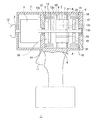
図2は、図1に示す電動工具1のA−A断面図を示す。図2は、第3保持部22およびモータ4の断面を示している。ハウジング2は、半割れの一対の第1ハウジング部材2aおよび第2ハウジング部材2bで構成される。第1ハウジング部材2aおよび第2ハウジング部材2bは、それぞれ内周面から突設する第1リブ部材22aおよび第2リブ部材22bを有し、第1リブ部材22aおよび第2リブ部材22bがステータ6の外周を挟持して固定する。第1リブ部材22aおよび第2リブ部材22bは、ハウジング2内の前後方向の空気流を遮蔽する。なお第1保持部20および第2保持部21も同様に形成されて、ハウジング2内の前後方向の空気流を遮蔽する。
FIG. 2 shows a cross-sectional view taken along the line AA of the
第4保持部23は、ハウジング2の後端部により構成され、モータ4の他端側、ここでは後端側から延びる第2モータ軸12bを支持する第2軸受13bの外周を保持する。なお第4保持部23は、第2保持部21と同様に、ハウジング2の内周面に突設されて、第2軸受13bの外周を挟持する一対のリブ部材で構成されてもよい。
The
モータ4において、ステータ6とロータ7の間には、エアギャップ18が形成されている。実施形態では、エアギャップ18に空気を送風する冷却構造を提供する。
In the motor 4, an
第1保持部20、第2保持部21、第3保持部22および第4保持部23は、工具前後方向の空気流を遮蔽する。そのため第1保持部20、第2保持部21およびハウジング2によって囲まれる第1室30が、前後方向に密閉された空間を形成し、第3保持部22、第4保持部23およびハウジング2によって囲まれる第2室31が、前後方向に密閉された空間を形成する。第1室30はハウジング2に、ハウジング外部と連通する第1通気口14を形成され、また第2室31はハウジング2に、ハウジング外部と連通する第2通気口15を形成される。第1通気口14および第2通気口15は、たとえば矩形状のスリットであってよい。なお第2室31において、第2通気口15は、ハウジング後端部に形成されてもよい。第1モータ軸12aに連結された冷却ファン3は、第1室30に収容される。
The
第1室30における空気の給排口は、エアギャップ18および第1通気口14であり、第2室31における空気の吸排口は、第2通気口15およびエアギャップ18である。実施形態の電動工具1では、ハウジング2内部をモータ4の前後で第1室30と第2室31とに分離し、冷却ファン3により取り込まれる空気の流路を制限している。
The air supply / exhaust ports in the
図3は、電動工具1における空気の流路を示す。作業者が操作スイッチ11を引くと、シャフト12が回転し、第1室30に配置された冷却ファン3も回転する。遠心ファンである冷却ファン3が回転すると、第1室30内の空気が第1通気口14から排気され、エアギャップ18を介して第2室31内の空気が第1室30に吸い込まれる。第2室31では、エアギャップ18から空気が排気されることで、外部の空気が第2通気口15から吸い込まれる。このように第1室30および第2室31を形成したことで、外部から吸い込まれた空気が確実にエアギャップ18に流入して、エアギャップ18を効率的に冷却できるようになる。
FIG. 3 shows an air flow path in the
たとえば第2保持部21が前後方向の空気流を遮蔽していない場合、冷却ファン3は、エアギャップ18から空気を吸い込むが、駆動ブロック8の配置空間からも空気を吸い込むことで、エアギャップ18を効率的に冷却できない。また第1室30と第2室31とが、エアギャップ18以外の流路でも連通している場合、エアギャップ18は狭く、空気流に対して大きな抵抗となるため、エアギャップ18以外の流路で流れる空気が多くなり、エアギャップ18を効率的に冷却できない。そこで第1保持部20、第2保持部21、第3保持部22を前後方向の空気流を遮蔽するように形成することで、エアギャップ18の効率的な冷却を実現できる。
For example, when the second holding
また図3の矢印に示すような空気流路を確実に形成するために、第1室30および第2室31は、できるだけ狭い空間となるように構成することが好ましい。そのため第1保持部20はモータ4の前端近傍の外周を保持し、第3保持部22はモータ4の後端近傍の外周を保持することが好ましい。
Further, in order to surely form the air flow path as shown by the arrow in FIG. 3, it is preferable that the
以上、本発明を実施形態をもとに説明した。この実施形態は例示であり、それらの各構成要素あるいは各処理プロセスの組合せにいろいろな変形例が可能なこと、またそうした変形例も本発明の範囲にあることは当業者に理解されるところである。 The present invention has been described above based on the embodiments. This embodiment is an example, and it will be understood by those skilled in the art that various modifications are possible for each of these components or combinations of each processing process, and that such modifications are also within the scope of the present invention. ..
実施形態では、冷却ファン3が第1室30に配置されているが、第2室31に配置されてもよい。また実施形態ではセンサ基板5が第2室31に配置されているが、第1室30に配置されてもよい。また第2室31には、センサ基板5以外に、たとえばロータ7を駆動するためのスイッチング素子を搭載した回路基板が配置されてもよい。
In the embodiment, the cooling
本発明の態様の概要は、次の通りである。
本発明のある態様の電動工具(1)は、ハウジング(2)内に、モータケースを有しないビルトイン式のモータ(4)を内装する。電動工具(1)は、ハウジング(2)の内周面に設けられ、モータ(4)の一端側の外周を保持する第1保持部(20)と、モータ(4)の一端側から延びる第1モータ軸(12a)を支持する第1軸受(13a)の外周を保持する第2保持部(21)と、ハウジング(2)の内周面に設けられ、モータ(4)の他端側の外周を保持する第3保持部(22)と、モータ(4)の他端側から延びる第2モータ軸(12b)を支持する第2軸受(13b)の外周を保持する第4保持部(23)と、を備える。
第1保持部(20)、第2保持部(21)およびハウジング(2)によって囲まれる第1室(30)は、ハウジング外部と連通する第1通気口(14)を有し、第3保持部(22)、第4保持部(23)およびハウジング(2)によって囲まれる第2室(31)は、ハウジング外部と連通する第2通気口(15)を有し、第1モータ軸(12a)に連結された冷却ファン(3)が、第1室(30)に収容されてよい。
The outline of the aspect of the present invention is as follows.
In the power tool (1) of the embodiment of the present invention, a built-in type motor (4) having no motor case is installed in a housing (2). The power tool (1) is provided on the inner peripheral surface of the housing (2), and has a first holding portion (20) that holds the outer periphery of one end side of the motor (4) and a second holding portion (20) that extends from one end side of the motor (4). 1 A second holding portion (21) that holds the outer periphery of the first bearing (13a) that supports the motor shaft (12a), and a second holding portion (21) that is provided on the inner peripheral surface of the housing (2) and is provided on the other end side of the motor (4). A third holding portion (22) that holds the outer circumference and a fourth holding portion (23) that holds the outer circumference of the second bearing (13b) that supports the second motor shaft (12b) extending from the other end side of the motor (4). ) And.
The first chamber (30) surrounded by the first holding portion (20), the second holding portion (21) and the housing (2) has a first vent (14) communicating with the outside of the housing, and a third holding portion (14). The second chamber (31) surrounded by the portion (22), the fourth holding portion (23) and the housing (2) has a second vent (15) communicating with the outside of the housing, and the first motor shaft (12a). ) May be housed in the first chamber (30).
第2保持部(21)および第4保持部(23)の少なくとも一方は、ハウジング(2)の内周面に設けられてよい。第2保持部(21)および第4保持部(23)の一方が、ハウジングの内周面に設けられ、第2保持部(21)および第4保持部(23)の他方が、ハウジング(2)の後端部に形成されてもよい。 At least one of the second holding portion (21) and the fourth holding portion (23) may be provided on the inner peripheral surface of the housing (2). One of the second holding portion (21) and the fourth holding portion (23) is provided on the inner peripheral surface of the housing, and the other of the second holding portion (21) and the fourth holding portion (23) is the housing (2). ) May be formed at the rear end.
1・・・電動工具、2・・・ハウジング、2a・・・第1ハウジング部材、2b・・・第2ハウジング部材、3・・・冷却ファン、4・・・モータ、6・・・ステータ、7・・・ロータ、12・・・シャフト、12a・・・第1モータ軸、12b・・・第2モータ軸、13a・・・第1軸受、13b・・・第2軸受、14・・・第1通気口、15・・・第2通気口、18・・・エアギャップ、20・・・第1保持部、21・・・第2保持部、22・・・第3保持部、22a・・・第1リブ部材、22b・・・第2リブ部材、23・・・第4保持部、30・・・第1室、31・・・第2室。 1 ... Electric tool, 2 ... Housing, 2a ... 1st housing member, 2b ... 2nd housing member, 3 ... Cooling fan, 4 ... Motor, 6 ... Stator, 7 ... Rotor, 12 ... Shaft, 12a ... 1st motor shaft, 12b ... 2nd motor shaft, 13a ... 1st bearing, 13b ... 2nd bearing, 14 ... 1st vent, 15 ... 2nd vent, 18 ... air gap, 20 ... 1st holding part, 21 ... 2nd holding part, 22 ... 3rd holding part, 22a ... .. 1st rib member, 22b ... 2nd rib member, 23 ... 4th holding part, 30 ... 1st chamber, 31 ... 2nd chamber.
Claims (3)
前記ハウジングの内周面に設けられ、前記モータの一端側の外周を保持する第1保持部と、
前記ハウジングの内周面に設けられ、前記モータの一端側から延びる第1モータ軸を支持する第1軸受の外周を保持する第2保持部と、
前記第1モータ軸の回転を出力軸に伝達する動力伝達機構を有する駆動ブロックと、
前記ハウジングの内周面に設けられ、前記モータの他端側の外周を保持する第3保持部と、
前記ハウジングの後端部に形成され、前記モータの他端側から延びる第2モータ軸を支持する第2軸受の外周を保持する第4保持部と、を備え、
前記第1保持部、前記第2保持部および前記ハウジングによって囲まれる第1室は、前後方向に密閉された空間を形成して、ハウジング外部と連通する第1通気口を有し、
前記第3保持部、前記第4保持部および前記ハウジングによって囲まれる第2室は、ハウジング外部と連通する第2通気口を有し、
前記第1モータ軸に連結された冷却ファンが、前記第1室に収容される、
ことを特徴とする電動工具。 The motor built into the housing is a power tool that is a built-in motor that does not have a motor case.
A first holding portion provided on the inner peripheral surface of the housing and holding an outer circumference on one end side of the motor, and a first holding portion.
A second holding portion provided on the inner peripheral surface of the housing and holding the outer periphery of the first bearing that supports the first motor shaft extending from one end side of the motor.
A drive block having a power transmission mechanism that transmits the rotation of the first motor shaft to the output shaft,
A third holding portion provided on the inner peripheral surface of the housing and holding the outer periphery of the other end side of the motor,
A fourth holding portion formed at the rear end portion of the housing and holding the outer circumference of the second bearing that supports the second motor shaft extending from the other end side of the motor is provided.
The first holding portion, the second holding portion, and the first chamber surrounded by the housing form a space sealed in the front-rear direction and have a first vent that communicates with the outside of the housing.
The third holding portion, the fourth holding portion, and the second chamber surrounded by the housing have a second vent that communicates with the outside of the housing.
The cooling fan connected to the first motor shaft is housed in the first chamber.
A power tool characterized by that.
ことを特徴とする請求項1に記載の電動工具。 The second chamber forms a space sealed in the front-rear direction.
The power tool according to claim 1.
ことを特徴とする請求項1または2に記載の電動工具。 The first chamber and the second chamber are communicated by an air gap between the stator and the rotor in the motor.
The power tool according to claim 1 or 2.
Priority Applications (4)
| Application Number | Priority Date | Filing Date | Title |
|---|---|---|---|
| JP2017071892A JP6857871B2 (en) | 2017-03-31 | 2017-03-31 | Electric tool |
| PCT/JP2017/043090 WO2018179587A1 (en) | 2017-03-31 | 2017-11-30 | Power tool |
| CN201780088953.XA CN110475646A (en) | 2017-03-31 | 2017-11-30 | Electric tool |
| EP17903771.8A EP3603894B1 (en) | 2017-03-31 | 2017-11-30 | Power tool |
Applications Claiming Priority (1)
| Application Number | Priority Date | Filing Date | Title |
|---|---|---|---|
| JP2017071892A JP6857871B2 (en) | 2017-03-31 | 2017-03-31 | Electric tool |
Publications (2)
| Publication Number | Publication Date |
|---|---|
| JP2018171685A JP2018171685A (en) | 2018-11-08 |
| JP6857871B2 true JP6857871B2 (en) | 2021-04-14 |
Family
ID=63677466
Family Applications (1)
| Application Number | Title | Priority Date | Filing Date |
|---|---|---|---|
| JP2017071892A Active JP6857871B2 (en) | 2017-03-31 | 2017-03-31 | Electric tool |
Country Status (4)
| Country | Link |
|---|---|
| EP (1) | EP3603894B1 (en) |
| JP (1) | JP6857871B2 (en) |
| CN (1) | CN110475646A (en) |
| WO (1) | WO2018179587A1 (en) |
Families Citing this family (2)
| Publication number | Priority date | Publication date | Assignee | Title |
|---|---|---|---|---|
| DE102020210674A1 (en) * | 2019-09-11 | 2021-03-11 | Robert Bosch Gesellschaft mit beschränkter Haftung | Hand machine tool with a sensor board |
| JP7464112B2 (en) * | 2020-04-28 | 2024-04-09 | 工機ホールディングス株式会社 | Power Tools |
Family Cites Families (18)
| Publication number | Priority date | Publication date | Assignee | Title |
|---|---|---|---|---|
| US6290587B1 (en) * | 1995-10-20 | 2001-09-18 | Wilton Tool Company, Llc | Electrically-powered polisher |
| JP4407392B2 (en) | 2004-06-17 | 2010-02-03 | パナソニック電工株式会社 | Impact tools |
| JP4631663B2 (en) | 2005-11-17 | 2011-02-16 | パナソニック電工株式会社 | Electric tool |
| JP4986258B2 (en) * | 2005-12-27 | 2012-07-25 | 日立工機株式会社 | Electric tool |
| JP2012013022A (en) * | 2010-07-01 | 2012-01-19 | Nippon Densan Corp | Blower fan |
| JP2012071360A (en) | 2010-09-27 | 2012-04-12 | Panasonic Eco Solutions Power Tools Co Ltd | Rotary tool |
| JP5722638B2 (en) * | 2010-09-28 | 2015-05-27 | 株式会社マキタ | Rechargeable power tool |
| CN103282165B (en) * | 2010-11-04 | 2015-12-09 | 英格索尔-兰德公司 | There is the cordless power tools of general purpose controller and tool identification and battery identification |
| JP5799220B2 (en) * | 2011-03-23 | 2015-10-21 | パナソニックIpマネジメント株式会社 | Electric tool |
| JP5722156B2 (en) * | 2011-08-02 | 2015-05-20 | 株式会社マキタ | Electric tool |
| JP5739271B2 (en) * | 2011-08-09 | 2015-06-24 | 株式会社マキタ | Impact tool |
| US20140091648A1 (en) * | 2012-10-02 | 2014-04-03 | Makita Corporation | Electric power tool |
| US20160344170A1 (en) * | 2012-10-12 | 2016-11-24 | Carl Russel Tamm | Remote Control Tool Assembly For Use In Live Line Environments |
| JP2014117792A (en) * | 2012-12-19 | 2014-06-30 | Hitachi Koki Co Ltd | Electric power tool |
| JP6095529B2 (en) * | 2013-09-06 | 2017-03-15 | 株式会社マキタ | Electric tool |
| JP6389362B2 (en) * | 2013-12-25 | 2018-09-12 | 株式会社マキタ | Electric tool |
| JP6140104B2 (en) * | 2014-05-22 | 2017-05-31 | ファナック株式会社 | Electric motor having air purge function |
| JP6268040B2 (en) * | 2014-05-27 | 2018-01-24 | 株式会社マキタ | Electric tool |
-
2017
- 2017-03-31 JP JP2017071892A patent/JP6857871B2/en active Active
- 2017-11-30 CN CN201780088953.XA patent/CN110475646A/en active Pending
- 2017-11-30 EP EP17903771.8A patent/EP3603894B1/en active Active
- 2017-11-30 WO PCT/JP2017/043090 patent/WO2018179587A1/en active Application Filing
Also Published As
| Publication number | Publication date |
|---|---|
| EP3603894A1 (en) | 2020-02-05 |
| EP3603894B1 (en) | 2021-09-15 |
| JP2018171685A (en) | 2018-11-08 |
| EP3603894A4 (en) | 2020-04-15 |
| WO2018179587A1 (en) | 2018-10-04 |
| CN110475646A (en) | 2019-11-19 |
Similar Documents
| Publication | Publication Date | Title |
|---|---|---|
| US7064462B2 (en) | Power tools with switched reluctance motor | |
| JP4487836B2 (en) | Electric tool | |
| US9680349B2 (en) | Power tool with substrate having apertures for cooling coils and switching elements | |
| JP6402915B2 (en) | Brushless motor and electric tool | |
| JP4974054B2 (en) | Electric tool | |
| WO2016031719A1 (en) | Electric working machine | |
| US20110014856A1 (en) | Direct motor-drive portable angle grinder | |
| JP2018137843A (en) | Electrically-driven tool | |
| WO2018180085A1 (en) | Electric tool | |
| US8872398B2 (en) | Electric power tool | |
| US10044245B2 (en) | Electric motor with improved cooling | |
| EP1634359B1 (en) | Generator having dual path airflow cooling arrangement and method therefor | |
| JP6857871B2 (en) | Electric tool | |
| JP6287110B2 (en) | Electric tool | |
| JP6007951B2 (en) | Rotating electric machine | |
| JP4993193B2 (en) | Electric tool | |
| JP6439382B2 (en) | Power working machine | |
| JP2018103318A (en) | Electric tool | |
| JP6827198B2 (en) | Brushless motors and power tools | |
| JP5651940B2 (en) | Electric motor and work machine | |
| JP5125900B2 (en) | Electric tool | |
| JP2009240140A (en) | Electric tool | |
| JP6450711B2 (en) | Electric motor having balance structure and machine tool including the electric motor | |
| JP6759759B2 (en) | Electric tool | |
| JP2006315107A (en) | Power tool |
Legal Events
| Date | Code | Title | Description |
|---|---|---|---|
| RD04 | Notification of resignation of power of attorney |
Free format text: JAPANESE INTERMEDIATE CODE: A7424 Effective date: 20180417 |
|
| A621 | Written request for application examination |
Free format text: JAPANESE INTERMEDIATE CODE: A621 Effective date: 20191216 |
|
| A131 | Notification of reasons for refusal |
Free format text: JAPANESE INTERMEDIATE CODE: A131 Effective date: 20201104 |
|
| A521 | Request for written amendment filed |
Free format text: JAPANESE INTERMEDIATE CODE: A523 Effective date: 20201224 |
|
| TRDD | Decision of grant or rejection written | ||
| A01 | Written decision to grant a patent or to grant a registration (utility model) |
Free format text: JAPANESE INTERMEDIATE CODE: A01 Effective date: 20210224 |
|
| A61 | First payment of annual fees (during grant procedure) |
Free format text: JAPANESE INTERMEDIATE CODE: A61 Effective date: 20210309 |
|
| R151 | Written notification of patent or utility model registration |
Ref document number: 6857871 Country of ref document: JP Free format text: JAPANESE INTERMEDIATE CODE: R151 |