JP5739271B2 - Impact tool - Google Patents
Impact tool Download PDFInfo
- Publication number
- JP5739271B2 JP5739271B2 JP2011174130A JP2011174130A JP5739271B2 JP 5739271 B2 JP5739271 B2 JP 5739271B2 JP 2011174130 A JP2011174130 A JP 2011174130A JP 2011174130 A JP2011174130 A JP 2011174130A JP 5739271 B2 JP5739271 B2 JP 5739271B2
- Authority
- JP
- Japan
- Prior art keywords
- stator
- partition wall
- housing
- rotor
- motor
- Prior art date
- Legal status (The legal status is an assumption and is not a legal conclusion. Google has not performed a legal analysis and makes no representation as to the accuracy of the status listed.)
- Active
Links
Images


Classifications
-
- B—PERFORMING OPERATIONS; TRANSPORTING
- B25—HAND TOOLS; PORTABLE POWER-DRIVEN TOOLS; MANIPULATORS
- B25F—COMBINATION OR MULTI-PURPOSE TOOLS NOT OTHERWISE PROVIDED FOR; DETAILS OR COMPONENTS OF PORTABLE POWER-DRIVEN TOOLS NOT PARTICULARLY RELATED TO THE OPERATIONS PERFORMED AND NOT OTHERWISE PROVIDED FOR
- B25F5/00—Details or components of portable power-driven tools not particularly related to the operations performed and not otherwise provided for
- B25F5/008—Cooling means
Description
本発明は、ブラシレスモータを備えたインパクトドライバ等の打撃工具に関する。 The present invention relates to an impact tool such as an impact driver equipped with a brushless motor.
インパクトドライバ等の打撃工具は、モータを収容するハウジングの前方に、打撃機構を収容するハンマーケースを保持させて、ハンマーケースから前方にアンビルを突出させている。モータには、ブラシの交換が不要となるブラシレスモータが用いられて、モータから打撃機構への回転伝達は、例えば特許文献1,2に示すように、センサ基板を貫通して前方へ突出する回転子の回転軸を、ハンマーケースの後面を閉塞する円盤状のキャップにボールベアリングを介して軸支させて、ハンマーケース内に突出させた回転軸のピニオンをスピンドルが保持する遊星歯車に噛合させることで行っている。
また、回転軸の後端には、ファンが固着されて、モータの駆動に伴うファンの回転により、ハウジングの側面でモータの前端付近に設けた吸気口から外気を吸い込み、モータを通過させた後、ハウジングの後方部でファンの外側に設けた排気口から排気することで、モータの冷却を可能としている。
A hitting tool such as an impact driver holds a hammer case that houses a striking mechanism in front of a housing that houses a motor, and projects an anvil forward from the hammer case. The motor uses a brushless motor that eliminates the need for brush replacement, and rotation transmission from the motor to the striking mechanism is, for example, rotation that projects forward through the sensor board as shown in
In addition, a fan is fixed to the rear end of the rotating shaft, and after the fan rotates as the motor is driven, outside air is sucked from the intake port provided near the front end of the motor on the side surface of the housing and passed through the motor. The motor can be cooled by exhausting air from an exhaust port provided outside the fan at the rear part of the housing.
このような打撃工具においては、ハウジングに開口する吸気口や排気口を介して雨水等が浸入するおそれがあり、これがモータ内部へ達すると故障や劣化の原因となってしまう。 In such a striking tool, there is a risk that rainwater or the like may enter through the air inlet and the air outlet opening in the housing, and if this reaches the inside of the motor, it may cause failure or deterioration.
そこで、本発明は、モータの防水性を高めて吸気口等から雨水等が浸入してもモータの故障や劣化を好適に防止できる打撃工具を提供することを目的としたものである。 Therefore, an object of the present invention is to provide a striking tool that can prevent the motor from being broken or deteriorated even if rainwater or the like enters from an air inlet or the like by improving the waterproofness of the motor.
上記目的を達成するために、請求項1に記載の発明は、ハウジング内の後部に形成したモータ収容室に、永久磁石が設けられた回転子と、内周側に固定子巻線を有する固定子とからなるブラシレスモータを収容すると共に、そのブラシレスモータの後方に、回転によってハウジング内に外気を吸い込んでモータ収容室内を通気させるファンを配置する一方、ブラシレスモータの前方に、打撃機構を内設し、回転子の回転軸が突出する筒状のハンマーケースを配置した打撃工具であって、固定子の内周に、回転子と固定子巻線との間を仕切る仕切壁を全周に亘って設けて、仕切壁の前端を、固定子の前側の開口を閉塞して回転軸が貫通する閉塞板に当接させる一方、仕切壁の後端を後仕切壁で閉塞して、閉塞板における回転軸の貫通孔に、ハンマーケースの後側の開口を閉塞するキャップに形成されて回転軸を軸支する受け筒を嵌合させて、ファンの回転によってハウジング内に吸い込まれた外気を、仕切壁の外側で固定子巻線間のみを通過させるようにしたことを特徴とするものである。
請求項2に記載の発明は、請求項1の構成において、受け筒に、貫通孔との嵌合部分よりも大径に形成されて閉塞板の前面に当接するオーバーラップ部を設けたことを特徴とするものである。
請求項3に記載の発明は、固定子巻線を有する固定子と、前記固定子に対して回転可能であって永久磁石を有する回転子と、を備えたブラシレスモータと、前記ブラシレスモータを収容し、吸気口及び排気口を有するハウジングと、を含んでなる電動工具であって、前記固定子と前記回転子との間を仕切る仕切壁を設けて前記仕切壁の後端を後仕切壁で閉塞して、前記吸気口から吸い込まれた外気を、前記固定子の内側を通過させて前記回転子側へ侵入しないようにしたことを特徴とするものである。
In order to achieve the above object, according to the first aspect of the present invention, there is provided a motor housing chamber formed in a rear portion of a housing, a rotor provided with a permanent magnet, and a stator winding having a stator winding on the inner peripheral side. A brushless motor consisting of a child is accommodated, and a fan that sucks outside air into the housing by rotation and ventilates the motor housing chamber is arranged behind the brushless motor, while an impact mechanism is provided in front of the brushless motor. An impact tool in which a cylindrical hammer case from which the rotor's rotating shaft protrudes is arranged, and a partition wall that divides the rotor and the stator winding is provided around the entire circumference of the stator. The front end of the partition wall is closed against the closing plate through which the rotating shaft passes by closing the opening on the front side of the stator, while the rear end of the partition wall is closed with the rear partition wall. In the through hole of the rotating shaft, -A cap that is formed on the cap that closes the opening on the rear side of the case and is fitted with a receiving tube that supports the rotating shaft, and the outside air sucked into the housing by the rotation of the fan It is characterized in that only the gap is allowed to pass.
According to a second aspect of the present invention, in the configuration of the first aspect, the receiving tube is provided with an overlap portion that is formed in a diameter larger than a fitting portion with the through hole and contacts the front surface of the closing plate. It is a feature.
According to a third aspect of the present invention, there is provided a brushless motor comprising a stator having a stator winding, a rotor rotatable with respect to the stator and having a permanent magnet, and the brushless motor accommodated therein And a housing having an intake port and an exhaust port, wherein a partition wall for partitioning the stator and the rotor is provided, and the rear end of the partition wall is a rear partition wall. The outside air that has been closed and sucked from the intake port is allowed to pass through the inside of the stator so as not to enter the rotor side.
本発明によれば、モータの防水性を高めることができ、ハウジングに設けた吸気口等から雨水等が浸入してもモータの故障や劣化を好適に防止することができる。
請求項2に記載の発明によれば、請求項1の効果に加えて、閉塞板と受け筒との間のシール性が高まり、ここからの雨水等の浸入をより確実に防止可能となる。
ADVANTAGE OF THE INVENTION According to this invention, the waterproofness of a motor can be improved and even if rainwater etc. permeate from the inlet port etc. which were provided in the housing, the failure and deterioration of a motor can be prevented suitably.
According to the second aspect of the present invention, in addition to the effect of the first aspect, the sealing performance between the closing plate and the receiving tube is enhanced, and the intrusion of rainwater and the like from here can be more reliably prevented.
以下、本発明の実施の形態を図面に基づいて説明する。
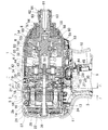
図1は、打撃工具の一例であるインパクトドライバの縦断面図で、インパクトドライバ1は、後方(図1の右側を前方とする。)にモータ5を収容し、下方にハンドル3を延設したハウジング2と、そのハウジング2の前方に組み付けられて打撃機構6を収容するハンマーケース4とを備える。ハウジング2は、図2に示すように、左右一対の半割ハウジング2a,2bを組み付けて互いにネジ止めすることで形成される。ハンマーケース4は、後方部が半割ハウジング2a,2bによって挟持されて前方部が前方へ行くに従って先細りとなる釣鐘状の筒体で、前方部には、合成樹脂製のカバー7及びゴム製のバンパ8が被着されている。ハンドル3の下端には、電源となる図示しないバッテリーパックが装着される一方、ハンドル3の根元側には、前方へトリガー10を突出させるスイッチ9が収容されている。
Hereinafter, embodiments of the present invention will be described with reference to the drawings.
FIG. 1 is a longitudinal sectional view of an impact driver which is an example of an impact tool. The
モータ5は、回転軸12及び永久磁石13が設けられた回転子11と、内周に突設した6本のティース15,15・・に、3相の固定子巻線16,16・・を巻回して回転子11が貫通する筒状の固定子14とからなるブラシレスモータである。モータ5の固定子14は、ハウジング2の後方に形成されるモータ収容室17内で、各半割ハウジング2a,2bの内面で周方向に突設されたリブ18,18・・により、図2(A)に示すように、ハウジング2の内面との間に隙間を形成した状態で支持されている。固定子14の前端には、回転子11の磁極の位置を検出する磁気センサを備えた閉塞板としてのセンサ基板19が取り付けられて、固定子14の前端を閉塞しているが、センサ基板19の中央には、回転軸12が貫通する貫通孔20が形成されている。
The
また、固定子14においては、図2(B)に示すように隣接するティース15,15の突出端同士が互いに連結されて、固定子巻線16,16・・よりも軸心側に、固定子巻線16と回転子11の永久磁石13との間を仕切る仕切壁21が全周に亘って形成されている。この仕切壁21は、前端がセンサ基板19の後面へ全周に亘って当接し、後端は、回転軸12が貫通する後仕切壁22によってシールされている。これにより、モータ収容室17内で回転子11は、仕切壁21及び後仕切壁22によって囲まれることになる。一方、固定子14側では、固定子14の前端に、周方向に所定間隔をおいて複数の切欠き23,23・・が形成されて、固定子14の内側でティース15,15間に形成されるスロット24,24・・を、固定子14の外側と連通させている。
Further, in the
25は、ハンマーケース4の後部開口に取り付けられる円盤状のキャップで、中央には、後方へ行くに従って段階的に小径となる2つの受け筒26,27が形成されて、ハウジング2内でハンマーケース4とモータ5との間を仕切る前壁28に保持されている。受け筒26,27の間には、半径方向へ突出するフランジ29が周設されており、このフランジ29が前壁28に形成された溝30に係合することで、ハンマーケース4を前後方向で位置決めしている。モータ5の回転軸12は、受け筒26,27を貫通して、受け筒27にボールベアリング31を介して軸支されて、前端に嵌着したピニオン32をハンマーケース4内に設けられたスピンドル33の内部に突出させている。
また、受け筒27の後端は、図3にも示すように、センサ基板19の貫通孔20内に達するまで延設されて、その外側に、貫通孔20に嵌合して外周面が貫通孔20の内周面に当接するフランジ部34を周設している。このフランジ部34は、センサ基板19よりも前側へ突出する肉厚に形成されて、前側の外周に、センサ基板19の前面に当接するオーバーラップ部35を周設している。オーバーラップ部35の後面には、センサ基板19の前面に当接するOリング36が保持されて、センサ基板19とオーバーラップ部35との間をシールしている。
Further, as shown in FIG. 3, the rear end of the
そして、ハウジング2におけるモータ収容室17の後方には、ファン収容部37が設けられている。このファン収容部37内に突出する回転軸12は、ファン収容部37の後部に設けたボールベアリング38に軸支されて、ボールベアリング38の前側でファン39が固着されている。
また、ハウジング2の側面において、センサ基板19から固定子5にかけてその外側に当たる位置には、図4に示すように、複数の吸気口40,40・・が穿設される一方、ファン収容部37の側面において、ファン39の外側に当たる位置には、複数の排気口41,41・・が穿設されている。
A
Further, as shown in FIG. 4, a plurality of
一方、ハンマーケース4内において、スピンドル33は、受け筒26に保持されたボールベアリング42によって後端が軸支され、その前方に設けたキャリア部43が保持する2つの遊星歯車44,44を、回転軸12のピニオン32に噛合させている。45はインターナルギヤである。
打撃機構6は、スピンドル33の前端に外装されるハンマー50と、そのハンマー50の後面に形成されたリング溝51に前端を挿着させたコイルバネ52とを備え、ハンマー50は、スピンドル33との間に跨って嵌合するボール53,53を介してスピンドル33と連結されている。この連結は、ハンマー50の内周面に前端から後方へ向けて凹設されて後端が先細りとなる山形のカム溝54と、スピンドル33の外周面で先端を前方に向けて凹設されたV字状のカム溝55とに跨ってボール53,53が嵌合することで行われている。ハンマー50は、コイルバネ52により、ボール53が山形のカム溝54の後端とV字状のカム溝55の先端とに位置する前進位置に付勢されている。
On the other hand, in the
The
56はアンビルで、アンビル56は、ハンマーケース4の前端に保持された軸受57によって中間部が軸支され、後面軸心に形成した軸受孔58に、スピンドル33の前端に突設した小径部59を嵌合させている。また、ハンマーケース4内でアンビル56の後端には、ハンマー50の前面に突設した図示しない爪が回転方向で係合する一対のアーム60,60が放射状に延設されている。
さらに、ハンマーケース4から突出するアンビル56の前端には、図示しないビットの挿着孔61が形成されると共に、挿着孔61に挿入されたビットを抜け止め装着するボール63及びスリーブ64等を備えたチャック機構62が設けられている。
Further, a bit insertion hole 61 (not shown) is formed at the front end of the
以上の如く構成されたインパクトドライバ1においては、トリガー10を押し込み操作してモータ5を駆動させると、回転軸12の回転が遊星歯車44,44を介してスピンドル33に伝わり、スピンドル33を回転させる。スピンドル33は、ボール53,53を介してハンマー50を回転させ、ハンマー50が係合するアンビル56を回転させるため、アンビル56の先端に装着したビットによってネジ締め等が可能となる。ネジ締めが進んでアンビル56のトルクが高まると、ハンマー50は、ボール53,53がカム溝55,55に沿って転動することで、スピンドル33に対して相対的に回転しながらコイルバネ52の付勢に抗して後退する。そして、ハンマー50の爪がアンビル56のアーム60,60から外れると、ハンマー50はコイルバネ52の付勢により、ボール53,53がカム溝55,55の先端に向けて転動することで回転しながら前進する。よって、爪が再びアーム60,60に係合して回転打撃力(インパクト)を発生させる。このアンビル56への係脱をハンマー50が繰り返すことで増し締めが行われる。
In the
一方、モータ5の駆動によって回転軸12と共にファン39が回転すると、ハウジング2の吸気口40から外気が吸い込まれてハウジング2と固定子14との隙間に進入する。この外気は、固定子14の切欠き23から固定子14の内側に入り、そのままスロット24,24・・を通過して後方へ流れてファン収容部37に至り、排気口41から外部へ排出される。この空気の流れにより、固定子巻線16が冷却される。
ここで、吸気口40や排気口41から雨水等が浸入しても、モータ5側では仕切壁21及び後仕切壁22によって回転子11が覆われているので、雨水等が回転子11側へ浸入することがない。また、雨水等がセンサ基板19の前側へ回り込むことがあっても、センサ基板19と受け筒27のフランジ部34との間もシールされているので、雨水等が回転子11側や受け筒27内へ浸入することもない。
On the other hand, when the
Here, even if rainwater or the like enters from the
このように、上記形態のインパクトドライバ1によれば、モータ5の固定子14の内周に、回転子14と固定子巻線16との間を仕切る仕切壁21を全周に亘って設けて、仕切壁21の前端を、固定子14の前側の開口を閉塞して回転軸12が貫通するセンサ基板19に当接させる一方、仕切壁21の後端を後仕切壁22で閉塞して、センサ基板19における回転軸12の貫通孔20に、ハンマーケース4の後側の開口を閉塞するキャップ25に形成されて回転軸12を軸支する受け筒27を嵌合させて、ファン39の回転によって吸気口40からハウジング2内に吸い込まれた外気を、仕切壁21の外側で固定子巻線16間のみを通過させるようにしたことで、モータ5の防水性を高めて吸気口40等から雨水等が浸入してもモータ5の故障や劣化を好適に防止できる。
特にここでは、受け筒27のフランジ部34に、貫通孔20との嵌合部分よりも大径に形成されてセンサ基板19の前面に当接するオーバーラップ部35を設けているので、センサ基板19と受け筒27との間のシール性が高まり、ここからの雨水等の浸入をより確実に防止可能となる。
Thus, according to the
In particular, here, since the
なお、上記形態では、閉塞板としてセンサ基板を利用しているが、センサ基板の位置や形状によってはセンサ基板を利用せずに別の閉塞板を設けて固定子の前側を閉塞するようにしてもよい。
また、閉塞板とキャップの受け筒との嵌合も、上記形態では受け筒のフランジ部を閉塞板よりも肉厚としているが、同じ厚さとしてオーバーラップ部を省略したり、閉塞板の内周にも段部を設けて受け筒との間でいんろう接合したり等、適宜変更可能である。さらに、貫通孔の大きさ等によってはフランジ部を省略して受け筒の後端を直接貫通孔に嵌合させても差し支えない。
In the above embodiment, the sensor substrate is used as the closing plate. However, depending on the position and shape of the sensor substrate, a separate closing plate is provided to close the front side of the stator without using the sensor substrate. Also good.
In addition, in the above embodiment, the flange of the receiving tube is made thicker than the closing plate in the above embodiment, but the overlap portion may be omitted or the inner portion of the closing plate may be omitted. It can be changed as appropriate, for example, by providing a stepped portion around the periphery and joining it with the receiving tube. Further, depending on the size or the like of the through hole, the flange portion may be omitted and the rear end of the receiving cylinder may be directly fitted into the through hole.
一方、上記形態では、ファン39をファン収容部37に突出させた回転軸12に設けているが、図5に示すインパクトドライバ1Aのように、ファン収容部37をハウジング2と別体に形成して、ハウジング2の後方を後板46で閉塞する一方、ファン収容部37の前方を前板65で閉塞して、ファン収容部37を後方からハウジング2にネジ止め結合させることもできる。従って、ここでは回転軸12の後端はモータ収容室17内にとどめて、後仕切壁22の内側にベアリング受け部47を形成し、ベアリング受け部47に保持させたボールベアリング48で回転軸12の後端を軸支させている。
On the other hand, in the above embodiment, the
また、ファン収容部37内では、前板65の後面にベアリング受け部66を形成し、ベアリング受け部66にボールベアリング67を保持させて、そのボールベアリング67と後部のボールベアリング38とで、ファン39を固着したファンシャフト68の前後端をそれぞれ軸支させるようにしている。後板46と前板65とには、モータ5のスロット24の後方に位置する透孔69,69・・を複数形成して、スロット24とファン収容部37とを連通させて外気の通過を可能としている。
In the
このようにすれば、ファン収容部37を取り外せば、図6に示すように前後方向の全長が短くなってコンパクト化するため、長時間連続使用しない場合や狭い場所で作業を行うような場合には、任意にファン収容部37を取り外して使用すればよい。この場合は後板46の透孔69が排気口となる。
但し、ファン39を回転軸12と別体のファンシャフト68に設けることで、ファンシャフト68を回転させる駆動源が必要となる。これは、例えばファン収容部37にファン用のモータを新たに設けてギヤ等を介してファンシャフト68に回転伝達すると共に、後板46と前板65とにファン収容部37の結合状態で電気的接続する端子(接触式や差込式等)をそれぞれ設けて、バッテリーパックから電源を得るようにすればよい。また、ファンと回転子との距離が近ければ、ファンの前面に回転子の永久磁石に対応する永久磁石又は磁性体を設けて、回転子の永久磁石の吸引力によってファンを同期して回転させることも考えられる。
In this way, if the
However, providing the
1,1A・・インパクトドライバ、2・・ハウジング、3・・ハンドル、4・・ハンマーケース、5・・モータ、6・・打撃機構、11・・回転子、12・・回転軸、13・・永久磁石、14・・固定子、15・・ティース、16・・固定子巻線、17・・モータ収容室、19・・センサ基板、20・・貫通孔、21・・仕切壁、22・・後仕切壁、23・・切欠き、24・・スロット、25・・キャップ、26,27・・受け筒、31,38,42,48,67・・ボールベアリング、33・・スピンドル、34・・フランジ部、35・・オーバーラップ部、37・・ファン収容部、39・・ファン、40・・吸気口、41・・排気口、46・・後板、47,66・・ベアリング受け部、50・・ハンマー、52・・コイルバネ、53・・ボール、56・・アンビル、60・・アーム、68・・ファンシャフト、69・・透孔。 1, 1A-Impact driver, 2-Housing, 3-Handle, 4-Hammer case, 5-Motor, 6-Blow mechanism, 11-Rotor, 12-Rotary shaft, 13- Permanent magnet, 14 .. Stator, 15 .. Teeth, 16 .. Stator winding, 17 .. Motor housing chamber, 19 .. Sensor board, 20 .. Through hole, 21 .. Partition wall, 22. Rear partition wall, 23, notch, 24, slot, 25, cap, 26, 27, receiving cylinder, 31, 38, 42, 48, 67, ball bearing, 33, spindle, 34, ... Flange part, 35 .. Overlap part, 37 .. Fan housing part, 39 .. Fan, 40 .. Inlet port, 41 .. Exhaust port, 46 .. Rear plate, 47, 66. ..Hammer, 52 ... Coil spring, 53 ... Lumpur, 56 ... anvil, 60 ... arm, 68 ... fan shaft, 69 ... through hole.
Claims (3)
前記固定子の内周に、前記回転子と前記固定子巻線との間を仕切る仕切壁を全周に亘って設けて、前記仕切壁の前端を、前記固定子の前側の開口を閉塞して前記回転軸が貫通する閉塞板に当接させる一方、前記仕切壁の後端を後仕切壁で閉塞して、
前記閉塞板における前記回転軸の貫通孔に、前記ハンマーケースの後側の開口を閉塞するキャップに形成されて前記回転軸を軸支する受け筒を嵌合させて、
前記ファンの回転によって前記ハウジング内に吸い込まれた外気を、前記仕切壁の外側で前記固定子巻線間のみを通過させるようにしたことを特徴とする打撃工具。 A motor housing chamber formed in the rear part of the housing accommodates a brushless motor including a rotor provided with a permanent magnet and a stator having a stator winding on the inner peripheral side, and behind the brushless motor. In addition, a fan that sucks outside air into the housing by rotation and vents the motor housing chamber is disposed, while a striking mechanism is provided in front of the brushless motor, and a rotating shaft of the rotor projects. An impact tool with a hammer case,
A partition wall for partitioning between the rotor and the stator winding is provided over the entire circumference on the inner periphery of the stator, and the front end of the partition wall is closed off the opening on the front side of the stator. The rear end of the partition wall is closed with a rear partition wall,
In a through hole of the rotary shaft in the closing plate, a cap that is formed on a cap that closes an opening on the rear side of the hammer case and fits a receiving cylinder that supports the rotary shaft,
An impact tool characterized in that the outside air sucked into the housing by the rotation of the fan is allowed to pass only between the stator windings outside the partition wall.
前記ブラシレスモータを収容し、吸気口及び排気口を有するハウジングと、を含んでなる電動工具であって、
前記固定子と前記回転子との間を仕切る仕切壁を設けて前記仕切壁の後端を後仕切壁で閉塞して、
前記吸気口から吸い込まれた外気を、前記固定子の内側を通過させて前記回転子側へ侵入しないようにしたことを特徴とする電動工具。 A brushless motor comprising: a stator having a stator winding; and a rotor rotatable relative to the stator and having a permanent magnet;
A housing that houses the brushless motor and has an intake port and an exhaust port,
Providing a partition wall for partitioning between the stator and the rotor and closing the rear end of the partition wall with a rear partition wall ;
An electric tool characterized in that the outside air sucked from the air intake port does not enter the rotor side through the inside of the stator.
Priority Applications (2)
| Application Number | Priority Date | Filing Date | Title |
|---|---|---|---|
| JP2011174130A JP5739271B2 (en) | 2011-08-09 | 2011-08-09 | Impact tool |
| CN201210281680.XA CN102950585B (en) | 2011-08-09 | 2012-08-09 | Hitting tool |
Applications Claiming Priority (1)
| Application Number | Priority Date | Filing Date | Title |
|---|---|---|---|
| JP2011174130A JP5739271B2 (en) | 2011-08-09 | 2011-08-09 | Impact tool |
Publications (3)
| Publication Number | Publication Date |
|---|---|
| JP2013035105A JP2013035105A (en) | 2013-02-21 |
| JP2013035105A5 JP2013035105A5 (en) | 2014-04-17 |
| JP5739271B2 true JP5739271B2 (en) | 2015-06-24 |
Family
ID=47760270
Family Applications (1)
| Application Number | Title | Priority Date | Filing Date |
|---|---|---|---|
| JP2011174130A Active JP5739271B2 (en) | 2011-08-09 | 2011-08-09 | Impact tool |
Country Status (2)
| Country | Link |
|---|---|
| JP (1) | JP5739271B2 (en) |
| CN (1) | CN102950585B (en) |
Families Citing this family (6)
| Publication number | Priority date | Publication date | Assignee | Title |
|---|---|---|---|---|
| JP6334914B2 (en) * | 2013-12-25 | 2018-05-30 | 株式会社マキタ | Electric tool |
| US9954418B2 (en) * | 2014-03-17 | 2018-04-24 | Makita Corporation | Power tool |
| DE102017211773A1 (en) * | 2016-07-11 | 2018-01-11 | Robert Bosch Gmbh | Hand machine tool device |
| JP6857871B2 (en) * | 2017-03-31 | 2021-04-14 | パナソニックIpマネジメント株式会社 | Electric tool |
| US10987784B2 (en) | 2018-02-23 | 2021-04-27 | Ingersoll-Rand Industrial U.S., Inc. | Cordless impact tool with brushless, sensorless, motor and drive |
| JP7229807B2 (en) * | 2019-02-21 | 2023-02-28 | 株式会社マキタ | Electric tool |
Family Cites Families (6)
| Publication number | Priority date | Publication date | Assignee | Title |
|---|---|---|---|---|
| US6903475B2 (en) * | 2001-02-23 | 2005-06-07 | Black & Decker Inc. | Stator assembly with an overmolding that secures magnets to a flux ring and the flux ring to a stator housing |
| EP1588469A4 (en) * | 2002-12-13 | 2014-04-30 | Black & Decker Inc | A stator assembly with an overmolding that secures magnets to a flux ring and the flux ring to a stator housing |
| CN101004181A (en) * | 2006-01-17 | 2007-07-25 | 台达电子工业股份有限公司 | Fan and motor |
| JP4993193B2 (en) * | 2007-05-30 | 2012-08-08 | 日立工機株式会社 | Electric tool |
| JP5478987B2 (en) * | 2009-08-21 | 2014-04-23 | 株式会社マキタ | Electric tool |
| CN201789359U (en) * | 2010-09-14 | 2011-04-06 | 中山大洋电机制造有限公司 | External rotor electric machine with waterproof structure |
-
2011
- 2011-08-09 JP JP2011174130A patent/JP5739271B2/en active Active
-
2012
- 2012-08-09 CN CN201210281680.XA patent/CN102950585B/en active Active
Also Published As
| Publication number | Publication date |
|---|---|
| CN102950585B (en) | 2015-04-01 |
| JP2013035105A (en) | 2013-02-21 |
| CN102950585A (en) | 2013-03-06 |
Similar Documents
| Publication | Publication Date | Title |
|---|---|---|
| JP5739271B2 (en) | Impact tool | |
| JP5728303B2 (en) | Impact tool | |
| US10967496B2 (en) | Impact tool | |
| JP2019510456A (en) | Brushless motor for power tools | |
| JP2017100259A (en) | Electric tool with vibration mechanism | |
| CN112296949B (en) | Rotary striking tool | |
| WO2017159201A1 (en) | Electrically driven tool | |
| JP6095529B2 (en) | Electric tool | |
| JP6539513B2 (en) | Electric driver | |
| JP2013035105A5 (en) | ||
| CN111590506B (en) | Electric tool | |
| JP6416664B2 (en) | Rotating hammer tool | |
| US20230188021A1 (en) | Outer-rotor motor assembly | |
| JP7070337B2 (en) | Electrical equipment | |
| JP2014061557A (en) | Electric tool | |
| JP6112959B2 (en) | Electric tool | |
| JP2019000982A (en) | Power tool | |
| JP2022066012A (en) | Oil pulse tool | |
| JP5187058B2 (en) | Electric tool | |
| JP2020188631A (en) | Electric work machine | |
| US11916447B2 (en) | Overmolded rotor structure | |
| US20240022126A1 (en) | Rotor magnet retention structure in brushless motor | |
| JP2019048383A (en) | Electric rotary tool | |
| JP7390166B2 (en) | power tools | |
| EP4113795A2 (en) | Motor rotor with sleeve for retention of magnet ring |
Legal Events
| Date | Code | Title | Description |
|---|---|---|---|
| A521 | Request for written amendment filed |
Free format text: JAPANESE INTERMEDIATE CODE: A523 Effective date: 20140304 |
|
| A621 | Written request for application examination |
Free format text: JAPANESE INTERMEDIATE CODE: A621 Effective date: 20140304 |
|
| A977 | Report on retrieval |
Free format text: JAPANESE INTERMEDIATE CODE: A971007 Effective date: 20150115 |
|
| A131 | Notification of reasons for refusal |
Free format text: JAPANESE INTERMEDIATE CODE: A131 Effective date: 20150120 |
|
| A521 | Request for written amendment filed |
Free format text: JAPANESE INTERMEDIATE CODE: A523 Effective date: 20150303 |
|
| TRDD | Decision of grant or rejection written | ||
| A01 | Written decision to grant a patent or to grant a registration (utility model) |
Free format text: JAPANESE INTERMEDIATE CODE: A01 Effective date: 20150331 |
|
| A61 | First payment of annual fees (during grant procedure) |
Free format text: JAPANESE INTERMEDIATE CODE: A61 Effective date: 20150423 |
|
| R150 | Certificate of patent or registration of utility model |
Ref document number: 5739271 Country of ref document: JP Free format text: JAPANESE INTERMEDIATE CODE: R150 |
|
| R250 | Receipt of annual fees |
Free format text: JAPANESE INTERMEDIATE CODE: R250 |
|
| R250 | Receipt of annual fees |
Free format text: JAPANESE INTERMEDIATE CODE: R250 |
|
| R250 | Receipt of annual fees |
Free format text: JAPANESE INTERMEDIATE CODE: R250 |
|
| R250 | Receipt of annual fees |
Free format text: JAPANESE INTERMEDIATE CODE: R250 |
|
| R250 | Receipt of annual fees |
Free format text: JAPANESE INTERMEDIATE CODE: R250 |
|
| R250 | Receipt of annual fees |
Free format text: JAPANESE INTERMEDIATE CODE: R250 |