JP6857088B2 - Image processing equipment and its control method, imaging equipment, monitoring system - Google Patents
Image processing equipment and its control method, imaging equipment, monitoring system Download PDFInfo
- Publication number
- JP6857088B2 JP6857088B2 JP2017120807A JP2017120807A JP6857088B2 JP 6857088 B2 JP6857088 B2 JP 6857088B2 JP 2017120807 A JP2017120807 A JP 2017120807A JP 2017120807 A JP2017120807 A JP 2017120807A JP 6857088 B2 JP6857088 B2 JP 6857088B2
- Authority
- JP
- Japan
- Prior art keywords
- image
- user interface
- area
- processing apparatus
- image processing
- Prior art date
- Legal status (The legal status is an assumption and is not a legal conclusion. Google has not performed a legal analysis and makes no representation as to the accuracy of the status listed.)
- Active
Links
- 238000012545 processing Methods 0.000 title claims description 68
- 238000000034 method Methods 0.000 title claims description 43
- 238000003384 imaging method Methods 0.000 title claims description 10
- 238000012544 monitoring process Methods 0.000 title claims description 7
- 230000008569 process Effects 0.000 claims description 36
- 230000009466 transformation Effects 0.000 claims description 10
- 230000004044 response Effects 0.000 claims description 9
- 230000006870 function Effects 0.000 description 18
- 238000004891 communication Methods 0.000 description 9
- 238000010586 diagram Methods 0.000 description 9
- 238000003825 pressing Methods 0.000 description 8
- 238000013139 quantization Methods 0.000 description 8
- 230000008859 change Effects 0.000 description 5
- 230000006835 compression Effects 0.000 description 4
- 238000007906 compression Methods 0.000 description 4
- 238000012937 correction Methods 0.000 description 3
- 238000005516 engineering process Methods 0.000 description 2
- 238000012986 modification Methods 0.000 description 2
- 230000004048 modification Effects 0.000 description 2
- 230000000694 effects Effects 0.000 description 1
- 230000002708 enhancing effect Effects 0.000 description 1
- 230000007246 mechanism Effects 0.000 description 1
- 230000002093 peripheral effect Effects 0.000 description 1
- 230000009467 reduction Effects 0.000 description 1
- 230000007704 transition Effects 0.000 description 1
Images


Classifications
-
- G06T5/80—
-
- G06T3/12—
-
- H—ELECTRICITY
- H04—ELECTRIC COMMUNICATION TECHNIQUE
- H04N—PICTORIAL COMMUNICATION, e.g. TELEVISION
- H04N19/00—Methods or arrangements for coding, decoding, compressing or decompressing digital video signals
- H04N19/10—Methods or arrangements for coding, decoding, compressing or decompressing digital video signals using adaptive coding
- H04N19/169—Methods or arrangements for coding, decoding, compressing or decompressing digital video signals using adaptive coding characterised by the coding unit, i.e. the structural portion or semantic portion of the video signal being the object or the subject of the adaptive coding
- H04N19/17—Methods or arrangements for coding, decoding, compressing or decompressing digital video signals using adaptive coding characterised by the coding unit, i.e. the structural portion or semantic portion of the video signal being the object or the subject of the adaptive coding the unit being an image region, e.g. an object
-
- H—ELECTRICITY
- H04—ELECTRIC COMMUNICATION TECHNIQUE
- H04N—PICTORIAL COMMUNICATION, e.g. TELEVISION
- H04N19/00—Methods or arrangements for coding, decoding, compressing or decompressing digital video signals
- H04N19/50—Methods or arrangements for coding, decoding, compressing or decompressing digital video signals using predictive coding
- H04N19/597—Methods or arrangements for coding, decoding, compressing or decompressing digital video signals using predictive coding specially adapted for multi-view video sequence encoding
-
- H—ELECTRICITY
- H04—ELECTRIC COMMUNICATION TECHNIQUE
- H04N—PICTORIAL COMMUNICATION, e.g. TELEVISION
- H04N23/00—Cameras or camera modules comprising electronic image sensors; Control thereof
- H04N23/60—Control of cameras or camera modules
- H04N23/62—Control of parameters via user interfaces
-
- H—ELECTRICITY
- H04—ELECTRIC COMMUNICATION TECHNIQUE
- H04N—PICTORIAL COMMUNICATION, e.g. TELEVISION
- H04N23/00—Cameras or camera modules comprising electronic image sensors; Control thereof
- H04N23/60—Control of cameras or camera modules
- H04N23/63—Control of cameras or camera modules by using electronic viewfinders
- H04N23/633—Control of cameras or camera modules by using electronic viewfinders for displaying additional information relating to control or operation of the camera
- H04N23/635—Region indicators; Field of view indicators
-
- H—ELECTRICITY
- H04—ELECTRIC COMMUNICATION TECHNIQUE
- H04N—PICTORIAL COMMUNICATION, e.g. TELEVISION
- H04N23/00—Cameras or camera modules comprising electronic image sensors; Control thereof
- H04N23/60—Control of cameras or camera modules
- H04N23/698—Control of cameras or camera modules for achieving an enlarged field of view, e.g. panoramic image capture
-
- H—ELECTRICITY
- H04—ELECTRIC COMMUNICATION TECHNIQUE
- H04N—PICTORIAL COMMUNICATION, e.g. TELEVISION
- H04N23/00—Cameras or camera modules comprising electronic image sensors; Control thereof
- H04N23/80—Camera processing pipelines; Components thereof
- H04N23/81—Camera processing pipelines; Components thereof for suppressing or minimising disturbance in the image signal generation
-
- G—PHYSICS
- G06—COMPUTING; CALCULATING OR COUNTING
- G06T—IMAGE DATA PROCESSING OR GENERATION, IN GENERAL
- G06T2200/00—Indexing scheme for image data processing or generation, in general
- G06T2200/24—Indexing scheme for image data processing or generation, in general involving graphical user interfaces [GUIs]
-
- G—PHYSICS
- G06—COMPUTING; CALCULATING OR COUNTING
- G06T—IMAGE DATA PROCESSING OR GENERATION, IN GENERAL
- G06T2207/00—Indexing scheme for image analysis or image enhancement
- G06T2207/30—Subject of image; Context of image processing
- G06T2207/30232—Surveillance
-
- H—ELECTRICITY
- H04—ELECTRIC COMMUNICATION TECHNIQUE
- H04N—PICTORIAL COMMUNICATION, e.g. TELEVISION
- H04N19/00—Methods or arrangements for coding, decoding, compressing or decompressing digital video signals
- H04N19/10—Methods or arrangements for coding, decoding, compressing or decompressing digital video signals using adaptive coding
- H04N19/102—Methods or arrangements for coding, decoding, compressing or decompressing digital video signals using adaptive coding characterised by the element, parameter or selection affected or controlled by the adaptive coding
- H04N19/124—Quantisation
Description
本発明は画像処理装置およびその制御方法、撮像装置、監視システムに関する。 The present invention relates to an image processing device, a control method thereof, an imaging device, and a monitoring system.
全方位ミラーまたは全周魚眼レンズを搭載した全方位カメラは、一度に全周囲(360度)の景観を撮影する撮像装置であり、監視カメラやロボットナビゲーションなどのさまざまな用途に利用されている。例えば、全周魚眼レンズを搭載した全方位カメラでは、360度円環あるいは円形などの魚眼画像が撮影される。撮影された魚眼画像は歪を含むが、魚眼画像から画像を切り出して幾何変換処理を行なうことにより、パノラマ展開画像、平面透視投影画像などの切り出し画像が得られる。 An omnidirectional camera equipped with an omnidirectional mirror or an omnidirectional fisheye lens is an imaging device that captures a landscape of the entire circumference (360 degrees) at a time, and is used for various purposes such as surveillance cameras and robot navigation. For example, an omnidirectional camera equipped with an all-around fisheye lens captures a fisheye image such as a 360-degree ring or a circle. Although the captured fisheye image contains distortion, a cutout image such as a panoramic developed image or a plane perspective projection image can be obtained by cutting out the image from the fisheye image and performing geometric transformation processing.
特許文献1では、全方位カメラのような広視野角カメラの画像を部分的に切り出して配信する技術が開示されている。また、近年、ネットワークカメラなどの撮像装置において、領域毎に画像の品質を変えることが可能な撮像装置が提案されている。特許文献2では、画面中央部の映像を高画質にし、周辺部の映像を低画質にする事で実質の画質を向上しつつ画像のデータ容量を抑えることが開示されている。 Patent Document 1 discloses a technique for partially cutting out and distributing an image of a wide viewing angle camera such as an omnidirectional camera. Further, in recent years, in an imaging device such as a network camera, an imaging device capable of changing the image quality for each region has been proposed. Patent Document 2 discloses that the image data in the central portion of the screen is made high quality and the image quality in the peripheral portion is made low, so that the actual image quality is improved and the data capacity of the image is suppressed.
動画像の圧縮、符号化技術として、MPEG規格が知られている。MPEG規格に従って動画像を符号化する符号化装置は、目標とするデータレートに基づいてピクチャ毎に目標とする符号量を決定している。そして、各ピクチャの目標符号量に基づいて、各ピクチャを構成する全てのマクロブロックに平均的に目標となる符号量を割り当てる。その後、目標符号量となるよう、各マクロブロックを符号化する際の量子化ステップを決定し、符号化を行う。この量子化ステップを小さくすれば、符号量は増加するが高画質な画像が得られる。したがって、例えば、符号化対象の画像中に設定された領域を高画質にする場合、その領域を構成するマクロブロックの量子化ステップを他の領域のマクロブロックの量子化ステップよりも小さくする。なお、HEVC(High efficiency video coding)規格では、マクロブロックではなく、Coding unitと呼ばれる単位で量子化ステップが決定される。いずれにしても、動画像の圧縮符号化技術では、複数の画素からなる矩形状のブロック単位に量子化ステップが決定される。なお、動画像の圧縮符号化技術では、量子化ステップ以外のパラメータも基本的に矩形状のブロック単位に決定される。 The MPEG standard is known as a video compression and coding technology. A coding device that encodes a moving image according to the MPEG standard determines a target code amount for each picture based on a target data rate. Then, based on the target code amount of each picture, the target code amount is assigned to all the macroblocks constituting each picture on average. After that, the quantization step for coding each macroblock is determined so that the target code amount is obtained, and the coding is performed. If this quantization step is made small, the amount of code increases, but a high-quality image can be obtained. Therefore, for example, when the region set in the image to be encoded has high image quality, the quantization step of the macroblock constituting the region is made smaller than the quantization step of the macroblock of the other region. In the HEVC (High efficiency video coding) standard, the quantization step is determined not by a macroblock but by a unit called a Coding unit. In any case, in the moving image compression coding technique, the quantization step is determined in a rectangular block unit composed of a plurality of pixels. In the moving image compression coding technology, parameters other than the quantization step are basically determined in rectangular block units.
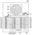
図8(A)に示されるように、魚眼画像800に対して高画質に符号化する領域801を設定した場合を考える。図8(B)において、切り出し画像850は、歪を有する魚眼画像800から部分的に切り出され、歪を取り除くための幾何変換処理を行って得られた画像である。魚眼画像800に設定された高画質な領域801を切り出し画像850上に展開すると、領域801は上記の幾何変換処理によって歪むため、領域851のようになる。領域851はマクロブロック単位の形状にはならず、MPEG規格のようにマクロブロック単位で符号化する場合に切り出し画像850に対して高画質に符号化する領域を設定することができない。上記の事項は、高画質に符号化する領域だけではなく、符号化に影響する機能に係る領域を設定する場合も同様である。
As shown in FIG. 8A, consider a case where a
本発明は上記の課題を解決するためになされたものであり、第1の画像と第1の画像から切り出され歪みが補正された第2の画像の両方に、符号化処理に影響する機能に係る領域を適切に設定可能とすることを目的とする。 The present invention has been made to solve the above-mentioned problems, and has a function of affecting the coding process for both the first image and the second image cut out from the first image and corrected for distortion. The purpose is to make it possible to set the relevant area appropriately.
本発明の一態様による画像処理装置は、
第1の画像を取得する取得手段と、
前記第1の画像の少なくとも一部を切り出して歪み補正した第2の画像を生成する生成手段と、
前記第1の画像に対して符号化処理に影響する機能に係る領域を設定するための第1のユーザインターフェースと、前記第2の画像に対して符号化処理に影響する機能に係る領域を設定するための第2のユーザインターフェースとを提供する提供手段と、
前記第1のユーザインターフェースを用いて設定された領域の画質に基づいて前記第1の画像を符号化し、前記第2のユーザインターフェースを用いて設定された領域に基づいて前記第2の画像を符号化する符号化手段と、を備える。
The image processing apparatus according to one aspect of the present invention is
The acquisition means for acquiring the first image and
A generation means for generating a second image in which at least a part of the first image is cut out and distortion-corrected, and
A first user interface for setting an area related to a function affecting the coding process for the first image and an area related to a function affecting the coding process for the second image are set. A means of providing a second user interface for
The first image is encoded based on the image quality of the area set using the first user interface, and the second image is encoded based on the area set using the second user interface. A coding means for converting is provided.
本発明によれば、第1の画像と第1の画像から切り出され歪みが補正された第2の画像の両方に、符号化処理に影響する機能に係る領域を適切に設定することが可能となる。 According to the present invention, it is possible to appropriately set a region related to a function affecting the coding process in both the first image and the second image cut out from the first image and corrected for distortion. Become.
以下に、本発明の実施形態のいくつかを、図面に基づいて詳細に説明する。 Hereinafter, some embodiments of the present invention will be described in detail with reference to the drawings.
<第1実施形態>
図1(b)は第1実施形態による監視システムの装置構成例を示す図である。画像処理装置としてのカメラサーバ200とクライアント220がネットワーク230を介して相互に通信可能に接続されている。カメラサーバ200は撮影画角が可変のカメラ210と接続され、カメラ210で撮影した画像を、ネットワーク230を介して外部装置へ配信する。カメラ210は、たとえば、全周魚眼レンズを搭載した全方位カメラである。クライアント220はカメラサーバ200にアクセスし、画像を取得しながら、パン・チルト・ズーム及びフォーカスや露出等の撮影パラメータを制御する。また、クライアント220は、それら撮影パラメータをカメラサーバ200にプリセット設定する。それぞれの詳細については後述する。なお、説明の簡略化のためにカメラサーバが1台の監視システムを示したが、カメラサーバが2台以上であっても構わない。またクライアント220以外にもカメラサーバ200にアクセスして画像の受信や蓄積を行う他のクライアントがあっても構わない。また、カメラサーバ200の機能がカメラ210に組み込まれていてもよい。
<First Embodiment>
FIG. 1B is a diagram showing an example of a device configuration of a monitoring system according to the first embodiment. The
ネットワーク230はEthernet(登録商標)等の通信規格を満足する複数のルータ、スイッチ、ケーブル等から構成される。本実施形態においては各サーバ・クライアント間の通信が支障なく行えるものであればその通信規格、規模、構成を問わない。故に、ネットワーク230には、インターネットからLAN(Local Ara Network)まで、種々のネットワークを適用可能である。
The
図2はカメラサーバ200のハードウェア構成例を示すブロック図である。カメラサーバ200では、CPU300、一次記憶装置310、二次記憶装置320、画像キャプチャI/F330、雲台制御I/F340、ネットワークI/F360が内部バス301を介して相互に接続されている。
FIG. 2 is a block diagram showing a hardware configuration example of the
CPU300は、一次記憶装置310にロードされた所定のプログラムを実行することにより各種の制御を実現する。一次記憶装置310はRAMに代表される書き込み可能な高速の記憶装置である。一次記憶装置310には、CPU300が実行するOSと各種プログラム、及び各種データが二次記憶装置320からロードされる。また、一次記憶装置310は、OSや各種プログラムを実行するCPU300の作業領域としても使用される。二次記憶装置320はFDDやHDD、フラッシュメモリ、CD−ROMドライブ等に代表される不揮発性を持った記憶装置である。二次記憶装置320は、OSや各種プログラム及び各種データの永続的な記憶領域として使用される他に、短期的な各種データの記憶領域としても使用される。カメラサーバ200の一次記憶装置310及び二次記憶装置320に置かれる各種プログラム等の詳細については後述する。
The
画像キャプチャI/F330にはカメラ210の画像センサ370が接続される。画像センサ370は、CCDセンサまたはCMOSセンサにより構成される。CPU300は、画像センサ370から画像キャプチャI/F330を介して画像データを取得し、取得した画像データを画質パラメータに従って画像処理し、所定のフォーマットに変換・圧縮して一次記憶装置310に格納する。雲台制御I/F340は、カメラ210のレンズ/雲台380と接続される。CPU300は、雲台制御I/F340を介してパン・チルト・ズーム機構を制御してカメラ210(画像センサ370)の撮影位置や撮影画角を変更する。ネットワークI/F360はネットワーク230と接続するためのI/Fであり、Ethernet等の通信媒体を介してクライアント220等との通信を担う。
The
図1(a)は、カメラサーバ200の機能構成例を示すブロック図である。図1(a)に示される撮像処理部110、プリセット制御部111、通信処理部112、領域処理部114、一時記憶部113の各機能部は、CPU300が一次記憶装置310にロードされたプログラム(ソフトウェア)を実行することにより実現される。ただし、各機能部は、専用のハードウェアにより実現されてもよいし、ハードウェアとソフトウェアの協働により実現されてもよい。
FIG. 1A is a block diagram showing a functional configuration example of the
撮像処理部110は、カメラ210により撮像された画像(歪みを有する画像)を取得し、取得した画像の少なくとも一部を切り出して歪み補正した画像を生成する。より具体的には、撮像処理部110は、画像センサ370で生成された画像データを画像キャプチャI/F330を介して取得し、プリセット制御部111から指定された画質パラメータに従って画像処理と符号化処理を行う。なお、本実施形態では、画像センサ370から全方位画像(魚眼画像)が取得され、撮像処理部110は、魚眼画像の全体を符号化した魚眼画像データを出力する。また、撮像処理部110は、魚眼画像から一部を切り出した画像に歪みを除去または低減するための幾何変換(歪み補正)を行って得られた画像(切り出し画像)を符号化した切り出し画像データを出力する。なお、切り出し画像の切り出し位置と切り出しサイズは、クライアント220から設定可能としてもよい。また、本実施形態では、歪みを有する画像として魚眼画像を用いるが、これに限定されるものではない。
The image
プリセット制御部111は、クライアント220から設定されたプリセット位置、プリセット巡回設定、および/またはイベントによるプリセット移動設定、などの撮影パラメータに応じて、雲台制御I/F340を介してレンズ/雲台380を制御する。これにより、プリセットの内容に応じてパン・チルト・ズーム位置が制御される。また、プリセット制御部111は、プリセットとして保存されている画質パラメータを、撮像処理部110に設定する。画質パラメータには、例えば、フォーカス、露出、ホワイトバランス、デイナイト、スマートシェード補正、ノイズリダクション、シャープネス、色の濃さ等のパラメータが含まれる。また、プリセットには魚眼画像から切り出し画像を得るための切り出し範囲を示す情報が含まれてもよい。
The preset control unit 111 sets the lens /
通信処理部112は、クライアント220からのリクエストに応じて、一次記憶装置310に保存された画像データを、ネットワークI/F360およびネットワーク230を介してクライアント220へ送る。また、通信処理部112は、クライアント220から送られる撮影パラメータ(パン・チルト・ズームの位置など)や画質パラメータをプリセット制御部111に伝える。受信したプリセットの内容は二次記憶装置320に保存される。
In response to the request from the client 220, the
一時記憶部113は、撮像処理部110により符号化された画像データ(魚眼画像データ、切り出し画像データ)を一次記憶装置310に保存する。領域処理部114は、クライアント220により指定された、同じ画像内の他の領域よりも高画質とする高画質領域(符号化処理に影響する機能に係る領域の一例)を受け付け、撮像処理部110に設定する。高画質領域については後述する。例えば、領域処理部114は、魚眼画像または切り出し画像において高画質領域に指定された領域を構成するマクロブロックの量子化ステップを他の領域よりも小さく設定する。これにより、撮像処理部110により生成された画像データは、高画質領域の画質が他の領域の画質よりも高い画像データとなる。なお、各機能部の相互の連携は、例えばオペレーティングシステムが提供する機能を用いることで実現され得る。なお、マクロブロックは一例であり、使用する動画圧縮符号化規格で規定される処理単位であればよい。また、符号化処理に影響する機能としては、画像内の特定の領域の画質を変更する機能だけではなく、符号化に係るパラメータの変更が発生する機能であればよい。
The
以下、図3、図4、図5を参照して、第1実施形態による、高画質領域の設定処理について説明する。図3は、カメラサーバ200による、魚眼画像およびその魚眼画像から切り出され、幾何変換処理により歪みが低減もしくは除去された切り出し画像に対して高画質領域を設定する処理を示すフローチャートである。図4、図5は、高画質領域を設定する際のクライアント220上のユーザインターフェース(UI)画面の一例である。図4は魚眼画像に対して高画質領域を設定するためのユーザインターフェースの画面(UI画面)、図5は切り出し画像に対して高画質領域を設定するためのユーザインターフェースの画面(UI画面)を示す。
Hereinafter, the setting process of the high image quality region according to the first embodiment will be described with reference to FIGS. 3, 4, and 5. FIG. 3 is a flowchart showing a process of setting a high image quality region for a fisheye image and a cutout image cut out from the fisheye image and whose distortion is reduced or removed by geometric transformation processing by the
なお、本実施形態では、UIはカメラサーバ200からクライアント220に提供される。例えば、クライアント220において高画質領域を設定するためのUIは領域処理部114からウェブページの形態で提供され、クライアント220で稼働するブラウザにより表示される。もちろん、UIの提供形態はこれに限られるものではなく、クライアント220上で専用のアプリケーションを実行することでUIが実現されてもよい。
In this embodiment, the UI is provided from the
ユーザは、例えばクライアント220上の設定画面(不図示)等を操作することで、魚眼画像に対して高画質領域を設定するかどうかを指示することができる。魚眼画像に対して高画質領域を設定することが指示された場合、その指示がクライアント220からカメラサーバ200に通知される。領域処理部114は、魚眼画像に対して高画質領域を設定することの指示を受け付けると(S401でYES)、魚眼画像に対して高画質領域を設定するためのユーザインターフェースをクライアント220に提供する。具体的には、魚眼画像用の領域設定画面500a(図4)をクライアント220に送信する(S402)。クライアント220は、魚眼画像用の領域設定画面500aを受信すると、これをディスプレイ上に表示する。魚眼画像の高画質領域を設定する指示がなされない場合は(S401でNO)、処理はS402をスキップしてS403へ進む。
The user can instruct whether or not to set a high image quality region for the fisheye image by operating, for example, a setting screen (not shown) on the client 220. When it is instructed to set the high image quality region for the fisheye image, the instruction is notified from the client 220 to the
図4は、領域処理部114により提供され、クライアント220で表示される魚眼画像用の領域設定画面500aの一例を示す図である。領域設定画面500aの魚眼画像表示528は、カメラ210により撮影された魚眼画像を表示する。ユーザは、この魚眼画像表示528における魚眼画像の表示上で高画質領域を指定することにより、魚眼画像に高画質領域を設定することができる。図4では、2つの高画質領域529、530が有効に設定されている様子が示されている。
FIG. 4 is a diagram showing an example of an
本実施形態の領域設定画面500aでは、8個の高画質領域を設定しておくことができ、それらの有効、無効を個別に設定することができる。なお、設定可能な高画質領域の数が8に限られないことは言うまでもない。項目501〜508は領域1〜領域8として魚眼画像上に設定される高画質領域に対応する。例えば、ユーザが、項目501を選択し、ポインティングデバイスを用いて魚眼画像表示528上の任意の位置に任意の大きさの矩形を指定すると、領域1に対応する高画質領域が設定される。図4では、高画質領域529が領域1に対応し、高画質領域530が領域2に対応しているとする。また、例えば、ユーザが項目501(領域1)を指定すると、これに対応する高画質領域529の枠がハイライト表示される。あるいは、魚眼画像表示528上で高画質領域529を選択すると対応する項目501がハイライト表示される。これにより、ユーザは項目501〜508と魚眼画像上の高画質領域との対応を把握できる。
On the
なお、各領域を矩形で設定する理由は、符号化における処理単位(マクロブロックやCoding unit等)が矩形状だからである。なお、各領域は矩形に限らず、画像の縦方向又は横方向に平行な直線によって規定してもよい。また、符号化における処理単位に合うように、ユーザによって設定された領域を自動的に調整するようにしてもよい。 The reason for setting each area as a rectangle is that the processing unit (macroblock, Coding unit, etc.) in coding is rectangular. In addition, each region is not limited to a rectangle, and may be defined by a straight line parallel to the vertical direction or the horizontal direction of the image. Further, the area set by the user may be automatically adjusted so as to match the processing unit in the coding.
ユーザは、プルダウンリスト509〜516を用いて、領域1〜8のそれぞれの高画質領域について有効/無効を設定することができる。また、ユーザは、プレビューボタン517〜524により、それぞれの高画質領域をプレビュー表示させることができる。図4では、領域1(501)の高画質領域529と領域2(502)の高画質領域530が有効となっている。また、ユーザは、高画質領域529および530の位置および形状(矩形のアスペクト比)を、例えばポインティングデバイスを用いて変更することができる。
The user can set valid / invalid for each high image quality area of the areas 1 to 8 by using the pull-down lists 509 to 516. In addition, the user can preview and display each high image quality area by pressing the
領域設定画面500aにおいてなされた上記設定内容は、適用ボタン526の押下に応じてクライアント220からカメラサーバ200に送信され、領域処理部114によって二次記憶装置320に保存される。クリアボタン527が押下されると、これらの設定が変更前に戻る(二次記憶装置320に保存されている設定内容は更新されない)。適用ボタン526またはクリアボタン527の押下により領域設定画面500aによる設定処理(S402)は終了し、処理はS403へ進む。
The above-mentioned setting contents made on the
ユーザは、例えばクライアント220上の設定画面(不図示)等を操作することで、切り出し画像に対して高画質領域を設定するかどうかを指示することができる。切り出し画像に対して高画質領域を設定することが指示された場合、その指示がクライアント220からカメラサーバ200に通知される。領域処理部114は、切り出し画像に対して高画質領域を設定することの指示を受け付けると(S403でYES)、切り出し画像に対して高画質領域を設定するためのユーザインターフェースをクライアント220に提供する。より具体的には、切り出し画像用の領域設定画面500bをクライアント220に送信する(S404)。クライアント220は、切り出し画像用の領域設定画面500bを受信すると、これをディスプレイ上に表示する。切り出し画像の高画質領域を設定する指示がなされない場合は(S403でNO)、S404はスキップされ、本処理は終了する。なお、図4に示した魚眼画像用の領域設定画面500aの適用ボタン526の押下に応じて、クライアント220の表示が切り出し画像用の領域設定画面500bへ遷移するようにしてもよい。
The user can instruct whether or not to set a high image quality region for the cropped image by operating, for example, a setting screen (not shown) on the client 220. When it is instructed to set the high image quality area for the cropped image, the instruction is notified from the client 220 to the
図5は、領域処理部114により提供され、クライアント220で表示される切り出し画像用の領域設定画面500bの一例を示す図である。領域設定画面500bの切り出し画像表示578には切り出し画像が表示される。切り出し画像は、カメラ210により撮影された魚眼画像から一部が切り出され、幾何変換処理された画像である。ユーザは、この切り出し画像表示578における切り出し画像の表示上で高画質領域を指定することにより、切り出し画像に高画質領域を設定することができる。図5では、2つの高画質領域579、580が有効に設定されている様子が示されている。
FIG. 5 is a diagram showing an example of an
項目551〜558、プルダウンリスト559〜566、プレビューボタン567〜574の機能は、それぞれ図4の項目501〜508、プルダウンリスト509〜516、プレビューボタン517〜524と同様である。また、魚眼画像用の領域設定画面500aと同様に、ユーザは、切り出し画像表示578上の高画質領域579、高画質領域580の位置および形状をポインティングデバイスの操作により変更することができる。ここでも図4の説明と同様に、各領域を矩形で設定する。その理由は、符号化における処理単位が矩形状だからである。なお、図4の説明と同様に各領域は矩形に限らず、画像の縦方向又は横方向に平行な直線によって規定してもよい。また、符号化における処理単位に合うように、ユーザによって設定された領域を自動的に調整するようにしてもよい。
The functions of
領域設定画面500bにおいてなされた設定内容は、適用ボタン576の押下に応じてクライアント220からカメラサーバ200に送信され、領域処理部114によって二次記憶装置320に保存される。クリアボタン577が押下されると、これらの設定が変更前に戻る(二次記憶装置320に保存されている設定内容は更新されない)。適用ボタン576またはクリアボタン577の押下により領域設定画面500bによる設定処理(S404)は終了し、図3の処理が終了する。
The setting content made on the
以上のように、第1実施形態によれば、魚眼画像とその魚眼画像から切り出され、歪み補正された切り出し画像それぞれに対して別々に符号化処理に影響する機能に係る領域を設定させることができる。また、魚眼画像と切り出し画像の両画像に対して符号化処理に係る規定の処理単位に適した形状の領域を設定することができる。なお、魚眼画像への領域の設定に応じて(例えば、適用ボタン526の押下に応じて)、その魚眼画像から切り出された切り出し画像に領域を設定するためのユーザインターフェース(領域設定画面500b)が表示されるようにしてもよい。また、逆に、切り出し画像への領域の設定に応じて(例えば、適用ボタン576の押下に応じて)、その切り出し画像の元の魚眼画像に領域を設定するためのユーザインターフェース(領域設定画面500a)が表示されるようにしてもよい。
As described above, according to the first embodiment, the fisheye image and the area related to the function that affects the coding process are separately set for each of the fisheye image and the distortion-corrected cutout image. be able to. Further, it is possible to set a region having a shape suitable for a predetermined processing unit related to the coding process for both the fisheye image and the cutout image. A user interface (
<第2実施形態>
以下、図6および図7を参照して、第2実施形態を説明する。第2実施形態では、魚眼画像と切り出し画像のいずれか一方にのみ同じ画像内の他の領域よりも高画質とする高画質領域(符号化処理に影響する機能に係る領域の一例)が設定されている場合にその旨のメッセージが通知される。図6は、魚眼画像および切り出し画像に対して高画質領域を設定するための第2の実施形態による処理を示すフローチャートである。図7は、高画質領域を設定する際のクライアント220上のUI画面の一例を示す図である。
<Second Embodiment>
Hereinafter, the second embodiment will be described with reference to FIGS. 6 and 7. In the second embodiment, only one of the fisheye image and the cutout image is set with a high image quality region (an example of an region related to a function affecting the coding process) that has a higher image quality than the other regions in the same image. If so, a message to that effect will be notified. FIG. 6 is a flowchart showing a process according to the second embodiment for setting a high image quality region for a fisheye image and a cutout image. FIG. 7 is a diagram showing an example of a UI screen on the client 220 when setting a high image quality area.
図6において、S401〜S404の処理は第1実施形態(図3)と同様である。S605において、領域処理部114は、魚眼画像と切り出し画像のどちらか一方のみに高画質領域が設定されているかどうかを判定する。魚眼画像と切り出し画像のどちらか一方のみに高画質領域が設定されている場合(S605でYES)、領域処理部114は、注意のメッセージをクライアント220に送信する(S606)。クライアント220がこのメッセージをUI画面(不図示)に表示することで、ユーザが片方の画像に対してだけ高画質領域を設定し、もう片方の画像に対して高画質領域を設定し忘れることを防止できる。魚眼画像と切り出し画像の両方に高画質領域が設定されている場合、または、それらのいずれにも高画質領域が設定されていない場合は(S605でNO)、S606はスキップされ、本処理が終了する。
In FIG. 6, the processes of S401 to S404 are the same as those of the first embodiment (FIG. 3). In S605, the
例えば、ユーザは、それぞれの領域設定画面において適用ボタン526、576を押下し、設定を反映させることができる。魚眼画像および切り出し画像のどちらか一方のみに対してのみ高画質領域が設定された状態(適用ボタン526、527の一方を押下し、他方を押下していない状態)で、ユーザが領域設定画面から他の画面へ遷移させると、S605でYESと判定される。この場合、領域処理部114は、注意のメッセージをクライアント220に送信し、クライアント220のUI画面(不図示)に表示させる(S606)。
For example, the user can press the apply
以上のように、第2実施形態によれば、魚眼画像および切り出し画像のどちらか一方のみに対して高画質領域が設定されている場合にユーザに対して注意喚起することで、ユーザが本来設定すべき領域設定を失念することを防止できる。なお、ここでは注意メッセージを表示したが、エラーメッセージを表示し、設定していない方の画像の領域設定画面に強制的に遷移するようにしてもよい。 As described above, according to the second embodiment, when the high image quality region is set for only one of the fisheye image and the cutout image, the user is originally alerted to the user. It is possible to prevent forgetting to set the area to be set. Although a caution message is displayed here, an error message may be displayed to force a transition to the area setting screen of the image that has not been set.
<他の実施形態>
上記各実施形態において、領域設定画面500aが領域設定画面500bへ切り換えるための操作項目を含み、領域設定画面500bが領域設定画面500aへ切り換えるための操作項目を含むようにしてもよい。この場合、たとえば、図7に示すような領域設定画面500cが用いられる。領域設定画面500cは、魚眼画像用の領域設定画面であり、図4に示した領域設定画面500aに、ユーザインターフェースを切り換えるための操作項目としての画像種別プルダウンリスト701が追加されている。画像種別プルダウンリスト701において魚眼画像が選択されると魚眼画像用の領域設定画面(図7)が提供される。また、画像種別プルダウンリスト701において切り出し画像が選択されると、切り出し画像用の領域設定画面が提供される。この場合、切り出し画像用の領域設定画面は、図4に示した領域設定画面500aに画像種別プルダウンリスト701が追加されたものとなる。魚眼画像を表示している図7の領域設定画面500cにおいて画像種別プルダウンリスト701から切り出し画像が選択されると、表示中の魚眼画像から切り出された切り出し画像に領域設定を行うための領域設定画面が提供される。同様に、切り出し画像を表示している領域設定画面において画像種別プルダウンリスト701から切り出し画像が選択されると、表示中の切り出し画像の元の魚眼画像に領域設定を行うための領域設定画面が提供される。いずれの領域設定画面においても、画像種別プルダウンリスト701が含まれる。
<Other Embodiments>
In each of the above embodiments, the
また、上記各実施形態では、符号化処理に影響する機能に係る領域について有効/無効を切り換えるのみであったが、これに限られるものではない。例えば、高画質に複数段階のレベルを設けて、領域ごとに指定できるようにしてもよい。例えば、高画質、中間画質、無効のいずれかを領域ごとに指定できるようにしてもよい。また、上記実施形態では、画質を高める領域を指定する構成を示したが、画質を下げる領域を指定するようにしてもよい。すなわち、領域処理部114がクライアント220に提供するUIは、魚眼画像または引き出し画像において異なる画質とするべき領域を設定するものであればよい。そして、撮像処理部110の符号化は、UIにより設定された領域の画質が他の領域の画質と異なるように魚眼画像または引き出し画像を符号化する。
Further, in each of the above embodiments, only the valid / invalid area is switched for the area related to the function affecting the coding process, but the present invention is not limited to this. For example, a plurality of levels may be provided for high image quality so that they can be specified for each area. For example, one of high image quality, intermediate image quality, and invalidity may be specified for each area. Further, in the above embodiment, the configuration for designating the region for enhancing the image quality is shown, but the region for lowering the image quality may be designated. That is, the UI provided by the
また、上記各実施形態において、領域設定画面の魚眼画像表示528において、切り出し画像において設定された高画質領域に対応する領域が、高画質領域529,530と区別可能に(例えば点線により)表示されてもよい。同様に、領域設定画面の切り出し画像表示578に、魚眼画像において設定された高画質領域に対応する領域が、高画質領域579,580と区別可能に(例えば点線により)表示されてもよい。このようにすれば、例えば、ユーザは、切り出し画像上で高画質領域を設定する際に、魚眼画像で設定された高画質領域を切り出し画像表示578上で確認することができる。この場合、魚眼画像で設定された高画質領域は、魚眼画像の歪みを補正する幾何変換により矩形から変形するが、ユーザは、その領域を囲むように高画質領域の範囲(矩形)を設定することができる。これにより、ユーザは、容易に、魚眼画像で設定された高画質領域に対応する範囲を切り出し画像における高画質領域に設定することができる。
Further, in each of the above embodiments, in the
以上、本発明の好ましい実施形態について説明したが、本発明はこれらの実施形態に限定されず、その要旨の範囲内で種々の変形及び変更が可能である。例えば、上記各実施形態では、魚眼画像と魚眼画像を幾何変換処理によって補正した画像を高画質領域の設定対象としたが、補正が必要な画像であれば魚眼画像に限定されない。 Although the preferred embodiments of the present invention have been described above, the present invention is not limited to these embodiments, and various modifications and modifications can be made within the scope of the gist thereof. For example, in each of the above embodiments, the fisheye image and the image obtained by correcting the fisheye image by the geometric transformation process are set as the target for setting the high image quality region, but the image is not limited to the fisheye image as long as the image requires correction.
本発明は、上述の実施形態の1以上の機能を実現するプログラムを、ネットワーク又は記憶媒体を介してシステム又は装置に供給し、そのシステム又は装置のコンピュータにおける1つ以上のプロセッサがプログラムを読出し実行する処理でも実現可能である。また、1以上の機能を実現する回路(例えば、ASIC)によっても実現可能である。 The present invention supplies a program that realizes one or more functions of the above-described embodiment to a system or device via a network or storage medium, and one or more processors in the computer of the system or device reads and executes the program. It can also be realized by the processing to be performed. It can also be realized by a circuit (for example, ASIC) that realizes one or more functions.
110:撮像処理部、111:プリセット制御部、112:通信処理部、113:一時記憶部、200:カメラサーバ、210:カメラ、220:クライアント、230:ネットワーク 110: Imaging processing unit, 111: Preset control unit, 112: Communication processing unit, 113: Temporary storage unit, 200: Camera server, 210: Camera, 220: Client, 230: Network
Claims (15)
前記第1の画像の少なくとも一部を切り出して歪み補正した第2の画像を生成する生成手段と、
前記第1の画像に対して符号化処理に影響する機能に係る領域を設定するための第1のユーザインターフェースと、前記第2の画像に対して符号化処理に影響する機能に係る領域を設定するための第2のユーザインターフェースとを提供する提供手段と、
前記第1のユーザインターフェースを用いて設定された領域に基づいて前記第1の画像を符号化し、前記第2のユーザインターフェースを用いて設定された領域に基づいて前記第2の画像を符号化する符号化手段と、を備えることを特徴とする画像処理装置。 The acquisition means for acquiring the first image and
A generation means for generating a second image in which at least a part of the first image is cut out and distortion-corrected, and
A first user interface for setting an area related to a function affecting the coding process for the first image and an area related to a function affecting the coding process for the second image are set. A means of providing a second user interface for
The first image is encoded based on a region set using the first user interface and the second image is encoded based on a region set using the second user interface. An image processing apparatus including a coding means.
前記生成手段は、前記第1の画像の一部を切り出して幾何変換処理を行うことにより前記第2の画像を生成することを特徴とする請求項1に記載の画像処理装置。 The acquisition means acquires an image captured by the camera as the first image, and obtains the image.
The image processing apparatus according to claim 1, wherein the generation means generates the second image by cutting out a part of the first image and performing a geometric transformation process.
前記第2の画像は、前記魚眼画像の一部を切り出して幾何変換処理が施された切り出し画像であることを特徴とする請求項1または2に記載の画像処理装置。 The first image is a fisheye image captured by a fisheye lens .
The image processing apparatus according to claim 1 or 2, wherein the second image is a cut-out image obtained by cutting out a part of the fisheye image and performing a geometric transformation process.
前記撮像手段により撮像された第1の画像を取得する取得手段と、
前記第1の画像の少なくとも一部を切り出して歪み補正した第2の画像を生成する生成手段と、
前記第1の画像に対して符号化処理に影響する機能に係る領域を設定するための第1のユーザインターフェースと、前記第2の画像に対して符号化処理に影響する機能に係る領域を設定するための第2のユーザインターフェースとを外部装置に提供する提供手段と、
前記外部装置が前記第1のユーザインターフェースを用いて設定した領域に基づいて前記第1の画像を符号化し、前記外部装置が前記第2のユーザインターフェースを用いて設定した領域に基づいて前記第2の画像を符号化する符号化手段と、を備えることを特徴とする撮像装置。 Imaging means and
Acquiring means for acquiring the first image captured by the imaging means, and
A generation means for generating a second image in which at least a part of the first image is cut out and distortion-corrected, and
A first user interface for setting an area related to a function affecting the coding process for the first image and an area related to a function affecting the coding process for the second image are set. A means of providing an external device with a second user interface for
The first image is encoded based on a region set by the external device using the first user interface, and the second image is based on a region set by the external device using the second user interface. An image pickup apparatus comprising: a coding means for encoding an image of the above.
前記画像処理装置が、
前記撮像装置が撮像した第1の画像を取得する取得手段と、
前記第1の画像の少なくとも一部を切り出して歪み補正した第2の画像を生成する生成手段と、
前記第1の画像に対して符号化処理に影響する機能に係る領域を設定するための第1のユーザインターフェースと、前記第2の画像に対して符号化処理に影響する機能に係る領域を設定するための第2のユーザインターフェースとを、前記がクライアント装置に提供する提供手段と、
前記クライアント装置により前記第1のユーザインターフェースを用いて設定された領域に基づいて前記第1の画像を符号化し、前記クライアント装置により前記第2のユーザインターフェースを用いて設定された領域に基づいて前記第2の画像を符号化する符号化手段と、を備えることを特徴とする監視システム。 A monitoring system including an image pickup device, an image processing device, and a client device.
The image processing device
An acquisition means for acquiring a first image captured by the imaging device, and
A generation means for generating a second image in which at least a part of the first image is cut out and distortion-corrected, and
A first user interface for setting an area related to a function affecting the coding process for the first image and an area related to a function affecting the coding process for the second image are set. A second user interface for providing a second user interface, the means for which the above provides to the client device, and
The first image is encoded based on a region set by the client device using the first user interface, and said based on a region set by the client device using the second user interface. A monitoring system comprising a coding means for encoding a second image.
第1の画像を取得する取得工程と、
前記第1の画像の少なくとも一部を切り出して歪み補正した第2の画像を生成する生成工程と、
前記第1の画像に対して符号化処理に影響する機能に係る領域を設定するための第1のユーザインターフェースと、前記第2の画像に対して符号化処理に影響する機能に係る領域を設定するための第2のユーザインターフェースとを提供する提供工程と、
前記第1のユーザインターフェースを用いて設定された領域に基づいて前記第1の画像を符号化し、前記第2のユーザインターフェースを用いて設定された領域に基づいて前記第2の画像を符号化する符号化工程と、を有することを特徴とする画像処理装置の制御方法。 It is a control method of an image processing device.
The acquisition process to acquire the first image and
A generation step of cutting out at least a part of the first image to generate a distortion-corrected second image, and
A first user interface for setting an area related to a function affecting the coding process for the first image and an area related to a function affecting the coding process for the second image are set. A provision process that provides a second user interface for
The first image is encoded based on a region set using the first user interface and the second image is encoded based on a region set using the second user interface. A method for controlling an image processing apparatus, which comprises a coding step.
Priority Applications (2)
| Application Number | Priority Date | Filing Date | Title |
|---|---|---|---|
| JP2017120807A JP6857088B2 (en) | 2017-06-20 | 2017-06-20 | Image processing equipment and its control method, imaging equipment, monitoring system |
| US16/009,307 US10607322B2 (en) | 2017-06-20 | 2018-06-15 | Image processing apparatus and method for controlling the same, imaging apparatus, and monitoring system |
Applications Claiming Priority (1)
| Application Number | Priority Date | Filing Date | Title |
|---|---|---|---|
| JP2017120807A JP6857088B2 (en) | 2017-06-20 | 2017-06-20 | Image processing equipment and its control method, imaging equipment, monitoring system |
Publications (3)
| Publication Number | Publication Date |
|---|---|
| JP2019009507A JP2019009507A (en) | 2019-01-17 |
| JP2019009507A5 JP2019009507A5 (en) | 2020-07-30 |
| JP6857088B2 true JP6857088B2 (en) | 2021-04-14 |
Family
ID=64657450
Family Applications (1)
| Application Number | Title | Priority Date | Filing Date |
|---|---|---|---|
| JP2017120807A Active JP6857088B2 (en) | 2017-06-20 | 2017-06-20 | Image processing equipment and its control method, imaging equipment, monitoring system |
Country Status (2)
| Country | Link |
|---|---|
| US (1) | US10607322B2 (en) |
| JP (1) | JP6857088B2 (en) |
Families Citing this family (1)
| Publication number | Priority date | Publication date | Assignee | Title |
|---|---|---|---|---|
| US20220345619A1 (en) * | 2019-09-27 | 2022-10-27 | Ricoh Company, Ltd. | Apparatus, image processing system, communication system, method for setting, image processing method, and recording medium |
Family Cites Families (18)
| Publication number | Priority date | Publication date | Assignee | Title |
|---|---|---|---|---|
| JPH06284395A (en) * | 1993-03-26 | 1994-10-07 | Toshiba Corp | Image compression-encoder |
| US20040015343A1 (en) * | 2002-07-22 | 2004-01-22 | Toshiba Tec Kabushiki Kaisha | System and method for customizing the language displayed on the interface of an image processing deivce |
| JP4717408B2 (en) * | 2004-10-13 | 2011-07-06 | キヤノン株式会社 | Video distribution system and method |
| WO2007055336A1 (en) * | 2005-11-11 | 2007-05-18 | Sony Corporation | Image processing device, image processing method, program thereof, recording medium containing the program, and imaging device |
| JP2007257585A (en) * | 2006-03-27 | 2007-10-04 | Fujifilm Corp | Image processing method, device and program |
| US8645105B1 (en) * | 2008-11-14 | 2014-02-04 | Adobe Systems Incorporated | Methods and systems for round-trip editing of component artwork |
| JP5340772B2 (en) * | 2009-03-13 | 2013-11-13 | パナソニック株式会社 | Image communication system |
| US9766089B2 (en) * | 2009-12-14 | 2017-09-19 | Nokia Technologies Oy | Method and apparatus for correlating and navigating between a live image and a prerecorded panoramic image |
| JP5818091B2 (en) * | 2011-12-27 | 2015-11-18 | ソニー株式会社 | Image processing apparatus, image processing system, image processing method, and program |
| GB2514495B (en) * | 2012-01-31 | 2015-04-22 | Panasonic Ip Man Co Ltd | Image processing device and image processing method |
| SE537088C2 (en) * | 2013-05-08 | 2015-01-07 | Cellavision Ab | Graphical user interface for analysis of red blood cells |
| JP2015126475A (en) * | 2013-12-27 | 2015-07-06 | ソニー株式会社 | Imaging apparatus, image distribution system, image processing method and program |
| CN103927054B (en) * | 2014-04-15 | 2017-02-01 | 华为终端有限公司 | Operation interface displaying method and device and touch screen terminal |
| US9971840B2 (en) * | 2014-05-07 | 2018-05-15 | Connectwise, Inc. | Systems and methods for discovering and monitoring devices using search patterns for object identifiers and values |
| US20160132219A1 (en) * | 2014-11-06 | 2016-05-12 | Microsoft Technology Licensing, Llc | Enhanced view transitions |
| US9846505B2 (en) * | 2015-01-07 | 2017-12-19 | Honeywell International Inc. | Customizable user interface |
| JP6345345B2 (en) * | 2015-05-15 | 2018-06-20 | 三菱電機株式会社 | Image processing apparatus, image processing method, and image processing program |
| US20180052966A1 (en) * | 2016-08-19 | 2018-02-22 | VisibleHand, Inc. | Systems And Methods for Optimizing Care For Patients and Residents Based On Interactive Data Processing, Collection, And Report Generation |
-
2017
- 2017-06-20 JP JP2017120807A patent/JP6857088B2/en active Active
-
2018
- 2018-06-15 US US16/009,307 patent/US10607322B2/en active Active
Also Published As
| Publication number | Publication date |
|---|---|
| JP2019009507A (en) | 2019-01-17 |
| US10607322B2 (en) | 2020-03-31 |
| US20180365814A1 (en) | 2018-12-20 |
Similar Documents
| Publication | Publication Date | Title |
|---|---|---|
| JP5268743B2 (en) | Image communication system | |
| US10297005B2 (en) | Method for generating panoramic image | |
| US8953046B2 (en) | Information processing apparatus for selecting a camera to be used to generate a virtual viewpoint video from images shot by a plurality of cameras | |
| JP6160357B2 (en) | Image processing apparatus, image processing method, and image communication system | |
| US10593013B2 (en) | Image processing apparatus and method for controlling the same, imaging apparatus, and monitoring system | |
| CN110022431B (en) | Image pickup apparatus, image pickup method, display apparatus, and display method | |
| JP7130385B2 (en) | Information processing device, information processing method and program | |
| CN105721767B (en) | The method for handling video flowing | |
| JP6141137B2 (en) | REMOTE CONTROL DEVICE AND ITS CONTROL METHOD, IMAGING DEVICE AND ITS CONTROL METHOD, SYSTEM, AND PROGRAM | |
| JP4793449B2 (en) | Network video composition display system | |
| JP6857088B2 (en) | Image processing equipment and its control method, imaging equipment, monitoring system | |
| JP7150456B2 (en) | IMAGING SYSTEM, INFORMATION PROCESSING DEVICE, CONTROL METHOD OF INFORMATION PROCESSING DEVICE, AND PROGRAM | |
| JP5960996B2 (en) | Imaging control device, image delivery method and program for imaging control device | |
| JP2010219872A (en) | Camera apparatus, display, system and method for processing image | |
| JP2014123881A (en) | Information processing device, information processing method, and computer program | |
| JP2014192745A (en) | Imaging apparatus, information processing apparatus, control method and program thereof | |
| JP2016096482A (en) | Image processing apparatus, image processing method, and program | |
| JP6245847B2 (en) | Image processing apparatus and image processing method | |
| JP2021002808A (en) | Information processing device, system, control method of information processing device, and program | |
| JP5917175B2 (en) | IMAGING DEVICE, IMAGING DEVICE DISTRIBUTION METHOD, IMAGING SYSTEM, AND PROGRAM | |
| JP2023176702A (en) | Imaging device, information processing device, control method, program and storage medium | |
| JP6679779B1 (en) | Information processing device, information processing method, and program | |
| JP2008131475A (en) | Imaging apparatus | |
| JP2012227603A (en) | Camera control unit and control method of camera control unit | |
| JP2018207254A (en) | Imaging apparatus, control method, program, and imaging system |
Legal Events
| Date | Code | Title | Description |
|---|---|---|---|
| A521 | Request for written amendment filed |
Free format text: JAPANESE INTERMEDIATE CODE: A523 Effective date: 20200616 |
|
| A621 | Written request for application examination |
Free format text: JAPANESE INTERMEDIATE CODE: A621 Effective date: 20200616 |
|
| RD01 | Notification of change of attorney |
Free format text: JAPANESE INTERMEDIATE CODE: A7421 Effective date: 20210103 |
|
| A521 | Request for written amendment filed |
Free format text: JAPANESE INTERMEDIATE CODE: A523 Effective date: 20210113 |
|
| A977 | Report on retrieval |
Free format text: JAPANESE INTERMEDIATE CODE: A971007 Effective date: 20210122 |
|
| TRDD | Decision of grant or rejection written | ||
| A01 | Written decision to grant a patent or to grant a registration (utility model) |
Free format text: JAPANESE INTERMEDIATE CODE: A01 Effective date: 20210219 |
|
| A61 | First payment of annual fees (during grant procedure) |
Free format text: JAPANESE INTERMEDIATE CODE: A61 Effective date: 20210319 |
|
| R151 | Written notification of patent or utility model registration |
Ref document number: 6857088 Country of ref document: JP Free format text: JAPANESE INTERMEDIATE CODE: R151 |