US10607322B2 - Image processing apparatus and method for controlling the same, imaging apparatus, and monitoring system - Google Patents
Image processing apparatus and method for controlling the same, imaging apparatus, and monitoring system Download PDFInfo
- Publication number
- US10607322B2 US10607322B2 US16/009,307 US201816009307A US10607322B2 US 10607322 B2 US10607322 B2 US 10607322B2 US 201816009307 A US201816009307 A US 201816009307A US 10607322 B2 US10607322 B2 US 10607322B2
- Authority
- US
- United States
- Prior art keywords
- image
- user interface
- area
- setting
- encoding
- Prior art date
- Legal status (The legal status is an assumption and is not a legal conclusion. Google has not performed a legal analysis and makes no representation as to the accuracy of the status listed.)
- Active
Links
- 238000012545 processing Methods 0.000 title claims abstract description 123
- 238000003384 imaging method Methods 0.000 title claims description 31
- 238000000034 method Methods 0.000 title claims description 17
- 238000012544 monitoring process Methods 0.000 title claims description 9
- 230000006870 function Effects 0.000 claims description 47
- 238000006243 chemical reaction Methods 0.000 claims description 10
- 230000015654 memory Effects 0.000 claims description 7
- 230000004044 response Effects 0.000 claims 8
- 230000002250 progressing effect Effects 0.000 claims 1
- 238000010586 diagram Methods 0.000 description 13
- 238000013139 quantization Methods 0.000 description 8
- 238000004891 communication Methods 0.000 description 7
- 230000008859 change Effects 0.000 description 4
- 230000006835 compression Effects 0.000 description 4
- 238000007906 compression Methods 0.000 description 4
- 238000012937 correction Methods 0.000 description 2
- 238000012986 modification Methods 0.000 description 2
- 230000004048 modification Effects 0.000 description 2
- 238000003825 pressing Methods 0.000 description 2
- 230000008901 benefit Effects 0.000 description 1
- 230000007246 mechanism Effects 0.000 description 1
- 230000003287 optical effect Effects 0.000 description 1
- 230000002093 peripheral effect Effects 0.000 description 1
- 230000009467 reduction Effects 0.000 description 1
- 230000007704 transition Effects 0.000 description 1
Images


Classifications
-
- G06T3/12—
-
- G06T5/80—
-
- G—PHYSICS
- G06—COMPUTING; CALCULATING OR COUNTING
- G06T—IMAGE DATA PROCESSING OR GENERATION, IN GENERAL
- G06T5/00—Image enhancement or restoration
- G06T5/006—Geometric correction
-
- G—PHYSICS
- G06—COMPUTING; CALCULATING OR COUNTING
- G06T—IMAGE DATA PROCESSING OR GENERATION, IN GENERAL
- G06T3/00—Geometric image transformation in the plane of the image
- G06T3/0062—Panospheric to cylindrical image transformation
-
- H—ELECTRICITY
- H04—ELECTRIC COMMUNICATION TECHNIQUE
- H04N—PICTORIAL COMMUNICATION, e.g. TELEVISION
- H04N19/00—Methods or arrangements for coding, decoding, compressing or decompressing digital video signals
- H04N19/10—Methods or arrangements for coding, decoding, compressing or decompressing digital video signals using adaptive coding
- H04N19/169—Methods or arrangements for coding, decoding, compressing or decompressing digital video signals using adaptive coding characterised by the coding unit, i.e. the structural portion or semantic portion of the video signal being the object or the subject of the adaptive coding
- H04N19/17—Methods or arrangements for coding, decoding, compressing or decompressing digital video signals using adaptive coding characterised by the coding unit, i.e. the structural portion or semantic portion of the video signal being the object or the subject of the adaptive coding the unit being an image region, e.g. an object
-
- H—ELECTRICITY
- H04—ELECTRIC COMMUNICATION TECHNIQUE
- H04N—PICTORIAL COMMUNICATION, e.g. TELEVISION
- H04N19/00—Methods or arrangements for coding, decoding, compressing or decompressing digital video signals
- H04N19/50—Methods or arrangements for coding, decoding, compressing or decompressing digital video signals using predictive coding
- H04N19/597—Methods or arrangements for coding, decoding, compressing or decompressing digital video signals using predictive coding specially adapted for multi-view video sequence encoding
-
- H—ELECTRICITY
- H04—ELECTRIC COMMUNICATION TECHNIQUE
- H04N—PICTORIAL COMMUNICATION, e.g. TELEVISION
- H04N23/00—Cameras or camera modules comprising electronic image sensors; Control thereof
- H04N23/60—Control of cameras or camera modules
- H04N23/62—Control of parameters via user interfaces
-
- H—ELECTRICITY
- H04—ELECTRIC COMMUNICATION TECHNIQUE
- H04N—PICTORIAL COMMUNICATION, e.g. TELEVISION
- H04N23/00—Cameras or camera modules comprising electronic image sensors; Control thereof
- H04N23/60—Control of cameras or camera modules
- H04N23/63—Control of cameras or camera modules by using electronic viewfinders
- H04N23/633—Control of cameras or camera modules by using electronic viewfinders for displaying additional information relating to control or operation of the camera
- H04N23/635—Region indicators; Field of view indicators
-
- H—ELECTRICITY
- H04—ELECTRIC COMMUNICATION TECHNIQUE
- H04N—PICTORIAL COMMUNICATION, e.g. TELEVISION
- H04N23/00—Cameras or camera modules comprising electronic image sensors; Control thereof
- H04N23/60—Control of cameras or camera modules
- H04N23/698—Control of cameras or camera modules for achieving an enlarged field of view, e.g. panoramic image capture
-
- H—ELECTRICITY
- H04—ELECTRIC COMMUNICATION TECHNIQUE
- H04N—PICTORIAL COMMUNICATION, e.g. TELEVISION
- H04N23/00—Cameras or camera modules comprising electronic image sensors; Control thereof
- H04N23/80—Camera processing pipelines; Components thereof
- H04N23/81—Camera processing pipelines; Components thereof for suppressing or minimising disturbance in the image signal generation
-
- H04N5/217—
-
- H04N5/23216—
-
- H04N5/23238—
-
- H04N5/232945—
-
- G—PHYSICS
- G06—COMPUTING; CALCULATING OR COUNTING
- G06T—IMAGE DATA PROCESSING OR GENERATION, IN GENERAL
- G06T2200/00—Indexing scheme for image data processing or generation, in general
- G06T2200/24—Indexing scheme for image data processing or generation, in general involving graphical user interfaces [GUIs]
-
- G—PHYSICS
- G06—COMPUTING; CALCULATING OR COUNTING
- G06T—IMAGE DATA PROCESSING OR GENERATION, IN GENERAL
- G06T2207/00—Indexing scheme for image analysis or image enhancement
- G06T2207/30—Subject of image; Context of image processing
- G06T2207/30232—Surveillance
-
- H—ELECTRICITY
- H04—ELECTRIC COMMUNICATION TECHNIQUE
- H04N—PICTORIAL COMMUNICATION, e.g. TELEVISION
- H04N19/00—Methods or arrangements for coding, decoding, compressing or decompressing digital video signals
- H04N19/10—Methods or arrangements for coding, decoding, compressing or decompressing digital video signals using adaptive coding
- H04N19/102—Methods or arrangements for coding, decoding, compressing or decompressing digital video signals using adaptive coding characterised by the element, parameter or selection affected or controlled by the adaptive coding
- H04N19/124—Quantisation
Definitions
- the present invention relates to an image processing apparatus and a method for controlling the same, an imaging apparatus, and a monitoring system.
- Omnidirectional cameras in which an omnidirectional mirror or an entire circumference fish-eye lens is mounted are imaging apparatuses that capture images of an entire circumferential (360-degree) view at a time, and are used for various applications such as a monitoring camera and robot navigation.
- An omnidirectional camera in which an entire circumference fish-eye lens is mounted captures a 360-degree fish-eye image in a ring shape or a circular shape, for example.
- a captured fish-eye image contains distortion, but a cut image, such as a panoramic image or a planar perspective projection image, can be obtained by cutting out an image from the fish-eye image and performing geometric conversion processing thereon.
- Japanese Patent Laid-Open No. 2006-115046 discloses a technique of partially cutting out an image obtained by a wide viewing angle camera, such as an omnidirectional camera, and delivering this cut image. Meanwhile, recently, regarding imaging apparatuses such as a network camera, an imaging apparatus capable of changing image quality in respective areas has been proposed.
- Japanese Patent Laid-Open No. 06-284395 discloses that the data volume of an image is suppressed while increasing the substantial image quality by increasing the image quality in a screen center portion and reducing the image quality in a peripheral portion.
- the MPEG standard is known as a moving image compression and encoding technique.
- An encoding apparatus that encodes a moving image conforming to the MPEG standard determines a target amount of code for each picture based on a target data rate. Then, based on the target amount of code for each picture, the target amount of code is allocated in an averaged manner to all macroblocks that constitute each picture. Thereafter, the quantization step width for encoding each macroblock is determined so as to achieve the target amount of code, and encoding is performed. If this quantization step width is made smaller, the amount of code increases but a high-quality image can be obtained.
- the quantization step width for macroblocks that constitute this area is made smaller than the quantization step width for macroblocks in the other area.
- the quantization step is determined using a unit called a “coding unit”, rather than a macroblock.
- the quantization step is determined for each of the rectangular block units, each of which is constituted by a plurality of pixels. Note that, in the moving image compression and encoding techniques, parameters other than the quantization step are also basically determined for each of the rectangular block units.
- FIG. 8A A case is considered where an area 801 , which is to be encoded so as to increase the image quality, is set in a fish-eye image 800 , as shown in FIG. 8A .
- a cut image 850 is an image obtained by cutting out a portion of the fish-eye image 800 that contains distortion, and performing geometric conversion processing to remove the distortion. If the high-quality image area 801 that is set in the fish-eye image 800 is expanded in the cut image 850 , the area 801 is distorted due to the aforementioned geometric conversion processing and thus becomes an area 851 .
- the area 851 does not have a shape that is based on a macroblock unit, and, in the case of performing encoding for each macroblock as in the MPEG standard, an area that is to be encoded so as to increase the image quality cannot be set in the cut image 850 . This point applies not only to the area that is to be encoded so as to increase the image quality, but also to the case of setting an area that is associated with a function that influences the encoding.
- An embodiment of the present invention provides an image processing apparatus in which an area that is associated with a function that influences encoding processing can be set appropriately in both a first image and a second image that has been cut out of the first image and in which distortion has been corrected, a control method thereof, an imaging apparatus, and a monitoring system.
- an image processing apparatus comprising: an obtaining unit configured to obtain a first image; a generating unit configured to cut out at least a portion of the first image to generate a second image that is distortion-corrected; a providing unit configured to provide a first user interface for setting, in the first image, an area associated with a function that influences encoding processing, and a second user interface for setting, in the second image, an area associated with the function that influences encoding processing; and an encoding unit configured to encode the first image based on the area set using the first user interface, and encode the second image based on the area set using the second user interface.
- an imaging apparatus comprising: an imaging unit; an obtaining unit configured to obtain a first image captured by the imaging unit; a generating unit configured to cut out at least a portion of the first image to generate a second image that is distortion-corrected; a providing unit configured to provide an external apparatus with a first user interface for setting, in the first image, an area associated with a function that influences encoding processing, and a second user interface for setting, in the second image, an area associated with the function that influences encoding processing; and an encoding unit configured to encode the first image based on the area set by the external apparatus using the first user interface, and encode the second image based on the area set by the external apparatus using the second user interface.
- a monitoring system that includes an imaging apparatus, an image processing apparatus, and a client apparatus, the image processing apparatus comprising: an obtaining unit configured to obtain a first image captured by the imaging apparatus; a generating unit configured to cut out at least a portion of the first image to generate a second image that is distortion-corrected; a providing unit configured to provide the client apparatus with a first user interface for setting, in the first image, an area associated with a function that influences encoding processing, and a second user interface for setting, in the second image, an area associated with the function that influences encoding processing; and an encoding unit configured to encode the first image based on the area set by the client apparatus using the first user interface, and encode the second image based on the area set by the client apparatus using the second user interface.
- a method for controlling an image processing apparatus comprising: obtaining a first image; cutting out at least a portion of the first image to generate a second image that is distortion-corrected; providing a first user interface for setting, in the first image, an area associated with a function that influences encoding processing, and a second user interface for setting, in the second image, an area associated with the function that influences encoding processing; and encoding the first image based on the area set using the first user interface, and encoding the second image based on the area set using the second user interface.
- a non-transitory computer-readable medium storing a program for causing a computer to execute a method for controlling an image processing apparatus, the control method comprising: obtaining a first image; cutting out at least a portion of the first image to generate a second image that is distortion-corrected; providing a first user interface for setting, in the first image, an area associated with a function that influences encoding processing, and a second user interface for setting, in the second image, an area associated with the function that influences encoding processing; and encoding the first image based on the area set using the first user interface, and encoding the second image based on the area set using the second user interface.
- FIG. 1A is a block diagram showing an example of a functional configuration of a camera server according to the present embodiments.
- FIG. 1B is a diagram showing an example of a configuration of a monitoring system according to the present embodiments.
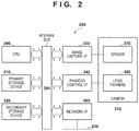
- FIG. 2 is a block diagram showing an example of a hardware configuration of the camera server according to the present embodiments.
- FIG. 3 is a flowchart illustrating processing to set a high-quality image area in a fish-eye image and a cut image, according to a first embodiment.
- FIG. 4 is a diagram showing an example of a UI screen for setting a high-quality image area in a fish-eye image.
- FIG. 5 is a diagram showing an example of a screen for setting a high-quality image area in a cut image.
- FIG. 6 is a flowchart illustrating processing to set a high-quality image area in a fish-eye image and a cut image, according to a second embodiment.
- FIG. 7 is a diagram showing an example of a UI screen for setting a high-quality image area, according to a third embodiment.
- FIGS. 8A and 8B are diagrams showing a relationship between a cut-out area in a fish-eye image and a cut-out area in a cut image.
- FIG. 1B is a diagram showing an example of an apparatus configuration of a monitoring system according to the first embodiment.
- a camera server 200 which serves as an image processing apparatus, and a client 220 are communicably connected to each other via a network 230 .
- the camera server 200 is connected to a camera 210 , the angle of view of which is variable, and delivers an image captured by the camera 210 to an external apparatus via the network 230 .
- the camera 210 is, for example, an omnidirectional camera in which an entire circumference fish-eye lens is mounted.
- the client 220 which serves as an external apparatus, controls imaging parameters for pan/tilt/zoom, focus, exposure, or the like, while accessing the camera server 200 and obtaining an image.
- the client 220 also presets these imaging parameters for the camera server 200 .
- the details will be described later. Not that, although a monitoring system that includes one camera server is described for simplification of the description, two or more camera servers may also be provided. A client that is not the client 220 and accesses the camera server 200 to receive and accumulate images may also be provided. Functions of the camera server 200 may also be incorporated in the camera 210 .
- the network 230 is constituted by a plurality of routers, switches, cables, or the like that conform to a communication standard, such as Ethernet (registered trademark).
- a communication standard such as Ethernet (registered trademark).
- any communication standard, scale, or configuration of the network 230 may be employed as long as the server and client can communicate without a problem.
- various kinds of networks including the Internet and a LAN (Local Area Network), are applicable to the network 230 .
- FIG. 2 is a block diagram showing an example of a hardware configuration of the camera server 200 .
- a CPU 300 In the camera server 200 , a CPU 300 , a primary storage device 310 , a secondary storage device 320 , an image capture I/F 330 , a panhead control I/F 340 , and a network I/F 360 are connected to one another via an internal bus 301 .
- the CPU 300 realizes various kinds of control by executing predetermined programs that are loaded to the primary storage device 310 .
- the primary storage device 310 is a high-speed writable storage device, which is typified by a RAM.
- An OS and various programs that are to be executed by the CPU 300 , and various kinds of data are loaded from the secondary storage device 320 to the primary storage device 310 .
- the primary storage device 310 is also used as a work area for the CPU 300 that executes the OS and various programs.
- the secondary storage device 320 is a nonvolatile storage device, which is typified by an FDD, an HDD, a flash memory, a CD-ROM drive, or the like.
- the secondary storage device 320 is used as a permanent storage area for storing the OS, various programs, and various kinds of data.
- the secondary storage device 320 is also used as a storage area for storing various kinds of short-term data. The details of various programs and the like stored in the primary storage device 310 and the secondary storage device 320 in the camera server 200 will be described later.
- An image sensor 370 in the camera 210 is connected to the image capture I/F 330 .
- the image sensor 370 is constituted by a CCD sensor or a CMOS sensor.
- the CPU 300 obtains image data from the image sensor 370 via the image capture IX 330 , performs image processing on the obtained image data in accordance with image quality parameters, converts and compresses the processed image into a predetermined format, and stores the resulting image in the primary storage device 310 .
- the panhead control I/F 340 is connected to a lens/panhead 380 of the camera 210 .
- the CPU 300 controls the pan/tilt/zoom mechanism in the lens/panhead 380 via the panhead control I/F 340 to change the imaging position and the angle of view of the camera 210 (image sensor 370 ).
- the network I/F 360 is an I/F for connecting to the network 230 , and enables communication with the client 220 , for example, via a communication medium such as Ethernet.
- FIG. 1A is a block diagram showing an example of a functional configuration of the camera server 200 .
- Functional units shown in FIG. 1A namely an imaging processing unit 110 , a preset control unit 111 , a communication processing unit 112 , an area processing unit 114 , and a temporary storage unit 113 are realized by the CPU 300 executing programs (software) that are loaded to the primary storage device 310 .
- the functional units may be realized by dedicated hardware, or may also be realized through cooperation between hardware and software.
- the imaging processing unit 110 obtains an image captured by the camera 210 (an image that contains distortion), and cuts out at least a portion of the obtained image to generate a distortion-corrected image. More specifically, the imaging processing unit 110 obtains, via the image capture I/F 330 , image data generated by the image sensor 370 , and performs image processing and encoding processing in accordance with image quality parameters that are designated by the preset control unit 111 . Note that, in this embodiment, an omnidirectional image (fish-eye image) is obtained from the image sensor 370 , and the imaging processing unit 110 outputs fish-eye image data, in which the entire fish-eye image is encoded.
- an omnidirectional image fish-eye image
- the imaging processing unit 110 also outputs cut image data, in which an image (cut image) that is obtained by cutting out a portion of a fish-eye image and performing geometric conversion (distortion correction) on this cut-out portion to eliminate or reduce distortion, is encoded.
- the client 220 may be able to set the cutting position and cutting size of the cut image.
- a fish-eye image is used as an image that contains distortion, but is not limited thereto.
- the preset control unit 111 controls the lens/panhead 380 via the panhead control I/F 340 in accordance with imaging parameters such as a preset position, a preset circulation setting, and/or a preset setting of movement according to an event that are set through the client 220 .
- imaging parameters such as a preset position, a preset circulation setting, and/or a preset setting of movement according to an event that are set through the client 220 .
- the preset control unit 111 also sets image quality parameters that are saved as preset parameters, for the imaging processing unit 110 .
- the image quality parameters include, for example, parameters for focus, exposure, white balance, day/night, smart shade control, noise reduction, sharpness, color contrast, and the like.
- the preset parameters may also include information that indicates a cutting range for obtaining a cut image from a fish-eye image.
- the communication processing unit 112 sends image data that is saved in the primary storage device 310 to the client 220 via the network I/F 360 and the network 230 , in accordance with a request from the client 220 .
- the communication processing unit 112 also informs the preset control unit 111 of imaging parameters (pan/tilt/zoom positions etc.) and image quality parameters that are sent from the client 220 .
- the received preset content is saved in the secondary storage device 320 .
- the temporary storage unit 113 saves, in the primary storage device 310 , image data (fish-eye image data, cut image data) that has been encoded by the imaging processing unit 110 .
- the area processing unit 114 accepts designation of a high-quality image area (an example of an area that is associated with a function that influences encoding processing) that is designated by the client 220 and in which image quality is to be made higher than the image quality in the other area of the same image, and sets the designated high-quality image area for the imaging processing unit 110 .
- the details of the high-quality image area will be described later.
- the area processing unit 114 sets the step width of the quantization step of macroblocks that constitute the area designated as the high-quality image area in a fish-eye image or a cut image, to be smaller than that in the other area.
- the image quality in the high-quality image area is higher than the image quality in the other area.
- the high-quality image area is formed in units of macroblocks, as mentioned above.
- cooperation between the functional units may be realized by using functions provided by the operating system, for example.
- a macroblock is an example of a processing unit of encoding, but need only be the processing unit of encoding that is defined by a moving image compression/encoding standard that is to be used.
- the function that influences encoding processing is not limited to the function of changing the image quality in a specific area in an image, but need only be a function with which parameters associated with encoding change.
- FIG. 3 is a flowchart illustrating processing that is performed by the camera server 200 to set a high-quality image area in a fish-eye image and a cut image that is cut out from this fish-eye image and in which distortion has been reduced or eliminated through geometric conversion processing.
- FIGS. 4 and 5 show examples of user interface (UI) screens on the client 220 for setting a high-quality image area.
- FIG. 4 shows a user interface screen (UI screen) for setting a high-quality image area in a fish-eye image
- FIG. 5 shows a user interface screen (UI screen) for setting a high-quality image area in a cut image.
- the UIs are provided to the client 220 by the camera server 200 .
- a UI for setting a high-quality image area using the client 220 is provided in the form of a web page by the area processing unit 114 , and is displayed by a browser that operates on the client 220 .
- the provision form of the UIs is not limited thereto, and the UIs may also be realized by executing a dedicated application on the client 220 .
- a user can give an instruction regarding whether to set a high-quality image area in a fish-eye image by operating a setting screen (not shown) or the like on the client 220 , for example. If an instruction to set a high-quality image area in a fish-eye image is given, the camera server 200 is notified of this instruction from the client 220 .
- the area processing unit 114 Upon receiving the instruction to set a high-quality image area in a fish-eye image (YES in S 401 ), the area processing unit 114 provides the client 220 a user interface for setting a high-quality image area in a fish-eye image. Specifically, the area processing unit 114 transmits an area setting screen 500 a ( FIG. 4 ) for fish-eye images to the client 220 (S 402 ).
- the client 220 Upon receiving the area setting screen 500 a for fish-eye images, the client 220 displays the received area setting screen 500 a on a display. If the instruction to set a high-quality image area in a fish-eye image is not given (NO in S 401 ), the processing skips step S 402 and proceeds to step S 403 .
- FIG. 4 is a diagram showing an example of the area setting screen 500 a for fish-eye images that is provided by the area processing unit 114 and is displayed on the client 220 .
- a displayed fish-eye image 528 in the area setting screen 500 a indicates a fish-eye image captured by the camera 210 .
- a user can set a high-quality image area of the fish-eye image by designating a high-quality image area on this displayed fish-eye image 528 .
- FIG. 4 shows a state where two high-quality image areas 529 and 530 are set to be valid.
- the area setting screen 500 a In the area setting screen 500 a according to this embodiment, up to eight high-quality image areas can be set, and validity and invalidity thereof can be set individually. Note that, needless to say, the number of settable high-quality image areas is not limited to eight. Items 501 to 508 correspond to the high-quality image areas that are set as areas 1 to 8 on a fish-eye image. For example, upon the user selecting the item 501 and designating a rectangle having any size at any position on the displayed fish-eye image 528 using a pointing device, a high-quality image area that corresponds to the area 1 is set. It is assumed in FIG. 4 that the high-quality image area 529 corresponds to the area 1 , and the high-quality image area 530 corresponds to the area 2 .
- the user can comprehend the correspondence between the items 501 to 508 and high-quality image areas on the fish-eye image.
- each area may not necessarily be defined in a rectangular shape, and may also be defined by lines parallel to a vertical direction or a lateral direction of the image. Also, areas set by the user may also be automatically adjusted in a manner suitable for the processing unit of encoding.
- the user can set the validity or invalidity of each of the high-quality image areas that are the areas 1 to 8 , by using pull-down lists 509 to 516 .
- the user can also display a preview of each high-quality image area using preview buttons 517 to 524 .
- the high-quality image area 529 which is the area 1 ( 501 )
- the high-quality image area 530 which is the area 2 ( 502 )
- the user can also change the position and shape (aspect ratio of the rectangle) of the high-quality image areas 529 and 530 by using a pointing device, for example.
- the above set content that is configured on the area setting screen 500 a is transmitted from the client 220 to the camera server 200 upon an apply button 526 being pressed, and is saved in the secondary storage device 320 by the area processing unit 114 .
- the set content is restored to the content before being changed (i.e. the set content saved in the secondary storage device 320 is not updated).
- setting processing (S 402 ) using the area setting screen 500 a ends, and the processing proceeds to step S 403 .
- the user can give an instruction regarding whether to set a high-quality image area in a cut image, by operating a setting screen (not shown) or the like on the client 220 , for example. If an instruction to set a high-quality image area in a cut image is given, the camera server 200 is notified of this instruction from the client 220 .
- the area processing unit 114 Upon receiving the instruction to set a high-quality image area in a cut image (YES in S 403 ), the area processing unit 114 provides the client 220 with a user interface for setting a high-quality image area in a cut image. More specifically, the area processing unit 114 transmits an area setting screen 500 b for cut images to the client 220 (S 404 ).
- the client 220 Upon receiving the area setting screen 500 b for cut images, the client 220 displays the received area setting screen 500 b on a display. If the instruction to set a high-quality image area in a cut image is not given (NO in S 403 ), the processing skips step S 404 and ends. Note that a configuration may also be employed in which, upon the apply button 526 in the area setting screen 500 a for fish-eye images shown in FIG. 4 being pressed, the display of the client 220 transitions to the area setting screen 500 b for cut images.
- FIG. 5 is a diagram showing an example of the area setting screen 500 b for cut images that is provided by the area processing unit 114 and is displayed on the client 220 .
- a cut image is displayed as a displayed cut image 578 on the area setting screen 500 b .
- the cut image is an image obtained by cutting out a portion of a fish-eye image captured by the camera 210 and being subjected to geometric conversion processing.
- the user can set a high-quality image area in a cut image by designating a high-quality image area on this displayed cut image 578 .
- FIG. 5 shows a state where two high-quality image areas 579 and 580 are set to be valid.
- Functions of items 551 to 558 , pull-down lists 559 to 566 , and preview buttons 567 to 574 are similar to the items 501 to 508 , the pull-down lists 509 to 516 , and the preview buttons 517 to 524 in FIG. 4 .
- the user can change the position and shape of the high-quality image area 579 and the high-quality image area 580 on the displayed cut image 578 by operating a pointing device.
- each area is set in a rectangular shape, as in the description of FIG. 4 . This is because the processing unit of encoding has a rectangular shape. Note that, as in the description of FIG.
- each area may not necessarily be defined by a rectangle, and may also be defined by lines parallel to a vertical direction or a lateral direction of the image. Also, areas set by the user may also be automatically adjusted in a manner suitable for the processing unit of encoding.
- the set content that is configured on the area setting screen 500 b is transmitted from the client 220 to the camera server 200 upon an apply button 576 being pressed, and is saved in the secondary storage device 320 by the area processing unit 114 .
- the set content is restored to the content before being changed (i.e. the set content saved in the secondary storage device 320 is not updated).
- setting processing (S 404 ) using the area setting screen 500 b ends, and the processing in FIG. 3 ends.
- an area associated with a function that influences encoding processing can be set separately in a fish-eye image and a cut image that is cut out from the fish-eye image and in which distortion has been corrected.
- an area in a shape that is suitable for a prescribed processing unit of encoding processing can be set in both a fish-eye image and a cut image.
- a user interface for setting an area in a cut image that is cut out from a fish-eye image may also be displayed in accordance with setting of an area in this fish-eye image (e.g. upon the apply button 526 being pressed).
- a user interface for setting an area in an original fish-eye image from which a cut image is cut out, from which a cut image is cut out, may also be displayed in accordance with setting of an area in this cut image (e.g. upon the apply button 576 being pressed).
- FIG. 6 is a flowchart illustrating processing to set a high-quality image area in a fish-eye image and a cut image, according to the second embodiment.
- step S 605 the area processing unit 114 determines whether or not a high-quality image area is set in only one of the fish-eye image and the cut image. If a high-quality image area is set in only one of the fish-eye image and the cut image (YES in S 605 ), the area processing unit 114 transmits a warning message to the client 220 (S 606 ). As a result of the client 220 displaying this message on a UI screen (not shown), it is possible to prevent the user from setting a high-quality image area only in one of those images and forgetting to set a high-quality image area in the other image. If a high-quality image area is set in both the fish-eye image and the cut image, or if a high-quality image area is set in neither of these images (NO in S 605 ), the processing skips step S 606 and ends.
- the user can reflect the settings by pressing the apply button 526 in the area setting screen 500 a for fish-eye images or pressing the apply button 576 in the area setting screen 500 b for cut images. If the user switches the screen from the area setting screen to another screen in a state where a high-quality image area is set in only one of the fish-eye image or the cut image (i.e. in a state where one of the apply buttons 526 and 576 has been pressed and the other button leas not been pressed), the determination result in step S 605 is YES. In this case, the area processing unit 114 transmits a warning message to the client 220 and displays the warning message on a UI screen (not shown) of the client (S 606 ).
- a high-quality image area is set in only one of a fish-eye image and a cut image, the user is warned about this setting, thereby preventing the user from forgetting to set an area that was originally to be set.
- a warning message is displayed here, a configuration may also be employed in which an error message is displayed, and then the screen is forcibly switched to an area setting screen for the image in which a high-quality image area is not set.
- the area setting screen 500 a may also include an operation item for switching to the area setting screen 500 b
- the area setting screen 500 b may also include an operation item for switching to the area setting screen 500 a
- an area setting screen 500 c such as one shown in FIG. 7
- FIG. 7 is a diagram showing an example of a UI screen on the client 220 for setting a high-quality image area according to the third embodiment.
- the area setting screen 500 c is an area setting screen for fish-eye images, and is the same as the area setting screen 500 a shown FIG. 4 but additionally includes an image type pull-down list 701 , which serves as an operation item for switching the user interface.
- the area setting screen for fish-eye images ( FIG. 7 ) is provided. If “cut image” is selected in the image type pull-down list 701 , the area setting screen for cut images is provided. In this case, the area setting screen for cut images is the area setting screen 500 b shown in FIG. 5 to which the image type pull-down list 701 is added. If “cut image” is selected in the image type pull-down list 701 in the area setting screen 500 c in FIG. 7 that is displaying a fish-eye image, the area setting screen for setting an area in a cut image that is cut out from the displayed fish-eye image is provided.
- the image type pull-down list 701 is included in both area setting screens.
- the areas associated with a function that influences encoding processing are only switched between a valid state and an invalid state, but the present invention is not limited thereto.
- a configuration may also be employed in which a plurality of image quality levels is provided, and a level can be designated for each area.
- high image quality, medium image quality, or an invalid state may also be able to be designated for each area.
- an area to increase the image quality is designated
- an area to reduce the image quality may also be designated.
- a UI that the area processing unit 114 provides to the client 220 need only be one for setting an area in which the image quality is to differ from the image quality in the other area of a fish-eye image or a cut image.
- a fish-eye image or a cut image is encoded so that the image quality in an area set through the UI differs from the image quality in the other area.
- an area that corresponds to a high-quality image area set in a cut image may also be displayed (e.g. using dotted lines) on the displayed fish-eye image 528 on the area setting screen so that this area can be distinguished from the high-quality image areas 529 and 530 .
- an area that corresponds to a high-quality image area set in a fish-eye image may also be displayed (e.g. using dotted lines) on the displayed cut image 578 on the area setting screen so that this area can be distinguished from the high-quality image areas 579 and 580 .
- the user can check, on the displayed cut image 578 , the high-quality image area set in the fish-eye image.
- the high-quality image area set in the fish-eye image is deformed from the rectangular shape due to geometric conversion for correcting distortion of the fish-eye image, but the user can set the area (rectangle) of the high-quality image area so as to encircle the deformed area.
- the user can readily set an area that corresponds to the high-quality image area set in the fish-eye image, as a high-quality image area in the cut image.
- a high-quality image area is to be set in a fish-eye image and an image obtained by correcting the fish-eye image through geometric conversion processing
- any kind of image other than a fish-eye image may be employed as long as correction is required.
- Embodiment(s) of the present invention can also be realized by a computer of a system or apparatus that reads out and executes computer executable instructions (e.g., one or more programs) recorded on a storage medium (which may also be referred to more fully as a ‘non-transitory computer-readable storage medium’) to perform the functions of one or more of the above-described embodiment(s) and/or that includes one or more circuits (e.g., application specific integrated circuit (ASIC)) for performing the functions of one or more of the above-described embodiment(s), and by a method performed by the computer of the system or apparatus by, for example, reading out and executing the computer executable instructions from the storage medium to perform the functions of one or more of the above-described embodiment(s) and/or controlling the one or more circuits to perform the functions of one or more of the above-described embodiment(s).
- computer executable instructions e.g., one or more programs
- a storage medium which may also be referred to more fully as a
- the computer may comprise one or more processors (e.g., central processing unit (CPU), micro processing unit (MPU)) and may include a network of separate computers or separate processors to read out and execute the computer executable instructions.
- the computer executable instructions may be provided to the computer, for example, from a network or the storage medium.
- the storage medium may include, for example, one or more of a hard disk, a random-access memory (RAM), a read only memory (ROM), a storage of distributed computing systems, an optical disk (such as a compact disc (CD), digital versatile disc (DVD), or Blu-ray Disc (BD)TM), a flash memory device, a memory card, and the like.
Abstract
Description
Claims (16)
Applications Claiming Priority (2)
| Application Number | Priority Date | Filing Date | Title |
|---|---|---|---|
| JP2017-120807 | 2017-06-20 | ||
| JP2017120807A JP6857088B2 (en) | 2017-06-20 | 2017-06-20 | Image processing equipment and its control method, imaging equipment, monitoring system |
Publications (2)
| Publication Number | Publication Date |
|---|---|
| US20180365814A1 US20180365814A1 (en) | 2018-12-20 |
| US10607322B2 true US10607322B2 (en) | 2020-03-31 |
Family
ID=64657450
Family Applications (1)
| Application Number | Title | Priority Date | Filing Date |
|---|---|---|---|
| US16/009,307 Active US10607322B2 (en) | 2017-06-20 | 2018-06-15 | Image processing apparatus and method for controlling the same, imaging apparatus, and monitoring system |
Country Status (2)
| Country | Link |
|---|---|
| US (1) | US10607322B2 (en) |
| JP (1) | JP6857088B2 (en) |
Families Citing this family (1)
| Publication number | Priority date | Publication date | Assignee | Title |
|---|---|---|---|---|
| EP4035353A1 (en) * | 2019-09-27 | 2022-08-03 | Ricoh Company, Ltd. | Apparatus, image processing system, communication system, method for setting, image processing method, and recording medium |
Citations (14)
| Publication number | Priority date | Publication date | Assignee | Title |
|---|---|---|---|---|
| JPH06284395A (en) | 1993-03-26 | 1994-10-07 | Toshiba Corp | Image compression-encoder |
| US20040015343A1 (en) * | 2002-07-22 | 2004-01-22 | Toshiba Tec Kabushiki Kaisha | System and method for customizing the language displayed on the interface of an image processing deivce |
| JP2006115046A (en) | 2004-10-13 | 2006-04-27 | Canon Inc | Video image distribution apparatus and client |
| US20070223830A1 (en) * | 2006-03-27 | 2007-09-27 | Fujifilm Corporation | Image processing method, apparatus, and computer readable recording medium on which the program is recorded |
| US20110141141A1 (en) * | 2009-12-14 | 2011-06-16 | Nokia Corporation | Method and apparatus for correlating and navigating between a live image and a prerecorded panoramic image |
| US8645105B1 (en) * | 2008-11-14 | 2014-02-04 | Adobe Systems Incorporated | Methods and systems for round-trip editing of component artwork |
| US20150016746A1 (en) * | 2012-01-31 | 2015-01-15 | Panasonic Corporation | Image processing apparatus and image processing method |
| US20150125030A1 (en) * | 2011-12-27 | 2015-05-07 | Sony Corporation | Image processing device, image processing system, image processing method, and program |
| US20150324465A1 (en) * | 2014-05-07 | 2015-11-12 | Labtech Llc | Systems and methods for discovering and monitoring devices using search patterns for object identifiers and values |
| US20160078276A1 (en) * | 2013-05-08 | 2016-03-17 | Cellavision Ab | Graphical user interface for analysis of red blood cells |
| US20160132219A1 (en) * | 2014-11-06 | 2016-05-12 | Microsoft Technology Licensing, Llc | Enhanced view transitions |
| US20170031510A1 (en) * | 2014-04-15 | 2017-02-02 | Huawei Device Co., Ltd. | Method and apparatus for displaying operation interface and touchscreen terminal |
| US20170371483A1 (en) * | 2015-01-07 | 2017-12-28 | Honeywell International Inc. | Customizable user interface |
| US20180052966A1 (en) * | 2016-08-19 | 2018-02-22 | VisibleHand, Inc. | Systems And Methods for Optimizing Care For Patients and Residents Based On Interactive Data Processing, Collection, And Report Generation |
Family Cites Families (4)
| Publication number | Priority date | Publication date | Assignee | Title |
|---|---|---|---|---|
| WO2007055336A1 (en) * | 2005-11-11 | 2007-05-18 | Sony Corporation | Image processing device, image processing method, program thereof, recording medium containing the program, and imaging device |
| JP5340772B2 (en) * | 2009-03-13 | 2013-11-13 | パナソニック株式会社 | Image communication system |
| JP2015126475A (en) * | 2013-12-27 | 2015-07-06 | ソニー株式会社 | Imaging apparatus, image distribution system, image processing method and program |
| JP6345345B2 (en) * | 2015-05-15 | 2018-06-20 | 三菱電機株式会社 | Image processing apparatus, image processing method, and image processing program |
-
2017
- 2017-06-20 JP JP2017120807A patent/JP6857088B2/en active Active
-
2018
- 2018-06-15 US US16/009,307 patent/US10607322B2/en active Active
Patent Citations (14)
| Publication number | Priority date | Publication date | Assignee | Title |
|---|---|---|---|---|
| JPH06284395A (en) | 1993-03-26 | 1994-10-07 | Toshiba Corp | Image compression-encoder |
| US20040015343A1 (en) * | 2002-07-22 | 2004-01-22 | Toshiba Tec Kabushiki Kaisha | System and method for customizing the language displayed on the interface of an image processing deivce |
| JP2006115046A (en) | 2004-10-13 | 2006-04-27 | Canon Inc | Video image distribution apparatus and client |
| US20070223830A1 (en) * | 2006-03-27 | 2007-09-27 | Fujifilm Corporation | Image processing method, apparatus, and computer readable recording medium on which the program is recorded |
| US8645105B1 (en) * | 2008-11-14 | 2014-02-04 | Adobe Systems Incorporated | Methods and systems for round-trip editing of component artwork |
| US20110141141A1 (en) * | 2009-12-14 | 2011-06-16 | Nokia Corporation | Method and apparatus for correlating and navigating between a live image and a prerecorded panoramic image |
| US20150125030A1 (en) * | 2011-12-27 | 2015-05-07 | Sony Corporation | Image processing device, image processing system, image processing method, and program |
| US20150016746A1 (en) * | 2012-01-31 | 2015-01-15 | Panasonic Corporation | Image processing apparatus and image processing method |
| US20160078276A1 (en) * | 2013-05-08 | 2016-03-17 | Cellavision Ab | Graphical user interface for analysis of red blood cells |
| US20170031510A1 (en) * | 2014-04-15 | 2017-02-02 | Huawei Device Co., Ltd. | Method and apparatus for displaying operation interface and touchscreen terminal |
| US20150324465A1 (en) * | 2014-05-07 | 2015-11-12 | Labtech Llc | Systems and methods for discovering and monitoring devices using search patterns for object identifiers and values |
| US20160132219A1 (en) * | 2014-11-06 | 2016-05-12 | Microsoft Technology Licensing, Llc | Enhanced view transitions |
| US20170371483A1 (en) * | 2015-01-07 | 2017-12-28 | Honeywell International Inc. | Customizable user interface |
| US20180052966A1 (en) * | 2016-08-19 | 2018-02-22 | VisibleHand, Inc. | Systems And Methods for Optimizing Care For Patients and Residents Based On Interactive Data Processing, Collection, And Report Generation |
Also Published As
| Publication number | Publication date |
|---|---|
| JP6857088B2 (en) | 2021-04-14 |
| JP2019009507A (en) | 2019-01-17 |
| US20180365814A1 (en) | 2018-12-20 |
Similar Documents
| Publication | Publication Date | Title |
|---|---|---|
| US10593013B2 (en) | Image processing apparatus and method for controlling the same, imaging apparatus, and monitoring system | |
| US8633965B2 (en) | Image photographing device and control method thereof | |
| US8953046B2 (en) | Information processing apparatus for selecting a camera to be used to generate a virtual viewpoint video from images shot by a plurality of cameras | |
| JP5268743B2 (en) | Image communication system | |
| US20140244858A1 (en) | Communication system and relaying device | |
| CN110062154B (en) | Image capturing apparatus, image processing control apparatus, control method therefor, and storage medium | |
| KR20180129667A (en) | Display control apparatus, display control method, and storage medium | |
| US10531087B2 (en) | Image processing apparatus, imaging apparatus, and image processing method | |
| US10607322B2 (en) | Image processing apparatus and method for controlling the same, imaging apparatus, and monitoring system | |
| JP2010219872A (en) | Camera apparatus, display, system and method for processing image | |
| WO2015064057A1 (en) | Image capturing apparatus, external apparatus, image capturing system, method for controlling image capturing apparatus, computer program, and computer-readable storage medium | |
| CN108366205B (en) | Image pickup apparatus and control method of image pickup apparatus | |
| US9247147B2 (en) | Output apparatus for outputting a captured image based on an aspect ratio change, method of controlling output apparatus, and recording medium | |
| JP6445831B2 (en) | Imaging apparatus, control method thereof, and program | |
| US11023999B2 (en) | Image processing apparatus, information processing system, information processing method, and storage medium | |
| US10397587B2 (en) | Image processing apparatus and control method thereof | |
| JP6980450B2 (en) | Controls, control methods, and programs | |
| US20200294211A1 (en) | Image display apparatus, image supply apparatus, and control method thereof | |
| US11064103B2 (en) | Video image transmission apparatus, information processing apparatus, system, information processing method, and recording medium | |
| JP6245847B2 (en) | Image processing apparatus and image processing method | |
| US20230388637A1 (en) | Image capturing apparatus, information processing apparatus, control method, and storage medium | |
| US20230410258A1 (en) | Image capturing apparatus, image capturing system, method, and non-transitory computer readable storage medium | |
| JP2008131475A (en) | Imaging apparatus | |
| JP6270526B2 (en) | Imaging apparatus and imaging system | |
| JP2019124832A (en) | Display control device, display control method, image display device, program, and storage medium |
Legal Events
| Date | Code | Title | Description |
|---|---|---|---|
| FEPP | Fee payment procedure |
Free format text: ENTITY STATUS SET TO UNDISCOUNTED (ORIGINAL EVENT CODE: BIG.); ENTITY STATUS OF PATENT OWNER: LARGE ENTITY |
|
| STPP | Information on status: patent application and granting procedure in general |
Free format text: DOCKETED NEW CASE - READY FOR EXAMINATION |
|
| AS | Assignment |
Owner name: CANON KABUSHIKI KAISHA, JAPAN Free format text: ASSIGNMENT OF ASSIGNORS INTEREST;ASSIGNOR:YOKOMIZO, TSUYOSHI;REEL/FRAME:047013/0010 Effective date: 20180601 |
|
| STPP | Information on status: patent application and granting procedure in general |
Free format text: NON FINAL ACTION MAILED |
|
| STPP | Information on status: patent application and granting procedure in general |
Free format text: RESPONSE TO NON-FINAL OFFICE ACTION ENTERED AND FORWARDED TO EXAMINER |
|
| STPP | Information on status: patent application and granting procedure in general |
Free format text: FINAL REJECTION MAILED |
|
| STPP | Information on status: patent application and granting procedure in general |
Free format text: RESPONSE AFTER FINAL ACTION FORWARDED TO EXAMINER |
|
| STPP | Information on status: patent application and granting procedure in general |
Free format text: NOTICE OF ALLOWANCE MAILED -- APPLICATION RECEIVED IN OFFICE OF PUBLICATIONS |
|
| STPP | Information on status: patent application and granting procedure in general |
Free format text: PUBLICATIONS -- ISSUE FEE PAYMENT RECEIVED |
|
| STPP | Information on status: patent application and granting procedure in general |
Free format text: PUBLICATIONS -- ISSUE FEE PAYMENT VERIFIED |
|
| STCF | Information on status: patent grant |
Free format text: PATENTED CASE |
|
| MAFP | Maintenance fee payment |
Free format text: PAYMENT OF MAINTENANCE FEE, 4TH YEAR, LARGE ENTITY (ORIGINAL EVENT CODE: M1551); ENTITY STATUS OF PATENT OWNER: LARGE ENTITY Year of fee payment: 4 |