JP6855679B2 - Gastrointestinal stent - Google Patents
Gastrointestinal stent Download PDFInfo
- Publication number
- JP6855679B2 JP6855679B2 JP2016035794A JP2016035794A JP6855679B2 JP 6855679 B2 JP6855679 B2 JP 6855679B2 JP 2016035794 A JP2016035794 A JP 2016035794A JP 2016035794 A JP2016035794 A JP 2016035794A JP 6855679 B2 JP6855679 B2 JP 6855679B2
- Authority
- JP
- Japan
- Prior art keywords
- bent portion
- bent
- wire rod
- stent
- gastrointestinal
- Prior art date
- Legal status (The legal status is an assumption and is not a legal conclusion. Google has not performed a legal analysis and makes no representation as to the accuracy of the status listed.)
- Active
Links
- 230000002496 gastric effect Effects 0.000 title claims description 93
- 238000005452 bending Methods 0.000 claims description 45
- 239000003550 marker Substances 0.000 claims description 19
- 210000002429 large intestine Anatomy 0.000 description 8
- 239000000463 material Substances 0.000 description 6
- BASFCYQUMIYNBI-UHFFFAOYSA-N platinum Chemical compound [Pt] BASFCYQUMIYNBI-UHFFFAOYSA-N 0.000 description 4
- 239000000843 powder Substances 0.000 description 4
- 238000004904 shortening Methods 0.000 description 4
- 210000000013 bile duct Anatomy 0.000 description 3
- 210000002249 digestive system Anatomy 0.000 description 3
- 229910052751 metal Inorganic materials 0.000 description 3
- 239000002184 metal Substances 0.000 description 3
- 239000011347 resin Substances 0.000 description 3
- 229920005989 resin Polymers 0.000 description 3
- 208000031481 Pathologic Constriction Diseases 0.000 description 2
- HZEWFHLRYVTOIW-UHFFFAOYSA-N [Ti].[Ni] Chemical compound [Ti].[Ni] HZEWFHLRYVTOIW-UHFFFAOYSA-N 0.000 description 2
- 229910045601 alloy Inorganic materials 0.000 description 2
- 239000000956 alloy Substances 0.000 description 2
- 210000001198 duodenum Anatomy 0.000 description 2
- 210000003238 esophagus Anatomy 0.000 description 2
- 238000003698 laser cutting Methods 0.000 description 2
- 238000004519 manufacturing process Methods 0.000 description 2
- 229910001000 nickel titanium Inorganic materials 0.000 description 2
- 230000002093 peripheral effect Effects 0.000 description 2
- 230000002572 peristaltic effect Effects 0.000 description 2
- 229910052697 platinum Inorganic materials 0.000 description 2
- 238000005498 polishing Methods 0.000 description 2
- 210000000813 small intestine Anatomy 0.000 description 2
- 229910001220 stainless steel Inorganic materials 0.000 description 2
- 239000010935 stainless steel Substances 0.000 description 2
- 208000037804 stenosis Diseases 0.000 description 2
- 230000036262 stenosis Effects 0.000 description 2
- 238000009941 weaving Methods 0.000 description 2
- 229910000014 Bismuth subcarbonate Inorganic materials 0.000 description 1
- 229910000861 Mg alloy Inorganic materials 0.000 description 1
- 206010028980 Neoplasm Diseases 0.000 description 1
- 229910000566 Platinum-iridium alloy Inorganic materials 0.000 description 1
- BQCADISMDOOEFD-UHFFFAOYSA-N Silver Chemical compound [Ag] BQCADISMDOOEFD-UHFFFAOYSA-N 0.000 description 1
- 229910000971 Silver steel Inorganic materials 0.000 description 1
- 229910001069 Ti alloy Inorganic materials 0.000 description 1
- RTAQQCXQSZGOHL-UHFFFAOYSA-N Titanium Chemical compound [Ti] RTAQQCXQSZGOHL-UHFFFAOYSA-N 0.000 description 1
- WAIPAZQMEIHHTJ-UHFFFAOYSA-N [Cr].[Co] Chemical class [Cr].[Co] WAIPAZQMEIHHTJ-UHFFFAOYSA-N 0.000 description 1
- TZCXTZWJZNENPQ-UHFFFAOYSA-L barium sulfate Chemical compound [Ba+2].[O-]S([O-])(=O)=O TZCXTZWJZNENPQ-UHFFFAOYSA-L 0.000 description 1
- MGLUJXPJRXTKJM-UHFFFAOYSA-L bismuth subcarbonate Chemical compound O=[Bi]OC(=O)O[Bi]=O MGLUJXPJRXTKJM-UHFFFAOYSA-L 0.000 description 1
- 229940036358 bismuth subcarbonate Drugs 0.000 description 1
- 201000011510 cancer Diseases 0.000 description 1
- 230000008602 contraction Effects 0.000 description 1
- 230000005684 electric field Effects 0.000 description 1
- 210000001035 gastrointestinal tract Anatomy 0.000 description 1
- PCHJSUWPFVWCPO-UHFFFAOYSA-N gold Chemical compound [Au] PCHJSUWPFVWCPO-UHFFFAOYSA-N 0.000 description 1
- 229910052737 gold Inorganic materials 0.000 description 1
- 239000010931 gold Substances 0.000 description 1
- 238000010438 heat treatment Methods 0.000 description 1
- 238000011065 in-situ storage Methods 0.000 description 1
- 150000002739 metals Chemical class 0.000 description 1
- HWLDNSXPUQTBOD-UHFFFAOYSA-N platinum-iridium alloy Chemical class [Ir].[Pt] HWLDNSXPUQTBOD-UHFFFAOYSA-N 0.000 description 1
- 239000004332 silver Substances 0.000 description 1
- 230000002966 stenotic effect Effects 0.000 description 1
- 229910052715 tantalum Inorganic materials 0.000 description 1
- GUVRBAGPIYLISA-UHFFFAOYSA-N tantalum atom Chemical compound [Ta] GUVRBAGPIYLISA-UHFFFAOYSA-N 0.000 description 1
- 239000010936 titanium Substances 0.000 description 1
- 229910052719 titanium Inorganic materials 0.000 description 1
- WFKWXMTUELFFGS-UHFFFAOYSA-N tungsten Chemical compound [W] WFKWXMTUELFFGS-UHFFFAOYSA-N 0.000 description 1
Images


Landscapes
- Media Introduction/Drainage Providing Device (AREA)
Description
本発明は、消化管ステントに関し、より詳細には、消化管における狭窄部位や閉塞部位への留置に好適に用いられる消化管ステントに関する。 The present invention relates to a gastrointestinal stent, and more particularly to a gastrointestinal stent that is suitably used for placement in a stenotic or occluded site in the gastrointestinal tract.
生体内の胆管、食道、十二指腸、小腸、大腸等の消化器系体内管腔の管腔に、例えば癌細胞等により狭窄部分や閉塞部分が生じた場合、ステントをその狭窄部分あるいは閉塞部分に挿入して留置し、狭窄の改善、管腔の確保あるいは管腔の径の維持等を図ることが医療現場において行われている(例えば特許文献1参照)。 If a stenosis or obstruction occurs in the lumen of the gastrointestinal lumen such as the bile duct, esophagus, duodenum, small intestine, or large intestine due to cancer cells, for example, a stent is inserted into the constriction or obstruction. It is practiced in the medical field to improve the stenosis, secure the lumen, maintain the diameter of the lumen, and the like (see, for example, Patent Document 1).
この種のステントとしては種々の形態のものが使用されているが、金属製で網目の周面を有する円管状のステントが一般的である。また、そのようなステントとしては、製造方法に起因する主なものとして、線材(フィラメント)を織り込み又は編み込みして形成される編み込みタイプのものと、円管状素材をレーザー切断して多数の屈曲部を有する線材によって構成される網目状筒体を形成するレーザーカットタイプのものとを挙げることができる。レーザーカットタイプのステントは、ショートニングが少なく、また設計の自由度が高く、近年広く普及している(例えば特許文献2参照)。 Various types of stents are used as this type of stent, but a circular tubular stent made of metal and having a mesh peripheral surface is generally used. Further, as such a stent, the main ones due to the manufacturing method are a braided type formed by weaving or weaving a wire rod (filament), and a large number of bent portions by laser cutting a circular tubular material. It can be mentioned as a laser cut type that forms a mesh-like tubular body composed of a wire rod having. Laser-cut type stents have less shortening and a high degree of freedom in design, and have become widespread in recent years (see, for example, Patent Document 2).
ところで、レーザーカットタイプのステントは、ショートニングが少なくなるような設計をするために、そのステントを構成する線材の屈曲部分が鋭利になりやすい傾向にある。ステントが鋭利な屈曲部を有していると、体内管腔に留置された際に、鋭利な屈曲部が体内管腔壁を穿孔する危険性が生じてしまうという問題がある。例えば、収縮と弛緩を繰り返す蠕動運動が活発な大腸壁を有する大腸にステントを留置する場合には、ステント留置後における大腸の運動により、大腸壁がステントに強く押し当てられる可能性があるため、従来の消化管ステントは、穿孔の防止という点について課題を有している。 By the way, in order to design a laser-cut type stent so as to reduce shortening, the bent portion of the wire rod constituting the stent tends to be sharpened. If the stent has a sharp bend, there is a problem that when the stent is placed in the lumen of the body, there is a risk that the sharp bend will pierce the wall of the lumen of the body. For example, when a stent is placed in a large intestine having a large intestine wall where peristaltic movements that repeat contraction and relaxation are active, the large intestine wall may be strongly pressed against the stent due to the movement of the large intestine after the stent placement. Conventional gastrointestinal stents have a problem in preventing perforation.
本発明は、このような実状に鑑みてなされ、その目的は、留置後における管腔壁への負荷を低減した消化管ステントを提供することである。 The present invention has been made in view of such circumstances, and an object of the present invention is to provide a gastrointestinal stent in which the load on the luminal wall after indwelling is reduced.
上記目的を達成するために、本発明に係る消化管ステントは、
屈曲を繰り返しながら周方向に延びる線材で構成されるリング状の環状単位を複数有しており、前記環状単位が、軸方向に沿って複数接続されて管状を呈する管状部と、
前記管状部における前記軸方向の一方である第1方向側の端部に接続しており、屈曲を繰り返しながら前記周方向に延びる線材で構成される第1線材部を有する第1端部と、を有しており、
前記環状単位は、前記第1方向側に凸となる第1屈曲部と、前記軸方向の他方である第2方向側に凸となる第2屈曲部と、を有しており、
前記第1線材部は、前記第1方向側に凸となる第3屈曲部と、前記第2方向側に凸となる第4屈曲部と、を有しており、
前記第3屈曲部は、前記第1屈曲部より緩やかに屈曲していることを特徴とする。
In order to achieve the above object, the gastrointestinal stent according to the present invention is
It has a plurality of ring-shaped annular units composed of wire rods extending in the circumferential direction while repeatedly bending, and the annular units are connected in the axial direction and are connected to each other to form a tubular portion.
A first end portion of the tubular portion, which is connected to an end portion on the first direction side, which is one of the axial directions, and has a first wire rod portion composed of a wire rod extending in the circumferential direction while repeating bending. Have and
The annular unit has a first bent portion that is convex in the first direction side and a second bent portion that is convex in the second direction side, which is the other side in the axial direction.
The first wire rod portion has a third bent portion that is convex toward the first direction side and a fourth bent portion that is convex toward the second direction side.
The third bent portion is characterized in that it is bent more gently than the first bent portion.
本発明に係る消化管ステントにおいて、第3屈曲部は、ステント全体における第1方向側の先端に位置しており、留置時において管腔壁に対して強く接触する可能性が高い部分である。しかし、本発明に係るステントは、第3屈曲部が管状部における第1屈曲部より緩やかに屈曲しているため、先端の鋭利さが低減されており、端部に位置する屈曲部が鋭利である従来のステントより、管腔壁との接触面積が拡大されている。したがって、このようなステントは、留置後における管腔壁への負荷を低減することができ、管腔壁の穿孔を防止できる。また、管状部の第1屈曲部は、第3屈曲部より急激に屈曲させることにより、留置時にステントを収縮状態から拡張状態に変化させた際にステントの軸方向に沿った長さが短くなる度合いを小さく、すなわちショートニングを少なくすることができる。 In the gastrointestinal stent according to the present invention, the third bent portion is located at the tip of the entire stent on the first direction side, and is a portion that is likely to come into strong contact with the luminal wall during indwelling. However, in the stent according to the present invention, since the third bent portion is bent more gently than the first bent portion in the tubular portion, the sharpness of the tip is reduced, and the bent portion located at the end is sharp. The contact area with the luminal wall is larger than that of some conventional stents. Therefore, such a stent can reduce the load on the luminal wall after indwelling and prevent perforation of the luminal wall. Further, by bending the first bent portion of the tubular portion more rapidly than the third bent portion, the length along the axial direction of the stent becomes shorter when the stent is changed from the contracted state to the expanded state at the time of indwelling. The degree can be reduced, that is, the shortening can be reduced.
また、例えば、1つの前記第1線材部の中で隣接する前記第3屈曲部と前記第4屈曲部との間の長さは、1つの前記環状単位の中で隣接する前記第1屈曲部と前記第2屈曲部との間の長さより長くてもよい。 Further, for example, the length between the third bent portion and the fourth bent portion adjacent to each other in the first wire rod portion is the length of the first bent portion adjacent to each other in the annular unit. It may be longer than the length between the second bent portion and the second bent portion.
第3屈曲部と第4屈曲部との間が長いため、このようなステントでは、第1端部が変形し易い。したがって、このようなステントでは、管腔壁に対して強く接触する可能性が高い第1端部が柔軟であり、留置後における管腔壁への負荷を低減することができる。 Since the distance between the third bent portion and the fourth bent portion is long, the first end portion is easily deformed in such a stent. Therefore, in such a stent, the first end portion, which is likely to come into strong contact with the luminal wall, is flexible, and the load on the luminal wall after indwelling can be reduced.
また、例えば、前記第1端部は、前記第4屈曲部に設けられるX線不透過マーカーを有してもよい。 Further, for example, the first end portion may have an X-ray opaque marker provided in the fourth bent portion.
X線不透過マーカーを、第1端部において第2方向側へ凸となる第4屈曲部に設けることにより、X線不透過マーカーが管腔壁に強く押し当てられることを防止し、X線不透過マーカーが損傷又は脱落する問題を防止できる。 By providing the X-ray opaque marker at the fourth bent portion that is convex toward the second direction at the first end portion, the X-ray opaque marker is prevented from being strongly pressed against the lumen wall, and X-rays are emitted. The problem of opaque markers being damaged or falling off can be prevented.
前記第4屈曲部は、前記第1屈曲部及び前記第2屈曲部のいずれにも接続されていなくてもよい。 The fourth bent portion may not be connected to either the first bent portion or the second bent portion.
このような第4屈曲部を有する第1端部は柔軟で変形し易いため、このような第1端部を有するステントは、留置後における管腔壁への負荷を低減することができる。 Since the first end portion having such a fourth bent portion is flexible and easily deformed, the stent having such a first end portion can reduce the load on the luminal wall after indwelling.
本発明に係る消化管ステントは、前記管状部に対して、前記第2方向側の端部に接続しており、屈曲しながら前記周方向に延びる線材で構成される第2線材部を有する第2端部と、を有しており、
前記第2線材部は、前記第1方向側に凸となる第5屈曲部と、前記第2方向側に凸となる第6屈曲部と、を有しており、
前記第6屈曲部は、前記第2屈曲部より緩やかに屈曲していてもよい。
The gastrointestinal stent according to the present invention has a second wire rod portion which is connected to the end portion on the second direction side with respect to the tubular portion and is composed of a wire rod extending in the circumferential direction while bending. It has two ends and
The second wire rod portion has a fifth bent portion that is convex toward the first direction side and a sixth bent portion that is convex toward the second direction side.
The sixth bent portion may be bent more gently than the second bent portion.
第2端部の第6屈曲部も、第1端部の第3屈曲部と同様に、留置時において管腔壁に対して強く接触する可能性が高い部分である。しかし、第6屈曲部が管状部における第2屈曲部より緩やかに屈曲しているステントは、第2方向側の先端の鋭利さが低減されており、端部に位置する屈曲部が鋭利である従来のステントより、管腔壁との接触面積が拡大されている。したがって、このようなステントは、留置後における管腔壁への負荷を低減することができ、管腔壁の穿孔を防止できる。 The sixth bent portion of the second end portion, like the third bent portion of the first end portion, is also a portion that is likely to come into strong contact with the lumen wall during indwelling. However, in a stent in which the sixth bent portion is bent more gently than the second bent portion in the tubular portion, the sharpness of the tip on the second direction side is reduced, and the bent portion located at the end is sharp. The contact area with the lumen wall is larger than that of a conventional stent. Therefore, such a stent can reduce the load on the luminal wall after indwelling and prevent perforation of the luminal wall.
以下、本発明を、図面に示す実施形態に基づき説明する。
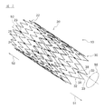
図1は、本発明の第1実施形態に係る消化管ステント10における第1端部30付近の構造を概略的に示す正面図であり、図2は消化管ステント10の概略斜視図である。なお、図1及び図2では、消化管ステント10が拡張した状態を示している。
Hereinafter, the present invention will be described based on the embodiments shown in the drawings.
FIG. 1 is a front view schematically showing a structure in the vicinity of the
図1及び図2に示すように、消化管ステント10は円筒状の外形状を有しており、胆管、食道、十二指腸、小腸、大腸等の消化器系体内管腔に留置され、主として管腔を確保する目的で使用される。本実施形態の消化管ステント10は、その外周面側を樹脂フィルム等で被覆したいわゆるカバードステントではなく、フィルム等で被覆されないベアステントである。ただし、消化管ステント10は、樹脂フィルム等で被覆してカバードステントとして用いることもできる。
As shown in FIGS. 1 and 2, the
消化管ステント10は、管状を呈する管状部20と、管状部20の第1方向51側の端部に接続された第1端部30とを有している。管状部20は、リング状の環状単位22を複数有しており、環状単位22が軸方向50に沿って複数接続された構造を有している。各環状単位22は、隣接する環状単位22に対して、接続部28を介して接続されている。
The
各環状単位22は、屈曲を繰り返しながら周方向56に延びる線材で構成されている。環状単位22は、第1方向51側に凸となる第1屈曲部23と、第2方向52側に凸となる第2屈曲部24とを有しており、第1屈曲部23と第2屈曲部24とが、周方向56に交互に繰り返されるジグザグ形状である。
Each
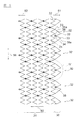
図2等に示すように、接続部28は、接続部28に対して第2方向52側に位置する環状単位22の第1屈曲部23と、接続部28に対して第1方向51側に位置する環状単位22の第2屈曲部24とを接続する。消化管ステント10の展開図である図3に示すように、各環状単位22は、第1屈曲部23と第2屈曲部24とを20ずつ有しており、隣接する環状単位22は、周方向56に等間隔に配置された5つの接続部28によって接続されている。接続部28は、逆S字型の湾曲形状(図4参照)を有し、隣接する環状単位22同士を相対的に動かせるようにフレキシブルに環状単位22を接続している。ただし、環状単位22に含まれる第1屈曲部23及び第2屈曲部24の数や、接続部28の数、配置、及び形状は、特に限定されない。
As shown in FIG. 2 and the like, the connecting
図1に示すように、第1端部30は、屈曲を繰り返しながら周方向56に延びる線材で構成される第1線材部32と、X線不透過マーカー38とを有する。第1線材部32は、管状部20における第1方向51側の端部に接続している。第1線材部32は、第1方向51側に凸となる第3屈曲部33と、第2方向52側に凸となる第4屈曲部34とを有している。
As shown in FIG. 1, the
消化管ステント10の展開図である図3に示すように、第1端部30は、5つの第1線材部32を有しており、各第1線材部32は、管状部20における第1方向51側の端部に位置する環状単位22の第1屈曲部23に接続している。また、X線不透過マーカー38は、略円盤状の形状を有しており、第4屈曲部34において第1線材部32に設けられたアイレットに嵌め込まれて、第1線材部32に接合されている。したがって、X線造影等によりX線不透過マーカー38の位置を確認することによって、消化管ステント10の体内での留置位置を確認することができる。なお、第1端部30が有する第1線材部32の数や、消化管ステント10におけるX線不透過マーカー38の有無、形状及びX線不透過マーカー38を設ける位置は、特に限定されない。
As shown in FIG. 3, which is a development view of the
図3の部分拡大図である図4に示すように、第1線材部32は、第3屈曲部33と第4屈曲部34とが、周方向56に交互に配置されるジグザグ形状である。第1線材部32は、2つの第3屈曲部33と1つの第4屈曲部34とを有しており、屈曲の繰り返し回数は3回である。ただし、第1線材部32に含まれる第3及び第4屈曲部33、34の数は特に限定されない。
As shown in FIG. 4, which is a partially enlarged view of FIG. 3, the first
第1線材部32は、第1屈曲部23と第4屈曲部34とを接続する直線状の接続直線部35aを2つ有しており、第1線材部32は、その周方向56の両側において、接続直線部35aを介して2つの第1屈曲部23に接続されている。一方で、第1線材部32の第4屈曲部34は、第1屈曲部23及び第2屈曲部24のいずれにも接続されておらず、環状単位22と第4屈曲部34を直接接続する線材は設けられていない。
The first
図4に示すように、環状単位22において、1つの第1線材部32が接続する2つの第1屈曲部23に挟まれる部分には、3つの第2屈曲部24と2つの第1屈曲部23とが含まれ、第2屈曲部24と第1屈曲部23とを合わせた屈曲の繰り返し回数は5回である。これに対して、接続する2つの第1屈曲部23の間に挟まれる第1線材部32における屈曲の繰り返し回数は3回であるから、単位周方向56長さ当たりの屈曲回数は、第1線材部32の方が、環状単位22より少ない。
As shown in FIG. 4, in the
第1線材部32の第3屈曲部33における屈曲角度θ3は、環状単位22の第1屈曲部23における屈曲角度θ1より大きく、第3屈曲部33は、第1屈曲部23より緩やかに屈曲している。
The bending angle θ3 at the
図1及び図2では図示していないが、消化管ステント10は、管状部20の第2方向側の端部に接続された第2端部40を有している。図5は、第2端部40の周辺の概略構造を表す展開図である。
Although not shown in FIGS. 1 and 2, the
図5に示すように、第2端部40は、図3に示す第1端部30と略対称な形状を有している。第2端部40は、屈曲を繰り返しながら周方向56に延びる線材で構成される第2線材部42を有しており、第2線材部42は、第1方向51側に凸となる第5屈曲部43と、第2方向52側に凸となる第6屈曲部44とを有している。
As shown in FIG. 5, the
第2端部40は、5つの第2線材部42を有しており、各第2線材部42は、管状部20における第2方向52側の端部に位置する環状単位22の第2屈曲部24に接続している。また、第2端部40は、第5屈曲部43に設けられるX線不透過マーカー48を有している。
The
第2線材部42の形状は、図3に示す第1線材部32と略対称な形状を有しており、第3屈曲部33と第4屈曲部34とが、周方向56に交互に配置されるジグザグ形状である。また、第2線材部42の第6屈曲部44における屈曲角度θ6は、環状単位22の第2屈曲部24における屈曲角度θ2より大きく、第6屈曲部44は、第2屈曲部24より緩やかに屈曲している。
The shape of the second
消化管ステント10の環状単位22、第1線材部32及び第2線材部42を構成する線材の線径は、0.05〜1mm程度であることが好ましい。また、線材の断面が断面長方形の帯状体である場合には、例えば長辺方向の長さが0.1〜1mmであって短辺方向の長さが0.05〜0.5mm程度であることが好ましい。
The wire diameter of the wire rod constituting the
消化管ステント10の外形寸法は、消化管ステント10が留置される体内管腔の大きさによって異なるが、例えば、外径が2〜40mm、内径が1〜29mm、長さが5〜200mmである。また、胆管ステントとして用いられる消化管ステント10の場合、その外形寸法は、外径が5〜20mm、内径が4〜19mm、長さが10〜100mmとすることが好ましい。また、消化管ステント10は蠕動運動が活発な大腸に留置する大腸ステントとして特に好適に用いられるが、大腸ステントとして用いられる消化管ステント10の場合、その寸法は、外径が10〜40mm、内径が9〜39mm、長さが20〜200mmとすることが好ましい。また、消化管ステント10の外径は、消化管ステント10がステントデリバリー装置などによって留置部位まで搬送される際には、上述の値の数分の1程度に径方向に収縮されて搬送される。
The external dimensions of the
消化管ステント10の材料としては、例えば、ニッケルチタン(Ni−Ti)合金、ステンレス鋼、タンタル、チタン、コバルトクロム合金、マグネシウム合金等の金属が挙げられる。消化管ステント10は、セルフエキスパンダブル型のステントであってもよく、バルーンエキスパンダブル型のステントであってもよいが、本実施形態の消化管ステント10は、超弾性合金であるNi−Ti合金で形成されたセルフエキスパンダブル型のステントである。
Examples of the material of the
また、X線不透過マーカー38、48に使用されるX線造影性材料としては、例えば、金、プラチナ、プラチナイリジウム合金、白金、銀、ステンレス等が挙げられる。また、X線不透過マーカー38、48は、X線造影性材料の粉末を含有する樹脂成形物によって構成されていてもよい。X線不透過マーカー38、48に用いられるX線造影性材料の粉末としては、硫酸バリウム粉末、次炭酸ビスマス粉末、タングステン粉末及び上述した金属の粉末等を使用できる。
Examples of the X-ray contrasting material used for the X-ray
このような構成の消化管ステント10を製造する場合、例えば、まず、消化管ステント10を形成するための材料で形成された円筒体(パイプ)に対して、例えば、YAGレーザー等を用いたレーザー加工(レーザーカット)をすることによって、図示のようなパターンの成形を行う。次に、所定の熱処理を行って形状付け(形状記憶)を行う。その後、電界研磨等の研磨を行い、マーカー付けを行い、消化管ステント10が製造される。
When manufacturing a
また、セルフエキスパンダブル型である消化管ステント10は、いわゆるステントデリバリー装置により消化器系体内管腔内の狭窄部等に留置できる。ステントデリバリー装置は、内管と、内管がスライド可能に挿通された外管とを有するカテーテル部を有し、内管の遠位端近傍に設けられたステント配置部に消化管ステント10を配置して外管の遠位端近傍の内側で消化管ステント10を径方向に収縮させた状態で保持し、カテーテル部の遠位端を目的とする留置部位に導く。この際、カテーテル部は、内管内に挿通され先行して管腔内に挿入されたガイドワイヤーに沿って進行され、その遠位端が消化管ステント10を留置する部位まで導入される。そして、ステント配置部がその留置部位に達したら、カテーテル部の近位端側において外管を内管に対して近位端側にスライドさせることにより、消化管ステント10が外管から露出し、消化管ステント10の弾性によってその場で拡張され、留置される。
Further, the self-expandable
以上に述べたように、図1〜図5に示す消化管ステント10は、消化管ステント10の両端に配置される第1端部30の第3屈曲部33及び第2端部40の第6屈曲部44が、消化管ステント10の中央部分に配置される環状単位22の第1屈曲部23や第2屈曲部24より緩やかに屈曲している。したがって、第3屈曲部33及び第6屈曲部44は、体内の管腔壁に押し当てられた場合に、第1屈曲部23や第2屈曲部24が同様に管腔壁に押し当てられた場合に比べて、管腔壁との接触面積が広く、管腔壁への負荷が小さい。
As described above, the
また、消化管ステント10の両端は、留置時において体内の管腔壁に対して強く接触する可能性が高い部分である。したがって、このような両端に、緩やかに屈曲している第3屈曲部33及び第6屈曲部44を配置することで、消化管ステント10は、管腔壁への負荷を低減し、管腔壁の穿孔リスクを低減できる。
In addition, both ends of the
消化管ステント10において、第1端部30及び第2端部40に含まれるX線不透過マーカー38、48は、管状部20側(軸方向50中央側)に凸となる第4屈曲部34及び第5屈曲部43に設けられている。そのため、X線不透過マーカー38、48は、より両端側に配置される第1線材部32及び第2線材部42に保護され、消化管ステント10は、X線不透過マーカー38、48が管腔壁に強く押し当てられる問題を防止できる。したがって、消化管ステント10は、X線不透過マーカー38、48が、損傷又は脱落する問題を防止できる。
In the
また、消化管ステント10において、第4及び第5屈曲部34、43は、第1屈曲部23及び第2屈曲部24のいずれにも、直接的に接続されてはいない。このような構造を有する消化管ステント10は、管状部20の両端に接続する第1端部30及び第2端部40が柔軟で変形し易いため、留置後における管腔壁への負荷を低減し、管腔壁の穿孔を防止することができる。
Further, in the
また、消化管ステント10の中央部に配置される管状部20に含まれる第1屈曲部23及び第2屈曲部24は、両端部の第3屈曲部33や第6屈曲部44より鋭く屈曲しており、また、管状部20での単位周方向56長さ当たりの屈曲回数は、第1端部30及び第2端部40のそれよりも多い。これにより、消化管ステント10は、径方向に収縮させた状態から拡張させる際のショートニング(消化管ステント10の全長が短くなる現象)の度合いが小さいものとなる。したがって、消化管ステント10は、消化器系体内管腔内における目的とする位置に留置しやすいものとなる。
Further, the first
図6は、本発明の第2実施形態に係る消化管ステント100における第1端部130付近の構造を概略的に示す正面図であり、図7は、消化管ステント100の概略斜視図である。消化管ステント100は、第1端部130及び図示しない第2端部の形状及び構造が、消化管ステント10とは異なるが、管状部20については消化管ステント10と同様である。消化管ステント100の説明では、消化管ステント10との共通点については、説明を省略する。
FIG. 6 is a front view schematically showing the structure near the
図6に示すように、消化管ステント100の第1端部130は、図1に示す消化管ステント10と同様に、屈曲を繰り返しながら周方向56に延びる線材で構成される第1線材部132と、X線不透過マーカー138aを有している。また、一部の第1線材部132は、X線不透過マーカー138bをさらに有する。第1線材部132は、管状部20における第1方向51側の端部に接続しており、第1方向51側に凸となる第3屈曲部133と、第2方向52側に凸となる第4屈曲部134とを有している。
As shown in FIG. 6, the
消化管ステント100の展開図である図8に示すように、第1端部130は、4つの第1線材部132を有しており、各第1線材部132は、管状部20における第1方向51側の端部に位置する環状単位22の第1屈曲部23に接続している。X線不透過マーカー138a、138bのうち、X線不透過マーカー138aは、第1線材部132における第4屈曲部134に設けられており、X線不透過マーカー138bは第3屈曲部133に設けられている。
As shown in FIG. 8 which is a development view of the
第1線材部132は、第1線材部32と同様に、2つの第3屈曲部133と1つの第4屈曲部134とを有している。第1線材部132は、第1屈曲部23と第3屈曲部133とを接続する直線状の接続直線部135aを2つ有しており、第1線材部132は、その周方向56の両側において、接続直線部135aを介して2つの第1屈曲部23に接続されている。また、第1線材部132の第4屈曲部134は、X線不透過マーカー138aを介して環状単位22の第1屈曲部23に接続されている。
Like the first
環状単位22において、第1線材部132が接続する2つの第1屈曲部23に挟まれる部分には、4つの第2屈曲部24と3つの第1屈曲部23とが含まれ、第2屈曲部24と第1屈曲部23とを合わせた屈曲の繰り返し回数は7回である。したがって、単位周方向56長さ当たりの屈曲回数は、第1線材部132の方が、環状単位22より少ない。また、第1線材部132の中で隣接する第3屈曲部133と第4屈曲部134との間の長さL34は、1つの環状単位22の中で隣接する第1屈曲部23と第2屈曲部24との間の長さL12より長い。
In the
第1線材部132の第3屈曲部133における屈曲角度θ13は、環状単位22の第1屈曲部23における屈曲角度θ1より大きく、第3屈曲部133は、第1屈曲部23より緩やかに屈曲している。また、図6〜図8では図示していないが、消化管ステント100は、消化管ステント10と同様に、管状部20の第2方向側の端部に接続された第2端部を有している。
The bending angle θ13 at the
図6〜図8に示す消化管ステント100は、消化管ステント100における第1端部130の第3屈曲部133が、環状単位22の第1屈曲部23より緩やかに屈曲している。したがって、このような第3屈曲部133を有する消化管ステント100は、図1等に示す消化管ステント10と同様に、留置時において体内の管腔壁への負荷を低減し、管腔壁の穿孔リスクを低減できる。
In the
また、消化管ステント100では、第3屈曲部133と第4屈曲部134との間の長さL34が、第1屈曲部23と第2屈曲部24との間の長さL12より長いため、第1端部130が柔軟で変形し易い。したがって、消化管ステント100は、この点でも、留置後における管腔壁への負荷を低減し、管腔壁の穿孔を防止することができる。
Further, in the
なお、消化管ステント100は、図3等に示す消化管ステント10とは異なり、第1線材部132の第4屈曲部134が、環状単位22の第1屈曲部23に対して接続されている。しかし、消化管ステント100は、第3屈曲部133と第4屈曲部134との間の長さL34の長さが長く、また、第3屈曲部133の屈曲角度θ13が十分に大きいため、第4屈曲部134が第1屈曲部23に接続されていても、管腔壁の穿孔を適切に防止することができる。
In the
消化管ステント100は、第4屈曲部134に設けられるX線不透過マーカー138aと、第3屈曲部133に設けられるX線不透過マーカー138bとを有している。消化管ステント100の端部である第3屈曲部133に設けられるX線不透過マーカー138bは、留置時における脱落を防止するため、第3屈曲部133に対して強固に固定されていることが好ましい。
The
なお、本発明は、前述した実施形態に限定されるものではなく、本発明の範囲内で種々に改変することができる。 The present invention is not limited to the above-described embodiment, and can be variously modified within the scope of the present invention.
例えば、前述した各実施形態において、環状単位22、第1線材部32、132及び第2線材部42は、周方向56に沿ったジグザグパターンとした。しかしながら、各部を構成する線材の形状は、これに限られるものではなく、拡張可能、変形可能で適度な柔軟性を発揮できるように屈曲を繰り返すパターンであれば任意の形状でよい。また、第1端部又は第2端部は、実施形態に示すように、周方向56に不連続な複数の第1線材部32、132又は第2線材部42を有していてもよいが、周方向56に連続する1つの第1線材部又は第2線材部を有していてもよい。
For example, in each of the above-described embodiments, the
なお、消化管ステント10、100では、第1端部30、130及び第2端部40が、管状部20から軸方向50にまっすぐ伸びていて、消化管ステント10、100全体として、直胴円筒形状を有している。ただし、本発明に係る消化管ステントの形状はこれに限定されず、例えば、第1端部30、130及び第2端部40を、管状部20に対して径方向内側に曲がった形状としてもよい。
In the
10、100…消化管ステント
20…管状部
22…環状単位
23…第1屈曲部
24…第2屈曲部
30、130…第1端部
32、132…第1線材部
33、133…第3屈曲部
34、134…第4屈曲部
38、48、138a、138b…X線不透過マーカー
40…第2端部
42…第2線材部
43…第5屈曲部
44…第6屈曲部
50…軸方向
51…第1方向
52…第2方向
56…周方向
10, 100 ...
Claims (4)
前記管状部における前記軸方向の一方である第1方向側の端部に接続しており、屈曲を繰り返しながら前記周方向に延びる線材で構成される第1線材部を有する第1端部と、を有しており、
前記環状単位は、前記第1方向側に凸となる第1屈曲部と、前記軸方向の他方である第2方向側に凸となる第2屈曲部と、を有しており、
前記第1線材部は、前記第1方向側に凸となる第3屈曲部と、前記第2方向側に凸となる第4屈曲部と、を有しており、
前記第1線材部は、前記第3屈曲部と前記環状単位の前記第1屈曲部とを接続する接続直線部を有し、周方向の両側において前記接続直線部を介して前記環状単位の前記第1屈曲部に接続されており、
前記第3屈曲部は、前記第1屈曲部より緩やかに屈曲しており、
前記第4屈曲部は、前記第1屈曲部及び前記第2屈曲部のいずれにも接続されておらず、
前記第1端部は、相互に接続されていない複数の前記第1線材部を有していることを特徴とする消化管ステント。 It has a plurality of ring-shaped annular units composed of wire rods extending in the circumferential direction while repeatedly bending, and the annular units are connected in the axial direction and are connected to each other to form a tubular portion.
A first end portion of the tubular portion, which is connected to an end portion on the first direction side, which is one of the axial directions, and has a first wire rod portion composed of a wire rod extending in the circumferential direction while repeating bending. Have and
The annular unit has a first bent portion that is convex in the first direction side and a second bent portion that is convex in the second direction side, which is the other side in the axial direction.
The first wire rod portion has a third bent portion that is convex toward the first direction side and a fourth bent portion that is convex toward the second direction side.
The first wire rod portion has a connecting straight line portion that connects the third bent portion and the first bent portion of the annular unit, and the annular unit is said to have the connecting straight line portion on both sides in the circumferential direction. It is connected to the first bend and
The third bent portion is bent more gently than the first bent portion .
The fourth bent portion is not connected to either the first bent portion or the second bent portion.
The gastrointestinal stent, wherein the first end portion has a plurality of the first wire rod portions that are not connected to each other.
前記第2線材部は、前記第1方向側に凸となる第5屈曲部と、前記第2方向側に凸となる第6屈曲部と、を有しており、
前記第6屈曲部は、前記第2屈曲部より緩やかに屈曲していることを特徴とする請求項1から請求項3までのいずれかに記載の消化管ステント。 The tubular portion has a second end portion that is connected to the end portion on the second direction side and has a second wire rod portion that is formed of a wire rod that extends in the circumferential direction while bending. Ori,
The second wire rod portion has a fifth bent portion that is convex toward the first direction side and a sixth bent portion that is convex toward the second direction side.
The gastrointestinal stent according to any one of claims 1 to 3, wherein the sixth bent portion is bent more gently than the second bent portion.
Priority Applications (1)
| Application Number | Priority Date | Filing Date | Title |
|---|---|---|---|
| JP2016035794A JP6855679B2 (en) | 2016-02-26 | 2016-02-26 | Gastrointestinal stent |
Applications Claiming Priority (1)
| Application Number | Priority Date | Filing Date | Title |
|---|---|---|---|
| JP2016035794A JP6855679B2 (en) | 2016-02-26 | 2016-02-26 | Gastrointestinal stent |
Publications (2)
| Publication Number | Publication Date |
|---|---|
| JP2017148403A JP2017148403A (en) | 2017-08-31 |
| JP6855679B2 true JP6855679B2 (en) | 2021-04-07 |
Family
ID=59740972
Family Applications (1)
| Application Number | Title | Priority Date | Filing Date |
|---|---|---|---|
| JP2016035794A Active JP6855679B2 (en) | 2016-02-26 | 2016-02-26 | Gastrointestinal stent |
Country Status (1)
| Country | Link |
|---|---|
| JP (1) | JP6855679B2 (en) |
Families Citing this family (1)
| Publication number | Priority date | Publication date | Assignee | Title |
|---|---|---|---|---|
| WO2020049734A1 (en) * | 2018-09-07 | 2020-03-12 | オリンパス株式会社 | Stent |
Family Cites Families (4)
| Publication number | Priority date | Publication date | Assignee | Title |
|---|---|---|---|---|
| US7112216B2 (en) * | 2003-05-28 | 2006-09-26 | Boston Scientific Scimed, Inc. | Stent with tapered flexibility |
| JP2012055484A (en) * | 2010-09-08 | 2012-03-22 | Terumo Corp | Instrument for remedying biological organ lesion |
| JP6155765B2 (en) * | 2013-03-29 | 2017-07-05 | 日本ゼオン株式会社 | Gastrointestinal stent |
| EP3119354B1 (en) * | 2014-03-18 | 2018-06-06 | Boston Scientific Scimed, Inc. | Reduced granulation and inflammation stent design |
-
2016
- 2016-02-26 JP JP2016035794A patent/JP6855679B2/en active Active
Also Published As
| Publication number | Publication date |
|---|---|
| JP2017148403A (en) | 2017-08-31 |
Similar Documents
| Publication | Publication Date | Title |
|---|---|---|
| JP4844394B2 (en) | Stent | |
| EP2702964B1 (en) | Stent | |
| JP6083533B2 (en) | Stent graft with marker and reinforcement and marker ring | |
| US9144508B2 (en) | Radially expandable stent | |
| CN110063825B (en) | Endoluminal device | |
| KR20170139086A (en) | Stents and medical devices | |
| JP6736627B2 (en) | Medical tubular body | |
| JP2007517567A (en) | Longitudinal flexible stent | |
| US9925078B2 (en) | Stent delivery system | |
| KR20190064595A (en) | Flexible stent | |
| JP2016073553A (en) | Pusher guide wire | |
| EP3811899B1 (en) | Stent for bypass between hollow organs and stent delivery system including stent for bypass between hollow organs | |
| JP6425981B2 (en) | Self-expanding stent | |
| JP6855679B2 (en) | Gastrointestinal stent | |
| US10863997B2 (en) | Medical device | |
| WO2014171183A1 (en) | Medical tubular body | |
| JP6155765B2 (en) | Gastrointestinal stent | |
| US11918494B2 (en) | Stent and method for inspection thereof | |
| JP4835113B2 (en) | Stent | |
| JP6901869B2 (en) | Covered stent | |
| JP2020103893A (en) | Stent | |
| JP7351292B2 (en) | A stent delivery system including a stent for luminal interorgan bypass and a stent for luminal interorgan bypass | |
| JP2021000256A (en) | Hollow shaft and catheter | |
| JP6380757B2 (en) | Stent | |
| US11331207B2 (en) | Stent |
Legal Events
| Date | Code | Title | Description |
|---|---|---|---|
| A621 | Written request for application examination |
Free format text: JAPANESE INTERMEDIATE CODE: A621 Effective date: 20190222 |
|
| A131 | Notification of reasons for refusal |
Free format text: JAPANESE INTERMEDIATE CODE: A131 Effective date: 20191029 |
|
| A977 | Report on retrieval |
Free format text: JAPANESE INTERMEDIATE CODE: A971007 Effective date: 20191101 |
|
| A601 | Written request for extension of time |
Free format text: JAPANESE INTERMEDIATE CODE: A601 Effective date: 20191219 |
|
| A521 | Request for written amendment filed |
Free format text: JAPANESE INTERMEDIATE CODE: A523 Effective date: 20200228 |
|
| A131 | Notification of reasons for refusal |
Free format text: JAPANESE INTERMEDIATE CODE: A131 Effective date: 20200609 |
|
| A601 | Written request for extension of time |
Free format text: JAPANESE INTERMEDIATE CODE: A601 Effective date: 20200806 |
|
| TRDD | Decision of grant or rejection written | ||
| A01 | Written decision to grant a patent or to grant a registration (utility model) |
Free format text: JAPANESE INTERMEDIATE CODE: A01 Effective date: 20210216 |
|
| A61 | First payment of annual fees (during grant procedure) |
Free format text: JAPANESE INTERMEDIATE CODE: A61 Effective date: 20210301 |
|
| R150 | Certificate of patent or registration of utility model |
Ref document number: 6855679 Country of ref document: JP Free format text: JAPANESE INTERMEDIATE CODE: R150 |
|
| R250 | Receipt of annual fees |
Free format text: JAPANESE INTERMEDIATE CODE: R250 |