JP6855448B2 - Pattern forming method, processed circuit board manufacturing method, optical component manufacturing method, circuit board manufacturing method, electronic component manufacturing method, imprint mold manufacturing method - Google Patents
Pattern forming method, processed circuit board manufacturing method, optical component manufacturing method, circuit board manufacturing method, electronic component manufacturing method, imprint mold manufacturing method Download PDFInfo
- Publication number
- JP6855448B2 JP6855448B2 JP2018509341A JP2018509341A JP6855448B2 JP 6855448 B2 JP6855448 B2 JP 6855448B2 JP 2018509341 A JP2018509341 A JP 2018509341A JP 2018509341 A JP2018509341 A JP 2018509341A JP 6855448 B2 JP6855448 B2 JP 6855448B2
- Authority
- JP
- Japan
- Prior art keywords
- curable composition
- component
- mold
- substrate
- pattern forming
- Prior art date
- Legal status (The legal status is an assumption and is not a legal conclusion. Google has not performed a legal analysis and makes no representation as to the accuracy of the status listed.)
- Active
Links
Images


Classifications
-
- G—PHYSICS
- G03—PHOTOGRAPHY; CINEMATOGRAPHY; ANALOGOUS TECHNIQUES USING WAVES OTHER THAN OPTICAL WAVES; ELECTROGRAPHY; HOLOGRAPHY
- G03F—PHOTOMECHANICAL PRODUCTION OF TEXTURED OR PATTERNED SURFACES, e.g. FOR PRINTING, FOR PROCESSING OF SEMICONDUCTOR DEVICES; MATERIALS THEREFOR; ORIGINALS THEREFOR; APPARATUS SPECIALLY ADAPTED THEREFOR
- G03F7/00—Photomechanical, e.g. photolithographic, production of textured or patterned surfaces, e.g. printing surfaces; Materials therefor, e.g. comprising photoresists; Apparatus specially adapted therefor
- G03F7/0002—Lithographic processes using patterning methods other than those involving the exposure to radiation, e.g. by stamping
-
- C—CHEMISTRY; METALLURGY
- C09—DYES; PAINTS; POLISHES; NATURAL RESINS; ADHESIVES; COMPOSITIONS NOT OTHERWISE PROVIDED FOR; APPLICATIONS OF MATERIALS NOT OTHERWISE PROVIDED FOR
- C09D—COATING COMPOSITIONS, e.g. PAINTS, VARNISHES OR LACQUERS; FILLING PASTES; CHEMICAL PAINT OR INK REMOVERS; INKS; CORRECTING FLUIDS; WOODSTAINS; PASTES OR SOLIDS FOR COLOURING OR PRINTING; USE OF MATERIALS THEREFOR
- C09D133/00—Coating compositions based on homopolymers or copolymers of compounds having one or more unsaturated aliphatic radicals, each having only one carbon-to-carbon double bond, and at least one being terminated by only one carboxyl radical, or of salts, anhydrides, esters, amides, imides, or nitriles thereof; Coating compositions based on derivatives of such polymers
- C09D133/04—Homopolymers or copolymers of esters
- C09D133/06—Homopolymers or copolymers of esters of esters containing only carbon, hydrogen and oxygen, the oxygen atom being present only as part of the carboxyl radical
- C09D133/08—Homopolymers or copolymers of acrylic acid esters
-
- C—CHEMISTRY; METALLURGY
- C09—DYES; PAINTS; POLISHES; NATURAL RESINS; ADHESIVES; COMPOSITIONS NOT OTHERWISE PROVIDED FOR; APPLICATIONS OF MATERIALS NOT OTHERWISE PROVIDED FOR
- C09D—COATING COMPOSITIONS, e.g. PAINTS, VARNISHES OR LACQUERS; FILLING PASTES; CHEMICAL PAINT OR INK REMOVERS; INKS; CORRECTING FLUIDS; WOODSTAINS; PASTES OR SOLIDS FOR COLOURING OR PRINTING; USE OF MATERIALS THEREFOR
- C09D135/00—Coating compositions based on homopolymers or copolymers of compounds having one or more unsaturated aliphatic radicals, each having only one carbon-to-carbon double bond, and at least one being terminated by a carboxyl radical, and containing at least another carboxyl radical in the molecule, or of salts, anhydrides, esters, amides, imides or nitriles thereof; Coating compositions based on derivatives of such polymers
- C09D135/02—Homopolymers or copolymers of esters
-
- G—PHYSICS
- G03—PHOTOGRAPHY; CINEMATOGRAPHY; ANALOGOUS TECHNIQUES USING WAVES OTHER THAN OPTICAL WAVES; ELECTROGRAPHY; HOLOGRAPHY
- G03F—PHOTOMECHANICAL PRODUCTION OF TEXTURED OR PATTERNED SURFACES, e.g. FOR PRINTING, FOR PROCESSING OF SEMICONDUCTOR DEVICES; MATERIALS THEREFOR; ORIGINALS THEREFOR; APPARATUS SPECIALLY ADAPTED THEREFOR
- G03F7/00—Photomechanical, e.g. photolithographic, production of textured or patterned surfaces, e.g. printing surfaces; Materials therefor, e.g. comprising photoresists; Apparatus specially adapted therefor
- G03F7/16—Coating processes; Apparatus therefor
- G03F7/161—Coating processes; Apparatus therefor using a previously coated surface, e.g. by stamping or by transfer lamination
-
- B—PERFORMING OPERATIONS; TRANSPORTING
- B29—WORKING OF PLASTICS; WORKING OF SUBSTANCES IN A PLASTIC STATE IN GENERAL
- B29C—SHAPING OR JOINING OF PLASTICS; SHAPING OF MATERIAL IN A PLASTIC STATE, NOT OTHERWISE PROVIDED FOR; AFTER-TREATMENT OF THE SHAPED PRODUCTS, e.g. REPAIRING
- B29C59/00—Surface shaping of articles, e.g. embossing; Apparatus therefor
- B29C59/02—Surface shaping of articles, e.g. embossing; Apparatus therefor by mechanical means, e.g. pressing
- B29C59/022—Surface shaping of articles, e.g. embossing; Apparatus therefor by mechanical means, e.g. pressing characterised by the disposition or the configuration, e.g. dimensions, of the embossments or the shaping tools therefor
- B29C2059/023—Microembossing
-
- B—PERFORMING OPERATIONS; TRANSPORTING
- B29—WORKING OF PLASTICS; WORKING OF SUBSTANCES IN A PLASTIC STATE IN GENERAL
- B29K—INDEXING SCHEME ASSOCIATED WITH SUBCLASSES B29B, B29C OR B29D, RELATING TO MOULDING MATERIALS OR TO MATERIALS FOR MOULDS, REINFORCEMENTS, FILLERS OR PREFORMED PARTS, e.g. INSERTS
- B29K2105/00—Condition, form or state of moulded material or of the material to be shaped
- B29K2105/0002—Condition, form or state of moulded material or of the material to be shaped monomers or prepolymers
-
- B—PERFORMING OPERATIONS; TRANSPORTING
- B29—WORKING OF PLASTICS; WORKING OF SUBSTANCES IN A PLASTIC STATE IN GENERAL
- B29K—INDEXING SCHEME ASSOCIATED WITH SUBCLASSES B29B, B29C OR B29D, RELATING TO MOULDING MATERIALS OR TO MATERIALS FOR MOULDS, REINFORCEMENTS, FILLERS OR PREFORMED PARTS, e.g. INSERTS
- B29K2105/00—Condition, form or state of moulded material or of the material to be shaped
- B29K2105/0094—Condition, form or state of moulded material or of the material to be shaped having particular viscosity
-
- B—PERFORMING OPERATIONS; TRANSPORTING
- B29—WORKING OF PLASTICS; WORKING OF SUBSTANCES IN A PLASTIC STATE IN GENERAL
- B29K—INDEXING SCHEME ASSOCIATED WITH SUBCLASSES B29B, B29C OR B29D, RELATING TO MOULDING MATERIALS OR TO MATERIALS FOR MOULDS, REINFORCEMENTS, FILLERS OR PREFORMED PARTS, e.g. INSERTS
- B29K2909/00—Use of inorganic materials not provided for in groups B29K2803/00 - B29K2807/00, as mould material
-
- G—PHYSICS
- G03—PHOTOGRAPHY; CINEMATOGRAPHY; ANALOGOUS TECHNIQUES USING WAVES OTHER THAN OPTICAL WAVES; ELECTROGRAPHY; HOLOGRAPHY
- G03F—PHOTOMECHANICAL PRODUCTION OF TEXTURED OR PATTERNED SURFACES, e.g. FOR PRINTING, FOR PROCESSING OF SEMICONDUCTOR DEVICES; MATERIALS THEREFOR; ORIGINALS THEREFOR; APPARATUS SPECIALLY ADAPTED THEREFOR
- G03F1/00—Originals for photomechanical production of textured or patterned surfaces, e.g., masks, photo-masks, reticles; Mask blanks or pellicles therefor; Containers specially adapted therefor; Preparation thereof
- G03F1/68—Preparation processes not covered by groups G03F1/20 - G03F1/50
- G03F1/80—Etching
-
- G—PHYSICS
- G03—PHOTOGRAPHY; CINEMATOGRAPHY; ANALOGOUS TECHNIQUES USING WAVES OTHER THAN OPTICAL WAVES; ELECTROGRAPHY; HOLOGRAPHY
- G03F—PHOTOMECHANICAL PRODUCTION OF TEXTURED OR PATTERNED SURFACES, e.g. FOR PRINTING, FOR PROCESSING OF SEMICONDUCTOR DEVICES; MATERIALS THEREFOR; ORIGINALS THEREFOR; APPARATUS SPECIALLY ADAPTED THEREFOR
- G03F7/00—Photomechanical, e.g. photolithographic, production of textured or patterned surfaces, e.g. printing surfaces; Materials therefor, e.g. comprising photoresists; Apparatus specially adapted therefor
- G03F7/004—Photosensitive materials
- G03F7/0045—Photosensitive materials with organic non-macromolecular light-sensitive compounds not otherwise provided for, e.g. dissolution inhibitors
-
- G—PHYSICS
- G03—PHOTOGRAPHY; CINEMATOGRAPHY; ANALOGOUS TECHNIQUES USING WAVES OTHER THAN OPTICAL WAVES; ELECTROGRAPHY; HOLOGRAPHY
- G03F—PHOTOMECHANICAL PRODUCTION OF TEXTURED OR PATTERNED SURFACES, e.g. FOR PRINTING, FOR PROCESSING OF SEMICONDUCTOR DEVICES; MATERIALS THEREFOR; ORIGINALS THEREFOR; APPARATUS SPECIALLY ADAPTED THEREFOR
- G03F7/00—Photomechanical, e.g. photolithographic, production of textured or patterned surfaces, e.g. printing surfaces; Materials therefor, e.g. comprising photoresists; Apparatus specially adapted therefor
- G03F7/004—Photosensitive materials
- G03F7/0046—Photosensitive materials with perfluoro compounds, e.g. for dry lithography
Description
本発明は、パターン形成方法、加工基板の製造方法、光学部品の製造方法、回路基板の製造方法、電子部品の製造方法、インプリントモールドの製造方法に関する。 The present invention relates to a pattern forming method, a processed circuit board manufacturing method, an optical component manufacturing method, a circuit board manufacturing method, an electronic component manufacturing method, and an imprint mold manufacturing method.
半導体デバイスやMEMS等においては、微細化の要求が高まっており、微細加工技術として、光ナノインプリント技術が注目されている。 In semiconductor devices, MEMS, etc., the demand for miniaturization is increasing, and optical nanoimprint technology is drawing attention as a microfabrication technology.
光ナノインプリント技術では、表面に微細な凹凸パターンが形成されたモールド(型)を光硬化性組成物(レジスト)が塗布された基板(ウエハ)に押しつけた状態で光硬化性組成物を硬化させる。これにより、モールドの凹凸パターンを光硬化性組成物の硬化膜に転写し、パターンを基板上に形成する。光ナノインプリント技術によれば、基板上に数ナノメートルオーダーの微細な構造体を形成することができる。 In the optical nanoimprint technology, the photocurable composition is cured in a state where a mold having a fine uneven pattern formed on the surface is pressed against a substrate (wafer) coated with the photocurable composition (resist). As a result, the uneven pattern of the mold is transferred to the cured film of the photocurable composition, and the pattern is formed on the substrate. According to the optical nanoimprint technology, it is possible to form a fine structure on the order of several nanometers on a substrate.
特許文献1に記載の光ナノインプリント技術を、図1を用いて説明する。まず、基板101上のパターン形成領域にインクジェット法を用いて、液状のレジスト102を離散的に滴下する(配置工程(1)、図1(a)〜(c))。滴下されたレジスト102の液滴は液滴の広がる方向を示す矢印104で示すように基板101上に広がるが、この現象をプレスプレッドと呼ぶ(図1(c))。次に、このレジスト102を、パターンが形成された、後述する照射光106に対して透明なモールド(型)105を用いて成形する(型接触工程(2)、図1(d)及び1(da))。型接触工程においては、レジスト102の液滴が液滴の広がる方向を示す矢印104で示すように基板101とモールド105の間隙の全域へ広がる(図1(d))。この現象をスプレッドと呼ぶ。また、型接触工程においては、レジスト102はモールド105上の凹部の内部へも液滴の広がる方向を示す矢印104で示すように毛細管現象により充填される(図1(da))。この充填現象をフィルと呼ぶ。スプレッドとフィルが完了するまでの時間を充填時間と呼ぶ。レジスト102の充填が完了した後、照射光106を照射してレジスト102を硬化させ(光照射工程(3)、図1(e))、その後、基板101を型から引き離す(離型工程(4)、図1(f)及び1(fa))。これらの工程を実施することにより、所定のパターン形状を有する光硬化膜107(図1(f))が基板101上に形成される。
The optical nanoimprint technique described in Patent Document 1 will be described with reference to FIG. First, the
また、特許文献2には、2種類の硬化性組成物を積層させ、モールド側にモールド離型性に優れた硬化性組成物を配置することで、モールド離型性を改善したインプリント方法が記載される。 Further, Patent Document 2 describes an imprint method in which two types of curable compositions are laminated and a curable composition having excellent mold releasability is placed on the mold side to improve mold releasability. be written.
特許文献1に記載の光ナノインプリント技術においては、型接触開始からスプレッドとフィルが完了するまでの時間(充填時間)が長く、スループットが低い、という課題があった。 The optical nanoimprint technique described in Patent Document 1 has a problem that the time (filling time) from the start of mold contact to the completion of spread and fill is long and the throughput is low.
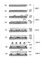
そこで本発明者らは、充填時間が短い、つまり高スループットな光ナノインプリント技術(Short Spread Time Nanoimprint Lithography、以下、SST−NIL)を考案した。SST−NILは、図2の模式断面図に示すように、
基板201上に、液状の硬化性組成物(A1)202を積層する第一積層工程(1)、
前記硬化性組成物(A1)202の層上に、硬化性組成物(A2)203の液滴を離散的に積層する第二積層工程(2)、
パターンを有するモールド205と基板201の間に硬化性組成物(A1)202と硬化性組成物(A2)203が部分的に混合してなる層をサンドイッチする型接触工程(3)、
前記2種の硬化性組成物が部分的に混合してなる混合層206を形成し、モールド205側から照射光207を照射することにより硬化させる光照射工程(4)、
モールド205を硬化後の硬化性組成物からなる層(パターン形状を有する硬化膜208)から引き離す離型工程(5)、
を有する。Therefore, the present inventors have devised an optical nanoimprint technology (Short Spread Time Nanoimprint Lithography, hereinafter referred to as SST-NIL) having a short filling time, that is, a high throughput. SST-NIL is a SST-NIL, as shown in the schematic cross-sectional view of FIG.
First laminating step (1) of laminating the liquid curable composition (A1) 202 on the
The second laminating step (2), in which the droplets of the curable composition (A2) 203 are discretely laminated on the layer of the curable composition (A1) 202.
A mold contact step (3) of sandwiching a layer formed by partially mixing the curable composition (A1) 202 and the curable composition (A2) 203 between the
Light irradiation step (4), in which a
Mold release step (5), which separates the
Have.
SST−NILにおいて、第二積層工程(2)から離型工程(5)までの一連の工程単位を「ショット」と称し、モールド205が硬化性組成物(A1)202及び硬化性組成物(A2)203と接触する領域、つまり、基板201上でパターンが形成される領域を「ショット領域」と称する。
In SST-NIL, a series of step units from the second laminating step (2) to the mold release step (5) is referred to as a "shot", and the
SST−NILにおいては、離散的に滴下された硬化性組成物(A2)203の液滴が、硬化性組成物(A1)202の液膜上において液滴の広がる方向を示す矢印204で示すように速やかに拡大するため、充填時間が短く、高スループットである。SST−NILの詳しいメカニズムは後述する。
In SST-NIL, the droplets of the curable composition (A2) 203 dropped discretely are indicated by
本発明が解決しようとするSST−NILの課題は、2種類の液状の硬化性組成物の混合が不十分となることによって、面内に硬化性組成物の組成分布が生じることである。例えば硬化特性の異なる2種類の硬化性組成物(A1)202および硬化性組成物(A2)203が混合せず、分離した場合について図3を用いて説明する。図3は、図2における光照射工程(4)及び離型工程(5)を再掲し、さらにエッチング工程(6)を付加したものである。
光照射工程(4)では、まず前記2種類の硬化性組成物が分離してなる混合層306を基板301上に形成し、照射光307をモールド305側から照射することで硬化膜308を形成する。この硬化膜308を離型工程(5)で離型する際に生じる不具合を説明する。例えば硬化性組成物(A1)302と硬化性組成物(A2)303が分離して混合が不十分であると、硬化性組成物(A1)302と硬化性組成物(A2)303の2種類の機械強度をもつ領域が生じることで機械強度の分布が生じ、倒れ欠陥やプラグ欠陥が多い領域が生じる。また、例えば硬化性組成物(A1)302が光重合開始剤を含まない場合、硬化性組成物(A2)303中の光重合開始剤が硬化性組成物(A1)302へ拡散して硬化性組成物(A1)302を硬化させることになる。硬化性組成物(A1)302と硬化性組成物(A2)303の混合が不十分であると、硬化性組成物(A1)302の濃度が高い領域において、光重合開始剤の濃度が低い領域が生じ、硬化不良やパターン欠陥が生じる。また、この硬化膜308をエッチング工程(6)でエッチングした場合、硬化が不十分な硬化性組成物(A1)302が先にエッチングで除去され、エッチング速度に分布ができてしまうという問題が生じる。The problem of SST-NIL to be solved by the present invention is that the composition distribution of the curable composition is generated in the plane due to insufficient mixing of the two liquid curable compositions. For example, a case where two types of curable compositions (A1) 202 and curable composition (A2) 203 having different curing characteristics are not mixed and separated will be described with reference to FIG. FIG. 3 reprints the light irradiation step (4) and the mold release step (5) in FIG. 2, and further adds an etching step (6).
In the light irradiation step (4), first, a mixed layer 306 formed by separating the two types of curable compositions is formed on the
本発明は、良好に混合する2種類の液状の硬化性組成物を用いることで面内分布を抑制したSST−NIL技術を提供することを目的とする。 An object of the present invention is to provide an SST-NIL technique in which in-plane distribution is suppressed by using two kinds of liquid curable compositions that are well mixed.
本発明に係るパターン形成方法は、基板の表面に、少なくとも重合性化合物である成分(a1)を含む硬化性組成物(A1)からなる層を積層する第一積層工程(1)、
前記硬化性組成物(A1)からなる層の上に、少なくとも重合性化合物である成分(a2)及び光重合開始剤である成分(b2)を含む硬化性組成物(A2)の液滴を離散的に滴下して積層する第二積層工程(2)、
パターンを有するモールドと前記基板の間に前記硬化性組成物(A1)及び前記硬化性組成物(A2)が部分的に混合してなる混合層をサンドイッチする型接触工程(3)、
前記混合層を前記モールド側から光を照射することにより硬化させる光照射工程(4)、
前記モールドを硬化後の前記混合層から引き離す離型工程(5)、
を該順に有するパターン形成方法であって、
前記硬化性組成物(A1)中の前記重合性化合物である成分(a1)と前記硬化性組成物(A2)のハンセン距離Ra((a1)−(A2))が6以下である、
ことを特徴とする。The pattern forming method according to the present invention is the first laminating step (1) of laminating a layer made of a curable composition (A1) containing at least a polymerizable compound component (a1) on the surface of a substrate.
On the layer made of the curable composition (A1), droplets of the curable composition (A2) containing at least the component (a2) which is a polymerizable compound and the component (b2) which is a photopolymerization initiator are dispersed. Second laminating step (2), in which the particles are dropped and laminated.
A mold contact step (3) of sandwiching a mixed layer formed by partially mixing the curable composition (A1) and the curable composition (A2) between a mold having a pattern and the substrate.
Light irradiation step (4), in which the mixed layer is cured by irradiating light from the mold side.
A mold release step (5) of pulling the mold away from the cured mixed layer.
Is a pattern forming method having the above in the same order.
The Hansen distance Ra ((a1)-(A2)) between the component (a1) which is the polymerizable compound in the curable composition (A1) and the curable composition (A2) is 6 or less.
It is characterized by that.
本発明によれば、良好に混合する2種類の液状の硬化性組成物を用いることで面内組成分布を抑制したSST−NIL技術を提供することができる。 According to the present invention, it is possible to provide an SST-NIL technique in which an in-plane composition distribution is suppressed by using two kinds of liquid curable compositions that are well mixed.
本発明の他の特徴は、添付された図面を参照して各種実施の形態を例示する以下の説明により明らかにされる。 Other features of the present invention will be clarified by the following description illustrating various embodiments with reference to the accompanying drawings.
以下、本発明の実施形態について適宜図面を参照しながら詳細に説明する。ただし、本発明は以下に説明する実施形態に限定されるものではない。また、本発明の趣旨を逸脱しない範囲で、当業者の通常の知識に基づいて、以下に説明する実施形態に対して適宜変更、改良等が加えられたものも本発明の範囲に含まれる。なお、硬化性組成物(A1)に含まれる成分(a)を成分(a1)と表記し、硬化性組成物(A2)に含まれる成分(a)を成分(a2)と表記する。成分(b)から成分(d)についても同様である。 Hereinafter, embodiments of the present invention will be described in detail with reference to the drawings as appropriate. However, the present invention is not limited to the embodiments described below. In addition, the scope of the present invention also includes modifications and improvements as appropriate to the embodiments described below based on the ordinary knowledge of those skilled in the art without departing from the spirit of the present invention. The component (a) contained in the curable composition (A1) is referred to as a component (a1), and the component (a) contained in the curable composition (A2) is referred to as a component (a2). The same applies to the component (b) to the component (d).
[硬化性組成物]
本実施形態に係る硬化性組成物(A1)及び(A2)は、少なくとも重合性化合物である成分(a)を有する組成物である。本実施形態に係る硬化性組成物はさらに、光重合開始剤である成分(b)、非重合性化合物である成分(c)、溶剤である成分(d)を含有してもよい。[Curable composition]
The curable compositions (A1) and (A2) according to the present embodiment are compositions having at least the component (a) which is a polymerizable compound. The curable composition according to the present embodiment may further contain a component (b) which is a photopolymerization initiator, a component (c) which is a non-polymerizable compound, and a component (d) which is a solvent.
また、本明細書において硬化膜とは、基板上で硬化性組成物を重合させて硬化させた膜を意味する。なお、硬化膜の形状は特に限定されず、表面にパターン形状を有していてもよい。
以下、各成分について、詳細に説明する。Further, in the present specification, the cured film means a film obtained by polymerizing and curing a curable composition on a substrate. The shape of the cured film is not particularly limited, and may have a pattern shape on the surface.
Hereinafter, each component will be described in detail.
<成分(a):重合性化合物>
成分(a)は重合性化合物である。ここで、本明細書において重合性化合物とは、光重合開始剤である成分(b)から発生した重合因子(ラジカル等)と反応し、連鎖反応(重合反応)によって高分子化合物からなる膜を形成する化合物である。<Component (a): Polymerizable compound>
Component (a) is a polymerizable compound. Here, the polymerizable compound in the present specification reacts with a polymerization factor (radical or the like) generated from the component (b) which is a photopolymerization initiator, and forms a film made of the polymer compound by a chain reaction (polymerization reaction). It is a compound that forms.
このような重合性化合物としては、例えば、ラジカル重合性化合物が挙げられる。重合性化合物である成分(a)は、一種類の重合性化合物のみから構成されていてもよく、複数種類の重合性化合物で構成されていてもよい。 Examples of such a polymerizable compound include a radically polymerizable compound. The component (a) which is a polymerizable compound may be composed of only one kind of polymerizable compound, or may be composed of a plurality of kinds of polymerizable compounds.
ラジカル重合性化合物としては、アクリロイル基またはメタクリロイル基を1つ以上有する化合物、すなわち、(メタ)アクリル化合物であることが好ましい。したがって、本実施形態に係る硬化性組成物は、成分(a)として(メタ)アクリル化合物を含むことが好ましく、成分(a)の主成分が(メタ)アクリル化合物であることがより好ましく、成分(a)の全てが(メタ)アクリル化合物であることが最も好ましい。なお、ここで記載する成分(a)の主成分が(メタ)アクリル化合物であるとは、成分(a)の90重量%以上が(メタ)アクリル化合物であることを示す。 The radically polymerizable compound is preferably a compound having one or more acryloyl group or methacryloyl group, that is, a (meth) acrylic compound. Therefore, the curable composition according to the present embodiment preferably contains a (meth) acrylic compound as the component (a), and more preferably the main component of the component (a) is a (meth) acrylic compound. Most preferably, all of (a) are (meth) acrylic compounds. The fact that the main component of the component (a) described here is a (meth) acrylic compound means that 90% by weight or more of the component (a) is a (meth) acrylic compound.
ラジカル重合性化合物が、アクリロイル基またはメタクリロイル基を1つ以上有する複数種類の化合物で構成される場合には、単官能(メタ)アクリルモノマーと多官能(メタ)アクリルモノマーを含むことが好ましい。これは、単官能(メタ)アクリルモノマーと多官能(メタ)アクリルモノマーを組み合わせることで、機械的強度が強い硬化膜が得られるからである。 When the radically polymerizable compound is composed of a plurality of types of compounds having one or more acryloyl group or methacryloyl group, it preferably contains a monofunctional (meth) acrylic monomer and a polyfunctional (meth) acrylic monomer. This is because a cured film having high mechanical strength can be obtained by combining the monofunctional (meth) acrylic monomer and the polyfunctional (meth) acrylic monomer.
アクリロイル基またはメタクリロイル基を1つ有する単官能(メタ)アクリル化合物としては、例えば、フェノキシエチル(メタ)アクリレート、フェノキシ−2−メチルエチル(メタ)アクリレート、フェノキシエトキシエチル(メタ)アクリレート、3−フェノキシ−2−ヒドロキシプロピル(メタ)アクリレート、2−フェニルフェノキシエチル(メタ)アクリレート、4−フェニルフェノキシエチル(メタ)アクリレート、3−(2−フェニルフェニル)−2−ヒドロキシプロピル(メタ)アクリレート、EO変性p−クミルフェノールの(メタ)アクリレート、2−ブロモフェノキシエチル(メタ)アクリレート、2,4−ジブロモフェノキシエチル(メタ)アクリレート、2,4,6−トリブロモフェノキシエチル(メタ)アクリレート、EO変性フェノキシ(メタ)アクリレート、PO変性フェノキシ(メタ)アクリレート、ポリオキシエチレンノニルフェニルエーテル(メタ)アクリレート、イソボルニル(メタ)アクリレート、1−アダマンチル(メタ)アクリレート、2−メチル−2−アダマンチル(メタ)アクリレート、2−エチル−2−アダマンチル(メタ)アクリレート、ボルニル(メタ)アクリレート、トリシクロデカニル(メタ)アクリレート、ジシクロペンタニル(メタ)アクリレート、ジシクロペンテニル(メタ)アクリレート、シクロヘキシル(メタ)アクリレート、4−ブチルシクロヘキシル(メタ)アクリレート、アクリロイルモルホリン、2−ヒドロキシエチル(メタ)アクリレート、2−ヒドロキシプロピル(メタ)アクリレート、2−ヒドロキシブチル(メタ)アクリレート、メチル(メタ)アクリレート、エチル(メタ)アクリレート、プロピル(メタ)アクリレート、イソプロピル(メタ)アクリレート、ブチル(メタ)アクリレート、アミル(メタ)アクリレート、イソブチル(メタ)アクリレート、t−ブチル(メタ)アクリレート、ペンチル(メタ)アクリレート、イソアミル(メタ)アクリレート、へキシル(メタ)アクリレート、ヘプチル(メタ)アクリレート、オクチル(メタ)アクリレート、イソオクチル(メタ)アクリレート、2−エチルヘキシル(メタ)アクリレート、ノニル(メタ)アクリレート、デシル(メタ)アクリレート、イソデシル(メタ)アクリレート、ウンデシル(メタ)アクリレート、ドデシル(メタ)アクリレート、ラウリル(メタ)アクリレート、ステアリル(メタ)アクリレート、イソステアリル(メタ)アクリレート、ベンジル(メタ)アクリレート、テトラヒドロフルフリル(メタ)アクリレート、ブトキシエチル(メタ)アクリレート、エトキシジエチレングリコール(メタ)アクリレート、ポリエチレングリコールモノ(メタ)アクリレート、ポリプロピレングリコールモノ(メタ)アクリレート、メトキシエチレングリコール(メタ)アクリレート、エトキシエチル(メタ)アクリレート、メトキシポリエチレングリコール(メタ)アクリレート、メトキシポリプロピレングリコール(メタ)アクリレート、ジアセトン(メタ)アクリルアミド、イソブトキシメチル(メタ)アクリルアミド、N,N−ジメチル(メタ)アクリルアミド、t−オクチル(メタ)アクリルアミド、ジメチルアミノエチル(メタ)アクリレート、ジエチルアミノエチル(メタ)アクリレート、7−アミノ−3,7−ジメチルオクチル(メタ)アクリレート、N,N−ジエチル(メタ)アクリルアミド、N,N−ジメチルアミノプロピル(メタ)アクリルアミド等が挙げられるが、これらに限定されない。 Examples of the monofunctional (meth) acrylic compound having one acryloyl group or methacryloyl group include phenoxyethyl (meth) acrylate, phenoxy-2-methylethyl (meth) acrylate, phenoxyethoxyethyl (meth) acrylate, and 3-phenoxy. -2-Hydroxypropyl (meth) acrylate, 2-phenylphenoxyethyl (meth) acrylate, 4-phenylphenoxyethyl (meth) acrylate, 3- (2-phenylphenyl) -2-hydroxypropyl (meth) acrylate, EO modified (Meta) acrylate of p-cumylphenol, 2-bromophenoxyethyl (meth) acrylate, 2,4-dibromophenoxyethyl (meth) acrylate, 2,4,6-tribromophenoxyethyl (meth) acrylate, EO modification Phenoxy (meth) acrylate, PO-modified phenoxy (meth) acrylate, polyoxyethylene nonylphenyl ether (meth) acrylate, isobornyl (meth) acrylate, 1-adamantyl (meth) acrylate, 2-methyl-2-adamantyl (meth) acrylate , 2-Ethyl-2-adamantyl (meth) acrylate, Bornyl (meth) acrylate, Tricyclodecanyl (meth) acrylate, Dicyclopentanyl (meth) acrylate, Dicyclopentenyl (meth) acrylate, Cyclohexyl (meth) acrylate , 4-Butylcyclohexyl (meth) acrylate, acryloylmorpholine, 2-hydroxyethyl (meth) acrylate, 2-hydroxypropyl (meth) acrylate, 2-hydroxybutyl (meth) acrylate, methyl (meth) acrylate, ethyl (meth) Acrylate, propyl (meth) acrylate, isopropyl (meth) acrylate, butyl (meth) acrylate, amyl (meth) acrylate, isobutyl (meth) acrylate, t-butyl (meth) acrylate, pentyl (meth) acrylate, isoamyl (meth) Acrylate, hexyl (meth) acrylate, heptyl (meth) acrylate, octyl (meth) acrylate, isooctyl (meth) acrylate, 2-ethylhexyl (meth) acrylate, nonyl (meth) acrylate, decyl (meth) acrylate, isodecyl (meth) ) Acrylate, undecyl (meth) acrylate, dodecyl (meth) acrylate, lauryl ( Meta) acrylate, stearyl (meth) acrylate, isostearyl (meth) acrylate, benzyl (meth) acrylate, tetrahydrofurfuryl (meth) acrylate, butoxyethyl (meth) acrylate, ethoxydiethylene glycol (meth) acrylate, polyethylene glycol mono (meth) ) Acrylate, polypropylene glycol mono (meth) acrylate, methoxyethylene glycol (meth) acrylate, ethoxyethyl (meth) acrylate, methoxypolyethylene glycol (meth) acrylate, methoxypolypropylene glycol (meth) acrylate, diacetone (meth) acrylamide, isobutoxy Methyl (meth) acrylamide, N, N-dimethyl (meth) acrylamide, t-octyl (meth) acrylamide, dimethylaminoethyl (meth) acrylate, diethylaminoethyl (meth) acrylate, 7-amino-3,7-dimethyloctyl ( Examples thereof include, but are not limited to, meta) acrylate, N, N-diethyl (meth) acrylamide, N, N-dimethylaminopropyl (meth) acrylamide and the like.
上記単官能(メタ)アクリル化合物の市販品としては、アロニックス(登録商標)M101、M102、M110、M111、M113、M117、M5700、TO−1317、M120、M150、M156(以上、東亞合成製)、MEDOL10、MIBDOL10、CHDOL10、MMDOL30、MEDOL30、MIBDOL30、CHDOL30、LA、IBXA、2−MTA、HPA、ビスコート#150、#155、#158、#190、#192、#193、#220、#2000、#2100、#2150(以上、大阪有機化学工業製)、ライトアクリレートBO−A、EC−A、DMP−A、THF−A、HOP−A、HOA−MPE、HOA−MPL、PO−A、P−200A、NP−4EA、NP−8EA、エポキシエステルM−600A(以上、共栄社化学製)、KAYARAD(登録商標) TC110S、R−564、R−128H(以上、日本化薬製)、NKエステルAMP−10G、AMP−20G(以上、新中村化学工業製)、FA−511A、512A、513A(以上、日立化成製)、PHE、CEA、PHE−2、PHE−4、BR−31、BR−31M、BR−32(以上、第一工業製薬製)、VP(BASF製)、ACMO、DMAA、DMAPAA(以上、興人製)等が挙げられるが、これらに限定されない。
また、アクリロイル基またはメタクリロイル基を2つ以上有する多官能(メタ)アクリル化合物としては、例えば、トリメチロールプロパンジ(メタ)アクリレート、トリメチロールプロパントリ(メタ)アクリレート、EO変性トリメチロールプロパントリ(メタ)アクリレート、PO変性トリメチロールプロパントリ(メタ)アクリレート、EO,PO変性トリメチロールプロパントリ(メタ)アクリレート、ジメチロールトリシクロデカンジ(メタ)アクリレート、ペンタエリスリトールトリ(メタ)アクリレート、ペンタエリスリトールテトラ(メタ)アクリレート、エチレングリコールジ(メタ)アクリレート、テトラエチレングリコールジ(メタ)アクリレート、ポリエチレングリコールジ(メタ)アクリレート、ポリプロピレングリコールジ(メタ)アクリレート、1,4−ブタンジオールジ(メタ)アクリレート、1,6−へキサンジオールジ(メタ)アクリレート、ネオペンチルグリコールジ(メタ)アクリレート、1,9−ノナンジオールジ(メタ)アクリレート、1,10−デカンジオールジ(メタ)アクリレート、1,3−アダマンタンジメタノールジ(メタ)アクリレート、トリス(2−ヒドロキシエチル)イソシアヌレートトリ(メタ)アクリレート、トリス(アクリロイルオキシ)イソシアヌレート、ビス(ヒドロキシメチル)トリシクロデカンジ(メタ)アクリレート、ジペンタエリスリトールペンタ(メタ)アクリレート、ジペンタエリスリトールヘキサ(メタ)アクリレート、EO変性2,2−ビス(4−((メタ)アクリロキシ)フェニル)プロパン、PO変性2,2−ビス(4−((メタ)アクリロキシ)フェニル)プロパン、EO,PO変性2,2−ビス(4−((メタ)アクリロキシ)フェニル)プロパン等が挙げられるが、これらに限定されない。Commercially available products of the monofunctional (meth) acrylic compound include Aronix (registered trademarks) M101, M102, M110, M111, M113, M117, M5700, TO-1317, M120, M150, and M156 (all manufactured by Toa Synthetic). MEDOL10, MIBDOL10, CHDOL10, MMDOL30, MEDOL30, MIBDOL30, CHDOL30, LA, IBXA, 2-MTA, HPA, Viscort # 150, # 155, # 158, # 190, # 192, # 193, # 220, # 2000, # 2100, # 2150 (all manufactured by Osaka Organic Chemical Industry Co., Ltd.), Light Acrylate BO-A, EC-A, DMP-A, THF-A, HOP-A, HOA-MPE, HOA-MPL, PO-A, P- 200A, NP-4EA, NP-8EA, Epoxy Ester M-600A (above, manufactured by Kyoeisha Chemical Co., Ltd.), KAYARAD (registered trademark) TC110S, R-564, R-128H (above, manufactured by Nippon Kayaku), NK Ester AMP- 10G, AMP-20G (above, manufactured by Shin-Nakamura Chemical Industry), FA-511A, 512A, 513A (above, manufactured by Hitachi Kayaku), PHE, CEA, PHE-2, PHE-4, BR-31, BR-31M, BR-32 (above, manufactured by Daiichi Kogyo Seiyaku Co., Ltd.), VP (manufactured by BASF), ACMO, DMAA, DMAPAA (above, manufactured by Kojin) and the like can be mentioned, but are not limited thereto.
Examples of the polyfunctional (meth) acrylic compound having two or more acryloyl groups or methacryloyl groups include trimethylolpropandi (meth) acrylate, trimethylolpropane tri (meth) acrylate, and EO-modified trimethylolpropanetri (meth). ) Acrylate, PO-modified trimethylolpropantri (meth) acrylate, EO, PO-modified trimethylolpropanthry (meth) acrylate, dimethyloltricyclodecandi (meth) acrylate, pentaerythritol tri (meth) acrylate, pentaerythritol tetra ( Meta) acrylate, ethylene glycol di (meth) acrylate, tetraethylene glycol di (meth) acrylate, polyethylene glycol di (meth) acrylate, polypropylene glycol di (meth) acrylate, 1,4-butanediol di (meth) acrylate, 1 , 6-Hexanediol di (meth) acrylate, neopentyl glycol di (meth) acrylate, 1,9-nonanediol di (meth) acrylate, 1,10-decanediol di (meth) acrylate, 1,3-adamantan Dimethanol di (meth) acrylate, tris (2-hydroxyethyl) isocyanurate tri (meth) acrylate, tris (acryloyloxy) isocyanurate, bis (hydroxymethyl) tricyclodecandi (meth) acrylate, dipentaerythritol penta ( Meta) acrylate, dipentaerythritol hexa (meth) acrylate, EO-modified 2,2-bis (4-((meth) acryloxy) phenyl) propane, PO-modified 2,2-bis (4-((meth) acryloxy) phenyl) ) Propane, EO, PO-modified 2,2-bis (4-((meth) acryloxy) phenyl) propane and the like, but are not limited thereto.
上記多官能(メタ)アクリル化合物の市販品としては、ユピマー(登録商標)UV SA1002、SA2007(以上、三菱化学製)、ビスコート#195、#230、#215、#260、#335HP、#295、#300、#360、#700、GPT、3PA(以上、大阪有機化学工業製)、ライトアクリレート4EG−A、9EG−A、NP−A、DCP−A、BP−4EA、BP−4PA、TMP−A、PE−3A、PE−4A、DPE−6A(以上、共栄社化学製)、KAYARAD(登録商標) PET−30、TMPTA、R−604、DPHA、DPCA−20、−30、−60、−120、HX−620、D−310、D−330(以上、日本化薬製)、アロニックス(登録商標)M208、M210、M215、M220、M240、M305、M309、M310、M315、M325、M400(以上、東亞合成製)、リポキシ(登録商標)VR−77、VR−60、VR−90(以上、昭和高分子製)等が挙げられるが、これらに限定されない。 Commercially available products of the above polyfunctional (meth) acrylic compounds include Yupimer (registered trademark) UV SA1002, SA2007 (all manufactured by Mitsubishi Chemical), Viscort # 195, # 230, # 215, # 260, # 335HP, # 295, and so on. # 300, # 360, # 700, GPT, 3PA (all manufactured by Osaka Organic Chemical Industry Co., Ltd.), Light Acrylate 4EG-A, 9EG-A, NP-A, DCP-A, BP-4EA, BP-4PA, TMP- A, PE-3A, PE-4A, DPE-6A (all manufactured by Kyoeisha Chemical Co., Ltd.), KAYARAD (registered trademark) PET-30, TMPTA, R-604, DPHA, DPCA-20, -30, -60, -120 , HX-620, D-310, D-330 (above, manufactured by Nippon Kayaku), Aronix (registered trademark) M208, M210, M215, M220, M240, M305, M309, M310, M315, M325, M400 (above, Examples include, but are not limited to, Lipoxy (registered trademark) VR-77, VR-60, VR-90 (all manufactured by Showa High Polymer Co., Ltd.).
なお、上述した化合物群において、(メタ)アクリレートとは、アクリレートまたはそれと同等のアルコール残基を有するメタクリレートを意味する。(メタ)アクリロイル基とは、アクリロイル基またはそれと同等のアルコール残基を有するメタクリロイル基を意味する。EOは、エチレンオキサイドを示し、EO変性化合物Aとは、化合物Aの(メタ)アクリル酸残基とアルコール残基がエチレンオキサイド基のブロック構造を介して結合している化合物を示す。また、POは、プロピレンオキサイドを示し、PO変性化合物Bとは、化合物Bの(メタ)アクリル酸残基とアルコール残基がプロピレンオキサイド基のブロック構造を介して結合している化合物を示す。 In the above-mentioned compound group, (meth) acrylate means acrylate or methacrylate having an alcohol residue equivalent thereto. The (meth) acryloyl group means an acryloyl group or a methacryloyl group having an alcohol residue equivalent thereto. EO indicates ethylene oxide, and EO-modified compound A refers to a compound in which a (meth) acrylic acid residue and an alcohol residue of compound A are bonded via a block structure of an ethylene oxide group. Further, PO indicates propylene oxide, and PO-modified compound B refers to a compound in which a (meth) acrylic acid residue and an alcohol residue of compound B are bonded via a block structure of a propylene oxide group.
重合性化合物である成分(a1)の硬化性組成物(A1)における配合割合は、成分(a1)、成分(b1)、成分(c1)の合計重量、すなわち溶剤である成分(d1)を除く硬化性組成物(A1)の成分の合計重量に対して、50重量%以上100重量%以下であるとよい。また、好ましくは、80重量%以上100重量%以下であり、さらに好ましくは90重量%より大きく100重量%以下である。
重合性化合物である成分(a1)の硬化性組成物(A1)における配合割合を、成分(a1)、成分(b1)、成分(c1)の合計重量に対して50重量%以上とすることにより、得られる硬化膜をある程度の機械的強度を有する硬化膜とすることができる。The blending ratio of the component (a1), which is a polymerizable compound, in the curable composition (A1) excludes the total weight of the component (a1), the component (b1), and the component (c1), that is, the component (d1) which is a solvent. It is preferable that it is 50% by weight or more and 100% by weight or less with respect to the total weight of the components of the curable composition (A1). Further, it is preferably 80% by weight or more and 100% by weight or less, and more preferably more than 90% by weight and 100% by weight or less.
By setting the blending ratio of the component (a1), which is a polymerizable compound, in the curable composition (A1) to 50% by weight or more with respect to the total weight of the component (a1), the component (b1), and the component (c1). The obtained cured film can be a cured film having a certain degree of mechanical strength.
重合性化合物である成分(a2)の硬化性組成物(A2)における配合割合は、成分(a2)、成分(b2)、成分(c2)の合計重量、すなわち溶剤である成分(d2)を除く硬化性組成物(A2)の成分の合計重量に対して、50重量%以上99.9重量%以下であるとよい。また、好ましくは、80重量%以上99重量%以下であり、さらに好ましくは90重量%より大きく98重量%以下である。
重合性化合物である成分(a2)の硬化性組成物(A2)における配合割合を、成分(a2)、成分(b2)、成分(c2)の合計重量に対して50重量%以上とすることにより、得られる硬化膜をある程度の機械的強度を有する硬化膜とすることができる。The blending ratio of the component (a2), which is a polymerizable compound, in the curable composition (A2) excludes the total weight of the component (a2), the component (b2), and the component (c2), that is, the component (d2) which is a solvent. It is preferable that it is 50% by weight or more and 99.9% by weight or less with respect to the total weight of the components of the curable composition (A2). Further, it is preferably 80% by weight or more and 99% by weight or less, and more preferably more than 90% by weight and 98% by weight or less.
By setting the blending ratio of the component (a2), which is a polymerizable compound, in the curable composition (A2) to 50% by weight or more with respect to the total weight of the component (a2), the component (b2), and the component (c2). The obtained cured film can be a cured film having a certain degree of mechanical strength.
また、後述するように、硬化性組成物(A1)は、成分(d1)を含有することが好ましく、成分(a1)は溶剤である成分(d1)を含む硬化性組成物(A1)の成分の合計重量に対して、0.01重量%以上10重量%以下であるとよい。 Further, as will be described later, the curable composition (A1) preferably contains the component (d1), and the component (a1) is a component of the curable composition (A1) containing the component (d1) which is a solvent. It is preferable that it is 0.01% by weight or more and 10% by weight or less with respect to the total weight of.
<成分(b):光重合開始剤>
成分(b)は、光重合開始剤である。
本明細書において光重合開始剤は、所定の波長の光を感知して上記重合因子(ラジカル)を発生させる化合物である。具体的には、光重合開始剤は、光(赤外線、可視光線、紫外線、遠紫外線、X線、電子線等の荷電粒子線等、放射線)によりラジカルを発生する重合開始剤(ラジカル発生剤)である。<Component (b): Photopolymerization Initiator>
Component (b) is a photopolymerization initiator.
In the present specification, the photopolymerization initiator is a compound that senses light of a predetermined wavelength to generate the above-mentioned polymerization factor (radical). Specifically, the photopolymerization initiator is a polymerization initiator (radical generator) that generates radicals by light (radiation such as charged particle beams such as infrared rays, visible rays, ultraviolet rays, far ultraviolet rays, X-rays, and electron beams). Is.
成分(b)は、一種類の光重合開始剤で構成されていてもよく、複数種類の光重合開始剤で構成されていてもよい。 The component (b) may be composed of one kind of photopolymerization initiator or a plurality of kinds of photopolymerization initiators.
ラジカル発生剤としては、例えば、2−(o−クロロフェニル)−4,5−ジフェニルイミダゾール二量体、2−(o−クロロフェニル)−4,5−ジ(メトキシフェニル)イミダゾール二量体、2−(o−フルオロフェニル)−4,5−ジフェニルイミダゾール二量体、2−(o−またはp−メトキシフェニル)−4,5−ジフェニルイミダゾール二量体等の置換基を有してもよい2,4,5−トリアリールイミダゾール二量体;ベンゾフェノン、N,N’−テトラメチル−4,4’−ジアミノベンゾフェノン(ミヒラーケトン)、N,N’−テトラエチル−4,4’−ジアミノベンゾフェノン、4−メトキシ−4’−ジメチルアミノベンゾフェノン、4−クロロベンゾフェノン、4,4’−ジメトキシベンゾフェノン、4,4’−ジアミノベンゾフェノン等のベンゾフェノン誘導体;2−ベンジル−2−ジメチルアミノ−1−(4−モルフォリノフェニル)−ブタノン−1、2−メチル−1−〔4−(メチルチオ)フェニル〕−2−モルフォリノ−プロパン−1−オン等のα−アミノ芳香族ケトン誘導体;2−エチルアントラキノン、フェナントレンキノン、2−t−ブチルアントラキノン、オクタメチルアントラキノン、1,2−ベンズアントラキノン、2,3−ベンズアントラキノン、2−フェニルアントラキノン、2,3−ジフェニルアントラキノン、1−クロロアントラキノン、2−メチルアントラキノン、1,4−ナフトキノン、9,10−フェナンタラキノン、2−メチル−1,4−ナフトキノン、2,3−ジメチルアントラキノン等のキノン類;ベンゾインメチルエーテル、ベンゾインエチルエーテル、ベンゾインフェニルエーテル等のベンゾインエーテル誘導体;ベンゾイン、メチルベンゾイン、エチルベンゾイン、プロピルベンゾイン等のベンゾイン誘導体;ベンジルジメチルケタール等のベンジル誘導体;9−フェニルアクリジン、1,7−ビス(9,9’−アクリジニル)ヘプタン等のアクリジン誘導体;N−フェニルグリシン等のN−フェニルグリシン誘導体;アセトフェノン、3−メチルアセトフェノン、アセトフェノンベンジルケタール、1−ヒドロキシシクロヘキシルフェニルケトン、2,2−ジメトキシ−2−フェニルアセトフェノン等のアセトフェノン誘導体;チオキサントン、ジエチルチオキサントン、2−イソプロピルチオキサントン、2−クロロチオキサントン等のチオキサントン誘導体;2,4,6−トリメチルベンゾイルジフェニルフォスフィンオキサイド、ビス(2,4,6−トリメチルベンゾイル)フェニルフォスフィンオキサイド、ビス−(2,6−ジメトキシベンゾイル)−2,4,4−トリメチルペンチルフォスフィンオキサイド等のアシルフォスフィンオキサイド誘導体;1,2−オクタンジオン−1−[4−(フェニルチオフェニル)]−2−(O−ベンゾイルオキシム)、およびエタノン−1−[9−エチル−6−(2−メチルベンゾイル)−9H−カルバゾール−3−イル]−1−(O−アセチルオキシム)等のオキシムエステル誘導体;キサントン、フルオレノン、ベンズアルデヒド、フルオレン、アントラキノン、トリフェニルアミン、カルバゾール、1−(4−イソプロピルフェニル)−2−ヒドロキシ−2−メチルプロパン−1−オン、2−ヒドロキシ−2−メチル−1−フェニルプロパン−1−オン等が挙げられるが、これらに限定されない。
上記ラジカル発生剤の市販品として、Irgacure 184、369、651、500、819、907、784、2959、CGI−1700、−1750、−1850、CG24−61、Darocur 1116、1173、Lucirin(登録商標) TPO、LR8893、LR8970(以上、BASF製)、ユベクリルP36(UCB製)等が挙げられるが、これらに限定されない。
Examples of the radical generator include 2- (o-chlorophenyl) -4,5-diphenylimidazole dimer, 2- (o-chlorophenyl) 4,5-di (methoxyphenyl) imidazole dimer, 2-. It may have a substituent such as (o-fluorophenyl) -4,5-diphenylimidazole dimer, 2- (o- or p-methoxyphenyl) -4,5-diphenylimidazole dimer, etc. 2, 4,5-Triarylimidazole dimer; benzophenone, N, N'-tetramethyl-4,4'-diaminobenzophenone (Michlerketone), N, N'-tetraethyl-4,4'-diaminobenzophenone, 4-methoxy Benzophenone derivatives such as -4'-dimethylaminobenzophenone, 4-chlorobenzophenone, 4,4'-dimethoxybenzophenone, 4,4'-diaminobenzophenone; 2-benzyl-2-dimethylamino-1- (4-morpholinophenyl) ) -Butanone-1, 2-Methyl-1- [4- (methylthio) phenyl] -2-morpholino-Propane-1-one and other α-aminoaromatic ketone derivatives; 2-ethylanthraquinone, phenanthrenquinone, 2- t-butyl anthraquinone, octamethyl anthraquinone, 1,2-benz anthraquinone, 2,3-benz anthraquinone, 2-phenyl anthraquinone, 2,3-diphenyl anthraquinone, 1-chloroanthraquinone, 2-methyl anthraquinone, 1,4-naphthoquinone , 9,10-Phenantaraquinone, 2-methyl-1,4-naphthoquinone, 2,3-dimethylanthraquinone and other quinones; benzoin ether derivatives such as benzoin methyl ether, benzoin ethyl ether, benzoin phenyl ether; benzoin, methyl Benzophenones such as benzophenone, ethylbenzoin, propylbenzoin; benzyl derivatives such as benzyldimethylketal; acridin derivatives such as 9-phenylaclysine, 1,7-bis (9,9'-acrydinyl) heptane; N-phenylglycine and the like N-phenylglycine derivatives; acetophenone derivatives such as acetophenone, 3-methylacetophenone, acetophenone benzyl ketal, 1-hydroxycyclohexylphenylketone, 2,2-dimethoxy-2-phenylacetophenone; thioxanthone, diethylthioxanthone, 2-isopropylthioxanthone, 2 -Tioxa such as chlorothioxanthone Nton derivatives; 2,4,6-trimethylbenzoyldiphenylphosphine oxide, bis (2,4,6-trimethylbenzoyl) phenylphosphine oxide, bis- (2,6-dimethoxybenzoyl) -2,4,4-trimethyl acylphosphine oxide derivatives such as pentyl phosphine oxide; 1,2-octanedione - 1- [4- (phenylthio phenyl)] -2 - (O-benzoyl oxime), and ethanone - 1- [9-ethyl-6 -(2-Methylbenzoyl) -9H-carbazole-3-yl] -1- (O-acetyloxime) and other oxime ester derivatives; xanthone, fluorenone, benzaldehyde, fluorene, anthraquinone, triphenylamine, carbazole, 1-( 4-Isopropyl) -2-hydroxy-2-methylpropan-1-one, 2-hydroxy-2-methyl-1-phenylpropan-1-one and the like can be mentioned, but the present invention is not limited thereto.
Commercially available products of the above radical generator include Irgacure 184, 369, 651, 500, 819, 907, 784, 2959, CGI-1700, -1750, -1850, CG24-61, Darocur 1116, 1173, Lucirin (registered trademark). Examples thereof include, but are not limited to, TPO, LR8883, LR8970 (all manufactured by BASF), and Yubekrill P36 (manufactured by UCB).
これらの中でも、成分(b)は、アシルフォスフィンオキサイド系重合開始剤であることが好ましい。なお、上記の例のうち、アシルフォスフィンオキサイド系重合開始剤は、2,4,6−トリメチルベンゾイルジフェニルフォスフィンオキサイド、ビス(2,4,6−トリメチルベンゾイル)フェニルフォスフィンオキサイド、ビス(2,6−ジメトキシベンゾイル)−2,4,4−トリメチルペンチルフォスフィンオキサイドなどのアシルフォスフィンオキサイド化合物である。 Among these, the component (b) is preferably an acylphosphine oxide-based polymerization initiator. Among the above examples, the acylphosphine oxide-based polymerization initiators are 2,4,6-trimethylbenzoyldiphenylphosphine oxide, bis (2,4,6-trimethylbenzoyl) phenylphosphine oxide, and bis (2). , 6-Dimethoxybenzoyl) -2,4,4-trimethylpentylphosphine oxide compounds.
本発明において、硬化性組成物(A1)は実質的に光反応性を有さないことが好ましい。このために、光重合開始剤である成分(b1)の硬化性組成物(A1)における配合割合は、成分(a1)、成分(b1)、後述する成分(c1)の合計重量、すなわち溶剤である成分(d1)を除く硬化性組成物(A1)の成分の合計重量に対して、0.1重量%未満であることが好ましい。また、さらに好ましくは、0.01重量%以下である。 In the present invention, it is preferable that the curable composition (A1) has substantially no photoreactivity. Therefore, the blending ratio of the component (b1), which is a photopolymerization initiator, in the curable composition (A1) is the total weight of the component (a1), the component (b1), and the component (c1) described later, that is, the solvent. It is preferably less than 0.1% by weight based on the total weight of the components of the curable composition (A1) excluding a certain component (d1). Further, it is more preferably 0.01% by weight or less.
硬化性組成物(A1)における成分(b1)の配合割合を成分(a1)、成分(b1)、成分(c1)の合計重量に対して0.1重量%未満とすることにより、硬化性組成物(A1)は実質的に光反応性を有さず、当該ショット領域外へ漏れ出た照射光により、当該ショット領域外に積層されている硬化性組成物(A1)が光硬化する、という問題を防止することができる。 The curable composition is formed by setting the blending ratio of the component (b1) in the curable composition (A1) to less than 0.1% by weight based on the total weight of the component (a1), the component (b1), and the component (c1). It is said that the substance (A1) has substantially no photoreactivity, and the curable composition (A1) laminated outside the shot region is photocured by the irradiation light leaking out of the shot region. The problem can be prevented.
光重合開始剤である成分(b2)の硬化性組成物(A2)における配合割合は、成分(a2)、成分(b2)、後述する成分(c2)の合計重量、すなわち溶剤である成分(d2)を除く硬化性組成物(A2)の成分の合計重量、に対して、0.1重量%以上50重量%以下であるとよい。また、好ましくは、0.1重量%以上20重量%以下であり、さらに好ましくは1重量%以上10重量%以下である。 The blending ratio of the component (b2), which is a photopolymerization initiator, in the curable composition (A2) is the total weight of the component (a2), the component (b2), and the component (c2) described later, that is, the component (d2) which is a solvent. ) Is excluded from the total weight of the components of the curable composition (A2), which is preferably 0.1% by weight or more and 50% by weight or less. Further, it is preferably 0.1% by weight or more and 20% by weight or less, and more preferably 1% by weight or more and 10% by weight or less.
硬化性組成物(A2)における成分(b2)の配合割合を成分(a2)、成分(b2)、成分(c2)の合計重量に対して0.1重量%以上とすることにより、組成物の硬化速度が速くなり、反応効率を良くすることができる。また、成分(b2)の配合割合を成分(a2)、成分(b2)、成分(c2)の合計に対して50重量%以下とすることにより、得られる硬化膜をある程度の機械的強度を有する硬化膜とすることができる。 The composition is composed by setting the blending ratio of the component (b2) in the curable composition (A2) to 0.1% by weight or more with respect to the total weight of the component (a2), the component (b2), and the component (c2). The curing rate becomes high, and the reaction efficiency can be improved. Further, by setting the blending ratio of the component (b2) to 50% by weight or less with respect to the total of the component (a2), the component (b2) and the component (c2), the obtained cured film has a certain degree of mechanical strength. It can be a cured film.
<成分(c):非重合性化合物>
本実施形態に係る硬化性組成物(A1)及び(A2)は、前述した、成分(a)、成分(b)の他に、種々の目的に応じ、本発明の効果を損なわない範囲で、さらに非重合性化合物である成分(c)を含有することができる。このような成分(c)としては、(メタ)アクリロイル基などの重合性官能基を有さず、かつ、所定の波長の光を感知して上記重合因子(ラジカル)を発生させる能力を有さない化合物が挙げられる。例えば、増感剤、水素供与体、内添型離型剤、界面活性剤、酸化防止剤、ポリマー成分、その他添加剤等が挙げられる。成分(c)として前記化合物を複数種類含有してもよい。<Component (c): Non-polymerizable compound>
The curable compositions (A1) and (A2) according to the present embodiment are used for various purposes in addition to the above-mentioned components (a) and (b), as long as the effects of the present invention are not impaired. Further, the component (c) which is a non-polymerizable compound can be contained. Such a component (c) does not have a polymerizable functional group such as a (meth) acryloyl group, and has an ability to detect light of a predetermined wavelength and generate the above-mentioned polymerization factor (radical). Examples include no compounds. For example, sensitizers, hydrogen donors, internal release mold release agents, surfactants, antioxidants, polymer components, other additives and the like can be mentioned. A plurality of types of the compound may be contained as the component (c).
増感剤は、重合反応促進や反応転化率の向上を目的として、適宜添加される化合物である。増感剤として、例えば、増感色素等が挙げられる。
増感色素は、特定の波長の光を吸収することにより励起され、光重合開始剤である成分(b)と相互作用する化合物である。なお、ここで記載する相互作用とは、励起状態の増感色素から光重合開始剤である成分(b)へのエネルギー移動や電子移動等である。The sensitizer is a compound appropriately added for the purpose of promoting the polymerization reaction and improving the reaction conversion rate. Examples of the sensitizer include sensitizing dyes and the like.
The sensitizing dye is a compound that is excited by absorbing light of a specific wavelength and interacts with the component (b) that is a photopolymerization initiator. The interaction described here is energy transfer, electron transfer, or the like from the excited state sensitizing dye to the component (b) which is the photopolymerization initiator.
増感色素の具体例としては、アントラセン誘導体、アントラキノン誘導体、ピレン誘導体、ペリレン誘導体、カルバゾール誘導体、ベンゾフェノン誘導体、チオキサントン誘導体、キサントン誘導体、クマリン誘導体、フェノチアジン誘導体、カンファキノン誘導体、アクリジン系色素、チオピリリウム塩系色素、メロシアニン系色素、キノリン系色素、スチリルキノリン系色素、ケトクマリン系色素、チオキサンテン系色素、キサンテン系色素、オキソノール系色素、シアニン系色素、ローダミン系色素、ピリリウム塩系色素等が挙げられるが、これらに限定されない。
増感剤は、一種類を単独で用いてもよいし、二種類以上を混合して用いてもよい。Specific examples of the sensitizing dye include anthracene derivatives, anthracene derivatives, pyrene derivatives, perylene derivatives, carbazole derivatives, benzophenone derivatives, thioxanthone derivatives, xanthene derivatives, coumarin derivatives, phenothiazine derivatives, camphaquinone derivatives, acrydin-based dyes, and thiopyrilium salts. Examples thereof include dyes, merocyanine dyes, quinoline dyes, styrylquinolin dyes, ketocoumarin dyes, thioxanthene dyes, xanthene dyes, oxonor dyes, cyanine dyes, rhodamine dyes, pyrylium salt dyes, etc. Not limited to these.
One type of sensitizer may be used alone, or two or more types may be used in combination.
水素供与体は、光重合開始剤である成分(b)から発生した開始ラジカルや、重合成長末端のラジカルと反応し、より反応性が高いラジカルを発生する化合物である。光重合開始剤である成分(b)が光ラジカル発生剤である場合に添加することが好ましい。 The hydrogen donor is a compound that reacts with the starting radical generated from the component (b), which is the photopolymerization initiator, or the radical at the end of the polymerization growth to generate a radical having higher reactivity. It is preferable to add the component (b) which is a photopolymerization initiator when it is a photoradical generator.
このような水素供与体の具体例としては、n−ブチルアミン、ジ−n−ブチルアミン、アリルチオ尿素、トリエチルアミン、トリエチレンテトラミン、4,4’−ビス(ジアルキルアミノ)ベンゾフェノン、N,N−ジメチルアミノ安息香酸エチルエステル、N,N−ジメチルアミノ安息香酸イソアミルエステル、ペンチル−4−ジメチルアミノベンゾエート、トリエタノールアミン、N−フェニルグリシンなどのアミン化合物、2−メルカプト−N−フェニルベンゾイミダゾール、メルカプトプロピオン酸エステル等のメルカプト化合物、s−ベンジルイソチウロニウム−p−トルエンスルフィネート等の硫黄化合物、トリ−n−ブチルホスフィンがアミン化合物等のリン化合物等が挙げられるが、これらに限定されない。 Specific examples of such hydrogen donors include n-butylamine, di-n-butylamine, allylthiourea, triethylamine, triethylenetetramine, 4,4'-bis (dialkylamino) benzophenone, and N, N-dimethylaminobenzo. Acid ethyl ester, N, N-dimethylaminobenzoic acid isoamyl ester, pentyl-4-dimethylaminobenzoate, triethanolamine, amine compounds such as N-phenylglycine, 2-mercapto-N-phenylbenzoimidazole, mercaptopropionic acid ester Examples thereof include, but are not limited to, mercapto compounds such as, sulfur compounds such as s-benzylisotiuronium-p-toluene sulfinate, and phosphorus compounds such as an amine compound containing tri-n-butylphosphine.
水素供与体は、一種類を単独で用いてもよいし二種類以上を混合して用いてもよい。また、水素供与体は、増感剤としての機能を有してもよい。 As the hydrogen donor, one type may be used alone, or two or more types may be used in combination. Further, the hydrogen donor may have a function as a sensitizer.
モールドとレジストとの間の界面結合力の低減、すなわち後述する離型工程における離型力の低減を目的として、硬化性組成物に内添型離型剤を添加することができる。本明細書において内添型とは、硬化性組成物の配置工程の前に予め硬化性組成物に添加されていることを意味する。 An internal mold release agent can be added to the curable composition for the purpose of reducing the interfacial bonding force between the mold and the resist, that is, reducing the release force in the release step described later. As used herein, the term "internal addition type" means that the curable composition has been added in advance to the curable composition before the step of arranging the curable composition.
内添型離型剤としては、シリコーン系界面活性剤、フッ素系界面活性剤及び炭化水素系界面活性剤等の界面活性剤等を使用できる。なお、本発明において内添型離型剤は、重合性を有さないものとする。 As the internal release type release agent, a silicone-based surfactant, a fluorine-based surfactant, a hydrocarbon-based surfactant, or the like can be used. In the present invention, the internal release type release agent shall not have polymerizable property.
フッ素系界面活性剤としては、パーフルオロアルキル基を有するアルコールのポリアルキレンオキサイド(ポリエチレンオキサイド、ポリプロピレンオキサイド等)付加物、パーフルオロポリエーテルのポリアルキレンオキサイド(ポリエチレンオキサイド、ポリプロピレンオキサイド等)付加物等が含まれる。なお、フッ素系界面活性剤は、分子構造の一部(例えば、末端基)に、ヒドロキシル基、アルコキシ基、アルキル基、アミノ基、チオール基等を有してもよい。 Examples of the fluorine-based surfactant include a polyalkylene oxide (polyethylene oxide, polypropylene oxide, etc.) adduct of an alcohol having a perfluoroalkyl group, a polyalkylene oxide (polyethylene oxide, polypropylene oxide, etc.) adduct of perfluoropolyether, and the like. included. The fluorine-based surfactant may have a hydroxyl group, an alkoxy group, an alkyl group, an amino group, a thiol group or the like in a part of the molecular structure (for example, a terminal group).
フッ素系界面活性剤としては、市販品を使用してもよい。市販品としては、例えば、メガファック(登録商標)F−444、TF−2066、TF−2067、TF−2068(以上、DIC製)、フロラード FC−430、FC−431(以上、住友スリーエム製)、サーフロン(登録商標) S−382(AGC製)、EFTOP EF−122A、122B、122C、EF−121、EF−126、EF−127、MF−100(以上、トーケムプロダクツ製)、PF−636、PF−6320、PF−656、PF−6520(以上、OMNOVA Solutions製)、ユニダイン(登録商標)DS−401、DS−403、DS−451(以上、ダイキン工業製)、フタージェント(登録商標) 250、251、222F、208G(以上、ネオス製)等が挙げられる。 As the fluorine-based surfactant, a commercially available product may be used. Commercially available products include, for example, Megafuck (registered trademark) F-444, TF-2066, TF-2067, TF-2068 (above, manufactured by DIC), Florard FC-430, FC-431 (above, manufactured by Sumitomo 3M). , Surflon (registered trademark) S-382 (manufactured by AGC), EFTOP EF-122A, 122B, 122C, EF-121, EF-126, EF-127, MF-100 (manufactured by Tochem Products), PF-636 , PF-6320, PF-656, PF-6520 (above, manufactured by OMNOVA Solutions), Unidyne (registered trademark) DS-401, DS-403, DS-451 (above, manufactured by Daikin Industries), Futergent (registered trademark). 250, 251 and 222F, 208G (all manufactured by Neos) and the like can be mentioned.
また、内添型離型剤は、炭化水素系界面活性剤でもよい。
炭化水素系界面活性剤としては、炭素数1〜50のアルキルアルコールに炭素数2〜4のアルキレンオキサイドを付加した、アルキルアルコールポリアルキレンオキサイド付加物等が含まれる。
アルキルアルコールポリアルキレンオキサイド付加物としては、メチルアルコールエチレンオキサイド付加物、デシルアルコールエチレンオキサイド付加物、ラウリルアルコールエチレンオキサイド付加物、セチルアルコールエチレンオキサイド付加物、ステアリルアルコールエチレンオキサイド付加物、ステアリルアルコールエチレンオキサイド/プロピレンオキサイド付加物等が挙げられる。なお、アルキルアルコールポリアルキレンオキサイド付加物の末端基は、単純にアルキルアルコールにポリアルキレンオキサイドを付加して製造できるヒドロキシル基に限定されない。このヒドロキシル基が他の置換基、例えば、カルボキシル基、アミノ基、ピリジル基、チオール基、シラノール基等の極性官能基やアルキル基、アルコキシ基等の疎水性官能基に置換されていてもよい。Further, the internal addition type release agent may be a hydrocarbon-based surfactant.
The hydrocarbon-based surfactant includes an alkyl alcohol polyalkylene oxide adduct obtained by adding an alkylene oxide having 2 to 4 carbon atoms to an alkyl alcohol having 1 to 50 carbon atoms.
As the alkyl alcohol polyalkylene oxide adduct, methyl alcohol ethylene oxide adduct, decyl alcohol ethylene oxide adduct, lauryl alcohol ethylene oxide adduct, cetyl alcohol ethylene oxide adduct, stearyl alcohol ethylene oxide adduct, stearyl alcohol ethylene oxide adduct / Examples include propylene oxide adducts. The terminal group of the alkyl alcohol polyalkylene oxide adduct is not limited to the hydroxyl group that can be produced by simply adding the polyalkylene oxide to the alkyl alcohol. This hydroxyl group may be substituted with another substituent, for example, a polar functional group such as a carboxyl group, an amino group, a pyridyl group, a thiol group or a silanol group, or a hydrophobic functional group such as an alkyl group or an alkoxy group.
アルキルアルコールポリアルキレンオキサイド付加物は、市販品を使用してもよい。市販品としては、例えば、青木油脂工業製のポリオキシエチレンメチルエーテル(メチルアルコールエチレンオキサイド付加物)(BLAUNON MP−400、MP−550、MP−1000)、青木油脂工業製のポリオキシエチレンデシルエーテル(デシルアルコールエチレンオキサイド付加物)(FINESURF D−1303、D−1305、D−1307、D−1310)、青木油脂工業製のポリオキシエチレンラウリルエーテル(ラウリルアルコールエチレンオキサイド付加物)(BLAUNON EL−1505)、青木油脂工業製のポリオキシエチレンセチルエーテル(セチルアルコールエチレンオキサイド付加物)(BLAUNON CH−305、CH−310)、青木油脂工業製のポリオキシエチレンステアリルエーテル(ステアリルアルコールエチレンオキサイド付加物)(BLAUNON SR−705、SR−707、SR−715、SR−720、SR−730、SR−750)、青木油脂工業製のランダム重合型ポリオキシエチレンポリオキシプロピレンステアリルエーテル(BLAUNON SA−50/50 1000R、SA−30/70 2000R)、BASF製のポリオキシエチレンメチルエーテル(Pluriol(登録商標) A760E)、花王製のポリオキシエチレンアルキルエーテル(エマルゲンシリーズ)等が挙げられる。 As the alkyl alcohol polyalkylene oxide adduct, a commercially available product may be used. Examples of commercially available products include polyoxyethylene methyl ether (methyl alcohol ethylene oxide adduct) manufactured by Aoki Yushi Kogyo (BLAUNON MP-400, MP-550, MP-1000), and polyoxyethylene decyl ether manufactured by Aoki Yushi Kogyo. (Decil alcohol ethylene oxide adduct) (FINESURF D-1303, D-1305, D-1307, D-1310), Polyoxyethylene lauryl ether (lauryl alcohol ethylene oxide adduct) manufactured by Aoki Yushi Kogyo (BLAUNON EL-1505). ), Polyoxyethylene cetyl ether (cetyl alcohol ethylene oxide adduct) manufactured by Aoki Yushi Kogyo (BLAUNON CH-305, CH-310), polyoxyethylene stearyl ether (stearyl alcohol ethylene oxide adduct) manufactured by Aoki Yushi Kogyo. BLAUNON SR-705, SR-707, SR-715, SR-720, SR-730, SR-750), Randomly Polymerized Polyoxyethylene Polyoxypropylene Stearyl Ether (BLAUNON SA-50 / 50 1000R) manufactured by Aoki Yushi Kogyo , SA-30 / 70 2000R), polyoxyethylene methyl ether (Pluril® A760E) manufactured by BASF, polyoxyethylene alkyl ether (Emargen series) manufactured by Kao, and the like.
これらの炭化水素系界面活性剤の中でも内添型離型剤としては、アルキルアルコールポリアルキレンオキサイド付加物であることが好ましく、長鎖アルキルアルコールポリアルキレンオキサイド付加物であることがより好ましい。 Among these hydrocarbon-based surfactants, the internal addition type release agent is preferably an alkyl alcohol polyalkylene oxide adduct, and more preferably a long chain alkyl alcohol polyalkylene oxide adduct.
内添型離型剤は、一種類を単独で用いてもよいし、二種類以上を混合して用いてもよい。 As the internal addition type release agent, one type may be used alone, or two or more types may be used in combination.
非重合性化合物である成分(c)の硬化性組成物における配合割合は、成分(a)、成分(b)、後述する成分(c)の合計重量、すなわち溶剤を除く硬化性組成物の成分の合計重量、に対して、0重量%以上50重量%以下であるとよい。また、好ましくは、0.1重量%以上50重量%以下であり、さらに好ましくは0.1重量%以上20重量%以下である。 The blending ratio of the component (c), which is a non-polymerizable compound, in the curable composition is the total weight of the component (a), the component (b), and the component (c) described later, that is, the components of the curable composition excluding the solvent. It is preferable that it is 0% by weight or more and 50% by weight or less with respect to the total weight of. Further, it is preferably 0.1% by weight or more and 50% by weight or less, and more preferably 0.1% by weight or more and 20% by weight or less.
成分(c)の配合割合を成分(a)、成分(b)、成分(c)の合計重量に対して50重量%以下とすることにより、得られる硬化膜をある程度の機械的強度を有する硬化膜とすることができる。 By setting the blending ratio of the component (c) to 50% by weight or less with respect to the total weight of the component (a), the component (b), and the component (c), the obtained cured film is cured with a certain degree of mechanical strength. It can be a membrane.
<成分(d):溶剤>
本実施形態に係る硬化性組成物は、溶剤である成分(d)を含有していてもよい。成分(d)としては、成分(a)、成分(b)、成分(c)が溶解する溶剤であれば、特に限定はされない。好ましい溶剤としては常圧における沸点が80℃以上200℃以下の溶剤である。さらに好ましくは、エステル構造、ケトン構造、水酸基、エーテル構造のいずれかを少なくとも1つ有する溶剤である。具体的には、プロピレングリコールモノメチルエーテルアセテート、プロピレングリコールモノメチルエーテル、シクロヘキサノン、2−ヘプタノン、γ−ブチロラクトン、乳酸エチルから選ばれる単独、あるいはこれらの混合溶剤である。<Component (d): Solvent>
The curable composition according to the present embodiment may contain a component (d) which is a solvent. The component (d) is not particularly limited as long as it is a solvent in which the component (a), the component (b), and the component (c) are dissolved. A preferable solvent is a solvent having a boiling point of 80 ° C. or higher and 200 ° C. or lower at normal pressure. More preferably, it is a solvent having at least one of an ester structure, a ketone structure, a hydroxyl group, and an ether structure. Specifically, it is a single solvent selected from propylene glycol monomethyl ether acetate, propylene glycol monomethyl ether, cyclohexanone, 2-heptanone, γ-butyrolactone, and ethyl lactate, or a mixed solvent thereof.
本実施形態に係る硬化性組成物(A1)は、成分(d1)を含有することが好ましい。後述するように、基板上への硬化性組成物(A1)の塗布方法としてスピンコート法が好ましいためである。 The curable composition (A1) according to the present embodiment preferably contains the component (d1). This is because, as will be described later, the spin coating method is preferable as the method for applying the curable composition (A1) onto the substrate.
<硬化性組成物のハンセン溶解度パラメータ>
2つの硬化性組成物の混合の度合いは、後述のハンセン溶解度パラメータを用いたハンセン距離Raで表すことができる。ハンセン距離Raが小さい程、混合しやすいことを表す。本発明における、硬化性組成物(A1)中の重合性化合物である成分(a1)と硬化性組成物(A2)のハンセン距離Ra((a1)−(A2))は6以下であることが好ましい。さらに好ましくは3以下であることが好ましい。ハンセン距離Ra((a1)−(A2))が6以下、好ましくは3以下の場合、速やかな混合と硬化物の均一性が得られる。一方、ハンセン距離Ra((a1−A2))が6より大きい場合、硬化性組成物(A1)と硬化性組成物(A2)の混合がしにくくなり、速やかな混合が阻害され硬化物の均質性が損なわれる。
また、ここで記載する硬化性組成物(A1)中の重合性化合物である成分(a1)と硬化性組成物(A2)とのハンセン距離Ra((a1)−(A2))は、式(1)で定義される。
Ra=(4(δd(a1)−δd(A2))2+(δp(a1)−δp(A2))2+(δh(a1)−δh(A2))2)1/2 式(1)<Hansen solubility parameter of curable composition>
The degree of mixing of the two curable compositions can be expressed by the Hansen distance Ra using the Hansen solubility parameter described later. The smaller the Hansen distance Ra, the easier it is to mix. In the present invention, the Hansen distance Ra ((a1)-(A2)) between the component (a1) which is a polymerizable compound in the curable composition (A1) and the curable composition (A2) is 6 or less. preferable. More preferably, it is 3 or less. When the Hansen distance Ra ((a1)-(A2)) is 6 or less, preferably 3 or less, rapid mixing and uniformity of the cured product can be obtained. On the other hand, when the Hansen distance Ra ((a1-A2)) is larger than 6, it becomes difficult to mix the curable composition (A1) and the curable composition (A2), rapid mixing is hindered, and the cured product is homogeneous. Sexuality is impaired.
Further, the Hansen distance Ra ((a1)-(A2)) between the component (a1) which is a polymerizable compound in the curable composition (A1) described here and the curable composition (A2) is expressed by the formula ((a1)-(A2)). It is defined in 1).
Ra = (4 (δd (a1) -δd (A2)) 2 + (δp (a1) -δp (A2)) 2 + (δh (a1) -δh (A2)) 2 ) 1/2 equation (1)
ここで、式(1)において、硬化性組成物(A1)中の重合性化合物である成分(a1)のハンセン溶解度パラメータの、分散項、極性項、水素結合項を、各々、δd(a1)、δp(a1)、δh(a1)[単位(MPa)1/2]とし、硬化性組成物(A2)のハンセン溶解度パラメータの、分散項、極性項、水素結合項を、各々、δd(A2)、δp(A2)、δh(A2)[単位(MPa)1/2]とした。 Here, in the formula (1), the dispersion term, the polar term, and the hydrogen bond term of the Hansen solubility parameter of the component (a1) which is a polymerizable compound in the curable composition (A1) are set to δd (a1), respectively. , Δp (a1), δh (a1) [unit (MPa) 1/2], and the Hansen solubility parameter of the curable composition (A2) has a dispersion term, a polar term, and a hydrogen bond term, respectively, δd (A2). ), δp (A2), δh (A2) [unit (MPa) 1/2].
なお、ハンセン溶解度パラメータは、化学構造からハンセン溶解度パラメータを計算するソフトウェアHansen Solubility Parameters in Practice(HSPiP)4thEdition.4.0.05などにより計算することができる。また、複数種類の化合物からなる組成物のハンセン溶解度パラメータは、個々の化合物のハンセン溶解度パラメータの体積比率で計算する。 The Hansen solubility parameter is described in Hansen Solubility Parameters in Practice (HSPiP) 4th Edition, which is software that calculates the Hansen solubility parameter from the chemical structure. It can be calculated by 4.0.05 or the like. The Hansen solubility parameter of the composition composed of a plurality of types of compounds is calculated by the volume ratio of the Hansen solubility parameter of each compound.
また、硬化性組成物(A1)及び硬化性組成物(A2)の部分的な混合の結果、硬化性組成物(A2)の光重合開始剤である成分(b2)が硬化性組成物(A1)にも移行する。硬化性組成物(A1)が単独で光反応性を有さない場合には、硬化性組成物(A2)の光重合開始剤である成分(b2)の移行によって、硬化性組成物(A1)が初めて光反応性を獲得する。従って、硬化性組成物(A2)中の光重合開始剤である成分(b2)が、硬化性組成物(A2)中の重合性化合物である成分(a2)よりも硬化性組成物(A1)中の重合性化合物である成分(a1)に溶けやすい性質を有することで、速やかな混合と硬化物の均一性が得られる。 Further, as a result of partial mixing of the curable composition (A1) and the curable composition (A2), the component (b2) which is the photopolymerization initiator of the curable composition (A2) becomes the curable composition (A1). ) Also. When the curable composition (A1) alone does not have photoreactivity, the curable composition (A1) is transferred by the transfer of the component (b2) which is the photopolymerization initiator of the curable composition (A2). Acquires photoreactivity for the first time. Therefore, the component (b2) which is a photopolymerization initiator in the curable composition (A2) is more curable than the component (a2) which is a polymerizable compound in the curable composition (A2). By having the property of being easily dissolved in the component (a1) which is the polymerizable compound inside, rapid mixing and uniformity of the cured product can be obtained.
また、ここで記載する硬化性組成物(A2)の重合性化合物である成分(a2)と光重合開始剤である成分(b2)のハンセン距離Ra((a2)−(b2))は式(2)に、硬化性組成物(A1)の重合性化合物である成分(a1)と硬化性組成物(A2)の光重合開始剤である成分(b2)のハンセン距離Ra((a1)−(b2))は、式(3)で定義される。
Ra((a2)−(b2))=(4(δd(a2)−δd(b2))2+(δp(a2)−δp(b2))2+(δh(a2)−δh(b2))2)1/2 式(2)
Ra((a1)−(b2))=(4(δd(a1)−δd(b2))2+(δp(a1)−δp(b2))2+(δh(a1)−δh(b2))2)1/2 式(3)
Further, the Hansen distance Ra ((a2)-(b2)) of the component (a2) which is a polymerizable compound of the curable composition (A2) described here and the component (b2) which is a photopolymerization initiator is expressed by the formula ((a2)-(b2)). In 2), the Hansen distance Ra ((a1)-((a1)-() of the component (a1) which is a polymerizable compound of the curable composition (A1) and the component (b2) which is a photopolymerization initiator of the curable composition (A2). b2)) is defined by the equation (3).
Ra ((a2)-(b2)) = (4 (δd (a2) -δd (b2)) 2 + (δp (a2) -δp (b2)) 2 + (δh (a2) -δh (b2)) 2 ) 1/2 formula (2)
Ra ((a1)-(b2)) = (4 (δd (a1) -δd (b2)) 2 + (δp (a1) -δp (b2)) 2 + (δh (a1) -δh (b2)) 2 ) 1/2 formula (3)
そして、式(2)と式(3)が以下の式(4)の関係を満たすとき、硬化性組成物(A2)中の光重合開始剤である成分(b2)が、硬化性組成物(A2)中の重合性化合物である成分(a2)よりも硬化性組成物(A1)中の重合性化合物である成分(a1)に溶けやすくなる。
式(3) Ra((a1)−(b2))<式(2) Ra((a2)−(b2)) 式(4)
Then, when the formula (2) and the formula (3) satisfy the relationship of the following formula (4), the component (b2) which is the photopolymerization initiator in the curable composition (A2) becomes the curable composition (b2). It becomes more soluble in the component (a1) which is a polymerizable compound in the curable composition (A1) than the component (a2) which is a polymerizable compound in A2).
Equation (3) Ra ((a1)-(b2)) <Equation (2) Ra ((a2)-(b2)) Equation (4)
ここで、式(2)、式(3)において、硬化性組成物(A1)中の重合性化合物である成分(a1)の分散項、極性項、水素結合項を各々、δd(a1)、δp(a1)、δh(a1)[(MPa)1/2]とし、硬化性組成物(A2)中の重合性化合物である成分(a2)の分散項、極性項、水素結合項を各々、δd(a2)、δp(a2)、δh(a2)[(MPa)1/2]とした。また、硬化性組成物(A2)中の光重合開始剤である成分(b2)の分散項、極性項、水素結合項を各々、δd(b2)、δp(b2)、δh(b2)[(MPa)1/2]とした。 Here, in the formulas (2) and (3), the dispersion term, the polarity term, and the hydrogen bond term of the component (a1) which is a polymerizable compound in the curable composition (A1) are set to δd (a1), respectively. Let δp (a1) and δh (a1) [(MPa) 1/2], and set the dispersion term, polarity term, and hydrogen bond term of the component (a2) which is a polymerizable compound in the curable composition (A2), respectively. δd (a2), δp (a2), δh (a2) [(MPa) 1/2]. Further, the dispersion term, the polar term, and the hydrogen bond term of the component (b2) which is the photopolymerization initiator in the curable composition (A2) are δd (b2), δp (b2), δh (b2) [(, respectively. MPa) 1/2].
<硬化性組成物の配合時の温度>
本実施形態の硬化性組成物(A1)及び(A2)を調製する際には、各成分を所定の温度条件下で混合・溶解させる。具体的には、0℃以上100℃以下の範囲で行う。<Temperature when the curable composition is blended>
When preparing the curable compositions (A1) and (A2) of the present embodiment, each component is mixed and dissolved under predetermined temperature conditions. Specifically, it is carried out in the range of 0 ° C. or higher and 100 ° C. or lower.
<硬化性組成物の粘度>
本実施形態に係る硬化性組成物(A1)及び(A2)は液体であることが好ましい。なぜならば、後述する型接触工程において、硬化性組成物(A1)及び/または(A2)のスプレッド及びフィルが速やかに完了する、つまり充填時間が短いからである。<Viscosity of curable composition>
The curable compositions (A1) and (A2) according to this embodiment are preferably liquids. This is because the spread and fill of the curable composition (A1) and / or (A2) are completed quickly, that is, the filling time is short, in the mold contact step described later.
本実施形態に係る溶剤である成分(d1)を除く硬化性組成物(A1)の成分の組成物の25℃での粘度は、1mPa・s以上1000mPa・s以下であることが好ましい。また、より好ましくは、1mPa・s以上500mPa・s以下であり、さらに好ましくは、1mPa・s以上100mPa・s以下である。 The viscosity of the component of the curable composition (A1) excluding the solvent component (d1) according to the present embodiment at 25 ° C. is preferably 1 mPa · s or more and 1000 mPa · s or less. Further, it is more preferably 1 mPa · s or more and 500 mPa · s or less, and further preferably 1 mPa · s or more and 100 mPa · s or less.
本実施形態に係る溶剤である成分(d2)を除く硬化性組成物(A2)の成分の組成物の25℃での粘度は、1mPa・s以上100mPa・s以下であることが好ましい。また、より好ましくは、1mPa・s以上50mPa・s以下であり、さらに好ましくは、1mPa・s以上12mPa・s以下である。 The viscosity of the component of the curable composition (A2) excluding the solvent component (d2) according to the present embodiment at 25 ° C. is preferably 1 mPa · s or more and 100 mPa · s or less. Further, it is more preferably 1 mPa · s or more and 50 mPa · s or less, and further preferably 1 mPa · s or more and 12 mPa · s or less.
硬化性組成物(A1)及び(A2)の粘度を100mPa・s以下とすることにより、硬化性組成物(A1)及び(A2)をモールドに接触する際に、スプレッド及びフィルが速やかに完了する(非特許文献1)。つまり、本実施形態に係る硬化性組成物を用いることで、光ナノインプリント法を高いスループットで実施することができる。また、充填不良によるパターン欠陥が生じにくい。 By setting the viscosities of the curable compositions (A1) and (A2) to 100 mPa · s or less, the spread and fill are quickly completed when the curable compositions (A1) and (A2) are brought into contact with the mold. (Non-Patent Document 1). That is, by using the curable composition according to the present embodiment, the optical nanoimprint method can be carried out with high throughput. In addition, pattern defects due to poor filling are unlikely to occur.
また、粘度を1mPa・s以上とすることにより、硬化性組成物(A1)及び(A2)を基板上に塗布する際に塗りムラが生じにくくなる。さらに、硬化性組成物(A1)及び(A2)をモールドに接触する際に、モールドの端部から硬化性組成物(A1)及び(A2)が流出しにくくなる。 Further, when the viscosity is set to 1 mPa · s or more, uneven coating is less likely to occur when the curable compositions (A1) and (A2) are applied onto the substrate. Further, when the curable compositions (A1) and (A2) are brought into contact with the mold, the curable compositions (A1) and (A2) are less likely to flow out from the end of the mold.
<硬化性組成物の表面張力>
本実施形態に係る硬化性組成物(A1)及び(A2)の表面張力は、溶剤である成分(d)を除く硬化性組成物(A1)または(A2)の成分の組成物について23℃での表面張力が、5mN/m以上70mN/m以下であることが好ましい。また、より好ましくは、7mN/m以上50mN/m以下であり、さらに好ましくは、10mN/m以上40mN/m以下である。ここで、表面張力が高いほど、例えば5mN/m以上であると、毛細管力が強く働くため、硬化性組成物(A1)及び/または(A2)をモールドに接触させた際に、充填(スプレッド及びフィル)が短時間で完了する(非特許文献1)。<Surface tension of curable composition>
The surface tension of the curable compositions (A1) and (A2) according to the present embodiment is 23 ° C. for the composition of the components of the curable composition (A1) or (A2) excluding the component (d) which is a solvent. The surface tension of is preferably 5 mN / m or more and 70 mN / m or less. Further, it is more preferably 7 mN / m or more and 50 mN / m or less, and further preferably 10 mN / m or more and 40 mN / m or less. Here, the higher the surface tension, for example, 5 mN / m or more, the stronger the capillary force acts. Therefore, when the curable composition (A1) and / or (A2) is brought into contact with the mold, it is filled (spread). And Phil) are completed in a short time (Non-Patent Document 1).
また、表面張力を70mN/m以下とすることにより、硬化性組成物を硬化して得られる硬化膜が表面平滑性を有する硬化膜となる。 Further, by setting the surface tension to 70 mN / m or less, the cured film obtained by curing the curable composition becomes a cured film having surface smoothness.
本実施形態においては、溶剤である成分(d1)を除く硬化性組成物(A1)の成分の組成物の表面張力が、溶剤である成分(d2)を除く硬化性組成物(A2)の成分の組成物の表面張力より高いことが好ましい。型接触工程前に、後述するマランゴニ効果により硬化性組成物(A2)のプレスプレッドが加速され(液滴が広範囲に広がり)、後述する型接触工程中のスプレッドに要する時間が短縮され、結果として充填時間が短縮されるためである。 In the present embodiment, the surface tension of the composition of the component of the curable composition (A1) excluding the solvent component (d1) is the component of the curable composition (A2) excluding the solvent component (d2). It is preferably higher than the surface tension of the composition of. Prior to the mold contact step, the Marangoni effect described below accelerates the prespread of the curable composition (A2) (droplets spread over a wide area), reducing the time required for the spread during the mold contact step described below, resulting in a reduction. This is because the filling time is shortened.
マランゴニ効果とは液体の表面張力の局所的な差に起因した自由表面移動の現象である(非特許文献2)。表面張力の差を駆動力として、表面張力の低い液体が、より広い表面を覆うような拡散が生じる。つまり、基板全面に表面張力の高い硬化性組成物(A1)を塗布しておき、表面張力の低い硬化性組成物(A2)を滴下すれば、硬化性組成物(A2)のプレスプレッドが加速されるのである。 The Marangoni effect is a phenomenon of free surface movement caused by a local difference in the surface tension of a liquid (Non-Patent Document 2). Using the difference in surface tension as a driving force, a liquid having a low surface tension diffuses to cover a wider surface. That is, if the curable composition (A1) having a high surface tension is applied to the entire surface of the substrate and the curable composition (A2) having a low surface tension is dropped, the prespread of the curable composition (A2) is accelerated. It will be done.
<硬化性組成物の接触角>
本実施形態に係る硬化性組成物(A1)及び(A2)の接触角は、溶剤である成分(d)を除く硬化性組成物(A1)または(A2)の成分の組成物について、基板表面及びモールド表面の双方に対して0°以上90°以下であることが好ましい。接触角が90°より大きいと、モールドパターンの内部や基板−モールドの間隙において毛細管力が負の方向(モールドと硬化性組成物間の接触界面を収縮させる方向)に働き、充填しない。0°以上30°以下であることが特に好ましい。接触角が低いほど毛細管力が強く働くため、充填速度が速い(非特許文献1)。<Contact angle of curable composition>
The contact angles of the curable compositions (A1) and (A2) according to the present embodiment are the substrate surface of the composition of the components of the curable composition (A1) or (A2) excluding the component (d) which is a solvent. It is preferable that the temperature is 0 ° or more and 90 ° or less with respect to both the mold surface and the mold surface. If the contact angle is larger than 90 °, the capillary force acts in the negative direction (the direction in which the contact interface between the mold and the curable composition is contracted) inside the mold pattern or in the gap between the substrate and the mold, and the film is not filled. It is particularly preferable that the temperature is 0 ° or more and 30 ° or less. The lower the contact angle, the stronger the capillary force, and the faster the filling speed (Non-Patent Document 1).
本実施形態に係る硬化性組成物(A1)及び(A2)の粘度、表面張力、及び接触角は、溶剤である成分(d)を添加することで変化し得るが、溶剤である成分(d)は硬化性組成物の硬化を妨げる。従って、本実施形態では、溶剤である成分(d)を除く硬化性組成物(A1)の成分の組成物の粘度、表面張力、及び接触角を所定の値にすることが好ましい。 The viscosity, surface tension, and contact angle of the curable compositions (A1) and (A2) according to the present embodiment can be changed by adding the component (d) which is a solvent, but the component (d) which is a solvent can be changed. ) Prevents the curing of the curable composition. Therefore, in the present embodiment, it is preferable to set the viscosity, surface tension, and contact angle of the components of the curable composition (A1) excluding the solvent component (d) to predetermined values.
<硬化性組成物に混入している不純物>
本実施形態に係る硬化性組成物(A1)及び(A2)は、できる限り不純物を含まないことが好ましい。ここで記載する不純物とは、前述した成分(a)、成分(b)、成分(c)及び成分(d)以外のものを意味する。<Objections mixed in the curable composition>
The curable compositions (A1) and (A2) according to this embodiment preferably contain as little impurities as possible. The impurities described here mean those other than the above-mentioned component (a), component (b), component (c) and component (d).
したがって、本実施形態に係る硬化性組成物は、精製工程を経て得られたものであることが好ましい。このような精製工程としては、フィルタを用いた濾過等が好ましい。 Therefore, the curable composition according to the present embodiment is preferably obtained through a purification step. As such a purification step, filtration using a filter or the like is preferable.
フィルタを用いた濾過を行う際には、具体的には、前述した成分(a)、成分(b)及び必要に応じて添加する添加成分を混合した後、例えば、孔径0.001μm以上5.0μm以下のフィルタで濾過することが好ましい。フィルタを用いた濾過を行う際には、多段階で行ったり、多数回繰り返したりすることがさらに好ましい。また、濾過した液を再度濾過してもよい。孔径の異なるフィルタを複数用いて濾過してもよい。濾過に使用するフィルタとしては、ポリエチレン樹脂製、ポリプロピレン樹脂製、フッ素樹脂製、ナイロン樹脂製等のフィルタを使用することができるが、特に限定されるものではない。 When performing filtration using a filter, specifically, after mixing the above-mentioned components (a) and (b) and additional components to be added as necessary, for example, the pore size is 0.001 μm or more. It is preferable to filter with a filter of 0 μm or less. When performing filtration using a filter, it is more preferable to carry out the filtration in multiple steps or to repeat the filtration many times. Further, the filtered liquid may be filtered again. Filtration may be performed using a plurality of filters having different pore diameters. As the filter used for filtration, a filter made of polyethylene resin, polypropylene resin, fluororesin, nylon resin or the like can be used, but the filter is not particularly limited.
このような精製工程を経ることで、硬化性組成物に混入したパーティクル等の不純物を取り除くことができる。これにより、パーティクル等の不純物によって、硬化性組成物を硬化した後に得られる硬化膜に不用意に凹凸が生じてパターンの欠陥が発生することを防止することができる。 By going through such a purification step, impurities such as particles mixed in the curable composition can be removed. As a result, it is possible to prevent the cured film obtained after curing the curable composition from being inadvertently uneven due to impurities such as particles and causing pattern defects.
なお、本実施形態に係る硬化性組成物を、半導体集積回路を製造するために使用する場合、製品の動作を阻害しないようにするため、硬化性組成物中に金属原子を含有する不純物(金属不純物)が混入することを極力避けることが好ましい。このような場合、硬化性組成物に含まれる金属不純物の濃度としては、10ppm以下が好ましく、100ppb以下にすることがさらに好ましい。 When the curable composition according to the present embodiment is used for manufacturing a semiconductor integrated circuit, impurities (metals) containing metal atoms in the curable composition are not disturbed so as not to interfere with the operation of the product. It is preferable to avoid contamination with impurities) as much as possible. In such a case, the concentration of the metal impurity contained in the curable composition is preferably 10 ppm or less, more preferably 100 ppb or less.
[パターン形成方法]
次に、本実施形態に係るパターン形成方法について、図2の模式断面図を用いて説明する。[Pattern formation method]
Next, the pattern forming method according to the present embodiment will be described with reference to the schematic cross-sectional view of FIG.
本実施形態に係るパターン形成方法は、光ナノインプリント方法の一形態である。本実施形態のパターン形成方法は、
基板201上に、前述の本実施形態の硬化性組成物(A1)202を積層する第一積層工程(1)、
前記硬化性組成物(A1)202の層上に、硬化性組成物(A2)203を積層する第二積層工程(2)、
パターンを有するモールド205と基板201の間に硬化性組成物(A1)202と硬化性組成物(A2)203が部分的に混合してなる混合層206をサンドイッチする型接触工程(3)、
前記2種の硬化性組成物が部分的に混合してなる混合層206をモールド205側から照射光207を照射することにより一度に硬化させる光照射工程(4)、
モールド205を硬化後の硬化性組成物からなる硬化膜208から引き離す離型工程(5)、
を有する。The pattern forming method according to this embodiment is one of the optical nanoimprint methods. The pattern forming method of this embodiment is
The first laminating step (1) of laminating the curable composition (A1) 202 of the present embodiment on the
The second laminating step (2) of laminating the curable composition (A2) 203 on the layer of the curable composition (A1) 202,
A mold contact step (3) of sandwiching a
Light irradiation step (4), in which the
Mold release step (5), which separates the
Have.
本実施形態に係るパターン形状を有する硬化膜の製造方法によって得られる硬化膜は、1nm以上10mm以下のサイズのパターンを有する膜であることが好ましい。また、10nm以上100μm以下のサイズのパターンを有する膜であることがより好ましい。なお、一般に、光を利用してナノサイズ(1nm以上100nm以下)のパターン(凹凸構造)を有する膜を作製するパターン形成技術は、光ナノインプリント法と呼ばれている。本実施形態に係るパターン形成方法は、光ナノインプリント法を利用している。
以下、各工程について説明する。The cured film obtained by the method for producing a cured film having a pattern shape according to the present embodiment is preferably a film having a pattern having a size of 1 nm or more and 10 mm or less. Further, it is more preferable that the film has a pattern having a size of 10 nm or more and 100 μm or less. In general, a pattern forming technique for producing a film having a nano-sized (1 nm or more and 100 nm or less) pattern (concavo-convex structure) using light is called an optical nanoimprint method. The pattern forming method according to this embodiment uses an optical nanoimprint method.
Hereinafter, each step will be described.
<第一積層工程(1)>
本工程(第一積層工程)では、図2(a)及び2(b)に示す通り、前述した本実施形態に係る硬化性組成物(A1)202を基板201上に積層(塗布)して塗布膜を形成する。<First lamination process (1)>
In this step (first laminating step), as shown in FIGS. 2A and 2B, the curable composition (A1) 202 according to the present embodiment described above is laminated (coated) on the
硬化性組成物(A1)202を配置する対象である基板201は、被加工基板であり、通常、シリコンウエハが用いられる。基板201上には、被加工層が形成されていてもよい。基板201及び被加工層の間にさらに他の層が形成されていてもよい。また、基板201として石英基板を用いれば、石英インプリントモールドのレプリカ(モールドレプリカ)を作製することができる。
The
ただし本発明において、基板201はシリコンウエハや石英基板に限定されるものではない。基板201は、アルミニウム、チタン−タングステン合金、アルミニウム−ケイ素合金、アルミニウム−銅−ケイ素合金、酸化ケイ素、窒化ケイ素等の半導体デバイス用基板として知られているものの中からも任意に選択することができる。
However, in the present invention, the
なお、使用される基板201(被加工基板)あるいは被加工層の表面は、シランカップリング処理、シラザン処理、有機薄膜の成膜、等の表面処理によって硬化性組成物(A1)202及び硬化性組成物(A2)203との密着性を向上されていてもよい。 The surface of the substrate 201 (the substrate to be processed) or the layer to be processed can be treated with the curable composition (A1) 202 and curable by surface treatment such as silane coupling treatment, silazane treatment, and film formation of an organic thin film. The adhesion with the composition (A2) 203 may be improved.
本実施形態において、硬化性組成物(A1)202を基板201あるいは被加工層上に配置する方法としては、例えば、インクジェット法、ディップコート法、エアーナイフコート法、カーテンコート法、ワイヤーバーコート法、グラビアコート法、エクストルージョンコート法、スピンコート法、スリットスキャン法等を用いることができる。本発明においては、スピンコート法が特に好ましい。
In the present embodiment, examples of the method of arranging the curable composition (A1) 202 on the
スピンコート法を用いて硬化性組成物(A1)202を基板201あるいは被加工層上に配置する場合、必要に応じてベーク工程を実施し、溶剤である成分(d1)を揮発させても良い。
When the curable composition (A1) 202 is placed on the
なお、硬化性組成物(A1)202の膜の平均膜厚は、使用する用途によっても異なるが、例えば、0.1nm以上10,000nm以下であり、好ましくは1nm以上20nm以下であり、特に好ましくは1nm以上10nm以下である。 The average film thickness of the film of the curable composition (A1) 202 varies depending on the intended use, but is, for example, 0.1 nm or more and 10,000 nm or less, preferably 1 nm or more and 20 nm or less, and is particularly preferable. Is 1 nm or more and 10 nm or less.
<第二積層工程(2)>
本工程(第二積層工程)では、図2(c)及び2(d)に示す通り、硬化性組成物(A2)203の液滴を、前記硬化性組成物(A1)202の層上に離散的に滴下して配置することが好ましい。配置方法としてはインクジェット法が特に好ましい。硬化性組成物(A2)203の液滴は、モールド205上に凹部が密に存在する領域に対向する基板201上には密に、凹部が疎に存在する領域に対向する基板201上には疎に配置される。このことにより、後述する残膜108(図1(fa)参照)を、モールド205上のパターンの疎密によらずに均一な厚さに制御することができる。また、前記硬化性組成物(A2)203を配置する雰囲気としては、凝縮性ガスを含む雰囲気(以下、「凝縮性ガス雰囲気」と称する。)下で行ってもよい。凝縮性ガス雰囲気下で配置することで、凝縮性ガスが前記硬化性組成物(A2)203の液滴に溶解して液滴の粘度が低下し、液滴がより広がる。凝縮性ガスの別の側面については、次の型接触工程において説明する。<Second laminating process (2)>
In this step (second laminating step), as shown in FIGS. 2 (c) and 2 (d), droplets of the curable composition (A2) 203 are placed on the layer of the curable composition (A1) 202. It is preferable to drop them discretely and arrange them. The inkjet method is particularly preferable as the arrangement method. The droplets of the curable composition (A2) 203 are densely placed on the
本発明においては、本工程(第二積層工程)で配置された硬化性組成物(A2)203の液滴は、前述のように、表面張力の差を駆動力とするマランゴニ効果により速やかに広がる(プレスプレッド)(図2(c)及び2(d))。本発明の発明者らはプレスプレッドの過程において、硬化性組成物(A1)202及び硬化性組成物(A2)203が部分的に混合すること、また硬化性組成物(A1)202中の重合性化合物である成分(a1)と硬化性組成物(A2)203の混合の度合いが硬化物の均質性に影響を及ぼすことを見出した。そしてその混合の度合いが硬化物の均質性、例えば機械強度、光硬化性、エッチング耐性の均一性に影響を及ぼす。 In the present invention, the droplets of the curable composition (A2) 203 arranged in this step (second laminating step) spread rapidly due to the Marangoni effect driven by the difference in surface tension as described above. (Prespread) (FIGS. 2 (c) and 2 (d)). In the process of prespreading, the inventors of the present invention partially mix the curable composition (A1) 202 and the curable composition (A2) 203, and polymerize in the curable composition (A1) 202. It has been found that the degree of mixing of the component (a1) which is a sex compound and the curable composition (A2) 203 affects the homogeneity of the cured product. The degree of mixing affects the homogeneity of the cured product, such as mechanical strength, photocurability, and etching resistance.
前述のように、本発明においては、硬化性組成物(A1)202の重合性化合物である成分(a1)と硬化性組成物(A2)203のハンセン距離Ra((a1)−(A2))が6以下であり、また、硬化性組成物(A2)203中の光重合開始剤である成分(b2)と硬化性組成物(A1)202中の重合性化合物である成分(a1)のハンセン距離Ra((a1)−(b2))が、硬化性組成物(A2)203中の光重合開始剤である成分(b2)と硬化性組成物(A2)203中の重合性化合物である成分(a2)のハンセン距離Ra((a2)−(b2))よりも小さいことから、硬化性組成物(A1)202と硬化性組成物(A2)203の混合が速やかかつ均一に進行し、硬化物の均質性、例えば機械強度、光硬化性、エッチング耐性の均一性が得られる。 As described above, in the present invention, the Hansen distance Ra ((a1)-(A2)) between the component (a1) which is a polymerizable compound of the curable composition (A1) 202 and the curable composition (A2) 203. Is 6 or less, and Hansen of the component (b2) which is a photopolymerization initiator in the curable composition (A2) 203 and the component (a1) which is a polymerizable compound in the curable composition (A1) 202. The distance Ra ((a1)-(b2)) is a component (b2) that is a photopolymerization initiator in the curable composition (A2) 203 and a component that is a polymerizable compound in the curable composition (A2) 203. Since it is smaller than the Hansen distance Ra ((a2)-(b2)) of (a2), the mixing of the curable composition (A1) 202 and the curable composition (A2) 203 proceeds rapidly and uniformly, and the curable composition (A2) 203 is cured. The homogeneity of the object, such as mechanical strength, photocurability, and etching resistance, can be obtained.
<型接触工程(3)>
次に、図2(e)に示すように、前工程(第一及び第二積層工程)で形成された硬化性組成物(A1)202及び硬化性組成物(A2)203が部分的に混合してなる液体の層にパターン形状を転写するための原型パターンを有するモールド205を接触させる。これにより、モールド205が表面に有する微細パターンの凹部に硬化性組成物(A1)202及び硬化性組成物(A2)203が部分的に混合してなる液体が充填(フィル)されて、モールド205の微細パターンに充填(フィル)された液膜となる。<Mold contact process (3)>
Next, as shown in FIG. 2E, the curable composition (A1) 202 and the curable composition (A2) 203 formed in the previous steps (first and second laminating steps) are partially mixed. A
モールド205としては、次の工程(光照射工程)を考慮して光透過性の材料で構成されたモールド205を用いるとよい。モールド205を構成する材料の材質としては、具体的には、ガラス、石英、PMMA、ポリカーボネート樹脂等の光透過性樹脂、透明金属蒸着膜、ポリジメチルシロキサン等の柔軟膜、光硬化膜、金属膜等が好ましい。ただし、モールド205を構成する材料の材質として光透過性樹脂を使用する場合は、硬化性組成物に含まれる成分に溶解しない樹脂を選択する必要がある。熱膨張係数が小さくパターン歪みが小さいことから、モールド205を構成する材料の材質は、石英であることが特に好ましい。
As the
モールド205が表面に有する微細パターンは、4nm以上200nm以下のパターン高さを有することが好ましい。
The fine pattern on the surface of the
パターン高さが低いほど、離型工程においてモールド205をレジストの光硬化膜から引き剥がす力、すなわち離型力が低く、また、離型に伴ってレジストパターンがひきちぎられてマスク側に残存する離型欠陥数が少ない。モールド205を引き剥がす際の衝撃によるレジストパターンの弾性変形で隣接レジストパターン同士が接触し、レジストパターンが癒着あるいは破損する場合があるが、パターン幅に対してパターン高さが2倍程度以下(アスペクト比2以下)であると、それらの不具合を回避できる可能性が高い。一方、パターン高さが低過ぎると、基板201(被加工基板)の加工精度が低い。
The lower the pattern height, the lower the force for peeling the
モールド205には、硬化性組成物(A1)202及び硬化性組成物(A2)203とモールド205の表面との剥離性を向上させるために、硬化性組成物(A1)202及び硬化性組成物(A2)203とモールド205との型接触工程である本工程の前に表面処理を行っておいてもよい。表面処理の方法としては、モールド205の表面に離型剤を塗布して離型剤層を形成する方法が挙げられる。ここで、モールド205の表面に塗布する離型剤としては、シリコーン系離型剤、フッ素系離型剤、炭化水素系離型剤、ポリエチレン系離型剤、ポリプロピレン系離型剤、パラフィン系離型剤、モンタン系離型剤、カルナバ系離型剤等が挙げられる。例えば、ダイキン工業(株)製のオプツール(登録商標)DSX等の市販の塗布型離型剤も好適に用いることができる。なお、離型剤は、一種類を単独で用いてもよいし、二種類以上を併用して用いてもよい。これらの中でも、フッ素系及び炭化水素系の離型剤が特に好ましい。
In order to improve the peelability between the curable composition (A1) 202 and the curable composition (A2) 203 and the surface of the
本工程(型接触工程)において、図2(e)に示すように、モールド205と硬化性組成物(A1)202及び硬化性組成物(A2)203とを接触させる際に、硬化性組成物(A1)202及び硬化性組成物(A2)203に加える圧力は特に限定はされない。該圧力は0MPa以上100MPa以下とするとよい。また、該圧力は0MPa以上50MPa以下であることが好ましく、0MPa以上30MPa以下であることがより好ましく、0MPa以上20MPa以下であることがさらに好ましい。
In this step (mold contact step), as shown in FIG. 2 (e), when the
本発明では、前工程(第二積層工程)において硬化性組成物(A2)203の液滴のプレスプレッドが進行しているため、本工程における硬化性組成物(A2)203のスプレッドは速やかに完了する。硬化性組成物(A2)203の液滴間境界領域においては、スプレッドが最後に完了し、かつ硬化性組成物(A1)202の濃度が高いが、前述のように硬化性組成物(A1)202の接触角が低いため、この領域においてもフィルが速やかに完了する。
以上のように、本工程において硬化性組成物(A1)202及び硬化性組成物(A2)203のスプレッド及びフィルが速やかに完了するため、モールド205と硬化性組成物(A1)202及び硬化性組成物(A2)203を接触させる時間を短く設定できる。つまり短時間で多くのパターン形成工程を完了でき、高い生産性を得られることが、本発明の効果の一つである。接触させる時間は、特に限定はされないが、例えば0.1秒以上600秒以下とすると良い。また、該時間は0.1秒以上3秒以下であることが好ましく、0.1秒以上1秒以下であることが特に好ましい。0.1秒より短いと、スプレッド及びフィルが不十分となり、未充填欠陥と呼ばれる欠陥が多発する傾向がある。In the present invention, since the prespread of the droplet of the curable composition (A2) 203 is progressing in the previous step (second laminating step), the spread of the curable composition (A2) 203 in this step is rapidly spread. Complete. In the interdroplet boundary region of the curable composition (A2) 203, the spread is finally completed and the concentration of the curable composition (A1) 202 is high, but as described above, the curable composition (A1) Since the contact angle of 202 is low, filling is completed quickly even in this region.
As described above, since the spread and fill of the curable composition (A1) 202 and the curable composition (A2) 203 are completed quickly in this step, the
本工程は、大気雰囲気下、減圧雰囲気下、不活性ガス雰囲気下のいずれの条件下でも行うことができるが、酸素や水分による硬化反応への影響を防ぐことができるため、減圧雰囲気や不活性ガス雰囲気とすることが好ましい。不活性ガス雰囲気下で本工程を行う場合に使用することができる不活性ガスの具体例としては、窒素、二酸化炭素、ヘリウム、アルゴン、各種フロンガス等、あるいはこれらの混合ガスが挙げられる。大気雰囲気下を含めて特定のガスの雰囲気下で本工程を行う場合、好ましい圧力は、0.0001気圧以上10気圧以下である。 This step can be performed under any of the conditions of an atmospheric atmosphere, a reduced pressure atmosphere, and an inert gas atmosphere, but since the influence of oxygen and moisture on the curing reaction can be prevented, the reduced pressure atmosphere and the inert gas can be prevented. It is preferable to have a gas atmosphere. Specific examples of the inert gas that can be used when this step is performed in an inert gas atmosphere include nitrogen, carbon dioxide, helium, argon, various freon gases, and a mixed gas thereof. When this step is performed in a specific gas atmosphere including an atmospheric atmosphere, the preferable pressure is 0.0001 atm or more and 10 atm or less.
型接触工程は、凝縮性ガス雰囲気下で行ってもよい。本明細書において凝縮性ガスとは、モールド205上に形成された微細パターンの凹部、及びモールド205と基板201との間隙に、硬化性組成物(A1)202及び硬化性組成物(A2)203と一緒に雰囲気中のガスが充填されたとき、充填時に発生する毛細管圧力で凝縮して液化するガスのことを指す。なお凝縮性ガスは、型接触工程で硬化性組成物(A1)202及び硬化性組成物(A2)203とモールド205とが接触する前は雰囲気中に気体として存在する(図1(d)及び1(da)参照)。
The mold contact step may be performed in a condensing gas atmosphere. In the present specification, the condensable gas refers to the curable composition (A1) 202 and the curable composition (A2) 203 in the concave portion of the fine pattern formed on the
凝縮性ガス雰囲気下で型接触工程を行うと、微細パターンの凹部に充填されたガスが硬化性組成物(A1)202及び硬化性組成物(A2)203により発生する毛細管圧力により液化することで気泡が消滅するため、充填性が優れる。凝縮性ガスは、硬化性組成物(A1)202及び/または硬化性組成物(A2)203に溶解してもよい。 When the mold contact step is performed in a condensing gas atmosphere, the gas filled in the recesses of the fine pattern is liquefied by the capillary pressure generated by the curable composition (A1) 202 and the curable composition (A2) 203. Since the bubbles disappear, the filling property is excellent. The condensable gas may be dissolved in the curable composition (A1) 202 and / or the curable composition (A2) 203.
凝縮性ガスの沸点は、型接触工程の雰囲気温度以下であれば限定はされないが、−10℃〜23℃が好ましく、さらに好ましくは10℃〜23℃である。この範囲であれば、充填性がさらに優れる。 The boiling point of the condensable gas is not limited as long as it is equal to or lower than the atmospheric temperature of the mold contact step, but is preferably −10 ° C. to 23 ° C., and more preferably 10 ° C. to 23 ° C. Within this range, the filling property is further excellent.
凝縮性ガスの型接触工程の雰囲気温度での蒸気圧は、型接触工程で押印するときのモールド205と硬化性組成物(A1)202及び硬化性組成物(A2)203とを接触させる際に、硬化性組成物(A1)202及び硬化性組成物(A2)203に加える圧力以下であれば制限がないが、0.1〜0.4MPaが好ましい。この範囲であれば、充填性がさらに優れる。雰囲気温度での蒸気圧が0.4MPaより大きいと、気泡の消滅の効果を十分に得ることができない傾向がある。一方、雰囲気温度での蒸気圧が0.1MPaよりも小さいと、減圧が必要となり、装置が複雑になる傾向がある。
型接触工程の雰囲気温度は、特に制限がないが、20℃〜25℃が好ましい。
凝縮性ガスとして、具体的には、トリクロロフルオロメタン等のクロロフルオロカーボン(CFC)、フルオロカーボン(FC)、ハイドロクロロフルオロカーボン(HCFC)、1,1,1,3,3−ペンタフルオロプロパン(CHF2CH2CF3、HFC−245fa、PFP)等のハイドロフルオロカーボン(HFC)、ペンタフルオロエチルメチルエーテル(CF3CF2OCH3、HFE−245mc)等のハイドロフルオロエーテル(HFE)等のフロン類が挙げられる。The vapor pressure at the atmospheric temperature of the condensable gas mold contact step is the vapor pressure when the
The atmospheric temperature in the mold contact step is not particularly limited, but is preferably 20 ° C to 25 ° C.
Specific examples of the condensable gas include chlorofluorocarbon (CFC) such as trichlorofluoromethane, fluorocarbon (FC), hydrochlorofluorocarbon (HCFC), and 1,1,1,3,3-pentafluoropropane (CHF 2 CH). CFCs such as hydrofluorocarbons (HFCs) such as 2 CF 3 , HFC-245fa, PFP) and fluorocarbons ( HFEs) such as pentafluoroethyl methyl ether (CF 3 CF 2 OCH 3 , HFE-245 mc) can be mentioned. ..
これらのうち、型接触工程の雰囲気温度が20℃〜25℃での充填性が優れるという観点から、1,1,1,3,3−ペンタフルオロプロパン(23℃での蒸気圧0.14MPa、沸点15℃)、トリクロロフルオロメタン(23℃での蒸気圧0.1056MPa、沸点24℃)、及びペンタフルオロエチルメチルエーテルが好ましい。さらに、安全性が優れるという観点から、1,1,1,3,3−ペンタフルオロプロパンが特に好ましい。
凝縮性ガスは、一種類を単独で用いてもよいし、二種類以上を混合して用いてもよい。またこれら凝縮性ガスは、空気、窒素、二酸化炭素、ヘリウム、アルゴン等の非凝縮性ガスと混合して用いてもよい。凝縮性ガスと混合する非凝縮性ガスとしては、充填性の観点から、ヘリウムが好ましい。ヘリウムはモールド205を透過することができる。そのため、型接触工程でモールド205上に形成された微細パターンの凹部に硬化性組成物(A1)202及び/または硬化性組成物(A2)203と一緒に雰囲気中のガス(凝縮性ガス及びヘリウム)が充填されたとき、凝縮性ガスが液化するとともにヘリウムはモールド205を透過する。Of these, 1,1,1,3,3-pentafluoropropane (vapor pressure 0.14 MPa at 23 ° C.), from the viewpoint of excellent filling property at an atmospheric temperature of 20 ° C. to 25 ° C. in the mold contact process, Boiling point 15 ° C.), trichlorofluoromethane (vapor pressure 0.1056 MPa at 23 ° C., boiling point 24 ° C.), and pentafluoroethyl methyl ether are preferred. Further, 1,1,1,3,3-pentafluoropropane is particularly preferable from the viewpoint of excellent safety.
One type of condensable gas may be used alone, or two or more types may be mixed and used. Further, these condensable gases may be mixed with non-condensable gases such as air, nitrogen, carbon dioxide, helium and argon. As the non-condensable gas to be mixed with the condensable gas, helium is preferable from the viewpoint of filling property. Helium can pass through the
<光照射工程(4)>
次に、図2(f)及び2(g)に示すように、硬化性組成物(A1)202及び硬化性組成物(A2)203が部分的に混合してなる混合層206に対し、モールド205を介して照射光207を照射する。より詳細には、モールド205の微細パターンに充填された硬化性組成物(A1)202及び/または硬化性組成物(A2)203に、モールド205を介して照射光207を照射する。これにより、モールド205の微細パターンに充填された硬化性組成物(A1)202及び/または硬化性組成物(A2)203は、照射光207によって硬化してパターン形状を有する硬化膜208となる。<Light irradiation step (4)>
Next, as shown in FIGS. 2 (f) and 2 (g), a mold is formed on the
ここで、モールド205の微細パターンに充填された硬化性組成物(A1)202及び/または硬化性組成物(A2)203に照射する照射光207は、硬化性組成物(A1)202及び硬化性組成物(A2)203の感度波長に応じて選択される。具体的には、150nm以上400nm以下の波長の紫外光や、X線、電子線等を適宜選択して使用することが好ましい。
Here, the
これらの中でも、照射光207は、紫外光が特に好ましい。これは、硬化助剤(光重合開始剤)として市販されているものは、紫外光に感度を有する化合物が多いからである。ここで紫外光を発する光源としては、例えば、高圧水銀灯、超高圧水銀灯、低圧水銀灯、Deep−UVランプ、炭素アーク灯、ケミカルランプ、メタルハライドランプ、キセノンランプ、KrFエキシマレーザ、ArFエキシマレーザ、F2エキシマレーザ等が挙げられるが、超高圧水銀灯が特に好ましい。また使用する光源の数は1つでもよいしまたは複数であってもよい。また、光照射を行う際には、モールド205の微細パターンに充填された硬化性組成物(A1)202及び/または硬化性組成物(A2)203の全面に行ってもよく、一部領域にのみ行ってもよい。Among these, the
また、光照射は、基板201上の全領域に断続的に複数回行ってもよいし、全領域に連続照射してもよい。さらに、第一の照射過程で一部領域Aを照射し、第二の照射過程で領域Aとは異なる領域Bを照射してもよい。
Further, the light irradiation may be performed intermittently a plurality of times on the entire region on the
光照射工程(4)においては、前述のように漏れ光、つまり当該ショット領域外への光の拡散が、モールド205及び装置のコストの制約上不可避である。
In the light irradiation step (4), as described above, leakage light, that is, diffusion of light outside the shot region is unavoidable due to cost constraints of the
本発明において、硬化性組成物(A1)202は実質的に光反応性を有さないことが好ましい。硬化性組成物(A1)202は、成分(b)の配合割合を成分(a)、成分(b)、成分(c)の合計に対して0.1重量%未満とすることにより、硬化性組成物(A1)202は実質的に光反応性を有さず、当該ショット領域外へ漏れ出た照射光207により、当該ショット領域外に積層されている硬化性組成物(A1)202が光硬化する、という問題を防止することができる。
In the present invention, it is preferable that the curable composition (A1) 202 has substantially no photoreactivity. The curable composition (A1) 202 is curable by setting the blending ratio of the component (b) to less than 0.1% by weight based on the total of the component (a), the component (b), and the component (c). The composition (A1) 202 has substantially no photoreactivity, and the curable composition (A1) 202 laminated outside the shot region is illuminated by the
<離型工程(5)>
次に、パターン形状を有する硬化膜208とモールド205と引き離す。本工程(離型工程)では、図2(h)に示すように、パターン形状を有する硬化膜208とモールド205とを引き離し、工程(4)(光照射工程)において、モールド205上に形成された微細パターンの反転パターンとなるパターン形状を有する硬化膜208が自立した状態で得られる。なお、パターン形状を有する硬化膜208の凹凸パターンの凹部にも硬化膜が残存するが、この膜のことを残膜108(図1(fa)参照)と呼ぶこととする。<Release process (5)>
Next, the cured
なお、型接触工程を凝縮性ガス雰囲気下で行った場合、離型工程で硬化膜208とモールド205とを引き離す際に、硬化膜208とモールド205とが接触する界面の圧力が低下することに伴って凝縮性ガスが気化する。これにより、硬化膜208とモールド205とを引き離すために必要な力である離型力を低減させる効果を奏する傾向がある。
When the mold contact step is performed in a condensing gas atmosphere, the pressure at the interface between the cured
パターン形状を有する硬化膜208とモールド205とを引き離す方法としては、引き離す際にパターン形状を有する硬化膜208の一部が物理的に破損しなければ特に限定されず、各種条件等も特に限定されない。例えば、基板201(被加工基板)を固定してモールド205を基板201から遠ざかるように移動させて剥離してもよい。もしくは、モールド205を固定して基板201をモールド205から遠ざかるように移動させて剥離してもよい。あるいは、これらの両方を正反対の方向へ引っ張って剥離してもよい。
The method for separating the cured
以上の工程(1)〜工程(5)を有する一連の工程(製造プロセス)によって、所望の凹凸パターン形状(モールド205の凹凸形状に因むパターン形状)を、所望の位置に有する硬化膜208を得ることができる。
By a series of steps (manufacturing process) having the above steps (1) to (5), a cured
本実施形態のパターン形状を有する膜の製造方法では、工程(1)で基板201の表面の大部分に硬化性組成物(A1)202を一括して積層し、工程(2)〜工程(5)からなる繰り返し単位(ショット)を、同一基板上で繰り返して複数回行うことができる。また、工程(1)〜工程(5)を同一基板上で繰り返して複数回行ってもよい。工程(1)〜工程(5)あるいは工程(2)〜工程(5)からなる繰り返し単位(ショット)を複数回繰り返すことで、基板201(被加工基板)の所望の位置に複数の所望の凹凸パターン形状(モールド205の凹凸形状に因むパターン形状)を有する硬化膜208を得ることができる。
In the method for producing a film having a pattern shape of the present embodiment, the curable composition (A1) 202 is collectively laminated on most of the surface of the
工程(1)〜工程(5)を経て得られた、パターン形状を有する硬化膜208をマスクとして、基板201(被加工基板)あるいは基板201(被加工基板)上の被加工層をエッチングなどの加工手段を用いてパターン状に加工し、加工基板を得ることができる。また、パターン形状を有する硬化膜208上にさらに被加工層を成膜した後に、エッチングなどの加工手段を用いてパターン転写を行っても良い。このようにして、パターン形状を有する硬化膜208のパターン形状に基づく回路構造を基板201上に形成することができる。これにより、半導体素子等で利用される回路基板を製造することができる。また、この回路基板と回路基板の回路制御機構などとを接続することにより、ディスプレイ、カメラ、医療装置などの電子機器を形成することもできる。ここでいう半導体素子とは、例えば、LSI、システムLSI、DRAM、SDRAM、RDRAM、D−RDRAM、NANDフラッシュ等が挙げられる。
Using the cured
工程(1)〜工程(5)を経て得られた、パターン形状を有する硬化膜208を回折格子や偏光板などの光学部材(光学部材の一部材として用いる場合を含む)として利用し、光学部品を得ることもできる。このような場合、少なくとも、基板201と、この基板201上のパターン形状を有する硬化膜208と、を有する光学部品とすることができる。
The cured
また、基板201として石英基板を用いて、工程(1)〜工程(5)を経てパターン形状を有する硬化膜208を作製し、エッチングなどの加工手段を用いてパターン転写を行って石英インプリントモールドの石英モールドレプリカを作製することもできる。
Further, using a quartz substrate as the
[インプリント前処理コーティング材料(硬化性組成物(A1))、及びインプリントレジスト(硬化性組成物(A2))のセット]
上述した本発明の別の態様は、基板上に前処理コーティングとなる液膜を形成し、液膜に対し液滴を付与することで液滴成分の基板面方向の広がりを促進するインプリント前処理コーティング材料を提供するものである。[Set of imprint pretreatment coating material (curable composition (A1)) and imprint resist (curable composition (A2))]
In another aspect of the present invention described above, before imprinting, a liquid film to be a pretreatment coating is formed on the substrate, and droplets are applied to the liquid film to promote the spread of the droplet components in the substrate surface direction. It provides a treated coating material.
すなわち、本発明は、基板上に前処理コーティングとなる液膜を形成し、前記液膜に対し硬化性組成物(A2)からなる液滴を付与することで液滴成分の基板面方向の広がりを促進する硬化性組成物(A1)からなるインプリント前処理コーティング材料であって、
前記インプリント前処理コーティング材料中の重合性化合物である成分(a1)と、前記付与される液滴の前記硬化性組成物(A2)とのハンセン距離Ra((a1)−(A2))が6以下である、ことを特徴とするインプリント前処理コーティング材料、を包含する。That is, in the present invention, a liquid film serving as a pretreatment coating is formed on the substrate, and droplets made of the curable composition (A2) are applied to the liquid film to spread the droplet components in the substrate surface direction. An imprint pretreatment coating material comprising a curable composition (A1) that promotes
The Hansen distance Ra ((a1)-(A2)) between the component (a1) which is a polymerizable compound in the imprint pretreatment coating material and the curable composition (A2) of the added droplet is Includes imprint pretreated coating materials, characterized in that they are 6 or less.
インプリント前処理コーティングの表面張力が付与される液滴の表面張力よりも高いことが好ましい。特に、溶剤を除くインプリント前処理コーティング材料の成分の組成物の表面張力が、溶剤を除くインプリントレジストの成分の組成物の表面張力より高いことが好ましい。これにより、液膜に対し液滴を付与することで液滴成分の基板面方向の広がりが促進され、好適なインプリントを実現することができる。 The surface tension of the imprint pretreatment coating is preferably higher than the surface tension of the droplet to which it is applied. In particular, it is preferable that the surface tension of the composition of the component of the imprint pretreatment coating material excluding the solvent is higher than the surface tension of the composition of the component of the imprint resist excluding the solvent. As a result, by applying the droplets to the liquid film, the spread of the droplet components in the substrate surface direction is promoted, and a suitable imprint can be realized.
特に、インプリントレジストと、インプリント前処理コーティング材料とを組み合わせたセットとして提供されることが好ましい。すなわち、溶剤を除く前記インプリント前処理コーティング材料の成分の組成物の表面張力が、溶剤を除く前記インプリントレジストの成分の組成物の表面張力より高い、という関係で組み合わせたセットとして提供することで、好適なインプリントを実現する。さらに、溶剤を除くインプリント前処理コーティング材料の成分の組成物の表面張力と、溶剤を除くインプリントレジストの成分の組成物の表面張力の差が、1mN/m以上25mN/m以下である組み合わせのセットであるとより好ましい。 In particular, it is preferable that the imprint resist and the imprint pretreatment coating material are provided as a combined set. That is, it is provided as a set in which the surface tension of the composition of the component of the imprint pretreatment coating material excluding the solvent is higher than the surface tension of the composition of the component of the imprint resist excluding the solvent. Therefore, a suitable imprint is realized. Further, a combination in which the difference between the surface tension of the composition of the component of the imprint pretreatment coating material excluding the solvent and the surface tension of the composition of the component of the imprint resist excluding the solvent is 1 mN / m or more and 25 mN / m or less. It is more preferable that it is a set of.
また、本発明の別の側面は、インプリント前処理コーティング材料を基板上にコーティングすることで、インプリントを行うための好適な基板の前処理方法をも提供するものである。 Another aspect of the present invention also provides a suitable substrate pretreatment method for imprinting by coating the substrate with an imprint pretreatment coating material.
加えて本発明は、基板上にパターンを形成するためのパターン形成方法をも包含するものである。インプリント前処理コーティング材料がコーティングされた基板上にレジストを不連続に滴下する工程を有することで、レジスト成分の基板面方向の広がりが促進され、インプリントに要する時間を短縮することができる。 In addition, the present invention also includes a pattern forming method for forming a pattern on a substrate. By having the step of dropping the resist discontinuously on the substrate coated with the imprint pretreatment coating material, the spread of the resist component in the substrate surface direction is promoted, and the time required for imprinting can be shortened.
以下、実施例により本発明をより詳細に説明するが、本発明の技術的範囲は以下に説明する実施例に限定されるものではない。尚、以下に使用される「部」及び「%」は特に示さない限りすべて重量基準である。 Hereinafter, the present invention will be described in more detail with reference to Examples, but the technical scope of the present invention is not limited to the Examples described below. In addition, "part" and "%" used below are all based on weight unless otherwise specified.
(実施例1)
(1)硬化性組成物(A1−1)の調製
下記に示される成分(a1)、成分(b1)、成分(c1)、成分(d1)を配合し、これを0.2μmの超高分子量ポリエチレン製フィルタでろ過し、実施例1の硬化性組成物(A1−1)を調製した。
(1−1)成分(a1):合計100重量部
m−キシリレンジアクリレート(NARD製、略称mXDA):100重量部
(1−2)成分(b1):合計0重量部
成分(b1)は添加しなかった。
(1−3)成分(c1):合計0重量部
成分(c1)は添加しなかった。
(1−4)成分(d1):合計33000重量部
プロピレングリコールモノメチルエーテルアセテート(東京化成工業製、略称PGMEA):33000重量部(Example 1)
(1) Preparation of curable composition (A1-1) A component (a1), a component (b1), a component (c1), and a component (d1) shown below are blended, and this is combined with an ultra-high molecular weight of 0.2 μm. The curable composition (A1-1) of Example 1 was prepared by filtering with a polyethylene filter.
(1-1) Component (a1): Total 100 parts by weight m-xylylene acrylate (manufactured by NARD, abbreviated as mXDA): 100 parts by weight (1-2) Component (b1): Total 0 parts by weight Component (b1) is added. I didn't.
(1-3) Component (c1): Total 0 parts by weight Component (c1) was not added.
(1-4) Component (d1): Total 33000 parts by weight Propylene glycol monomethyl ether acetate (manufactured by Tokyo Chemical Industry, abbreviated as PGMEA): 33000 parts by weight
(2)硬化性組成物(A1−1)の表面張力の測定
自動表面張力計DY−300(協和界面化学製)を用い、白金プレートを用いたプレート法により、25℃における溶剤である成分(d1)を除く硬化性組成物(A1−1)の成分の組成物の表面張力を測定したところ、39.3mN/mであった。なお、測定は、測定回数5回、白金プレートのプリウェット浸漬距離0.35mmの条件で行った。1回目の測定値を除いて、2回目から5回目の測定値の平均値を表面張力とした。(2) Measurement of Surface Tension of Curable Composition (A1-1) A component that is a solvent at 25 ° C. by a plate method using an automatic surface tension meter DY-300 (manufactured by Kyowa Surface Chemical Co., Ltd.) and a platinum plate. The surface tension of the composition of the components of the curable composition (A1-1) excluding d1) was measured and found to be 39.3 mN / m. The measurement was performed under the condition that the number of measurements was 5 times and the pre-wet immersion distance of the platinum plate was 0.35 mm. Except for the first measured value, the average value of the second to fifth measured values was taken as the surface tension.
(3)硬化性組成物(A2−1)の調製
下記に示される成分(a2)、成分(b2)、成分(c2)、成分(d2)を配合し、これを0.2μmの超高分子量ポリエチレン製フィルタでろ過し、実施例1の硬化性組成物(A2−1)を調製した。
(3−1)成分(a2):合計94重量部
イソボルニルアクリレート(共栄社化学製、商品名:IB−XA)、比重0.993:9重量部
ベンジルアクリレート(大阪有機化学工業製、商品名:V#160)、比重1.06:38重量部
ネオペンチルグリコールジアクリレート(共栄社化学製、商品名:NP−A)、比重0.998:47重量部
(3−2)成分(b2):合計3重量部
Irgacure369(BASF製、略称I.369):3重量部
(3−3)成分(c2):合計0重量部
成分(c2)は添加しなかった。
(3−4)成分(d2):合計0重量部
成分(d2)は添加しなかった。(3) Preparation of curable composition (A2-1) The following component (a2), component (b2), component (c2), and component (d2) are blended, and this is combined with an ultrahigh molecular weight of 0.2 μm. The curable composition (A2-1) of Example 1 was prepared by filtering with a polyethylene filter.
(3-1) Ingredient (a2): 94 parts by weight in total Isobornyl acrylate (manufactured by Kyoeisha Chemical Co., Ltd., trade name: IB-XA), specific weight 0.993: 9 parts by weight benzyl acrylate (manufactured by Osaka Organic Chemical Industry, trade name) : V # 160), specific weight 1.06: 38 parts by weight Neopentyl glycol diacrylate (manufactured by Kyoeisha Chemical Co., Ltd., trade name: NP-A), specific weight 0.998: 47 parts by weight (3-2) component (b2): Total 3 parts by weight Irgacure369 (manufactured by BASF, abbreviated as I.369): 3 parts by weight (3-3) Component (c2): Total 0 parts by weight Component (c2) was not added.
(3-4) Component (d2): Total 0 parts by weight Component (d2) was not added.
(4)硬化性組成物(A2−1)の表面張力の測定
硬化性組成物(A1−1)と同様の方法で硬化性組成物(A2−1)の表面張力を測定したところ、33.4mN/mであった。(4) Measurement of Surface Tension of Curable Composition (A2-1) When the surface tension of the curable composition (A2-1) was measured by the same method as that of the curable composition (A1-1), 33. It was 4 mN / m.
(5)溶解度パラメータの算出
硬化性組成物(A1−1)中の成分(a1)、硬化性組成物(A2−1)、並びに硬化性組成物(A2−1)中の成分(a2)及び成分(b2)のハンセン溶解度パラメータを計算ソフトHSPiPを用いて算出した。成分(a2)のハンセン溶解度パラメータは各アクリレートの比重と混合した重量部から体積比率を算出して求めた。算出結果は表3から表5に示す。
これらの値を用いて、式(1)のRa((a1)−(A2−1))を算出したところ、2.2であり、成分(a1)と硬化性組成物(A2−1)は十分な混合が得られると予想された。
次いで、式(2)−式(3)、即ちRa((a2)−(b2))−Ra((a1)−(b2))を算出したところ、1.6であった。これは式(4)の関係を満たした。成分(b2)は成分(a1)に溶けやすい性質を有し、速やかな混合が予測された。(5) Calculation of solubility parameter The component (a1) in the curable composition (A1-1), the curable composition (A2-1), and the component (a2) in the curable composition (A2-1) and The Hansen solubility parameter of the component (b2) was calculated using the calculation software HSPiP. The Hansen solubility parameter of the component (a2) was obtained by calculating the volume ratio from the parts by weight mixed with the specific gravity of each acrylate. The calculation results are shown in Tables 3 to 5.
When Ra ((a1)-(A2-1)) of the formula (1) was calculated using these values, it was 2.2, and the component (a1) and the curable composition (A2-1) were found to be 2.2. It was expected that a sufficient mixture would be obtained.
Next, the formula (2) -formula (3), that is, Ra ((a2)-(b2))-Ra ((a1)-(b2)) was calculated and found to be 1.6. This satisfied the relationship of equation (4). The component (b2) has a property of being easily dissolved in the component (a1), and rapid mixing was predicted.
(6)光ナノインプリントプロセス
スピンコーターを用いて硬化性組成物(A1−1)をシリコン基板上に塗布することで、5〜10nm程度の厚さの硬化性組成物(A1−1)の膜を得ることができる。
硬化性組成物(A1−1)の膜の上に、インクジェット法を用いて硬化性組成物(A2−1)の1pLの液滴を離散的に配置することができる。液滴量は、例えば、硬化膜の平均膜厚が50nm程度になる量とする。このとき、下層に配置されている硬化性組成物(A1−1)の表面張力は、その上層に滴下される硬化性組成物(A2−1)の表面張力より高いので、マランゴニ効果が発現し、硬化性組成物(A2−1)の液滴の拡大(プレスプレッド)は速やかである。
第二積層工程及び型接触工程において、硬化性組成物(A1−1)と硬化性組成物(A2−1)が混合し、硬化性組成物(A2−1)から光重合開始剤成分(b2)が硬化性組成物(A1−1)に移行することで硬化性組成物(A1−1)も光重合性を獲得する。そして光照射工程において硬化性組成物(A1−1)と硬化性組成物(A2−1)の混合物は良好に硬化する。(6) Optical nanoimprint process By applying the curable composition (A1-1) on a silicon substrate using a spin coater, a film of the curable composition (A1-1) having a thickness of about 5 to 10 nm is formed. Obtainable.
On the film of the curable composition (A1-1), 1 pL droplets of the curable composition (A2-1) can be discretely arranged by using an inkjet method. The amount of droplets is, for example, an amount such that the average film thickness of the cured film is about 50 nm. At this time, the surface tension of the curable composition (A1-1) arranged in the lower layer is higher than the surface tension of the curable composition (A2-1) dropped on the upper layer, so that the Marangoni effect is exhibited. , The droplet expansion (prespread) of the curable composition (A2-1) is rapid.
In the second laminating step and the mold contacting step, the curable composition (A1-1) and the curable composition (A2-1) are mixed, and the photopolymerization initiator component (b2) is transferred from the curable composition (A2-1). ) Is transferred to the curable composition (A1-1), so that the curable composition (A1-1) also acquires photopolymerizability. Then, in the light irradiation step, the mixture of the curable composition (A1-1) and the curable composition (A2-1) is cured well.
(7)エッチングプロセス
ドライエッチング装置を用いて硬化膜をドライエッチングすれば、面内分布の均一性を確認することができる。(7) Etching process If the cured film is dry-etched using a dry etching apparatus, the uniformity of the in-plane distribution can be confirmed.
(実施例2)
(1)〜(2)硬化性組成物(A1−2)について
実施例1と同様の組成物を硬化性組成物(A1−2)として用いた。(Example 2)
(1)-(2) Curable Composition (A1-2) The same composition as in Example 1 was used as the curable composition (A1-2).
(3)硬化性組成物(A2−2)の調製
下記に示される成分(a2)、成分(b2)、成分(c2)、成分(d2)を配合し、これを0.2μmの超高分子量ポリエチレン製フィルタでろ過し、実施例2の硬化性組成物(A2−2)を調製した。
(3−1)成分(a2):合計94重量部
実施例1と同様とした。
(3−2)成分(b2):合計3重量部
IrgacureTPO−L(BASF製、略称ITPO−L):3重量部
(3−3)成分(c2):合計0重量部
実施例1と同様とした。
(3−4)成分(d2):合計0重量部
実施例1と同様とした。(3) Preparation of curable composition (A2-2) The following component (a2), component (b2), component (c2), and component (d2) are blended, and this is combined with an ultrahigh molecular weight of 0.2 μm. The curable composition (A2-2) of Example 2 was prepared by filtering with a polyethylene filter.
(3-1) Component (a2): 94 parts by weight in total The same as in Example 1.
(3-2) Component (b2): Total 3 parts by weight Irgacure TPO-L (manufactured by BASF, abbreviated as ITPO-L): 3 parts by weight (3-3) Component (c2): Total 0 parts by weight Same as in Example 1. did.
(3-4) Component (d2): Total 0 parts by weight Same as in Example 1.
(4)硬化性組成物(A2−2)の表面張力の測定
実施例1と同様に硬化性組成物(A2−2)の表面張力を測定したところ、33.4mN/mであった。(4) Measurement of Surface Tension of Curable Composition (A2-2) The surface tension of the curable composition (A2-2) was measured in the same manner as in Example 1 and found to be 33.4 mN / m.
(5)溶解度パラメータの算出
実施例1と同様に硬化性組成物(A1−2)中の成分(a1)、硬化性組成物(A2−2)、並びに硬化性組成物(A2−2)中の成分(a2)及び成分(b2)のハンセン溶解度パラメータを計算ソフトHSPiPを用いて算出した。算出結果は表3から表5に示す。
これらの値を用いて、式(1)のRa((a1)−(A2−2))を算出したところ、2.2であり、成分(a1)と硬化性組成物(A2−2)は十分な混合が得られると予想された。
次いで、式(2)− 式(3)、即ちRa((a2)−(b2))−Ra((a1)−(b2))を算出したところ、1.8であり、式(4)の関係を満たした。成分(b2)は成分(a1)に溶けやすい性質を有し、速やかな混合が予測された。(5) Calculation of Solubility Parameter In the component (a1), the curable composition (A2-2), and the curable composition (A2-2) in the curable composition (A1-2) as in Example 1. The Hansen solubility parameter of the component (a2) and the component (b2) of the above was calculated using the calculation software HSPiP. The calculation results are shown in Tables 3 to 5.
Ra ((a1)-(A2-2)) of the formula (1) was calculated using these values and found to be 2.2, and the component (a1) and the curable composition (A2-2) were found to be 2.2. It was expected that sufficient mixing would be obtained.
Next, the formula (2)-formula (3), that is, Ra ((a2)-(b2))-Ra ((a1)-(b2)) was calculated to be 1.8, which is the formula (4). Satisfied the relationship. The component (b2) has a property of being easily dissolved in the component (a1), and rapid mixing was predicted.
(6)光ナノインプリントプロセス
実施例1と同様に、下層に配置されている硬化性組成物(A1−2)の表面張力は、その上層に滴下される硬化性組成物(A2−2)の表面張力より高いので、マランゴニ効果が発現し、硬化性組成物(A2−2)の液滴の拡大(プレスプレッド)は速やかである。
実施例1と同様に、光照射工程において硬化性組成物(A1−2)と硬化性組成物(A2−2)の混合物は良好に硬化する。(6) Optical Nanoimprint Process Similar to Example 1, the surface tension of the curable composition (A1-2) arranged in the lower layer is the surface tension of the curable composition (A2-2) dropped on the upper layer. Since it is higher than the tension, the Marangoni effect is exhibited, and the droplet expansion (prespread) of the curable composition (A2-2) is rapid.
Similar to Example 1, the mixture of the curable composition (A1-2) and the curable composition (A2-2) cures well in the light irradiation step.
(7)エッチングプロセス
ドライエッチング装置を用いて硬化膜をドライエッチングすれば、面内分布の均一性を確認することができる。(7) Etching process If the cured film is dry-etched using a dry etching apparatus, the uniformity of the in-plane distribution can be confirmed.
(実施例3)
(1)硬化性組成物(A1−3)について
成分(a1)を以下の材料を用いた以外は、実施例1と同様にして硬化組成物A1−3を得た。
成分(a1):合計100重量部
トリメチロールプロパントリアクリレート(アルドリッチ製、略称TMPTA):100重量部(Example 3)
(1) Regarding the curable composition (A1-3), the cured composition A1-3 was obtained in the same manner as in Example 1 except that the following materials were used as the component (a1).
Ingredient (a1): 100 parts by weight in total Trimethylolpropane triacrylate (manufactured by Aldrich, abbreviated as TMPTA): 100 parts by weight
(2)硬化性組成物(A1−3)の表面張力の測定
実施例1と同様、溶剤である成分(d1)を除く硬化性組成物(A1−3)の成分の組成物の表面張力を測定したところ、36.4mN/mであった。(2) Measurement of Surface Tension of Curable Composition (A1-3) Similar to Example 1, the surface tension of the composition of the components of the curable composition (A1-3) excluding the solvent component (d1) is measured. When measured, it was 36.4 mN / m.
(3)硬化性組成物(A2−3)の調製
下記に示される成分(a2)、成分(b2)、成分(c2)、成分(d2)を配合し、これを0.2μmの超高分子量ポリエチレン製フィルタでろ過し、実施例3の硬化性組成物(A2−3)を調製した。
(3−1)成分(a2):合計94重量部
実施例1と同様とした。
(3−2)成分(b2):合計3重量部
Irgacure1173(BASF製、略称I.1173):3重量部
(3−3)成分(c2):合計0重量部
実施例1と同様とした。
(3−4)成分(d2):合計0重量部
実施例1と同様とした。(3) Preparation of curable composition (A2-3) The following component (a2), component (b2), component (c2), and component (d2) are blended, and this is combined with an ultrahigh molecular weight of 0.2 μm. The curable composition (A2-3) of Example 3 was prepared by filtering with a polyethylene filter.
(3-1) Component (a2): 94 parts by weight in total The same as in Example 1.
(3-2) Component (b2): Total 3 parts by weight Irgacure1173 (manufactured by BASF, abbreviated as I.1173): 3 parts by weight (3-3) Component (c2): Total 0 parts by weight Same as in Example 1.
(3-4) Component (d2): Total 0 parts by weight Same as in Example 1.
(4)硬化性組成物(A2−3)の表面張力の測定
実施例1と同様に硬化性組成物(A2−3)の表面張力を測定したところ、33.4mN/mであった。(4) Measurement of Surface Tension of Curable Composition (A2-3) The surface tension of the curable composition (A2-3) was measured in the same manner as in Example 1 and found to be 33.4 mN / m.
(5)溶解度パラメータの算出
実施例1と同様に硬化性組成物(A1−3)中の成分(a1)、硬化性組成物(A2−3)、並びに硬化性組成物(A2−3)中の成分(a2)及び成分(b2)のハンセン溶解度パラメータを計算ソフトHSPiPを用いて算出した。算出結果は表3から表5に示す。
これらの値を用いて、式(1)のRa((a1)−(A2−3))を算出したところ、1.1であり、成分(a1)と硬化性組成物(A2−3)は十分な混合が得られると予想された。
次いで、式(2)−式(3)、即ちRa((a2)−(b2))−Ra((a1)−(b2))を算出したところ、0.2であり、式(4)の関係を満たした。成分(b2)は成分(a1)に溶けやすい性質を有し、速やかな混合が予測された。(5) Calculation of Solubility Parameter In the component (a1), the curable composition (A2-3), and the curable composition (A2-3) in the curable composition (A1-3) as in Example 1. The Hansen solubility parameter of the component (a2) and the component (b2) of the above was calculated using the calculation software HSPiP. The calculation results are shown in Tables 3 to 5.
When Ra ((a1)-(A2-3)) of the formula (1) was calculated using these values, it was 1.1, and the component (a1) and the curable composition (A2-3) were It was expected that sufficient mixing would be obtained.
Next, the formula (2) -formula (3), that is, Ra ((a2)-(b2))-Ra ((a1)-(b2)) was calculated to be 0.2, which is the formula (4). Satisfied the relationship. The component (b2) has a property of being easily dissolved in the component (a1), and rapid mixing was predicted.
(6)光ナノインプリントプロセス
実施例1と同様に、下層に配置されている硬化性組成物(A1−3)の表面張力は、その上層に滴下される硬化性組成物(A2−3)の表面張力より高いので、マランゴニ効果が発現し、硬化性組成物(A2−3)の液滴の拡大(プレスプレッド)は速やかである。
実施例1と同様に、光照射工程において硬化性組成物(A1−3)と硬化性組成物(A2−3)の混合物は良好に硬化する。(6) Optical Nanoimprint Process Similar to Example 1, the surface tension of the curable composition (A1-3) arranged in the lower layer is the surface tension of the curable composition (A2-3) dropped on the upper layer. Since it is higher than the tension, the Marangoni effect is exhibited, and the droplet expansion (prespread) of the curable composition (A2-3) is rapid.
Similar to Example 1, the mixture of the curable composition (A1-3) and the curable composition (A2-3) cures well in the light irradiation step.
(7)エッチングプロセス
ドライエッチング装置を用いて硬化膜をドライエッチングすれば、面内分布の均一性を確認することができる。(7) Etching process If the cured film is dry-etched using a dry etching apparatus, the uniformity of the in-plane distribution can be confirmed.
(実施例4)
(1)硬化性組成物(A1−4)について
成分(a1)を以下の材料を用いた以外は、実施例1と同様にして硬化組成物A1−4を得た。
成分(a1):合計100重量部
ジメチロールトリシクロデカンジアクリレート(共栄社製、略称DCP−A):100重量部(Example 4)
(1) Regarding the curable composition (A1-4), the cured composition A1-4 was obtained in the same manner as in Example 1 except that the following materials were used as the component (a1).
Ingredient (a1): 100 parts by weight in total Dimethylol tricyclodecanediacrylate (manufactured by Kyoeisha, abbreviated as DCP-A): 100 parts by weight
(2)硬化性組成物(A1−4)の表面張力の測定
実施例1と同様に、溶剤である成分(d1)を除く硬化性組成物(A1−4)の成分の組成物の表面張力を測定したところ、38.6mN/mであった。(2) Measurement of Surface Tension of Curable Composition (A1-4) As in Example 1, the surface tension of the composition of the components of the curable composition (A1-4) excluding the solvent component (d1). Was measured and found to be 38.6 mN / m.
(3)硬化性組成物(A2−4)の調製
下記に示される成分(a2)、成分(b2)、成分(c2)、成分(d2)を配合し、これを0.2μmの超高分子量ポリエチレン製フィルタでろ過し、実施例4の硬化性組成物(A2−4)を調製した。
(3−1)成分(a2):合計94重量部
実施例1と同様とした。
(3−2)成分(b2):合計3重量部
1,7−ビス(9,9'−ヘプタメチレンジアクリジン)(株式会社ADEKA製、略称N.1717):3重量部
(3−3)成分(c2):合計0重量部
実施例1と同様とした。
(3−4)成分(d2):合計0重量部
実施例1と同様とした。(3) Preparation of curable composition (A2-4) The following component (a2), component (b2), component (c2), and component (d2) are blended, and this is combined with an ultrahigh molecular weight of 0.2 μm. The curable composition (A2-4) of Example 4 was prepared by filtering with a polyethylene filter.
(3-1) Component (a2): 94 parts by weight in total The same as in Example 1.
(3-2) Ingredient (b2): Total 3 parts by weight 1,7-bis (9,9'-heptamethylene diacridine) (manufactured by ADEKA Corporation, abbreviated as N.1717): 3 parts by weight (3-3) Component (c2): Total 0 parts by weight Same as in Example 1.
(3-4) Component (d2): Total 0 parts by weight Same as in Example 1.
(4)硬化性組成物(A2−4)の表面張力の測定
実施例1と同様に硬化性組成物(A2−4)の表面張力を測定したところ、33.4mN/mであった。(4) Measurement of Surface Tension of Curable Composition (A2-4) The surface tension of the curable composition (A2-4) was measured in the same manner as in Example 1 and found to be 33.4 mN / m.
(5)溶解度パラメータの算出
実施例1と同様に硬化性組成物(A1−4)中の成分(a1)、硬化性組成物(A2−4)、硬化性組成物(A2−4)中の成分(a2)及び成分(b2)のハンセン溶解度パラメータを計算ソフトHSPiPを用いて算出した。算出結果は表3から表5に示す。
これらの値を用いて、式(1)のRa((a1)−(A2−4))を算出したところ、1.4であり、成分(a1)と硬化性組成物(A2−4)は十分な混合が得られると予想された。
次いで、式(2)−式(3)、即ちRa((a2)−(b2))−Ra((a1)−(b2))を算出したところ、1.0であり、式(4)の関係を満たした。成分(b2)は成分(a1)に溶けやすい性質を有し、速やかな混合が予測された。(5) Calculation of Solubility Parameter In the component (a1), the curable composition (A2-4), and the curable composition (A2-4) in the curable composition (A1-4) as in Example 1. The Hansen solubility parameter of the component (a2) and the component (b2) was calculated using the calculation software HSPiP. The calculation results are shown in Tables 3 to 5.
When Ra ((a1)-(A2-4)) of the formula (1) was calculated using these values, it was 1.4, and the component (a1) and the curable composition (A2-4) were It was expected that sufficient mixing would be obtained.
Next, the formula (2) -formula (3), that is, Ra ((a2)-(b2))-Ra ((a1)-(b2)) was calculated to be 1.0, which is the formula (4). Satisfied the relationship. The component (b2) has a property of being easily dissolved in the component (a1), and rapid mixing was predicted.
(6)光ナノインプリントプロセス
実施例1と同様に、下層に配置されている硬化性組成物(A1−4)の表面張力は、その上層に滴下される硬化性組成物(A2−4)の表面張力より高いので、マランゴニ効果が発現し、硬化性組成物(A2−4)の液滴の拡大(プレスプレッド)は速やかである。
実施例1と同様に、光照射工程において硬化性組成物(A1−4)と硬化性組成物(A2−4)の混合物は良好に硬化する。(6) Optical Nanoimprint Process Similar to Example 1, the surface tension of the curable composition (A1-4) arranged in the lower layer is the surface tension of the curable composition (A2-4) dropped on the upper layer. Since it is higher than the tension, the Marangoni effect is exhibited, and the droplet expansion (prespread) of the curable composition (A2-4) is rapid.
Similar to Example 1, the mixture of the curable composition (A1-4) and the curable composition (A2-4) cures well in the light irradiation step.
(7)エッチングプロセス
ドライエッチング装置を用いて硬化膜をドライエッチングすれば、面内分布の均一性を確認することができる。(7) Etching process If the cured film is dry-etched using a dry etching apparatus, the uniformity of the in-plane distribution can be confirmed.
(実施例5)
(1)硬化性組成物(A1−5)について
成分(a1)を以下の材料を用いた以外は、実施例1と同様にして硬化組成物A1−5を得た。
成分(a1):合計100重量部
ペンタエリスリトールトリアクリレート(第一工業製薬製、略称PET−3):100重量部(Example 5)
(1) Regarding the curable composition (A1-5), the cured composition A1-5 was obtained in the same manner as in Example 1 except that the following materials were used as the component (a1).
Ingredient (a1): 100 parts by weight in total Pentaerythritol triacrylate (manufactured by Dai-ichi Kogyo Seiyaku Co., Ltd., abbreviated as PET-3): 100 parts by weight
(2)硬化性組成物(A1−5)の表面張力の測定
実施例1と同様に、溶剤である成分(d1)を除く硬化性組成物(A1−5)の成分の組成物の表面張力を測定したところ、39.6mN/mであった。(2) Measurement of Surface Tension of Curable Composition (A1-5) As in Example 1, the surface tension of the composition of the component of the curable composition (A1-5) excluding the component (d1) which is a solvent. Was measured and found to be 39.6 mN / m.
(3)硬化性組成物(A2−5)の調製
下記に示される成分(a2)、成分(b2)、成分(c2)、成分(d2)を配合し、これを0.2μmの超高分子量ポリエチレン製フィルタでろ過し、実施例5の硬化性組成物(A2−5)を調製した。
(3−1)成分(a2):合計94重量部
実施例1と同様とした。
(3−2)成分(b2):合計3重量部
Irgacure1173(BASF製、略称I.1173):3重量部
(3−3)成分(c2):合計0重量部
実施例1と同様とした。
(3−4)成分(d2):合計0重量部
実施例1と同様とした。
(3) Preparation of curable composition (A2-5) The following component (a2), component (b2), component (c2), and component (d2) are blended, and this is combined with an ultrahigh molecular weight of 0.2 μm. The curable composition (A2-5) of Example 5 was prepared by filtering with a polyethylene filter.
(3-1) Component (a2): 94 parts by weight in total The same as in Example 1.
(3-2) Component (b2): Total 3 parts by weight Irgacure1173 (manufactured by BASF, abbreviated as I.1173): 3 parts by weight (3-3) Component (c2): Total 0 parts by weight Same as in Example 1.
(3-4) Component (d2): Total 0 parts by weight Same as in Example 1.
(4)硬化性組成物(A2−5)の表面張力の測定
実施例1と同様に硬化性組成物(A2−5)の表面張力を測定したところ、33.4mN/mであった。(4) Measurement of Surface Tension of Curable Composition (A2-5) The surface tension of the curable composition (A2-5) was measured in the same manner as in Example 1 and found to be 33.4 mN / m.
(5)溶解度パラメータの算出
実施例1と同様に硬化性組成物(A1−5)中の成分(a1)、硬化性組成物(A2−5)、並びに硬化性組成物(A2−5)中の成分(a2)及び成分(b2)のハンセン溶解度パラメータを計算ソフトHSPiPを用いて算出した。算出結果は表3から表5に示す。
これらの値を用いて、式(1)のRa((a1)−(A2−5))を算出したところ、5.2であり、成分(a1)と硬化性組成物(A2−5)は十分な混合が得られると予想された。
次いで、式(2)−式(3)、即ちRa((a2)−(b2))−Ra((a1)−(b2))を算出したところ、1.7であり、式(4)の関係を満たした。成分(b2)は成分(a1)に溶けやすい性質を有し、速やかな混合が予測された。(5) Calculation of Solubility Parameter In the component (a1), the curable composition (A2-5), and the curable composition (A2-5) in the curable composition (A1-5) as in Example 1. The Hansen solubility parameter of the component (a2) and the component (b2) of the above was calculated using the calculation software HSPiP. The calculation results are shown in Tables 3 to 5.
Ra ((a1)-(A2-5)) of the formula (1) was calculated using these values and found to be 5.2, and the component (a1) and the curable composition (A2-5) were found to be 5.2. It was expected that sufficient mixing would be obtained.
Next, the formula (2) -formula (3), that is, Ra ((a2)-(b2))-Ra ((a1)-(b2)) was calculated to be 1.7, which is the formula (4). Satisfied the relationship. The component (b2) has a property of being easily dissolved in the component (a1), and rapid mixing was predicted.
(6)光ナノインプリントプロセス
実施例1と同様に、下層に配置されている硬化性組成物(A1−5)の表面張力は、その上層に滴下される硬化性組成物(A2−5)の表面張力より高いので、マランゴニ効果が発現し、硬化性組成物(A2−5)の液滴の拡大(プレスプレッド)は速やかである。
実施例1と同様に、光照射工程において硬化性組成物(A1−5)と硬化性組成物(A2−5)の混合物は良好に硬化する。(6) Optical Nanoimprint Process Similar to Example 1, the surface tension of the curable composition (A1-5) arranged in the lower layer is the surface tension of the curable composition (A2-5) dropped on the upper layer. Since it is higher than the tension, the Marangoni effect is exhibited, and the droplet expansion (prespread) of the curable composition (A2-5) is rapid.
Similar to Example 1, the mixture of the curable composition (A1-5) and the curable composition (A2-5) cures well in the light irradiation step.
(7)エッチングプロセス
ドライエッチング装置を用いて硬化膜をドライエッチングすれば、面内分布の均一性を確認することができる。(7) Etching process If the cured film is dry-etched using a dry etching apparatus, the uniformity of the in-plane distribution can be confirmed.
(比較例0)
(1)〜(2)硬化性組成物(A1−0´)について
比較例0において、硬化性組成物(A1)は使用しなかった。(Comparative Example 0)
(1)-(2) Curable Composition (A1-0') In Comparative Example 0, the curable composition (A1) was not used.
(3)〜(4)硬化性組成物(A2−0´)
実施例1と同様の組成物を硬化性組成物(A2−0´)として用いた。(3)-(4) Curable composition (A2-0')
The same composition as in Example 1 was used as the curable composition (A2-0').
(6)光ナノインプリントプロセス
硬化性組成物(A2−0´)を固体表面である基板表面に直接滴下するとマランゴニ効果は発現しない。つまり、プレスプレッドの促進効果が得られず、硬化性組成物(A2−0´)の液滴の拡大は、本発明の実施例と比較して遅い。(6) Optical nanoimprint process When the curable composition (A2-0') is directly dropped on the surface of a substrate which is a solid surface, the Marangoni effect is not exhibited. That is, the effect of promoting prespread cannot be obtained, and the expansion of the droplets of the curable composition (A2-0') is slower than that of the examples of the present invention.
(7)エッチングプロセス
ドライエッチング装置を用いて硬化膜をドライエッチングすれば、面内分布の均一性を確認することができる。(7) Etching process If the cured film is dry-etched using a dry etching apparatus, the uniformity of the in-plane distribution can be confirmed.
(比較例1)
(1)硬化性組成物(A1−1´)の調製
下記に示される成分(a1)、成分(b1)、成分(c1)、成分(d1)を配合し、これを0.2μmの超高分子量ポリエチレン製フィルタでろ過し、比較例1の硬化性組成物(A1−1´)を調製した。
(1−1)成分(a1):合計100重量部
アクリル酸(アルドリッチ製、):100重量部
(1−2)成分(b1):合計0重量部
成分(b1)は添加しなかった。
(1−3)成分(c1):合計0重量部
成分(c1)は添加しなかった。
(1−4)成分(d1):合計33000重量部
プロピレングリコールモノメチルエーテルアセテート(東京化成工業製、略称PGMEA):33000重量部(Comparative Example 1)
(1) Preparation of curable composition (A1-1') The following component (a1), component (b1), component (c1), and component (d1) are blended, and this is ultra-high 0.2 μm. The curable composition (A1-1') of Comparative Example 1 was prepared by filtering with a filter made of molecular weight polyethylene.
(1-1) Component (a1): 100 parts by weight in total Acrylic acid (manufactured by Aldrich): 100 parts by weight (1-2) Component (b1): 0 parts by weight in total No component (b1) was added.
(1-3) Component (c1): Total 0 parts by weight Component (c1) was not added.
(1-4) Component (d1): Total 33000 parts by weight Propylene glycol monomethyl ether acetate (manufactured by Tokyo Chemical Industry, abbreviated as PGMEA): 33000 parts by weight
(2)硬化性組成物(A1−1´)の表面張力の測定
実施例1と同様に、溶剤である成分(d1)を除く硬化性組成物(A1−1´)の成分の組成物の表面張力を測定したところ、69.9mN/mであった。(2) Measurement of Surface Tension of Curable Composition (A1-1') Similar to Example 1, the composition of the components of the curable composition (A1-1') excluding the component (d1) which is a solvent. The surface tension was measured and found to be 69.9 mN / m.
(3)硬化性組成物(A2−1´)の調製
成分(b2)として以下の材料を用いた以外は、実施例1と同様にして硬化組成物(A2−1´)を得た。
(3−2)成分(b2):合計3重量部
2,2'−ビス(o−メトキシフェニル)−4,4',5,5'−テトラフェニル−1,1'−ビ(1H−イミダゾール) (東京化成工業製、略称HABI−Me):3重量部(3) A cured composition (A2-1') was obtained in the same manner as in Example 1 except that the following materials were used as the preparation component (b2) of the curable composition (A2-1').
(3-2) Component (b2): Total 3 parts by weight 2,2'-bis (o-methoxyphenyl) -4,4', 5,5'-tetraphenyl-1,1'-bi (1H-imidazole) ) (Made by Tokyo Chemical Industry, abbreviated as HABI-Me): 3 parts by weight
(4)硬化性組成物(A2−1´)の表面張力の測定
実施例1と同様に硬化性組成物(A2−1´)の表面張力を測定したところ、33.4mN/mであった。(4) Measurement of Surface Tension of Curable Composition (A2-1') The surface tension of the curable composition (A2-1') was measured in the same manner as in Example 1 and found to be 33.4 mN / m. ..
(5)溶解度パラメータの算出
実施例1と同様に硬化性組成物(A1−1´)中の成分(a1)、硬化性組成物(A2−1´)、並びに硬化性組成物(A2−1´)中の成分(a2)及び成分(b2)のハンセン溶解度パラメータを計算ソフトHSPiPを用いて算出した。算出結果は表3から表5に示す。
これらの値を用いて、式(1)のRa((a1)−(A2−1´))を算出したところ、11.2であり、成分(a1)と硬化性組成物(A2−1´)は十分な混合が得られないと予想された。
次いで、式(2)−式(3)、即ちRa((a2)−(b2))−Ra((a1)−(b2))を算出したところ、−10.2であった。これは式(4)の関係を満たさないことを示す。成分(b2)は成分(a1)に溶けにくい性質を有し、速やかな混合は得られないことが予測された。(5) Calculation of Solubility Parameter The component (a1) in the curable composition (A1-1'), the curable composition (A2-1'), and the curable composition (A2-1') are the same as in Example 1. The Hansen solubility parameter of the component (a2) and the component (b2) in (')) was calculated using the calculation software HSPiP. The calculation results are shown in Tables 3 to 5.
When Ra ((a1)-(A2-1')) of the formula (1) was calculated using these values, it was 11.2, which was 11.2, which was the component (a1) and the curable composition (A2-1'). ) Was expected not to provide sufficient mixing.
Next, the formula (2) -formula (3), that is, Ra ((a2)-(b2))-Ra ((a1)-(b2)) was calculated and found to be -10.2. This indicates that the relationship of equation (4) is not satisfied. It was predicted that the component (b2) had a property of being difficult to dissolve in the component (a1), and rapid mixing could not be obtained.
(6)光ナノインプリントプロセス
実施例1と同様に、下層に配置されている硬化性組成物(A1−1´)の表面張力は、その上層に滴下される硬化性組成物(A2−1´)の表面張力より高いので、マランゴニ効果が発現し、硬化性組成物(A2−1´)の液滴の拡大(プレスプレッド)は速やかである。
しかし、成分(b2)が成分(a1)に速やかに混合しないことから、光照射工程において硬化性組成物(A1−1´)の濃度の高い領域は良好に硬化しない。(6) Optical Nanoimprint Process Similar to Example 1, the surface tension of the curable composition (A1-1') arranged in the lower layer is the curable composition (A2-1') dropped on the upper layer. Since it is higher than the surface tension of, the Marangoni effect is exhibited, and the droplet expansion (prespread) of the curable composition (A2-1') is rapid.
However, since the component (b2) does not mix rapidly with the component (a1), the region having a high concentration of the curable composition (A1-1') does not cure well in the light irradiation step.
(7)エッチングプロセス
ドライエッチング装置を用いて硬化膜をドライエッチングしたところ、良好に硬化していない(A1−1´)の硬化膜が選択的にエッチングされ、硬化性組成物面内分布が生じ、良好なパターンを転写することができない。(7) Etching process When the cured film was dry-etched using a dry etching apparatus, the cured film that was not well cured (A1-1') was selectively etched, and an in-plane distribution of the curable composition was generated. , Good pattern cannot be transferred.
(比較例2)
(1)硬化性組成物(A1−2´)の調製
下記に示される成分(a1)、成分(b1)、成分(c1)、成分(d1)を配合し、これを0.2μmの超高分子量ポリエチレン製フィルタでろ過し、比較例2の硬化性組成物(A1−2´)を調製した。
(1−1)成分(a1):合計100重量部
アクリル酸(ダウ・ケミカル製、):100重量部
(1−2)成分(b1):合計0重量部
成分(b1)は添加しなかった。
(1−3)成分(c1):合計0重量部
成分(c1)は添加しなかった。
(1−4)成分(d1):合計33000重量部
プロピレングリコールモノメチルエーテルアセテート(東京化成工業製、略称PGMEA):33000重量部(Comparative Example 2)
(1) Preparation of curable composition (A1-2') The following component (a1), component (b1), component (c1), and component (d1) are blended, and this is ultra-high 0.2 μm. The curable composition (A1-2') of Comparative Example 2 was prepared by filtering with a filter made of molecular weight polyethylene.
(1-1) Component (a1): Total 100 parts by weight Acrylic acid (manufactured by Dow Chemical Co., Ltd.): 100 parts by weight (1-2) Component (b1): Total 0 parts by weight Component (b1) was not added. ..
(1-3) Component (c1): Total 0 parts by weight Component (c1) was not added.
(1-4) Component (d1): Total 33000 parts by weight Propylene glycol monomethyl ether acetate (manufactured by Tokyo Chemical Industry, abbreviated as PGMEA): 33000 parts by weight
(2)硬化性組成物(A1−2´)の表面張力の測定
実施例1と同様に、溶剤である成分(d1)を除く硬化性組成物(A1−2´)の成分の組成物の表面張力を測定したところ、69.9mN/mであった。(2) Measurement of Surface Tension of Curable Composition (A1-2') As in Example 1, the composition of the components of the curable composition (A1-2') excluding the component (d1) which is a solvent. The surface tension was measured and found to be 69.9 mN / m.
(3)硬化性組成物(A2−2´)の調製
成分(b2)として以下の材料を用いた以外は、実施例1と同様にして硬化組成物(A2−2´)を得た。
(3−2)成分(b2):合計3重量部
IrgacureOXE02(BASF製、略称I.OXE02):3重量部(3) Preparation of Curable Composition (A2-2') A cured composition (A2-2') was obtained in the same manner as in Example 1 except that the following materials were used as the component (b2).
(3-2) Ingredient (b2): 3 parts by weight in total IrgacureOXE02 (manufactured by BASF, abbreviated as I.OXE02): 3 parts by weight
(4)硬化性組成物(A2−2´)の表面張力の測定
実施例1と同様に硬化性組成物(A2−2´)の表面張力を測定したところ、33.4mN/mであった。(4) Measurement of Surface Tension of Curable Composition (A2-2') The surface tension of the curable composition (A2-2') was measured in the same manner as in Example 1 and found to be 33.4 mN / m. ..
(5)溶解度パラメータの算出
実施例1と同様に硬化性組成物(A1−2´)中の成分(a1)、硬化性組成物(A2−2´)、並びに硬化性組成物(A2−2´)中の成分(a2)及び成分(b2)のハンセン溶解度パラメータを計算ソフトHSPiPを用いて算出した。算出結果は表3から表5に示す。
これらの値を用いて、式(1)のRa((a1)−(A2−2´))を算出したところ、11.0であり、成分(a1)と硬化性組成物(A2−2´)は十分な混合が得られないと予想された。
次いで、式(2)−式(3)、即ちRa((a2)−(b2))−Ra((a1)−(b2))を算出したところ、−6.8であった。これは式(4)の関係を満たさないことを示す。成分(b2)は成分(a1)に溶けにくい性質を有し、速やかな混合は得られないことが予測された。(5) Calculation of Solubility Parameter The component (a1) in the curable composition (A1-2'), the curable composition (A2-2'), and the curable composition (A2-2') are the same as in Example 1. The Hansen solubility parameter of the component (a2) and the component (b2) in (')) was calculated using the calculation software HSPiP. The calculation results are shown in Tables 3 to 5.
When Ra ((a1)-(A2-2')) of the formula (1) was calculated using these values, it was 11.0, which was 11.0, and the component (a1) and the curable composition (A2-2'). ) Was expected not to provide sufficient mixing.
Next, the formula (2) -formula (3), that is, Ra ((a2)-(b2))-Ra ((a1)-(b2)) was calculated and found to be -6.8. This indicates that the relationship of equation (4) is not satisfied. It was predicted that the component (b2) had a property of being difficult to dissolve in the component (a1), and rapid mixing could not be obtained.
(6)光ナノインプリントプロセス
実施例1と同様に、下層に配置されている硬化性組成物(A1−2´)の表面張力は、その上層に滴下される硬化性組成物(A2−2´)の表面張力より高いので、マランゴニ効果が発現し、硬化性組成物(A2−2´)の液滴の拡大(プレスプレッド)は速やかである。
しかし、成分(b2)が成分(a1)に速やかに混合しないことから、光照射工程において硬化性組成物(A1−2´)の濃度が高い領域は良好に硬化しない。(6) Optical Nanoimprint Process Similar to Example 1, the surface tension of the curable composition (A1-2') arranged in the lower layer is the curable composition (A2-2') dropped on the upper layer. Since it is higher than the surface tension of, the Marangoni effect is exhibited, and the droplet expansion (prespread) of the curable composition (A2-2') is rapid.
However, since the component (b2) does not mix rapidly with the component (a1), the region where the concentration of the curable composition (A1-2') is high in the light irradiation step does not cure well.
(7)エッチングプロセス
ドライエッチング装置を用いて硬化膜をドライエッチングしたところ、良好に硬化していない(A1−2´)の硬化膜が選択的にエッチングされ、硬化性組成物面内分布が生じ、良好なパターンを転写することができない。(7) Etching process When the cured film was dry-etched using a dry etching apparatus, the cured film that was not well cured (A1-2') was selectively etched, and an in-plane distribution of the curable composition was generated. , Good pattern cannot be transferred.
(比較例3)
(1)硬化性組成物(A1−3´)の調製
下記に示される成分(a1)、成分(b1)、成分(c1)、成分(d1)を配合し、これを0.2μmの超高分子量ポリエチレン製フィルタでろ過し、比較例3の硬化性組成物(A1−3´)を調製した。
(1−1)成分(a1):合計100重量部
アクリル酸(ダウ・ケミカル製):100重量部
(1−2)成分(b1):合計0重量部
成分(b1)は添加しなかった。
(1−3)成分(c1):合計0重量部
成分(c1)は添加しなかった。
(1−4)成分(d1):合計33000重量部
プロピレングリコールモノメチルエーテルアセテート(東京化成工業製、略称PGMEA):33000重量部(Comparative Example 3)
(1) Preparation of curable composition (A1-3') The following component (a1), component (b1), component (c1), and component (d1) are blended, and this is ultra-high 0.2 μm. The curable composition (A1-3') of Comparative Example 3 was prepared by filtering through a filter made of molecular weight polyethylene.
(1-1) Component (a1): 100 parts by weight in total Acrylic acid (manufactured by Dow Chemical): 100 parts by weight (1-2) Component (b1): 0 parts by weight in total No component (b1) was added.
(1-3) Component (c1): Total 0 parts by weight Component (c1) was not added.
(1-4) Component (d1): Total 33000 parts by weight Propylene glycol monomethyl ether acetate (manufactured by Tokyo Chemical Industry, abbreviated as PGMEA): 33000 parts by weight
(2)硬化性組成物(A1−3´)の表面張力の測定
実施例1と同様に、溶剤である成分(d1)を除く硬化性組成物(A1−3´)の成分の組成物の表面張力を測定したところ、69.6mN/mであった。(2) Measurement of Surface Tension of Curable Composition (A1-3') Similar to Example 1, the composition of the components of the curable composition (A1-3') excluding the component (d1) which is a solvent. The surface tension was measured and found to be 69.6 mN / m.
(3)硬化性組成物(A2−3´)の調製
成分(b2)として以下の材料を用いた以外は、実施例1と同様にして硬化組成物(A2−3´)を得た。
(3−2)成分(b2):合計3重量部
IrgacureOXE01(BASF製、略称I.OXE01):3重量部(3) Preparation of Curable Composition (A2-3') A cured composition (A2-3') was obtained in the same manner as in Example 1 except that the following materials were used as the component (b2).
(3-2) Component (b2): 3 parts by weight in total IrgacureOXE01 (manufactured by BASF, abbreviated as I.OXE01): 3 parts by weight
(4)硬化性組成物(A2−3´)の表面張力の測定
実施例1と同様に硬化性組成物(A2−3´)の表面張力を測定したところ、33.4mN/mであった。(4) Measurement of Surface Tension of Curable Composition (A2-3') The surface tension of the curable composition (A2-3') was measured in the same manner as in Example 1 and found to be 33.4 mN / m. ..
(5)溶解度パラメータの算出
実施例1と同様に硬化性組成物(A1−3´)中の成分(a1)、硬化性組成物(A2−3´)、並びに硬化性組成物(A2−3´)中の成分(a2)及び成分(b2)のハンセン溶解度パラメータを計算ソフトHSPiPを用いて算出した。算出結果は表3から表5に示す。
これらの値を用いて、式(1)のRa((a1)−(A2−3´))を算出したところ、11.0であり、成分(a1)と硬化性組成物(A2−3´)は十分な混合が得られないと予想された。
次いで、式(2)−式(3)、即ちRa((a2)−(b2))−Ra((a1)−(b2))を算出したところ、−7.8であった。これは式(4)の関係を満たさないことを示す。成分(b2)は成分(a1)に溶けにくい性質を有し、速やかな混合は得られないことが予測された。(5) Calculation of Solubility Parameter The component (a1) in the curable composition (A1-3'), the curable composition (A2-3'), and the curable composition (A2-3') are the same as in Example 1. The Hansen solubility parameter of the component (a2) and the component (b2) in (')) was calculated using the calculation software HSPiP. The calculation results are shown in Tables 3 to 5.
When Ra ((a1)-(A2-3')) of the formula (1) was calculated using these values, it was 11.0, which was 11.0, which was the component (a1) and the curable composition (A2-3'). ) Was expected not to provide sufficient mixing.
Next, the formula (2) -formula (3), that is, Ra ((a2)-(b2))-Ra ((a1)-(b2)) was calculated and found to be -7.8. This indicates that the relationship of equation (4) is not satisfied. It was predicted that the component (b2) had a property of being difficult to dissolve in the component (a1), and rapid mixing could not be obtained.
(6)光ナノインプリントプロセス
実施例1と同様に、下層に配置されている硬化性組成物(A1−3´)の表面張力は、その上層に滴下される硬化性組成物(A2−3´)の表面張力より高いので、マランゴニ効果が発現し、硬化性組成物(A2−3´)の液滴の拡大(プレスプレッド)は速やかである。
しかし、成分(b2)が成分(a1)に速やかに混合しないことから、光照射工程において硬化性組成物(A1−3´)の濃度が高い領域は良好に硬化しない。(6) Optical Nanoimprint Process Similar to Example 1, the surface tension of the curable composition (A1-3') arranged in the lower layer is the curable composition (A2-3') dropped on the upper layer. Since it is higher than the surface tension of, the Marangoni effect is exhibited, and the droplet expansion (prespread) of the curable composition (A2-3') is rapid.
However, since the component (b2) does not mix rapidly with the component (a1), the region where the concentration of the curable composition (A1-3') is high in the light irradiation step does not cure well.
(7)エッチングプロセス
ドライエッチング装置を用いて硬化膜をドライエッチングしたところ、良好に硬化していない(A1−3´)の硬化膜が選択的にエッチングされ、硬化性組成物面内分布が生じ、良好なパターンを転写することができない。(7) Etching process When the cured film was dry-etched using a dry etching apparatus, the cured film that was not well cured (A1-3') was selectively etched, and an in-plane distribution of the curable composition was generated. , Good pattern cannot be transferred.
(実施例及び比較例のまとめ)
実施例1〜5及び比較例0〜3の組成表を表1及び表2に、ハンセン溶解度パラメータを表3〜5に、実施例及び比較例の結果を表6にまとめて示す。
(Summary of Examples and Comparative Examples)
The composition tables of Examples 1 to 5 and Comparative Examples 0 to 3 are shown in Tables 1 and 2, the Hansen solubility parameter is shown in Tables 3 to 5, and the results of Examples and Comparative Examples are shown in Table 6.

表6において、プレスプレッドの評価は比較例0を基準とした相対評価とした。つまり、比較例0より速い速度であれば「速い」とし、比較例0と同程度あるいは比較例0より遅い速度であれば「遅い」とした。実施例1〜5及び比較例1〜3のプレスプレッドは、比較例0、つまり硬化性組成物(A1)を使用しない場合よりも、マランゴニ効果のため速い。
実施例1〜5、比較例0では組成物A1と組成物A2の混合不良から生じるドライエッチング耐性など、各種特性の面内分布の影響はない。比較例1〜3では混合不良から生じるドライエッチング耐性などの影響があり、各種特性の面内分布の影響が生じるという問題が生じる。
以上のように、実施例1〜5において、高速なプレスプレッドを各種特性の面内分布の影響なしに得られることが示された。
以上、本実施形態の方法を用いることで、良好に混合する2種類の液状の硬化性組成物を用いることで面内分布を抑制したSST−NIL技術を提供することができる。In Table 6, the pre-spread evaluation was a relative evaluation based on Comparative Example 0. That is, if the speed is faster than Comparative Example 0, it is set as "fast", and if the speed is about the same as that of Comparative Example 0 or slower than Comparative Example 0, it is set as "slow". The prespreads of Examples 1-5 and Comparative Examples 1 to 3 are faster due to the Marangoni effect than in Comparative Example 0, i.e., without the curable composition (A1).
In Examples 1 to 5 and Comparative Example 0, there is no influence of the in-plane distribution of various characteristics such as dry etching resistance caused by poor mixing of the composition A1 and the composition A2. In Comparative Examples 1 to 3, there is an influence such as dry etching resistance caused by poor mixing, and there arises a problem that the in-plane distribution of various characteristics is affected.
As described above, in Examples 1 to 5, it was shown that a high-speed prespread can be obtained without being affected by the in-plane distribution of various characteristics.
As described above, by using the method of the present embodiment, it is possible to provide an SST-NIL technique in which the in-plane distribution is suppressed by using two kinds of liquid curable compositions that are well mixed.
この出願は2016年3月31日に出願された米国特許出願番号62/315,738及び2017年3月8日に出願された米国特許出願番号15/453,540からの優先権を主張するものであり、それらの内容を引用してこの出願の一部とするものである。 This application claims priority from U.S. Patent Application Nos. 62 / 315,738 filed on March 31, 2016 and U.S. Patent Application No. 15 / 453,540 filed on March 8, 2017. And are part of this application by quoting their content.
101 基板
102 レジスト
104 液滴の広がる方向を示す矢印
105 モールド
106 照射光
107 光硬化膜
108 残膜
201 基板(被加工基板)
202 硬化性組成物(A1)
203 硬化性組成物(A2)
204 液滴の広がる方向を示す矢印
205 モールド
206 混合層
207 照射光
208 硬化膜
301 基板
302 硬化性組成物(A1)
303 硬化性組成物(A2)
305 モールド
306 混合層
307 照射光
308 硬化膜101
202 Curable composition (A1)
203 Curable composition (A2)
204 Arrow indicating the direction in which the droplets spread 205
303 Curable composition (A2)
305 Mold 306
Claims (23)
前記硬化性組成物(A1)からなる層の上に、少なくとも重合性化合物である成分(a2)及び光重合開始剤である成分(b2)を含む硬化性組成物(A2)の液滴を離散的に滴下して積層する第二積層工程(2)、
パターンを有するモールドと前記基板の間に前記硬化性組成物(A1)及び前記硬化性組成物(A2)が部分的に混合してなる混合層をサンドイッチする型接触工程(3)、
前記混合層を前記モールド側から光を照射することにより硬化させる光照射工程(4)、
前記モールドを硬化後の前記混合層から引き離す離型工程(5)、
を該順に有するパターン形成方法であって、
前記硬化性組成物(A1)中の前記重合性化合物である成分(a1)と前記硬化性組成物(A2)とのハンセン距離Ra((a1)−(A2))が6以下である、
ことを特徴とするパターン形成方法。 The first laminating step (1) of laminating a layer made of a curable composition (A1) containing at least a polymerizable compound component (a1) on the surface of a substrate.
On the layer made of the curable composition (A1), droplets of the curable composition (A2) containing at least the component (a2) which is a polymerizable compound and the component (b2) which is a photopolymerization initiator are dispersed. Second laminating step (2), in which the particles are dropped and laminated.
A mold contact step (3) of sandwiching a mixed layer formed by partially mixing the curable composition (A1) and the curable composition (A2) between a mold having a pattern and the substrate.
Light irradiation step (4), in which the mixed layer is cured by irradiating light from the mold side.
A mold release step (5) of pulling the mold away from the cured mixed layer.
Is a pattern forming method having the above in the same order.
The Hansen distance Ra ((a1)-(A2)) between the component (a1) which is the polymerizable compound in the curable composition (A1) and the curable composition (A2) is 6 or less.
A pattern forming method characterized by the fact that.
前記硬化性組成物(A1)からなる層上に、少なくとも重合性化合物である成分(a2)及び光重合開始剤である成分(b2)を含む硬化性組成物(A2)の液滴を離散的に滴下して積層する第二積層工程(2)、
パターンを有するモールドと前記基板の間に前記硬化性組成物(A1)及び前記硬化性組成物(A2)が部分的に混合してなる混合層をサンドイッチする型接触工程(3)、
前記混合層を前記モールド側から光を照射することにより硬化させる光照射工程(4)、
前記モールドを硬化後の前記混合層から引き離す離型工程(5)、
を該順に有するパターン形成方法であって、
前記硬化性組成物(A2)中の前記光重合開始剤である成分(b2)と前記硬化性組成物(A1)中の重合性化合物である成分(a1)のハンセン距離Ra((a1)−(b2))が、該光重合開始剤である成分(b2)と前記硬化性組成物(A2)中の前記重合性化合物である成分(a2)とのハンセン距離Ra((a2)−(b2))よりも小さいことを特徴とするパターン形成方法。 The first laminating step (1) of laminating a layer made of a curable composition (A1) containing at least a polymerizable compound component (a1) on the surface of a substrate.
On the layer made of the curable composition (A1), droplets of the curable composition (A2) containing at least the component (a2) which is a polymerizable compound and the component (b2) which is a photopolymerization initiator are discretely dispersed. Second laminating step (2), in which the layers are dropped and laminated.
A mold contact step (3) of sandwiching a mixed layer formed by partially mixing the curable composition (A1) and the curable composition (A2) between a mold having a pattern and the substrate.
Light irradiation step (4), in which the mixed layer is cured by irradiating light from the mold side.
A mold release step (5) of pulling the mold away from the cured mixed layer.
Is a pattern forming method having the above in the same order.
The Hansen distance Ra ((a1)-) of the component (b2) which is the photopolymerization initiator in the curable composition (A2) and the component (a1) which is the polymerizable compound in the curable composition (A1). (B2)) is the Hansen distance Ra ((a2)-(b2)) between the component (b2) which is the photopolymerization initiator and the component (a2) which is the polymerizable compound in the curable composition (A2). )) A pattern forming method characterized by being smaller than).
基板上に前処理コーティングとなる液膜を形成し、前記液膜に対し前記インプリントレジストの液滴を付与することで該液滴の成分の基板面方向の広がりを促進する硬化性組成物(A1)からなるインプリント前処理コーティング材料と、
を有するセットであって、
前記インプリント前処理コーティング材料中の重合性化合物である成分(a1)と、付与される前記液滴の前記インプリントレジストである前記硬化性組成物(A2)とのハンセン距離Ra((a1)−(A2))が6以下である、ことを特徴とするセット。 An imprint resist made of the curable composition (A2) and
Liquid film is formed as a pretreatment coating on the substrate, the liquid curable composition that promotes the in applying the droplet of imprintable resist to the substrate surface direction of the component of the liquid droplets spread to film ( Imprint pretreatment coating material consisting of A1) and
Is a set with
The Hansen distance Ra ((a1)) between the component (a1) which is a polymerizable compound in the imprint pretreatment coating material and the curable composition (A2) which is the imprint resist of the added droplets. - (A2)) is 6 or less, the set, characterized in that.
前記インプリント前処理コーティング材料中の重合性化合物である成分(a1)と、前記インプリントレジスト中の前記硬化性組成物(A2)とのハンセン距離Ra((a1)−(A2))が6以下である、ことを特徴とする前処理方法。 A pretreatment method for performing an imprint by placing an imprint resist comprising the cured composition on the base plate (A2), wherein the imprint pretreatment coating material comprising a cured composition (A1) A substrate pretreatment method characterized by coating on a substrate .
The Hansen distance Ra ((a1)-(A2)) between the component (a1) which is a polymerizable compound in the imprint pretreatment coating material and the curable composition (A2) in the imprint resist is 6. A pretreatment method characterized by the following .
前記インプリント前処理コーティング材料中の重合性化合物である成分(a1)と、前記インプリントレジスト中の前記硬化性組成物(A2)とのハンセン距離Ra((a1)−(A2))が6以下である、ことを特徴とするパターン形成方法。 A pattern forming method for forming a pattern on a substrate, the imprint of the imprinting pretreatment coating material comprising a cured composition (A1) is made of a curable composition on the substrate that has been coated (A2) A pattern forming method characterized by having a step of dropping a resist discontinuously .
The Hansen distance Ra ((a1)-(A2)) between the component (a1) which is a polymerizable compound in the imprint pretreatment coating material and the curable composition (A2) in the imprint resist is 6. A pattern forming method characterized by the following .
基板上に配置された前処理コーティングの液膜上に、硬化性組成物(A2)を離散的に付与することで、該硬化性組成物(A2)が前記前処理コーティングの前記液膜上に広がった状態を得る工程と、 By discretely applying the curable composition (A2) onto the liquid film of the pretreatment coating arranged on the substrate, the curable composition (A2) is applied onto the liquid film of the pretreatment coating. The process of obtaining a spread state and
広がった状態の前記硬化性組成物(A2)と前記前処理コーティングとの混合物を型と接触させる工程と、 A step of bringing a mixture of the cured composition (A2) in an expanded state and the pretreatment coating into contact with a mold,
前記混合物を重合させ、前記基板上に前記混合物が硬化した層を得る工程と、を有し、 It comprises a step of polymerizing the mixture to obtain a cured layer of the mixture on the substrate.
前記前処理コーティングは、少なくとも重合性化合物である成分(a1)を含み、 The pretreatment coating contains at least a polymerizable compound component (a1).
前記硬化性組成物(A2)は、少なくとも重合性化合物である成分(a2)及び光重合開始剤である成分(b2)を含み、 The curable composition (A2) contains at least a component (a2) which is a polymerizable compound and a component (b2) which is a photopolymerization initiator.
前記前処理コーティング中の前記重合性化合物である成分(a1)と前記硬化性組成物(A2)とのハンセン距離Ra((a1)−(A2))が6以下である、 The Hansen distance Ra ((a1)-(A2)) between the polymerizable compound component (a1) and the curable composition (A2) in the pretreatment coating is 6 or less.
ことを特徴とする、パターン形成方法。A pattern forming method, characterized in that.
基板上に前処理コーティングの液膜を配置する工程と、 The process of arranging the liquid film of the pretreatment coating on the substrate, and
前記基板上に配置された前記前処理コーティングの前記液膜上に、硬化性組成物(A2)を離散的に付与することで、該硬化性組成物(A2)が前記前処理コーティングの前記液膜上に広がった状態を得る工程と、 By discretely applying the curable composition (A2) onto the liquid film of the pretreatment coating arranged on the substrate, the curable composition (A2) becomes the liquid of the pretreatment coating. The process of obtaining the state of spreading on the film and
広がった状態の前記硬化性組成物(A2)と前記前処理コーティングとの混合物を型と接触させる工程と、 A step of bringing a mixture of the cured composition (A2) in an expanded state and the pretreatment coating into contact with a mold,
前記混合物を重合させ、前記基板上に前記混合物が硬化した層を得る工程と、 A step of polymerizing the mixture to obtain a cured layer of the mixture on the substrate, and
前記混合物が硬化した層から前記型を離型する工程と、および A step of releasing the mold from a layer on which the mixture has hardened, and
前記混合物が硬化した前記層を介して前記基板をエッチングする工程と、を有し、 It comprises a step of etching the substrate through the layer in which the mixture is cured.
前記前処理コーティングは、少なくとも重合性化合物である成分(a1)を含み、 The pretreatment coating contains at least a polymerizable compound component (a1).
前記硬化性組成物(A2)は、少なくとも重合性化合物である成分(a2)及び光重合開始剤である成分(b2)を含み、 The curable composition (A2) contains at least a component (a2) which is a polymerizable compound and a component (b2) which is a photopolymerization initiator.
前記前処理コーティング中の前記重合性化合物である成分(a1)と前記硬化性組成物(A2)とのハンセン距離Ra((a1)−(A2))が6以下である、 The Hansen distance Ra ((a1)-(A2)) between the polymerizable compound component (a1) and the curable composition (A2) in the pretreatment coating is 6 or less.
ことを特徴とする、半導体素子の製造方法。A method for manufacturing a semiconductor device.
前記エッチングする工程が、ドライエッチング装置を用いて前記基板をエッチングすることを特徴とする、請求項22に記載の製造方法。 The manufacturing method according to claim 22, wherein the etching step comprises etching the substrate using a dry etching apparatus.
Applications Claiming Priority (5)
| Application Number | Priority Date | Filing Date | Title |
|---|---|---|---|
| US201662315738P | 2016-03-31 | 2016-03-31 | |
| US62/315,738 | 2016-03-31 | ||
| US15/453,540 | 2017-03-08 | ||
| US15/453,540 US10578965B2 (en) | 2016-03-31 | 2017-03-08 | Pattern forming method |
| PCT/JP2017/012904 WO2017170697A1 (en) | 2016-03-31 | 2017-03-29 | Method for forming pattern, method for manufacturing processed substrate, method for manufacturing optical component, method for manufacturing circuit board, method for manufacturing electronic component, and method for manufacturing imprint mold |
Publications (2)
| Publication Number | Publication Date |
|---|---|
| JPWO2017170697A1 JPWO2017170697A1 (en) | 2019-02-07 |
| JP6855448B2 true JP6855448B2 (en) | 2021-04-07 |
Family
ID=59960885
Family Applications (1)
| Application Number | Title | Priority Date | Filing Date |
|---|---|---|---|
| JP2018509341A Active JP6855448B2 (en) | 2016-03-31 | 2017-03-29 | Pattern forming method, processed circuit board manufacturing method, optical component manufacturing method, circuit board manufacturing method, electronic component manufacturing method, imprint mold manufacturing method |
Country Status (6)
| Country | Link |
|---|---|
| US (1) | US10578965B2 (en) |
| JP (1) | JP6855448B2 (en) |
| KR (1) | KR102208986B1 (en) |
| CN (1) | CN108885976B (en) |
| TW (1) | TWI666685B (en) |
| WO (1) | WO2017170697A1 (en) |
Families Citing this family (31)
| Publication number | Priority date | Publication date | Assignee | Title |
|---|---|---|---|---|
| US20170066208A1 (en) | 2015-09-08 | 2017-03-09 | Canon Kabushiki Kaisha | Substrate pretreatment for reducing fill time in nanoimprint lithography |
| US10488753B2 (en) | 2015-09-08 | 2019-11-26 | Canon Kabushiki Kaisha | Substrate pretreatment and etch uniformity in nanoimprint lithography |
| US10754244B2 (en) | 2016-03-31 | 2020-08-25 | Canon Kabushiki Kaisha | Pattern forming method as well as production methods for processed substrate, optical component, circuit board, electronic component and imprint mold |
| US10620539B2 (en) | 2016-03-31 | 2020-04-14 | Canon Kabushiki Kaisha | Curing substrate pretreatment compositions in nanoimprint lithography |
| US10095106B2 (en) | 2016-03-31 | 2018-10-09 | Canon Kabushiki Kaisha | Removing substrate pretreatment compositions in nanoimprint lithography |
| US10829644B2 (en) | 2016-03-31 | 2020-11-10 | Canon Kabushiki Kaisha | Pattern forming method as well as production methods for processed substrate, optical component, circuit board, electronic component and imprint mold |
| US10578965B2 (en) * | 2016-03-31 | 2020-03-03 | Canon Kabushiki Kaisha | Pattern forming method |
| US10883006B2 (en) * | 2016-03-31 | 2021-01-05 | Canon Kabushiki Kaisha | Pattern forming method as well as production methods for processed substrate, optical component, circuit board, electronic component and imprint mold |
| US10754245B2 (en) | 2016-03-31 | 2020-08-25 | Canon Kabushiki Kaisha | Pattern forming method as well as production methods for processed substrate, optical component, circuit board, electronic component and imprint mold |
| US10134588B2 (en) | 2016-03-31 | 2018-11-20 | Canon Kabushiki Kaisha | Imprint resist and substrate pretreatment for reducing fill time in nanoimprint lithography |
| US10845700B2 (en) | 2016-03-31 | 2020-11-24 | Canon Kabushiki Kaisha | Pattern forming method as well as production methods for processed substrate, optical component, circuit board, electronic component and imprint mold |
| US10754243B2 (en) | 2016-03-31 | 2020-08-25 | Canon Kabushiki Kaisha | Pattern forming method as well as production methods for processed substrate, optical component, circuit board, electronic component and imprint mold |
| JP6983760B2 (en) | 2016-04-08 | 2021-12-17 | キヤノン株式会社 | Cured product pattern forming method, processed circuit board manufacturing method, optical component manufacturing method, circuit board manufacturing method, electronic component manufacturing method, imprint mold manufacturing method, and imprint pretreatment coating material. |
| US10509313B2 (en) | 2016-06-28 | 2019-12-17 | Canon Kabushiki Kaisha | Imprint resist with fluorinated photoinitiator and substrate pretreatment for reducing fill time in nanoimprint lithography |
| JP6942487B2 (en) * | 2017-03-03 | 2021-09-29 | キヤノン株式会社 | Imprinting equipment, imprinting method, and article manufacturing method |
| US10317793B2 (en) | 2017-03-03 | 2019-06-11 | Canon Kabushiki Kaisha | Substrate pretreatment compositions for nanoimprint lithography |
| WO2018163995A1 (en) | 2017-03-08 | 2018-09-13 | キヤノン株式会社 | Pattern formation method, method for manufacturing processing substrate, optical component, and quartz mold replica, imprint pretreatment coating material, and set of said coating material and imprint resist |
| JP7071331B2 (en) | 2017-03-08 | 2022-05-18 | キヤノン株式会社 | Pattern forming methods using optical nanoimprint technology, imprinting equipment, and curable compositions |
| WO2018164017A1 (en) | 2017-03-08 | 2018-09-13 | キヤノン株式会社 | Production method for cured product pattern, production method for optical component, circuit board and quartz mold replica, and imprint pretreatment coating material and cured product thereof |
| WO2018164015A1 (en) | 2017-03-08 | 2018-09-13 | キヤノン株式会社 | Pattern forming method, imprint preprocessing coating material, and substrate preprocessing method |
| TWI758490B (en) * | 2017-06-14 | 2022-03-21 | 日商富士軟片股份有限公司 | Set, layered product, method for producing layered product, method for producing pattern of cured product, and method for producing circuit board |
| WO2019031409A1 (en) | 2017-08-10 | 2019-02-14 | キヤノン株式会社 | Pattern forming method |
| JP6754344B2 (en) * | 2017-09-26 | 2020-09-09 | 富士フイルム株式会社 | Composition for forming underlayer film for imprint, kit, laminate, method for manufacturing laminate, method for manufacturing cured product pattern, method for manufacturing circuit board |
| TWI797243B (en) * | 2018-02-09 | 2023-04-01 | 日商富士軟片股份有限公司 | Kit, underlayer film-forming composition for imprint, laminate, and manufacturing method using the same |
| TWI783115B (en) | 2018-02-14 | 2022-11-11 | 日商富士軟片股份有限公司 | Kit, composition for forming underlayer film for imprint, method for forming pattern, method for manufacturing semiconductor device |
| JPWO2020059603A1 (en) * | 2018-09-18 | 2021-09-16 | 富士フイルム株式会社 | Imprint laminate, imprint laminate manufacturing method, pattern formation method and kit |
| JPWO2020059604A1 (en) * | 2018-09-18 | 2021-09-16 | 富士フイルム株式会社 | Imprint laminate, imprint laminate manufacturing method, pattern formation method and kit |
| KR102575257B1 (en) * | 2019-03-29 | 2023-09-06 | 후지필름 가부시키가이샤 | Composition for forming lower layer film in imprint method, kit, pattern manufacturing method, laminate and semiconductor element manufacturing method |
| US11752519B2 (en) | 2020-06-19 | 2023-09-12 | Canon Kabushiki Kaisha | Planarization method and photocurable composition |
| JPWO2022176778A1 (en) * | 2021-02-16 | 2022-08-25 | ||
| JP2022155693A (en) * | 2021-03-31 | 2022-10-14 | キヤノン株式会社 | Molding device, molding method, and flattening method |
Family Cites Families (47)
| Publication number | Priority date | Publication date | Assignee | Title |
|---|---|---|---|---|
| US6943117B2 (en) * | 2003-03-27 | 2005-09-13 | Korea Institute Of Machinery & Materials | UV nanoimprint lithography process using elementwise embossed stamp and selectively additive pressurization |
| US7157036B2 (en) | 2003-06-17 | 2007-01-02 | Molecular Imprints, Inc | Method to reduce adhesion between a conformable region and a pattern of a mold |
| US7307118B2 (en) | 2004-11-24 | 2007-12-11 | Molecular Imprints, Inc. | Composition to reduce adhesion between a conformable region and a mold |
| US20060108710A1 (en) | 2004-11-24 | 2006-05-25 | Molecular Imprints, Inc. | Method to reduce adhesion between a conformable region and a mold |
| US20050160934A1 (en) | 2004-01-23 | 2005-07-28 | Molecular Imprints, Inc. | Materials and methods for imprint lithography |
| US8846195B2 (en) * | 2005-07-22 | 2014-09-30 | Canon Nanotechnologies, Inc. | Ultra-thin polymeric adhesion layer |
| US8557351B2 (en) * | 2005-07-22 | 2013-10-15 | Molecular Imprints, Inc. | Method for adhering materials together |
| US8142703B2 (en) | 2005-10-05 | 2012-03-27 | Molecular Imprints, Inc. | Imprint lithography method |
| KR20090027169A (en) | 2007-09-11 | 2009-03-16 | 후지필름 가부시키가이샤 | Curable composition for optical nanoimprint, a cured article and a method for making the same |
| JP5065101B2 (en) | 2008-03-05 | 2012-10-31 | 東洋合成工業株式会社 | Pattern formation method |
| JP2010106185A (en) | 2008-10-31 | 2010-05-13 | Fujifilm Corp | Curable composition for photo-imprint, and method for pattern formation using the same |
| JP4617387B2 (en) * | 2009-06-17 | 2011-01-26 | キヤノン株式会社 | Manufacturing method of fine structure |
| CN102548744A (en) | 2009-09-02 | 2012-07-04 | 佳能株式会社 | Manufacturing method for plastic member and plastic member |
| JP5419634B2 (en) * | 2009-10-26 | 2014-02-19 | 株式会社東芝 | Pattern formation method |
| JP5483083B2 (en) | 2010-02-03 | 2014-05-07 | 富士フイルム株式会社 | Fine pattern manufacturing method |
| JP5489887B2 (en) * | 2010-06-30 | 2014-05-14 | 富士フイルム株式会社 | Liquid coating apparatus, liquid coating method, and nanoimprint system |
| JP6012344B2 (en) | 2011-10-24 | 2016-10-25 | キヤノン株式会社 | Method for forming film |
| JP5959865B2 (en) | 2012-02-09 | 2016-08-02 | キヤノン株式会社 | Photocured product and method for producing the same |
| JP2013222791A (en) * | 2012-04-16 | 2013-10-28 | Fujifilm Corp | Nanoimprint method, substrate for nanoimprint, and manufacturing method for patterning substrate using the same |
| JP5930832B2 (en) | 2012-04-27 | 2016-06-08 | キヤノン株式会社 | Method for producing photocured product |
| JP6071255B2 (en) | 2012-06-04 | 2017-02-01 | キヤノン株式会社 | Photocured material |
| JP5932500B2 (en) | 2012-06-05 | 2016-06-08 | キヤノン株式会社 | Imprint method, imprint apparatus, and article manufacturing method using the same |
| JP5827180B2 (en) | 2012-06-18 | 2015-12-02 | 富士フイルム株式会社 | Imprint curable composition and substrate adhesion composition, and semiconductor device using the same |
| JP6000712B2 (en) | 2012-07-24 | 2016-10-05 | キヤノン株式会社 | Resin manufacturing method and resin manufacturing apparatus |
| JP6278645B2 (en) | 2012-09-24 | 2018-02-14 | キヤノン株式会社 | Photocurable composition and method for producing film using the same |
| JP2014076556A (en) | 2012-10-09 | 2014-05-01 | Mitsubishi Rayon Co Ltd | Article having fine rugged structure, and method for producing the article |
| JP6748399B2 (en) * | 2012-11-30 | 2020-09-02 | キヤノン株式会社 | Imprint method and curable composition for imprint |
| JP2014110367A (en) * | 2012-12-04 | 2014-06-12 | Fujifilm Corp | Nanoimprint method and method for manufacturing patterned substrate using the method |
| JP6305058B2 (en) | 2013-03-05 | 2018-04-04 | キヤノン株式会社 | Photosensitive gas generating agent, photocurable composition |
| JP6047049B2 (en) | 2013-03-27 | 2016-12-21 | 富士フイルム株式会社 | Composition, cured product, laminate, method for producing underlayer film, pattern forming method, pattern and method for producing semiconductor resist |
| JP6167057B2 (en) | 2013-05-31 | 2017-07-19 | Jxtgエネルギー株式会社 | Method for manufacturing uneven pattern transfer mold and method for manufacturing member having uneven structure |
| JP6327948B2 (en) | 2013-06-26 | 2018-05-23 | キヤノン株式会社 | Photocurable composition, cured product, film manufacturing method, optical component manufacturing method, circuit board manufacturing method, and electronic component manufacturing method using the same |
| JP6328001B2 (en) | 2013-08-30 | 2018-05-23 | キヤノン株式会社 | Curable composition for imprint, film, method for producing film |
| JP6460672B2 (en) | 2013-09-18 | 2019-01-30 | キヤノン株式会社 | Film manufacturing method, optical component manufacturing method, circuit board manufacturing method, and electronic component manufacturing method |
| JP6230353B2 (en) * | 2013-09-25 | 2017-11-15 | キヤノン株式会社 | Manufacturing method of film having pattern shape, manufacturing method of optical component, manufacturing method of circuit board, manufacturing method of electronic device |
| JP5763796B2 (en) | 2014-02-05 | 2015-08-12 | 富士フイルム株式会社 | Fine pattern manufacturing method |
| US20170068159A1 (en) * | 2015-09-08 | 2017-03-09 | Canon Kabushiki Kaisha | Substrate pretreatment for reducing fill time in nanoimprint lithography |
| KR102285063B1 (en) | 2016-01-25 | 2021-08-04 | 캐논 가부시끼가이샤 | Pattern forming method, processing board manufacturing method, optical component manufacturing method, circuit board manufacturing method, electronic component manufacturing method, imprint mold manufacturing method |
| US10845700B2 (en) | 2016-03-31 | 2020-11-24 | Canon Kabushiki Kaisha | Pattern forming method as well as production methods for processed substrate, optical component, circuit board, electronic component and imprint mold |
| US10578965B2 (en) * | 2016-03-31 | 2020-03-03 | Canon Kabushiki Kaisha | Pattern forming method |
| US10829644B2 (en) | 2016-03-31 | 2020-11-10 | Canon Kabushiki Kaisha | Pattern forming method as well as production methods for processed substrate, optical component, circuit board, electronic component and imprint mold |
| US10754244B2 (en) | 2016-03-31 | 2020-08-25 | Canon Kabushiki Kaisha | Pattern forming method as well as production methods for processed substrate, optical component, circuit board, electronic component and imprint mold |
| US10754245B2 (en) | 2016-03-31 | 2020-08-25 | Canon Kabushiki Kaisha | Pattern forming method as well as production methods for processed substrate, optical component, circuit board, electronic component and imprint mold |
| US10754243B2 (en) | 2016-03-31 | 2020-08-25 | Canon Kabushiki Kaisha | Pattern forming method as well as production methods for processed substrate, optical component, circuit board, electronic component and imprint mold |
| US10883006B2 (en) | 2016-03-31 | 2021-01-05 | Canon Kabushiki Kaisha | Pattern forming method as well as production methods for processed substrate, optical component, circuit board, electronic component and imprint mold |
| JP6983760B2 (en) | 2016-04-08 | 2021-12-17 | キヤノン株式会社 | Cured product pattern forming method, processed circuit board manufacturing method, optical component manufacturing method, circuit board manufacturing method, electronic component manufacturing method, imprint mold manufacturing method, and imprint pretreatment coating material. |
| US20180253000A1 (en) * | 2017-03-06 | 2018-09-06 | Canon Kabushiki Kaisha | Pattern forming method, imprint apparatus, manufacturing method and mixing method |
-
2017
- 2017-03-08 US US15/453,540 patent/US10578965B2/en active Active
- 2017-03-29 WO PCT/JP2017/012904 patent/WO2017170697A1/en active Application Filing
- 2017-03-29 CN CN201780022176.9A patent/CN108885976B/en active Active
- 2017-03-29 JP JP2018509341A patent/JP6855448B2/en active Active
- 2017-03-29 KR KR1020187029972A patent/KR102208986B1/en active IP Right Grant
- 2017-03-31 TW TW106111220A patent/TWI666685B/en active
Also Published As
| Publication number | Publication date |
|---|---|
| KR20180124945A (en) | 2018-11-21 |
| TW201801145A (en) | 2018-01-01 |
| JPWO2017170697A1 (en) | 2019-02-07 |
| CN108885976A (en) | 2018-11-23 |
| CN108885976B (en) | 2023-05-02 |
| TWI666685B (en) | 2019-07-21 |
| KR102208986B1 (en) | 2021-01-28 |
| WO2017170697A1 (en) | 2017-10-05 |
| US10578965B2 (en) | 2020-03-03 |
| US20170285465A1 (en) | 2017-10-05 |
Similar Documents
| Publication | Publication Date | Title |
|---|---|---|
| JP6855448B2 (en) | Pattern forming method, processed circuit board manufacturing method, optical component manufacturing method, circuit board manufacturing method, electronic component manufacturing method, imprint mold manufacturing method | |
| JP6806766B2 (en) | Pattern forming method, processed circuit board manufacturing method, optical component manufacturing method, circuit board manufacturing method, electronic component manufacturing method, imprint mold manufacturing method | |
| JP6884757B2 (en) | Pattern forming method, processed circuit board manufacturing method, optical component manufacturing method, circuit board manufacturing method, electronic component manufacturing method, imprint mold manufacturing method | |
| JP6983757B2 (en) | Pattern formation method, processed circuit board manufacturing method, optical component manufacturing method, circuit board manufacturing method, electronic component manufacturing method, imprint mold manufacturing method | |
| JP7094878B2 (en) | Pattern formation method, processed substrate manufacturing method, optical component manufacturing method, quartz mold replica manufacturing method, semiconductor element manufacturing method | |
| JP7086841B2 (en) | Pattern forming method, processed circuit board manufacturing method, optical component manufacturing method, circuit board manufacturing method, electronic component manufacturing method, imprint mold manufacturing method | |
| JP7155002B2 (en) | Pattern forming method, processed substrate manufacturing method, optical component manufacturing method, circuit board manufacturing method, electronic component manufacturing method, imprint mold manufacturing method | |
| JP6961495B2 (en) | Pattern formation method, processed circuit board manufacturing method, optical component manufacturing method, circuit board manufacturing method, electronic component manufacturing method, imprint mold manufacturing method | |
| JP7066674B2 (en) | Pattern formation method, imprint pretreatment coating material, and substrate pretreatment method | |
| JP7328888B2 (en) | Method for producing cured product pattern, method for producing optical component, circuit board and quartz mold replica, imprint pretreatment coating material and its cured product | |
| JP6584174B2 (en) | Adhesion layer composition, method for producing film by nanoimprint, method for producing optical component, method for producing circuit board, and method for producing electronic device | |
| KR102256347B1 (en) | Pattern formation method, processing substrate, manufacturing method of optical component and quartz mold replica, and imprint pretreatment coating material and set of the same and imprint resist | |
| JP7071331B2 (en) | Pattern forming methods using optical nanoimprint technology, imprinting equipment, and curable compositions | |
| JP2018125559A (en) | Photocurable composition for imprint, manufacturing method of film using the same, manufacturing method of optical component, manufacturing method of circuit board and manufacturing method of electronic component | |
| JP7077178B2 (en) | Pattern formation method |
Legal Events
| Date | Code | Title | Description |
|---|---|---|---|
| A621 | Written request for application examination |
Free format text: JAPANESE INTERMEDIATE CODE: A621 Effective date: 20200326 |
|
| A131 | Notification of reasons for refusal |
Free format text: JAPANESE INTERMEDIATE CODE: A131 Effective date: 20201105 |
|
| A521 | Request for written amendment filed |
Free format text: JAPANESE INTERMEDIATE CODE: A523 Effective date: 20201225 |
|
| TRDD | Decision of grant or rejection written | ||
| A01 | Written decision to grant a patent or to grant a registration (utility model) |
Free format text: JAPANESE INTERMEDIATE CODE: A01 Effective date: 20210216 |
|
| A61 | First payment of annual fees (during grant procedure) |
Free format text: JAPANESE INTERMEDIATE CODE: A61 Effective date: 20210317 |
|
| R151 | Written notification of patent or utility model registration |
Ref document number: 6855448 Country of ref document: JP Free format text: JAPANESE INTERMEDIATE CODE: R151 |