JP6851268B2 - Automotive cover member and its mounting structure - Google Patents
Automotive cover member and its mounting structure Download PDFInfo
- Publication number
- JP6851268B2 JP6851268B2 JP2017118208A JP2017118208A JP6851268B2 JP 6851268 B2 JP6851268 B2 JP 6851268B2 JP 2017118208 A JP2017118208 A JP 2017118208A JP 2017118208 A JP2017118208 A JP 2017118208A JP 6851268 B2 JP6851268 B2 JP 6851268B2
- Authority
- JP
- Japan
- Prior art keywords
- wall portion
- clip
- shape
- cover member
- automobile
- Prior art date
- Legal status (The legal status is an assumption and is not a legal conclusion. Google has not performed a legal analysis and makes no representation as to the accuracy of the status listed.)
- Active
Links
- 230000002093 peripheral effect Effects 0.000 claims description 18
- 230000013011 mating Effects 0.000 claims description 15
- 238000000034 method Methods 0.000 claims description 3
- 229910003460 diamond Inorganic materials 0.000 claims 1
- 239000010432 diamond Substances 0.000 claims 1
- 238000003780 insertion Methods 0.000 description 6
- 230000037431 insertion Effects 0.000 description 6
- 239000000463 material Substances 0.000 description 6
- DZXBDDZXKRDQTM-RKAHIXHKSA-N (4s)-4-[4-(1-amino-2-hydroxyethyl)triazol-1-yl]-5-[4-[4-[4-[(2s)-2-[4-(1-amino-2-hydroxyethyl)triazol-1-yl]-4-carboxybutanoyl]piperazin-1-yl]-6-[2-[2-(2-prop-2-ynoxyethoxy)ethoxy]ethylamino]-1,3,5-triazin-2-yl]piperazin-1-yl]-5-oxopentanoic acid;hydrochlo Chemical compound Cl.N1=NC(C(CO)N)=CN1[C@@H](CCC(O)=O)C(=O)N1CCN(C=2N=C(N=C(NCCOCCOCCOCC#C)N=2)N2CCN(CC2)C(=O)[C@H](CCC(O)=O)N2N=NC(=C2)C(N)CO)CC1 DZXBDDZXKRDQTM-RKAHIXHKSA-N 0.000 description 4
- 210000000078 claw Anatomy 0.000 description 3
- 239000004743 Polypropylene Substances 0.000 description 2
- 230000007423 decrease Effects 0.000 description 2
- 230000000694 effects Effects 0.000 description 2
- 230000005489 elastic deformation Effects 0.000 description 2
- 229920002943 EPDM rubber Polymers 0.000 description 1
- 238000005452 bending Methods 0.000 description 1
- 239000000805 composite resin Substances 0.000 description 1
- 238000000605 extraction Methods 0.000 description 1
- 230000002452 interceptive effect Effects 0.000 description 1
- 230000014759 maintenance of location Effects 0.000 description 1
- -1 polypropylene Polymers 0.000 description 1
- 229920001155 polypropylene Polymers 0.000 description 1
Images


Description
本発明は、自動車の内装部材または外装部材としてクリップ止め方式により相手側部材に装着される自動車用カバー部材とその取付構造に関する。 The present invention relates to an automobile cover member and its mounting structure, which are attached to a mating side member by a clip fixing method as an interior member or an exterior member of an automobile.
この種の自動車用カバー部材として、例えば特許文献1および2に開示されているように、自動車のフロントガラスの下部コーナー部上面のうちカウルトップカバーとフロントフェンダーとのなす角隅部に装着されるフロントフェンダーカバーが知られている。このフロントフェンダーカバーの取り付けに際し、特にカウルトップカバーとの関係に着目した場合に、特許文献2の図7に図示されているように、フロントフェンダーカバーの裏面に一体に突出形成されたクリップ(係止突起)をカウルトップカバー側の係止孔に挿入して、フロントフェンダーカバーをカウルトップカバーに固定保持させるようにしている。
As this type of automobile cover member, for example, as disclosed in
特許文献2の図7に示されているようなクリップによるフロントフェンダーカバーの取付形態において、例えば相手側となるカウルトップカバーの造形上あるいは強度上の観点から、フロントフェンダーカバーの取付部位の裏面側に壁部が設定されることがある。カウルトップカバーの裏面側に壁部が設定されると、フロントフェンダーカバーの取付時にクリップが壁部と干渉してしまい、クリップの長さ(カウルトップカバー側へのクリップの突出長さ)を小さくしないかぎり、フロントフェンダーカバーの取り付けが不能になるおそれがある。
In the mounting form of the front fender cover by the clip as shown in FIG. 7 of
本発明はこのような課題に着目してなされたものであり、クリップの長さが制限された場合でも、フロントフェンダーカバーに代表されるカバー部材を確実に相手側部材に固定できるように考慮された構造を提供するものである。 The present invention has been made by paying attention to such a problem, and is considered so that a cover member represented by a front fender cover can be reliably fixed to a mating member even when the length of the clip is limited. It provides a structure.
本発明は、請求項1に記載のように、自動車の内装部材または外装部材としてクリップ止め方式により相手側部材に装着される自動車用カバー部材であって、前記自動車用カバー部材は、プレート状のカバー本体と、前記カバー本体の裏面に突出形成された側面視で変形菱形状をなすクリップ部と、を備えている。 As described in claim 1, the present invention is an automobile cover member that is attached to a mating side member as an interior member or an exterior member of an automobile by a clip fixing method, and the automobile cover member is in the shape of a plate. It includes a cover main body and a clip portion formed on the back surface of the cover main body so as to form a deformed rhombus in a side view.
そして、前記カバー本体は、裏面側が凸形状で表面側が凹形状となるように湾曲していて、前記凸形状の裏面に前記クリップ部が一体に突出形成され、
前記クリップ部の中央部には、前記変形菱形状とほぼ相似形をなす中空部が形成されていて、前記クリップ部における変形菱形状の一方の外側面は、根元部から外側に向かって張り出すように傾斜した一方側の保持壁部と、この一方側の保持壁部の最大張り出し部から内側に向かって傾斜した一方側のガイド壁部とにより、略くの字状に屈曲した形状となっている一方、前記クリップ部における変形菱形状の一方の外側面に対向する他方の外側面は、根元部から外側に向かって張り出すように傾斜した他方側の保持壁部と、この他方側の保持壁部の最大張り出し部から内側に向かって傾斜した他方側のガイド壁部とにより、略くの字状に屈曲した形状となっている。
The cover body is curved so that the back surface side has a convex shape and the front surface side has a concave shape, and the clip portion is integrally projected on the back surface of the convex shape.
A hollow portion having a shape substantially similar to the deformed rhombus shape is formed in the central portion of the clip portion, and one outer surface of the deformed rhombus shape in the clip portion projects outward from the root portion. The shape of the holding wall on one side, which is inclined in this way, and the guide wall on one side, which is inclined inward from the maximum overhang of the holding wall on one side, form a shape that is bent in an abbreviated shape. On the other hand, the other outer surface of the clip portion facing one outer surface of the deformed rhombus is a holding wall portion on the other side that is inclined so as to project outward from the root portion and a holding wall portion on the other side. The shape is bent in an abbreviated shape due to the guide wall portion on the other side inclined inward from the maximum overhanging portion of the holding wall portion.
その上で、前記他方側の保持壁部の根元部外側の角隅部、および前記他方側の保持壁部と前記他方側のガイド壁部とにまたがる内側の角隅部に、それぞれにノッチ部が形成されていることを特徴とするものである。 On top of that, notches are formed in the corners outside the root of the holding wall on the other side and in the corners on the inside straddling the holding wall on the other side and the guide wall on the other side. Is formed.
より具体的には、請求項2に記載のように、前記クリップ部における変形菱形状の他方の外側面は、根元部から直立する直立壁部と、この直立壁部から外側に向かって張り出すように傾斜した他方側の保持壁部と、この他方側の保持壁部の最大張り出し部から内側に向かって傾斜した他方側のガイド壁部とを有していると共に、前記他方側の保持壁部と前記他方側のガイド壁部とにより略くの字状に屈曲した形状となっていて、前記直立壁部と前記他方側の保持壁部とにまたがる外側の角隅部に、ノッチ部が形成されているものとする。
More specifically, as described in
望ましくは、請求項3に記載のように、前記一方側の保持壁部の最大張り出し部での張り出し量よりも前記他方側の保持壁部の最大張り出し部での張り出し量の方が大きく設定されていることで、側面視で変形菱形状をなす前記クリップ部が左右非対称形状となっているものとする。
Desirably, as described in
同様に、請求項4に記載のように、前記カバー本体から突出している前記クリップ部の長さをH、前記一方側の保持壁部と前記他方側の保持壁部の最大張り出し部同士のなす距離をWとしたとき、H≒WまたはH<Wの関係を満たすようにそれぞれの寸法が設定されているものとする。 Similarly, as described in claim 4, the length of the clip portion protruding from the cover body is H, and the maximum overhanging portion of the holding wall portion on one side and the holding wall portion on the other side is formed. When the distance is W, it is assumed that the respective dimensions are set so as to satisfy the relationship of H≈W or H <W.
より具体的には、請求項5に記載のように、前記自動車用カバー部材は、自動車のフロントガラスの下部コーナー部上面のうちカウルトップカバーとフロントフェンダーとのなす角隅部に装着されるフロントフェンダーカバーであり、前記相手側部材は前記カウルトップカバーであるものとする。
More specifically, as described in
前記自動車用カバー部材の取付構造としては、請求項6に記載のように、前記クリップ部は前記相手側部材に形成された角孔状の取付孔に挿入されるようになっていると共に、前記取付孔のうち側面視で変形菱形状をなす前記クリップ部を受容する部分の寸法が、前記一方側の保持壁部と前記他方側の保持壁部の最大張り出し部同士のなす距離よりも小さく設定されていて、前記相手側部材に対する前記自動車用カバー部材の正規取付状態では、前記一方側および他方側の保持部が前記取付孔の開口縁に係止されて抜け止め機能が発揮されるようになっているものとする。
As for the mounting structure of the automobile cover member, as described in
具体的には、請求項7に記載のように、前記取付孔の内周面のうち少なくとも一方側の保持部に対応する部分が、その一方側の保持部と同等の傾斜面に形成されているものとする。
Specifically, as described in
同様に、請求項8に記載のように、前記相手側部材に対する前記自動車用カバー部材の正規取付状態では、前記取付孔の内周面のうち前記直立壁部に対応する部分と当該直立壁部との間に隙間が確保されるようになっているものとする。
Similarly, as described in
本発明によれば、クリップ部の内外の二箇所にノッチ部が形成されていて、クリップ部自体の屈曲容易性が確保されているので、クリップ部の長さが制限された場合でも、組付性および組付後の保持性が良好なものとなるほか、クリップ部が挿入係止された際の節度感も良好なものとなる。 According to the present invention, notches are formed at two locations inside and outside the clip portion, and the flexibility of the clip portion itself is ensured. Therefore, even if the length of the clip portion is limited, it can be assembled. In addition to having good properties and retention after assembly, the feeling of moderation when the clip portion is inserted and locked is also good.
特に請求項3,4に記載の発明によれば、側面視で変形菱形状をなすクリップ部が左右の張り出し量の相違に基づく左右非対称形状となっているので、クリップ部を相手側の取付孔に挿入する際にクリップ部全体が変形しやすくなり、組付性が一段と向上する。
In particular, according to the inventions of
また、請求項7に記載の発明によれば、取付孔の内周面のうち少なくとも一方側の保持部に対応する部分が傾斜面となっていて、取付孔へのクリップ部の挿入後に取付孔側の傾斜面と一方側の保持部とが傾斜面接触することになるので、取付孔へのクリップ部の挿入容易性と挿入後の抜けにくさを両立することが可能となる。
Further , according to the invention of
請求項8に記載の発明によれば、取付孔の内周面のうち前記直立壁部に対応する部分と当該直立壁部との間に隙間が確保されるようになっているので、取付孔へのクリップ部の挿入容易性と挿入後の抜けにくさを両立しつつ、特にクリップ部の挿入容易性が一段と向上する。
According to the invention of
図1〜12は本発明に係る自動車用カバー部材とその取付構造を実施するためのより具体的な形態を示していて、特に図1はフロントフェンダーカバー6が装着される自動車のフロントガラス周りを左前方側から見た斜視図を示し、図2は図1のa部の拡大図であって、カウルトップカバー2とフロントフェンダーカバー6との相対位置関係を示している。
1 to 12 show a more specific form for implementing the automobile cover member and the mounting structure thereof according to the present invention, and FIG. 1 particularly shows the periphery of the windshield of the automobile to which the
図1に示すように、自動車の前部には、エンジンルームの上面を覆うフード1が配設されると共に、フード1の後端下面側には車幅方向に沿ってカウルトップカバー2が配設される。このカウルトップカバー2から斜め後方側に向かってフロントガラス3が延びている。フロントガラス3の車幅方向両側にはそのフロントガラス3とほぼ平行に車体骨格部材であるフロントピラー4が位置している。さらに、フロントピラー4の下側にはフロントフェンダー5の上端部がフード1およびフロントピラー4と整合するように位置している。
As shown in FIG. 1, a hood 1 covering the upper surface of the engine room is arranged in the front part of the automobile, and a
そして、図1のa部の拡大図として図2に示すように、フロントガラス3の下部コーナー部上面であってカウルトップカバー2とフロントフェンダー5の上端部とのなす角隅部に、自動車用の外装材であるカバー部材としてのフロントフェンダーカバー6がカウルトップカバー2と一部重なり合うようにして装着されている。
Then, as shown in FIG. 2 as an enlarged view of the portion a in FIG. 1, the corner portion formed by the
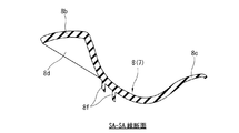
図3は図2に示した自動車用のカバー部材としてのフロントフェンダーカバー6のみを裏側から見た拡大図であって、図4〜8は図3のSA−SA線、SB−SB線、SC−SC線、SD−SD線およびSE−SE線に沿ったそれぞれの断面図を示している。ただし、図8のみ図4〜7に比べて拡大倍率を大きくしている。
FIG. 3 is an enlarged view of only the
図3に示すフロントフェンダーカバー6は、図2に示したカウルトップカバー2との重合部となる一方の端末部8aから反対側に向かって幅寸法が漸次小さくなるように徐変するプレート状のベース部8と、このベース部8から長手方向に向かって突出して幅寸法が漸次小さくなるように徐変する先細りバー形状の延長部9と、を備えている。そして、これらのベース部8と延長部9とでフロントフェンダーカバー6のカバー本体7が形成される。
The
カバー本体7のベース部8と延長部9との間には段差部10が設定されていると共に、ベース部8と延長部9とを含むカバー本体7全体として略弓形状に滑らかに湾曲した形状となっている。なお、このフロントフェンダーカバー6は、カバー本体7に後述する複数のクリップ部11,12を含むかたちで、例えばPP(ポリプロピレン)とEPDMとの複合樹脂材料により形成されていて、特にカバー本体7は方向を問わず屈曲性および柔軟性に富んでいる。
A
フロントフェンダーカバー6におけるカバー本体7のベース部8は図4〜6から明らかなように、表面側(上面側)が凹形状で裏面側が凸形状となり、且つ幅方向の中央部が低く幅方向の両端部が高くなるように湾曲していて、幅方向の一方の端部には、カウルトップカバー2やフロントフェンダー5(図1参照。)との突き合わせ部となるフランジ部8bが形成されている。
As is clear from FIGS. 4 to 6, the
他方、ベース部8の幅方向の他方の端部には、後述する図10に示すように、フロントガラス3に密着するリップ部8cが形成されている。ベース部8の一方の端末部8aの裏面には、図3に示すように、相手側部材であるカウルトップカバー2に対する固定部として機能する二つのクリップ部11,12が一体に突出形成されている。このうち、クリップ部12の詳細については後述する。また、ベース部8の裏面の各部は、複数個並設されたリブ8d,8e,8fやウェブ8gによって補強されている。
On the other hand, as shown in FIG. 10 described later, a
また、図3に示したベース部8に連続する延長部9についても、図7に示すように、ベース部8と同様に、幅方向の両端部にフランジ部9aとリップ部9bがそれぞれに形成されていると共に、裏面の各部は、複数個並設されたリブ9c,9dによって補強されている。さらに、延長部9の裏面における長手方向の中間部には、図7から明らかなように、単一の係止爪13が突出形成されている。以上の説明から明らかなように、ベース部8と延長部9とからなるカバー本体7に、少なくとも単一のクリップ部12を含むかたたちで、自動車用の外装材であるカバー部材としてのフロントフェンダーカバー6が形成されている。
Further, with respect to the
そして、後述する図10に示すフロントフェンダーカバー6の正規組付状態では、図3に示したベース部8の裏面の二つのクリップ部11,12がカウルトップカバー2側の取付孔に係止される一方で、延長部9の裏面の係止爪13がフロントガラス3の端縁に係止されることになる。
Then, in the normally assembled state of the
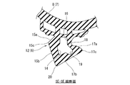
図3のSE−SE線断面である図8に拡大して示すように、カバー本体7におけるベース部8の裏面に突出形成されたクリップ部12は、外形状が側面視にて略変形菱形状をなしていて、図3に示すように所定の厚みtを有している。そして、クリップ部12の中央部には外形状とほぼ相似形をなす中空部14が厚み方向に貫通するようにして形成されている。
As shown in an enlarged view in FIG. 8 which is a cross section of the SE-SE line in FIG. 3, the
図8に示したクリップ部12における変形菱形状の一方の外側面(図8の左側の外側面)は、根元部から外側に向かって張り出すように傾斜した一方側の保持壁部15aと、この一方側の保持壁部15aの最大張り出し部となる頂部15cから内側に向かって傾斜した一方側のガイド壁部15bとにより、略くの字状に屈曲した形状に形成されている。ここで、上記根元部とは、カバー本体7を形成しているベース部8の裏面と、その裏面から突出形成されたクリップ部12との境界部近傍とする。
One outer surface (the outer surface on the left side of FIG. 8) of the deformed rhombus shape in the
他方、図8に示したクリップ部12における変形菱形状の一方の外側面に対向する他方の外側面(図8の右側の外側面)は、根元部から外側に向かって張り出すように傾斜した他方側の保持壁部17aと、この他方側の保持壁部17aの最大張り出し部である頂部17cから内側に向かって傾斜した他方側のガイド壁部17bとにより、略くの字状に屈曲した形状に形成されている。
On the other hand, the other outer surface (the outer surface on the right side of FIG. 8) facing one outer surface of the deformed rhombus shape in the
そして、図8に示した他方側の保持壁部17aの根元部外側の角隅部に、逃がし凹部として機能する円弧状のノッチ部18が形成されていると共に、他方側の保持壁部17aと他方側のガイド壁部17bとにまたがる内側の角隅部に、同じく逃がし凹部として機能する円弧状のノッチ部19が形成されている。
An
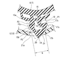
より詳しくは、図8に示したクリップ部12は、双方のノッチ部18,19が形成されていない状態では、図9に示す形状を基本形状としている。図9に示す基本形状のクリップ部12Aでは、変形菱形状の他方の外側面(図9の右側の外側面)は、根元部から直立する直立壁部16と、この直立壁部16から外側に向かって張り出すように傾斜した他方側の保持壁部17aと、この他方側の保持壁部17aの最大張り出し部である頂部17cから内側に向かって傾斜した他方側のガイド壁部17bとを有している。そして、他方側の保持壁部17aと同じく他方側のガイド壁部17bとにより略くの字状に屈曲した形状に形成されている。
More specifically, the
また、図9に示すクリップ部12Aの根元部の幅寸法を二分する線を基準中心線C1とし、この基準中心線C1から一方側の保持壁部15aの最大張り出し位置である頂部15cまでの距離をWa、同様に基準中心線C1から他方の保持壁部17aの最大張り出し位置である頂部17cまでの距離をWbとした場合、Wa<Wbの関係を満たすようにそれぞれの寸法が設定されている。
Further, the line that bisects the width dimension of the root portion of the
そして、図9に示すクリップ部12Aの先端の頂部20は、基準中心線C1よりも一方側の保持壁部15aおよびガイド壁部15b側に偏倚している。さらに、カバー本体7におけるベース部8の裏面から突出しているクリップ部12Aの長さをH、一方側の保持壁部15aと他方側の保持壁部17aの最大張り出し部である頂部15c,17c同士のなす距離をWとしたとき、H≒WまたはH<Wの関係を満たすようにそれぞれの寸法が設定されている。これらにより、側面視にて変形菱形状をなす基本形状のクリップ部12Aは、基準中心線C1を基準とした場合に左右非対称の形状となっている。
The top 20 of the tip of the
本実施の形態では、図9に示した基本形状のクリップ部12Aを前提とし、その上で、図8に示すように、図9の直立壁部16と他方側の保持壁部17aとにまたがる外側の角隅部に逃がし凹部として機能するノッチ部18を形成すると共に、他方側の保持壁部17aと他方側のガイド壁部17bとにまたがる内側の角隅部に、同じく逃がし凹部として機能するノッチ部19を形成することで、図8に示した変形菱形状のクリップ部12が形成されていることになる。これにより、双方のノッチ部18,19が形成された部位の肉厚が、弾性変形の起点となりやすいように局部的に薄肉化されていることになる。
In the present embodiment, the
その一方、図2のSF−SF線に沿った拡大断面図を図10に示している。なお、図10は図3のSE−SE線に沿った断面図である図8にも対応している。また、図10のクリップ部12の拡大図を図11に示し、さらにクリップ部12の挿入途中の状態を図12に示している。なお、図12において、クリップ部12の撓み変形前の外形形状を仮想線で示している。
On the other hand, an enlarged cross-sectional view taken along the SF-SF line of FIG. 2 is shown in FIG. Note that FIG. 10 also corresponds to FIG. 8, which is a cross-sectional view taken along the SE-SE line of FIG. Further, an enlarged view of the
図10に示すように、フロントフェンダーカバー6が装着されることになるカウルトップカバー2は、フロントフェンダーカバー6の少なくとも一方の端末部8a(図3参照。)が着座することになる部分では、フロントフェンダーカバー6の湾曲形状に倣って、上面側が凹形状で裏面側が凸形状となるように湾曲した着座壁部2aが形成されている。
As shown in FIG. 10, the
カウルトップカバー2の着座壁部2aの一部には、クリップ部12の形状に対応した角孔状の取付孔21が貫通形成されている。そして、図11,12に拡大して示すように、この取付孔21の内周面のうちクリップ部12の一方側の保持壁部15aに対応する部分には、その一方側の保持壁部15aの傾斜度合いに対応した同等の傾斜内周面21aが形成されている。また、図12に示すように、取付孔21のうちクリップ部12の挿入側の寸法Qは、図9に示した寸法Wよりも小さく設定されている。
A square hole-shaped mounting
なお、図3に示したフロントフェンダーカバー6の裏面において、必要に応じて、クリップ部12を二個以上設けても良いことは言うまでもない。
Needless to say, two or
したがって、このように構成されたフロントフェンダーカバー6によれば、図2に示すように、カウルトップカバー2と一部重なり合うようにフロントフェンダーカバー6を装着するにあたっては次の通りとする。
Therefore, according to the
図10に示すように、カウルトップカバー2側の取付孔21とフロントフェンダーカバー6におけるカバー本体7側のクリップ部12の位置を合致させた上で、カバー本体7の上面のうちクリップ部12に相当する位置をカウルトップカバー2側に押し込んで、クリップ部12を取付孔21に挿入・係止させるものとする。なお、図3に示したもう一方のクリップ部11も図示を省略した取付孔に挿入・係止させると共に、同じく図3に示した係止爪13をフロントガラス3に係止させることになるが、これらの事項は本発明の主要部ではないので、ここでの詳細な説明は省略するものとする。
As shown in FIG. 10, after matching the positions of the mounting
図10に示したクリップ部12を相手側となる取付孔21に押し込んで挿入する際には、図12に示すように、双方のガイド壁部15b,17bと取付孔21の開口縁との傾斜面接触により案内効果が発揮され、取付孔21がこの取付孔21よりも幅広の寸法W(図9参照。)を有するクリップ部12を受容するべく、双方のガイド壁部15b,17b同士のなす頂部20の角度を縮小化するようにクリップ部12自体が弾性変形することになる。
When the
クリップ部12が弾性変形する際には、図12に示すように、最初にノッチ部18を起点として他方側の保持壁部17aの頂部17c側が矢印P1方向に押し上げられるように撓み変形し、次いで、なおも押し込み力が加わると、一方側のガイド壁部15bと保持壁部15aも根元部から全体的に矢印P2方向に倒れ込むように撓み変形することになる。
When the
そのタイミングで、図10,11に示すように、クリップ部12の双方の頂部15c,17cが取付孔21を乗り越えて、クリップ部12全体が取付孔21よりも下方側に挿入されることになる。同時に、クリップ部12の双方の頂部15c,17cが取付孔21を乗り越えたことによる適度な節度感が得られることになる。
At that timing, as shown in FIGS. 10 and 11, both
取付孔21を乗り越えてその取付孔21に挿入されたクリップ部12は直ちに元の状態に自己復元することになる。図11に示すように、傾斜している一方側の保持壁部15aが取付孔21の内周面のうち同じく傾斜している傾斜内周面21aに密着する一方、他方側の保持壁部17aが取付孔21の内周面のうち傾斜内周面21aとは反対側の内周面の開口縁に係止されることになる。この係止状態においては、一方のノッチ部18に相当する部分で取付孔21の内周面との間に所定の隙間Gが確保されている。したがって、先に述べたように、取付孔21をこの取付孔21よりも幅広の寸法Wを有するクリップ部12が通過する際の弾性変形が無理なく許容される。
The
以上により、図10,11に示したクリップ部12による係止保持力をもって、カウルトップカバー2に対してフロントフェンダーカバー6が固定保持され、同時にカウルトップカバー2からのフロントフェンダーカバー6の抜け止め効果が発揮されることになる。すなわち、図10,11に示した状態をもって、クリップ部12の取付孔21への挿入方向とは逆方向の抜き出し力に対して十分に対抗することができる。
As described above, the
ここで、図10,11に示すように、カウルトップカバー2の造形上あるいは強度上の観点から、フロントフェンダーカバー6が着座することになるカウルトップカバー2の着座壁部2aの背面側に別の壁部2bが設定されることがある。このような壁部2bが設定されていたとしても、クリップ部12について、先に述べたように、クリップ部12の長さHと双方の頂部15c,17c同士のなす距離Wとの関係として、H≒WまたはH<Wの関係を満たすようにそれぞれの寸法が設定されているので、クリップ部12が壁部2bと干渉するのを未然に回避することができる。
Here, as shown in FIGS. 10 and 11, from the viewpoint of modeling or strength of the cowl
しかも、壁部2bの存在によりクリップ部12の長さHが制限されたとしても、クリップ部12は図10,11の状態をもって、カウルトップカバー2に対するフロントフェンダーカバー6の係止固定状態を安定して維持することが可能となる。
Moreover, even if the length H of the
このように本実施の形態のフロントフェンダーカバー6の取付構造によれば、クリップ部12の内外の二箇所にノッチ部18,19が形成されていて、クリップ部12自体の屈曲容易性が優れているので、クリップ部12の長さが制限された場合でも、組付性および組付後の保持性が良好なものとなるほか、クリップ部12が挿入係止された際の節度感も良好なものとなる。
As described above, according to the mounting structure of the
また、側面視で変形菱形状をなすクリップ部12が左右の張り出し量の相違に基づく左右非対称形状となっているので、クリップ部12をカウルトップカバー2側の取付孔21に挿入する際にクリップ部12全体が変形しやすくなり、組付性が一段と向上する。
Further, since the
さらに、カウルトップカバー2側の取付孔21の内周面のうち少なくとも一方側の保持部15aに対応する部分が傾斜内周面21aとなっていて、取付孔21へのクリップ部12の挿入後に、その取付孔21側の傾斜内周面21aと一方側の保持部15aとが傾斜面接触することになるので、取付孔21へのクリップ部12の挿入容易性と挿入後の抜けにくさを両立することが可能となる。
Further, of the inner peripheral surface of the mounting
加えて、図11に示すように、カウルトップカバー2側の取付孔21の内周面のうちノッチ部18に対応する部分では両者の間に隙間Gが確保されるようになっているので、取付孔21へのクリップ部12の挿入容易性と挿入後の抜けにくさを両立しつつ、特にクリップ部12の挿入容易性が一段と向上することになる。
In addition, as shown in FIG. 11, a gap G is secured between the inner peripheral surface of the mounting
ここで、上記実施の形態では、自動車用の外装材であるカバー部材としてのフロントフェンダーカバー6を例にとって説明したが、その実質的特徴はクリップ部12にあるので、本発明の適用範囲は必ずしもフロントフェンダーカバー6のみには限定されない。例えば、カバー部材の裏面にクリップ部を有するものであれば、フロントフェンダーカバー6以外にも、自動車の外装材であるか内装材であるかを問わず、同種のカバー部材に本発明を適用することができる。
Here, in the above-described embodiment, the
2…カウルトップカバー
3…フロントガラス
5…フロントフェンダー
6…フロントフェンダーカバー(自動車用カバー部材)
7…カバー本体
8…ベース部
9…延長部
12…クリップ部
14…中空部
15a…一方側の保持壁部
15b…一方側のガイド壁部
15c…頂部(最大張り出し部)
16…直立壁部
17a…他方側の保持壁部
17b…他方側のガイド壁部
17c…頂部(最大張り出し部)
18…ノッチ部
19…ノッチ部
21…取付孔
21a…傾斜内周面
G…隙間
2 ... Cowl
7 ...
16 ...
18 ...
Claims (8)
前記自動車用カバー部材は、プレート状のカバー本体と、前記カバー本体の裏面に突出形成された側面視で変形菱形状をなすクリップ部と、を備え、
前記カバー本体は、裏面側が凸形状で表面側が凹形状となるように湾曲していて、前記凸形状の裏面に前記クリップ部が一体に突出形成され、
前記クリップ部の中央部には、前記変形菱形状とほぼ相似形をなす中空部が形成されていて、
前記クリップ部における変形菱形状の一方の外側面は、根元部から外側に向かって張り出すように傾斜した一方側の保持壁部と、この一方側の保持壁部の最大張り出し部から内側に向かって傾斜した一方側のガイド壁部とにより、略くの字状に屈曲した形状となっている一方、
前記クリップ部における変形菱形状の一方の外側面に対向する他方の外側面は、根元部から外側に向かって張り出すように傾斜した他方側の保持壁部と、この他方側の保持壁部の最大張り出し部から内側に向かって傾斜した他方側のガイド壁部とにより、略くの字状に屈曲した形状となっていて、
前記他方側の保持壁部の根元部外側の角隅部、および前記他方側の保持壁部と前記他方側のガイド壁部とにまたがる内側の角隅部に、それぞれにノッチ部が形成されていることを特徴とする自動車用カバー部材。 An automobile cover member that is attached to a mating member by a clip-on method as an interior member or an exterior member of an automobile.
The automobile cover member includes a plate-shaped cover main body and a clip portion formed on the back surface of the cover main body and having a deformed rhombus shape in a side view.
The cover body is curved so that the back surface side is convex and the front surface side is concave, and the clip portion is integrally projected on the back surface of the convex shape.
A hollow portion having a shape substantially similar to the deformed rhombus shape is formed in the central portion of the clip portion.
One outer surface of the deformed rhombus shape in the clip portion faces inward from the holding wall portion on one side that is inclined so as to project outward from the root portion and the maximum overhanging portion of the holding wall portion on one side. The guide wall on one side, which is tilted, has a shape that is bent in an abbreviated shape.
The other outer surface of the clip portion, which faces one outer surface of the deformed rhombus, is a holding wall portion on the other side that is inclined so as to project outward from the root portion, and a holding wall portion on the other side. Due to the guide wall on the other side that slopes inward from the maximum overhang, it has a shape that is bent in an abbreviation shape.
Notches are formed in the outer corners of the root of the holding wall on the other side and the inner corners straddling the holding wall on the other side and the guide wall on the other side. A cover member for automobiles, which is characterized by being present.
前記直立壁部と前記他方側の保持壁部とにまたがる外側の角隅部に、ノッチ部が形成されていることを特徴とする請求項1に記載の自動車用カバー部材。 The other outer surface of the deformed rhombus shape in the clip portion includes an upright wall portion that stands upright from the root portion, a holding wall portion on the other side that is inclined so as to project outward from the upright wall portion, and the other side thereof. It has a guide wall portion on the other side that is inclined inward from the maximum overhanging portion of the holding wall portion, and is abbreviated by the holding wall portion on the other side and the guide wall portion on the other side. It has a bent shape,
The automobile cover member according to claim 1, wherein a notch portion is formed in an outer corner portion straddling the upright wall portion and the holding wall portion on the other side.
前記相手側部材は前記カウルトップカバーであることを特徴とする請求項1〜4のいずれか一項に記載の自動車用カバー部材。 The automobile cover member according to any one of claims 1 to 4, wherein the mating side member is the cowl top cover.
前記クリップ部は前記相手側部材に形成された角孔状の取付孔に挿入されるようになっていると共に、
前記取付孔のうち側面視で変形菱形状をなす前記クリップ部を受容する部分の寸法が、前記一方側の保持壁部と前記他方側の保持壁部の最大張り出し部同士のなす距離よりも小さく設定されていて、
前記相手側部材に対する前記自動車用カバー部材の正規取付状態では、前記一方側および他方側の保持部が前記取付孔の開口縁に係止されて抜け止め機能が発揮されるようになっていることを特徴とする自動車用カバー部材の取付構造。 The mounting structure for an automobile cover member according to any one of claims 1 to 5.
The clip portion is inserted into a square hole-shaped mounting hole formed in the mating member, and is also inserted into the square hole-shaped mounting hole.
The size of the portion of the mounting hole that receives the clip portion that has a deformed rhombus shape when viewed from the side is smaller than the distance between the holding wall portion on one side and the maximum overhanging portion of the holding wall portion on the other side. It has been set and
In the normally mounted state of the automobile cover member with respect to the mating side member, the holding portions on one side and the other side are locked to the opening edge of the mounting hole so that the retaining function is exhibited. The mounting structure of the cover member for automobiles, which is characterized by.
Priority Applications (1)
| Application Number | Priority Date | Filing Date | Title |
|---|---|---|---|
| JP2017118208A JP6851268B2 (en) | 2017-06-16 | 2017-06-16 | Automotive cover member and its mounting structure |
Applications Claiming Priority (1)
| Application Number | Priority Date | Filing Date | Title |
|---|---|---|---|
| JP2017118208A JP6851268B2 (en) | 2017-06-16 | 2017-06-16 | Automotive cover member and its mounting structure |
Publications (2)
| Publication Number | Publication Date |
|---|---|
| JP2019001326A JP2019001326A (en) | 2019-01-10 |
| JP6851268B2 true JP6851268B2 (en) | 2021-03-31 |
Family
ID=65005838
Family Applications (1)
| Application Number | Title | Priority Date | Filing Date |
|---|---|---|---|
| JP2017118208A Active JP6851268B2 (en) | 2017-06-16 | 2017-06-16 | Automotive cover member and its mounting structure |
Country Status (1)
| Country | Link |
|---|---|
| JP (1) | JP6851268B2 (en) |
Family Cites Families (8)
| Publication number | Priority date | Publication date | Assignee | Title |
|---|---|---|---|---|
| JPS6160341A (en) * | 1984-08-31 | 1986-03-28 | Toyoda Gosei Co Ltd | Molding |
| JPS61139306U (en) * | 1984-10-30 | 1986-08-29 | ||
| JPH01148108U (en) * | 1988-03-31 | 1989-10-13 | ||
| JP3201229B2 (en) * | 1995-09-27 | 2001-08-20 | 日産自動車株式会社 | Car rear ceiling structure |
| KR100681067B1 (en) * | 2005-10-24 | 2007-02-08 | 현대자동차주식회사 | A clip for molding |
| JP5103301B2 (en) * | 2008-06-30 | 2012-12-19 | 日本プラスト株式会社 | Automobile fender cover structure |
| JP2011196397A (en) * | 2010-03-17 | 2011-10-06 | Yazaki Corp | Fixing structure by clip of installation part to panel |
| US8876200B2 (en) * | 2012-06-28 | 2014-11-04 | Ford Global Technologies, Llc | Magnetic vehicle attachment system for use with non-magnetic body structure |
-
2017
- 2017-06-16 JP JP2017118208A patent/JP6851268B2/en active Active
Also Published As
| Publication number | Publication date |
|---|---|
| JP2019001326A (en) | 2019-01-10 |
Similar Documents
| Publication | Publication Date | Title |
|---|---|---|
| US9488202B2 (en) | Clip | |
| JP4790751B2 (en) | clip | |
| EP1832791B1 (en) | A fixture | |
| US7328873B2 (en) | Pipe clamp | |
| JP5859331B2 (en) | clip | |
| EP1795399B1 (en) | Mould end cap | |
| JP2019064586A (en) | Fitting structure of vehicle door lining | |
| CN108331811B (en) | Locking structure | |
| JP5210670B2 (en) | Engagement structure and automotive interior member provided with the same | |
| JP2014228112A (en) | Mounting structure for mounting member | |
| JP6851268B2 (en) | Automotive cover member and its mounting structure | |
| JP6076731B2 (en) | Resin nail structure | |
| WO2017199842A1 (en) | Clip | |
| JP7235570B2 (en) | clamp | |
| JP5911023B2 (en) | Resin member mounting structure | |
| JP2006336748A (en) | Resin molding mounting structure | |
| JP4292932B2 (en) | Mall end cap | |
| JP2007083916A (en) | Automobile hood seal structure | |
| JP5138450B2 (en) | Two-part assembly structure | |
| JP6294610B2 (en) | Resin clip | |
| JP2010143556A (en) | Molding for automobile and end cap | |
| JP2007110806A (en) | Fixing tool | |
| JP6062307B2 (en) | Parts matching part structure | |
| JP2018179268A (en) | Insertion structure in plate-like member | |
| JP2009030796A (en) | Interior component mounting structure |
Legal Events
| Date | Code | Title | Description |
|---|---|---|---|
| A621 | Written request for application examination |
Free format text: JAPANESE INTERMEDIATE CODE: A621 Effective date: 20200408 |
|
| A977 | Report on retrieval |
Free format text: JAPANESE INTERMEDIATE CODE: A971007 Effective date: 20201215 |
|
| A131 | Notification of reasons for refusal |
Free format text: JAPANESE INTERMEDIATE CODE: A131 Effective date: 20210105 |
|
| A521 | Request for written amendment filed |
Free format text: JAPANESE INTERMEDIATE CODE: A523 Effective date: 20210216 |
|
| TRDD | Decision of grant or rejection written | ||
| A01 | Written decision to grant a patent or to grant a registration (utility model) |
Free format text: JAPANESE INTERMEDIATE CODE: A01 Effective date: 20210302 |
|
| A61 | First payment of annual fees (during grant procedure) |
Free format text: JAPANESE INTERMEDIATE CODE: A61 Effective date: 20210309 |
|
| R150 | Certificate of patent or registration of utility model |
Ref document number: 6851268 Country of ref document: JP Free format text: JAPANESE INTERMEDIATE CODE: R150 |
|
| R250 | Receipt of annual fees |
Free format text: JAPANESE INTERMEDIATE CODE: R250 |