JP2010143556A - Molding for automobile and end cap - Google Patents
Molding for automobile and end cap Download PDFInfo
- Publication number
- JP2010143556A JP2010143556A JP2008326624A JP2008326624A JP2010143556A JP 2010143556 A JP2010143556 A JP 2010143556A JP 2008326624 A JP2008326624 A JP 2008326624A JP 2008326624 A JP2008326624 A JP 2008326624A JP 2010143556 A JP2010143556 A JP 2010143556A
- Authority
- JP
- Japan
- Prior art keywords
- end cap
- molding
- retaining
- molding body
- notch
- Prior art date
- Legal status (The legal status is an assumption and is not a legal conclusion. Google has not performed a legal analysis and makes no representation as to the accuracy of the status listed.)
- Granted
Links
Images


Landscapes
- Vehicle Interior And Exterior Ornaments, Soundproofing, And Insulation (AREA)
Abstract
Description
本発明は自動車用モールに関し、特にモール本体の端部に取り付けるエンドキャップ構造に係る。 The present invention relates to an automobile molding, and more particularly to an end cap structure attached to an end of a molding body.
自動車にはルーフモール、ベルトラインモール、サイドモール等端部が開口したモール本体とモール本体の端部開口部をふさぐためのエンドキャップとから構成された各種モール部品が採用されている。
モール本体はロール成形、押出成形等にて製作され、所定の長さに切断及び曲げ加工等を行い、端部の開口部にエンドキャップを挿入するものである。
エンドキャップはモール本体の端部開口部に挿入する挿入部と、モール本体の端部開口部をふさぐ意匠部とを有している。
この種の自動車用モールにあっては、エンドキャップがモール本体に挿入しやすく、且つエンドキャップをモール本体に取り付けた後において、エンドキャップにガタが生じたり、エンドキャップ意匠部とモール本体の端末との間に隙間が生じるのを防止することが要求される。
Various types of molding parts composed of a molding main body having an open end, such as a roof molding, a belt line molding, a side molding, and an end cap for closing the end opening of the molding main body are employed in automobiles.
The molding body is manufactured by roll molding, extrusion molding or the like, and is cut and bent to a predetermined length, and an end cap is inserted into the opening of the end.
The end cap has an insertion portion that is inserted into the end opening of the molding body, and a design portion that covers the opening of the molding body.
In this type of automobile molding, it is easy to insert the end cap into the molding main body, and after the end cap is attached to the molding main body, the end cap is loose or the end cap design part and the terminal of the molding main body It is required to prevent a gap between the two.
特許文献1には、エンドキャップのモール挿入部に前後が傾斜面で側面が台形形状の第1段部とこの第1段部の上段に後面が垂直面で側面が台形形状又は三角形状の第2段部を有する引掛部を形成したエンドキャップ構造を開示する。
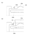
しかし、1つの引掛部にガタ止め部と抜け止め部を形成すると図6に示すような問題があった。
図6には、エンドキャップに形成した引掛部123の拡大図とモール本体112の係止部113を模式的に示した。
引掛部前面が傾斜面123aになり、頂部123dから後方側に抜け止め用垂直面123cとガタ止め用の傾斜面123bを有している場合に、抜け止めに必要な高さにガタ止めに必要な高さを加えた寸法がaとなるために、このa寸法を大きくせざるを得ない。
a寸法が大きいと、図6(b)に示すようにエンドキャップをモール本体に挿入する際に引掛部123を内側に大きく撓ませる必要があるだけでなく、f方向の力が1点に集中するように生じるためにエンドキャップが傾き、モール本体に挿入しにくくなる。
また、引掛部123の撓み量が大きいことから、挿入時の摺動抵抗が大きく、エンドキャップを真っすぐに戻す力も必要となるために、組み付け作業に大きな労力が必要となる問題もあった。
また、a寸法に合せて深い切欠部が必要になるが、ルーフモール等においては切欠部113を大きく形成するのが困難な場合もある。
Patent Document 1 discloses a first step portion having an inclined front surface and a trapezoidal side surface at a molding insertion portion of an end cap, and a trapezoidal or triangular shape having a trapezoidal shape or a rear surface that is a vertical surface on the upper stage of the first step portion. An end cap structure in which a hook portion having two steps is formed is disclosed.
However, when the backlash-preventing portion and the retaining portion are formed in one hooking portion, there is a problem as shown in FIG.
FIG. 6 schematically shows an enlarged view of the
Necessary for rattling to a height required for retaining when the front surface of the hook portion is an
If the dimension a is large, it is not only necessary to bend the
In addition, since the amount of deflection of the
Further, although a deep cutout is required in accordance with the dimension a, it may be difficult to form the
本発明は、エンドキャップのモ−ル本体への組み付け性に優れ、エンドキャップとモール本体との間に隙間やガタが生じるのを防止できるエンドキャップ及びそれを用いた自動車用モールの提供を目的とする。 An object of the present invention is to provide an end cap that is excellent in assembling of an end cap to a mold main body and can prevent a gap or play between the end cap and the molding main body, and an automobile molding using the end cap. And
本発明の技術的要旨は、モール本体とモール本体の端末部に挿着するエンドキャップとを有する自動車用モールであって、モール本体は、ベース部とベース部の幅方向両側から裏面側にそれぞれ折り返した一対のフランジ部を有し、且つ一方のフランジ部はエンドキャップのガタ止め用切欠部を有し、他方のフランジ部はエンドキャップの抜け止め用切欠部を有し、エンドキャップは、モール本体の端末をふさぐ意匠部と、モール本体の端末から内側に挿入される挿入部を有し、挿入部は、モール本体のガタ止め用切欠部に向けて突出し、挿入方向前後であって突出方向に相互に縮幅した傾斜面を有するガタ止め部と、モール本体の抜け止め用切欠部に向けて突出し、挿入方向前側に先端後方に傾いた傾斜面と、後側に垂直面又は先端部が鋭角の鋭角斜面を有する抜け止め部とを形成したことを特徴とする。 The technical gist of the present invention is an automobile molding having a molding body and an end cap that is inserted into a terminal portion of the molding body, and the molding body is formed from the base portion and the width direction both sides of the base portion to the back side, respectively. It has a pair of folded flange parts, and one flange part has a notch part for end cap backlash, the other flange part has a notch part for end cap retaining part, and the end cap It has a design part that covers the terminal of the main body and an insertion part that is inserted inwardly from the terminal of the molding body, and the insertion part projects toward the notch part for backlash prevention of the molding body, and is in the protruding direction before and after the insertion direction. A slack surface that has an inclined surface that is mutually reduced in width, a slant surface that protrudes toward the notch for retaining of the molding body, and that is slanted rearward at the front side in the insertion direction, and a vertical surface or front end portion at the rear side. Sharp Characterized in that the forming a retaining portion having an acute angle slope.
本発明は、エンドキャップをモール本体に組み付ける際に、エンドキャップのガタ止め手段と、抜け止め手段とを分離した点に特徴がある。 The present invention is characterized in that when the end cap is assembled to the molding body, the end cap rattling prevention means and the retaining means are separated.
本発明において、エンドキャップのガタ止め部及び抜け止め部は、モール本体の幅方向内側に撓み弾性変形可能になっているのが好ましい。
モ−ル本体の切欠部に、エンドキャップの外側に突出したガタ止め部及び抜け止め部を挿入係止させるには、ガタ止め部及び抜け止め部を内側に撓ませるか、モ−ル本体のフランジ部を外側に撓ませる必要がある。
モ−ル本体を金属製の芯材とその表面の樹脂被覆部で形成したような場合には、エンドキャップのガタ止め部及び抜け止め部の方を内側に撓むように設計した方が製作しやすい。
エンドキャップのガタ止め部又は抜け止め部を撓み弾性変形可能にする手段としては、各種方法が採用される。
例えば、ガタ止め部又は抜け止め部をエンドキャップの挿入方向に沿って延在させたバネ部材で形成したり、エンドキャップの挿入部とその幅方向外側に形成したガタ止め部や抜け止め部との間に貫通した溝部を形成し、この溝幅が縮小することでガタ止め部又は抜け止め部が内側に撓み弾性変形する方法等が挙げられる。
In the present invention, it is preferable that the back stopper part and the stopper part of the end cap bend inward in the width direction of the molding body and be elastically deformable.
In order to insert and lock the back-and-forth part and the retaining part protruding outside the end cap into the cutout part of the mall body, the back-and-forth part and retaining part can be bent inward or the It is necessary to bend the flange portion outward.
When the mold body is formed of a metal core and the resin coating on the surface, it is easier to manufacture if the back cap and the stopper portion of the end cap are designed to bend inward. .
Various methods are adopted as means for flexing and elastically deforming the back-stop portion or the stopper portion of the end cap.
For example, a rattling stop or retaining part is formed of a spring member extending along the insertion direction of the end cap, or an end cap insertion part and a rattling stopper or retaining part formed on the outer side in the width direction thereof. For example, there is a method in which a groove portion penetrating between them is formed and the backlash portion or the retaining portion is bent inward and elastically deformed by reducing the groove width.
エンドキャップの抜け止め部は、モール本体の切欠部の端末側端部に、垂直面又は先端部が鋭角の鋭角斜面に引掛かるように当接するため、モール本体の抜け止め用切欠部から外れる恐れは小さい。
エンドキャップのガタ止め部は挿入方向後側も先端が挿入方向前方に向けて傾いた傾斜面になっているので、エンドキャップを挿入方向奥側に移動させるように働く分力と、エンドキャップを幅方向抜け止め切欠部側に押しやる分力が働くが、エンドキャップが抜け方向に上記分力よりも大きい力が加わると、抜け止め部が内側に撓む恐れもある。
そこで、エンドキャップは、モール本体に挿着後にガタ止め部が幅方向内側に撓むのを防止する撓み防止手段を有していてもよい。
この撓み防止手段は、エンドキャップのガタ止め部が内側に撓むのを防止する作用が生じるものであれば各種方法を採用できる。
例えば、エンドキャップの挿入部とガタ止め部との間に溝部を形成した場合にあっては溝部の幅が縮小しないようにピン部材等を挿入してもよい。
The end cap retaining part comes into contact with the terminal side end of the notch part of the molding body so that the vertical surface or the tip part is hooked on an acute angled slope, so that it may come off from the retaining notch part of the molding body. Is small.
Since the back end of the end cap has an inclined surface with the tip inclined toward the front in the insertion direction on the rear side in the insertion direction, the component force that moves the end cap to the back in the insertion direction and the end cap Although the component force which pushes to the width direction retaining notch part side acts, if a force larger than the said component force is added to an end cap in the direction of withdrawal, the retaining part may be bent inward.
Therefore, the end cap may have a deflection preventing means for preventing the rattling stopper from bending in the width direction after being inserted into the molding body.
Various methods can be adopted as the means for preventing the deflection as long as the action of preventing the back stopper portion of the end cap from bending inward occurs.
For example, when a groove portion is formed between the insertion portion of the end cap and the ratchet stop portion, a pin member or the like may be inserted so as not to reduce the width of the groove portion.
本発明に係るエンドキャップにあっては、モール本体のベース部の幅方向両側に裏面側に折り返した一対のフランジ部を形成し、この一対のフランジ部を切り欠いて、一方のフランジ部にガタ止め用の切欠部を形成し、他方のフランジ部に抜け止め用の切欠部を形成し、エンドキャップにモール本体のガタ止め用切欠部に対応したガタ止め部と、抜け止め用切欠部に対応した抜け止め部を形成したことにより、エンドキャップのモール幅方向両側にガタ止め部と抜け止め部が分離していることになる。
このように、ガタ止め部と抜け止め部とが分離しているので、図6に示した従来例に比較して、ガタ止め部及び抜け止め部の突出高さを低く抑えることができ、それに対応してフランジ部の切欠き深さが浅くなるためにフランジ幅を小さくできる。
またこれにより、エンドキャップの挿入時にエンドキャップの両側のガタ止め部と抜け止め部の両方から幅方向の力が加わるのでエンドキャップが傾くのを抑え、真っすぐに挿入しやすく、且つ挿入力の低減が可能になる。
In the end cap according to the present invention, a pair of flange portions folded back on the back surface side are formed on both sides in the width direction of the base portion of the molding body, the pair of flange portions are cut out, and one flange portion has a backlash. A notch for locking is formed, a notch for retaining is formed on the other flange, and the back cap corresponding to the back notch for molding on the end cap is compatible with the notch for retaining. By forming the retaining portion, the back-stop portion and the retaining portion are separated on both sides of the end cap in the molding width direction.
As described above, since the rattling stop portion and the retaining portion are separated from each other, the protrusion height of the rattling retaining portion and the retaining portion can be suppressed lower than that of the conventional example shown in FIG. Correspondingly, since the notch depth of the flange portion becomes shallow, the flange width can be reduced.
In addition, as a result, force in the width direction is applied from both the rattling stop and the retaining part on both sides of the end cap when the end cap is inserted, so that the end cap is prevented from tilting, and it is easy to insert straight and the insertion force is reduced. Is possible.
本発明にあっては、抜け止め部の他に分離して、ガタ止め部を有し、ガタ止め部はエンドキャップの挿入方向の前側と後側の両方に突出先方向に相互に縮幅した向かい合う傾斜面を有し、エンドキャップをモール本体に挿着した状態ではモール本体のガタ止め用切欠部の端末側とエンドキャップのガタ止め部後側の傾斜面と当接している。
これにより、エンドキャップには挿入方向の分力が働き、エンドキャップの意匠部とモール本体の端面との間に隙間が生じるのを防止する。
また、エンドキャップにはモール幅方向の分力も生じるので幅方向のガタも防止する。
従って、モール本体の抜け止め用切欠部の端末からの寸法と、エンドキャップの端末当接部から抜け止め部の垂直面又は鋭角傾斜面までの寸法に相対的なバラツキが生じてもエンドキャップに隙間やガタ付きが発生するのを防止できる。
In the present invention, in addition to the retaining portion, it is separated and has a ratchet portion, and the ratchet portion is mutually reduced in width in the protruding direction on both the front side and the rear side in the insertion direction of the end cap. In the state which has an inclined surface which faces each other and the end cap is inserted into the molding body, the terminal side of the back-cutting notch portion of the molding body and the inclined surface on the rear side of the back-locking portion of the end cap are in contact.
Thereby, a component force in the insertion direction acts on the end cap, thereby preventing a gap from being generated between the design portion of the end cap and the end surface of the molding body.
Further, the end cap also generates a component force in the molding width direction, thereby preventing backlash in the width direction.
Therefore, even if there is a relative variation in the dimension from the end of the notch for retaining of the molding body to the end and the dimension from the end abutting part of the end cap to the vertical surface or acute angle inclined surface of the retaining part, the end cap is not affected. The occurrence of gaps and backlash can be prevented.
本発明において、エンドキャップのガタ止め部が撓み変形するのを防止する撓み防止手段をエンドキャップに設けると、エンドキャップをモール本体に組み付けた後の挿着係止力が向上する。 In the present invention, when the end cap is provided with a deflection preventing means for preventing the back cap ratchet portion from being bent and deformed, the insertion locking force after the end cap is assembled to the molding body is improved.
本発明に係る自動車用モール及びエンドキャップの構造例を以下図面に基づいて説明する。
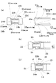
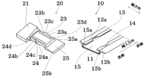
図1は、ルーフモール用のモール本体10の端部開口部にエンドキャップ20を挿着する例を示し、図2にモール本体10の端部の裏側から見た斜視図とエンドキャップ20の斜視図を示す。
図1及び図2の例では、モール本体の端末が斜めになっている例を示すが、端末の切断形状はこれに限定されるものでなく、モール本体10の断面形状も幅方向の両側にフランジ部12a,12bを形成したものである限りにおいて、各種断面形状を採用できる。
A structural example of an automobile molding and an end cap according to the present invention will be described below with reference to the drawings.
FIG. 1 shows an example in which an
1 and 2 show an example in which the terminal of the mall body is inclined, but the cut shape of the terminal is not limited to this, and the cross-sectional shape of the
モール本体10の端部には、エンドキャップ20の意匠部21のふさぎ部21aが当接する端末部11から所定の位置にガタ止め用切欠部13と抜け止め用切欠部14を形成してある。
図1,図2に示した例では、モール本体10のベース部15の幅方向両側から裏面側に向けてフランジ部12a,12bを形成した断面略Cチャンネル形状になっている。
図3に拡大図を示すように一方のフランジ部12aには、ガタ止め用切欠部13を形成してあり、このガタ止め用切欠部13は、端末部11側の切欠端部13aが直角又は先端が鋭角になるようにフランジ部12aを切り欠いてある。
なお、ガタ止め用切欠部13の挿入方向前方側の切欠端部13bは後述するエンドキャップ20のガタ止め部と干渉しない範囲にて形状は限定されない。
他方のフランジ部12bには抜け止め用切欠部14を形成してあり、この抜け止め用切欠部14は、端末部11側の切欠端部14aが直角又は先端が鋭角になるようにフランジ部12bを切り欠いてある。
抜け止め用切欠部14の挿入方向前方側の切欠部14bは後述するエンドキャップの抜け止め部と干渉しないようになっている。
At the end of the
In the example shown in FIG. 1 and FIG. 2, the cross section has a substantially C channel shape in which
As shown in an enlarged view in FIG. 3, one
The shape of the
The
The
エンドキャップ20は、モール本体10の端部の開口部から挿入される挿入部22とモール本体の端末をふさぐ意匠部21とを有している。
本実施例では、意匠部21を模式化しており、モ−ル本体10の端末部11に当接するふさぎ部21aを有している限りにおいて、各種形状を採用できる。
本実施例では、挿入部22の挿入先端側に挿入ガイド部25を形成してあり、挿入ガイド部25は幅方向両側25a,25bがモール本体10のベース部15とフランジ部12a,12bとの間にできた凹部15a,15bに臨むようになっていて、エンドキャップ20をモール本体10に挿入しやすいようになっている。
The
In the present embodiment, the
In the present embodiment, the
エンドキャップ20は、挿入部22の一方の幅方向側部にモ−ル本体のガタ止め用切欠部13に対応させたガタ止め部23を有している。
ガタ止め部23は、挿入方向前側に傾斜面23a、挿入方向後側に傾斜面23bを有し、傾斜面23aと23bとは頂部23cでつながっている。
前側の傾斜面23aと後側の傾斜面23bとは相互に向かい合い、突出方向頂部23cに向かってお互いの幅が縮幅するような方向の傾斜面になっている。
図1に示した裏面視では、略台形形状又は略三角形状になっている。
The
The
The front
In the back view shown in FIG. 1, it has a substantially trapezoidal shape or a substantially triangular shape.
エンドキャップ20は挿入部22の他方の幅方向側部にモール本体の抜け止め用切欠部14に対応させた抜け止め部24を有している。
抜け止め部24は、挿入方向前側に傾斜面24a、後側に垂直方向に切り欠いた垂直面24bを有している。
この垂直面24bは抜け止め用切欠部の端末側切欠部14aに引掛かり抜け止めとなるものであり、先端が鋭角になった鋭角傾斜面でもよい。
傾斜面24aと垂直面24bとは頂部24cにてつながっている。
図1に示した裏面視では、側辺が垂直の略台形形状又は略三角形状になっている。
The
The retaining
The
The
In the rear view shown in FIG. 1, the sides are substantially trapezoidal or substantially triangular.
本実施例では、ガタ止め部23及び抜け止め部24がエンドキャップ挿入時に内側に撓み弾性変形しやすいように挿入部22との間に挿入方向のスリット状に溝部23d,24dを形成してある。
なお、ガタ止め部23及び抜け止め部24とが内側に撓む構造であれば本実施例に限定されない。
In this embodiment, the
Note that the present invention is not limited to this embodiment as long as the rattling
次にエンドキャップ20をモ−ル本体10の端部に挿着する流れを説明する。
図1(a)に示した状態から、挿入ガイド部25をモール本体10の端部開口部に挿入する。
エンドキャップ20の幅方向両側に設けたガタ止め部23と抜け止め部24との間の寸法は、フランジ部12a,12bの内側寸法よりも大きく、ガタ止め部23と抜け止め部24とがモール本体の端部に当接する。
この際にガタ止め部23の前側が傾斜面23aに形成され、抜け止め部24の前側が傾斜面24aに形成されているため、図1(b)に示すように、ガタ止め部23及び抜け止め部24が内側に押圧されつつ挿入が進行する。
本実施例では、ガタ止め部23及び抜け止め部24が内側に撓みやすいようにスリット状の溝部23d,24dを有している。
この撓み部を拡大したのが図4に示す模式図である。
溝部23dの幅方向寸法が縮小し、頂部23cの突出寸法a1がフランジ部12aの内側端面までの寸法a2になるまで弾性変形する。
このa1からa2になる寸法変化は、ガタ止め部23と抜け止め部24に分散されるので、図6に示した従来の突出寸法aよりも小さく抑えることができる。
Next, the flow of inserting and attaching the
The
The dimension between the
At this time, since the front side of the rattling
In this embodiment, the
FIG. 4 is a schematic diagram showing the enlarged bent portion.
Shrinking the width dimension of the
Dimensional change comprising the a 1 to a 2 can be distributed to the
さらにエンドキャップが挿入され、図1(c)のように意匠部21のふさぎ部21aとモ−ル本体10の端末部11との間に隙間d=0になった状態で固定される。
この状態では抜け止め部24は、抜け止め用切欠部14内に位置しているが、ガタ止め部23は後側の傾斜面23bとガタ止め用切欠部13の端末側端部13aと斜めに当接した状態になるように位置決めしてある。
これにより、エンドキャップには挿入方向の分力と図1では下方向の分力が生じるので隙間dがなくなり、図1で上下方向のガタも生じなくなる。
Further, an end cap is inserted and fixed in a state where the gap d = 0 between the blocking portion 21a of the
In this state, the retaining
As a result, a component force in the insertion direction and a component force in the downward direction in FIG. 1 are generated in the end cap, so that there is no gap d and no play in the vertical direction in FIG.
図3にてガタ止め部23と抜け止め部24の位置関係を説明する。
図3(a)は標準状態で端末から端末側切欠端部14aまでの寸法M1より端末から垂直面23bまでの寸法E1の方が少しだけ大きい。
図3(b)はモール本体10の切欠部の位置が端末から長くなる方に又はエンドキャップのガタ止め部23及び抜け止め部24までの寸法が短くなる方向にずれた場合の状態を示す。
抜け止め部24の垂直面24bは抜け止め用切欠部の端末側端部14aにほぼ引掛かった状態であるが、ガタ止め部23は後側の傾斜面23bの頂部23cよりにて端末側端部13aに当接している。
図3(c)は(b)とは逆方向に寸法がズレた状態例を示す。
この場合にガタ止め部23の後側傾斜面23bの根元側よりに端末側端部13aが当接する範囲にて寸法E3が寸法M3よりも大きくてよい。
このようにエンドキャップ20のガタ止め部23及び抜け止め部24との寸法と、モール本体10の切欠位置の寸法にバラツキがあってもその寸法バラツキを吸収することが可能である。
The positional relationship between the rattling
3 (a) is greater from the terminal than the dimension M 1 from the terminal to the terminal-side notched
FIG. 3B shows a state in which the position of the notch portion of the
The
FIG. 3C shows an example of a state in which the dimension is shifted in the direction opposite to that in FIG.
In this case the
In this way, even if there is a variation in the dimensions of the
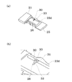
図5は、エンドキャップ20のガタ止め部23に撓み防止手段を設けた例を示す。
ガタ止め部23から内側に向けて、上下する抜け止めピン30を樹脂成形により一体的に形成した例である。
抜け止めピン30は溝部23dの内側から連結部31を形成し、連結部31の先に上下方向のピン部32を形成してあり、エンドキャップ20をモール本体10に挿着後にピン部32の先をエンドキャップの挿入部22に形成した係止溝26に差し込むようにした。
ピン部32の後端は差し込みやすいように上に突出した押圧部33を設けてある。
このように、抜け止めピン30を設けると、エンドキャップがモール本体から外れなくなる。
FIG. 5 shows an example in which a bend preventing means is provided in the
This is an example in which a retaining
The retaining
The rear end of the
Thus, when the retaining
10 モール本体
11 端末部
12a,12b フランジ部
13 ガタ止め用切欠部
14 抜け止め用切欠部
15 ベース部
20 エンドキャップ
21 意匠部
21a ふさぎ部
22 挿入部
23 ガタ止め部
24 抜け止め部
25 挿入ガイド部
DESCRIPTION OF
Claims (4)
モール本体は、ベース部とベース部の幅方向両側から裏面側にそれぞれ折り返した一対のフランジ部を有し、且つ一方のフランジ部はエンドキャップのガタ止め用切欠部を有し、他方のフランジ部はエンドキャップの抜け止め用切欠部を有し、
エンドキャップは、モール本体の端末をふさぐ意匠部と、モール本体の端末から内側に挿入される挿入部を有し、
挿入部は、モール本体のガタ止め用切欠部に向けて突出し、挿入方向前後であって突出方向に相互に縮幅した傾斜面を有するガタ止め部と、モール本体の抜け止め用切欠部に向けて突出し、挿入方向前側に先端後方に傾いた傾斜面と、後側に垂直面又は先端部が鋭角の鋭角斜面を有する抜け止め部とを形成したことを特徴とする自動車モール。 An automotive mall having a mall body and an end cap that is inserted into a terminal portion of the mall body,
The molding body has a base portion and a pair of flange portions that are folded back from the both sides in the width direction of the base portion to the back surface side, and one flange portion has a notch portion for rattling of the end cap, and the other flange portion. Has an end cap retaining notch,
The end cap has a design portion that covers the terminal of the mall body, and an insertion portion that is inserted inside from the terminal of the mall body,
The insertion part protrudes toward the notch for backlash prevention of the molding body, and has a backlashing part having an inclined surface that is before and after the insertion direction and has a mutually reduced width in the protruding direction, and toward the notching part for prevention of removal of the molding body. An automobile molding characterized in that an inclined surface that protrudes forward and is inclined to the front side in the insertion direction and inclined to the rear of the tip and a retaining portion that has a vertical surface or an acute slope with a sharp tip on the rear side.
Priority Applications (1)
| Application Number | Priority Date | Filing Date | Title |
|---|---|---|---|
| JP2008326624A JP4996590B2 (en) | 2008-12-22 | 2008-12-22 | Automotive malls and end caps |
Applications Claiming Priority (1)
| Application Number | Priority Date | Filing Date | Title |
|---|---|---|---|
| JP2008326624A JP4996590B2 (en) | 2008-12-22 | 2008-12-22 | Automotive malls and end caps |
Publications (2)
| Publication Number | Publication Date |
|---|---|
| JP2010143556A true JP2010143556A (en) | 2010-07-01 |
| JP4996590B2 JP4996590B2 (en) | 2012-08-08 |
Family
ID=42564417
Family Applications (1)
| Application Number | Title | Priority Date | Filing Date |
|---|---|---|---|
| JP2008326624A Active JP4996590B2 (en) | 2008-12-22 | 2008-12-22 | Automotive malls and end caps |
Country Status (1)
| Country | Link |
|---|---|
| JP (1) | JP4996590B2 (en) |
Cited By (3)
| Publication number | Priority date | Publication date | Assignee | Title |
|---|---|---|---|---|
| WO2012141012A1 (en) * | 2011-04-13 | 2012-10-18 | 片山工業株式会社 | Molding endcap |
| JP2015182536A (en) * | 2014-03-24 | 2015-10-22 | シロキ工業株式会社 | Molding for vehicle |
| CN112224153A (en) * | 2019-07-15 | 2021-01-15 | 长城汽车股份有限公司 | Ornamental strip subassembly and vehicle |
Citations (3)
| Publication number | Priority date | Publication date | Assignee | Title |
|---|---|---|---|---|
| JPS6024659U (en) * | 1983-07-27 | 1985-02-20 | トヨタ自動車株式会社 | Automobile mall |
| JPS6434356U (en) * | 1987-08-26 | 1989-03-02 | ||
| JP2005254904A (en) * | 2004-03-10 | 2005-09-22 | Shiroki Corp | Molding structure |
-
2008
- 2008-12-22 JP JP2008326624A patent/JP4996590B2/en active Active
Patent Citations (3)
| Publication number | Priority date | Publication date | Assignee | Title |
|---|---|---|---|---|
| JPS6024659U (en) * | 1983-07-27 | 1985-02-20 | トヨタ自動車株式会社 | Automobile mall |
| JPS6434356U (en) * | 1987-08-26 | 1989-03-02 | ||
| JP2005254904A (en) * | 2004-03-10 | 2005-09-22 | Shiroki Corp | Molding structure |
Cited By (8)
| Publication number | Priority date | Publication date | Assignee | Title |
|---|---|---|---|---|
| WO2012141012A1 (en) * | 2011-04-13 | 2012-10-18 | 片山工業株式会社 | Molding endcap |
| CN103534140A (en) * | 2011-04-13 | 2014-01-22 | 片山工业株式会社 | Molding endcap |
| US8740276B2 (en) | 2011-04-13 | 2014-06-03 | Katayama Kogyo Co., Ltd. | Molding end cap |
| JP5552571B2 (en) * | 2011-04-13 | 2014-07-16 | 片山工業株式会社 | Mall end cap |
| CN103534140B (en) * | 2011-04-13 | 2015-12-23 | 片山工业株式会社 | Filler rod end cap |
| JP2015182536A (en) * | 2014-03-24 | 2015-10-22 | シロキ工業株式会社 | Molding for vehicle |
| CN112224153A (en) * | 2019-07-15 | 2021-01-15 | 长城汽车股份有限公司 | Ornamental strip subassembly and vehicle |
| CN112224153B (en) * | 2019-07-15 | 2022-05-06 | 长城汽车股份有限公司 | Ornamental strip subassembly and vehicle |
Also Published As
| Publication number | Publication date |
|---|---|
| JP4996590B2 (en) | 2012-08-08 |
Similar Documents
| Publication | Publication Date | Title |
|---|---|---|
| JP4885638B2 (en) | Protector | |
| JP5552571B2 (en) | Mall end cap | |
| JP2007168636A (en) | Bracket for mounting bumper | |
| JP5219696B2 (en) | connector | |
| JP5741608B2 (en) | Bonding structure of resin parts and bumper cover structure | |
| JP4996590B2 (en) | Automotive malls and end caps | |
| JP6378259B2 (en) | Mall end cap mounting structure and automobile molding using the same | |
| JP5179284B2 (en) | Automotive mall | |
| JP6076731B2 (en) | Resin nail structure | |
| JP2011093367A (en) | Molding mounting structure | |
| JP5911023B2 (en) | Resin member mounting structure | |
| JP2008032040A (en) | Clip and mounting structure using clip | |
| JP4712672B2 (en) | clip | |
| JP6025551B2 (en) | Resin parts locking structure | |
| JP4292932B2 (en) | Mall end cap | |
| JP2010000817A (en) | Molding for automobile | |
| JP4543285B2 (en) | Mall material fixture | |
| JP4950674B2 (en) | clip | |
| JP2016196277A (en) | Garnish attachment structure | |
| JP6076730B2 (en) | Resin nail structure | |
| JP2006262667A (en) | Locking structure of wire harness protector | |
| JP5623650B2 (en) | Mall end cap mounting structure | |
| JP7128535B2 (en) | Roof molding and its terminal assembly structure | |
| JP7226606B2 (en) | engagement structure | |
| JP6851268B2 (en) | Automotive cover member and its mounting structure |
Legal Events
| Date | Code | Title | Description |
|---|---|---|---|
| A977 | Report on retrieval |
Free format text: JAPANESE INTERMEDIATE CODE: A971007 Effective date: 20111017 |
|
| A131 | Notification of reasons for refusal |
Free format text: JAPANESE INTERMEDIATE CODE: A131 Effective date: 20111031 |
|
| A521 | Written amendment |
Free format text: JAPANESE INTERMEDIATE CODE: A523 Effective date: 20111226 |
|
| TRDD | Decision of grant or rejection written | ||
| A01 | Written decision to grant a patent or to grant a registration (utility model) |
Free format text: JAPANESE INTERMEDIATE CODE: A01 Effective date: 20120507 |
|
| A01 | Written decision to grant a patent or to grant a registration (utility model) |
Free format text: JAPANESE INTERMEDIATE CODE: A01 |
|
| A61 | First payment of annual fees (during grant procedure) |
Free format text: JAPANESE INTERMEDIATE CODE: A61 Effective date: 20120511 |
|
| FPAY | Renewal fee payment (event date is renewal date of database) |
Free format text: PAYMENT UNTIL: 20150518 Year of fee payment: 3 |
|
| R150 | Certificate of patent or registration of utility model |
Free format text: JAPANESE INTERMEDIATE CODE: R150 Ref document number: 4996590 Country of ref document: JP Free format text: JAPANESE INTERMEDIATE CODE: R150 |
|
| R250 | Receipt of annual fees |
Free format text: JAPANESE INTERMEDIATE CODE: R250 |
|
| R250 | Receipt of annual fees |
Free format text: JAPANESE INTERMEDIATE CODE: R250 |
|
| R250 | Receipt of annual fees |
Free format text: JAPANESE INTERMEDIATE CODE: R250 |