[1.パチンコ機の全体構造]
以下に実施形態のパチンコ機1を図面を参照して詳細に説明する。なお、説明の便宜上、パチンコ機の遊技者に対向する側を「前」又は「表」、反対側を「後」又は「裏」とする。
[1. Overall structure of pachinko machine]
The pachinko machine 1 of the embodiment will be described in detail below with reference to the drawings. For convenience of explanation, the side of the pachinko machine facing the player is referred to as "front" or "front", and the opposite side is referred to as "rear" or "back".
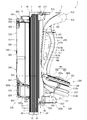
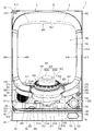
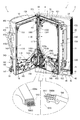
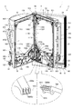
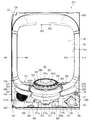
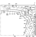
まず、図1乃至図13を参照してパチンコ機1の全体構成について説明する。図1はパチンコ機の正面図である。図2はパチンコ機の右側面図であり、図3はパチンコ機の左側面図であり、図4はパチンコ機の背面図である。図5はパチンコ機を右前から見た斜視図であり、図6はパチンコ機を左前から見た斜視図であり、図7はパチンコ機を後ろから見た斜視図である。図8は演出操作ユニットの押圧操作部が上昇位置の時のパチンコ機の正面図であり、図9は演出操作ユニットの押圧操作部が上昇位置の時のパチンコ機を右前から見た斜視図である。また、図10、図11は、本体枠から扉枠を開放させると共に、外枠から本体枠を開放させた状態で前から見たパチンコ機の斜視図である。図12はパチンコ機を扉枠、遊技盤、本体枠、及び外枠に分解して前から見た分解斜視図であり、図13はパチンコ機を扉枠、遊技盤、本体枠、及び外枠に分解して後ろから見た分解斜視図である。
First, the overall configuration of the pachinko machine 1 will be described with reference to FIGS. 1 to 13. FIG. 1 is a front view of a pachinko machine. FIG. 2 is a right side view of the pachinko machine, FIG. 3 is a left side view of the pachinko machine, and FIG. 4 is a rear view of the pachinko machine. FIG. 5 is a perspective view of the pachinko machine viewed from the front right, FIG. 6 is a perspective view of the pachinko machine viewed from the front left, and FIG. 7 is a perspective view of the pachinko machine viewed from the back. FIG. 8 is a front view of the pachinko machine when the pressing operation unit of the effect operating unit is in the raised position, and FIG. 9 is a perspective view of the pachinko machine when the pressing operation unit of the effect operating unit is in the raised position. is there. 10 and 11 are perspective views of the pachinko machine viewed from the front with the door frame opened from the main body frame and the main body frame opened from the outer frame. FIG. 12 is an exploded perspective view of the pachinko machine disassembled into a door frame, a game board, a main body frame, and an outer frame, and FIG. 13 is an exploded perspective view of the pachinko machine as a door frame, a game board, a main body frame, and an outer frame. It is an exploded perspective view seen from behind by disassembling into.
パチンコ機1は、遊技ホールの島設備(図示しない)に設置される枠状の外枠2と、外枠2の前面を開閉可能に閉鎖する扉枠3と、扉枠3を開閉可能に支持していると共に外枠2に開閉可能に取付けられている本体枠4と、本体枠4に前側から着脱可能に取付けられると共に扉枠3を通して遊技者側から視認可能とされ遊技者によって遊技球B(図106を参照)が打込まれる遊技領域5aを有した遊技盤5と、を備えている。
The pachinko machine 1 supports a frame-shaped outer frame 2 installed in an island facility (not shown) of a game hall, a door frame 3 that opens and closes the front surface of the outer frame 2, and a door frame 3 that can be opened and closed. The main body frame 4 which is attached to the outer frame 2 so as to be openable and closable, and the main body frame 4 which is detachably attached to the main body frame 4 from the front side and is visible from the player side through the door frame 3 It includes a game board 5 having a game area 5a into which (see FIG. 106) is driven.
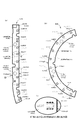
外枠2は、正面視の形状が上下に延びた四角形の枠に形成されている。外枠2は、左右に離間しており上下に延びている外枠左組立体10及び外枠右組立体20と、外枠左組立体10及び外枠右組立体20の上端同士を連結している外枠上部材30と、外枠左組立体10及び外枠右組立体20の下端同士を連結している外枠下組立体40と、外枠上部材30の上面左端に取付けられている外枠上ヒンジ組立体50と、外枠左組立体10の右側面下部と外枠下組立体40の上面左端に取付けられている外枠下ヒンジ部材60と、を備えている。
The outer frame 2 is formed in a quadrangular frame whose front view shape extends vertically. The outer frame 2 connects the outer frame left assembly 10 and the outer frame right assembly 20 which are separated from each other to the left and right and extend vertically, and the upper ends of the outer frame left assembly 10 and the outer frame right assembly 20. The outer frame upper member 30 is attached to the outer frame lower assembly 40 connecting the lower ends of the outer frame left assembly 10 and the outer frame right assembly 20, and the upper left end of the outer frame upper member 30. The outer frame upper hinge assembly 50 and the outer frame lower hinge member 60 attached to the lower right surface of the outer frame left assembly 10 and the upper left end of the outer frame lower assembly 40 are provided.
外枠2は、パチンコ機1が設置される遊技ホールの島設備に取付けられ、外枠上ヒンジ組立体50と外枠下ヒンジ部材60とによって、本体枠4の本体枠上ヒンジ部材510と本体枠下ヒンジ組立体520とを同軸上で回転可能に支持して、本体枠4を正面視左側を中心にして前方へ開閉可能に取付けるためのものである。
The outer frame 2 is attached to the island equipment of the game hall where the pachinko machine 1 is installed, and the outer frame upper hinge assembly 50 and the outer frame lower hinge member 60 make up the main body frame upper hinge member 510 and the main body of the main body frame 4. The hinge assembly 520 under the frame is rotatably supported on the same axis, and the main body frame 4 is attached so as to be openable and closable forward centering on the left side in the front view.
また、扉枠3は、本体枠4を閉じた時に、外枠下組立体40が、本体枠4における基板ユニット620のスピーカユニット620aと協働して、本体枠スピーカ622のエンクロージャ624の一部を形成し、本体枠スピーカ622の後方へ出力されたサウンドを、位相反転させて前方へ放射することで、より重低音のサウンドを遊技者に聴かせることができるものである。
Further, in the door frame 3, when the main body frame 4 is closed, the outer frame lower assembly 40 cooperates with the speaker unit 620a of the board unit 620 in the main body frame 4 to form a part of the enclosure 624 of the main body frame speaker 622. Is formed, and the sound output to the rear of the main body frame speaker 622 is phase-inverted and radiated forward, so that the player can hear a deeper bass sound.
扉枠3は、遊技球Bが打込まれる遊技盤5の遊技領域5aを前側から視認可能に閉鎖し、遊技領域5a内に打込むための遊技球Bを貯留すると共に、貯留している遊技球Bを遊技領域5a内へ打込むために遊技者が操作する操作媒体たるハンドル182を備えているものである。また、扉枠3は、パチンコ機1の前面全体を装飾するものである。
The door frame 3 visibly closes the game area 5a of the game board 5 into which the game ball B is driven, stores the game ball B for driving into the game area 5a, and stores the stored game. It is provided with a handle 182 which is an operation medium operated by a player to drive the ball B into the game area 5a. Further, the door frame 3 decorates the entire front surface of the pachinko machine 1.
また、扉枠3は、ハンドル182とは別に遊技者が操作可能な演出操作部301を備えており、遊技者参加型演出が実行された際に、遊技者が演出操作部301を操作することで遊技者が演出に参加できるようになり、遊技球Bによる遊技に加えて、演出操作部301の操作によっても遊技者を楽しませることができるようにしている。
Further, the door frame 3 is provided with an effect operation unit 301 that can be operated by the player separately from the handle 182, and the player operates the effect operation unit 301 when the player participation type effect is executed. The player can participate in the production, and the player can be entertained by operating the production operation unit 301 in addition to the game by the game ball B.
本体枠4は、後部が外枠2の枠内に挿入可能とされると共に遊技盤5の外周を支持可能とされた枠状の本体枠ベースユニット500と、本体枠4を外枠2に対して開閉可能に取付けると共に扉枠3を開閉可能に取付けるための本体枠上ヒンジ部材510及び本体枠下ヒンジ組立体520と、本体枠ベースユニット500を補強している金属製の本体枠補強フレーム530と、遊技盤5の遊技領域5a内に遊技球Bを打込むための球発射装置540と、遊技ホールの島設備から供給される遊技球Bを受取る払出ベースユニット550と、払出ベースユニット550で受取った遊技球Bを遊技者側へ払出すための払出ユニット560と、パチンコ機1の電源投入を行うことができる電源スイッチ630aを備える電源基板630のほかに払出制御基板633を有している基板ユニット620と、本体枠ベース501に取付けられた遊技盤5の後側を覆う裏カバー640と、外枠2と本体枠4、及び扉枠3と本体枠4の間を施錠する施錠ユニット650と、を備えている。
The main body frame 4 has a frame-shaped main body frame base unit 500 whose rear portion can be inserted into the frame of the outer frame 2 and which can support the outer circumference of the game board 5, and the main body frame 4 with respect to the outer frame 2. The main body frame upper hinge member 510 and the main body frame lower hinge assembly 520 for attaching the door frame 3 so as to be openable and closable, and the metal main body frame reinforcement frame 530 that reinforces the main body frame base unit 500. A ball launching device 540 for driving the game ball B into the game area 5a of the game board 5, a payout base unit 550 for receiving the game ball B supplied from the island equipment of the game hall, and a payout base unit 550. It has a payout control board 633 in addition to a payout unit 560 for paying out the received game ball B to the player side and a power supply board 630 provided with a power supply switch 630a capable of turning on the power of the pachinko machine 1. A locking unit 650 that locks between the board unit 620, the back cover 640 that covers the rear side of the game board 5 attached to the main body frame base 501, the outer frame 2 and the main body frame 4, and the door frame 3 and the main body frame 4. And have.
本体枠4は、遊技球Bを打込むことで遊技が行われる遊技領域5aを有した遊技盤5を保持すると共に、遊技球Bを遊技者側へ払出したり、遊技に使用された遊技球Bをパチンコ機1の後方(遊技ホールの島設備側)へ排出したり、するためのものである。本体枠4は、前方が開放された箱状に形成されており、内部に前方から遊技盤5が着脱可能に収容される。また、本体枠4は、正面左辺側前端の上下において、遊技ホールの島設備に取付けられる枠状の外枠2に開閉可能に取付けられると共に、開放された前面側が閉鎖されるように扉枠3が開閉可能に取付けられる。
The main body frame 4 holds the game board 5 having the game area 5a in which the game is played by hitting the game ball B, and pays out the game ball B to the player side, or the game ball B used for the game. Is for discharging to the rear of the pachinko machine 1 (on the island equipment side of the game hall). The main body frame 4 is formed in a box shape with an open front, and the game board 5 is detachably housed inside from the front. Further, the main body frame 4 is attached to the frame-shaped outer frame 2 attached to the island equipment of the game hall above and below the front end on the left side of the front side so as to be openable and closable, and the door frame 3 is closed so that the opened front side is closed. Can be installed so that it can be opened and closed.
遊技盤5は、遊技者の操作によって遊技球Bが打ち込まれる遊技領域5aと、遊技領域5aの外周を区画し外形が正面視略四角形状とされた前構成部材1000と、前構成部材1000の後側に取付けられており遊技領域5aの後端を区画する板状の遊技パネル1100と、遊技パネル1100の後側下部に取付けられている基板ホルダ1200と、基板ホルダ1200の後面に取付けられており主制御基板1310X及び設定変更基板1310Yを有している主制御ユニット1300と、主制御基板1310Xからの制御信号に基づいて遊技状況を表示する機能表示ユニット1400と、遊技パネル1100の後側に配置されている周辺制御ユニット1500と、正面視において遊技領域5aの中央に配置されており所定の演出画像を表示可能な演出表示装置1600と、遊技パネル1100の前面に取付けられる表ユニット2000と、遊技パネル1100の後面に取付けられる裏ユニット3000と、を備えている。裏ユニット3000には、遊技状態に応じて可動演出や発光演出を行うことが可能な裏演出ユニット3100を備えている。
The game board 5 includes a game area 5a into which a game ball B is driven by a player's operation, a front component 1000 that divides the outer periphery of the game area 5a and has a substantially square outer shape in front view, and a front component 1000. A plate-shaped game panel 1100 attached to the rear side and partitioning the rear end of the game area 5a, a board holder 1200 attached to the lower part of the rear side of the game panel 1100, and a board holder 1200 attached to the rear surface of the board holder 1200. On the rear side of the main control unit 1300 having the main control board 1310X and the setting change board 1310Y, the function display unit 1400 that displays the game status based on the control signal from the main control board 1310X, and the game panel 1100. The peripheral control unit 1500 arranged, the effect display device 1600 arranged in the center of the game area 5a in front view and capable of displaying a predetermined effect image, the table unit 2000 attached to the front surface of the game panel 1100, and the table unit 2000. It includes a back unit 3000 attached to the rear surface of the game panel 1100. The back unit 3000 is provided with a back effect unit 3100 capable of performing a movable effect or a light emitting effect according to the game state.
遊技盤5の遊技領域5a内には、所定のゲージ配列で遊技パネル1100の前面に植設されていて遊技球Bの動きに変化を与える複数の障害釘2007と、遊技球Bの受け入れにより遊技者に対して所定の特典(例えば、所定数の遊技球Bの払出し)を付与する一般入賞口2001、第一始動口2002、第二始動口2004及び大入賞口2005等の受入口と、遊技球Bの通過により遊技者に対して所定の特典(例えば、第二始動口2004への入賞を所定時間可能にする。)を付与するゲート部2003と、遊技球Bが入球し得るもののそれによって利益がもたらされない不利な第1受入口2006(詳細については後述する。)が備えられている。この一般入賞口2001、第一始動口2002、ゲート部2003、第二始動口2004、大入賞口2005及び第1受入口2006は、表ユニット2000に備えられている。
In the game area 5a of the game board 5, a plurality of obstacle nails 2007, which are planted in front of the game panel 1100 in a predetermined gauge arrangement and change the movement of the game ball B, and a game by accepting the game ball B Entrances and exits for general winning openings 2001, first starting opening 2002, second starting opening 2004, large winning opening 2005, etc., which give a predetermined privilege (for example, payout of a predetermined number of game balls B) to a person, and a game. A gate portion 2003 that grants a predetermined privilege (for example, a prize to the second starting port 2004 is possible for a predetermined time) to the player by passing the ball B, and a game ball B that can enter the ball. It is equipped with a disadvantageous first entrance 2006 (details will be described later) that does not bring any benefit. The general winning opening 2001, the first starting port 2002, the gate portion 2003, the second starting port 2004, the large winning opening 2005, and the first receiving port 2006 are provided in the table unit 2000.
遊技盤5の遊技領域5a内には、遊技者が遊技者操作用のハンドルユニット180を操作して打力調節という遊技用の入力をすることで、任意の強さで遊技球Bを打込むことができる。これにより遊技球Bを、遊技領域5a内の一般入賞口2001、第一始動口2002、ゲート部2003、第二始動口2004及び大入賞口2005等に受入れさせたり通過させ、不利な第1受入口2006へ入球させない、というように、遊技者に対してハンドル182の打込操作を楽しませることができる。
In the game area 5a of the game board 5, the player operates the handle unit 180 for the player operation and inputs the game force to adjust the striking force, so that the game ball B is driven with an arbitrary strength. be able to. As a result, the game ball B is accepted or passed through the general winning opening 2001, the first starting opening 2002, the gate portion 2003, the second starting opening 2004, the large winning opening 2005, etc. in the game area 5a, which is disadvantageous for the first receiving. It is possible to entertain the player with the driving operation of the handle 182, such as not allowing the ball to enter the entrance 2006.
また、遊技盤5は、遊技領域5a内に遊技球Bを打込むことで変化する遊技状態に応じて、演出表示装置1600に所定の演出画像を表示させたり、裏演出ユニット3100により可動演出や発光演出を行わせたりして、遊技者を楽しませることができる。
Further, the game board 5 displays a predetermined effect image on the effect display device 1600 according to the game state that changes by hitting the game ball B into the game area 5a, or a movable effect is performed by the back effect unit 3100. It is possible to entertain the player by performing a light emitting effect.
パチンコ機1は、後述する上皿201に遊技球を貯留した状態で遊技者がハンドル182を回転操作すると、球発射装置540によってハンドル182の回転角度(ハンドル182の操作量)に応じた強さで遊技球が打ち出され、その遊技球が、発射レール544と外レール1001と内レール1002とによる発射通路部1012で形成された発射球通路を通って遊技盤5の遊技領域5a内へ案内される。そして、遊技領域5a内に打込まれた遊技球が、前記一般入賞口2001等に受入れられると、受入れられた入賞口に応じて、所定数の遊技球が後述する払出装置580によって球用開口から上皿201に払出される。
When the player rotates the handle 182 while the game balls are stored in the upper plate 201, which will be described later, the pachinko machine 1 has a strength corresponding to the rotation angle of the handle 182 (the amount of operation of the handle 182) by the ball launcher 540. The game ball is launched at, and the game ball is guided into the game area 5a of the game board 5 through the launch ball passage formed by the launch passage portion 1012 formed by the launch rail 544, the outer rail 1001 and the inner rail 1002. To. Then, when the game balls driven into the game area 5a are received by the general winning opening 2001 or the like, a predetermined number of game balls are opened for balls by the payout device 580 described later according to the received winning openings. Is paid out to the upper plate 201.
なお、遊技球の打込強さ等の関係で、遊技領域5aに到達不能な強さ、つまり弱い発射力で発射された遊技球が遊技領域5a内に到達しなかった場合は、図10、図39に示したように、発射レール544の端部(終端部)と外レール1001の端部(始端部)との間に開設されたファール球落下口1013に落下し、それが後述する返却通路部1014を構成するファールカバーユニット150のファール球受部150cに受けられ、ファールカバーユニット150内を通って球用開口たる下皿球供給口211cから下皿202に排出される。
If the strength of the game ball that cannot reach the game area 5a due to the driving strength of the game ball, that is, the game ball launched with a weak firing force does not reach the game area 5a, FIG. As shown in FIG. 39, the ball falls into the foul ball drop opening 1013 provided between the end (end) of the launch rail 544 and the end (start) of the outer rail 1001, which is returned later. It is received by the foul ball receiving portion 150c of the foul cover unit 150 constituting the passage portion 1014, passes through the foul cover unit 150, and is discharged to the lower plate 202 from the lower plate ball supply port 211c which is an opening for the ball.
[2.外枠の全体構成]
パチンコ機1の外枠2について、図14乃至図19を参照して説明する。図14はパチンコ機における外枠の正面図であり、図15は外枠の背面図であり、図16は外枠の右側面図である。また、図17は外枠を前から見た斜視図であり、図18は外枠を後ろから見た斜視図である。図19は、外枠を主な部材毎に分解して前から見た分解斜視図である。外枠2は、遊技ホール等のパチンコ機1が設置される島設備(図示は省略)に取付けられるものである。外枠2は、正面視の形状が上下に延びた四角形の枠に形成されている。
[2. Overall composition of the outer frame]
The outer frame 2 of the pachinko machine 1 will be described with reference to FIGS. 14 to 19. FIG. 14 is a front view of the outer frame of the pachinko machine, FIG. 15 is a rear view of the outer frame, and FIG. 16 is a right side view of the outer frame. Further, FIG. 17 is a perspective view of the outer frame viewed from the front, and FIG. 18 is a perspective view of the outer frame viewed from the back. FIG. 19 is an exploded perspective view of the outer frame disassembled for each main member and viewed from the front. The outer frame 2 is attached to an island facility (not shown) in which a pachinko machine 1 is installed, such as a game hall. The outer frame 2 is formed in a quadrangular frame whose front view shape extends vertically.
外枠2は、図示するように、左右に離間しており上下に延びている外枠左組立体10及び外枠右組立体20と、外枠左組立体10及び外枠右組立体20の上端同士を連結している外枠上部材30と、外枠左組立体10及び外枠右組立体20の下端同士を連結している外枠下組立体40と、外枠上部材30の上面左端に取付けられている外枠上ヒンジ組立体50と、外枠左組立体10の右側面下部と外枠下組立体40の上面左端に取付けられている外枠下ヒンジ部材60と、を備えている。
As shown in the figure, the outer frame 2 includes an outer frame left assembly 10 and an outer frame right assembly 20 which are separated from each other to the left and right and extend vertically, and an outer frame left assembly 10 and an outer frame right assembly 20. The outer frame upper member 30 connecting the upper ends, the outer frame lower assembly 40 connecting the lower ends of the outer frame left assembly 10 and the outer frame right assembly 20, and the upper surface of the outer frame upper member 30. The outer frame upper hinge assembly 50 attached to the left end, and the outer frame lower hinge member 60 attached to the lower right side of the outer frame left assembly 10 and the upper left end of the outer frame lower assembly 40 are provided. ing.
外枠2は、本体枠4を閉じた時に、外枠下組立体40が、本体枠4における基板ユニット620のスピーカユニット620aと協働して、本体枠スピーカ622のエンクロージャ624の一部を形成していると共に、本体枠スピーカ622の後方へ出力されたサウンドを、位相反転させて前方へ放射することができるものである。
In the outer frame 2, when the main body frame 4 is closed, the outer frame lower assembly 40 cooperates with the speaker unit 620a of the board unit 620 in the main body frame 4 to form a part of the enclosure 624 of the main body frame speaker 622. At the same time, the sound output to the rear of the main body frame speaker 622 can be phase-inverted and radiated forward.
外枠2は、外枠上ヒンジ組立体50が、本体枠4の本体枠上ヒンジ部材510を着脱可能に支持することができる。外枠2は、外枠上ヒンジ組立体50と外枠下ヒンジ部材60とによって、本体枠4の本体枠上ヒンジ部材510と本体枠下ヒンジ組立体520とを同軸上で回転可能に支持することができ、本体枠4を正面視左側を中心にして前方へ開閉可能に取付けることができる。
In the outer frame 2, the outer frame upper hinge assembly 50 can detachably support the main body frame upper hinge member 510 of the main body frame 4. The outer frame 2 coaxially and rotatably supports the main body frame upper hinge member 510 and the main body frame lower hinge assembly 520 of the main body frame 4 by the outer frame upper hinge assembly 50 and the outer frame lower hinge member 60. The main body frame 4 can be attached so as to be openable and closable forward with the left side of the front view as the center.
[2−1.外枠左組立体及び外枠右組立体]
外枠2の外枠左組立体10及び外枠右組立体20について、主に図20を参照して詳細に説明する。図20は、外枠の外枠左組立体及び外枠右組立体をそれぞれ分解して前から見た分解斜視図である。外枠2の外枠左組立体10及び外枠右組立体20は、それぞれが上下に延びており、互いに左右に離間して配置されている。外枠左組立体10及び外枠右組立体20は、本体枠4の本体枠上ヒンジ部材510及び本体枠下ヒンジ組立体520を同軸上で回転可能に支持して、外枠2に対して本体枠4を開閉可能に取付けるためのものである。
[2-1. Outer frame left assembly and outer frame right assembly]
The outer frame left assembly 10 and the outer frame right assembly 20 of the outer frame 2 will be described in detail mainly with reference to FIG. FIG. 20 is an exploded perspective view of the outer frame left assembly and the outer frame right assembly of the outer frame as viewed from the front by disassembling them. The outer frame left assembly 10 and the outer frame right assembly 20 of the outer frame 2 extend vertically, and are arranged so as to be separated from each other on the left and right. The outer frame left assembly 10 and the outer frame right assembly 20 coaxially and rotatably support the main body frame upper hinge member 510 and the main body frame lower hinge assembly 520 of the main body frame 4 with respect to the outer frame 2. This is for attaching the main body frame 4 so that it can be opened and closed.
まず、外枠左組立体10は、前後方向が一定の幅(奥行)で上下に延びている外枠左部材11と、外枠左部材11の右側面上端に取付けられている左上連結部材12と、外枠左部材11の右側面下端に取付けられている左下連結部材13と、を備えている。
First, in the outer frame left assembly 10, the outer frame left member 11 extending vertically with a constant width (depth) in the front-rear direction and the upper left connecting member 12 attached to the upper end of the right side surface of the outer frame left member 11 And a lower left connecting member 13 attached to the lower end of the right side surface of the outer frame left member 11.
外枠左部材11は、一定の断面形状で上下に延びており、アルミ合金の押出型材によって形成されている。外枠左部材11は、左側面における前後方向を三等分したうちの後側の部位において平坦状に右方へ窪んでいる凹部11aと、右側面における凹部11aとは反対側の部位から右方へ膨出している膨出部11bと、膨出部11bを上下に貫通している空洞部11cと、を備えている。外枠左部材11は、凹部11aや膨出部11bによって、強度・剛性が高められていると共に、空洞部11cによって、重量が軽減されている。
The outer frame left member 11 extends vertically with a constant cross-sectional shape, and is formed of an extruded aluminum alloy mold material. The outer frame left member 11 has a recess 11a that is flatly recessed to the right in the rear portion of the left side surface divided into three equal parts in the front-rear direction, and a recess 11a on the right side surface that is opposite to the recess 11a to the right. It includes a bulging portion 11b that bulges toward the direction and a hollow portion 11c that vertically penetrates the bulging portion 11b. The strength and rigidity of the outer frame left member 11 are increased by the recess 11a and the bulging portion 11b, and the weight is reduced by the cavity 11c.
また、外枠左部材11は、左右両側面において、上下に延びた複数の溝が形成されている。左側面の複数の溝は、V字状に形成されており、右側面の複数の溝は、半円形状に形成されている。外枠左部材11は、後述する外枠右組立体20の外枠右部材21と左右対称形状に形成されている。
Further, the outer frame left member 11 is formed with a plurality of grooves extending vertically on both the left and right side surfaces. The plurality of grooves on the left side surface are formed in a V shape, and the plurality of grooves on the right side surface are formed in a semicircular shape. The outer frame left member 11 is formed symmetrically with the outer frame right member 21 of the outer frame right assembly 20, which will be described later.
左上連結部材12は、外枠左部材11の上端と外枠上部材30の左端とを連結するためのものである。左上連結部材12は、水平に延びた平板状の水平固定部12aと、水平固定部12aの左辺における前後方向の中間から上方へ延出している平板状の上横固定部12bと、水平固定部12aの左辺における上横固定部12bの前後両側から下方へ延出している平板状の一対の下横固定部12cと、を備えている。左上連結部材12は、平板状の金属板を屈曲させて形成されている。
The upper left connecting member 12 is for connecting the upper end of the outer frame left member 11 and the left end of the outer frame upper member 30. The upper left connecting member 12 includes a horizontally extending flat plate-shaped horizontal fixing portion 12a, a flat plate-shaped upper and horizontal fixing portion 12b extending upward from the middle in the front-rear direction on the left side of the horizontal fixing portion 12a, and a horizontal fixing portion. A pair of flat plate-shaped lower horizontal fixing portions 12c extending downward from both front and rear sides of the upper horizontal fixing portion 12b on the left side of 12a are provided. The upper left connecting member 12 is formed by bending a flat metal plate.
左上連結部材12は、後側の下横固定部12cを外枠左部材11の空洞部11c内に挿入させると共に、水平固定部12aを外枠左部材11の上端に当接させ、更に、前側及び後側の下横固定部12cを外枠左部材11の右側面に当接させた状態で、外枠左部材11の左側面の外側から下横固定部12cにビスを捩じ込むことで、外枠左部材11に取付けられる。また、左上連結部材12は、水平固定部12aを外枠上部材30の左端側の下面に当接させると共に、上横固定部12bを外枠上部材30の左側面の切欠部30a内に挿入させた状態で、水平固定部12a及び上横固定部12bを通して外枠上部材30にビスを捩じ込むことで、外枠上部材30に取付けられる。
In the upper left connecting member 12, the lower horizontal fixing portion 12c on the rear side is inserted into the cavity portion 11c of the outer frame left member 11, the horizontal fixing portion 12a is brought into contact with the upper end of the outer frame left member 11, and further, the front side. In a state where the lower horizontal fixing portion 12c on the rear side is in contact with the right side surface of the outer frame left member 11, a screw is screwed into the lower horizontal fixing portion 12c from the outside of the left side surface of the outer frame left member 11. , Attached to the outer frame left member 11. Further, in the upper left connecting member 12, the horizontal fixing portion 12a is brought into contact with the lower surface on the left end side of the outer frame upper member 30, and the upper horizontal fixing portion 12b is inserted into the notch 30a on the left side surface of the outer frame upper member 30. In this state, it is attached to the outer frame upper member 30 by screwing a screw into the outer frame upper member 30 through the horizontal fixing portion 12a and the upper horizontal fixing portion 12b.
左下連結部材13は、外枠左部材11の下端と外枠下組立体40(外枠下部材41)の左端とを連結するためのものである。左下連結部材13は、水平に延びた平板状の水平固定部13aと、水平固定部13aの左辺から上方へ延出していると共に水平固定部13aよりも後方へ延出している平板状の上横固定部13bと、上横固定部13bの下辺における水平固定部よりも後側の部位から下方へ延出している平板状の下横固定部13cと、上横固定部13bの後辺から右方へ短く延出している平板状の当接部13dと、を備えている。左下連結部材13は、平板状の金属板を屈曲させて形成されている。
The lower left connecting member 13 is for connecting the lower end of the outer frame left member 11 and the left end of the outer frame lower assembly 40 (outer frame lower member 41). The lower left connecting member 13 has a horizontally extending flat plate-shaped horizontal fixing portion 13a and a flat plate-shaped upper side extending upward from the left side of the horizontal fixing portion 13a and extending rearward from the horizontal fixing portion 13a. The fixed portion 13b, the flat plate-shaped lower lateral fixing portion 13c extending downward from the portion posterior to the horizontal fixing portion on the lower side of the upper lateral fixing portion 13b, and the upper lateral fixing portion 13b to the right from the rear side. It is provided with a flat plate-shaped contact portion 13d extending shortly to. The lower left connecting member 13 is formed by bending a flat metal plate.
左下連結部材13は、当接部13dの後面を外枠左部材11の膨出部11bの前面に当接させると共に、上横固定部13bの左側面を外枠左部材11の右側面に当接させ、水平固定部13aの下面を外枠左部材11の下端と一致させた状態で、外枠左部材11の左側面の外側から上横固定部13bにビスを捩じ込むことで、外枠左部材11に取付けられる。また、左下連結部材13は、水平固定部13aを外枠下部材41の左端側の上面に当接させると共に、下横固定部13cを外枠下部材41の左側面の切欠部41aに挿入させた状態で、水平固定部13a及び下横固定部13cを通して外枠下部材にビスを捩じ込むことで、外枠下部材41に取付けられる。
In the lower left connecting member 13, the rear surface of the contact portion 13d is brought into contact with the front surface of the bulging portion 11b of the outer frame left member 11, and the left surface of the upper horizontal fixing portion 13b is in contact with the right surface of the outer frame left member 11. With the lower surface of the horizontal fixing portion 13a in contact with the lower end of the outer frame left member 11, a screw is screwed into the upper horizontal fixing portion 13b from the outside of the left side surface of the outer frame left member 11 to remove the outer frame. It is attached to the frame left member 11. Further, in the lower left connecting member 13, the horizontal fixing portion 13a is brought into contact with the upper surface on the left end side of the outer frame lower member 41, and the lower horizontal fixing portion 13c is inserted into the cutout portion 41a on the left side surface of the outer frame lower member 41. In this state, it is attached to the outer frame lower member 41 by screwing a screw into the outer frame lower member through the horizontal fixing portion 13a and the lower horizontal fixing portion 13c.
次に、外枠右組立体20は、前後方向が一定の幅(奥行)で上下に延びている外枠右部材21と、外枠右部材21の左側面上端に取付けられている右上連結部材22と、外枠右部材21の左側面下端に取付けられている右下連結部材23と、外枠右部材21の左側面上部に取付けられている上鉤掛部材24と、外枠右部材21の左側面下部に取付けられている下鉤掛部材25と、を備えている。
Next, the outer frame right assembly 20 has an outer frame right member 21 extending vertically with a constant width (depth) in the front-rear direction and an upper right connecting member attached to the upper end of the left side surface of the outer frame right member 21. 22, the lower right connecting member 23 attached to the lower end of the left side surface of the outer frame right member 21, the upper hook member 24 attached to the upper part of the left side surface of the outer frame right member 21, and the outer frame right member 21. It includes a lower hook member 25 attached to the lower part of the left side surface.
外枠右部材21は、一定の断面形状で上下に延びており、アルミ合金の押出型材によって形成されている。外枠右部材21は、右側面における前後方向を三等分したうちの後側の部位において平坦状に左方へ窪んでいる凹部21aと、左側面における凹部21aとは反対側の部位から左方へ膨出している膨出部21bと、膨出部21bを上下に貫通している空洞部21cと、を備えている。外枠右部材21は、凹部21aや膨出部21bによって、強度・剛性が高められていると共に、空洞部21cによって、重量が軽減されている。
The outer frame right member 21 extends vertically with a constant cross-sectional shape, and is formed of an extruded aluminum alloy mold material. The outer frame right member 21 has a recess 21a that is flatly recessed to the left in the rear portion of the right side surface divided into three equal parts in the front-rear direction, and a recess 21a on the left side surface that is opposite to the recess 21a to the left. It includes a bulging portion 21b that bulges toward the direction and a hollow portion 21c that vertically penetrates the bulging portion 21b. The strength and rigidity of the outer frame right member 21 are increased by the concave portion 21a and the bulging portion 21b, and the weight is reduced by the hollow portion 21c.
また、外枠右部材21は、左右両側面において、上下に延びた複数の溝が形成されている。右側面の複数の溝は、V字状に形成されており、左側面の複数の溝は、半円形状に形成されている。外枠右部材21は、外枠左組立体10の外枠左部材11と左右対称形状に形成されている。
Further, the outer frame right member 21 is formed with a plurality of grooves extending vertically on both the left and right side surfaces. The plurality of grooves on the right side surface are formed in a V shape, and the plurality of grooves on the left side surface are formed in a semicircular shape. The outer frame right member 21 is formed symmetrically with the outer frame left member 11 of the outer frame left assembly 10.
右上連結部材22は、外枠右部材21の上端と外枠上部材30の右端とを連結するためのものである。右上連結部材22は、水平に延びた平板状の水平固定部22aと、水平固定部22aの右辺における前後方向の中間から上方へ延出している平板状の上横固定部22bと、水平固定部22aの右辺における上横固定部22bの前後両側から下方へ延出している平板状の一対の下横固定部22cと、を備えている。右上連結部材22は、平板状の金属板を屈曲させて形成されている。
The upper right connecting member 22 is for connecting the upper end of the outer frame right member 21 and the right end of the outer frame upper member 30. The upper right connecting member 22 includes a horizontally extending flat plate-shaped horizontal fixing portion 22a, a flat plate-shaped upper and horizontal fixing portion 22b extending upward from the middle in the front-rear direction on the right side of the horizontal fixing portion 22a, and a horizontal fixing portion. A pair of flat plate-shaped lower horizontal fixing portions 22c extending downward from both front and rear sides of the upper horizontal fixing portion 22b on the right side of 22a are provided. The upper right connecting member 22 is formed by bending a flat metal plate.
右上連結部材22は、後側の下横固定部22cを外枠右部材21の空洞部21c内に挿入させると共に、水平固定部22aを外枠右部材21の上端に当接させ、更に、前側及び後側の下横固定部22cを外枠右部材21の左側面に当接させた状態で、外枠右部材21の右側面の外側から下横固定部22cにビスを捩じ込むことで、外枠右部材21に取付けられる。また、右上連結部材22は、水平固定部22aを外枠上部材30の右端側の下面に当接させると共に、上横固定部22bを外枠上部材30の右側面の切欠部30a内に挿入させた状態で、水平固定部22a及び上横固定部22bを通して外枠上部材30にビスを捩じ込むことで、外枠上部材30に取付けられる。
In the upper right connecting member 22, the lower horizontal fixing portion 22c on the rear side is inserted into the hollow portion 21c of the outer frame right member 21, the horizontal fixing portion 22a is brought into contact with the upper end of the outer frame right member 21, and further, the front side. In a state where the lower horizontal fixing portion 22c on the rear side is in contact with the left side surface of the outer frame right member 21, a screw is screwed into the lower horizontal fixing portion 22c from the outside of the right side surface of the outer frame right member 21. , Attached to the outer frame right member 21. Further, in the upper right connecting member 22, the horizontal fixing portion 22a is brought into contact with the lower surface on the right end side of the outer frame upper member 30, and the upper horizontal fixing portion 22b is inserted into the notch 30a on the right side surface of the outer frame upper member 30. In this state, it is attached to the outer frame upper member 30 by screwing a screw into the outer frame upper member 30 through the horizontal fixing portion 22a and the upper horizontal fixing portion 22b.
右下連結部材23は、外枠右部材21の下端と外枠下組立体40(外枠下部材41)の右端とを連結するためのものである。右下連結部材23は、水平に延びた平板状の水平固定部23aと、水平固定部23aの右辺から上方へ延出していると共に水平固定部23aよりも後方へ延出している平板状の上横固定部23bと、上横固定部23bの下辺における水平固定部よりも後側の部位から下方へ延出している平板状の下横固定部23cと、上横固定部23bの後辺から左方へ短く延出している平板状の当接部23dと、を備えている。右下連結部材23は、平板状の金属板を屈曲させて形成されている。
The lower right connecting member 23 is for connecting the lower end of the outer frame right member 21 and the right end of the outer frame lower assembly 40 (outer frame lower member 41). The lower right connecting member 23 has a horizontally extending flat plate-shaped horizontal fixing portion 23a and a flat plate-shaped upper portion extending upward from the right side of the horizontal fixing portion 23a and extending rearward from the horizontal fixing portion 23a. The horizontal fixing portion 23b, the flat plate-shaped lower horizontal fixing portion 23c extending downward from the portion posterior to the horizontal fixing portion on the lower side of the upper horizontal fixing portion 23b, and the upper horizontal fixing portion 23b from the rear side to the left. It is provided with a flat plate-shaped contact portion 23d that extends shortly toward the direction. The lower right connecting member 23 is formed by bending a flat metal plate.
右下連結部材23は、当接部23dの後面を外枠右部材21の膨出部21bの前面に当接させると共に、上横固定部23bの右側面を外枠右部材21の左側面に当接させ、水平固定部23aの下面を外枠右部材21の下端と一致させた状態で、外枠右部材21の右側面の外側から上横固定部23bにビスを捩じ込むことで、外枠右部材21に取付けられる。また、右下連結部材23は、水平固定部23aを外枠下部材41の右端側の上面に当接させると共に、下横固定部23cを外枠下部材41の右側面の切欠部41aに挿入させた状態で、水平固定部23a及び下横固定部23cを通して外枠下部材にビスを捩じ込むことで、外枠下部材41に取付けられる。
In the lower right connecting member 23, the rear surface of the contact portion 23d is brought into contact with the front surface of the bulging portion 21b of the outer frame right member 21, and the right surface of the upper horizontal fixing portion 23b is brought into contact with the left surface of the outer frame right member 21. By abutting and aligning the lower surface of the horizontal fixing portion 23a with the lower end of the outer frame right member 21, a screw is screwed into the upper horizontal fixing portion 23b from the outside of the right side surface of the outer frame right member 21. It is attached to the outer frame right member 21. Further, in the lower right connecting member 23, the horizontal fixing portion 23a is brought into contact with the upper surface on the right end side of the outer frame lower member 41, and the lower horizontal fixing portion 23c is inserted into the cutout portion 41a on the right side surface of the outer frame lower member 41. In this state, it is attached to the outer frame lower member 41 by screwing a screw into the outer frame lower member through the horizontal fixing portion 23a and the lower horizontal fixing portion 23c.
上鉤掛部材24及び下鉤掛部材25は、後述する本体枠4における施錠ユニット650の外枠用鉤653が掛止されるものである。上鉤掛部材24は、前後方向に一定の幅で上下に延びており外枠右部材21の左側面に取付けられる平板状の取付部24aと、取付部24aの前辺から左方へ延出しており上側の外枠用鉤653が掛止される平板状の掛止片部24bと、を備えている。
The upper hook member 24 and the lower hook member 25 are for hooking the outer frame hook 653 of the locking unit 650 in the main body frame 4, which will be described later. The upper hook member 24 extends vertically with a constant width in the front-rear direction, and extends to the left from the front side of the flat plate-shaped mounting portion 24a to be mounted on the left side surface of the outer frame right member 21 and the mounting portion 24a. It is provided with a flat plate-shaped hooking piece portion 24b on which the hook 653 for the outer frame on the upper side of the cage is hooked.
下鉤掛部材25は、前後方向に一定の幅で上下に延びており外枠右部材21の左側面に取付けられる平板状の取付部25aと、取付部25aの前辺から左方へ延出しており下側の外枠用鉤653が掛止される平板状の掛止片部25bと、掛止片部25bを前後に貫通しており下側の外枠用鉤653が挿通可能な挿通口25cと、を備えている。
The lower hook member 25 extends vertically with a constant width in the front-rear direction, and has a flat plate-shaped mounting portion 25a attached to the left side surface of the outer frame right member 21 and extending from the front side of the mounting portion 25a to the left. Insertion that allows the lower outer frame hook 653 to be inserted through the flat plate-shaped hook piece portion 25b on which the lower outer frame hook 653 is hooked and the hook piece portion 25b. It has a mouth 25c and.
[2−2.外枠上部材]
外枠2の外枠上部材30について、主に図19を参照して詳細に説明する。外枠上部材30は、左右に離間している外枠左組立体10及び外枠右組立体20の上端同士を連結するためのものである。外枠上部材30は、前後方向の幅が、外枠左部材11及び外枠右部材21の前後方向と略同じ幅で、上下方向の厚さが一定で、左右方向に延びており、木材によって形成されている。外枠上部材30は、左右方向の長さが、後述する外枠下組立体40の外枠下部材41の左右方向の長さと同じに形成されている。
[2-2. Outer frame upper member]
The outer frame upper member 30 of the outer frame 2 will be described in detail mainly with reference to FIG. The outer frame upper member 30 is for connecting the upper ends of the outer frame left assembly 10 and the outer frame right assembly 20 that are separated from each other to the left and right. The width of the outer frame upper member 30 in the front-rear direction is substantially the same as the width in the front-rear direction of the outer frame left member 11 and the outer frame right member 21, the thickness in the vertical direction is constant, and the width extends in the left-right direction. Is formed by. The outer frame upper member 30 is formed so that the length in the left-right direction is the same as the length in the left-right direction of the outer frame lower member 41 of the outer frame lower assembly 40 described later.
外枠上部材30は、左右両側面における前後方向の中央において、上下に貫通した状態で左右方向中央側へそれぞれ窪んでいる切欠部30aを備えている。これら左右両端の切欠部30aには、左上連結部材12の上横固定部12b及び右上連結部材22の上横固定部22bがそれぞれ挿入された状態で取付けられる。
The outer frame upper member 30 is provided with a notch 30a that is recessed toward the center side in the left-right direction while penetrating vertically at the center in the front-rear direction on both the left and right side surfaces. The upper lateral fixing portion 12b of the upper left connecting member 12 and the upper lateral fixing portion 22b of the upper right connecting member 22 are inserted into the cutout portions 30a at both left and right ends, respectively.
また、外枠上部材30は、左側端部において、上面と前面が一般面よりも窪んだ取付段部30bを備えている。この取付段部30bには、後述する外枠上ヒンジ組立体50が取付けられる。
Further, the outer frame upper member 30 includes a mounting step portion 30b whose upper surface and front surface are recessed from the general surface at the left end portion. A hinge assembly 50 on an outer frame, which will be described later, is attached to the attachment step portion 30b.
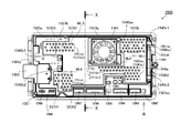
[2−3.外枠下組立体]
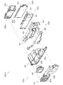
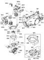
外枠2の外枠下組立体40について、主に図21を参照して詳細に説明する。図21は、外枠の外枠下組立体を分解して前から見た分解斜視図である。外枠下組立体40は、左右に離間している外枠左組立体10及び外枠右組立体20の下端同士を連結すると共に、パチンコ機1において扉枠3よりも下側を閉鎖して装飾するためのものである。
[2-3. Assembly under the outer frame]
The outer frame lower assembly 40 of the outer frame 2 will be described in detail mainly with reference to FIG. FIG. 21 is an exploded perspective view of the outer frame lower assembly as viewed from the front by disassembling it. The outer frame lower assembly 40 connects the lower ends of the outer frame left assembly 10 and the outer frame right assembly 20 that are separated to the left and right, and closes the lower side of the pachinko machine 1 below the door frame 3. It is for decoration.
外枠下組立体40は、左右に離間している外枠左組立体10及び外枠右組立体20の下端同士を連結しており左右に延びている外枠下部材41と、外枠下部材41の前方に配置されており外枠下部材41に沿って左右に延びていると共に後方が開放されている箱状の幕板前部材42と、幕板前部材42の後側に取付けられていると共に外枠下部材41の上面に取付けられており前方が開放されている左右に延びた箱状の幕板後部材43と、幕板後部材43の上面における左端に形成されている球噛防止機構44と、を備えている。
The outer frame lower assembly 40 includes an outer frame lower member 41 that connects the lower ends of the outer frame left assembly 10 and the outer frame right assembly 20 that are separated to the left and right and extends to the left and right, and the outer frame lower assembly 40. A box-shaped front curtain plate member 42 that is arranged in front of the member 41 and extends to the left and right along the lower member 41 of the outer frame and is open at the rear, and is attached to the rear side of the front curtain plate member 42. A box-shaped rear curtain plate member 43 that is attached to the upper surface of the outer frame lower member 41 and has an open front, and a ball bite prevention formed at the left end on the upper surface of the rear curtain plate member 43. It includes a mechanism 44 and.
外枠下部材41は、前後方向の幅が、外枠左部材11及び外枠右部材21の前後方向と略同じ幅で、上下方向の厚さが一定で、左右方向に延びており、木材によって形成されている。外枠下部材41は、左右方向の長さが、外枠上部材30の左右方向の長さと同じに形成されている。
The width of the outer frame lower member 41 in the front-rear direction is substantially the same as the width in the front-rear direction of the outer frame left member 11 and the outer frame right member 21, the thickness in the vertical direction is constant, and the width extends in the left-right direction. Is formed by. The outer frame lower member 41 is formed so that the length in the left-right direction is the same as the length in the left-right direction of the outer frame upper member 30.
外枠下部材41は、左右両側面における前後方向の中央において、上下に貫通した状態で左右方向中央側へそれぞれ窪んでいる切欠部41aを備えている。これら左右両端の切欠部41aには、左下連結部材13の下横固定部13c及び右下連結部材23の下横固定部23cがそれぞれ挿入された状態で取付けられる。これにより、外枠左部材11及び外枠右部材21の下端同士を連結することができる。
The outer frame lower member 41 includes notches 41a that are recessed toward the center side in the left-right direction in a state of penetrating vertically at the center in the front-rear direction on both the left and right side surfaces. The lower lateral fixing portion 13c of the lower left connecting member 13 and the lower lateral fixing portion 23c of the lower right connecting member 23 are respectively inserted into the cutout portions 41a at both left and right ends. As a result, the lower ends of the outer frame left member 11 and the outer frame right member 21 can be connected to each other.
また、外枠下部材41は、上面から凹んでおり、幕板後部材43の下部が挿入される凹部41bを備えている。凹部41bは、左右に延びていると共に、前後方向中央の後ろ寄りの位置から前端側へ抜けている。この凹部41bにより、幕板前部材42及び幕板後部材43により形成される幕板内部空間40aの容積を可及的に広くしている。
Further, the outer frame lower member 41 is recessed from the upper surface, and includes a recess 41b into which the lower portion of the curtain plate rear member 43 is inserted. The recess 41b extends to the left and right, and is pulled out from a position closer to the rear in the center in the front-rear direction toward the front end side. The recess 41b makes the volume of the curtain plate internal space 40a formed by the curtain plate front member 42 and the curtain plate rear member 43 as large as possible.
幕板前部材42は、左右方向の長さが外枠下部材41と同じ長さに延びており、高さに対して前後方向の奥行が短い横長の直方体状の箱状に形成されており、後側の全面が開放されている。幕板前部材42は、開放されている後側を、幕板後部材43によって閉鎖することで、幕板後部材43と協働して本体枠スピーカ622のエンクロージャ624の一部となる幕板内部空間40aを形成する。幕板前部材42は、右端付近の前面において、前後に貫通していると共に左右に延びている長孔状の開口部42aを備えている。
The curtain plate front member 42 is formed in a horizontally long rectangular parallelepiped shape in which the length in the left-right direction extends to the same length as the outer frame lower member 41 and the depth in the front-rear direction is short with respect to the height. The entire rear side is open. The curtain plate front member 42 is closed on the open rear side by the curtain plate rear member 43, so that the curtain plate front member 42 becomes a part of the enclosure 624 of the main body frame speaker 622 in cooperation with the curtain plate rear member 43. The space 40a is formed. The curtain plate front member 42 includes an elongated hole-shaped opening 42a that penetrates the front and rear and extends to the left and right on the front surface near the right end.
幕板後部材43は、左右方向の長さが外枠下部材41よりも若干短く延びており、前方が開放された箱状に形成されている。幕板後部材43は、前面に幕板前部材42を取付けることで、幕板前部材42と協働して本体枠スピーカ622のエンクロージャ624の一部となる幕板内部空間40aを形成する。幕板後部材43は、上面における左右方向中央部において、左右に延びていると共に上方へ突出しており幕板内部空間40aと連通している筒状の接続筒部43aを有している。接続筒部43aは、上端が、幕板後部材43の一般的な上面と一致している前端側から後方へ向かうほど上方へ位置するように傾斜している。本形態では、接続筒部43aの上端は、45度の角度で傾斜している。
The curtain plate rear member 43 has a length in the left-right direction slightly shorter than that of the outer frame lower member 41, and is formed in a box shape with an open front. By attaching the curtain plate front member 42 to the front surface of the curtain plate rear member 43, the curtain plate front member 42 cooperates with the curtain plate front member 42 to form a curtain plate internal space 40a that becomes a part of the enclosure 624 of the main body frame speaker 622. The curtain plate rear member 43 has a tubular connecting cylinder portion 43a that extends left and right and projects upward at the central portion in the left-right direction on the upper surface and communicates with the curtain plate internal space 40a. The upper end of the connecting cylinder portion 43a is inclined so as to be positioned upward from the front end side, which coincides with the general upper surface of the curtain plate rear member 43, toward the rear. In this embodiment, the upper end of the connecting cylinder portion 43a is inclined at an angle of 45 degrees.
この接続筒部43aは、左右方向の長さが、幕板後部材43全体の約1/3の長さに形成されていると共に、前後方向の奥行が、幕板後部材43全体の奥行よりも若干短く形成されている。接続筒部43a内には、前端側と後端側とを結ぶ複数のリブ43bが備えられている。この接続筒部43aの上端には、外枠2に対して本体枠4を閉じた時に、本体枠4における基板ユニット620のスピーカユニット620aにおけるスピーカカバー621の接続部621cが接続されて、スピーカユニット620aの内部空間と連通した状態となり、エンクロージャ624を形成する。
The length of the connecting cylinder portion 43a in the left-right direction is formed to be about 1/3 of the length of the entire curtain plate rear member 43, and the depth in the front-rear direction is greater than the depth of the entire curtain plate rear member 43. Is also formed slightly shorter. A plurality of ribs 43b connecting the front end side and the rear end side are provided in the connecting cylinder portion 43a. When the main body frame 4 is closed with respect to the outer frame 2, the connection portion 621c of the speaker cover 621 in the speaker unit 620a of the board unit 620 in the main body frame 4 is connected to the upper end of the connection cylinder portion 43a to connect the speaker unit. It communicates with the internal space of the 620a and forms the enclosure 624.
球噛防止機構44は、幕板後部材43の上面における左端において、外枠下ヒンジ部材60の部位に遊技球Bが滞留することで、外枠2と本体枠4との間に遊技球Bが挟まれるのを防止するためのものである。
In the ball biting prevention mechanism 44, the game ball B stays at the portion of the outer frame lower hinge member 60 at the left end on the upper surface of the curtain plate rear member 43, so that the game ball B is between the outer frame 2 and the main body frame 4. Is to prevent being pinched.
球噛防止機構44は、幕板後部材43の上面における左端に形成されており、後述する外枠下ヒンジ部材60が際されるように平坦に形成された載置部44aと、載置部44aの左端において上方へ向かって開口している第一排出口44bと、載置部44aにおける第一排出口44bよりも右方で上方へ向かって開口している第二排出口44cと、載置部44aの後辺及び右辺から上方へ延出している立壁部44dと、立壁部44dの上端から前方へ突出していると共に上面が後方へ向かうに従って上方に位置するように傾斜している上端突出部44eと、を備えている。
The ball biting prevention mechanism 44 is formed at the left end on the upper surface of the curtain plate rear member 43, and is a mounting portion 44a formed flat so that the hinge member 60 under the outer frame, which will be described later, is highlighted, and a mounting portion. The first discharge port 44b that opens upward at the left end of 44a and the second discharge port 44c that opens upward to the right of the first discharge port 44b in the mounting portion 44a are mounted. A vertical wall portion 44d extending upward from the rear side and the right side of the placement portion 44a, and an upper end protrusion protruding forward from the upper end of the vertical wall portion 44d and being inclined so that the upper surface is positioned upward as the upper surface is directed backward. A part 44e and a part 44e are provided.
第一排出口44bは、後述する外枠下ヒンジ部材60の排出孔60dと一致する位置に形成されている。第一排出口44b及び第二排出口44cは、遊技球Bが通過可能な大きさに形成されている。第一排出口44b及び第二排出口44cは、幕板内部空間40aとは連通しておらず、幕板後部材43の後面に開口している。したがって、第一排出口44b及び第二排出口44cに進入した遊技球Bを、幕板後部材43の後方へ排出することができる。
The first discharge port 44b is formed at a position corresponding to the discharge hole 60d of the outer frame lower hinge member 60, which will be described later. The first discharge port 44b and the second discharge port 44c are formed in a size that allows the game ball B to pass through. The first discharge port 44b and the second discharge port 44c do not communicate with the curtain plate internal space 40a and are open to the rear surface of the curtain plate rear member 43. Therefore, the game ball B that has entered the first discharge port 44b and the second discharge port 44c can be discharged to the rear of the curtain plate rear member 43.
この球噛防止機構44は、球噛防止機構44は、外枠下ヒンジ部材60と後述する本体枠下ヒンジ組立体520との間の隙間を通して、ピアノ線等の不正な工具が挿入された場合、載置部44aの後端から立上っている立壁部44dにより、不正な工具の侵入を阻止することができる。仮に、不正な工具の先端が立壁部44dに当接することで、上方へ曲がったとしても、立壁部44dの上端に備えられている前方へ突出した上端突出部44eに当接し、これ以上の侵入を阻止することができる。したがって、外枠下ヒンジ部材60の部位を介して、不正行為が行われるのを防止することができる。
The ball biting prevention mechanism 44 is a case where an illegal tool such as a piano wire is inserted through the gap between the outer frame lower hinge member 60 and the main body frame lower hinge assembly 520 described later. The standing wall portion 44d rising from the rear end of the mounting portion 44a can prevent an unauthorized tool from entering. Even if the tip of an illegal tool abuts on the standing wall portion 44d and bends upward, it abuts on the upper end protruding portion 44e provided at the upper end of the standing wall portion 44d and further invades. Can be blocked. Therefore, it is possible to prevent fraudulent acts from being performed through the portion of the hinge member 60 under the outer frame.
ところで、載置部44aの後端に立壁部44dを備えた場合、外枠2に対して本体枠4を開けた時に、何らかの理由により載置部44a上に落下した遊技球Bが、立壁部44dによって外枠2の後方への移動が阻止されるため、載置部44a上に遊技球Bが滞留し易くなる。そして、載置部44a上に遊技球Bが滞留していると、外枠2に対して本体枠4を閉じる際に、外枠2と本体枠4との間に遊技球Bが挟み込まれてしまい、本体枠4を閉じることができなくなる問題が発生する。
By the way, when the standing wall portion 44d is provided at the rear end of the mounting portion 44a, the game ball B that has fallen on the mounting portion 44a for some reason when the main body frame 4 is opened with respect to the outer frame 2 is the standing wall portion. Since the movement of the outer frame 2 to the rear is prevented by the 44d, the game ball B is likely to stay on the mounting portion 44a. If the game ball B stays on the mounting portion 44a, the game ball B is sandwiched between the outer frame 2 and the main body frame 4 when the main body frame 4 is closed with respect to the outer frame 2. This causes a problem that the main body frame 4 cannot be closed.
これに対して、本形態の球噛防止機構44では、外枠下ヒンジ部材60上や載置部44a上に落下した遊技球Bを、外枠下ヒンジ部材60の排出孔60dと第一排出口44bを通して、又は、第二排出口44cを通して、遊技球Bを幕板後部材43の後方(外枠2の後方)へ排出することができ、外枠2と本体枠4との間に遊技球Bが挟まれるのを防止することができる。
On the other hand, in the ball biting prevention mechanism 44 of the present embodiment, the game ball B that has fallen on the outer frame lower hinge member 60 or the mounting portion 44a is first discharged to the discharge hole 60d of the outer frame lower hinge member 60. The game ball B can be discharged to the rear of the curtain plate rear member 43 (behind the outer frame 2) through the outlet 44b or the second discharge port 44c, and the game can be played between the outer frame 2 and the main body frame 4. It is possible to prevent the ball B from being pinched.
外枠下組立体40は、幕板前部材42及び幕板後部材43の上面に左右に離間して配置されている一対の案内部材45と、幕板前部材42の開口部42aを後側から閉鎖している平板状のグリル部材46と、グリル部材46を挟んで開口部42aを閉鎖するように幕板前部材42の内部に取付けられており前後に延びた二つの円筒を有したポート部材47と、幕板後部材43の接続筒部43aの上端に配置される枠状のシール部材48と、を備えている。
The outer frame lower assembly 40 closes a pair of guide members 45 arranged apart from each other on the upper surfaces of the curtain plate front member 42 and the curtain plate rear member 43, and the opening 42a of the curtain plate front member 42 from the rear side. A flat plate-shaped grill member 46 and a port member 47 having two cylinders extending back and forth, which are attached to the inside of the curtain plate front member 42 so as to close the opening 42a with the grill member 46 sandwiched between them. A frame-shaped seal member 48 arranged at the upper end of the connecting cylinder portion 43a of the curtain plate rear member 43 is provided.
一対の案内部材45は、外枠2に対して本体枠4を閉じた時に、扉枠3の下端が当接するものである。案内部材45は、摩擦抵抗の低い低摩擦材料によって形成されており、本体枠4の下端を滑り易くして、開閉を容易にしている。
The pair of guide members 45 are such that the lower end of the door frame 3 comes into contact with the outer frame 2 when the main body frame 4 is closed. The guide member 45 is made of a low friction material having low frictional resistance, and makes the lower end of the main body frame 4 slippery to facilitate opening and closing.
グリル部材46は、無数の小穴を有したパンチングメタルにより形成されている。ポート部材47は、二つの円筒により、グリル部材46を介して幕板内部空間40a(エンクロージャ624)と外枠2の前方とを連通させている。ポート部材47は、二つの円筒が、所定の内径で所定の長さに形成されており、ヘルムホルツ共鳴の原理により本体枠スピーカ622から後方(エンクロージャ624内)へ発せられた低音を共振・増幅させて、豊かな低音を外枠2の前方(遊技者側)へ放射することができる。つまり、本形態では、本体枠スピーカ622のエンクロージャ624がバスレフ型とされており、遊技者に対して重低音を聞かせることができる。
The grill member 46 is formed of a punching metal having innumerable small holes. The port member 47 communicates between the curtain plate internal space 40a (enclosure 624) and the front of the outer frame 2 via the grill member 46 by two cylinders. The port member 47 has two cylinders formed with a predetermined inner diameter and a predetermined length, and resonates and amplifies the bass emitted from the main body frame speaker 622 to the rear (inside the enclosure 624) by the principle of Helmholtz resonance. Therefore, rich bass can be radiated to the front (player side) of the outer frame 2. That is, in this embodiment, the enclosure 624 of the main body frame speaker 622 is a bass reflex type, and the player can hear the deep bass.
シール部材48は、外枠2に対して本体枠4を閉じた時に、接続筒部43aの上端と本体枠4におけるスピーカカバー621の接続部621cの下端との間に挟まれて圧縮されるものであり、接続筒部43aと接続部621cとの間からスピーカのエンクロージャ内の音が漏れるのを防止するものである。
The seal member 48 is sandwiched and compressed between the upper end of the connection cylinder portion 43a and the lower end of the connection portion 621c of the speaker cover 621 in the main body frame 4 when the main body frame 4 is closed with respect to the outer frame 2. This is to prevent the sound in the speaker enclosure from leaking from between the connection cylinder portion 43a and the connection portion 621c.
[2−4.外枠上ヒンジ組立体]
外枠2の外枠上ヒンジ組立体50について、主に図22を参照して詳細に説明する。図22(a)は外枠2の外枠上ヒンジ組立体を分解して前上から見た分解斜視図であり、(b)は(a)を前下から見た分解斜視図である。外枠上ヒンジ組立体50は、外枠左組立体10の上端と外枠上部材30の左端に取付けられるものであり、外枠2に対して本体枠4をヒンジ回転可能に取付けるためのものである。外枠上ヒンジ組立体50は、外枠左部材11の凹部11aの上端と外枠上部材30の取付段部30bとに取付けられる外枠上ヒンジ部材51と、外枠上ヒンジ部材51に取付けられているロック部材52と、ロック部材52を外枠上ヒンジ部材51に取付けている取付ビス53と、を備えている。
[2-4. Hinge assembly on outer frame]
The hinge assembly 50 on the outer frame of the outer frame 2 will be described in detail mainly with reference to FIG. FIG. 22 (a) is an exploded perspective view of the outer frame upper hinge assembly of the outer frame 2 disassembled and viewed from the front upper side, and FIG. 22 (b) is an exploded perspective view of (a) viewed from the front lower surface. The outer frame upper hinge assembly 50 is attached to the upper end of the outer frame left assembly 10 and the left end of the outer frame upper member 30, and is for attaching the main body frame 4 to the outer frame 2 so that the hinge can be rotated. Is. The outer frame upper hinge assembly 50 is attached to the outer frame upper hinge member 51 attached to the upper end of the recess 11a of the outer frame left member 11 and the mounting step portion 30b of the outer frame upper member 30, and to the outer frame upper hinge member 51. The lock member 52 is provided, and a mounting screw 53 for attaching the lock member 52 to the hinge member 51 on the outer frame is provided.
外枠上ヒンジ部材51は、水平に延びた平板状で外枠上部材30の取付段部30bの上面に取付けられる上固定部51aと、上固定部51aの前辺から前方へ延出している平板状の前方延出部51bと、前方延出部51bの右辺の途中から前方へ向かうに従って前方延出部51bの左右中央へ延びており上下に貫通している軸受溝51cと、上固定部51aの左辺から下方へ延びている平板状の横固定部51dと、前方延出部51bの左辺から前辺を周って軸受溝51cが開口している部位までの端縁から下方へ延びており横固定部51dと連続している平板状の端縁壁部51eと、を備えている。外枠上ヒンジ部材51は、金属板をプレス成型により打抜き・屈曲させて形成されている。外枠上ヒンジ部材51は、軸受溝51c内において、本体枠上ヒンジ部材510の後述する本体枠上ヒンジピン512を回転可能に支持することができる。
The outer frame upper hinge member 51 has an upper fixing portion 51a which is horizontally extended and is attached to the upper surface of the mounting step portion 30b of the outer frame upper member 30, and extends forward from the front side of the upper fixing portion 51a. A flat plate-shaped front extending portion 51b, a bearing groove 51c extending from the middle of the right side of the front extending portion 51b to the left and right center of the front extending portion 51b and penetrating vertically, and an upper fixing portion. The flat plate-shaped horizontal fixing portion 51d extending downward from the left side of the 51a and the end edge extending downward from the left side of the front extending portion 51b to the portion where the bearing groove 51c is opened around the front side. It is provided with a flat plate-shaped edge wall portion 51e that is continuous with the cage horizontal fixing portion 51d. The hinge member 51 on the outer frame is formed by punching and bending a metal plate by press molding. The outer frame upper hinge member 51 can rotatably support the main body frame upper hinge pin 512, which will be described later, of the main body frame upper hinge member 510 in the bearing groove 51c.
ロック部材52は、前後に延びている帯板状のロック本体52aと、ロック本体52aの後端から右方へ突出している操作片52bと、ロック本体52aの後端から左方へ延びた後に斜め左前方へ延びている弾性変形可能な棒状の弾性部52cと、ロック本体52aの後端付近で上下に貫通している取付孔52dと、を備えている。ロック部材52は、合成樹脂によって形成されている。ロック部材52は、取付ビス53によって、外枠上ヒンジ部材51における前方延出部51bの下面で、軸受溝51cよりも後側の部位に回動可能に取付けられる。
The lock member 52 includes a strip-shaped lock body 52a extending back and forth, an operation piece 52b protruding to the right from the rear end of the lock body 52a, and after extending to the left from the rear end of the lock body 52a. It is provided with an elastically deformable rod-shaped elastic portion 52c extending diagonally to the left front and a mounting hole 52d penetrating vertically near the rear end of the lock body 52a. The lock member 52 is made of synthetic resin. The lock member 52 is rotatably attached to a portion rearward of the bearing groove 51c on the lower surface of the front extending portion 51b of the hinge member 51 on the outer frame by the attachment screw 53.
ロック部材52は、外枠上ヒンジ部材51に取付けた状態で、ロック本体52aが、平面視で軸受溝51cを遮ることができると共に、前端付近の右側面が、外枠上ヒンジ部材51の端縁壁部51eにおける軸受溝51cの開口まで延びている部位と当接可能となるように前方へ延びている。また、ロック本体52aの後端から左方へ延びている弾性部52cの先端は、外枠上ヒンジ部材51における端縁壁部51eの内周面に当接している。このロック部材52は、弾性部52cの付勢力によって取付孔52dを中心に、前端が左方へ回動する方向に付勢されている。したがって、通常の状態では、ロック部材52のロック本体52aの前端付近の右側面が、端縁壁部51eに当接している。この状態では、軸受溝51cにおけるロック本体52aよりも前側の部位に、本体枠上ヒンジ部材510の本体枠上ヒンジピン512を収容可能な空間が形成される。
When the lock member 52 is attached to the hinge member 51 on the outer frame, the lock body 52a can block the bearing groove 51c in a plan view, and the right surface near the front end is the end of the hinge member 51 on the outer frame. It extends forward so that it can come into contact with a portion of the edge wall portion 51e that extends to the opening of the bearing groove 51c. Further, the tip of the elastic portion 52c extending to the left from the rear end of the lock body 52a is in contact with the inner peripheral surface of the end edge wall portion 51e of the hinge member 51 on the outer frame. The lock member 52 is urged by the urging force of the elastic portion 52c in a direction in which the front end rotates to the left around the mounting hole 52d. Therefore, in a normal state, the right side surface of the lock member 52 near the front end of the lock body 52a is in contact with the edge wall portion 51e. In this state, a space is formed in the bearing groove 51c on the front side of the lock main body 52a so that the hinge pin 512 on the main body frame of the hinge member 510 on the main body frame can be accommodated.
このロック部材52は、操作片52bを操作することで、弾性部52cの付勢力に抗してロック本体52aを回動させることができる。そして、操作片52bの操作によって、ロック本体52aを、その前端が左方へ移動する方向へ回動させることで、平面視において軸受溝51cからロック本体52aを後退させることができ、軸受溝51cが全通している状態とすることができる。これにより、軸受溝51c内に本体枠上ヒンジピン512を挿入したり、軸受溝51c内から本体枠上ヒンジピン512を外したりすることができる。
By operating the operation piece 52b, the lock member 52 can rotate the lock body 52a against the urging force of the elastic portion 52c. Then, by operating the operation piece 52b, the lock body 52a is rotated in the direction in which the front end thereof moves to the left, so that the lock body 52a can be retracted from the bearing groove 51c in a plan view, and the bearing groove 51c can be retracted. Can be in a state of being fully passed. As a result, the hinge pin 512 on the main body frame can be inserted into the bearing groove 51c, and the hinge pin 512 on the main body frame can be removed from the bearing groove 51c.
[2−5.外枠下ヒンジ部材]
外枠2の外枠下ヒンジ部材60について、主に図19を参照して詳細に説明する。外枠下ヒンジ部材60は、水平に延びた平板状の水平部60aと、水平部60aの左辺において前後方向中央よりも後側の部位から上方へ立上っている平板状の立上部60bと、水平部60aの前端付近から上方へ突出している外枠下ヒンジピン60cと、水平部60aを上下に貫通しており遊技球Bが一つのみ通過可能な大きさの排出孔60dと、を備えている。この外枠下ヒンジ部材60は、金属板をプレス成型により打抜き・屈曲させて形成されている。
[2-5. Hinge member under the outer frame]
The lower hinge member 60 of the outer frame 2 will be described in detail mainly with reference to FIG. The outer frame lower hinge member 60 includes a horizontally extending flat plate-shaped horizontal portion 60a and a flat plate-shaped rising portion 60b rising upward from a portion rearward of the center in the front-rear direction on the left side of the horizontal portion 60a. A hinge pin 60c under the outer frame that protrudes upward from the vicinity of the front end of the horizontal portion 60a, and a discharge hole 60d that penetrates the horizontal portion 60a up and down and allows only one game ball B to pass through. ing. The outer frame lower hinge member 60 is formed by punching and bending a metal plate by press molding.
外枠下ヒンジ部材60の水平部60aは、平面視において、左辺を底辺とした台形に形成されている。外枠下ヒンジピン60cは、円柱状で、上下方向中央よりも上部が、上端が窄まった円錐台状に形成されている。この外枠下ヒンジピン60cは、水平部60aの前端付近における左寄りの位置に取付けられている。排出孔60dは、水平部60aにおいて、立上部60bの前後方向中央の部位と接し、水平部60aの左辺から右方へ逆U字状に延びるように形成されている。この排出孔60dは、外枠下組立体40における球噛防止機構44の第一排出口44bと、略同じ大きさに形成されている。
The horizontal portion 60a of the outer frame lower hinge member 60 is formed in a trapezoidal shape with the left side as the base in a plan view. The lower hinge pin 60c of the outer frame is columnar and is formed in a truncated cone shape in which the upper end is narrowed above the center in the vertical direction. The lower hinge pin 60c of the outer frame is attached at a position to the left near the front end of the horizontal portion 60a. The discharge hole 60d is formed in the horizontal portion 60a so as to be in contact with the central portion of the rising portion 60b in the front-rear direction and extend from the left side of the horizontal portion 60a to the right in an inverted U shape. The discharge hole 60d is formed to have substantially the same size as the first discharge port 44b of the ball biting prevention mechanism 44 in the outer frame lower assembly 40.
外枠下ヒンジ部材60は、外枠2に組立てた状態で、水平部60aの後部が、外枠下組立体40における幕板後部材43の載置部44a上に載置され、図示しないビスによって幕板後部材43に固定されている。また、立上部60bが、外枠左部材11の右側面における膨出部11bよりも前側の部位に、図示しないビスによって取付けられている。この外枠下ヒンジ部材60は、外枠下ヒンジピン60cを、本体枠4の本体枠下ヒンジ組立体520における外枠用下ヒンジ孔521aに挿通させることで、外枠上ヒンジ部材51と協働して本体枠4を開閉可能に取付けることができる。
In the state where the outer frame lower hinge member 60 is assembled on the outer frame 2, the rear portion of the horizontal portion 60a is mounted on the mounting portion 44a of the curtain plate rear member 43 in the outer frame lower assembly 40, and a screw (not shown) is provided. It is fixed to the rear member 43 of the curtain plate. Further, the rising portion 60b is attached to a portion on the right side surface of the outer frame left member 11 on the front side of the bulging portion 11b by a screw (not shown). The outer frame lower hinge member 60 cooperates with the outer frame upper hinge member 51 by inserting the outer frame lower hinge pin 60c into the outer frame lower hinge hole 521a in the main body frame lower hinge assembly 520 of the main body frame 4. Then, the main body frame 4 can be attached so as to be openable and closable.
また、外枠2を組立てた状態では、排出孔60dが、外枠下組立体40における球噛防止機構44の第一排出口44bと一致している。これにより、水平部60a上の遊技球Bを、排出孔60d及び第一排出口44bを通して、外枠2の後方へ落下(排出)させることができる。詳述すると、外枠2に対して本体枠4を閉じる時に、外枠2と本体枠4との間に落下した遊技球Bが、本体枠4が閉じられるのに従って、外枠2と本体枠4との間が徐々に狭くなることから、間隔が広い後方側へ転動とすることとなり、排出孔60dから排出させることができる。この際に、排出孔60dが、パチンコ機1に組立てた状態で、外枠2に対して本体枠4を閉じた時に、本体枠4の後端と略同じとなる位置に形成されているため、外枠2と本体枠4との間に落下した遊技球Bを、排出孔60dから排出させることで本体枠4よりも後側へ転動するのを阻止し易くすることができ、外枠下ヒンジ部材60の部位に遊技球Bが留まり難くすることができる。
Further, in the state where the outer frame 2 is assembled, the discharge hole 60d coincides with the first discharge port 44b of the ball biting prevention mechanism 44 in the outer frame lower assembly 40. As a result, the game ball B on the horizontal portion 60a can be dropped (discharged) to the rear of the outer frame 2 through the discharge hole 60d and the first discharge port 44b. More specifically, when the main body frame 4 is closed with respect to the outer frame 2, the game ball B that has fallen between the outer frame 2 and the main body frame 4 is moved between the outer frame 2 and the main body frame as the main body frame 4 is closed. Since the distance from 4 is gradually narrowed, the vehicle rolls to the rear side where the distance is wide, and the battery can be discharged from the discharge hole 60d. At this time, since the discharge hole 60d is formed at a position substantially the same as the rear end of the main body frame 4 when the main body frame 4 is closed with respect to the outer frame 2 in the state of being assembled in the pachinko machine 1. By discharging the game ball B that has fallen between the outer frame 2 and the main body frame 4 from the discharge hole 60d, it is possible to easily prevent the game ball B from rolling to the rear side of the main body frame 4, and the outer frame can be easily prevented from rolling. The game ball B can be made difficult to stay at the portion of the lower hinge member 60.
[3.扉枠の全体構成]
パチンコ機1の扉枠3について、主に図23〜図31を参照して詳細に説明する。図23はパチンコ機における扉枠の表面図であり、図24は扉枠の背面図であり、図25は扉枠の左側面図であり、図26は扉枠の右側面図である。図27は扉枠を右前から見た斜視図であり、図28は扉枠を左前から見た斜視図であり、図29は扉枠を後ろから見た斜視図である。図30は扉枠を主な部材毎に分解して前から見た分解斜視図であり、図31は扉枠を主な部材毎に分解して後ろから見た分解斜視図である。
[3. Overall configuration of door frame]
The door frame 3 of the pachinko machine 1 will be described in detail mainly with reference to FIGS. 23 to 31. FIG. 23 is a front view of the door frame in the pachinko machine, FIG. 24 is a rear view of the door frame, FIG. 25 is a left side view of the door frame, and FIG. 26 is a right side view of the door frame. 27 is a perspective view of the door frame viewed from the front right, FIG. 28 is a perspective view of the door frame viewed from the front left, and FIG. 29 is a perspective view of the door frame viewed from the back. FIG. 30 is an exploded perspective view of the door frame disassembled for each main member and viewed from the front, and FIG. 31 is an exploded perspective view of the door frame disassembled for each main member and viewed from the rear.
扉枠3は、外枠2の枠内と略同じ大きさで正面視において上下に延びた四角形に形成されており、本体枠4を介して外枠2の枠内を前側から開閉可能に取付けられている。扉枠3は、遊技球Bが打込まれる遊技盤5の遊技領域5aを前側から視認可能に閉鎖し、遊技領域5a内に打込むための遊技球Bを貯留すると共に、貯留している遊技球Bを遊技領域5a内へ打込むために遊技者が操作するハンドル182を備えているものである。また、扉枠3は、パチンコ機1の前面全体を装飾するものである。
The door frame 3 has substantially the same size as the inside of the outer frame 2 and is formed in a quadrangle extending vertically in front view, and the inside of the outer frame 2 can be opened and closed from the front side via the main body frame 4. Has been done. The door frame 3 visibly closes the game area 5a of the game board 5 into which the game ball B is driven, stores the game ball B for driving into the game area 5a, and stores the stored game. It is provided with a handle 182 operated by a player to drive the ball B into the game area 5a. Further, the door frame 3 decorates the entire front surface of the pachinko machine 1.
扉枠3は、正面視の外形が上下に延びた四角形で枠状の扉枠ベースユニット100と、扉枠ベースユニット100に着脱可能に取付けられており本体枠4に取付けられた遊技盤5の遊技領域5aを前方から視認可能に閉鎖しているガラスユニット160と、ガラスユニット160の下部を後側から覆うように扉枠ベースユニット100に取付けられている防犯カバー170と、扉枠ベースユニット100の前面右下隅に取付けられているハンドルユニット180と、扉枠ベースユニット100の前面下部に取付けられている皿ユニット200と、皿ユニット200の上側で扉枠ベースユニット100の前面左部に取付けられている扉枠左サイドユニット400と、皿ユニットの上側で扉枠ベースユニット100の前面右部に取付けられている扉枠右サイドユニット410と、扉枠左サイドユニット400及び扉枠右サイドユニット410の上側で扉枠ベースユニット100の前面上部に取付けられている扉枠トップユニット450と、を備えている。
The door frame 3 is a square and frame-shaped door frame base unit 100 whose outer shape extends vertically when viewed from the front, and a game board 5 which is detachably attached to the door frame base unit 100 and is attached to the main body frame 4. A glass unit 160 that visibly closes the game area 5a from the front, a security cover 170 that is attached to the door frame base unit 100 so as to cover the lower part of the glass unit 160 from the rear side, and a door frame base unit 100. The handle unit 180 attached to the lower right corner of the front surface of the door frame, the dish unit 200 attached to the lower part of the front surface of the door frame base unit 100, and the upper side of the dish unit 200 attached to the front left portion of the door frame base unit 100. The door frame left side unit 400, the door frame right side unit 410 attached to the front right part of the door frame base unit 100 on the upper side of the dish unit, the door frame left side unit 400, and the door frame right side unit 410. The door frame top unit 450, which is attached to the upper part of the front surface of the door frame base unit 100 on the upper side of the door frame, is provided.
扉枠ベースユニット100は、正面視の外形が上下に延びた四角形(長方形)に形成されており前後に貫通している扉窓101aを有した扉枠ベース101と、扉枠ベース101の前面右下に取付けられているハンドル取付部材102と、扉枠ベース101の後側で背面視右下隅に取付けられているスピーカダクト103と、扉枠ベース101の後側の下部における背面視右端付近に取付けられている扉枠主中継基板104と、扉枠主中継基板104の背面視左方に取付けられている扉枠副中継基板105と、扉枠副中継基板105の背面視左方に取付けられているハンドル後中継基板106と、扉枠主中継基板104と扉枠副中継基板105の一部とを後側から被覆する扉枠中継基板カバー107と、ハンドル後中継基板106を後側から被覆するハンドル後中継基板カバー108と、配線ケーブルを被覆するケーブルカバー109と、を備えている。
The door frame base unit 100 includes a door frame base 101 having a door window 101a which is formed in a square shape (rectangular shape) whose outer shape extends vertically and penetrates in the front-rear direction, and a front right side of the door frame base 101. The handle mounting member 102 mounted below, the speaker duct 103 mounted in the lower right corner of the rear view on the rear side of the door frame base 101, and the speaker duct 103 mounted in the lower part of the rear side of the door frame base 101 near the right end of the rear view. The door frame main relay board 104, the door frame sub-relay board 105 attached to the left side of the door frame main relay board 104, and the door frame sub-relay board 105 attached to the left side of the rear view. Covers the rear relay board 106 after the handle, the door frame relay board cover 107 that covers the door frame main relay board 104 and a part of the door frame sub relay board 105 from the rear side, and the door frame rear relay board 106 from the rear side. It includes a relay board cover 108 after the handle and a cable cover 109 that covers the wiring cable.
また、扉枠ベースユニット100は、扉枠ベース101の後側に取付けられている枠状の扉枠補強ユニット110と、扉枠補強ユニット110に取付けられている扉枠上ヒンジ組立体120及び扉枠下ヒンジ部材125と、扉枠補強ユニット110に取付けられている開閉用のシリンダ錠130と、扉枠ベース101の後側でハンドル後中継基板106の上方に取付けられている球送給ユニット140と、扉枠ベース101の後側の下部における背面視右側に取付けられているファールカバーユニット150と、を備えている。
Further, the door frame base unit 100 includes a frame-shaped door frame reinforcing unit 110 attached to the rear side of the door frame base 101, a hinge assembly 120 on the door frame attached to the door frame reinforcing unit 110, and a door. The hinge member 125 under the frame, the cylinder lock 130 for opening and closing attached to the door frame reinforcing unit 110, and the ball feeding unit 140 attached to the rear side of the door frame base 101 and above the relay board 106 after the handle. And a foul cover unit 150 attached to the right side of the rear view at the lower part of the rear side of the door frame base 101.
扉枠補強ユニット110は、扉枠ベース101の後側に取付けられることで、扉枠ベース101を補強して剛性を付与するものである。扉枠上ヒンジ組立体120及び扉枠下ヒンジ部材125は、扉枠3を本体枠4に対して開閉可能に取付けるためのものである。シリンダ錠130は、本体枠4の施錠ユニット650と協働して、扉枠3と本体枠4との開閉、及び、外枠2と本体枠4との開閉施錠に使用されるものである。
The door frame reinforcing unit 110 is attached to the rear side of the door frame base 101 to reinforce the door frame base 101 and impart rigidity. The door frame upper hinge assembly 120 and the door frame lower hinge member 125 are for attaching the door frame 3 to the main body frame 4 so as to be openable and closable. The cylinder lock 130 is used in cooperation with the locking unit 650 of the main body frame 4 to open and close the door frame 3 and the main body frame 4, and to open and close the outer frame 2 and the main body frame 4.
また、球送給ユニット140は、上皿201内の遊技球Bを一つずつ本体枠4の球発射装置540へ供給するためのものである。また、ファールカバーユニット150は、球発射装置540により弱い発射力で発射されて遊技盤5の遊技領域5a内に到達しなかった遊技球B(ファール球)を、下皿202に誘導すると共に、払出装置580から払出された遊技球Bを、上皿201又は下皿202に誘導するためのものである。
Further, the ball feeding unit 140 is for supplying the game balls B in the upper plate 201 one by one to the ball launching device 540 of the main body frame 4. Further, the foul cover unit 150 guides the game ball B (foul ball), which is launched by the ball launcher 540 with a weak firing force and does not reach the game area 5a of the game board 5, to the lower plate 202, and at the same time. This is for guiding the game ball B paid out from the payout device 580 to the upper plate 201 or the lower plate 202.
ガラスユニット160は、透明なガラス板162を有しており扉枠ベース101の扉窓101aを閉鎖している。防犯カバー170は、ガラスユニット160の下部を後方から覆うように扉枠ベース101に取付けられている。ハンドルユニット180は、遊技者が回転操作可能なハンドル182を備えており、ハンドル182を操作することで、上皿201内の遊技球Bを、球発射装置540によって遊技盤5の遊技領域5a内に打込むものである。
The glass unit 160 has a transparent glass plate 162 and closes the door window 101a of the door frame base 101. The security cover 170 is attached to the door frame base 101 so as to cover the lower portion of the glass unit 160 from the rear. The handle unit 180 includes a handle 182 that can be rotated by the player, and by operating the handle 182, the game ball B in the upper plate 201 is moved into the game area 5a of the game board 5 by the ball launcher 540. It is something to drive into.
[3−1.扉枠ベースユニットの全体構成]
扉枠3の扉枠ベースユニット100について、主に図32〜図34を参照して詳細に説明する。図32(a)は扉枠の扉枠ベースユニットを前から見た斜視図であり、(b)は扉枠ベースユニットを後ろから見た斜視図である。図33は扉枠ベースユニットを主な部材毎に分解して前から見た分解斜視図であり、図34は扉枠ベースユニットを主な部材毎に分解して後ろから見た分解斜視図である。
[3-1. Overall configuration of door frame base unit]
The door frame base unit 100 of the door frame 3 will be described in detail mainly with reference to FIGS. 32 to 34. FIG. 32 (a) is a perspective view of the door frame base unit of the door frame as viewed from the front, and FIG. 32 (b) is a perspective view of the door frame base unit as viewed from the rear. FIG. 33 is an exploded perspective view of the door frame base unit disassembled for each main member and viewed from the front, and FIG. 34 is an exploded perspective view of the door frame base unit disassembled for each main member and viewed from the rear. is there.
扉枠ベースユニット100は、正面視左辺側が本体枠4に対してヒンジ回転可能に取付けられ、本体枠4の前面を開閉可能に閉鎖していると共に、本体枠4に取付けられている遊技盤の遊技領域を前方から視認可能としている。扉枠ベースユニット100は、外形が上下に延びた四角形で平板状の扉枠ベース101と、扉枠ベース101の前面右下に取付けられておりハンドルユニット180を取付けるためのハンドル取付部材102と、扉枠ベース101の後側で背面視右下隅に取付けられているスピーカダクト103と、を備えている。
The door frame base unit 100 is attached so that the left side of the front view can be hinged with respect to the main body frame 4, and the front surface of the main body frame 4 is closed so as to be openable and closable. The game area is visible from the front. The door frame base unit 100 includes a square and flat door frame base 101 whose outer shape extends vertically, a handle mounting member 102 mounted on the lower right front surface of the door frame base 101 for mounting the handle unit 180, and the like. It is provided with a speaker duct 103 attached to the lower right corner of the rear view on the rear side of the door frame base 101.
また、扉枠ベースユニット100は、扉枠ベース101の後側の下部における背面視右端付近に取付けられている扉枠主中継基板104と、扉枠ベース101の後側の下部における扉枠主中継基板104の背面視左方に取付けられている扉枠副中継基板105と、扉枠ベース101の後側の下部における扉枠副中継基板105の背面視左方に取付けられているハンドル後中継基板106と、扉枠ベース101の後側に取付けられており扉枠主中継基板104と扉枠副中継基板105の一部とを後側から被覆する扉枠中継基板カバー107と、扉枠ベース101の後側に取付けられておりハンドル後中継基板106を後側から被覆するハンドル後中継基板カバー108と、扉枠ベース101の後側に取付けられており配線ケーブルを被覆するケーブルカバー109と、を備えている。
Further, the door frame base unit 100 includes a door frame main relay board 104 attached near the right end of the rear view at the lower rear side of the door frame base 101, and a door frame main relay at the lower rear side of the door frame base 101. The door frame sub-relay board 105 attached to the left side of the board 104 in the rear view, and the rear handle relay board attached to the left side of the door frame sub-relay board 105 in the lower part of the rear side of the door frame base 101. The door frame relay board cover 107, which is attached to the rear side of the door frame base 101 and covers a part of the door frame main relay board 104 and the door frame sub relay board 105 from the rear side, and the door frame base 101. The rear relay board cover 108, which is attached to the rear side and covers the rear relay board 106 from the rear side, and the cable cover 109, which is attached to the rear side of the door frame base 101 and covers the wiring cable, are attached. I have.
更に、扉枠ベースユニット100は、扉枠ベース101の後側に取付けられている枠状の扉枠補強ユニット110と、扉枠補強ユニット110に取付けられている扉枠上ヒンジ組立体120及び扉枠下ヒンジ部材125と、扉枠補強ユニット110に取付けられている開閉用のシリンダ錠130と、扉枠ベース101の後側でハンドル後中継基板106の上方に取付けられている球送給ユニット140と、扉枠ベース101の後側の下部における背面視右側に取付けられているファールカバーユニット150と、を備えている。
Further, the door frame base unit 100 includes a frame-shaped door frame reinforcing unit 110 attached to the rear side of the door frame base 101, a hinge assembly 120 on the door frame attached to the door frame reinforcing unit 110, and a door. The hinge member 125 under the frame, the cylinder lock 130 for opening and closing attached to the door frame reinforcing unit 110, and the ball feeding unit 140 attached to the rear side of the door frame base 101 and above the relay board 106 after the handle. And a foul cover unit 150 attached to the right side of the rear view at the lower part of the rear side of the door frame base 101.
この扉枠ベースユニット100には、前面下隅にハンドルユニット180が、扉窓101aの下側前面に皿ユニット200が、扉窓101aの左外側前面に扉枠左サイドユニット400が、扉窓101aの右外側前面に扉枠右サイドユニット410が、扉窓101aの上外側前面に扉枠トップユニット450が、それぞれ取付けられるものである。
The door frame base unit 100 has a handle unit 180 in the lower front corner, a dish unit 200 in the lower front surface of the door window 101a, a door frame left side unit 400 in the left outer front surface of the door window 101a, and a door window 101a. The door frame right side unit 410 is attached to the right outer front surface, and the door frame top unit 450 is attached to the upper outer front surface of the door window 101a.
また、扉枠ベースユニット100には、扉窓101aを後方から閉鎖するようにガラスユニット160が取付けられると共に、ガラスユニット160の下部を後方から覆うように透明な防犯カバー170が取付けられるものである。
Further, a glass unit 160 is attached to the door frame base unit 100 so as to close the door window 101a from the rear, and a transparent security cover 170 is attached so as to cover the lower portion of the glass unit 160 from the rear. ..
[3−1−1.扉枠ベース]
扉枠3における扉枠ベースユニット100の扉枠ベース101について、主に図32〜図34を参照して詳細に説明する。扉枠ベース101は、正面視の外形が上下に延びた四角形(長方形)に形成されている。扉枠ベース101は、前後に貫通しており、正面視における内周形状が上下に延びた略四角形に形成された扉窓101aを備えている。扉窓101aは、内周を形成している上辺及び左右両辺が、扉枠ベース101の外周辺にそれぞれ接近しており、内周を形成している下辺が、扉枠ベース101の下端から上下方向の約1/3の高さに位置している。このように、扉枠ベース101は、前後に貫通している扉窓101aにより全体が枠状に形成されている。この扉枠ベース101は、合成樹脂により一体成形されている。
[3-1-1. Door frame base]
The door frame base 101 of the door frame base unit 100 in the door frame 3 will be described in detail mainly with reference to FIGS. 32 to 34. The door frame base 101 is formed in a quadrangle (rectangle) whose outer shape in front view extends vertically. The door frame base 101 is provided with a door window 101a that penetrates the front and rear and is formed in a substantially quadrangular shape having an inner peripheral shape extending vertically in a front view. In the door window 101a, the upper side and the left and right sides forming the inner circumference are close to the outer periphery of the door frame base 101, respectively, and the lower side forming the inner circumference is up and down from the lower end of the door frame base 101. It is located at a height of about 1/3 in the direction. As described above, the door frame base 101 is entirely formed in a frame shape by the door windows 101a penetrating the front and rear. The door frame base 101 is integrally molded with a synthetic resin.
扉枠ベース101は、前面における正面視右下隅に形成されており左端側が右端側よりも前方へやや突出するように傾斜しているハンドル取付座面101bと、ハンドル取付座面101bと扉窓101aとの間で正面視右端付近に後面から前方へ向かって窪み、扉枠補強ユニット110のシリンダ取付フレーム115が挿入される挿入凹部101cと、挿入凹部101cにおいて前後に貫通しておりシリンダ錠130のシリンダ本体131が挿通されるシリンダ挿通孔101dと、シリンダ挿通孔101d及びハンドル取付座面101bの正面視左側で前後に貫通しており球送給ユニット140の進入口141a及び球抜口141bを前方に臨ませるための球送給開口101eと、を備えている。
The door frame base 101 is formed in the lower right corner of the front view and is inclined so that the left end side slightly protrudes forward from the right end side, the handle mounting seat surface 101b, the handle mounting seat surface 101b, and the door window 101a. The insertion recess 101c, in which the cylinder mounting frame 115 of the door frame reinforcing unit 110 is inserted, and the insertion recess 101c, which are recessed from the rear surface to the front near the right end of the front view, penetrate the front and rear of the cylinder lock 130. The cylinder insertion hole 101d through which the cylinder body 131 is inserted, the cylinder insertion hole 101d, and the handle mounting seat surface 101b penetrate the front and rear on the left side of the front view, and the entry entrance 141a and the ball outlet 141b of the ball feeding unit 140 are forward. It is equipped with a ball feeding opening 101e for facing the cylinder.
また、扉枠ベース101は、左右方向中央より左寄りで且つハンドル取付座面101bと略同じ高さで前後に貫通しておりファールカバーユニット150の球放出口150dを前方に臨ませる下皿用球通過口101fと、正面視左端付近で扉窓101aの下辺に隣接するように前後に貫通しておりファールカバーユニット150の貫通球通路150aを前方に臨ませる上皿用球通過口101gと、扉窓101aの内周に沿って後面から前方へ向かって窪み、ガラスユニット160のガラス枠161が挿入されるガラスユニット取付部101hと、を備えている。
Further, the door frame base 101 is to the left of the center in the left-right direction and penetrates back and forth at substantially the same height as the handle mounting seat surface 101b, so that the ball discharge port 150d of the foul cover unit 150 faces forward. The passage port 101f, the upper plate ball passage port 101g that penetrates the front and rear so as to be adjacent to the lower side of the door window 101a near the left end of the front view and faces the through ball passage 150a of the foul cover unit 150 to the front, and the door. It is provided with a glass unit mounting portion 101h that is recessed from the rear surface to the front along the inner circumference of the window 101a and into which the glass frame 161 of the glass unit 160 is inserted.
また、扉枠ベース101は、正面視左下隅(上皿用球通過口101gの下方)に形成されており前後に貫通した縦長の複数のスリット101iを、備えている。複数のスリット101iの後側にスピーカダクト103が取付けられる。また、複数のスリット101iは、パチンコ機1を組立てた状態で、前方に皿ユニット200における皿ユニットベース211のスピーカ口211bが位置していると共に、後方に本体枠4のスピーカユニット620aにおける本体枠スピーカ622が位置しており、本体枠スピーカ622からの音を前方へ放射することができる。
Further, the door frame base 101 is formed in the lower left corner of the front view (below the upper plate ball passage port 101 g), and is provided with a plurality of vertically long slits 101i penetrating the front and rear. A speaker duct 103 is attached to the rear side of the plurality of slits 101i. Further, in the plurality of slits 101i, in the state where the pachinko machine 1 is assembled, the speaker port 211b of the dish unit base 211 in the dish unit 200 is located in front, and the main body frame in the speaker unit 620a of the main body frame 4 is located in the rear. The speaker 622 is located, and the sound from the main body frame speaker 622 can be radiated forward.
更に、扉枠ベース101は、扉窓101aの下方でハンドル取付座面101bの上方において、前後に貫通している貫通孔101jを備えている。この貫通孔101jは、扉枠ベースユニット100側と皿ユニット200側とを接続する配線ケーブル(図示は省略)が挿通されるものであり、後述する扉枠補強ユニット110における中間補強フレーム114の貫通部114bと一致するように形成されている。
Further, the door frame base 101 is provided with a through hole 101j penetrating back and forth below the door window 101a and above the handle mounting seat surface 101b. A wiring cable (not shown) connecting the door frame base unit 100 side and the dish unit 200 side is inserted through the through hole 101j, and the intermediate reinforcing frame 114 in the door frame reinforcing unit 110 described later is penetrated. It is formed so as to coincide with the portion 114b.
[3−1−2.ハンドル取付部材]
扉枠ベースユニット100のハンドル取付部材102について、主に図32〜図34を参照して詳細に説明する。ハンドル取付部材102は、扉枠ベース101の前面にハンドルユニットを取付けるためのものであり、扉枠ベース101の前面のハンドル取付座面101bに取付けられる。
[3-1-2. Handle mounting member]
The handle mounting member 102 of the door frame base unit 100 will be described in detail mainly with reference to FIGS. 32 to 34. The handle mounting member 102 is for mounting the handle unit on the front surface of the door frame base 101, and is mounted on the handle mounting seat surface 101b on the front surface of the door frame base 101.
ハンドル取付部材102は、前後方向へ延びた円筒状の筒部102aと、筒部102aの後端から筒部102aの軸に対して直角方向外方へ延びた円環状のフランジ部102bと、筒部102a内に突出していると共に筒部102aの軸方向全長に亘って延びており筒部102aの周方向に対して不等間隔に配置された複数(本例では三つ)の突条102cと、筒部102aの外周面とフランジ部102bの前面とを繋ぎ、筒部102aの周方向に対して複数配置された補強リブ102dと、を備えている。
The handle mounting member 102 includes a cylindrical tubular portion 102a extending in the front-rear direction, an annular flange portion 102b extending outward in a direction perpendicular to the axis of the tubular portion 102a from the rear end of the tubular portion 102a, and a cylinder. With a plurality of (three in this example) ridges 102c that protrude into the portion 102a and extend over the entire length of the tubular portion 102a in the axial direction and are arranged at unequal intervals in the circumferential direction of the tubular portion 102a. The outer peripheral surface of the tubular portion 102a and the front surface of the flange portion 102b are connected to each other, and a plurality of reinforcing ribs 102d arranged in the circumferential direction of the tubular portion 102a are provided.
ハンドル取付部材102は、フランジ部102bの後面を、扉枠ベース101におけるハンドル取付座面101bの前面に当接させた状態で、ビスによってハンドル取付座面101bに取付けられる。
The handle mounting member 102 is mounted on the handle mounting seat surface 101b with screws in a state where the rear surface of the flange portion 102b is in contact with the front surface of the handle mounting seat surface 101b of the door frame base 101.
筒部102aは、内径がハンドルユニット180におけるハンドルベース181の基部181aの外径よりも若干大きく形成されている。三つの突条102cは、一つが筒部102aの上部に備えられており、残り二つが筒部102aの下部に備えられている。これら三つの突条102cは、ハンドルベース181における三つの溝部181cと対応する位置に形成されている。したがって、ハンドル取付部材102は、三つの突条102cと、ハンドルベース181の三つの溝部181cとを一致させた状態でのみ、筒部102a内にハンドルベース181の基部181aを挿入させることができ、扉枠ベース101に対してハンドルベース181(ハンドルユニット180)の回転位置を規制することができる。
The inner diameter of the tubular portion 102a is formed to be slightly larger than the outer diameter of the base portion 181a of the handle base 181 in the handle unit 180. One of the three ridges 102c is provided on the upper portion of the tubular portion 102a, and the other two are provided on the lower portion of the tubular portion 102a. These three ridges 102c are formed at positions corresponding to the three groove portions 181c in the handle base 181. Therefore, the handle mounting member 102 can insert the base portion 181a of the handle base 181 into the tubular portion 102a only when the three ridges 102c and the three groove portions 181c of the handle base 181 are aligned with each other. The rotation position of the handle base 181 (handle unit 180) can be regulated with respect to the door frame base 101.
なお、ハンドル取付部材102は、フランジ部102bの後面に対して、筒部102aの軸線が垂直に延びていることから、扉枠ベース101の傾斜しているハンドル取付座面101bに取付けることで、筒部102aの軸線が右前方へ延びるように傾いた状態となり、ハンドルユニット180を同様に傾いた状態で扉枠ベース101に取付けることができる。
Since the axis of the tubular portion 102a extends perpendicularly to the rear surface of the flange portion 102b, the handle mounting member 102 can be attached to the inclined handle mounting seat surface 101b of the door frame base 101. The axis of the tubular portion 102a is tilted so as to extend to the front right, and the handle unit 180 can be attached to the door frame base 101 in the same tilted state.
[3−1−3.スピーカダクト]
扉枠ベースユニット100のスピーカダクト103について、主に図32〜図34を参照して詳細に説明する。このスピーカダクト103は、筒状に形成されており、扉枠ベース101の後側において複数のスリット101iが形成されている部位に取付けられる。スピーカダクト103は、パチンコ機1を組立てた状態で、筒状の部位の後端が、本体枠4の本体枠スピーカ622の前方に位置している。これにより、本体枠4の本体枠スピーカ622から放射(出力)された音(サウンド)を、拡散させることなく前方へ誘導することができ、扉枠ベース101の複数のスリット101i及び皿ユニット200の皿ユニットベース211におけるスピーカ口211bを通して、パチンコ機1の前方(遊技者側)へ良好に誘導することができる。
[3-1-3. Speaker duct]
The speaker duct 103 of the door frame base unit 100 will be described in detail mainly with reference to FIGS. 32 to 34. The speaker duct 103 is formed in a tubular shape, and is attached to a portion where a plurality of slits 101i are formed on the rear side of the door frame base 101. In the speaker duct 103, when the pachinko machine 1 is assembled, the rear end of the tubular portion is located in front of the main body frame speaker 622 of the main body frame 4. As a result, the sound (sound) radiated (output) from the main body frame speaker 622 of the main body frame 4 can be guided forward without being diffused, and the plurality of slits 101i of the door frame base 101 and the dish unit 200 can be guided. Through the speaker port 211b in the dish unit base 211, the pachinko machine 1 can be satisfactorily guided to the front (player side).
また、スピーカダクト103は、筒状の部位の下方の後面に、接続ケーブル503を保持するケーブルホルダ103aを備えている。ケーブルホルダ103aは、扉枠中継基板カバー107よりも正面視左方に配置されており、扉枠主中継基板104及び扉枠副中継基板105に接続されている接続ケーブル503を、扉枠3の左端側へ延びるように保持している。
Further, the speaker duct 103 is provided with a cable holder 103a for holding the connection cable 503 on the lower rear surface of the tubular portion. The cable holder 103a is arranged on the left side of the door frame relay board cover 107 when viewed from the front, and the connection cable 503 connected to the door frame main relay board 104 and the door frame sub-relay board 105 is connected to the door frame 3. It is held so as to extend to the left end side.
[3−1−4.扉枠主中継基板・扉枠副中継基板・ハンドル後中継基板]
扉枠ベースユニット100の扉枠主中継基板104、扉枠副中継基板105、ハンドル後中継基板106について、主に図33及び図34等を参照して説明する。扉枠主中継基板104は、外形が上下に延びた四角形に形成されており、扉枠ベース101の後側の下部における背面視右下隅に取付けられる。扉枠主中継基板104は、ハンドル後中継基板106と本体枠4の基板ユニット620におけるインターフェイス基板635との接続を中継するためのものであり、本体枠4から延びている接続ケーブル503(図99及び図100を参照)の一部が接続される。
[3-1-4. Door frame main relay board, door frame sub relay board, rear relay board after handle]
The door frame main relay board 104, the door frame sub-relay board 105, and the rear-handle relay board 106 of the door frame base unit 100 will be described mainly with reference to FIGS. 33 and 34. The door frame main relay board 104 is formed in a quadrangle whose outer shape extends vertically, and is attached to the lower right corner of the rear side of the door frame base 101 when viewed from the rear. The door frame main relay board 104 is for relaying the connection between the relay board 106 after the handle and the interface board 635 in the board unit 620 of the main body frame 4, and the connection cable 503 extending from the main body frame 4 (FIG. 99). And a part of (see FIG. 100) are connected.
扉枠副中継基板105は、外形が、上下に延びた四角形の上部の正面視右側に左右に延びた四角形が組み合された逆L字状に形成されており、上下に延びているが扉枠主中継基板104の背面視左方に隣接するように、扉枠ベース101の後側に取付けられている。扉枠副中継基板105は、ハンドルユニット180のハンドル装飾基板184、皿ユニット200の皿ユニット中継基板214、扉枠左サイドユニット400の扉枠左サイド装飾基板402、扉枠右サイドユニット410のサイド窓内装飾部装飾基板413及び扉枠右サイド装飾基板418、扉枠トップユニット450の扉枠トップ中継基板467等と、本体枠4のインターフェイス基板635との接続を中継するためのものであり、本体枠4から延びている接続ケーブル503の残りが接続される。
The door frame sub-relay board 105 is formed in an inverted L shape in which the quadrangles extending to the left and right are combined on the right side of the front view of the upper part of the quadrangles extending vertically, and the door frame is formed in an inverted L shape. It is attached to the rear side of the door frame base 101 so as to be adjacent to the left side of the frame main relay board 104 when viewed from the rear. The door frame sub-relay board 105 is a handle decorative board 184 of the handle unit 180, a dish unit relay board 214 of the dish unit 200, a door frame left side decorative board 402 of the door frame left side unit 400, and a side of the door frame right side unit 410. It is for relaying the connection between the decorative substrate 413 of the window decoration, the decorative substrate 418 on the right side of the door frame, the door frame top relay substrate 467 of the door frame top unit 450, and the interface substrate 635 of the main body frame 4. The rest of the connection cable 503 extending from the main body frame 4 is connected.
扉枠主中継基板104及び扉枠副中継基板105は、接続端子が後方へ向かって突出するように、扉枠ベース101に取付けられる。扉枠主中継基板104及び扉枠副中継基板105は、扉枠ベースユニット100を組立てた状態で、扉枠主中継基板104と扉枠副中継基板105の上下に延びている部位とが、扉枠中継基板カバー107によって後側が被覆された状態となり、扉枠副中継基板105の残りの部位が、ファールカバーユニット150によって後側が被覆された状態となる。
The door frame main relay board 104 and the door frame sub-relay board 105 are attached to the door frame base 101 so that the connection terminals project rearward. In the door frame main relay board 104 and the door frame sub-relay board 105, when the door frame base unit 100 is assembled, the door frame main relay board 104 and the parts extending vertically of the door frame sub-relay board 105 are doors. The rear side is covered by the frame relay board cover 107, and the remaining portion of the door frame sub-relay board 105 is covered by the foul cover unit 150.
ハンドル後中継基板106は、外形が左右に延びた四角形に形成されており、扉枠ベース101の後側における球送給開口101eの下方でハンドル取付座面101bの後側に取付けられる。ハンドル後中継基板106は、扉枠主中継基板104とハンドルユニット180のハンドル回転検知センサ189、ハンドルタッチセンサ192、単発ボタン操作センサ194、及び球送給ユニット140の球送給ソレノイド145との接続を中継するためのものである。ハンドル後中継基板106は、扉枠ベースユニット100を組立てた状態で、ハンドル後中継基板カバー108によって後側が被覆された状態となる。
The rear handle relay board 106 is formed in a quadrangle whose outer shape extends to the left and right, and is mounted on the rear side of the handle mounting seat surface 101b below the ball feeding opening 101e on the rear side of the door frame base 101. The rear-handle relay board 106 is connected to the door frame main relay board 104, the handle rotation detection sensor 189 of the handle unit 180, the handle touch sensor 192, the single-shot button operation sensor 194, and the ball feed solenoid 145 of the ball feed unit 140. Is for relaying. The rear side of the rear-handle relay board 106 is covered with the rear-handle relay board cover 108 in a state where the door frame base unit 100 is assembled.
[3−1−5.扉枠中継基板カバー・ハンドル後中継基板カバー・ケーブルカバー]
扉枠ベースユニット100の扉枠中継基板カバー107、ハンドル後中継基板カバー108、及びケーブルカバー109について、主に図32〜図34を参照して説明する。扉枠中継基板カバー107は、扉枠ベース101の後側に取付けることで、扉枠主中継基板104と扉枠副中継基板の一部(逆L字状の上下に延びている部位)の後側を被覆するものである。扉枠中継基板カバー107は、前方及び正面視左方が開放された箱状に形成されている。扉枠ベースユニット100に組立てた状態では、後側を被覆している扉枠主中継基板104及び扉枠副中継基板105の接続端子が扉枠中継基板カバー107の内部に露出しており、開放されている左側から接続ケーブル503を内部に挿入して、それら端子に接続することができる。
[3-1-5. Door frame relay board cover / rear relay board cover / cable cover]
The door frame relay board cover 107, the rear relay board cover 108 after the handle, and the cable cover 109 of the door frame base unit 100 will be described mainly with reference to FIGS. 32 to 34. By attaching the door frame relay board cover 107 to the rear side of the door frame base 101, it is behind a part of the door frame main relay board 104 and the door frame sub relay board (a portion extending vertically in an inverted L shape). It covers the side. The door frame relay board cover 107 is formed in a box shape with the front side and the left side when viewed from the front open. In the state of being assembled to the door frame base unit 100, the connection terminals of the door frame main relay board 104 and the door frame sub relay board 105 covering the rear side are exposed inside the door frame relay board cover 107 and are open. The connection cable 503 can be inserted into the inside from the left side and connected to those terminals.
ハンドル後中継基板カバー108は、ハンドル後中継基板106の後側を被覆するように扉枠ベース101の後側に取付けられるものである。ケーブルカバー109は、扉枠補強ユニット110における中間補強フレーム114の後側に取付けられ、扉枠主中継基板104と皿ユニット200の球貸操作ユニット220とを接続する配線ケーブル(図示は省略)を被覆するためのものである。ケーブルカバー109は、左右に延びた箱状に形成されており、前面の左端付近と下面の左右方向中央に、配線ケーブルを通すための開口が形成されている。
The rear-handle relay board cover 108 is attached to the rear side of the door frame base 101 so as to cover the rear side of the rear-handle relay board 106. The cable cover 109 is attached to the rear side of the intermediate reinforcing frame 114 in the door frame reinforcing unit 110, and provides a wiring cable (not shown) that connects the door frame main relay board 104 and the ball rental operation unit 220 of the dish unit 200. It is for covering. The cable cover 109 is formed in a box shape extending to the left and right, and openings for passing wiring cables are formed in the vicinity of the left end of the front surface and in the center of the lower surface in the left-right direction.
[3−1−6.扉枠補強ユニット]
扉枠ベースユニット100の扉枠補強ユニット110について、主に図32〜図34を参照して詳細に説明する。扉枠補強ユニット110は、扉枠ベース101の後側に取付けられることで、平板状の扉枠ベース101を補強して、扉枠ベースユニット100に剛性を付与している。扉枠補強ユニット110は、左右に離間して配置されている上下に延びた左補強フレーム111及び右補強フレーム112と、左補強フレーム111及び右補強フレーム112の上端同士を連結している左右に延びた上補強フレーム113と、左補強フレーム111の下端から上寄りの位置に左端側が取付けられており右補強フレーム112付近まで右方へ延びた中間補強フレーム114と、中間補強フレーム114の右端と右補強フレーム112とを連結しているシリンダ取付フレーム115と、右補強フレーム112の後側に上下に離間して複数取付けられており本体枠4の施錠ユニット650の扉枠用鉤652が掛止される鉤掛部材116と、を備えている。
[3-1-6. Door frame reinforcement unit]
The door frame reinforcing unit 110 of the door frame base unit 100 will be described in detail mainly with reference to FIGS. 32 to 34. The door frame reinforcing unit 110 is attached to the rear side of the door frame base 101 to reinforce the flat plate-shaped door frame base 101 and impart rigidity to the door frame base unit 100. The door frame reinforcing unit 110 is provided on the left and right sides connecting the vertically extending left reinforcing frame 111 and the right reinforcing frame 112, which are arranged apart from each other on the left and right, and the upper ends of the left reinforcing frame 111 and the right reinforcing frame 112. The extended upper reinforcing frame 113, the intermediate reinforcing frame 114 having the left end side attached at a position upward from the lower end of the left reinforcing frame 111 and extending to the right to the vicinity of the right reinforcing frame 112, and the right end of the intermediate reinforcing frame 114. A cylinder mounting frame 115 connecting the right reinforcing frame 112 and a plurality of mounted cylinder mounting frames 115 vertically separated from each other on the rear side of the right reinforcing frame 112, and a hook 652 for the door frame of the locking unit 650 of the main body frame 4 is hooked. The hook member 116 is provided.
左補強フレーム111及び右補強フレーム112は、左右方向が一定の幅で、扉枠ベース101の上下の高さと略同じ長さで上下に延びている。右補強フレーム112には、上下方向に離間しており、前後方向に貫通している複数の挿通孔が形成されている。これら挿通孔は、本体枠4に対して扉枠3を閉めた時に、施錠ユニット650の扉枠用鉤652の先端が挿通される。上補強フレーム113は、上下方向が一定の幅で、扉枠ベース101の左右の幅と略同じ長さで左右に延びている。
The left reinforcing frame 111 and the right reinforcing frame 112 have a constant width in the left-right direction, and extend vertically at substantially the same length as the vertical height of the door frame base 101. The right reinforcing frame 112 is formed with a plurality of insertion holes that are separated in the vertical direction and penetrate in the front-rear direction. When the door frame 3 is closed with respect to the main body frame 4, the tip of the door frame hook 652 of the locking unit 650 is inserted into these insertion holes. The upper reinforcing frame 113 has a constant width in the vertical direction, and extends to the left and right with substantially the same length as the left and right width of the door frame base 101.
中間補強フレーム114は、上下方向が上補強フレーム113の上下の幅よりも広い幅で左右に延びている。中間補強フレーム114は、左端付近において上端から下方へ四角く切欠かれた切欠部114aと、右端付近において前後に貫通している貫通部114bと、を有している。切欠部114aは、扉枠ベース101の上皿用球通過口101gと、貫通部114bは、扉枠ベース101の貫通孔101jと、それぞれ一致する位置に形成されている。
The intermediate reinforcing frame 114 extends to the left and right in the vertical direction with a width wider than the vertical width of the upper reinforcing frame 113. The intermediate reinforcing frame 114 has a notch 114a that is squarely cut downward from the upper end near the left end, and a penetrating portion 114b that penetrates back and forth near the right end. The cutout portion 114a is formed at a position corresponding to the upper plate ball passage port 101g of the door frame base 101, and the penetrating portion 114b is formed at a position corresponding to the through hole 101j of the door frame base 101.
シリンダ取付フレーム115は、左右に離間して配置されており正面視において上下に延びた四角形の平板状に形成されている一対の後片部と、一対の後片部の対面しているそれぞれの辺から前方へ平板状に延出している一対の側片部と、一対の前方延出部の前端の辺同士を連結している平板状の前片部と、を備えている。このシリンダ取付フレーム115は、平面視の形状が前方へ突出した凸形状に形成されている。シリンダ取付フレーム115は、左側の後片部が中間補強フレーム114の右端に取付けられ、右側の後片部が右補強フレーム112に取付けられる。このシリンダ取付フレーム115は、前片部にシリンダ錠130が取付けられる。
The cylinder mounting frame 115 is arranged so as to be separated from each other on the left and right sides, and has a pair of rear piece portions that are formed in a quadrangular flat plate shape that extends vertically in front view, and a pair of rear piece portions that face each other. It includes a pair of side pieces extending in a flat plate shape from the side to the front, and a flat plate-shaped front piece portion connecting the front end sides of the pair of front extending portions. The cylinder mounting frame 115 is formed in a convex shape in which the shape in a plan view protrudes forward. The left rear piece of the cylinder mounting frame 115 is attached to the right end of the intermediate reinforcing frame 114, and the right rear piece is attached to the right reinforcing frame 112. A cylinder lock 130 is attached to the front piece of the cylinder attachment frame 115.
鉤掛部材116は、右補強フレーム112の後側において、前後に貫通している挿通孔の部位に取付けられている。これら鉤掛部材116は、施錠ユニット650の扉枠用鉤652が掛止される。
The hook member 116 is attached to the rear side of the right reinforcing frame 112 at a portion of an insertion hole penetrating the front and rear. The hook 652 for the door frame of the locking unit 650 is hooked on these hook members 116.
扉枠補強ユニット110を構成している左補強フレーム111、右補強フレーム112、上補強フレーム113、中間補強フレーム114、シリンダ取付フレーム115、及び鉤掛部材116は、金属板をプレス成型によって打抜き・屈曲することで形成されている。これらは、リベットによって組立てられている。
The left reinforcing frame 111, the right reinforcing frame 112, the upper reinforcing frame 113, the intermediate reinforcing frame 114, the cylinder mounting frame 115, and the hooking member 116 constituting the door frame reinforcing unit 110 are punched metal plates by press molding. It is formed by bending. These are assembled by rivets.
扉枠補強ユニット110は、左補強フレーム111、右補強フレーム112、及び上補強フレーム113が、扉枠ベース101の左辺、右辺、及び上辺に沿うように組立てられていると共に、中間補強フレーム114が、扉枠ベース101の扉窓101aの下方に位置するように組立てられている。
In the door frame reinforcing unit 110, the left reinforcing frame 111, the right reinforcing frame 112, and the upper reinforcing frame 113 are assembled along the left side, the right side, and the upper side of the door frame base 101, and the intermediate reinforcing frame 114 is assembled. , It is assembled so as to be located below the door window 101a of the door frame base 101.
扉枠補強ユニット110は、図示しない複数のビスにより扉枠ベース101の後側に取付けられる。この扉枠補強ユニット110は、扉枠ベース101に取付けた状態で、中間補強フレーム114の切欠部114a及び貫通部114bが、扉枠ベース101の上皿用球通過口101g及び貫通孔101jと一致した状態となると共に、シリンダ取付フレーム115が、扉枠ベース101の挿入凹部101c内に挿入された状態となる。
The door frame reinforcing unit 110 is attached to the rear side of the door frame base 101 by a plurality of screws (not shown). In the state where the door frame reinforcing unit 110 is attached to the door frame base 101, the cutout portion 114a and the penetrating portion 114b of the intermediate reinforcing frame 114 coincide with the upper plate ball passage port 101g and the through hole 101j of the door frame base 101. The cylinder mounting frame 115 is inserted into the insertion recess 101c of the door frame base 101.
[3−1−7.扉枠上ヒンジ組立体]
扉枠ベースユニット100の扉枠上ヒンジ組立体120について、主に図32〜図34を参照して説明する。扉枠上ヒンジ組立体120は、扉枠補強ユニット110の正面視左上隅に取付けられる。扉枠上ヒンジ組立体120は、扉枠3を、扉枠下ヒンジ部材125と協働して本体枠4に対してヒンジ回転可能に取付けるためのものである。扉枠上ヒンジ組立体120は、扉枠補強ユニット110に取付けられるヒンジブラケット121と、ヒンジブラケット121に上下方向へ移動可能に取付けられる扉枠上ヒンジピン122と、扉枠上ヒンジピン122に取付けられる鍔部材123と、扉枠上ヒンジピン122を上方へ移動するように付勢しているロックバネ124と、を備えている。
[3-1-7. Door frame hinge assembly]
The hinge assembly 120 on the door frame of the door frame base unit 100 will be described mainly with reference to FIGS. 32 to 34. The door frame upper hinge assembly 120 is attached to the front upper left corner of the door frame reinforcing unit 110. The door frame upper hinge assembly 120 is for attaching the door frame 3 to the main body frame 4 in cooperation with the door frame lower hinge member 125 so that the hinge can be rotated. The door frame upper hinge assembly 120 includes a hinge bracket 121 attached to the door frame reinforcing unit 110, a door frame upper hinge pin 122 attached to the hinge bracket 121 so as to be movable in the vertical direction, and a flange attached to the door frame upper hinge pin 122. It includes a member 123 and a lock spring 124 that urges the hinge pin 122 on the door frame to move upward.
ヒンジブラケット121は、正面視四角形の平板状の取付片121aと、取付片121aの上辺及び下辺から前方へ延出している平板状の突出片121bと、を備えている。ヒンジブラケット121は、取付片121aが扉枠補強ユニット110に取付けられる。ヒンジブラケット121は、金属板を屈曲させて形成されている。
The hinge bracket 121 includes a flat plate-shaped mounting piece 121a having a quadrangular front view, and a flat plate-shaped protruding piece 121b extending forward from the upper side and the lower side of the mounting piece 121a. In the hinge bracket 121, the mounting piece 121a is mounted on the door frame reinforcing unit 110. The hinge bracket 121 is formed by bending a metal plate.
扉枠上ヒンジピン122は、円柱状の金属棒をL字状に屈曲させたものである。扉枠上ヒンジピン122は、扉枠上ヒンジ組立体120に組立てた状態で、上下に延びている部位が、ヒンジブラケット121における一対の突出片121bの前端付近において下方から貫通し、上端が上側の突出片121bよりも上方へ延び出していると共に、水平に延びている部位が下側の突出片121bの下面に当接している。扉枠上ヒンジピン122は、上端が本体枠4の本体枠上ヒンジ部材510における上ヒンジ本体511の扉枠用上ヒンジ孔511aに回転可能に挿通される。
The hinge pin 122 on the door frame is a columnar metal rod bent into an L shape. When the door frame upper hinge pin 122 is assembled to the door frame upper hinge assembly 120, a portion extending vertically penetrates from below near the front end of the pair of projecting pieces 121b in the hinge bracket 121, and the upper end is on the upper side. A portion extending upward from the protruding piece 121b and extending horizontally is in contact with the lower surface of the lower protruding piece 121b. The upper end of the door frame upper hinge pin 122 is rotatably inserted into the door frame upper hinge hole 511a of the upper hinge main body 511 in the main body frame upper hinge member 510 of the main body frame 4.
鍔部材123は、Eリングとされており、扉枠上ヒンジピン122における一対の突出片121bの間となる部位に取付けられている。ロックバネ124は、コイル状に形成されており、鍔部材123とヒンジブラケット121における下側の突出片121bとの間において扉枠上ヒンジピン122の上下に延びている部位の周りに被せられている。このロックバネ124により、鍔部材123を介して扉枠上ヒンジピン122が上方へ付勢されている。
The collar member 123 is an E-ring, and is attached to a portion of the hinge pin 122 on the door frame between the pair of projecting pieces 121b. The lock spring 124 is formed in a coil shape, and is placed around a portion extending vertically on the hinge pin 122 on the door frame between the flange member 123 and the lower protruding piece 121b of the hinge bracket 121. The lock spring 124 urges the hinge pin 122 on the door frame upward via the collar member 123.
扉枠上ヒンジ組立体120は、扉枠上ヒンジピン122がロックバネ124により上方へ付勢された状態となっており、扉枠上ヒンジピン122における下端の水平に延びている部位が下側の突出片121bの下面に当接することで、これ以上の上方への移動が規制されている。この状態では、扉枠上ヒンジピン122の上端が、上側の突出片121bの上面よりも所定量上方に突出している。
In the door frame upper hinge assembly 120, the door frame upper hinge pin 122 is in a state of being urged upward by the lock spring 124, and the horizontally extending portion of the lower end of the door frame upper hinge pin 122 is a lower protruding piece. Further upward movement is restricted by abutting on the lower surface of 121b. In this state, the upper end of the hinge pin 122 on the door frame protrudes a predetermined amount above the upper surface of the upper protruding piece 121b.
扉枠上ヒンジ組立体120は、扉枠上ヒンジピン122における下端の水平に延びている部位を、ロックバネ124の付勢力に抗してその部位を下方へ移動させると、扉枠上ヒンジピン122を全体的に下方へ移動させることができ、扉枠上ヒンジピン122の上端を、上側の突出片121bの上面よりも下方へ没入させることができる。したがって、扉枠上ヒンジ組立体120は、扉枠上ヒンジピン122の上端を、本体枠上ヒンジ部材510の扉枠用上ヒンジ孔511aに対して下方から挿入させたり、下方へ抜いたりすることができる。これにより、扉枠上ヒンジピン122の上端を、本体枠上ヒンジ部材510の扉枠用上ヒンジ孔511aに挿入させることで、扉枠3の正面視上部左端を、本体枠4に対してヒンジ回転可能に支持させることができる。
When the horizontally extending portion of the lower end of the door frame upper hinge pin 122 is moved downward against the urging force of the lock spring 124, the door frame upper hinge assembly 120 moves the door frame upper hinge pin 122 as a whole. The upper end of the hinge pin 122 on the door frame can be immersed below the upper surface of the upper protruding piece 121b. Therefore, in the door frame upper hinge assembly 120, the upper end of the door frame upper hinge pin 122 may be inserted from below into the door frame upper hinge hole 511a of the main body frame upper hinge member 510, or may be pulled out downward. it can. As a result, the upper end of the door frame upper hinge pin 122 is inserted into the door frame upper hinge hole 511a of the main body frame upper hinge member 510, so that the upper left end of the door frame 3 in front view is hinged with respect to the main body frame 4. It can be supported as much as possible.
また、扉枠上ヒンジ組立体120は、扉枠上ヒンジピン122における上下に延びている部位が、後述する扉枠下ヒンジ部材125の扉枠下ヒンジピン126と同軸上に位置している。これにより、扉枠上ヒンジピン122と扉枠下ヒンジピン126とによって、扉枠3を本体枠4に対して良好な状態でヒンジ回転させることができる。
Further, in the door frame upper hinge assembly 120, a portion of the door frame upper hinge pin 122 extending vertically is located coaxially with the door frame lower hinge pin 126 of the door frame lower hinge member 125 described later. As a result, the door frame 3 can be hinged with respect to the main body frame 4 by the door frame upper hinge pin 122 and the door frame lower hinge pin 126.
[3−1−8.扉枠下ヒンジ部材]
扉枠ベースユニット100の扉枠下ヒンジ部材125について、主に図32〜図34を参照して説明する。扉枠下ヒンジ部材125は、扉枠補強ユニット110の正面視左下隅に取付けられる。扉枠下ヒンジ部材125は、扉枠3を、扉枠上ヒンジ組立体120と協働して本体枠4に対してヒンジ回転可能に取付けるためのものである。
[3-1-8. Hinge member under the door frame]
The hinge member 125 under the door frame of the door frame base unit 100 will be described mainly with reference to FIGS. 32 to 34. The door frame lower hinge member 125 is attached to the front left lower corner of the door frame reinforcing unit 110. The door frame lower hinge member 125 is for attaching the door frame 3 to the main body frame 4 in cooperation with the door frame upper hinge assembly 120 so that the hinge can be rotated.
扉枠下ヒンジ部材125は、扉枠補強ユニット110に取付けられ正面視四角形で平板状の取付片125aと、取付片125aの下辺から前方へ延出している平板状の突出片125bと、突出片125bの前端付近の下面から下方へ突出している扉枠下ヒンジピン126(図23等を参照)と、を備えている。
The door frame lower hinge member 125 is attached to the door frame reinforcing unit 110 and has a quadrangular front view flat plate-shaped mounting piece 125a, a flat plate-shaped projecting piece 125b extending forward from the lower side of the mounting piece 125a, and a projecting piece. The door frame lower hinge pin 126 (see FIG. 23 and the like) projecting downward from the lower surface near the front end of 125b is provided.
扉枠下ヒンジ部材125の取付片125a及び突出片125bは、金属板を屈曲させて形成されている。扉枠下ヒンジピン126は、円柱状の金属棒で、下端部の外周にテーパ状の面取りが施されている。この扉枠下ヒンジピン126は、扉枠ベースユニット100に組立てた状態で、突出片125bにおける扉枠上ヒンジ組立体120の扉枠上ヒンジピン122の上下に延びている部位と同軸上となる部位に取付けられている。
The mounting piece 125a and the protruding piece 125b of the hinge member 125 under the door frame are formed by bending a metal plate. The door frame lower hinge pin 126 is a columnar metal rod having a tapered chamfer on the outer periphery of the lower end portion. When the door frame lower hinge pin 126 is assembled to the door frame base unit 100, the hinge pin 126 is located on the protruding piece 125b so as to be coaxial with the portion extending vertically of the door frame upper hinge pin 122 of the door frame upper hinge assembly 120. It is installed.
この扉枠下ヒンジ部材125は、扉枠下ヒンジピン126を本体枠側下ヒンジ部材の扉枠用ヒンジ孔に挿入することで、扉枠3を本体枠4に対してヒンジ回転可能に支持することができる。
The door frame lower hinge member 125 supports the door frame 3 with respect to the main body frame 4 so as to be rotatable by inserting the door frame lower hinge pin 126 into the door frame hinge hole of the main body frame side lower hinge member. Can be done.
[3−1−9.シリンダ錠]
扉枠ベースユニット100のシリンダ錠130について、主に図32〜図34を参照して詳細に説明する。シリンダ錠130は、扉枠補強ユニット110のシリンダ取付フレーム115に取付けられ、後述する施錠ユニット650と協働して、扉枠3と本体枠4との開閉、及び、外枠2と本体枠4との開閉施錠に使用されるものである。シリンダ錠130は、前後に延びた円柱状のシリンダ本体131と、シリンダ本体131の前端面に形成されている鍵穴132と、シリンダ本体131の後側に取付けられており鍵穴132に挿入され正規の鍵を回転させると一緒に回転する回転伝達部材133と、を備えている。
[3-1-9. Cylinder lock]
The cylinder lock 130 of the door frame base unit 100 will be described in detail mainly with reference to FIGS. 32 to 34. The cylinder lock 130 is attached to the cylinder mounting frame 115 of the door frame reinforcing unit 110, and cooperates with the locking unit 650 described later to open and close the door frame 3 and the main body frame 4, and the outer frame 2 and the main body frame 4. It is used for opening and closing locks. The cylinder lock 130 is a regular cylinder lock 130 that is attached to the rear side of a cylindrical cylinder body 131 extending forward and backward, a keyhole 132 formed on the front end surface of the cylinder body 131, and a keyhole 132 that is inserted into the keyhole 132. It includes a rotation transmission member 133 that rotates with the rotation of the key.
シリンダ錠130のシリンダ本体131は、シリンダ取付フレーム115の前片部を後方から貫通して後端が前片部に取付けられている。回転伝達部材133は、後方が開放された円筒状(詳しくは、後方へ向かうに従って直径が大きくなる円錐筒状)に形成されており、中心軸を挟んで対向した位置に後端から前方へ向かって切欠かれた一対の切欠部を有している。回転伝達部材133は、本体枠4における施錠ユニット650の伝達シリンダ654が後方から挿入されるように形成されており、伝達シリンダ654の一対の突起が一対の切欠部内に挿入されることで、回転伝達部材133(鍵穴132に挿入された鍵)の回転を、伝達シリンダ654に伝達させて回転させることができる。
The cylinder body 131 of the cylinder lock 130 penetrates the front piece portion of the cylinder mounting frame 115 from the rear, and the rear end is attached to the front piece portion. The rotation transmission member 133 is formed in a cylindrical shape with an open rear (specifically, a conical cylinder whose diameter increases toward the rear), and faces forward from the rear end to positions facing each other across the central axis. It has a pair of notches that are notched. The rotation transmission member 133 is formed so that the transmission cylinder 654 of the locking unit 650 in the main body frame 4 is inserted from the rear, and the rotation is rotated by inserting the pair of protrusions of the transmission cylinder 654 into the pair of notches. The rotation of the transmission member 133 (the key inserted in the keyhole 132) can be transmitted to the transmission cylinder 654 to rotate.
シリンダ錠130は、扉枠3に組立てた状態で、シリンダ本体131の前端が皿ユニット200における皿ユニット本体252のシリンダ挿通口252hの前端と略一致した状態となる(図23等を参照)。
When the cylinder lock 130 is assembled to the door frame 3, the front end of the cylinder body 131 is in a state of substantially coincident with the front end of the cylinder insertion port 252h of the dish unit main body 252 in the dish unit 200 (see FIG. 23 and the like).
[3−1−10.球送給ユニット]
扉枠ベースユニット100の球送給ユニット140について、主に図35及び図36を参照して詳細に説明する。図35(a)は扉枠ベースユニットの球送給ユニットを前から見た斜視図であり、(b)は球送給ユニットを後ろから見た斜視図である。図36(a)は球送給ユニットを分解して前から見た分解斜視図であり、(b)は球送給ユニットの後ケースと不正防止部材を外して後から見た分解斜視図である。球送給ユニット140は、皿ユニット200の上皿201から供給される遊技球Bを一つずつ本体枠4の球発射装置540へ供給することができると共に、上皿201内に貯留された遊技球Bを、上皿球抜ボタン222の操作によって下皿202へ抜くことができるものである。
[3-1-10. Ball feeding unit]
The ball feeding unit 140 of the door frame base unit 100 will be described in detail mainly with reference to FIGS. 35 and 36. FIG. 35A is a perspective view of the ball feeding unit of the door frame base unit as viewed from the front, and FIG. 35B is a perspective view of the ball feeding unit as viewed from the rear. FIG. 36A is an exploded perspective view of the ball feeding unit disassembled and viewed from the front, and FIG. 36B is an exploded perspective view of the ball feeding unit after removing the rear case and the fraud prevention member. is there. The ball feeding unit 140 can supply the game balls B supplied from the upper plate 201 of the plate unit 200 one by one to the ball launching device 540 of the main body frame 4, and the game stored in the upper plate 201. The ball B can be pulled out to the lower plate 202 by operating the upper plate ball removal button 222.
球送給ユニット140は、皿ユニット200の上皿201から遊技球Bが供給され前後方向に貫通している進入口141a、及び進入口141aの下側に開口する球抜口141bを有し後方が開放された箱状の前カバー141と、前カバー141の後端を閉鎖すると共に前方が開放された箱状で、前後方向に貫通している前カバー141の進入口141aから進入した遊技球Bを球発射装置540へ供給するための打球供給口142aを有した後カバー142と、後カバー142及び前カバー141の間で前後方向へ延びた軸周りに回動可能に軸支され前カバー141の後側で進入口141aと球抜口141bとの間を仕切る仕切部143aを有した球抜部材143と、球抜部材143の仕切部143a上の遊技球Bを一つずつ後カバー142の打球供給口142aへ送り、前カバー141と後カバー142との間で上下方向へ延びた軸周りに回動可能に支持された球送給部材144と、球送給部材144を回動させる球送給ソレノイド145と、を備えている。
The ball feeding unit 140 has an entrance 141a through which the game ball B is supplied from the upper plate 201 of the plate unit 200 and penetrates in the front-rear direction, and a ball outlet 141b that opens below the entrance 141a. A box-shaped front cover 141 with an open front cover and a box-shaped front cover with the rear end of the front cover 141 closed and the front open, and a game ball entered from the entrance 141a of the front cover 141 penetrating in the front-rear direction. The front cover is rotatably supported around an axis extending in the front-rear direction between the rear cover 142 having a ball hitting supply port 142a for supplying B to the ball launcher 540, the rear cover 142, and the front cover 141. A ball pulling member 143 having a partition portion 143a for partitioning between the entrance 141a and the ball pulling port 141b on the rear side of 141, and a game ball B on the partition portion 143a of the ball pulling member 143 are covered one by one. The ball feeding member 144, which is rotatably supported around the axis extending in the vertical direction between the front cover 141 and the rear cover 142, and the ball feeding member 144 are rotated. It is provided with a ball feeding solenoid 145.
この球送給ユニット140は、図示するように、正面視で、球送給部材144が進入口141aの右側に配置されており、球送給部材144の左側に球抜部材143が、球送給部材144の右側に球送給ソレノイド145がそれぞれ配置されている。
As shown in the figure, in the ball feeding unit 140, the ball feeding member 144 is arranged on the right side of the entrance 141a in the front view, and the ball feeding member 143 is ball feeding on the left side of the ball feeding member 144. Ball feeding solenoids 145 are arranged on the right side of the feeding member 144, respectively.
球送給ユニット140の前カバー141は、正面視で球抜口141bの左側に、球抜部材143の回転中心に対して同心円状に形成された円弧状のスリット141cを備えており、このスリット141cから後述する球抜部材143の作動棹143cが前方へ延びだすようになっている。また、前カバー141は、進入口141aの上縁から上側が上方へ延びだしており、扉枠3を組立てた際に、上皿球抜後ユニット240における後ベース241の球送給誘導路241b及び球抜誘導路241cの上流端側の後方へ開放されている部位を後側から閉鎖するように形成されている。
The front cover 141 of the ball feeding unit 140 is provided with an arc-shaped slit 141c formed concentrically with respect to the rotation center of the ball pulling member 143 on the left side of the ball pulling port 141b when viewed from the front. From 141c, the operating rod 143c of the ball pulling member 143, which will be described later, extends forward. Further, the front cover 141 extends upward from the upper edge of the entrance 141a, and when the door frame 3 is assembled, the ball feeding guide path 241b of the rear base 241 in the upper plate ball removing unit 240 The portion of the ball-extracting taxiway 241c that is open to the rear on the upstream end side is closed from the rear side.
球抜部材143は、進入口141aよりも下側で進入口141aと球抜口141bとの間を仕切り上面が球送給部材144の方向へ向かって低くなる仕切部143aと、仕切部143aの球送給部材144とは反対側の端部から下方へ延出すると共に上下方向の中間付近から球抜口141bの下側中央へ向かってく字状に屈曲し下端が前後方向へ延びた軸周りに回動可能に支持される回動棹部143bと、回動棹部143bの上端から前方へ向かって突出する棒状の作動棹143cと、作動棹143cよりも下側で回動棹部143bの側面から仕切部143aとは反対側へ突出した錘部143dと、を備えている。球抜部材143の作動棹143cは、前カバー141に形成された円弧状のスリット141cを通して前方へ突出するように形成されている(図35(a)を参照)。作動棹143cは、扉枠ベース101の球送給開口101eを介して皿ユニット200の上皿球抜ボタン222の押圧操作によって下方へ移動する上皿球抜スライダ242の作動伝達部242bの上端(上面)と当接する。
The ball pulling member 143 has a partition portion 143a and a partition portion 143a whose upper surface is lowered toward the ball feeding member 144 as a partition between the entrance entrance 141a and the ball ejection port 141b below the entrance 141a. Around the axis that extends downward from the end opposite to the ball feeding member 144 and bends in a dogleg shape from the middle of the vertical direction toward the lower center of the ball outlet 141b, and the lower end extends in the front-rear direction. A rotating paddle portion 143b that is rotatably supported, a rod-shaped operating rod 143c that protrudes forward from the upper end of the rotating rod portion 143b, and a rotating rod portion 143b that is below the operating rod 143c. It is provided with a weight portion 143d protruding from the side surface to the side opposite to the partition portion 143a. The working paddle 143c of the ball pulling member 143 is formed so as to project forward through the arcuate slit 141c formed in the front cover 141 (see FIG. 35 (a)). The operation paddle 143c is the upper end of the operation transmission portion 242b of the upper plate ball removal slider 242 that moves downward by the pressing operation of the upper plate ball removal button 222 of the plate unit 200 through the ball feeding opening 101e of the door frame base 101. Contact with the upper surface).
球送給部材144は、進入口141a及び球抜部材143の仕切部143aの方を向き上下方向へ延びた回転軸芯を中心とした平面視が扇状の遮断部144aと、遮断部144aの後端から回転軸芯側へ円弧状に窪んだ球保持部144bと、球保持部144bの後端から下方へ延出する棒状の棹部144cと、を備えている。球送給部材144における遮断部144aと球保持部144bは、それぞれ回転軸芯を中心とした約180゜の角度範囲内に隣接して形成されている。また、球送給部材144の球保持部144bは、一つの遊技球Bを保持可能な大きさとされている。球送給部材144は、球送給ソレノイド145の駆動によって回転軸芯と偏芯した位置に配置された棹部144cが左右方向へ移動させられることで、回転軸芯周りに回動する。
The ball feeding member 144 is after the blocking portion 144a and the blocking portion 144a having a fan-shaped plan view centered on the rotation axis extending in the vertical direction toward the partition portion 143a of the entrance / exit 141a and the ball pulling member 143. It is provided with a ball holding portion 144b recessed in an arc shape from the end toward the center of rotation axis, and a rod-shaped paddle portion 144c extending downward from the rear end of the ball holding portion 144b. The blocking portion 144a and the ball holding portion 144b of the ball feeding member 144 are formed adjacent to each other within an angle range of about 180 ° about the center of rotation axis. Further, the ball holding portion 144b of the ball feeding member 144 has a size capable of holding one game ball B. The ball feeding member 144 rotates around the rotating shaft core by moving the paddle portion 144c arranged at a position eccentric to the rotating shaft core in the left-right direction by driving the ball feeding solenoid 145.
この球送給部材144は、遮断部144aが仕切部143aの方向を向くと同時に球保持部144bが打球供給口142aと連通した方向を向いた供給位置と、球保持部144bが仕切部143aの方向へ向いた保持位置との間で回動するようになっている。球送給部材144が供給位置の時には、球保持部144bに保持された遊技球Bが、打球供給口142aから球発射装置540へ供給されると共に、進入口141aから仕切部143a上に進入した遊技球Bが、遮断部144aによって球保持部144b(打球供給口142a)側への移動が遮断されて仕切部143a上に留まった状態(待機位置に留まった状態)となる。一方、球送給部材144が保持位置へ回動すると、球保持部144bが仕切部143aの方向を向くと共に、球保持部144bの棹部144c側の端部が打球供給口142aを閉鎖した状態となり、待機位置である仕切部143a上の遊技球Bが一つだけ球保持部144b内に保持される。
The ball feeding member 144 has a supply position in which the blocking portion 144a faces the direction of the partition portion 143a and at the same time the ball holding portion 144b faces the direction in which the ball holding portion 144b communicates with the hit ball supply port 142a, and the ball holding portion 144b faces the partition portion 143a. It is designed to rotate with and from the holding position facing in the direction. When the ball feeding member 144 is in the supply position, the game ball B held by the ball holding portion 144b is supplied to the ball launching device 540 from the hit ball supply port 142a and enters the partition portion 143a from the entrance 141a. The game ball B is blocked from moving toward the ball holding portion 144b (striking ball supply port 142a) by the blocking portion 144a and stays on the partition portion 143a (a state of staying in the standby position). On the other hand, when the ball feeding member 144 rotates to the holding position, the ball holding portion 144b faces the direction of the partition portion 143a, and the end of the ball holding portion 144b on the paddle portion 144c side closes the ball hitting supply port 142a. Therefore, only one game ball B on the partition portion 143a, which is the standby position, is held in the ball holding portion 144b.
また、球送給ユニット140は、球送給ソレノイド145の駆動(通電)によって先端が上下方向へ揺動する球送給作動棹146と、球送給作動棹146における上下方向へ揺動する先端の動きによって前後方向へ延びた軸周りに回動すると共に、球送給部材144を上下方向へ延びた軸周りに回動させる球送給クランク147と、を備えている。
Further, the ball feeding unit 140 has a ball feeding operating rod 146 whose tip swings in the vertical direction by driving (energizing) the ball feeding solenoid 145 and a tip swinging in the vertical direction in the ball feeding operating rod 146. It is provided with a ball feeding crank 147 that rotates around an axis extending in the front-rear direction and rotates a ball feeding member 144 around an axis extending in the vertical direction.
球送給作動棹146は、球送給ソレノイド145の下方の部位に鉄板146aを備えている。球送給作動棹146は、左右に延びており、球送給クランク147とは反対側の端部(右端部)が前後に延びた軸周りに回転可能に前カバー141及び後カバー142に取付けられている。球送給作動棹146は、球送給ソレノイド145が駆動されると、発生する磁力によって鉄板146aが球送給ソレノイド145の方(上方)へ引寄せられ、右端部を中心にして球送給クランク147に近い左端部側が上方へ移動するように回動する。その後、球送給ソレノイド145の駆動が解除されると、磁力が消滅することによって鉄板146aの自重が作用して、右端部を中心にして球送給クランク147に近い左端部側が下方へ移動するように回動して初めの状態に復帰する。これにより、球送給作動棹146は、球送給ソレノイド145によって、球送給クランク147に近い左端部(先端)が上下方向に揺動することとなる。
The ball feeding operation paddle 146 is provided with an iron plate 146a at a portion below the ball feeding solenoid 145. The ball feeding operation paddle 146 extends to the left and right, and is attached to the front cover 141 and the rear cover 142 so that the end (right end) opposite to the ball feeding crank 147 can rotate around the axis extending back and forth. Has been done. When the ball feeding solenoid 145 is driven, the iron plate 146a is pulled toward the ball feeding solenoid 145 (upward) by the generated magnetic force, and the ball feeding operation rod 146 is centered on the right end. The left end side near the crank 147 rotates so as to move upward. After that, when the drive of the ball feeding solenoid 145 is released, the magnetic force disappears and the weight of the iron plate 146a acts, and the left end side close to the ball feeding crank 147 moves downward around the right end. It rotates in this way and returns to the initial state. As a result, in the ball feeding operation paddle 146, the left end portion (tip) near the ball feeding crank 147 swings in the vertical direction by the ball feeding solenoid 145.
球送給クランク147は、球送給作動棹146の上下動する先端と係合可能とされ左右方向へ延びた係合部147aと、係合部147aの球送給作動棹146と係合する側とは反対側に配置され前カバー141と後カバー142との間で前後方向へ延びた軸周りに回動可能に軸支される軸部147bと、軸部147bから上方へ延出しており、球送給部材144における回動中心に対して偏芯した位置から下方へ突出する棒状の棹部144c(図36(b)を参照)と係合する伝達部147cと、を備えている。
The ball feeding crank 147 engages with the engaging portion 147a extending in the left-right direction so as to be able to engage with the vertically moving tip of the ball feeding operating rod 146 and the ball feeding operating rod 146 of the engaging portion 147a. A shaft portion 147b that is arranged on the opposite side to the side and is rotatably supported around an axis extending in the front-rear direction between the front cover 141 and the rear cover 142, and extends upward from the shaft portion 147b. The ball feeding member 144 includes a transmission portion 147c that engages with a rod-shaped paddle portion 144c (see FIG. 36B) that projects downward from a position eccentric with respect to the center of rotation.
この球送給ユニット140は、球送給ソレノイド145の駆動により球送給作動棹146の先端(左端)を上方へ移動させることで、球送給作動棹146を介して球送給クランク147を前後に延びた軸周りに回動させることができる。
The ball feeding unit 140 moves the tip (left end) of the ball feeding operation paddle 146 upward by driving the ball feeding solenoid 145, thereby moving the ball feeding crank 147 via the ball feeding operating paddle 146. It can be rotated around an axis that extends back and forth.
球送給ユニット140は、球送給ソレノイド145の非駆動時(通常時)では、球送給作動棹146が球送給ソレノイド145の下端から離れて先端が下方へ位置した状態となり、この状態では球送給部材144が供給位置に位置した状態となる。また、球送給ソレノイド145の駆動時では、球送給作動棹146が球送給ソレノイド145の下端に吸引されて先端(左端)が上方へ位置した状態となり、球送給部材144が保持位置へ回動する。つまり、球送給ソレノイド145が駆動される(ONの状態)と、球送給部材144が待機位置にある遊技球Bを一つ受入れ、球送給ソレノイド145の駆動が解除される(OFFの状態)と、球送給部材144が受入れた遊技球Bを球発射装置540側へ送る(供給する)ことができる。この球送給ユニット140における球送給ソレノイド145の駆動は、払出制御基板633の発射制御部633b(図151を参照)により発射ソレノイド542の駆動制御と同期して制御される。
In the ball feeding unit 140, when the ball feeding solenoid 145 is not driven (normal time), the ball feeding operation paddle 146 is separated from the lower end of the ball feeding solenoid 145 and the tip is positioned downward. Then, the ball feeding member 144 is in a state of being positioned at the feeding position. Further, when the ball feeding solenoid 145 is driven, the ball feeding operating rod 146 is sucked by the lower end of the ball feeding solenoid 145, and the tip (left end) is positioned upward, and the ball feeding member 144 is in the holding position. Rotate to. That is, when the ball feeding solenoid 145 is driven (ON state), the ball feeding member 144 receives one game ball B in the standby position, and the driving of the ball feeding solenoid 145 is released (OFF). The state) and the game ball B received by the ball feeding member 144 can be sent (supplied) to the ball launching device 540 side. The drive of the ball feed solenoid 145 in the ball feed unit 140 is controlled by the launch control unit 633b (see FIG. 151) of the payout control board 633 in synchronization with the drive control of the launch solenoid 542.
また、球送給ユニット140は、回動可能に軸支されている球抜部材143か、錘部143dによって正面視反時計周りの方向へ回転するようなモーメントがかかるようになっている。しかしながら、球抜部材143の前方へ突出している作動棹143cが、皿ユニット200の上皿球抜ボタン222の押圧操作によって動作する上皿球抜スライダ242の作動伝達部242bの上端と当接することで、その回動が規制されているため、通常の状態では、球抜部材143の仕切部143aが進入口141aと球抜口141bとの間に位置して仕切っており、球抜口141b側へ遊技球Bが侵入することはない。
Further, the ball feeding unit 140 is adapted to apply a moment that rotates in a counterclockwise direction when viewed from the front by a ball pulling member 143 that is rotatably supported by the ball or a weight portion 143d. However, the operating rod 143c projecting forward of the ball removing member 143 comes into contact with the upper end of the operation transmitting portion 242b of the upper plate ball removing slider 242 that operates by pressing the upper plate ball removing button 222 of the plate unit 200. Since the rotation is restricted, the partition portion 143a of the ball pulling member 143 is located between the entrance 141a and the ball pulling port 141b to partition the ball pulling member 143, and the ball pulling port 141b side. The game ball B does not invade.
そして、遊技者が、皿ユニットの上皿球抜ボタンを下方へ押圧操作すると、上皿球抜スライダが作動伝達部と共に下方へスライドし、作動伝達部の下方への移動に伴って作動棹143cも相対的に下方へ移動することとなる。作動伝達部と共に作動棹143cが下方へ移動すると、球抜部材143が正面視反時計周りの方向へ回動し、仕切部143aが進入口141aと球抜口141bとの間から移動して仕切りが解除される。これにより、進入口141aから進入した遊技球Bが、球抜口141b側へ落下し、球抜口141bから皿ユニット200における上皿球抜後ユニット240の球抜誘導路241cへと排出され、下皿球供給口211cを介して下皿202へ排出(供給)させることができる。
Then, when the player presses the upper plate ball removal button of the plate unit downward, the upper plate ball removal slider slides downward together with the operation transmission unit, and the operation paddle 143c slides downward as the operation transmission unit moves downward. Will move relatively downward. When the operating rod 143c moves downward together with the operation transmitting portion, the ball pulling member 143 rotates in the counterclockwise direction when viewed from the front, and the partition portion 143a moves from between the entrance 141a and the ball pulling port 141b to partition. Is released. As a result, the game ball B that has entered from the entrance 141a falls to the ball outlet 141b side, and is discharged from the ball outlet 141b to the ball extraction guide path 241c of the upper plate ball extraction unit 240 in the plate unit 200. It can be discharged (supplied) to the lower plate 202 via the lower plate ball supply port 211c.
なお、球抜部材143の作動棹143cが当接する作動伝達部242bが形成されている上皿球抜スライダ242は、バネ243によって上方へ付勢されているので、仕切部143a上に遊技球Bが勢い良く供給されても、その衝撃を、作動棹143cを介してバネ243によって吸収させることができ、球抜部材143等が破損するのを防止することができると共に、遊技球Bが仕切部143aで跳ね返るのを防止することができる。
Since the upper plate ball pulling slider 242 in which the working transmission portion 242b with which the working paddle 143c of the ball pulling member 143 abuts is formed is urged upward by the spring 243, the game ball B is placed on the partition portion 143a. Even if the ball is supplied vigorously, the impact can be absorbed by the spring 243 via the operating rod 143c, the ball pulling member 143 and the like can be prevented from being damaged, and the game ball B is a partition portion. It is possible to prevent the bounce at 143a.
また、球送給ユニット140は、後カバー142における打球供給口142aの背面視で右上に前方へ窪んだ矩形状の取付凹部142b(図36(b)等を参照)が形成されていると共に、その取付凹部142b内に第1の不正防止手段たる操作線無効化部材700が収容されるように取付けられている。球送給ユニット140の操作線無効化部材700は、工具鋼やステンレス等の硬質の金属板により形成されており、後カバー142の取付凹部142b内に対して後側から脱着可能に取付けられている。なお、ここで、操作線の無効化とは、操作線を切断又は挟止(挟んで止める)又は絡める(巻き取る)又はホットメルト等で接着する等して不正球の操作が正常に行えない状態にすることをいう。
Further, the ball feeding unit 140 is formed with a rectangular mounting recess 142b (see FIG. 36B and the like) that is recessed forward to the upper right in the rear view of the ball hitting port 142a in the rear cover 142. The operation line invalidating member 700, which is the first fraud prevention means, is mounted in the mounting recess 142b. The operation line invalidating member 700 of the ball feeding unit 140 is formed of a hard metal plate such as tool steel or stainless steel, and is detachably attached to the inside of the mounting recess 142b of the rear cover 142 from the rear side. There is. Here, disabling the operation line means that the operation line cannot be normally operated by cutting or pinching (pinching and stopping), entwining (winding), or adhering with hot melt or the like. It means to put it in a state.
操作線無効化部材700は、正面視の外形が左右に延びた長方形状に形成されており、右辺から左方へ所定距離の間において、上下方向略中央で上下に分離している第一片部701及び第二片部702と、第一片部701及び第二片部702の互いに対向している辺の先端側(正面視右端側)でC面取り状にそれぞれ形成されている傾斜部703と、を備えている。操作線無効化部材700の第一片部701は、操作線無効化部材700の平板面に対して、図36(a)において正面視右端が後方へ突出するように屈曲させられている。一方、第二片部702は、操作線無効化部材700の平板面と同一面上に延びている。これにより、平面視において、第一片部701と第二片部702とによって、右方に向かうに従ってV字状に広がる剪断部700vを形成している。
The operation line nullification member 700 is formed in a rectangular shape with the outer shape of the front view extending to the left and right, and is separated vertically at a substantially center in the vertical direction within a predetermined distance from the right side to the left. Inclined portions 703 formed in a C chamfer shape on the tip side (right end side in front view) of the portions 701 and the second piece portion 702 and the sides of the first piece portion 701 and the second piece portion 702 facing each other. And have. The first piece 701 of the operation line invalidation member 700 is bent so that the right end in the front view protrudes rearward with respect to the flat plate surface of the operation line invalidation member 700 in FIG. 36 (a). On the other hand, the second piece 702 extends on the same surface as the flat plate surface of the operation line invalidation member 700. As a result, in a plan view, the first piece portion 701 and the second piece portion 702 form a shearing portion 700v that spreads in a V shape toward the right.
操作線無効化部材700は、後カバー142の取付凹部142bに取付けられることで、第一片部701と第二片部702とで形成されるV字状の剪断部700vが打球供給口142a内と連通した状態となる。
By attaching the operation line invalidation member 700 to the mounting recess 142b of the rear cover 142, a V-shaped shearing portion 700v formed by the first piece portion 701 and the second piece portion 702 is formed in the ball striking supply port 142a. It will be in a state of communication with.
この操作線無効化部材700によれば、柔軟な紐状の操作線(糸、ピアノ線、ワイヤーあるいはカテーテル等の線状部材)を取付けた不正球(遊技球か又はそれとほぼ同径の金属球又はそれとほぼ同径の合成樹脂球)を、上皿201から球送給ユニット140を介して球発射装置540により遊技領域5a内に打込み、不正球に取付けられた上皿201側に出ている操作線を操作して、不正球を用いて不正な球流路を形成したり、不正球を第一始動口2002等に出し入れさせるような不正行為が行われる際に、球発射装置540により遊技領域5aに到達可能な強さで発射(打球)された不正球の勢いによって、不正球に取付けられた操作線を、第一片部701と第二片部702との間に挿入させた上で、第一片部701と第二片部702とによって形成された剪断部700vの狭くなった部位によりハサミのごとくに切断させることができ、そうして操作線を無効化して不正球を用いた不正行為が行われるのを抑止することができる。
According to the operation line invalidation member 700, an illegal ball (game ball or a metal ball having almost the same diameter as the game ball) to which a flexible string-shaped operation line (a linear member such as a thread, a piano wire, a wire or a catheter) is attached. Or a synthetic resin ball having almost the same diameter as that) is driven into the game area 5a from the upper plate 201 via the ball feeding unit 140 by the ball launching device 540, and is projected to the upper plate 201 side attached to the illegal ball. When the operation line is operated to form an illegal ball flow path using an illegal ball, or when an illegal act such as causing an illegal ball to be taken in and out of the first starting port 2002 or the like is performed, the ball launching device 540 plays a game. The operation line attached to the fraudulent ball is inserted between the first piece 701 and the second piece 702 by the momentum of the fraudulent ball launched (struck) with a strength that can reach the region 5a. Then, it can be cut like scissors by the narrowed part of the shearing part 700v formed by the first piece part 701 and the second piece part 702, and thus the operation line is invalidated and the illegal ball is used. It is possible to deter the fraudulent activity that was being carried out.
なお、球送給ユニット140に設けられる第1の不正防止手段としては、上記した形態のものに限らず、他の形態であってもよい。例えば、不正球に取付けられた操作線を切断或は狭止して、不正行為を抑止する構成であれば、金属板を上述と異なる形態に屈曲させたり、折り曲げた操作線無効化部材700を設ける構成としてもよいし、不正球に取付けられた操作線を切断或は狭止し得る形状を有した樹脂成型部材を、金属板に代えて設ける構成としてもよい。
The first fraud prevention means provided in the ball feeding unit 140 is not limited to the above-described form, but may be another form. For example, if the operation line attached to the fraudulent ball is cut or narrowed to prevent fraudulent activity, the metal plate may be bent into a form different from the above, or the bent operation line nullifying member 700 may be formed. It may be provided, or a resin molded member having a shape capable of cutting or narrowing the operation line attached to the illegal ball may be provided in place of the metal plate.
また、不正球がアクリル等の合成樹脂製である場合には、球送給ユニット140の上述した待機位置(上述した仕切部143a上)にある金属製の遊技球を非接触タイプ(例えば近接スイッチ)のセンサーで検知し、その検知信号を電動送給手段たる球送給ソレノイド145の駆動条件に加えることで不正球の発射自体を防止することができる。非接触タイプのセンサーでは合成樹脂製の不正球が検知されず、球送給ソレノイド145が球送給用の駆動を行わないためである。
When the illegal ball is made of a synthetic resin such as acrylic, the metal game ball at the above-mentioned standby position (on the above-mentioned partition portion 143a) of the ball feeding unit 140 is a non-contact type (for example, a proximity switch). ) Is detected, and the detection signal is added to the driving conditions of the ball feeding solenoid 145, which is an electric feeding means, to prevent the firing of an illegal ball itself. This is because the non-contact type sensor does not detect an illegal ball made of synthetic resin, and the ball feeding solenoid 145 does not drive the ball feeding.
[3−1−11.ファールカバーユニット]
扉枠ベースユニット100のファールカバーユニット150について、主に図37及び図38を参照して詳細に説明する。図37(a)は扉枠ベースユニットのファールカバーユニットを前から見た斜視図であり、(b)はファールカバーユニットを後ろから見た斜視図である。また、図38(a)はファールカバーユニットを蓋部材を外して前から見た分解斜視図であり、(b)はファールカバーユニットを蓋部材を外して後ろから見た分解斜視図である。
[3-1-11. Foul cover unit]
The foul cover unit 150 of the door frame base unit 100 will be described in detail mainly with reference to FIGS. 37 and 38. FIG. 37 (a) is a perspective view of the foul cover unit of the door frame base unit as viewed from the front, and FIG. 37 (b) is a perspective view of the foul cover unit as viewed from the rear. Further, FIG. 38 (a) is an exploded perspective view of the foul cover unit viewed from the front with the lid member removed, and FIG. 38 (b) is an exploded perspective view of the foul cover unit viewed from the rear with the lid member removed.
ファールカバーユニット150は、扉枠ベース101の後側の下部における背面視右側に取付けられている。ファールカバーユニット150は、球発射装置540により所定の力(遊技領域5aに到達可能な発射力)より弱い力(遊技領域5aに到達不能な発射力)で発射されて遊技盤5の遊技領域5a内に到達しなかった遊技球B(ファール球)を、下皿202に誘導すると共に、払出装置580から払出された遊技球Bを、上皿201又は下皿202に誘導するためのものである。
The foul cover unit 150 is attached to the right side in the rear view at the lower part of the rear side of the door frame base 101. The foul cover unit 150 is launched by the ball launching device 540 with a force weaker than a predetermined force (launching force that can reach the game area 5a) (launching force that cannot reach the game area 5a), and the game area 5a of the game board 5 is launched. The purpose is to guide the game ball B (foul ball) that has not reached the inside to the lower plate 202, and to guide the game ball B paid out from the payout device 580 to the upper plate 201 or the lower plate 202. ..
ファールカバーユニット150は、図示するように、扉枠ベース101の後側に取付けられ前側が開放された浅い箱状のユニット本体151と、ユニット本体151の前面に取付けられている平板状の蓋部材152と、を備えている。
As shown in the figure, the foul cover unit 150 includes a shallow box-shaped unit main body 151 attached to the rear side of the door frame base 101 and an open front side, and a flat plate-shaped lid member attached to the front surface of the unit main body 151. It is equipped with 152.
ファールカバーユニット150は、正面視左上隅において前後に貫通しており本体枠4の下部満タン球経路ユニット610の下部通常払出通路610aと皿ユニット200の球用開口である上皿球供給口211aとを連通させる貫通球通路150aと、貫通球通路150aの正面視右下側で後方へ向かって開口しており本体枠4の下部満タン球経路ユニット610の下部満タン払出通路610bと連通可能な満タン球受口150bと、を備えている。
The foul cover unit 150 penetrates back and forth in the upper left corner of the front view, and is the lower normal payout passage 610a of the lower full tank path unit 610 of the main body frame 4 and the upper dish ball supply port 211a which is an opening for the ball of the dish unit 200. It is possible to communicate with the penetrating ball passage 150a that communicates with the penetrating ball passage 150a and the lower full tank payout passage 610b of the lower full ball path unit 610 of the main body frame 4 that opens rearward on the lower right side of the penetrating ball passage 150a in the front view. It is equipped with a full tank ball receiving port 150b.
また、ファールカバーユニット150は、満タン球受口150bの正面視右側で上方へ向かって開口しており本体枠4の球発射装置540で発射レール544から発射されたにも関わらず勢い不足で遊技領域5a内へ到達することなく発射レール544と外レール1001との間に形成されたファール球落下口1013に落下した遊技球B(ファール球)を受けるファール球受部150cと、正面視右下隅付近で前方へ向かって開口しており満タン球受口150b及びファール球受部150cに受入れられた遊技球Bを前方へ放出すると共に皿ユニット200の球用開口たる下皿球供給口211cと連通する球放出口150dと、球放出口150d(厳密には後述する貯留通路150e)とファール球受部150cとをつなぐ連絡通路150hと、を備えている。この連絡通路150hは、ファール球受部150cの底壁150gの下側に底壁150gとは逆の勾配にして配設された上部通路壁150iと、上部通路壁150iから遊技球ほぼ1個(1球)分の間隔を離して平行に配設された下部通路壁150jとからなり、始端部がファール球受部150cの底壁150gの下傾端部に上向きに開口し、終端部が貯留通路150eに対して下向きに開口する。
Further, the foul cover unit 150 opens upward on the right side of the front view of the full tank ball receiving port 150b, and although it is launched from the launch rail 544 by the ball launching device 540 of the main body frame 4, the momentum is insufficient. The foul ball receiving portion 150c that receives the game ball B (foul ball) that has fallen into the foul ball falling port 1013 formed between the launch rail 544 and the outer rail 1001 without reaching the game area 5a, and the front view right. The game ball B, which is open toward the front near the lower corner and is received by the full tank ball receiving port 150b and the foul ball receiving portion 150c, is discharged forward, and the lower dish ball supply port 211c, which is the opening for the ball of the dish unit 200. It is provided with a ball discharge port 150d communicating with the ball discharge port 150d, and a communication passage 150h connecting the ball discharge port 150d (strictly speaking, the storage passage 150e described later) and the foul ball receiving portion 150c. The connecting passage 150h includes an upper passage wall 150i arranged below the bottom wall 150g of the foul ball receiving portion 150c with a slope opposite to that of the bottom wall 150g, and approximately one game ball from the upper passage wall 150i ( It consists of a lower passage wall 150j arranged in parallel with an interval of 1 ball), and the starting end opens upward to the downward tilting end of the bottom wall 150g of the foul ball receiving portion 150c, and the ending portion is stored. It opens downward with respect to the passage 150e.
なお、発射レール544と外レール1001の間に開設されたファール球落下口1013からファール球受部150cと連絡通路150hと貯留通路150eを通って球放出口150dに至る一連の通路がファール球返却通路であり、これら一連の要素によって返却通路部1014が形成される。
A series of passages from the foul ball drop port 1013 established between the launch rail 544 and the outer rail 1001 to the ball discharge port 150d through the foul ball receiving portion 150c, the connecting passage 150h and the storage passage 150e are returned. It is a passage, and the return passage portion 1014 is formed by these series of elements.
更に、ファールカバーユニット150は、ユニット本体151及び蓋部材152によって、満タン球受口150b及びファール球受部150cと球放出口150dとの間に形成されており所定量の遊技球Bを貯留可能な広さを有している貯留通路150eを、備えている。
Further, the foul cover unit 150 is formed by the unit body 151 and the lid member 152 between the full tank ball receiving port 150b, the foul ball receiving portion 150c, and the ball discharging port 150d, and stores a predetermined amount of the game ball B. It is provided with a storage passage 150e having a possible size.
貫通球通路150aは、ユニット本体151と蓋部材152の両方に跨って形成されている。満タン球受口150b及びファール球受部150cは、ユニット本体151に形成されている。球放出口150dは、蓋部材152に形成されている。貯留通路150eは、ユニット本体151と蓋部材152とで形成されている。
The penetrating ball passage 150a is formed so as to straddle both the unit main body 151 and the lid member 152. The full tank ball receiving port 150b and the foul ball receiving portion 150c are formed in the unit main body 151. The ball discharge port 150d is formed on the lid member 152. The storage passage 150e is formed by the unit main body 151 and the lid member 152.
また、ファールカバーユニット150は、貯留通路150eの内壁の一部を構成しており下端が回動可能にユニット本体151及び蓋部材152に取付けられている平板状の可動片153と、可動片153の貯留通路150eから遠ざかる方向への回動を検知する満タン検知センサ154と、可動片153を貯留通路150e側へ付勢しているバネ155と、を備えている。
Further, the foul cover unit 150 constitutes a part of the inner wall of the storage passage 150e, and has a flat plate-shaped movable piece 153 and a movable piece 153 whose lower end is rotatably attached to the unit main body 151 and the lid member 152. It is provided with a full tank detection sensor 154 that detects rotation in a direction away from the storage passage 150e, and a spring 155 that urges the movable piece 153 toward the storage passage 150e.
このファールカバーユニット150は、皿ユニット200の下皿202内が遊技球Bで一杯になって、球放出口150dから遊技球Bが下皿202側へ放出されなくなると、貯留通路150e内にある程度の数の遊技球Bを貯留することができる。そして、貯留通路150e内にある程度の数の遊技球Bが貯留されると、遊技球Bの重さによって可動片153の上端がバネ155の付勢力に抗して貯留通路150eから遠ざかる方向へ移動するように可動片153が回動し、その回動が満タン検知センサ154によって検知される。これにより、下皿202が遊技球Bで満タンになっていると判断することができるため、満タン検知センサ154により満タンが検知されると、これ以上の遊技球Bの払出しを停止させると共に、その旨を遊技者や遊技ホールの係員等に報知して、下皿202の満タンを解消させるように促すことができる。
In this foul cover unit 150, when the lower plate 202 of the plate unit 200 is filled with the game ball B and the game ball B is not discharged from the ball discharge port 150d to the lower plate 202 side, the storage passage 150e is filled to some extent. The number of game balls B can be stored. Then, when a certain number of game balls B are stored in the storage passage 150e, the upper end of the movable piece 153 moves in a direction away from the storage passage 150e against the urging force of the spring 155 due to the weight of the game balls B. The movable piece 153 rotates so as to do so, and the rotation is detected by the full tank detection sensor 154. As a result, it can be determined that the lower plate 202 is full with the game ball B. Therefore, when the full tank detection sensor 154 detects that the lower plate 202 is full, the payout of the game ball B is stopped. At the same time, it is possible to notify the player, the staff of the game hall, and the like to that effect, and urge the player to eliminate the fullness of the lower plate 202.
また、ファールカバーユニット150は、ユニット本体151の後側で貫通球通路150aの下側に取付けられており、本体枠4の後述する払出ユニット560における下部満タン球経路ユニット610の払出通路開閉扉613の作動突部613aが当接可能な扉開閉当接部150fを備えている(図109を参照)。扉開閉当接部150fは、後面が下方へ向かうに従って前方へ移動するように傾斜している。この扉開閉当接部150fに払出通路開閉扉613の作動突部613aが当接することで、払出通路開閉扉613を回動させて下部通常払出通路610a及び下部満タン払出通路610bの下流端(前側開口)を開放させることができる。
Further, the foul cover unit 150 is attached to the lower side of the penetrating ball passage 150a on the rear side of the unit main body 151, and the payout passage opening / closing door of the lower full tank path unit 610 in the payout unit 560 described later in the main body frame 4. The door opening / closing contact portion 150f to which the operating protrusion 613a of the 613 can come into contact is provided (see FIG. 109). The door opening / closing contact portion 150f is inclined so as to move forward as the rear surface moves downward. When the operating protrusion 613a of the payout passage opening / closing door 613 comes into contact with the door opening / closing contact portion 150f, the payout passage opening / closing door 613 is rotated to rotate the lower end of the lower normal payout passage 610a and the lower full tank payout passage 610b. The front opening) can be opened.
また、ファールカバーユニット150には、操作線Lを取付けた不正球Qによる不正を抑止するための第2の不正防止手段たる操作線無効化部材7000が設けられ、同じく発射レール544と外レール1001の間に開設されたファール球落下口1013には第3の不正防止手段たる操作線無効化部材7000H,7000Sが設けられている。
Further, the foul cover unit 150 is provided with an operation line invalidating member 7000 as a second fraud prevention means for suppressing fraud caused by the fraudulent ball Q to which the operation line L is attached, and similarly, the launch rail 544 and the outer rail 1001 are provided. The foul ball drop port 1013 opened between the two is provided with operation line invalidating members 7000H and 7000S as a third fraud prevention means.
ファールカバーユニット150に設けられた第2の操作線無効化部材7000は、連絡通路150hの上部通路壁150iとファール球受部150cの底壁150gとの間の内部空間であって、図40拡大図に示したようにユニット本体151の取付孔151h及び蓋部材152の取付孔152hに両横の凸部7001が嵌合支持され且つ上部通路壁150iの上面に固着(接着)して取り付けられ、さらに、安全上の配慮から従業員や遊技機組立作業員等の手が接触困難なように、ユニット本体151及び蓋部材152によって外部からカバーして収容されている。
The second operation line invalidating member 7000 provided on the foul cover unit 150 is an internal space between the upper passage wall 150i of the connecting passage 150h and the bottom wall 150g of the foul ball receiving portion 150c, which is enlarged in FIG. 40. As shown in the figure, the convex portions 7001 on both sides are fitted and supported in the mounting holes 151h of the unit main body 151 and the mounting holes 152h of the lid member 152, and are fixed (adhered) to the upper surface of the upper passage wall 150i. Further, for safety reasons, the unit body 151 and the lid member 152 cover and accommodate the unit body 151 and the lid member 152 so that the hands of employees, game machine assembly workers, and the like are difficult to contact.
具体的な操作線無効化部材7000は、球送給ユニット140に設けられた操作線無効化部材700と同等の構成要素を備えており、図36の屈曲した第一片部701に相当する第一片部7010と、真っ直ぐな第二片部702に相当する凸部7001から延設された第二片部7020とによって、連絡通路150hの球の流下方向と対向する向きに開口するV字状の剪断部7000vが形成されている。
The specific operation line invalidation member 7000 includes the same components as the operation line invalidation member 700 provided in the ball feeding unit 140, and corresponds to the bent first piece portion 701 of FIG. 36. A V-shape that opens in the direction facing the flow direction of the ball in the connecting passage 150h by the one piece 7010 and the second piece 7020 extending from the convex portion 7001 corresponding to the straight second piece 702. The sheared portion 7000v is formed.
なお、本形態のファールカバーユニット150は、図40拡大図に示したように、操作線無効化部材7000のV字状の剪断部7000vの中心が、ファールカバーユニット150を構成する蓋部材152の内面とほぼ面一になるように配設されると共にファール球受部150cの底壁150gと連絡通路150hの上部通路壁150iとの折り返し部分に操作線無効化部材7000の剪断部7000vに向けて操作線Lを誘導し得るテーパ状の誘導部150kが設けられている。具体的にはファール球受部150cの底壁150gは、その上面を遊技球が流下するに必要な面幅を有しつつ、上部通路壁150iとの折り返し部分に、蓋部材152側に向けて操作線無効化部材7000側に下る第一の傾斜部150kaと、その第一の傾斜部150kaに連続するように蓋部材152沿いに操作線無効化部材7000の剪断部7000vに向かって幅が狭くなる先窄み形状(操作線Lを捕獲し得る形状)の第二の傾斜部150kbと、からなるテーパ状の誘導部150kを有している。そして、この誘導部150kに不正球Qの転がりや外部からの引張りで張力を受けた操作線Lが巻回状に摺接すると、操作線Lに加わる張力によって第一の傾斜部150kaから第二の傾斜部150kbを滑るようにして操作線Lが操作線無効化部材7000に誘導される。これにより、操作線Lを操作線無効化部材7000で確実に捉えることができる。このようにして正常なファール球の円滑な流下と、不正球Qに取り付けられた操作線Lの誘導を担っている。なお、操作線Lをより捕獲しやすくするために、誘導部150kの第一の傾斜部150kaと第二の傾斜部150kbの角部を湾曲状に形成しておくようにしてもよい。
In the foul cover unit 150 of the present embodiment, as shown in the enlarged view of FIG. 40, the center of the V-shaped sheared portion 7000v of the operation line invalidation member 7000 is the lid member 152 constituting the foul cover unit 150. It is arranged so as to be substantially flush with the inner surface, and at the folded portion between the bottom wall 150 g of the foul ball receiving portion 150c and the upper passage wall 150i of the connecting passage 150h, toward the sheared portion 7000v of the operation line invalidating member 7000. A tapered guide portion 150k capable of guiding the operation line L is provided. Specifically, the bottom wall 150g of the foul ball receiving portion 150c has a surface width required for the game ball to flow down on the upper surface thereof, and is directed toward the lid member 152 side at the folded portion with the upper passage wall 150i. The width narrows toward the sheared portion 7000v of the operation line invalidating member 7000 along the lid member 152 so as to be continuous with the first inclined portion 150ka descending to the operation line invalidating member 7000 side and the first inclined portion 150ka. It has a second inclined portion 150 kb having a narrowed tip shape (a shape capable of capturing the operation line L) and a tapered guide portion 150 kb. Then, when the operation line L, which is tensioned by the rolling of the illegal ball Q or the tension from the outside, slides into the guide portion 150k in a winding shape, the tension applied to the operation line L causes the first inclined portion 150ka to the second. The operation line L is guided to the operation line invalidation member 7000 by sliding the inclined portion 150 kb of the above. As a result, the operation line L can be reliably captured by the operation line invalidation member 7000. In this way, it is responsible for the smooth flow of the normal foul ball and the guidance of the operation line L attached to the illegal ball Q. In addition, in order to make it easier to capture the operation line L, the corner portions of the first inclined portion 150 ka and the second inclined portion 150 kb of the guide portion 150 k may be formed in a curved shape.
ファールカバーユニット150に設けられた第2の操作線無効化部材7000は以上のように構成されているため、下皿球供給口211cから遊技領域5aに連通する空間を用いて、操作線Lを取付けた不正球Qを遊技領域5aに侵入させるとともに、下皿球供給口211c側に出ている操作線Lを操作して、不正球Qを用いて不正な球流路を形成したり、不正球Qを第一始動口等に出し入れさせるような不正行為を抑止することができる。
Since the second operation line invalidating member 7000 provided on the foul cover unit 150 is configured as described above, the operation line L is provided by using the space communicating from the lower plate ball supply port 211c to the game area 5a. The attached illegal ball Q is allowed to enter the game area 5a, and the operation line L protruding from the lower plate ball supply port 211c is operated to form an illegal ball flow path using the illegal ball Q, or to be illegal. It is possible to deter fraudulent acts such as moving the ball Q in and out of the first starting port or the like.
例えば、下皿球供給口211cからセル板等の専用工具を使って不正球Qを返却通路部1014に押し込んで逆流させて球発射装置540の発射位置に送り込むような不正行為(以下「不正行為A」という。)が行われた場合、不正球Qが連絡通路150hの上部通路壁150iとファール球受部150cの底壁150gとの折り返し部分を越えて発射レール544の発射位置に向かうと、それに引っ張られて(張力が負荷されて)操作線Lが同折り返し部分に沿ってUターン状に回り込む。そうすると、操作線Lが、誘導部150kのテーパに沿って操作線無効化部材7000に案内され、第一片部7010と第二片部7020によるV字状の剪断部7000vに入り込んで最終的に切断され、結果的に操作線Lが操作できなくなるから不正球Qを用いた不正行為を抑止することが可能となる。
For example, a fraudulent act such as pushing the fraudulent ball Q into the return passage portion 1014 from the lower plate ball supply port 211c using a special tool such as a cell plate, causing it to flow backward, and sending it to the launch position of the ball launcher 540 (hereinafter, “illegal act”). When "A") is performed, when the illegal ball Q goes over the folded portion between the upper passage wall 150i of the connecting passage 150h and the bottom wall 150g of the foul ball receiving portion 150c and heads for the launch position of the launch rail 544, Pulled by it (tension is applied), the operation line L wraps around in a U-turn along the folded portion. Then, the operation line L is guided to the operation line invalidation member 7000 along the taper of the guide portion 150k, enters the V-shaped shearing portion 7000v by the first piece portion 7010 and the second piece portion 7020, and finally. Since the operation line L cannot be operated as a result of being disconnected, it is possible to deter fraudulent acts using the fraudulent ball Q.
また、操作線Lに複数の不正球Qをつなげてそのうちの1つを打球供給口142aから発射位置に送り込み、それを意図的にファール球にして、球用開口である下皿球供給口211cからファール球となった不正球に繋げられた操作線Lを掴んで後続の不正球Qを遊技領域5aに発射する不正行為(以下「不正行為B」という。)が行われた場合にも、連絡通路150hの上部通路壁150iとファール球受部150cの底壁150gとの折り返し部分に存在する操作線Lが、後続の不正球Qの発射により引っ張られて(張力が負荷されて)操作線Lが同折り返し部分に押し付けられ、上記と同様に操作線Lが剪断部7000vに入り込んで切断され、結果的に操作線Lが操作できなくなるから不正球Qを用いた不正行為を抑止することが可能となる。なお、図39、図40は、不正行為Bが行われた場合を想定した説明図である。また、上述した不正行為Bに対しては、第1の不正防止手段たる操作線無効化部材700等がファール球となる不正球Qに十分に効果を発揮できない可能性(例えば、ファール球となる程度の強さで不正球Qが発射されても操作線Lが第1の不正防止手段で無効化されない可能性)もあるため、本形態は、第1の不正防止手段による不正対策を補強する効果も有している。このため、不正行為Bを対象にする場合には、第1、第2の不正防止手段たる操作線無効化部材700,7000、さらには後述する第3の不正防止手段たる操作線無効化部材7000H,7000Sを適宜併用することが好ましく、第1の操作線無効化部材700と、それとは別の第2の操作線無効化部材7000或は第3の操作線無効化部材7000H,7000Sを一台のパチンコ機1に一緒に設けるとよい。この場合、第1の操作線無効化部材700と第2の操作線無効化部材7000は、扉枠3側に一緒に且つ外部に露出しない状態に設けられているため目立ちにくく、従って球詰まり等のトラブルで扉枠3を開いても不正対策情報が漏れにくい。また、操作線無効化部材700,7000は、切れ味の低下等が防犯性能を左右するため、扉枠3と一緒に交換されるようにすれば防犯性能を維持することが容易である。
Further, a plurality of illegal balls Q are connected to the operation line L, one of them is sent from the hit ball supply port 142a to the launch position, and the ball is intentionally made into a foul ball to be a ball opening, the lower plate ball supply port 211c. Even when a fraudulent act (hereinafter referred to as "cheating act B") is performed in which the operation line L connected to the fraudulent ball that has become a foul ball is grabbed and the subsequent fraudulent ball Q is launched into the game area 5a. The operation line L existing at the folded portion between the upper passage wall 150i of the connecting passage 150h and the bottom wall 150g of the foul ball receiving portion 150c is pulled (tension is applied) by the subsequent firing of the illegal ball Q and is operated. L is pressed against the folded-back portion, and the operation line L enters the shearing portion 7000v and is cut in the same manner as described above, and as a result, the operation line L cannot be operated. It will be possible. It should be noted that FIGS. 39 and 40 are explanatory views assuming a case where a fraudulent act B is performed. Further, with respect to the above-mentioned fraudulent act B, there is a possibility that the operation line invalidating member 700 or the like, which is the first fraud prevention means, cannot sufficiently exert an effect on the fraudulent ball Q which becomes a foul ball (for example, it becomes a foul ball). Even if the fraudulent ball Q is fired with a certain degree of strength, the operation line L may not be invalidated by the first fraud prevention means), so this embodiment reinforces the fraud countermeasure by the first fraud prevention means. It also has an effect. Therefore, when targeting fraudulent activity B, the operation line invalidating member 700, 7000, which is the first and second fraud prevention means, and the operation line invalidating member 7000H, which is the third fraud prevention means described later. , 7000S is preferably used in combination as appropriate, and one unit of the first operation line invalidation member 700 and another second operation line invalidation member 7000 or the third operation line invalidation member 7000H, 7000S. It is recommended to install it together with the pachinko machine 1. In this case, the first operation line invalidation member 700 and the second operation line invalidation member 7000 are provided together on the door frame 3 side and in a state where they are not exposed to the outside, so that they are inconspicuous. Even if the door frame 3 is opened due to the trouble of, it is difficult for fraud countermeasure information to be leaked. Further, since the operation line invalidation members 700 and 7000 are affected by the decrease in sharpness and the like, the crime prevention performance can be easily maintained by replacing the operation line invalidating members 700 and 7000 together with the door frame 3.
ところで上述した第1、第2の不正防止手段たる操作線無効化部材700,7000は、剪断部700v,7000vによって操作線Lを切断して無効化するものであるが、操作線Lを挟止させる、つまり操作線Lを例えば二枚の金属板7011,7022間に挟み込んで柔軟な操作線Lを押し引き不能又は押し引き困難な状態にして操作線Lに繋がる不正球Qを容易に操作できないように無効化するようにしてもよい。
By the way, the operation line invalidating members 700 and 7000, which are the first and second fraud prevention means described above, cut the operation line L by the shearing portions 700v and 7000v to invalidate the operation line L, but sandwich the operation line L. That is, the operation line L is sandwiched between, for example, two metal plates 7011 and 7022, and the flexible operation line L cannot be pushed or pulled or is difficult to push or pull, and the illegal ball Q connected to the operation line L cannot be easily operated. It may be invalidated as follows.
具体的には、例えば図41、図42に示したように操作線無効化部材7000を図41拡大図の斜線部で接合した二枚の金属板7011,7022で形成し、金属板7011,7022の先端の非接合部前半をV字状に拡開させて導入案内部7033とし、非接合部後半を挟止部7044とする。このような操作線無効化部材7000は、蓋部材152の内面に固着して取り付けられ、さらに、安全上の配慮から従業員や遊技機組立者等の手に接触困難なように、ユニット本体151及び蓋部材152によって外部からカバーして収容されている。
Specifically, for example, as shown in FIGS. 41 and 42, the operation line invalidating member 7000 is formed of two metal plates 7011 and 7022 joined by the shaded portions in the enlarged view of FIG. 41, and the metal plates 7011 and 7022 are formed. The first half of the non-joint portion at the tip of the non-joint portion is expanded in a V shape to form an introduction guide portion 7033, and the latter half of the non-joint portion is used as a holding portion 7044. Such an operation line invalidation member 7000 is fixedly attached to the inner surface of the lid member 152, and further, for safety reasons, the unit main body 151 is prevented so as to be difficult to touch the hands of employees, game machine assemblers, and the like. And it is covered and accommodated from the outside by the lid member 152.
かかる操作線無効化部材7000によれば、図42拡大図に示したように操作線Lが、不正球Qに引っ張られて連絡通路150hの上部通路壁150iとファール球受部150cの底壁150gとの折り返し部分をUターン状に回り込むとき、同折り返し部分の誘導部150kのテーパに沿って操作線無効化部材7000に案内され、金属板7011と金属板7022の非接合部後半の挟止部7044によってピンセットのごとくに挟まれて挟止される。
According to the operation line invalidation member 7000, as shown in the enlarged view of FIG. 42, the operation line L is pulled by the illegal ball Q, and the upper passage wall 150i of the connecting passage 150h and the bottom wall 150g of the foul ball receiving portion 150c are pulled. When wrapping around the folded-back portion in a U-turn shape, the metal plate 7011 and the metal plate 7022 are guided by the operation line invalidating member 7000 along the taper of the guide portion 150k of the folded-back portion, and the holding portion in the latter half of the non-joint portion of the metal plate 7011 and the metal plate 7022 It is pinched and pinched by 7044 like tweezers.
これにより、上述した不正行為Aにより下皿球供給口211cから逆流した不正球Qが発射レール544の発射位置に到達すること、或は、不正行為Bにより意図的にファール球にした不正球Qが球用開口である下皿球供給口211cに到達することを抑制することが可能になると共に、仮にそこまで到達したとしても、操作線Lが操作線無効化部材7000に挟まれた状態にあるため、下皿球供給口211cから柔軟な操作線Lをいくら押し入れようとしてもそこで弛むのみであって結果的に操作線Lの繰り出し量が調整できない(遊技領域5aにぶら下がった不正球Qの高さが調整できない)ようになるから不正球Qを用いた不正行為を抑止することが可能となる。
As a result, the fraudulent ball Q that has flowed back from the lower plate ball supply port 211c due to the above-mentioned fraudulent act A reaches the launch position of the launch rail 544, or the fraudulent ball Q that is intentionally made into a foul ball by the fraudulent act B. It becomes possible to suppress the arrival of the lower plate ball supply port 211c, which is the opening for the ball, and even if it reaches there, the operation line L is sandwiched between the operation line invalidation member 7000. Therefore, no matter how much the flexible operation line L is pushed in from the lower plate ball supply port 211c, it only loosens there, and as a result, the amount of extension of the operation line L cannot be adjusted (the illegal ball Q hanging in the game area 5a). Since the height cannot be adjusted), it is possible to deter fraudulent acts using the fraudulent ball Q.
なお、上述した形態では、二枚の金属板7011,7022の先端の非接合部前半をV字状に拡開させて導入案内部7033とし、非接合部後半を挟止部7044とする構成としたが、これに代えて、一枚の金属板を板面を重ねるように折り曲げて、折り曲がった一方の板面の先端部分をV字状に拡開させて導入案内部7033(誘導部)とし、両板面の挟幅部分を挟止部7044とする構成としてもよい。これにより、上述の不正抑止効果と同様の効果を奏しつつ、金属板の部品点数を減らすことによる組付作業効率を向上させることができる。
In the above-described embodiment, the first half of the non-joining portion at the tips of the two metal plates 7011 and 7022 is expanded in a V shape to form an introduction guide portion 7033, and the latter half of the non-joining portion is used as a holding portion 7044. However, instead of this, one metal plate is bent so as to overlap the plate surfaces, and the tip portion of one of the bent plate surfaces is expanded in a V shape to introduce the introduction guide portion 7033 (guidance portion). The sandwiching width portion of both plate surfaces may be the sandwiching portion 7044. As a result, it is possible to improve the assembling work efficiency by reducing the number of parts of the metal plate while achieving the same effect as the above-mentioned fraud deterrent effect.
また、操作線Lを挟止させる操作線無効化部材7000は、図示しないが図42の第二の傾斜部150kbの隙間に両面テープを設置するか或は硬化しない性質の粘着剤を充填するなどして粘着部を形成し、そうして第二の傾斜部150kbに誘導された操作線Lがこの粘着部に接着されて動けなくなるようにしてもよい。
Further, although not shown, the operation line invalidation member 7000 that sandwiches the operation line L is provided with a double-sided tape in the gap of the second inclined portion 150 kb in FIG. 42, or is filled with an adhesive having a property of not hardening. Then, the adhesive portion may be formed, and the operation line L guided to the second inclined portion 150 kb may be adhered to the adhesive portion so as not to move.
また、操作線Lを挟止させる操作線無効化部材7000は、二枚の金属板7011,7022からなる上記のものを、図43に示したようにコイルスプリングに変更し、このコイルスプリングを、誘導部150kの第二の傾斜部150kbの誘導方向と自己の中心軸線とが略直交するように設置して形成してもよい。かかるコイルスプリングの隣合うコイル同士の間に第二の傾斜部150kbで案内された操作線Lが嵌り込んで挟止される。
Further, the operation line invalidation member 7000 for sandwiching the operation line L is changed from the above-mentioned one composed of two metal plates 7011 and 7022 to a coil spring as shown in FIG. 43, and this coil spring is replaced with a coil spring. It may be formed by installing so that the guiding direction of the second inclined portion 150kb of the guiding portion 150k and its own central axis are substantially orthogonal to each other. The operation line L guided by the second inclined portion 150 kb is fitted between the adjacent coils of the coil spring and is sandwiched.
なお、コイルスプリングは、引張りコイルスプリングや捩りコイルスプリングのような無荷重時に隣合うコイル同士が当接している構造のものが、圧縮コイルスプリングのように圧縮状態にして設置する必要があるものに比べて設置作業上有利である。
The coil spring has a structure in which adjacent coils are in contact with each other when no load is applied, such as a tension coil spring or a torsion coil spring, but it is necessary to install the coil spring in a compressed state like a compression coil spring. Compared to this, it is advantageous in terms of installation work.
また、コイルスプリングは、無荷重時の真っ直ぐな状態で設置してももちろんよいが、図43に示したように操作線Lの進入側のコイル同士が若干拡開する向きに湾曲させて設置する方が、操作線Lの進入が円滑になるため好ましい。このように、操作線無効化部材7000をコイルスプリングで形成した場合には、安価に製造できるため低コストにすることができる。
Further, the coil spring may be installed in a straight state when no load is applied, but as shown in FIG. 43, the coil spring is installed by being curved in a direction in which the coils on the approach side of the operation line L are slightly expanded. This is preferable because the operation line L can enter smoothly. As described above, when the operation line invalidation member 7000 is formed by the coil spring, it can be manufactured at low cost, so that the cost can be reduced.
また、上述した操作線無効化部材7000に対し、球用開口(下皿球供給口211c)からセル板等の異物を差し込んでこのセル板で操作線無効化部材7000への誘導部150kを塞ごうとするさらなる不正工作が考えられるが、これに対応すべく上述した形態では、ファール球の返却通路部1014の進路変更部分(本形態では下皿球供給口211c直上に対応する部分)に、かかるセル板(異物)が入り込むスリット1015を形成している(図39参照)。これにより、球用開口(下皿球供給口211c)から異物を差し込んで誘導部150kを塞ごうとするさらなる不正工作も抑止することができる。なお、球用開口(下皿球供給口211c)からセル板等の異物を差し込んで誘導部150kを塞ごうとする不正工作の対応としては、上述のスリット1015のようにセル板等の異物を取り込む取り込み口を形成するものに限らず、図39に二点鎖線で示したように、セル板等の異物を衝突させて誘導部150kまでの到達を阻害する突起状の障害部1016を設ける構成として、さらに高度な不正防止が達成できるようにしてもよい。
Further, a foreign substance such as a cell plate is inserted into the operation line invalidation member 7000 described above through the opening for the ball (lower plate ball supply port 211c), and the cell plate closes the guide portion 150k to the operation line invalidation member 7000. Further fraudulent work is conceivable, but in the above-mentioned form, in order to deal with this, the course change part of the return passage portion 1014 of the foul ball (in this form, the part corresponding to directly above the lower plate ball supply port 211c) is A slit 1015 into which such a cell plate (foreign matter) enters is formed (see FIG. 39). As a result, it is possible to prevent further illicit work in which a foreign object is inserted through the ball opening (lower plate ball supply port 211c) to close the guide portion 150k. As a countermeasure against illegal work in which a foreign substance such as a cell plate is inserted through the ball opening (lower plate ball supply port 211c) to close the guide portion 150k, a foreign substance such as a cell plate is inserted as in the slit 1015 described above. Not limited to the one that forms the intake port, as shown by the alternate long and short dash line in FIG. 39, a configuration is provided in which a protruding obstacle portion 1016 is provided to prevent foreign matter such as a cell plate from colliding with the guide portion 150k. As a result, a higher degree of fraud prevention may be achieved.
また、これまで説明した第1、第2の操作線無効化部材700,7000は、操作線Lの進入を待って無効化する静的構造になっているが、図49、図50、図51、図52、図53に示したように、不正球Qの存在によって操作線Lを積極的に無効化する動的な操作線無効化部材7000Dにしてもよい。
Further, the first and second operation line invalidation members 700 and 7000 described so far have a static structure that waits for the entry of the operation line L and invalidates the members. As shown in FIGS. 52 and 53, a dynamic operation line invalidation member 7000D that positively invalidates the operation line L due to the presence of the illegal ball Q may be used.
図49、図50、図51は、動的な操作線無効化部材7000Dの一つの具体例を示したものであり、その操作線無効化部材7000Dは、ファール球返却通路(返却通路部1014)の進路変更部(下皿球供給口211c直上に対応する角部)に揺動可能に軸着されている。
49, 50, and 51 show one specific example of the dynamic operation line invalidation member 7000D, and the operation line invalidation member 7000D is a foul ball return passage (return passage portion 1014). It is swingably attached to the course change portion (corner portion corresponding to directly above the lower plate ball supply port 211c).
つまり、操作線無効化部材7000Dは、図49において、水平な板状の球受部2645と、球受部2645の右端に垂直に突設した板状の無効化部2646と、球受部2645と無効化部2646が交わる角部に形成した軸孔2647と、無効化部2646の上縁から右側に突設された軸孔2647を中心とする弧状の球止部2648と、を有し、軸孔2647にファールカバーユニット150に植設された支持軸2649が回転自在に挿通されていて、図50(a)の球受け姿勢から反時計回りに約90゜回転した図50(b)のリリース姿勢に揺動し得る。また、操作線無効化部材7000Dには、球受部2645と無効化部2646の軸孔2647を挟んだ反対側にバランスウェイト2660が設けられており、バランスウェイト2660の付勢によって球受部2645に外力(具体的には遊技球1個分の荷重)が作用しない状態で図50(a)の球受け姿勢が保たれ、一方、球受部2645に遊技球1個分の荷重が作用したとき図50(b)のリリース姿勢に揺動するようになっている。
That is, in FIG. 49, the operation line invalidation member 7000D has a horizontal plate-shaped ball receiving portion 2645, a plate-shaped invalidating portion 2646 projecting vertically to the right end of the ball receiving portion 2645, and a ball receiving portion 2645. It has a shaft hole 2647 formed at a corner where the nullification portion 2646 and the nullification portion 2646 intersect, and an arc-shaped ball stop portion 2648 centered on the shaft hole 2647 projecting to the right from the upper edge of the nullification portion 2646. The support shaft 2649 planted in the foul cover unit 150 is rotatably inserted into the shaft hole 2647, and is rotated by about 90 ° counterclockwise from the ball receiving posture of FIG. 50 (a). Can swing to release position. Further, the operation line invalidation member 7000D is provided with a balance weight 2660 on the opposite side of the ball receiving portion 2645 and the invalidating portion 2646 sandwiching the shaft hole 2647, and the ball receiving portion 2645 is urged by the balance weight 2660. The ball receiving posture shown in FIG. 50 (a) was maintained in a state where no external force (specifically, the load equivalent to one game ball) was applied to the ball receiving portion 2645, while the load corresponding to one game ball was applied to the ball receiving portion 2645. When it swings to the release posture shown in FIG. 50 (b).
また、操作線無効化部材7000Dの無効化部2646の端縁は、軸孔2647を中心に旋回してファール球返却通路(返却通路部1014)を横切る交差辺部2651になっており、操作線無効化部材7000Dが図50(b)のリリース姿勢に揺動したとき交差辺部2651がファール球返却通路の受部2652に嵌まるようになっている。
Further, the end edge of the invalidation portion 2646 of the operation line invalidation member 7000D is an intersection side portion 2651 that turns around the shaft hole 2647 and crosses the foul ball return passage (return passage portion 1014), and is an operation line. When the invalidating member 7000D swings to the release posture shown in FIG. 50 (b), the intersection side portion 2651 is fitted into the receiving portion 2652 of the foul ball return passage.
以上の動的な操作線無効化部材7000Dを備えたファールカバーユニット150に通常のファール球が流入した場合は、このファール球が図50(a)のようにファール球返却通路の連絡通路150hを流下し、進路変更部で下向きに進路を変えた直後に球受け姿勢にある操作線無効化部材7000Dの球受部2645に載る。このファール球の荷重により操作線無効化部材7000Dが支持軸2649を中心に反時計回りに回動して図50(b)のリリース姿勢に変わる。そうすると、操作線無効化部材7000Dの球受部2645に載っていたファール球が下流の貯留通路150eに放出されるため、このファール球から解放された操作線無効化部材7000Dがバランスウェイト2660の付勢により元の球受け姿勢に復動する。
When a normal foul ball flows into the foul cover unit 150 provided with the above dynamic operation line nullification member 7000D, the foul ball passes through the connecting passage 150h of the foul ball return passage as shown in FIG. 50 (a). Immediately after flowing down and changing the course downward at the course changing section, the ball is placed on the ball receiving section 2645 of the operation line invalidating member 7000D in the ball receiving posture. Due to the load of the foul ball, the operation line nullification member 7000D rotates counterclockwise around the support shaft 2649 and changes to the release posture shown in FIG. 50 (b). Then, the foul ball resting on the ball receiving portion 2645 of the operation line invalidation member 7000D is released to the downstream storage passage 150e, so that the operation line invalidation member 7000D released from the foul ball is attached with the balance weight 2660. It returns to the original ball receiving posture by the force.
なお、まれに複数のファール球が一度に発生する場合があるが、そうした場合でも先のファール球が操作線無効化部材7000Dで処理される間、後のファール球が図50(b)のように弧状の球止部2648で止められ、操作線無効化部材7000Dが復動してから続けて処理される。したがって、ファール球が複数個同時に発生しても、一個ずつ順番に支障なく処理することができる。
In rare cases, a plurality of foul spheres may be generated at one time, but even in such a case, while the first foul sphere is processed by the operation line invalidation member 7000D, the latter foul sphere is as shown in FIG. 50 (b). It is stopped by the arc-shaped ball stop 2648, and the operation line invalidation member 7000D is reactivated before being continuously processed. Therefore, even if a plurality of foul spheres are generated at the same time, they can be processed one by one without any problem.
次に、動的な操作線無効化部材7000Dを備えたファールカバーユニット150に上述した不正行為B(操作線Lに複数の不正球Qをつなげてそのうちの1つを打球供給口142aから発射位置に送り込み、その不正球を意図的に弱く発射することによりファール球にして球用開口である下皿球供給口211cから取り出し、さらにその不正球に繋げられた操作線Lを掴んで後続の不正球Qを遊技領域5aに発射する不正行為)による不正球Qが流入した場合は、不正球Qが図51(a)のように連絡通路150hを流下し、進路変更部で下向きに進路を変えた直後に球受け姿勢にある操作線無効化部材7000Dの球受部2645に載る。そしてこの不正球Qの荷重により操作線無効化部材7000Dが支持軸2649を中心に反時計回りに回動して図51(b)のリリース姿勢に変わる。このとき操作線無効化部材7000Dの無効化部2646も回動し、その端縁の交差辺部2651がファール球返却通路を横切って通路側の受部2652に嵌まるが、交差辺部2651がファール球返却通路を横切る際、そこを通る操作線Lも当然に横切るため、操作線Lが図51(b)のように交差辺部2651と受部2652の間に挟まって動けない状態(挟止)になる。そうすると、操作線Lに繋がっている不正球Qが落下不能になるため、操作線無効化部材7000Dの球受部2645が不正球Qから解放されずにリリース姿勢を継続することになる。もちろん操作線無効化部材7000Dは、球用開口たる下皿球供給口211cから手を入れても届かない位置にあるため、この位置に止まる不正球Qが外部から取り出されるおそれはない。
Next, the above-mentioned fraudulent act B (a plurality of fraudulent balls Q are connected to the operation line L and one of them is launched from the hit ball supply port 142a) to the foul cover unit 150 provided with the dynamic operation line nullification member 7000D. By intentionally firing the illegal ball weakly, it is made into a foul ball and taken out from the lower plate ball supply port 211c which is an opening for the ball, and further, the operation line L connected to the illegal ball is grasped and the subsequent illegal ball is performed. When the fraudulent ball Q (a fraudulent act of firing the ball Q into the game area 5a) flows in, the fraudulent ball Q flows down the connecting passage 150h as shown in FIG. Immediately after that, it is placed on the ball receiving portion 2645 of the operation line invalidating member 7000D in the ball receiving posture. Then, due to the load of the illegal ball Q, the operation line nullification member 7000D rotates counterclockwise around the support shaft 2649 and changes to the release posture shown in FIG. 51 (b). At this time, the invalidation portion 2646 of the operation line invalidation member 7000D also rotates, and the intersection side portion 2651 of the end edge crosses the foul ball return passage and fits into the receiving portion 2652 on the passage side, but the intersection side portion 2651 When crossing the foul ball return passage, the operation line L passing through the passage naturally also crosses, so that the operation line L is sandwiched between the intersection side portion 2651 and the receiving portion 2652 as shown in FIG. Stop). Then, since the illegal ball Q connected to the operation line L cannot fall, the ball receiving portion 2645 of the operation line invalidation member 7000D is not released from the illegal ball Q and continues the release posture. Of course, since the operation line invalidation member 7000D is in a position that cannot be reached even if a hand is put in from the lower plate ball supply port 211c, which is an opening for the ball, there is no possibility that the illegal ball Q that stops at this position is taken out from the outside.
なお、交差辺部2651と受部2652の間で操作線Lを蛇行させるなどして操作線Lの逆進が困難になるようにしておけば、操作線無効化部材7000Dに捕捉された状態の不正球Qを打球供給口142a側に引き戻すことも困難になる。これにより、操作線無効化部材7000Dに残った不正球Qを証拠球として保存・回収することができる。
If the operation line L is meandered between the intersection side portion 2651 and the receiving portion 2652 to make it difficult for the operation line L to reverse, it is in a state of being captured by the operation line invalidation member 7000D. It is also difficult to pull the illegal ball Q back to the hit ball supply port 142a side. As a result, the illegal ball Q remaining on the operation line invalidation member 7000D can be stored and recovered as a proof ball.
以上の動的な操作線無効化部材7000Dは、不正球Qの自重を利用したものであるが、操作線無効化部材7000Dを図52に示したように電動駆動手段で作動させるようにしてもよい。
The above-mentioned dynamic operation line invalidation member 7000D utilizes the own weight of the illegal ball Q, but even if the operation line invalidation member 7000D is operated by the electric drive means as shown in FIG. Good.
つまり図52の操作線無効化部材7000Dは、上述したバランスウェイト2660を設けた部分に電動駆動手段たるソレノイド2653のプランジャ2654を連結すると共に操作線無効化部材7000Dの無効化部2646に球検出器2655を設けてなり、球受部2645に遊技球が載ってそれが球検出器2655によって検出されるとソレノイド2653のプランジャ2654が上昇して操作線無効化部材7000Dが球受け姿勢からリリース姿勢に変化し、また、球受部2645から遊技球が放出されてそれが球検出器2655によって検出(遊技球有りから無しへの信号の変化)されるとソレノイド2653のプランジャ2654が下降して操作線無効化部材7000Dがリリース姿勢から球受け姿勢に復動するようになっている。
That is, in the operation line invalidation member 7000D of FIG. 52, the plunger 2654 of the solenoid 2653 as an electric drive means is connected to the portion provided with the balance weight 2660 described above, and the ball detector is connected to the invalidation unit 2646 of the operation line invalidation member 7000D. 2655 is provided, and when a game ball is placed on the ball receiving portion 2645 and it is detected by the ball detector 2655, the plunger 2654 of the solenoid 2653 rises and the operation line invalidating member 7000D changes from the ball receiving posture to the release posture. When the game ball is released from the ball receiving unit 2645 and detected by the ball detector 2655 (the signal changes from the presence of the game ball to the absence of the game ball), the plunger 2654 of the solenoid 2653 is lowered to operate the operation line. The nullifying member 7000D is adapted to return from the release posture to the ball receiving posture.
斯かる操作線無効化部材7000Dの球受部2645に正常なファール球が載った場合は、ファール球の発生と放出が球検出器2655の信号の変化によって検出され、それを受けてソレノイド2653が適宜作動するため、自重利用の操作線無効化部材7000Dと同様にファール球が一個ずつ処理される。
When a normal foul ball is placed on the ball receiving portion 2645 of the operation line invalidating member 7000D, the generation and release of the foul ball are detected by the change of the signal of the ball detector 2655, and the solenoid 2653 receives the change. In order to operate appropriately, foul balls are processed one by one in the same manner as the operation line nullification member 7000D using its own weight.
一方、操作線無効化部材7000Dの球受部2645に不正球Qが載った場合は、不正球Qが球検出器2655で検出されるため、ソレノイド2653のプランジャ2654が上昇して操作線無効化部材7000Dが不正球Qを伴ってリリース姿勢に変化するものの、上述したように、操作線Lが無効化部2646の交差辺部2651と受部2652に挟止されて不正球Qが落下せず、球検出器2655から放出の信号が発せられないため、ソレノイド2653のプランジャ2654が上昇位置に止まる。よって不正球Qが狙った球用開口から取り出せないため、不正を未然に防止することができる。
On the other hand, when the illegal ball Q is placed on the ball receiving portion 2645 of the operation line invalidation member 7000D, the illegal ball Q is detected by the ball detector 2655, so that the plunger 2654 of the solenoid 2653 rises to invalidate the operation line. Although the member 7000D changes to the release posture with the illegal ball Q, as described above, the operation line L is sandwiched between the intersecting side portion 2651 and the receiving portion 2652 of the invalidation portion 2646, and the illegal ball Q does not fall. Since the emission signal is not emitted from the ball detector 2655, the plunger 2654 of the solenoid 2653 stops at the ascending position. Therefore, since the fraudulent ball Q cannot be taken out from the target ball opening, fraudulent ball Q can be prevented.
なお、上述した動的な操作線無効化部材7000Dは、無効化部2646の交差辺部2651及び/又は受部2652に切断刃を設けておくことにより、操作線Lを切断して無効化することができる。また、本形態の操作線無効化部材7000Dは、球受部2645が返却通路部104を塞いだ状態で球用開口側からの不正球Qの侵入を阻止する機能を有するため、後述する不正球逆進防止手段として利用することもできる。よって、より高い不正防止機能を発揮する。
The dynamic operation line invalidation member 7000D described above cuts and invalidates the operation line L by providing a cutting blade at the intersecting side portion 2651 and / or the receiving portion 2652 of the invalidation portion 2646. be able to. Further, since the operation line invalidation member 7000D of the present embodiment has a function of preventing the illegal ball Q from entering from the opening side of the ball while the ball receiving portion 2645 is blocking the return passage portion 104, the illegal ball described later will be described. It can also be used as a measure to prevent reverse movement. Therefore, it exhibits a higher fraud prevention function.
また、動的な操作線無効化部材7000Dは、上述した構成以外にも、例えば無効化部を、直線的に進退して連絡通路150hを開閉するシャッター板構造に形成すると共にそのシャッター板の先端をファール球返却通路を横切る交差辺部となし、また、連絡通路150hの流路の途中であって交差辺部の可動領域より下流に球検出器を設置すると共に交差辺部の可動領域を通過した後の不正球Qをこの球検出器で検出して無効化部を作動させるようになし、そうして連絡通路150hを横切った交差辺部で操作線Lを挟止又は切断させるようにしてもよい。
Further, in the dynamic operation line invalidation member 7000D, in addition to the above-described configuration, for example, the invalidation portion is formed in a shutter plate structure that linearly advances and retreats to open and close the connecting passage 150h, and the tip of the shutter plate is formed. Is a crossing side that crosses the foul ball return passage, and a ball detector is installed in the middle of the flow path of the connecting passage 150h and downstream of the movable area of the crossing side, and passes through the movable area of the crossing side. The illegal ball Q is detected by this ball detector to activate the invalidation unit, and the operation line L is pinched or cut at the intersection crossing the connecting passage 150h. May be good.
また、上述した動的な操作線無効化部材7000Dは、球送給ユニット140の第1の操作線無効化部材700に適用することもできる。具体的には、球送給ユニット140に設けられている球送給ソレノイド145を操作線無効化部材7000Dのソレノイド2653に置き換え、球送給部材144を操作線無効化部材7000Dに置き換える。この場合、不正球Qが球送給ユニット140内に止まって球発射装置540へ供給されなくなるため、不正抑止効果を確実に高めることができる。
Further, the above-mentioned dynamic operation line invalidation member 7000D can also be applied to the first operation line invalidation member 700 of the ball feeding unit 140. Specifically, the ball feeding solenoid 145 provided in the ball feeding unit 140 is replaced with the solenoid 2653 of the operation line nullifying member 7000D, and the ball feeding member 144 is replaced with the operating line nullifying member 7000D. In this case, since the illegal ball Q stops in the ball feeding unit 140 and is not supplied to the ball launching device 540, the illegal deterrent effect can be surely enhanced.
また、図53は、動的な操作線無効化部材7000Dであって、操作線Lを巻き取って無効化するものである。
Further, FIG. 53 is a dynamic operation line invalidation member 7000D, which winds up the operation line L and invalidates it.
つまり、この操作線無効化部材7000Dは、ファールカバーユニット150の連絡通路150h内にこの通路と直交する向きの回転軸2656を中心に回転し得るように取り付けられた角リング状の無効化部2646と、無効化部2646を回転させる電動駆動手段たるモーター2657と、無効化部2646の連絡通路150hを横切る横棒を交差辺部2651として交差辺部2651の可動(回転)領域より下流に設けられた球検出器2655と、からなり、球検出器2655でファール球が検出される度に無効化部2646を1回転させるようにしたものである。
That is, the operation line invalidation member 7000D is a square ring-shaped invalidation portion 2646 mounted in the connecting passage 150h of the foul cover unit 150 so as to be able to rotate about a rotation shaft 2656 in a direction orthogonal to this passage. The motor 2657, which is an electric drive means for rotating the disabling portion 2646, and a horizontal bar crossing the connecting passage 150h of the disabling portion 2646 are provided as the crossing side portion 2651 downstream from the movable (rotation) region of the crossing side portion 2651. It is composed of a ball detector 2655 and a ball detector 2655, and each time a foul ball is detected by the ball detector 2655, the invalidation unit 2646 is rotated once.
斯かる操作線無効化部材7000Dを備えたファールカバーユニット150に通常のファール球が流入した場合は、このファール球が連絡通路150hに入って無効化部2646を潜り抜け、そのファール球が球検出器2655で検出されることで無効化部2646が1回空回りするが、ファール球はそのまま流下して球用開口から外部に放出される。
When a normal foul ball flows into the foul cover unit 150 provided with such an operation line nullification member 7000D, the foul ball enters the connecting passage 150h and passes through the nullification section 2646, and the foul ball detects the ball. The invalidation unit 2646 spins once when it is detected by the vessel 2655, but the foul ball flows down as it is and is discharged to the outside through the opening for the ball.
一方、この操作線無効化部材7000Dを備えたファールカバーユニット150に上述した不正行為Bによる不正球Qが流入した場合は、不正球Qが無効化部2646を潜った時点で操作線Lも無効化部2646を通るため、不正球Qが球検出器2655で検出されて無効化部2646が1回転すると操作線Lが無効化部2646に巻き付く。したがって、不正球Qが連絡通路150h内に止まるため、不正者の手に渡るおそれがない。
On the other hand, when the fraudulent ball Q due to the above-mentioned fraudulent act B flows into the foul cover unit 150 provided with the operation line invalidation member 7000D, the operation line L is also invalidated when the fraudulent ball Q goes under the invalidation unit 2646. In order to pass through the conversion unit 2646, when the illegal ball Q is detected by the ball detector 2655 and the invalidation unit 2646 makes one rotation, the operation line L winds around the invalidation unit 2646. Therefore, since the fraudulent ball Q stops in the connecting passage 150h, there is no possibility that the fraudulent ball Q will fall into the hands of the fraudulent person.
なお、不正球Qを検出する球検出器2655は、不正球Qに付された操作線Lの張力を受けて変位するものでもよく、そうした場合は、不正球Qを確実に検出することができるため、上述した操作線Lを巻き取る操作線無効化部材7000Dの無駄な空回しをなくすることができる。
The ball detector 2655 that detects the illegal ball Q may be displaced by receiving the tension of the operation line L attached to the illegal ball Q, and in such a case, the illegal ball Q can be reliably detected. Therefore, it is possible to eliminate unnecessary idle rotation of the operation line invalidation member 7000D that winds up the operation line L described above.
以上、動的な操作線無効化部材に関する説明には、次のような技術的思想が含まれる。
「遊技球で遊技を行う遊技領域と、
遊技球を発射する球発射装置と、
前記球発射装置の発射位置から前記遊技領域に連通する発射球通路を形成する発射通路部と、
前記発射球通路の途中に開設されたファール球落下口と機前の外部に遊技球を放出する球用開口とを結ぶファール球返却通路を形成する返却通路部と、
不正球に付された操作線の機前からの操作を防止し得る不正防止手段と、を備え、
前記不正防止手段は、前記操作線を挟止又は切断又は巻き取って無効化する操作線無効化部材であり、
該操作線無効化部材は、遊技球の前記ファール球返却通路を横切る交差辺部を備えると共に前記不正球が該交差辺部の可動領域を通過した後に該交差辺部を作動させて前記ファール球返却通路を横切らせるようになし、そうして前記交差辺部で前記ファール球返却通路を通る前記操作線を挟止又は切断又は巻き取って無効化するものであることを特徴とする遊技機。」
As described above, the description of the dynamic operation line nullification member includes the following technical ideas.
"A game area where you play with a game ball, and
A ball launcher that launches a game ball,
A launch passage portion that forms a launch ball passage that communicates with the game area from the launch position of the ball launcher.
A return passage portion forming a foul ball return passage connecting a foul ball drop port opened in the middle of the launch ball passage and a ball opening for discharging a game ball to the outside of the machine.
Equipped with fraud prevention means that can prevent the operation of the operation line attached to the fraudulent ball from the front of the machine.
The fraud prevention means is an operation line invalidating member that clamps, cuts, or winds the operation line to invalidate it.
The operation line nullification member includes an intersection side portion of the game ball that crosses the foul ball return passage, and operates the intersection side portion after the illegal ball has passed through the movable region of the intersection side portion to operate the foul ball. A gaming machine characterized in that it is designed to cross a return passage, and thus the operation line passing through the foul ball return passage is pinched, cut, or wound up at the intersection to invalidate the operation line. "
次に、上述したファール球落下口1013に設けられた第3の不正防止手段は、図10、図11、図39、図47、図48に示したように、発射レール544の端部(終端部)に設けられた操作線無効化部材7000Hと外レール1001の端部(具体的には樹脂製のレール基台1001x)に設けられた操作線無効化部材7000Sとからなる。
Next, as shown in FIGS. 10, 11, 39, 47, and 48, the third fraud prevention means provided at the foul ball drop port 1013 described above is the end (termination) of the launch rail 544. The operation line invalidation member 7000H provided on the part) and the operation line invalidation member 7000S provided on the end portion (specifically, the resin rail base 1001x) of the outer rail 1001.
発射レール544の飛び出し側の端部に設けられた操作線無効化部材7000Hは、鋭利な切断刃であり、その刃先に作業者の手が直接触れないように金属製の三角プレートを櫛歯状に並べた安全カバー部1017でカバーしてなる。なお、切断刃は、この安全カバー部1017によって支持されている。
The operation line nullification member 7000H provided at the protruding end of the launch rail 544 is a sharp cutting blade, and a metal triangular plate is combed so that the operator's hand does not directly touch the cutting edge. It is covered with the safety cover part 1017 arranged in. The cutting blade is supported by the safety cover portion 1017.
したがって、上述したように、下皿球供給口211cからセル板等の専用工具を使って不正球Qを返却通路部1014に押し込んで逆流させ、球発射装置540の発射位置に送り込むような不正行為Aが行われた場合、不正球Qが発射レール544の端部に載って傾斜により転がって発射位置に向かうと、それに引っ張られて(張力が負荷されて)操作線Lが操作線無効化部材7000Hの切断刃に触れて切断される。よって操作線Lが操作できなくなる。
Therefore, as described above, an illegal act such as pushing the illegal ball Q from the lower plate ball supply port 211c into the return passage portion 1014 using a special tool such as a cell plate to cause the illegal ball Q to flow backward and send it to the launch position of the ball launcher 540. When A is performed, when the illegal ball Q is placed on the end of the launch rail 544 and rolls due to the inclination toward the launch position, it is pulled by it (tension is applied) and the operation line L becomes the operation line invalidation member. It is cut by touching the cutting blade of 7000H. Therefore, the operation line L cannot be operated.
また、操作線Lに複数の不正球Qをつなげてそのうちの1つを打球供給口142aから発射位置に送り込み、それを意図的にファール球にして球用開口である下皿球供給口211cから不正球Qに繋げられた操作線Lを掴んで後続の不正球Qを遊技領域5aに発射する不正行為Bが行われた場合にも、不正球Qがファール球となって返却通路部1014を落下する過程で操作線Lが操作線無効化部材7000Hの切断刃に触れるため、その段階で切断される。よって操作線Lが操作できなくなる。
Further, a plurality of illegal balls Q are connected to the operation line L, one of them is sent from the hit ball supply port 142a to the launch position, and the ball is intentionally made into a foul ball from the lower plate ball supply port 211c which is an opening for the ball. Even when a fraudulent act B is performed in which the operation line L connected to the fraudulent ball Q is grabbed and the subsequent fraudulent ball Q is launched into the game area 5a, the fraudulent ball Q becomes a foul ball and the return passage portion 1014 is used. Since the operation line L touches the cutting blade of the operation line invalidation member 7000H in the process of falling, it is cut at that stage. Therefore, the operation line L cannot be operated.
一方、外レール1001を構成する樹脂製のレール基台1001xに設けられた操作線無効化部材7000Sは、図10、図39及び図47に示したように硬質樹脂製の線材をブラシ状に多数突設してなる。
On the other hand, the operation line invalidating member 7000S provided on the resin rail base 1001x constituting the outer rail 1001 has a large number of hard resin wire rods in a brush shape as shown in FIGS. 10, 39 and 47. It's a rush.
かかる操作線無効化部材7000Sによれば、仮に不正球Qが遊技領域5aに到達して操作線Lにつながった状態でぶら下がり、その操作線Lの端を球用開口である下皿球供給口211cを介して不正者が掴んでいるとしても、遊技領域5aの不正球Qを上昇させるべく操作線Lを外部から引っ張ったとき、その張力により操作線Lが操作線無効化部材7000Sの線材同士の間に入り込むため、その後、不正球Qを下降させるべく操作線Lを操る手の力を緩めても、操作線Lが操作線無効化部材7000Sの線材群から受ける抵抗で滑りにくくなっているから緩めた手の動きが不正球Qに伝わらない。つまり遊技領域5aにある不正球Qが下げられないため、結果的に不正球Qを用いた不正行為を抑止することができる。
According to the operation line invalidation member 7000S, the illegal ball Q tentatively hangs in a state where it reaches the game area 5a and is connected to the operation line L, and the end of the operation line L is a lower plate ball supply port which is an opening for a ball. Even if an illegal person is grasping through 211c, when the operation line L is pulled from the outside in order to raise the illegal ball Q in the game area 5a, the operation line L is caused by the tension between the wires of the operation line invalidation member 7000S. After that, even if the force of the hand operating the operation line L is loosened in order to lower the illegal ball Q, the operation line L is hard to slip due to the resistance received from the wire group of the operation line invalidation member 7000S. The movement of the loosened hand is not transmitted to the illegal ball Q. That is, since the fraudulent ball Q in the game area 5a cannot be lowered, as a result, fraudulent acts using the fraudulent ball Q can be suppressed.
このように第3の不正防止手段は、不正行為A、Bの初期段階で発射レール544側の操作線無効化部材7000Hが効果を発揮し、また、仮にそれが破られたとしても外レール1001側の操作線無効化部材7000Sが効果を発揮するため、より高度な不正防止効果が得られる。
As described above, as the third fraud prevention means, the operation line invalidation member 7000H on the launch rail 544 side is effective at the initial stage of the fraudulent acts A and B, and even if it is broken, the outer rail 1001 Since the operation line nullification member 7000S on the side exerts its effect, a higher fraud prevention effect can be obtained.
なお、操作線無効化部材7000H,7000Sの何れか一方を単独で使用することももちろん可能であり、また、操作線無効化部材7000Hと操作線無効化部材7000Sの具体的な無効化部材も両形態同士で入れ替えたり、同じ無効化部材を採用してもよい。
Of course, it is also possible to use either one of the operation line invalidation member 7000H and 7000S alone, and both the operation line invalidation member 7000H and the specific invalidation member of the operation line invalidation member 7000S. The forms may be exchanged with each other, or the same invalidating member may be adopted.
また、操作線無効化部材7000H,7000Sを本形態のように別部品化して発射レール544や外レール1001に取り付ける場合の他、例えば発射レール544を構成する金属板を適宜加工して操作線無効化部材7000Hを一体に形成したり、或は外レール1001を構成する樹脂製のレール基台1001xに線材を一体成形するか、またはレール基台1001xの角部に図8BのようにV溝状の挟止部7000Svを刻設し挟止部7000Svの溝奥に操作線Lを誘引して挟止するようにしてもよい。
Further, in addition to the case where the operation line invalidation members 7000H and 7000S are made into separate parts as in this embodiment and attached to the launch rail 544 and the outer rail 1001, for example, the metal plate constituting the launch rail 544 is appropriately processed to invalidate the operation line. The chemical member 7000H is integrally formed, or the wire is integrally formed on the resin rail base 1001x constituting the outer rail 1001, or the corner of the rail base 1001x is V-grooved as shown in FIG. 8B. The pinching portion 7000Sv of the above may be engraved and the operation line L may be attracted to the depth of the groove of the pinching portion 7000Sv to be pinched.
更にまた、外レール1001の操作線無効化部材7000Sを、図48に示したように第2の操作線無効化部材7000と同じ構成、例えば図41、図42で説明した二枚の金属板7011,7022で形成し、外レール1001のレール基台1001xに第一の傾斜部150kaと第二の傾斜部150kbとからなる誘導部150kを設ける構成にしてもよい。
Furthermore, the operation line invalidation member 7000S of the outer rail 1001 has the same configuration as the second operation line invalidation member 7000 as shown in FIG. 48, for example, the two metal plates 7011 described with reference to FIGS. 41 and 42. , 7022, and the rail base 1001x of the outer rail 1001 may be provided with a guide portion 150k including a first inclined portion 150 ka and a second inclined portion 150 kb.
以上、不正球Qに取り付けられた操作線Lを無効化する第2の操作線無効化部材7000を返却通路部1014に設ける形態について、また、同じく第3の操作線無効化部材7000をファール球落下口1013に設ける形態について説明したが、もちろん本発明は上述の形態に限定されるものではない。
As described above, regarding the embodiment in which the second operation line invalidating member 7000 attached to the illegal ball Q is provided in the return passage portion 1014, and the third operation line invalidating member 7000 is also provided as a foul ball. Although the form provided in the drop port 1013 has been described, the present invention is not limited to the above-mentioned form, of course.
例えば、上述の形態では操作線無効化部材7000をファール球受部150cの底壁150gと連絡通路150hの上部通路壁150iとの折り返し部分、つまり連絡通路150hの入口部分に設けたが、操作線無効化部材7000を連絡通路150hの出口部分(図39矢示z参照)に設けたり、図38(a)の球放出口150dの後面側に設けたり、ファール球落下口1013を構成する外レール1001の始端部と発射レール544の終端部のそれぞれに設ける等、操作線Lが返却通路部1014の一部に当接して屈曲する部位であって操作線Lが不正球Qの重量等と不正者による引張り力とによる張力を受けて真っ直ぐ張ろうとした場合に押圧力を受ける部位であることを条件として、返却通路部1014内のどの位置に設けるようにしてもよい。なお、本形態の操作線無効化部材7000の設置位置は、球用開口から遊技者が指先を挿入しても触れることができない位置としており、この位置が、遊技者の安全面及び操作線無効化部材7000自体に対する不正工作が困難になる防犯面を考慮すると好ましい。
For example, in the above-described embodiment, the operation line invalidating member 7000 is provided at the folded portion between the bottom wall 150 g of the foul ball receiving portion 150c and the upper passage wall 150i of the connecting passage 150h, that is, at the entrance portion of the connecting passage 150h. An invalidating member 7000 is provided at the exit portion of the connecting passage 150h (see arrow z in FIG. 39), is provided on the rear surface side of the ball discharge port 150d in FIG. 38 (a), or is an outer rail constituting the foul ball drop port 1013. The operation line L is a part where the operation line L abuts on a part of the return passage portion 1014 and bends, such as being provided at the start end of 1001 and the end of the launch rail 544, and the operation line L is illegal with the weight of the illegal ball Q or the like. It may be provided at any position in the return passage portion 1014, provided that it is a portion that receives a pressing force when it tries to be stretched straight by receiving a tension due to a pulling force by a person. The operation line invalidation member 7000 of the present embodiment is installed at a position where the player cannot touch the ball even if the player inserts a fingertip through the opening for the ball, and this position is the safety aspect of the player and the operation line invalidation. It is preferable in consideration of the crime prevention aspect that makes it difficult to illegally work on the chemical member 7000 itself.
また、本形態では操作線無効化部材7000を連絡通路150hの一方に片寄せて設けるようにしたが、図44(a),(b)のように通路幅一杯に操作線無効化部材7000として切断刃を配置するようにしてもよい。なお、図44(a),(b)では、ファール球受部150cの底壁150gの終端部分と連絡通路150hの始端部分を櫛歯状の安全カバー部1017にして切断刃の刃先が作業者に触れないようになっている。この場合の操作線無効化部材7000の切断刃は、周知の折れ刃構造又はチップ構造のものを使用し、これを上部通路壁150iの上面の鞘状ホルダー部1018に設置すると共にユニット本体151と蓋部材152のそれぞれに装填口1019と排出口1020を設け、そうして切断刃をところてん式に押し出して新旧交換し得るようにすれば、常にシャープな切れ味を持続させることができる。その他、図44(a),(b)において符合1021は、安全カバー部1017の谷部に切り込んだ操作線L用の挟止割線部であり、挟止割線部1021に操作線Lが食い込み得るようになっている。したがって、もし仮に切断刃の操作線無効化部材7000が操作線Lの切断に失敗したとしても、底壁150g等の挟止割線部1021に操作線Lが食い込み得るため、不正防止の確実性が向上する。
Further, in the present embodiment, the operation line invalidating member 7000 is provided so as to be offset to one side of the connecting passage 150h, but as shown in FIGS. 44 (a) and 44 (b), the operation line invalidating member 7000 is provided to fill the passage width. The cutting blade may be arranged. In FIGS. 44 (a) and 44 (b), the end portion of the bottom wall 150 g of the foul ball receiving portion 150c and the start end portion of the connecting passage 150h are made into a comb-shaped safety cover portion 1017, and the cutting edge of the cutting blade is an operator. It is designed not to touch. In this case, the cutting blade of the operation line invalidation member 7000 uses a well-known folding blade structure or a chip structure, which is installed in the sheath-shaped holder portion 1018 on the upper surface of the upper passage wall 150i and with the unit main body 151. If the loading port 1019 and the discharging port 1020 are provided in each of the lid members 152, and the cutting blade is pushed out in a tokoroten manner so that the old and new can be replaced, the sharpness can always be maintained. In addition, in FIGS. 44A and 44B, reference numeral 1021 is a pinching secant line portion for the operation line L cut into the valley portion of the safety cover portion 1017, and the operation line L can bite into the pinching secant line portion 1021. It has become like. Therefore, even if the operation line invalidating member 7000 of the cutting blade fails to cut the operation line L, the operation line L can bite into the pinching secant line portion 1021 such as the bottom wall 150 g, so that the certainty of fraud prevention is ensured. improves.
また、上述の形態ではファール球が下皿に返却される例を示したが、ファール球が上皿(下皿がない場合を含む)に返却される構造の遊技機もあり、こうした遊技機の場合、上皿球供給口(球用開口)から遊技領域5aに連通する空間を用いて、操作線Lを取付けた不正球Qを遊技領域5aに侵入させる不正行為(上述した不正行為A、Bに類似する不正行為)が行われる虞がある。こうした遊技機の場合には、上皿球供給口から遊技領域5aに連通する空間に位置するファール返却通路の所定部位に、上述した実施例と同様に第2の不正防止手段を設けることが例示できる。
Further, in the above-described form, an example in which the foul ball is returned to the lower plate is shown, but there is also a game machine having a structure in which the foul ball is returned to the upper plate (including the case where there is no lower plate). In this case, the fraudulent act of invading the fraudulent ball Q to which the operation line L is attached into the game area 5a by using the space communicating from the upper plate ball supply port (opening for the ball) to the game area 5a (the above-mentioned fraudulent acts A and B). There is a risk of fraudulent activity similar to. In the case of such a game machine, it is exemplified that a second fraud prevention means is provided at a predetermined portion of the foul return passage located in the space communicating from the upper plate ball supply port to the game area 5a, as in the above-described embodiment. it can.
また、上述の形態では、返却通路部1014を構成するファールカバーユニット150を扉枠3側に設けたが、ファールカバーユニット150は本体枠4側に設けてもよい。
Further, in the above-described embodiment, the foul cover unit 150 constituting the return passage portion 1014 is provided on the door frame 3 side, but the foul cover unit 150 may be provided on the main body frame 4 side.
また、上述の形態では、返却通路部1014を構成するファールカバーユニット150に第2の不正防止手段を一つ設けるようにしたが、複数設けるようにしてもよい。例えば、返却通路部1014に上述した形態の折り返し部分のような屈曲部が複数形成される通路構成の場合、屈曲部の各々に(折り返し部分の各々に)、上述した形態のような第2の不正防止手段を設けるようにしてもよい。これにより、不正球Qを用いた不正行為の抑止効果を一層高めることが可能となる。
Further, in the above-described embodiment, the foul cover unit 150 constituting the return passage portion 1014 is provided with one second fraud prevention means, but a plurality of second fraud prevention means may be provided. For example, in the case of a passage configuration in which a plurality of bent portions such as the folded portion of the above-described form are formed in the return passage portion 1014, each of the bent portions (each of the folded portions) has a second bent portion as described above. Fraud prevention measures may be provided. This makes it possible to further enhance the deterrent effect of fraudulent activity using the fraudulent ball Q.
また、上述の形態では、返却通路部1014を構成するファールカバーユニット150に第2の不正防止手段として金属板を設けるようにしたが、金属板でなく同様の構成の樹脂成型物を設けるものとしたり、あるいは、ファールカバーユニット150の成型そのものを特殊な形状として第2の不正防止手段として機能し得るようにしてもよい。例えば、前述した形態における第2の不正防止手段である金属板を設けず、代わりに、ファール球受部150cの底壁150gと連絡通路150hの上部通路壁150iとの折り返し部分に設けられるテーパ状の誘導部150kの最も幅が狭い部分(最狭部分)で操作線Lを捕獲し得るように、返却通路部1014を構成する樹脂成型部品にスリット状の捕獲部を形成するようにしておき、この誘導部150kの最狭部分である捕獲部で不正球Qに取り付けられた操作線Lが挟止される構成としてもよい。このような構成でも、上述した形態と同等の不正抑止効果を奏することができる。
Further, in the above-described embodiment, the foul cover unit 150 constituting the return passage portion 1014 is provided with a metal plate as a second fraud prevention means, but a resin molded product having the same configuration is provided instead of the metal plate. Alternatively, the molding itself of the foul cover unit 150 may be made into a special shape so as to function as a second fraud prevention means. For example, the metal plate which is the second fraud prevention means in the above-described embodiment is not provided, but instead, a tapered shape provided at the folded portion between the bottom wall 150g of the foul ball receiving portion 150c and the upper passage wall 150i of the connecting passage 150h. A slit-shaped catching portion is formed in the resin molded part constituting the return passage portion 1014 so that the operation line L can be captured in the narrowest portion (narrowest portion) of the guiding portion 150k. The operation line L attached to the fraudulent ball Q may be sandwiched by the catching portion which is the narrowest portion of the guiding portion 150k. Even with such a configuration, it is possible to obtain the same fraud deterrent effect as the above-mentioned form.
また、上述の形態では不正球Qに取り付けられた操作線Lを操作線無効化部材7000によって切断又は挟止するようにしたが、上述した不正行為Aの対策に特化したものとして、図45,図46,図49では、正常なファール球の流下に影響を与えることなく、球用開口からの不正球Qの侵入を阻止する(不正球Qの逆進・逆流を阻止する)不正球逆進防止手段を設けることによって、不正球Qによる不正を防止するようにしている。
Further, in the above-described embodiment, the operation line L attached to the fraudulent ball Q is cut or pinched by the operation line invalidation member 7000. In FIGS. 46 and 49, the illegal ball Q is prevented from entering through the opening for the ball (preventing the reverse / reverse flow of the illegal ball Q) without affecting the flow of the normal foul ball. By providing advance prevention means, fraud due to the fraudulent ball Q is prevented.
具体的には、図45のように、返却通路部1014の進路変更部(下皿球供給口211c直上に対応する部分)に、例えば不正球Qを押し込むセル板(異物)のような専用工具だけでなく、不正球Qそのものを別通路に誘引して動きを封じるための誘引部1022を設けることが例示できる(第1の不正球逆進防止手段)。これにより、正常なファール球の流下に影響を与えることなく、上述した不正行為Aのような不正球Qを逆流させる不正行為を抑止できる。加えて、誘引部1022の入口部分に、逆流した不正球Qの誘引部1022への侵入方向にのみ揺動可能な捕獲弁(誘引部1022への侵入を許容し、且つ、誘引部1022からの離脱を不能とする片開き式の弁、図示省略)を設けるようにしてもよく、これにより不正球Qを使用した痕跡、不正行為を行った証拠を残すことができる。
Specifically, as shown in FIG. 45, a special tool such as a cell plate (foreign matter) for pushing an illegal ball Q into the course change portion (the portion directly above the lower plate ball supply port 211c) of the return passage portion 1014. Not only that, it can be exemplified that the attracting portion 1022 for attracting the fraudulent ball Q itself to another passage and blocking the movement is provided (first fraudulent ball reversal prevention means). As a result, it is possible to suppress fraudulent acts such as the above-mentioned fraudulent act A in which the fraudulent ball Q flows backward without affecting the flow of the normal foul ball. In addition, a capture valve that can swing only in the direction in which the backflowing illegal ball Q enters the attracting portion 1022 at the inlet portion of the attracting portion 1022 (allows the intrusion into the attracting portion 1022 and from the attracting portion 1022). A one-sided valve that makes it impossible to leave (not shown) may be provided, whereby a trace of using the fraudulent ball Q and evidence of cheating can be left.
また、図46のように、返却通路部1014の所定部位に遊技球の流下方向にのみ揺動可能な逆止弁1023を設けて、不正球Qの逆進(逆流)を阻止することが例示できる(第2の不正球逆進防止手段)。このような構成によっても、正常なファール球の流下に影響を与えることなく、上述した不正行為Aのような不正球Qを逆流させる不正行為を抑止できる。なお、図49の操作線無効化部材7000Dも一種の逆止弁であり、逆止弁1023と同様な効果を発揮する。
Further, as shown in FIG. 46, it is exemplified that a check valve 1023 that can swing only in the flow direction of the game ball is provided at a predetermined portion of the return passage portion 1014 to prevent the backflow (backflow) of the illegal ball Q. Yes (second illegal ball reversal prevention means). Even with such a configuration, it is possible to suppress a fraudulent act of regurgitating the fraudulent ball Q such as the above-mentioned fraudulent act A without affecting the flow of a normal foul ball. The operation line nullification member 7000D of FIG. 49 is also a kind of check valve, and exhibits the same effect as the check valve 1023.
また、上述した静的な操作線無効化部材と動的な操作線無効化部材は、両方を兼ね備えるようにしてももちろんよい。
Further, of course, the static operation line invalidation member and the dynamic operation line invalidation member described above may have both of them.
また、上述の形態では第1の操作線無効化部材700とは別の操作線無効化部材を返却通路部1014に設けるようにしたが、かかる操作線無効化部材を例えばファール球落下口1013と発射位置との間或はファール球落下口1013と内レール1002の上端との間に設けるようにしてもよい。
Further, in the above-described embodiment, an operation line invalidation member different from the first operation line invalidation member 700 is provided in the return passage portion 1014, but such an operation line invalidation member is provided with, for example, a foul ball drop port 1013. It may be provided between the launch position or between the foul ball drop port 1013 and the upper end of the inner rail 1002.
また、上述の形態では遊技機としてパチンコ機1に適用したものを示したが、これに限定するものではなく、パチスロ機や、パチンコ機とパチスロ機とを融合させてなる遊技機に、適用しても良く、この場合でも、上記と同様の作用効果を奏することができる。
Further, in the above-described form, the one applied to the pachinko machine 1 as a gaming machine is shown, but the present invention is not limited to this, and is applied to a pachislot machine or a gaming machine obtained by fusing a pachinko machine and a pachislot machine. In this case as well, the same action and effect as described above can be obtained.
[3−2.ガラスユニット]
扉枠3におけるガラスユニット160について、主に図30及び図31等を参照して詳細に説明する。ガラスユニット160は、扉枠ベースユニット100における扉枠ベース101の扉窓101aを閉鎖するように、後方からガラスユニット取付部101h内に挿入されて着脱可能に取付けられている。このガラスユニット160は、扉枠3を本体枠4に対して閉めた時に、本体枠4に取付けられている遊技盤5の遊技領域5aを遊技者側(前方)から視認可能とすると共に、遊技領域5aの前方を閉鎖するものである。
[3-2. Glass unit]
The glass unit 160 in the door frame 3 will be described in detail mainly with reference to FIGS. 30 and 31 and the like. The glass unit 160 is inserted into the glass unit mounting portion 101h from the rear and is detachably attached so as to close the door window 101a of the door frame base 101 in the door frame base unit 100. When the door frame 3 is closed with respect to the main body frame 4, the glass unit 160 makes the game area 5a of the game board 5 attached to the main body frame 4 visible from the player side (front), and also makes the game visible. It closes the front of the region 5a.
ガラスユニット160は、扉枠ベース101の扉窓101aの内周形状よりも大きくガラスユニット取付部101hに取付可能な枠状のガラス枠161と、ガラス枠161の枠内を閉鎖し外周がガラス枠161に取付けられている透明な二つのガラス板162と、扉枠ベースユニット100における扉枠ベース101の後側に回転可能に取付けられガラス枠161を扉枠ベース101に取付けるための一対のガラスユニット取付部材163と、を備えている。
The glass unit 160 has a frame-shaped glass frame 161 that is larger than the inner peripheral shape of the door window 101a of the door frame base 101 and can be attached to the glass unit mounting portion 101h, and the glass frame 161 is closed and the outer periphery is a glass frame. Two transparent glass plates 162 attached to 161 and a pair of glass units rotatably attached to the rear side of the door frame base 101 in the door frame base unit 100 to attach the glass frame 161 to the door frame base 101. It includes a mounting member 163.
ガラス枠161は、正面視左右上隅よりも下側の位置から外方へ平板状に延出している一対の取付片161aと、下端から下方へ突出していると共に下辺に沿って延びている帯板状の係止片161bと、を有している。ガラス枠161の取付片161aは、ガラスユニット取付部材163の突出部163bと当接可能とされている。係止片161bは、扉枠ベース101と扉枠補強ユニット110の中間補強フレーム114との間の空間内に挿入可能とされている(図116を参照)。二つのガラス板162は、ガラス枠161の前端側と後端側とにそれぞれ取付けられており、互いの間に空間が形成されるように前後に離間している(図116を参照)。
The glass frame 161 includes a pair of mounting pieces 161a extending outward in a flat plate shape from a position below the upper left and right corners in the front view, and a band extending downward from the lower end and extending along the lower side. It has a plate-shaped locking piece 161b and. The mounting piece 161a of the glass frame 161 can be brought into contact with the protruding portion 163b of the glass unit mounting member 163. The locking piece 161b can be inserted into the space between the door frame base 101 and the intermediate reinforcing frame 114 of the door frame reinforcing unit 110 (see FIG. 116). The two glass plates 162 are attached to the front end side and the rear end side of the glass frame 161, respectively, and are separated from each other in the front-rear direction so as to form a space between them (see FIG. 116).
ガラスユニット取付部材163は、扉枠ベース101の後側で前後に延びた軸線周りに対して回転可能に取付けられる円盤状の基部163aと、基部163aから回転軸線に対して直角方向へ棒状に突出している突出部163bと、を有している。ガラスユニット取付部材163は、扉枠ベース101の後面における扉窓101aの四隅のうち上側の二つの隅の外側に、それぞれ回転可能に取付けられる。
The glass unit mounting member 163 has a disk-shaped base 163a that is rotatably mounted around an axis extending back and forth on the rear side of the door frame base 101, and a rod-shaped protrusion from the base 163a in a direction perpendicular to the rotation axis. It has a protruding portion 163b and a protruding portion 163b. The glass unit mounting member 163 is rotatably mounted on the outside of the upper two corners of the four corners of the door window 101a on the rear surface of the door frame base 101.
ガラスユニット160を扉枠ベース101に取付けるには、まず、扉枠ベース101に取付けられているガラスユニット取付部材163を、突出部163bが基部163aよりも上方に位置するように回転させた状態とする。そして、扉枠ベース101の後側から、ガラスユニット160のガラス枠161の係止片161bを、扉枠ベース101と扉枠補強ユニット110の中間補強フレーム114との間の隙間に上方から挿入した上で、ガラス枠161の前端を扉枠ベース101のガラスユニット取付部101hの後面に当接させる。その後、ガラスユニット取付部材163を、突出部163bが基部163aよりも下方に位置するように回転させて、突出部163bをガラス枠161の取付片161aの後面と当接させる。これにより、ガラスユニット160が扉枠ベース101に取付けられる。
To attach the glass unit 160 to the door frame base 101, first, the glass unit attachment member 163 attached to the door frame base 101 is rotated so that the protruding portion 163b is located above the base portion 163a. To do. Then, from the rear side of the door frame base 101, the locking piece 161b of the glass frame 161 of the glass unit 160 was inserted from above into the gap between the door frame base 101 and the intermediate reinforcing frame 114 of the door frame reinforcing unit 110. Above, the front end of the glass frame 161 is brought into contact with the rear surface of the glass unit mounting portion 101h of the door frame base 101. After that, the glass unit mounting member 163 is rotated so that the protruding portion 163b is located below the base portion 163a, and the protruding portion 163b is brought into contact with the rear surface of the mounting piece 161a of the glass frame 161. As a result, the glass unit 160 is attached to the door frame base 101.
ガラスユニット160を扉枠ベース101から取外す場合は、上述した手順と逆の手順により、取外すことができる。これにより、ガラスユニット160は、扉枠ベース101(扉枠ベースユニット100)に対して着脱可能となっている。
When the glass unit 160 is removed from the door frame base 101, it can be removed by reversing the procedure described above. As a result, the glass unit 160 can be attached to and detached from the door frame base 101 (door frame base unit 100).
なお、ガラスユニット160では、ガラスユニット取付部材163の突出部163bが、基部163aよりも下方に位置している回転位置の時に、突出部163bによりガラス枠161の後方への移動を規制しているため、ガラスユニット取付部材163に振動等が作用しても、突出部163bが基部163aよりも上方となるように位置へ回転することはない。したがって、ガラス枠161の後方への移動の規制が自然に解除されることはなく、ガラスユニット160が扉枠ベース101から自然に外れることはない。
In the glass unit 160, when the protruding portion 163b of the glass unit mounting member 163 is in the rotational position located below the base portion 163a, the protruding portion 163b restricts the movement of the glass frame 161 to the rear. Therefore, even if vibration or the like acts on the glass unit mounting member 163, the protruding portion 163b does not rotate to a position above the base portion 163a. Therefore, the restriction on the rearward movement of the glass frame 161 is not naturally lifted, and the glass unit 160 is not naturally disengaged from the door frame base 101.
[3−3.防犯カバー]
扉枠3における防犯カバー170について、主に図30及び図31等を参照して詳細に説明する。防犯カバー170は、ガラスユニット160の後面下部を覆うように扉枠ベースユニット100の後側に取付けられ、透明な合成樹脂により形成されている。防犯カバー170は、外周が所定形状に形成された平板状の本体部171と、本体部171の外周縁に沿って後方へ短く突出した平板状の後方突片172と、左右に離間して配置され本体部171よりも前方に突出し、扉枠ベース101の後側に係止可能とされている一対の係止片173と、を備えている。
[3-3. Security cover]
The security cover 170 in the door frame 3 will be described in detail with reference to FIGS. 30 and 31 and the like. The security cover 170 is attached to the rear side of the door frame base unit 100 so as to cover the lower part of the rear surface of the glass unit 160, and is made of a transparent synthetic resin. The security cover 170 is arranged separately from the left and right sides of the flat plate-shaped main body 171 having a predetermined outer circumference and the flat plate-shaped rear projecting piece 172 protruding rearward along the outer peripheral edge of the main body 171. It is provided with a pair of locking pieces 173 that project forward from the main body 171 and are lockable on the rear side of the door frame base 101.
防犯カバー170の本体部171は、扉枠ベースユニット100に取付けた状態で下端がガラスユニット160の下端よりも下方へ突出するように形成されている。また、本体部171は、上端が、パチンコ機1に組立てた状態で、遊技盤5における遊技領域5aの下端に沿った形状に形成されている。詳述すると、本体部171の上端は、後述する前構成部材1000の内レール1002の一部、アウト誘導部1003、右下レール1004の一部、及び右レール1005に沿った形状に形成されており、パチンコ機1に組立てた状態で遊技領域5a内に突出しないように形成されている。
The main body 171 of the security cover 170 is formed so that the lower end thereof protrudes downward from the lower end of the glass unit 160 when attached to the door frame base unit 100. Further, the upper end of the main body 171 is formed in a shape along the lower end of the game area 5a in the game board 5 in a state where the upper end is assembled to the pachinko machine 1. More specifically, the upper end of the main body 171 is formed in a shape along a part of the inner rail 1002 of the front component 1000 described later, an out guide part 1003, a part of the lower right rail 1004, and the right rail 1005. The rails are formed so as not to protrude into the game area 5a when assembled in the pachinko machine 1.
後方突片172は、本体部171の外周縁の略全周に亘って形成されている。したがって、防犯カバー170は、本体部171と後方突片172とによって、後方へ開放された浅い箱状に形成されており、強度・剛性が高くなっている。また、後方突片172は、本体部171の外周縁とは異なる本体部171の後面の一部からも後方に突出している。この本体部171の後面の一部から後方に突出している後方突片172は、パチンコ機1に組立てた状態で遊技盤5の前構成部材1000における外レール1001の一部と沿うように形成されている。
The rear projecting piece 172 is formed over substantially the entire circumference of the outer peripheral edge of the main body portion 171. Therefore, the security cover 170 is formed in a shallow box shape that is opened rearward by the main body portion 171 and the rear projecting piece 172, and has high strength and rigidity. Further, the rear projecting piece 172 also protrudes rearward from a part of the rear surface of the main body portion 171 which is different from the outer peripheral edge of the main body portion 171. The rear projecting piece 172 projecting rearward from a part of the rear surface of the main body 171 is formed along a part of the outer rail 1001 in the front component 1000 of the game board 5 in a state of being assembled in the pachinko machine 1. ing.
なお、後方突片172は、パチンコ機1に組立てた状態で、遊技盤5における外レール1001と内レール1002との間に位置する部位には形成されていない。これにより、外レール1001と内レール1002との間を通る遊技球B(球発射装置540により発射された遊技球B)が、防犯カバー170の後方突片172に当接することはなく、遊技領域5a内への遊技球Bの打込みを阻害することはない。
The rear projecting piece 172 is not formed at a portion of the game board 5 located between the outer rail 1001 and the inner rail 1002 in a state of being assembled on the pachinko machine 1. As a result, the game ball B (the game ball B launched by the ball launching device 540) passing between the outer rail 1001 and the inner rail 1002 does not come into contact with the rear projecting piece 172 of the security cover 170, and the game area. It does not hinder the driving of the game ball B into 5a.
一対の係止片173は、扉枠ベースユニット100(スピーカダクト103及びケーブルカバー109)の後側に弾性係止される。これにより、防犯カバー170は、扉枠ベースユニット100に対して容易に着脱することができる。
The pair of locking pieces 173 are elastically locked to the rear side of the door frame base unit 100 (speaker duct 103 and cable cover 109). As a result, the security cover 170 can be easily attached to and detached from the door frame base unit 100.
防犯カバー170は、パチンコ機1に組立てた状態で、本体部171の前面がガラスユニット160の後面(ガラス枠161の後端)と当接し、本体部171の下辺から後方へ突出している部位を除いた後方突片172が、前構成部材1000の防犯凹部1009内に挿入された状態となる。また、防犯カバー170は、本体部171の下辺から後方に突出している後方突片172が、前構成部材1000の下面と接するように前構成部材1000の前面よりも後方へ突出している状態となる。これにより、防犯カバー170と遊技盤5(前構成部材1000)との間が、防犯カバー170の後方突片172と前構成部材1000の防犯凹部1009とによって複雑に屈曲した状態となるため、遊技盤5の前面下方より防犯カバー170と前構成部材1000との間を通してピアノ線等の不正な工具を遊技領域5a内に侵入させようとしても、後方突片172や防犯凹部1009に阻まれることとなり、遊技領域5a内への不正な工具の侵入を阻止することができる。
When the security cover 170 is assembled in the pachinko machine 1, the front surface of the main body 171 is in contact with the rear surface of the glass unit 160 (the rear end of the glass frame 161), and the portion protruding rearward from the lower side of the main body 171 is formed. The removed rear projecting piece 172 is in a state of being inserted into the security recess 1009 of the front component 1000. Further, the security cover 170 is in a state in which the rear projecting piece 172 projecting rearward from the lower side of the main body 171 projects rearward from the front surface of the front component 1000 so as to come into contact with the lower surface of the front component 1000. .. As a result, the space between the security cover 170 and the game board 5 (front component 1000) is complicatedly bent by the rear projecting piece 172 of the security cover 170 and the security recess 1009 of the front component 1000. Even if an illegal tool such as a piano wire is allowed to enter the game area 5a from below the front surface of the board 5 through between the security cover 170 and the front component 1000, it will be blocked by the rear projecting piece 172 and the security recess 1009. , It is possible to prevent an unauthorized tool from entering the game area 5a.
[3−4.ハンドルユニット]
扉枠3におけるハンドルユニット180について、主に図54等を参照して詳細に説明する。図54(a)は扉枠におけるハンドルユニットを分解して前から見た分解斜視図であり、(b)はハンドルユニットを分解して後ろから見た分解斜視図である。ハンドルユニット180は、扉枠ベースユニット100のハンドル取付部材102(図30、図32〜図34参照)に取付けられ、遊技者が操作することで、上皿201内の遊技球Bを遊技盤5の遊技領域5a内に打込むことができるものである。
[3-4. Handle unit]
The handle unit 180 in the door frame 3 will be described in detail mainly with reference to FIG. 54 and the like. FIG. 54A is an exploded perspective view of the handle unit in the door frame disassembled and viewed from the front, and FIG. 54B is an exploded perspective view of the handle unit disassembled and viewed from the rear. The handle unit 180 is attached to the handle mounting member 102 (see FIGS. 30, 32 to 34) of the door frame base unit 100, and is operated by the player to move the game ball B in the upper plate 201 to the game board 5. It can be driven into the game area 5a of.
ハンドルユニット180は、扉枠ベースユニット100におけるハンドル取付部材102の筒部102aに取付けられるハンドルベース181と、ハンドルベース181の前端に回転可能に取付けられるハンドル182と、ハンドル182の前端側を覆うようにハンドルベース181に取付けられる円盤状のカバー台座183と、カバー台座183の前側に取付けられており前面に複数のLEDが実装されているハンドル装飾基板184と、ハンドル装飾基板184の前側を覆うようにカバー台座183に取付けられているハンドルキャップ185と、を備えている。
The handle unit 180 covers the handle base 181 attached to the tubular portion 102a of the handle mounting member 102 in the door frame base unit 100, the handle 182 rotatably attached to the front end of the handle base 181 and the front end side of the handle 182. Covers the disk-shaped cover pedestal 183 attached to the handle base 181 and the handle decorative substrate 184 attached to the front side of the cover pedestal 183 and having a plurality of LEDs mounted on the front side, and the front side of the handle decorative substrate 184. The handle cap 185, which is attached to the cover pedestal 183, is provided.
また、ハンドルユニット180は、ハンドル182の後側でハンドルベース181の前面に取付けられるインナーベース186と、前端にハンドル182が取付けられると共にインナーベース186とハンドルベース181とによって回転可能に取付けられ外周に駆動ギア部187aを有している軸部材187と、軸部材187の駆動ギア部187aと噛合している伝達ギア188と、伝達ギア188と一体回転する検知軸189aを有しハンドルベース181とインナーベース186との間に挟持されているハンドル回転検知センサ189と、を備えている。
Further, the handle unit 180 has an inner base 186 attached to the front side of the handle base 181 on the rear side of the handle 182, and a handle 182 attached to the front end and rotatably attached to the outer periphery by the inner base 186 and the handle base 181. The handle base 181 and the inner have a shaft member 187 having a drive gear portion 187a, a transmission gear 188 meshing with the drive gear portion 187a of the shaft member 187, and a detection shaft 189a that rotates integrally with the transmission gear 188. It includes a handle rotation detection sensor 189 sandwiched between the base 186 and the base 186.
更に、ハンドルユニット180は、一端側がハンドルベース181に取付けられると共に他端側がハンドル182に取付けられハンドル182を初期回転位置(正面視で反時計周りの方向への回転始端)へ復帰させるように付勢しているハンドル復帰バネ190と、一端側がインナーベース186に取付けられると共に他端側が伝達ギア188に取付けられ伝達ギア188を介してハンドル回転検知センサ189の検知軸189aを正面視で時計回りの方向へ付勢している補助バネ191と、を備えている。
Further, the handle unit 180 is attached so that one end side is attached to the handle base 181 and the other end side is attached to the handle 182 so that the handle 182 returns to the initial rotation position (the start end of rotation in the counterclockwise direction when viewed from the front). The steering wheel return spring 190 and the other end side are attached to the inner base 186 and the other end side is attached to the transmission gear 188, and the detection shaft 189a of the handle rotation detection sensor 189 is clockwise in front view via the transmission gear 188. It is equipped with an auxiliary spring 191 that is urged in the direction.
また、ハンドルユニット180は、インナーベース186の後方でハンドルベース181に取付けられているハンドルタッチセンサ192と、先端側がハンドルベース181の前端外周面の正面視における左側から外方に突出していると共に基端側がインナーベース186の後方でハンドルベース181に前後に延びた軸周りに回転可能に取付けられている単発ボタン193と、単発ボタン193の押圧操作を検知しハンドルベース181に取付けられている単発ボタン操作センサ194と、を備えている。
Further, the handle unit 180 has a handle touch sensor 192 attached to the handle base 181 behind the inner base 186, and the tip side of the handle unit 180 protrudes outward from the left side in front view of the outer peripheral surface of the front end of the handle base 181. A single-shot button 193 whose end side is rotatably attached to the handle base 181 behind the inner base 186 around an axis extending back and forth, and a single-shot button that detects the pressing operation of the single-shot button 193 and is attached to the handle base 181. It is equipped with an operation sensor 194.
ハンドルユニット180のハンドルベース181は、前後に延びた円筒状の基部181aと、基部181aの前端から半径方向へ突出している円盤状の前端部181bと、円筒状の基部181aの外周面から内向きに窪んでいると共に軸方向に延びており周方向へ不等間隔で三つ形成されている溝部181cと、を備えている。ハンドルベース181の基部181aは、外径がハンドル取付部材102の筒部102aの内径よりも若干小さく形成されている。また、三つの溝部181cは、ハンドル取付部材102における筒部102aの三つの突条102cと対応した位置に形成されている。したがって、三つの溝部181cを三つの突条102cと一致させた状態で、基部181aをハンドル取付部材102の筒部102a内に挿入させることができると共に、三つの溝部181c内にそれぞれ突条102cが挿入されることで、ハンドルベース181がハンドル取付部材102に対して相対回転不能な状態となる。
The handle base 181 of the handle unit 180 has a cylindrical base 181a extending in the front-rear direction, a disk-shaped front end 181b protruding radially from the front end of the base 181a, and an inward direction from the outer peripheral surface of the cylindrical base 181a. It is provided with three groove portions 181c that are recessed in the same direction and extend in the axial direction and are formed at irregular intervals in the circumferential direction. The outer diameter of the base portion 181a of the handle base 181 is formed to be slightly smaller than the inner diameter of the tubular portion 102a of the handle mounting member 102. Further, the three groove portions 181c are formed at positions corresponding to the three ridges 102c of the tubular portion 102a of the handle mounting member 102. Therefore, with the three groove portions 181c aligned with the three ridges 102c, the base portion 181a can be inserted into the tubular portion 102a of the handle mounting member 102, and the ridges 102c are formed in the three groove portions 181c, respectively. When inserted, the handle base 181 becomes unable to rotate relative to the handle mounting member 102.
ハンドル182は、外周面から周方向に離れて外方へ突出している四つの第一突起182a、第二突起182b、第三突起182c、及び第四突起182dと、回転軸(軸部材187)を中心として円弧状に延びていると共に前後方向に貫通している二つのスリット182eと、スリット182eよりも回転中心に対して内側の位置から後方に突出しておりハンドル復帰バネ190の他端側が係止される係止突部182fと、を備えている。
The handle 182 has four first protrusions 182a, a second protrusion 182b, a third protrusion 182c, and a fourth protrusion 182d protruding outward from the outer peripheral surface in the circumferential direction, and a rotation shaft (shaft member 187). Two slits 182e extending in an arc shape as the center and penetrating in the front-rear direction, and protruding rearward from a position inside the rotation center with respect to the slit 182e, the other end side of the handle return spring 190 is locked. It is provided with a locking protrusion 182f to be formed.
四つの第一突起182a、第二突起182b、第三突起182c、及び第四突起182dは、正面視において時計回りの方向に順番に備えられている。詳述すると、第一突起182aは、ハンドル182の一般外周面から最も突出した部位の正面視時計回りの方向の側面が、外側へ膨らむように膨出しており、反対側である反時計回りの方向の側面が、内側へ湾曲するように凹んでいる(抉れている)。第二突起182bは、ハンドル182の一般外周面から最も突出した部位が、第一突起182aの最も突出した部位から時計回りの方向へ約85度の回転角度で離れており、第一突起182aよりはやや低く突出している。この第二突起182bは、最も突出した部位の正面視時計回りの方向の側面が、外側へ膨らむように膨出しており、反対側である反時計回りの方向の側面が、内側へ湾曲するように凹んでおり、第一突起182aと相似した形状に形成されている。
The four first protrusions 182a, the second protrusions 182b, the third protrusions 182c, and the fourth protrusions 182d are provided in order in the clockwise direction in the front view. More specifically, the first protrusion 182a has a side surface in the front-view clockwise direction of the portion most protruding from the general outer peripheral surface of the handle 182, which bulges outward so as to bulge outward, and counterclockwise on the opposite side. The side surface in the direction is recessed (cut) so as to curve inward. In the second protrusion 182b, the most protruding portion from the general outer peripheral surface of the handle 182 is separated from the most protruding portion of the first protrusion 182a in the clockwise direction at a rotation angle of about 85 degrees, and the second protrusion 182b is separated from the first protrusion 182a. It protrudes slightly low. The second protrusion 182b bulges so that the side surface in the front view clockwise direction of the most protruding portion bulges outward, and the side surface in the counterclockwise direction on the opposite side curves inward. It is recessed in the shape of the first protrusion 182a and is formed in a shape similar to that of the first protrusion 182a.
第三突起182cは、ハンドル182の一般外周面から最も突出した部位が、第二突起182bの最も突出した部位から時計回りの方向へ約70度の回転角度で離れており、第一突起182aの約半分の高さで突出している。この第三突起182cは、両側の側面が略直線状に傾斜しており、時計回りの方向の側面が反対側である反時計回りの方向の側面よりもなだらかに傾斜している。第四突起182dは、ハンドル182の一般外周面から最も突出した部位が、第三突起182cの最も突出した部位から時計回りの方向へ約55度の回転角度で離れており、第一突起182aよりもやや高く突出している。この第四突起182dは、両側の側面が略直線状に傾斜しており、略二等辺三角形に形成されている。
In the third protrusion 182c, the most protruding portion from the general outer peripheral surface of the handle 182 is separated from the most protruding portion of the second protrusion 182b in the clockwise direction at a rotation angle of about 70 degrees, and the third protrusion 182a has a rotation angle of about 70 degrees. It protrudes at about half the height. The side surfaces of the third protrusion 182c are inclined substantially linearly on both sides, and the side surface in the clockwise direction is inclined more gently than the side surface in the counterclockwise direction on the opposite side. In the fourth protrusion 182d, the most protruding portion from the general outer peripheral surface of the handle 182 is separated from the most protruding portion of the third protrusion 182c in the clockwise direction at a rotation angle of about 55 degrees, and the fourth protrusion 182d is separated from the first protrusion 182a. It protrudes slightly higher. The fourth protrusion 182d has side surfaces on both sides that are inclined in a substantially straight line, and is formed in a substantially isosceles triangle.
カバー台座183は、円盤状に形成されており、後面から後方へ突出している三つの取付ボス183aを備えている。三つの取付ボス183aは、ハンドル182のスリット182eを前方から貫通してハンドルベース181の前面に取付けられる。ハンドルキャップ185の取付ボス183aが、ハンドル182のスリット182eを貫通していることから、取付ボス183aがスリット182eの周方向端部に当接することとなり、ハンドル182の回転角度を規制している。本例では、ハンドル182を、約120度の回転角度の範囲内で回転させることができる。
The cover pedestal 183 is formed in a disk shape and includes three mounting bosses 183a projecting rearward from the rear surface. The three mounting bosses 183a penetrate the slit 182e of the handle 182 from the front and are mounted on the front surface of the handle base 181. Since the mounting boss 183a of the handle cap 185 penetrates the slit 182e of the handle 182, the mounting boss 183a comes into contact with the circumferential end of the slit 182e, which regulates the rotation angle of the handle 182. In this example, the handle 182 can be rotated within a rotation angle of about 120 degrees.
ハンドルキャップ185は、前面が前方へ丸く膨出しており、透光性を有している。ハンドルキャップ185は、内部に、透明な部材で立体的に形成されたレンズ部材が備えられている。このハンドルキャップ185は、ハンドル装飾基板184の前面のLEDを適宜発光させることで発光装飾させられる。
The front surface of the handle cap 185 is rounded and bulges forward, and has translucency. The handle cap 185 is provided with a lens member three-dimensionally formed of a transparent member inside. The handle cap 185 is light-emitting and decorated by appropriately emitting an LED on the front surface of the handle decoration substrate 184.
このハンドルユニット180は、扉枠ベース101のハンドル取付座面101bに対して、ハンドル取付部材102を介して取付けられる。この扉枠ベース101のハンドル取付座面101bは、平面視において、右端側が左端側よりも後方に位置するように傾斜しており、外側(開放側)を向いているため、ハンドル取付部材102を介して取付けられるハンドルユニット180も平面視で外側に傾斜(換言すると、パチンコ機1の前面に直交する線に対してその先端部がパチンコ機1の外側に向かうように傾斜している。)して扉枠3に取付固定される。これにより、遊技者がハンドルユニット180のハンドル182が握り易く、違和感がなく回動操作を行わせることができる。
The handle unit 180 is attached to the handle mounting seat surface 101b of the door frame base 101 via the handle mounting member 102. The handle mounting seat surface 101b of the door frame base 101 is inclined so that the right end side is located behind the left end side in a plan view and faces the outside (open side). The handle unit 180 attached via the slingshot unit 180 is also tilted outward in a plan view (in other words, its tip is tilted toward the outside of the pachinko machine 1 with respect to a line orthogonal to the front surface of the pachinko machine 1). It is attached and fixed to the door frame 3. As a result, the player can easily grip the handle 182 of the handle unit 180 and perform the rotation operation without a sense of discomfort.
ハンドルユニット180のハンドル回転検知センサ189は、可変抵抗器とされており、ハンドル182を回転させると、軸部材187及び伝達ギア188を介してハンドル回転検知センサ189の検知軸189aが回転する。この検知軸189aの回転角度に応じてハンドル回転検知センサ189の内部抵抗が変化し、ハンドル回転検知センサ189の内部抵抗に応じて後述する球発射装置540における発射ソレノイド542の駆動力が変化して、ハンドル182の回転角度に応じた強さ、つまり遊技者が入力した強さで遊技球Bが遊技領域5a内へ打ち込まれる。
The handle rotation detection sensor 189 of the handle unit 180 is a variable resistor, and when the handle 182 is rotated, the detection shaft 189a of the handle rotation detection sensor 189 rotates via the shaft member 187 and the transmission gear 188. The internal resistance of the handle rotation detection sensor 189 changes according to the rotation angle of the detection shaft 189a, and the driving force of the launch solenoid 542 in the ball launcher 540 described later changes according to the internal resistance of the handle rotation detection sensor 189. , The game ball B is driven into the game area 5a with the strength corresponding to the rotation angle of the handle 182, that is, the strength input by the player.
ハンドルタッチセンサ192は、ハンドルユニット180に作用する静電気を検知するものであり、遊技者がハンドル182等に接触することで、遊技者から作用する静電気を検知し、遊技者のハンドル182等への接触を検出する。そして、ハンドルタッチセンサ192が遊技者の接触を検出している時に、ハンドル182を回動させると、ハンドル回転検知センサ189の検知が受付けられ、ハンドル182の回転角度に応じた強さで発射ソレノイド542の駆動が制御されて、遊技球Bを打込むことができる。つまり、遊技者がハンドル182に触れずに、何らかの方法でハンドル182を回転させて遊技球Bを遊技領域5a内に打込もうとしても、ハンドルタッチセンサ192が遊技者の接触を検知していないことから、発射ソレノイド542は駆動されず、遊技球Bを打込むことができないようになっている。これにより、遊技者が本来とは異なる方法でハンドル182を回転させて遊技が行われるのを防止することができ、パチンコ機1を設置する遊技ホールに係る負荷(負担)を軽減させることができる。
The steering wheel touch sensor 192 detects static electricity acting on the steering wheel unit 180, and when the player comes into contact with the steering wheel 182 or the like, the static electricity acting by the player is detected and the handle 182 or the like of the player is subjected to the static electricity. Detect contact. Then, when the handle 182 is rotated while the handle touch sensor 192 is detecting the contact of the player, the detection of the handle rotation detection sensor 189 is received, and the firing solenoid has a strength corresponding to the rotation angle of the handle 182. The drive of 542 is controlled, and the game ball B can be driven. That is, even if the player tries to drive the game ball B into the game area 5a by rotating the handle 182 in some way without touching the handle 182, the handle touch sensor 192 does not detect the player's contact. Therefore, the firing solenoid 542 is not driven, and the game ball B cannot be driven. As a result, it is possible to prevent the player from rotating the handle 182 by a method different from the original one to play the game, and it is possible to reduce the load (burden) on the game hall in which the pachinko machine 1 is installed. ..
また、ハンドルユニット180は、遊技者がハンドル182を回転操作中に、単発ボタン193を押圧すると、単発ボタン操作センサ194が単発ボタン193の操作を検知し、払出制御基板633の発射制御部633bによって発射ソレノイド542の駆動が停止させられる。これにより、ハンドル182の回転操作を戻さなくても、遊技球Bの発射を一時的に停止させることができると共に、単発ボタン193の押圧操作を解除することで、単発ボタン193を操作する前の打込み強さで再び遊技球Bを遊技領域5a内に打込むことができる。
Further, in the handle unit 180, when the player presses the single-shot button 193 while the player is rotating the handle 182, the single-shot button operation sensor 194 detects the operation of the single-shot button 193, and the firing control unit 633b of the payout control board 633 detects the operation of the single-shot button 193. The drive of the firing solenoid 542 is stopped. As a result, the firing of the game ball B can be temporarily stopped without returning the rotation operation of the handle 182, and by releasing the pressing operation of the single-shot button 193, before operating the single-shot button 193. The game ball B can be driven into the game area 5a again with the driving strength.
更に、ハンドルユニット180は、ハンドル182に、四つの第一突起182a、第二突起182b、第三突起182c、及び第四突起182dを備えており、ハンドル182を正面視時計回りの方向へ大きく回転させて、遊技球Bを強く遊技領域5a内に打込むようにした(所謂、「右打ち」した)時に、第四突起182dが、ハンドル182を回転させていない時の第一突起182aの位置と略同じ位置となるため、第四突起182dを第一突起182aとしてハンドル182を持ち替えることで、遊技者が楽な状態で「右打ち」の位置でハンドル182を維持させることができ、遊技者の疲労感を軽減させて遊技に対する興趣の低下を抑制させることができる。
Further, the handle unit 180 includes four first protrusions 182a, second protrusions 182b, third protrusions 182c, and fourth protrusions 182d on the handle 182, and the handle 182 is largely rotated in the front view clockwise direction. When the game ball B is strongly driven into the game area 5a (so-called "right-handed"), the fourth protrusion 182d is the position of the first protrusion 182a when the handle 182 is not rotated. By changing the handle 182 with the fourth protrusion 182d as the first protrusion 182a, the player can maintain the handle 182 in the "right-handed" position in a comfortable state. It is possible to reduce the feeling of fatigue and suppress the decline in the interest in the game.
[3−5.皿ユニットの全体構成]
扉枠3における皿ユニット200について、主に図55〜図58を参照して詳細に説明する。図55は扉枠の皿ユニットを見た斜視図であり、図56は皿ユニットを後ろから見た斜視図である。図57は皿ユニットを主な部材毎に分解して前から見た分解斜視図であり、図58は皿ユニットを主な部材毎に分解して後ろから見た分解斜視図である。皿ユニット200は、扉枠ベースユニット100の扉枠ベース101の前面における扉窓101aよりも下側の部位に取付けられる。皿ユニット200は、遊技領域5a内に打込むための遊技球Bを貯留する上皿201と、上皿201の下側に配置されており上皿201やファールカバーユニット150から供給される遊技球Bを貯留可能な下皿202と、を備えている。
[3-5. Overall configuration of the dish unit]
The dish unit 200 in the door frame 3 will be described in detail mainly with reference to FIGS. 55 to 58. FIG. 55 is a perspective view of the plate unit of the door frame, and FIG. 56 is a perspective view of the plate unit as viewed from behind. FIG. 57 is an exploded perspective view of the dish unit disassembled for each main member and viewed from the front, and FIG. 58 is an exploded perspective view of the dish unit disassembled for each main member and viewed from the rear. The dish unit 200 is attached to a portion of the door frame base unit 100 on the front surface of the door frame base 101 below the door window 101a. The plate unit 200 has an upper plate 201 for storing a game ball B for driving into the game area 5a, and a game ball arranged below the upper plate 201 and supplied from the upper plate 201 and the foul cover unit 150. It is provided with a lower plate 202 capable of storing B.
皿ユニット200は、上皿201を有しており扉枠ベースユニット100の扉枠ベース101の前面に取付けられている皿ベースユニット210と、皿ベースユニット210の前面に取付けられており下皿202を有している皿装飾ユニット250と、皿装飾ユニット250及び皿ベースユニット210の前面に取付けられており遊技者が操作可能な演出操作ユニット300と、を備えている。
The plate unit 200 has an upper plate 201 and is attached to the front surface of the door frame base 101 of the door frame base unit 100, and the lower plate 202 is attached to the front surface of the plate base unit 210. It is provided with a plate decoration unit 250 having a plate decoration unit 250, and a production operation unit 300 attached to the front surface of the plate decoration unit 250 and the plate base unit 210 and operated by a player.
皿ベースユニット210は、左右に延びた平板状の皿ユニットベース211と、皿ユニットベース211の前面上部に取付けられ上皿201を有している上皿本体212と、上皿本体212の右方に取付けられており前方へ突出している取付ベース213と、取付ベース213の右方に取付けられている皿ユニット中継基板214と、取付ベース213の上面に取付けられている球貸操作ユニット220と、取付ベース213の下方に取付けられている上皿球抜前ユニット230と、上皿球抜前ユニット230の後方に取付けられている上皿球抜後ユニット240と、を備えている。
The plate base unit 210 includes a flat plate-shaped plate unit base 211 extending to the left and right, an upper plate main body 212 attached to the upper front surface of the plate unit base 211 and having an upper plate 201, and the right side of the upper plate main body 212. The mounting base 213 mounted on the mounting base 213 and protruding forward, the dish unit relay board 214 mounted on the right side of the mounting base 213, and the ball lending operation unit 220 mounted on the upper surface of the mounting base 213. The upper plate ball removal unit 230 mounted below the mounting base 213 and the upper plate ball removal unit 240 mounted behind the upper plate ball removal unit 230 are provided.
皿装飾ユニット250は、皿ユニットベース211の前面下部に取付けられており下皿202を有している下皿本体251と、下皿本体251の外周を覆うように皿ユニットベース211の前面に取付けられる皿ユニット本体252と、下皿本体251の下面に取付けられている下皿球抜ユニット260と、皿ユニット本体252の前面上部に左右に離間してそれぞれ取付けられている皿左上装飾ユニット270及び皿右上装飾ユニット275と、皿左上装飾ユニット270及び皿右上装飾ユニット275のそれぞれの下方に取付けられている皿左下装飾ユニット280及び皿右下装飾ユニット285と、を備えている。
The plate decoration unit 250 is attached to the lower part of the front surface of the plate unit base 211 and is attached to the front surface of the plate unit base 211 so as to cover the lower plate body 251 having the lower plate 202 and the outer periphery of the lower plate body 251. The dish unit main body 252, the lower dish ball pulling unit 260 attached to the lower surface of the lower dish main body 251 and the dish upper left decorative unit 270 attached to the upper part of the front surface of the dish unit main body 252, respectively. It includes a plate upper right decoration unit 275, a plate upper left decoration unit 270, and a plate upper left decoration unit 280 and a plate lower right decoration unit 285 attached below each of the plate upper right decoration unit 275.
演出操作ユニット300は、遊技者が操作可能な演出操作部301として、遊技者が回転操作可能な回転操作部302と、遊技者が押圧操作可能な押圧操作部303と、を備えている。演出操作ユニット300は、皿装飾ユニット250の前面に取付けられる演出操作部カバーユニット310と、演出操作部カバーユニット310内に収容される操作部ベース320と、操作部ベース320の上面に取付けられており回転操作部302を有している円環状の演出操作リング330と、回転操作部302を回転させる回転駆動ユニット340と、回転駆動ユニット340の回転を回転操作部302に伝達させる操作リング用伝達ギア350と、操作リング用伝達ギア350を回転可能に取付けているギア取付部材351と、を備えている。
The effect operation unit 300 includes a rotation operation unit 302 that can be rotated by the player and a pressing operation unit 303 that can be pressed by the player as the effect operation unit 301 that can be operated by the player. The effect operation unit 300 is attached to the upper surface of the effect operation unit cover unit 310 mounted on the front surface of the dish decoration unit 250, the operation unit base 320 housed in the effect operation unit cover unit 310, and the operation unit base 320. An annular effect operation ring 330 having a gear rotation operation unit 302, a rotation drive unit 340 for rotating the rotation operation unit 302, and an operation ring transmission for transmitting the rotation of the rotation drive unit 340 to the rotation operation unit 302. It includes a gear 350 and a gear mounting member 351 that rotatably mounts a transmission gear 350 for an operation ring.
また、演出操作ユニット300は、演出操作リング330を発光装飾させる演出操作リング装飾基板352と、演出操作リング装飾基板352の上側を覆う装飾基板カバー353と、操作部ベース320の下面に取付けられている振動スピーカ354と、演出操作リング330の環内に臨むように操作部ベース320に取付けられている演出操作ボタンユニット360と、操作部ベース320の後面に取付けられている操作部中継基板ユニット390と、を備えている。
Further, the effect operation unit 300 is attached to the effect operation ring decorative substrate 352 that emits and decorates the effect operation ring 330, the decorative substrate cover 353 that covers the upper side of the effect operation ring decorative substrate 352, and the lower surface of the operation unit base 320. The vibrating speaker 354, the effect operation button unit 360 attached to the operation unit base 320 so as to face the inside of the ring of the effect operation ring 330, and the operation unit relay board unit 390 attached to the rear surface of the operation unit base 320. And have.
皿ユニット200は、全体が前方へ膨出しており、左右方向中央において演出操作部301の上面が斜め上前方を向くように演出操作ユニット300が配置されており、上面における演出操作ユニット300の左側に上皿201が演出操作ユニット300の右側に球貸操作ユニット220が配置されていると共に、上皿201の下側で演出操作ユニット300の左側に下皿202が配置されている。ここまでの説明で明らかなように、皿ユニット200の上皿201と演出操作ユニット300等が、扉枠3の前面下半部の左右方向の中間領域に遊技者側に向けて突設された前方膨出構造物を構成する。
The plate unit 200 bulges forward as a whole, and the effect operation unit 300 is arranged so that the upper surface of the effect operation unit 301 faces diagonally upward and forward at the center in the left-right direction, and the left side of the effect operation unit 300 on the upper surface. The upper plate 201 is arranged on the right side of the effect operation unit 300, and the ball lending operation unit 220 is arranged on the right side, and the lower plate 202 is arranged on the lower side of the upper plate 201 and on the left side of the effect operation unit 300. As is clear from the explanations so far, the upper plate 201 of the plate unit 200, the effect operation unit 300, and the like are projected toward the player side in the intermediate region in the left-right direction of the lower front half of the door frame 3. Consists of a forward bulging structure.
[3−5−1.上皿]
皿ユニット200の上皿201について、主に図55〜図58等を参照して詳細に説明する。上皿201は、皿ユニットベース211と上皿本体212とによって形成されており、正面視左右の中央より左側の方が大きく前方へ膨出し、上方へ開放された容器状に形成されている。上皿201(上皿本体212)は、扉枠3の左右方向の幅に対して左端から右方へ約1/3の部位が最も前方に膨出している。上皿201は、最も膨出した部位から正面視右方へ向かうに従って、前端が後方へ後退しており、前後方向の奥行が遊技球Bの外径よりも若干大きい誘導通路部201a(図62を参照)を有している。上皿201は、誘導通路部201aを含む底面の全体が、右端側が低くなるように傾斜しており、誘導通路部201aの正面視右端側が、球貸操作ユニット220の下方へ潜り込んでいる。
[3-5-1. Upper plate]
The upper plate 201 of the plate unit 200 will be described in detail mainly with reference to FIGS. 55 to 58 and the like. The upper plate 201 is formed by the plate unit base 211 and the upper plate main body 212, and is formed in a container shape in which the left side side bulges forward more than the center of the left and right sides of the front view and is opened upward. In the upper plate 201 (upper plate main body 212), a portion of about 1/3 from the left end to the right with respect to the width of the door frame 3 in the left-right direction bulges most forward. The front end of the upper plate 201 recedes backward from the most bulging portion toward the right in the front view, and the depth in the front-rear direction is slightly larger than the outer diameter of the game ball B. See). The entire bottom surface of the upper plate 201 including the guide passage portion 201a is inclined so that the right end side is lowered, and the front view right end side of the guide passage portion 201a is recessed below the ball lending operation unit 220.
上皿201は、皿ユニット200に組立てた状態で、その底面が、皿ユニットベース211の上皿球供給口211aよりも下側の位置から上皿球送給口211eの上端に対して遊技球Bの外径よりも若干下側の位置へ向かって低くなるように傾斜している。これにより、上皿球供給口211aから前方へ放出された遊技球Bが、上皿201内に受けられて貯留させることができると共に、受けられた遊技球Bを誘導通路部201aの右端側から上皿球送給口211eを通って球送給ユニット140側へ供給させることができる。
When the upper plate 201 is assembled in the plate unit 200, the bottom surface of the upper plate 201 is a game ball from a position lower than the upper plate ball supply port 211a of the plate unit base 211 with respect to the upper end of the upper plate ball supply port 211e. It is inclined so as to be slightly lower than the outer diameter of B. As a result, the game ball B discharged forward from the upper plate ball supply port 211a can be received and stored in the upper plate 201, and the received game ball B can be received from the right end side of the guide passage portion 201a. It can be supplied to the ball feeding unit 140 side through the upper plate ball feeding port 211e.
なお、誘導通路部201aには、パチンコ機1において電気的に接地(大地アース)されている金属製のアース金具201bが備えられており、遊技球Bが接触(転動)することで、遊技球Bに帯電した静電気を除去させることができる。
The guide passage portion 201a is provided with a metal ground fitting 201b that is electrically grounded (grounded) in the pachinko machine 1, and the game ball B comes into contact with (rolls) to play a game. The static electricity charged on the sphere B can be removed.
[3−5−2.下皿]
皿ユニット200の下皿202について、主に図55〜図58等を参照して詳細に説明する。下皿202は、上皿201の下方で、正面視おいて皿ユニット200(扉枠3)の左右方向中央よりも左側に配置されている。下皿202は、下皿本体251と皿ユニットベース211とで形成されている。下皿202は、遊技球Bを貯留可能な容器状に形成されており、底壁に上下に貫通し遊技球Bを排出可能とされた下皿球抜孔202aを備えている。下皿202の下皿球抜孔202aは、下皿球抜ユニット260によって開閉可能に閉鎖されている。
[3-5-2. Lower plate]
The lower plate 202 of the plate unit 200 will be described in detail mainly with reference to FIGS. 55 to 58 and the like. The lower plate 202 is arranged below the upper plate 201 and on the left side of the center of the plate unit 200 (door frame 3) in the left-right direction when viewed from the front. The lower plate 202 is formed of a lower plate main body 251 and a plate unit base 211. The lower plate 202 is formed in a container shape capable of storing the game ball B, and is provided with a lower plate ball extraction hole 202a that penetrates vertically through the bottom wall and is capable of discharging the game ball B. The lower plate ball extraction hole 202a of the lower plate 202 is closed by the lower plate ball extraction unit 260 so as to be openable and closable.
下皿202は、平面視の形状が左右に延びた略四角形に形成されており、左右方向中央より左側の前端が右側よりも前方へ突出している。下皿202は、上下に貫通している下皿球抜孔202aが、右端付近の前端付近に配置されている。この下皿202は、底面が下皿球抜孔202aへ向かって低くなるように傾斜している。下皿202の下皿球抜孔202aは、皿ユニット200に組立てた状態で、下皿球供給口211cの前方で演出操作ユニット300の下方に位置している。
The lower plate 202 is formed in a substantially quadrangle shape in a plan view extending to the left and right, and the front end on the left side of the center in the left-right direction protrudes forward from the right side. In the lower plate 202, a lower plate ball extraction hole 202a penetrating vertically is arranged near the front end near the right end. The bottom surface of the lower plate 202 is inclined so as to be lowered toward the lower plate ball extraction hole 202a. The lower plate ball extraction hole 202a of the lower plate 202 is located in front of the lower plate ball supply port 211c and below the effect operation unit 300 in a state of being assembled in the plate unit 200.
下皿202は、下皿球抜孔202aを閉鎖している状態で、下皿球供給口211cから前方へ放出された遊技球Bを貯留することができると共に、下皿球抜孔202aを開放することで貯留されている遊技球Bを皿ユニット200の下方(例えば、ドル箱)へ排出させることができる。また、下皿202の下皿球抜孔202aが開放されている状態では、下皿球抜孔202aが下皿球供給口211cの前方に配置されていることから、下皿球供給口211cから前方へ放出された遊技球Bを、最短距離の移動で速やかに下皿球抜孔202aから下方へ排出させることができる。
The lower plate 202 can store the game ball B discharged forward from the lower plate ball supply port 211c in a state where the lower plate ball extraction hole 202a is closed, and at the same time, the lower plate ball extraction hole 202a is opened. The game ball B stored in the plate unit 200 can be discharged below the plate unit 200 (for example, a dollar box). Further, in the state where the lower plate ball extraction hole 202a of the lower plate 202 is open, since the lower plate ball extraction hole 202a is arranged in front of the lower plate ball supply port 211c, the lower plate ball supply port 211c is forward. The released game ball B can be quickly discharged downward from the lower plate ball extraction hole 202a by moving the shortest distance.
[3−5−3.皿ベースユニット]
皿ユニット200における皿ベースユニット210について、主に図59〜図62を参照して詳細に説明する。図59は皿ユニットにおける皿ベースユニットを前から見た斜視図であり、図60は皿ユニットにおける皿ベースユニットを後ろから見た斜視図である。また、図61は皿ベースユニットを主な部材毎に分解して前から見た分解斜視図であり、図62は皿ベースユニットを主な部材毎に分解して後ろから見た分解斜視図である。皿ベースユニット210は、扉枠ベースユニット100の扉枠ベース101の前面における扉窓101aの下方に取付けられると共に、前面に、皿装飾ユニット250及び演出操作ユニット300が取付けられるものである。
[3-5-3. Plate base unit]
The dish base unit 210 in the dish unit 200 will be described in detail mainly with reference to FIGS. 59 to 62. FIG. 59 is a perspective view of the plate base unit of the plate unit as viewed from the front, and FIG. 60 is a perspective view of the plate base unit of the plate unit as viewed from the back. Further, FIG. 61 is an exploded perspective view of the dish base unit disassembled for each main member and viewed from the front, and FIG. 62 is an exploded perspective view of the dish base unit disassembled for each main member and viewed from the rear. is there. The plate base unit 210 is attached below the door window 101a on the front surface of the door frame base 101 of the door frame base unit 100, and the plate decoration unit 250 and the effect operation unit 300 are attached to the front surface.
皿ベースユニット210は、扉枠ベースユニット100の前面下部に取付けられ左右に延びた平板状の皿ユニットベース211と、皿ユニットベース211の前面上部に取付けられ上皿201を有している上皿本体212と、皿ユニットベース211の前面上部における上皿本体212の右方に取付けられており前方へ突出している取付ベース213と、皿ユニットベース211の前面で取付ベース213の右方に取付けられている皿ユニット中継基板214と、を備えている。
The plate base unit 210 has a flat plate-shaped plate unit base 211 attached to the lower front surface of the door frame base unit 100 and extending to the left and right, and an upper plate attached to the upper front surface of the plate unit base 211 and having an upper plate 201. The main body 212, the mounting base 213 which is mounted on the right side of the upper dish main body 212 on the upper front surface of the dish unit base 211 and projects forward, and the mounting base 213 which is mounted on the front surface of the dish unit base 211 on the right side of the mounting base 213. The dish unit relay board 214 is provided.
また、皿ベースユニット210は、取付ベース213の上面に取付けられている球貸操作ユニット220と、取付ベース213の下方で皿ユニットベース211の前面に取付けられている上皿球抜前ユニット230と、上皿球抜前ユニット230の後方で皿ユニットベース211の後側に取付けられている上皿球抜後ユニット240と、を備えている。
Further, the dish base unit 210 includes a ball lending operation unit 220 mounted on the upper surface of the mounting base 213 and an upper dish ball pulling-out unit 230 mounted on the front surface of the dish unit base 211 below the mounting base 213. A unit 240 after removing the upper plate ball, which is attached to the rear side of the plate unit base 211 behind the unit 230 before removing the upper plate ball.
[3−5−3a.皿ユニットベース]
皿ベースユニット210の皿ユニットベース211について、主に図61及び図62を参照して詳細に説明する。皿ユニットベース211は、扉枠ベースユニット100の扉枠ベース101の前面における扉窓101aの下方に取付けられ、扉枠ベース101の全幅に亘って左右に延びた平板状(後方が開放された浅い箱状)に形成されている。
[3-5-3a. Dish unit base]
The dish unit base 211 of the dish base unit 210 will be described in detail mainly with reference to FIGS. 61 and 62. The dish unit base 211 is attached below the door window 101a on the front surface of the door frame base 101 of the door frame base unit 100, and has a flat plate shape (a shallow rear is open) extending to the left and right over the entire width of the door frame base 101. It is formed in a box shape).
皿ユニットベース211は、正面視左上隅付近で前後に貫通していると共に後方へ筒状に延びている上皿球供給口211aと、上皿球供給口211aの下方で前後に貫通しており前側にパンチングメタルが取付けられているスピーカ口211bと、正面視左右中央に対して左寄りの下部において前後に貫通していると共に後方へ筒状に延びている下皿球供給口211cと、下皿球供給口211cの後方へ筒状に延びている部位の右側壁において遊技球Bが通過可能な大きさに切欠かれている切欠部211dと、下皿球供給口211cの正面視右上側で前後に貫通していると共に上下に延びており上部が上皿本体212の右端に位置する上皿球送給口211eと、を備えている。
The plate unit base 211 penetrates back and forth near the upper left corner of the front view and also penetrates back and forth below the upper plate ball supply port 211a and the upper plate ball supply port 211a extending rearward in a tubular shape. A speaker port 211b with a punching metal attached to the front side, a lower plate ball supply port 211c that penetrates back and forth at the lower part on the left side of the center of the left and right sides of the front view, and extends rearward in a tubular shape, and a lower plate. A notch 211d that is cut out to a size that allows the game ball B to pass through the right wall of a portion that extends cylindrically to the rear of the ball supply port 211c, and front and rear on the upper right side of the front view of the lower plate ball supply port 211c. It is provided with an upper plate ball feeding port 211e whose upper portion is located at the right end of the upper plate main body 212.
また、皿ユニットベース211は、上皿球送給口211eの右方で前方へ突出しており取付ベースが載置される載置突部211fと、上皿球送給口211eの左方で上皿本体の下方において前後に貫通しており上皿球抜後ユニット240における上皿球抜スライダ242の作動伝達部242bが挿通されるスライダ挿通口211gと、正面視右下隅で前後に貫通しており扉枠ベースユニット100のハンドル取付部材102の筒部102aが挿通されるハンドル挿通口211hと、正面視右隅付近で前後に貫通しておりシリンダ錠130のシリンダ本体131が挿通されるシリンダ挿通口211iと、を備えている。
Further, the plate unit base 211 protrudes forward on the right side of the upper plate ball feeding port 211e, and is upper on the left side of the mounting protrusion 211f on which the mounting base is placed and the upper plate ball feeding port 211e. It penetrates back and forth below the plate body and penetrates back and forth at the lower right corner of the front view with the slider insertion port 211g through which the operation transmission portion 242b of the upper plate ball removal slider 242 in the upper plate ball removal slider 242 is inserted. The handle insertion port 211h through which the tubular portion 102a of the handle mounting member 102 of the cage door frame base unit 100 is inserted, and the cylinder insertion through which the cylinder body 131 of the cylinder lock 130 is inserted through the front and rear near the right corner of the front view. It is equipped with a mouth 211i.
皿ユニットベース211の上皿球供給口211aは、扉枠3に組立てた状態で、前端が上皿201の後壁に開口し、筒状の後端が扉枠ベース101の上皿用球通過口101gを前側から貫通してファールカバーユニット150の貫通球通路150aの前端と接続している。これにより、払出ユニット560の払出装置580から払出された遊技球Bが、上皿球供給口211aを通って上皿201内に供給(払出)される。
The upper plate ball supply port 211a of the plate unit base 211 is assembled in the door frame 3, the front end opens to the rear wall of the upper plate 201, and the tubular rear end passes through the upper plate ball of the door frame base 101. The mouth 101g is penetrated from the front side and connected to the front end of the penetrating ball passage 150a of the foul cover unit 150. As a result, the game ball B paid out from the payout device 580 of the payout unit 560 is supplied (paid out) into the upper plate 201 through the upper plate ball supply port 211a.
下皿球供給口211cは、扉枠3に組立てた状態で、前端が下皿202の後壁に開口し、筒状の後端が扉枠ベース101の下皿用球通過口101fを前側から貫通してファールカバーユニット150の球放出口150dの前端と接続している。これにより、ファールカバーユニット150の貯留通路150e内を流通する遊技球Bが、下皿球供給口211cを通って下皿202内に供給される。また、下皿球供給口211cの筒状に延びている部位に形成されている切欠部211dには、上皿球抜後ユニット240の後ベース241における球抜誘導路241cの下流端が接続されている。これにより、上皿201に貯留されている遊技球Bが、上皿球抜ボタン222の操作により、上皿球送給口211e、球送給ユニット140の進入口141a及び球抜口141b、上皿球抜後ユニット240の球送給誘導路241b及び球抜誘導路241c、及び切欠部211dを介して、下皿球供給口211cから下皿202内に排出される。
The lower plate ball supply port 211c has a front end opening to the rear wall of the lower plate 202 and a tubular rear end having a lower plate ball passage port 101f of the door frame base 101 from the front side in a state of being assembled to the door frame 3. It penetrates and is connected to the front end of the ball discharge port 150d of the foul cover unit 150. As a result, the game ball B circulating in the storage passage 150e of the foul cover unit 150 is supplied into the lower plate 202 through the lower plate ball supply port 211c. Further, the downstream end of the ball extraction guide path 241c in the rear base 241 of the upper plate ball extraction unit 240 is connected to the notch portion 211d formed in the tubular portion of the lower plate ball supply port 211c. ing. As a result, the game ball B stored in the upper plate 201 can be moved to the upper plate ball feeding port 211e, the entrance / exit 141a and the ball removing port 141b of the ball feeding unit 140 by operating the upper plate ball removing button 222. After the dish ball is pulled out, the dish is discharged from the lower dish ball supply port 211c into the lower dish 202 via the ball feeding guide path 241b and the ball pulling guide path 241c of the unit 240, and the notch 211d.
上皿球送給口211eは、皿ベースユニット210に組立てた状態で、上皿球抜後ユニット240における後ベース241の球受口241aの前方に位置しており、上皿201内の遊技球Bが、上皿球抜後ユニット240の球受口241aから球送給誘導路241bへ供給される。
The upper plate ball feeding port 211e is located in front of the ball receiving port 241a of the rear base 241 in the unit 240 after removing the upper plate ball in a state of being assembled to the plate base unit 210, and is a game ball in the upper plate 201. B is supplied from the ball receiving port 241a of the unit 240 to the ball feeding guide path 241b after the upper plate ball is pulled out.
[3−5−3b.上皿本体]
皿ベースユニット210の上皿本体212について、主に図61及び図62等を参照して詳細に説明する。上皿本体212は、皿ユニットベース211の前面に取付けられ、皿ユニットベース211と協働して上皿201を形成するものである。上皿本体212は、上方及び後方が開放された容器状(皿状)に形成されている。上皿本体212は、左右に延びており、正面視左右の中央より左側の方が大きく前方へ膨出している。上皿本体212は、最も前方へ膨出した部位から正面視右方へ向かうに従って、前端が後方へ後退しており、前後方向の奥行が遊技球Bの外径よりも若干大きい幅に形成されている。上皿本体212の底面は、右端が最も低くなるように傾斜している。上皿本体212は、右端付近の上方が閉鎖されている。
[3-5-3b. Upper plate body]
The upper plate main body 212 of the plate base unit 210 will be described in detail mainly with reference to FIGS. 61 and 62 and the like. The upper plate main body 212 is attached to the front surface of the plate unit base 211 and cooperates with the plate unit base 211 to form the upper plate 201. The upper plate main body 212 is formed in a container shape (dish shape) with the upper and rear sides open. The upper plate main body 212 extends to the left and right, and the left side is larger and bulges forward than the center of the left and right in the front view. The front end of the upper plate main body 212 recedes rearward from the most forwardly bulging portion toward the right side of the front view, and the depth in the front-rear direction is formed to have a width slightly larger than the outer diameter of the game ball B. ing. The bottom surface of the upper plate body 212 is inclined so that the right end is the lowest. The upper plate main body 212 is closed above the right end.
上皿本体212は、皿ユニット200に組立てた状態で、右端付近の上方が閉鎖されている部位が、球貸操作ユニット220の下方に潜り込むように取付けられている。また、上皿本体212は、上部における左右方向の中間部に、演出操作ユニット取付部212aが形成されており、この演出操作ユニット取付部212aに演出操作ユニット300の一部が取付けられる。
In the state of being assembled to the plate unit 200, the upper plate main body 212 is attached so that the portion where the upper part is closed near the right end is recessed below the ball lending operation unit 220. Further, in the upper plate main body 212, an effect operation unit mounting portion 212a is formed in an intermediate portion in the left-right direction at the upper portion, and a part of the effect operation unit 300 is attached to the effect operation unit mounting portion 212a.
[3−5−3c.取付ベース]
皿ベースユニット210の取付ベース213について、主に図61及び図62を参照して詳細に説明する。取付ベース213は、皿ユニットベース211の載置突部211fの上面に載置された状態で皿ユニットベース211の前面に取付けられると共に、上側に球貸操作ユニット220が取付けられるものである。取付ベース213は、上方が開放された浅い箱状に形成されている。取付ベース213は、左端付近において上下に貫通している挿通口213aと、後端右隅において上下に貫通している貫通口213bと、を備えている。
[3-5-3c. Mounting base]
The mounting base 213 of the dish base unit 210 will be described in detail mainly with reference to FIGS. 61 and 62. The mounting base 213 is mounted on the front surface of the dish unit base 211 in a state of being mounted on the upper surface of the mounting protrusion 211f of the dish unit base 211, and the ball lending operation unit 220 is mounted on the upper side. The mounting base 213 is formed in a shallow box shape with an open upper part. The mounting base 213 includes an insertion port 213a that penetrates vertically near the left end and a through opening 213b that penetrates vertically at the right corner of the rear end.
取付ベース213の挿通口213aは、上皿球抜前ユニット230の前スライダ232が挿通されるものである。また、貫通口213bは、球貸操作ユニット220と扉枠主中継基板104とを接続するための配線ケーブルが挿通されるものである。
The front slider 232 of the upper plate ball pulling-out unit 230 is inserted into the insertion port 213a of the mounting base 213. Further, a wiring cable for connecting the ball rental operation unit 220 and the door frame main relay board 104 is inserted through the through port 213b.
[3−5−3d.皿ユニット中継基板]
皿ベースユニット210の皿ユニット中継基板214は、扉枠ベースユニット100における扉枠副中継基板105と、皿左下装飾基板283、皿右下装飾基板288、及び操作部中継基板392との接続を中継するためのものである。皿ユニット中継基板214は、皿ユニットベース211の前面における載置突部211fより右側に取付けられる。この皿ユニット中継基板214は、皿ユニットベース211に取付けた状態では、後面が皿ユニットベース211の後側に臨んでいる。
[3-5-3d. Dish unit relay board]
The dish unit relay board 214 of the dish base unit 210 relays the connection between the door frame sub-relay board 105 in the door frame base unit 100, the dish lower left decorative board 283, the dish lower right decorative board 288, and the operation unit relay board 392. It is for doing. The dish unit relay board 214 is attached to the right side of the mounting protrusion 211f on the front surface of the dish unit base 211. When the dish unit relay board 214 is attached to the dish unit base 211, its rear surface faces the rear side of the dish unit base 211.
[3−5−3e.球貸操作ユニット]
皿ベースユニット210の球貸操作ユニット220について、主に図55〜図62等を参照して詳細に説明する。球貸操作ユニット220は、取付ベース213を介して皿ユニットベース211の前面に取付けられている。この球貸操作ユニット220は、上皿201に貯留されている遊技球Bを下皿202へ排出したり、パチンコ機1に隣接して設けられた球貸機(図示は省略)に対して現金やプリペイドカードを投入した上で、所定数の遊技球Bを皿ユニット200の上皿201内へ貸出したり、球貸機に投入された現金やプリペイドカードの残量を表示したり、球貸機に投入された現金やプリペイドカードを貸出された遊技球Bの分を差し引いて返却したり、するためのものである。
[3-5-3e. Ball rental operation unit]
The ball lending operation unit 220 of the plate base unit 210 will be described in detail mainly with reference to FIGS. 55 to 62 and the like. The ball lending operation unit 220 is attached to the front surface of the dish unit base 211 via the attachment base 213. The ball lending operation unit 220 discharges the game ball B stored in the upper plate 201 to the lower plate 202, or cashes the ball lending machine (not shown) provided adjacent to the pachinko machine 1. After inserting a prepaid card or a prepaid card, a predetermined number of game balls B can be lent into the upper plate 201 of the plate unit 200, the remaining amount of cash or prepaid card inserted in the ball lending machine can be displayed, or the ball lending machine The purpose is to deduct the amount of the lent game ball B and return the cash or prepaid card that was put into the machine.
球貸操作ユニット220は、取付ベース213の上側に取付けられるベース部221と、ベース部221の上面の左端付近に配置されている上皿球抜ボタン222と、ベース部221の上面における上皿球抜ボタン222の右方に配置されており透光性を有した円盤状の球貸操作ベース223と、球貸操作ベース223の前部左側に配置されている球貸ボタン224と、球貸操作ベース223の前部右側に配置されている返却ボタン225と、球貸操作ベース223の後部下方に配置されている球貸表示部(図示は省略)と、を備えている。
The ball lending operation unit 220 includes a base portion 221 mounted on the upper side of the mounting base 213, an upper plate ball removal button 222 arranged near the left end of the upper surface of the base portion 221 and an upper plate ball on the upper surface of the base portion 221. A disk-shaped ball lending operation base 223 that is arranged on the right side of the pull-out button 222 and has translucency, a ball lending button 224 that is arranged on the front left side of the ball lending operation base 223, and a ball lending operation. It includes a return button 225 arranged on the right side of the front part of the base 223, and a ball lending display unit (not shown) arranged below the rear part of the ball lending operation base 223.
上皿球抜ボタン222は、ベース部221の上面から円柱状に上方へ突出しており、遊技者が押圧操作することで下方へ移動することができる。球貸ボタン224は、円形状に形成されている。返却ボタン225は、三角形状に形成されている。球貸表示部は、三つの7セグメントLEDにより構成されており、発光している状態で透明な球貸操作ベース223を通して視認することができる。
The upper plate ball pulling button 222 projects upward in a columnar shape from the upper surface of the base portion 221 and can be moved downward by a pressing operation by the player. The ball lending button 224 is formed in a circular shape. The return button 225 is formed in a triangular shape. The ball lending display unit is composed of three 7-segment LEDs, and can be visually recognized through the transparent ball lending operation base 223 in a light emitting state.
球貸操作ユニット220は、上皿球抜ボタン222を押圧操作することで、上皿201に貯留されている遊技球Bを下皿へ排出することができる。また、球貸機に現金や残金のあるプリペイドカードを投入した上で、球貸ボタン224を押圧操作すると、所定数の遊技球Bが上皿201に供給される。返却ボタン225を押圧操作すると、球貸機に投入されている現金やプリペイドカードに対して、貸出された遊技球Bの分を差し引いて返却する。球貸表示部には、球貸機に投入されている現金やプリペイドカードの残量が表示される。また、球貸表示部には、球貸機が故障した時にエラーコードが表示される。
The ball lending operation unit 220 can discharge the game ball B stored in the upper plate 201 to the lower plate by pressing the upper plate ball removal button 222. Further, when a prepaid card having cash or a balance is inserted into the ball lending machine and then the ball lending button 224 is pressed, a predetermined number of game balls B are supplied to the upper plate 201. When the return button 225 is pressed, the rented game ball B is deducted from the cash or prepaid card inserted in the ball lending machine and returned. The ball lending display unit displays the remaining amount of cash and prepaid cards inserted in the ball lending machine. In addition, an error code is displayed on the ball lending display unit when the ball lending machine breaks down.
[3−5−3f.上皿球抜前ユニット及び上皿球抜後ユニット]
皿ベースユニット210における上皿球抜前ユニット230及び上皿球抜後ユニット240について、主に図61及び図62等を参照して詳細に説明する。上皿球抜前ユニット230及び上皿球抜後ユニット240は、球貸操作ユニット220の上皿球抜ボタン222が押圧操作された時に、球送給ユニット140と協働して、上皿201内に貯留されている遊技球Bを下皿202へ排出させるためのものである。
[3-5-3f. Unit before removing the upper plate ball and unit after removing the upper plate ball]
The unit 230 before removing the upper plate ball and the unit 240 after removing the upper plate ball in the plate base unit 210 will be described in detail mainly with reference to FIGS. 61 and 62. The upper plate ball removal unit 230 and the upper plate ball removal unit 240 cooperate with the ball feeding unit 140 when the upper plate ball removal button 222 of the ball lending operation unit 220 is pressed, and the upper plate 201 This is for discharging the game ball B stored in the lower plate 202 to the lower plate 202.
上皿球抜前ユニット230は、皿ユニットベース211の前面における載置突部211fの左方で球貸操作ユニット220の下方に取付けられる。上皿球抜後ユニット240は、皿ユニットベース211の後面における上皿球抜前ユニット230の後方となる部位に取付けられる。
The upper plate ball extraction unit 230 is attached below the ball lending operation unit 220 on the left side of the mounting protrusion 211f on the front surface of the plate unit base 211. The upper plate ball removal unit 240 is attached to a portion on the rear surface of the plate unit base 211 behind the upper plate ball removal unit 230.
上皿球抜前ユニット230は、皿ユニットベース211の前面に取付けられており上下に延びた筒状の前ベース231と、前ベース231の筒内に上下方向へ移動可能に挿入されている前スライダ232と、を備えている。前ベース231は、皿ユニットベース211の前面における上皿球送給口211e及びスライダ挿通口211gの前方付近に取付けられている。前スライダ232は、上下に延びており、上端が上皿球抜ボタン222の下端と当接していると共に、下端が上皿球抜後ユニット240の上皿球抜スライダ242の作動受部242aの上面と当接している。
The upper plate ball extraction front unit 230 is attached to the front surface of the plate unit base 211 and has a tubular front base 231 extending vertically and a front base 231 that is movably inserted into the cylinder of the front base 231. It includes a slider 232 and. The front base 231 is attached to the front surface of the dish unit base 211 near the front of the upper dish ball feeding port 211e and the slider insertion port 211g. The front slider 232 extends vertically, and the upper end is in contact with the lower end of the upper plate ball removal button 222, and the lower end is the operation receiving portion 242a of the upper plate ball removal slider 242 of the upper plate ball removal unit 240 after the upper plate ball removal. It is in contact with the upper surface.
上皿球抜後ユニット240は、上皿球送給口211e及びスライダ挿通口211gを後方から閉鎖するように皿ユニットベース211の後面に取付けられる後ベース241と、後ベース241の前面に上下方向へスライド可能に取付けられている上皿球抜スライダ242と、上皿球抜スライダ242を上方へ付勢しているバネ243と、後ベース241の後側に取付けられている後カバー244と、を備えている。
After removing the upper plate ball, the unit 240 is attached to the rear surface of the plate unit base 211 so as to close the upper plate ball feeding port 211e and the slider insertion port 211g from the rear, and the rear base 241 and the rear base 241 in the vertical direction. An upper plate ball pulling slider 242 attached so as to be slidable to, a spring 243 for urging the upper plate ball pulling slider 242 upward, and a rear cover 244 attached to the rear side of the rear base 241. It has.
後ベース241は、上皿球抜スライダ242をスライド可能に取付ける部位から上方へ突出していると共に前方へ向かって開口しており遊技球Bが通過可能な球受口241aと、球受口241aに受入れられた遊技球Bを後ベース241の後面において下方へ誘導した後に後方へ誘導する球送給誘導路241bと、後ベース241の後面において球送給誘導路241bよりも下側の位置から遊技球Bを下方へ誘導した後に背面視右方へ誘導する球抜誘導路241cと、を備えている。
The rear base 241 protrudes upward from the portion where the upper plate ball pulling slider 242 is slidably attached and is open forward so that the game ball B can pass through the ball receiving port 241a and the ball receiving port 241a. A game from a position below the ball feeding guide path 241b on the rear surface of the rear base 241 and a ball feeding guide path 241b that guides the received game ball B downward on the rear surface of the rear base 241 and then guides it backward. It is provided with a ball-extracting taxiway 241c that guides the ball B downward and then to the right in the rear view.
球受口241aは、皿ベースユニット210に組立てた状態で、上皿201の誘導通路部201a下流端(正面視右端)において、皿ユニットベース211の上皿球送給口211eを通して前方へ向かって開口する位置に形成されている。球送給誘導路241bは、扉枠3に組立てた状態で、下部の後方に球送給ユニット140の進入口141aが位置するように形成されている。これにより、上皿201に供給された遊技球Bが、球受口241a及び球送給誘導路241bを通って球送給ユニット140の進入口141aに進入するようになっている。
The ball receiving port 241a is assembled in the plate base unit 210, and at the downstream end (right end in the front view) of the guide passage portion 201a of the upper plate 201, the ball receiving port 241a is directed forward through the upper plate ball feeding port 211e of the plate unit base 211. It is formed at the opening position. The ball feeding guide path 241b is formed so that the entrance 141a of the ball feeding unit 140 is located behind the lower part in a state of being assembled to the door frame 3. As a result, the game ball B supplied to the upper plate 201 enters the entrance 141a of the ball feeding unit 140 through the ball receiving port 241a and the ball feeding guide path 241b.
球抜誘導路241cの左右に延びている部位は、上皿球抜スライダ242をスライド可能に取付けている部位よりも背面視右方へ突出していると共に、背面視右端側が低くなるように傾斜しており、背面視右側面に開口している。球抜誘導路241cの左右に延びている部位は、後側が後カバー244によって閉鎖される。球抜誘導路241cは、扉枠3に組立てた状態で、球送給誘導路241bの下方で上下に延びている部位の上部が、球送給ユニット140の球抜口141bの前方に位置すると共に、左右に延びている部位の背面視右端が皿ユニットベース211における下皿球供給口211cの切欠部211dに接続されるように形成されている。これにより、球送給ユニット140の球抜口141bから排出された遊技球Bは、球抜誘導路241c及び切欠部211dを介して下皿球供給口211cから下皿202内へ放出される。
The part extending to the left and right of the ball-extracting taxiway 241c protrudes to the right of the rear view from the part where the upper plate ball-extracting slider 242 is slidably attached, and is inclined so that the right end side of the rear view is lower. It opens on the right side of the rear view. The rear side of the portion extending to the left and right of the ball-extracting taxiway 241c is closed by the rear cover 244. In the state where the ball feeding guide path 241c is assembled to the door frame 3, the upper part of the portion extending vertically below the ball feeding guiding path 241b is located in front of the ball feeding port 141b of the ball feeding unit 140. At the same time, the right end of the portion extending to the left and right in the rear view is formed so as to be connected to the notch 211d of the lower plate ball supply port 211c in the plate unit base 211. As a result, the game ball B discharged from the ball ejection port 141b of the ball feeding unit 140 is discharged from the lower plate ball supply port 211c into the lower plate 202 via the ball extraction guide path 241c and the notch 211d.
上皿球抜スライダ242は、正面視の形状が四角形に形成されており、左上隅から前方へ突出している作動受部242aと、作動受部242aの後側となる後面から後方へ突出している作動伝達部242bと、を備えている。作動受部242aは、上面が平坦に形成されている。また、作動伝達部242bは、上面が後方へ向かうに従って下方へ位置するように傾斜しており、上面の後端と繋がるように下面が水平に延びている。
The upper plate ball pulling slider 242 has a quadrangular shape in front view, and has an actuating receiving portion 242a projecting forward from the upper left corner and an actuating receiving portion 242a projecting rearward from a rear surface on the rear side of the actuating receiving portion 242a. It is provided with an operation transmission unit 242b. The upper surface of the actuating receiving portion 242a is formed to be flat. Further, the operation transmitting portion 242b is inclined so that the upper surface is positioned downward toward the rear, and the lower surface thereof extends horizontally so as to be connected to the rear end of the upper surface.
上皿球抜スライダ242は、扉枠3に組立てた状態で、作動受部242aが、皿ユニットベース211のスライダ挿通口211gを後側から貫通して前方へ突出していると共に、作動受部242aの上面に上皿球抜前ユニット230の前スライダ232の下端が当接している。また、上皿球抜スライダ242は、扉枠3に組立てた状態で、作動伝達部242bが、後ベース241の後方に突出していると共に、上面に球送給ユニット140の球抜部材143における作動棹143cが当接している。
In the state where the upper plate ball pulling slider 242 is assembled to the door frame 3, the operation receiving portion 242a penetrates the slider insertion port 211g of the plate unit base 211 from the rear side and protrudes forward, and the actuating receiving portion 242a. The lower end of the front slider 232 of the upper plate ball extraction unit 230 is in contact with the upper surface of the above. Further, in the state where the upper plate ball pulling slider 242 is assembled on the door frame 3, the operation transmitting portion 242b projects rearward of the rear base 241 and the ball feeding unit 140 operates on the ball pulling member 143 on the upper surface. The paddle 143c is in contact.
バネ243は、上端が後ベース241に取付けられていると共に、下端が上皿球抜スライダ242に取付けられており、上皿球抜スライダ242を上方へ付勢している。したがって、上皿球抜スライダ242は、バネ243の付勢力により上方への移動端に位置しており、バネ243の付勢力に抗することで下方へ移動することができる。
The upper end of the spring 243 is attached to the rear base 241 and the lower end is attached to the upper plate ball removal slider 242, and the upper plate ball removal slider 242 is urged upward. Therefore, the upper plate ball pulling slider 242 is located at the upward moving end by the urging force of the spring 243, and can move downward by resisting the urging force of the spring 243.
上皿球抜前ユニット230及び上皿球抜後ユニット240は、バネ243の付勢力により、上皿球抜スライダ242が上方への移動端に位置させていると共に、上皿球抜スライダ242の作動受部242aの上面に当接している前スライダ232を介して上皿球抜ボタン222を上方へ移動端に位置させている。また、バネ243の付勢力により、上皿球抜スライダ242が上方への移動端に位置させていることから、作動伝達部242bの上面に当接している作動棹143cの下方への移動を阻止しており、球抜部材143の仕切部143aを進入口141aと球抜口141bとの間に位置させて、両者の間を仕切っている。
In the upper plate ball removal unit 230 and the upper plate ball removal unit 240, the upper plate ball removal slider 242 is positioned at the upward moving end by the urging force of the spring 243, and the upper plate ball removal slider 242 The upper plate ball pulling button 222 is positioned at the moving end upward via the front slider 232 that is in contact with the upper surface of the operation receiving portion 242a. Further, since the upper plate ball pulling slider 242 is positioned at the upward moving end by the urging force of the spring 243, the downward movement of the working paddle 143c which is in contact with the upper surface of the working transmission portion 242b is prevented. The partition portion 143a of the ball pulling member 143 is positioned between the entrance 141a and the ball pulling port 141b to partition the two.
したがって、上皿球抜ボタン222を押圧していない状態では、球送給ユニット140において進入口141aと球抜口141bとの間が仕切られており、上皿201から球受口241aへ送られた遊技球Bを、進入口141a及び球送給部材144を介して打球供給口142aから球発射装置540側へ送ることができる。
Therefore, when the upper plate ball removal button 222 is not pressed, the ball feeding unit 140 is partitioned between the entrance 141a and the ball extraction port 141b, and is sent from the upper plate 201 to the ball receiving port 241a. The game ball B can be sent from the hit ball supply port 142a to the ball launcher 540 side via the entrance 141a and the ball feeding member 144.
一方、上皿球抜ボタン222を、バネ243の付勢力に抗して下方へ押圧すると、前スライダ232を介して上皿球抜スライダ242が下方へ移動し、上皿球抜スライダ242の作動伝達部242bの上面に当接している球抜部材143の作動棹143cが下方へ移動できるようになり、球抜部材143の錘部143dの荷重により球抜部材143が回動して仕切部143aが進入口141aと球抜口141bとの間から後退する。これにより、上皿201から球受口241a及び球送給誘導路241bを通って進入口141aに進入した遊技球Bが、進入口141aの下方に開口している球抜口141bから前方へ排出されることとなる。そして、球抜口141bから前方へ排出された遊技球Bは、球抜誘導路241cを通って切欠部211dから下皿球供給口211c内へ誘導された後に、下皿球供給口211cから下皿202内へ放出され、上皿201内の遊技球Bが下皿202内へ排出されることとなる。
On the other hand, when the upper plate ball removal button 222 is pressed downward against the urging force of the spring 243, the upper plate ball removal slider 242 moves downward via the front slider 232, and the upper plate ball removal slider 242 operates. The operating rod 143c of the ball pulling member 143 that is in contact with the upper surface of the transmission portion 242b can move downward, and the ball pulling member 143 rotates due to the load of the weight portion 143d of the ball pulling member 143 to rotate the partition portion 143a. Retreats from between the entrance 141a and the ball outlet 141b. As a result, the game ball B that has entered the entrance 141a from the upper plate 201 through the ball receiving port 241a and the ball feeding guide path 241b is discharged forward from the ball outlet 141b that opens below the entrance 141a. Will be done. Then, the game ball B discharged forward from the ball extraction port 141b is guided from the notch portion 211d into the lower plate ball supply port 211c through the ball extraction guide path 241c, and then lower from the lower plate ball supply port 211c. It is discharged into the plate 202, and the game ball B in the upper plate 201 is discharged into the lower plate 202.
上皿球抜ボタン222の下方への押圧を解除すると、バネ243の付勢力により上皿球抜スライダ242が上方へ移動し、作動受部242aと当接している前スライダ232を介して上皿球抜ボタン222が上昇すると共に、作動伝達部242bと当接している作動棹143cにより球抜部材143が回動して進入口141aと球抜口141bとの間に仕切部143aが位置して元の状態に復帰することとなる。
When the downward pressure of the upper plate ball removal button 222 is released, the upper plate ball removal slider 242 moves upward due to the urging force of the spring 243, and the upper plate is passed through the front slider 232 that is in contact with the actuating receiving portion 242a. As the ball pulling button 222 rises, the ball pulling member 143 rotates due to the operating rod 143c in contact with the operation transmitting portion 242b, and the partition portion 143a is positioned between the entrance 141a and the ball pulling port 141b. It will return to the original state.
このように、上皿球抜前ユニット230及び上皿球抜後ユニット240によって、上皿201内の遊技球Bを、球送給ユニット140を介して球発射装置540側へ送給したり、下皿202側へ排出したりすることができる。
In this way, the game ball B in the upper plate 201 can be fed to the ball launching device 540 side via the ball feeding unit 140 by the upper plate ball extraction unit 230 and the upper plate ball extraction unit 240. It can be discharged to the lower plate 202 side.
[3−5−4.皿装飾ユニット]
皿ユニット200における皿装飾ユニット250について、主に図63〜図66等を参照して詳細に説明する。図63は皿ユニットにおける皿装飾ユニットを前から見た斜視図であり、図64は皿装飾ユニットを後ろから見た斜視図である。また、図65は皿装飾ユニットを主な部材毎に分解して前から見た分解斜視図であり、図66は皿装飾ユニットを主な部材毎に分解して後ろから見た分解斜視図である。皿装飾ユニット250は、下皿202を有しており皿ベースユニット210の前面に取付けられると共に、左右方向中央に前方から演出操作ユニット300が取付けられるものである。皿装飾ユニット250は、皿ユニット200の略全体を装飾している。
[3-5-4. Plate decoration unit]
The dish decoration unit 250 in the dish unit 200 will be described in detail mainly with reference to FIGS. 63 to 66 and the like. FIG. 63 is a perspective view of the plate decoration unit in the plate unit as viewed from the front, and FIG. 64 is a perspective view of the plate decoration unit as viewed from the back. Further, FIG. 65 is an exploded perspective view of the dish decoration unit disassembled for each main member and viewed from the front, and FIG. 66 is an exploded perspective view of the dish decoration unit disassembled for each main member and viewed from the rear. is there. The plate decoration unit 250 has a lower plate 202 and is attached to the front surface of the plate base unit 210, and the effect operation unit 300 is attached to the center in the left-right direction from the front. The dish decoration unit 250 decorates substantially the entire dish unit 200.
皿装飾ユニット250は、皿ユニットベース211の前面下部に取付けられ皿ユニットベース211と協働して下皿202を形成する下皿本体251と、下皿本体251の外周を覆うように皿ユニットベース211の前面に取付けられる皿ユニット本体252と、下皿本体251の下面に取付けられている下皿球抜ユニット260と、皿ユニット本体252の前面上部に左右に離間してそれぞれ取付けられている皿左上装飾ユニット270及び皿右上装飾ユニット275と、皿ユニット本体252の全面で皿左上装飾ユニット270及び皿右上装飾ユニット275のそれぞれの下方に取付けられている皿左下装飾ユニット280及び皿右下装飾ユニット285と、を備えている。
The plate decoration unit 250 is attached to the lower part of the front surface of the plate unit base 211 to form the lower plate 202 in cooperation with the plate unit base 211, and the plate unit base so as to cover the outer periphery of the lower plate body 251. The plate unit main body 252 attached to the front surface of 211, the lower plate ball removal unit 260 attached to the lower surface of the lower plate main body 251 and the plates attached to the upper front surface of the plate unit main body 252, respectively. The upper left decoration unit 270 and the upper right decoration unit 275 of the plate, and the lower left decoration unit 280 and the lower right decoration unit of the plate attached below the upper left decoration unit 270 and the upper right decoration unit 275 of the plate on the entire surface of the plate unit main body 252. 285 and.
[3−5−4a.下皿本体]
皿装飾ユニット250における下皿本体251について、主に図63〜図66等を参照して詳細に説明する。下皿本体251は、皿ベースユニット210の皿ユニットベース211と協働して下皿202を形成するものである。下皿本体251は、左右に延びていると共に、上方及び後方が開放された容器状(皿状)に形成されている。この下皿本体251は、皿ユニットベース211の前面下部における左右方向中央より左側の部位に、開放されている後方が閉鎖されるように取付けられる。
[3-5-4a. Lower plate body]
The lower plate main body 251 in the plate decoration unit 250 will be described in detail mainly with reference to FIGS. 63 to 66 and the like. The lower plate main body 251 forms the lower plate 202 in cooperation with the plate unit base 211 of the plate base unit 210. The lower plate body 251 extends to the left and right, and is formed in a container shape (dish shape) with the upper and rear sides open. The lower plate main body 251 is attached to a portion of the lower part of the front surface of the plate unit base 211 on the left side of the center in the left-right direction so that the open rear portion is closed.
下皿本体251は、平面視の形状が左右に延びた略四角形に形成されており、左右方向中央より左側の前端が右側よりも前方へ突出している。下皿本体251には、平面視において、右端の前端付近において、上下に貫通している下皿球抜孔202aが形成されている。下皿本体251は、底面が、下皿球抜孔202aへ向かって低くなるように傾斜している。下皿球抜孔202aは、下皿球抜ユニット260の下皿球抜蓋265によって開閉可能に閉鎖される。
The lower plate main body 251 is formed in a substantially quadrangular shape in a plan view extending to the left and right, and the front end on the left side from the center in the left-right direction protrudes forward from the right side. The lower plate main body 251 is formed with a lower plate ball extraction hole 202a that penetrates vertically in the vicinity of the front end at the right end in a plan view. The bottom surface of the lower plate main body 251 is inclined so as to be lowered toward the lower plate ball extraction hole 202a. The lower plate ball extraction hole 202a is closed by the lower plate ball extraction lid 265 of the lower plate ball extraction unit 260 so as to be openable and closable.
下皿本体251は、皿装飾ユニット250に組立てた状態で、外周と下面の一部とが皿ユニット本体252に覆われた状態となる。また、下皿本体は、皿ユニット200に組立てた状態で、底面が皿ユニットベース211の下皿球供給口211cよりも下方に位置していると共に、下皿球抜孔202aが下皿球供給口211cの前方に位置している。これにより、下皿球供給口211cから前方へ放出された遊技球Bを、貯留することができる。
The lower plate main body 251 is in a state of being assembled to the plate decoration unit 250, and the outer periphery and a part of the lower surface are covered with the plate unit main body 252. Further, in the state where the lower plate body is assembled in the plate unit 200, the bottom surface is located below the lower plate ball supply port 211c of the plate unit base 211, and the lower plate ball extraction hole 202a is the lower plate ball supply port. It is located in front of 211c. As a result, the game ball B discharged forward from the lower plate ball supply port 211c can be stored.
[3−5−4b.皿ユニット本体]
皿装飾ユニット250における皿ユニット本体252について、主に図63〜図66等を参照して詳細に説明する。皿ユニット本体252は、皿ベースユニット210における皿ユニットベース211の前面に取付けられ、皿ユニット200の前面を装飾するものである。皿ユニット本体252は、上部側では左右方向の中央が前方へ突出するように膨出しており、下部側では左右方向の左側が前方へ突出するように膨出している。また、皿ユニット本体252は、上面が、左右方向の中央が最も低くなるように湾曲している。皿ユニット本体252は、後方へ開放された箱状に形成されている。
[3-5-4b. Dish unit body]
The plate unit main body 252 of the plate decoration unit 250 will be described in detail with reference to FIGS. 63 to 66 and the like. The plate unit main body 252 is attached to the front surface of the plate unit base 211 in the plate base unit 210 to decorate the front surface of the plate unit 200. The dish unit main body 252 bulges so that the center in the left-right direction protrudes forward on the upper side, and the left side in the left-right direction protrudes forward on the lower side. Further, the upper surface of the dish unit main body 252 is curved so that the center in the left-right direction is the lowest. The dish unit main body 252 is formed in a box shape that is open to the rear.
皿ユニット本体252は、上部において左右両端から左右方向中央へ向かうに従って前方へ膨出していると共に下方へ延びており左右に離間している上部サイド膨出部252aと、下部において左右方向中央より左側が下皿本体251の外周を被覆するように前方へ膨出している下部前面装飾部252bと、下部前面装飾部252bの下端から後方へ平板状に延びている底板部252cと、を備えている。
The dish unit main body 252 has an upper side bulging portion 252a that bulges forward from both left and right ends toward the center in the left-right direction and extends downward and is separated from each other to the left and right, and a left side from the center in the left-right direction at the lower part. Includes a lower front decorative portion 252b that bulges forward so as to cover the outer periphery of the lower plate main body 251 and a bottom plate portion 252c that extends rearward from the lower end of the lower front decorative portion 252b in a flat plate shape. ..
左右の上部サイド膨出部252aは、後方が開放された箱状に形成されており、それぞれの前面に皿左上装飾ユニット270及び皿左下装飾ユニット280と皿右上装飾ユニット275及び皿右下装飾ユニット285が取付けられる。左側の上部サイド膨出部252aは、下面の右端が下部前面装飾部252bと接続されている。また、右側の上部サイド膨出部252aは、下端が下部前面装飾部252bと接続されている。
The left and right upper side bulging portions 252a are formed in a box shape with the rear open, and the upper left decorative unit 270 and the lower left decorative unit 280 of the plate, the upper right decorative unit 275 of the plate, and the lower right decorative unit of the plate are formed on the front surfaces thereof. 285 is attached. The right end of the lower surface of the upper side bulging portion 252a on the left side is connected to the lower front decorative portion 252b. Further, the lower end of the upper side bulging portion 252a on the right side is connected to the lower front decorative portion 252b.
皿ユニット本体252は、左側の上部サイド膨出部252aと下部前面装飾部252bとの間で前後に貫通している下皿開口部252dが形成されている。下皿開口部252dは、遊技者の手指が挿入可能な大きさで、左方へ向かうに従って上下が広くなるように形成されている。下皿開口部252dは、下皿本体251と左側の上部サイド膨出部252aの下面とによって、前後に延びた筒状に形成されている。
The plate unit main body 252 is formed with a lower plate opening 252d that penetrates back and forth between the upper side bulging portion 252a on the left side and the lower front decorative portion 252b. The lower plate opening 252d has a size that allows the player's fingers to be inserted, and is formed so that the upper and lower sides become wider toward the left. The lower plate opening 252d is formed in a tubular shape extending back and forth by the lower plate main body 251 and the lower surface of the upper side bulging portion 252a on the left side.
また、皿ユニット本体252は、下部前面装飾部252bにおける下皿本体251の外周を被覆している部位の前面下端から上方へ切欠かれている前面切欠部252eと、底板部252cにおける下皿本体251の下方となる部位において切欠かれている底面切欠部252fと、を備えている。前面切欠部252e及び底面切欠部252fには、下皿球抜ユニット260が挿入される。
Further, the plate unit main body 252 includes a front notch portion 252e cut out upward from the front lower end of a portion covering the outer circumference of the lower plate main body 251 in the lower front decorative portion 252b, and a lower plate main body 251 in the bottom plate portion 252c. It is provided with a bottom surface notch 252f, which is notched at a portion below the above. The lower plate ball removing unit 260 is inserted into the front notch 252e and the bottom notch 252f.
更に、皿ユニット本体252は、下部前面装飾部252bの右下隅において前後に貫通しておりハンドル取付部材102の筒部102aが挿通されるハンドル挿通口252gと、ハンドル挿通口252gの上方で下部前面装飾部252bを前後に貫通しておりシリンダ錠130のシリンダ本体131が挿通されるシリンダ挿通口252hと、左右方向中央となる一対の上部サイド膨出部252aの間に形成されており演出操作ユニット300が取付けられる演出操作ユニット取付部252iと、を備えている。演出操作ユニット取付部252iは、皿ユニット本体252の左右方向の幅の約1/3の幅に形成されている。
Further, the dish unit main body 252 penetrates back and forth in the lower right corner of the lower front decorative portion 252b, and has a handle insertion port 252 g through which the cylinder portion 102a of the handle mounting member 102 is inserted, and a lower front surface above the handle insertion port 252 g. A production operation unit formed between a cylinder insertion port 252h that penetrates the decorative portion 252b in the front-rear direction and into which the cylinder body 131 of the cylinder lock 130 is inserted and a pair of upper side bulging portions 252a that are centered in the left-right direction. It is provided with an effect operation unit mounting portion 252i to which the 300 is mounted. The effect operation unit mounting portion 252i is formed to have a width of about 1/3 of the width in the left-right direction of the dish unit main body 252.
皿ユニット本体252は、皿ユニット200に組立てた状態で、皿ベースユニット210の前面を全体的に覆うように形成されており、下皿開口部252dを通してスピーカ口211bが前方へ臨んだ状態となる。また、皿装飾ユニット250に組立てた状態では、前面切欠部252eから下皿球抜ユニット260の下皿球抜ボタン263が前方へ臨むと共に、下皿球抜ユニット260の下皿球抜ベース261が底面切欠部252fを閉鎖して下面同士が同一面上の状態となる。
The plate unit main body 252 is formed so as to cover the entire front surface of the plate base unit 210 in a state of being assembled to the plate unit 200, and the speaker port 211b faces forward through the lower plate opening 252d. .. Further, in the state of being assembled to the plate decoration unit 250, the lower plate ball removal button 263 of the lower plate ball removal unit 260 faces forward from the front notch 252e, and the lower plate ball removal base 261 of the lower plate ball removal unit 260 faces forward. The bottom surface notch 252f is closed so that the bottom surfaces are on the same surface.
[3−5−4c.下皿球抜ユニット]
皿装飾ユニット250における下皿球抜ユニット260について、主に図63〜図66等を参照して詳細に説明する。下皿球抜ユニット260は、下皿本体251の下面に取付けられ、下皿球抜孔202aを開閉させることで、下皿202に遊技球Bを貯留させたり、下皿202から遊技球Bを排出させたりするためのものである。
[3-5-4c. Lower plate ball removal unit]
The lower plate ball removing unit 260 in the plate decoration unit 250 will be described in detail mainly with reference to FIGS. 63 to 66 and the like. The lower plate ball removing unit 260 is attached to the lower surface of the lower plate main body 251 and opens and closes the lower plate ball removing hole 202a to store the game ball B in the lower plate 202 and discharge the game ball B from the lower plate 202. It is for letting you do it.
下皿球抜ユニット260は、下皿本体251の下面に取付けられており平面視右前隅に上下に貫通している貫通孔を有した平板状の下皿球抜ベース261と、下皿球抜ベース261の上面側において前後へスライド可能に取付けられているスライダ262と、スライダ262の前端に取付けられている下皿球抜ボタン263と、スライダ262を前方へ付勢しているバネ264と、スライダ262の前後方向への移動によって貫通孔を開閉する下皿球抜蓋265と、スライダ262を介して下皿球抜蓋265を開状態に保持する保持機構266と、を備えている。
The lower plate ball removal unit 260 is attached to the lower surface of the lower plate main body 251 and has a flat plate-shaped lower plate ball removal base 261 having a through hole penetrating up and down in the right front corner in a plan view, and a lower plate ball removal unit 260. A slider 262 that is slidably attached back and forth on the upper surface side of the base 261, a lower plate ball removal button 263 that is attached to the front end of the slider 262, and a spring 264 that urges the slider 262 forward. It includes a lower plate ball removing lid 265 that opens and closes a through hole by moving the slider 262 in the front-rear direction, and a holding mechanism 266 that holds the lower plate ball removing lid 265 in an open state via the slider 262.
下皿球抜ベース261は、皿ユニット本体252の底面切欠部252fを閉鎖する大きさに形成されており、下皿202(下皿本体251)の下皿球抜孔202aと一致する位置に上下に貫通している貫通孔が形成されている。下皿球抜ベース261の貫通孔は、下皿球抜孔202aと同じ大きさに形成されている。スライダ262は、前後に延びた平板状に形成されており、下皿球抜ベース261における左右方向中央から左寄りの部位に、前後へスライド可能に取付けられている。スライダ262は、上方へ円柱状に突出している突ピンを備えている。
The lower plate ball removal base 261 is formed in a size that closes the bottom notch 252f of the plate unit main body 252, and is vertically located at a position corresponding to the lower plate ball extraction hole 202a of the lower plate 202 (lower plate main body 251). A through hole that penetrates is formed. The through hole of the lower plate ball extraction base 261 is formed to have the same size as the lower plate ball extraction hole 202a. The slider 262 is formed in a flat plate shape extending in the front-rear direction, and is slidably attached to a portion of the lower plate ball removal base 261 to the left from the center in the left-right direction. The slider 262 includes a protruding pin that projects upward in a columnar shape.
下皿球抜蓋265は、左端側が、スライダ262よりも左方の位置で、上下に延びた軸周りに対して回転可能に下皿球抜ベース261に取付けられており、右端側が、スライダ262を越えて右方へ延出しており右端側が貫通孔を閉鎖可能に形成されている。下皿球抜蓋265には、スライダ262の突ピンが摺動可能に挿入される左右に延びたスリットが形成されている。
The lower plate ball removal lid 265 is attached to the lower plate ball removal base 261 so that the left end side can rotate around the axis extending vertically at a position to the left of the slider 262, and the right end side is the slider 262. It extends to the right beyond the above, and the right end side is formed so that the through hole can be closed. The lower plate ball removing lid 265 is formed with slits extending to the left and right into which the protrusion pin of the slider 262 is slidably inserted.
下皿球抜ユニット260は、皿装飾ユニット250に組立てた状態で、下皿球抜ベース261が皿ユニット本体252の底面切欠部252fを閉鎖していると共に、下皿球抜ベース261の下面が底板部252cの下面と同一面上に位置している。また、下皿球抜ボタン263が、皿ユニット本体252の前面切欠部252eから前方に臨んでいる。下皿球抜ユニット260は、通常の状態では、スライダ262がバネ264の付勢力により前方側の移動端に位置していると共に、下皿球抜蓋265の右端側が貫通孔の直上に位置しており、貫通孔(下皿球抜孔202a)を閉鎖している。
In the state where the lower plate ball removal unit 260 is assembled to the plate decoration unit 250, the lower plate ball removal base 261 closes the bottom notch 252f of the plate unit main body 252, and the lower surface of the lower plate ball removal base 261 It is located on the same surface as the lower surface of the bottom plate portion 252c. Further, the lower plate ball removal button 263 faces forward from the front notch 252e of the plate unit main body 252. In the lower plate ball removing unit 260, under normal conditions, the slider 262 is located at the moving end on the front side due to the urging force of the spring 264, and the right end side of the lower plate ball removing lid 265 is located directly above the through hole. The through hole (lower plate ball extraction hole 202a) is closed.
この通常の状態では、下皿球抜孔202aが下皿球抜蓋265によって閉鎖されており、下皿202に遊技球Bを貯留させることができる。また、通常の状態では、下皿球抜ボタン263の前面が、下部前面装飾部252bの前面における前面切欠部252eの周囲の前面と略一致している。
In this normal state, the lower plate ball extraction hole 202a is closed by the lower plate ball extraction lid 265, and the game ball B can be stored in the lower plate 202. Further, in a normal state, the front surface of the lower plate ball pulling button 263 substantially coincides with the front surface around the front surface notch portion 252e on the front surface of the lower front surface decorative portion 252b.
通常の状態において、下皿球抜ボタン263を後方へ押圧して、バネ264の付勢力に抗して後方へ移動させると、下皿球抜ボタン263と伴にスライダ262が後方へ移動することとなる。このスライダ262が後方へ移動することで、スライダ262の突ピンがスリットを介して下皿球抜蓋265を後方へ押圧し、下皿球抜蓋265が左端側を中心にして右端側が後方へ移動する方向へ回動することとなる。そして、貫通孔の直上に位置していた下皿球抜蓋265の右端側が、貫通孔の位置から後方へ移動することで、貫通孔が開放されて下皿球抜孔202aが開いた状態となり、下皿球抜孔202aを通して下皿202内の遊技球Bを皿ユニット200の下方へ排出させることができる。
In the normal state, when the lower plate ball removal button 263 is pressed backward and moved backward against the urging force of the spring 264, the slider 262 moves backward together with the lower plate ball removal button 263. It becomes. When the slider 262 moves backward, the protruding pin of the slider 262 pushes the lower plate ball removal lid 265 rearward through the slit, and the lower plate ball removal lid 265 is centered on the left end side and the right end side is rearward. It will rotate in the direction of movement. Then, the right end side of the lower plate ball extraction lid 265, which was located directly above the through hole, moves rearward from the position of the through hole, so that the through hole is opened and the lower plate ball extraction hole 202a is opened. The game ball B in the lower plate 202 can be discharged below the plate unit 200 through the lower plate ball extraction hole 202a.
なお、下皿球抜ボタン263の押圧によりスライダ262を後方へ移動させると、スライダ262の後端が保持機構266によって保持されるようになっており、下皿球抜ボタン263の押圧を解除しても、スライダ262がバネ264の付勢力によって前方へ移動することはない。これにより、下皿球抜蓋265の右端側が後方へ回動したままの状態となり、下皿球抜孔202aが開放されたままの状態で維持され、下皿202内の遊技球Bを連続して下方へ排出させることができる。
When the slider 262 is moved backward by pressing the lower plate ball pulling button 263, the rear end of the slider 262 is held by the holding mechanism 266, and the pressing of the lower plate ball pulling button 263 is released. However, the slider 262 does not move forward due to the urging force of the spring 264. As a result, the right end side of the lower plate ball removal lid 265 remains rotated backward, the lower plate ball extraction hole 202a is maintained in an open state, and the game balls B in the lower plate 202 are continuously played. It can be discharged downward.
この状態から下皿球抜孔202aを閉鎖するには、下部前面装飾部252bの前面よりも後退している下皿球抜ボタン263を後方へ押圧すると、保持機構266によるスライダ262の保持が解除される。そして、下皿球抜ボタン263の押圧を放すと、スライダ262がバネ264の付勢力により前方へ移動し、下皿球抜ボタン263の前面が下部前面装飾部252bの前面と一致した状態に復帰すると共に、下皿球抜蓋265が回動して右端側が貫通孔の直上に位置し、下皿球抜孔202aが下皿球抜蓋265により閉鎖された状態となる。これにより、下皿202内に遊技球Bを貯留させることができる。
To close the lower plate ball extraction hole 202a from this state, press the lower plate ball extraction button 263, which is recessed from the front surface of the lower front decorative portion 252b, backward, and the holding of the slider 262 by the holding mechanism 266 is released. To. Then, when the pressure of the lower plate ball removal button 263 is released, the slider 262 moves forward by the urging force of the spring 264, and the front surface of the lower plate ball removal button 263 returns to the state where it coincides with the front surface of the lower front decorative portion 252b. At the same time, the lower plate ball removal lid 265 rotates so that the right end side is located directly above the through hole, and the lower plate ball removal hole 202a is closed by the lower plate ball removal lid 265. As a result, the game ball B can be stored in the lower plate 202.
[3−5−4d.皿左上装飾ユニット及び皿右上装飾ユニット]
皿装飾ユニット250における皿左上装飾ユニット270及び皿右上装飾ユニット275について、主に図63〜図66等を参照して詳細に説明する。皿左上装飾ユニット270及び皿右上装飾ユニット275は、皿ユニット本体252の上部サイド膨出部252aにおける前面の上部に取付けられる。皿左上装飾ユニット270及び皿右上装飾ユニット275は、皿ユニット200の上部で演出操作ユニット300の左右両側を装飾するものである。
[3-5-4d. Plate upper left decoration unit and plate upper right decoration unit]
The plate upper left decoration unit 270 and the plate upper right decoration unit 275 in the plate decoration unit 250 will be described in detail mainly with reference to FIGS. 63 to 66 and the like. The dish upper left decorative unit 270 and the dish upper right decorative unit 275 are attached to the upper part of the front surface of the upper side bulging portion 252a of the dish unit main body 252. The plate upper left decoration unit 270 and the plate upper right decoration unit 275 decorate both the left and right sides of the effect operation unit 300 at the upper part of the plate unit 200.
皿左上装飾ユニット270は、半円筒状で左右に延びており透光性を有している皿左上装飾体271と、皿左上装飾体271の後側に取付けられている皿左上リフレクタ272と、皿左上リフレクタ272の後側に取付けられており前面に複数のLEDが実装されている皿左上装飾基板273と、を備えている。
The dish upper left decorative unit 270 includes a dish upper left decorative body 271 that is semi-cylindrical and extends to the left and right and has translucency, and a dish upper left reflector 272 that is attached to the rear side of the dish upper left decorative body 271. It is provided with a dish upper left decorative substrate 273 which is attached to the rear side of the dish upper left reflector 272 and has a plurality of LEDs mounted on the front surface.
皿左上装飾体271は、左端から右端へ向かうに従って、前方へ移動すると共に下方へ移動するように曲線状に延びており、左側の上部サイド膨出部252aの上部に取付けられる。皿左上装飾体271は、前方へ膨出した半円弧が、左端では中心軸が斜め左上に延びていると共に、右端では中心軸が左右に延びており、半円筒が捩れているような形状に形成されている。この皿左上装飾体271は、乳白色に形成されている。
The dish upper left decorative body 271 extends in a curved shape so as to move forward and downward from the left end to the right end, and is attached to the upper part of the left upper side bulging portion 252a. The upper left decorative body 271 of the plate has a semi-circular shape that bulges forward, and the central axis extends diagonally to the upper left at the left end, and the central axis extends to the left and right at the right end, giving the shape that the semi-cylinder is twisted. It is formed. The upper left decorative body 271 of the plate is formed in a milky white color.
皿左上リフレクタ272は、皿左上装飾体271の内部に後方から挿入されており、皿左上装飾基板273のLEDと対応している部位に貫通孔が形成されている。皿左上装飾基板273は、皿左上装飾体271に沿うように左右に延びた細長い帯板状に形成されている。皿左上装飾基板273に実装されている複数のLEDは、フルカラーLEDとされており、発光させることで、皿左上装飾体271を発光装飾させることができる。
The dish upper left reflector 272 is inserted into the dish upper left decorative body 271 from the rear, and a through hole is formed in a portion of the dish upper left decorative substrate 273 corresponding to the LED. The plate upper left decorative substrate 273 is formed in the shape of an elongated strip extending to the left and right along the plate upper left decorative body 271. The plurality of LEDs mounted on the plate upper left decorative substrate 273 are full-color LEDs, and by emitting light, the plate upper left decorative body 271 can be light-emittingly decorated.
皿左上装飾ユニット270は、扉枠3に組立てた状態で、左端が扉枠左サイドユニット400の下端と連続し、右端が演出操作ユニット300におけるユニット前カバー312の皿中央上装飾体312aの左端と連続している。皿左上装飾ユニット270は、皿左上装飾体271において長手方向の途中にリブを有していないことから、皿左上装飾基板273の複数のLEDを発光させると、皿左上装飾体271の前面全体を略均一に発光装飾させることができ、蛍光灯が埋め込まれているように見せることができる。
When the plate upper left decorative unit 270 is assembled to the door frame 3, the left end is continuous with the lower end of the door frame left side unit 400, and the right end is the left end of the plate center upper decorative body 312a of the unit front cover 312 in the effect operation unit 300. Is continuous. Since the dish upper left decorative unit 270 does not have a rib in the middle of the dish upper left decorative body 271 in the longitudinal direction, when a plurality of LEDs of the dish upper left decorative substrate 273 are made to emit light, the entire front surface of the dish upper left decorative body 271 is emitted. The light emitting decoration can be made almost uniformly, and it can be made to appear as if a fluorescent lamp is embedded.
皿右上装飾ユニット275は、半円筒状で左右に延びており透光性を有している皿右上装飾体276と、皿右上装飾体276の後側に取付けられている皿右上リフレクタ277と、皿右上リフレクタ277の後側に取付けられており前面に複数のLEDが実装されている皿右上装飾基板278と、を備えている。
The dish upper right decoration unit 275 has a semi-cylindrical shape that extends to the left and right and has translucency, a dish upper right decorative body 276, and a dish upper right reflector 277 attached to the rear side of the dish upper right decorative body 276. It is equipped with a dish upper right decorative substrate 278, which is attached to the rear side of the dish upper right reflector 277 and has a plurality of LEDs mounted on the front surface.
皿右上装飾体276は、右端から左端へ向かうに従って、前方へ移動すると共に下方へ移動するように曲線状に延びており、右側の上部サイド膨出部252aの上部に取付けられる。皿右上装飾体276は、前方へ膨出した半円弧が、右端では中心軸が斜め右上に延びていると共に、左端では中心軸が左右に延びており、半円筒が捩れているような形状に形成されている。この皿右上装飾体276は、乳白色に形成されている。
The dish upper right decorative body 276 extends in a curved shape so as to move forward and downward from the right end to the left end, and is attached to the upper part of the upper right side bulge 252a. The dish upper right decorative body 276 has a semi-circular shape that bulges forward, and the central axis extends diagonally to the upper right at the right end, and the central axis extends to the left and right at the left end, giving the shape of a twisted semi-cylinder. It is formed. The upper right decorative body 276 of the plate is formed in a milky white color.
皿右上リフレクタ277は、皿右上装飾体276の内部に後方から挿入されており、皿右上装飾基板278のLEDと対応している部位に貫通孔が形成されている。皿右上装飾基板278は、皿右上装飾体276に沿うように左右に延びた細長い帯板状に形成されている。皿右上装飾基板278に実装されている複数のLEDは、フルカラーLEDとされており、発光させることで、皿右上装飾体276を発光装飾させることができる。
The dish upper right reflector 277 is inserted into the dish upper right decorative body 276 from the rear, and a through hole is formed in a portion corresponding to the LED of the dish upper right decorative substrate 278. The plate upper right decorative substrate 278 is formed in the shape of an elongated strip extending to the left and right along the plate upper right decorative body 276. The plurality of LEDs mounted on the plate upper right decorative substrate 278 are full-color LEDs, and by emitting light, the plate upper right decorative body 276 can be light-emittingly decorated.
皿右上装飾ユニット275は、扉枠3に組立てた状態で、右端が扉枠右サイドユニット410の下端と連続し、左端が演出操作ユニット300におけるユニット前カバー312の皿中央上装飾体312aの右端と連続している。皿右上装飾ユニット275は、皿右上装飾体276において長手方向の途中にリブを有していないことから、皿右上装飾基板278の複数のLEDを発光させると、皿右上装飾体276の前面全体を略均一に発光装飾させることができ、蛍光灯が埋め込まれているように見せることができる。
In the state where the plate upper right decorative unit 275 is assembled to the door frame 3, the right end is continuous with the lower end of the door frame right side unit 410, and the left end is the right end of the plate center upper decorative body 312a of the unit front cover 312 in the effect operation unit 300. Is continuous. Since the dish upper right decorative unit 275 does not have a rib in the middle of the dish upper right decorative body 276 in the longitudinal direction, when a plurality of LEDs of the dish upper right decorative board 278 are made to emit light, the entire front surface of the dish upper right decorative body 276 is emitted. The light emitting decoration can be made almost uniformly, and it can be made to appear as if a fluorescent lamp is embedded.
[3−5−4e.皿左下装飾ユニット及び皿右下装飾ユニット]
皿装飾ユニット250における皿左下装飾ユニット280及び皿右下装飾ユニット285について、主に図63〜図66等を参照して詳細に説明する。皿左下装飾ユニット280及び皿右下装飾ユニット285は、皿左上装飾ユニット270及び皿右上装飾ユニット275にそれぞれ沿って延びるように、皿ユニット本体252の上部サイド膨出部252aにおける前面の下部に取付けられる。皿左下装飾ユニット280及び皿右下装飾ユニット285は、皿左上装飾ユニット270及び皿右上装飾ユニット275と協働して、皿ユニット200の前面と演出操作ユニット300の左右両側を装飾するものである。
[3-5-4e. Lower left decoration unit of the plate and lower right decoration unit of the plate]
The plate lower left decoration unit 280 and the plate lower right decoration unit 285 in the plate decoration unit 250 will be described in detail mainly with reference to FIGS. 63 to 66 and the like. The lower left decorative unit 280 and the lower right decorative unit 285 of the plate are attached to the lower part of the front surface of the upper side bulge 252a of the plate unit main body 252 so as to extend along the upper left decorative unit 270 and the upper right decorative unit 275 of the plate, respectively. Be done. The lower left decorative unit 280 and the lower right decorative unit 285 of the plate cooperate with the upper left decorative unit 270 of the plate and the upper right decorative unit 275 to decorate the front surface of the plate unit 200 and the left and right sides of the effect operation unit 300. ..
皿左下装飾ユニット280は、半円筒状で左右に延びており透光性を有している皿左下装飾体281と、皿左下装飾体281の後側に取付けられている皿左下リフレクタ282と、皿左下リフレクタ282の後側に取付けられており前面に複数のLEDが実装されている皿左下装飾基板283と、を備えている。
The lower left dish decorative unit 280 has a semi-cylindrical shape extending to the left and right to have translucency, a lower left dish decorative body 281, and a lower left dish reflector 282 attached to the rear side of the lower left dish decorative body 281. It is provided with a dish lower left decorative substrate 283, which is attached to the rear side of the dish lower left reflector 282 and has a plurality of LEDs mounted on the front surface.
皿左下装飾体281は、左端から右端へ向かうに従って、前方へ移動すると共に下方へ移動するように曲線状に延びていると共に、平面視において後方に中心を有した円弧状に延びており、左側の上部サイド膨出部252aの下部に取付けられる。皿左下装飾体281は、皿左上装飾体271及び皿右上装飾体276よりも小さい半径で前方へ膨出した半円弧が、左端では中心軸がやや斜め左上後方に延びていると共に、右端では中心軸が左右に延びており、半円筒が曲げられているような形状に形成されている。皿左下装飾体281は、左端が球面状に形成されている。皿左下装飾体281は、左端側へ向かうに従って細くなるように半円弧の曲率が変化している。この皿左下装飾体281は、乳白色に形成されている。
The lower left decorative body 281 of the plate extends in a curved shape so as to move forward and downward from the left end to the right end, and extends in an arc shape having a center in the rear in a plan view. It is attached to the lower part of the upper side bulging portion 252a of the above. In the lower left decorative body 281 of the plate, a semicircle that bulges forward with a radius smaller than that of the upper left decorative body 271 of the plate and the upper right decorative body 276 of the plate, the central axis extends slightly diagonally to the upper left and rear at the left end, and the center at the right end. The shaft extends to the left and right, and is formed in a shape in which a semi-cylinder is bent. The left end of the lower left decorative body 281 of the plate is formed in a spherical shape. The curvature of the semicircular arc of the lower left decorative body 281 of the plate changes so as to become thinner toward the left end side. The lower left decorative body 281 of the plate is formed in a milky white color.
皿左下リフレクタ282は、皿左下装飾体281の内部に後方から挿入されており、皿左下装飾基板283のLEDと対応している部位に貫通孔が形成されている。皿左下装飾基板283は、皿左下装飾体281に沿うように左右に延びた細長い帯板状に形成されている。皿左下装飾基板283に実装されている複数のLEDは、フルカラーLEDとされており、発光させることで、皿左下装飾体281を発光装飾させることができる。
The lower left dish reflector 282 is inserted into the lower left dish decorative body 281 from the rear, and a through hole is formed in a portion of the lower left dish decorative substrate 283 corresponding to the LED. The lower left decorative substrate 283 of the plate is formed in the shape of an elongated strip extending to the left and right along the lower left decorative body 281 of the plate. The plurality of LEDs mounted on the lower left decorative substrate 283 of the plate are full-color LEDs, and by emitting light, the lower left decorative body 281 of the plate can be light-emittingly decorated.
皿左下装飾ユニット280は、扉枠3に組立てた状態で、左端が皿左上装飾ユニット270の左端の下方に位置し、右端が演出操作ユニット300におけるユニット前カバー312の皿中央下装飾体312bの左端と連続している。皿左下装飾ユニット280は、皿左下装飾体281の左端が球面状に形成されていることから、左端が扉枠3内へ潜り込んでいるように見える。皿左下装飾ユニット280は、皿左下装飾体281において長手方向の途中にリブを有していないことから、皿左下装飾基板283の複数のLEDを発光させると、皿左下装飾体281の前面全体を略均一に発光装飾させることができ、蛍光灯が埋め込まれているように見せることができる。
The lower left decorative unit 280 of the plate is assembled on the door frame 3, the left end is located below the left end of the upper left decorative unit 270 of the plate, and the right end is the lower left decorative unit 312b of the unit front cover 312 of the effect operation unit 300. It is continuous with the left end. Since the left end of the lower left decorative body 281 of the plate is formed in a spherical shape, the lower left decorative unit 280 of the plate seems to have the left end sunk into the door frame 3. Since the lower left decorative unit 280 of the dish does not have a rib in the middle of the lower left decorative body 281 in the longitudinal direction, when a plurality of LEDs of the lower left decorative substrate 283 of the dish are made to emit light, the entire front surface of the lower left decorative body 281 of the dish is emitted. The light emitting decoration can be made almost uniformly, and it can be made to appear as if a fluorescent lamp is embedded.
皿右下装飾ユニット285は、半円筒状で左右に延びており透光性を有している皿右下装飾体286と、皿右下装飾体286の後側に取付けられている皿右下リフレクタ287と、皿右下リフレクタ287の後側に取付けられており前面に複数のLEDが実装されている皿右下装飾基板288と、を備えている。
The lower right decorative unit 285 of the plate has a semi-cylindrical shape extending to the left and right and has translucency, and the lower right decorative unit 286 of the plate and the lower right of the plate attached to the rear side of the lower right decorative body 286. It includes a reflector 287 and a dish lower right decorative substrate 288 that is attached to the rear side of the dish lower right reflector 287 and has a plurality of LEDs mounted on the front surface.
皿右下装飾体286は、右端から左端へ向かうに従って、前方へ移動すると共に下方へ移動するように曲線状に延びていると共に、平面視において後方に中心を有した円弧状に延びており、右側の上部サイド膨出部252aの下部に取付けられる。皿右下装飾体286は、皿左上装飾体271及び皿右上装飾体276よりも小さい半径で前方へ膨出した半円弧が、右端では中心軸がやや斜め右上後方に延びていると共に、左端では中心軸が左右に延びており、半円筒が曲げられているような形状に形成されている。皿右下装飾体286は、右端が球面状に形成されている。皿右下装飾体286は、右端側へ向かうに従って細くなるように半円弧の曲率が変化している。この皿右下装飾体286は、乳白色に形成されている。
The lower right decorative body 286 of the plate extends in a curved shape so as to move forward and downward from the right end to the left end, and also extends in an arc shape having a center at the rear in a plan view. It is attached to the lower part of the upper side bulge 252a on the right side. The lower right decorative body 286 of the plate has a semicircular arc that bulges forward with a radius smaller than that of the upper left decorative body 271 of the plate and the upper right decorative body 276 of the plate, and the central axis extends slightly diagonally to the upper right and rear at the right end, and at the left end. The central axis extends to the left and right, and is formed in a shape in which a semi-cylinder is bent. The right end of the lower right decorative body 286 of the plate is formed in a spherical shape. The curvature of the semicircular arc of the lower right decorative body 286 of the plate changes so as to become thinner toward the right end side. The lower right decorative body 286 of the plate is formed in a milky white color.
皿右下リフレクタ287は、皿右下装飾体286の内部に後方から挿入されており、皿右下装飾基板288のLEDと対応している部位に貫通孔が形成されている。皿右下装飾基板288は、皿右下装飾体286に沿うように左右に延びた細長い帯板状に形成されている。皿右下装飾基板288に実装されている複数のLEDは、フルカラーLEDとされており、発光させることで、皿右下装飾体286を発光装飾させることができる。
The dish lower right reflector 287 is inserted into the dish lower right decorative body 286 from the rear, and a through hole is formed in a portion of the dish lower right decorative substrate 288 corresponding to the LED. The lower right decorative substrate 288 of the plate is formed in the shape of an elongated strip extending to the left and right along the lower right decorative body 286 of the plate. The plurality of LEDs mounted on the lower right decorative substrate 288 of the plate are full-color LEDs, and by emitting light, the lower right decorative body 286 of the plate can be light-emittingly decorated.
皿右下装飾ユニット285は、扉枠3に組立てた状態で、右端が皿右上装飾ユニット275の右端の下方に位置し、左端が演出操作ユニット300におけるユニット前カバー312の皿中央下装飾体312bの右端と連続している。皿右下装飾ユニット285は、皿右下装飾体286の右端が球面状に形成されていることから、右端が扉枠3内へ潜り込んでいるように見える。皿右下装飾ユニット285は、皿右下装飾体286において長手方向の途中にリブを有していないことから、皿右下装飾基板288の複数のLEDを発光させると、皿右下装飾体286の前面全体を略均一に発光装飾させることができ、蛍光灯が埋め込まれているように見せることができる。
The lower right decorative unit 285 of the plate is assembled on the door frame 3, the right end is located below the right end of the upper right decorative unit 275 of the plate, and the left end is the lower right decorative unit 312b of the unit front cover 312 of the effect operation unit 300. It is continuous with the right end of. Since the right end of the lower right decorative body 286 of the plate is formed in a spherical shape, the lower right decorative unit 285 of the plate seems to have the right end sunk into the door frame 3. Since the lower right decorative unit 285 of the plate does not have a rib in the middle of the lower right decorative body 286 in the longitudinal direction, when a plurality of LEDs of the lower right decorative substrate 288 of the plate are made to emit light, the lower right decorative unit 286 of the plate emits light. The entire front surface of the can be luminescent and decorated almost uniformly, and it can be made to appear as if a fluorescent lamp is embedded.
[3−5−5.演出操作ユニットの全体構成]
皿ユニット200における演出操作ユニット300の全体構成について、主に図67〜図70等を参照して詳細に説明する。図67は、皿ユニットにおける演出操作ユニットを演出操作ボタンの進退方向から見た平面図である。図68(a)は演出操作ユニットを前から見た斜視図であり、(b)は演出操作ユニットを後ろから見た斜視図である。図69は演出操作ユニットを主な部材毎に分解して前から見た分解斜視図であり、図70は演出操作ユニットを主な部材毎に分解して後ろから見た分解斜視図である。演出操作ユニット300は、皿ユニット200における左右方向中央に備えられており、皿ユニット200を装飾していると共に、遊技者参加型演出が実行された際に遊技者が操作して演出に参加することができるものである。演出操作ユニット300は、皿ベースユニット210と皿装飾ユニット250とに取付けられている。
[3-5-5. Overall configuration of the production operation unit]
The overall configuration of the effect operation unit 300 in the plate unit 200 will be described in detail with reference to FIGS. 67 to 70 and the like. FIG. 67 is a plan view of the effect operation unit in the plate unit as viewed from the advancing / retreating direction of the effect operation button. FIG. 68A is a perspective view of the effect operation unit viewed from the front, and FIG. 68B is a perspective view of the effect operation unit viewed from the back. FIG. 69 is an exploded perspective view of the effect operation unit disassembled for each main member and viewed from the front, and FIG. 70 is an exploded perspective view of the effect operation unit disassembled for each main member and viewed from the rear. The effect operation unit 300 is provided in the center of the plate unit 200 in the left-right direction, decorates the plate unit 200, and is operated by the player to participate in the effect when the player participation type effect is executed. It is something that can be done. The effect operation unit 300 is attached to the plate base unit 210 and the plate decoration unit 250.
演出操作ユニット300は、遊技者が操作可能な演出操作部301を備えている。演出操作部301は、遊技者が回転操作可能な回転操作部302と、遊技者が押圧操作可能な押圧操作部303と、から構成されている。演出操作部301は、回転操作部302が、外径に対して約3/5の大きさの内径を有した円環状に形成されており、その環内に押圧操作部303が配置されている。押圧操作部303は、回転操作部302の中心に配置され、回転操作部302の内径の半分よりも若干大きい直径の中央押圧操作部303aと、中央押圧操作部303aの外周と回転操作部302の内周との間に配置されている円環状の外周押圧操作部303bとで構成されている。
The effect operation unit 300 includes an effect operation unit 301 that can be operated by the player. The effect operation unit 301 is composed of a rotation operation unit 302 that can be rotated by the player and a pressing operation unit 303 that can be pressed by the player. In the effect operation unit 301, the rotation operation unit 302 is formed in an annular shape having an inner diameter of about 3/5 of the outer diameter, and the pressing operation unit 303 is arranged in the ring. .. The pressing operation unit 303 is arranged at the center of the rotation operation unit 302, and has a central pressing operation unit 303a having a diameter slightly larger than half the inner diameter of the rotation operation unit 302, and an outer circumference of the central pressing operation unit 303a and the rotation operation unit 302. It is composed of an annular outer peripheral pressing operation unit 303b arranged between the inner circumference and the inner circumference.
演出操作ユニット300は、皿装飾ユニット250の前面に取付けられる演出操作部カバーユニット310と、演出操作部カバーユニット310に内に収容される操作部ベース320と、操作部ベース320の上面に取付けられており回転操作部302を有している円環状の演出操作リング330と、演出操作リング330の回転操作部302を回転させる回転駆動ユニット340と、回転駆動ユニット340と演出操作リング330の回転操作部302との間で回転を伝達させる操作リング用伝達ギア350と、操作リング用伝達ギア350を回転可能に操作部ベース320に取付けているギア取付部材351と、を備えている。
The effect operation unit 300 is attached to the upper surface of the effect operation unit cover unit 310 mounted on the front surface of the dish decoration unit 250, the operation unit base 320 housed in the effect operation unit cover unit 310, and the operation unit base 320. An annular effect operation ring 330 having a rotation operation unit 302, a rotation drive unit 340 for rotating the rotation operation unit 302 of the effect operation ring 330, and a rotation operation of the rotation drive unit 340 and the effect operation ring 330. It includes a transmission gear 350 for an operation ring that transmits rotation to and from the unit 302, and a gear mounting member 351 that rotatably attaches the transmission gear 350 for the operation ring to the operation unit base 320.
また、演出操作ユニット300は、演出操作リング330の下方で操作部ベース320の上面に取付けられており上面に複数のLEDが実装されている演出操作リング装飾基板352と、演出操作リング装飾基板352の上側を覆うように操作部ベース320に取付けられている装飾基板カバー353と、操作部ベース320の下面に取付けられている振動スピーカ354と、演出操作リング330の環内に臨むように操作部ベース320に取付けられている演出操作ボタンユニット360と、操作部ベース320の後面に取付けられている操作部中継基板ユニット390と、を備えている。
Further, the effect operation unit 300 is attached to the upper surface of the operation unit base 320 below the effect operation ring 330, and the effect operation ring decorative board 352 and the effect operation ring decorative board 352 on which a plurality of LEDs are mounted on the upper surface. The decorative board cover 353 attached to the operation unit base 320 so as to cover the upper side of the operation unit base 320, the vibration speaker 354 attached to the lower surface of the operation unit base 320, and the operation unit so as to face the inside of the ring of the effect operation ring 330. It includes an effect operation button unit 360 attached to the base 320, and an operation unit relay board unit 390 attached to the rear surface of the operation unit base 320.
[3−5−5a.演出操作部カバーユニット]
演出操作ユニット300の演出操作部カバーユニット310について、主に図69及び図70等を参照して詳細に説明する。演出操作部カバーユニット310は、皿装飾ユニット250の皿ユニット本体252の演出操作ユニット取付部252iに取付けられ、皿ユニット200の左右方向中央で演出操作ユニット300の前面を装飾するものである。演出操作部カバーユニット310は、上方及び後方が開放された容器状に形成されている。
[3-5-5a. Production operation unit cover unit]
The effect operation unit cover unit 310 of the effect operation unit 300 will be described in detail mainly with reference to FIGS. 69 and 70. The effect operation unit cover unit 310 is attached to the effect operation unit mounting portion 252i of the plate unit main body 252 of the plate decoration unit 250, and decorates the front surface of the effect operation unit 300 at the center in the left-right direction of the plate unit 200. The effect operation unit cover unit 310 is formed in a container shape with the upper and rear sides open.
演出操作部カバーユニット310は、下方へ窪んだ半球状のユニット下カバー311と、ユニット下カバー311の前側上端に取付けられており前方へ膨出した半円環状のユニット前カバー312と、ユニット前カバー312の皿中央上装飾体312a内に後方から取付けられている皿中央上リフレクタ313と、皿中央上リフレクタ313に取付けられており前方へ向かって光を照射可能な複数のLEDが実装されている皿中央上装飾基板314と、ユニット前カバー312の皿中央下装飾体312b内に後方から取付けられている皿中央下リフレクタ315と、皿中央下リフレクタ315に取付けられており前方へ向かって光を照射可能な複数のLEDが実装されている皿中央下装飾基板316と、を備えている。
The effect operation unit cover unit 310 includes a hemispherical unit lower cover 311 that is recessed downward, a semi-annular unit front cover 312 that is attached to the front upper end of the unit lower cover 311 and bulges forward, and the front of the unit. A dish center upper reflector 313 mounted from the rear inside the dish center upper decorative body 312a of the cover 312, and a plurality of LEDs mounted on the dish center upper reflector 313 and capable of irradiating light toward the front are mounted. The dish center upper decorative substrate 314, the dish center lower reflector 315 attached to the dish center lower decorative body 312b of the unit front cover 312 from the rear, and the dish center lower reflector 315 attached to the dish center lower reflector 315, and light toward the front. It is provided with a dish center lower decorative substrate 316 on which a plurality of LEDs capable of illuminating the dish are mounted.
ユニット下カバー311は、ユニット下カバー311は、前後方向中央後寄りから前側が、下方へ膨出した半球面状に形成されており、これより後側が、皿ユニット本体252の演出操作ユニット取付部252iに、上方から載置されるように取付けられる。ユニット下カバー311は、前部の半円弧状に延びている上端縁に形成される仮想の平面に垂直な軸線が、上方へ向かうに従って前方へ位置するように、傾斜した状態で取付けられる。本形態では、鉛直線に対して約18度(18.65度)の角度で傾斜している。ユニット下カバー311は、皿ユニット200に組立てた時に、最も低くなる部位に複数の排水孔311aが形成されている。
The unit lower cover 311 is formed in a hemispherical shape in which the front side of the unit lower cover 311 bulges downward from the rear side in the center in the front-rear direction, and the rear side of the unit lower cover 311 is the effect operation unit mounting portion of the dish unit main body 252. It is attached to the 252i so as to be mounted from above. The unit lower cover 311 is attached in an inclined state so that the axis perpendicular to the virtual plane formed on the upper end edge extending in a semicircular shape at the front is positioned forward as it goes upward. In this embodiment, it is inclined at an angle of about 18 degrees (18.65 degrees) with respect to the vertical line. When the unit lower cover 311 is assembled into the dish unit 200, a plurality of drain holes 311a are formed at the lowest portion.
ユニット前カバー312は、ユニット前カバー312は、平面視の形状がユニット下カバー311の前端に沿うように前方へ膨出した半円弧状に形成されており、ユニット下カバー311の前部上端に取付けられている。ユニット前カバー312は、前方へ膨出した半円弧がユニット下カバー311の前端に沿うように半円弧状に延びている皿中央上装飾体312aと、皿中央上装飾体312aの下方で前方へ膨出した半円弧がユニット下カバー311の前端に沿うように半円弧状に延びている皿中央下装飾体312bと、を備えている。ユニット前カバー312は、皿中央下装飾体312bの下端がユニット下カバー311に取付けられている。
The unit front cover 312 is formed in a semicircular shape in which the plan view shape is bulged forward along the front end of the unit lower cover 311 and is formed on the upper end of the front portion of the unit lower cover 311. It is installed. The unit front cover 312 has a semicircular arc extending forward along the front end of the unit lower cover 311 in a semicircular shape, and a dish center upper decorative body 312a and a dish center upper decorative body 312a below the dish center upper decorative body 312a. It is provided with a dish center lower decorative body 312b in which a bulging semicircle extends in a semicircular shape along the front end of the unit lower cover 311. In the unit front cover 312, the lower end of the dish center lower decorative body 312b is attached to the unit lower cover 311.
ユニット前カバー312の皿中央上装飾体312aと皿中央下装飾体312bは、略同じ太さ(半径)の円筒を、半割にした上で割面を中心側へ向けて半円弧状に延びるように屈曲させた形状に形成されている。皿中央上装飾体312aに対して皿中央下装飾体312bは、大きい曲率で半円弧状に延びていると共に、皿中央上装飾体312aに対して皿中央下装飾体312bは、若干細い太さの半円筒状に形成されている。ユニット前カバー312は、皿ユニット200に組立てた状態で、皿中央上装飾体312aの前端が、皿中央下装飾体312bの前端よりも前方へ突出している。また、皿ユニット200に組立てた状態では、皿中央上装飾体312aの左右両端が、皿左上装飾ユニット270の右端及び皿右上装飾ユニット275の左端とそれぞれ連続していると共に、皿中央下装飾体312bの左右両端が、皿左下装飾ユニット280の右端及び皿右下装飾ユニット285の左端とそれぞれ連続している。ユニット前カバー312は、透光性を有し、乳白色に形成されている。
The dish center upper decorative body 312a and the dish center lower decorative body 312b of the unit front cover 312 are formed by halving a cylinder having substantially the same thickness (radius) and extending the split surface toward the center in a semicircular shape. It is formed in such a bent shape. The dish center lower decoration 312b extends in a semicircular shape with a large curvature with respect to the dish center upper decoration 312a, and the dish center lower decoration 312b has a slightly thinner thickness than the dish center upper decoration 312a. It is formed in a semi-cylindrical shape. When the unit front cover 312 is assembled in the dish unit 200, the front end of the dish center upper decorative body 312a protrudes forward from the front end of the dish center lower decorative body 312b. Further, in the state of being assembled in the plate unit 200, the left and right ends of the plate center upper decoration unit 312a are continuous with the right end of the plate upper left decoration unit 270 and the left end of the plate upper right decoration unit 275, respectively, and the plate center lower decoration body. The left and right ends of the 312b are continuous with the right end of the lower left decorative unit 280 of the plate and the left end of the lower right decorative unit 285 of the plate. The unit front cover 312 is translucent and is formed in a milky white color.
また、ユニット前カバー312は、扉枠3に組立てた状態で、その前端が扉枠3の前端となっており、扉枠ベース101の前面からユニット前カバー312の前端までの距離が、扉枠ベース101の左右方向の全幅の約1/2の距離となっている。
Further, the unit front cover 312 is assembled on the door frame 3, and the front end thereof is the front end of the door frame 3, and the distance from the front surface of the door frame base 101 to the front end of the unit front cover 312 is the door frame. The distance is about 1/2 of the total width of the base 101 in the left-right direction.
皿中央上リフレクタ313は、前方へ膨出した半円弧状に形成されており、ユニット前カバー312の皿中央上装飾体312a内に後方から挿入されて取付けられる。皿中央上リフレクタ313は、皿中央上装飾基板314に実装されているLEDからの光が、後方(内側)へ漏れるのを遮断している。皿中央上装飾基板314は、皿中央上装飾体312aに沿うように半円弧状を有する細長い帯板状に形成されており、上面に前方(外側)へ向かって光を照射可能な複数のLEDが実装されている。皿中央上装飾基板314の複数のLEDは、フルカラーLEDとされており、発光させることで皿中央上装飾体312aを発光装飾させることができる。
The dish center upper reflector 313 is formed in a semicircular shape that bulges forward, and is inserted and attached from the rear into the dish center upper decorative body 312a of the unit front cover 312. The dish center upper reflector 313 blocks the light from the LED mounted on the dish center upper decorative substrate 314 from leaking to the rear (inside). The decorative substrate 314 on the center of the plate is formed in an elongated strip shape having a semicircular arc shape along the decorative body 312a on the center of the plate, and a plurality of LEDs capable of irradiating the upper surface with light toward the front (outside). Is implemented. The plurality of LEDs of the decorative substrate 314 on the center of the plate are full-color LEDs, and the decorative body 312a on the center of the plate can be light-emittingly decorated by emitting light.
皿中央下リフレクタ315は、前方へ膨出した半円弧状に形成されており、ユニット前カバー312の皿中央下装飾体312b内に後方から挿入されて取付けられる。皿中央下リフレクタ315は、皿中央下装飾基板316に実装されているLEDからの光が、後方(内側)へ漏れるのを遮断している。皿中央下装飾基板316は、皿中央下装飾体312bに沿うように半円弧状を有する細長い帯板状に形成されており、上面に前方(外側)へ向かって光を照射可能な複数のLEDが実装されている。皿中央下装飾基板316の複数のLEDは、フルカラーLEDとされており、発光させることで皿中央下装飾体312bを発光装飾させることができる。
The dish center lower reflector 315 is formed in a semicircular shape that bulges forward, and is inserted and attached from the rear into the dish center lower decorative body 312b of the unit front cover 312. The dish center lower reflector 315 blocks the light from the LED mounted on the dish center lower decorative substrate 316 from leaking to the rear (inside). The dish center lower decorative substrate 316 is formed in an elongated strip shape having a semicircular arc shape along the dish center lower decorative body 312b, and a plurality of LEDs capable of irradiating the upper surface with light forward (outside). Is implemented. The plurality of LEDs of the dish center lower decoration substrate 316 are full-color LEDs, and the dish center lower decoration body 312b can be light-emitting and decorated by emitting light.
演出操作部カバーユニット310は、ユニット前カバー312の皿中央上装飾体312a及び皿中央下装飾体312bにおいて、半円弧状に延びている途中に補強用のリブを有していないことから、皿中央上装飾基板314のLED及び皿中央下装飾基板316のLEDを発光させると、それぞれの全体を略均一に発光装飾させることができ、蛍光灯が埋め込まれているように見せることができる。
Since the effect operation unit cover unit 310 does not have a rib for reinforcement in the middle of the dish center upper decorative body 312a and the dish center lower decorative body 312b of the unit front cover 312 extending in a semi-arc shape, the dish When the LED of the upper center decorative substrate 314 and the LED of the lower center decorative substrate 316 of the plate are made to emit light, the whole of each can be light-emitting and decorated substantially uniformly, and it can be made to appear as if a fluorescent lamp is embedded.
演出操作部カバーユニット310は、皿ユニット200に組立てた状態で、前端が、上皿201や下皿202よりも前方へ大きく突出している。また、演出操作部カバーユニット310は、皿中央上装飾体312aが皿左上装飾体271及び皿右上装飾体276と連続していると共に、皿中央下装飾体312bが皿左下装飾体281及び皿右下装飾体286と連続している。これにより、演出操作ユニット300を目立たせていると共に、一体的な装飾により見栄えを良くしている。
The front end of the effect operation unit cover unit 310 is greatly projected forward from the upper plate 201 and the lower plate 202 in a state of being assembled to the plate unit 200. Further, in the effect operation unit cover unit 310, the upper left decorative body 312a of the plate is continuous with the upper left decorative body 271 of the plate and the upper right decorative body 276 of the plate, and the lower upper decorative body 312b of the plate is the lower left decorative body 281 of the plate and the right of the plate. It is continuous with the lower decoration body 286. As a result, the production operation unit 300 is made to stand out, and the appearance is improved by the integrated decoration.
[3−5−5b.操作部ベース]
演出操作ユニット300の操作部ベース320について、主に図69及び図70等を参照して詳細に説明する。操作部ベース320は、演出操作部カバーユニット310内に上方から挿入され、下端が演出操作部カバーユニット310に取付けられると共に、上部後端が皿ベースユニット210における上皿本体212の演出操作ユニット取付部212aに取付けられる。操作部ベース320は、上方が開放された容器状に形成されている。
[3-5-5b. Operation unit base]
The operation unit base 320 of the effect operation unit 300 will be described in detail mainly with reference to FIGS. 69 and 70. The operation unit base 320 is inserted into the effect operation unit cover unit 310 from above, the lower end is attached to the effect operation unit cover unit 310, and the upper rear end is the effect operation unit attachment of the upper plate body 212 on the plate base unit 210. It is attached to the portion 212a. The operation unit base 320 is formed in the shape of a container with an open upper part.
操作部ベース320は、外形が略立方体の箱状に形成されており上方が開放されている本体部321と、本体部321の上端から外方へ延出しており外周が円形状に形成されているフランジ部322と、本体部321の底面から下方へ突出している複数(ここでは四つ)の脚部323と、フランジ部322の後端に形成されており皿ベースユニット210に取付けられる上部取付部324と、本体部321の左外側でフランジ部322を貫通して上方に開口しており操作リング用伝達ギア350を回転可能に支持するためのギア軸受部325と、を備えている。
The operation unit base 320 has a main body portion 321 whose outer shape is formed in a substantially cubic box shape and whose upper portion is open, and a main body portion 321 which extends outward from the upper end of the main body portion 321 and has a circular outer circumference. The flange portion 322, the plurality of (four in this case) leg portions 323 protruding downward from the bottom surface of the main body portion 321, and the upper mounting formed at the rear end of the flange portion 322 and attached to the dish base unit 210. A portion 324 and a gear bearing portion 325 that rotatably supports the operation ring transmission gear 350 that penetrates the flange portion 322 and opens upward on the left outer side of the main body portion 321 are provided.
操作部ベース320は、本体部321が、内部に演出操作ボタンユニット360を収容可能な大きさに形成されている。本体部321は、底壁に下側から振動スピーカ354が取付けられると共に、下面における振動スピーカ354が取付けられる部位が平坦面に形成されている。本体部321の底壁は、振動スピーカ354からの振動に対して共振し易く形成されており、振動を増幅させることができると共に、振動を音声や音楽等のサウンドに変換して出力させることができる。
The operation unit base 320 is formed in such a size that the main body unit 321 can accommodate the effect operation button unit 360 inside. The vibration speaker 354 is attached to the bottom wall of the main body 321 from below, and the portion of the lower surface to which the vibration speaker 354 is attached is formed on a flat surface. The bottom wall of the main body 321 is formed so as to easily resonate with the vibration from the vibration speaker 354, and the vibration can be amplified and the vibration can be converted into a sound such as voice or music and output. it can.
本体部321の底壁の上面には、演出操作ボタンユニット360におけるボタンユニットベース361の脚部361bが取付けられる。また、本体部321は、底壁の外周縁において、本体部321内に侵入した液体を排出させる貫通孔が形成されている。本体部321は、左側壁外側に回転駆動ユニット340が取付けられると共に、後側壁外側に操作部中継基板ユニット390が取付けられる。
The leg portion 361b of the button unit base 361 of the effect operation button unit 360 is attached to the upper surface of the bottom wall of the main body portion 321. Further, the main body portion 321 is formed with a through hole on the outer peripheral edge of the bottom wall for discharging the liquid that has entered the main body portion 321. The rotation drive unit 340 is attached to the outside of the left side wall of the main body 321 and the operation unit relay board unit 390 is attached to the outside of the rear side wall.
フランジ部322は、外周がユニット前カバー312の皿中央上装飾体312aの内周と略一致する直径に形成されている。フランジ部322の上面には、演出操作リング装飾基板352及び装飾基板カバー353が取付けられると共に、演出操作リング330のリング取付ベース331が取付けられる。複数の脚部323は、下端が演出操作部カバーユニット310におけるユニット下カバー311の上面に取付けられる。
The outer circumference of the flange portion 322 is formed to have a diameter substantially matching the inner circumference of the decorative body 312a on the center of the dish of the unit front cover 312. The effect operation ring decorative substrate 352 and the decorative substrate cover 353 are attached to the upper surface of the flange portion 322, and the ring attachment base 331 of the effect operation ring 330 is attached. The lower ends of the plurality of legs 323 are attached to the upper surface of the unit lower cover 311 in the effect operation unit cover unit 310.
ギア軸受部325は、ギア取付部材と協働して操作リング用伝達ギアを、左右に延びた軸周りに対して回転可能に取付けることができる。ギア軸受部325に操作リング用伝達ギア350を取付けた状態では、操作リング用伝達ギア350の上部が上方へ突出した状態となると共に、操作リング用伝達ギア350の駆動側ギア部350bがフランジ部322の下方において外側に露出した状態となる。
The gear bearing portion 325 can rotatably mount the transmission gear for the operation ring around the axis extending to the left and right in cooperation with the gear mounting member. When the operation ring transmission gear 350 is attached to the gear bearing portion 325, the upper portion of the operation ring transmission gear 350 protrudes upward, and the drive side gear portion 350b of the operation ring transmission gear 350 is a flange portion. Below 322, it is exposed to the outside.
操作部ベース320は、演出操作ユニット300に組立てた状態で、フランジ部322の上面が、ユニット前カバー312の皿中央上装飾体312aの上面よりも若干下方に位置している。また、演出操作ユニット300に組立てた状態では、本体部321の下面に振動スピーカ354が接した状態で取付けられている。
When the operation unit base 320 is assembled to the effect operation unit 300, the upper surface of the flange portion 322 is located slightly below the upper surface of the dish center upper decorative body 312a of the unit front cover 312. Further, in the state of being assembled to the effect operation unit 300, the vibration speaker 354 is attached to the lower surface of the main body 321 in a state of being in contact with the lower surface.
[3−5−5c.演出操作リング]
演出操作ユニット300の演出操作リング330について、主に図71及び図72等を参照して詳細に説明する。図71(a)は演出操作ユニットの演出操作リングを上前から見た斜視図であり、(b)は演出操作リングを下前から見た斜視図である。図72(a)は演出操作リングを分解して上前から見た分解斜視図であり、(b)は演出操作リングを分解して下前から見た分解斜視図である。演出操作リング330は、操作部ベース320におけるフランジ部322の上面に取付けられ、遊技者が回転操作可能な回転操作部302を有している。演出操作リング330(回転操作部302)は、直径(外径)が上皿201の前後方向の寸法の約2倍の大きさとされており、内径が外径の約3/5の大きさの円環状に形成されている。本形態では、演出操作リング330の外径が約13cmとされている。
[3-5-5c. Production operation ring]
The effect operation ring 330 of the effect operation unit 300 will be described in detail mainly with reference to FIGS. 71 and 72. FIG. 71 (a) is a perspective view of the effect operation ring of the effect operation unit viewed from the top front, and FIG. 71 (b) is a perspective view of the effect operation ring viewed from the bottom front. FIG. 72 (a) is an exploded perspective view of the effect operation ring disassembled and viewed from the upper front, and FIG. 72 (b) is an exploded perspective view of the effect operation ring disassembled and viewed from the lower front. The effect operation ring 330 is attached to the upper surface of the flange portion 322 of the operation unit base 320, and has a rotation operation unit 302 that can be rotated by the player. The diameter (outer diameter) of the effect operation ring 330 (rotation operation unit 302) is about twice the size of the upper plate 201 in the front-rear direction, and the inner diameter is about 3/5 of the outer diameter. It is formed in an annular shape. In this embodiment, the outer diameter of the effect operation ring 330 is about 13 cm.
演出操作リング330は、操作部ベース320のフランジ部322の上面に取付けられる円環状のリング取付ベース331と、リング取付ベース331に回転可能に載置される円環状の回転ベース332と、回転ベース332の外周面と当接しリング取付ベース331に上下に延びた軸周りに回転可能に取付けられている複数のブッシュ333と、リング取付ベース331に取付けられており回転ベース332の上方への移動を規制しているリング抜止部材334と、を備えている。
The effect operation ring 330 includes an annular ring mounting base 331 mounted on the upper surface of the flange portion 322 of the operating portion base 320, an annular rotation base 332 rotatably mounted on the ring mounting base 331, and a rotation base. A plurality of bushes 333 that are rotatably mounted around an axis extending vertically and vertically on the ring mounting base 331 that abuts on the outer peripheral surface of the 332, and that is mounted on the ring mounting base 331 and moves upward of the rotating base 332. It is provided with a regulating ring retaining member 334.
また、演出操作リング330は、回転ベース332の上面に取付けられており回転操作部302の一部を構成しているリング外上カバー335と、リング外上カバー335の下側に取付けられており回転操作部302の一部を構成しているリング外下カバー336と、リング外上カバー335の内周側で回転ベース332の上面に取付けられており回転操作部302の一部を構成しているリング内カバー337と、を備えている。リング外上カバー335、リング外下カバー336、及びリング内カバー337は、それぞれ透光性を有した円環状に形成されている。
Further, the effect operation ring 330 is attached to the upper surface of the rotation base 332 and is attached to the lower side of the ring outer upper cover 335 and the ring outer upper cover 335 which form a part of the rotation operation unit 302. The ring outer lower cover 336, which forms a part of the rotation operation unit 302, and the ring outer upper cover 335, which are attached to the upper surface of the rotation base 332 on the inner peripheral side, form a part of the rotation operation unit 302. It is provided with a ring inner cover 337. The ring outer upper cover 335, the ring outer lower cover 336, and the ring inner cover 337 are each formed in an annular shape having translucency.
リング取付ベース331は、外径が操作部ベース320のフランジ部322の外径よりも若干大きく、内径がフランジ部322の内径と略同じ大きさに形成されている。リング取付ベース331は、内周縁に沿った上面側に回転ベース332が周方向へ摺動可能に載置される載置部331aと、上面における載置部331aよりも外側で周方向へ離間して複数(ここでは四つ)の部位から上方へ円筒状に突出しておりブッシュ333を回転可能に取付けるためのボス部331bと、上面における載置部331aよりも外側で周方向へ間隔をあけて複数の部位において上下に貫通している貫通口331cと、を備えている。複数の貫通口331cは、演出操作リング装飾基板352のLEDと対応する位置に形成されている。
The outer diameter of the ring mounting base 331 is slightly larger than the outer diameter of the flange portion 322 of the operation portion base 320, and the inner diameter is formed to be substantially the same as the inner diameter of the flange portion 322. The ring mounting base 331 is separated from the mounting portion 331a on which the rotary base 332 is slidably mounted on the upper surface side along the inner peripheral edge in the circumferential direction on the outer side of the mounting portion 331a on the upper surface. The boss portion 331b, which protrudes upward in a cylindrical shape from a plurality of (here, four) parts and for rotatably mounting the bush 333, and the mounting portion 331a on the upper surface are spaced apart from each other in the circumferential direction. It is provided with a through-hole 331c that penetrates up and down at a plurality of parts. The plurality of through holes 331c are formed at positions corresponding to the LEDs of the effect operation ring decorative substrate 352.
回転ベース332は、外径がリング取付ベース331の載置部331aの直径(外径)よりも若干小さく、内径がリング取付ベース331の内径よりも小さく形成されている。回転ベース332は、下面から下方へ突出していると共に周方向へ延びているリングギア332aを備えている。リングギア332aは、回転ベース332の中心側へ向かうに従って下方へ突出するように傘歯車に形成されている。リングギア332aは、リング取付ベース331の内径よりも外径が小さく形成されており、演出操作リング330に組立てた状態では、リング取付ベース331の内周側から下方へ臨んだ状態となる。このリングギア332aは、演出操作ユニット300に組立てた状態で、操作リング用伝達ギア350のリング側ギア部350aと噛合する。
The outer diameter of the rotating base 332 is slightly smaller than the diameter (outer diameter) of the mounting portion 331a of the ring mounting base 331, and the inner diameter is smaller than the inner diameter of the ring mounting base 331. The rotary base 332 includes a ring gear 332a that projects downward from the lower surface and extends in the circumferential direction. The ring gear 332a is formed on the bevel gear so as to project downward toward the center side of the rotation base 332. The ring gear 332a is formed to have an outer diameter smaller than the inner diameter of the ring mounting base 331, and when assembled to the effect operation ring 330, the ring gear 332a faces downward from the inner peripheral side of the ring mounting base 331. The ring gear 332a meshes with the ring-side gear portion 350a of the operation ring transmission gear 350 in a state of being assembled to the effect operation unit 300.
リング外上カバー335は、円形における外部且つ上部を構成している円弧が円環状に延びている外上表面部335aと、外上表面部335aに立体的に形成されており周方向へ複数配置されている装飾部335bと、外上表面部335aの内周端から下方へ延出した後に中心側へ延出しており周方向へ複数配置されている外上カバー取付部335cと、を備えている。リング外上カバー335の外上表面部335aは、円の1/4の範囲の円弧が円環状に延びた形状に形成されている。装飾部335bは、外形が六角形に形成されている。外上カバー取付部335cは、外上表面部335aの下端よりも若干下方へ延出しており、回転ベース332の上面に取付けられるものである。
The ring outer upper cover 335 is three-dimensionally formed on the outer upper surface portion 335a and the outer upper surface portion 335a in which the arcs forming the outer and upper parts of the ring extend in an annular shape, and a plurality of ring outer upper covers 335 are arranged in the circumferential direction. The decorative portion 335b is provided, and the outer upper cover mounting portion 335c that extends downward from the inner peripheral end of the outer upper surface portion 335a and then extends toward the center side and is arranged in a plurality of circumferential directions. There is. The outer upper surface portion 335a of the ring outer upper cover 335 is formed in a shape in which an arc in a range of 1/4 of a circle extends in an annular shape. The decorative portion 335b has a hexagonal outer shape. The outer upper cover mounting portion 335c extends slightly downward from the lower end of the outer upper surface portion 335a, and is mounted on the upper surface of the rotation base 332.
リング外下カバー336は、円形における外部且つ下部を構成している円弧が円環状に延びている外下表面部336aと、外下表面部336aの内側から上方且つ中心側へ突出しており周方向へ複数配置されている外下カバー取付部336bと、を備えている。リング外下カバー336の外下表面部336aは、円の1/8の範囲の円弧が円環状に延びた形状に形成されている。外下カバー取付部336bは、リング外上カバー335に取付けられるものである。
The outer lower cover 336 of the ring has an outer lower surface portion 336a in which an arc constituting the outer and lower parts in a circle extends in an annular shape, and the outer lower surface portion 336a projecting upward and toward the center from the inside in the circumferential direction. A plurality of outer and lower cover mounting portions 336b, which are arranged in a plurality of units, are provided. The outer lower surface portion 336a of the ring outer lower cover 336 is formed in a shape in which an arc in a range of 1/8 of a circle extends in an annular shape. The outer lower cover attachment portion 336b is attached to the ring outer upper cover 335.
リング内カバー337は、円形における内部且つ上部を構成している円弧が円環状に延びている内表面部337aと、内表面部337aの内側端部から中心軸に平行に下方へ延びている筒状の筒表面部337bと、筒表面部337bの外周に形成されており周方向へ複数配置されている内カバー取付部337cと、を備えている。リング内カバー337の内表面部337aは、円の1/8の範囲の円弧が円環状に延びた形状に形成されている。筒表面部337bは、円筒状の内径が回転ベース332の内径と同じ大きさである。内カバー取付部337cは、回転ベース332の上面に取付けられるものである。
The ring inner cover 337 is a cylinder having an inner surface portion 337a in which an arc forming an inner and upper portion in a circle extends in an annular shape and a cylinder extending downward in parallel with the central axis from the inner end portion of the inner surface portion 337a. It is provided with a tubular surface portion 337b and an inner cover mounting portion 337c formed on the outer periphery of the tubular surface portion 337b and arranged in a plurality in the circumferential direction. The inner surface portion 337a of the ring inner cover 337 is formed in a shape in which an arc in a range of 1/8 of a circle extends in an annular shape. The cylindrical inner diameter of the cylinder surface portion 337b is the same as the inner diameter of the rotary base 332. The inner cover mounting portion 337c is mounted on the upper surface of the rotation base 332.
リング外上カバー335、リング外下カバー336、及びリング内カバー337は、演出操作リング330に組立てた状態で、外上表面部335a、外下表面部336a、及び内表面部337aが、連続するように形成されており、外上表面部335a、外下表面部336a、及び内表面部337aによって、円の1/2以上の範囲の部位を構成し、全体がドーナツ状となる。演出操作リング330は、演出操作リング装飾基板352によって発光装飾可能とされている。
When the ring outer upper cover 335, the ring outer lower cover 336, and the ring inner cover 337 are assembled to the effect operation ring 330, the outer upper surface portion 335a, the outer lower surface portion 336a, and the inner surface portion 337a are continuous. The outer upper surface portion 335a, the outer lower surface portion 336a, and the inner surface portion 337a form a portion in a range of 1/2 or more of the circle, and the whole is donut-shaped. The effect operation ring 330 can be light-emitting decorated by the effect operation ring decorative substrate 352.
[3−5−5d.回転駆動ユニット]
演出操作ユニット300における回転駆動ユニット340について、主に図73〜図75等を参照して詳細に説明する。図73(a)は演出操作ユニットの回転駆動ユニットを前から見た斜視図であり、(b)は回転駆動ユニットを後ろから見た斜視図である。図74は回転駆動ユニットを分解して右前から見た分解斜視図であり、図75は回転駆動ユニットを分解して左前から見た分解斜視図である。回転駆動ユニット340は、演出操作リング330の回転操作部302を回転駆動させたり、回転操作部302の回転操作を検知したりするためのものである。回転駆動ユニット340は、操作部ベース320の本体部321における左側面の外側に取付けられる。
[3-5-5d. Rotation drive unit]
The rotation drive unit 340 in the effect operation unit 300 will be described in detail with reference to FIGS. 73 to 75 and the like. FIG. 73A is a perspective view of the rotation drive unit of the effect operation unit as viewed from the front, and FIG. 73B is a perspective view of the rotation drive unit as viewed from the rear. FIG. 74 is an exploded perspective view of the rotary drive unit disassembled and viewed from the front right, and FIG. 75 is an exploded perspective view of the rotary drive unit disassembled and viewed from the front left. The rotation drive unit 340 is for rotating the rotation operation unit 302 of the effect operation ring 330 and detecting the rotation operation of the rotation operation unit 302. The rotation drive unit 340 is attached to the outside of the left side surface of the main body 321 of the operation unit base 320.
回転駆動ユニット340は、操作部ベース320の本体部321に取付けられる回転駆動ベース341と、回転駆動ベース341の右側面後部に回転軸が左方へ突出するように取付けられる操作リング駆動モータ342と、操作リング駆動モータ342の回転軸に取付けられる駆動ギア343と、駆動ギア343により回転させられる変速ギア344と、変速ギア344により回転させられると共に操作リング用伝達ギア350を回転させる伝達検知ギア部材345と、変速ギア344及び伝達検知ギア部材345を回転駆動ベースを協働して回転可能に取付けていると共に駆動ギア343、変速ギア344及び伝達検知ギア部材345左方から被覆しているギアカバー346と、を備えている。
The rotation drive unit 340 includes a rotation drive base 341 attached to the main body 321 of the operation unit base 320, and an operation ring drive motor 342 attached to the rear portion of the right side surface of the rotation drive base 341 so that the rotation shaft projects to the left. , A drive gear 343 attached to the rotating shaft of the operation ring drive motor 342, a transmission gear 344 rotated by the drive gear 343, and a transmission detection gear member rotated by the transmission gear 344 and rotating the operation ring transmission gear 350. A gear cover that rotatably attaches the 345, the transmission gear 344, and the transmission detection gear member 345 to the rotary drive base, and covers the drive gear 343, the transmission gear 344, and the transmission detection gear member 345 from the left side. It is equipped with 346 and.
また、回転駆動ユニット340は、ギアカバー346に取付けられており伝達検知ギア部材345の回転位置を検知している第一回転検知センサ347及び第二回転検知センサ348と、第一回転検知センサ347及び第二回転検知センサ348を左方から覆うようにギアカバー346に取付けられているセンサカバー349と、を備えている。
Further, the rotation drive unit 340 includes a first rotation detection sensor 347 and a second rotation detection sensor 348, which are attached to the gear cover 346 and detect the rotation position of the transmission detection gear member 345, and a first rotation detection sensor 347. And a sensor cover 349 attached to the gear cover 346 so as to cover the second rotation detection sensor 348 from the left side.
回転駆動ベース341は、左右方向が短く前後方向へ長く延びており左方へ開放されている浅い箱状に形成されている。操作リング駆動モータ342は、ステッピングモータとされている。駆動ギア343は、平歯車とされている。変速ギア344は、駆動ギアと噛合する平歯車状の第一ギア344aと、第一ギア344aと一体回転すると共に大径に形成されている平歯車状の第二ギア344bと、から構成されている。変速ギア344の第二ギア344bは、伝達検知ギア部材345のギア部345aと噛合する。
The rotary drive base 341 is formed in a shallow box shape that is short in the left-right direction and long in the front-rear direction and is open to the left. The operation ring drive motor 342 is a stepping motor. The drive gear 343 is a spur gear. The transmission gear 344 is composed of a spur gear-shaped first gear 344a that meshes with the drive gear, and a spur gear-shaped second gear 344b that rotates integrally with the first gear 344a and is formed to have a large diameter. There is. The second gear 344b of the transmission gear 344 meshes with the gear portion 345a of the transmission detection gear member 345.
伝達検知ギア部材345は、変速ギア344よりも大径(第二ギア344bの直径の2倍の大きさ)のギア部345aと、ギア部345aの左側面から左方へ突出しており周方向に一定の間隔で列設されている複数の検知片345bと、を備えている。ギア部345aは、変速ギア344の第二ギア344bと噛合すると共に、操作リング用伝達ギア350の駆動側ギア部350bと噛合する。複数の検知片345bは、周方向の長さが周方向へ離間している間隔と同じ長さとされている。本形態では、検知片345bは、45度の回転角度の間隔で、周方向に八つ配置されている。これら検知片345bは、第一回転検知センサ347及び第二回転検知センサ348によって検知される。
The transmission detection gear member 345 has a gear portion 345a having a diameter larger than that of the transmission gear 344 (twice the diameter of the second gear 344b) and a gear portion 345a projecting to the left from the left side surface of the gear portion 345a in the circumferential direction. A plurality of detection pieces 345b, which are arranged in a row at regular intervals, are provided. The gear portion 345a meshes with the second gear 344b of the transmission gear 344 and also meshes with the drive side gear portion 350b of the operation ring transmission gear 350. The plurality of detection pieces 345b have the same length as the interval in which the length in the circumferential direction is separated in the circumferential direction. In this embodiment, eight detection pieces 345b are arranged in the circumferential direction at intervals of a rotation angle of 45 degrees. These detection pieces 345b are detected by the first rotation detection sensor 347 and the second rotation detection sensor 348.
第一回転検知センサ347及び第二回転検知センサ348は、伝達検知ギア部材345の検知片345bを検知するものである。第一回転検知センサ347及び第二回転検知センサ348は、周方向へ列設されている検知片345bの間隔に対して、整数倍とは異なる間隔で周方向へ離間して配置されている。本形態では、第一回転検知センサ347及び第二回転検知センサ348は、101.25度の回転角度で離間している。これにより、伝達検知ギア部材345が回転した時に、第一回転検知センサ347及び第二回転検知センサ348が同じタイミングで検知片345bを検知することはなく、一方が先に検知片345bを検知するようになっている。これにより、伝達検知ギア部材345を介して演出操作リング330における回転操作部302の回転方向や回転速度を検知することができる。
The first rotation detection sensor 347 and the second rotation detection sensor 348 detect the detection piece 345b of the transmission detection gear member 345. The first rotation detection sensor 347 and the second rotation detection sensor 348 are arranged so as to be spaced apart from each other in the circumferential direction at intervals different from an integral multiple with respect to the interval of the detection pieces 345b arranged in the circumferential direction. In this embodiment, the first rotation detection sensor 347 and the second rotation detection sensor 348 are separated by a rotation angle of 101.25 degrees. As a result, when the transmission detection gear member 345 rotates, the first rotation detection sensor 347 and the second rotation detection sensor 348 do not detect the detection piece 345b at the same timing, and one of them first detects the detection piece 345b. It has become like. Thereby, the rotation direction and the rotation speed of the rotation operation unit 302 in the effect operation ring 330 can be detected via the transmission detection gear member 345.
回転駆動ユニット340は、組立てた状態で、伝達検知ギア部材345のギア部345aの上部が上方へ露出しており、ギア部345aの露出した部位が操作リング用伝達ギア350の駆動側ギア部350bと噛合する。また、回転駆動ユニット340は、演出操作ユニット300に組立てた状態で、全体が演出操作部カバーユニット310内に位置している。
In the assembled state of the rotary drive unit 340, the upper portion of the gear portion 345a of the transmission detection gear member 345 is exposed upward, and the exposed portion of the gear portion 345a is the drive side gear portion 350b of the transmission gear 350 for the operation ring. To mesh with. Further, the rotation drive unit 340 is entirely located in the effect operation unit cover unit 310 in a state of being assembled to the effect operation unit 300.
回転駆動ユニット340は、操作リング駆動モータ342の駆動により、駆動ギア343、変速ギア344、伝達検知ギア部材345、及び操作リング用伝達ギアを介して、演出操作リング330の回転操作部302を任意の方向へ回転させることができる。また、回転駆動ユニット340は、操作リング駆動モータ342により駆動ギア343を、所定の回転角度の範囲で正転・逆転を繰返させることで、回転操作部302を往復回動させて振動させることができる。
The rotation drive unit 340 arbitrarily drives the rotation operation unit 302 of the effect operation ring 330 via the drive gear 343, the transmission gear 344, the transmission detection gear member 345, and the operation ring transmission gear by driving the operation ring drive motor 342. Can be rotated in the direction of. Further, the rotation drive unit 340 can reciprocate and vibrate the rotation operation unit 302 by repeating forward rotation and reverse rotation of the drive gear 343 by the operation ring drive motor 342 within a range of a predetermined rotation angle. it can.
また、回転駆動ユニット340は、遊技者により演出操作リング330の回転操作部302が回転させられると、操作リング用伝達ギア350を介して伝達検知ギア部材345が回転し、伝達検知ギア部材345の検知片345bが第一回転検知センサ347及び第二回転検知センサ348によって検知され、回転操作部302の回転操作を検知することができる。したがって、回転操作部302の回転方向に応じて遊技者参加型演出の内容を変化させることができる。
Further, in the rotation drive unit 340, when the rotation operation unit 302 of the effect operation ring 330 is rotated by the player, the transmission detection gear member 345 rotates via the operation ring transmission gear 350, and the transmission detection gear member 345 The detection piece 345b is detected by the first rotation detection sensor 347 and the second rotation detection sensor 348, and can detect the rotation operation of the rotation operation unit 302. Therefore, the content of the player participation type effect can be changed according to the rotation direction of the rotation operation unit 302.
また、回転駆動ユニット340では、第一回転検知センサ347及び第二回転検知センサ348によって回転操作部302の回転操作を検知することができるため、回転操作された回転方向と同じ方向へ操作リング駆動モータ342を駆動させることで、遊技者の回転操作をアシストすることができる。或いは、回転操作部302の回転方向とは反対の方向へ操作リング駆動モータ342を駆動させることで、遊技者の回転操作に負荷を与えることができる。したがって、これらを適宜組合せることで、回転操作部302に、遊技者参加型演出の内容に応じた操作感を付与したり、クリック感を付与したりすることができる。
Further, in the rotation drive unit 340, since the rotation operation of the rotation operation unit 302 can be detected by the first rotation detection sensor 347 and the second rotation detection sensor 348, the operation ring is driven in the same direction as the rotation operation. By driving the motor 342, it is possible to assist the player in the rotation operation. Alternatively, by driving the operation ring drive motor 342 in the direction opposite to the rotation direction of the rotation operation unit 302, a load can be applied to the rotation operation of the player. Therefore, by appropriately combining these, it is possible to give the rotation operation unit 302 an operation feeling or a click feeling according to the content of the player participation type production.
[3−5−5e.操作リング用伝達ギア]
演出操作ユニット300の操作リング用伝達ギア350について、主に図69及び図70等を参照して詳細に説明する。操作リング用伝達ギア350は、回転駆動ユニット340の伝達検知ギア部材345と演出操作リング330の回転操作部302の回転ベース332との間で回転を伝達させるものであり、操作部ベース320のギア軸受部325に回転可能に取付けられるものである。
[3-5-5e. Transmission gear for operation ring]
The operation ring transmission gear 350 of the effect operation unit 300 will be described in detail mainly with reference to FIGS. 69 and 70. The operation ring transmission gear 350 transmits rotation between the transmission detection gear member 345 of the rotation drive unit 340 and the rotation base 332 of the rotation operation unit 302 of the effect operation ring 330, and is a gear of the operation unit base 320. It is rotatably attached to the bearing portion 325.
操作リング用伝達ギア350は、演出操作リング330の回転ベース332におけるリングギア332aと噛合する傘歯車状のリング側ギア部350aと、リング側ギア部350aと一体回転し回転駆動ユニット340の伝達検知ギア部材345におけるギア部345aと噛合する平歯車状の駆動側ギア部350bと、を備えている。リング側ギア部350aと駆動側ギア部350bは、ピッチ円が同じ直径に形成されている。傘歯車状のリング側ギア部350aは、回転ベース332の回転軸の方向へ窄まっている。
The transmission gear 350 for the operation ring rotates integrally with the ring-side gear portion 350a in the shape of a bevel gear that meshes with the ring gear 332a in the rotation base 332 of the effect operation ring 330 and the ring-side gear portion 350a to detect transmission of the rotation drive unit 340. A spur gear-shaped drive-side gear portion 350b that meshes with the gear portion 345a of the gear member 345 is provided. The ring-side gear portion 350a and the drive-side gear portion 350b have pitch circles having the same diameter. The bevel gear-shaped ring-side gear portion 350a is narrowed in the direction of the rotation axis of the rotation base 332.
操作リング用伝達ギア350は、回転軸が左右方向へ延びていると共に、演出操作リング330の回転ベース332の回転軸と交わるように、操作部ベース320に取付けられる。操作リング用伝達ギア350は、操作部ベース320のギア軸受部325に上方から挿入された上で、ギア取付部材351が操作部ベース320に取付けられることで、操作部ベース320に回転可能に取付けられる。
The operation ring transmission gear 350 is attached to the operation unit base 320 so that the rotation axis extends in the left-right direction and intersects the rotation axis of the rotation base 332 of the effect operation ring 330. The transmission gear 350 for the operation ring is rotatably attached to the operation unit base 320 by being inserted into the gear bearing portion 325 of the operation unit base 320 from above and then the gear attachment member 351 is attached to the operation unit base 320. Be done.
操作リング用伝達ギア350は、演出操作ユニット300に組立てられた状態で、リング側ギア部350aが演出操作リング330における回転ベース332のリングギア332aと噛合していると共に、駆動側ギア部350bが回転駆動ユニット340における伝達検知ギア部材345のギア部345aと噛合している。したがって、操作リング用伝達ギア350は、演出操作リング330の回転操作部302の回転操作を回転駆動ユニット340側へ伝達させることができると共に、回転駆動ユニット340の操作リング駆動モータ342の回転駆動を演出操作リング330の回転操作部302に伝達させて回転させることができる。
In the state where the operation ring transmission gear 350 is assembled to the effect operation unit 300, the ring side gear portion 350a meshes with the ring gear 332a of the rotation base 332 in the effect operation ring 330, and the drive side gear portion 350b It meshes with the gear portion 345a of the transmission detection gear member 345 in the rotation drive unit 340. Therefore, the operation ring transmission gear 350 can transmit the rotation operation of the rotation operation unit 302 of the effect operation ring 330 to the rotation drive unit 340 side, and can also transmit the rotation drive of the operation ring drive motor 342 of the rotation drive unit 340. It can be transmitted to the rotation operation unit 302 of the effect operation ring 330 and rotated.
[3−5−5f.演出操作リング装飾基板]
演出操作ユニット300における演出操作リング装飾基板352について、主に図69及び図70等を参照して説明する。演出操作リング装飾基板352は、操作部ベース320におけるフランジ部322の上面に取付けられ、上面に複数のLEDが実装されている。演出操作リング装飾基板352は、演出操作リング330の下方に取付けられており、複数のLEDを適宜発光させることで演出操作リング330(回転操作部302)を発光装飾させることができる。
[3-5-5f. Production operation ring decorative board]
The effect operation ring decorative substrate 352 in the effect operation unit 300 will be described mainly with reference to FIGS. 69 and 70. The effect operation ring decorative substrate 352 is attached to the upper surface of the flange portion 322 of the operation portion base 320, and a plurality of LEDs are mounted on the upper surface. The effect operation ring decoration substrate 352 is attached below the effect operation ring 330, and the effect operation ring 330 (rotation operation unit 302) can be light-emitting and decorated by appropriately emitting light from a plurality of LEDs.
演出操作リング装飾基板352は、円環を前後に分割したような形態に形成されており、前側の半円弧状を有する細長い帯板状に形成される前装飾基板352aと、後側の半円弧状を有する細長い帯板状に形成される後装飾基板352bとで構成されている。前装飾基板352a及び後装飾基板352bの上面のそれぞれに、複数のLEDが外周に沿って列設されている。演出操作リング装飾基板352の複数のLEDは、フルカラーLEDとされている。
The effect operation ring decorative substrate 352 is formed in a form in which the annulus is divided into front and rear parts, and the front decorative substrate 352a formed in the shape of an elongated strip having a semicircular arc shape on the front side and the semicircle on the rear side. It is composed of a rear decorative substrate 352b formed in the shape of an elongated strip having an arc shape. A plurality of LEDs are arranged in rows along the outer circumference on each of the upper surfaces of the front decorative substrate 352a and the rear decorative substrate 352b. The plurality of LEDs of the effect operation ring decorative substrate 352 are full-color LEDs.
演出操作リング装飾基板352は、演出操作ユニット300に組立てた状態で、演出操作リング330のリング取付ベース331の下方に位置している。演出操作リング装飾基板352は、上側が透明な装飾基板カバー353によって被覆されている。装飾基板カバー353は、演出操作リング装飾基板352と同様に、前後に分割された形態に形成されており、前装飾基板352aを上側から覆い操作部ベース320のフランジ部322に取付けられる前基板カバー353aと、後装飾基板352bを上側から覆い操作部ベース320のフランジ部322に取付けられる後基板カバー353bと、で構成されている。
The effect operation ring decorative substrate 352 is located below the ring mounting base 331 of the effect operation ring 330 in a state of being assembled to the effect operation unit 300. The effect operation ring decorative substrate 352 is covered with a decorative substrate cover 353 whose upper side is transparent. The decorative substrate cover 353 is formed in a front and rear divided form like the effect operation ring decorative substrate 352, and covers the front decorative substrate 352a from above and is attached to the flange portion 322 of the operation portion base 320. It is composed of 353a and a rear substrate cover 353b that covers the rear decorative substrate 352b from above and is attached to the flange portion 322 of the operation unit base 320.
演出操作リング装飾基板352は、上面に実装されている複数のLEDを発光させることで、装飾基板カバー353及びリング取付ベース331の貫通口331cを通して、回転操作部302を構成しているリング外上カバー335、リング外下カバー336、及びリング内カバー337を、内部から発光装飾させることができる。したがって、回転操作部302内にLEDが備えられているような発光装飾を遊技者に見せることができる。
The effect operation ring decorative substrate 352 emits light from a plurality of LEDs mounted on the upper surface, thereby passing through the decorative substrate cover 353 and the through port 331c of the ring mounting base 331, and above the ring forming the rotation operation unit 302. The cover 335, the ring outer and lower covers 336, and the ring inner cover 337 can be light-emitting decorated from the inside. Therefore, it is possible to show the player a light emitting decoration as if an LED is provided in the rotation operation unit 302.
[3−5−5g.振動スピーカ]
演出操作ユニット300における振動スピーカ354について、主に図69及び図70等を参照して詳細に説明する。振動スピーカ354は、操作部ベース320における本体部321の下面に出力方向を上方へ向けて取付けられており、音声や音楽等のサウンドに加えて、多彩な周波数の振動を出力することができるものである。
[3-5-5 g. Vibration speaker]
The vibration speaker 354 in the effect operation unit 300 will be described in detail mainly with reference to FIGS. 69 and 70. The vibration speaker 354 is attached to the lower surface of the main body 321 of the operation unit base 320 with the output direction facing upward, and can output vibrations of various frequencies in addition to sounds such as voice and music. Is.
振動スピーカ354は、操作部ベース320の底壁を振動板として振動させることで、音声、効果音、音楽等のサウンド(音)を出力することができる。また、振動スピーカ354は、操作部ベース320を介して演出操作ユニット300全体を振動させることができる。このとき、遊技者は、演出操作ユニット300が震えたかのような感触を得ることとなる。この振動スピーカ354は、偏芯させた錘をモータで回転させる振動装置と比較して、様々な周波数の振動を発生させることができ、より多彩な演出を遊技者に提供することができる。
The vibration speaker 354 can output sounds such as voice, sound effects, and music by vibrating the bottom wall of the operation unit base 320 as a diaphragm. Further, the vibration speaker 354 can vibrate the entire effect operation unit 300 via the operation unit base 320. At this time, the player feels as if the effect operation unit 300 trembles. The vibration speaker 354 can generate vibrations of various frequencies as compared with a vibration device that rotates an eccentric weight with a motor, and can provide a player with a wider variety of effects.
振動スピーカ354は音情報を与えて、演出操作部301を振動させることを目的としており、共振により振動が得られるように音情報を与えることとなる。ここで、共振させるにあたっては、遊技機に取り付けられる振動スピーカ354の特性、振動スピーカを取り付ける部材の材質、硬さ、取り付け方法に左右されるため、特定の周波数のみの音情報を入力するようにした場合には、特性のバラツキによって共振せずに振動が得られない場合がある。本実施形態では、これらの特性のバラツキを吸収すべく、入力する音情報の周波数を単一の周波数とはせずに、幅を持たせた周波数として入力している。具体的には、40Hz±2Hzの正弦波、38Hzから42Hzを1Hz単位で各1周期、およそ1秒間に8回変化(スイープ)させている。これを断続的に、1秒スイープ入力しては、1秒後再び入力することを繰り返し行っている。
The vibration speaker 354 is intended to give sound information to vibrate the effect operation unit 301, and gives sound information so that vibration can be obtained by resonance. Here, in resonating, since it depends on the characteristics of the vibration speaker 354 attached to the game machine, the material and hardness of the member to which the vibration speaker is attached, and the attachment method, sound information of only a specific frequency should be input. In that case, vibration may not be obtained without resonance due to variations in characteristics. In the present embodiment, in order to absorb the variation in these characteristics, the frequency of the sound information to be input is not a single frequency but is input as a frequency having a width. Specifically, a sine wave of 40 Hz ± 2 Hz and 38 Hz to 42 Hz are changed (sweep) 8 times per second in 1 Hz units for each cycle. This is intermittently input by sweeping for 1 second, and then input again after 1 second.
なお、遊技機の組み立て作業において、出荷時における振動スピーカの検査(動作確認)については、遊技の進行を制御する主制御ユニット1300の主制御基板1310Xに設けられるRAMクリアスイッチが操作されることに基づいて行うようになっている。具体的には、検査員が遊技機の電源投入時に所定期間内にRAMクリアスイッチを操作すると(又は、検査員がRAMクリアスイッチを操作した状態で遊技機の電源を投入すると)、主制御基板1310XがRAMをクリアして初期化する旨のコマンドを後述する周辺制御ユニット1500の周辺制御基板へ送信(出力)する。周辺制御基板は、このコマンドを受信すると、振動スピーカの検査(動作確認)を行う振動スピーカ動作確認処理を行う。検査員は、この振動スピーカ動作確認処理により、振動スピーカ354による音声や音楽等のサウンド(音)を確認することができるほかに、振動スピーカ354による演出操作ユニット300の振動を確認することもできる。
In the assembly work of the game machine, the RAM clear switch provided on the main control board 1310X of the main control unit 1300 that controls the progress of the game is operated for the inspection (operation check) of the vibration speaker at the time of shipment. It is supposed to be done based on. Specifically, when the inspector operates the RAM clear switch within a predetermined period when the power of the game machine is turned on (or when the inspector turns on the power of the game machine while operating the RAM clear switch), the main control board The 1310X transmits (outputs) a command to clear and initialize the RAM to the peripheral control board of the peripheral control unit 1500, which will be described later. Upon receiving this command, the peripheral control board performs a vibration speaker operation confirmation process for inspecting (operation confirmation) the vibration speaker. By this vibration speaker operation confirmation process, the inspector can confirm the sound (sound) such as voice and music by the vibration speaker 354, and can also confirm the vibration of the effect operation unit 300 by the vibration speaker 354. ..
[3−5−5h.演出操作ボタンユニット]
演出操作ユニット300における演出操作ボタンユニット360について、主に図76〜図78等を参照して詳細に説明する。図76は演出操作ユニットの演出操作ボタンユニットを分解して前上から見た分解斜視図であり、図77は演出操作ボタンユニットを分解して前下から見た分解斜視図である。図78(a)は押圧操作部が下降位置の時の演出操作ボタンユニットの断面図であり、(b)押圧操作部が上昇位置の時の演出操作ボタンユニットの断面図である。演出操作ボタンユニット360は、演出操作リング330の環内に臨むように操作部ベース320に取付けられており、遊技者が押圧操作可能な押圧操作部303を有している。演出操作ボタンユニット360の押圧操作部303は、円柱状の中央押圧操作部303aと、中央押圧操作部303aの外周を覆うように形成されている円筒状の外周押圧操作部303bと、で構成されている。
[3-5-5h. Production operation button unit]
The effect operation button unit 360 in the effect operation unit 300 will be described in detail with reference to FIGS. 76 to 78 and the like. FIG. 76 is an exploded perspective view of the effect operation button unit of the effect operation unit disassembled and viewed from the front upper side, and FIG. 77 is an exploded perspective view of the effect operation button unit disassembled and viewed from the front lower side. FIG. 78 (a) is a cross-sectional view of the effect operation button unit when the pressing operation unit is in the descending position, and FIG. 78 (b) is a cross-sectional view of the effect operation button unit when the pressing operation unit is in the ascending position. The effect operation button unit 360 is attached to the operation unit base 320 so as to face the inside of the ring of the effect operation ring 330, and has a pressing operation unit 303 that can be pressed by the player. The pressing operation unit 303 of the effect operation button unit 360 is composed of a cylindrical central pressing operation unit 303a and a cylindrical outer peripheral pressing operation unit 303b formed so as to cover the outer circumference of the central pressing operation unit 303a. ing.
演出操作ボタンユニット360は、外周が略円形状に形成されており操作部ベース320の本体部321内に取付けられるボタンユニットベース361と、ボタンユニットベース361の中心軸を境にして対象に配置されており上方へ円柱状に延出している一対のガイドシャフト362と、一対のガイドシャフト362の上端同士を連結しており外周がボタンユニットベース361よりも小さい円形状に形成されている円盤状の上部ベース363と、上部ベース363とボタンユニットベース361との間において一対のガイドシャフト362によって上下方向へ移動可能に取付けられており外周がボタンユニットベース361と略同じ大きさの円形状に形成されている円盤状の昇降ベース364と、一対のガイドシャフト362がそれぞれ挿通されており昇降ベース364を上方へ付勢している一対の昇降バネ365と、を備えている。
The effect operation button unit 360 has a substantially circular outer circumference, and is arranged on a target with the button unit base 361 mounted in the main body 321 of the operation unit base 320 and the central axis of the button unit base 361 as a boundary. A disk-shaped guide shaft 362 that extends upward in a columnar shape and the upper ends of the pair of guide shafts 362 are connected to each other and the outer circumference is formed in a circular shape smaller than the button unit base 361. It is attached to the upper base 363, the upper base 363, and the button unit base 361 so as to be movable in the vertical direction by a pair of guide shafts 362, and the outer circumference is formed in a circular shape having substantially the same size as the button unit base 361. It is provided with a disk-shaped elevating base 364 and a pair of elevating springs 365 through which a pair of guide shafts 362 are inserted and urging the elevating base 364 upward.
また、演出操作ボタンユニット360は、ボタンユニットベース361の中心から上方へ円柱状に延出しており上端が上部ベース363に取付けられている中央シャフト366と、ボタンユニットベース361の下面に回転軸が上方へ突出するように取付けられている操作ボタン昇降駆動モータ367と、操作ボタン昇降駆動モータ367の回転軸に取付けられている平歯車状の昇降駆動ギア368と、昇降駆動ギア368と噛合しておりボタンユニットベース361の上側に回転可能に取付けられている平歯車状の従動ギア369と、従動ギア369により回転させられ中央シャフト366が挿通されて回転可能に取付けられている昇降カム駆動ギア部材370と、昇降カム駆動ギア部材370と下端が連結されていると共に中央シャフト366が挿通されて回転可能に取付けられており回転することで昇降ベース364を昇降させる昇降カム部材371と、昇降駆動ギア368、従動ギア369、及び昇降カム駆動ギア部材370を上方から覆うようにボタンユニットベース361の上側に取付けられている円盤状のギアカバー372と、を備えている。
Further, the effect operation button unit 360 has a central shaft 366 that extends upward from the center of the button unit base 361 in a columnar shape and whose upper end is attached to the upper base 363, and a rotation shaft on the lower surface of the button unit base 361. The operation button elevating drive motor 367 attached so as to project upward, the spur gear-shaped elevating drive gear 368 attached to the rotating shaft of the operation button elevating drive motor 367, and the elevating drive gear 368 mesh with each other. A spur gear-shaped driven gear 369 rotatably attached to the upper side of the cage button unit base 361, and an elevating cam drive gear member rotatably attached by inserting a central shaft 366 rotated by the driven gear 369. The 370, the elevating cam drive gear member 370 and the lower end are connected, and the central shaft 366 is inserted and rotatably attached. The elevating cam member 371 that elevates and elevates the elevating base 364 by rotating, and the elevating drive gear. It includes a 368, a driven gear 369, and a disk-shaped gear cover 372 attached to the upper side of the button unit base 361 so as to cover the elevating cam drive gear member 370 from above.
更に、演出操作ボタンユニット360は、内径が上部ベースよりも大径で上下に延びた有底筒状に形成されており昇降ベース364より上側で一対のガイドシャフト362によって上下方向へ移動可能に取付けられている中央ボタン本体373と、中央ボタン本体373と昇降ベース364との間に配置されており中央ボタン本体373を上方へ付勢している一対のボタンバネ374と、中央ボタン本体373と略同じ径で上端側が閉鎖された有底筒状に形成されており上部ベース363の上方を覆うように中央ボタン本体373の上端に取付けられている中央ボタンカバー375と、上部ベース363の上面に取付けられており上方へ光を照射可能な複数のLEDが実装されている中央ボタン装飾基板376と、を備えている。演出操作ボタンユニット360は、中央ボタン本体373と中央ボタンカバー375とで中央押圧操作部303aを構成している。
Further, the effect operation button unit 360 is formed in a bottomed tubular shape having an inner diameter larger than that of the upper base and extending vertically, and is mounted on the upper side of the elevating base 364 so as to be movable in the vertical direction by a pair of guide shafts 362. The center button body 373, the pair of button springs 374 that are arranged between the center button body 373 and the elevating base 364 and urging the center button body 373 upward, and the center button body 373 are substantially the same. The central button cover 375, which is formed in a bottomed tubular shape with the upper end side closed by diameter and is attached to the upper end of the central button body 373 so as to cover the upper part of the upper base 363, and is attached to the upper surface of the upper base 363. It is provided with a central button decorative substrate 376 on which a plurality of LEDs capable of irradiating light upward are mounted. In the effect operation button unit 360, the central button main body 373 and the central button cover 375 form a central pressing operation unit 303a.
また、演出操作ボタンユニット360は、昇降ベース364の上面における中央ボタン本体373よりも外側の部位に取付けられており上面に複数のLEDが実装されている円環状の外周ボタン装飾基板377と、外周ボタン装飾基板377の上側を覆うと共に中央ボタン本体373の外周を覆うように昇降ベース364に取付けられている外周基板カバー378と、外周基板カバー378における中央ボタン本体373の外周を覆っている部位の外周側で外周ボタン装飾基板377の上方に配置されており立体的な装飾が施された透光性を有する円筒状の外周装飾レンズ379と、外周装飾レンズ379の外周及び上面を覆うように昇降ベース364に取付けられており中央において中央ボタンカバー375が上方へ臨む透明な外周ボタンカバー380と、を備えている。演出操作ボタンユニット360は、外周基板カバー378と外周装飾レンズ379と外周ボタンカバー380とで、外周押圧操作部303bを構成している。
Further, the effect operation button unit 360 is attached to a portion of the upper surface of the elevating base 364 outside the central button body 373, and has an annular outer peripheral button decorative substrate 377 on which a plurality of LEDs are mounted on the upper surface, and an outer circumference. The outer peripheral board cover 378 attached to the elevating base 364 so as to cover the upper side of the button decorative board 377 and the outer circumference of the central button main body 373, and the portion of the outer peripheral board cover 378 that covers the outer circumference of the central button main body 373. A cylindrical outer peripheral decorative lens 379 that is arranged above the outer peripheral button decorative substrate 377 on the outer peripheral side and has a three-dimensional decoration and has translucency, and moves up and down so as to cover the outer circumference and the upper surface of the outer peripheral decorative lens 379. It is attached to the base 364 and has a transparent outer peripheral button cover 380 in which the central button cover 375 faces upward in the center. In the effect operation button unit 360, the outer peripheral substrate cover 378, the outer peripheral decorative lens 379, and the outer peripheral button cover 380 constitute the outer peripheral pressing operation unit 303b.
また、演出操作ボタンユニット360は、ボタンユニットベース361に取付けられており押圧操作部303の押圧操作を検知する押圧検知センサ381と、ボタンユニットベース361に取付けられており昇降カム駆動ギア部材370の回転位置を検知することで昇降ベース364の昇降を検知する昇降検知センサ382と、を備えている。
Further, the effect operation button unit 360 is attached to the button unit base 361 and is attached to the pressure detection sensor 381 that detects the pressing operation of the pressing operation unit 303, and is attached to the button unit base 361 and is attached to the elevating cam drive gear member 370. It is provided with an elevating detection sensor 382 that detects the elevating of the elevating base 364 by detecting the rotation position.
ボタンユニットベース361は、円盤状に形成されているベース本体361aと、ベース本体361aから下方へ突出している複数の脚部361bと、を備えている。ボタンユニットベース361のベース本体361aは、外径が、操作部ベース320における本体部321の内周径よりも若干小さい大きさに形成されている。このベース本体361aは、上面に、一対のガイドシャフト362、中央シャフト366、従動ギア369、昇降カム駆動ギア部材370、及びギアカバー372が取付けられ、下面に、押圧検知センサ381及び昇降検知センサ382が取付けられる。ボタンユニットベース361は、脚部361bの下端が操作部ベース320における本体部321の底壁に取付けられる。
The button unit base 361 includes a base body 361a formed in a disk shape, and a plurality of leg portions 361b protruding downward from the base body 361a. The outer diameter of the base main body 361a of the button unit base 361 is formed to be slightly smaller than the inner peripheral diameter of the main body 321 of the operation unit base 320. A pair of guide shafts 362, a central shaft 366, a driven gear 369, an elevating cam drive gear member 370, and a gear cover 372 are attached to the upper surface of the base body 361a, and a pressure detection sensor 381 and an elevating detection sensor 382 are attached to the lower surface. Is installed. The lower end of the leg portion 361b of the button unit base 361 is attached to the bottom wall of the main body portion 321 of the operation portion base 320.
一対のガイドシャフト362は、ボタンユニットベース361のベース本体361aの上面において、中心から前方及び後方へ、ベース本体361aの直径の半分の距離の位置にそれぞれ取付けられている。一対のガイドシャフト362及び中央シャフト366は、金属棒によって形成されている。一対のガイドシャフト362は、中央シャフト366よりも太く形成されている。
The pair of guide shafts 362 are attached to the upper surface of the base body 361a of the button unit base 361 from the center to the front and rear at a distance of half the diameter of the base body 361a, respectively. The pair of guide shafts 362 and the central shaft 366 are formed of metal rods. The pair of guide shafts 362 are formed thicker than the central shaft 366.
上部ベース363は、外径がボタンユニットベース361のベース本体361aの外径の約1/2の大きさに形成されている。一対の昇降バネ365は、コイルスプリングとされており、下端がボタンユニットベース361のベース本体361aに当接していると共に、上端が昇降ベース364に当接している。昇降バネ365は、ボタンバネ374よりも付勢力の強いバネとされている。
The outer diameter of the upper base 363 is formed to be about ½ of the outer diameter of the base body 361a of the button unit base 361. The pair of elevating springs 365 are coil springs, the lower end of which is in contact with the base body 361a of the button unit base 361, and the upper end of which is in contact with the elevating base 364. The elevating spring 365 is a spring having a stronger urging force than the button spring 374.
昇降ベース364は、外径がボタンユニットベース361のベース本体361aの外径と略同じ大きさに形成されている。昇降ベース364は、一対のガイドシャフト362がそれぞれ摺動可能に挿入される一対のガイド孔364aと、中央において昇降カム部材371が通過可能な大きさで上下に貫通している中央孔364bと、中央孔364bの周縁から上方へ円筒状に突出している立壁部364cと、立壁部364cの下端付近において中央孔364bの内へ互いに対向するように突出している一対の案内ピン364dと、を備えている。一対の案内ピン364dは、同一軸芯上で互いに対向していると共に、軸芯周りに回転可能に取付けられている。
The elevating base 364 is formed so that the outer diameter is substantially the same as the outer diameter of the base body 361a of the button unit base 361. The elevating base 364 includes a pair of guide holes 364a into which a pair of guide shafts 362 are slidably inserted, and a central hole 364b in which the elevating cam member 371 penetrates vertically in a size that allows the elevating cam member 371 to pass therethrough. A vertical wall portion 364c protruding upward from the peripheral edge of the central hole 364b in a cylindrical shape, and a pair of guide pins 364d protruding upward from the peripheral edge of the central hole 364b so as to face each other in the central hole 364b near the lower end of the vertical wall portion 364c. There is. The pair of guide pins 364d face each other on the same axis and are rotatably attached around the axis.
昇降ベース364は、一対のガイド孔364aに一対のガイドシャフト362が挿通されることで、上下方向へ昇降可能に案内される。昇降ベース364は、立壁部364cの上端が上部ベース363に当接することで、上方への移動が規制されると共に、上部ベース363との間に中央ボタン本体373の底部373bが移動可能な空間を形成している。また、昇降ベース364は、一対の案内ピン364dが、昇降カム部材371のカム部371aに案内されることで、上下方向へ移動させられる。
The elevating base 364 is guided so as to be able to elevate in the vertical direction by inserting a pair of guide shafts 362 into the pair of guide holes 364a. The elevating base 364 is restricted from moving upward by the upper end of the vertical wall portion 364c abutting on the upper base 363, and at the same time, a space where the bottom 373b of the central button body 373 can move is provided between the elevating base 364 and the upper base 363. Is forming. Further, the elevating base 364 is moved in the vertical direction by a pair of guide pins 364d being guided by the cam portion 371a of the elevating cam member 371.
昇降カム駆動ギア部材370は、従動ギア369と噛合する平歯車状のギア部370aと、ギア部370aから上方へ突出しており昇降カム部材371の下端が連結される連結部370bと、ギア部370aから下方へ筒状に突出していると共に対向している二箇所が切欠かれており昇降検知センサ382により検知される昇降検知片370cと、を備えている。昇降カム駆動ギア部材370は、ギア部370aの中心に中央シャフト366が挿入されることで、回転可能に取付けられる。
The elevating cam drive gear member 370 includes a spur gear-shaped gear portion 370a that meshes with the driven gear 369, a connecting portion 370b that protrudes upward from the gear portion 370a and connects the lower end of the elevating cam member 371, and a gear portion 370a. It is provided with an elevating detection piece 370c, which protrudes downward from the top in a tubular shape and has two notches facing each other and is detected by the elevating detection sensor 382. The elevating cam drive gear member 370 is rotatably attached by inserting the central shaft 366 into the center of the gear portion 370a.
昇降カム部材371は、中心に中央シャフト366が挿通されることで、回転可能に取付けられる。昇降カム部材371は、円柱状の外周面において周方向へ180度離間しており、外方へ突出している一対のカム部371aを備えている。一対のカム部371aは、昇降ベース364の案内ピン364dを案内するものである。
The elevating cam member 371 is rotatably attached by inserting the central shaft 366 in the center. The elevating cam member 371 includes a pair of cam portions 371a that are separated by 180 degrees in the circumferential direction on the outer peripheral surface of the columnar column and protrude outward. The pair of cam portions 371a guide the guide pin 364d of the elevating base 364.
カム部371aは、下端付近において軸芯に対して直角方向へ延びている第一カム371bと、第一カム371bの中間で上方へ窪んでいる係止部371cと、第一カム371bの一方の端部から軸芯と平行に上方へ延びている第二カム371dと、第一カム371bの第二カム371dとは反対側の端部から螺旋状に上方へ延びている第三カム371eと、を備えている(図78を参照)。第二カム371dと第三カム371eは、同じ高さまで上方へ延びており、隣接するカム部371a同士の間では、昇降ベース364の案内ピン364dの直径よりも小さい距離で離間している。
The cam portion 371a is one of a first cam 371b extending in a direction perpendicular to the axis near the lower end, a locking portion 371c recessed upward in the middle of the first cam 371b, and one of the first cam 371b. A second cam 371d extending upward from the end in parallel with the shaft core, and a third cam 371e spirally extending upward from the end of the first cam 371b opposite to the second cam 371d. (See FIG. 78). The second cam 371d and the third cam 371e extend upward to the same height, and are separated from each other by a distance smaller than the diameter of the guide pin 364d of the elevating base 364 between the adjacent cam portions 371a.
また、昇降カム部材371は、下端に昇降カム駆動ギア部材370の連結部370bと連結する被連結部371fを備えている。
Further, the elevating cam member 371 is provided with a connected portion 371f connected to the connecting portion 370b of the elevating cam drive gear member 370 at the lower end.
昇降カム部材371は、カム部371aにおいて、第二カム371dが、昇降カム部材371を平面視において反時計回りの方向へ回転させた時に、第一カム371bの後端側から上方へ延出するように形成されている。昇降カム部材371は、回転することで、カム部371aにより昇降ベース364の案内ピン364dを案内して昇降ベース364を昇降させることができる。
The elevating cam member 371 extends upward from the rear end side of the first cam 371b in the cam portion 371a when the second cam 371d rotates the elevating cam member 371 in the counterclockwise direction in a plan view. It is formed like this. By rotating the elevating cam member 371, the elevating base 364 can be moved up and down by guiding the guide pin 364d of the elevating base 364 by the cam portion 371a.
中央ボタン本体373は、中央ボタン本体373は、上下に延びた円筒状の筒部373aと、筒部373aの下端側を閉鎖している底部373bと、底部373bを貫通しており一対のガイドシャフト362が摺動可能に挿入される一対のガイド孔373cと、底部373bの中央において昇降ベース364の立壁部364cの外径よりも大きい径で貫通している中央口373dと、底部373bから下方へ突出しており押圧検知センサ381により検知される押圧検知片373eと、底部373bから後方へ円柱状に突出しておりボタンバネ374に挿通される一対のガイドボス373fと、を備えている。
The center button body 373 is a pair of guide shafts that penetrate the cylindrical cylinder portion 373a extending vertically, the bottom portion 373b that closes the lower end side of the cylinder portion 373a, and the bottom portion 373b. A pair of guide holes 373c into which the 362 is slidably inserted, a central opening 373d penetrating at the center of the bottom portion 373b with a diameter larger than the outer diameter of the vertical wall portion 364c of the elevating base 364, and downward from the bottom portion 373b. It includes a pressure detection piece 373e that protrudes and is detected by the pressure detection sensor 381, and a pair of guide bosses 373f that protrude rearward from the bottom 373b and are inserted into the button spring 374.
中央ボタン本体373は、筒部373aと底部373bとによって、有底筒状に形成されている。中央ボタン本体373は、底部373bが上部ベース363と昇降ベース364との間に配置されると共に、筒部373aの上端が上部ベース363よりも上方へ突出するように形成されている。中央口373dは、下方へ短く延びた円筒状に形成されており、下端が昇降ベース364の上面に当接することで、中央ボタン本体373の下方への移動が規制される。中央ボタン本体373の中央口373dを通って、昇降ベース364の立壁部364cの上端が上部ベース363に当接する。
The central button main body 373 is formed in a bottomed tubular shape by a tubular portion 373a and a bottom portion 373b. The central button body 373 is formed so that the bottom portion 373b is arranged between the upper base 363 and the elevating base 364, and the upper end of the tubular portion 373a projects upward from the upper base 363. The central port 373d is formed in a cylindrical shape extending downward shortly, and the lower end abuts on the upper surface of the elevating base 364 to restrict the downward movement of the central button body 373. The upper end of the vertical wall portion 364c of the elevating base 364 comes into contact with the upper base 363 through the central opening 373d of the central button main body 373.
中央ボタン本体373は、一対のガイドボス373fが挿通されている一対のボタンバネ374によって上方へ付勢されている。一対のガイドボス373fは、下端が昇降ベース364を貫通して下方へ延出するように形成されており、下端にワッシャが挿通されたビスが取付けられる。ガイドボス373fの下端に取付けられたワッシャが昇降ベース364の下面に当接することで、中央ボタン本体373の上方への移動が規制される。
The central button body 373 is urged upward by a pair of button springs 374 through which a pair of guide bosses 373f are inserted. The pair of guide bosses 373f are formed so that the lower end penetrates the elevating base 364 and extends downward, and a screw having a washer inserted is attached to the lower end. The washer attached to the lower end of the guide boss 373f comes into contact with the lower surface of the elevating base 364, thereby restricting the upward movement of the center button body 373.
中央ボタン本体373の押圧検知片373eは、一対のボタンバネ374の付勢力に抗して中央ボタン本体373の底部373b(中央口373dの下端)が昇降ベース364の上面に当接した時に、昇降ベース364を貫通して下方へ突出するように形成されている。この中央ボタン本体373は、不透明に形成されている。一対のボタンバネ374は、昇降バネ365よりも付勢力の弱いコイルバネとされている。
The pressure detection piece 373e of the central button body 373 is a lifting base when the bottom portion 373b (lower end of the central port 373d) of the center button body 373 abuts on the upper surface of the lifting base 364 against the urging force of the pair of button springs 374. It is formed so as to penetrate 364 and project downward. The central button body 373 is opaquely formed. The pair of button springs 374 are coil springs having a weaker urging force than the elevating spring 365.
中央ボタンカバー375は、中央ボタン本体373の筒部373aと略同じ直径の円盤状の天板部375aと、天板部375aの外周から下方へ延出している筒状の周壁部375bと、を備えており、透光性を有するように形成されている。中央ボタンカバー375は、天板部375aと周壁部375bとによって有底筒状に形成されている。この中央ボタンカバー375は、周壁部375bの下端が中央ボタン本体373における筒部373aの上端に取付けられる。
The central button cover 375 includes a disk-shaped top plate portion 375a having substantially the same diameter as the tubular portion 373a of the central button main body 373, and a tubular peripheral wall portion 375b extending downward from the outer periphery of the top plate portion 375a. It is provided and is formed to have translucency. The central button cover 375 is formed in a bottomed tubular shape by the top plate portion 375a and the peripheral wall portion 375b. The lower end of the peripheral wall portion 375b of the central button cover 375 is attached to the upper end of the tubular portion 373a of the central button main body 373.
中央ボタン装飾基板376は、上面に実装されている複数のLEDがフルカラーLEDとされている。中央ボタン装飾基板376は、複数のLEDを適宜発光させることで、中央ボタンカバー375を発光装飾させることができる。外周ボタン装飾基板377は、上面に実装されている複数のLEDがフルカラーLEDとされている。外周ボタン装飾基板377は、複数のLEDを適宜発光させることで、外周装飾レンズ379及び外周ボタンカバー380を発光装飾させることができる。
In the central button decorative substrate 376, a plurality of LEDs mounted on the upper surface are full-color LEDs. The central button decoration substrate 376 can make the central button cover 375 emit light by appropriately emitting light from a plurality of LEDs. In the outer peripheral button decorative substrate 377, a plurality of LEDs mounted on the upper surface are full-color LEDs. The outer peripheral button decoration substrate 377 can illuminate and decorate the outer peripheral decorative lens 379 and the outer peripheral button cover 380 by appropriately emitting light from a plurality of LEDs.
外周基板カバー378は、外周ボタン装飾基板377の上側を覆い昇降ベース364に取付けられる円環状の基板部378aと、基板部378aの内周から上方へ筒状に延出しており中央ボタン本体373の外周を覆う円筒部378bと、を備えている。外周基板カバー378は、透明に形成されている。
The outer peripheral board cover 378 has an annular substrate portion 378a that covers the upper side of the outer peripheral button decorative substrate 377 and is attached to the elevating base 364, and a tubular portion 378 that extends upward from the inner circumference of the substrate portion 378a. It is provided with a cylindrical portion 378b that covers the outer periphery. The outer peripheral substrate cover 378 is formed transparently.
外周装飾レンズ379は、上方へ向かうに従って周方向へ移動するように延びている捩れた部位が、周方向に一定の間隔で列設されている。外周装飾レンズ379は、外周基板カバー378における基板部378aの上側に取付けられている。外周ボタンカバー380は、外周装飾レンズ379の外周を覆う円筒状の筒状部380aと、筒状部380aの上端から中心側へ延出している円環状の環状部380bと、を備えている。外周ボタンカバー380は、筒状部380aの下端が昇降ベース364に取付けられる。環状部380bは、内径が外周基板カバー378の円筒部378bと略同じ大きさに形成されている。
In the outer peripheral decorative lens 379, twisted portions extending so as to move in the circumferential direction toward the upward direction are arranged in a row at regular intervals in the circumferential direction. The outer peripheral decorative lens 379 is attached to the upper side of the substrate portion 378a of the outer peripheral substrate cover 378. The outer peripheral button cover 380 includes a cylindrical tubular portion 380a that covers the outer periphery of the outer peripheral decorative lens 379, and an annular annular portion 380b that extends from the upper end of the tubular portion 380a toward the center. The lower end of the tubular portion 380a of the outer peripheral button cover 380 is attached to the elevating base 364. The inner diameter of the annular portion 380b is formed to be substantially the same as that of the cylindrical portion 378b of the outer peripheral substrate cover 378.
演出操作ボタンユニット360は、組立てた状態では、図78(a)に示すように、昇降ベース364が一対の昇降バネ365によって上方へ付勢された状態で、昇降ベース364の案内ピン364dが、昇降カム部材371のカム部371aにおける係止部371cに下方から挿入されている。この状態では、昇降ベース364が下方へ移動した下降位置の状態となっており、一対の昇降バネ365が圧縮されている。また、この状態では、中央ボタン本体373がボタンバネ374の付勢力により上方側への移動端に位置しており、中央ボタンカバー375の上面が、外周ボタンカバー380の上面よりも上方へ突出した状態となっている。
In the assembled state of the effect operation button unit 360, as shown in FIG. 78A, the elevating base 364 is urged upward by the pair of elevating springs 365, and the guide pin 364d of the elevating base 364 It is inserted from below into the locking portion 371c of the cam portion 371a of the elevating cam member 371. In this state, the elevating base 364 is in the descending position where the elevating base 364 is moved downward, and the pair of elevating springs 365 are compressed. Further, in this state, the central button body 373 is located at the upward moving end due to the urging force of the button spring 374, and the upper surface of the central button cover 375 projects upward from the upper surface of the outer peripheral button cover 380. It has become.
したがって、演出操作ユニット300に組立てた状態では、外周ボタンカバー380の上面が演出操作リング330の上面よりも僅かに上方へ突出していると共に、中央ボタンカバー375の上面が外周ボタンカバー380の上面よりも上方へ突出している(図79等を参照)。
Therefore, in the state of being assembled to the effect operation unit 300, the upper surface of the outer peripheral button cover 380 protrudes slightly upward from the upper surface of the effect operation ring 330, and the upper surface of the central button cover 375 protrudes from the upper surface of the outer peripheral button cover 380. Also protrudes upward (see FIG. 79 and the like).
この状態(図78(a)の状態)で、中央ボタンカバー375(中央押圧操作部303a)を下方へ押圧して、ボタンバネ374の付勢力に抗して下方へ移動させると、中央ボタン本体373の押圧検知片373eが押圧検知センサ381により検知され、中央押圧操作部303aの押圧操作が検知される。中央押圧操作部303aを押圧操作した状態では、中央ボタンカバー375の上面が、外周ボタンカバー380の上面と略一致した高さとなっている(図81(c)を参照)。
In this state (state of FIG. 78A), when the central button cover 375 (center pressing operation unit 303a) is pressed downward and moved downward against the urging force of the button spring 374, the central button main body 373 The pressing detection piece 373e is detected by the pressing detection sensor 381, and the pressing operation of the central pressing operation unit 303a is detected. When the central pressing operation unit 303a is pressed, the upper surface of the central button cover 375 has a height that substantially coincides with the upper surface of the outer peripheral button cover 380 (see FIG. 81 (c)).
また、この状態で、外周ボタンカバー380(外周押圧操作部303b)を下方へ押圧操作しても、外周ボタンカバー380は下方へ移動することはなく、中央ボタン本体373の押圧検知片373eが押圧検知センサ381に検知されることもない。つまり、押圧操作部303の押圧操作が検知されない。
Further, in this state, even if the outer peripheral button cover 380 (outer peripheral pressing operation unit 303b) is pressed downward, the outer peripheral button cover 380 does not move downward, and the pressing detection piece 373e of the central button main body 373 presses. It is not detected by the detection sensor 381. That is, the pressing operation of the pressing operation unit 303 is not detected.
この下降位置の状態で、操作ボタン昇降駆動モータ367により昇降駆動ギア368を平面視において反時計回りの方向へ回転させると、昇降駆動ギア368と噛合している従動ギア369を介して昇降カム駆動ギア部材370が平面視反時計回りの方向へ回転し、昇降カム駆動ギア部材370と連結されている昇降カム部材371も同じ方向へ回転することとなる。この昇降カム部材371が反時計回りの方向へ回転すると、図78において正面に見えているカム部371aが右方へ移動することとなり、昇降ベース364の案内ピン364dが、係止部371cから第一カム371bにおける係止部371cの左方の部位へ転動すると共に、案内ピン364dを介して昇降ベース364が昇降バネ365の付勢力に抗して下方へ移動する。
In this lowered position, when the lift drive gear 368 is rotated in the counterclockwise direction in the plan view by the operation button lift drive motor 367, the lift cam is driven via the driven gear 369 meshing with the lift drive gear 368. The gear member 370 rotates in the counterclockwise direction in a plan view, and the elevating cam member 371 connected to the elevating cam drive gear member 370 also rotates in the same direction. When the elevating cam member 371 rotates in the counterclockwise direction, the cam portion 371a seen in the front in FIG. 78 moves to the right, and the guide pin 364d of the elevating base 364 moves from the locking portion 371c to the third. The cam 371b rolls to the left side of the locking portion 371c, and the elevating base 364 moves downward against the urging force of the elevating spring 365 via the guide pin 364d.
そして、昇降カム部材371の回転に伴って、第一カム371bに沿って相対的に左方へ転動する案内ピン364dが、第一カム371bの左端から第二カム371d側へ位置すると、第二カム371dが第一カム371bに対して垂直に上方へ延びていることから、昇降バネ365の付勢力により案内ピン364dが第二カム371dに沿って上方へ移動することとなり、案内ピン364dと一緒に昇降ベース364が上昇して上昇位置の状態となる。
Then, when the guide pin 364d that rolls relatively to the left along the first cam 371b with the rotation of the elevating cam member 371 is located from the left end of the first cam 371b to the second cam 371d side, the second cam Since the second cam 371d extends vertically upward with respect to the first cam 371b, the guide pin 364d moves upward along the second cam 371d due to the urging force of the elevating spring 365, and the guide pin 364d and the guide pin 364d At the same time, the elevating base 364 rises and is in the ascending position.
上昇位置の状態では、図78(b)に示すように、昇降ベース364の案内ピン364dが、一方のカム部371aの第二カム371dと残りのカム部371aの第三カム371eとに接した状態となっている。この状態で、操作ボタン昇降駆動モータ367の駆動が一旦停止される。
In the raised position, as shown in FIG. 78B, the guide pin 364d of the elevating base 364 is in contact with the second cam 371d of one cam portion 371a and the third cam 371e of the remaining cam portion 371a. It is in a state. In this state, the drive of the operation button elevating drive motor 367 is temporarily stopped.
上昇位置の状態では、昇降ベース364の立壁部364cの上端が上部ベース363の下面に当接しており、昇降ベース364のこれ以上の上方への移動が規制されている。また、上昇位置の状態では、下降位置の時の中央ボタンカバー375(中央押圧操作部303a)と外周ボタンカバー380(外周押圧操作部303b)との位置関係が保持されており、中央ボタンカバー375及び外周ボタンカバー380を含む押圧操作部303全体が上方へ移動していると共に、中央ボタンカバー375の上面が外周ボタンカバー380の上面よりも上方へ突出している。
In the raised position, the upper end of the vertical wall portion 364c of the elevating base 364 is in contact with the lower surface of the upper base 363, and the elevating base 364 is restricted from moving further upward. Further, in the raised position, the positional relationship between the central button cover 375 (center pressing operation unit 303a) and the outer peripheral button cover 380 (outer peripheral pressing operation unit 303b) in the lowered position is maintained, and the central button cover 375 is maintained. The entire pressing operation unit 303 including the outer peripheral button cover 380 and the outer peripheral button cover 380 are moved upward, and the upper surface of the central button cover 375 projects upward from the upper surface of the outer peripheral button cover 380.
演出操作ユニット300に組立てた状態で、上昇位置へ移動させると、中央ボタンカバー375及び外周ボタンカバー380が、演出操作リング330の上面よりも大きく突出した状態となる(図81(b)等を参照)。
When the center button cover 375 and the outer peripheral button cover 380 are moved to the ascending position while assembled in the effect operation unit 300, the central button cover 375 and the outer peripheral button cover 380 are in a state of protruding more than the upper surface of the effect operation ring 330 (FIG. 81 (b) and the like). reference).
この上昇位置の状態で、中央ボタンカバー375(中央押圧操作部303a)を、ボタンバネ374の付勢力よりも強い力で下方へ押圧した場合、中央ボタンカバー375及び中央ボタン本体373がボタンバネ374の付勢力に抗して下方へ移動し、中央ボタン本体373が昇降ベース364に当接することとなる。中央ボタン本体373が昇降ベース364に当接している状態では、中央ボタン本体373の押圧検知片373eが昇降ベース364よりも下方へ突出した状態となっているが、昇降ベース364がボタンユニットベース361から離れているため、押圧検知片373eが押圧検知センサ381によって検知されることはない。
When the center button cover 375 (center pressing operation unit 303a) is pressed downward with a force stronger than the urging force of the button spring 374 in this raised position, the center button cover 375 and the center button body 373 are attached with the button spring 374. It moves downward against the force, and the center button body 373 comes into contact with the elevating base 364. In the state where the center button main body 373 is in contact with the elevating base 364, the pressure detection piece 373e of the central button main body 373 is in a state of protruding downward from the elevating base 364, but the elevating base 364 is the button unit base 361. Since the pressure detection piece 373e is separated from the pressure detection sensor 381, the pressure detection piece 373e is not detected by the pressure detection sensor 381.
中央ボタンカバー375(中央押圧操作部303a)を、昇降バネ365の付勢力よりも強い力で下方へ押圧した場合、中央ボタンカバー375及び中央ボタン本体373がボタンバネ374の付勢力に抗して、中央ボタン本体373が昇降ベース364に当接した上で、昇降ベース364が、昇降バネ365の付勢力に抗して下方へ移動し、昇降ベース364の下端がボタンユニットベース361に当接することとなる。昇降ベース364がボタンユニットベース361に当接することで、昇降ベース364が下降位置の状態となり、昇降ベース364と共に外周ボタンカバー380(外周押圧操作部303b)も下降位置の状態となる。
When the central button cover 375 (center pressing operation unit 303a) is pressed downward with a force stronger than the urging force of the elevating spring 365, the center button cover 375 and the center button body 373 resist the urging force of the button spring 374. After the central button body 373 comes into contact with the elevating base 364, the elevating base 364 moves downward against the urging force of the elevating spring 365, and the lower end of the elevating base 364 comes into contact with the button unit base 361. Become. When the elevating base 364 comes into contact with the button unit base 361, the elevating base 364 is in the lowered position, and the outer peripheral button cover 380 (outer peripheral pressing operation unit 303b) is also in the lowered position together with the elevating base 364.
このように、中央ボタン本体373が昇降ベース364に当接した状態で、昇降ベース364がボタンユニットベース361に当接すると、昇降ベース364から下方へ突出している中央ボタン本体373の押圧検知片373eが、押圧検知センサ381に検知された状態となり、中央ボタンカバー375(中央押圧操作部303a)の押圧が検知される。
In this way, when the elevating base 364 comes into contact with the button unit base 361 while the central button body 373 is in contact with the elevating base 364, the pressure detection piece 373e of the central button body 373 protruding downward from the elevating base 364e. Is detected by the press detection sensor 381, and the press of the center button cover 375 (center press operation unit 303a) is detected.
一方、上昇位置の状態で、外周ボタンカバー380(外周押圧操作部303b)を、昇降バネ365の付勢力よりも力で下方へ押圧した場合、外周ボタンカバー380を介して昇降ベース364が昇降バネ365の付勢力に抗して下方へ移動し、昇降ベース364の下端がボタンユニットベース361に当接することとなる。この状態では、昇降ベース364と共に外周ボタンカバー380が下降位置の状態となるが、中央ボタンカバー375(中央押圧操作部303a)がボタンバネ374の付勢力により上方へ突出していることから、中央ボタン本体373の押圧検知片373eが昇降ベース364から下方へ突出しておらず、押圧検知片373eが押圧検知センサ381により検知されない。
On the other hand, when the outer peripheral button cover 380 (outer peripheral pressing operation unit 303b) is pressed downward by a force lower than the urging force of the elevating spring 365 in the raised position, the elevating base 364 is moved to the elevating spring via the outer peripheral button cover 380. It moves downward against the urging force of 365, and the lower end of the elevating base 364 comes into contact with the button unit base 361. In this state, the outer peripheral button cover 380 is in the lowered position together with the elevating base 364, but since the center button cover 375 (center pressing operation unit 303a) protrudes upward due to the urging force of the button spring 374, the center button main body The press detection piece 373e of 373 does not protrude downward from the elevating base 364, and the press detection piece 373e is not detected by the press detection sensor 381.
中央ボタンカバー375及び外周ボタンカバー380を(押圧操作部303を)、上昇位置から下降位置へ戻すには、操作ボタン昇降駆動モータ367により、昇降カム部材371を平面視反時計回りの方向へ回転させると、図78(b)において、昇降ベース364の案内ピン364dの左上と当接している第三カム371eが、右方(案内ピン364dの方向)へ移動することとなるため、第三カム371eによって案内ピン364dが下方へ押圧され、案内ピン364dを介して昇降ベース364が昇降バネ365の付勢力に抗して下方へ移動することとなる。
To return the central button cover 375 and the outer peripheral button cover 380 (pressing operation unit 303) from the ascending position to the descending position, the elevating cam member 371 is rotated counterclockwise in a plan view by the operation button elevating drive motor 367. Then, in FIG. 78B, the third cam 371e, which is in contact with the upper left of the guide pin 364d of the elevating base 364, moves to the right (direction of the guide pin 364d), so that the third cam The guide pin 364d is pressed downward by the 371e, and the elevating base 364 moves downward against the urging force of the elevating spring 365 via the guide pin 364d.
そして、昇降カム部材371の回転に伴って案内ピン364dが第三カム371eの下端から第一カム371b側へ移動すると、昇降ベース364の下方への移動が停止し、案内ピン364dが第一カム371bに沿って転動する。その後、案内ピン364dが第一カム371bの途中の係止部371cの位置に到達すると、昇降バネ365の付勢力により案内ピン364dが上方へ窪んだ係止部371c内に挿入されると共に、操作ボタン昇降駆動モータ367による昇降カム部材371の回転を停止させることで、元の下降位置の状態となる。
Then, when the guide pin 364d moves from the lower end of the third cam 371e to the first cam 371b side with the rotation of the elevating cam member 371, the downward movement of the elevating base 364 stops and the guide pin 364d moves to the first cam. It rolls along 371b. After that, when the guide pin 364d reaches the position of the locking portion 371c in the middle of the first cam 371b, the guide pin 364d is inserted into the locking portion 371c recessed upward by the urging force of the elevating spring 365, and the operation is performed. By stopping the rotation of the elevating cam member 371 by the button elevating drive motor 367, the original descending position is restored.
[3−5−5i.操作部中継基板ユニット]
演出操作ユニット300における操作部中継基板ユニット390について、主に図69及び図70等を参照して詳細に説明する。操作部中継基板ユニット390は、操作部ベース320の後面に取付けられている。操作部中継基板ユニット390は、操作部ベース320における本体部321の後面に取付けられる箱状の基板ボックス391と、基板ボックス391内に取付けられている操作部中継基板392と、を備えている。
[3-5-5i. Operation unit relay board unit]
The operation unit relay board unit 390 in the effect operation unit 300 will be described in detail mainly with reference to FIGS. 69 and 70. The operation unit relay board unit 390 is attached to the rear surface of the operation unit base 320. The operation unit relay board unit 390 includes a box-shaped substrate box 391 attached to the rear surface of the main body 321 of the operation unit base 320, and an operation unit relay board 392 installed in the substrate box 391.
基板ボックス391は、演出操作ユニット300に組立てた時に、回転駆動ユニット340の操作リング駆動モータ342を後側から覆うモータカバー部391aを有している。操作部中継基板392は、皿中央上装飾基板314、皿中央下装飾基板316、操作リング駆動モータ342、第一回転検知センサ347、第二回転検知センサ348、演出操作リング装飾基板352、振動スピーカ354、操作ボタン昇降駆動モータ367、中央ボタン装飾基板376、外周ボタン装飾基板377、押圧検知センサ381、及び昇降検知センサ382と、皿ベースユニット210の皿ユニット中継基板214との接続を中継している。
The board box 391 has a motor cover portion 391a that covers the operation ring drive motor 342 of the rotation drive unit 340 from the rear side when assembled into the effect operation unit 300. The operation unit relay board 392 includes a decorative substrate 314 on the center of the plate, a decorative substrate 316 below the center of the plate, an operation ring drive motor 342, a first rotation detection sensor 347, a second rotation detection sensor 348, an effect operation ring decorative substrate 352, and a vibration speaker. 354, operation button elevating drive motor 367, center button decorative board 376, outer peripheral button decorative board 377, pressure detection sensor 381, elevating detection sensor 382, and relaying the connection between the dish unit relay board 214 of the dish base unit 210 There is.
[3−5−5j.演出操作ユニットの作用]
次に、演出操作ユニット300の作用について、主に図79〜図81等を参照して詳細に説明する。図79は、演出操作ユニットの左側面図において演出操作リングと回転駆動ユニットとの関係を示す説明図である。図80は、演出操作ユニットを押圧操作部の押圧方向から見た平面図において演出操作リングと演出操作リング装飾基板との関係を示す説明図である。図81(a)は通常の状態で示す皿ユニットの正面図であり、(b)は押圧操作部が上昇位置の時の皿ユニットの正面図であり、(c)は押圧操作部の中央押圧操作部を押圧した時の皿ユニットの正面図である。
[3-5-5j. Action of production operation unit]
Next, the operation of the effect operation unit 300 will be described in detail with reference to FIGS. 79 to 81 and the like. FIG. 79 is an explanatory view showing the relationship between the effect operation ring and the rotation drive unit in the left side view of the effect operation unit. FIG. 80 is an explanatory view showing the relationship between the effect operation ring and the effect operation ring decorative substrate in a plan view of the effect operation unit viewed from the pressing direction of the pressing operation unit. FIG. 81A is a front view of the plate unit shown in a normal state, FIG. 81B is a front view of the plate unit when the pressing operation unit is in the raised position, and FIG. 81C is a central pressing of the pressing operation unit. It is a front view of the dish unit when the operation part is pressed.
演出操作ユニット300は、上面に遊技者が操作可能な演出操作部301を備えている。演出操作部301は、大きな円環状の回転操作部302と、回転操作部302の環内に配置されている押圧操作部303とで構成されている。押圧操作部303は、回転操作部302の中心に位置する円柱状の中央押圧操作部303aと、中央押圧操作部303aと回転操作部302との間に配置されている円環状の外周押圧操作部303bとで構成されている。
The effect operation unit 300 is provided with an effect operation unit 301 that can be operated by the player on the upper surface. The effect operation unit 301 is composed of a large annular rotation operation unit 302 and a pressing operation unit 303 arranged in the ring of the rotation operation unit 302. The pressing operation unit 303 is an annular outer peripheral pressing operation unit arranged between the cylindrical central pressing operation unit 303a located at the center of the rotation operation unit 302 and the central pressing operation unit 303a and the rotation operation unit 302. It is composed of 303b.
回転操作部302は、演出操作リング330のリング外上カバー335、リング外下カバー336、及びリング内カバー337によって形成されている。中央押圧操作部303aは、演出操作ボタンユニット360の中央ボタンカバー375及び中央ボタン本体373によって形成されており、外周押圧操作部303bは、外周ボタンカバー380及び外周基板カバー378によって形成されている。
The rotation operation unit 302 is formed by a ring outer upper cover 335, a ring outer lower cover 336, and a ring inner cover 337 of the effect operation ring 330. The central pressing operation unit 303a is formed by the central button cover 375 and the central button main body 373 of the effect operation button unit 360, and the outer peripheral pressing operation unit 303b is formed by the outer peripheral button cover 380 and the outer peripheral substrate cover 378.
演出操作ユニット300は、円環状の回転操作部302(演出操作リング330)の上面によって形成される仮想の平面の前方側が低くなるように傾斜した状態で皿ユニット200に組立てられる。したがって、回転操作部302の環内に配置されている押圧操作部303の押圧方向が、下方へ向かうに従って後方へ移動する(換言すると、上方へ向かうに従って前方へ移動する)ように傾斜している。
The effect operation unit 300 is assembled to the dish unit 200 in a state of being inclined so that the front side of the virtual plane formed by the upper surface of the annular rotation operation unit 302 (effect operation ring 330) is lowered. Therefore, the pressing direction of the pressing operation unit 303 arranged in the ring of the rotation operating unit 302 is inclined so as to move backward as it goes downward (in other words, it moves forward as it goes upward). ..
演出操作ユニット300は、通常の状態では、回転操作部302の上面よりも押圧操作部303が僅かに上方へ突出した状態となっている。詳しくは、演出操作リング330の上面よりも外周ボタンカバー380の上面が僅かに上方へ突出していると共に、外周ボタンカバー380の上面よりも中央ボタンカバー375の上面が上方へ突出した状態となっている(図79等を参照)。
In the normal state, the effect operation unit 300 is in a state in which the pressing operation unit 303 slightly protrudes upward from the upper surface of the rotation operation unit 302. Specifically, the upper surface of the outer peripheral button cover 380 slightly protrudes upward from the upper surface of the effect operation ring 330, and the upper surface of the central button cover 375 protrudes upward from the upper surface of the outer peripheral button cover 380. (See Fig. 79, etc.).
この通常の状態で、回転駆動ユニット340の操作リング駆動モータ342により、伝達検知ギア部材345を左側面視で時計回りの方向へ回転させると、操作リング用伝達ギア350を介して演出操作リング330の回転操作部302が、平面視において時計周りの方向へ回転する。一方、操作リング駆動モータ342により、伝達検知ギア部材345を左側面視で反時計周りの方向へ回転させると、演出操作リング330の回転操作部302が平面視において反時計回りの方向へ回転する。
In this normal state, when the transmission detection gear member 345 is rotated clockwise by the operation ring drive motor 342 of the rotation drive unit 340 in the left side view, the effect operation ring 330 is passed through the operation ring transmission gear 350. The rotation operation unit 302 of the above rotates in the clockwise direction in a plan view. On the other hand, when the transmission detection gear member 345 is rotated in the counterclockwise direction in the left side view by the operation ring drive motor 342, the rotation operation unit 302 of the effect operation ring 330 rotates in the counterclockwise direction in the plan view. ..
操作リング駆動モータ342は、ステッピングモータとされており、所定の回転角度の範囲で正転・逆転を繰返させることで、回転操作部302を往復回動させて振動させることができる。この振動は、振動スピーカ354による振動とは異なり、回転操作部302のみが振動する。
The operation ring drive motor 342 is a stepping motor, and the rotation operation unit 302 can be reciprocally rotated and vibrated by repeating forward rotation and reverse rotation within a predetermined rotation angle range. This vibration is different from the vibration caused by the vibration speaker 354, and only the rotation operation unit 302 vibrates.
演出操作リング330の回転操作部302は、操作リング駆動モータ342により回転させられるだけでなく、遊技者によっても回転させることができる。回転操作部302を平面視において時計回りの方向へ回転させると、操作リング用伝達ギア350を介して回転駆動ユニット340の伝達検知ギア部材345が左側面視において時計回りの方向へ回転し、回転操作部302を平面視において反時計回りの方向へ回転させると、伝達検知ギア部材345が左側面視において反時計回りの方向へ回転する。この伝達検知ギア部材345は、第一回転検知センサ347と第二回転検知センサ348の二つのセンサによって回転を検知している。
The rotation operation unit 302 of the effect operation ring 330 can be rotated not only by the operation ring drive motor 342 but also by the player. When the rotation operation unit 302 is rotated in the clockwise direction in the plan view, the transmission detection gear member 345 of the rotation drive unit 340 is rotated in the clockwise direction in the left side view via the transmission gear 350 for the operation ring and rotates. When the operation unit 302 is rotated in the counterclockwise direction in the plan view, the transmission detection gear member 345 is rotated in the counterclockwise direction in the left side view. The transmission detection gear member 345 detects rotation by two sensors, a first rotation detection sensor 347 and a second rotation detection sensor 348.
伝達検知ギア部材345の回転は、複数の検知片345bを第一回転検知センサ347及び第二回転検知センサ348によって検知することで、回転を検知している。詳述すると、周方向に等間隔で列設されている複数の検知片345bの間隔に対して、周方向に離間している第一回転検知センサ347と第二回転検知センサ348との間隔が、整数倍とならない間隔とされている。これにより、第一回転検知センサ347と第二回転検知センサ348とが、同じタイミングで検知片345bを検知しないように構成されている。
The rotation of the transmission detection gear member 345 is detected by detecting a plurality of detection pieces 345b by the first rotation detection sensor 347 and the second rotation detection sensor 348. More specifically, the distance between the first rotation detection sensor 347 and the second rotation detection sensor 348, which are separated in the circumferential direction, is equal to the distance between the plurality of detection pieces 345b arranged at equal intervals in the circumferential direction. , The interval is not an integral multiple. As a result, the first rotation detection sensor 347 and the second rotation detection sensor 348 are configured so as not to detect the detection piece 345b at the same timing.
本形態では、伝達検知ギア部材345が左側面視において時計回りの方向へ回転すると、第二回転検知センサ348が検知片345bを検知してから第一回転検知センサ347が検知片345bを検知する。これに対して、伝達検知ギア部材345が左側面視において反時計回りの方向へ回転すると、第一回転検知センサ347が検知片345bを検知してから第二回転検知センサ348が検知片345bを検知する。したがって、第一回転検知センサ347と第二回転検知センサ348とが、検知片345bを検知する順番によって、伝達検知ギア部材345(回転操作部302)の回転方向を検知することができる。また、第一回転検知センサ347及び第二回転検知センサ348における検知片345bの検知時間によって、伝達検知ギア部材345(回転操作部302)の回転速度を検知することができる。
In this embodiment, when the transmission detection gear member 345 rotates in the clockwise direction in the left side view, the second rotation detection sensor 348 detects the detection piece 345b, and then the first rotation detection sensor 347 detects the detection piece 345b. .. On the other hand, when the transmission detection gear member 345 rotates in the counterclockwise direction in the left side view, the first rotation detection sensor 347 detects the detection piece 345b, and then the second rotation detection sensor 348 detects the detection piece 345b. Detect. Therefore, the first rotation detection sensor 347 and the second rotation detection sensor 348 can detect the rotation direction of the transmission detection gear member 345 (rotation operation unit 302) in the order of detecting the detection piece 345b. Further, the rotation speed of the transmission detection gear member 345 (rotation operation unit 302) can be detected by the detection time of the detection piece 345b in the first rotation detection sensor 347 and the second rotation detection sensor 348.
このように、回転操作部302の回転操作を検知することができるため、回転操作部302の回転方向に応じて遊技者参加型演出の内容を変化させることができる。また、回転操作部302の回転操作を検知した時に、操作リング駆動モータ342により、回転操作部302を回転操作方向と同じ方向へ回転駆動させることで、回転操作を軽くしてアシストすることができる。或いは、操作リング駆動モータ342により、回転操作部302を回転操作方向と反対方向へ回転駆動させることで、回転操作を重くしたり、クリック感を付与したりすることができる。
In this way, since the rotation operation of the rotation operation unit 302 can be detected, the content of the player participation type effect can be changed according to the rotation direction of the rotation operation unit 302. Further, when the rotation operation of the rotation operation unit 302 is detected, the operation ring drive motor 342 drives the rotation operation unit 302 to rotate in the same direction as the rotation operation direction, so that the rotation operation can be lightened and assisted. .. Alternatively, the rotation operation unit 302 can be rotationally driven in the direction opposite to the rotation operation direction by the operation ring drive motor 342 to make the rotation operation heavier or give a click feeling.
演出操作リング330の回転操作部302は、リング外上カバー335、リング外下カバー336、及びリング内カバー337によって形成されており、円の半分以上の円弧が環状に延びている形状に形成されている。換言すると、回転操作部302がドーナツ状に形成されている。そして、回転操作部302は、図示するように、外周面、上面、及び内周面の一部、が露出した状態で取付けられているため、遊技者の手で掴み易い形状に形成されている。
The rotation operation unit 302 of the effect operation ring 330 is formed by a ring outer upper cover 335, a ring outer lower cover 336, and a ring inner cover 337, and is formed in a shape in which an arc of more than half of a circle extends in an annular shape. ing. In other words, the rotation operation unit 302 is formed in a donut shape. As shown in the figure, the rotation operation unit 302 is attached in a state where the outer peripheral surface, the upper surface, and a part of the inner peripheral surface are exposed, so that the rotation operation unit 302 is formed in a shape that can be easily grasped by the player's hand. ..
これにより、回転操作部302に対して遊技者が様々な方向から触れることができるため、遊技者のやり易い思い思いの仕方で回転操作部302を回転操作させることができ、回転操作部302の操作性が高められている。また、回転操作部302は、押圧操作部303が下降位置又は上昇位置の何れの状態の時でも、回転操作することができる。なお、回転操作部302は、下面側が操作部ベース320に取付けられているため、自動車のハンドルのように握ることはできない。
As a result, the player can touch the rotation operation unit 302 from various directions, so that the rotation operation unit 302 can be rotated in a way that is easy for the player to do, and the rotation operation unit 302 can be operated. The sex is enhanced. Further, the rotation operation unit 302 can be rotated when the pressing operation unit 303 is in either the lower position or the ascending position. Since the lower surface side of the rotation operation unit 302 is attached to the operation unit base 320, the rotation operation unit 302 cannot be gripped like the steering wheel of an automobile.
演出操作ユニット300は、図80に示すように、演出操作リング330の下方に、複数のLEDが円環状に列設されている演出操作リング装飾基板352を備えている。これにより、演出操作リング装飾基板352のLEDを発光させることで、演出操作リング330の回転操作部302を発光装飾させることができる。また、演出操作リング装飾基板352では、複数のLEDを回転操作部302に沿って環状に列設しているため、回転操作部302の回転に合わせて、列設されている複数のLEDを順次発光させることで、回転している回転操作部302の特定の部位のみを発光装飾させることができる。これにより、回転する回転操作部302内に、LED(装飾基板)が備えられているように遊技者を錯覚させることができる。
As shown in FIG. 80, the effect operation unit 300 includes an effect operation ring decorative substrate 352 in which a plurality of LEDs are arranged in an annular shape below the effect operation ring 330. As a result, the rotation operation unit 302 of the effect operation ring 330 can be light-emitting and decorated by emitting the LED of the effect operation ring decoration substrate 352. Further, in the effect operation ring decorative substrate 352, since a plurality of LEDs are arranged in a ring along the rotation operation unit 302, the plurality of LEDs arranged in a row are sequentially arranged according to the rotation of the rotation operation unit 302. By emitting light, it is possible to illuminate and decorate only a specific portion of the rotating rotation operation unit 302. This makes it possible for the player to have the illusion that an LED (decorative substrate) is provided in the rotating rotation operation unit 302.
演出操作ユニット300は、通常の状態では、図81(a)に示すように、回転操作部302の環内に配置されている押圧操作部303が、その上面が回転操作部302の上面よりも僅かに上方に突出した下降位置の状態となっている。この状態では、回転操作部302を回転させることができると共に、押圧操作部303における中央押圧操作部303aを押圧操作することができる。中央押圧操作部303aを下方へ押圧操作すると、中央押圧操作部303a(中央ボタンカバー375)の上面が、外周押圧操作部303b(外周ボタンカバー380)の上面と略同じ高さまで下降し、押圧検知センサ381により押圧が検知される。
In the normal state of the effect operation unit 300, as shown in FIG. 81 (a), the pressing operation unit 303 arranged in the ring of the rotation operation unit 302 has an upper surface thereof more than the upper surface of the rotation operation unit 302. It is in a descending position that protrudes slightly upward. In this state, the rotation operation unit 302 can be rotated, and the central pressing operation unit 303a in the pressing operation unit 303 can be pressed. When the central pressing operation unit 303a is pressed downward, the upper surface of the central pressing operation unit 303a (center button cover 375) is lowered to substantially the same height as the upper surface of the outer peripheral pressing operation unit 303b (outer peripheral button cover 380), and the pressure is detected. Pressing is detected by the sensor 381.
この通常(下降位置)の状態では、押圧操作部303における外周押圧操作部303bを下方へ押圧しても、外周押圧操作部303b(外周ボタンカバー380)が下方へ移動することはなく、押圧検知センサ381により押圧が検知されることはない。
In this normal (lowering position) state, even if the outer peripheral pressing operation unit 303b in the pressing operation unit 303 is pressed downward, the outer peripheral pressing operation unit 303b (outer peripheral button cover 380) does not move downward, and the pressure is detected. No pressing is detected by the sensor 381.
通常の状態で、操作ボタン昇降駆動モータ367により、昇降カム部材371を平面視において反時計回りの方向へ回転させると、昇降ベース364の案内ピン364dがカム部371a(第一カム371b)から外れて、一対の昇降バネ365の付勢力により、昇降ベース364と共に押圧操作部303が勢いよく上方へ突出して上昇位置の状態となる(図81(b)を参照)。この上昇位置の状態では、押圧操作部303の上面が回転操作部302の上面よりも大きく上方に位置している。換言すると、中央ボタンカバー375及び外周ボタンカバー380が、演出操作リング330の上面よりも大きく上方へ突出している。
In a normal state, when the elevating cam member 371 is rotated in the counterclockwise direction in a plan view by the operation button elevating drive motor 367, the guide pin 364d of the elevating base 364 is disengaged from the cam portion 371a (first cam 371b). Then, due to the urging force of the pair of elevating springs 365, the pressing operation unit 303 vigorously protrudes upward together with the elevating base 364 to be in the ascending position (see FIG. 81 (b)). In this raised position, the upper surface of the pressing operation unit 303 is located above the upper surface of the rotation operating unit 302. In other words, the central button cover 375 and the outer peripheral button cover 380 project significantly upward from the upper surface of the effect operation ring 330.
押圧操作部303が上昇位置の状態で、中央押圧操作部303aを下方へ押圧すると、まず、ボタンバネ374の付勢力に抗して中央押圧操作部303aが下方へ移動し、中央押圧操作部303aの上面と外周押圧操作部303bの上面とが略同じ高さの状態となる。この状態では、押圧検知センサ381が押圧を検知しない。更に、昇降バネ365の付勢力に抗して中央押圧操作部303aが外周押圧操作部303bと一緒に下方へ移動し、中央押圧操作部303a及び外周押圧操作部303bの上面が回転操作部302の上面と略同じ高さの状態となる(図81(c)を参照)。この状態では、押圧検知センサ381が押圧を検知する。
When the central pressing operation unit 303a is pressed downward while the pressing operation unit 303 is in the raised position, the central pressing operation unit 303a first moves downward against the urging force of the button spring 374, and the central pressing operation unit 303a The upper surface and the upper surface of the outer peripheral pressing operation unit 303b are in a state of substantially the same height. In this state, the pressure detection sensor 381 does not detect the pressure. Further, the central pressing operation unit 303a moves downward together with the outer peripheral pressing operation unit 303b against the urging force of the elevating spring 365, and the upper surfaces of the central pressing operation unit 303a and the outer peripheral pressing operation unit 303b are the rotation operation unit 302. It is in a state of substantially the same height as the upper surface (see FIG. 81 (c)). In this state, the pressure detection sensor 381 detects the pressure.
また、押圧操作部303が上昇位置の状態で、外周押圧操作部303bを下方へ押圧すると、中央押圧操作部303aの上面が外周押圧操作部303bの上面よりも上方へ突出している状態のまま、外周押圧操作部303bと中央押圧操作部303aとが下方へ移動し、外周押圧操作部303bの上面が回転操作部302の上面と略同じ高さの状態となる(図81(a)を参照)。この状態では、押圧検知センサ381が押圧を検知しない。
Further, when the outer peripheral pressing operation unit 303b is pressed downward while the pressing operation unit 303 is in the raised position, the upper surface of the central pressing operation unit 303a remains projected upward from the upper surface of the outer peripheral pressing operation unit 303b. The outer peripheral pressing operation unit 303b and the central pressing operation unit 303a move downward, and the upper surface of the outer peripheral pressing operation unit 303b is in a state of substantially the same height as the upper surface of the rotation operation unit 302 (see FIG. 81 (a)). .. In this state, the pressure detection sensor 381 does not detect the pressure.
このように、本形態の押圧操作部303は、下降位置或いは上昇位置に関わらず、中央押圧操作部303aを、下方への移動端まで押圧しないと、押圧検知センサ381により検知されないようになっている。したがって、遊技者に対して、中央押圧操作部303aをしっかりと押圧操作させることを促すことが可能となるため、遊技者参加型演出において演出操作部301の操作に注意を引付けさせることができ、遊技者参加型演出をより楽しませることができる。
As described above, the pressing operation unit 303 of the present embodiment is not detected by the pressing detection sensor 381 unless the central pressing operation unit 303a is pressed to the downward moving end regardless of the descending position or the ascending position. There is. Therefore, since it is possible to urge the player to firmly press the central pressing operation unit 303a, it is possible to draw attention to the operation of the effect operation unit 301 in the player participation type production. , Player participation type production can be more enjoyed.
なお、押圧操作部303が上昇位置の状態でも、回転操作部302を回転させることができる。したがって、押圧操作部303を上昇位置の状態とした時では、遊技者によっては、押圧操作部303を手がかりにして回転操作が楽になったり、押圧操作部303が邪魔になって回転操作がし難くなったりすることから、回転操作部302の操作性を変化させることができ、より多彩な操作を楽しませることができる。
The rotation operation unit 302 can be rotated even when the pressing operation unit 303 is in the raised position. Therefore, when the pressing operation unit 303 is in the raised position, depending on the player, the pressing operation unit 303 may be used as a clue to facilitate the rotation operation, or the pressing operation unit 303 may be an obstacle to perform the rotation operation. Therefore, the operability of the rotation operation unit 302 can be changed, and more various operations can be enjoyed.
[3−6.扉枠左サイドユニット]
扉枠3における扉枠左サイドユニット400について、主に図82〜図84を参照して詳細に説明する。図82(a)は扉枠の扉枠左サイドユニットを前から見た斜視図であり、(b)は扉枠左サイドユニットを後ろから見た斜視図である。図83は扉枠左サイドユニットを分解して前から見た分解斜視図であり、図84は扉枠左サイドユニットを分解して後ろから見た分解斜視図である。扉枠左サイドユニット400は、皿ユニット200の上側で扉枠ベースユニット100の前面左部に取付けられており、正面視において遊技領域5aの左外側を装飾するものである。
[3-6. Door frame left side unit]
The door frame left side unit 400 in the door frame 3 will be described in detail mainly with reference to FIGS. 82 to 84. FIG. 82 (a) is a perspective view of the door frame left side unit of the door frame as viewed from the front, and FIG. 82 (b) is a perspective view of the door frame left side unit as viewed from the rear. FIG. 83 is an exploded perspective view of the door frame left side unit disassembled and viewed from the front, and FIG. 84 is an exploded perspective view of the door frame left side unit disassembled and viewed from the rear. The door frame left side unit 400 is attached to the front left portion of the door frame base unit 100 on the upper side of the plate unit 200, and decorates the left outer side of the game area 5a in the front view.
扉枠左サイドユニット400は、扉枠ベースユニット100の扉枠ベース101の前面における扉窓101aの左外側に取付けられる扉枠左サイドベース401と、扉枠左サイドベース401の前面に取付けられており前面に複数のLEDが実装されている扉枠左サイド装飾基板402と、扉枠左サイド装飾基板402の前側を覆うように扉枠左サイドベース401に取付けられている左サイドリフレクタ403と、左サイドリフレクタ403の前側を覆うように扉枠左サイドベース401に取付けられている扉枠左サイド装飾体404と、を備えている。
The door frame left side unit 400 is attached to the front surface of the door frame left side base 401 and the door frame left side base 401 attached to the left outer side of the door window 101a on the front surface of the door frame base 101 of the door frame base unit 100. A door frame left side decorative board 402 on which a plurality of LEDs are mounted on the front surface of the cage, and a left side reflector 403 attached to the door frame left side base 401 so as to cover the front side of the door frame left side decorative board 402. A door frame left side decorative body 404 attached to the door frame left side base 401 so as to cover the front side of the left side reflector 403 is provided.
扉枠左サイドベース401は、上下に延びており前方へ開放された箱状に形成されている。扉枠左サイド装飾基板402は、扉枠左サイド装飾体404に沿うように上下に延びた細長い帯板状に形成されており、左サイド上装飾基板402aと左サイド下装飾基板402bとで構成されている。扉枠左サイド装飾基板402は、前面に実装されている複数のLEDが、フルカラーLEDとされている。扉枠左サイド装飾基板402は、複数のLEDを適宜発光させることで、扉枠左サイド装飾体404を発光装飾させることができる。
The door frame left side base 401 extends vertically and is formed in a box shape that is open forward. The door frame left side decorative substrate 402 is formed in the shape of an elongated strip extending vertically along the door frame left side decorative substrate 404, and is composed of the left side upper decorative substrate 402a and the left side lower decorative substrate 402b. Has been done. In the door frame left side decorative substrate 402, a plurality of LEDs mounted on the front surface are full-color LEDs. The door frame left side decorative substrate 402 can illuminate and decorate the door frame left side decorative body 404 by appropriately emitting light from a plurality of LEDs.
左サイドリフレクタ403は、扉枠左サイド装飾基板402に実装されているLEDと対応する位置に前後に貫通している貫通孔403aが形成されている。扉枠左サイド装飾体404は、透光性を有した乳白色に形成されている。扉枠左サイド装飾体404は、前方へ膨出した半円弧が上下に延びた形態に形成されている。これにより、扉枠左サイド装飾体404は、後方へ開放された半チューブ状に形成されている。
The left side reflector 403 has a through hole 403a formed in the front and rear at a position corresponding to the LED mounted on the door frame left side decorative substrate 402. The door frame left side decorative body 404 is formed in a milky white color having translucency. The door frame left side decorative body 404 is formed in a form in which a semicircle bulging forward extends vertically. As a result, the door frame left side decorative body 404 is formed in a semi-tube shape that is open to the rear.
扉枠左サイドユニット400は、下端が皿ユニット200における皿左上装飾ユニット270の皿左上装飾体271の左端と連続するように形成されており、上端が扉枠トップユニット450の扉枠トップ装飾体453の左側下端と連続するように形成されている。
The lower end of the door frame left side unit 400 is formed so as to be continuous with the left end of the dish upper left decorative unit 271 of the dish upper left decorative unit 270 in the dish unit 200, and the upper end is formed so as to be continuous with the left end of the door frame top decorative body of the door frame top unit 450. It is formed so as to be continuous with the lower left end of 453.
扉枠左サイドユニット400は、左右方向の幅と前後方向の奥行が、略同じ距離に形成されている。扉枠左サイドユニット400は、扉枠3に組立てた状態で、扉枠ベース101の扉窓101aの左外側を装飾しており、円柱状の蛍光灯が埋め込まれているように見せている。
The door frame left side unit 400 is formed so that the width in the left-right direction and the depth in the front-rear direction are substantially the same distance. The door frame left side unit 400 is assembled on the door frame 3 and decorates the left outer side of the door window 101a of the door frame base 101, so that it looks as if a columnar fluorescent lamp is embedded in the door frame left side unit 400.
[3−7.扉枠右サイドユニット]
扉枠3における扉枠右サイドユニット410について、主に図85〜図87を参照して詳細に説明する。図85(a)は扉枠の扉枠右サイドユニットを前から見た斜視図であり、(b)は扉枠右サイドユニットを後ろから見た斜視図である。図86は扉枠右サイドユニットを分解して前から見た分解斜視図であり、図87は扉枠右サイドユニットを分解して後ろから見た分解斜視図である。扉枠右サイドユニット410は、皿ユニット200の上側で扉枠ベースユニット100の前面右部に取付けられており、正面視において遊技領域5aの右外側を装飾するものである。
[3-7. Door frame right side unit]
The door frame right side unit 410 in the door frame 3 will be described in detail mainly with reference to FIGS. 85 to 87. FIG. 85A is a perspective view of the door frame right side unit of the door frame as viewed from the front, and FIG. 85B is a perspective view of the door frame right side unit as viewed from the rear. FIG. 86 is an exploded perspective view of the door frame right side unit disassembled and viewed from the front, and FIG. 87 is an exploded perspective view of the door frame right side unit disassembled and viewed from the rear. The door frame right side unit 410 is attached to the front right portion of the door frame base unit 100 on the upper side of the plate unit 200, and decorates the right outer side of the game area 5a in the front view.
扉枠右サイドユニット410は、扉枠3の右辺から皿ユニット200の上皿201や下皿202と略同じ位置まで前方へ平板状に延出しており、左右方向へ貫通しているサイド窓410aと、サイド窓410a内に複数配置されている発光可能なサイド窓内装飾部410bと、を備えている。この扉枠右サイドユニット410は、パチンコ機1が設置された遊技ホール等において、右側に配置されているパチンコ機の遊技領域内を見え難くしたり、右側のパチンコ機で遊技している遊技者から本パチンコ機1の遊技領域5a内を見え難くしたりすることができ、遊技のプライバシーを保護するような遊技者のパーソナル空間を形成することができる。
The door frame right side unit 410 extends forward in a flat plate shape from the right side of the door frame 3 to substantially the same position as the upper plate 201 and the lower plate 202 of the plate unit 200, and the side window 410a penetrates in the left-right direction. And, a plurality of light emitting side window interior decoration portions 410b arranged in the side window 410a are provided. The door frame right side unit 410 makes it difficult to see the inside of the game area of the pachinko machine arranged on the right side in a game hall or the like where the pachinko machine 1 is installed, or a player playing a game with the pachinko machine on the right side. Therefore, it is possible to make it difficult to see the inside of the game area 5a of the pachinko machine 1, and it is possible to form a personal space for the player that protects the privacy of the game.
扉枠右サイドユニット410は、扉枠ベースユニット100の扉枠ベース101の前面における扉窓101aの右外側に取付けられ上下に延びている扉枠右サイドベース411と、扉枠右サイドベース411の前面に取付けられており前方へ円筒状に延出し上下に列設されている複数のサイド窓内装飾部410bを有するサイド窓内装飾部材412と、前面におけるサイド窓内装飾部材412の複数のサイド窓内装飾部410bと対応する部位に複数のLEDが実装されており扉枠右サイドベース411の前側に取付けられているサイド窓内装飾部装飾基板413と、サイド窓内装飾部材412の複数のサイド窓内装飾部410bの内部にそれぞれ挿入されている内部リフレクタ414と、を備えている。
The door frame right side unit 410 is a door frame right side base 411 attached to the right outside of the door window 101a on the front surface of the door frame base 101 of the door frame base unit 100 and extending vertically, and a door frame right side base 411. A side window interior decoration member 412 having a plurality of side window interior decoration members 410b mounted on the front surface and extending forward in a cylindrical shape and arranged vertically, and a plurality of sides of the side window interior decoration member 412 on the front surface. A plurality of LEDs are mounted on the portion corresponding to the window interior decoration portion 410b, and the side window interior decoration portion decoration substrate 413 attached to the front side of the door frame right side base 411 and a plurality of side window interior decoration members 412. It is provided with an internal reflector 414, which is inserted into each of the side window interior decoration portions 410b.
また、扉枠右サイドユニット410は、サイド窓内装飾部材412の前端よりも前方に配置されており上下に延びている右サイドリフレクタ415と、扉枠右サイドベース411に取付けられており扉枠右サイドベース411と右サイドリフレクタ415の右側面を被覆するように上下方向及び前後方向へ平板状に延びていると共に左右方向へ貫通しサイド窓410aを構成する貫通口416aが形成されている扉枠右サイド外パネル416と、扉枠右サイドベース411及び右サイドリフレクタ415に取付けられており扉枠右サイドベース411と右サイドリフレクタ415の左側面を被覆するように上下方向及び前後方向へ平板状に延びていると共に左右方向へ貫通しサイド窓410aを構成する貫通口417aが形成されている扉枠右サイド内パネルと417と、を備えている。
Further, the door frame right side unit 410 is attached to the right side reflector 415, which is arranged in front of the front end of the side window interior decorative member 412 and extends vertically, and the door frame right side base 411, and is attached to the door frame. A door that extends in a flat plate shape in the vertical and front-rear directions so as to cover the right side surface of the right side base 411 and the right side reflector 415, and also has a through opening 416a that penetrates in the left-right direction and constitutes a side window 410a. It is attached to the frame right side outer panel 416, the door frame right side base 411 and the right side reflector 415, and is flattened in the vertical and front-rear directions so as to cover the left side surfaces of the door frame right side base 411 and the right side reflector 415. It is provided with an inner panel on the right side of the door frame and 417, which extend in a shape and penetrate in the left-right direction to form a through opening 417a forming a side window 410a.
更に、扉枠右サイドユニット410は、右サイドリフレクタ415の後面に取付けられており前面に複数のLEDが実装されている扉枠右サイド装飾基板418と、右サイドリフレクタ415の前側を覆うように右サイドリフレクタ415に取付けられている扉枠右サイド装飾体419と、を備えている。
Further, the door frame right side unit 410 is attached to the rear surface of the right side reflector 415 so as to cover the door frame right side decorative substrate 418 on which a plurality of LEDs are mounted on the front surface and the front side of the right side reflector 415. It is provided with a door frame right side decorative body 419 attached to the right side reflector 415.
扉枠右サイドベース411は、上下に延びており後方へ開放された箱状に形成されている。サイド窓内装飾部材412は、上下方向に列設されている複数(ここでは三つ)のサイド窓内装飾部410bの下端同士を連結している平板状の連結ベース412aを有している。サイド窓内装飾部材412のサイド窓内装飾部410bは、前端側が後端側よりも外径がやや小さくなった円錐台状の円筒に形成されていると共に、円筒の前端が半球状に形成されている。サイド窓内装飾部材412は、サイド窓内装飾部410bの前端が扉枠右サイド外パネル416に取付けられる。サイド窓内装飾部材412は、扉枠右サイドベース411の前面において、上下方向中央に対して下寄りの位置から上側の部位に取付けられる。サイド窓内装飾部材412は、透光性を有した乳白色に形成されている。
The door frame right side base 411 extends vertically and is formed in a box shape that is open to the rear. The side window interior decoration member 412 has a flat plate-shaped connecting base 412a that connects the lower ends of a plurality of (here, three) side window interior decoration portions 410b arranged in a vertical direction. The side window interior decoration portion 410b of the side window interior decoration member 412 is formed into a truncated cone-shaped cylinder whose outer diameter is slightly smaller than that of the rear end side on the front end side, and the front end of the cylinder is formed in a hemispherical shape. ing. In the side window interior decoration member 412, the front end of the side window interior decoration portion 410b is attached to the door frame right side outer panel 416. The side window interior decorative member 412 is attached to a portion on the front surface of the door frame right side base 411 from a position lower to the center in the vertical direction to an upper portion. The decorative member 412 in the side window is formed in a milky white color having translucency.
サイド窓内装飾部装飾基板413は、サイド窓内装飾部材412に沿うように上下に延びた細長い帯板状に形成されており、扉枠右サイドベース411の前面において、サイド窓内装飾部材412の連結ベース412aの後方となる部位に取付けられる。サイド窓内装飾部装飾基板413に備えられている複数のLEDは、フルカラーLEDとされている。サイド窓内装飾部装飾基板413は、複数のサイド窓内装飾部410bのそれぞれの後方となる部位に、四つのLEDがサイド窓内装飾部410bの軸芯を中心として上下左右の十字状に配置されている。
The decorative substrate 413 for the decorative portion in the side window is formed in the shape of an elongated strip extending vertically along the decorative member 412 in the side window, and the decorative member 412 in the side window is formed on the front surface of the right side base 411 of the door frame. It is attached to the portion behind the connecting base 412a of. The plurality of LEDs provided on the decorative substrate 413 of the decorative portion in the side window are full-color LEDs. In the side window interior decoration portion decorative substrate 413, four LEDs are arranged in a cross shape up, down, left and right around the axis of the side window interior decoration portion 410b at a portion behind each of the plurality of side window interior decoration portions 410b. Has been done.
内部リフレクタ414は、正面視の形状がX状に形成されており、挿入されるサイド窓内装飾部410bの内面に沿うように前後方向に延びている。内部リフレクタ414は、サイド窓内装飾部410bの内部を、上下左右の四つに仕切っている。
The internal reflector 414 has an X-shaped front view, and extends in the front-rear direction along the inner surface of the side window interior decoration portion 410b to be inserted. The internal reflector 414 divides the inside of the side window interior decoration portion 410b into four parts, top, bottom, left, and right.
右サイドリフレクタ415は、扉枠右サイドベース411と同じ高さで上下に延びており、前後方向の形状が、上端から下端へ向かうに従って、前方へ移動した後に後方へ移動するような波状に形成されている。右サイドリフレクタ415は、前後に貫通し、扉枠右サイド装飾基板418のLEDが前方へ臨む複数の貫通孔415aが形成されている。
The right side reflector 415 extends vertically at the same height as the door frame right side base 411, and the shape in the front-rear direction is formed in a wavy shape that moves forward and then backward as it goes from the upper end to the lower end. Has been done. The right side reflector 415 penetrates back and forth, and a plurality of through holes 415a are formed so that the LED of the door frame right side decorative substrate 418 faces forward.
扉枠右サイド外パネル416は、平板状で上下及び前後に延びており、後辺が鉛直に直線状に延びていると共に、前辺が右サイドリフレクタ415に沿って波状に延びている。扉枠右サイド外パネル416は、左右方向へ貫通している貫通口416aが、上下に延びた変楕円形状に形成されていると共に、サイド窓内装飾部材412の連結ベース412aの前側と扉枠右サイド装飾基板418(右サイドリフレクタ415)の後側とを被覆可能に形成されている。扉枠右サイド外パネル416は、不透光性に形成されている。
The door frame right side outer panel 416 is flat and extends vertically and front and back, and the rear side extends vertically and linearly, and the front side extends in a wavy shape along the right side reflector 415. The door frame right side outer panel 416 has a through hole 416a penetrating in the left-right direction formed in a deformed elliptical shape extending vertically, and the front side of the connecting base 412a of the side window interior decorative member 412 and the door frame. It is formed so as to be able to cover the rear side of the right side decorative substrate 418 (right side reflector 415). The outer panel 416 on the right side of the door frame is formed to be translucent.
扉枠右サイド内パネル417は、平板状で上下及び前後に延びており、後辺が鉛直に直線状に延びていると共に、前辺が右サイドリフレクタ415に沿って波状に延びている。扉枠右サイド内パネル417は、左右方向へ貫通している貫通口417aが、上下に延びた変楕円形状に形成されていると共に、サイド窓内装飾部材412の連結ベース412aの前側と扉枠右サイド装飾基板418(右サイドリフレクタ415)の後側とを被覆可能に形成されている。扉枠右サイド内パネル417は、不透光性に形成されている。
The inner panel 417 on the right side of the door frame is flat and extends vertically and front and back, and the rear side extends vertically and linearly, and the front side extends in a wavy shape along the right side reflector 415. In the door frame right side inner panel 417, the through-port 417a penetrating in the left-right direction is formed in a deformed elliptical shape extending vertically, and the front side of the connecting base 412a of the side window interior decorative member 412 and the door frame. It is formed so as to be able to cover the rear side of the right side decorative substrate 418 (right side reflector 415). The inner panel 417 on the right side of the door frame is formed to be translucent.
扉枠右サイド装飾基板418は、扉枠右サイド装飾体419に沿うように上下に延びた細長い帯板状に形成されており、右サイド上装飾基板418aと右サイド下装飾基板418bとで構成されている。扉枠右サイド装飾基板418は、前面に実装されている複数のLEDが、フルカラーLEDとされている。扉枠右サイド装飾基板418は、複数のLEDを適宜発光させることで、扉枠右サイド装飾体419を発光装飾させることができる。
The door frame right side decorative substrate 418 is formed in an elongated strip shape extending vertically along the door frame right side decorative substrate 419, and is composed of a right side upper decorative substrate 418a and a right side lower decorative substrate 418b. Has been done. In the door frame right side decorative substrate 418, a plurality of LEDs mounted on the front surface are full-color LEDs. The door frame right side decorative substrate 418 can illuminate and decorate the door frame right side decorative body 419 by appropriately emitting light from a plurality of LEDs.
扉枠右サイド装飾体419は、透光性を有した乳白色に形成されている。扉枠右サイド装飾体419は、前方へ膨出した半円弧が、右サイドリフレクタ415に沿うように波状に上下に延びた形態に形成されている。これにより、扉枠右サイド装飾体419は、後方へ開放された半チューブ状に形成されている。
The door frame right side decorative body 419 is formed in a milky white color having translucency. The door frame right side decorative body 419 is formed in a form in which a semicircle bulging forward extends vertically in a wavy shape along the right side reflector 415. As a result, the door frame right side decorative body 419 is formed in a semi-tube shape that is open to the rear.
扉枠右サイドユニット410は、下端が皿ユニット200における皿右上装飾ユニット275の皿右上装飾体276の右端と連続するように形成されていると共に、上端が扉枠トップユニット450の扉枠トップ装飾体453の右側下端と連続するように形成されている。
The lower end of the door frame right side unit 410 is formed so as to be continuous with the right end of the dish upper right decorative body 276 of the dish upper right decorative unit 275 in the dish unit 200, and the upper end is the door frame top decoration of the door frame top unit 450. It is formed so as to be continuous with the lower right end of the body 453.
扉枠右サイドユニット410は、扉枠3に組立てた状態で、扉枠ベース101の扉窓101aの右外側を装飾しており、扉枠右サイド装飾体419の部位が円柱状の蛍光灯が埋め込まれているように見える。扉枠右サイドユニット410は、上から1/4の部位が最も前方へ突出するように前端(前辺)が波状に前方へ延びており、衝立状に形成されている。扉枠右サイドユニット410は、左右方向へ貫通しているサイド窓410aを有しており、サイド窓410aを通して反対側を視認することができる。
The door frame right side unit 410 decorates the right outside of the door window 101a of the door frame base 101 in a state of being assembled to the door frame 3, and the part of the door frame right side decorative body 419 is a cylindrical fluorescent lamp. Looks like it's embedded. The front end (front side) of the door frame right side unit 410 extends forward in a wavy shape so that a quarter portion from the top protrudes most forward, and is formed in a tsuitate shape. The door frame right side unit 410 has a side window 410a penetrating in the left-right direction, and the opposite side can be visually recognized through the side window 410a.
扉枠右サイドユニット410は、サイド窓410a内に、前後に延びた円筒状(円柱状)のサイド窓内装飾部410bを備えており、サイド窓内装飾部装飾基板413のLEDを発光させることで、サイド窓内装飾部410bを発光装飾させることができる。そして、サイド窓内装飾部410bを発光装飾させることで、サイド窓410a内を眩しくすることができ、サイド窓410aを通して反対側を見え難くすることができる。
The door frame right side unit 410 includes a cylindrical (cylindrical) side window interior decoration portion 410b extending in the front-rear direction in the side window 410a, and causes the LED of the side window interior decoration portion decoration substrate 413 to emit light. Therefore, the decoration portion 410b in the side window can be light-emittingly decorated. Then, by illuminating the decoration portion 410b in the side window, the inside of the side window 410a can be dazzled, and the opposite side can be made difficult to see through the side window 410a.
本形態の扉枠右サイドユニット410によれば、通常の状態では、複数のサイド窓内装飾部410bを発光装飾させるサイド窓内装飾部装飾基板413のLEDが消灯しているため、サイド窓410aにおける三つのサイド窓内装飾部410bの間を通して、本パチンコ機1の横(島設備の端)から遊技領域5a内を視認することができる。したがって、遊技をするパチンコ機として本パチンコ機1(本遊技盤5)を探している遊技者が、島設備に沿って本パチンコ機1の前方まで移動しなくても、本パチンコ機1を簡単に見つけることができ、本パチンコ機1での遊技に対する期待感を高めさせて興趣の低下を抑制させることができる。
According to the door frame right side unit 410 of the present embodiment, in a normal state, the LEDs of the side window interior decoration board 413 that emits and decorates the plurality of side window interior decorations 410b are turned off, so that the side window 410a The inside of the game area 5a can be visually recognized from the side (edge of the island equipment) of the pachinko machine 1 through between the three side window decoration portions 410b in the above. Therefore, a player who is looking for the pachinko machine 1 (the game board 5) as a pachinko machine to play a game can easily use the pachinko machine 1 without having to move to the front of the pachinko machine 1 along the island equipment. It can be found in, and it is possible to raise the expectation for the game with this pachinko machine 1 and suppress the decline in interest.
また、扉枠右サイドユニット410にサイド窓410aが貫通していてもサイド窓内装飾部410bを含むその他の部位によって、近隣に位置している遊技者の視線を遮ることができるため、他の遊技者から遊技領域5aの全体を見え辛くすることができ、他の遊技者から見られているような感じを受け難くすることで他の遊技者に気兼ねすることなく遊技を行わせることができる。
Further, even if the side window 410a penetrates the door frame right side unit 410, the line of sight of a player located in the vicinity can be blocked by other parts including the side window interior decoration portion 410b. It is possible to make it difficult for the player to see the entire game area 5a, and to make it difficult for the player to feel as if it is being seen by another player, so that the other player can play the game without hesitation. ..
更に、サイド窓内装飾部装飾基板413のLEDにより三つのサイド窓内装飾部410bを発光させると、その光によりサイド窓410a内を眩しくすることができ、サイド窓410aを通した視認性を変化させる。この際に、三つのサイド窓内装飾部410bを、円柱状としていることから、光が帯状且つ放射状に放射されることとなるため、サイド窓内装飾部410bを眩しくさせて間から反対側を視認し難くすることができ、隣等の他の遊技者から遊技領域5a内を覗かれ難くすることができる。このように、遊技領域5a内を覗かれ難くすることができることから、他の遊技者が本パチンコ機1に注目するのを回避させることができるため、注目されることで他の遊技者が気になって遊技に専念できないことから不快感を覚えたり、ミスが誘発されることで損した気分になったりするのを防止することができ、遊技者を遊技に専念させることで遊技をより楽しませて興趣の低下を抑制させることができる。
Further, when the three side window interior decoration portions 410b are made to emit light by the LED of the side window interior decoration portion decorative substrate 413, the inside of the side window 410a can be dazzled by the light, and the visibility through the side window 410a is changed. Let me. At this time, since the three side window interior decoration portions 410b are columnar, the light is radiated in a band-like and radial manner. Therefore, the side window interior decoration portions 410b are dazzled and the opposite side is radiated. It is possible to make it difficult to see, and it is possible to make it difficult for other players such as those next to each other to look into the game area 5a. In this way, since it is possible to make it difficult for the inside of the game area 5a to be seen, it is possible to prevent other players from paying attention to the pachinko machine 1. It is possible to prevent the player from feeling uncomfortable because he / she cannot concentrate on the game, or feeling lost due to the induction of mistakes, and by devoting the player to the game, he / she can enjoy the game more. However, it is possible to suppress the decline in interest.
[3−8.扉枠トップユニット]
扉枠3における扉枠トップユニット450について、主に図88〜図90等を参照して詳細に説明する。図88(a)は扉枠における扉枠トップユニットを前から見た斜視図であり、(b)は扉枠トップユニットを後ろから見た斜視図であり、(c)はトップ下カバーを外した状態で示す扉枠トップユニットの底面図である。図89は扉枠トップユニットを分解して前上から見た分解斜視図であり、図90は扉枠トップユニットを分解して前下から見た分解斜視図である。扉枠トップユニット450は、扉枠左サイドユニット400及び扉枠右サイドユニット410の上側で扉枠ベースユニット100の前面上部の配置領域420に取付けられるものである。
[3-8. Door frame top unit]
The door frame top unit 450 in the door frame 3 will be described in detail with reference to FIGS. 88 to 90 and the like. FIG. 88 (a) is a perspective view of the door frame top unit in the door frame as viewed from the front, FIG. 88 (b) is a perspective view of the door frame top unit as viewed from the back, and FIG. It is the bottom view of the door frame top unit shown in this state. FIG. 89 is an exploded perspective view of the door frame top unit disassembled and viewed from the front upper side, and FIG. 90 is an exploded perspective view of the door frame top unit disassembled and viewed from the front lower side. The door frame top unit 450 is attached to the arrangement area 420 on the upper front surface of the door frame base unit 100 above the door frame left side unit 400 and the door frame right side unit 410.
扉枠トップユニット450は、扉枠ベースユニット100の扉枠ベース101の前面における扉窓101aよりも上側に取付けられる扉枠トップベース451と、扉枠トップベース451の左右両側と前面上部を覆うように扉枠トップベース451に取付けられているトップ上カバー452と、トップ上カバー452の前端に取付けられている扉枠トップ装飾体453と、扉枠トップ装飾体453の下端と扉枠トップベース451の下端とを連結している扉枠トップ底板454と、を備えている。
The door frame top unit 450 covers the door frame top base 451 mounted on the front surface of the door frame base 101 of the door frame base unit 100 above the door window 101a, the left and right sides of the door frame top base 451 and the upper front surface. The top top cover 452 attached to the door frame top base 451, the door frame top decorative body 453 attached to the front end of the top top cover 452, the lower end of the door frame top decorative body 453, and the door frame top base 451. It is provided with a door frame top bottom plate 454 that connects to the lower end of the door frame.
また、扉枠トップユニット450は、扉枠トップ装飾体453の後方でトップ上カバー452の前面中央に取付けられており前面に複数のLEDが実装されている扉枠トップ中央装飾基板455と、扉枠トップ装飾体453の後方でトップ上カバー452の前面における扉枠トップ中央装飾基板455の左方に取付けられており前面に複数のLEDが実装されている扉枠トップ左装飾基板456と、扉枠トップ装飾体453の後方でトップ上カバー452の前面における扉枠トップ中央装飾基板455の右方に取付けられており前面に複数のLEDが実装されている扉枠トップ右装飾基板457と、を備えている。
Further, the door frame top unit 450 is attached to the center of the front surface of the top top cover 452 behind the door frame top decorative body 453, and has a door frame top central decorative board 455 on which a plurality of LEDs are mounted on the front surface and a door. Door frame top left decorative board 456 mounted on the left side of the door frame top center decorative board 455 on the front side of the top top cover 452 behind the frame top decorative body 453 and having a plurality of LEDs mounted on the front, and a door The door frame top right decorative board 457, which is attached to the right side of the door frame top center decorative board 455 on the front side of the top top cover 452 behind the frame top decorative body 453 and has a plurality of LEDs mounted on the front surface. I have.
また、扉枠トップユニット450は、扉枠トップ装飾体453と扉枠トップ中央装飾基板455との間に配置されトップ上カバー452の前面に取付けられているトップ中央リフレクタ458と、扉枠トップ装飾体453と扉枠トップ左装飾基板456との間に配置されトップ上カバー452の前面に取付けられているトップ左リフレクタ459と、扉枠トップ装飾体453と扉枠トップ右装飾基板457との間に配置されトップ上カバー452の前面に取付けられているトップ右リフレクタ460と、を備えている。
Further, the door frame top unit 450 includes a top center reflector 458 arranged between the door frame top decorative body 453 and the door frame top central decorative substrate 455 and attached to the front surface of the top top cover 452, and the door frame top decoration. Between the top left reflector 459, which is arranged between the body 453 and the door frame top left decorative board 456 and attached to the front surface of the top top cover 452, and between the door frame top decorative body 453 and the door frame top right decorative board 457. It is provided with a top right reflector 460, which is arranged in and attached to the front surface of the top top cover 452.
更に、扉枠トップユニット450は、扉枠トップ底板454の上面中央に取付けられている中央スピーカボックス461と、中央スピーカボックス461に下方へ向けて取付けられている一対のトップ中央スピーカ462と、扉枠トップベース451の前面左右両端付近に取付けられている一対のスピーカブラケット463と、一対のスピーカブラケット463にそれぞれ取付けられている一対のトップサイドスピーカ464と、扉枠トップ底板454を下方から覆うように扉枠トップ底板454に取付けられているトップ下カバー465と、トップ下カバー465の外周縁を下方から押圧するように扉枠トップ底板454に取付けられている下カバー枠466と、扉枠トップベース451の上部右端付近に取付けられている扉枠トップ中継基板467と、扉枠トップベース451の上方を覆うようにトップ上カバー452に取付けられている扉枠トップ天板468と、を備えている。
Further, the door frame top unit 450 includes a central speaker box 461 attached to the center of the upper surface of the door frame top bottom plate 454, a pair of top central speakers 462 attached downward to the central speaker box 461, and a door. Cover the pair of speaker brackets 463 attached to the front left and right ends of the frame top base 451, the pair of top side speakers 464 attached to the pair of speaker brackets 463, and the door frame top bottom plate 454 from below. The top lower cover 465 attached to the door frame top bottom plate 454, the lower cover frame 466 attached to the door frame top bottom plate 454 so as to press the outer peripheral edge of the top lower cover 465 from below, and the door frame top. The door frame top relay board 467 attached near the upper right end of the base 451 and the door frame top top plate 468 attached to the top top cover 452 so as to cover the upper part of the door frame top base 451 are provided. There is.
扉枠トップベース451は、扉枠ベースユニット100の扉枠ベース101の左右方向の幅と同じ長さで左右に延びている平板状の本体部451aと、本体部451aの前面における左右両端付近から前方へ突出している前方突出部451bと、を備えている。本体部451aは、下辺が、扉枠ベース101における扉窓101aの上縁と沿うように、左右方向の中央が上方へ位置するような湾曲状に形成されている。左右の前方突出部451bは、前端が下方へ向かうに従って後方へ移動するように傾斜しており、後方へ開放された箱状に形成されている。正面視右側の前方突出部451bは、上方にも開放されている。
The door frame top base 451 has a flat plate-shaped main body portion 451a extending to the left and right with the same length as the width in the left-right direction of the door frame base 101 of the door frame base unit 100, and from the vicinity of both left and right ends on the front surface of the main body portion 451a. It includes a front protruding portion 451b that protrudes forward. The main body portion 451a is formed in a curved shape so that the lower side thereof is aligned with the upper edge of the door window 101a in the door frame base 101 and the center in the left-right direction is positioned upward. The left and right front projecting portions 451b are inclined so as to move rearward as the front end moves downward, and are formed in a box shape open to the rear. The front protrusion 451b on the right side of the front view is also open upward.
トップ上カバー452は、正面視の形状が、扉枠トップベース451と略同じ形状に形成されている。トップ上カバー452は、扉枠トップベース451の左右の前方突出部451bのそれぞれの外側を覆うと共に、左右の前方突出部451bの前端上部の間を結ぶような形状に形成されている。トップ上カバー452の前端は、左右方向中央が前方へ最も突出しており、左右方向中央から左右方向両端へ向かうに従って、下方及び後方へ移動するように湾曲状に延びている。また、トップ上カバー452は、上面に後端から前方へ向かって大きく切欠かれた開口部452aを有している。この開口部452aは、扉枠トップ天板468によって閉鎖される。
The top top cover 452 is formed so that the front view shape is substantially the same as that of the door frame top base 451. The top top cover 452 is formed so as to cover the outside of each of the left and right front protrusions 451b of the door frame top base 451 and to connect the upper front ends of the left and right front protrusions 451b. The front end of the top top cover 452 projects most forward in the center in the left-right direction, and extends in a curved shape so as to move downward and rearward from the center in the left-right direction toward both ends in the left-right direction. Further, the top top cover 452 has an opening 452a on the upper surface, which is largely cut out from the rear end to the front. The opening 452a is closed by the door frame top top plate 468.
扉枠トップ装飾体453は、透光性を有した乳白色に形成されている。扉枠トップ装飾体453は、前方へ膨出した半円弧が、左右両端から左右方向中央へ向かうに従って曲率が小さくなると共に、トップ上カバー452の前端に沿うように、左右方向へ延びた形態に形成されている。これにより、扉枠トップ装飾体453は、後方へ開放された半チューブ状に形成されている。扉枠トップ装飾体453は、左右方向の両端が下方へ延びるように向いており、扉枠左サイド装飾体404及び扉枠右サイド装飾体419の上端とそれぞれ連続するように形成されている。
The door frame top decorative body 453 is formed in a milky white color having translucency. The door frame top decorative body 453 has a shape in which a semicircular arc that bulges forward decreases in curvature toward the center in the left-right direction from both left and right ends, and extends in the left-right direction along the front end of the top top cover 452. It is formed. As a result, the door frame top decorative body 453 is formed in a semi-tube shape that is open to the rear. The door frame top decorative body 453 is oriented so that both ends in the left-right direction extend downward, and is formed so as to be continuous with the upper ends of the door frame left side decorative body 404 and the door frame right side decorative body 419, respectively.
扉枠トップ底板454は、扉枠トップ装飾体453の下端と扉枠トップベース451の本体部451aの下端同士を連結するように前後方向へ延びていると共に、左右方向中央が上方へ膨出するように左右方向へ延びている。扉枠トップ底板454は、前後方向の中央が下方へ突出するように折れ曲がった形態に形成されている。扉枠トップ底板454は、左右方向へ離間しており前端と後端とを結ぶと共に上方へ平板状に延びている一対の補強リブ454aと、一対の補強リブ454aの間において上下に貫通しておりトップ中央スピーカ462が臨む一対の中央スピーカ口454bと、一対の補強リブ454aのそれぞれの左右方向外側において上下に貫通しておりトップサイドスピーカ464が臨む一対のサイドスピーカ口454cと、を有している。扉枠トップ底板454の上面における一対の補強リブ454aの間に中央スピーカボックス461が取付けられる。
The door frame top bottom plate 454 extends in the front-rear direction so as to connect the lower end of the door frame top decorative body 453 and the lower end of the main body portion 451a of the door frame top base 451, and the center in the left-right direction bulges upward. It extends in the left-right direction. The door frame top bottom plate 454 is formed in a bent form so that the center in the front-rear direction protrudes downward. The door frame top bottom plate 454 penetrates vertically between the pair of reinforcing ribs 454a, which are separated in the left-right direction, connect the front end and the rear end, and extend upward in a flat plate shape, and the pair of reinforcing ribs 454a. It has a pair of central speaker ports 454b facing the top center speaker 462 and a pair of side speaker ports 454c penetrating vertically on the outside of each of the pair of reinforcing ribs 454a in the left-right direction and facing the top side speaker 464. ing. The central speaker box 461 is mounted between the pair of reinforcing ribs 454a on the upper surface of the door frame top bottom plate 454.
扉枠トップ中央装飾基板455は、左右に延びた細長い帯板状に形成されている。扉枠トップ中央装飾基板455は、前面に実装されている複数のLEDが、フルカラーLEDとされている。この扉枠トップ中央装飾基板455は、複数のLEDを適宜発光させることで、扉枠トップ装飾体453の中央部分を発光装飾させることができる。
The door frame top central decorative substrate 455 is formed in the shape of an elongated strip extending to the left and right. The plurality of LEDs mounted on the front surface of the door frame top central decorative substrate 455 are full-color LEDs. The door frame top central decorative substrate 455 can illuminate and decorate the central portion of the door frame top decorative body 453 by appropriately emitting light from a plurality of LEDs.
扉枠トップ左装飾基板456は、左右に延びた細長い帯板状に形成されている。扉枠トップ左装飾基板456は、前面に実装されている複数のLEDが、フルカラーLEDとされている。この扉枠トップ左装飾基板456は、複数のLEDを適宜発光させることで、扉枠トップ装飾体453の左部分を発光装飾させることができる。
The door frame top left decorative substrate 456 is formed in the shape of an elongated strip extending to the left and right. In the door frame top left decorative substrate 456, a plurality of LEDs mounted on the front surface are full-color LEDs. The door frame top left decorative substrate 456 can illuminate and decorate the left portion of the door frame top decorative body 453 by appropriately emitting a plurality of LEDs.
扉枠トップ右装飾基板457は、左右に延びた細長い帯板状に形成されている。扉枠トップ右装飾基板457は、前面に実装されている複数のLEDが、フルカラーLEDとされている。この扉枠トップ右装飾基板457は、複数のLEDを適宜発光させることで、扉枠トップ装飾体453の右部分を発光装飾させることができる。
The door frame top right decorative substrate 457 is formed in the shape of an elongated strip extending to the left and right. The plurality of LEDs mounted on the front surface of the door frame top right decorative substrate 457 are full-color LEDs. The door frame top right decorative substrate 457 can illuminate and decorate the right portion of the door frame top decorative body 453 by appropriately emitting light from a plurality of LEDs.
トップ中央リフレクタ458、トップ左リフレクタ459、及びトップ右リフレクタ460は、それぞれ左右方向に延びており、扉枠トップ中央装飾基板455、扉枠トップ左装飾基板456、及び扉枠トップ右装飾基板457にそれぞれ実装されているLEDと対応する位置に前後に貫通している貫通孔が形成されている。
The top center reflector 458, the top left reflector 459, and the top right reflector 460 extend in the left-right direction, respectively, to the door frame top center decorative board 455, the door frame top left decorative board 456, and the door frame top right decorative board 457. Through holes are formed at positions corresponding to the mounted LEDs in the front-rear direction.
中央スピーカボックス461は、左右に延びた箱状に形成され、一対のトップ中央スピーカ462が下前を向くように取付けられる。この中央スピーカボックス461は、扉枠トップ底板454の上面における一対の補強リブ454aの間に取付けられる。トップ中央スピーカ462は、フルレンジスピーカとされており、広い周波数帯域で音声や音楽等のサウンドを出力するものである。
The central speaker box 461 is formed in a box shape extending to the left and right, and a pair of top central speakers 462 are attached so as to face downward and forward. The central speaker box 461 is mounted between a pair of reinforcing ribs 454a on the upper surface of the door frame top bottom plate 454. The top center speaker 462 is a full-range speaker, and outputs sounds such as voice and music in a wide frequency band.
スピーカブラケット463は、扉枠トップベース451における左右の前方突出部451bの下面に取付けられる。トップサイドスピーカ464は、ツイータとされており、音声や音楽等のサウンドの高音域を出力するものである。
The speaker bracket 463 is attached to the lower surface of the left and right front protrusions 451b of the door frame top base 451. The top-side speaker 464 is a tweeter and outputs a high frequency range of sounds such as voice and music.
トップ下カバー465は、無数の貫通孔を有した金属板からなるパンチングメタルによって形成されている。トップ下カバー465を通して、トップ中央スピーカ462やトップサイドスピーカ464から出力されたサウンドが、前方且つ下方へ向けて放射される。
The top lower cover 465 is formed of a punching metal made of a metal plate having innumerable through holes. Through the top lower cover 465, the sound output from the top center speaker 462 and the top side speaker 464 is radiated forward and downward.
扉枠トップ中継基板467は、扉枠トップ中央装飾基板455、扉枠トップ左装飾基板456、扉枠トップ右装飾基板457、トップ中央スピーカ462、及びトップサイドスピーカ464と、扉枠ベースユニット100の扉枠副中継基板105との接続を中継するためのものである。
The door frame top relay board 467 includes a door frame top central decorative board 455, a door frame top left decorative board 456, a door frame top right decorative board 457, a top center speaker 462, a top side speaker 464, and a door frame base unit 100. This is for relaying the connection with the door frame sub-relay board 105.
扉枠トップ天板468は、トップ上カバー452の開口部452aを閉鎖するものであり、前端がトップ上カバー452に係止されると共に、後端が扉枠ベースユニット100に取付けられる。
The door frame top top plate 468 closes the opening 452a of the top top cover 452, the front end is locked to the top top cover 452, and the rear end is attached to the door frame base unit 100.
扉枠トップユニット450は、扉枠3に組立てた状態で、扉枠ベース101の扉窓101aの上外側を装飾している。扉枠トップユニット450は、扉枠トップ装飾体453の左右両端が、扉枠左サイド装飾体404及び扉枠右サイド装飾体419の上端とそれぞれ連続しており、一体的な装飾を形成している。また、扉枠トップユニット450は、一対のトップ中央スピーカ462及び一対のトップサイドスピーカ464によって、音声や音楽等のサウンドを遊技者側へ出力することができる。
The door frame top unit 450 is assembled on the door frame 3 and decorates the upper and outer sides of the door window 101a of the door frame base 101. In the door frame top unit 450, the left and right ends of the door frame top decorative body 453 are continuous with the upper ends of the door frame left side decorative body 404 and the door frame right side decorative body 419, respectively, forming an integral decoration. There is. Further, the door frame top unit 450 can output sounds such as voice and music to the player side by the pair of top center speakers 462 and the pair of top side speakers 464.
[3−9.扉枠の装飾]
扉枠3における装飾について、主に図91A等を参照して詳細に説明する。図91Aは、各装飾基板と共に示す扉枠の正面図である。扉枠3は、図示するように、正面視中央に、ガラスユニット160の透明なガラス板162によって閉鎖されている上下に延びた略四角形の扉窓101aを有している。扉枠3は、皿ユニット200の皿左上装飾体271、皿右上装飾体276、演出操作ユニット300の皿中央上装飾体312a、扉枠左サイドユニット400の扉枠左サイド装飾体404、扉枠右サイドユニット410の扉枠右サイド装飾体419、及び扉枠トップユニット450の扉枠トップ装飾体453によって、扉窓101aの外周が全周に亘って囲まれている。
[3-9. Door frame decoration]
The decoration of the door frame 3 will be described in detail mainly with reference to FIG. 91A and the like. FIG. 91A is a front view of the door frame shown together with each decorative substrate. As shown in the figure, the door frame 3 has a substantially quadrangular door window 101a extending vertically and closed by a transparent glass plate 162 of the glass unit 160 in the center of the front view. The door frame 3 includes a plate upper left decorative body 271 of the plate unit 200, a plate upper right decorative body 276, a plate center upper decorative body 312a of the effect operation unit 300, a door frame left side decorative body 404 of the door frame left side unit 400, and a door frame. The outer periphery of the door window 101a is surrounded by the door frame right side decorative body 419 of the right side unit 410 and the door frame top decorative body 453 of the door frame top unit 450 over the entire circumference.
扉窓101aの外周を囲っている皿左上装飾体271、皿右上装飾体276、皿中央上装飾体312a、扉枠左サイド装飾体404、扉枠右サイド装飾体419、及び扉枠トップ装飾体453は、半チューブ状に形成されているため、扉窓101aの全周が蛍光灯で囲まれているような装飾を遊技者に見せることができる。
Plate upper left decorative body 271, dish upper right decorative body 276, dish center upper decorative body 312a, door frame left side decorative body 404, door frame right side decorative body 419, and door frame top decorative body surrounding the outer periphery of the door window 101a. Since the 453 is formed in a semi-tube shape, it is possible to show the player a decoration in which the entire circumference of the door window 101a is surrounded by a fluorescent lamp.
扉枠3では、扉窓101aの外周を囲っている皿左上装飾体271、皿右上装飾体276、皿中央上装飾体312a、扉枠左サイド装飾体404、扉枠右サイド装飾体419、及び扉枠トップ装飾体453の後方に、皿左上装飾基板273、皿右上装飾基板278、皿中央上装飾基板314、扉枠左サイド装飾基板402、扉枠右サイド装飾基板418、扉枠トップ中央装飾基板455、扉枠トップ左装飾基板456、及び扉枠トップ右装飾基板457が配置されているため、それら装飾基板のLEDを適宜発光させることで、扉窓101aの外周全体を発光装飾させたり、扉窓101aの外周に沿って光が移動するように発光演出を遊技者に見せたり、することができる。
In the door frame 3, the upper left decorative body 271 of the plate, the upper right decorative body 276 of the plate, the upper upper decorative body 312a of the plate, the left side decorative body 404 of the door frame, the right side decorative body 419 of the door frame, and Behind the door frame top decorative body 453, the dish upper left decorative board 273, the dish upper right decorative board 278, the dish center upper decorative board 314, the door frame left side decorative board 402, the door frame right side decorative board 418, the door frame top center decoration Since the substrate 455, the door frame top left decorative substrate 456, and the door frame top right decorative substrate 457 are arranged, the entire outer periphery of the door window 101a can be illuminated and decorated by appropriately emitting the LEDs of the decorative substrate. It is possible to show the player a light emitting effect so that the light moves along the outer periphery of the door window 101a.
扉枠3の皿ユニット200では、上面に、上皿201の前後方向の距離よりも直径が大きい円環状でドーナツ形状の回転操作部302と、回転操作部302の環内に同軸状に配置された円筒状の外周押圧操作部303bと円柱状の中央押圧操作部303aとからなる押圧操作部303とが取付けられていると共に、回転操作部302の下方に回転操作部302と同じような半円弧のドーナツ形状(半円筒状、若しくは、半チューブ状)で直径の大きな二つの皿中央上装飾体312a及び皿中央下装飾体312bが上下に二つ離間して取付けられていると共に、皿中央上装飾体312a及び皿中央下装飾体312bの両端と連続するように同じような形状の扉枠左サイドユニット400の扉枠左サイド装飾体404、扉枠右サイドユニット410の扉枠右サイド装飾体419、及び扉枠トップユニット450の扉枠トップ装飾体453が遊技領域5aの外周を囲むように扉枠ベース101の扉窓101aの外側に取付けられている。
In the plate unit 200 of the door frame 3, the annular and donut-shaped rotation operation unit 302 having a diameter larger than the distance in the front-rear direction of the upper plate 201 is arranged coaxially in the ring of the rotation operation unit 302 on the upper surface. A pressing operation unit 303 including a cylindrical outer peripheral pressing operation unit 303b and a cylindrical central pressing operation unit 303a is attached, and a semicircular arc similar to the rotation operation unit 302 is attached below the rotation operation unit 302. Two donut-shaped (semi-cylindrical or semi-tube-shaped) large diameter upper decorative bodies 312a and lower center of the dish 312b are attached vertically apart from each other, and above the center of the dish. Door frame left side unit 400 door frame left side decorative body 404, door frame right side unit 410 door frame right side decorative body having the same shape so as to be continuous with both ends of the decorative body 312a and the lower center decorative body 312b of the plate. 419 and the door frame top decorative body 453 of the door frame top unit 450 are attached to the outside of the door window 101a of the door frame base 101 so as to surround the outer periphery of the game area 5a.
これにより、皿ユニット200において、回転操作部302と二つの皿中央上装飾体312a及び皿中央下装飾体312bとで三つのドーナツ形状の部材が上下に並んでいると共に、回転操作部302、外周押圧操作部303b、及び中央押圧操作部303aが同心円状に並んでいるため、見た目のインパクトを高めることができ、回転操作部302や押圧操作部303を目立たせることができる。
As a result, in the plate unit 200, the rotation operation unit 302, the two plate center upper decorative bodies 312a, and the plate center lower decorative body 312b are arranged vertically with three donut-shaped members, and the rotation operation unit 302, the outer circumference. Since the pressing operation unit 303b and the central pressing operation unit 303a are arranged concentrically, the impact of appearance can be enhanced, and the rotation operation unit 302 and the pressing operation unit 303 can be made conspicuous.
また、皿左上装飾体271、皿右上装飾体276、及び皿中央上装飾体312aの下方に配置されている皿左下装飾体281、皿右下装飾体286及び皿中央下装飾体312bを、半チューブ状のチューブの太さを若干細くしていると共に、皿中央下装飾体312bの下方に半球面状のユニット下カバー311を備えている。これにより、演出操作ユニット300では下端から上方へ向かうほど大きくなっているため、上下方向に対する遠近感を強調することが可能となり、上側に配置されている遊技者が操作可能な回転操作部302や押圧操作部303を大きく見せることができ、遊技者の関心を皿ユニット200の上面の演出操作ユニット300における回転操作部302や押圧操作部303へ強く引付けさせて興趣の低下を抑制させることができる。
Further, the dish upper left decorative body 271, the dish upper right decorative body 276, and the dish lower left decorative body 281, the dish lower right decorative body 286, and the dish center lower decorative body 312b arranged below the dish central upper decorative body 312a are half. The thickness of the tubular tube is slightly reduced, and a hemispherical unit lower cover 311 is provided below the dish center lower decorative body 312b. As a result, since the effect operation unit 300 becomes larger from the lower end toward the upper side, it is possible to emphasize the perspective in the vertical direction, and the rotation operation unit 302 arranged on the upper side can be operated by the player. The pressing operation unit 303 can be made to look large, and the player's interest can be strongly attracted to the rotation operation unit 302 and the pressing operation unit 303 in the effect operation unit 300 on the upper surface of the plate unit 200, and the deterioration of the interest can be suppressed. it can.
更に、皿ユニット200の上面に、ドーナツ形状の回転操作部302を上方へ向かうに従って前方へ位置するように延びている軸周りに回転可能に取付けており、回転操作部302の上面が、前端側が低くなるように傾斜した状態となるため、回転操作部302や押圧操作部303の上面が本パチンコ機1の前方に着座した遊技者の頭(顔)の方向を向くこととなり、遊技者から回転操作部302や押圧操作部303の全容を見え易くすることができ、回転操作部302や押圧操作部303を大きく見せることができる。また、上述したように、回転操作部302や押圧操作部303の全容が判り易くなるため、遊技者に対して回転操作部302がドーナツ形状であることを認識させ易くすることができる。したがって、遊技者に対して、ドーナツ形状の回転操作部302が回転操作するものであることを即座に認識させることができるため、遊技者参加型演出が実行された時に、即座に遊技者が回転操作部302を回転操作することができ、回転操作部302の操作により遊技者参加型演出を楽しませて興趣の低下を抑制させることができる。
Further, a donut-shaped rotation operation unit 302 is rotatably attached to the upper surface of the dish unit 200 around an axis extending so as to be positioned forward as it goes upward, and the upper surface of the rotation operation unit 302 has a front end side. Since the slingshot is tilted so as to be lowered, the upper surfaces of the rotation operation unit 302 and the pressing operation unit 303 face the direction of the head (face) of the player seated in front of the pachinko machine 1, and the pachinko machine rotates from the player. The entire operation unit 302 and the pressing operation unit 303 can be easily seen, and the rotation operation unit 302 and the pressing operation unit 303 can be made to look larger. Further, as described above, since the entire rotation operation unit 302 and the pressing operation unit 303 can be easily understood, it is possible to make it easier for the player to recognize that the rotation operation unit 302 has a donut shape. Therefore, since the player can be made to immediately recognize that the donut-shaped rotation operation unit 302 is to be rotated, the player is immediately rotated when the player participation type production is executed. The operation unit 302 can be rotated, and the operation of the rotation operation unit 302 can entertain the player-participation-type production and suppress the deterioration of the interest.
また、回転操作部302の直径を上皿201の前後方向の距離よりも大きくしていると共に、皿中央上装飾体312a及び皿中央下装飾体312bの直径を回転操作部302よりも大きくしており、パチンコ機1の皿ユニット200において、回転操作部302や皿中央上装飾体312a及び皿中央下装飾体312bの前端側が上皿201よりも前方へ大きく突出した状態となると共に、皿中央上装飾体312a及び皿中央下装飾体312bが回転操作部302の外周を装飾している状態となるため、回転操作部302や皿中央上装飾体312a及び皿中央下装飾体312bを大きく目立たせることができると同時に、皿中央上装飾体312a及び皿中央下装飾体312bによって回転操作部302周りの見栄えを良くすることができる。したがって、遊技者に対して、一見して他のパチンコ機とは異なるパチンコ機1であることを認識させることができ、遊技者の関心を強く引付けさせることができると共に、遊技者に対する訴求力を高めることができ、遊技するパチンコ機として本パチンコ機1を選択させ易くすることができる。
Further, the diameter of the rotation operation unit 302 is made larger than the distance in the front-rear direction of the upper plate 201, and the diameters of the upper plate center upper decoration body 312a and the plate center lower decoration body 312b are made larger than the rotation operation unit 302. In the plate unit 200 of the pachinko machine 1, the front end side of the rotation operation unit 302, the plate center upper decorative body 312a, and the plate center lower decorative body 312b is in a state of protruding more forward than the upper plate 201, and is on the plate center. Since the decorative body 312a and the plate center lower decoration body 312b are in a state of decorating the outer periphery of the rotation operation unit 302, the rotation operation unit 302, the plate center upper decoration body 312a, and the plate center lower decoration body 312b should be greatly conspicuous. At the same time, the appearance around the rotation operation unit 302 can be improved by the decorative body 312a on the center of the plate and the decorative body 312b on the lower center of the plate. Therefore, it is possible to make the player recognize that the pachinko machine 1 is different from other pachinko machines at first glance, and it is possible to strongly attract the interest of the player and appeal to the player. This makes it easier to select the pachinko machine 1 as a pachinko machine to play.
[3−10.扉枠の装飾の大型化対策]
近年のパチンコ機1は、遊技の興趣を増大させるため、扉枠3の前面の装飾である扉枠左サイドユニット400、扉枠右サイドユニット410、扉枠トップユニット450が大型化しており、遊技者側に向けて迫り出す突出量が増えている。これにより従業員が営業時間中に扉枠3を開閉するとき、従業員自身や遊技者が扉枠トップユニット450等に接触するおそれがあった。また、隣接するパチンコ機1や台間球貸機との干渉を防止する必要があるため、扉枠3の開き角度が大きく制約されるおそれもある。
[3-10. Measures to increase the size of door frame decoration]
In recent pachinko machines 1, in order to increase the enjoyment of the game, the door frame left side unit 400, the door frame right side unit 410, and the door frame top unit 450, which are decorations on the front surface of the door frame 3, have become larger, and the game The amount of protrusion that sticks out toward the person is increasing. As a result, when the employee opens and closes the door frame 3 during business hours, the employee himself or the player may come into contact with the door frame top unit 450 or the like. Further, since it is necessary to prevent interference with the adjacent pachinko machine 1 and the inter-vehicle ball lending machine, the opening angle of the door frame 3 may be greatly restricted.
かかる課題に対応可能なパチンコ機1の実施形態について、図91B〜図91Gによって説明する。
これまでの説明から明らかなように実施形態のパチンコ機1は、前面側を構成し遊技領域5aを視認可能とするための扉窓101aを有する開閉可能な扉枠3と、閉状態にある扉枠3の所定部位の前側に位置し且つ扉窓101aよりも前方に突出するように配置される前面装飾部たる扉枠左サイドユニット400と扉枠右サイドユニット410と扉枠トップユニット450と、を備えている。なお、実施形態では、これら三ユニットの中から扉枠トップユニット450に前記課題を解消するための手段を施したものであり、よって扉枠トップユニット450を前面装飾部450として説明する。もちろん、これ以降の前面装飾部450に関する説明は、扉枠左サイドユニット400や扉枠右サイドユニット410にも適用可能である。
An embodiment of the pachinko machine 1 capable of coping with such a problem will be described with reference to FIGS. 91B to 91G.
As is clear from the above description, the pachinko machine 1 of the embodiment has a door frame 3 that can be opened and closed and a door that is closed and has a door window 101a that constitutes the front side and makes the game area 5a visible. The door frame left side unit 400, the door frame right side unit 410, and the door frame top unit 450, which are front decorative parts arranged so as to be located on the front side of a predetermined portion of the frame 3 and project forward from the door window 101a. It has. In the embodiment, the door frame top unit 450 is provided with a means for solving the above-mentioned problems among these three units, and the door frame top unit 450 will be described as the front decorative portion 450. Of course, the following description of the front decorative portion 450 can also be applied to the door frame left side unit 400 and the door frame right side unit 410.
[3−10−1.前面装飾部]
前記前面装飾部450は、扉枠3の前面であって扉窓101aの上部に形成された配置領域420に回動自在且つ着脱自在に設けられており、図91Eに示した三方施錠ユニット6500で、図91C実線のように配置領域420にロックされた遊技可能状態と、図91D実線のように配置領域420から外れたメンテナンス状態とに切り替え得る。
[3-10-1. Front decoration part]
The front decorative portion 450 is rotatably and detachably provided in the arrangement region 420 formed on the upper part of the door window 101a on the front surface of the door frame 3, and is the three-way locking unit 6500 shown in FIG. It is possible to switch between a playable state locked in the arrangement area 420 as shown by the solid line in FIG. 91C and a maintenance state outside the arrangement area 420 as shown by the solid line in FIG. 91D.
[3−10−1−1.配置領域]
前記配置領域420は、扉枠ベース101の上部を前方に向けて膨出させた形態の扉側配置部421の前面と、該扉側配置部421の上端面にほぼ当接するように本体枠4の上部前面に桟状に突設された本体側配置部422の前面と、により形成されている。
なお、扉側配置部421は扉枠3と一体であり、一方、本体側配置部422は本体枠4と一体であるため、扉枠3の本体枠4から独立した開閉に支障がないよう、扉側配置部421の上端面と本体側配置部422の下端面とが向かい合う対向箇所には適宜な隙間(クリアランス)が設けられている。したがって、その隙間から異物挿入による不正行為が行われる可能性があるため、扉側配置部421と本体側配置部422の端面同士の対向箇所には、例えば互いの噛合片423と噛合溝424を入り組ませることにより前記隙間を蛇行させ、そうして異物の通過を困難にする、というような異物挿入防止部425が形成されている。
[3-10-1-1. Placement area]
The main body frame 4 is such that the arrangement area 420 substantially abuts on the front surface of the door side arrangement portion 421 in a form in which the upper portion of the door frame base 101 is bulged forward and the upper end surface of the door side arrangement portion 421. It is formed by the front surface of the main body side arrangement portion 422 projecting in a cross shape from the upper front surface of the door.
The door side arrangement portion 421 is integrated with the door frame 3, while the main body side arrangement portion 422 is integrated with the main body frame 4, so that the door frame 3 can be opened and closed independently of the main body frame 4. An appropriate gap (clearance) is provided at the facing portion where the upper end surface of the door side arrangement portion 421 and the lower end surface of the main body side arrangement portion 422 face each other. Therefore, since there is a possibility that a fraudulent act is performed by inserting a foreign object through the gap, for example, a meshing piece 423 and a meshing groove 424 are provided at the positions where the end faces of the door side arrangement portion 421 and the main body side arrangement portion 422 face each other. A foreign matter insertion prevention portion 425 is formed in which the gap is meandered by being intricately formed, thereby making it difficult for foreign matter to pass through.
また、前記配置領域420には、図88(c)において扉枠トップユニット450に設けられていたトップ中央スピーカ462が、扉枠3側の基準演出部(前面装飾部450のデザインや機構に左右されず、全ての演出に共通使用可能な基準要素)として本体側配置部422の前面側に設けられており、したがって実施形態の前面装飾部450の後面には、図示しないが前記トップ中央スピーカ462(基準演出部)に対応する位置に該トップ中央スピーカ462が収まり得る収容空間が形成されている。
こうすることにより、前面装飾部450を仕様変更等により変更しても基準演出部はそのまま使い回しできるため、前面装飾部450を交換するコストや演出制御の変更コストが抑制できる。
Further, in the arrangement area 420, the top center speaker 462 provided in the door frame top unit 450 in FIG. 88 (c) is left and right depending on the design and mechanism of the reference effect portion (front decoration portion 450) on the door frame 3 side. It is provided on the front side of the main body side arrangement portion 422 as a reference element that can be commonly used for all effects), and therefore, on the rear surface of the front decoration portion 450 of the embodiment, although not shown, the top center speaker 462 A storage space in which the top center speaker 462 can be accommodated is formed at a position corresponding to (reference effect unit).
By doing so, even if the front decorative portion 450 is changed due to a specification change or the like, the reference effect portion can be reused as it is, so that the cost of replacing the front decorative portion 450 and the cost of changing the effect control can be suppressed.
[3−10−1−2.装飾部ヒンジ具]
前面装飾部450は、自己の後側上部に回動自在に軸着してなる装飾ヒンジ具450aを介して配置領域420に、具体的には本体側配置部422に回動自在且つ着脱自在に取り付けられている。
すなわち、装飾ヒンジ具450aは、図91Bの拡大図に示したように、平面視T字状の樹脂又は金属製の連結部材であって、前面装飾部450の内部に横設したヒンジ軸450bを自己の軸孔450cに通して該前面装飾部450に回動可能に軸着される軸受け片450dと、その軸受け片450dの後端から該軸受け片450dと直交する方向に設けられた取付け片450eと、からなる。
一方、配置領域420の本体側配置部422には、装飾ヒンジ具450aの取付け片450eの全部と軸受け片450dの基部が上方から抜き差し可能な形状のT溝422tが形成されており、このT溝422tに装飾ヒンジ具450aが抜き差し可能な状態に装着されている。
[3-10-1-2. Decorative hinges]
The front decorative portion 450 is rotatably and detachably attached to the arrangement region 420, specifically to the main body side arranging portion 422, via a decorative hinge 450a rotatably attached to the upper rear side of the self. It is attached.
That is, as shown in the enlarged view of FIG. 91B, the decorative hinge 450a is a connecting member made of resin or metal having a T-shape in a plan view, and has a hinge shaft 450b horizontally provided inside the front decorative portion 450. A bearing piece 450d rotatably attached to the front decorative portion 450 through its own shaft hole 450c, and a mounting piece 450e provided in a direction orthogonal to the bearing piece 450d from the rear end of the bearing piece 450d. And consists of.
On the other hand, in the main body side arranging portion 422 of the arranging area 420, a T groove 422t having a shape in which the entire mounting piece 450e of the decorative hinge 450a and the base of the bearing piece 450d can be inserted and removed from above is formed. A decorative hinge 450a is attached to the 422t so that it can be inserted and removed.
[3−10−1−3.係止部]
また、装飾ヒンジ具450aは、T溝422tに装着された状態で、着脱操作にドライバー等の工具を必要としない工具レスの係止部426によって係止されている。工具レスの係止部426としては、手回し用の摘みを頭部に設けたネジ(図91B参照)、図示しないがレバーを上又は下に動かすワンタッチ操作で着脱可能な周知のパチン錠や、レバーの回転で着脱可能な周知のクレセント錠、などがある。
[3-10-1--3. Locking part]
Further, the decorative hinge 450a is locked by a toolless locking portion 426 that does not require a tool such as a screwdriver for attachment / detachment operation while being mounted on the T groove 422t. The tool-less locking portion 426 includes a screw with a hand-cranked knob on the head (see FIG. 91B), a well-known snap lock that can be attached and detached by one-touch operation of moving the lever up or down (not shown), or a lever. There is a well-known crescent lock that can be attached and detached by rotating.
係止部426は、一つの前面装飾部450に対して複数個(実施形態では2個)を適宜な間隔を置いて設けた方が安定性に優れるが、その場合、図91Bに示したように同一種類のもので統一してもよいし、或は係止構造の異なる複数種を混在させるようにしてもよい。好ましくは、一つの前面装飾部450に対して係止構造の異なる複数種類を混在させるとよく、例えば手回し用の摘みを頭部に設けたネジと、パチン錠やクレセント錠とを混在させれば、固定の確実性と、着脱操作の容易性という夫々の特徴を活かしつつ他方の欠点を補うことができる。
It is better to provide a plurality of locking portions 426 (two in the embodiment) with respect to one front decorative portion 450 at appropriate intervals. In that case, as shown in FIG. 91B. The same type may be unified, or a plurality of types having different locking structures may be mixed. Preferably, a plurality of types having different locking structures may be mixed with respect to one front decorative portion 450. For example, a screw having a hand-cranked knob on the head and a snap lock or a crescent lock may be mixed. It is possible to make up for the other drawback while taking advantage of the respective features of certainty of fixing and ease of attachment / detachment operation.
そしてさらに、一つの前面装飾部450に対して係止構造の異なる複数種類を混在させた場合には、着脱時の種類別(係止構造別)の操作順位、例えば作業性に優れた係止構造は、ワンタッチ操作によりクランプが一気に外れて前面装飾部450の落下防止措置(一時的に手で押さえる等)が講じにくいため先に外し、確実性に優れた係止構造は例えばネジを回しながら前面装飾部450の落下防止措置(一時的に手で押さえる等)を講じる時間的余裕があるため最後に外す、という種類別の操作順位を、例えばパチン錠のレバーに目印部(図示せず)を形成して作業者に認識させるとよい。この目印部としては、例えば赤などの膨張色で前記レバーを塗るか或は赤などのシールを貼る、等して強く注意を惹く手段が挙げられる。
Further, when a plurality of types having different locking structures are mixed for one front decorative portion 450, the operation order for each type (by locking structure) at the time of attachment / detachment, for example, locking with excellent workability. As for the structure, the clamp is released at once by one-touch operation and it is difficult to take measures to prevent the front decoration part 450 from falling (temporarily pressing it by hand, etc.), so remove it first. The operation order for each type, such as removing the front decorative part 450 at the end because there is time to take measures to prevent it from falling (temporarily holding it by hand, etc.), is indicated on the lever of the snap lock, for example, as a mark (not shown). It is good to form and make the worker recognize it. Examples of the mark portion include means for drawing strong attention, such as painting the lever with an expansion color such as red or attaching a sticker such as red.
なお、実施形態の係止部426は、好ましい例として工具レスのものを使用したがこれに限定されるものではなく、ドライバー等の工具を用いて係止する係止部426を使用することももちろん可能である。
As the locking portion 426 of the embodiment, a toolless one is used as a preferable example, but the present invention is not limited to this, and a locking portion 426 that is locked by using a tool such as a screwdriver may be used. Of course it is possible.
[3−10−1−4.三方施錠ユニット]
図91Eに示した三方施錠ユニット6500は、後述する[4−10.施錠ユニット]と図117に記載した施錠ユニット650の一部を改変して三要素の組合せ、すなわち扉枠3と前面装飾部450、本体枠4と扉枠3、外枠2と本体枠4の組合せについて、それぞれの施錠と解錠を担うようにしたものである。
この三方施錠ユニット6500は、本体枠ベース501の後面側方に取付けられるユニットベース651と、ユニットベース651から前方へ突出して前面装飾部450と係合可能な装飾部用鉤6520と、ユニットベース651から前方へ突出して扉枠3と係合可能な複数の扉枠用鉤652と、ユニットベース651から後方へ突出して外枠2と係合可能な複数の外枠用鉤653と、ユニットベース651の前端下部から前方へ突出して回転方向によって装飾部用鉤6520又は外枠用鉤653を上下方向へ移動させる伝達シリンダ654と、ユニットベース651から前方へ突出して例えば操作ロッド427aの手動操作によって扉枠用鉤652を上下方向へ移動させる工具レスの開操作部427と、を備えている。
[3-10-1-4. Three-way locking unit]
The three-way locking unit 6500 shown in FIG. 91E will be described later [4-10. Locking unit] and a part of the locking unit 650 shown in FIG. 117 are modified to combine three elements, that is, the door frame 3 and the front decorative portion 450, the main body frame 4 and the door frame 3, and the outer frame 2 and the main body frame 4. For each combination, it is supposed to be responsible for locking and unlocking.
The three-way locking unit 6500 includes a unit base 651 attached to the rear side of the main body frame base 501, a decorative hook 6520 protruding forward from the unit base 651 and engaging with the front decorative portion 450, and a unit base 651. A plurality of door frame hooks 652 that project forward from the door frame 3 and engage with the door frame 3, a plurality of outer frame hooks 653 that project rearward from the unit base 651 and engage with the outer frame 2, and a unit base 651. A transmission cylinder 654 that projects forward from the lower part of the front end of the door to move the decorative hook 6520 or the outer frame hook 653 in the vertical direction depending on the direction of rotation, and a door that projects forward from the unit base 651 and is operated by, for example, the operation rod 427a. It is provided with a toolless opening operation unit 427 that moves the frame hook 652 in the vertical direction.
また、三方施錠ユニット6500は、装飾部用鉤6520を下方へ付勢していると共に外枠用鉤653を上方へ付勢している錠バネ655と、ユニットベース651の前端における伝達シリンダ654よりも上方の位置から前方へ突出しており下方へスライドさせることで、外枠用鉤653を下方へ移動させる外枠用開錠レバー656と、を備えている。
Further, the three-way locking unit 6500 is composed of a lock spring 655 that urges the decorative hook 6520 downward and an outer frame hook 653 upward, and a transmission cylinder 654 at the front end of the unit base 651. Also includes an outer frame unlocking lever 656 that projects forward from an upper position and slides downward to move the outer frame hook 653 downward.
三方施錠ユニット6500は、本体枠4の後面側方に組み付けた状態で、開操作部427の操作ロッド427a、装飾部用鉤6520、扉枠用鉤652、伝達シリンダ654及び外枠用開錠レバー656が、本体枠ベース501の前面よりも前方へ突出している。伝達シリンダ654は、本体枠ベース501のシリンダ挿通口501fを通って前方へ突出し、本体枠4に対して扉枠3を閉じた状態とすることで、前端が扉枠3のシリンダ錠130の回転伝達部材133と係合し、鍵穴132に挿入された鍵の回転が伝達されて回転する。
The three-way locking unit 6500 is assembled on the rear side side of the main body frame 4, and has an operation rod 427a of the opening operation unit 427, a hook for the decorative part 6520, a hook for the door frame 652, a transmission cylinder 654, and an unlocking lever for the outer frame. 656 protrudes forward from the front surface of the main body frame base 501. The transmission cylinder 654 protrudes forward through the cylinder insertion port 501f of the main body frame base 501, and the door frame 3 is closed with respect to the main body frame 4, so that the front end of the cylinder lock 130 of the door frame 3 rotates. It engages with the transmission member 133, and the rotation of the key inserted in the keyhole 132 is transmitted and rotates.
三方施錠ユニット6500は、装飾部用鉤6520が前面装飾部450の後面に設けた鉤掛部材(図示せず)に係止され、扉枠用鉤652が扉枠3の扉枠ベースユニット100における扉枠補強ユニット110の鉤掛部材116に係止され、外枠用鉤653が、外枠2における外枠右組立体20の上鉤掛部材24と下鉤掛部材25とに係止される。
In the three-way locking unit 6500, the decorative hook 6520 is locked to a hook member (not shown) provided on the rear surface of the front decorative portion 450, and the door frame hook 652 is attached to the door frame base unit 100 of the door frame 3. It is locked to the hook member 116 of the door frame reinforcing unit 110, and the outer frame hook 653 is locked to the upper hook member 24 and the lower hook member 25 of the outer frame right assembly 20 in the outer frame 2.
[3−10−1−5.その他の要素]
その他、図91B〜Eにおいて符合428は、前面装飾部450を前方に押す方向に付勢すべく前面装飾部450と配置領域420の間に設けられた付勢手段(具体的には、前面装飾部450の後面に取り付けたリーフスプリングであるが、このようなリーフスプリングやコイルスプリングを配置領域420側に取り付けてもよい。)であり、ロックが解けた前面装飾部450を、少なくとも装飾部用鉤部6520に再ロックされない位置まで回動させるようにしたものである。
また、符合429は、前面装飾部450の電気系統と遊技盤5の電気系統を直結させるためのドロワコネクタである。このドロワコネクタ429は、差込み側429Aを受け側429Bに差し込む周知のものであって、実施形態では差込み側429Aが前面装飾部450の後面に取り付けられ、受け側429Bが遊技盤5の上方であって遊技領域5aの外側に取り付けられている。もちろんこれとは逆に、ドロワコネクタ429の差込み側429Aを遊技盤5の遊技領域5a外に設け、受け側429Bを前面装飾部450の後面に設けてもよい。ドロワコネクタ429は横長の形状であり、その長手辺と前面装飾部450のヒンジ軸450bの軸線とが平行に揃えられている。前面装飾部450と遊技盤5の間には扉枠3(扉側配置部421)が介在しているため、そこにはドロワコネクタ429を通すためのコネクタ用貫通孔が設けられている。なお、ドロワコネクタ429の差込み側429A又は受け側429Bを扉枠3(扉側配置部421)に設けて、前面装飾部450と扉枠3を電気的に直結させるようにしてもよい。
また、符合430は前面装飾部450が遊技可能状態にあることを検知するための検知手段である。この検知手段430は、前面装飾部450が遊技可能状態からメンテナンス状態に変化するとき、その変化を前記ドロワコネクタ429が外れる前に検知し、その逆にメンテナンス状態から遊技可能状態に変化するとき、その変化をドロワコネクタ429が結合された後に検知し得る位置或は構造に設定するのがよい。そうすることにより、ドロワコネクタ429の抜き差しによる電気的な変化から各制御部を保護する手段が講じやすい。
また、符合4681は、後述する前面トップユニット4500の揺動可能な前面トップ天板4680と同じ構造の可動トップ天板であり、該可動トップ天板4681の閉姿勢と起立姿勢が周辺制御基板1510との連係により、遊技の進行に応じて或は遊技の進行とは別に定められた所定のタイミング(例えば皿ユニット200の適所に召還ボタンを設けて、その召還ボタンにより起立姿勢から閉姿勢に強制的に戻すことができるようにする。)で適宜切り替え得るようになっている。これにより前面装飾部450に可動トップ天板4681のような可動装飾部が組み込まれていて、その可動装飾部が作動中でも、召還ボタンを使って前面装飾部450を安全にメンテナンス状態に変化させることができる。
[3-10-1--5. Other elements]
In addition, in FIGS. 91B to 91E, reference numeral 428 is an urging means (specifically, front decoration) provided between the front decoration portion 450 and the arrangement area 420 so as to urge the front decoration portion 450 in the direction of pushing forward. Although it is a leaf spring attached to the rear surface of the portion 450, such a leaf spring or a coil spring may be attached to the arrangement area 420 side), and the unlocked front decorative portion 450 is at least for the decorative portion. It is designed to be rotated to a position where it is not relocked by the hook portion 6520.
Further, the code 429 is a drawer connector for directly connecting the electric system of the front decorative portion 450 and the electric system of the game board 5. This drawer connector 429 is a well-known one that inserts the insertion side 429A into the receiving side 429B. In the embodiment, the insertion side 429A is attached to the rear surface of the front decorative portion 450, and the receiving side 429B is above the game board 5. It is attached to the outside of the game area 5a. Of course, on the contrary, the insertion side 429A of the drawer connector 429 may be provided outside the game area 5a of the game board 5, and the receiving side 429B may be provided on the rear surface of the front decorative portion 450. The drawer connector 429 has a horizontally long shape, and its longitudinal side and the axis of the hinge shaft 450b of the front decorative portion 450 are aligned in parallel. Since the door frame 3 (door side arrangement portion 421) is interposed between the front decorative portion 450 and the game board 5, a connector through hole for passing the drawer connector 429 is provided there. The insertion side 429A or the receiving side 429B of the drawer connector 429 may be provided on the door frame 3 (door side arrangement portion 421) so that the front decorative portion 450 and the door frame 3 are directly connected electrically.
Further, the code 430 is a detection means for detecting that the front decorative portion 450 is in a playable state. When the front decorative portion 450 changes from the playable state to the maintenance state, the detection means 430 detects the change before the drawer connector 429 is disconnected, and conversely, when the front decorative portion 450 changes from the maintenance state to the playable state. The change should be set at a position or structure that can be detected after the drawer connector 429 is coupled. By doing so, it is easy to take measures to protect each control unit from electrical changes due to the insertion and removal of the drawer connector 429.
Further, the code 4681 is a movable top top plate having the same structure as the swingable front top top plate 4680 of the front top unit 4500, which will be described later, and the closed posture and the standing posture of the movable top top plate 4681 are peripheral control boards 1510. By coordinating with, a summon button is provided at a predetermined timing determined according to the progress of the game or separately from the progress of the game (for example, a summon button is provided at an appropriate position of the plate unit 200, and the summon button forces the posture from the standing posture to the closed posture. It is possible to switch back as appropriate with (). As a result, a movable decorative part such as a movable top top plate 4681 is incorporated in the front decorative part 450, and even when the movable decorative part is operating, the summon button can be used to safely change the front decorative part 450 to the maintenance state. Can be done.
[3−10−2.大型化対策の作用・効果]
図91B〜Eのパチンコ機1は、以上のように構成されており、通常の遊技状態では、本体枠4が三方施錠ユニット6500の外枠用鉤653で外枠2に施錠され、扉枠3が三方施錠ユニット6500の扉枠用鉤652で本体枠4に施錠され、前面装飾部450が三方施錠ユニット6500の装飾部用鉤6520で扉枠3に施錠されている。なお、前面装飾部450が装飾部用鉤6520でロックされている状態は、配置領域420の前側にロックされた遊技可能状態として前記検知手段430で検知され、その検知信号が主制御部1310に送信されて制御上遊技が可能になる。
[3-10-2. Actions and effects of measures against upsizing]
The pachinko machines 1 shown in FIGS. 91B to 91E are configured as described above. In a normal gaming state, the main body frame 4 is locked to the outer frame 2 by the hook 653 for the outer frame of the three-way locking unit 6500, and the door frame 3 Is locked to the main body frame 4 by the door frame hook 652 of the three-way locking unit 6500, and the front decorative portion 450 is locked to the door frame 3 by the decorative part hook 6520 of the three-way locking unit 6500. The state in which the front decorative portion 450 is locked by the decorative hook 6520 is detected by the detection means 430 as a playable state locked on the front side of the arrangement area 420, and the detection signal is transmitted to the main control unit 1310. It is transmitted and the game can be controlled.
次ぎに、球詰まり等のトラブルなどに対処するために扉枠3を開いて遊技領域5aを開放する場合は、まず、シリンダ錠130の鍵穴132に鍵を差し込んでこれを正面視反時計回りの方向へ回転させる。これにより伝達シリンダ654を介して装飾部用鉤6520が上方へ移動し、配置領域420の前側にあって遊技可能状態にロックされている前面装飾部450が解錠され、それと同時に付勢手段428の付勢により前面装飾部450が僅かに回動する。この前面装飾部450の僅かな回動が検知手段430で検知され(検知手段430がOFF状態になり)、その検知信号(OFF信号)を受けることにより前面装飾部450が遊技可能状態にないものと判断され、主制御部1310や周辺制御部1511で必要な処理(例えば、ドロワコネクタ429の結合が外れる前に回路を保護するプログラムを実行し、或は不正行為に対する警戒プログラムを実行して、トップ中央スピーカ462などから適宜な音量で、扉枠3が開いている旨をフライング的にアピールする。)を実行する。具体的には、前面装飾部450の僅かな回動が検知手段430で検知されて検知手段430がOFF状態になるか、ドロワコネクタ429の結合が外れるか(検知手段430を設けない場合を含めて検知手段430による検知を条件に組み込まない)、或は検知手段430がOFF状態になり且つドロワコネクタ429の結合が外れると、その信号を受けて警戒プログラムとして、トップ中央スピーカ462などから「扉が開かれそうです」という事前警告用のメッセージ報知(扉枠3が実際に開放されたときに出力される「扉が開いています」のメッセージ報知とは異なる報知)を所定時間(20秒)に亘って出力するとともに各種のランプを事前警告用の態様で発光させる処理が開始される。事前警告用のメッセージ報知は、所定時間(20秒)の経過後に終了するが、事前警告用のランプ発光は、検知手段430がON状態になるまで(前面装飾部450が正常に接続されるまで)継続される。このように不正行為に対する警戒プログラムとして、前面装飾部450が遊技可能状態から外れる(検知手段430がOFF状態になる)と直ちに、或はドロワコネクタ429の結合が外れると直ちに、或は検知手段430がOFF状態になる条件とドロワコネクタ429の結合が外れた条件が重なると直ちに、扉枠3に関するメッセージ報知をフライング的(実際には扉枠3が開いていないとき)に開始すれば、その後に実際に扉枠3が開かれた場合に蒙るであろう実害を未然に防止することができる。
Next, when opening the door frame 3 to open the game area 5a in order to deal with troubles such as ball clogging, first, insert the key into the keyhole 132 of the cylinder lock 130 and turn it counterclockwise when viewed from the front. Rotate in the direction. As a result, the decorative hook 6520 moves upward via the transmission cylinder 654, and the front decorative portion 450, which is located on the front side of the arrangement area 420 and is locked in a playable state, is unlocked, and at the same time, the urging means 428 is unlocked. The front decorative portion 450 rotates slightly due to the urging of. A slight rotation of the front decorative portion 450 is detected by the detecting means 430 (the detecting means 430 is turned OFF), and the front decorative portion 450 is not in the playable state by receiving the detection signal (OFF signal). Is determined, and the main control unit 1310 and the peripheral control unit 1511 execute necessary processing (for example, execute a program that protects the circuit before the drawer connector 429 is disconnected, or execute a warning program against fraudulent activity. From the top center speaker 462 or the like, the fact that the door frame 3 is open is appealed in a flying manner at an appropriate volume.) Specifically, whether the detection means 430 detects a slight rotation of the front decorative portion 450 and the detection means 430 is turned off, or the drawer connector 429 is disconnected (including the case where the detection means 430 is not provided). When the detection means 430 is turned off and the drawer connector 429 is disconnected, the signal is received from the top center speaker 462 or the like as a warning program. A message notification for advance warning that "is likely to be opened" (a notification different from the "door is open" message notification that is output when the door frame 3 is actually opened) is sent for a predetermined time (20 seconds). And the process of causing various lamps to emit light in a manner for prior warning is started. The advance warning message notification ends after a predetermined time (20 seconds) has elapsed, but the advance warning lamp light emission is until the detection means 430 is turned on (until the front decorative portion 450 is normally connected). ) Continued. As a warning program against fraudulent activity, as soon as the front decorative portion 450 is removed from the playable state (the detection means 430 is turned off), or as soon as the drawer connector 429 is disconnected, or the detection means 430 is released. As soon as the condition that the door frame 3 is turned off and the condition that the drawer connector 429 is disconnected are met, the message notification regarding the door frame 3 is started in a flying manner (when the door frame 3 is not actually opened), and then after that. It is possible to prevent the actual damage that would occur when the door frame 3 is actually opened.
なお、上述では、事前警告用のメッセージ報知と、扉枠3が実際に開放されたときに出力されるメッセージ報知とを異なる内容の報知としたが、これに限らず、事前警告用のメッセージ報知と、扉枠3が実際に開放されたときに出力されるメッセージ報知を同じ内容の報知としてもよい。例えば、ドロワコネクタ429の結合が外れて前面装飾部450の僅かな回動が検知手段430で検知されて検知手段430がOFF状態になり、その検知信号(OFF信号)を受けたとき、扉枠3が実際に開放されたときに所定時間(たとえば20秒)出力される「扉が開放されています」という内容のメッセージ報知と、扉枠3が実際に開放されたときの態様で各種のランプを発光させる扉開放時の処理を先行して開始することとし、さらに、その後に扉枠3が実際に開放された場合には、その扉開放時の処理と同じ処理を新たに開始するようにしてもよい。このような形態によれば、検知手段430がOFF状態になり、所定時間が経過した後に扉枠3が実際に開放された場合には、扉開放時の処理が2度行われることとなり、所定時間で終了するメッセージ報知を複数回開始して扉枠3の開放に関する外部への報知を十分なものとすることができる。また、検知手段430がOFF状態になり、所定時間が経過する前に扉枠3が実際に開放された場合にも、扉開放時の処理が上書きされて延長するかたちで行われることとなり、所定時間で終了するメッセージ報知を延長して扉枠3の開放に関する外部への報知を十分なものとすることができる。
In the above description, the message notification for advance warning and the message notification output when the door frame 3 is actually opened are different from each other, but the notification is not limited to this, and the message notification for advance warning is not limited to this. And, the message notification output when the door frame 3 is actually opened may be the same content notification. For example, when the drawer connector 429 is disconnected and a slight rotation of the front decorative portion 450 is detected by the detection means 430, the detection means 430 is turned off, and the detection signal (OFF signal) is received, the door frame Various lamps are output for a predetermined time (for example, 20 seconds) when 3 is actually opened, and a message notification with the content "door is open" and a mode when the door frame 3 is actually opened. When the door frame 3 is actually opened after that, the same process as the process when the door is opened is newly started. You may. According to such a form, when the detection means 430 is turned off and the door frame 3 is actually opened after a predetermined time has elapsed, the processing at the time of opening the door is performed twice, which is predetermined. It is possible to start the message notification that ends in time a plurality of times to sufficiently notify the outside regarding the opening of the door frame 3. Further, even if the detection means 430 is turned off and the door frame 3 is actually opened before the predetermined time elapses, the processing at the time of opening the door is overwritten and extended. It is possible to extend the message notification that ends in time to provide sufficient notification to the outside regarding the opening of the door frame 3.
次ぎに、この状態で前面装飾部450を、装飾ヒンジ具450のヒンジ軸450bを中心に跳ね上げ方向に手動で回動させ、図91Eのように配置領域420の前側に位置しないメンテナンス状態に変化させる。具体的には前面装飾部450を扉枠3の開閉軌道と重ならない位置で待機させる。
なお、このメンテナンス状態は、図示しない係脱自在なストッパー等により手による支えが無くとも維持されるようになっている。また、このメンテナンス状態では、遊技可能状態で隠れていた前面装飾部450の底面と後面が外部に露呈するため、前面装飾部450の不具合や修理が行い易い。
また、前面装飾部450のメンテナンス状態への変化は、扉枠3の開閉とは異なる方向への動きによるものであって目立つため、前面装飾部450がメンテナンス状態であることが遠くにいる従業員からでも判り易い。したがって前面装飾部450をメンテナンス状態にしてから実行する手口の不正行為の発見が容易であり、さらにそのことが不正の抑止力にもなる。
Next, in this state, the front decorative portion 450 is manually rotated around the hinge shaft 450b of the decorative hinge tool 450 in the flip-up direction, and changes to a maintenance state that is not located on the front side of the arrangement area 420 as shown in FIG. 91E. Let me. Specifically, the front decorative portion 450 is made to stand by at a position that does not overlap with the opening / closing track of the door frame 3.
It should be noted that this maintenance state is maintained even without manual support by a stopper or the like that can be engaged and detached (not shown). Further, in this maintenance state, since the bottom surface and the rear surface of the front decorative portion 450 hidden in the playable state are exposed to the outside, defects and repairs of the front decorative portion 450 can be easily performed.
Further, since the change of the front decorative portion 450 to the maintenance state is conspicuous due to the movement in a direction different from the opening and closing of the door frame 3, the employee who is far away from the front decorative portion 450 being in the maintenance state. Easy to understand even from the door. Therefore, it is easy to detect fraudulent acts that are executed after the front decorative portion 450 is in the maintenance state, and this also serves as a deterrent to fraud.
前面装飾部450をメンテナンス状態に変化させると、図91Dに示したように三方施錠ユニット6500の開操作部427の操作ロッド427aが外部に露呈する。そして、この操作ロッド427aをコイルスプリング427bの付勢に抗して手で押し込むと、その操作ロッド427aの押し込み方向の直線運動がシリンダ427d内の図示しない螺旋機構で回転運動に変換され、さらにその回転運動が扉枠用鉤652を引き上げる直線運動に変換されて扉枠用鉤652による扉枠3の施錠が解除される。
When the front decorative portion 450 is changed to the maintenance state, the operating rod 427a of the opening operation portion 427 of the three-way locking unit 6500 is exposed to the outside as shown in FIG. 91D. Then, when the operating rod 427a is pushed by hand against the urging of the coil spring 427b, the linear motion of the operating rod 427a in the pushing direction is converted into a rotary motion by a spiral mechanism (not shown) in the cylinder 427d. The rotary motion is converted into a linear motion that pulls up the door frame hook 652, and the door frame 3 is unlocked by the door frame hook 652.
そうすると図91D想像線のようにメンテナンス状態にある前面装飾部450の下を潜らせるようにして扉枠3を開くことができる。
このように実施形態のパチンコ機1は、メンテナンス状態の前面装飾部450が、扉枠3の開閉軌道と重ならない位置で待機し、つまり扉枠3の開閉と切り離されているため、扉枠3を開閉させても前面装飾部450が人と接触するおそれが殆どなく、また、扉枠3の開閉も隣接するパチンコ機等との干渉のおそれも殆どない。
そしてもし、扉枠3を開状態にして不正行為を行おうとする場合、その前提として前面装飾部450の前記した解除操作が必須であるため、不正が行われ難く且つ不正工作に時間が掛かるため発見も容易になる。
また、扉枠3の開操作に工具が要らないため作業性がよく、しかも従業員等は鍵や工具の大きな束を持ち歩く煩わしさもない。
Then, as shown in FIG. 91D, the door frame 3 can be opened so as to dive under the front decorative portion 450 in the maintenance state.
As described above, in the pachinko machine 1 of the embodiment, since the front decorative portion 450 in the maintenance state stands by at a position where it does not overlap with the opening / closing track of the door frame 3, that is, it is separated from the opening / closing of the door frame 3, the door frame 3 There is almost no risk that the front decorative portion 450 will come into contact with a person even if the door frame 3 is opened and closed, and there is almost no risk that the door frame 3 will open and close and interfere with an adjacent pachinko machine or the like.
If the door frame 3 is opened to perform fraudulent activity, the above-mentioned release operation of the front decorative portion 450 is indispensable as a premise, so that fraud is difficult to be performed and it takes time for fraudulent work. It will be easier to find.
Further, since no tool is required to open the door frame 3, workability is good, and employees and the like do not have to carry around a large bundle of keys and tools.
なお、実施形態では前面装飾部450を本体枠4の本体側配置部422に設けたが、前面装飾部450を扉枠3の扉側配置部421に設けることも可能であり、そうした場合には前面装飾部450が扉枠3と一緒に動くものの、前面装飾部450の前方への突出量が、遊技可能状態で大きく、メンテナンス状態で小さく変化するようなデザインにしておけば、人への接触リスクを低減させることは十分可能であり、また、隣接するパチンコ機や台間球貸機等との干渉も回避することができる。
また、装飾ヒンジ具450aを外枠2に取り付けることにより、前面装飾部450を外枠2に支持させることも可能であり、そうした場合には、メンテナンス状態の前面装飾部450を扉枠3の開閉はもちろん、本体枠4の開閉からも切り離すことができるため、さらに人への接触リスクを低減させ、或は隣接するパチンコ機や台間球貸機等との干渉を回避することができる。
In the embodiment, the front decorative portion 450 is provided on the main body side arranging portion 422 of the main body frame 4, but the front decorative portion 450 can also be provided on the door side arranging portion 421 of the door frame 3. Although the front decorative portion 450 moves together with the door frame 3, if the design is such that the amount of protrusion of the front decorative portion 450 to the front is large in the playable state and small in the maintenance state, contact with people It is possible to reduce the risk sufficiently, and it is also possible to avoid interference with adjacent pachinko machines, inter-door ball rental machines, and the like.
Further, by attaching the decorative hinge 450a to the outer frame 2, the front decorative portion 450 can be supported by the outer frame 2. In such a case, the front decorative portion 450 in the maintenance state can be opened and closed of the door frame 3. Of course, since it can be separated from the opening and closing of the main body frame 4, the risk of contact with a person can be further reduced, or interference with an adjacent pachinko machine, a platform ball lending machine, or the like can be avoided.
次ぎに、球詰まり等のトラブルを解消するなど必要な作業を終えて扉枠3を閉じると、扉枠用鉤652が自動的に施錠状態になって扉枠3が施錠され、その状態で前面装飾部450をメンテナンス状態から遊技可能状態に戻すと、まずドロワコネクタ429が接続され、そこからさらに付勢手段428(リーフスプリング)の付勢に抗して前面装飾部450を配置領域420にしっかり押し込むと、装飾部用鉤6520が自動的に施錠状態になって前面装飾部450が遊技可能状態にロックされ、その遊技可能状態が検知手段430により検知されて主制御部1310による前記した警戒プログラム等の実行を終了し、遊技が可能な状態に戻る。
Next, when the door frame 3 is closed after completing necessary work such as solving problems such as ball clogging, the door frame hook 652 is automatically locked and the door frame 3 is locked, and the front surface is in that state. When the decorative portion 450 is returned from the maintenance state to the playable state, the drawer connector 429 is first connected, and the front decorative portion 450 is firmly placed in the arrangement area 420 against the urging of the urging means 428 (leaf spring). When pushed in, the decorative hook 6520 is automatically locked and the front decorative portion 450 is locked in a playable state, and the playable state is detected by the detection means 430 and the warning program described above by the main control unit 1310. Etc. are finished, and the game returns to a state in which the game is possible.
なお、上記した前面装飾部450は、回動中心が装飾ヒンジ具450aのヒンジ軸450bに固定されていたが、もしメンテナンス状態に変化した前面装飾部450が、島設備の幕板側のデータ表示体(パチンコ機1上方の幕板に設けられた遊技の進行状況(大当り遊技の発生回数など)を示す表示装置。)等に干渉するおそれがある場合は、図91F、Gのように装飾ヒンジ具450aのヒンジ軸450bを通す軸孔450cを長孔状にして、前面装飾部450の回動中心を遊技者側に変化させ得るようにしてもよい。また、前面装飾部450は、装飾ヒンジ具450aのヒンジ軸450bを中心に回動させる場合の他、本体枠4や外枠2からガイドアームを突設してそのガイドアームに沿わせるようにしてもよい。
The center of rotation of the front decorative portion 450 described above was fixed to the hinge shaft 450b of the decorative hinge 450a, but if the front decorative portion 450 changed to the maintenance state, the data display on the curtain plate side of the island equipment If there is a risk of interference with the body (a display device provided on the curtain plate above the pachinko machine 1 that indicates the progress of the game (the number of times a big hit game has occurred, etc.)), a decorative hinge as shown in FIGS. 91F and G The shaft hole 450c through which the hinge shaft 450b of the tool 450a passes may be elongated so that the center of rotation of the front decorative portion 450 can be changed to the player side. Further, in addition to the case where the front decorative portion 450 is rotated around the hinge shaft 450b of the decorative hinge tool 450a, a guide arm is projected from the main body frame 4 and the outer frame 2 so as to follow the guide arm. May be good.
[3−11.扉枠の装飾の着脱構造]
実施形態のパチンコ機1は、上記のように、前面装飾部450が、配置領域420に対して装飾ヒンジ具450aを介して着脱自在に形成され且つ該装飾ヒンジ具450aがドライバー等の工具を必要としない工具レスの複数の係止部426によって係止されている。
したがって、例えば前面装飾部450に不具合が発生したとしても、まず前面装飾部450を上記の要領で図91Dのようにメンテナンス状態に変化させ、その状態で装飾ヒンジ具450aを止めている係止部426を手回し操作で外し、そうして図91C想像線のように前面装飾部450を装飾ヒンジ具450aごと引き上げて配置領域420から取り外し、その場で代替品に交換したのち、逆の順序で前面装飾部450を遊技可能状態に戻すことで遊技を再開させることができる。もちろん、前面装飾部450を新機種に対応した別モデルに変更することも容易且つ迅速に行える。
一方、前面装飾部450を係止している工具レスの係止部426は、例えば前面装飾部450の鍵による解除操作を前提として着脱操作が行えるようになっているため、たとえ係止部426が工具レスであっても遊技場の従業員などの特定の者以外の者によって取り外されるおそれは殆どない。
ところで、上記の一連の作業は、パチンコ機1の電源をOFFにして行うが、もし前面装飾部450の係止部426による係止が不十分である場合、前記ドロワコネクタ429が結合不良になるか或は検知手段430がON状態に切り替わらない可能性が高いため、パチンコ機1の電源をONにしたとき、検知手段430が設けられていない場合を含めてドロワコネクタ429単独の結合不良の信号、ドロワコネクタ429が設けられていない場合を含めて検知手段430単独のOFF状態の信号、ドロワコネクタ429の結合不良の信号と検知手段430のOFF状態の信号の双方の信号、の何れかの検出により係止部426の係止不良と判断し、例えば「前面装飾部の取り付けが十分ではありません」のような報知をトップ中央スピーカ462などで行うとよい。もちろんドロワコネクタ429の信号や検知手段430の信号を利用せず、係止部426の係止を検知する専用のセンサーを設けて同様の報知をするようにしてもよい。
[3-11. Detachable structure for door frame decoration]
In the pachinko machine 1 of the embodiment, as described above, the front decorative portion 450 is detachably formed with respect to the arrangement area 420 via the decorative hinge 450a, and the decorative hinge 450a requires a tool such as a screwdriver. It is locked by a plurality of toolless locking portions 426.
Therefore, for example, even if a problem occurs in the front decorative portion 450, the front decorative portion 450 is first changed to the maintenance state as shown in FIG. 91D as described above, and the locking portion that holds the decorative hinge 450a in that state is stopped. The 426 is manually removed, and as shown in Fig. 91C imaginary line, the front decorative part 450 is pulled up together with the decorative hinge 450a to be removed from the arrangement area 420, replaced with a substitute on the spot, and then the front is replaced in the reverse order. The game can be restarted by returning the decorative portion 450 to the playable state. Of course, it is possible to easily and quickly change the front decorative portion 450 to another model corresponding to the new model.
On the other hand, the toolless locking portion 426 that locks the front decorative portion 450 can be attached / detached on the premise that the front decorative portion 450 is released by the key, for example. Therefore, even if the locking portion 426 is used. Even if it is toolless, there is almost no risk that it will be removed by anyone other than a specific person, such as an employee of the amusement park.
By the way, the above series of operations is performed by turning off the power of the pachinko machine 1, but if the front decorative portion 450 is not sufficiently locked by the locking portion 426, the drawer connector 429 becomes poorly coupled. Or, since there is a high possibility that the detection means 430 does not switch to the ON state, when the power of the pachinko machine 1 is turned on, a signal of poor coupling of the drawer connector 429 alone, including the case where the detection means 430 is not provided. , Detection of either the OFF state signal of the detection means 430 alone, the connection failure signal of the drawer connector 429 and the OFF state signal of the detection means 430, including the case where the drawer connector 429 is not provided. Therefore, it is advisable to determine that the locking portion 426 is poorly locked, and to notify, for example, "the front decorative portion is not sufficiently attached" by the top center speaker 462 or the like. Of course, instead of using the signal of the drawer connector 429 or the signal of the detecting means 430, a dedicated sensor for detecting the locking of the locking portion 426 may be provided to perform the same notification.
なお、実施形態では、前面装飾部450の鍵による解除操作によって、係止部426の着脱操作が可能な状態に変化させるようにしたが、扉枠3の後面に係止部426の操作部を設けて、扉枠3の解除操作(この場合、前面装飾部450は、扉枠3に固定されていてもよく、後述する[4−10.施錠ユニット]と図117に記載した施錠ユニット650を使用してもよい。)によって係止部426の着脱操作を行い得るようにしてもよい。
In the embodiment, the front decorative portion 450 is changed to a state in which the locking portion 426 can be attached / detached by the unlocking operation with the key. However, the operating portion of the locking portion 426 is provided on the rear surface of the door frame 3. The door frame 3 is released (in this case, the front decorative portion 450 may be fixed to the door frame 3, and [4-10. Locking unit] described later and the locking unit 650 shown in FIG. 117 are provided. It may be used) so that the locking portion 426 can be attached / detached.
[3−12.特許請求の範囲と実施形態の関係]
以上のように図91B〜図91Gで説明したパチンコ機1は、特許請求の範囲の請求項に記載された発明又は[課題を解決するための手段]の各解決手段に記載された発明の実施形態に相当する。この場合、特許請求の範囲等の「開閉部」が実施形態の「扉枠3」に相当し、同様に「所定部位」が「配置領域420」に相当し、「窓部」が「扉窓101a」に相当する。
[3-12. Relationship between claims and embodiments]
As described above, the pachinko machine 1 described with reference to FIGS. 91B to 91G is the implementation of the invention described in the claims of the claims or the invention described in each of the solving means of [means for solving the problem]. Corresponds to the form. In this case, the "opening / closing part" in the claims corresponds to the "door frame 3" of the embodiment, the "predetermined part" corresponds to the "arrangement area 420", and the "window part" corresponds to the "door window". It corresponds to "101a".
[4.本体枠の全体構成]
パチンコ機1における本体枠4の全体構成について、主に図92〜図98を参照して詳細に説明する。図92はパチンコ機における本体枠の正面図であり、図93はパチンコ機における本体枠の背面図である。図94は本体枠を右前から見た斜視図であり、図95は本体枠を左前から見た斜視図であり、図96は本体枠を後ろから見た斜視図である。図97は本体枠を主な部材毎に分解して前から見た分解斜視図であり、図98は本体枠を主な部材毎に分解して後ろから見た分解斜視図である。
[4. Overall configuration of the main body frame]
The overall configuration of the main body frame 4 in the pachinko machine 1 will be described in detail mainly with reference to FIGS. 92 to 98. FIG. 92 is a front view of the main body frame of the pachinko machine, and FIG. 93 is a rear view of the main body frame of the pachinko machine. FIG. 94 is a perspective view of the main body frame viewed from the front right, FIG. 95 is a perspective view of the main body frame viewed from the front left, and FIG. 96 is a perspective view of the main body frame viewed from the back. FIG. 97 is an exploded perspective view of the main body frame disassembled for each main member and viewed from the front, and FIG. 98 is an exploded perspective view of the main body frame disassembled for each main member and viewed from the rear.
本体枠4は、遊技球Bを打込むことで遊技が行われる遊技領域5aを有した遊技盤5を保持すると共に、遊技球Bを遊技者側へ払出したり、遊技に使用された遊技球Bをパチンコ機1の後方(遊技ホールの島設備側)へ排出したり、するためのものである。本体枠4は、図示するように、前方が開放された箱状に形成されており、内部に前方から遊技盤5が着脱可能に収容される。本体枠4は、正面左辺側前端の上下において、遊技ホールの島設備に取付けられる枠状の外枠2に開閉可能に取付けられると共に、開放された前面側が閉鎖されるように扉枠3が開閉可能に取付けられる。
The main body frame 4 holds the game board 5 having the game area 5a in which the game is played by hitting the game ball B, and pays out the game ball B to the player side, or the game ball B used for the game. Is for discharging to the rear of the pachinko machine 1 (on the island equipment side of the game hall). As shown in the figure, the main body frame 4 is formed in a box shape with an open front, and the game board 5 is detachably housed inside from the front. The main body frame 4 is vertically attached to the frame-shaped outer frame 2 attached to the island equipment of the game hall above and below the front end on the left side of the front, and the door frame 3 is opened and closed so that the opened front side is closed. Can be installed.
本体枠4は、後部が外枠2の枠内に挿入可能とされると共に遊技盤5の外周を支持可能とされた枠状の本体枠ベースユニット500と、本体枠ベースユニット500の正面視左側の上端に取付けられ外枠2の外枠上ヒンジ組立体50に回転可能に取付けられると共に扉枠3の扉枠上ヒンジ組立体120が回転可能に取付けられる本体枠上ヒンジ部材510と、本体枠ベースユニット500の正面視左側の下端に取付けられ外枠2の外枠下ヒンジ部材60に回転可能に取付けられると共に扉枠3の扉枠下ヒンジ部材125が回転可能に取付けられる本体枠下ヒンジ組立体520と、を備えている。
The main body frame 4 has a frame-shaped main body frame base unit 500 whose rear portion can be inserted into the frame of the outer frame 2 and which can support the outer periphery of the game board 5, and the left side of the main body frame base unit 500 when viewed from the front. The main body frame upper hinge member 510 and the main body frame, which are attached to the upper end of the outer frame 2 and rotatably attached to the outer frame upper hinge assembly 50 of the outer frame 2 and rotatably attached to the door frame upper hinge assembly 120 of the door frame 3. Main body frame lower hinge assembly that is attached to the lower end on the left side of the front view of the base unit 500 and is rotatably attached to the outer frame lower hinge member 60 of the outer frame 2 and the door frame lower hinge member 125 of the door frame 3 is rotatably attached. It has a three-dimensional 520 and.
また、本体枠4は、本体枠ベースユニット500の正面視左側面に取付けられる金属製の本体枠補強フレーム530と、本体枠ベースユニット500の前面下部に取付けられており遊技盤5の遊技領域5a内に遊技球Bを打込むための球発射装置540と、本体枠ベースユニット500の後側における正面視上辺及び左辺に沿って取付けられている逆L字状の払出ベースユニット550と、払出ベースユニット550の後側に取付けられており遊技者側へ遊技球Bを払出すための払出ユニット560と、本体枠ベースユニット500の後面下部に取付けられている基板ユニット620と、本体枠ベースユニット500の後側に開閉可能に取付けられ本体枠ベース501に取付けられた遊技盤5の後側を覆う裏カバー640と、本体枠ベースユニット500の正面視右側面に取付けられており外枠2と本体枠4、及び扉枠3と本体枠4の間を施錠する施錠ユニット650と、を備えている。
Further, the main body frame 4 is attached to a metal main body frame reinforcing frame 530 attached to the left side surface of the main body frame base unit 500 when viewed from the front, and a game area 5a of the game board 5 attached to the lower front surface of the main body frame base unit 500. A ball launching device 540 for driving the game ball B inside, an inverted L-shaped payout base unit 550 attached along the upper side and the left side of the front view on the rear side of the main body frame base unit 500, and a payout base. A payout unit 560 attached to the rear side of the unit 550 for paying out the game ball B to the player side, a board unit 620 attached to the lower part of the rear surface of the main body frame base unit 500, and a main body frame base unit 500. A back cover 640 that can be opened and closed on the rear side and covers the rear side of the game board 5 attached to the main body frame base 501, and an outer frame 2 and the main body that are attached to the right side surface of the main body frame base unit 500 when viewed from the front. It includes a frame 4 and a locking unit 650 that locks between the door frame 3 and the main body frame 4.
本体枠ベースユニット500は、正面視の形状が上下に延びた長方形の枠状に形成されている本体枠ベース501と、扉枠3側と接続するための接続ケーブル503を案内する接続ケーブル案内部材502と、遊技盤5を着脱可能に保持するための遊技盤ロック部材505と、を備えている。
The main body frame base unit 500 is a connection cable guide member that guides the main body frame base 501, which is formed in a rectangular frame shape whose front view shape extends vertically, and the connection cable 503 for connecting to the door frame 3 side. It includes a 502 and a game board lock member 505 for holding the game board 5 detachably.
払出ベースユニット550は、本体枠ベースユニット500の本体枠ベース501の後側に取付けられる払出ベース551と、払出ベース551に取付けられており左右に延びた箱状で上方へ開放されている球タンク552と、球タンク552の左側に取付けられており上方へ開放された溝状に左方へ延びている1条の誘導通路を有するタンクレール553と、タンクレール553の上端に取付けられている第一レールカバー554と、第一レールカバー554から正面視左方に離間してタンクレール553の上端に取付けられている第二レールカバー555と、第一レールカバー554と第二レールカバー555の間の位置でタンクレール553の上端に取付けられている球整流部材556と、タンクレール553の下流側端に取付けられている球止部材557と、を備えている。
The payout base unit 550 includes a payout base 551 attached to the rear side of the main body frame base 501 of the main body frame base unit 500, and a ball tank attached to the payout base 551 and open upward in a box shape extending to the left and right. A 552, a tank rail 553 attached to the left side of the ball tank 552 and having a single guide passage extending to the left in a groove shape open upward, and a second attached to the upper end of the tank rail 553. Between one rail cover 554, the second rail cover 555 attached to the upper end of the tank rail 555 separated from the first rail cover 554 to the left in the front view, and between the first rail cover 554 and the second rail cover 555. A ball rectifying member 556 attached to the upper end of the tank rail 553 and a ball stopping member 557 attached to the downstream end of the tank rail 553 are provided at the position of.
払出ユニット560は、タンクレール553からの遊技球Bを蛇行状に下方へ誘導する1条の誘導通路を有する球誘導ユニット570と、球誘導ユニット570の1条の誘導通路により誘導された遊技球Bを払出制御基板633からの指示に基づいて一つずつ払出す払出装置580と、払出装置580を通った遊技球Bを下方へ誘導する上部満タン球経路ユニット600と、上部満タン球経路ユニット600を通った遊技球Bを扉枠3側又は基板ユニット620側へ誘導する下部満タン球経路ユニット610と、を備えている。
The payout unit 560 is a ball guiding unit 570 having a single guiding passage for guiding the game ball B from the tank rail 553 downward in a meandering manner, and a gaming ball guided by the one guiding passage of the ball guiding unit 570. A payout device 580 that pays out B one by one based on an instruction from the payout control board 633, an upper full tank path unit 600 that guides the game ball B passing through the payout device 580 downward, and an upper full tank path. It includes a lower full tank path unit 610 that guides the game ball B that has passed through the unit 600 to the door frame 3 side or the board unit 620 side.
基板ユニット620は、本体枠ベースユニット500の本体枠ベース501に取付けられるスピーカユニット620aと、本体枠ベース501の後面に取付けられるベースユニット620bと、ベースユニット620bの後側に取付けられている電源ユニット620cと、電源ユニット620cの後側に取付けられている払出制御ユニット620dと、スピーカユニット620aの後面に取付けられているインターフェイスユニット620eと、を備えている。
The board unit 620 includes a speaker unit 620a attached to the main body frame base 501 of the main body frame base unit 500, a base unit 620b attached to the rear surface of the main body frame base 501, and a power supply unit attached to the rear side of the base unit 620b. It includes a 620c, a payout control unit 620d attached to the rear side of the power supply unit 620c, and an interface unit 620e attached to the rear surface of the speaker unit 620a.
施錠ユニット650は、本体枠ベース501に取付けられるユニットベース651と、ユニットベース651から前方へ突出しており扉枠3と係止可能な複数の扉枠用鉤652と、ユニットベース651から後方へ突出しており外枠2と係止可能な複数の外枠用鉤653と、扉枠用鉤652又は外枠用鉤653を上下方向へ移動させる伝達シリンダ654と、扉枠用鉤652を下方へ付勢していると共に外枠用鉤653を上方へ付勢している錠バネ655と、外枠用鉤653を下方へ移動させる外枠用開錠レバー656と、を備えている。
The locking unit 650 includes a unit base 651 attached to the main body frame base 501, a plurality of door frame hooks 652 that project forward from the unit base 651 and can be locked to the door frame 3, and project rearward from the unit base 651. A plurality of outer frame hooks 653 that can be locked with the outer frame 2, a transmission cylinder 654 that moves the door frame hook 652 or the outer frame hook 653 in the vertical direction, and a door frame hook 652 are attached downward. It is provided with a lock spring 655 that is urging and urging the outer frame hook 653 upward, and an outer frame unlocking lever 656 that moves the outer frame hook 653 downward.
[4−1.本体枠ベースユニット]
本体枠4における本体枠ベースユニット500について、主に図92〜図100等を参照して詳細に説明する。図99(a)は本体枠における正面左下隅を示す拡大斜視図であり、(b)は本体枠に対して扉枠を開いた時の本体枠の正面左下隅を示す拡大斜視図である。図100は、本体枠に対する扉枠の開閉時における本体枠の接続ケーブル案内部材の動作を示す説明図である。本体枠ベースユニット500は、前方から後部が外枠2の枠内に挿入されると共に、前方から挿入された遊技盤5の外周を保持するものである。
[4-1. Body frame base unit]
The main body frame base unit 500 in the main body frame 4 will be described in detail mainly with reference to FIGS. 92 to 100 and the like. FIG. 99 (a) is an enlarged perspective view showing the lower left corner of the front surface of the main body frame, and FIG. 99 (b) is an enlarged perspective view showing the lower left corner of the front surface of the main body frame when the door frame is opened with respect to the main body frame. FIG. 100 is an explanatory diagram showing the operation of the connection cable guide member of the main body frame when the door frame is opened and closed with respect to the main body frame. The main body frame base unit 500 is for holding the outer periphery of the game board 5 inserted from the front while the rear portion is inserted into the frame of the outer frame 2 from the front.
本体枠ベースユニット500は、正面視の形状が上下に延びた長方形の枠状に形成されている本体枠ベース501と、本体枠ベース501の前面における左下隅に取付けられており接続ケーブル503を案内する接続ケーブル案内部材502と、本体枠ベース501の前面下部に前後に延びた軸周りに回転可能に取付けられており遊技盤5を着脱可能に保持するための遊技盤ロック部材505と、を備えている。
The main body frame base unit 500 is attached to the main body frame base 501, which is formed in a rectangular frame shape in which the front view extends vertically, and the lower left corner on the front surface of the main body frame base 501, and guides the connection cable 503. A connection cable guide member 502 to be connected, and a game board lock member 505 rotatably attached to the lower part of the front surface of the main body frame base 501 around an axis extending back and forth to hold the game board 5 detachably. ing.
本体枠ベースユニット500の本体枠ベース501は、正面視の形状が上下に延びた長方形に形成されているベース本体501aと、ベース本体501aの上端よりやや下側の位置から全高の約3/4の高さの範囲で前後に貫通しており遊技盤5が前側から挿入される遊技盤挿入口501bと、遊技盤挿入口501bの下辺を形成しており遊技盤5が載置される遊技盤載置部501cと、遊技盤載置部501cの左右方向中央から上方へ突出しており遊技盤5の下端の左右及び後方への移動を規制する遊技盤規制部501dと、を備えている。
The main body frame base 501 of the main body frame base unit 500 has a base main body 501a in which the shape of the front view is formed in a rectangular shape extending vertically, and about 3/4 of the total height from a position slightly lower than the upper end of the base main body 501a. A game board that penetrates back and forth within the height range of the game board 5 and forms the lower side of the game board insertion port 501b into which the game board 5 is inserted from the front side and the game board insertion port 501b on which the game board 5 is placed. It is provided with a mounting portion 501c and a game board regulating section 501d that projects upward from the center of the game board mounting section 501c in the left-right direction and regulates the movement of the lower end of the game board 5 to the left, right, and rearward.
また、本体枠ベース501は、ベース本体501aの前面における遊技盤載置部501cの正面視右下側で後方へ窪んでおり球発射装置540を取付けるための発射装置取付部501eと、発射装置取付部501eの正面視右側で前後に貫通しており施錠ユニット650の伝達シリンダ654が挿通されるシリンダ挿通口501fと、遊技盤載置部501cの正面視左下側で前後に貫通しており基板ユニット620におけるスピーカユニット620aの本体枠スピーカ622を前方へ臨ませる円形状のスピーカ用開口部501gと、本体枠ベース501は、スピーカ用開口部501gの下方で後方へ窪んでいると共に左右に延びており接続ケーブル案内部材502が取付けられるケーブル取付凹部501hと、ケーブル取付凹部501hの正面視右端上部において前後に貫通しているケーブル挿通口501iと、を備えている。
Further, the main body frame base 501 is recessed rearward on the lower right side of the front view of the game board mounting portion 501c on the front surface of the base main body 501a, and the launcher mounting portion 501e for mounting the ball launcher 540 and the launcher mounting portion 501e are mounted. The board unit penetrates back and forth on the right side of the front view of the unit 501e and penetrates back and forth on the lower left side of the front view of the cylinder insertion port 501f through which the transmission cylinder 654 of the locking unit 650 is inserted and the game board mounting portion 501c. The circular speaker opening 501 g for the main body frame speaker 622 of the speaker unit 620a in the 620 and the main body frame base 501 are recessed rearward and extend to the left and right below the speaker opening 501 g. It is provided with a cable mounting recess 501h to which the connection cable guide member 502 is mounted, and a cable insertion port 501i penetrating back and forth at the upper right end of the cable mounting recess 501h in the front view.
更に、本体枠ベース501は、ベース本体501aにおける遊技盤挿入口501bの正面視右辺から後方へ板状に延出しており、右側面に施錠ユニット650が取付けられると共に、後端に裏カバー640が回動可能に取付けられる後方延出部501jと、ベース本体501aの後面における正面視左端の上下両端部付近に形成されており、本体枠上ヒンジ部材510及び本体枠下ヒンジ組立体520を取付けるための上ヒンジ取付部501k及び下ヒンジ取付部501lと、を備えている。
Further, the main body frame base 501 extends in a plate shape from the right side of the game board insertion port 501b in the base main body 501a to the rear in a plate shape, the locking unit 650 is attached to the right side surface, and the back cover 640 is attached to the rear end. A rear extending portion 501j that can be rotatably attached and a rear extending portion 501j are formed near both upper and lower ends of the left end of the front view on the rear surface of the base main body 501a to attach the hinge member 510 on the main body frame and the hinge assembly 520 below the main body frame. It includes an upper hinge mounting portion 501k and a lower hinge mounting portion 501l.
また、本体枠ベース501は、ベース本体501aの前面における施錠ユニット650の伝達シリンダ654が挿通されるシリンダ挿通口501fの下方の位置に、本体枠4に対する扉枠3の開放を検出するための扉枠開放スイッチ4aが取り付けられている。扉枠開放スイッチ4aは、本体枠4に対して扉枠3が開かれる(開放される)と、その押圧が解除されて扉枠3の開放を検出することができるようになっている。扉枠開放スイッチ4aからの検出信号は、払出制御基板633を介して、主制御基板1310Xへ入力されている。また、本体枠ベース501は、扉枠開放スイッチ4aが取り付けられた位置よりも下方のベース本体501aの後面において、外枠2に対する本体枠4の開放を検出するための本体枠開放スイッチ4bが取り付けられている。本体枠開放スイッチ4bは、外枠2に対して本体枠4が開かれる(開放される)と、その押圧が解除されて本体枠4の開放を検出することができるようになっている。本体枠開放スイッチ4bからの検出信号は、払出制御基板633を介して、主制御基板1310Xへ入力されている。
Further, the main body frame base 501 is a door for detecting the opening of the door frame 3 with respect to the main body frame 4 at a position below the cylinder insertion port 501f through which the transmission cylinder 654 of the locking unit 650 is inserted in the front surface of the base main body 501a. A frame release switch 4a is attached. When the door frame 3 is opened (opened) with respect to the main body frame 4, the door frame opening switch 4a releases the pressure and can detect the opening of the door frame 3. The detection signal from the door frame opening switch 4a is input to the main control board 1310X via the payout control board 633. Further, the main body frame base 501 is attached with a main body frame opening switch 4b for detecting the opening of the main body frame 4 with respect to the outer frame 2 on the rear surface of the base main body 501a below the position where the door frame opening switch 4a is attached. Has been done. When the main body frame 4 is opened (opened) with respect to the outer frame 2, the main body frame opening switch 4b releases the pressing force and can detect the opening of the main body frame 4. The detection signal from the main body frame opening switch 4b is input to the main control board 1310X via the payout control board 633.
本体枠ベース501には、前面における遊技盤載置部501cの下方でスピーカ用開口部501gの右方の位置に、遊技盤ロック部材505が前後に延びた軸周りに回転可能に取付けられる。遊技盤ロック部材505は、遊技盤挿入口501bに挿通された遊技盤5の前方への移動を規制可能とすることで、遊技盤挿入口501bに挿入された遊技盤5を着脱可能としている。
The game board lock member 505 is rotatably attached to the main body frame base 501 at a position on the right side of the speaker opening 501 g below the game board mounting portion 501c on the front surface and around an axis extending back and forth. The game board lock member 505 makes it possible to restrict the forward movement of the game board 5 inserted through the game board insertion port 501b, so that the game board 5 inserted into the game board insertion port 501b can be attached and detached.
本体枠ベース501のケーブル取付凹部501hは、下ヒンジ取付部501lの右端側からスピーカ用開口部501gよりも右方で遊技盤ロック部材505が取付けられ部位の下方の位置まで左右方向に延びている。ケーブル取付凹部501hは、接続ケーブル案内部材502を収容可能な大きさに形成されており、接続ケーブル案内部材502の右端側を上下に延びた軸周りに回転可能に取付けることができる。
The cable mounting recess 501h of the main body frame base 501 extends in the left-right direction from the right end side of the lower hinge mounting portion 501l to the position below the portion where the game board lock member 505 is mounted on the right side of the speaker opening 501g. .. The cable mounting recess 501h is formed in a size capable of accommodating the connecting cable guide member 502, and the right end side of the connecting cable guide member 502 can be rotatably mounted around an vertically extending axis.
本体枠ベースユニット500の接続ケーブル案内部材502は、左右に延びた平板状の案内本体502aと、案内本体502aの上下両辺においてそれぞれ前方へ突出していると共に案内本体502aの右端よりも右方へ延出している帯板状の一対の枠片502bと、一対の枠片502bの右端同士を連結している円柱状の取付軸502cと、案内本体502aの上下両端において前後に貫通していると共に左右方向へ列設されている複数の貫通孔502dと、を備えている。
The connection cable guide member 502 of the main body frame base unit 500 protrudes forward on both the upper and lower sides of the flat guide main body 502a extending to the left and right and the guide main body 502a, and extends to the right of the right end of the guide main body 502a. A pair of strip-shaped frame pieces 502b that are exposed, a columnar mounting shaft 502c that connects the right ends of the pair of frame pieces 502b, and the upper and lower ends of the guide body 502a that penetrate back and forth and are left and right. It is provided with a plurality of through holes 502d arranged in a row in the direction.
接続ケーブル案内部材502は、左右方向の長さが、本体枠ベース501のケーブル取付凹部501hの左右方向の長さよりも若干短い長さとされており、ケーブル取付凹部501h内に収容可能な大きさに形成されている。接続ケーブル案内部材502は、取付軸502cが、ケーブル取付凹部501h内における右端付近において上下に延びた軸周りに回転可能に取付けられる。これにより、接続ケーブル案内部材502は、左端側が前方へ突出するように回動(ヒンジ回転)することができる。
The length of the connection cable guide member 502 in the left-right direction is slightly shorter than the length in the left-right direction of the cable mounting recess 501h of the main body frame base 501, and has a size that can be accommodated in the cable mounting recess 501h. It is formed. The connection cable guide member 502 is rotatably mounted around a shaft whose mounting shaft 502c extends vertically near the right end in the cable mounting recess 501h. As a result, the connection cable guide member 502 can be rotated (hinge rotation) so that the left end side protrudes forward.
この接続ケーブル案内部材502は、接続ケーブル503を案内するためのものである。接続ケーブル503は、複数の配線コードからなり、一方の端部が基板ユニット620のインターフェイス基板635に接続されると共に、反対側の端部が扉枠3の扉枠主中継基板104及び扉枠副中継基板105に接続される。
The connection cable guide member 502 is for guiding the connection cable 503. The connection cable 503 is composed of a plurality of wiring cords, one end of which is connected to the interface board 635 of the board unit 620, and the other end of the door frame 3 is the door frame main relay board 104 and the door frame sub. It is connected to the relay board 105.
続いて、接続ケーブル案内部材502による作用効果について説明する。接続ケーブル案内部材502は、図100等に示すように、本体枠ベース501に対して、左右方向における扉枠3をヒンジ回転可能に取付ける側(左側)とは反対側の端部(右側端部)が、扉枠3のヒンジ軸と平行に延びた軸周りに回転可能に取付けられる。
Subsequently, the action and effect of the connection cable guide member 502 will be described. As shown in FIG. 100 and the like, the connection cable guide member 502 has an end portion (right end portion) opposite to the side (left side) on which the door frame 3 is hinge-rotatably attached in the left-right direction with respect to the main body frame base 501. ) Is rotatably attached around an axis extending parallel to the hinge axis of the door frame 3.
そして、本体枠4のインターフェイス基板635と扉枠3の扉枠主中継基板104及び扉枠副中継基板105とを接続する接続ケーブル503は、インターフェイス基板635に接続されている側が、接続ケーブル案内部材502の案内本体502aの右方から左方へ延びるように案内本体502aの前面に当接させた状態で、案内本体502aの上下両端側に形成されている複数の貫通孔502dのうち左右方向が同じ位置の一組の貫通孔502dに挿通した結束バンド504により、案内本体502aと一緒に締付けられることで、案内本体502aに取付けられる。
The connection cable 503 that connects the interface board 635 of the main body frame 4 to the door frame main relay board 104 and the door frame sub-relay board 105 of the door frame 3 has a connection cable guide member on the side connected to the interface board 635. The left and right directions of the plurality of through holes 502d formed on both the upper and lower ends of the guide body 502a are in contact with the front surface of the guide body 502a so as to extend from the right side to the left side of the guide body 502a. It is attached to the guide main body 502a by being tightened together with the guide main body 502a by a binding band 504 inserted through a set of through holes 502d at the same position.
本体枠4の接続ケーブル案内部材502は、パチンコ機1に組立て扉枠3を本体枠4に対して閉じた状態で、扉枠3の扉枠主中継基板104及び扉枠副中継基板105の後方に位置している(図100(a)を参照)。この状態では、接続ケーブル503が、接続ケーブル案内部材502から左方へ延び出した後、下ヒンジ取付部501lの前方で曲げ返されて扉枠3のケーブルホルダ103aを通って扉枠中継基板カバー107内へ延出している。扉枠3のケーブルホルダ103aは、接続ケーブル案内部材502の左端よりも左方に配置されている。
The connection cable guide member 502 of the main body frame 4 is assembled in the pachinko machine 1 and the door frame 3 is closed with respect to the main body frame 4. Behind the door frame main relay board 104 and the door frame sub-relay board 105 of the door frame 3. It is located at (see FIG. 100 (a)). In this state, the connection cable 503 extends to the left from the connection cable guide member 502, is then bent back in front of the lower hinge mounting portion 501l, passes through the cable holder 103a of the door frame 3, and covers the door frame relay board. It extends into 107. The cable holder 103a of the door frame 3 is arranged to the left of the left end of the connection cable guide member 502.
この状態で、扉枠3を本体枠4に対して開くようにヒンジ回転させると、接続ケーブル案内部材502の左端側が、接続ケーブル503における扉枠3に取付けられている側によって前方へ引っ張られ、接続ケーブル案内部材502が右端の取付軸502cを中心にして回動することとなる。この際に、本形態では、扉枠3の開角度αと、接続ケーブル案内部材502の開角度βとの関係が、 α/2≧β (望ましくは、α/3≧β) を満たすように形成されている(図100(b)を参照)。
In this state, when the door frame 3 is hinged to open with respect to the main body frame 4, the left end side of the connection cable guide member 502 is pulled forward by the side of the connection cable 503 attached to the door frame 3. The connection cable guide member 502 rotates about the rightmost mounting shaft 502c. At this time, in the present embodiment, the relationship between the opening angle α of the door frame 3 and the opening angle β of the connecting cable guide member 502 satisfies α / 2 ≧ β (preferably α / 3 ≧ β). It is formed (see FIG. 100 (b)).
接続ケーブル案内部材502の開角度βは、扉枠3が閉じている状態(扉枠3の開角度αが0度の状態)では、0度となっている。接続ケーブル案内部材502の開角度βは、扉枠3を開いて開角度αが大きくなるに従って、大きくなるが、開角度αがある程度(例えば、約90度)よりも大きくなると、増加が停止するように推移する。本形態では、開角度βの最大角度が、45度未満とされている。
The opening angle β of the connecting cable guide member 502 is 0 degrees when the door frame 3 is closed (when the opening angle α of the door frame 3 is 0 degrees). The opening angle β of the connecting cable guide member 502 increases as the opening angle α increases when the door frame 3 is opened, but the increase stops when the opening angle α becomes larger than a certain level (for example, about 90 degrees). It changes like this. In this embodiment, the maximum opening angle β is set to be less than 45 degrees.
このように、扉枠3を開けた時に、接続ケーブル案内部材502の左端側が、本体枠ベース501よりも前方へ移動するように接続ケーブル案内部材502が回動するため、接続ケーブル案内部材502に接続ケーブル503が案内されることで、扉枠3と本体枠4との間で接続ケーブル503が垂れ下がってしまうのを防止することができる。
In this way, when the door frame 3 is opened, the connection cable guide member 502 rotates so that the left end side of the connection cable guide member 502 moves forward of the main body frame base 501, so that the connection cable guide member 502 By guiding the connection cable 503, it is possible to prevent the connection cable 503 from hanging between the door frame 3 and the main body frame 4.
開いた扉枠3を閉める時には、接続ケーブル503における扉枠3に取付けられている部位が相対的に後方へ移動することとなるため、接続ケーブル503によって接続ケーブル案内部材502の左端側が後方へ押圧され、接続ケーブル案内部材502が取付軸502cを中心にして左端側が後方へ移動するように回動することとなる。この際に、接続ケーブル案内部材502が、45度未満の開角度βで開いているため、接続ケーブル案内部材502が扉枠3の閉じる方向への移動を阻害することはなく、扉枠3をスムーズに閉めることができる。また、接続ケーブル503が接続ケーブル案内部材502に案内されているため、扉枠3を閉める際に、接続ケーブル503が扉枠3と本体枠4との間に挟まれることはなく、接続ケーブル503に不具合が生じるのを防止することができる。
When the open door frame 3 is closed, the portion of the connection cable 503 attached to the door frame 3 moves relatively rearward, so that the connection cable 503 presses the left end side of the connection cable guide member 502 rearward. Then, the connection cable guide member 502 rotates about the mounting shaft 502c so that the left end side moves rearward. At this time, since the connecting cable guide member 502 is opened at an opening angle β of less than 45 degrees, the connecting cable guide member 502 does not hinder the movement of the door frame 3 in the closing direction, and the door frame 3 is opened. It can be closed smoothly. Further, since the connection cable 503 is guided by the connection cable guide member 502, the connection cable 503 is not sandwiched between the door frame 3 and the main body frame 4 when the door frame 3 is closed, and the connection cable 503 is not sandwiched between the door frame 3 and the main body frame 4. It is possible to prevent a problem from occurring in the door.
また、本体枠4に対して扉枠3を閉じた時に、接続ケーブル案内部材502に案内されている接続ケーブル503を、180度折返していることから、接続ケーブル503の折返している部位に、折り癖を付けることができる。これにより、扉枠3を開くことで、接続ケーブル503の180度折返されている部位が開くように変化した時に、折り癖により接続ケーブル503に対して閉じようとする力が作用することとなるため、扉枠3を閉じる際に、その折り癖により接続ケーブル503(接続ケーブル案内部材502)が開く方向へ移動するのを阻止することができると共に、接続ケーブル503(接続ケーブル案内部材502)を閉じる方向へ誘導させることができ、扉枠3を円滑に閉じさせることができる。
Further, when the door frame 3 is closed with respect to the main body frame 4, the connection cable 503 guided by the connection cable guide member 502 is folded 180 degrees, so that the connection cable 503 is folded at the folded portion. You can make a habit. As a result, when the door frame 3 is opened and the portion of the connecting cable 503 that is folded 180 degrees is changed to open, a force that tries to close the connecting cable 503 due to the folding habit acts. Therefore, when the door frame 3 is closed, it is possible to prevent the connection cable 503 (connection cable guide member 502) from moving in the opening direction due to the bending habit, and the connection cable 503 (connection cable guide member 502) is closed. It can be guided in the closing direction, and the door frame 3 can be closed smoothly.
更に、扉枠3側において、折返されている接続ケーブル503を接続ケーブル案内部材502の先端よりも扉枠上ヒンジピン122及び扉枠下ヒンジピン126の中心軸(軸芯)に近い位置でケーブルホルダ103aによって保持していることから、本体枠4に対して扉枠3を閉じる際に、ケーブルホルダ103aによって保持されている接続ケーブル503により、接続ケーブル案内部材502の先端側を扉枠上ヒンジピン122及び扉枠下ヒンジピン126の中心軸(軸芯)側へ引寄せることができる。
Further, on the door frame 3 side, the folded connection cable 503 is placed closer to the central axis (axis core) of the hinge pin 122 above the door frame and the hinge pin 126 below the door frame than the tip of the connection cable guide member 502. When the door frame 3 is closed with respect to the main body frame 4, the connection cable 503 held by the cable holder 103a causes the tip end side of the connection cable guide member 502 to be held by the hinge pin 122 on the door frame and the hinge pin 122 on the door frame. It can be pulled toward the central axis (axis core) side of the hinge pin 126 under the door frame.
また、本形態では、接続ケーブル案内部材502の回転中心を通り、扉枠上ヒンジピン122及び扉枠下ヒンジピン126の中心軸(軸芯)を中心として、スピーカダクト103におけるケーブルホルダ103aよりも扉枠上ヒンジピン122及び扉枠下ヒンジピン126の中心軸(軸芯)側で後方へ突出している部位(押圧部)を通る円に接する接線と、本体枠4の前面と交差する角度が、45度以下となるように構成している。これにより、これにより、本体枠4に対して扉枠3を閉じる時に、押圧部が接続ケーブル503に当接することにより、接続ケーブル503を介して開いている接続ケーブル案内部材502の先端側を閉じる方向へ押圧することができるため、扉枠3の閉方向への移動に伴って接続ケーブル案内部材502をスムーズに閉じさせることができ、扉枠3を確実に閉じることができる。また、扉枠3の開閉に伴って回転(開閉)する接続ケーブル案内部材502の最大開角度βを、45度以下とすることができるため、扉枠3を閉じる際に、接続ケーブル案内部材502を閉じる方向へ確実に回転させることができ、上述と同様の作用効果を奏することができる。
Further, in the present embodiment, the door frame passes through the rotation center of the connection cable guide member 502, is centered on the central axis (axis core) of the hinge pin 122 above the door frame and the hinge pin 126 below the door frame, and is more than the cable holder 103a in the speaker duct 103. The angle between the tangent line tangent to the circle passing through the portion (pressing portion) protruding rearward on the central axis (axis core) side of the upper hinge pin 122 and the lower hinge pin 126 of the door frame and the front surface of the main body frame 4 is 45 degrees or less. It is configured to be. As a result, when the door frame 3 is closed with respect to the main body frame 4, the pressing portion abuts on the connection cable 503, thereby closing the tip end side of the connection cable guide member 502 that is open via the connection cable 503. Since it can be pressed in the direction, the connection cable guide member 502 can be smoothly closed as the door frame 3 moves in the closing direction, and the door frame 3 can be reliably closed. Further, since the maximum opening angle β of the connection cable guide member 502 that rotates (opens and closes) with the opening and closing of the door frame 3 can be set to 45 degrees or less, the connection cable guide member 502 is used when the door frame 3 is closed. Can be reliably rotated in the closing direction, and the same effects as described above can be obtained.
[4−2.本体枠上ヒンジ部材]
本体枠4における本体枠上ヒンジ部材510について、主に図97及び図98等を参照して詳細に説明する。本体枠上ヒンジ部材510は、本体枠ベースユニット500の本体枠ベース501における上ヒンジ取付部501kに取付けられ、外枠2の外枠上ヒンジ組立体50に回転可能に取付けられると共に、扉枠3の扉枠上ヒンジ組立体120を回転可能に取付けるものである。
[4-2. Hinge member on the main body frame]
The hinge member 510 on the main body frame in the main body frame 4 will be described in detail mainly with reference to FIGS. 97 and 98. The main body frame upper hinge member 510 is attached to the upper hinge mounting portion 501k of the main body frame base 501 of the main body frame base unit 500, and is rotatably attached to the outer frame upper hinge assembly 50 of the outer frame 2, and the door frame 3 The hinge assembly 120 on the door frame is rotatably attached.
本体枠上ヒンジ部材510は、水平に延びた平板状の板材の後部が下方へL字状に折り曲げられている上ヒンジ本体511と、上ヒンジ本体511の前端から上方へ円柱状に突出しており外枠上ヒンジ組立体50に軸支される本体枠上ヒンジピン512と、を備えている。上ヒンジ本体511は、水平に延びた部位における本体枠上ヒンジピン512の正面視左側で上下方向に貫通しており扉枠上ヒンジ組立体120を軸支するための扉枠用上ヒンジ孔511aを備えている。
The hinge member 510 on the main body frame has an upper hinge main body 511 in which the rear portion of a horizontally extending flat plate is bent downward in an L shape, and the upper hinge main body 511 projects upward in a columnar shape from the front end. An outer frame upper hinge assembly 50 is provided with a main body frame upper hinge pin 512 that is pivotally supported. The upper hinge main body 511 penetrates in the vertical direction on the left side of the front view of the main body frame upper hinge pin 512 in a horizontally extended portion, and provides a door frame upper hinge hole 511a for axially supporting the door frame upper hinge assembly 120. I have.
本体枠上ヒンジ部材510は、上ヒンジ本体511における下方へ折り曲げられて上下に延びている部位が、本体枠ベースユニット500の本体枠ベース501における上ヒンジ取付部501kに取付けられる。本体枠上ヒンジ部材510は、本体枠上ヒンジピン512が、外枠上ヒンジ組立体50における外枠上ヒンジ部材51の軸受溝51c内に挿入されて軸支される。上ヒンジ本体511の扉枠用上ヒンジ孔511aには、扉枠3の扉枠上ヒンジ組立体120における扉枠上ヒンジピン122が下方から回転可能に挿入される。
In the main body frame upper hinge member 510, a portion of the upper hinge main body 511 that is bent downward and extends vertically is attached to the upper hinge mounting portion 501k of the main body frame base 501 of the main body frame base unit 500. The main body frame upper hinge member 510 is pivotally supported by the main body frame upper hinge pin 512 being inserted into the bearing groove 51c of the outer frame upper hinge member 51 in the outer frame upper hinge assembly 50. The hinge pin 122 on the door frame of the door frame upper hinge assembly 120 of the door frame 3 is rotatably inserted into the door frame upper hinge hole 511a of the upper hinge main body 511 from below.
この本体枠上ヒンジ部材510は、本体枠下ヒンジ組立体520と協働して、本体枠4を外枠2に対してヒンジ回転可能に取付けることができると共に、本体枠4に対して扉枠3をヒンジ回転可能に取付けることができる。
The main body frame upper hinge member 510 can cooperate with the main body frame lower hinge assembly 520 to rotatably attach the main body frame 4 to the outer frame 2 and the door frame to the main body frame 4. 3 can be attached so that the hinge can be rotated.
[4−3.本体枠下ヒンジ組立体]
本体枠4における本体枠下ヒンジ組立体520について、主に図97及び図98等を参照して詳細に説明する。本体枠下ヒンジ組立体520は、本体枠ベースユニット500の本体枠ベース501における下ヒンジ取付部501lに取付けられ、外枠2の外枠下ヒンジ部材60に回転可能に取付けられると共に、扉枠3の扉枠下ヒンジ部材125が回転可能に取付けられる。
[4-3. Hinge assembly under the main body frame]
The hinge assembly 520 under the main body frame in the main body frame 4 will be described in detail mainly with reference to FIGS. 97 and 98. The main body frame lower hinge assembly 520 is attached to the lower hinge mounting portion 501l of the main body frame base 501 of the main body frame base unit 500, and is rotatably attached to the outer frame lower hinge member 60 of the outer frame 2, and the door frame 3 The hinge member 125 under the door frame is rotatably attached.
本体枠下ヒンジ組立体520は、水平に延びた平板状の板材の後部が上方へL字状に折り曲げられている下ヒンジ第一本体521と、下ヒンジ第一本体521の上側に配置されており水平に延びた平板状の板材の後部が上方へL字状に折り曲げられている下ヒンジ第二本体522と、を備えている。本体枠下ヒンジ組立体520は、下ヒンジ第一本体521の水平に延びている部位から上方へ間隔をあけて下ヒンジ第二本体522の水平に延びている部位が配置されていると共に、下ヒンジ第一本体521の垂直に延びている部位の前面に、下ヒンジ第二本体522の垂直に延びている部位が当接している。
The lower hinge assembly 520 of the main body frame is arranged above the lower hinge first main body 521 and the lower hinge first main body 521 in which the rear portion of the horizontally extending flat plate material is bent upward in an L shape. It is provided with a lower hinge second main body 522 in which the rear portion of a flat plate-like plate extending horizontally is bent upward in an L shape. In the lower hinge assembly 520 of the main body frame, the horizontally extending portion of the lower hinge second main body 522 is arranged at an upward interval from the horizontally extending portion of the lower hinge first main body 521, and the lower portion is arranged. The vertically extending portion of the lower hinge second main body 522 is in contact with the front surface of the vertically extending portion of the hinge first main body 521.
下ヒンジ第一本体521は、水平に延びている部位の前端付近で上下に貫通しており外枠2の外枠下ヒンジ部材60における外枠下ヒンジピン60cが下方から挿入される外枠用下ヒンジ孔521aを有している。外枠用下ヒンジ孔521aは、本体枠上ヒンジ部材510の本体枠上ヒンジピン512と同軸上に形成されている。
The lower hinge first main body 521 penetrates up and down near the front end of the horizontally extending portion, and the lower hinge pin 60c of the outer frame lower hinge member 60 of the outer frame 2 is inserted from below. It has a hinge hole 521a. The lower hinge hole 521a for the outer frame is formed coaxially with the hinge pin 512 on the main body frame of the hinge member 510 on the main body frame.
下ヒンジ第二本体522は、水平に延びている部位の前端付近で上下に貫通しており扉枠3の扉枠下ヒンジ部材125の扉枠下ヒンジピン126が上方から挿入される扉枠用下ヒンジ孔522aと、水平に延びている部位の左辺における扉枠用下ヒンジ孔522aよりも後側の位置から上方へ延出しており扉枠3の回動範囲を規制するための規制片522bと、を備えている。扉枠用下ヒンジ孔522aは、本体枠上ヒンジ部材510の上ヒンジ本体511における扉枠用上ヒンジ孔511aと同軸上に形成されている。
The lower hinge second main body 522 penetrates up and down near the front end of the horizontally extending portion, and the lower hinge pin 126 of the door frame lower hinge member 125 of the door frame 3 is inserted from above. A hinge hole 522a and a restricting piece 522b extending upward from a position rearward from the lower hinge hole 522a for the door frame on the left side of the horizontally extending portion to regulate the rotation range of the door frame 3. , Is equipped. The lower hinge hole 522a for the door frame is formed coaxially with the upper hinge hole 511a for the door frame in the upper hinge main body 511 of the main body frame upper hinge member 510.
本体枠下ヒンジ組立体520は、下ヒンジ第一本体521と下ヒンジ第二本体522とにおける垂直に延びている部位が、本体枠ベースユニット500の本体枠ベース501における下ヒンジ取付部501lに取付けられる。本体枠下ヒンジ組立体520は、本体枠上ヒンジ部材510と協働して、本体枠4を外枠2に対してヒンジ回転可能に取付けることができると共に、本体枠4に対して扉枠3をヒンジ回転可能に取付けることができる。
In the main body frame lower hinge assembly 520, the vertically extending portions of the lower hinge first main body 521 and the lower hinge second main body 522 are attached to the lower hinge mounting portion 501l of the main body frame base 501 of the main body frame base unit 500. Be done. The main body frame lower hinge assembly 520 can attach the main body frame 4 to the outer frame 2 so that the hinge can be rotated in cooperation with the main body frame upper hinge member 510, and the door frame 3 to the main body frame 4. Can be mounted so that the hinge can be rotated.
[4−4.本体枠補強フレーム]
本体枠4における本体枠補強フレーム530について、主に図97及び図98等を参照して詳細に説明する。本体枠補強フレーム530は、本体枠ベースユニット500における本体枠ベース501の左側面に取付けられる。本体枠補強フレーム530は、平面視の断面形状が、右側が開放されたコ字状に形成されており、一定の断面形状で上下に延びている。本形態では、本体枠補強フレーム530が、金属の押出型材によって形成されている。
[4-4. Body frame reinforcement frame]
The main body frame reinforcing frame 530 in the main body frame 4 will be described in detail mainly with reference to FIGS. 97 and 98. The main body frame reinforcing frame 530 is attached to the left side surface of the main body frame base 501 of the main body frame base unit 500. The main body frame reinforcing frame 530 has a cross-sectional shape in a plan view formed in a U-shape with the right side open, and extends vertically with a constant cross-sectional shape. In this embodiment, the main body frame reinforcing frame 530 is formed of an extruded metal material.
本体枠補強フレーム530には、前端から右方へ延びている部位の後側に、本体枠ベース501の遊技盤挿入口501bに挿入された遊技盤5が前方及び上下に移動するのを規制する左位置規制部材531が、上下に離間して二つ取付けられている。
The main body frame reinforcing frame 530 regulates the movement of the game board 5 inserted into the game board insertion port 501b of the main body frame base 501 forward and up and down on the rear side of the portion extending from the front end to the right. Two left position regulating members 531 are attached vertically separated from each other.
本体枠補強フレーム530は、本体枠ベースユニット500の本体枠ベース501の左側(ヒンジ側)を補強していると共に、外枠2と本体枠4の間を通した左側からの本体枠4内(遊技盤5)への不正な工具の差し込みを防止している。
The main body frame reinforcing frame 530 reinforces the left side (hinge side) of the main body frame base 501 of the main body frame base unit 500, and the inside of the main body frame 4 from the left side passing between the outer frame 2 and the main body frame 4 ( It prevents unauthorized insertion of tools into the game board 5).
[4−5.球発射装置]
本体枠4における球発射装置540について、主に図101等を参照して詳細に説明する。図101(a)は本体枠における球発射装置を前から見た斜視図であり、(b)は球発射装置を後ろから見た斜視図である。球発射装置540は、本体枠ベースユニット500の前面下部に取付けられており、扉枠3における皿ユニット200の上皿201に貯留されている遊技球Bを、本体枠4に取付けられた遊技盤5の遊技領域5a内に打込むためのものである。球発射装置540は、扉枠3の前面右下隅のハンドルユニット180のハンドル182の回動角度に応じた強さで遊技球Bを打込むことができる。
[4-5. Ball launcher]
The ball launching device 540 in the main body frame 4 will be described in detail mainly with reference to FIG. 101 and the like. FIG. 101 (a) is a perspective view of the ball launching device in the main body frame as viewed from the front, and FIG. 101 (b) is a perspective view of the ball launching device as viewed from the rear. The ball launcher 540 is attached to the lower part of the front surface of the main body frame base unit 500, and the game ball B stored in the upper plate 201 of the plate unit 200 in the door frame 3 is attached to the main body frame 4. This is for driving into the game area 5a of 5. The ball launcher 540 can drive the game ball B with a strength corresponding to the rotation angle of the handle 182 of the handle unit 180 in the lower right corner of the front surface of the door frame 3.
球発射装置540は、本体枠ベースユニット500における本体枠ベース501の発射装置取付部501eに取付けられる平板状の発射ベース541と、発射ベース541の正面視右部の後面に取付けられており回動軸が発射ベース541を貫通して前方へ延出しているロータリーソレノイドからなる発射ソレノイド542と、発射ソレノイド542の回転軸に基端が取付けられている打球槌543と、打球槌543の先端付近から左斜め上方へ延出するように発射ベース541の前面に取付けられており遊技球Bが転動可能な発射レール544と、を備えている。
The ball launching device 540 is attached to the flat launching base 541 attached to the launching device mounting portion 501e of the main body frame base 501 of the main body frame base unit 500, and the rear surface of the right portion of the launching base 541 when viewed from the front, and rotates. From the launch solenoid 542, which consists of a rotary solenoid whose shaft penetrates the launch base 541 and extends forward, the ball hammer 543 whose base end is attached to the rotation shaft of the launch solenoid 542, and the vicinity of the tip of the ball mallet 543. It is equipped with a launch rail 544 that is attached to the front surface of the launch base 541 so as to extend diagonally upward to the left and on which the game ball B can roll.
球発射装置540は、扉枠3の球送給ユニット140から遊技球Bが発射レール544の上面右端の発射位置に供給されるようになっており、発射レール544の発射位置に遊技球Bが供給されている状態で、ハンドル182を回動操作すると、その回動操作角度に応じた強さで発射ソレノイド542が駆動して、打球槌543により遊技球Bを打球する。そして、打球槌543により打たれた遊技球Bは、発射レール544と遊技盤5の外レール1001及び内レール1002よりなる発射通路部1012の発射球通路(図39参照)を通って遊技領域5a内に打込まれる。
In the ball launcher 540, the game ball B is supplied from the ball feeding unit 140 of the door frame 3 to the launch position at the right end of the upper surface of the launch rail 544, and the game ball B is supplied to the launch position of the launch rail 544. When the handle 182 is rotated while being supplied, the firing solenoid 542 is driven with a strength corresponding to the rotation operation angle, and the game ball B is hit by the hitting mallet 543. Then, the game ball B struck by the ball hammer 543 passes through the launch ball passage (see FIG. 39) of the launch passage portion 1012 composed of the launch rail 544, the outer rail 1001 and the inner rail 1002 of the game board 5, and the game area 5a. Driven in.
なお、遊技球Bの打込強さ等の関係で、発射した遊技球Bが遊技領域5a内に到達しなかった場合は、図39に示したように、発射レール544と外レール1001の間に開設されたファール球落下口1013から返却通路部1014を構成するファールカバーユニット150のファール球受部150cへ落下し、ファールカバーユニット150内を通って球用開口たる下皿球供給口211cから下皿202に排出される。
If the launched game ball B does not reach the game area 5a due to the driving strength of the game ball B or the like, as shown in FIG. 39, between the launch rail 544 and the outer rail 1001. It falls from the rail ball drop port 1013 opened in the above to the rail ball receiving portion 150c of the foul cover unit 150 constituting the return passage portion 1014, passes through the foul cover unit 150, and passes from the lower plate ball supply port 211c which is an opening for the ball. It is discharged to the lower plate 202.
[4−6.払出ベースユニット]
本体枠4における払出ベースユニット550について、主に図102等を参照して詳細に説明する。図102(a)は本体枠の払出ベースユニットを前から見た斜視図であり、(b)は払出ベースユニットを後ろから見た斜視図である。払出ベースユニット550は、逆L字状に形成されており、本体枠ベースユニット500の後側に取付けられる。
[4-6. Payout base unit]
The payout base unit 550 in the main body frame 4 will be described in detail mainly with reference to FIG. 102 and the like. FIG. 102 (a) is a perspective view of the payout base unit of the main body frame as viewed from the front, and FIG. 102 (b) is a perspective view of the payout base unit as viewed from the back. The payout base unit 550 is formed in an inverted L shape and is attached to the rear side of the main body frame base unit 500.
払出ベースユニット550は、本体枠ベースユニット500における本体枠ベース501の後側に取付けられる払出ベース551を備えている。払出ベース551は、透明な合成樹脂によって成型され、前後方向が略一定の幅で左右に延びている天板部551aと、天板部551aの正面視左辺から前後方向の幅が天板部と略同じ幅で下方へ長く延びている左側板部551bと、天板部551aの正面視右辺から前後方向の幅が天板部551aと略同じ幅で下方へ短く延びている右側板部551cと、天板部551aの後辺から右側板部551cの下辺と同じ位置まで下方へ延びている背板上部551dと、左側板部551bの後辺よりも前方寄りの位置から右方へ略一定の幅で下端付近まで延びている背板左部551eと、背板左部551eの右辺から後方へ左側板部551bの後辺と同じ位置まで延びている内側板部551fと、左側板部551bの下辺の前部から右方へ背板左部551eの右辺と略同じ位置まで延びている底板部551gと、底板部551gの右辺と内側板部551fの下辺とを連結している連結板部551hと、を備えている。払出ベース551は、正面視において逆L字状に形成されており、前方とL字の内方へ開放された箱状に形成されている。なお、背板上部551dの後面には、その下辺から所定長さ離間した部位に後方へ向かって突出する庇部551daが左右方向に形成されている。
The payout base unit 550 includes a payout base 551 attached to the rear side of the main body frame base 501 in the main body frame base unit 500. The payout base 551 is molded from a transparent synthetic resin and has a top plate portion 551a whose front-rear direction extends to the left and right with a substantially constant width, and a top plate portion whose width in the front-rear direction from the left side of the top plate portion 551a in the front-rear direction is the top plate portion. The left plate portion 551b having substantially the same width and extending downward long, and the right plate portion 551c having a width in the front-rear direction from the front view right side of the top plate portion 551a extending downward with substantially the same width as the top plate portion 551a. , The upper part 551d of the back plate extending downward from the rear side of the top plate portion 551a to the same position as the lower side of the right side plate portion 551c, and the position closer to the front than the rear side of the left side plate portion 551b are substantially constant to the right. A back plate left portion 551e extending to the vicinity of the lower end in width, an inner plate portion 551f extending rearward from the right side of the back plate left portion 551e to the same position as the rear side of the left plate portion 551b, and a left plate portion 551b. A connecting plate portion 551h that connects the bottom plate portion 551g extending from the front portion of the lower side to the right to substantially the same position as the right side of the back plate left portion 551e, and the right side of the bottom plate portion 551g and the lower side of the inner plate portion 551f. And have. The payout base 551 is formed in an inverted L shape in front view, and is formed in a box shape open to the front and inward of the L shape. In addition, on the rear surface of the upper portion 551d of the back plate, an eaves portion 551da protruding rearward is formed at a portion separated by a predetermined length from the lower side thereof in the left-right direction.
払出ベース551は、天板部551aが本体枠ベース501の遊技盤挿入口501bの左右方向の幅と略同じ長さで左右に延びていると共に、左側板部551bが遊技盤挿入口501bの上下方向の高さと略同じ長さで上下に延びている。払出ベース551は、天板部551a、左側板部551b、及び右側板部551cの前端が本体枠ベース501の後側に取付けられる。
In the payout base 551, the top plate portion 551a extends to the left and right with substantially the same length as the width of the game board insertion port 501b of the main body frame base 501 in the left-right direction, and the left plate portion 551b extends above and below the game board insertion port 501b. It extends up and down with approximately the same length as the height in the direction. In the payout base 551, the front ends of the top plate portion 551a, the left side plate portion 551b, and the right side plate portion 551c are attached to the rear side of the main body frame base 501.
また、払出ベース551は、左側板部551b、背板左部551e、及び内側板部551fによって、後方へ開放されており上下に延びている浅い凹部状の部位を備えており、その部位に払出ユニット560が取付けられる。また、払出ベース551は、内側板部551fの正面視右側面の上部において右方へ突出しており、裏カバー640が取付けられる裏カバー取付部551iを有している。
Further, the payout base 551 is provided with a shallow concave portion that is open rearward and extends vertically by the left plate portion 551b, the back plate left portion 551e, and the inner plate portion 551f, and the payout base 551 is provided in the portion. The unit 560 is mounted. Further, the payout base 551 projects to the right at the upper part of the right side surface of the inner plate portion 551f in the front view, and has a back cover mounting portion 551i to which the back cover 640 is mounted.
払出ベースユニット550は、払出ベース551の天板部551aの上面に取付けられており左右に延びた箱状で上方へ開放されている球タンク552と、払出ベース551の左右に延びている部位の上側における球タンク552の左側に取付けられており上方へ開放された溝状に左方へ延びているタンクレール553と、を備えている。
The payout base unit 550 is a box-shaped ball tank 552 attached to the upper surface of the top plate portion 551a of the payout base 551 and extending upward to the left and right, and a portion extending to the left and right of the payout base 551. It is provided with a tank rail 553 that is attached to the left side of the ball tank 552 on the upper side and extends to the left in a groove shape that is open upward.
また、払出ベースユニット550は、タンクレール553の上端における左右方向の途中に取付けられている第一レールカバー554と、第一レールカバー554から正面視左方に離間してタンクレール553の上端に取付けられておりタンクレール553の左端まで延びている第二レールカバー555と、第一レールカバー554と第二レールカバー555の間の位置でタンクレール553の上端に取付けられている球整流部材556と、タンクレール553の下端における正面視左端付近に取付けられている球止部材557と、を備えている。
Further, the payout base unit 550 is separated from the first rail cover 554 attached in the middle of the upper end of the tank rail 535 in the left-right direction and the first rail cover 554 to the left in the front view, and is attached to the upper end of the tank rail 535. A ball rectifying member 556 that is attached and is attached to the upper end of the tank rail 555 at a position between the second rail cover 555 that extends to the left end of the tank rail 555 and the first rail cover 554 and the second rail cover 555. And a ball stop member 557 attached near the left end of the front view at the lower end of the tank rail 553.
球タンク552は、ポリカーボネートにカーボンを含有した導電性の樹脂製であり、不透明な黒色に成型され、左右方向が払出ベース551の天板部551aの左右方向の幅の約半分の長さに形成されていると共に、前後方向が天板部551aの前後方向の奥行よりも短い長さに形成されている。球タンク552は、天板部551aの上面において、左右方向の右寄りの位置に取付けられている。球タンク552の底面は、左端側が低くなるように傾斜している。球タンク552は、左端側がタンクレール553と連通している。
The ball tank 552 is made of a conductive resin containing carbon in polycarbonate, is molded in an opaque black color, and is formed in the left-right direction to be approximately half the width of the top plate portion 551a of the payout base 551 in the left-right direction. In addition, the length in the front-rear direction is shorter than the depth in the front-rear direction of the top plate portion 551a. The ball tank 552 is attached to the upper surface of the top plate portion 551a at a position to the right in the left-right direction. The bottom surface of the ball tank 552 is inclined so that the left end side is lowered. The left end side of the ball tank 552 communicates with the tank rail 553.
タンクレール553は、非導電性の透明な合成樹脂によって成型され、払出ベース551の天板部551aの上面における左右方向中央より左側の後端付近に取付けられている。タンクレール553は、平面視の形状が、球タンク552と連通している右端から左方且つ後方へ斜めで前後方向の奥行が遊技球Bの外径の数倍の奥行から略一つ分の奥行になるように延びた後に、前後方向の奥行が遊技球Bの外径よりも若干大きい奥行で左方へ真直ぐに延びた形状に形成されている。タンクレール553は、左端側が低くなるように底面が傾斜しており、底面の左端が遊技球Bの外径よりも若干大きい大きさで下方へ向かって開口することにより1条の誘導通路が形成されている。タンクレール553の底面の左端の開口が、払出ユニット560の球誘導ユニット570における1条の誘導通路570aの上端開口と連通している。
The tank rail 553 is molded from a non-conductive transparent synthetic resin and is attached to the upper surface of the top plate portion 551a of the payout base 551 near the rear end on the left side of the center in the left-right direction. The shape of the tank rail 553 in a plan view is diagonally to the left and rearward from the right end communicating with the ball tank 552, and the depth in the front-rear direction is about one from the depth of several times the outer diameter of the game ball B. After extending to the depth, the depth in the front-rear direction is formed in a shape extending straight to the left with a depth slightly larger than the outer diameter of the game ball B. The bottom surface of the tank rail 553 is inclined so that the left end side is low, and the left end of the bottom surface is slightly larger than the outer diameter of the game ball B and opens downward to form a single guide passage. Has been done. The opening at the left end of the bottom surface of the tank rail 553 communicates with the upper end opening of the one guide passage 570a in the ball guidance unit 570 of the payout unit 560.
また、タンクレール553は、左方へ真直ぐに延びている部位の上端が、左端側の高さが遊技球Bの外径よりも若干大きい高さとなるように、底面よりも水平に対して急な角度で左端側が低くなるように傾斜している。タンクレール553は、左方へ真直ぐに延びている部位の後端が、天板部551aの後辺と略一致するように天板部551aの上面に取付けられる。タンクレール553が天板部551aに取付けられると、タンクレール553の下方に天板部551aが配置されると共に、タンクレール553の後面と背板上部551dの後面とが略同一面上に配置されるようになっている。なお、タンクレール553が配置される天板部551aの前後方向の断面形状は、天板部551aの前辺から後辺へ向かう(天板部551aの前方から後方へ向かう)に従って下方へ複数屈曲した階段状に形成されている。また、タンクレール553は、左方へ真直ぐ延びている部位の上端に、第一レールカバー554、第二レールカバー555、球整流部材556、及び球止部材557が取付けられる。
Further, the tank rail 553 is steeper than the bottom surface so that the upper end of the portion extending straight to the left has a height slightly larger than the outer diameter of the game ball B on the left end side. It is tilted so that the left end side is low at an angle. The tank rail 553 is attached to the upper surface of the top plate portion 551a so that the rear end of the portion extending straight to the left substantially coincides with the rear side of the top plate portion 551a. When the tank rail 553 is attached to the top plate portion 551a, the top plate portion 551a is arranged below the tank rail 553, and the rear surface of the tank rail 553 and the rear surface of the back plate upper portion 551d are arranged on substantially the same surface. It has become so. The cross-sectional shape of the top plate portion 551a on which the tank rail 553 is arranged is bent downward from the front side to the rear side of the top plate portion 551a (from the front to the rear of the top plate portion 551a). It is formed in a staircase shape. Further, in the tank rail 553, the first rail cover 554, the second rail cover 555, the ball rectifying member 556, and the ball stopping member 557 are attached to the upper end of the portion extending straight to the left.
第一レールカバー554及び第二レールカバー555は、ポリアミド(ナイロン)の樹脂製であり、不透明な白色に成型されており、タンクレール553における左方へ真直ぐに延びている部位の上端に取付けられる。第一レールカバー554及び第二レールカバー555は、タンクレール553の上端の前後方向の奥行が、タンクレール553内の遊技球Bの圧力によって、広がったり、狭くなったりするのを防止するためのものである。
The first rail cover 554 and the second rail cover 555 are made of polyamide (nylon) resin, are molded in an opaque white color, and are attached to the upper end of a portion of the tank rail 553 that extends straight to the left. .. The first rail cover 554 and the second rail cover 555 are for preventing the depth of the upper end of the tank rail 555 in the front-rear direction from expanding or narrowing due to the pressure of the game ball B in the tank rail 553. It is a thing.
球整流部材556は、ポリアミド(ナイロン)の樹脂製であり、不透明な白色に成型されており、タンクレール553の上端における第一レールカバー554と第二レールカバー555との間に部位において、第一レールカバー554側の端部が前後方向に延びた軸周りに対して回転可能に取付けられている。球整流部材556は、タンクレール553内へ突出し左右方向に延びている整流片556aを備えている(図111を参照)。この整流片556aによって上下二段になって流通している遊技球Bの上段側の遊技球Bの流れを遅らせて、下流側では一段となって流れるように整流することで、タンクレール553内の高さが低くなっても球詰りしないようにしている。
The ball rectifying member 556 is made of a polyamide (nylon) resin and is molded in an opaque white color, and is formed at a position between the first rail cover 554 and the second rail cover 555 at the upper end of the tank rail 555. One end of the rail cover on the 554 side is rotatably attached around an axis extending in the front-rear direction. The ball rectifying member 556 includes a rectifying piece 556a that protrudes into the tank rail 553 and extends in the left-right direction (see FIG. 111). The rectifying piece 556a delays the flow of the game ball B on the upper side of the game ball B, which is distributed in two upper and lower stages, and rectifies the game ball B so that it flows in one stage on the downstream side. I try not to clog the ball even if the height becomes low.
球止部材557は、ポリアミド(ナイロン)の樹脂製であり、不透明な赤色に成型されており、タンクレール553の下面における正面視左端付近において、左右方向へスライド可能に取付けられており、左方へスライドさせることで、タンクレール553の底面左端の開口を閉鎖して、タンクレール553から下流の払出ユニット側へ遊技球Bが流通しないようにすることができる。
The ball stop member 557 is made of polyamide (nylon) resin and is molded in an opaque red color, and is slidably attached to the left side in the vicinity of the left end of the front view on the lower surface of the tank rail 553. By sliding to, the opening at the left end of the bottom surface of the tank rail 553 can be closed to prevent the game ball B from flowing from the tank rail 553 to the payout unit side downstream.
タンクレール553が配置される天板部551aの前後方向の断面形状は、上述したように、天板部551aの前辺から後辺へ向かう(天板部551aの前方から後方へ向かう)に従って下方へ複数屈曲した階段状に形成されている。この複数屈曲した階段状に形成される部分のうち、一部の領域が、外部端子板558と枠アース基板559とを取付ける基板収容部551aaとして形成されている。外部端子板558の上側は、透明な合成樹脂によって成型される端子カバー551kにより覆われている。外部端子板558は、その実装面と複数の電線接続端子558a(複数の外部端子(本実施形態では、払出ベースユニット550を後ろから見て左側から右側へ向かって一列に配置される外部端子XCN1〜XCN10という10個の外部端子を備えている。))とが露出するように、払出ベース551を正面から見て、その実装面を払出ベース551の後方へ向けて垂直となるように基板収容部551aaに取付けられている。これに対して、枠アース基板559は、複数のアース端子(本実施形態では、アース端子ECN1〜ECN5という5個のアース端子を備えている。)が実装される実装面を下方へ向けて水平となるように、払出ベース551を正面から見て、外部端子板558の前方に配置して基板収容部551aaに取付けられて端子カバー551kにより覆われている。このため、枠アース基板559は、基板収容部551aaと端子カバー551kとにより形成される空間に収容された状態となっている。端子カバー551kが透明な合成樹脂によって成型されているため、基板収容部551aaと端子カバー551kとにより形成される空間に収容される枠アース基板559を端子カバー551kの外部から視認することができるようになっている。
As described above, the cross-sectional shape of the top plate portion 551a on which the tank rail 553 is arranged decreases downward from the front side to the rear side of the top plate portion 551a (from the front to the rear of the top plate portion 551a). It is formed in a staircase shape with multiple bends. A part of the plurality of bent stepped portions is formed as a substrate accommodating portion 551aa for mounting the external terminal plate 558 and the frame ground substrate 559. The upper side of the external terminal plate 558 is covered with a terminal cover 551k molded from a transparent synthetic resin. The external terminal board 558 has a mounting surface thereof and a plurality of electric wire connection terminals 558a (a plurality of external terminals (in this embodiment, the external terminals XCN1 arranged in a row from the left side to the right side when the payout base unit 550 is viewed from the back). The board is housed so that the payout base 551 is viewed from the front and its mounting surface is perpendicular to the rear of the payout base 551 so that 10 external terminals called XCN10 are exposed.)) It is attached to the portion 551aa. On the other hand, the frame ground board 559 is horizontal with the mounting surface on which a plurality of ground terminals (in this embodiment, five ground terminals ECN1 to ECN5) are mounted facing downward. When the payout base 551 is viewed from the front, the payout base 551 is arranged in front of the external terminal plate 558, attached to the substrate accommodating portion 551aa, and covered with the terminal cover 551k. Therefore, the frame ground board 559 is housed in the space formed by the board housing portion 551aa and the terminal cover 551k. Since the terminal cover 551k is molded of a transparent synthetic resin, the frame ground substrate 559 housed in the space formed by the board accommodating portion 551aa and the terminal cover 551k can be visually recognized from the outside of the terminal cover 551k. It has become.
なお、アース端子ECN1〜ECN5のうち、アース端子ECN2〜ECN4の高さは、13.4mm(アース端子ECN2〜ECN4に対応するハウジングが挿入されると、実装高さが18.6mmとなる。)であるのに対して、アース端子ECN1,ECN5の高さは、7mm(アース端子ECN1,ECN5に対応するハウジングが挿入されると、実装高さが9.8mmとなる。)である。基板収容部551aaの内部に枠アース基板559が収容されて取付けられると共に、基板収容部551aaの後面に外部端子板558が取付けられる状態においては、パチンコ機1を背面から見ると、枠アース基板559が外部端子板558の存在により隠れて視認困難となるものの、枠アース基板559のアース端子ECN1〜ECN5のうち、アース端子ECN2,ECN4のみ、外部端子板558の下辺より飛び出した状態となり、パチンコ機1の背面から視認することができるようになっている(例えば、図93を参照)。アース端子ECN3は、その高さが上述したように13.4mmであり高いものの、パチンコ機1を背面から見ると、球整流部材556の存在により隠れて視認し難くなっている。アース端子ECN1,ECN5は、その高さが上述したように7mmであり低く、外部端子板558の下辺より飛び出すことができず、パチンコ機1を背面から見ると、外部端子板558の存在により隠れて視認困難となっている。枠アース基板559についての詳細な説明を後述する。
Of the ground terminals ECN1 to ECN5, the height of the ground terminals ECN2 to ECN4 is 13.4 mm (when the housing corresponding to the ground terminals ECN2 to ECN4 is inserted, the mounting height becomes 18.6 mm). On the other hand, the height of the ground terminals ECN1 and ECN5 is 7 mm (when the housing corresponding to the ground terminals ECN1 and ECN5 is inserted, the mounting height becomes 9.8 mm). In a state where the frame grounding board 559 is housed and mounted inside the board housing part 551aa and the external terminal board 558 is mounted on the rear surface of the board housing part 551aa, the frame grounding board 559 is viewed from the back of the pachinko machine 1. Is hidden by the presence of the external terminal board 558 and difficult to see, but among the ground terminals ECN1 to ECN5 of the frame ground board 559, only the ground terminals ECN2 and ECN4 are in a state of protruding from the lower side of the external terminal board 558, and the pachinko machine. It can be visually recognized from the back surface of No. 1 (see, for example, FIG. 93). Although the height of the ground terminal ECN3 is as high as 13.4 mm as described above, when the pachinko machine 1 is viewed from the back, it is hidden by the presence of the ball rectifying member 556 and is difficult to see. The heights of the ground terminals ECN1 and ECN5 are as low as 7 mm as described above, and cannot protrude from the lower side of the external terminal plate 558. When the pachinko machine 1 is viewed from the back, it is hidden by the presence of the external terminal plate 558. It is difficult to see. A detailed description of the frame ground substrate 559 will be described later.
外部端子板558は、パチンコ機1とパチンコ機1が設置される遊技ホールの島設備との間で電気的な接続を行うためのものである。枠アース基板559は、各所で生じた電磁波ノイズを一旦集約して遊技ホールの島設備に接地(大地アース)するためのものである。
The external terminal plate 558 is for making an electrical connection between the pachinko machine 1 and the island equipment of the game hall where the pachinko machine 1 is installed. The frame grounding board 559 is for temporarily collecting electromagnetic noise generated in various places and grounding (earth grounding) to the island equipment of the game hall.
[4−7.払出ユニットの全体構成]
本体枠4における払出ユニット560の全体構成について、主に図103及び図104等を参照して詳細に説明する。図103(a)は本体枠における払出ユニットを前から見た斜視図であり、(b)は払出ユニットを後ろから見た斜視図である。図104(a)は払出ユニットを主な構成毎に分解して前から見た分解斜視図であり、(b)は払出ユニットを主な構成毎に分解して後ろから見た分解斜視図である。払出ユニット560は、払出ベースユニット550の払出ベース551の背板左部551eの後面に取付けられるものである。
[4-7. Overall configuration of payout unit]
The overall configuration of the payout unit 560 in the main body frame 4 will be described in detail mainly with reference to FIGS. 103 and 104. FIG. 103 (a) is a perspective view of the payout unit in the main body frame as viewed from the front, and FIG. 103 (b) is a perspective view of the payout unit as viewed from the back. FIG. 104 (a) is an exploded perspective view of the payout unit disassembled for each main configuration and viewed from the front, and FIG. 104 (b) is an exploded perspective view of the payout unit disassembled for each main configuration and viewed from behind. is there. The payout unit 560 is attached to the rear surface of the back plate left portion 551e of the payout base 551 of the payout base unit 550.
払出ユニット560は、タンクレール553からの遊技球Bを蛇行状に下方へ誘導する球誘導ユニット570と、球誘導ユニット570の下側に配置されており球誘導ユニット570により誘導された遊技球Bを払出制御基板633からの指示に基づいて一つずつ払出す払出装置580と、払出装置580を通った遊技球Bを下方へ誘導する上部満タン球経路ユニット600と、上部満タン球経路ユニット600を通った遊技球Bを扉枠3側又は基板ユニット620側へ誘導する下部満タン球経路ユニット610と、を備えている。
The payout unit 560 is a ball guidance unit 570 that guides the game ball B from the tank rail 553 downward in a meandering manner, and a game ball B that is arranged below the ball guidance unit 570 and is guided by the ball guidance unit 570. A payout device 580 that pays out one by one based on an instruction from the payout control board 633, an upper full tank path unit 600 that guides the game ball B passing through the payout device 580 downward, and an upper full tank path unit. It is provided with a lower full tank path unit 610 that guides the game ball B that has passed through 600 to the door frame 3 side or the board unit 620 side.
球誘導ユニット570は、タンクレール553の1条の誘導通路により一列に整列された遊技球Bを、払出装置580へ供給する。払出装置580は、球誘導ユニット570の1条の誘導通路570aから供給された遊技球Bが流通可能な1条の払出通路580aと、払出通路580aの途中から分岐している1条の球抜通路580bとを有しており、通常の状態では、払出制御基板633からの指示に基づいて払出通路580aから上部満タン球経路ユニット600側へ遊技球Bを放出し、球抜レバー593が操作される球抜通路580bから上部満タン球経路ユニット600側へ遊技球Bを放出するものである。
The ball guidance unit 570 supplies the game balls B arranged in a row by the guidance passage of one of the tank rails 553 to the payout device 580. The payout device 580 includes one payout passage 580a through which the game ball B supplied from the one guide passage 570a of the ball guidance unit 570 can be distributed, and one payout passage 580a branched from the middle of the payout passage 580a. It has a passage 580b, and in a normal state, the game ball B is discharged from the payout passage 580a to the upper full tank path unit 600 side based on the instruction from the payout control board 633, and the ball removal lever 593 is operated. The game ball B is discharged from the ball pulling passage 580b to the upper full tank path unit 600 side.
上部満タン球経路ユニット600は、払出装置580の払出通路580aから放出された遊技球Bと、球抜通路580bから放出された遊技球Bとを、分けて下方へ誘導するものである。下部満タン球経路ユニット610は、上部満タン球経路ユニット600を介して、払出装置580の払出通路580aから放出された遊技球Bを扉枠3側へ誘導し、球抜通路580bから放出された遊技球Bを基板ユニット620側へ誘導するものである。
The upper full tank path unit 600 separately guides the game ball B discharged from the payout passage 580a of the payout device 580 and the game ball B discharged from the ball removal passage 580b downward. The lower full tank path unit 610 guides the game ball B discharged from the payout passage 580a of the payout device 580 to the door frame 3 side via the upper full tank path unit 600, and is discharged from the ball removal passage 580b. The game ball B is guided to the substrate unit 620 side.
[4−7−1.球誘導ユニット]
払出ユニット560における球誘導ユニット570について、主に図103及び図104等を参照して詳細に説明する。球誘導ユニット570は、払出ベースユニット550における払出ベース551の背板左部551eの後面上部に後方から取付けられ、タンクレール553からの遊技球Bを受取って払出装置580側へ遊技球Bを誘導するためのものである。
[4-7-1. Ball guidance unit]
The ball guidance unit 570 in the payout unit 560 will be described in detail mainly with reference to FIGS. 103 and 104. The ball guidance unit 570 is attached from the rear to the upper part of the rear surface of the left portion 551e of the back plate of the payout base 551 in the payout base unit 550, receives the game ball B from the tank rail 553, and guides the game ball B to the payout device 580 side. It is for doing.
球誘導ユニット570は、遊技球Bが流通可能な蛇行状に延びた誘導通路570aを有しており前方へ開放されている箱状の誘導ユニットベース571と、誘導ユニットベース571の前側を閉鎖している平板状の誘導通路前蓋572と、誘導通路570a内を流通する遊技球Bにより可動する可動片部材573と、可動片部材573の可動を検知することで誘導通路570a内の遊技球Bの有無を検知する球切検知センサ574と、を備えている(図111を参照)。
The ball guidance unit 570 has a meandering guidance passage 570a through which the game ball B can flow, and closes the box-shaped guidance unit base 571 that is open forward and the front side of the guidance unit base 571. The movable piece member 573 that is movable by the flat plate-shaped guide passage front lid 572 and the game ball B that circulates in the guide passage 570a, and the game ball B in the guide passage 570a by detecting the movement of the movable piece member 573. It is provided with a ball-cutting detection sensor 574 that detects the presence or absence of a ball (see FIG. 111).
球誘導ユニット570は、誘導ユニットベース571及び誘導通路前蓋572の正面視の形状が、上下に延びた四角形に形成されている。誘導通路570aは、誘導ユニットベース571の上面の左端付近において上方へ開口しており、上端から誘導ユニットベース571の高さ方向中央付近まで垂直に下方へ延びた後に、右方へ屈曲し、誘導ユニットベース571の左右方向の幅の間で折返しを繰返しながら蛇行状に下方へ延びて、誘導ユニットベース571の下面の左端付近において下方へ開口している。
The ball guidance unit 570 has a front view shape of the guidance unit base 571 and the guidance passage front lid 572 formed in a quadrangle extending vertically. The guidance passage 570a opens upward near the left end of the upper surface of the guidance unit base 571, extends vertically downward from the upper end to the vicinity of the center in the height direction of the guidance unit base 571, and then bends to the right to guide. It extends downward in a meandering manner while repeatedly folding back between the widths of the unit base 571 in the left-right direction, and opens downward near the left end of the lower surface of the induction unit base 571.
誘導通路570aは、遊技球Bが流通する流通方向に対して、前後右方の奥行と、左右方向の幅とが、遊技球Bの外径よりも若干大きく形成されており、遊技球Bを一列で誘導することができる。
The guide passage 570a has a depth on the front-back right side and a width in the left-right direction slightly larger than the outer diameter of the game ball B with respect to the distribution direction in which the game ball B is distributed. It can be guided in a row.
球誘導ユニット570は、上部付近において、可動片部材573が誘導通路570a内へ進退可能に取付けられている。詳しくは、可動片部材573は、上部が誘導通路570aの正面視右外側の部位で前後に延びた軸周りに回転可能に取付けられており、自重により下端の一部が誘導通路570a内へ突出するように形成されている。この可動片部材573は、誘導通路570a内へ突出している部位に遊技球Bが当接することで、突出している部位が遊技球Bに押されて誘導通路570a内から後退して突出していない状態となる。
In the ball guidance unit 570, a movable piece member 573 is attached in the vicinity of the upper portion so as to be able to move forward and backward into the guidance passage 570a. Specifically, the movable piece member 573 is rotatably attached around an axis whose upper portion extends forward and backward at a portion on the right outer side of the guide passage 570a when viewed from the front, and a part of its lower end protrudes into the guide passage 570a due to its own weight. It is formed to do. The movable piece member 573 is in a state in which the game ball B comes into contact with the portion protruding into the guidance passage 570a, so that the protruding portion is pushed by the game ball B and retracts from the guidance passage 570a and does not protrude. It becomes.
球切検知センサ574は、可動片部材573の一部が誘導通路570a内へ突出している時には、可動片部材573を検知せず、可動片部材573の一部が誘導通路570a内から後退して突出していない時には、可動片部材573を検知する。したがって、球切検知センサ574は、誘導通路570a内に遊技球Bが存在している時には検知の状態となり、誘導通路570a内に遊技球Bが存在していない時には非検知の状態となる。
When a part of the movable piece member 573 protrudes into the guide passage 570a, the ball cutting detection sensor 574 does not detect the movable piece member 573, and a part of the movable piece member 573 retracts from the inside of the guide passage 570a. When it is not protruding, the movable piece member 573 is detected. Therefore, the ball cutting detection sensor 574 is in the detection state when the game ball B is present in the guidance passage 570a, and is in the non-detection state when the game ball B is not present in the guidance passage 570a.
球誘導ユニット570は、本体枠4に組立てた状態で、誘導通路570aの上流端が、タンクレール553の下流端と連通していると共に、誘導通路570aの下流端が、払出装置580の払出通路580aの上流端と連通している。球誘導ユニット570は、遊技球Bを誘導する誘導通路570aが蛇行状に延びていることから、球誘導ユニット570の全高によりも誘導通路570aが長く延びており、誘導通路570a内に多くの遊技球Bを貯留することができる。また、球誘導ユニット570は、球切検知センサ574によって誘導通路570a内の遊技球Bの有無を検知することができるため、誘導通路570aを介して球タンク552内の遊技球Bの有無を検知することができる。
In the state where the ball guidance unit 570 is assembled in the main body frame 4, the upstream end of the guidance passage 570a communicates with the downstream end of the tank rail 553, and the downstream end of the guidance passage 570a is the payout passage of the payout device 580. It communicates with the upstream end of 580a. In the ball guidance unit 570, since the guidance passage 570a for guiding the game ball B extends in a meandering shape, the guidance passage 570a extends longer than the total height of the ball guidance unit 570, and many games are played in the guidance passage 570a. The sphere B can be stored. Further, since the ball guidance unit 570 can detect the presence or absence of the game ball B in the guidance passage 570a by the ball cutting detection sensor 574, the presence or absence of the game ball B in the ball tank 552 is detected via the guidance passage 570a. can do.
[4−7−2.払出装置]
払出ユニット560における払出装置580について、主に図103〜図108等を参照して詳細に説明する。図105は、払出ユニットの払出装置を払出羽根の前後方向中央で切断した背面断面図である。図106(a)は球抜可動片が開状態の時に払出装置を払出羽根の前後方向中央で切断した背面断面図であり、(b)は(a)におけるA−A線で切断した断面図である。図107は払出羽根の回転位置を説明するための払出装置の背面図である。図108は球詰まり及び球抜け防止を説明するための払出装置の背面図である。なお、図107は、払出羽根の回転位置を説明するために、払出装置の背面から視認できない払出ギア部材や各種ギアの一部を視認可能に記載していると共に、説明の対象となっている払出羽根589の球収容部589bの底部分に小さな丸印を付している。ここでは、まず払出装置580の構成について説明し、続いて払出羽根の回転位置、球詰まり防止及び球抜け防止について説明する。
[4-7-2. Payout device]
The payout device 580 in the payout unit 560 will be described in detail mainly with reference to FIGS. 103 to 108 and the like. FIG. 105 is a rear sectional view of the payout device of the payout unit cut at the center of the payout blade in the front-rear direction. FIG. 106 (a) is a rear sectional view of the payout device cut at the center of the payout blade in the front-rear direction when the ball-extracting movable piece is in the open state, and FIG. 106 (b) is a cross-sectional view taken along the line AA in (a). Is. FIG. 107 is a rear view of the payout device for explaining the rotation position of the payout blade. FIG. 108 is a rear view of a payout device for explaining prevention of ball clogging and ball dropout. In addition, in order to explain the rotation position of the payout blade, FIG. 107 is a visible description of a payout gear member and a part of various gears that cannot be seen from the back surface of the payout device, and is the subject of the description. A small circle is attached to the bottom portion of the ball accommodating portion 589b of the payout blade 589. Here, the configuration of the payout device 580 will be described first, and then the rotation position of the payout blade, the prevention of ball clogging, and the prevention of ball dropout will be described.
[4−7−2a.払出装置の構成]
払出装置580は、払出ベースユニット550の払出ベース551における背板左部551eの後面の球誘導ユニット570の下側に後方から着脱可能に取付けられる。払出装置580は、後方へ開放された箱状で遊技球Bが流通可能な払出通路580a及び払出通路580aの途中から分岐している球抜通路580bを有している払出装置本体581と、払出装置本体581を後側から閉鎖している平板状の払出装置後蓋582と、払出装置本体581の前側に取付けられており後方へ開放された浅い箱状の払出装置前蓋583と、を備えている。なお、払出装置本体581、及び払出装置前蓋583は、ポリカーボネートの樹脂製であり、不透明な黒色に成型されている。払出装置後蓋582は、ポリカーボネートの樹脂製であり、透明に成型されている。このため、払出装置580の払出通路580a及び払出通路580aを流下する遊技球Bを、透明な払出装置後蓋582を通して、払出装置580の背面側から視認することができる。
[4-7-2a. Disposal device configuration]
The payout device 580 is detachably attached to the lower side of the ball guidance unit 570 on the rear surface of the back plate left portion 551e of the payout base 551 of the payout base unit 550 from the rear. The payout device 580 includes a payout device main body 581 having a box-shaped payout passage 580a open to the rear and a ball ejection passage 580b branched from the middle of the payout passage 580a through which the game ball B can be distributed, and a payout device main body 581. It is provided with a flat plate-shaped payout device rear lid 582 that closes the device main body 581 from the rear side, and a shallow box-shaped payout device front lid 583 that is attached to the front side of the payout device main body 581 and is open to the rear. ing. The payout device main body 581 and the payout device front lid 583 are made of polycarbonate resin and are molded in an opaque black color. The rear lid 582 of the dispensing device is made of polycarbonate resin and is transparently molded. Therefore, the payout passage 580a of the payout device 580 and the game ball B flowing down the payout passage 580a can be visually recognized from the back side of the payout device 580 through the transparent back lid 582 of the payout device.
また、払出装置580は、払出装置本体581の後面に取付けられており回転軸が払出装置本体581と払出装置前蓋583との間に突出している払出モータ584と、払出モータ584の回転軸に取付けられている平歯車状の駆動ギア585(歯数Z0:9)と、駆動ギア585と噛合しており払出装置本体581と払出装置前蓋583とによって回転可能に取付けられている平歯車状の第一伝達ギア586(歯数Z1:20)と、第一伝達ギア586と噛合しており払出装置本体581と払出装置前蓋583とによって回転可能に取付けられている平歯車状の第二伝達ギア587(歯数Z2:20)と、第二伝達ギア587と噛合している平歯車状の払出ギア588a(歯数Z3:24)及び払出ギア588aよりも外方へ延出している複数の検知片588bを有し払出装置本体581と払出装置前蓋583との間で回転可能に取付けられている払出ギア部材588と、払出装置本体581と払出装置後蓋582との間で払出ギア部材588と一体回転し払出通路580a内に突出している複数の羽根片589aを有した払出羽根589と、払出装置本体581の後側に取付けられており払出ギア部材588の検知片588bを検知する羽根回転検知センサ590と、を備えている。払出モータ584は、払出制御基板633により制御されてステップ駆動される。払出モータ584は、ステップ駆動されると、これに応じて予め定めた角度(本実施形態では、18度)で回転軸をステップ回転する。つまり、払出モータ584は、1ステップ回転でその回転軸を18度回転する。羽根回転検知センサ590からの検出信号は、払出制御基板633に入力されている。なお、駆動ギア585、第一伝達ギア586、第二伝達ギア587、及び払出ギア部材588は、ポリアミド(ナイロン)の樹脂製であり、不透明な黒色に成型されている。払出羽根589は、ポリアミド(ナイロン)の樹脂製であり、不透明な白色に成型されている。
Further, the payout device 580 is attached to the rear surface of the payout device main body 581, and the rotary shaft is projected on the payout motor 584 between the payout device main body 581 and the payout device front lid 583, and the rotary shaft of the payout motor 584. The spur gear-shaped drive gear 585 (number of teeth Z0: 9) that is attached and the spur gear-shaped that is rotatably attached by the payout device main body 581 and the payout device front lid 583 that mesh with the drive gear 585. A spur gear-shaped second gear that meshes with the first transmission gear 586 (number of teeth Z1: 20) and is rotatably attached by the payout device main body 581 and the payout device front lid 583. A plurality of transmission gears 587 (number of teeth Z2: 20), spur gear-shaped payout gears 588a (number of teeth Z3: 24) meshing with the second transmission gear 587, and a plurality of payout gears 588a extending outward. The payout gear member 588 which has the detection piece 588b and is rotatably attached between the payout device main body 581 and the payout device front lid 583, and the payout gear between the payout device main body 581 and the payout device rear lid 582. Detects the payout blade 589 having a plurality of blade pieces 589a that rotate integrally with the member 588 and project into the payout passage 580a, and the detection piece 588b of the payout gear member 588 attached to the rear side of the payout device main body 581. It is equipped with a blade rotation detection sensor 590. The payout motor 584 is step-driven under the control of the payout control board 633. When the payout motor 584 is step-driven, the payout motor 584 steps-rotates the rotation shaft at a predetermined angle (18 degrees in the present embodiment) accordingly. That is, the payout motor 584 rotates its rotation axis by 18 degrees in one step. The detection signal from the blade rotation detection sensor 590 is input to the payout control board 633. The drive gear 585, the first transmission gear 586, the second transmission gear 587, and the payout gear member 588 are made of polyamide (nylon) resin and are molded in an opaque black color. The payout blade 589 is made of a polyamide (nylon) resin and is molded into an opaque white color.
更に、払出装置580は、払出通路580aの下流端において払出装置本体581と払出装置後蓋582とによって取付けられており遊技球Bを検知する払出検知センサ591と、払出装置本体581と払出装置後蓋582とによって払出通路580aから分岐する部位で球抜通路580bを開閉可能に取付けられている球抜可動片592と、球抜可動片592が球抜通路580bを閉鎖している位置で保持可能とされており払出装置本体581と払出装置後蓋582とによって上下方向へスライド可能に取付けられている球抜レバー593と、を備えている。なお、球抜可動片592は、ポリアミド(ナイロン)の樹脂製であり、不透明な白色に成型されている。球抜レバー593は、ポリアミド(ナイロン)の樹脂製であり、不透明な赤色に成型されている。
Further, the payout device 580 is attached by a payout device main body 581 and a payout device rear lid 582 at the downstream end of the payout passage 580a, and a payout detection sensor 591 for detecting the game ball B, and a payout device main body 581 and after the payout device. A ball-extracting movable piece 592 attached so that the ball-extracting passage 580b can be opened and closed at a portion branched from the payout passage 580a by the lid 582, and a ball-extracting movable piece 592 can be held at a position where the ball-extracting passage 580b is closed. It is provided with a ball pulling lever 593 that is slidably attached in the vertical direction by the payout device main body 581 and the payout device rear lid 582. The ball-extracting movable piece 592 is made of polyamide (nylon) resin and is molded into an opaque white color. The ball pulling lever 593 is made of polyamide (nylon) resin and is molded in an opaque red color.
払出装置580は、平面視の形状が上下に延びた四角形に形成されている。払出装置580は、左右方向の幅が、球誘導ユニット570の左右方向の幅よりも正面視右方へ大きく形成されている。
The payout device 580 is formed in a quadrangle whose plan view shape extends vertically. The width of the payout device 580 in the left-right direction is formed to be larger to the right in the front view than the width in the left-right direction of the ball guidance unit 570.
払出装置580の払出通路580aは、図105に示すように、背面視において、上流端が左右方向の中央から左寄りの位置で上方へ開口しており、下流端が左右方向の右端付近の位置で下方へ開口している。払出通路580aは、上流端から下方へ向かうに従って少しずつ左方へ移動するように上から全高の約1/3の高さほど下方へ斜めに延び、そこから右方やや斜め下へ折れ曲がった後に、左右の幅の約1/3のところで折れ曲がって払出羽根589の中心(回転軸)へ向かうように下方へ略垂直に延びている。そして、払出羽根589の中心よりも上側において、遊技球Bの外径よりも若干大きい幅で背面視右方へ折れ曲がった後に、払出羽根589の外周との間に遊技球Bよりも若干大きい隙間が形成されるように払出羽根589と同心円の円弧状に下方へ延びた上で、払出羽根589の中心よりも背面視右方の位置で下流端まで下方へ垂直に延びている。
As shown in FIG. 105, the payout passage 580a of the payout device 580 has an upstream end opening upward from the center in the left-right direction to the left and a downstream end near the right end in the left-right direction. It opens downward. The payout passage 580a extends diagonally downward from the top to a height of about 1/3 of the total height so as to gradually move to the left from the upstream end, and then bends slightly diagonally downward to the right. It bends at about 1/3 of the left and right width and extends substantially vertically downward toward the center (rotation axis) of the payout blade 589. Then, above the center of the payout blade 589, after bending to the right in the rear view with a width slightly larger than the outer diameter of the game ball B, a gap slightly larger than the game ball B is provided between the payout blade 589 and the outer circumference. It extends downward in an arc shape concentric with the payout blade 589 so as to form, and then extends vertically downward to the downstream end at a position on the right side of the rear view from the center of the payout blade 589.
払出通路580a内において、払出羽根589よりも下方で下流端の直上に払出検知センサ591が配置されている。払出検知センサ591には、非接触タイプの電磁式の近接スイッチを用いている。
In the payout passage 580a, the payout detection sensor 591 is arranged below the payout blade 589 and directly above the downstream end. A non-contact type electromagnetic proximity switch is used for the payout detection sensor 591.
球抜通路580bは、払出通路580a内における上流端から斜め下方へ延びて右方へ折れ曲がっている部位で分岐して、背面視左辺に沿って下端まで垂直に延びており、底面の背面視における左端付近で下方へ開口している。この分岐する部位には、払出通路580aを形成する通路内壁の一部が所定距離寸法を有して球抜通路580bへ向かってリブ状に球詰まり防止部581rが突設され、球詰まり防止部581rの上面と払出通路580aを形成する通路内壁面とが同一平面状に形成されて背面視右下り傾斜面となっている。この球詰まり防止部581rについての詳細な説明を後述する。
The ball-extracting passage 580b branches at a portion of the payout passage 580a that extends diagonally downward from the upstream end and bends to the right, and extends vertically to the lower end along the left side of the rear view. It opens downward near the left end. A part of the inner wall of the passage forming the payout passage 580a has a predetermined distance dimension, and a ball clogging prevention portion 581r is projected in a rib shape toward the ball removal passage 580b at the branching portion. The upper surface of the 581r and the inner wall surface of the passage forming the payout passage 580a are formed in the same plane to form a downwardly inclined surface in the rear view. A detailed description of the ball clogging prevention unit 581r will be described later.
払出装置本体581及び払出装置後蓋582は、払出通路580aと球抜通路580bとが分岐している部位における球抜可動片592が取付けられている側において、互いに対向し遊技球Bの外径よりも狭い隙間を形成するようにそれぞれから後方及び前方へ突出していると共に、それぞれが払出通路580aと球抜通路580bの背面視における左側壁と連続するように形成されている本体側ガイド壁581a及び後蓋側ガイド壁582aを備えている。本体側ガイド壁581a及び後蓋側ガイド壁582aは、払出通路580aにおける球抜通路580bと分岐して上から約1/3の高さの位置で背面視右方へ延びている部位の背面視左方の位置に形成されている。本体側ガイド壁581a及び後蓋側ガイド壁582aは、背面視において左斜め上へ窪むように湾曲しており、主に球抜通路580bの側壁を構成するように形成されている。本体側ガイド壁581aと後蓋側ガイド壁582aとの間を通って球抜可動片592が回動する。
The payout device main body 581 and the payout device rear lid 582 face each other on the side where the ball pulling movable piece 592 is attached at the portion where the payout passage 580a and the ball pulling passage 580b are branched, and the outer diameter of the game ball B is opposed to each other. The main body side guide wall 581a is formed so as to project rearward and forward from each so as to form a narrower gap, and to be continuous with the left side wall in the rear view of the payout passage 580a and the ball ejection passage 580b, respectively. And a rear lid side guide wall 582a is provided. The main body side guide wall 581a and the rear lid side guide wall 582a are rear view of the portion extending to the right side of the rear view at a height of about 1/3 from the top branching from the ball ejection passage 580b in the payout passage 580a. It is formed in the left position. The main body side guide wall 581a and the rear lid side guide wall 582a are curved so as to be recessed diagonally upward to the left in the rear view, and are mainly formed to form a side wall of the ball pulling passage 580b. The ball pulling movable piece 592 rotates between the main body side guide wall 581a and the rear lid side guide wall 582a.
払出モータ584は、払出装置本体581における払出通路580aが上流端から斜め下方へ延びている部位の背面視右方に取付けられている。駆動ギア585、第一伝達ギア586、第二伝達ギア587、及び払出ギア部材588は、払出装置本体581の前方に配置されており、前側が払出装置前蓋583によって被覆されている。払出ギア部材588は、外方へ延出している円弧状を有する平板状の検知片588bが、周方向へ120度の角度の間隔で三つ備えられている。
The payout motor 584 is attached to the right side of the rear view of the portion of the payout device main body 581 where the payout passage 580a extends diagonally downward from the upstream end. The drive gear 585, the first transmission gear 586, the second transmission gear 587, and the payout gear member 588 are arranged in front of the payout device main body 581, and the front side is covered with the payout device front lid 583. The payout gear member 588 is provided with three flat plate-shaped detection pieces 588b having an arc shape extending outward at intervals of 120 degrees in the circumferential direction.
払出羽根589は、払出装置本体581と払出装置後蓋582との間に配置されている。払出羽根589は、その回転軸から同心円状に外方へ平板状に延出している円弧状を有する複数の羽根片589aが、周方向へ120度の角度の間隔で三つ備えられている。羽根片589aは、払出通路580a内における上方から回転軸に向かって延びた後に背面視右方へ延びている部位において、払出通路の側壁との間が遊技球Bの外径よりも狭くなるように、払出通路580a内へ突出している。払出羽根589は、三つの羽根片589aの間に、中心側へ遊技球Bの半径よりも若大きい半径の円弧で窪んだ球収容部589bを備えており、円柱形状の外周部分に円弧で窪んだ球収容部589bが等間隔に形成されることで、山となる羽根片589aと、谷となる球収容部589bと、が交互に三つ形成される形状となっている。この球収容部589bには、遊技球Bを一つのみ収容可能とされている。これにより、払出羽根589は、羽根片589aによって払出通路580a内の遊技球Bが、払出羽根589よりも下流側へ移動するのを規制することができると共に、背面視時計回りの方向へ回転することで球収容部589bに収容された遊技球Bを下流側へ移動させることができる。
The payout blade 589 is arranged between the payout device main body 581 and the payout device rear lid 582. The payout blade 589 is provided with a plurality of blade pieces 589a having an arc shape extending concentrically outward from the rotation axis in a flat plate shape at intervals of 120 degrees in the circumferential direction. The blade piece 589a extends from above toward the rotation axis in the payout passage 580a and then extends to the right in the rear view so that the distance between the blade piece 589a and the side wall of the payout passage becomes narrower than the outer diameter of the game ball B. In addition, it protrudes into the payout passage 580a. The payout blade 589 is provided with a ball accommodating portion 589b recessed in an arc with a radius younger than the radius of the game ball B toward the center between the three blade pieces 589a, and is recessed in the outer peripheral portion of the cylindrical shape with an arc. By forming the ball accommodating portions 589b at equal intervals, three blade pieces 589a forming a mountain and three ball accommodating portions 589b forming a valley are formed alternately. Only one game ball B can be accommodated in the ball accommodating portion 589b. As a result, the payout blade 589 can be restricted from moving the game ball B in the payout passage 580a to the downstream side of the payout blade 589 by the blade piece 589a, and is rotated in the clockwise direction in the rear view. As a result, the game ball B accommodated in the ball accommodating portion 589b can be moved to the downstream side.
払出ギア部材588と払出羽根589は、払出装置後蓋582と払出装置前蓋583とによって同軸上で一体回転可能に取付けられている。羽根回転検知センサ590は、背面視において、払出ギア部材588の回転軸の背面視左方に配置されている。羽根回転検知センサ590は、払出羽根589と一体回転する払出ギア部材588の検知片588bを検知することで、払出羽根589の回転を検知するためのものである。
The payout gear member 588 and the payout blade 589 are coaxially and integrally rotatably attached by the payout device rear lid 582 and the payout device front lid 583. The blade rotation detection sensor 590 is arranged on the left side of the rotation shaft of the payout gear member 588 in the rear view. The blade rotation detection sensor 590 is for detecting the rotation of the payout blade 589 by detecting the detection piece 588b of the payout gear member 588 that rotates integrally with the payout blade 589.
球抜可動片592は、上端が、本体側ガイド壁581a及び後蓋側ガイド壁582aの上端において前後に延びた軸周りに回転可能に取付けられている。球抜可動片592は、く字状に屈曲しており、窪んでいる側が払出通路580a内を向くように取付けられている。球抜可動片592は、前後方向の奥行が、本体側ガイド壁581aと後蓋側ガイド壁582aとの間の隙間よりも小さく形成されており、本体側ガイド壁581a及び後蓋側ガイド壁582aの間の隙間を通って、球抜通路580b内へ突出したり球抜通路580b外へ後退したりすることができる。
The ball pulling movable piece 592 is rotatably attached around an axis extending back and forth at the upper ends of the main body side guide wall 581a and the rear lid side guide wall 582a. The ball-extracting movable piece 592 is bent in a dogleg shape, and is attached so that the recessed side faces the inside of the payout passage 580a. The ball pulling movable piece 592 is formed so that the depth in the front-rear direction is smaller than the gap between the main body side guide wall 581a and the rear lid side guide wall 582a, and the main body side guide wall 581a and the rear lid side guide wall 582a. Through the gap between them, it is possible to project into the ball pulling passage 580b or retreat to the outside of the ball pulling passage 580b.
球抜レバー593は、球抜可動片592の上端付近の背面視左方において上下方向へスライド可能に、払出装置本体581及び払出装置後蓋582に取付けられている。球抜レバー593は、一部が払出装置後蓋582を貫通して後方へ突出しており、その突出している部位を操作することで、スライドさせることができる。球抜レバー593は、下降端に位置させることで、下部が球抜可動片592と当接可能となり、球抜可動片592の背面視時計回りの方向への回動を規制することができ、球抜可動片592によって球抜通路580bを閉鎖させることができる。また、球抜レバー593は、上昇端に位置させることで、球抜可動片592を球抜通路580bの外側へ回動できるようにすることができ、球抜通路580bを開くことができる(図106を参照)。このように、球抜レバー593を用いて球抜通路580bを開くことにより球抜きを行うことができるようになっている。
The ball pulling lever 593 is attached to the payout device main body 581 and the payout device rear lid 582 so as to be slidable in the vertical direction on the left side of the rear view near the upper end of the ball pulling movable piece 592. A part of the ball pulling lever 593 penetrates the rear lid 582 of the payout device and protrudes rearward, and can be slid by operating the protruding portion. By locating the ball pulling lever 593 at the descending end, the lower part can come into contact with the ball pulling movable piece 592, and the rotation of the ball pulling movable piece 592 in the clockwise direction in the rear view can be restricted. The ball pulling passage 580b can be closed by the ball pulling movable piece 592. Further, by locating the ball pulling lever 593 at the rising end, the ball pulling movable piece 592 can be rotated to the outside of the ball pulling passage 580b, and the ball pulling passage 580b can be opened (FIG. FIG. See 106). In this way, the ball can be pulled out by opening the ball pulling passage 580b using the ball pulling lever 593.
球抜レバー593を上昇させて球抜可動片592を回動可能な状態とすることにより球抜きを行うと、球抜可動片592の上流側で数珠繋ぎのような状態となっていた遊技球Bが、球抜可動片592を越えて球抜通路580b側へ流下することとなる。この際に、球抜通路580bが払出通路580aの上流側から真直ぐに直線状に延びているため、払出通路580aの上流から流下してきた遊技球Bが、真直ぐに球抜通路580b側へ流下すると共に、球抜通路580bの下流側が島設備側に連通していることから、払出羽根589のように遊技球Bの流れを抑制するようなものがないため、遊技球Bが払出通路580a側よりも早く流下することとなる。
When the ball is pulled out by raising the ball pulling lever 593 to make the ball pulling movable piece 592 rotatable, the game ball B is in a state like a string of beads on the upstream side of the ball pulling movable piece 592. However, it will flow down to the ball pulling passage 580b side beyond the ball pulling movable piece 592. At this time, since the ball ejection passage 580b extends straight from the upstream side of the payout passage 580a, the game ball B flowing down from the upstream side of the payout passage 580a flows straight down to the ball ejection passage 580b side. At the same time, since the downstream side of the ball removal passage 580b communicates with the island equipment side, there is no such thing as a payout blade 589 that suppresses the flow of the game ball B, so that the game ball B is from the payout passage 580a side. Will flow down soon.
このように、球抜可動片592を回動可能としている状態では、球抜通路580b内を遊技球Bが早い速度で流下することから、球抜通路580b内に突出している球抜可動片592の下端側に遊技球Bが勢い良く当接することとなるが、球抜可動片592が払出装置本体581の本体側ガイド壁581aと払出装置後蓋582の後蓋側ガイド壁582aとの間を通して球抜通路580bの内面よりも外側へ移動することができることから、その当接の力によって球抜可動片592が球抜通路580bの外側へ移動することとなるため、球抜可動片592が球抜通路580bの壁面と遊技球Bとの間に挟まれることはなく、遊技球Bにより球抜可動片592に強い力が作用しないようにすることができ、遊技球Bの衝突による球抜可動片592の耐久性の低下や破損を抑制させることができる。
In this way, in the state where the ball-extracting movable piece 592 is rotatable, the game ball B flows down in the ball-extracting passage 580b at a high speed, so that the ball-extracting movable piece 592 projecting into the ball-extracting passage 580b. The game ball B vigorously abuts on the lower end side of the ball, but the ball pulling movable piece 592 passes between the main body side guide wall 581a of the payout device main body 581 and the rear lid side guide wall 582a of the payout device rear lid 582. Since the ball pulling passage 580b can be moved to the outside of the inner surface, the ball pulling movable piece 592 moves to the outside of the ball pulling passage 580b due to the contact force, so that the ball pulling movable piece 592 is a ball. It is not sandwiched between the wall surface of the drawing passage 580b and the game ball B, and the game ball B can prevent a strong force from acting on the ball pulling movable piece 592, and the ball can be pulled out by the collision of the game ball B. It is possible to suppress a decrease in durability and damage of the piece 592.
このようなことから、球抜可動片592を破損し難くすることができることから、球抜通路580bの下流側の島設備側へより多くの遊技球Bをより早く排出させることができるため、パチンコ機1の交換やメンテナンス等にかかる時間の増加を抑制させることができ、遊技ホール側の負担を軽減させることができる。
For this reason, the movable ball-extracting piece 592 can be made less likely to be damaged, and more game balls B can be discharged to the island equipment side on the downstream side of the ball-extracting passage 580b more quickly. It is possible to suppress an increase in the time required for replacement and maintenance of the machine 1, and it is possible to reduce the burden on the game hall side.
また、球抜可動片592が回動可能な状態の時に、球抜可動片592が遊技球Bよりも狭い間隔の本体側ガイド壁581aと後蓋側ガイド壁582aとの間を通して球抜通路580bの外側へ移動するため、球抜通路580b内に突出している球抜可動片592に遊技球Bが当接することで球抜可動片592が本体側ガイド壁581aと後蓋側ガイド壁582aとの間を通して外側へ移動する際に、球抜可動片592と一緒に遊技球Bが本体側ガイド壁581aと後蓋側ガイド壁582aとの間側へ移動しても、遊技球Bよりも間隔の狭い本体側ガイド壁581aと後蓋側ガイド壁582aとの間により、遊技球Bのみが外側への移動を阻止することができる。
Further, when the ball pulling movable piece 592 is in a rotatable state, the ball pulling movable piece 592 passes between the main body side guide wall 581a and the rear lid side guide wall 582a at a narrower interval than the game ball B, and the ball pulling passage 580b. In order to move to the outside of the ball pulling passage 580b, the ball pulling movable piece 592 comes into contact with the ball pulling movable piece 592 protruding into the ball pulling passage 580b, so that the ball pulling movable piece 592 becomes a main body side guide wall 581a and a rear lid side guide wall 582a. Even if the game ball B moves to the side between the main body side guide wall 581a and the rear lid side guide wall 582a together with the ball pulling movable piece 592 when moving outward through the space, the space is larger than that of the game ball B. Due to the narrow space between the main body side guide wall 581a and the rear lid side guide wall 582a, only the game ball B can be prevented from moving outward.
そして、本体側ガイド壁581aと後蓋側ガイド壁582aとの間によって遊技球Bの外側への移動が阻止されることで、球抜可動片592から遊技球Bが離れることとなり、その後の球抜可動片592の移動が慣性力によることとなるため、球抜可動片592に対して強い力が作用することはなく、球抜可動片592を破損し難くすることができると共に、本体側ガイド壁581aと後蓋側ガイド壁582aとの間から遊技球Bが球抜通路580bの外側へ飛び出すことはなく、遊技球Bを球抜通路580bの下流側へ確実に流通させることができる。
Then, the movement of the game ball B to the outside is blocked by the space between the main body side guide wall 581a and the rear lid side guide wall 582a, so that the game ball B is separated from the ball pulling movable piece 592, and the subsequent ball. Since the movement of the movable ball-pulling piece 592 is due to the inertial force, a strong force does not act on the movable ball-pulling piece 592, and the movable ball-pulling piece 592 can be made hard to be damaged, and the guide on the main body side. The game ball B does not jump out of the ball pulling passage 580b from between the wall 581a and the rear lid side guide wall 582a, and the game ball B can be reliably distributed to the downstream side of the ball pulling passage 580b.
[4−7−2b.払出羽根の回転位置]
払出装置580は、上述したように、払出モータ584の回転軸に取付けられる平歯車状の駆動ギア585(歯数Z0:9)、駆動ギア585と噛合する平歯車状の第一伝達ギア586(歯数Z1:20)、第一伝達ギア586と噛合する平歯車状の第二伝達ギア587(歯数Z2:20)、第二伝達ギア587と噛合する平歯車状の払出ギア588a(歯数Z3:24)と複数の検知片588bとを有する払出ギア部材588、払出ギア部材588と一体回転する払出羽根589、払出ギア部材588の検知片588bを検知する羽根回転検知センサ590等を備え、払出モータ584の回転軸が回転駆動すると、その回転が駆動ギア585、第一伝達ギア586、第二伝達ギア587、払出ギア部材588の払出ギア588aを介して払出羽根589を回転するように伝達される。
[4-7-2b. Rotation position of payout blade]
As described above, the payout device 580 includes a spur gear-shaped drive gear 585 (number of teeth Z0: 9) attached to the rotating shaft of the payout motor 584, and a spur gear-shaped first transmission gear 586 that meshes with the drive gear 585. Number of teeth Z1: 20), spur gear-shaped second transmission gear 587 that meshes with the first transmission gear 586 (number of teeth Z2: 20), spur gear-shaped payout gear 588a that meshes with the second transmission gear 587 (number of teeth) It is provided with a payout gear member 588 having Z3: 24) and a plurality of detection pieces 588b, a payout blade 589 that rotates integrally with the payout gear member 588, a blade rotation detection sensor 590 that detects the detection piece 588b of the payout gear member 588, and the like. When the rotation shaft of the payout motor 584 is rotationally driven, the rotation is transmitted so as to rotate the payout blade 589 via the drive gear 585, the first transmission gear 586, the second transmission gear 587, and the payout gear 588a of the payout gear member 588. Will be done.
ここで、払出ギア部材588の回転速度は、駆動ギア585、第一伝達ギア586、第二伝達ギア587、払出ギア部材588の払出ギア588aによって、払出モータ584の回転速度を減速したものとなる。この減速比nは、機構学による計算により、駆動ギア585の歯数Z0(=9)/払出ギア部材588の払出ギア588aの歯数Z3(=24)に設定されている。本実施形態では、払出モータ584は1ステップ回転で18度回転する回転軸を有する2−2相励磁により励磁されるステッピングモータであり(払出モータ584の回転軸が20ステップ回転して360度(=18度×20ステップ)回転する。)、払出ギア部材588と一体回転する払出羽根589は、払出モータ584の回転軸が1ステップ回転すると、6.75度(=18度×減速比n)回転することとなる。これにより、払出モータ584の回転軸が54ステップ回転すると、払出羽根589が364.5度(=6.75度×54ステップ)回転することとなり、一回転(360度回転)すると、4.5度余分に回転することとなる。
Here, the rotation speed of the payout gear member 588 is such that the rotation speed of the payout motor 584 is reduced by the drive gear 585, the first transmission gear 586, the second transmission gear 587, and the payout gear 588a of the payout gear member 588. .. The reduction ratio n is set to the number of teeth Z0 (= 9) of the drive gear 585 / the number of teeth Z3 (= 24) of the payout gear 588a of the payout gear member 588 by calculation by mechanics. In the present embodiment, the payout motor 584 is a stepping motor excited by 2-2 phase excitation having a rotation shaft that rotates 18 degrees in one step rotation (the rotation shaft of the payout motor 584 rotates 20 steps and 360 degrees ( The payout blade 589, which rotates integrally with the payout gear member 588, rotates 6.75 degrees (= 18 degrees x reduction ratio n) when the rotation shaft of the payout motor 584 rotates one step. It will rotate. As a result, when the rotation axis of the payout motor 584 rotates 54 steps, the payout blade 589 rotates 364.5 degrees (= 6.75 degrees x 54 steps), and when it makes one rotation (360 degrees rotation), it rotates 4.5 degrees. It will rotate extra degrees.
このように、本実施形態では、払出モータ584の回転軸を54ステップ回転すると、払出羽根589が364.5度回転することとなるため、払出羽根589が一回転(360度回転)するには払出モータ584の回転軸を53.333・・・(=360度÷6.75度)ステップ回転する必要があり、払出羽根589の一回転(360度回転)に見合う払出モータ584へのステップ駆動の回数であるステップ回数が整数とならないようになっている。
As described above, in the present embodiment, when the rotation shaft of the payout motor 584 is rotated by 54 steps, the payout blade 589 is rotated by 364.5 degrees. It is necessary to rotate the rotation axis of the payout motor 584 in steps of 53.333 ... (= 360 degrees ÷ 6.75 degrees), and step drive to the payout motor 584 corresponding to one rotation (360 degree rotation) of the payout blade 589. The number of steps, which is the number of times of, is not an integer.
つまり、本実施形態では、払出羽根589に球収容部589bが等間隔に3つ形成され、払出モータ584の回転軸がステップ駆動されることに応じて予め定めた角度として18度だけ回転し、駆動ギア585、第一伝達ギア586、第二伝達ギア587、払出ギア部材588の払出ギア588aを介して、払出羽根589が6.75度だけ回転する(つまり、払出モータ584の回転軸が1ステップ回転(18度回転)すると、払出羽根589が6.75度回転する)ようになっているため、払出羽根589が120度の回転ごとに1球の遊技球Bを送り出すことができ、払出羽根589を120度回転させるためには、払出モータ584の回転軸を17.777・・・ステップ回転(=120度÷6.75度)する必要がある。そこで、本実施形態では、この小数点以下を切り上げた整数となる18ステップ回転を、払出羽根589による1球の遊技球の送り出しに見合う払出モータ584へのステップ駆動の回数とすることで、払出羽根589を、120度を超えた回転(実際には、121.5度回転(=18ステップ回転×6.75度))することで、次の遊技球Bを受け入れる位置まで払出羽根589の回転位置を回転することができるようになっている。
That is, in the present embodiment, three ball accommodating portions 589b are formed on the payout blade 589 at equal intervals, and the rotation shaft of the payout motor 584 is step-driven and rotated by 18 degrees as a predetermined angle. The payout blade 589 rotates by 6.75 degrees via the drive gear 585, the first transmission gear 586, the second transmission gear 587, and the payout gear 588a of the payout gear member 588 (that is, the rotation axis of the payout motor 584 is 1). When the step rotation (rotation by 18 degrees), the payout blade 589 rotates 6.75 degrees), so that the payout blade 589 can send out one game ball B every 120 degree rotation, and payout. In order to rotate the blade 589 by 120 degrees, it is necessary to rotate the rotation axis of the payout motor 584 in steps of 17.777 ... (= 120 degrees ÷ 6.75 degrees). Therefore, in the present embodiment, the 18-step rotation, which is an integer rounded up after the decimal point, is set as the number of step drives to the payout motor 584, which is commensurate with the delivery of one game ball by the payout blade 589. By rotating the 589 over 120 degrees (actually, 121.5 degrees (= 18 steps rotation x 6.75 degrees)), the rotation position of the payout blade 589 to the position where the next game ball B is received. Can be rotated.
払出羽根589は、一回転(360度回転)するごとに、3球の遊技球Bを払い出すことができるものの、1球のみ遊技球Bを払い出す場合もあるし、例えばタバコのヤニや埃などにより払出羽根589の回転位置を羽根回転検知センサ590が誤検出する場合もあるため、1球の遊技球Bを払い出すごとに、払出羽根589の回転位置の原点を設定する処理を行うことが好ましい。本実施形態では、払出羽根589による1球の遊技球の送り出しに見合う払出モータ584へのステップ駆動の回数として、上述したように、小数点以下を切り上げた整数となる18ステップ回転とすることで、払出羽根589を、120度を超えた回転(実際には、121.5度回転(=18ステップ回転×6.75度))とするとともに、1球の遊技球Bを払い出すごとに、払出羽根589の回転位置の原点を設定する処理を行って払出羽根589の回転位置の精度を高めている。
Although the payout blade 589 can pay out three game balls B for each rotation (360 degree rotation), only one game ball B may be paid out, for example, tobacco tar or dust. Since the blade rotation detection sensor 590 may erroneously detect the rotation position of the payout blade 589 due to such reasons, the origin of the rotation position of the payout blade 589 is set every time one game ball B is paid out. Is preferable. In the present embodiment, as described above, the number of step drives to the payout motor 584 corresponding to the delivery of one game ball by the payout blade 589 is set to 18 steps, which is an integer rounded up to the nearest whole number. The payout blade 589 is rotated over 120 degrees (actually, it is rotated by 121.5 degrees (= 18 step rotation x 6.75 degrees)), and it is paid out every time one game ball B is paid out. The process of setting the origin of the rotation position of the blade 589 is performed to improve the accuracy of the rotation position of the payout blade 589.
また、払出羽根589による1球の遊技球Bの送り出しに見合う払出モータ584へのステップ駆動の回数は、上述したように、整数とならないようになっているため、遊技球を1球払い出すごとに誤差が累積しても、払出羽根589の回転角度は、払出羽根589の回転軸と同軸に設けられた払出ギア部材588の複数の検知片588bにて検出することにより、遊技球を1球払い出すごとに、その累積した誤差をリセットすることができるようになっている。これにより、仮にタバコのヤニや埃などの影響を受けて遊技球を1球払い出すごとに誤差が生じても、その累積した誤差を遊技球を1球払い出すごとに確実にリセットすることができるようになっている。したがって、遊技球を受け入れて送り出す払出羽根589の回転位置に誤差が生じ難くすることができる。
Further, as described above, the number of step drives to the payout motor 584 corresponding to the delivery of one game ball B by the payout blade 589 is not an integer, so that every time one game ball is paid out. Even if the error is accumulated, the rotation angle of the payout blade 589 is detected by a plurality of detection pieces 588b of the payout gear member 588 provided coaxially with the rotation axis of the payout blade 589, so that one game ball can be played. The accumulated error can be reset each time it is paid out. As a result, even if an error occurs every time one game ball is paid out due to the influence of cigarette tar or dust, the accumulated error can be reliably reset every time one game ball is paid out. You can do it. Therefore, it is possible to make it difficult for an error to occur in the rotation position of the payout blade 589 that receives and sends out the game ball.
また、払出羽根589による1球の遊技球Bの送り出しに見合う払出モータ584へのステップ駆動の回数は、上述したように、整数とならないようになっているため、遊技球を1球払い出すごとに位置決め位置が毎回異なる。これにより、遊技球と払出羽根589との接触位置が毎回異なることによりヤニや埃の付着位置を分散することができる。また当然このような位置決め誤差を生じるような回転伝達部材の減速比に設定すると、誤差が累積するものの、遊技球を1球払い出すごとに誤差が累積しても、払出羽根589の回転角度は、払出羽根589の回転軸と同軸に設けられた、図105の払出ギア部材588の複数の検知片588bにて検出することにより、その累積した誤差がある程度溜まるとリセットされる。これにより、払い出される遊技球の数の正確さは担保される。したがって、パチンコ機1においては、遊技球を受け入れて送り出す球送り回転部の回転位置を、遊技球を払い出すごとに変化させてヤニや埃が付着する位置を分散させることによりヤニや埃などに対して強い払出装置580を持つことができる。なお、払出装置580は、上述したように、1条の払出通路580aを有している。このため、2条の払出通路にそれぞれ払出羽根を有する払出装置と比べると、遊技球の払出速度を同一とする場合、本実施形態における1条の払出通路580aを有する払出装置580の払出羽根589は、2倍速く回転する必要がある。そうすると、本実施形態における1条の払出通路580aを有する払出装置580の払出羽根589は、2条の払出通路にそれぞれ払出羽根を有する払出装置と比べて、遊技球と払出羽根589とが衝突する回数も2倍となるため、払出羽根589に対してタバコのヤニや埃が付着する蓋然性が高くなっている。
Further, as described above, the number of step drives to the payout motor 584 corresponding to the delivery of one game ball B by the payout blade 589 is not an integer, so that every time one game ball is paid out. The positioning position is different every time. As a result, the contact positions between the game ball and the payout blade 589 are different each time, so that the positions where tar and dust are attached can be dispersed. Of course, if the reduction ratio of the rotation transmission member is set so as to cause such a positioning error, the error is accumulated, but even if the error is accumulated every time one game ball is paid out, the rotation angle of the payout blade 589 is By detecting with a plurality of detection pieces 588b of the payout gear member 588 of FIG. 105 provided coaxially with the rotation axis of the payout blade 589, the accumulated error is reset to some extent. As a result, the accuracy of the number of game balls to be paid out is guaranteed. Therefore, in the pachinko machine 1, the rotation position of the ball feed rotating portion that receives and sends out the game ball is changed each time the game ball is discharged to disperse the position where the tar and dust adhere to the sling and dust. On the other hand, it is possible to have a strong payout device 580. As described above, the payout device 580 has one payout passage 580a. Therefore, when the payout speed of the game ball is the same as that of the payout device having the payout blades in the payout passages of Article 2, the payout blades 589 of the payout device 580 having the payout passage 580a of Article 1 in the present embodiment. Needs to rotate twice as fast. Then, the payout blade 589 of the payout device 580 having the payout passage 580a of Article 1 in the present embodiment collides with the game ball and the payout blade 589 as compared with the payout device having the payout blades in the payout passages of Article 2. Since the number of times is doubled, there is a high possibility that tobacco tar and dust will adhere to the payout blade 589.
本実施形態では、払出モータ584の回転軸を54ステップ回転すると、上述したように、払出羽根589が1回転を超えるため、払出羽根589の1回転を払出モータ584の回転軸の54ステップ回転とするセットとして定めて管理する制御を行うと、払出モータ584の回転軸が54ステップ回転するごとに払出羽根589の1回転に対して4.5度の角度差が生ずることとなり、例えば、80セットの場合で角度差が最終的に360度(=4.5度×80セット)まで積み上がることとなって、遊技球Bを払い出す球数が3球増加することとなる。
In the present embodiment, when the rotation shaft of the payout motor 584 is rotated by 54 steps, the payout blade 589 exceeds one rotation as described above. Therefore, one rotation of the payout blade 589 is regarded as 54 steps of rotation of the rotation shaft of the payout motor 584. If the control is performed to determine and manage the set, an angle difference of 4.5 degrees will occur with respect to one rotation of the payout blade 589 every 54 steps of the rotation shaft of the payout motor 584. For example, 80 sets. In the case of, the angle difference is finally accumulated up to 360 degrees (= 4.5 degrees × 80 sets), and the number of balls to be paid out of the game ball B is increased by 3.
払出ギア部材588は、上述したように、外方へ延出している平板状の検知片588bが、周方向へ120度の角度の間隔で3つ備えられている。具体的には、検知片588bが形成されている60度の領域と検知片588bが形成されていない60度の領域とを有する120度の領域を、周方向に沿って3つ配置されている。検知片588bは、上述したように、羽根回転検知センサ590により検知され、羽根回転検知センサ590からの検出信号が払出制御基板633に入力されるようになっている。
As described above, the payout gear member 588 is provided with three flat plate-shaped detection pieces 588b extending outward at intervals of 120 degrees in the circumferential direction. Specifically, three 120-degree regions having a 60-degree region in which the detection piece 588b is formed and a 60-degree region in which the detection piece 588b is not formed are arranged along the circumferential direction. .. As described above, the detection piece 588b is detected by the blade rotation detection sensor 590, and the detection signal from the blade rotation detection sensor 590 is input to the payout control board 633.
そこで、本実施形態では、上述した角度差が生じないように、払出制御基板633は、羽根回転検知センサ590からの検出信号に基づいて、払出ギア部材588と一体回転する払出羽根589の回転位置として、検知片588bが形成されている60度の領域と検知片588bが形成されていない60度の領域とを有する120度の領域を1つの管理範囲とすることにより、遊技球Bを1球ずつ払い出す動作として管理することができるようになっている。
Therefore, in the present embodiment, the payout control board 633 rotates integrally with the payout gear member 588 based on the detection signal from the blade rotation detection sensor 590 so that the above-mentioned angle difference does not occur. As a result, one game ball B is set as one management range by setting a 120-degree region having a 60-degree region where the detection piece 588b is formed and a 60-degree region where the detection piece 588b is not formed as one management range. It can be managed as an operation to pay out one by one.
具体的には、まず、払出ギア部材588の周方向の120度の領域のうち、検知片588bが形成されている60度の領域は羽根回転検知センサ590の光軸を検知片588bが遮断する状態であるため遮光範囲として払出モータ584の回転軸の9ステップ回転(払出ギア部材588と一体回転する払出羽根589の60.75度(=6.75度×9ステップ)回転に相当する。)として管理され、検知片588bが形成されていない60度の領域は羽根回転検知センサ590の光軸を検知片588bが非遮断する状態であるため受光範囲として払出モータ584の回転軸の9ステップ回転(払出ギア部材588と一体回転する払出羽根589の60.75度(=6.75度×9ステップ)回転に相当する。)として管理されている。
Specifically, first, of the 120-degree region of the payout gear member 588 in the circumferential direction, the detection piece 588b blocks the optical axis of the blade rotation detection sensor 590 in the 60-degree region where the detection piece 588b is formed. Since it is in a light-shielding state, the rotation shaft of the payout motor 584 is rotated in 9 steps (corresponding to 60.75 degrees (= 6.75 degrees x 9 steps) rotation of the payout blade 589 that rotates integrally with the payout gear member 588). Since the detection piece 588b does not block the optical axis of the blade rotation detection sensor 590 in the 60-degree region where the detection piece 588b is not formed, the light receiving range is the 9-step rotation of the rotation shaft of the payout motor 584. (It corresponds to 60.75 degrees (= 6.75 degrees x 9 steps) rotation of the payout blade 589 that rotates integrally with the payout gear member 588.).
つまり、本実施形態では、払出ギア部材588の周方向の120度の領域を、検知片588bが形成されている60度の領域を遮光範囲として払出モータ584の回転軸の9ステップ回転と、検知片588bが形成されていない60度の領域を受光範囲として払出モータ584の回転軸の9ステップ回転と、を合わせた18ステップ回転により管理されており、遊技球Bの1球の払い出しに対して払出モータ584の回転軸が18ステップ回転することにより行われるようになっている。
That is, in the present embodiment, the region of 120 degrees in the circumferential direction of the payout gear member 588 is set as the light-shielding range of the region of 60 degrees in which the detection piece 588b is formed, and the rotation shaft of the payout motor 584 is rotated in 9 steps. It is managed by a total of 18 steps of rotation of the rotation shaft of the payout motor 584, with the region of 60 degrees where the piece 588b is not formed as the light receiving range, for the payout of one ball of the game ball B. This is done by rotating the rotation shaft of the payout motor 584 by 18 steps.
なお、払出モータ584の回転軸が9ステップ回転すると、払出ギア部材588と一体回転する払出羽根589が60.75度(=6.75度×9ステップ)回転するため、遮光範囲である60度と受光範囲である60度とに比べて少し大きく払出モータ584の回転軸が回転することができるようになっているため、検知片588bが形成されている60度の領域(遮光範囲)と、検知片588bが形成されていない60度の領域(受光範囲)と、を確実に判別することができる。
When the rotation shaft of the payout motor 584 rotates 9 steps, the payout blade 589, which rotates integrally with the payout gear member 588, rotates 60.75 degrees (= 6.75 degrees x 9 steps), which is a light-shielding range of 60 degrees. Since the rotation axis of the payout motor 584 can rotate slightly larger than the light receiving range of 60 degrees, the 60 degree region (shading range) where the detection piece 588b is formed and It is possible to reliably discriminate the region (light receiving range) of 60 degrees in which the detection piece 588b is not formed.
ここで、払出ギア部材588と一体回転する払出羽根589の原点の設定方法について、図107を参照して説明する。払出制御基板633は、図107(a)に示すように、払出ギア部材588の検知片588bが羽根回転検知センサ590の光軸を遮断状態から非遮断状態へ遷移した状態(「第1のエッジ検出状態」という。)を払出羽根589の回転位置をA点として設定する。このA点においては、払出羽根589の羽根片589aによって払出通路580a内の遊技球Bが払出羽根589よりも下流側への移動が規制される状態となる。
Here, a method of setting the origin of the payout blade 589 that rotates integrally with the payout gear member 588 will be described with reference to FIG. 107. As shown in FIG. 107A, the payout control board 633 is in a state in which the detection piece 588b of the payout gear member 588 transitions the optical axis of the blade rotation detection sensor 590 from the cutoff state to the non-cutoff state (“first edge”). The "detection state") is set with the rotation position of the payout blade 589 as point A. At this point A, the blade piece 589a of the payout blade 589 restricts the movement of the game ball B in the payout passage 580a to the downstream side of the payout blade 589.
払出制御基板633は、このA点から払出モータ584の回転軸を5ステップ回転した払出羽根589の回転位置を、図107(b)に示すように、原点と設定する。この原点においては、払出通路580a内の遊技球Bが一つのみ払出羽根589の球収容部589bに収容される状態となる。この状態では、払出羽根589の球収容部589bに収容された遊技球Bの中心(重心)と、払出羽根589の回転中心軸と、が同一垂直線上に配置される。
The payout control board 633 sets the rotation position of the payout blade 589, which is obtained by rotating the rotation axis of the payout motor 584 by 5 steps from the point A, as the origin as shown in FIG. 107 (b). At this origin, only one game ball B in the payout passage 580a is housed in the ball accommodating portion 589b of the payout blade 589. In this state, the center (center of gravity) of the game ball B housed in the ball accommodating portion 589b of the payout blade 589 and the rotation center axis of the payout blade 589 are arranged on the same vertical line.
払出制御基板633は、原点から払出モータ584の回転軸を4ステップ回転した払出羽根589の回転位置をB点として設定する。このB点においては、払出ギア部材588の検知片588bが羽根回転検知センサ590の光軸を非遮断状態から遮断状態へ遷移した状態(「第2のエッジ検出状態」という。)となる。払出ギア部材588と一体回転する払出羽根589の回転位置がA点から原点そしてB点までに亘って回転する領域において、図107(d)に示すように、受光範囲(つまり、上述した払出ギア部材588の周方向の120度の領域のうち、検知片588bが形成されていない60度の領域)となる。
The payout control board 633 sets the rotation position of the payout blade 589, which is obtained by rotating the rotation axis of the payout motor 584 from the origin by 4 steps, as point B. At this point B, the detection piece 588b of the payout gear member 588 is in a state in which the optical axis of the blade rotation detection sensor 590 is transitioned from the non-blocking state to the blocking state (referred to as “second edge detection state”). In the region where the rotation position of the payout blade 589, which rotates integrally with the payout gear member 588, rotates from the point A to the origin and the point B, as shown in FIG. 107 (d), the light receiving range (that is, the payout gear described above). Of the 120-degree region in the circumferential direction of the member 588, the 60-degree region in which the detection piece 588b is not formed).
払出制御基板633は、B点から払出モータ584の回転軸を9ステップ回転した払出羽根589の回転位置を再び上述したA点として設定する。このとき、原点において払出羽根589の球収容部589bに収容された遊技球Bが払出通路580a内の払出羽根589よりも下流側へ移動される状態となる。払出ギア部材588と一体回転する払出羽根589の回転位置がB点からA点までに亘って回転する領域において、図107(d)に示すように、遮光範囲(つまり、上述した払出ギア部材588の周方向の120度の領域のうち、検知片588bが形成されている60度の領域)となる。
The payout control board 633 sets the rotation position of the payout blade 589, which is obtained by rotating the rotation shaft of the payout motor 584 by 9 steps from the point B, as the above-mentioned point A again. At this time, the game ball B housed in the ball accommodating portion 589b of the payout blade 589 at the origin is moved to the downstream side of the payout blade 589 in the payout passage 580a. In the region where the rotation position of the payout blade 589 that rotates integrally with the payout gear member 588 rotates from the point B to the point A, as shown in FIG. 107 (d), a light-shielding range (that is, the above-mentioned payout gear member 588) Of the 120-degree region in the circumferential direction of the above, the 60-degree region where the detection piece 588b is formed).
ここで、払出制御基板633による払出装置580の制御について簡単に説明する。払出制御基板633は、パチンコ機1の電源投入時や停電(瞬間的に停電が発生する瞬停も含む。)後の電力回復時における復電時において、払出制御側電源投入時処理を実行する。払出制御基板633は、払出制御側電源投入時処理において、初期設定処理、割り込み開始設定を実行すると、定常処理を繰り返し実行する。払出制御基板633は、割り込み開始設定後に、2ミリ秒(ms)ごとに割り込みが発生し、払出制御側2ms割り込み処理を実行する。払出制御基板633は、払出制御側2ms割り込み処理において、払出モータ制御処理、履歴作成処理、原点設定処理等の各種処理を繰り返し行う。
Here, the control of the payout device 580 by the payout control board 633 will be briefly described. The payout control board 633 executes the payout control side power-on processing at the time of power-on of the pachinko machine 1 or at the time of power recovery at the time of power recovery after a power failure (including a momentary power failure in which a momentary power failure occurs). .. The payout control board 633 repeatedly executes the steady-state process when the initial setting process and the interrupt start setting are executed in the payout control side power-on processing. The payout control board 633 generates an interrupt every 2 milliseconds (ms) after the interrupt start setting is set, and executes the payout control side 2 ms interrupt process. The payout control board 633 repeatedly performs various processes such as payout motor control process, history creation process, and origin setting process in the payout control side 2 ms interrupt process.
払出制御基板633は、払出モータ制御処理を繰り返し実行することにより、パルス幅を4msとする、2−2相励磁により払出モータ584を励磁している。払出制御基板633は、履歴作成処理を繰り返し実行することにより、2msごとに、羽根回転検知センサ590からの検出信号の入力の有無を確認している。払出制御基板633は、2−2相励磁による払出モータ584を励磁切り替えする4msごとに、つまり今回と前回とにそれぞれ確認した羽根回転検知センサ590からの検出信号に基づいて羽根回転検知センサ590の光軸を検知片588bが遮断する状態であるか非遮断する状態であるかのうちいずれか一方の状態であるかを確認した結果を、8ビット幅を有する履歴情報の最下位ビットから最上位ビットへ向かって1つずつビットシフトした後に、今回と前回との確認結果がともに羽根回転検知センサ590の光軸を検知片588bが遮断する状態であったときには値0を最下位ビットにセットする一方、今回と前回との確認結果がともに羽根回転検知センサ590の光軸を検知片588bが非遮断する状態であったとき、又は今回と前回との確認結果が異なるとき(例えば、今回と前回との確認結果の一方が羽根回転検知センサ590の光軸を検知片588bが遮断する状態であったときであって他方が羽根回転検知センサ590の光軸を検知片588bが非遮断する状態であったとき)には値1を最下位ビットにセットする。
The payout control board 633 excites the payout motor 584 by 2-2 phase excitation with a pulse width of 4 ms by repeatedly executing the payout motor control process. The payout control board 633 repeatedly executes the history creation process to confirm whether or not a detection signal is input from the blade rotation detection sensor 590 every 2 ms. The payout control board 633 of the blade rotation detection sensor 590 is based on the detection signals from the blade rotation detection sensor 590 confirmed this time and the previous time, that is, every 4 ms when the payout motor 584 by 2-2 phase excitation is excited and switched. The result of confirming whether the detection piece 588b is in a state of blocking or not blocking the optical axis is obtained from the lowest bit to the most significant bit of the history information having an 8-bit width. After shifting the bits one by one toward the bits, if the confirmation results of this time and the previous time are both in the state where the detection piece 588b blocks the optical axis of the blade rotation detection sensor 590, the value 0 is set to the most significant bit. On the other hand, when the confirmation results of this time and the previous time are both in a state where the detection piece 588b does not block the optical axis of the blade rotation detection sensor 590, or when the confirmation results of this time and the previous time are different (for example, this time and the previous time). One of the confirmation results is when the detection piece 588b blocks the optical axis of the blade rotation detection sensor 590, and the other is the state where the detection piece 588b does not block the optical axis of the blade rotation detection sensor 590. If there is), the value 1 is set to the most significant bit.
このように、払出制御基板633は、履歴作成処理において、8ビット幅を有する履歴情報を、2−2相励磁による払出モータ584を励磁切り替えする4msごとに更新作成している。払出制御基板633は、4msごとに更新作成する履歴情報に基づいて、払出羽根589の回転位置を原点に設定する原点設定処理を実行する。払出制御基板633は、払出モータ制御処理を繰り返し実行することにより、払出羽根589の回転位置がA点に位置している状態から払出モータ584の回転軸を5ステップ回転すると、上述したように、払出羽根589の回転位置が原点となるため、上述した検知片588bが形成されていない60度の領域に羽根回転検知センサ590の光軸が位置し、羽根回転検知センサ590の光軸を検知片588bが非遮断する状態となる。
As described above, in the history creation process, the payout control board 633 updates and creates the history information having an 8-bit width every 4 ms when the payout motor 584 by 2-2 phase excitation is excited and switched. The payout control board 633 executes an origin setting process for setting the rotation position of the payout blade 589 to the origin based on the history information updated and created every 4 ms. When the payout control board 633 repeatedly executes the payout motor control process to rotate the rotation axis of the payout motor 584 by 5 steps from the state where the rotation position of the payout blade 589 is located at the point A, as described above, Since the rotation position of the payout blade 589 is the origin, the optical axis of the blade rotation detection sensor 590 is located in the region of 60 degrees where the detection piece 588b described above is not formed, and the optical axis of the blade rotation detection sensor 590 is detected. The 588b is in a non-blocking state.
そうすると、8ビット幅を有する履歴情報に記憶保持される最上位ビットから最下位ビットまでの情報には、払出羽根589の回転位置がA点に位置する直前において検知片588bが羽根回転検知センサ590の光軸を遮断状態から非遮断状態へ遷移した状態(第1のエッジ検出状態)となるため、00000001B(「B」はビット情報であることを示す。以下、同じ。)がセットされている。そして、払出羽根589の回転位置がA点から原点まで進むと、8ビット幅を有する履歴情報に記憶保持される最上位ビットから最下位ビットまでの情報には、00111111Bがセットされているため、払出制御基板633は、原点設定処理において、11110000Bという第1判定値を履歴情報に対して第1マスク処理することにより、履歴情報から8回前から5回前までのデータを演算結果として取り出した後に(ここでは、第1マスク処理により、演算結果が00110000Bとなる。)、この取り出したデータに対して00010000Bという第2判定値をさらに第2マスク処理することにより、履歴情報から5回前のデータを演算結果として取り出し(ここでは、第2マスク処理により、演算結果が00010000Bとなる。)、値0である場合には払出羽根589の現在の回転位置が原点にないと判別して払出羽根589の現在の回転位置を原点として設定しない一方、値0でない場合には払出羽根589の現在の回転位置が原点にあると判別して払出羽根589の現在の回転位置を原点として設定する。
Then, in the information from the most significant bit to the least significant bit stored in the history information having an 8-bit width, the detection piece 588b is the blade rotation detection sensor 590 immediately before the rotation position of the payout blade 589 is located at the point A. Since the optical axis of the above is changed from the blocked state to the non-blocked state (first edge detection state), 00000001B (“B” indicates bit information. The same shall apply hereinafter) is set. .. Then, when the rotation position of the payout blade 589 advances from the point A to the origin, 00111111B is set in the information from the most significant bit to the least significant bit stored and held in the history information having an 8-bit width. In the origin setting process, the payout control board 633 extracts the data from 8 times before to 5 times before as the calculation result by performing the first mask processing on the history information with the first determination value of 11110000B. Later (here, the calculation result becomes 00110000B by the first mask processing), by further performing the second mask processing of the second determination value of 00010000B on the extracted data, five times before the history information. The data is taken out as the calculation result (here, the calculation result becomes 00010000B by the second mask processing), and when the value is 0, it is determined that the current rotation position of the payout blade 589 is not at the origin, and the payout blade is determined. While the current rotation position of the 589 is not set as the origin, if the value is not 0, it is determined that the current rotation position of the payout blade 589 is at the origin and the current rotation position of the payout blade 589 is set as the origin.
なお、払出制御基板633は、原点設定処理において、払出羽根589の回転位置を原点として設定すると、払出羽根589の回転位置が原点に位置している状態から払出モータ584の回転軸を5ステップ回転して払出羽根589の回転位置をB点とし、そして、払出羽根589の回転位置がB点に位置している状態から払出モータ584の回転軸を9ステップ回転して(つまり、遮光範囲を超えて再び受光範囲となる)払出羽根589の回転位置を再びA点とする合計13ステップ回転において、本処理をそのまま終了する。つまり、本実施形態では、払出制御基板633は、原点設定処理において、払出羽根589の回転位置を原点として設定すると、払出モータ584の回転軸を合計13ステップ回転するまでの時間が経過するまで、払出羽根589に対する原点設定を禁止するという原点検出禁止時間が設けられている。
When the rotation position of the payout blade 589 is set as the origin in the origin setting process, the payout control board 633 rotates the rotation axis of the payout motor 584 by 5 steps from the state where the rotation position of the payout blade 589 is located at the origin. Then, the rotation position of the payout blade 589 is set to point B, and the rotation axis of the payout motor 584 is rotated by 9 steps from the state where the rotation position of the payout blade 589 is located at point B (that is, the light-shielding range is exceeded). This process is terminated as it is in a total of 13 steps of rotation in which the rotation position of the payout blade 589 is set to point A again. That is, in the present embodiment, when the payout control board 633 sets the rotation position of the payout blade 589 as the origin in the origin setting process, the time until the rotation axis of the payout motor 584 is rotated by a total of 13 steps elapses. An origin detection prohibition time is provided for prohibiting the origin setting for the payout blade 589.
払出制御基板633は、払出モータ制御処理を実行することにより、4msごとに2−2相励磁による払出モータ584を励磁切り替えしている。払出制御基板633は、図107に示したように、払出羽根589の回転位置がA点に位置している状態から払出モータ584の回転軸を5ステップ回転して払出羽根589の回転位置を原点とする時間は20ms(=4ms×5ステップ回転)となり、払出羽根589の回転位置が原点に位置している状態から払出モータ584の回転軸を5ステップ回転して払出羽根589の回転位置をB点とする時間は16ms(=4ms×4ステップ回転)となり、払出羽根589の回転位置がB点に位置している状態から払出モータ584の回転軸を9ステップ回転して(つまり、遮光範囲を超えて再び受光範囲となる)払出羽根589の回転位置を再びA点とする時間は36ms(=4ms×9ステップ回転)となる。遊技球Bの1球の払い出しには、上述したように、払出モータ584の回転軸の18ステップ回転により行われるようになっているため、遊技球Bの1球の払い出しにかかる時間は、払出モータ584の回転軸の18ステップ回転により行われることにより、72ms(=4ms×18ステップ回転)となる。
The payout control board 633 excites and switches the payout motor 584 by 2-2 phase excitation every 4 ms by executing the payout motor control process. As shown in FIG. 107, the payout control board 633 rotates the rotation axis of the payout motor 584 by 5 steps from the state where the rotation position of the payout blade 589 is located at point A, and the rotation position of the payout blade 589 is the origin. The time is 20 ms (= 4 ms × 5 step rotation), and the rotation axis of the payout motor 584 is rotated by 5 steps from the state where the rotation position of the payout blade 589 is located at the origin, and the rotation position of the payout blade 589 is set to B. The time to be a point is 16 ms (= 4 ms × 4 step rotation), and the rotation axis of the payout motor 584 is rotated by 9 steps from the state where the rotation position of the payout blade 589 is located at the point B (that is, the shading range is set. The time to set the rotation position of the payout blade 589 (which is within the light receiving range again) to point A again is 36 ms (= 4 ms × 9 step rotation). As described above, the payout of one ball of the game ball B is performed by 18-step rotation of the rotation axis of the payout motor 584. Therefore, the time required for paying out one ball of the game ball B is paid out. By rotating the rotation shaft of the motor 584 in 18 steps, it becomes 72 ms (= 4 ms × 18 steps).
因みに、従来より、払出モータが駆動されることにより遊技球を受け入れて送り出す払出回転体の回転量に応じた個数の遊技球を払い出す払出装置を備える遊技機が提案されている(例えば、特開2004−041261号公報(段落[0052]、及び図4))。この文献の遊技機では、払出モータの1ステップの回転時間が18mSに設定され、4ステップ分のデータ駆動データの出力によって払出モータが30度回転して遊技球を1球払い出すように設定されている。パチンコ店に設置されるパチンコ機において遊技球に付着したタバコのヤニや埃などが払出装置の内部に付着することは避けられない。また払出装置を分解して清掃することは行われないため、タバコのヤニや埃などに対して強い払出装置が求められている。ところで、この文献の遊技機では、払出モータの4ステップ分の駆動によって払出モータが30度回転して遊技球を1球払い出すように設定されているため、正確な動作を期待できる半面、遊技球と払出回転体との接触位置が毎回同じであることがわかる。このため、タバコのヤニや埃が付着する位置も固定されてしまい堆積されやすいという問題があった。
Incidentally, conventionally, a gaming machine equipped with a payout device that pays out a number of game balls corresponding to the amount of rotation of a payout rotating body that receives and sends out game balls by driving a payout motor has been proposed (for example, special feature). Kai 2004-041261 (paragraph [0052], and FIG. 4)). In the game machine of this document, the rotation time of one step of the payout motor is set to 18 mS, and the payout motor is set to rotate 30 degrees by the output of the data drive data for four steps to pay out one game ball. ing. In pachinko machines installed in pachinko parlors, it is inevitable that cigarette tar and dust adhering to the game balls will adhere to the inside of the payout device. Further, since the dispensing device is not disassembled and cleaned, a dispensing device that is strong against tobacco tar and dust is required. By the way, in the game machine of this document, since the payout motor is set to rotate 30 degrees by driving four steps of the payout motor and pay out one game ball, accurate operation can be expected, but the game It can be seen that the contact position between the sphere and the payout rotating body is the same every time. For this reason, there is a problem that the position where tobacco tar and dust adhere is fixed and easily deposited.
[4−7−2c.球詰まり防止及び球抜け防止]
次に、球詰まり防止及び球抜け防止について、図108を参照して説明する。ここでは、まず球抜き時における球詰まり防止について説明し、続いて払出モータ584の非通電状態による球抜け防止について説明する。
[4-7-2c. Ball clogging prevention and ball dropout prevention]
Next, prevention of ball clogging and prevention of ball omission will be described with reference to FIG. 108. Here, prevention of ball clogging at the time of ball removal will be described first, and then prevention of ball removal due to the non-energized state of the payout motor 584 will be described.
球抜レバー593は、上述したように、上昇端に位置させることで、球抜可動片592を球抜通路580bの外側へ回動できるようにすることができ、球抜通路580bを開くことができるようになっている。球抜きを行う場合には、この球抜レバー593を上昇させて球抜可動片592を回動可能な状態とする。このとき、払出羽根589の回転位置が原点に停止している状態において、図108(a)に示すように、払出羽根589の球収容部589bから、払出通路580aを形成する通路内壁の一部が所定距離寸法を有して球抜通路580bへ向かって突設されたリブ状の球詰まり防止部581rまでに亘って、合計4球の遊技球Bが停留されている状態となっている。この所定距離寸法としては、球詰まり防止部581rの上面に停留する遊技球Bの中心(重心)位置が球詰まり防止部581rの左端辺より右側であって下流側(つまり、払出羽根589が存在する払出通路580aの下流側)に位置する長さとなっている。これにより、払出羽根589の球収容部589bから、払出通路580aを形成する通路内壁の一部が所定距離寸法を有して球抜通路580bへ向かって突設されたリブ状の球詰まり防止部581rまでに亘って複数の遊技球Bが払出通路580aに停留するときには、この停留する最後尾の遊技球Bの一部が球詰まり防止部581rにおいて球抜通路580bへ向かってはみ出す状態となる。つまり、所定距離寸法としては、球詰まり防止部581rの上面に遊技球B(つまり、最後尾の遊技球B)が停留されているときにおいて、球抜通路580bの側壁を構成するように形成されている上述した本体側ガイド壁581a及び後蓋側ガイド壁582aに沿って流下する遊技球Bが球詰まり防止部581rの上面に停留する遊技球B(つまり、最後尾の遊技球B)と衝突しても、球抜通路580b側へ流下することができる長さとなっている。このように、球詰まり防止部581rの上面において遊技球B(つまり、最後尾の遊技球B)の一部が球抜通路580bへ向かってはみ出す状態で停留することにより(換言すると、球詰まり防止部581rの上面に停留する遊技球Bの一部が球抜通路580bへ向かってはみ出す長さにより)、球抜通路580bの幅として1球の遊技球Bが流下することができる幅に規制することができるようになっている。
By locating the ball pulling lever 593 at the rising end as described above, the ball pulling movable piece 592 can be rotated to the outside of the ball pulling passage 580b, and the ball pulling passage 580b can be opened. You can do it. When the ball is pulled out, the ball pulling lever 593 is raised to make the ball pulling movable piece 592 rotatable. At this time, in a state where the rotation position of the payout blade 589 is stopped at the origin, as shown in FIG. 108 (a), a part of the passage inner wall forming the payout passage 580a from the ball accommodating portion 589b of the payout blade 589. A total of four game balls B are parked up to the rib-shaped ball clogging prevention portion 581r, which has a predetermined distance dimension and protrudes toward the ball removal passage 580b. As for this predetermined distance dimension, the center (center of gravity) position of the game ball B anchored on the upper surface of the ball clogging prevention portion 581r is on the right side of the left end side of the ball clogging prevention portion 581r and is on the downstream side (that is, the payout blade 589 exists). It has a length located on the downstream side of the payout passage 580a). As a result, a rib-shaped ball clogging prevention portion in which a part of the inner wall of the passage forming the payout passage 580a is projected from the ball accommodating portion 589b of the payout blade 589 toward the ball ejection passage 580b having a predetermined distance dimension. When a plurality of game balls B are stopped in the payout passage 580a up to 581r, a part of the last game ball B to be stopped is in a state of protruding toward the ball removal passage 580b in the ball clogging prevention unit 581r. That is, the predetermined distance dimension is formed so as to form a side wall of the ball pulling passage 580b when the game ball B (that is, the last game ball B) is parked on the upper surface of the ball clogging prevention portion 581r. The game ball B flowing down along the main body side guide wall 581a and the rear lid side guide wall 582a described above collides with the game ball B (that is, the last game ball B) staying on the upper surface of the ball clogging prevention portion 581r. Even so, it has a length that allows it to flow down to the ball ejection passage 580b side. In this way, a part of the game ball B (that is, the last game ball B) stays on the upper surface of the ball clogging prevention portion 581r in a state of protruding toward the ball removal passage 580b (in other words, ball clogging prevention). The width of the ball-extracting passage 580b is restricted to the width at which one game ball B can flow down (depending on the length of a part of the game ball B staying on the upper surface of the portion 581r protruding toward the ball-extracting passage 580b). You can do it.
また、球詰まり防止部581rは、上述したように、その上面と払出通路580aを形成する通路内壁面とが同一平面状に形成されて背面視右下り傾斜面となっている。
Further, as described above, the ball clogging prevention portion 581r is formed so that the upper surface thereof and the inner wall surface of the passage forming the payout passage 580a are formed in the same plane so as to be a downwardly inclined surface in the rear view.
つまり、球詰まり防止部581rの上面に遊技球B(つまり、最後尾の遊技球B)が停留している状態で球抜きを行う場合においては、払出通路580aの上流から流下してきた遊技球Bが、球詰まり防止部581rの上面に停留する遊技球B(つまり、最後尾の遊技球B)と衝突しても、球詰まり防止部581rの上面が背面視右下り傾斜面となっていると共に、球詰まり防止部581rの上面に停留する遊技球B(つまり、最後尾の遊技球B)の中心(重心)位置が球詰まり防止部581rの左端辺より右側であって下流側に位置するように形成されているため、球詰まり防止部581rの上面に停留する遊技球B(つまり、最後尾の遊技球B)が衝突により弾けて球抜通路580bへ向かって流下することを防止することができるようになっている。これにより、球詰まり防止部581rの左端近傍において、払出通路580aの上流から流下してきた遊技球Bが球詰まりを生ずることを防止することができる。
That is, when the ball is pulled out while the game ball B (that is, the last game ball B) is stopped on the upper surface of the ball clogging prevention portion 581r, the game ball B that has flowed down from the upstream of the payout passage 580a. However, even if the ball collides with the game ball B (that is, the last game ball B) that stays on the upper surface of the ball clogging prevention portion 581r, the upper surface of the ball clogging prevention portion 581r is a downwardly inclined surface in the rear view. The center (center of gravity) of the game ball B (that is, the rearmost game ball B) staying on the upper surface of the ball clogging prevention portion 581r is located on the right side of the left end side of the ball clogging prevention portion 581r and on the downstream side. It is possible to prevent the game ball B (that is, the last game ball B) stopped on the upper surface of the ball clogging prevention portion 581r from popping due to a collision and flowing down toward the ball removal passage 580b. You can do it. As a result, it is possible to prevent the game ball B flowing down from the upstream of the payout passage 580a from causing ball clogging in the vicinity of the left end of the ball clogging prevention portion 581r.
この結果、球詰まり防止部581rの上面に停留する遊技球B(つまり、最後尾の遊技球B)が球抜き経路(本体側ガイド壁581a及び後蓋側ガイド壁582aに沿って球抜通路580b側へ流下する経路)上の遊技球Bの流下経路を図108(a)の一点鎖線のように、球抜通路580bの幅として1球の遊技球Bが流下することができる幅に規制することにより球詰まりを防止することができる。したがって、球抜き時における球詰まりを確実に防止することができる。なお、本実施形態では、球抜通路580bの幅として、払出羽根589の回転位置により変動するものの、最小幅:12mmから最大幅:14mmまでとなるように設定されており、払出羽根589の回転位置が原点に停止している状態において13mmに設定されている。因みに、各種通路の幅を遊技球の直径(11mm)の2倍より広いところから遊技球の直径の2倍より少し狭く(例えば21mm)絞る場所において球詰まりが発生しやすい。
As a result, the game ball B (that is, the last game ball B) staying on the upper surface of the ball clogging prevention portion 581r is passed along the ball removal path (main body side guide wall 581a and rear lid side guide wall 582a). The flow path of the game ball B on the side) is restricted to the width at which one game ball B can flow down as the width of the ball removal passage 580b as shown by the alternate long and short dash line in FIG. 108 (a). This makes it possible to prevent ball clogging. Therefore, it is possible to reliably prevent ball clogging when the ball is pulled out. In the present embodiment, the width of the ball ejection passage 580b is set to be from the minimum width: 12 mm to the maximum width: 14 mm, although it varies depending on the rotation position of the payout blade 589, and the rotation of the payout blade 589. It is set to 13 mm when the position is stopped at the origin. Incidentally, ball clogging is likely to occur in a place where the width of various passages is narrowed from a place wider than twice the diameter of the game ball (11 mm) to a little narrower than twice the diameter of the game ball (for example, 21 mm).
次に、払出モータ584の非通電状態による球抜け防止について説明する。払出羽根589の回転位置が原点に停止している状態において、図108(a)に示すように、払出羽根589の球収容部589bには払出通路580a内の遊技球Bが一つのみ収容される状態となると共に、この遊技球Bに数珠繋ぎで後続の遊技球Bが当接した状態で払出通路580aに停留される状態となる。この状態では、上述したように、払出羽根589の球収容部589bに収容された遊技球Bの中心(重心)と、払出羽根589の回転中心軸と、が同一垂直線上に配置される。また、払出通路580aは、上述したように、上流端から下方へ向かうに従って少しずつ左方へ移動するように上から全高の約1/3の高さほど下方へ斜めに延び、そこから右方やや斜め下へ折れ曲がった後に、左右の幅の約1/3のところで折れ曲がって払出羽根589の中心(回転軸)へ向かうように下方へ略垂直に延びている。
Next, prevention of ball dropout due to the non-energized state of the payout motor 584 will be described. In a state where the rotation position of the payout blade 589 is stopped at the origin, as shown in FIG. At the same time, the game ball B is connected to the game ball B in a state where the subsequent game ball B is in contact with the game ball B and is stopped in the payout passage 580a. In this state, as described above, the center (center of gravity) of the game ball B housed in the ball accommodating portion 589b of the payout blade 589 and the rotation center axis of the payout blade 589 are arranged on the same vertical line. Further, as described above, the payout passage 580a extends diagonally downward from the top to a height of about 1/3 of the total height so as to gradually move to the left from the upstream end toward the bottom, and slightly to the right from there. After bending diagonally downward, it bends at about 1/3 of the left and right width and extends substantially vertically downward toward the center (rotation axis) of the payout blade 589.
このため、払出羽根589の球収容部589bに収容される遊技球Bと当接する遊技球Bの中心(重心)位置は、払出羽根589の球収容部589bに収容される遊技球Bの中心(重心)位置と比べて少し左側にズレて位置することとなり、払出羽根589の回転位置が原点に停止している状態において、払出羽根589の球収容部589bに収容される遊技球Bには後続する遊技球Bの自重による球圧により払出羽根589の回転中心軸に対して右向きの力(つまり、時計方向へ向かって回転する力)が作用する状態となっている。
Therefore, the center (center of gravity) position of the game ball B in contact with the game ball B accommodated in the ball accommodating portion 589b of the payout blade 589 is the center of the game ball B accommodated in the ball accommodating portion 589b of the payout blade 589 (the center of gravity). The position is slightly shifted to the left side of the position of the center of gravity), and in a state where the rotation position of the payout blade 589 is stopped at the origin, the game ball B housed in the ball accommodating portion 589b of the payout blade 589 is followed. Due to the ball pressure due to the weight of the game ball B, a rightward force (that is, a force that rotates clockwise) acts on the rotation center axis of the payout blade 589.
このような状態において、払出モータ584が非通電状態となると、払出羽根589の回転中心軸に対して時計方向へ向かって自然に回転することとなり、払出羽根589の球収容部589bに収容される遊技球Bが払出通路580aの下流側へ流下する(送り出される)こととなり、球抜けが生ずることとなる。
In such a state, when the payout motor 584 is de-energized, it naturally rotates clockwise with respect to the rotation center axis of the payout blade 589, and is housed in the ball accommodating portion 589b of the payout blade 589. The game ball B will flow down (delivered) to the downstream side of the payout passage 580a, and the ball will come off.
そこで、本実施形態では、払出モータ584が非通電状態となると、払出羽根589の回転中心軸に対して時計方向へ向かって自然に回転しても、払出モータ584の回転軸が払出羽根589の原点から6ステップ回転で停止することができるように背面視において払出羽根589の右方の払出通路580aの形状が形成されている。
Therefore, in the present embodiment, when the payout motor 584 is in a non-energized state, the rotation axis of the payout motor 584 is the payout blade 589 even if it naturally rotates clockwise with respect to the rotation center axis of the payout van 589. The shape of the payout passage 580a on the right side of the payout blade 589 is formed in the rear view so that it can be stopped by rotating 6 steps from the origin.
具体的には、図108(b),(c)に示すように、払出モータ584が非通電状態となると、払出モータ584の回転軸が払出羽根589の原点から6ステップ回転して停止した状態において、払出羽根589の球収容部589bに収容された遊技球Bに当接する遊技球Bが、払出通路580aの側壁に当接するS1点と、払出羽根589の円弧状を有する羽根片589aの外周面のうち遊技球Bが収容された球収容部589b側寄り(つまり、遊技球Bが収容された球収容部589bと、この球収容部589bと後続する遊技球Bが収容されていない球収容部589bと、を繋ぐ羽根片589aの外周面のうち、この外周面の中心より遊技球Bが収容された球収容部589b側寄り)に当接するS2点と、にそれぞれもたれかかることにように払出通路580aの形状が形成されている。これにより、払出羽根589の羽根片589aの外周面を押さえつける球圧が生ずることができ、払出モータ584の回転軸が払出羽根589の原点から6ステップ回転して停止することができる。したがって、払出モータ584の非通電状態による球抜けを確実に防止することができる。
Specifically, as shown in FIGS. 108 (b) and 108 (c), when the payout motor 584 is in a non-energized state, the rotation shaft of the payout motor 584 rotates 6 steps from the origin of the payout blade 589 and stops. The outer circumference of the blade piece 589a having an arc shape of the payout blade 589 and the S1 point where the game ball B abutting on the game ball B housed in the ball accommodating portion 589b of the payout blade 589 abuts on the side wall of the payout passage 580a. Of the surface, the ball accommodating portion 589b in which the game ball B is accommodated is closer to the side (that is, the ball accommodating portion 589b in which the game ball B is accommodated, and the ball accommodating portion 589b and the subsequent game ball B are not accommodated. Of the outer peripheral surface of the blade piece 589a connecting the portion 589b, the S2 point that comes into contact with the ball accommodating portion 589b (closer to the ball accommodating portion 589b side in which the game ball B is accommodated) is leaned against the center of the outer peripheral surface. The shape of the payout passage 580a is formed. As a result, a ball pressure that presses the outer peripheral surface of the blade piece 589a of the payout blade 589 can be generated, and the rotation shaft of the payout motor 584 can be stopped by rotating 6 steps from the origin of the payout blade 589. Therefore, it is possible to reliably prevent the ball from coming off due to the non-energized state of the payout motor 584.
なお、払出モータ584の回転軸が払出羽根589の原点から6ステップ回転して停止した状態において、払出制御基板633が払出モータ584を制御開始する場合では、払出羽根589の原点から6ステップ回転して進んでいるため、図107(d)に示した、原点から4ステップ回転して進んだB点を超えて遮光範囲(9ステップ)のうち、2ステップ回転して進んだ状態となっているものの、払出モータ584の回転軸が13ステップ回転(図107(d)に示した、9ステップのうち2ステップ回転して進むため残りの7ステップ回転+A点から5ステップ回転)すると、払出羽根589の回転位置が原点となり、払出羽根589の球収容部589bに収容された遊技球Bが払出通路580aの下流側へ流下し(送り出され)、払出検知センサ591により確実に検知されるようになっている。したがって、払出モータ584の回転軸が払出羽根589の原点からズレて(6ステップ回転して進んで)停止した状態においても、遊技球Bが払い出される球数の過多は発生しない。
When the payout control board 633 starts controlling the payout motor 584 when the rotation shaft of the payout motor 584 rotates 6 steps from the origin of the payout blade 589 and stops, it rotates 6 steps from the origin of the payout blade 589. Therefore, it is in a state of being rotated by 2 steps in the shading range (9 steps) beyond the point B which is rotated by 4 steps from the origin and advanced as shown in FIG. 107 (d). However, when the rotation axis of the payout motor 584 rotates 13 steps (the remaining 7 steps rotate + 5 steps from point A because it rotates 2 steps out of 9 steps shown in FIG. 107 (d)), the payout blade 589 rotates. The game ball B housed in the ball accommodating portion 589b of the payout blade 589 flows down (delivered) to the downstream side of the payout passage 580a, and is reliably detected by the payout detection sensor 591. ing. Therefore, even when the rotation axis of the payout motor 584 is deviated from the origin of the payout blade 589 (rotates by 6 steps and advances) and stops, the number of balls to which the game ball B is paid out does not become excessive.
また、本実施形態では、払出制御基板633は、上述したように、皿ユニット200における球貸操作ユニット220の球貸ボタン224の押圧操作や、遊技盤5の主制御基板等からの払出コマンドに応じて、払出装置580の払出モータ584を制御して、指示された数の遊技球Bを遊技者側(上皿201又は下皿202)に払出すため、パチンコ機1の電源投入時や停電(瞬間的に停電が発生する瞬停も含む。)後の電力回復時における復電時において、まず払出モータ584を制御して払出羽根589の回転位置を原点に戻す動作を行わないようになっている。これは、上述したように、払出モータ584の回転軸が払出羽根589の原点からズレて(6ステップ回転して進んで)停止した状態において、遊技球Bが払い出される球数の過多を発生することを防止するためである。
Further, in the present embodiment, as described above, the payout control board 633 can be used for pressing the ball lending button 224 of the ball lending operation unit 220 in the dish unit 200, or for a payout command from the main control board of the game board 5. Accordingly, the payout motor 584 of the payout device 580 is controlled to pay out the instructed number of game balls B to the player side (upper plate 201 or lower plate 202), so that the pachinko machine 1 is turned on or has a power failure. (Including a momentary power failure that causes a momentary power failure.) When the power is restored when the power is restored after that, the payout motor 584 is first controlled so that the rotation position of the payout blade 589 is not returned to the origin. ing. This causes an excessive number of balls to be paid out by the game ball B in a state where the rotation shaft of the payout motor 584 is deviated from the origin of the payout blade 589 (rotates by 6 steps and advances) and is stopped. This is to prevent this.
なお、上述した実施形態では、払出羽根589は、外方へ平板状に延出している円弧状を有する複数の羽根片589aが、周方向へ120度の角度の間隔で三つ備えられていたが、周方向へ90度の角度の間隔で四つ備えられていてもよい。図109は、払出装置の変形例であり、円弧状を有する四つの羽根片589aを備える払出羽根589が設けられると共に、電波センサが設けられる払出装置の切断した背面断面図である。図109は、上述した図105と対応する払出ユニットの払出装置を払出羽根の前後方向中央で切断した背面断面図であり、図105と同一の符号が付してある。円弧状を有する四つの羽根片589aを払出羽根589が備える場合には、図109に図示しないが、上述した払出ギア部材588は、外方へ延出している円弧状を有する平板状の検知片588bが、周方向へ90度の角度の間隔で四つ備えられることとなり、払出ギア部材588の周方向の90度の領域を、検知片588bが形成されている45度の領域を遮光範囲として払出モータ584の回転軸の9ステップ回転と、検知片588bが形成されていない45度の領域を受光範囲として払出モータ584の回転軸の9ステップ回転と、を合わせた18ステップ回転により管理されるように、減速比nが選定され、遊技球Bの1球の払い出しに対して払出モータ584の回転軸が18ステップ回転することにより行われる構成となる。換言すると、払出モータ584の回転軸が18ステップ回転すると、払出ギア部材588と一体回転する払出羽根589が90度回転することができるように、駆動ギア585、第一伝達ギア586、第二伝達ギア587、及び払出ギア部材588の払出ギア588aの歯数がそれぞれ選定されることによって減速比nを定めることができる。
In the above-described embodiment, the payout blade 589 is provided with a plurality of blade pieces 589a having an arc shape extending outward in a flat plate shape at intervals of an angle of 120 degrees in the circumferential direction. However, four may be provided at intervals of 90 degrees in the circumferential direction. FIG. 109 is a modified example of the payout device, and is a cut rear sectional view of the payout device provided with the payout blade 589 provided with four blade pieces 589a having an arc shape and provided with a radio wave sensor. FIG. 109 is a rear sectional view of the payout device of the payout unit corresponding to the above-mentioned FIG. 105 cut at the center in the front-rear direction of the payout blade, and has the same reference numerals as those in FIG. 105. When the payout blade 589 includes four blade pieces 589a having an arc shape, although not shown in FIG. 109, the above-mentioned payout gear member 588 is a flat plate-shaped detection piece having an arc shape extending outward. Four 588b are provided at intervals of 90 degrees in the circumferential direction, and the 90 degree region in the circumferential direction of the payout gear member 588 is set as the light shielding range in the 45 degree region where the detection piece 588b is formed. It is managed by a total of 18 steps of rotation of the rotation shaft of the payout motor 584 and 9 steps of the rotation shaft of the payout motor 584 with the region of 45 degrees where the detection piece 588b is not formed as the light receiving range. As described above, the reduction ratio n is selected, and the rotation shaft of the payout motor 584 rotates 18 steps with respect to the payout of one ball of the game ball B. In other words, when the rotation shaft of the payout motor 584 rotates 18 steps, the drive gear 585, the first transmission gear 586, and the second transmission so that the payout blade 589, which rotates integrally with the payout gear member 588, can rotate 90 degrees. The reduction ratio n can be determined by selecting the number of teeth of the payout gear 588 and the payout gear 588 of the gear 587 and the payout gear member 588, respectively.
更に、上述した実施形態では、払出装置580は、払出通路580aの下流端において払出装置本体581と払出装置後蓋582とによって取付けられており遊技球Bを検知する払出検知センサ591を備えていたが、この払出検知センサ591の近傍に電波を検知する電波センサを備えていてもよい。払出検知センサ591は、非接触タイプの電磁式の近接スイッチを用いており、遊技球Bの通過を検知するものであるが、電波の影響を受けると、遊技球Bが実際に通過しているにもかかわらず、誤動作して遊技球Bが通過していない状態に見せかけることができる。この場合、払出検知センサ591からの検出信号が入力される払出制御基板633は、払出検知センサ591からの検出信号に基づいて、遊技球Bの払い出しが完了していないと判断して、払出モータ584の回転軸を過剰に回転する制御を行うことで遊技球Bを多量に払い出すこととなる。このような不正に遊技球Bを獲得するという不正行為(「電波ゴト」という。)を検出するために、図109に示すように、払出検知センサ591の上方近傍に電波センサ594を払出装置580に設けて構成することができる。電波センサ594からの検出信号は、払出制御基板633に入力されることにより、払出制御基板633は、電波センサ594からの検出信号に基づいて、異常な電波が照射されていると判別したときには、払出モータ584の回転軸を緊急停止すると共に、その旨を伝える電波ゴト報知コマンドを、主制御基板1310Xへ送信する。このとき、払出制御基板633は、外部端子板558を介して、ホールコンピュータへ電波ゴト報知信号を出力するように構成してもよい。主制御基板1310Xは、払出制御基板633からの8ビット幅の電波ゴト報知コマンドを受信すると、この電波ゴト報知コマンドを8ビット幅から16ビット幅として、電波ゴト警告音を最大音量に設定して各種スピーカ(振動スピーカ354、トップ中央スピーカ462、トップサイドスピーカ464、本体枠スピーカ622等)から流すと共に各種LEDを警告報知発光態様(例えば、赤色に点滅する発光態様)に設定して電波ゴトを報知することができるという内容に整形して周辺制御基板1510へ送信する。周辺制御基板1510は、16ビット幅を有する電波ゴト報知コマンドを受信すると、演出表示装置1600に「異常が発生しています。」というメッセージを大きく表示して、各種LEDを警告報知発光態様に制御する。
Further, in the above-described embodiment, the payout device 580 is attached by the payout device main body 581 and the payout device rear lid 582 at the downstream end of the payout passage 580a, and includes a payout detection sensor 591 that detects the game ball B. However, a radio wave sensor that detects radio waves may be provided in the vicinity of the payout detection sensor 591. The payout detection sensor 591 uses a non-contact type electromagnetic proximity switch to detect the passage of the game ball B, but when affected by radio waves, the game ball B actually passes through. Nevertheless, it is possible to make it appear that the game ball B has not passed due to a malfunction. In this case, the payout control board 633 to which the detection signal from the payout detection sensor 591 is input determines that the payout of the game ball B is not completed based on the detection signal from the payout detection sensor 591, and determines that the payout of the game ball B is not completed, and the payout motor By controlling the excessive rotation of the rotation axis of 584, a large amount of the game ball B is paid out. In order to detect such a fraudulent act of illegally acquiring the game ball B (referred to as "radio wave goto"), as shown in FIG. 109, a radio wave sensor 594 is placed in the vicinity above the payout detection sensor 591 and the payout device 580. Can be provided and configured in. When the payout control board 633 determines that an abnormal radio wave is being emitted based on the detection signal from the radio wave sensor 594, the detection signal from the radio wave sensor 594 is input to the payout control board 633. The rotation shaft of the payout motor 584 is urgently stopped, and a radio wave goto notification command to that effect is transmitted to the main control board 1310X. At this time, the payout control board 633 may be configured to output a radio wave goto notification signal to the hall computer via the external terminal board 558. When the main control board 1310X receives the 8-bit wide radio wave goto notification command from the payout control board 633, the main control board 1310X sets the radio goto notification command to an 8-bit width to a 16-bit width and sets the radio goto warning sound to the maximum volume. While flowing from various speakers (vibration speaker 354, top center speaker 462, top side speaker 464, main body frame speaker 622, etc.), various LEDs are set to the warning notification light emission mode (for example, the light emission mode blinking red) to set the radio wave goto. It is shaped so that it can be notified and transmitted to the peripheral control board 1510. When the peripheral control board 1510 receives a radio wave goto notification command having a width of 16 bits, the effect display device 1600 displays a large message "An abnormality has occurred" and controls various LEDs to a warning notification light emitting mode. To do.
なお、電波センサ594に代えて、接触タイプのON/OFF動作式のメカニカルスイッチである接触式球通過センサ594’を用いてもよい。接触式球通過センサ594’からの検出信号が払出制御基板633に入力され、払出制御基板633は、払出検知センサ591からの検出信号と、接触式球通過センサ594’からの検出信号と、に基づいて、遊技球Bを払い出した球数が合致しないときには何らかの不正が行われたとして判別することができるように構成することができる。払出制御基板633は、何らかの不正が行われたとして判別したときには、払出モータ584の回転軸を緊急停止すると共に、その旨を伝えるゴト報知コマンドを、主制御基板1310Xへ送信する。このとき、払出制御基板633は、外部端子板558を介して、ホールコンピュータへゴト報知信号を出力するように構成してもよい。主制御基板1310Xは、払出制御基板633からの8ビット幅のゴト報知コマンドを受信すると、このゴト報知コマンドを8ビット幅から16ビット幅として、ゴト警告音を最大音量に設定して各種スピーカから流すと共に各種LEDを警告報知発光態様(例えば、赤色に点滅する発光態様)に設定してゴトを報知することができるという内容に整形して周辺制御基板1510へ送信する。周辺制御基板1510は、16ビット幅を有するゴト報知コマンドを受信すると、演出表示装置1600に「異常が発生しています。」というメッセージを大きく表示して、各種LEDを警告報知発光態様に制御する。
Instead of the radio wave sensor 594, a contact type ball passing sensor 594', which is a contact type ON / OFF operation type mechanical switch, may be used. The detection signal from the contact type ball passing sensor 594'is input to the payout control board 633, and the payout control board 633 is divided into a detection signal from the payout detection sensor 591 and a detection signal from the contact type ball passing sensor 594'. Based on this, when the number of balls paid out from the game ball B does not match, it can be configured so that it can be determined that some kind of fraud has been performed. When the payout control board 633 determines that some kind of fraud has been performed, it urgently stops the rotation shaft of the payout motor 584 and transmits a goto notification command to that effect to the main control board 1310X. At this time, the payout control board 633 may be configured to output a goto notification signal to the hall computer via the external terminal board 558. When the main control board 1310X receives an 8-bit wide goto notification command from the payout control board 633, the main control board 1310X sets the goto notification command to an 8-bit width to a 16-bit width and sets the goto warning sound to the maximum volume from various speakers. Along with the flow, various LEDs are set to a warning notification light emission mode (for example, a light emission mode blinking in red), and the LED is shaped so that the goto can be notified and transmitted to the peripheral control board 1510. When the peripheral control board 1510 receives a goto notification command having a width of 16 bits, the effect display device 1600 displays a large message "An abnormality has occurred" and controls various LEDs in a warning notification light emitting mode. ..
また、上述した実施形態では、払出モータ584はステッピングモータであったがDCモータとしてもよい。この場合、DCモータがステップ駆動されると、これに応じて予め定めた角度として18度で回転軸をステップ回転するように構成する。つまり、DCモータは、1ステップ回転でその回転軸を18度回転する。
Further, in the above-described embodiment, the payout motor 584 is a stepping motor, but it may be a DC motor. In this case, when the DC motor is step-driven, the rotation shaft is configured to step-rotate at 18 degrees as a predetermined angle accordingly. That is, the DC motor rotates its rotation axis by 18 degrees in one step.
更に、上述した実施形態では、払出モータ584の回転軸を、回転伝達部材を構成する、駆動ギア585、第一伝達ギア586、第二伝達ギア587、払出ギア部材588の払出ギア588aを介して、減速し、払出羽根589を回転することができるように構成されていたが、払出モータ584の回転軸を低速に回転して回転伝達部材(複数のギア(例えば、第一伝達ギア586’、第二伝達ギア587’、払出ギア部材588の払出ギア588a’))を介して、増速し、払出羽根589を回転することができるように構成してもよい。こうすれば、払出羽根589による1球の遊技球の送り出しに見合う払出モータ584へのステップ駆動の回数は、整数とならないように回転伝達部材の増速比が予め決定されているため、遊技球を1球払い出すごとに位置決め位置が毎回異なる。これにより、遊技球と払出羽根589との接触位置が毎回異なることによりヤニや埃の付着位置を分散することができる。また当然このような位置決め誤差を生じるような上述した回転伝達部材の増速比に設定すると、誤差が累積するものの、遊技球を1球払い出すごとに誤差が累積しても、払出羽根589の回転角度は、払出羽根589の回転軸と同軸に設けられた払出ギア部材588の複数の検知片588b(遮光片)にて検出することにより、その累積した誤差がある程度溜まるとリセットされる。これにより、払い出される遊技球の数の正確さは担保される。したがって、このような回転伝達部材の増速比が予め決定されるパチンコ機1においても、遊技球を受け入れて送り出す払出羽根589の回転位置を、遊技球を払い出すごとに変化させてヤニや埃が付着する位置を分散させることによりヤニや埃などに対して強い払出装置580を持つことができる。
Further, in the above-described embodiment, the rotation shaft of the payout motor 584 is passed through the drive gear 585, the first transmission gear 586, the second transmission gear 587, and the payout gear 588a of the payout gear member 588, which constitute the rotation transmission member. , The payout blade 589 was configured to be able to decelerate and rotate, but the rotation shaft of the payout motor 584 was rotated at a low speed to rotate a rotation transmission member (a plurality of gears (for example, the first transmission gear 586',, The speed may be increased and the payout blade 589 may be rotated via the second transmission gear 587'and the payout gear 588a')) of the payout gear member 588. In this way, the speed-up ratio of the rotation transmission member is determined in advance so that the number of step drives to the payout motor 584 corresponding to the delivery of one game ball by the payout blade 589 is not an integer, so that the game ball The positioning position is different each time one ball is paid out. As a result, the contact positions between the game ball and the payout blade 589 are different each time, so that the positions where tar and dust are attached can be dispersed. Further, of course, if the speed increase ratio of the rotation transmission member described above is set so as to cause such a positioning error, the error is accumulated, but even if the error is accumulated every time one game ball is paid out, the payout blade 589 The rotation angle is detected by a plurality of detection pieces 588b (light-shielding pieces) of the payout gear member 588 provided coaxially with the rotation axis of the payout blade 589, and is reset when the accumulated error accumulates to some extent. As a result, the accuracy of the number of game balls to be paid out is guaranteed. Therefore, even in the pachinko machine 1 in which the speed increase ratio of such a rotation transmission member is determined in advance, the rotation position of the payout blade 589 that receives and sends out the game ball is changed every time the game ball is paid out, and the tar and dust are changed. It is possible to have a payout device 580 that is strong against tar and dust by dispersing the positions where the deposits adhere.
[4−7−3.上部満タン球経路ユニット]
払出ユニット560における上部満タン球経路ユニット600について、主に図103及び図104等を参照して詳細に説明する。上部満タン球経路ユニット600は、払出ベースユニット550における払出ベース551の背板左部551eの後面下部で払出装置580の下側に後方から取付けられる。上部満タン球経路ユニット600は、払出装置580から下方へ放出され遊技球Bを、下部満タン球経路ユニット610へ誘導するためのものである。上部満タン球経路ユニット600は、正面視の形状が上下に延びた四角形に形成されている。
[4-7-3. Upper full tank path unit]
The upper full tank path unit 600 in the payout unit 560 will be described in detail mainly with reference to FIGS. 103 and 104. The upper full tank path unit 600 is attached from the rear to the lower side of the payout device 580 at the lower part of the rear surface of the left side portion 551e of the back plate of the payout base 551 in the payout base unit 550. The upper full tank path unit 600 is for guiding the game ball B downward from the payout device 580 to the lower full tank path unit 610. The upper full tank path unit 600 is formed in a quadrangle whose front view shape extends vertically.
上部満タン球経路ユニット600は、払出ベース551に取付けられ後側が開放された箱状の上部満タンベース601と、上部満タンベース601の後側に取付けられており前側が開放された箱状の上部満タンカバー602と、上部満タンカバー602の上端付近に回転可能に取付けられており払出装置580を上方へ押圧可能な払出装置押圧部材603と、を備えている。上部満タンベース601は、正面視右辺から右方へ突出しており、裏カバーを取付けるための裏カバー取付部601aを備えている。
The upper full tank path unit 600 has a box-shaped upper full tank base 601 attached to the payout base 551 and the rear side is open, and a box shape attached to the rear side of the upper full tank base 601 and the front side is open. The upper full tank cover 602 and the payout device pressing member 603 rotatably attached near the upper end of the upper full tank cover 602 and capable of pressing the payout device 580 upward are provided. The upper full tank base 601 projects from the right side in the front view to the right, and includes a back cover mounting portion 601a for mounting the back cover.
また、上部満タン球経路ユニット600は、上面における正面視左端付近において上方へ開口しており下から全高の約2/3の高さの位置まで左辺に沿って下方へ延出している上部払出球受通路600aと、上部払出球受通路600aと連通しており正面視右方へ全幅の約3/4ほど延びていると共に下から全高の約1/6の高さまで下方へ延出している上部球貯留通路600bと、上部球貯留通路600bの左右方向中央より正面視左側から下方へ延びており下面において下方へ開口している上部通常払出通路600cと、上部通常払出通路600cと隣接し上部球貯留通路600bの左右方向中央より正面視右側から下方へ延びており下面において下方へ開口している上部満タン払出通路600dと、上面における正面視右端付近において上方へ開口して下方へ略垂直に延びた後に下面の右端付近において下方へ開口している上部球抜通路600eと、を備えている(図111を参照)。
Further, the upper full tank path unit 600 is open upward near the left end of the front view on the upper surface, and extends downward along the left side from the bottom to a position at a height of about 2/3 of the total height. It communicates with the ball receiving passage 600a and the upper payout ball receiving passage 600a, and extends to the right of the front view by about 3/4 of the total width and extends downward from the bottom to a height of about 1/6 of the total height. The upper sphere storage passage 600b, the upper normal payout passage 600c extending downward from the left side in the front view from the center of the upper sphere storage passage 600b in the left-right direction and opening downward on the lower surface, and the upper normal payout passage 600c adjacent to the upper normal payout passage 600c. The upper full tank discharge passage 600d extending downward from the right side of the front view and opening downward on the lower surface of the ball storage passage 600b from the center in the left-right direction, and the upper full tank discharge passage 600d opening upward near the right end of the front view on the upper surface and substantially vertical downward. It is provided with an upper ball-extracting passage 600e that opens downward near the right end of the lower surface after extending to (see FIG. 111).
上部満タン球経路ユニット600は、下面において、正面視左側から、上部通常払出通路600c、上部満タン払出通路600d、及び上部球抜通路600eが、順に並んで下方へ開口している。上部満タン球経路ユニット600は、払出ユニット560に組立てた状態で、上部払出球受通路600aの上流端が、払出装置580における払出通路580aの下流端の直下で開口しており、上部球抜通路600eの上流端が、払出装置580における球抜通路580bの下流端の直下で開口している。これにより、払出装置580の払出通路580aから放出(払出)された遊技球Bは、上部払出球受通路600a及び上部球貯留通路600bを通って、上部通常払出通路600c又は上部満タン払出通路600dの何れかから下方へ放出される。また、払出装置580の球抜通路580bから下方へ放出された遊技球Bは、上部球抜通路600eを通って下方へ放出される。
On the lower surface of the upper full tank path unit 600, the upper normal payout passage 600c, the upper full tank payout passage 600d, and the upper ball removal passage 600e are opened downward in order from the left side in the front view. In the state where the upper full tank path unit 600 is assembled in the payout unit 560, the upstream end of the upper payout ball receiving passage 600a is opened just below the downstream end of the payout passage 580a in the payout device 580, and the upper ball is pulled out. The upstream end of the passage 600e opens just below the downstream end of the ball ejection passage 580b in the payout device 580. As a result, the game ball B released (paid out) from the payout passage 580a of the payout device 580 passes through the upper payout ball receiving passage 600a and the upper ball storage passage 600b, and passes through the upper normal payout passage 600c or the upper full tank payout passage 600d. It is emitted downward from any of the above. Further, the game ball B discharged downward from the ball pulling passage 580b of the payout device 580 is discharged downward through the upper ball pulling passage 600e.
[4−7−4.下部満タン球経路ユニット]
払出ユニット560における下部満タン球経路ユニット610について、主に図103及び図104等を参照して詳細に説明する。下部満タン球経路ユニット610は、払出ベースユニット550における払出ベース551の底板部551gに載置されると共に、上部満タン球経路ユニット600の下部に取付けられる。下部満タン球経路ユニット610は、上部満タン球経路ユニット600から下方へ放出された遊技球Bを、扉枠3側へ誘導したり、基板ユニット620側へ誘導したりするものである。下部満タン球経路ユニット610は、前端側が低くなるように前後方向に延びていると共に、後端が上方へ延びている。
[4-7-4. Lower full tank path unit]
The lower full tank path unit 610 in the payout unit 560 will be described in detail mainly with reference to FIGS. 103 and 104. The lower full tank path unit 610 is placed on the bottom plate portion 551 g of the payout base 551 in the payout base unit 550, and is attached to the lower part of the upper full tank path unit 600. The lower full tank path unit 610 guides the game ball B discharged downward from the upper full tank path unit 600 to the door frame 3 side or to the substrate unit 620 side. The lower full tank path unit 610 extends in the front-rear direction so that the front end side is lowered, and the rear end extends upward.
下部満タン球経路ユニット610は、下部通常払出通路610a、下部満タン払出通路610b、及び下部球抜通路610cを有しており前後方向に延びていると共に上方へ開放されている下部満タンベース611と、下部満タンベース611の上側に取付けられている下部満タンカバー612と、下部満タンベース611の前端に前後に延びた軸周りに回動可能に取付けられており下部通常払出通路610a及び下部満タン払出通路610bの下流端開口を開閉可能としている払出通路開閉扉613と、下部通常払出通路610a及び下部満タン払出通路610bの下流端開口を閉鎖する方向へ払出通路開閉扉613を付勢している閉鎖バネ614と、を備えている。
The lower full tank path unit 610 has a lower normal payout passage 610a, a lower full tank payout passage 610b, and a lower ball removal passage 610c, and is a lower full tank base that extends in the front-rear direction and is open upward. 611, the lower full tank cover 612 attached to the upper side of the lower full tank base 611, and the lower normal payout passage 610a and the lower normal payout passage 610a which are rotatably attached to the front end of the lower full tank base 611 around an axis extending back and forth. A payout passage opening / closing door 613 that can open and close the downstream end opening of the lower full tank payout passage 610b, and a payout passage opening / closing door 613 in the direction of closing the downstream end opening of the lower normal payout passage 610a and the lower full tank payout passage 610b are attached. It is equipped with a rushing closing spring 614.
下部満タン球経路ユニット610は、後端の上方へ延びている部位の上面に、正面視左から順に、下部通常払出通路610a、下部満タン払出通路610b、及び下部球抜通路610cが並んだ状態で、それぞれの上流端が上方へ向かって開口している。下部通常払出通路610a及び下部満タン払出通路610bは、左右に並んだ状態で前方へ延びた上で、下部満タン球経路ユニット610の前端において前方へ向かって開口している。下部満タン払出通路610bは、下部通常払出通路610aよりも若干低い状態で前方へ延びている。下部球抜通路610cは、下部満タン払出通路610bの正面視右側面に沿って前方へ延びており、前後方向の途中において右方へ向かって開口している。
In the lower full tank path unit 610, the lower normal payout passage 610a, the lower full tank payout passage 610b, and the lower ball removal passage 610c are arranged in this order from the left in the front view on the upper surface of the portion extending upward at the rear end. In the state, each upstream end opens upward. The lower normal payout passage 610a and the lower full tank payout passage 610b extend forward in a state of being arranged side by side, and then open forward at the front end of the lower full tank ball path unit 610. The lower full tank payout passage 610b extends forward in a state slightly lower than the lower normal payout passage 610a. The lower ball pulling passage 610c extends forward along the right side surface of the lower full tank payout passage 610b in the front view, and opens to the right in the middle of the front-rear direction.
払出通路開閉扉613は、下部通常払出通路610aと下部満タン払出通路610bとのそれぞれの前端開口の間の位置で回動可能に取付けられている。この払出通路開閉扉613は、閉鎖バネ614によって正面視時計回りの方向へ付勢されており、通常の状態では、下部通常払出通路610a及び下部満タン払出通路610bのそれぞれの前端開口(下流端開口)を閉鎖している。払出通路開閉扉613は、前方へ突出している作動突部613aを備えている。作動突部613aは、正面視の形状が、払出通路開閉扉613の回動中心を中心とした短い円弧状に形成されており、前端面が、反時計回りの方向の端部側へ近付くに従って前方へ突出するように傾斜している。この作動突部613aは、本体枠4に対して扉枠3を閉めた時に、扉枠3におけるファールカバーユニット150の扉開閉当接部150fと当接するように形成されている。
The payout passage opening / closing door 613 is rotatably attached at a position between the front end openings of the lower normal payout passage 610a and the lower full tank payout passage 610b. The payout passage opening / closing door 613 is urged in the clockwise direction when viewed from the front by a closing spring 614. Under normal conditions, the front end openings (downstream ends) of the lower normal payout passage 610a and the lower full tank payout passage 610b are provided. The opening) is closed. The payout passage opening / closing door 613 is provided with an actuating protrusion 613a projecting forward. The front view of the actuating protrusion 613a is formed in a short arc shape centered on the rotation center of the payout passage opening / closing door 613, and as the front end surface approaches the end side in the counterclockwise direction. It is tilted so that it protrudes forward. The actuating protrusion 613a is formed so as to abut the door opening / closing contact portion 150f of the foul cover unit 150 in the door frame 3 when the door frame 3 is closed with respect to the main body frame 4.
下部満タン球経路ユニット610は、払出ユニット560に組立てた状態で、後部上端において上方へ開口している下部通常払出通路610a、下部満タン払出通路610b、下部球抜通路610cが、それぞれ上部満タン球経路ユニット600の上部通常払出通路600c、上部満タン払出通路600d、及び上部球抜通路600eの下流端の直下に位置している。これにより、上部通常払出通路600cから下方へ放出された遊技球Bは、下部通常払出通路610aを流通し、上部満タン払出通路600dから下方へ放出された遊技球Bは下部満タン払出通路610bを流通し、上部球抜通路600eから下方へ放出された遊技球Bは下部球抜通路610cを流通することとなる。
In the state where the lower full tank path unit 610 is assembled to the payout unit 560, the lower normal payout passage 610a, the lower full tank payout passage 610b, and the lower ball removal passage 610c, which are open upward at the upper end of the rear portion, are respectively upper full. It is located directly below the downstream end of the upper normal payout passage 600c, the upper full tank payout passage 600d, and the upper ball removal passage 600e of the tongue ball path unit 600. As a result, the game ball B discharged downward from the upper normal payout passage 600c circulates in the lower normal payout passage 610a, and the game ball B discharged downward from the upper full tank payout passage 600d circulates in the lower full tank payout passage 610b. The game ball B discharged downward from the upper ball pulling passage 600e will circulate in the lower ball pulling passage 610c.
また、下部満タン球経路ユニット610は、パチンコ機1に組立てた状態で、下部通常払出通路610a及び下部満タン払出通路610bの前端(下流端)が、扉枠3におけるファールカバーユニット150の貫通球通路150a及び満タン球受口150bの直後で開口している。また、下部球抜通路610cの下流端は、基板ユニット620のベースユニット620bにおける左方へ開口した球抜誘導部627と対向するように開口している。
Further, in the state where the lower full tank path unit 610 is assembled in the pachinko machine 1, the front end (downstream end) of the lower normal payout passage 610a and the lower full tank payout passage 610b penetrates the foul cover unit 150 in the door frame 3. It opens immediately after the ball passage 150a and the full ball receiving port 150b. Further, the downstream end of the lower ball pulling passage 610c is opened so as to face the ball pulling guide portion 627 which is opened to the left in the base unit 620b of the substrate unit 620.
下部満タン球経路ユニット610は、通常の状態(本体枠4に対して扉枠3を閉じている状態)では、払出通路開閉扉613の作動突部613aがファールカバーユニット150の扉開閉当接部150fと当接することで、閉鎖バネ614の付勢力に抗して正面視反時計回りの方向へ回動している。これにより、下部通常払出通路610a及び下部満タン払出通路610bのそれぞれの下流端の開口が開いた状態となっており、ファールカバーユニット150の貫通球通路150a及び満タン球受口150bと連通した状態となっている。
In the normal state (the state in which the door frame 3 is closed with respect to the main body frame 4), the lower full tank path unit 610 has the operating protrusion 613a of the payout passage opening / closing door 613 in contact with the door opening / closing contact of the foul cover unit 150. By abutting against the portion 150f, it rotates in the counterclockwise direction when viewed from the front against the urging force of the closing spring 614. As a result, the openings at the downstream ends of the lower normal payout passage 610a and the lower full tank payout passage 610b are open, and communicate with the penetrating ball passage 150a and the full tank receiver 150b of the foul cover unit 150. It is in a state.
一方、本体枠4に対して扉枠3を開いた状態とすると、払出通路開閉扉613の作動突部613aがファールカバーユニット150の扉開閉当接部150fから離れることとなり、払出通路開閉扉613が閉鎖バネ614の付勢力によって正面視時計回りの方向へ回動し、下部通常払出通路610a及び下部満タン払出通路610bのそれぞれの下流端の開口が閉じられた状態となる。この状態では、下部通常払出通路610a及び下部満タン払出通路610b内の遊技球Bが、それぞれの前端開口から前方へ移動することができなくなる。これにより、本体枠4に対して扉枠3を開けても、下部通常払出通路610a及び下部満タン払出通路610bから遊技球Bがこぼれることはない。
On the other hand, when the door frame 3 is opened with respect to the main body frame 4, the operating protrusion 613a of the payout passage opening / closing door 613 is separated from the door opening / closing contact portion 150f of the foul cover unit 150, and the payout passage opening / closing door 613 Is rotated in the clockwise direction in the front view by the urging force of the closing spring 614, and the openings at the downstream ends of the lower normal payout passage 610a and the lower full tank payout passage 610b are closed. In this state, the game balls B in the lower normal payout passage 610a and the lower full tank payout passage 610b cannot move forward from their respective front end openings. As a result, even if the door frame 3 is opened with respect to the main body frame 4, the game ball B does not spill from the lower normal payout passage 610a and the lower full tank payout passage 610b.
[4−7−5.払出ユニットにおける遊技球の流れ]
続いて、払出ユニット560における遊技球Bの流れについて、主に図111を参照して詳細に説明する。払出ユニット560は、本体枠4に組立てた状態では、払出ベース551の後面に取付けられている。通常の状態では、払出装置580の球抜レバー593が下降端に位置しており、払出通路580aから分岐している球抜通路580bを分岐部分において閉鎖している。また、下部満タン球経路ユニット610では、払出通路開閉扉613が開状態となっている。
[4-7-5. Flow of game balls in the payout unit]
Subsequently, the flow of the game ball B in the payout unit 560 will be described in detail mainly with reference to FIG. 111. The payout unit 560 is attached to the rear surface of the payout base 551 when assembled on the main body frame 4. In a normal state, the ball pulling lever 593 of the payout device 580 is located at the descending end, and the ball pulling passage 580b branching from the payout passage 580a is closed at the branch portion. Further, in the lower full tank path unit 610, the payout passage opening / closing door 613 is in the open state.
上方へ開放されている球タンク552には、パチンコ機1を設置している遊技ホールの島設備から、例えば、球誘導ユニット570の球切検知センサ574による球切れの検知に基づいて、所定数の遊技球Bが供給される。球タンク552に供給・貯留された遊技球Bは、タンクレール553によって一列に整列された状態で、球誘導ユニット570の誘導通路570aを通って払出装置580の払出通路580a内へと送られる。払出モータ584が回転していない状態では、遊技球Bが払出羽根589よりも下流側へ移動(流下)することができず、払出羽根589よりも上流側に複数の遊技球Bが滞留した状態となる。
A predetermined number of ball tanks 552 opened upward are detected by the ball cutting detection sensor 574 of the ball guidance unit 570, for example, from the island equipment of the game hall where the pachinko machine 1 is installed. Game ball B is supplied. The game balls B supplied and stored in the ball tank 552 are sent into the payout passage 580a of the payout device 580 through the guide passage 570a of the ball guide unit 570 in a state of being arranged in a row by the tank rail 553. When the payout motor 584 is not rotating, the game ball B cannot move (flow down) to the downstream side of the payout blade 589, and a plurality of game balls B stay on the upstream side of the payout blade 589. It becomes.
そして、球誘導ユニット570の誘導通路570a内の遊技球Bが可動片部材573を押圧し、球切検知センサ574が可動片部材573を検知することなる。これにより、少なくとも可動片部材573から払出羽根589までの間の通路内に遊技球Bが貯留されていることが判る。
Then, the game ball B in the guidance passage 570a of the ball guidance unit 570 presses the movable piece member 573, and the ball cutting detection sensor 574 detects the movable piece member 573. From this, it can be seen that the game ball B is stored in the passage between at least the movable piece member 573 and the payout blade 589.
この状態で、払出モータ584により払出羽根589が背面視時計周りの方向へ回転すると、球収容部589bに収容された遊技球Bが背面視時計回りの方向へ移動し、払出通路580aにおける払出羽根589よりも下流側へ放出される。そして、払出羽根589(球収容部589b)から放出された遊技球Bは、払出検知センサ591に検知された後に、上部満タン球経路ユニット600の上部払出球受通路600aへと送られる。
In this state, when the payout blade 589 is rotated in the rear view clockwise direction by the payout motor 584, the game ball B housed in the ball accommodating portion 589b moves in the rear view clockwise direction, and the payout blade 580a in the payout passage 580a is moved. It is released to the downstream side of 589. Then, the game ball B released from the payout blade 589 (ball accommodating portion 589b) is sent to the upper payout ball receiving passage 600a of the upper full tank ball path unit 600 after being detected by the payout detection sensor 591.
上部満タン球経路ユニット600の上部払出球受通路600aへ送られた遊技球Bは、通常の状態では、上部球貯留通路600bを通って、上部払出球受通路600aの直下に配置されている上部通常払出通路600cへと流下する。そして、上部通常払出通路600cへと流下した遊技球Bは、下部満タン球経路ユニット610の下部通常払出通路610a、扉枠3のファールカバーユニット150の貫通球通路150aを通って、皿ユニット200における皿ユニットベース211の上皿球供給口211aから上皿201内へ放出される。
The game ball B sent to the upper payout ball receiving passage 600a of the upper full tank path unit 600 is arranged directly under the upper payout ball receiving passage 600a through the upper ball storage passage 600b in a normal state. It flows down to the upper normal payout passage 600c. Then, the game ball B that has flowed down into the upper normal payout passage 600c passes through the lower normal payout passage 610a of the lower full tank path unit 610 and the through ball passage 150a of the foul cover unit 150 of the door frame 3, and the plate unit 200. It is discharged into the upper plate 201 from the upper plate ball supply port 211a of the plate unit base 211 in the above.
払出装置580から多くの遊技球Bが払出されて、上皿201内が遊技球Bで一杯になると、上皿球供給口211aから前方へ遊技球Bを放出することができなくなるため、払出装置580から払出された遊技球Bが、下部満タン球経路ユニット610の下部通常払出通路610a内に滞留するようになり、更に遊技球Bが払出されると、下部通常払出通路610aと上流側で連通している上部満タン球経路ユニット600の上部通常払出通路600c内にも滞留することとなる。そして、上部通常払出通路600c内が遊技球Bで一杯になった状態で、更に遊技球Bが払出されると、上部通常払出通路600cの上流側で連通している上部球貯留通路600b内に遊技球Bが滞留し始める共に、遊技球Bが上部通常払出通路600cと隣接している上部満タン払出通路600d側へ流下し初める。
When a large number of game balls B are paid out from the payout device 580 and the inside of the upper plate 201 is filled with the game balls B, the game balls B cannot be discharged forward from the upper plate ball supply port 211a, so that the payout device The game ball B paid out from the 580 stays in the lower normal payout passage 610a of the lower full tank path unit 610, and when the game ball B is further paid out, the lower normal payout passage 610a and the upstream side It will also stay in the upper normal payout passage 600c of the upper full tank path unit 600 that communicates. Then, when the upper normal payout passage 600c is filled with the game ball B and the game ball B is further paid out, the upper normal payout passage 600c is filled with the upper ball storage passage 600b which is connected to the upstream side of the upper normal payout passage 600c. As the game ball B begins to stay, the game ball B begins to flow down to the upper full tank payout passage 600d adjacent to the upper normal payout passage 600c.
そして、上部満タン払出通路600d側へ流下した遊技球Bは、下部満タン球経路ユニット610の下部満タン払出通路610bを通って、扉枠3のファールカバーユニット150における満タン球受口150bに受けられる。その後、満タン球受口150bに受けられた遊技球Bは、貯留通路150e、球放出口150d、及び皿ユニットベース211の下皿球供給口211cを通って下皿202内へ放出される。これにより、上皿201が遊技球Bで満タンになった状態で、更に遊技球Bが払出された場合、遊技球Bを自動的に下皿202へ払出させることができる。
Then, the game ball B that has flowed down to the upper full tank payout passage 600d passes through the lower full tank payout passage 610b of the lower full tank path unit 610, and the full tank receiver 150b in the foul cover unit 150 of the door frame 3 Can be received by. After that, the game ball B received by the full tank ball receiving port 150b is discharged into the lower plate 202 through the storage passage 150e, the ball discharge port 150d, and the lower plate ball supply port 211c of the plate unit base 211. As a result, when the upper plate 201 is filled with the game ball B and the game ball B is further paid out, the game ball B can be automatically paid out to the lower plate 202.
なお、下皿202が遊技球Bで一杯になって、下皿球供給口211cから前方へ遊技球Bを放出することができなくなった状態で、更に遊技球Bが払出されると、下皿球供給口211cの上流側のファールカバーユニット150の貯留通路150e内に遊技球Bが滞留して貯留されることとなる。そして、貯留通路150e内にある程度の数の遊技球Bが貯留されると、可動片153が可動して満タン検知センサ154に検知され、上皿201及び下皿202が遊技球Bで満杯(満タン)になっていることを遊技者に案内すると共に、払出装置580の払出モータ584を、満タン検知センサ154が非検知の状態となるまで一時的に停止させる。
When the lower plate 202 is filled with the game ball B and the game ball B cannot be discharged forward from the lower plate ball supply port 211c, the lower plate B is further paid out. The game ball B is retained and stored in the storage passage 150e of the foul cover unit 150 on the upstream side of the ball supply port 211c. When a certain number of game balls B are stored in the storage passage 150e, the movable piece 153 moves and is detected by the full tank detection sensor 154, and the upper plate 201 and the lower plate 202 are filled with the game balls B ( The player is informed that the tank is full), and the payout motor 584 of the payout device 580 is temporarily stopped until the full tank detection sensor 154 is in a non-detection state.
パチンコ機1のメンテナンスや交換等の際に、球タンク552内に貯留されている遊技球Bをパチンコ機1から排出する場合は、払出装置580の球抜レバー593を下降端の位置から上方へスライドさせて上昇端の位置の状態とする。その後、球抜可動片592の下端側が遊技球Bに押されて、背面視時計回りの方向へ回動することとなり、球抜可動片592が本体側ガイド壁581aと後蓋側ガイド壁582aとの間を通って、球抜通路580bの外側へ押し出された状態となる。これにより、払出通路580aから分岐している球抜通路580bへ遊技球Bが進入可能となり、上流側の遊技球Bが球抜通路580bを通って下方へ放出される。
When the game ball B stored in the ball tank 552 is discharged from the pachinko machine 1 during maintenance or replacement of the pachinko machine 1, the ball pulling lever 593 of the payout device 580 is moved upward from the position of the descending end. Slide it to the position of the rising end. After that, the lower end side of the ball-extracting movable piece 592 is pushed by the game ball B and rotates in the clockwise direction in the rear view, and the ball-extracting movable piece 592 becomes the main body side guide wall 581a and the rear lid side guide wall 582a. It is in a state of being pushed out to the outside of the ball pulling passage 580b through the space. As a result, the game ball B can enter the ball pulling passage 580b branching from the payout passage 580a, and the game ball B on the upstream side is discharged downward through the ball pulling passage 580b.
この際に、球抜可動片592の部位では、流下する遊技球Bが、球抜可動片592よりも本体側ガイド壁581a及び後蓋側ガイド壁582aに強く当接するため、球抜可動片592が破損し難くなっている。
At this time, at the portion of the ball pulling movable piece 592, the flowing game ball B comes into contact with the main body side guide wall 581a and the rear lid side guide wall 582a more strongly than the ball pulling movable piece 592, so that the ball pulling movable piece 592 Is hard to break.
そして、払出装置580の球抜通路580bから下方へ放出された遊技球Bは、上部満タン球経路ユニット600の上部球抜通路600e、及び下部満タン球経路ユニット610の下部球抜通路610cを通って、下部球抜通路610cの下流端開口から基板ユニット620の球抜誘導部627へ放出された後に、排出球受部628及び球排出口629を通ってパチンコ機1の後方外部(遊技ホールの島設備側)に排出される。
Then, the game ball B discharged downward from the ball pulling passage 580b of the payout device 580 passes through the upper ball pulling passage 600e of the upper full tank path unit 600 and the lower ball pulling passage 610c of the lower full ball path unit 610. After being discharged from the downstream end opening of the lower ball ejection passage 610c to the ball ejection guiding portion 627 of the substrate unit 620, it passes through the ejection ball receiving portion 628 and the ball ejection port 629 to the rear outside of the pachinko machine 1 (game hole). It is discharged to the island facility side).
[4−8.基板ユニット]
本体枠4における基板ユニット620について、主に図112〜図116等を参照して詳細に説明する。図112(a)は本体枠の基板ユニットを前から見た斜視図であり、(b)は基板ユニットを後ろから見た斜視図である。図113は、基板ユニットを後ろ下から見た斜視図である。図114は基板ユニットを主な構成毎に分解して前から見た分解斜視図であり、図115は基板ユニットを主な構成毎に分解して後ろから見た分解斜視図である。図116は、左右方向中央で切断したパチンコ機の下部を示す拡大側面断面図である。基板ユニット620は、本体枠ベースユニット500の後面下部に取付けられている。
[4-8. Board unit]
The substrate unit 620 in the main body frame 4 will be described in detail with reference to FIGS. 112 to 116 and the like. FIG. 112A is a perspective view of the substrate unit of the main body frame as viewed from the front, and FIG. 112B is a perspective view of the substrate unit as viewed from the rear. FIG. 113 is a perspective view of the substrate unit as viewed from below. FIG. 114 is an exploded perspective view of the substrate unit disassembled for each main configuration and viewed from the front, and FIG. 115 is an exploded perspective view of the substrate unit disassembled for each main configuration and viewed from the rear. FIG. 116 is an enlarged side sectional view showing the lower part of the pachinko machine cut at the center in the left-right direction. The board unit 620 is attached to the lower part of the rear surface of the main body frame base unit 500.
基板ユニット620は、本体枠ベースユニット500における本体枠ベース501の後面における遊技盤載置部501cよりも下側に取付けられるスピーカユニット620aと、スピーカユニット620aの一部を後方から覆うように本体枠ベース501の後面に取付けられるベースユニット620bと、ベースユニット620bの後側に取付けられている電源ユニット620cと、電源ユニット620cの後側に取付けられている払出制御ユニット620dと、払出制御ユニット620dの一部を後方から覆うようにスピーカユニット620aの後面に取付けられているインターフェイスユニット620eと、を備えている。
The board unit 620 includes a speaker unit 620a mounted below the game board mounting portion 501c on the rear surface of the main body frame base 501 of the main body frame base unit 500, and a main body frame so as to cover a part of the speaker unit 620a from the rear. A base unit 620b mounted on the rear surface of the base 501, a power supply unit 620c mounted on the rear side of the base unit 620b, a payout control unit 620d mounted on the rear side of the power supply unit 620c, and a payout control unit 620d. It includes an interface unit 620e attached to the rear surface of the speaker unit 620a so as to partially cover the speaker unit 620a from the rear.
スピーカユニット620aは、本体枠ベースユニット500における本体枠ベース501の後面における遊技盤載置部501cよりも下側に取付けられるスピーカカバー621と、スピーカカバー621の後面における正面視左端付近において前方へ向けて取付けられている本体枠スピーカ622と、本体枠スピーカ622の後側を覆うようにスピーカカバー621の後側に取付けられており前方へ開放された容器状のスピーカボックス623と、を備えている。
The speaker unit 620a has a speaker cover 621 mounted below the game board mounting portion 501c on the rear surface of the main body frame base 501 of the main body frame base unit 500, and the speaker unit 621 faces forward near the left end of the front view on the rear surface of the speaker cover 621. It is provided with a main body frame speaker 622 attached to the main body frame speaker 622, and a container-shaped speaker box 623 attached to the rear side of the speaker cover 621 so as to cover the rear side of the main body frame speaker 622 and opened forward. ..
スピーカカバー621は、左右方向へ延びており、正面視左端付近において前後に貫通しており上下に延びた複数のスリットにより構成されている円形状のスピーカ取付部621aと、スピーカ取付部621aの正面視右方側で後方から前方へ膨出するように窪んでいる空間用前凹部621bと、空間用前凹部621bの下面から下方へ突出していると共に左右方向へ延びており斜め下後へ向けて開口している接続部621cと、を備えている。
The speaker cover 621 extends in the left-right direction, penetrates back and forth near the left end of the front view, and has a circular speaker mounting portion 621a formed by a plurality of slits extending vertically, and the front surface of the speaker mounting portion 621a. The space front recess 621b, which is recessed so as to bulge from the rear to the front on the right side of the view, and the space front recess 621b, which protrudes downward from the lower surface and extends in the left-right direction, diagonally downward and backward. It is provided with an open connection portion 621c.
スピーカカバー621のスピーカ取付部621aに、後側から本体枠スピーカ622が前方へ向けて取付けられる。また、スピーカカバー621の接続部621cは、下端が外枠2の外枠下組立体40における幕板後部材43の接続筒部43aの上端と一致するように45度の角度で傾斜している。本体枠スピーカ622は、主に低音を出力するコーン型スピーカとされている
The main body frame speaker 622 is attached to the speaker mounting portion 621a of the speaker cover 621 from the rear side toward the front. Further, the connection portion 621c of the speaker cover 621 is inclined at an angle of 45 degrees so that the lower end coincides with the upper end of the connection cylinder portion 43a of the curtain plate rear member 43 in the outer frame lower assembly 40 of the outer frame 2. .. The main body frame speaker 622 is a cone-type speaker that mainly outputs bass.
スピーカボックス623は、前方へ開放された容器状に形成されており、本体枠スピーカ622の後側となる部位が後方へ最も大きく突出しており、正面視右方へ向かうに従って、階段状に後方への突出が小さくなるように形成されている。これにより、スピーカボックス623の正面視中央より右側の後方の空間を十分に確保することができ、ベースユニット620bや電源ユニット620c等が配置できるようにしている。スピーカボックス623は、スピーカカバー621の接続部621cを除いた後面の全体を被覆する(閉じる)ように形成されている。
The speaker box 623 is formed in a container shape that is open to the front, and the portion on the rear side of the main body frame speaker 622 protrudes most rearward. It is formed so that the protrusion of the speaker is small. As a result, a sufficient space behind the center of the front view of the speaker box 623 can be secured, and the base unit 620b, the power supply unit 620c, and the like can be arranged. The speaker box 623 is formed so as to cover (close) the entire rear surface of the speaker cover 621 except for the connecting portion 621c.
スピーカユニット620aは、スピーカカバー621とスピーカボックス623とで本体枠スピーカ622から後方へ出力されるサウンドを封じ込めるエンクロージャ624の一部を形成している。このエンクロージャ624は、スピーカカバー621においてスピーカ取付部621aの正面視右方に前方へ膨出した空間用前凹部621bが形成されていることから、スピーカボックス623が右方へ向かうに従って後方への突出量が小さくなるように階段状に形成されていても、本体枠スピーカ622よりも右方の空間を充分に広く確保されている。
The speaker unit 620a is formed by a speaker cover 621 and a speaker box 623 as a part of an enclosure 624 for containing the sound output rearward from the main body frame speaker 622. Since the enclosure 624 has a front recess 621b for space that bulges forward to the right of the front view of the speaker mounting portion 621a in the speaker cover 621, the speaker box 623 projects rearward as it moves to the right. Even if the speaker is formed in a stepped shape so that the amount is small, the space to the right of the main body frame speaker 622 is sufficiently widened.
スピーカユニット620aは、外枠2に対して本体枠4を閉じた状態とすると、スピーカカバー621の接続部621cがシール部材48を挟むように接続筒部43aに接続され、本体枠スピーカ622の後方の空間と、外枠2の幕板内部空間40aとが連通した状態となる。したがって、本体枠スピーカ622の後側に、スピーカカバー621、スピーカボックス623、幕板前部材42、及び幕板後部材43によって、広い空間のエンクロージャ624を形成することができ、本体枠スピーカ622の後方へ出力されたサウンドを幕板前部材42の開口部42aから前方へ出力(放射)させることができる。
When the main body frame 4 of the speaker unit 620a is closed with respect to the outer frame 2, the connection portion 621c of the speaker cover 621 is connected to the connection cylinder portion 43a so as to sandwich the seal member 48, and is behind the main body frame speaker 622. And the space 40a inside the curtain plate of the outer frame 2 are in communication with each other. Therefore, an enclosure 624 in a wide space can be formed by the speaker cover 621, the speaker box 623, the curtain plate front member 42, and the curtain plate rear member 43 on the rear side of the main body frame speaker 622, and behind the main body frame speaker 622. The sound output to can be output (radiated) forward from the opening 42a of the curtain plate front member 42.
詳述すると、上述したように、スピーカユニット620aでは、本体枠スピーカ622の後方の空間(エンクロージャ624の一部)を、比較的広い奥行で正面視右方まで延出させて、接続部621c及び接続筒部43aを介して外枠下組立体40側へ連通させていることから、本体枠スピーカ622から後方へ出力されたサウンドにおいて、特に低音域を減衰させることなく、外枠下組立体40側へ伝達させることができると共に、伝達された低音域を二つのポート部材47を通すことで共振・増幅させて幕板前部材42の開口部42aから前方へ放射することができる。
More specifically, as described above, in the speaker unit 620a, the space behind the main body frame speaker 622 (a part of the enclosure 624) is extended to the right side of the front view with a relatively wide depth, and the connection portion 621c and the connection portion 621c and the speaker unit 620a are extended. Since the sound is communicated to the outer frame lower assembly 40 side via the connection cylinder portion 43a, the outer frame lower assembly 40 does not particularly attenuate the bass range in the sound output rearward from the main body frame speaker 622. It can be transmitted to the side, and the transmitted bass range can be resonated and amplified by passing through the two port members 47 and radiated forward from the opening 42a of the curtain plate front member 42.
この際に、幕板前部材42の開口部42aから前方へ放射されるサウンドは、位相が反転された状態で、放射されるようにしているため、本体枠スピーカ622の前面から出力されて皿ユニット200のスピーカ口211bから放射されたサウンドに対して、増幅させるように共振することとなり、本体枠スピーカ622の口径が小さくても重低音が響く大きなサウンドを出力することができる。
At this time, since the sound radiated forward from the opening 42a of the curtain plate front member 42 is radiated in a state where the phase is inverted, it is output from the front surface of the main body frame speaker 622 and is a dish unit. The sound radiated from the speaker port 211b of 200 is resonated so as to be amplified, and even if the diameter of the main body frame speaker 622 is small, it is possible to output a large sound in which deep bass sounds.
つまり、本実施形態では、本体枠スピーカ622のエンクロージャ624がバスレフ型とされており、遊技者に対して重低音を聞かせることができる。これにより、本体枠スピーカ622の前面から出力されて皿ユニット200のスピーカ口211bから放射されるサウンドと、本体枠スピーカ622の後面から出力されて外枠2のグリル部材46から放射されるサウンドとによって、豊かな低音を有したサウンドを遊技者に聴かせることができる。
That is, in the present embodiment, the enclosure 624 of the main body frame speaker 622 is a bass reflex type, and the player can hear the deep bass. As a result, the sound output from the front surface of the main body frame speaker 622 and radiated from the speaker port 211b of the dish unit 200 and the sound output from the rear surface of the main body frame speaker 622 and radiated from the grill member 46 of the outer frame 2 This makes it possible for the player to hear a sound having rich bass.
また、スピーカユニット620aは、スピーカカバー621に、スピーカ取付部621aの下部と空間用前凹部621bとの間の位置で前後方向に貫通している貫通口621dが形成されていると共に、スピーカボックス623に、貫通口621dと連通して筒状に延びており前後に貫通している貫通筒623aが形成されている。スピーカユニット620aに組立てた状態では、貫通口621dと貫通筒623aが互いに連通し、エンクロージャ624とは独立した状態となる。これら貫通口621d及び貫通筒623aには、接続ケーブル503が挿通される。
Further, in the speaker unit 620a, the speaker cover 621 is formed with a through hole 621d penetrating in the front-rear direction at a position between the lower portion of the speaker mounting portion 621a and the front recess 621b for space, and the speaker box 623. A through-cylinder 623a that communicates with the through-hole 621d and extends in a tubular shape and penetrates in the front-rear direction is formed. In the state of being assembled to the speaker unit 620a, the through-hole 621d and the through-cylinder 623a communicate with each other and become independent from the enclosure 624. A connection cable 503 is inserted through the through port 621d and the through cylinder 623a.
基板ユニット620のベースユニット620bは、スピーカボックス623の一部を後方から覆うように本体枠ベース501の後面に取付けられる前ベース625と、前ベース625の後側に取付けられており後面に電源ユニット620cが取付けられる後ベース626と、を備えている。
The base unit 620b of the board unit 620 has a front base 625 attached to the rear surface of the main body frame base 501 so as to cover a part of the speaker box 623 from the rear, and a power supply unit attached to the rear side of the front base 625. It is equipped with a rear base 626 to which the 620c is mounted.
また、ベースユニット620bは、前ベース625と後ベース626とで協働して形成しており、下部満タン球経路ユニット610の下部球抜通路610cから放出された遊技球Bを受取って正面視右方へ誘導する球抜誘導部627と、球抜誘導部627の下流側で正面視右方において上方へ開口しており遊技盤5から下方に排出された遊技球Bを受ける排出球受部628と、球抜誘導部627及び排出球受部628を通った遊技球Bを下方へ排出する球排出口629と、を備えている。
Further, the base unit 620b is formed by the front base 625 and the rear base 626 in cooperation with each other, and receives the game ball B released from the lower ball removal passage 610c of the lower full tank path unit 610 and is viewed from the front. A ball ejection guidance unit 627 that guides to the right, and a discharge ball receiving portion that is open upward on the right side of the front view on the downstream side of the ball extraction guidance unit 627 and receives the game ball B discharged downward from the game board 5. It includes a 628, a ball ejection port 629 that ejects the game ball B that has passed through the ball extraction guiding portion 627 and the ejection ball receiving portion 628 downward.
球抜誘導部627は、上流端が正面視において左側面の上部に左方へ向けて開口しており、下流端が排出球受部628の左端側に開口している。球抜誘導部627は、本体枠4に組立てた状態で、上流端の開口が、下部満タン球経路ユニット610の下部球抜通路610cの下流端開口と一致するように対向しており、下部球抜通路610cから放出された遊技球Bを受取って、排出球受部628へ誘導することができる。
The ball pulling guide portion 627 has an upstream end opening to the upper part of the left side surface toward the left in front view, and a downstream end opening to the left end side of the discharge ball receiving portion 628. In the state of being assembled to the main body frame 4, the ball pulling guide portion 627 faces the opening at the upstream end so as to coincide with the opening at the downstream end of the lower ball pulling passage 610c of the lower full tank path unit 610. The game ball B released from the ball removal passage 610c can be received and guided to the discharge ball receiving portion 628.
排出球受部628は、上方へ開放されていると共に、左右に長く延びている。排出球受部628の底面は、正面視左端が球抜誘導部627の底面と連続しており、右方へ向かうに従って低くなるように傾斜している。
The discharge ball receiving portion 628 is open upward and extends long to the left and right. The bottom surface of the discharge ball receiving portion 628 is inclined so that the left end of the front view is continuous with the bottom surface of the ball ejection guiding portion 627 and becomes lower toward the right.
ベースユニット620bは、球タンク552から抜かれた遊技球Bや、遊技盤5から排出された遊技球Bを、球抜誘導部627や排出球受部628によって正面視右方へ誘導した後に、球排出口629から下方へ排出するようにしているため、正面視において左右方向中央より左側の空間を広く確保し易くすることができる。これにより、スピーカユニット620aのエンクロージャ624の空間を広くすることができ、従来のパチンコ機よりも豊かな低音を有したサウンドを遊技者に聴かせることができる。
The base unit 620b guides the game ball B pulled out from the ball tank 552 and the game ball B discharged from the game board 5 to the right in the front view by the ball pulling guide unit 627 and the discharge ball receiving unit 628, and then the ball. Since the space is discharged downward from the discharge port 629, it is possible to easily secure a large space on the left side of the center in the left-right direction in the front view. As a result, the space of the enclosure 624 of the speaker unit 620a can be widened, and the player can hear the sound having richer bass than the conventional pachinko machine.
基板ユニット620の電源ユニット620cは、ベースユニット620bの後ベース626の後側に取付けられている電源基板630と、電源基板630の後側を覆うように後ベース626に取付けられている電源基板カバー631と、を備えている。この電源基板カバー631は、透明な合成樹脂で整形され、電源基板カバー631を後ベース626から取り外さなくても、電源基板カバー631を介して、電源基板630を目視することができるようになっている。なお、遊技ホールの島設備には図示しないトランスがあり、交流100ボルト(AC100V)の商用電源電圧を交流24ボルト(AC24V)の遊技機用電源電圧に降圧している。遊技ホールの島設備において降圧されるAC24Vが図示しない電源コードを介して電源基板630に供給されている。電源基板630は、遊技ホールの島設備から供給されるAC24Vから各種電源(直流+35V、直流+12V、直流+5V等の各種直流電圧)を作成して各種基板へ供給している。また、電源基板630は、本来AC24Vの遊技機用電源電圧が供給されなければならないが、図示しない電源コードの誤接続によりAC100Vの商用電源電圧が供給されて破壊される可能性がある。そこで、本実施形態では、一般的な工具であるプラスドライバーを用いて電源ユニット620cを交換することができるように構成されている(なお、プラスドライバーなどの一般的な工具を用いず、締結具を手で操作して着脱できるように構成することもできる)。
The power supply unit 620c of the board unit 620 is a power supply board 630 attached to the rear side of the rear base 626 of the base unit 620b and a power supply board cover attached to the rear base 626 so as to cover the rear side of the power supply board 630. It is equipped with 631 and. The power supply board cover 631 is shaped with a transparent synthetic resin so that the power supply board 630 can be visually observed through the power supply board cover 631 without removing the power supply board cover 631 from the rear base 626. There is. There is a transformer (not shown) in the island equipment of the game hall, and the commercial power supply voltage of AC 100 volt (AC100 V) is stepped down to the AC 24 volt (AC24V) power supply voltage for the game machine. AC24V, which is stepped down in the island equipment of the game hall, is supplied to the power supply board 630 via a power cord (not shown). The power supply board 630 creates various power sources (various DC voltages such as DC + 35V, DC + 12V, and DC + 5V) from AC24V supplied from the island equipment of the game hall and supplies them to various boards. Further, although the power supply board 630 originally has to be supplied with a power supply voltage for a game machine of AC24V, a commercial power supply voltage of AC100V may be supplied and destroyed due to an erroneous connection of a power cord (not shown). Therefore, in the present embodiment, the power supply unit 620c can be replaced by using a Phillips screwdriver, which is a general tool (note that the fastener is not used as a general tool such as a Phillips screwdriver. Can also be configured so that it can be attached and detached by manually operating.)
払出制御ユニット620dは、電源ユニット620cにおける電源基板カバー631の後側に着脱可能に取付けられる箱状の払出制御基板ボックス632と、払出制御基板ボックス632内に収容されている払出制御基板633(図116を参照)と、を備えている。払出制御基板633は、皿ユニット200における球貸操作ユニット220の球貸ボタン224の押圧操作や、遊技盤5の主制御基板等からの払出コマンドに応じて、払出装置580の払出モータ584を制御して、指示された数の遊技球Bを遊技者側(上皿201又は下皿202)に払出すためのものである。
The payout control unit 620d includes a box-shaped payout control board box 632 that is detachably attached to the rear side of the power supply board cover 631 in the power supply unit 620c, and a payout control board 633 housed in the payout control board box 632 (FIG. (See 116) and. The payout control board 633 controls the payout motor 584 of the payout device 580 in response to a pressing operation of the ball lending button 224 of the ball lending operation unit 220 in the dish unit 200 and a payout command from the main control board of the game board 5. Then, the instructed number of game balls B are paid out to the player side (upper plate 201 or lower plate 202).
払出制御基板ボックス632は、図示しないカバー体と図示しないベース体とから構成されている。カバー体とベース体とは、ポリカーボネートの樹脂製であり、透明に成型されている。カバー体とベース体とにより形成される内部空間には、払出制御基板633を収容することができるようになっている。カバー体とベース体とがポリカーボネートの樹脂製により透明に成型されていることにより、払出制御基板633の表面側や裏面側の状態(不正な改変が行われているか否か、又は不正ICが実装されているか否か)を、払出制御基板ボックス632の外側から確認することができるようになっている。また、払出制御基板ボックス632は、カバー体とベース体とにそれぞれ対応するように複数の封印機構を備えており、一つの封印機構を用いて払出制御基板ボックス632を閉じると、次に、払出制御基板ボックス632を開けるためにはその封印機構を破壊する必要があり、払出制御基板ボックス632の開閉の痕跡を残すことができる。したがって、開閉の痕跡を見ることで、払出制御基板ボックス632の不正な開閉を発見することができ、払出制御基板ボックス632への不正行為に対する抑止力が高められている。
The payout control board box 632 is composed of a cover body (not shown) and a base body (not shown). The cover body and the base body are made of polycarbonate resin and are transparently molded. The payout control board 633 can be accommodated in the internal space formed by the cover body and the base body. Since the cover body and the base body are transparently molded from the polycarbonate resin, the state of the front side and the back side of the payout control board 633 (whether or not it has been tampered with or the illicit IC is mounted). Whether or not it is done) can be confirmed from the outside of the payout control board box 632. Further, the payout control board box 632 is provided with a plurality of sealing mechanisms corresponding to the cover body and the base body, respectively, and when the payout control board box 632 is closed by using one sealing mechanism, the payout control board box 632 is then paid out. In order to open the control board box 632, it is necessary to destroy the sealing mechanism, and it is possible to leave a trace of opening and closing of the payout control board box 632. Therefore, by looking at the traces of opening and closing, it is possible to detect unauthorized opening and closing of the payout control board box 632, and the deterrent force against fraudulent acts on the payout control board box 632 is enhanced.
インターフェイスユニット620eは、スピーカユニット620aにおけるスピーカボックス623の後側に取付けられている基板ベース634と、基板ベース634の後面に取付けられているインターフェイス基板635と、インターフェイス基板635の後側を覆うように基板ベース634に取付けられているインターフェイス基板カバー636と、を備えている。
The interface unit 620e covers the substrate base 634 attached to the rear side of the speaker box 623 in the speaker unit 620a, the interface substrate 635 attached to the rear surface of the substrate base 634, and the rear side of the interface substrate 635. It includes an interface board cover 636 attached to the board base 634.
基板ベース634は、スピーカボックス623の後面における本体枠スピーカ622の後方となる後方へ最も突出している部位に取付けられている。インターフェイス基板635は、接続ケーブル503の一方(本体枠4側)の端部が接続されている。インターフェイス基板635は、電源基板630、払出制御基板633、主制御基板、周辺制御基板、等が接続されると共に、パチンコ機1の外部に設置されているCRユニットと接続される。インターフェイス基板カバー636は、払出制御ユニット620dの一部を覆うように基板ベース634(インターフェイス基板635)よりも正面視右方へ延出している。
The board base 634 is attached to a portion of the rear surface of the speaker box 623 that protrudes most rearward, which is behind the main body frame speaker 622. One end (main body frame 4 side) of the connection cable 503 is connected to the interface board 635. The interface board 635 is connected to the power supply board 630, the payout control board 633, the main control board, the peripheral control board, and the like, and is also connected to the CR unit installed outside the pachinko machine 1. The interface board cover 636 extends to the right in the front view from the board base 634 (interface board 635) so as to cover a part of the payout control unit 620d.
[4−9.裏カバー]
本体枠4における裏カバー640について、主に図92〜図98を参照して詳細に説明する。裏カバー640は、本体枠ベースユニット500の本体枠ベース501の遊技盤挿入口501b内に前方から挿入されて取付けられた遊技盤5の後側を覆うものである。裏カバー640は、正面視における右辺が、本体枠ベース501の後方延出部501jの上下に延びている後端に、上下に延びた軸周りに回転可能に取付けられ、左辺が、払出ベース551の裏カバー取付部551iと上部満タン球経路ユニット600の裏カバー取付部601aとに取付けられる。
[4-9. Back cover]
The back cover 640 in the main body frame 4 will be described in detail mainly with reference to FIGS. 92 to 98. The back cover 640 covers the rear side of the game board 5 inserted and attached from the front into the game board insertion port 501b of the main body frame base 501 of the main body frame base unit 500. The back cover 640 is rotatably attached to the rear end where the right side in front view extends vertically of the rear extending portion 501j of the main body frame base 501, and the left side is the payout base 551. The back cover mounting portion 551i and the back cover mounting portion 601a of the upper full tank path unit 600 are mounted.
裏カバー640は、上下左右に延びた平板の正面視右辺側が前方へ折り曲げられたような形状に形成されていると共に、上辺側に前方へ一段下がった当接部640aが形成されており、本体枠4に組立てた状態で、後面が払出ベース551の背板上部551dの後面(上述した背板上部551dに形成される庇部551daの後面)と略同一面上に位置するように形成されている。また、裏カバー640が本体枠4に組立てた状態では、当接部640aの前面が払出ベース551の背板上部551dの後面に面接触する当接した状態となると共に、この当接した部分が、背板上部551dに突出して形成される庇部551daによって覆われている。
The back cover 640 is formed in a shape in which the right side of the flat plate extending vertically and horizontally is bent forward, and the contact portion 640a which is lowered one step forward is formed on the upper side. In the state of being assembled to the frame 4, the rear surface is formed so as to be positioned substantially on the same surface as the rear surface of the back plate upper portion 551d of the payout base 551 (the rear surface of the eaves portion 551da formed on the back plate upper portion 551d described above). There is. Further, when the back cover 640 is assembled on the main body frame 4, the front surface of the contact portion 640a is in contact with the rear surface of the upper portion 551d of the back plate of the payout base 551, and the contact portion is in contact with the rear surface. , It is covered with an eaves portion 551da formed so as to project from the upper portion 551d of the back plate.
裏カバー640は、当接部640aを除いて、前後に貫通し上下に延びている複数のスリット641が形成されている。本実施形態では、裏カバー640は、透明な合成樹脂によって形成されており、パチンコ機1の後側から本体枠4内を視認することができる。
The back cover 640 is formed with a plurality of slits 641 that penetrate the front and rear and extend vertically, except for the contact portion 640a. In the present embodiment, the back cover 640 is made of a transparent synthetic resin, and the inside of the main body frame 4 can be visually recognized from the rear side of the pachinko machine 1.
[4−10.施錠ユニット]
本体枠4における施錠ユニット650について、主に図117を参照して詳細に説明する。図117(a)は本体枠の施錠ユニットを前から見た斜視図であり、(b)は施錠ユニットを後ろから見た斜視図である。施錠ユニット650は、本体枠4の本体枠ベース501に取付けられ、本体枠4と扉枠3、本体枠4と外枠2、との間を施錠するものである。
[4-10. Locking unit]
The locking unit 650 in the main body frame 4 will be described in detail mainly with reference to FIG. 117. FIG. 117 (a) is a perspective view of the locking unit of the main body frame as viewed from the front, and FIG. 117 (b) is a perspective view of the locking unit as viewed from the rear. The locking unit 650 is attached to the main body frame base 501 of the main body frame 4 and locks between the main body frame 4 and the door frame 3 and between the main body frame 4 and the outer frame 2.
施錠ユニット650は、本体枠ベース501の後方延出部501jの右側面に取付けられ上下に延びているユニットベース651と、ユニットベース651から前方へ突出しており扉枠3と係止可能な複数の扉枠用鉤652と、ユニットベース651から後方へ突出しており外枠2と係止可能な複数の外枠用鉤653と、ユニットベース651の前端下部から前方へ突出しており回転方向によって扉枠用鉤652又は外枠用鉤653を上下方向へ移動させる伝達シリンダ654と、を備えている。
The locking unit 650 includes a unit base 651 that is attached to the right side surface of the rear extending portion 501j of the main body frame base 501 and extends vertically, and a plurality of units that project forward from the unit base 651 and can be locked to the door frame 3. Door frame hook 652, multiple outer frame hooks 653 protruding rearward from the unit base 651 and lockable to the outer frame 2, and door frame protruding forward from the lower front end of the unit base 651 depending on the direction of rotation. It is provided with a transmission cylinder 654 for moving the hook 652 or the hook 653 for the outer frame in the vertical direction.
また、施錠ユニット650は、扉枠用鉤652を下方へ付勢していると共に外枠用鉤653を上方へ付勢している錠バネ655と、ユニットベース651の前端における伝達シリンダ654よりも上方の位置から前方へ突出しており下方へスライドさせることで、外枠用鉤653を下方へ移動させる外枠用開錠レバー656と、を備えている。
Further, the locking unit 650 is more than a lock spring 655 that urges the door frame hook 652 downward and an outer frame hook 653 upward, and a transmission cylinder 654 at the front end of the unit base 651. It is provided with an outer frame unlocking lever 656 that projects forward from an upper position and slides downward to move the outer frame hook 653 downward.
施錠ユニット650は、本体枠4に組立てた状態で、複数(三つ)の扉枠用鉤652、伝達シリンダ654、及び外枠用開錠レバー656が、本体枠ベース501の前面よりも前方へ突出している。伝達シリンダ654は、本体枠ベース501のシリンダ挿通口501fを通って前方へ突出し、本体枠4に対して扉枠3を閉じた状態とすることで、前端が扉枠3のシリンダ錠130の回転伝達部材133と係合し、鍵穴132に挿入された鍵の回転が伝達されて回転する。
In the state where the locking unit 650 is assembled to the main body frame 4, a plurality of (three) door frame hooks 652, transmission cylinder 654, and outer frame unlocking lever 656 are moved forward from the front surface of the main body frame base 501. It is protruding. The transmission cylinder 654 protrudes forward through the cylinder insertion port 501f of the main body frame base 501, and the door frame 3 is closed with respect to the main body frame 4, so that the front end of the cylinder lock 130 of the door frame 3 rotates. It engages with the transmission member 133, and the rotation of the key inserted in the keyhole 132 is transmitted and rotates.
施錠ユニット650は、複数(三つ)の扉枠用鉤652が、扉枠3の扉枠ベースユニット100における扉枠補強ユニット110の鉤掛部材116に係止され、複数(二つ)の外枠用鉤653が、外枠2における外枠右組立体20の上鉤掛部材24と下鉤掛部材25とに係止される。
In the locking unit 650, a plurality of (three) door frame hooks 652 are locked to the hook member 116 of the door frame reinforcing unit 110 in the door frame base unit 100 of the door frame 3, and the outside of the plurality (two). The frame hook 653 is locked to the upper hook member 24 and the lower hook member 25 of the outer frame right assembly 20 in the outer frame 2.
施錠ユニット650は、パチンコ機1に組立てた状態で、シリンダ錠130の鍵穴132に対応している鍵を差し込んで、正面視反時計回りの方向へ回転させると、伝達シリンダ654を介して複数の扉枠用鉤652が上方へ移動し、本体枠4に対して扉枠3が開錠される。一方、鍵を正面視時計回りの方向へ回転させると、伝達シリンダ654を介して複数の外枠用鉤653が下方へ移動し、外枠2に対して本体枠4が開錠される。本体枠4に対して扉枠3を開いた状態では、外枠用開錠レバー656を下方へスライドさせると、複数の外枠用鉤653が下方へ移動し、外枠2に対して本体枠4が開錠される。このようにして、本体枠4と扉枠3との間や、本体枠4と外枠2との間の施錠を、開錠することができる。
When the lock unit 650 is assembled in the pachinko machine 1 and the key corresponding to the keyhole 132 of the cylinder lock 130 is inserted and rotated in the counterclockwise direction when viewed from the front, a plurality of lock units 650 are inserted via the transmission cylinder 654. The door frame hook 652 moves upward, and the door frame 3 is unlocked with respect to the main body frame 4. On the other hand, when the key is rotated in the clockwise direction in the front view, a plurality of outer frame hooks 653 move downward via the transmission cylinder 654, and the main body frame 4 is unlocked with respect to the outer frame 2. When the door frame 3 is opened with respect to the main body frame 4, when the outer frame unlocking lever 656 is slid downward, a plurality of outer frame hooks 653 move downward, and the main body frame with respect to the outer frame 2 is moved downward. 4 is unlocked. In this way, the lock between the main body frame 4 and the door frame 3 and between the main body frame 4 and the outer frame 2 can be unlocked.
本体枠4と扉枠3との間や、本体枠4と外枠2との間を施錠する場合は、扉枠用鉤652及び外枠用鉤653の先端側が細くなるように傾斜しているため、本体枠4に対して扉枠3を閉じたり、外枠2に対して本体枠4を閉じたりすると、扉枠用鉤652や外枠用鉤653が、鉤掛部材116や上鉤掛部材24及び下鉤掛部材25を乗り越えるように下方や上方へ移動した後に、錠バネ655の付勢力によって施錠状態となる。
When locking between the main body frame 4 and the door frame 3 or between the main body frame 4 and the outer frame 2, the tip side of the door frame hook 652 and the outer frame hook 653 is inclined so as to be thin. Therefore, when the door frame 3 is closed with respect to the main body frame 4 or the main body frame 4 is closed with respect to the outer frame 2, the door frame hook 652 and the outer frame hook 653 are replaced with the hook member 116 and the upper hook member. After moving downward or upward so as to get over the 24 and the lower hook member 25, the door is locked by the urging force of the lock spring 655.
[4−11.本体枠上部の詳細な構成]
次に、本体枠4の上部の詳細な構成について、主に図118〜図125を参照して詳細に説明する。図118(a)は本体枠の平面図であり、(b)は(a)におけるB−B線で切断した断面図である。図119は、本体枠を後ろから見た斜視図において上部を拡大して示す拡大図である。図120(a)は球タンクにタンクレール等を組立てた状態で前上から見た斜視図であり、(b)は(a)を前下から見た斜視図である。図121は、図120(a)を分解して前から見た分解斜視図である。図122は、本体枠上部における球タンクから溢れた遊技球が流通する領域を示す説明図である。図123は、本体枠上部における球タンクから溢れた遊技球の流れを示す説明図である。図124は、本体枠上部における迂回通路への遊技球の流れを示す説明図である。図125は、本体枠をヒンジ側の後ろから見た斜視図においてタンクレール付近を拡大して示す拡大図である。
[4-11. Detailed configuration of the upper part of the main body frame]
Next, the detailed configuration of the upper part of the main body frame 4 will be described in detail mainly with reference to FIGS. 118 to 125. FIG. 118 (a) is a plan view of the main body frame, and FIG. 118 (b) is a cross-sectional view taken along the line BB in (a). FIG. 119 is an enlarged view showing an enlarged upper portion of the main body frame in a perspective view viewed from the rear. FIG. 120 (a) is a perspective view seen from the front upper side with a tank rail or the like assembled on the ball tank, and FIG. 120 (b) is a perspective view seen from the front lower side of (a). FIG. 121 is an exploded perspective view of FIG. 120 (a) as viewed from the front. FIG. 122 is an explanatory diagram showing a region in the upper part of the main body frame where game balls overflowing from the ball tank circulate. FIG. 123 is an explanatory diagram showing the flow of the game ball overflowing from the ball tank at the upper part of the main body frame. FIG. 124 is an explanatory diagram showing the flow of the game ball to the detour passage in the upper part of the main body frame. FIG. 125 is an enlarged view showing the vicinity of the tank rail in an enlarged perspective view of the main body frame viewed from behind on the hinge side.
本体枠4は、上述したように、後部が外枠2の枠内に挿入可能とされると共に本体枠上ヒンジ部材510及び本体枠下ヒンジ組立体520により外枠2に対して着脱可能且つヒンジ回転可能に取付けられ遊技盤5の外周を支持可能とされた枠状の本体枠ベース501と、本体枠ベース501の後側における正面視上辺及び左辺に沿って取付けられている逆L字状の払出ベース551と、払出ベース551に取付けられており左右に延びた箱状(容器状)で上方へ開放されている球タンク552と、球タンク552の左側に取付けられており上方へ開放された溝状に左方へ延びているタンクレール553と、タンクレール553の上端の一部に取付けられている第一レールカバー554と、第一レールカバー554から正面視左方に離間してタンクレール553の上端に取付けられている第二レールカバー555と、第一レールカバー554と第二レールカバー555の間の位置でタンクレール553の上端に取付けられている球整流部材556と、タンクレール553の下流側端に取付けられている球止部材557と、払出ベース551の後側でタンクレール553の下流側に取付けられており遊技者側へ遊技球Bを払出すための払出装置580と、を備えている。
As described above, the main body frame 4 has a rear portion that can be inserted into the frame of the outer frame 2, and is removable and hinged to the outer frame 2 by the hinge member 510 on the main body frame and the hinge assembly 520 below the main body frame. A frame-shaped main frame base 501 that is rotatably attached to support the outer periphery of the game board 5, and an inverted L-shaped base that is attached along the upper side and the left side of the front view on the rear side of the main body frame base 501. The payout base 551, the ball tank 552 attached to the payout base 551 and open upward in a box shape (container shape) extending to the left and right, and the ball tank 552 attached to the left side of the ball tank 552 and opened upward. The tank rail 553 extending to the left in a groove shape, the first rail cover 554 attached to a part of the upper end of the tank rail 553, and the tank rail separated from the first rail cover 554 to the left in the front view. The second rail cover 555 attached to the upper end of the 553, the ball rectifying member 556 attached to the upper end of the tank rail 555 at a position between the first rail cover 554 and the second rail cover 555, and the tank rail 553. A ball stop member 557 attached to the downstream end of the ball, and a payout device 580 attached to the downstream side of the tank rail 553 on the rear side of the payout base 551 to pay out the game ball B to the player side. It has.
球タンク552は、平面視の形状が左右方向へ延びた四角形に形成されており正面視において左側が低くなるように傾斜している底壁552aと、底壁552aの前辺及び後辺からそれぞれ上方へ延びている前壁552b及び後壁552cと、底壁552aの左右両辺からそれぞれ上方へ延びている左側壁552d及び右側壁552eと、を有し、上側が開放されている容器状に形成されている。球タンク552には、パチンコ機1が設置される遊技ホール等の島設備から供給される遊技球Bが貯留される。
The ball tank 552 has a bottom wall 552a which is formed in a quadrangle whose plan view extends in the left-right direction and is inclined so that the left side is lowered in the front view, and the bottom wall 552a from the front side and the rear side, respectively. It has a front wall 552b and a rear wall 552c extending upward, and a left side wall 552d and a right side wall 552e extending upward from both the left and right sides of the bottom wall 552a, respectively, and is formed in a container shape with the upper side open. Has been done. The ball tank 552 stores the game ball B supplied from the island equipment such as the game hall where the pachinko machine 1 is installed.
また、球タンク552は、前壁552bにおいて上方から切欠いて残りの外周上端縁よりも低く形成されている越流部552fを有している。この越流部552fは、前壁552bにおける左側壁552dの端部側から反対側(右側壁552e側)の端部へ向かって、前壁552bの左右方向の長さの約3/4の長さに亘って形成されている。
Further, the ball tank 552 has an overflow portion 552f which is notched from above in the front wall 552b and is formed lower than the remaining outer peripheral upper end edge. The overflow portion 552f has a length of about 3/4 of the lateral length of the front wall 552b from the end side of the left side wall 552d of the front wall 552b toward the end on the opposite side (right side wall 552e side). It is formed over the length.
タンクレール553は、正面視において右端側(上流側)が球タンク552の内部と連通していると共に、球タンク552から遠ざかるように下流側が左右方向の一方側(左方側)へ延びている。タンクレール553は、底部において上流付近から下流端まで延びており遊技球Bの流通方向に直交する幅方向が遊技球Bを一つのみ流通可能に形成されている樋状の主誘導部553aを有している。主誘導部553aは、正面視左方へ向かうほど低くなるように傾斜している。また、主誘導部553aは、平面視において、右端側から左方へ左右方向に延びた軸線に対して平行に右端から左右方向の全長の約1/10の位置まで延びた後に、左方へ向かうに従って後方へ移動するように右端から左右方向の全長の約4/10の位置まで斜めに延び、そこから左右方向に延びた軸線に対して平行に左端まで延びたクランク状に形成されている。
The right end side (upstream side) of the tank rail 553 communicates with the inside of the ball tank 552 when viewed from the front, and the downstream side extends to one side (left side) in the left-right direction so as to move away from the ball tank 552. .. The tank rail 553 has a gutter-shaped main guide portion 553a that extends from the vicinity of the upstream to the downstream end at the bottom and is formed so that only one game ball B can be circulated in the width direction orthogonal to the distribution direction of the game sphere B. Have. The main guide portion 553a is inclined so as to be lowered toward the left side of the front view. Further, in a plan view, the main guide portion 553a extends from the right end to a position of about 1/10 of the total length in the left-right direction in parallel with the axis extending in the left-right direction from the right end side, and then moves to the left. It is formed in a crank shape that extends diagonally from the right end to a position of about 4/10 of the total length in the left-right direction so as to move backward as it goes toward it, and extends parallel to the axis line extending in the left-right direction to the left end. ..
タンクレール553は、主誘導部553aにおいて、左端から右方へ左右方向に延びた軸線に対して平行に延びている部位が、同じ幅で上端まで延びており、この部位の上端に第一レールカバー554、第二レールカバー555、及び球整流部材556が取付けられることで上側が閉鎖される。また、タンクレール553は、上側が閉鎖される部位において、遊技球Bが流通する流路の高さが下流端(左端)へ向かうに従って低くなるように形成されており、下流端では遊技球Bが一つのみ流通可能な高さ(遊技球Bの外径よりも若干高い高さ)に形成されている。
In the tank rail 553, a portion of the main guide portion 553a extending parallel to the axis extending from the left end to the right in the left-right direction extends to the upper end with the same width, and the first rail extends to the upper end of this portion. The upper side is closed by attaching the cover 554, the second rail cover 555, and the ball rectifying member 556. Further, the tank rail 553 is formed so that the height of the flow path through which the game ball B flows becomes lower toward the downstream end (left end) at the portion where the upper side is closed, and the game ball B is formed at the downstream end. Is formed at a height at which only one can be distributed (a height slightly higher than the outer diameter of the game ball B).
また、タンクレール553は、上側が閉鎖される部位において、樋状の主誘導部553aの底面と正面視において主誘導部553aの後壁とに左右方向に所定長さ(本実施形態では、約30mm)を有する矩形状の切り欠き部553aaが所定間隔(本実施形態では、約10mm)を有して三つ形成されている。矩形状の切り欠き部553aaにより、主誘導部553aの底面には主誘導部553aの後壁から前方へ向かってその後壁の厚み(本実施形態では、約2.5mm)を加えた約7mm、左右方向の長さ約30mmを有する長方形状の穴が形成されると共に、主誘導部553aの後壁には主誘導部553aの底面から上方へ向かってその底面の底板の厚み(本実施形態では、約2.5mm)を加えた高さ約7mm、左右方向の長さ約30mmを有する長方形状の穴が形成され、これらの長方形状の穴が連通して形成されている。
Further, the tank rail 553 has a predetermined length in the left-right direction with respect to the bottom surface of the gutter-shaped main guide portion 553a and the rear wall of the main guide portion 553a in the front view at the portion where the upper side is closed. Three rectangular notch portions 553aa having (30 mm) are formed with a predetermined interval (about 10 mm in this embodiment). Due to the rectangular notch 553aa, the bottom surface of the main guiding portion 553a is added with the thickness of the rear wall (about 2.5 mm in this embodiment) from the rear wall of the main guiding portion 553a to the front, and is about 7 mm. A rectangular hole having a length of about 30 mm in the left-right direction is formed, and the thickness of the bottom plate of the main guide portion 553a upward from the bottom surface of the main guide portion 553a (in the present embodiment). , About 2.5 mm) is added to form a rectangular hole having a height of about 7 mm and a length of about 30 mm in the left-right direction, and these rectangular holes are formed in communication with each other.
球タンク552からタンクレール553へ流入する遊技球Bは、遊技球Bが互いに衝突したり、擦れ合ったり等の摩耗により遊技球Bから金属粉が剥がれて落下する。このため、遊技球Bの摩耗により生じた金属粉が主誘導部553aに付着する状態となると、遊技球Bの下流方向への流れが妨げられることにより、遊技球Bを下流側へ向かってスムーズに供給することが困難となって、払出装置580による遊技球Bの払出しが停止することとなる。
In the game ball B flowing from the ball tank 552 into the tank rail 553, the metal powder is peeled off from the game ball B and falls due to wear such as the game balls B colliding with each other or rubbing against each other. Therefore, when the metal powder generated by the wear of the game ball B adheres to the main guide portion 553a, the flow of the game ball B in the downstream direction is obstructed, so that the game ball B is smoothly moved toward the downstream side. It becomes difficult to supply the game ball B to the payout device 580, and the payout of the game ball B is stopped.
そこで、本実施形態では、主誘導部553aに切り欠き部553aaを複数形成し、遊技球Bの摩耗により生じた金属粉を主誘導部553aから取り除くことができるように構成されている。これにより、例えば、遊技球Bの摩耗により生じた金属粉が切り欠き部553aaを介して主誘導部553aから外部へ自然に落下することで金属粉を主誘導部553aから取り除くことができるし、主誘導部553aを転動する遊技球Bの振動により主誘導部553aに付着している遊技球Bの摩耗により生じた金属粉が切り欠き部553aaを介して主誘導部553aから外部へ落下することで金属粉を主誘導部553aから取り除くことができるし、遊技ホールの店員等の係員により綿棒を切り欠き部553aaに挿入して主誘導部553aに付着している遊技球Bの摩耗により生じた金属粉を取り除く作業を行うことですることで金属粉を主誘導部553aから取り除くことができる。
Therefore, in the present embodiment, a plurality of notched portions 553aa are formed in the main guiding portion 553a so that the metal powder generated by the wear of the game ball B can be removed from the main guiding portion 553a. Thereby, for example, the metal powder generated by the wear of the game ball B naturally falls from the main guide portion 553a to the outside through the notch portion 553aa, so that the metal powder can be removed from the main guide portion 553a. The metal powder generated by the wear of the game ball B adhering to the main guide portion 553a due to the vibration of the game ball B rolling on the main guide portion 553a falls from the main guide portion 553a to the outside through the notch portion 553aa. As a result, the metal powder can be removed from the main guide portion 553a, and a cotton rod is inserted into the cutout portion 553aa by a staff member such as a clerk in the game hall, which is caused by wear of the game ball B attached to the main guide portion 553a. By performing the work of removing the metal powder, the metal powder can be removed from the main induction portion 553a.
また、タンクレール553は、主誘導部553aよりも上方で上流端から上側が閉鎖される部位まで延びており、遊技球Bの流通方向に直交する幅方向へ遊技球Bが複数並ぶように主誘導部553aの幅よりも広く膨出していると共に上流端から下流側へ向かって幅方向が狭くなって主誘導部553aの幅と一致するように変化している膨出部553bを有している。この膨出部553bによって、上流側では幅方向に広がっていた複数の遊技球Bを、下流側へ向かうに従って、幅方向を遊技球B一つ分の幅となるように整列させることができる。また、膨出部553bは、上端側から下方の主誘導部553aへ向かうに従って幅方向が狭くなるように形成されている。このようなことから、タンクレール553は、膨出部553bを流通している複数の遊技球Bを、下流側及び下方側へ向かうに従って、幅方向が一列となるように整列させることができる。
Further, the tank rail 553 extends above the main guide portion 553a from the upstream end to a portion where the upper side is closed, and is mainly arranged so that a plurality of game balls B are lined up in the width direction orthogonal to the distribution direction of the game balls B. It has a bulging portion 553b that bulges wider than the width of the guiding portion 553a and narrows in the width direction from the upstream end to the downstream side so as to match the width of the main guiding portion 553a. There is. With this bulging portion 553b, a plurality of game balls B that have spread in the width direction on the upstream side can be aligned so that the width direction becomes the width of one game ball B toward the downstream side. Further, the bulging portion 553b is formed so that the width direction becomes narrower from the upper end side toward the lower main guiding portion 553a. Therefore, the tank rail 553 can align the plurality of game balls B circulating in the bulging portion 553b so that the width directions are aligned in the downstream side and the downward side.
タンクレール553の膨出部553bは、曲率の中心が内部側に配置されており、三次元的に湾曲した形状に形成されている。膨出部553bは、湾曲している曲率の中心が、主誘導部553aよりも上方に配置されているため、タンクレール553では、主誘導部553aと膨出部553bとの境に、わずかに面取りされた角が形成されている。また、膨出部553bは、上流側よりも下流側の方が、湾曲している曲率が大きく形成されている。このようなことから、三次元的に湾曲している膨出部553bを流通する遊技球Bでは、当接する膨出部553bの位置によって、膨出部553b側からの反力が作用する向きが様々に方向へ変化することとなり、膨出部553b内において球ガミの発生を抑制させることができる。詳述すると、膨出部553bを一定に延びている形状に形成した場合、膨出部553b内を流通する遊技球Bには、膨出部553bの内面から常に一定の方向へ反力が作用することとなり、反力が分散し難くなるため、内部の遊技球Bが常に一定の方向へ押されることで、遊技球Bが逃げ難くなり、球詰り(球ガミ)が発生し易くなる。これに対して、膨出部553bを三次元的な湾曲面としていることから、遊技球Bの位置によって膨出部553bの内面から作用する反力の向きが区々となるため、内部を流通する複数の遊技球Bの押される方向が分散されることで、押された遊技球Bを逃げ易くすることができ、球詰り(球ガミ)を発生し難くすることができる。
The bulging portion 553b of the tank rail 553 has the center of curvature arranged on the inner side, and is formed in a three-dimensionally curved shape. Since the center of the curved curvature of the bulging portion 553b is arranged above the main guiding portion 553a, the tank rail 553 is slightly at the boundary between the main guiding portion 553a and the bulging portion 553b. Chamfered corners are formed. Further, the bulging portion 553b is formed to have a larger curvature on the downstream side than on the upstream side. For this reason, in the game ball B flowing through the three-dimensionally curved bulging portion 553b, the direction in which the reaction force from the bulging portion 553b side acts depends on the position of the bulging portion 553b that abuts. It changes in various directions, and it is possible to suppress the occurrence of ball shavings in the bulging portion 553b. More specifically, when the bulging portion 553b is formed into a shape that extends constantly, a reaction force always acts in a constant direction from the inner surface of the bulging portion 553b on the game ball B circulating in the bulging portion 553b. Since the reaction force is difficult to disperse, the internal game ball B is always pushed in a certain direction, so that the game ball B is difficult to escape and ball clogging (ball shaving) is likely to occur. On the other hand, since the bulging portion 553b has a three-dimensional curved surface, the direction of the reaction force acting from the inner surface of the bulging portion 553b varies depending on the position of the game ball B. By dispersing the pushing directions of the plurality of game balls B to be pushed, it is possible to make it easier for the pushed game balls B to escape, and it is possible to make it difficult for ball clogging (ball shavings) to occur.
また、タンクレール553は、透明な素材により形成されており、外側から内部を視認することができるように構成されている。これにより、仮に、タンクレール553内において球詰り(球ガミ)が発生しても、外側からタンクレール553内の遊技球Bの状態を見ることができるため、球詰りしている場所を素早く特定することができる。したがって、タンクレール553内での球詰りを、素早く解消させることができるため、球詰りの発生による遊技の中断を可及的に短くすることができ、遊技の中断による遊技者の遊技に対する興趣の低下を抑制させることができる。また、タンクレール553を透明にしていることから、後方からタンクレール553を通して本体枠4に取付けられている遊技盤5の後側(裏ユニット3000)を視認することができるため、遊技盤5の各種演出ユニット等において可動の不具合が発生した時に、遊技盤5を本体枠4に取付けたままの状態で、駆動モータやギアやベルト等の伝達機構の状況を確認することができ、上述した相用効果と同様の作用効果を奏することができる。
Further, the tank rail 553 is made of a transparent material and is configured so that the inside can be visually recognized from the outside. As a result, even if a ball jam (ball gummy) occurs in the tank rail 553, the state of the game ball B in the tank rail 553 can be seen from the outside, so that the location where the ball is jammed can be quickly identified. can do. Therefore, since the ball clogging in the tank rail 553 can be quickly cleared, the interruption of the game due to the occurrence of the ball clogging can be shortened as much as possible, and the player's interest in the game due to the interruption of the game can be achieved. The decrease can be suppressed. Further, since the tank rail 553 is made transparent, the rear side (back unit 3000) of the game board 5 attached to the main body frame 4 can be visually recognized from the rear through the tank rail 553. When a movable defect occurs in various production units, etc., the status of the transmission mechanism such as the drive motor, gears, and belt can be confirmed with the game board 5 attached to the main body frame 4, and the above-mentioned phase can be confirmed. It can produce the same effect as the effect.
本体枠4は、球タンク552の前側に備えられ、前後方向へ延びていると共に左右方向におけるタンクレール553の下流側と同じ側(正面視において左側)が球タンク552の左側壁552dよりも外方(左方)へ延びており、球タンク552から前方へ溢れた遊技球Bを球タンク552へ戻すために後端側が越流部552fと同じ高さで前端側が高くなるように傾斜している越流面部501mと、越流面部501mの後端における球タンク552の左側壁552dの外側からタンクレール553における上側が開放されている膨出部553bの上方まで後方へ延び、後端側が低くなるように傾斜していると共に、左右方向において球タンク552から遠ざかっている側(左側)が低くなるように傾斜しており、球タンク552から越流面部501mに溢れた遊技球Bの一部を誘導する迂回通路552gと、を備えている。
The main body frame 4 is provided on the front side of the ball tank 552, extends in the front-rear direction, and the same side (left side in the front view) as the downstream side of the tank rail 553 in the left-right direction is outside the left side wall 552d of the ball tank 552. In order to return the game ball B, which extends to the left (left) and overflows forward from the ball tank 552, to the ball tank 552, the rear end side is inclined so as to be the same height as the overflow portion 552f and the front end side is higher. It extends rearward from the outside of the left side wall 552d of the ball tank 552 at the rear end of the overflow surface portion 501 m and the overflow surface portion 501 m to the upper side of the bulging portion 553b where the upper side of the tank rail 553 is open, and the rear end side is low. A part of the game ball B that overflows from the ball tank 552 to the overflow surface portion 501 m because the side (left side) away from the ball tank 552 is inclined so as to be low in the left-right direction. It is equipped with a detour passage 552 g for guiding the vehicle.
また、本体枠4は、迂回通路552gの左右方向両外側のうち球タンク552の左側壁552dとは反対側に備えられており、左右方向の間隔が遊技球の外径よりも広く、底面の高さがタンクレール553における上側が開放されている部位よりも低い排出部551jと、排出部551jを間にして迂回通路552gとは反対側で、越流面部501mよりも低い位置に備えられており、後方から電気配線を接続可能とされている複数の電線接続端子558aを有した外部端子板558と、複数の電線接続端子558a(外部端子板558)の上側を覆い、上面が越流面部501mよりも高い位置で水平に延びている端子カバー551kと、を備えている。
Further, the main body frame 4 is provided on the side opposite to the left side wall 552d of the ball tank 552 on both outer sides of the detour passage 552 g in the left-right direction, and the distance in the left-right direction is wider than the outer diameter of the game ball and the bottom surface It is provided at a position lower than the overflow surface portion 501 m on the opposite side of the detour passage 552 g with the discharge portion 551j whose height is lower than the portion where the upper side of the tank rail 553 is open and the discharge portion 551j. It covers the upper side of an external terminal plate 558 having a plurality of electric wire connection terminals 558a to which electrical wiring can be connected from the rear and a plurality of electric wire connection terminals 558a (external terminal plate 558), and the upper surface is an overflow surface portion. It includes a terminal cover 551k that extends horizontally at a position higher than 501 m.
越流面部501mは、本体枠ベース501に形成されている。越流面部501mは、正面視の形状が上下に延びた長方形に形成されているベース本体501aの後面における上辺から遊技球Bの外径の2倍〜4倍の距離低い位置から後方へ平板状に延出している。越流面部501mは、左右方向の長さが、本体枠ベース501の左右方向の長さの約1/3の長さに形成されており、正面視における左端が、本体枠ベース501の左端から左右方向の全長の1/3よりも右方に位置している。越流面部501mは、前端から後端までの高さが、遊技球Bの外径の約1/2の高さに形成されている。この越流面部501mは、本体枠4を外枠2に対して閉じた状態で、外枠上部材30との間に、遊技球Bの外径の約2倍の距離の隙間が形成される。
The overflow surface portion 501 m is formed on the main body frame base 501. The overflow surface portion 501 m has a flat plate shape from a position lower than the outer diameter of the game ball B by a distance of 2 to 4 times from the upper side on the rear surface of the base body 501a, which is formed in a rectangular shape with a front view extending vertically. It extends to. The overflow surface portion 501 m is formed so that the length in the left-right direction is about 1/3 of the length in the left-right direction of the main body frame base 501, and the left end in the front view is from the left end of the main body frame base 501. It is located to the right of 1/3 of the total length in the left-right direction. The height of the overflow surface portion 501 m from the front end to the rear end is formed to be about ½ of the outer diameter of the game ball B. In the overflow surface portion 501 m, a gap is formed between the main body frame 4 and the outer frame upper member 30 at a distance of about twice the outer diameter of the game ball B in a state where the main body frame 4 is closed with respect to the outer frame 2. ..
本体枠ベース501は、越流面部501mの左右両側に配置されており、越流面部501mの前端と同じ高さで略水平に延びている平板状の左段部501n及び右段部501oと、左段部501n及び右段部501oのそれぞれの左右方向両外側において左段部501n及び右段部501oよりも上端が高く前後方向へ帯板状に延びており、左右方向へ遊技球Bの外径よりも狭い間隔で列設されている複数のリブ501pと、を有している。左段部501nは、前後方向の長さに対して、左右方向の長さが短く形成されている。また、左段部501nは、水平面に対して、正面視において後端右隅が僅かに低くなるように傾斜している。右段部501oは、前後方向の長さに対して、左右方向の長さが長く形成されている。また、右段部501oは、水平面に対して、正面視において後端左隅が僅かに低くなるように傾斜している。
The main body frame base 501 is arranged on both the left and right sides of the overflow surface portion 501 m, and has a flat plate-shaped left step portion 501n and a right step portion 501o extending substantially horizontally at the same height as the front end of the overflow surface portion 501 m. On both outer sides of the left-stage portion 501n and the right-stage portion 501o in the left-right direction, the upper ends are higher than the left-stage portion 501n and the right-stage portion 501o and extend in a strip-like shape in the front-rear direction, and the outside of the game ball B in the left-right direction. It has a plurality of ribs 501p, which are arranged in rows at intervals narrower than the diameter. The left-stage portion 501n is formed so that the length in the left-right direction is shorter than the length in the front-rear direction. Further, the left step portion 501n is inclined so that the right corner at the rear end is slightly lower than the horizontal plane in the front view. The right-stage portion 501o is formed to have a longer length in the left-right direction than a length in the front-rear direction. Further, the right step portion 501o is inclined so that the left corner at the rear end is slightly lower than the horizontal plane when viewed from the front.
本体枠ベース501の複数のリブ501pは、端子カバー551kの上面よりも高く形成されており、本体枠4を外枠2に対して閉じた状態では、外枠2の外枠上部材30の下面との間の隙間が、遊技球Bの外径よりも狭くなる高さに形成されている。
The plurality of ribs 501p of the main body frame base 501 are formed higher than the upper surface of the terminal cover 551k, and when the main body frame 4 is closed with respect to the outer frame 2, the lower surface of the outer frame upper member 30 of the outer frame 2 is formed. The gap between the two is formed at a height that is narrower than the outer diameter of the game ball B.
本体枠ベース501は、本体枠4に組立てた状態で、正面視において、越流面部501mの右端が球タンク552における越流部552fの右端と左右方向が一致していると共に、越流面部501mの左端が迂回通路552gの左端と左右方向が度一致しており、右段部501oの右端が球タンク552の右側壁552eと左右方向が一致している。
When the main body frame base 501 is assembled to the main body frame 4, the right end of the overflow surface portion 501 m coincides with the right end of the overflow portion 552f in the ball tank 552 in the left-right direction in the front view, and the overflow surface portion 501 m. The left end of the detour passage 552g coincides with the left end in the left-right direction, and the right end of the right step portion 501o coincides with the right end of the ball tank 552 in the left-right direction.
迂回通路552gは、球タンク552と一体に形成されている。なお、以下では、底壁552a、前壁552b、後壁552c、左側壁552d、及び右側壁552eで囲まれた容器状の領域を、単に球タンク552とも称する。迂回通路552gは、球タンク552の左側壁552dの外側から左方へ平板状に延出しており前端が越流部552fと同じ高さで後端が低くなるように傾斜している通路面552hと、通路面552hにおける左側壁552dとは反対側の端辺から上方へ左側壁552dと同じ高さまで延出している堰部と、を有している。迂回通路552gの通路面552hの後端辺は、正面視において後端辺の左端側(堰部552i側)が、球タンク552の後壁552cと同じ位置まで後方に延びており、その左端側から右端側へ向かうに従って前方へ移動するように斜めに延びている。なお、迂回通路552gの通路面552hは、左右方向の傾斜を水平にしてもよい。
The detour passage 552 g is integrally formed with the ball tank 552. In the following, the container-shaped region surrounded by the bottom wall 552a, the front wall 552b, the rear wall 552c, the left side wall 552d, and the right side wall 552e is also simply referred to as a ball tank 552. The detour passage 552g extends from the outside of the left side wall 552d of the ball tank 552 to the left in a flat plate shape, and the front end is the same height as the overflow portion 552f and the rear end is inclined so as to be low. And a weir portion extending upward from the end side of the passage surface 552h opposite to the left side wall 552d to the same height as the left side wall 552d. Regarding the rear end side of the passage surface 552h of the detour passage 552g, the left end side (weir portion 552i side) of the rear end side extends rearward to the same position as the rear wall 552c of the ball tank 552 in front view, and the left end side thereof. It extends diagonally so that it moves forward toward the right end. The passage surface 552h of the detour passage 552g may be inclined in the left-right direction horizontally.
迂回通路552gは、本体枠4に組立てた状態で、後端が、左右方向へクランク状に延びているタンクレール553において、左右方向に対して斜めに延びている部位の前端側と沿うように延びている。つまり、迂回通路552gの後端は、左右方向に対して斜めに延びている。これにより、迂回通路552gにより後方へ誘導された遊技球Bは、斜めになっている後端より、その流通方向が斜めの後端に対して垂直方向となるように変化することとなる。迂回通路552gの斜めに延びている後端は、タンクレール553の斜めに延びている部位と、略平行(タンクレール553内における遊技球Bの流通方向)に延びている。したがって、迂回通路552gの後端からは、タンクレール553の流通方向(幅方向)に対して略垂直な方向へ遊技球Bが放出されるため、タンクレール553で幅の広い部位で迂回通路552gからの遊技球Bを受けることができる。また、迂回通路552gからタンクレール553内へは、遊技球Bの流通方向に対して略垂直方向(直角方向)に遊技球Bが供給されるため、迂回通路552gからの遊技球Bによるタンクレール553内での球詰りを発生し難くすることができる。
The detour passage 552g is assembled on the main body frame 4 so that the rear end of the tank rail 553 extending in a crank shape in the left-right direction is along the front end side of the portion extending diagonally in the left-right direction. It is extending. That is, the rear end of the detour passage 552 g extends diagonally in the left-right direction. As a result, the game ball B guided backward by the detour passage 552 g changes so that its distribution direction is perpendicular to the diagonal rear end from the oblique rear end. The diagonally extending rear end of the detour passage 552g extends substantially parallel to the diagonally extending portion of the tank rail 553 (the distribution direction of the game ball B in the tank rail 553). Therefore, since the game ball B is discharged from the rear end of the detour passage 552 g in a direction substantially perpendicular to the distribution direction (width direction) of the tank rail 553, the detour passage 552 g is discharged at a wide portion of the tank rail 553. You can receive the game ball B from. Further, since the game ball B is supplied from the detour passage 552 g into the tank rail 553 in a direction substantially perpendicular (perpendicular direction) to the distribution direction of the game ball B, the tank rail by the game ball B from the detour passage 552 g. It is possible to make it difficult for ball clogging in 553 to occur.
迂回通路552gは、後端が、タンクレール553の下流側へ向かうに従って後方へ移動するように、左右方向に対して斜めに延びているため、迂回通路552gからタンクレール553側へ遊技球Bが放出される際に、斜めに延びている後端により、遊技球Bを、タンクレール553の幅が狭くなっている下流側よりも幅の広くなっている上流側へ放出することができ、幅の広い部位に放出することでタンクレール553内での球ガミの発生を抑制することができる。
Since the rear end of the detour passage 552g extends diagonally in the left-right direction so as to move backward toward the downstream side of the tank rail 553, the game ball B moves from the detour passage 552g to the tank rail 553 side. When released, the diagonally extending rear end allows the game ball B to be discharged to the upstream side, which is wider than the downstream side, where the width of the tank rail 553 is narrower. It is possible to suppress the occurrence of ball shavings in the tank rail 553 by discharging it to a wide part of the tank rail.
また、迂回通路552gにより遊技球Bを誘導する部位は、タンクレール553において、球タンク552の左側壁552dの後部と後壁552cの正面視左部の外側に該当している。この部位には、球タンク552内から、球タンク552の案内面部552jの下側(開口部552kの天井側)を潜った遊技球Bが流通する。このようなことから、タンクレール553における迂回通路552gの後方となる部位では、上下方向に積み重なった複数の遊技球Bの高さが、開口部552kの天井の高さ(タンクレール553の壁の高さ)を越えることはない。したがって、タンクレール553における球タンク552の下流側、つまり、迂回通路552gの後端側において、上側へ遊技球Bを積み重ねることが可能なスペース(空き)を確保することができるため、迂回通路552gにより後方へ誘導された遊技球Bを、タンクレール553において確実に受取ることができ、タンクレール553から遊技球Bが後方へこぼれることはない。
Further, the portion for guiding the game ball B by the detour passage 552g corresponds to the rear portion of the left side wall 552d of the ball tank 552 and the outside of the left portion in the front view of the rear wall 552c in the tank rail 553. A game ball B that goes under the guide surface portion 552j of the ball tank 552 (the ceiling side of the opening 552k) is distributed from the inside of the ball tank 552 to this portion. For this reason, at the portion of the tank rail 553 behind the detour passage 552 g, the height of the plurality of game balls B stacked in the vertical direction is the height of the ceiling of the opening 552 k (the wall of the tank rail 553). Height) will not be exceeded. Therefore, on the downstream side of the ball tank 552 in the tank rail 553, that is, on the rear end side of the detour passage 552 g, it is possible to secure a space (vacant space) in which the game balls B can be stacked upward, so that the detour passage 552 g. The game ball B guided to the rear can be reliably received by the tank rail 553, and the game ball B does not spill backward from the tank rail 553.
球タンク552は、前壁552b、後壁552c、及び左側壁552dに囲まれた内側において、左側壁552dにおける越流部552fよりも若干低い位置から右方へ低くなるように延びている平板状の案内面部552jを有している。案内面部552jは、前後方向が前壁552bから後壁552cまで延びている。また、案内面部552jは、正面視において右端辺が、前壁552bにおける左端から前壁552bの左右方向の全長の約1/3の位置から、前壁552bにおける左端から前壁552bの左右方向の全長の約1/9で前壁552bから左側壁552dの前後方向の全長の約1/2付近の位置まで後方へ斜めに延びた後に、左側壁552dと平行に後壁552cの近傍まで延び、そこから後壁552cに平行に前後方向が一定の幅で後壁552cの左端から後壁552cの左右方向の全長の約1/3の位置まで延びた形状に形成されている。
The ball tank 552 has a flat plate shape extending to the right from a position slightly lower than the overflow portion 552f on the left side wall 552d inside surrounded by the front wall 552b, the rear wall 552c, and the left side wall 552d. It has a guide surface portion 552j. The guide surface portion 552j extends in the front-rear direction from the front wall 552b to the rear wall 552c. Further, the guide surface portion 552j has a right end side in the front view from a position of about 1/3 of the total length in the left-right direction of the front wall 552b from the left end of the front wall 552b in the left-right direction from the left end of the front wall 552b to the front wall 552b. Approximately 1/9 of the total length extends diagonally backward from the front wall 552b to a position near about 1/2 of the total length in the front-rear direction of the left side wall 552d, and then extends parallel to the left side wall 552d to the vicinity of the rear wall 552c. From there, it is formed in a shape parallel to the rear wall 552c with a constant width in the front-rear direction and extending from the left end of the rear wall 552c to a position of about 1/3 of the total length in the left-right direction of the rear wall 552c.
球タンク552には、平面視において、上述した形状に形成されている案内面部552jの右端辺と、当該右端辺の前壁552b側の端と後壁552c側の端とを結んだ直線とで囲まれた領域が、上下方向に貫通するように形成された開口部552kを有している。また、球タンク552は、右側壁552eの前端側と迂回通路552gの堰部552iの前端側に、それぞれ前壁552bと同一面上で左右方向外方及び上下方向に延びている平板状のフランジ部552lを有している。球タンク552は、前壁552bにおける越流部552fを除いた部位の上端縁と、二つのフランジ部552lの上端縁の高さが、左側壁552dや後壁552cの上端縁(本体枠ベース501の左段部501n及び右段部501oの上面)よりも高く形成されている。
The ball tank 552 has a straight line connecting the right end side of the guide surface portion 552j formed in the above-mentioned shape and the end of the right end side on the front wall 552b side and the end on the rear wall 552c side in a plan view. The enclosed area has an opening 552k formed so as to penetrate in the vertical direction. Further, the ball tank 552 is a flat plate-shaped flange extending laterally outward and vertically on the same surface as the front wall 552b on the front end side of the right side wall 552e and the front end side of the weir portion 552i of the detour passage 552 g, respectively. It has a portion 552 liters. In the ball tank 552, the height of the upper end edge of the front wall 552b excluding the overflow portion 552f and the upper end edge of the two flange portions 552l is the upper end edge of the left side wall 552d and the rear wall 552c (main body frame base 501). It is formed higher than the left step portion 501n and the right step portion 501o).
球タンク552とタンクレール553は、互いに組立てた状態では、球タンク552の開口部552kに、タンクレール553の上流端(正面視において右端)が接続されている。また、平面視においてクランク状に左右方向へ延びているタンクレール553の斜めに延びている部位とその左側の左右方向へ真直ぐに延びている部位とは、球タンク552よりも後方に位置(突出)している。そして、球タンク552の左側壁552dの左側の迂回通路552gの後端辺は、クランク状に左右方向へ延びているタンクレール553の斜めに延びている部位の前端に位置している。
When the ball tank 552 and the tank rail 553 are assembled from each other, the upstream end (right end in the front view) of the tank rail 553 is connected to the opening 552k of the ball tank 552. Further, in a plan view, the diagonally extending portion of the tank rail 553 extending in the left-right direction in a crank shape and the portion extending straight in the left-right direction on the left side thereof are located rearward (protruding) from the ball tank 552. )are doing. The rear end side of the detour passage 552g on the left side of the left side wall 552d of the ball tank 552 is located at the front end of the diagonally extending portion of the tank rail 553 extending in the left-right direction in a crank shape.
排出部551jは、払出ベース551の上面に形成されている。排出部551jは、本体枠4に組立てた状態で、迂回通路552gよりも低い高さから球タンク552の底壁552aと同じ高さまで後方へ向かって階段状に低くなるように、球タンク552における正面視左側のフランジ部552lの後側からタンクレール553まで後方へ延びた後に、タンクレール553に沿って左方へタンクレール553の上端よりも高くなる位置(第二レールカバー555の左右方向中央付近の位置)まで延びた上で、後方へ向かって延びている。
The discharge portion 551j is formed on the upper surface of the payout base 551. The discharge portion 551j is in the ball tank 552 so as to be stepped backward from a height lower than the detour passage 552 g to the same height as the bottom wall 552a of the ball tank 552 in a state of being assembled in the main body frame 4. After extending rearward from the rear side of the flange portion 552l on the left side of the front view to the tank rail 553, a position higher than the upper end of the tank rail 553 to the left along the tank rail 553 (center in the left-right direction of the second rail cover 555). It extends to a nearby position) and then extends backward.
外部端子板558は、後面に複数の電線接続端子558aが左右方向へ並んだ状態で取付けられている。この電線接続端子558aは、レバーの操作により把持部が開いて電気配線の先端を把持することができワンタッチターミナルである。外部端子板558は、本体枠4に組立てた状態で、タンクレール553における上側が第一レールカバー554、第二レールカバー555、及び球整流部材556により閉鎖される部位の前方に配置されている。外部端子板558(複数の電線接続端子558a)の上側を覆う端子カバー551kは、払出ベース551の上面に形成されている。端子カバー551kの上面は、球タンク552におけるフランジ部552lの上端と略同じ高さに形成されている。
The external terminal plate 558 is attached with a plurality of electric wire connection terminals 558a arranged side by side in the left-right direction on the rear surface. The electric wire connection terminal 558a is a one-touch terminal in which the grip portion can be opened by operating the lever to grip the tip of the electric wiring. The external terminal plate 558 is arranged in front of the portion closed by the first rail cover 554, the second rail cover 555, and the ball rectifying member 556 on the upper side of the tank rail 553 in the state of being assembled to the main body frame 4. .. The terminal cover 551k that covers the upper side of the external terminal plate 558 (a plurality of electric wire connection terminals 558a) is formed on the upper surface of the payout base 551. The upper surface of the terminal cover 551k is formed at substantially the same height as the upper end of the flange portion 552l of the ball tank 552.
次に、パチンコ機1における本体枠4の上部の作用効果について説明する。まず、越流面部501m、左段部501n、右段部501o、及び迂回通路552gは、図122において白抜きの矢印で示すように、越流面部501mと迂回通路552gは後端側が低くなるように傾斜しており、左段部501nは後端右隅が、右段部501oは後端左隅が、それぞれ低くなるように傾斜している。また、球タンク552の底壁552a及びタンクレール553(主誘導部553a)は、正面視において、それぞれ左端側が低くなるように傾斜している。また、球タンク552の案内面部552jは、底壁552aとは逆方向の右端側が低くなるように傾斜している。
Next, the action and effect of the upper part of the main body frame 4 in the pachinko machine 1 will be described. First, the overflow surface portion 501m, the left step portion 501n, the right step portion 501o, and the detour passage 552g are arranged so that the overflow surface portion 501m and the detour passage 552g are lower on the rear end side as shown by the white arrows in FIG. 122. The left-stage portion 501n is inclined so that the rear end right corner is lowered, and the right-stage portion 501o is inclined so that the rear end left corner is lowered. Further, the bottom wall 552a and the tank rail 553 (main guide portion 553a) of the ball tank 552 are inclined so that the left end side thereof is lower in the front view. Further, the guide surface portion 552j of the ball tank 552 is inclined so that the right end side in the direction opposite to the bottom wall 552a is lower.
そして、島設備から供給されることで球タンク552内に貯留されている遊技球Bの量が増えてくると、まず初めに、外周上端縁のうち最も高さの低い越流部552fを越えて球タンク552の外側(前方)へ流出させることができ、球タンク552から溢れた遊技球Bを越流面部501mに逃すことができると共に、球タンク552から前方の越流面部501mへ流出させた遊技球Bを、越流面部501mの傾斜により球タンク552内へ戻すことができる(図123を参照)。したがって、球タンク552内でのこれ以上の遊技球Bの増加を防止することができるため、球タンク552内において遊技球B同士が強く押し合うこと(球圧の増加)を抑制させることができ、球タンク552内において遊技球B同士の噛み合いによる詰り(いわゆる、球ガミ)の発生を防止することができる。
Then, when the amount of the game ball B stored in the ball tank 552 increases due to the supply from the island equipment, first of all, the overflow portion 552f, which is the lowest of the uppermost edges of the outer circumference, is exceeded. The game ball B overflowing from the ball tank 552 can be released to the overflow surface portion 501 m, and can be discharged from the ball tank 552 to the front overflow surface portion 501 m. The game ball B can be returned to the ball tank 552 by inclining the overflow surface portion 501 m (see FIG. 123). Therefore, since it is possible to prevent the game balls B from further increasing in the ball tank 552, it is possible to suppress the strong pressing of the game balls B in the ball tank 552 (increase in ball pressure). , It is possible to prevent the occurrence of clogging (so-called ball shavings) due to the engagement of the game balls B in the ball tank 552.
また、迂回通路552gを備えていることから、図124に示すように、球タンク552から越流面部501mに溢れた遊技球Bを、迂回通路552gを介してタンクレール553へ送ることができる。これにより、越流面部501mに溜った遊技球Bにより球タンク552内の遊技球Bに後方への押圧力が強く作用することを回避させることができ、球タンク552内における遊技球Bの詰りを防止することができる。また、迂回通路552gを介して遊技球Bをタンクレール553へ送ることができるため、球タンク552や越流面部501mから溢れた遊技球Bが本体枠4の外側(後側)にこぼれるのを防止することができる。したがって、本体枠4の外側にこぼれた遊技球Bが、外枠2と本体枠4との間に挟まれて本体枠4が開閉できなくなるような不具合の発生を回避させることができる。
Further, since the detour passage 552 g is provided, as shown in FIG. 124, the game ball B overflowing from the ball tank 552 to the overflow surface portion 501 m can be sent to the tank rail 553 via the detour passage 552 g. As a result, it is possible to prevent the game ball B accumulated in the overflow surface portion 501 m from exerting a strong backward pressing force on the game ball B in the ball tank 552, and the game ball B in the ball tank 552 is clogged. Can be prevented. Further, since the game ball B can be sent to the tank rail 553 via the detour passage 552 g, the game ball B overflowing from the ball tank 552 and the overflow surface portion 501 m can be prevented from spilling to the outside (rear side) of the main body frame 4. Can be prevented. Therefore, it is possible to avoid the occurrence of a problem that the game ball B spilled on the outside of the main body frame 4 is sandwiched between the outer frame 2 and the main body frame 4 and the main body frame 4 cannot be opened or closed.
更に、球タンク552から越流面部501mに溢れた遊技球Bの一部を、迂回通路552gによりタンクレール553の下流側へ誘導することができると共に、球タンク552から遠ざかっている左側に沿った一定の位置から遊技球Bをタンクレール553へ送ることができるため、迂回通路552gによってタンクレール553へ送られた遊技球Bによる流れ(圧力)をタンクレール553の下流側へ向けさせることができ、タンクレール553内において遊技球B同士が強く押し合うのを抑制して遊技球Bが詰まるのを防止することができる。
Further, a part of the game ball B overflowing from the ball tank 552 to the overflow surface portion 501 m can be guided to the downstream side of the tank rail 553 by the detour passage 552 g, and along the left side away from the ball tank 552. Since the game ball B can be sent to the tank rail 553 from a fixed position, the flow (pressure) of the game ball B sent to the tank rail 553 by the detour passage 552 g can be directed to the downstream side of the tank rail 553. , It is possible to prevent the game balls B from being clogged by suppressing the game balls B from being strongly pressed against each other in the tank rail 553.
また、球タンク552の外周上端縁において、越流部552f以外の残りの上端縁の高さを越流部552fよりも高くしていることから、球タンク552と迂回通路552gとの間の球タンク552における左右方向の一方側の左側壁552dの上端縁が、越流部552f、つまり、越流面部501mの後端よりも高くなっている。これにより、球タンク552から越流部552fを越えて越流面部501mに溢れた上で、越流面部501mから迂回通路552gへ流通している遊技球Bが、球タンク552の一方側の左側壁552dにより遮られることで、迂回通路552gから球タンク552側へ戻ってしまうことを防止することができ、迂回通路552g側の遊技球Bが球タンク552内の遊技球Bを押圧して球タンク552内において遊技球Bの詰りが発生することを防止することができる。
Further, since the height of the remaining upper end edge other than the overflow portion 552f is higher than that of the overflow portion 552f at the outer peripheral upper end edge of the ball tank 552, the ball between the ball tank 552 and the detour passage 552g. The upper end edge of the left side wall 552d on one side in the left-right direction of the tank 552 is higher than the overflow portion 552f, that is, the rear end of the overflow surface portion 501 m. As a result, the game ball B, which overflows from the ball tank 552 to the overflow surface portion 501 m beyond the overflow portion 552 f and is distributed from the overflow surface portion 501 m to the detour passage 552 g, is on the left side of one side of the ball tank 552. By being blocked by the wall 552d, it is possible to prevent the ball from returning from the detour passage 552 g to the ball tank 552 side, and the game ball B on the detour passage 552 g side presses the game ball B in the ball tank 552. It is possible to prevent the game ball B from being clogged in the tank 552.
更に、上述したように、球タンク552と迂回通路552gとの間の左側壁552dの上端縁が、越流面部501mの後端(迂回通路552gにおける遊技球Bが転動する通路面552h)よりも高くなっているため、越流面部501mを介することなく遊技球Bが球タンク552から迂回通路552gへ溢れてしまうことを防止することができる。これにより、迂回通路552gに対して横(球タンク552)からの遊技球Bの流入を防止することができるため、迂回通路552gにおける遊技球Bの流れを、前端側の越流面部501mから後端側のタンクレール553へ向かう一定の方向の流れとすることができ、迂回通路552gからタンクレール553へ誘導される遊技球Bの圧力を一定方向とすることができる。したがって、タンクレール553内において、遊技球Bにかかる圧力の向きがばらばらとなることで遊技球B同士が押し合って噛み込んでしまうことを防止することができ、遊技球Bの詰りの発生を防止することができる。
Further, as described above, the upper end edge of the left side wall 552d between the ball tank 552 and the detour passage 552g is from the rear end of the overflow surface portion 501m (passage surface 552h in which the game ball B rolls in the detour passage 552g). It is possible to prevent the game ball B from overflowing from the ball tank 552 to the detour passage 552 g without passing through the overflow surface portion 501 m. As a result, the inflow of the game ball B from the side (ball tank 552) to the detour passage 552 g can be prevented, so that the flow of the game ball B in the detour passage 552 g is rearward from the overflow surface portion 501 m on the front end side. The flow can be in a fixed direction toward the tank rail 553 on the end side, and the pressure of the game ball B guided from the detour passage 552 g to the tank rail 553 can be in a fixed direction. Therefore, in the tank rail 553, it is possible to prevent the game balls B from being pushed against each other and being bitten by the different directions of the pressure applied to the game balls B, and the game balls B are clogged. Can be prevented.
また、タンクレール553の底部に、下流端まで延びている主誘導部553aを備えていることから、タンクレール553内の遊技球Bが主誘導部553aに到達することで、左右方向へ一列に並んだ状態となるため、タンクレール553内の遊技球Bを整列させることができ、遊技球Bを下流側の払出装置580へ確実に誘導することができる。また、タンクレール553における上側が開放されている部位において、複数の遊技球Bが並ぶことが可能な幅の広い膨出部553bを備えているため、迂回通路552gの後端から放出された遊技球Bを確実に受けることができ、上述した作用効果を確実に奏することができる。
Further, since the bottom of the tank rail 553 is provided with the main guide portion 553a extending to the downstream end, the game balls B in the tank rail 553 reach the main guide portion 553a in a row in the left-right direction. Since the game balls B are arranged side by side, the game balls B in the tank rail 553 can be aligned, and the game balls B can be reliably guided to the payout device 580 on the downstream side. Further, since the tank rail 553 is provided with a wide bulging portion 553b in which a plurality of game balls B can be lined up in a portion where the upper side is open, the game released from the rear end of the detour passage 552 g. The ball B can be reliably received, and the above-mentioned action and effect can be reliably achieved.
また、タンクレール553の膨出部553bを、上流端から上側が閉鎖されている部位まで延びるようにすると共に、上流端から下流側へ向かって幅方向が狭くなって主誘導部553aの幅と一致するように変化させるようにしているため、複数の遊技球Bが膨出部553b内において下流側へ向かうに従って、それらが幅方向に対して一列となるように整列させられることができる。また、タンクレール553における上側が閉鎖されている部位を、遊技球Bが流通する流路の高さが下流端へ向かうに従って低くなるように形成しているため、上流側(球タンク552側)において高さ方向へ複数段に積み重なっていた複数の遊技球Bを、タンクレール553における上側が閉鎖されている部位を通って下流側へ流通させることで、高さ方向の段数を少なくして一列に整列させることができる。したがって、タンクレール553により、複数の遊技球Bを、一列に整列させた状態で下流側(払出装置580側)へ誘導することができる。
Further, the bulging portion 553b of the tank rail 553 is extended from the upstream end to the portion where the upper side is closed, and the width direction is narrowed from the upstream end to the downstream side to match the width of the main guiding portion 553a. Since they are changed so as to match, as the plurality of game balls B move toward the downstream side in the bulging portion 553b, they can be aligned so as to be aligned with respect to the width direction. Further, since the portion of the tank rail 553 where the upper side is closed is formed so that the height of the flow path through which the game ball B flows decreases toward the downstream end, the upstream side (ball tank 552 side). By distributing a plurality of game balls B stacked in a plurality of stages in the height direction to the downstream side through a portion of the tank rail 553 where the upper side is closed, the number of stages in the height direction is reduced in a row. Can be aligned with. Therefore, the tank rail 553 can guide the plurality of game balls B to the downstream side (payout device 580 side) in a state of being aligned in a row.
更に、越流面部501m及び迂回通路552gを備えていることから、それらにおいて或る程度の数の遊技球Bを貯留することが可能となると共に、タンクレール553に膨出部553bを備えていることから、タンクレール553内の容積を大きくすることができるため、球タンク552と合わせてより多くの遊技球Bを貯留することができる。
Further, since the overflow surface portion 501 m and the detour passage 552 g are provided, it is possible to store a certain number of game balls B in them, and the tank rail 553 is provided with a bulge portion 553 b. Therefore, since the volume inside the tank rail 553 can be increased, more game balls B can be stored together with the ball tank 552.
また、迂回通路552g及び排出部551jを間にして球タンク552とは反対側に、電気配線が接続される複数の電線接続端子558aを備えた外部端子板558と、複数の電線接続端子558a(外部端子板558)の上側を覆う端子カバー551kとを備えているため、島設備から遊技球Bが供給される球タンク552に対して、電線接続端子558a及び端子カバー551kを遠くすることができるため、島設備から供給された遊技球Bが、球タンク552や越流面部501mにおいて跳ねたり勢いよく供給されたりしても、電線接続端子558a等に到達(当接)し難くすることができ、遊技球Bの当接によりショートしたり電気配線が外れたりするような不具合が発生することはない。
Further, an external terminal plate 558 provided with a plurality of electric wire connection terminals 558a to which electrical wiring is connected and a plurality of electric wire connection terminals 558a on the opposite side of the ball tank 552 with the detour passage 552g and the discharge portion 551j in between. Since the terminal cover 551k that covers the upper side of the external terminal plate 558) is provided, the electric wire connection terminal 558a and the terminal cover 551k can be separated from the ball tank 552 to which the game ball B is supplied from the island equipment. Therefore, even if the game ball B supplied from the island equipment bounces or is vigorously supplied in the ball tank 552 or the overflow surface portion 501 m, it can be difficult to reach (contact) the electric wire connection terminal 558a or the like. , There is no problem such as short circuit or disconnection of the electric wiring due to the contact of the game ball B.
また、複数の電線接続端子558aを後方へ向けると共に、端子カバー551kの上面を、越流面部501mよりも高くしているため、島設備から球タンク552に供給された遊技球Bが球タンク552や越流面部501mで跳ねても、端子カバー551kの上面に乗り難くすることができると共に、端子カバー551kの上面に遊技球Bが乗っても、後側から落下し難くすることができ上述したような不具合の発生を回避させ易くすることができる。
Further, since the plurality of electric wire connection terminals 558a are directed rearward and the upper surface of the terminal cover 551k is higher than the overflow surface portion 501m, the game ball B supplied from the island equipment to the ball tank 552 is the ball tank 552. Even if it bounces on the overflow surface portion 501 m, it can be made difficult to get on the upper surface of the terminal cover 551k, and even if the game ball B gets on the upper surface of the terminal cover 551k, it can be made difficult to fall from the rear side. It is possible to easily avoid the occurrence of such a problem.
更に、越流面部501mから球タンク552の案内面部552jに戻された遊技球Bは、案内面部552jの傾斜により球タンク552の上流側(図123において右方向)へ送られる。これにより、案内面部552j上の遊技球Bが、球タンク552内の遊技球Bに対して下流方向へ押圧することを防止することができ、球タンク552内において遊技球Bの詰りが発生することを防止することができる。
Further, the game ball B returned from the overflow surface portion 501 m to the guide surface portion 552j of the ball tank 552 is sent to the upstream side of the ball tank 552 (to the right in FIG. 123) due to the inclination of the guide surface portion 552j. As a result, it is possible to prevent the game ball B on the guide surface portion 552j from pressing the game ball B in the ball tank 552 in the downstream direction, and the game ball B is clogged in the ball tank 552. Can be prevented.
また、島設備から球タンク552に供給された遊技球Bが、球タンク552や越流面部501mで跳ねて、越流面部501mの左右両側にある左段部501nや右段部501oに乗っても、図123に示すように、それらの傾斜により遊技球Bを越流面部501mや迂回通路552gへ誘導することができ、本体枠4の外側に遊技球Bがこぼれることで不具合が発生するのを防止することができる。
Further, the game ball B supplied from the island equipment to the ball tank 552 bounces on the ball tank 552 and the overflow surface portion 501 m, and rides on the left stage portion 501n and the right stage portion 501o on the left and right sides of the overflow surface portion 501 m. However, as shown in FIG. 123, the game ball B can be guided to the overflow surface portion 501 m and the detour passage 552 g by their inclination, and the game ball B spills on the outside of the main body frame 4, causing a problem. Can be prevented.
また、球タンク552からタンクレール553側へ遊技球Bが流通する際に、遊技球Bが案内面部552jの下側を通る構成としているため、案内面部552jによりタンクレール553において上側に積み重なる遊技球Bの量(高さ)を、案内面部552jの下面よりも高くならないように規制することができる。したがって、タンクレール553における球タンク552(案内面部552j)の下流側、つまり、迂回通路552gの後端側において、上側へ遊技球Bを積み重ねることが可能なスペース(空き)を確保することができ、迂回通路552gにより誘導された遊技球Bを確実に受取ることができる。
Further, since the game ball B is configured to pass under the guide surface portion 552j when the game ball B is distributed from the ball tank 552 to the tank rail 553 side, the game balls stacked on the upper side of the tank rail 552 by the guide surface portion 552j. The amount (height) of B can be regulated so as not to be higher than the lower surface of the guide surface portion 552j. Therefore, on the downstream side of the ball tank 552 (guide surface portion 552j) of the tank rail 553, that is, on the rear end side of the detour passage 552 g, it is possible to secure a space (vacant space) in which the game balls B can be stacked upward. , The game ball B guided by the detour passage 552 g can be reliably received.
更に、複数の電線接続端子558a及び端子カバー551kを、タンクレール553における上側が閉鎖されている部位の前方に配置しているため、端子カバー551kから後方へ遊技球Bが落下しても、その遊技球Bがタンクレール553に受入られることはなく、当該遊技球Bがタンクレール553内の遊技球Bに影響を与えて不具合が発生することを防止することができる。
Further, since the plurality of electric wire connection terminals 558a and the terminal cover 551k are arranged in front of the portion where the upper side of the tank rail 553 is closed, even if the game ball B falls backward from the terminal cover 551k, the game ball B is not affected. The game ball B is not accepted by the tank rail 553, and it is possible to prevent the game ball B from affecting the game ball B in the tank rail 553 and causing a problem.
また、球タンク552は導電性の樹脂により成型されるのに対して、タンクレール553と後述する周辺制御ユニット1500の周辺制御基板ボックスとは非導電性の樹脂により成型されている。本実施形態では、タンクレール553と周辺制御基板ボックスとが帯電すると、同じ極性となるようになっているため、タンクレール553に付着した遊技球Bの金属粉は、同じ極性の周辺制御基板ボックスと反発し、周辺制御基板ボックスに引き寄せられないようになっている。
Further, while the ball tank 552 is molded from a conductive resin, the tank rail 553 and the peripheral control board box of the peripheral control unit 1500 described later are molded from a non-conductive resin. In the present embodiment, when the tank rail 553 and the peripheral control board box are charged, they have the same polarity. Therefore, the metal powder of the game ball B adhering to the tank rail 553 has the same polarity as the peripheral control board box. It repels and is not drawn to the peripheral control board box.
なお、上述した実施形態では、タンクレール553における主誘導部553aに切り欠き部553aaを複数形成して遊技球Bの摩耗により生じた金属粉を主誘導部553aから取り除くことができるように構成されていたが、遊技球Bが転動する球通路に対して切り欠き部553aaと同様一の切り欠き部、孔、又は溝を形成してもよい。具体的には、図111に示した、タンクレール553からの遊技球Bを蛇行状に下方へ誘導する1条の誘導通路570aを有する球誘導ユニット570において、誘導通路570aにおける遊技球Bの金属粉を誘導通路570aから外部へ取り除くことができる切り欠き部、孔、又は溝を図104に示した誘導ユニット570の誘導ユニットベース571の後面に形成することができる。球誘導ユニット570の下方には、図111に示したように、払出装置580、そして基板ユニット620等が配置されており、払出装置580は羽根回転検知センサ590が実装される基板等を有し、基板ユニット620は図112に示した電源基板630、払出制御基板633、インターフェイス基板635等を有し、各種基板が配置されている。このため、誘導ユニットベース571の後面に切り欠き部、孔、又は溝を形成する場合には、誘導ユニットベース571の後面に形成される切り欠き部、孔、又は溝を介して落下する遊技球Bの金属粉が誘導ユニット570の下方に配置される各種基板へ付着することを防止する必要がある。そこで、図103に示した払出装置580の払出装置後蓋582の上辺に沿って庇状の部材を後方へ向かって突出して形成して構成することができるし、誘導ユニットベース571の後面に形成される切り欠き部、孔、又は溝の位置と、払出装置580における羽根回転検知センサ590が実装される基板等の各種基板の位置と、をズラして構成することができるし、両者を採用して構成することもできる。また、図112に示した電源基板630の電源基板カバー631、払出制御基板633の払出制御基板ボックス632、インターフェイス基板635のインターフェイス基板カバー636等の上辺に沿って庇状の部材を後方へ向かって突出して形成して構成することができるし、誘導ユニットベース571の後面に形成される切り欠き部、孔、又は溝の位置と、電源基板カバー631、払出制御基板ボックス632、及びインターフェイス基板カバー636の位置と、をズラして構成することができるし、両者を採用して構成することもできる。なお、図112に示した電源基板630の電源基板カバー631、払出制御基板633の払出制御基板ボックス632、インターフェイス基板635のインターフェイス基板カバー636の上辺に設けられるカバー側壁に通風孔を形成しないことによっても遊技球Bの金属粉が各種基板へ付着することを防止できる。周辺制御基板ボックス1505の下方に配置される主制御基板1310Xにおいては、主制御基板1310Xを有している主制御ユニット1300を周辺制御基板ボックス1505が庇となる位置に配置したり、主制御ユニット1300に対応する庇状の部材を配置したり、主制御ユニット1300の上辺に設けられるカバー側壁に通風孔を形成しないことによっても遊技球Bの金属粉が付着することを防止できる。
In the above-described embodiment, a plurality of notched portions 553aa are formed in the main guiding portion 553a of the tank rail 553 so that the metal powder generated by the wear of the game ball B can be removed from the main guiding portion 553a. However, one notch, a hole, or a groove may be formed in the ball passage through which the game ball B rolls, as in the case of the notch 553aa. Specifically, in the ball guidance unit 570 having one guide passage 570a that guides the game ball B from the tank rail 553 downward in a meandering manner, as shown in FIG. 111, the metal of the game ball B in the guidance passage 570a. A notch, a hole, or a groove capable of removing powder from the guide passage 570a to the outside can be formed on the rear surface of the guide unit base 571 of the guide unit 570 shown in FIG. 104. As shown in FIG. 111, a payout device 580, a board unit 620, and the like are arranged below the ball guidance unit 570, and the payout device 580 has a board and the like on which the blade rotation detection sensor 590 is mounted. The board unit 620 has a power supply board 630, a payout control board 633, an interface board 635, and the like shown in FIG. 112, and various boards are arranged on the board unit 620. Therefore, when a notch, a hole, or a groove is formed on the rear surface of the induction unit base 571, a game ball that falls through the notch, the hole, or the groove formed on the rear surface of the induction unit base 571. It is necessary to prevent the metal powder of B from adhering to various substrates arranged below the induction unit 570. Therefore, an eaves-shaped member can be formed so as to project rearward along the upper side of the payout device rear lid 582 of the payout device 580 shown in FIG. 103, and is formed on the rear surface of the induction unit base 571. The position of the notch, the hole, or the groove to be formed and the position of various substrates such as the substrate on which the blade rotation detection sensor 590 of the payout device 580 are mounted can be misaligned, and both can be adopted. Can also be configured. Further, a box-shaped member is moved rearward along the upper side of the power supply board cover 631 of the power supply board 630, the payout control board box 632 of the payout control board 633, the interface board cover 636 of the interface board 635, and the like shown in FIG. 112. It can be formed so as to project, and the positions of notches, holes, or grooves formed on the rear surface of the induction unit base 571, the power supply board cover 631, the payout control board box 632, and the interface board cover 636. It can be configured by shifting the position of, or it can be configured by adopting both. By not forming ventilation holes in the power supply board cover 631 of the power supply board 630 shown in FIG. 112, the payout control board box 632 of the payout control board 633, and the cover side wall provided on the upper side of the interface board cover 636 of the interface board 635. Also, it is possible to prevent the metal powder of the game ball B from adhering to various substrates. In the main control board 1310X arranged below the peripheral control board box 1505, the main control unit 1300 having the main control board 1310X is arranged at a position where the peripheral control board box 1505 serves as an eave, or the main control unit. It is also possible to prevent the metal powder of the game ball B from adhering by arranging the eaves-shaped member corresponding to the 1300 or by not forming a ventilation hole in the cover side wall provided on the upper side of the main control unit 1300.
[4−12.金属粉対策の構成]
次に、タンクレール553の樋状の主誘導部553aに複数形成される切り欠き部553aaを介して主誘導部553aから外部へ落下した遊技球Bの金属粉によって引き起こされる電気的なトラブル(短絡)を回避することができる金属粉対策の構成について、図126を参照して説明する。図126は、図118(a)のC−C線で切断した断面図の一部を拡大した図であり、金属粉対策の構成の概要図である。なお、図126では、遊技盤5の外形を実線により表し、説明上必要な遊技盤5の箇所のみ断面図として表した。
[4-12. Composition of metal powder measures]
Next, an electrical trouble (short circuit) caused by the metal powder of the game ball B that has fallen from the main guide portion 553a to the outside through a plurality of notch portions 553a formed in the gutter-shaped main guide portion 553a of the tank rail 553. ) Can be avoided with reference to FIG. 126. FIG. 126 is an enlarged view of a part of the cross-sectional view cut along the line CC of FIG. 118 (a), and is a schematic view of the configuration of measures against metal powder. In FIG. 126, the outer shape of the game board 5 is represented by a solid line, and only the portion of the game board 5 necessary for explanation is shown as a cross-sectional view.
タンクレール553の樋状の主誘導部553aに複数形成される切り欠き部553aaから落下する遊技球Bの金属粉(異物)がタンクレール553の下方に配置される周辺制御ユニット1500に付着すると、電気的なトラブルが生じて周辺制御ユニット1500に不具合が発生したり、誤動作したりする等の原因となる。例えば、周辺制御ユニット1500の周辺制御基板1510には、後述する周辺制御IC、ROM、SDRAM等のICを備え、後述する周辺データROM基板には、周辺データROM等のICを備えている。これらのICのピン間隔が小さくなっていると共に、周辺制御基板1510に備える各種コネクタ、特殊コネクタのピン間隔が狭くなり、周辺制御基板1510にコネクタの数が増大することで各種コネクタの間隔が狭くなり、コネクタと特殊コネクタとの間隔も狭くなっているため、タンクレールからの落下異物による電気的なトラブルの対策を講ずる必要がある。
When metal powder (foreign matter) of the game ball B falling from the cutouts 553aa formed in the gutter-shaped main guide portion 553a of the tank rail 553 adheres to the peripheral control unit 1500 arranged below the tank rail 553, An electrical trouble may occur and the peripheral control unit 1500 may malfunction or malfunction. For example, the peripheral control board 1510 of the peripheral control unit 1500 is provided with ICs such as peripheral control ICs, ROMs, and SDRAMs, which will be described later, and the peripheral data ROM board, which will be described later, is provided with ICs such as peripheral data ROMs. As the pin spacing of these ICs becomes smaller, the pin spacing of various connectors and special connectors provided in the peripheral control board 1510 becomes narrower, and the number of connectors on the peripheral control board 1510 increases, so that the spacing of various connectors becomes narrower. As a result, the distance between the connector and the special connector is narrowed, so it is necessary to take measures against electrical troubles caused by foreign matter falling from the tank rail.
まず、タンクレール553の樋状の主誘導部553aに複数形成される切り欠き部553aaは、図126に示すように、遊技盤5の遊技パネル1100の後側(裏ユニット3000の裏箱3010の後面に取付けられている演出表示装置1600の後側)に取り付けられる周辺制御ユニット1500のカバー体1501と比べて後方へ向かってズレ(本実施形態では、遊技球Bの直径の約2分の1の距離寸法だけズレ)て配置されている。
First, as shown in FIG. 126, a plurality of cutout portions 553aa formed in the gutter-shaped main guide portion 553a of the tank rail 553 are on the rear side of the game panel 1100 of the game board 5 (the back box 3010 of the back unit 3000). Compared to the cover body 1501 of the peripheral control unit 1500 attached to the rear side of the effect display device 1600 attached to the rear surface, the deviation toward the rear (in this embodiment, about half the diameter of the game ball B). It is arranged with a deviation of only the distance dimension of.
タンクレール553が配置される払出ベース551の天板部551aの前後方向の断面形状は、上述したように、天板部551aの前辺から後辺へ向かう(天板部551aの前方から後方へ向かう)に従って下方へ複数屈曲した階段状に形成されている。この天板部551aの後辺から右側板部551cの下辺と同じ位置まで下方へ背板上部551dが延びている。タンクレール553が天板部551aに取付けられると、タンクレール553の下方に屈曲した天板部551aが配置されると共に、タンクレール553の後面と背板上部551dの後面とが略同一面上に配置されるようになっている。また、裏カバー640が本体枠4に組立てた状態では、上述したように、裏カバー640に形成される当接部640aの前面が払出ベース551の背板上部551dの後面に面接触する当接した状態となっていると共に、この当接した部分が、背板上部551dの後面において後方へ向かって突出して形成される凸部551daによって覆われている。
As described above, the cross-sectional shape of the top plate portion 551a of the payout base 551 on which the tank rail 551 is arranged is from the front side to the rear side of the top plate portion 551a (from the front to the rear of the top plate portion 551a). It is formed in a staircase shape that bends downward in accordance with (toward). The upper part 551d of the back plate extends downward from the rear side of the top plate portion 551a to the same position as the lower side of the right side plate portion 551c. When the tank rail 553 is attached to the top plate portion 551a, the bent top plate portion 551a is arranged below the tank rail 553, and the rear surface of the tank rail 553 and the rear surface of the back plate upper portion 551d are substantially on the same surface. It is designed to be placed. Further, when the back cover 640 is assembled on the main body frame 4, as described above, the front surface of the contact portion 640a formed on the back cover 640 comes into surface contact with the rear surface of the back plate upper portion 551d of the payout base 551. The contacted portion is covered with a convex portion 551da formed so as to project rearward on the rear surface of the upper portion 551d of the back plate.
これにより、切り欠き部553aaを介して主誘導部553aから外部へ落下した遊技球Bの金属粉は、天板部551aにおいて受けられて付着したり、凸部551daにおいて受けられて付着したりすることができるようになっている。更に、裏カバー640に形成される当接部640aの前面と払出ベース551の背板上部551dの後面とが面接触する当接した部分は、背板上部551dの後面において後方へ向かって突出して形成される凸部551daによって覆われているため、切り欠き部553aaを介して主誘導部553aから外部へ落下した遊技球Bの金属粉がその当接した部分から、遊技盤5の遊技パネル1100の後側(裏ユニット3000の裏箱3010の後面に取付けられている演出表示装置1600の後側)に取り付けられる周辺制御ユニット1500のカバー体1501、及びベース体1502へ向かって落下することできないようになっている。
As a result, the metal powder of the game ball B that has fallen from the main guide portion 553a to the outside through the notch portion 553a is received and adhered by the top plate portion 551a, or is received and adhered by the convex portion 551da. You can do it. Further, the contacted portion where the front surface of the contact portion 640a formed on the back cover 640 and the rear surface of the back plate upper portion 551d of the payout base 551 are in surface contact is projected rearward on the rear surface of the back plate upper portion 551d. Since it is covered by the convex portion 551da formed, the metal powder of the game ball B that has fallen to the outside from the main guide portion 553a via the notch portion 553a abuts on the game panel 1100 of the game board 5. To prevent the peripheral control unit 1500 from falling toward the cover body 1501 and the base body 1502 attached to the rear side (the rear side of the effect display device 1600 attached to the rear surface of the back box 3010 of the back unit 3000). It has become.
このように、払出ベース551の天板部551a、及び背板上部551dは、主誘導部553aに複数形成される切り欠き部553aaを介して主誘導部553aから外部へ落下した遊技球Bの金属粉が遊技盤5の遊技パネル1100の後側(裏ユニット3000の裏箱3010の後面に取付けられている演出表示装置1600の後側)に取り付けられる周辺制御ユニット1500へ向かって落下することを防止することができる庇として機能している。したがって、タンクレール553からの遊技球Bの金属粉による電気的なトラブルを防止することができる。
In this way, the top plate portion 551a and the back plate upper portion 551d of the payout base 551 are made of metal of the game ball B that has fallen to the outside from the main guide portion 553a via a plurality of cutout portions 553aa formed in the main guide portion 553a. Prevents powder from falling toward the peripheral control unit 1500 attached to the rear side of the game panel 1100 of the game board 5 (the rear side of the effect display device 1600 attached to the rear surface of the back box 3010 of the back unit 3000). It is functioning as an eaves that can be used. Therefore, it is possible to prevent electrical troubles caused by the metal powder of the game ball B from the tank rail 553.
また、本実施形態では、タンクレール553の樋状の主誘導部553aに複数形成される切り欠き部553aaと、遊技盤5の遊技パネル1100の後側(裏ユニット3000の裏箱3010の後面に取付けられている演出表示装置1600の後側)に取り付けられる周辺制御ユニット1500のカバー体1501と、がズレ(本実施形態では、遊技球Bの直径の約2分の1の距離寸法だけズレ)た配置となっていることにより(つまり、切り欠き部553aaの真下に周辺制御ユニット1500が配置されない構造となっていることにより)、タンクレール553からの遊技球Bの金属粉による電気的なトラブルを防止することができる金属粉対策に効果がある。
Further, in the present embodiment, a plurality of cutout portions 553aa formed in the gutter-shaped main guide portion 553a of the tank rail 553 and the rear side of the game panel 1100 of the game board 5 (on the rear surface of the back box 3010 of the back unit 3000). The cover body 1501 of the peripheral control unit 1500 attached to the attached effect display device 1600 (rear side) is misaligned (in this embodiment, the distance dimension is about half the diameter of the game ball B). Due to the arrangement (that is, the structure is such that the peripheral control unit 1500 is not arranged directly under the notch 553aa), there is an electrical trouble due to the metal powder of the game ball B from the tank rail 553. It is effective as a measure against metal powder that can prevent.
また、カバー体1501に複数形成される通風孔1501azは、カバー体1501の後面(後述するカバー平板)に設けられているのに対して、カバー体1501(後述するカバー平板)の上辺、左辺、下辺、及び右辺にそれぞれ設けられる各カバー側壁に設けられていないため、仮に、カバー体1501の上側壁(後述するカバー平板の上辺に形成されるカバー側壁)に遊技球Bの金属粉が付着してもカバー体1501の内部へ侵入することが困難とすることができるようになっている。
Further, a plurality of ventilation holes 1501az formed in the cover body 1501 are provided on the rear surface (cover flat plate described later) of the cover body 1501, whereas the upper side and the left side of the cover body 1501 (cover flat plate described later). Since it is not provided on each cover side wall provided on the lower side and the right side, the metal powder of the game ball B temporarily adheres to the upper side wall of the cover body 1501 (the cover side wall formed on the upper side of the cover flat plate described later). However, it is possible to make it difficult to invade the inside of the cover body 1501.
また、周辺制御ユニット1500におけるカバー体1501は、その中央側に、空冷ファンFANを取り付けるための正方形状を有する後述するFAN取付凹部が形成されると共に、FAN取付凹部の底面に複数の同心円上に沿って後述する円弧形状のスリット孔が複数それぞれ形成されている。また、カバー体1501は、その下辺側に沿って、カバー体1501の内側に取り付けられる周辺制御基板1510に備える後述する7つのコネクタ、及び音量調整スイッチと対応する位置に、7つのコネクタ穴、及び音量調整穴がそれぞれ形成されていると共に、後述する液晶出力基板に備える2つのコネクタと対応する位置に、2つのコネクタ穴がそれぞれ形成されている。カバー体1501の内側に周辺制御基板1510が取り付けられた状態では、周辺制御基板1510に備える7つのコネクタと、カバー体1501に形成される7つのコネクタ穴と、にすき間が形成されて、これらの7つコネクタ穴から周辺制御基板1510に備える7つのコネクタがそれぞれ露出すると共に、周辺制御基板1510に備える音量調整スイッチと、カバー体1501に形成される音量調整穴と、にすき間が形成されて、この音量調整穴から周辺制御基板1510に備える音量調整スイッチが露出する。また、カバー体1501の内側に後述する液晶出力基板が取り付けられた状態では、液晶出力基板に備える2つのコネクタと、カバー体1501に形成される2つのコネクタ穴と、にすき間が形成されて、これらの2つコネクタ穴から液晶出力基板に備える2つのコネクタがそれぞれ露出する。
Further, the cover body 1501 in the peripheral control unit 1500 is formed with a square-shaped FAN mounting recess described later having a square shape for mounting the air-cooled fan FAN on the central side thereof, and is formed on a plurality of concentric circles on the bottom surface of the FAN mounting recess. A plurality of arc-shaped slit holes, which will be described later, are formed along the line. Further, the cover body 1501 has seven connector holes, which will be described later, provided on the peripheral control board 1510 attached to the inside of the cover body 1501 along the lower side thereof, and seven connector holes at positions corresponding to the volume control switch. The volume control holes are formed respectively, and two connector holes are formed at positions corresponding to the two connectors provided on the liquid crystal output board described later. When the peripheral control board 1510 is attached to the inside of the cover body 1501, a gap is formed between the seven connectors provided in the peripheral control board 1510 and the seven connector holes formed in the cover body 1501. The seven connectors provided on the peripheral control board 1510 are exposed from the seven connector holes, and a gap is formed between the volume control switch provided on the peripheral control board 1510 and the volume control hole formed on the cover body 1501. The volume control switch provided on the peripheral control board 1510 is exposed from the volume control hole. Further, in a state where the liquid crystal output board described later is attached to the inside of the cover body 1501, a gap is formed between the two connectors provided in the liquid crystal output board and the two connector holes formed in the cover body 1501. The two connectors provided on the liquid crystal output board are exposed from these two connector holes.
周辺制御ユニット1500に取り付けられる空冷ファンFANの羽部が回転すると、この回転により羽部を介して、カバー体1501の内側空間の空気を周辺制御ユニット1500の外部へ向かってはき出すことにより、周辺制御ユニット1500の外部から空気を、カバー体1501に複数形成される通風孔1501az、そしてカバー体1501とベース体1502との空間内に収容されるシールド板1540に複数形成される通風孔1540azを介して、取り込むと共に、上述したすき間(周辺制御基板1510に備える7つのコネクタと、カバー体1501に形成される7つのコネクタ穴と、に形成されるすき間、周辺制御基板1510に備える音量調整スイッチと、カバー体1501に形成される音量調整穴と、に形成されるすき間、そして液晶出力基板に備える2つのコネクタと、カバー体1501に形成される2つのコネクタ穴と、に形成されるすき間)を介して、取り込むこととなる。
When the wings of the air-cooled fan FAN attached to the peripheral control unit 1500 rotate, the rotation causes the air in the inner space of the cover body 1501 to be ejected to the outside of the peripheral control unit 1500 to control the peripherals. A plurality of ventilation holes 1501az formed in the cover body 1501 and a plurality of ventilation holes 1540az formed in the shield plate 1540 accommodated in the space between the cover body 1501 and the base body 1502 allow air from the outside of the unit 1500 to pass through. , The gaps formed in the above-mentioned gaps (seven connectors provided in the peripheral control board 1510 and the seven connector holes formed in the cover body 1501), the volume adjustment switch provided in the peripheral control board 1510, and the cover. Through the volume control hole formed in the body 1501, the gap formed in, and the gap formed in the two connectors provided in the liquid crystal output board and the two connector holes formed in the cover body 1501). , Will be taken in.
カバー体1501のFAN取付凹部の底面に形成される複数の円弧形状のスリット孔におけるそれぞれ面積を加えたもの(総面積)は、カバー体1501に複数形成される通風孔1501azにおける面積と、上述したすき間(周辺制御基板1510に備える7つのコネクタと、カバー体1501に形成される7つのコネクタ穴と、に形成されるすき間、周辺制御基板1510に備える音量調整スイッチと、カバー体1501に形成される音量調整穴と、に形成されるすき間、そして液晶出力基板に備える2つのコネクタと、カバー体1501に形成される2つのコネクタ穴と、に形成されるすき間)における面積と、を加えたものより小さくなっている。このため、周辺制御ユニット1500に取り付けられる空冷ファンFANの羽部が回転すると、この回転により羽部を介して、カバー体1501の内側空間の空気を周辺制御ユニット1500の外部へ向かってはき出すことにより、周辺制御ユニット1500の外部から空気を、カバー体1501に複数形成される通風孔1501az、そしてカバー体1501とベース体1502との空間内に収容されるシールド板1540に複数形成される通風孔1540azを介して、取り込む際に、カバー体1501に複数形成される通風孔1501azのそれぞれに流入する空気の流速を小さく抑えることができる。これにより、遊技球Bの金属粉という重い粉が空気の流れの影響を受けて通風孔1501azを介してカバー体1501の内側空間へ侵入することを防止することができるようになっている。
The sum of the areas (total area) of the plurality of arc-shaped slit holes formed on the bottom surface of the FAN mounting recess of the cover body 1501 is the area of the plurality of ventilation holes 1501az formed in the cover body 1501 and the above-mentioned. Gap (seven connectors provided in the peripheral control board 1510, seven connector holes formed in the cover body 1501), a gap formed in the gap, a volume control switch provided in the peripheral control board 1510, and a volume control switch formed in the cover body 1501. From the sum of the volume adjustment hole, the gap formed in, the two connectors provided in the liquid crystal output board, and the area in the two connector holes formed in the cover body 1501 and the gap formed in). It's getting smaller. Therefore, when the wings of the air-cooled fan FAN attached to the peripheral control unit 1500 rotate, the rotation causes the air in the inner space of the cover body 1501 to be expelled to the outside of the peripheral control unit 1500. , A plurality of ventilation holes 1501az formed in the cover body 1501 from the outside of the peripheral control unit 1500, and a plurality of ventilation holes 1540az formed in the shield plate 1540 accommodated in the space between the cover body 1501 and the base body 1502. The flow velocity of the air flowing into each of the plurality of ventilation holes 1501az formed in the cover body 1501 can be suppressed to be small when the air is taken in. As a result, it is possible to prevent heavy powder called metal powder of the game ball B from invading the inner space of the cover body 1501 through the ventilation hole 1501az under the influence of the air flow.
因みに、周辺制御ユニット1500の空冷ファンFANの羽部が回転すると、この回転により羽部を介して、周辺制御ユニット1500の外部の空気をカバー体1501の内側空間へ向かって吸い込むときには、空冷ファンFANの羽部の回転による空気の流速が速くなるため、遊技球Bの金属粉という重い粉が空気の流れの影響を受けてカバー体1501の内側空間へ向かって吸い込まれる蓋然性が高くなり、吸い込んだ金属粉による電気的なトラブル(短絡)により、カバー体1501の内側に取り付けられる周辺データROM基板1520、及び液晶出力基板1530等の各種基板に備える各種電子部品等に不具合(故障)が生ずることとなる。
Incidentally, when the wings of the air-cooled fan FAN of the peripheral control unit 1500 rotate, the air-cooled fan FAN sucks the air outside the peripheral control unit 1500 toward the inner space of the cover body 1501 through the wings due to this rotation. Since the air flow velocity increases due to the rotation of the wings of the game ball B, it is highly probable that heavy powder called metal powder of the game ball B will be sucked into the inner space of the cover body 1501 under the influence of the air flow. Due to electrical troubles (short circuits) caused by metal powder, defects (failures) occur in the peripheral data ROM substrate 1520 mounted inside the cover body 1501 and various electronic components provided in various substrates such as the liquid crystal output substrate 1530. Become.
そこで、このような電気的なトラブル(短絡)を防止するために、周辺制御ユニット1500におけるカバー体1501の上辺に沿って突出部を形成することにより、遊技球Bの金属粉という重い粉が空冷ファンFANに吸い込まれることを防止する庇としての機能を有するように構成することができるし、カバー体1501に形成されるFAN取付凹部の上辺近傍に沿って突出部を形成することにより、遊技球Bの金属粉という重い粉が空冷ファンFANに吸い込まれることを防止する庇としての機能を有するように構成することができるし、空冷ファンFANの奥行き方向の距離寸法(厚み)を薄いタイプのものを選定して(つまり、FAN取付凹部の奥行き方向の距離寸法と比べて、空冷ファンFANの奥行き方向の距離寸法(厚み)が短い距離寸法を有するものを選定して)、カバー体1501に形成されるFAN取付凹部に空冷ファンFANを収容した際にFAN取付凹部の内壁により、遊技球Bの金属粉という重い粉が空冷ファンFANに吸い込まれることを防止する庇としての機能を有するように構成することができる。なお、周辺制御ユニット1500の構成についての詳細な説明を後述する。
Therefore, in order to prevent such an electrical trouble (short circuit), by forming a protruding portion along the upper side of the cover body 1501 in the peripheral control unit 1500, a heavy powder called metal powder of the game ball B is air-cooled. It can be configured to have a function as an eaves to prevent being sucked into the fan FAN, and by forming a protruding portion along the vicinity of the upper side of the FAN mounting recess formed in the cover body 1501, the game ball. It can be configured to have a function as an eaves to prevent heavy powder called metal powder of B from being sucked into the air-cooled fan FAN, and the air-cooled fan FAN has a thin distance dimension (thickness) in the depth direction. (That is, the air-cooled fan FAN has a distance dimension (thickness) that is shorter in the depth direction than the distance dimension in the depth direction of the FAN mounting recess) and is formed on the cover body 1501. When the air-cooled fan FAN is housed in the FAN mounting recess, the inner wall of the FAN mounting recess has a function as a shelter to prevent heavy powder called metal powder of the game ball B from being sucked into the air-cooled fan FAN. can do. A detailed description of the configuration of the peripheral control unit 1500 will be described later.
次に、遊技球Bの金属粉よって引き起こされる電気的なトラブルを回避することができるという金属粉対策が講じられる本発明の他の構成(以下、「第2乃至5実施形態に係る金属粉対策の構成」と記載する。)について、図127乃至図130を参照して説明する。図127は第2実施形態に係る金属粉対策の構成であり、第2実施形態に係る金属粉対策の構成の概要図である。図128は第3実施形態に係る金属粉対策の構成であり、第3実施形態に係る金属粉対策の構成の概要図である。図129は第4実施形態に係る金属粉対策の構成であり、第4実施形態に係る金属粉対策の構成の概要図である。図130は第5実施形態に係る金属粉対策の構成であり、第5実施形態に係る金属粉対策の構成の概要図である。なお、図127乃至図130では、図126に示した実施形態(以下、「第1実施形態に係る金属粉対策の構成」と記載する。)と同じ機能を奏する部材には、同じ符号を付して表すと共に、遊技盤5の外形を実線により表し、説明上必要な遊技盤5の箇所のみ断面図として表した。
Next, another configuration of the present invention in which a metal powder countermeasure is taken that an electrical trouble caused by the metal powder of the game ball B can be avoided (hereinafter, "metal powder countermeasure according to the second to fifth embodiments"). (Structure) will be described with reference to FIGS. 127 to 130. FIG. 127 is a configuration of a metal powder countermeasure according to the second embodiment, and is a schematic diagram of a configuration of a metal powder countermeasure according to the second embodiment. FIG. 128 is a configuration of the metal powder countermeasure according to the third embodiment, and is a schematic diagram of the configuration of the metal powder countermeasure according to the third embodiment. FIG. 129 is a configuration of the metal powder countermeasure according to the fourth embodiment, and is a schematic diagram of the configuration of the metal powder countermeasure according to the fourth embodiment. FIG. 130 is a configuration of the metal powder countermeasure according to the fifth embodiment, and is a schematic diagram of the configuration of the metal powder countermeasure according to the fifth embodiment. In addition, in FIGS. 127 to 130, the same reference numerals are given to the members having the same functions as those of the embodiment shown in FIG. 126 (hereinafter, referred to as “the configuration of the metal powder countermeasures according to the first embodiment”). The outer shape of the game board 5 is represented by a solid line, and only the portion of the game board 5 necessary for explanation is shown as a cross-sectional view.
[第1実施形態に係る金属粉対策の構成と第2実施形態に係る金属粉対策の構成との対比]
第1実施形態に係る金属粉対策の構成では、タンクレール553が配置される天板部551aの前後方向の断面形状は、上述したように、天板部551aの前辺から後辺へ向かう(天板部551aの前方から後方へ向かう)に従って下方へ複数屈曲した階段状に形成され、この天板部551aの後辺から右側板部551cの下辺と同じ位置まで下方へ背板上部551dが延びており、タンクレール553が天板部551aに取付けられると、上述したように、タンクレール553の下方に屈曲した天板部551aが配置されると共に、タンクレール553の後面と背板上部551dの後面とが略同一面上に配置されるようになっている。
[Comparison between the configuration of the metal powder countermeasure according to the first embodiment and the configuration of the metal powder countermeasure according to the second embodiment]
In the configuration of the metal powder countermeasure according to the first embodiment, the cross-sectional shape of the top plate portion 551a on which the tank rail 551 is arranged in the front-rear direction is directed from the front side to the rear side of the top plate portion 551a as described above. The top plate portion 551a is formed in a stepped shape that is bent downward in accordance with (from the front to the rear), and the back plate upper portion 551d extends downward from the rear side of the top plate portion 551a to the same position as the lower side of the right side plate portion 551c. When the tank rail 553 is attached to the top plate portion 551a, the bent top plate portion 551a is arranged below the tank rail 553, and the rear surface of the tank rail 553 and the upper portion 551d of the back plate are arranged. The rear surface is arranged on substantially the same surface.
これに対して、第2実施形態に係る金属粉対策の構成では、図127に示すように、タンクレール553が配置される天板部551aの前後方向の断面形状は、天板部551aの前辺から後辺へ向かう(天板部551aの前方から後方へ向かう)に従って下方へ複数屈曲した階段状に形成されるものの、第1実施形態に係る金属粉対策の構成における上述した背板上部551dが全く設けられず、屈曲した天板部551aの後辺が天板部551aに形成される樋状の主誘導部553aの前壁と平行となると共に、主誘導部553aの底部から上方へ向かって所定距離寸法(本実施形態では、遊技球Bの直径の約2分の1の距離寸法)を有して形成されている。つまり、屈曲した天板部551aの端面が主誘導部553aの底部と比べて上方に配置されている。タンクレール553が天板部551aに取付けられると共に、遊技盤5がパチンコ機1に装着された状態では、タンクレール553の下方に裏ユニット3000における裏箱3010の上壁3010aが配置されると共に、タンクレール553の後面と裏ユニット3000における裏箱3010の後面3010dとが略同一面上に配置されるようになっている。なお、タンクレール553と略同一面上に配置される裏ユニット3000における裏箱3010の後面3010dは、演出表示装置1600を取り付ける部分から枝分かれして後方へ向かって延出されて形成されている。
On the other hand, in the configuration of the metal powder countermeasure according to the second embodiment, as shown in FIG. 127, the cross-sectional shape of the top plate portion 551a on which the tank rail 353 is arranged in the front-rear direction is in front of the top plate portion 551a. Although a plurality of steps are formed in which the top plate portion 551a is bent downward from the side to the rear side (from the front to the rear of the top plate portion 551a), the back plate upper portion 551d described above in the configuration of the metal powder countermeasure according to the first embodiment. Is not provided at all, and the rear side of the bent top plate portion 551a is parallel to the front wall of the gutter-shaped main guide portion 553a formed on the top plate portion 551a, and is directed upward from the bottom of the main guide portion 553a. It is formed to have a predetermined distance dimension (in the present embodiment, a distance dimension of about half the diameter of the game ball B). That is, the end surface of the bent top plate portion 551a is arranged above the bottom portion of the main guide portion 553a. When the tank rail 553 is attached to the top plate portion 551a and the game board 5 is attached to the pachinko machine 1, the upper wall 3010a of the back box 3010 in the back unit 3000 is arranged below the tank rail 553. The rear surface of the tank rail 553 and the rear surface 3010d of the back box 3010 in the back unit 3000 are arranged on substantially the same surface. The rear surface 3010d of the back box 3010 in the back unit 3000 arranged on substantially the same surface as the tank rail 553 is formed by branching from a portion to which the effect display device 1600 is attached and extending rearward.
また、第1実施形態に係る金属粉対策の構成では、裏カバー640が本体枠4に組立てた状態において、上述したように、裏カバー640に形成される当接部640aの前面が払出ベース551の背板上部551dの後面に面接触する当接した状態となっていると共に、この当接した部分が、背板上部551dの後面において後方へ向かって突出して形成される凸部551daによって覆われている。
Further, in the configuration of the metal powder countermeasure according to the first embodiment, in the state where the back cover 640 is assembled on the main body frame 4, as described above, the front surface of the contact portion 640a formed on the back cover 640 is the payout base 551. The contacted portion is in contact with the rear surface of the back plate upper portion 551d in surface contact, and the contacted portion is covered with a convex portion 551da formed so as to project rearward on the rear surface of the back plate upper portion 551d. ing.
これに対して、第2実施形態に係る金属粉対策の構成では、裏カバー640が本体枠4に組立てた状態において裏カバー640に形成される当接部640aの前面が裏箱3010の後面3010dに形成される取付凹部3010daに面接触する当接した状態となっていると共に、この当接した部分が、取付凹部3010daにより形成される上壁によって覆われている。
On the other hand, in the configuration of the metal powder countermeasure according to the second embodiment, the front surface of the contact portion 640a formed on the back cover 640 in the state where the back cover 640 is assembled on the main body frame 4 is the rear surface 3010d of the back box 3010. It is in a state of contact with the mounting recess 3010da formed in the above surface, and the contacted portion is covered with an upper wall formed by the mounting recess 3010da.
このように、第1実施形態に係る金属粉対策の構成では、タンクレール553が天板部551aに取付けられると、タンクレール553の下方に屈曲した天板部551aが配置されると共に、タンクレール553の後面と背板上部551dの後面とが略同一面上に配置されるのに対して、第2実施形態に係る金属粉対策の構成では、タンクレール553が天板部551aに取付けられると共に、遊技盤5がパチンコ機1に装着された状態において、タンクレール553の下方に裏ユニット3000における裏箱3010の上壁3010aが配置されると共に、タンクレール553の後面と裏ユニット3000における裏箱3010の後面3010dとが略同一面上に配置されるという点で相違している。また、第1実施形態に係る金属粉対策の構成では、裏カバー640が本体枠4に組立てた状態において裏カバー640に形成される当接部640aの前面が払出ベース551の背板上部551dの後面に面接触する当接した状態となっていると共に、この当接した部分が、背板上部551dの後面において後方へ向かって突出して形成される凸部551daによって覆われるのに対して、第2実施形態に係る金属粉対策の構成では、裏カバー640が本体枠4に組立てた状態において裏カバー640に形成される当接部640aの前面が裏箱3010の後面3010dに形成される取付凹部3010daに面接触する当接した状態となっていると共に、この当接した部分が、取付凹部3010daにより形成される上壁によって覆われるという点で相違している。
As described above, in the configuration of the metal powder countermeasure according to the first embodiment, when the tank rail 551 is attached to the top plate portion 551a, the bent top plate portion 551a is arranged below the tank rail 553 and the tank rail is arranged. While the rear surface of the 553 and the rear surface of the upper portion 551d of the back plate are arranged on substantially the same surface, in the configuration of the metal powder countermeasure according to the second embodiment, the tank rail 553 is attached to the top plate portion 551a. In a state where the game board 5 is mounted on the pachinko machine 1, the upper wall 3010a of the back box 3010 in the back unit 3000 is arranged below the tank rail 553, and the rear surface of the tank rail 553 and the back box in the back unit 3000. It differs from the rear surface 3010d of 3010 in that it is arranged on substantially the same surface. Further, in the configuration of the metal powder countermeasure according to the first embodiment, the front surface of the contact portion 640a formed on the back cover 640 in the state where the back cover 640 is assembled on the main body frame 4 is the back plate upper portion 551d of the payout base 551. The contacted portion is in contact with the rear surface, and the contacted portion is covered with the convex portion 551da formed so as to project rearward on the rear surface of the upper portion 551d of the back plate. In the configuration of the metal powder countermeasures according to the second embodiment, the front surface of the contact portion 640a formed on the back cover 640 when the back cover 640 is assembled on the main body frame 4 is formed on the rear surface 3010d of the back box 3010. It is different in that it is in a state of contact with the surface of 3010da, and the contacted portion is covered with an upper wall formed by the mounting recess 3010da.
第2実施形態に係る金属粉対策の構成においても、第1実施形態に係る金属粉対策の構成と同様な作用効果を奏することができる。つまり、主誘導部553aに複数形成される切り欠き部553aaを介して主誘導部553aから外部へ落下した遊技球Bの金属粉は、裏ユニット3000における裏箱3010の上壁3010aにおいて受けられて付着することができるようになっている。更に、裏カバー640に形成される当接部640aの前面と裏箱3010の後面3010dに形成される取付凹部3010daとが面接触する当接した部分は、取付凹部3010daにより形成される上壁によって覆われているため、切り欠き部553aaを介して主誘導部553aから外部へ落下した遊技球Bの金属粉がその当接した部分から、遊技盤5の遊技パネル1100の後側(裏ユニット3000の裏箱3010の後面に取付けられている演出表示装置1600の後側)に取り付けられる周辺制御ユニット1500のカバー体1501、及びベース体1502へ向かって落下することできないようになっている。
In the configuration of the metal powder countermeasures according to the second embodiment, the same action and effect as the configuration of the metal powder countermeasures according to the first embodiment can be obtained. That is, the metal powder of the game ball B that has fallen to the outside from the main guide portion 553a via the notch portions 553a formed in the main guide portion 553a is received by the upper wall 3010a of the back box 3010 in the back unit 3000. It is designed to be able to adhere. Further, the contact portion where the front surface of the contact portion 640a formed on the back cover 640 and the mounting recess 3010da formed on the rear surface 3010d of the back box 3010 are in surface contact is formed by the upper wall formed by the mounting recess 3010da. Since it is covered, the metal powder of the game ball B that has fallen to the outside from the main guide portion 553a via the notch portion 553a abuts on the rear side of the game panel 1100 of the game board 5 (back unit 3000). The peripheral control unit 1500 attached to the rear surface of the effect display device 1600 attached to the rear surface of the back box 3010 cannot fall toward the cover body 1501 and the base body 1502.
このように、裏ユニット3000における裏箱3010の上壁3010a、及び裏箱3010の後面3010dは、主誘導部553aに複数形成される切り欠き部553aaを介して主誘導部553aから外部へ落下した遊技球Bの金属粉が遊技盤5の遊技パネル1100の後側(裏ユニット3000の裏箱3010の後面に取付けられている演出表示装置1600の後側)に取り付けられる周辺制御ユニット1500へ向かって落下することを防止することができる庇として機能している。したがって、タンクレール553からの遊技球Bの金属粉による電気的なトラブルを防止することができる。
In this way, the upper wall 3010a of the back box 3010 and the rear surface 3010d of the back box 3010 in the back unit 3000 fell from the main guide portion 553a to the outside through the notches 553a formed in the main guide portion 553a. The metal powder of the game ball B is directed toward the peripheral control unit 1500 attached to the rear side of the game panel 1100 of the game board 5 (the rear side of the effect display device 1600 attached to the rear surface of the back box 3010 of the back unit 3000). It functions as an eave that can prevent it from falling. Therefore, it is possible to prevent electrical troubles caused by the metal powder of the game ball B from the tank rail 553.
なお、第2実施形態に係る金属粉対策の構成において、切り欠き部553aaを介して主誘導部553aから外部へ落下した遊技球Bの金属粉が、遊技盤5の遊技パネル1100の後側(裏ユニット3000の裏箱3010の後面に取付けられている演出表示装置1600の後側)に取り付けられる周辺制御ユニット1500のカバー体1501、及びベース体1502へ向かって落下することができない。このため、周辺制御ユニット1500におけるカバー体1501には、冷却効果を向上させるため、カバー体1501(後述するカバー平板)の上辺に複数形成される通風孔1501azを設けるのが望ましい。
In the configuration of the metal powder countermeasures according to the second embodiment, the metal powder of the game ball B that has fallen to the outside from the main guide portion 553a via the notch portion 553aa is located behind the game panel 1100 of the game board 5. It cannot fall toward the cover body 1501 and the base body 1502 of the peripheral control unit 1500 attached to the rear side of the effect display device 1600 attached to the rear surface of the back box 3010 of the back unit 3000. Therefore, in order to improve the cooling effect, it is desirable that the cover body 1501 in the peripheral control unit 1500 is provided with a plurality of ventilation holes 1501az formed on the upper side of the cover body 1501 (cover flat plate to be described later).
[第1実施形態に係る金属粉対策の構成と第3実施形態に係る金属粉対策の構成との対比]
第1実施形態に係る金属粉対策の構成では、タンクレール553が配置される天板部551aの前後方向の断面形状は、上述したように、天板部551aの前辺から後辺へ向かう(天板部551aの前方から後方へ向かう)に従って下方へ複数屈曲した階段状に形成され、この天板部551aの後辺から右側板部551cの下辺と同じ位置まで下方へ背板上部551dが延びており、タンクレール553が天板部551aに取付けられると、上述したように、タンクレール553の下方に屈曲した天板部551aが配置されると共に、タンクレール553の後面と背板上部551dの後面とが略同一面上に配置されるようになっている。
[Comparison between the configuration of the metal powder countermeasure according to the first embodiment and the configuration of the metal powder countermeasure according to the third embodiment]
In the configuration of the metal powder countermeasure according to the first embodiment, the cross-sectional shape of the top plate portion 551a on which the tank rail 551 is arranged in the front-rear direction is directed from the front side to the rear side of the top plate portion 551a as described above. The top plate portion 551a is formed in a stepped shape that is bent downward in accordance with (from the front to the rear), and the back plate upper portion 551d extends downward from the rear side of the top plate portion 551a to the same position as the lower side of the right side plate portion 551c. When the tank rail 553 is attached to the top plate portion 551a, the bent top plate portion 551a is arranged below the tank rail 553, and the rear surface of the tank rail 553 and the upper portion 551d of the back plate are arranged. The rear surface is arranged on substantially the same surface.
これに対して、第3実施形態に係る金属粉対策の構成では、図128に示すように、タンクレール553が配置される天板部551aの前後方向の断面形状は、天板部551aの前辺から後辺へ向かう(天板部551aの前方から後方へ向かう)に従って下方へ複数屈曲した階段状に形成されるものの、第1実施形態に係る金属粉対策の構成における上述した背板上部551dが全く設けられていない。タンクレール553が天板部551aに取付けられると、タンクレール553の下方に屈曲した天板部551aが配置されると共に、この屈曲した天板部551aの端面がタンクレール553の後面寄りであって主誘導部553aに形成される切り欠き部553aaの下方まで突出して配置されるようになっている。
On the other hand, in the configuration of the metal powder countermeasure according to the third embodiment, as shown in FIG. 128, the cross-sectional shape of the top plate portion 551a on which the tank rail 551 is arranged is in front of the top plate portion 551a. Although it is formed in a stepped shape that is bent downward in the direction from the side to the rear side (from the front to the rear of the top plate portion 551a), the above-mentioned upper back plate 551d in the configuration of the metal powder countermeasure according to the first embodiment Is not provided at all. When the tank rail 553 is attached to the top plate portion 551a, the bent top plate portion 551a is arranged below the tank rail 553, and the end surface of the bent top plate portion 551a is closer to the rear surface of the tank rail 553. It is arranged so as to project below the notch portion 553aa formed in the main guide portion 553a.
また、第1実施形態に係る金属粉対策の構成では、裏カバー640が本体枠4に組立てた状態において、上述したように、裏カバー640に形成される当接部640aの前面が払出ベース551の背板上部551dの後面に面接触する当接した状態となっていると共に、この当接した部分が、背板上部551dの後面において後方へ向かって突出して形成される凸部551daによって覆われている。
Further, in the configuration of the metal powder countermeasure according to the first embodiment, in the state where the back cover 640 is assembled on the main body frame 4, as described above, the front surface of the contact portion 640a formed on the back cover 640 is the payout base 551. The contacted portion is in contact with the rear surface of the back plate upper portion 551d in surface contact, and the contacted portion is covered with a convex portion 551da formed so as to project rearward on the rear surface of the back plate upper portion 551d. ing.
これに対して、第3実施形態に係る金属粉対策の構成では、裏カバー640が本体枠4に組立てた状態において裏カバー640に形成される当接部640aの前面が、タンクレール553の下方に配置される屈曲した天板部551aの端面に面接触する当接した状態となっていると共に、タンクレール553の下方に配置される屈曲した天板部551aの上面と当接部640aの上面とが同一面に配置されている。
On the other hand, in the configuration of the metal powder countermeasure according to the third embodiment, the front surface of the contact portion 640a formed on the back cover 640 in the state where the back cover 640 is assembled on the main body frame 4 is below the tank rail 553. The upper surface of the bent top plate portion 551a arranged below the tank rail 553 and the upper surface of the contact portion 640a are in contact with the end surface of the bent top plate portion 551a arranged in the above. Are arranged on the same surface.
このように、第1実施形態に係る金属粉対策の構成では、タンクレール553が天板部551aに取付けられると、タンクレール553の下方に屈曲した天板部551aが配置されると共に、タンクレール553の後面と背板上部551dの後面とが略同一面上に配置されるのに対して、第3実施形態に係る金属粉対策の構成では、タンクレール553が天板部551aに取付けられると、タンクレール553の下方に屈曲した天板部551aが配置されると共に、タンクレール553の後面と、タンクレール553の下方に配置される屈曲した天板部551aの端面と、が略同一面上に配置されるという点で相違している。また、第1実施形態に係る金属粉対策の構成では、裏カバー640が本体枠4に組立てた状態において裏カバー640に形成される当接部640aの前面が払出ベース551の背板上部551dの後面に面接触する当接した状態となっていると共に、この当接した部分が、背板上部551dの後面において後方へ向かって突出して形成される凸部551daによって覆われるのに対して、第3実施形態に係る金属粉対策の構成では、裏カバー640が本体枠4に組立てた状態において裏カバー640に形成される当接部640aの前面が、タンクレール553の下方に配置される屈曲した天板部551aの端面に面接触する当接した状態となっていると共に、タンクレール553の下方に配置される屈曲した天板部551aの上面と当接部640aの上面とが同一面に配置されるという点で相違している。
As described above, in the configuration of the metal powder countermeasure according to the first embodiment, when the tank rail 551 is attached to the top plate portion 551a, the bent top plate portion 551a is arranged below the tank rail 553 and the tank rail is arranged. While the rear surface of the 553 and the rear surface of the back plate upper portion 551d are arranged on substantially the same surface, in the configuration of the metal powder countermeasure according to the third embodiment, when the tank rail 553 is attached to the top plate portion 551a. , The bent top plate portion 551a is arranged below the tank rail 553, and the rear surface of the tank rail 553 and the end surface of the bent top plate portion 551a arranged below the tank rail 553 are substantially on the same surface. It differs in that it is placed in. Further, in the configuration of the metal powder countermeasure according to the first embodiment, the front surface of the contact portion 640a formed on the back cover 640 in the state where the back cover 640 is assembled on the main body frame 4 is the back plate upper portion 551d of the payout base 551. The contacted portion is in contact with the rear surface, and the contacted portion is covered with the convex portion 551da formed so as to project rearward on the rear surface of the upper portion 551d of the back plate. In the configuration of the metal powder countermeasure according to the third embodiment, the front surface of the contact portion 640a formed on the back cover 640 in the state where the back cover 640 is assembled on the main body frame 4 is bent so as to be arranged below the tank rail 553. The top surface of the top plate portion 551a is in contact with the end surface of the top plate portion 551a, and the upper surface of the bent top plate portion 551a arranged below the tank rail 553 and the upper surface of the contact portion 640a are arranged on the same surface. It differs in that it is done.
第3実施形態に係る金属粉対策の構成においても、第1実施形態に係る金属粉対策の構成と同様な作用効果を奏することができる。つまり、主誘導部553aに複数形成される切り欠き部553aaを介して主誘導部553aから外部へ落下した遊技球Bの金属粉は、タンクレール553の下方に配置された屈曲した天板部551aや裏カバー640の当接部640aの上面において受けられて付着することができるようになっている。更に、裏カバー640に形成される当接部640aの前面と、タンクレール553の下方に配置された屈曲した天板部551aの端面と、が面接触する当接した部分は、当接していることにより、すき間が形成されない状態となっているため、切り欠き部553aaを介して主誘導部553aから外部へ落下した遊技球Bの金属粉がその当接した部分から、遊技盤5の遊技パネル1100の後側(裏ユニット3000の裏箱3010の後面に取付けられている演出表示装置1600の後側)に取り付けられる周辺制御ユニット1500のカバー体1501、及びベース体1502へ向かって落下することできないようになっている。
In the configuration of the metal powder countermeasures according to the third embodiment, the same action and effect as the configuration of the metal powder countermeasures according to the first embodiment can be obtained. That is, the metal powder of the game ball B that has fallen to the outside from the main guide portion 553a via the notch portions 553a formed in the main guide portion 553a is the bent top plate portion 551a arranged below the tank rail 553. And on the upper surface of the contact portion 640a of the back cover 640, it can be received and adhered. Further, the front surface of the contact portion 640a formed on the back cover 640 and the end surface of the bent top plate portion 551a arranged below the tank rail 553 are in contact with each other. As a result, since a gap is not formed, the game panel of the game board 5 is exposed to the metal powder of the game ball B that has fallen to the outside from the main guide portion 553a via the notch portion 553aa. It cannot fall toward the cover body 1501 and the base body 1502 of the peripheral control unit 1500 attached to the rear side of the 1100 (the rear side of the effect display device 1600 attached to the rear surface of the back box 3010 of the back unit 3000). It has become like.
このように、タンクレール553の下方に配置された屈曲した天板部551aは、主誘導部553aに複数形成される切り欠き部553aaを介して主誘導部553aから外部へ落下した遊技球Bの金属粉が遊技盤5の遊技パネル1100の後側(裏ユニット3000の裏箱3010の後面に取付けられている演出表示装置1600の後側)に取り付けられる周辺制御ユニット1500へ向かって落下することを防止することができる庇として機能している。したがって、タンクレール553からの遊技球Bの金属粉による電気的なトラブルを防止することができる。
In this way, the bent top plate portion 551a arranged below the tank rail 553 of the game ball B that has fallen to the outside from the main guide portion 553a via a plurality of cutout portions 553aa formed in the main guide portion 553a. The metal powder may fall toward the peripheral control unit 1500 attached to the rear side of the game panel 1100 of the game board 5 (the rear side of the effect display device 1600 attached to the rear surface of the back box 3010 of the back unit 3000). It functions as an eaves that can be prevented. Therefore, it is possible to prevent electrical troubles caused by the metal powder of the game ball B from the tank rail 553.
なお、裏カバー640に形成される当接部640aの前面と、タンクレール553の下方に配置された屈曲した天板部551aの端面と、が面接触する当接した部分は、当接していることにより、すき間が形成されない状態となっているが、裏カバー640に形成される当接部640aがタンクレール553の下方に配置された屈曲した天板部551aの下に密接して潜り込んだ状態の位置関係もしくは、タンクレール553の下方に配置された屈曲した天板部551aが裏カバー640に形成される当接部640aの下に密接して潜り込んだ状態の位置関係においても裏カバー640に形成される当接部640aとタンクレール553の下方に配置された屈曲した天板部551aの密接した部分にはすき間が形成されない状態となっているため、切り欠き部553aaを介して主誘導部553aから外部へ落下した遊技球Bの金属粉がその密接した部分から、遊技盤5の遊技パネル1100の後側(裏ユニット3000の裏箱3010の後面に取付けられている演出表示装置1600の後側)に取り付けられる周辺制御ユニット1500のカバー体1501、及びベース体1502へ向かって落下することできないようになっている。
The front surface of the contact portion 640a formed on the back cover 640 and the end surface of the bent top plate portion 551a arranged below the tank rail 553 are in contact with each other. As a result, no gap is formed, but the contact portion 640a formed on the back cover 640 is in close contact with the bent top plate portion 551a arranged below the tank rail 553. The back cover 640 also has a positional relationship in which the bent top plate portion 551a arranged below the tank rail 553 is closely submerged under the abutting portion 640a formed on the back cover 640. Since no gap is formed between the contact portion 640a to be formed and the bent top plate portion 551a arranged below the tank rail 553 so that a gap is not formed, the main guide portion is passed through the notch portion 553aa. From the close portion of the metal powder of the game ball B that has fallen from 553a to the outside, the rear side of the game panel 1100 of the game board 5 (after the effect display device 1600 attached to the rear surface of the back box 3010 of the back unit 3000). The peripheral control unit 1500 attached to the side) cannot fall toward the cover body 1501 and the base body 1502.
また、第3実施形態に係る金属粉対策の構成において、切り欠き部553aaを介して主誘導部553aから外部へ落下した遊技球Bの金属粉が、遊技盤5の遊技パネル1100の後側(裏ユニット3000の裏箱3010の後面に取付けられている演出表示装置1600の後側)に取り付けられる周辺制御ユニット1500のカバー体1501、及びベース体1502へ向かって落下することができない。このため、周辺制御ユニット1500におけるカバー体1501には、冷却効果を向上させるため、カバー体1501(後述するカバー平板)の上辺に複数形成される通風孔1501azを設けるのが望ましい。
Further, in the configuration of the metal powder countermeasures according to the third embodiment, the metal powder of the game ball B that has fallen to the outside from the main guide portion 553a via the notch portion 553aa is on the rear side of the game panel 1100 of the game board 5. It cannot fall toward the cover body 1501 and the base body 1502 of the peripheral control unit 1500 attached to the rear side of the effect display device 1600 attached to the rear surface of the back box 3010 of the back unit 3000. Therefore, in order to improve the cooling effect, it is desirable that the cover body 1501 in the peripheral control unit 1500 is provided with a plurality of ventilation holes 1501az formed on the upper side of the cover body 1501 (cover flat plate to be described later).
[第1実施形態に係る金属粉対策の構成と第4実施形態に係る金属粉対策の構成との対比]
第1実施形態に係る金属粉対策の構成では、タンクレール553が配置される天板部551aの前後方向の断面形状は、上述したように、天板部551aの前辺から後辺へ向かう(天板部551aの前方から後方へ向かう)に従って下方へ複数屈曲した階段状に形成され、この天板部551aの後辺から右側板部551cの下辺と同じ位置まで下方へ背板上部551dが延びており、タンクレール553が天板部551aに取付けられると、上述したように、タンクレール553の下方に屈曲した天板部551aが配置されると共に、タンクレール553の後面と背板上部551dの後面とが略同一面上に配置されるようになっている。
[Comparison between the configuration of the metal powder countermeasure according to the first embodiment and the configuration of the metal powder countermeasure according to the fourth embodiment]
In the configuration of the metal powder countermeasure according to the first embodiment, the cross-sectional shape of the top plate portion 551a on which the tank rail 551 is arranged in the front-rear direction is directed from the front side to the rear side of the top plate portion 551a as described above. The top plate portion 551a is formed in a stepped shape that is bent downward in accordance with (from the front to the rear), and the back plate upper portion 551d extends downward from the rear side of the top plate portion 551a to the same position as the lower side of the right side plate portion 551c. When the tank rail 553 is attached to the top plate portion 551a, the bent top plate portion 551a is arranged below the tank rail 553, and the rear surface of the tank rail 553 and the upper portion 551d of the back plate are arranged. The rear surface is arranged on substantially the same surface.
これに対して、第4実施形態に係る金属粉対策の構成では、図129に示すように、タンクレール553が配置される天板部551aの前後方向の断面形状は、天板部551aの前辺から後辺へ向かう(天板部551aの前方から後方へ向かう)に従って下方へ複数屈曲した階段状に形成されるものの、第1実施形態に係る金属粉対策の構成における上述した背板上部551dが全く設けられていない。タンクレール553が天板部551aに取付けられると、タンクレール553の下方に屈曲した天板部551aが配置されると共に、屈曲した天板部551aの端面がタンクレール553の後面から後方へ向かって所定距離寸法(本実施形態では、遊技球Bの直径の約3分の1の距離寸法)だけ突出して配置されるようになっている。
On the other hand, in the configuration of the metal powder countermeasure according to the fourth embodiment, as shown in FIG. 129, the cross-sectional shape of the top plate portion 551a on which the tank rail 553 is arranged is in front of the top plate portion 551a. Although it is formed in a stepped shape that is bent downward in the direction from the side to the rear side (from the front to the rear of the top plate portion 551a), the upper part of the back plate 551d described above in the configuration of the metal powder countermeasure according to the first embodiment. Is not provided at all. When the tank rail 553 is attached to the top plate portion 551a, the bent top plate portion 551a is arranged below the tank rail 553, and the end surface of the bent top plate portion 551a is directed from the rear surface to the rear of the tank rail 553. It is arranged so as to project by a predetermined distance dimension (in the present embodiment, a distance dimension of about one-third of the diameter of the game ball B).
また、第1実施形態に係る金属粉対策の構成では、裏カバー640が本体枠4に組立てた状態において、上述したように、裏カバー640に形成される当接部640aの前面が払出ベース551の背板上部551dの後面に面接触する当接した状態となっていると共に、この当接した部分が、背板上部551dの後面において後方へ向かって突出して形成される凸部551daによって覆われている。
Further, in the configuration of the metal powder countermeasure according to the first embodiment, in the state where the back cover 640 is assembled on the main body frame 4, as described above, the front surface of the contact portion 640a formed on the back cover 640 is the payout base 551. The contacted portion is in contact with the rear surface of the back plate upper portion 551d in surface contact, and the contacted portion is covered with a convex portion 551da formed so as to project rearward on the rear surface of the back plate upper portion 551d. ing.
これに対して、第4実施形態に係る金属粉対策の構成では、裏カバー640が本体枠4に組立てた状態において裏カバー640に形成される当接部640aの前面が、タンクレール553の下方に配置された、屈曲した天板部551aの後面において下方へ向かって突出して形成される凸部551abに面接触する当接した状態となっていると共に、この当接した部分が、タンクレール553の下方に配置された、屈曲した天板部551aの後面によって覆われている。
On the other hand, in the configuration of the metal powder countermeasure according to the fourth embodiment, the front surface of the contact portion 640a formed on the back cover 640 in the state where the back cover 640 is assembled on the main body frame 4 is below the tank rail 553. On the rear surface of the bent top plate portion 551a arranged in the above, the convex portion 551ab formed by projecting downward is in contact with the convex portion 551ab, and the contacted portion is in contact with the tank rail 553. It is covered by the rear surface of the bent top plate portion 551a, which is arranged below the.
このように、第1実施形態に係る金属粉対策の構成では、タンクレール553が天板部551aに取付けられると、タンクレール553の下方に屈曲した天板部551aが配置されると共に、タンクレール553の後面と背板上部551dの後面とが略同一面上に配置されるのに対して、第4実施形態に係る金属粉対策の構成では、タンクレール553が天板部551aに取付けられると、タンクレール553の下方に屈曲した天板部551aが配置されると共に、屈曲した天板部551aの端面がタンクレール553の後面と比べて後方へ向かって少し突出するように配置されるという点で相違している。また、第1実施形態に係る金属粉対策の構成では、裏カバー640が本体枠4に組立てた状態において裏カバー640に形成される当接部640aの前面が払出ベース551の背板上部551dの後面に面接触する当接した状態となっていると共に、この当接した部分が、背板上部551dの後面において後方へ向かって突出して形成される凸部551daによって覆われるのに対して、第4実施形態に係る金属粉対策の構成では、裏カバー640が本体枠4に組立てた状態において裏カバー640に形成される当接部640aの前面が、タンクレール553の下方に配置された、屈曲した天板部551aの後面において下方へ向かって突出して形成される凸部551abに面接触する当接した状態となっていると共に、この当接した部分が、タンクレール553の下方に配置された、屈曲した天板部551aの後面によって覆われるという点で相違している。
As described above, in the configuration of the metal powder countermeasure according to the first embodiment, when the tank rail 551 is attached to the top plate portion 551a, the bent top plate portion 551a is arranged below the tank rail 553 and the tank rail is arranged. While the rear surface of the 553 and the rear surface of the upper portion 551d of the back plate are arranged on substantially the same surface, in the configuration of the metal powder countermeasure according to the fourth embodiment, when the tank rail 553 is attached to the top plate portion 551a. The point that the bent top plate portion 551a is arranged below the tank rail 553 and the end surface of the bent top plate portion 551a is arranged so as to project slightly rearward with respect to the rear surface of the tank rail 553. Is different. Further, in the configuration of the metal powder countermeasure according to the first embodiment, the front surface of the contact portion 640a formed on the back cover 640 in the state where the back cover 640 is assembled on the main body frame 4 is the back plate upper portion 551d of the payout base 551. The contacted portion is in contact with the rear surface, and the contacted portion is covered with the convex portion 551da formed so as to project rearward on the rear surface of the upper portion 551d of the back plate. In the configuration of the metal powder countermeasure according to the fourth embodiment, the front surface of the contact portion 640a formed on the back cover 640 in the state where the back cover 640 is assembled on the main body frame 4 is arranged below the tank rail 553 and is bent. On the rear surface of the top plate portion 551a, the convex portion 551ab formed so as to project downward is in contact with the convex portion 551ab, and the contacted portion is arranged below the tank rail 553. , The difference is that it is covered by the rear surface of the bent top plate portion 551a.
第4実施形態に係る金属粉対策の構成においても、第1実施形態に係る金属粉対策の構成と同様な作用効果を奏することができる。つまり、主誘導部553aに複数形成される切り欠き部553aaを介して主誘導部553aから外部へ落下した遊技球Bの金属粉は、タンクレール553の下方に配置された、屈曲した天板部551aにおいて受けられて付着することができるようになっている。更に、裏カバー640に形成される当接部640aの前面と、タンクレール553の下方に配置された、屈曲した天板部551aの後面において下方へ向かって突出して形成される凸部551abと、が面接触する当接した部分は、タンクレール553の下方に配置された、屈曲した天板部551aの後面によって覆われているため、切り欠き部553aaを介して主誘導部553aから外部へ落下した遊技球Bの金属粉がその当接した部分から、遊技盤5の遊技パネル1100の後側(裏ユニット3000の裏箱3010の後面に取付けられている演出表示装置1600の後側)に取り付けられる周辺制御ユニット1500のカバー体1501、及びベース体1502へ向かって落下することできないようになっている。
Also in the configuration of the metal powder countermeasure according to the fourth embodiment, the same action and effect as the configuration of the metal powder countermeasure according to the first embodiment can be obtained. That is, the metal powder of the game ball B that has fallen to the outside from the main guide portion 553a via the notch portions 553a formed in the main guide portion 553a is a bent top plate portion arranged below the tank rail 553. It can be received and attached at 551a. Further, the front surface of the contact portion 640a formed on the back cover 640 and the convex portion 551ab formed below the tank rail 553 and projected downward on the rear surface of the bent top plate portion 551a. Since the contacted portion where the surface contacts is covered by the rear surface of the bent top plate portion 551a arranged below the tank rail 553, the contact portion falls from the main guide portion 553a to the outside through the notch portion 553aa. Attached to the rear side of the game panel 1100 of the game board 5 (the rear side of the effect display device 1600 attached to the rear surface of the back box 3010 of the back unit 3000) from the portion where the metal powder of the game ball B abuts. It is designed so that it cannot fall toward the cover body 1501 and the base body 1502 of the peripheral control unit 1500.
このように、タンクレール553の下方に配置された、屈曲した天板部551aは、主誘導部553aに複数形成される切り欠き部553aaを介して主誘導部553aから外部へ落下した遊技球Bの金属粉が遊技盤5の遊技パネル1100の後側(裏ユニット3000の裏箱3010の後面に取付けられている演出表示装置1600の後側)に取り付けられる周辺制御ユニット1500へ向かって落下することを防止することができる庇として機能していると共に、遊技球Bの金属粉の受け皿としても機能している。したがって、タンクレール553からの遊技球Bの金属粉による電気的なトラブルを防止することができる。
In this way, the bent top plate portion 551a arranged below the tank rail 553 is a game ball B that has fallen to the outside from the main guide portion 553a via a plurality of cutout portions 553aa formed in the main guide portion 553a. Metal powder falls toward the peripheral control unit 1500 attached to the rear side of the game panel 1100 of the game board 5 (the rear side of the effect display device 1600 attached to the rear surface of the back box 3010 of the back unit 3000). As well as functioning as an eaves that can prevent the above, it also functions as a saucer for the metal powder of the game ball B. Therefore, it is possible to prevent electrical troubles caused by the metal powder of the game ball B from the tank rail 553.
なお、第4実施形態に係る金属粉対策の構成においては、タンクレール553の下方に配置される庇として機能する屈曲した天板部551aを、別部材(別の構造部品)として天板部551aに取付けるように構成することもできる。
In the configuration of the metal powder countermeasures according to the fourth embodiment, the bent top plate portion 551a that functions as an eaves arranged below the tank rail 553 is used as a separate member (another structural component) of the top plate portion 551a. It can also be configured to be mounted on.
また、天板部551aを、別部材(別の構造部品)とした場合は、付着した金属粉を取り除くことを目的として脱着可能または取り付け位置から動かせて取り付け位置に戻せる機構としても良い。この場合、天板部551aは周辺の部材と異なる色とすることにより、脱着可能または取り付け位置から動かせて取り付け位置に戻せる機構部分を明確にでき、付着した金属粉を取り除く作業の容易性を向上させる。
Further, when the top plate portion 551a is a separate member (another structural component), it may be a mechanism that can be detached or moved from the mounting position and returned to the mounting position for the purpose of removing the adhered metal powder. In this case, by making the top plate portion 551a a different color from the surrounding members, it is possible to clarify the mechanism portion that can be detached or moved from the mounting position and returned to the mounting position, improving the ease of work of removing the adhering metal powder. Let me.
また、第4実施形態に係る金属粉対策の構成において、切り欠き部553aaを介して主誘導部553aから外部へ落下した遊技球Bの金属粉が、遊技盤5の遊技パネル1100の後側(裏ユニット3000の裏箱3010の後面に取付けられている演出表示装置1600の後側)に取り付けられる周辺制御ユニット1500のカバー体1501、及びベース体1502へ向かって落下することができない。このため、周辺制御ユニット1500におけるカバー体1501には、冷却効果を向上させるため、カバー体1501(後述するカバー平板)の上辺に複数形成される通風孔1501azを設けるのが望ましい。
Further, in the configuration of the metal powder countermeasures according to the fourth embodiment, the metal powder of the game ball B that has fallen to the outside from the main guide portion 553a via the notch portion 553aa is on the rear side of the game panel 1100 of the game board 5. It cannot fall toward the cover body 1501 and the base body 1502 of the peripheral control unit 1500 attached to the rear side of the effect display device 1600 attached to the rear surface of the back box 3010 of the back unit 3000. Therefore, in order to improve the cooling effect, it is desirable that the cover body 1501 in the peripheral control unit 1500 is provided with a plurality of ventilation holes 1501az formed on the upper side of the cover body 1501 (cover flat plate to be described later).
[第1実施形態に係る金属粉対策の構成と第5実施形態に係る金属粉対策の構成との対比]
第1実施形態に係る金属粉対策の構成では、タンクレール553が配置される天板部551aの前後方向の断面形状は、上述したように、天板部551aの前辺から後辺へ向かう(天板部551aの前方から後方へ向かう)に従って下方へ複数屈曲した階段状に形成され、この天板部551aの後辺から右側板部551cの下辺と同じ位置まで下方へ背板上部551dが延びており、タンクレール553が天板部551aに取付けられると、上述したようにタンクレール553の下方に屈曲した天板部551aが配置されると共に、タンクレール553の後面と背板上部551dの後面とが略同一面上に配置されるようになっている。
[Comparison between the configuration of the metal powder countermeasure according to the first embodiment and the configuration of the metal powder countermeasure according to the fifth embodiment]
In the configuration of the metal powder countermeasure according to the first embodiment, the cross-sectional shape of the top plate portion 551a on which the tank rail 551 is arranged in the front-rear direction is directed from the front side to the rear side of the top plate portion 551a as described above ( (From the front to the rear of the top plate portion 551a), a plurality of downwardly curved steps are formed, and the upper back plate portion 551d extends downward from the rear side of the top plate portion 551a to the same position as the lower side of the right side plate portion 551c. When the tank rail 553 is attached to the top plate portion 551a, the bent top plate portion 551a is arranged below the tank rail 553 as described above, and the rear surface of the tank rail 553 and the rear surface of the back plate upper portion 551d are arranged. And are arranged on substantially the same plane.
これに対して、第5実施形態に係る金属粉対策の構成では、図130に示すように、タンクレール553が配置される天板部551aの前後方向の断面形状は、天板部551aの前辺から後辺へ向かう(天板部551aの前方から後方へ向かう)に従って下方へ複数屈曲した階段状に形成されるものの、第1実施形態に係る金属粉対策の構成における上述した背板上部551dが全く設けられず、屈曲した天板部551aの後辺が天板部551aに形成される樋状の主誘導部553aの前壁と平行となると共に、主誘導部553aの底部から下方へ向かって所定距離寸法(本実施形態では、遊技球Bの直径の約2分の1の距離寸法)を有して形成されている。つまり、屈曲した天板部551aの端面が主誘導部553aの底部と比べて下方に突出して配置されるようになっている。
On the other hand, in the configuration of the metal powder countermeasure according to the fifth embodiment, as shown in FIG. 130, the cross-sectional shape of the top plate portion 551a on which the tank rail 353 is arranged is in front of the top plate portion 551a. Although a plurality of steps are formed in which the top plate portion 551a is bent downward from the side to the rear side (from the front to the rear of the top plate portion 551a), the back plate upper portion 551d described above in the configuration of the metal powder countermeasure according to the first embodiment. Is not provided at all, and the rear side of the bent top plate portion 551a is parallel to the front wall of the gutter-shaped main guide portion 553a formed on the top plate portion 551a, and is directed downward from the bottom of the main guide portion 553a. It is formed to have a predetermined distance dimension (in the present embodiment, a distance dimension of about half the diameter of the game ball B). That is, the end face of the bent top plate portion 551a is arranged so as to project downward with respect to the bottom portion of the main guide portion 553a.
また、第1実施形態に係る金属粉対策の構成では、裏カバー640が本体枠4に組立てた状態において、上述したように、裏カバー640に形成される当接部640aの前面が払出ベース551の背板上部551dの後面に面接触する当接した状態となっていると共に、この当接した部分が、背板上部551dの後面において後方へ向かって突出して形成される凸部551daによって覆われている。
Further, in the configuration of the metal powder countermeasure according to the first embodiment, in the state where the back cover 640 is assembled on the main body frame 4, as described above, the front surface of the contact portion 640a formed on the back cover 640 is the payout base 551. The contacted portion is in contact with the rear surface of the back plate upper portion 551d in surface contact, and the contacted portion is covered with a convex portion 551da formed so as to project rearward on the rear surface of the back plate upper portion 551d. ing.
これに対して、第5実施形態に係る金属粉対策の構成では、裏カバー640が本体枠4に組立てた状態において裏カバー640の上辺側が前方へ向かって大きく折り曲げられて形成される当接部640aの前面が、樋状の主誘導部553aの前壁と平行に配置されると共に、主誘導部553aの底部と比べて下方に突出して配置される天板部551aの後面に面接触する当接した状態となっている。
On the other hand, in the configuration of the metal powder countermeasure according to the fifth embodiment, when the back cover 640 is assembled to the main body frame 4, the upper side of the back cover 640 is largely bent forward to form a contact portion. The front surface of the 640a is arranged in parallel with the front wall of the gutter-shaped main guiding portion 553a, and is in surface contact with the rear surface of the top plate portion 551a arranged so as to project downward from the bottom of the main guiding portion 553a. It is in contact.
また、第1実施形態に係る金属粉対策の構成では、裏カバー640が本体枠4に組立てた状態において、上述したように、裏カバー640に形成される当接部640aの前面が払出ベース551の背板上部551dの後面に面接触する当接した状態となっていると共に、この当接した部分が、背板上部551dの後面において後方へ向かって突出して形成される凸部551daによって覆われている。
Further, in the configuration of the metal powder countermeasure according to the first embodiment, in the state where the back cover 640 is assembled on the main body frame 4, as described above, the front surface of the contact portion 640a formed on the back cover 640 is the payout base 551. The contacted portion is in contact with the rear surface of the back plate upper portion 551d in surface contact, and the contacted portion is covered with a convex portion 551da formed so as to project rearward on the rear surface of the back plate upper portion 551d. ing.
これに対して、第5実施形態に係る金属粉対策の構成では、裏カバー640が本体枠4に組立てた状態において裏カバー640に形成される当接部640aの前面が、樋状の主誘導部553aの前壁と平行に配置されると共に主誘導部553aの底部と比べて下方に突出して配置される天板部551aの後面に面接触する当接した状態となっていると共に、この当接した部分が、主誘導部553aに複数形成される切り欠き部553aaより前方に大きくズレて配置されている。
On the other hand, in the configuration of the metal powder countermeasure according to the fifth embodiment, the front surface of the contact portion 640a formed on the back cover 640 in the state where the back cover 640 is assembled on the main body frame 4 is a gutter-shaped main guide. It is in a state of being in contact with the rear surface of the top plate portion 551a which is arranged parallel to the front wall of the portion 553a and is arranged so as to project downward from the bottom portion of the main guide portion 553a. The contacted portions are arranged so as to be largely displaced forward from the notch portions 553aa formed in the main guide portion 553a.
このように、第1実施形態に係る金属粉対策の構成では、タンクレール553が天板部551aに取付けられると、タンクレール553の下方に屈曲した天板部551aが配置されると共に、タンクレール553の後面と背板上部551dの後面とが略同一面上に配置されるのに対して、第5実施形態に係る金属粉対策の構成では、タンクレール553が天板部551aに取付けられると、タンクレール553の下方に、屈曲した天板部551aが配置されず、裏カバー640が本体枠4に組立てた状態において裏カバー640の上辺側が前方へ向かって大きく折り曲げられて形成される当接部640aが配置されるという点で相違している。また、第1実施形態に係る金属粉対策の構成では、裏カバー640が本体枠4に組立てた状態において裏カバー640に形成される当接部640aの前面が払出ベース551の背板上部551dの後面に面接触する当接した状態となっていると共に、この当接した部分が、背板上部551dの後面において後方へ向かって突出して形成される凸部551daによって覆われるのに対して、第5実施形態に係る金属粉対策の構成では、裏カバー640が本体枠4に組立てた状態において裏カバー640に形成される当接部640aの前面が、樋状の主誘導部553aの前壁と平行に配置されると共に主誘導部553aの底部と比べて下方に突出して配置される天板部551aの後面に面接触する当接した状態となっていると共に、この当接した部分が、主誘導部553aに複数形成される切り欠き部553aaより前方に大きくズレて配置されるという点で相違している。
As described above, in the configuration of the metal powder countermeasure according to the first embodiment, when the tank rail 551 is attached to the top plate portion 551a, the bent top plate portion 551a is arranged below the tank rail 553 and the tank rail is arranged. While the rear surface of the 553 and the rear surface of the upper portion 551d of the back plate are arranged on substantially the same surface, in the configuration of the metal powder countermeasure according to the fifth embodiment, when the tank rail 553 is attached to the top plate portion 551a. , The bent top plate portion 551a is not arranged below the tank rail 553, and the upper side of the back cover 640 is greatly bent forward in a state where the back cover 640 is assembled to the main body frame 4. The difference is that the portion 640a is arranged. Further, in the configuration of the metal powder countermeasure according to the first embodiment, the front surface of the contact portion 640a formed on the back cover 640 in the state where the back cover 640 is assembled on the main body frame 4 is the back plate upper portion 551d of the payout base 551. The contacted portion is in contact with the rear surface, and the contacted portion is covered with the convex portion 551da formed so as to project rearward on the rear surface of the upper portion 551d of the back plate. In the configuration of the metal powder countermeasure according to the fifth embodiment, the front surface of the contact portion 640a formed on the back cover 640 in the state where the back cover 640 is assembled on the main body frame 4 is the front wall of the gutter-shaped main guide portion 553a. It is in a state of being in contact with the rear surface of the top plate portion 551a which is arranged in parallel and is arranged so as to project downward from the bottom of the main guide portion 553a, and this contacted portion is the main. The difference is that they are arranged with a large deviation in front of the notch portions 553aa formed in the guide portion 553a.
第5実施形態に係る金属粉対策の構成においても、第1実施形態に係る金属粉対策の構成と同様な作用効果を奏することができる。つまり、主誘導部553aに複数形成される切り欠き部553aaを介して主誘導部553aから外部へ落下した遊技球Bの金属粉は、タンクレール553の下方に配置された、裏カバー640の上辺側が前方へ向かって大きく折り曲げられて形成される当接部640aの上面において受けられて付着することができるようになっている。更に、裏カバー640に形成される当接部640aの前面と、樋状の主誘導部553aの前壁と平行に配置されると共に主誘導部553aの底部と比べて下方に突出して配置される天板部551aの後面と、が面接触する当接した部分は、主誘導部553aに複数形成される切り欠き部553aaより前方に大きくズレて配置されていると共に、当接しているため、すき間が形成されない状態となっている。このため、切り欠き部553aaを介して主誘導部553aから外部へ落下した遊技球Bの金属粉がその当接した部分から、遊技盤5の遊技パネル1100の後側(裏ユニット3000の裏箱3010の後面に取付けられている演出表示装置1600の後側)に取り付けられる周辺制御ユニット1500のカバー体1501、及びベース体1502へ向かって落下することできないようになっている。
Also in the configuration of the metal powder countermeasure according to the fifth embodiment, the same action and effect as the configuration of the metal powder countermeasure according to the first embodiment can be obtained. That is, the metal powder of the game ball B that has fallen to the outside from the main guide portion 553a via the notch portions 553a formed in the main guide portion 553a is the upper side of the back cover 640 arranged below the tank rail 553. The side can be received and adhered on the upper surface of the contact portion 640a formed by being greatly bent toward the front. Further, it is arranged parallel to the front surface of the contact portion 640a formed on the back cover 640 and the front wall of the gutter-shaped main guide portion 553a, and is arranged so as to project downward from the bottom portion of the main guide portion 553a. The contacted portions that come into surface contact with the rear surface of the top plate portion 551a are arranged so as to be largely displaced forward from the notch portions 553aa formed in the main guiding portion 553a, and are in contact with each other, so that there is a gap. Is not formed. Therefore, from the portion where the metal powder of the game ball B that has fallen from the main guide portion 553a to the outside through the notch portion 553a abuts, the rear side of the game panel 1100 of the game board 5 (the back box of the back unit 3000). The peripheral control unit 1500 attached to the rear surface of the effect display device 1600 attached to the rear surface of the 3010 cannot be dropped toward the cover body 1501 and the base body 1502.
このように、裏カバー640の上辺側が前方へ向かって大きく折り曲げられて形成される当接部640aは、主誘導部553aに複数形成される切り欠き部553aaを介して主誘導部553aから外部へ落下した遊技球Bの金属粉が遊技盤5の遊技パネル1100の後側(裏ユニット3000の裏箱3010の後面に取付けられている演出表示装置1600の後側)に取り付けられる周辺制御ユニット1500へ向かって落下することを防止することができる庇として機能していると共に、遊技球Bの金属粉の受け皿としても機能している。したがって、タンクレール553からの遊技球Bの金属粉による電気的なトラブルを防止することができる。
In this way, the abutting portion 640a formed by the upper side of the back cover 640 being largely bent forward is from the main guiding portion 553a to the outside via a plurality of notched portions 553aa formed in the main guiding portion 553a. The dropped metal powder of the game ball B is attached to the peripheral control unit 1500 attached to the rear side of the game panel 1100 of the game board 5 (the rear side of the effect display device 1600 attached to the rear surface of the back box 3010 of the back unit 3000). It functions as an eave that can prevent it from falling toward it, and also functions as a saucer for the metal powder of the game ball B. Therefore, it is possible to prevent electrical troubles caused by the metal powder of the game ball B from the tank rail 553.
なお、第5実施形態に係る金属粉対策の構成において、切り欠き部553aaを介して主誘導部553aから外部へ落下した遊技球Bの金属粉が、遊技盤5の遊技パネル1100の後側(裏ユニット3000の裏箱3010の後面に取付けられている演出表示装置1600の後側)に取り付けられる周辺制御ユニット1500のカバー体1501、及びベース体1502へ向かって落下することができない。このため、周辺制御ユニット1500におけるカバー体1501には、冷却効果を向上させるため、カバー体1501(後述するカバー平板)の上辺に複数形成される通風孔1501azを設けるのが望ましい。
In the configuration of the metal powder countermeasures according to the fifth embodiment, the metal powder of the game ball B that has fallen to the outside from the main guide portion 553a via the notch portion 553aa is on the rear side of the game panel 1100 of the game board 5. It cannot fall toward the cover body 1501 and the base body 1502 of the peripheral control unit 1500 attached to the rear side of the effect display device 1600 attached to the rear surface of the back box 3010 of the back unit 3000. Therefore, in order to improve the cooling effect, it is desirable that the cover body 1501 in the peripheral control unit 1500 is provided with a plurality of ventilation holes 1501az formed on the upper side of the cover body 1501 (cover flat plate to be described later).
因みに、従来より、球タンクからの遊技球を下流側へ導くタンクレールを備える遊技機が提案されている(例えば、特開2013−215440号公報(図2))。このタンクレールには、遊技球によって生ずる異物を排出する孔が設けられていた。ところが、タンクレールに設けられる孔から落下する異物がタンクレールの下方に配置される制御基板に付着すると、電気的なトラブルが生じて制御基板に不具合が発生したり、誤動作したりする等の原因となっていた。最近の制御基板では、制御対象の数が増大することによりコネクタのピン間隔が狭くなり、コネクタの数が増大することでコネクタの間隔が狭くなっていると共に、さらに、ICのピン間隔が小さくなっているため、タンクレールからの落下異物による電気的なトラブルの対策を講ずる必要がある。
Incidentally, conventionally, a game machine including a tank rail for guiding a game ball from a ball tank to the downstream side has been proposed (for example, Japanese Patent Application Laid-Open No. 2013-215440 (FIG. 2)). The tank rail was provided with a hole for discharging foreign matter generated by the game ball. However, if foreign matter that falls from the holes provided in the tank rail adheres to the control board placed below the tank rail, electrical troubles may occur and the control board may malfunction or malfunction. It was. In recent control boards, as the number of control targets increases, the pin spacing of the connectors becomes narrower, and as the number of connectors increases, the connector spacing becomes narrower, and the IC pin spacing becomes smaller. Therefore, it is necessary to take measures against electrical troubles caused by foreign matter falling from the tank rail.
[5.遊技盤の全体構成]
パチンコ機1における遊技盤5の全体構成について、主に図131乃至図141を参照して詳細に説明する。図131はパチンコ機における遊技盤の正面図、図132〜図139は遊技盤の要部拡大正面図である。図140は遊技盤を主な構成毎に分解して前から見た分解斜視図であり、図141は遊技盤を主な構成毎に分解して後ろから見た分解斜視図であり、図142は遊技領域の外側で前構成部材の左上隅に取付けられる機能表示ユニットの概略図であり、図143は遊技盤を後ろから見た斜視図であり、図144Aは主制御基板における機能表示ユニットからの配線の引き回しの概略説明図である。
[5. Overall configuration of the game board]
The overall configuration of the game board 5 in the pachinko machine 1 will be described in detail mainly with reference to FIGS. 131 to 141. FIG. 131 is a front view of a game board in a pachinko machine, and FIGS. 132 to 139 are enlarged front views of a main part of the game board. FIG. 140 is an exploded perspective view of the game board disassembled for each main configuration and viewed from the front, and FIG. 141 is an exploded perspective view of the game board disassembled for each main configuration and viewed from the rear. FIG. 142. Is a schematic view of a function display unit attached to the upper left corner of the front component outside the game area, FIG. 143 is a perspective view of the game board as viewed from behind, and FIG. 144A is from the function display unit on the main control board. It is the schematic explanatory drawing of the wiring routing of.
パチンコ機1の遊技盤5は、遊技者がハンドルユニット180のハンドル182を操作することで遊技球Bが打込まれる遊技領域5aを有している。この遊技領域5aは、所定の発射力(遊技者によるハンドル182の操作量小の場合)で発射された遊技球が流下し得る第1遊技領域5a1と、所定の発射力よりも強い特定の発射力(第1遊技領域5a1を飛び越える程度の強さの発射力/遊技者によるハンドル182の操作量大の場合)で発射された遊技球が流下し得る第2遊技領域5a2と、さらにこの第2遊技領域5a2と第1遊技領域5a1が合流する下流の第3遊技領域5a3と、に分けることができる。
The game board 5 of the pachinko machine 1 has a game area 5a in which the game ball B is hit by the player operating the handle 182 of the handle unit 180. The game area 5a is a first game area 5a1 in which a game ball launched with a predetermined firing force (when the amount of operation of the handle 182 by the player is small) can flow down, and a specific firing stronger than the predetermined firing force. The second game area 5a2 and the second game area 5a2 in which the game ball launched by the force (the firing force having a strength enough to jump over the first game area 5a1 / the amount of operation of the handle 182 by the player is large) can flow down. It can be divided into a third game area 5a3 downstream where the game area 5a2 and the first game area 5a1 meet.
遊技領域5aの第1遊技領域5a1とその下流側につながる第3遊技領域5a3の左半分には、遊技球Bの受け入れにより遊技者に対して所定の特典(例えば、所定数の遊技球Bの払出し)を付与する一般入賞口2001が複数備えられており、また、第2遊技領域5a2とその下流側につながる第3遊技領域5a3の右半分には、遊技球Bの受け入れにより遊技者に対して所定の特典(例えば、所定数の遊技球Bの払出し。)を付与する一般入賞口2001と第二始動口2004と大入賞口2005及び遊技球Bの通過を検知して遊技者に対して所定の特典(例えば、第二始動口2004の開閉片850を所定時間開いて入賞可能に変化させる。)を付与するゲート部2003と、が備えられており、また、第3遊技領域5a3の中央には、遊技球Bの受け入れにより遊技者に対して所定の特典(例えば、所定数の遊技球Bの払出し等。)を付与する第一始動口2002が備えられている。
In the left half of the first game area 5a1 of the game area 5a and the third game area 5a3 connected to the downstream side thereof, a predetermined privilege (for example, a predetermined number of game balls B) is given to the player by accepting the game ball B. A plurality of general winning openings 2001 for granting payouts) are provided, and in the right half of the second game area 5a2 and the third game area 5a3 connected to the downstream side thereof, the game ball B is accepted to the player. Detects the passage of the general winning opening 2001, the second starting opening 2004, the large winning opening 2005, and the game ball B to give a predetermined privilege (for example, paying out a predetermined number of game balls B) to the player. A gate portion 2003 that grants a predetermined privilege (for example, the opening / closing piece 850 of the second starting port 2004 is opened for a predetermined time to be changed so as to be able to win a prize) is provided, and the center of the third gaming area 5a3 is provided. Is provided with a first starting port 2002 that grants a predetermined privilege (for example, payout of a predetermined number of game balls B) to a player by accepting the game ball B.
そしてさらに第2遊技領域5a2には、遊技球Bを受け入れ得る特異な受入口として、遊技球Bの受け入れが可能でありながらその遊技球Bを回収して遊技者に利益を与えない不利な第1受入口2006が備えられている。なお、第2遊技領域5a2において、遊技球Bを受け入れて遊技者に所定の特典を付与するようにした一般入賞口2001と第二始動口2004を、第1受入口2006よりも有利な第2受入口ともいう。この第2受入口は、第1受入口2006よりも相対的に有利であればよく、したがって第1受入口2006の設定が入球に対して遊技球を1個も付与しない、というものであれば、入球により1個の遊技球を付与する、という程度のものであってもよい。また、第1受入口2006の設定が入球に対して遊技球を1個付与する、というものであれば、入球により2個以上の遊技球を付与する、というものであってもよい。
Further, in the second game area 5a2, as a peculiar entrance that can accept the game ball B, the game ball B can be accepted, but the game ball B is collected and does not give a profit to the player. One entrance 2006 is provided. In the second game area 5a2, the general winning opening 2001 and the second starting port 2004 that accept the game ball B and give the player a predetermined privilege are the second, which is more advantageous than the first entrance 2006. Also called a reception. The second inlet may be relatively more advantageous than the first inlet 2006, so that the setting of the first inlet 2006 does not give any game balls to the incoming ball. For example, one game ball may be given by entering the ball. Further, if the setting of the first entrance 2006 is to give one game ball to the incoming ball, it may be to give two or more game balls by entering the ball.
また、遊技領域5aは、第1遊技領域5a1と第2遊技領域5a2を上方で連結することによって、特定の強い発射力で発射された遊技球Bが第2遊技領域5a2に進入するのに先立って通過可能な連絡通路部5a4を有する。
Further, in the game area 5a, by connecting the first game area 5a1 and the second game area 5a2 upward, the game ball B launched with a specific strong firing force enters the second game area 5a2. It has a connecting passage portion 5a4 through which it can pass.
遊技盤5は、遊技領域5aの外周を区画し外形が正面視略四角形状とされた前構成部材1000と、前構成部材1000の後側に取付けられており遊技領域5aの後端を区画する板状の遊技パネル1100と、を備えている。遊技パネル1100の前面における遊技領域5a内となる部位には、遊技球Bと当接する複数の障害釘2007が所定のゲージ配列で植設されている。
The game board 5 is attached to the rear side of the front component 1000, which divides the outer periphery of the game area 5a and has a substantially square outer shape in front view, and the rear end of the game area 5a. It is provided with a plate-shaped game panel 1100. A plurality of obstacle nails 2007 in contact with the game ball B are planted in a predetermined gauge arrangement in a portion within the game area 5a on the front surface of the game panel 1100.
また、遊技盤5は、遊技パネル1100の後側下部に取付けられている基板ホルダ1200と、基板ホルダ1200の後面に取付けられており遊技球Bを遊技領域5a内へ打込むことで行われる遊技内容を制御する主制御基板1310X(図151を参照)を有している主制御ユニット1300と、を備えている。
Further, the game board 5 is a game played by driving the game ball B into the game area 5a, which is attached to the rear surface of the board holder 1200 attached to the lower rear side of the game panel 1100 and the board holder 1200. It includes a main control unit 1300 having a main control board 1310X (see FIG. 151) that controls the contents.
更に、遊技盤5は、主制御基板1310Xからの制御信号に基づいて遊技状況を表示し前構成部材1000の左下隅に遊技者側へ視認可能に取付けられている機能表示ユニット1400と、遊技パネル1100の後側に配置されている周辺制御ユニット1500と、正面視において遊技領域5aの中央に配置されており所定の演出画像を表示可能な演出表示装置1600と、遊技パネル1100の前面に取付けられる表ユニット2000と、遊技パネル1100の後面に取付けられる裏ユニット3000と、を備えている。また、裏ユニット3000の後面に演出表示装置1600が取付けられていると共に、演出表示装置1600の後面に周辺制御ユニット1500が取付けられている。
Further, the game board 5 displays a game status based on a control signal from the main control board 1310X, and has a function display unit 1400 and a game panel visibly attached to the player side in the lower left corner of the front component 1000. It is attached to the peripheral control unit 1500 arranged on the rear side of the 1100, the effect display device 1600 arranged in the center of the game area 5a in front view and capable of displaying a predetermined effect image, and the front surface of the game panel 1100. It includes a front unit 2000 and a back unit 3000 attached to the rear surface of the game panel 1100. Further, the effect display device 1600 is attached to the rear surface of the back unit 3000, and the peripheral control unit 1500 is attached to the rear surface of the effect display device 1600.
遊技パネル1100は、外周が枠状の前構成部材1000の内周よりもやや大きく形成されていると共に透明な平板状のベースパネル1110と、ベースパネル1110の外周を保持しており前構成部材1000の後側に取付けられると共に後面に裏ユニット3000が取付けられる枠状のパネルホルダ1120と、を備えている。
The game panel 1100 holds the transparent flat plate-shaped base panel 1110 and the outer circumference of the base panel 1110, which are formed to have an outer circumference slightly larger than the inner circumference of the frame-shaped front component 1000. It is provided with a frame-shaped panel holder 1120 that is attached to the rear side and to which the back unit 3000 is attached to the rear surface.
表ユニット2000は、遊技領域5aの第3遊技領域5a3内の左右方向中央に取付けられていて第一始動口2002と一つの一般入賞口2001を有している始動口ユニット2100と、第1遊技領域5a1と第3遊技領域5a3の中間領域付近に内レール1002に沿うように取付けられていて二つの一般入賞口2001を有しているサイドユニット2200と、第2遊技領域5a2と第3遊技領域の中間領域付近に取付けられていて大入賞口2005を有しているアタッカユニット2400と、一つの一般入賞口2001(第2受入口)、第二始動口2004(第2受入口)、ゲート部2003及び第1受入口2006を有し遊技領域5a内の正面視略中央やや上寄り(第1遊技領域5a1と第2遊技領域5a2と第3遊技領域5a3で両横と下の三方を囲われた状態)に取付けられている枠状のセンター部材2500と、を備えている。
The table unit 2000 includes a start port unit 2100 which is attached to the center of the third game area 5a3 of the game area 5a in the left-right direction and has a first start port 2002 and one general winning opening 2001, and a first game. A side unit 2200 that is mounted along the inner rail 1002 and has two general winning openings 2001 near the intermediate region between the regions 5a1 and the third gaming region 5a3, and the second gaming region 5a2 and the third gaming region. The attacker unit 2400, which is installed near the intermediate region of the above and has a large winning opening 2005, one general winning opening 2001 (second entrance), the second starting port 2004 (second entrance), and the gate portion. It has 2003 and the first entrance 2006, and is slightly above the center of the front view in the game area 5a (the first game area 5a1, the second game area 5a2, and the third game area 5a3 are surrounded on both sides and the lower side. It is provided with a frame-shaped center member 2500 attached to the (state).
裏ユニット3000は、パネルホルダ1120の後面に取付けられ前方が開放されている箱状で後壁に四角い開口部3010a2を有している裏箱3010と、裏箱3010の後面に取付けられており演出表示装置1600を着脱可能に取付けるためのロック機構3020と、裏箱3010の後面における開口部3010a2よりも下側に取付けられている駆動基板ユニット1700と、裏箱3010内に取付けられている複数の裏演出ユニット3100と、を備えている。
The back unit 3000 is attached to the rear surface of the panel holder 1120 and is attached to the rear surface of the back box 3010 which is box-shaped and has a square opening 3010a2 on the rear wall and the front is open. A lock mechanism 3020 for detachably mounting the display device 1600, a drive board unit 1700 mounted below the opening 3010a2 on the rear surface of the back box 3010, and a plurality of drive board units 1700 mounted in the back box 3010. It is equipped with a back production unit 3100.
駆動基板ユニット1700は、主制御基板1310X(図151を参照)と遊技盤5に設けられる各種センサや各種スイッチとの接続を中継するパネル中継基板1710と、周辺制御ユニット1500に有する周辺制御基板1510からのコマンドに応じて各種装飾基板及び各種電気的駆動源(各種モータや各種ソレノイド)を駆動するパネル駆動基板1720と、パネル中継基板1710とパネル駆動基板1720とを収容する駆動基板ボックス1730と、を備えている。
The drive board unit 1700 includes a panel relay board 1710 that relays the connection between the main control board 1310X (see FIG. 151) and various sensors and switches provided on the game board 5, and the peripheral control board 1510 included in the peripheral control unit 1500. A panel drive board 1720 for driving various decorative boards and various electrical drive sources (various motors and various solenoids) in response to a command from, a drive board box 1730 for accommodating a panel relay board 1710 and a panel drive board 1720, and a drive board box 1730. It has.
[5−1.前構成部材]
遊技盤5における前構成部材1000について、主に図131乃至図141を参照して詳細に説明する。前構成部材1000は、正面視の外形が略正方形とされ、内形が略円形状に前後方向へ貫通しており、内形の内周によって遊技領域5aの外周を区画している。この前構成部材1000は、正面視で左右方向中央から左寄りの下端から時計回りの周方向へ沿って円弧状に延び正面視左右方向中央上端を通り過ぎて右斜め上部まで延びた外レール1001と、外レール1001に略沿って前構成部材1000の内側に配置され正面視左右方向中央下部から正面視左斜め上部まで円弧状に延びた内レール1002と、内レール1002の下端の正面視右側で遊技領域5aの最も低くなった位置に形成されており後方へ向かって低くなるように傾斜しているアウト誘導部1003と、を備えている。
[5-1. Front component]
The front component 1000 in the game board 5 will be described in detail mainly with reference to FIGS. 131 to 141. The front component 1000 has a substantially square outer shape when viewed from the front, and has a substantially circular inner shape penetrating in the front-rear direction, and the outer circumference of the game area 5a is divided by the inner circumference of the inner shape. The front component 1000 includes an outer rail 1001 that extends in an arc shape from the lower end to the left from the center in the left-right direction in the front view in an arc shape along the clockwise circumferential direction, passes through the upper end in the center in the left-right direction in the front view, and extends diagonally to the upper right. The game is played on the inner rail 1002, which is arranged inside the front component 1000 substantially along the outer rail 1001 and extends in an arc shape from the lower center in the left-right direction in the front view to the diagonally upper left side in the front view, and the right side in the front view of the lower end of the inner rail 1002. It includes an out-guide portion 1003, which is formed at the lowest position of the region 5a and is inclined so as to be lowered toward the rear.
また、前構成部材1000は、アウト誘導部1003の正面視右端から前構成部材1000の右辺付近まで右端側が僅かに高くなるように直線状に傾斜している右下レール1004と、右下レール1004の右端から前構成部材1000の右辺に沿って外レール1001の上端の下側まで延びており上部が前構成部材1000の内側へ湾曲している右レール1005と、外レール1001の遊技球Bの打球方向に対する終端と右レール1005の上端との交点に設けられたゴム等の衝止部1006と、を備えている。
Further, the front component 1000 has a lower right rail 1004 and a lower right rail 1004 that are linearly inclined so that the right end side is slightly higher from the right end of the out guide portion 1003 in the front view to the vicinity of the right side of the front component 1000. The right rail 1005, which extends from the right end of the front component 1000 to the lower side of the upper end of the outer rail 1001 along the right side of the front component 1000, and the upper portion of which is curved inward of the front component 1000, and the game ball B of the outer rail 1001. It is provided with an abutting portion 1006 such as rubber provided at the intersection of the end point with respect to the hitting direction and the upper end of the right rail 1005.
また、前構成部材1000は、内レール1002の上端に回動可能に軸支され、外レール1001との間を閉鎖するように内レール1002の上端から上方へ延出した閉鎖位置と正面視時計回りの方向へ回動して外レール1001との間を開放した開放位置との間でのみ回動可能とされると共に閉鎖位置側へ復帰するように図示しないバネによって付勢された逆流防止部材1007を、備えている。
Further, the front component 1000 is rotatably supported by the upper end of the inner rail 1002, and extends upward from the upper end of the inner rail 1002 so as to close between the front component 1000 and the front view clock. A backflow prevention member urged by a spring (not shown) so that it can rotate only with the open position that rotates in the circumferential direction and opens between the outer rail 1001 and returns to the closed position side. It is equipped with 1007.
更に、前構成部材1000は、枠内における正面視左右方向中央下部で、アウト誘導部1003の後端において前後に貫通しているアウト球口1008を備えている。アウト誘導部1003によって後方へ誘導された遊技球Bは、アウト球口1008を通って前構成部材1000(遊技パネル1100)の後方へ排出される。
Further, the front component 1000 includes an out ball opening 1008 that penetrates back and forth at the rear end of the out guide portion 1003 at the lower center in the left-right direction in the front view in the frame. The game ball B guided rearward by the out guide unit 1003 is discharged to the rear of the front component 1000 (game panel 1100) through the out ball mouth 1008.
また、前構成部材1000は、外レール1001及び内レール1002における下端から略垂直に延びた付近の部位の外側、アウト誘導部1003及び右下レール1004の下側、及び右レール1005の外側、のそれぞれの部位において、前端から後方へ窪んだ防犯凹部1009を備えている。この防犯凹部1009は、遊技盤5を本体枠4に取付けて、本体枠4に対して扉枠3を閉じた状態とすると、扉枠3における防犯カバー170の後方へ突出した後方突片172が挿入された状態となる。これにより、防犯カバー170と遊技盤5(前構成部材1000)との間が、防犯カバー170の後方突片172と前構成部材1000の防犯凹部1009とによって複雑に屈曲した状態となるため、遊技盤5の前面下方より防犯カバー170と前構成部材1000との間を通してピアノ線等の不正な工具を遊技領域5a内に侵入させようとしても、後方突片172や防犯凹部1009に阻まれることとなり、遊技領域5a内への不正な工具の侵入を阻止することができる。
Further, the front component 1000 is formed on the outside of the portion of the outer rail 1001 and the inner rail 1002 that extends substantially vertically from the lower end, the lower side of the out guide portion 1003 and the lower right rail 1004, and the outer side of the right rail 1005. Each portion is provided with a security recess 1009 recessed from the front end to the rear. When the game board 5 is attached to the main body frame 4 and the door frame 3 is closed with respect to the main body frame 4, the security recess 1009 has a rear projecting piece 172 protruding rearward of the security cover 170 in the door frame 3. It will be in the inserted state. As a result, the space between the security cover 170 and the game board 5 (front component 1000) is complicatedly bent by the rear projecting piece 172 of the security cover 170 and the security recess 1009 of the front component 1000. Even if an illegal tool such as a piano wire is allowed to enter the game area 5a from below the front surface of the board 5 through between the security cover 170 and the front component 1000, it will be blocked by the rear projecting piece 172 and the security recess 1009. , It is possible to prevent an unauthorized tool from entering the game area 5a.
また、前構成部材1000は、正面視左下隅において下端から上方へ切欠かれている切欠部1010を備えている。この切欠部1010は、遊技パネル1100におけるパネルホルダ1120の切欠部1122と一致しており、遊技盤5を本体枠4に取付けた時に、切欠部1010及び切欠部1122を貫通して下部満タン球経路ユニット610の下部通常払出通路610a及び下部満タン払出通路610bの前端開口が前方へ臨むようになっている。
Further, the front component 1000 includes a notch portion 1010 notched upward from the lower end in the lower left corner of the front view. This notch 1010 coincides with the notch 1122 of the panel holder 1120 in the game panel 1100, and when the game board 5 is attached to the main body frame 4, the lower full ball penetrates the notch 1010 and the notch 1122. The front end openings of the lower normal payout passage 610a and the lower full tank payout passage 610b of the route unit 610 face forward.
[5−2.遊技パネル]
遊技盤5における遊技パネル1100について、主に図131乃至図141を参照して詳細に説明する。遊技パネル1100は、前構成部材1000の後面に取付けられており、表ユニット2000及び裏ユニット3000が取付けられるものである。遊技パネル1100は、外周が枠状の前構成部材1000の内周よりもやや大きく形成されていると共に透明な合成樹脂で形成されている平板状のベースパネル1110と、ベースパネル1110の外周を保持しており前構成部材1000の後側に取付けられると共に後面に裏ユニット3000が取付けられる枠状のパネルホルダ1120と、を備えている。
[5-2. Game panel]
The game panel 1100 in the game board 5 will be described in detail mainly with reference to FIGS. 131 to 141. The game panel 1100 is attached to the rear surface of the front component 1000, to which the front unit 2000 and the back unit 3000 are attached. The game panel 1100 holds a flat plate-shaped base panel 1110 whose outer circumference is slightly larger than the inner circumference of the frame-shaped front component 1000 and is made of a transparent synthetic resin, and the outer circumference of the base panel 1110. It is provided with a frame-shaped panel holder 1120 which is attached to the rear side of the front component 1000 and to which the back unit 3000 is attached to the rear surface.
遊技パネル1100のベースパネル1110は、アクリル樹脂、ポリカーボネート樹脂、ポリアリレート樹脂、メタクリル樹脂等の合成樹脂板や、ガラスや金属等の無機質板により形成されている。このベースパネル1110の板厚は、パネルホルダ1120よりも薄く、障害釘を前面に植設したり表ユニット2000を取付けたりしても十分に保持可能な必要最低限の厚さ(8〜10mm)とされている。なお、本実施形態では、透明な合成樹脂板によってベースパネル1110が形成されている。
The base panel 1110 of the game panel 1100 is formed of a synthetic resin plate such as an acrylic resin, a polycarbonate resin, a polyarylate resin, or a methacrylic resin, or an inorganic plate such as glass or metal. The thickness of the base panel 1110 is thinner than that of the panel holder 1120, and is the minimum necessary thickness (8 to 10 mm) that can be sufficiently held even if an obstacle nail is planted on the front surface or the front unit 2000 is attached. It is said that. In this embodiment, the base panel 1110 is formed of a transparent synthetic resin plate.
ベースパネル板1110は、後面に、複数の線状の溝により形成した装飾パターンを備えている。本実施形態の装飾パターンは、一定の間隔で水平に延びた複数の水平線と、複数の水平線と同じ間隔で反時計回りに60度回転させた複数の右上り斜線と、水平線と右上り斜線との交点を通り、複数の水平線と同じ間隔で時計回りに60度回転させた複数の左上り斜線と、で構成された幾何学模様の絵柄である。換言すると、装飾パターンは、水平線と右上り斜線と左上り斜線とで形成された正三角形の輪郭が一定のパターンで複数並んだ幾何学模様の絵柄である。この装飾パターンは、遊技盤5に組立てた状態で、第一始動口2002の左右両側となる二つの正三角形の輪郭の部位と、内レール1002の上端付近の三つの正三角形の輪郭の部位とのそれぞれの内側に、大きさの異なる二つの正三角形の輪郭線からなる絵柄を、更に備えている。
The base panel plate 1110 has a decorative pattern formed by a plurality of linear grooves on the rear surface. The decorative pattern of the present embodiment includes a plurality of horizontal lines extending horizontally at regular intervals, a plurality of upper right diagonal lines rotated 60 degrees counterclockwise at the same intervals as the plurality of horizontal lines, and a horizontal line and an upper right diagonal line. It is a geometric pattern composed of a plurality of upper left diagonal lines rotated 60 degrees clockwise at the same intervals as a plurality of horizontal lines passing through the intersection of the above. In other words, the decorative pattern is a geometric pattern in which a plurality of equilateral triangle contours formed by horizontal lines, upper right diagonal lines, and upper left diagonal lines are arranged in a constant pattern. This decorative pattern includes two equilateral triangle contour parts on the left and right sides of the first starting port 2002 and three equilateral triangle contour parts near the upper end of the inner rail 1002 when assembled on the game board 5. Inside each of the above, a pattern consisting of the outlines of two equilateral triangles of different sizes is further provided.
装飾パターンは、断面形状がV字状に形成されている。この装飾パターン1150は、パネル装飾基板に実装されるベースパネル板1110の周面へ向かって光を照射する複数のパネル装飾用LEDを発光させていない状態でも、前方の遊技者側から視認することができ、遊技領域5a内を装飾している。また、ベースパネル板1110は、パネル装飾基板のパネル装飾用LEDを発光させてベースパネル板1110の内部に光を入射させると、複数の正三角形の輪郭からなる幾何学模様の絵柄に形成された装飾パターンを発光装飾させることができる。
The decorative pattern has a V-shaped cross section. The decorative pattern 1150 is visible from the front player side even when a plurality of panel decorative LEDs that irradiate light toward the peripheral surface of the base panel plate 1110 mounted on the panel decorative substrate are not emitted. The inside of the game area 5a is decorated. Further, the base panel plate 1110 was formed into a geometric pattern consisting of the contours of a plurality of equilateral triangles when the panel decoration LED of the panel decoration substrate was made to emit light and the light was incident on the inside of the base panel plate 1110. The decorative pattern can be luminescently decorated.
ベースパネル板1110の装飾パターンは、ベースパネル板1110の周面から内部へ照射された光を主に前方へ反射させる放射部と、ベースパネル板1110の周面から内部へ照射された光を前方へ反射させると共に線状に沿って導光する放射導光部と、から構成されている。放射導光部は、放射部と比較して、溝の深さが深い、及び、断面において周長が長い、の少なくとも一方を満たしているものである。放射導光部は、複数の放射部を結ぶように(あるいは交差するように)形成され、ベースパネル板1110の周面から内部へ照射された光を、ベースパネル板1110内において乱反射させることで、溝の延びている方向へ光を導くことができる。つまり、放射導光部は、自身が結ぶ複数の放射部のうちの一方から他方に光を導光する役割を担うものであり、これにより、パネル装飾用LEDの配置部位、配置数が限られたなかで、ベースパネル板1110の装飾パターン全体の感光率(前方へ放射(反射)される光の量の割合)が高められる。具体的には、放射導光部は、後述する左上パネル装飾基板1131のパネル装飾用LED1130aや左下パネル装飾基板のパネル装飾用LEDから通常導光領域の範囲内よりも外側に配置されている放射部へ光を導いて、その放射部を発光させ、装飾パターン全体の感光率が高められることとなる。
The decorative pattern of the base panel plate 1110 consists of a radiation portion that mainly reflects the light radiated from the peripheral surface of the base panel plate 1110 to the inside and a light radiated from the peripheral surface of the base panel plate 1110 to the inside. It is composed of a radiating light guide unit that reflects light and guides light along a line. The radiating light guide section satisfies at least one of a deeper groove depth and a longer peripheral length in cross section as compared with the radiating section. The radiated light guide portion is formed so as to connect (or intersect) a plurality of radiating portions, and the light emitted from the peripheral surface of the base panel plate 1110 to the inside is diffusely reflected in the base panel plate 1110. , Can guide light in the direction of the groove extension. That is, the radiating light guide portion plays a role of guiding light from one of the plurality of radiating portions connected by itself to the other, thereby limiting the arrangement portion and the number of arrangement of the panel decoration LED. Among them, the emissivity of the entire decorative pattern of the base panel plate 1110 (the ratio of the amount of light radiated (reflected) forward) is increased. Specifically, the radiation light guide unit is arranged outside the range of the normal light guide region from the panel decoration LED 1130a of the upper left panel decorative substrate 1131 and the panel decoration LED of the lower left panel decoration substrate, which will be described later. Light is guided to the part, and the radiating part is made to emit light, so that the photosensitivity of the entire decorative pattern is increased.
これにより、パネル装飾用LEDからの光が届き難い部位(通常導光領域よりも外側の部位)に形成されている装飾パターンの放射部に対して、放射導光部により多くの光を届かせて放射部を十分な光量で発光装飾させることができる。したがって、パネル装飾基板のパネル装飾用LEDを発光させると、ベースパネル板1110の内部に入射された光が、放射部及び放射導光部から前方へ反射し、複数の正三角形の輪郭からなる幾何学模様の絵柄に形成された装飾パターンを、略全体に亘って均一な明るさで発光装飾させることができる。
As a result, more light can reach the radiating light guide portion with respect to the radiating portion of the decorative pattern formed in the portion where the light from the panel decoration LED is difficult to reach (usually the portion outside the light guide region). The radiant part can be decorated with light emission with a sufficient amount of light. Therefore, when the panel decoration LED of the panel decoration substrate is made to emit light, the light incident on the inside of the base panel plate 1110 is reflected forward from the radiating portion and the radiating light guide portion, and the geometry consists of the contours of a plurality of equilateral triangles. The decorative pattern formed in the academic pattern can be radiated and decorated with uniform brightness over substantially the entire area.
ベースパネル1110は、遊技領域5a内において最も低い位置となり前構成部材1000のアウト球口1008と対応した位置に下端から上方へ窪んだアウト凹部1111が形成されている。また、ベースパネル1110には、表ユニット2000を取付けるための前後に貫通する貫通孔1112が複数形成されている。
The base panel 1110 is at the lowest position in the game area 5a, and an out recess 1111 recessed upward from the lower end is formed at a position corresponding to the out ball opening 1008 of the front component 1000. Further, the base panel 1110 is formed with a plurality of through holes 1112 penetrating the front and rear for mounting the table unit 2000.
遊技パネル1100のパネルホルダ1120は、ベースパネル1110を包含する大きさで外形が略四角形状とされ、ベースパネル1110よりも厚く(本実施形態では、約20mm)形成されている。パネルホルダ1120は、合成樹脂(例えば、熱可塑性合成樹脂)により形成されている。このパネルホルダ1120は、ベースパネル1110を着脱可能に保持し前面側から後方側に向かって凹んだ上で、内側が略遊技領域5aと同等の大きさで前後方向に貫通している貫通口1121を備えている。
The panel holder 1120 of the game panel 1100 has a size that includes the base panel 1110 and has a substantially quadrangular outer shape, and is formed to be thicker than the base panel 1110 (about 20 mm in this embodiment). The panel holder 1120 is made of a synthetic resin (for example, a thermoplastic synthetic resin). The panel holder 1120 holds the base panel 1110 detachably, is recessed from the front side to the rear side, and the inside is substantially the same size as the game area 5a and penetrates in the front-rear direction 1121. It has.
また、パネルホルダ1120は、正面視左下隅において下端から上方へ切欠かれている切欠部1122を備えている。この切欠部1122は、前構成部材1000の切欠部1010と一致するように形成されており、遊技盤5を本体枠4に取付けた時に、切欠部1010及び切欠部1122を貫通して貫通して下部満タン球経路ユニット610の下部通常払出通路610a及び下部満タン払出通路610bの前端開口が前方へ臨むようになっている。
Further, the panel holder 1120 includes a notch 1122 that is notched upward from the lower end in the lower left corner of the front view. The notch 1122 is formed so as to coincide with the notch 1010 of the front component 1000, and when the game board 5 is attached to the main body frame 4, it penetrates through the notch 1010 and the notch 1122. The front end openings of the lower normal payout passage 610a and the lower full tank payout passage 610b of the lower full tank path unit 610 face forward.
[5−3.基板ホルダ]
遊技盤5における基板ホルダ1200について、主に図140及び図141を参照して詳細に説明する。基板ホルダ1200は、上方及び前方が開放された横長の箱状に形成されており、底面が左右方向中央へ向かって低くなるように傾斜している。基板ホルダ1200は、底面における左右方向中央において、前端から後方へ向かって切欠かれている排出部1201を有している。この基板ホルダ1200は、遊技盤5に組立てた状態で、遊技パネル1100の後側に取付けられている裏ユニット3000の下部を下側及び後側から覆っていると共に、後面に主制御ユニット1300の主制御基板ボックス1320が取付けられている。
[5-3. Board holder]
The substrate holder 1200 in the game board 5 will be described in detail mainly with reference to FIGS. 140 and 141. The substrate holder 1200 is formed in a horizontally long box shape with the upper and front sides open, and the bottom surface is inclined so as to be lowered toward the center in the left-right direction. The substrate holder 1200 has a discharge portion 1201 notched from the front end to the rear at the center in the left-right direction on the bottom surface. The board holder 1200 covers the lower part of the back unit 3000 attached to the rear side of the game panel 1100 from the lower side and the rear side in a state of being assembled on the game board 5, and the main control unit 1300 is on the rear surface. The main control board box 1320 is attached.
基板ホルダ1200は、パチンコ機1に組立てた状態で、排出部1201が、本体枠4の基板ユニット620におけるベースユニット620bの排出球受部628の直上に位置している。これにより、アウト球口1008を通って遊技パネル1100の後側へ排出された遊技球B、及び、表ユニット2000及び裏ユニット3000から下方へ排出された遊技球B、を全て受けることができ、底面に形成された排出部1201から下方の排出球受部628へ排出させることができる。
When the board holder 1200 is assembled in the pachinko machine 1, the discharge unit 1201 is located directly above the discharge ball receiving portion 628 of the base unit 620b in the board unit 620 of the main body frame 4. As a result, it is possible to receive all the game balls B discharged to the rear side of the game panel 1100 through the out ball opening 1008 and the game balls B discharged downward from the front unit 2000 and the back unit 3000. It can be discharged from the discharge portion 1201 formed on the bottom surface to the discharge ball receiving portion 628 below.
[5−4.主制御ユニット]
遊技盤5における主制御ユニット1300について、主に図140、図141、図143及び図144A〜図144Kを参照して詳細に説明する。主制御ユニット1300は、基板ホルダ1200の後面に着脱可能に取付けられている。主制御ユニット1300は、遊技の進行を制御する主制御MPU1310a有する主制御部1310と、該主制御部1310を収容して基板ホルダ1200に取付けられる収容体たる主制御基板ボックス1320と、を備えている。
[5-4. Main control unit]
The main control unit 1300 in the game board 5 will be described in detail mainly with reference to FIGS. 140, 141, 143 and 144A to 144K. The main control unit 1300 is detachably attached to the rear surface of the board holder 1200. The main control unit 1300 includes a main control unit 1310 having a main control MPU 1310a that controls the progress of the game, and a main control board box 1320 that houses the main control unit 1310 and is attached to the board holder 1200. There is.
[5−4−1.主制御基板ボックス]
主制御基板ボックス1320は、カバー体1301とベース体1302とから構成されている。カバー体1301とベース体1302は、ポリカーボネート製であり、透明な合成樹脂で成型されている。ベース体1302にカバー体1301を重ねて形成される内部空間1320sには、主制御部1310を収容することができるようになっている。カバー体1301とベース体1302とが合成樹脂(ポリカーボネート)により透明に成型されていることにより、主制御部1310の表面側や裏面側の状態(不正な改変が行われているか否か、又は不正ICチップが実装されているか否か)を、主制御基板ボックス1320の外側から確認することができるようになっている。また、主制御基板ボックス1320は、カバー体1301とベース体1302とにそれぞれ対応するように複数の封印機構1320zを備えており、一つの封印機構1320zを用いて主制御基板ボックス1320を閉じると、次に、主制御基板ボックス1320を開けるためにはその一つの封印機構1320zを破壊する必要があり、主制御基板ボックス1320の開閉の痕跡を残すことができる。したがって、封印機構1320zに残る開閉の痕跡を見ることで、主制御基板ボックス1320の不正な開閉を発見することができ、主制御部1310への不正行為に対する抑止力が高められている。
[5-4-1. Main control board box]
The main control board box 1320 is composed of a cover body 1301 and a base body 1302. The cover body 1301 and the base body 1302 are made of polycarbonate and are molded of a transparent synthetic resin. The main control unit 1310 can be accommodated in the internal space 1320s formed by superimposing the cover body 1301 on the base body 1302. Since the cover body 1301 and the base body 1302 are transparently molded from the synthetic resin (polycarbonate), the state of the front surface side and the back surface side of the main control unit 1310 (whether or not they have been tampered with or is illicit). Whether or not the IC chip is mounted) can be confirmed from the outside of the main control board box 1320. Further, the main control board box 1320 is provided with a plurality of sealing mechanisms 1320z so as to correspond to the cover body 1301 and the base body 1302, respectively, and when the main control board box 1320 is closed by using one sealing mechanism 1320z, Next, in order to open the main control board box 1320, it is necessary to destroy one of the sealing mechanisms 1320z, and it is possible to leave a trace of opening and closing of the main control board box 1320. Therefore, by observing the traces of opening and closing remaining in the sealing mechanism 1320z, it is possible to detect the illegal opening and closing of the main control board box 1320, and the deterrent force against the illegal act on the main control unit 1310 is enhanced.
[5−4−2.主制御部]
前記主制御部1310は、遊技の進行及び遊技球Bの払出し等を制御する主制御基板1310X(図151を参照)と、後述する抽選の当り確率や遊技者にとって有利となる領域への振り分け率等に関する遊技設定を複数段階の設定値のうちのいずれかに設定することができる設定変更基板1310Y(図151を参照)と、から概略構成される。なお、主制御部1310は、主制御基板1310Xと設定変更基板1310Yを一枚の基板にしてもよい。
[5-4-2. Main control unit]
The main control unit 1310 has a main control board 1310X (see FIG. 151) that controls the progress of the game and the payout of the game ball B, a winning probability of a lottery described later, and a distribution rate to an area that is advantageous to the player. It is roughly composed of a setting change board 1310Y (see FIG. 151) capable of setting a game setting related to such as, etc. to any one of a plurality of stages of setting values. The main control unit 1310 may use the main control board 1310X and the setting change board 1310Y as a single board.
[5−4−2−1.主制御基板]
主制御部1310の主制御基板1310Xは、インターフェイス基板635、周辺制御基板1510、設定変更基板1310Yと、接続されている。また、主制御基板1310Xは、機能表示ユニット1400、ゲートセンサ2401、第二始動口センサ2402、大入賞口センサ2403、第1受入口センサ2406、始動口ソレノイド2404、アタッカソレノイド2405、一般入賞口センサ3001、第一始動口センサ3002、磁気センサ3003、アウト口左センサ1008a、アウト口右センサ1008b、と接続されている。
[5-4-2-1. Main control board]
The main control board 1310X of the main control unit 1310 is connected to the interface board 635, the peripheral control board 1510, and the setting change board 1310Y. Further, the main control board 1310X includes a function display unit 1400, a gate sensor 2401, a second starting port sensor 2402, a large winning opening sensor 2403, a first receiving / receiving sensor 2406, a starting port solenoid 2404, an attacker solenoid 2405, and a general winning opening sensor. It is connected to 3001, the first start port sensor 3002, the magnetic sensor 3003, the out port left sensor 1008a, and the out port right sensor 1008b.
[5−4−2−2.設定変更基板]
主制御部1310の設定変更基板1310Yは、パチンコ機1の前記設定値の切り替えと設定値の確認とを行うことができる設定スイッチ1311a、設定値を選択して切り替えることができる設定切替ボタン1311b、パチンコ機1の設定値の切り替えが許可されている状態を示す設定変更許可ランプ1311cと、を備えている。設定変更基板1310YのコネクタSMCNは、主制御基板1310XのコネクタMSCNとコネクタ接続(基板間接続)されている(設定変更基板1310YのコネクタSMCNと主制御基板1310XのコネクタMSCNとのコネクタ間を、ハーネスを介して、電気的に接続してもよい)。このコネクタ接続(基板間接続)されることにより、設定スイッチ1311aからの信号、設定切替ボタン1311bからの信号は、主制御基板1310Xと電気的に接続される。設定変更基板1310Yは、その右辺及び左辺の上下方向の距離寸法が主制御基板1310Xの右辺及び左辺の上下方向の距離寸法とほぼ同一であり、その左右方向の距離寸法が主制御基板1310Xの左右方向の距離寸法と比べて短く、主制御基板1310Xの右辺と左辺とのそれぞれの中点を通る中心線と、設定変更基板1310Yの右辺と左辺とのそれぞれの中点を通る中心線と、が合致している。
[5-4-2-2. Setting change board]
The setting change board 1310Y of the main control unit 1310 has a setting switch 1311a capable of switching the set value of the pachinko machine 1 and confirming the set value, and a setting switching button 1311b capable of selecting and switching the set value. It is provided with a setting change permission lamp 1311c indicating a state in which switching of the setting value of the pachinko machine 1 is permitted. The connector SMCN of the setting change board 1310Y is connected to the connector MSCN of the main control board 1310X by a connector (connection between boards) (a harness between the connector SMCN of the setting change board 1310Y and the connector MSCN of the main control board 1310X). May be electrically connected via). By this connector connection (connection between boards), the signal from the setting switch 1311a and the signal from the setting switching button 1311b are electrically connected to the main control board 1310X. The vertical distance dimension of the right side and the left side of the setting change board 1310Y is almost the same as the vertical distance dimension of the right side and the left side of the main control board 1310X, and the horizontal distance dimension thereof is the left and right of the main control board 1310X. It is shorter than the distance dimension in the direction, and the center line passing through the midpoints of the right side and the left side of the main control board 1310X and the center line passing through the midpoints of the right side and the left side of the setting change board 1310Y are It matches.
設定変更基板1310YのコネクタSMCNは、設定変更基板1310Yの右辺に沿って、その上下方向の距離寸法の中心となる位置が中心線上に配置されているとともに、主制御基板1310XのコネクタMSCNは、主制御基板1310Xの左辺に沿って、その上下方向の距離寸法の中心となる位置が中心線上に配置されている。設定変更基板1310Yの中心線より下方に設定キーK1が挿入されて回動操作される設定キーシリンダを有する設定スイッチ1311aが配置され、設定変更基板1310Yの中心線より上方に押圧操作部1311pを有する設定切替ボタン1311bが配置され、設定変更基板1310Yの中心線上であって設定スイッチ1311aの左上方(設定切替ボタン1311bの左下方)に単色(例えば、赤色)に発光することができる設定変更許可ランプ1311cが配置されている。主制御基板1310Xの中心線より上方であってコネクタMSCNの近傍に小数点付き(いわゆる、ドット付き)7セグメントLED表示器単体で構成される設定表示器1310gが配置され、主制御基板1310Xの中心線より下方であって中央から右辺へ向かって小数点付き(いわゆる、ドット付き)7セグメントLED表示器が6つ一列に連なって構成されるベースモニタ1310hが配置され、主制御基板1310Xの下辺の中央寄りに前記設定切替ボタン1311bの押圧操作部1311pと同様の押圧操作部を有するRAMクリアスイッチ1310fが配置されている。
The connector SMCN of the setting change board 1310Y is arranged along the right side of the setting change board 1310Y at the center of the vertical distance dimension on the center line, and the connector MSCN of the main control board 1310X is the main. Along the left side of the control board 1310X, a position at the center of the vertical distance dimension is arranged on the center line. A setting switch 1311a having a setting key cylinder for which the setting key K1 is inserted and rotated is arranged below the center line of the setting change board 1310Y, and has a pressing operation unit 1311p above the center line of the setting change board 1310Y. A setting change permission lamp on which the setting change button 1311b is arranged and capable of emitting a single color (for example, red) on the center line of the setting change board 1310Y and on the upper left side of the setting switch 1311a (lower left of the setting change button 1311b). 1311c is arranged. A setting indicator 1310g consisting of a single 7-segment LED display with a decimal point (so-called dots) is placed above the center line of the main control board 1310X and near the connector MSCN, and the center line of the main control board 1310X. The base monitor 1310h, which is lower than the center and is composed of six 7-segment LED displays with a decimal point (so-called dots) arranged in a row from the center to the right side, is arranged near the center of the lower side of the main control board 1310X. A RAM clear switch 1310f having a pressing operation unit similar to the pressing operation unit 1311p of the setting switching button 1311b is arranged.
本実施形態では、設定スイッチ1311aの設定キーシリンダに形成される差し込み口に設定キーK1が差し込まれる準備が整っている位置(例えば、矩形状を有する差し込み口の長手方向が上下方向へ沿う位置)において、初期位置として設定スイッチ1311aをOFFとする状態となっている。設定キーシリンダが初期位置にあるときにおいて、差し込み口に設定キーK1を差し込むことができるとともに、差し込み口から設定キーK1を抜き取ることができるようになっている。なお、本実施形態では、差し込み口に設定キーK1が差し込まれた状態のまま、外枠2に対して本体枠4を閉鎖したとしても、遊技ホールの島設備に背向かいで列設される他のパチンコ機の部材(又は遊技ホールの島設備の部材)と設定キーK1とが互いに干渉せずに損傷しないように設定スイッチ1311aの奥行き方向の距離寸法を採用している。
In the present embodiment, the position where the setting key K1 is ready to be inserted into the insertion port formed in the setting key cylinder of the setting switch 1311a (for example, the position where the longitudinal direction of the insertion port having a rectangular shape is along the vertical direction). In the initial position, the setting switch 1311a is turned off. When the setting key cylinder is in the initial position, the setting key K1 can be inserted into the insertion port and the setting key K1 can be removed from the insertion port. In the present embodiment, even if the main body frame 4 is closed with respect to the outer frame 2 with the setting key K1 inserted in the insertion port, the main frame 4 is lined up opposite to the island equipment of the game hall. The distance dimension of the setting switch 1311a in the depth direction is adopted so that the member of the pachinko machine (or the member of the island equipment of the game hall) and the setting key K1 do not interfere with each other and are not damaged.
設定キーシリンダが初期位置から時計方向へ向かって60度回動操作されて第1のON操作されることにより設定スイッチ1311aを設定キーONとすることができ、この設定キーONの信号が設定変更基板1310Yから主制御基板1310Xの主制御MPU1310aへ入力される。また、設定キーシリンダが初期位置から反時計方向へ向かって60度回転操作されて第2のON操作されることにより設定スイッチ1311aを決定キーONとすることができ、この決定キーONの信号が設定変更基板1310Yから主制御基板1310Xの主制御MPU1310aへ入力される。また、設定スイッチ1311aを設定キーONした設定キーシリンダの回転位置から元の位置である初期位置(つまり、設定スイッチ1311aをOFFする設定キーシリンダの回転位置)へ戻すように設定キーシリンダが反時計方向へ向かって60度回転操作されてOFF操作されることにより設定スイッチ1311aをOFFとすることができるとともに、設定スイッチ1311aを決定キーONした設定キーシリンダの回転位置から元の位置である初期位置(つまり、設定スイッチ1311aをOFFする設定キーシリンダの回転位置)へ戻すように設定キーシリンダが時計方向へ向かって60度回転操作されてOFF操作されることにより設定スイッチ1311aをOFFとすることができる。このOFFの信号が設定変更基板1310Yから主制御基板1310Xの主制御MPU1310aへ入力される。本実施形態では、設定キーONという機能と決定キーONという機能とが全く異なる2つの機能を、設定キーシリンが回動操作される方向によって、設定スイッチ1311aという単体のみで実現することができ、設定スイッチ1311aという単体のみによって、設定キーONとする操作と決定キーONとする操作とをまとめて行うことができる。
The setting switch 1311a can be turned on by turning the setting key cylinder 60 degrees clockwise from the initial position and the first ON operation, and the setting key ON signal changes the setting. Input is input from the board 1310Y to the main control MPU 1310a of the main control board 1310X. Further, the setting switch 1311a can be turned on by turning the setting key cylinder 60 degrees counterclockwise from the initial position and performing the second ON operation, and the signal of the decision key ON can be turned on. It is input from the setting change board 1310Y to the main control MPU 1310a of the main control board 1310X. Further, the setting key cylinder is counterclockwise so as to return the setting switch 1311a from the rotation position of the setting key cylinder in which the setting key is turned on to the initial position (that is, the rotation position of the setting key cylinder for turning off the setting switch 1311a). The setting switch 1311a can be turned off by rotating the setting switch 1311a 60 degrees in the direction and turning it off, and the initial position which is the original position from the rotation position of the setting key cylinder in which the setting switch 1311a is turned on. (That is, the setting switch 1311a can be turned off by rotating the setting key cylinder 60 degrees clockwise to turn it back to the setting switch 1311a, which is the rotation position of the setting key cylinder). it can. This OFF signal is input from the setting change board 1310Y to the main control MPU 1310a of the main control board 1310X. In the present embodiment, two functions in which the function of setting key ON and the function of setting key ON are completely different can be realized by a single setting switch 1311a depending on the direction in which the setting key silin is rotated. The operation of turning on the setting key and the operation of turning on the enter key can be performed collectively by using only the switch 1311a.
設定スイッチ1311aの設定キーシリンダの基部前面、設定切替ボタン1311bの押圧操作部1311p、及びRAMクリアスイッチ1310fの押圧操作部は、それぞれ対応する主制御基板ボックス1320のカバー体1301に形成される開口部1301hを介して外部に露呈されているものの、設定スイッチ1311aの設定キーシリンダの基部前面、設定切替ボタン1311bの押圧操作部1311p、及びRAMクリアスイッチ1310fの押圧操作部と、それぞれ対応する開口部1301hとに形成される「すき間」から針金などの異物を侵入させて設定変更基板1310Y及び主制御基板1310Xを改変することができないように、カバー体1301のこれらの開口部1301hに対応する部分と設定スイッチ1311a、設定切替ボタン1311b、RAMクリアスイッチ1310fとの間に、針金等の異物の侵入を防止する異物侵入防止部1301v(例えば図144Hに示した筒体1301c同士の嵌め合わせ)がそれぞれ成型されている。設定表示器1310g、及びベースモニタ1310hは、カバー体1301とベース体1302とにより形成される内部空間1320sに収容されて全く触れることができないものの、カバー体1301が、上述したように透明に成型されているため、カバー体1301を通して、設定表示器1310gが表示する設定値と、ベースモニタ1310hが表示する球数と、を視認することができる。
The front surface of the base of the setting key cylinder of the setting switch 1311a, the pressing operation unit 1311p of the setting switching button 1311b, and the pressing operation unit of the RAM clear switch 1310f are openings formed in the cover body 1301 of the corresponding main control board box 1320. Although exposed to the outside via 1301h, the front surface of the base of the setting key cylinder of the setting switch 1311a, the pressing operation unit 1311p of the setting switching button 1311b, and the pressing operation unit of the RAM clear switch 1310f, and the corresponding openings 1301h, respectively. The portion and setting corresponding to these openings 1301h of the cover body 1301 so that the setting change substrate 1310Y and the main control substrate 1310X cannot be modified by invading foreign matter such as a wire through the "gap" formed in and. A foreign matter intrusion prevention unit 1301v (for example, fitting of the cylinders 1301c shown in FIG. 144H) for preventing the intrusion of foreign matter such as a wire is molded between the switch 1311a, the setting changeover button 1311b, and the RAM clear switch 1310f. ing. Although the setting display 1310g and the base monitor 1310h are housed in the internal space 1320s formed by the cover body 1301 and the base body 1302 and cannot be touched at all, the cover body 1301 is transparently molded as described above. Therefore, the set value displayed by the setting display 1310g and the number of balls displayed by the base monitor 1310h can be visually recognized through the cover body 1301.
なお、不正な改変を防止するために、設定スイッチ1311aの設定キーONの信号が伝送される配線パターンと、設定スイッチ1311aの決定キーONの信号が伝送される配線パターンと、設定スイッチ1311aのOFFの信号が伝送される配線パターンと、設定切替ボタン1311bからの信号が伝送される配線パターンと、の引き回しとして、設定変更基板1310Yにおいて相互に近づけないように(相互に離間して)形成されるとともに、設定変更基板1310YのコネクタSMCNの端子(主制御基板1310XのコネクタMSCNの端子)への接続も離間して形成され、主制御基板1310Xにおいても、設定スイッチ1311aからの各種信号が伝送される配線パターン(つまり、設定スイッチ1311aの設定キーONの信号が伝送される配線パターン、設定スイッチ1311aの決定キーONの信号が伝送される配線パターン、及び設定スイッチ1311aのOFFの信号が伝送される配線パターン)と設定切替ボタン1311bからの信号が伝送される配線パターンとの引き回しも相互に近づけないように(相互に離間して)形成されているとともに、RAMクリアスイッチ1310fからの信号が伝送される配線パターンとの引き回しも相互に近づけないように(相互に離間して)形成されている。
In order to prevent unauthorized modification, the wiring pattern in which the setting key ON signal of the setting switch 1311a is transmitted, the wiring pattern in which the determination key ON signal of the setting switch 1311a is transmitted, and the setting switch 1311a are OFF. The wiring pattern in which the signal of the above is transmitted and the wiring pattern in which the signal from the setting switching button 1311b is transmitted are arranged so as not to approach each other (separate from each other) on the setting change board 1310Y. At the same time, the connection to the terminal of the connector SMCN of the setting change board 1310Y (the terminal of the connector MSCN of the main control board 1310X) is also formed separately, and various signals from the setting switch 1311a are also transmitted on the main control board 1310X. Wiring pattern (that is, the wiring pattern in which the setting key ON signal of the setting switch 1311a is transmitted, the wiring pattern in which the determination key ON signal of the setting switch 1311a is transmitted, and the wiring in which the OFF signal of the setting switch 1311a is transmitted. The pattern) and the wiring pattern in which the signal from the setting switching button 1311b is transmitted are also formed so as not to be close to each other (separated from each other), and the signal from the RAM clear switch 1310f is transmitted. The routing with the wiring pattern is also formed so as not to approach each other (separate from each other).
[5−4−2−3.設定スイッチ、設定切替ボタン、設定表示器]
設定スイッチ1311a、設定切替ボタン1311b、及び設定表示器1について簡単に説明する。ここで、まず遊技設定の設定値の変更を行う場合について簡単に説明し、現在の設定値の確認表示を行う場合について簡単に説明する。なお、設定キーK1は、設定値の変更のほかに、設定されている現状の設定値の確認等を行うことができる重要なものであるため、遊技ホールの店長を含めた2〜3人の限られた者のみが所持している。
[5-4-2-3. Setting switch, setting switching button, setting indicator]
The setting switch 1311a, the setting changeover button 1311b, and the setting display 1 will be briefly described. Here, first, a case of changing the set value of the game setting will be briefly described, and a case of confirming and displaying the current set value will be briefly described. In addition to changing the set value, the setting key K1 is important for checking the current set value, etc., so it is important for 2 to 3 people including the manager of the game hall. Only a limited number of people have it.
設定値の設定変更を行う場合には、パチンコ機1の電源投入時や停電(瞬間的に停電が発生する瞬停も含む。)後の電力回復時における復電時において、外枠2に対して本体枠4が開放され、かつ、設定スイッチ1311aの設定キーシリンダの差し込み口に設定キーK1が差し込まれ、設定キーシリンダが時計方向へ向かって60度回動操作されて第1のON操作されることで設定スイッチ1311aが設定キーONされているという「予め定めた設定値変更許可条件」が成立する必要がある。つまり、実際に設定値の設定変更を行う者は、まず外枠2に対して本体枠4を開放する作業を行い、続いてパチンコ機1の電源を電源スイッチ630aでOFFにしてから設定スイッチ1311aの設定キーシリンダの差し込み口に設定キーK1を差し込み、その設定キーK1を時計方向へ向かって60度回動操作して第1のON操作することにより設定スイッチ1311aを設定キーONし、その後再び電源スイッチ630aでパチンコ機1の電源投入を行うこととなる。
When changing the setting of the set value, the outer frame 2 is used when the pachinko machine 1 is turned on or when the power is restored when the power is restored after a power failure (including a momentary power failure in which a power failure occurs). The main body frame 4 is opened, and the setting key K1 is inserted into the insertion port of the setting key cylinder of the setting switch 1311a, and the setting key cylinder is rotated 60 degrees clockwise to perform the first ON operation. As a result, it is necessary to satisfy the "predetermined setting value change permission condition" that the setting switch 1311a is turned on. That is, the person who actually changes the setting value first performs the work of opening the main body frame 4 with respect to the outer frame 2, then turns off the power of the pachinko machine 1 with the power switch 630a, and then turns off the setting switch 1311a. The setting key K1 is inserted into the insertion port of the setting key cylinder, and the setting key K1 is rotated 60 degrees clockwise to turn the setting switch 1311a on by the first ON operation, and then the setting key 1311a is turned ON again. The power switch 630a turns on the power of the pachinko machine 1.
したがって設定値の設定変更を行う者は、まず外枠2に対して本体枠4を開放する作業を行い、続いてパチンコ機1の電源を図7の電源スイッチ630aでOFFにしてから設定スイッチ1311aの設定キーシリンダの差し込み口に設定キーK1を差し込み、その設定キーK1を時計方向へ向かって60度回動操作して第1のON操作することにより設定スイッチ1311aを設定キーONとする。続いて電源スイッチ630aを操作してパチンコ機1の電源投入を行う。これにより、設定キーONの信号が設定変更基板1310Yから主制御基板1310Xの主制御MPU1310aへ入力される。主制御MPU1310aは、その内蔵されているRAMの特定領域に格納されている現状の設定値(設定スイッチ1311aの設定キーシリンダが第1のON操作された時点における設定値1〜設定値6のうち設定されている値)を設定表示器1310gに表示し、設定変更許可ランプ1311cを消灯した状態から点灯する状態へと切り替える。
Therefore, the person who changes the setting of the set value first performs the work of opening the main body frame 4 with respect to the outer frame 2, then turns off the power of the pachinko machine 1 with the power switch 630a of FIG. 7, and then turns off the setting switch 1311a. The setting key K1 is inserted into the insertion port of the setting key cylinder of the above, and the setting key K1 is rotated 60 degrees clockwise and the first ON operation is performed to turn the setting switch 1311a ON. Subsequently, the power switch 630a is operated to turn on the power of the pachinko machine 1. As a result, the setting key ON signal is input from the setting change board 1310Y to the main control MPU 1310a of the main control board 1310X. The main control MPU 1310a is among the current set values 1 to the set value 6 at the time when the setting key cylinder of the setting switch 1311a is first turned on, which is stored in the specific area of the built-in RAM. The set value) is displayed on the setting display 1310g, and the setting change permission lamp 1311c is switched from the off state to the on state.
次ぎに、設定切替ボタン1311bの押圧操作部1311pを押圧すると、設定変更基板1310Yの設定切替ボタン1311bからの検出信号が設定変更基板1310Yから主制御基板1310Xの主制御MPU1310aへ入力される。設定値の設定変更を行う者が設定切替ボタン1311bの押圧操作部を押圧するごとに、主制御MPU1310aは、設定変更基板1310Yの設定切替ボタン1311bからの検出信号に基づいて、現状の設定値から値1ずつ増加し、最大値である設定値6に達すると、初期値である設定値1へ戻り、再び値1ずつ増加し、設定値を設定表示器1310gに表示する制御を行う。
Next, when the pressing operation unit 1311p of the setting switching button 1311b is pressed, the detection signal from the setting switching button 1311b of the setting changing board 1310Y is input from the setting changing board 1310Y to the main control MPU 1310a of the main control board 1310X. Each time a person who changes the setting of the set value presses the pressing operation unit of the setting switching button 1311b, the main control MPU 1310a starts from the current setting value based on the detection signal from the setting switching button 1311b of the setting change board 1310Y. When the value is increased by 1 and the maximum value of the set value of 6 is reached, the value is returned to the initial value of the set value of 1, the value is increased by 1 again, and the set value is displayed on the setting display 1310 g.
次ぎに、設定値を決定する場合には、設定キーシリンダを反時計方向へ向かって120度回動操作して(つまり、設定スイッチ1311aを設定キーONした設定キーシリンダの回転位置から元の位置である初期位置(つまり、設定スイッチ1311aをOFFする設定キーシリンダの回転位置)へ戻すように反時計方向へ向かって60度回転操作してOFF操作し、さらに反時計方向へ向かって60度回転操作して)第2のON操作することにより設定スイッチ1311aを決定キーONとする。この決定キーONの信号が設定変更基板1310Yから主制御基板1310Xの主制御MPU1310aへ入力される。これにより、主制御MPU1310aは、設定変更して決定した設定値を主制御MPU1310aに内蔵されているRAMの特定領域に格納する。
Next, when determining the set value, the setting key cylinder is rotated 120 degrees counterclockwise (that is, the original position from the rotation position of the setting key cylinder in which the setting switch 1311a is turned on). Rotate 60 degrees counterclockwise to return to the initial position (that is, the rotation position of the setting key cylinder that turns off the setting switch 1311a) to turn it off, and then rotate 60 degrees counterclockwise. By operating the second ON operation, the setting switch 1311a is turned ON by the enter key. This determination key ON signal is input from the setting change board 1310Y to the main control MPU 1310a of the main control board 1310X. As a result, the main control MPU 1310a stores the set value determined by changing the setting in the specific area of the RAM built in the main control MPU 1310a.
次ぎに、設定スイッチ1311aを決定キーONした設定キーシリンダの回転位置から元の位置(つまり、設定スイッチ1311aをOFFする設定キーシリンダの回転位置)へ戻すように設定キーシリンダを時計方向へ向かって60度回転操作してOFF操作することにより、設定スイッチ1311aをOFFとする。この設定キーOFFの信号が設定変更基板1310Yから主制御基板1310Xの主制御MPU1310aへ入力される。これにより、主制御MPU1310aは、設定表示器1310gを非表示状態に切り替え、設定変更許可ランプ1311cを消灯する。
Next, move the setting key cylinder clockwise so that the setting switch 1311a is returned to the original position (that is, the rotation position of the setting key cylinder that turns off the setting switch 1311a) from the rotation position of the setting key cylinder in which the enter key is turned on. The setting switch 1311a is turned off by rotating it 60 degrees and turning it off. This setting key OFF signal is input from the setting change board 1310Y to the main control MPU 1310a of the main control board 1310X. As a result, the main control MPU 1310a switches the setting display 1310g to the non-display state and turns off the setting change permission lamp 1311c.
次ぎに、設定スイッチ1311aの設定キーシリンダの差し込み口から設定キーK1を抜き取り、外枠2に対して本体枠4を閉鎖する作業を行い、設定値の設定変更の作業を完了する。
Next, the setting key K1 is pulled out from the insertion port of the setting key cylinder of the setting switch 1311a, the main body frame 4 is closed with respect to the outer frame 2, and the work of changing the setting of the set value is completed.
また、現在設定されている設定値の確認表示を行う場合には、パチンコ機1の電源投入時や停電(瞬間的に停電が発生する瞬停も含む。)後の電力回復された復電後において、外枠2に対して本体枠4が開放され、かつ、設定スイッチ1311aの設定キーシリンダの差し込み口に設定キーK1が差し込まれ、設定キーシリンダが時計方向へ向かって60度回動操作されて第1のON操作されることで、設定スイッチ1311aが設定キーONされているという「予め定めた設定値表示許可条件」が成立する必要がある。つまり、実際に現在設定されている設定値の確認表示を行う者は、まずパチンコ機1が電源投入されている状態(停電や瞬停が発生して電力が回復した状態)を確認してから、外枠2に対して本体枠4を開放する作業を行い、続いて設定スイッチ1311aの設定キーシリンダの差し込み口に設定キーK1を差し込んで時計方向へ向かって60度回動操作して第1のON操作することにより設定スイッチ1311aを設定キーONすることとなる。
In addition, when confirming and displaying the currently set value, the power is restored after the pachinko machine 1 is turned on or after a power failure (including a momentary power failure that causes a momentary power failure). In, the main body frame 4 is opened with respect to the outer frame 2, the setting key K1 is inserted into the insertion port of the setting key cylinder of the setting switch 1311a, and the setting key cylinder is rotated 60 degrees clockwise. By the first ON operation, it is necessary to satisfy the "predetermined setting value display permission condition" that the setting switch 1311a is turned ON. That is, the person who actually confirms and displays the currently set value first confirms that the pachinko machine 1 is turned on (a state in which power is restored due to a power failure or a momentary power failure). , The work of opening the main body frame 4 with respect to the outer frame 2 is performed, and then the setting key K1 is inserted into the insertion port of the setting key cylinder of the setting switch 1311a and rotated 60 degrees clockwise to perform the first operation. By turning on the setting switch 1311a, the setting key is turned on.
したがって、現在の設定値の確認を行う者は、まずパチンコ機1が電源投入されている状態(停電や瞬停が発生して電力が回復した状態)を確認してから、外枠2に対して本体枠4を開放する作業を行い、続いて設定スイッチ1311aの設定キーシリンダの差し込み口に設定キーK1を差し込んで時計方向へ向かって60度回動操作して第1のON操作することにより設定スイッチ1311aを設定キーONする。この設定キーONの信号が設定変更基板1310Yから主制御基板1310Xの主制御MPU1310aへ入力される。主制御MPU1310aは、その内蔵されているRAMの特定領域に格納されている現状の設定値(設定スイッチ1311aの設定キーシリンダが第1のON操作された時点における設定値1〜設定値6のうち設定されている値)を設定表示器1310gに表示する。このとき、設定変更許可ランプ1311cを消灯した状態が維持され、また設定値の確認を行う者が設定切替ボタン1311bの押圧操作部1311pを押圧しても、この押圧操作に対応して設定値が全く変更されないし、設定表示器1310gに表示された内容も変更されない。
Therefore, the person who confirms the current set value first confirms that the pachinko machine 1 is turned on (a state in which the power is restored due to a power failure or a momentary power failure), and then the outer frame 2 is checked. The main body frame 4 is opened, and then the setting key K1 is inserted into the insertion port of the setting key cylinder of the setting switch 1311a and rotated 60 degrees clockwise to perform the first ON operation. Turn on the setting switch 1311a. This setting key ON signal is input from the setting change board 1310Y to the main control MPU 1310a of the main control board 1310X. The main control MPU 1310a is among the current set values 1 to the set value 6 at the time when the setting key cylinder of the setting switch 1311a is first turned on, which is stored in the specific area of the built-in RAM. The set value) is displayed on the setting display 1310 g. At this time, the state in which the setting change permission lamp 1311c is turned off is maintained, and even if a person who confirms the set value presses the pressing operation unit 1311p of the setting switching button 1311b, the set value is set in response to this pressing operation. It is not changed at all, and the content displayed on the setting display 1310g is not changed.
そして、現在設定されている設定値の確認を完了すると、設定スイッチ1311aを設定キーONした設定キーシリンダの回転位置から元の位置(つまり、設定スイッチ1311aをOFFする設定キーシリンダの回転位置)へ戻すように反時計方向へ向かって60度回転操作してOFF操作する。この設定キーOFFの信号が設定変更基板1310Yから主制御基板1310Xの主制御MPU1310aへ入力され、設定表示器1310gによる設定値の状態が消える。
Then, when the confirmation of the currently set setting value is completed, the setting switch 1311a is returned from the rotation position of the setting key cylinder in which the setting key is turned on to the original position (that is, the rotation position of the setting key cylinder in which the setting switch 1311a is turned off). Rotate 60 degrees counterclockwise to return and turn it off. This setting key OFF signal is input from the setting change board 1310Y to the main control MPU 1310a of the main control board 1310X, and the state of the set value by the setting display 1310g disappears.
最後に、設定スイッチ1311aの設定キーシリンダの差し込み口から設定キーK1を抜き取り、外枠2に対して本体枠4を閉鎖する作業を行い、現在設定されている設定値の確認表示の作業を完了する。
Finally, the setting key K1 is pulled out from the insertion port of the setting key cylinder of the setting switch 1311a, the work of closing the main body frame 4 with respect to the outer frame 2 is performed, and the work of confirming and displaying the currently set setting value is completed. To do.
なお、予め定めた設定値変更許可条件は、上述したように、パチンコ機1の電源投入時や停電(瞬間的に停電が発生する瞬停も含む。)後の電力回復時における復電時において、外枠2に対して本体枠4が開放され、かつ、設定スイッチ1311aの設定キーシリンダの差し込み口に設定キーK1が差し込まれ、設定キーシリンダが時計方向へ向かって60度回動操作されて第1のON操作されることで設定キーON操作されていることが必要であるのに対して、予め定めた設定値表示許可条件は、上述したように、パチンコ機1の電源投入時や停電(瞬間的に停電が発生する瞬停も含む。)後の電力回復された復電後において、外枠2に対して本体枠4が開放され、かつ、設定スイッチ1311aの設定キーシリンダの差し込み口に設定キーK1が差し込まれ、設定キーシリンダが時計方向へ向かって60度回動操作されて第1のON操作されることで設定キーON操作されていることが必要である。このように、予め定めた設定値変更許可条件と予め定めた設定値表示許可条件とは、外枠2に対して本体枠4が開放され、かつ、設定スイッチ1311aの設定キーシリンダの差し込み口に設定キーK1が差し込まれ、設定キーシリンダが時計方向へ向かって60度回動操作されて第1のON操作されることで設定キーON操作されているという点で共通する要件があり、予め定めた設定値変更許可条件には「復電時」を要件とするのに対して、予め定めた設定値表示許可条件には「復電後」を要件とする点で相違する。
As described above, the predetermined setting value change permission conditions are set when the pachinko machine 1 is turned on or when the power is restored when the power is restored after a power failure (including a momentary power failure in which a power failure occurs). The main body frame 4 is opened with respect to the outer frame 2, and the setting key K1 is inserted into the insertion port of the setting key cylinder of the setting switch 1311a, and the setting key cylinder is rotated 60 degrees clockwise. While it is necessary that the setting key is turned on by the first ON operation, the predetermined set value display permission condition is, as described above, when the pachinko machine 1 is turned on or when a power failure occurs. (Including a momentary power failure in which a power failure occurs momentarily.) After the power is restored after the power is restored, the main body frame 4 is opened with respect to the outer frame 2, and the setting key cylinder insertion port of the setting switch 1311a is inserted. It is necessary that the setting key K1 is inserted into the machine, the setting key cylinder is rotated 60 degrees clockwise, and the first ON operation is performed to turn the setting key ON. As described above, the predetermined setting value change permission condition and the predetermined setting value display permission condition are such that the main body frame 4 is opened with respect to the outer frame 2 and the setting key cylinder of the setting switch 1311a is inserted. There is a common requirement that the setting key K1 is inserted, the setting key cylinder is rotated 60 degrees clockwise, and the setting key is turned on by the first ON operation. The difference is that the set value change permission condition requires "at the time of power recovery", whereas the predetermined set value display permission condition requires "after power recovery".
ここで、遊技設定の設定値について説明すると、「設定値」とは、大当りか否かを抽選判定するための確率や小当りか否かを抽選判定するための確率のほかに、確変時から通常時へ移行する際に抽選判定するための確率(以上を総称して「抽選の当りの確率」ともいう。)、遊技者にとって有利となる領域への振り分け率等を変更することができるものであり、遊技者にとって有利となる(つまり、遊技者が獲得することができる遊技球の球数を増やすことができる)確率(有利度合い)が予め設定されているものである。本実施形態では、複数段階の設定値として、設定値1、設定値2、設定値3、設定値4、設定値5、及び設定値6が予め用意されており、設定値1から設定値6へ向かって遊技者にとって有利となる確率(有利度合い)が予め設定されている。主制御基板1310Xの主制御MPU1310aは、設定値と対応付けた各種抽選判定で用いられる各種テーブル(例えば、大当りに当選したことを示す大当り判定値の割合が規定される大当り判定テーブル、大当り図柄の決定の判定値の割合が規定される大当り図柄決定テーブル、小当りに当選したことを示す小当り判定値の割合が規定される小当り判定テーブル、小当り図柄の決定の判定値の割合が規定される小当り図柄決定テーブル、確変時から通常時への移行決定の判定値の割合が規定される通常時移行判定テーブル等)を選択したり、設定値と対応付けた各種振り分け率で用いられる各種テーブル(例えば、振り分ける時間が規定される振り分けテーブル、モータやソレノイド等の電気的駆動源の駆動を管理するブロック等)を選択したりする。設定値と対応付けた各種抽選判定で用いられる各種テーブルには、各種判定値には所定の割合で割り振られている。なお、各種抽選判定で用いられる各種テーブルは、相互に少なくとも一部の値が異なるように設定され、各種振り分け率で用いられる各種テーブルは、相互に少なくとも一部の値が異なるように設定されているものもあれば、一の電気的駆動源の駆動を管理するブロックに対応するテーブルと他の電気的駆動源の駆動を管理するブロックに対応するテーブルとの関係性に基づいて値が異なるように設定されているものもある。また、上述した設定値としては、設定値1から設定値6までに亘る範囲の6つの設定値(整数)としていたが、これと比べて少ない範囲のものでもあってもよいし、多い範囲のものであってもよい。例えば、設定値1〜設定値4までに亘る範囲の4つの設定値(整数)としてもよいし、設定値1〜設定値8までに亘る範囲の8つの設定値(整数)としてもよい。
Here, the set value of the game setting will be described. The "set value" is the probability for determining whether or not it is a big hit by lottery, the probability for determining whether or not it is a small hit by lottery, and the probability from the time of probability change. Probability for determining lottery when shifting to normal time (the above are also collectively referred to as "probability of winning the lottery"), distribution rate to areas that are advantageous to the player, etc. can be changed. Therefore, the probability (degree of advantage) that is advantageous to the player (that is, the number of game balls that the player can acquire can be increased) is set in advance. In the present embodiment, setting value 1, setting value 2, setting value 3, setting value 4, setting value 5, and setting value 6 are prepared in advance as setting values of a plurality of stages, and setting values 1 to 6 are prepared in advance. The probability (degree of advantage) that is advantageous to the player toward the player is preset. The main control MPU 1310a of the main control board 1310X is of various tables used in various lottery determinations associated with set values (for example, a jackpot determination table in which the ratio of jackpot determination values indicating that a jackpot has been won is defined, and a jackpot symbol. The jackpot symbol determination table that defines the ratio of the judgment value of the decision, the small hit judgment table that defines the percentage of the small hit judgment value that indicates that the small hit was won, and the percentage of the judgment value of the determination of the small hit symbol are specified. It is used to select the small hit symbol determination table, the normal transition determination table that defines the ratio of the determination value of the transition decision from the probability change to the normal time, etc.), or to use various distribution rates associated with the set value. Various tables (for example, a distribution table in which the distribution time is specified, a block that manages the drive of an electric drive source such as a motor or a solenoid, etc.) are selected. In various tables used in various lottery determinations associated with set values, various determination values are assigned at a predetermined ratio. The various tables used in the various lottery determinations are set so that at least a part of the values are different from each other, and the various tables used in the various distribution rates are set so that at least a part of the values are different from each other. Some have different values based on the relationship between the table corresponding to the block that manages the drive of one electrical drive source and the table that corresponds to the block that manages the drive of the other electrical drive source. Some are set to. Further, as the above-mentioned setting values, six setting values (integers) in the range from the setting value 1 to the setting value 6 are set, but the setting values may be smaller than this and may be in the larger range. It may be a thing. For example, it may be four setting values (integers) in the range of setting values 1 to 4, or eight setting values (integers) in the range of setting values 1 to 8.
設定表示器1310gは、上述したように、設定値の表示を行うほかに、主制御MPU1310aが復電時に自身に内蔵されているRAMの内容をチェックして異常があるか否かを判定して異常があると判定した場合、電源遮断時に主制御側電源断時処理が正常に終了していない場合には、自身に内蔵されているRAMに格納されている内容に異常がある(又は信用することができないものである)として、その旨を伝えるエラー表示を行う。本実施形態では、主制御MPU1310aがエラー表示として英字Eを設定表示器1310gに表示するようになっている。
As described above, the setting display 1310g not only displays the set value, but also checks the contents of the RAM built in the main control MPU 1310a at the time of power recovery to determine whether or not there is an abnormality. If it is determined that there is an error, and if the main control side power off processing is not completed normally when the power is turned off, there is an error (or trust) in the contents stored in the RAM built in the unit. An error message is displayed to that effect. In the present embodiment, the main control MPU 1310a displays the letter E as an error display on the setting display 1310g.
次に、ベースモニタ1310hについて簡単に説明すると、ベースモニタ1310hは、遊技領域5aに発射された遊技球のうち、遊技盤5に区画形成される遊技領域5aに設けられるアウト口1008により回収された遊技球の球数が表示されるものである。遊技領域5aに発射された遊技球のうち、アウト口1008により回収された遊技球は、アウト口左センサ1008a、及びアウト口右センサ1008bのうち、いずれか一方で検出され、この検出信号がパネル中継基板1710を介して主制御MPU1310aへ入力される。
Next, the base monitor 1310h will be briefly described. Among the game balls launched in the game area 5a, the base monitor 1310h is collected by the out port 1008 provided in the game area 5a partitioned on the game board 5. The number of game balls is displayed. Of the game balls launched into the game area 5a, the game ball collected by the out port 1008 is detected by either the out port left sensor 1008a or the out port right sensor 1008b, and this detection signal is detected on the panel. It is input to the main control MPU 1310a via the relay board 1710.
主制御MPU1310aは、アウト口1008により回収された遊技球の球数を計数し、計数結果(総数)を、その内蔵されているRAMの特定領域に格納するとともに、ベースモニタ1310hに表示するようになっている。
The main control MPU 1310a counts the number of game balls collected by the out port 1008, stores the counting result (total number) in a specific area of the built-in RAM, and displays it on the base monitor 1310h. It has become.
なお、上述した実施形態では、設定スイッチ1311aを設定キーONした設定キーシリンダの回転位置から元の位置である初期位置(つまり、設定スイッチ1311aをOFFする設定キーシリンダの回転位置)へ戻すように反時計方向へ向かって60度回転操作してOFF操作し、さらに反時計方向へ向かって60度回転操作して)第2のON操作することにより設定スイッチ1311aを決定キーONとすることができ、この決定キーONの信号が設定変更基板1310Yから主制御基板1310Xの主制御MPU1310aへ入力されるようになっていたが、この設定スイッチ1311aを初期位置から設定スイッチ1311aを設定キーONした設定キーシリンダの回転位置までに亘る範囲のみ回動操作することができる設定スイッチ1311a’としてもよい。この場合、設定スイッチ1311a’を設定キーONした設定キーシリンダの回転位置から元の位置である初期位置(つまり、設定スイッチ1311aをOFFする設定キーシリンダの回転位置)へ戻すように反時計方向へ向かって60度回転操作してOFF操作することにより設定スイッチ1311a’を決定キーONとすることができ、この決定キーONの信号が設定変更基板1310Yから主制御基板1310Xの主制御MPU1310aへ入力されるようにしてもよい(設定スイッチ1311a’の態様を「決定キーの変形例(1)」と記載する場合がある)。
In the above-described embodiment, the setting switch 1311a is returned from the rotation position of the setting key cylinder in which the setting key is turned on to the initial position (that is, the rotation position of the setting key cylinder in which the setting switch 1311a is turned off). The setting switch 1311a can be turned on by the second ON operation (rotating 60 degrees counterclockwise to turn it OFF, and then rotating it 60 degrees counterclockwise to turn it OFF). , The signal of this decision key ON was input from the setting change board 1310Y to the main control MPU 1310a of the main control board 1310X. The setting switch 1311a'which can rotate only within the range up to the rotation position of the cylinder may be used. In this case, the setting switch 1311a'is counterclockwise so as to return from the rotation position of the setting key cylinder in which the setting key is turned on to the initial position (that is, the rotation position of the setting key cylinder in which the setting switch 1311a is turned off). The setting switch 1311a'can be turned on by rotating the setting switch 1311a'by 60 degrees and turning it off, and the signal of turning the decision key ON is input from the setting change board 1310Y to the main control MPU 1310a of the main control board 1310X. (The mode of the setting switch 1311a'may be described as "variation example (1) of the determination key").
また、上述した実施形態では、設定スイッチ1311aを設定キーONした設定キーシリンダの回転位置から元の位置である初期位置(つまり、設定スイッチ1311aをOFFする設定キーシリンダの回転位置)へ戻すように反時計方向へ向かって60度回転操作してOFF操作し、さらに反時計方向へ向かって60度回転操作して)第2のON操作することにより設定スイッチ1311aを決定キーONとすることができ、この決定キーONの信号が設定変更基板1310Yから主制御基板1310Xの主制御MPU1310aへ入力されるようになっていたが、これに代えて、図示しないが、設定変更基板1310Yに押圧操作部を有する決定キーボタンを設けてもよい。この場合、決定キーボタンの押圧操作部は、決定キーボタンと対応する主制御基板ボックス1320のカバー体1301に形成される開口部を介して外部に露呈され、決定キーボタンの押圧操作部と、これに対応する開口部と、に形成される「すき間」から針金などの異物を侵入させて設定変更基板1310Y及び主制御基板1310Xを改変することができないように、設定切替ボタン1311bの異物侵入防止部1301vと同様の異物侵入防止部が設けられる。
決定キーボタンの押圧操作部が押圧されると、この操作信号が設定変更基板1310Yから主制御基板1310Xの主制御MPU1310aへ入力される。主制御MPU1310aは、決定キーボタンからの検出信号に基づいて決定キーボタンの押圧操作部が押圧操作されているときには決定キーONであると判定することができる一方、決定キーボタンの押圧操作部が押圧操作されていないときには決定キーONでないと判定することができる。
Further, in the above-described embodiment, the setting switch 1311a is returned from the rotation position of the setting key cylinder in which the setting key is turned on to the initial position (that is, the rotation position of the setting key cylinder in which the setting switch 1311a is turned off). The setting switch 1311a can be turned on by the second ON operation (rotating 60 degrees counterclockwise to turn it OFF, and then rotating it 60 degrees counterclockwise to turn it OFF). , The signal of this decision key ON was input from the setting change board 1310Y to the main control MPU 1310a of the main control board 1310X. A decision key button to have may be provided. In this case, the pressing operation unit of the decision key button is exposed to the outside through the opening formed in the cover body 1301 of the main control board box 1320 corresponding to the determination key button, and the pressing operation unit of the determination key button and the pressing operation unit of the determination key button are exposed. Preventing foreign matter from entering the setting switching button 1311b so that foreign matter such as wire cannot enter through the corresponding opening and the "gap" formed in the setting change board 1310Y and main control board 1310X. A foreign matter intrusion prevention unit similar to the unit 1301v is provided.
When the pressing operation unit of the enter key button is pressed, this operation signal is input from the setting change board 1310Y to the main control MPU 1310a of the main control board 1310X. The main control MPU 1310a can determine that the decision key is ON when the press operation unit of the enter key button is pressed based on the detection signal from the enter key button, while the press operation unit of the enter key button is pressed. It can be determined that the enter key is not ON when the pressing operation is not performed.
なお、設定変更基板1310Yに決定キーボタンを配置する位置は、設定スイッチ1311aの近傍であってもよし、設定切替ボタン1311bの近傍であってもよい。主制御基板ボックス1320のカバー体1301には、決定キーボタンと設定切替ボタン1311bとが混同されないように決定キーボタンと設定切替ボタン1311bとに、各ボタンの名称が印刷されたシールが貼られている(このシールに替えてカバー体に各ボタンの名称が成型されていてもよい)。また、決定キーボタンと設定切替ボタン1311bとが混同されないように、決定キーボタンと設定切替ボタン1311bとのうちいずれか一方の押圧操作部を覆うカバー付きのボタン(押圧操作部を押圧操作するためにカバーを開放する必要がある。)を採用してもよいし、押圧操作部の色を異なるものを採用してもよいし、決定キーボタンと設定切替ボタン1311bとの外形の形状又は押圧操作部の形状が異なるものを採用してもよいし、決定キーボタンとして押圧操作部を有するものでない他の種類のスイッチを採用してもよい。決定キーボタンとして押圧操作部を有するものでない他の種類のスイッチとしては、例えば、レバーを有するトグルスイッチ、スライド部を有するスライドスイッチ、回転操作部を有するロータリースイッチ、ロッカスイッチ、タッチスイッチ等の各種スイッチを挙げることができる。また、設定変更基板1310Yに決定キーボタンと設定切替ボタン1311bとを設ける場合には、不正な改変を防止するために、決定キーボタンへの配線パターンと設定切替ボタン1311bへの配線パターンとの引き回しとして設定変更基板1310Yにおいて相互に近づけないように(相互に離間して)形成されるとともに、設定変更基板1310YのコネクタSMCNの端子(主制御基板1310XのコネクタMSCNの端子)への接続も離間して形成され、主制御基板1310Xにおいても、決定キーボタンからの検出信号が伝送される配線パターンと設定切替ボタン1311bからの検出信号が伝送される配線パターンとの引き回しも相互に近づけないように(相互に離間して)形成されている。また、設定変更基板1310Yに決定キーボタンを設ける場合には、設定スイッチ1311aを初期位置から設定スイッチ1311aを設定キーONした設定キーシリンダの回転位置までに亘る範囲のみ回動操作することができる設定スイッチ1311a’としてもよい(決定キーボタンの態様(設定スイッチ1311a’の態様を含めてもよい。)を「決定キーの変形例(2)」と記載する場合がある)。
The position where the decision key button is arranged on the setting change board 1310Y may be near the setting switch 1311a or near the setting switching button 1311b. On the cover body 1301 of the main control board box 1320, a sticker on which the name of each button is printed is affixed to the enter key button and the setting changeover button 1311b so that the enter key button and the setting changeover button 1311b are not confused. (The name of each button may be molded on the cover instead of this sticker). Further, a button with a cover covering the pressing operation portion of either the enter key button or the setting switching button 1311b (to press the pressing operation portion) so that the enter key button and the setting switching button 1311b are not confused. It is necessary to open the cover), or the color of the pressing operation unit may be different, or the outer shape of the enter key button and the setting switching button 1311b or the pressing operation. A switch having a different shape of the portion may be adopted, or another type of switch that does not have a pressing operation portion may be adopted as the enter key button. Other types of switches that do not have a push operation unit as a decision key button include, for example, a toggle switch having a lever, a slide switch having a slide unit, a rotary switch having a rotation operation unit, a rocker switch, a touch switch, and the like. The switch can be mentioned. Further, when the decision key button and the setting switching button 1311b are provided on the setting change board 1310Y, the wiring pattern to the decision key button and the wiring pattern to the setting switching button 1311b are routed in order to prevent unauthorized modification. The setting change board 1310Y is formed so as not to approach each other (separate from each other), and the connection to the connector SMCN terminal of the setting change board 1310Y (the terminal of the connector MSCN of the main control board 1310X) is also separated. In the main control board 1310X as well, the routing pattern in which the detection signal from the enter key button is transmitted and the wiring pattern in which the detection signal from the setting switching button 1311b is transmitted should not be brought close to each other ( It is formed (separated from each other). Further, when the setting change board 1310Y is provided with the enter key button, the setting switch 1311a can be rotated only in a range extending from the initial position to the rotation position of the setting key cylinder in which the setting switch 1311a is turned on. The switch 1311a'may be used (the mode of the decision key button (the mode of the setting switch 1311a' may be included) may be described as "a modification of the decision key (2)").
また、上述した実施形態では、設定スイッチ1311aを設定キーONした設定キーシリンダの回転位置から元の位置である初期位置(つまり、設定スイッチ1311aをOFFする設定キーシリンダの回転位置)へ戻すように反時計方向へ向かって60度回転操作してOFF操作し、さらに反時計方向へ向かって60度回転操作して)第2のON操作することにより設定スイッチ1311aを決定キーONとすることができ、この決定キーONの信号が設定変更基板1310Yから主制御基板1310Xの主制御MPU1310aへ入力されるようになっていたが、これに代えて、ハンドルユニット180おける、ハンドル182に手のひらや指が触れているか否かを検出するハンドルタッチセンサ192からの検出信号、及び遊技者の意志によって遊技球Bの打ち出しを強制的に停止するか否かを検出する単発ボタン操作センサ194からの検出信号が、払出制御基板633において分岐されて払出制御基板633を介して、主制御基板1310Xの主制御MPU1310aへ入力され、これらの検出信号に基づいて決定キーONの有無を判定してもよい。この場合、主制御MPU1310aは、ハンドルタッチセンサ192からの検出信号に基づいてハンドル182に手のひらや指が触れているときには決定キーONであると判定することができる一方、ハンドル182に手のひらや指が触れていないときには決定キーONでないと判定することができるし、及び/又は、単発ボタン操作センサ194からの検出信号に基づいて遊技球Bの打ち出しを強制的に停止しているときには決定キーONであると判定することができる一方、遊技球Bの打ち出しを強制的に停止していないときには決定キーONでないと判定することができる(ハンドルタッチセンサの態様(単発ボタン操作センサの態様を含めてもよい。)を「決定キーの変形例(3)」と記載する場合がある)。
Further, in the above-described embodiment, the setting switch 1311a is returned from the rotation position of the setting key cylinder in which the setting key is turned on to the initial position (that is, the rotation position of the setting key cylinder in which the setting switch 1311a is turned off). The setting switch 1311a can be turned on by the second ON operation (by rotating 60 degrees counterclockwise to turn it OFF, and then rotating it 60 degrees counterclockwise to turn it OFF). , The signal of this decision key ON was input from the setting change board 1310Y to the main control MPU 1310a of the main control board 1310X, but instead of this, the palm or finger touches the handle 182 in the handle unit 180. The detection signal from the steering wheel touch sensor 192 that detects whether or not the switch is on, and the detection signal from the single-shot button operation sensor 194 that detects whether or not the launch of the game ball B is forcibly stopped by the player's will. It may be branched in the payout control board 633 and input to the main control MPU 1310a of the main control board 1310X via the payout control board 633, and the presence or absence of the determination key ON may be determined based on these detection signals. In this case, the main control MPU 1310a can determine that the decision key is ON when the palm or finger is touching the handle 182 based on the detection signal from the handle touch sensor 192, while the palm or finger is on the handle 182. When not touching, it can be determined that the decision key is not ON, and / or when the launch of the game ball B is forcibly stopped based on the detection signal from the single-shot button operation sensor 194, the decision key is ON. On the other hand, when the launch of the game ball B is not forcibly stopped, it can be determined that the decision key is not ON (even if the mode of the handle touch sensor (including the mode of the single-shot button operation sensor) is included. Good) may be described as "a modified example of the enter key (3)").
また、上述した実施形態では、設定スイッチ1311aを設定キーONした設定キーシリンダの回転位置から元の位置である初期位置(つまり、設定スイッチ1311aをOFFする設定キーシリンダの回転位置)へ戻すように反時計方向へ向かって60度回転操作してOFF操作し、さらに反時計方向へ向かって60度回転操作して)第2のON操作することにより設定スイッチ1311aを決定キーONとすることができ、この決定キーONの信号が設定変更基板1310Yから主制御基板1310Xの主制御MPU1310aへ入力されるようになっていたが、これに代えて、後述する払出制御基板633の発射制御部633bに備える発射タイミング制御回路から発射基準パルスが払出制御基板633において分岐されて払出制御基板633を介して、主制御基板1310Xの主制御MPU1310aへ入力され、これらの発射基準パルスに基づいて決定キーONの有無を判定してもよい。発射基準パルスは、1分当たり100個の遊技球Bが遊技領域5aに向かって打ち出すことができる基準パルスであり、発振回路からのクロック信号に基づいて生成されるものである。この場合、主制御MPU1310aは、払出制御基板633からの発射基準パルスが入力されると、決定キーONであると判定することができる一方、発射基準パルスが入力されないと、決定キーONでないと判定することができる(発射基準パルスの態様を「決定キーの変形例(4)」と記載する場合がある)。
Further, in the above-described embodiment, the setting switch 1311a is returned from the rotation position of the setting key cylinder in which the setting key is turned on to the initial position (that is, the rotation position of the setting key cylinder in which the setting switch 1311a is turned off). The setting switch 1311a can be turned on by the second ON operation (by rotating 60 degrees counterclockwise to turn it OFF, and then rotating it 60 degrees counterclockwise to turn it OFF). , The signal of this decision key ON was input from the setting change board 1310Y to the main control MPU 1310a of the main control board 1310X, but instead of this, the firing control unit 633b of the payout control board 633 described later is provided. A firing reference pulse is branched from the firing timing control circuit on the payout control board 633 and input to the main control MPU 1310a of the main control board 1310X via the payout control board 633, and the presence or absence of the determination key ON based on these firing reference pulses. May be determined. The firing reference pulse is a reference pulse in which 100 game balls B can be launched toward the game area 5a per minute, and is generated based on a clock signal from the oscillation circuit. In this case, the main control MPU 1310a can determine that the determination key is ON when the emission reference pulse from the payout control board 633 is input, while it is determined that the determination key is not ON when the emission reference pulse is not input. (The mode of the firing reference pulse may be described as "variation example (4) of the determination key").
また、上述した実施形態では、設定スイッチ1311aを設定キーONした設定キーシリンダの回転位置から元の位置である初期位置(つまり、設定スイッチ1311aをOFFする設定キーシリンダの回転位置)へ戻すように反時計方向へ向かって60度回転操作してOFF操作し、さらに反時計方向へ向かって60度回転操作して)第2のON操作することにより設定スイッチ1311aを決定キーONとすることができ、この決定キーONの信号が設定変更基板1310Yから主制御基板1310Xの主制御MPU1310aへ入力されるようになっていたが、パチンコ機1の対面に着座する遊技者の動作を検出することができる測距センサが遊技盤5に設けられ、この測距センサからの検出信号が中継基板を介して周辺制御基板1510へ入力されている場合には、この測距センサからの検出信号が中継基板において分岐されて中継基板を介して主制御基板1310Xの主制御MPU1310aへ入力され、この検出信号に基づいて決定キーONの有無を判定してもよい。測距センサは、発光部が発した光が扉枠3におけるガラスユニット160の透明なガラス板162を通過して、予め定めた距離寸法内において、遊技者の腕又は手等に反射し、この反射した光が再び透明なガラス板162を通過して受光部で受光されることにより遊技者の動作を検出することができるものである。この場合、主制御MPU1310aは、測距センサからの検出信号が中継基板を介して入力されると、この検出信号に基づいて動作の有無を判定し、動作があると判定したときには決定キーONであると判定することができる一方、動作がないと判定したときには決定キーONでないと判定することができる(測距センサの態様を「決定キーの変形例(5)」と記載する場合がある)。
Further, in the above-described embodiment, the setting switch 1311a is returned from the rotation position of the setting key cylinder in which the setting key is turned on to the initial position (that is, the rotation position of the setting key cylinder in which the setting switch 1311a is turned off). The setting switch 1311a can be turned on by the second ON operation (by rotating 60 degrees counterclockwise to turn it OFF, and then rotating it 60 degrees counterclockwise to turn it OFF). , The signal of this decision key ON was input from the setting change board 1310Y to the main control MPU 1310a of the main control board 1310X, but the movement of the player sitting on the opposite side of the pachinko machine 1 can be detected. When the distance measuring sensor is provided on the game board 5 and the detection signal from the distance measuring sensor is input to the peripheral control board 1510 via the relay board, the detection signal from the distance measuring sensor is input to the relay board. It may be branched and input to the main control MPU 1310a of the main control board 1310X via the relay board, and whether or not the determination key is ON may be determined based on this detection signal. In the distance measuring sensor, the light emitted by the light emitting unit passes through the transparent glass plate 162 of the glass unit 160 in the door frame 3 and is reflected on the player's arm or hand within a predetermined distance dimension. The reflected light passes through the transparent glass plate 162 again and is received by the light receiving unit, so that the movement of the player can be detected. In this case, when the detection signal from the distance measuring sensor is input via the relay board, the main control MPU 1310a determines whether or not there is an operation based on the detection signal, and when it is determined that there is an operation, the enter key is turned on. On the other hand, when it is determined that there is no operation, it can be determined that the determination key is not ON (the mode of the distance measuring sensor may be described as "a modification of the determination key (5)"). ..
また、上述した実施形態では、設定キーシリンダが初期位置から時計方向へ向かって60度回動操作されて第1のON操作されることにより設定スイッチ1311aを設定キーONとすることができ、この設定キーONの信号が設定変更基板1310Yから主制御基板1310Xの主制御MPU1310aへ入力され、また、設定キーシリンダが初期位置から反時計方向へ向かって60度回転操作されて第2のON操作されることにより設定スイッチ1311aを決定キーONとすることができ、この決定キーONの信号が設定変更基板1310Yから主制御基板1310Xの主制御MPU1310aへ入力され、また、設定スイッチ1311aを設定キーONした設定キーシリンダの回転位置から元の位置である初期位置(つまり、設定スイッチ1311aをOFFする設定キーシリンダの回転位置)へ戻すように設定キーシリンダが反時計方向へ向かって60度回転操作されてOFF操作されることにより設定スイッチ1311aをOFFとすることができるとともに、設定スイッチ1311aを決定キーONした設定キーシリンダの回転位置から元の位置である初期位置(つまり、設定スイッチ1311aをOFFする設定キーシリンダの回転位置)へ戻すように設定キーシリンダが時計方向へ向かって60度回転操作されてOFF操作されることにより設定スイッチ1311aをOFFとすることができ、このOFFの信号が設定変更基板1310Yから主制御基板1310Xの主制御MPU1310aへ入力されるようになっていたが、設定キーON、決定キーON、及びOFFを伝える情報を、シリアル情報として、外部へシリアル出力することができるシリアル出力回路を、設定スイッチ1311aに設けてもよい。これにより、設定スイッチ1311aからの信号に対してセキュリティーを向上することができる。このシリアル出力回路が設けられる設定スイッチ1311aは、設定変更基板1310Yに備えていたが、これに代えて、主制御基板1310Xに備えていてもよいし、払出制御基板633に備えていてもよい。このシリアル出力回路からシリアル出力されるシリアル情報が設定変更基板1310Yから主制御基板1310Xの主制御MPU1310aへ入力されると、主制御MPU1310aは、受信したシリアル情報から設定キーON、決定キーON、及びOFFのうち、いずれを伝えるものであるかを判別することができる(シリアル回路を有する設定スイッチ1311aの態様を「決定キーの変形例(6)」と記載する場合がある)。
Further, in the above-described embodiment, the setting switch 1311a can be turned on by turning the setting key cylinder 60 degrees clockwise from the initial position and operating the first ON operation. The setting key ON signal is input from the setting change board 1310Y to the main control MPU 1310a of the main control board 1310X, and the setting key cylinder is rotated 60 degrees counterclockwise from the initial position to perform the second ON operation. By doing so, the setting switch 1311a can be turned on, and the signal for turning on the decision key is input from the setting change board 1310Y to the main control MPU 1310a of the main control board 1310X, and the setting switch 1311a is turned on. The setting key cylinder is rotated 60 degrees counterclockwise so as to return from the rotation position of the setting key cylinder to the original position (that is, the rotation position of the setting key cylinder that turns off the setting switch 1311a). The setting switch 1311a can be turned off by the OFF operation, and the initial position (that is, the setting to turn off the setting switch 1311a) which is the original position from the rotation position of the setting key cylinder in which the setting switch 1311a is turned on is set to be turned off. Setting to return to the rotation position of the key cylinder) The setting switch 1311a can be turned off by rotating the key cylinder 60 degrees clockwise and turning it off, and this OFF signal is the setting change board. It was supposed to be input from 1310Y to the main control MPU 1310a of the main control board 1310X, but the information for transmitting the setting key ON, the enter key ON, and OFF can be serially output to the outside as serial information. The circuit may be provided in the setting switch 1311a. Thereby, the security for the signal from the setting switch 1311a can be improved. The setting switch 1311a provided with the serial output circuit is provided on the setting change board 1310Y, but may be provided on the main control board 1310X or the payout control board 633 instead. When the serial information serially output from the serial output circuit is input from the setting change board 1310Y to the main control MPU 1310a of the main control board 1310X, the main control MPU 1310a uses the received serial information to set key ON, enter key ON, and It is possible to determine which of the OFFs is to be transmitted (the mode of the setting switch 1311a having a serial circuit may be described as "a modification of the determination key (6)").
また、上述した実施形態では、設定キーシリンダが初期位置から時計方向へ向かって60度回動操作されて第1のON操作されることにより設定スイッチ1311aを設定キーONとすることができ、この設定キーONの信号が設定変更基板1310Yから主制御基板1310Xの主制御MPU1310aへ入力され、また、設定キーシリンダが初期位置から反時計方向へ向かって60度回転操作されて第2のON操作されることにより設定スイッチ1311aを決定キーONとすることができ、この決定キーONの信号が設定変更基板1310Yから主制御基板1310Xの主制御MPU1310aへ入力され、また、設定スイッチ1311aを設定キーONした設定キーシリンダの回転位置から元の位置である初期位置(つまり、設定スイッチ1311aをOFFする設定キーシリンダの回転位置)へ戻すように設定キーシリンダが反時計方向へ向かって60度回転操作されてOFF操作されることにより設定スイッチ1311aをOFFとすることができるとともに、設定スイッチ1311aを決定キーONした設定キーシリンダの回転位置から元の位置である初期位置(つまり、設定スイッチ1311aをOFFする設定キーシリンダの回転位置)へ戻すように設定キーシリンダが時計方向へ向かって60度回転操作されてOFF操作されることにより設定スイッチ1311aをOFFとすることができ、このOFFの信号が設定変更基板1310Yから主制御基板1310Xの主制御MPU1310aへ入力されるようになっていたが、設定キーON、決定キーON、及びOFFを伝える情報を、パルス信号として、外部へ出力することができるパルス出力回路を、設定スイッチ1311aに設けてもよい。これにより、設定スイッチ1311aからの信号に対してセキュリティーを向上することができる。このパルス出力回路が設けられる設定スイッチ1311aは、設定変更基板1310Yに備えていたが、これに代えて、主制御基板1310Xに備えていてもよいし、払出制御基板633に備えていてもよい。このパルス出力回路から出力されるパルス信号は、例えば、設定キーONを伝える情報である場合にはパルス幅が1msに設定され、決定キーONを伝える情報である場合にはパルス幅が3msに設定され、OFFを伝える情報である場合にはパルス幅が5msに設定される。このパルス出力回路から出力されるパルス信号は、設定変更基板1310Yから主制御基板1310Xの主制御MPU1310aへ入力されると、主制御MPU1310aは、入力されたパルス信号から設定キーON、決定キーON、及びOFFのうち、いずれを伝える情報であるかを判別することができる(パルス出力回路を有する設定スイッチ1311aの態様を「決定キーの変形例(7)」と記載する場合がある)。
Further, in the above-described embodiment, the setting switch 1311a can be turned on by turning the setting key cylinder 60 degrees clockwise from the initial position and operating the first ON operation. The setting key ON signal is input from the setting change board 1310Y to the main control MPU 1310a of the main control board 1310X, and the setting key cylinder is rotated 60 degrees counterclockwise from the initial position to perform the second ON operation. By doing so, the setting switch 1311a can be turned on, and the signal for turning on the decision key is input from the setting change board 1310Y to the main control MPU 1310a of the main control board 1310X, and the setting switch 1311a is turned on. The setting key cylinder is rotated 60 degrees counterclockwise so as to return from the rotation position of the setting key cylinder to the original position (that is, the rotation position of the setting key cylinder that turns off the setting switch 1311a). The setting switch 1311a can be turned off by the OFF operation, and the initial position (that is, the setting to turn off the setting switch 1311a) which is the original position from the rotation position of the setting key cylinder in which the setting switch 1311a is turned on is set to be turned off. Setting to return to the rotation position of the key cylinder) The setting switch 1311a can be turned off by rotating the key cylinder 60 degrees clockwise and turning it off, and this OFF signal is the setting change board. Although it was supposed to be input from the 1310Y to the main control MPU 1310a of the main control board 1310X, a pulse output circuit capable of outputting information for transmitting the setting key ON, the enter key ON, and OFF as a pulse signal to the outside. May be provided in the setting switch 1311a. Thereby, the security for the signal from the setting switch 1311a can be improved. The setting switch 1311a provided with this pulse output circuit is provided on the setting change board 1310Y, but may be provided on the main control board 1310X or the payout control board 633 instead. For the pulse signal output from this pulse output circuit, for example, the pulse width is set to 1 ms when the information conveys the setting key ON, and the pulse width is set to 3 ms when the information conveys the enter key ON. If the information conveys OFF, the pulse width is set to 5 ms. When the pulse signal output from this pulse output circuit is input from the setting change board 1310Y to the main control MPU 1310a of the main control board 1310X, the main control MPU 1310a sets key ON, enter key ON, from the input pulse signal. It is possible to determine which of the above and OFF is the information to be transmitted (the mode of the setting switch 1311a having the pulse output circuit may be described as "a modification of the determination key (7)").
また、上述した実施形態では、設定キーシリンダが初期位置から時計方向へ向かって60度回動操作されて第1のON操作されることにより設定スイッチ1311aを設定キーONとすることができ、この設定キーONの信号が設定変更基板1310Yから主制御基板1310Xの主制御MPU1310aへ入力され、また、設定キーシリンダが初期位置から反時計方向へ向かって60度回転操作されて第2のON操作されることにより設定スイッチ1311aを決定キーONとすることができ、この決定キーONの信号が設定変更基板1310Yから主制御基板1310Xの主制御MPU1310aへ入力され、また、設定スイッチ1311aを設定キーONした設定キーシリンダの回転位置から元の位置である初期位置(つまり、設定スイッチ1311aをOFFする設定キーシリンダの回転位置)へ戻すように設定キーシリンダが反時計方向へ向かって60度回転操作されてOFF操作されることにより設定スイッチ1311aをOFFとすることができるとともに、設定スイッチ1311aを決定キーONした設定キーシリンダの回転位置から元の位置である初期位置(つまり、設定スイッチ1311aをOFFする設定キーシリンダの回転位置)へ戻すように設定キーシリンダが時計方向へ向かって60度回転操作されてOFF操作されることにより設定スイッチ1311aをOFFとすることができ、このOFFの信号が設定変更基板1310Yから主制御基板1310Xの主制御MPU1310aへ入力されるようになっていたが、設定キーONの信号の電圧レベル、決定キーONの信号の電圧レベル、及びOFFの信号の電圧レベルを、設定変更基板1310Yから主制御基板1310Xまでに亘る基板間において、中間電位(例えば、ゼロVから5Vまでのうち、2Vから3Vまでの電位)を用い、主制御基板1310Xにおいてコンパレータ回路を設けて、コンパレータ回路による比較結果が主制御MPU1310aへ入力されることで、主制御MPU1310aが設定キーONの信号のON/OFF、決定キーONの信号のON/OFF、及びOFFの信号のON/OFFを判定してもよい。これにより、設定スイッチ1311aからの信号に対してセキュリティーを向上することができる(中間電位を用いる設定スイッチの態様を「決定キーの変形例(8)」と記載する場合がある)。
Further, in the above-described embodiment, the setting switch 1311a can be turned on by turning the setting key cylinder 60 degrees clockwise from the initial position and operating the first ON operation. The setting key ON signal is input from the setting change board 1310Y to the main control MPU 1310a of the main control board 1310X, and the setting key cylinder is rotated 60 degrees counterclockwise from the initial position to perform the second ON operation. By doing so, the setting switch 1311a can be turned on, and the signal for turning on the decision key is input from the setting change board 1310Y to the main control MPU 1310a of the main control board 1310X, and the setting switch 1311a is turned on. The setting key cylinder is rotated 60 degrees counterclockwise so as to return from the rotation position of the setting key cylinder to the original position (that is, the rotation position of the setting key cylinder that turns off the setting switch 1311a). The setting switch 1311a can be turned off by the OFF operation, and the initial position (that is, the setting to turn off the setting switch 1311a) which is the original position from the rotation position of the setting key cylinder in which the setting switch 1311a is turned on is set. Setting to return to the rotation position of the key cylinder) The setting switch 1311a can be turned off by rotating the key cylinder 60 degrees clockwise and turning it off, and this OFF signal is the setting change board. It was supposed to be input from 1310Y to the main control MPU 1310a of the main control board 1310X, but the voltage level of the setting key ON signal, the voltage level of the enter key ON signal, and the voltage level of the OFF signal were changed. An intermediate potential (for example, a potential of 2V to 3V from zero V to 5V) is used between the boards extending from the board 1310Y to the main control board 1310X, and a comparator circuit is provided on the main control board 1310X to provide a comparator circuit. When the comparison result is input to the main control MPU 1310a, the main control MPU 1310a determines ON / OFF of the setting key ON signal, ON / OFF of the enter key ON signal, and ON / OFF of the OFF signal. May be good. Thereby, the security for the signal from the setting switch 1311a can be improved (the mode of the setting switch using the intermediate potential may be described as "variation example (8) of the determination key").
また、上述した実施形態では、設定スイッチ1311aを設定キーONした設定キーシリンダの回転位置から元の位置である初期位置(つまり、設定スイッチ1311aをOFFする設定キーシリンダの回転位置)へ戻すように反時計方向へ向かって60度回転操作してOFF操作し、さらに反時計方向へ向かって60度回転操作して)第2のON操作することにより設定スイッチ1311aを決定キーONとすることができ、この決定キーONの信号が設定変更基板1310Yから主制御基板1310Xの主制御MPU1310aへ入力されるようになっていたが、これに代えて、払出制御基板633に押圧操作部を有する決定キーボタンを設けてもよい。この場合、決定キーボタンの押圧操作部は、決定キーボタンと対応する払出制御基板ボックス632のカバー体に形成される開口部を介して露出され、決定キーボタンの押圧操作部と、これに対応する開口部と、に形成される「すき間」から針金などを侵入して払出制御基板633を改変することができないように、開口部に対して針金侵入防止部がカバー体に成型される構造となる。決定キーボタンの押圧操作部が押圧操作されると、この操作信号が払出制御基板633から主制御基板1310Xの主制御MPU1310aへ入力される。主制御MPU1310aは、決定キーボタンからの検出信号に基づいて決定キーボタンの押圧操作部が押圧操作されているときには決定キーONであると判定することができる一方、決定キーボタンの押圧操作部が押圧操作されていないときには決定キーONでないと判定することができる。
Further, in the above-described embodiment, the setting switch 1311a is returned from the rotation position of the setting key cylinder in which the setting key is turned on to the initial position (that is, the rotation position of the setting key cylinder in which the setting switch 1311a is turned off). The setting switch 1311a can be turned on by the second ON operation (rotating 60 degrees counterclockwise to turn it OFF, and then rotating it 60 degrees counterclockwise to turn it OFF). , The signal of this decision key ON was input from the setting change board 1310Y to the main control MPU 1310a of the main control board 1310X, but instead of this, the decision key button having the pressing operation unit on the payout control board 633. May be provided. In this case, the pressing operation unit of the enter key button is exposed through the opening formed in the cover body of the payout control board box 632 corresponding to the enter key button, and corresponds to the press operation portion of the enter key button. A structure in which a wire intrusion prevention portion is molded into the cover body with respect to the opening so that the payout control board 633 cannot be modified by invading the wire or the like through the "gap" formed in the opening. Become. When the pressing operation unit of the enter key button is pressed, this operation signal is input from the payout control board 633 to the main control MPU 1310a of the main control board 1310X. The main control MPU 1310a can determine that the decision key is ON when the press operation unit of the enter key button is pressed based on the detection signal from the enter key button, while the press operation unit of the enter key button is pressed. It can be determined that the enter key is not ON when the pressing operation is not performed.
なお、払出制御基板633に決定キーボタンを配置する位置は、後述する押圧操作部を有するエラー解除スイッチ633dの近傍であってもよい。払出制御基板633のカバー体には、決定キーボタンとエラー解除スイッチ633dとが混同されないように決定キーボタンとエラー解除スイッチ633dとにそれぞれ対応する位置に、各ボタンの名称が印刷されたシールが貼られている(このシールに替えてカバー体に各ボタンの名称が成型されていてもよい)。また、決定キーボタンとエラー解除スイッチ633dとが混同されないように、決定キーボタンとエラー解除スイッチ633dとのうちいずれか一方の押圧操作部を覆うカバー付きのボタン(押圧操作部を押圧操作するためにカバーを開放する必要がある。)を採用してもよいし、押圧操作部の色を異なるものを採用してもよいし、決定キーボタンとエラー解除スイッチ633dとの外形の形状又は押圧操作部の形状が異なるものを採用してもよいし、決定キーボタンとして押圧操作部を有するものでない他の種類のスイッチを採用してもよい。決定キーボタンとして押圧操作部を有するものでない他の種類のスイッチとしては、例えば、レバーを有するトグルスイッチ、スライド部を有するスライドスイッチ、回転操作部を有するロータリースイッチ、ロッカスイッチ、タッチスイッチ等の各種スイッチを挙げることができる。また、払出制御基板633に決定キーボタンとエラー解除スイッチ633dとを設ける場合には、不正な改変を防止するために、決定キーボタンへの配線パターンとエラー解除スイッチ633dへの配線パターンとの引き回しとして払出制御基板633において相互に近づけないように(相互に離間して)形成されるとともに、払出制御基板633のコネクタの端子(主制御基板1310Xのコネクタの端子)への接続も離間して形成され、主制御基板1310Xにおいても、決定キーボタンからの検出信号が伝送される配線パターンとエラー解除スイッチ633dからの検出信号が伝送される配線パターンとの引き回しも相互に近づけないように(相互に離間して)形成されている。また、払出制御基板633に決定キーボタンを設ける場合には、設定スイッチ1311aを初期位置から設定スイッチ1311aを設定キーONした設定キーシリンダの回転位置までに亘る範囲のみ回動操作することができる設定スイッチ1311a’としてもよい(決定キーボタンの態様(設定スイッチ1311a’の態様を含めてもよい。)を「決定キーの変形例(9)」と記載する場合がある)。
The position where the decision key button is arranged on the payout control board 633 may be near the error release switch 633d having the pressing operation unit described later. On the cover body of the payout control board 633, there is a sticker on which the name of each button is printed at the position corresponding to the enter key button and the error release switch 633d so that the enter key button and the error release switch 633d are not confused. It is affixed (the name of each button may be molded on the cover instead of this sticker). Further, so that the enter key button and the error release switch 633d are not confused, a button with a cover covering one of the enter key button and the error release switch 633d (to press the push operation unit). It is necessary to open the cover), or the color of the pressing operation unit may be different, or the outer shape of the enter key button and the error release switch 633d or the pressing operation. A switch having a different shape of the portion may be adopted, or another type of switch that does not have a pressing operation portion may be adopted as the enter key button. Other types of switches that do not have a push operation unit as a decision key button include, for example, a toggle switch having a lever, a slide switch having a slide unit, a rotary switch having a rotation operation unit, a rocker switch, a touch switch, and the like. The switch can be mentioned. Further, when the decision key button and the error release switch 633d are provided on the payout control board 633, the wiring pattern to the decision key button and the wiring pattern to the error release switch 633d are routed in order to prevent unauthorized modification. The payout control board 633 is formed so as not to be close to each other (separate from each other), and the connection to the connector terminal of the payout control board 633 (the terminal of the connector of the main control board 1310X) is also formed separately. Also in the main control board 1310X, the wiring pattern in which the detection signal from the enter key button is transmitted and the wiring pattern in which the detection signal from the error release switch 633d is transmitted should not be close to each other (mutually). Formed (separately). Further, when the decision key button is provided on the payout control board 633, the setting switch 1311a can be rotated only in a range extending from the initial position to the rotation position of the setting key cylinder in which the setting key 1311a is turned on. The switch 1311a'may be used (the mode of the decision key button (the mode of the setting switch 1311a' may be included) may be described as "a modification of the decision key (9)").
また、上述した実施形態では、設定スイッチ1311aを設定キーONした設定キーシリンダの回転位置から元の位置である初期位置(つまり、設定スイッチ1311aをOFFする設定キーシリンダの回転位置)へ戻すように反時計方向へ向かって60度回転操作してOFF操作し、さらに反時計方向へ向かって60度回転操作して)第2のON操作することにより設定スイッチ1311aを決定キーONとすることができ、この決定キーONの信号が設定変更基板1310Yから主制御基板1310Xの主制御MPU1310aへ入力されるようになっていたが、これに代えて、払出制御基板633に押圧操作部を有するエラー解除スイッチ633dからの信号が、払出制御基板633において分岐されて払出制御基板633を介して、主制御基板1310Xの主制御MPU1310aへ入力され、この信号に基づいて決定キーONの有無を判定してもよい。エラー解除スイッチ633dは、上述したように、エラーLED表示器633cに表示されているエラーを解除するためのものであり、復電後においてパチンコ機1のシステムが起動完了し(各種制御基板の電源時投入時処理を完了して割り込み処理を行っている状態となり)、パチンコ機1の状態としてエラーが発生していない場合には、エラー解除スイッチ633dの押圧操作部を操作することが全くない。そこで、主制御MPU1310aは、エラー解除スイッチ633dからの信号に基づいてエラー解除スイッチ633dの押圧操作部が操作されているときには決定キーONであると判定することができる一方、エラー解除スイッチ633dからの信号に基づいてエラー解除スイッチ633dの押圧操作部が操作されていないときには決定キーONでないと判定することができる。これにより、決定キーONの有無に対してセキュリティーを向上することができる(エラー解除スイッチの態様を「決定キーの変形例(10)」と記載する場合がある)。
Further, in the above-described embodiment, the setting switch 1311a is returned from the rotation position of the setting key cylinder in which the setting key is turned on to the initial position (that is, the rotation position of the setting key cylinder in which the setting switch 1311a is turned off). The setting switch 1311a can be turned on by the second ON operation (by rotating 60 degrees counterclockwise to turn it OFF, and then rotating it 60 degrees counterclockwise). , The signal of this decision key ON was input from the setting change board 1310Y to the main control MPU 1310a of the main control board 1310X, but instead of this, an error release switch having a pressing operation unit on the payout control board 633. The signal from 633d may be branched at the payout control board 633 and input to the main control MPU 1310a of the main control board 1310X via the payout control board 633, and it may be determined whether or not the decision key is ON based on this signal. .. As described above, the error release switch 633d is for canceling the error displayed on the error LED display 633c, and the system of the pachinko machine 1 is started up after the power is restored (power supply of various control boards). When the time-on processing is completed and the interrupt processing is being performed) and no error has occurred in the state of the pachinko machine 1, the pressing operation unit of the error release switch 633d is not operated at all. Therefore, the main control MPU 1310a can determine that the decision key is ON when the pressing operation unit of the error release switch 633d is operated based on the signal from the error release switch 633d, while the error release switch 633d is used. When the pressing operation unit of the error release switch 633d is not operated based on the signal, it can be determined that the determination key is not ON. As a result, security can be improved with respect to the presence or absence of the decision key ON (the mode of the error release switch may be described as "a modification of the decision key (10)").
また、上述した実施形態では、設定スイッチ1311aを設定キーONした設定キーシリンダの回転位置から元の位置である初期位置(つまり、設定スイッチ1311aをOFFする設定キーシリンダの回転位置)へ戻すように反時計方向へ向かって60度回転操作してOFF操作し、さらに反時計方向へ向かって60度回転操作して)第2のON操作することにより設定スイッチ1311aを決定キーONとすることができ、この決定キーONの信号が設定変更基板1310Yから主制御基板1310Xの主制御MPU1310aへ入力されるようになっていたが、これに代えて、払出制御基板633に押圧操作部を有するエラー解除スイッチ633dからの信号の論理を払出制御基板633の払出制御MPU633aaが後述する払出制御部電源投入時処理のポート入力処理において監視してコマンドを作成し、後述する払出制御部電源投入時処理のコマンド送信処理において作成したコマンドを主制御基板1310Xへ送信し、このコマンドを受信した主制御基板1310Xの主制御MPU1310aが決定キーONの有無を判定してもよい。エラー解除スイッチ633dは、上述したように、エラーLED表示器633cに表示されているエラーを解除するためのものであり、復電後においてパチンコ機1のシステムが起動完了し(各種制御基板の電源時投入時処理を完了して割り込み処理を行っている状態となり)、パチンコ機1の状態としてエラーが発生していない場合には、エラー解除スイッチ633dの押圧操作部を操作することが全くない。そこで、主制御MPU1310aは、後述する主制御タイマ割り込み処理における枠コマンド受信処理において、エラー解除スイッチ633dからの信号に基づいて押圧操作部が操作されていると払出制御MPU633aaが判定してその旨を伝えるコマンドを受信したときには決定キーONであると判定することができる一方、エラー解除スイッチ633dからの信号に基づいて押圧操作部が操作されていないと払出制御MPU633aaが判定してその旨を伝えるコマンドを受信したときには決定キーONでないと判定することができる。これにより、決定キーONの有無に対してセキュリティーを向上することができる(エラー解除スイッチの態様2を「決定キーの変形例(11)」と記載する場合がある)。
Further, in the above-described embodiment, the setting switch 1311a is returned from the rotation position of the setting key cylinder in which the setting key is turned on to the initial position (that is, the rotation position of the setting key cylinder in which the setting switch 1311a is turned off). The setting switch 1311a can be turned on by the second ON operation (rotating 60 degrees counterclockwise to turn it OFF, and then rotating it 60 degrees counterclockwise to turn it OFF). , The signal of this decision key ON was input from the setting change board 1310Y to the main control MPU 1310a of the main control board 1310X, but instead of this, an error release switch having a pressing operation unit on the payout control board 633. The logic of the signal from 633d is monitored by the payout control MPU633aa of the payout control board 633 in the port input process of the payout control unit power-on processing described later to create a command, and the command transmission of the payout control unit power-on process described later is performed. The command created in the process may be transmitted to the main control board 1310X, and the main control MPU 1310a of the main control board 1310X receiving this command may determine whether or not the enter key is ON. As described above, the error release switch 633d is for canceling the error displayed on the error LED display 633c, and the system of the pachinko machine 1 is started up after the power is restored (power supply of various control boards). When the time-on processing is completed and the interrupt processing is being performed) and no error has occurred in the state of the pachinko machine 1, the pressing operation unit of the error release switch 633d is not operated at all. Therefore, in the main control MPU 1310a, the payout control MPU 633aa determines that the pressing operation unit is operated based on the signal from the error release switch 633d in the frame command reception processing in the main control timer interrupt processing described later, and determines that fact. When the command to be transmitted is received, it can be determined that the enter key is ON, while the payout control MPU633aa determines that the pressing operation unit is not operated based on the signal from the error release switch 633d and conveys that fact. Is received, it can be determined that the enter key is not ON. As a result, security can be improved with respect to the presence or absence of the decision key ON (Aspect 2 of the error release switch may be described as "a modification of the decision key (11)").
また、上述した実施形態では、RAMクリアスイッチ1310fが主制御基板1310Xに備えられ、設定スイッチ1311aを設定キーONした設定キーシリンダの回転位置から元の位置である初期位置(つまり、設定スイッチ1311aをOFFする設定キーシリンダの回転位置)へ戻すように反時計方向へ向かって60度回転操作してOFF操作し、さらに反時計方向へ向かって60度回転操作して)第2のON操作することにより設定スイッチ1311aを決定キーONとすることができ、この決定キーONの信号が設定変更基板1310Yから主制御基板1310Xの主制御MPU1310aへ入力されるようになっていたが、これに代えて、RAMクリアスイッチ1310fを払出制御基板633に備えるようにして、RAMクリアスイッチ1310fからの操作信号が払出制御基板633の払出制御MPU633aaへ入力されるとともに、払出制御基板633において分岐されて払出制御基板633を介して主制御基板1310Xの主制御MPU1310aへ入力され、主制御MPU1310aが入力される操作信号に基づいて決定キーONの有無を判定してもよい。RAMクリアスイッチ1310fは、後述するように、復電時に押圧操作部が操作されている場合(正確には、RAMクリアスイッチ1310fの押圧操作部を押圧操作しながらパチンコ機1の電源投入を行う場合)、設定値を変更決定することができる設定変更を行う場合(主制御MPU1310aが後述する設定変更処理を行った場合)には、主制御MPU1310aが自身に内蔵されているRAMの所定領域(RAMの全領域のうち特定領域を除く領域。)を必ずクリアする。そこで、RAMクリアスイッチ1310fの押圧操作部が押圧操作されながらパチンコ機1の電源投入が行われることで主制御MPU1310aが自身に内蔵されているRAMの所定領域を必ずクリアするため、RAMクリアスイッチ1310fを決定キーとして流用することができ、主制御MPU1310aは、払出制御基板633に備えるRAMクリアスイッチ1310fからの操作信号に基づいてRAMクリアスイッチ1310fの押圧操作部が押圧操作されているときには決定キーONであると判定することができる一方、払出制御基板633に備えるRAMクリアスイッチ1310fからの操作信号に基づいてRAMクリアスイッチ1310fの押圧操作部が押圧操作されていないときには決定キーONでないと判定することができる。これにより、決定キーONの有無に対してセキュリティーを向上することができる。
Further, in the above-described embodiment, the RAM clear switch 1310f is provided on the main control board 1310X, and the initial position (that is, the setting switch 1311a) which is the original position from the rotation position of the setting key cylinder in which the setting key 1311a is turned on is set. Set to turn off The second ON operation (by rotating 60 degrees counterclockwise to return to the rotation position of the key cylinder) and then turning it 60 degrees counterclockwise. The setting switch 1311a can be turned on by the setting switch 1311a, and the signal of this decision key ON is input from the setting change board 1310Y to the main control MPU 1310a of the main control board 1310X. The RAM clear switch 1310f is provided on the payout control board 633, and the operation signal from the RAM clear switch 1310f is input to the payout control MPU 633aa of the payout control board 633, and is branched at the payout control board 633 to be branched on the payout control board 633. The presence or absence of the determination key ON may be determined based on the operation signal input to the main control MPU 1310a of the main control board 1310X and input to the main control MPU 1310a. As will be described later, when the pressing operation unit of the RAM clear switch 1310f is operated at the time of power recovery (to be exact, when the pachinko machine 1 is turned on while pressing the pressing operation unit of the RAM clear switch 1310f). ), When the setting is changed so that the setting value can be changed (when the main control MPU 1310a performs the setting change processing described later), the main control MPU 1310a has a predetermined area (RAM) of the RAM built in the main control MPU 1310a. Be sure to clear the area excluding the specific area out of all the areas of.). Therefore, when the power of the pachinko machine 1 is turned on while the pressing operation unit of the RAM clear switch 1310f is pressed, the main control MPU 1310a always clears a predetermined area of the RAM built in the RAM clear switch 1310f. Can be diverted as the determination key, and the main control MPU 1310a turns on the determination key when the pressing operation unit of the RAM clear switch 1310f is pressed based on the operation signal from the RAM clear switch 1310f provided on the payout control board 633. On the other hand, it is determined that the determination key is not ON when the pressing operation unit of the RAM clear switch 1310f is not pressed based on the operation signal from the RAM clear switch 1310f provided on the payout control board 633. Can be done. As a result, security can be improved with respect to whether or not the decision key is ON.
払出制御基板633に備えるRAMクリアスイッチ1310fの押圧操作部は、RAMクリアスイッチ1310fと対応する払出制御基板ボックス632のカバー体に形成される開口部を介して露出され、RAMクリアスイッチ1310fの押圧操作部と、これに対応する開口部と、に形成される「すき間」から針金などを侵入させて払出制御基板633を改変することができないように、前記異物侵入防止部1301vと同様の異物侵入防止部が形成されている。
The pressing operation unit of the RAM clear switch 1310f provided on the payout control board 633 is exposed through an opening formed in the cover body of the payout control board box 632 corresponding to the RAM clear switch 1310f, and the pressing operation of the RAM clear switch 1310f is performed. Foreign matter intrusion prevention similar to the foreign matter intrusion prevention portion 1301v so that the payout control board 633 cannot be modified by invading a wire or the like through the "gap" formed in the portion and the opening corresponding thereto. The part is formed.
なお、払出制御基板633にRAMクリアスイッチ1310fを配置する位置は、後述する押圧操作部を有するエラー解除スイッチ633dの近傍であってもよい。払出制御基板633のカバー体には、RAMクリアスイッチ1310fとエラー解除スイッチ633dとが混同されないようにRAMクリアスイッチ1310fとエラー解除スイッチ633dとにそれぞれ対応する位置に、各ボタンの名称が印刷されたシールが貼られている(このシールに替えてカバー体に各ボタンの名称が成型されていてもよい)。また、RAMクリアスイッチ1310fとエラー解除スイッチ633dとが混同されないように、RAMクリアスイッチ1310fとエラー解除スイッチ633dとのうちいずれか一方の押圧操作部を覆うカバー付きのボタン(押圧操作部を押圧操作するためにカバーを開放する必要がある。)を採用してもよいし、押圧操作部の色を異なるものを採用してもよいし、RAMクリアスイッチ1310fとエラー解除スイッチ633dとの外形の形状又は押圧操作部の形状が異なるものを採用してもよいし、RAMクリアスイッチ1310fとして押圧操作部を有するものでない他の種類のスイッチを採用してもよい。RAMクリアスイッチ1310fとして押圧操作部を有するものでない他の種類のスイッチとしては、例えば、レバーを有するトグルスイッチ、スライド部を有するスライドスイッチ、回転操作部を有するロータリースイッチ、ロッカスイッチ、タッチスイッチ等の各種スイッチを挙げることができる。また、払出制御基板633にRAMクリアスイッチ1310fとエラー解除スイッチ633dとを設ける場合には、不正な改変を防止するために、RAMクリアスイッチ1310fへの配線パターンとエラー解除スイッチ633dへの配線パターンとの引き回しとして払出制御基板633において相互に近づけないように(相互に離間して)形成されるとともに、払出制御基板633のコネクタの端子(主制御基板1310Xのコネクタの端子)への接続も離間して形成され、主制御基板1310Xにおいても、RAMクリアスイッチ1310fからの操作信号が伝送される配線パターンとエラー解除スイッチ633dからの検出信号が伝送される配線パターンとの引き回しも相互に近づけないように(相互に離間して)形成されている。また、払出制御基板633にRAMクリアスイッチ1310fを設ける場合には、設定スイッチ1311aを初期位置から設定スイッチ1311aを設定キーONした設定キーシリンダの回転位置までに亘る範囲のみ回動操作することができる設定スイッチ1311a’としてもよい(RAMクリアスイッチの態様(設定スイッチ1311a’の態様を含めてもよい。)を「決定キーの変形例(12)」と記載する場合がある)。
The position where the RAM clear switch 1310f is arranged on the payout control board 633 may be near the error release switch 633d having the pressing operation unit described later. The name of each button is printed on the cover body of the payout control board 633 at the position corresponding to the RAM clear switch 1310f and the error release switch 633d so that the RAM clear switch 1310f and the error release switch 633d are not confused. A sticker is affixed (the name of each button may be molded on the cover instead of this sticker). Further, so that the RAM clear switch 1310f and the error release switch 633d are not confused, a button with a cover covering the pressing operation portion of either the RAM clear switch 1310f or the error canceling switch 633d (pressing operation of the pressing operation unit). It is necessary to open the cover in order to do so.), The color of the pressing operation unit may be different, or the outer shape of the RAM clear switch 1310f and the error release switch 633d may be adopted. Alternatively, a switch having a different shape of the pressing operation unit may be adopted, or another type of switch that does not have the pressing operation unit may be adopted as the RAM clear switch 1310f. Other types of switches that do not have a pressing operation unit as the RAM clear switch 1310f include, for example, a toggle switch having a lever, a slide switch having a slide unit, a rotary switch having a rotation operation unit, a rocker switch, a touch switch, and the like. Various switches can be mentioned. Further, when the RAM clear switch 1310f and the error release switch 633d are provided on the payout control board 633, in order to prevent unauthorized modification, a wiring pattern to the RAM clear switch 1310f and a wiring pattern to the error release switch 633d are used. The payout control board 633 is formed so as not to approach each other (separate from each other), and the connection to the connector terminal of the payout control board 633 (the terminal of the connector of the main control board 1310X) is also separated. In the main control board 1310X as well, the wiring pattern in which the operation signal from the RAM clear switch 1310f is transmitted and the wiring pattern in which the detection signal from the error release switch 633d is transmitted should not be brought close to each other. It is formed (separated from each other). Further, when the RAM clear switch 1310f is provided on the payout control board 633, the setting switch 1311a can be rotated only in a range extending from the initial position to the rotation position of the setting key cylinder in which the setting key 1311a is turned on. The setting switch 1311a'may be used (the mode of the RAM clear switch (the mode of the setting switch 1311a' may be included) may be described as "a modification of the decision key (12)").
また、上述した実施形態では、RAMクリアスイッチ1310fが主制御基板1310Xに備えられ、設定スイッチ1311aを設定キーONした設定キーシリンダの回転位置から元の位置である初期位置(つまり、設定スイッチ1311aをOFFする設定キーシリンダの回転位置)へ戻すように反時計方向へ向かって60度回転操作してOFF操作し、さらに反時計方向へ向かって60度回転操作して)第2のON操作することにより設定スイッチ1311aを決定キーONとすることができ、この決定キーONの信号が設定変更基板1310Yから主制御基板1310Xの主制御MPU1310aへ入力されるようになっていたが、これに代えて、RAMクリアスイッチ1310fを払出制御基板633に備えるようにして、RAMクリアスイッチ1310fからの操作信号の論理を払出制御基板633の払出制御MPU633aaが後述する払出制御部電源投入時処理のポート入力処理において監視してコマンドを作成し、後述する払出制御部電源投入時処理のコマンド送信処理において作成したコマンドを主制御基板1310Xへ送信し、このコマンドを受信した主制御基板1310Xの主制御MPU1310aが決定キーONの有無を判定してもよい。RAMクリアスイッチ1310fは、後述するように、復電時に押圧操作部が操作されている場合(正確には、RAMクリアスイッチ1310fの押圧操作部を押圧操作しながらパチンコ機1の電源投入を行う場合)、設定値を変更決定することができる設定変更を行う場合(主制御MPU1310aが後述する設定変更処理を行った場合)には、主制御MPU1310aが自身に内蔵されているRAMの所定領域(RAMの全領域のうち特定領域を除く領域。)を必ずクリアする。そこで、RAMクリアスイッチ1310fの押圧操作部が押圧操作されながらパチンコ機1の電源投入が行われることで主制御MPU1310aが自身に内蔵されているRAMの所定領域を必ずクリアするため、RAMクリアスイッチ1310fを決定キーとして流用することができ、主制御MPU1310aは、後述する主制御タイマ割り込み処理における枠コマンド受信処理において、払出制御基板633に備えるRAMクリアスイッチ1310fからの操作信号に基づいてRAMクリアスイッチ1310fの押圧操作部が操作されていると払出制御MPU633aaが判定してその旨を伝えるコマンドを受信したときには決定キーONであると判定することができる一方、払出制御基板633に備えるRAMクリアスイッチ1310fからの操作信号に基づいてRAMクリアスイッチ1310fの押圧操作部が操作されていないと払出制御MPU633aaが判定してその旨を伝えるコマンドを受信したときには決定キーONでないと判定することができる。これにより、決定キーONの有無に対してセキュリティーを向上することができる(RAMクリアスイッチの態様2(設定スイッチ1311a’の態様を含めてもよい。)を「決定キーの変形例(13)」と記載する場合がある)。
Further, in the above-described embodiment, the RAM clear switch 1310f is provided on the main control board 1310X, and the initial position (that is, the setting switch 1311a) which is the original position from the rotation position of the setting key cylinder in which the setting key 1311a is turned on is set. Set to turn off The second ON operation (by rotating 60 degrees counterclockwise to return to the rotation position of the key cylinder) and then turning it 60 degrees counterclockwise. The setting switch 1311a can be turned on by the setting switch 1311a, and the signal of this decision key ON is input from the setting change board 1310Y to the main control MPU 1310a of the main control board 1310X. The RAM clear switch 1310f is provided on the payout control board 633, and the logic of the operation signal from the RAM clear switch 1310f is monitored by the payout control MPU 633aa of the payout control board 633 in the port input process of the payout control unit power-on processing described later. Then, the command created in the command transmission process of the payout control unit power-on processing described later is transmitted to the main control board 1310X, and the main control MPU 1310a of the main control board 1310X that receives this command turns on the decision key. You may determine the presence or absence of. As will be described later, when the pressing operation unit of the RAM clear switch 1310f is operated at the time of power recovery (to be exact, when the pachinko machine 1 is turned on while pressing the pressing operation unit of the RAM clear switch 1310f). ), When the setting is changed so that the setting value can be changed (when the main control MPU 1310a performs the setting change processing described later), the main control MPU 1310a has a predetermined area (RAM) of the RAM built in the main control MPU 1310a. Be sure to clear the area excluding the specific area out of all the areas of.). Therefore, when the power of the pachinko machine 1 is turned on while the pressing operation unit of the RAM clear switch 1310f is pressed, the main control MPU 1310a always clears a predetermined area of the RAM built in the RAM clear switch 1310f. Can be diverted as a decision key, and the main control MPU 1310a is a RAM clear switch 1310f based on an operation signal from the RAM clear switch 1310f provided on the payout control board 633 in the frame command reception process in the main control timer interrupt process described later. When the payout control MPU633aa determines that the pressing operation unit of the above is being operated and receives a command to that effect, it can be determined that the decision key is ON, while the RAM clear switch 1310f provided on the payout control board 633 can be used. When the payout control MPU633aa determines that the pressing operation unit of the RAM clear switch 1310f is not operated based on the operation signal of the above and receives a command to convey that fact, it can be determined that the determination key is not ON. Thereby, the security can be improved with respect to the presence / absence of the decision key ON (the aspect 2 of the RAM clear switch (the aspect of the setting switch 1311a' may be included)) is referred to as "a modification of the decision key (13)". May be described as).
また、上述した実施形態では、アウト口左センサ1008a、及びアウト口右センサ1008bがパネル中継基板1710を介して主制御基板1310Xに入力され、設定スイッチ1311aを設定キーONした設定キーシリンダの回転位置から元の位置である初期位置(つまり、設定スイッチ1311aをOFFする設定キーシリンダの回転位置)へ戻すように反時計方向へ向かって60度回転操作してOFF操作し、さらに反時計方向へ向かって60度回転操作して)第2のON操作することにより設定スイッチ1311aを決定キーONとすることができ、この決定キーONの信号が設定変更基板1310Yから主制御基板1310Xの主制御MPU1310aへ入力されるようになっていたが、これに代えて、アウト口左センサ1008a、及びアウト口右センサ1008bが払出制御基板633を介して(経由して)、主制御基板1310Xの主制御MPU1310aへ入力され、主制御MPU1310aが入力されるアウト口左センサ1008a、及びアウト口右センサ1008bからの検出信号に基づいて決定キーONの有無を判定してもよい。遊技盤5に区画形成される遊技領域5aに発射された遊技球は、上述したように、この遊技領域5aに設けられるアウト口1008により回収される。このアウト口1008により回収された遊技球は、上述したように、アウト口左センサ1008a、及びアウト口右センサ1008bのうち、いずれか一方で検出される。そこで、主制御MPU1310aは、扉枠開放スイッチ4aからの検出信号に基づいて、本体枠4に対して扉枠3が開放されている場合であって、かつ、アウト口左センサ1008a、及びアウト口右センサ1008bのうち、いずれか一方からの検出信号に基づいて、アウト口1008が遊技球を回収したときには決定キーONであると判定することができる一方、本体枠4に対して扉枠3が開放されていない(つまり閉鎖されている)場合、及び/又は、アウト口左センサ1008aとアウト口右センサ1008bとの検出信号に基づいて、いずれもアウト口1008が遊技球を回収していないときには決定キーONでないと判定することができる。この場合、設定スイッチ1311aを初期位置から設定スイッチ1311aを設定キーONした設定キーシリンダの回転位置までに亘る範囲のみ回動操作することができる設定スイッチ1311a’としてもよい(アウト口スイッチの態様(設定スイッチ1311a’の態様を含めてもよい。)を「決定キーの変形例(14)」と記載する場合がある)。なお、この場合、設定値の設定変更を行う者は、決定キーONとするために、本体枠4に対して扉枠3を開放して、遊技球Bをアウト口1008へ送り込む必要がある。
Further, in the above-described embodiment, the out-port left sensor 1008a and the out-port right sensor 1008b are input to the main control board 1310X via the panel relay board 1710, and the rotation position of the setting key cylinder in which the setting switch 1311a is turned on. Turn 60 degrees counterclockwise to return to the original position (that is, the rotation position of the setting key cylinder that turns off the setting switch 1311a), and then turn it off. The setting switch 1311a can be turned on by the second ON operation (by rotating 60 degrees), and the signal of this decision key ON is sent from the setting change board 1310Y to the main control MPU 1310a of the main control board 1310X. Instead of this, the out-port left sensor 1008a and the out-port right sensor 1008b are input to the main control MPU 1310a of the main control board 1310X via (via) the payout control board 633. The presence or absence of the determination key ON may be determined based on the detection signals from the out-port left sensor 1008a and the out-port right sensor 1008b to which the main control MPU 1310a is input. As described above, the game balls launched into the game area 5a partitioned on the game board 5 are collected by the out port 1008 provided in the game area 5a. As described above, the game ball collected by the out port 1008 is detected by either one of the out port left sensor 1008a and the out port right sensor 1008b. Therefore, in the main control MPU 1310a, the door frame 3 is open to the main body frame 4 based on the detection signal from the door frame opening switch 4a, and the out port left sensor 1008a and the out port are out. Based on the detection signal from any one of the right sensors 1008b, it can be determined that the decision key is ON when the out port 1008 collects the game ball, while the door frame 3 has a door frame 3 with respect to the main body frame 4. When it is not open (that is, it is closed) and / or when the out port 1008 is not collecting the game ball based on the detection signals of the out port left sensor 1008a and the out port right sensor 1008b. It can be determined that the enter key is not ON. In this case, the setting switch 1311a may be set to the setting switch 1311a'in which the setting switch 1311a can be rotated only in a range extending from the initial position to the rotation position of the setting key cylinder in which the setting key 1311a is turned on. The mode of the setting switch 1311a'may be included)) may be described as “a modification of the decision key (14)”). In this case, the person who changes the setting of the set value needs to open the door frame 3 with respect to the main body frame 4 and send the game ball B to the out port 1008 in order to turn on the determination key.
また、上述した実施形態では、アウト口左センサ1008a、及びアウト口右センサ1008bがパネル中継基板1710を介して主制御基板1310Xに入力され、設定スイッチ1311aを設定キーONした設定キーシリンダの回転位置から元の位置である初期位置(つまり、設定スイッチ1311aをOFFする設定キーシリンダの回転位置)へ戻すように反時計方向へ向かって60度回転操作してOFF操作し、さらに反時計方向へ向かって60度回転操作して)第2のON操作することにより設定スイッチ1311aを決定キーONとすることができ、この決定キーONの信号が設定変更基板1310Yから主制御基板1310Xの主制御MPU1310aへ入力されるようになっていたが、これに代えて、アウト口左センサ1008a、及びアウト口右センサ1008bからの検出信号の論理を払出制御基板633の払出制御MPU633aaが後述する払出制御部電源投入時処理のポート入力処理において監視してコマンドを作成し、後述する払出制御部電源投入時処理のコマンド送信処理において作成したコマンドを主制御基板1310Xへ送信し、このコマンドを受信した主制御基板1310Xの主制御MPU1310aが決定キーONの有無を判定してもよい。遊技盤5に区画形成される遊技領域5aに発射された遊技球は、上述したように、この遊技領域5aに設けられるアウト口1008により回収される。このアウト口1008により回収された遊技球は、上述したように、アウト口左センサ1008a、及びアウト口右センサ1008bのうち、いずれか一方で検出される。そこで、主制御MPU1310aは、後述する主制御タイマ割り込み処理における枠コマンド受信処理において、アウト口左センサ1008a、及びアウト口右センサ1008bからの検出信号に基づいて、アウト口1008により遊技球が回収されたと払出制御MPU633aaが判定してその旨を伝えるコマンドを受信したときには決定キーONであると判定することができる一方、アウト口1008により遊技球が回収されていないと払出制御MPU633aaが判定してその旨を伝えるコマンドを受信したときには決定キーONでないと判定することができる。この場合、設定スイッチ1311aを初期位置から設定スイッチ1311aを設定キーONした設定キーシリンダの回転位置までに亘る範囲のみ回動操作することができる設定スイッチ1311a’としてもよい(アウト口スイッチの態様2(設定スイッチ1311a’の態様を含めてもよい。)を「決定キーの変形例(15)」と記載する場合がある)。なお、この場合、設定値の設定変更を行う者は、決定キーONとするために、本体枠4に対して扉枠3を開放して、遊技球Bをアウト口1008へ送り込む必要がある。
Further, in the above-described embodiment, the out-port left sensor 1008a and the out-port right sensor 1008b are input to the main control board 1310X via the panel relay board 1710, and the rotation position of the setting key cylinder in which the setting switch 1311a is turned on. Rotate 60 degrees counterclockwise to return to the original position (that is, the rotation position of the setting key cylinder that turns off the setting switch 1311a) to turn it off, and then turn it counterclockwise. The setting switch 1311a can be turned on by the second ON operation (by rotating 60 degrees), and the signal of this decision key ON is sent from the setting change board 1310Y to the main control MPU 1310a of the main control board 1310X. Instead of this, the logic of the detection signal from the out port left sensor 1008a and the out port right sensor 1008b is input by the payout control MPU633aa of the payout control board 633 to turn on the power of the payout control unit, which will be described later. The command is created by monitoring in the port input processing of the time processing, the command created in the command transmission processing of the payout control unit power-on processing described later is transmitted to the main control board 1310X, and the main control board 1310X that receives this command is transmitted. The main control MPU 1310a of the above may determine whether or not the determination key is ON. As described above, the game balls launched into the game area 5a partitioned on the game board 5 are collected by the out port 1008 provided in the game area 5a. As described above, the game ball collected by the out port 1008 is detected by either one of the out port left sensor 1008a and the out port right sensor 1008b. Therefore, in the main control MPU 1310a, the game ball is collected by the out port 1008 based on the detection signals from the out port left sensor 1008a and the out port right sensor 1008b in the frame command reception process in the main control timer interrupt process described later. When the payout control MPU633aa determines and receives a command to convey that fact, it can be determined that the decision key is ON, while the payout control MPU633aa determines that the game ball has not been collected by the out port 1008. When a command to that effect is received, it can be determined that the enter key is not ON. In this case, the setting switch 1311a may be set to the setting switch 1311a'which can rotate only the range from the initial position to the rotation position of the setting key cylinder in which the setting key 1311a is turned on (aspect 2 of the out port switch). (The mode of the setting switch 1311a'may be included) may be described as "a modification of the decision key (15)"). In this case, the person who changes the setting of the set value needs to open the door frame 3 with respect to the main body frame 4 and send the game ball B to the out port 1008 in order to turn on the determination key.
また、上述した実施形態では、設定スイッチ1311aを設定キーONした設定キーシリンダの回転位置から元の位置である初期位置(つまり、設定スイッチ1311aをOFFする設定キーシリンダの回転位置)へ戻すように反時計方向へ向かって60度回転操作してOFF操作し、さらに反時計方向へ向かって60度回転操作して)第2のON操作することにより設定スイッチ1311aを決定キーONとすることができ、この決定キーONの信号が設定変更基板1310Yから主制御基板1310Xの主制御MPU1310aへ入力されるようになっていたが、これに代えて、満タン検知センサ154、球切検知センサ574、又は払出検知センサ591からの検出信号が払出制御基板633の払出制御MPU633aaへ入力されるとともに、払出制御基板633において分岐されて払出制御基板633を介して主制御基板1310Xの主制御MPU1310aへ入力され、これらの検出信号に基づいて主制御MPU1310aが決定キーONの有無を判定してもよいし、満タン検知センサ154、球切検知センサ574、又は払出検知センサ591からの検出信号の論理を払出制御基板633の払出制御MPU633aaが後述する払出制御部電源投入時処理のポート入力処理において監視してコマンドを作成し、後述する払出制御部電源投入時処理のコマンド送信処理において作成したコマンドを主制御基板1310Xへ送信し、このコマンドを受信した主制御基板1310Xの主制御MPU1310aが決定キーONの有無を判定してもよい。この場合、設定スイッチ1311aを初期位置から設定スイッチ1311aを設定キーONした設定キーシリンダの回転位置までに亘る範囲のみ回動操作することができる設定スイッチ1311a’としてもよい(払出ユニットの態様(設定スイッチ1311a’の態様を含めてもよい。)を「決定キーの変形例(16)」と記載する場合がある)。
Further, in the above-described embodiment, the setting switch 1311a is returned from the rotation position of the setting key cylinder in which the setting key is turned on to the initial position (that is, the rotation position of the setting key cylinder in which the setting switch 1311a is turned off). The setting switch 1311a can be turned on by the second ON operation (by rotating 60 degrees counterclockwise to turn it OFF, and then rotating it 60 degrees counterclockwise to turn it OFF). , The signal of this decision key ON was input from the setting change board 1310Y to the main control MPU 1310a of the main control board 1310X, but instead of this, the full tank detection sensor 154, the ball cut detection sensor 574, or The detection signal from the payout detection sensor 591 is input to the payout control MPU 633aa of the payout control board 633, and is branched at the payout control board 633 and input to the main control MPU 1310a of the main control board 1310X via the payout control board 633. Based on these detection signals, the main control MPU 1310a may determine whether or not the decision key is ON, or the logic of the detection signal from the full tank detection sensor 154, the ball cut detection sensor 574, or the payout detection sensor 591 is paid out control. The payout control MPU633aa of the board 633 monitors and creates a command in the port input process of the payout control unit power-on process described later, and the command created in the command transmission process of the payout control unit power-on process described later is the main control board. The main control MPU 1310a of the main control board 1310X that transmits to 1310X and receives this command may determine whether or not the decision key is ON. In this case, the setting switch 1311a may be set to the setting switch 1311a'which can rotate only the range from the initial position to the rotation position of the setting key cylinder in which the setting key 1311a is turned on (a mode (setting) of the payout unit. The aspect of the switch 1311a'may be included)) may be described as “a modification of the decision key (16)”).
また、上述した実施形態では、設定スイッチ1311aを設定キーONした設定キーシリンダの回転位置から元の位置である初期位置(つまり、設定スイッチ1311aをOFFする設定キーシリンダの回転位置)へ戻すように反時計方向へ向かって60度回転操作してOFF操作し、さらに反時計方向へ向かって60度回転操作して)第2のON操作することにより設定スイッチ1311aを決定キーONとすることができ、この決定キーONの信号が設定変更基板1310Yから主制御基板1310Xの主制御MPU1310aへ入力されるようになっていたが、これに代えて、主制御MPU1310aは、本体枠開放スイッチ4bからの検出信号に基づいて、外枠2に対して本体枠4が閉鎖されたときには決定キーONであると判定することができる一方、外枠2に対して本体枠4が開放されたままの状態が維持されているときには決定キーONでないと判定することができる。この場合、設定スイッチ1311aを初期位置から設定スイッチ1311aを設定キーONした設定キーシリンダの回転位置までに亘る範囲のみ回動操作することができる設定スイッチ1311a’としてもよい(本体枠開放スイッチの態様(設定スイッチ1311a’の態様を含めてもよい。)を「決定キーの変形例(17)」と記載する場合がある)。なお、この場合、設定値の設定変更を行う者は、決定キーONとするために、外枠2に対して本体枠4を閉鎖する必要があり、決定キーONした後に、外枠2に対して本体枠4を再び開放して、設定スイッチ1311aの設定キーシリンダの差し込み口から設定キーK1を抜き取り、外枠2に対して本体枠4を再び閉鎖する必要がある。
Further, in the above-described embodiment, the setting switch 1311a is returned from the rotation position of the setting key cylinder in which the setting key is turned on to the initial position (that is, the rotation position of the setting key cylinder in which the setting switch 1311a is turned off). The setting switch 1311a can be turned on by the second ON operation (rotating 60 degrees counterclockwise to turn it OFF, and then rotating it 60 degrees counterclockwise to turn it OFF). , The signal of this decision key ON was input from the setting change board 1310Y to the main control MPU 1310a of the main control board 1310X, but instead of this, the main control MPU 1310a detects from the main body frame release switch 4b. Based on the signal, it can be determined that the decision key is ON when the main body frame 4 is closed with respect to the outer frame 2, while the state in which the main body frame 4 remains open with respect to the outer frame 2 is maintained. When it is set, it can be determined that the enter key is not ON. In this case, the setting switch 1311a may be set as the setting switch 1311a'which can rotate only the range from the initial position to the rotation position of the setting key cylinder in which the setting key 1311a is turned on (a mode of the main body frame opening switch). (The mode of the setting switch 1311a'may be included) may be described as "a modification of the decision key (17)"). In this case, the person who changes the setting of the set value needs to close the main body frame 4 with respect to the outer frame 2 in order to turn on the decision key, and after turning on the decision key, the outer frame 2 is closed. It is necessary to open the main body frame 4 again, pull out the setting key K1 from the insertion port of the setting key cylinder of the setting switch 1311a, and close the main body frame 4 again with respect to the outer frame 2.
また、上述した実施形態では、設定スイッチ1311aを設定キーONした設定キーシリンダの回転位置から元の位置である初期位置(つまり、設定スイッチ1311aをOFFする設定キーシリンダの回転位置)へ戻すように反時計方向へ向かって60度回転操作してOFF操作し、さらに反時計方向へ向かって60度回転操作して)第2のON操作することにより設定スイッチ1311aを決定キーONとすることができ、この決定キーONの信号が設定変更基板1310Yから主制御基板1310Xの主制御MPU1310aへ入力されるようになっていたが、これに代えて、主制御MPU1310aは、扉枠開放スイッチ4aからの検出信号に基づいて、本体枠4に対して扉枠3が開放されたときには決定キーONであると判定することができる一方、本体枠4に対して扉枠3が閉鎖されたままの状態が維持されているときには決定キーONでないと判定することができる。この場合、設定スイッチ1311aを初期位置から設定スイッチ1311aを設定キーONした設定キーシリンダの回転位置までに亘る範囲のみ回動操作することができる設定スイッチ1311a’としてもよい(扉枠開放スイッチの態様(設定スイッチ1311a’の態様を含めてもよい。)を「決定キーの変形例(17)」と記載する場合がある)。なお、この場合、設定値の設定変更を行う者は、決定キーONとするために、本体枠4に対して扉枠3を開放する必要があり、決定キーONした後に、本体枠4に対して扉枠3を再び閉鎖し、設定スイッチ1311aの設定キーシリンダの差し込み口から設定キーを抜き取り、外枠2に対して本体枠4を閉鎖する必要がある。
Further, in the above-described embodiment, the setting switch 1311a is returned from the rotation position of the setting key cylinder in which the setting key is turned on to the initial position (that is, the rotation position of the setting key cylinder in which the setting switch 1311a is turned off). The setting switch 1311a can be turned on by the second ON operation (rotating 60 degrees counterclockwise to turn it OFF, and then rotating it 60 degrees counterclockwise to turn it OFF). , The signal of this decision key ON was input from the setting change board 1310Y to the main control MPU 1310a of the main control board 1310X, but instead of this, the main control MPU 1310a detects from the door frame opening switch 4a. Based on the signal, it can be determined that the decision key is ON when the door frame 3 is opened with respect to the main body frame 4, while the state in which the door frame 3 remains closed with respect to the main body frame 4 is maintained. When it is set, it can be determined that the enter key is not ON. In this case, the setting switch 1311a may be set as the setting switch 1311a'which can rotate only the range from the initial position to the rotation position of the setting key cylinder in which the setting key 1311a is turned on (a mode of the door frame opening switch). (The mode of the setting switch 1311a'may be included) may be described as "a modification of the decision key (17)"). In this case, the person who changes the setting of the set value needs to open the door frame 3 with respect to the main body frame 4 in order to turn on the decision key, and after turning on the decision key, with respect to the main body frame 4. It is necessary to close the door frame 3 again, remove the setting key from the insertion port of the setting key cylinder of the setting switch 1311a, and close the main body frame 4 with respect to the outer frame 2.
また、上述した実施形態では、設定変更基板1310Yに備える設定スイッチ1311aを設定キーONした設定キーシリンダの回転位置から元の位置である初期位置(つまり、設定スイッチ1311aをOFFする設定キーシリンダの回転位置)へ戻すように反時計方向へ向かって60度回転操作してOFF操作し、さらに反時計方向へ向かって60度回転操作して)第2のON操作することにより設定スイッチ1311aを決定キーONとすることができ、この決定キーONの信号が設定変更基板1310Yから主制御基板1310Xの主制御MPU1310aへ入力されるようになっていたが、この設定スイッチ1311aを主制御基板1310Xに備えるようにしてもよい(設定スイッチの態様を「決定キーの変形例(18)」と記載する場合がある)。
Further, in the above-described embodiment, the rotation of the setting key cylinder that is the original position from the rotation position of the setting key cylinder in which the setting switch 1311a provided on the setting change board 1310Y is turned on (that is, the rotation of the setting key cylinder that turns off the setting switch 1311a). Turn the setting switch 1311a counterclockwise by 60 degrees to return it to the position) to turn it off, and then rotate it 60 degrees counterclockwise to turn it back to the second ON operation to set the setting switch 1311a. It can be turned ON, and the signal of this decision key ON is input from the setting change board 1310Y to the main control MPU 1310a of the main control board 1310X, but this setting switch 1311a is provided in the main control board 1310X. (The mode of the setting switch may be described as "a modification of the decision key (18)").
また、上述した実施形態では、設定変更基板1310Yに備える設定スイッチ1311aを設定キーONした設定キーシリンダの回転位置から元の位置である初期位置(つまり、設定スイッチ1311aをOFFする設定キーシリンダの回転位置)へ戻すように反時計方向へ向かって60度回転操作してOFF操作し、さらに反時計方向へ向かって60度回転操作して)第2のON操作することにより設定スイッチ1311aを決定キーONとすることができ、この決定キーONの信号が設定変更基板1310Yから主制御基板1310Xの主制御MPU1310aへ入力されるようになっていたが、この設定スイッチ1311aを主制御基板1310Xに備えるとともに、設定スイッチ1311aを設定キーONした設定キーシリンダの回転位置から初期位置へ回動操作されてOFF操作されることにより設定スイッチ1311aをOFFとすることができ、このOFFの信号が主制御基板1310Xの主制御MPU1310aへ入力されることで、主制御MPU1310aは、OFFの信号が入力されたときには決定キーONであると判定することができる一方、OFFの信号が入力されていないときには決定キーONでないと判定することができる。この場合、設定スイッチ1311aを初期位置から設定スイッチ1311aを設定キーONした設定キーシリンダの回転位置までに亘る範囲のみ回動操作することができる設定スイッチ1311a’としてもよい(設定スイッチの態様2(設定スイッチ1311a’の態様を含めてもよい。)を「決定キーの変形例(19)」と記載する場合がある)。
Further, in the above-described embodiment, the initial position (that is, the rotation of the setting key cylinder for turning off the setting switch 1311a) is the original position from the rotation position of the setting key cylinder in which the setting key 1311a provided on the setting change board 1310Y is turned on. Rotate the setting switch 1311a 60 degrees counterclockwise to return to the position) to turn it off, and then rotate it 60 degrees counterclockwise to turn it back to the second ON operation to set the setting switch 1311a. It can be turned ON, and the signal of this decision key ON is input from the setting change board 1310Y to the main control MPU 1310a of the main control board 1310X. The setting switch 1311a can be turned off by rotating the setting key 1311a from the rotation position of the setting key cylinder to the initial position and turning it off, and this OFF signal is the main control board 1310X. By inputting to the main control MPU 1310a of, the main control MPU 1310a can determine that the decision key is ON when the OFF signal is input, but is not ON when the OFF signal is not input. Can be determined. In this case, the setting switch 1311a may be set to the setting switch 1311a'in which the setting switch 1311a can be rotated only in a range extending from the initial position to the rotation position of the setting key cylinder in which the setting key 1311a is turned on (mode 2 of the setting switch (mode 2 of the setting switch). The mode of the setting switch 1311a'may be included)) may be described as “a modification of the decision key (19)”).
また、上述した実施形態では、設定スイッチ1311aを設定キーONした設定キーシリンダの回転位置から元の位置である初期位置(つまり、設定スイッチ1311aをOFFする設定キーシリンダの回転位置)へ戻すように反時計方向へ向かって60度回転操作してOFF操作し、さらに反時計方向へ向かって60度回転操作して)第2のON操作することにより設定スイッチ1311aを決定キーONとすることができ、この決定キーONの信号が設定変更基板1310Yから主制御基板1310Xの主制御MPU1310aへ入力されるようになっていたが、これに代えて、主制御基板1310Xに押圧操作部を有する決定キーボタンを設けてもよい。この場合、決定キーボタンの押圧操作部は、決定キーボタンと対応する主制御基板ボックス1320のカバー体1301に形成される開口部を介して露出され、決定キーボタンの押圧操作部と、これに対応する開口部と、に形成される「すき間」から針金などを侵入して主制御基板1310Xを改変することができないように、カバー体1301の開口部に対応する部分と押圧操作部との間に、前記異物侵入防止部1301v(図144H参照)と同様の異物侵入防止部が形成されている。決定キーボタンの押圧操作部が押圧操作されると、この操作信号が主制御基板1310Xの主制御MPU1310aへ入力される。主制御MPU1310aは、決定キーボタンからの検出信号に基づいて決定キーボタンの押圧操作部が押圧操作されているときには決定キーONであると判定することができる一方、決定キーボタンの押圧操作部が押圧操作されていないときには決定キーONでないと判定することができる。
Further, in the above-described embodiment, the setting switch 1311a is returned from the rotation position of the setting key cylinder in which the setting key is turned on to the initial position (that is, the rotation position of the setting key cylinder in which the setting switch 1311a is turned off). The setting switch 1311a can be turned on by the second ON operation (rotating 60 degrees counterclockwise to turn it OFF, and then rotating it 60 degrees counterclockwise to turn it OFF). , The signal of this decision key ON was input from the setting change board 1310Y to the main control MPU 1310a of the main control board 1310X, but instead of this, the decision key button having the pressing operation unit on the main control board 1310X. May be provided. In this case, the pressing operation unit of the decision key button is exposed through the opening formed in the cover body 1301 of the main control board box 1320 corresponding to the determination key button, and the pressing operation unit of the determination key button and the pressing operation unit thereof. Between the portion corresponding to the opening of the cover body 1301 and the pressing operation portion so that the main control board 1310X cannot be modified by invading a wire or the like through the corresponding opening and the "gap" formed in the cover body 1301. A foreign matter intrusion prevention portion similar to the foreign matter intrusion prevention portion 1301v (see FIG. 144H) is formed in the foreign matter intrusion prevention portion 1301v (see FIG. 144H). When the pressing operation unit of the enter key button is pressed, this operation signal is input to the main control MPU 1310a of the main control board 1310X. The main control MPU 1310a can determine that the decision key is ON when the press operation unit of the enter key button is pressed based on the detection signal from the enter key button, while the press operation unit of the enter key button is pressed. It can be determined that the enter key is not ON when the pressing operation is not performed.
なお、主制御基板1310Xに決定キーボタンを配置する位置は、RAMクリアスイッチ1310fの近傍であってもよい。主制御基板ボックス1320のカバー体には、決定キーボタンとRAMクリアスイッチ1310fとが混同されないように決定キーボタンとRAMクリアスイッチ1310fとにそれぞれ対応する位置に、各ボタンの名称が印刷されたシールが貼られている(このシールに替えてカバー体に各ボタンの名称が成型されていてもよい)。また、決定キーボタンとRAMクリアスイッチ1310fとが混同されないように、決定キーボタンとRAMクリアスイッチ1310fとのうちいずれか一方の押圧操作部を覆うカバー付きのボタン(押圧操作部を押圧操作するためにカバーを開放する必要がある。)を採用してもよいし、押圧操作部の色を異なるものを採用してもよいし、決定キーボタンとRAMクリアスイッチ1310fとの外形の形状又は押圧操作部の形状が異なるものを採用してもよいし、決定キーボタンとして押圧操作部を有するものでない他の種類のスイッチを採用してもよい。決定キーボタンとして押圧操作部を有するものでない他の種類のスイッチとしては、例えば、レバーを有するトグルスイッチ、スライド部を有するスライドスイッチ、回転操作部を有するロータリースイッチ、ロッカスイッチ、タッチスイッチ等の各種スイッチを挙げることができる。また、主制御基板1310Xに決定キーボタンとRAMクリアスイッチ1310fとを設ける場合には、不正な改変を防止するために、決定キーボタンへの配線パターンとRAMクリアスイッチ1310fへの配線パターンとの引き回しとして主制御基板1310Xにおいて相互に近づけないように(相互に離間して)形成されている。また、主制御基板1310Xに決定キーボタンを設ける場合には、設定スイッチ1311aを初期位置から設定スイッチ1311aを設定キーONした設定キーシリンダの回転位置までに亘る範囲のみ回動操作することができる設定スイッチ1311a’としてもよい(決定キーボタンの態様2(設定スイッチ1311a’の態様を含めてもよい。)を「決定キーの変形例(20)」と記載する場合がある)。
The position where the decision key button is arranged on the main control board 1310X may be near the RAM clear switch 1310f. On the cover body of the main control board box 1320, a sticker on which the name of each button is printed at the position corresponding to the enter key button and the RAM clear switch 1310f so that the enter key button and the RAM clear switch 1310f are not confused. (The name of each button may be molded on the cover instead of this sticker). Further, a button with a cover covering the pressing operation portion of either the enter key button or the RAM clear switch 1310f (to press the pressing operation portion) so that the enter key button and the RAM clear switch 1310f are not confused. It is necessary to open the cover), or a different color of the pressing operation unit may be adopted, or the outer shape of the enter key button and the RAM clear switch 1310f or the pressing operation. A switch having a different shape of the portion may be adopted, or another type of switch that does not have a pressing operation portion may be adopted as the enter key button. Other types of switches that do not have a push operation unit as a decision key button include, for example, a toggle switch having a lever, a slide switch having a slide unit, a rotary switch having a rotation operation unit, a rocker switch, a touch switch, and the like. The switch can be mentioned. Further, when the decision key button and the RAM clear switch 1310f are provided on the main control board 1310X, the wiring pattern to the decision key button and the wiring pattern to the RAM clear switch 1310f are routed in order to prevent unauthorized modification. The main control board 1310X is formed so as not to approach each other (separate from each other). Further, when the decision key button is provided on the main control board 1310X, the setting switch 1311a can be rotated only in a range extending from the initial position to the rotation position of the setting key cylinder in which the setting key 1311a is turned on. The switch 1311a'may be used (aspect 2 of the decision key button (aspect of the setting switch 1311a' may be included) may be described as a "modification example (20) of the decision key").
また、上述した実施形態では、設定スイッチ1311aを設定キーONした設定キーシリンダの回転位置から元の位置である初期位置(つまり、設定スイッチ1311aをOFFする設定キーシリンダの回転位置)へ戻すように反時計方向へ向かって60度回転操作してOFF操作し、さらに反時計方向へ向かって60度回転操作して)第2のON操作することにより設定スイッチ1311aを決定キーONとすることができ、この決定キーONの信号が設定変更基板1310Yから主制御基板1310Xの主制御MPU1310aへ入力されるようになっていたが、これに代えて、主制御MPU1310aが入力されるRAMクリアスイッチ1310fからの操作信号に基づいて決定キーONの有無を判定してもよい。RAMクリアスイッチ1310fは、後述するように、復電時に押圧操作部が操作されている場合(正確には、RAMクリアスイッチ1310fの押圧操作部を押圧操作しながらパチンコ機1の電源投入を行う場合)、設定値を変更決定することができる設定変更を行う場合(主制御MPU1310aが後述する設定変更処理を行った場合)には、主制御MPU1310aが自身に内蔵されているRAMの所定領域(RAMの全領域のうち特定領域を除く領域。)を必ずクリアする。そこで、RAMクリアスイッチ1310fの押圧操作部が押圧操作されながらパチンコ機1の電源投入が行われることで主制御MPU1310aが自身に内蔵されているRAMの所定領域を必ずクリアするため、RAMクリアスイッチ1310fを決定キーとして流用することができ、主制御MPU1310aは、RAMクリアスイッチ1310fからの操作信号に基づいてRAMクリアスイッチ1310fの押圧操作部が押圧操作されているときには決定キーONであると判定することができる一方、払出制御基板633に備えるRAMクリアスイッチ1310fからの操作信号に基づいてRAMクリアスイッチ1310fの押圧操作部が押圧操作されていないときには決定キーONでないと判定することができる。これにより、決定キーONの有無に対してセキュリティーを向上することができる。この場合、設定スイッチ1311aを初期位置から設定スイッチ1311aを設定キーONした設定キーシリンダの回転位置までに亘る範囲のみ回動操作することができる設定スイッチ1311a’としてもよい(RAMクリアスイッチの態様3(設定スイッチ1311a’の態様を含めてもよい。)を「決定キーの変形例(21)」と記載する場合がある)。なお、RAMクリアスイッチ1310fの押圧操作部が押圧操作される期間がパチンコ機1の電源投入時と限定されるとともに、RAMクリアスイッチ1310fからの操作信号は、後述するように、払出制御基板633の払出制御MPU633aaに入力されるため、RAMクリアスイッチ1310fが後述するエラー解除スイッチ633dの機能を兼ねるように構成する場合には、払出制御基板633にエラー解除スイッチ633dが不要となる。
Further, in the above-described embodiment, the setting switch 1311a is returned from the rotation position of the setting key cylinder in which the setting key is turned on to the initial position (that is, the rotation position of the setting key cylinder in which the setting switch 1311a is turned off). The setting switch 1311a can be turned on by the second ON operation (rotating 60 degrees counterclockwise to turn it OFF, and then rotating it 60 degrees counterclockwise to turn it OFF). , The signal of this decision key ON was input from the setting change board 1310Y to the main control MPU 1310a of the main control board 1310X, but instead of this, from the RAM clear switch 1310f to which the main control MPU 1310a is input. Whether or not the enter key is ON may be determined based on the operation signal. As will be described later, when the pressing operation unit of the RAM clear switch 1310f is operated at the time of power recovery (to be exact, when the pachinko machine 1 is turned on while pressing the pressing operation unit of the RAM clear switch 1310f). ), When the setting is changed so that the setting value can be changed (when the main control MPU 1310a performs the setting change processing described later), the main control MPU 1310a has a predetermined area (RAM) of the RAM built in the main control MPU 1310a. Be sure to clear the area excluding the specific area out of all the areas of.). Therefore, the main control MPU 1310a always clears a predetermined area of the RAM built in the main control MPU 1310a by turning on the power of the pachinko machine 1 while the pressing operation unit of the RAM clear switch 1310f is pressed, so that the RAM clear switch 1310f Can be diverted as the decision key, and the main control MPU 1310a determines that the decision key is ON when the pressing operation unit of the RAM clear switch 1310f is pressed based on the operation signal from the RAM clear switch 1310f. On the other hand, based on the operation signal from the RAM clear switch 1310f provided on the payout control board 633, it can be determined that the determination key is not ON when the pressing operation unit of the RAM clear switch 1310f is not pressed. As a result, security can be improved with respect to whether or not the decision key is ON. In this case, the setting switch 1311a may be set to the setting switch 1311a'which can rotate only the range from the initial position to the rotation position of the setting key cylinder in which the setting key 1311a is turned on (aspect 3 of the RAM clear switch). (The mode of the setting switch 1311a'may be included) may be described as "a modification of the decision key (21)"). The period during which the pressing operation unit of the RAM clear switch 1310f is pressed is limited to when the power of the pachinko machine 1 is turned on, and the operation signal from the RAM clear switch 1310f is a payout control board 633, as will be described later. Since it is input to the payout control MPU 633aa, when the RAM clear switch 1310f is configured to also have the function of the error canceling switch 633d described later, the payout control board 633 does not need the error canceling switch 633d.
また、上述した実施形態では、設定スイッチ1311aを設定キーONした設定キーシリンダの回転位置から元の位置である初期位置(つまり、設定スイッチ1311aをOFFする設定キーシリンダの回転位置)へ戻すように反時計方向へ向かって60度回転操作してOFF操作し、さらに反時計方向へ向かって60度回転操作して)第2のON操作することにより設定スイッチ1311aを決定キーONとすることができ、この決定キーONの信号が設定変更基板1310Yから主制御基板1310Xの主制御MPU1310aへ入力されるようになっていたが、これに代えて、遊技盤5に設けられる、ゲート部2003のゲートセンサ2401、各種入賞口の各種センサ(例えば、第二始動口センサ2402、大入賞口センサ2403、第1受入口センサ2406、一般入賞口センサ3001、第一始動口センサ3002)、アウト口1008のアウト口左センサ1008a及びアウト口右センサ1008bからの検出信号が入力される主制御MPU1310aがこれらの検出信号に基づいて決定キーONの有無を判定してもよい。この場合、設定スイッチ1311aを初期位置から設定スイッチ1311aを設定キーONした設定キーシリンダの回転位置までに亘る範囲のみ回動操作することができる設定スイッチ1311a’としてもよい(各種センサ等の態様(設定スイッチ1311a’の態様を含めてもよい。)を「決定キーの変形例(22)」と記載する場合がある)。なお、この場合、設定値の設定変更を行う者は、決定キーONとするために、本体枠4に対して扉枠3を開放して、ゲート部2003へ遊技球Bを送り込んだり、各種入賞口へ遊技球Bを送り込んだり、アウト口1008へ遊技球Bを送り込んだりする必要がある。
Further, in the above-described embodiment, the setting switch 1311a is returned from the rotation position of the setting key cylinder in which the setting key is turned on to the initial position (that is, the rotation position of the setting key cylinder in which the setting switch 1311a is turned off). The setting switch 1311a can be turned on by the second ON operation (by rotating 60 degrees counterclockwise to turn it OFF, and then rotating it 60 degrees counterclockwise to turn it OFF). , The signal of this decision key ON was input from the setting change board 1310Y to the main control MPU 1310a of the main control board 1310X, but instead of this, the gate sensor of the gate unit 2003 provided on the game board 5 2401, various sensors of various winning openings (for example, second starting opening sensor 2402, large winning opening sensor 2403, first entrance sensor 2406, general winning opening sensor 3001, first starting opening sensor 3002), out of out opening 1008 The main control MPU1310a to which the detection signals from the mouth left sensor 1008a and the out mouth right sensor 1008b are input may determine whether or not the determination key is ON based on these detection signals. In this case, the setting switch 1311a may be set to the setting switch 1311a'in which the setting switch 1311a can be rotated only in a range extending from the initial position to the rotation position of the setting key cylinder in which the setting key 1311a is turned on. The mode of the setting switch 1311a'may be included)) may be described as “a modification of the decision key (22)”). In this case, the person who changes the setting of the set value opens the door frame 3 with respect to the main body frame 4 to send the game ball B to the gate portion 2003, or various prizes, in order to turn on the decision key. It is necessary to send the game ball B to the mouth or to send the game ball B to the out door 1008.
また、上述した実施形態では、設定スイッチ1311aを設定キーONした設定キーシリンダの回転位置から元の位置である初期位置(つまり、設定スイッチ1311aをOFFする設定キーシリンダの回転位置)へ戻すように反時計方向へ向かって60度回転操作してOFF操作し、さらに反時計方向へ向かって60度回転操作して)第2のON操作することにより設定スイッチ1311aを決定キーONとすることができ、この決定キーONの信号が設定変更基板1310Yから主制御基板1310Xの主制御MPU1310aへ入力されるようになっていたが、これに代えて、主制御MPU1310aがステッピングモータ、DCモータ、ソレノイド等の電気的駆動源の駆動制御を行って可動体(役物)の作動を制御し、光学式センサ(フォトセンサや測距センサ等)から検出信号に基づいて可動体(役物)の原位置や作動位置等を判定する場合には、この光学式センサからの検出信号に基づいて主制御MPU1310aが決定キーONの有無を判定してもよい。この場合、設定スイッチ1311aを初期位置から設定スイッチ1311aを設定キーONした設定キーシリンダの回転位置までに亘る範囲のみ回動操作することができる設定スイッチ1311a’としてもよい(光学式役物センサの態様(設定スイッチ1311a’の態様を含めてもよい。)を「決定キーの変形例(23)」と記載する場合がある)。なお、この場合、設定値の設定変更を行う者は、決定キーONとするために、本体枠4に対して扉枠3を開放して、光学式センサが可動体(役物)の原位置や作動位置等を検知するように、可動体(役物)を移動させる必要がある。
Further, in the above-described embodiment, the setting switch 1311a is returned from the rotation position of the setting key cylinder in which the setting key is turned on to the initial position (that is, the rotation position of the setting key cylinder in which the setting switch 1311a is turned off). The setting switch 1311a can be turned on by the second ON operation (by rotating 60 degrees counterclockwise to turn it OFF, and then rotating it 60 degrees counterclockwise to turn it OFF). , The signal of this decision key ON was input from the setting change board 1310Y to the main control MPU 1310a of the main control board 1310X, but instead, the main control MPU 1310a is used for stepping motors, DC motors, solenoids, etc. The drive control of the electric drive source is performed to control the operation of the movable body (feature), and the original position of the movable body (feature) and the original position of the movable body (feature) based on the detection signal from the optical sensor (photo sensor, distance measuring sensor, etc.) When determining the operating position or the like, the main control MPU 1310a may determine whether or not the determination key is ON based on the detection signal from the optical sensor. In this case, the setting switch 1311a may be set as the setting switch 1311a'which can rotate only the range from the initial position to the rotation position of the setting key cylinder in which the setting key 1311a is turned on (of the optical accessory sensor). A mode (a mode of the setting switch 1311a'may be included) may be described as "a modification of the decision key (23)"). In this case, the person who changes the setting value opens the door frame 3 with respect to the main body frame 4 in order to turn on the decision key, and the optical sensor is in the original position of the movable body (accessory). It is necessary to move the movable body (accessory) so as to detect the operating position and the like.
また、上述した実施形態では、設定スイッチ1311aを設定キーONした設定キーシリンダの回転位置から元の位置である初期位置(つまり、設定スイッチ1311aをOFFする設定キーシリンダの回転位置)へ戻すように反時計方向へ向かって60度回転操作してOFF操作し、さらに反時計方向へ向かって60度回転操作して)第2のON操作することにより設定スイッチ1311aを決定キーONとすることができ、この決定キーONの信号が設定変更基板1310Yから主制御基板1310Xの主制御MPU1310aへ入力されるようになっていたが、これに代えて、遊技領域5a内における不正な磁気を検知する磁気センサ3003からの検出信号が入力される主制御MPU1310aが磁気センサ3003からの検出信号に基づいて決定キーONの有無を判定してもよい。この場合、設定スイッチ1311aを初期位置から設定スイッチ1311aを設定キーONした設定キーシリンダの回転位置までに亘る範囲のみ回動操作することができる設定スイッチ1311a’としてもよい(磁気センサの態様(設定スイッチ1311a’の態様を含めてもよい。)を「決定キーの変形例(24)」と記載する場合がある)。なお、この場合、設定値の設定変更を行う者は、決定キーONとするために、パチンコ機1の正面から遊技盤5の前面へ向かって磁石を近づける必要がある。
Further, in the above-described embodiment, the setting switch 1311a is returned from the rotation position of the setting key cylinder in which the setting key is turned on to the initial position (that is, the rotation position of the setting key cylinder in which the setting switch 1311a is turned off). The setting switch 1311a can be turned on by the second ON operation (by rotating 60 degrees counterclockwise to turn it OFF, and then rotating it 60 degrees counterclockwise to turn it OFF). , The signal of this decision key ON was input from the setting change board 1310Y to the main control MPU 1310a of the main control board 1310X, but instead of this, a magnetic sensor that detects an illegal magnetism in the game area 5a. The main control MPU 1310a to which the detection signal from the 3003 is input may determine whether or not the determination key is ON based on the detection signal from the magnetic sensor 3003. In this case, the setting switch 1311a may be set to the setting switch 1311a'which can rotate only the range from the initial position to the rotation position of the setting key cylinder in which the setting key 1311a is turned on (the mode (setting) of the magnetic sensor). The aspect of the switch 1311a'may be included)) may be described as “a modification of the decision key (24)”). In this case, the person who changes the setting of the set value needs to bring the magnet closer from the front of the pachinko machine 1 to the front of the game board 5 in order to turn on the determination key.
また、上述した実施形態では、設定スイッチ1311aを設定キーONした設定キーシリンダの回転位置から元の位置である初期位置(つまり、設定スイッチ1311aをOFFする設定キーシリンダの回転位置)へ戻すように反時計方向へ向かって60度回転操作してOFF操作し、さらに反時計方向へ向かって60度回転操作して)第2のON操作することにより設定スイッチ1311aを決定キーONとすることができ、この決定キーONの信号が設定変更基板1310Yから主制御基板1310Xの主制御MPU1310aへ入力されるようになっていたが、これに代えて、パチンコ機1をゆすったり、叩いたりすることでパチンコ機1に振動を加えて遊技盤5に区画形成される遊技領域5aを流下する遊技球の進路を変更して遊技盤5に設けられる各種入賞口やゲート部(ゲート)に入球させる不正行為を検知する振動センサを遊技盤5に設ける場合には、主制御MPU1310aが振動センサからの検出信号に基づいて不正行為の有無を判定するとともに、振動センサからの検出信号に基づいて決定キーONの有無を判定してもよい。この場合、設定スイッチ1311aを初期位置から設定スイッチ1311aを設定キーONした設定キーシリンダの回転位置までに亘る範囲のみ回動操作することができる設定スイッチ1311a’としてもよい(振動センサの態様(設定スイッチ1311a’の態様を含めてもよい。)を「決定キーの変形例(25)」と記載する場合がある)。なお、この場合、設定値の設定変更を行う者は、決定キーONとするために、パチンコ機1をゆすったり、叩いたりする必要がある。
Further, in the above-described embodiment, the setting switch 1311a is returned from the rotation position of the setting key cylinder in which the setting key is turned on to the initial position (that is, the rotation position of the setting key cylinder in which the setting switch 1311a is turned off). The setting switch 1311a can be turned on by the second ON operation (by rotating 60 degrees counterclockwise to turn it OFF, and then rotating it 60 degrees counterclockwise to turn it OFF). , The signal of this decision key ON was input from the setting change board 1310Y to the main control MPU 1310a of the main control board 1310X, but instead of this, the pachinko machine 1 is shaken or hit to pachinko. A fraudulent act of vibrating the machine 1 to change the course of a game ball flowing down a game area 5a partitioned on the game board 5 and allowing the ball to enter various winning openings and gates provided in the game board 5. When the vibration sensor for detecting the above is provided in the game board 5, the main control MPU1310a determines the presence or absence of fraudulent activity based on the detection signal from the vibration sensor, and the decision key is turned on based on the detection signal from the vibration sensor. The presence or absence may be determined. In this case, the setting switch 1311a may be set to the setting switch 1311a'which can rotate only the range from the initial position to the rotation position of the setting key cylinder in which the setting key 1311a is turned on (the mode of the vibration sensor (setting). The aspect of the switch 1311a'may be included)) may be described as “a modification of the decision key (25)”). In this case, the person who changes the setting of the set value needs to shake or hit the pachinko machine 1 in order to turn on the determination key.
また、上述した実施形態では、設定スイッチ1311aを設定キーONした設定キーシリンダの回転位置から元の位置である初期位置(つまり、設定スイッチ1311aをOFFする設定キーシリンダの回転位置)へ戻すように反時計方向へ向かって60度回転操作してOFF操作し、さらに反時計方向へ向かって60度回転操作して)第2のON操作することにより設定スイッチ1311aを決定キーONとすることができ、この決定キーONの信号が設定変更基板1310Yから主制御基板1310Xの主制御MPU1310aへ入力されるようになっていたが、これに代えて、パチンコ機1に電波を照射して遊技盤5に設けられる各種入賞口の各種センサや払出装置580に設けられる各種センサの誤動作をさせて遊技球Bを不正に獲得する不正行為を検知する電波センサを遊技盤5や払出装置580に設ける場合には、主制御MPU1310aが電波センサからの検出信号に基づいて不正行為の有無を判定するとともに、電波センサからの検出信号に基づいて決定キーONの有無を判定してもよい。この場合、設定スイッチ1311aを初期位置から設定スイッチ1311aを設定キーONした設定キーシリンダの回転位置までに亘る範囲のみ回動操作することができる設定スイッチ1311a’としてもよい(電波センサの態様(設定スイッチ1311a’の態様を含めてもよい。)を「決定キーの変形例(26)」と記載する場合がある)。なお、この場合、設定値の設定変更を行う者は、決定キーONとするために、パチンコ機1に電波を照射する必要がある。
Further, in the above-described embodiment, the setting switch 1311a is returned from the rotation position of the setting key cylinder in which the setting key is turned on to the initial position (that is, the rotation position of the setting key cylinder in which the setting switch 1311a is turned off). The setting switch 1311a can be turned on by the second ON operation (by rotating 60 degrees counterclockwise to turn it OFF, and then rotating it 60 degrees counterclockwise to turn it OFF). , The signal of this decision key ON was input from the setting change board 1310Y to the main control MPU 1310a of the main control board 1310X, but instead of this, the pachinko machine 1 was irradiated with radio waves to the game board 5. When the game board 5 or the payout device 580 is provided with a radio wave sensor that detects a fraudulent act of illegally acquiring the game ball B by malfunctioning the various sensors of the various winning openings provided or the various sensors provided in the payout device 580. The main control MPU 1310a may determine the presence or absence of fraudulent activity based on the detection signal from the radio wave sensor, and may determine the presence or absence of the determination key ON based on the detection signal from the radio wave sensor. In this case, the setting switch 1311a may be set to the setting switch 1311a'which can rotate only the range from the initial position to the rotation position of the setting key cylinder in which the setting key 1311a is turned on (a mode of the radio wave sensor (setting). The aspect of the switch 1311a'may be included)) may be described as “a modification of the decision key (26)”). In this case, the person who changes the setting of the set value needs to irradiate the pachinko machine 1 with radio waves in order to turn on the determination key.
また、上述した実施形態では、設定スイッチ1311aを設定キーONした設定キーシリンダの回転位置から元の位置である初期位置(つまり、設定スイッチ1311aをOFFする設定キーシリンダの回転位置)へ戻すように反時計方向へ向かって60度回転操作してOFF操作し、さらに反時計方向へ向かって60度回転操作して)第2のON操作することにより設定スイッチ1311aを決定キーONとすることができ、この決定キーONの信号が設定変更基板1310Yから主制御基板1310Xの主制御MPU1310aへ入力されるようになっていたが、これに代えて、演出操作ボタンユニット360の押圧操作部303の押圧操作を検知する押圧検知センサ381からの検出信号、演出操作ボタンユニット360の回転操作部302の回転方向を検知する第一回転検知センサ347と第二回転検知センサ348とからの検出信号が周辺制御基板1510へ入力されるとともに、周辺制御基板1510において分岐されて主制御基板1310Xの主制御MPU1310aへ入力され、これらの検出信号に基づいて主制御MPU1310aが決定キーONの有無を判定してもよい。この場合、設定スイッチ1311aを初期位置から設定スイッチ1311aを設定キーONした設定キーシリンダの回転位置までに亘る範囲のみ回動操作することができる設定スイッチ1311a’としてもよい(演出操作ボタンユニットの態様(設定スイッチ1311a’の態様を含めてもよい。)を「決定キーの変形例(27)」と記載する場合がある)。
Further, in the above-described embodiment, the setting switch 1311a is returned from the rotation position of the setting key cylinder in which the setting key is turned on to the initial position (that is, the rotation position of the setting key cylinder in which the setting switch 1311a is turned off). The setting switch 1311a can be turned on by the second ON operation (rotating 60 degrees counterclockwise to turn it OFF, and then rotating it 60 degrees counterclockwise to turn it OFF). , The signal of this decision key ON was input from the setting change board 1310Y to the main control MPU 1310a of the main control board 1310X, but instead of this, the pressing operation of the pressing operation unit 303 of the effect operation button unit 360 The detection signal from the pressure detection sensor 381 that detects the above, and the detection signal from the first rotation detection sensor 347 and the second rotation detection sensor 348 that detect the rotation direction of the rotation operation unit 302 of the effect operation button unit 360 are peripheral control boards. At the same time as being input to the peripheral control board 1510, the peripheral control board 1510 may be branched and input to the main control MPU 1310a of the main control board 1310X, and the main control MPU 1310a may determine whether or not the decision key is ON based on these detection signals. In this case, the setting switch 1311a may be set as the setting switch 1311a'which can rotate only the range from the initial position to the rotation position of the setting key cylinder in which the setting key 1311a is turned on (aspect of the effect operation button unit). (The mode of the setting switch 1311a'may be included) may be described as "a modification of the decision key (27)").
また、上述した実施形態では、カバー体1301とベース体1302とから構成されている主制御基板ボックス1320の内部空間1320sに主制御基板1310X及び設定変更基板1310Yが収容されていたが、設定変更基板1310Yを別体の設定変更基板ボックスに収容して主制御基板ボックス1320の周囲又は隣接して配置してもよい。主制御基板ボックス1320は、カバー体1301とベース体1302とがカシメ部1303のワンウェイネジ等によりカシメられている。このカシメ部1303は、封印機構であり、複数備えている。一つの封印機構を用いてカバー体1301とベース体1302とがカシメ部1303のワンウェイネジ等によりカシメられることで主制御基板ボックス1320を閉じることができ、次に、主制御基板ボックス1320を開けるためにはその封印機構を破壊する必要がある。つまり、その封印機構を破壊しない限り、カバー体1301をベース体1302から取り外すことができない。このような主制御基板ボックス1320の構造は、設定変更基板ボックスの構造においても、適用することができる。この場合、設定スイッチ1311aの設定キーシリンダの前面、及び決定キーボタンの押圧操作部は、それぞれと対応する主制御基板ボックス1320のカバー体に形成される開口部を介して露出されているものの、設定スイッチ1311aの設定キーシリンダの前面、及び決定キーボタンの押圧操作部とそれぞれ対応する開口部とに形成される「すき間」から針金などを侵入して設定変更基板1310Yを改変することができないように、カバー体の開口部に対応する部分と押圧操作部との間に、前記異物侵入防止部1301v(図144H参照)と同様の異物侵入防止部が形成される。なお、設定変更基板ボックスの構造として、上述した主制御基板ボックス1320の構造と異なり、カバー体をベース体から開放又は閉鎖することができるように構成されている場合には、ベース体に対してカバー体の開放を検出することができる設定変更基板カバー体用開閉スイッチを設けてもよい。この場合、設定変更基板カバー体用開閉スイッチからの検出信号を主制御基板1310Xへ直接入力されるように構成してもよいし、設定変更基板1310Yを介して主制御基板1310Xへ(間接)入力されるように構成してもよい。設定変更基板カバー体用開閉スイッチからの検出信号に基づいて、カバー体をベース体から開放されている場合ことを、上述した予め定めた設定値変更許可条件に含むことができる(設定変更基板ボックスの態様を「決定キーの変形例(28)」と記載する場合がある)。
Further, in the above-described embodiment, the main control board 1310X and the setting change board 1310Y are housed in the internal space 1320s of the main control board box 1320 composed of the cover body 1301 and the base body 1302. The 1310Y may be housed in a separate setting change board box and arranged around or adjacent to the main control board box 1320. In the main control board box 1320, the cover body 1301 and the base body 1302 are crimped by a one-way screw or the like of the caulking portion 1303. The caulking portion 1303 is a sealing mechanism and includes a plurality of the caulking portions 1303. The main control board box 1320 can be closed by caulking the cover body 1301 and the base body 1302 with a one-way screw or the like of the caulking portion 1303 using one sealing mechanism, and then the main control board box 1320 is opened. Needs to destroy its sealing mechanism. That is, the cover body 1301 cannot be removed from the base body 1302 unless the sealing mechanism is destroyed. Such a structure of the main control board box 1320 can also be applied to the structure of the setting change board box. In this case, the front surface of the setting key cylinder of the setting switch 1311a and the pressing operation unit of the enter key button are exposed through the openings formed in the cover body of the main control board box 1320 corresponding to each. The setting change board 1310Y cannot be modified by invading a wire or the like through the "gap" formed in the front surface of the setting key cylinder of the setting switch 1311a and the pressing operation portion of the enter key button and the corresponding openings. In addition, a foreign matter intrusion prevention portion similar to the foreign matter intrusion prevention portion 1301v (see FIG. 144H) is formed between the portion corresponding to the opening of the cover body and the pressing operation portion. When the structure of the setting change board box is different from the structure of the main control board box 1320 described above and is configured so that the cover body can be opened or closed from the base body, the structure of the base body is changed. A setting change board cover body open / close switch capable of detecting the opening of the cover body may be provided. In this case, the detection signal from the open / close switch for the setting change board cover may be directly input to the main control board 1310X, or (indirectly) input to the main control board 1310X via the setting change board 1310Y. It may be configured to be. The case where the cover body is released from the base body based on the detection signal from the open / close switch for the setting change board cover body can be included in the above-mentioned predetermined setting value change permission condition (setting change board box). The embodiment may be described as "a modified example of the determination key (28)").
また、上述した実施形態では、設定変更基板1310YのコネクタSMCNと主制御基板1310XのコネクタMSCNの端子とが接続されるように構成され、不正な改変を防止するために、設定スイッチ1311aの設定キーONの信号が伝送される配線パターンと、設定スイッチ1311aの決定キーONの信号が伝送される配線パターンと、設定スイッチ1311aのOFFの信号が伝送される配線パターンと、設定切替ボタン1311bからの信号が伝送される配線パターンと、の引き回しとして、設定変更基板1310Yにおいて相互に近づけないように(相互に離間して)形成されるとともに、設定変更基板1310YのコネクタSMCNの端子(主制御基板1310XのコネクタMSCNの端子)への接続も離間して形成され、主制御基板1310Xにおいても、設定スイッチ1311aからの各種信号が伝送される配線パターン(つまり、設定スイッチ1311aの設定キーONの信号が伝送される配線パターン、設定スイッチ1311aの決定キーONの信号が伝送される配線パターン、及び設定スイッチ1311aのOFFの信号が伝送される配線パターン)と設定切替ボタン1311bからの信号が伝送される配線パターンとの引き回しも相互に近づけないように(相互に離間して)形成されていたが、設定スイッチ1311aの設定キーONの信号が伝送される配線パターンと、設定スイッチ1311aの決定キーONの信号が伝送される配線パターンと、のうち、いずれか一方の配線パターンついては、設定変更基板1310YのコネクタSMCNと別体に設定変更基板1310Yに設けられる他のコネクタを介して、主制御基板1310XのコネクタMSCNと別体に主制御基板1310Xに設けられる他のコネクタとコネクタ接続(基板間接続)されてもよいし、この設定変更基板1310Yに設けられるの他のコネクタと主制御基板1310Xに設けられる他のコネクタとを、ハーネスを介して、電気的に接続されてもよい(配線パターンの引き回しの態様を「決定キーの変形例(29)」と記載する場合がある)。
Further, in the above-described embodiment, the connector SMCN of the setting change board 1310Y and the terminal of the connector MSCN of the main control board 1310X are configured to be connected, and in order to prevent unauthorized modification, the setting key of the setting switch 1311a is formed. The wiring pattern in which the ON signal is transmitted, the wiring pattern in which the decision key ON signal of the setting switch 1311a is transmitted, the wiring pattern in which the OFF signal of the setting switch 1311a is transmitted, and the signal from the setting switching button 1311b. Is formed on the setting change board 1310Y so as not to approach each other (separate from each other) as a routing with and to the wiring pattern to be transmitted, and the terminal of the connector SMCN of the setting change board 1310Y (main control board 1310X). The connection to the connector MSCN terminal) is also formed separately, and the main control board 1310X also transmits the wiring pattern in which various signals from the setting switch 1311a are transmitted (that is, the setting key ON signal of the setting switch 1311a is transmitted). Wiring pattern, the wiring pattern in which the OK signal of the setting switch 1311a is transmitted, and the wiring pattern in which the OFF signal of the setting switch 1311a is transmitted) and the wiring pattern in which the signal from the setting switching button 1311b is transmitted. Although they were formed so as not to be close to each other (separate from each other), the wiring pattern in which the setting key ON signal of the setting switch 1311a is transmitted and the decision key ON signal of the setting switch 1311a are transmitted. One of the wiring patterns is connected to the connector SMCN of the setting change board 1310Y and the connector MSCN of the main control board 1310X via another connector provided on the setting change board 1310Y separately. It may be separately connected to another connector provided on the main control board 1310X (connection between boards), or another connector provided on the setting change board 1310Y and another connector provided on the main control board 1310X. May be electrically connected via a harness (the mode of routing the wiring pattern may be described as "a modification of the determination key (29)").
また、上述した決定キーの変形例(1)〜(29)のうち、適宜選択して組み合わせた態様を採用してもよい(変形例の選択組み合わせの態様を「決定キーの変形例(30)」と記載する場合がある)。
Further, the mode in which the determination key is appropriately selected and combined from the above-described modification keys (1) to (29) may be adopted (the mode of the selection combination of the modification key is described as "the modification key modification (30)). May be described).
また、上述した設定値では、大当りか否かを抽選判定するための確率や小当りか否かを抽選判定するための確率のほかに、確変時から通常時へ移行する際に抽選判定するための確率、遊技者にとって有利となる領域への振り分け率等を変更することができるものであり、遊技者にとって有利となる(つまり、遊技者が獲得することができる遊技球の球数を増やすことができる)確率(有利度合い)が予め設定されている。本実施形態では、設定値として、設定値1、設定値2、設定値3、設定値4、設定値5、及び設定値6が予め用意されており、設定値1から設定値6へ向かって遊技者にとって有利となる確率(有利度合い)が予め設定されていた。ところで、本実施形態のパチンコ機1には、設定値1〜設定値6までに亘って複数の設定値が存在するものの、他のパチンコ機には遊技者にとって有利となる確率(有利度合い)が予め設定される単一の設定値が存在するものもある。つまり、本実施形態のパチンコ機1のように遊技者にとって有利となる確率(有利度合い)が予め複数の設定値として存在して設定変更が必要な遊技仕様のものと、遊技者にとって有利となる確率(有利度合い)が予め単一の設定値のみが存在して設定変更が全く必要ない遊技仕様のものと、がある。ところが、このような遊技仕様に応じて主制御基板1310Xのハードウェア構成を設計変更するとともに、設定変更基板1310Yのハードウェア構成を設計変更又は不使用とすると、主制御基板1310X及び設定変更基板1310Yが遊技仕様に依存されることとなるため、遊技仕様に応じてハードウェア構成が類似する又は異なる主制御基板1310X及び設定変更基板1310Yを有することとなる。そこで、主制御基板1310X及び設定変更基板1310Yを、遊技仕様に依存されない、つまりハードウェア構成の設計変更を伴わずに共通して使用することができるものが求められる。
In addition, in the above-mentioned set values, in addition to the probability for determining whether or not a big hit is a lottery and the probability for determining whether or not a small hit is a lottery, the lottery is determined when shifting from the probability change to the normal time. It is possible to change the probability of the above, the distribution rate to the area that is advantageous to the player, etc., which is advantageous to the player (that is, to increase the number of game balls that the player can acquire). Probability (degree of advantage) is set in advance. In the present embodiment, the set value 1, the set value 2, the set value 3, the set value 4, the set value 5, and the set value 6 are prepared in advance as the set values, and the set value 1 to the set value 6 The probability (degree of advantage) that is advantageous to the player is set in advance. By the way, although the pachinko machine 1 of the present embodiment has a plurality of set values from the set value 1 to the set value 6, the other pachinko machines have a probability (degree of advantage) of being advantageous to the player. Some have a single preset value. That is, there are game specifications such as the pachinko machine 1 of the present embodiment in which the probability (degree of advantage) that is advantageous to the player exists as a plurality of set values in advance and the setting needs to be changed, and the player is advantageous. There is a game specification in which only a single setting value has a probability (advantage) in advance and no setting change is required. However, if the hardware configuration of the main control board 1310X is changed according to such game specifications and the hardware configuration of the setting change board 1310Y is changed or not used, the main control board 1310X and the setting change board 1310Y are used. Will depend on the game specifications, and therefore will have a main control board 1310X and a setting change board 1310Y having similar or different hardware configurations depending on the game specifications. Therefore, it is required that the main control board 1310X and the setting change board 1310Y can be used in common without depending on the game specifications, that is, without changing the design of the hardware configuration.
例えば、遊技者にとって有利となる確率(有利度合い)が予め単一の設定値のみが存在して設定変更が全く必要ない遊技仕様においては、設定値を遊技者にとって有利となる確率(有利度合い)として使用する必要が全くなくなるため、設定値1、設定値2、設定値3、設定値4、設定値5、及び設定値6を、次のような内容として割り当てるソフトウェアによる設計変更により対応することができる。
For example, in a game specification in which only a single set value exists in advance and the setting value does not need to be changed at all, the probability (advantage degree) that is advantageous to the player is the probability (advantage degree) that the set value is advantageous to the player. Since there is no need to use the set value 1, the set value 2, the set value 3, the set value 4, the set value 5, and the set value 6 are assigned as the following contents by design change by software. Can be done.
例えば、主制御MPU1310aが自身に内蔵されているRAMの所定領域(RAMの全領域のうち特定領域を除く領域。)をクリアした後に実機確認動作パターンを複数設定することができる(RAMクリア後におけるパチンコ機1の起動方法にバリエーションを持たせることができる)設定値として使用することができる。この場合には、主制御MPU1310aが制御する対象となっている可動体(役物)の動作、ランプやLED等の発光体の点灯に対して、設定値1として「全動作(可動体(役物)の動作、発光体の点灯)」を指定する実機確認動作パターン1が割り当てられ、設定値2として「可動体(役物)の動作」を指定する実機確認動作パターン2が割り当てられ、設定値3として「発光体の点灯」を指定する実機確認動作パターン3が割り当てられ、設定値4として「可動体(役物)の詳細動作(移動速度の可変、作動領域全体に亘る移動、他の構造体や他の可動体(役物)との干渉チェック、他の可動体(役物)との作動順番などの動作)」を指定する実機確認動作パターン4が割り当てられ、設定値5として「発光体1ポート単位(主制御MPU1310aの所定の出力ポート単位(つまり、1つの出力ポートごと)による発光体の点灯)の点灯」を指定する実機確認動作パターン5が割り当てられ、設定値6として「動作なし」を指定する実機確認動作パターン6が割り当てられる(RAMクリア後の実機確認動作の変更設定の態様を「共通ハードウェア構成による変形例(1)」と記載する場合がある)。なお、主制御MPU1310aは、RAMクリア後の実機確認動作を、後述する主制御側タイマ割り込み処理を繰り返し行うことにより可動体(役物)の動作、ランプやLED等の発光体の点灯を行う。主制御MPU1310aからの設定変更コマンドを受信する周辺制御基板1510は、設定変更コマンドに含まれる設定値に応じた内容(実機確認動作パターン)で周辺制御基板1510が制御する対象となっている可動体(役物)の動作、発光体の点灯を行うことができる。このRAMクリア後の実機確認動作の変更設定の態様により、RAMクリア後におけるパチンコ機1の起動方法にバリエーションを持たせることができる。
For example, after the main control MPU 1310a clears a predetermined area of the RAM built in the main control MPU 1310a (an area excluding a specific area among all the areas of the RAM), a plurality of actual machine confirmation operation patterns can be set (after the RAM is cleared). It can be used as a set value (which can give variation to the starting method of the pachinko machine 1). In this case, with respect to the operation of the movable body (accessory) controlled by the main control MPU1310a and the lighting of the light emitting body such as a lamp or LED, the setting value 1 is set to "all operations (movable body (role)). Actual machine confirmation operation pattern 1 that specifies "operation of object), lighting of light emitter)" is assigned, and actual machine confirmation operation pattern 2 that specifies "operation of movable body (accessory)" is assigned and set as setting value 2. The actual machine confirmation operation pattern 3 that specifies "lighting of the light emitting body" is assigned as the value 3, and the "detailed operation of the movable body (accessory) (variable movement speed, movement over the entire operating area, etc.) is assigned as the setting value 4. The actual machine confirmation operation pattern 4 that specifies "check for interference with the structure and other movable bodies (roles), operation order with other movable bodies (roles), etc.)" is assigned, and the set value 5 is " An actual machine confirmation operation pattern 5 for designating "lighting of the light emitter in units of one light emitter (lighting of the light emitter in a predetermined output port unit (that is, for each output port) of the main control MPU 1310a)" is assigned, and " An actual machine confirmation operation pattern 6 that specifies "no operation" is assigned (the mode of the change setting of the actual machine confirmation operation after clearing the RAM may be described as "variation example (1) by common hardware configuration"). The main control MPU 1310a operates a movable body (accessory) and lights a light emitting body such as a lamp or an LED by repeatedly performing an actual machine confirmation operation after clearing the RAM and a timer interrupt process on the main control side, which will be described later. The peripheral control board 1510 that receives the setting change command from the main control MPU 1310a is a movable body that is controlled by the peripheral control board 1510 according to the content (actual machine confirmation operation pattern) according to the setting value included in the setting change command. (Characteristics) can be operated and the light emitting body can be turned on. Depending on the mode of changing the actual machine confirmation operation after clearing the RAM, the method of starting the pachinko machine 1 after clearing the RAM can be varied.
また、例えば、図柄の変動終了後からデモンストレーション(遊技者待ち状態となって行われるデモ演出)となるまでの時間を複数設定することができる設定値として使用することができる。この場合には、設定値1として「10秒」を指定する時間設定パターン1が割り当てられ、設定値2として「15秒」を指定する時間設定パターン2が割り当てられ、設定値3として「20秒」を指定する時間設定パターン3が割り当てられ、設定値4として「25秒」を指定する時間設定パターン4が割り当てられ、設定値5として「30秒」を指定する時間設定パターン5が割り当てられ、設定値6として「35秒」を指定する時間設定パターン6が割り当てられる(図柄の変動終了後から遊技者待ち状態となるでの時間の変更設定の態様を「共通ハードウェア構成による変形例(2)」と記載する場合がある)。なお、主制御MPU1310aからの設定変更コマンドを受信する周辺制御基板1510は、設定変更コマンドに含まれる設定値に応じた時間(時間設定パターン)でデモンストレーションを開始することができる。この図柄の変動終了後から遊技者待ち状態となるでの時間の変更設定の態様により、図柄の変動終了後からデモンストレーションとなるまでの時間にバリエーションを持たせることができる。
Further, for example, it can be used as a setting value capable of setting a plurality of times from the end of the fluctuation of the symbol to the demonstration (demo production performed in the player waiting state). In this case, the time setting pattern 1 that specifies "10 seconds" is assigned as the setting value 1, the time setting pattern 2 that specifies "15 seconds" is assigned as the setting value 2, and "20 seconds" is assigned as the setting value 3. The time setting pattern 3 that specifies "" is assigned, the time setting pattern 4 that specifies "25 seconds" is assigned as the setting value 4, and the time setting pattern 5 that specifies "30 seconds" is assigned as the setting value 5. A time setting pattern 6 that specifies "35 seconds" as the setting value 6 is assigned (a modification of the time change setting in the state of waiting for the player after the end of the symbol change is set to "Modification example by common hardware configuration (2). ) ”). The peripheral control board 1510 that receives the setting change command from the main control MPU 1310a can start the demonstration at a time (time setting pattern) corresponding to the setting value included in the setting change command. Depending on the mode of setting the time change from the end of the symbol change to the player waiting state, the time from the end of the symbol change to the demonstration can be varied.
また、例えば、図柄の変動終了後に行われるデモンストレーション(遊技者待ち状態となって行われるデモ演出)の内容を複数設定することができる設定値として使用することができる。この場合には、設定値1として「コミカル演出」を指定するデモ演出設定パターン1が割り当てられ、設定値2として「コミカル演出、可動体(役物)の動作演出」を指定するデモ演出設定パターン2が割り当てられ、設定値3として「シリアス演出」を指定するデモ演出設定パターン3が割り当てられ、設定値4として「シリアル演出、可動体(役物)の動作演出」を指定するデモ演出設定パターン4が割り当てられ、設定値5として「時代劇風演出」を指定するデモ演出設定パターン5が割り当てられ、設定値6として「時代劇風演出、可動体(役物)」を指定するデモ演出設定パターン6が割り当てられる(デモ演出の内容の変更設定の態様を「共通ハードウェア構成による変形例(3)」と記載する場合がある)。なお、主制御MPU1310aからの設定変更コマンドを受信する周辺制御基板1510は、設定変更コマンドに含まれる設定値に応じたデモ演出(デモ演出設定パターン)でデモンストレーションを行うことができる。このデモ演出の内容の変更設定の態様により、図柄の変動終了後に行われるデモ演出の内容にバリエーションを持たせることができる。
Further, for example, it can be used as a setting value capable of setting a plurality of contents of a demonstration (demo effect performed in a player waiting state) performed after the end of the change of the symbol. In this case, the demo effect setting pattern 1 that specifies "comical effect" is assigned as the setting value 1, and the demo effect setting pattern 1 that specifies "comical effect, motion effect of the movable body (character)" is assigned as the setting value 2. 2 is assigned, and a demo effect setting pattern 3 that specifies "serious effect" as a setting value 3 is assigned, and a demo effect setting pattern 3 that specifies "serial effect, motion effect of a movable body (character)" as a setting value 4 is assigned. 4 is assigned, and a demo production setting pattern 5 that specifies "historical drama-style production" as a setting value 5 is assigned, and a demo production setting that specifies "historical drama-style production, movable body (role)" as a setting value 6. Pattern 6 is assigned (the mode of setting the change of the content of the demo effect may be described as "variation example (3) by common hardware configuration"). The peripheral control board 1510 that receives the setting change command from the main control MPU 1310a can perform a demonstration with a demo effect (demo effect setting pattern) according to the setting value included in the setting change command. Depending on the mode of changing the content of the demo effect, it is possible to give variation to the content of the demo effect performed after the end of the change of the symbol.
また、例えば、周辺制御基板1510に備えるスライド方式の音量調整スイッチ1510dにより調整されるデフォルト音量を複数設定することができる設定値として使用することができる。音量調整スイッチ1510dがスライド操作されることでデフォルト音量から音量を大きくしたり、小さくしたりすることができる。この場合には、設定値1として「音量1」を指定する音量設定パターン1が割り当てられ、設定値2として「音量2」を指定する音量設定パターン2が割り当てられ、設定値3として「音量3」を指定する音量設定パターン3が割り当てられ、設定値4として「音量4」を指定する音量設定パターン4が割り当てられ、設定値5として「音量5」を指定する音量設定パターン5が割り当てられ、設定値6として「音量6」を指定する音量設定パターン6が割り当てられる(デフォルト音量の変更設定の態様を「共通ハードウェア構成による変形例(4)」と記載する場合がある)。なお、設定値1から設定値6へ向かって音量が大きくなるように設定されている。主制御MPU1310aからの設定変更コマンドを受信する周辺制御基板1510は、設定変更コマンドに含まれる設定値に応じた音量(音量設定パターン)でデフォルト音量が設定される。また、設定値1に割り当てられる「音量1」のデフォルト音量は、スライド方式の音量調整スイッチ1510dが音量を小さくする方向へ移動され(音量を大きくする方向と反対方向へ移動され)、音量最小側末端へ移動完了されて最小側音量に調整されたときには、消音となるようにしてもよいし、パチンコ機の前面で立ち止まると、音を認識することができる音量としてもよい。また、設定値6に割り当てられる「音量6」のデフォルト音量は、スライド方式の音量調整スイッチ1510dが音量を大きくする方向へ移動され(音量を小さくする方向と反対方向へ移動され)、音量最大側末端へ移動完了されて最大側音量に調整されたときには、最大音量としてもよいし、最大音量の所定割合(例えば、85%)の音量としてもよい。このデフォルト音量の変更設定の態様により、周辺制御基板1510に備えるスライド方式の音量調整スイッチ1510dにより調整されるデフォルト音量にバリエーションを持たせることができる。
Further, for example, it can be used as a setting value capable of setting a plurality of default volumes adjusted by the slide-type volume adjustment switch 1510d provided on the peripheral control board 1510. By sliding the volume control switch 1510d, the volume can be increased or decreased from the default volume. In this case, the volume setting pattern 1 that specifies "volume 1" is assigned as the setting value 1, the volume setting pattern 2 that specifies "volume 2" is assigned as the setting value 2, and the "volume 3" is assigned as the setting value 3. The volume setting pattern 3 that specifies "volume 5" is assigned, the volume setting pattern 4 that specifies "volume 4" is assigned as the setting value 4, and the volume setting pattern 5 that specifies "volume 5" is assigned as the setting value 5. A volume setting pattern 6 that specifies "volume 6" is assigned as the setting value 6 (the mode of setting the change of the default volume may be described as "variation example (4) by common hardware configuration"). The volume is set to increase from the set value 1 to the set value 6. The peripheral control board 1510 that receives the setting change command from the main control MPU 1310a is set with a default volume (volume setting pattern) according to the setting value included in the setting change command. Further, the default volume of "volume 1" assigned to the setting value 1 is such that the slide-type volume adjustment switch 1510d is moved in the direction of decreasing the volume (moved in the direction opposite to the direction of increasing the volume), and the volume is minimized. When the movement to the end is completed and the volume is adjusted to the minimum side volume, the sound may be muted, or the volume may be such that the sound can be recognized when the pachinko machine stops in front of the machine. Further, the default volume of "volume 6" assigned to the set value 6 is such that the slide-type volume adjustment switch 1510d is moved in the direction of increasing the volume (moved in the direction opposite to the direction of decreasing the volume), and the volume is maximized. When the movement to the end is completed and the volume is adjusted to the maximum side volume, the volume may be the maximum volume or the volume may be a predetermined ratio (for example, 85%) of the maximum volume. Depending on the mode of changing the default volume, the default volume adjusted by the slide-type volume adjusting switch 1510d provided on the peripheral control board 1510 can be varied.
また、例えば、各種の不具合、ゴト、及びエラー等のエラー報知におけるエラー報知音の音量を複数設定することができる設定値として使用することができる。各種エラー報知音は、周辺制御基板1510に備えるスライド方式の音量調整スイッチ1510dの操作により調整することができないもの(つまり、依存されないもの)であり、最大音量とすることでエラー報知音が発するパチンコ機を遊技ホールの店員等の係員が気付きやすいものの、他のパチンコ機で遊技を行っている遊技者に対して、耳障りに感じる場合もある。そこで、各種エラー報知音の音量を調整することができるものも求められる。この場合には、設定値1として「エラー報知音量1」を指定するエラー報知音量設定パターン1が割り当てられ、設定値2として「エラー報知音量2」を指定するエラー報知音量設定パターン2が割り当てられ、設定値3として「エラー報知音量3」を指定するエラー報知音量設定パターン3が割り当てられ、設定値4として「音量4」を指定するエラー報知音量設定パターン4が割り当てられ、設定値5として「エラー報知音量5」を指定するエラー報知音量設定パターン5が割り当てられ、設定値6として「エラー報知音量6(最大音量)」を指定するエラー報知音量設定パターン6が割り当てられる(エラー報知音の音量の変更設定の態様を「共通ハードウェア構成による変形例(5)」と記載する場合がある)。なお、設定値1(消音とならない音量であって、エラー報知音を発するパチンコ機の前面で立ち止まると、そのエラー報知音を認識することができる音量)から設定値6(最大音量であって、エラー報知音を発するパチンコ機から数メートル離れてもそのエラー報知音を十分に認識することができる音量)へ向かってエラー報知音の音量が大きくなるように設定されている。主制御MPU1310aからの設定変更コマンドを受信する周辺制御基板1510は、設定変更コマンドに含まれる設定値に応じたエラー報知音の音量(エラー報知音量設定パターン)でエラー報知音を発する制御を行う。このエラー報知音の音量の変更設定の態様により、エラー報知におけるエラー報知音の音量にバリエーションを持たせることができる。
Further, for example, it can be used as a setting value capable of setting a plurality of volume of error notification sound in error notification such as various defects, gotos, and errors. Various error notification sounds cannot be adjusted (that is, are not dependent) by operating the slide-type volume adjustment switch 1510d provided on the peripheral control board 1510, and the pachinko that emits the error notification sound when the maximum volume is set. Although it is easy for a staff member such as a clerk in a game hall to notice the machine, it may be jarring to a player playing a game with another pachinko machine. Therefore, a device capable of adjusting the volume of various error notification sounds is also required. In this case, the error notification volume setting pattern 1 that specifies "error notification volume 1" is assigned as the setting value 1, and the error notification volume setting pattern 2 that specifies "error notification volume 2" is assigned as the setting value 2. , The error notification volume setting pattern 3 that specifies "error notification volume 3" is assigned as the setting value 3, the error notification volume setting pattern 4 that specifies "volume 4" is assigned as the setting value 4, and "error notification volume setting pattern 4" is assigned as the setting value 5. The error notification volume setting pattern 5 that specifies "error notification volume 5" is assigned, and the error notification volume setting pattern 6 that specifies "error notification volume 6 (maximum volume)" is assigned as the setting value 6 (error notification volume volume). The mode of the change setting of the above may be described as "variation example (5) by common hardware configuration"). It should be noted that the set value 1 (the volume that does not mute and the error notification sound can be recognized when the pachinko machine that emits the error notification sound is stopped) to the setting value 6 (the maximum volume and the maximum volume). The volume of the error notification sound is set to increase toward (the volume at which the error notification sound can be sufficiently recognized even if the distance from the pachinko machine that emits the error notification sound is several meters). The peripheral control board 1510 that receives the setting change command from the main control MPU 1310a controls to emit an error notification sound at the volume of the error notification sound (error notification volume setting pattern) according to the setting value included in the setting change command. Depending on the mode of changing the volume of the error notification sound, the volume of the error notification sound in the error notification can be varied.
また、例えば、ランプやLED等の発光体のデフォルト輝度を複数設定することができる設定値として使用することができる。主制御MPU1310aが制御する対象となっている発光体に対して、デフォルト輝度から輝度を高くしたり、低くしたりすることができる。この場合には、設定値1として「輝度1」を指定するデフォルト輝度設定パターン1が割り当てられ、設定値2として「輝度2」を指定するデフォルト輝度設定パターン2が割り当てられ、設定値3として「輝度3」を指定するデフォルト輝度設定パターン3が割り当てられ、設定値4として「輝度4」を指定するデフォルト輝度設定パターン4が割り当てられ、設定値5として「輝度5」を指定するデフォルト輝度設定パターン5が割り当てられ、設定値6として「輝度6」を指定するデフォルト輝度設定パターン6が割り当てられる(デフォルト輝度の変更設定の態様を「共通ハードウェア構成による変形例(6)」と記載する場合がある)。なお、主制御MPU1310aは、デフォルト輝度の変更設定を、後述する主制御側タイマ割り込み処理を繰り返し行うことにより発光体の輝度を調整して発光体の点灯、点滅、階調点等を行う。主制御MPU1310aからの設定変更コマンドを受信する周辺制御基板1510は、設定変更コマンドに含まれる設定値に応じたデフォルト輝度(デフォルト輝度設定パターン)に基づいて周辺制御基板1510が制御する対象となっている発光体の輝度を調整して発光体の点灯、点滅、階調点等を行うことができる。このデフォルト輝度の内容の変更設定の態様により、ランプやLED等の発光体のデフォルト輝度にバリエーションを持たせることができる。
Further, for example, it can be used as a setting value at which a plurality of default brightness of a light emitter such as a lamp or an LED can be set. The brightness of the light emitter to be controlled by the main control MPU 1310a can be increased or decreased from the default brightness. In this case, the default brightness setting pattern 1 that specifies "brightness 1" is assigned as the setting value 1, the default brightness setting pattern 2 that specifies "brightness 2" is assigned as the setting value 2, and "brightness 2" is assigned as the setting value 3. The default brightness setting pattern 3 that specifies "brightness 3" is assigned, the default brightness setting pattern 4 that specifies "brightness 4" is assigned as the setting value 4, and the default brightness setting pattern 4 that specifies "brightness 5" as the setting value 5 is assigned. 5 is assigned, and the default brightness setting pattern 6 that specifies "brightness 6" as the setting value 6 is assigned (the mode of setting the change of the default brightness may be described as "variation example (6) by common hardware configuration". is there). The main control MPU 1310a adjusts the brightness of the light emitter by repeatedly performing the main control side timer interrupt process described later for changing the default brightness, and lights, blinks, gradation points, etc. of the light emitter. The peripheral control board 1510 that receives the setting change command from the main control MPU 1310a is the target to be controlled by the peripheral control board 1510 based on the default brightness (default brightness setting pattern) according to the setting value included in the setting change command. It is possible to adjust the brightness of the light emitting body to turn on, blink, and perform gradation points of the light emitting body. Depending on the mode of changing the content of the default brightness, the default brightness of a light emitter such as a lamp or an LED can be varied.
また、例えば、各種の不具合、ゴト、及びエラー等のエラー報知におけるランプやLED等の発光体の輝度を複数設定することができる設定値として使用することができる。主制御MPU1310aが制御する対象となっているランプに対して、設定値1として「エラー報知輝度1」を指定するエラー報知輝度設定パターン1が割り当てられ、設定値2として「エラー報知輝度2」を指定するエラー報知輝度設定パターン2が割り当てられ、設定値3として「エラー報知輝度3」を指定するエラー報知輝度設定パターン3が割り当てられ、設定値4として「エラー報知輝度4」を指定するエラー報知輝度設定パターン4が割り当てられ、設定値5として「エラー報知輝度5」を指定するエラー報知輝度設定パターン5が割り当てられ、設定値6として「エラー報知輝度6(最大輝度)」を指定するエラー報知輝度設定パターン6が割り当てられる(エラー報知における発光体の輝度の変更設定の態様を「共通ハードウェア構成による変形例(7)」と記載する場合がある)。なお、設定値1(消灯とならないものの、ランプの輝度が低く、パチンコ機の前面で立ち止まると、エラー報知を認識することができるランプの輝度)から設定値6(最大輝度)へ向かってランプの輝度が高くなるように設定されている。主制御MPU1310aは、エラー報知における発光体の輝度の変更設定を、後述する主制御側タイマ割り込み処理を繰り返し行うことにより発光体の輝度を調整して発光体の点灯、点滅、階調点等を行う。主制御MPU1310aからの設定変更コマンドを受信する周辺制御基板1510は、設定変更コマンドに含まれる設定値に応じたエラー報知輝度(エラー報知輝度設定パターン)に基づいて周辺制御基板1510が制御する対象となっている発光体の輝度を調整して発光体の点灯、点滅、階調点等を行うことができる。このエラー報知における発光体の輝度の変更設定の態様により、エラー報知におけるランプやLED等の発光体の輝度にバリエーションを持たせることができる。
Further, for example, it can be used as a setting value capable of setting a plurality of brightness of a light emitter such as a lamp or an LED in error notification such as various defects, gotos, and errors. An error notification brightness setting pattern 1 that specifies "error notification brightness 1" is assigned as the setting value 1 to the lamp controlled by the main control MPU 1310a, and "error notification brightness 2" is assigned as the setting value 2. The specified error notification brightness setting pattern 2 is assigned, the error notification brightness setting pattern 3 that specifies "error notification brightness 3" is assigned as the setting value 3, and the error notification that specifies "error notification brightness 4" as the setting value 4 is assigned. The brightness setting pattern 4 is assigned, and the error notification brightness setting pattern 5 that specifies "error notification brightness 5" as the setting value 5 is assigned, and the error notification that specifies "error notification brightness 6 (maximum brightness)" as the setting value 6 is assigned. The brightness setting pattern 6 is assigned (the mode of setting the change of the brightness of the light emitter in the error notification may be described as "variation example (7) by common hardware configuration"). From the set value 1 (the brightness of the lamp is low, although it does not turn off, and the brightness of the lamp that can recognize the error notification when stopped in front of the pachinko machine), the lamp is moved toward the set value 6 (maximum brightness). The brightness is set to be high. The main control MPU 1310a adjusts the brightness of the light emitting body by repeatedly performing the main control side timer interrupt process described later for changing the brightness of the light emitting body in the error notification, and lights, blinks, gradation points, etc. of the light emitting body. Do. The peripheral control board 1510 that receives the setting change command from the main control MPU 1310a is the target that the peripheral control board 1510 controls based on the error notification brightness (error notification brightness setting pattern) according to the setting value included in the setting change command. It is possible to adjust the brightness of the light emitting body so that the light emitting body can be turned on, blinked, and have gradation points. Depending on the mode of changing the brightness of the light emitting body in the error notification, the brightness of the light emitting body such as a lamp or LED in the error notification can be varied.
また、上述した共通ハードウェア構成による変形例(1)〜(7)に割り当てられる各種設定値は、主制御MPU1310aが行う後述する設定値確認表示処理において予め定めた設定値表示許可条件が成立したときに設定表示器1310gに表示されるようになっているが、パチンコ機1の電源投入後から電源遮断時までに亘って常に設定表示器1310gに表示されるようにしてもよい(設定値表示の態様を「共通ハードウェア構成による変形例(8)」と記載する場合がある)。
Further, for the various setting values assigned to the above-mentioned modification examples (1) to (7) due to the common hardware configuration, the setting value display permission condition predetermined in the setting value confirmation display process described later performed by the main control MPU 1310a is satisfied. Occasionally, it is displayed on the setting display 1310g, but it may always be displayed on the setting display 1310g from the time when the power of the pachinko machine 1 is turned on to the time when the power is turned off (setting value display). Aspect may be described as "variation example (8) by common hardware configuration").
また、上述した共通ハードウェア構成による変形例(1)〜(8)のうち、いずれか1つを適宜選択して、上述した決定キーの変形例(30)に採用してもよい。
Further, any one of the above-described modified examples (1) to (8) based on the common hardware configuration may be appropriately selected and adopted in the above-mentioned modified example (30) of the determination key.
また、上述した予め定めた設定値変更許可条件は、パチンコ機1の電源投入時や停電(瞬間的に停電が発生する瞬停も含む。)後の電力回復時における復電時において、外枠2に対して本体枠4が開放され、かつ、設定スイッチ1311aの設定キーシリンダの差し込み口に設定キーが差し込まれ、設定キーシリンダが時計方向へ向かって60度回動操作されて第1のON操作されることで設定キーON操作されていることが必要であった。RAMクリアスイッチ1310fの押圧操作部を押圧操作しながらパチンコ機1の電源投入が行われると、主制御MPU1310aは、後述する主制御側電源投入時処理において主制御内蔵RAMの全領域のうち特定領域を除いてクリアし、その後、割り込み許可設定などを行うことで遊技を進行する。また、パチンコ機1の復電時において上述した予め定めた設定値変更許可条件が成立すると、主制御MPU1310aは、後述する主制御側電源投入時処理において設定変更処理を行って主制御内蔵RAMの全領域のうち特定領域を除いてクリアし、その後、割り込み許可設定などを行うことで遊技を進行する。つまり、RAMクリアスイッチ1310fの押圧操作部を押圧操作しながらパチンコ機1の電源投入を行う場合、パチンコ機1の復電時において上述した予め定めた設定値変更許可条件が成立する場合には、いずれにおいても、主制御MPU1310aは、後述する主制御側電源投入時処理において主制御内蔵RAMの全領域のうち特定領域を除いてクリアし、その後、割り込み許可設定などを行うことで遊技を進行することとなる。そこで、上述した予め定めた設定値変更許可条件として、パチンコ機1の電源投入時や停電(瞬間的に停電が発生する瞬停も含む。)後の電力回復時における復電時において、外枠2に対して本体枠4が開放され、かつ、設定スイッチ1311aの設定キーシリンダの差し込み口に設定キーが差し込まれ、設定キーシリンダが時計方向へ向かって60度回動操作されて第1のON操作されることで設定キーON操作されていることに加えて、RAMクリアスイッチ1310fの押圧操作部が押圧操作されていてもよい(「予め定めた設定値変更許可条件の変形例」と記載する場合がある)。
Further, the above-mentioned predetermined setting value change permission condition is applied to the outer frame when the pachinko machine 1 is turned on or when the power is restored when the power is restored after a power failure (including a momentary power failure in which a power failure occurs momentarily). The main body frame 4 is opened with respect to 2, and the setting key is inserted into the insertion port of the setting key cylinder of the setting switch 1311a, and the setting key cylinder is rotated 60 degrees clockwise to turn the first ON. It was necessary that the setting key was turned on by being operated. When the power of the pachinko machine 1 is turned on while pressing the pressing operation unit of the RAM clear switch 1310f, the main control MPU 1310a is subjected to a specific area of the entire area of the main control built-in RAM in the main control side power-on processing described later. Clear except for, and then proceed with the game by setting interrupt permission and so on. Further, when the above-mentioned predetermined setting value change permission condition is satisfied at the time of power recovery of the pachinko machine 1, the main control MPU 1310a performs the setting change processing in the main control side power-on processing described later to perform the setting change processing of the main control built-in RAM. Clear all areas except for a specific area, and then proceed with the game by setting interrupt permission and so on. That is, when the power of the pachinko machine 1 is turned on while pressing the pressing operation unit of the RAM clear switch 1310f, when the above-mentioned predetermined setting value change permission condition is satisfied when the pachinko machine 1 is restored to power, In either case, the main control MPU 1310a clears all areas of the main control built-in RAM except for a specific area in the main control side power-on processing described later, and then advances the game by setting interrupt permission and the like. It will be. Therefore, as the above-mentioned predetermined setting value change permission condition, the outer frame is used when the pachinko machine 1 is turned on or when the power is restored when the power is restored after a power failure (including a momentary power failure in which a power failure occurs momentarily). The main body frame 4 is opened with respect to 2, and the setting key is inserted into the insertion port of the setting key cylinder of the setting switch 1311a, and the setting key cylinder is rotated 60 degrees clockwise to turn the first ON. In addition to the setting key being turned on by being operated, the pressing operation unit of the RAM clear switch 1310f may be pressed (described as "a modification of a predetermined setting value change permission condition"). In some cases).
また、上述した予め定めた設定値表示許可条件は、パチンコ機1の電源投入時や停電(瞬間的に停電が発生する瞬停も含む。)後の電力回復された復電後において、外枠2に対して本体枠4が開放され、かつ、設定スイッチ1311aの設定キーシリンダの差し込み口に設定キーが差し込まれ、設定キーシリンダが時計方向へ向かって60度回動操作されて第1のON操作されることで設定キーON操作されていることが必要であった。主制御MPU1310aは、この予め定めた設定値表示許可条件が成立すると、後述する主制御側タイマ割り込み処理の一処理として行われる設定値確認表示処理において、設定されている現状の設定値を設定表示器1310gに表示する。また、RAMクリアスイッチ1310fは、上述したように、パチンコ機1の電源投入を行うときに押圧操作部が押圧操作されている必要があり、押圧操作される期間が限定されていた。そこで、上述した予め定めた設定値表示許可条件として、パチンコ機1の電源投入時や停電(瞬間的に停電が発生する瞬停も含む。)後の電力回復時における復電時において、外枠2に対して本体枠4が開放され、かつ、設定スイッチ1311aの設定キーシリンダの差し込み口に設定キーが差し込まれ、設定キーシリンダが時計方向へ向かって60度回動操作されて第1のON操作されることで設定キーON操作されていることに加えて、RAMクリアスイッチ1310fの押圧操作部が押圧操作されていなくてもよい(「予め定めた設定値表示許可条件の変形例」と記載する場合がある)。この場合、主制御MPU1310aは、予め定めた設定値表示許可条件の変形例が成立すると、設定値確認表示処理を後述する主制御側タイマ割り込み処理の一処理として行わずに後述する主制御側電源投入時処理において、内蔵WDTの初期設定及び起動設定を行う前までに行い、その後、割り込み許可設定などを行うことで遊技を進行することとなる。なお、主制御MPU1310aは、予め定めた設定値表示許可条件の変形例が成立して設定値確認表示処理を行う場合には、まだ割り込み許可設定を行っていないため、主制御側タイマ割り込み処理を行わず、外枠2に対する本体枠4の開放を検出するための本体枠開放スイッチ4bからの検出信号と、設定スイッチ1311aの設定キーシリンダの差し込み口に設定キーが差し込まれ、設定キーシリンダが初期位置(つまり、設定スイッチ1311aをOFFする設定キーシリンダの回転位置)から時計方向へ向かって60度回動操作されて第1のON操作されることで設定スイッチ1311aが設定キーONされ、設定スイッチ1311aからの設定キーONの信号と、を読み取って後述する入力情報として主制御内蔵RAMの入力情報記憶領域に記憶していない。このため、主制御MPU1310aは、予め定めた設定値表示許可条件の変形例が成立して設定値確認表示処理を行う場合に、外枠2に対する本体枠4の開放を検出するための本体枠開放スイッチ4bからの検出信号と、設定スイッチ1311aからの設定キーONの信号と、を読み取る。
In addition, the above-mentioned predetermined set value display permission condition is the outer frame after the power is restored when the pachinko machine 1 is turned on or after a power failure (including a momentary power failure in which a power failure occurs momentarily). The main body frame 4 is opened with respect to 2, and the setting key is inserted into the insertion port of the setting key cylinder of the setting switch 1311a, and the setting key cylinder is rotated 60 degrees clockwise to turn the first ON. It was necessary that the setting key was turned on by being operated. When the predetermined set value display permission condition is satisfied, the main control MPU 1310a sets and displays the current set value set in the set value confirmation display process performed as one process of the main control side timer interrupt process described later. Display on the vessel 1310 g. Further, as described above, in the RAM clear switch 1310f, the pressing operation unit needs to be pressed when the pachinko machine 1 is turned on, and the period of the pressing operation is limited. Therefore, as the above-mentioned predetermined setting value display permission condition, the outer frame is used when the pachinko machine 1 is turned on or when the power is restored when the power is restored after a power failure (including a momentary power failure in which a power failure occurs momentarily). The main body frame 4 is opened with respect to 2, and the setting key is inserted into the insertion port of the setting key cylinder of the setting switch 1311a, and the setting key cylinder is rotated 60 degrees clockwise to turn the first ON. In addition to the setting key being turned on by being operated, the pressing operation unit of the RAM clear switch 1310f may not be pressed (described as "a modified example of a predetermined set value display permission condition"). May be). In this case, when the modified example of the preset value display permission condition is satisfied, the main control MPU 1310a does not perform the set value confirmation display process as one process of the main control side timer interrupt process described later, but the main control side power supply described later. In the on-time processing, the game is advanced by performing the initial setting and the start setting of the built-in WDT before the initial setting and the start setting, and then performing the interrupt permission setting and the like. Note that the main control MPU 1310a does not yet set the interrupt enable when the preset value display permission condition is satisfied and the set value confirmation display process is performed. Therefore, the main control side timer interrupt process is performed. Instead, the detection signal from the main body frame opening switch 4b for detecting the opening of the main body frame 4 with respect to the outer frame 2 and the setting key are inserted into the insertion port of the setting key cylinder of the setting switch 1311a, and the setting key cylinder is initially set. The setting switch 1311a is turned on by turning the setting switch 1311a 60 degrees clockwise from the position (that is, the rotation position of the setting key cylinder for turning off the setting switch 1311a) and the first ON operation is performed to turn on the setting key and the setting switch. The setting key ON signal from 1311a is read and is not stored in the input information storage area of the main control built-in RAM as input information described later. Therefore, the main control MPU 1310a opens the main body frame for detecting the opening of the main body frame 4 with respect to the outer frame 2 when a modification of the predetermined set value display permission condition is satisfied and the set value confirmation display process is performed. The detection signal from the switch 4b and the setting key ON signal from the setting switch 1311a are read.
上述した予め定めた設定値変更許可条件の変形例と上述した予め定めた設定値表示許可条件の変形例とを共に採用することにより、パチンコ機1の電源投入時や停電(瞬間的に停電が発生する瞬停も含む。)後の電力回復時における復電時において、外枠2に対して本体枠4が開放され、かつ、設定スイッチ1311aの設定キーシリンダの差し込み口に設定キーが差し込まれ、設定キーシリンダが時計方向へ向かって60度回動操作されて第1のON操作されることで設定キーON操作されていることを前提として、RAMクリアスイッチ1310fの押圧操作部が押圧操作されているときには、主制御MPU1310aは、後述する主制御側電源投入時処理において設定変更処理を行って主制御内蔵RAMの全領域のうち特定領域を除いてクリアし、その後、割り込み許可設定などを行うことで遊技を進行するのに対して、RAMクリアスイッチ1310fの押圧操作部が押圧操作されていないときには、主制御MPU1310aは、後述する主制御側電源投入時処理において設定値確認表示処理を行い、その後、割り込み許可設定などを行うことで遊技を進行する。この態様を採用することにより、主制御MPU1310aは、遊技の進行を開始すると、設定値確認表示処理が一度も行われない。つまり、主制御MPU1310aは、割り込み許可設定などを行うことで遊技の進行を開始すると、設定されている現状の設定値を設定表示器1310gに表示することが一度もない。主制御MPU1310aは、後述する主制御側電源投入時処理の球数計数処理において遊技盤5に区画形成される遊技領域5aに設けられるアウト口1008により回収された遊技球の球数を計数して後述する主制御側電源投入時処理のポート出力処理においてベースモニタ1310hに出力してアウト口1008により回収された遊技球の球数をベースモニタ1310hに表示する。そこで、設定表示器1310gが表示する設定されている現状の設定値を、上述したベースモニタ1310hに表示するようにしてもよい(「ベースモニタの利用方法の変形例」と記載する場合がある)。これにより、主制御MPU1310aは、ベースモニタ1310hを用いて、復電してから割り込み許可設定などを行うことで遊技の進行を開始するまでの期間において、設定されている現状の設定値を表示することができるとともに、復電してから割り込み許可設定などを行うことで遊技の進行を開始すると、アウト口1008により回収された遊技球の球数を表示することができるため、設定表示器1310gを設ける必要がなくなりコスト削減に寄与することができる。
By adopting both the above-mentioned modified example of the predetermined set value change permission condition and the above-mentioned modified example of the predetermined set value display permission condition, the pachinko machine 1 is turned on or has a power failure (a momentary power failure occurs). (Including the momentary power failure that occurs.) At the time of power recovery at the time of power recovery after that, the main body frame 4 is opened with respect to the outer frame 2, and the setting key is inserted into the insertion port of the setting key cylinder of the setting switch 1311a. , The pressing operation unit of the RAM clear switch 1310f is pressed on the premise that the setting key is turned ON by rotating the setting key cylinder 60 degrees clockwise and the first ON operation. When this is the case, the main control MPU 1310a performs a setting change process in the main control side power-on processing described later to clear all areas of the main control built-in RAM except for a specific area, and then performs an interrupt permission setting and the like. When the pressing operation unit of the RAM clear switch 1310f is not pressed, the main control MPU 1310a performs a set value confirmation display process in the main control side power-on processing described later. After that, the game proceeds by setting the interruption permission and the like. By adopting this aspect, when the main control MPU 1310a starts the progress of the game, the set value confirmation display process is never performed. That is, when the main control MPU 1310a starts the progress of the game by setting the interrupt permission or the like, the current set value that has been set is never displayed on the setting display 1310g. The main control MPU 1310a counts the number of game balls collected by the out port 1008 provided in the game area 5a partitioned on the game board 5 in the ball number counting process of the main control side power-on processing described later. The number of game balls that are output to the base monitor 1310h and collected by the out port 1008 in the port output processing of the main control side power-on processing described later is displayed on the base monitor 1310h. Therefore, the current set value displayed by the setting display 1310g may be displayed on the above-mentioned base monitor 1310h (may be described as "a modified example of how to use the base monitor"). .. As a result, the main control MPU 1310a displays the current set value set in the period from when the power is restored to when the progress of the game is started by setting the interrupt permission or the like using the base monitor 1310h. At the same time, when the progress of the game is started by setting the interrupt permission after the power is restored, the number of game balls collected by the out port 1008 can be displayed. Therefore, the setting display 1310 g is used. It is not necessary to provide it, which can contribute to cost reduction.
また、上述した予め定めた設定値変更許可条件の変形例、上述した予め定めた設定値表示許可条件の変形例、及び上述したベースモニタの利用方法の変形例のうち、いずれか一つを適宜選択して、上述した決定キーの変形例(30)に採用してもよい。
Further, any one of the above-mentioned modified example of the predetermined set value change permission condition, the above-mentioned modified example of the predetermined set value display permission condition, and the above-mentioned modified example of the usage method of the base monitor is appropriately selected. It may be selected and adopted in the above-mentioned modification of the decision key (30).
また、上述した予め定めた設定値変更許可条件の変形例、上述した予め定めた設定値表示許可条件の変形例、及び上述したベースモニタの利用方法の変形例のうち、いずれか一つを適宜選択して、上述した共通ハードウェア構成による変形例(1)〜(8)に採用してもよい。
In addition, any one of the above-mentioned modified example of the predetermined set value change permission condition, the above-mentioned modified example of the predetermined set value display permission condition, and the above-mentioned modified example of the usage method of the base monitor is appropriately selected. It may be selected and adopted in the above-mentioned modification examples (1) to (8) based on the common hardware configuration.
因みに、従来より、遊技盤の遊技領域には、複数の釘が植設され、発射装置により発射された遊技球が入球することができる受入口が設けられている。遊技領域を流下する遊技球が受入口に入球すると、所定の確率による抽選手段によって当選すると、遊技者にとって有利な遊技状態が発生する遊技機が提案されている(例えば、特開2008−012194号公報(段落[0029]、段落[0033]、及び図2))。このような遊技機では、釘の姿勢により遊技領域を流下する遊技球の進路が変化するため、この流下する遊技球の動きの変化を楽しむことができる。ところが、釘の姿勢を理解することができる遊技者のみが流下する遊技球の動きの変化に富んだ台を遊技ホールに設置される複数台の遊技機から選択することができるため、遊技の幅を広げることができる者が限定されていた。
Incidentally, conventionally, a plurality of nails are planted in the game area of the game board, and a receiving port where the game ball launched by the launching device can enter is provided. A game machine has been proposed in which when a game ball flowing down a game area enters a reception port and is won by a lottery means with a predetermined probability, a game state advantageous to the player is generated (for example, Japanese Patent Application Laid-Open No. 2008-012194). Gazette (paragraph [0029], paragraph [0033], and FIG. 2)). In such a game machine, since the course of the game ball flowing down the game area changes depending on the posture of the nail, it is possible to enjoy the change in the movement of the game ball flowing down. However, since only a player who can understand the posture of the nail can select a table with abundant changes in the movement of the game ball flowing down from a plurality of game machines installed in the game hall, the range of the game is wide. The number of people who could spread the word was limited.
また、従来より、電源が投入されると、主制御基板がメイン処理でタイマ割込を許可してタイマ割込み処理を実行することにより遊技を進行することができる遊技機が提案されている(例えば、特開2013−252306号公報(図2、及び図4))。ところが、この文献に記載される遊技機は、電源が投入されると、メイン処理の流れに沿って各種処理が進行されることで電源投入時からタイマ割込が許可されるまでの各種処理が同一となっているため、遊技機の起動方法を遊技ホールにおいて選択することができなかった。
Further, conventionally, when the power is turned on, a gaming machine has been proposed in which the main control board allows timer interruption in the main processing and executes the timer interrupt processing to advance the game (for example,). , Japanese Patent Application Laid-Open No. 2013-252306 (FIGS. 2 and 4). However, in the gaming machines described in this document, when the power is turned on, various processes proceed along the flow of the main process, so that various processes from the time the power is turned on until the timer interrupt is permitted are performed. Since they are the same, it was not possible to select the activation method of the game machine in the game hall.
また、従来より、電源が投入されると、主制御基板がメイン処理でタイマ割込を許可してタイマ割込み処理を実行することにより遊技を進行することができる遊技機が提案されている(例えば、特開2013−252306号公報(図2、及び図4))。ところが、この文献に記載される遊技機では、遊技ホールの店員等の係員がRAMの初期化を行って内容を消去するときにはRAMクリアスイッチを操作する必要があり、遊技ホールの店員等の係員による消去方法が1つに限定されていた。
Further, conventionally, when the power is turned on, a gaming machine has been proposed in which the main control board allows timer interruption in the main processing and executes the timer interrupt processing to advance the game (for example,). , Japanese Patent Application Laid-Open No. 2013-252306 (FIGS. 2 and 4). However, in the game machine described in this document, when a clerk of a game hall or the like initializes the RAM and erases the contents, it is necessary to operate the RAM clear switch, and the clerk of the game hall or the like needs to operate the RAM clear switch. The erasing method was limited to one.
[5−4−3.遊技設定の防犯構造]
以上のように本発明のパチンコ機1は、遊技者の利益に関係する遊技設定を複数段階の設定値として備えていて、その設定値を設定スイッチ1311a、設定切替ボタン1311b、設定表示器1310g等の変更操作手段で変更し得るようになっており、そのような遊技設定の設定値の不正変更を防止するための防犯構造が設けられている。以下に、その防犯構造の具体例について説明する。
[5-4-3. Security structure of game settings]
As described above, the pachinko machine 1 of the present invention includes game settings related to the interests of the player as setting values of a plurality of stages, and the setting values are set by the setting switch 1311a, the setting switching button 1311b, the setting display 1310g, and the like. It can be changed by the changing operation means, and a security structure is provided to prevent such an unauthorized change of the set value of the game setting. A specific example of the security structure will be described below.
[5−4−3−1.変更操作手段の防犯構造(1)]
変更操作手段の不正操作を防止するための第一の防犯構造(1)は、図144A〜図144Cの実施形態について上記で説明したように、変更操作手段の、特に設定変更開始を制御する特定操作部を設定キーK1によってON操作させる設定スイッチ1311a(先端の面部にキー挿入部を有する)で構成してなる。これによって変更操作手段による遊技設定の設定値の変更が、設定キーK1を持つ遊技ホールの店長を含めた特定の者にしか行えない。
[5-4-3-1. Security structure of change operation means (1)]
The first security structure (1) for preventing unauthorized operation of the change operation means is a specification for controlling the start of setting change of the change operation means, as described above for the embodiments of FIGS. 144A to 144C. It is composed of a setting switch 1311a (having a key insertion portion on the front surface portion) for turning on the operation portion by the setting key K1. As a result, the set value of the game setting by the change operation means can be changed only by a specific person including the manager of the game hall having the setting key K1.
変更操作手段は、設定値の変更を行うためのものであって、実施形態では電源スイッチ630a、設定スイッチ1311a、設定切替ボタン1311b、設定表示器1310gで構成され、このうち設定スイッチ1311aが、主制御部1310に設けられていて設定変更開始を制御する特定操作部であり、また、設定切替ボタン1311bが主制御部1310に設けられていて設定変更開始以外の設定操作を行う別操作部である。そして、この別操作部に対しては、針金などの異物の侵入を阻止する異物侵入防止部1301v以外の防犯対策は講じられておらず、したがって外部からの入力操作(設定切替ボタン1311bの押圧操作部1311pの押圧操作)は特定の者以外でも一応可能であるが、特定操作部たる設定スイッチ1311aが設定キーK1によって設定キーONされているという「予め定めた設定値変更許可条件」が成立していない状態での入力は制御上無効であるため、防犯上の問題は殆どない。
The change operation means is for changing the set value, and in the embodiment, it is composed of a power switch 630a, a setting switch 1311a, a setting changeover button 1311b, and a setting display 1310g, of which the setting switch 1311a is the main. It is a specific operation unit provided in the control unit 1310 to control the start of setting change, and is another operation unit provided in the main control unit 1310 to perform a setting operation other than the start of setting change. .. No security measures have been taken for this separate operation unit other than the foreign matter intrusion prevention unit 1301v that prevents the intrusion of foreign matter such as wires. Therefore, an external input operation (pressing operation of the setting switching button 1311b) The pressing operation of the unit 1311p) can be performed by anyone other than a specific person, but the "predetermined setting value change permission condition" that the setting switch 1311a, which is the specific operation unit, is turned on by the setting key K1 is satisfied. Since the input in the non-existing state is invalid in terms of control, there is almost no problem in crime prevention.
なお、変更操作手段の特定操作部である設定スイッチ1311aは、図示したように主制御部1310の基板面に対して直交する方向に軸線が向けられており、その先端部分がカバー体1301の外面に出っ張っているが、その出っ張りが遊技ホールの島設備の奥行きによっては邪魔になるおそれがあり、さらには保管時などにも邪魔になる可能性がある。
As shown in the figure, the setting switch 1311a, which is a specific operation unit of the change operation means, has an axis oriented in a direction orthogonal to the substrate surface of the main control unit 1310, and the tip portion thereof is the outer surface of the cover body 1301. However, depending on the depth of the island equipment in the game hall, the protrusion may be an obstacle, and it may also be an obstacle during storage.
そのような場合には、図144A、Bに想像線で示したように、設定キーK1によって操作する変更操作手段(例えば、キー挿入部を有する設定スイッチ1311a)の軸線を主制御部1310の基板面に対して略平行となる向きに設定し、その先端面(キー挿入面)を主制御基板ボックス1320の側面側に臨ませるようにすることが例示できる。具体的には、キー挿入部を主制御部1310の基板面の正面視左端(ヒンジ部側)から突出するように(基板端からはみだすように)に変更操作手段を主制御部1310の基板面に対して略平行となる向きに配置するとともに、設定スイッチ1311aに嵌り合うように、収容体である主制御基板ボックス1320のベース体1302に形成した半円状の切欠き部と、主制御基板ボックス1320のカバー体1301に形成した切欠き部との双方によって、キー挿入部を外部に露呈した状態で変更操作手段の突出部分を収容することが例示できる。なお、キー挿入部を主制御部1310の基板面の正面視左端から突出させるにあたり、キー挿入部が設けられる面部を主制御基板ボックス1320の側面部と略同一の面にしてもよいし、キー挿入部が設けられる面部を主制御基板ボックス1320の側面部よりも突出させるようにしてもよい。
In such a case, as shown by imaginary lines in FIGS. 144A and 144B, the axis of the changing operation means (for example, the setting switch 1311a having the key insertion portion) operated by the setting key K1 is the substrate of the main control unit 1310. For example, the orientation is set so as to be substantially parallel to the surface, and the tip surface (key insertion surface) thereof faces the side surface side of the main control board box 1320. Specifically, the key insertion portion is changed so as to protrude from the front left end (hinge portion side) of the board surface of the main control unit 1310 (so as to protrude from the board end). The operating means is changed to the board surface of the main control unit 1310. A semi-circular notch formed in the base body 1302 of the main control board box 1320, which is an accommodating body, and a main control board so as to be arranged so as to be substantially parallel to the setting switch 1311a. It can be exemplified that the protruding portion of the changing operation means is accommodated in a state where the key insertion portion is exposed to the outside by both the notch portion formed in the cover body 1301 of the box 1320. When the key insertion portion is projected from the left end of the board surface of the main control unit 1310 when viewed from the front, the surface portion on which the key insertion portion is provided may be substantially the same surface as the side surface portion of the main control board box 1320, or the key. The surface portion on which the insertion portion is provided may be projected from the side surface portion of the main control board box 1320.
これにより変更操作手段の主制御基板ボックス1320の後方側(パチンコ機1の背面側)への出っ張りを殆ど無くすか或は小さくすることができる。また、主制御部1310の基板を主制御基板ボックス1320のベース体1302あるいはカバー体1301に配置する作業を行う際に、基板端から突出したキー挿入部を前記切欠き部に収めることによって、主制御部1310の基板の位置決め(位置合わせ)を容易にし、パチンコ機1の組立作業の負担を軽減することもできる。
As a result, the protrusion of the changing operation means toward the rear side (rear side of the pachinko machine 1) of the main control board box 1320 can be almost eliminated or reduced. Further, when arranging the substrate of the main control unit 1310 in the base body 1302 or the cover body 1301 of the main control board box 1320, the key insertion portion protruding from the end of the substrate is accommodated in the notch portion to form the main control board. It is also possible to facilitate the positioning (alignment) of the substrate of the control unit 1310 and reduce the burden of the assembly work of the pachinko machine 1.
[5−4−3−2.変更操作手段の防犯構造(2)]
変更操作手段の不正操作を防止するための第二の防犯構造(2)は、図144D〜図144Iに示されているように、変更操作手段の少なくとも一部を覆う変更抑制手段1312と、該変更抑制手段1312をロック(保持)する第1状態保持手段(以下、ロック部ともいう。)1313と、からなる。
[5-4-3-2. Security structure of change operation means (2)]
The second security structure (2) for preventing unauthorized operation of the change operation means includes the change suppressing means 1312 that covers at least a part of the change operation means and the change suppressing means 1312, as shown in FIGS. 144D to 144I. It is composed of a first state holding means (hereinafter, also referred to as a lock portion) 1313 that locks (holds) the change suppressing means 1312.
この防犯構造(2)の変更操作手段は、上記防犯構造(1)と同様に電源スイッチ630a、設定スイッチ1311a、設定切替ボタン1311b、設定表示器1310gで構成され、このうち主制御部1310に設けられている変更操作手段は、電源ユニット620cに設けられている電源スイッチ630aを除く、設定スイッチ1311a(以下、「特定操作部1311a」ともいう。)と、設定切替ボタン1311b(以下、「別操作部1311b」ともいう。)と、設定値を表示するための設定表示器1310gである。この防犯構造(2)において、特定操作部たる設定スイッチ1311aと別操作部たる設定切替ボタン1311bは、共に押圧操作部1311pを押圧操作することでON・OFF可能な小型の操作ロッドスイッチであり、自身は針金などの異物の侵入を阻止する異物侵入防止部1301v以外の防犯構造を備えていない。
The changing operation means of the security structure (2) is composed of a power switch 630a, a setting switch 1311a, a setting changeover button 1311b, and a setting display 1310g, as in the security structure (1), and is provided in the main control unit 1310. The changing operation means provided are a setting switch 1311a (hereinafter, also referred to as "specific operation unit 1311a") and a setting switching button 1311b (hereinafter, "separate operation"), excluding the power switch 630a provided in the power supply unit 620c. It is also referred to as "part 1311b") and a setting display 1310g for displaying a set value. In this crime prevention structure (2), the setting switch 1311a, which is a specific operation unit, and the setting changeover button 1311b, which is a separate operation unit, are both small operation rod switches that can be turned ON / OFF by pressing the pressing operation unit 1311p. It does not have a security structure other than the foreign matter intrusion prevention unit 1301v that prevents the intrusion of foreign matter such as a wire.
防犯構造(2)の変更抑制手段1312は、遊技設定の変更操作を困難にするべく変更操作手段の少なくとも一部を覆うものであり、具体的構成については後述するが、変更操作手段の少なくとも一部を覆って遊技設定の変更操作を困難にする第1状態と、該第1状態で覆われていた変更操作手段を露呈させて遊技設定の変更操作を可能にする第2状態とに変化し得る。
ここで変更操作手段の少なくとも一部とは、変更操作手段が複数の要素からなる場合の全部はもちろん、その複数の要素の中の遊技設定上必須の変更操作に拘わる一要素でも良いことを意味する。また、変更操作手段の一つの要素に対して、その要素が完全に覆われていなくとも、遊技設定の変更操作が困難であれば多少の隙間があっても良いことをも意味している。つまり、変更操作手段の少なくとも一部を覆う、という概念には、前記した数的なものと、前記した質的なものの何れをも含む。
The change suppressing means 1312 of the crime prevention structure (2) covers at least a part of the changing operation means in order to make the changing operation of the game setting difficult, and the specific configuration will be described later, but at least one of the changing operating means. It changes into a first state that covers the part and makes it difficult to change the game setting, and a second state that exposes the changing operation means covered in the first state and enables the changing operation of the game setting. obtain.
Here, at least a part of the change operation means means that not only the whole case where the change operation means consists of a plurality of elements, but also one element related to the change operation which is indispensable for the game setting in the plurality of elements may be used. To do. It also means that even if one element of the changing operation means is not completely covered, there may be some gap if it is difficult to change the game setting. That is, the concept of covering at least a part of the change operation means includes both the above-mentioned numerical ones and the above-mentioned qualitative ones.
防犯構造(2)のロック部(第1状態保持手段)1313は、具体的構成については後述するが、変更抑制手段1312を前記第1状態でロック(保持)し且つそのロック(保持)を特定の解除操作によって解除して、変更抑制手段1312の第1状態から第2状態への変化と、第2状態から第1状態への変化を切り替えるものである。
The lock portion (first state holding means) 1313 of the security structure (2) locks (holds) the change suppressing means 1312 in the first state and specifies the lock (holding), although the specific configuration will be described later. It is released by the release operation of the change suppressing means 1312, and the change from the first state to the second state and the change from the second state to the first state are switched.
[5−4−3−2−1.変更抑制手段とロック部(第1状態保持手段)]
具体的な防犯構造(2)の変更抑制手段1312とロック部(第1状態保持手段)1313を図144D〜図144Iによって説明する。
先ず、図144Dの変更抑制手段1312(D)は、主制御基板ボックス1320のカバー体1301の外面のほぼ片側半分(つまり収容体の一部)を覆う平板形状であって、主制御部1310に設けられた変更操作手段の特定操作部1311a(設定スイッチ1311a)と別操作部1311b(設定切替ボタン1311b)と、さらに前記RAMクリアスイッチ1310fを一括して覆い得る。この変更抑制手段1312は、一端側をカバー体1301の軸受け部1301aに軸着することにより片開きの扉状に回動可能であり、図144Dに実線で示したように、前記特定操作部1311a等を覆って遊技設定の変更操作を困難にする第1状態と、同図に想像線で示したように、特定操作部1311a等を露呈させて遊技設定の変更操作を可能にする第2状態とに変化(回動)し得る。
[5-4-3-2-1. Change suppression means and lock unit (first state holding means)]
The change suppressing means 1312 and the lock portion (first state holding means) 1313 of the specific crime prevention structure (2) will be described with reference to FIGS. 144D to 144I.
First, the change suppressing means 1312 (D) of FIG. 144D has a flat plate shape that covers substantially one half (that is, a part of the accommodating body) of the outer surface of the cover body 1301 of the main control board box 1320, and is attached to the main control unit 1310. The specific operation unit 1311a (setting switch 1311a) and another operation unit 1311b (setting changeover button 1311b) of the provided change operation means, and the RAM clear switch 1310f can be collectively covered. The change suppressing means 1312 can rotate like a single door by axially attaching one end side to the bearing portion 1301a of the cover body 1301, and as shown by the solid line in FIG. 144D, the specific operation portion 1311a The first state that makes it difficult to change the game setting by covering the above, and the second state that exposes the specific operation unit 1311a etc. to enable the change operation of the game setting as shown by the imaginary line in the figure. Can change (rotate) to.
一方、図144Dのロック部(第1状態保持手段)1313(D)は、変更抑制手段1312(D)の自由端側に一体に設けられたシリンダー錠1313aであり、そのシリンダー錠1313aの回転錠軸1313bの先端に設けたロック部材1313cを主制御基板ボックス1320のカバー体1301に突設した錠受け部材1301bに係合させることによって、第1状態の変更抑制手段1312(D)とカバー体1301とを結合して該変更抑制手段1312(D)を第1状態にロックする。
また、ロック部(第1状態保持手段)1313(D)は、解錠キーK2を使ってシリンダー錠1313aの回転錠軸1313bを回転させ、そうしてカバー体1301の錠受け部材1301bからロック部材1313cを外す、という特定の解除操作によって変更抑制手段1312(D)の第1状態のロック(保持)を解除して第2状態への変化を可能とし、さらに第2状態から第1状態に変化させた変更抑制手段1312(D)を前記解錠キーK2でロック(保持)し得るものである。
On the other hand, the lock portion (first state holding means) 1313 (D) of FIG. 144D is a cylinder lock 1313a integrally provided on the free end side of the change suppressing means 1312 (D), and the rotary lock of the cylinder lock 1313a. By engaging the lock member 1313c provided at the tip of the shaft 1313b with the lock receiving member 1301b projecting from the cover body 1301 of the main control board box 1320, the change suppressing means 1312 (D) in the first state and the cover body 1301 And lock the change suppressing means 1312 (D) to the first state.
Further, the lock portion (first state holding means) 1313 (D) uses the unlock key K2 to rotate the rotary lock shaft 1313b of the cylinder lock 1313a, whereby the lock member from the lock receiving member 1301b of the cover body 1301 to the lock member 1301b. A specific release operation of removing 1313c unlocks (holds) the first state of the change suppressing means 1312 (D) to enable a change to the second state, and further changes from the second state to the first state. The change suppressing means 1312 (D) that has been made can be locked (held) by the unlocking key K2.
したがって、図144Dの変更抑制手段1312(D)とロック部(第1状態保持手段)1313(D)の防犯構造(2)を備えたパチンコ機1は、変更操作手段による遊技設定の設定値の変更が、解錠キーK2を持つ特定の者にしか行えないため、変更操作手段自体に遊技設定の変更に掛かる防犯構造を備えなくとも、防犯構造(1)と同じく防犯上の問題は殆どない。
Therefore, the pachinko machine 1 provided with the security structure (2) of the change suppressing means 1312 (D) and the lock portion (first state holding means) 1313 (D) of FIG. 144D has the set value of the game setting by the change operating means. Since the change can only be made by a specific person who has the unlock key K2, there is almost no problem in crime prevention as in the security structure (1) even if the change operation means itself does not have a security structure for changing the game setting. ..
なお、変更抑制手段1312(D)は、透過性(例えば透明)を有する合成樹脂製であって、第1状態で変更操作手段を覆っても該変更操作手段の視認性を妨げない。また、カバー体1301と変更抑制手段1312(D)の夫々は、変更抑制手段1312(D)が第1状態にあってカバー体1301を覆ったとき、互いに重ならない位置に管理番号や所定の説明文を記載した情報表示部1314を備えている。これにより、不正の隠蔽を目的に行われるカバー体1301や変更抑制手段1312(D)のすり替え(状態の良い部品同士の寄せ集め)が容易に発見でき、さらに、変更操作手段、特に特定操作部1311aに対する不正工作への目視による確認が容易に行える。
The change suppressing means 1312 (D) is made of a transparent (for example, transparent) synthetic resin, and even if the change operating means is covered in the first state, the visibility of the changing operating means is not hindered. Further, when the change suppressing means 1312 (D) is in the first state and covers the cover body 1301, each of the cover body 1301 and the change suppressing means 1312 (D) has a control number and a predetermined description at positions where they do not overlap each other. An information display unit 1314 on which a sentence is described is provided. As a result, it is possible to easily find the replacement of the cover body 1301 and the change suppressing means 1312 (D) (collection of parts in good condition) performed for the purpose of concealing fraud, and further, the changing operation means, particularly the specific operation unit. It is easy to visually confirm the illegal work of 1311a.
また、変更抑制手段1312(D)は、カバー体1301の一部を覆う大きさ・形状にしたが、例えば変更抑制手段1312(D)を、主制御ユニット1300を丸ごと覆い得る大きさ・形状に形成すると共に前記軸受け部1301aとロック部(第1状態保持手段)1313(D)の錠受け部材1301bを本体枠4側の固定部材(例えば基板ホルダ1200)に設けるようにしてもよい。そうすることにより、主制御ユニット1300全体の安全性を高めることができる。
Further, the change suppressing means 1312 (D) has a size and shape that covers a part of the cover body 1301, but for example, the change suppressing means 1312 (D) has a size and shape that can completely cover the main control unit 1300. At the same time, the bearing portion 1301a and the lock portion 1301b of the lock portion (first state holding means) 1313 (D) may be provided on the fixing member (for example, the substrate holder 1200) on the main body frame 4 side. By doing so, the safety of the main control unit 1300 as a whole can be enhanced.
また、この変更抑制手段1312(D)の防犯性能は、図144Dに示したように回動中心(軸受け部1301a)を本体枠4の自由端側に設けることにより、仮にロック部(第1状態保持手段)1313(D)が破壊されたとしても、さらなる防犯が可能に構成されている。すなわち、同図に想像線で示したように、変更抑制手段1312(D)は、開いた状態で衝立状になって変更操作手段(特定操作部1311a、別操作部1311b)の左側近傍を壁状にガードする役割を担うように構成されており、本体枠4の自由端側から変更操作手段に対して不正に変更操作を行う行為を、開いた状態とされた変更抑制手段1312(D)そのものによってブロックできるようになっている。つまり、このように変更抑制手段1312(D)の回動中心を本体枠4の自由端側に設けることにより、第1状態で変更操作手段を保護し得ることはもちろん、第2状態で衝立状になって変更操作手段に対する不正な変更操作を妨害することができる。また、かかる効果を最大限に享受するため、図144Dの変更抑制手段1312(D)は、開いた状態とされたときに軸受け部1301aからパチンコ機1の後方に向けて突出する長さ(距離)を、軸受け部1301aから変更操作手段(特定操作部1311a、別操作部1311b)が配置される箇所までの長さ(距離)よりも大きく構成しており、開いた状態の変更抑制手段1312(D)の右方に変更操作手段(特定操作部1311a、別操作部1311b)が直近する構成としている。また、変更操作手段(特定操作部1311a、別操作部1311b)が配置される箇所を変更抑制手段1312(D)の上下長の中心に近い位置にし、変更操作手段(特定操作部1311a、別操作部1311b)の上方および下方からのアクセスを困難にするとともに、さらに変更抑制手段1312(D)の回動は衝立状に起立した状態で停止(固定)させるようにしている。なお、これら各構成の一部を有することで防犯性能を向上させることができるが、最も好ましくはこれらを全て満たすのがよい。
Further, the crime prevention performance of the change suppressing means 1312 (D) is tentatively obtained by providing the rotation center (bearing portion 1301a) on the free end side of the main body frame 4 as shown in FIG. 144D. Even if the holding means) 1313 (D) is destroyed, further crime prevention is possible. That is, as shown by an imaginary line in the figure, the change suppressing means 1312 (D) becomes a tsuitate in an open state, and a wall is formed near the left side of the change operation means (specific operation unit 1311a, another operation unit 1311b). The change suppressing means 1312 (D), which is configured to play a role of guarding in a shape, is in an open state when the act of illegally performing a change operation on the change operation means from the free end side of the main body frame 4 is opened. It can be blocked by itself. That is, by providing the rotation center of the change suppressing means 1312 (D) on the free end side of the main body frame 4 in this way, it is possible to protect the change operating means in the first state, and of course, the tsuitate in the second state. It is possible to prevent an illegal change operation for the change operation means. Further, in order to maximize the effect, the change suppressing means 1312 (D) of FIG. 144D has a length (distance) protruding from the bearing portion 1301a toward the rear of the pachinko machine 1 when it is opened. ) Is larger than the length (distance) from the bearing unit 1301a to the location where the change operation means (specific operation unit 1311a, separate operation unit 1311b) is arranged. The change operation means (specific operation unit 1311a, another operation unit 1311b) is located closest to the right side of D). Further, the place where the change operation means (specific operation unit 1311a, another operation unit 1311b) is arranged is set to a position close to the center of the vertical length of the change suppression means 1312 (D), and the change operation means (specific operation unit 1311a, another operation) is set. Access from above and below of the portion 1311b) is made difficult, and the rotation of the change suppressing means 1312 (D) is stopped (fixed) in an upright state. Although it is possible to improve the crime prevention performance by having a part of each of these configurations, it is most preferable to satisfy all of them.
また、逆に変更抑制手段1312(D)を小さくして特定操作部1311aのみが覆われるようになし、別操作部1311bが第1状態、第2状態のいずれでも覆わないようにしてもよい。このように複数の要素(特定操作部と別操作部)からなる変更操作手段の防護対象をセキュリティー上の重要度の高いものに絞り込むことにより、セキュリティー上の重要度の低いものを外部に開放しておくことで設定変更の作業性を向上させることができる。
On the contrary, the change suppressing means 1312 (D) may be reduced so that only the specific operation unit 1311a is covered, and the separate operation unit 1311b may not be covered in either the first state or the second state. In this way, by narrowing down the protection target of the change operation means consisting of multiple elements (specific operation unit and separate operation unit) to those with high security importance, those with low security importance are opened to the outside. By keeping it, the workability of changing the settings can be improved.
なお、防犯構造(1)で説明した、変更操作手段の軸線を主制御部1310の基板面に対して略平行となる向きに設定すると共に該変更操作手段の先端部を収容体の側面に臨ませるようにした技術的思想については、ロック部(第1状態保持手段)1313(D)のシリンダー錠1313aなどにも適用可能である。
The axis of the changing operation means described in the crime prevention structure (1) is set so as to be substantially parallel to the substrate surface of the main control unit 1310, and the tip of the changing operating means faces the side surface of the housing. The technical idea to be removed can also be applied to the cylinder lock 1313a of the lock portion (first state holding means) 1313 (D).
次ぎに、図144Eの変更抑制手段1312(E)は、図144Dの変更抑制手段1312(D)とほぼ同一であり、よって詳細な説明を省略する。
一方、図144Eのロック部(第1状態保持手段)1313(E)は、変更抑制手段1312(E)の自由端側に一体に設けられた孔明き錠受け部材1315と、カバー体1301側に突設された前記孔明き錠受け部材1316とを逆さU字状のロック部材1313cで結合する南京錠1313dであり、両孔明き錠受け部材1315,1316をロック部材1313cで係合させることによって、第1状態の変更抑制手段1312(E)とカバー体1301とを結合して該変更抑制手段1312(E)を第1状態にロック(保持)する。
また、ロック部(第1状態保持手段)1313(E)は、解錠キーK2を使って南京錠1313dのロック部材1313cを解錠方向に変化させ、そうして変更抑制手段1312(E)の孔明き錠受け部材1315とカバー体1301の孔明き錠受け部材1316からロック部材1313cを外す、という特定の解除操作によって変更抑制手段1312(E)の第1状態のロック(保持)を解除して第2状態への変化を可能とし、さらに第2状態から第1状態に変化させた変更抑制手段1312(E)を前記南京錠1313dでロック(保持)し得るものである。
Next, the change suppressing means 1312 (E) of FIG. 144E is substantially the same as the change suppressing means 1312 (D) of FIG. 144D, and thus detailed description thereof will be omitted.
On the other hand, the lock portion (first state holding means) 1313 (E) of FIG. 144E is provided on the perforated lock receiving member 1315 integrally provided on the free end side of the change suppressing means 1312 (E) and on the cover body 1301 side. It is a Nanjing lock 1313d that connects the projecting perforated lock receiving member 1316 with an inverted U-shaped lock member 1313c, and by engaging the both perforated lock receiving members 1315 and 1316 with the lock member 1313c, the first The change suppressing means 1312 (E) in one state and the cover body 1301 are coupled to lock (hold) the change suppressing means 1312 (E) in the first state.
Further, the lock portion (first state holding means) 1313 (E) uses the unlock key K2 to change the lock member 1313c of the padlock 1313d in the unlocking direction, thereby making a hole in the change suppressing means 1312 (E). The lock (holding) in the first state of the change suppressing means 1312 (E) is released by a specific release operation of removing the lock member 1313c from the perforated lock receiving member 1315 of the lock receiving member 1315 and the cover body 1301. The change suppressing means 1312 (E) which enables the change to the two states and further changes from the second state to the first state can be locked (held) by the padlock 1313d.
なお、ロック部(第1状態保持手段)1313(E)は、周知の南京錠1313dを使用するものであり、したがってロック解除状態では変更抑制手段1312(E)とカバー体1301のどちらからも離脱する。よってロック部(第1状態保持手段)(E)は、カバー体1301に対して例えばワイヤー状或はチェーン状の支持部1317で繋ぐことにより、ロック解除状態でカバー体1301(収容体)から離脱しないようになっている。これにより、ロック解除状態でロック部(第1状態保持手段)1313(E)を島設備内に落下させてしまうおそれがなく、また、外したロック部(第1状態保持手段)1313(E)を置いた場所を失念し、ロック段階でそれを探す、という時間の無駄をなくすることができる。
The lock portion (first state holding means) 1313 (E) uses a well-known padlock 1313d. Therefore, in the unlocked state, the lock portion (first state holding means) 1313 (E) is separated from both the change suppressing means 1312 (E) and the cover body 1301. .. Therefore, the lock portion (first state holding means) (E) is separated from the cover body 1301 (accommodating body) in the unlocked state by connecting to the cover body 1301 with, for example, a wire-shaped or chain-shaped support portion 1317. It is designed not to be done. As a result, there is no risk of the lock portion (first state holding means) 1313 (E) being dropped into the island equipment in the unlocked state, and the removed lock portion (first state holding means) 1313 (E). You can eliminate the waste of time of forgetting where you put the item and looking for it at the lock stage.
次ぎに、図144F〜Hの変更抑制手段1312(F)は、略横向き扇形状で扇の要に相当する部分を主制御基板ボックス1320のカバー体1301に軸着することにより揺動自在にしたものであり、図144Fのように変更操作手段の特定操作部1311aを覆う前記第1状態と、図144Hのように特定操作部1311aを外部に露呈させる前記第2状態とに変化し得る。また、変更抑制手段1312(F)は、特定操作部1311aに対して第1状態にあるとき別操作部1311bを覆わず、一方、特定操作部1311aに対して第2状態に変化したとき、別操作部1311bを覆うようになっている。このように特定操作部1311aと別操作部1311bを変更抑制手段1312(F)で択一的に覆うことにより、特定操作部1311aと別操作部1311bを同時に操作する誤操作が起きにくい。
Next, the change suppressing means 1312 (F) shown in FIGS. 144F to 144 has a substantially horizontal fan shape, and a portion corresponding to the main part of the fan is pivotally attached to the cover body 1301 of the main control board box 1320 to make it swingable. The first state, which covers the specific operation unit 1311a of the change operation means as shown in FIG. 144F, and the second state, which exposes the specific operation unit 1311a to the outside as shown in FIG. 144H, can be changed. Further, the change suppressing means 1312 (F) does not cover the separate operation unit 1311b when it is in the first state with respect to the specific operation unit 1311a, while it is different when it changes to the second state with respect to the specific operation unit 1311a. It covers the operation unit 1311b. By selectively covering the specific operation unit 1311a and the separate operation unit 1311b with the change suppressing means 1312 (F) in this way, an erroneous operation of simultaneously operating the specific operation unit 1311a and the separate operation unit 1311b is unlikely to occur.
なお、変更抑制手段1312(F)は、揺動中心に設けた図示しない巻きバネにより別操作部1311bを覆う方向に常時付勢されており、後述するロック部(第1状態保持手段)1313(F)による第1状態のロック(保持)が解除されると巻きバネの弾性により第2状態に変化する。このように変更抑制手段1312(F)を第2状態に向けて付勢することで変更抑制手段1312(F)が中途半端な位置で停止するおそれがなく、操作性が向上する。なお、変更抑制手段1312(F)の付勢方向は、第1状態と第2状態のどちらでもよいが、好ましくは第2状態に向けて付勢しておけば、変更抑制手段1312(F)のロック(保持)が解除されたとき、特別操作部1311aが自動的に外部に露呈するため、変更操作の手順が判り易い。
The change suppressing means 1312 (F) is constantly urged in a direction of covering the separate operation portion 1311b by a winding spring (not shown) provided at the center of the swing, and the lock portion (first state holding means) 1313 (described later) When the lock (holding) of the first state by F) is released, the state changes to the second state due to the elasticity of the winding spring. By urging the change suppressing means 1312 (F) toward the second state in this way, there is no possibility that the change suppressing means 1312 (F) will stop at a halfway position, and the operability is improved. The urging direction of the change suppressing means 1312 (F) may be either the first state or the second state, but if the change suppressing means 1312 (F) is urged toward the second state, the change suppressing means 1312 (F) is preferably used. When the lock (holding) of is released, the special operation unit 1311a is automatically exposed to the outside, so that the procedure of the change operation is easy to understand.
図144F〜図144Hのロック部(第1状態保持手段)1313(F)は、カバー体1301に突設された取付台部1301dと、その取付台部1301dに固着されたシリンダー錠1313aと、そのシリンダー錠1313aの回転錠軸1313bの先端に取り付けたカム1313eと、からなり、該カム1313eの周面(カム面)を変更抑制手段1312(F)の上側面に摺接させることによって変更抑制手段1312を前記巻きバネの付勢に抗して押し下げて特定操作部1311aを覆う第1状態にロック(保持)する。
また、ロック部(第1状態保持手段)1313(F)は、解錠キーK2を使ってシリンダー錠1313aの回転錠軸1313bを回転させ、それによるカム1313eの周面形状の変化によって変更抑制手段1312(F)のロック(保持)を外す、という特定の解除操作によって変更抑制手段1312(F)の第1状態のロック(保持)を解除して第2状態への変化を可能とし(実施形態の変更抑制手段1312(F)は、図示しない巻きバネによって第2状態に向かう向きに付勢されているため、第1状態のロック(保持)が解除されると、カム1313eの周面に摺接しつつ自動的に第2状態に変化する。)、さらに第2状態から第1状態に変化させた変更抑制手段1312(F)を前記解錠キーK2でロック(保持)し得るものである。
The lock portion (first state holding means) 1313 (F) of FIGS. 144F to 144H includes a mounting base portion 1301d projecting from the cover body 1301, a cylinder lock 1313a fixed to the mounting base portion 1301d, and a cylinder lock 1313a thereof. The cam 1313e is attached to the tip of the rotary lock shaft 1313b of the cylinder lock 1313a, and the change suppressing means is formed by sliding the peripheral surface (cam surface) of the cam 1313e with the upper side surface of the change suppressing means 1312 (F). The 1312 is pushed down against the urging of the winding spring to lock (hold) the 1312 in the first state covering the specific operation unit 1311a.
Further, the lock portion (first state holding means) 1313 (F) uses the unlocking key K2 to rotate the rotary lock shaft 1313b of the cylinder lock 1313a, and the change suppressing means is caused by the change in the peripheral surface shape of the cam 1313e. By a specific release operation of unlocking the lock (holding) of the 1312 (F), the lock (holding) of the first state of the change suppressing means 1312 (F) is released, and the change to the second state is possible (embodiment). Since the change suppressing means 1312 (F) is urged in the direction toward the second state by a winding spring (not shown), when the lock (holding) of the first state is released, the change suppressing means 1312 (F) slides on the peripheral surface of the cam 1313e. The change suppressing means 1312 (F) that has been changed from the second state to the first state can be locked (held) by the unlocking key K2.
なお、設定値の変更操作において、変更抑制手段1312(F)が第2状態にあって別操作部1311bを覆っているとき、該別操作部1311bを操作する必要がある場合は、変更抑制手段1312(F)に突設した操作突片1312mに指を掛けるなどして手動で押し下げて別操作部1311bを露呈させればよい。
In the change operation of the set value, when the change suppressing means 1312 (F) is in the second state and covers the other operation unit 1311b, if it is necessary to operate the other operation unit 1311b, the change suppression means The operation projectile piece 1312 m projecting from the 1312 (F) may be manually pushed down by hanging a finger or the like to expose another operation unit 1311b.
以上のように、図144F、図144Hの変更抑制手段1312(F)とロック部(第1状態保持手段)1313(F)の防犯構造(2)を備えたパチンコ機1は、変更操作手段による遊技設定の設定値の変更が、解錠キーK2を持つ特定の者にしか行えないため、変更操作手段自体に遊技設定の変更に掛かる防犯構造を備えなくとも、防犯構造(1)と同じく防犯上の問題は殆どない。
As described above, the pachinko machine 1 provided with the security structure (2) of the change suppressing means 1312 (F) and the lock portion (first state holding means) 1313 (F) of FIGS. 144F and 144H depends on the changing operating means. Since the setting value of the game setting can be changed only by a specific person having the unlock key K2, even if the changing operation means itself does not have a security structure for changing the game setting, the security structure is the same as the security structure (1). There is almost no above problem.
次ぎに、図144Iの変更抑制手段1312(I)は、主制御基板ボックス1320のカバー体1301の設定変更基板1310Xに対応する部分を切り離して独立させた形態のものであり、主制御基板ボックス1320のベース体1302の一辺に形成された鍵型ヒンジ部1302aに自己の鍵型ヒンジ部1312bを係合させることにより、ベース体1302に対して回動自在であり、設定変更基板1310Yに設けられている特定操作部1311aと別操作部1311bとを一括して覆う第1状態と、特定操作部1311aと別操作部1311bを露呈させて変更操作を可能にする第2状態とに変化し得る。なお、主制御基板1310Xに対応するカバー体1301は、設定変更基板1310Yと主制御基板1310Xとの間にベース体1302から立ち上げた仕切壁1302bに回動自在に取り付けられている。
Next, the change suppressing means 1312 (I) of FIG. 144I has a form in which the portion corresponding to the setting change board 1310X of the cover body 1301 of the main control board box 1320 is separated and made independent, and the main control board box 1320 is separated. By engaging its own key-type hinge portion 1312b with the key-type hinge portion 1302a formed on one side of the base body 1302, it is rotatable with respect to the base body 1302 and is provided on the setting change substrate 1310Y. It can be changed into a first state in which the specific operation unit 1311a and the separate operation unit 1311b are collectively covered, and a second state in which the specific operation unit 1311a and the separate operation unit 1311b are exposed to enable the change operation. The cover body 1301 corresponding to the main control board 1310X is rotatably attached to the partition wall 1302b raised from the base body 1302 between the setting change board 1310Y and the main control board 1310X.
図144Iのロック部(第1状態保持手段)1313(I)は、変更抑制手段1312(I)のカバー体1301側の縁に設けられたダイヤル錠1313fであり、そのダイヤル錠1313fの進退錠軸1313gの先端を、カバー体1301の縁に設けた錠軸通し1301fに係合させることによって、第1状態の変更抑制手段1312(I)とカバー体1301とを結合して該変更抑制手段1312(I)を第1状態にロック(保持)する。
また、ロック部(第1状態保持手段)1313(I)は、ダイヤル錠1313fの複数のダイヤルを解錠番号通りに回転させて進退錠軸1313gを後退させ、そうしてカバー体1301の錠軸通し1301fから進退錠軸1313gを外す、という特定の解除操作によって変更抑制手段1312(I)の第1状態のロック(保持)を解除して第2状態への変化を可能とし、さらに第2状態から第1状態に変化させた変更抑制手段1312(I)をダイヤル錠1313fでロック(保持)し得るものである。
The lock portion (first state holding means) 1313 (I) of FIG. 144I is a dial lock 1313f provided on the edge of the change suppressing means 1312 (I) on the cover body 1301 side, and the advancing / retreating shaft of the dial lock 1313f. By engaging the tip of 1313 g with the lock shaft thread 1301f provided on the edge of the cover body 1301, the change suppressing means 1312 (I) in the first state and the cover body 1301 are combined to form the change suppressing means 1312 ( I) is locked (held) in the first state.
Further, the lock portion (first state holding means) 1313 (I) rotates a plurality of dials of the dial lock 1313f according to the unlocking number to retract the advance / retreat lock shaft 1313 g, thereby retracting the lock shaft of the cover body 1301. The lock (holding) of the first state of the change suppressing means 1312 (I) is released by a specific release operation of removing the advance / retreat lock shaft 1313 g from the through 1301f to enable the change to the second state, and further, the second state. The change suppressing means 1312 (I) changed from the first state to the first state can be locked (held) by the dial lock 1313f.
したがって、図144Iの変更抑制手段1312(I)とロック部(第1状態保持手段)1313(I)の防犯構造(2)を備えたパチンコ機1は、変更操作手段による遊技設定の設定値の変更が、ダイヤル錠1313fの解錠番号を知る特定の者にしか行えないため、変更操作手段自体に遊技設定の変更に掛かる防犯構造を備えなくとも、防犯構造(1)と同じく防犯上の問題は殆どない。なお、防犯構造(2)で例示した第1状態保持手段1313は、シリンダー錠1313a、南京錠1313d、ダイヤル錠1313fなど比較的防犯性能の高いものを採用しているが、仮にこれらより防犯性能が低くとも、第1状態に保持された変更抑制手段1312を特定の解除操作で解除し得る構成を備える限り、どのようなものであってもよい。
また、図144Iの変更抑制手段1312(I)は、カバー体1301から独立しているため、仮にカバー体1301を交換する必要が生じた場合でも変更抑制手段1312(I)はそのまま再利用可能である。また、カバー体1301のヒンジ部側に変更抑制手段1312(I)を連結した場合には、変更抑制手段1312(I)を回動させた第2状態でのみカバー体1301の回動が可能になるため、仮に不正者がカバー体1301の封印機構1320zを破壊したとしても、変更抑制手段1312(I)の特定の操作、つまりダイヤル錠1313fの解錠番号が判らなければ不正工作が行えない。したがって変更抑制手段1312(I)によってカバー体1301の不正防止機能をを向上させることができる。
Therefore, the pachinko machine 1 provided with the security structure (2) of the change suppressing means 1312 (I) and the lock portion (first state holding means) 1313 (I) of FIG. 144I has the set value of the game setting by the change operating means. Since the change can only be made by a specific person who knows the unlocking number of the dial lock 1313f, even if the change operation means itself does not have a security structure for changing the game setting, there is a security problem as in the security structure (1). Is almost nonexistent. The first state holding means 1313 illustrated in the security structure (2) employs relatively high security performance such as a cylinder lock 1313a, a padlock 1313d, and a dial lock 1313f, but the security performance is tentatively lower than these. Anything may be used as long as it has a configuration in which the change suppressing means 1312 held in the first state can be released by a specific release operation.
Further, since the change suppressing means 1312 (I) of FIG. 144I is independent of the cover body 1301, the change suppressing means 1312 (I) can be reused as it is even if the cover body 1301 needs to be replaced. is there. Further, when the change suppressing means 1312 (I) is connected to the hinge portion side of the cover body 1301, the cover body 1301 can be rotated only in the second state in which the change suppressing means 1312 (I) is rotated. Therefore, even if an unauthorized person destroys the sealing mechanism 1320z of the cover body 1301, the unauthorized operation cannot be performed unless the specific operation of the change suppressing means 1312 (I), that is, the unlocking number of the dial lock 1313f is known. Therefore, the change suppressing means 1312 (I) can improve the fraud prevention function of the cover body 1301.
[5−4−3−3.変更操作手段の防犯構造(3)]
変更操作手段の不正操作を防止するための第三の防犯構造(3)は、前記防犯構造(2)が、変更抑制手段1312を第2状態にして変更操作手段を外部に露呈させ、その状態で変更操作手段を直接操作するものであるのに対し、変更抑制手段1312を収容体(主制御基板ボックス1320)側の変更操作手段に被さる位置に設けてそれ自体で変更操作手段の変更操作を困難にする一方、その変更抑制手段1312に変更操作手段の操作を代行させるようにしたものである。
すなわち、防犯構造(3)の変更抑制手段1312(J)は、図144Jに示したように、収容体であるカバー体1301側であって特定操作部1311a(別操作部1311bでもよい。)に被さる位置、つまり特定操作部1311aを露呈させるための前記開口部1301hを覆う第1状態の位置に固定的に設けられたシリンダー錠1313aを備えており、特定操作部1311aに対する外部からの直接的な変更操作を困難にする。
また、変更抑制手段1312(J)は、外部からの特定の操作によってスイッチ入力の仲介動作が可能なように、シリンダー錠1313aの回転錠軸1313bに固着した端面カム1313iの回転を、押圧操作摺動子1313hの直線運動、すなわちスイッチ入力用の動作が可能な運動にする運動変換機構を備えている。
そして、変更抑制手段1312(J)に対して解錠キーK2を差し込んでシリンダー錠1313aの回転錠軸1313bを回転させる特定の操作がなされると、運動変換機構の上記作用により、特定操作部1311aに対する外部からの直接的な変更操作が、変更抑制手段1312(J)の押圧操作摺動子1313hによって代行され、換言すると、特定操作部1311aに対する外部からの直接的な変更操作が、変更抑制手段1312(J)の押圧操作摺動子1313hを介して実行される。
[5-4-3-3. Security structure of change operation means (3)]
The third security structure (3) for preventing unauthorized operation of the change operation means is such that the security structure (2) puts the change suppression means 1312 in the second state and exposes the change operation means to the outside. While the change operation means is directly operated in the above, the change suppressing means 1312 is provided at a position covering the change operation means on the accommodating body (main control board box 1320) side, and the change operation means can be changed by itself. While making it difficult, the change suppressing means 1312 is made to act for the operation of the change operation means.
That is, as shown in FIG. 144J, the change suppressing means 1312 (J) of the crime prevention structure (3) is on the cover body 1301 side which is the accommodating body and is on the specific operation unit 1311a (may be another operation unit 1311b). It is provided with a cylinder lock 1313a fixedly provided at a position to cover, that is, a position in a first state covering the opening 1301h for exposing the specific operation unit 1311a, and is directly attached to the specific operation unit 1311a from the outside. Make the change operation difficult.
Further, the change suppressing means 1312 (J) presses the rotation of the end face cam 1313i fixed to the rotary lock shaft 1313b of the cylinder lock 1313a so that the switch input can be mediated by a specific operation from the outside. It is provided with a motion conversion mechanism for linear motion of the mover 1313h, that is, a motion capable of a switch input motion.
Then, when a specific operation of inserting the unlocking key K2 into the change suppressing means 1312 (J) to rotate the rotary lock shaft 1313b of the cylinder lock 1313a is performed, the specific operation unit 1311a is operated by the above-mentioned action of the motion conversion mechanism. The direct change operation from the outside to the specific operation unit 1311a is replaced by the pressing operation slider 1313h of the change suppression means 1312 (J), in other words, the direct change operation from the outside to the specific operation unit 1311a is the change suppression means. It is executed via the pressing operation slider 1313h of 1312 (J).
この変更抑制手段1312(J)によれば、変更操作手段による外部からの遊技設定の変更操作が、カバー体1301側に対して変更操作手段に被さる位置に固定的に設けられた変更抑制手段によって困難な状態になっているため、遊技設定が不正に変更されるおそれは殆どない。
一方、変更操作手段による遊技設定の変更を正規に行う場合は、変更抑制手段1312(J)に対する外部からの特定の操作として、例えば外部から解錠キーK2を差し込んで捻る、という動作がなされると、変更抑制手段1312(J)に対するその動作よって変更操作手段に対する直接的な変更操作が代行(仲介実行)されて遊技設定の変更が可能になる。
そして、遊技設定の変更が完了した後、変更抑制手段1312(J)に対する特定の操作を終了することにより、変更操作手段に対する外部からの直接的な変更操作が困難な状態に戻すことができる。
According to the change suppressing means 1312 (J), the change operation of the game setting from the outside by the change operation means is fixedly provided at a position of the cover body 1301 side so as to cover the change operation means. Since it is in a difficult state, there is almost no possibility that the game settings will be changed illegally.
On the other hand, when the game setting is changed normally by the change operation means, as a specific operation from the outside to the change suppression means 1312 (J), for example, an operation of inserting the unlock key K2 from the outside and twisting is performed. Then, the direct change operation for the change operation means is performed on behalf of (intermediate execution) by the operation for the change suppression means 1312 (J), and the game setting can be changed.
Then, after the change of the game setting is completed, by terminating the specific operation for the change suppressing means 1312 (J), it is possible to return to a state in which it is difficult to directly change the change operation means from the outside.
なお、変更抑制手段1312(J)は、シリンダー錠1313aの回転錠軸1313bを解錠キーK2で回転させる場合以外にも、例えば変更抑制手段1312(I)のダイヤル錠1313fを、進退錠軸1313gの軸線と特定操作部1311aの押圧操作部1311pの軸線とを一致させるように配置し、ダイヤル錠1313fの各ダイヤルを解錠番号に合わせた状態で進退錠軸1313gを介して特定操作部1311aの押圧操作部1311pが押圧できるようにしてもよい。
また、変更抑制手段1312(J)の端面カム1313iに、図144Kに示したように別操作部1311bを覆うシャッター板1319を一体に突設し、特定の操作で端面カム1313iを回転させたときシャッター板1319も回転して別操作部1311bを露呈させるようにしてもよい。これにより別操作部1311bの不正操作も防止できることはもちろん、主制御基板ボックス1320の内部空間1320sへの埃の侵入も防止することができる。
The change suppressing means 1312 (J) is not limited to the case where the rotary lock shaft 1313b of the cylinder lock 1313a is rotated by the unlock key K2, for example, the dial lock 1313f of the change suppressing means 1312 (I) is used to advance / retreat the lock shaft 1313g. The axis of the specific operation unit 1311a and the axis of the pressing operation unit 1311p of the specific operation unit 1311a are arranged so as to coincide with each other. The pressing operation unit 1311p may be able to press.
Further, when the shutter plate 1319 covering the separate operation unit 1311b is integrally projected from the end face cam 1313i of the change suppressing means 1312 (J) as shown in FIG. 144K, and the end face cam 1313i is rotated by a specific operation. The shutter plate 1319 may also be rotated to expose another operation unit 1311b. As a result, not only the unauthorized operation of the separate operation unit 1311b can be prevented, but also the intrusion of dust into the internal space 1320s of the main control board box 1320 can be prevented.
以上のように図144J、図144Kの変更抑制手段1312(J)の防犯構造(3)を備えたパチンコ機1は、変更操作手段による遊技設定の設定値の変更が、解錠キーK2を持つ或は解錠番号を知っている等の特定の者にしか行えないため、変更操作手段自体に遊技設定の変更に掛かる防犯構造を備えなくとも、防犯構造(1)と同じく防犯上の問題は殆どない。
As described above, in the pachinko machine 1 provided with the security structure (3) of the change suppressing means 1312 (J) shown in FIGS. 144J and 144K, the change of the game setting set value by the change operation means has the unlock key K2. Or, since it can only be performed by a specific person who knows the unlocking number, even if the changing operation means itself does not have a security structure for changing the game settings, the security problem is the same as in the security structure (1). Almost none.
なお、防犯構造(1)で説明した、変更操作手段の軸線を主制御部1310の基板面に対して略平行となる向きに設定すると共に該変更操作手段の先端部を収容体の側面に臨ませるようにした技術的思想については、変更抑制手段1312(J)のシリンダー錠1313aなどにも適用可能である。
The axis of the changing operation means described in the crime prevention structure (1) is set so as to be substantially parallel to the substrate surface of the main control unit 1310, and the tip of the changing operating means faces the side surface of the housing. The technical idea to be removed can also be applied to the cylinder lock 1313a of the change suppressing means 1312 (J).
[5−4−3−4.防犯構造に関する技術的思想]
上記した遊技設定の防犯構造は、以下に記載した背景技術に対する解決手段1〜8の実施形態に相当する。
[背景技術]
[5-4-3-4. Technical Thought on Security Structure]
The security structure of the game setting described above corresponds to the embodiments of the solutions 1 to 8 for the background technology described below.
[Background technology]
従来より、遊技盤の遊技領域には、複数の釘が植設されると共に遊技球が入球し得る受入口が設けられている。そして、発射装置により発射された遊技球が釘に当たって進路を変えながら遊技領域を流下して特定の受入口(例えば、始動入賞口)に入球すると、所定条件の成立により抽選が行われ、該抽選の結果が当りの場合に遊技者にとって有利な遊技状態が発生する、という遊技機が提案されている(例えば、特開2008−012194号公報)。このような遊技機では、釘の姿勢により遊技領域を流下する遊技球の進路が変化し、それにより特定の受入口に入球する確率も変化するため、遊技者は釘の状態を確認しつつ遊技機を選択するのが一般的であった。
Conventionally, in the game area of the game board, a plurality of nails are planted and a receiving port where a game ball can enter is provided. Then, when the game ball launched by the launching device hits the nail and flows down the game area while changing the course and enters a specific entrance (for example, the starting winning opening), a lottery is performed when a predetermined condition is satisfied, and the lottery is performed. A gaming machine has been proposed in which a gaming state advantageous to the player occurs when the result of the lottery is successful (for example, Japanese Patent Application Laid-Open No. 2008-012194). In such a game machine, the course of the game ball flowing down the game area changes depending on the posture of the nail, and the probability of entering a specific receiving port also changes accordingly, so that the player checks the state of the nail. It was common to choose a game machine.
ところが、釘の姿勢の違いは微妙であり、ごく一部の遊技者のみにしか遊技ホールに設置されている複数台の中から有利な遊技機を選択することができないため、遊技の利益を得ることができる者が一部に偏在する問題があり、見方を変えると、一部のプロ化した遊技者によって遊技ホールの利益が害される問題があった。
斯かる問題を解決するため、抽選の当りの確率を複数段階のうちのいずれかに変更し得るようにしたものも開発されているが、そうすると当りの確率を、一部の遊技者によって或はこれらと結託する遊技ホール側の従業員によって不正に変更されるおそれがあり、そのような不正を防止するための効果的な対策が望まれていた。
However, the difference in the posture of the nails is subtle, and only a small number of players can select an advantageous game machine from multiple machines installed in the game hall, so that the profit of the game is obtained. There was a problem that the people who could do it were unevenly distributed, and from a different point of view, there was a problem that the profits of the game hall were harmed by some professional players.
In order to solve such a problem, a lottery winning probability has been developed so that the winning probability can be changed to one of a plurality of stages, but then the winning probability is changed by some players or by some players. There is a possibility that it will be changed illegally by the employees on the game hall side who collude with these, and effective measures to prevent such fraud have been desired.
(解決手段1)
所定条件の成立により抽選を行い、該抽選の結果が当りの場合に遊技者に所定の利益を付与する遊技機であって、
遊技機の背面側に設けられ、遊技の進行を制御する主制御MPUを有する主制御部と、
該主制御部に設けられると共に、前記抽選の当り確率に関する遊技設定を複数段階のうちのいずれかに変更し得る変更操作手段と、
該変更操作手段の少なくとも一部を覆って前記遊技設定の変更操作を困難にする第1状態と、前記第1状態で覆われていた前記変更操作手段を露呈させて前記遊技設定の変更操作を可能にする第2状態と、に変化可能な変更抑制手段と、
該変更抑制手段を前記第1状態で保持し且つその保持を特定の解除操作によって解除し得るようにした第1状態保持手段と、を備えてなることを特徴とする遊技機。
(Solution 1)
It is a gaming machine that draws a lottery when a predetermined condition is satisfied and gives a predetermined profit to the player when the result of the lottery is a win.
A main control unit provided on the back side of the game machine and having a main control MPU that controls the progress of the game,
A change operation means provided in the main control unit and capable of changing the game setting regarding the winning probability of the lottery to any one of a plurality of stages.
The first state that covers at least a part of the changing operation means to make the changing operation of the game setting difficult, and the changing operation means covered in the first state are exposed to perform the changing operation of the game setting. A second state that enables it, a change suppression measure that can be changed to,
A gaming machine comprising: a first state holding means which holds the change suppressing means in the first state and can release the holding by a specific release operation.
かかる遊技機によれば、変更操作手段による遊技設定の変更操作が、第1状態に保持(ロック)された変更抑制手段によって困難な状態になっているため、遊技設定が不正に変更されるおそれは殆どない。
一方、管理者等が、変更操作手段による遊技設定の変更操作を正規に行う場合は、特定の解除操作として例えば鍵による解錠等により第1状態保持手段の保持(ロック)を解除して変更抑制手段を第2状態に変化させ、これにより外部に露呈した変更操作手段を操作して遊技設定を変更する。
そして、遊技設定の変更が完了した後、変更抑制手段を第1状態に戻して第1状態保持手段の保持(ロック)を施すことにより、遊技設定の変更操作が困難な状態に戻すことができる。
なお、同じ課題を解決すべく、専用の鍵でON・OFF可能なキースイッチを変更操作手段として主制御部の基板に直付けすることも可能であるが、現在の主制御部は、限られたスペースの中に高密度に電子部品が配置されているため、キースイッチを主制御部に直付けするとなると基板構成の大幅な変更が必要になる。これに対して解決手段1の遊技機では、変更操作手段を変更抑制手段と第1状態保持手段の組合せで不正な設定変更からブロックするようにしたため、変更操作手段を小さな操作ロッドスイッチで形成することが可能であり、したがって主制御部の基板構成の大幅な変更が不要になる。
According to such a game machine, the change operation of the game setting by the change operation means is in a difficult state by the change suppression means held (locked) in the first state, so that the game setting is illegally changed. It's almost nonexistent.
On the other hand, when the administrator or the like normally performs the operation of changing the game setting by the change operation means, the hold (lock) of the first state holding means is released and changed as a specific release operation, for example, by unlocking with a key. The suppressing means is changed to the second state, and the changing operation means exposed to the outside is operated to change the game setting.
Then, after the change of the game setting is completed, the change suppressing means is returned to the first state and the first state holding means is held (locked), so that the changing operation of the game setting can be returned to a difficult state. ..
In order to solve the same problem, it is possible to directly attach a key switch that can be turned ON / OFF with a dedicated key to the board of the main control unit as a change operation means, but the current main control unit is limited. Since electronic components are arranged at high density in the space, if the key switch is directly attached to the main control unit, a drastic change in the board configuration is required. On the other hand, in the gaming machine of the solution 1, the change operation means is blocked from the illegal setting change by the combination of the change suppressing means and the first state holding means, so that the change operation means is formed by a small operation rod switch. It is possible, and therefore, a drastic change in the board configuration of the main control unit is not required.
(解決手段2)
上記解決手段1の遊技機は、
前記主制御部を収容する収容体と、
該収容体に収容された主制御部の前記変更操作手段を外部に連通させるために該収容体に設けられた開口部と、を有し、
さらに、前記収容体と前記変更操作手段との間に、前記開口部からの異物の侵入を防止する異物侵入防止部を設けるようにしてもよい。
そうすることにより、開口部から針金等の異物を侵入させて主制御部に不正な工作を施そうとする不正行為を予防することができる。
(Solution 2)
The gaming machine of the above-mentioned solution 1 is
An accommodating body accommodating the main control unit and
It has an opening provided in the housing body for communicating the changing operation means of the main control unit housed in the housing body to the outside.
Further, a foreign matter intrusion prevention portion for preventing foreign matter from entering through the opening may be provided between the housing and the change operation means.
By doing so, it is possible to prevent a fraudulent act of invading a foreign substance such as a wire through the opening and attempting to perform an illegal operation on the main control unit.
(解決手段3)
また、上記解決手段1又は2の遊技機において、
前記変更操作手段は、設定変更開始を制御する特定操作部と、それ以外の設定操作を行う別操作部と、を備え、
前記変更抑制手段は、前記特定操作部を覆って前記第1状態と第2状態に変化可能とする一方、前記別操作部を覆わないようにしてもよい。
このように複数の要素からなる変更操作手段の防護対象をセキュリティー上の重要度の高いものに絞り込むことにより、変更抑制手段の形状のコンパクト化と、それに伴う可動域の縮小等、設計の自由度が増すため、より高度な不正対策が可能であり、一方、セキュリティー上の重要度の低いものを外部に開放しておくことで設定変更の作業性を向上させることができる。
(Solution 3)
Further, in the game machine of the above-mentioned solution 1 or 2,
The change operation means includes a specific operation unit that controls the start of setting change and another operation unit that performs other setting operations.
The change suppressing means may cover the specific operation unit so that the specific operation unit can be changed into the first state and the second state, while not covering the other operation unit.
In this way, by narrowing down the protection target of the change operation means consisting of multiple elements to those with high security importance, the degree of freedom in design such as making the shape of the change suppression means compact and reducing the range of motion accordingly. Therefore, it is possible to take more advanced anti-fraud measures, and on the other hand, it is possible to improve the workability of setting change by opening the ones with low security importance to the outside.
(解決手段4)
また、上記解決手段1又は2の遊技機において、
前記変更操作手段は、設定変更開始を制御する特定操作部と、それ以外の設定操作を行う別操作部と、を備え、
前記変更抑制手段は、前記特定操作部に対して前記第1状態と第2状態とに変化可能であり、且つ、特定操作部に対して第2状態に変化したとき前記別操作部を覆い得るように形成され、さらに前記第1状態保持手段による保持(ロック)が解除された状態で前記第1状態又は前記第2状態の何れか一方に向けて付勢するようにしてもよい。
かかる遊技機は、特定操作部と別操作部を変更抑制手段で択一的に覆うことで特定操作部と別操作部を同時に操作する誤操作が起きにくい。また、変更抑制手段を第1状態又は第2状態の何れか一方に向けて付勢することで変更抑制手段が中途半端な位置で停止するおそれがなく、操作性が向上する。なお、好ましくは、変更抑制手段を第2状態に向けて付勢しておけば、変更抑制手段の第1状態の保持(ロック)が解除されたとき、自動的に特別操作部が外部に露呈するため、変更操作の手順が判り易い。
(Solution 4)
Further, in the game machine of the above-mentioned solution 1 or 2,
The change operation means includes a specific operation unit that controls the start of setting change and another operation unit that performs other setting operations.
The change suppressing means can change between the first state and the second state with respect to the specific operation unit, and can cover the other operation unit when the specific operation unit changes to the second state. It may be formed as described above, and may be urged toward either the first state or the second state in a state where the holding (lock) by the first state holding means is released.
In such a game machine, by alternately covering the specific operation unit and the separate operation unit with the change suppressing means, erroneous operation of operating the specific operation unit and the separate operation unit at the same time is unlikely to occur. Further, by urging the change suppressing means toward either the first state or the second state, there is no possibility that the change suppressing means will stop at a halfway position, and the operability is improved. It should be noted that preferably, if the change suppressing means is urged toward the second state, the special operation unit is automatically exposed to the outside when the holding (lock) of the first state of the change suppressing means is released. Therefore, the procedure of the change operation is easy to understand.
(解決手段5)
また、上記解決手段1〜4の何れかの遊技機において、
前記第1状態保持手段は、第1状態の前記変更抑制手段と、前記収容体とをロック部材で結合して該変更抑制手段を第1状態にロックするようにしてもよい。
これにより変更抑制手段を第1状態に簡単確実にロックすることができる。
(Solution 5)
Further, in any of the game machines of the above-mentioned solutions 1 to 4,
The first state holding means may connect the change suppressing means in the first state and the accommodating body with a lock member to lock the change suppressing means in the first state.
As a result, the change suppressing means can be easily and surely locked to the first state.
(解決手段6)
また、上記解決手段5の遊技機において、
前記第1状態保持手段は、前記収容体に対して支持部で繋ぐことにより、ロック解除状態で収容体から離脱しないようにしてもよい。
そうすることにより第1状態保持手段がロック解除状態でも収容体から離脱しないため、第1状態保持手段を島設備内に落下させてしまうおそれがなく、また、外した第1状態保持手段を置いた場所を失念し、ロック段階でそれを探す、という時間の無駄もなくすることができる。
(Solution 6)
In addition, in the game machine of the above-mentioned solution 5.
The first state holding means may be connected to the accommodating body by a support portion so as not to be separated from the accommodating body in the unlocked state.
By doing so, since the first state holding means does not separate from the housing even in the unlocked state, there is no risk of dropping the first state holding means into the island equipment, and the removed first state holding means is placed. You can avoid wasting time forgetting where you were and looking for it at the lock stage.
(解決手段7)
また、上記解決手段1〜6の何れかの遊技機は、
前記主制御部を収容する収容体を備え、
前記変更抑制手段は、前記第1状態にあるときに前記収容体の一部又は全部を覆うものであり、
前記収容体と前記変更抑制手段は、透過性を有すると共に管理番号や所定の説明文を記載した情報表示部を夫々に備えており、
さらに各情報表示部は、前記変更抑制手段が前記第1状態にあるとき互いに重ならず且つ前記特定操作部の視認性を妨げない位置に設けるようにしてもよい。
そうすることにより、不正の隠蔽を目的に行われる収容体や変更抑制手段のすり替え(状態の良い部品同士の寄せ集め)が容易に発見でき、さらに、特定操作部に対する不正工作への目視による確認が容易に行える。
(Solution 7)
Further, the gaming machine according to any one of the above-mentioned solutions 1 to 6 is
A housing body for accommodating the main control unit is provided.
The change suppressing means covers a part or all of the housing when it is in the first state.
The accommodating body and the change suppressing means are each provided with an information display unit on which a control number and a predetermined explanatory text are described as well as being transparent.
Further, the information display units may be provided at positions that do not overlap each other when the change suppressing means are in the first state and do not interfere with the visibility of the specific operation unit.
By doing so, it is possible to easily find the replacement of the housing and the change suppressing means (collection of parts in good condition) for the purpose of concealing fraud, and further, visually confirm the fraudulent work on the specific operation part. Can be easily done.
(解決手段8)
上記解決手段1〜7は、変更抑制手段を第2状態にして変更操作手段を外部に露呈させ、その状態で変更操作手段を直接操作するものであるが、変更抑制手段を収容体側の変更操作手段に被さる位置に設けて変更操作手段の変更操作を困難にする一方、その変更抑制手段に変更操作手段の操作を代行させるようにしてもよい。
すなわち、解決手段8の遊技機は、所定条件の成立により抽選を行い、該抽選の結果が当りの場合に遊技者に所定の利益を付与するものであって、
遊技機の背面側に設けられ、遊技の進行を制御する主制御MPUを有する主制御部と、
該主制御部を収容する収容体と、
該主制御部に設けられると共に、前記抽選の当り確率に関する遊技設定を複数段階のうちのいずれかに変更し得る変更操作手段と、
前記収容体側であって前記変更操作手段に被さる位置に設けられ、前記変更操作手段に対する外部からの直接的な変更操作を困難にする変更抑制手段と、を備え、
前記変更抑制手段は、外部からの特定の操作によって動作可能なものであり、
該変更抑制手段に対して前記特定の操作がなされると、前記変更操作手段に対する直接的な変更操作を前記変更抑制手段が代行するように動作することを特徴とする。
(Solution 8)
In the above-mentioned solutions 1 to 7, the change suppressing means is set to the second state, the changing operating means is exposed to the outside, and the changing operating means is directly operated in that state. It may be provided at a position overlying the means to make the change operation of the change operation means difficult, while the change suppressing means may be made to act for the operation of the change operation means.
That is, the gaming machine of the solution 8 draws a lottery when a predetermined condition is satisfied, and gives a predetermined profit to the player when the result of the lottery is a hit.
A main control unit provided on the back side of the game machine and having a main control MPU that controls the progress of the game,
An accommodating body accommodating the main control unit and
A change operation means provided in the main control unit and capable of changing the game setting regarding the winning probability of the lottery to any one of a plurality of stages.
It is provided with a change suppressing means which is provided on the accommodating body side and covers the change operation means and makes it difficult to directly change the change operation means from the outside.
The change suppressing means can be operated by a specific operation from the outside.
When the specific operation is performed on the change suppressing means, the change suppressing means operates so as to perform a direct change operation on the change operating means.
かかる遊技機によれば、変更操作手段による外部からの遊技設定の変更操作が、収容体側の該変更操作手段に被さる位置に固定的に設けられた変更抑制手段によって困難な状態になっているため、遊技設定が不正に変更されるおそれは殆どない。
一方、管理者等が、変更操作手段による遊技設定の変更を正規に行う場合は、変更抑制手段に対する外部からの特定の操作として、例えば外部から解錠キーを差し込んで捻る、という動作がなされると、変更抑制手段に対するその動作よって変更操作手段に対する直接的な変更操作が代行されて遊技設定の変更が可能になる。
そして、遊技設定の変更が完了した後、変更抑制手段に対する特定の操作を終了することにより、変更操作手段に対する外部からの直接的な変更操作が困難な状態に戻すことができる。
なお、この解決手段8も、収容体側に設けた変更抑制手段で変更操作手段を不正からブロックするようにしたため、変更操作手段を小さな操作ロッドスイッチで形成することが可能であり、したがって主制御部の基板構成の大幅な変更が不要になる。
According to such a game machine, it is difficult to change the game setting from the outside by the change operation means by the change suppressing means fixedly provided at the position of the accommodating body so as to cover the change operation means. , There is almost no risk that the game settings will be changed illegally.
On the other hand, when the administrator or the like normally changes the game setting by the change operation means, as a specific operation from the outside to the change suppression means, for example, an operation of inserting an unlock key from the outside and twisting is performed. Then, the direct change operation for the change operation means is performed on behalf of the operation for the change suppression means, and the game setting can be changed.
Then, after the change of the game setting is completed, by terminating the specific operation for the change suppressing means, it is possible to return to a state in which it is difficult to directly change the change operation means from the outside.
In addition, since the change operation means is blocked from fraud by the change suppressing means provided on the housing body side, the change operation means can be formed by a small operation rod switch, and therefore the main control unit 8 can be formed. There is no need to make major changes to the board configuration.
[5−5.機能表示ユニット]
遊技盤5における機能表示ユニット1400について、図131、図142〜図144Aを参照して詳細に説明する。ここでは、まず、遊技領域5aの外側で前構成部材1000の左下隅に取付けられる機能表示ユニット1400について説明し、続いて、遊技領域5aの外側で前構成部材1000の左上隅に取付けられる機能表示ユニット1400について説明する。
[5-5. Function display unit]
The function display unit 1400 in the game board 5 will be described in detail with reference to FIGS. 131 and 142 to 144A. Here, first, the function display unit 1400 attached to the lower left corner of the front component 1000 outside the game area 5a will be described, and then the function display attached to the upper left corner of the front component 1000 outside the game area 5a will be described. Unit 1400 will be described.
[5−5−1.遊技領域の外側で前構成部材の左下隅に取付けられる場合]
機能表示ユニット1400は、図131に示すように、遊技領域5aの外側で前構成部材1000の左下隅に取付けられている。機能表示ユニット1400は、パチンコ機1に組立てた状態で、扉枠3の扉窓101aを通して前方(遊技者側)から視認することができる。この機能表示ユニット1400は、主制御基板1310Xからの制御信号に基づき複数のLEDを用いて、遊技状態(遊技状況)や、普通抽選結果や特別抽選結果等を表示するものである。
[5-5-1. When attached to the lower left corner of the front component outside the game area]
As shown in FIG. 131, the function display unit 1400 is attached to the lower left corner of the front component 1000 on the outside of the game area 5a. The function display unit 1400 can be visually recognized from the front (player side) through the door window 101a of the door frame 3 in a state of being assembled in the pachinko machine 1. The function display unit 1400 uses a plurality of LEDs based on control signals from the main control board 1310X to display a game state (game status), a normal lottery result, a special lottery result, and the like.
機能表示ユニット1400は、図131において拡大して示すように、遊技状態を表示する三つのLEDからなる状態表示器1401と、ゲート部2003に対する遊技球Bの通過により抽選される普通抽選結果を表示する二つのLEDからなる普通図柄表示器1402と、ゲート部2003に対する遊技球Bの通過に係る保留数を表示する二つのLEDからなる普通保留表示器1403と、を備えている。
As shown in an enlarged manner in FIG. 131, the function display unit 1400 displays a status indicator 1401 composed of three LEDs for displaying the game status and a normal lottery result drawn by passing the game ball B to the gate portion 2003. It is provided with a normal symbol display 1402 composed of two LEDs and a normal hold display 1403 composed of two LEDs for displaying the number of holds related to the passage of the game ball B with respect to the gate portion 2003.
また、機能表示ユニット1400は、第一始動口2002への遊技球Bの受入れにより抽選された第一特別抽選結果を表示する八つのLEDからなる第一特別図柄表示器1404と、第一始動口2002への遊技球Bの受入れに係る保留数を表示する二つのLEDからなる第一特別保留数表示器1405と、第二始動口2004への遊技球Bの受入れにより抽選された第二特別抽選結果を表示する八つのLEDからなる第二特別図柄表示器1406と、第二始動口2004への遊技球Bの受入れに係る保留数を表示する二つのLEDからなる第二特別保留数表示器1407と、を備えている。
Further, the function display unit 1400 includes a first special symbol display 1404 composed of eight LEDs for displaying the result of the first special lottery drawn by accepting the game ball B into the first starting port 2002, and the first starting port. The first special hold number indicator 1405 consisting of two LEDs that display the number of holds related to the acceptance of the game ball B to 2002, and the second special lottery drawn by accepting the game ball B to the second start port 2004. The second special symbol display 1406 consisting of eight LEDs displaying the result and the second special holding number display 1407 consisting of two LEDs displaying the number of holdings related to the acceptance of the game ball B into the second starting port 2004. And have.
更に、機能表示ユニット1400は、第一特別抽選結果又は第二特別抽選結果が「大当り」等の時に、大入賞口2005の開閉パターンの繰返し回数(ラウンド数)を表示する五つのLEDからなるラウンド表示器1408、を備えている。
Further, the function display unit 1400 is a round composed of five LEDs that displays the number of repetitions (number of rounds) of the opening / closing pattern of the big winning opening 2005 when the first special lottery result or the second special lottery result is "big hit" or the like. It is equipped with a display 1408.
この機能表示ユニット1400では、備えられているLEDを、適宜、点灯、消灯、及び、点滅、等させることにより、保留数や図柄等を表示することができる。
In this function display unit 1400, the number of holds, symbols, and the like can be displayed by appropriately turning on, turning off, blinking, and the like the provided LEDs.
[5−5−2.遊技領域の外側で前構成部材の左上隅に取付けられる場合]
機能表示ユニット1400は、図142に示すように、遊技領域5aの外側で前構成部材1000の左上隅に取付けられている。この機能表示ユニット1400の各種表示器の配置は、図131に示した機能表示ユニット1400の各種表示器の配置を時計回りに90度回転したものであり、各種表示の機能も図131に示した機能表示ユニット1400の各種表示器の機能と同一である。
[5-5-2. When mounted on the upper left corner of the front component outside the game area]
As shown in FIG. 142, the function display unit 1400 is attached to the upper left corner of the front component 1000 on the outside of the game area 5a. The arrangement of various indicators of the function display unit 1400 is obtained by rotating the arrangement of various indicators of the function display unit 1400 shown in FIG. 131 clockwise by 90 degrees, and the functions of various displays are also shown in FIG. 131. Function It is the same as the function of various indicators of the display unit 1400.
ここで、機能表示ユニット1400が遊技領域5aの外側で前構成部材1000の左上隅に取付けられる場合におけるノイズ対策として、特に機能表示ユニット1400と主制御基板1310Xとを電気的に接続して、主制御基板1310Xから機能表示ユニット1400へ制御信号を伝える複数の配線(以下、単に「配線」と記載する場合がある。)について詳細に説明する。
Here, as a noise countermeasure when the function display unit 1400 is attached to the upper left corner of the front component 1000 outside the game area 5a, in particular, the function display unit 1400 and the main control board 1310X are electrically connected to the main. A plurality of wirings for transmitting control signals from the control board 1310X to the function display unit 1400 (hereinafter, may be simply referred to as “wiring”) will be described in detail.
機能表示ユニット1400の裏面側に設けられた接続コネクタ1400aを介して電気的に接続される配線FCBLは、図143及び図144Aに示すように、遊技盤5の右上隅から裏箱3010の後面の上辺まで引き回されると、裏箱3010の後面の下方へ向かって曲げられ、裏箱3010の後面の右辺側に沿って上下方向に複数形成される配線処理片3011によりそれぞれ纏められて遊技パネル1100の後側下部に取付けられている基板ホルダ1200の後面の上辺に達する前に屈曲されて又はそのまま基板ホルダ1200の後面に取付けられる主制御ユニット1300の主制御基板ボックス1320の右辺側に沿って下方へ向かって引き回される。
As shown in FIGS. 143 and 144A, the wiring FCBL electrically connected via the connector 1400a provided on the back surface side of the function display unit 1400 is located on the rear surface of the back box 3010 from the upper right corner of the game board 5. When it is drawn to the upper side, it is bent downward on the rear surface of the back box 3010, and is put together by a plurality of wiring processing pieces 3011 formed in the vertical direction along the right side side of the rear surface of the back box 3010. Along the right side of the main control board box 1320 of the main control unit 1300 which is bent before reaching the upper side of the rear surface of the board holder 1200 attached to the lower rear side of the 1100 or which is directly attached to the rear surface of the board holder 1200. It is routed downward.
そして、その配線FCBLは、主制御基板ボックス1320の下辺まで引き回されると、主制御基板ボックス1320の左辺へ向かって曲げられ、主制御基板ボックス1320の下辺に沿って機能表示ユニット用コネクタMFCNの下方までに引き回された後、機能表示ユニット用コネクタMFCNへ電気的に接続されるようになっている。
Then, when the wiring FCBL is routed to the lower side of the main control board box 1320, it is bent toward the left side of the main control board box 1320, and the function display unit connector MFCN is bent along the lower side of the main control board box 1320. After being routed to the lower part of, it is electrically connected to the function display unit connector MFCN.
このように、機能表示ユニット1400と主制御基板1310Xとを電気的に接続する配線FCBLは、その配線長が長くなるとともに、特に、遊技盤5の右上隅から遊技パネル1100の後面、そして裏箱3010の後面の上辺まで引き回される配線FCBLは、裏箱3010の後面の下方へ向かって曲げられ、裏箱3010の後面の右辺側に沿って上下方向に複数形成される配線処理片3011によりそれぞれ纏められて遊技パネル1100の後側下部に取付けられている基板ホルダ1200の後面であって主制御基板ボックス1320の右辺側に沿って主制御基板ボックス1320の下辺まで引き回されている。このように配線FCBLが引き回される領域は、遊技盤5がパチンコ機1に装着された状態では、図97に示した本体枠4における払出ベースユニット550に取付けられている払出ユニット560の前方に配置されることとなる。
In this way, the wiring FCBL that electrically connects the function display unit 1400 and the main control board 1310X has a long wiring length, and in particular, from the upper right corner of the game board 5, the rear surface of the game panel 1100, and the back box. The wiring FCBL routed to the upper side of the rear surface of the back box 3010 is bent downward toward the rear surface of the back box 3010, and is formed by a plurality of wiring processing pieces 3011 formed in the vertical direction along the right side side of the rear surface of the back box 3010. It is the rear surface of the board holder 1200 which is attached to the lower rear side of the game panel 1100, and is routed along the right side of the main control board box 1320 to the lower side of the main control board box 1320. In this way, the area where the wiring FCBL is routed is in front of the payout unit 560 attached to the payout base unit 550 in the main body frame 4 shown in FIG. 97 when the game board 5 is mounted on the pachinko machine 1. Will be placed in.
遊技パネル1100は、ベースパネル板1110の周面へ向かって光を照射する複数のパネル装飾用LEDが実装されているパネル装飾基板と、パネル装飾基板をパネルホルダ1120に取付けている基板カバーと、を備えている場合において、パネル装飾基板は、パネルホルダ1120の正面視左上隅に配置される左上パネル装飾基板1131と、パネルホルダ1120の正面視左下隅に配置される左下パネル装飾基板と、から構成される。基板カバーは、左上パネル装飾基板1131をパネルホルダ1120に取付けるための左上基板カバーと、左下パネル装飾基板をパネルホルダ1120に取付けるための左下基板カバーと、から構成されている。
The game panel 1100 includes a panel decorative substrate on which a plurality of panel decorative LEDs that irradiate light toward the peripheral surface of the base panel plate 1110 are mounted, a substrate cover on which the panel decorative substrate is attached to the panel holder 1120, and the like. The panel decorative substrate is composed of the upper left panel decorative substrate 1131 arranged in the upper left corner of the front view of the panel holder 1120 and the lower left panel decorative substrate arranged in the lower left corner of the panel holder 1120 in the front view. It is composed. The substrate cover is composed of an upper left substrate cover for attaching the upper left panel decorative substrate 1131 to the panel holder 1120 and a lower left substrate cover for attaching the lower left panel decorative substrate to the panel holder 1120.
機能表示ユニット1400の後方には、左上パネル装飾基板1131が配置されている。左上パネル装飾基板1131の裏面側に設けられた接続コネクタ1131aを介して電気的に接続される接続ケーブルである配線UPCBLは、遊技パネル1100の後面上側へ屈曲されると、裏箱3010の前面の上辺で裏箱3010の後面へ向かって曲げられ、上述した配線FCBLと共に近接した状態(又は接触した状態)で、裏箱3010の後面の上辺まで引き回されると、裏箱3010の後面の下方へ向かって曲げられ、裏箱3010の後面の右辺側に沿って上下方向に複数形成される配線処理片3011によりそれぞれ纏められて周辺制御ユニット1500の下方であって駆動基板ユニット1700の上辺まで引き回される。そして、その配線UPCBLは、上述した配線FCBLの経路と別れて、周辺制御ユニット1500の下方であって駆動基板ユニット1700の上辺において左辺へ向かって曲げられて駆動基板ユニット1700の上辺側に沿って引き回され、駆動基板ユニット1700におけるパネル駆動基板1720の所定コネクタの上方までに引き回された後、その所定コネクタへ電気的に接続されるようになっている。
The upper left panel decorative substrate 1131 is arranged behind the function display unit 1400. When the wiring UPCBL, which is a connection cable electrically connected via the connection connector 1131a provided on the back surface side of the upper left panel decorative board 1131, is bent upward on the rear surface of the game panel 1100, the front surface of the back box 3010 is bent. When it is bent toward the rear surface of the back box 3010 at the upper side and is routed to the upper side of the rear surface of the back box 3010 in a state of being close to (or in contact with) the above-mentioned wiring FCBL, it is below the rear surface of the back box 3010. It is bent toward the back box 3010 and is gathered by a plurality of wiring processing pieces 3011 formed in the vertical direction along the right side of the rear surface of the back box 3010, and pulled to the lower side of the peripheral control unit 1500 and to the upper side of the drive board unit 1700. It is turned. Then, the wiring UPCBL is separated from the path of the wiring FCBL described above, is bent toward the left side at the upper side of the drive board unit 1700 below the peripheral control unit 1500, and is bent toward the left side along the upper side side of the drive board unit 1700. It is routed, routed above a predetermined connector of the panel drive board 1720 in the drive board unit 1700, and then electrically connected to the predetermined connector.
このように、機能表示ユニット1400の後方に配置される左上パネル装飾基板1131とパネル駆動基板1720とを電気的に接続する配線UPCBLは、その配線長が長くなるとともに、特に、遊技盤5の右上隅から遊技パネル1100の後面、そして裏箱3010の後面の上辺まで引き回される配線FCBLは、裏箱3010の後面の下方へ向かって曲げられ、裏箱3010の後面の右辺側に沿って上下方向に複数形成される配線処理片3011によりそれぞれ纏められて周辺制御ユニット1500の下方であって駆動基板ユニット1700の上辺まで引き回されている。このように配線UPCBLが引き回される領域は、上述した配線FCBLと同様に、遊技盤5がパチンコ機1に装着された状態では、図97に示した本体枠4における払出ベースユニット550に取付けられている払出ユニット560の前方に配置されることとなる。
In this way, the wiring UPCBL that electrically connects the upper left panel decorative board 1131 and the panel drive board 1720 arranged behind the function display unit 1400 has a longer wiring length, and in particular, the upper right of the game board 5. The wiring FCBL routed from the corner to the rear surface of the game panel 1100 and to the upper side of the rear surface of the back box 3010 is bent downward toward the rear surface of the back box 3010 and moves up and down along the right side of the rear surface of the back box 3010. A plurality of wiring processing pieces 3011 formed in the direction are grouped together and routed below the peripheral control unit 1500 to the upper side of the drive board unit 1700. Similar to the wiring FCBL described above, the area where the wiring UPCBL is routed is attached to the payout base unit 550 in the main body frame 4 shown in FIG. 97 when the game board 5 is mounted on the pachinko machine 1. It will be placed in front of the payout unit 560.
払出ユニット560は、上述したように、タンクレール553からの遊技球Bを蛇行状に下方へ誘導する1条の誘導通路を有する球誘導ユニット570と、球誘導ユニット570の1条の誘導通路により誘導された遊技球Bを払出制御基板633からの指示に基づいて一つずつ払出す払出装置580と、払出装置580を通った遊技球Bを下方へ誘導する上部満タン球経路ユニット600と、上部満タン球経路ユニット600を通った遊技球Bを扉枠3側又は基板ユニット620側へ誘導する下部満タン球経路ユニット610と、を備えている。
As described above, the payout unit 560 is composed of a ball guiding unit 570 having a single guiding passage for guiding the game ball B from the tank rail 553 downward in a meandering manner, and a single guiding passage of the ball guiding unit 570. A payout device 580 that pays out the guided game balls B one by one based on an instruction from the payout control board 633, and an upper full tank path unit 600 that guides the game ball B passing through the payout device 580 downward. It includes a lower full tank path unit 610 that guides the game ball B that has passed through the upper full tank path unit 600 to the door frame 3 side or the substrate unit 620 side.
また、遊技球Bは、上述したように、遊技ホールの島設備において研磨されたり、島設備とパチンコ機1との循環において互いにこすれ合ったりして、帯電して静電放電することにより電磁波ノイズを放出する。このため、遊技球Bを滞留することができる球タンク552や払出ユニット560を取付ける領域及びその周囲は静電気が溜まりやすい。
Further, as described above, the game ball B is polished in the island equipment of the game hall or rubbed against each other in the circulation between the island equipment and the pachinko machine 1, and is charged and electrostatically discharged to cause electromagnetic noise. Is released. Therefore, static electricity tends to accumulate in the area where the ball tank 552 and the payout unit 560, which can retain the game ball B, and the surrounding area thereof.
また、主制御基板1310Xは、その詳細な説明を後述するが、各種処理プログラムや各種コマンドを記憶するROMや一時的にデータを記憶するRAM等が内蔵されるマイクロプロセッサである主制御MPU1310a等(図151を参照)を備えている。この主制御MPU1310aは、電気的なノイズの影響を受けると、ハードウェアによって強制的にリセットがかかる回路が内蔵されており(以下、「内蔵リセット回路」と記載する。)、このような内蔵リセット回路による強制リセットは、ユーザプログラムによって制御して無効化することができない仕組みとなっている。このため、主制御MPU1310aは、内蔵リセット回路による強制リセットがかかると、後述する主制御側電源断時処理を実行することなく、リセットがかかり、再び、後述する主制御側電源投入時処理を実行することとなる。この場合、主制御側電源断時処理が実行されていないため、後述するように、必ず主制御MPU1310aに内蔵されているRAMのチェックサム(サム値)エラーとなるため、主制御MPU1310aに内蔵されているRAMの内容が完全に消去(クリア)されることとなる。つまり、内蔵リセット回路により強制リセットされると、再び主制御MPU1310aが起動する際にRAMクリアを実行することとなる。
Further, the main control board 1310X will be described in detail later, but is a main control MPU 1310a or the like (main control MPU 1310a) which is a microprocessor in which a ROM for storing various processing programs and various commands, a RAM for temporarily storing data, and the like are built. (See FIG. 151). The main control MPU 1310a has a built-in circuit that is forcibly reset by hardware when affected by electrical noise (hereinafter, referred to as "built-in reset circuit"), and such a built-in reset. The forced reset by the circuit is a mechanism that cannot be invalidated by controlling it by a user program. Therefore, when the main control MPU 1310a is forcibly reset by the built-in reset circuit, it is reset without executing the main control side power off processing described later, and again executes the main control side power on power processing described later. Will be reset. In this case, since the main control side power off processing is not executed, a checksum (sum value) error of the RAM built in the main control MPU 1310a always occurs, so that it is built in the main control MPU 1310a, as will be described later. The contents of the RAM will be completely erased (cleared). That is, if it is forcibly reset by the built-in reset circuit, the RAM is cleared when the main control MPU 1310a is started again.
また、本実施形態では、主制御MPU1310aのパッケージとしてZIP(Zigzag Inline Package)タイプのものが採用されており、主制御基板1310Xの実装面に主制御MPU1310aを実装すると、主制御MPU1310aの各種ピンが主制御基板1310Xのハンダ付け面(実装面と反対側の面)から突出した状態となる。つまり、主制御MPU1310aの各種ピンが主制御基板ボックス1320の底板へ向かって突出する状態となる。
Further, in the present embodiment, a ZIP (Zigzag Inline Package) type package is adopted as the main control MPU 1310a package, and when the main control MPU 1310a is mounted on the mounting surface of the main control board 1310X, various pins of the main control MPU 1310a are mounted. It is in a state of protruding from the soldering surface (the surface opposite to the mounting surface) of the main control board 1310X. That is, various pins of the main control MPU 1310a project toward the bottom plate of the main control board box 1320.
このように、球タンク552や払出ユニット560を取付ける領域及びその周囲は静電気が溜まりやすいため、静電放電することにより電磁波ノイズが放出されると、払出ユニット560の前方に配置される、機能表示ユニット1400と主制御基板1310Xとを電気的に接続する配線FCBLに侵入する場合があるし、機能表示ユニット1400の後方に配置される左上パネル装飾基板1131と周辺制御基板1510とを電気的に接続する配線UPCBLに侵入する場合がある。これにより、配線FCBLに侵入した電磁波ノイズが飛び出して配線UPCBLへ侵入する場合もあるし、これとは反対に、配線UPCBLに侵入した電磁波ノイズが飛び出して配線FCBLへ侵入する場合もある。
In this way, static electricity tends to accumulate in and around the area where the ball tank 552 and the payout unit 560 are mounted. Therefore, when electromagnetic noise is emitted due to electrostatic discharge, the function display is arranged in front of the payout unit 560. The wiring FCBL that electrically connects the unit 1400 and the main control board 1310X may be invaded, and the upper left panel decorative board 1131 and the peripheral control board 1510 arranged behind the function display unit 1400 are electrically connected. Wiring may invade UPCBL. As a result, the electromagnetic wave noise that has entered the wiring FCBL may pop out and invade the wiring UPCBL, and conversely, the electromagnetic wave noise that has entered the wiring UPCBL may pop out and invade the wiring FCBL.
例えば、機能表示ユニット1400と主制御基板1310Xとを電気的に接続する配線FCBLが、仮に、基板ホルダ1200の後面と主制御基板ボックス1320の底板との間に形成される配線空間内を、主制御基板ボックス1320の右辺側の所定位置から主制御基板ボックス1320の左辺へ向かって直線上に引き回され(例えば、主制御基板ボックス1320の右辺であって、主制御基板ボックス1320の上辺から約4分の1の長さを有するところで、主制御基板ボックス1320の上辺、又は下辺と平行となるように主制御基板ボックス1320の左辺へ向かって曲げられ)、主制御基板1310Xの下辺中央から左辺寄りに配置された機能表示ユニット用コネクタMFCNの上方を通り過ぎた段階で主制御基板ボックス1320の下辺へ向かって曲げられ、主制御基板ボックス1320の下辺から引き出された後、機能表示ユニット用コネクタMFCNへ電気的に接続される場合には、この配線FCBLに電磁波ノイズが侵入すると、配線FCBLが基板ホルダ1200の後面と主制御基板ボックス1320の底板との間に形成される配線空間内を引き回されると、主制御MPU1310aの実装位置と対応する、主制御基板1310Xの前方(つまり、主制御基板ボックス1320の底板の前方)の領域を通ると、その配線FCBLを介して、電磁波ノイズが主制御基板ボックス1320の底板へ向かって突出する主制御MPU1310aの各種ピンに侵入し、この侵入した電磁波ノイズの影響を受けて主制御MPU1310aが自身の内蔵リセット回路により強制リセットがかかるおそれがある。
For example, the wiring FCBL that electrically connects the function display unit 1400 and the main control board 1310X is assumed to be mainly in the wiring space formed between the rear surface of the board holder 1200 and the bottom plate of the main control board box 1320. It is routed in a straight line from a predetermined position on the right side of the control board box 1320 toward the left side of the main control board box 1320 (for example, the right side of the main control board box 1320 and about from the upper side of the main control board box 1320. Bent toward the left side of the main control board box 1320 so as to be parallel to the upper or lower side of the main control board box 1320 where it has a quarter length), from the center to the left side of the lower side of the main control board 1310X. After passing above the function display unit connector MFCN arranged closer to it, it is bent toward the lower side of the main control board box 1320, pulled out from the lower side of the main control board box 1320, and then the function display unit connector MFCN. When electromagnetic noise enters the wiring FCBL, the wiring FCBL is routed in the wiring space formed between the rear surface of the board holder 1200 and the bottom plate of the main control board box 1320. Then, when passing through the region in front of the main control board 1310X (that is, in front of the bottom plate of the main control board box 1320) corresponding to the mounting position of the main control MPU 1310a, electromagnetic noise is mainly transmitted through the wiring FCBL. The main control MPU 1310a may invade various pins of the main control MPU 1310a protruding toward the bottom plate of the control board box 1320, and the main control MPU 1310a may be forcibly reset by its own built-in reset circuit under the influence of the invading electromagnetic noise.
なお、基板ホルダ1200の後面と主制御基板ボックス1320の底板との間に形成される配線空間内に代えて、基板ホルダ1200の後面に配線収容溝が形成されている場合には、配線FCBLは、基板ホルダ1200の後面と主制御基板ボックス1320の底板との間に形成される配線空間ではなく、配線収容溝に沿って収容され、主制御基板ボックス1320の下辺から引き出された後、機能表示ユニット用コネクタMFCNへ電気的に接続される。この場合にも、この配線FCBLに電磁波ノイズが侵入すると、上述したように、配線FCBLが基板ホルダ1200の後面に形成される配線収容溝に沿って収容されて引き回されると、主制御MPU1310aの実装位置と対応する、主制御基板1310Xの前方(つまり、主制御基板ボックス1320の底板の前方)の領域を通ると、その配線FCBLを介して、電磁波ノイズが主制御基板ボックス1320の底板へ向かって突出する主制御MPU1310aの各種ピンに侵入し、この侵入した電磁波ノイズの影響を受けて主制御MPU1310aが自身の内蔵リセット回路により強制リセットがかかるおそれがある。
If a wiring accommodating groove is formed on the rear surface of the board holder 1200 instead of the wiring space formed between the rear surface of the board holder 1200 and the bottom plate of the main control board box 1320, the wiring FCBL , The function is displayed after being accommodated along the wiring accommodating groove instead of the wiring space formed between the rear surface of the substrate holder 1200 and the bottom plate of the main control board box 1320 and pulled out from the lower side of the main control board box 1320. It is electrically connected to the unit connector MFCN. Also in this case, when electromagnetic noise enters the wiring FCBL, as described above, when the wiring FCBL is accommodated and routed along the wiring accommodating groove formed on the rear surface of the substrate holder 1200, the main control MPU1310a When passing through the area in front of the main control board 1310X (that is, in front of the bottom plate of the main control board box 1320) corresponding to the mounting position of, electromagnetic noise is transmitted to the bottom plate of the main control board box 1320 via the wiring FCBL. There is a possibility that the main control MPU 1310a will invade various pins of the main control MPU 1310a protruding toward it, and the main control MPU 1310a will be forcibly reset by its own built-in reset circuit under the influence of the invading electromagnetic noise.
そこで、本実施形態では、配線FCBLが電気的に接続される機能表示ユニット用コネクタMFCNの実装位置と、主制御MPU1310aの実装位置と、の位置関係として、機能表示ユニット用コネクタMFCNを主制御基板1310Xの下辺中央から左辺寄りに配置しているとともに、主制御MPU1310aを主制御基板1310Xの右辺と左辺とのそれぞれの中点を通る中心線より上方に配置している。つまり、本実施形態では、主制御MPU1310aを主制御基板1310Xの右辺と左辺とのそれぞれの中点を通る中心線より下方に機能表示ユニット用コネクタMFCNを配置しているのに対して、この中心線より上方に主制御MPU1310aを配置していることによって、機能表示ユニット用コネクタMFCNと主制御MPU1310aとを主制御基板1310Xにおいて離間する配置となっている。
Therefore, in the present embodiment, the function display unit connector MFCN is used as the main control board as the positional relationship between the mounting position of the function display unit connector MFCN to which the wiring FCBL is electrically connected and the mounting position of the main control MPU1310a. The main control MPU 1310a is arranged from the center of the lower side of the 1310X to the left side, and above the center line passing through the midpoints of the right side and the left side of the main control board 1310X. That is, in the present embodiment, the function display unit connector MFCN is arranged below the center line of the main control MPU 1310a passing through the midpoints of the right side and the left side of the main control board 1310X, whereas this center is provided. By arranging the main control MPU 1310a above the line, the function display unit connector MFCN and the main control MPU 1310a are arranged so as to be separated from each other on the main control board 1310X.
これにより、配線FCBLが電気的に接続される機能表示ユニット用コネクタMFCNから主制御MPU1310aを離して配置することができるため、配線FCBLに侵入した電磁波ノイズが、機能表示ユニット用コネクタMFCNと主制御MPU1310aとを主制御基板1310Xにおいて離間する空間を介して、主制御基板ボックス1320の底板へ向かって突出する主制御MPU1310aの各種ピンに侵入することを防止することができる。したがって、電磁波ノイズが侵入することができる配線FCBLから主制御MPU1310aを保護することができる。
As a result, the main control MPU1310a can be arranged away from the function display unit connector MFCN to which the wiring FCBL is electrically connected, so that the electromagnetic noise that has entered the wiring FCBL is mainly controlled by the function display unit connector MFCN. It is possible to prevent the MPU 1310a from invading various pins of the main control MPU 1310a projecting toward the bottom plate of the main control board box 1320 through a space separated from the main control board 1310X. Therefore, the main control MPU 1310a can be protected from the wiring FCBL in which electromagnetic noise can enter.
また、配線FCBLが電気的に接続される機能表示ユニット用コネクタMFCNから主制御MPU1310aを離して配置することにより、配線FCBLに電磁波ノイズが侵入しても、主制御MPU1310aに影響が及ばないように、主制御基板1310X上において、又は機能表示ユニット用コネクタMFCNと主制御MPU1310aとを主制御基板1310Xにおいて離間する空間において、この配線FCBLを介して侵入する電磁波ノイズを減衰させることができるようになっている。この点においても、電磁波ノイズが侵入することができる配線FCBLから主制御MPU1310aを保護することができる。
Further, by arranging the main control MPU 1310a away from the function display unit connector MFCN to which the wiring FCBL is electrically connected, even if electromagnetic wave noise invades the wiring FCBL, the main control MPU 1310a is not affected. , The electromagnetic wave noise invading through the wiring FCBL can be attenuated on the main control board 1310X or in the space where the function display unit connector MFCN and the main control MPU 1310a are separated from each other on the main control board 1310X. ing. In this respect as well, the main control MPU 1310a can be protected from the wiring FCBL in which electromagnetic noise can enter.
なお、本実施形態では、主制御MPU1310aは、そのパッケージ右辺が主制御基板1310Xの右辺から少なくとも所定の距離寸法(以下、「第1配線離間距離寸法」と記載する。)だけ離間して配置されている。これは、機能表示ユニット1400と主制御基板1310Xとを電気的に接続する配線FCBLが主制御基板ボックス1320の右辺側に沿って下方へ向かって引き回されるため、この配線FCBLに侵入した電磁波ノイズが、この配線FCBLから第1配線離間距離寸法を有する空間を介して、主制御基板ボックス1320の底板へ向かって突出する主制御MPU1310aの各種ピンに侵入することを防止するためである。
In the present embodiment, the main control MPU 1310a is arranged so that the right side of the package is separated from the right side of the main control board 1310X by at least a predetermined distance dimension (hereinafter, referred to as “first wiring separation distance dimension”). ing. This is because the wiring FCBL that electrically connects the function display unit 1400 and the main control board 1310X is routed downward along the right side of the main control board box 1320, so that the electromagnetic wave that has entered the wiring FCBL This is to prevent noise from entering the various pins of the main control MPU 1310a projecting from the wiring FCBL toward the bottom plate of the main control board box 1320 through the space having the first wiring separation distance dimension.
また、機能表示ユニット1400と主制御基板1310Xとを電気的に接続する配線FCBLは、上述したように、基板ホルダ1200の後面と主制御基板ボックス1320の底板との間に形成される配線空間内(又は、基板ホルダ1200の後面に形成される配線収容溝に沿って収容されて)を引き回れずに、基板ホルダ1200の後面に取付けられる主制御ユニット1300の主制御基板ボックス1320の右辺側に沿って下方へ向かって引き回されると、主制御基板ボックス1320の左辺へ向かって曲げられ、主制御基板ボックス1320の下辺に沿って機能表示ユニット用コネクタMFCNの下方までに引き回された後、機能表示ユニット用コネクタMFCNへ電気的に接続されるようになっているため、主制御基板ボックス1320の下辺に沿って引き回される配線FCBLと、主制御基板ボックス1320の底板へ向かって突出する主制御MPU1310aの各種ピンと、の距離寸法(以下、「第2配線離間距離寸法」と記載する。)を大きく確保することができる。この第2配線離間距離寸法は、第1配線離間距離寸法と比べて大きい距離寸法を有している。これにより、この配線FCBLに侵入した電磁波ノイズが、この配線FCBLから第2配線離間距離寸法を有する空間を介して、主制御基板ボックス1320の底板へ向かって突出する主制御MPU1310aの各種ピンに侵入することを防止することができる。この点においても、電磁波ノイズが侵入することができる配線FCBLから主制御MPU1310aを保護することができる。
Further, as described above, the wiring FCBL that electrically connects the function display unit 1400 and the main control board 1310X is located in the wiring space formed between the rear surface of the board holder 1200 and the bottom plate of the main control board box 1320. On the right side of the main control board box 1320 of the main control unit 1300 mounted on the rear surface of the board holder 1200 without being routed (or accommodated along the wiring accommodating groove formed on the rear surface of the board holder 1200). When it is routed downward along, it is bent toward the left side of the main control board box 1320, and after being routed along the lower side of the main control board box 1320 to the lower side of the function display unit connector MFCN. Since it is electrically connected to the function display unit connector MFCN, the wiring FCBL routed along the lower side of the main control board box 1320 and the wiring FCBL projecting toward the bottom plate of the main control board box 1320. It is possible to secure a large distance dimension (hereinafter, referred to as "second wiring separation distance dimension") from the various pins of the main control MPU 1310a. The second wiring separation distance dimension has a larger distance dimension than the first wiring separation distance dimension. As a result, the electromagnetic noise that has entered the wiring FCBL invades the various pins of the main control MPU 1310a that protrudes from the wiring FCBL toward the bottom plate of the main control board box 1320 through the space having the second wiring separation distance dimension. It can be prevented from doing so. In this respect as well, the main control MPU 1310a can be protected from the wiring FCBL in which electromagnetic noise can enter.
なお、本実施形態では、機能表示ユニット1400と主制御基板1310Xとを配線FCBLにより直接電気的に接続していたが、機能表示ユニット1400と主制御基板1310Xとをパネル中継基板1710を介して電気的に接続するように構成することもできる。この場合、パネル中継基板1710に、上述した配線FCBLに侵入した電磁波ノイズを低減若しくは除去することができる素子を設けることが好ましい(つまり、主制御基板1310Xから機能表示ユニット1400へ制御信号を伝える複数の配線FCBLに対して電磁波ノイズを低減若しくは除去することができる素子をそれぞれ設けることが好ましい)。これにより、配線FCBLを介して侵入する電磁波ノイズを主制御MPU1310aに影響が及ばないようにすることができる。したがって、電磁波ノイズが侵入することができる配線FCBLから主制御MPU1310aを保護することができる。
In the present embodiment, the function display unit 1400 and the main control board 1310X are directly electrically connected by the wiring FCBL, but the function display unit 1400 and the main control board 1310X are electrically connected via the panel relay board 1710. It can also be configured to connect in a targeted manner. In this case, it is preferable that the panel relay board 1710 is provided with an element capable of reducing or removing electromagnetic noise that has entered the wiring FCBL described above (that is, a plurality of control signals transmitted from the main control board 1310X to the function display unit 1400). It is preferable to provide elements capable of reducing or eliminating electromagnetic noise in each of the wiring FCBLs). This makes it possible to prevent electromagnetic noise entering through the wiring FCBL from affecting the main control MPU 1310a. Therefore, the main control MPU 1310a can be protected from the wiring FCBL in which electromagnetic noise can enter.
このような素子として、抵抗、フィルタ回路等を挙げることができる。電磁波ノイズの波形の観測結果から電磁波ノイズの波形幅が2マイクロ秒(μs)程度内に収まることがわかっており、フィルタ回路としては、このような波形幅と比べて大きな波形幅を有する信号を通過するものとして設計される。
Examples of such an element include a resistor and a filter circuit. From the observation results of the waveform of the electromagnetic noise, it is known that the waveform width of the electromagnetic noise is within about 2 microseconds (μs), and as a filter circuit, a signal having a larger waveform width than such a waveform width is obtained. Designed to pass through.
また、このような素子として、抵抗、フィルタ回路等のほかに、EMC対策部品(コイル、ビーズ、コンデンサ等)も挙げることができ、コイルやビーズを用いる場合には複数の配線FCBLに対して電気的にそれぞれ直列接続するように挿入され、コンデンサを用いる場合には複数の配線FCBLに対して電気的にそれぞれ並列接続するように挿入される。また、より急崚な減衰特性が必要となる場合には、複数の配線FCBLに対して、コイルとコンデンサとを組み合わせて構成した回路がそれぞれ挿入されるようにしてもよいし、ビーズとコンデンサとを組み合わせて構成した回路がそれぞれ挿入されるようにしてもよい。
In addition to resistors and filter circuits, EMC countermeasure parts (coils, beads, capacitors, etc.) can also be mentioned as such elements. When coils and beads are used, electricity is supplied to a plurality of wiring FCBLs. They are inserted so as to be connected in series, and when a capacitor is used, they are inserted so as to be electrically connected in parallel to a plurality of wiring FCBLs. Further, when a more rapid attenuation characteristic is required, a circuit composed of a combination of a coil and a capacitor may be inserted into each of a plurality of wiring FCBLs, or a bead and a capacitor may be inserted. The circuits configured by combining the above may be inserted respectively.
また、パネル中継基板1710は、遊技盤5に設けられるゲート部2003を通過した遊技球Bを検知するゲートセンサ2401、遊技盤5に設けられる大入賞口2005に受入れられた遊技球Bを検知する大入賞口センサ2403、遊技盤5に設けられる一般入賞口2001に受入れられた遊技球Bを検知する一般入賞口センサ3001、遊技盤5に設けられる第一始動口2002付近に作用する磁気を検知する磁気センサ3003等の各種センサからの2本の配線は、それぞれ電気的に接続されて集約されている。つまり、パネル中継基板1710は、各種センサからの2本の配線に加えて、機能表示ユニット1400からの配線FCBLも電気的に接続されて集約されている。なお、第一始動口2002に受入れられた遊技球Bを検知する第一始動口センサ3002からの2本の配線と、第二始動口2004に受入れられた遊技球Bを検知する第二始動口センサ2402からの2本の配線とは、それぞれパネル中継基板1710を介すことなく、直接、主制御基板1310Xのそれぞれの所定コネクタに電気的に接続されている。
Further, the panel relay board 1710 detects the game ball B received in the gate sensor 2401 that detects the game ball B that has passed through the gate portion 2003 provided in the game board 5, and the large winning opening 2005 provided in the game board 5. The large winning opening sensor 2403, the general winning opening sensor 3001 for detecting the game ball B received in the general winning opening 2001 provided in the game board 5, and the magnetism acting near the first starting port 2002 provided in the game board 5 are detected. The two wires from various sensors such as the magnetic sensor 3003 are electrically connected and integrated. That is, in the panel relay board 1710, in addition to the two wirings from various sensors, the wiring FCBL from the function display unit 1400 is also electrically connected and integrated. The two wires from the first start port sensor 3002 for detecting the game ball B received in the first start port 2002 and the second start port for detecting the game ball B received in the second start port 2004. The two wires from the sensor 2402 are directly electrically connected to the respective predetermined connectors of the main control board 1310X without passing through the panel relay board 1710.
パネル中継基板1710は、各種センサからの2本の配線に加えて、機能表示ユニット1400からの配線FCBLを、接続コネクタ1710aを介して、主制御基板1310Xへ電気的に接続されている。このため、機能表示ユニット1400と主制御基板1310Xとをパネル中継基板1710を介して電気的に接続するように構成する場合には、パネル中継基板1710に、配線FCBLに侵入した電磁波ノイズを低減若しくは除去することができる素子を設けることにより(つまり、主制御基板1310Xから機能表示ユニット1400へ制御信号を伝える複数の配線FCBLに対して電磁波ノイズを低減若しくは除去することができる素子をそれぞれ設けることにより)、各種センサからの2本の配線への電磁波ノイズの侵入を防止することができる。
In the panel relay board 1710, in addition to the two wires from the various sensors, the wiring FCBL from the function display unit 1400 is electrically connected to the main control board 1310X via the connector 1710a. Therefore, when the function display unit 1400 and the main control board 1310X are configured to be electrically connected via the panel relay board 1710, the panel relay board 1710 can be configured to reduce electromagnetic noise that has entered the wiring FCBL. By providing an element that can be removed (that is, by providing an element that can reduce or remove electromagnetic noise for a plurality of wiring FCBLs that transmit control signals from the main control board 1310X to the function display unit 1400. ), It is possible to prevent electromagnetic noise from entering the two wires from various sensors.
なお、機能表示ユニット1400の後方に配置される左上パネル装飾基板1131とパネル駆動基板1720とを電気的に接続する配線UPCBLは、上述したように、その配線長が長くなるとともに、特に、遊技盤5の右上隅から遊技パネル1100の後面、そして裏箱3010の後面の上辺まで引き回される配線UPCBLは、裏箱3010の後面の下方へ向かって曲げられ、裏箱3010の後面の右辺側に沿って上下方向に複数形成される配線処理片3011によりそれぞれ纏められて周辺制御ユニット1500の下方であって駆動基板ユニット1700の上辺まで引き回されているため、このように配線UPCBLが引き回される領域は、上述した配線FCBLと同様に、電磁波ノイズが侵入する場合がある。この配線UPCBLは、上述したように、周辺制御ユニット1500の下方であって駆動基板ユニット1700の上辺において左辺へ向かって曲げられて駆動基板ユニット1700の上辺側に沿って引き回され、駆動基板ユニット1700におけるパネル駆動基板1720の所定コネクタの上方までに引き回された後、その所定コネクタへ電気的に接続されるため、配線UPCBLによる電磁波ノイズの影響が周辺制御ユニット1500における周辺制御基板1510に及ぶおそれがある。
As described above, the wiring UPCBL that electrically connects the upper left panel decorative board 1131 and the panel drive board 1720 arranged behind the function display unit 1400 has a longer wiring length, and in particular, a game board. The wiring UPCBL routed from the upper right corner of 5 to the rear surface of the game panel 1100 and the upper side of the rear surface of the back box 3010 is bent downward from the rear surface of the back box 3010 to the right side of the rear surface of the back box 3010. Since a plurality of wiring processing pieces 3011 formed along the line in the vertical direction are grouped together and routed to the lower side of the peripheral control unit 1500 and to the upper side of the drive board unit 1700, the wiring UPCBL is routed in this way. Similar to the wiring FCBL described above, electromagnetic noise may enter the region. As described above, this wiring UPCBL is bent toward the left side at the upper side of the drive board unit 1700 below the peripheral control unit 1500 and is routed along the upper side of the drive board unit 1700, and is routed along the upper side of the drive board unit 1700. After being routed above the predetermined connector of the panel drive board 1720 in 1700, it is electrically connected to the predetermined connector, so that the influence of electromagnetic noise due to the wiring UPCBL extends to the peripheral control board 1510 in the peripheral control unit 1500. There is a risk.
具体的には、周辺制御ユニット1500の下辺側には、その詳細な説明を後述するが、周辺制御基板1510に備えるコネクタCN2〜CN7(図148を参照。)、及び液晶出力基板1530に備えるコネクタCN8,CN9が配置されている(図148を参照)。このようなコネクタCN2〜CN9には、それぞれ対応する各種配線が電気的に接続されている。このため、コネクタCN2〜CN9に電気的に接続される各種配線と配線UPCBLとが交差又は接触する配置(またぐ配置)となることにより、配線UPCBLに侵入した電磁波ノイズが飛び出してコネクタCN2〜CN9に電気的に接続される各種配線に侵入すると、配線UPCBLに侵入した電磁波ノイズの影響を受けて、例えば、演出表示装置1600に描画される演出画像に乱れが生ずる(例えば、黒画面等の図柄の乱れが生ずる)。
Specifically, on the lower side of the peripheral control unit 1500, a detailed description thereof will be described later, but the connectors CN2 to CN7 (see FIG. 148) provided on the peripheral control board 1510 and the connectors provided on the liquid crystal output board 1530. CN8 and CN9 are arranged (see FIG. 148). Various corresponding wirings are electrically connected to such connectors CN2 to CN9. For this reason, various wirings electrically connected to the connectors CN2 to CN9 and the wiring UPCBL are arranged so as to intersect or come into contact with each other (arrangement straddling), so that electromagnetic noise that has entered the wiring UPCBL pops out to the connectors CN2 to CN9. When it invades various electrically connected wirings, it is affected by the electromagnetic noise that has invaded the wiring UPCBL, and the effect image drawn on the effect display device 1600 is disturbed (for example, a pattern such as a black screen). Disturbance occurs).
そこで、本実施形態では、図示しないが、コネクタCN2〜CN9に電気的に接続される各種配線を、周辺制御ユニット1500の下辺側に沿って引き回すことにより、駆動基板ユニット1700の上辺から離間させている。これにより、駆動基板ユニット1700の上辺側に沿って引き回される配線UPCBLは、コネクタCN2〜CN9に電気的に接続される各種配線と交差又は接触する配置(またぐ配置)とならない。具体的には、駆動基板ユニット1700の上辺側に沿って引き回される配線UPCBLは、コネクタCN2〜CN9に電気的に接続される各種配線と平行に接触しないし、コネクタCN2〜CN9に電気的に接続される各種配線の一部の配線と接触しない。なお、本実施形態では、主制御MPU1310aが上述した内蔵リセット回路により強制的にリセットがかかることを防止するために、主制御基板1310Xと電気的に接続される各種配線が配線UPCBLと交差又は接触しないように配置されている。
Therefore, in the present embodiment, although not shown, various wirings electrically connected to the connectors CN2 to CN9 are routed along the lower side of the peripheral control unit 1500 so as to be separated from the upper side of the drive board unit 1700. There is. As a result, the wiring UPCBL routed along the upper side of the drive board unit 1700 is not arranged so as to intersect or come into contact with various wirings electrically connected to the connectors CN2 to CN9. Specifically, the wiring UPCBL routed along the upper side of the drive board unit 1700 does not come into contact with various wirings electrically connected to the connectors CN2 to CN9, and is electrically connected to the connectors CN2 to CN9. Does not come into contact with some of the various wirings connected to. In the present embodiment, in order to prevent the main control MPU 1310a from being forcibly reset by the built-in reset circuit described above, various wirings electrically connected to the main control board 1310X intersect or come into contact with the wiring UPCBL. It is arranged so as not to.
また、本実施形態では、周辺制御ユニット1500の下方であって駆動基板ユニット1700の上辺側に沿って引き回される配線UPCBLと、周辺制御ユニット1500に収容される周辺制御基板1510の周辺制御IC(図151に示す後述する周辺制御IC1510a)の実装位置と、の位置関係として、周辺制御IC1510aを周辺制御1510の右辺と左辺とのそれぞれの中点を通る中心線より上方に配置している。つまり、本実施形態では、周辺制御IC1510aを周辺制御基板1510の右辺と左辺とのそれぞれの中点を通る中心線より上方に周辺制御IC1510aを配置していることによって、配線UPCBLと周辺制御IC1510aとを離間する配置となっている。
Further, in the present embodiment, the wiring UPCBL which is located below the peripheral control unit 1500 and is routed along the upper side of the drive board unit 1700 and the peripheral control IC of the peripheral control board 1510 housed in the peripheral control unit 1500. As a positional relationship with the mounting position of the peripheral control IC 1510a shown in FIG. 151 (described later), the peripheral control IC 1510a is arranged above the center line passing through the midpoints of the right side and the left side of the peripheral control 1510. That is, in the present embodiment, the peripheral control IC 1510a is arranged above the center line passing through the midpoints of the right side and the left side of the peripheral control board 1510, so that the wiring UPCBL and the peripheral control IC 1510a are arranged. Are arranged so as to be separated from each other.
これにより、周辺制御ユニット1500の下方であって駆動基板ユニット1700の上辺側に沿って引き回される配線UPCBLから周辺制御ユニット1500に収容される周辺制御基板1510の周辺制御IC1510aを離して配置することができるため、配線UPCBLに侵入した電磁波ノイズが、配線UPCBLと周辺制御IC1510aとを離間する空間を介して、周辺制御ユニット1500に収容されると共に周辺制御基板1510に実装される周辺制御IC1510aの各種ピンに侵入することを防止することができる。したがって、電磁波ノイズが侵入することができる配線UPCBLから周辺制御IC1510aを保護することができる。
As a result, the peripheral control IC 1510a of the peripheral control board 1510 housed in the peripheral control unit 1500 is arranged away from the wiring UPCBL which is located below the peripheral control unit 1500 and is routed along the upper side of the drive board unit 1700. Therefore, the electromagnetic noise that has entered the wiring UPCBL is accommodated in the peripheral control unit 1500 and mounted on the peripheral control board 1510 through the space separating the wiring UPCBL and the peripheral control IC 1510a. It is possible to prevent invasion of various pins. Therefore, the peripheral control IC 1510a can be protected from the wiring UPCBL in which electromagnetic noise can enter.
また、周辺制御ユニット1500の下方であって駆動基板ユニット1700の上辺側に沿って引き回される配線UPCBLから周辺制御ユニット1500に収容される周辺制御基板1510の周辺制御IC1510aを離して配置することにより、配線UPCBLに電磁波ノイズが侵入しても、周辺制御IC1510aに影響が及ばないように、周辺制御基板1510上において、又は配線UPCBLと周辺制御IC1510aとを離間する空間において、この配線UPCBLを介して侵入する電磁波ノイズを減衰させることができるようになっている。この点においても、電磁波ノイズが侵入することができる配線UPCBLから周辺制御IC1510aを保護することができる。
Further, the peripheral control IC 1510a of the peripheral control board 1510 housed in the peripheral control unit 1500 is arranged apart from the wiring UPCBL which is located below the peripheral control unit 1500 and is routed along the upper side of the drive board unit 1700. Therefore, even if electromagnetic noise invades the wiring UPCBL, the peripheral control IC 1510a is not affected by the wiring UPCBL on the peripheral control board 1510 or in a space separating the wiring UPCBL and the peripheral control IC1510a. It is possible to attenuate the electromagnetic noise that enters. In this respect as well, the peripheral control IC 1510a can be protected from the wiring UPCBL in which electromagnetic noise can enter.
更に、周辺制御ユニット1500の周辺制御基板1510と駆動基板ユニット1700のパネル駆動基板1720との基板間は、図示しない配線を介して、電気的に接続され、この配線と配線UPCBLとが交差又は接触する配置(またぐ配置)とならないようになっているため、配線UPCBLを介して侵入する電磁波ノイズは、パネル駆動基板1720において減衰されることによって、パネル駆動基板1720から配線を介して周辺制御基板1510へ侵入すること極めて困難となり、電磁波ノイズの影響が周辺制御基板1510及ばない。この点においても、電磁波ノイズが侵入することができる配線UPCBLから周辺制御IC1510aを保護することができる。
Further, the peripheral control board 1510 of the peripheral control unit 1500 and the panel drive board 1720 of the drive board unit 1700 are electrically connected via a wiring (not shown), and the wiring and the wiring UPCBL intersect or come into contact with each other. Since the arrangement is not such that it is arranged (a straddle arrangement), the electromagnetic noise that invades through the wiring UPCBL is attenuated in the panel drive board 1720, so that the peripheral control board 1510 is transmitted from the panel drive board 1720 via the wiring. It becomes extremely difficult to penetrate into the peripheral control board 1510, and the influence of electromagnetic noise does not reach the peripheral control board 1510. In this respect as well, the peripheral control IC 1510a can be protected from the wiring UPCBL in which electromagnetic noise can enter.
なお、パネル駆動基板1720では、配線UPCBLを介して侵入する電磁波ノイズをグランド(ベタアース)により減衰させているが、さらに、電磁波ノイズを低減若しくは除去することができる素子を設けることが好ましい(つまり、パネル駆動基板1720から機能表示ユニット1400の後方に配置される左上パネル装飾基板1131へ制御信号を伝える複数の配線UPCBLに対して電磁波ノイズを低減若しくは除去することができる素子をそれぞれ設けることが好ましい)。これにより、配線UPCBLを介して侵入する電磁波ノイズをパネル駆動基板1720において確実に減衰又は除去することができる。したがって、電磁波ノイズが侵入することができる配線UPCBLから周辺制御IC1510aを保護することができる。
In the panel drive board 1720, the electromagnetic wave noise invading through the wiring UPCBL is attenuated by the ground (solid earth), but it is preferable to provide an element capable of reducing or removing the electromagnetic wave noise (that is, that is). It is preferable to provide elements capable of reducing or eliminating electromagnetic noise for a plurality of wiring UPCBLs that transmit control signals from the panel drive board 1720 to the upper left panel decorative board 1131 arranged behind the function display unit 1400). .. Thereby, the electromagnetic wave noise invading through the wiring UPCBL can be reliably attenuated or removed in the panel drive substrate 1720. Therefore, the peripheral control IC 1510a can be protected from the wiring UPCBL in which electromagnetic noise can enter.
このような素子として、抵抗、フィルタ回路等を挙げることができる。電磁波ノイズの波形の観測結果から電磁波ノイズの波形幅が2マイクロ秒(μs)程度内に収まることがわかっており、フィルタ回路としては、このような波形幅と比べて大きな波形幅を有する信号を通過するものとして設計される。
Examples of such an element include a resistor and a filter circuit. From the observation results of the waveform of the electromagnetic noise, it is known that the waveform width of the electromagnetic noise is within about 2 microseconds (μs), and as a filter circuit, a signal having a larger waveform width than such a waveform width is obtained. Designed to pass through.
また、このような素子として、抵抗、フィルタ回路等のほかに、EMC対策部品(コイル、ビーズ、コンデンサ等)も挙げることができ、コイルやビーズを用いる場合には複数の配線UPCBLに対して電気的にそれぞれ直列接続するように挿入され、コンデンサを用いる場合には複数の配線UPCBLに対して電気的にそれぞれ並列接続するように挿入される。また、より急崚な減衰特性が必要となる場合には、複数の配線UPCBLに対して、コイルとコンデンサとを組み合わせて構成した回路がそれぞれ挿入されるようにしてもよいし、ビーズとコンデンサとを組み合わせて構成した回路がそれぞれ挿入されるようにしてもよい。
In addition to resistors and filter circuits, EMC countermeasure parts (coils, beads, capacitors, etc.) can also be mentioned as such elements. When coils and beads are used, electricity is applied to a plurality of wiring UPCBLs. They are inserted so as to be connected in series, and when a capacitor is used, they are inserted so as to be electrically connected in parallel to a plurality of wiring UPCBLs. Further, when a more rapid attenuation characteristic is required, a circuit composed of a combination of a coil and a capacitor may be inserted into each of a plurality of wiring UPCBLs, or a bead and a capacitor may be inserted. The circuits configured by combining the above may be inserted respectively.
なお、上述した実施形態では、左上パネル装飾基板1131と周辺制御基板1510とを電気的に接続する配線として、配線UPCBL、及び周辺制御基板1510とパネル駆動基板1720との基板間を電気的に接続する図示しない配線のうち、配線UPCBLは、球供給手段の近傍(球タンク552、球誘導ユニット570、及び払出装置580のうち少なくとも1つの近傍)を通るようになっていた。そして、左上パネル装飾基板1131と周辺制御基板1510との伝送経路を形成する配線のうち配線UPCBLは、左上パネル装飾基板1131を除く、扉枠側の各種装飾基板184,273,etc等と周辺制御基板1510との伝送経路を形成する配線と交差又は接触しないように配置されていた。そこで、このような構成を、主制御基板1310Xに電気的に接続される各種配線に採用することもできる。例えば、主制御基板1310Xに電気的に接続される各種配線のうち、電磁波ノイズの影響を強く受ける環境下を通る配線と、この配線を除く他の配線と、を交差又は接触しないように配置することで、水晶発振器の高周波回路により動作することができる主制御MPU1310a(主制御基板1310X)が上述した内蔵リセット回路により強制的にリセットがかかることを防止することができる。したがって、電磁波ノイズの影響による誤動作を防止することができる。
In the above-described embodiment, the wiring UPCBL and the boards between the peripheral control board 1510 and the panel drive board 1720 are electrically connected as wiring for electrically connecting the upper left panel decorative board 1131 and the peripheral control board 1510. Of the wiring (not shown), the wiring UPCBL was adapted to pass in the vicinity of the ball supply means (near at least one of the ball tank 552, the ball guidance unit 570, and the payout device 580). Among the wiring forming the transmission path between the upper left panel decorative board 1131 and the peripheral control board 1510, the wiring UPCBL is peripherally controlled with various decorative boards 184, 273, etc. on the door frame side except for the upper left panel decorative board 1131. It was arranged so as not to intersect or contact the wiring forming the transmission path with the substrate 1510. Therefore, such a configuration can be adopted for various wirings electrically connected to the main control board 1310X. For example, among various wirings electrically connected to the main control board 1310X, wirings that pass through an environment strongly affected by electromagnetic noise and other wirings other than this wiring are arranged so as not to intersect or come into contact with each other. This makes it possible to prevent the main control MPU 1310a (main control board 1310X), which can be operated by the high frequency circuit of the crystal oscillator, from being forcibly reset by the built-in reset circuit described above. Therefore, it is possible to prevent malfunction due to the influence of electromagnetic noise.
また、上述した実施形態では、左上パネル装飾基板1131と周辺制御基板1510とを電気的に接続する配線(左上パネル装飾基板1131と周辺制御基板1510とを電気的に接続するための伝送経路を形成する配線)として、配線UPCBL、及び周辺制御基板1510とパネル駆動基板1720との基板間を電気的に接続する図示しない配線であったが、左上パネル装飾基板1131の裏面側に設けられた接続コネクタ1131aを介して電気的に接続される接続ケーブルである配線UPCBL’を、直接、周辺制御基板1510と電気的に接続されるように引き回してもよい。この場合、配線UPCBL’は、周辺制御基板1510と電気的に接続される他の伝送経路を形成する配線(左上パネル装飾基板1131を除く、他の演出手段として扉枠側の各種装飾基板184,273,etc等と周辺制御基板1510との伝送経路を形成する配線)と交差又は接触しないように配置される。これにより、左上パネル装飾基板1131と周辺制御基板1510との伝送経路を形成する配線、つまり左上パネル装飾基板1131の裏面側に設けられた接続コネクタ1131aと周辺制御基板1510とを直接電気的に接続する配線UPCBL’に侵入した電磁波ノイズが飛び出して周辺制御基板1510と電気的に接続される他の伝送経路を形成する配線(特定の演出手段を除く他の演出手段と制御手段との伝送経路を形成する配線である周辺制御ユニット1500のコネクタCN2〜CN9(図148を参照。)に電気的に接続される各種配線)へ侵入することを防止することができる。したがって、電磁波ノイズの影響による誤動作を防止することができる。
Further, in the above-described embodiment, wiring for electrically connecting the upper left panel decorative board 1131 and the peripheral control board 1510 (a transmission path for electrically connecting the upper left panel decorative board 1131 and the peripheral control board 1510 is formed). Wiring to be performed) is wiring UPCBL and wiring (not shown) that electrically connects the peripheral control board 1510 and the panel drive board 1720, but the connection connector provided on the back side of the upper left panel decorative board 1131. Wiring UPCBL', which is a connection cable electrically connected via 1131a, may be routed so as to be directly electrically connected to the peripheral control board 1510. In this case, the wiring UPCBL'is a wiring that forms another transmission path electrically connected to the peripheral control board 1510 (except for the upper left panel decorative board 1131), and various decorative boards 184 on the door frame side as other production means. 273, etc. and the wiring forming the transmission path between the peripheral control board 1510 and the like) are arranged so as not to intersect or come into contact with each other. As a result, the wiring forming the transmission path between the upper left panel decorative board 1131 and the peripheral control board 1510, that is, the connection connector 1131a provided on the back surface side of the upper left panel decorative board 1131 and the peripheral control board 1510 are directly electrically connected. Wiring that invades UPCBL'and forms another transmission path that is electrically connected to the peripheral control board 1510. It is possible to prevent the wiring from invading the connectors CN2 to CN9 (see FIG. 148) of the peripheral control unit 1500, which are the wirings to be formed. Therefore, it is possible to prevent malfunction due to the influence of electromagnetic noise.
更に、上述した実施形態では、機能表示ユニット1400の裏面側に設けられた図示しないコネクタを介して電気的に接続される配線FCBLは、遊技盤5の右上隅から遊技パネル1100の後面、そして裏箱3010の後面の上辺まで引き回されると、裏箱3010の後面の下方へ向かって曲げられ、裏箱3010の後面の右辺側に沿って上下方向に複数形成される配線処理片3011によりそれぞれ纏められていたが、遊技盤5の右上隅から遊技パネル1100の後面、そして裏箱3010の後面の上辺まで引き回されると、その上辺から左辺へ向かって曲げられ、裏箱3010の後面の左辺側において裏箱3010の後面の下方へ向かって再び曲げられ、裏箱3010の後面の左辺側に沿って上下方向に複数形成される配線処理片によりそれぞれ纏められて遊技パネル1100の後側下部に取付けられている基板ホルダ1200の後面の上辺に達する前に屈曲されて基板ホルダ1200の後面に取付けられる主制御ユニット1300の主制御基板ボックス1320の左辺側に沿って下方へ向かって引き回されると、主制御基板ボックス1320の右辺へ向かって曲げられ、主制御基板ボックス1320の下辺に沿って機能表示ユニット用コネクタMFCNの下方までに引き回された後、機能表示ユニット用コネクタMFCNへ電気的に接続されるようにしてもよい。
Further, in the above-described embodiment, the wiring FCBL electrically connected via a connector (not shown) provided on the back surface side of the function display unit 1400 is arranged from the upper right corner of the game board 5 to the rear surface and the back surface of the game panel 1100. When it is drawn to the upper side of the rear surface of the box 3010, it is bent downward from the rear surface of the back box 3010, and is formed by a plurality of wiring processing pieces 3011 formed in the vertical direction along the right side side of the rear surface of the back box 3010. It was put together, but when it was drawn from the upper right corner of the game board 5 to the rear surface of the game panel 1100 and the upper side of the rear surface of the back box 3010, it was bent from the upper side toward the left side, and the rear surface of the back box 3010. On the left side, it is bent again toward the lower side of the rear surface of the back box 3010, and is grouped by a plurality of wiring processing pieces formed in the vertical direction along the left side of the rear surface of the back box 3010. It is bent downward before reaching the upper side of the rear surface of the board holder 1200 mounted on the board holder 1200 and is routed downward along the left side side of the main control board box 1320 of the main control unit 1300 mounted on the rear surface of the board holder 1200. Then, it is bent toward the right side of the main control board box 1320, routed to the lower side of the function display unit connector MFCN along the lower side of the main control board box 1320, and then electrically connected to the function display unit connector MFCN. May be connected.
こうすれば、配線FCBLと主制御MPU1310aのパッケージ左辺との距離寸法を、上述した第1配線離間距離寸法より大きい距離寸法とすることができるため、配線FCBLに侵入した電磁波ノイズが、この配線FCBLから主制御MPU1310aのパッケージ左辺までの距離寸法を有する空間を介して、主制御基板ボックス1320の底板へ向かって突出する主制御MPU1310aの各種ピンに侵入することを防止することができる。なぜなら、遊技盤5がパチンコ機1に装着された状態では、図97及び図98に示したように、本体枠4における払出ベースユニット550に取付けられている球タンク552やタンクレール553の下方に配置されることとなることによって、球タンク552やタンクレール553を取付ける領域及びその周囲は静電気が溜まりやすく、静電放電することにより電磁波ノイズが放出されると、球タンク552やタンクレール553の下方に配置される、機能表示ユニット1400と主制御基板1310Xとを電気的に接続する配線FCBLに侵入する場合があるからである。
By doing so, the distance dimension between the wiring FCBL and the left side of the package of the main control MPU 1310a can be set to a distance dimension larger than the above-mentioned first wiring separation distance dimension. It is possible to prevent the main control MPU 1310a from invading various pins protruding toward the bottom plate of the main control board box 1320 through a space having a distance dimension from the main control MPU 1310a to the left side of the package. This is because, when the game board 5 is mounted on the pachinko machine 1, as shown in FIGS. 97 and 98, below the ball tank 552 and the tank rail 553 attached to the payout base unit 550 in the main body frame 4. By arranging the ball tank 552 and the tank rail 553, static electricity easily accumulates in and around the area where the ball tank 552 and the tank rail 553 are attached. This is because the wiring FCBL that electrically connects the function display unit 1400 and the main control board 1310X, which is arranged below, may be invaded.
なお、このような態様を採用して、機能表示ユニット1400と主制御基板1310Xとをパネル中継基板1710を介して電気的に接続するように構成する場合には、パネル中継基板1710に、上述した配線FCBLに侵入した電磁波ノイズを低減若しくは除去することができる素子を設けることが好ましい。これにより、配線FCBLを介して侵入する電磁波ノイズを主制御MPU1310aに影響が及ばないようにすることができる。したがって、電磁波ノイズが侵入することができる配線FCBLから主制御MPU1310aを保護することができる。
When the function display unit 1400 and the main control board 1310X are configured to be electrically connected via the panel relay board 1710 by adopting such an aspect, the panel relay board 1710 is described above. It is preferable to provide an element capable of reducing or removing electromagnetic noise that has entered the wiring FCBL. This makes it possible to prevent electromagnetic noise entering through the wiring FCBL from affecting the main control MPU 1310a. Therefore, the main control MPU 1310a can be protected from the wiring FCBL in which electromagnetic noise can enter.
このような素子として、抵抗、フィルタ回路等を挙げることができる。電磁波ノイズの波形の観測結果から電磁波ノイズの波形幅が、上述したように、2マイクロ秒(μs)程度内に収まることがわかっており、フィルタ回路としては、このような波形幅と比べて大きな波形幅を有する信号を通過するものとして設計される。
Examples of such an element include a resistor and a filter circuit. From the observation results of the waveform of the electromagnetic noise, it is known that the waveform width of the electromagnetic noise is within about 2 microseconds (μs) as described above, and the filter circuit is larger than such a waveform width. It is designed to pass a signal with a waveform width.
また、このような素子として、抵抗、フィルタ回路等のほかに、上述したように、EMC対策部品(コイル、ビーズ、コンデンサ等)も挙げることができ、コイルやビーズを用いる場合には複数の配線FCBLに対して電気的にそれぞれ直列接続するように挿入され、コンデンサを用いる場合には複数の配線FCBLに対して電気的にそれぞれ並列接続するように挿入される。また、より急崚な減衰特性が必要となる場合には、複数の配線FCBLに対して、コイルとコンデンサとを組み合わせて構成した回路がそれぞれ挿入されるようにしてもよいし、ビーズとコンデンサとを組み合わせて構成した回路がそれぞれ挿入されるようにしてもよい。
Further, as such an element, in addition to a resistor, a filter circuit, etc., as described above, EMC countermeasure parts (coils, beads, capacitors, etc.) can be mentioned, and when a coil or beads are used, a plurality of wirings can be mentioned. It is inserted so as to be electrically connected in series to the FCBL, and when a capacitor is used, it is inserted so as to be electrically connected in parallel to a plurality of wiring FCBLs. Further, when a more rapid attenuation characteristic is required, a circuit composed of a combination of a coil and a capacitor may be inserted into each of a plurality of wiring FCBLs, or a bead and a capacitor may be inserted. The circuits configured by combining the above may be inserted respectively.
また、上述した実施形態では、機能表示ユニット1400の裏面側に設けられた図示しないコネクタを介して電気的に接続される配線FCBLは、遊技盤5の右上隅から遊技パネル1100の後面、そして裏箱3010の後面の上辺まで引き回されると、裏箱3010の後面の下方へ向かって曲げられ、裏箱3010の後面の右辺側に沿って上下方向に複数形成される配線処理片3011によりそれぞれ纏められていたが、仮に、この配線処理片3011によりそれぞれ纏められた配線FCBLが周辺制御ユニット1500の下辺側において左辺へ向かって曲げられて周辺制御ユニット1500の下辺側に沿って引き回され、裏箱3010の後面の左辺側設けられた下方の配線処理片により纏められて遊技パネル1100の後側下部に取付けられている基板ホルダ1200の後面の上辺に達する前に屈曲されて基板ホルダ1200の後面に取付けられる主制御ユニット1300の主制御基板ボックス1320の左辺側に沿って下方へ向かって引き回されると、主制御基板ボックス1320の右辺へ向かって曲げられ、主制御基板ボックス1320の下辺に沿って機能表示ユニット用コネクタMFCNの下方までに引き回された後、機能表示ユニット用コネクタMFCNへ電気的に接続されると、配線FCBLに侵入した電磁波ノイズが周辺制御ユニット1500に影響を及ぼすおそれがある。
Further, in the above-described embodiment, the wiring FCBL electrically connected via a connector (not shown) provided on the back surface side of the function display unit 1400 is arranged from the upper right corner of the game board 5 to the rear surface and the back surface of the game panel 1100. When it is routed to the upper side of the rear surface of the box 3010, it is bent downward from the rear surface of the back box 3010, and is formed by a plurality of wiring processing pieces 3011 formed in the vertical direction along the right side side of the rear surface of the back box 3010. Although they were put together, the wiring FCBLs put together by the wiring processing piece 3011 were bent toward the left side on the lower side of the peripheral control unit 1500 and routed along the lower side of the peripheral control unit 1500. The board holder 1200 is bent before reaching the upper side of the rear surface of the board holder 1200 which is gathered by the lower wiring processing piece provided on the left side of the rear surface of the back box 3010 and attached to the lower rear side of the game panel 1100. When it is routed downward along the left side of the main control board box 1320 of the main control unit 1300 mounted on the rear surface, it is bent toward the right side of the main control board box 1320 and the lower side of the main control board box 1320. When the connector MFCN for the function display unit is electrically connected to the connector MFCN for the function display unit after being routed to the lower side of the connector MFCN for the function display unit, the electromagnetic noise that has entered the wiring FCBL affects the peripheral control unit 1500. There is a risk.
具体的には、周辺制御ユニット1500の下辺側には、周辺制御基板1510に備えるコネクタCN2〜CN7(図148を参照。)、及び液晶出力基板1530に備えるコネクタCN8,CN9が配置されている。このようなコネクタCN2〜CN9には、それぞれ対応する各種配線が電気的に接続されている。このため、コネクタCN2〜CN9に電気的に接続される各種配線と配線FCBLとが交差又は接触する配置(またぐ配置)となることにより、配線FCBLに侵入した電磁波ノイズがコネクタCN2〜CN9に電気的に接続される各種配線に侵入すると、配線FCBLに侵入した電磁波ノイズの影響を受けて、例えば、演出表示装置1600に描画される演出画像に乱れが生ずる(例えば、黒画面等の図柄の乱れが生ずる)。
Specifically, on the lower side of the peripheral control unit 1500, connectors CN2 to CN7 (see FIG. 148) provided on the peripheral control board 1510 and connectors CN8 and CN9 provided on the liquid crystal output board 1530 are arranged. Various corresponding wirings are electrically connected to such connectors CN2 to CN9. Therefore, various wirings electrically connected to the connectors CN2 to CN9 and the wiring FCBL are arranged so as to intersect or come into contact with each other (arrangement straddling the wiring FCBL), so that electromagnetic noise invading the wiring FCBL is electrically transmitted to the connectors CN2 to CN9. When invading various wirings connected to the wiring FCBL, the effect image drawn on the effect display device 1600 is distorted due to the influence of the electromagnetic wave noise invading the wiring FCBL (for example, the pattern such as a black screen is distorted). Occurs).
そこで、配線FCBLを周辺制御ユニット1500の下方(周辺制御ユニット1500の下辺側)に沿って引き回さないように(コネクタCN2〜CN9に電気的に接続される各種配線と配線FCBLとが交差又は接触する配置(またぐ配置)とならないように)構成することが好ましい。例えば、コネクタCN2〜CN9に電気的に接続される各種配線と配線FCBLとが交差又は接触する配置(またぐ配置)とならない配線FCBLの引き回し方法として、機能表示ユニット1400の裏面側に設けられた図示しないコネクタを介して電気的に接続される配線FCBLは、遊技盤5の右上隅から遊技パネル1100の後面、そして裏箱3010の後面の上辺まで引き回すと、その上辺から左辺へ向かって曲げられ、裏箱3010の後面の左辺側において裏箱3010の後面の下方へ向かって再び曲げられ、裏箱3010の後面の左辺側に沿って上下方向に複数形成される配線処理片によりそれぞれ纏められて遊技パネル1100の後側下部に取付けられている基板ホルダ1200の後面の上辺に達する前に屈曲されて基板ホルダ1200の後面に取付けられる主制御ユニット1300の主制御基板ボックス1320の左辺側に沿って下方へ向かって引き回されると、主制御基板ボックス1320の右辺へ向かって曲げられ、主制御基板ボックス1320の下辺に沿って機能表示ユニット用コネクタMFCNの下方までに引き回された後、機能表示ユニット用コネクタMFCNへ電気的に接続されるようにしてもよい。
Therefore, the wiring FCBL intersects or the wiring FCBL intersects with various wirings electrically connected to the connectors CN2 to CN9 so as not to route the wiring FCBL along the lower side of the peripheral control unit 1500 (the lower side of the peripheral control unit 1500). It is preferable to configure it so that it does not come into contact with each other (a straddle arrangement). For example, as a method of routing the wiring FCBL in which the various wirings electrically connected to the connectors CN2 to CN9 and the wiring FCBL do not intersect or come into contact with each other (a straddling arrangement), the illustration provided on the back surface side of the function display unit 1400. The wiring FCBL, which is electrically connected via a connector that does not, is bent from the upper side to the left side when it is routed from the upper right corner of the game board 5 to the rear surface of the game panel 1100 and the upper side of the rear surface of the back box 3010. On the left side of the rear surface of the back box 3010, the game is bent again toward the lower side of the rear surface of the back box 3010, and is put together by a plurality of wiring processing pieces formed in the vertical direction along the left side of the rear surface of the back box 3010. Down along the left side of the main control board box 1320 of the main control unit 1300 that is bent before reaching the upper side of the rear surface of the board holder 1200 attached to the lower rear side of the panel 1100 and attached to the rear surface of the board holder 1200. When it is routed toward, it is bent toward the right side of the main control board box 1320, and is routed along the lower side of the main control board box 1320 to the lower side of the function display unit connector MFCN, and then the function display. It may be electrically connected to the unit connector MFCN.
こうすれば、さらに、配線FCBLと主制御MPU1310aのパッケージ左辺との距離寸法を、上述した第1配線離間距離寸法より大きい距離寸法とすることができるため、配線FCBLに侵入した電磁波ノイズが、この配線FCBLから主制御MPU1310aのパッケージ左辺までの距離寸法を有する空間を介して、主制御基板ボックス1320の底板へ向かって突出する主制御MPU1310aの各種ピンに侵入することを防止することができる。なぜなら、遊技盤5がパチンコ機1に装着された状態では、図97及び図98に示したように、本体枠4における払出ベースユニット550に取付けられている球タンク552やタンクレール553の下方に配置されることとなることによって、球タンク552やタンクレール553を取付ける領域及びその周囲は静電気が溜まりやすく、静電放電することにより電磁波ノイズが放出されると、球タンク552やタンクレール553の下方に配置される、機能表示ユニット1400と主制御基板1310Xとを電気的に接続する配線FCBLに侵入する場合があるからである。
By doing so, the distance dimension between the wiring FCBL and the left side of the package of the main control MPU 1310a can be made larger than the above-mentioned first wiring separation distance dimension. It is possible to prevent the main control MPU 1310a from invading various pins protruding toward the bottom plate of the main control board box 1320 through a space having a distance dimension from the wiring FCBL to the left side of the package of the main control MPU 1310a. This is because, when the game board 5 is mounted on the pachinko machine 1, as shown in FIGS. 97 and 98, below the ball tank 552 and the tank rail 553 attached to the payout base unit 550 in the main body frame 4. By arranging the ball tank 552 and the tank rail 553, static electricity easily accumulates in and around the area where the ball tank 552 and the tank rail 553 are attached. This is because the wiring FCBL that electrically connects the function display unit 1400 and the main control board 1310X, which is arranged below, may be invaded.
なお、このような態様を採用して、機能表示ユニット1400と主制御基板1310Xとをパネル中継基板1710を介して電気的に接続するように構成する場合には、パネル中継基板1710に、上述した配線FCBLに侵入した電磁波ノイズを低減若しくは除去することができる素子を設けることが好ましい。これにより、配線FCBLを介して侵入する電磁波ノイズを主制御MPU1310aに影響が及ばないようにすることができる。したがって、電磁波ノイズが侵入することができる配線FCBLから主制御MPU1310aを保護することができる。
When the function display unit 1400 and the main control board 1310X are configured to be electrically connected via the panel relay board 1710 by adopting such an aspect, the panel relay board 1710 is described above. It is preferable to provide an element capable of reducing or removing electromagnetic noise that has entered the wiring FCBL. This makes it possible to prevent electromagnetic noise entering through the wiring FCBL from affecting the main control MPU 1310a. Therefore, the main control MPU 1310a can be protected from the wiring FCBL in which electromagnetic noise can enter.
このような素子として、抵抗、フィルタ回路等を挙げることができる。電磁波ノイズの波形の観測結果から電磁波ノイズの波形幅が、上述したように、2マイクロ秒(μs)程度内に収まることがわかっており、フィルタ回路としては、このような波形幅と比べて大きな波形幅を有する信号を通過するものとして設計される。
Examples of such an element include a resistor and a filter circuit. From the observation results of the waveform of the electromagnetic noise, it is known that the waveform width of the electromagnetic noise is within about 2 microseconds (μs) as described above, and the filter circuit is larger than such a waveform width. It is designed to pass a signal with a waveform width.
また、このような素子として、抵抗、フィルタ回路等のほかに、上述したように、EMC対策部品(コイル、ビーズ、コンデンサ等)も挙げることができ、コイルやビーズを用いる場合には複数の配線FCBLに対して電気的にそれぞれ直列接続するように挿入され、コンデンサを用いる場合には複数の配線FCBLに対して電気的にそれぞれ並列接続するように挿入される。また、より急崚な減衰特性が必要となる場合には、複数の配線FCBLに対して、コイルとコンデンサとを組み合わせて構成した回路がそれぞれ挿入されるようにしてもよいし、ビーズとコンデンサとを組み合わせて構成した回路がそれぞれ挿入されるようにしてもよい。
Further, as such an element, in addition to a resistor, a filter circuit, etc., as described above, EMC countermeasure parts (coils, beads, capacitors, etc.) can be mentioned, and when a coil or beads are used, a plurality of wirings can be mentioned. It is inserted so as to be electrically connected in series to the FCBL, and when a capacitor is used, it is inserted so as to be electrically connected in parallel to a plurality of wiring FCBLs. Further, when a more rapid attenuation characteristic is required, a circuit composed of a combination of a coil and a capacitor may be inserted into each of a plurality of wiring FCBLs, or a bead and a capacitor may be inserted. The circuits configured by combining the above may be inserted respectively.
更に、上述した実施形態では、主制御基板1310Xの右辺と左辺とのそれぞれの中点を通る中心線より下方に機能表示ユニット用コネクタMFCNを配置しているのに対して、この中心線より上方に主制御MPU1310aを配置していたが、この位置関係を逆転して、この中心線より下方に主制御MPU1310aを配置するのに対して、この中心線より上方に機能表示ユニット用コネクタMFCNを配置するようにし、機能表示ユニット用コネクタMFCNと主制御MPU1310aとを主制御基板1310Xにおいて離間する配置としてもよい。このように構成しても、配線FCBLが電気的に接続される機能表示ユニット用コネクタMFCNから主制御MPU1310aを離して配置することができるため、配線FCBLに侵入した電磁波ノイズが、機能表示ユニット用コネクタMFCNと主制御MPU1310aとを主制御基板1310Xにおいて離間する空間を介して、主制御基板ボックス1320の底板へ向かって突出する主制御MPU1310aの各種ピンに侵入することを防止することができる。したがって、電磁波ノイズが侵入することができる配線FCBLから主制御MPU1310aを保護することができる。
Further, in the above-described embodiment, the function display unit connector MFCN is arranged below the center line passing through the midpoints of the right side and the left side of the main control board 1310X, whereas it is above the center line. The main control MPU 1310a was placed in the above, but this positional relationship is reversed and the main control MPU 1310a is placed below the center line, whereas the function display unit connector MFCN is placed above the center line. The function display unit connector MFCN and the main control MPU 1310a may be arranged so as to be separated from each other on the main control board 1310X. Even with this configuration, the main control MPU1310a can be arranged away from the function display unit connector MFCN to which the wiring FCBL is electrically connected, so that electromagnetic noise that has entered the wiring FCBL can be generated for the function display unit. It is possible to prevent the connector MFCN and the main control MPU 1310a from invading various pins of the main control MPU 1310a protruding toward the bottom plate of the main control board box 1320 through a space separated from each other in the main control board 1310X. Therefore, the main control MPU 1310a can be protected from the wiring FCBL in which electromagnetic noise can enter.
また、上述した実施形態では、機能表示ユニット1400の裏面側に設けられた図示しないコネクタを介して電気的に接続される配線FCBLは、遊技盤5の右上隅から遊技パネル1100の後面、そして裏箱3010の後面の上辺まで引き回されると、裏箱3010の後面の下方へ向かって曲げられ、裏箱3010の後面の右辺側に沿って上下方向に複数形成される配線処理片3011によりそれぞれ纏められて遊技パネル1100の後側下部に取付けられている基板ホルダ1200の後面の上辺に達する前に屈曲されて基板ホルダ1200の後面に取付けられる主制御ユニット1300の主制御基板ボックス1320の右辺側に沿って下方へ向かって引き回されていた。このように配線FCBLが引き回される領域は、遊技盤5がパチンコ機1に装着された状態では、図97に示した本体枠4における払出ベースユニット550に取付けられている払出ユニット560の前方に配置されていた。この払出ユニット560は、上述したように、タンクレール553からの遊技球Bを蛇行状に下方へ誘導する1条の誘導通路を有する球誘導ユニット570と、球誘導ユニット570の1条の誘導通路により誘導された遊技球Bを払出制御基板633からの指示に基づいて一つずつ払出す払出装置580と、払出装置580を通った遊技球Bを下方へ誘導する上部満タン球経路ユニット600と、上部満タン球経路ユニット600を通った遊技球Bを扉枠3側又は基板ユニット620側へ誘導する下部満タン球経路ユニット610と、を備えている。換言すると、このように配線FCBLが引き回される領域は、遊技盤5がパチンコ機1に装着された状態では、球誘導ユニット570、払出装置580、及び下部満タン球経路ユニット610の前方に配置されていた。そこで、電磁波ノイズが侵入することができる配線FCBLから主制御MPU1310aを保護することができる場合には、このような配線FCBLの引き回しのほかに、球タンク552、球誘導ユニット570、及び払出装置580のうち少なくとも1つの近傍を通り、基板ホルダ1200の後面と主制御基板ボックス1320の底板との間に形成される配線空間内を引き回されないように(又は、基板ホルダ1200の後面に形成される配線収容溝に沿って収容されて引き回されないように)、主制御基板ボックス1320の下辺に沿って機能表示ユニット用コネクタMFCNの下方までに引き回された後、機能表示ユニット用コネクタMFCNへ電気的に接続されるようにしてもよい。
Further, in the above-described embodiment, the wiring FCBL electrically connected via a connector (not shown) provided on the back surface side of the function display unit 1400 is arranged from the upper right corner of the game board 5 to the rear surface and the back surface of the game panel 1100. When it is routed to the upper side of the rear surface of the box 3010, it is bent downward from the rear surface of the back box 3010, and is formed by a plurality of wiring processing pieces 3011 formed in the vertical direction along the right side side of the rear surface of the back box 3010. The right side of the main control board box 1320 of the main control unit 1300 that is bent and attached to the rear surface of the board holder 1200 before reaching the upper side of the rear surface of the board holder 1200 that is collectively attached to the lower rear side of the game panel 1100. It was routed downward along the line. In this way, the area where the wiring FCBL is routed is in front of the payout unit 560 attached to the payout base unit 550 in the main body frame 4 shown in FIG. 97 when the game board 5 is mounted on the pachinko machine 1. Was placed in. As described above, the payout unit 560 includes a ball guiding unit 570 having a single guiding passage for guiding the game ball B from the tank rail 553 downward in a meandering manner, and a single guiding passage of the ball guiding unit 570. A payout device 580 that pays out the game balls B guided by the above one by one based on an instruction from the payout control board 633, and an upper full tank path unit 600 that guides the game balls B that have passed through the payout device 580 downward. The lower full tank path unit 610 guides the game ball B passing through the upper full tank path unit 600 to the door frame 3 side or the substrate unit 620 side. In other words, the area where the wiring FCBL is routed in this way is in front of the ball guidance unit 570, the payout device 580, and the lower full tank path unit 610 when the game board 5 is mounted on the pachinko machine 1. It was placed. Therefore, when the main control MPU 1310a can be protected from the wiring FCBL in which electromagnetic noise can enter, in addition to such wiring FCBL, the ball tank 552, the ball guidance unit 570, and the payout device 580 are used. It is formed on the rear surface of the board holder 1200 so as not to be routed in the wiring space formed between the rear surface of the board holder 1200 and the bottom plate of the main control board box 1320 through at least one of the vicinitys. (Do not be accommodated and routed along the wiring accommodating groove), routed along the lower side of the main control board box 1320 to the bottom of the function display unit connector MFCN, and then electrically connected to the function display unit connector MFCN. May be connected.
更に、上述した実施形態では、機能表示ユニット1400が遊技領域5aの外側で前構成部材1000の左上隅に取付けられていたが、この領域に、機能表示ユニット1400に代えて、複数のフルカラーLEDが実装される装飾基板が取付けられてもよい。この装飾基板の裏面側に設けられた図示しないコネクタを介して電気的に接続される複数の配線(以下、単に「配線」と記載する場合がある。)は、例えば、図143を参照して説明すると、遊技盤5の右上隅から遊技パネル1100の後面、そして裏箱3010の後面の上辺まで引き回されると、裏箱3010の後面の下方へ向かって曲げられ、裏箱3010の後面の右辺側に沿って上下方向に複数形成される配線処理片3011によりそれぞれ纏められて周辺制御ユニット1500の下方において左辺へ向かって曲げられて、対応する周辺制御ユニット1500(周辺制御基板1510)のコネクタの下方までに引き回された後、このコネクタへ電気的に接続されるという配線の引き回し方法を挙げることができるし、又は、遊技盤5の右上隅から遊技パネル1100の後面、そして裏箱3010の後面の上辺まで引き回されると、その上辺から左辺へ向かって曲げられ、裏箱3010の後面の左辺側において裏箱3010の後面の下方へ向かって再び曲げられ、裏箱3010の後面の左辺側に沿って上下方向に複数形成される配線処理片3011によりそれぞれ纏められて周辺制御ユニット1500の下方において右辺へ向かって曲げられて、対応する周辺制御ユニット1500(周辺制御基板1510)のコネクタの下方までに引き回された後、このコネクタへ電気的に接続されるという配線の引き回し方法を挙げることができる。
Further, in the above-described embodiment, the function display unit 1400 is attached to the upper left corner of the front component 1000 outside the game area 5a, but in this area, a plurality of full-color LEDs are used instead of the function display unit 1400. The decorative substrate to be mounted may be attached. A plurality of wirings (hereinafter, may be simply referred to as “wirings”) electrically connected via a connector (not shown) provided on the back surface side of the decorative substrate are described, for example, with reference to FIG. 143. To explain, when the game board 5 is routed from the upper right corner of the game board 5 to the rear surface of the game panel 1100 and the upper side of the rear surface of the back box 3010, it is bent downward from the rear surface of the back box 3010 to the rear surface of the back box 3010. A plurality of wiring processing pieces 3011 formed in the vertical direction along the right side are grouped together and bent toward the left side below the peripheral control unit 1500, and the connector of the corresponding peripheral control unit 1500 (peripheral control board 1510). A method of wiring the wiring that is electrically connected to this connector after being routed to the lower part of the game board 5 can be mentioned, or from the upper right corner of the game board 5 to the rear surface of the game panel 1100, and the back box 3010. When it is routed to the upper side of the rear surface, it is bent from the upper side toward the left side, and again bent downward on the rear surface of the back box 3010 on the left side side of the rear surface of the back box 3010, and is bent toward the lower side of the rear surface of the back box 3010. A plurality of wiring processing pieces 3011 formed in the vertical direction along the left side are gathered together and bent toward the right side below the peripheral control unit 1500, and the connector of the corresponding peripheral control unit 1500 (peripheral control board 1510). It can be mentioned that the wiring is routed to the lower part of the wire and then electrically connected to this connector.
このような配線の引き回し方法により配線が引き回される領域は、遊技盤5がパチンコ機1に装着された状態では、図97に示した本体枠4における払出ベースユニット550に取付けられている払出ユニット560の前方に配置されたり、球タンク552の近傍(下方)に配置されたりするため、上述したように、配線に電磁波ノイズが侵入するおそれがある。
In the area where the wiring is routed by such a wiring method, when the game board 5 is mounted on the pachinko machine 1, the payout base unit 550 in the main body frame 4 shown in FIG. 97 is attached to the payout base unit 550. Since it is arranged in front of the unit 560 or near (below) the ball tank 552, electromagnetic noise may enter the wiring as described above.
そこで、周辺制御ユニット1500における周辺制御基板1510の周辺制御IC1510aを周辺制御基板1510の右辺と左辺とのそれぞれの中点を通る中心線より下方にコネクタを配置するのに対して、この中心線より上方に周辺制御IC1510aを配置することによって、コネクタと周辺制御IC1510aとを周辺制御基板1510において離間する配置とする。これにより、配線が電気的に接続される周辺制御基板1510のコネクタから周辺制御IC1510aを離して配置することができるため、配線に侵入した電磁波ノイズが、このコネクタと周辺制御IC1510aとを周辺制御基板1510において離間する空間を介して、周辺制御IC1510aの各種ピンに侵入することを防止することができる。したがって、電磁波ノイズが侵入することができる配線から周辺制御IC1510aを保護することができる。
Therefore, while the peripheral control IC 1510a of the peripheral control board 1510 in the peripheral control unit 1500 is arranged below the center line passing through the midpoints of the right side and the left side of the peripheral control board 1510, the connector is arranged below the center line. By arranging the peripheral control IC 1510a above, the connector and the peripheral control IC 1510a are arranged so as to be separated from each other on the peripheral control board 1510. As a result, the peripheral control IC 1510a can be arranged away from the connector of the peripheral control board 1510 to which the wiring is electrically connected. Therefore, electromagnetic noise that has entered the wiring causes the connector and the peripheral control IC 1510a to be connected to the peripheral control board. It is possible to prevent the peripheral control IC 1510a from invading various pins through the space separated in the 1510. Therefore, the peripheral control IC 1510a can be protected from wiring in which electromagnetic noise can enter.
また、配線が電気的に接続される周辺制御基板1510のコネクタから周辺制御IC1510aを離して配置することにより、配線に電磁波ノイズが侵入しても、周辺制御IC1510aに影響が及ばないように、周辺制御基板1510上において、又は周辺制御基板1510のコネクタと周辺制御IC1510aとを周辺制御基板1510において離間する空間において、この配線を介して侵入する電磁波ノイズを減衰させることができるようになっている。この点においても、電磁波ノイズが侵入することができる配線から周辺制御IC1510aを保護することができる。
Further, by arranging the peripheral control IC 1510a away from the connector of the peripheral control board 1510 to which the wiring is electrically connected, even if electromagnetic noise enters the wiring, the peripheral control IC 1510a is not affected. The electromagnetic noise that invades through the wiring can be attenuated on the control board 1510 or in the space where the connector of the peripheral control board 1510 and the peripheral control IC 1510a are separated from each other in the peripheral control board 1510. In this respect as well, the peripheral control IC 1510a can be protected from wiring in which electromagnetic noise can enter.
なお、装飾基板と周辺制御ユニット1500における周辺制御基板1510とを配線により直接電気的に接続していたが、装飾基板と周辺制御ユニット1500における周辺制御基板1510とをパネル中継基板1710を介して電気的に接続するように構成することもできる。この場合、パネル中継基板1710に、上述した配線に侵入した電磁波ノイズを低減若しくは除去することができる素子を設けることが好ましい(つまり、周辺制御基板1510から装飾基板へ制御信号を伝える複数の配線に対して電磁波ノイズを低減若しくは除去することができる素子をそれぞれ設けることが好ましい)。これにより、配線を介して侵入する電磁波ノイズを周辺制御基板1510の周辺制御IC1510aに影響が及ばないようにすることができる。したがって、電磁波ノイズが侵入することができる配線から周辺制御IC1510aを保護することができる。
Although the decorative board and the peripheral control board 1510 in the peripheral control unit 1500 were directly electrically connected by wiring, the decorative board and the peripheral control board 1510 in the peripheral control unit 1500 were electrically connected via the panel relay board 1710. It can also be configured to connect in a targeted manner. In this case, it is preferable that the panel relay board 1710 is provided with an element capable of reducing or removing electromagnetic noise that has entered the wiring described above (that is, a plurality of wirings that transmit control signals from the peripheral control board 1510 to the decorative board). On the other hand, it is preferable to provide each element capable of reducing or removing electromagnetic noise). As a result, it is possible to prevent electromagnetic noise entering through the wiring from affecting the peripheral control IC 1510a of the peripheral control board 1510. Therefore, the peripheral control IC 1510a can be protected from wiring in which electromagnetic noise can enter.
このような素子として、抵抗、フィルタ回路等を挙げることができる。電磁波ノイズの波形の観測結果から電磁波ノイズの波形幅が2マイクロ秒(μs)程度内に収まることがわかっており、フィルタ回路としては、このような波形幅と比べて大きな波形幅を有する信号を通過するものとして設計される。
Examples of such an element include a resistor and a filter circuit. From the observation results of the waveform of the electromagnetic noise, it is known that the waveform width of the electromagnetic noise is within about 2 microseconds (μs), and as a filter circuit, a signal having a larger waveform width than such a waveform width is obtained. Designed to pass through.
また、このような素子として、抵抗、フィルタ回路等のほかに、EMC対策部品(コイル、ビーズ、コンデンサ等)も挙げることができ、コイルやビーズを用いる場合には複数の配線に対して電気的にそれぞれ直列接続するように挿入され、コンデンサを用いる場合には複数の配線に対して電気的にそれぞれ並列接続するように挿入される。また、より急崚な減衰特性が必要となる場合には、複数の配線に対して、コイルとコンデンサとを組み合わせて構成した回路がそれぞれ挿入されるようにしてもよいし、ビーズとコンデンサとを組み合わせて構成した回路がそれぞれ挿入されるようにしてもよい。
In addition to resistors and filter circuits, EMC countermeasure parts (coils, beads, capacitors, etc.) can also be mentioned as such elements. When coils and beads are used, electrical wiring is applied to a plurality of wires. It is inserted so as to be connected in series to each of them, and when a capacitor is used, it is inserted so as to be electrically connected in parallel to a plurality of wires. Further, when a more rapid attenuation characteristic is required, a circuit composed of a combination of a coil and a capacitor may be inserted into each of a plurality of wires, or a bead and a capacitor may be inserted. Circuits configured in combination may be inserted respectively.
また、上述した実施形態では、機能表示ユニット1400の後方に左上パネル装飾基板1131が配置され、左上パネル装飾基板1131の裏面側に設けられた接続コネクタ1131aを介して電気的に接続される配線UPCBLは、遊技パネル1100の後面上側へ屈曲されると、裏箱3010の前面の上辺で裏箱3010の後面へ向かって曲げられ、上述した配線FCBLと共に近接した状態(又は接触した状態)で、裏箱3010の後面の上辺まで引き回されると、裏箱3010の後面の下方へ向かって曲げられ、裏箱3010の後面の右辺側に沿って上下方向に複数形成される配線処理片3011によりそれぞれ纏められていたが、遊技盤5の右上隅から遊技パネル1100の後面、そして裏箱3010の後面の上辺まで引き回されると、その上辺から左辺へ向かって曲げられ、裏箱3010の後面の左辺側において裏箱3010の後面の下方へ向かって再び曲げられ、裏箱3010の後面の左辺側に沿って上下方向に複数形成される配線処理片によりそれぞれ纏められて周辺制御ユニット1500の下方であって駆動基板ユニット1700の上辺まで引き回されると、駆動基板ユニット1700の上辺において右辺へ向かって曲げられて駆動基板ユニット1700の上辺側に沿って引き回され、駆動基板ユニット1700におけるパネル駆動基板1720の所定コネクタの上方までに引き回された後、その所定コネクタへ電気的に接続されるようにしてもよい。この場合、周辺制御ユニット1500のコネクタCN2〜CN9(図148を参照。)に電気的に接続される各種配線を、図示しないが、周辺制御ユニット1500の下辺側に沿って引き回すことにより、駆動基板ユニット1700の上辺から離間させる。これにより、駆動基板ユニット1700の上辺側に沿って引き回される配線FCBLは、コネクタCN2〜CN9に電気的に接続される各種配線と交差又は接触する配置(またぐ配置)とならない。このように構成することにより、周辺制御ユニット1500の下方であって駆動基板ユニット1700の上辺側に沿って引き回される配線UPCBLと、周辺制御ユニット1500に収容される周辺制御基板1510の周辺制御IC1510a(図151を参照。)の実装位置と、の位置関係として、周辺制御IC1510aを周辺制御1510の右辺と左辺とのそれぞれの中点を通る中心線より上方に配置することができる。つまり、周辺制御IC1510aを周辺制御基板1510の右辺と左辺とのそれぞれの中点を通る中心線より上方に周辺制御IC1510aを配置していることによって、配線UPCBLと周辺制御IC1510aとを離間する配置とすることができる。これにより、周辺制御ユニット1500の下方であって駆動基板ユニット1700の上辺側に沿って引き回される配線UPCBLから周辺制御ユニット1500に収容される周辺制御基板1510の周辺制御IC1510aを離して配置することができるため、配線UPCBLに侵入した電磁波ノイズが、配線UPCBLと周辺制御IC1510aとを離間する空間を介して、周辺制御ユニット1500に収容されると共に周辺制御基板1510に実装される周辺制御IC1510aの各種ピンに侵入することを防止することができる。したがって、電磁波ノイズが侵入することができる配線UPCBLから周辺制御IC1510aを保護することができる。
Further, in the above-described embodiment, the upper left panel decorative board 1131 is arranged behind the function display unit 1400, and the wiring UPCBL is electrically connected via the connection connector 1131a provided on the back surface side of the upper left panel decorative board 1131. When bent upward on the rear surface of the game panel 1100, it is bent toward the rear surface of the back box 3010 at the upper side of the front surface of the back box 3010, and is in close proximity (or in contact with) the wiring FCBL described above. When it is routed to the upper side of the rear surface of the box 3010, it is bent downward from the rear surface of the back box 3010, and is formed by a plurality of wiring processing pieces 3011 formed in the vertical direction along the right side side of the rear surface of the back box 3010. It was put together, but when it was routed from the upper right corner of the game board 5 to the rear surface of the game panel 1100 and the upper side of the rear surface of the back box 3010, it was bent from the upper side toward the left side, and the rear surface of the back box 3010. On the left side, it is bent again toward the lower side of the rear surface of the back box 3010, and is grouped by a plurality of wiring processing pieces formed in the vertical direction along the left side of the rear surface of the back box 3010, respectively, below the peripheral control unit 1500. When it is routed to the upper side of the drive board unit 1700, it is bent toward the right side at the upper side of the drive board unit 1700 and is routed along the upper side of the drive board unit 1700, and the panel drive in the drive board unit 1700 is performed. After being routed above the predetermined connector of the board 1720, it may be electrically connected to the predetermined connector. In this case, although not shown, various wirings electrically connected to the connectors CN2 to CN9 (see FIG. 148) of the peripheral control unit 1500 are routed along the lower side of the peripheral control unit 1500 to drive the drive board. Separate from the upper side of the unit 1700. As a result, the wiring FCBL routed along the upper side of the drive board unit 1700 is not arranged so as to intersect or come into contact with various wirings electrically connected to the connectors CN2 to CN9. With this configuration, the wiring UPCBL that is located below the peripheral control unit 1500 and is routed along the upper side of the drive board unit 1700, and the peripheral control of the peripheral control board 1510 housed in the peripheral control unit 1500. As a positional relationship with the mounting position of the IC 1510a (see FIG. 151), the peripheral control IC 1510a can be arranged above the center line passing through the midpoints of the right side and the left side of the peripheral control 1510. That is, by arranging the peripheral control IC 1510a above the center line passing through the midpoints of the right side and the left side of the peripheral control board 1510, the wiring UPCBL and the peripheral control IC 1510a are separated from each other. can do. As a result, the peripheral control IC 1510a of the peripheral control board 1510 housed in the peripheral control unit 1500 is arranged away from the wiring UPCBL which is located below the peripheral control unit 1500 and is routed along the upper side of the drive board unit 1700. Therefore, the electromagnetic noise that has entered the wiring UPCBL is accommodated in the peripheral control unit 1500 and mounted on the peripheral control board 1510 through the space separating the wiring UPCBL and the peripheral control IC 1510a. It is possible to prevent invasion of various pins. Therefore, the peripheral control IC 1510a can be protected from the wiring UPCBL in which electromagnetic noise can enter.
因みに、従来より、普図変動表示ゲーム、特図変動表示ゲーム、遊技状態の表示等を行う表示装置(表示部)が遊技盤の表面に配置された遊技機が提案されている(例えば、特開2016−154676号公報(段落[0014]、段落[0070]、図2、及び図21))。この表示装置(表示部)は、遊技制御装置のCPU(遊技制御マイクロプロセッサ)により表示制御されている。ところで、表示装置(表示部)と遊技制御装置(遊技制御手段)とを電気的に接続する配線に電磁波ノイズが侵入すると、この配線を介して、遊技制御装置のCPU(遊技制御マイクロプロセッサ)に影響を及ぼすおそれがあった。
Incidentally, conventionally, a game machine in which a display device (display unit) for displaying a normal figure variation display game, a special figure variation display game, a game state display, etc. is arranged on the surface of a game board has been proposed (for example, a special map) Open 2016-154676 (paragraph [0014], paragraph [0070], FIG. 2, and FIG. 21). This display device (display unit) is displayed and controlled by the CPU (game control microprocessor) of the game control device. By the way, when electromagnetic wave noise invades the wiring that electrically connects the display device (display unit) and the game control device (game control means), it enters the CPU (game control microprocessor) of the game control device via this wiring. There was a risk of affecting it.
[5−6.周辺制御ユニット]
遊技盤5における周辺制御ユニット1500について、主に図141を参照して説明する。周辺制御ユニット1500は、裏ユニット3000の裏箱3010の後面に取付けられている演出表示装置1600の後側に取付けられている。周辺制御ユニット1500は、主制御基板1310Xからの制御信号に基づいて遊技者に提示する演出を制御する周辺制御基板1510(図151を参照)等を収容している周辺制御基板ボックス1520を備えている。周辺制御基板1510は、図示は省略するが、発光演出、サウンド演出、及び可動演出、等を制御するための周辺制御部1511と、演出画像を制御するための演出表示制御部1512と、を備えている。
[5-6. Peripheral control unit]
The peripheral control unit 1500 in the game board 5 will be described mainly with reference to FIG. 141. The peripheral control unit 1500 is attached to the rear side of the effect display device 1600 attached to the rear surface of the back box 3010 of the back unit 3000. The peripheral control unit 1500 includes a peripheral control board box 1520 that houses a peripheral control board 1510 (see FIG. 151) that controls an effect presented to the player based on a control signal from the main control board 1310X. There is. Although not shown, the peripheral control board 1510 includes a peripheral control unit 1511 for controlling light emission effect, sound effect, movable effect, and the like, and an effect display control unit 1512 for controlling an effect image. ing.
周辺制御ユニット1500の周辺制御基板1510は、主制御基板1310X、演出操作ユニット300、扉枠3側の各種装飾基板、及び他の基板(後述する周辺データROM基板、液晶出力基板)等と接続されている。なお、周辺制御ユニット1500の構成については後述する。
The peripheral control board 1510 of the peripheral control unit 1500 is connected to the main control board 1310X, the effect operation unit 300, various decorative boards on the door frame 3 side, and other boards (peripheral data ROM board, liquid crystal output board described later) and the like. ing. The configuration of the peripheral control unit 1500 will be described later.
[5−7.演出表示装置]
遊技盤5における演出表示装置1600について、主に図131乃至図141を参照して説明する。演出表示装置1600は、正面視において遊技領域5aの中央に配置されており、遊技パネル1100の後側に、裏ユニット3000の裏箱3010を介して取付けられている。演出表示装置1600は、裏箱の後壁の略中央の後面に対して、着脱可能に取付けられている。演出表示装置1600は、遊技盤5を組立てた状態で、枠状のセンター部材2500の枠内を通して、前側(遊技者側)から視認することができる。演出表示装置1600は、白色LEDをバックライトとした12inchのフルカラーの液晶表示装置である。演出表示装置は、周辺制御基板1510に接続されており、所定の静止画像や動画を表示することができる。
[5-7. Production display device]
The effect display device 1600 on the game board 5 will be described mainly with reference to FIGS. 131 to 141. The effect display device 1600 is arranged in the center of the game area 5a in the front view, and is attached to the rear side of the game panel 1100 via the back box 3010 of the back unit 3000. The effect display device 1600 is detachably attached to the rear surface at the substantially center of the rear wall of the back box. The effect display device 1600 can be visually recognized from the front side (player side) through the frame of the frame-shaped center member 2500 in a state where the game board 5 is assembled. The effect display device 1600 is a 12-inch full-color liquid crystal display device backed by a white LED. The effect display device is connected to the peripheral control board 1510, and can display a predetermined still image or moving image.
演出表示装置1600は、正面視左側面から外方へ突出している二つの左固定片1601と、正面視右側面から外方へ突出している右固定片1602と、を備えている。この演出表示装置1600は、液晶画面を前方へ向けた状態で、後述する裏箱3010の枠状の液晶取付部3010b内の正面視左内周面に開口している二つの固定溝3010cに、裏箱3010の斜め後方から二つの左固定片1601を挿入した上で、右固定片1602側を前方へ移動させて、右固定片1602をロック機構3020の開口部内に挿入し、ロック機構3020を下方へスライドさせることにより、裏箱3010に取付けられる。
The effect display device 1600 includes two left fixing pieces 1601 protruding outward from the left side surface in front view, and a right fixing piece 1602 protruding outward from the right side surface in front view. The effect display device 1600 has two fixing grooves 3010c opened on the left inner peripheral surface of the front view in the frame-shaped liquid crystal mounting portion 3010b of the back box 3010, which will be described later, with the liquid crystal screen facing forward. After inserting the two left fixing pieces 1601 diagonally from the rear of the back box 3010, move the right fixing piece 1602 side forward, insert the right fixing piece 1602 into the opening of the lock mechanism 3020, and insert the lock mechanism 3020. It is attached to the back box 3010 by sliding it downward.
[5−8.表ユニット]
遊技盤5における表ユニット2000について、主に図131乃至図141を参照して詳細に説明する。表ユニット2000は、遊技パネル1100のベースパネル1110に前方から取付けられており、前端がベースパネル1110の前面よりも前方へ突出していると共に、後端の一部が貫通孔1112を貫通してベースパネル1110の後面よりも後方へ突出している。
[5-8. Table unit]
The table unit 2000 in the game board 5 will be described in detail mainly with reference to FIGS. 131 to 141. The front unit 2000 is attached to the base panel 1110 of the game panel 1100 from the front, the front end protrudes forward from the front surface of the base panel 1110, and a part of the rear end penetrates the through hole 1112 to base. It protrudes rearward from the rear surface of the panel 1110.
表ユニット2000は、上述したように、遊技領域5aの第3遊技領域5a3内の左右方向中央に取付けられていて第一始動口2002と一つの一般入賞口2001を有している始動口ユニット2100と、第1遊技領域5a1と第3遊技領域5a3の中間領域付近に内レール1002に沿うように取付けられていて二つの一般入賞口2001を有しているサイドユニット2200と、第2遊技領域5a2と第3遊技領域の中間領域付近に取付けられていて大入賞口2005を有しているアタッカユニット2400と、一つの一般入賞口2001(第2受入口)、ゲート部2003、第二始動口2004(第2受入口)、不利な第1受入口2006を有し遊技領域5a内の正面視略中央やや上寄り(第1遊技領域5a1と第2遊技領域5a2と第3遊技領域5a3で両横と下の三方を囲われた状態)に取付けられている枠状のセンター部材2500と、を備えており、さらにセンター部材2500に取付けられている表演出ユニット2600を備えている。
As described above, the table unit 2000 is a start port unit 2100 which is attached to the center of the third game area 5a3 of the game area 5a in the left-right direction and has a first start port 2002 and one general winning opening 2001. And the side unit 2200 which is attached along the inner rail 1002 near the intermediate region between the first game area 5a1 and the third game area 5a3 and has two general winning openings 2001, and the second game area 5a2. The attacker unit 2400, which is installed near the intermediate region of the third game area and has a large winning opening 2005, one general winning opening 2001 (second entrance), the gate portion 2003, and the second starting opening 2004. (2nd entrance), has a disadvantageous 1st entrance 2006, and is slightly above the center of the front view in the game area 5a (1st game area 5a1, 2nd game area 5a2, and 3rd game area 5a3 on both sides. It is provided with a frame-shaped center member 2500 attached to the lower three sides), and further includes a front effect unit 2600 attached to the center member 2500.
[5−8−1.センター部材]
表ユニット2000のセンター部材2500は、ゲート部2003を通過した遊技球Bを検知するゲートセンサ2401と、第二始動口2004に受入れられた遊技球Bを検知する第二始動口センサ2402と、第1受入口2006に受け入れられた遊技球Bを検知する第1受入口センサ2406と、を備え、また、アタッカユニット2400は、大入賞口2005に受入れられた遊技球Bを検知する大入賞口センサ2403(カウントセンサとも称する)を備えている(図126を参照)。また、センター部材2500は、ゲート部2003の遊技球Bの通過により抽選される普通抽選結果に応じて第二始動口2004を開閉させる始動口ソレノイド2404を備え、また、アタッカユニット2400は、第一始動口2002又は第二始動口2004への遊技球Bの受入れにより抽選される第一特別抽選結果又は第二特別抽選結果に応じて大入賞口2005を開閉させるアタッカソレノイド2405を備えている。
[5-8-1. Center member]
The center member 2500 of the table unit 2000 includes a gate sensor 2401 that detects a game ball B that has passed through the gate portion 2003, a second start port sensor 2402 that detects a game ball B that has been received in the second start port 2004, and a second start port sensor 2402. 1 The first entrance sensor 2406 for detecting the game ball B received in the entrance 2006 is provided, and the attacker unit 2400 is provided with a large prize opening sensor for detecting the game ball B received in the large prize opening 2005. It is equipped with 2403 (also referred to as a count sensor) (see FIG. 126). Further, the center member 2500 includes a start port solenoid 2404 that opens and closes the second start port 2004 according to the result of a normal lottery drawn by passing the game ball B of the gate portion 2003, and the attacker unit 2400 is the first. An attacker solenoid 2405 that opens and closes the large winning opening 2005 according to the result of the first special lottery or the result of the second special lottery drawn by accepting the game ball B into the starting port 2002 or the second starting port 2004 is provided.
センター部材2500は、遊技領域5a内において、始動口ユニット2100及びサイドユニット2200よりも上方で、正面視略中央やや上寄りに配置されており、遊技パネル1100のベースパネル1110の前面に取付フランジ部830を介して取付けられている。センター部材2500は、枠状に形成されており、枠内を通して遊技パネル1100の後方に配置された演出表示装置1600や裏ユニット3000に備えられている各種演出ユニット等を前方から視認することができる。
The center member 2500 is arranged in the game area 5a above the start port unit 2100 and the side unit 2200 and slightly above the center of the front view, and is mounted on the front surface of the base panel 1110 of the game panel 1100. It is attached via 830. The center member 2500 is formed in a frame shape, and various effect units provided in the effect display device 1600 and the back unit 3000 arranged behind the game panel 1100 can be visually recognized from the front through the frame. ..
枠状のセンター部材2500は、下辺を除いた周囲に遊技パネル1100のベースパネル1110の前面よりも前方へ突出する囲い枠832を有しており、囲い枠832により遊技領域5a内に打込まれた遊技球Bが枠内に侵入できないようになっている。
The frame-shaped center member 2500 has an enclosure frame 832 protruding forward from the front surface of the base panel 1110 of the game panel 1100 around the periphery excluding the lower side, and is driven into the game area 5a by the enclosure frame 832. The game ball B cannot enter the frame.
センター部材2500は、囲い枠832の正面視左側の外周面に、第1遊技領域5a1内の遊技球Bが進入可能に開口しているワープ入口2501と、ワープ入口2501に進入した遊技球Bを放出可能とされ枠内に開口しているワープ出口2502と、ワープ出口2502から放出された遊技球Bを左右方向に転動させた後に第3遊技領域5a3へ放出可能なステージ棚2503と、を備えている。
The center member 2500 has a warp entrance 2501 in which the game ball B in the first game area 5a1 is open to enter and a game ball B that has entered the warp entrance 2501 on the outer peripheral surface of the enclosure frame 832 on the left side in the front view. A warp outlet 2502 that can be released and is open in the frame, and a stage shelf 2503 that can be released to the third game area 5a3 after rolling the game ball B released from the warp outlet 2502 in the left-right direction. I have.
センター部材2500のステージ棚2503は、左右方向の中央側が窪んだ湾曲状で、始動口ユニット2100の第一始動口2002の直上と対応した位置、つまり、センター部材2500を遊技パネル1100(ベースパネル1110)に取付けた状態で左右方向の略中央の位置が、その左右両側よりも若干高くなるような波状に形成されている。このステージ棚2503は、左右方向中央の左右両側よりも若干高くなっている部位(頂部)と、その左右両側の最も低くなっている部位(谷部)とが、前方へ向かって低くなるように傾斜しており、それらの部位から遊技球Bを第3遊技領域5a3へ放出させることができる。
The stage shelf 2503 of the center member 2500 has a curved shape with a concave center side in the left-right direction, and the position corresponding to directly above the first start port 2002 of the start port unit 2100, that is, the center member 2500 is placed on the game panel 1100 (base panel 1110). ) Is formed in a wavy shape so that the position at the substantially center in the left-right direction is slightly higher than that on both the left and right sides. In this stage shelf 2503, the portion (top) slightly higher than the left and right sides in the center in the left-right direction and the lowest portion (valley) on both the left and right sides thereof are lowered toward the front. It is inclined, and the game ball B can be discharged from those parts to the third game area 5a3.
センター部材2500は、遊技盤5に組立てた状態で、ステージ棚2503の左右方向中央の高くなっている部位(頂部)が、始動口ユニット2100の第一始動口2002の直上に位置している。これにより、ステージ棚2503の中央から遊技球Bが放出されると、極めて高い確率で第一始動口2002に受入れられる。
When the center member 2500 is assembled on the game board 5, the raised portion (top) at the center of the stage shelf 2503 in the left-right direction is located directly above the first start port 2002 of the start port unit 2100. As a result, when the game ball B is released from the center of the stage shelf 2503, it is received by the first starting port 2002 with an extremely high probability.
センター部材2500は、正面視右側に突設された第2遊技領域5a2の前面側に位置する領域形成部2504を延設して有しており、領域形成部2504に、図131において上から順に、ゲート部2003、第1受入口2006、一般入賞口2001(第2受入口)、開閉片850付きの第二始動口2004(第2受入口)が設けられ、これらが第2遊技領域5a2に形成された装着用開口に前方から装着されている。また、領域形成部2504には、第1遊技領域5a1と同様にベースパネル1110に障害釘2007が植設されている。なお、本実施形態では、センター部材2500と領域形成部2504とを一体で設けるように構成しているが、別の形態としてセンター部材2500と領域形成部2504とを別体で設けるように構成してもよい。また、第2遊技領域5a2の面積が小面積となる場合には、領域形成部2504に球流下面部や障害突起部を形成して、領域形成部2504が上述した第2遊技領域5a2と同等の機能を有するようにしてもよい。
The center member 2500 has a region forming portion 2504 located on the front side of the second gaming region 5a2 projecting to the right side in the front view, and extends to the region forming portion 2504 in order from the top in FIG. 131. , Gate portion 2003, first entrance 2006, general winning opening 2001 (second entrance), second starting port 2004 (second entrance) with opening / closing piece 850, and these are provided in the second gaming area 5a2. It is mounted from the front in the formed mounting opening. Further, in the area forming portion 2504, an obstacle nail 2007 is planted in the base panel 1110 as in the first game area 5a1. In the present embodiment, the center member 2500 and the region forming portion 2504 are integrally provided, but as another embodiment, the center member 2500 and the region forming portion 2504 are separately provided. You may. When the area of the second game area 5a2 is small, the area forming portion 2504 is formed with a ball flow lower surface portion or an obstacle protrusion portion, and the area forming portion 2504 is equivalent to the second gaming area 5a2 described above. It may have a function.
センター部材2500は、遊技盤5に組み付けた状態で、囲い枠832の上面(具体的には、左右方向ほぼ中央より右側の上面)と、遊技領域5aの上側を囲う外レール1001との間で遊技球Bの外径(本実施形態では11mm)よりも若干大きい隙間(遊技球一個分強の幅の隙間。本実施形態では13mm)が形成されるように取付けられている。この隙間が、上述した第1遊技領域5a1と第2遊技領域5a2を上方で連結する連絡通路部5a4である。
When the center member 2500 is assembled to the game board 5, it is between the upper surface of the enclosure 832 (specifically, the upper surface on the right side of the center in the left-right direction) and the outer rail 1001 that surrounds the upper side of the game area 5a. It is attached so as to form a gap slightly larger than the outer diameter of the game ball B (11 mm in the present embodiment) (a gap having a width of a little over one game ball; 13 mm in the present embodiment). This gap is a connecting passage portion 5a4 that connects the first game area 5a1 and the second game area 5a2 described above upward.
図131に示した実施形態の連絡通路部5a4は、囲い枠832の上面ほぼ中央の段部832aのテーパ付きコーナー部832bから上述した外レール1001と右レール1005の交点に設けられた衝止部1006に至る左右方向に伸びる横方向通路部分と、この横方向通路部分の下流側に位置し、上下方向に伸びる縦方向通路部分とを有している。横方向通路部分は、ほぼ直線状の隙間であり、発射された遊技球Bが描く外レール1001に沿った円弧の頂点に対してほぼ接線方向に延びている。したがって、特定の強い発射力(第1遊技領域5a1を飛び越える強さの発射力)で発射された遊技球Bが、囲い枠832の段部832aのテーパ付きコーナー部832bの上面に乗るか或は遠心力で外レール1001の内面に接しつつ転がって横方向通路部分の奥方(縦方向通路部分の入口付近)に移動し得る。
The connecting passage portion 5a4 of the embodiment shown in FIG. 131 is an abutting portion provided at the intersection of the outer rail 1001 and the right rail 1005 described above from the tapered corner portion 832b of the step portion 832a substantially in the center of the upper surface of the enclosure frame 832. It has a lateral passage portion extending in the left-right direction up to 1006, and a vertical passage portion located on the downstream side of the lateral passage portion and extending in the vertical direction. The lateral passage portion is a substantially linear gap, and extends in a substantially tangential direction with respect to the apex of the arc along the outer rail 1001 drawn by the launched game ball B. Therefore, the game ball B launched with a specific strong firing force (the firing force having a strength that jumps over the first game area 5a1) rides on the upper surface of the tapered corner portion 832b of the step portion 832a of the enclosure frame 832. It may roll while being in contact with the inner surface of the outer rail 1001 by centrifugal force and move to the back of the lateral passage portion (near the entrance of the vertical passage portion).
連絡通路部5a4の縦方向通路部分は、図131の要部を拡大した図132に示したように、衝止部1006の直下に開口部848aHを開設して下向きに連通する縦樋状の放出部848aと、遊技球Bの打球方向に対して放出部848aよりほぼ遊技球1個分手前側に開口部848bHを開設して下向きに連通する縦樋状の放出部848bとが所定幅を有する仕切部848eによって仕切られるかたちで設けられている。この仕切部848eは、開口部848aHと開口部848bHとを区分けする役割を担うものであり、その頂部(最上面)は、遊技球を右方へ流下させるように傾斜している。また、仕切部848eは、遊技球衝突を考慮して左右方向に所定幅を有して形成された補強部材(補強用樹脂848e1)と、その補強部材を収容する収容部848e2を有している。また、収容部848e2を形成する周囲の壁部から下方にかけて、放出部848aと放出部848bを左右方向に分断する左右仕切壁848e3が形成され、放出部848aを流下する遊技球Bと、放出部848bを流下する遊技球Bとが、その流下途中で混在することを防止している。また、図132の実施形態では、開口部848bHと開口部848aHの間の仕切部848eの頂部(最上面)が、連絡通路部5a4の底面(センター部材2500の囲い枠832の上面)を仮想的に延長した場合の延長線上と略同一面となる高さで形成されている。これにより、特定の強い発射力(第1遊技領域5a1を飛び越える強さの発射力)で発射された遊技球Bのうち、仕切部848eを飛び越えない程度の速度にて連絡通路部5a4の底面を転がるような遊技球Bは、仕切部848eの手前の開口部848bHに入る。また、特定の強い発射力(第1遊技領域5a1を飛び越える強さの発射力)で発射された遊技球Bのうち、遠心力で外レール1001の内面に接したまま仕切部848eの頂部を越えた遊技球B(連絡通路部5a4の底面から浮いた状態で仕切部848eの頂部を越えた遊技球B)は、衝止部1006に衝突する等して、開口部848aHに入る。また、この複数の放出部848a,848bは、第2遊技領域5a2の最頂部に横並びの状態、つまり第2遊技領域5a2に進入する箇所5a2a,5a2b(連絡通路部5a4の出口部分、あるいは第2遊技領域5a2の入口部分)を相違させる状態にしてつながっている。このように、本実施形態では、特定の強い発射力(第1遊技領域5a1を飛び越える強さの発射力)で遊技球Bを発射させる遊技性を有しながらも、その特定の強い発射力の範囲内でのハンドル調節の強弱を加味して、第1遊技領域5a1を飛び越えた後の遊技球の行方が多様にする新たなゲーム性を有するようにしている。
As shown in FIG. 132, which is an enlarged view of the main part of FIG. 131, the vertical passage portion of the connecting passage portion 5a4 has a gutter-shaped discharge that opens an opening 848aH directly under the abutting portion 1006 and communicates downward. A partition having a predetermined width between the portion 848a and the vertical gutter-shaped discharge portion 848b having an opening 848bH opened on the front side of the release portion 848a by approximately one game ball with respect to the hitting direction of the game ball B and communicating downward. It is provided in a form partitioned by a portion 848e. The partition portion 848e plays a role of separating the opening portion 848aH and the opening portion 848bH, and the top portion (top surface) thereof is inclined so as to allow the game ball to flow down to the right. Further, the partition portion 848e has a reinforcing member (reinforcing resin 848e1) formed with a predetermined width in the left-right direction in consideration of a game ball collision, and an accommodating portion 848e2 for accommodating the reinforcing member. .. Further, from the surrounding wall portion forming the accommodating portion 848e2 to the lower side, a left and right partition wall 848e3 that divides the discharge portion 848a and the discharge portion 848b in the left-right direction is formed, and a game ball B flowing down the discharge portion 848a and a discharge portion. The game ball B flowing down the 848b is prevented from being mixed in the middle of the flow down. Further, in the embodiment of FIG. 132, the top portion (top surface) of the partition portion 848e between the opening portion 848bH and the opening portion 848aH virtualizes the bottom surface (upper surface of the enclosure frame 832 of the center member 2500) of the connecting passage portion 5a4. It is formed at a height that is substantially flush with the extension line when extended to. As a result, among the game balls B launched with a specific strong firing force (launching force that jumps over the first game area 5a1), the bottom surface of the connecting passage portion 5a4 is pressed at a speed that does not jump over the partition portion 848e. The rolling game ball B enters the opening 848bH in front of the partition 848e. Further, among the game balls B launched with a specific strong firing force (launching force that jumps over the first game area 5a1), the top of the partition portion 848e is crossed while being in contact with the inner surface of the outer rail 1001 by centrifugal force. The game ball B (the game ball B that has crossed the top of the partition portion 848e while floating from the bottom surface of the connecting passage portion 5a4) enters the opening 848aH by colliding with the abutting portion 1006 or the like. Further, the plurality of discharging portions 848a and 848b are arranged side by side at the top of the second gaming area 5a2, that is, the locations 5a2a and 5a2b entering the second gaming area 5a2 (the exit portion of the connecting passage portion 5a4 or the second The entrance portion of the game area 5a2) is connected in a different state. As described above, in the present embodiment, the game ball B is launched with a specific strong firing force (a firing force having a strength that jumps over the first game area 5a1), but the specific strong firing force is achieved. Taking into account the strength of the handle adjustment within the range, the game has a new game property in which the whereabouts of the game ball after jumping over the first game area 5a1 are diversified.
上述したように第2遊技領域5a2には、遊技球Bを受け入れ又は通過させて遊技者に所定の特典を付与するようにした一般入賞口2001(第2受入口)、第二始動口2004(第2受入口)、ゲート部2003等と、これら第2受入口より入球に対する扱い(入球による結果)が不利に設定されている第1受入口2006(実施形態では入球=アウト)を備えており、それらへの入球確率が、連絡通路部5a4の出口の種類と、障害釘2007の配列とによって適宜設定されている。
As described above, the second gaming area 5a2 has a general winning opening 2001 (second entrance) and a second starting opening 2004 (second entrance) in which the game ball B is accepted or passed to give a predetermined privilege to the player. The second inlet), the gate portion 2003, etc., and the first inlet 2006 (in the embodiment, the entry = out) in which the handling of the entry (result by the entry) is disadvantageously set from these second entrances. The ball entry probability is appropriately set according to the type of the exit of the connecting passage portion 5a4 and the arrangement of the obstacle nails 2007.
例えば図132の例では、連絡通路部5a4を通って衝止部1006直下の放出部848aの開口部848aHに対応する箇所5a2aから第2遊技領域5a2に進入(落下)する遊技球Bは、第1受入口2006に入る入球確率が第2受入口に入る入球確率やゲート部2003を通る確率より大きくなるように設定されている。
For example, in the example of FIG. 132, the game ball B that enters (falls) into the second game area 5a2 from the portion 5a2a corresponding to the opening 848aH of the discharge portion 848a directly below the impact portion 1006 through the connecting passage portion 5a4 The probability of entering the first entrance 2006 is set to be larger than the probability of entering the second entrance or passing through the gate portion 2003.
一方、隣の放出部848bの開口部848bHに対応する箇所5a2bから第2遊技領域5a2に進入する遊技球Bは、第1受入口2006に入る入球確率は小さく相対的に第2受入口に入る入球確率やゲート部2003を通る確率が大きくなるように設定されている。
On the other hand, the game ball B entering the second game area 5a2 from the portion 5a2b corresponding to the opening 848bH of the adjacent discharge portion 848b has a small probability of entering the first entrance 2006 and is relatively in the second entrance. It is set so that the probability of entering the ball and the probability of passing through the gate portion 2003 are large.
したがって遊技者は、第2遊技領域5a2に打ち込む場合、第2受入口に入りやすく第1受入口2006には入りにくい、という左側のルートに通じる放出部848bを狙うべく、衝止部1006に衝突させず、仕切部848eを飛び越えない程度の速度にて連絡通路部5a4の底面を遊技球Bが転がり得る勢いで遊技球Bが発射されるようハンドル182の打力調節を注意深く行うこととなる。
Therefore, the player collides with the impulsion portion 1006 in order to aim at the discharge portion 848b leading to the route on the left side, which is easy to enter the second inlet and difficult to enter the first inlet 2006 when driving into the second game area 5a2. The striking force of the handle 182 is carefully adjusted so that the game ball B is launched with a force that allows the game ball B to roll on the bottom surface of the connecting passage portion 5a4 at a speed that does not jump over the partition portion 848e.
なお、放出部848a,848bには、流路の途中に障害凸条849や屈曲部849s等の減速手段が設けられており、この減速手段によって遊技球Bがどちらの放出部848a,848bを通っているかを遊技者に認識させる時間が確保されるようになっている。これは、遊技球Bがどちらの放出部848a,848bを通るかは、遊技者の利益に大きく影響するからである。なお、流路途中の減速手段については、上述した実施形態に限らず、放出部848a,848bの両方に障害凸条849を設けるようにしたり、放出部848a,848bの両方に屈曲部849sを設けるようにしたり、また、放出部848a,848bの両方の前方を覆う程度の幅を有する透明なカバー体を設け、その透明なカバー体の裏面側に障害凸条を設けることによって実現することとしてもよい。
The discharge portions 848a and 848b are provided with deceleration means such as obstacle ridges 849 and bent portions 849s in the middle of the flow path, and the game ball B passes through either of the discharge portions 848a and 848b by the deceleration means. Time is secured to make the player recognize whether or not the game is being played. This is because which of the discharging portions 848a and 848b the game ball B passes through has a great influence on the profit of the player. The deceleration means in the middle of the flow path is not limited to the above-described embodiment, and the obstacle ridges 849 are provided on both of the discharge portions 848a and 848b, and the bent portions 849s are provided on both of the discharge portions 848a and 848b. Alternatively, it may be realized by providing a transparent cover body having a width enough to cover the fronts of both the discharge portions 848a and 848b and providing an obstacle ridge on the back surface side of the transparent cover body. Good.
また、放出部848a,848bの裏側に対応する位置にも演出表示装置1600の画像が表示されるように演出表示装置1600を大型化し、放出部848a,848bの通路面を透明に形成すると共に、その透明な通路面を通して演出表示装置1600の画像を視認できるようにし、この演出表示装置1600の画像によって放出部848a,848bを装飾するようにしてもよい。例えば、第2遊技領域5a2を用いることが必要な遊技状態(例えば時短遊技状態など)にて、放出部848bの後方で特定の画像(例えば炎画像)を表示するようにして、放出部848aに比べて放出部848bが有利である旨を遊技者に知らせるようにしてもよい。
Further, the effect display device 1600 is enlarged so that the image of the effect display device 1600 is displayed at a position corresponding to the back side of the release units 848a and 848b, and the passage surface of the release units 848a and 848b is transparently formed. The image of the effect display device 1600 may be visually recognized through the transparent passage surface, and the emission units 848a and 848b may be decorated with the image of the effect display device 1600. For example, in a gaming state where it is necessary to use the second gaming area 5a2 (for example, a time-saving gaming state), a specific image (for example, a flame image) is displayed behind the emitting unit 848b so that the emitting unit 848a is displayed. The player may be informed that the release unit 848b is advantageous in comparison.
また、第2遊技領域5a2を用いることが必要な遊技状態(例えば時短遊技状態など)の開始に先立って、放出部848aに比べて放出部848bが有利である旨を遊技者に事前に知らせるアナウンス画像(例えば「左側の通路を狙って右打ちしてね!」のメッセージ画像など)を所定の表示領域に表示するようにしたり、あるいは、放出部848bの後方に「ここを狙って右打ちしてね!」のメッセージ画像を表示するようにし、時短状態の開始時に遊技者が困惑しないように、従来よりも一層詳細な「右打ち」に関する説明演出を実行するようにしても良い。
Further, prior to the start of a gaming state (for example, a time-saving gaming state) in which it is necessary to use the second gaming area 5a2, an announcement is made in advance to inform the player that the releasing unit 848b is more advantageous than the releasing unit 848a. An image (for example, a message image of "Aim at the passage on the left side and hit right!") Is displayed in a predetermined display area, or "Aim at this and hit right" behind the emission unit 848b. The message image of "Tene!" May be displayed, and a more detailed explanation about "right-handed" may be performed so that the player does not get confused at the start of the time saving state.
更に、これらの場合、好ましくは、放出部848a,848bの例えば開口部848aH,848bHに遊技球Bを検出する演出用センサー(放出種別検出手段)を各々設けて、遊技球Bが通過した放出部848a,848bがいずれであるかによって、音声や画像表示、あるいは放出部848a,848bに設けた発光体の発光を用いた所定の通知を行うようにしてもよい。たとえば、各々の演出用センサーによって、放出部848aを通過した遊技球の数と、放出部848bを通過した遊技球の数とを各々計数し、それら計数値の状況によって、通知種別(通知パターン)を相違させることが例示できる。具体的には、時短遊技状態にて放出部848aを通過した遊技球数の計数値が所定数(例えば10個)に到達した場合に「がんばって!」との音声報知や特定の画像表示a、特定発光パターンaでの発光の全部あるいは一部を行うようにしたり、時短遊技状態にて放出部848bを通過した遊技球数の計数値が所定数(例えば10個)に到達した場合に「おめでとう!」との音声報知や特定の画像表示b、特定発光パターンbでの発光の全部あるいは一部を行うようにしたりすることが例示できる。また、放出部848bを遊技球が通過することなく放出部848aのみを連続して通過した遊技球数の計数値が所定数(例えば3個)に到達した場合には「注意して!」との音声報知や特定の画像表示c、特定発光パターンcでの発光の全部あるいは一部を行うようにしたり、放出部848aを遊技球が通過することなく放出部848bのみを連続して通過した遊技球数の計数値が所定数(例えば3個)に到達した場合には「うまい!うまい!」との音声報知や特定の画像表示d、特定発光パターンdでの発光の全部あるいは一部を行うようにすることが例示でき、これらによって、一層の満足感や達成感を遊技者に付与することが可能になる。
Further, in these cases, preferably, an effect sensor (release type detecting means) for detecting the game ball B is provided in each of the release units 848a, 848b, for example, the openings 848aH and 848bH, and the release unit through which the game ball B has passed is provided. Depending on which of the 848a and 848b is, a predetermined notification may be performed by using a voice or an image display or a light emission of a light emitting body provided in the emitting unit 848a or 848b. For example, each effect sensor counts the number of game balls that have passed through the release unit 848a and the number of game balls that have passed through the release unit 848b, and the notification type (notification pattern) depends on the status of the counted values. Can be exemplified. Specifically, when the count value of the number of game balls that have passed through the release unit 848a in the time-saving game state reaches a predetermined number (for example, 10), a voice notification saying "Do your best!" Or a specific image display a, "Congratulations" when all or part of the light emission in the specific light emission pattern a is performed, or when the count value of the number of game balls passing through the emission unit 848b reaches a predetermined number (for example, 10 pieces) in the time-saving game state. For example, voice notification such as "!", Specific image display b, and all or part of light emission in the specific light emission pattern b can be performed. In addition, when the count value of the number of game balls that continuously pass only the release unit 848a without passing through the release unit 848b reaches a predetermined number (for example, 3), "Be careful!" A game in which all or part of the light emission in the voice notification, the specific image display c, and the specific light emission pattern c is performed, or only the emission unit 848b is continuously passed without the game ball passing through the emission unit 848a. When the count value of the number of spheres reaches a predetermined number (for example, 3), voice notification of "good! Good!", Specific image display d, and all or part of light emission in the specific light emission pattern d are performed. It is possible to give the player a feeling of satisfaction and a sense of accomplishment.
図133〜図139は、連絡通路部5a4又は放出部848a,848b又は第2遊技領域5a2の他の形態を示したものである。
FIGS. 133 to 139 show other forms of the connecting passage portion 5a4 or the discharging portion 848a, 848b or the second gaming region 5a2.
図133に示したものは、連絡通路部5a4の高さ方向の幅を遊技球ほぼ二個分に広げたものであり、この高さを利用して開口部848bHと開口部848aHの間の仕切部848eの頂部が、連絡通路部5a4の底面(センター部材2500の囲い枠832の上面)より若干高くなっている。これにより連絡通路部5a4の底面を転がるような遊技球Bが、仕切部848eの頂部の左方側に当たって開口部848bHに入るため、遊技球Bの放出部848aへのハンドル調節による打ち分けをさらに容易にすることができる。
In FIG. 133, the width of the connecting passage portion 5a4 in the height direction is widened to approximately two game balls, and this height is used to partition the opening 848bH and the opening 848aH. The top of the portion 848e is slightly higher than the bottom surface of the connecting passage portion 5a4 (the upper surface of the enclosure frame 832 of the center member 2500). As a result, the game ball B that rolls on the bottom surface of the connecting passage portion 5a4 hits the left side of the top of the partition portion 848e and enters the opening 848bH. Can be facilitated.
また、この連絡通路部5a4は、高さ方向の幅が広く、打ち出された遊技球Bの高低が一見して判るため、どちらの放出部848a,848bに入るかが早い段階で予測できる。したがって発射力の調節が短時間で行える。
そしてさらに、複数の遊技球Bをまとめて発射する俗に言う「ひねり打ち」が行われたとしても、図133に示したように複数の遊技球が上下に並んで移動した場合には、下の遊技球Bが仕切部848eに当たって放出部848bに流れ、上の遊技球Bが仕切部848eを飛び越して放出部848aに流れるため、「ひねり打ち」などによる損害が生じにくい。
Further, since the connecting passage portion 5a4 has a wide width in the height direction and the height of the launched game ball B can be seen at a glance, it can be predicted at an early stage which of the discharging portions 848a and 848b will be entered. Therefore, the firing force can be adjusted in a short time.
Further, even if a so-called "twisting" is performed in which a plurality of game balls B are fired together, if the plurality of game balls move side by side as shown in FIG. 133, the lower part is displayed. The game ball B hits the partition portion 848e and flows to the discharge portion 848b, and the upper game ball B jumps over the partition portion 848e and flows to the discharge portion 848a, so that damage due to "twisting" or the like is unlikely to occur.
ところで、図133のような形態では、上述したように仕切部848eには打ち出された遊技球Bが繰り返し衝突し、また、衝止部1006に当たって跳ね返った遊技球Bも衝突するため、前後双方からの衝撃に耐え得る、例えばリブの成形や金属板のインサート等の補強を施すとよい。また、遊技球Bが繰り返し接触することから、仕切部848eの表面に、例えば金属板等の耐摩耗性を有する材料のカバーを施すとよい。
By the way, in the form as shown in FIG. 133, as described above, the launched game ball B repeatedly collides with the partition portion 848e, and the game ball B that bounces off the abutting portion 1006 also collides with the partition portion 848e. It is advisable to reinforce the ribs, insert metal plates, etc., which can withstand the impact of the above. Further, since the game balls B repeatedly come into contact with each other, it is preferable to cover the surface of the partition portion 848e with a material having wear resistance such as a metal plate.
また、図134に示したものは、図132や図133とは異なり、補強用樹脂848e1よりも上流側にも分岐部848cが延設された実施形態である。具体的には、図134では、連絡通路部5a4に、複数の放出部848a,848bよりも上流側で上下方向に複数の球通路が形成されるように通路を隔てる左右方向に延びた上下仕切壁848c1を有する分岐部848cが設けられており、その分岐部848cによって形成された複数の球通路のうちの第1球通路5a4aは、複数の放出部848a,848bのうちの放出部848a(第1放出部)に連通し、分岐部848cによって形成された複数の球通路のうちの第2球通路5a4bは、複数の放出部848a,848bのうちの放出部848b(第2放出部)に連通するように構成したものである。
Further, unlike FIG. 132 and FIG. 133, the one shown in FIG. 134 is an embodiment in which the branch portion 848c is extended to the upstream side of the reinforcing resin 848e1. Specifically, in FIG. 134, a vertical partition extending in the left-right direction separating the passages so that a plurality of ball passages are formed in the vertical direction on the upstream side of the plurality of discharge portions 848a and 848b in the connecting passage portion 5a4. A branch portion 848c having a wall 848c1 is provided, and the first ball passage 5a4a among the plurality of ball passages formed by the branch portion 848c is the discharge portion 848a (the first) among the plurality of discharge portions 848a and 848b. The second ball passage 5a4b of the plurality of ball passages formed by the branch portion 848c communicates with the discharge portion 848b (second discharge portion) of the plurality of discharge portions 848a and 848b. It is configured to do so.
分岐部848cは、その先端に金属製の緩衝ピン848dを備えており、この緩衝ピン848dが遊技球Bの衝撃を受け止めて分岐部848cの破損を防止する。もちろん分岐部848cの上下仕切壁848c1の先端を金属カバー等で覆って補強すれば緩衝ピン848dは無くてもよい。
The branch portion 848c is provided with a metal buffer pin 848d at its tip, and the buffer pin 848d receives the impact of the game ball B to prevent the branch portion 848c from being damaged. Of course, the buffer pin 848d may not be provided if the tip of the upper and lower partition walls 848c1 of the branch portion 848c is covered with a metal cover or the like to reinforce it.
この場合も遊技者は、遊技球Bの発射力をハンドル182で調節して第1球通路5a4aと第2球通路5a4bの何れかを狙うのであるが、打球の勢いが強い段階で第1球通路5a4aと第2球通路5a4bを打ち分ける必要があるためハンドル182の調節の難易度が高く、遊技者によるテクニックの差が反映されやすい。したがって、意図する結果が得られた場合の達成感・満足感が大きくなる。
In this case as well, the player adjusts the firing force of the game ball B with the handle 182 to aim at either the first ball passage 5a4a or the second ball passage 5a4b, but the first ball is at a stage where the momentum of the hit ball is strong. Since it is necessary to separate the passage 5a4a and the second ball passage 5a4b, the difficulty of adjusting the handle 182 is high, and the difference in technique depending on the player is easily reflected. Therefore, the sense of accomplishment and satisfaction when the intended result is obtained is increased.
なお、図134に示したものは、補強用樹脂848e1の収容部848e2の左方に空間部分が形成されているが、この空間部分には、補強用樹脂848e1を挿入したり、補強用樹脂848e1とは異なる別の補強用部材を装着したりする等して、一層の強度向上を図るようにしてもよい。また、この空間部分が大型化した際の見栄えを考慮して、その空間部分に装着される補強用樹脂や補強用部材の表面側に所定の装飾を施すようにしたり、補強用樹脂や補強用部材でなく何らかの演出装置(例えば第4図柄表示装置やサブ液晶など)を設けて補強面と演出面の両効果を有するようにしても良い。
In the one shown in FIG. 134, a space portion is formed on the left side of the accommodating portion 848e2 of the reinforcing resin 848e1, and the reinforcing resin 848e1 can be inserted into this space portion, or the reinforcing resin 848e1 can be inserted. It is also possible to further improve the strength by attaching another reinforcing member different from the above. In addition, in consideration of the appearance when this space portion is enlarged, the surface side of the reinforcing resin or the reinforcing member to be attached to the space portion may be provided with a predetermined decoration, or the reinforcing resin or the reinforcing member may be used. Instead of the members, some kind of effect device (for example, a fourth symbol display device, a sub liquid crystal, etc.) may be provided to have both a reinforcing surface and an effect surface.
図135(a)、(b)に示したものは、図134の連絡通路部5a4の分岐部848cの一部に第1球通路5a4aと第2球通路5a4bを繋ぐ落下口5a4cを設けて第1球通路5a4aを流れる遊技球の一部が第2球通路5a4bに落下して第2放出部848bから第2遊技領域5a2の特定の箇所5a2bに落下し得るようになっている。この場合、放出部848a,848bを打ち分けるハンドル182の調節のバリエーション(例えば、図135(b)のように分岐部848cの緩衝ピン848dに遊技球Bをぶつけて進行方向を上向きに変え、そうして遊技球Bを外レール1001に当てて跳ね返ったものが落下口5a4cに入るようにする。)が広がるため、遊技の興趣も増大する。
In the ones shown in FIGS. 135 (a) and 135 (b), a drop port 5a4c connecting the first ball passage 5a4a and the second ball passage 5a4b is provided in a part of the branch portion 848c of the connecting passage portion 5a4 in FIG. 134. A part of the game ball flowing through the one-ball passage 5a4a can fall into the second ball passage 5a4b and fall from the second release unit 848b to a specific portion 5a2b in the second game area 5a2. In this case, a variation of the adjustment of the handle 182 that separates the release portions 848a and 848b (for example, as shown in FIG. 135 (b), the game ball B is hit against the buffer pin 848d of the branch portion 848c to change the traveling direction upward. Then, the game ball B is hit against the outer rail 1001 so that the bounced object enters the drop opening 5a4c.) Therefore, the interest of the game is also increased.
図136に示したものは、図134に示したものの分岐部848cの先端をセンター部材2500の囲い枠832の段部832a付近に設定したものであり、そうすることにより分岐部848cの先端に当たった遊技球Bが第1遊技領域5a1に跳ね返されやすくなるため、さらに第1球通路5a4a,5a4bの打ち分けの難度が向上する。ちなみに、図134、図135(a),(b)の例では、分岐部848cの先端とセンター部材2500の囲い枠832の段部832aとの間に跳ね返り空間832cが設けられているため、分岐部848cに当たって跳ね返った遊技球Bの多くは、囲い枠832の上面に載って転がりながら第2球通路5a4bに入る。
In the one shown in FIG. 136, the tip of the branch portion 848c of the one shown in FIG. 134 is set in the vicinity of the step portion 832a of the enclosure frame 832 of the center member 2500, and thereby hits the tip of the branch portion 848c. Since the game ball B is likely to be bounced back to the first game area 5a1, the difficulty of striking the first ball passages 5a4a and 5a4b is further improved. Incidentally, in the examples of FIGS. 134, 135 (a), and (b), since the bounce space 832c is provided between the tip of the branch portion 848c and the step portion 832a of the enclosure frame 832 of the center member 2500, the branch is branched. Most of the game balls B that bounce off the portion 848c enter the second ball passage 5a4b while being placed on the upper surface of the enclosure frame 832 and rolling.
図137、図138に示したものは、図132の放出部848a,848bを長くし、逆に第2遊技領域5a2を上下方向に短くした例であり、この場合、放出部848a,848bを通る遊技球Bの滞留時間を長くすることができるため、放出部848a,848bを通る遊技球Bの視認性を高め得る効果がある。
The ones shown in FIGS. 137 and 138 are examples in which the emission portions 848a and 848b of FIG. 132 are lengthened and the second game area 5a2 is shortened in the vertical direction. Since the residence time of the game ball B can be lengthened, there is an effect that the visibility of the game ball B passing through the discharging portions 848a and 848b can be improved.
また、図137、図138に示したものは、第1受入口2006をゲート部2003の上下に配置することによって第1受入口2006に入るリスクを大きくした例であり、そうすることによってゲート部2003を狙うスリルを高めることができるため、遊技の興趣を増大させ得る効果がある。
Further, those shown in FIGS. 137 and 138 are examples in which the risk of entering the first inlet 2006 is increased by arranging the first inlet 2006 above and below the gate portion 2003, and by doing so, the gate portion is increased. Since the thrill of aiming for 2003 can be increased, there is an effect that the interest of the game can be increased.
以上、図131〜図138の例では、第2遊技領域5a2に進入する箇所5a2a,5a2b同士でその後の落下経路に有利・不利の利益差を設け、そうして常に有利な方の箇所5a2bを狙うようにしたが、進入する箇所5a2a,5a2b同士でその後の落下経路に異なる種類の利益を設け、そうして遊技状態に応じて箇所5a2a,5a2bの何れか一方を適宜選択して狙うようにしてもよい。
As described above, in the example of FIGS. 131 to 138, the advantageous / disadvantageous profit difference is provided between the portions 5a2a and 5a2b that enter the second gaming area 5a2 in the subsequent fall path, and thus the advantageous portion 5a2b is always provided. I tried to aim, but I made different kinds of benefits in the subsequent fall path between the entering points 5a2a and 5a2b, and then I chose one of the points 5a2a and 5a2b as appropriate according to the game state and aimed at it. You may.
つまり図139の例では、連絡通路部5a4を通って衝止部1006直下の放出部848aの開口部848aHに対応する箇所5a2aから進入する遊技球Bは、第1受入口2006に入る入球確率が、第2受入口に入る入球確率より大きくなるものの、ゲート部2003を通る可能性があるように設定されている。
That is, in the example of FIG. 139, the game ball B entering from the portion 5a2a corresponding to the opening 848aH of the discharge portion 848a directly below the impact portion 1006 through the connecting passage portion 5a4 has a probability of entering the first receiving port 2006. However, although it is larger than the probability of entering the second entrance, it is set so that it may pass through the gate portion 2003.
一方、隣の放出部848bの開口部848bHに対応する箇所5a2bから進入する遊技球Bは、第1受入口2006に入る入球確率は極めて小さく第2受入口に入る入球確率が大きくなるように設定されている。
On the other hand, the game ball B entering from the portion 5a2b corresponding to the opening 848bH of the adjacent discharge portion 848b has an extremely small probability of entering the first entrance 2006 and a large probability of entering the second entrance. Is set to.
したがって遊技者は、第2遊技領域5a2に打ち込む場合、遊技状態に応じて第1受入口2006に入るリスクを負ってもゲート部2003を狙って衝止部1006に衝突させ、そうして放出部848aを狙い、例えば大当り状態のときには第1受入口2006に入りにくくて第2受入口に入りやすく、低リスクで大入賞口2005に達しやすい放出部848bを狙う、というように適宜ハンドル182の打力調節を行うこととなる。
Therefore, when the player hits the second gaming area 5a2, he / she aims at the gate portion 2003 and collides with the abutting portion 1006 even if he / she bears the risk of entering the first receiving port 2006 depending on the gaming state, and thus the releasing portion. Aim at 848a, for example, when in a big hit state, it is difficult to enter the first entrance 2006 and it is easy to enter the second entrance, and aim at the discharge part 848b which is easy to reach the big winning opening 2005 with low risk, and so on. The force will be adjusted.
なお、図示しないが、上述したセンター部材2500を、例えば、センター部材2500の第2遊技領域5a2に対応する部分と、それ以外の部分、というように、異なる機種同士で共通する部分と機種毎に変更する部分に分けて複数個(少なくとも2個)にブロック化し、そのブロックを組み合わせて一つのセンター部材2500が形成されるようにしてもよい。そうすることにより各機種間で共通する部分の量産化が可能になるため、センター部材2500のコストを抑制することができる。
Although not shown, the above-mentioned center member 2500 is a part common to different models and a part for each model, such as a part corresponding to the second gaming area 5a2 of the center member 2500 and a other part. It may be divided into a plurality of (at least two) blocks to be changed, and the blocks may be combined to form one center member 2500. By doing so, mass production of parts common to each model becomes possible, so that the cost of the center member 2500 can be suppressed.
また、放出部848aと放出部848bの間の部材を可動式にして特定の条件が成立すると一方の放出部848a又は848bの開口部848aH又は848bHの間隔が広がるようにしてもよい。
Further, the member between the discharge unit 848a and the discharge unit 848b may be movable so that the distance between the openings 848aH or 848bH of one of the discharge units 848a or 848b is widened when a specific condition is satisfied.
また、連絡通路部5a4の内面にも放出部848a,848bに設けた障害凸条849のごとき減速手段を設けて放出部848bへの進入が技術的に容易になるように調整してもよい。
Further, a deceleration means such as the obstacle ridge 849 provided on the discharge portions 848a and 848b may be provided on the inner surface of the connecting passage portion 5a4 so as to technically facilitate the entry into the discharge portion 848b.
表ユニット2000において、一般入賞口2001に受入れられた遊技球Bは、遊技パネル1100の後側の裏ユニット3000へ送られて一般入賞口センサ3001により検知された上で、下方の基板ホルダ1200へ排出される。
In the front unit 2000, the game ball B received in the general winning opening 2001 is sent to the back unit 3000 on the rear side of the game panel 1100, detected by the general winning opening sensor 3001, and then sent to the lower board holder 1200. It is discharged.
また、第一始動口2002に受入れられた遊技球Bは、遊技パネル1100の後側の裏ユニット3000へ送られて第一始動口センサ3002により検知された上で、下方の基板ホルダ1200へ排出される。
Further, the game ball B received in the first start port 2002 is sent to the back unit 3000 on the rear side of the game panel 1100, detected by the first start port sensor 3002, and then discharged to the lower board holder 1200. Will be done.
また、第二始動口2004に受入れられた遊技球Bは、第二始動口センサ2402に検知された後に、遊技パネル1100の後側へ送られて、下方の基板ホルダ1200へ排出される。大入賞口2005に受入れられた遊技球Bは、大入賞口センサ2403に検知された後に、遊技パネル1100の後側へ送られて、下方の基板ホルダ1200へ排出される。第1受入口2006に受入れられた遊技球Bは、第1受入口センサ2406に検知された後に、遊技パネル1100の後側へ送られて、下方の基板ホルダ1200へ排出される。
Further, the game ball B received in the second start port 2004 is sent to the rear side of the game panel 1100 after being detected by the second start port sensor 2402, and is discharged to the lower substrate holder 1200. The game ball B received in the large winning opening 2005 is sent to the rear side of the game panel 1100 after being detected by the large winning opening sensor 2403, and is discharged to the lower substrate holder 1200. The game ball B received in the first reception port 2006 is sent to the rear side of the game panel 1100 after being detected by the first reception sensor 2406, and is discharged to the lower substrate holder 1200.
なお、第一始動口センサ3002は、第一始動口センサ主側(以下、「第一始動口センサ主側3002a」と記載する。)と第一始動口センサ従側(以下、「第一始動口センサ従側3002b」と記載する。)とから構成されており、第一始動口センサ主側3002aと第一始動口センサ従側3002bとが少なくとも誤検出防止距離寸法(本実施形態では、14mmであり、遊技球の直径(11mm)と比べて大きい距離寸法を有している。)以上だけ上下方向に互いに離間して配置されている。第一始動口センサ主側3002aと第一始動口センサ従側3002bとは、同一の非接触タイプの電磁式の近接スイッチを用いているため、第一始動口センサ主側3002aと第一始動口センサ従側3002bとが誤検出防止距離寸法以下となる状態で配置されると、第一始動口センサ主側3002aを通過する遊技球Bを、第一始動口センサ主側3002aと共に第一始動口センサ従側3002bにより検知される場合があり、また第一始動口センサ従側3002bを通過する遊技球Bを、第一始動口センサ主側3002aと共に第一始動口センサ従側3002bにより検知される場合があるからである。
The first start port sensor 3002 includes a first start port sensor main side (hereinafter, referred to as “first start port sensor main side 3002a”) and a first start port sensor slave side (hereinafter, “first start”). It is described as "mouth sensor slave side 3002b"), and the first start port sensor main side 3002a and the first start port sensor slave side 3002b have at least a false detection prevention distance dimension (14 mm in this embodiment). It has a large distance dimension as compared with the diameter (11 mm) of the game ball.) They are arranged apart from each other in the vertical direction by more than that. Since the first start port sensor main side 3002a and the first start port sensor slave side 3002b use the same non-contact type electromagnetic proximity switch, the first start port sensor main side 3002a and the first start port When the sensor slave side 3002b is arranged so as to be equal to or less than the false detection prevention distance dimension, the game ball B passing through the first start port sensor main side 3002a is moved to the first start port together with the first start port sensor main side 3002a. It may be detected by the sensor slave side 3002b, and the game ball B passing through the first start port sensor slave side 3002b is detected by the first start port sensor slave side 3002b together with the first start port sensor main side 3002a. Because there are cases.
そこで、本実施形態では、第一始動口センサ主側3002aと第一始動口センサ従側3002bとを誤検出防止距離寸法よりも大きい寸法距離(本実施形態では、43mm)だけ離間して配置することにより、第一始動口センサ主側3002aを通過する遊技球Bを第一始動口センサ主側3002aが検知した際に、その検知による電気的な影響が第一始動口センサ従側3002bに及ぶことにより、その遊技球Bが第一始動口センサ従側3002bに未だ通過していない状態であるにもかかわらず、第一始動口センサ従側3002bが誤って検知することを物理的な構造により防止することができるようになっているし、かつ、第一始動口センサ従側3002bを通過する遊技球Bを第一始動口センサ従側3002bが検知した際に、その検知による電気的な影響が第一始動口センサ主側3002aに及ぶことにより、その遊技球Bが第一始動口センサ主側3002aをすでに通過している状態であるにもかかわらず、第一始動口センサ主側3002aが誤って検知することを物理的な構造により防止することができるようになっている。このように、第一始動口2002に受入れられた遊技球Bは、まず第一始動口センサ主側3002aを通ることで第一始動口センサ主側3002aにより検知され、そして第一始動口センサ従側3002bを通ることで第一始動口センサ従側3002bにより検知された後に、下方の基板ホルダ1200へ排出されることとなる。
Therefore, in the present embodiment, the first start port sensor main side 3002a and the first start port sensor slave side 3002b are arranged apart by a dimensional distance (43 mm in the present embodiment) larger than the false detection prevention distance dimension. As a result, when the first start port sensor main side 3002a detects the game ball B passing through the first start port sensor main side 3002a, the electrical influence of the detection extends to the first start port sensor slave side 3002b. As a result, the physical structure allows the first start port sensor slave side 3002b to erroneously detect that the game ball B has not yet passed through the first start port sensor slave side 3002b. When the first start port sensor slave side 3002b detects a game ball B that can be prevented and passes through the first start port sensor slave side 3002b, the electrical effect of the detection. Is extended to the first start port sensor main side 3002a, so that the first start port sensor main side 3002a is in a state where the game ball B has already passed through the first start port sensor main side 3002a. The physical structure can prevent erroneous detection. In this way, the game ball B received in the first start port 2002 is detected by the first start port sensor main side 3002a by first passing through the first start port sensor main side 3002a, and then the first start port sensor slave. After passing through the side 3002b and being detected by the first start port sensor slave side 3002b, the sensor is discharged to the lower substrate holder 1200.
本実施形態では、第一始動口センサ主側3002a、及び第一始動口センサ従側3002bという2つのセンサ(ダブルセンサ)から構成される第一始動口センサ3002を採用することにより、第一始動口2002に受入れられた遊技球Bを、確実に検知することができるようになっている。なお、柔軟な紐状の操作線(糸、ピアノ線、ワイヤーあるいはカテーテル等の線状部材)を取付けた不正球(遊技球か又はそれとほぼ同径の金属球又はそれとほぼ同径の合成樹脂球)を用いた電波照射による不正行為を、2つのセンサ(ダブルセンサ)から構成される第一始動口センサ3002により検出して報知することができる不正行為検出処理についての詳細な説明を後述する。
In the present embodiment, the first start is started by adopting the first start port sensor 3002 composed of two sensors (double sensors), the first start port sensor main side 3002a and the first start port sensor slave side 3002b. The game ball B received in the mouth 2002 can be reliably detected. An illegal ball (game ball or a metal ball having almost the same diameter as the game ball or a synthetic resin ball having the same diameter) to which a flexible string-shaped operation line (a linear member such as a thread, a piano wire, a wire or a catheter) is attached. ) Is detected and notified by the first start port sensor 3002 composed of two sensors (double sensors), and a detailed description of the fraud detection process will be described later.
[5−8−2.表演出ユニット]
表演出ユニット2600は、詳細に図示は省略するが、第一始動口2002や第二始動口2004への遊技球Bの受入れにより抽選された第一特別抽選結果や第二特別抽選結果に応じて、可動したり発光したりする複数の演出装飾体を備えており、可動演出や発光演出を行うことができるものである。表演出ユニット2600は、複数の演出装飾体を適宜用いて、発光演出や可動演出等を行うことが可能であり、それらを適宜組合せることで多彩なパターンの演出を遊技者に提示することができ、遊技者を飽きさせ難くすることができると共に、各種の演出によって遊技者を楽しませることができ、遊技者の遊技に対する興趣が低下するのを抑制することができる。
[5-8-2. Table production unit]
Although not shown in detail, the front effect unit 2600 depends on the result of the first special lottery and the result of the second special lottery drawn by accepting the game ball B into the first start port 2002 and the second start port 2004. , It is equipped with a plurality of effect decorations that can move and emit light, and can perform movable effects and light emission effects. The front production unit 2600 can appropriately use a plurality of production decorations to perform light emission production, movable production, and the like, and by appropriately combining them, it is possible to present various patterns of production to the player. It is possible to make it difficult for the player to get bored, and it is possible to entertain the player by various productions, and it is possible to suppress a decrease in the player's interest in the game.
表演出ユニット2600は、枠状のセンター部材2500の枠内を閉鎖するように、センター部材2500に取付けられている。表演出ユニット2600は、センター部材2500の後側に取付けられており、センター部材2500の枠内を閉鎖する透明な平板状の導光板と、導光板の上面から光を入射させることで発光装飾される第一絵柄用の複数のLEDが実装されている第一絵柄用装飾基板と、導光板の右側面から光を入射させることで発光装飾される第二絵柄用の複数のLEDが実装されている第二絵柄用装飾基板と、導光板の右側面と第二絵柄用の複数のLEDとの間に設けられており第二絵柄用の複数のLEDからの光を拡散させる複数の拡散レンズと、を備えている。第一絵柄用の複数のLED及び第二絵柄用の複数のLEDは、フルカラーLEDである。
The front effect unit 2600 is attached to the center member 2500 so as to close the inside of the frame-shaped center member 2500. The front effect unit 2600 is attached to the rear side of the center member 2500, and is decorated by emitting light from a transparent flat plate-shaped light guide plate that closes the frame of the center member 2500 and light incident from the upper surface of the light guide plate. A decorative substrate for the first pattern on which multiple LEDs for the first pattern are mounted, and a plurality of LEDs for the second pattern that are decorated by emitting light from the right side of the light guide plate are mounted. A plurality of diffusing lenses provided between the decorative substrate for the second pattern and the right side surface of the light guide plate and the plurality of LEDs for the second pattern to diffuse the light from the plurality of LEDs for the second pattern. , Is equipped. The plurality of LEDs for the first pattern and the plurality of LEDs for the second pattern are full-color LEDs.
導光板は、上方向からの光のみを前方へ反射させる凹凸状の無数の上反射部により形成されている第一絵柄と、右方向からの光のみを前方へ反射させる凹凸状の無数の右反射部により形成されている第二絵柄と、を備えている。つまり、表演出ユニット2600は、第一絵柄用装飾基板のLEDを発光させると、第一絵柄を発光表示させることができ、第二絵柄用装飾基板のLEDを発光させると、第二絵柄を発光表示させることができる。
The light guide plate has a first pattern formed by a myriad of concave-convex upper-reflecting parts that reflect only light from above and an innumerable right-convex that reflects only light from the right. It has a second pattern formed by the reflective part. That is, the front effect unit 2600 can emit the first pattern by emitting light when the LED of the decorative substrate for the first pattern is emitted, and emits the second pattern when the LED of the decorative substrate for the second pattern is emitted. It can be displayed.
導光板は、第一絵柄を形成している無数の上反射部や、第二絵柄を形成している無数の右反射部が、それぞれの凹凸が微細に形成されており、第一絵柄用装飾基板の第一絵柄用の複数のLEDや第二絵柄用装飾基板の第二絵柄用の複数のLEDを発光させていない状態では、透明に見えて、後側に配置されている裏ユニット3000の各種の装飾体や演出表示装置1600に表示されている演出画像等を、良好な状態で視認することができる。
The light guide plate has innumerable upper reflection parts forming the first pattern and innumerable right reflection parts forming the second pattern, each of which has fine irregularities formed, and is a decoration for the first pattern. When the multiple LEDs for the first pattern on the board and the multiple LEDs for the second pattern on the decorative board for the second pattern are not emitted, they look transparent and the back unit 3000 arranged on the rear side. Various decorative objects, effect images displayed on the effect display device 1600, and the like can be visually recognized in good condition.
第一絵柄を形成している複数の上反射部や、第二絵柄を形成している右反射部は、それぞれが対応している第一絵柄用の複数のLEDや第二絵柄用の複数のLEDと結んだ直線に対して、直角方向へ延びていると共に導光板の後面に対して45度傾斜している平面を有している。上反射部や右反射部は、ペントルーフ状の三角形に凹んでいる。上反射部や右反射部は、対応している第一絵柄用の複数のLEDや第二絵柄用の複数のLEDから入射された光を、導光板の前面の垂直線に対して略平行な方向へ反射させる。一方、対応していない第一絵柄用の複数のLEDや第二絵柄用の複数のLEDから入射された光は、導光板の前面の垂直線に対して傾斜している方向へ反射させる。したがって、対応している第一絵柄用の複数のLEDや第二絵柄用の複数のLEDからの光のみを、導光板の前方に位置している遊技者の目に届かせることができる。
The plurality of upper reflection parts forming the first pattern and the right reflection part forming the second pattern correspond to a plurality of LEDs for the first pattern and a plurality of LEDs for the second pattern. It has a plane that extends in a direction perpendicular to the straight line connected to the LED and is inclined by 45 degrees with respect to the rear surface of the light guide plate. The upper reflection part and the right reflection part are recessed in a pent roof-shaped triangle. The upper reflector and the right reflector are substantially parallel to the vertical line on the front surface of the light guide plate with the light incident from the corresponding multiple LEDs for the first pattern and the plurality of LEDs for the second pattern. Reflect in the direction. On the other hand, the light incident from the plurality of LEDs for the first pattern and the plurality of LEDs for the second pattern, which do not correspond to each other, is reflected in the direction inclined with respect to the vertical line on the front surface of the light guide plate. Therefore, only the light from the corresponding plurality of LEDs for the first pattern and the plurality of LEDs for the second pattern can reach the eyes of the player located in front of the light guide plate.
第一絵柄用装飾基板の下面に実装されている複数の第一絵柄用の複数のLEDは、左右方向へ一列に並べられており、第一LEDa、第二LEDb、第三LEDc、及び第四LEDdの四つのグループに分けられている。第一LEDa、第二LEDb、第三LEDc、及び第四LEDdは、左から所定個数(ここでは三個)ずつ二巡するように並んでいる。
The plurality of LEDs for the first pattern mounted on the lower surface of the decorative substrate for the first pattern are arranged in a row in the left-right direction, and the first LEDa, the second LEDb, the third LEDc, and the fourth LEDc are arranged in a row. It is divided into four groups of LEDd. The first LEDa, the second LEDb, the third LEDc, and the fourth LEDd are arranged so as to make two rounds of a predetermined number (here, three) from the left.
第一絵柄は、装飾パターンを形成している水平線、右上り斜線、及び左上り斜線のそれぞれの延長線を境界にした複数の正三角形により構成された絵柄である。第一絵柄は、装飾パターンにおける一つの正三角形の輪郭が四つ集まって形成される正三角形と略同じ大きさの六つの大三角形の絵柄と、装飾パターンにおける一つの正三角形の輪郭の内部に収まる大きさの複数の小三角形の絵柄とで、構成されている。六つの大三角形の絵柄は、全体が六角形となるように遊技領域5aの中央付近を中心として円形状に配置されており、六つの大三角形の絵柄を囲むように複数の小三角形の絵柄が配置されている。
The first pattern is a pattern composed of a plurality of equilateral triangles whose boundaries are the horizontal lines forming the decorative pattern, the upper right diagonal line, and the extension lines of the upper left diagonal line. The first pattern is a pattern of six large triangles that are approximately the same size as an equilateral triangle formed by gathering four outlines of one equilateral triangle in the decorative pattern, and inside the outline of one equilateral triangle in the decorative pattern. It is composed of multiple small triangle patterns that fit. The six large triangle patterns are arranged in a circular shape centered near the center of the game area 5a so that the entire pattern is a hexagon, and a plurality of small triangle patterns surround the six large triangle patterns. Have been placed.
第一絵柄の大三角形の絵柄は、大きさの異なる複数の正三角形が、遊技領域5aの中央に近い頂点側へ偏芯した状態で、大きさが順番に小さくなるように重ね合わされたような絵柄に形成されている。第一絵柄の小三角形の絵柄は、正三角形の輪郭線が同心円状に並んだ絵柄に形成されている。
The large triangle pattern of the first pattern is such that a plurality of equilateral triangles of different sizes are superposed so that the sizes become smaller in order while being eccentric toward the apex side near the center of the game area 5a. It is formed in a pattern. The small triangle pattern of the first pattern is formed into a pattern in which the contour lines of equilateral triangles are arranged concentrically.
第一絵柄は、第一LEDaに対応した複数の上反射部により構成されている第一絵柄部と、第二LEDbに対応した複数の上反射部により構成されている第二絵柄部と、第三LEDcに対応した複数の上反射部により構成されている第三絵柄部と、第四LEDdに対応して複数の上反射部により構成されている第四絵柄部と、から構成されている。
The first pattern includes a first pattern portion composed of a plurality of upper reflection portions corresponding to the first LEDa, a second pattern portion composed of a plurality of upper reflection portions corresponding to the second LEDb, and a first pattern. It is composed of a third pattern portion composed of a plurality of upper reflection portions corresponding to the three LEDc, and a fourth pattern portion composed of a plurality of upper reflection portions corresponding to the fourth LEDd.
第一絵柄における大きさの異なる複数の正三角形が重ね合われた大三角形の絵柄は、大きさが順番に小さくなるように、第一絵柄部、第二絵柄部、第三絵柄部、第四絵柄部、第一絵柄部、第二絵柄部、第三絵柄部、が遊技領域5aの中心側へ偏芯して重ね合わされている。また、第一絵柄における複数の正三角形の輪郭からなる小三角形の絵柄は、大きさが順番に小さくなるように、第一絵柄部、第二絵柄部、第三絵柄部、第四絵柄部、の順番で同心円状に配置されている。
The large triangle pattern in which multiple equilateral triangles of different sizes are superimposed in the first pattern has the first pattern part, the second pattern part, the third pattern part, and the fourth pattern so that the sizes become smaller in order. The portion, the first pattern portion, the second pattern portion, and the third pattern portion are eccentrically overlapped with each other toward the center side of the game area 5a. In addition, the small triangle pattern consisting of the outlines of a plurality of equilateral triangles in the first pattern has the first pattern part, the second pattern part, the third pattern part, the fourth pattern part, so that the size becomes smaller in order. They are arranged concentrically in the order of.
第二絵柄は、「CHANCE!」の文字からなる遊技者に対する案内(メッセージ)を有した絵柄である。
The second pattern is a pattern having a guide (message) to the player consisting of the characters "CHANGE!".
次に、表演出ユニット2600による発光演出について簡単に説明する。第一絵柄用装飾基板の第一LEDaを発光させると、導光板内に入射された光が、第一絵柄部では正面へ反射され、残りの第二絵柄部、第三絵柄部、第四絵柄部、及び第二絵柄では正面以外へ反射されるため、パチンコ機1の正面に着座した遊技者からは第一絵柄部のみが光って見える。また、第一絵柄用装飾基板の第二LEDbを発光させると、導光板内に入射された光が、第二絵柄部では正面へ反射され、残りの第一絵柄部、第三絵柄部、第四絵柄部、及び第二絵柄では正面以外へ反射されるため、パチンコ機1の正面に着座した遊技者からは第二絵柄部のみが光って見える。
Next, the light emission effect by the table effect unit 2600 will be briefly described. When the first LEDa of the decorative substrate for the first pattern is made to emit light, the light incident on the light guide plate is reflected to the front in the first pattern portion, and the remaining second pattern portion, third pattern portion, and fourth pattern are emitted. Since the part and the second pattern are reflected to other than the front, only the first pattern part appears to shine from the player sitting in front of the pachinko machine 1. Further, when the second LEDb of the decorative substrate for the first pattern is made to emit light, the light incident on the light guide plate is reflected to the front at the second pattern portion, and the remaining first pattern portion, third pattern portion, and first pattern portion are emitted. Since the four patterns and the second pattern are reflected to other than the front, only the second pattern appears to shine from the player seated in front of the pachinko machine 1.
また、第一絵柄用装飾基板の第三LEDcを発光させると、導光板内に入射された光が、第三絵柄部では正面へ反射され、残りの第一絵柄部、第二絵柄部、第四絵柄部、及び第二絵柄では正面以外へ反射されるため、パチンコ機1の正面に着座した遊技者からは第三絵柄部のみが光って見える。更に、第一絵柄用装飾基板の第四LEDdを発光させると、導光板内に入射された光が、第四絵柄部では正面へ反射され、残りの第一絵柄部、第二絵柄部、第三絵柄部、及び第二絵柄では正面以外へ反射されるため、パチンコ機1の正面に着座した遊技者からは第四絵柄部のみが光って見える。
Further, when the third LEDc of the decorative substrate for the first pattern is made to emit light, the light incident on the light guide plate is reflected to the front at the third pattern portion, and the remaining first pattern portion, second pattern portion, and first pattern portion are emitted. Since the four patterns and the second pattern are reflected to other than the front, only the third pattern appears to shine from the player seated in front of the pachinko machine 1. Further, when the fourth LEDd of the decorative substrate for the first pattern is made to emit light, the light incident on the light guide plate is reflected to the front at the fourth pattern portion, and the remaining first pattern portion, second pattern portion, and first pattern portion are emitted. Since the three patterns and the second pattern are reflected to other than the front, only the fourth pattern appears to shine from the player seated in front of the pachinko machine 1.
そして、第一絵柄では、大三角形の絵柄の部位では、第一絵柄部、第二絵柄部、第三絵柄部、第四絵柄部、第一絵柄部、第二絵柄部、第三絵柄部、が遊技領域5aの中心側へ偏芯して重ね合わされており、小三角形の絵柄の部位では、第一絵柄部、第二絵柄部、第三絵柄部、第四絵柄部、の順番で同心円状に中心へ向かって配されていることから、第一LEDa、第二LEDb、第三LEDc、第四LEDd、の順番に発光させると、第一絵柄部、第二絵柄部、第三絵柄部、第四絵柄部の順番に発光することとなり、外側から中心へ向かって移動するような動きのあるアニメーションのような発光演出を行うことができる。
And in the first pattern, in the part of the large triangle pattern, the first pattern part, the second pattern part, the third pattern part, the fourth pattern part, the first pattern part, the second pattern part, the third pattern part, Are eccentrically overlapped toward the center side of the game area 5a, and in the small triangular pattern part, the first pattern part, the second pattern part, the third pattern part, and the fourth pattern part are concentric in this order. Since it is arranged toward the center, when the first LEDa, the second LEDb, the third LEDc, and the fourth LEDd are made to emit light in this order, the first pattern part, the second picture part, and the third picture part, The light is emitted in the order of the fourth pattern portion, and it is possible to perform a light emitting effect such as an animation with a movement that moves from the outside to the center.
一方、第四LEDd、第三LEDc、第二LEDb、第一LEDa、の順番に発光させると、第四絵柄部、第三絵柄部、第二絵柄部、第一絵柄部の順番に発光し、中心側から外側へ向かって移動するような動きのあるアニメーションのような発光演出を行うことができる。
On the other hand, when the fourth LEDd, the third LEDc, the second LEDb, and the first LEDa are emitted in this order, the fourth LEDd, the third LEDc, the second LEDb, and the first LEDa are emitted in this order. It is possible to perform a light emitting effect such as an animation with a movement that moves from the center side to the outside.
更に、第一LEDa、第二LEDb、第三LEDc、第四LEDdをそれぞれ異なる色で発光させると、第一絵柄部、第二絵柄部、第三絵柄部、第四絵柄部を、それぞれ異なる色に発光させることができる。
Further, when the first LEDa, the second LEDb, the third LEDc, and the fourth LEDd are made to emit light in different colors, the first pattern portion, the second pattern portion, the third pattern portion, and the fourth pattern portion are made to emit different colors. Can be made to emit light.
また、第二絵柄用装飾基板の複数の第二絵柄用の複数のLEDを発光させると、導光板内に入射された光が、第二絵柄では正面へ反射され、残りの第一絵柄部、第二絵柄部、第三絵柄部、及び第四絵柄部では正面以外へ反射されるため、パチンコ機1の正面に着座した遊技者からは第二絵柄のみが光って見える。したがって、複数の第二絵柄用の複数のLEDにより「CHANCE!」の文字からなる第二絵柄を発光させることができる。
Further, when a plurality of LEDs for the second pattern of the decorative substrate for the second pattern are made to emit light, the light incident on the light guide plate is reflected to the front in the second pattern, and the remaining first pattern portion, Since the second pattern, the third pattern, and the fourth pattern are reflected to other than the front, only the second pattern appears to shine from the player seated in front of the pachinko machine 1. Therefore, the second pattern composed of the characters "CHANGE!" Can be made to emit light by the plurality of LEDs for the plurality of second patterns.
このように、表演出ユニット2600によれば、一枚の導光板により、複数(3つ以上)の互いに異なる絵柄(第一絵柄部、第二絵柄部、第三絵柄部、第四絵柄部)を発光させることができるため、アニメーション表示等をさせるために絵柄毎に複数の導光板を備える必要がなく、前後方向の厚さを可及的に薄くすることができる。したがって、導光板の後方に、広いスペースを確保し易くすることができるため、そのスペースに他の演出ユニットを配置することができ、遊技者に対する訴求力を高めさせることができると共に、遊技者を楽しませることができ、遊技に対する興趣の低下を抑制させることができる。
As described above, according to the front effect unit 2600, a plurality of (three or more) different patterns (first pattern section, second pattern section, third pattern section, fourth pattern section) are provided by one light guide plate. It is not necessary to provide a plurality of light guide plates for each pattern in order to display an animation or the like, and the thickness in the front-rear direction can be made as thin as possible. Therefore, since it is possible to easily secure a large space behind the light guide plate, another production unit can be arranged in that space, the appealing power to the player can be enhanced, and the player can be attracted to the player. It can be entertained and can suppress the decline in interest in the game.
また、導光板により、裏ユニット3000や演出表示装置1600の前方において、半透明な第一絵柄が浮かびあがってアニメーションのように動く発光装飾を見せることができるため、従来の導光板を用いた発光演出に見慣れた遊技者に対して強いインパクトを与えることができ、遊技者を驚かせて楽しませることができると共に、遊技者に対して何か良いことがあるのではないかと思わせることができ、遊技者の遊技に対する期待感を高めさせて興趣の低下を抑制させることができる。
Further, since the light guide plate can show a light emitting decoration in which a semi-transparent first pattern emerges and moves like an animation in front of the back unit 3000 and the effect display device 1600, light emission using the conventional light guide plate is possible. It can give a strong impact to the player who is accustomed to the production, can surprise and entertain the player, and can make the player think that there is something good. It is possible to raise the player's expectation for the game and suppress the decline in interest.
更に、第一絵柄や第二絵柄では、遊技パネル1100におけるベースパネル板1110に形成されている装飾パターン1150と関連した絵柄とすることにより、センター部材2500の枠内と枠外とが連続するような一体感のある装飾を遊技者に見せることができ、遊技領域5a内の見栄えを良くすることができる。
Further, in the first pattern and the second pattern, by making the pattern related to the decorative pattern 1150 formed on the base panel plate 1110 in the game panel 1100, the inside and outside of the frame of the center member 2500 are continuous. The decoration with a sense of unity can be shown to the player, and the appearance in the game area 5a can be improved.
また、パチンコ機1の前方正面に着座している遊技者のみが導光板による第一絵柄や第二絵柄の発光表示を良好に見ることができるため、正面から離れている他の遊技者からは第一絵柄や第二絵柄の発光表示が見辛くなり、他の遊技者に対して、導光板を用いた演出が行われていることを気付かせ難くすることができ、他の遊技者が注目するのを抑制することができると共に、他の遊技者に気兼ねすることなく遊技を行うことができ、遊技を楽しませて興趣の低下を抑制させることができる。
In addition, only the player sitting in front of the pachinko machine 1 can see the light emitting display of the first pattern and the second pattern by the light guide plate well, so that other players who are away from the front can see the light emission display. The light emitting display of the first pattern and the second pattern becomes difficult to see, and it is possible to make it difficult for other players to notice that the effect using the light guide plate is being performed, and other players are paying attention. In addition to being able to suppress playing, it is possible to play the game without worrying about other players, and it is possible to entertain the game and suppress a decline in interest.
[5−9.裏ユニット]
遊技盤5における裏ユニット3000について、主に図131乃至図141を参照して説明する。裏ユニット3000は、遊技パネル1100におけるパネルホルダ1120の後面に取付けられており、後側に演出表示装置1600及び周辺制御ユニット1500が取付けられている。裏ユニット3000は、表ユニット2000の一般入賞口2001に受入れられた遊技球Bを検知する一般入賞口センサ3001と、第一始動口2002に受入れられた遊技球Bを検知する第一始動口センサ3002と、第一始動口2002付近に作用する磁気を検知する磁気センサ3003と、を備えている(図151を参照)。
[5-9. Back unit]
The back unit 3000 in the game board 5 will be described mainly with reference to FIGS. 131 to 141. The back unit 3000 is attached to the rear surface of the panel holder 1120 in the game panel 1100, and the effect display device 1600 and the peripheral control unit 1500 are attached to the rear side. The back unit 3000 includes a general winning opening sensor 3001 that detects the game ball B received in the general winning opening 2001 of the front unit 2000, and a first starting port sensor that detects the game ball B received in the first starting port 2002. It includes 3002 and a magnetic sensor 3003 that detects magnetism acting in the vicinity of the first starting port 2002 (see FIG. 151).
裏ユニット3000は、パネルホルダ1120の後面に取付けられ前方が開放されている箱状で後壁に四角い開口部3010a2を有している裏箱3010と、裏箱3010の後面に取付けられており演出表示装置1600を着脱可能に取付けるためのロック機構3020と、裏箱3010の後面における開口部3010a2よりも下側に取付けられている駆動基板ユニット1700と、裏箱3010内に取付けられている裏演出ユニット3100と、を備えている。
The back unit 3000 is attached to the rear surface of the panel holder 1120 and is attached to the back surface of the back box 3010 which is box-shaped and has a square opening 3010a2 on the rear wall and is attached to the rear surface of the back box 3010. A lock mechanism 3020 for detachably mounting the display device 1600, a drive board unit 1700 mounted below the opening 3010a2 on the rear surface of the back box 3010, and a back effect mounted inside the back box 3010. It is equipped with a unit 3100.
裏ユニット3000の裏箱3010は、前方が開放されている箱状で後壁に四角く貫通している開口部3010a2と、開口部3010a2の周縁から間隔を開けて後方へ突出している平板枠状の液晶取付部3010bと、液晶取付部3010bにおける背面視右辺において枠内の内側から外方へ向かって窪んでおり演出表示装置1600の左固定片1601が挿入される二つの固定溝3010cと、液晶取付部3010bの背面視左辺の上下方向中央において後端から裏箱3010の後壁まで切欠かれロック機構3020が取付けられる切欠部3010dと、を備えている。
The back box 3010 of the back unit 3000 has a box-shaped opening with an open front and a flat plate frame-like opening 3010a2 that penetrates the rear wall in a square shape and a flat plate frame that protrudes rearward at a distance from the peripheral edge of the opening 3010a2. The liquid crystal mounting portion 3010b, the two fixing grooves 3010c that are recessed from the inside to the outside in the frame on the right side of the rear view of the liquid crystal mounting portion 3010b into which the left fixing piece 1601 of the effect display device 1600 is inserted, and the liquid crystal mounting portion 3010c. A notch 3010d is provided, which is cut out from the rear end to the rear wall of the back box 3010 at the center of the left side of the rear view of the portion 3010b in the vertical direction and to which the lock mechanism 3020 is attached.
裏箱3010の開口部3010a2は、演出表示装置1600の表示画面より若干小さく形成されている。また、液晶取付部3010bは、枠内に演出表示装置1600を嵌め込むことが可能な大きさに形成されている。裏箱3010は、後面における切欠部3010dの背面視左側にロック機構3020が上下にスライド可能に取付けられる。
The opening 3010a2 of the back box 3010 is formed to be slightly smaller than the display screen of the effect display device 1600. Further, the liquid crystal mounting portion 3010b is formed in a size capable of fitting the effect display device 1600 into the frame. The lock mechanism 3020 is slidably attached to the back box 3010 on the left side of the notch 3010d on the rear surface when viewed from the rear.
また、裏箱3010は、前端から外方へ延出している平板状の固定片部3010eを備えている。この固定片部3010eは、前面が遊技パネル1100のパネルホルダ1120の後面に当接した状態で、パネルホルダ1120に取付けられる。裏箱3010は、裏演出ユニット3100等を取付けるためのボスや取付孔等が適宜位置に形成されている。
Further, the back box 3010 includes a flat plate-shaped fixed piece portion 3010e extending outward from the front end. The fixed piece portion 3010e is attached to the panel holder 1120 with the front surface in contact with the rear surface of the panel holder 1120 of the game panel 1100. The back box 3010 is formed with bosses, mounting holes, and the like for mounting the back effect unit 3100 and the like at appropriate positions.
裏演出ユニット3100は、第一始動口2002や第二始動口2004への遊技球Bの受入れにより抽選された第一特別抽選結果や第二特別抽選結果に応じて、可動したり発光したりする複数の演出装飾体を備えており、可動演出や発光演出を行うことができるものである。裏演出ユニット3100は、複数の演出装飾体を適宜用いて、発光演出や可動演出等を行うことが可能であり、それらを適宜組合せることで多彩なパターンの演出を遊技者に提示することができ、遊技者を飽きさせ難くすることができると共に、各種の演出によって遊技者を楽しませることができ、遊技者の遊技に対する興趣が低下するのを抑制することができる。
The back effect unit 3100 moves or emits light according to the result of the first special lottery or the result of the second special lottery drawn by accepting the game ball B to the first start port 2002 or the second start port 2004. It is equipped with a plurality of effect decorations, and can perform movable effects and light emission effects. The back effect unit 3100 can perform light emission effect, movable effect, etc. by appropriately using a plurality of effect decorative bodies, and by appropriately combining them, it is possible to present various patterns of effect to the player. It is possible to make the player less bored, and it is possible to entertain the player by various productions, and it is possible to suppress a decrease in the player's interest in the game.
ここで、可動演出や発光演出を行うことができる演出装飾体の一例について図145を参照して説明する。図145は演出装飾体の内部構造の概略斜視図である。演出装飾体である裏左上可動装飾体3310は、裏箱3010内の開口部3010a2の左側に取付けられている。
Here, an example of an effect decorative body capable of performing a movable effect or a light emitting effect will be described with reference to FIG. 145. FIG. 145 is a schematic perspective view of the internal structure of the effect decorative body. The back upper left movable decorative body 3310, which is an effect decorative body, is attached to the left side of the opening 3010a2 in the back box 3010.
裏左上可動装飾体3310は、先端を右方へ向けた三角錐状に形成されており、図示しない駆動モータにより、図示しない機構を介して、左右方向へ移動したり、上下方向へ移動したりすることができるようになっている。裏左上可動装飾体3310は、正面視の外形形状が、正三角形に形成されている。また、三角錐状の裏左上可動装飾体3310は、左右方向に対して先端が、前方へ位置するように傾いている。
The back upper left movable decorative body 3310 is formed in a triangular pyramid shape with its tip directed to the right, and is moved in the left-right direction or in the up-down direction by a drive motor (not shown) via a mechanism (not shown). You can do it. The rear left upper left movable decorative body 3310 has an equilateral triangular outer shape when viewed from the front. Further, the triangular pyramid-shaped back upper left movable decorative body 3310 is inclined so that the tip is positioned forward with respect to the left-right direction.
裏左上可動装飾体3310は、正面視の形状が右方へ窄まる台形状の基段装飾部3311と、基段装飾部3311の右側面に回転可能に取付けられており先端を右方へ向けた三角錐状の先段装飾部3312と、基段装飾部3311の内部に取付けられており先段装飾部3312を回転させるための裏左上回転駆動モータと、基段装飾部3311の内部に取付けられており基段装飾部3311を発光装飾させるための裏左上基段装飾基板と、基段装飾部3311の右側面に取付けられており先段装飾部3312を発光装飾させるための裏左上先段装飾基板3311aと、を備えている。基段装飾部3311及び先段装飾部3312は、透光性を有するように形成されている。
The back upper left movable decorative body 3310 is rotatably attached to the trapezoidal base decoration portion 3311 whose front view shape is narrowed to the right and the right side surface of the base decoration portion 3311, and the tip is directed to the right. The triangular pyramid-shaped front-stage decorative portion 3312, the back upper left rotation drive motor for rotating the front-stage decorative portion 3312, which is installed inside the base-stage decorative portion 3311, and the base-stage decorative portion 3311 are installed inside. The back upper left base decorative substrate for luminescent decoration of the base decoration part 3311 and the back upper left front stage for luminescent decoration of the front decoration part 3312 attached to the right side surface of the base decoration part 3311. It includes a decorative substrate 3311a. The base decoration portion 3311 and the front decoration portion 3312 are formed so as to have translucency.
裏左上基段装飾基板は、自身が取付けられる基段装飾部3311の内壁へ向けて光を照射する図示しない複数のフルカラーLEDが実装されている。裏左上先段装飾基板3311aは、先段装飾部3312の左面側へ向けて光を照射する複数のフルカラーLED3311aa(本実施形態では、8つのフルカラーLED3311aa(1)〜3311aa(8))が実装されている。
A plurality of full-color LEDs (not shown) that irradiate light toward the inner wall of the base decoration portion 3311 to which the base decoration board is attached are mounted on the back upper left base decoration substrate. A plurality of full-color LEDs 3311aa (in this embodiment, eight full-color LEDs 3311aa (1) to 3311aa (8)) that irradiate light toward the left side of the front-stage decorative portion 3312 are mounted on the back upper left front-stage decorative substrate 3311a. ing.
裏左上回転駆動モータの出力軸(回転軸)の回転は、裏左上回転駆動モータの出力軸(回転軸)に取付けられて固定される図示しない主歯車と、先段装飾部3312の回転軸に取付けられて固定される図示しない従歯車と、が噛合する図示しない裏左上回転伝達機構を介して、先段装飾部3312の回転となる。基段装飾部3311の右側面と対向する先段装飾部3312の左側面には、先段装飾部3312の回転軸の近傍に小型の円柱形状を有するマグネット3312aが配置されて固定されている。具体的には、マグネット3312aは、先段装飾部3312の回転軸の近傍であって、その軸心が先段装飾部3312の回転軸と平行となるように先段装飾部3312の左側面に対して垂直となる配置とされると共に、その左面が先段装飾部3312の左側面から基段装飾部3311の右側面へ向かって突出しないように、先段装飾部3312の内部空間に収容されて固定されている。マグネット3312aは、先段装飾部3312の回転軸の近傍に配置されているが、これは、裏左上回転駆動モータによる先段装飾部3312の回転により先段装飾部3312の回転軸が共振現象を発生しない位置となっている。
The rotation of the output shaft (rotational shaft) of the upper left rotary drive motor on the back is to the main gear (not shown) that is attached and fixed to the output shaft (rotary shaft) of the upper left rotary drive motor on the back and the rotary shaft of the front decoration part 3312. The rotation of the front-stage decorative portion 3312 is performed via a back upper left rotation transmission mechanism (not shown) that meshes with a slave gear (not shown) that is attached and fixed. On the left side surface of the front stage decoration portion 3312 facing the right side surface of the base stage decoration portion 3311, a magnet 3312a having a small cylindrical shape is arranged and fixed in the vicinity of the rotation axis of the front stage decoration portion 3312. Specifically, the magnet 3312a is located near the rotation axis of the front decoration portion 3312 and on the left side surface of the front decoration portion 3312 so that its axis is parallel to the rotation axis of the front decoration portion 3312. It is arranged vertically to the front, and is housed in the internal space of the pre-decorative portion 3312 so that its left surface does not protrude from the left surface of the pre-decorative portion 3312 toward the right surface of the base decorative portion 3311. Is fixed. The magnet 3312a is arranged in the vicinity of the rotation axis of the front decoration portion 3312, and this is because the rotation axis of the front decoration portion 3312 resonates due to the rotation of the front decoration portion 3312 by the back upper left rotation drive motor. It is a position where it does not occur.
マグネット3312aは、先段装飾部3312の回転軸の近傍に固定されているため、裏左上回転駆動モータの出力軸(回転軸)の回転が上述した図示しない裏左上回転伝達機構を介して先段装飾部3312の回転軸へ伝達されて先段装飾部3312が回転開始すると、その軌跡が円軌道となる。
Since the magnet 3312a is fixed in the vicinity of the rotation shaft of the front-stage decorative portion 3312, the rotation of the output shaft (rotation shaft) of the back-upper left rotation drive motor passes through the back-upper left rotation transmission mechanism (not shown) described above. When it is transmitted to the rotation axis of the decorative portion 3312 and the first-stage decorative portion 3312 starts rotating, its locus becomes a circular orbit.
そこで、裏左上先段装飾基板3311aには、この円軌道上の一の位置と対応する位置に(小型の円柱形状を有するマグネット3312aの磁気を帯びた面と対向して)、ホール素子、及び周辺回路から構成されて磁極の変化を検知することができる裏左上磁極変化検知回路3311abが実装されている。この裏左上磁極変化検知回路3311abは、先段装飾部3312に固定されたマグネット3312aの磁気を検知することで先段装飾部3312の回転位置を特定して原位置を設定するために用いられる回路であり、その詳細な説明を後述する。なお、先段装飾部3312の回転位置の原位置(待機位置)としては、例えば、基段装飾部3311、及び先段装飾部3312のそれぞれの三角形の頂点が一致して、一つの三角錐を形成している状態を挙げることができる。
Therefore, on the back upper left front stage decorative substrate 3311a, at a position corresponding to one position on the circular orbit (opposing the magnetic surface of the magnet 3312a having a small cylindrical shape), a Hall element and A back upper left magnetic pole change detection circuit 3311ab, which is composed of peripheral circuits and can detect changes in magnetic poles, is mounted. The back upper left magnetic pole change detection circuit 3311ab is a circuit used to specify the rotation position of the front decoration portion 3312 and set the original position by detecting the magnetism of the magnet 3312a fixed to the front decoration portion 3312. The detailed description thereof will be described later. As the original position (standby position) of the rotation position of the first-stage decorative portion 3312, for example, the vertices of the respective triangles of the base-stage decorative portion 3311 and the first-stage decorative portion 3312 match to form one triangular pyramid. The forming state can be mentioned.
なお、上述した実施形態では、裏左上可動装飾体3310の正面視の形状を、正三角形としたものを示したが、これに限定するものではなく、例えば、「四角形」、「六角形」、「八角形」、「扇形」、「星形」、等としてもよい。
In the above-described embodiment, the shape of the front upper left movable decorative body 3310 is an equilateral triangle, but the present invention is not limited to this, and for example, "quadrangle", "hexagon", and the like. It may be "octagonal", "fan", "star", or the like.
また、上述した実施形態では、先段装飾部3312の待機位置(原位置)を検知するセンサとして裏左上磁極変化検知回路3311abという小型の電子部品(磁気式のセンサ)を用いることにより可動体である先段装飾部3312の待機位置(原位置)を検知するセンサとして採用し、先段装飾部3312のマグネット3312の磁気を検知することで先段装飾部3312の回転位置を特定して待機位置(原位置)を設定していたが、磁石ゴトによる磁石の接近を検知するセンサとして用いることもできる。これは、裏左上磁極変化検知回路3311abという小型の電子部品(磁気式のセンサ)は、先段装飾部3312が連続回転されている状況において、間欠的に、先段装飾部3312のマグネット3312の磁気を検知するはずが、連続的に磁気を検知している場合には不正な磁石の接近を磁石ゴトとして検知することができるからである。
Further, in the above-described embodiment, a movable body is formed by using a small electronic component (magnetic sensor) called the back upper left magnetic pole change detection circuit 3311ab as a sensor for detecting the standby position (original position) of the front decorative portion 3312. It is adopted as a sensor to detect the standby position (original position) of a certain first-stage decoration unit 3312, and by detecting the magnetism of the magnet 3312 of the first-stage decoration unit 3312, the rotation position of the first-stage decoration unit 3312 is specified and the standby position is specified. Although the (original position) was set, it can also be used as a sensor to detect the approach of a magnet by a magnet goto. This is because a small electronic component (magnetic sensor) called the back left upper left magnetic pole change detection circuit 3311ab intermittently has a magnet 3312 of the front decoration part 3312 in a situation where the front decoration part 3312 is continuously rotated. This is because magnetism should be detected, but when magnetism is continuously detected, an illegal magnet approach can be detected as a magnet goto.
更に、上述した実施形態では、各種演出ユニットに備える各種駆動モータは、ステッピングモータであるが、エンコーダ等の回転検出器を備えるモータ(サーボモータ)を用いてもよい。この場合、サーボモータの出力軸(回転軸)の回転角度を回転検出器で検出してフィードバック制御により駆動パルスを制御する。これにより、サーボモータの出力軸(回転軸)を所定の回転速度とすることができる。
Further, in the above-described embodiment, the various drive motors provided in the various production units are stepping motors, but a motor (servo motor) including a rotation detector such as an encoder may be used. In this case, the rotation angle of the output shaft (rotation shaft) of the servomotor is detected by the rotation detector, and the drive pulse is controlled by feedback control. As a result, the output shaft (rotational shaft) of the servomotor can be set to a predetermined rotation speed.
また、上述した実施形態では、球供給手段である球タンク552、球誘導ユニット570、及び払出装置580から供給される遊技球が皿ユニット200の上皿201に払い出されていたが、遊技盤5に区画形成される遊技領域5aに設けられる受入口である一般入賞口2001、第一始動口2002、第二始動口2004、第1受入口2006、及び大入賞口2005に受け入れた遊技球と、遊技盤5に区画形成される遊技領域5aに設けられるアウト口1008に回収された遊技球とを合わせて回収する回収口を有する球回収装置を備えると共に、この球回収装置によって回収された遊技球を球発射装置540へ向けて搬送する球搬送装置を備え、遊技球の払い出しを皿ユニット200の上皿201に供給することなく、打球発射装置540、遊技盤5に区画形成される遊技領域5a、球回収装置、及び球搬送装置による遊技球の循環経路を形成して、所定数量の遊技球を閉鎖的に循環させるように構成して遊技を行うようにすることもできる。
Further, in the above-described embodiment, the game balls supplied from the ball tank 552, the ball guidance unit 570, and the payout device 580, which are the ball supply means, are paid out to the upper plate 201 of the plate unit 200. With the game balls received in the general winning opening 2001, the first starting port 2002, the second starting port 2004, the first receiving port 2006, and the large winning opening 2005, which are the entrances provided in the game area 5a formed in the section 5. A ball collecting device having a collecting port for collecting the collected game balls together with the game balls collected in the out port 1008 provided in the game area 5a partitioned on the game board 5 is provided, and the game collected by the ball collecting device is provided. A game area having a ball transport device for transporting a ball toward the ball launcher 540, which is partitioned between the ball launcher 540 and the game board 5 without supplying the payout of the game ball to the upper plate 201 of the plate unit 200. It is also possible to form a circulation path for the game balls by the 5a, the ball collecting device, and the ball conveying device so that a predetermined number of game balls are circulated in a closed manner so that the game can be played.
[6.周辺制御ユニットの構成]
次に、図13に示した遊技盤5に備える遊技パネル1100の後側(裏ユニット3000の裏箱3010の後面に取付けられている演出表示装置1600の後側)に配置される周辺制御ユニット1500の全体構成について、図146〜図150を参照して詳細に説明する。図146は周辺制御ユニットの正面分解斜視図であり、図147は周辺制御ユニットの背面分解斜視図であり、図148は周辺制御ユニットの正面図であり、図149は図148のX−X線の断面図であり、図150は図148のA矢視図である。ここでは、パチンコ機1の背面側を周辺制御ユニット1500の正面側として説明する。
[6. Peripheral control unit configuration]
Next, the peripheral control unit 1500 arranged on the rear side of the game panel 1100 provided in the game board 5 shown in FIG. 13 (the rear side of the effect display device 1600 attached to the rear surface of the back box 3010 of the back unit 3000). The overall configuration of the above will be described in detail with reference to FIGS. 146 to 150. 146 is a front exploded perspective view of the peripheral control unit, FIG. 147 is a rear exploded perspective view of the peripheral control unit, FIG. 148 is a front view of the peripheral control unit, and FIG. 149 is an X-ray line of FIG. 148. FIG. 150 is a view taken along the line A of FIG. 148. Here, the back side of the pachinko machine 1 will be described as the front side of the peripheral control unit 1500.
周辺制御ユニット1500は、図146及び図147に示すように、後方が開口されると共に上下方向と比べて左右方向に長いボックス形状を有する透明なカバー体1501と、遊技の進行を制御する主制御ユニット1300の主制御基板1310Xからのコマンドに基づいて演出の進行を制御することができる周辺制御基板1510と、周辺制御基板1510と電気的に接続される周辺データROM基板1520と、周辺制御基板1510と電気的に接続される液晶出力基板1530と、周辺制御基板1510、周辺データROM基板1520、及び液晶出力基板1530へ侵入する電磁波ノイズを低減(抑制)することができる金属製のシールド板1540と、金属製のシールド板1540の所定箇所に取付けられる(接着される)導電性弾性部材1545と、カバー体1501の開口を塞ぐ透明なベース体1502と、を備えている。カバー体1501の内部空間内には、周辺制御基板1510、周辺データROM基板1520、及び液晶出力基板1530等の各種基板が金属製のシールド板1540と共にそれぞれ所定位置に取り付けられることによりシールド板1540がカバー体1501と各種基板とにより挟持され、カバー体1501の開口をベース体1502により塞ぐことにより、カバー体1501とベース体1502とによる周辺制御基板ボックス1505(封印基板ボックス)が構成されている。
As shown in FIGS. 146 and 147, the peripheral control unit 1500 includes a transparent cover body 1501 that is open at the rear and has a box shape that is longer in the left-right direction than in the up-down direction, and a main control that controls the progress of the game. A peripheral control board 1510 capable of controlling the progress of the effect based on a command from the main control board 1310X of the unit 1300, a peripheral data ROM board 1520 electrically connected to the peripheral control board 1510, and a peripheral control board 1510. A liquid crystal output board 1530 electrically connected to the peripheral control board 1510, a peripheral data ROM board 1520, and a metal shield plate 1540 capable of reducing (suppressing) electromagnetic noise invading the liquid crystal output board 1530. , A conductive elastic member 1545 attached (adhered) to a predetermined position of the metal shield plate 1540, and a transparent base body 1502 for closing the opening of the cover body 1501. In the internal space of the cover body 1501, various substrates such as a peripheral control substrate 1510, a peripheral data ROM substrate 1520, and a liquid crystal output substrate 1530 are attached to a predetermined position together with a metal shield plate 1540 to form a shield plate 1540. A peripheral control board box 1505 (sealed board box) is formed by the cover body 1501 and the base body 1502 by being sandwiched between the cover body 1501 and various substrates and closing the opening of the cover body 1501 with the base body 1502.
[6−1.カバー体]
カバー体1501の内部空間内に取り付けられる各種基板には、周辺制御基板1510のほかに、周辺制御基板1510の制御対象となっている各種の制御情報(周辺データ)を記憶することができる周辺データROM基板1520と、演出表示装置1600に画像を描画するための描画データを出力することができる液晶出力基板1530と、がある。周辺制御基板1510は、カバー体1501を背面から見て、約3分の2の領域を有する横長の長方形状を有し、カバー体1501の左側に詰めて配置されている。周辺データROM基板1520と液晶出力基板1530とは、カバー体1501を背面から見て、残り約3分の1の領域のうち、周辺データROM基板1520が正方形状を有してカバー体1501の右上側に配置されている一方、液晶出力基板1530が周辺データROM基板1520と比べて二回り大きい正方形状を有してカバー体1501の右下側に配置されている。
[6-1. Cover body]
In addition to the peripheral control board 1510, various control information (peripheral data) controlled by the peripheral control board 1510 can be stored in the various boards mounted in the internal space of the cover body 1501. There are a ROM board 1520 and a liquid crystal output board 1530 capable of outputting drawing data for drawing an image on the effect display device 1600. The peripheral control board 1510 has a horizontally long rectangular shape having a region of about two-thirds when the cover body 1501 is viewed from the back surface, and is arranged so as to be packed on the left side of the cover body 1501. The peripheral data ROM board 1520 and the liquid crystal output board 1530 have a square shape in the peripheral data ROM board 1520 in the remaining one-third of the area when the cover body 1501 is viewed from the back, and the upper right corner of the cover body 1501 On the other hand, the liquid crystal output substrate 1530 has a square shape that is twice as large as the peripheral data ROM substrate 1520, and is arranged on the lower right side of the cover body 1501.
周辺制御基板1510と周辺データROM基板1520との基板間は、後述する基板間コネクタにより電気的に接続され、周辺制御基板1510と液晶出力基板1530との基板間は、後述する基板間コネクタにより電気的に接続されている。これにより、周辺制御基板1510のグランド(GND)ラインと、周辺データROM基板1520のグランド(GND)ラインと、液晶出力基板1530のグランド(GND)ラインと、が電気的に接続され、同一のグランド(GND)となっている。なお、周辺制御基板1510、周辺データROM基板1520、及び液晶出力基板1530のグランド(GND)ラインは、図113に示した本体枠4の基板ユニット620における電源基板630のグランド(GND)ラインと電気的に接続されている。
The boards of the peripheral control board 1510 and the peripheral data ROM board 1520 are electrically connected by a board-to-board connector described later, and the boards of the peripheral control board 1510 and the liquid crystal output board 1530 are electrically connected by a board-to-board connector described later. Is connected. As a result, the ground (GND) line of the peripheral control board 1510, the ground (GND) line of the peripheral data ROM board 1520, and the ground (GND) line of the liquid crystal output board 1530 are electrically connected and are the same ground. (GND). The ground (GND) lines of the peripheral control board 1510, the peripheral data ROM board 1520, and the liquid crystal output board 1530 are the ground (GND) line of the power supply board 630 in the board unit 620 of the main body frame 4 shown in FIG. 113 and electricity. Is connected.
カバー体1501は、非導電性の樹脂製であり、透明に成型され、その正面から見て、横長の長方形状のカバー平板1501a(板厚:2mm)の上辺、左辺、下辺、及び右辺にカバー側壁1501b〜1501eが後方(パチンコ機1の正面側)へ向かってそれぞれ突設されることにより開口を有するボックス形状に形成されている。
The cover body 1501 is made of a non-conductive resin, is transparently molded, and covers the upper, left, lower, and right sides of a horizontally long rectangular cover flat plate 1501a (plate thickness: 2 mm) when viewed from the front. The side walls 1501b to 1501e are formed in a box shape having an opening by projecting each of the side walls 1501b to 1501e toward the rear (front side of the pachinko machine 1).
カバー平板1501aは、その正面から見て、その中央やや右上側であって、カバー平板1501aの裏面側に取り付けられる周辺制御基板1510に備える周辺制御IC1510aと対応する位置に、空冷ファンFANを取り付けるための正方形状を有するFAN取付凹部1501aaがカバー体1501の開口側へ向かって突出されて形成されている。FAN取付凹部1501aaの底面には、この底面の上下左右方向の中心を中心点とする複数の同心円上に沿って、円弧形状のスリット孔1501aaaが複数それぞれ形成されている。またFAN取付凹部1501aaの底面の四隅には、正方形状を有する空冷ファンFANの四隅に形成される貫通孔th1〜th4と対応する位置に、この貫通孔th1〜th4に挿通される円柱形状の所定高さ(空冷ファンFANの奥行き方向の距離寸法より短い距離寸法)を有する案内突出部1501aab1〜1501aab4がカバー体1501の開口側と反対側へ向かって突出されてそれぞれ形成されている。なお、円弧形状のスリット孔1501aaaとして形成することにより、周辺制御基板1510に備える各種電子部品等を、周辺制御基板1510から不正に取り出す不正行為を防止することができるようになっている。
The cover flat plate 1501a is for mounting the air cooling fan FAN at a position slightly on the upper right side of the center thereof when viewed from the front and corresponding to the peripheral control IC 1510a provided on the peripheral control board 1510 attached to the back surface side of the cover flat plate 1501a. The FAN mounting recess 1501aa having a square shape is formed so as to project toward the opening side of the cover body 1501. On the bottom surface of the FAN mounting recess 1501aa, a plurality of arc-shaped slit holes 1501aa are formed along a plurality of concentric circles centered on the center in the vertical and horizontal directions of the bottom surface. Further, at the four corners of the bottom surface of the FAN mounting recess 1501aa, a cylindrical shape to be inserted through the through holes th1 to th4 at positions corresponding to the through holes th1 to th4 formed at the four corners of the air-cooled fan FAN having a square shape. Guide protrusions 1501ab1 to 1501ab4 having a height (distance dimension shorter than the distance dimension in the depth direction of the air-cooling fan FAN) are formed so as to project toward the opening side and the opposite side of the cover body 1501. By forming the arc-shaped slit holes 1501aa, it is possible to prevent fraudulent acts of illegally taking out various electronic components and the like provided in the peripheral control board 1510 from the peripheral control board 1510.
またカバー平板1501aには、FAN取付凹部1501aaの近傍であって対角状に一対の取付孔1501aac1,aac2が形成されている。空冷ファンFANをFAN取付凹部1501aaに押し込んで取り付けると、空冷ファンFANの正面側の面と、カバー体1501のカバー平板1501aの正面側の面と、が同一の平面上に配置されるようになっている。この状態において、一対の取付孔1501aac1,aac2にそれぞれカバー平板1501aの正面から後方へ向かって、図示しない金属製の座付きナベねじ(ナベ頭と平ワッシャーとを一体とした形状を有するねじ)をねじ込むことにより、座付きナベねじの座部分である平ワッシャーが空冷ファンFANの正面とカバー体1501のカバー平板1501aの正面とに当接する状態となることによって、空冷ファンFANがFAN取付凹部1501aaから飛び出すことを防止することができるようになっている。
Further, the cover flat plate 1501a is formed with a pair of mounting holes 1501aac1 and aac2 diagonally in the vicinity of the FAN mounting recess 1501aa. When the air-cooled fan FAN is pushed into the FAN mounting recess 1501aa and mounted, the front surface of the air-cooled fan FAN and the front surface of the cover flat plate 1501a of the cover body 1501 are arranged on the same plane. ing. In this state, a metal countersunk head screw (a screw having a shape in which the pan head and the flat washer are integrated), which is not shown, is screwed into the pair of mounting holes 1501aac1 and aac2 from the front to the rear of the cover flat plate 1501a, respectively. As a result, the flat washer, which is the seat portion of the pan head screw with a seat, comes into contact with the front surface of the air-cooled fan FAN and the front surface of the cover flat plate 1501a of the cover body 1501, so that the air-cooled fan FAN pops out from the FAN mounting recess 1501aa. Can be prevented.
カバー平板1501aの裏面側に周辺制御基板1510が固定されると、周辺制御IC1510aの表面(品番や型式が印刷されている面)とFAN取付凹部1501aaの後面とに所定の距離寸法を有する隙間(本実施形態では、2.3mm)が形成される状態となる。
When the peripheral control board 1510 is fixed to the back surface side of the cover flat plate 1501a, a gap having a predetermined distance dimension between the front surface of the peripheral control IC 1510a (the surface on which the product number and model are printed) and the rear surface of the FAN mounting recess 1501aa ( In this embodiment, 2.3 mm) is formed.
なお、カバー平板1501aは、FAN取付凹部1501aaに連通すると共に、FAN取付凹部1501aaの底面と比べて高い位置(カバー平板1501aの正面からFAN取付凹部1501aaの底面までの距離寸法と比べて短い距離寸法を有する位置)に、配線引出凹部1501abがカバー体1501の開口部へ向かって突出されて形成されている。空冷ファンFANがFAN取付凹部1501aaに取り付けられて固定されると、空冷ファンFANからの複数の配線を配線引出凹部1501abから引き出せるようになっている。
The cover flat plate 1501a communicates with the FAN mounting recess 1501aa and is located at a higher position than the bottom surface of the FAN mounting recess 1501aa (a distance dimension shorter than the distance dimension from the front surface of the cover flat plate 1501a to the bottom surface of the FAN mounting recess 1501aa). The wiring lead-out recess 1501ab is formed so as to project toward the opening of the cover body 1501. When the air-cooled fan FAN is attached to and fixed to the FAN mounting recess 1501aa, a plurality of wires from the air-cooled fan FAN can be drawn out from the wiring drawer recess 1501ab.
カバー平板1501aは、その正面から見て、その下辺側に沿って、カバー平板1501aの裏面側に取り付けられる、周辺制御基板1510に備えるコネクタCN1〜CN7、及び音量調整スイッチ1510dと対応する位置を1つの閉じたほぼ横長の長方形領域(正確には、音量調整スイッチ1510dとコネクタCN1とを上部とすると共に、コネクタCN2〜コネクタCN7を下部とする凸状領域)としてコネクタ凹部1501acがFAN取付凹部1501aaの底面と比べて低い位置(カバー平板1501aの正面からFAN取付凹部1501aaの底面までの距離寸法と比べて長い距離寸法を有する位置)に、カバー体1501の開口側へ向かって突出されて形成されている。コネクタ凹部1501acの底面には、周辺制御基板1510に備えるコネクタCN1〜CN7、及び音量調整スイッチ1510dと対応する位置に、コネクタ穴1501ac1〜1501ac7、及び音量調整穴1501ac8がそれぞれ形成されている。なお、コネクタ凹部1501acの底面は、カバー平板1501aを正面から見て、右下側の領域を概ね占有している。このため、コネクタ凹部1501acの底面の面積が大きくなることによって生ずるカバー体1501(カバー平板1501a)の強度不足及び反りの対策として、コネクタ凹部1501acの底面には、コネクタ穴1501ac1〜1501ac7、及び音量調整穴1501ac8と干渉しない位置であって、上下方向に細長い2つの補強リブ1510aci1,1510aci2が所定間隔をあけて前方へ突出して形成されている。
The cover flat plate 1501a has a position corresponding to the connectors CN1 to CN7 provided on the peripheral control board 1510 and the volume control switch 1510d attached to the back surface side of the cover flat plate 1501a along the lower side thereof when viewed from the front. The connector recess 1501ac is the FAN mounting recess 1501aa as two closed, almost horizontally long rectangular regions (to be exact, a convex region with the volume control switch 1510d and the connector CN1 at the top and the connector CN2 to the connector CN7 at the bottom). It is formed so as to project toward the opening side of the cover body 1501 at a position lower than the bottom surface (a position having a longer distance dimension than the distance dimension from the front surface of the cover flat plate 1501a to the bottom surface of the FAN mounting recess 1501aa). There is. On the bottom surface of the connector recess 1501ac, connector holes 1501ac1 to 1501ac7 and volume adjustment holes 1501ac8 are formed at positions corresponding to the connectors CN1 to CN7 provided on the peripheral control board 1510 and the volume adjustment switch 1510d, respectively. The bottom surface of the connector recess 1501ac occupies a region on the lower right side when the cover flat plate 1501a is viewed from the front. Therefore, as a countermeasure against insufficient strength and warpage of the cover body 1501 (cover flat plate 1501a) caused by an increase in the area of the bottom surface of the connector recess 1501ac, the bottom surface of the connector recess 1501ac has connector holes 1501ac1 to 1501ac7 and volume adjustment. Two reinforcing ribs 1510aci1 and 1510aci2 elongated in the vertical direction are formed so as to project forward at predetermined intervals at positions that do not interfere with the holes 1501ac8.
カバー平板1501aの裏面側に周辺制御基板1510が固定されると、周辺制御基板1510に備えるコネクタCN1〜CN7、及び音量調整スイッチ1510dは、コネクタ凹部1501acの底面に形成されるコネクタ穴1501ac1〜1501ac7、及び音量調整穴1501ac8からそれぞれ露出する状態となる。このとき、コネクタCN1〜CN7に対応するプラグが挿入されると、実装高さは、コネクタ凹部1501acの底面からカバー平板1501aの表面までに亘る距離寸法と比べて低くなるようになっている。つまり、コネクタ凹部1501acの底面から見ると、コネクタ凹部1501acの底面の上側がカバー平板1501aという突出する壁により、コネクタCN1〜CN7に対応するプラグが挿入されても、プラグが隠れた状態となってカバー平板1501aの表面から突出することができないようになっている。音量調整スイッチ1510dはコネクタCN1〜CN7の高さより低く、カバー平板1501aの表面から突出することができない。これにより、カバー平板1501aの上辺に設けられるカバー側壁1501bに付着した塵、何らかの金属性を有する粉等がカバー側壁1501bから落下しても、コネクタCN1〜CN7、及び音量調整スイッチ1510dに付着することを防止することができるようになっている。
When the peripheral control board 1510 is fixed to the back surface side of the cover flat plate 1501a, the connectors CN1 to CN7 and the volume control switch 1510d provided on the peripheral control board 1510 have connector holes 1501ac1 to 1501ac7 formed on the bottom surface of the connector recess 1501ac. And the volume adjustment hole 1501ac8 is exposed. At this time, when the plugs corresponding to the connectors CN1 to CN7 are inserted, the mounting height is lower than the distance dimension from the bottom surface of the connector recess 1501ac to the surface of the cover flat plate 1501a. That is, when viewed from the bottom surface of the connector recess 1501ac, the upper side of the bottom surface of the connector recess 1501ac is a protruding wall called the cover flat plate 1501a, so that the plug is hidden even if the plug corresponding to the connectors CN1 to CN7 is inserted. It is designed so that it cannot protrude from the surface of the cover flat plate 1501a. The volume control switch 1510d is lower than the height of the connectors CN1 to CN7 and cannot protrude from the surface of the cover flat plate 1501a. As a result, even if dust adhering to the cover side wall 1501b provided on the upper side of the cover flat plate 1501a, powder having some metallic property, or the like falls from the cover side wall 1501b, it adheres to the connectors CN1 to CN7 and the volume control switch 1510d. Can be prevented.
カバー平板1501aは、その正面から見て、その下辺側に沿って、カバー平板1501aの裏面側に取り付けられる液晶出力基板1530に備えるコネクタCN8,CN9と対応する位置を1つの閉じた横長の長方形領域としてコネクタ凹部1501adがFAN取付凹部1501aaの底面と比べて低い位置(カバー平板1501aの正面からFAN取付凹部1501aaの底面までの距離寸法と比べて長い距離寸法を有する位置)に、カバー体1501の開口側へ向かって突出されて形成され、コネクタ凹部1501adの底面とコネクタ凹部1501acの底面とが同一の平面上に配置されている。コネクタ凹部1501adの底面には、液晶出力基板1530に備えるコネクタCN8,CN9と対応する位置に、コネクタ穴1501ac9,1501ac10がそれぞれ形成されている。
The cover flat plate 1501a is a horizontally long rectangular region with one closed position corresponding to the connectors CN8 and CN9 provided on the liquid crystal output substrate 1530 attached to the back surface side of the cover flat plate 1501a along the lower side thereof when viewed from the front. The opening of the cover body 1501 at a position where the connector recess 1501ad is lower than the bottom surface of the FAN mounting recess 1501aa (a position having a longer distance dimension than the distance dimension from the front surface of the cover flat plate 1501a to the bottom surface of the FAN mounting recess 1501aa). It is formed so as to project toward the side, and the bottom surface of the connector recess 1501ad and the bottom surface of the connector recess 1501ac are arranged on the same plane. On the bottom surface of the connector recess 1501ad, connector holes 1501ac9 and 1501ac10 are formed at positions corresponding to the connectors CN8 and CN9 provided on the liquid crystal output board 1530, respectively.
カバー平板1501aの裏面側に液晶出力基板1530が固定されると、液晶出力基板1530に備えるコネクタCN8,CN9は、コネクタ凹部1501adの底面に形成されるコネクタ穴1501ac9,1501ac10からそれぞれ露出する状態となる。このとき、コネクタCN8,CN9に対応するプラグが挿入されると、実装高さは、コネクタ凹部1501acの底面からカバー平板1501aの表面までに亘る距離寸法と比べて低くなるようになっている。つまり、コネクタ凹部1501acの底面から見ると、コネクタ凹部1501acの底面の上側がカバー平板1501aという突出する壁により、コネクタCN8,CN9に対応するプラグが挿入されても、プラグが隠れた状態となってカバー平板1501aの表面から突出することができないようになっている。これにより、カバー平板1501aの上辺に設けられるカバー側壁1501bに付着した塵、何らかの金属性を有する粉等がカバー側壁1501bから落下しても、コネクタCN8,CN9に付着することを防止することができるようになっている。
When the liquid crystal output board 1530 is fixed to the back surface side of the cover flat plate 1501a, the connectors CN8 and CN9 provided on the liquid crystal output board 1530 are exposed from the connector holes 1501ac9 and 1501ac10 formed on the bottom surface of the connector recess 1501ad, respectively. .. At this time, when the plugs corresponding to the connectors CN8 and CN9 are inserted, the mounting height is lower than the distance dimension from the bottom surface of the connector recess 1501ac to the surface of the cover flat plate 1501a. That is, when viewed from the bottom surface of the connector recess 1501ac, the upper side of the bottom surface of the connector recess 1501ac is a protruding wall called the cover flat plate 1501a, so that the plug is hidden even if the plugs corresponding to the connectors CN8 and CN9 are inserted. It is designed so that it cannot protrude from the surface of the cover flat plate 1501a. As a result, even if dust adhering to the cover side wall 1501b provided on the upper side of the cover flat plate 1501a, powder having some metallic property, or the like falls from the cover side wall 1501b, it can be prevented from adhering to the connectors CN8 and CN9. It has become like.
またカバー平板1501aは、その正面から見て、その左辺側に沿って、液晶出力基板1530に備えるCN10と対応する位置に、配線引出開口部1501aeが形成されている。この配線引出開口部1501aeに連通すると共に、配線引出開口部1501aeを塞ぐことができる横長の長方形状を有する配線カバー体1503を取り付けるための取付凹部1501afが上述したFAN取付凹部1501aaの底面と比べて高い位置(カバー平板1501aの正面からFAN取付凹部1501aaの底面までの距離寸法と比べて短い距離寸法を有する位置)に、カバー体1501の開口部へ向かって突出されて形成されている。取付凹部1501afは、配線カバー体1503に形成される貫通穴1503aと対応する位置に、この貫通穴1503aに挿通される円柱形状の所定高さ(配線カバー体1503の奥行き方向の距離寸法より短い距離寸法)を有する突出部1501afaがカバー体1501の開口側と反対側へ向かって突出されて形成されると共に、配線カバー体1503に形成される貫通孔1503b1,1503b2と対応する位置に、取付孔1501afb1,1501afb2がそれぞれ形成されている。
Further, the cover flat plate 1501a has a wiring outlet opening 1501ae formed at a position corresponding to CN10 provided on the liquid crystal output substrate 1530 along the left side side thereof when viewed from the front. The mounting recess 1501af for mounting the wiring cover body 1503 having a horizontally long rectangular shape that communicates with the wiring drawer opening 1501ae and can close the wiring drawer opening 1501ae is compared with the bottom surface of the FAN mounting recess 1501aa described above. It is formed at a high position (a position having a distance dimension shorter than the distance dimension from the front surface of the cover flat plate 1501a to the bottom surface of the FAN mounting recess 1501aa) so as to project toward the opening of the cover body 1501. The mounting recess 1501af is located at a position corresponding to the through hole 1503a formed in the wiring cover body 1503, and has a predetermined height of a cylindrical shape inserted into the through hole 1503a (a distance shorter than the distance dimension in the depth direction of the wiring cover body 1503). The protruding portion 1501afa having the dimensions) is formed so as to project toward the side opposite to the opening side of the cover body 1501, and the mounting holes 1501afb1 are located at positions corresponding to the through holes 1503b1 and 1503b2 formed in the wiring cover body 1503. , 1501afb2 are formed, respectively.
配線カバー体1503を取付凹部1501afに嵌め合わせると、配線カバー体1503の正面側の面と、カバー体1501のカバー平板1501aの正面側の面と、が同一の平面上に配置されるようになっている。この状態において、配線カバー体1503に形成される貫通孔1503b1,1503b2に図示しない金属製のナベねじを挿入して取付孔1501afb1,1501afb2にそれぞれ配線カバー体1503の正面から後方へ向かってねじ込むことにより、配線カバー体1503を取付凹部1501afに固定することができる。
When the wiring cover body 1503 is fitted into the mounting recess 1501af, the front surface of the wiring cover body 1503 and the front surface of the cover flat plate 1501a of the cover body 1501 are arranged on the same plane. ing. In this state, by inserting metal pan screws (not shown) into the through holes 1503b1 and 1503b2 formed in the wiring cover body 1503 and screwing them into the mounting holes 1501afb1 and 1501afb2 from the front to the rear, respectively. , The wiring cover body 1503 can be fixed to the mounting recess 1501af.
配線カバー体1503が取付凹部1501afに固定されると、配線引出開口部1501aeを塞ぐと共に、液晶出力基板1530に備えるコネクタCN10と接続される複数の配線(演出表示装置1600に描画データを伝送するための複数の配線)を触れることができないように保護するカバーとして配線カバー体1503が機能することができるようになっている。配線カバー体1503は、非導電性の樹脂製であり、透明に成型されている。
When the wiring cover body 1503 is fixed to the mounting recess 1501af, the wiring outlet opening 1501ae is closed and a plurality of wirings (to transmit drawing data to the effect display device 1600) connected to the connector CN10 provided on the liquid crystal output board 1530. The wiring cover body 1503 can function as a cover that protects the wiring from being touched. The wiring cover body 1503 is made of a non-conductive resin and is transparently molded.
カバー体1501を正面から見て、左側のカバー側壁1501cのカバー体1501の開口側近傍であって中央所定間隔をあけて上下それぞれ外側へ突出する板状の案内部1501ca,1501cbが形成されていると共に、案内部1501caの上方に配置され外側へ突出するヒンジ掛け部1501ccと、案内部1501cbの下方に配置され外側へ突出するヒンジ掛け部1501cdと、がそれぞれ形成されている。案内部1501ca,1501cbの左端の後面側は面取りが形成されている。これに対して、ヒンジ掛け部1501cc,1501cdの左端の前面側に前方に対して突出するL字状の鉤部1501cca,1501cdaが形成されている。また、右側のカバー側壁1501eのカバー体1501の中央には、外側へ突出するカバー側封印部1501eaが形成されている。
When the cover body 1501 is viewed from the front, plate-shaped guide portions 1501ca and 1501cc are formed in the vicinity of the opening side of the cover body 1501 on the left side cover side wall 1501c and project upward and downward at predetermined intervals in the center. At the same time, a hinge hooking portion 1501cc arranged above the guide portion 1501ca and projecting outward, and a hinge hooking portion 1501cd arranged below the guide portion 1501cc and projecting outward are formed. A chamfer is formed on the rear surface side of the left end of the guide portions 1501ca and 1501cc. On the other hand, L-shaped hook portions 1501cca and 1501cda protruding forward are formed on the front side of the left end of the hinge hooking portions 1501cc and 1501cd. Further, in the center of the cover body 1501 of the cover side wall 1501e on the right side, a cover-side sealing portion 1501ea protruding outward is formed.
周辺制御基板1510がカバー体1501の背面の左側に詰めて配置されるように、カバー平板1501aは、その背面から見て、周辺制御基板1510に形成される4つの貫通孔1510r1〜1510r4と対応する位置に、4つの取付ボス孔1501ag1〜1501ag4がカバー平板1501aの裏面からカバー体1501の開口側へ向かって突出されて形成されている。周辺制御基板1510に形成される4つの貫通孔1510r1〜1510r4の周囲は、周辺制御基板1510の表面側に円形状を有するハンダ付け用銅箔(いわゆる、「ランド」)1510rf1〜1510rf4と、周辺制御基板1510の裏面側に円形状を有するハンダ付け用銅箔(いわゆる、「ランド」)1510rb1〜1510rb4と、がそれぞれ形成されると共に、これらのランド1510rf1〜1510rf4,1510rb1〜1510rb4は、それぞれ周辺制御基板1510のグランド(GND)ラインと電気的に接続されるように配線パターンが周辺制御基板1510に形成されている。
The cover flat plate 1501a corresponds to the four through holes 1510r1 to 1510r4 formed in the peripheral control board 1510 when viewed from the back surface so that the peripheral control board 1510 is arranged so as to be packed on the left side of the back surface of the cover body 1501. At the positions, four mounting boss holes 1501ag1 to 1501ag4 are formed so as to project from the back surface of the cover flat plate 1501a toward the opening side of the cover body 1501. The periphery of the four through holes 1510r1 to 1510r4 formed in the peripheral control board 1510 is a copper foil for soldering (so-called "land") 1510rf1 to 1510rf4 having a circular shape on the surface side of the peripheral control board 1510, and peripheral control. Copper foils for soldering (so-called "lands") 1510rb1 to 1510rb4 having a circular shape are formed on the back surface side of the substrate 1510, and these lands 1510rf1 to 1510rf4 and 1510rb1 to 1510rb4 are peripheral control substrates, respectively. A wiring pattern is formed on the peripheral control board 1510 so as to be electrically connected to the ground (GND) line of 1510.
周辺制御基板1510をカバー平板1501aの裏面側に取り付けるときには、後述する金属製のシールド板1540のL字状取付片1540c1に形成される貫通孔1540c1aを、カバー平板1501aの裏面側に形成される取付ボス孔1501ag1に合わせるように配置し、後述する金属製のシールド板1540のL字状取付片1540c2に形成される貫通孔1540c2aを、カバー平板1501aの裏面側に形成される取付ボス孔1501ag4に合わせるように配置する。そして、周辺制御基板1510に形成される貫通孔1510r1〜1510r4のうち、貫通孔1510r1,1510r4を、シールド板1540のL字状取付片1540c1に形成される貫通孔1540c1a、シールド板1540のL字状取付片1540c1に形成される貫通孔1540c2a、及びカバー平板1501aの裏面側に形成される取付ボス孔1501ag1,1501ag4に合わせるように配置すると共に、周辺制御基板1510に形成される貫通孔1510r2,1510r3を、カバー平板1501aの裏面側に形成される取付ボス孔1501ag2,1501ag3に合わせるように配置する。そして、貫通孔1510r1〜1510r4に図示しない金属製のナベねじを挿入して取付ボス孔1501ag1〜1501ag4へ向かってねじ込むことにより周辺制御基板1510をカバー平板1501aの裏面側に固定することができる。これにより、金属製のシールド板1540のL字状取付片1540c1,1540c2がカバー体1501と周辺制御基板1510とにより挟持される状態となる。この状態において、周辺制御基板1510の表面側に形成されるランド1510rf1〜1510rf4のうち、ランド1510rf1,1510rf4と、金属製のシールド板1540のL字状取付片1540c1,1540c2の裏面と、がそれぞれ当接した状態となると共に、ランド1510rf2,1510rf3と、カバー平板1501aの裏面側に形成される取付ボス孔1501ag2,1501ag3の取付面(ボス面)と、がそれぞれ当接した状態となる。また、周辺制御基板1510の裏面側に形成されるランド1510rb1〜1510rb4と、金属製のナベねじの座面と、がそれぞれ当接した状態となる。さらに、金属製のナベねじの軸(ネジ部)がカバー平板1501aの裏面側に形成される取付ボス孔1501ag1〜1501ag4にねじ込まれた状態となる。
When the peripheral control board 1510 is mounted on the back surface side of the cover flat plate 1501a, the through hole 1540c1a formed in the L-shaped mounting piece 1540c1 of the metal shield plate 1540 described later is mounted on the back surface side of the cover flat plate 1501a. Arranged so as to match the boss hole 1501ag1, the through hole 1540c2a formed in the L-shaped mounting piece 1540c2 of the metal shield plate 1540 described later is aligned with the mounting boss hole 1501ag4 formed on the back surface side of the cover flat plate 1501a. Arrange as follows. Then, among the through holes 1510r1 to 1510r4 formed in the peripheral control board 1510, the through holes 1510r1 and 1510r4 are formed in the L-shaped mounting piece 1540c1 of the shield plate 1540, and the through holes 1540c1a and the shield plate 1540 are L-shaped. The through holes 1510r2 and 1510r3 formed in the peripheral control board 1510 are arranged so as to match the through holes 1540c2a formed in the mounting piece 1540c1 and the mounting boss holes 1501ag1 and 1501ag4 formed on the back surface side of the cover flat plate 1501a. , The cover flat plate 1501a is arranged so as to match the mounting boss holes 1501ag2 and 1501ag3 formed on the back surface side. Then, the peripheral control board 1510 can be fixed to the back surface side of the cover flat plate 1501a by inserting a metal pan head screw (not shown) into the through holes 1510r1 to 1510r4 and screwing it toward the mounting boss holes 1501ag1 to 1501ag4. As a result, the L-shaped mounting pieces 1540c1 and 1540c2 of the metal shield plate 1540 are sandwiched between the cover body 1501 and the peripheral control board 1510. In this state, of the lands 1510rf1 to 1510rf4 formed on the front surface side of the peripheral control board 1510, the lands 1510rf1 and 1510rf4 and the back surfaces of the L-shaped mounting pieces 1540c1 and 1540c2 of the metal shield plate 1540 correspond to each other. In addition to being in contact with each other, the land 1510rf2 and 1510rf3 and the mounting surface (boss surface) of the mounting boss holes 1501ag2 and 1501ag3 formed on the back surface side of the cover flat plate 1501a are in contact with each other. Further, the lands 1510rb1 to 1510rb4 formed on the back surface side of the peripheral control board 1510 and the seating surface of the metal pan head screw are in contact with each other. Further, the shaft (screw portion) of the metal pan head screw is screwed into the mounting boss holes 1501ag1 to 1501ag4 formed on the back surface side of the cover flat plate 1501a.
これにより、金属製のシールド板1540のL字状取付片1540c1,1540c2は、周辺制御基板1510に形成されるランド1510rf1,1510rf4とそれぞれ電気的に接続される状態となることで金属製のシールド板1540が周辺制御基板1510のグランド(GND)へ接続されることとなる。周辺制御基板1510のグランド(GND)ラインは、上述したように、周辺データROM基板1520のグランド(GND)ラインと、液晶出力基板1530のグランド(GND)ラインと、が電気的に接続され、同一のグランド(GND)となっているため、金属製のシールド板1540は、周辺制御基板1510のグランド(GND)へ接続されることにより、周辺データROM基板1520のグランド(GND)と、液晶出力基板1530のグランド(GND)と、へ接続されることとなる。また、周辺制御基板1510、周辺データROM基板1520、及び液晶出力基板1530のグランド(GND)ラインは、上述したように、本体枠4の基板ユニット620における電源基板630のグランド(GND)ラインと電気的に接続されているため、金属製のシールド板1540は、周辺制御基板1510のグランド(GND)へ接続されることにより、電源基板630のグランド(GND)ラインへ接続されることとなる。
As a result, the L-shaped mounting pieces 1540c1 and 1540c2 of the metal shield plate 1540 are electrically connected to the lands 1510rf1 and 1510rf4 formed on the peripheral control board 1510, respectively, so that the metal shield plate is electrically connected. The 1540 will be connected to the ground (GND) of the peripheral control board 1510. As described above, the ground (GND) line of the peripheral control board 1510 is the same because the ground (GND) line of the peripheral data ROM board 1520 and the ground (GND) line of the liquid crystal output board 1530 are electrically connected. The metal shield plate 1540 is connected to the ground (GND) of the peripheral control board 1510 to connect to the ground (GND) of the peripheral data ROM board 1520 and the liquid crystal output board. It will be connected to the ground (GND) of 1530. Further, as described above, the ground (GND) lines of the peripheral control board 1510, the peripheral data ROM board 1520, and the liquid crystal output board 1530 are the same as the ground (GND) line of the power supply board 630 in the board unit 620 of the main body frame 4. The metal shield plate 1540 is connected to the ground (GND) line of the power supply board 630 by being connected to the ground (GND) of the peripheral control board 1510.
なお、周辺制御基板1510がカバー平板1501aの裏面側に固定されると、貫通孔1510r1〜1510r4に挿入されてねじ込んだ金属製のナベねじの頭部がカバー体1501のカバー側壁1501b〜1501eの開口側の端面より内側に(つまり、カバー側壁1501b〜1501eの開口側の端面より外側へ飛び出さないように)配置されるようになっている。
When the peripheral control board 1510 is fixed to the back surface side of the cover flat plate 1501a, the head of the metal pan head screw inserted and screwed into the through holes 1510r1 to 1510r4 opens the cover side walls 1501b to 1501e of the cover body 1501. It is arranged inward from the end face on the side (that is, so as not to protrude outward from the end face on the opening side of the cover side walls 1501b to 1501e).
周辺データROM基板1520がカバー体1501の背面の右上側に配置されるように、カバー平板1501aは、その背面から見て、周辺データROM基板1520に形成される4つの貫通孔1520r1〜1520r4と対応する位置に、一対の取付ボス孔1501ah1,1501ah2と、一対の取付ボス突出部1501ai1,1501ai2と、が対角状に、カバー平板1501aの裏面からカバー体1501の開口側へ向かって突出されて形成されている。周辺データROM基板1520に形成される4つの貫通孔1520r1〜1520r4の周囲は、周辺データROM基板1520の表面側に円形状を有するハンダ付け用銅箔(いわゆる、「ランド」)1520rf1〜1520rf4と、周辺データROM基板1520の裏面側に円形状を有するハンダ付け用銅箔(いわゆる、「ランド」)1520rb1〜1520rb4と、がそれぞれ形成されると共に、これらのランド1520rf1〜1520rf4,1520rb1〜1520rb4は、それぞれ周辺データROM基板1520のグランド(GND)ラインと電気的に接続されるように配線パターンが周辺データROM基板1520に形成されている。
The cover flat plate 1501a corresponds to the four through holes 1520r1 to 1520r4 formed in the peripheral data ROM board 1520 when viewed from the back surface so that the peripheral data ROM board 1520 is arranged on the upper right side of the back surface of the cover body 1501. A pair of mounting boss holes 1501ah1, 1501ah2 and a pair of mounting boss projecting portions 1501ai1, 1501ai2 are formed diagonally from the back surface of the cover flat plate 1501a toward the opening side of the cover body 1501. Has been done. The four through holes 1520r1 to 1520r4 formed in the peripheral data ROM substrate 1520 are surrounded by soldering copper foils (so-called "lands") 1520rf1 to 1520rf4 having a circular shape on the surface side of the peripheral data ROM substrate 1520. Soldering copper foils (so-called “lands”) 1520 rb1 to 1520 rb4 having a circular shape are formed on the back surface side of the peripheral data ROM substrate 1520, and these lands 1520 rf1 to 1520 rf4 and 1520 rb1 to 1520 rb4 are respectively formed. A wiring pattern is formed on the peripheral data ROM board 1520 so as to be electrically connected to the ground (GND) line of the peripheral data ROM board 1520.
周辺データROM基板1520をカバー平板1501aの裏面側に取り付けるときには、後述する金属製のシールド板1540のL字状取付片1540b1に形成される貫通孔1540b1aを、カバー平板1501aの裏面側に形成される取付ボス孔1501ah2に合わせるように配置する。そして、周辺データROM基板1520に形成される貫通孔1520r1,1520r3を、カバー平板1501aの裏面側に形成される取付ボス突出部1501ai1,1501ai2に挿入する。そして、周辺データROM基板1520に形成される貫通孔1520r2,1520r4に図示しない金属製のナベねじを挿入してカバー平板1501aの裏面側に形成される取付ボス孔1501ah1,1501ah2へ向かってねじ込むことにより周辺データROM基板1520をカバー平板1501aの裏面側に固定することができる。これにより、金属製のシールド板1540のL字状取付片1540b1がカバー体1501と周辺データROM基板1520とにより挟持される状態となる。この状態において、周辺データROM基板1520の表面側に形成されるランド1520rf1〜1520rf4のうち、ランド1520rf4と、金属製のシールド板1540のL字状取付片1540b1の裏面と、が当接した状態となると共に、ランド1520rf1〜1520rf3と、カバー平板1501aの裏面側に形成される取付ボス突出部1501ai1,1501ai2の取付面(ボス面)及び取付ボス孔1501ah1の取付面(ボス面)と、がそれぞれ当接した状態となる。また、周辺データROM基板1520の裏面側に形成されるランド1520rb1〜1520rb4と、金属製のナベねじの座面と、がそれぞれ当接した状態となる。さらに、金属製のナベねじの軸(ネジ部)がカバー平板1501aの裏面側に形成される取付ボス孔1501ah1,1501ah2にねじ込まれた状態となる。
When the peripheral data ROM substrate 1520 is attached to the back surface side of the cover flat plate 1501a, a through hole 1540b1a formed in the L-shaped attachment piece 1540b1 of the metal shield plate 1540 described later is formed on the back surface side of the cover flat plate 1501a. Arrange so as to match the mounting boss hole 1501ah2. Then, the through holes 1520r1 and 1520r3 formed in the peripheral data ROM substrate 1520 are inserted into the mounting boss protrusions 1501ai1 and 1501ai2 formed on the back surface side of the cover flat plate 1501a. Then, a metal pan head screw (not shown) is inserted into the through holes 1520r2 and 1520r4 formed in the peripheral data ROM substrate 1520 and screwed toward the mounting boss holes 1501ah1 and 1501ah2 formed on the back surface side of the cover flat plate 1501a. The peripheral data ROM substrate 1520 can be fixed to the back surface side of the cover flat plate 1501a. As a result, the L-shaped mounting piece 1540b1 of the metal shield plate 1540 is sandwiched between the cover body 1501 and the peripheral data ROM substrate 1520. In this state, of the lands 1520rf1 to 1520rf4 formed on the front surface side of the peripheral data ROM substrate 1520, the lands 1520rf4 and the back surface of the L-shaped mounting piece 1540b1 of the metal shield plate 1540 are in contact with each other. At the same time, the lands 1520rf1 to 1520rf3, the mounting surface (boss surface) of the mounting boss protrusions 1501ai1 and 1501ai2 formed on the back surface side of the cover flat plate 1501a, and the mounting surface (boss surface) of the mounting boss hole 1501ah1 are in contact with each other. It will be in contact. Further, the lands 1520rb1 to 1520rb4 formed on the back surface side of the peripheral data ROM substrate 1520 and the seating surface of the metal pan head screw are in contact with each other. Further, the shaft (screw portion) of the metal pan head screw is screwed into the mounting boss holes 1501ah1 and 1501ah2 formed on the back surface side of the cover flat plate 1501a.
これにより、金属製のシールド板1540のL字状取付片1540b1は、周辺データROM基板1520に形成されるランド1520rf4と電気的に接続される状態となることで金属製のシールド板1540が周辺データROM基板1520のグランド(GND)へ接続されることとなる。周辺データROM基板1520のグランド(GND)ラインは、上述したように、周辺制御基板1510のグランド(GND)ラインと、液晶出力基板1530のグランド(GND)ラインと、が電気的に接続され、同一のグランド(GND)となっているため、金属製のシールド板1540は、周辺データROM基板1520のグランド(GND)へ接続されることにより、周辺制御基板1510のグランド(GND)と、液晶出力基板1530のグランド(GND)と、へ接続されることとなる。また、周辺制御基板1510、周辺データROM基板1520、及び液晶出力基板1530のグランド(GND)ラインは、上述したように、本体枠4の基板ユニット620における電源基板630のグランド(GND)ラインと電気的に接続されているため、金属製のシールド板1540は、周辺データROM基板1520のグランド(GND)へ接続されることにより、電源基板630のグランド(GND)ラインへ接続されることとなる。
As a result, the L-shaped mounting piece 1540b1 of the metal shield plate 1540 is in a state of being electrically connected to the land 1520rf4 formed on the peripheral data ROM substrate 1520, so that the metal shield plate 1540 is in a state of being electrically connected to the peripheral data. It will be connected to the ground (GND) of the ROM board 1520. As described above, the ground (GND) line of the peripheral data ROM board 1520 is the same because the ground (GND) line of the peripheral control board 1510 and the ground (GND) line of the liquid crystal output board 1530 are electrically connected. The metal shield plate 1540 is connected to the ground (GND) of the peripheral data ROM board 1520 to connect to the ground (GND) of the peripheral control board 1510 and the liquid crystal output board. It will be connected to the ground (GND) of 1530. Further, as described above, the ground (GND) lines of the peripheral control board 1510, the peripheral data ROM board 1520, and the liquid crystal output board 1530 are the ground (GND) line of the power supply board 630 in the board unit 620 of the main body frame 4 and electricity. The metal shield plate 1540 is connected to the ground (GND) of the peripheral data ROM board 1520, thereby being connected to the ground (GND) line of the power supply board 630.
なお、周辺データROM基板1520がカバー平板1501aの裏面側に固定されると、貫通孔1520r2,1520r4に挿入されてねじ込んだ金属製のナベねじの頭部がカバー体1501のカバー側壁1501b〜1501eの開口側の端面より内側に(つまり、カバー側壁1501b〜1501eの開口側の端面より外側へ飛び出さないように)配置されると共に、周辺データROM基板1520の裏面と、カバー平板1501aの裏面側に固定される周辺制御基板1510の裏面と、が同一の平面上に配置されるようになっている。
When the peripheral data ROM substrate 1520 is fixed to the back surface side of the cover flat plate 1501a, the head of the metal pan screw inserted into the through holes 1520r2 and 1520r4 and screwed into the cover side wall 1501b to 1501e of the cover body 1501. It is arranged inside the end face on the opening side (that is, so as not to protrude outside from the end face on the opening side of the cover side walls 1501b to 1501e), and is placed on the back surface of the peripheral data ROM substrate 1520 and the back surface side of the cover flat plate 1501a. The back surface of the peripheral control board 1510 to be fixed is arranged on the same plane.
液晶出力基板1530がカバー体1501の背面の右下側に配置されるように、カバー平板1501aは、その背面から見て、液晶出力基板1530に形成される4つの貫通孔1530r1〜1530r4と対応する位置に、一対の取付ボス孔1501am1,1501am2と、一対の取付ボス突出部1501an1,1501an2と、が対角状に、カバー平板1501aの裏面からカバー体1501の開口側へ向かって突出されて形成されている。液晶出力基板1530に形成される4つの貫通孔1530r1〜1530r4の周囲は、液晶出力基板1530の表面側に円形状を有するハンダ付け用銅箔(いわゆる、「ランド」)1530rf1〜1530rf4と、液晶出力基板1530の裏面側に円形状を有するハンダ付け用銅箔(いわゆる、「ランド」)1530rb1〜1530rb4と、がそれぞれ形成されると共に、これらのランド1530rf1〜1530rf4,1530rb1〜1530rb4は、それぞれ液晶出力基板1530のグランド(GND)ラインと電気的に接続されるように配線パターンが液晶出力基板1530に形成されている。
The cover flat plate 1501a corresponds to the four through holes 1530r1 to 1530r4 formed in the liquid crystal output substrate 1530 when viewed from the back surface so that the liquid crystal output substrate 1530 is arranged on the lower right side of the back surface of the cover body 1501. At the positions, a pair of mounting boss holes 1501am1,1501am2 and a pair of mounting boss projecting portions 1501an1,1501an2 are formed diagonally so as to project from the back surface of the cover flat plate 1501a toward the opening side of the cover body 1501. ing. Around the four through holes 1530r1 to 1530r4 formed in the liquid crystal output substrate 1530, a copper foil for soldering (so-called "land") 1530rf1 to 1530rf4 having a circular shape on the surface side of the liquid crystal output substrate 1530 and a liquid crystal output Copper foils for soldering (so-called "lands") 1530rb1 to 1530rb4 having a circular shape are formed on the back surface side of the substrate 1530, and these lands 1530rf1 to 1530rf4 and 1530rb1 to 1530rb4 are liquid crystal output substrates, respectively. A wiring pattern is formed on the liquid crystal output board 1530 so as to be electrically connected to the ground (GND) line of the 1530.
液晶出力基板1530をカバー平板1501aの裏面側に取り付けるときには、後述する金属製のシールド板1540のL字状取付片1540b2に形成される貫通孔1540b2aを、カバー平板1501aの裏面側に形成される取付ボス孔1501am1に合わせるように配置する。そして、液晶出力基板1530に形成される貫通孔1530r2,1530r4を、カバー平板1501aの裏面側に形成される取付ボス突出部1501an1,1501an2に挿入する。そして、液晶出力基板1530に形成される貫通孔1530r1,1530r3に図示しない金属製のナベねじを挿入してカバー平板1501aの裏面側に形成される取付ボス孔1501am1,1501am2へ向かってねじ込むことにより液晶出力基板1530をカバー平板1501aの裏面側に固定することができる。これにより、金属製のシールド板1540のL字状取付片1540b2がカバー体1501と液晶出力基板1530とにより挟持される状態となる。この状態において、液晶出力基板1530の表面側に形成されるランド1530rf1〜1530rf4のうち、ランド1530rf1と、金属製のシールド板1540のL字状取付片1540b2の裏面と、が当接した状態となると共に、ランド1530rf2〜1530rf4と、カバー平板1501aの裏面側に形成される取付ボス突出部1501n1,1501n2の取付面(ボス面)及び取付ボス孔1501am2の取付面(ボス面)と、がそれぞれ当接した状態となると共に、液晶出力基板1530の裏面側に形成されるランド1530rb1〜1530rb4と、金属製のナベねじの座面と、がそれぞれ当接した状態となる。さらに、金属製のナベねじの軸(ネジ部)がカバー平板1501aの裏面側に形成される取付ボス孔1501am1,1501am2にねじ込まれた状態となる。
When the liquid crystal output substrate 1530 is attached to the back surface side of the cover flat plate 1501a, the through hole 1540b2a formed in the L-shaped attachment piece 1540b2 of the metal shield plate 1540 described later is attached to the back surface side of the cover flat plate 1501a. Arrange so as to match the boss hole 1501 am1. Then, the through holes 1530r2 and 1530r4 formed in the liquid crystal output substrate 1530 are inserted into the mounting boss protrusions 1501an1 and 1501an2 formed on the back surface side of the cover flat plate 1501a. Then, a metal pan head screw (not shown) is inserted into the through holes 1530r1 and 1530r3 formed in the liquid crystal output substrate 1530, and the liquid crystal is screwed into the mounting boss holes 1501am1 and 1501am2 formed on the back surface side of the cover flat plate 1501a. The output board 1530 can be fixed to the back surface side of the cover flat plate 1501a. As a result, the L-shaped mounting piece 1540b2 of the metal shield plate 1540 is sandwiched between the cover body 1501 and the liquid crystal output substrate 1530. In this state, of the lands 1530rf1 to 1530rf4 formed on the front surface side of the liquid crystal output substrate 1530, the lands 1530rf1 and the back surface of the L-shaped mounting piece 1540b2 of the metal shield plate 1540 are in contact with each other. At the same time, the lands 1530rf2 to 1530rf4 and the mounting surface (boss surface) of the mounting boss protrusions 1501n1, 1501n2 formed on the back surface side of the cover flat plate 1501a and the mounting surface (boss surface) of the mounting boss hole 1501am2 are in contact with each other. In addition to this, the lands 1530rb1 to 1530rb4 formed on the back surface side of the liquid crystal output substrate 1530 and the seating surface of the metal pan head screw are in contact with each other. Further, the shaft (screw portion) of the metal pan head screw is screwed into the mounting boss holes 1501am1 and 1501am2 formed on the back surface side of the cover flat plate 1501a.
これにより、金属製のシールド板1540のL字状取付片1540b2は、液晶出力基板1530に形成されるランド1530rf1と電気的に接続される状態となることで金属製のシールド板1540が液晶出力基板1530のグランド(GND)へ接続されることとなる。液晶出力基板1530のグランド(GND)ラインは、上述したように、周辺制御基板1510のグランド(GND)ラインと、周辺データROM基板1520のグランド(GND)ラインと、が電気的に接続され、同一のグランド(GND)となっているため、金属製のシールド板1540は、液晶出力基板1530のグランド(GND)へ接続されることにより、周辺制御基板1510のグランド(GND)と、周辺データROM基板1520のグランド(GND)と、へ接続されることとなる。また、周辺制御基板1510、周辺データROM基板1520、及び液晶出力基板1530のグランド(GND)ラインは、上述したように、本体枠4の基板ユニット620における電源基板630のグランド(GND)ラインと電気的に接続されているため、金属製のシールド板1540は、液晶出力基板1530のグランド(GND)へ接続されることにより、電源基板630のグランド(GND)ラインへ接続されることとなる。
As a result, the L-shaped mounting piece 1540b2 of the metal shield plate 1540 is in a state of being electrically connected to the land 1530rf1 formed on the liquid crystal output substrate 1530, so that the metal shield plate 1540 is connected to the liquid crystal output substrate. It will be connected to the ground (GND) of 1530. As described above, the ground (GND) line of the liquid crystal output board 1530 is the same as the ground (GND) line of the peripheral control board 1510 and the ground (GND) line of the peripheral data ROM board 1520, which are electrically connected to each other. The metal shield plate 1540 is connected to the ground (GND) of the liquid crystal output board 1530 to connect to the ground (GND) of the peripheral control board 1510 and the peripheral data ROM board. It will be connected to the ground (GND) of 1520. Further, as described above, the ground (GND) lines of the peripheral control board 1510, the peripheral data ROM board 1520, and the liquid crystal output board 1530 are the ground (GND) line of the power supply board 630 in the board unit 620 of the main body frame 4 and electricity. The metal shield plate 1540 is connected to the ground (GND) line of the power supply board 630 by being connected to the ground (GND) of the liquid crystal output board 1530.
なお、液晶出力基板1530がカバー平板1501aの裏面側に固定されると、貫通孔1530r1,1530r3に挿入されてねじ込んだ金属製のナベねじの頭部がカバー体1501のカバー側壁1501b〜1501eの開口側の端面より内側に(つまり、カバー側壁1501b〜1501eの開口側の端面より外側へ飛び出さないように)配置されると共に、液晶出力基板1530の裏面と、カバー平板1501aの裏面側に固定される周辺制御基板1510の裏面と、カバー平板1501aの裏面側に固定される周辺データROM基板1520の裏面と、が同一の平面上に配置されるようになっている。
When the liquid crystal output substrate 1530 is fixed to the back surface side of the cover flat plate 1501a, the head of the metal pan screw inserted and screwed into the through holes 1530r1 and 1530r3 opens the cover side walls 1501b to 1501e of the cover body 1501. It is arranged inside the end surface on the side (that is, so as not to protrude outward from the end surface on the opening side of the cover side walls 1501b to 1501e), and is fixed to the back surface of the liquid crystal output substrate 1530 and the back surface side of the cover flat plate 1501a. The back surface of the peripheral control board 1510 and the back surface of the peripheral data ROM board 1520 fixed to the back surface side of the cover flat plate 1501a are arranged on the same plane.
周辺制御基板1510、周辺データROM基板1520、及び液晶出力基板1530等の各種基板が金属製のシールド板1540と共にそれぞれカバー平板1501aの裏面側の所定位置に取り付けられることによりシールド板1540がカバー体1501と各種基板とにより挟持されて固定される状態において、周辺制御IC1510aの表面(品番や型式が印刷されている面)とFAN取付凹部1501aaの後面とには、上述した所定の距離寸法を有する隙間(本実施形態では、2.3mm)が形成される状態となる。
Various substrates such as the peripheral control board 1510, the peripheral data ROM board 1520, and the liquid crystal output board 1530 are attached together with the metal shield plate 1540 at predetermined positions on the back surface side of the cover flat plate 1501a, so that the shield plate 1540 becomes the cover body 1501. A gap having the above-mentioned predetermined distance dimension between the surface of the peripheral control IC 1510a (the surface on which the product number and model are printed) and the rear surface of the FAN mounting recess 1501aa in a state where the peripheral control IC 1510a is sandwiched and fixed by the various substrates. (2.3 mm in this embodiment) is formed.
カバー体1501のカバー平板1501aには、複数の円形状を有する通風孔1501azがFAN取付凹部1501aaの右側、右下側、左下側、及び左側にそれぞれ形成されている。FAN取付凹部1501aaに取り付けられる空冷ファンFANの羽部が回転すると、この回転により羽部を介して、カバー体1501の内側空間の空気を周辺制御ユニット1500の外部へ向かってはき出すことにより、周辺制御ユニット1500の外部から空気を、これらの通風孔1501azを介して、取り込むことでカバー体1501の内側空間(特に、周辺制御IC1510a)を空冷することができる。これらの通風孔1501azは、直径が3mm、左右方向のピッチ幅が6.5mm、上下方向のピッチ幅が6.0mm〜6.5mmを有して形成されている。
In the cover flat plate 1501a of the cover body 1501, ventilation holes 1501az having a plurality of circular shapes are formed on the right side, the lower right side, the lower left side, and the left side of the FAN mounting recess 1501aa, respectively. When the wings of the air-cooled fan FAN mounted in the FAN mounting recess 1501aa rotate, the rotation causes the air in the inner space of the cover body 1501 to be expelled to the outside of the peripheral control unit 1500 to control the peripherals. By taking in air from the outside of the unit 1500 through these ventilation holes 1501az, the inner space of the cover body 1501 (particularly, the peripheral control IC 1510a) can be air-cooled. These ventilation holes 1501az are formed to have a diameter of 3 mm, a pitch width in the left-right direction of 6.5 mm, and a pitch width in the up-down direction of 6.0 mm to 6.5 mm.
なお、カバー平板1501aの裏面側に周辺制御基板1510が固定されると、周辺制御基板1510に備える7つのコネクタCN1〜CN7と、カバー体1501に形成される7つのコネクタ穴1501ac1〜1501ac7と、にすき間が形成されると共に、周辺制御基板1510に備える音量調整スイッチ1510dと、カバー体1501に形成される音量調整穴1501ac8と、にすき間が形成される。また、カバー平板1501aの裏面側に液晶出力基板1530が固定されると、液晶出力基板1530に備える2つのコネクタCN8,CN9と、カバー体1501に形成される2つのコネクタ穴1501ac9,1501ac10と、にすき間が形成される。このため、FAN取付凹部1501aaに取り付けられる空冷ファンFANの羽部が回転すると、この回転により羽部を介して、カバー体1501の内側空間の空気を周辺制御ユニット1500の外部へ向かってはき出すことにより、周辺制御ユニット1500の外部から空気を、叙述した通風孔1501azを介して、取り込むと共に、上述したすき間(周辺制御基板1510に備える7つのコネクタCN1〜CN7と、カバー体1501に形成される7つのコネクタ穴1501ac1〜1501ac7と、に形成されるすき間、周辺制御基板1510に備える音量調整スイッチ1510dと、カバー体1501に形成される音量調整穴1501ac8と、に形成されるすき間、そして液晶出力基板1530に備える2つのコネクタCN8,CN9と、カバー体1501に形成される2つのコネクタ穴1501ac9,1501ac10と、に形成されるすき間)を介して、取り込むこととなる。
When the peripheral control board 1510 is fixed to the back surface side of the cover flat plate 1501a, the seven connectors CN1 to CN7 provided in the peripheral control board 1510 and the seven connector holes 1501ac1 to 1501ac7 formed in the cover body 1501 become A gap is formed, and a gap is formed between the volume adjusting switch 1510d provided in the peripheral control board 1510 and the volume adjusting hole 1501ac8 formed in the cover body 1501. When the liquid crystal output substrate 1530 is fixed to the back surface side of the cover flat plate 1501a, the two connectors CN8 and CN9 provided on the liquid crystal output substrate 1530 and the two connector holes 1501ac9 and 1501ac10 formed in the cover body 1501 are formed. A gap is formed. Therefore, when the wings of the air-cooled fan FAN mounted in the FAN mounting recess 1501aa rotate, the rotation causes the air in the inner space of the cover body 1501 to be expelled to the outside of the peripheral control unit 1500. , Air is taken in from the outside of the peripheral control unit 1500 through the ventilation holes 1501az described above, and the above-mentioned gaps (seven connectors CN1 to CN7 provided in the peripheral control board 1510 and seven formed in the cover body 1501) are taken in. The gaps formed in the connector holes 1501ac1 to 1501ac7, the volume adjustment switch 1510d provided in the peripheral control board 1510, the gaps formed in the volume control holes 1501ac8 formed in the cover body 1501, and the liquid crystal output board 1530. It is taken in through the two connectors CN8 and CN9 provided and the gaps formed in the two connector holes 1501ac9 and 1501ac10 formed in the cover body 1501).
FAN取付凹部1501aaの底面に形成される複数の円弧形状のスリット孔1501aaaにおけるそれぞれ面積を加えたもの(総面積)は、カバー体1501のカバー平板1501aに複数形成される通風孔1501azにおける面積と、上述したすき間(周辺制御基板1510に備える7つのコネクタCN1〜CN7と、カバー体1501に形成される7つのコネクタ穴1501ac1〜1501ac7と、に形成されるすき間、周辺制御基板1510に備える音量調整スイッチ1510dと、カバー体1501に形成される音量調整穴1501ac8と、に形成されるすき間、そして液晶出力基板1530に備える2つのコネクタCN8,CN9と、カバー体1501に形成される2つのコネクタ穴1501ac9,1501ac10と、に形成されるすき間)における面積と、を加えたものより小さくなっている。このため、FAN取付凹部1501aaに取り付けられる空冷ファンFANの羽部が回転すると、この回転により羽部を介して、カバー体1501の内側空間の空気を周辺制御ユニット1500の外部へ向かってはき出すことにより、周辺制御ユニット1500の外部から空気を、カバー体1501のカバー平板1501aに複数形成される通風孔1501az、そしてカバー体1501とベース体1502との空間内に収容されるシールド板1540に複数形成される通風孔1540azを介して、取り込む際に、カバー体1501のカバー平板1501aに複数形成される通風孔1501azのそれぞれに流入する空気の流速を小さく抑えることができるようになっている。
The sum of the areas (total area) of the plurality of arc-shaped slit holes 1501aa formed on the bottom surface of the FAN mounting recess 1501aa is the area of the ventilation holes 1501az formed in the cover flat plate 1501a of the cover body 1501. The gaps formed in the above-mentioned gaps (seven connectors CN1 to CN7 provided in the peripheral control board 1510 and the seven connector holes 1501ac1 to 1501ac7 formed in the cover body 1501) and the volume control switch 1510d provided in the peripheral control board 1510. The volume control holes 1501ac8 formed in the cover body 1501, the gaps formed in the cover body 1501, the two connectors CN8 and CN9 provided in the liquid crystal output substrate 1530, and the two connector holes 1501ac9, 1501ac10 formed in the cover body 1501. And the area in the gap formed in) is smaller than the sum of. Therefore, when the wings of the air-cooling fan FAN mounted in the FAN mounting recess 1501aa rotate, the rotation causes the air in the inner space of the cover body 1501 to be expelled to the outside of the peripheral control unit 1500. , A plurality of air is formed from the outside of the peripheral control unit 1500 in the ventilation holes 1501az formed in the cover flat plate 1501a of the cover body 1501 and in the shield plate 1540 accommodated in the space between the cover body 1501 and the base body 1502. The flow velocity of the air flowing into each of the plurality of ventilation holes 1501az formed in the cover flat plate 1501a of the cover body 1501 can be suppressed to be small when the air is taken in through the ventilation holes 1540az.
[6−2.ベース体]
カバー体1501の開口を塞ぐベース体1502は、非導電性の樹脂製であり、透明に成型され、その正面から見て、横長の長方形状のベース平板1502aの上辺、左辺、下辺、及び右辺にベース側壁1502b〜1502eが前方(パチンコ機1の背面側)へ向かってそれぞれ突設されることにより開口を有するボックス形状に形成されている。ベース体1502のベース側壁1502b〜1502eにより形成される開口の大きさは、カバー体1501のカバー側壁1501b〜1501eにより形成される開口の大きさと比べると、一回り大きく形成されている。これにより、カバー体1501にベース体1502を被せることによりカバー体1501の開口をベース体1502で塞ぐ状態においては、ベース体1502のベース側壁1502b〜1502eの内側にカバー体1501のカバー側壁1501b〜1501eが嵌まると共に内接(面接触)する状態となる。
[6-2. Base body]
The base body 1502 that closes the opening of the cover body 1501 is made of a non-conductive resin, is molded transparently, and is formed on the upper side, the left side, the lower side, and the right side of the horizontally long rectangular base flat plate 1502a when viewed from the front. The base side walls 1502b to 1502e are formed in a box shape having an opening by projecting each of the base side walls 1502b to 1502e toward the front (the back side of the pachinko machine 1). The size of the openings formed by the base side walls 1502b to 1502e of the base body 1502 is one size larger than the size of the openings formed by the cover side walls 1501b to 1501e of the cover body 1501. As a result, in a state where the opening of the cover body 1501 is closed by the base body 1502 by covering the cover body 1501 with the base body 1502, the cover side walls 1501b to 1501e of the cover body 1501 are inside the base side walls 1502b to 1502e of the base body 1502. Is fitted and inscribed (surface contact).
ベース平板1502aは、その正面から見て、下辺側に沿って、所定間隔をあけて、周辺制御基板1510に備えるコネクタCN2〜CN7と干渉しない位置に、これらのコネクタCN2〜CN7に対して配線を接続するためのコネクタを挿入するときの力により周辺制御基板1510が反って周辺制御基板1510に形成される電気配線パターンが断線するのを防ぐ上下方向に細長い断線防止リブ部1502aa1〜1502aa3がそれぞれ形成され、周辺制御基板1510に備えるコネクタCN1及び音量調整スイッチ1510dと干渉しない位置に、コネクタCN1に対して配線を接続するためのコネクタを挿入するときの力や音量調整スイッチ1510dを操作するときの力により周辺制御基板1510が反って周辺制御基板1510に形成される電気配線パターンが断線するのを防ぐ左右方向に細長い断線防止リブ部1502aa4が形成されている。
When viewed from the front of the base flat plate 1502a, wiring is provided to the connectors CN2 to CN7 at positions that do not interfere with the connectors CN2 to CN7 provided on the peripheral control board 1510 at predetermined intervals along the lower side. The peripheral control board 1510 is warped by the force when the connector for connection is inserted, and the vertically elongated disconnection prevention rib portions 1502aa1 to 1502aa3 are formed to prevent the electrical wiring pattern formed on the peripheral control board 1510 from being disconnected. The force for inserting the connector for connecting the wiring to the connector CN1 and the force for operating the volume adjustment switch 1510d at positions that do not interfere with the connector CN1 and the volume adjustment switch 1510d provided on the peripheral control board 1510. As a result, the peripheral control board 1510 is warped, and an elongated disconnection prevention rib portion 1502aa4 is formed in the left-right direction to prevent the electrical wiring pattern formed on the peripheral control board 1510 from being disconnected.
また、ベース平板1502aは、その正面から見て、右側であって、後述する金属製のシールド板1540に屈曲して形成されるL字状回路接続片1540dと対応する位置に、L字状回路接続片1540dの裏面形状より一回り大きい形状となる、上下方向に長い長方形状の貫通口1502abが形成されている。
Further, the base flat plate 1502a is located on the right side when viewed from the front thereof, at a position corresponding to the L-shaped circuit connection piece 1540d formed by bending the metal shield plate 1540 described later. A rectangular through-hole 1502ab long in the vertical direction is formed, which is one size larger than the back surface shape of the connecting piece 1540d.
ベース体1502を正面から見て、左側のベース側壁1502cのベース体1502の開口側近傍には、外側へ突出する係合部1502caが形成されている。この係合部1502caには、カバー体1501に形成される板状の案内部1501ca,1501cbと対応する位置に案内受部1502caa,1502cabと、カバー体1501に形成されるヒンジ掛け部1501cc,1501cdと対応する位置にヒンジ受け部1502cac,1502cadと、がそれぞれ形成されている。ヒンジ受け部1502cac,1502cadは、U字溝形状の袋部1502cae,1502cafが形成されている。
When the base body 1502 is viewed from the front, an engaging portion 1502ca protruding outward is formed in the vicinity of the opening side of the base body 1502 of the base side wall 1502c on the left side. The engaging portion 1502ca includes guide receiving portions 1502caa and 1502cab at positions corresponding to the plate-shaped guide portions 1501ca and 1501cc formed on the cover body 1501, and hinge hooking portions 1501cc and 1501cd formed on the cover body 1501. Hinge receiving portions 1502 cc and 1502 cad are formed at corresponding positions, respectively. The hinge receiving portions 1502ca and 1502cad are formed with U-shaped groove-shaped bag portions 1502cae and 1502caf.
案内受部1502caa,1502cabに、上述したカバー体1501に形成される板状の案内部1501ca,1501cbを挿入すると共に、ヒンジ受け部1502cac,1502cadのU字溝形状の袋部1502cae,1502cafに、上述したカバー体1501に形成されるヒンジ掛け部1501cc,1501cdのL字状の鉤部1501cca,1501cdaを挿入する。そして、ヒンジ受け部1502cac,1502cadのU字溝形状の袋部1502cae,1502cafに、カバー体1501に形成されるヒンジ掛け部1501cc,1501cdのL字状の鉤部1501cca,1501cdaが当接した状態で回り込ませることによって、ヒンジ受け部1502cac,1502cadのU字溝形状の袋部1502cae,1502cafに、カバー体1501に形成されるヒンジ掛け部1501cc,1501cdのL字状の鉤部1501cca,1501cdaを引っ掛けて係合することができるようになっている。
The plate-shaped guide portions 1501ca and 1501cc formed on the cover body 1501 described above are inserted into the guide receiving portions 1502ca and 1502cab, and the hinge receiving portions 1502ca and 1502cad are inserted into the U-shaped groove-shaped bag portions 1502cae and 1502caf described above. The hinge hooks 1501cc and 1501cd L-shaped hooks 1501cc and 1501cd formed on the cover body 1501 are inserted. Then, in a state where the hinge receiving portions 1502 cc and 1502 cad U-shaped groove-shaped bag portions 1502 cae and 1502 caf are in contact with the hinge hook portions 1501 cc and 1501 cd L-shaped hook portions 1501 cca and 1501 cda formed on the cover body 1501. By wrapping around, the hinge receiving portions 1502ca and 1502cad U-shaped groove-shaped bag portions 1502cae and 1502caf are hooked on the hinge hanging portions 1501cc and 1501cd L-shaped hook portions 1501cca and 1501cda formed on the cover body 1501. It is designed to be able to engage.
また、右側のベース側壁1502eの中央には、カバー体1501に形成されるカバー側封印部1501eaと対応する位置に外側へ突出するベース側封印部1502eaが形成されている。また右側のベース側壁1502eの上側及び下側には、周辺制御ユニット1500を遊技盤5に備える遊技パネル1100に取り付けるための貫通孔1502eb1,1502eb2がそれぞれ形成されている。
Further, in the center of the base side wall 1502e on the right side, a base-side sealing portion 1502ea is formed so as to project outward at a position corresponding to the cover-side sealing portion 1501ea formed on the cover body 1501. Further, through holes 1502eb1 and 1502eb2 for attaching the peripheral control unit 1500 to the game panel 1100 provided in the game board 5 are formed on the upper side and the lower side of the base side wall 1502e on the right side, respectively.
[6−3.シールド板]
周辺制御基板1510、周辺データROM基板1520、及び液晶出力基板1530へ侵入する電磁波ノイズを低減(抑制)することができる金属製のシールド板1540は、その正面から見て、横長の長方形状のシールド平板1540a(板厚:1.2mm)の左辺中央上側と左辺中央下側において所定距離寸法(本実施形態では、シールド平板1540aの裏面から12mm)だけ後方へ屈曲したL字状取付片1540b1,1540b2がそれぞれ形成されている。
[6-3. Shield plate]
The metal shield plate 1540 capable of reducing (suppressing) electromagnetic noise entering the peripheral control board 1510, the peripheral data ROM board 1520, and the liquid crystal output board 1530 is a horizontally long rectangular shield when viewed from the front. L-shaped mounting pieces 1540b1, 1540b2 bent rearward by a predetermined distance dimension (12 mm from the back surface of the shield flat plate 1540a in this embodiment) at the upper center of the left side and the lower center of the left side of the flat plate 1540a (plate thickness: 1.2 mm). Are formed respectively.
また、金属製のシールド板1540は、その正面から見て、横長の長方形状のシールド平板1540a(板厚:1.2mm)の右辺上側、及び右辺下側において所定距離寸法(本実施形態では、シールド平板1540aの裏面から12mm)だけ後方へ屈曲したL字状取付片1540c1,1540c2がそれぞれ形成されていると共に、横長の長方形状のシールド平板1540a(板厚:1.2mm)の中央であってL字状取付片1540c1,1540c2の間に所定距離寸法(本実施形態では、シールド平板1540aの裏面から25mm)だけ後方へ屈曲したL字状回路接続片1540dが形成されている。L字状回路接続片1540dの裏面には、その上端から下端までに亘って導電性弾性部材1545が取り付けられている(接着されている)。
Further, the metal shield plate 1540 has a predetermined distance dimension (in the present embodiment) on the upper right side and the lower right side of the horizontally long rectangular shield flat plate 1540a (plate thickness: 1.2 mm) when viewed from the front. L-shaped mounting pieces 1540c1 and 1540c2 bent rearward by 12 mm from the back surface of the shield flat plate 1540a are formed, respectively, and at the center of the horizontally long rectangular shield flat plate 1540a (plate thickness: 1.2 mm). An L-shaped circuit connection piece 1540d bent rearward by a predetermined distance dimension (25 mm from the back surface of the shield flat plate 1540a in this embodiment) is formed between the L-shaped mounting pieces 1540c1 and 1540c2. A conductive elastic member 1545 is attached (bonded) to the back surface of the L-shaped circuit connection piece 1540d from the upper end to the lower end.
シールド平板1540aは、その周囲に、カバー側壁1501b〜1501eと干渉しないように切り欠きがそれぞれ形成されていると共に、カバー平板1501aのFAN取付凹部1501aa、及び配線引出凹部1501abと対応する位置に、略正方形状の開口部1540aaが形成されている。これにより、周辺制御基板1510、周辺データROM基板1520、及び液晶出力基板1530等の各種基板が金属製のシールド板1540と共にそれぞれカバー平板1501aの裏面側の所定位置に取り付けられることによりシールド板1540がカバー体1501と各種基板とにより挟持されて固定される状態においては、カバー体1501のカバー側壁1501b〜1501eがシールド平板1540aの外形周囲とそれぞれ干渉せず、カバー平板1501aのFAN取付凹部1501aa、及び配線引出凹部1501abがシールド平板1540aの開口部1540aaに接触することなく挿入される状態となる。
The shield flat plate 1540a is formed with notches around it so as not to interfere with the cover side walls 1501b to 1501e, and is substantially located at a position corresponding to the FAN mounting recess 1501aa and the wiring lead-out recess 1501ab of the cover flat plate 1501a. A square opening 1540aa is formed. As a result, various substrates such as the peripheral control board 1510, the peripheral data ROM board 1520, and the liquid crystal output board 1530 are attached together with the metal shield plate 1540 at predetermined positions on the back surface side of the cover flat plate 1501a, whereby the shield plate 1540 is formed. In a state where the cover body 1501 is sandwiched and fixed by various substrates, the cover side walls 1501b to 1501e of the cover body 1501 do not interfere with the outer peripheral circumference of the shield flat plate 1540a, respectively, and the FAN mounting recess 1501aa of the cover flat plate 1501a and the FAN mounting recess 1501aa and The wiring extraction recess 1501ab is inserted without contacting the opening 1540aa of the shield flat plate 1540a.
金属製のシールド板1540は、L字状取付片1540b1,1540b2の裏面と、L字状取付片1540c1,1540c2の裏面と、が同一平面に配置されるように屈曲して形成されていると共に、L字状取付片1540b1,1540b2,1540c1,1540c2の裏面と、シールド平板1540aの表面と、がそれぞれ平行な面となるように形成されている。なお、本実施形態では、シールド平板1540aの表面からL字状取付片1540b1,1540b2,1540c1,1540c2の裏面までに亘る距離寸法が13.2mmとなっている。
The metal shield plate 1540 is formed by bending so that the back surface of the L-shaped mounting pieces 1540b1, 1540b2 and the back surface of the L-shaped mounting pieces 1540c1, 1540c2 are arranged in the same plane. The back surface of the L-shaped mounting piece 1540b1, 1540b2, 1540c1, 1540c2 and the front surface of the shield flat plate 1540a are formed so as to be parallel surfaces. In the present embodiment, the distance dimension from the front surface of the shield flat plate 1540a to the back surface of the L-shaped mounting pieces 1540b1, 1540b2, 1540c1, 1540c2 is 13.2 mm.
L字状取付片1540b1,1540b2には、上述したカバー体1501の裏面に形成される取付ボス孔1501ah2,1501am1と対応する位置に、貫通孔1540b1a,1540b2aがそれぞれ形成されている。取付ボス孔1501ah2は、上述したように、周辺データROM基板1520に形成される4つの貫通孔1520r1〜1520r4と対応する位置に、カバー平板1501aの裏面からカバー体1501の開口側へ向かって突出されて形成された一対の取付ボス突出部1501ai1,1501ai2のうちの1つの取付ボス孔である。取付ボス孔1501am1は、上述したように、液晶出力基板1530に形成される4つの貫通孔1530r1〜1530r4と対応する位置に、カバー平板1501aの裏面からカバー体1501の開口側へ向かって突出されて形成された一対の取付ボス孔1501am1,1501am2のうちの1つの取付ボス孔である。
Through holes 1540b1a and 1540b2a are formed in the L-shaped mounting pieces 1540b1 and 1540b2 at positions corresponding to the mounting boss holes 1501ah2 and 1501am1 formed on the back surface of the cover body 1501 described above, respectively. As described above, the mounting boss holes 1501ah2 are projected from the back surface of the cover flat plate 1501a toward the opening side of the cover body 1501 at positions corresponding to the four through holes 1520r1 to 1520r4 formed in the peripheral data ROM substrate 1520. It is one of the mounting boss holes of the pair of mounting boss protrusions 1501ai1 and 1501ai2 formed in the above. As described above, the mounting boss holes 1501am1 are projected from the back surface of the cover flat plate 1501a toward the opening side of the cover body 1501 at positions corresponding to the four through holes 1530r1 to 1530r4 formed in the liquid crystal output substrate 1530. It is one of the pair of mounting boss holes 1501am1 and 1501am2 formed.
L字状取付片1540c1,1540c2には、上述したカバー体1501の裏面に形成される取付ボス孔1501ag1,1501ag4と対応する位置に、貫通孔1540c1a,1540c2aがそれぞれ形成されている。これらの取付ボス孔1501ag1,1501ag4は、上述したように、周辺制御基板1510に形成される4つの貫通孔1510r1〜1510r4と対応する位置に、カバー平板1501aの裏面からカバー体1501の開口側へ向かって突出されて形成された4つの取付ボス孔1501ag1〜1501ag4のうちの2つの取付ボス孔である。
Through holes 1540c1a and 1540c2a are formed in the L-shaped mounting pieces 1540c1 and 1540c2 at positions corresponding to the mounting boss holes 1501ag1 and 1501ag4 formed on the back surface of the cover body 1501 described above, respectively. As described above, these mounting boss holes 1501ag1 and 1501ag4 are located at positions corresponding to the four through holes 1510r1 to 1510r4 formed in the peripheral control board 1510 from the back surface of the cover flat plate 1501a toward the opening side of the cover body 1501. Two of the four mounting boss holes 1501ag1 to 1501ag4 formed so as to be projected.
周辺制御基板1510、周辺データROM基板1520、及び液晶出力基板1530等の各種基板が金属製のシールド板1540と共にそれぞれカバー平板1501aの裏面側の所定位置に取り付けられることによりシールド板1540がカバー体1501と各種基板とにより挟持されて固定される状態においては、各種基板の表面(カバー平板1501aの裏面側と対向する面)とカバー平板1501aの裏面との間に所定高さの距離寸法(本実施形態では、14.8mm)を有する空間が形成される状態となり、この空間内に金属製のシールド板1540が配置されることで2つの空間が形成される状態となる。
Various substrates such as the peripheral control board 1510, the peripheral data ROM board 1520, and the liquid crystal output board 1530 are attached together with the metal shield plate 1540 at predetermined positions on the back surface side of the cover flat plate 1501a, so that the shield plate 1540 becomes the cover body 1501. In a state of being sandwiched and fixed by various substrates, a predetermined height distance dimension between the front surface of various substrates (the surface facing the back surface side of the cover flat plate 1501a) and the back surface of the cover flat plate 1501a (this implementation). In the form, a space having 14.8 mm) is formed, and two spaces are formed by arranging the metal shield plate 1540 in this space.
この2つの空間は、各種基板の表面(カバー平板1501aの裏面側と対向する面)と後述する金属製のシールド板1540のシールド平板1540aの裏面との間に第1の所定高さの距離寸法(本実施形態では、12mm)を有する第1の空間1505a(図149を参照。)と、後述する金属製のシールド板1540のシールド平板1540aの表面とカバー平板1501aの裏面との間に第2の所定高さの距離寸法(本実施形態では、1.6mm)を有する第2の空間1505b(図149を参照。)と、から構成されている。
These two spaces have a distance dimension of a first predetermined height between the front surface of various substrates (the surface facing the back surface side of the cover flat plate 1501a) and the back surface of the shield flat plate 1540a of the metal shield plate 1540 described later. A second space 1505a (see FIG. 149) having (12 mm in the present embodiment) and a second space between the front surface of the shield flat plate 1540a of the metal shield plate 1540 and the back surface of the cover flat plate 1501a, which will be described later. It is composed of a second space 1505b (see FIG. 149) having a distance dimension (1.6 mm in this embodiment) of a predetermined height.
第1の空間1505aには、周辺制御基板1510に備える各種電子部品等(周辺制御IC1510a、後述する制御ROM1510b、後述するSDRAM1510c、図示しないリアルタイムクロックIC、後述するバックアップ電源1510e、図示しない電源作成回路、図示しない抵抗、図示しないコンデンサ、後述するLEDML1〜ML4、後述する特殊コネクタSCN1,SCN2等)、周辺データROM基板1520に備える各種電子部品等(後述する周辺データROM1520a、図示しない抵抗、図示しないコンデンサ、後述する特殊コネクタSCN3等)、及び液晶出力基板1530に備える各種電子部品等(図示しない抵抗、図示しないコンデンサ、後述する特殊コネクタSCN4等)が収容されているのに対して、第2の空間1505bには、各種電子部品等が全く収容されていない。これは、電磁波ノイズの影響を受け易い各種電子部品等を第1の空間1505a内に収容することにより電磁波ノイズの対策を講ずることができると共に、第2の空間1505b内に熱を発する各種電子部品等を収容しないことで第1の空間1505a内における各種電子部品等から発する熱を、金属製のシールド板1540を介して、第2の空間1505bへ効率良く伝えるためである。つまり、金属製のシールド板1540は、電磁波ノイズの低減(抑制)する機能に加えて、放熱板としての機能も有している。
In the first space 1505a, various electronic components and the like provided in the peripheral control board 1510 (peripheral control IC 1510a, control ROM 1510b described later, SDRAM 1510c described later, real-time clock IC (not shown), backup power supply 1510e described later, power supply creation circuit (not shown), etc. Resistors not shown, capacitors not shown, LEDs ML1 to ML4 described later, special connectors SCN1, SCN2 described later, various electronic components provided in the peripheral data ROM board 1520 (peripheral data ROM 1520a described later, resistors not shown, capacitors not shown), The second space 1505b is accommodated while the special connector SCN3, etc. described later) and various electronic components (resistors (not shown, capacitors not shown, special connector SCN4, etc.) described later are accommodated in the liquid crystal output board 1530. Does not contain various electronic components at all. This is because various electronic components that are easily affected by electromagnetic noise can be accommodated in the first space 1505a to take measures against electromagnetic noise, and various electronic components that generate heat in the second space 1505b. This is because the heat generated from various electronic components and the like in the first space 1505a is efficiently transferred to the second space 1505b via the metal shield plate 1540 by not accommodating the above. That is, the metal shield plate 1540 has a function as a heat radiating plate in addition to the function of reducing (suppressing) electromagnetic noise.
シールド板1540のシールド平板1540aには、カバー体1501のカバー平板1501aに形成される複数の円形状を有する通風孔1501azと対応する位置に、それぞれ同一形状の通風孔1540azが形成されている。つまり、これらの通風孔1540azは、通風孔1501azと同様に、直径が3mm、左右方向のピッチ幅が6.5mm、上下方向のピッチ幅が6.0mm〜6.5mmを有して形成されている。カバー体1501のFAN取付凹部1501aaに取り付けられる空冷ファンFANの羽部が回転すると、この回転により羽部を介して、カバー体1501の内側空間の空気を周辺制御ユニット1500の外部へ向かってはき出すことにより、周辺制御ユニット1500の外部から空気を、カバー体1501のカバー平板1501aに形成される通風孔1501az、そしてシールド板1540のシールド平板1540aに形成される通風孔1540azを介して、取り込むことでカバー体1501の内側空間のうち第1の空間1505a(特に、周辺制御IC1510a)を空冷することができると共に、金属製のシールド板1540を空冷することができる。
In the shield flat plate 1540a of the shield plate 1540, ventilation holes 1540az having the same shape are formed at positions corresponding to the ventilation holes 1501az having a plurality of circular shapes formed in the cover flat plate 1501a of the cover body 1501. That is, these ventilation holes 1540az are formed to have a diameter of 3 mm, a pitch width in the left-right direction of 6.5 mm, and a pitch width in the vertical direction of 6.0 mm to 6.5 mm, similarly to the ventilation holes 1501az. There is. When the wings of the air-cooled fan FAN attached to the FAN mounting recess 1501aa of the cover body 1501 rotate, the rotation causes the air in the inner space of the cover body 1501 to be expelled to the outside of the peripheral control unit 1500 through the wings. As a result, air is taken in from the outside of the peripheral control unit 1500 through the ventilation holes 1501az formed in the cover flat plate 1501a of the cover body 1501 and the ventilation holes 1540az formed in the shield flat plate 1540a of the shield plate 1540. The first space 1505a (particularly, the peripheral control IC 1510a) of the inner space of the body 1501 can be air-cooled, and the metal shield plate 1540 can be air-cooled.
[6−4.導電性弾性部材]
金属製のシールド板1540のL字状回路接続片1540dの裏面に取り付けられる(接着される)導電性弾性部材1545は、クッション性(弾性)を有する導電部材であり、導電性被覆部1545aと、導電性被覆部1545aにより被覆される芯材としての矩形形状を有する発泡体1545bと、導電性被覆部1545aに貼られる導電性粘着テープ1545cと、から構成されている。被覆部1545aとしては、例えば、ポリエステル織布に銅及びニッケルの金属被膜が形成されているもの、ポリイミドフィルムに銅及びニッケルの導電層が形成されるもの等を挙げることができる。発泡体1545bとしては、例えば、耐熱性を有するポリウレタンフォームを挙げることができる。導電性粘着テープ1545cとしては、例えば、アクリル系粘着剤が使用された導電性両面接着テープを挙がることができる。導電性粘着テープ1545cの表面は、使用されるまでピール紙により保護されており、導電性被覆部1545aを他の部材へ取り付ける(接着する)ときにピール紙を剥がす。
[6-4. Conductive elastic member]
The conductive elastic member 1545 attached (adhered) to the back surface of the L-shaped circuit connection piece 1540d of the metal shield plate 1540 is a conductive member having cushioning properties (elasticity), and the conductive coating portion 1545a and the conductive coating portion 1545a It is composed of a foam 1545b having a rectangular shape as a core material covered by the conductive coating portion 1545a, and a conductive adhesive tape 1545c attached to the conductive coating portion 1545a. Examples of the covering portion 1545a include those in which a metal coating of copper and nickel is formed on a polyester woven fabric, those in which a conductive layer of copper and nickel is formed on a polyimide film, and the like. Examples of the foam 1545b include polyurethane foam having heat resistance. As the conductive adhesive tape 1545c, for example, a conductive double-sided adhesive tape using an acrylic pressure-sensitive adhesive can be mentioned. The surface of the conductive adhesive tape 1545c is protected by peel paper until it is used, and the peel paper is peeled off when the conductive coating portion 1545a is attached (adhered) to another member.
なお、導電性弾性部材1545は、その幅が5mm、その高さが3mmである長方形状を有し、導電性粘着テープ1545cは、その幅が2mm、その高さが0.035mmである長方形状を有している。
The conductive elastic member 1545 has a rectangular shape having a width of 5 mm and a height of 3 mm, and the conductive adhesive tape 1545c has a rectangular shape having a width of 2 mm and a height of 0.035 mm. have.
[6−5.各種コネクタ]
カバー体1501の内部空間内に取り付けられる周辺制御基板1510は、CPU、RAM、VDP、VRAM、音源、シリアルATAコントローラ(Advanced Technology Attachment、以下、「SATAコントローラ」と記載する。)、そして各種I/Oインターフェイス等が1つの半導体チップ上に集積される周辺制御IC1510aと、遊技演出の進行やデモンストレーション(遊技者待ち状態となって行われるデモ演出)を制御することができる各種プログラムや演出の進行を規定する各種スケジュールデータを予め記憶する制御ROM1510bと、周辺データROM基板1520に備える周辺データROM1520aに記憶される各種の制御情報(周辺データ)が転送されて記憶することができるSDRAM(Synchronous Dynamic
Random Access Memory)1510c1,1510c2から構成されるSDRAM1510cと、音量を調整することができるスライド方式の音量調整スイッチ1510dと、図示しないリアルタイムクロックICに電源断時においても電源を供給することができるバックアップ電源1510eと、各種電源電圧を作成する図示しない電源作成回路と、各種コネクタCN1〜CN7と、を備えている。このような周辺制御基板1510に備える周辺制御IC1510a、ROM1510b、SDRAM1510c、及び周辺データROM基板1520に備える周辺データROM1520aは、ICのピン間隔が小さくなっていると共に、周辺制御基板1510に備える各種コネクタCN1〜CN7、特殊コネクタSCN1,SCN2のピン間隔が狭くなり、周辺制御基板1510にコネクタの数が増大することでコネクタCN1〜CN7の間隔が狭くなり、コネクタCN7と特殊コネクタSCN2との間隔も狭くなっている。
[6-5. Various connectors]
The peripheral control board 1510 mounted in the internal space of the cover body 1501 includes a CPU, RAM, VDP, VRAM, a sound source, a serial ATA controller (Advanced Technology Attainment, hereinafter referred to as "SATA controller"), and various I /. Peripheral control IC1510a in which O-interfaces and the like are integrated on one semiconductor chip, and various programs and productions that can control the progress and demonstration of the game production (demo production performed while waiting for the player). SDRAM (Synchronous Dynamic) that can transfer and store various control information (peripheral data) stored in the control ROM 1510b that stores various specified schedule data in advance and the peripheral data ROM 1520a provided in the peripheral data ROM board 1520.
Random Access Memory) SDRAM 1510c consisting of 1510c1 and 1510c2, a slide-type volume control switch 1510d that can adjust the volume, and a backup power supply that can supply power to a real-time clock IC (not shown) even when the power is turned off. It includes a 1510e, a power supply creation circuit (not shown) for creating various power supply voltages, and various connectors CN1 to CN7. The peripheral control ICs 1510a, ROM 1510b, SSD 1510c provided in the peripheral control board 1510, and the peripheral data ROM 1520a provided in the peripheral data ROM board 1520 have smaller IC pin spacings and various connectors CN1 provided in the peripheral control board 1510. ~ CN7, special connectors SCN1 and SCN2 pin spacing becomes narrower, and the number of connectors on the peripheral control board 1510 increases, so the spacing between connectors CN1 and CN7 becomes narrower, and the spacing between connector CN7 and special connector SCN2 also becomes narrower. ing.
周辺制御基板1510に備える制御ROM1510bは、128Mbitの記憶容量を有し、周辺制御基板1510に備えるSDRAM1510c1,1510c2は、それぞれ2Gbitの記憶容量を有している。周辺データROM基板1520に備える周辺データROM1520aは、62Gbitの記憶容量を有している。
The control ROM 1510b provided in the peripheral control board 1510 has a storage capacity of 128 Mbit, and the SDRAMs 1510c1 and 1510c2 provided in the peripheral control board 1510 each have a storage capacity of 2 Gbit. The peripheral data ROM 1520a provided in the peripheral data ROM board 1520 has a storage capacity of 62 Gbit.
周辺制御基板1510の各種I/Oインターフェイスとしては、各種シリアルI/O、各種パラレルI/O等がある。各種シリアルI/Oとしては、SPI(Serial Peripheral Interface)通信、UART(Universal Asynchronous Receiver Transmitter)通信、及びI2C(Inter−Integrated Circuit)通信等である。
Various I / O interfaces of the peripheral control board 1510 include various serial I / O, various parallel I / O, and the like. Examples of various serial I / O include SPI (Serial Peripheral Interface) communication, UART (Universal Asynchronous Receiver Transmitter) communication, and I2C (Inter-Integrated Circuit) communication.
本実施形態では、主制御基板1310Xからのコマンドを受信する通信方法としてUART通信を採用し(コネクタCN5を介して通信する。)、遊技盤5側に備える各種基板、扉枠側に備える各種基板に対して制御データを送信する通信方法としてSPI通信やI2C通信を採用しているものもある(コネクタCN3、コネクタCN6、及びコネクタCN7のうち、対応するコネクタを介して通信している)。
In this embodiment, UART communication is adopted as a communication method for receiving a command from the main control board 1310X (communication is performed via the connector CN5), various boards provided on the game board 5 side, and various boards provided on the door frame side. Some of them employ SPI communication or I2C communication as a communication method for transmitting control data to the connector (communication is performed via the corresponding connector among the connector CN3, the connector CN6, and the connector CN7).
本実施形態では、例えば、SPI通信やI2C通信を用いて、遊技盤5側に備える電気的駆動源(例えば、各種演出ユニットに備える各種モータであり、コネクタCN6又はコネクタCN7を介して通信している。)や、扉枠3側に備える電気的駆動源(例えば、演出操作ユニット300に備える操作リング駆動モータ342や操作ボタン昇降駆動モータ367等であり、コネクタCN3を介して通信している。)を駆動する駆動制御ICに対して駆動データを送信したり、遊技盤5側に備える各種センサ(例えば、各種演出ユニットに備える各種検知センサであり、コネクタCN6を介して通信している。)からの信号を検知データとして受信したり、扉枠3側に備える各種センサ(例えば、演出操作ユニット300に備える各種検知センサであり、コネクタCN3を介して通信している。)からの信号を検知データとして受信したりする。なお、本実施形態では、SPI通信による転送速度は、250kpbsに設定され、I2C通信による転送速度は、1kbpsに設定されている。
In the present embodiment, for example, using SPI communication or I2C communication, an electric drive source provided on the game board 5 side (for example, various motors provided in various production units, and communicating via the connector CN6 or the connector CN7). An electric drive source (for example, an operation ring drive motor 342 provided in the effect operation unit 300, an operation button elevating drive motor 367, etc.) provided on the door frame 3 side, and communicate with each other via the connector CN3. ) Is transmitted to the drive control IC, and various sensors provided on the game board 5 side (for example, various detection sensors provided in various production units, which communicate via the connector CN6). The signal from is received as detection data, or the signal from various sensors provided on the door frame 3 side (for example, various detection sensors provided in the effect operation unit 300 and communicating via the connector CN3) is detected. Receive as data. In the present embodiment, the transfer rate by SPI communication is set to 250 kbps, and the transfer rate by I2C communication is set to 1 kbps.
各種パラレルI/Oとしては、GPIO(General Purpose Input/Output、汎用IO)がある。本実施形態では、遊技盤5の周辺制御ユニット1500に備える空冷ファンFANの回転状態を伝える空冷ファンFANからの信号が(コネクタCN1を介して)GPIOに入力されたり、遊技盤5側に備える図示しない制御対象の動作や原点位置を確認する各種センサからの信号が(コネクタCN6を介して)GPIOに入力されたり、遊技盤5側に備える図示しない制御対象に対する制御信号をGPIOから(コネクタCN6を介して)出力したり、周辺制御IC1510aが動作している旨を報知するための周辺制御基板1510に備えるLEDML4に信号をGPIOから出力したりする。また、本実施形態では、GPIOをシリアル通信として機能するように使用している。例えば、所定の割り込み処理(例えば、16ミリ秒(ms)ごとに発生する割り込み処理)において、GPIOからクロック信号を作り出すとともに、このクロック信号に基づいて、GPIOからデータを1ビットずつ出力することでシリアルデータを作り出すことができる。このようなGPIOをシリアル通信として機能するように使用することにより、所定の割り込み処理(例えば、16ミリ秒(ms)ごとに発生する割り込み処理)において、例えば、遊技盤5側に備える複数のLED(コネクタCN1を介して通信している。)に対して発光データを複数の遊技盤側シリアル系統として出力することができるとともに、扉枠3側に備える複数のLED(コネクタCN6を介して通信している。)に対して発光データを複数の扉枠側シリアル系統で送信することができる。
As various parallel I / Os, there are GPIO (General Purpose Input / Output, general-purpose IO). In the present embodiment, a signal from the air-cooled fan FAN that conveys the rotation state of the air-cooled fan FAN provided in the peripheral control unit 1500 of the game board 5 is input to the GPIO (via the connector CN1), or is provided on the game board 5 side. No signals from various sensors that confirm the operation of the controlled object and the origin position are input to the GPIO (via the connector CN6), and control signals for the controlled object (not shown) provided on the game board 5 side are input from the GPIO (connector CN6). It outputs (via) or outputs a signal from GPIO to LEDML4 provided in the peripheral control board 1510 for notifying that the peripheral control IC 1510a is operating. Further, in this embodiment, GPIO is used so as to function as serial communication. For example, in a predetermined interrupt process (for example, an interrupt process generated every 16 milliseconds (ms)), a clock signal is generated from the GPIO, and data is output bit by bit from the GPIO based on this clock signal. Can produce serial data. By using such a GPIO so as to function as serial communication, in a predetermined interrupt process (for example, an interrupt process generated every 16 milliseconds (ms)), for example, a plurality of LEDs provided on the game board 5 side. (Communicating via the connector CN1), the light emission data can be output as a plurality of game board side serial systems, and a plurality of LEDs (communication via the connector CN6) provided on the door frame 3 side can be output. The light emission data can be transmitted by a plurality of door frame side serial systems.
本実施形態では、例えば、コネクタCN1にはGPIOが割り当てられ、コネクタCN3にはSPI通信、及びI2C通信が割り当てられ(つまり、コネクタCN3は、SPI通信、及びI2C通信が併存するコネクタとして割り当てられ)、コネクタCN5にはUART通信が割り当てられ、コネクタCN6にはSPI通信、及びGPIOが割り当てられ(つまり、コネクタCN6は、SPI通信、及びGPIOが併存するコネクタとして割り当てられ)、コネクタCN7にはSPI通信が割り当てられている。
In the present embodiment, for example, GPIO is assigned to the connector CN1, SPI communication and I2C communication are assigned to the connector CN3 (that is, the connector CN3 is assigned as a connector in which SPI communication and I2C communication coexist). , Connector CN5 is assigned UART communication, connector CN6 is assigned SPI communication and GPIO (that is, connector CN6 is assigned as a connector in which SPI communication and GPIO coexist), and connector CN7 is assigned SPI communication. Is assigned.
周辺制御IC1510aのSATAコントローラは、周辺データROM基板1520に備える周辺データROM1520aとSATA規格に準拠する通信を確立することができ、2Gbpsという高速な転送速度(3Gbpsまで対応。)を実現している。周辺制御IC1510aのSATAコントローラは、周辺制御IC1510aのCPUの指示により、周辺データROM基板1520に備える周辺データROM1520aからの各種の制御情報(周辺データ)を、周辺制御IC1510aのRAMに高速に転送したり、SDRAM1510c1,1510c2に高速に転送したりすることができるようになっている。
The SATA controller of the peripheral control IC 1510a can establish communication conforming to the SATA standard with the peripheral data ROM 1520a provided in the peripheral data ROM board 1520, and realizes a high transfer rate of 2 Gbps (supports up to 3 Gbps). The SATA controller of the peripheral control IC 1510a transfers various control information (peripheral data) from the peripheral data ROM 1520a provided in the peripheral data ROM board 1520 to the RAM of the peripheral control IC 1510a at high speed according to the instruction of the CPU of the peripheral control IC 1510a. , It is possible to transfer to SRAM 1510c1 and 1510c2 at high speed.
SDRAM1510c1,1510c2は、DDR3 SDRAM(Double Data Rate3 Synchronous Dynamic Random Access Memory)であり、高速なデータ通信速度を実現することができるものである。SDRAM1510c1,1510c2は、周辺データROM基板1520に備える周辺データROM1520aからの各種の制御情報(周辺データ)が周辺制御IC1510aのSATAコントローラにより高速に転送される。
The SDRAMs 1510c1 and 1510c2 are DDR3 SDRAMs (Double Data Rate3 Synchronous Dynamic Random Access Memory), and can realize high-speed data communication speed. In the SDRAMs 1510c1 and 1510c2, various control information (peripheral data) from the peripheral data ROM 1520a provided in the peripheral data ROM board 1520 is transferred at high speed by the SATA controller of the peripheral control IC 1510a.
周辺制御基板1510は、さらに、周辺データROM基板1520と基板間接続するための特殊コネクタSCN1と、液晶出力基板1530と基板間接続するための特殊コネクタSCN2と、を備えている。周辺データROM基板1520は、周辺制御基板1510と基板間接続するための特殊コネクタSCN3を備えている。液晶出力基板1530は、周辺制御基板1510と基板間接続するための特殊コネクタSCN4を備えている。
The peripheral control board 1510 further includes a special connector SCN1 for connecting the peripheral data ROM board 1520 and the boards, and a special connector SCN2 for connecting the liquid crystal output board 1530 and the boards. The peripheral data ROM board 1520 includes a special connector SCN3 for connecting the peripheral control board 1510 and the boards. The liquid crystal output board 1530 includes a special connector SCN4 for connecting the peripheral control board 1510 and the boards.
周辺制御基板1510は、演出表示装置等の表示装置に描画する画像の描画データを複数種類の映像信号の方式で特殊コネクタSCN2から出力する。この複数種類の映像信号の方式としては、例えば、RGB方式、LVDS方式、MIPI(Mobile Industry Processor Interface)方式、eDP(Embedded DisplayPort)方式及びクロックレス方式等の複数種類の方式があり、本実施形態では、RGB方式を1系統、LVDS方式を2系統(第1のLVDS方式、第2のLVDS方式)、及びMIPI方式という4つの方式(合計4系統)が採用されている。また、本実施形態では、演出表示装置1600に入力される映像信号の方式として、2つのLVDS方式の系統のうち、一方のLVDS方式の系統(例えば、第1のLVDS方式の系統)が採用されている。なお、MIPI方式に代えて例えばeDP方式を採用し、RGB方式を1系統、LVDS方式を2系統(第1のLVDS方式、第2のLVDS方式)、及びeDP方式を1系統とする周辺制御基板1510を作成することもできる。
The peripheral control board 1510 outputs drawing data of an image to be drawn on a display device such as an effect display device from the special connector SCN2 in the form of a plurality of types of video signals. Examples of the plurality of types of video signal systems include a plurality of types such as an RGB system, an LVDS system, a MIPI (Mobile Indicator Interface) system, an eDP (Embedded DisplayPort) system, and a clockless system. In, four systems (a total of four systems) are adopted: one RGB system, two LVDS systems (first LVDS system, second LVDS system), and MIPI system. Further, in the present embodiment, one of the two LVDS system systems (for example, the first LVDS system system) is adopted as the system of the video signal input to the effect display device 1600. ing. A peripheral control board that uses, for example, an eDP system instead of the MIPI system, with one RGB system, two LVDS systems (first LVDS system, second LVDS system), and one eDP system. You can also create 1510.
また、周辺制御基板1510は、さらに、制御ROM1510bの近傍にLEDML1と、SDRAM1510cの近傍にLEDML2と、特殊コネクタSCN1の近傍にLEDML3と、特殊コネクタSCN2の近傍にLEDML4と、を備えている。周辺制御基板1510は、後述するが、基板ユニット620の電源基板630からの各種電圧(直流+35V、直流+12V、及び直流+5V)が直接供給されている。LEDML1は、直流+5Vが供給されている状態を確認(モニター)するものであり、直流+5Vが供給されている状態において点灯状態が維持される。LEDML2は、直流+12Vが供給されている状態を確認(モニター)するものであり、直流+12Vが供給されている状態において点灯状態が維持される。LEDML3は、直流+35Vが供給されている状態を確認(モニター)するものであり、直流+35Vが供給されている状態において点灯状態が維持される。LEDML4は、周辺制御IC1510aの動作を確認(モニター)するものであり、周辺制御IC1510aが動作している状態において点灯状態が維持される。
Further, the peripheral control board 1510 further includes LEDML1 in the vicinity of the control ROM 1510b, LEDML2 in the vicinity of the SDRAM 1510c, LEDML3 in the vicinity of the special connector SCN1, and LEDML4 in the vicinity of the special connector SCN2. As will be described later, the peripheral control board 1510 is directly supplied with various voltages (DC + 35V, DC + 12V, and DC + 5V) from the power supply board 630 of the board unit 620. The LEDML1 confirms (monitors) the state in which the direct current + 5V is supplied, and the lighting state is maintained in the state in which the direct current + 5V is supplied. The LEDML2 confirms (monitors) the state in which the direct current + 12V is supplied, and the lighting state is maintained in the state in which the direct current + 12V is supplied. The LEDML3 confirms (monitors) the state in which the direct current + 35V is supplied, and the lighting state is maintained in the state in which the direct current + 35V is supplied. The LEDML4 confirms (monitors) the operation of the peripheral control IC 1510a, and the lighting state is maintained in the state where the peripheral control IC 1510a is operating.
周辺制御基板1510、周辺データROM基板1520、及び液晶出力基板1530等の各種基板が金属製のシールド板1540と共にそれぞれカバー平板1501aの裏面側の所定位置に取り付けられることによりシールド板1540がカバー体1501と各種基板とにより挟持されて固定される状態においては、上述したように、各種基板の表面(カバー平板1501aの裏面側と対向する面)とカバー平板1501aの裏面との間に所定高さの距離寸法(本実施形態では、14.8mm)を有する空間が形成される状態となり、この空間内に金属製のシールド板1540が配置されることで2つの空間が形成される状態となる。この2つの空間は、上述したように、各種基板の表面(カバー平板1501aの裏面側と対向する面)と金属製のシールド板1540のシールド平板1540aの裏面との間に第1の所定高さの距離寸法(本実施形態では、12mm)を有する第1の空間1505a(図149を参照。)と、金属製のシールド板1540のシールド平板1540aの表面とカバー平板1501aの裏面との間に第2の所定高さの距離寸法(本実施形態では、1.6mm)を有する第2の空間1505b(図149を参照。)と、から構成されている。
Various substrates such as the peripheral control board 1510, the peripheral data ROM board 1520, and the liquid crystal output board 1530 are attached together with the metal shield plate 1540 at predetermined positions on the back surface side of the cover flat plate 1501a, so that the shield plate 1540 becomes the cover body 1501. In a state of being sandwiched and fixed by the various substrates, as described above, a predetermined height is provided between the front surface of the various substrates (the surface facing the back surface side of the cover flat plate 1501a) and the back surface of the cover flat plate 1501a. A space having a distance dimension (14.8 mm in this embodiment) is formed, and two spaces are formed by arranging the metal shield plate 1540 in this space. As described above, these two spaces have a first predetermined height between the front surface of various substrates (the surface facing the back surface side of the cover flat plate 1501a) and the back surface of the shield flat plate 1540a of the metal shield plate 1540. Between the first space 1505a (see FIG. 149) having the distance dimension (12 mm in this embodiment) and the front surface of the shield plate 1540a of the metal shield plate 1540 and the back surface of the cover plate 1501a. It is composed of a second space 1505b (see FIG. 149) having a distance dimension (1.6 mm in this embodiment) of a predetermined height of 2.
第1の空間1505aには、上述したように、周辺制御基板1510に備える各種電子部品等、周辺データROM基板1520に備える各種電子部品等、及び液晶出力基板1530に備える各種電子部品等が収容されている。このように形成される第1の空間1505a内を、周辺制御基板1510の表面に備えるLEDML1〜LEDML4が点灯することによって、明るく照らすことができるようになっている。
As described above, the first space 1505a accommodates various electronic components provided in the peripheral control board 1510, various electronic components provided in the peripheral data ROM board 1520, and various electronic components provided in the liquid crystal output board 1530. ing. The inside of the first space 1505a formed in this way can be brightly illuminated by lighting the LEDs ML1 to LEDML4 provided on the surface of the peripheral control board 1510.
周辺制御基板1510に備える特殊コネクタSCN1,SCN2、周辺データROM基板1520に備える特殊コネクタSCN3、及び液晶出力基板1530に備える特殊コネクタSCN4は、フローティング機構を備えている点で、周辺制御基板1510に備えるコネクタCN1〜CN7、及び液晶出力基板1530に備えるコネクタCN8〜CN10と構造が全くことなっている。これらのコネクタCN1〜CN10は、それぞれソケットであり、周辺制御基板1510及び液晶出力基板1530に対して垂直方向に、対応するコネクタのプラグを挿入して押し込むことによりソケットとプラグとが嵌合する。コネクタCN1〜CN10のソケットは、この嵌合する際に、周辺制御基板1510及び液晶出力基板1530を正面から見てそれぞれ上下方向へ移動する量が全くない構造となっている。
The special connectors SCN1 and SCN2 provided on the peripheral control board 1510, the special connector SCN3 provided on the peripheral data ROM board 1520, and the special connector SCN4 provided on the liquid crystal output board 1530 are provided on the peripheral control board 1510 in that they are provided with a floating mechanism. The structure is completely different from the connectors CN1 to CN7 and the connectors CN8 to CN10 provided on the liquid crystal output board 1530. These connectors CN1 to CN10 are sockets, respectively, and the socket and the plug are fitted by inserting and pushing the plug of the corresponding connector in the direction perpendicular to the peripheral control board 1510 and the liquid crystal output board 1530. The sockets of the connectors CN1 to CN10 have a structure in which the peripheral control board 1510 and the liquid crystal output board 1530 do not move in the vertical direction at all when they are fitted.
周辺制御基板1510に備える特殊コネクタSCN1,SCN2は、それぞれプラグであり、周辺データROM基板1520に備える特殊コネクタSCN3、及び液晶出力基板1530に備える特殊コネクタSCN4は、それぞれソケットである。
The special connectors SCN1 and SCN2 provided on the peripheral control board 1510 are plugs, respectively, and the special connector SCN3 provided on the peripheral data ROM board 1520 and the special connector SCN4 provided on the liquid crystal output board 1530 are sockets, respectively.
周辺データROM基板1520に備える特殊コネクタSCN3のソケットを、周辺制御基板1510に備える特殊コネクタSCN1のプラグに挿入して押し込むことによりソケットとプラグとが嵌合する。周辺データROM基板1520に備える特殊コネクタSCN3のソケットは、この嵌合する際に、周辺データROM基板1520(周辺制御基板1510)を正面から見てソケットが前後方向(パチンコ機1の背面と正面との方向)へ向かって所定距離範囲を動くことによって押し込む際に生ずる前後方向の誤差を吸収することができるというフローティング機構が設けられている構造となっている。なお、周辺データROM基板1520に備える特殊コネクタSCN3のソケットは、周辺データROM基板1520がカバー体1501のカバー平板1501aの裏面側の所定位置に取り付けられて固定される状態において、周辺データROM基板1520(周辺制御基板1510)を正面から見て上述した所定距離範囲のうち、最大限動いたとしても、特殊コネクタSCN3のソケットの正面(上面)がカバー体1501のカバー平板1501aの裏面に接触しないように、特殊コネクタSCN3のソケットの正面(上面)と、カバー体1501のカバー平板1501aの裏面と、の間にすき間が形成されている。
The socket of the special connector SCN3 provided on the peripheral data ROM board 1520 is inserted into the plug of the special connector SCN1 provided on the peripheral control board 1510 and pushed in to fit the socket and the plug. When the socket of the special connector SCN3 provided on the peripheral data ROM board 1520 is fitted, the socket is viewed from the front of the peripheral data ROM board 1520 (peripheral control board 1510) in the front-rear direction (the back and front of the pachinko machine 1). The structure is provided with a floating mechanism that can absorb the error in the front-rear direction that occurs when pushing in by moving in a predetermined distance range (in the direction of). The socket of the special connector SCN3 provided on the peripheral data ROM board 1520 is the peripheral data ROM board 1520 in a state where the peripheral data ROM board 1520 is attached and fixed at a predetermined position on the back surface side of the cover flat plate 1501a of the cover body 1501. The front surface (upper surface) of the socket of the special connector SCN3 does not come into contact with the back surface of the cover flat plate 1501a of the cover body 1501 even if the (peripheral control board 1510) is moved to the maximum within the predetermined distance range described above when viewed from the front. A gap is formed between the front surface (upper surface) of the socket of the special connector SCN3 and the back surface of the cover flat plate 1501a of the cover body 1501.
液晶出力基板1530に備える特殊コネクタSCN4のソケットを、周辺制御基板1510に備える特殊コネクタSCN2のプラグに挿入して押し込むことによりソケットとプラグとが嵌合する。液晶出力基板1530に備える特殊コネクタSCN4のソケットは、この嵌合する際に、液晶出力基板1530(周辺制御基板1510)を正面から見てソケットが前後方向(パチンコ機1の背面と正面との方向)へ向かって所定距離範囲を可動することによって押し込む際に生ずる前後方向の誤差を吸収することができるというフローティング機構が設けられている構造となっている。なお、液晶出力基板1530に備える特殊コネクタSCN4のソケットは、液晶出力基板1530がカバー体1501のカバー平板1501aの裏面側の所定位置に取り付けられて固定される状態において、液晶出力基板1530(周辺制御基板1510)を正面から見て上述した所定距離範囲のうち、最大限動いたとしても、特殊コネクタSCN4のソケットの正面(上面)がカバー体1501のカバー平板1501aの裏面に接触しないように、特殊コネクタSCN4のソケットの正面(上面)と、カバー体1501のカバー平板1501aの裏面と、の間にすき間が形成されている。
The socket and the plug are fitted by inserting the socket of the special connector SCN4 provided in the liquid crystal output board 1530 into the plug of the special connector SCN2 provided in the peripheral control board 1510 and pushing it in. When the socket of the special connector SCN4 provided on the liquid crystal output board 1530 is fitted, the socket is in the front-rear direction (direction between the back surface and the front surface of the pachinko machine 1) when the liquid crystal output board 1530 (peripheral control board 1510) is viewed from the front. ), The structure is provided with a floating mechanism that can absorb the error in the front-rear direction that occurs when pushing in by moving within a predetermined distance range. The socket of the special connector SCN4 provided on the liquid crystal output board 1530 is the liquid crystal output board 1530 (peripheral control) in a state where the liquid crystal output board 1530 is attached and fixed at a predetermined position on the back surface side of the cover flat plate 1501a of the cover body 1501. Special so that the front surface (upper surface) of the socket of the special connector SCN4 does not come into contact with the back surface of the cover flat plate 1501a of the cover body 1501 even if the substrate 1510) is moved to the maximum within the predetermined distance range described above when viewed from the front. A gap is formed between the front surface (upper surface) of the socket of the connector SCN4 and the back surface of the cover flat plate 1501a of the cover body 1501.
ここで、周辺データROM基板1520に特殊コネクタSCN3、液晶出力基板1530に特殊コネクタSCN4を採用した理由について簡単に説明する。周辺データROM基板1520には、周辺制御基板1510の制御対象となっている各種の制御情報(周辺データ)を記憶することができる周辺データROM1520aを備えている。各種の制御情報(周辺データ)としては、演出表示装置1600にさまざまな演出画像を描画するための背景画像、キャラクタ画像、図柄画像等の画像データ、扉枠3や遊技盤5に備える各種装飾基板に複数実装される各種LED等の発光態様(点灯、階調、点滅、消灯等)を規定する発光データ、音楽、音声、警告音、報知音等の音データ、扉枠3や遊技盤5に備える各種可動演出体を駆動制御するための駆動データ等を挙げることができる。
Here, the reason why the special connector SCN3 is adopted for the peripheral data ROM board 1520 and the special connector SCN4 is adopted for the liquid crystal output board 1530 will be briefly described. The peripheral data ROM board 1520 includes a peripheral data ROM 1520a that can store various control information (peripheral data) that is the control target of the peripheral control board 1510. As various control information (peripheral data), image data such as a background image, a character image, a pattern image, etc. for drawing various effect images on the effect display device 1600, and various decorative substrates provided in the door frame 3 and the game board 5. Light emission data that defines the light emission mode (lighting, gradation, blinking, extinguishing, etc.) of various LEDs mounted on the door frame 3, sound data such as music, voice, warning sound, notification sound, etc. Drive data for driving and controlling various movable effect bodies provided can be mentioned.
周辺データROM1520aは、NAND型フラッシュ(不揮発性)メモリであり、NOR型フラッシュ(不揮発性)メモリと比べて安価であり、大容量であり、そして各種データの書き込みを高速に行うことができる。周辺データROM1520aは、動作電圧が低く、消費電力を抑制することができと共に、SATA規格に準拠する通信による高速な転送速度を実現することができる。
The peripheral data ROM 1520a is a NAND type flash (nonvolatile) memory, which is cheaper than the NOR type flash (nonvolatile) memory, has a large capacity, and can write various data at high speed. The peripheral data ROM 1520a has a low operating voltage, can suppress power consumption, and can realize a high transfer rate by communication conforming to the SATA standard.
このように、周辺データROM1520aとしてNAND型フラッシュ(不揮発性)メモリを採用することによって、コストダウンを実現すると共に、消費電力の抑制に寄与し、記憶した各種データを高速な転送速度により読み出すことができる。ところが、周辺データROM1520aは、その動作電圧が低いことにより消費電力を抑制することができるものの、動作電圧が低いことによってノイズの影響を受けやすい。また周辺データROM基板1520から、周辺データROM1520aに記憶される各種データを周辺制御基板1510に対して、正確にかつ確実に伝送する必要がある。そこで、本実施形態では、周辺データROM基板1520と周辺制御基板1510との基板間を、配線(ハーネス)を介して、電気的に接続するという構成を採用せず、周辺データROM基板1520と周辺制御基板1510とを基板間コネクタにより電気的に接続するという構成を採用することで基板間伝送路に対して侵入するノイズの影響を低減している。
In this way, by adopting the NAND flash (nonvolatile) memory as the peripheral data ROM 1520a, it is possible to realize cost reduction, contribute to reduction of power consumption, and read various stored data at a high transfer speed. it can. However, although the peripheral data ROM 1520a can suppress power consumption due to its low operating voltage, it is easily affected by noise due to its low operating voltage. Further, it is necessary to accurately and surely transmit various data stored in the peripheral data ROM 1520a from the peripheral data ROM board 1520 to the peripheral control board 1510. Therefore, in the present embodiment, the configuration of electrically connecting the peripheral data ROM board 1520 and the peripheral control board 1510 via wiring (harness) is not adopted, and the peripheral data ROM board 1520 and the peripherals are not adopted. By adopting a configuration in which the control board 1510 is electrically connected by a board-to-board connector, the influence of noise invading the board-to-board transmission line is reduced.
カバー体1501の内部空間内に各種基板の取り付け手順については後述するが、周辺データROM基板1520は、自身に備える特殊コネクタSCN3のソケットを、周辺制御基板1510に備える特殊コネクタSCN1のプラグに挿入して押し込んだ後に、周辺制御基板1510と共に、周辺データROM基板1520及び液晶出力基板1530をカバー平板1501aの裏面側に固定する必要があるため、上述したフローティング機構が設けられる特殊コネクタSCN3のソケットを採用することにより、この周辺制御基板1510と共に、周辺データROM基板1520をカバー平板1501aの裏面側に固定する際に生ずる前後方向の誤差を吸収することで、プラグとソケットとに複数形成される接続端子の破損を防止して、周辺制御基板1510と周辺データROM基板1520との基板間における伝送路を確実に形成することができることができる。
The procedure for mounting various boards in the internal space of the cover body 1501 will be described later, but the peripheral data ROM board 1520 inserts the socket of the special connector SCN3 provided in itself into the plug of the special connector SCN1 provided in the peripheral control board 1510. Since it is necessary to fix the peripheral data ROM board 1520 and the liquid crystal output board 1530 to the back surface side of the cover flat plate 1501a together with the peripheral control board 1510 after pushing in, the socket of the special connector SCN3 provided with the above-mentioned floating mechanism is adopted. By absorbing the error in the front-rear direction that occurs when the peripheral data ROM board 1520 is fixed to the back surface side of the cover flat plate 1501a together with the peripheral control board 1510, a plurality of connection terminals formed on the plug and the socket are formed. It is possible to reliably form a transmission path between the peripheral control board 1510 and the peripheral data ROM board 1520 by preventing damage to the peripheral control board 1510.
また、カバー体1501は、上述したように、非導電性の樹脂製であるため、設計寸法距離公差内であるものの、成型後にカバー体1501のカバー平板1501aが反る場合がある。このような場合であっても、上述したフローティング機構が設けられる特殊コネクタSCN3のソケットを採用することにより、周辺制御基板1510と共に、周辺データROM基板1520を、反ったカバー平板1501aの裏面側に固定する際に生ずる前後方向の誤差を吸収することで、プラグとソケットとに複数形成される接続端子の破損を防止して、周辺制御基板1510と周辺データROM基板1520との基板間における伝送路を確実に形成することができることができる。
Further, as described above, since the cover body 1501 is made of a non-conductive resin, the cover flat plate 1501a of the cover body 1501 may warp after molding, although it is within the design dimensional distance tolerance. Even in such a case, by adopting the socket of the special connector SCN3 provided with the above-mentioned floating mechanism, the peripheral data ROM board 1520 is fixed to the back surface side of the warped cover flat plate 1501a together with the peripheral control board 1510. By absorbing the error in the front-rear direction that occurs during this operation, it is possible to prevent damage to the multiple connection terminals formed between the plug and the socket, and to provide a transmission path between the peripheral control board 1510 and the peripheral data ROM board 1520. It can be reliably formed.
液晶出力基板1530は、周辺制御基板1510から伝送される演出表示装置1600に描画する画像の描画データをコネクタCN10から出力することにより、演出表示装置1600に演出の進行(例えば、遊技者に対して通常状態と比べて有利な大当り遊技状態が発生する旨を伝える画像、大当り遊技状態が発生しない旨を伝える画像、大当り遊技状態が発生しないものの、通常状態と比べて大当り遊技状態が発生する状態へ近づいている旨を伝える画像等)を画像として描画する重要な基板である。このため、周辺制御基板1510からの演出表示装置1600に描画する画像の描画データを液晶出力基板1530に対して、正確にかつ確実に伝送する必要がある。そこで、本実施形態では、液晶出力基板1530と周辺制御基板1510との基板間を、配線(ハーネス)を介して、電気的に接続するという構成を採用せず、液晶出力基板1530と周辺制御基板1510とを基板間コネクタにより電気的に接続するという構成を採用することで基板間伝送路に対して侵入するノイズの影響を低減している。
The liquid crystal output board 1530 outputs the drawing data of the image to be drawn on the effect display device 1600 transmitted from the peripheral control board 1510 from the connector CN10, so that the effect progresses to the effect display device 1600 (for example, for the player). An image telling that a jackpot gaming state that is more advantageous than the normal state will occur, an image telling that the jackpot gaming state will not occur, and a state in which the jackpot gaming state does not occur but the jackpot gaming state occurs compared to the normal state. It is an important board for drawing an image (such as an image that conveys that it is approaching) as an image. Therefore, it is necessary to accurately and surely transmit the drawing data of the image drawn on the effect display device 1600 from the peripheral control board 1510 to the liquid crystal output board 1530. Therefore, in the present embodiment, the configuration of electrically connecting the liquid crystal output board 1530 and the peripheral control board 1510 via wiring (harness) is not adopted, and the liquid crystal output board 1530 and the peripheral control board 1530 and the peripheral control board are not adopted. By adopting a configuration in which the 1510 is electrically connected by an inter-board connector, the influence of noise invading the inter-board transmission line is reduced.
カバー体1501の内部空間内に各種基板の取り付け手順については後述するが、液晶出力基板1530は、自身に備える特殊コネクタSCN4のソケットを、周辺制御基板1510に備える特殊コネクタSCN2のプラグに挿入して押し込んだ後に、周辺制御基板1510と共に、周辺データROM基板1520及び液晶出力基板1530をカバー平板1501aの裏面側に固定する必要があるため、上述したフローティング機構が設けられる特殊コネクタSCN4のソケットを採用することにより、この周辺制御基板1510と共に、液晶出力基板1530をカバー平板1501aの裏面側に固定する押し込む際に生ずる前後方向の誤差を吸収することで、プラグとソケットとに複数形成される接続端子の破損を防止して、周辺制御基板1510と液晶出力基板1530との基板間における伝送路を確実に形成することができることができる。
The procedure for mounting various substrates in the internal space of the cover body 1501 will be described later, but the liquid crystal output substrate 1530 inserts the socket of the special connector SCN4 provided in itself into the plug of the special connector SCN2 provided in the peripheral control board 1510. Since it is necessary to fix the peripheral data ROM board 1520 and the liquid crystal output board 1530 to the back surface side of the cover flat plate 1501a together with the peripheral control board 1510 after pushing in, the socket of the special connector SCN4 provided with the above-mentioned floating mechanism is adopted. By absorbing the error in the front-rear direction that occurs when the liquid crystal output board 1530 is fixed to the back surface side of the cover flat plate 1501a together with the peripheral control board 1510 and pushed in, a plurality of connection terminals formed on the plug and the socket can be connected. It is possible to prevent damage and reliably form a transmission path between the peripheral control board 1510 and the liquid crystal output board 1530.
また、カバー体1501は、上述したように、非導電性の樹脂製であるため、設計寸法距離公差内であるものの、成型後にカバー体1501のカバー平板1501aが反る場合がある。このような場合であっても、上述したフローティング機構が設けられる特殊コネクタSCN4のソケットを採用することにより、周辺制御基板1510と共に、液晶出力基板1530を、反ったカバー平板1501aの裏面側に固定する際に生ずる前後方向の誤差を吸収することで、プラグとソケットとに複数形成される接続端子の破損を防止して、周辺制御基板1510と液晶出力基板1530との基板間における伝送路を確実に形成することができることができる。
Further, as described above, since the cover body 1501 is made of a non-conductive resin, the cover flat plate 1501a of the cover body 1501 may warp after molding, although it is within the design dimensional distance tolerance. Even in such a case, the liquid crystal output board 1530 is fixed to the back surface side of the warped cover flat plate 1501a together with the peripheral control board 1510 by adopting the socket of the special connector SCN4 provided with the above-mentioned floating mechanism. By absorbing the error in the front-rear direction that occurs at that time, it is possible to prevent damage to the multiple connection terminals formed between the plug and the socket, and to ensure the transmission path between the peripheral control board 1510 and the liquid crystal output board 1530. Can be formed.
なお、周辺制御基板1510、周辺データROM基板1520、及び液晶出力基板1530がカバー平板1501aの裏面側に固定されると、上述したように、周辺制御基板1510の裏面と、周辺データROM基板1520の裏面と、液晶出力基板1530の裏面と、が同一の平面上に配置されるようになっているため、周辺制御基板1510に表面に対して周辺データROM基板1520や液晶出力基板1530を配置するという立体配置を行う場合と比べると、周辺制御ユニット1500の前後方向(つまり奥行き方向)の距離寸法を小さくすることができるため、例えば、遊技盤5に大型の演出ユニット(可動演出体を作動することができる電気的駆動源や駆動機構、及び原点位置や作動位置を検出すための各種センサ)を配置するための奥行き方向の距離寸法の確保に寄与することができる。
When the peripheral control board 1510, the peripheral data ROM board 1520, and the liquid crystal output board 1530 are fixed to the back surface side of the cover flat plate 1501a, as described above, the back surface of the peripheral control board 1510 and the peripheral data ROM board 1520 Since the back surface and the back surface of the liquid crystal output board 1530 are arranged on the same plane, the peripheral data ROM board 1520 and the liquid crystal output board 1530 are arranged on the peripheral control board 1510 with respect to the front surface. Compared with the case of three-dimensional arrangement, the distance dimension of the peripheral control unit 1500 in the front-rear direction (that is, the depth direction) can be reduced. Therefore, for example, a large effect unit (movable effect body) is operated on the game board 5. It is possible to contribute to securing the distance dimension in the depth direction for arranging the electric drive source and the drive mechanism, and various sensors for detecting the origin position and the operating position).
[6−6.周辺制御ユニットの組み立て方法]
ここで、周辺制御ユニット1500の組み立て方法について説明する。まず、周辺データROM基板1520に備える特殊コネクタSCN3のソケットを、周辺制御基板1510に備える特殊コネクタSCN1のプラグに挿入して押し込む。続いて、液晶出力基板1530に備える特殊コネクタSCN4のソケットを、周辺制御基板1510に備える特殊コネクタSCN2のプラグに挿入して押し込む。
[6-6. How to assemble the peripheral control unit]
Here, a method of assembling the peripheral control unit 1500 will be described. First, the socket of the special connector SCN3 provided on the peripheral data ROM board 1520 is inserted into the plug of the special connector SCN1 provided on the peripheral control board 1510 and pushed in. Subsequently, the socket of the special connector SCN4 provided on the liquid crystal output board 1530 is inserted into the plug of the special connector SCN2 provided on the peripheral control board 1510 and pushed in.
続いて、周辺制御基板1510、周辺データROM基板1520及び液晶出力基板1530をカバー平板1501aの裏面側に取り付けるために、金属製のシールド板1540のL字状取付片1540c1に形成される貫通孔1540c1aを、カバー平板1501aの裏面側に形成される取付ボス孔1501ag1に合わせるように配置し、金属製のシールド板1540のL字状取付片1540c2に形成される貫通孔1540c2aを、カバー平板1501aの裏面側に形成される取付ボス孔1501ag4に合わせるように配置し、金属製のシールド板1540のL字状取付片1540b1に形成される貫通孔1540b1aを、カバー平板1501aの裏面側に形成される取付ボス孔1501ah2に合わせるように配置し、金属製のシールド板1540のL字状取付片1540b2に形成される貫通孔1540b2aを、カバー平板1501aの裏面側に形成される取付ボス孔1501am1に合わせるように配置する。
Subsequently, in order to attach the peripheral control board 1510, the peripheral data ROM board 1520, and the liquid crystal output board 1530 to the back surface side of the cover flat plate 1501a, the through hole 1540c1a formed in the L-shaped mounting piece 1540c1 of the metal shield plate 1540. Is arranged so as to match the mounting boss hole 1501ag1 formed on the back surface side of the cover flat plate 1501a, and the through hole 1540c2a formed in the L-shaped mounting piece 1540c2 of the metal shield plate 1540 is provided on the back surface of the cover flat plate 1501a. The mounting boss is arranged so as to match the mounting boss hole 1501ag4 formed on the side, and the through hole 1540b1a formed in the L-shaped mounting piece 1540b1 of the metal shield plate 1540 is formed on the back surface side of the cover flat plate 1501a. Arranged so as to be aligned with the hole 1501ah2, and the through hole 1540b2a formed in the L-shaped mounting piece 1540b2 of the metal shield plate 1540 is arranged so as to be aligned with the mounting boss hole 1501am1 formed on the back surface side of the cover flat plate 1501a. To do.
続いて、周辺データROM基板1520に形成される貫通孔1520r1,1520r3を、カバー平板1501aの裏面側に形成される取付ボス突出部1501ai1,1501ai2に挿入すると共に、液晶出力基板1530に形成される貫通孔1530r2,1530r4を、カバー平板1501aの裏面側に形成される取付ボス突出部1501an1,1501an2に挿入する。これにより、周辺制御基板1510に形成される貫通孔1510r1〜1510r4は、カバー平板1501aの裏面側に形成される取付ボス孔1501ag1〜1501ag4と対応する配置となり、周辺データROM基板1520に形成される貫通孔1520r2,1520r4は、カバー平板1501aの裏面側に形成される取付ボス孔1501ah1,1501ah2と対応する配置となり、そして液晶出力基板1530に形成される貫通孔1530r1,1530r3は、カバー平板1501aの裏面側に形成される取付ボス孔1501am1,1501am2と対応する配置となる。
Subsequently, the through holes 1520r1 and 1520r3 formed in the peripheral data ROM substrate 1520 are inserted into the mounting boss protrusions 1501ai1 and 1501ai2 formed on the back surface side of the cover flat plate 1501a, and the through holes formed in the liquid crystal output substrate 1530. The holes 1530r2 and 1530r4 are inserted into the mounting boss protrusions 1501an1 and 1501an2 formed on the back surface side of the cover flat plate 1501a. As a result, the through holes 1510r1 to 1510r4 formed in the peripheral control board 1510 are arranged to correspond to the mounting boss holes 1501ag1 to 1501ag4 formed on the back surface side of the cover flat plate 1501a, and the through holes formed in the peripheral data ROM board 1520. The holes 1520r2 and 1520r4 are arranged to correspond to the mounting boss holes 1501ah1 and 1501ah2 formed on the back surface side of the cover flat plate 1501a, and the through holes 1530r1 and 1530r3 formed in the liquid crystal output substrate 1530 are on the back surface side of the cover flat plate 1501a. The arrangement corresponds to the mounting boss holes 1501am1 and 1501am2 formed in.
続いて、周辺データROM基板1520に形成される貫通孔1520r2,1520r4に図示しない金属製のナベねじを挿入してカバー平板1501aの裏面側に形成される取付ボス孔1501ah1,1501ah2へ向かってねじ込むことにより周辺データROM基板1520をカバー平板1501aの裏面側に固定し、液晶出力基板1530に形成される貫通孔1530r1,1530r3に図示しない金属製のナベねじを挿入してカバー平板1501aの裏面側に形成される取付ボス孔1501am1,1501am2へ向かってねじ込むことにより液晶出力基板1530をカバー平板1501aの裏面側に固定する。これにより、金属製のシールド板1540のL字状取付片1540b1がカバー体1501と周辺データROM基板1520とにより挟持される状態となると共に、金属製のシールド板1540のL字状取付片1540b2がカバー体1501と液晶出力基板1530とにより挟持される状態となる。
Subsequently, a metal pan screw (not shown) is inserted into the through holes 1520r2 and 1520r4 formed in the peripheral data ROM substrate 1520 and screwed toward the mounting boss holes 1501ah1 and 1501ah2 formed on the back surface side of the cover flat plate 1501a. The peripheral data ROM substrate 1520 is fixed to the back surface side of the cover flat plate 1501a, and a metal pan screw (not shown) is inserted into the through holes 1530r1 and 1530r3 formed in the liquid crystal output substrate 1530 to form the peripheral data ROM substrate 1520 on the back surface side of the cover flat plate 1501a. The liquid crystal output substrate 1530 is fixed to the back surface side of the cover flat plate 1501a by screwing into the mounting boss holes 1501am1 and 1501am2. As a result, the L-shaped mounting piece 1540b1 of the metal shield plate 1540 is sandwiched between the cover body 1501 and the peripheral data ROM substrate 1520, and the L-shaped mounting piece 1540b2 of the metal shield plate 1540 is held. It is in a state of being sandwiched between the cover body 1501 and the liquid crystal output substrate 1530.
続いて、周辺制御基板1510に形成される貫通孔1510r1〜1510r4は、カバー平板1501aの裏面側に形成される取付ボス孔1501ag1〜1501ag4と対応する配置となっているため、そのまま、又は、微調整する必要がある場合には周辺制御基板1510に形成される貫通孔1510r1〜1510r4を、カバー平板1501aの裏面側に形成される取付ボス孔1501ag1〜1501ag4に合わせるように微調整して配置し、貫通孔1510r1〜1510r4に図示しない金属製のナベねじを挿入して取付ボス孔1501ag1〜1501ag4へ向かってねじ込むことにより周辺制御基板1510をカバー平板1501aの裏面側に固定する。これにより、金属製のシールド板1540のL字状取付片1540c1,1540c2がカバー体1501と周辺制御基板1510とにより挟持される状態となる。つまり、周辺制御基板1510、周辺データROM基板1520、及び液晶出力基板1530等の各種基板が金属製のシールド板1540と共にそれぞれカバー平板1501aの裏面側の所定位置に取り付けられることによりシールド板1540がカバー体1501と各種基板とにより挟持されて固定される状態となる。
Subsequently, the through holes 1510r1 to 1510r4 formed in the peripheral control board 1510 are arranged as they are or finely adjusted because they are arranged to correspond to the mounting boss holes 1501ag1 to 1501ag4 formed on the back surface side of the cover flat plate 1501a. If necessary, the through holes 1510r1 to 1510r4 formed in the peripheral control board 1510 are finely adjusted and arranged so as to match the mounting boss holes 1501ag1 to 1501ag4 formed on the back surface side of the cover flat plate 1501a, and penetrated. The peripheral control board 1510 is fixed to the back surface side of the cover flat plate 1501a by inserting a metal pan screw (not shown) into the holes 1510r1 to 1510r4 and screwing it toward the mounting boss holes 1501ag1 to 1501ag4. As a result, the L-shaped mounting pieces 1540c1 and 1540c2 of the metal shield plate 1540 are sandwiched between the cover body 1501 and the peripheral control board 1510. That is, various substrates such as the peripheral control board 1510, the peripheral data ROM board 1520, and the liquid crystal output board 1530 are attached together with the metal shield plate 1540 at predetermined positions on the back surface side of the cover flat plate 1501a to cover the shield plate 1540. It is in a state of being sandwiched and fixed by the body 1501 and various substrates.
このように、周辺データROM基板1520、液晶出力基板1530、及び周辺制御基板1510のうち、周辺制御基板1510を最後にカバー平板1501aの裏面側に固定するようになっている。
In this way, of the peripheral data ROM board 1520, the liquid crystal output board 1530, and the peripheral control board 1510, the peripheral control board 1510 is finally fixed to the back surface side of the cover flat plate 1501a.
周辺データROM基板1520は、カバー平板1501aの裏面側に形成される取付ボス突出部1501ai1,1501ai2に挿入されことにより上下左右方向の移動が拘束されると共に、液晶出力基板1530は、カバー平板1501aの裏面側に形成される取付ボス突出部1501an1,1501an2に挿入されることにより上下左右方向の移動が拘束されるのに対して、周辺制御基板1510には、上下左右方向を拘束するための取付ボス突出部がカバー平板1501aの裏面側に形成されていない。これは、周辺データROM基板1520、及び液晶出力基板1530をカバー平板1501aの裏面側に固定することにより上下左右方向を拘束して、このような拘束による寸法誤差を、周辺制御基板1510をカバー平板1501aの裏面側に固定する際に、周辺制御基板1510に形成される貫通孔1510r1〜1510r4と、カバー平板1501aの裏面側に形成される取付ボス孔1501ag1〜1501ag4と、におけるそれぞれの寸法公差により吸収することができるようになっている。
The peripheral data ROM board 1520 is inserted into the mounting boss protrusions 1501ai1 and 1501ai2 formed on the back surface side of the cover flat plate 1501a to restrain the movement in the vertical and horizontal directions, and the liquid crystal output board 1530 is the cover flat plate 1501a. The mounting bosses formed on the back surface side are inserted into the protruding portions 1501an1 and 1501an2 to restrain the movement in the vertical and horizontal directions, whereas the peripheral control board 1510 has the mounting bosses for restraining the vertical and horizontal directions. The protruding portion is not formed on the back surface side of the cover flat plate 1501a. This is because the peripheral data ROM substrate 1520 and the liquid crystal output substrate 1530 are fixed to the back surface side of the cover flat plate 1501a to constrain the vertical and horizontal directions, and the peripheral control substrate 1510 is covered with the peripheral control plate 1510. Absorbed by the dimensional tolerances of the through holes 1510r1 to 1510r4 formed in the peripheral control board 1510 and the mounting boss holes 1501ag1 to 1501ag4 formed on the back surface side of the cover flat plate 1501a when fixed to the back surface side of the 1501a. You can do it.
続いて、カバー平板1501aの裏面側に周辺データROM基板1520、液晶出力基板1530、及び周辺制御基板1510が固定された状態において、カバー体1501に形成される板状の案内部1501ca,1501cbを、ベース体1502の係合部1502caに形成される案内受部1502caa,1502cabに挿入すると共に、カバー体1501に形成されるヒンジ掛け部1501cc,1501cdのL字状の鉤部1501cca,1501cdaを、ベース体1502の係合部1502caに形成されるヒンジ受け部1502cac,1502cadのU字溝形状の袋部1502cae,1502cafに挿入する。
Subsequently, in a state where the peripheral data ROM substrate 1520, the liquid crystal output substrate 1530, and the peripheral control substrate 1510 are fixed to the back surface side of the cover flat plate 1501a, the plate-shaped guide portions 1501ca and 1501cc formed on the cover body 1501 are provided. The guide receiving portions 1502ca and 1502ca formed in the engaging portion 1502ca of the base body 1502 are inserted, and the hinge hook portions 1501cc and 1501cd L-shaped hook portions 1501cca and 1501cda formed in the cover body 1501 are inserted into the base body. It is inserted into the U-shaped groove-shaped bag portions 1502cae and 1502caf of the hinge receiving portions 1502ca and 1502cad formed on the engaging portion 1502ca of 1502.
続いて、ヒンジ受け部1502cac,1502cadのU字溝形状の袋部1502cae,1502cafに、カバー体1501に形成されるヒンジ掛け部1501cc,1501cdのL字状の鉤部1501cca,1501cdaが当接した状態でベース体1502によりカバー体1501の開口側を覆うように回り込ませ、金属製のシールド板1540のL字状回路接続片1540dがベース体1502の貫通口1502abを通って、そのままベース体1502をカバー体1501に被せた状態において、L字状回路接続片1540dがベース体1502の裏面から突出する状態となり、カバー体1501に形成されるカバー側封印部1501eaに図示しない金属製のアンカーリベットが挿入された金属製ワンウェイネジを挿入してベース体1502に形成されるベース側封印部1502eaへ向かってねじ込む。金属製ワンウェイネジがねじ込まれることにより金属製アンカーリベットの先端面がベース側封印部1502eaにおいて外部へ向かって広がることによって、カバー体1501に形成されるカバー側封印部1501eaと、ベース体1502に形成されるベース側封印部1502eaと、が封印される状態となる。
Subsequently, the U-shaped groove-shaped bag portions 1502cae and 1502caf of the hinge receiving portions 1502ca and 1502cad are in contact with the L-shaped hook portions 1501cca and 1501cd of the hinge hanging portions 1501cc and 1501cd formed on the cover body 1501. The base body 1502 wraps around the cover body 1501 so as to cover the opening side, and the L-shaped circuit connection piece 1540d of the metal shield plate 1540 passes through the through hole 1502ab of the base body 1502 and covers the base body 1502 as it is. In the state of covering the body 1501, the L-shaped circuit connection piece 1540d protrudes from the back surface of the base body 1502, and a metal anchor rivet (not shown) is inserted into the cover side sealing portion 1501ea formed on the cover body 1501. Insert the metal one-way screw and screw it toward the base-side sealing portion 1502ea formed on the base body 1502. When the metal one-way screw is screwed in, the tip surface of the metal anchor rivet expands outward at the base side sealing portion 1502ea, so that the cover side sealing portion 1501ea formed on the cover body 1501 and the base body 1502 are formed. The base side sealing portion 1502ea and the base side sealing portion 1502ea are sealed.
このような封印された状態においては、ベース体1502のベース側壁1502b〜1502eの内側にカバー体1501のカバー側壁1501b〜1501eが嵌まると共に内接(面接触)する状態となる。また、このように封印された状態において、金属製のシールド板1540のL字状回路接続片1540dがベース体1502の裏面から突出する状態となり、ベース体1502の裏面からL字状回路接続片1540dの裏面までに亘る距離寸法(突出長さ)が6.8mmとなっている。
In such a sealed state, the cover side walls 1501b to 1501e of the cover body 1501 are fitted inside the base side walls 1502b to 1502e of the base body 1502, and are inscribed (surface contact). Further, in the sealed state in this way, the L-shaped circuit connection piece 1540d of the metal shield plate 1540 protrudes from the back surface of the base body 1502, and the L-shaped circuit connection piece 1540d from the back surface of the base body 1502. The distance dimension (protruding length) extending to the back surface of is 6.8 mm.
なお、このような封印された状態を解除する場合には、カバー体1501に形成されるカバー側封印部1501eaを工具により破壊しなければならい構造となっている。したがって、開閉の痕跡を見ることで、カバー体1501とベース体1502とから構成される周辺制御基板ボックス1505の不正な開閉を発見することができ、周辺制御基板ボックス1505への不正行為に対する抑止力が高められている。
In addition, in order to release such a sealed state, the cover side sealing portion 1501ea formed on the cover body 1501 must be broken by a tool. Therefore, by looking at the traces of opening and closing, it is possible to detect unauthorized opening and closing of the peripheral control board box 1505 composed of the cover body 1501 and the base body 1502, and a deterrent against illegal acts on the peripheral control board box 1505. Has been raised.
続いて、カバー体1501のカバー平板1501aに形成されるFAN取付凹部1501aaに空冷ファンFANを押し込み、空冷ファンFANからの複数の配線をカバー体1501のカバー平板1501aに形成される配線引出凹部1501abから引き出し、取付孔1501aac1,aac2にそれぞれカバー平板1501aの正面から後方へ向かって、図示しない金属製の座付きナベねじ(ナベ頭と平ワッシャーとを一体とした形状を有するねじ)をねじ込む。
Subsequently, the air-cooled fan FAN is pushed into the FAN mounting recess 1501a formed in the cover flat plate 1501a of the cover body 1501, and a plurality of screws from the air-cooled fan FAN are connected from the wiring drawer recess 1501ab formed in the cover flat plate 1501a of the cover body 1501. A metal countersunk head screw (a screw having a shape in which a pan head and a flat washer are integrated), which is not shown, is screwed into the drawer and the mounting holes 1501aac1 and aac2 from the front to the rear of the cover flat plate 1501a, respectively.
続いて、液晶出力基板1530のコネクタCN10に対して、カバー体1501のカバー平板1501aに形成される配線引出開口部1501aeを介して、演出表示装置1600への複数の配線(ハーネス)を接続するためのコネクタを挿入して取り付けて、カバー体1501のカバー平板1501aに形成される取付凹部1501afに配線カバー体1503を嵌め合わせる。配線カバー体1503に形成される貫通孔1503b1,1503b2に図示しない金属製のナベねじを挿入して取付孔1501afb1,1501afb2にそれぞれ配線カバー体1503の正面から後方へ向かってねじ込むことにより、配線カバー体1503を取付凹部1501afに固定する。これにより、複数の配線は、配線カバー体1503によりカバーされて触れることができない。
Subsequently, in order to connect a plurality of wires (harnesses) to the effect display device 1600 to the connector CN10 of the liquid crystal output board 1530 via the wiring drawer opening 1501ae formed in the cover flat plate 1501a of the cover body 1501. The connector of the above is inserted and attached, and the wiring cover body 1503 is fitted into the mounting recess 1501af formed in the cover flat plate 1501a of the cover body 1501. A metal pan screw (not shown) is inserted into the through holes 1503b1 and 1503b2 formed in the wiring cover body 1503 and screwed into the mounting holes 1501afb1 and 1501afb2 from the front to the rear of the wiring cover body 1503, respectively. The 1503 is fixed to the mounting recess 1501af. As a result, the plurality of wirings are covered by the wiring cover body 1503 and cannot be touched.
続いて、導電性弾性部材1545の導電性粘着テープ1545cのピール紙を剥がして、ベース体1502の裏面から突出する金属製のシールド板1540のL字状回路接続片1540dの裏面に導電性弾性部材1545の粘着テープ1545cを取り付ける(接着する)。
Subsequently, the peel paper of the conductive adhesive tape 1545c of the conductive elastic member 1545 is peeled off, and the conductive elastic member is attached to the back surface of the L-shaped circuit connection piece 1540d of the metal shield plate 1540 protruding from the back surface of the base body 1502. Attach (adhere) the adhesive tape 1545c of 1545.
このように組み立てられる周辺制御ユニット1500を、遊技盤5に備える遊技パネル1100の後側であって演出表示装置1600を収容する透明な合成樹脂製ボックスの裏面側に形成される取付部に取り付ける場合には、周辺制御ユニット1500を正面から見て、周辺制御ユニット1500の左辺側(周辺制御ユニット1500のベース体1502に形成される係合部1502ca側)を、透明な合成樹脂製ボックスの裏面側に形成される取付部を構成する装着溝に挿入し、周辺制御ユニット1500のベース体1502に形成される貫通孔1502eb1,1502eb2に図示しない金属製のナベねじを挿入して透明な合成樹脂製ボックスの裏面側に形成される取付部を構成する取付孔へ向かってねじ込むことにより固定する。
When the peripheral control unit 1500 assembled in this way is attached to a mounting portion formed on the rear side of the game panel 1100 provided in the game board 5 and on the back side of a transparent synthetic resin box accommodating the effect display device 1600. When the peripheral control unit 1500 is viewed from the front, the left side of the peripheral control unit 1500 (the engaging portion 1502ca side formed on the base body 1502 of the peripheral control unit 1500) is placed on the back side of the transparent synthetic resin box. A transparent synthetic resin box that is inserted into the mounting groove that constitutes the mounting portion formed in the above, and a metal pan screw (not shown) is inserted into the through holes 1502eb1 and 1502eb2 formed in the base body 1502 of the peripheral control unit 1500. It is fixed by screwing it toward the mounting hole that constitutes the mounting portion formed on the back side of the.
演出表示装置1600は、上述したように、額縁状の金属製フレームと、この金属製フレームの後面全体を塞ぐ金属製裏蓋と、透明な合成樹脂製ボックスと、により構成されている。額縁状の金属製フレームには、液晶パネル、バックライト、駆動回路等が収容されている。この額縁状の金属製フレームの後面全体が金属製裏蓋により塞がれて固定された状態となっており、透明な合成樹脂製ボックスに収容されている。また、演出表示装置1600は、上述したように、自身の後側に取付けられる周辺制御ユニット1500により制御され、周辺制御ユニット1500に収容される周辺制御基板1510等のグランド(GND)ラインと電気的に接続されることにより同一のグランド(GND)となるようになっている。周辺制御ユニット1500を演出表示装置1600の透明な合成樹脂製ボックスの裏面側に形成される取付部に取り付けると、ベース体1502の裏面から突出する金属製のシールド板1540のL字状回路接続片1540dが透明な合成樹脂製ボックスの裏面側に形成される図示しない貫通口を通って、図150に示すように、導電性弾性部材1545を介して、演出表示装置1600の金属製裏蓋に当接した状態となる。このとき、導電性弾性部材1545が押し込まれて高さ方向につぶれる(本実施形態では、導電性弾性部材1545の高さが1mm〜1.5mmつぶれる)ことにより、寸法公差や組み付け誤差による寸法ズレを導電性弾性部材1545により吸収することができるようになっている。これにより、周辺制御ユニット1500の金属製のシールド板1540と、演出表示装置1600の金属製裏蓋と、が電気的に確実に接続される状態とし、周辺制御ユニット1500に収容される周辺制御基板1510等のグランド(GND)ラインと電気的に接続されて、同一のグランド(GND)とすることができるため、電磁波ノイズに対して強い環境を周辺制御ユニット1500とその周辺に対して構築することができる。
As described above, the effect display device 1600 includes a frame-shaped metal frame, a metal back cover that closes the entire rear surface of the metal frame, and a transparent synthetic resin box. A liquid crystal panel, a backlight, a drive circuit, and the like are housed in a frame-shaped metal frame. The entire rear surface of this frame-shaped metal frame is closed and fixed by a metal back cover, and is housed in a transparent synthetic resin box. Further, as described above, the effect display device 1600 is controlled by the peripheral control unit 1500 attached to the rear side of the effect display device 1600, and is electrically connected to the ground (GND) line such as the peripheral control board 1510 housed in the peripheral control unit 1500. By being connected to, it becomes the same ground (GND). When the peripheral control unit 1500 is attached to the mounting portion formed on the back surface side of the transparent synthetic resin box of the effect display device 1600, the L-shaped circuit connection piece of the metal shield plate 1540 protruding from the back surface of the base body 1502. As shown in FIG. 150, the 1540d hits the metal back cover of the effect display device 1600 through the through hole (not shown) formed on the back surface side of the transparent synthetic resin box via the conductive elastic member 1545. It will be in contact. At this time, the conductive elastic member 1545 is pushed in and collapses in the height direction (in the present embodiment, the height of the conductive elastic member 1545 collapses by 1 mm to 1.5 mm), resulting in a dimensional deviation due to dimensional tolerances and assembly errors. Can be absorbed by the conductive elastic member 1545. As a result, the metal shield plate 1540 of the peripheral control unit 1500 and the metal back cover of the effect display device 1600 are electrically and securely connected, and the peripheral control board accommodated in the peripheral control unit 1500 is provided. Since it can be electrically connected to a ground (GND) line such as 1510 to form the same ground (GND), an environment resistant to electromagnetic noise should be constructed for the peripheral control unit 1500 and its surroundings. Can be done.
なお、上述した組み立て方法のうち、カバー体1501の内部空間内に各種基板の取り付け手順においては、例えば、まず金属製のシールド板1540のL字状取付片1540c1に形成される貫通孔1540c1aを、カバー平板1501aの裏面側に形成される取付ボス孔1501ag1に合わせるように配置し、金属製のシールド板1540のL字状取付片1540c2に形成される貫通孔1540c2aを、カバー平板1501aの裏面側に形成される取付ボス孔1501ag4に合わせるように配置し、金属製のシールド板1540のL字状取付片1540b1に形成される貫通孔1540b1aを、カバー平板1501aの裏面側に形成される取付ボス孔1501ah2に合わせるように配置し、金属製のシールド板1540のL字状取付片1540b2に形成される貫通孔1540b2aを、カバー平板1501aの裏面側に形成される取付ボス孔1501am1に合わせるように配置する。
In the assembly method described above, in the procedure for mounting various substrates in the internal space of the cover body 1501, for example, first, a through hole 1540c1a formed in the L-shaped mounting piece 1540c1 of the metal shield plate 1540 is formed. Arranged so as to match the mounting boss hole 1501ag1 formed on the back surface side of the cover flat plate 1501a, the through hole 1540c2a formed in the L-shaped mounting piece 1540c2 of the metal shield plate 1540 is provided on the back surface side of the cover flat plate 1501a. The mounting boss hole 1501ah2 is arranged so as to match the mounting boss hole 1501ag4 to be formed, and the through hole 1540b1a formed in the L-shaped mounting piece 1540b1 of the metal shield plate 1540 is formed on the back surface side of the cover flat plate 1501a. The through hole 1540b2a formed in the L-shaped mounting piece 1540b2 of the metal shield plate 1540 is arranged so as to be aligned with the mounting boss hole 1501am1 formed on the back surface side of the cover flat plate 1501a.
続いて、周辺データROM基板1520を周辺制御基板1510のカバー平板1501aの裏面側における上述した所定位置(周辺データROM基板1520は、カバー体1501を背面から見て、カバー体1501の右上側に配置されている。)に固定すると共に、液晶出力基板1530を周辺制御基板1510のカバー平板1501aの裏面側における上述した所定位置(液晶出力基板1530とは、カバー体1501を背面から見て、カバー体1501の右下側に配置されている。)に固定した後において、周辺データROM基板1520に備える特殊コネクタSCN3のソケットを、周辺制御基板1510に備える特殊コネクタSCN1のプラグに挿入して押し込むと共に、液晶出力基板1530に備える特殊コネクタSCN4のソケットを、周辺制御基板1510に備える特殊コネクタSCN2のプラグに挿入して押し込み、周辺制御基板1510を上述した所定位置(周辺制御基板1510は、カバー体1501を背面から見て、カバー体1501の左側に詰めて配置されている。)に固定することもできる。このような各種基板の取り付け手順においても、上述したフローティング機構が設けられる特殊コネクタSCN3,SCN4のソケットを採用することにより、この押し込む際に生ずる前後方向の誤差を吸収することで、プラグとソケットとに複数形成される接続端子の破損を防止して、周辺データROM基板1520と周辺制御基板1510との基板間における伝送路を確実にそれぞれ形成することができることができると共に、液晶出力基板1530と周辺制御基板1510との基板間における伝送路を確実に形成することができることができる。
Subsequently, the peripheral data ROM board 1520 is arranged at the above-mentioned predetermined position on the back surface side of the cover flat plate 1501a of the peripheral control board 1510 (the peripheral data ROM board 1520 is arranged on the upper right side of the cover body 1501 when the cover body 1501 is viewed from the back side. The liquid crystal output board 1530 is fixed to the above-mentioned predetermined position on the back surface side of the cover flat plate 1501a of the peripheral control board 1510 (the liquid crystal output board 1530 is a cover body when the cover body 1501 is viewed from the back surface). After fixing to (located on the lower right side of 1501), the socket of the special connector SCN3 provided on the peripheral data ROM board 1520 is inserted into the plug of the special connector SCN1 provided on the peripheral control board 1510 and pushed in. The socket of the special connector SCN4 provided in the liquid crystal output board 1530 is inserted into the plug of the special connector SCN2 provided in the peripheral control board 1510 and pushed in, and the peripheral control board 1510 is pushed into the above-mentioned predetermined position (the peripheral control board 1510 has the cover body 1501 It can also be fixed to the left side of the cover body 1501 when viewed from the back side.). Even in the mounting procedure of such various boards, by adopting the sockets of the special connectors SCN3 and SCN4 provided with the above-mentioned floating mechanism, the error in the front-rear direction generated when pushing the board is absorbed, so that the plug and the socket can be connected. It is possible to prevent damage to a plurality of connection terminals formed in the peripheral data ROM substrate 1520 and to reliably form transmission paths between the peripheral data ROM substrate 1520 and the peripheral control substrate 1510, and to form the respective transmission paths between the peripheral data ROM substrate 1520 and the peripheral control substrate 1510. It is possible to reliably form a transmission line between the control board 1510 and the board.
ところで、パチンコ機に装着される遊技盤には、遊技仕様が異なる複数種類のものが存在する。本実施形態では、カバー体1501のカバー平板1501aの裏面側に、周辺制御基板1510、周辺データROM基板1520、及び液晶出力基板1530等の各種基板を3つに分割してそれぞれ取り付けることができるように構成すると共に、周辺制御基板1510はパチンコ機に装着される遊技盤の遊技仕様に依存されない共通に利用することができる基板とし、周辺データROM基板1520は周辺データROM1520aに遊技盤の遊技仕様ごとに対応する周辺データが記憶されることで遊技盤の遊技仕様に依存される基板とし、液晶出力基板1530は演出表示装置1600に入力される映像信号の方式に依存される基板としている。
By the way, there are a plurality of types of game boards mounted on pachinko machines with different game specifications. In the present embodiment, various substrates such as the peripheral control board 1510, the peripheral data ROM board 1520, and the liquid crystal output board 1530 can be divided into three and attached to the back surface side of the cover flat plate 1501a of the cover body 1501. The peripheral control board 1510 is a board that can be used in common regardless of the game specifications of the game board mounted on the pachinko machine, and the peripheral data ROM board 1520 is attached to the peripheral data ROM 1520a for each game specification of the game board. The peripheral data corresponding to the above is stored as a substrate that depends on the game specifications of the game board, and the liquid crystal output substrate 1530 is a substrate that depends on the method of the video signal input to the effect display device 1600.
これにより、周辺制御基板1510は、遊技盤の遊技仕様に依存されない基板であって、かつ、演出表示装置1600に入力される映像信号の方式に依存されない基板であり、共通化された基板となっているため、再利用(使い回し)することができる。また、遊技盤の遊技仕様ごとに対応する周辺データが記憶される周辺データROM1520aを備える周辺データROM基板1520と周辺制御基板1510とが上述した基板間コネクタにより電気的に接続されるようになっているため、遊技盤の遊技仕様に合わせて、周辺データROM基板1520を容易に交換することができる。
As a result, the peripheral control board 1510 is a board that does not depend on the game specifications of the game board and does not depend on the method of the video signal input to the effect display device 1600, and becomes a common board. Therefore, it can be reused (reused). Further, the peripheral data ROM board 1520 provided with the peripheral data ROM 1520a in which the peripheral data corresponding to each game specification of the game board is stored and the peripheral control board 1510 are electrically connected by the above-mentioned inter-board connector. Therefore, the peripheral data ROM board 1520 can be easily replaced according to the game specifications of the game board.
演出表示装置等の表示装置に入力される映像信号の方式には、例えば、上述したように、RGB方式、LVDS方式、MIPI方式、eDP方式及びクロックレス方式等の複数種類の方式がある。これら複数種類の方式と対応する液晶出力基板1530と周辺制御基板1510とが上述した基板間コネクタにより電気的に接続されるようになっている。つまり、演出表示装置1600に入力される映像信号の方式に合わせて、液晶出力基板1530を容易に交換することができる。本実施形態では、上述したように、演出表示装置1600に入力される映像信号の方式として、2つのLVDS方式の系統のうち、一方のLVDS方式の系統(例えば、第1のLVDS方式の系統)が採用されているため、演出表示装置1600に入力される映像信号の方式(LVDS方式)に合わせた液晶出力基板1530が周辺制御基板1510と上述した基板間コネクタにより電気的に接続されている。
As described above, there are a plurality of types of video signal systems input to a display device such as a production display device, such as an RGB system, an LVDS system, a MIPI system, an eDP system, and a clockless system. The liquid crystal output board 1530 and the peripheral control board 1510 corresponding to these plurality of types of methods are electrically connected by the above-mentioned inter-board connector. That is, the liquid crystal output board 1530 can be easily replaced according to the method of the video signal input to the effect display device 1600. In the present embodiment, as described above, one of the two LVDS system systems (for example, the first LVDS system system) is used as the system of the video signal input to the effect display device 1600. Is adopted, the liquid crystal output board 1530 corresponding to the method (LVDS method) of the video signal input to the effect display device 1600 is electrically connected to the peripheral control board 1510 by the above-mentioned inter-board connector.
また、本実施形態では、カバー体1501、ベース体1502、及び配線カバー体1503は、非導電性の樹脂製として透明に成型されて構成され、カバー体1501の内部空間内には、周辺制御基板1510、周辺データROM基板1520、及び液晶出力基板1530等の各種基板が金属製のシールド板1540と共にそれぞれ所定位置に取り付けられることによりシールド板1540がカバー体1501と各種基板とにより挟持されて固定されると、金属製のシールド板1540が各種基板のグランド(GND)へ接続されるように構成されている。また、周辺制御基板1510、周辺データROM基板1520、及び液晶出力基板1530のグランド(GND)ラインは、上述したように、本体枠4の基板ユニット620における電源基板630のグランド(GND)ラインと電気的に接続されている。このため、カバー体1501、ベース体1502、及び配線カバー体1503から侵入した電磁波ノイズを、金属製のシールド板1540を介して、回路グランド(各種基板のグランド(GND))へ導いて除去することができるようになっている。これにより、各種基板(電源基板630を含む。)に、このような電磁波ノイズを除去する専用のフィルタをそれぞれ備える必要がなく、各種基板(電源基板630を含む。)のコストダウンに寄与することができる。
Further, in the present embodiment, the cover body 1501, the base body 1502, and the wiring cover body 1503 are made of non-conductive resin and are transparently molded, and the peripheral control substrate is contained in the internal space of the cover body 1501. Various substrates such as the 1510, the peripheral data ROM substrate 1520, and the liquid crystal output substrate 1530 are attached to the predetermined positions together with the metal shield plate 1540, so that the shield plate 1540 is sandwiched and fixed by the cover body 1501 and the various substrates. Then, the metal shield plate 1540 is configured to be connected to the ground (GND) of various substrates. Further, as described above, the ground (GND) lines of the peripheral control board 1510, the peripheral data ROM board 1520, and the liquid crystal output board 1530 are the same as the ground (GND) line of the power supply board 630 in the board unit 620 of the main body frame 4. Is connected. Therefore, the electromagnetic wave noise that has entered from the cover body 1501, the base body 1502, and the wiring cover body 1503 is guided to the circuit ground (ground (GND) of various substrates) via the metal shield plate 1540 and removed. Can be done. As a result, it is not necessary for each of the various boards (including the power supply board 630) to be provided with a dedicated filter for removing such electromagnetic noise, which contributes to cost reduction of the various boards (including the power supply board 630). Can be done.
ここで、カバー体1501のカバー平板1501aに形成される複数の円形状を有する通風孔1501azの配置と、金属製のシールド板1540のシールド平板1540aに形成される複数の円形状を有する通風孔1540azの配置と、について説明する。これらの複数の円形状を有する通風孔1501az,1540azは、上述したように、カバー体1501の内側空間を空冷することができると共に、不正の有無を確認することができる機能も有している。
Here, the arrangement of the ventilation holes 1501az having a plurality of circular shapes formed in the cover flat plate 1501a of the cover body 1501 and the ventilation holes 1540az having a plurality of circular shapes formed in the shield flat plate 1540a of the metal shield plate 1540. And the arrangement of. As described above, the ventilation holes 1501az and 1540az having a plurality of circular shapes can air-cool the inner space of the cover body 1501 and also have a function of confirming the presence or absence of fraud.
具体的には、周辺制御ユニット1500を上述したように組み立てると、図148に示すように、FAN取付凹部1501aaの右側に配置される複数の円形状を有する通風孔1501az,1540azは、周辺制御基板1510に備える制御ROM1510bの表面に印刷されている品番や型式(又は管理番号)と、制御ROM1510bのICピンの状態と、周辺制御基板1510にシルク印刷された内容(例えば、ICの向き、部品番号、ピン番号等)と、を視認することができるように、つまり、制御ROM1510bの表面と、ICピンの状態と、周辺制御基板1510にシルク印刷された内容と、を多方向の角度から確認することができるように、制御ROM1510bの形状より大きな領域となるようにそれぞれ分散して配置されている。これにより、制御ROM1510bと周辺制御基板1510にシルク印刷された内容との対応関係に加えて、制御ROM1510bの改変を、複数の円形状を有する通風孔1501az,1540azを介して、確認することができる。また、制御ROM1510bの近傍に配置されるLEDML1は、基板ユニット620の電源基板630からの直流+5Vが供給されている状態において点灯状態が維持されるようになっているため、本来、直流+5Vが供給されている状態を確認(モニター)する機能を有しているものの、制御ROM1510bを明るく照らすというスポットライトとしての機能も更に有することによって、制御ROM1510bの表面の視認性の向上と、ICピンの状態の視認性の向上と、周辺制御基板1510にシルク印刷された内容の視認性の向上と、に寄与することができるようになっている。
Specifically, when the peripheral control unit 1500 is assembled as described above, as shown in FIG. 148, the ventilation holes 1501az and 1540az having a plurality of circular shapes arranged on the right side of the FAN mounting recess 1501aa are peripheral control boards. The part number and model (or control number) printed on the surface of the control ROM 1510b provided in 1510, the state of the IC pin of the control ROM 1510b, and the contents silk-printed on the peripheral control board 1510 (for example, the orientation of the IC and the part number). , Pin number, etc.), that is, the surface of the control ROM 1510b, the state of the IC pin, and the contents silk-printed on the peripheral control board 1510 are confirmed from multiple directions. The regions are distributed and arranged so as to have an area larger than the shape of the control ROM 1510b so as to be able to do so. Thereby, in addition to the correspondence between the control ROM 1510b and the contents silk-printed on the peripheral control board 1510, the modification of the control ROM 1510b can be confirmed through the ventilation holes 1501az and 1540az having a plurality of circular shapes. .. Further, since the LEDML1 arranged in the vicinity of the control ROM 1510b is maintained in the lighting state while the DC + 5V from the power supply board 630 of the board unit 620 is supplied, the DC + 5V is originally supplied. Although it has a function to check (monitor) the state in which it is being printed, it also has a function as a spotlight that illuminates the control ROM 1510b brightly, thereby improving the visibility of the surface of the control ROM 1510b and the state of the IC pin. It is possible to contribute to the improvement of the visibility of the contents printed on the peripheral control board 1510 and the improvement of the visibility of the contents silk-printed on the peripheral control board 1510.
また、FAN取付凹部1501aaの左側に配置される複数の円形状を有する通風孔1501az,1540azは、周辺制御基板1510と周辺データROM基板1520との基板間コネクタの接続状態を確認することができるように、基板間コネクタの形状(周辺制御基板1510に備える特殊コネクタSCN1と周辺データROM基板1520に特殊コネクタSCN3とにより構成される形状)より大きな領域であって、さらに、周辺データROM基板1520に備える周辺データROM1520aの表面に印刷されている品番や型式(又は管理番号)と、周辺データROM1520aのICピンの状態と、周辺制御基板1510と周辺データROM基板1520とにそれぞれシルク印刷された内容(例えば、コネクタのピン数、ICの向き、部品番号、ピン番号等)を視認することができるように、つまり、周辺データROM1520aの表面と、ICピンの状態と、周辺制御基板1510と周辺データROM基板1520とにそれぞれにシルク印刷された内容と、を多方向の角度からほぼ確認することができる大きな領域となるようにそれぞれ分散して配置されている。これにより、周辺制御基板1510に備える特殊コネクタSCN1と周辺制御基板1510にシルク印刷された内容との対応関係、周辺データROM基板1520に備える特殊コネクタSCN3と周辺データROM基板1520にシルク印刷された内容との対応関係に加えて、周辺データROM基板1520に備える周辺データROM1520aの改変、周辺制御基板1510に備える特殊コネクタSCN1と周辺データROM基板1520に備える特殊コネクタSCN3とによる基板間コネクタの改変を、複数の円形状を有する通風孔1501azを介して、確認することができる。また、特殊コネクタSCN1の近傍に配置されるLEDML3は、基板ユニット620の電源基板630からの直流+35Vが供給されている状態において点灯状態が維持されるようになっているため、本来、直流+35Vが供給されている状態を確認(モニター)する機能を有しているものの、周辺制御基板1510に備える特殊コネクタSCN1と周辺データROM基板1520に特殊コネクタSCN3とによる基板間コネクタを明るく照らすというスポットライトとしての機能も更に有することによって、周辺データROM1520aの表面の視認性の向上と、ICピンの状態の視認性の向上と、周辺制御基板1510と周辺データROM基板1520とにそれぞれにシルク印刷された内容の視認性の向上と、周辺制御基板1510に備える特殊コネクタSCN1と周辺データROM基板1520に備える特殊コネクタSCN3とによる基板間コネクタの視認性の向上と、に寄与することができるようになっている。
Further, the ventilation holes 1501az and 1540az having a plurality of circular shapes arranged on the left side of the FAN mounting recess 1501aa can confirm the connection state of the inter-board connector between the peripheral control board 1510 and the peripheral data ROM board 1520. The area is larger than the shape of the inter-board connector (the shape composed of the special connector SCN1 provided in the peripheral control board 1510 and the special connector SCN3 provided in the peripheral data ROM board 1520), and further provided in the peripheral data ROM board 1520. The product number and model (or control number) printed on the surface of the peripheral data ROM 1520a, the state of the IC pin of the peripheral data ROM 1520a, and the contents silk-printed on the peripheral control board 1510 and the peripheral data ROM board 1520, respectively (for example). , Connector pin number, IC orientation, part number, pin number, etc.), that is, the surface of the peripheral data ROM 1520a, the state of the IC pins, the peripheral control board 1510, and the peripheral data ROM board. The contents silk-printed on each of the 1520 and the 1520 are distributed and arranged so as to be a large area where the contents can be substantially confirmed from multiple directions. As a result, the correspondence between the special connector SCN1 provided on the peripheral control board 1510 and the contents silk-printed on the peripheral control board 1510, and the contents silk-printed on the special connector SCN3 provided on the peripheral data ROM board 1520 and the peripheral data ROM board 1520. In addition to the correspondence with the above, the peripheral data ROM 1520a provided in the peripheral data ROM board 1520 is modified, and the inter-board connector modified by the special connector SCN1 provided in the peripheral control board 1510 and the special connector SCN3 provided in the peripheral data ROM board 1520. It can be confirmed through the ventilation holes 1501az having a plurality of circular shapes. Further, since the LEDML3 arranged in the vicinity of the special connector SCN1 is maintained in a lit state while the DC + 35V from the power supply board 630 of the board unit 620 is supplied, the DC + 35V is originally set. Although it has a function to check (monitor) the supplied state, it is a spotlight that brightly illuminates the inter-board connector by the special connector SCN1 provided in the peripheral control board 1510 and the special connector SCN3 in the peripheral data ROM board 1520. By further having the above functions, the visibility of the surface of the peripheral data ROM 1520a is improved, the visibility of the state of the IC pin is improved, and the contents silk-printed on the peripheral control board 1510 and the peripheral data ROM board 1520, respectively. It is possible to contribute to the improvement of the visibility of the inter-board connector by the special connector SCN1 provided in the peripheral control board 1510 and the special connector SCN3 provided in the peripheral data ROM board 1520. ..
また、FAN取付凹部1501aaの左下側に配置される複数の円形状を有する通風孔1501az,1540azは、周辺制御基板1510と液晶出力基板1530との基板間コネクタの接続状態を確認することができるように、基板間コネクタの形状(周辺制御基板1510に備える特殊コネクタSCN2と液晶出力基板1530に特殊コネクタSCN4とにより構成される形状)より大きな領域であって、さらに、周辺制御基板1510と液晶出力基板1530とにそれぞれシルク印刷された内容(例えば、コネクタのピン数、ICの向き、部品番号、ピン番号等)を視認することができるように、それぞれ分散して配置されている。これにより、周辺制御基板1510に備える特殊コネクタSCN2と周辺制御基板1510にシルク印刷された内容との対応関係、液晶出力基板1530に備える特殊コネクタSCN4と液晶出力基板1530にシルク印刷された内容との対応関係に加えて、周辺制御基板1510に備える特殊コネクタSCN2と液晶出力基板1530に備える特殊コネクタSCN4とによる基板間コネクタの改変を、複数の円形状を有する通風孔1501az,1540azを介して、確認することができる。また、特殊コネクタSCN2の近傍に配置されるLEDML4は、周辺制御IC1510aが動作している状態において点灯状態が維持されるようになっているため、本来、周辺制御IC1510aの動作を確認(モニター)する機能を有しているものの、周辺制御基板1510に備える特殊コネクタSCN2と液晶出力基板1530に特殊コネクタSCN4とによる基板間コネクタを明るく照らすというスポットライトとしての機能を有することによって、周辺制御基板1510と液晶出力基板1530とにそれぞれにシルク印刷された内容の視認性の向上と、周辺制御基板1510に備える特殊コネクタSCN2と液晶出力基板1530に備える特殊コネクタSCN4とによる基板間コネクタの視認性の向上と、に寄与することができるようになっている。
Further, the ventilation holes 1501az and 1540az having a plurality of circular shapes arranged on the lower left side of the FAN mounting recess 1501aa can confirm the connection state of the inter-board connector between the peripheral control board 1510 and the liquid crystal output board 1530. The area is larger than the shape of the inter-board connector (the shape composed of the special connector SCN2 provided on the peripheral control board 1510 and the special connector SCN4 on the liquid crystal output board 1530), and further, the peripheral control board 1510 and the liquid crystal output board. The silk-printed contents (for example, the number of pins of the connector, the orientation of the IC, the part number, the pin number, etc.) are distributed and arranged on the 1530 so that they can be visually recognized. As a result, the correspondence between the special connector SCN2 provided on the peripheral control board 1510 and the silk-printed contents on the peripheral control board 1510, and the silk-printed contents on the special connector SCN4 provided on the liquid crystal output board 1530 and the liquid crystal output board 1530. In addition to the correspondence, the modification of the inter-board connector by the special connector SCN2 provided in the peripheral control board 1510 and the special connector SCN4 provided in the liquid crystal output board 1530 is confirmed through the ventilation holes 1501az and 1540az having a plurality of circular shapes. can do. Further, since the LEDML4 arranged in the vicinity of the special connector SCN2 is maintained in a lit state while the peripheral control IC 1510a is operating, the operation of the peripheral control IC 1510a is originally confirmed (monitored). Although it has a function, it has a function as a spotlight that brightly illuminates the inter-board connector by the special connector SCN2 provided in the peripheral control board 1510 and the liquid crystal output board 1530 by the special connector SCN4. Improved visibility of silk-printed contents on the liquid crystal output board 1530, and improved visibility of the inter-board connector by the special connector SCN2 provided on the peripheral control board 1510 and the special connector SCN4 provided on the liquid crystal output board 1530. , Can be contributed to.
また、FAN取付凹部1501aaの右下側に配置される複数の円形状を有する通風孔1501az,1540azは、周辺制御基板1510に備えるSDRAM1510c1,1510c2の表面に印刷されている品番や型式と、SDRAM1510c1,1510c2のICピンの状態と、周辺制御基板1510にシルク印刷された内容(例えば、ICの向き、部品番号、ピン番号等)と、を視認することができるように、つまり、SDRAM1510c1,1510c2の表面と、ICピンの状態と、周辺制御基板1510にシルク印刷された内容と、を多方向の角度から確認することができるように、SDRAM1510c1,1510c2の形状より大きな領域となるようにそれぞれ分散して配置されている。これにより、SDRAM1510c1,1510c2と周辺制御基板1510にシルク印刷された内容との対応関係に加えて、SDRAM1510c1,1510c2の改変を、複数の円形状を有する通風孔1501az,1540azを介して、確認することができる。また、SDRAM1510c1,1510c2から構成されるSDRAM1510cの近傍に配置されるLEDML2は、基板ユニット620の電源基板630からの直流+12Vが供給されている状態において点灯状態が維持されるようになっているため、本来、直流+12Vが供給されている状態を確認(モニター)する機能を有しているものの、SDRAM1510cを明るく照らすというスポットライトとしての機能も更に有することによって、SDRAM1510c(つまり、SDRAM1510c1,1510c2)の表面の視認性の向上と、ICピンの状態の視認性の向上と、周辺制御基板1510にシルク印刷された内容の視認性の向上と、に寄与することができるようになっている。
Further, the ventilation holes 1501az and 1540az having a plurality of circular shapes arranged on the lower right side of the FAN mounting recess 1501aa include the part number and model printed on the surface of the SDRAM 1510c1 and 1510c2 provided in the peripheral control board 1510, and the SDRAM 1510c1. The state of the IC pins of the 1510c2 and the contents silk-printed on the peripheral control board 1510 (for example, the orientation of the IC, the part number, the pin number, etc.) can be visually recognized, that is, the surfaces of the SDRAMs 1510c1 and 1510c2. And, the state of the IC pin and the content silk-printed on the peripheral control board 1510 are dispersed so as to be a region larger than the shape of the SDRAMs 1510c1 and 1510c2 so that the contents can be confirmed from multiple directions. Have been placed. Thereby, in addition to the correspondence between the SDRAMs 1510c1, 1510c2 and the contents silk-printed on the peripheral control board 1510, the modification of the SDRAMs 1510c1, 1510c2 can be confirmed through the ventilation holes 1501az and 1540az having a plurality of circular shapes. Can be done. Further, the LEDML2 arranged in the vicinity of the SDRAM 1510c composed of the SDRAMs 1510c1 and 1510c2 is maintained in a lit state while the DC + 12V from the power supply board 630 of the board unit 620 is supplied. Originally, it has a function of confirming (monitoring) the state in which DC + 12V is supplied, but by further having a function as a spotlight that illuminates the SDRAM 1510c brightly, the surface of the SDRAM 1510c (that is, the SRAM 1510c1, 1510c2) is provided. It is possible to contribute to the improvement of the visibility of the IC pin, the improvement of the visibility of the state of the IC pin, and the improvement of the visibility of the contents silk-printed on the peripheral control board 1510.
また、空冷ファンFANの羽部を構成する複数のブレードのうち、ブレードとブレードとのすき間(具体的には、検査人が空冷ファンFANの羽部を回転させることによりブレードとブレードとのすき間)から周辺制御基板1510に備える周辺制御IC1510aの品番を確認することができる。これにより、周辺制御IC1510aの周囲に不正基板が配置されていないかを、複数の円形状を有する通風孔1501azを介して、確認することができる。
Further, among the plurality of blades constituting the vane of the air-cooled fan FAN, the gap between the blades (specifically, the gap between the blades when the inspector rotates the vane of the air-cooled fan FAN). The part number of the peripheral control IC 1510a provided in the peripheral control board 1510 can be confirmed from. As a result, it is possible to confirm whether or not an unauthorized substrate is arranged around the peripheral control IC 1510a through the ventilation holes 1501az having a plurality of circular shapes.
なお、本実施形態では、周辺制御基板1510に備えるLEDML1〜LEDML4として、面実装型であって角度が120度程度というワイドなものであり、指向性の弱いタイプのものが採用されているため、照明としての用途にも適している。周辺制御基板1510、周辺データROM基板1520、及び液晶出力基板1530等の各種基板が金属製のシールド板1540と共にそれぞれカバー平板1501aの裏面側の所定位置に取り付けられることによりシールド板1540がカバー体1501と各種基板とにより挟持されて固定される状態においては、上述したように、各種基板の表面(カバー平板1501aの裏面側と対向する面)とカバー平板1501aの裏面との間に所定高さの距離寸法(本実施形態では、14.8mm)を有する空間が形成される状態となり、この空間内に金属製のシールド板1540が配置されることで2つの空間が形成される状態となる。この2つの空間は、上述したように、各種基板の表面(カバー平板1501aの裏面側と対向する面)と金属製のシールド板1540のシールド平板1540aの裏面との間に第1の所定高さの距離寸法(本実施形態では、12mm)を有する第1の空間1505a(図149を参照。)と、金属製のシールド板1540のシールド平板1540aの表面とカバー平板1501aの裏面との間に第2の所定高さの距離寸法(本実施形態では、1.6mm)を有する第2の空間1505b(図149を参照。)と、から構成されている。第1の空間1505aには、上述したように、周辺制御基板1510に備える各種電子部品等、周辺データROM基板1520に備える各種電子部品等、及び液晶出力基板1530に備える各種電子部品等が収容されている。このように形成される第1の空間1505a内を、照明としての用途にも適している周辺制御基板1510の表面に備えるLEDML1〜LEDML4が点灯することによって、明るく照らすことができる。
In this embodiment, as the LEDML1 to LEDML4 provided in the peripheral control board 1510, a surface-mounted type having a wide angle of about 120 degrees and a weak directivity type are adopted. It is also suitable for use as lighting. Various substrates such as the peripheral control board 1510, the peripheral data ROM board 1520, and the liquid crystal output board 1530 are attached together with the metal shield plate 1540 at predetermined positions on the back surface side of the cover flat plate 1501a, so that the shield plate 1540 becomes the cover body 1501. In a state of being sandwiched and fixed by the various substrates, as described above, a predetermined height is provided between the front surface of the various substrates (the surface facing the back surface side of the cover flat plate 1501a) and the back surface of the cover flat plate 1501a. A space having a distance dimension (14.8 mm in this embodiment) is formed, and two spaces are formed by arranging the metal shield plate 1540 in this space. As described above, these two spaces have a first predetermined height between the front surface of various substrates (the surface facing the back surface side of the cover flat plate 1501a) and the back surface of the shield flat plate 1540a of the metal shield plate 1540. Between the first space 1505a (see FIG. 149) having the distance dimension (12 mm in this embodiment) and the front surface of the shield plate 1540a of the metal shield plate 1540 and the back surface of the cover plate 1501a. It is composed of a second space 1505b (see FIG. 149) having a distance dimension (1.6 mm in this embodiment) of a predetermined height of 2. As described above, the first space 1505a accommodates various electronic components provided in the peripheral control board 1510, various electronic components provided in the peripheral data ROM board 1520, and various electronic components provided in the liquid crystal output board 1530. ing. The inside of the first space 1505a formed in this way can be brightly illuminated by lighting the LEDs ML1 to LEDML4 provided on the surface of the peripheral control substrate 1510, which is also suitable for use as lighting.
また、シールド板1540が金属製であるため、光沢を有しており、周辺制御基板1510に備えるLEDML1〜LEDML4の発光面とそれぞれ対向する、金属製のシールド板1540のシールド平板1540aの裏面の領域及びその周囲に対しては、LEDML1〜LEDML4が発した光を反射させて再び周辺制御基板1510へ向かわせることができる反射部としての機能も有している。これらの反射部には、光沢を有する着色塗料をさらに塗布するように構成してもよい。
Further, since the shield plate 1540 is made of metal, it has a gloss, and is a region of the back surface of the shield flat plate 1540a of the metal shield plate 1540, which faces the light emitting surfaces of LEDs ML1 to LEDML4 provided in the peripheral control board 1510. It also has a function as a reflecting unit capable of reflecting the light emitted by the LEDs ML1 to LEDML4 and directing the light emitted from the LEDML1 to the LEDML4 to the peripheral control board 1510 again. These reflective portions may be configured to be further coated with a glossy colored paint.
また、周辺制御ユニット1500が取り付けられる遊技盤5の近傍には、図4に示したように、遊技盤5の上方に球タンク552やタンクレール553が配置され、遊技盤5の側方に払出ユニット560が配置されるため、これらにより構成される球経路において遊技球が互いにこすれ合って帯電して静電放電することでノイズ源となる。このため、球経路が形成される遊技盤5の近傍は、遊技球からの静電放電による電磁波ノイズの影響を受ける環境が存在する。またパチンコ機1は、遊技ホールの島設備に背向かいで列設されている。このように、遊技盤5の周囲は電磁波ノイズの影響を極めて受け易い環境下にある。そこで、本実施形態においては、カバー体1501、ベース体1502、及び配線カバー体1503を、上述したように、非導電性の樹脂製として透明に成型されて構成し、カバー体1501の内部空間内に、周辺制御基板1510、周辺データROM基板1520、及び液晶出力基板1530等の各種基板を金属製のシールド板1540と共にそれぞれ所定位置に取り付けてシールド板1540をカバー体1501と各種基板とにより挟持して固定することにより、金属製のシールド板1540を各種基板のグランド(GND)と電気的に接続するという構成を採用した。また、本実施形態においては、周辺制御基板1510、周辺データROM基板1520、及び液晶出力基板1530のグランド(GND)ラインを、上述したように、本体枠4の基板ユニット620における電源基板630のグランド(GND)ラインと電気的に接続することにより、同一のグランド(GND)とする構成を採用した。
Further, as shown in FIG. 4, a ball tank 552 and a tank rail 553 are arranged above the game board 5 in the vicinity of the game board 5 to which the peripheral control unit 1500 is attached, and are discharged to the side of the game board 5. Since the unit 560 is arranged, the game balls rub against each other in the ball path formed by these units to be charged and electrostatically discharged, which becomes a noise source. Therefore, in the vicinity of the game board 5 on which the ball path is formed, there is an environment affected by electromagnetic noise due to electrostatic discharge from the game ball. In addition, the pachinko machines 1 are lined up behind the island equipment in the game hall. As described above, the surroundings of the game board 5 are in an environment that is extremely susceptible to electromagnetic noise. Therefore, in the present embodiment, the cover body 1501, the base body 1502, and the wiring cover body 1503 are transparently molded and configured as a non-conductive resin as described above, and are formed in the internal space of the cover body 1501. In addition, various substrates such as the peripheral control board 1510, the peripheral data ROM board 1520, and the liquid crystal output board 1530 are attached at predetermined positions together with the metal shield plate 1540, and the shield plate 1540 is sandwiched between the cover body 1501 and the various boards. By fixing the shield plate 1540, a metal shield plate 1540 is electrically connected to the ground (GND) of various substrates. Further, in the present embodiment, the ground (GND) lines of the peripheral control board 1510, the peripheral data ROM board 1520, and the liquid crystal output board 1530 are the grounds of the power supply board 630 in the board unit 620 of the main body frame 4 as described above. By electrically connecting to the (GND) line, the same ground (GND) was adopted.
これにより、遊技盤5の遊技パネル1100の後側(裏ユニット3000の裏箱3010の後面に取付けられている演出表示装置1600の後側)に取り付けられる周辺制御ユニット1500のカバー体1501、及びベース体1502から侵入した電磁波ノイズを、金属製のシールド板1540を介して、周辺制御基板1510、周辺データROM基板1520、及び液晶出力基板1530等の各種基板のグランド(GND)へ導いて除去することができる。換言すると、遊技盤5の遊技パネル1100の後側(裏ユニット3000の裏箱3010の後面に取付けられている演出表示装置1600の後側)に取り付けられる周辺制御ユニット1500のカバー体1501、及びベース体1502から侵入した電磁波ノイズを、金属製のシールド板1540を介して、回路グランド(各種基板のグランド(GND))へ導いて除去することができる。
As a result, the cover body 1501 and the base of the peripheral control unit 1500 attached to the rear side of the game panel 1100 of the game board 5 (the rear side of the effect display device 1600 attached to the rear surface of the back box 3010 of the back unit 3000). Electromagnetic noise that has entered from the body 1502 is guided to and removed from the ground (GND) of various substrates such as the peripheral control substrate 1510, the peripheral data ROM substrate 1520, and the liquid crystal output substrate 1530 via the metal shield plate 1540. Can be done. In other words, the cover body 1501 and the base of the peripheral control unit 1500 attached to the rear side of the game panel 1100 of the game board 5 (the rear side of the effect display device 1600 attached to the rear surface of the back box 3010 of the back unit 3000). Electromagnetic wave noise that has entered from the body 1502 can be guided to a circuit ground (ground (GND) of various substrates) via a metal shield plate 1540 and removed.
また、周辺制御ユニット1500が取り付けられる遊技盤5の近傍には、図4に示したように、遊技盤5の上方に球タンク552やタンクレール553が配置され、遊技盤5の遊技パネル1100の後側(裏ユニット3000の裏箱3010の後面に取付けられている演出表示装置1600の後側)に周辺制御ユニット1500が取り付けられた状態においては、周辺制御基板1510に備える特殊コネクタSCN1と周辺データROM基板1520に備える特殊コネクタSCN3とによる基板間コネクタと、周辺制御基板1510に備える特殊コネクタSCN2と液晶出力基板1530に備える特殊コネクタSCN4とによる基板間コネクタと、を球タンク552の中央寄りに配置することで、タンクレール553から離して配置することができるようになっている。タンクレール553は、上述したように、主誘導部553aに複数形成される切り欠き部553aaを介して外部へ遊技球Bの金属粉を落下することができるようになっているため、上述した基板間コネクタをタンクレール553から離して配置することにより、上述した基板間コネクタにおいて遊技球Bの金属粉による電気的なトラブルの発生を防止することができる。
Further, as shown in FIG. 4, a ball tank 552 and a tank rail 553 are arranged above the game board 5 in the vicinity of the game board 5 to which the peripheral control unit 1500 is attached, and the game panel 1100 of the game board 5 is arranged. When the peripheral control unit 1500 is attached to the rear side (the rear side of the effect display device 1600 attached to the rear surface of the back box 3010 of the back unit 3000), the special connector SCN1 provided on the peripheral control board 1510 and the peripheral data The inter-board connector with the special connector SCN3 provided on the ROM board 1520 and the inter-board connector with the special connector SCN2 provided on the peripheral control board 1510 and the special connector SCN4 provided on the liquid crystal output board 1530 are arranged near the center of the ball tank 552. By doing so, it can be arranged away from the tank rail 553. As described above, the tank rail 553 is capable of dropping the metal powder of the game ball B to the outside through the notch portions 553aa formed in the main guide portion 553a, and thus the above-described substrate. By arranging the inter-board connector away from the tank rail 553, it is possible to prevent the occurrence of electrical troubles due to the metal powder of the game ball B in the inter-board connector described above.
また、周辺制御基板1510に備える特殊コネクタSCN1と周辺データROM基板1520に備える特殊コネクタSCN3とによる基板間コネクタと、周辺制御基板1510に備える特殊コネクタSCN2と液晶出力基板1530に備える特殊コネクタSCN4とによる基板間コネクタと、は、遊技盤5の遊技パネル1100の後側(裏ユニット3000の裏箱3010の後面に取付けられている演出表示装置1600の後側)に周辺制御ユニット1500が取り付けられた状態において、図148に示したように、上下方向に長い配置とすることができるため、塵、何らかの金属性を有する粉等が付着する面積を最小限とすることができる。なお、上述した基板間コネクタを左右方向に長い配置とする場合には、塵、何らかの金属性を有する粉等が付着する面積が極めて増大することとなる。これに対して、周辺制御基板1510に備えるコネクタCN1〜CN7、及び液晶出力基板1530に備えるコネクタCN8,CN9は、図148に示したように、左右方向に長い配置となり、塵、何らかの金属性を有する粉等が付着する面積が極めて増大する配置となっているが、上述したように、コネクタ凹部1501acの底面から見ると、コネクタ凹部1501acの底面の上側がカバー平板1501aという突出する壁により、コネクタCN1〜CN9に対応するプラグが挿入されても、プラグが隠れた状態となってカバー平板1501aの表面から突出することができないようになっているため、カバー平板1501aの上辺に設けられるカバー側壁1501bに付着した塵、何らかの金属性を有する粉等がカバー側壁1501bから落下しても、コネクタCN1〜CN9に付着することを防止することができるようになっている。このように、塵、何らかの金属性を有する粉等が各電気端子への付着を防止することができるように、上述した基板間コネクタを配置する向きと、コネクタCN1〜CN9を配置する向きと、が選択されている。
Further, the inter-board connector by the special connector SCN1 provided on the peripheral control board 1510 and the special connector SCN3 provided on the peripheral data ROM board 1520, and the special connector SCN2 provided on the peripheral control board 1510 and the special connector SCN4 provided on the liquid crystal output board 1530 are used. The inter-board connector is a state in which the peripheral control unit 1500 is attached to the rear side of the game panel 1100 of the game board 5 (the rear side of the effect display device 1600 attached to the rear surface of the back box 3010 of the back unit 3000). In the above, as shown in FIG. 148, since the arrangement can be long in the vertical direction, the area to which dust, powder having some metallic property, or the like adheres can be minimized. When the above-mentioned inter-board connector is arranged long in the left-right direction, the area to which dust, powder having some metallic property, or the like adheres is extremely increased. On the other hand, the connectors CN1 to CN7 provided on the peripheral control board 1510 and the connectors CN8 and CN9 provided on the liquid crystal output board 1530 are arranged long in the left-right direction as shown in FIG. The area to which the powder or the like is attached is extremely increased. However, as described above, when viewed from the bottom surface of the connector recess 1501ac, the upper side of the bottom surface of the connector recess 1501ac is a connector due to a protruding wall called a cover flat plate 1501a. Even if the plugs corresponding to CN1 to CN9 are inserted, the plugs are hidden so that they cannot protrude from the surface of the cover flat plate 1501a. Therefore, the cover side wall 1501b provided on the upper side of the cover flat plate 1501a is provided. Even if dust adhering to the connector, powder having some metallic property, or the like falls from the cover side wall 1501b, it can be prevented from adhering to the connectors CN1 to CN9. In this way, the orientation in which the above-mentioned inter-board connector is arranged and the orientation in which the connectors CN1 to CN9 are arranged so that dust, powder having some metallic property, etc. can be prevented from adhering to each electric terminal. Is selected.
なお、上述した実施形態では、周辺制御基板1510に特殊コネクタSCN1,SCN2のプラグを備え、周辺データROM基板1520に特殊コネクタSCN3のソケットを備え、液晶出力基板1530に特殊コネクタSCN4のソケットを備えていたが、情報や信号が流れる方向が視認できるように備えるように配置してもよい。このような場合には、情報や信号を送信する側をプラグ(又はソケット)とするとともに、これに対応して、情報や信号を受信する側をソケット(又はプラグ)とすることができる。例えば、上述した実施形態では、周辺データROM基板1520に備える周辺データROM1520aに記憶される各種の制御情報(周辺データ)は、周辺データROM基板1520から周辺制御基板1510へ転送されるため、周辺データROM基板1520が送信側で周辺制御基板1510が受信側となる。このような場合には、周辺データROM基板1520にプラグとなる特殊コネクタ(又はソケットとなる特殊コネクタ)を備えるとともに、これに対応して、周辺制御基板1510にソケットとなると特殊コネクタ(又はプラグとなる特殊コネクタ)を備えることができる。また、上述した実施形態では、周辺制御基板1510から複数種類の映像信号の方式が液晶出力基板1530へ出力されるため、周辺制御基板1510が送信側で液晶出力基板1530が受信側となる。このような場合には、周辺制御基板1510にプラグとなる特殊コネクタ(又はソケットとなる特殊コネクタ)を備えるとともに、これに対応して、液晶出力基板1530にソケットとなると特殊コネクタ(又はプラグとなる特殊コネクタ)を備えることができる。
In the above-described embodiment, the peripheral control board 1510 is provided with the plugs of the special connectors SCN1 and SCN2, the peripheral data ROM board 1520 is provided with the socket of the special connector SCN3, and the liquid crystal output board 1530 is provided with the socket of the special connector SCN4. However, it may be arranged so that the direction in which information or signals flow can be visually recognized. In such a case, the side that transmits information or signals can be a plug (or socket), and the side that receives information or signals can be a socket (or socket). For example, in the above-described embodiment, various control information (peripheral data) stored in the peripheral data ROM 1520a provided in the peripheral data ROM board 1520 is transferred from the peripheral data ROM board 1520 to the peripheral control board 1510, so that the peripheral data The ROM board 1520 is the transmitting side, and the peripheral control board 1510 is the receiving side. In such a case, the peripheral data ROM board 1520 is provided with a special connector (or a special connector that serves as a socket) as a plug, and the peripheral control board 1510 is provided with a special connector (or a plug) that serves as a socket. Special connector) can be provided. Further, in the above-described embodiment, since the peripheral control board 1510 outputs a plurality of types of video signal methods to the liquid crystal output board 1530, the peripheral control board 1510 is the transmitting side and the liquid crystal output board 1530 is the receiving side. In such a case, the peripheral control board 1510 is provided with a special connector (or a special connector to be a socket) as a plug, and correspondingly, the liquid crystal output board 1530 is provided with a special connector (or a plug) to be a socket. Special connector) can be provided.
また、上述した実施形態では、カバー体1501、ベース体1502、及び配線カバー体1503は、非導電性の樹脂製として透明に成型されて構成されていたが、ポリカーボネートにカーボンを含有した導電性の樹脂製として不透明な黒色に成型されて構成されていてもよいし、カバー体1501、ベース体1502、及び配線カバー体1503が導電性の樹脂製であれば、半透明な有色に成型されて構成されていてもよい。このように構成しても、カバー体1501、ベース体1502、及び配線カバー体1503が導電性の樹脂製であるため、カバー体1501(カバー平板1501a)の裏面側に、上述した、周辺制御基板1510、周辺データROM基板1520、及び液晶出力基板1530等の各種基板を金属製のナベねじによりそれぞれ固定することにより、上述したように、これら各種基板のグランド(GND)へ接続するように構成することができる。これにより、カバー体1501、ベース体1502、及び配線カバー体1503から侵入したノイズを各種基板のグランド(GND)へ流し、ノイズを除去することができる。
Further, in the above-described embodiment, the cover body 1501, the base body 1502, and the wiring cover body 1503 are made of a non-conductive resin and are transparently molded, but the polycarbonate contains carbon and is conductive. It may be made of resin and may be molded in opaque black, or if the cover body 1501, the base body 1502, and the wiring cover body 1503 are made of conductive resin, it may be molded in a translucent colored color. It may have been done. Even with this configuration, since the cover body 1501, the base body 1502, and the wiring cover body 1503 are made of conductive resin, the peripheral control board described above is placed on the back surface side of the cover body 1501 (cover flat plate 1501a). By fixing various substrates such as 1510, peripheral data ROM substrate 1520, and liquid crystal output substrate 1530 with metal pan screws, they are configured to be connected to the ground (GND) of these various substrates as described above. be able to. As a result, the noise that has entered from the cover body 1501, the base body 1502, and the wiring cover body 1503 can be passed to the ground (GND) of various substrates, and the noise can be removed.
更に、上述した実施形態では、周辺制御基板1510、周辺データROM基板1520、及び液晶出力基板1530等の各種基板が金属製のシールド板1540と共にそれぞれカバー平板1501aの裏面側の所定位置に取り付けられることによりシールド板1540がカバー体1501と各種基板とにより挟持されて固定される状態においては、各種基板の表面(カバー平板1501aの裏面側と対向する面)とカバー平板1501aの裏面との間に所定高さの距離寸法(本実施形態では、14.8mm)を有する空間が形成される状態となり、この空間内に金属製のシールド板1540が配置されることで2つの空間が形成され、この2つの空間が、各種基板の表面(カバー平板1501aの裏面側と対向する面)と金属製のシールド板1540のシールド平板1540aの裏面との間に第1の所定高さの距離寸法(本実施形態では、12mm)を有する第1の空間1505aと、金属製のシールド板1540のシールド平板1540aの表面とカバー平板1501aの裏面との間に第2の所定高さの距離寸法(本実施形態では、1.6mm)を有する第2の空間1505bと、から構成されていた。換言すると、第1の所定高さの距離寸法が第2の所定高さの距離寸法より大きく形成されていた。遊技盤5に大型の演出ユニット(可動演出体を作動することができる電気的駆動源や駆動機構、及び原点位置や作動位置を検出すための各種センサ)を配置した場合であって奥行き方向の距離寸法に余裕がある場合には、第1の所定高さの距離寸法と第2の所定高さの距離寸法とを同一の所定高さの距離寸法として構成してもよいし、第2の所定高さの距離寸法を第1の所定高さの距離寸法と比べて大きくするように構成してもよい。このように構成しても、電磁波ノイズの影響を受け易い各種電子部品等を第1の空間1505a内に収容することにより電磁波ノイズの対策を講ずることができると共に、第2の空間1505b内に熱を発する各種電子部品等を収容しないことで第1の空間1505a内における各種電子部品等から発する熱を、金属製のシールド板1540を介して、第2の空間1505bへ効率良く伝えることができる。
Further, in the above-described embodiment, various substrates such as the peripheral control substrate 1510, the peripheral data ROM substrate 1520, and the liquid crystal output substrate 1530 are attached together with the metal shield plate 1540 at predetermined positions on the back surface side of the cover flat plate 1501a. In a state where the shield plate 1540 is sandwiched and fixed by the cover body 1501 and various substrates, a predetermined space is formed between the front surface of the various substrates (the surface facing the back surface side of the cover flat plate 1501a) and the back surface of the cover flat plate 1501a. A space having a height distance dimension (14.8 mm in this embodiment) is formed, and two spaces are formed by arranging a metal shield plate 1540 in this space. One space is a distance dimension of a first predetermined height between the front surface of various substrates (the surface facing the back surface side of the cover flat plate 1501a) and the back surface of the shield flat plate 1540a of the metal shield plate 1540 (the present embodiment). Then, a distance dimension of a second predetermined height between the first space 1505a having (12 mm), the front surface of the shield flat plate 1540a of the metal shield plate 1540, and the back surface of the cover flat plate 1501a (in this embodiment, It was composed of a second space 1505b having (1.6 mm). In other words, the distance dimension of the first predetermined height was formed to be larger than the distance dimension of the second predetermined height. When a large effect unit (an electric drive source and a drive mechanism capable of operating a movable effect body, and various sensors for detecting the origin position and the operation position) is arranged on the game board 5, and is in the depth direction. If there is a margin in the distance dimension, the distance dimension of the first predetermined height and the distance dimension of the second predetermined height may be configured as the same predetermined height distance dimension, or the second predetermined height distance dimension may be configured. The distance dimension of the predetermined height may be configured to be larger than the distance dimension of the first predetermined height. Even with this configuration, it is possible to take measures against electromagnetic noise by accommodating various electronic components and the like that are easily affected by electromagnetic noise in the first space 1505a, and heat in the second space 1505b. By not accommodating the various electronic components and the like that generate the noise, the heat generated from the various electronic components and the like in the first space 1505a can be efficiently transferred to the second space 1505b via the metal shield plate 1540.
また、上述した実施形態では、金属製のシールド板1540dには、円形状を有す複数の通風孔1540azが形成されることにより、周辺制御基板1510に備える制御ROM1510bの表面に印刷されている品番や型式(又は管理番号)と、制御ROM1510bのICピンの状態と、周辺制御基板1510にシルク印刷された内容(例えば、ICの向き、部品番号、ピン番号等)と、を視認することができ、また周辺制御基板1510に備えるSDRAM1510c1,1510c2の表面に印刷されている品番や型式と、SDRAM1510c1,1510c2のICピンの状態と、周辺制御基板1510にシルク印刷された内容(例えば、ICの向き、部品番号、ピン番号等)と、を視認することができ、また周辺データROM基板1520に備える周辺データROM1520aの表面に印刷されている品番や型式(又は管理番号)と、周辺データROM1520aのICピンの状態と、周辺制御基板1510と周辺データROM基板1520とにそれぞれシルク印刷された内容(例えば、コネクタのピン数、ICの向き、部品番号、ピン番号等)を視認することができるように構成されていたが、制御ROM1510b、SDRAM1510c1,1510c2、周辺データROM1520aと対応する金属製のシールド板1540dの位置に矩形状の開口部を設けるように構成することもできる。なお、制御ROM1510b、SDRAM1510c1,1510c2、周辺データROM1520aに加えて、その周囲も視認することができるように、金属製のシールド板1540dの位置に矩形状の開口部を設けるように構成することもできる。また、周辺制御基板1510と周辺データROM基板1520との基板間コネクタの接続状態を確認することができるように、基板間コネクタの形状(周辺制御基板1510に備える特殊コネクタSCN1と周辺データROM基板1520に特殊コネクタSCN3とにより構成される形状)より大きな領域と対応する金属製のシールド板1540dの位置に矩形状の開口部を設けるように構成することもできるし、周辺制御基板1510と液晶出力基板1530との基板間コネクタの接続状態を確認することができるように、基板間コネクタの形状(周辺制御基板1510に備える特殊コネクタSCN2と液晶出力基板1530に特殊コネクタSCN4とにより構成される形状)より大きな領域と対応する金属製のシールド板1540dの位置に矩形状の開口部を設けるように構成することもできる。
Further, in the above-described embodiment, the metal shield plate 1540d is formed with a plurality of circular ventilation holes 1540az, so that the product number printed on the surface of the control ROM 1510b provided on the peripheral control board 1510. The model (or control number), the state of the IC pin of the control ROM 1510b, and the contents silk-printed on the peripheral control board 1510 (for example, the orientation of the IC, the part number, the pin number, etc.) can be visually recognized. The part number and model printed on the surface of the SDRAM 1510c1 and 1510c2 provided on the peripheral control board 1510, the state of the IC pins of the SDRAM 1510c1 and 1510c2, and the silk-printed contents on the peripheral control board 1510 (for example, the orientation of the IC, (Part number, pin number, etc.) can be visually recognized, and the part number and model (or control number) printed on the surface of the peripheral data ROM 1520a provided on the peripheral data ROM board 1520 and the IC pin of the peripheral data ROM 1520a. And the contents silk-printed on the peripheral control board 1510 and the peripheral data ROM board 1520 (for example, the number of pins of the connector, the orientation of the IC, the part number, the pin number, etc.) can be visually recognized. However, it is also possible to provide a rectangular opening at the position of the metal shield plate 1540d corresponding to the control ROM 1510b, the SDRAM 1510c1, 1510c2, and the peripheral data ROM 1520a. In addition to the control ROM 1510b, the SDRAMs 1510c1, 1510c2, and the peripheral data ROM 1520a, a rectangular opening may be provided at the position of the metal shield plate 1540d so that the surroundings can be visually recognized. .. Further, the shape of the inter-board connector (special connector SCN1 provided in the peripheral control board 1510 and the peripheral data ROM board 1520) so that the connection state of the inter-board connector between the peripheral control board 1510 and the peripheral data ROM board 1520 can be confirmed. It is also possible to provide a rectangular opening at the position of the metal shield plate 1540d corresponding to a larger area (a shape composed of the special connector SCN3), or to provide a peripheral control board 1510 and a liquid crystal output board. From the shape of the inter-board connector (the shape composed of the special connector SCN2 provided on the peripheral control board 1510 and the special connector SCN4 on the liquid crystal output board 1530) so that the connection state of the inter-board connector with the 1530 can be confirmed. It can also be configured to provide a rectangular opening at the position of the metal shield plate 1540d corresponding to the large area.
更に、上述した実施形態では、カバー体1501のカバー平板1510aに通風孔1501azを複数形成していたが、カバー体1501のカバー平板の上辺、左辺、下辺、及び右辺にそれぞれ設けられるカバー側壁1501b〜1501eのうち、上辺に設けられるカバー側壁1501bを除いて、いずれかに一つまたは組み合わせて通風孔1501azを複数形成してもよい。例えば、左辺に設けられるカバー側壁1501cにのみ通風孔1501azを複数形成してもよいし、下辺に設けられるカバー側壁1501dのみに通風孔1501azを複数形成してもよいし、右辺に設けられるカバー側壁1501eのみに通風孔1501azを複数形成してもよいし、カバー平板1510a、左辺、下辺、及び右辺にそれぞれ設けられるカバー側壁1501c〜1501eのうち複数組み合わせて通風孔1501azをそれぞれ複数形成してもよい。このように構成しても、この通風孔1501azを介して、周辺制御基板ボックス1505の内部へ向かって遊技球Bによって生ずる異物(例えば、遊技球Bの摩耗により生じた金属粉)が落下して侵入することを防止することができる。これにより、周辺制御基板ボックス1505の各種基板への落下異物による電気的なトラブルを防止することができる。したがって、タンクレール553からの落下異物による電気的なトラブルを防止することができる。なお、上辺に設けられるカバー側壁1501bに通風孔1501azを形成しない理由としては、仮に、上辺に設けられるカバー側壁1501bに通風孔1501azを形成すると、この通風孔1501azを介して、周辺制御基板ボックス1505の内部へ向かって遊技球Bによって生ずる異物(例えば、遊技球Bの摩耗により生じた金属粉)が落下して侵入することにより、周辺制御基板ボックス1505の各種基板への落下異物による電気的なトラブルが生ずる蓋然性が高くなるからである。
Further, in the above-described embodiment, a plurality of ventilation holes 1501az are formed in the cover flat plate 1510a of the cover body 1501, but the cover side walls 1501b to be provided on the upper side, the left side, the lower side, and the right side of the cover flat plate of the cover body 1501, respectively. A plurality of ventilation holes 1501az may be formed in one or a combination of the 1501e except for the cover side wall 1501b provided on the upper side. For example, a plurality of ventilation holes 1501az may be formed only on the cover side wall 1501c provided on the left side, a plurality of ventilation holes 1501az may be formed only on the cover side wall 1501d provided on the lower side, or a cover side wall provided on the right side. A plurality of ventilation holes 1501az may be formed only in the 1501e, or a plurality of ventilation holes 1501az may be formed by combining a plurality of the cover side walls 1501c to 1501e provided on the cover flat plate 1510a, the left side, the lower side, and the right side, respectively. .. Even with this configuration, foreign matter generated by the game ball B (for example, metal powder generated by the wear of the game ball B) falls toward the inside of the peripheral control board box 1505 through the ventilation holes 1501az. It is possible to prevent intrusion. As a result, it is possible to prevent electrical troubles caused by foreign matter falling on the various boards of the peripheral control board box 1505. Therefore, it is possible to prevent electrical troubles due to foreign matter falling from the tank rail 553. The reason why the ventilation hole 1501az is not formed in the cover side wall 1501b provided on the upper side is that if the ventilation hole 1501az is formed in the cover side wall 1501b provided on the upper side, the peripheral control board box 1505 is formed through the ventilation hole 1501az. Foreign matter generated by the game ball B (for example, metal powder generated by the wear of the game ball B) falls and invades the inside of the peripheral control board box 1505, and the foreign matter falls on various boards of the peripheral control board box 1505. This is because there is a high probability that trouble will occur.
また、上述した実施形態では、カバー体1501のカバー平板1510aに通風孔1501azを複数形成していたが、カバー体1501のカバー平板の上辺、左辺、下辺、及び右辺にそれぞれ設けられるカバー側壁1501b〜1501eのうち、上辺に設けられるカバー側壁1501bを除いて、左辺、下辺、及び右辺にそれぞれ設けられるカバー側壁1501c〜1501eに通風孔1501azを複数形成してもよい。こうすれば、左辺、下辺、及び右辺にそれぞれ設けられるカバー側壁1501c〜1501eに通風孔1501azを複数形成することにより周辺制御基板ボックス1505の温度上昇を抑制することに寄与することができる。なお、上辺に設けられるカバー側壁1501bに通風孔1501azを形成しない理由としては、上述したように、仮に、上辺に設けられるカバー側壁1501bに通風孔1501azを形成すると、この通風孔1501azを介して、周辺制御基板ボックス1505の内部へ向かって遊技球Bによって生ずる異物(例えば、遊技球Bの摩耗により生じた金属粉)が落下して侵入することにより、周辺制御基板ボックス1505の各種基板への落下異物による電気的なトラブルが生ずる蓋然性が高くなるからである。
Further, in the above-described embodiment, a plurality of ventilation holes 1501az are formed in the cover flat plate 1510a of the cover body 1501, but the cover side walls 1501b to be provided on the upper side, the left side, the lower side, and the right side of the cover flat plate of the cover body 1501, respectively. Of the 1501e, a plurality of ventilation holes 1501az may be formed in the cover side walls 1501c to 1501e provided on the left side, the lower side, and the right side, respectively, except for the cover side wall 1501b provided on the upper side. By doing so, it is possible to contribute to suppressing the temperature rise of the peripheral control board box 1505 by forming a plurality of ventilation holes 1501az in the cover side walls 1501c to 1501e provided on the left side, the lower side, and the right side, respectively. The reason why the ventilation hole 1501az is not formed in the cover side wall 1501b provided on the upper side is that, as described above, if the ventilation hole 1501az is formed in the cover side wall 1501b provided on the upper side, the ventilation hole 1501az is passed through the ventilation hole 1501az. Foreign matter generated by the game ball B (for example, metal powder generated by the wear of the game ball B) falls and invades the inside of the peripheral control board box 1505, so that the peripheral control board box 1505 falls onto various boards. This is because there is a high probability that electrical trouble will occur due to foreign matter.
因みに、従来より、図柄、各種背景画像、文字、キャラクタなどの画像データが記憶されるROM、種々の画像を表示する表示装置を制御するCPU等が実装される演出制御基板等を備える遊技機が提案されている(例えば、特開2016−116667号公報(図2))。ところで、表示装置に入力される映像信号の方式には複数種類のものがある。このため、この文献に記載される遊技機においては、表示装置に入力される映像信号に合わせて演出制御基板を改変して製造する必要があり、演出制御基板のコストを抑制することが困難であった。
By the way, conventionally, a game machine equipped with a ROM for storing image data such as a design, various background images, characters, characters, a production control board on which a CPU for controlling a display device for displaying various images, etc. is mounted. It has been proposed (for example, Japanese Patent Application Laid-Open No. 2016-116667 (Fig. 2)). By the way, there are a plurality of types of video signal methods input to the display device. Therefore, in the gaming machine described in this document, it is necessary to modify and manufacture the effect control board according to the video signal input to the display device, and it is difficult to suppress the cost of the effect control board. there were.
また、従来より、図柄、各種背景画像、文字、キャラクタなどの画像データが記憶されるROM、種々の画像を表示する表示装置を制御するCPU等が実装される演出制御基板(演出制御手段)等を備える遊技機が提案されている(例えば、特開2016−116667号公報(図2))。ところで、遊技ホールの島設備から遊技機に供給される遊技球は、遊技ホールの島設備と遊技機とを循環する際に遊技球が互いに擦れ合うことで静電気を帯びるため、遊技機には遊技球からの静電放電による電磁波ノイズの対策を講ずる必要がある。
Further, conventionally, a production control board (effect control means) or the like on which a ROM for storing image data such as a design, various background images, characters, and characters, a CPU for controlling a display device for displaying various images, and the like are mounted. (For example, Japanese Patent Application Laid-Open No. 2016-116667 (FIG. 2)). By the way, the game balls supplied from the island equipment of the game hall to the game machine are charged with static electricity due to the game balls rubbing against each other when circulating between the island equipment of the game hall and the game machine. It is necessary to take measures against electromagnetic noise caused by electrostatic discharge from the island.
[7.制御構成]
次に、パチンコ機1の各種制御を行う制御構成について、図151を参照して説明する。図151は、パチンコ機の制御構成を概略で示すブロック図である。パチンコ機1の主な制御構成は、遊技盤5に取付けられる主制御基板1310X及び周辺制御基板1510と、本体枠4に取付けられる払出制御基板633と、から構成されており、それぞれの制御が分担されている。主制御基板1310Xは、遊技動作(遊技の進行)を制御することができるものである。周辺制御基板1510は、主制御基板1310Xからのコマンドに基づいて遊技中の各種演出を制御する周辺制御部1511と、周辺制御部1511からの各種コマンドに基づいて演出の進行を制御することができるものである。払出制御基板633は、遊技球Bの払出し等を制御する払出制御部633aと、ハンドル182の回転操作による遊技球Bの発射を制御する発射制御部633bと、を備えている。
[7. Control configuration]
Next, a control configuration for performing various controls of the pachinko machine 1 will be described with reference to FIG. 151. FIG. 151 is a block diagram schematically showing a control configuration of a pachinko machine. The main control configuration of the pachinko machine 1 is composed of a main control board 1310X and a peripheral control board 1510 attached to the game board 5, and a payout control board 633 attached to the main body frame 4, and the respective controls are shared. Has been done. The main control board 1310X can control the game operation (progress of the game). The peripheral control board 1510 can control the progress of the effects based on the peripheral control unit 1511 that controls various effects during the game based on the commands from the main control board 1310X and the various commands from the peripheral control units 1511. It is a thing. The payout control board 633 includes a payout control unit 633a that controls the payout of the game ball B and the like, and a launch control unit 633b that controls the launch of the game ball B by rotating the handle 182.
[7−1.主制御基板]
遊技の進行を制御することができる主制御基板1310Xは、電源投入時に実行される電源投入時処理を制御するとともに電源投入時から所定時間が経過した後に実行される遊技動作を制御するメイン制御プログラムなどの各種処理プログラムや各種コマンドを記憶するROMや一時的にデータを記憶するRAM等が内蔵されるマイクロプロセッサである主制御MPU1310aと、各種センサからの検出信号が入力される主制御入力回路1310bと、各種信号を外部の基板等へ出力するための主制御出力回路1310cと、各種ソレノイドを駆動するための主制御ソレノイド駆動回路1310dと、予め定めた電圧の停電又は瞬停の兆候を監視する停電監視回路1310eと、主制御MPU1310aに内蔵されているRAMに記憶された情報を完全に消去するためのRAMクリアスイッチ1310fと、設定値の表示やエラー表示を行うための設定表示器1310g、遊技盤5に区画形成される遊技領域5aに設けられるアウト口1008により回収された遊技球の球数を表示するためのベースモニタ1310hと、を備えている。なお、主制御MPU1310aは、主制御基板1310Xに備える図示しない水晶発振器の高周波回路により動作する。
[7-1. Main control board]
The main control board 1310X capable of controlling the progress of the game is a main control program that controls the power-on processing executed at the time of power-on and controls the game operation executed after a predetermined time has elapsed from the time of power-on. Main control MPU 1310a, which is a microprocessor with a built-in ROM for storing various processing programs and various commands, RAM for temporarily storing data, etc., and a main control input circuit 1310b for inputting detection signals from various sensors. The main control output circuit 1310c for outputting various signals to an external board or the like, the main control solenoid drive circuit 1310d for driving various solenoids, and the signs of a power failure or momentary power failure of a predetermined voltage are monitored. A power failure monitoring circuit 1310e, a RAM clear switch 1310f for completely erasing the information stored in the RAM built in the main control MPU 1310a, a setting display 1310g for displaying a set value and an error, and a game. It is provided with a base monitor 1310h for displaying the number of game balls collected by the out port 1008 provided in the game area 5a partitioned on the board 5. The main control MPU 1310a is operated by a high frequency circuit of a crystal oscillator (not shown) provided in the main control board 1310X.
主制御MPU1310aには、その内蔵されているRAM(以下、「主制御内蔵RAM」と記載する。)や、その内蔵されているROM(以下、「主制御内蔵ROM」と記載する。)のほかに、その動作(システム)を監視するウォッチドックタイマ(以下、「主制御内蔵WDT」と記載する。)や不正を防止するための機能等も内蔵されている。
In addition to the built-in RAM (hereinafter, referred to as "main control built-in RAM") and the built-in ROM (hereinafter, referred to as "main control built-in ROM") of the main control MPU 1310a. It also has a built-in watchdog timer (hereinafter referred to as "main control built-in WDT") for monitoring its operation (system) and a function for preventing fraud.
また、主制御MPU1310aは、不揮発性のRAMが内蔵されている。この不揮発性のRAMには、主制御MPU4100aを製造したメーカによって個体を識別するためのユニークな符号(世界で1つしか存在しない符号)が付された固有のIDコードが予め記憶されている。この一度付されたIDコードは、不揮発性のRAMに記憶されるため、外部装置を用いても書き換えることができない。主制御MPU4100aは、不揮発性のRAMからIDコードを取り出して参照することができるようになっている。
Further, the main control MPU 1310a has a built-in non-volatile RAM. In this non-volatile RAM, a unique ID code with a unique code (a code that exists only once in the world) for identifying an individual by the manufacturer of the main control MPU4100a is stored in advance. Since the ID code once attached is stored in the non-volatile RAM, it cannot be rewritten even by using an external device. The main control MPU4100a can take out an ID code from the non-volatile RAM and refer to it.
また、主制御MPU1310aは、電気的なノイズの影響を受けると、ハードウェアによって強制的にリセットがかかる回路も内蔵されている(以下、「内蔵リセット回路」と記載する)。内蔵リセット回路は、主制御MPU1310aの所定のレジスタの内容を監視して、つじつまの合わない内容にレジスタが変化した場合に、電気的なノイズの影響を受けたとして、主制御MPU1310aを強制的にリセットする回路である。このような内蔵リセット回路による強制リセットは、ユーザプログラムによって制御して無効化することができない仕組みとなっている。このため、主制御MPU1310aは、内蔵リセット回路による強制リセットがかかると、後述する主制御側電源断時処理を実行することなく、リセットがかかり、再び、後述する主制御側電源投入時処理を実行することとなる。この場合、主制御側電源断時処理が実行されていないため、後述するように、必ず主制御内蔵RAMのチェックサム(サム値)エラーとなるため、主制御内蔵RAMの内容が完全に消去(クリア)されることとなる。なお、主制御MPU1310aが内蔵リセット回路により強制リセットがかかったとしても、主制御MPU1310aの内蔵リセット回路から払出制御基板633に対してリセット信号を出力することがないため、主制御基板1310X(主制御MPU1310a)のみが再起動することとなり、払出制御基板633は起動した状態が維持されている。
The main control MPU 1310a also has a built-in circuit that is forcibly reset by hardware when affected by electrical noise (hereinafter, referred to as "built-in reset circuit"). The built-in reset circuit monitors the contents of a predetermined register of the main control MPU 1310a, and when the register changes to a content that does not make sense, the main control MPU 1310a is forced to be affected by electrical noise. It is a circuit to reset. Such a forced reset by the built-in reset circuit cannot be invalidated by being controlled by a user program. Therefore, when the main control MPU 1310a is forcibly reset by the built-in reset circuit, it is reset without executing the main control side power off processing described later, and again executes the main control side power on power processing described later. Will be reset. In this case, since the main control side power off processing is not executed, a checksum (sum value) error of the main control built-in RAM always occurs, and the contents of the main control built-in RAM are completely erased (as described later). Will be cleared). Even if the main control MPU 1310a is forcibly reset by the built-in reset circuit, the main control board 1310X (main control) does not output a reset signal to the payout control board 633 from the built-in reset circuit of the main control MPU 1310a. Only the MPU1310a) will be restarted, and the payout control board 633 will be maintained in the activated state.
また、主制御MPU1310aは、遊技に関する各種乱数のうち、大当り遊技状態を発生させるか否かの決定に用いるための大当り判定用乱数をハードウェアにより更新するハード乱数回路(以下、「主制御内蔵ハード乱数回路」と記載する。)が内蔵されている。この主制御内蔵ハード乱数回路は、予め定めた数値範囲(本実施形態では、最小値として値0〜最大値として値65535という数値範囲が予め設定されている。)内において乱数を生成し、初期値として予め定めた値が固定されず(つまり、初期値が固定されず)、主制御MPU1310aがリセットされるごとに異なる値がセットされるように回路構成されている。具体的には、主制御内蔵ハード乱数回路は、主制御MPU1310aがリセットされると、まず、予め定めた数値範囲内における一の値を初期値として、主制御MPU1310aに入力されるクロック信号(主制御MPU1310aと別体に設けた図示しない水晶発振器から出力されるクロック信号)に基づいて高速に予め定めた数値範囲内における他の値を重複することなく次々に抽出し、予め定めた数値範囲内におけるすべての値を抽出し終えると、再び、予め定めた数値範囲内における一の値を抽出して、主制御MPU1310aに入力されるクロック信号に基づいて高速に予め定めた数値範囲内における他の値を重複することなく次々に抽出する。このような高速な抽選を主制御内蔵ハード乱数回路が繰り返し行い、主制御MPU1310aは、主制御内蔵ハード乱数回路から値を取得する時点における主制御内蔵ハード乱数回路が抽出した値を大当り判定用乱数としてセットするようになっている。
Further, the main control MPU 1310a is a hard random number circuit (hereinafter, "hardware with built-in main control") that updates a big hit determination random number to be used for determining whether or not to generate a big hit game state among various random numbers related to the game. It is described as "random number circuit"). This main control built-in hard random number circuit generates random numbers within a predetermined numerical range (in the present embodiment, a numerical range of a value 0 to a maximum value of 65535 is preset as a minimum value), and an initial value is generated. The circuit is configured so that a predetermined value is not fixed as a value (that is, the initial value is not fixed), and a different value is set each time the main control MPU 1310a is reset. Specifically, when the main control MPU 1310a is reset, the main control built-in hard random number circuit first sets a single value within a predetermined numerical range as an initial value, and a clock signal (main) input to the main control MPU 1310a. Based on the control MPU 1310a (clock signal output from a crystal oscillator (not shown) provided separately), other values within a predetermined numerical range are extracted one after another at high speed without duplication, and within the predetermined numerical range. When all the values in the above are extracted, one value in the predetermined numerical range is extracted again, and the other values in the predetermined numerical range are extracted at high speed based on the clock signal input to the main control MPU1310a. Extract values one after another without duplication. The main control built-in hard random number circuit repeatedly performs such a high-speed lottery, and the main control MPU1310a uses the value extracted by the main control built-in hard random number circuit at the time of acquiring the value from the main control built-in hard random number circuit as a random number for jackpot determination. It is designed to be set as.
主制御入力回路1310bは、その各種入力端子に各種センサからの検出信号がそれぞれ入力された情報を強制的にリセットするためのリセット端子が設けられず、リセット機能を有していない。このため、主制御入力回路1310bは、図示しない主制御システムリセットからのシステムリセット信号が入力されない回路として構成されている。つまり、主制御入力回路1310bは、その各種入力端子に入力されている各種センサからの検出信号に基づく情報が主制御システムリセットによりリセットされないことによって、その情報に基づく各種信号がその各種出力端子から出力される回路として構成されている。
The main control input circuit 1310b is not provided with a reset terminal for forcibly resetting the information in which the detection signals from the various sensors are input to the various input terminals, and does not have a reset function. Therefore, the main control input circuit 1310b is configured as a circuit in which a system reset signal from a main control system reset (not shown) is not input. That is, in the main control input circuit 1310b, the information based on the detection signals from the various sensors input to the various input terminals is not reset by the main control system reset, so that various signals based on the information are transmitted from the various output terminals. It is configured as an output circuit.
主制御出力回路1310cは、エミッタ端子がグランド(GND)と接地されたオープンコレクタ出力タイプとして回路構成されており、その各種入力端子に各種信号を外部の基板等へ出力するための各種信号が入力された情報を強制的にリセットするためのリセット端子が設けられるリセット機能を有するリセット機能付き主制御出力回路と、リセット端子が設けられていないリセット機能を有しないリセット機能なし主制御出力回路と、から構成されている。リセット機能付き主制御出力回路は、図示しない主制御システムリセットからのシステムリセット信号が入力される回路として構成されている。つまり、リセット機能付き主制御出力回路は、その各種入力端子に入力されている各種信号を外部の基板等へ出力するための情報が主制御システムリセットによりリセットされることによって、その情報に基づく信号がその各種出力端子から全く出力されない回路として構成されている。これに対して、リセット機能なし主制御出力回路は、図示しない主制御システムリセットからのシステムリセット信号が入力されない回路として構成されている。つまり、リセット機能なし主制御出力回路は、その各種入力端子に入力されている各種信号を外部の基板等へ出力するための情報が主制御システムリセットによりリセットされないことによって、その情報に基づく信号がその各種出力端子から出力される回路として構成されている。
The main control output circuit 1310c is configured as an open collector output type in which the emitter terminal is grounded to ground (GND), and various signals for outputting various signals to an external board or the like are input to the various input terminals. A main control output circuit with a reset function provided with a reset terminal for forcibly resetting the input information, a main control output circuit without a reset function without a reset terminal, and a main control output circuit without a reset function. It is composed of. The main control output circuit with a reset function is configured as a circuit in which a system reset signal from a main control system reset (not shown) is input. That is, in the main control output circuit with a reset function, the information for outputting various signals input to the various input terminals to an external board or the like is reset by the main control system reset, and the signal based on the information is reset. Is configured as a circuit in which no output is made from the various output terminals. On the other hand, the main control output circuit without a reset function is configured as a circuit in which a system reset signal from a main control system reset (not shown) is not input. That is, in the main control output circuit without a reset function, the information for outputting various signals input to the various input terminals to an external board or the like is not reset by the main control system reset, so that the signal based on the information is generated. It is configured as a circuit that is output from the various output terminals.
第一始動口2002に受入れられた遊技球Bを検出する第一始動口センサ3002(上述した、第一始動口センサ主側3002a、及び第一始動口センサ従側3002b)、第二始動口2004に受入れられた遊技球Bを検出する第二始動口センサ2402、一般入賞口2001に受入れられた遊技球Bを検出する一般入賞口センサ3001、ゲート部2003を通過した遊技球Bを検知するゲートセンサ2401、第1受入口2006に受け入れられた遊技球Bを検知する第1受入口センサ2406、大入賞口2005に受入れられた遊技球Bを検知する大入賞口センサ2403、遊技領域5a内における不正な磁気を検知する磁気センサ3003、遊技盤5に区画形成される遊技領域5aに設けられるアウト口1008により回収される遊技球Bをいずれか一方で検出するアウト口左センサ1008a及びアウト口右センサ1008b、等からのそれぞれの検出信号は、主制御入力回路1310bを介して主制御MPU1310aの所定の入力ポートの入力端子に入力されている。
The first start port sensor 3002 (described above, the first start port sensor main side 3002a and the first start port sensor slave side 3002b) for detecting the game ball B received in the first start port 2002, the second start port 2004 The second start port sensor 2402 that detects the game ball B received in the above, the general winning opening sensor 3001 that detects the game ball B received in the general winning opening 2001, and the gate that detects the game ball B that has passed through the gate unit 2003. In the sensor 2401, the first entrance sensor 2406 that detects the game ball B received in the first entrance 2006, the large winning opening sensor 2403 that detects the game ball B received in the large winning opening 2005, and the game area 5a. Out port left sensor 1008a and out port right that detect one of the magnetic sensor 3003 that detects illegal magnetism, the game ball B that is collected by the out port 1008 provided in the game area 5a that is partitioned on the game board 5. Each detection signal from the sensor 1008b, etc. is input to the input terminal of the predetermined input port of the main control MPU 1310a via the main control input circuit 1310b.
また、設定変更基板1310Yに備える設定キー1311a、設定切替ボタン1311bからのそれぞれの検出信号は、主制御入力回路1310bを介して主制御MPU1310aの所定の入力ポートの入力端子に入力されている。
Further, each detection signal from the setting key 1311a and the setting switching button 1311b provided on the setting change board 1310Y is input to the input terminal of the predetermined input port of the main control MPU 1310a via the main control input circuit 1310b.
また、扉枠開放スイッチ4aからの検出信号と本体枠開放スイッチ4bからの検出信号とは、払出制御基板633を介して(経由して、つまり、後述する、払出制御入力回路633ab、そして払出制御出力回路633acを介すことなく、そのまま)、主制御基板1310Xへそれぞれ入力されると、主制御入力回路1310bを介して、主制御MPU1310aの所定の入力ポートの入力端子にそれぞれ入力されている。
Further, the detection signal from the door frame opening switch 4a and the detection signal from the main body frame opening switch 4b are transmitted via the payout control board 633 (via, that is, the payout control input circuit 633ab, which will be described later, and the payout control. When they are input to the main control board 1310X as they are without going through the output circuit 633ac), they are input to the input terminals of the predetermined input ports of the main control MPU 1310a via the main control input circuit 1310b.
なお、第一始動口センサ3002、及び第二始動口センサ2402からのそれぞれの検出信号は、他の基板を介すことなく、つまり直接、主制御基板1310Xに入力され、主制御入力回路1310bを介して主制御MPU1310aの所定の入力ポートの入力端子に入力されている。これに対して、一般入賞口センサ3001、ゲートセンサ2401、第1受入口センサ2406、大入賞口センサ2403、磁気センサ3003、アウト口左センサ1008a、及びアウト口右センサ1008bからのそれぞれの検出信号は、パネル中継基板1710を介して、つまり間接的に、主制御基板1310Xに入力され、主制御入力回路1310bを介して主制御MPU1310aの所定の入力ポートの入力端子に入力されている。
The detection signals from the first start port sensor 3002 and the second start port sensor 2402 are directly input to the main control board 1310X without passing through another board, and the main control input circuit 1310b is input. It is input to the input terminal of a predetermined input port of the main control MPU 1310a via the main control MPU 1310a. On the other hand, the detection signals from the general winning opening sensor 3001, the gate sensor 2401, the first entrance sensor 2406, the large winning opening sensor 2403, the magnetic sensor 3003, the out opening left sensor 1008a, and the out opening right sensor 1008b, respectively. Is input to the main control board 1310X via the panel relay board 1710, that is, indirectly, and is input to the input terminal of the predetermined input port of the main control MPU 1310a via the main control input circuit 1310b.
主制御MPU1310aは、これらの検出信号に基づいて、その所定の出力ポートの出力端子からリセット機能付き主制御出力回路1310caに駆動信号を出力することにより、リセット機能付き主制御出力回路から主制御ソレノイド駆動回路1310dに制御信号を出力することにより、主制御ソレノイド駆動回路1310dから始動口ソレノイド2404、及びアタッカソレノイド2405へそれぞれの駆動信号を、パネル中継基板1710を介して、つまり間接的に、出力したり、その所定の出力ポートの出力端子からリセット機能付き主制御出力回路に駆動信号を出力することにより、リセット機能付き主制御出力回路から機能表示ユニット1400の状態表示器1401、普通図柄表示器1402、普通保留表示器1403、第一特別図柄表示器1404、第一特別保留数表示器1405、第二特別図柄表示器1406、第二特別保留数表示器1407、ラウンド表示器1408へそれぞれの駆動信号を、他の基板を介すことなく、つまり直接、出力したりする。
The main control MPU 1310a outputs a drive signal from the output terminal of the predetermined output port to the main control output circuit 1310ca with a reset function based on these detection signals, so that the main control solenoid from the main control output circuit with a reset function By outputting the control signal to the drive circuit 1310d, each drive signal is output from the main control solenoid drive circuit 1310d to the start port solenoid 2404 and the attacker solenoid 2405 via the panel relay board 1710, that is, indirectly. Alternatively, by outputting a drive signal from the output terminal of the predetermined output port to the main control output circuit with a reset function, the status indicator 1401 and the normal symbol display 1402 of the function display unit 1400 are output from the main control output circuit with a reset function. , Ordinary hold indicator 1403, first special symbol indicator 1404, first special hold number indicator 1405, second special symbol indicator 1406, second special hold number indicator 1407, round indicator 1408, respectively. Is output without going through another board, that is, directly.
また、主制御MPU1310aは、これらの検出信号に基づいて、その所定の出力ポートの出力端子からリセット機能付き主制御出力回路1310caに駆動信号を出力することにより、リセット機能付き主制御出力回路から設定変更基板1310Yの設定変更許可ランプ1311cへ駆動信号を出力する。
Further, the main control MPU 1310a is set from the main control output circuit with a reset function by outputting a drive signal from the output terminal of the predetermined output port to the main control output circuit 1310ca with a reset function based on these detection signals. A drive signal is output to the setting change permission lamp 1311c of the change board 1310Y.
また、主制御MPU1310aは、その所定の出力ポートの出力端子からリセット機能付き主制御出力回路に遊技に関する各種情報(遊技情報)を出力することにより、リセット機能付き主制御出力回路から払出制御基板633に対して遊技に関する各種情報(遊技情報)を出力したり、その所定の出力ポートの出力端子からリセット機能付き主制御出力回路に信号(停電クリア信号)を出力することにより、リセット機能付き主制御出力回路から停電監視回路1310eに対して信号(停電クリア信号)を出力したり、その所定の出力ポートの出力端子からリセット機能付き主制御出力回路に遊技球Bの発射を許可する旨を伝える発射許可信号を出力することにより、リセット機能付き主制御出力回路から払出制御基板633に対して遊技球Bの発射を許可する旨を伝える発射許可信号を出力したりする。この発射を許可する旨を伝える発射許可信号の論理は、発射を許可するときには発射許可論理に設定される一方、発射を許可しないときには発射許可論理を反転させた発射停止論理(発射非許可論理)に設定される。なお、発射許可信号の論理は、初期値(デフォルト)として、パチンコ機1が電源投入されてから(復電してから)後述する主制御側タイマ割り込み処理における発射許可信号設定処理が開始されるまでに亘って、発射許可論理を反転させた発射停止論理(発射非許可論理)に設定されるようにリセット機能付き主制御出力回路を含むハードウェアにより構成されている。
Further, the main control MPU 1310a outputs various information (game information) related to the game from the output terminal of the predetermined output port to the main control output circuit with a reset function, so that the payout control board 633 is output from the main control output circuit with a reset function. Main control with reset function by outputting various information (game information) related to the game or outputting a signal (power failure clear signal) to the main control output circuit with reset function from the output terminal of the predetermined output port. A signal (power failure clear signal) is output from the output circuit to the power failure monitoring circuit 1310e, and the output terminal of the predetermined output port notifies the main control output circuit with a reset function that the game ball B is allowed to be fired. By outputting the permission signal, the main control output circuit with the reset function outputs a firing permission signal informing the payout control board 633 that the game ball B is allowed to be fired. The logic of the launch permission signal that conveys that the launch is permitted is set to the launch permission logic when the launch is permitted, while the launch stop logic (launch non-permission logic) in which the launch permission logic is reversed when the launch is not permitted. Is set to. As for the logic of the launch permission signal, as an initial value (default), the launch permission signal setting process in the main control side timer interrupt process, which will be described later, is started after the pachinko machine 1 is turned on (after the power is restored). It is composed of hardware including a main control output circuit with a reset function so as to be set to a launch stop logic (launch non-permission logic) in which the launch permission logic is inverted.
なお、本実施形態おいて、第一始動口センサ3002(第一始動口センサ主側3002a、及び第一始動口センサ従側3002b)、第二始動口センサ2402、ゲートセンサ2401、大入賞口センサ2403、アウト口左センサ1008a、及びアウト口右センサ1008bには、非接触タイプの電磁式の近接スイッチを用いているのに対して、一般入賞口センサ3001には、接触タイプのON/OFF動作式のメカニカルスイッチを用いている。これは、遊技球Bが、第一始動口2002や第二始動口2004に頻繁に入球すると共に、ゲート部2003を頻繁に通過するため、第一始動口センサ3002、第二始動口センサ2402、及びゲートセンサ2401による遊技球Bの検出も頻繁に発生する。このため、第一始動口センサ3002、第二始動口センサ2402、及びゲートセンサ2401には、耐久性が高く寿命の長い近接スイッチを用いている。
In this embodiment, the first start port sensor 3002 (first start port sensor main side 3002a and first start port sensor slave side 3002b), second start port sensor 2402, gate sensor 2401, and grand prize opening sensor The non-contact type electromagnetic proximity switch is used for the 2403, the out-port left sensor 1008a, and the out-port right sensor 1008b, while the contact-type ON / OFF operation is used for the general winning port sensor 3001. The type of mechanical switch is used. This is because the game ball B frequently enters the first start port 2002 and the second start port 2004 and frequently passes through the gate portion 2003, so that the first start port sensor 3002 and the second start port sensor 2402 , And the detection of the game ball B by the gate sensor 2401 also frequently occurs. Therefore, the proximity switch having high durability and long life is used for the first start port sensor 3002, the second start port sensor 2402, and the gate sensor 2401.
また、遊技者にとって有利となる有利遊技状態(「大当り」遊技、等)が発生すると、大入賞口2005が開放されて遊技球Bが頻繁に入球するため、大入賞口センサ2403による遊技球Bの検出も頻繁に発生する。このため、大入賞口センサ2403に対しても、耐久性が高く寿命の長い近接スイッチを用いている。また、遊技領域5aに発射された遊技球Bは、遊技盤5に区画形成される遊技領域5aに設けられるアウト口1008により多量に回収されるため、アウト口左センサ1008aによる遊技球Bの検出、及びアウト口右センサ1008bによる遊技球Bの検出も頻繁に発生する。このため、アウト口左センサ1008a、及びアウト口右センサ1008bに対しても、耐久性が高く寿命の長い近接スイッチを用いている。これに対して、遊技球Bが頻繁に入球しない一般入賞口2001や第1受入口センサ2406には、一般入賞口センサ3001や第1受入口センサ2406による検出も頻繁に発生しない。このため、一般入賞口センサ3001や第1受入口センサ2406には、近接スイッチより寿命が短いメカニカルスイッチを用いている。なお、一般入賞口2001や第1受入口センサ2406に遊技球Bが頻繁に入球するしないに関係なく、耐久性が高く寿命の長い近接スイッチを用いてもよい。
In addition, when an advantageous gaming state (“big hit” game, etc.) that is advantageous to the player occurs, the big winning opening 2005 is opened and the game ball B frequently enters, so that the game ball by the big winning opening sensor 2403 B detection also occurs frequently. For this reason, a proximity switch with high durability and long life is also used for the large winning opening sensor 2403. Further, since the game ball B launched into the game area 5a is collected in a large amount by the out port 1008 provided in the game area 5a partitioned on the game board 5, the game ball B is detected by the out port left sensor 1008a. , And the detection of the game ball B by the out-mouth right sensor 1008b also frequently occurs. Therefore, the proximity switch having high durability and long life is also used for the out port left sensor 1008a and the out port right sensor 1008b. On the other hand, in the general winning opening 2001 and the first entrance sensor 2406 in which the game ball B does not enter frequently, the detection by the general winning opening sensor 3001 and the first entrance sensor 2406 does not occur frequently. Therefore, a mechanical switch having a shorter life than the proximity switch is used for the general winning opening sensor 3001 and the first inlet / outlet sensor 2406. Regardless of whether the game ball B frequently enters the general winning opening 2001 or the first entrance sensor 2406, a proximity switch having high durability and a long life may be used.
また、主制御MPU1310aは、その所定のシリアル出力ポートの出力端子からリセット機能なし主制御出力回路に払い出しに関する各種コマンドをシリアルデータとして送信することにより、リセット機能なし主制御出力回路から払出制御基板633に対して各種コマンドをシリアルデータとして送信する。払出制御基板633は、主制御基板1310Xからの各種コマンドをシリアルデータとして正常受信完了すると、その旨を伝える信号(払主ACK信号)を主制御基板1310Xに対して出力する。この信号(払主ACK信号)が主制御入力回路1310bを介して主制御MPU1310aの所定の入力ポートの入力端子に入力されるようになっている。
Further, the main control MPU 1310a transmits various commands related to payout from the output terminal of the predetermined serial output port to the main control output circuit without a reset function as serial data, so that the payout control board 633 does not have a reset function. Various commands are sent as serial data to. When the payout control board 633 normally completes receiving various commands from the main control board 1310X as serial data, the payout control board 633 outputs a signal (payer ACK signal) to that effect to the main control board 1310X. This signal (payer ACK signal) is input to the input terminal of a predetermined input port of the main control MPU 1310a via the main control input circuit 1310b.
また、主制御MPU11310aは、払出制御基板633からのパチンコ機1の状態に関する各種コマンドをシリアルデータとして主制御入力回路1310bで受信することにより、主制御入力回路1310bからその所定のシリアル入力ポートの入力端子で各種コマンドをシリアルデータとして受信する。主制御MPU1310aは、払出制御基板633からの各種コマンドをシリアルデータとして正常受信完了すると、その旨を伝える信号(主払ACK信号)を、その所定の出力ポートの出力端子からリセット機能付き主制御出力回路に出力し、リセット機能付き主制御出力回路から払出制御基板633に対して信号(主払ACK信号)を出力する。
Further, the main control MPU 11310a receives various commands related to the state of the pachinko machine 1 from the payout control board 633 as serial data in the main control input circuit 1310b, so that the main control input circuit 1310b inputs the predetermined serial input port. Receive various commands as serial data at the terminal. When the main control MPU 1310a normally receives various commands from the payout control board 633 as serial data, the main control MPU 1310a outputs a signal (main payment ACK signal) to that effect from the output terminal of the predetermined output port with a reset function. It is output to the circuit, and a signal (main payment ACK signal) is output to the payout control board 633 from the main control output circuit with a reset function.
また、主制御MPU1310aは、その所定のシリアル出力ポートの出力端子からリセット機能なし主制御出力回路に遊技演出の制御に関する各種コマンド及びパチンコ機1の状態に関する各種コマンドをシリアルデータとして送信することにより、リセット機能なし主制御出力回路から周辺制御基板1510に対して各種コマンドをシリアルデータとして送信する。
Further, the main control MPU 1310a transmits various commands related to the control of the game effect and various commands related to the state of the pachinko machine 1 as serial data from the output terminal of the predetermined serial output port to the main control output circuit without the reset function. No reset function Various commands are transmitted as serial data from the main control output circuit to the peripheral control board 1510.
主制御基板1310Xには、基板ユニット620の電源基板630からの各種電圧(直流+35V、直流+12V、及び直流+5V)が払出制御基板633を介して供給されている。この主制御基板1310Xに各種電圧を供給する電源基板630は、電源遮断時にでも所定時間、主制御基板1310Xに電力を供給するためのバックアップ電源としての電気二重層キャパシタ(以下、単に「キャパシタ」と記載する。)BC0(図160等を参照)を備えている。このキャパシタBC0により主制御MPU1310aは、電源遮断時にでも電源断時処理において各種情報を主制御内蔵RAMに記憶することができるようになっている。主制御内蔵RAMの所定領域(主制御内蔵RAMの全領域のうち特定領域を除く領域。)に記憶される各種情報は、電源投入時から予め定めた期間内に主制御基板1310XのRAMクリアスイッチ1310fが操作されると、RAMクリアスイッチ1310fからの操作信号(RAMクリア信号)が主制御入力回路1310bを介して主制御MPU1310aの所定の入力ポートの入力端子に入力され、これを契機として、主制御MPU1310aによって主制御内蔵RAMから完全に消去(クリア)されるようになっている。この操作信号(RAMクリア信号)は、リセット機能なし主制御出力回路に出力され、リセット機能なし主制御出力回路から払出制御基板633に対して出力されるようにもなっている。
Various voltages (DC + 35V, DC + 12V, and DC + 5V) from the power supply board 630 of the board unit 620 are supplied to the main control board 1310X via the payout control board 633. The power supply board 630 that supplies various voltages to the main control board 1310X is an electric double layer capacitor (hereinafter, simply referred to as "capacitor") as a backup power source for supplying power to the main control board 1310X for a predetermined time even when the power supply is cut off. Described.) BC0 (see FIG. 160 and the like) is provided. The capacitor BC0 allows the main control MPU 1310a to store various information in the main control built-in RAM in the power off processing even when the power is cut off. Various information stored in the predetermined area of the main control built-in RAM (the area excluding the specific area of the total area of the main control built-in RAM) is stored in the RAM clear switch of the main control board 1310X within a predetermined period from the time when the power is turned on. When the 1310f is operated, the operation signal (RAM clear signal) from the RAM clear switch 1310f is input to the input terminal of the predetermined input port of the main control MPU 1310a via the main control input circuit 1310b. The control MPU 1310a completely erases (clears) the main control built-in RAM. This operation signal (RAM clear signal) is output to the main control output circuit without the reset function, and is also output to the payout control board 633 from the main control output circuit without the reset function.
停電監視回路1310eは、電源基板630からの直流+12V及び直流+35Vが供給されており、これら直流+12V及び直流+35Vの停電又は瞬停の兆候を監視している。停電監視回路1310eは、直流+12V及び直流+35Vの停電又は瞬停の兆候を検出すると、停電予告として停電予告信号を主制御MPU1310aに出力し、停電予告信号は、主制御MPU1310aの所定の入力ポートの入力端子に入力されるとともに、主制御基板1310X(主制御出力回1310cを介して出力され)、そして払出制御基板4110の払出制御入力回路633abを介して払出制御MPU633aaの所定の入力ポートの入力端子に入力される。また、停電予告信号は、主制御基板1310Xを介して周辺制御基板1510に入力される。なお、停電予告信号は、扉枠3の装着される基板等にそれぞれ入力されるように構成してもよい。
The power failure monitoring circuit 1310e is supplied with DC + 12V and DC + 35V from the power supply board 630, and monitors signs of a power failure or momentary power failure of these DC + 12V and DC + 35V. When the power failure monitoring circuit 1310e detects a sign of a power failure or momentary power failure of DC + 12V and DC + 35V, it outputs a power failure warning signal to the main control MPU 1310a as a power failure warning, and the power failure warning signal is from a predetermined input port of the main control MPU 1310a. Along with being input to the input terminal, the input terminal of the predetermined input port of the main control board 1310X (output via the main control output times 1310c) and the payout control input circuit 633ab of the payout control board 4110. Is entered in. Further, the power failure warning signal is input to the peripheral control board 1510 via the main control board 1310X. The power failure warning signal may be configured to be input to the board or the like on which the door frame 3 is mounted.
本実施形態では、停電監視回路1310eは、直流+12Vが供給される電源ライン(+12V電源ライン)と、直流+35Vが供給される電源ライン(+35V電源ライン)と、の2つの電源ラインに印加される電圧をそれぞれ監視することによって、+12V電源ライン又は+35V電源ラインの一方の電源ラインに印加される電圧を監視する場合と比べて、停電又は瞬停等の電源断の兆候をより正確に把握することができるようになっている。
In the present embodiment, the power failure monitoring circuit 1310e is applied to two power supply lines, a power supply line to which DC + 12V is supplied (+ 12V power supply line) and a power supply line to which DC + 35V is supplied (+ 35V power supply line). By monitoring each voltage, the signs of power failure such as power failure or momentary power failure can be grasped more accurately than when monitoring the voltage applied to one of the + 12V power supply line or the + 35V power supply line. Can be done.
[7−2.払出制御基板]
遊技球Bの払出制御のほかに、遊技球Bの発射制御や球送制御等を行う払出制御基板633は、払い出しに関する各種制御を行う払出制御部633aと、発射ソレノイド542による発射制御を行うと共に、球送給ソレノイド145による球送給制御を行う発射制御部633bと、パチンコ機1の状態を表示するエラーLED表示器633cと、エラーLED表示器633cに表示されているエラーを解除するための押圧操作部を有するエラー解除スイッチ633dと、を備えている。
[7-2. Payout control board]
In addition to the payout control of the game ball B, the payout control board 633 that controls the launch of the game ball B, the ball feed control, etc., performs the payout control unit 633a that performs various controls related to the payout, and the launch control by the launch solenoid 542. , The launch control unit 633b that controls the ball feeding by the ball feeding solenoid 145, the error LED display 633c that displays the status of the pachinko machine 1, and the error LED display 633c for canceling the error. It includes an error release switch 633d having a pressing operation unit.
[7−2−1.払出制御部]
払出制御基板633における払い出しに関する各種制御を行う払出制御部633aは、電源投入時に実行される電源投入時処理を制御するとともに電源投入時から所定時間が経過した後に実行される遊技媒体の払出動作を制御する払出制御プログラムを含む各種処理プログラムや各種コマンドを記憶するROMや一時的にデータを記憶するRAM等が内蔵されるマイクロプロセッサである払出制御MPU633aaと、払い出しに関する各種センサからの検出信号が入力される払出制御入力回路633abと、各種信号を外部の基板等へ出力するための払出制御出力回路633acと、払出装置580の払出モータ584に駆動信号を出力するための払出モータ駆動回路633adと、を備えている。
[7-2-1. Payout control unit]
The payout control unit 633a, which performs various controls related to payout on the payout control board 633, controls the power-on processing executed at the time of power-on, and also performs a game medium payout operation executed after a predetermined time has elapsed from the time of power-on. The payout control MPU633aa, which is a microprocessor with a built-in ROM for storing various processing programs including a payout control program to be controlled, a ROM for storing various commands, and a RAM for temporarily storing data, and detection signals from various sensors related to payout are input. The payout control input circuit 633ab, the payout control output circuit 633ac for outputting various signals to an external board, and the payout motor drive circuit 633ad for outputting the drive signal to the payout motor 584 of the payout device 580. It has.
払出制御MPU633aaには、その内蔵されているRAM(以下、「払出制御内蔵RAM」と記載する。)、その内蔵されたROM(以下、「払出制御内蔵ROM」と記載する。)、その動作(システム)を監視するウォッチドックタイマ(以下、「払出制御内蔵WDT」と記載する。)や不正を防止するため機能等も内蔵されている。
The payout control MPU633aa includes its built-in RAM (hereinafter referred to as "payout control built-in RAM"), its built-in ROM (hereinafter referred to as "payout control built-in ROM"), and its operation (hereinafter referred to as "payout control built-in ROM"). It also has a built-in watchdog timer (hereinafter referred to as "WDT with built-in payout control") that monitors the system) and a function to prevent fraud.
払出制御入力回路633abは、その各種入力端子に各種センサからの検出信号がそれぞれ入力された情報を強制的にリセットするためのリセット端子が設けられず、リセット機能を有していない。このため、払出制御入力回路633abは、図示しない払出制御システムリセットからのシステムリセット信号が入力されない回路として構成されている。つまり、払出制御入力回路633abは、その各種入力端子に入力されている各種センサからの検出信号に基づく情報が払出制御システムリセットによりリセットされないことによって、その情報に基づく各種信号がその各種出力端子から出力される回路として構成されている。
The payout control input circuit 633ab is not provided with a reset terminal for forcibly resetting the information in which detection signals from various sensors are input to the various input terminals, and does not have a reset function. Therefore, the payout control input circuit 633ab is configured as a circuit in which a system reset signal from a payout control system reset (not shown) is not input. That is, the payout control input circuit 633ab does not reset the information based on the detection signals from the various sensors input to the various input terminals by the payout control system reset, so that various signals based on the information are transmitted from the various output terminals. It is configured as an output circuit.
払出制御出力回路633acは、エミッタ端子がグランド(GND)と接地されたオープンコレクタ出力タイプとして回路構成されており、その各種入力端子に各種信号を外部の基板等へ出力するための各種信号が入力された情報を強制的にリセットするためのリセット端子が設けられるリセット機能を有するリセット機能付き払出制御出力回路と、リセット端子が設けられていないリセット機能を有しないリセット機能なし払出制御出力回路と、から構成されている。リセット機能付き払出制御出力回路は、図示しない払出制御システムリセットからのシステムリセット信号が入力される回路として構成されている。つまり、リセット機能付き払出制御出力回路は、その各種入力端子に入力されている各種信号を外部の基板等へ出力するための情報が払出制御システムリセットによりリセットされることによって、その情報に基づく信号がその各種出力端子から全く出力されない回路として構成されている。これに対して、リセット機能なし払出制御出力回路4120cbは、図示しない払出制御システムリセットからのシステムリセット信号が入力されない回路として構成されている。つまり、リセット機能なし払出制御出力回路は、その各種入力端子に入力されている各種信号を外部の基板等へ出力するための情報が払出制御システムリセットによりリセットされないことによって、その情報に基づく信号がその各種出力端子から出力される回路として構成されている。
The payout control output circuit 633ac is configured as an open collector output type in which the emitter terminal is grounded to ground (GND), and various signals for outputting various signals to an external board or the like are input to the various input terminals. A payout control output circuit with a reset function having a reset function provided with a reset terminal for forcibly resetting the input information, a payout control output circuit without a reset function having no reset function without a reset terminal, and a payout control output circuit without a reset function. It is composed of. The payout control output circuit with a reset function is configured as a circuit in which a system reset signal from a payout control system reset (not shown) is input. That is, in the payout control output circuit with a reset function, the information for outputting various signals input to the various input terminals to an external board or the like is reset by the payout control system reset, and the signal based on the information is reset. Is configured as a circuit in which no output is made from the various output terminals. On the other hand, the payout control output circuit 4120cc without a reset function is configured as a circuit in which a system reset signal from a payout control system reset (not shown) is not input. That is, in the payout control output circuit without a reset function, the information for outputting various signals input to the various input terminals to an external board or the like is not reset by the payout control system reset, so that the signal based on the information is generated. It is configured as a circuit that is output from the various output terminals.
ファールカバーユニット150の満タン検知センサ154からの検出信号、球誘導ユニット570の球切検知センサ574からの検出信号、払出装置580の羽根回転検知センサ590からの検出信号、払出装置580の払出検知センサ591からの検出信号、主制御基板1310Xの停電監視回路1310eからの停電予告信号、エラー解除スイッチ633dからのエラー解除信号は、払出制御入力回路633abを介して、払出制御MPU633aaの所定の入力ポートの入力端子に入力されている。
Detection signal from the full tank detection sensor 154 of the foul cover unit 150, detection signal from the ball cut detection sensor 574 of the ball guidance unit 570, detection signal from the blade rotation detection sensor 590 of the payout device 580, payout detection of the payout device 580. The detection signal from the sensor 591, the power failure warning signal from the power failure monitoring circuit 1310e of the main control board 1310X, and the error release signal from the error release switch 633d are sent to the predetermined input port of the payout control MPU 633aa via the payout control input circuit 633ab. It is input to the input terminal of.
また、本体枠4に対する扉枠3の開放を検出する扉枠開放スイッチ4aからの検出信号は、上述したように、払出制御基板633を介して(経由して、つまり、払出制御入力回路633ab、そして払出制御出力回路633acを介すことなく、そのまま)、主制御基板1310Xへ入力されている。また、外枠2に対する本体枠4の開放を検出する本体枠開放スイッチ4bからの検出信号は、上述したように、払出制御基板633を介して(経由して)、主制御基板1310Xへ入力されている。
Further, as described above, the detection signal from the door frame opening switch 4a for detecting the opening of the door frame 3 with respect to the main body frame 4 is transmitted via the payout control board 633 (via, that is, the payout control input circuit 633ab, Then, it is input to the main control board 1310X as it is without going through the payout control output circuit 633ac). Further, the detection signal from the main body frame opening switch 4b for detecting the opening of the main body frame 4 with respect to the outer frame 2 is input to the main control board 1310X via (via) the payout control board 633 as described above. ing.
また、主制御基板1310Xからの払い出しに関する各種コマンドは、払出制御入力回路633abを介して、払出制御MPU633aaのシリアル入力ポートの入力端子でシリアルデータ方式により受信されている。また、主制御基板1310XからのRAMクリアスイッチ1310fの操作信号(検出信号)は、払出制御入力回路633abを介して払出制御MPU633aaの所定の入力ポートの入力端子に入力されている。
Further, various commands related to payout from the main control board 1310X are received by the serial data method at the input terminal of the serial input port of the payout control MPU 633aa via the payout control input circuit 633ab. Further, the operation signal (detection signal) of the RAM clear switch 1310f from the main control board 1310X is input to the input terminal of the predetermined input port of the payout control MPU 633aa via the payout control input circuit 633ab.
払出制御MPU633aaは、主制御基板1310Xからの各種コマンドをシリアルデータとして正常受信完了すると、その旨を伝える信号(払主ACK信号)を、その所定の出力ポートの出力端子からリセット機能付き払出制御出力回路に出力することにより、リセット機能付き払出制御出力回路から主制御基板1310Xに対して信号(払主ACK信号)を出力する。
When the payout control MPU633aa normally receives various commands from the main control board 1310X as serial data, a signal (payer ACK signal) to that effect is sent from the output terminal of the predetermined output port to the payout control output with a reset function. By outputting to the circuit, a signal (payer ACK signal) is output from the payout control output circuit with a reset function to the main control board 1310X.
また、払出制御MPU633aaは、そのシリアル出力ポートの出力端子から、パチンコ機1の状態を示すための各種コマンドをシリアルデータとしてリセット機能なし払出制御出力回路に送信することにより、リセット機能なし払出制御出力回路から主制御基板1310Xに対して各種コマンドをシリアルデータとして送信する。主制御基板1310Xは、払出制御基板633からの各種コマンドをシリアルデータとして正常受信完了すると、その旨を伝える信号(主払ACK信号)を払出制御基板633に対して出力する。この信号(主払ACK信号)が払出制御入力回路633abを介して払出制御MPU633aaの所定の入力ポートの入力端子に入力されるようになっている。
Further, the payout control MPU633aa transmits various commands for indicating the state of the pachinko machine 1 as serial data from the output terminal of the serial output port to the payout control output circuit without the reset function, so that the payout control output without the reset function is output. Various commands are transmitted as serial data from the circuit to the main control board 1310X. When the main control board 1310X normally completes receiving various commands from the payout control board 633 as serial data, the main control board 1310X outputs a signal (main payout ACK signal) to that effect to the payout control board 633. This signal (main payment ACK signal) is input to the input terminal of a predetermined input port of the payout control MPU 633aa via the payout control input circuit 633ab.
また、払出制御MPU633aaは、その所定の出力ポートの出力端子から、払出モータ584を駆動するための駆動信号をリセット機能付き払出制御出力回路に出力することにより、リセット機能付き払出制御出力回路から駆動信号を払出モータ駆動回路633adに出力し、払出モータ駆動回路633adから払出モータ584へ駆動信号を出力したり、その所定の出力ポートの出力端子から、パチンコ機1の状態をエラーLED表示器633cに表示するための駆動信号をリセット機能付き払出制御出力回路に出力することにより、リセット機能付き払出制御出力回路からエラーLED表示器633cへ駆動信号を出力したりする。
Further, the payout control MPU633aa is driven from the payout control output circuit with a reset function by outputting a drive signal for driving the payout motor 584 to the payout control output circuit with a reset function from the output terminal of the predetermined output port. A signal is output to the payout motor drive circuit 633ad, a drive signal is output from the payout motor drive circuit 633ad to the payout motor 584, and the state of the pachinko machine 1 is displayed on the error LED display 633c from the output terminal of the predetermined output port. By outputting the drive signal for display to the payout control output circuit with the reset function, the drive signal is output from the payout control output circuit with the reset function to the error LED display 633c.
エラーLED表示器633dは、セグメント表示器であり、英数字や図形等を表示してパチンコ機1の状態を表示している。エラーLED表示器633dが表示して報知する内容としては、次のようなものがある。例えば、図形「−」が表示されているときには「正常」である旨を報知し、数字「0」が表示されているときには「接続異常」である旨(具体的には、主制御基板1310Xと払出制御基板633との基板間において電気的な接続に異常が生じている旨)を報知し、数字「1」が表示されているときには「球切れ」である旨(具体的には、球切検知センサ574からの検出信号に基づいて球誘導ユニット570の誘導通路570a内に遊技球Bがない旨)を報知し、数字「2」が表示されているときには「球ガミ」である旨(具体的には、羽根回転検知センサ590からの検出信号に基づいて払出羽根589と遊技球Bとがかみ合って払出羽根589が回転困難となっている旨)を報知し、数字「3」が表示されているときには「計数スイッチエラー」である旨(具体的には、払出検知センサ591からの検出信号に基づいて払出検知センサ591に不具合が生じている旨)を報知し、数字「5」が表示されているときには「リトライエラー」である旨(具体的には、払い出し動作のリトライ回数が予め設定された上限値に達した旨)を報知し、数字「6」が表示されているときには「満タン」である旨(具体的には、満タン検知センサ154からの検出信号に基づいて下皿202が貯留された遊技球Bで満タンである旨)を報知し、数字「7」が表示されているときには「CR未接続」である旨(払出制御基板633からパチンコ機1の外部に設置されているCRユニットまでに亘るいずれかにおいて電気的な接続が切断されている旨)を報知し、数字「9」が表示されているときには「ストック中(賞球ストック(未払出)あり)」である旨(具体的には、まだ払い出していない遊技球Bの球数が予め定めた球数に達している旨)を報知している。
The error LED display 633d is a segment display, and displays alphanumeric characters, figures, and the like to display the status of the pachinko machine 1. The contents displayed and notified by the error LED display 633d are as follows. For example, when the figure "-" is displayed, it is notified that it is "normal", and when the number "0" is displayed, it means that it is "connection abnormality" (specifically, with the main control board 1310X). Notifies that there is an abnormality in the electrical connection between the payout control board 633 and the board, and when the number "1" is displayed, it means that the ball is out (specifically, the ball is out). Based on the detection signal from the detection sensor 574, it notifies that there is no game ball B in the guidance passage 570a of the ball guidance unit 570, and when the number "2" is displayed, it means that it is a "ball gummy" (specifically). Specifically, based on the detection signal from the blade rotation detection sensor 590, the payout blade 589 and the game ball B are engaged with each other to indicate that the payout blade 589 is difficult to rotate), and the number "3" is displayed. When it is, it notifies that it is a "count switch error" (specifically, that the payout detection sensor 591 has a problem based on the detection signal from the payout detection sensor 591), and the number "5" is displayed. When it is, it notifies that it is a "retry error" (specifically, it means that the number of retries of the payout operation has reached a preset upper limit value), and when the number "6" is displayed, it is "full". Notifies that it is "tan" (specifically, that the lower plate 202 is full in the game ball B stored based on the detection signal from the full tank detection sensor 154), and the number "7" is displayed. When it is, it notifies that "CR is not connected" (the electrical connection is disconnected in any of the areas from the payout control board 633 to the CR unit installed outside the pachinko machine 1). , When the number "9" is displayed, it means "in stock (there is a prize ball stock (unpaid))" (specifically, the number of balls of the game ball B that has not been paid out is a predetermined number of balls). Has been reached) is notified.
また、払出制御MPU633aaは、その所定の出力ポートの出力端子から、賞球として実際に払い出した遊技球Bの球数等をリセット機能付き払出制御出力回路に出力することにより、リセット機能付き払出制御出力回路から図示しない抵抗を介して外部端子板558に対して賞球として実際に払い出した遊技球の球数等を出力したりする。
Further, the payout control MPU633aa outputs the number of balls of the game ball B actually paid out as a prize ball to the payout control output circuit with a reset function from the output terminal of the predetermined output port, thereby payout control with a reset function. The number of game balls actually paid out as prize balls is output from the output circuit to the external terminal plate 558 via a resistor (not shown).
また、払出制御基板633は、主制御基板1310Xからの遊技に関する各種情報(遊技情報)を図示しない抵抗を介して外部端子板558に対して出力している。外部端子板558は、図示しない複数のフォトカプラ(赤外LEDとフォトICとが内蔵されて構成されている。)が設けられており、これらの複数のフォトカプラを介して、遊技場(ホール)に設置されたホールコンピュータに遊技球Bの球数等及び各種情報(遊技情報、遊技球の払出動作に関するエラー内容又はエラーがあった旨)をそれぞれ伝えるようになっている。外部端子板558とホールコンピュータとは、複数のフォトカプラにより電気的に絶縁された状態となっており、パチンコ機1の外部端子板558を経由してホールコンピュータへ異常な電圧が印加されてホールコンピュータが誤動作したり故障したりしないようになっているし、ホールコンピュータからパチンコ機1の外部端子板558を経由して遊技を進行することができる主制御基板1310X、払出等を制御することができる払出制御基板633、及び演出の進行を制御することができる周辺制御基板1510に異常な電圧が印加されて誤動作したり故障したりしなしようになっている。ホールコンピュータは、パチンコ機1が賞球として実際に払い出した遊技球Bの球数、パチンコ機1の遊技情報等を把握することにより、パチンコ機1の払出動作による遊技球Bの払出情報(いわゆる、出球情報)と、遊技者の遊技と、を監視している。
Further, the payout control board 633 outputs various information (game information) related to the game from the main control board 1310X to the external terminal board 558 via a resistor (not shown). The external terminal plate 558 is provided with a plurality of photocouplers (which are configured by incorporating an infrared LED and a photoIC) (not shown), and the playground (hall) is provided through the plurality of photocouplers. ), The number of balls of the game ball B and various information (game information, error content related to the payout operation of the game ball, or an error) are transmitted to the hall computer installed in). The external terminal board 558 and the hall computer are electrically insulated by a plurality of photocouplers, and an abnormal voltage is applied to the hall computer via the external terminal board 558 of the pachinko machine 1 to perform a hall. It is designed so that the computer does not malfunction or break down, and it is possible to control the main control board 1310X, the payout, etc., which allows the game to proceed from the hall computer via the external terminal board 558 of the pachinko machine 1. An abnormal voltage is applied to the payout control board 633 that can be made and the peripheral control board 1510 that can control the progress of the effect so as to prevent malfunction or failure. The hall computer grasps the number of balls of the game ball B actually paid out by the pachinko machine 1 as a prize ball, the game information of the pachinko machine 1, and the like, so that the payout information of the game ball B by the payout operation of the pachinko machine 1 (so-called). , Ball launch information) and the player's game are monitored.
球貸ボタン224からの遊技球Bの球貸要求信号、及び返却ボタン225からのプリペイドカードの返却要求信号は、パチンコ機1の外部に設置されているCRユニットに入力されるようになっている。CRユニットは、球貸要求信号に従って貸し出す遊技球Bの球数を指定した信号を、払出制御基板633にシリアル方式で送信し、この信号が図示しないCRユニット入出力回路を介して払出制御MPU633aaaの所定の入力ポートの入力端子に入力されるようになっている。また、CRユニットは、貸出した遊技球Bの球数に応じて挿入されたプリペイドカードの残度を更新すると共に、その残度の表示信号を球貸操作ユニット220へ出力し、この信号が球貸操作ユニット220の球貸表示部に入力されて表示されるようになっている。
The ball lending request signal of the game ball B from the ball lending button 224 and the return request signal of the prepaid card from the return button 225 are input to the CR unit installed outside the pachinko machine 1. .. The CR unit serially transmits a signal specifying the number of balls of the game ball B to be rented according to the ball lending request signal to the payout control board 633, and this signal is transmitted to the payout control board 633 via a CR unit input / output circuit (not shown) of the payout control MPU633aa. It is designed to be input to the input terminal of a predetermined input port. Further, the CR unit updates the remaining amount of the inserted prepaid card according to the number of balls of the rented game ball B, and outputs a display signal of the remaining amount to the ball lending operation unit 220, and this signal is a ball. It is input and displayed on the ball rental display unit of the rental operation unit 220.
なお、払出制御基板633には、基板ユニット620の電源基板630からの各種電圧(直流+35V、直流+12V、及び直流+5V)が直接供給されている。この払出制御基板633に各種電圧を供給する電源基板630は、上述したように、電源遮断時にでも所定時間、主制御基板1310Xに電力を供給するためのバックアップ電源としてのキャパシタBC0(図160等を参照)を備えている。このキャパシタBC0により主制御MPU1310aに加えて払出制御MPU633aaは、電源遮断時にでも電源断時処理において各種情報を払出制御内蔵RAM(払出記憶部)に記憶することができるようになっている。払出制御内蔵RAMに記憶される各種情報は、電源投入時から予め定めた期間内に主制御基板1310XのRAMクリアスイッチ1310fが操作されると、その操作信号(RAMクリア信号)が払出制御入力回路633abを介して、払出制御MPU633aaの所定の入力ポートの入力端子に入力され、これを契機として、払出制御MPU633aaによって払出制御内蔵RAMから完全に消去(クリア)されるようになっている。
Various voltages (DC + 35V, DC + 12V, and DC + 5V) from the power supply board 630 of the board unit 620 are directly supplied to the payout control board 633. As described above, the power supply board 630 that supplies various voltages to the payout control board 633 has a capacitor BC0 (FIG. 160, etc.) as a backup power source for supplying power to the main control board 1310X for a predetermined time even when the power supply is cut off. See). By the capacitor BC0, in addition to the main control MPU 1310a, the payout control MPU633aa can store various information in the payout control built-in RAM (payout storage unit) in the power off processing even when the power is cut off. When the RAM clear switch 1310f of the main control board 1310X is operated within a predetermined period from the time when the power is turned on, the various information stored in the built-in payout control RAM is converted into the payout control input circuit. It is input to the input terminal of the predetermined input port of the payout control MPU 633aa via the 633ab, and with this as an opportunity, the payout control MPU 633aa completely erases (clears) the RAM of the payout control built-in RAM.
[7−2−2.発射制御部]
発射制御部633bは、発射ソレノイド542による発射制御と、球送給ソレノイド145による球送給制御と、を行う。発射制御部633bは、詳細に図示は省略するが、発射に関する各種センサからの検出信号が入力される発射制御入力回路と、定時間毎にクロック信号を出力する発振回路と、このクロック信号に基づいて遊技球Bを遊技領域5aに向かって打ち出すための発射基準パルスを出力する発射タイミング制御回路と、この発射基準パルスに基づいて発射ソレノイド542に駆動信号を出力する発射ソレノイド駆動回路と、発射基準パルスに基づいて球送給ソレノイド145に駆動信号を出力する球送給ソレノイド駆動回路と、を備えている。発射タイミング制御回路は、発振回路からのクロック信号に基づいて、1分当たり100個の遊技球Bが遊技領域5aに向かって打ち出されるよう発射基準パルスを生成して発射ソレノイド駆動回路に出力すると共に、発射基準パルスを所定数倍した球送基準パルスを生成して球送給ソレノイド駆動回路に出力する。
[7-2-2. Launch control unit]
The launch control unit 633b performs launch control by the launch solenoid 542 and ball feed control by the ball feed solenoid 145. Although not shown in detail, the launch control unit 633b is based on a launch control input circuit for inputting detection signals from various sensors related to launch, an oscillation circuit for outputting a clock signal at regular time intervals, and an oscillation circuit based on the clock signal. A launch timing control circuit that outputs a launch reference pulse for launching the game ball B toward the game area 5a, a launch solenoid drive circuit that outputs a drive signal to the launch solenoid 542 based on this launch reference pulse, and a launch reference. It is provided with a ball feeding solenoid drive circuit that outputs a drive signal to the ball feeding solenoid 145 based on a pulse. The launch timing control circuit generates a launch reference pulse so that 100 game balls B are launched toward the game region 5a per minute based on the clock signal from the oscillation circuit, and outputs the launch reference pulse to the launch solenoid drive circuit. , Generates a ball feed reference pulse obtained by multiplying the launch reference pulse by a predetermined number and outputs it to the ball feed solenoid drive circuit.
ハンドルユニット180の関係では、ハンドル182に手のひらや指が触れているか否かを検出するハンドルタッチセンサ192からの検出信号、及び遊技者の意志によって遊技球Bの打ち出しを強制的に停止するか否かを検出する単発ボタン操作センサ194からの検出信号は、発射制御入力回路に入力された後に、発射タイミング制御回路に入力される。またCRユニットとCRユニット接続端子板とが電気的に接続されると、CR接続信号として発射制御入力回路に入力され、発射タイミング制御回路に入力される。遊技球Bの発射を許可する旨を伝える主制御基板1310Xからの発射許可信号は、発射制御入力回路に入力された後に、発射タイミング制御回路に入力される。ハンドル182の回転位置に応じて遊技球Bを遊技領域5aに向かって打ち出す強度を電気的に調節するハンドル回転検知センサ189からの信号は、発射ソレノイド駆動回路に入力される。
In relation to the handle unit 180, whether or not the launch of the game ball B is forcibly stopped by the detection signal from the handle touch sensor 192 that detects whether or not the palm or finger is touching the handle 182 and the player's will. The detection signal from the single-shot button operation sensor 194 that detects this is input to the firing control input circuit and then input to the firing timing control circuit. When the CR unit and the CR unit connection terminal plate are electrically connected, they are input to the firing control input circuit as a CR connection signal and input to the firing timing control circuit. The launch permission signal from the main control board 1310X that conveys that the launch of the game ball B is permitted is input to the launch control input circuit and then input to the launch timing control circuit. The signal from the handle rotation detection sensor 189 that electrically adjusts the strength of launching the game ball B toward the game area 5a according to the rotation position of the handle 182 is input to the firing solenoid drive circuit.
発射タイミング制御回路は、ハンドルタッチセンサ192からの検出信号に基づいてハンドル182に手のひらや指が触れているという発射条件1が成立し、CR接続信号に基づいてCRユニットとCRユニット接続端子板とが電気的に接続されるという発射条件2が成立し、主制御基板1310Xからの発射許可信号に基づいて遊技球Bの発射が許可されているという発射条件3が成立しなければ、遊技球Bを遊技領域5aに向かって打ち出すための発射基準パルスを出力しないため、例えば、発射ソレノイド駆動回路が発射ソレノイド542に駆動信号を出力せず遊技球Bを発射することができない。
In the launch timing control circuit, the launch condition 1 that the palm or finger is touching the handle 182 is satisfied based on the detection signal from the handle touch sensor 192, and the CR unit and the CR unit connection terminal board are formed based on the CR connection signal. If the launch condition 2 that is electrically connected is satisfied and the launch condition 3 that the launch of the game ball B is permitted based on the launch permission signal from the main control board 1310X is not satisfied, the game ball B is not satisfied. Since the firing reference pulse for launching the game toward the game area 5a is not output, for example, the firing solenoid drive circuit does not output a drive signal to the firing solenoid 542 and the game ball B cannot be launched.
この発射ソレノイド駆動回路は、ハンドル回転検知センサ189からの信号に基づいて、ハンドル182の回転位置に見合う打ち出し強度で遊技球Bを遊技領域5aに向かって打ち出すための駆動電流を、発射基準パルスが入力されたことを契機として、発射ソレノイド542に出力する。一方、球送給ソレノイド駆動回路は、球送基準パルスが入力されたことを契機として、球送給ソレノイド145に一定電流を出力することにより、皿ユニット200の上皿201に貯留された遊技球Bを球送給ユニット140内に1球受入れ、その球送基準パルスの入力が終了したことを契機として、その一定電流の出力を停止することにより受入れた遊技球Bを球発射装置540側へ送る。このように、発射ソレノイド駆動回路から発射ソレノイド542に出力される駆動電流は可変に制御されるのに対して、球送給ソレノイド駆動回路から球送給ソレノイド145に出力される駆動電流は一定に制御されている。
In this launch solenoid drive circuit, based on the signal from the handle rotation detection sensor 189, the launch reference pulse generates a drive current for launching the game ball B toward the game region 5a with a launch strength commensurate with the rotation position of the handle 182. When it is input, it is output to the firing solenoid 542. On the other hand, the ball feeding solenoid drive circuit outputs a constant current to the ball feeding solenoid 145 when the ball feeding reference pulse is input, so that the game ball stored in the upper dish 201 of the dish unit 200 One ball B is received in the ball feeding unit 140, and when the input of the ball feeding reference pulse is completed, the output of the constant current is stopped to move the received game ball B to the ball launching device 540 side. send. In this way, the drive current output from the launch solenoid drive circuit to the launch solenoid 542 is variably controlled, whereas the drive current output from the ball feed solenoid drive circuit to the ball feed solenoid 145 is constant. It is controlled.
なお、本実施形態では、発射ソレノイド542による発射制御を行うと共に球送給ソレノイド145による球送給制御を行う発射制御部633bを、払出制御基板633に備えたが、電源基板630に備えるように構成してもよい。この場合、主制御基板1310Xからの発射許可信号は、電源基板630に直接入力されるように構成してもよいし、払出制御基板633を介して電源基板630へ入力されてもよいし、図示しない中継基板を介して電源基板630へ入力されてもよい。
In the present embodiment, the payout control board 633 is provided with the launch control unit 633b, which controls the launch by the launch solenoid 542 and the ball feed control by the ball feed solenoid 145, but the power supply board 630 is provided. It may be configured. In this case, the emission permission signal from the main control board 1310X may be configured to be directly input to the power supply board 630, may be input to the power supply board 630 via the payout control board 633, and is shown in the figure. It may be input to the power supply board 630 via a relay board that does not.
[7−3.周辺制御基板]
周辺制御基板1510は、上述したように、主制御基板1310Xからの各種コマンドに基づいて演出の進行を制御するものであり、CPU、RAM、VDP、VRAM、音源、SATAコントローラ、そして各種I/Oインターフェイス等が1つの半導体チップ上に集積される周辺制御IC1510aと、各種プログラムや演出の進行を規定する各種スケジュールデータを予め記憶する制御ROM1510bと、周辺データROM基板1520に備える周辺データROM1520aに記憶される各種の制御情報(周辺データ)が転送されて記憶することができるSDRAM1510c1,1510c2から構成されるSDRAM1510cと、音量を調整することができるスライド方式の音量調整スイッチ1510dと、図示しないリアルタイムクロックICに電源断時においても電源を供給することができるバックアップ電源1510eと、各種電源電圧を作成する図示しない電源作成回路と、図示しない周辺制御入力回路と、を備えている。各種I/Oインターフェイスとしては、各種シリアルI/Oポート、各種パラレルI/Oポート等を挙げることができる。
[7-3. Peripheral control board]
As described above, the peripheral control board 1510 controls the progress of the effect based on various commands from the main control board 1310X, and is a CPU, RAM, VDP, VRAM, sound source, SATA controller, and various I / Os. Peripheral control IC 1510a in which interfaces and the like are integrated on one semiconductor chip, control ROM 1510b that stores various schedule data that defines the progress of various programs and effects in advance, and peripheral data ROM 1520a provided in the peripheral data ROM board 1520. To the SDRAM 1510c composed of the SRAMs 1510c1 and 1510c2 that can transfer and store various control information (peripheral data), the slide-type volume adjustment switch 1510d that can adjust the volume, and the real-time clock IC (not shown). It includes a backup power supply 1510e that can supply power even when the power is turned off, a power supply creation circuit (not shown) that creates various power supply voltages, and a peripheral control input circuit (not shown). Examples of the various I / O interfaces include various serial I / O ports and various parallel I / O ports.
周辺制御IC1510aのCPUは、電源投入時(停電から復電する場合も含む。)における初期設定処理の一処理として、周辺データROM基板1520に備える周辺データROM1520aに記憶される各種の制御情報(周辺データ)をSDRAM1510c1,1510c2に転送する制御を行う。周辺データROM基板1520に備える周辺データROM1520aとSDRAM1510c1,1510c2との間においては、上述したように、2Gbpsという転送速度を有しているため、周辺データROM1520aに記憶される制御情報がSDRAM1510c1,1510c2へ高速に転送される。制御情報(周辺データ)としては、上述したように、演出表示装置1600にさまざまな演出画像を描画するための背景画像、キャラクタ画像、図柄画像等の画像データ、扉枠3や遊技盤5に備える各種装飾基板に複数実装される各種LED等の発光態様(点灯、階調、点滅、消灯等)を規定する発光データ、音楽、音声、警告音、報知音等の音データ、扉枠3や遊技盤5に備える各種可動演出体を駆動制御するための駆動データ等である。
The CPU of the peripheral control IC 1510a has various control information (peripheral) stored in the peripheral data ROM 1520a provided in the peripheral data ROM board 1520 as one of the initial setting processes when the power is turned on (including the case where the power is restored from a power failure). Data) is controlled to be transferred to the SDRAMs 1510c1 and 1510c2. Since the peripheral data ROM 1520a provided in the peripheral data ROM board 1520 and the peripheral data ROM 1520a and the DRAMs 1510c1 and 1510c2 have a transfer rate of 2 Gbps as described above, the control information stored in the peripheral data ROM 1520a is transferred to the peripheral data ROMs 1510c1 and 1510c2. Transferred at high speed. As the control information (peripheral data), as described above, image data such as a background image, a character image, and a pattern image for drawing various effect images on the effect display device 1600, and the door frame 3 and the game board 5 are provided. Light emission data that defines light emission modes (lighting, gradation, blinking, extinguishing, etc.) of various LEDs mounted on various decorative boards, sound data such as music, voice, warning sound, notification sound, door frame 3 and games. It is drive data and the like for driving and controlling various movable effect bodies provided on the board 5.
周辺制御IC1510aのCPUは、周辺制御IC1510aのRAMを用いて、処理に伴う一時的に情報を記憶したり、その情報を削除したりする。また周辺制御IC1510aのCPUは、自身のシステムを起動完了すると、主制御基板1310Xから各種コマンドに基づいて、SDRAM1510c1,1510c2に転送された各種の制御情報(周辺データ)を読み出して演出の進行を行う。
The CPU of the peripheral control IC 1510a uses the RAM of the peripheral control IC 1510a to temporarily store information or delete the information during processing. Further, when the CPU of the peripheral control IC 1510a completes the startup of its own system, the CPU reads various control information (peripheral data) transferred to the SDRAMs 1510c1 and 1510c2 from the main control board 1310X based on various commands, and proceeds with the production. ..
また、周辺制御IC1510aのCPUは、自身のシステムを起動完了して主制御基板1310Xから各種コマンドを受信すると、この各種コマンドに基づいて、制御ROM1510bに記憶される各種スケジュールデータを読み出して、読み出したスケジュールデータに沿って、SDRAM1510c1,1510c2に転送された各種の制御情報(周辺データ)を読み出し、演出表示装置1600に画像を描画する制御を行ったり、各種演出に合わせた各種LEDの発光態様となるように制御を行ったり、各種演出に合わせた音楽及び効果音等のサウンドが流れるように制御を行ったりすることにより各種演出を進行する。
Further, when the CPU of the peripheral control IC 1510a completes the startup of its own system and receives various commands from the main control board 1310X, the CPU reads and reads various schedule data stored in the control ROM 1510b based on the various commands. Various control information (peripheral data) transferred to the SDRAMs 1510c1 and 1510c2 is read out according to the schedule data, and control is performed to draw an image on the effect display device 1600. Various effects are advanced by controlling the system so that sounds such as music and sound effects that match the various effects flow.
周辺制御IC1510aのVDPは、周辺制御IC1510aのCPUからの指示に基づいて、SDRAM1510c1,1510c2から画像データを読み出して演出表示装置1600に画像を描画するための描画データを周辺制御IC1510aのVRAM上に生成して液晶出力基板1530に出力する制御を行う。この描画データは、液晶出力基板1530を介して、演出表示装置1600に伝送されて演出表示装置1600にさまざまな画像が描画される。なお、周辺制御IC1510aのVDPは、画面の構成を規定する画面データを受け入れることができる状態となると、Vブランク信号を周辺制御IC1510aのCPUに出力することで、その旨を伝える。
The VDP of the peripheral control IC 1510a reads the image data from the SDRAMs 1510c1 and 1510c2 based on the instruction from the CPU of the peripheral control IC 1510a and generates drawing data for drawing the image on the effect display device 1600 on the VRAM of the peripheral control IC 1510a. Then, the output to the liquid crystal output board 1530 is controlled. This drawing data is transmitted to the effect display device 1600 via the liquid crystal output board 1530, and various images are drawn on the effect display device 1600. When the VDP of the peripheral control IC 1510a is in a state where it can accept screen data that defines the screen configuration, it outputs a V blank signal to the CPU of the peripheral control IC 1510a to convey that fact.
周辺制御IC1510aの音源は、周辺制御IC1510aのCPUからの指示に基づいて、SDRAM1510c1,1510c2から音データを読み出して生成して出力することにより、扉枠3や本体枠4等に設けられた振動スピーカ354、トップ中央スピーカ462、トップサイドスピーカ464や、本体枠4の本体枠スピーカ622等から各種演出に合せた音楽及び効果音等のサウンドが流れるように制御を行う。なお、周辺制御基板1510に備えるスライド方式の音量調整スイッチ1510dを操作すると、この音量調整操作信号が周辺制御入力回路を介して周辺制御IC1510aの各種パラレルI/Oポートに入力される。周辺制御IC1510aの音源は、周辺制御IC1510aのCPUからの指示に基づいて、入力された音量調整操作信号に応じた音量を調整することができ、扉枠3側のトップ中央スピーカ462、トップサイドスピーカ464と、本体枠4の低音用の本体枠スピーカ622と、に対して音響信号(例えば、2chステレオ信号、4chステレオ信号、2.1chサラウンド信号、または、4.1chサラウンド信号、等)を出力することで、従来よりも臨場感のある音響効果(音響演出)を提供することができる。
The sound source of the peripheral control IC 1510a is a vibration speaker provided on the door frame 3 or the main body frame 4 or the like by reading sound data from the SDRAMs 1510c1 and 1510c2, generating and outputting the sound data based on the instruction from the CPU of the peripheral control IC 1510a. Control is performed so that sounds such as music and sound effects according to various effects flow from the 354, the top center speaker 462, the top side speaker 464, the main body frame speaker 622 of the main body frame 4, and the like. When the slide-type volume adjustment switch 1510d provided on the peripheral control board 1510 is operated, the volume adjustment operation signal is input to various parallel I / O ports of the peripheral control IC 1510a via the peripheral control input circuit. The sound source of the peripheral control IC 1510a can adjust the volume according to the input volume adjustment operation signal based on the instruction from the CPU of the peripheral control IC 1510a, and the top center speaker 462 and the top side speaker on the door frame 3 side can be adjusted. Outputs acoustic signals (for example, 2ch stereo signal, 4ch stereo signal, 2.1ch surround signal, 4.1ch surround signal, etc.) to the 464 and the main body frame speaker 622 for bass of the main body frame 4. By doing so, it is possible to provide a more realistic sound effect (acoustic effect) than before.
周辺制御IC1510aのCPUは、自身のシステムを起動完了して主制御基板1310Xから各種コマンドを受信すると、この各種コマンドに基づいて、制御ROM1510bに記憶される各種スケジュールデータを読み出して、読み出したスケジュールデータに沿って、遊技盤5の各装飾基板に設けられたフルカラーLEDや単色のカラーLED等への点灯信号、点滅信号又は階調点灯信号を出力するための遊技盤側発光データをSDRAM1510c1,1510c2から読み出してコマンドとして各種シリアルI/Oポートからパネル駆動基板1720を介して遊技盤5の各装飾基板に対して送信したり、遊技盤5に設けられた各種演出ユニットに備える各種駆動モータへの駆動信号を出力するための遊技盤側駆動データをSDRAM1510c1,1510c2から読み出してコマンドとして各種シリアルI/Oポートからパネル駆動基板1720に対して送信したり、扉枠3に設けられた操作リング駆動モータ342、及び操作ボタン昇降駆動モータ367等への駆動信号を出力するための扉側駆動データと、扉枠3の各装飾基板に設けられたフルカラーLEDや単色のカラーLED等への点灯信号、点滅信号又は階調点灯信号を出力するための扉側発光データと、から構成される扉側駆動発光データをSDRAM1510c1,1510c2から読み出してコマンドとして各種シリアルI/Oポートから扉枠3側に送信したりする。なお、パネル駆動基板1720は、周辺制御基板1510(周辺制御IC1510a)からの遊技盤側駆動データを受信すると、受信した遊技盤側駆動データ(つまり、コマンド)に基づいて、遊技盤5に設けられた各種演出ユニットに備える各種駆動モータに駆動信号を出力することができる図示しない駆動モータ制御回路が設けられている。
When the CPU of the peripheral control IC 1510a has started up its own system and receives various commands from the main control board 1310X, it reads various schedule data stored in the control ROM 1510b based on these various commands, and the read schedule data. From SDRAM 1510c1, 1510c2, the game board side light emission data for outputting a lighting signal, a blinking signal, or a gradation lighting signal to a full-color LED, a single-color color LED, or the like provided on each decorative substrate of the game board 5 is obtained. It is read out and transmitted as a command from various serial I / O ports to each decorative board of the game board 5 via the panel drive board 1720, or driven to various drive motors provided in various production units provided on the game board 5. The game board side drive data for outputting a signal is read from the SDRAMs 1510c1 and 1510c2 and transmitted as a command from various serial I / O ports to the panel drive board 1720, or the operation ring drive motor 342 provided on the door frame 3 is provided. , And the door side drive data for outputting the drive signal to the operation button elevating drive motor 367, etc., and the lighting signal and blinking signal to the full-color LED, monochromatic color LED, etc. provided on each decorative substrate of the door frame 3. Alternatively, the door-side light emission data for outputting the gradation lighting signal and the door-side drive light emission data composed of the data are read from the SDRAMs 1510c1 and 1510c2 and transmitted as commands from various serial I / O ports to the door frame 3 side. .. When the panel drive board 1720 receives the game board side drive data from the peripheral control board 1510 (peripheral control IC 1510a), the panel drive board 1720 is provided on the game board 5 based on the received game board side drive data (that is, a command). A drive motor control circuit (not shown) capable of outputting a drive signal to various drive motors provided in the various effect units is provided.
遊技盤5に設けられた裏ユニット3000の各種演出ユニットに備えるの位置(待機位置(原位置)、各合体位置)を検出するための各種検知センサからの検出信号は、パネル駆動基板1720、そして周辺制御入力回路を介して周辺制御IC1510aの各種パラレルI/Oポートに入力されている。また、扉枠3に設けられた演出操作ユニット300の押圧検知センサ381からの検出信号、昇降検知センサ382からの検出信号、第一回転検知センサ347からの検出信号、及び第二回転検知センサ348からの検出信号は、周辺制御入力回路を介して周辺制御IC1510aの各種シリアルI/Oポートに受信されている。また、遊技盤5の周辺制御ユニット1500に備える空冷ファンFANの回転状態を伝える空冷ファンFANからの信号は、周辺制御入力回路を介して周辺制御IC1510aの各種パラレルI/Oポートに入力されている。
The detection signals from the various detection sensors for detecting the positions (standby position (original position), each united position) provided in the various production units of the back unit 3000 provided on the game board 5 are the panel drive board 1720 and the panel drive board 1720. It is input to various parallel I / O ports of the peripheral control IC 1510a via the peripheral control input circuit. Further, a detection signal from the pressure detection sensor 381 of the effect operation unit 300 provided on the door frame 3, a detection signal from the elevating detection sensor 382, a detection signal from the first rotation detection sensor 347, and a second rotation detection sensor 348. The detection signal from is received by various serial I / O ports of the peripheral control IC 1510a via the peripheral control input circuit. Further, signals from the air-cooled fan FAN that conveys the rotation state of the air-cooled fan FAN provided in the peripheral control unit 1500 of the game board 5 are input to various parallel I / O ports of the peripheral control IC 1510a via the peripheral control input circuit. ..
周辺制御基板1510には、基板ユニット620の電源基板630からの各種電圧(直流+35V、直流+12V、及び直流+5V)が直接供給されている。周辺制御基板1510に備える図示しない電源作成回路は、電源基板630からの各種電圧のうち、一の電圧(例えば、直流+12V)から周辺制御基板1510に備える各種電子部品に対応する制御電圧をそれぞれ複数種類作成して供給している。
Various voltages (DC + 35V, DC + 12V, and DC + 5V) are directly supplied to the peripheral control board 1510 from the power supply board 630 of the board unit 620. The power supply creation circuit (not shown) provided in the peripheral control board 1510 has a plurality of control voltages corresponding to various electronic components provided in the peripheral control board 1510 from one voltage (for example, DC + 12V) among various voltages from the power supply board 630. Types are created and supplied.
なお、周辺制御IC1510aは、図示しない、外部WDT(ウォッチドックタイマ)を備えており、周辺制御IC1510aは、外部WDTを利用して自身のシステムが暴走しているか否かを診断している。
The peripheral control IC 1510a includes an external WDT (watchdog timer) (not shown), and the peripheral control IC 1510a uses the external WDT to diagnose whether or not its own system is out of control.
[7−4.パネル駆動基板]
ここで、周辺制御基板1510の従属基板となるパネル駆動基板1720について簡単に説明する。ここでは、遊技盤5の各装飾基板との関係について説明し、続いて、各種演出ユニットの各種駆動モータとの関係、各種検知センサとの関係について説明する。
[7-4. Panel drive board]
Here, the panel drive board 1720 which is a subordinate board of the peripheral control board 1510 will be briefly described. Here, the relationship with each decorative substrate of the game board 5 will be described, and then the relationship with various drive motors of various production units and the relationship with various detection sensors will be described.
[7−4−1.遊技盤の各装飾基板との関係]
周辺制御基板1510の周辺制御IC1510aは、上述したように、遊技盤5の各装飾基板に設けられたフルカラーLEDや単色のカラーLED等への点灯信号、点滅信号又は階調点灯信号を出力するための遊技盤側発光データをSDRAM1510c1,1510c2から読み出してコマンドとして各種シリアルI/Oポートからパネル駆動基板1720を介して遊技盤5の各装飾基板に対して送信する。遊技盤5の各装飾基板は、LEDに所定の定電流を流すことができるLED定電流駆動回路を1つ又は複数備えている。
[7-4-1. Relationship with each decorative board of the game board]
As described above, the peripheral control IC 1510a of the peripheral control board 1510 outputs a lighting signal, a blinking signal, or a gradation lighting signal to the full-color LED, the monochromatic color LED, or the like provided on each decorative board of the game board 5. The light emitting data on the game board side is read from the SDRAMs 1510c1 and 1510c2 and transmitted as a command from various serial I / O ports to each decorative board of the game board 5 via the panel drive board 1720. Each decorative substrate of the game board 5 includes one or a plurality of LED constant current drive circuits capable of passing a predetermined constant current through the LEDs.
遊技盤5の各装飾基板として、例えば、表演出ユニット2600における導光板の上面から光を入射させることで発光装飾される第一絵柄用の複数のLEDが実装されている第一絵柄用装飾基板と、表演出ユニット2600における導光板の右側面から光を入射させることで発光装飾される第二絵柄用の複数のLEDが実装されている第二絵柄用装飾基板と、がある。
As each decorative substrate of the game board 5, for example, a decorative substrate for the first pattern on which a plurality of LEDs for the first pattern that are light-emitting and decorated by incident light from the upper surface of the light guide plate in the front effect unit 2600 are mounted. There is a second pattern decorative substrate on which a plurality of LEDs for the second pattern are mounted, which are decorated by emitting light from the right side surface of the light guide plate in the front effect unit 2600.
また、遊技盤5の各装飾基板として、例えば、パネルホルダ1120の正面視左上隅に配置されると共にベースパネル板1110の周面へ向かって光を照射する複数のパネル装飾用LED1130aが実装される左上パネル装飾基板1131と、パネルホルダ1120の正面視左下隅に配置されると共にベースパネル板1110の周面へ向かって光を照射する複数のパネル装飾用LEDが実装される左下パネル装飾基板と、がある。
Further, as each decorative substrate of the game board 5, for example, a plurality of panel decorative LEDs 1130a arranged in the upper left corner of the front view of the panel holder 1120 and irradiating light toward the peripheral surface of the base panel plate 1110 are mounted. An upper left panel decorative board 1131, a lower left panel decorative board on which a plurality of panel decorative LEDs arranged in the lower left corner of the panel holder 1120 in front view and irradiating light toward the peripheral surface of the base panel board 1110 are mounted. There is.
また、遊技盤5の各装飾基板として、例えば、裏ユニット3000の裏演出ユニット3100における裏左上可動装飾体3310の先段装飾部3312を発光装飾する複数のフルカラーLED3311aaが実装される裏左上先段装飾基板3311a等がある。
Further, as each decorative substrate of the game board 5, for example, a plurality of full-color LEDs 3311aa for light-emitting decoration of the front upper left movable decorative body 3310 in the back effect unit 3100 of the back unit 3000 are mounted on the back upper left front stage. There is a decorative substrate 3311a and the like.
[7−3−1b.各種演出ユニットの各種駆動モータとの関係]
周辺制御基板1510の周辺制御IC1510aは、上述したように、遊技盤5に設けられた各種演出ユニットに備える各種駆動モータへの駆動信号を出力するための遊技盤側駆動データをSDRAM1510c1,1510c2から読み出してコマンドとして各種シリアルI/Oポートからパネル駆動基板1720に対して送信する。パネル駆動基板1720は、上述したように、周辺制御基板1510(周辺制御IC1510a)からの遊技盤側駆動データを図示しない駆動モータ制御回路で受信すると、この図示しない駆動モータ制御回路は、受信した遊技盤側駆動データ(つまり、コマンド)に基づいて、遊技盤5に設けられた各種演出ユニットに備える各種駆動モータに駆動信号を出力する。
[7-3-1b. Relationship with various drive motors of various production units]
As described above, the peripheral control IC 1510a of the peripheral control board 1510 reads the game board side drive data for outputting the drive signals to the various drive motors provided in the various effect units provided on the game board 5 from the SDRAMs 1510c1 and 1510c2. As a command, it is transmitted from various serial I / O ports to the panel drive board 1720. As described above, when the panel drive board 1720 receives the game board side drive data from the peripheral control board 1510 (peripheral control IC 1510a) by the drive motor control circuit (not shown), the drive motor control circuit (not shown) receives the game. Based on the board-side drive data (that is, a command), a drive signal is output to various drive motors provided in the various effect units provided on the game board 5.
各種演出ユニットに備える各種駆動モータとして、例えば、裏左上可動装飾体3310の先段装飾部3312を回転する裏左上回転駆動モータ等がある。
As various drive motors provided in the various production units, for example, there is a back upper left rotary drive motor that rotates the front upper left decorative portion 3312 of the back upper left movable decorative body 3310.
[7−3−1c.各種検知センサとの関係]
遊技盤5に設けられた裏ユニット3000の各種演出ユニットに備える位置(待機位置(原位置)、各合体位置)を検出するための各種検知センサからの検出信号は、上述したように、パネル駆動基板1720、そして周辺制御基板1510における周辺制御IC1510aの周辺制御入力回路を介して周辺制御IC1510aの各種パラレルI/Oポートに入力される。
[7-3-1c. Relationship with various detection sensors]
As described above, the detection signals from the various detection sensors for detecting the positions (standby position (original position), each united position) provided in the various production units of the back unit 3000 provided on the game board 5 are panel-driven. It is input to various parallel I / O ports of the peripheral control IC 1510a via the peripheral control input circuit of the peripheral control IC 1510a on the substrate 1720 and the peripheral control board 1510.
各種演出ユニットに備える位置(待機位置(原位置)、各合体位置)を検出するための各種検知センサとして、例えば、裏左上可動装飾体3310の先段装飾部3312の回転位置の待機位置(原位置)を検出する、裏左上先段装飾基板3311aに実装される磁気式の裏左上磁極変化検知回路3311ab等がある。
As various detection sensors for detecting the positions (standby position (original position), each united position) provided in various production units, for example, the standby position (original) of the rotation position of the front-stage decorative portion 3312 of the back upper left movable decorative body 3310. There is a magnetic back upper left magnetic pole change detection circuit 3311ab or the like mounted on the back upper left front stage decorative substrate 3311a for detecting the position).
なお、裏左上可動装飾体3310の先段装飾部3312の待機位置(原位置)は、裏左上先段装飾基板3311aに実装される磁気式の裏左上磁極変化検知回路3311abからの検出信号に基づいて周辺制御IC1510aにより設定される。
The standby position (original position) of the front-stage decorative portion 3312 of the back upper left movable decorative body 3310 is based on the detection signal from the magnetic back upper left magnetic pole change detection circuit 3311ab mounted on the back upper left front stage decorative substrate 3311a. It is set by the peripheral control IC 1510a.
[8.アース線の系統]
図102に示した枠アース基板559は、各所で生じた電磁波ノイズを一旦集約して遊技ホールの島設備に接地(大地アース)することができるものである。ここでは、枠アース基板559によるアース線の系統について、図152を参照して説明する。図152は枠アース基板559の構成を示す図であり、図152(a)は枠アース基板559の側面図であり、図152(b)は枠アース基板559の実装面であり、図152(c)は枠アース基板559の回路図であり、図152(d)は枠アース基板559に備える各アース端子の説明を示すテーブルである。なお、枠アース基板559は、図152(a)に示すように、その実装面が下向きとなった状態(つまり、アース端子ECN1〜ECN5のコネクタ差込口がそれぞれ下向きとなった状態)で、図102(b)に示した払出ベース551の天板部551aに形成される基板収容部551aaの内部に収容されて取付けられる。
[8. Ground wire system]
The frame grounding board 559 shown in FIG. 102 can temporarily aggregate electromagnetic noise generated in various places and ground (ground ground) to the island equipment of the game hall. Here, the system of the ground wire by the frame ground substrate 559 will be described with reference to FIG. 152. FIG. 152 is a diagram showing the configuration of the frame grounding board 559, FIG. 152 (a) is a side view of the frame grounding board 559, and FIG. 152 (b) is a mounting surface of the frame grounding board 559. c) is a circuit diagram of the frame ground board 559, and FIG. 152 (d) is a table showing a description of each ground terminal provided on the frame ground board 559. As shown in FIG. 152 (a), the frame ground board 559 is in a state where its mounting surface is facing downward (that is, in a state where the connector insertion ports of the ground terminals ECN1 to ECN5 are facing downward). The payout base 551 shown in FIG. 102 (b) is housed and mounted inside the substrate housing portion 551a formed on the top plate portion 551a.
枠アース基板559は、図152(b)に示すように、その上辺沿って右側から左側へ向かってアース端子ECN1,ECN5,ECN4,ECN2が一列に並んで配置されていると共に、その左辺の中央下寄りアース端子ECN3が配置されている。アース端子ECN1〜ECN5について簡単に説明すると、図152(d)に示すように、アース端子ECN1は、インターフェースアースとして、図115に示した本体枠4の基板ユニット620におけるインターフェイス基板635に設けられるアース接続端子とインターフェースアース線を介して電気的に接続されるものであり、アース端子ECN2は、島設備アースとして、遊技ホールの島設備におけるアース接続端子と島設備アース線を介して電気的に接続されるものであり、アース端子ECN3は、球タンクアースとして、図102(b)に示した球タンク552(具体的には、基板収容部551aa寄りの球タンク552の側壁の外側に)に図示しない金属ネジにより球タンクアース線の一端が取付けられると共に、この球タンクアース線の他端が電気的に接続されるものであり、アース端子ECN4は、本体枠金属アースとして、図97に示した本体枠4の本体枠ベースユニット500における金属製の本体枠補強フレーム530(具体的には、本体枠補強フレーム530の上側)に図示しない金属ネジにより本体枠金属アース線の一端が取付けられると共に、この本体枠金属アース線の他端が電気的に接続されるものであり、アース端子ECN5は、電源アースとして、図114に示した本体枠4の基板ユニット620における電源基板630に設けられるアース接続端子と電源アース線を介して電気的に接続されるものである。
As shown in FIG. 152 (b), the frame ground substrate 559 has ground terminals ECN1, ECN5, ECN4, and ECN2 arranged in a row from the right side to the left side along the upper side thereof, and the center of the left side thereof. The lower ground terminal ECN3 is arranged. Briefly explaining the ground terminals ECN1 to ECN5, as shown in FIG. 152 (d), the ground terminal ECN1 is provided as an interface ground on the interface board 635 in the board unit 620 of the main body frame 4 shown in FIG. 115. It is electrically connected to the connection terminal via the interface ground wire, and the ground terminal ECN2 is electrically connected as the island equipment ground via the ground connection terminal in the island equipment of the game hall and the island equipment ground wire. The ground terminal ECN3 is shown on the ball tank 552 shown in FIG. 102 (b) (specifically, on the outside of the side wall of the ball tank 552 near the substrate accommodating portion 551aa) as the ball tank ground. One end of the ball tank ground wire is attached by a metal screw that does not, and the other end of the ball tank ground wire is electrically connected. The ground terminal ECN4 is shown in FIG. 97 as the main body frame metal ground. One end of the main body frame metal ground wire is attached to the metal main body frame reinforcing frame 530 (specifically, the upper side of the main body frame reinforcing frame 530) of the main body frame base unit 500 of the main body frame 4 by a metal screw (not shown). The other end of the main body frame metal ground wire is electrically connected, and the ground terminal ECN5 is provided as a power supply ground on the power supply board 630 in the board unit 620 of the main body frame 4 shown in FIG. 114. It is electrically connected to the terminal via the power supply ground wire.
枠アース基板559の回路は、図152(c)に示すように、球タンクアースとしてのアース端子ECN3は、抵抗ER1の一端と電気的に接続され、この抵抗ER1の他端が電源アースとしてのアース端子ECN5、島設備アースとしてのアース端子ECN2、及びインターフェースアースとしてのアース端子ECN1とそれぞれ電気的に接続され、本体枠金属アースとしてのアース端子ECN4は、抵抗ER2の一端と電気的に接続されると共に、この抵抗ER2の他端が電源アースとしてのアース端子ECN5、島設備アースとしてのアース端子ECN2、及びインターフェースアースとしてのアース端子ECN1とそれぞれ電気的に接続されている。つまり、抵抗ER1の他端と抵抗ER2の他端とが電気的に接続されている。本実施形態では、抵抗ER1,ER2として、510オーム(Ω)、2ワット(W)を採用している。
In the circuit of the frame ground board 559, as shown in FIG. 152 (c), the ground terminal ECN3 as the ball tank ground is electrically connected to one end of the resistor ER1, and the other end of the resistor ER1 is used as the power supply ground. The ground terminal ECN5, the ground terminal ECN2 as the island equipment ground, and the ground terminal ECN1 as the interface ground are electrically connected to each other, and the ground terminal ECN4 as the main body frame metal ground is electrically connected to one end of the resistor ER2. At the same time, the other end of the resistor ER2 is electrically connected to the ground terminal ECN5 as the power supply ground, the ground terminal ECN2 as the island equipment ground, and the ground terminal ECN1 as the interface ground. That is, the other end of the resistor ER1 and the other end of the resistor ER2 are electrically connected. In this embodiment, 510 ohms (Ω) and 2 watts (W) are used as resistors ER1 and ER2.
インターフェースアースとしてのアース端子ECN1に流れる電磁波ノイズは、島設備アースとしてのアース端子ECN2、島設備アース線を介して、遊技ホールの島設備の大地アースへ導かれて除去され、球タンクアースとしてのアース端子ECN3に流れる電磁波ノイズは、島設備アースとしてのアース端子ECN2、島設備アース線を介して、遊技ホールの島設備の大地アースへ導かれて除去され、本体枠金属アースとしてのアース端子ECN4に流れる電磁波ノイズは、島設備アースとしてのアース端子ECN2、島設備アース線を介して、遊技ホールの島設備の大地アースへ導かれて除去され、電源アースとしてのアース端子ECN5に流れる電磁波ノイズは、島設備アースとしてのアース端子ECN2、島設備アース線を介して、遊技ホールの島設備の大地アースへ導かれて除去されるようになっている。
The electromagnetic noise flowing through the ground terminal ECN1 as the interface ground is guided to the ground ground of the island equipment of the game hall via the ground terminal ECN2 as the island equipment ground and the island equipment ground wire, and is removed as the ball tank ground. The electromagnetic noise flowing through the ground terminal ECN3 is removed by being guided to the ground ground of the island equipment of the game hall via the ground terminal ECN2 as the island equipment ground and the island equipment ground wire, and the ground terminal ECN4 as the main body frame metal ground. The electromagnetic noise flowing to the ground is removed by being guided to the ground ground of the island equipment of the game hall via the ground terminal ECN2 as the island equipment ground and the island equipment ground wire, and the electromagnetic noise flowing to the earth terminal ECN5 as the power supply ground is removed. , The ground terminal ECN2 as the island equipment ground and the island equipment ground wire are guided to the ground ground of the island equipment in the game hall and removed.
図98に示したように、本体枠4における払出ベースユニット550には、球タンク552、及び払出ユニット560等が取付けられる。球タンク552は、遊技ホールの島設備からの遊技球Bが供給され、球タンク552から払出ユニット560に遊技球Bが供給される。遊技球Bは、遊技ホールの島設備において研磨されたり、島設備とパチンコ機1との循環において互いにこすれ合ったりして、帯電して静電放電することにより電磁波ノイズを放出する。このため、遊技球Bを滞留することができる球タンク552や払出ユニット560を取付ける領域及びその周囲は静電気が溜まりやすい。
As shown in FIG. 98, a ball tank 552, a payout unit 560, and the like are attached to the payout base unit 550 in the main body frame 4. The ball tank 552 is supplied with the game ball B from the island equipment of the game hall, and the game ball B is supplied from the ball tank 552 to the payout unit 560. The game ball B is polished in the island equipment of the game hall, or rubs against each other in the circulation between the island equipment and the pachinko machine 1, and is charged and electrostatically discharged to emit electromagnetic noise. Therefore, static electricity tends to accumulate in the area where the ball tank 552 and the payout unit 560, which can retain the game ball B, and the surrounding area thereof.
そこで、本実施形態では、静電気が溜まりやすい球タンク552や払出ユニット560の近傍に枠アース基板559を配置すると共に、静電気が溜まりやすい結果、電磁波ノイズの影響を強く受ける、球タンク552と、払出ユニット560に近傍であって本体枠4の本体枠ベースユニット500における金属製の本体枠補強フレーム530と、に対して、枠アース基板559において、球タンクアースとしてのアース端子ECN3と、本体枠金属アースとしてのアース端子ECN4と、をそれぞれ抵抗ER1,ER2を介して、電磁波ノイズを徐々に流して減衰させて高電圧の瞬時的な放電を抑制し、島設備アースとしてのアース端子ECN2から島設備アース線を介して遊技ホールの島設備の大地アースへ導くことができるようになっている。換言すると、静電気が溜まりやすい球タンク552や払出ユニット560のから侵入した電磁波ノイズは、フレームグランドというフレームアースとして、球タンク552や金属製の本体枠補強フレーム530を介して、枠アース基板559から遊技ホールの島設備の大地アースへ導くことにより、球タンク552や払出ユニット560のから侵入した電磁波ノイズを遊技ホールの島設備の大地アースへ流して除去することができる。
Therefore, in the present embodiment, the frame grounding substrate 559 is arranged in the vicinity of the ball tank 552 and the payout unit 560 where static electricity is likely to be accumulated, and as a result, the ball tank 552 and the ball tank 552 which are strongly affected by electromagnetic noise as a result of the easy accumulation of static electricity are dispensed. In contrast to the metal main body frame reinforcing frame 530 in the main body frame base unit 500 of the main body frame 4 which is in the vicinity of the unit 560, in the frame grounding board 559, the ground terminal ECN3 as a ball tank ground and the main body frame metal The ground terminal ECN4 as the ground and the ground terminal ECN4 as the ground are gradually passed through the resistors ER1 and ER2, respectively, and attenuated to suppress the instantaneous discharge of high voltage. It is possible to lead to the ground ground of the island equipment of the game hall via the ground wire. In other words, the electromagnetic noise that has invaded from the ball tank 552 and the payout unit 560, where static electricity tends to accumulate, is sent from the frame ground board 559 via the ball tank 552 and the metal body frame reinforcement frame 530 as a frame ground called the frame ground. By guiding to the ground ground of the island equipment of the game hall, the electromagnetic noise invading from the ball tank 552 and the payout unit 560 can be flowed to the ground ground of the island equipment of the game hall to be removed.
本実施形態では、アース端子ECN1〜ECN5のうち、球タンクアースとしてのアース端子ECN3と、本体枠金属アースとしてのアース端子ECN4と、については、上述したように、電磁波ノイズの影響を強く受ける領域(その周囲)と対応するものであるため、大型のアース端子が採用されると共に、島設備アースとしてのアース端子ECN2は、上述したように、枠アース基板559に流れ込んだ電磁波ノイズを遊技ホールの島設備の大地アースへ導いて除去するものであるため、大型のアース端子が採用されている。この大型のアース端子を採用したアース端子ECN2〜ECN4は、その端子の断面形状が一辺1.14mmを有する正方形であり、定格電流:7A(AC・DC、AWG#18使用時)、定格電圧:250V(AC・DC)、適用電線範囲:AWG#22〜#18という一般仕様を有し、図152(a)に示すように、その高さが13.4mmとなっている(アース端子ECN2〜ECN4に対応するハウジングが挿入されると、実装高さが18.6mmとなる)。
In the present embodiment, among the ground terminals ECN1 to ECN5, the ground terminal ECN3 as the ball tank ground and the ground terminal ECN4 as the main body frame metal ground are in a region strongly affected by electromagnetic noise as described above. Since it corresponds to (around it), a large ground terminal is adopted, and the ground terminal ECN2 as the island equipment ground uses the electromagnetic noise that has flowed into the frame ground board 559 as described above in the game hall. A large ground terminal is used because it is guided to the ground ground of the island facility and removed. The ground terminals ECN2 to ECN4 that employ this large ground terminal are squares with a side crossing of 1.14 mm, rated current: 7A (when using AC / DC, AWG # 18), rated voltage: It has the general specifications of 250V (AC / DC) and applicable current range: AWG # 22 to # 18, and its height is 13.4 mm as shown in FIG. 152 (a) (earth terminal ECN2 to 2). When the housing corresponding to ECN4 is inserted, the mounting height becomes 18.6 mm).
これに対して、インターフェースアースとしてのアース端子ECN1と、電源アースとしのアース端子ECN5と、に流れ込む電磁波ノイズは、上述したアース端子ECN2〜ECN4と比べて小さく、電流が小さいため、本実施形態では、アース端子ECN1,ECN5については、小型のアース端子が採用されている。この小型のアース端子を採用したアース端子ECN1,ECN5は、その端子の断面形状が一辺0.64mmを有する正方形であり、定格電流:3A(AC・DC、AWG#22使用時)、定格電圧:250V(AC・DC)、適用電線範囲:AWG#30〜#22という一般仕様を有し、図152(a)に示すように、その高さが7mmとなっている(アース端子ECN1,ECN5に対応するハウジングが挿入されると、実装高さが9.8mmとなる)。
On the other hand, the electromagnetic noise flowing into the ground terminal ECN1 as the interface ground and the ground terminal ECN5 as the power supply ground is smaller than that of the above-mentioned ground terminals ECN2 to ECN4, and the current is small. , A small ground terminal is adopted for the ground terminals ECN1 and ECN5. The ground terminals ECN1 and ECN5 that employ this small ground terminal are squares with a cross-sectional shape of 0.64 mm on each side, rated current: 3A (when using AC / DC, AWG # 22), rated voltage: It has a general specification of 250V (AC / DC) and applicable current range: AWG # 30 to # 22, and its height is 7 mm as shown in FIG. 152 (a) (ground terminals ECN1 and ECN5). When the corresponding housing is inserted, the mounting height will be 9.8 mm).
本実施形態では、アース端子ECN2〜ECN4に電気的に接続されるそれぞれのアース線(島設備アース線、球タンクアース線、本体枠アース線)は、アース端子ECN1,ECN5に電気的に接続されるそれぞれのアース線(インターフェースアース線、電源アース線)と比べると、電磁波ノイズによる電流が大きいため、アース端子ECN2〜ECN4に電気的に接続されるそれぞれのアース線(島設備アース線、球タンクアース線、本体枠アース線)の太さがアース端子ECN1,ECN5に電気的に接続されるそれぞれのアース線(インターフェースアース線、電源アース線)の太さと比べて太いものが採用されている。なお、本実施形態では、枠アース基板559の板厚として、図152(a)に示すように、1.6mmを採用している。
In the present embodiment, each ground wire (island equipment ground wire, ball tank ground wire, main body frame ground wire) electrically connected to the ground terminals ECN2 to ECN4 is electrically connected to the ground terminals ECN1 and ECN5. Since the current due to electromagnetic noise is larger than each ground wire (interface ground wire, power supply ground wire), each ground wire (island equipment ground wire, ball tank) electrically connected to the ground terminals ECN2 to ECN4. The thickness of the ground wire (ground wire, main body frame ground wire) is thicker than the thickness of each ground wire (interface ground wire, power supply ground wire) electrically connected to the ground terminals ECN1 and ECN5. In this embodiment, as shown in FIG. 152 (a), 1.6 mm is adopted as the plate thickness of the frame grounding substrate 559.
このように、各所で発生する電磁波ノイズを枠アース基板559に一旦集約して枠アース基板559から遊技ホールの島設備の大地アースへ導いて除去することができるように構成されているため、枠アース基板559は、除電作用を発揮する機能を有している。
In this way, the electromagnetic noise generated in various places is once collected on the frame ground board 559 and guided from the frame ground board 559 to the ground ground of the island equipment of the game hall to be removed. The ground substrate 559 has a function of exerting a static elimination action.
また、各所で発生する電磁波ノイズを枠アース基板559に一旦集約して枠アース基板559から遊技ホールの島設備の大地アースへ導いて除去することができるように構成されているため、パチンコ機1の上側に配置される球タンク552からのアース線(配線)をパチンコ機1の下側に配置される電源基板630に引き回して、電源基板630において電磁波ノイズを一旦集約して遊技ホールの島設備の大地アースへ導いて除去するという構成と比べると、アース線(配線)の引き回しが極めて簡単となる。
Further, since the electromagnetic noise generated in various places is once collected on the frame ground board 559 and guided from the frame ground board 559 to the ground ground of the island equipment of the game hall to be removed, the pachinko machine 1 The ground wire (wiring) from the ball tank 552 arranged on the upper side of the is routed to the power supply board 630 arranged on the lower side of the pachinko machine 1, and the electromagnetic noise is temporarily collected on the power supply board 630 to collect the electromagnetic noise once and the island equipment of the game hall Compared to the configuration in which the ground wire is guided to the ground and removed, the ground wire (wiring) is extremely easy to route.
また、外部端子板558と枠アース基板559とを近接した状態で払出ベース551の基板収容部551aaに配置することができるように構成されているため、外部端子板558に設けられる複数の電線接続端子558a(複数の外部端子(本実施形態では、払出ベースユニット550を後ろから見て左側から右側へ向かって一列に配置される外部端子XCN1〜XCN10という10個の外部端子を備えている。))と、遊技ホールに設けられるホールコンピュータと、をそれぞれ配線で電気的につなげる作業と、枠アース基板559における島設備アースとしてのアース端子ECN2と、遊技ホールの島設備に設けられるアース接続端子と、を島設備アース線(配線)で電気的につなげる作業と、を一連の作業として行うことができるため、作業性の向上に寄与することができる。
Further, since the external terminal board 558 and the frame ground board 559 are configured to be arranged in the board accommodating portion 551aa of the payout base 551 in a close state, a plurality of electric wires connected to the external terminal board 558 are connected. Terminal 558a (A plurality of external terminals (in this embodiment, the payout base unit 550 is provided with 10 external terminals called external terminals XCN1 to XCN10 arranged in a row from the left side to the right side when viewed from the back). ) And the hall computer provided in the game hall, respectively, with wiring, the ground terminal ECN2 as the island equipment ground on the frame ground board 559, and the ground connection terminal provided in the island equipment in the game hall. , Can be performed as a series of work, such as electrically connecting the island equipment with a ground wire (wiring), which can contribute to the improvement of workability.
また、枠アース基板559を払出ベース551の基板収容部551aaに配置することができるように構成されているため、枠アース基板559の島設備アースとしてのアース端子ECN2と、遊技ホールの島設備に設けられるアース接続端子と、を電気的に接続する島設備アース線(配線)を、遊技盤5に備える各種制御基板(例えば、遊技の進行を制御する主制御ユニット1300の主制御基板1310X、演出の進行を制御することができる周辺制御基板1510、周辺制御基板1510と電気的に接続される周辺データROM基板1520や液晶出力基板1530等)から引き離すように配置することができるため、各種制御基板に備える電子部品(コネクタも含む)等への悪影響を排除することができる。
Further, since the frame ground board 559 is configured so that it can be arranged in the board accommodating portion 551aa of the payout base 551, the ground terminal ECN2 as the island equipment ground of the frame ground board 559 and the island equipment of the game hall can be used. Various control boards (for example, the main control board 1310X of the main control unit 1300 that controls the progress of the game) provided with the island equipment ground wire (wiring) that electrically connects the provided ground connection terminal to the game board 5. Since it can be arranged so as to be separated from the peripheral control board 1510 capable of controlling the progress of the peripheral control board, the peripheral data ROM board 1520 electrically connected to the peripheral control board 1510, the liquid crystal output board 1530, etc.), various control boards It is possible to eliminate an adverse effect on the electronic components (including the connector) provided in the above.
また、静電気が溜まりやすい球タンク552や払出ユニット560の近傍に枠アース基板559を配置することにより、電磁波ノイズの影響を強く受ける、球タンク552と、払出ユニット560に近傍であって本体枠4の本体枠ベースユニット500における金属製の本体枠補強フレーム530と、に対して、枠アース基板559において、球タンクアースとしてのアース端子ECN3と、本体枠金属アースとしてのアース端子ECN4と、をそれぞれ電気的に接続するアース線(球タンクアース線、本体枠金属アース線)の長さを極めて短くして、電磁波ノイズを、枠アース基板559から遊技ホールの島設備の大地アースへ導いて除去することができる。
Further, by arranging the frame grounding substrate 559 in the vicinity of the ball tank 552 and the payout unit 560 where static electricity easily accumulates, the ball tank 552, which is strongly affected by electromagnetic noise, and the main body frame 4 in the vicinity of the payout unit 560. The metal main body frame reinforcing frame 530 in the main body frame base unit 500, and the ground terminal ECN3 as the ball tank ground and the ground terminal ECN4 as the main body frame metal ground in the frame grounding board 559, respectively. The length of the electrically connected ground wire (ball tank ground wire, main body frame metal ground wire) is made extremely short, and electromagnetic noise is removed by guiding it from the frame ground board 559 to the ground ground of the island equipment in the game hall. be able to.
また、静電気が溜まりやすい球タンク552や払出ユニット560の近傍に枠アース基板559を配置することにより、静電気が溜まりやすい球タンク552と除電作用を発揮する枠アース基板559とを電気的に接続する球タンクアース線(配線)の長さは、金属製の本体枠補強フレーム530と除電作用を発揮する枠アース基板559とを電気的に接続する本体枠金属アース線(配線)の長さと、電源基板630と除電作用を発揮する枠アース基板559とを電気的に接続する電源アース線(配線)の長さと、インターフェイス基板635と除電作用を発揮する枠アース基板559とを電気的に接続するインターフェースアース線(配線)の長さと、比べて最短となるように構成することができる。
Further, by arranging the frame grounding board 559 in the vicinity of the ball tank 552 where static electricity easily accumulates and the dispensing unit 560, the ball tank 552 where static electricity easily accumulates and the frame grounding board 559 which exerts a static elimination action are electrically connected. The length of the ball tank ground wire (wiring) is the length of the main body frame metal ground wire (wiring) that electrically connects the metal main body frame reinforcement frame 530 and the frame ground board 559 that exerts the static elimination effect, and the power supply. The length of the power supply ground wire (wiring) that electrically connects the board 630 and the frame ground board 559 that exerts the static elimination effect, and the interface that electrically connects the interface board 635 and the frame ground board 559 that exerts the static elimination action. It can be configured to be the shortest compared to the length of the ground wire (wiring).
また、静電気が溜まりやすい球タンク552や払出ユニット560の近傍に枠アース基板559を配置することにより、電磁波ノイズの影響を強く受ける、球タンク552と、払出ユニット560に近傍であって本体枠4の本体枠ベースユニット500における金属製の本体枠補強フレーム530と、に対して、枠アース基板559において、球タンクアースとしてのアース端子ECN3と、本体枠金属アースとしてのアース端子ECN4と、には大きな電流が流れるものの、枠アース基板559の抵抗ER1,ER2により低減されることにより、電源基板630の動作に影響が生ずることなく、枠アース基板559の島設備アースとしてのアース端子ECN2から島設備アース線を介して遊技ホールの島設備の大地アースへ導いて除去することができる。
Further, by arranging the frame grounding substrate 559 in the vicinity of the ball tank 552 and the payout unit 560 where static electricity easily accumulates, the ball tank 552, which is strongly affected by electromagnetic noise, and the main body frame 4 in the vicinity of the payout unit 560. In contrast to the metal main body frame reinforcing frame 530 in the main body frame base unit 500, and the ground terminal ECN3 as a ball tank ground and the ground terminal ECN4 as a main body frame metal ground in the frame grounding board 559, Although a large current flows, it is reduced by the resistors ER1 and ER2 of the frame ground board 559, so that the operation of the power supply board 630 is not affected. It can be removed by guiding it to the ground ground of the island equipment of the game hall via the ground wire.
因みに、従来より、CRユニットの電源AC24Vを供給し易いように本体枠の下部のCRユニット側に配置された電源基板に各アースを一旦集約し、電源基板を介して島設備の大地アースに接続して接地する遊技機が提案されていた(例えば、特開2012−120593号公報(段落[0335]、図84、図85))。電源基板は一般的に重量があるため、遊技機において下方に配置されることが多い。そのため、アースを電源基板において集約するためには、遊技機の上部の球タンクや賞球装置等からアース線を下方の電源基板に向けて引き回す必要がある。このようにアース線を引き回すことによって、途中に存在する各種制御基板に電磁波ノイズが伝達して予期せぬ影響を及ぼすおそれがあった。また、電源基板にアース線を集約しているため、電源基板に何らかの問題が発生するとアースに影響が出たり、逆にアース線に電流が流れることによって、電源基板の動作に影響を与えるおそれがあった。また、島設備の大地アースを取る箇所が遊技機の上方にある場合などは、電源基板で集約したアース線を再度下方から上方に引き回して接続する必要があるため煩雑となることがあった。
By the way, conventionally, each ground is once integrated on the power supply board arranged on the CR unit side at the bottom of the main body frame so that the power supply AC24V of the CR unit can be easily supplied, and connected to the ground ground of the island equipment via the power supply board. (For example, Japanese Patent Application Laid-Open No. 2012-120595 (paragraph [0335], FIG. 84, FIG. 85)) has been proposed. Since the power supply board is generally heavy, it is often arranged downward in the game machine. Therefore, in order to consolidate the ground on the power supply board, it is necessary to route the ground wire from the ball tank at the upper part of the game machine, the prize ball device, etc. toward the lower power supply board. By routing the ground wire in this way, electromagnetic noise may be transmitted to various control boards existing in the middle, which may have an unexpected effect. In addition, since the ground wire is integrated on the power supply board, if any problem occurs on the power supply board, the ground may be affected, or conversely, the current may flow through the ground wire, which may affect the operation of the power supply board. there were. In addition, when the ground grounding point of the island equipment is above the game machine, it may be complicated because it is necessary to route the ground wire integrated on the power supply board from the bottom to the top again.
[9.大地に対して浮いた導体]
次に、大地に対して浮いた導体の扱いとして遊技盤に備える部材について図153を参照して説明する。図153は、遊技盤に備える各種演出ユニットに備える大地に対して浮いた導体の扱いの概略図である。
[9. Conductor floating on the ground]
Next, a member provided in the game board as a treatment of the conductor floating with respect to the ground will be described with reference to FIG. FIG. 153 is a schematic view of the handling of a conductor floating with respect to the ground provided in various production units provided in the game board.
遊技盤5の近傍には、上述したように、遊技盤5の上方に球タンク552やタンクレール553が配置され、遊技盤5の側方に払出ユニット560が配置されるため、これらにより構成される球経路において遊技球が互いにこすれ合って帯電して静電放電することでノイズ源となる。このため、球経路が形成される遊技盤5の近傍は、遊技球からの静電放電による電磁波ノイズの影響を受ける環境が存在する。またパチンコ機1は、遊技ホールの島設備に背向かいで列設されている。このように、遊技盤5の周囲は電磁波ノイズの影響を極めて受け易い環境下にある。
As described above, the ball tank 552 and the tank rail 553 are arranged above the game board 5 and the payout unit 560 is arranged on the side of the game board 5 in the vicinity of the game board 5. The game balls rub against each other in the rail path, are charged, and are electrostatically discharged, which becomes a noise source. Therefore, in the vicinity of the game board 5 on which the ball path is formed, there is an environment affected by electromagnetic noise due to electrostatic discharge from the game ball. In addition, the pachinko machines 1 are lined up behind the island equipment in the game hall. As described above, the surroundings of the game board 5 are in an environment that is extremely susceptible to electromagnetic noise.
遊技盤5には、裏ユニット3000に各種演出ユニットが設けられている。各種演出ユニットには、剛性の向上に利用される構造物、駆動機構の機械部品、電気部品(電気部品の筐体を含む。)、装飾用の構造物に施された導電性のメッキ、及び導電性樹脂により成型される構造物(装飾用の構造物を含む。)等の複数の導体が用いられている。また、遊技盤5には、各種基板が設けられており、これらの各種基板と各種演出ユニットが接近した配置となっている。また、これらの導体は、その表面積の大きさによって静電放電した場合の電気回路に対して影響が変わる。導体の表面積が小さいものでは、電荷を蓄えられる量が小さく静電放電による電気回路への影響を無視できる程度であり、静電放電による電磁波ノイズを除去する必要がない。これに対して、導体の表面積が大きいものでは、電荷を蓄えられる量が大きく静電放電による電気回路への影響を無視することができず静電放電による電磁波ノイズを安全に除去する必要がある。
In the game board 5, various production units are provided on the back unit 3000. Various production units include structures used to improve rigidity, mechanical parts of drive mechanisms, electrical parts (including housings for electrical parts), conductive plating applied to decorative structures, and A plurality of conductors such as a structure molded from a conductive resin (including a decorative structure) are used. Further, various boards are provided on the game board 5, and these various boards and various effect units are arranged close to each other. Further, these conductors have different effects on the electric circuit when electrostatically discharged depending on the size of the surface area. When the surface area of the conductor is small, the amount of electric charge that can be stored is small and the influence of electrostatic discharge on the electric circuit can be ignored, and it is not necessary to remove electromagnetic noise due to electrostatic discharge. On the other hand, if the conductor has a large surface area, the amount of electric charge that can be stored is large and the influence of electrostatic discharge on the electric circuit cannot be ignored, and it is necessary to safely remove electromagnetic noise due to electrostatic discharge. ..
これらの導体が大地に対して浮いた状態では、遊技盤5が上述した電磁波ノイズの影響を極めて受け易い環境下にあるため、電磁波ノイズの影響を受けて導体に静電誘導が生ずる。そうすると、大地に対して浮いた導体から静電放電されると、遊技盤5に備える各種基板が損傷するおそれがある。
When these conductors are floating on the ground, the game board 5 is in an environment that is extremely susceptible to the above-mentioned electromagnetic noise, so that the conductors are electrostatically induced under the influence of the electromagnetic noise. Then, if electrostatic discharge is performed from the conductor floating on the ground, various substrates provided in the game board 5 may be damaged.
そこで、本実施形態では、遊技盤5の裏ユニット3000に設けられる各種演出ユニットにおける複数の導体のうち、少なくとも、静電放電されると、遊技盤5に備える各種基板に影響を及ぼして誤作動するおそれがあるものや損傷するおそれがあるものに対して、大地に対して浮いた状態とならないような構成を採用した。
Therefore, in the present embodiment, of the plurality of conductors in the various production units provided in the back unit 3000 of the game board 5, at least when electrostatically discharged, the various substrates provided in the game board 5 are affected and malfunctions occur. We adopted a configuration that does not float on the ground for items that may be damaged or damaged.
[9−1.演出ユニットの導体に対する扱い例(その1)]
各種演出ユニットのうち、一の演出ユニットには、その剛性を高めるために、その裏面側を覆うように図示しない金属製の補強板が設けられると共に、この補強板の左右方向の両端のうち、駆動モータ3151の近傍に配置される一方が上下方向へ所定距離寸法だけスライド移動可能な金属製のスライドレール3151nsに取付けられていると共に、駆動モータ3151の近傍に配置されない他方が図示しない金属製の円柱棒に沿ってスライド移動(金属製の円柱棒の表面を、円柱棒の長手方向に沿ってすべらせながら移動)する図示しない摺動部(導電性の樹脂により成型されていてもよいし、非導電性の樹脂により成型されていてもよい。)が取付けられている。
[9-1. Example of handling the conductor of the production unit (1)]
Of the various production units, one production unit is provided with a metal reinforcing plate (not shown) so as to cover the back surface side thereof in order to increase its rigidity, and among both ends of the reinforcing plate in the left-right direction in the left-right direction. One placed near the drive motor 3151 is attached to a metal slide rail 3151ns that can slide in the vertical direction by a predetermined distance, and the other not placed near the drive motor 3151 is made of metal (not shown). Sliding parts (which may be molded from a conductive resin) that slides along the columnar rod (moves while sliding the surface of the metal columnar rod along the longitudinal direction of the columnar rod) (may be molded with a conductive resin). It may be molded from a non-conductive resin.) Is attached.
本実施形態では、各種演出ユニットに設けられる複数の導体のうち、少なくとも、静電放電されると、遊技盤5に備える各種基板に影響を及ぼして誤作動するおそれがあるものや損傷するおそれがあるものとして導体単体の表面積が予め定めた表面積と比べて大きくなるものに対して、大地に対して浮いた状態とならない対象と選定され、それぞれを構造的に接触させて固定して導通する状態としている。例えば、金属製の補強板と金属製のスライドレール3151nsとを取付けて構造的に接触させて電気的に接続した導通する状態としている。
In the present embodiment, of the plurality of conductors provided in the various production units, at least when electrostatically discharged, there is a risk of affecting various substrates provided in the game board 5 and causing malfunction or damage. A state in which the surface area of a single conductor is larger than a predetermined surface area, but it is selected as an object that does not float on the ground, and each conductor is structurally contacted, fixed, and conductive. It is supposed to be. For example, a metal reinforcing plate and a metal slide rail 3151ns are attached and structurally brought into contact with each other so as to be electrically connected and conductive.
本実施形態では、図153(a)に示すように、駆動モータ3151の近傍に配置される上下方向へ所定距離寸法だけスライド移動可能な金属製の裏下移動アーム用スライドレール3151nsの金属製の筐体と、駆動モータ3151の金属製の筐体に設けられる一対の取付穴3151n,3151fのうち、スライドレール3151nsに近い方の取付穴3151nと、を第1導体電位変動防止配線3151ncを介して電気的に接続すると共に、スライドレール3151nsに遠い方の取付穴3151fとパネル駆動基板1720とを第2導体電位変動防止配線3151fcを介して電気的に接続する。
In the present embodiment, as shown in FIG. 153 (a), the metal slide rail 3151ns for the lower back moving arm, which is arranged in the vicinity of the drive motor 3151 and can slide in the vertical direction by a predetermined distance dimension, is made of metal. Of the housing and the pair of mounting holes 3151n and 3151f provided in the metal housing of the drive motor 3151, the mounting holes 3151n closer to the slide rail 3151ns are provided via the first conductor potential fluctuation prevention wiring 3151nc. In addition to being electrically connected, the mounting hole 3151f farther from the slide rail 3151ns and the panel drive substrate 1720 are electrically connected via the second conductor potential fluctuation prevention wiring 3151fc.
第1導体電位変動防止配線3151ncは、その両端に配線用端子が圧着され、その一端の配線用端子がスライドレール3151nsの金属製の筐体にネジ止めされて固定されると共に、その他端の配線用端子が駆動モータ3151の金属製の筐体に設けられる取付穴3151nにネジ止めされて固定される。このとき、取付穴3151nを形成する駆動モータ3151の金属製の筐体が演出ユニットに固定される。
The wiring terminals of the first conductor potential fluctuation prevention wiring 3151nc are crimped to both ends, and the wiring terminals at one end thereof are screwed and fixed to the metal housing of the slide rail 3151ns, and the wiring at the other ends. The terminal is screwed and fixed to the mounting hole 3151n provided in the metal housing of the drive motor 3151. At this time, the metal housing of the drive motor 3151 forming the mounting hole 3151n is fixed to the effect unit.
第2導体電位変動防止配線3151fcは、その一端に配線用端子が圧着され、その他端にコネクタが設けられ、その一端の配線用端子が駆動モータ3151の金属製の筐体に設けられる取付穴3151fにネジ止めされて固定されると共に、その他端のコネクタがパネル駆動基板1720における対応するコネクタに挿入されて固定される。このとき、取付穴3151fを形成する駆動モータ3151の金属製の筐体が演出ユニットに固定される。第2導体電位変動防止配線3151fcは、パネル駆動基板1720と電気的に接続されると、抵抗Rs0を介して、グランド(GND)に電気的に接続される。パネル駆動基板1720のグランド(GND)ラインは、電源基板630、主制御基板1310X、周辺制御基板1510、周辺データROM基板1520、液晶出力基板1530、各種中継基板及び各種装飾基板等の各種基板のグランド(GND)ラインと電気的に接続されている。
The second conductor potential fluctuation prevention wiring 3151fc has a wiring terminal crimped at one end, a connector is provided at the other end, and the wiring terminal at one end is provided in a metal housing of the drive motor 3151. The other end of the connector is inserted into and fixed to the corresponding connector on the panel drive board 1720. At this time, the metal housing of the drive motor 3151 forming the mounting hole 3151f is fixed to the effect unit. When the second conductor potential fluctuation prevention wiring 3151fc is electrically connected to the panel drive substrate 1720, it is electrically connected to the ground (GND) via the resistor Rs0. The ground (GND) line of the panel drive board 1720 is the ground of various boards such as power supply board 630, main control board 1310X, peripheral control board 1510, peripheral data ROM board 1520, liquid crystal output board 1530, various relay boards and various decorative boards. It is electrically connected to the (GND) line.
駆動モータ3151を駆動する複数の電気配線(ハーネス)は、コネクタが設けられ、第2導体電位変動防止配線3151fcのコネクタが挿入されるコネクタと異なるパネル駆動基板1720における対応するコネクタに挿入される。
The plurality of electrical wirings (harnesses) that drive the drive motor 3151 are inserted into the corresponding connectors on the panel drive board 1720 that are different from the connectors into which the connectors of the second conductor potential fluctuation prevention wiring 3151fc are inserted.
このように、各種演出ユニットに設けられる複数の導体のうち、少なくとも、静電放電されると、遊技盤5に備える各種基板に影響を及ぼして誤作動するおそれがあるものや損傷するおそれがあるものとして導体単体の表面積が予め定めた表面積と比べて大きくなるものに対して、それぞれを構造的に接触させて固定して導通する状態とし、例えば、金属製の補強板と金属製のスライドレール3151nsとを取付けて構造的に接触させて電気的に接続した導通する状態としていると共に、これらの導体は、第1導体電位変動防止配線3151nc、駆動モータ3151の金属製の筐体、第2導体電位変動防止配線3151fc、そしてパネル駆動基板1720の抵抗Rs0を介してグランド(GND)に電気的に接続されている。
As described above, among the plurality of conductors provided in the various production units, at least when electrostatically discharged, there is a risk of affecting various substrates provided in the game board 5 and causing malfunction or damage. As a conductor, the surface area of a single conductor is larger than the predetermined surface area, but the conductors are structurally contacted and fixed to conduct electricity. For example, a metal reinforcing plate and a metal slide rail are used. 3151ns are attached to make structural contact to make them electrically connected, and these conductors are the first conductor potential fluctuation prevention wiring 3151nc, the metal housing of the drive motor 3151, and the second conductor. It is electrically connected to the ground (GND) via the potential fluctuation prevention wiring 3151fc and the resistor Rs0 of the panel drive substrate 1720.
これにより、各種演出ユニットに設けられる複数の導体のうち、少なくとも、静電放電されると、遊技盤5に備える各種基板に影響を及ぼして誤作動するおそれがあるものや損傷するおそれがあるものとして導体単体の表面積が予め定めた表面積と比べて大きくなるものに対して、これらの導体が大地から浮いた状態とならないように構成されているため、仮に、これらの導体に電磁波ノイズが侵入したとしても、この侵入した電磁波ノイズを、パネル駆動基板1720の抵抗Rs0を介して、回路グランド(各種基板のグランド(GND))へ導いて安全に除去することができる。したがって、静電放電(電磁波ノイズ)による遊技盤5に備える各種基板の誤作動や損傷を防止することができる。
As a result, among the plurality of conductors provided in the various production units, at least those that may affect the various substrates provided in the game board 5 and malfunction or may be damaged when electrostatically discharged. As a result, the surface area of a single conductor is larger than the predetermined surface area, but these conductors are configured so as not to float from the ground. Therefore, electromagnetic noise has entered these conductors. Even so, the invading electromagnetic noise can be safely removed by guiding it to the circuit ground (ground (GND) of various boards) via the resistor Rs0 of the panel drive board 1720. Therefore, it is possible to prevent malfunction and damage of various substrates provided in the game board 5 due to electrostatic discharge (electromagnetic wave noise).
また、上述したように、仮に、これらの導体に電磁波ノイズが侵入したとしても、この侵入した電磁波ノイズを、遊技盤5に備える各種基板における電気回路部が誤動作や故障等の影響を受けないように安全に除去することができるようになっているため、パチンコ機1が正常な動作を続けることができると共に、静電放電による衝撃、大当り遊技状態の発生の消滅、及び確変変動の発生状態の消滅等の遊技者の不快を防止することができる。
Further, as described above, even if electromagnetic wave noise invades these conductors, the invaded electromagnetic wave noise is prevented from being affected by malfunctions, failures, etc. of the electric circuit parts of various boards provided in the game board 5. Since it can be safely removed, the pachinko machine 1 can continue to operate normally, and at the same time, the impact due to electrostatic discharge, the disappearance of the occurrence of the jackpot gaming state, and the occurrence state of the probability variation fluctuation It is possible to prevent the player's discomfort such as disappearance.
[9−2.演出ユニットの導体に対する扱い例(その2)]
各種演出ユニットは、他の演出ユニットには、その移動アームベースの上下方向の両端のうち、駆動モータ3151の近傍に配置される一方が左右方向へ所定距離寸法だけスライド移動可能な金属製のスライドレール3151nsに取付けられていると共に、駆動モータ3151の近傍に配置されない他方が図示しない金属製の円柱棒に沿ってスライド移動(金属製の円柱棒の表面を、円柱棒の長手方向に沿ってすべらせながら移動)する図示しない摺動部(導電性の樹脂により成型されていてもよいし、非導電性の樹脂により成型されていてもよい。)が取付けられている。
[9-2. Example of handling the conductor of the production unit (Part 2)]
In the other production units, one of the upper and lower ends of the moving arm base, which is arranged near the drive motor 3151, can slide in the left-right direction by a predetermined distance. Attached to the rail 3151ns and not located near the drive motor 3151, the other slides along a metal columnar rod (not shown) (slides the surface of the metal columnar rod along the longitudinal direction of the columnar rod). A sliding portion (which may be molded from a conductive resin or a non-conductive resin) which moves while moving) is attached.
本実施形態では、各種演出ユニットに設けられる複数の導体のうち、少なくとも、静電放電されると、遊技盤5に備える各種基板に影響を及ぼして誤作動するおそれがあるものや損傷するおそれがあるものとして導体単体の表面積が予め定めた表面積と比べて大きくなるものに対して、大地に対して浮いた状態とならない対象と選定される。例えば、金属製のスライドレール3151ns。
In the present embodiment, of the plurality of conductors provided in the various production units, at least when electrostatically discharged, there is a risk of affecting various substrates provided in the game board 5 and causing malfunction or damage. As a certain thing, the surface area of a single conductor is larger than the predetermined surface area, but it is selected as an object that does not float on the ground. For example, a metal slide rail 3151ns.
本実施形態では、図153(b)に示すように、駆動モータ3151の近傍に配置される左右方向へ所定距離寸法だけスライド移動可能な金属製のスライドレール3151nsの金属製の筐体と、駆動モータ3151の金属製の筐体に設けられる一対の取付穴3151n,3151fのうち、スライドレール3151nsに近い方の取付穴3151n(3452n)と、を第1導体電位変動防止配線3151ncを介して電気的に接続すると共に、スライドレール3151nsに遠い方の取付穴3151fと演出ユニットに設けられる中継基板3151aとを第2導体電位変動防止配線3151fcを介して電気的に接続する。
In the present embodiment, as shown in FIG. 153 (b), a metal housing of a metal slide rail 3151ns, which is arranged in the vicinity of the drive motor 3151 and can slide and move in the left-right direction by a predetermined distance dimension, and a drive. Of the pair of mounting holes 3151n and 3151f provided in the metal housing of the motor 3151, the mounting holes 3151n (3452n) closer to the slide rail 3151ns are electrically connected via the first conductor potential fluctuation prevention wiring 3151nc. The mounting hole 3151f farther from the slide rail 3151ns and the relay board 3151a provided in the effect unit are electrically connected via the second conductor potential fluctuation prevention wiring 3151fc.
第1導体電位変動防止配線3151ncは、その両端に配線用端子が圧着され、その一端の配線用端子がスライドレール3151nsの金属製の筐体にネジ止めされて固定されると共に、その他端の配線用端子が駆動モータ3151の金属製の筐体に設けられる取付穴3151nにネジ止めされて固定される。このとき、取付穴3151nを形成する駆動モータ3151の金属製の筐体が演出ユニットに固定される。
The wiring terminals of the first conductor potential fluctuation prevention wiring 3151nc are crimped to both ends, and the wiring terminals at one end thereof are screwed and fixed to the metal housing of the slide rail 3151ns, and the wiring at the other ends. The terminal is screwed and fixed to the mounting hole 3151n provided in the metal housing of the drive motor 3151. At this time, the metal housing of the drive motor 3151 forming the mounting hole 3151n is fixed to the effect unit.
第2導体電位変動防止配線3151fcは、その一端に配線用端子が圧着され、その他端にコネクタが設けられ、その一端の配線用端子が駆動モータ3151の金属製の筐体に設けられる取付穴3151fにネジ止めされて固定されると共に、その他端のコネクタが演出ユニットに設けられる中継基板3151aにおける対応するコネクタに挿入されて固定される。このとき、取付穴3151fを形成する駆動モータ3151の金属製の筐体が演出ユニットに固定される。第2導体電位変動防止配線3151fcは、演出ユニットに設けられる中継基板3151aと電気的に接続されると、抵抗Rs2を介して、グランド(GND)に電気的に接続される。演出ユニットに設けられる中継基板3151aのグランド(GND)ラインは、パネル駆動基板1720、電源基板630、主制御基板1310X、周辺制御基板1510、周辺データROM基板1520、液晶出力基板1530、各種中継基板及び各種装飾基板等の各種基板のグランド(GND)ラインと電気的に接続されている。
The second conductor potential fluctuation prevention wiring 3151fc has a wiring terminal crimped at one end, a connector is provided at the other end, and the wiring terminal at one end is provided in a metal housing of the drive motor 3151. At the same time, the connector at the other end is inserted into and fixed to the corresponding connector in the relay board 3151a provided in the effect unit. At this time, the metal housing of the drive motor 3151 forming the mounting hole 3151f is fixed to the effect unit. When the second conductor potential fluctuation prevention wiring 3151fc is electrically connected to the relay board 3151a provided in the effect unit, it is electrically connected to the ground (GND) via the resistor Rs2. The ground (GND) line of the relay board 3151a provided in the production unit includes a panel drive board 1720, a power supply board 630, a main control board 1310X, a peripheral control board 1510, a peripheral data ROM board 1520, a liquid crystal output board 1530, various relay boards, and the like. It is electrically connected to the ground (GND) line of various substrates such as various decorative substrates.
駆動モータ3151を駆動する複数の電気配線(ハーネス)は、コネクタが設けられ、第2導体電位変動防止配線3151fcのコネクタが挿入されるコネクタと異なる演出ユニットに設けられる中継基板3151aにおける対応するコネクタに挿入される。演出ユニットに設けられる中継基板3151aは、電気配線(ハーネス)を介して、パネル駆動基板1720と電気的に接続されている。この電気配線(ハーネス)は、その両端にコネクタ設けられ、パネル駆動基板1720における対応するコネクタに挿入されて固定される。
The plurality of electrical wirings (harnesses) for driving the drive motor 3151 are provided with connectors, and the connectors of the second conductor potential fluctuation prevention wiring 3151fc are inserted into the corresponding connectors on the relay board 3151a provided in the production unit different from the connector. Will be inserted. The relay board 3151a provided in the effect unit is electrically connected to the panel drive board 1720 via an electric wiring (harness). The electrical wiring (harness) is provided with connectors at both ends thereof, and is inserted and fixed to the corresponding connectors on the panel drive board 1720.
このように、各種演出ユニットに設けられる複数の導体のうち、少なくとも、静電放電されると、遊技盤5に備える各種基板に影響を及ぼして誤作動するおそれがあるものや損傷するおそれがあるものとして導体単体の表面積が予め定めた表面積と比べて大きくなるものに対して、例えば、金属製のスライドレール3151nsの導体は、第1導体電位変動防止配線3151nc、駆動モータ3151の金属製の筐体、第2導体電位変動防止配線3151fc、そして演出ユニットに設けられる中継基板3151aの抵抗Rs2を介してグランド(GND)に電気的に接続されている。
As described above, among the plurality of conductors provided in the various production units, at least when electrostatically discharged, there is a risk of affecting the various substrates provided in the game board 5 and causing malfunction or damage. Whereas the surface area of a single conductor is larger than the predetermined surface area, for example, the conductor of the metal slide rail 3151ns has the first conductor potential fluctuation prevention wiring 3151 nc and the metal casing of the drive motor 3151. It is electrically connected to the ground (GND) via the body, the second conductor potential fluctuation prevention wiring 3151fc, and the resistor Rs2 of the relay substrate 3151a provided in the effect unit.
これにより、各種演出ユニットに設けられる複数の導体のうち、少なくとも、静電放電されると、遊技盤5に備える各種基板に影響を及ぼして誤作動するおそれがあるものや損傷するおそれがあるものとして導体単体の表面積が予め定めた表面積と比べて大きくなるものに対して、これらの導体が大地から浮いた状態とならないように構成されているため、仮に、これらの導体に電磁波ノイズが侵入したとしても、この侵入した電磁波ノイズを、演出ユニットに設けられる中継基板3151aの抵抗Rs2を介して、回路グランド(各種基板のグランド(GND))へ導いて安全に除去することができる。したがって、静電放電(電磁波ノイズ)による遊技盤5に備える各種基板の誤作動や損傷を防止することができる。
As a result, among the plurality of conductors provided in the various production units, at least those that may affect the various substrates provided in the game board 5 and malfunction or may be damaged when electrostatically discharged. As a result, the surface area of a single conductor is larger than the predetermined surface area, but these conductors are configured so as not to float from the ground. Therefore, electromagnetic noise has entered these conductors. Even so, the invading electromagnetic noise can be safely removed by guiding it to the circuit ground (ground (GND) of various boards) via the resistor Rs2 of the relay board 3151a provided in the effect unit. Therefore, it is possible to prevent malfunction and damage of various substrates provided in the game board 5 due to electrostatic discharge (electromagnetic wave noise).
また、上述したように、仮に、これらの導体に電磁波ノイズが侵入したとしても、この侵入した電磁波ノイズを、遊技盤5に備える各種基板における電気回路部が誤動作や故障等の影響を受けないように安全に除去することができるようになっているため、パチンコ機1が正常な動作を続けることができると共に、静電放電による衝撃、大当り遊技状態の発生の消滅、及び確変変動の発生状態の消滅等の遊技者の不快を防止することができる。
Further, as described above, even if electromagnetic wave noise invades these conductors, the invaded electromagnetic wave noise is prevented from being affected by malfunctions, failures, etc. of the electric circuit parts of various boards provided in the game board 5. Since it can be safely removed, the pachinko machine 1 can continue to operate normally, and at the same time, the impact due to electrostatic discharge, the disappearance of the occurrence of the jackpot gaming state, and the occurrence state of the probability variation fluctuation It is possible to prevent the player's discomfort such as disappearance.
なお、上述したように、扉枠3や本体枠4における各所で発生する電磁波ノイズを枠アース基板559に一旦集約して枠アース基板559から遊技ホールの島設備の大地アースへ導いて除去することができるように構成されているため、枠アース基板559は、除電作用を発揮する機能を有している。つまり、扉枠3や本体枠4における各所で発生する電磁波ノイズを遊技ホールの島設備の大地アースへ導いて安全に除去する経路が形成されている。これに対して、遊技盤5の裏ユニット3000に設けられる各種演出ユニットにおける複数の導体のうち、少なくとも、静電放電されると、遊技盤5に備える各種基板に影響を及ぼして誤作動するおそれがあるものや損傷するおそれがあるものに対して、大地に対して浮いた状態とならないように、回路グランド(各種基板のグランド(GND))へ導いて安全に除去することができる。つまり、遊技盤5の裏ユニット3000に設けられる各種演出ユニットにおける複数の導体のうち、少なくとも、静電放電されると、遊技盤5に備える各種基板に影響を及ぼして誤作動するおそれがあるものや損傷するおそれがあるものに対して電磁波ノイズを回路グランド(各種基板のグランド(GND))へ導いて安全に除去することができる経路が形成されている。このように、扉枠3や本体枠4と遊技盤5とに独立した電磁波ノイズを安全に除去する経路がそれぞれ形成されると共に、相互に影響を受けることがないようになっている。したがって、この点においても、静電放電(電磁波ノイズ)による誤動作や損傷を防止することができる。
As described above, electromagnetic noise generated in various places in the door frame 3 and the main body frame 4 is once collected on the frame ground board 559 and guided from the frame ground board 559 to the ground ground of the island equipment of the game hall to be removed. The frame grounding board 559 has a function of exerting a static elimination action because it is configured so as to be capable of removing electricity. That is, a path is formed in which electromagnetic noise generated in various places in the door frame 3 and the main body frame 4 is guided to the ground ground of the island equipment of the game hall and safely removed. On the other hand, of the plurality of conductors in the various production units provided in the back unit 3000 of the game board 5, at least when electrostatically discharged, the various boards provided in the game board 5 may be affected and malfunction may occur. It can be safely removed by guiding it to a circuit ground (ground (GND) of various substrates) so that it does not float on the ground for something that is or may be damaged. That is, among a plurality of conductors in various production units provided on the back unit 3000 of the game board 5, at least those that may affect various substrates provided in the game board 5 and malfunction when electrostatically discharged. A path is formed in which electromagnetic noise can be safely removed by guiding it to a circuit ground (ground (GND) of various substrates) for something that may be damaged. In this way, independent paths for safely removing electromagnetic noise are formed in the door frame 3, the main body frame 4, and the game board 5, and are not affected by each other. Therefore, also in this respect, it is possible to prevent malfunction and damage due to electrostatic discharge (electromagnetic wave noise).
導体は、上述したように、その表面積の大きさによって静電放電した場合の電気回路に対して影響が変わる。また、導体は、電気回路との距離寸法によって静電放電のし易さが変わる。そこで、本実施形態では、導体の表面積の大きさ、導体と電気回路との距離寸法、をそれぞれ加味して、複数の導体のうち、電磁波ノイズを遊技ホールの島設備の大地アースへ導いて安全に除去する必要がある導体を個別に選定している(大地アースへ落とす導体であるか否かを個別に区別している)とともに、電磁波ノイズを回路グランド(各種基板のグランド(GND))へ導いて安全に除去する必要がある導体を個別に選定している。
As described above, the influence of a conductor on an electric circuit when electrostatically discharged varies depending on the size of its surface area. Further, the ease of electrostatic discharge of the conductor changes depending on the distance dimension from the electric circuit. Therefore, in the present embodiment, the size of the surface area of the conductor and the distance dimension between the conductor and the electric circuit are taken into consideration, and among the plurality of conductors, the electromagnetic noise is guided to the ground ground of the island facility of the game hall for safety. The conductors that need to be removed are individually selected (whether or not they are conductors that drop to the ground ground are individually distinguished), and electromagnetic noise is guided to the circuit ground (ground (GND) of various substrates). The conductors that need to be safely removed are individually selected.
なお、上述した実施形態では、遊技盤5の裏ユニット3000に設けられる各種演出ユニットにおける複数の導体のうち、少なくとも、静電放電されると、遊技盤5に備える各種基板に影響を及ぼして誤作動するおそれがあるものや損傷するおそれがあるものとして導体単体の表面積が予め定めた表面積と比べて大きくなるものに対して、それぞれを構造的に接触させて固定して導通する状態とし、例えば、金属製の補強板と金属製のスライドレール3151nsとを取付けて構造的に接触させて電気的に接続した導通する状態としていると共に、これらの導体は、第1導体電位変動防止配線3151nc、駆動モータ3151の金属製の筐体、第2導体電位変動防止配線3151fc、そしてパネル駆動基板1720の抵抗Rs0を介してグランド(GND)に電気的に接続される経路となっていたが、駆動モータ3151の金属製の筐体に代えて、金属製のネジを設けて、この金属製のネジ単体を介して行うようにしてもよいし、ラグ板(金属製のラグ端子を絶縁基板に固定されるもの)を設けて、このラグ板を介して行うようにしてもよい。つまり、これらの導体は、第1導体電位変動防止配線3151nc、金属製のネジ(又はラグ板)、第2導体電位変動防止配線3151fc、そしてパネル駆動基板1720の抵抗Rs0を介してグランド(GND)に電気的に接続される経路としてもよい。遊技盤5の裏ユニット3000に設けられる各種演出ユニットにおける複数の導体についても同様に構成することができる。
In the above-described embodiment, of the plurality of conductors in the various production units provided on the back unit 3000 of the game board 5, at least when electrostatically discharged, it affects various substrates provided in the game board 5 and is erroneous. For example, a conductor that has a potential to operate or is damaged and the surface area of the conductor itself is larger than a predetermined surface surface is structurally contacted with each other to be fixed and conductive. , A metal reinforcing plate and a metal slide rail 3151ns are attached to structurally contact each other so as to be electrically connected to each other, and these conductors are driven by the first conductor potential fluctuation prevention wiring 3151nc. The path was electrically connected to the ground (GND) via the metal housing of the motor 3151, the second conductor potential fluctuation prevention wiring 3151fc, and the resistor Rs0 of the panel drive substrate 1720, but the drive motor 3151 Instead of the metal housing of the above, a metal screw may be provided and this may be performed via the metal screw alone, or a lug plate (a metal lug terminal is fixed to an insulating substrate). It is also possible to provide a thing) and perform it through this lug plate. That is, these conductors are grounded (GND) via the first conductor potential fluctuation prevention wiring 3151 nc, the metal screw (or lug plate), the second conductor potential fluctuation prevention wiring 3151 fc, and the resistor Rs0 of the panel drive substrate 1720. It may be a path electrically connected to. Similarly, a plurality of conductors in various effect units provided on the back unit 3000 of the game board 5 can be configured in the same manner.
更に、上述した実施形態では、金属製のスライドレール3151nsの導体は、第1導体電位変動防止配線3151ncという渡り配線を介して駆動モータ3151の金属製の筐体と電気的に接続されていたが、金属製のスライドレール3151nsの導体と他の導電性の部材(例えば、剛性の向上に利用される構造物、駆動機構の機械部品、電気部品(電気部品の筐体を含む。)、装飾用の構造物に施された導電性のメッキ、及び導電性樹脂により成型される構造物(装飾用の構造物を含む。)等の複数の導体のうち、一の導体)とを他の渡り配線で電気的に接続されていてもよい。つまり、2段以上の渡り配線で電気的に接続する構成としてもよい。この場合、複数の導体をぞれぞれ渡り配線で数珠繋ぎに電気的に接続してもよいし、複数の導体をそれぞれ渡り配線で直列接続及び並列接続してもよし、金属製のネジを設けて、一の導体と他の導体とを電気的に接続する渡り配線の中継を、この金属製のネジ単体を介して行うようにしてもよいし、ラグ板(金属製のラグ端子を絶縁基板に固定されるもの)を設けて、このラグ板を介して行うようにしてもよい。複数の渡り配線のそれぞれ長さが短くなるように構成することが好ましい。
Further, in the above-described embodiment, the conductor of the metal slide rail 3151ns is electrically connected to the metal housing of the drive motor 3151 via a crossover wiring called the first conductor potential fluctuation prevention wiring 3151nc. , Conductors of metal slide rails 3151ns and other conductive members (eg, structures used to improve rigidity, mechanical parts of drive mechanisms, electrical parts (including housings of electrical parts), decorative (One conductor out of a plurality of conductors such as a conductive plating applied to the structure of the above and a structure molded by a conductive resin (including a decorative structure)) and another cross wiring. It may be electrically connected with. That is, it may be configured to be electrically connected by two or more stages of crossover wiring. In this case, a plurality of conductors may be electrically connected to each other by a crossover wiring, or a plurality of conductors may be connected in series or in parallel by a crossover wiring, respectively, or a metal screw is provided. The crossover wiring that electrically connects one conductor and the other conductor may be relayed through this metal screw alone, or a lug plate (a metal lug terminal is an insulating substrate). It may be done through this lug plate by providing what is fixed to. It is preferable to configure the plurality of crossover wires so that the length of each is shortened.
[10.電源基板]
次に、図113に示した基板ユニット620の電源ユニット620cに備える電源基板630について、図154〜図159を参照して説明する。図154は電源基板の回路構成の概要を説明する回路図であり、図155は電源基板を部分拡大した斜視図であり、図156は図155のB矢視図であり、図157は電源基板の実装面に印刷された電子部品のシルク印刷(その1)であり、図158は電源基板の実装面に印刷された電子部品のシルク印刷(その2)であり、図159は製造中止電子部品の概要を説明する斜視図である。ここでは、まず電源基板の回路構成について説明し、続いて同一形状の電子部品の識別方法、ヒューズの溶断確認、キャパシタの容量、製造中止電子部品対策について説明する。
[10. Power supply board]
Next, the power supply board 630 provided in the power supply unit 620c of the board unit 620 shown in FIG. 113 will be described with reference to FIGS. 154 to 159. FIG. 154 is a circuit diagram for explaining the outline of the circuit configuration of the power supply board, FIG. 155 is a partially enlarged perspective view of the power supply board, FIG. 156 is a B arrow view of FIG. 155, and FIG. 157 is a power supply board. Silk printing of electronic components printed on the mounting surface of (No. 1), FIG. 158 is silk printing of electronic components printed on the mounting surface of the power supply board (Part 2), and FIG. 159 shows discontinued electronic components. It is a perspective view explaining the outline of. Here, the circuit configuration of the power supply board will be described first, and then the method of identifying electronic components having the same shape, confirmation of blown fuse, capacitor capacity, and countermeasures for discontinued electronic components will be described.
遊技ホールの島設備には、上述したように、図示しないトランスがあり、AC100Vの商用電源電圧をAC24Vの遊技機用電源電圧に降圧している。図示しない電源コードのプラグが遊技ホールの島設備の遊技機用電源電圧であるAC24Vの電源コンセントに差し込まれると、AC24Vが電源基板630に供給される。電源基板630は、遊技ホールの島設備から供給されるAC24Vから各種電源(直流+35V、直流+12V、直流+5V等の各種直流電圧)を作成して電源基板630からパチンコ機1内部の各基板へ供給している。
As described above, the island equipment of the game hall has a transformer (not shown), which steps down the commercial power supply voltage of AC100V to the power supply voltage of AC24V for the game machine. When a plug of a power cord (not shown) is plugged into a power outlet of AC24V, which is a power supply voltage for a game machine of an island facility in a game hall, AC24V is supplied to a power supply board 630. The power supply board 630 creates various power supplies (various DC voltages such as DC + 35V, DC + 12V, DC + 5V) from AC24V supplied from the island equipment of the game hall, and supplies the power supply board 630 to each board inside the pachinko machine 1. are doing.
[10−1.電源基板の回路構成]
電源基板630の回路は、図154に示すように、電源スイッチ630a、ノイズ対策回路630b、整流回路630c、力率改善回路630d、平滑化回路630e、電源作成回路630f、電源破壊回路630g、バックアップ電源回路630hを主として構成されている。
[10-1. Power supply board circuit configuration]
As shown in FIG. 154, the circuit of the power supply board 630 includes a power supply switch 630a, a noise suppression circuit 630b, a rectifier circuit 630c, a power factor improvement circuit 630d, a smoothing circuit 630e, a power supply creation circuit 630f, a power supply destruction circuit 630g, and a backup power supply. The circuit 630h is mainly configured.
遊技ホールの島設備からのAC24Vが図示しない電源コードを介して電源線コネクタDCN1に供給されている。遊技ホールの島設備からのAC24Vは、図示しない電源線を介して電源線コネクタDCN1に供給されると、ヒューズFUSE1,FUSE2(本実施形態では、直径:5mm、長さ:20mmの透明なガラス管(両端の支持端子は金属製)、電気用品安全法で規定するB種溶断)を介して、電源スイッチ630aの入力側端子3,1に入力される。具体的には、電源スイッチ630aの入力側端子3にはAC24Vのライン1(以下、「AC24V1」と記載する(「L側」と記載する場合がある)。)が入力されており、電源スイッチ630aの入力側端子1にはAC24Vのライン2(以下、「AC24V2」と記載する(「N側」と記載する場合がある)。)が入力されている。電源スイッチ630aの出力側端子4,2は、ノイズ対策回路630bに入力される。
AC24V from the island facility of the game hall is supplied to the power line connector DCN1 via a power cord (not shown). When AC24V from the island facility of the game hall is supplied to the power line connector DCN1 via a power line (not shown), fuses FUSE1 and FUSE2 (in this embodiment, a transparent glass tube having a diameter of 5 mm and a length of 20 mm). (The support terminals at both ends are made of metal), and the input is input to the input side terminals 3 and 1 of the power switch 630a via the class B fuse specified by the Electrical Appliance and Material Safety Law). Specifically, the AC24V line 1 (hereinafter referred to as "AC24V1" (hereinafter, may be described as "L side")) is input to the input side terminal 3 of the power switch 630a, and the power switch. A 24V AC line 2 (hereinafter, referred to as "AC24V2" (may be referred to as "N side")) is input to the input side terminal 1 of the 630a. The output side terminals 4 and 2 of the power switch 630a are input to the noise suppression circuit 630b.
遊技ホールの店員等の係員が電源スイッチ630aをON操作すると、入力側端子3と出力側端子4とが電気的に導通する状態となりAC24V1がノイズ対策回路630bを介して電源基板630の各種回路へ供給開始されるとともに、入力側端子1と出力側端子2とが電気的に導通する状態となりAC24V2がノイズ対策回路630bを介して電源基板630の各種回路へ供給開始される。これにより、電源スイッチ630aのON操作によるパチンコ機1の電源投入を行うことができる。これに対して、遊技ホールの店員等の係員が電源スイッチ630aをOFF操作すると、入力側端子3と出力側端子4とが電気的に非導通する状態となりAC24V1が電源基板630の各種回路への供給が遮断されるとともに、入力側端子1と出力側端子2とが電気的に非導通する状態となりAC24V2が電源基板630の各種回路への供給が遮断される。これにより、電源スイッチ630aのOFF操作によるパチンコ機1の電源遮断を行うことができる。
When a staff member such as a clerk in the game hall turns on the power switch 630a, the input side terminal 3 and the output side terminal 4 become electrically conductive, and the AC24V1 goes to various circuits of the power supply board 630 via the noise suppression circuit 630b. At the same time as the supply is started, the input side terminal 1 and the output side terminal 2 are electrically conductive, and the AC24V2 is started to be supplied to various circuits of the power supply board 630 via the noise suppression circuit 630b. As a result, the pachinko machine 1 can be turned on by turning on the power switch 630a. On the other hand, when a staff member such as a clerk in the game hall turns off the power switch 630a, the input side terminal 3 and the output side terminal 4 are electrically non-conducting, and the AC24V1 is connected to various circuits of the power supply board 630. The supply is cut off, and the input side terminal 1 and the output side terminal 2 are electrically non-conducting, so that the AC24V 2 is cut off from the supply to various circuits of the power supply board 630. As a result, the power of the pachinko machine 1 can be shut off by turning off the power switch 630a.
なお、遊技ホールに設置されるパチンコ機の電源スイッチをON操作した状態のままとして、遊技ホール店員等の係員は、遊技ホールのブレーカをON操作することにより、遊技ホールに設置されるパチンコ機の電源投入を一斉に行う場合があるし、遊技ホールのブレーカをOFF操作することにより、遊技ホールに設置されるパチンコ機の電源遮断を一斉に行う場合がある。
With the power switch of the pachinko machine installed in the game hall turned on, the staff such as the clerk of the game hall can turn on the breaker of the game hall to turn on the pachinko machine installed in the game hall. The power may be turned on all at once, or the breakers in the game hall may be turned off to shut off the power of the pachinko machines installed in the game hall all at once.
[10−1−1.ノイズ対策回路]
ノイズ対策回路630bは、コモンモードノイズ対策用の回路であるコモンモードノイズ対策回路CMC、ノーマルモードノイズ対策用の回路であるノーマルモードノイズ対策回路NMC、チョークコイルL1から構成され、電源スイッチ630aの出力側端子4,2は、コモンモードノイズ対策回路CMC、ノーマルモードノイズ対策回路NMC、そしてチョークコイルL1に入力される。
[10-1-1. Noise suppression circuit]
The noise countermeasure circuit 630b is composed of a common mode noise countermeasure circuit CMC which is a circuit for common mode noise countermeasures, a normal mode noise countermeasure circuit NMC which is a circuit for normal mode noise countermeasures, and a choke coil L1. The side terminals 4 and 2 are input to the common mode noise suppression circuit CMC, the normal mode noise suppression circuit NMC, and the choke coil L1.
コモンモードノイズ対策回路CMCは、コンデンサC1,C2、バリスタZNR1,ZNR2から構成されている。コンデンサC1,C2はその容量が同一のものであり、コモンモードノイズを除去するものである。一方バリスタZNR1,ZNR2は、サージ吸収素子(サージアブソーバ)であり、そのバリスタ電圧が同一のものである。バリスタZNR1,ZNR2は、コンデンサC1,C2で低減できなかったノイズを除去するものである。
The common mode noise suppression circuit CMC is composed of capacitors C1 and C2 and varistor ZNR1 and ZNR2. The capacitors C1 and C2 have the same capacitance and remove common mode noise. On the other hand, the varistors ZNR1 and ZNR2 are surge absorbing elements (surge absorbers), and the varistor voltages are the same. The varistor ZNR1 and ZNR2 remove noise that cannot be reduced by the capacitors C1 and C2.
コンデンサC1の一端が電源スイッチ630aを介してAC24V1と電気的に接続され、コンデンサC1の他端がコンデンサC2の一端と電気的に接続され、コンデンサC2の他端が電源スイッチ630aを介してAC24V2と電気的に接続されている。また、バリスタZNR1の一端が電源スイッチ630aを介してAC24V1と電気的に接続され、バリスタZNR1の他端がバリスタZNR2の一端と電気的に接続され、バリスタZNR2の他端が電源スイッチ630aを介してAC24V2と電気的に接続されている。コンデンサC1の他端と、コンデンサC2の一端と、バリスタZNR1の他端と、バリスタZNR1の一端と、が電気的に接続されてフレームグランドFG2としてアース接続端子DCN5に入力される。このアース接続端子DCN5は、図示しない電源アース線を介して、図152に示した枠アース基板559のアース端子ECN5に電気的に接続される。
One end of the capacitor C1 is electrically connected to AC24V1 via the power switch 630a, the other end of the capacitor C1 is electrically connected to one end of the capacitor C2, and the other end of the capacitor C2 is connected to AC24V2 via the power switch 630a. It is electrically connected. Further, one end of the varistor ZNR1 is electrically connected to AC24V1 via the power switch 630a, the other end of the varistor ZNR1 is electrically connected to one end of the varistor ZNR2, and the other end of the varistor ZNR2 is electrically connected to the power switch 630a. It is electrically connected to AC24V2. The other end of the capacitor C1, one end of the capacitor C2, the other end of the varistor ZNR1, and one end of the varistor ZNR1 are electrically connected and input to the ground connection terminal DCN5 as a frame ground FG2. The ground connection terminal DCN5 is electrically connected to the ground terminal ECN5 of the frame ground board 559 shown in FIG. 152 via a power supply ground wire (not shown).
ノーマルモードノイズ対策回路NMCは、コンデンサC3、バリスタZNR3から構成されている。コンデンサC3は、AC24V1、AC24V2に発生したノーマルモードノイズを除去するものである。バリスタZNR3は、サージ吸収素子(サージアブソーバ)であり、コンデンサC3で除去できなかったノイズを除去するものである。
The normal mode noise suppression circuit NMC is composed of a capacitor C3 and a varistor ZNR3. The capacitor C3 removes the normal mode noise generated in AC24V1 and AC24V2. The varistor ZNR3 is a surge absorbing element (surge absorber) and removes noise that could not be removed by the capacitor C3.
コンデンサC3の一端が電源スイッチ630aを介してAC24V1と電気的に接続され、コンデンサC3の他端が電源スイッチ630aを介してAC24V2と電気的に接続されている。また、バリスタZNR3の一端が電源スイッチ630aを介してAC24V1と電気的に接続され、バリスタZNR3の他端が電源スイッチ630aを介してAC24V2と電気的に接続されている。
One end of the capacitor C3 is electrically connected to AC24V1 via the power switch 630a, and the other end of the capacitor C3 is electrically connected to AC24V2 via the power switch 630a. Further, one end of the varistor ZNR3 is electrically connected to AC24V1 via the power switch 630a, and the other end of the varistor ZNR3 is electrically connected to AC24V2 via the power switch 630a.
電源スイッチ630aの出力側端子4から出力されたAC24V1は、コモンモードノイズ対策回路CMC、そしてノーマルモードノイズ対策回路NMCを介してチョークコイルL1に入力されるとともにAC24VAとして電源線コネクタDCN2に入力され、電源スイッチ630aの出力側端子2から出力されたAC24V2は、コモンモードノイズ対策回路CMC、そしてノーマルモードノイズ対策回路NMCを介してチョークコイルL1に入力されるとともにAC24Vとして電源線コネクタDCN2に入力される。チョークコイルL1は、AC24V1、AC24V2のコモンモードノイズの対策部品であり、ノイズ障害を防止している。電源線コネクタDCN2は、図示しないインターフェイス基板用電源線、図115に示した基板ユニット620のインターフェイス基板635、そして図示しないCRユニット用電源線を介して、パチンコ機1の外部に設置されている図示しないCRユニットに電気的に接続され、AC24VA、AC24Vを図示しないCRユニットに供給している。
The AC24V1 output from the output side terminal 4 of the power switch 630a is input to the choke coil L1 via the common mode noise countermeasure circuit CMC and the normal mode noise countermeasure circuit NMC, and is input to the power supply line connector DCN2 as AC24VA. The AC24V2 output from the output side terminal 2 of the power switch 630a is input to the choke coil L1 via the common mode noise countermeasure circuit CMC and the normal mode noise countermeasure circuit NMC, and is input to the power supply line connector DCN2 as AC24V. .. The choke coil L1 is a countermeasure component for common mode noise of AC24V1 and AC24V2, and prevents noise interference. The power line connector DCN2 is installed outside the pachinko machine 1 via a power line for an interface board (not shown), an interface board 635 of the board unit 620 shown in FIG. 115, and a power line for a CR unit (not shown). It is electrically connected to a CR unit that does not supply AC24VA and AC24V to a CR unit (not shown).
チョークコイルL1でコモンモードノイズが低減されたAC24V1,AC24V2は、整流回路630cに入力される。
AC24V1 and AC24V2 in which common mode noise is reduced by the choke coil L1 are input to the rectifier circuit 630c.
[10−1−2.整流回路]
整流回路630cは、Nチャンネルの電界効果トランジスタ(以下、「FET」と記載する。)Q1,Q2、周辺回路630caから構成されている。周辺回路630caは、FETQ1,Q2の周辺回路であり、主として、抵抗、ダイオード、ツェナーダイオードなどの複数の電子部品から構成されている。
[10-1-2. Rectifier circuit]
The rectifier circuit 630c is composed of N-channel field effect transistors (hereinafter, referred to as “FETs”) Q1 and Q2, and peripheral circuits 630ca. The peripheral circuit 630ca is a peripheral circuit of FETs Q1 and Q2, and is mainly composed of a plurality of electronic components such as a resistor, a diode, and a Zener diode.
チョークコイルL1でコモンモードノイズが低減されたAC24V1は、ショットキーバリアダイオードD1のアノード端子1とアノード端子3とに入力されるとともに、周辺回路630caを介してFETQ1のゲート端子に入力される一方、周辺回路630caを介さず直接FETQ2のドレイン端子に入力される。チョークコイルL1でコモンモードノイズが低減されたAC24V2は、ショットキーバリアダイオードD2のアノード端子1とアノード端子3とに入力されるとともに、周辺回路630caを介してFETQ2のゲート端子に入力される一方、周辺回路630caを介さず直接FETQ1のドレイン端子に入力される。FETQ1,Q2のソース端子は、電源作成回路630fのCAI端子にそれぞれ入力される。
The AC24V1 whose common mode noise is reduced by the choke coil L1 is input to the anode terminal 1 and the anode terminal 3 of the Schottky barrier diode D1 and is input to the gate terminal of the FET Q1 via the peripheral circuit 630ca. It is directly input to the drain terminal of the FET Q2 without going through the peripheral circuit 630ca. The AC24V2 whose common mode noise is reduced by the choke coil L1 is input to the anode terminal 1 and the anode terminal 3 of the Schottky barrier diode D2, and is also input to the gate terminal of the FET Q2 via the peripheral circuit 630ca. It is directly input to the drain terminal of the FET Q1 without going through the peripheral circuit 630ca. The source terminals of the FETs Q1 and Q2 are input to the CAI terminals of the power supply creation circuit 630f, respectively.
チョークコイルL1でコモンモードノイズが低減されたAC24V1,AC24V2は、FETQ1,Q2、及び周辺回路630caによるスイッチングによって直流に整流されてショットキーバリアダイオードD1のカソード端子2とショットキーバリアダイオードD2のカソード端子2とからそれぞれ出力される。なお、FETQ1、FETQ2、ショットキーバリアダイオードD1、及びショットキーバリアダイオードD2のパッケージの種類としては、いわゆるTO−220Fであり、同一種類であり、放熱フィンHS1(図155を参照。)に固定されている。この放熱フィンHS1は、電源基板630にハンダ付けされて固定されることにより電源基板630のグランド(GND)に接地されている。
AC24V1 and AC24V2 in which common mode noise is reduced by the choke coil L1 are rectified to direct current by switching by FET Q1 and Q2 and peripheral circuit 630ca, and the cathode terminal 2 of the Schottky barrier diode D1 and the cathode terminal of the Schottky barrier diode D2. It is output from 2 and respectively. The package types of FETQ1, FETQ2, Schottky barrier diode D1 and Schottky barrier diode D2 are so-called TO-220F, which are the same type and are fixed to the heat radiation fin HS1 (see FIG. 155). ing. The heat radiation fin HS1 is grounded to the ground (GND) of the power supply board 630 by being soldered and fixed to the power supply board 630.
チョークコイルL1でコモンモードノイズが低減されたAC24V1,AC24V2は、上述したように、整流回路630cに入力されるほかに、ダイオードD5,D6のアノード端子にそれぞれ入力され、ダイオードD5,D6のカソード端子からそれぞれ出力されて電源作成回路630fのAC−DET端子に入力される。
As described above, AC24V1 and AC24V2 in which common mode noise is reduced by the choke coil L1 are input to the rectifier circuit 630c and also to the anode terminals of the diodes D5 and D6, respectively, and the cathode terminals of the diodes D5 and D6. Is output from and input to the AC-DET terminal of the power supply creation circuit 630f.
ショットキーバリアダイオードD1,D2のカソード端子2からそれぞれ出力される整流された直流は、チョークコイルL2を介して、力率改善回路630dに入力される。
The rectified direct current output from the cathode terminals 2 of the Schottky barrier diodes D1 and D2 is input to the power factor improving circuit 630d via the choke coil L2.
[10−1−3.力率改善回路]
力率改善回路630dは、Nチャンネルの電界効果トランジスタ(以下、「FET」と記載する。)Q3,Q4、周辺回路630daから構成されている。周辺回路630daは、FETQ3,Q4の周辺回路であり、主として、抵抗、ダイオード、インダクタなどの複数の電子部品から構成されている。
[10-1-3. Power factor improvement circuit]
The power factor improving circuit 630d is composed of N-channel field effect transistors (hereinafter referred to as “FETs”) Q3 and Q4 and peripheral circuits 630da. The peripheral circuit 630da is a peripheral circuit of FETs Q3 and Q4, and is mainly composed of a plurality of electronic components such as a resistor, a diode, and an inductor.
チョークコイルL2でコモンモードノイズが低減された直流は、ショットキーバリアダイオードD9,D10のアノード端子1とアノード端子3とにそれぞれ入力されるとともに、周辺回路630daを介さず直接FETQ3,Q4のドレイン端子にそれぞれ入力される。FETQ3,Q4のゲート端子は、電源作成回路のPFC−GATE端子からの力率改善回路用ゲート信号が周辺回路630daを介して入力される。FETQ3,Q4のソース端子とドレイン端子は、周辺回路630daを介して、電源基板630のグランド(GND)に接地されている。
The direct current in which the common mode noise is reduced by the choke coil L2 is input to the anode terminals 1 and the anode terminals 3 of the Schottky barrier diodes D9 and D10, respectively, and the drain terminals of the FETs Q3 and Q4 are directly input without passing through the peripheral circuit 630da. Is entered in each. At the gate terminals of the FETs Q3 and Q4, the gate signal for the power factor improving circuit from the PFC-GATE terminal of the power supply making circuit is input via the peripheral circuit 630da. The source terminal and drain terminal of the FETs Q3 and Q4 are grounded to the ground (GND) of the power supply board 630 via the peripheral circuit 630da.
チョークコイルL2でコモンモードノイズが低減された直流は、FETQ3,Q4、及び周辺回路630daによるスイッチングによって高調波の発生を抑制して力率が改善されてショットキーバリアダイオードD9,D10のカソード端子2からそれぞれ出力される。なお、FETQ3,Q4、ショットキーバリアダイオードD9,D10のパッケージの種類としては、FETQ1,Q2、ショットキーバリアダイオードD1,D2のパッケージの種類と同一の種類(上述したTO−220F)であり、放熱フィンHS2(図155を参照。)に固定されている。この放熱フィンHS2は、電源基板630にハンダ付けされて固定されることにより電源基板630のグランド(GND)に接地されている。
The DC whose common mode noise is reduced by the choke coil L2 suppresses the generation of harmonics by switching by FET Q3 and Q4 and the peripheral circuit 630da to improve the power factor, and the cathode terminals 2 of the Schottky barrier diodes D9 and D10. Is output from each. The types of packages of FET Q3, Q4 and Schottky barrier diodes D9 and D10 are the same as the types of packages of FET Q1, Q2 and Schottky barrier diodes D1 and D2 (TO-220F described above), and heat is dissipated. It is fixed to fin HS2 (see FIG. 155). The heat radiation fin HS2 is grounded to the ground (GND) of the power supply board 630 by being soldered and fixed to the power supply board 630.
力率改善回路630dで力率が改善された直流は、平滑化回路630eに入力される。
The direct current whose power factor has been improved by the power factor improving circuit 630d is input to the smoothing circuit 630e.
[10−1−4.平滑化回路]
平滑化回路630eは、図示しない複数の電解コンデンサから構成されている。これら複数の電解コンデンサは、そのマイナス端子が電源基板630のグランド(GND)にそれぞれ接地されるとともに、そのプラス端子が力率改善回路630dで力率が改善された直流がそれぞれ入力される。平滑化回路630eは、力率改善回路630dで力率が改善された直流から脈流をなだらかに(平滑化)して電源作成回路630fのPFC−OUT端子に出力するととともに、ヒューズFUSE3(本実施形態では、ヒューズFUSE1,FUSE2と同一の形状であり、直径:5mm、長さ:20mmの透明なガラス管(両端の支持端子は金属製)、電気用品安全法で規定するB種溶断)を介して、直流+35Vとして電源基板630からパチンコ機1内部の各基板へ供給する。ヒューズFUSE3を介して供給される電源ラインがパチンコ機1内部の各基板の+35V電源ラインとなる。
[10-1-4. Smoothing circuit]
The smoothing circuit 630e is composed of a plurality of electrolytic capacitors (not shown). The negative terminals of these plurality of electrolytic capacitors are grounded to the ground (GND) of the power supply board 630, and the positive terminals are input with direct current having a power factor improved by the power factor improving circuit 630d. The smoothing circuit 630e gently (smooths) the pulsating flow from the direct current whose power factor has been improved by the power factor improving circuit 630d and outputs it to the PFC-OUT terminal of the power supply creation circuit 630f, and also fuses FUSE3 (this implementation). In terms of form, it has the same shape as fuses FUSE1 and FUSE2, via a transparent glass tube with a diameter of 5 mm and a length of 20 mm (support terminals at both ends are made of metal), and a class B fuse specified by the Electrical Appliance and Material Safety Law). Then, it is supplied as DC + 35V from the power supply board 630 to each board inside the pachinko machine 1. The power supply line supplied via the fuse FUSE 3 is the + 35V power supply line of each board inside the pachinko machine 1.
[10−1−5.電源作成回路]
電源作成回路630fは、平滑化回路630eからの直流がPFC−OU端子に入力されると、この入力された直流から直流+12V及び直流+5Vをそれぞれ作成する。電源作成回路630fは、作成した直流+12Vを+12V端子から出力して電源基板630からパチンコ機1内部の各基板へ供給するとともに、作成した直流+5Vを+5V端子から出力して電源基板630からパチンコ機1内部の各基板へ供給する。電源作成回路630fの+12V端子から供給される電源ラインがパチンコ機1内部の各基板の+12V電源ラインとなり、電源作成回路630fの+5V端子から供給される電源ラインがパチンコ機1内部の各基板の+5V電源ラインとなる。
[10-1-5. Power supply creation circuit]
When the direct current from the smoothing circuit 630e is input to the PFC-OU terminal, the power supply creation circuit 630f creates direct current + 12V and direct current + 5V from the input direct current, respectively. The power supply creation circuit 630f outputs the created DC + 12V from the + 12V terminal and supplies it from the power supply board 630 to each board inside the pachinko machine 1, and outputs the created DC + 5V from the + 5V terminal to the pachinko machine from the power supply board 630. 1 Supply to each internal board. The power supply line supplied from the + 12V terminal of the power supply creation circuit 630f becomes the + 12V power supply line of each board inside the pachinko machine 1, and the power supply line supplied from the + 5V terminal of the power supply creation circuit 630f becomes the + 5V of each board inside the pachinko machine 1. It becomes a power line.
電源作成回路630fは、PFC−GATE端子から力率改善用ゲート信号を力率改善回路630dに出力する制御を行うことにより力率改善回路630dにおけるFETQ3,Q4、及び周辺回路630daによるスイッチングを制御して高調波の発生を抑制する。
The power supply creation circuit 630f controls switching by the FETs Q3 and Q4 and the peripheral circuit 630da in the power factor improvement circuit 630d by controlling the power factor improvement gate signal to be output from the PFC-GATE terminal to the power factor improvement circuit 630d. To suppress the generation of harmonics.
電源作成回路630fは、チョークコイルL1でコモンモードノイズが低減されたAC24V1,AC24V2がダイオードD5,D6を介してAC−DET端子に入力されている。電源作成回路630fは、このAC−DET端子に入力された電圧を監視し、電源破壊回路630gに対してFUSE−GATE端子から電源破壊回路用ゲート信号を出力するか否かを判別している。
In the power supply creation circuit 630f, AC24V1 and AC24V2 in which common mode noise is reduced by the choke coil L1 are input to the AC-DET terminal via diodes D5 and D6. The power supply creation circuit 630f monitors the voltage input to the AC-DET terminal, and determines whether or not to output the power supply destruction circuit gate signal from the FUSE-GATE terminal to the power supply destruction circuit 630g.
図示しない電源コードのプラグが遊技ホールの島設備の遊技機用電源電圧であるAC24Vの電源コンセントに差し込まれず、遊技機用電源電圧であるAC24Vより高い商用電源電圧であるAC100Vの電源コンセントに誤って差し込まれると、平滑化回路630eから直流+35Vより高い電源電圧が電源作成回路630fのPFC−OUT端子へ入力されることとなる。
The plug of the power cord (not shown) is not plugged into the AC24V power outlet, which is the power supply voltage for the game machine of the island facility in the game hall, and is mistakenly plugged into the AC100V power outlet, which is a commercial power supply voltage higher than the AC24V power supply voltage for the game machine. When plugged in, a power supply voltage higher than DC + 35V is input from the smoothing circuit 630e to the PFC-OUT terminal of the power supply creation circuit 630f.
電源作成回路630fは、AC−DET端子に入力されるチョークコイルL1でコモンモードノイズが低減された電源電圧に基づいて、この電源電圧の大きさが予め定めた値(しきい値:本実施形態では、約50Vに設定されている。)に達すると、電源破壊回路630gに対して電源破壊回路用ゲート信号を出力することができるようになっている。
In the power supply creation circuit 630f, the magnitude of the power supply voltage is a predetermined value (threshold value: the present embodiment) based on the power supply voltage in which the common mode noise is reduced by the choke coil L1 input to the AC-DET terminal. Then, when it reaches about 50 V), the gate signal for the power supply destruction circuit can be output to the power supply destruction circuit 630 g.
電源作成回路630fが電源破壊回路630gに対して電源破壊回路用ゲート信号を出力すると、電源破壊回路630gが自己破壊してショートモードとなる。電源破壊回路630gがショートモードとなると、電源スイッチ630aがON操作された状態であるときには、ヒューズFUSE1,FUSE2を通る電流がノイズ対策回路630b、整流回路630c、そして電源破壊回路630gを介して、電源作成回路630fのCGND端子へ向かって一気に流れ込むことで、ヒューズFUSE1,FUSE2に大電流が流れてヒューズFUSE1,FUSE2の一方又は両方が溶断することとなる。
When the power supply creation circuit 630f outputs a gate signal for the power supply destruction circuit to the power supply destruction circuit 630g, the power supply destruction circuit 630g self-destroys to enter the short mode. When the power supply destruction circuit 630g is in the short mode, when the power supply switch 630a is turned on, the current passing through the fuses FUSE1 and FUSE2 passes through the noise suppression circuit 630b, the rectifier circuit 630c, and the power supply destruction circuit 630g to supply power. When the current flows into the CGND terminal of the created circuit 630f at once, a large current flows through the fuses FUSE1 and FUSE2, and one or both of the fuses FUSE1 and FUSE2 are blown.
電源作成回路630fのGND端子は、電源基板630のグランド(GND)に接地されている。電源作成回路630fのGND端子が接地される電源基板630のグランド(GND)がパチンコ機1内部の各基板のグランド(GND)ラインとなる。
The GND terminal of the power supply creation circuit 630f is grounded to the ground (GND) of the power supply board 630. The ground (GND) of the power supply board 630 to which the GND terminal of the power supply creation circuit 630f is grounded becomes the ground (GND) line of each board inside the pachinko machine 1.
[10−1−6.電源破壊回路]
電源破壊回路630gは、Nチャンネルの電界効果トランジスタ(以下、「FET」と記載する。)Q5、抵抗R25,R24、コンデンサC22から構成されている。FETQ5のドレイン端子は、ショットキーバリアダイオードD1,D2のカソード端子2と電気的に接続されている。FETQ5のゲート端子は、抵抗25の一端と電気的に接続されるとともに、抵抗R25の他端が電源作成回路630fのFUSE−GATE端子と電気的に接続されている。FETQ5のソース端子は、抵抗R24の一端と電気的に接続され、コンデンサC22の一端と電気的に接続され、そして電源作成回路630fのCGND端子と電気的に接続されている。抵抗R24の他端とコンデンサC22の他端とは、一端がFETQ5のゲート端子と電気的に接続される抵抗R25と反対側の他端と電気的に接続されていることにより、電源作成回路630fのFUSE−GATE端子に、抵抗R25の他端に加えて、抵抗R24の他端とコンデンサC22の他端とが電気的に接続されている。
[10-1-6. Power supply destruction circuit]
The power supply destruction circuit 630g is composed of an N-channel field effect transistor (hereinafter referred to as “FET”) Q5, resistors R25 and R24, and a capacitor C22. The drain terminal of the FET Q5 is electrically connected to the cathode terminal 2 of the Schottky barrier diodes D1 and D2. The gate terminal of the FET Q5 is electrically connected to one end of the resistor 25, and the other end of the resistor R25 is electrically connected to the FUSE-GATE terminal of the power supply creation circuit 630f. The source terminal of the FET Q5 is electrically connected to one end of the resistor R24, electrically connected to one end of the capacitor C22, and electrically connected to the CGND terminal of the power supply making circuit 630f. The other end of the resistor R24 and the other end of the capacitor C22 are electrically connected to the other end on the opposite side of the resistor R25, which is electrically connected to the gate terminal of the FET Q5. In addition to the other end of the resistor R25, the other end of the resistor R24 and the other end of the capacitor C22 are electrically connected to the FUSE-GATE terminal of the above.
電源破壊回路630gは、電源作成回路630fのFUSE−GATE端子から電源破壊回路用ゲート信号が抵抗R25を介してFETQ5のゲート端子に入力されると、FETQ5が作動してFETQ5のドレイン端子からソース端子へ向かって大電流が流れる(FETQ5のドレイン端子とソース端子とが過電流となる)ことで、FETQ5が破壊されることによって、FETQ5のドレイン端子とソース端子とが導通するショートモードの状態が維持される。なお、FETQ5は、そのパッケージの種類として、FETQ1,Q2,Q3,Q4、ショットキーバリアダイオードD1,D2,D9,D10のパッケージの種類と同一の種類(上述したTO−220F)であるものの、FETQ1,Q2,Q3,Q4、ショットキーバリアダイオードD1,D2,D9,D10と異なり、放熱フィンHS1,HS2と接触されない位置に配置されている。具体的には、FETQ5は、放熱フィンHS1,HS2が配置される間に配置され、放熱フィンHS1,HS2に全く固定されていない(図155、及び図156を参照)。これは、FETQ1,Q2,Q3,Q4、ショットキーバリアダイオードD1,D2,D9,D10が発熱により破壊されないように、放熱フィンHS1,HS2を介して、その熱を吸収して冷却することを目的とするのに対して、FETQ5は、FETQ5が作動してFETQ5のドレイン端子からソース端子へ向かって大電流が流れる(FETQ5のドレイン端子とソース端子とが過電流となる)際に、発熱によって短時間に破壊されるように寄与するためである。
In the power supply destruction circuit 630g, when the gate signal for the power supply destruction circuit is input from the FUSE-GATE terminal of the power supply creation circuit 630f to the gate terminal of the FET Q5 via the resistor R25, the FET Q5 operates and the drain terminal of the FET Q5 to the source terminal. A large current flows toward the direction (the drain terminal and the source terminal of the FET Q5 become overcurrent), and the FET Q5 is destroyed, so that the short mode state in which the drain terminal and the source terminal of the FET Q5 are conductive is maintained. Will be done. Although the FET Q5 has the same package type as the FET Q1, Q2, Q3, Q4, Schottky barrier diodes D1, D2, D9, and D10 (TO-220F described above), the FET Q1 , Q2, Q3, Q4, and unlike the Schottky barrier diodes D1, D2, D9, and D10, they are arranged at positions where they do not come into contact with the heat radiation fins HS1 and HS2. Specifically, the FET Q5 is arranged while the heat radiation fins HS1 and HS2 are arranged, and is not fixed to the heat radiation fins HS1 and HS2 at all (see FIGS. 155 and 156). The purpose of this is to absorb and cool the heat through the heat radiation fins HS1 and HS2 so that the FETs Q1, Q2, Q3 and Q4 and the Schottky barrier diodes D1, D2, D9 and D10 are not destroyed by heat generation. On the other hand, the FET Q5 is short due to heat generation when the FET Q5 operates and a large current flows from the drain terminal of the FET Q5 to the source terminal (the drain terminal and the source terminal of the FET Q5 become overcurrent). This is to contribute to being destroyed in time.
つまり、電源コードのプラグが遊技ホールの島設備の遊技機用電源電圧であるAC24Vの電源コンセントに差し込まれず、遊技機用電源電圧であるAC24Vより高い商用電源電圧であるAC100Vの電源コンセントに誤って差し込まれると、電源作成回路630fは、AC−DET端子に入力されるチョークコイルL1でコモンモードノイズが低減された電源電圧に基づいて、この電源電圧の大きさが予め定めた値(しきい値:本実施形態では、約50Vに設定されている。)に達すると、電源破壊回路用ゲート信号を電源破壊回路630gに対して出力してFETQ5が自己破壊するように制御する。これにより、FETQ5のドレイン端子とソース端子とが導通するショートモードの状態が維持されるとともに、FETQ5のソース端子が電源作成回路630fのCGND端子と電気的に接続されているため、電源スイッチ630aがON操作された状態であるときには、ヒューズFUSE1,FUSE2を通る電流がノイズ対策回路630b、整流回路630c、そして電源破壊回路630gにおけるショートモードの状態となっているFETQ5を介して、電源作成回路630fのCGND端子へ向かって一気に流れ込むことで、ヒューズFUSE1,FUSE2に大電流が流れてヒューズFUSE1,FUSE2の一方又は両方が溶断することとなって、電源基板630のみが破壊され、電源コードのプラグが商用電源電圧であるAC100Vの電源コンセントに誤って差し込まれたとしても、電源基板630を除くパチンコ機1内部の各基板が破壊されることを確実に防止することができるようになっている。
That is, the plug of the power cord is not plugged into the power outlet of AC24V, which is the power supply voltage for the game machine of the island facility of the game hall, and is mistakenly plugged into the power outlet of AC100V, which is a commercial power supply voltage higher than the power supply voltage of AC24V for the game machine. When plugged in, the power supply creation circuit 630f is based on a power supply voltage in which common mode noise is reduced by the choke coil L1 input to the AC-DET terminal, and the magnitude of this power supply voltage is a predetermined value (threshold value). : In the present embodiment, it is set to about 50V.) When the power supply destruction circuit gate signal is output to the power supply destruction circuit 630g, the FET Q5 is controlled to self-destruct. As a result, the state of the short mode in which the drain terminal and the source terminal of the FET Q5 are conductive is maintained, and the source terminal of the FET Q5 is electrically connected to the CGND terminal of the power supply creation circuit 630f, so that the power switch 630a is operated. When the ON operation is performed, the current passing through the fuses FUSE1 and FUSE2 passes through the noise suppression circuit 630b, the rectifier circuit 630c, and the FETQ5 in the power supply destruction circuit 630g in the short mode state. By flowing into the CGND terminal at once, a large current flows through the fuses FUSE1 and FUSE2, and one or both of the fuses FUSE1 and FUSE2 are blown, only the power supply board 630 is destroyed, and the plug of the power supply cord is commercialized. Even if it is accidentally plugged into a power outlet of AC100V, which is a power supply voltage, it is possible to reliably prevent each board inside the pachinko machine 1 except for the power supply board 630 from being destroyed.
なお、電源コードのプラグが遊技ホールの島設備の遊技機用電源電圧であるAC24Vの電源コンセントに差し込まれず、遊技機用電源電圧であるAC24Vより高い商用電源電圧であるAC100Vの電源コンセントに誤って差し込まれて電源破壊回路630gのFETQ5が破壊された状態では、ヒューズFUSE1,FUSE2を溶断していないものに交換して、電源コードのプラグを遊技ホールの島設備の遊技機用電源電圧であるAC24Vの電源コンセントに差し込んだとしても、電源破壊回路630gのFETQ5がすでに破壊されてショートモードが維持される状態となっているため、ヒューズFUSE1,FUSE2、電源スイッチ630a、ノイズ対策回路630b、整流回路630c、そして電源破壊回路630gにおけるショートモードの状態となっているFETQ5を介して、電源作成回路630fのCGND端子へ向かって大電流が流れることによって、交換したヒューズFUSE1,FUSE2に大電流が流れてヒューズFUSE1,FUSE2の一方又は両方が再び溶断することとなる。つまり、電源破壊回路630gのFETQ5がすでに破壊された電源基板630を電源破壊回路630gのFETQ5が破壊されていない正常な電源基板630に交換しなければ、電源コードのプラグを遊技ホールの島設備の遊技機用電源電圧であるAC24Vの電源コンセントに差し込んだとしても、遊技を開始することができないようになっている。
In addition, the plug of the power cord was not plugged into the power outlet of AC24V, which is the power supply voltage for the game machine of the island facility of the game hall, and was mistakenly plugged into the power outlet of AC100V, which is a commercial power supply voltage higher than AC24V, which is the power supply voltage for the game machine. When the FET Q5 of the power supply destruction circuit 630g is broken by being plugged in, replace the fuses FUSE1 and FUSE2 with unblown ones, and replace the power cord plug with AC24V, which is the power supply voltage for the game machine of the island facility in the game hall. Even if it is plugged into the power outlet, the FET Q5 of the power supply destruction circuit 630g has already been destroyed and the short mode is maintained. Therefore, the fuses FUSE1 and FUSE2, the power supply switch 630a, the noise suppression circuit 630b, and the rectifier circuit 630c Then, a large current flows toward the CGND terminal of the power supply creation circuit 630f via the FET Q5 which is in the short mode state in the power supply destruction circuit 630g, so that a large current flows through the replaced fuses FUSE1 and FUSE2 and the fuse. One or both of FUSE1 and FUSE2 will be blown again. That is, unless the power supply board 630 in which the FET Q5 of the power supply destruction circuit 630 g is already destroyed is replaced with a normal power supply board 630 in which the FET Q5 of the power supply destruction circuit 630 g is not destroyed, the plug of the power cord is used in the island equipment of the game hall. Even if it is plugged into the power outlet of AC24V, which is the power supply voltage for the game machine, the game cannot be started.
[10−1−7.バックアップ電源回路]
バックアップ電源回路630hは、ショットキーバリアダイオードD20、キャパシタBC0から構成されている。ショットキーバリアダイオードD20は、順方向の電圧降下が低くスイッチング速度が速いものである。ショットキーバリアダイオードD20のアノード端子は、電源作成回路630fの+5V端子から供給される電源ライン(つまり、+5V電源ライン)と電気的に接続され、ショットキーバリアダイオードD20のカソード端子は、キャパシタBC0のプラス(+)端子と電気的に接続されている。キャパシタBC0のマイナス(−)端子はグランド(GND)に接地されている。ショットキーバリアダイオードD20のカソード端子とキャパシタBC0のプラス(+)端子との端子間から、図151に示した主制御基板1310Xに備える主制御MPU1310aの主制御内蔵RAMへのバックアップ電源ラインとなる主VBBと、図151に示した払出制御基板633の払出制御部633aに備える払出制御MPU633aaの払出制御内蔵RAMへのバックアップ電源ラインとなる払VBBと、を取り出す配線パターンが形成される回路となっている。
[10-1-7. Backup power supply circuit]
The backup power supply circuit 630h is composed of a Schottky barrier diode D20 and a capacitor BC0. The Schottky barrier diode D20 has a low forward voltage drop and a high switching speed. The anode terminal of the Schottky barrier diode D20 is electrically connected to the power supply line (that is, the + 5V power supply line) supplied from the + 5V terminal of the power supply creation circuit 630f, and the cathode terminal of the Schottky barrier diode D20 is the capacitor BC0. It is electrically connected to the positive (+) terminal. The negative (-) terminal of capacitor BC0 is grounded to ground (GND). The main control power supply line from between the cathode terminal of the Schottky barrier diode D20 and the positive (+) terminal of the capacitor BC0 to the main control built-in RAM of the main control MPU 1310a provided in the main control board 1310X shown in FIG. 151. A circuit in which a wiring pattern for taking out the VBB and the payout VBB serving as a backup power supply line to the payout control built-in RAM of the payout control MPU 633aa provided in the payout control unit 633a of the payout control board 633 shown in FIG. 151 is formed. There is.
つまり、キャパシタBC0のマイナス(−)端子はグランド(GND)に接地されている。ショットキーバリアダイオードD20のカソード端子とキャパシタBC0のプラス(+)端子との端子間から、主制御基板1310Xに備える主制御MPU1310aの主制御内蔵RAMへのバックアップ電源ラインとなる主VBBと、払出制御基板633の払出制御部633aに備える払出制御MPU633aaの払出制御内蔵RAMへのバックアップ電源ラインとなる払VBBと、の2系統に分けられている回路となっている。
That is, the negative (−) terminal of the capacitor BC0 is grounded to ground (GND). From between the cathode terminal of the Schottky barrier diode D20 and the positive (+) terminal of the capacitor BC0, the main VBB that serves as the backup power line to the main control built-in RAM of the main control MPU 1310a provided in the main control board 1310X and the payout control. The circuit is divided into two systems: a payout VBB that serves as a backup power line to the payout control built-in RAM of the payout control MPU 633aa provided in the payout control unit 633a of the board 633.
パチンコ機1が電源投入されたり、停電や瞬停が発生して復電したりすると、電源作成回路630fの+5V端子から供給される電源ライン(つまり、+5V電源ライン)は、ショットキーバリアダイオードD20を介して、キャパシタBC0へ供給してキャパシタBC0を充電するとともに、主VBBとして主制御基板1310Xに備える主制御MPU1310aの主制御内蔵RAMへ供給して主制御内蔵RAMに記憶される各種情報を保持し、払VBBとして払出制御基板633の払出制御部633aに備える払出制御MPU633aaの払出制御内蔵RAMへ供給して払出制御内蔵RAMに記憶される各種情報を保持する。
When the power of the pachinko machine 1 is turned on, or when a power failure or momentary power failure occurs and the power is restored, the power supply line (that is, the + 5V power supply line) supplied from the + 5V terminal of the power supply creation circuit 630f is the Schottky barrier diode D20. It is supplied to the capacitor BC0 to charge the capacitor BC0, and is supplied to the main control built-in RAM of the main control MPU 1310a provided in the main control board 1310X as the main VBB to hold various information stored in the main control built-in RAM. Then, as the payout VBB, it is supplied to the payout control built-in RAM of the payout control MPU 633aa provided in the payout control unit 633a of the payout control board 633, and various information stored in the payout control built-in RAM is held.
一方、パチンコ機1が電源遮断されたり(遊技ホールのブレーカをOFF操作することにより、遊技ホールに設置されるパチンコ機の電源遮断を一斉に行う場合も含む。)、停電や瞬停が発生したりすると、電源作成回路630fの+5V端子から供給される電源ライン(つまり、+5V電源ライン)による直流+5VがキャパシタBC0へ供給されなくなる。これに応じてキャパシタBC0は放電を開始する。この放電は、ショットキーバリアダイオードD20により、電源作成回路630fの+5V端子から供給される電源ライン(つまり、+5V電源ライン)への供給が妨げられるの対して、主VBBとして主制御基板1310Xに備える主制御MPU1310aの主制御内蔵RAMへ供給して主制御内蔵RAMに記憶される各種情報を保持し、払VBBとして払出制御基板633の払出制御部633aに備える払出制御MPU633aaの払出制御内蔵RAMへ供給して払出制御内蔵RAMに記憶される各種情報を保持する。
On the other hand, the power of the pachinko machine 1 is cut off (including the case where the power of the pachinko machines installed in the game hall is cut off all at once by turning off the breaker of the game hall), and a power failure or a momentary power failure occurs. Then, the DC + 5V from the power supply line (that is, the + 5V power supply line) supplied from the + 5V terminal of the power supply creation circuit 630f is not supplied to the capacitor BC0. In response to this, the capacitor BC0 starts discharging. This discharge is provided on the main control board 1310X as the main VBB, while the Schottky barrier diode D20 prevents the supply to the power supply line (that is, the + 5V power supply line) supplied from the + 5V terminal of the power supply creation circuit 630f. It is supplied to the main control built-in RAM of the main control MPU 1310a to hold various information stored in the main control built-in RAM, and is supplied to the payout control built-in RAM of the payout control MPU 633aa provided in the payout control unit 633a of the payout control board 633 as a payout VBB. And holds various information stored in the payout control built-in RAM.
つまり、パチンコ機1が電源遮断されたり(遊技ホールのブレーカをOFF操作することにより、遊技ホールに設置されるパチンコ機の電源遮断を一斉に行う場合も含む。)、停電や瞬停が発生したりすると、電源作成回路630fの+5V端子から供給される電源ライン(つまり、+5V電源ライン)による直流+5VがキャパシタBC0へ供給されなくなっても、キャパシタBC0の放電により、主VBBとして主制御基板1310Xに備える主制御MPU1310aの主制御内蔵RAMに記憶される各種情報が保持されるようになっているとともに、払VBBとして払出制御基板633の払出制御部633aに備える払出制御MPU633aaの払出制御内蔵RAMに記憶される各種情報が保持されるようになっている。
That is, the power of the pachinko machine 1 is cut off (including the case where the power of the pachinko machines installed in the game hall is cut off all at once by turning off the breaker of the game hall), and a power failure or a momentary power failure occurs. Then, even if the DC + 5V from the power supply line (that is, the + 5V power supply line) supplied from the + 5V terminal of the power supply creation circuit 630f is not supplied to the capacitor BC0, the discharge of the capacitor BC0 causes the main control board 1310X as the main VBB. Various information stored in the main control built-in RAM of the main control MPU 1310a provided is held, and is stored in the payout control built-in RAM of the payout control MPU 633a provided in the payout control unit 633a of the payout control board 633 as a payout VBB. Various information to be used is retained.
[10−2.同一形状を有する電子部品の識別方法]
次に、電源基板630に実装される同一形状を有する電子部品の識別方法について説明する。電源基板630に実装される同一形状を有する電子部品としては、上述したように、整流回路630cのFETQ1,Q2及びショットキーバリアダイオードD1,D2と、力率改善回路630dのFETQ3,Q4及びショットキーバリアダイオードD9,D10と、電源破壊回路630gのFETQ5と、におけるパッケージの種類が同一の種類(TO−220F)であり、またヒューズFUSE1,FUSE2,FUSE3の形状も同一の形状(直径:5mm、長さ:20mmの透明なガラス管(両端の支持端子は金属製))である。
[10-2. How to identify electronic components that have the same shape]
Next, a method for identifying electronic components having the same shape mounted on the power supply board 630 will be described. As described above, the electronic components having the same shape mounted on the power supply board 630 include the FETs Q1 and Q2 and the Schottky barrier diodes D1 and D2 of the rectifier circuit 630c, and the FETs Q3 and Q4 and the Schottky of the power factor improvement circuit 630d. The types of packages in the barrier diodes D9 and D10 and the FET Q5 of the power supply destruction circuit 630 g are the same type (TO-220F), and the shapes of the fuses FUSE1, FUSE2, and FUSE3 are also the same (diameter: 5 mm, length). S: 20 mm transparent glass tube (support terminals at both ends are made of metal).
FETQ1,Q2,Q3,Q4,Q5とショットキーバリアダイオードD1,D2,D9,D10とは、全く種類の異なる電子部品であるものの、FETQ1,Q2,Q3,Q4とショットキーバリアダイオードD1,D2,D9,D10とは、破壊されない電子部品であり、FETQ5が唯一破壊される電子部品となっている。そこで、本実施形態では、電源基板630に実装される同一形状を有する電子部品としてFETQ1,Q2,Q3,Q4,Q5とショットキーバリアダイオードD1,D2,D9,D10のうち、唯一破壊される電子部品を識別し易いように、電源基板630の実装面に印刷されるシルク印刷を他のものと異なる特徴を有したものを採用している。
Although FET Q1, Q2, Q3, Q4, Q5 and Schottky barrier diodes D1, D2, D9, D10 are completely different types of electronic components, FET Q1, Q2, Q3, Q4 and Schottky barrier diodes D1, D2, D9 and D10 are electronic components that are not destroyed, and FETQ5 is the only electronic component that is destroyed. Therefore, in the present embodiment, among the FETs Q1, Q2, Q3, Q4, and Q5 and the Schottky barrier diodes D1, D2, D9, and D10, which are the only electronic components having the same shape mounted on the power supply board 630, the electrons that are destroyed are destroyed. In order to make it easy to identify the components, the silk printing printed on the mounting surface of the power supply board 630 has characteristics different from those of other parts.
具体的には、破壊されない電子部品である、FETQ1,Q2,Q3,Q4とショットキーバリアダイオードD1,D2,D9,D10とに対しては、図157(a)に示すように、白色の外形線と、電子部品の配置する向きを示す白色の太線と、がシルク印刷として、ショットキーバリアダイオードD1,D2,D9,D10に対してシルク印刷TSLK1〜4、FETQ1,Q2,Q3,Q4に対してTSLK5〜8が電源基板630の実装面に印刷されている。白色の太線が放熱フィンHS1,HS2に固定される側となっている。なお、図155では、FETQ1,Q2,Q3,Q4とショットキーバリアダイオードD1,D2,D9,D10とを放熱フィンHS1,HS2に固定するために隣接して配置する必要があり、放熱フィンHS1,HS2が配置される白色の外形線のシルク印刷とシルク印刷TSLK1〜8の白色の太線の部分とが接続した配置となるように電源基板630の実装面に印刷されている。
Specifically, as shown in FIG. 157 (a), the white outer shape of the FET Q1, Q2, Q3, Q4 and the Schottky barrier diodes D1, D2, D9, D10, which are electronic components that are not destroyed, is obtained. The line and the thick white line indicating the direction in which the electronic components are arranged are used as silk printing for the Schottky barrier diodes D1, D2, D9, and D10, and for the Schottky barrier diodes D1, D2, D9, and D10. TSLKs 5 to 8 are printed on the mounting surface of the power supply board 630. The thick white wire is on the side fixed to the heat radiation fins HS1 and HS2. In FIG. 155, the FETs Q1, Q2, Q3, and Q4 and the Schottky barrier diodes D1, D2, D9, and D10 need to be arranged adjacent to each other in order to be fixed to the heat radiation fins HS1 and HS2. It is printed on the mounting surface of the power supply board 630 so that the silk printing of the white outline on which the HS2 is arranged and the thick white lines of the silk printing TSLKs 1 to 8 are connected to each other.
これに対して、唯一破壊される電子部品であるFETQ5に対しては、図157(b)に示すように、白色の外形線と、この外形線内を等間隔に複数配置される白色の斜線ad1と、電子部品の配置する向きを示す白色の太線と、がシルク印刷として、シルク印刷TSLK9が電源基板630の実装面に印刷されている。つまり、白色の斜線ad1が特徴的な模様として表されるようになっている。
On the other hand, for FETQ5, which is the only electronic component to be destroyed, as shown in FIG. 157 (b), a white outline and a plurality of white diagonal lines arranged at equal intervals within the outline. The ad1 and the thick white line indicating the orientation of the electronic components are printed as silk printing, and the silk printing TSLK9 is printed on the mounting surface of the power supply board 630. That is, the white diagonal line ad1 is represented as a characteristic pattern.
このように、FETQ1,Q2,Q3,Q4,Q5とショットキーバリアダイオードD1,D2,D9,D10とが同一形状を有する電子部品であっても、電源基板630の実装面に印刷されたシルク印刷TSLK1〜9のうち、特徴的な模様として表されている白色の斜線ad1を目視することにより、同一形状を有する種類の異なる電子部品のうち、どの電子部品が他の電子部品と比べて注視すべき電子部品であるかを識別することができるようになっている。これにより、同一形状を有する種類の異なる電子部品のうち、どの電子部品が唯一破壊される電子部品であるかを極めて簡単に特定することができる。
In this way, even if the FETs Q1, Q2, Q3, Q4, Q5 and the Schottky barrier diodes D1, D2, D9, and D10 are electronic components having the same shape, silk printing printed on the mounting surface of the power supply board 630. By visually observing the white diagonal line ad1 represented as a characteristic pattern among TSLKs 1 to 9, which of the different types of electronic components having the same shape is gazed at in comparison with other electronic components. It is possible to identify whether it is an electronic component that should be used. Thereby, it is possible to very easily identify which of the different types of electronic components having the same shape is the only electronic component to be destroyed.
また、パチンコ機1の製造元のサービスセンターの担当者が遊技ホールの店員等の係員に電話でFETQ5を指示する場合には、特徴的な模様として表されている白色の斜線ad1を有するシルク印刷TSLK9を探す旨を指示することで、遊技ホールの店員等の係員がFETQ5の位置を的確に把握することができるため、サービスセンターの担当者と遊技ホールの店員等の係員との意思疎通がし易くなる。
Further, when the person in charge of the service center of the manufacturer of the pachinko machine 1 instructs the staff such as the clerk of the game hall to instruct FETQ5 by telephone, the silk-printed TSLK9 having the white diagonal line ad1 represented as a characteristic pattern. By instructing to search for, the staff of the game hall, etc. can accurately grasp the position of FETQ5, so that it is easy to communicate between the person in charge of the service center and the staff of the game hall, etc. Become.
これにより、パチンコ機1の製造元のサービスセンターの担当者が遊技ホールの店員等の係員に電話でFETQ5を指示する場合には、遊技ホールの店員等の係員は、サービスセンターの担当者の指示通りに、電源基板630に実装される複数の電子部品のうち、注目すべきFETQ5を特定することできるようになっている。したがって、複数の電子部品のうち、注目すべきFETQ5を、他の電子部品であるFETQ1,Q2,Q3,Q4と、ショットキーバリアダイオードD1,D2,D9,D10と、から識別することができる。
As a result, when the person in charge of the service center of the manufacturer of the pachinko machine 1 instructs the staff of the game hall, etc. to FETQ5 by telephone, the staff of the game hall, etc., follow the instructions of the person in charge of the service center. In addition, among a plurality of electronic components mounted on the power supply board 630, a noteworthy FET Q5 can be specified. Therefore, among the plurality of electronic components, the notable FET Q5 can be identified from the other electronic components, FET Q1, Q2, Q3, Q4 and Schottky barrier diodes D1, D2, D9, D10.
FETQ1,Q2,Q3,Q4,Q5とショットキーバリアダイオードD1,D2,D9,D10とは、上述したように、全くことなる電子部品であるのに対して、ヒューズFUSE1,FUSE2,FUSE3は、同一種類の電子部品であるものの、電源コードのプラグが遊技ホールの島設備の遊技機用電源電圧であるAC24Vの電源コンセントに差し込まれず、遊技機用電源電圧であるAC24Vより高い商用電源電圧であるAC100Vの電源コンセントに誤って差し込まれると、上述したように、電源破壊回路630gのFETQ5が自己破壊されてショートモードが維持され、ヒューズFUSE1,FUSE2に大電流が流れてヒューズFUSE1,FUSE2の一方又は両方が溶断する。つまり、電源コードのプラグが誤って商用電源電圧であるAC100Vの電源コンセントに差し込まれた痕跡として、ヒューズFUSE1,FUSE2,FUSE3のち、ヒューズFUSE1,FUSE2の一方又は両方が破壊される電子部品となっている。そこで、本実施形態では、電源基板630に実装される同一形状を有する電子部品としてヒューズFUSE1,FUSE2,FUSE3のうち、破壊される電子部品を識別し易いように、電源基板630の実装面に印刷されるシルク印刷を他のものと異なる特徴を有したものを採用している。
As described above, the FETs Q1, Q2, Q3, Q4, and Q5 and the Schottky barrier diodes D1, D2, D9, and D10 are completely different electronic components, whereas the fuses FUSE1, FUSE2, and FUSE3 are the same. Although it is a kind of electronic component, the plug of the power cord is not plugged into the power outlet of AC24V, which is the power supply voltage for the game machine of the island facility in the game hall, and AC100V, which is a commercial power supply voltage higher than AC24V, which is the power supply voltage for the game machine. If it is accidentally plugged into the power outlet of, as described above, the FET Q5 of the power supply destruction circuit 630 g is self-destructed and the short mode is maintained, a large current flows through the fuses FUSE1 and FUSE2, and one or both of the fuses FUSE1 and FUSE2. Fuse. That is, as a trace that the plug of the power cord is accidentally inserted into the power outlet of AC100V which is the commercial power supply voltage, it becomes an electronic component in which one or both of the fuses FUSE1, FUSE2 and FUSE2 are destroyed after the fuses FUSE1, FUSE2 and FUSE3. There is. Therefore, in the present embodiment, the fuses FUSE1, FUSE2, and FUSE3 are printed on the mounting surface of the power supply board 630 so as to easily identify the electronic component to be destroyed as an electronic component having the same shape mounted on the power supply board 630. The silk printing that is done is adopted that has different characteristics from others.
具体的には、電源コードのプラグが誤って商用電源電圧であるAC100Vの電源コンセントに差し込まれても破壊されない電子部品であるヒューズFUSE3に対しては、図158(a)に示すように、白色の外形線がシルク印刷としてシルク印刷FSLK1が電源基板630の実装面に印刷されている。
Specifically, for fuse FUSE3, which is an electronic component that is not destroyed even if the plug of the power cord is accidentally plugged into a power outlet of AC100V, which is a commercial power supply voltage, as shown in FIG. 158 (a), it is white. The outline of the above is silk-printed, and silk-printed FSLK1 is printed on the mounting surface of the power supply board 630.
これに対して、電源コードのプラグが誤って商用電源電圧であるAC100Vの電源コンセントに差し込まれた痕跡として破壊される電子部品であるヒューズFUSE1,FUSE2に対しては、図158(b)に示すように、白色の外形線と、この外形線内を白色にベタ塗りした領域ad2と、がシルク印刷として、シルク印刷FSLK2,3が電源基板630の実装面に印刷されている。つまり、白色にベタ塗りした領域ad2が特徴的な模様として表されるようになっている。ヒューズFUSE1,FUSE2,FUSE3の両端は、それぞれ図示しない支持金具が電源基板630にハンダ付けされているものの、白色の外形線の内側領域と支持金具の周辺との領域には、白色にベタ塗りした領域ad2が目視されることができるようになっているし、白色の外形線の内側領域であってヒューズFUSE1,FUSE2の両端を除く透明なガラス管と対応する白色にベタ塗りした領域ad2が透明なガラス管を介して確実に目視されることができるようになっている。
On the other hand, the fuses FUSE1 and FUSE2, which are electronic components that are destroyed as traces of the power cord plug being accidentally inserted into the power outlet of AC100V, which is the commercial power supply voltage, are shown in FIG. 158 (b). As described above, the white outline and the region ad2 in which the inside of the outline is solidly painted in white are printed as silk printing, and the silk printing FSLK2 and 3 are printed on the mounting surface of the power supply board 630. That is, the white solid area ad2 is represented as a characteristic pattern. Although support brackets (not shown) are soldered to the power supply board 630 at both ends of the fuses FUSE1, FUSE2, and FUSE3, the inner region of the white outline and the periphery of the support bracket are solidly painted white. The area ad2 can be visually recognized, and the area ad2 that is the inner area of the white outline and is solidly painted in white corresponding to the transparent glass tube excluding both ends of the fuses FUSE1 and FUSE2 is transparent. It can be reliably seen through a simple glass tube.
このように、ヒューズFUSE1,FUSE2,FUSE3が同一形状を有する電子部品であっても、電源基板630の実装面に印刷されたシルク印刷FSLK1〜3のうち、特徴的な模様として表されている白色にベタ塗りした領域ad2を目視することにより、同一形状を有する同一種類の電子部品のうち、どの電子部品が他の電子部品と比べて注視すべき電子部品であるかを識別することができるようになっている。これにより、同一形状を有する同一種類の電子部品のうち、どの電子部品が電源コードのプラグが誤って商用電源電圧であるAC100Vの電源コンセントに差し込まれた痕跡を示す電子部品であるかを極めて簡単に特定することができるようになっている。
As described above, even if the fuses FUSE1, FUSE2, and FUSE3 are electronic components having the same shape, the white color represented as a characteristic pattern among the silk-printed FSLK1 to 3 printed on the mounting surface of the power supply board 630. By visually observing the solid-painted area ad2, it is possible to identify which of the same types of electronic components having the same shape is an electronic component to be watched as compared with other electronic components. It has become. This makes it extremely easy to determine which of the same types of electronic components have the same shape and that show traces of the power cord plug being accidentally plugged into a commercial power outlet of AC100V. It can be specified to.
また、パチンコ機1の製造元のサービスセンターの担当者が遊技ホールの店員等の係員に電話でヒューズFUSE1,FUSE2を指示する場合には、特徴的な模様として表されている白色にベタ塗りした領域ad2を有するシルク印刷FSLK2,3を探す旨を指示することで、遊技ホールの店員等の係員がヒューズFUSE1,FUSE2の位置を的確に把握することができるため、サービスセンターの担当者と遊技ホールの店員等の係員との意思疎通がし易くなる。
In addition, when the person in charge of the service center of the manufacturer of the pachinko machine 1 instructs the staff such as the clerk of the game hall to instruct the fuses FUSE1 and FUSE2 by telephone, the area painted in white, which is represented as a characteristic pattern By instructing to search for silk-printed FSLK2 and 3 having ad2, the staff of the game hall can accurately grasp the positions of the fuses FUSE1 and FUSE2. It becomes easier to communicate with staff such as clerk.
これにより、パチンコ機1の製造元のサービスセンターの担当者が遊技ホールの店員等の係員に電話でヒューズFUSE1,FUSE2を指示する場合には、遊技ホールの店員等の係員は、サービスセンターの担当者の指示通りに、電源基板630に実装される複数の電子部品のうち、注目すべきヒューズFUSE1,FUSE2を特定することできるようになっている。したがって、複数の電子部品のうち、注目すべきヒューズFUSE1,FUSE2を他の電子部品であるヒューズFUSE3から識別することができる。
As a result, when the person in charge of the service center of the manufacturer of the pachinko machine 1 instructs the staff of the game hall, etc., to instruct Hughes FUSE1 and FUSE2 by telephone, the staff of the game hall, etc. Of the plurality of electronic components mounted on the power supply board 630, the notable fuses FUSE1 and FUSE2 can be specified as instructed in the above. Therefore, among the plurality of electronic components, the notable fuses FUSE1 and FUSE2 can be identified from the other electronic components, the fuse FUSE3.
[10−3.ヒューズの溶断確認]
次に、電源基板630に実装される同一形状を有する同一種類のヒューズFUSE1,FUSE2,FUSE3の溶断確認について説明する。ヒューズFUSE1,FUSE2,FUSE3は、上述したように、透明なガラス管(両端の支持端子は金属製)であり、溶断すると、透明なガラス管に収容されるヒューズ線が断線して透明なガラス管の内側にススが付着する。ヒューズFUSE1,FUSE2,FUSE3のうち、ヒューズFUSE1,FUSE2は、上述したように、電源コードのプラグが誤って商用電源電圧であるAC100Vの電源コンセントに差し込まれた痕跡を示すことができる電子部品であり、電源コードのプラグが誤って商用電源電圧であるAC100Vの電源コンセントに差し込まれると、溶断する。そこで、本実施形態では、溶断したヒューズ線の様子を確認し易いように、ヒューズFUSE1,FUSE2に対するシルク印刷として、上述したシルク印刷FSLK2,3が電源基板630の実装面に印刷されている。シルク印刷FSLK2,3は、上述したように、白色にベタ塗りした領域ad2が特徴的な模様として表されるようになっているため、ヒューズFUSE1,FUSE2の両端を除く透明なガラス管と対応する白色にベタ塗りした領域ad2を、透明なガラス管を介して、目視することで、ヒューズFUSE1,FUSE2の透明なガラス管に収容されるヒューズ線の断線の有無を容易に確認することができる。
[10-3. Fuse blow confirmation]
Next, confirmation of blowing of the same type of fuses FUSE1, FUSE2, and FUSE3 having the same shape mounted on the power supply board 630 will be described. As described above, the fuses FUSE1, FUSE2, and FUSE3 are transparent glass tubes (support terminals at both ends are made of metal), and when the fuses are blown, the fuse wire contained in the transparent glass tube is broken and the transparent glass tube is used. Soot adheres to the inside of the glass. Of the fuses FUSE1, FUSE2, and FUSE3, the fuses FUSE1 and FUSE2 are electronic components that can show traces of the power cord plug being accidentally inserted into the AC100V power outlet, which is the commercial power supply voltage, as described above. If the plug of the power cord is accidentally plugged into the power outlet of AC100V, which is the commercial power supply voltage, it will blow. Therefore, in the present embodiment, the above-mentioned silk printing FSLK2 and 3 are printed on the mounting surface of the power supply board 630 as silk printing on the fuses FUSE1 and FUSE2 so that the state of the blown fuse wire can be easily confirmed. As described above, the silk-printed FSLK2 and 3 correspond to the transparent glass tubes excluding both ends of the fuses FUSE1 and FUSE2 because the region ad2 solidly painted in white is represented as a characteristic pattern. By visually observing the white solid-painted region ad2 through the transparent glass tube, it is possible to easily confirm whether or not the fuse wire accommodated in the transparent glass tube of the fuses FUSE1 and FUSE2 is broken.
これにより、遊技ホールの店員等の係員やパチンコ機1を設置する(遊技盤5を交換する)作業者がパチンコ機1に電源電圧を供給する電源コードのプラグを遊技機用電源電圧であるAC24Vの電源コンセントではなく、誤って商用電源電圧であるAC100Vの電源コンセントに差し込んで電源基板630の電源スイッチ630aをON操作してパチンコ機1の電源投入を行うと、その痕跡として、ヒューズFUSE1,FUSE2のうち、一方又は両方の透明なガラス管に収容されるヒューズ線が断線して透明なガラス管の内側にススが付着するため、遊技ホールの店員等の係員や作業者等が「電源コートのプラグを電源コンセントに差し込んでも、電源投入できないから初期不良ではないか。」という主張をしても、自身の作業ミス(配線ミス)を、ごまかすことができない(言い訳できない)ようになっている。
As a result, a staff member such as a clerk in the game hall or a worker who installs the pachinko machine 1 (replaces the game board 5) plugs the power cord that supplies the power supply voltage to the pachinko machine 1 to AC24V, which is the power supply voltage for the game machine. When the power switch 630a of the power supply board 630 is turned on by mistakenly plugging it into the power outlet of AC100V, which is the commercial power supply voltage, to turn on the power of the pachinko machine 1, the fuses FUSE1 and FUSE2 are traced. Of these, the fuse wire housed in one or both of the transparent glass tubes is broken and soot adheres to the inside of the transparent glass tube. Even if you plug it into a power outlet, you can't turn on the power, so it's an initial failure. ”Even if you insist, you can't cheat your own work mistake (wiring mistake) (no excuse).
一方、ヒューズFUSE3に対するシルク印刷として、上述したように、シルク印刷FSLK1が電源基板630の実装面に印刷されている。本実施形態では、電源基板630のレジストとして緑色を採用している。また、本実施形態では、ヒューズFUSE3に対するシルク印刷FSLK1と対応する電源基板630の実装面の領域には、緑色のレジストがベタ塗りされている。ヒューズFUSE3の透明なガラス管と対応するベタ塗りされた緑色のレジストの領域には、配線パターンが全くレイアウトされていない(つまり、ヒューズFUSE3の透明なガラス管と対応するベタ塗りされた緑色のレジストの領域を回避するように配線パターンが形成されているため、この領域には配線パターンが全く形成されていない)。これは、ヒューズFUSE3の透明なガラス管と対応するベタ塗りされた緑色のレジストの領域を、透明なガラス管を介して、目視することにより、ヒューズFUSE3の透明なガラス管に収容されるヒューズ線の状態の視認性を向上して、このヒューズ線の断線の有無を確認することができるようになっている。
On the other hand, as silk printing on the fuse FUSE3, as described above, silk printing FSLK1 is printed on the mounting surface of the power supply board 630. In this embodiment, green is adopted as the resist of the power supply board 630. Further, in the present embodiment, a green resist is solidly coated on the area of the mounting surface of the power supply board 630 corresponding to the silk-printed FSLK1 for the fuse FUSE3. No wiring pattern is laid out in the area of the solid green resist that corresponds to the clear glass tube of Fuse FUSE3 (ie, the solid green resist that corresponds to the clear glass tube of Fuse FUSE3). Since the wiring pattern is formed so as to avoid the region of, no wiring pattern is formed in this region). This is a fuse wire housed in the transparent glass tube of the fuse FUSE3 by visually observing the area of the solid green resist corresponding to the transparent glass tube of the fuse FUSE3 through the transparent glass tube. It is possible to improve the visibility of the state of the fuse wire and confirm the presence or absence of the blown fuse wire.
また、ヒューズFUSE3の透明なガラス管と対応するベタ塗りされた緑色のレジストの領域において、配線パターンが全てレイアウトされた状態でも配線パターンが全くレイアウトされていない場合と同じように、ヒューズFUSE3の透明なガラス管と対応するベタ塗りされた緑色のレジストの領域を、透明なガラス管を介して、目視させることにより、ヒューズFUSE3の透明なガラス管に収容されるヒューズ線の状態の視認性を向上して、このヒューズ線の断線の有無を確認し易くできる。
Further, in the area of the solid green resist corresponding to the transparent glass tube of the fuse FUSE3, the transparency of the fuse FUSE3 is the same as the case where the wiring pattern is not laid out at all even when all the wiring patterns are laid out. By visually observing the area of the solid green resist corresponding to the solid glass tube through the transparent glass tube, the visibility of the state of the fuse wire housed in the transparent glass tube of the fuse FUSE3 is improved. Therefore, it is possible to easily confirm whether or not the fuse wire is broken.
なお、電源基板630の電源線コネクタDCN2は、上述したように、図示しないインターフェイス基板用電源線、図115に示した基板ユニット620のインターフェイス基板635、そして図示しないCRユニット用電源線を介して、パチンコ機1の外部に設置されている図示しないCRユニットに電気的に接続され、AC24VA、AC24Vを図示しないCRユニットに供給している。換言すると、インターフェイス基板635は、各種信号を中継する手段としての機能のほかに、図示しないCRユニットに対して電源を供給する手段としての機能も有している。インターフェイス基板635は、図示しないヒューズFUSE(本実施形態では、直径:5mm、長さ:20mmの透明なガラス管(両端の支持端子は金属製)、電気用品安全法で規定するB種溶断)が設けられており、上述した電源基板630のヒューズFUSE3に対する図158(a)に示したシルク印刷がその実装面に印刷されている。図示しないヒューズFUSEに対するシルク印刷と対応するインターフェイス基板635の実装面の領域には、緑色のレジストがベタ塗りされている。図示しないヒューズFUSEの透明なガラス管と対応するベタ塗りされた緑色のレジストの領域には、配線パターンが全くレイアウトされていない(つまり、図示しないヒューズFUSEの透明なガラス管と対応するベタ塗りされた緑色のレジストの領域を回避するように配線パターンが形成されているため、この領域には配線パターンが全く形成されていない)。これは、図示しないヒューズFUSEの透明なガラス管と対応するベタ塗りされた緑色のレジストの領域を、透明なガラス管を介して、目視することにより、ヒューズFUSEの透明なガラス管に収容されるヒューズ線の状態の視認性を向上して、このヒューズ線の断線の有無を確認することができるようになっている。インターフェイス基板635に設けられる図示しないヒューズFUSEは、電源基板630の電源線コネクタDCN2から供給されるAC24VA、AC24Vのうち、一方に設けるように構成することができるし、両方にそれぞれ設けるように構成することもできる。
As described above, the power supply line connector DCN2 of the power supply board 630 is connected to the power supply line for the interface board (not shown), the interface board 635 of the board unit 620 shown in FIG. 115, and the power supply line for the CR unit (not shown). It is electrically connected to a CR unit (not shown) installed outside the pachinko machine 1, and supplies AC24VA and AC24V to the CR unit (not shown). In other words, the interface board 635 has a function as a means for relaying various signals and also as a means for supplying power to a CR unit (not shown). The interface board 635 is provided with a fuse FUSE (in this embodiment, a transparent glass tube having a diameter of 5 mm and a length of 20 mm (support terminals at both ends are made of metal), and a class B blown specified by the Electrical Appliance and Material Safety Law). The silk printing shown in FIG. 158 (a) on the fuse FUSE3 of the power supply board 630 described above is printed on the mounting surface thereof. The area of the mounting surface of the interface board 635 corresponding to silk printing on the fuse FUSE (not shown) is solidly coated with a green resist. No wiring pattern is laid out in the area of the solid green resist that corresponds to the transparent glass tube of the fuse FUSE (not shown) (ie, the clear glass tube of the fuse FUSE not shown) and the corresponding solid color. Since the wiring pattern is formed so as to avoid the area of the green resist, no wiring pattern is formed in this area). This is accommodated in the transparent glass tube of the fuse FUSE by visually observing the area of the solid green resist corresponding to the transparent glass tube of the fuse FUSE (not shown) through the transparent glass tube. By improving the visibility of the state of the fuse wire, it is possible to confirm whether or not the fuse wire is broken. The fuse FUSE (not shown) provided on the interface board 635 can be configured to be provided on one of AC24VA and AC24V supplied from the power line connector DCN2 on the power supply board 630, or is configured to be provided on both of them. You can also do it.
また、図示しないヒューズFUSEの透明なガラス管と対応するベタ塗りされた緑色のレジストの領域において、配線パターンが全てレイアウトされた状態でも配線パターンが全くレイアウトされていない場合と同じように、図示しないヒューズFUSEの透明なガラス管と対応するベタ塗りされた緑色のレジストの領域を、透明なガラス管を介して、目視させることにより、ヒューズFUSEの透明なガラス管に収容されるヒューズ線の状態の視認性を向上して、このヒューズ線の断線の有無を確認し易くできる。
Further, in the area of the solid green resist corresponding to the transparent glass tube of the fuse FUSE (not shown), the wiring pattern is not shown even if all the wiring patterns are laid out, as in the case where the wiring pattern is not laid out at all. By visually observing the area of the solid green resist corresponding to the transparent glass tube of the fuse FUSE through the transparent glass tube, the state of the fuse wire housed in the transparent glass tube of the fuse FUSE. The visibility can be improved and it can be easily confirmed whether or not the fuse wire is broken.
[10−4.キャパシタの容量]
次に、キャパシタBC0の容量について説明する。キャパシタBC0は、上述したように、パチンコ機1が電源投入されたり、停電や瞬停が発生して復電したりすると、電源作成回路630fの+5V端子から供給される電源ライン(つまり、+5V電源ライン)により直流+5VがショットキーバリアダイオードD20を介してキャパシタBC0へ供給されることで充電することができるようになっているのに対して、パチンコ機1が電源遮断されたり(遊技ホールのブレーカをOFF操作することにより、遊技ホールに設置されるパチンコ機の電源遮断を一斉に行う場合も含む。)、停電や瞬停が発生したりすると、電源作成回路630fの+5V端子から供給される電源ライン(つまり、+5V電源ライン)による直流+5VがキャパシタBC0へ供給されなくなることに応じて放電を開始する。
[10-4. Capacitor capacity]
Next, the capacitance of the capacitor BC0 will be described. As described above, the capacitor BC0 is a power supply line (that is, a + 5V power supply) supplied from the + 5V terminal of the power supply creation circuit 630f when the power of the pachinko machine 1 is turned on or a power failure or momentary power failure occurs and the power is restored. DC + 5V is supplied to the capacitor BC0 via the Schottky barrier diode D20 to charge the capacitor, while the pachinko machine 1 is cut off (breaker in the game hall). By turning off the power, the power of the pachinko machines installed in the game hall may be shut off all at once.) In the event of a power failure or momentary power failure, the power supplied from the + 5V terminal of the power creation circuit 630f. Discharge is started in response to the DC + 5V from the line (that is, the + 5V power supply line) being no longer supplied to the capacitor BC0.
このキャパシタBC0の放電により、パチンコ機1が電源遮断されたり(遊技ホールのブレーカをOFF操作することにより、遊技ホールに設置されるパチンコ機の電源遮断を一斉に行う場合も含む。)、停電や瞬停が発生した状態において、主VBBとしてバックアップ電源が主制御基板1310Xに備える主制御MPU1310aの主制御内蔵RAMへ供給されることで主制御内蔵RAMに記憶される各種情報が保持されるようになっているとともに、払VBBとしてバックアップ電源が払出制御基板633の払出制御部633aに備える払出制御MPU633aaの払出制御内蔵RAMへ供給されることで払出制御内蔵RAMに記憶される各種情報が保持されるようになっている。
The power of the pachinko machine 1 is cut off by the discharge of the capacitor BC0 (including the case where the power of the pachinko machines installed in the game hall is shut off all at once by turning off the breaker of the game hall), or a power failure occurs. In a state where a momentary power failure occurs, the backup power supply is supplied to the main control built-in RAM of the main control MPU 1310a provided in the main control board 1310X as the main VBB so that various information stored in the main control built-in RAM is retained. In addition, the backup power supply is supplied as the payout VBB to the payout control built-in RAM of the payout control MPU 633aa provided in the payout control unit 633a of the payout control board 633, so that various information stored in the payout control built-in RAM is retained. It has become like.
遊技ホールの営業が終了すると、遊技ホールの店員等の係員が遊技ホールのブレーカをOFF操作することにより、遊技ホールに設置されるパチンコ機の電源遮断を一斉に行う。そして、次の営業を開始するときに(通常、遊技ホールに設置されるパチンコ機の電源スイッチは、ON操作された状態のままとしてある。)、遊技ホールの店員等の係員が遊技ホールのブレーカをON操作することにより、遊技ホールに設置されるパチンコ機の電源投入を一斉に行う。このとき、キャパシタBC0の容量が小さいものであると、遊技ホールの営業が終了して次の営業を開始するまでの期間に、キャパシタBC0の放電が完了することにより、主制御基板1310Xに備える主制御MPU1310aの主制御内蔵RAM、払出制御基板633の払出制御部633aに備える払出制御MPU633aaの払出制御内蔵RAMの各種情報が保持できない。これにより、営業を開始するときに、遊技ホールの店員等の係員が遊技ホールのブレーカをON操作することにより、遊技ホールに設置されるパチンコ機の電源投入を一斉に行うと、RAMクリアスイッチが操作されたか否かにかかわらず、主制御基板に備える主制御MPUが電源投入時処理において主制御内蔵RAMのチェックサム(サム値)エラーを判定して主制御内蔵RAMの内容を完全に消去(クリア)した旨を伝えるRAMクリア報知をすべてのパチンコ機が一斉に実行することとなるため、すべてのパチンコ機のスピーカから流れるRAMクリア報知音が遊技ホール内に鳴り響くこととなる。なお、この場合、すべてのパチンコ機において、払出制御基板に備える払出制御MPUが電源投入時処理において払出制御内蔵RAMのチェックサム(サム値)エラーを判定して払出制御内蔵RAMの内容を完全に消去(クリア)する。
When the business of the game hall is closed, a staff member such as a clerk of the game hall turns off the breaker of the game hall to shut off the power of the pachinko machines installed in the game hall all at once. Then, when the next business is started (usually, the power switch of the pachinko machine installed in the game hall is left in the ON-operated state), a staff member such as a clerk of the game hall breaks the game hall. By turning on, the pachinko machines installed in the game hall are turned on all at once. At this time, if the capacity of the capacitor BC0 is small, the main control board 1310X is provided with the main control board 1310X by completing the discharge of the capacitor BC0 during the period from the end of the game hall business to the start of the next business. Various information of the main control built-in RAM of the control MPU 1310a and the payout control built-in RAM of the payout control MPU 633aa provided in the payout control unit 633a of the payout control board 633 cannot be held. As a result, when the business starts, when a staff member such as a clerk in the game hall turns on the breaker in the game hall to turn on the power of the pachinko machines installed in the game hall all at once, the RAM clear switch is activated. Regardless of whether or not it has been operated, the main control MPU provided on the main control board determines the check sum (sum value) error of the main control built-in RAM in the power-on processing and completely erases the contents of the main control built-in RAM ( Since all the pachinko machines will execute the RAM clear notification to the effect that they have cleared) all at once, the RAM clear notification sound flowing from the speakers of all the pachinko machines will reverberate in the game hall. In this case, in all pachinko machines, the payout control MPU provided on the payout control board determines the checksum (sum value) error of the payout control built-in RAM in the power-on processing, and completely completes the contents of the payout control built-in RAM. Erase (clear).
そこで、本実施形態では、遊技ホールの営業が終了して次の営業を開始しても、RAMクリア報知を実行しないようにキャパシタBC0の容量を選定している。具体的には、キャパシタBC0の容量として、遊技ホールの営業が終了してから約3日間(約72時間)に亘って、主VBBとして主制御基板1310Xに備える主制御MPU1310aの主制御内蔵RAMへ供給して主制御内蔵RAMに記憶される各種情報を保持することができるとともに、払VBBとして払出制御基板633の払出制御部633aに備える払出制御MPU633aaの払出制御内蔵RAMへ供給して払出制御内蔵RAMに記憶される各種情報を保持することができる容量のものが選定されている。この容量の選定は、主制御基板1310Xに備える主制御MPU1310aの主制御内蔵RAMに供給される主VBBの消費電力が、払出制御基板633の払出制御部633aに備える払出制御MPU633aaの払出制御内蔵RAMに供給される払VBBの消費電力と比べると、約10倍程度大きい場合もある点も加味されている。なお、主制御基板1310Xに備える主制御MPU1310aに供給される制御電圧(直流+5V)の消費電力は、払出制御基板633の払出制御部633aに備える払出制御MPU633aaに供給される制御電圧(直流+5V)の消費電力と比べると、大きい。
Therefore, in the present embodiment, the capacity of the capacitor BC0 is selected so that the RAM clear notification is not executed even when the business of the game hall is closed and the next business is started. Specifically, as the capacity of the capacitor BC0, the main control built-in RAM of the main control MPU 1310a provided on the main control board 1310X is used as the main VBB for about 3 days (about 72 hours) after the game hall is closed. Various information that can be supplied and stored in the main control built-in RAM can be held, and as a payout VBB, it is supplied to the payout control built-in RAM of the payout control MPU 633aa provided in the payout control unit 633a of the payout control board 633 and has a built-in payout control. A capacitor having a capacity that can hold various information stored in the RAM is selected. In this capacity selection, the power consumption of the main VBB supplied to the main control built-in RAM of the main control MPU 1310a provided in the main control board 1310X is the payout control built-in RAM of the payout control MPU 633a provided in the payout control unit 633a of the payout control board 633. It is also taken into consideration that the power consumption of the paid VBB supplied to the circuit board may be about 10 times larger than that of the power consumption of the VBB. The power consumption of the control voltage (DC + 5V) supplied to the main control MPU 1310a provided in the main control board 1310X is the control voltage (DC + 5V) supplied to the payout control MPU 633a provided in the payout control unit 633a of the payout control board 633. Compared to the power consumption of
[10−5.製造中止電子部品対策]
次に、製造中止電子部品対策について説明する。まず、パチンコ機1の諸事情により、電源基板、主制御基板、払出制御基板などの主基板として扱われる基板については、その表面側である実装面にリードタイプの電子部品を実装して、裏面側であるハンダ付け面でハンダ付けするする必要がある。ところが、リードタイプの電子部品は、パチンコ機、スロット、融合遊技機等の遊技機を製造するメーカにおいては、重要なものであるものの、他の一般電機メーカは、小型化可能な面実装タイプ(いわゆる、SMDタイプ)のものを使用している。このため、リードタイプの電子部品の生産数が減少することで製造中止となる場合がある。仮に、一の電子部品製造メーカから入手していたリードタイプの電子部品が製造中止となって、その代替を探しても、他の電子部品製造メーカも製造中止となる蓋然性が高いため、代替となるリードタイプの電子部品を時限付きで使用することとなり、いずれ主基板として扱われる基板に対してリードタイプの電子部品を実装することが困難となる。
[10-5. Countermeasures for discontinued electronic components]
Next, countermeasures for discontinued electronic components will be described. First, due to various circumstances of the pachinko machine 1, for a board treated as a main board such as a power supply board, a main control board, and a payout control board, a lead type electronic component is mounted on the mounting surface on the front side thereof, and the back surface is mounted. It is necessary to solder on the soldering surface on the side. However, although reed-type electronic components are important for manufacturers of gaming machines such as pachinko machines, slots, and fusion game machines, other general electrical equipment manufacturers offer surface mount type (miniaturization possible). So-called SMD type) is used. For this reason, production may be discontinued due to a decrease in the number of lead-type electronic components produced. Even if a lead-type electronic component obtained from one electronic component manufacturer is discontinued and a replacement is sought, it is highly probable that other electronic component manufacturers will also be discontinued. Lead-type electronic components will be used for a limited time, and it will be difficult to mount the lead-type electronic components on a board that will eventually be treated as the main board.
そこで、本実施形態では、SMDタイプの電子部品をリードタイプの電子部品として構成することができるリードタイプ化電子部品を主基板として扱われる基板の実装面に実装することができるようになっている。ここでは、電源基板630のバックアップ電源回路630hのショットキーバリアダイオードD20について説明する。
Therefore, in the present embodiment, a lead-type electronic component capable of configuring an SMD-type electronic component as a lead-type electronic component can be mounted on a mounting surface of a board treated as a main board. .. Here, the Schottky barrier diode D20 of the backup power supply circuit 630h of the power supply board 630 will be described.
ショットキーバリアダイオードD20は、図159(a)に示すように、基板D20aの表面(実装面)に、SMDタイプのショットキーバリアダイオードD20bの端子となるアノード側D20ca,カソード側D20cbと対応する位置にSMD用ランドパターンD20da,D20dbが形成され、SMD用ランドパターンD20da,D20dbと対応するリードD20ea,D20ebの一端が配置される位置にリード用ランドパターンD20fa,D20fbが形成され、SMD用ランドパターンD20da,D20dbとリード用ランドパターンD20fa,D20fbとを電気的に接続する配線パターンD20ga,D20gbが形成されている。
As shown in FIG. 159 (a), the Schottky barrier diode D20 is located on the surface (mounting surface) of the substrate D20a at positions corresponding to the anode side D20ca and the cathode side D20cc which are the terminals of the SMD type Schottky barrier diode D20b. The land patterns D20da and D20db for SMD are formed in the land pattern D20fa and D20db for SMD, and the land patterns D20fa and D20fb for lead are formed at the positions where one ends of the leads D20ea and D20eb corresponding to the land patterns D20da and D20db for SMD are arranged. , D20db and the wiring patterns D20ga and D20gb for electrically connecting the lead land patterns D20fa and D20fb are formed.
基板D20aの表面(実装面)に形成されるSMD用ランドパターンD20da,D20dbにSMDタイプのショットキーバリアダイオードD20bの端子となるアノード側D20ca,カソード側D20cbと対応するように配置してハンダ付けし、アノード側D20ca,カソード側D20cbとSMD用ランドパターンD20da,D20dbとをハンダ付けするとともに、リードD20ea,D20ebの一端をリード用ランドパターンD20fa,D20fbにそれぞれハンダ付けする。そして、基板D20aの表面(実装面)及び裏面全体をエポキシ樹脂により包み込むことでモールディングして、SMDタイプのショットキーバリアダイオードD20b、リードD20ea,D20ebの一端を覆う電子部品本体D20hを形成し、この電子部品本体D20hから2本のリードD20ea,D20ebが突出するというリードタイプ化電子部品としてショットキーバリアダイオードD20を構成することができる。電子部品本体D20hの表面及び/又は裏面には、図159(b)に示すように、ショットキーバリアダイオードD20の順方向を示す記号D20haが印刷されている。また、電子部品本体D20hの表面及び/又は裏面には、図示しないが、ショットキーバリアダイオードD20の製造会社名及び品番(カタログに掲載される番号)も印刷されている。
Soldered on the land patterns D20da and D20db for SMD formed on the surface (mounting surface) of the substrate D20a so as to correspond to the anode side D20ca and the cathode side D20cc which are the terminals of the SMD type shotkey barrier diode D20b. , The anode side D20ca and the cathode side D20cc and the SMD land patterns D20da and D20db are soldered, and one ends of the leads D20ea and D20eb are soldered to the lead land patterns D20fa and D20fb, respectively. Then, the front surface (mounting surface) and the entire back surface of the substrate D20a are molded by wrapping them with an epoxy resin to form an electronic component main body D20h that covers one end of the SMD type Schottky barrier diode D20b and the leads D20ea and D20eb. The Schottky barrier diode D20 can be configured as a lead-type electronic component in which two leads D20ea and D20eb project from the electronic component main body D20h. As shown in FIG. 159 (b), the symbol D20ha indicating the forward direction of the Schottky barrier diode D20 is printed on the front surface and / or the back surface of the electronic component main body D20h. Further, although not shown, the manufacturer name and product number (number published in the catalog) of the Schottky barrier diode D20 are also printed on the front surface and / or the back surface of the electronic component main body D20h.
このように、SMDタイプの電子部品をリードタイプ化電子部品として構成することができるため、リードタイプの電子部品の生産数が減少することで製造中止となって入手困難となった場合でも、一般電機メーカが使用するSMDタイプの電子部品を利用して対応することができる。
In this way, since the SMD type electronic component can be configured as a lead type electronic component, even if the production of the lead type electronic component is reduced and the production is discontinued and it becomes difficult to obtain the component, it is general. This can be done by using SMD type electronic components used by electrical equipment manufacturers.
なお、上述した実施形態では、ショットキーバリアダイオードD20について説明したが、SMDタイプのコンデンサ、SMDタイプの抵抗、SMDタイプのコイル等についても適用することができる。また、同一のSMDタイプの電子部品を一列に複数並べたアレイ状に配置してリードタイプ化電子部品として構成することもできる。
Although the Schottky barrier diode D20 has been described in the above-described embodiment, it can also be applied to an SMD type capacitor, an SMD type resistor, an SMD type coil, and the like. Further, it is also possible to arrange a plurality of the same SMD type electronic components in a row in an array to form a lead type electronic component.
次に、遊技ホールの島設備からの交流電源をパチンコ機1へ供給するための電源コードのプラグが商用電源電圧(AC100V)の電源コンセントに誤って差し込まれた場合の商用電源電圧対策が講じられる本発明の他の構成(以下、「第2実施形態に係る商用電源電圧対策の構成」と記載する。)について、図160を参照して説明する。図160は第2実施形態に係る商用電源電圧対策の構成である。なお、図160では、図154に示した実施形態(以下、「第1実施形態に係る商用電源電圧対策の構成」と記載する。)と同じ機能を奏する部材には、同じ符号を付して表した。
Next, measures against the commercial power supply voltage are taken when the plug of the power cord for supplying the AC power supply from the island equipment of the game hall to the pachinko machine 1 is accidentally plugged into the power outlet of the commercial power supply voltage (AC100V). Another configuration of the present invention (hereinafter, referred to as “configuration of the commercial power supply voltage countermeasure according to the second embodiment”) will be described with reference to FIG. 160. FIG. 160 shows the configuration of the commercial power supply voltage countermeasure according to the second embodiment. In FIG. 160, members having the same functions as those of the embodiment shown in FIG. 154 (hereinafter, referred to as “configuration of measures for commercial power supply voltage according to the first embodiment”) are designated by the same reference numerals. expressed.
[第1実施形態に係る商用電源電圧対策の構成と第2実施形態に係る商用電源電圧対策の構成との対比]
第1実施形態に係る商用電源電圧対策の構成では、電源破壊回路630gは、上述したように、FETQ5、抵抗R25,R24、コンデンサC22から構成され、電源作成回路630fのFUSE−GATE端子から電源破壊回路用ゲート信号が抵抗R25を介してFETQ5のゲート端子に入力されると、FETQ5が作動してFETQ5のドレイン端子からソース端子へ向かって大電流が流れる(FETQ5のドレイン端子とソース端子とが過電流となる)ことでFETQ5が破壊されることによって、FETQ5のドレイン端子とソース端子とが導通するショートモードの状態が維持されるようになっている。
[Comparison between the configuration of the commercial power supply voltage countermeasure according to the first embodiment and the configuration of the commercial power supply voltage countermeasure according to the second embodiment]
In the configuration of the commercial power supply voltage countermeasure according to the first embodiment, the power supply destruction circuit 630g is composed of the FETQ5, the resistors R25, R24, and the capacitor C22 as described above, and the power supply is destroyed from the FUSE-GATE terminal of the power supply creation circuit 630f. When the circuit gate signal is input to the gate terminal of the FET Q5 via the resistor R25, the FET Q5 operates and a large current flows from the drain terminal of the FET Q5 to the source terminal (the drain terminal and the source terminal of the FET Q5 are overcurrent). By destroying the FET Q5 by (becoming an electric current), the state of the short mode in which the drain terminal and the source terminal of the FET Q5 are conductive is maintained.
また、第1実施形態に係る商用電源電圧対策の構成では、ノイズ対策回路630bは、上述したように、コモンモードノイズ対策用の回路であるコモンモードノイズ対策回路CMC、ノーマルモードノイズ対策用の回路であるノーマルモードノイズ対策回路NMC、チョークコイルL1から構成され、電源スイッチ630aの出力側端子4,2は、コモンモードノイズ対策回路CMC、ノーマルモードノイズ対策回路NMC、そしてチョークコイルL1に入力されている。
Further, in the configuration of the commercial power supply voltage countermeasure according to the first embodiment, as described above, the noise countermeasure circuit 630b includes a common mode noise countermeasure circuit CMC, which is a circuit for common mode noise countermeasure, and a circuit for normal mode noise countermeasure. It is composed of a normal mode noise countermeasure circuit NMC and a choke coil L1, and the output side terminals 4 and 2 of the power switch 630a are input to the common mode noise countermeasure circuit CMC, the normal mode noise countermeasure circuit NMC, and the choke coil L1. There is.
また、第1実施形態に係る商用電源電圧対策の構成では、チョークコイルL1でコモンモードノイズが低減されたAC24V1,AC24V2は、上述したように、整流回路630cに入力されるほかに、ダイオードD5,D6のアノード端子にそれぞれ入力され、ダイオードD5,D6のカソード端子からそれぞれ出力されて電源作成回路630fのAC−DET端子に入力されている。
Further, in the configuration of the commercial power supply voltage countermeasure according to the first embodiment, the AC24V1 and AC24V2 in which the common mode noise is reduced by the choke coil L1 are input to the rectifier circuit 630c as described above, and the diodes D5 and D5. It is input to the anode terminal of D6, output from the cathode terminal of the diodes D5 and D6, respectively, and input to the AC-DET terminal of the power supply creation circuit 630f.
また、第1実施形態に係る商用電源電圧対策の構成では、遊技ホールの島設備からのAC24Vは、上述したように、図示しない電源コードを介して電源線コネクタDCN1に供給されると、ヒューズFUSE1,FUSE2を介して、電源スイッチ630aの入力側端子3,1に入力されている。ヒューズFUSE1,FUSE2に対しては、上述したように、白色の外形線と、この外形線内を白色にベタ塗りした領域ad2と、がシルク印刷として、シルク印刷FSLK2,3が電源基板630の実装面に印刷されている。つまり、白色にベタ塗りした領域ad2が特徴的な模様として表されるようになっている。ヒューズFUSE1,FUSE2の両端は、上述したように、それぞれ図示しない支持金具が電源基板630にハンダ付けされているものの、白色の外形線の内側領域と支持金具の周辺との領域には、白色にベタ塗りした領域ad2が目視されることができるようになっているし、白色の外形線の内側領域であってヒューズFUSE1,FUSE2の両端を除く透明なガラス管と対応する白色にベタ塗りした領域ad2が透明なガラス管を介して確実に目視されることができるようになっている。
Further, in the configuration of the commercial power supply voltage countermeasure according to the first embodiment, when the AC24V from the island facility of the game hall is supplied to the power supply line connector DCN1 via a power cord (not shown) as described above, the fuse FUSE1 , It is input to the input side terminals 3 and 1 of the power switch 630a via FUSE2. For the fuses FUSE1 and FUSE2, as described above, the white outline and the area ad2 in which the inside of the outline is solidly painted white are silk-printed, and the silk-printed FSLK2 and 3 are mounted on the power supply board 630. It is printed on the surface. That is, the white solid area ad2 is represented as a characteristic pattern. As described above, both ends of the fuses FUSE1 and FUSE2 have support metal fittings (not shown) soldered to the power supply board 630, but the areas inside the white outline and the area around the support metal fittings are white. The solid-painted area ad2 can be visually recognized, and the white solid-painted area corresponding to the transparent glass tube excluding both ends of the fuses FUSE1 and FUSE2, which is the inner area of the white outline. The ad2 can be reliably seen through the transparent glass tube.
これに対して、第2実施形態に係る商用電源電圧対策の構成では、図160に示すように、遊技ホールの島設備からのAC24Vは、図示しない電源コードを介して電源線コネクタDCN1に供給されると、そのL側(AC24V1)を、ヒューズFUSE1を介して、電源スイッチ630aの入力側端子3に入力されるとともに、そのN側(AC24V2)を、電源スイッチ630aの入力側端子1にそのまま入力される。ヒューズFUSE1に対しては、上述したように、白色の外形線と、この外形線内を白色にベタ塗りした領域ad2と、がシルク印刷として、シルク印刷FSLK2が電源基板630の実装面に印刷されている。つまり、白色にベタ塗りした領域ad2が特徴的な模様として表されるようになっている。ヒューズFUSE1の両端は、上述したように、それぞれ図示しない支持金具が電源基板630にハンダ付けされているものの、白色の外形線の内側領域と支持金具の周辺との領域には、白色にベタ塗りした領域ad2が目視されることができるようになっているし、白色の外形線の内側領域であってヒューズFUSE1の両端を除く透明なガラス管と対応する白色にベタ塗りした領域ad2が透明なガラス管を介して確実に目視されることができるようになっている。
On the other hand, in the configuration of the commercial power supply voltage countermeasure according to the second embodiment, as shown in FIG. 160, AC24V from the island facility of the game hall is supplied to the power supply line connector DCN1 via a power cord (not shown). Then, the L side (AC24V1) is input to the input side terminal 3 of the power switch 630a via the fuse FUSE1, and the N side (AC24V2) is input to the input side terminal 1 of the power switch 630a as it is. Will be done. For the fuse FUSE1, as described above, the white outline and the area ad2 in which the inside of the outline is solidly painted in white are printed as silk printing, and the silk printing FSLK2 is printed on the mounting surface of the power supply board 630. ing. That is, the white solid area ad2 is represented as a characteristic pattern. As described above, both ends of the fuse FUSE1 have support brackets (not shown) soldered to the power supply board 630, but the inner region of the white outline and the periphery of the support bracket are painted solid white. The area ad2 that has been soldered can be visually recognized, and the area ad2 that is the inner area of the white outline and is solidly painted in white corresponding to the transparent glass tube excluding both ends of the fuse FUSE1 is transparent. It can be reliably seen through the glass tube.
また、第2実施形態に係る商用電源電圧対策の構成では、遊技ホールの島設備からのAC24Vは、第1実施形態に係る商用電源電圧対策の構成におけるヒューズFUSE2を省略している。これについて簡単に説明すると、第1実施形態に係る商用電源電圧対策の構成では、遊技ホールの島設備からのAC24Vは、ヒューズFUSE1、FUSE2を両方の電源コード(L側(AC24V1)、N側(AC24V2))に入力されていたが、出願人が行った試験によって、片方(N側(AC24V2))を省略しても問題は発生しなかったためである。これにより、第2実施形態に係る商用電源電圧対策の構成では、図160に示すように、遊技ホールの島設備からのAC24Vの片方(N側(AC24V2))を電源スイッチ630aの入力側端子1にそのまま入力することでコストダウンを実現している。
Further, in the configuration of the commercial power supply voltage countermeasure according to the second embodiment, the AC24V from the island facility of the game hall omits the fuse FUSE2 in the configuration of the commercial power supply voltage countermeasure according to the first embodiment. Briefly explaining this, in the configuration of the commercial power supply voltage countermeasure according to the first embodiment, the AC24V from the island equipment of the game hall has the fuses FUSE1 and FUSE2 on both power cords (L side (AC24V1), N side (L side (AC24V1), N side This is because it was input to AC24V2)), but according to the test conducted by the applicant, no problem occurred even if one (N side (AC24V2)) was omitted. As a result, in the configuration of the commercial power supply voltage countermeasure according to the second embodiment, as shown in FIG. 160, one side (N side (AC24V2)) of AC24V from the island equipment of the game hall is the input side terminal 1 of the power supply switch 630a. Cost reduction is realized by inputting as it is in.
また、第2実施形態に係る商用電源電圧対策の構成では、第1実施形態に係る商用電源電圧対策の構成における電源スイッチ630aと同一のものを採用している。これついて簡単に説明すると、電源スイッチ630aに関しては、遊技ホールの島設備からのAC24VのL側及びN側の両方を、確実に断/接を行う必要があるためである。これにより、第2実施形態に係る商用電源電圧対策の構成における電源スイッチ630aは、第1実施形態に係る商用電源電圧対策の構成における電源スイッチ630aと同様に、遊技ホールの島設備からのAC24VのL側及びN側の両方を、同時に断/接を行うことができる。
Further, in the configuration of the commercial power supply voltage countermeasure according to the second embodiment, the same power switch 630a as in the configuration of the commercial power supply voltage countermeasure according to the first embodiment is adopted. To briefly explain this, it is necessary to reliably disconnect / connect both the L side and the N side of the AC24V from the island equipment of the game hall with respect to the power switch 630a. As a result, the power switch 630a in the configuration of the commercial power supply voltage countermeasure according to the second embodiment is the AC24V from the island facility of the game hall, similarly to the power switch 630a in the configuration of the commercial power supply voltage countermeasure according to the first embodiment. Both the L side and the N side can be disconnected / contacted at the same time.
また、第2実施形態に係る商用電源電圧対策の構成では、図160に示すように、遊技ホールの島設備からのAC24VのN側(AC24V2)と、電源スイッチ630aの入力側端子1と、の間にマイクロギャップ式のアレスタAL1の一方と電気的に接続されている。このマイクロギャップ式のアレスタAL1の他方はアース接続端子DCN5のフレームグランドFG2と電気的に接続されている。マイクロギャップ式のアレスタAL1は、落雷によって遊技ホールの島設備からのAC24Vに高電圧(「サージ電圧」という。)が侵入した際に、そのサージ電圧を、アース接続端子DCN5のフレームグランドFG2にサージ電流として流すことによってサージ電圧を制限し、電源スイッチ630aにサージ電圧がかからないようにしたり、電源スイッチ630aのON/OFFすることによって一時的に生じる高電圧(サージ電圧)を、アース接続端子DCN5のフレームグランドFG2にサージ電流として流すことによってサージ電圧を制限し、電源スイッチ630aにサージ電圧がかからないようにしたりしている。また、マイクロギャップ式のアレスタAL1は、パチンコ機1を遊技ホールに設置する際に、作業者が過って、図102(b)に示した枠アース基板559のアース端子ECN2(島設備アース)と遊技ホールの島設備におけるアース接続端子とを、島設備アース線を介して、電気的に接続し忘れた場合に、担保として、電磁波ノイズを遊技ホールの島設備からのAC24VのN側(AC24V2)へ導いて除去することにより、ノイズ耐力を高めることができる。
Further, in the configuration of the commercial power supply voltage countermeasure according to the second embodiment, as shown in FIG. 160, the N side (AC24V2) of AC24V from the island equipment of the game hall and the input side terminal 1 of the power supply switch 630a. It is electrically connected to one of the microgap type arresters AL1 between them. The other end of this microgap type arrester AL1 is electrically connected to the frame ground FG2 of the ground connection terminal DCN5. The micro-gap type arrester AL1 surges the surge voltage to the frame ground FG2 of the ground connection terminal DCN5 when a high voltage (referred to as "surge voltage") invades AC24V from the island equipment of the game hall due to a lightning strike. The surge voltage is limited by flowing it as a current so that the surge voltage is not applied to the power switch 630a, or the high voltage (surge voltage) temporarily generated by turning on / off the power switch 630a is applied to the ground connection terminal DCN5. The surge voltage is limited by flowing it as a surge current through the frame ground FG2 so that the surge voltage is not applied to the power switch 630a. Further, in the microgap type arrester AL1, when the pachinko machine 1 is installed in the game hall, an operator mistakenly makes a mistake, and the ground terminal ECN2 (island equipment ground) of the frame ground board 559 shown in FIG. 102 (b). If you forget to electrically connect the ground connection terminal in the island equipment of the game hall and the ground connection terminal in the island equipment of the game hall via the ground wire of the island equipment, electromagnetic noise is used as a proof stress on the N side of AC24V (AC24V2) from the island equipment of the game hall. ), The noise resistance can be improved.
また、第2実施形態に係る商用電源電圧対策の構成では、コモンモードノイズ対策用の回路であるコモンモードノイズ対策回路CMC、ノーマルモードノイズ対策用の回路であるノーマルモードノイズ対策回路NMC、チョークコイルL1、に加えて、電源破壊回路630g’を構成するサージアブソーバSA1から構成され、電源スイッチ630aの出力側端子4,2は、コモンモードノイズ対策回路CMC、ノーマルモードノイズ対策回路NMC、電源破壊回路630g’、そしてチョークコイルL1に入力されている。電源破壊回路630g’を構成するサージアブソーバSA1は、コモンモードノイズ対策回路CMCのバリスタZNR1,ZNR2、及びノーマルモードノイズ対策回路NMCのバリスタZNR3と比べて反応速度が速いもの(例えば、サージアブソーバSA1としてシリコンサージアブソーバを挙げることができる。)であり、その一端が電源スイッチ630aを介してAC24VのL側(AC24V1)と電気的に接続され、その他端が電源スイッチ630aを介してAC24VのN側(AC24V2)と電気的に接続されており、定格電圧(ブレークダウン電圧)を超える回路電圧が入力されると、大電流が流れて破壊され、短絡してショートモードとなるものである。
Further, in the configuration of the commercial power supply voltage countermeasure according to the second embodiment, the common mode noise countermeasure circuit CMC which is a circuit for common mode noise countermeasure, the normal mode noise countermeasure circuit NMC which is a circuit for normal mode noise countermeasure, and a choke coil In addition to L1, it is composed of a surge absorber SA1 that constitutes a power supply destruction circuit 630g', and the output side terminals 4 and 2 of the power supply switch 630a are a common mode noise countermeasure circuit CMC, a normal mode noise countermeasure circuit NMC, and a power supply destruction circuit. It is input to 630 g'and the choke coil L1. The surge absorber SA1 constituting the power supply destruction circuit 630 g'has a faster reaction speed than the varistor ZNR1 and ZNR2 of the common mode noise countermeasure circuit CMC and the varistor ZNR3 of the normal mode noise countermeasure circuit NMC (for example, as the surge absorber SA1). A silicon surge absorber can be mentioned.), One end of which is electrically connected to the L side (AC24V1) of AC24V via the power switch 630a, and the other end is the N side of AC24V (AC24V1) via the power switch 630a. It is electrically connected to AC24V2), and when a circuit voltage exceeding the rated voltage (breakdown voltage) is input, a large current flows and is destroyed, short-circuited and short-circuited.
サージアブソーバSA1として、バリスタを用いてもよいが、ここでは、シリコンサージアブソーバ(半導体バリスタ、VRD等とも呼ばれる。)を用いている。シリコンサージアブソーバは、通常のバリスタと比較して立ち上がりの急峻なサージ電圧を吸収することができるものであり、シリコンのpn接合のアバランシェ(電子雪崩)効果を利用したものである。このシリコンサージアブソーバは、サージに対して応答性が非常に速く、制御電圧特性が非常に優れているとともに、漏れ電流が非常に小さいという特長を有するものである。なお、サージアブソーバSA1は、交流回路であるので双方向型のものを使用し、定格電圧(ブレークダウン電圧)は入力電圧の2倍程度である47Vのものを選べばよい。
A varistor may be used as the surge absorber SA1, but here, a silicon surge absorber (also referred to as a semiconductor varistor, VRD, etc.) is used. The silicon surge absorber can absorb a surge voltage having a steep rise as compared with a normal varistor, and utilizes the avalanche (electron avalanche) effect of a silicon pn junction. This silicon surge absorber has features that it has a very fast response to a surge, has a very good control voltage characteristic, and has a very small leakage current. Since the surge absorber SA1 is an AC circuit, a bidirectional type may be used, and a rated voltage (breakdown voltage) of 47 V, which is about twice the input voltage, may be selected.
また、第2実施形態に係る商用電源電圧対策の構成では、整流回路630cのショットキーバリアダイオードD1,D2のカソード端子2は、リレーRL1の2番(COM)端子と電気的に接続されるとともに、サーミスタTH1の一端と電気的に接続されている。このサーミスタTH1の他端は、リレーRL1の3番(NO)端子と電気的に接続されるとともに、チョークコイルL2の一端と電気的に接続されている。チョークコイルL2の他端は、力率改善回路630dと電気的に接続されている。リレーRL1の4端子はグランド(GND)に接地され、リレーRL1の1番端子は後述するリレー駆動回路630iと電気的に接続されている。これにより、リレーRL1の2番(COM)端子と3番端子との端子間(つまり、接点間)に、サーミスタTH1の両端をそれぞれ電気的に接続している。なお、サーミスタTH1は、温度が上昇すると抵抗値が低下するタイプのものであり、その特性として、縦軸を許容コンデンサ容量、横軸を交流電圧とすると、交流電圧の値が大きくなるのに連れて、許容コンデンサ容量の値が小さくなるという曲線を有し、商用電源電圧であるAC100Vが印加されても破壊されないものが選定されている。
Further, in the configuration of the commercial power supply voltage countermeasure according to the second embodiment, the cathode terminals 2 of the Schottky barrier diodes D1 and D2 of the rectifier circuit 630c are electrically connected to the No. 2 (COM) terminal of the relay RL1. , Is electrically connected to one end of the thermistor TH1. The other end of the thermistor TH1 is electrically connected to the No. 3 (NO) terminal of the relay RL1 and also electrically connected to one end of the choke coil L2. The other end of the choke coil L2 is electrically connected to the power factor improving circuit 630d. The four terminals of the relay RL1 are grounded to the ground (GND), and the first terminal of the relay RL1 is electrically connected to the relay drive circuit 630i described later. As a result, both ends of the thermistor TH1 are electrically connected between the terminals of the 2nd (COM) terminal and the 3rd terminal of the relay RL1 (that is, between the contacts). The thermistor TH1 is a type in which the resistance value decreases as the temperature rises. As its characteristics, if the vertical axis is the allowable capacitor capacity and the horizontal axis is the AC voltage, the AC voltage value increases. Therefore, a capacitor that has a curve that the value of the allowable capacitor capacity becomes smaller and is not destroyed even when AC100V, which is a commercial power supply voltage, is applied is selected.
力率改善回路630dで力率が改善された直流は、平滑化回路630eに入力され、電源作成回路630fに入力されるとともに、リレー駆動回路630iに入力される。リレー駆動回路630は、平滑化回路630eからの直流が入力されると、リレーRL1のコイルを作動することができる作動電圧(+24V)を作成してリレーRL1の1番端子へ供給する。
The direct current whose power factor has been improved by the power factor improving circuit 630d is input to the smoothing circuit 630e, input to the power supply making circuit 630f, and input to the relay drive circuit 630i. When the direct current from the smoothing circuit 630e is input, the relay drive circuit 630 creates an operating voltage (+ 24V) capable of operating the coil of the relay RL1 and supplies it to the first terminal of the relay RL1.
整流回路630cのショットキーバリアダイオードD1,D2のカソード端子2からそれぞれ出力される整流された直流は、電源スイッチ630aがON操作された際に、リレー駆動回路630iからの電力不足により(リレー駆動回路630iからの+24Vによる電力供給が不足して)リレーRL1のコイルが作動していない状態となっているため、リレーRL1をONすることができず(つまり、リレーRL1がOFFしたままの状態となり)、リレーRL1の2番(COM)端子と3番端子とが非導通する状態となったままリレーRL1を通ることなく、サーミスタTH1、そしてチョークコイルL2を介して、力率改善回路630dに入力される。これにより、整流回路630cのショットキーバリアダイオードD1,D2のカソード端子2からそれぞれ出力される整流された直流がサーミスタTH1のみへ向かって流れ、この直流がサーミスタTH1に流れ始めた時点では、抵抗値が高くサーミスタTH1の後続の負荷に弱い電流を流すものの、サーミスタTH1に流れる電流により徐々にサーミスタTH1の温度が上昇すると、これに応じてサーミスタTH1の抵抗値が低下することでサーミスタTH1の後続の負荷に強い電流を流す。
The rectified DC output from the Schottky barrier diodes D1 and D2 of the rectifying circuit 630c, respectively, is due to insufficient power from the relay drive circuit 630i when the power switch 630a is turned on (relay drive circuit). Since the coil of the relay RL1 is not operating (that is, the power supply by + 24V from the 630i is insufficient), the relay RL1 cannot be turned on (that is, the relay RL1 remains OFF). , The 2nd (COM) terminal and the 3rd terminal of the relay RL1 are input to the power factor improvement circuit 630d via the thermistor TH1 and the choke coil L2 without passing through the relay RL1 in a non-conducting state. To. As a result, the rectified DC output from the cathode terminals 2 of the shotkey barrier diodes D1 and D2 of the rectifier circuit 630c flows only toward the thermistor TH1, and when this DC begins to flow to the thermistor TH1, the resistance value. Although a weak current is passed through the load following the thermistor TH1, when the temperature of the thermistor TH1 gradually rises due to the current flowing through the thermistor TH1, the resistance value of the thermistor TH1 decreases accordingly, so that the thermistor TH1 succeeds. Pass a strong current through the load.
一方、電源スイッチ630aがON操作されてリレー駆動回路630iからの電力により(リレー駆動回路630iからの+24Vによる電力供給により)リレーRL1のコイルが作動しない状態から作動する状態へ切り換わると、リレーRL1をONすることでリレーRL1の2番(COM)端子と3番端子とが導通する状態とし、整流回路630cのショットキーバリアダイオードD1,D2のカソード端子2からそれぞれ出力される整流された直流がサーミスタTH1の他に、リレーRL1の2番(COM)端子と3番端子との端子間(つまり、接点間)に分流してそれぞれ通り、チョークコイルL2を介して、力率改善回路630dに入力される。これにより、整流回路630cのショットキーバリアダイオードD1,D2のカソード端子2からそれぞれ出力される整流された直流がリレーRL1の2番(COM)端子と3番端子との端子間(つまり、接点間)を通ることでサーミスタTH1への電流が減少してサーミスタTH1の温度が低下し、これに応じてサーミスタTH1の抵抗値が上昇することでリレーRL1の2番(COM)端子と3番端子との端子間(つまり、接点間)を通る電流が増大することとなる。
On the other hand, when the power switch 630a is turned ON and the power from the relay drive circuit 630i (by the power supply by + 24V from the relay drive circuit 630i) switches from the non-operating state to the operating state of the relay RL1 coil, the relay RL1 By turning on, the 2nd (COM) terminal and the 3rd terminal of the relay RL1 are made conductive, and the rectified direct current output from the cathode terminals 2 of the Schottky barrier diodes D1 and D2 of the rectifier circuit 630c is generated. In addition to the thermista TH1, the relay RL1 is diverted between the terminals of the 2nd (COM) terminal and the 3rd terminal (that is, between the contacts), passes through each of them, and is input to the power factor improvement circuit 630d via the choke coil L2. Will be done. As a result, the rectified DC output from the cathode terminals 2 of the Schottky barrier diodes D1 and D2 of the rectifier circuit 630c is between the terminals of the 2nd (COM) terminal and the 3rd terminal of the relay RL1 (that is, between the contacts). ), The current to the thermistor TH1 decreases, the temperature of the thermistor TH1 decreases, and the resistance value of the thermistor TH1 increases accordingly, so that the 2nd (COM) terminal and the 3rd terminal of the relay RL1 The current passing between the terminals (that is, between the contacts) will increase.
サーミスタTH1は、上述したように、温度が上昇すると抵抗値が低下するタイプのものであり、整流回路630cのショットキーバリアダイオードD1,D2のカソード端子2からそれぞれ出力される整流された直流がサーミスタTH1に流れると、サーミスタTH1の温度が上昇して抵抗値が低下することに応じてサーミスタTH1の後続の負荷への電流が強くなる。換言すると、サーミスタTH1が温度上昇するまで、チョークコイルL2へ流す電流を制限している。この機能を利用すると、電源コードのプラグが遊技ホールの島設備の遊技機用電源電圧であるAC24Vの電源コンセントに差し込まれず、遊技機用電源電圧であるAC24Vより高い商用電源電圧であるAC100Vの電源コンセントに誤って差し込まれると、サーミスタTH1が温度上昇するまでに、サージアブソーバSA1に印加される回路電圧が定格電圧(ブレークダウン電圧)を大幅に超え、サージアブソーバSA1に大電流が流れることでサージアブソーバSA1が破壊されてショートモードとすることができる。
As described above, the thermistor TH1 is of a type in which the resistance value decreases as the temperature rises, and the rectified DC output from the cathode terminals 2 of the Schottky barrier diodes D1 and D2 of the rectifier circuit 630c is the thermistor. When flowing through TH1, the current to the subsequent load of the thermistor TH1 becomes stronger as the temperature of the thermistor TH1 rises and the resistance value decreases. In other words, the current flowing through the choke coil L2 is limited until the temperature of the thermistor TH1 rises. When this function is used, the plug of the power cord is not plugged into the power outlet of AC24V, which is the power supply voltage for the game machine of the island facility in the game hall, and the power supply of AC100V, which is a commercial power supply voltage higher than AC24V, which is the power supply voltage for the game machine. If it is accidentally plugged into an outlet, the circuit voltage applied to the surge absorber SA1 will greatly exceed the rated voltage (breakdown voltage) by the time the temperature of the thermista TH1 rises, and a large current will flow through the surge absorber SA1 to cause a surge. The absorber SA1 can be destroyed to enter the short mode.
このような状態となると、電源スイッチ630aがON操作された状態であるときには、ノイズ対策回路630bにおけるショートモードの状態となっているサージアブソーバSA1を介してヒューズFUSE1に大電流が流れてヒューズFUSE1が溶断することとなる。また、サージアブソーバSA1がショートモードとなっている状態でヒューズFUSE1が溶断することにより、さらにサージアブソーバSA1に大電流が流され続けることがないためサージアブソーバSA1の素子が飛散してサージアブソーバSA1がオープンモードに破壊されることを防ぐことができる。これによって、電源基板630のみが破壊され、電源コードのプラグが商用電源電圧であるAC100Vの電源コンセントに誤って差し込まれたとしても、電源基板630を除くパチンコ機1内部の各基板が破壊されることを確実に防止することができるようになっている。
In such a state, when the power switch 630a is turned on, a large current flows through the fuse FUSE1 via the surge absorber SA1 which is in the short mode state in the noise suppression circuit 630b, and the fuse FUSE1 is blown. It will be blown. Further, when the fuse FUSE1 is blown while the surge absorber SA1 is in the short mode, a large current does not continue to flow through the surge absorber SA1, so that the elements of the surge absorber SA1 are scattered and the surge absorber SA1 becomes It can be prevented from being destroyed in open mode. As a result, only the power supply board 630 is destroyed, and even if the power cord plug is mistakenly inserted into the power outlet of AC100V, which is the commercial power supply voltage, each board inside the pachinko machine 1 except for the power supply board 630 is destroyed. It is possible to prevent this from happening.
第2実施形態に係る商用電源電圧対策の構成では、第1実施形態に係る商用電源電圧対策の構成における、チョークコイルL1でコモンモードノイズが低減された電源電圧を監視するためのAC−DET端子、電源破壊回路用ゲート信号を出力するFUSE−GATE端子、ヒューズFUSE1,FUSE2に大電流を流すためのCGND端子を設けずに済むため、回路構成が複雑とならない。
In the configuration of the commercial power supply voltage countermeasure according to the second embodiment, the AC-DET terminal for monitoring the power supply voltage in which the common mode noise is reduced by the choke coil L1 in the configuration of the commercial power supply voltage countermeasure according to the first embodiment. Since it is not necessary to provide the FUSE-GATE terminal for outputting the gate signal for the power supply destruction circuit and the CGND terminal for passing a large current to the fuses FUSE1 and FUSE2, the circuit configuration is not complicated.
なお、電源コードのプラグが遊技ホールの島設備の遊技機用電源電圧であるAC24Vの電源コンセントに差し込まれず、遊技機用電源電圧であるAC24Vより高い商用電源電圧であるAC100Vの電源コンセントに誤って差し込まれて電源破壊回路630g’を構成するサージアブソーバSA1が破壊された状態では、ヒューズFUSE1を溶断していないものに交換して、電源コードのプラグを遊技ホールの島設備の遊技機用電源電圧であるAC24Vの電源コンセントに差し込んだとしても、電源破壊回路630g’を構成するサージアブソーバSA1がすでに破壊されてショートモードが維持される状態となっているため、サージアブソーバSA1を介して交換したヒューズFUSE1に大電流が流れてヒューズFUSE1が再び溶断することとなる。つまり、電源破壊回路630g’を構成するサージアブソーバSA1がすでに破壊された電源基板630を、電源破壊回路630g’を構成するサージアブソーバSA1が破壊されていない正常な電源基板630に交換しなければ、電源コードのプラグを遊技ホールの島設備の遊技機用電源電圧であるAC24Vの電源コンセントに差し込んだとしても、遊技を開始することができないようになっている。
In addition, the plug of the power cord was not plugged into the power outlet of AC24V, which is the power supply voltage for the game machine of the island facility of the game hall, and was mistakenly plugged into the power outlet of AC100V, which is a commercial power supply voltage higher than AC24V, which is the power supply voltage for the game machine. When the surge absorber SA1 that is plugged in and constitutes the power supply destruction circuit 630g'is destroyed, replace the fuse FUSE1 with an unblown one and replace the power cord plug with the power supply voltage for the game machine of the island facility in the game hall. Even if the fuse is plugged into the AC24V power outlet, the surge absorber SA1 constituting the power supply destruction circuit 630g'has already been destroyed and the short mode is maintained. Therefore, the fuse replaced via the surge absorber SA1. A large current flows through FUSE1 and the fuse FUSE1 is blown again. That is, unless the power supply board 630 in which the surge absorber SA1 constituting the power supply destruction circuit 630g'is already destroyed is replaced with a normal power supply board 630 in which the surge absorber SA1 constituting the power supply destruction circuit 630g' is not destroyed. Even if the plug of the power cord is plugged into the power outlet of AC24V, which is the power supply voltage for the game machine of the island facility of the game hall, the game cannot be started.
なお、上述した実施形態では、電源基板630という1つの基板に、電源スイッチ630a、ノイズ対策回路630b、整流回路630c、力率改善回路630d、平滑化回路630e、電源作成回路630f、電源破壊回路630g、各種の電子部品等を備えていたが、2つの基板に分けて備えるように構成することもできる。例えば、電源基板630は、第1電源基板630A、第2電源基板630Bから構成され、第1電源基板630A、第2電源基板630Bが図113に示した基板ユニット620の電源ユニット620cに備えるように構成することもできる。この場合、第1電源基板630Aの回路は、図154に示した、電源線コネクタDCN1,DCN2、アース接続端子DCN5、ヒューズFUSE1,FUSE2、電源スイッチ630a、ノイズ対策回路630b、配線コネクタAを主として構成され、第2電源基板630Bの回路は、図154に示した、ダイオードD5,D6、整流回路630c、力率改善回路630d、平滑化回路630e、電源作成回路630f、電源破壊回路630g、チョークコイルL2、ヒューズFUSE3、配線コネクタBを主として構成される。第1電源基板630Aの配線コネクタAと、第2電源基板630Bの配線コネクタBとは、電源配線を介して、電気的に接続される。第1電源基板630Aにおける、電源スイッチ630aの出力側端子4,2から出力されたAC24V1,AC24V2は、ノイズ対策回路630b、配線コネクタA、そして電源配線を介して、第2電源基板630Bにおける、配線コネクタBへ入力されると、整流回路630cに入力されるほかに、ダイオードD5,D6のアノード端子にそれぞれ入力され、ダイオードD5,D6のカソード端子からそれぞれ出力されて電源作成回路630fに入力されることとなる。なお、第2電源基板630Bにおいて作成される、直流+35V、直流+12V、直流+5V等の各種直流電圧は、第2電源基板630Bから第1電源基板630Aを除くパチンコ機1内部の各基板へ供給される。
In the above-described embodiment, the power switch 630a, the noise suppression circuit 630b, the rectifier circuit 630c, the power factor improvement circuit 630d, the smoothing circuit 630e, the power supply creation circuit 630f, and the power supply destruction circuit 630g are mounted on one board called the power supply board 630. , Various electronic parts and the like were provided, but it can also be configured to be provided separately on two substrates. For example, the power supply board 630 is composed of a first power supply board 630A and a second power supply board 630B, so that the first power supply board 630A and the second power supply board 630B are provided in the power supply unit 620c of the board unit 620 shown in FIG. 113. It can also be configured. In this case, the circuit of the first power supply board 630A mainly comprises the power supply line connectors DCN1, DCN2, the ground connection terminal DCN5, the fuses FUSE1, FUSE2, the power supply switch 630a, the noise suppression circuit 630b, and the wiring connector A shown in FIG. 154. The circuit of the second power supply board 630B includes the diodes D5 and D6, the rectifying circuit 630c, the force factor improving circuit 630d, the smoothing circuit 630e, the power supply creating circuit 630f, the power supply destruction circuit 630g, and the choke coil L2 shown in FIG. , Fuse FUSE3, and wiring connector B are mainly configured. The wiring connector A of the first power supply board 630A and the wiring connector B of the second power supply board 630B are electrically connected via the power supply wiring. The AC24V1 and AC24V2 output from the output side terminals 4 and 2 of the power switch 630a in the first power supply board 630A are wired in the second power supply board 630B via the noise suppression circuit 630b, the wiring connector A, and the power supply wiring. When input to the connector B, in addition to being input to the rectifier circuit 630c, it is input to the anode terminals of the diodes D5 and D6, respectively, is output from the cathode terminals of the diodes D5 and D6, and is input to the power supply creation circuit 630f. It will be. Various DC voltages such as DC + 35V, DC + 12V, and DC + 5V created on the second power supply board 630B are supplied from the second power supply board 630B to each board inside the pachinko machine 1 except for the first power supply board 630A. To.
また、図160に示した電源基板630を、第1電源基板630A、第2電源基板630Bという2つの基板に分けて構成することもできる。この場合、第1電源基板630Aの回路は、図160に示した、電源線コネクタDCN1,DCN2、アース接続端子DCN5、ヒューズFUSE1、マイクロギャップ式のアレスタAL1、電源スイッチ630a、ノイズ対策回路630b、配線コネクタAを主として構成され、第2電源基板630Bの回路は、図160に示した、整流回路630c、力率改善回路630d、平滑化回路630e、電源作成回路630f、リレー駆動回路630i、リレーRL1、サーミスタTH1、チョークコイルL2、ヒューズFUSE3、配線コネクタBを主として構成される。第1電源基板630Aの配線コネクタAと、第2電源基板630Bの配線コネクタBとは、電源配線を介して、電気的に接続される。第1電源基板630Aにおける、電源スイッチ630aの出力側端子4,2から出力されたAC24V1,AC24V2は、ノイズ対策回路630b、配線コネクタA、そして電源配線を介して、第2電源基板630Bにおける、配線コネクタBへ入力される。なお、第2電源基板630Bにおいて作成される、直流+35V、直流+12V、直流+5V等の各種直流電圧は、第2電源基板630Bから第1電源基板630Aを除くパチンコ機1内部の各基板へ供給される。
Further, the power supply board 630 shown in FIG. 160 can be divided into two boards, a first power supply board 630A and a second power supply board 630B. In this case, the circuit of the first power supply board 630A is the power supply line connector DCN1, DCN2, the ground connection terminal DCN5, the fuse FUSE1, the microgap type arrester AL1, the power supply switch 630a, the noise suppression circuit 630b, and the wiring shown in FIG. The circuit of the second power supply board 630B, which is mainly composed of the connector A, includes a rectifying circuit 630c, a force factor improving circuit 630d, a smoothing circuit 630e, a power supply making circuit 630f, a relay drive circuit 630i, and a relay RL1 as shown in FIG. The thermistor TH1, the choke coil L2, the fuse FUSE3, and the wiring connector B are mainly configured. The wiring connector A of the first power supply board 630A and the wiring connector B of the second power supply board 630B are electrically connected via the power supply wiring. The AC24V1 and AC24V2 output from the output side terminals 4 and 2 of the power switch 630a in the first power supply board 630A are wired in the second power supply board 630B via the noise suppression circuit 630b, the wiring connector A, and the power supply wiring. Input to connector B. Various DC voltages such as DC + 35V, DC + 12V, and DC + 5V created on the second power supply board 630B are supplied from the second power supply board 630B to each board inside the pachinko machine 1 except for the first power supply board 630A. To.
更に、上述した実施形態では、遊技盤5の各種演出ユニットに備える各種駆動モータへの駆動電源ライン(例えば、電源基板630からの+35V電源ライン、又は電源基板630からの+12V電源ライン)は、各種駆動モータからの配線が直接接続される基板(例えば、図153(a)に示したパネル駆動基板1720、図153(b)に示した中継基板3151a)において、ヒューズ(チップヒューズであってもよい)やリセッタブルヒューズとしてポリスイッチを設けるようにしてもよいし、又は、電源基板630において、駆動電源ラインとして供給されるもの(例えば、電源基板630からの+35V電源ライン、又は電源基板630からの+12V電源ライン)に対してヒューズ(チップヒューズであってもよい)やリセッタブルヒューズとしてポリスイッチを設けるようにしてもよい。
Further, in the above-described embodiment, the drive power supply lines to the various drive motors provided in the various production units of the game board 5 (for example, the + 35V power supply line from the power supply board 630 or the + 12V power supply line from the power supply board 630) are various. In the substrate to which the wiring from the drive motor is directly connected (for example, the panel drive substrate 1720 shown in FIG. 153 (a) and the relay substrate 3151a shown in FIG. 153 (b)), a fuse (a chip fuse may be used). ) Or as a resettable fuse, or a power supply board 630 supplied as a drive power supply line (for example, a + 35V power supply line from the power supply board 630 or a power supply board 630). A poly switch may be provided as a fuse (which may be a chip fuse) or a resettable fuse for the + 12V power supply line).
因みに、従来より、遊技機外から供給される外部電源に基づいて遊技装置に必要な各種電源を作成することができる電源手段を備える遊技機が提案されている(例えば、特開2014−008221号公報(図2)。ところで、遊技機の製造元のサービスセンターの担当者が遊技ホールの店員等の係員に電話で電源手段の特定の部品を指示する場合には、サービスセンターの担当者の指示通りに、電源手段に実装される複数の部品のうち、注目すべき部品を特定することが難しいという問題があった。
Incidentally, conventionally, a game machine provided with a power supply means capable of creating various power sources required for the game device based on an external power source supplied from outside the game machine has been proposed (for example, Japanese Patent Application Laid-Open No. 2014-008221). Gazette (Fig. 2). By the way, when the person in charge of the service center of the manufacturer of the game machine instructs the staff of the game hall or the like by telephone to specify a specific part of the power supply means, the person in charge of the service center follows the instructions. In addition, there is a problem that it is difficult to identify a notable component among a plurality of components mounted on the power supply means.
また、従来より、遊技島設備からの電源に基づいて各種電源を作成して基板へ供給する電源手段を備える遊技機が提案されている(例えば、特開2014−083337号公報(段落[0038]))。遊技島設備は、商用交流電源(AC100V)を降圧した遊技機用交流電源(AC24V)へ変換している。ところが、島設備からの電力を遊技機へ供給するための電源コードが遊技機用交流電源の電源コンセントではなく、商用交流電源の電源コンセントに差し込まれると、商用交流電源が遊技機用交流電源より高い電圧を有しているため、電源手段から異常電源が出力されて遊技機内部の各種基板が破壊されるおそれがあった。
Further, conventionally, a game machine including a power source means for creating various power sources based on the power source from the game island equipment and supplying the power source to the substrate has been proposed (for example, Japanese Patent Application Laid-Open No. 2014-083337 (paragraph [0038]). )). The game island equipment converts the commercial AC power supply (AC100V) into a step-down AC power supply for game machines (AC24V). However, when the power cord for supplying power from the island equipment to the game machine is plugged into the power outlet of the commercial AC power supply instead of the power outlet of the game machine AC power supply, the commercial AC power supply is connected to the game machine AC power supply. Since it has a high voltage, there is a risk that an abnormal power source will be output from the power supply means and various boards inside the game machine will be destroyed.
[11.主制御基板の回路、払出制御基板の回路]
次に、図151に示した主制御基板1310X、払出制御基板633の回路等について、図161〜図162を参照して簡単に説明する。図161は主制御基板の回路を示す概略回路図であり、図162は払出制御基板の回路を示す概略回路図であり、図163は主基板として扱われる基板への配線の概要を説明する斜視図である。まず、主制御基板1310Xの回路における電源及び入力信号について説明し、払出制御基板633の回路における電源及び入力信号、主基板として扱われる基板への配線について説明する。
[11. Main control board circuit, payout control board circuit]
Next, the circuits of the main control board 1310X and the payout control board 633 shown in FIG. 151 will be briefly described with reference to FIGS. 161 to 162. FIG. 161 is a schematic circuit diagram showing a circuit of a main control board, FIG. 162 is a schematic circuit diagram showing a circuit of a payout control board, and FIG. 163 is a perspective for explaining an outline of wiring to a board treated as a main board. It is a figure. First, the power supply and the input signal in the circuit of the main control board 1310X will be described, and the power supply and the input signal in the circuit of the payout control board 633 and the wiring to the board treated as the main board will be described.
[11−1.主制御基板の回路における電源及び入力信号]
主制御基板1310Xの回路における電源のうち、主制御MPU1310aの制御電源は電源基板630の電源作成回路630f(630f’)からの直流+5Vが供給されているとともに、主制御MPU1310aの主制御内蔵RAMに供給されるバックアップ電源は電源基板630のバックアップ電源回路630hから主VBBとして供給されている。
[11-1. Power supply and input signal in the circuit of the main control board]
Of the power supplies in the circuit of the main control board 1310X, the control power supply of the main control MPU 1310a is supplied with DC + 5V from the power supply creation circuit 630f (630f') of the power supply board 630, and is supplied to the main control built-in RAM of the main control MPU 1310a. The backup power supply to be supplied is supplied as the main VBB from the backup power supply circuit 630h of the power supply board 630.
電源基板630の電源作成回路630f(630f’)からの直流+5Vは、図161に示すように、まず、主制御フィルタ回路1310hに入力される。この主制御フィルタ回路1310hは、主制御3端子フィルタMIC0を主として構成されている。この主制御3端子フィルタMIC0は、T型フィルタ回路であり、フェライトで磁気シールドした減衰特性の優れたものである。主制御3端子フィルタMIC0は、その1番端子に、電源基板630の電源作成回路630f(630f’)からの直流+5Vが印加され、その2番端子がグランド(GND)と電気的に接続され、その3番端子からノイズ成分を除去した直流+5Vが出力されている。1番端子に印加される直流+5Vは、一端がグランド(GND)と電気的に接続されるコンデンサMC0の他端と電気的に接続されることにより、まずリップル(電圧に畳重された交流成分)が除去されて平滑化されている。
The DC + 5V from the power supply creation circuit 630f (630f') of the power supply board 630 is first input to the main control filter circuit 1310h as shown in FIG. 161. The main control filter circuit 1310h mainly comprises a main control 3-terminal filter MIC0. This main control 3-terminal filter MIC0 is a T-type filter circuit, which is magnetically shielded with ferrite and has excellent attenuation characteristics. Direct current + 5V from the power supply creation circuit 630f (630f') of the power supply board 630 is applied to the first terminal of the main control three-terminal filter MIC0, and the second terminal is electrically connected to the ground (GND). DC + 5V with the noise component removed is output from the 3rd terminal. The direct current + 5V applied to the first terminal is first rippled (AC component overlapped with voltage) by being electrically connected to the other end of the capacitor MC0, one end of which is electrically connected to the ground (GND). ) Has been removed and smoothed.
3番端子から出力される直流+5Vは、一端がグランド(GND)と電気的に接続される、コンデンサMC1及び電解コンデンサMC2(本実施形態では、静電容量:470マイクロファラッド(μF))の他端とそれぞれ電気的に接続されることにより、さらにリップルが除去されて平滑化されている。この平滑化された直流+5Vは、主制御MPU1310aの電源端子であるVDD端子に印加されている。なお、主制御MPU1310aの電源端子であるVDD端子には、瞬停が発生して遊技ホールからの電源が遮断された場合に、電解コンデンサMC2に充電された電荷が、瞬停が発生してから約7ミリ秒(ms)という期間に亘って、直流+5Vとして印加されるようになっている。
The DC + 5V output from the 3rd terminal is the other end of the capacitor MC1 and the electrolytic capacitor MC2 (capacitance: 470 microfarad (μF) in this embodiment), one end of which is electrically connected to the ground (GND). Ripple is further removed and smoothed by being electrically connected to each of the above. This smoothed DC + 5V is applied to the VDD terminal, which is the power supply terminal of the main control MPU 1310a. When a momentary power failure occurs in the VDD terminal, which is the power supply terminal of the main control MPU 1310a, and the power supply from the game hall is cut off, the electric charge charged in the electrolytic capacitor MC2 is charged after the momentary power failure occurs. It is applied as DC + 5V over a period of about 7 milliseconds (ms).
主制御MPU1310aのVDD端子は一端がグランド(GND)と電気的に接続されるコンデンサMC3の他端と電気的に接続され、VDD端子に印加される直流+5Vはさらにリップルが除去されて平滑化されている。主制御MPU1310aのグランド端子であるVSS端子はグランド(GND)と電気的に接続されている。
The VDD terminal of the main control MPU 1310a is electrically connected to the other end of the capacitor MC3 whose one end is electrically connected to the ground (GND), and the DC + 5V applied to the VDD terminal is further stripped of ripples and smoothed. ing. The VSS terminal, which is the ground terminal of the main control MPU 1310a, is electrically connected to the ground (GND).
主制御MPU1310aの主制御内蔵RAMの電源端子であるVBB端子は、一端がグランド(GND)と電気的に接続されるコンデンサMC4の他端と電気的に接続されているほかに、抵抗MR0を介して、電源基板630のバックアップ電源回路630hのキャパシタBC0のプラス端子と電気的に接続されている。これにより、主制御MPU1310aの主制御内蔵RAMの電源端子であるVBB端子には、電源基板630のバックアップ電源回路630hからの主VBBが抵抗MR0を介して印加されている。
The VBB terminal, which is the power supply terminal of the main control built-in RAM of the main control MPU 1310a, is electrically connected to the other end of the capacitor MC4 whose one end is electrically connected to the ground (GND), and also via the resistor MR0. Therefore, it is electrically connected to the positive terminal of the capacitor BC0 of the backup power supply circuit 630h of the power supply board 630. As a result, the main VBB from the backup power supply circuit 630h of the power supply board 630 is applied to the VBB terminal, which is the power supply terminal of the main control built-in RAM of the main control MPU 1310a, via the resistor MR0.
主制御基板1310Xの回路における入力信号のうち、例えば、ゲートセンサ2401からの検出信号、一般入賞口センサ3001からの検出信号、大入賞口センサ2403からの検出信号、第1受入口センサ2406からの検出信号、磁気センサ3003からの検出信号、RAMクリアスイッチ1310fからの操作信号(RAMクリア信号)、アウト口左センサ1008aからの検出信号、アウト口右センサ1008bからの検出信号、等は、パネル中継基板1710を介して、主制御入力回路1310bにそれぞれ入力され、第一始動口センサ3002からの検出信号、第二始動口センサ2402からの検出信号は、パネル中継基板1710を介すことなく、直接、主制御入力回路1310bにそれぞれ入力され、扉枠開放スイッチ4aからの検出信号、本体枠開放スイッチ4bからの検出信号は、払出制御基板633を介して(経由して、つまり、払出制御入力回路633ab、そして払出制御出力回路633acを介すことなく、そのまま)、主制御入力回路1310bにそれぞれ入力され、設定スイッチ1311aからの信号、設定切替ボタン1311bからの信号は、設定変更基板1310Yから主制御入力回路1310bにそれぞれ入力されている。
Among the input signals in the circuit of the main control board 1310X, for example, the detection signal from the gate sensor 2401, the detection signal from the general winning opening sensor 3001, the detecting signal from the large winning opening sensor 2403, and the first entrance sensor 2406. The detection signal, the detection signal from the magnetic sensor 3003, the operation signal from the RAM clear switch 1310f (RAM clear signal), the detection signal from the out port left sensor 1008a, the detection signal from the out port right sensor 1008b, etc. are relayed on the panel. The detection signal from the first start port sensor 3002 and the detection signal from the second start port sensor 2402 are directly input to the main control input circuit 1310b via the board 1710, without going through the panel relay board 1710. , The detection signal from the door frame opening switch 4a and the detection signal from the main body frame opening switch 4b are input to the main control input circuit 1310b, respectively, via the payout control board 633 (via, that is, the payout control input circuit). (As it is, without going through the payout control output circuit 633ac), the signal from the setting switch 1311a and the signal from the setting changeover button 1311b are input to the main control input circuit 1310b, respectively) Each is input to the input circuit 1310b.
ゲートセンサ2401からの検出信号、一般入賞口センサ3001からの検出信号、第一始動口センサ3002からの検出信号、第二始動口センサ2402からの検出信号、大入賞口センサ2403からの検出信号、第1受入口センサ2406からの検出信号、磁気センサ3003からの検出信号は、それぞれ主制御入力回路1310bを介して、主制御MPU1310aの入力ポートPAの入力端子PA0〜PA6にそれぞれ入力されている。この入力ポートPAは8ビットにより構成されており、入力端子PA7は空き端子となっている。この空き端子となっている入力端子PA7は空き端子処理としてグランド(GND)に電気的に接続されている。
Detection signal from gate sensor 2401, detection signal from general winning opening sensor 3001, detection signal from first starting opening sensor 3002, detection signal from second starting opening sensor 2402, detection signal from large winning opening sensor 2403, The detection signal from the first inlet / outlet sensor 2406 and the detection signal from the magnetic sensor 3003 are input to the input terminals PA0 to PA6 of the input port PA of the main control MPU 1310a via the main control input circuit 1310b, respectively. This input port PA is composed of 8 bits, and the input terminal PA7 is an empty terminal. The input terminal PA7, which is an empty terminal, is electrically connected to the ground (GND) as an empty terminal process.
また、本実施形態では、第一始動口センサ3002が、上述したように、第一始動口センサ主側3002a、及び第一始動口センサ従側3002bという2つのセンサ(ダブルセンサ)から構成されている。第一始動口センサ主側3002aからの検出信号は、主制御基板1310Xへ電気的に接続されている(つまり、直接的に電気的に接続されている)のに対して、第一始動口センサ従側3002bからの検出信号は、パネル中継基板1710を介して、主制御基板1310Xへ電気的に接続されている(つまり、間接的に電気的に接続されている)。第一始動口センサ主側3002aからの検出信号は主制御入力回路1310bを介して主制御MPU1310aの入力ポートPAの入力端子PA2に入力されるとともに、第一始動口センサ従側3002bからの検出信号は主制御入力回路1310bを介して主制御MPU1310aの入力ポートPBの入力端子PB2に入力されている。
Further, in the present embodiment, as described above, the first start port sensor 3002 is composed of two sensors (double sensors), the first start port sensor main side 3002a and the first start port sensor slave side 3002b. There is. The detection signal from the first start port sensor main side 3002a is electrically connected to the main control board 1310X (that is, directly electrically connected), whereas the first start port sensor is electrically connected. The detection signal from the slave side 3002b is electrically connected (that is, indirectly electrically connected) to the main control board 1310X via the panel relay board 1710. The detection signal from the first start port sensor main side 3002a is input to the input terminal PA2 of the input port PA of the main control MPU 1310a via the main control input circuit 1310b, and the detection signal from the first start port sensor slave side 3002b. Is input to the input terminal PB2 of the input port PB of the main control MPU 1310a via the main control input circuit 1310b.
RAMクリアスイッチ1310fからの操作信号(RAMクリア信号)は、主制御入力回路1310bを介して、主制御MPU1310aの入力ポートPBの入力端子PB0に入力されている。この入力ポートPBは、入力ポートPAと同様に、8ビットにより構成されている。また、停電監視回路1310eからの停電予告信号が図示しないが入力ポートPBの入力端子PB1に入力されるほかに、他のセンサからの検出信号がそれぞれ主制御入力回路1310bを介して入力ポートPBの所定の入力端子にそれぞれ入力され、空き端子となる入力端子については、入力ポートPAの入力端子PA7と同様に、空き端子処理としてグランド(GND)に電気的に接続されている。
The operation signal (RAM clear signal) from the RAM clear switch 1310f is input to the input terminal PB0 of the input port PB of the main control MPU 1310a via the main control input circuit 1310b. Like the input port PA, the input port PB is composed of 8 bits. Further, although the power failure warning signal from the power failure monitoring circuit 1310e is not shown, it is input to the input terminal PB1 of the input port PB, and the detection signals from other sensors are input to the input port PB via the main control input circuit 1310b, respectively. The input terminals that are input to the predetermined input terminals and become empty terminals are electrically connected to the ground (GND) as an empty terminal process, similarly to the input terminal PA7 of the input port PA.
また、扉枠開放スイッチ4aからの検出信号、本体枠開放スイッチ4bからの検出信号、アウト口左センサ1008aからの検出信号、アウト口右センサ1008bからの検出信号、設定スイッチ1311aからの信号、及び設定切替ボタン1311bからの信号は、図示しないが、それぞれ主制御入力回路1310bを介して、主制御MPU1310aの所定の入力ポートの所定の入力端子にそれぞれ入力されている。
Further, the detection signal from the door frame opening switch 4a, the detection signal from the main body frame opening switch 4b, the detection signal from the out port left sensor 1008a, the detection signal from the out port right sensor 1008b, the signal from the setting switch 1311a, and Although not shown, the signals from the setting switching button 1311b are input to the predetermined input terminals of the predetermined input ports of the main control MPU 1310a via the main control input circuit 1310b.
[11−2.払出制御基板の回路における電源及び入力信号]
払出制御基板633の回路における電源のうち、払出制御MPU633aaの制御電源は電源基板630の電源作成回路630f(630f’)からの直流+5Vが供給されているとともに、払出制御MPU633aaの払出制御内蔵RAMに供給されるバックアップ電源は電源基板630のバックアップ電源回路630hから払VBBとして供給されている。
[11-2. Power supply and input signal in the circuit of the payout control board]
Of the power supplies in the circuit of the payout control board 633, the control power supply of the payout control MPU 633aa is supplied with DC + 5V from the power supply creation circuit 630f (630f') of the power supply board 630, and is supplied to the payout control built-in RAM of the payout control MPU 633aa. The backup power supply to be supplied is supplied as a pay VBB from the backup power supply circuit 630h of the power supply board 630.
電源基板630の電源作成回路630f(630f’)からの直流+5Vは、図162に示すように、まず、払出制御フィルタ回路633hに入力される。この払出制御フィルタ回路633hは、払出制御3端子フィルタPIC0を主として構成されている。この払出制御3端子フィルタPIC0は、T型フィルタ回路であり、フェライトで磁気シールドした減衰特性の優れたものである。払出制御3端子フィルタPIC0は、その1番端子に、電源基板630の電源作成回路630f(630f’)からの直流+5Vが印加され、その2番端子がグランド(GND)と電気的に接続され、その3番端子からノイズ成分を除去した直流+5Vが出力されている。1番端子に印加される直流+5Vは、一端がグランド(GND)と電気的に接続されるコンデンサPC0の他端と電気的に接続されることにより、まずリップル(電圧に畳重された交流成分)が除去されて平滑化されている。
As shown in FIG. 162, the DC + 5V from the power supply creation circuit 630f (630f') of the power supply board 630 is first input to the payout control filter circuit 633h. The payout control filter circuit 633h mainly comprises a payout control 3-terminal filter PIC0. The payout control 3-terminal filter PIC0 is a T-type filter circuit, which is magnetically shielded with ferrite and has excellent attenuation characteristics. Direct current + 5V from the power supply creation circuit 630f (630f') of the power supply board 630 is applied to the first terminal of the payout control three-terminal filter PIC0, and the second terminal is electrically connected to the ground (GND). DC + 5V with the noise component removed is output from the 3rd terminal. The direct current + 5V applied to the first terminal is first rippled (AC component overlapped with voltage) by being electrically connected to the other end of the capacitor PC0, one end of which is electrically connected to the ground (GND). ) Has been removed and smoothed.
3番端子から出力される直流+5Vは、一端がグランド(GND)と電気的に接続される、コンデンサPC1及び電解コンデンサPC2(本実施形態では、静電容量:180マイクロファラッド(μF))の他端とそれぞれ電気的に接続されることにより、さらにリップルが除去されて平滑化されている。この平滑化された直流+5Vは、払出制御MPU633aaの電源端子であるVDD端子に印加されている。なお、払出制御MPU633aaの電源端子であるVDD端子には、瞬停が発生して遊技ホールからの電源が遮断された場合に、電解コンデンサPC2に充電された電荷が、瞬停が発生してから約7ミリ秒(ms)という期間に亘って、直流+5Vとして印加されるようになっている。なお、主制御基板1310Xに備える主制御MPU1310aに供給される制御電圧(直流+5V)の消費電力は、払出制御基板633の払出制御部633aに備える払出制御MPU633aaに供給される制御電圧(直流+5V)の消費電力と比べると、大きいため、主制御基板1310Xの電解コンデンサMC2の容量(本実施形態では、静電容量:470マイクロファラッド(μF))は、払出制御基板633の電解コンデンサPC2の容量本実施形態では、静電容量:180マイクロファラッド(μF))と比べると、大きいものが選定されている。これにより、主制御基板1310X、払出制御基板633は、瞬停が発生して遊技ホールからの電源が遮断された場合に、主制御基板1310Xの電解コンデンサMC2、払出制御基板633の電解コンデンサPC2にそれぞれ充電された電荷が、瞬停が発生してから約7ミリ秒(ms)という期間に亘って、直流+5Vとしてそれぞれ印加されるようになっている。
The DC + 5V output from the 3rd terminal is the other end of the capacitor PC1 and the electrolytic capacitor PC2 (capacitance: 180 microfarad (μF) in this embodiment), one end of which is electrically connected to the ground (GND). Ripple is further removed and smoothed by being electrically connected to each of the above. This smoothed DC + 5V is applied to the VDD terminal, which is the power supply terminal of the payout control MPU633aa. When a momentary power failure occurs in the VDD terminal, which is the power supply terminal of the payout control MPU633aa, and the power supply from the game hall is cut off, the electric charge charged in the electrolytic capacitor PC2 is charged after the momentary power failure occurs. It is applied as DC + 5V over a period of about 7 milliseconds (ms). The power consumption of the control voltage (DC + 5V) supplied to the main control MPU 1310a provided in the main control board 1310X is the control voltage (DC + 5V) supplied to the payout control MPU 633a provided in the payout control unit 633a of the payout control board 633. Since the power consumption of the main control board 1310X is large, the capacity of the electrolytic capacitor MC2 of the main control board 1310X (capacitance: 470 microfarads (μF) in this embodiment) is the capacity of the electrolytic capacitor PC2 of the payout control board 633. In the form, a larger one is selected as compared with the capacitance: 180 microfarad (μF). As a result, the main control board 1310X and the payout control board 633 are connected to the electrolytic capacitor MC2 of the main control board 1310X and the electrolytic capacitor PC2 of the payout control board 633 when a momentary power failure occurs and the power supply from the game hall is cut off. Each charged charge is applied as DC + 5V over a period of about 7 milliseconds (ms) after the momentary power failure occurs.
払出制御MPU633aaのVDD端子は一端がグランド(GND)と電気的に接続されるコンデンサPC3の他端と電気的に接続され、VDD端子に印加される直流+5Vはさらにリップルが除去されて平滑化されている。払出制御MPU633aaのグランド端子であるVSS端子はグランド(GND)と電気的に接続されている。
The VDD terminal of the payout control MPU633aa is electrically connected to the other end of the capacitor PC3 whose one end is electrically connected to the ground (GND), and the DC + 5V applied to the VDD terminal is further stripped of ripples and smoothed. ing. The VSS terminal, which is the ground terminal of the payout control MPU633aa, is electrically connected to the ground (GND).
払出制御MPU633aaの払出制御内蔵RAMの電源端子であるVBB端子は、一端がグランド(GND)と電気的に接続されるコンデンサPC4の他端と電気的に接続されているほかに、抵抗PR0を介して、電源基板630のバックアップ電源回路630hのキャパシタBC0のプラス端子と電気的に接続されている。これにより、払出制御MPU633aaの払出制御内蔵RAMの電源端子であるVBB端子には、電源基板630のバックアップ電源回路630hからの払VBBが抵抗PR0を介して印加されている。
The VBB terminal, which is the power supply terminal of the RAM with built-in payout control of the payout control MPU633aa, is electrically connected to the other end of the capacitor PC4 whose one end is electrically connected to the ground (GND), and also via the resistor PR0. Therefore, it is electrically connected to the positive terminal of the capacitor BC0 of the backup power supply circuit 630h of the power supply board 630. As a result, the payout VBB from the backup power supply circuit 630h of the power supply board 630 is applied to the VBB terminal, which is the power supply terminal of the payout control built-in RAM of the payout control MPU633aa, via the resistor PR0.
払出制御基板633の回路における入力信号のうち、例えば、満タン検知センサ154からの検出信号、球切検知センサ194からの検出信号、羽根回転検知センサ590からの検出信号、払出検知センサ591からの検出信号、主制御基板1310XからのRAMクリア信号は、払出制御入力回路633abにそれぞれ入力されている。
Among the input signals in the circuit of the payout control board 633, for example, the detection signal from the full tank detection sensor 154, the detection signal from the ball cut detection sensor 194, the detection signal from the blade rotation detection sensor 590, and the payout detection sensor 591 The detection signal and the RAM clear signal from the main control board 1310X are input to the payout control input circuit 633ab, respectively.
満タン検知センサ154からの検出信号、球切検知センサ194からの検出信号、羽根回転検知センサ590からの検出信号、払出検知センサ591からの検出信号、主制御基板1310XからのRAMクリア信号、エラー解除スイッチ633dからのエラー解除信号は、それぞれ払出制御入力回路633abを介して、払出制御MPU633aaの入力ポートPAの入力端子PA0〜PA5にそれぞれ入力されている。この入力ポートPAは8ビットにより構成されており、入力端子PA6,PA7は空き端子となっている。これらの空き端子となっている入力端子PA6,PA7は空き端子処理としてグランド(GND)にそれぞれ電気的に接続されている。
Detection signal from full tank detection sensor 154, detection signal from ball cut detection sensor 194, detection signal from blade rotation detection sensor 590, detection signal from payout detection sensor 591, RAM clear signal from main control board 1310X, error The error release signals from the release switch 633d are input to the input terminals PA0 to PA5 of the input port PA of the payout control MPU 633aa via the payout control input circuit 633ab, respectively. This input port PA is composed of 8 bits, and the input terminals PA6 and PA7 are empty terminals. The input terminals PA6 and PA7, which are empty terminals, are electrically connected to the ground (GND) as an empty terminal process.
主制御基板1310Xの停電監視回路1310eからの停電予告信号は、払出制御入力回路633abを介して、図示しないが入力ポートPBの入力端子PB0に入力されるほかに、他のセンサからの検出信号がそれぞれ払出制御入力回路633abを介して入力ポートPBの所定の入力端子にそれぞれ入力され、空き端子となる入力端子については、入力ポートPAの入力端子PA6,PA7と同様に、空き端子処理としてグランド(GND)に電気的に接続されている。
The power failure warning signal from the power failure monitoring circuit 1310e of the main control board 1310X is input to the input terminal PB0 of the input port PB (not shown) via the payout control input circuit 633ab, and detection signals from other sensors are also transmitted. As with the input terminals PA6 and PA7 of the input port PA, the input terminals that are input to the predetermined input terminals of the input port PB via the payout control input circuit 633ab and become empty terminals are grounded as empty terminal processing (as in the case of the input terminals PA6 and PA7 of the input port PA). It is electrically connected to GND).
[11−3.主基板として扱われる基板への配線]
主基板として扱われる基板には、電源基板630、主制御基板1310X、払出制御基板633などを挙げることができる。主基板として扱われる基板への配線に不正に改変される不正行為が行われると、主基板として扱われる基板の動作を不安にして遊技球を賞球として多量に払い出し、不正な遊技球を不正行為者に獲得されるおそれがあるため、これらの各基板への配線が不正に改変された際に、改変された配線を早期に発見する必要がある。
[11-3. Wiring to the board treated as the main board]
Examples of the board treated as the main board include a power supply board 630, a main control board 1310X, and a payout control board 633. When a fraudulent act is performed in which the wiring to the board treated as the main board is illegally modified, a large amount of game balls are paid out as prize balls due to anxiety about the operation of the board treated as the main board, and the fraudulent game balls are fraudulent. Since there is a risk of being acquired by the actor, it is necessary to detect the modified wiring at an early stage when the wiring to each of these boards is tampered with.
そこで、本実施形態では、電源基板630への配線については、図163(a)に示すように、コネクタSHG(図示しないが、コネクタSHGには、製造会社名及び品番(カタログに掲載される番号))に接続される各配線の被覆部には、不正識別子として配線の製造会社名及び品番(カタログに掲載される番号)が繰り返しそれぞれ印刷されている。具体的には、例えば、コネクタSHGは、第1ピン〜第22ピンまでの合計22ピンを有するコネクタであり、第1ピンには配線SCBL1の被覆部に不正識別子SLABとして製造会社名:XXX、及び品番:ABC123(カタログに掲載される番号)が繰り返し印刷され、第2ピンには配線SCBL2の被覆部に不正識別子SLABとして製造会社名:XXX、及び品番:ABC123(カタログに掲載される番号)が繰り返し印刷されている。電源基板630への配線の長さは、配線の被覆部に不正識別子SLABとして製造会社名:XXX、及び品番:ABC123(カタログに掲載される番号)が確認できるように、少なくとも、配線の被覆部に不正識別子SLABが繰り返し2回分印刷された長さを有している。
Therefore, in the present embodiment, as shown in FIG. 163 (a), regarding the wiring to the power supply board 630, the connector SHG (not shown, but the connector SHG includes the manufacturer name and the product number (numbers listed in the catalog). The name of the manufacturer of the wiring and the product number (numbers listed in the catalog) are repeatedly printed as fraudulent identifiers on the covering portion of each wiring connected to)). Specifically, for example, the connector SHG is a connector having a total of 22 pins from the 1st pin to the 22nd pin, and the manufacturing company name: XXX, as an invalid identifier SLAB on the covering portion of the wiring SCBL1 on the 1st pin. And product number: ABC123 (number published in the catalog) is repeatedly printed, and the manufacturer name: XXX and product number: ABC123 (number published in the catalog) are printed on the second pin as an invalid identifier SLAB on the covering part of the wiring SCBL2. Is printed repeatedly. The length of the wiring to the power supply board 630 is at least the covering part of the wiring so that the manufacturing company name: XXX and the part number: ABC123 (numbers listed in the catalog) can be confirmed as the invalid identifier SLAB on the covering part of the wiring. The fraudulent identifier SLAB has a length printed twice repeatedly.
なお、第1ピンに接続される配線SCBL1の被覆部は、白色であり、被覆部の色に対して視認容易な色(例えば、黒色)で不正識別子SLABとして製造会社名:XXX、及び品番:ABC123(カタログに掲載される番号)が繰り返し印刷され、他のピンに接続される配線SCBL2〜SCBL22の被覆部は、白色と異なる他の色(単色(例えば、赤色や灰色)でもよく、又は複数の色(例えば、赤色、黄色、青色、緑色、橙色、桃色、灰色、黒色など))でもよく、被覆部の色に対して視認容易な色(例えば、単色でもよいし、複数の色でもよい)で不正識別子SLABとして製造会社名:XXX、及び品番:ABC123(カタログに掲載される番号)が繰り返し印刷されている。
The covering portion of the wiring SCBL1 connected to the first pin is white, and has a color (for example, black) that is easily visible with respect to the color of the covering portion as an invalid identifier SLAB. ABC123 (number listed in the catalog) is repeatedly printed, and the covering part of the wiring SCBL2 to SCBL22 connected to other pins may be in another color different from white (for example, red or gray), or a plurality of colors. (For example, red, yellow, blue, green, orange, pink, gray, black, etc.) may be used, and a color that is easily visible with respect to the color of the covering portion (for example, a single color or a plurality of colors may be used. ), The manufacturing company name: XXX and the product number: ABC123 (numbers listed in the catalog) are repeatedly printed as the fraudulent identifier SLAB.
主制御基板1310Xへの配線については、図163(b)に示すように、コネクタMHG(図示しないが、コネクタMHGには、製造会社名及び品番(カタログに掲載される番号))に接続される各配線の被覆部には、不正識別子として配線の製造会社名及び品番(カタログに掲載される番号)が繰り返しそれぞれ印刷されている。具体的には、例えば、コネクタMHGは、第1ピン〜第30ピンまでの合計30ピンを有するコネクタであり、第1ピンには配線MCBL1の被覆部に不正識別子MLABとして製造会社名:YYYYY、及び品番:DEFXYZ−1(カタログに掲載される番号)が繰り返し印刷され、第2ピンには配線MCBL2の被覆部に不正識別子MLABとして製造会社名:YYYYY、及び品番:DEFXYZ−1(カタログに掲載される番号)が繰り返し印刷されている。主制御基板1310Xへの配線の長さは、配線の被覆部に不正識別子MLABとして製造会社名:YYYYY、及び品番:DEFXYZ−1(カタログに掲載される番号)が確認できるように、少なくとも、配線の被覆部に不正識別子MLABが繰り返し2回分印刷された長さを有している。
As shown in FIG. 163 (b), the wiring to the main control board 1310X is connected to the connector MHG (not shown, but the connector MHG is connected to the manufacturer name and product number (number listed in the catalog)). The wiring manufacturer name and product number (numbers listed in the catalog) are repeatedly printed on the covering portion of each wiring as an invalid identifier. Specifically, for example, the connector MHG is a connector having a total of 30 pins from the 1st pin to the 30th pin, and the manufacturing company name: YYYY, as an invalid identifier MLAB on the covering portion of the wiring MCBL1 on the 1st pin. And product number: DEFXYZ-1 (number published in the catalog) is repeatedly printed, and the manufacturing company name: YYYYY and product number: DEFXYZ-1 (listed in the catalog) are printed on the second pin as an invalid identifier MLAB on the covering part of the wiring MCBL2. The number to be printed) is printed repeatedly. The length of the wiring to the main control board 1310X is at least the wiring so that the manufacturing company name: YYYY and the product number: DEFXYZ-1 (numbers listed in the catalog) can be confirmed as the invalid identifier MLAB on the wiring covering part. It has a length in which the fraudulent identifier MLAB is repeatedly printed twice on the covering portion of the above.
なお、第1ピンに接続される配線MCBL1の被覆部は、白色であり、被覆部の色に対して視認容易な色(例えば、黒色)で不正識別子MLABとして製造会社名:YYYYY、及び品番:DEFXYZ−1(カタログに掲載される番号)が繰り返し印刷され、他のピンに接続される配線MCBL2〜MCBL30の被覆部は、白色と異なる他の色(単色(例えば、赤色や灰色)でもよく、又は複数の色(例えば、赤色、黄色、青色、緑色、橙色、桃色、灰色、黒色など))でもよく、被覆部の色に対して視認容易な色(例えば、単色でもよいし、複数の色でもよい)で不正識別子MLABとして製造会社名:YYYYY、及び品番:DEFXYZ−1(カタログに掲載される番号)が繰り返し印刷されている。
The covering portion of the wiring MCBL1 connected to the first pin is white, and has a color that is easily visible with respect to the color of the covering portion (for example, black) as an invalid identifier MLAB. DEFXYZ-1 (number listed in the catalog) is repeatedly printed, and the covering part of the wiring MCBL2 to MCBL30 connected to other pins may be in another color (for example, red or gray) different from white. Alternatively, a plurality of colors (for example, red, yellow, blue, green, orange, pink, gray, black, etc.) may be used, and a color that is easily visible with respect to the color of the covering portion (for example, a single color or a plurality of colors) may be used. The manufacturing company name: YYYYY and the product number: DEFXYZ-1 (numbers listed in the catalog) are repeatedly printed as the fraudulent identifier MLAB.
払出制御基板633への配線については、図163(b)に示すように、コネクタHHG(図示しないが、コネクタHHGには、製造会社名及び品番(カタログに掲載される番号))に接続される各配線の被覆部には、不正識別子として配線の製造会社名及び品番(カタログに掲載される番号)が繰り返しそれぞれ印刷されている。具体的には、例えば、コネクタHHGは、第1ピン〜第30ピンまでの合計30ピンを有するコネクタであり、第1ピンには配線HCBL1の被覆部に不正識別子HLABとして製造会社名:YYYYY、及び品番:DEFXYZ−1(カタログに掲載される番号)が繰り返し印刷され、第2ピンには配線HCBL2の被覆部に不正識別子HLABとして製造会社名:YYYYY、及び品番:DEFXYZ−1(カタログに掲載される番号)が繰り返し印刷されている。払出制御基板633への配線の長さは、配線の被覆部に不正識別子HLABとして製造会社名:YYYYY、及び品番:DEFXYZ−1(カタログに掲載される番号)が確認できるように、少なくとも、配線の被覆部に不正識別子HLABが繰り返し2回分印刷された長さを有している。
As shown in FIG. 163 (b), the wiring to the payout control board 633 is connected to the connector HHG (not shown, but the connector HHG has the manufacturer name and product number (number listed in the catalog)). The wiring manufacturer name and product number (numbers listed in the catalog) are repeatedly printed on the covering portion of each wiring as an invalid identifier. Specifically, for example, the connector HHG is a connector having a total of 30 pins from the 1st pin to the 30th pin, and the manufacturing company name: YYYY, as an invalid identifier HLAB on the covering portion of the wiring HCBL1 on the 1st pin. And product number: DEFXYZ-1 (number published in the catalog) is repeatedly printed, and the manufacturing company name: YYYYY and product number: DEFXYZ-1 (listed in the catalog) are printed on the second pin as an invalid identifier HLAB on the covering part of the wiring HCBL2. The number to be printed) is printed repeatedly. The length of the wiring to the payout control board 633 is at least the wiring so that the manufacturing company name: YYYY and the product number: DEFXYZ-1 (numbers listed in the catalog) can be confirmed as the invalid identifier HLAB on the wiring covering part. It has a length in which the fraudulent identifier HLAB is repeatedly printed twice on the covering portion of the above.
なお、第1ピンに接続される配線HCBL1の被覆部は、白色であり、被覆部の色に対して視認容易な色(例えば、黒色)で不正識別子HLABとして製造会社名:YYYYY、及び品番:DEFXYZ−1(カタログに掲載される番号)が繰り返し印刷され、他のピンに接続される配線HCBL2〜HCBL30の被覆部は、白色と異なる他の色(単色(例えば、赤色や灰色)でもよく、又は複数の色(例えば、赤色、黄色、青色、緑色、橙色、桃色、灰色、黒色など))でもよく、被覆部の色に対して視認容易な色(例えば、単色でもよいし、複数の色でもよい)で不正識別子HLABとして製造会社名:YYYYY、及び品番:DEFXYZ−1(カタログに掲載される番号)が繰り返し印刷されている。
The covering portion of the wiring HCBL1 connected to the first pin is white, and has a color that is easily visible with respect to the color of the covering portion (for example, black) as an invalid identifier HLAB. DEFXYZ-1 (number listed in the catalog) is repeatedly printed, and the covering part of the wiring HCBL2 to HCBL30 connected to other pins may be in another color (for example, red or gray) different from white. Alternatively, a plurality of colors (for example, red, yellow, blue, green, orange, pink, gray, black, etc.) may be used, and a color that is easily visible with respect to the color of the covering portion (for example, a single color or a plurality of colors) may be used. The manufacturing company name: YYYYY and the product number: DEFXYZ-1 (numbers listed in the catalog) are repeatedly printed as the fraudulent identifier HLAB.
このように、主基板として扱われる基板への配線が不正に改変されても、コネクタ、及びコネクタに接続される配線には、製造会社名及び品番(カタログに掲載される番号)が繰り返しそれぞれ印刷されているため、改変された配線を早期に発見することに寄与することができる。なお、主基板として扱われる基板への配線として、カタログに掲載されるものであっても、入手困難な配線が好ましい。
In this way, even if the wiring to the board treated as the main board is tampered with, the manufacturer name and product number (numbers listed in the catalog) are repeatedly printed on the connector and the wiring connected to the connector. Therefore, it can contribute to the early detection of modified wiring. As the wiring to the board treated as the main board, even if it is listed in the catalog, the wiring that is difficult to obtain is preferable.
なお、本実施形態では、遊技盤5に設けられる第一始動口2002に受入れられた遊技球Bを検知する第一始動口センサ3002を構成する第一始動口センサ主側3002aからの2本の配線と、遊技盤5に設けられる第二始動口2004に受入れられた遊技球Bを検知する第二始動口センサ2402からの2本の配線と、はそれぞれ図示しないコネクタを介して、主制御基板1310Xへ直接電気的に接続される。これに対して、遊技盤5に設けられる第一始動口2002に受入れられた遊技球Bを検知する第一始動口センサ3002を構成する第一始動口センサ従側3002b、遊技盤5に設けられるゲート部2003を通過した遊技球Bを検知するゲートセンサ2401、遊技盤5に設けられる大入賞口2005に受入れられた遊技球Bを検知する大入賞口センサ2403、遊技盤5に設けられる一般入賞口2001に受入れられた遊技球Bを検知する一般入賞口センサ3001、遊技盤5に設けられる第1受入口2006に受入れられた遊技球Bを検知する第1受入口センサ2406、遊技盤5に設けられる第一始動口2002付近に作用する磁気を検知する磁気センサ3003等の各種センサからの2本の配線は、それぞれのコネクタを介してパネル中継基板1710において電気的に接続されて集約されるとともに、1つのコネクタを介して、主制御基板1310Xへ電気的に接続されている。
In this embodiment, two wires from the first start port sensor main side 3002a constituting the first start port sensor 3002 for detecting the game ball B received in the first start port 2002 provided on the game board 5. The wiring and the two wirings from the second starting port sensor 2402 that detects the game ball B received in the second starting port 2004 provided on the game board 5 are connected to the main control board via a connector (not shown). It is directly electrically connected to the 1310X. On the other hand, the first start port sensor slave side 3002b and the game board 5 that constitute the first start port sensor 3002 that detects the game ball B received by the first start port 2002 provided on the game board 5 are provided. The gate sensor 2401 that detects the game ball B that has passed through the gate unit 2003, the large prize opening sensor 2403 that detects the game ball B that is received in the large winning opening 2005 provided in the game board 5, and the general winning that is provided in the game board 5. The general winning opening sensor 3001 that detects the game ball B received in the mouth 2001, the first entrance sensor 2406 that detects the game ball B received in the first entrance 2006 provided in the game board 5, and the game board 5 Two wires from various sensors such as a magnetic sensor 3003 that detects magnetism acting near the first starting port 2002 provided are electrically connected and aggregated on the panel relay board 1710 via their respective connectors. At the same time, it is electrically connected to the main control board 1310X via one connector.
このため、第一始動口センサ3002を構成する第一始動口センサ主側3002aからの2本の配線と、第二始動口センサ2402からの2本の配線と、が主制御基板1310Xへ間違って電気的に接続されるおそれがある。そこで、本実施形態では、第一始動口センサ3002からの2本の配線の被覆部の色として、一方を黄色、他方をピンク色とするとともに、各配線の被覆部には、不正識別子として配線の製造会社名及び品番(カタログに掲載される番号)が繰り返しそれぞれ印刷されている。第二始動口センサ2402からの2本の配線の被覆部の色として、一方を白色、他方を黒色とするとともに、各配線の被覆部には、不正識別子として配線の製造会社名及び品番(カタログに掲載される番号)が繰り返しそれぞれ印刷されている。これにより、製造元においては、ラインの作業者は、第一始動口センサ3002からの2本の配線と、第二始動口センサ2402からの2本の配線と、をそれぞれ識別することができるようになっているとともに、遊技ホールにおいては、遊技ホールの店員等の係員は、第一始動口センサ3002からの2本の配線と、第二始動口センサ2402からの2本の配線と、をそれぞれ識別することができるようになっている。
Therefore, the two wires from the first start port sensor main side 3002a and the two wires from the second start port sensor 2402 constituting the first start port sensor 3002 are mistakenly connected to the main control board 1310X. May be electrically connected. Therefore, in the present embodiment, the colors of the covering portions of the two wires from the first start port sensor 3002 are yellow on one side and pink on the other side, and the covering parts of the wiring are wired as an invalid identifier. The manufacturer name and product number (numbers listed in the catalog) are printed repeatedly. As the color of the covering part of the two wirings from the second starting port sensor 2402, one is white and the other is black, and the covering part of each wiring has the wiring manufacturer name and part number (catalog) as an invalid identifier. The numbers listed in) are printed repeatedly. This allows the line operator to identify the two wires from the first start port sensor 3002 and the two wires from the second start port sensor 2402, respectively, at the manufacturer. At the same time, in the game hall, the staff such as the clerk of the game hall distinguishes the two wires from the first start port sensor 3002 and the two wires from the second start port sensor 2402, respectively. You can do it.
更に、本実施形態では、第一始動口センサ3002を構成する第一始動口センサ主側3002aからの2本の配線を主制御基板1310Xへ電気的に接続するコネクタとして2.5mmピッチを有するものが選定されているとともに、第二始動口センサ2402からの2本の配線を主制御基板1310Xへ電気的に接続するコネクタとして2.0mmピッチを有するものが選定されている。これにより、第一始動口センサ3002を構成する第一始動口センサ主側3002aからの2本の配線と、第二始動口センサ2402からの2本の配線と、が自身と対応するものとたけ電気的に接続することができるという物理的な構造とすることができるため、製造元においては、ラインの作業者は、製造工程において、第一始動口センサ3002を構成する第一始動口センサ主側3002aからの2本の配線と、第二始動口センサ2402からの2本の配線と、の誤配線という作業ミス(挿し間違いという配線ミス)を確実に防止することができるとともに、遊技ホールにおいては、遊技ホールの店員等の係員は、不正の有無を確認する場合、メンテナンスにより配線を一時的に外して元に戻す場合において、第一始動口センサ3002を構成する第一始動口センサ主側3002aからの2本の配線と、第二始動口センサ2402からの2本の配線と、の誤配線という作業ミス(挿し間違いという配線ミス)を確実に防止することができる。
Further, in the present embodiment, the connector having a 2.5 mm pitch as a connector for electrically connecting the two wires from the first start port sensor main side 3002a constituting the first start port sensor 3002 to the main control board 1310X. Is selected, and a connector having a 2.0 mm pitch is selected as a connector for electrically connecting the two wires from the second start port sensor 2402 to the main control board 1310X. As a result, the two wires from the first start port sensor main side 3002a and the two wires from the second start port sensor 2402 constituting the first start port sensor 3002 correspond to themselves. Since the physical structure can be electrically connected, in the manufacturer, the line operator can perform the first start port sensor main side constituting the first start port sensor 3002 in the manufacturing process. It is possible to reliably prevent work mistakes (wiring mistakes such as insertion mistakes) of incorrect wiring between the two wirings from 3002a and the two wirings from the second start port sensor 2402, and in the game hall. , The staff of the game hall, etc., when confirming the presence or absence of fraud, when temporarily removing the wiring for maintenance and returning it to the original state, the first starting port sensor main side 3002a constituting the first starting port sensor 3002 It is possible to reliably prevent a work error (wiring error of insertion error) of incorrect wiring between the two wirings from the second starting port sensor 2402 and the two wirings from the second starting port sensor 2402.
なお、上述した本実施形態では、遊技盤5に一般入賞口2001が複数設けられているが、これらの一般入賞口2001に対して、個別に又は複数のグループに分けて複数の一般入賞口センサを用いるように構成することもできる。この場合、一般入賞口センサからの2本の配線をパネル中継基板1710へ電気的に接続するコネクタは、同一形状のものが選定されている。これは、一般入賞口2001が複数存在するものの、どの一般入賞口2001に遊技球が入球しても、入球にともない所定の球数の遊技球が賞球として払い出されるのみであって、遊技の進行、演出の変化に寄与するものでないからである。また、一般入賞口センサからの2本の配線をパネル中継基板1710を介すことなく、直接、主制御基板1310Xへ電気的に接続する構成を採用する場合であっても、一般入賞口センサからの2本の配線を主制御基板1310Xへ電気的に接続するコネクタは、同一形状のものが選定される。これは、上述したように、一般入賞口2001が複数存在するものの、どの一般入賞口2001に遊技球が入球しても、入球にともない所定の球数の遊技球が賞球として払い出されるのみであって、遊技の進行、演出の変化に寄与するものでないからである。
In the above-described embodiment, the game board 5 is provided with a plurality of general winning openings 2001, and the general winning openings 2001 are individually or divided into a plurality of groups, and a plurality of general winning openings sensors are provided. Can also be configured to use. In this case, the connectors that electrically connect the two wires from the general winning opening sensor to the panel relay board 1710 are selected to have the same shape. This is because although there are a plurality of general winning openings 2001, no matter which general winning opening 2001 a game ball enters, only a predetermined number of game balls are paid out as prize balls with the entry. This is because it does not contribute to the progress of the game or the change in the production. Further, even in the case of adopting a configuration in which the two wires from the general winning opening sensor are electrically connected to the main control board 1310X directly without passing through the panel relay board 1710, the general winning opening sensor can be used. The connectors that electrically connect the two wires to the main control board 1310X are selected to have the same shape. As described above, although there are a plurality of general winning openings 2001, no matter which general winning opening 2001 a game ball enters, a predetermined number of game balls are paid out as prize balls. This is because it does not contribute to the progress of the game or the change of the production.
また、上述した実施形態では、第二始動口2004に受入れられた遊技球Bは、第二始動口センサ2402に検知された後に、遊技パネル1100の後側へ送られて、下方の基板ホルダ1200へ排出されていたが、第一始動口センサ3002と同様に、第二始動口センサ主側2402aと第二始動口センサ従側2402bとを少なくとも誤検出防止距離寸法だけ離間した状態で配置するという2つのセンサ(ダブルセンサ)から構成されてもよい。こうすれば、第一始動口センサ3002と同様に、第二始動口センサ主側2402a、及び第二始動口センサ従側2402bという2つのセンサ(ダブルセンサ)から構成される第二始動口センサ2402を採用することにより、第二始動口2004に受入れられた遊技球Bを、確実に検知することができる。なお、柔軟な紐状の操作線(糸、ピアノ線、ワイヤーあるいはカテーテル等の線状部材)を取付けた不正球(遊技球か又はそれとほぼ同径の金属球又はそれとほぼ同径の合成樹脂球)を用いた電波照射による不正行為を、後述する主制御側タイマ割り込み処理における不正行為検出処理において確実に検出して報知することにより、遊技ホールの店員等の係員が電波照射ゴトを早い段階で発見することができることに寄与することができる。
Further, in the above-described embodiment, the game ball B received in the second start port 2004 is sent to the rear side of the game panel 1100 after being detected by the second start port sensor 2402, and is sent to the rear side of the game panel 1100 to lower the substrate holder 1200. However, like the first start port sensor 3002, the second start port sensor main side 2402a and the second start port sensor slave side 2402b are arranged so as to be separated by at least the false detection prevention distance dimension. It may be composed of two sensors (double sensor). In this way, like the first start port sensor 3002, the second start port sensor 2402 is composed of two sensors (double sensor), the second start port sensor main side 2402a and the second start port sensor slave side 2402b. By adopting the above, the game ball B received in the second starting port 2004 can be reliably detected. An illegal ball (game ball or a metal ball having almost the same diameter as the game ball or a synthetic resin ball having the same diameter) to which a flexible string-shaped operation line (a linear member such as a thread, a piano wire, a wire or a catheter) is attached. ) Is reliably detected and notified in the fraud detection process in the main control side timer interrupt process, which will be described later, so that the staff such as the clerk of the game hall can irradiate the radio wave at an early stage. It can contribute to being able to discover.
この場合、第二始動口2004に受入れられた遊技球Bは、まず第二始動口センサ主側2402aを通ることで第二始動口センサ主側2402aにより検知され、そして第二始動口センサ従側2402bを通ることで第二始動口センサ従側2402bにより検知された後に、下方の基板ホルダ1200へ排出されることとなる。また、第二始動口センサ主側2402aからの検出信号は、主制御基板1310Xへ電気的に接続されている(つまり、直接的に電気的に接続されている)のに対して、第二始動口センサ従側2402bからの検出信号は、パネル中継基板1710を介して、主制御基板1310Xへ電気的に接続されている(つまり、間接的に電気的に接続されている)。第二始動口センサ主側2402aからの検出信号は主制御入力回路1310bを介して主制御MPU1310aの入力ポートPAの入力端子PA3に入力されるとともに、第二始動口センサ従側2402bからの検出信号は主制御入力回路1310bを介して主制御MPU1310aの入力ポートPBの入力端子PB3に入力されている。
In this case, the game ball B received in the second starting port 2004 is detected by the second starting port sensor main side 2402a by first passing through the second starting port sensor main side 2402a, and then the second starting port sensor slave side. After passing through 2402b and being detected by the second start port sensor slave side 2402b, the sensor is discharged to the lower substrate holder 1200. Further, the detection signal from the second start port sensor main side 2402a is electrically connected to the main control board 1310X (that is, directly electrically connected), whereas the second start is performed. The detection signal from the mouth sensor slave side 2402b is electrically connected (that is, indirectly electrically connected) to the main control board 1310X via the panel relay board 1710. The detection signal from the second start port sensor main side 2402a is input to the input terminal PA3 of the input port PA of the main control MPU 1310a via the main control input circuit 1310b, and the detection signal from the second start port sensor slave side 2402b. Is input to the input terminal PB3 of the input port PB of the main control MPU 1310a via the main control input circuit 1310b.
このパネル中継基板1710は、第二始動口センサ従側2402bからの検出信号のほかに、上述したように、遊技盤5に設けられる第一始動口2002に受入れられた遊技球Bを検知する第一始動口センサ3002を構成する第一始動口センサ従側3002b、遊技盤5に設けられるゲート部2003を通過した遊技球Bを検知するゲートセンサ2401、遊技盤5に設けられる大入賞口2005に受入れられた遊技球Bを検知する大入賞口センサ2403、遊技盤5に設けられる一般入賞口2001に受入れられた遊技球Bを検知する一般入賞口センサ3001、遊技盤5に設けられる第1受入口2006に受入れられた遊技球Bを検知する第1受入口センサ2406、遊技盤5に設けられる第一始動口2002付近に作用する磁気を検知する磁気センサ3003等の各種センサからの2本の配線が、それぞれのコネクタを介して電気的に接続されて集約されるとともに、1つのコネクタを介して、主制御基板1310Xへ電気的に接続されている。
In addition to the detection signal from the second start port sensor slave side 2402b, the panel relay board 1710 detects the game ball B received in the first start port 2002 provided in the game board 5 as described above. The first start port sensor slave side 3002b constituting one start port sensor 3002, the gate sensor 2401 for detecting the game ball B passing through the gate portion 2003 provided on the game board 5, and the large winning opening 2005 provided on the game board 5. The large winning opening sensor 2403 that detects the accepted game ball B, the general winning opening sensor 3001 that detects the accepted game ball B in the general winning opening 2001 provided in the game board 5, and the first receiver provided in the game board 5. Two sensors from various sensors such as the first inlet sensor 2406 that detects the game ball B received at the inlet 2006 and the magnetic sensor 3003 that detects the magnetism acting near the first start port 2002 provided on the game board 5. The wiring is electrically connected and aggregated via the respective connectors, and is electrically connected to the main control board 1310X via one connector.
更に、第一始動口センサ従側3002bからの検出信号と第二始動口センサ従側2402bからの検出信号とは、同一のパネル中継基板1710を介して、主制御基板1310Xへ電気的に接続されている。このため、第一始動口センサ従側3002bからの2本の配線をパネル中継基板1710へ電気的に接続するコネクタとして2.5mmピッチを有するものが選定されているとともに、第二始動口センサ従側2402bからの2本の配線をパネル中継基板1710へ電気的に接続するコネクタとして2.0mmピッチを有するものが選定されている。これにより、第一始動口センサ従側3002bからの2本の配線と、第二始動口センサ従側2402bからの2本の配線と、が自身と対応するものとたけ電気的に接続することができるという物理的な構造とすることができるため、製造元においては、ラインの作業者は、製造工程において、第一始動口センサ従側3002bからの2本の配線と、第二始動口センサ従側2402bからの2本の配線と、の誤配線という作業ミス(挿し間違いという配線ミス)を確実に防止することができるとともに、遊技ホールにおいては、遊技ホールの店員等の係員は、不正の有無を確認する場合、メンテナンスにより配線を一時的に外して元に戻す場合において、第一始動口センサ従側3002bからの2本の配線と、第二始動口センサ従側2402bからの2本の配線と、の誤配線という作業ミス(挿し間違いという配線ミス)を確実に防止することができる。
Further, the detection signal from the first start port sensor slave side 3002b and the detection signal from the second start port sensor slave side 2402b are electrically connected to the main control board 1310X via the same panel relay board 1710. ing. For this reason, a connector having a 2.5 mm pitch is selected as a connector for electrically connecting the two wires from the first start port sensor slave side 3002b to the panel relay board 1710, and the second start port sensor slave side. A connector having a 2.0 mm pitch is selected as a connector for electrically connecting the two wires from the side 2402b to the panel relay board 1710. As a result, the two wires from the first start port sensor slave side 3002b and the two wires from the second start port sensor slave side 2402b can be electrically connected to the ones corresponding to themselves. Since the physical structure can be such that the wiring can be made, in the manufacturer, the operator of the line has two wires from the first start port sensor slave side 3002b and the second start port sensor slave side in the manufacturing process. It is possible to reliably prevent work mistakes (wiring mistakes such as insertion mistakes) of two wirings from 2402b and incorrect wiring, and in the game hall, the staff such as the clerk of the game hall will check for fraud. When checking, when temporarily removing the wiring for maintenance and returning it to the original, two wirings from the first start port sensor slave side 3002b and two wires from the second start port sensor slave side 2402b It is possible to reliably prevent work mistakes such as incorrect wiring (wiring mistakes such as insertion mistakes).
更に、上述した実施形態では、遊技盤5に一般入賞口2001が複数設けられているが、これらの一般入賞口2001に対して、個別に分けて一般入賞口センサを用いるように構成することもできる。この場合、一般入賞口センサからのそれぞれの2本の配線をパネル中継基板1710へ電気的に接続するコネクタの形状を異なるものとして選定されていてもよい。例えば、各一般入賞口2001への入球にともない遊技の進行や演出の変化に寄与する場合には、各一般入賞口センサ3001からのそれぞれの2本の配線のコネクタの形状をそれぞれ異なるようにしてもよい。こうすれば、各一般入賞口センサ3001からのそれぞれの2本の配線が自身と対応するものとたけ電気的に接続することができるという物理的な構造とすることができるため、製造元においては、ラインの作業者は、製造工程において、各一般入賞口センサ3001からのそれぞれの2本の配線の誤配線という作業ミス(挿し間違いという配線ミス)を確実に防止することができるとともに、遊技ホールにおいては、遊技ホールの店員等の係員は、不正の有無を確認する場合、メンテナンスにより配線を一時的に外して元に戻す場合において、各一般入賞口センサ3001からのそれぞれの2本の配線の誤配線という作業ミス(挿し間違いという配線ミス)を確実に防止することができる。なお、各一般入賞口センサ3001からのそれぞれの2本の配線をパネル中継基板1710を介すことなく、直接、主制御基板1310Xへ電気的に接続する構成を採用する場合には、コネクタの形状をそれぞれ異なるものが選定される。これは、上述したように、各一般入賞口センサ3001からのそれぞれの2本の配線が自身と対応するものとたけ電気的に接続することができるという物理的な構造とすることができるため、製造元においては、ラインの作業者は、製造工程において、各一般入賞口センサ3001からのそれぞれの2本の配線の誤配線という作業ミス(挿し間違いという配線ミス)を確実に防止することができるとともに、遊技ホールにおいては、遊技ホールの店員等の係員は、不正の有無を確認する場合、メンテナンスにより配線を一時的に外して元に戻す場合において、各一般入賞口センサ3001からのそれぞれの2本の配線の誤配線という作業ミス(挿し間違いという配線ミス)を確実に防止することができる。
Further, in the above-described embodiment, the game board 5 is provided with a plurality of general winning openings 2001, but these general winning openings 2001 may be individually configured to use the general winning opening sensors. it can. In this case, the shape of the connector that electrically connects each of the two wires from the general winning opening sensor to the panel relay board 1710 may be selected to be different. For example, in the case of contributing to the progress of the game or the change of the effect as the ball enters each general winning opening 2001, the shape of the connector of each of the two wirings from each general winning opening sensor 3001 is made different. You may. By doing so, it is possible to have a physical structure in which each of the two wires from each general winning opening sensor 3001 can be electrically connected to the one corresponding to itself. In the manufacturing process, the line operator can surely prevent the work error of incorrect wiring of each of the two wirings from each general winning opening sensor 3001 (wiring error of insertion error), and at the game hall. When a staff member such as a clerk in a game hall confirms the presence or absence of fraud, or when temporarily removing the wiring for maintenance and returning it to the original position, there is an error in each of the two wirings from each general winning opening sensor 3001. It is possible to reliably prevent work mistakes such as wiring (wiring mistakes such as insertion mistakes). When adopting a configuration in which each of the two wires from each general winning opening sensor 3001 is electrically connected to the main control board 1310X directly without passing through the panel relay board 1710, the shape of the connector is used. Different ones are selected. As described above, this can be a physical structure in which each of the two wires from each general winning opening sensor 3001 can be electrically connected to the one corresponding to itself. At the manufacturer, the line operator can surely prevent the work error (wiring error of insertion error) of incorrect wiring of each of the two wirings from each general winning opening sensor 3001 in the manufacturing process. , In the game hall, the staff of the game hall, etc., when checking for fraud, when temporarily removing the wiring for maintenance and returning it to the original, each two from each general winning opening sensor 3001 It is possible to reliably prevent work mistakes such as incorrect wiring (wiring mistakes such as insertion mistakes).
また、上述した実施形態では、ゲート部2003を通過した遊技球Bは、ゲートセンサ2401により検知されていが、第一始動口センサ3002と同様に、ゲートセンサ主側2401aとゲートセンサ従側2401bとを少なくとも誤検出防止距離寸法だけ離間した状態で配置するという2つのセンサ(ダブルセンサ)から構成されてもよい。こうすれば、第一始動口センサ3002と同様に、ゲートセンサ主側2401a、及びゲートセンサ従側2401bという2つのセンサ(ダブルセンサ)から構成されるゲートセンサ2401を採用することにより、ゲート部2003を通過した遊技球Bを、確実に検知することができるようになっている。なお、柔軟な紐状の操作線(糸、ピアノ線、ワイヤーあるいはカテーテル等の線状部材)を取付けた不正球(遊技球か又はそれとほぼ同径の金属球又はそれとほぼ同径の合成樹脂球)を用いた電波照射による不正行為を、後述する主制御側タイマ割り込み処理における不正行為検出処理において確実に検出して報知することにより、遊技ホールの店員等の係員が電波照射ゴトを早い段階で発見することができることに寄与することができる。
Further, in the above-described embodiment, the game ball B that has passed through the gate portion 2003 is detected by the gate sensor 2401, but similarly to the first start port sensor 3002, the gate sensor main side 2401a and the gate sensor slave side 2401b It may be composed of two sensors (double sensors) in which the sensors are arranged so as to be separated by at least the false detection prevention distance dimension. In this way, by adopting the gate sensor 2401 composed of two sensors (double sensor), the gate sensor main side 2401a and the gate sensor slave side 2401b, as in the case of the first start port sensor 3002, the gate portion 2003 The game ball B that has passed through the above can be reliably detected. An illegal ball (game ball or a metal ball having almost the same diameter as the game ball or a synthetic resin ball having the same diameter) to which a flexible string-shaped operation line (a linear member such as a thread, a piano wire, a wire or a catheter) is attached. ) Is reliably detected and notified in the fraud detection process in the main control side timer interrupt process, which will be described later, so that the staff such as the clerk of the game hall can irradiate the radio wave at an early stage. It can contribute to being able to discover.
この場合、ゲート部2003を通過した遊技球Bは、まずゲートセンサ主側2401aを通ることでゲートセンサ主側2401aにより検知され、そしてゲートセンサ従側2401bを通ることでゲートセンサ従側2401bにより検知されることとなる。また、ゲートセンサ主側2401a、及びゲートセンサ従側2401bからの検出信号は、パネル中継基板1710を介して、主制御基板1310Xへ電気的に接続されている(つまり、間接的に電気的に接続されている)。ゲートセンサ主側2401aからの検出信号は主制御入力回路1310bを介して主制御MPU1310aの入力ポートPAの入力端子PA0に入力されるとともに、ゲートセンサ従側2401bからの検出信号は主制御入力回路1310bを介して主制御MPU1310aの入力ポートPC(この入力ポートは、8ビットにより構成されている。)の入力端子PC0に入力されている。
In this case, the game ball B that has passed through the gate portion 2003 is first detected by the gate sensor main side 2401a by passing through the gate sensor main side 2401a, and then detected by the gate sensor slave side 2401b by passing through the gate sensor slave side 2401b. Will be done. Further, the detection signals from the gate sensor main side 2401a and the gate sensor slave side 2401b are electrically connected to the main control board 1310X via the panel relay board 1710 (that is, indirectly electrically connected). Has been). The detection signal from the gate sensor main side 2401a is input to the input terminal PA0 of the input port PA of the main control MPU 1310a via the main control input circuit 1310b, and the detection signal from the gate sensor slave side 2401b is input to the main control input circuit 1310b. Is input to the input terminal PC0 of the input port PC of the main control MPU 1310a (this input port is composed of 8 bits).
更に、ゲートセンサ主側2401aからの検出信号とゲートセンサ従側2401bからの検出信号とは、同一のパネル中継基板1710を介して、主制御基板1310Xへ電気的に接続されている。このため、ゲートセンサ主側2401aからの2本の配線をパネル中継基板1710へ電気的に接続するコネクタとして2.5mmピッチを有するものが選定されているとともに、ゲートセンサ従側2401bからの2本の配線をパネル中継基板1710へ電気的に接続するコネクタとして2.0mmピッチを有するものが選定されている。これにより、ゲートセンサ主側2401aからの2本の配線と、ゲートセンサ従側2401bからの2本の配線と、が自身と対応するものとたけ電気的に接続することができるという物理的な構造とすることができるため、製造元においては、ラインの作業者は、製造工程において、ゲートセンサ主側2401aからの2本の配線と、ゲートセンサ従側2401bからの2本の配線と、の誤配線という作業ミス(挿し間違いという配線ミス)を確実に防止することができるとともに、遊技ホールにおいては、遊技ホールの店員等の係員は、不正の有無を確認する場合、メンテナンスにより配線を一時的に外して元に戻す場合において、ゲートセンサ主側2401aからの2本の配線と、ゲートセンサ従側2401bからの2本の配線と、の誤配線という作業ミス(挿し間違いという配線ミス)を確実に防止することができる。
Further, the detection signal from the gate sensor main side 2401a and the detection signal from the gate sensor slave side 2401b are electrically connected to the main control board 1310X via the same panel relay board 1710. For this reason, a connector having a 2.5 mm pitch is selected as a connector for electrically connecting the two wires from the gate sensor main side 2401a to the panel relay board 1710, and two wires from the gate sensor slave side 2401b. A connector having a pitch of 2.0 mm has been selected as a connector for electrically connecting the wiring of the above to the panel relay board 1710. As a result, the two wires from the gate sensor main side 2401a and the two wires from the gate sensor slave side 2401b can be electrically connected to the ones corresponding to themselves. Therefore, in the manufacturer, the line operator erroneously wires the two wires from the gate sensor main side 2401a and the two wires from the gate sensor slave side 2401b in the manufacturing process. In addition to being able to reliably prevent such work mistakes (wiring mistakes such as insertion mistakes), in the game hall, staff members such as game hall clerk temporarily remove the wiring for maintenance when checking for fraud. When returning to the original position, the work error of incorrect wiring (wiring error of insertion error) between the two wirings from the gate sensor main side 2401a and the two wirings from the gate sensor slave side 2401b is surely prevented. can do.
更に、上述した実施形態では、第一始動口センサ3002を構成する第一始動口センサ主側3002aからの2本の配線を主制御基板1310Xへ電気的に接続するコネクタとして2.5mmピッチを有するものが選定されているとともに、第二始動口センサ2402からの2本の配線を主制御基板1310Xへ電気的に接続するコネクタとして2.0mmピッチを有するものが選定されているが、第一始動口センサ3002を構成する第一始動口センサ主側3002aからの2本の配線と、第二始動口センサ2402からの2本の配線と、を合わせた4本の配線を1つのコネクタとして構成し、この4本の配線から構成される1つのコネクタが主制御基板1310Xへ電気的に接続されるように構成してもよい。こうすれば、第一始動口センサ3002を構成する第一始動口センサ主側3002aからの2本の配線を主制御基板1310Xへ電気的に接続するコネクタと、第二始動口センサ2402からの2本の配線を主制御基板1310Xへ電気的に接続するコネクタと、を別々な存在とせずに4本の配線から構成される1つのコネクタとする物理的な構造とすることができるため、製造元においては、ラインの作業者は、製造工程において、第一始動口センサ3002を構成する第一始動口センサ主側3002aからの2本の配線と、第二始動口センサ2402からの2本の配線と、の誤配線という作業ミス(挿し間違いという配線ミス)を確実に防止することができるとともに、遊技ホールにおいては、遊技ホールの店員等の係員は、不正の有無を確認する場合、メンテナンスにより配線を一時的に外して元に戻す場合において、第一始動口センサ3002を構成する第一始動口センサ主側3002aからの2本の配線と、第二始動口センサ2402からの2本の配線と、の誤配線という作業ミス(挿し間違いという配線ミス)を確実に防止することができる。
Further, in the above-described embodiment, the connector has a 2.5 mm pitch as a connector for electrically connecting the two wires from the first start port sensor main side 3002a constituting the first start port sensor 3002 to the main control board 1310X. The one with a 2.0 mm pitch is selected as the connector that electrically connects the two wires from the second start port sensor 2402 to the main control board 1310X, but the first start A total of four wires, including two wires from the first start port sensor main side 3002a and two wires from the second start port sensor 2402, which constitute the mouth sensor 3002, are configured as one connector. , One connector composed of these four wirings may be configured to be electrically connected to the main control board 1310X. In this way, a connector for electrically connecting the two wires from the first start port sensor main side 3002a constituting the first start port sensor 3002 to the main control board 1310X and two from the second start port sensor 2402. Since the connector that electrically connects the wiring of the book to the main control board 1310X can be made into one connector composed of four wirings without being separate, the manufacturer can use it. In the manufacturing process, the line operator has two wires from the first start port sensor main side 3002a and two wires from the second start port sensor 2402 that constitute the first start port sensor 3002. In addition to being able to reliably prevent work mistakes such as incorrect wiring (wiring mistakes such as incorrect insertion), in the game hall, staff such as the clerk of the game hall should perform wiring by maintenance when checking for fraud. In the case of temporarily removing and returning to the original state, two wires from the first start port sensor main side 3002a constituting the first start port sensor 3002 and two wires from the second start port sensor 2402, It is possible to reliably prevent work mistakes such as incorrect wiring (wiring mistakes such as insertion mistakes).
更に、この態様を採用し、第二始動口2004に受入れられた遊技球Bは、第二始動口センサ2402に検知された後に、遊技パネル1100の後側へ送られて、下方の基板ホルダ1200へ排出されていたが、第一始動口センサ3002と同様に、第二始動口センサ主側2402aと第二始動口センサ従側2402bとを少なくとも誤検出防止距離寸法だけ離間した状態で配置するという2つのセンサ(ダブルセンサ)から構成されてもよい。こうすれば、第一始動口センサ3002と同様に、第二始動口センサ主側2402a、及び第二始動口センサ従側2402bという2つのセンサ(ダブルセンサ)から構成される第二始動口センサ2402を採用することにより、第二始動口2004に受入れられた遊技球Bを、確実に検知することができる。なお、柔軟な紐状の操作線(糸、ピアノ線、ワイヤーあるいはカテーテル等の線状部材)を取付けた不正球(遊技球か又はそれとほぼ同径の金属球又はそれとほぼ同径の合成樹脂球)を用いた電波照射による不正行為を、後述する主制御側タイマ割り込み処理における不正行為検出処理において確実に検出して報知することにより、遊技ホールの店員等の係員が電波照射ゴトを早い段階で発見することができることに寄与することができる。
Further, adopting this aspect, the game ball B received in the second start port 2004 is sent to the rear side of the game panel 1100 after being detected by the second start port sensor 2402, and is sent to the rear side of the game panel 1100 to lower the substrate holder 1200. However, like the first start port sensor 3002, the second start port sensor main side 2402a and the second start port sensor slave side 2402b are arranged so as to be separated by at least the false detection prevention distance dimension. It may be composed of two sensors (double sensor). In this way, like the first start port sensor 3002, the second start port sensor 2402 is composed of two sensors (double sensor), the second start port sensor main side 2402a and the second start port sensor slave side 2402b. By adopting the above, the game ball B received in the second starting port 2004 can be reliably detected. An illegal ball (game ball or a metal ball having almost the same diameter as the game ball or a synthetic resin ball having the same diameter) to which a flexible string-shaped operation line (a linear member such as a thread, a piano wire, a wire or a catheter) is attached. ) Is reliably detected and notified in the fraud detection process in the main control side timer interrupt process, which will be described later, so that the staff such as the clerk of the game hall can irradiate the radio wave at an early stage. It can contribute to being able to discover.
この場合、第二始動口2004に受入れられた遊技球Bは、まず第二始動口センサ主側2402aを通ることで第二始動口センサ主側2402aにより検知され、そして第二始動口センサ従側2402bを通ることで第二始動口センサ従側2402bにより検知された後に、下方の基板ホルダ1200へ排出されることとなる。また、第一始動口センサ3002を構成する第一始動口センサ主側3002aからの2本の配線と、第二始動口センサ2402を構成する第二始動口センサ主側2402aからの2本の配線と、を合わせた4本の配線を1つのコネクタとして構成し、この4本の配線から構成される1つのコネクタが主制御基板1310Xへ電気的に接続される。第二始動口センサ主側2402aからの検出信号は、主制御基板1310Xへ電気的に接続されている(つまり、直接的に電気的に接続されている)のに対して、第二始動口センサ従側2402bからの検出信号は、パネル中継基板1710を介して、主制御基板1310Xへ電気的に接続されている(つまり、間接的に電気的に接続されている)。第二始動口センサ主側2402aからの検出信号は主制御入力回路1310bを介して主制御MPU1310aの入力ポートPAの入力端子PA3に入力されるとともに、第二始動口センサ従側2402bからの検出信号は主制御入力回路1310bを介して主制御MPU1310aの入力ポートPBの入力端子PB3に入力されている。
In this case, the game ball B received in the second starting port 2004 is detected by the second starting port sensor main side 2402a by first passing through the second starting port sensor main side 2402a, and then the second starting port sensor slave side. After passing through 2402b and being detected by the second start port sensor slave side 2402b, the sensor is discharged to the lower substrate holder 1200. Further, two wires from the first start port sensor main side 3002a constituting the first start port sensor 3002 and two wires from the second start port sensor main side 2402a constituting the second start port sensor 2402. And, four wirings in total are configured as one connector, and one connector composed of these four wirings is electrically connected to the main control board 1310X. The detection signal from the second start port sensor main side 2402a is electrically connected (that is, directly electrically connected) to the main control board 1310X, whereas the second start port sensor is electrically connected. The detection signal from the slave side 2402b is electrically connected (that is, indirectly electrically connected) to the main control board 1310X via the panel relay board 1710. The detection signal from the second start port sensor main side 2402a is input to the input terminal PA3 of the input port PA of the main control MPU 1310a via the main control input circuit 1310b, and the detection signal from the second start port sensor slave side 2402b. Is input to the input terminal PB3 of the input port PB of the main control MPU 1310a via the main control input circuit 1310b.
このパネル中継基板1710は、第二始動口センサ従側2402bからの検出信号のほかに、上述したように、遊技盤5に設けられる第一始動口2002に受入れられた遊技球Bを検知する第一始動口センサ3002を構成する第一始動口センサ従側3002b、遊技盤5に設けられるゲート部2003を通過した遊技球Bを検知するゲートセンサ2401、遊技盤5に設けられる大入賞口2005に受入れられた遊技球Bを検知する大入賞口センサ2403、遊技盤5に設けられる一般入賞口2001に受入れられた遊技球Bを検知する一般入賞口センサ3001、遊技盤5に設けられる第1受入口2006に受入れられた遊技球Bを検知する第1受入口センサ2406、遊技盤5に設けられる第一始動口2002付近に作用する磁気を検知する磁気センサ3003等の各種センサからの2本の配線が、それぞれのコネクタを介して電気的に接続されて集約されるとともに、1つのコネクタを介して、主制御基板1310Xへ電気的に接続されている。
In addition to the detection signal from the second start port sensor slave side 2402b, the panel relay board 1710 detects the game ball B received in the first start port 2002 provided in the game board 5 as described above. The first start port sensor slave side 3002b constituting one start port sensor 3002, the gate sensor 2401 for detecting the game ball B passing through the gate portion 2003 provided on the game board 5, and the large winning opening 2005 provided on the game board 5. The large winning opening sensor 2403 that detects the accepted game ball B, the general winning opening sensor 3001 that detects the accepted game ball B in the general winning opening 2001 provided in the game board 5, and the first receiver provided in the game board 5. Two sensors from various sensors such as the first inlet sensor 2406 that detects the game ball B received at the inlet 2006 and the magnetic sensor 3003 that detects the magnetism acting near the first start port 2002 provided on the game board 5. The wiring is electrically connected and aggregated via the respective connectors, and is electrically connected to the main control board 1310X via one connector.
更に、この態様を採用し、第一始動口センサ従側3002bからの検出信号と第二始動口センサ従側2402bからの検出信号とは、同一のパネル中継基板1710を介して、主制御基板1310Xへ電気的に接続されているため、第一始動口センサ従側3002bからの2本の配線と、第二始動口センサ従側2402bからの2本の配線と、を合わせた4本の配線を1つのコネクタとして構成し、この4本の配線から構成される1つのコネクタがパネル中継基板1710へ電気的に接続されるように構成してもよい。こうすれば、第一始動口センサ3002を構成する第一始動口センサ従側3002bからの2本の配線をパネル中継基板1710へ電気的に接続するコネクタと、第二始動口センサ2402を構成する第二始動口センサ従側2402bからの2本の配線をパネル中継基板1710へ電気的に接続するコネクタと、を別々な存在とせずに4本の配線から構成される1つのコネクタとする物理的な構造とすることができるため、製造元においては、ラインの作業者は、製造工程において、第一始動口センサ従側3002bからの2本の配線と、第二始動口センサ従側2402bからの2本の配線と、の誤配線という作業ミス(挿し間違いという配線ミス)を確実に防止することができるとともに、遊技ホールにおいては、遊技ホールの店員等の係員は、不正の有無を確認する場合、メンテナンスにより配線を一時的に外して元に戻す場合において、第一始動口センサ従側3002bからの2本の配線と、第二始動口センサ従側2402bからの2本の配線と、の誤配線という作業ミス(挿し間違いという配線ミス)を確実に防止することができる。
Further, by adopting this aspect, the detection signal from the first start port sensor slave side 3002b and the detection signal from the second start port sensor slave side 2402b are transmitted to the main control board 1310X via the same panel relay board 1710. Since it is electrically connected to, two wires from the first start port sensor slave side 3002b and two wires from the second start port sensor slave side 2402b, a total of four wires are connected. It may be configured as one connector, and one connector composed of the four wirings may be configured to be electrically connected to the panel relay board 1710. In this way, a connector for electrically connecting the two wires from the first start port sensor slave side 3002b constituting the first start port sensor 3002 to the panel relay board 1710 and the second start port sensor 2402 are configured. The connector that electrically connects the two wires from the second start port sensor slave side 2402b to the panel relay board 1710 and the connector that electrically connects the two wires to the panel relay board 1710 are physically made into one connector composed of four wires without being separate. In the manufacturing process, the line operator can use two wires from the first start port sensor slave side 3002b and two wires from the second start port sensor slave side 2402b in the manufacturing process. In addition to being able to reliably prevent work mistakes such as incorrect wiring of book wiring (wiring mistakes such as misinsertion), in the game hall, staff such as clerk of the game hall should check for fraud when checking for fraud. In the case of temporarily removing the wiring for maintenance and returning it to the original position, the two wirings from the first starting port sensor slave side 3002b and the two wirings from the second starting port sensor slave side 2402b are erroneously wired. It is possible to reliably prevent such work mistakes (wiring mistakes such as insertion mistakes).
また、上述した実施形態では、遊技盤5に一般入賞口2001が複数設けられているが、これらの一般入賞口2001に対して、個別に分けて一般入賞口センサを用いるように構成することもできる。この場合、一般入賞口センサからのそれぞれの2本の配線をパネル中継基板1710へ電気的に接続するコネクタとして、1つのコネクタ(単一コネクタ)として構成することもできる。例えば、各一般入賞口2001への入球にともない遊技の進行や演出の変化に寄与する場合には、各一般入賞口センサ3001からのそれぞれの2本の配線を1つにまとめた配線を1つのコネクタ(単一コネクタ)として構成し、この1つにまとめた配線から構成される1つのコネクタがパネル中継基板1710へ電気的に接続されるように構成してもよい。こうすれば、各一般入賞口センサ3001からのそれぞれの2本の配線を別々な存在とせずに1つにまとめた配線から構成される1つのコネクタとする物理的な構造とすることができるため、製造元においては、ラインの作業者は、製造工程において、各一般入賞口センサ3001からのそれぞれの2本の配線の誤配線という作業ミス(挿し間違いという配線ミス)を確実に防止することができるとともに、遊技ホールにおいては、遊技ホールの店員等の係員は、不正の有無を確認する場合、メンテナンスにより配線を一時的に外して元に戻す場合において、各一般入賞口センサ3001からのそれぞれの2本の配線の誤配線という作業ミス(挿し間違いという配線ミス)を確実に防止することができる。なお、1つにまとめた配線を1つのコネクタ(単一コネクタ)として構成し、1つにまとめた配線から構成される1つのコネクタがパネル中継基板1710を介すことなく、直接、主制御基板1310Xへ電気的に接続する構成を採用することもできる。このように構成しても、上述したように、各一般入賞口センサ3001からのそれぞれの2本の配線を別々な存在とせずに1つにまとめた配線から構成される1つのコネクタとする物理的な構造とすることができるため、製造元においては、ラインの作業者は、製造工程において、各一般入賞口センサ3001からのそれぞれの2本の配線の誤配線という作業ミス(挿し間違いという配線ミス)を確実に防止することができるとともに、遊技ホールにおいては、遊技ホールの店員等の係員は、不正の有無を確認する場合、メンテナンスにより配線を一時的に外して元に戻す場合において、各一般入賞口センサ3001からのそれぞれの2本の配線の誤配線という作業ミス(挿し間違いという配線ミス)を確実に防止することができる。
Further, in the above-described embodiment, the game board 5 is provided with a plurality of general winning openings 2001, but these general winning openings 2001 may be individually configured to use the general winning opening sensors. it can. In this case, it is also possible to configure one connector (single connector) as a connector for electrically connecting each of the two wires from the general winning opening sensor to the panel relay board 1710. For example, in the case of contributing to the progress of the game or the change of the production as the ball enters each general winning opening 2001, one wiring that combines the two wirings from each general winning opening sensor 3001 into one is used. It may be configured as one connector (single connector), and one connector composed of the wiring grouped together may be electrically connected to the panel relay board 1710. By doing so, it is possible to form a physical structure in which each of the two wirings from each general winning opening sensor 3001 is made into one connector composed of wirings that are combined into one rather than being separate. At the manufacturer, the line worker can surely prevent the work error (wiring error of insertion error) of incorrect wiring of each of the two wirings from each general winning opening sensor 3001 in the manufacturing process. At the same time, in the game hall, the staff such as the clerk of the game hall confirms the presence or absence of fraud, and when temporarily removing the wiring for maintenance and returning it to the original position, each 2 from each general winning opening sensor 3001. It is possible to reliably prevent work mistakes such as incorrect wiring of book wiring (wiring mistakes such as incorrect insertion). It should be noted that the wiring combined into one is configured as one connector (single connector), and one connector composed of the wiring combined into one is directly connected to the main control board without going through the panel relay board 1710. A configuration that electrically connects to the 1310X can also be adopted. Even with this configuration, as described above, the physical configuration of each of the two wires from each general winning opening sensor 3001 as one connector composed of wires that are combined into one rather than being separate. In the manufacturing process, the operator of the line can make a mistake in wiring each of the two wires from each general winning opening sensor 3001 (wiring mistake called misinsertion). ) Can be reliably prevented, and in the game hall, the staff of the game hall, etc., when checking for fraud, when temporarily removing the wiring for maintenance and returning it to the original state, are generally used. It is possible to reliably prevent a work error (wiring error of insertion error) of incorrect wiring of each of the two wirings from the winning port sensor 3001.
因みに、従来より、遊技盤の有利領域内に各種入球口を備え、各入球口に遊技球の通過を検出する各センサ(検知手段)が設けられている遊技機が提案されている(例えば、特開2016−154676号公報(段落[0014]〜段落[0016]、図2〜図4))。ところが、用途が類似する入球口を通る検知手段からの配線が誤って電気的に接続されると、電気仕様的には問題ないので、破損は免れるが入球口の検出信号が誤って受信されてしまい、遊技の進行に影響を与えてしまう。ところが、特に用途が類似しているため、場合によってはすぐには誤接続に気がつかない可能性があるという問題があった。
Incidentally, conventionally, a game machine has been proposed in which various entry ports are provided in an advantageous area of the game board, and each entry port is provided with each sensor (detection means) for detecting the passage of a game ball (detection means). For example, Japanese Patent Application Laid-Open No. 2016-154676 (paragraphs [0014] to [0016], FIGS. 2 to 4). However, if the wiring from the detection means passing through the entry port for similar purposes is mistakenly electrically connected, there is no problem in terms of electrical specifications, so damage is avoided, but the detection signal of the entry port is erroneously received. It will affect the progress of the game. However, there is a problem that the incorrect connection may not be noticed immediately in some cases because the uses are similar.
[12.扉枠に備える各装飾基板]
次に、図91に示した扉枠3に備える各装飾基板について、図164〜図168を参照して詳細に説明する。図164は扉枠に備える各装飾基板の電気的な接続を説明するブロック図であり、図165はLED定電流駆動回路を1つ備える装飾基板の一例を示すブロック図であり、図166はLED定電流駆動回路を2つ備える装飾基板の一例を示すブロック図であり、図167はLED定電流駆動回路の配置方法の概要図であり、図168は図167のD部におけるLED非実装面から見た拡大図である。ここでは、扉枠3に備える、各装飾基板と枠扉副中継基板との電気的な接続について説明し、LED定電流駆動回路の概要、LED定電流駆動回路を備える装飾基板、そしてLED定電流駆動回路の配置方法について説明する。
[12. Each decorative board provided for the door frame]
Next, each decorative substrate provided in the door frame 3 shown in FIG. 91 will be described in detail with reference to FIGS. 164 to 168. FIG. 164 is a block diagram illustrating the electrical connection of each decorative substrate provided in the door frame, FIG. 165 is a block diagram showing an example of a decorative substrate including one LED constant current drive circuit, and FIG. 166 is a block diagram showing an LED. It is a block diagram which shows an example of the decorative substrate provided with two constant current drive circuits, FIG. 167 is a schematic view of the arrangement method of LED constant current drive circuits, and FIG. 168 is from the LED non-mounting surface in part D of FIG. It is an enlarged view as seen. Here, the electrical connection between each decorative substrate and the frame door sub-relay substrate provided in the door frame 3 will be described, the outline of the LED constant current drive circuit, the decorative substrate provided with the LED constant current drive circuit, and the LED constant current The method of arranging the drive circuit will be described.
まず、扉枠3は、上述したように、扉窓101aの外周を囲うように、皿左上装飾体271、皿右上装飾体276、皿中央上装飾体312a、扉枠左サイド装飾体404、サイド窓内装飾部材412のサイド窓内装飾部410b、扉枠右サイド装飾体419、及び扉枠トップ装飾体453がそれぞれ配置されているとともに、皿左上装飾体271、皿右上装飾体276、及び皿中央上装飾体312aの下方に皿左下装飾体281、皿右下装飾体286及び皿中央下装飾体312bがそれぞれ配置されている。
First, as described above, the door frame 3 has a plate upper left decorative body 271, a plate upper right decorative body 276, a plate center upper decorative body 312a, a door frame left side decorative body 404, and a side so as to surround the outer periphery of the door window 101a. The side window decoration portion 410b of the window decoration member 412, the door frame right side decoration body 419, and the door frame top decoration body 453 are arranged, and the plate upper left decoration body 271, the plate upper right decoration body 276, and the plate. Below the central upper decorative body 312a, the lower left decorative body 281 of the plate, the lower right decorative body 286 of the plate, and the lower central decorative body 312b of the plate are arranged, respectively.
皿左上装飾体271は、その後方に、皿左上装飾体271に沿うように左右に延びた細長い帯板状に形成される皿左上装飾基板273が配置され、皿左上装飾基板273に複数実装されるフルカラーLED(本実施形態では、6個)により発光装飾される。皿右上装飾体276は、その後方に、皿右上装飾体276に沿うように左右に延びた細長い帯板状に形成される皿右上装飾基板278が配置され、皿右上装飾基板278に複数実装されるフルカラーLED(本実施形態では、5個)により発光装飾される。皿中央上装飾体312aは、その後方に、皿中央上装飾体312aに沿うように半円弧状を有する細長い帯板状に形成される皿中央上装飾基板314が配置され、皿中央上装飾基板314に複数実装されるフルカラーLED(本実施形態では、10個)により発光装飾される。
The dish upper left decorative board 271 has a dish upper left decorative board 273 formed in an elongated strip shape extending to the left and right along the dish upper left decorative body 271 and mounted on the dish upper left decorative board 273. It is light-emitting and decorated with full-color LEDs (6 in this embodiment). Behind the dish upper right decorative board 276, a dish upper right decorative board 278 formed in an elongated strip shape extending to the left and right along the dish upper right decorative body 276 is arranged, and a plurality of dish upper right decorative boards 278 are mounted on the dish upper right decorative board 278. It is light-emitting and decorated with full-color LEDs (five in this embodiment). The dish center upper decorative substrate 312a is provided with a dish center upper decorative substrate 314 formed in the shape of an elongated strip having a semicircular arc shape along the dish center upper decorative body 312a, and the dish center upper decorative substrate 312 is arranged. It is light-emitting and decorated by a plurality of full-color LEDs (10 in this embodiment) mounted on the 314.
扉枠左サイド装飾体404は、その後方に、扉枠左サイド装飾体404に沿うように上下に延びた細長い帯板状に形成される、左サイド上装飾基板402aと左サイド下装飾基板402bとから構成される扉枠左サイド装飾基板402が配置され、左サイド上装飾基板402aと左サイド下装飾基板402bとにそれぞれ複数実装されるフルカラーLED(本実施形態では、左サイド上装飾基板402aには5個、左サイド下装飾基板402bには10個)により発光装飾される。サイド窓内装飾部410bは、サイド窓内装飾部材412の上下方向に複数列設され、その後方に、サイド窓内装飾部材412に沿うように上下に延びた細長い帯板状に形成されるサイド窓内装飾部装飾基板413が配置され、サイド窓内装飾部装飾基板413に複数実装されるフルカラーLED(本実施形態では、12個)により発光装飾される。扉枠右サイド装飾体419は、その後方に、扉枠右サイド装飾体419に沿うように上下に延びた細長い帯板状に形成される、右サイド上装飾基板418aと右サイド下装飾基板418bとから構成される扉枠右サイド装飾基板418が配置され、右サイド上装飾基板418aと右サイド下装飾基板418bとにそれぞれ複数実装されるフルカラーLED(本実施形態では、右サイド上装飾基板418aには4個、右サイド下装飾基板418bには10個)により発光装飾される。
The door frame left side decorative substrate 404 is formed in the shape of an elongated strip extending vertically along the door frame left side decorative substrate 404 behind the left side upper decorative substrate 402a and the left side lower decorative substrate 402b. A door frame left side decorative substrate 402 composed of the above is arranged, and a plurality of full-color LEDs mounted on each of the left side upper decorative substrate 402a and the left side lower decorative substrate 402b (in this embodiment, the left side upper decorative substrate 402a). 5 pieces on the left side lower decorative substrate 402b) and 10 pieces on the left side lower decorative substrate 402b). A plurality of side window interior decorative members 410b are provided in a plurality of rows in the vertical direction of the side window interior decorative members 412, and behind the side window interior decorative members 410b are formed in an elongated strip shape extending vertically along the side window interior decorative members 412. A window decoration board 413 is arranged, and a plurality of full-color LEDs (12 in this embodiment) mounted on the side window decoration board 413 emit light and decorate. The door frame right side decorative substrate 419 is formed in the shape of an elongated strip extending vertically along the door frame right side decorative substrate 419 behind the right side upper decorative substrate 418a and the right side lower decorative substrate 418b. A door frame right side decorative substrate 418 composed of 4 pieces, and 10 pieces on the lower right side decorative substrate 418b) are luminescently decorated.
扉枠トップ装飾体453は、その後方に、扉枠トップ装飾体453の中央部分に沿うように左右に延びた細長い帯板状に形成される扉枠トップ中央装飾基板455が配置され、扉枠トップ装飾体453の左側部分に沿うように左右に延びた細長い帯板状に形成される扉枠トップ左装飾基板456が配置され、扉枠トップ装飾体453の右側部分に沿うように左右に延びた細長い帯板状に形成される扉枠トップ右装飾基板457が配置され、扉枠トップ中央装飾基板455、扉枠トップ左装飾基板456、及び扉枠トップ右装飾基板457にそれぞれ複数実装されるフルカラーLED(本実施形態では、扉枠トップ中央装飾基板455には11個、扉枠トップ左装飾基板456には7個、扉枠トップ右装飾基板457には6個)により発光装飾される。
In the door frame top decorative body 453, a door frame top central decorative substrate 455 formed in an elongated strip shape extending to the left and right along the central portion of the door frame top decorative body 453 is arranged behind the door frame top decorative body 453. A door frame top left decorative substrate 456 formed in an elongated strip shape extending left and right along the left side portion of the top decorative body 453 is arranged, and extends left and right along the right side portion of the door frame top decorative body 453. A door frame top right decorative board 457 formed in the shape of an elongated strip is arranged, and a plurality of door frame top right decorative boards 455 are mounted on the door frame top center decorative board 455, the door frame top left decorative board 456, and the door frame top right decorative board 457. Full-color LEDs (in this embodiment, 11 on the door frame top central decorative substrate 455, 7 on the door frame top left decorative substrate 456, 6 on the door frame top right decorative substrate 457) are luminescently decorated.
皿左下装飾体281は、その後方に、皿左下装飾体281に沿うように左右に延びた細長い帯板状に形成される皿左下装飾基板283が配置され、皿左下装飾基板283に複数実装されるフルカラーLED(本実施形態では、6個)により発光装飾される。皿右下装飾体286は、その後方に、皿右下装飾体286に沿うように左右に延びた細長い帯板状に形成される皿右下装飾基板288が配置され、皿右下装飾基板288に複数実装されるフルカラーLED(本実施形態では、6個)により発光装飾される。皿中央下装飾体312bは、その後方に、皿中央下装飾体312bに沿うように半円弧状を有する細長い帯板状に形成される皿中央下装飾基板316が配置され、皿中央下装飾基板316に複数実装されるフルカラーLED(本実施形態では、10個)により発光装飾される。
In the lower left decorative body 281 of the plate, a lower left decorative substrate 283 of the plate, which is formed in an elongated strip shape extending to the left and right along the lower left decorative body 281 of the plate, is arranged behind the decorative substrate 281. It is light-emitting and decorated with full-color LEDs (6 in this embodiment). In the lower right decorative body 286 of the plate, a lower right decorative substrate 288 of the plate formed in an elongated strip shape extending to the left and right along the lower right decorative body 286 of the plate is arranged behind the decorative substrate 286 of the lower right of the plate. It is light-emitting and decorated by a plurality of full-color LEDs (six in this embodiment) mounted on the. In the dish center lower decorative body 312b, a dish center lower decorative substrate 316 formed in a semicircular arc shape along the dish center lower decorative body 312b is arranged behind the dish center lower decorative substrate 312b, and the dish center lower decorative substrate 312b is arranged. It is light-emitting and decorated by a plurality of full-color LEDs (10 in this embodiment) mounted on the 316.
なお、扉枠3における皿ユニット200に備える図69に示した演出操作ユニット300は、上述したように、円環を前後に分割したような形態に形成される演出操作リング装飾基板352を備え、演出操作リング装飾基板352は、前側の半円弧状を有する細長い帯板状に形成される前装飾基板352aと、後側の半円弧状を有する細長い帯板状に形成される後装飾基板352bと、から構成されている。図69に示した演出操作ユニット300の回転操作部302は、前装飾基板352aに複数実装されるフルカラーLED(本実施形態では、9個)と、後装飾基板352bに複数実装されるフルカラーLED(本実施形態では、9個)と、により発光装飾される。
As described above, the effect operation unit 300 shown in FIG. 69 provided in the dish unit 200 in the door frame 3 includes an effect operation ring decorative substrate 352 formed in a form in which the annulus is divided into front and rear parts. The effect operation ring decorative substrate 352 includes a front decorative substrate 352a formed in an elongated strip shape having a semicircular shape on the front side and a rear decorative substrate 352b formed in an elongated strip shape having a semicircular arc shape on the rear side. , Consists of. The rotation operation unit 302 of the effect operation unit 300 shown in FIG. 69 includes a plurality of full-color LEDs (9 in this embodiment) mounted on the front decorative substrate 352a and a plurality of full-color LEDs mounted on the rear decorative substrate 352b (9 in this embodiment). In this embodiment, it is luminescently decorated with 9 pieces).
このように、扉枠3に備える各装飾基板は、細長い帯板状に形成されている。これにより、遊技盤5の上下方向及び左右方向の距離寸法を大きくすることで、図131に示した遊技盤5に可動体、装飾部材、表示装置等を複数設けることができるし、大型の可動体や大型の表示装置等も設けることができる。
As described above, each decorative substrate provided in the door frame 3 is formed in the shape of an elongated strip. As a result, by increasing the vertical and horizontal distance dimensions of the game board 5, a plurality of movable bodies, decorative members, display devices, etc. can be provided on the game board 5 shown in FIG. 131, and a large-sized movable body can be provided. A body, a large display device, and the like can also be provided.
[12−1.各装飾基板と枠扉副中継基板との電気的な接続]
扉枠3に備える各種装飾体や装飾部に配置される、皿左上装飾基板273、皿右上装飾基板278、皿中央上装飾基板314、左サイド上装飾基板402a、左サイド下装飾基板402b、サイド窓内装飾部装飾基板413、右サイド上装飾基板418a、右サイド下装飾基板418b、扉枠トップ中央装飾基板455、扉枠トップ左装飾基板456、扉枠トップ右装飾基板457、皿左下装飾基板283、皿右下装飾基板288、皿中央下装飾基板316、前装飾基板352a、及び後装飾基板352b等の扉枠側装飾基板と、図33に示した扉枠3の扉枠ベースユニット100に備える扉枠副中継基板105と、の電気的な接続について、図164を参照して簡単に説明する。
[12-1. Electrical connection between each decorative board and the frame door sub-relay board]
The decorative substrate 273 on the upper left of the plate, the decorative substrate 278 on the upper right of the plate, the decorative substrate 314 on the center of the plate, the decorative substrate 402a on the left side, the decorative substrate 402b on the left side, and the side Decorative board 413 in the window, decorative board 418a on the right side, decorative board 418b on the lower right side, door frame top center decorative board 455, door frame top left decorative board 456, door frame top right decorative board 457, dish lower left decorative board On the door frame side decorative substrate such as 283, the lower right decorative substrate 288 of the plate, the decorative substrate 316 below the center of the plate, the front decorative substrate 352a, and the rear decorative substrate 352b, and the door frame base unit 100 of the door frame 3 shown in FIG. 33. The electrical connection between the door frame sub-relay board 105 and the door frame sub-relay board 105 provided will be briefly described with reference to FIG. 164.
扉枠3の扉枠ベースユニット100に備える扉枠副中継基板105は、図96に示した本体枠4に備えるインターフェイス基板635を介して、図146に示した周辺制御基板1510に備える周辺制御IC1510aからシリアル出力される、扉枠側第1シリアル系統である発光データSDAT1、クロック信号SCLK1と、扉枠側第2シリアル系統である発光データSDAT2、クロック信号SCLK2と、がそれぞれ独立して入力されている。また、扉枠副中継基板105は、インターフェイス基板635を介して、図154に示した電源基板630の+12V電源ラインと電気的に接続されて直流+12Vが入力されるとともに、電源基板630のグランド(GND)ラインと電気的に接続されてグランド(GND)に接地されている。
The door frame sub-relay board 105 provided in the door frame base unit 100 of the door frame 3 is provided with the peripheral control IC 1510a provided in the peripheral control board 1510 shown in FIG. 146 via the interface board 635 provided in the main body frame 4 shown in FIG. 96. The light emitting data SDAT1 and clock signal SCLK1 which are the first serial system on the door frame side and the light emitting data SDAT2 and the clock signal SCLK2 which are the second serial system on the door frame side are independently input from the door frame side. There is. Further, the door frame sub-relay board 105 is electrically connected to the + 12V power supply line of the power supply board 630 shown in FIG. 154 via the interface board 635, and DC + 12V is input, and the ground of the power supply board 630 ( It is electrically connected to the GND) line and is grounded to the ground (GND).
[12−1−1.扉枠側第1シリアル系統]
扉枠副中継基板105に入力される、扉枠側第1シリアル系統(発光データSDAT1、クロック信号SCLK1)、直流+12V、及びグランド(GND)は、図56に示した皿ユニット200の皿ユニット中継基板214に入力されるとともに、図54に示したハンドルユニット180のハンドル装飾基板184に入力されている。
[12-1-1. Door frame side 1st serial system]
The first serial system (light emitting data SDAT1, clock signal SCLK1), DC + 12V, and ground (GND) on the door frame side input to the door frame sub-relay board 105 are relayed to the dish unit 200 of the dish unit 200 shown in FIG. It is input to the substrate 214 and is also input to the handle decorative substrate 184 of the handle unit 180 shown in FIG. 54.
皿ユニット中継基板214に入力される、扉枠側第1シリアル系統(発光データSDAT1、クロック信号SCLK1)、直流+12V、及びグランド(GND)は、皿左下装飾基板283、皿右下装飾基板288、及び図70に示した演出操作ユニット300の操作部中継基板392にそれぞれ入力されている。
The first serial system (light emitting data SDAT1, clock signal SCLK1), DC + 12V, and ground (GND) on the door frame side, which are input to the dish unit relay board 214, are the dish lower left decorative board 283, the dish lower right decorative board 288, and the dish unit relay board 214. And, they are input to the operation unit relay board 392 of the effect operation unit 300 shown in FIG. 70, respectively.
皿左下装飾基板283に入力される、扉枠側第1シリアル系統(発光データSDAT1、クロック信号SCLK1)、直流+12V、及びグランド(GND)は、皿左上装飾基板273にそれぞれ入力されている。つまり、皿左下装飾基板283が扉枠側第1シリアル系統(発光データSDAT1、クロック信号SCLK1)、直流+12V、及びグランド(GND)を皿左上装飾基板273へ伝える橋渡し基板となることで、皿左下装飾基板283と皿左上装飾基板273とが電気的に数珠繋ぎされた状態となっている。橋渡し基板となる皿左下装飾基板283には、皿ユニット中継基板214からの扉枠側第1シリアル系統(発光データSDAT1、クロック信号SCLK1)、直流+12V、及びグランド(GND)がそれぞれ入力される図示しない入力用コネクタが設けられているとともに、扉枠側第1シリアル系統(発光データSDAT1、クロック信号SCLK1)、直流+12V、及びグランド(GND)を皿左上装飾基板273へそれぞれ出力するための図示しない出力用コネクタが設けられている。これに対して、皿左下装飾基板283と電気的に数珠繋ぎされる(つまり、皿左下装飾基板283の後段であって最終段となる)皿左上装飾基板273には、皿左下装飾基板283の図示しない出力用コネクタからそれぞれ出力される扉枠側第1シリアル系統(発光データSDAT1、クロック信号SCLK1)、直流+12V、及びグランド(GND)がそれぞれ入力される図示しない入力用コネクタのみが設けられている。
The door frame side first serial system (light emitting data SDAT1, clock signal SCLK1), direct current + 12V, and ground (GND), which are input to the lower left decorative board 283 of the dish, are input to the upper left decorative board 273 of the dish, respectively. That is, the lower left decorative board 283 of the dish serves as a bridging board for transmitting the first serial system (light emitting data SDAT1, clock signal SCLK1), DC + 12V, and ground (GND) on the door frame side to the upper left decorative board 273 of the dish. The decorative substrate 283 and the decorative substrate 273 on the upper left of the plate are electrically connected to each other. The first serial system (light emission data SDAT1, clock signal SCLK1), DC + 12V, and ground (GND) on the door frame side from the plate unit relay board 214 are input to the decorative board 283 on the lower left of the plate, which is the bridging board. No input connector is provided, and the first serial system on the door frame side (light emitting data SDAT1, clock signal SCLK1), DC + 12V, and ground (GND) are not shown for outputting to the upper left decorative board 273 of the dish. An output connector is provided. On the other hand, the lower left decorative board 283 of the dish is shown on the upper left decorative board 273 of the dish, which is electrically connected to the lower left decorative board 283 of the dish (that is, after the lower left decorative board 283 of the dish and is the final stage). There is only an input connector (not shown) to which the first serial system (light emitting data SDAT1, clock signal SCLK1), DC + 12V, and ground (GND) on the door frame side, which are output from the output connectors, are input respectively. ..
皿右下装飾基板288に入力される、扉枠側第1シリアル系統(発光データSDAT1、クロック信号SCLK1)、直流+12V、及びグランド(GND)は、皿右上装飾基板278にそれぞれ入力されている。つまり、皿右下装飾基板288が扉枠側第1シリアル系統(発光データSDAT1、クロック信号SCLK1)、直流+12V、及びグランド(GND)を皿右上装飾基板278へ伝える橋渡し基板となることで、皿右下装飾基板288と皿右上装飾基板278とが電気的に数珠繋ぎされた状態となっている。橋渡し基板となる皿右下装飾基板288には、皿ユニット中継基板214からの扉枠側第1シリアル系統(発光データSDAT1、クロック信号SCLK1)、直流+12V、及びグランド(GND)がそれぞれ入力される図示しない入力用コネクタが設けられているとともに、扉枠側第1シリアル系統(発光データSDAT1、クロック信号SCLK1)、直流+12V、及びグランド(GND)を皿右上装飾基板278へそれぞれ出力するための図示しない出力用コネクタが設けられている。これに対して、皿右下装飾基板288と電気的に数珠繋ぎされる(つまり、皿右下装飾基板288の後段であって最終段となる)皿右上装飾基板278には、皿右下装飾基板288の図示しない出力用コネクタからそれぞれ出力される扉枠側第1シリアル系統(発光データSDAT1、クロック信号SCLK1)、直流+12V、及びグランド(GND)が入力される図示しない入力用コネクタのみが設けられている。
The door frame side first serial system (light emitting data SDAT1, clock signal SCLK1), direct current + 12V, and ground (GND), which are input to the lower right decorative board 288 of the dish, are input to the upper right decorative board 278 of the dish, respectively. That is, the decorative substrate 288 on the lower right of the plate serves as a bridging substrate for transmitting the first serial system (light emitting data SDAT1, clock signal SCLK1), DC + 12V, and ground (GND) on the door frame side to the decorative substrate 278 on the upper right of the plate. The lower right decorative substrate 288 and the upper right decorative substrate 278 of the plate are electrically connected in a beaded state. The first serial system (light emission data SDAT1, clock signal SCLK1), DC + 12V, and ground (GND) on the door frame side from the plate unit relay board 214 are input to the decorative board 288 on the lower right of the plate, which is the bridging board. An input connector (not shown) is provided, and the first serial system (light emitting data SDAT1, clock signal SCLK1), DC + 12V, and ground (GND) on the door frame side are shown to be output to the decorative substrate 278 on the upper right of the plate. No output connector is provided. On the other hand, the lower right decorative board 278 of the dish, which is electrically connected to the lower right decorative board 288 of the dish (that is, the latter and final stage of the lower right decorative board 288), has the lower right decorative board of the dish. Only the input connector (not shown) to which the first serial system (light emitting data SDAT1, clock signal SCLK1), DC + 12V, and ground (GND) on the door frame side, which are output from the output connectors (not shown) of 288, are input is provided. ing.
演出操作ユニット300の操作部中継基板392に入力される、扉枠側第1シリアル系統(発光データSDAT1、クロック信号SCLK1)、直流+12V、及びグランド(GND)は、皿中央上装飾基板314、皿中央下装飾基板316、及び演出操作リング装飾基板352の前装飾基板352aにそれぞれ入力されている。
The first serial system (light emitting data SDAT1, clock signal SCLK1), DC + 12V, and ground (GND) on the door frame side, which are input to the operation unit relay board 392 of the effect operation unit 300, are the decorative board 314 on the center of the plate and the plate. It is input to the front decorative substrate 352a of the lower center decorative substrate 316 and the effect operation ring decorative substrate 352, respectively.
前装飾基板352aに入力される、扉枠側第1シリアル系統(発光データSDAT1、クロック信号SCLK1)、直流+12V、及びグランド(GND)は、後装飾基板352bにそれぞれ入力されている。つまり、前装飾基板352aが扉枠側第1シリアル系統(発光データSDAT1、クロック信号SCLK1)、直流+12V、及びグランド(GND)を後装飾基板352bへ伝える橋渡し基板となることで、前装飾基板352aと後装飾基板352bとが電気的に数珠繋ぎされた状態となっている。橋渡し基板となる前装飾基板352aには、演出操作ユニット300の操作部中継基板392からの扉枠側第1シリアル系統(発光データSDAT1、クロック信号SCLK1)、直流+12V、及びグランド(GND)がそれぞれ入力される図示しない入力用コネクタが設けられているとともに、扉枠側第1シリアル系統(発光データSDAT1、クロック信号SCLK1)、直流+12V、及びグランド(GND)を後装飾基板352bへそれぞれ出力するための図示しない出力用コネクタが設けられている。これに対して、前装飾基板352aと電気的に数珠繋ぎされる(つまり、前装飾基板352aの後段であって最終段となる)後装飾基板352bには、前装飾基板352aの図示しない出力用コネクタからそれぞれ出力される扉枠側第1シリアル系統(発光データSDAT1、クロック信号SCLK1)、直流+12V、及びグランド(GND)がそれぞれ入力される図示しない入力用コネクタのみが設けられている。
The door frame side first serial system (light emitting data SDAT1, clock signal SCLK1), direct current + 12V, and ground (GND), which are input to the front decorative substrate 352a, are input to the rear decorative substrate 352b, respectively. That is, the front decorative substrate 352a serves as a bridging substrate that transmits the first serial system (light emitting data SDAT1, clock signal SCLK1), DC + 12V, and ground (GND) on the door frame side to the rear decorative substrate 352b, so that the front decorative substrate 352a And the rear decorative substrate 352b are electrically connected in a beaded state. The front decorative substrate 352a, which is the bridging substrate, contains the first serial system (light emitting data SDAT1, clock signal SCLK1), DC + 12V, and ground (GND) on the door frame side from the operation unit relay substrate 392 of the effect operation unit 300, respectively. An input connector (not shown) for input is provided, and the first serial system (light emitting data SDAT1, clock signal SCLK1), DC + 12V, and ground (GND) on the door frame side are output to the rear decorative substrate 352b, respectively. An output connector (not shown) is provided. On the other hand, the rear decorative substrate 352b, which is electrically connected to the front decorative substrate 352a (that is, the rear stage and the final stage of the front decorative substrate 352a), has an output connector (not shown) of the front decorative substrate 352a. Only an input connector (not shown) for inputting the first serial system (light emitting data SDAT1, clock signal SCLK1), DC + 12V, and ground (GND) on the door frame side, which are output from each of the above, is provided.
ここで、例えば、皿ユニット中継基板214からの扉枠側第1シリアル系統(発光データSDAT1、クロック信号SCLK1)、直流+12V、及びグランド(GND)が入力される皿左下装飾基板283について簡単に説明すると、皿左下装飾基板283は、LED定電流駆動回路283a、熱分散回路283c、6個のフルカラーLEDであるsdLED1〜sdLED6を備えている。LED定電流駆動回路283aは、sdLED1〜sdLED6に定電流を流すことができるシンク(吸い込み)タイプの定電流駆動回路283xと、sdLED1〜sdLED6に流す電流の最大電流を設定することができる最大電流設定回路283yと、から主として構成されている。定電流駆動回路283xは、皿ユニット中継基板214からの扉枠側第1シリアル系統(発光データSDAT1、クロック信号SCLK1)に基づいて、sdLED1〜sdLED6に定電流を流す制御を行う。定電流駆動回路283xは、上述したように、シンク(吸い込み)タイプであるため、sdLED1〜sdLED6に流れる定電流を吸い込むことにより発熱する。そこで、定電流駆動回路283xの発熱の一部を、熱分散回路283cで受け持つことにより、定電流駆動回路283xの発熱を分散することができるようになっている。
Here, for example, the lower left decorative board 283 on which the door frame side first serial system (light emitting data SDAT1, clock signal SCLK1), direct current + 12V, and ground (GND) from the dish unit relay board 214 are input will be briefly described. Then, the decorative substrate 283 on the lower left of the plate includes an LED constant current drive circuit 283a, a heat distribution circuit 283c, and six full-color LEDs sdLED1 to sdLED6. The LED constant current drive circuit 283a includes a sink (suction) type constant current drive circuit 283x capable of passing a constant current through the sdLED1 to sdLED6 and a maximum current setting capable of setting the maximum current of the current flowing through the sdLED1 to sdLED6. It is mainly composed of a circuit 283y. The constant current drive circuit 283x controls the constant current to flow through the sdLED1 to sdLED6 based on the door frame side first serial system (light emitting data SDAT1 and clock signal SCLK1) from the dish unit relay board 214. Since the constant current drive circuit 283x is a sink (suction) type as described above, heat is generated by sucking the constant current flowing through the sdLED1 to sdLED6. Therefore, by taking part of the heat generated by the constant current drive circuit 283x by the heat distribution circuit 283c, the heat generated by the constant current drive circuit 283x can be dispersed.
また、例えば、皿左下装飾基板283からの扉枠側第1シリアル系統(発光データSDAT1、クロック信号SCLK1)、直流+12V、及びグランド(GND)が入力される皿左上装飾基板273について簡単に説明すると、皿左上装飾基板273は、LED定電流駆動回路273a、熱分散回路273c、6個のフルカラーLEDであるsuLED1〜suLED6を備えている。LED定電流駆動回路273aは、皿左下装飾基板283のLED定電流駆動回路283aと同一の回路であり、suLED1〜suLED6に定電流を流すことができるシンク(吸い込み)タイプの定電流駆動回路273xと、suLED1〜suLED6に流す電流の最大電流を設定することができる最大電流設定回路273yと、から主として構成されている。定電流駆動回路273xは、皿左下装飾基板283からの扉枠側第1シリアル系統(発光データSDAT1、クロック信号SCLK1)に基づいて、suLED1〜suLED6に定電流を流す制御を行う。定電流駆動回路273xは、上述したように、シンク(吸い込み)タイプであるため、suLED1〜suLED6に流れる定電流を吸い込むことにより発熱する。そこで、定電流駆動回路273xの発熱の一部を、熱分散回路273cで受け持つことにより定電流駆動回路273xの発熱を分散することができるようになっている。
Further, for example, the dish upper left decorative board 273 to which the door frame side first serial system (light emitting data SDAT1, clock signal SCLK1), direct current + 12V, and ground (GND) from the dish lower left decorative board 283 is input will be briefly described. The plate upper left decorative substrate 273 includes an LED constant current drive circuit 273a, a heat distribution circuit 273c, and six full-color LEDs suLED1 to suLED6. The LED constant current drive circuit 273a is the same circuit as the LED constant current drive circuit 283a of the decorative substrate 283 on the lower left of the dish, and is a sink (suction) type constant current drive circuit 273x capable of passing a constant current through the suLED1 to suLED6. , A maximum current setting circuit 273y capable of setting the maximum current of the current flowing through the suLED1 to suLED6, and the like. The constant current drive circuit 273x controls to pass a constant current through suLED1 to suLED6 based on the door frame side first serial system (light emitting data SDAT1 and clock signal SCLK1) from the lower left decorative substrate 283 of the dish. As described above, since the constant current drive circuit 273x is a sink (suction) type, heat is generated by sucking the constant current flowing through the suLED1 to suLED6. Therefore, the heat generation of the constant current drive circuit 273x can be dispersed by taking charge of a part of the heat generation of the constant current drive circuit 273x by the heat distribution circuit 273c.
[12−1−2.扉枠側第2シリアル系統]
扉枠副中継基板105に入力される、扉枠側第2シリアル系統(発光データSDAT2、クロック信号SCLK2)、直流+12V、及びグランド(GND)は、扉枠左サイド装飾基板402の左サイド下装飾基板402bに入力されるとともに、サイド窓内装飾部装飾基板413、扉枠右サイド装飾基板418の右サイド下装飾基板418b、及び図89に示した扉枠トップユニット450の扉枠トップ中継基板467にそれぞれ入力されている。
[12-1-2. Door frame side second serial system]
The second serial system (light emitting data SDAT2, clock signal SCLK2), DC + 12V, and ground (GND) on the door frame side, which are input to the door frame sub-relay board 105, are decorated on the lower left side of the door frame left side decorative board 402. In addition to being input to the substrate 402b, the decorative substrate 413 in the side window, the decorative substrate 418b on the lower right side of the decorative substrate 418 on the right side of the door frame, and the door frame top relay substrate 467 of the door frame top unit 450 shown in FIG. Is entered in each.
扉枠左サイド装飾基板402の左サイド下装飾基板402bに入力される、直流+12V、及びグランド(GND)は、扉枠左サイド装飾基板402の左サイド上装飾基板402aに入力されている。扉枠トップユニット450の扉枠トップ中継基板467に入力される、扉枠側第2シリアル系統(発光データSDAT2、クロック信号SCLK2)、直流+12V、及びグランド(GND)は、扉枠トップ右装飾基板457に入力されている。
The direct current + 12V and the ground (GND) input to the left side lower decorative substrate 402b of the door frame left side decorative substrate 402 are input to the left side upper decorative substrate 402a of the door frame left side decorative substrate 402. The door frame side second serial system (light emitting data SDAT2, clock signal SCLK2), DC + 12V, and ground (GND) input to the door frame top relay board 467 of the door frame top unit 450 are the door frame top right decorative board. It is input to 457.
扉枠トップ右装飾基板457に入力される、扉枠側第2シリアル系統(発光データSDAT2、クロック信号SCLK2)、直流+12V、及びグランド(GND)は、扉枠トップ中央装飾基板455にそれぞれ入力されている。つまり、扉枠トップ右装飾基板457が扉枠側第2シリアル系統(発光データSDAT2、クロック信号SCLK2)、直流+12V、及びグランド(GND)を扉枠トップ中央装飾基板455へ伝える橋渡し基板となることで、扉枠トップ右装飾基板457と扉枠トップ中央装飾基板455とが電気的に数珠繋ぎされた状態となっている。橋渡し基板となる扉枠トップ右装飾基板457には、扉枠トップユニット450の扉枠トップ中継基板467からの扉枠側第2シリアル系統(発光データSDAT2、クロック信号SCLK2)、直流+12V、及びグランド(GND)がそれぞれ入力される図示しない入力用コネクタが設けられているとともに、扉枠側第2シリアル系統(発光データSDAT2、クロック信号SCLK2)、直流+12V、及びグランド(GND)を扉枠トップ中央装飾基板455へそれぞれ出力するための図示しない出力用コネクタが設けられている。また、扉枠トップ右装飾基板457と電気的に数珠繋ぎされる(つまり、扉枠トップ右装飾基板457の後段となる)扉枠トップ中央装飾基板455には、扉枠トップ右装飾基板457の図示しない出力用コネクタからそれぞれ出力される扉枠側第2シリアル系統(発光データSDAT2、クロック信号SCLK2)、直流+12V、及びグランド(GND)がそれぞれ入力される図示しない入力用コネクタが設けられているとともに、扉枠側第2シリアル系統(発光データSDAT2、クロック信号SCLK2)、直流+12V、及びグランド(GND)を扉枠トップ左装飾基板456へそれぞれ出力するための図示しない出力用コネクタが設けられている。
The second serial system on the door frame side (light emitting data SDAT2, clock signal SCLK2), DC + 12V, and ground (GND), which are input to the door frame top right decorative board 457, are input to the door frame top center decorative board 455, respectively. ing. That is, the door frame top right decorative board 457 serves as a bridging board that transmits the door frame side second serial system (light emitting data SDAT2, clock signal SCLK2), DC + 12V, and ground (GND) to the door frame top center decorative board 455. Therefore, the door frame top right decorative substrate 457 and the door frame top center decorative substrate 455 are electrically connected in a beaded state. The door frame top right decorative board 457, which is a bridging board, includes a second serial system (light emitting data SDAT2, clock signal SCLK2) on the door frame side from the door frame top relay board 467 of the door frame top unit 450, DC + 12V, and ground. An input connector (not shown) for inputting (GND) is provided, and the second serial system on the door frame side (light emission data SDAT2, clock signal SCLK2), DC + 12V, and ground (GND) are connected to the center of the door frame top. Output connectors (not shown) for outputting to the decorative substrate 455 are provided. Further, the door frame top right decorative substrate 457 is shown on the door frame top right decorative substrate 457, which is electrically connected to the door frame top right decorative substrate 457 (that is, after the door frame top right decorative substrate 457). There are input connectors (not shown) for inputting the second serial system (light emitting data SDAT2, clock signal SCLK2), DC + 12V, and ground (GND) on the door frame side, which are output from the output connectors, respectively. , The second serial system on the door frame side (light emitting data SDAT2, clock signal SCLK2), DC + 12V, and ground (GND) are provided with output connectors (not shown) for outputting to the door frame top left decorative board 456, respectively. ..
扉枠トップ中央装飾基板455に入力される、扉枠側第2シリアル系統(発光データSDAT2、クロック信号SCLK2)、直流+12V、及びグランド(GND)は、扉枠トップ左装飾基板456にそれぞれ入力されている。つまり、扉枠トップ中央装飾基板455が扉枠側第2シリアル系統(発光データSDAT2、クロック信号SCLK2)、直流+12V、及びグランド(GND)を扉枠トップ左装飾基板456へ伝える橋渡し基板となることで、扉枠トップ中央装飾基板455と扉枠トップ左装飾基板456とが電気的に数珠繋ぎされた状態となっている。これに対して、扉枠トップ中央装飾基板455と電気的に数珠繋ぎされる(つまり、扉枠トップ中央装飾基板455の後段であって最終段となる)扉枠トップ左装飾基板456には、扉枠トップ中央装飾基板455の図示しない出力用コネクタからそれぞれ出力される扉枠側第2シリアル系統(発光データSDAT2、クロック信号SCLK2)、直流+12V、及びグランド(GND)がそれぞれ入力される図示しない入力用コネクタのみが設けられている。
The second serial system on the door frame side (light emitting data SDAT2, clock signal SCLK2), DC + 12V, and ground (GND), which are input to the door frame top central decorative board 455, are input to the door frame top left decorative board 456, respectively. ing. That is, the door frame top central decorative substrate 455 serves as a bridging substrate that transmits the door frame side second serial system (light emitting data SDAT2, clock signal SCLK2), DC + 12V, and ground (GND) to the door frame top left decorative substrate 456. Therefore, the door frame top center decorative substrate 455 and the door frame top left decorative substrate 456 are electrically connected in a beaded state. On the other hand, the door frame top left decorative substrate 456, which is electrically connected to the door frame top central decorative substrate 455 (that is, the rear stage and the final stage of the door frame top central decorative substrate 455), has a door. Door frame side second serial system (light emitting data SDAT2, clock signal SCLK2), DC + 12V, and ground (GND) are input from output connectors (not shown) on the center decorative board 455 of the frame top. Only the connector for the door is provided.
ここで、例えば、扉枠副中継基板105からの扉枠側第2シリアル系統(発光データSDAT2、クロック信号SCLK2)、直流+12V、及びグランド(GND)が入力される扉枠左サイド装飾基板402の左サイド下装飾基板402bについて簡単に説明すると、左サイド下装飾基板402bは、2つのLED定電流駆動回路402ba,402bb、熱分散回路402bc、10個のフルカラーLEDであるhdLED1〜hdLED10を備えている。
Here, for example, the door frame left side decorative board 402 to which the door frame side second serial system (light emitting data SDAT2, clock signal SCLK2), direct current + 12V, and ground (GND) from the door frame sub-relay board 105 are input. Briefly explaining the lower left side decorative substrate 402b, the lower left decorative substrate 402b includes two LED constant current drive circuits 402ba and 402bb, a heat distribution circuit 402bc, and hdLED1 to hdLED10 which are ten full-color LEDs. ..
LED定電流駆動回路402baは、皿左下装飾基板283のLED定電流駆動回路283a、及び皿左上装飾基板273のLED定電流駆動回路273aと同一の回路であり、hdLED1〜hdLED8に定電流を流すことができるシンク(吸い込み)タイプの定電流駆動回路402baxと、hdLED1〜hdLED8に流す電流の最大電流を設定することができる最大電流設定回路402bayと、から主として構成されている。定電流駆動回路402baxは、扉枠副中継基板105からの扉枠側第2シリアル系統(発光データSDAT2、クロック信号SCLK2)に基づいて、8個のフルカラーLEDであるhdLED1〜hdLED8に定電流を流す制御を行う。
The LED constant current drive circuit 402ba is the same circuit as the LED constant current drive circuit 283a of the dish lower left decorative board 283 and the LED constant current drive circuit 273a of the dish upper left decorative board 273, and a constant current is passed through hdLED1 to hdLED8. It is mainly composed of a sink (suction) type constant current drive circuit 402bag that can be used, and a maximum current setting circuit 402bay that can set the maximum current of the current flowing through the hdLED1 to hdLED8. The constant current drive circuit 402bax applies a constant current to the eight full-color LEDs hdLED1 to hdLED8 based on the door frame side second serial system (light emitting data SDAT2, clock signal SCLK2) from the door frame sub-relay board 105. Take control.
LED定電流駆動回路402bbは、LED定電流駆動回路402ba、皿左下装飾基板283のLED定電流駆動回路283a、及び皿左上装飾基板273のLED定電流駆動回路273aと同一の回路であり、hdLED9,hdLED10、及び左サイド上装飾基板402aに実装される5個のフルカラーLEDであるhuLED1〜huLED5に定電流を流すことができるシンク(吸い込み)タイプの定電流駆動回路402bbxと、hdLED9,hdLED10、及び左サイド上装飾基板402aのhuLED1〜huLED5に流す電流の最大電流を設定することができる最大電流設定回路402bbyと、から主として構成されている。定電流駆動回路402bbxは、扉枠副中継基板105からの扉枠側第2シリアル系統(発光データSDAT2、クロック信号SCLK2)に基づいて、自身が実装される基板(左サイド下装飾基板402b)のhdLED9,hdLED10、及び左サイド上装飾基板402aのhuLED1〜huLED5に定電流を流す制御を行う。
The LED constant current drive circuit 402bb is the same circuit as the LED constant current drive circuit 402ba, the LED constant current drive circuit 283a of the dish lower left decorative board 283, and the LED constant current drive circuit 273a of the dish upper left decorative board 273. A sink (suction) type constant current drive circuit 402bbx capable of passing a constant current through the hdLED10 and the five full-color LEDs huLED1 to huLED5 mounted on the decorative substrate 402a on the left side, the hdLED9, the hdLED10, and the left. It is mainly composed of a maximum current setting circuit 402by that can set the maximum current of the current flowing through the huLED1 to huLED5 of the decorative substrate 402a on the side. The constant current drive circuit 402bbx is a substrate (decorative substrate 402b on the lower left side) on which the constant current drive circuit 402bbx is mounted based on the door frame side second serial system (light emitting data SDAT2, clock signal SCLK2) from the door frame sub-relay substrate 105. Control is performed to pass a constant current through the hdLED9, hdLED10, and huLED1 to huLED5 of the decorative substrate 402a on the left side.
LED定電流駆動回路402baの定電流駆動回路402baxは、上述したように、シンク(吸い込み)タイプであるため、huLED1〜huLED8に流れる定電流を吸い込むことにより発熱する。LED定電流駆動回路402bbの定電流駆動回路402bbxは、上述したように、シンク(吸い込み)タイプであるため、hdLED9,hdLED10、huLED1〜huLED5に流れる定電流を吸い込むことにより発熱する。そこで、定電流駆動回路402baxの発熱の一部を、熱分散回路402bcで受け持つことにより定電流駆動回路402baxの発熱を分散することができるようになっている。また、定電流駆動回路402bbxの発熱の一部を、熱分散回路402bcと、左サイド上装飾基板402aの熱分散回路402acと、により定電流駆動回路402bbxの発熱を分散することができるようになっている。
As described above, the constant current drive circuit 402bax of the LED constant current drive circuit 402ba is a sink (suction) type, and therefore generates heat by sucking the constant current flowing through the huLED1 to huLED8. As described above, the constant current drive circuit 402bbx of the LED constant current drive circuit 402bb is a sink (suction) type, and therefore generates heat by sucking the constant current flowing through the hdLED9, hdLED10, and huLED1 to huLED5. Therefore, it is possible to disperse the heat generated by the constant current drive circuit 402bax by taking charge of a part of the heat generated by the constant current drive circuit 402bax by the heat distribution circuit 402bc. Further, a part of the heat generated by the constant current drive circuit 402bbx can be distributed by the heat distribution circuit 402bc and the heat distribution circuit 402ac of the decorative substrate 402a on the left side. ing.
このように、定電流駆動回路402baxの発熱の一部は、自身が実装される基板(左サイド下装飾基板402b)の熱分散回路402bcのみにより定電流駆動回路402baxの発熱を分散することができるようになっているのに対して、定電流駆動回路402bbxの発熱の一部は、自身が実装される基板(左サイド下装飾基板402b)の熱分散回路402bcに加えて、後続の基板となる左サイド上装飾基板402aの熱分散回路402acにより定電流駆動回路402bbxの発熱を分散することができるようになっている。
As described above, a part of the heat generated by the constant current drive circuit 402bax can be distributed only by the heat distribution circuit 402bc of the substrate (decorative substrate 402b on the lower left side) on which the constant current drive circuit 402bax is mounted. On the other hand, a part of the heat generated by the constant current drive circuit 402bbx becomes a subsequent board in addition to the heat distribution circuit 402bc of the board (decorative board 402b on the lower left side) on which the constant current drive circuit 402bbx is mounted. The heat distribution circuit 402ac of the decorative substrate 402a on the left side can disperse the heat generated by the constant current drive circuit 402bbx.
定電流駆動回路402bbxは、自身が実装される基板(左サイド下装飾基板402b)をまたいで後続の基板となる左サイド上装飾基板402aに実装されるhuLED1〜huLED5に定電流を流すように構成されている。このため、左サイド下装飾基板402bと左サイド上装飾基板402aとの基板間を電気的に接続する作業が必ず伴う。この作業を行う作業者は、その指が左サイド下装飾基板402bのコネクタ、左サイド上装飾基板402aのコネクタ、左サイド下装飾基板402bの熱分散回路402bc、又は左サイド上装飾基板402aの熱分散回路402acに触れるため、左サイド下装飾基板402b、及び左サイド上装飾基板402aが静電気による損傷を防止する必要がある。そこで、左サイド下装飾基板402bの熱分散回路402bcと左サイド上装飾基板402aの熱分散回路402acとは、定電流駆動回路402bax,402bbxの発熱を分散することができるという機能に加えて、静電気による電子部品の損傷を防止することができる機能も備えている。
The constant current drive circuit 402bbx is configured to pass a constant current through the huLED1 to huLED5 mounted on the left side upper decorative substrate 402a, which is a subsequent substrate, straddling the substrate on which it is mounted (left side lower decorative substrate 402b). Has been done. Therefore, the work of electrically connecting the lower left side decorative substrate 402b and the upper left side decorative substrate 402a is always involved. The operator who performs this work has his / her finger on the connector of the lower left side decorative substrate 402b, the connector of the upper left side decorative substrate 402a, the heat distribution circuit 402bc of the lower left side decorative substrate 402b, or the heat of the upper left side decorative substrate 402a. In order to touch the distributed circuit 402ac, it is necessary to prevent the decorative substrate 402b on the lower left side and the decorative substrate 402a on the upper left side from being damaged by static electricity. Therefore, the heat distribution circuit 402bc of the left side lower decorative board 402b and the heat distribution circuit 402ac of the left side upper decoration board 402a have a function of being able to disperse the heat generated by the constant current drive circuits 402bax and 402bbx, and static electricity. It also has a function that can prevent damage to electronic components due to the above.
なお、左サイド上装飾基板402aは、上述したように、左サイド下装飾基板402bからの直流+12V、及びグランド(GND)が入力されるほかに、5個のフルカラーLEDであるhuLED1〜huLED5に定電流を流すラインがそれぞれ入力されている。左サイド上装飾基板402aは、上述したように、5個のフルカラーLEDであるhuLED1〜huLED5のほかに、熱分散回路402acを備えている。熱分散回路402acは、上述したように、定電流駆動回路402bbxの発熱を分散することができるという機能に加えて、静電気による電子部品の損傷を防止することができる機能も備えている。
As described above, the left side upper decorative substrate 402a is set to huLED1 to huLED5, which are five full-color LEDs, in addition to inputting direct current + 12V and ground (GND) from the left side lower decorative substrate 402b. Each line through which current flows is input. As described above, the decorative substrate 402a on the left side includes a heat distribution circuit 402ac in addition to the five full-color LEDs huLED1 to huLED5. As described above, the heat distribution circuit 402ac has a function of being able to disperse the heat generated by the constant current drive circuit 402bbx and also having a function of being able to prevent damage to electronic components due to static electricity.
[12−1−3.発光データ]
ここで、周辺制御基板1510に備える周辺制御IC1510aからシリアル出力される発光データSDAT1,SDAT2について簡単に説明すると、発光データSDAT1,SDAT2は、発光態様を指定するためのデータであり、ID情報と階調情報とから構成されている。ID情報は、扉枠3の各装飾基板に備えるLED定電流駆動回路のうち、いずれのLED定電流駆動回路を指定するものであるかを示す情報である。階調情報は、階調度0(ゼロ)〜階調度127のうち、いずれの階調度を指定するものであるかを示す情報である。
[12-1--3. Luminous data]
Here, the light emission data SDAT1 and SDAT2 serially output from the peripheral control IC 1510a provided in the peripheral control board 1510 will be briefly described. The light emission data SDAT1 and SDAT2 are data for designating a light emission mode, and are ID information and floor. It is composed of key information. The ID information is information indicating which of the LED constant current drive circuits provided in each decorative substrate of the door frame 3 is designated. The gradation information is information indicating which gradation degree is specified from the gradation degree 0 (zero) to the gradation degree 127.
[12−2.LED定電流駆動回路の概要]
次に、LED定電流駆動回路の概要について、図165を参照して詳細に説明する。本実施形態では、扉枠3の各装飾基板に備えるLED定電流駆動回路は、同一の回路であるため、ここでは、皿左下装飾基板283に備えるLED定電流駆動回路283aについて説明する。LED定電流駆動回路283aは、上述したように、sdLED1〜sdLED6に定電流を流すことができるシンク(吸い込み)タイプの定電流駆動回路283xと、sdLED1〜sdLED6に流す電流の最大電流を設定することができる最大電流設定回路283yと、から主として構成されている。
[12-2. Outline of LED constant current drive circuit]
Next, the outline of the LED constant current drive circuit will be described in detail with reference to FIG. 165. In the present embodiment, the LED constant current drive circuit provided in each decorative substrate of the door frame 3 is the same circuit. Therefore, here, the LED constant current drive circuit 283a provided in the lower left decorative substrate 283 of the dish will be described. As described above, the LED constant current drive circuit 283a sets the sink (suction) type constant current drive circuit 283x capable of passing a constant current through the sdLED1 to sdLED6 and the maximum current of the current flowing through the sdLED1 to sdLED6. It is mainly composed of a maximum current setting circuit 283y that can be used.
[12−2−1.定電流駆動回路]
定電流駆動回路は、出力チャンネルが24本あり、チャンネルごとに、電流を出力することができるようになっている。本実施形態では、1つのフルカラーLEDを構成する、赤色(R)に発光するLED素子、緑色(G)に発光するLED素子、及び青色(B)に発光するLED素子に対して、出力チャンネルLR,LG,LBを個別に制御することにより3本の出力チャンネルを使用している。つまり、本実施形態では、1つの定電流駆動回路で最大8個のフルカラーLEDに対して、出力チャンネルLR1〜LR8,LG1〜LG8,LB1〜LB8を個別に制御することにより発光態様を制御することができるようになっている。
[12-2-1. Constant current drive circuit]
The constant current drive circuit has 24 output channels and can output current for each channel. In the present embodiment, the output channel LR is relative to the LED element that emits red (R), the LED element that emits green (G), and the LED element that emits blue (B), which constitute one full-color LED. , LG and LB are individually controlled to use three output channels. That is, in the present embodiment, the light emission mode is controlled by individually controlling the output channels LR1 to LR8, LG1 to LG8, and LB1 to LB8 for a maximum of eight full-color LEDs in one constant current drive circuit. Can be done.
定電流駆動回路283xは、リニア電源283xa、リセット部283xb、データライン用バッファ283xc、クロックライン用バッファ283xd、アドレス設定部283xe、発振器283xf、ロジック処理部283xg、PWM部283xh、定電流駆動部283xiから主として構成されている。
The constant current drive circuit 283x is from the linear power supply 283xa, the reset unit 283xb, the data line buffer 283xc, the clock line buffer 283xd, the address setting unit 283xe, the oscillator 283xf, the logic processing unit 283xg, the PWM unit 283xh, and the constant current drive unit 283xi. It is mainly composed.
[12−2−1a.リニア電源]
リニア電源283xaは、+12V電源ラインからの直流+12Vが入力されて定電流駆動回路283x内で利用する内部電源Vreg(本実施形態では、直流+5V)を作成して供給することができる回路である。リニア電源283xaにより作成される内部電源Vregは、リセット部283xb、データライン用バッファ283xc、クロックライン用バッファ283xd、アドレス設定部283xe、発振器283xf、ロジック処理部283xg、PWM部283xh、及び定電流駆動部283xiにそれぞれ供給され、この内部電源Vergによりリセット部283xb、データライン用バッファ283xc、クロックライン用バッファ283xd、アドレス設定部283xe、発振器283xf、ロジック処理部283xg、PWM部283xh、及び定電流駆動部283xiが動作することができるようになっている。
[12-2-1a. Linear power supply]
The linear power supply 283xa is a circuit capable of creating and supplying an internal power supply Vreg (DC + 5V in this embodiment) to be used in the constant current drive circuit 283x by inputting DC + 12V from the + 12V power supply line. The internal power supply Vreg created by the linear power supply 283xa includes a reset unit 283xb, a data line buffer 283xc, a clock line buffer 283xd, an address setting unit 283xe, an oscillator 283xf, a logic processing unit 283xg, a PWM unit 283xh, and a constant current drive unit. It is supplied to 283xi respectively, and the reset unit 283xb, the data line buffer 283xc, the clock line buffer 283xd, the address setting unit 283xe, the oscillator 283xf, the logic processing unit 283xg, the PWM unit 283xh, and the constant current drive unit 283xi Is ready to work.
定電流駆動回路283xは、図154に示した電源基板630の+5V電源ラインと電気的に接続されず、独自に+直流5Vを内部電源Vregとして作成して定電流駆動回路283x内において利用している。これは、電源基板630からの+5V電源ラインを利用すると、この+5V電源ラインを、電気配線を引き回して利用することとなるため、直流+5Vを供給する+5V電源ラインの長さが長くなってノイズが侵入し易くなる。そうすると、外来ノイズが+5V電源ラインに伝わって直流+5Vが定電流駆動回路283xに入力されると、外来ノイズの影響を受けてLEDのちらつきが発生するおそれがある。そこで、本実施形態では、電源基板630からの+5V電源ラインを定電流駆動回路283xに不要とすることにより、+5V電源ラインと比べて耐ノイズ性が極めて高い+12V電源ラインから定電流駆動回路283xのリニア電源283xaにおいて独自に直流+5Vを内部電源Vregとして作成するという構成を採用した。
The constant current drive circuit 283x is not electrically connected to the + 5V power supply line of the power supply board 630 shown in FIG. 154, and + DC 5V is independently created as an internal power supply Vreg and used in the constant current drive circuit 283x. There is. This is because when the + 5V power supply line from the power supply board 630 is used, the + 5V power supply line is used by routing the electrical wiring, so that the length of the + 5V power supply line that supplies DC + 5V becomes long and noise is generated. It becomes easy to invade. Then, when the external noise is transmitted to the + 5V power supply line and the DC + 5V is input to the constant current drive circuit 283x, the LED may flicker due to the influence of the external noise. Therefore, in the present embodiment, by eliminating the need for the + 5V power supply line from the power supply board 630 in the constant current drive circuit 283x, the noise resistance resistance of the + 12V power supply line to the constant current drive circuit 283x is extremely high as compared with the + 5V power supply line. The linear power supply 283xa has adopted a configuration in which DC + 5V is independently created as an internal power supply Vreg.
このように、本実施形態では、定電流駆動回路283xから他の基板へ向かって内部電源Vregを出力せずに定電流駆動回路283x内においてのみ利用することにより、外来ノイズが内部電源Vregに伝わり難くすることができるため、内部電源Vregを安定化することができるようになっている。これにより、内部電源Vregが安定化されることで外来ノイズによるフルカラーLEDであるsdLED1〜sdLED6のちらつき防止に寄与することができる。したがって、外来ノイズに強くすることできる。また、+5V電源ラインに対する入力用電気配線と外部伝送用電気配線とが不要となり、コネクタの小型化に寄与することができる。
As described above, in the present embodiment, the external noise is transmitted to the internal power supply Vreg by using the internal power supply Vreg only in the constant current drive circuit 283x without outputting the internal power supply Vreg from the constant current drive circuit 283x to the other substrate. Since it can be made difficult, the internal power supply Vreg can be stabilized. As a result, the internal power supply Vreg is stabilized, which can contribute to the prevention of flicker of the sdLED1 to sdLED6, which are full-color LEDs due to external noise. Therefore, it can be made resistant to external noise. Further, the electric wiring for input and the electric wiring for external transmission to the + 5V power supply line are not required, which can contribute to the miniaturization of the connector.
[12−2−1b.リセット部]
リセット部283xbは、リニア電源283xaからの内部電源Vregに基づいて内部リセット信号RSTを作成して定電流駆動回路283x内に出力し、定電流駆動回路283xを初期化して定電流駆動回路283xを動作開始することができる、いわゆるパワーオンリセット回路である。リセット部283xbから出力される内部リセット信号RSTは、データライン用バッファ283xc、クロックライン用バッファ283xd、アドレス設定部283xe、発振器283xf、ロジック処理部283xg、PWM部283xh、及び定電流駆動部283xiに入力されると、データライン用バッファ283xc、クロックライン用バッファ283xd、アドレス設定部283xe、発振器283xf、ロジック処理部283xg、PWM部283xh、及び定電流駆動部283xiを初期化して、データライン用バッファ283xc、クロックライン用バッファ283xd、アドレス設定部283xe、発振器283xf、ロジック処理部283xg、PWM部283xh、及び定電流駆動部283xiを動作開始する。
[12-2-1b. Reset part]
The reset unit 283xb creates an internal reset signal RST based on the internal power supply Vreg from the linear power supply 283xa and outputs it into the constant current drive circuit 283x, initializes the constant current drive circuit 283x, and operates the constant current drive circuit 283x. It is a so-called power-on reset circuit that can be started. The internal reset signal RST output from the reset unit 283xb is input to the data line buffer 283xc, the clock line buffer 283xd, the address setting unit 283xe, the oscillator 283xf, the logic processing unit 283xg, the PWM unit 283xh, and the constant current drive unit 283xi. Then, the data line buffer 283xc, the clock line buffer 283xd, the address setting unit 283xe, the oscillator 283xf, the logic processing unit 283xg, the PWM unit 283xh, and the constant current drive unit 283xi are initialized, and the data line buffer 283xc, The clock line buffer 283xd, the address setting unit 283xe, the oscillator 283xf, the logic processing unit 283xg, the PWM unit 283xh, and the constant current drive unit 283xi are started to operate.
定電流駆動回路283xは、例えば、図146に示した周辺制御基板1510からのリセット信号が入力されず、独自にリセット信号を内部リセット信号RSTとして作成して定電流駆動回路283x内において利用している。これは、例えば、周辺制御基板1510からのリセット信号を伝送するライン(以下、「リセット信号伝送ライン」と記載する。)を利用すると、このリセット信号伝送ラインを、電気配線を引き回して利用することとなるため、リセット信号を伝えるリセット信号伝送ラインの長さが長くなってノイズが侵入し易くなる。そうすると、外来ノイズがリセット信号伝送ラインに伝わってリセット信号が定電流駆動回路283xに入力されると、外来ノイズの影響を受けて定電流駆動回路283xがリセットされてLEDが消灯するおそれがある。そこで、本実施形態では、リセット信号伝送ラインを定電流駆動回路283xに不要とすることにより、定電流駆動回路283xのリセット部283xbにおいて独自にリセット信号を内部リセット信号RSTとして作成するという構成を採用した。
For example, the constant current drive circuit 283x does not input the reset signal from the peripheral control board 1510 shown in FIG. 146, but independently creates a reset signal as an internal reset signal RST and uses it in the constant current drive circuit 283x. There is. For example, when a line for transmitting a reset signal from the peripheral control board 1510 (hereinafter, referred to as "reset signal transmission line") is used, this reset signal transmission line is used by routing electrical wiring. Therefore, the length of the reset signal transmission line that transmits the reset signal becomes long, and noise easily enters. Then, when the external noise is transmitted to the reset signal transmission line and the reset signal is input to the constant current drive circuit 283x, the constant current drive circuit 283x may be reset and the LED may be turned off due to the influence of the external noise. Therefore, in the present embodiment, by eliminating the need for the reset signal transmission line in the constant current drive circuit 283x, the reset unit 283xb of the constant current drive circuit 283x independently creates a reset signal as an internal reset signal RST. did.
このように、本実施形態では、外部基板からリセット信号が入力されず、かつ、定電流駆動回路283xから他の基板へ向かって内部リセット信号RSTを出力せずに定電流駆動回路283x内においてのみ利用することにより、外来ノイズが内部リセット信号RSTに伝わり難くすることができるため、内部リセット信号RSTを安定化することができるようになっている。これにより、内部リセット信号RSTが安定化される(つまり、定電流駆動回路283xの初期化が安定化される)ことで外来ノイズによる定電流駆動回路283xがリセットされず、出力チャンネルLR1〜LR8,LG1〜LG8,LB1〜LB8に対応するフルカラーLEDを構成するLED素子の予期せぬ消灯やちらつき防止に寄与することができる。したがって、外来ノイズに強くすることできる。また、リセット信号伝送ラインに対する入力用電気配線と外部伝送用電気配線とが不要となり、コネクタの小型化に寄与することができる。
As described above, in the present embodiment, the reset signal is not input from the external board, and the internal reset signal RST is not output from the constant current drive circuit 283x to the other board, and only in the constant current drive circuit 283x. By using this, it is possible to make it difficult for external noise to be transmitted to the internal reset signal RST, so that the internal reset signal RST can be stabilized. As a result, the internal reset signal RST is stabilized (that is, the initialization of the constant current drive circuit 283x is stabilized), so that the constant current drive circuit 283x due to external noise is not reset, and the output channels LR1 to LR8, It is possible to contribute to the prevention of unexpected extinguishing and flicker of the LED elements constituting the full-color LED corresponding to LG1 to LG8 and LB1 to LB8. Therefore, it can be made resistant to external noise. Further, the input electrical wiring and the external transmission electrical wiring for the reset signal transmission line are not required, which can contribute to the miniaturization of the connector.
[12−2−1c.バッファ]
データライン用バッファ283xcは、定電流駆動回路283xの外部からのシリアルデータ(ここでは、扉枠側第1シリアル系統の発光データSDAT1)を伝送するライン(以下、「データライン」と記載する。)からシリアルデータが入力されてシリアルデータを伝える信号の波形を整形してロジック処理部283xgと定電流駆動回路283xの外部とにそれぞれ出力することができる回路である。クロックライン用バッファ283xdは、定電流駆動回路283xの外部からのクロック信号(ここでは、扉枠側第1シリアル系統のクロック信号SCLK1)を伝送するライン(以下、「クロックライン」と記載する。)からクロック信号が入力されてクロック信号の波形を整形してロジック処理部283xgと定電流駆動回路283xの外部とにそれぞれ出力することができる回路である。
[12-2-1c. buffer]
The data line buffer 283xc is a line for transmitting serial data from the outside of the constant current drive circuit 283x (here, light emitting data SDAT1 of the first serial system on the door frame side) (hereinafter, referred to as "data line"). This circuit is capable of shaping the waveform of the signal from which serial data is input and transmitting the serial data and outputting it to the outside of the logic processing unit 283xg and the constant current drive circuit 283x, respectively. The clock line buffer 283xd is a line that transmits a clock signal from the outside of the constant current drive circuit 283x (here, the clock signal SCLK1 of the first serial system on the door frame side) (hereinafter, referred to as “clock line”). This is a circuit in which a clock signal is input from the clock signal, the waveform of the clock signal is shaped, and the clock signal can be output to the outside of the logic processing unit 283xg and the constant current drive circuit 283x, respectively.
データラインとクロックラインとは、上述したように、複数の基板や中継基板をまたいで伝送されている。このため、データラインとクロックラインとの長さがどちらも長くなってノイズが侵入し易くなる。そこで、本実施形態では、データライン用バッファ283xcとクロックライン用バッファ283xdとを定電流駆動回路283xに備えることで、定電流駆動回路283xに入力される直前におけるデータラインやクロックラインに侵入したノイズを、ロジック処理部283xg、そして後続の基板に伝えないように、データライン用バッファ283xcとクロックライン用バッファ283xdとにおいて波形を整形するという構成を採用した。
As described above, the data line and the clock line are transmitted across a plurality of boards and relay boards. Therefore, both the lengths of the data line and the clock line become long, and noise easily enters. Therefore, in the present embodiment, by providing the data line buffer 283xc and the clock line buffer 283xd in the constant current drive circuit 283x, noise that has entered the data line or clock line immediately before being input to the constant current drive circuit 283x. The waveform is shaped by the data line buffer 283xc and the clock line buffer 283xd so as not to be transmitted to the logic processing unit 283xg and the subsequent board.
このように、本実施形態では、データラインとクロックラインとの長さがどちらも長くなる場合であっても、ノイズに強い、データラインとクロックラインとを形成することができる。これにより、ノイズに強い信号伝送を実現することができる。したがって、外来ノイズに強くすることできる。
As described above, in the present embodiment, it is possible to form the data line and the clock line that are resistant to noise even when both the lengths of the data line and the clock line are long. As a result, it is possible to realize signal transmission that is resistant to noise. Therefore, it can be made resistant to external noise.
[12−2−1d.アドレス設定部]
アドレス設定部283xeは、リニア電源283xaからの内部電源Vregに基づいて、図示しない3つのID抵抗により64通りのアドレスを定電流駆動回路283xのID(個体を識別することができるID)として設定することができるようになっている。
[12-2-1d. Address setting section]
Based on the internal power supply Vreg from the linear power supply 283xa, the address setting unit 283xe sets 64 different addresses as IDs (IDs capable of identifying an individual) of the constant current drive circuit 283x by three ID resistors (not shown). You can do it.
このように、本実施形態では、定電流駆動回路283xの個体を識別することができるIDは、図示しない3つのID抵抗というハードウェアの構成によってアドレス設定部283xeにより予め設定されるようになっているものであって、ソフトウェアによるデータを受信して適宜設定されるものでない。
As described above, in the present embodiment, the ID capable of identifying the individual of the constant current drive circuit 283x is preset by the address setting unit 283x by the hardware configuration of three ID resistors (not shown). It is not the one that receives the data by the software and sets it appropriately.
[12−2−1e.発振器、ロジック処理部]
ロジック処理部283xgは、データライン用バッファ283xcにおいて整形された定電流駆動回路283xの外部からのシリアルデータ(ここでは、扉枠側第1シリアル系統の発光データSDAT1)と、クロックライン用バッファ283xdにおいて整形された定電流駆動回路283xの外部からのクロック信号(ここでは、扉枠側第1シリアル系統のクロック信号SCLK1)と、が入力されている。ロジック処理部283xgは、アドレス設定部283xeが設定する自身のIDであるアドレスに基づいて、シリアルデータ(扉枠側第1シリアル系統の発光データSDAT1)のID情報に自身のIDが含まれているときには、このシリアルデータから階調情報を取り込み、その取り込んだ階調情報となるように、発振器283xfからの信号(制御クロック信号)に基づいて、出力チャンネルにおける階調度をPWM部283xhに設定する制御を行う一方、シリアルデータ(扉枠側第1シリアル系統の発光データSDAT1)のID情報に自身のIDが含まれていないときには、このシリアルデータにおける階調情報を取り込まず、PWM部283xhに設定される現状の内容を維持する制御を行う。
[12-2-1e. Oscillator, logic processing unit]
The logic processing unit 283xg is used in the serial data from the outside of the constant current drive circuit 283x shaped in the data line buffer 283xc (here, the light emitting data SDAT1 of the first serial system on the door frame side) and the clock line buffer 283xd. A clock signal from the outside of the shaped constant current drive circuit 283x (here, the clock signal SCLK1 of the first serial system on the door frame side) is input. The logic processing unit 283xg includes its own ID in the ID information of the serial data (light emitting data SDAT1 of the first serial system on the door frame side) based on the address which is its own ID set by the address setting unit 283xe. Occasionally, the gradation information in the output channel is set in the PWM unit 283xh based on the signal (control clock signal) from the oscillator 283xf so as to capture the gradation information from this serial data and use the captured gradation information. On the other hand, when the ID information of the serial data (light emitting data SDAT1 of the first serial system on the door frame side) does not include its own ID, the gradation information in this serial data is not taken in and is set in the PWM unit 283xh. Control to maintain the current contents.
[12−2−1f.PWM部]
PWM部283xhは、各出力チャンネルにおけるLEDの明るさ(階調度)を、消灯から点灯(最大輝度)までを階調度0(ゼロ)〜階調度127という合計128段階で階調制御することができるものであり、1つの出力チャンネルに対して図示しない1つのPWM階調制御部により階調制御されるようになっている。つまりPWM部283xhは、出力チャンネルLR1〜LR8,LG1〜LG8,LB1〜LB8と対応するPWM階調制御部1〜PWM階調制御部24を個別(つまり24個のPWM階調制御部)に備えている。これらのPWM階調制御部1〜PWM階調制御部24は、階調度がそれぞれ設定されると、この設定された階調度となる電流を流すように定電流駆動部283xiの制御を行う。
[12-2-1f. PWM section]
The PWM unit 283xh can control the brightness (gradation) of the LED in each output channel from turning off to turning on (maximum brightness) in a total of 128 steps from 0 (zero) to 127 gradation. The gradation is controlled by one PWM gradation control unit (not shown) for one output channel. That is, the PWM unit 283xh individually includes the PWM gradation control units 1 to PWM gradation control units 24 corresponding to the output channels LR1 to LR8, LG1 to LG8, LB1 to LB8 (that is, 24 PWM gradation control units). ing. When the gradation degree is set, the PWM gradation control unit 1 to the PWM gradation control unit 24 control the constant current drive unit 283xi so as to flow a current having the set gradation degree.
[12−2−1g.定電流駆動部]
定電流駆動部283xiは、上述したPWM部283xhに備えるPWM階調制御部1〜PWM階調制御部24に設定される階調度となるように、1つの出力チャンネルに対して1つの図示しない定電流ドライバによりフルカラーLEDを構成するLED素子に定電流を流すものである。つまり定電流駆動部283xiは、PWM階調制御部1〜PWM階調制御部24と対応して定電流ドライバ1〜定電流ドライバ24を個別(つまり24個の定電流ドライバ)に備えている。
[12-2-1 g. Constant current drive unit]
The constant current drive unit 283xi has one constant (not shown) for one output channel so that the gradation degree is set in the PWM gradation control unit 1 to the PWM gradation control unit 24 provided in the PWM unit 283xh described above. A constant current is passed through the LED elements constituting the full-color LED by a current driver. That is, the constant current drive unit 283xi individually includes the constant current driver 1 to the constant current driver 24 (that is, 24 constant current drivers) corresponding to the PWM gradation control unit 1 to the PWM gradation control unit 24.
定電流ドライバ1〜定電流ドライバ8には、出力チャンネルLR1〜LR8までの8つの出力チャンネルにおけるフルカラーLEDを構成する赤色(R)に発光するLED素子に流す最大電流を設定する抵抗Rrの一端が電気的に接続されるとともに抵抗Rrの他端がグランド(GND)に接地されている。定電流ドライバ9〜定電流ドライバ16には、出力チャンネルLG1〜LG8までの8つの出力チャンネルにおけるフルカラーLEDを構成する緑色(G)に発光するLED素子に流す最大電流を設定する抵抗Rgの一端が電気的に接続されるとともに抵抗Rgの他端がグランド(GND)に接地されている。定電流ドライバ17〜定電流ドライバ24には、出力チャンネルLB1〜LB8までの8つの出力チャンネルにおけるフルカラーLEDを構成する青色(B)に発光するLED素子に流す最大電流を設定する抵抗Rbの一端が電気的に接続されるとともに抵抗Rbの他端がグランド(GND)に接地されている。
The constant current driver 1 to the constant current driver 8 include one end of a resistor Rr that sets the maximum current to be passed through the LED element that emits red (R) that constitutes a full-color LED in the eight output channels of the output channels LR1 to LR8. It is electrically connected and the other end of the resistor Rr is grounded to ground (GND). The constant current driver 9 to the constant current driver 16 have one end of a resistor Rg that sets the maximum current to be passed through the LED element that emits green light (G) that constitutes a full-color LED in the eight output channels of the output channels LG1 to LG8. It is electrically connected and the other end of the resistor Rg is grounded to ground (GND). The constant current driver 17 to the constant current driver 24 have one end of a resistor Rb that sets the maximum current to be passed through the LED element that emits blue light (B) that constitutes a full-color LED in the eight output channels of the output channels LB1 to LB8. It is electrically connected and the other end of the resistor Rb is grounded to ground (GND).
定電流ドライバ1〜定電流ドライバ24とそれぞれ対応するフルカラーLEDを構成する、赤色(R)のLED素子のアノード端子、緑色(G)のLED素子のアノード端子、及び青色(B)のLED素子のアノード端子は、+12V電源ラインと電気的に接続されて直流+12Vが入力されている。
The anode terminal of the red (R) LED element, the anode terminal of the green (G) LED element, and the blue (B) LED element that constitute the full-color LED corresponding to the constant current driver 1 to the constant current driver 24, respectively. The anode terminal is electrically connected to the + 12V power supply line and DC + 12V is input.
定電流ドライバ1〜定電流ドライバ8とそれぞれ対応するフルカラーLEDを構成する赤色(R)のLED素子のカソード端子は、それぞれ対応する熱分散抵抗を介して、出力チャンネルLR1〜LR8(つまり定電流ドライバ1〜定電流ドライバ8)と電気的にそれぞれ接続され、フルカラーLEDを構成する赤色(R)のLED素子に流れる定電流をそれぞれ定電流ドライバ1〜定電流ドライバ8側へ吸い込むことができるようになっている。定電流ドライバ9〜定電流ドライバ16とそれぞれ対応するフルカラーLEDを構成する緑色(g)のLED素子のカソード端子は、それぞれ対応する熱分散抵抗を介して、出力チャンネルLG1〜LG8(つまり定電流ドライバ9〜定電流ドライバ16)と電気的に接続され、フルカラーLEDを構成する緑色(G)のLED素子に流れる定電流をそれぞれ定電流ドライバ9〜定電流ドライバ16側へ吸い込むことができるようになっている。定電流ドライバ17〜定電流ドライバ24とそれぞれ対応するフルカラーLEDを構成する青色(B)のLED素子のカソード端子は、それぞれ対応する熱分散抵抗を介して、出力チャンネルLB1〜LB8(つまり定電流ドライバ17〜定電流ドライバ24)と電気的に接続され、フルカラーLEDを構成する青色(B)のLED素子に流れる定電流をそれぞれ定電流ドライバ17〜定電流ドライバ24側へ吸い込むことができるようになっている。
The cathode terminals of the red (R) LED elements constituting the full-color LED corresponding to the constant current driver 1 to the constant current driver 8 are connected to the output channels LR1 to LR8 (that is, the constant current driver) via the corresponding thermal dispersion resistors. It is electrically connected to 1 to the constant current driver 8) so that the constant current flowing through the red (R) LED element constituting the full-color LED can be sucked into the constant current driver 1 to the constant current driver 8 side, respectively. It has become. The cathode terminals of the green (g) LED elements constituting the full-color LEDs corresponding to the constant current drivers 9 to 16 are the output channels LG1 to LG8 (that is, the constant current drivers) via the corresponding thermal dispersion resistors. 9 to the constant current driver 16) are electrically connected, and the constant current flowing through the green (G) LED element constituting the full-color LED can be sucked into the constant current driver 9 to the constant current driver 16 side, respectively. ing. The cathode terminals of the blue (B) LED elements that make up the full-color LED corresponding to the constant current driver 17 to the constant current driver 24 are the output channels LB1 to LB8 (that is, the constant current driver) via the corresponding thermal dispersion resistors. 17 to the constant current driver 24) are electrically connected, and the constant current flowing through the blue (B) LED element constituting the full-color LED can be sucked into the constant current driver 17 to the constant current driver 24, respectively. ing.
定電流ドライバ1〜定電流ドライバ8は、個別に設定されたフルカラーLEDを構成する赤色(R)のLED素子に流れる定電流をそれぞれ吸い込むことにより、フルカラーLEDを構成する赤色(R)のLED素子を発光することができる。定電流ドライバ9〜定電流ドライバ16は、個別に設定されたフルカラーLEDを構成する緑色(G)のLED素子に流れる定電流をそれぞれ吸い込むことにより、フルカラーLEDを構成する緑色(G)のLED素子を発光することができる。定電流ドライバ17〜定電流ドライバ24は、個別に設定されたフルカラーLEDを構成する青色(B)のLED素子に流れる定電流をそれぞれ吸い込むことにより、フルカラーLEDを構成する青色(B)のLED素子を発光することができる。
The constant current driver 1 to the constant current driver 8 are the red (R) LED elements constituting the full-color LED by sucking the constant current flowing through the red (R) LED elements constituting the individually set full-color LEDs. Can emit light. The constant current driver 9 to the constant current driver 16 are the green (G) LED elements constituting the full-color LED by sucking the constant current flowing through the green (G) LED elements constituting the individually set full-color LEDs. Can emit light. The constant current driver 17 to the constant current driver 24 are blue (B) LED elements constituting the full-color LED by sucking the constant current flowing through the blue (B) LED elements constituting the individually set full-color LEDs. Can emit light.
このように、LED定電流駆動回路は、LED素子を24個、つまり8個のフルカラーLEDを個別に設定された定電流で発光することにより調光点灯することができるため、このよう調光点灯により、消灯、一の階調による点灯、一の階調による点滅などを行うことができるようになっている。
In this way, the LED constant current drive circuit can be dimmed and lit by emitting 24 LED elements, that is, eight full-color LEDs with a constant current set individually. As a result, it is possible to turn off the light, turn on the light with one gradation, blink with one gradation, and the like.
[12−2−2.最大電流設定回路]
最大電流設定回路は、上述した、出力チャンネルLR1〜LR8までの8つの出力チャンネルにおけるフルカラーLEDを構成する赤色(R)に発光するLED素子に流す最大電流を設定する抵抗Rrと、出力チャンネルLG1〜LG8までの8つの出力チャンネルにおけるフルカラーLEDを構成する緑色(G)に発光するLED素子に流す最大電流を設定する抵抗Rgと、出力チャンネルLB1〜LB8までの8つの出力チャンネルにおけるフルカラーLEDを構成する青色(B)に発光するLED素子に流す最大電流を設定する抵抗Rbと、から構成されている。
[12-2-2. Maximum current setting circuit]
The maximum current setting circuit includes the above-mentioned resistors Rr that set the maximum current to be passed to the LED element that emits red (R) that constitutes the full-color LED in the eight output channels from the output channels LR1 to LR8, and the output channels LG1 to LG1. Consists of full-color LEDs in the eight output channels up to LG8 A resistor Rg that sets the maximum current flowing through the LED element that emits green light (G) and full-color LEDs in the eight output channels LB1 to LB8 are configured. It is composed of a resistor Rb that sets the maximum current to be passed through the LED element that emits blue light (B).
抵抗Rrの一端は、上述したように、定電流駆動部283xiに備える定電流ドライバ1〜定電流ドライバ8と電気的に接続されるとともに、抵抗Rrの他端がグランド(GND)に接地されている。抵抗Rgの一端は、上述したように、定電流駆動部283xiに備える定電流ドライバ9〜定電流ドライバ16と電気的に接続されるとともに、抵抗Rgの他端がグランド(GND)に接地されている。抵抗Rbの一端は、上述したように、定電流駆動部283xiに備える定電流ドライバ17〜定電流ドライバ24と電気的に接続されるとともに、抵抗Rbの他端がグランド(GND)に接地されている。
As described above, one end of the resistor Rr is electrically connected to the constant current drivers 1 to 8 provided in the constant current drive unit 283xi, and the other end of the resistor Rr is grounded to the ground (GND). There is. As described above, one end of the resistor Rg is electrically connected to the constant current drivers 9 to 16 provided in the constant current drive unit 283xi, and the other end of the resistor Rg is grounded to the ground (GND). There is. As described above, one end of the resistor Rb is electrically connected to the constant current driver 17 to the constant current driver 24 provided in the constant current drive unit 283xi, and the other end of the resistor Rb is grounded to the ground (GND). There is.
[12−3.LED定電流駆動回路を備える装飾基板]
次に、LED定電流駆動回路を備える装飾基板について、図165及び図166を参照して詳細に説明する。ここでは、LED定電流駆動回路を1つ備える装飾基板について説明し、LED定電流駆動回路を2つ備える装飾基板について説明する。なお、扉枠3の各装飾基板に備える上述したLED定電流駆動回路は、同一の回路として構成されている。このため、図165及び図166には、説明の便宜上、上述した出力チャンネルLR1〜LR8,LG1〜LG8,LB1〜LB8を同一の符号で示した。
[12-3. Decorative board with LED constant current drive circuit]
Next, the decorative substrate including the LED constant current drive circuit will be described in detail with reference to FIGS. 165 and 166. Here, a decorative substrate including one LED constant current drive circuit will be described, and a decorative substrate including two LED constant current drive circuits will be described. The above-mentioned LED constant current drive circuit provided in each decorative substrate of the door frame 3 is configured as the same circuit. Therefore, for convenience of explanation, the output channels LR1 to LR8, LG1 to LG8, and LB1 to LB8 described above are shown by the same reference numerals in FIGS. 165 and 166 for convenience of explanation.
[12−3−1.LED定電流駆動回路を1つ備える装飾基板]
まず、LED定電流駆動回路を1つ備える装飾基板として、例えば、図165に示すように、皿左下装飾基板283は、LED定電流駆動回路283a、6個のフルカラーLEDであるsdLED1〜sdLED6、熱分散回路283cを備えている。
[12-3-1. Decorative board with one LED constant current drive circuit]
First, as a decorative substrate provided with one LED constant current drive circuit, for example, as shown in FIG. 165, the lower left decorative substrate 283 of the dish includes an LED constant current drive circuit 283a, six full-color LEDs sdLED1 to sdLED6, and heat. The distributed circuit 283c is provided.
扉枠3の扉枠ベースユニット100に備える扉枠副中継基板105は、上述したように、本体枠4に備えるインターフェイス基板635を介して、周辺制御基板1510に備える周辺制御IC1510aからシリアル出力される扉枠側第1シリアル系統である発光データSDAT1、クロック信号SCLK1が入力されている。また、扉枠副中継基板105は、インターフェイス基板635を介して、上述したように、電源基板630の+12V電源ラインと電気的に接続されて直流+12Vが入力されるとともに、電源基板630のグランド(GND)ラインと電気的に接続されてグランド(GND)に接地されている。
As described above, the door frame sub-relay board 105 provided in the door frame base unit 100 of the door frame 3 is serially output from the peripheral control IC 1510a provided in the peripheral control board 1510 via the interface board 635 provided in the main body frame 4. The light emission data SDAT1 and the clock signal SCLK1 which are the first serial system on the door frame side are input. Further, the door frame sub-relay board 105 is electrically connected to the + 12V power supply line of the power supply board 630 via the interface board 635, and DC + 12V is input, and the ground of the power supply board 630 ( It is electrically connected to the GND) line and is grounded to the ground (GND).
皿左下装飾基板283は、上述したように、扉枠副中継基板105からの扉枠側第1シリアル系統(発光データSDAT1、クロック信号SCLK1)、直流+12V、及びグランド(GND)が皿ユニット200の皿ユニット中継基板214介して入力されている。直流+12Vは、LED定電流駆動回路283aに入力されるとともに、フルカラーLEDであるsdLED1〜sdLED6を構成する、赤色(R)のLED素子のアノード端子、緑色(G)のLED素子のアノード端子、及び青色(B)のLED素子のアノード端子にもそれぞれ入力されている。
As described above, the dish unit 200 has the first serial system (emission data SDAT1, clock signal SCLK1), DC + 12V, and ground (GND) on the door frame side from the door frame sub-relay board 105. It is input via the dish unit relay board 214. DC + 12V is input to the LED constant current drive circuit 283a, and constitutes the full-color LEDs sdLED1 to sdLED6, the anode terminal of the red (R) LED element, the anode terminal of the green (G) LED element, and It is also input to the anode terminal of the blue (B) LED element.
フルカラーLEDであるsdLED1〜sdLED6を構成する赤色(R)のLED素子のカソード端子は、それぞれ熱分散抵抗sdRr1〜sdRr6を介して、LED定電流駆動回路283aの出力チャンネルLR1〜LR6(上述した定電流ドライバ1〜定電流ドライバ6)と電気的に接続されている。フルカラーLEDであるsdLED1〜sdLED6を構成する緑色(G)のLED素子のカソード端子は、それぞれ熱分散抵抗sdRg1〜sdRg6を介して、LED定電流駆動回路283aの出力チャンネルLG1〜LG6(上述した定電流ドライバ9〜定電流ドライバ14)と電気的に接続されている。フルカラーLEDであるsdLED1〜sdLED6を構成する青色(B)のLED素子のカソード端子は、それぞれ熱分散抵抗sdRb1〜sdRb6を介して、LED定電流駆動回路283aの出力チャンネルLB1〜LB6(上述した定電流ドライバ17〜定電流ドライバ22)と電気的に接続されている。なお、LED定電流駆動回路283aの出力チャンネルLR7,LR8,LG7,LG8,LB7,LB8は、未接続となっている。
The cathode terminals of the red (R) LED elements constituting the full-color LEDs sdLED1 to sdLED6 are connected to the output channels LR1 to LR6 of the LED constant current drive circuit 283a (constant current described above) via the thermal dispersion resistors sdRr1 to sdRr6, respectively. It is electrically connected to the driver 1 to the constant current driver 6). The cathode terminals of the green (G) LED elements constituting the full-color LEDs sdLED1 to sdLED6 are connected to the output channels LG1 to LG6 of the LED constant current drive circuit 283a (constant current described above) via the thermal dispersion resistors sdRg1 to sdRg6, respectively. It is electrically connected to the driver 9 to the constant current driver 14). The cathode terminals of the blue (B) LED elements constituting the full-color LEDs sdLED1 to sdLED6 are the output channels LB1 to LB6 of the LED constant current drive circuit 283a (constant current described above) via the thermal dispersion resistors sdRb1 to sdRb6, respectively. It is electrically connected to the driver 17 to the constant current driver 22). The output channels LR7, LR8, LG7, LG8, LB7, and LB8 of the LED constant current drive circuit 283a are not connected.
LED定電流駆動回路283aは、扉枠側第1シリアル系統(発光データSDAT1、クロック信号SCLK1)に基づいて、発光データSDAT1のID情報に自身のIDが含まれているときには、この発光データSDAT1から階調情報を取り込み、その取り込んだ階調情報となるように、フルカラーLEDであるsdLED1〜sdLED6を個別に制御して調光点灯する。
When the LED constant current drive circuit 283a includes its own ID in the ID information of the light emission data SDAT1 based on the door frame side first serial system (light emission data SDAT1 and clock signal SCLK1), the LED constant current drive circuit 283a starts from the light emission data SDAT1. The gradation information is taken in, and the sdLED1 to sdLED6, which are full-color LEDs, are individually controlled so as to be the taken-in gradation information, and the dimming lighting is performed.
LED定電流駆動回路283aは、上述したように、シンク(吸い込み)タイプであるため、sdLED1〜sdLED6に流れる定電流を吸い込むことにより発熱する。そこで、LED定電流駆動回路283a(正確には、定電流駆動回路283x)の発熱の一部を、熱分散回路283cを構成する、熱分散抵抗sdRr1〜sdRr6,sdRg1〜sdRg6,sdRb1〜sdRb6で受け持つことによりLED定電流駆動回路283a(正確には、定電流駆動回路283x)の発熱を分散することができるようになっている。
As described above, since the LED constant current drive circuit 283a is a sink (suction) type, heat is generated by sucking the constant current flowing through the sdLED1 to sdLED6. Therefore, a part of the heat generated by the LED constant current drive circuit 283a (to be exact, the constant current drive circuit 283x) is handled by the thermal dispersion resistors sdRr1 to sdRr6, sdRg1 to sdRg6, and sdRb1 to sdRb6, which constitute the thermal dispersion circuit 283c. This makes it possible to disperse the heat generated by the LED constant current drive circuit 283a (to be exact, the constant current drive circuit 283x).
なお、扉枠副中継基板105からの扉枠側第1シリアル系統(発光データSDAT1、クロック信号SCLK1)は、LED定電流駆動回路283a(上述した定電流駆動回路283x)を介して、皿左上装飾基板273に入力されるとともに、直流+12V、及びグランド(GND)は、皿左下装飾基板283を介して皿左上装飾基板273に入力される。これにより、LED定電流駆動回路283a(上述した定電流駆動回路283x)に入力される直前におけるデータラインやクロックラインに侵入したノイズを、後続の基板である皿左上装飾基板273に伝えないように、LED定電流駆動回路283aにおいて(上述した定電流駆動回路283xに備えるデータライン用バッファ283xcとクロックライン用バッファ283xdとにおいて)波形を整形することができるようになっている。
The first serial system on the door frame side (light emitting data SDAT1, clock signal SCLK1) from the door frame sub-relay board 105 is decorated on the upper left of the plate via the LED constant current drive circuit 283a (constant current drive circuit 283x described above). Along with being input to the substrate 273, DC + 12V and ground (GND) are input to the plate upper left decorative substrate 273 via the plate lower left decorative substrate 283. As a result, the noise that has invaded the data line or clock line immediately before being input to the LED constant current drive circuit 283a (constant current drive circuit 283x described above) is not transmitted to the subsequent board, the dish upper left decorative board 273. , The LED constant current drive circuit 283a can shape the waveform (in the data line buffer 283xc and the clock line buffer 283xd provided in the constant current drive circuit 283x described above).
直流+12Vは、LED定電流駆動回路273aに入力されるとともに、フルカラーLEDであるsuLED1〜suLED6を構成する、赤色(R)のLED素子のアノード端子、緑色(G)のLED素子のアノード端子、及び青色(B)のLED素子のアノード端子にもそれぞれ入力されている。
DC + 12V is input to the LED constant current drive circuit 273a, and constitutes the full-color LEDs suLED1 to suLED6, the anode terminal of the red (R) LED element, the anode terminal of the green (G) LED element, and It is also input to the anode terminal of the blue (B) LED element.
フルカラーLEDであるsuLED1〜suLED6を構成する赤色(R)のLED素子のカソード端子は、それぞれ熱分散抵抗suRr1〜suRr6を介して、LED定電流駆動回路273aの出力チャンネルLR1〜LR6(上述した定電流ドライバ1〜定電流ドライバ6)と電気的に接続されている。フルカラーLEDであるsuLED1〜suLED6を構成する緑色(G)のLED素子のカソード端子は、それぞれ熱分散抵抗suRg1〜suRg6を介して、LED定電流駆動回路273aの出力チャンネルLG1〜LG6(上述した定電流ドライバ9〜定電流ドライバ14)と電気的に接続されている。フルカラーLEDであるsuLED1〜suLED6を構成する青色(B)のLED素子のカソード端子は、それぞれ熱分散抵抗suRb1〜suRb6を介して、LED定電流駆動回路273aの出力チャンネルLB1〜LB6(上述した定電流ドライバ17〜定電流ドライバ22)と電気的に接続されている。なお、LED定電流駆動回路273aの出力チャンネルLR7,LR8,LG7,LG8,LB7,LB8は、未接続となっている。
The cathode terminals of the red (R) LED elements constituting the full-color LEDs suLED1 to suLED6 are connected to the output channels LR1 to LR6 of the LED constant current drive circuit 273a (constant current described above) via the thermal dispersion resistors suRr1 to suRr6, respectively. It is electrically connected to the driver 1 to the constant current driver 6). The cathode terminals of the green (G) LED elements constituting the full-color LEDs suLED1 to suLED6 are the output channels LG1 to LG6 of the LED constant current drive circuit 273a (constant current described above) via the thermal dispersion resistors suRg1 to suRg6, respectively. It is electrically connected to the driver 9 to the constant current driver 14). The cathode terminals of the blue (B) LED elements constituting the full-color LEDs suLED1 to suLED6 are the output channels LB1 to LB6 of the LED constant current drive circuit 273a (constant current described above) via the thermal dispersion resistors suRb1 to suRb6, respectively. It is electrically connected to the driver 17 to the constant current driver 22). The output channels LR7, LR8, LG7, LG8, LB7, and LB8 of the LED constant current drive circuit 273a are not connected.
LED定電流駆動回路273aは、扉枠側第1シリアル系統(発光データSDAT1、クロック信号SCLK1)に基づいて、発光データSDAT1のID情報に自身のIDが含まれているときには、この発光データSDAT1から階調情報を取り込み、その取り込んだ階調情報となるように、フルカラーLEDであるsuLED1〜suLED6を個別に制御して調光点灯する。
When the LED constant current drive circuit 273a includes its own ID in the ID information of the light emission data SDAT1 based on the door frame side first serial system (light emission data SDAT1 and clock signal SCLK1), the LED constant current drive circuit 273a starts from the light emission data SDAT1. The gradation information is captured, and the suLED1 to suLED6, which are full-color LEDs, are individually controlled so as to be the captured gradation information, and the dimming lighting is performed.
LED定電流駆動回路273aは、上述したように、シンク(吸い込み)タイプであるため、suLED1〜suLED6に流れる定電流を吸い込むことにより発熱する。そこで、LED定電流駆動回路273a(正確には、定電流駆動回路273x)の発熱の一部を、熱分散回路273cを構成する、熱分散抵抗suRr1〜suRr6,suRg1〜suRg6,suRb1〜suRb6で受け持つことによりLED定電流駆動回路273a(正確には、定電流駆動回路273x)の発熱を分散することができるようになっている。
As described above, since the LED constant current drive circuit 273a is a sink (suction) type, heat is generated by sucking the constant current flowing through the suLED1 to suLED6. Therefore, a part of the heat generated by the LED constant current drive circuit 273a (to be exact, the constant current drive circuit 273x) is handled by the thermal dispersion resistors suRr1 to suRr6, suRg1 to suRg6, and suRb1 to suRb6, which constitute the thermal dispersion circuit 273c. This makes it possible to disperse the heat generated by the LED constant current drive circuit 273a (to be exact, the constant current drive circuit 273x).
なお、LED定電流駆動回路を1つ備える装飾基板として、皿左下装飾基板283、皿左上装飾基板273のほかに、皿右下装飾基板288、皿右上装飾基板278、扉枠トップ左装飾基板456、及び扉枠トップ右装飾基板457がある。
As a decorative substrate provided with one LED constant current drive circuit, in addition to the decorative substrate 283 on the lower left of the plate and the decorative substrate 273 on the upper left of the plate, the decorative substrate 288 on the lower right of the plate, the decorative substrate 278 on the upper right of the plate, and the decorative substrate 456 on the top left of the door frame. , And the door frame top right decorative substrate 457.
[12−3−2.LED定電流駆動回路を2つ備える装飾基板]
次に、LED定電流駆動回路を2つ備える装飾基板として、例えば、図166に示すように、左サイド下装飾基板402bは、LED定電流駆動回路402ba,402bb、10個のフルカラーLEDであるhdLED1〜hdLED10、熱分散回路402bcを備えている。
[12-3-2. Decorative board with two LED constant current drive circuits]
Next, as a decorative substrate provided with two LED constant current drive circuits, for example, as shown in FIG. 166, the left side lower decorative substrate 402b is an LED constant current drive circuit 402ba, 402bb, and hdLED1 which is 10 full-color LEDs. It is provided with ~ hdLED10 and a heat distribution circuit 402bc.
扉枠3の扉枠ベースユニット100に備える扉枠副中継基板105は、上述したように、本体枠4に備えるインターフェイス基板635を介して、周辺制御基板1510に備える周辺制御IC1510aからシリアル出力される扉枠側第2シリアル系統である発光データSDAT2、クロック信号SCLK2が入力されている。また、扉枠副中継基板105は、インターフェイス基板635を介して、上述したように、電源基板630の+12V電源ラインと電気的に接続されて直流+12Vが入力されるとともに、電源基板630のグランド(GND)ラインと電気的に接続されてグランド(GND)に接地されている。
As described above, the door frame sub-relay board 105 provided in the door frame base unit 100 of the door frame 3 is serially output from the peripheral control IC 1510a provided in the peripheral control board 1510 via the interface board 635 provided in the main body frame 4. The light emission data SDAT2 and the clock signal SCLK2, which are the second serial system on the door frame side, are input. Further, the door frame sub-relay board 105 is electrically connected to the + 12V power supply line of the power supply board 630 via the interface board 635, and DC + 12V is input, and the ground of the power supply board 630 ( It is electrically connected to the GND) line and is grounded to the ground (GND).
左サイド下装飾基板402bは、上述したように、扉枠副中継基板105からの扉枠側第2シリアル系統(発光データSDAT2、クロック信号SCLK2)、直流+12V、及びグランド(GND)が入力されている。直流+12Vは、LED定電流駆動回路402ba,402bbに入力されるとともに、フルカラーLEDであるhdLED1〜hdLED10を構成する、赤色(R)のLED素子のアノード端子、緑色(G)のLED素子のアノード端子、及び青色(B)のLED素子のアノード端子にもそれぞれ入力されている。
As described above, the door frame side second serial system (light emitting data SDAT2, clock signal SCLK2), DC + 12V, and ground (GND) from the door frame sub-relay board 105 are input to the left side lower decorative substrate 402b. There is. DC + 12V is input to the LED constant current drive circuits 402ba and 402bb, and the anode terminal of the red (R) LED element and the anode terminal of the green (G) LED element constituting the hdLED1 to hdLED10 which are full-color LEDs. , And the anode terminal of the blue (B) LED element, respectively.
本実施形態では、上述したように、1つの定電流駆動回路で最大8個のフルカラーLEDに対して、出力チャンネルLR1〜LR8,LG1〜LG8,LB1〜LB8を個別に制御することにより発光態様を制御することができるようになっている。このため、10個のフルカラーLEDであるhdLED1〜hdLED10のうち、8個のフルカラーLEDであるhdLED1〜hdLED8に対してはLED定電流駆動回路402baにより発光態様が制御されるとともに、残りの2個のフルカラーLEDであるhdLED9,hdLED10に対してはLED定電流駆動回路402bbにより発光態様が制御されるようになっている。また、LED定電流駆動回路402bbは、自身が実装される基板(つまり左サイド下装飾基板402b)をまたいで後続の基板となる左サイド上装飾基板402aに実装される5個のフルカラーLEDであるhuLED1〜huLED5の発光態様を制御するようになっている。
In the present embodiment, as described above, the light emission mode is controlled by individually controlling the output channels LR1 to LR8, LG1 to LG8, and LB1 to LB8 for a maximum of eight full-color LEDs in one constant current drive circuit. It can be controlled. Therefore, among the 10 full-color LEDs hdLED1 to hdLED10, the light emitting mode of the eight full-color LEDs hdLED1 to hdLED8 is controlled by the LED constant current drive circuit 402ba, and the remaining two For the hdLED9 and hdLED10 which are full-color LEDs, the light emitting mode is controlled by the LED constant current drive circuit 402bb. Further, the LED constant current drive circuit 402bb is five full-color LEDs mounted on the left side upper decorative substrate 402a which is a subsequent substrate straddling the substrate on which the LED constant current drive circuit 402bb is mounted (that is, the left side lower decorative substrate 402b). The light emitting mode of the huLED1 to huLED5 is controlled.
10個のフルカラーLEDであるhdLED1〜hdLED10のうち、8個のフルカラーLEDであるhdLED1〜hdLED8に対して、フルカラーLEDであるhdLED1〜sdLED8を構成する赤色(R)のLED素子のカソード端子は、それぞれ熱分散抵抗hdRr1〜hdRr8を介して、LED定電流駆動回路402baの出力チャンネルLR1〜LR8(上述した定電流ドライバ1〜定電流ドライバ8)と電気的に接続され、フルカラーLEDであるhdLED1〜hdLED8を構成する緑色(G)のLED素子のカソード端子は、それぞれ熱分散抵抗hdRg1〜hdRg8を介して、LED定電流駆動回路402baの出力チャンネルLG1〜LG8(上述した定電流ドライバ9〜定電流ドライバ16)と電気的に接続され、フルカラーLEDであるhdLED1〜hdLED8を構成する青色(B)のLED素子のカソード端子は、それぞれ熱分散抵抗hdRb1〜hdRb8を介して、LED定電流駆動回路402baの出力チャンネルLB1〜LB8(上述した定電流ドライバ17〜定電流ドライバ24)と電気的に接続されている。
Of the 10 full-color LEDs hdLED1 to hdLED10, the cathode terminals of the red (R) LED elements constituting the full-color LEDs hdLED1 to sdLED8 are respectively opposed to the eight full-color LEDs hdLED1 to hdLED8. The hdLED1 to hdLED8, which are full-color LEDs, are electrically connected to the output channels LR1 to LR8 (constant current driver 1 to constant current driver 8 described above) of the LED constant current drive circuit 402ba via the thermal dispersion resistors hdRr1 to hdRr8. The cathode terminals of the green (G) LED elements that constitute the LED elements are the output channels LG1 to LG8 of the LED constant current drive circuit 402ba (the constant current driver 9 to the constant current driver 16 described above) via the thermal dispersion resistors hdRg1 to hdRg8, respectively. The cathode terminals of the blue (B) LED elements that are electrically connected to and constitute the full-color LEDs hdLED1 to hdLED8 are connected to the output channels LB1 of the LED constant current drive circuit 402ba via the thermal dispersion resistors hdRb1 to hdRb8, respectively. ~ LB8 (constant current driver 17 to constant current driver 24 described above) are electrically connected.
10個のフルカラーLEDであるhdLED1〜hdLED10のうち、2個のフルカラーLEDであるhdLED9,hdLED10に対して、フルカラーLEDであるhdLED9,sdLED10を構成する赤色(R)のLED素子のカソード端子は、それぞれ熱分散抵抗hdRr9,hdRr10を介して、LED定電流駆動回路402bbの出力チャンネルLR1,LR2(上述した定電流ドライバ1,定電流ドライバ2)と電気的に接続され、フルカラーLEDであるhdLED9,hdLED10を構成する緑色(G)のLED素子のカソード端子は、それぞれ熱分散抵抗hdRg9,hdRg10を介して、LED定電流駆動回路402bbの出力チャンネルLG1,LG2(上述した定電流ドライバ9,定電流ドライバ10)と電気的に接続され、フルカラーLEDであるhdLED9,hdLED10を構成する青色(B)のLED素子のカソード端子は、それぞれ熱分散抵抗hdRb9,hdRb10を介して、LED定電流駆動回路402bbの出力チャンネルLB1,LB2(上述した定電流ドライバ17,定電流ドライバ18)と電気的に接続されている。
Of the 10 full-color LEDs, hdLED1 to hdLED10, the cathode terminals of the red (R) LED elements constituting the full-color LEDs hdLED9 and sdLED10 are respectively opposed to the two full-color LEDs hdLED9 and hdLED10. The hdLED9 and hdLED10, which are full-color LEDs, are electrically connected to the output channels LR1 and LR2 (constant current driver 1 and constant current driver 2 described above) of the LED constant current drive circuit 402bb via the thermal dispersion resistors hdRr9 and hdRr10. The cathode terminals of the green (G) LED elements that constitute the LED elements are the output channels LG1 and LG2 of the LED constant current drive circuit 402bb (the constant current driver 9 and the constant current driver 10 described above) via the thermal dispersion resistors hdRg9 and hdRg10, respectively. The cathode terminals of the blue (B) LED elements that are electrically connected to and constitute the full-color LEDs hdLED9 and hdLED10 are connected to the output channels LB1 of the LED constant current drive circuit 402bb via the thermal dispersion resistors hdRb9 and hdRb10, respectively. , LB2 (constant current driver 17 and constant current driver 18 described above) are electrically connected.
また、左サイド下装飾基板402bの後続の基板となる左サイド上装飾基板402aに実装される5個のフルカラーLEDであるhuLED1〜huLED5に対して、フルカラーLEDであるhuLED1〜huLED5を構成する赤色(R)のLED素子のカソード端子は、それぞれ、左サイド上装飾基板402aにおける熱分散抵抗huRr1b〜huRr5b、そして左サイド下装飾基板402bにおける熱分散抵抗huRr1a〜huRr5aを介して、LED定電流駆動回路402bbの出力チャンネルLR3〜LR7(上述した定電流ドライバ3〜定電流ドライバ7)と電気的に接続され、フルカラーLEDであるhuLED1〜huLED5を構成する緑色(G)のLED素子のカソード端子は、それぞれ、左サイド上装飾基板402aにおける熱分散抵抗huRg1b〜huRg5b、そして左サイド下装飾基板402bにおける熱分散抵抗huRg1a〜huRg5aを介して、LED定電流駆動回路402bbの出力チャンネルLG3〜LG7(上述した定電流ドライバ11〜定電流ドライバ15)と電気的に接続され、フルカラーLEDであるhuLED1〜huLED5を構成する青色(B)のLED素子のカソード端子は、それぞれ、左サイド上装飾基板402aにおける熱分散抵抗huRb1b〜huRb5b、そして左サイド下装飾基板402bにおける熱分散抵抗huRb1a〜huRb5aを介して、LED定電流駆動回路402bbの出力チャンネルLB3〜LB7(上述した定電流ドライバ19〜定電流ドライバ23)と電気的に接続されている。なお、LED定電流駆動回路402bbの出力チャンネルLR8,LG8,LB8は、未接続となっている。
Further, with respect to the five full-color LEDs huLED1 to huLED5 mounted on the left-side upper decorative substrate 402a, which is the subsequent substrate of the left-side lower decorative substrate 402b, the red color (huLED1 to huLED5) constituting the full-color LEDs (huLED1 to huLED5). The cathode terminals of the LED elements of R) are connected to the LED constant current drive circuit 402bb via the thermal dispersion resistors huRr1b to huRr5b on the left side upper decorative substrate 402a and the thermal dispersion resistors huRr1a to huRr5a on the left side lower decorative substrate 402b, respectively. The cathode terminals of the green (G) LED elements that are electrically connected to the output channels LR3 to LR7 (constant current drivers 3 to constant current drivers 7 described above) and constitute the full-color LEDs huLED1 to huLED5, respectively. Output channels LG3 to LG7 (constant current driver described above) of the LED constant current drive circuit 402bb via the thermal dispersion resistors huRg1b to huRg5b on the left side upper decorative substrate 402a and the thermal dispersion resistors huRg1a to huRg5a on the left side lower decorative substrate 402b. The cathode terminals of the blue (B) LED elements that are electrically connected to the 11-constant current driver 15) and constitute the full-color LEDs huLED1 to huLED5 are the thermal dispersion resistance huRb1b to the decorative substrate 402a on the left side, respectively. Electrically connected to the output channels LB3 to LB7 (constant current driver 19 to constant current driver 23 described above) of the LED constant current drive circuit 402bb via the huRb5b and the thermal dispersion resistors huRb1a to huRb5a on the lower left side decorative substrate 402b. Has been done. The output channels LR8, LG8, and LB8 of the LED constant current drive circuit 402bb are not connected.
LED定電流駆動回路402baは、扉枠側第2シリアル系統(発光データSDAT2、クロック信号SCLK2)に基づいて、発光データSDAT2のID情報に自身のIDが含まれているときには、この発光データSDAT2から階調情報を取り込み、その取り込んだ階調情報となるように、10個のフルカラーLEDであるhdLED1〜hdLED10のうち、8個のフルカラーLEDであるhdLED1〜hdLED8を個別に制御して調光点灯する。
The LED constant current drive circuit 402ba is based on the door frame side second serial system (light emitting data SDAT2, clock signal SCLK2), and when its own ID is included in the ID information of the light emitting data SDAT2, the LED constant current drive circuit 402ba is referred to from the light emitting data SDAT2. Of the 10 full-color LEDs hdLED1 to hdLED10, 8 full-color LEDs hdLED1 to hdLED8 are individually controlled and dimmed so as to capture the gradation information and obtain the captured gradation information. ..
LED定電流駆動回路402bbは、LED定電流駆動回路402baを構成する定電流駆動回路402baxにおけるデータライン用バッファ402baxc、クロックライン用バッファ402baxdを介して入力される扉枠側第2シリアル系統(発光データSDAT2、クロック信号SCLK2)に基づいて、発光データSDAT2のID情報に自身のIDが含まれているときには、この発光データSDAT2から階調情報を取り込み、その取り込んだ階調情報となるように、10個のフルカラーLEDであるhdLED1〜hdLED10のうち、残りの2個のフルカラーLEDであるhdLED9,hdLED10を個別に制御して調光点灯するとともに、左サイド下装飾基板402bの後続の基板となる左サイド上装飾基板402aに実装される5個のフルカラーLEDであるhuLED1〜huLED5を個別に制御して調光点灯する。
The LED constant current drive circuit 402bb is a door frame side second serial system (light emitting data) input via the data line buffer 402baxc and the clock line buffer 402baxd in the constant current drive circuit 402bax constituting the LED constant current drive circuit 402ba. Based on SDAT2, clock signal SCLK2), when the ID information of the light emitting data LED2 includes its own ID, the gradation information is taken from the light emitting data LED2 so that the taken-in gradation information is used. Of the hdLED1 to hdLED10 which are full-color LEDs, the remaining two full-color LEDs hdLED9 and hdLED10 are individually controlled to be dimmed and lit, and the left side which is a subsequent board of the lower left side decorative board 402b. The huLED1 to huLED5, which are five full-color LEDs mounted on the upper decorative substrate 402a, are individually controlled to be dimmed and lit.
LED定電流駆動回路402baは、上述したように、シンク(吸い込み)タイプであるため、10個のフルカラーLEDであるhdLED1〜hdLED10のうち、8個のhdLED1〜hdLED8に流れる定電流を吸い込むことにより発熱する。そこで、LED定電流駆動回路402ba(正確には、定電流駆動回路402bax)の発熱の一部を、熱分散回路402bcを構成する、熱分散抵抗hdRr1〜hdRr8,hdRg1〜hdRg8,hdRb1〜hdRb8で受け持つことによりLED定電流駆動回路402ba(正確には、定電流駆動回路402bax)の発熱を分散することができるようになっている。
As described above, since the LED constant current drive circuit 402ba is a sink (suction) type, heat is generated by sucking the constant current flowing through 8 hdLED1 to hdLED8 among the 10 full-color LEDs hdLED1 to hdLED10. To do. Therefore, a part of the heat generated by the LED constant current drive circuit 402ba (to be exact, the constant current drive circuit 402bax) is handled by the thermal dispersion resistors hdRr1 to hdRr8, hdRg1 to hdRg8, hdRb1 to hdRb8 constituting the thermal dispersion circuit 402bc. This makes it possible to disperse the heat generated by the LED constant current drive circuit 402ba (to be exact, the constant current drive circuit 402bax).
LED定電流駆動回路402bbは、上述したように、シンク(吸い込み)タイプであるため、10個のフルカラーLEDであるhdLED1〜hdLED10のうち、2個のhdLED9,hdLED10に流れる定電流を吸い込むとともに、左サイド下装飾基板402bの後続の基板となる左サイド上装飾基板402aに実装される5個のフルカラーLEDであるhuLED1〜huLED5に流れる定電流を吸い込むことにより発熱する。そこで、LED定電流駆動回路402bb(正確には、定電流駆動回路402bbx)の発熱の一部を、10個のフルカラーLEDであるhdLED1〜hdLED10のうち、2個のhdLED9,hdLED10に対しては、熱分散回路402bcを構成する、熱分散抵抗hdRr9,hdRr10,hdRg9,hdRg10,hdRb9,hdRb10で受け持つとともに、左サイド下装飾基板402bの後続の基板となる左サイド上装飾基板402aに実装される5個のフルカラーLEDであるhuLED1〜huLED5に対しては、左サイド下装飾基板402bにおける熱分散回路402bcを構成する、熱分散抵抗huRr1a〜hudRr5a,huRg1a〜huRg5a,huRb1a〜huRb5aと、左サイド上装飾基板402aにおける熱分散回路402acを構成する、熱分散抵抗huRr1b〜hudRr5b,huRg1b〜huRg5b,huRb1b〜huRb5bと、で受け持つことによりLED定電流駆動回路402bb(正確には、定電流駆動回路402bbx)の発熱を分散することができるようになっている。
As described above, the LED constant current drive circuit 402bb is a sink (suction) type, so that the constant current flowing through two hdLED9 and hdLED10 among the ten full-color LEDs hdLED1 to hdLED10 is sucked and left. Heat is generated by sucking a constant current flowing through huLED1 to huLED5, which are five full-color LEDs mounted on the left side upper decorative substrate 402a, which is a subsequent substrate of the side lower decorative substrate 402b. Therefore, a part of the heat generated by the LED constant current drive circuit 402bb (to be exact, the constant current drive circuit 402bbx) is generated for two hdLED9s and hdLED10s out of the ten full-color LEDs hdLED1 to hdLED10. Five thermal dispersion resistors hdRr9, hdRr10, hdRg9, hdRg10, hdRb9, hdRb10 constituting the thermal dispersion circuit 402bc, and five mounted on the left side upper decorative substrate 402a which is a subsequent substrate of the left side lower decorative substrate 402b. For the full-color LEDs huLED1 to huLED5, the thermal dispersion resistors huRr1a to huRr5a, huRg1a to huRg5a, huRb1a to huRb5a, and the left side upper decorative substrate 402a, which constitute the thermal dispersion circuit 402bc in the left side lower decorative substrate 402b, are used. The heat generation of the LED constant current drive circuit 402bb (to be exact, the constant current drive circuit 402bbx) is dispersed by taking charge of the heat dispersion resistors huRr1b to huRr5b, huRg1b to huRg5b, and huRb1b to huRb5b constituting the heat distribution circuit 402ac. You can do it.
また、左サイド下装飾基板402bの熱分散回路402bcと左サイド上装飾基板402aの熱分散回路402acとは、上述したように、LED定電流駆動回路402bb(正確には、定電流駆動回路402bbx)の発熱を分散することができるという機能に加えて、静電気による電子部品の損傷を防止することができる機能も備えている。
Further, as described above, the heat distribution circuit 402bc of the left side lower decorative board 402b and the heat distribution circuit 402ac of the left side upper decoration board 402a are LED constant current drive circuit 402bb (to be exact, constant current drive circuit 402bbx). In addition to the function of being able to disperse the heat generated by the electric current, it also has the function of preventing damage to electronic components due to static electricity.
なお、LED定電流駆動回路を2つ備える装飾基板として、左サイド下装飾基板402bのほかに、皿中央上装飾基板314、皿中央下装飾基板316、サイド窓内装飾部装飾基板413、右サイド下装飾基板418b、及び扉枠トップ中央装飾基板455がある。
As a decorative substrate provided with two LED constant current drive circuits, in addition to the decorative substrate 402b below the left side, the decorative substrate 314 above the center of the plate, the decorative substrate 316 below the center of the plate, the decorative substrate 413 in the side window, and the right side. There is a lower decorative substrate 418b and a door frame top central decorative substrate 455.
また、LED定電流駆動回路を全く備えない装飾基板として、左サイド上装飾基板402aのほかに、右サイド上装飾基板418aがある。
Further, as a decorative substrate that does not have an LED constant current drive circuit at all, in addition to the decorative substrate 402a on the left side, there is a decorative substrate 418a on the right side.
[12−4.LED定電流駆動回路の配置方法]
次に、LED定電流駆動回路の配置方法について、図167及び図168を参照して詳細に説明する。本実施形態では、扉枠3の各装飾基板に備えるLED定電流駆動回路は、上述したように、同一の回路である。ここでは、LED定電流駆動回路を構成する定電流駆動回路が1つの半導体チップ上に集積された電子部品として説明する。定電流駆動回路のICパッケージの種類としては、平面形状が正方形状(横の長さ:6.0mm、縦の長さ:6.0mm)を有する表面実装型(SMD、高さ:0.9mm)であり、いわゆるVQFNである。定電流駆動回路の4端辺のうち、1つの端辺が入力側、残りの3つの端辺がそれぞれ出力側1〜出力側3となっている。なお、図168には、図面の見やすさから、各種電子部品を省略するとともに、一部のシルク印刷を省略して示した。
[12-4. How to arrange the LED constant current drive circuit]
Next, a method of arranging the LED constant current drive circuit will be described in detail with reference to FIGS. 167 and 168. In the present embodiment, the LED constant current drive circuit provided in each decorative substrate of the door frame 3 is the same circuit as described above. Here, the constant current drive circuit constituting the LED constant current drive circuit will be described as an electronic component integrated on one semiconductor chip. As a type of IC package for a constant current drive circuit, a surface mount type (SMD, height: 0.9 mm) having a square planar shape (horizontal length: 6.0 mm, vertical length: 6.0 mm) ), Which is the so-called VQFN. Of the four end sides of the constant current drive circuit, one end side is the input side, and the remaining three end sides are the output side 1 to the output side 3, respectively. In FIG. 168, various electronic components are omitted and some silk printing is omitted for the sake of readability of the drawings.
本実施形態における扉枠3の各装飾基板は、上述したように、細長い帯板状に形成されており、LED定電流駆動回路を1つ備えるものと、LED定電流駆動回路を2つ備えるものと、がある。扉枠3の各装飾基板におけるLED定電流駆動回路の配置方法はほぼ同一であるため、ここでは、LED定電流駆動回路を2つ備える、上下に延びた細長い帯板状に形成される左サイド下装飾基板402bと、半円弧状を有する細長い帯板状に形成される皿中央上装飾基板314と、について説明する。
As described above, each decorative substrate of the door frame 3 in the present embodiment is formed in an elongated strip shape, and includes one LED constant current drive circuit and two LED constant current drive circuits. And there is. Since the arrangement method of the LED constant current drive circuit in each decorative substrate of the door frame 3 is almost the same, here, the left side formed in the shape of an elongated strip extending vertically and having two LED constant current drive circuits. The lower decorative substrate 402b and the dish center upper decorative substrate 314 formed in the shape of an elongated strip having a semi-arc shape will be described.
[12−4−1.左サイド下装飾基板]
左サイド下装飾基板402bは、図167(a)に示すように、LED定電流駆動回路402ba,402bb、10個のフルカラーLEDであるhdLED1〜hdLED10等を備えている。10個のフルカラーLEDであるhdLED1〜hdLED10は、パチンコ機1の正面側となる左サイド下装飾基板402bのLED実装面402bxに実装されているのに対して、LED定電流駆動回路402ba,402bbは、パチンコ機1の背面側となる左サイド下装飾基板402bのLED非実装面402byに実装されている。なお、左サイド下装飾基板402bのLED実装面402bxにおける上端辺側には、左サイド上装飾基板402aと電気配線を接続するためのコネクタLDUCNが実装され、左サイド下装飾基板402bのLED非実装面402byにおける下端辺側には、扉枠副中継基板105と電気配線を接続するためのコネクタLDLCNが実装されている。
[12-4-1. Decorative board on the lower left side]
As shown in FIG. 167 (a), the lower left side decorative substrate 402b includes LED constant current drive circuits 402ba, 402bb, and hdLED1 to hdLED10, which are 10 full-color LEDs. The 10 full-color LEDs hdLED1 to hdLED10 are mounted on the LED mounting surface 402bx of the left side lower decorative substrate 402b, which is the front side of the pachinko machine 1, whereas the LED constant current drive circuits 402ba and 402bb are mounted on the LED mounting surface 402bx. , It is mounted on the LED non-mounting surface 402by of the left side lower decorative substrate 402b, which is the back side of the pachinko machine 1. A connector LDUCN for connecting the left side upper decorative board 402a and the electrical wiring is mounted on the upper end side of the LED mounting surface 402bx of the left side lower decorative board 402b, and the LED of the left side lower decorative board 402b is not mounted. A connector LEDCN for connecting the door frame sub-relay board 105 and the electrical wiring is mounted on the lower end side of the surface 402by.
左サイド下装飾基板402bのLED実装面402bx,LED非実装面402byには、白色のレジストがベタ塗りされている。本実施形態では、左サイド下装飾基板402bのLED実装面402bxにベタ塗りされた白色のレジストにより、フルカラーLEDであるhdLED1〜hdLED10の発光による前方(つまりパチンコ機1の正面側)への反射率を高めることができるようになっている。
A white resist is solidly coated on the LED mounting surface 402bx and the LED non-mounting surface 402by of the lower left side decorative substrate 402b. In the present embodiment, the reflectance to the front (that is, the front side of the pachinko machine 1) due to the light emission of the full-color LEDs hdLED1 to hdLED10 by the white resist solidly applied to the LED mounting surface 402bx of the lower left side decorative substrate 402b. Can be increased.
左サイド下装飾基板402bのLED実装面402bxには、フルカラーLEDであるhdLED1〜hdLED10と対応する部品番号と、フルカラーLEDであるhdLED1〜hdLED10を配置する位置を示す領域と、がシルク印刷として全く印刷されていない。また、左サイド下装飾基板402bのLED実装面402bxには、左サイド下装飾基板402bの基板管理番号が白色のレジストによる抜き文字としても形成されていない。
On the LED mounting surface 402bx of the lower left side decorative substrate 402b, the part numbers corresponding to the full-color LEDs hdLED1 to hdLED10 and the area indicating the position where the full-color LEDs hdLED1 to hdLED10 are arranged are completely printed as silk printing. It has not been. Further, on the LED mounting surface 402bx of the left side lower decorative substrate 402b, the substrate control number of the left side lower decorative substrate 402b is not formed as a blank character by a white resist.
これは、フルカラーLEDと対応する部品番号、及びフルカラーLEDを配置する位置を示す領域により、フルカラーLEDであるhdLED1〜hdLED10の発光による左サイド下装飾基板402bのLED実装面402bxにおける反射率が低下することを防止している。したがって、フルカラーLEDであるhdLED1〜hdLED10の発光による左サイド下装飾基板402bのLED実装面402bxにおける反射率が低下することを防止することができる。
This is because the part number corresponding to the full-color LED and the region indicating the position where the full-color LED is arranged reduce the reflectance on the LED mounting surface 402bx of the left side lower decorative substrate 402b due to the light emission of the full-color LEDs hdLED1 to hdLED10. It is preventing that. Therefore, it is possible to prevent the reflectance of the left side lower decorative substrate 402b from being lowered on the LED mounting surface 402bx due to the light emission of the hdLED1 to hdLED10, which are full-color LEDs.
また、扉枠3に設けられる図91Aに示した扉枠左サイド装飾体404は、上述したように、透光性を有した乳白色に形成されているものの、パチンコ機1の前方に着座した遊技者が頭(顔)を動かすことで頭(顔)の方向により視線が変化して、仮に、扉枠左サイド装飾体404に備える左サイド下装飾基板402bのLED実装面402bxを遊技者が視認することができる場合であっても、そもそも、左サイド下装飾基板402bのLED実装面402bxには、フルカラーLEDであるhdLED1〜hdLED10と対応する部品番号と、フルカラーLEDであるhdLED1〜hdLED10を配置する位置を示す領域と、がシルク印刷として全く印刷されていないため、遊技者にとって遊技と全く関係を持たないフルカラーLEDと対応する部品番号、及びフルカラーLEDを配置する位置を示す領域が遊技者に視認されることを防止している。したがって、フルカラーLEDであるhdLED1〜hdLED10を特定する番号(つまり、フルカラーLEDであるhdLED1〜hdLED10と対応する部品番号)やフルカラーLEDであるhdLED1〜hdLED10の実装位置を示す補助線(つまり、フルカラーLEDであるhdLED1〜hdLED10を配置する位置を示す領域)を遊技者に視認困難とすることができる。
Further, although the door frame left side decorative body 404 provided on the door frame 3 is formed in a milky white color having translucency as described above, a game seated in front of the pachinko machine 1. When the person moves the head (face), the line of sight changes depending on the direction of the head (face), and the player can see the LED mounting surface 402bx of the left side lower decorative board 402b provided in the door frame left side decorative body 404. Even if this is possible, the component numbers corresponding to the full-color LEDs hdLED1 to hdLED10 and the full-color LEDs hdLED1 to hdLED10 are arranged on the LED mounting surface 402bx of the lower left side decorative substrate 402b. Since the area indicating the position and the area indicating the position are not printed as silk printing at all, the part number corresponding to the full-color LED having nothing to do with the game for the player and the area indicating the position where the full-color LED is arranged are visible to the player. It is prevented from being done. Therefore, a number specifying the hdLED1 to hdLED10 which is a full-color LED (that is, a part number corresponding to the hdLED1 to hdLED10 which is a full-color LED) and an auxiliary line indicating a mounting position of the hdLED1 to hdLED10 which are full-color LEDs (that is, a full-color LED). A region indicating a position where a certain hdLED1 to hdLED10 is arranged) can be made difficult for the player to see.
なお、左サイド下装飾基板402bのLED実装面402bxには、コネクタLDLCNと対応する部品番号と、コネクタLDLCNを配置する位置を示す領域と、がシルク印刷として全く印刷されていない。これにより、遊技者にとって遊技と全く関係を持たないコネクタLDLCNと対応する部品番号、コネクタLDLCNを配置する位置を示す領域が遊技者に視認されることを防止している。
On the LED mounting surface 402bx of the lower left side decorative substrate 402b, the part number corresponding to the connector LDLCN and the area indicating the position where the connector LDLCN is arranged are not printed at all as silk printing. This prevents the player from seeing the area indicating the connector LDLCN, the corresponding part number, and the position where the connector LDLCN is arranged, which has nothing to do with the game for the player.
また、左サイド下装飾基板402bのLED実装面402bxが白色のレジストによりベタ塗りされている。フルカラーLEDであるhdLED1〜hdLED10は、それぞれのパッケージが白色(白色と同色であると認められる色)の樹脂製であるとともに、コネクタLDUCNは、そのハウジングが白色(ナチュラル色とも言われ、白色(ナチュラル色)と同色であると認められる色)の樹脂製である。つまり、左サイド下装飾基板402bのLED実装面402bxには、その全体が覆われる(ベタ塗りされる)白色のレジストと同一色(同色であると認められる色)のパッケージを有する電子部品であるフルカラーLEDであるhdLED1〜hdLED10と、その全体が覆われる(ベタ塗りされる)白色のレジストと同一色(同色であると認められる色)のハウジングを有するコネクタLDUCNと、が実装されている。このように、本実施形態では、白色を有していない図示しない抵抗やコンデンサ等の電子部品や、白色を有していないコネクタは、左サイド下装飾基板402bのLED実装面402bxに全く実装されていない。換言すると、白色を有していない抵抗及びコンデンサ等の電子部品や、白色を有していないコネクタは、フルカラーLEDの発光によるLED実装面における反射率が低下するものであるため、LED実装面に全く実装されていない。
Further, the LED mounting surface 402bx of the lower left side decorative substrate 402b is solidly coated with a white resist. The packages of hdLED1 to hdLED10, which are full-color LEDs, are made of white resin (a color recognized to be the same color as white), and the housing of the connector LDUCN is white (also called a natural color, which is white (natural)). It is made of resin (color) that is recognized to be the same color as (color). That is, the LED mounting surface 402bx of the lower left side decorative substrate 402b is an electronic component having a package of the same color (a color recognized to be the same color) as the white resist that covers (solidally coats) the entire surface. The hdLED1 to hdLED10, which are full-color LEDs, and the connector LDUCN, which has a housing of the same color (a color recognized to be the same color) as the white resist that covers (solidally coats) the entire surface, are mounted. As described above, in the present embodiment, electronic components such as resistors and capacitors (not shown) that do not have white color and connectors that do not have white color are completely mounted on the LED mounting surface 402bx of the lower left side decorative substrate 402b. Not. In other words, electronic components such as resistors and capacitors that do not have white color and connectors that do not have white color have reduced reflectance on the LED mounting surface due to the light emission of full-color LEDs, so they are placed on the LED mounting surface. Not implemented at all.
また、左サイド下装飾基板402bのLED実装面402bxには、左サイド下装飾基板402bの基板管理番号が箔抜き文字(つまり、配線パターンが形成される層(銅プレーン)において銅箔である配線パターンで文字を作りその周囲の銅箔を抜いて形成される抜き文字)として形成されており、左サイド下装飾基板402bのLED実装面402bxにベタ塗りされる白色のレジストによりその箔抜き文字が覆われている。この箔抜き文字を形成する配線パターンは、電子部品と電気的に絶縁されて形成されている。なお、左サイド下装飾基板402bの基板管理番号は、左サイド下装飾基板402bのLED実装面402bxに代えて、左サイド下装飾基板402bのLED非実装面402byに箔抜き文字(つまり、配線パターンが形成される層(銅プレーン)において銅箔である配線パターンで文字を作りその周囲の銅箔を抜いて形成される抜き文字)として形成されていてもよいし、左サイド下装飾基板402bのLED実装面402bxと左サイド下装飾基板402bのLED非実装面402byとに箔抜き文字(つまり、配線パターンが形成される層(銅プレーン)において銅箔である配線パターンで文字を作りその周囲の銅箔を抜いて形成される抜き文字)としてそれぞれ形成されていてもよい。また、左サイド下装飾基板402bのLED実装面402bx、LED非実装面402byは、後述するように、ベタアースとして形成されている。このため、左サイド下装飾基板402bの基板管理番号は、箔抜き文字(つまり、配線パターンが形成される層(銅プレーン)において銅箔である配線パターンで文字を作りその周囲の銅箔を抜いて形成される抜き文字)として形成せずに、LED実装面402bxのベタアースとLED非実装面402byのベタアースとのうち、いずれか一方の面又は両方の面において文字を抜いた抜き文字として形成されていてもよい。
Further, on the LED mounting surface 402bx of the lower left side decorative substrate 402b, the substrate control number of the lower left decorative substrate 402b is a foil-free character (that is, a copper foil in the layer (copper plane) on which the wiring pattern is formed). It is formed as a punched letter formed by making letters with a pattern and pulling out the copper foil around it), and the foil punched letters are solidly painted on the LED mounting surface 402bx of the lower left side decorative substrate 402b. It is covered. The wiring pattern forming the foil-free characters is formed so as to be electrically insulated from the electronic components. The board control number of the left side lower decorative board 402b is a foil removal character (that is, a wiring pattern) on the LED non-mounting surface 402by of the left side lower decorative board 402b instead of the LED mounting surface 402bx of the left side lower decorative board 402b. In the layer (copper plane) on which is formed, characters may be formed with a wiring pattern that is copper foil, and the surrounding copper foil may be removed to form characters), or the decorative substrate 402b on the lower left side may be formed. On the LED mounting surface 402bx and the LED non-mounting surface 402by of the lower left side decorative substrate 402b, a letter is made with a wiring pattern that is copper foil in the layer (copper plane) on which the wiring pattern is formed, and the surrounding area It may be formed as a blank character formed by pulling out the copper foil). Further, the LED mounting surface 402bx and the LED non-mounting surface 402by of the left side lower decorative substrate 402b are formed as solid earths as described later. For this reason, the board control number of the decorative substrate 402b on the lower left side is a character with a wiring pattern that is copper foil in the foil removal character (that is, the layer (copper plane) on which the wiring pattern is formed), and the copper foil around it is removed. It is formed as a blank character in which characters are punched out on one or both of the solid earth of the LED mounting surface 402bx and the solid ground of the LED non-mounting surface 402by, without forming as a blank character. You may be.
これに対して、左サイド下装飾基板402bのLED非実装面402byには、LED定電流駆動回路402baを構成する定電流駆動回路402bax、最大電流設定回路402bayの抵抗Rr,Rb,Rg、各種分散抵抗等の電子部品を配置する位置を示す領域がシルク印刷として黄色の実線(又は、黒色の実線)によりそれぞれ印刷されているとともに、これらの領域近傍に電子部品と対応する部品番号がシルク印刷として黄色(又は、黒色)でそれぞれ印刷されている。具体的には、例えば、定電流駆動回路402baxを配置する位置を示す領域がシルク印刷として黄色の実線(又は、黒色の実線)LSLKa(図168(a)を参照。)で左サイド下装飾基板402bのLED非実装面402byに印刷されているとともに、この領域LSLKaの近傍であって上方に定電流駆動回路402baxと対応する部品番号であるIC1(図168(a)を参照。)がシルク印刷として黄色の実線(又は、黒色の実線)で左サイド下装飾基板402bのLED非実装面402byに印刷されている。そして、最大電流設定回路402bayの抵抗Rr,Rb,Rgを配置する位置を示す領域がシルク印刷として黄色の実線(又は、黒色の実線)LSLKb,LSLKc,LSLKd(図168(a)を参照。)で左サイド下装飾基板402bのLED非実装面402byにそれぞれ印刷されているとともに、これらの領域LSLKb,LSLKc,LSLKdの近傍であって右方に、最大電流設定回路402bayの抵抗Rr,Rb,Rgと対応する部品番号であるR1,R2,R3(図168(a)を参照。)がシルク印刷として黄色(又は、黒色)で左サイド下装飾基板402bのLED非実装面402byにそれぞれ印刷されている。
On the other hand, on the LED non-mounting surface 402by of the lower left side decorative substrate 402b, the constant current drive circuit 402bax constituting the LED constant current drive circuit 402ba, the resistors Rr, Rb, Rg of the maximum current setting circuit 402bay, and various dispersions are provided. Areas indicating the positions where electronic components such as resistors are placed are printed as silk printing with solid yellow lines (or solid black lines), and the part numbers corresponding to the electronic components are printed as silk printing in the vicinity of these areas. It is printed in yellow (or black) respectively. Specifically, for example, the region indicating the position where the constant current drive circuit 402bax is arranged is silk-printed with a solid yellow line (or a solid black line) LSLKa (see FIG. 168 (a)) on the lower left side decorative substrate. IC1 (see FIG. 168 (a)), which is printed on the LED non-mounting surface 402by of 402b and has a part number corresponding to the constant current drive circuit 402bax in the vicinity of this region LSLKa, is silk-printed. The yellow solid line (or the black solid line) is printed on the LED non-mounting surface 402by of the lower left side decorative substrate 402b. Then, the region indicating the position where the resistors Rr, Rb, and Rg of the maximum current setting circuit 402bay are arranged is silk-printed with a solid yellow line (or a solid black line) LSLKb, LSLKc, LSLKd (see FIG. 168 (a)). It is printed on the LED non-mounting surface 402by of the lower left side decorative substrate 402b, respectively, and in the vicinity of these areas LSLKb, LSLKc, LSLKd and to the right, the resistors Rr, Rb, Rg of the maximum current setting circuit 402bay. R1, R2, and R3 (see FIG. 168 (a)) corresponding to the above are printed in yellow (or black) as silk printing on the LED non-mounting surface 402by of the lower left side decorative substrate 402b, respectively. There is.
また、左サイド下装飾基板402bのLED非実装面402byには、左サイド下装飾基板402bのLED実装面402bxに実装されるフルカラーLEDであるhdLED1〜hdLED10と対応する領域がシルク印刷として黄色の鎖線(又は、黒色の鎖線)LSLK1〜LSLK10(図168(a)には、フルカラーLEDであるhdLED4,hdLED5と対応する鎖線LSLK4,LSLK5のみそれぞれ表した。)でそれぞれ印刷されているとともに、これらの領域LSLK1〜LSLK10の近傍であって上方又は下方にフルカラーLEDであるhdLED1〜hdLED10と対応する部品番号(図168(a)には、フルカラーLEDであるhdLED4,hdLED5と対応する部品番号であるLED4,LED5のみそれぞれ表した。)がシルク印刷として黄色(又は、黒色)でそれぞれ印刷されている。
Further, on the LED non-mounting surface 402by of the left side lower decorative board 402b, the area corresponding to the hdLED1 to hdLED10, which are full-color LEDs mounted on the LED mounting surface 402bx of the left side lower decorative board 402b, is a yellow chain line as silk printing. (Or, black chain lines) LSLK1 to LSLK10 (in FIG. 168 (a), only the chain lines LSLK4 and LSLK5 corresponding to the full-color LEDs hdLED4 and hdLED5 are shown), and these areas are also printed. Part numbers corresponding to hdLED1 to hdLED10, which are full-color LEDs in the vicinity of LSLK1 to LSLK10 and above or below (in FIG. 168 (a), LED4, LED5 are part numbers corresponding to hdLED4, hdLED5, which are full-color LEDs. Only each is shown) is printed in yellow (or black) as silk printing.
なお、左サイド下装飾基板402bのLED非実装面402byには、左サイド下装飾基板402bのLED実装面402bxに実装されるコネクタLDLCNを配置する位置を示す領域がシルク印刷として図示しない黄色の鎖線(又は、黒色の鎖線)で印刷されているとともに、この領域の近傍にコネクタLDLCNと対応する部品番号がシルク印刷として図示しない黄色(又は、黒色)で印刷されている。
On the LED non-mounting surface 402by of the left side lower decorative board 402b, a yellow chain line (not shown as silk printing) indicating a position where the connector LDLCN mounted on the LED mounting surface 402bx of the left side lower decorative board 402b is arranged (Or, a black chain line) is printed, and a part number corresponding to the connector LDLCN is printed in yellow (or black), which is not shown as silk printing, in the vicinity of this area.
また、左サイド下装飾基板402bのLED非実装面402byに実装される抵抗及びコンデンサ等は白色を有していないし、また1つの半導体チップ上に集積された定電流駆動回路402bax(402bbx)はそのパッケージが黒色の樹脂製であり、またコネクタLDLCNはそのハウジングが黒色、茶色、又は青色のうちいずれかの色を有する樹脂製である。このように、白色を有していない抵抗、コンデンサ、及びIC等の電子部品や、白色を有していないコネクタは、フルカラーLEDの発光による反射率が低下するものであるため、LED非実装面に実装されている。
Further, the resistors and capacitors mounted on the LED non-mounting surface 402by of the lower left side decorative substrate 402b do not have white color, and the constant current drive circuit 402bax (402bbx) integrated on one semiconductor chip is the same. The package is made of black resin, and the housing of the connector LEDLCN is made of resin having a black, brown, or blue color. In this way, electronic components such as resistors, capacitors, and ICs that do not have white color, and connectors that do not have white color have low reflectance due to the light emission of full-color LEDs, so the LED non-mounting surface It is implemented in.
更に、左サイド下装飾基板402bのLED非実装面402byには、左サイド下装飾基板402bのLED実装面402bxに実装されるフルカラーLEDであるhdLED1〜hdLED10への点灯検査を個別に行う(例えば、1つのフルカラーLEDを構成する、赤色(R)に発光するLED素子、緑色(G)に発光するLED素子、及び青色(B)に発光するLED素子に対して、LED素子ごとに行う)ことができる図示しない複数のチェックピンが配線パターンに接続されるテストパッド(又は、スルーホール)として形成され、複数のチェックピンの近傍に複数のチェックピンのそれぞれと対応する部品番号がシルク印刷として図示しない黄色(又は、黒色)で印刷されている。複数のチェックピンは、白色のレジストが塗られていない。これにより、検査を行う作業者が図示しないブローブをチェックピンに接触させることで図示しないブローブとチェックピンとが電気的に接続されて導通する状態となって各種検査を行うことができる。なお、複数のチェックピンには、定電流駆動回路402baxや定電流駆動回路402bbxへのシリアルデータの内容を確認することができるものもある。
Further, on the LED non-mounting surface 402by of the left side lower decorative board 402b, lighting inspections for hdLED1 to hdLED10, which are full-color LEDs mounted on the LED mounting surface 402bx of the left side lower decorative board 402b, are individually performed (for example,). The LED element that emits red (R), the LED element that emits green (G), and the LED element that emits blue (B), which constitute one full-color LED, can be performed for each LED element). Multiple check pins (not shown) are formed as test pads (or through holes) connected to the wiring pattern, and the part numbers corresponding to each of the multiple check pins are not shown as silk printing in the vicinity of the multiple check pins. It is printed in yellow (or black). The check pins are not coated with white resist. As a result, when the operator performing the inspection brings a probe (not shown) into contact with the check pin, the probe (not shown) and the check pin are electrically connected and become conductive, so that various inspections can be performed. Some of the plurality of check pins can confirm the contents of the serial data to the constant current drive circuit 402bax and the constant current drive circuit 402bbx.
なお、実施形態では、フルカラーLEDの発光によるLED実装面における反射率が低下する白色を有していない抵抗及びコンデンサ等の電子部品や、白色を有していないコネクタは、フルカラーLEDの発光によるLED実装面における反射率が低下するものであるため、LED実装面に全く実装されていなかったが、フルカラーLEDの発光によるLED実装面のうち、前方に配置される部材と対応する領域がLED実装面における反射率に寄与することが困難である場合には、その領域に、白色を有していない抵抗及びコンデンサ等の電子部品や、白色を有していないコネクタを配置してもよい。この場合、LED非実装面には、電子部品やコネクタを配置する位置を示す領域がシルク印刷として図示しない黄色の鎖線(又は、黒色の鎖線)で印刷されるとともに、この領域の近傍に、電子部品やコネクタと対応する部品番号がシルク印刷として図示しない黄色(又は、黒色)で印刷される。
In the embodiment, electronic components such as resistors and capacitors that do not have white color, which reduces the reflectance on the LED mounting surface due to the light emission of the full-color LED, and the connector that does not have white color are LEDs that emit light from the full-color LED. Since the reflectance on the mounting surface is reduced, it was not mounted on the LED mounting surface at all. If it is difficult to contribute to the reflectance in the above, electronic components such as resistors and capacitors that do not have white color and connectors that do not have white color may be arranged in the region. In this case, on the LED non-mounting surface, an area indicating the position where the electronic component or the connector is arranged is printed by a yellow chain line (or a black chain line) not shown as silk printing, and an electron is formed in the vicinity of this area. The part number corresponding to the part or connector is printed in yellow (or black) (not shown) as silk printing.
左サイド下装飾基板402bのLED実装面402bx、LED非実装面402byは、電子部品やコネクタなどのランドパターンや配線パターンを除く領域をグランド(GND)に接地する、いわゆるベタアースとして形成されている。左サイド下装飾基板402bのLED実装面402bxに形成されるベタアースと、左サイド下装飾基板402bのLED非実装面402byに形成されるベタアースは、図示しない複数のスルーホールにより電気的に接続されている。
The LED mounting surface 402bx and the LED non-mounting surface 402by of the lower left side decorative substrate 402b are formed as so-called solid grounds in which areas other than land patterns and wiring patterns such as electronic components and connectors are grounded to ground (GND). The solid earth formed on the LED mounting surface 402bx of the lower left side decorative substrate 402b and the solid earth formed on the LED non-mounting surface 402by of the lower left side decorative substrate 402b are electrically connected by a plurality of through holes (not shown). There is.
左サイド下装飾基板402bは、上述したように、上下に延びた細長い帯板状に形成されているため、左サイド下装飾基板402bのLED実装面402bxから見て、左サイド下装飾基板402bの左端辺402beg1から右端辺402beg2までに亘る幅寸法が定電流駆動回路402bax,402bbxのランドパターンの左端辺から右端辺までの幅寸法の約1.78倍程度しかない。このため、左サイド下装飾基板402bの左端辺402beg1と右端辺402beg2とに平行となるように定電流駆動回路402bax,402bbxのランドパターンの端辺を配置すると、定電流駆動回路402bax,402bbxのランドパターンの端辺と、左サイド下装飾基板402bの左端辺402beg1又は右端辺402beg2と、の距離寸法が極めて短くなるため、その端辺に配列されたランドパターンの各リードパッドから配線パターンを引き出そうとしても、配線パターンのパターン幅、配線パターンの隣り合う間隔に最小距離寸法の制限があるため、その端辺に配列されたランドパターンの各リードパッドからすべての配線パターンを引き出すことが困難となる。
As described above, the lower left side decorative substrate 402b is formed in the shape of an elongated strip extending vertically, so that the lower left decorative substrate 402b is viewed from the LED mounting surface 402bx of the lower left decorative substrate 402b. The width dimension from the left end side 402beg1 to the right end side 402beg2 is only about 1.78 times the width dimension from the left end side to the right end side of the land pattern of the constant current drive circuits 402bax and 402bbx. Therefore, if the end edges of the land patterns of the constant current drive circuits 402bax and 402bbx are arranged so as to be parallel to the left end side 402beg1 and the right end side 402beg2 of the left side lower decorative substrate 402b, the lands of the constant current drive circuits 402bax and 402bbx are arranged. Since the distance dimension between the edge of the pattern and the left edge 402beg1 or the right edge 402beg2 of the left side lower decorative substrate 402b is extremely short, let's pull out the wiring pattern from each lead pad of the land pattern arranged on the edge. Even so, since there are restrictions on the minimum distance dimension for the pattern width of the wiring pattern and the adjacent spacing of the wiring patterns, it is difficult to pull out all the wiring patterns from each lead pad of the land pattern arranged at the end. ..
そこで、本実施形態では、定電流駆動回路402bax,402bbxのランドパターンの端辺を、左サイド下装飾基板402bの左端辺402beg1と右端辺402beg2とに対して、45度傾斜した状態として配置するという構成を採用した。
Therefore, in the present embodiment, the end edges of the land patterns of the constant current drive circuits 402bax and 402bbx are arranged in a state of being inclined by 45 degrees with respect to the left end side 402beg1 and the right end side 402beg2 of the left side lower decorative substrate 402b. Adopted the configuration.
本実施形態では、このような配置を採用することにより、左サイド下装飾基板402bのLED非実装面402byから見て、定電流駆動回路402bax,402bbxの4端辺のうち、右下端辺が入力側の端子となるよう左サイド下装飾基板402bの左端辺402beg1寄りに配置することにより、入力側の端子は、図166に示した、扉枠側第2シリアル系統(発光データSDAT2、クロック信号SCLK2)、直流+12V、及びグランド(GND)、最大電流設定回路402bay,402bbyの抵抗Rr,Rgが入力され、左下端辺、左上端辺、及び右上端辺がそれぞれ主として出力側1の端子〜出力側3の端子となり、出力側1の端子〜出力側3の端子は、図166に示した、出力チャンネルLR1〜LR8,LG1〜LG8,LB1〜LB8、及び扉枠側第2シリアル系統(発光データSDAT2、クロック信号SCLK2)等を出力する。なお、出力側1の端子は、最大電流設定回路402bay,402bbyの抵抗Rbが入力される端子を有し、出力側2及び出力側3は、グランド(GND)が入力される端子を有している。
In the present embodiment, by adopting such an arrangement, the right lower end side of the four end sides of the constant current drive circuits 402bax and 402bbx is input when viewed from the LED non-mounting surface 402by of the left side lower decorative substrate 402b. By arranging the terminal on the input side closer to the left end side 402beg1 of the decorative substrate 402b on the lower left side so as to be the terminal on the side, the terminal on the input side is the second serial system on the door frame side (light emitting data SDAT2, clock signal SCLK2) shown in FIG. ), DC + 12V, ground (GND), and resistances Rr and Rg of the maximum current setting circuits 402bay and 402by are input, and the lower left side, upper left end side, and upper right end side are mainly the terminal to output side of output side 1, respectively. The terminals 1 to 3 on the output side are the output channels LR1 to LR8, LG1 to LG8, LB1 to LB8, and the second serial system on the door frame side (light emitting data SDAT2) shown in FIG. , Clock signal SCLK2) and the like are output. The terminal on the output side 1 has a terminal on which the resistor Rb of the maximum current setting circuits 402bay and 402by is input, and the output side 2 and the output side 3 have a terminal on which the ground (GND) is input. There is.
また、このような配置を採用したことにより、定電流駆動回路402bax,402bbxのランドパターンの4端辺のうち、2端辺を左サイド下装飾基板402bの左端辺402beg1に対して45度傾斜した状態として配置することができるとともに、残りの2端辺を左サイド下装飾基板402bの右端辺402beg2に対して45度傾斜した状態として配置することができる。これにより、定電流駆動回路402bax,402bbxのランドパターンの4端辺に配列されたランドパターンの各リードパッドから、配線パターンのパターン幅、配線パターンの隣り合う間隔に最小距離寸法の制限を受けても、すべての配線パターンを引き出すことができる。したがって、上下に延びた細長い帯板状に形成される左サイド下装飾基板402bにおいて定電流駆動回路402bax,402bbxから配線(配線パターン)が引き出される領域を確保することができる。
Further, by adopting such an arrangement, two of the four end sides of the land pattern of the constant current drive circuits 402bax and 402bbx are inclined by 45 degrees with respect to the left end side 402beg1 of the left side lower decorative substrate 402b. It can be arranged as a state, and the remaining two end sides can be arranged in a state of being inclined by 45 degrees with respect to the right end side 402beg2 of the left side lower decorative substrate 402b. As a result, the minimum distance dimension is restricted by the pattern width of the wiring pattern and the adjacent spacing of the wiring patterns from the lead pads of the land patterns arranged on the four ends of the land patterns of the constant current drive circuits 402bax and 402bbx. Even, all wiring patterns can be drawn out. Therefore, it is possible to secure a region in which the wiring (wiring pattern) is drawn out from the constant current drive circuits 402bax and 402bbx in the left side lower decorative substrate 402b formed in the shape of an elongated strip extending vertically.
また、このような配置を採用したことにより、8個のフルカラーLEDであるhdLED1〜hdLED8のうち、4個のフルカラーLEDであるhdLED1〜hdLED4から構成されるグループ1と、4個のフルカラーLEDであるhdLED5〜hdLED8から構成されるグループ2と、の間に定電流駆動回路402baxを配置することができるため、定電流駆動回路402baxからグループ1とグループ2とへの配線パターンを引き回す際に、その長さを均等に形成することができる。これにより、グループ1とグループ2とへの配線パターンを引き回す長さがグループ1又はグループ2のいずれか一方のグループに偏って長くなったり、短くなったりするということを防ぐことができるため、アートワークにおいて配線パターンの配置や引き回しの効率を高めることができる。
Further, by adopting such an arrangement, the group 1 composed of the hdLED1 to hdLED4 which are four full-color LEDs and the four full-color LEDs among the hdLED1 to hdLED8 which are eight full-color LEDs are formed. Since the constant current drive circuit 402bax can be arranged between the group 2 composed of hdLED5 to hdLED8, the length of the wiring pattern from the constant current drive circuit 402bax to the group 1 and the group 2 is routed. Can be formed evenly. As a result, it is possible to prevent the length of the wiring pattern to be routed between the group 1 and the group 2 from becoming longer or shorter in the group 1 or the group 2 in a biased manner. It is possible to improve the efficiency of wiring pattern arrangement and routing in the work.
また、このような配置を採用したことにより、定電流駆動回路402baxを、左サイド下装飾基板402bのLED非実装面402byにおける上下方向の中央部分(図167(a)のフルカラーLEDであるhdLED6が配置される部分)と比べて下側寄りに配置することができるとともに、定電流駆動回路402bbxを、左サイド下装飾基板402bのLED非実装面402byにおける上下方向の中央部分(図167(a)のフルカラーLEDであるhdLED6が配置される部分)と比べて上側寄りであって、定電流駆動回路402baxにより発光制御されるグループ2に構成されるフルカラーLEDであるhdLED8の上方に配置することができる。これにより、定電流駆動回路402baxから、8個のフルカラーLEDであるhdLED1〜hdLED8への配線パターンの引き回し用の領域を左サイド下装飾基板402bに確保することができるとともに、定電流駆動回路402bbxから、2個のフルカラーLEDであるhdLED9,hdLED10及び図166に示した5個の左サイド上装飾基板402aに備えるフルカラーLEDであるhuLED1〜huLED5への配線パターンの引き回し用の領域を左サイド下装飾基板402bに確保することができる。
Further, by adopting such an arrangement, the constant current drive circuit 402bax is provided with the hdLED6 which is a full-color LED in the vertical direction on the LED non-mounting surface 402by of the lower left side decorative substrate 402b (FIG. 167 (a)). The constant current drive circuit 402bbx can be arranged closer to the lower side than the portion to be arranged), and the central portion in the vertical direction on the LED non-mounting surface 402by of the lower left side decorative substrate 402b (FIG. 167 (a)). It can be arranged above the hdLED 8 which is a full-color LED configured in Group 2 whose light emission is controlled by the constant current drive circuit 402bax, which is closer to the upper side than the portion where the hdLED 6 which is a full-color LED of the above is arranged. .. As a result, it is possible to secure an area for routing the wiring pattern from the constant current drive circuit 402bax to the eight full-color LEDs hdLED1 to hdLED8 on the lower left side decorative substrate 402b, and from the constant current drive circuit 402bbx. The area for routing the wiring pattern to the full-color LEDs huLED1 to huLED5 provided in the two full-color LEDs hdLED9, hdLED10 and the five left-side upper decorative boards 402a shown in FIG. 166 is the left-side lower decorative board. It can be secured at 402b.
なお、本実施形態では、最大電流設定回路402bay,402bbyの抵抗Rr,Rg,Rbのほかに、図示しないコンデンサが左サイド下装飾基板402bのLED非実装面402byにハンダ付けされている。抵抗Rr,Rg,Rb、及び図示しないコンデンサは、平面形状が長方形状の表面実装型(SMD)であり、いわゆるEIA形式で0805(呼称で2012、横の長さ:2.0mm、縦の長さ:1.25mm)である。つまり、抵抗Rr,Rg,Rb、及び図示しないコンデンサの大きさは、定電流駆動回路402bax,402bbxの大きさ(横の長さ:6.0mm、縦の長さ:6.0mm)と比べて極めて小さい。このため、抵抗Rr,Rg,Rb、及び図示しないコンデンサは、定電流駆動回路402bax,402bbxと異なり、抵抗Rr,Rg,Rbは、その長手方向の一端辺が左サイド下装飾基板402bの左端辺402beg1と右端辺402beg2とに対して平行となるように配置され、図示しないコンデンサは、その長手方向の一端辺が左サイド下装飾基板402bの左端辺402beg1と右端辺402beg2とに対して垂直となるように配置されている。換言すると、ランドパターンの端辺が左サイド下装飾基板402bの左端辺402beg1と右端辺402beg2とに対して45度傾斜した状態として配置される定電流駆動回路402bax,402bbxの各端辺と、抵抗Rr,Rg,Rb、及び図示しないコンデンサの長手方向の一端辺と、が非平行となるように、左サイド下装飾基板402bのLED非実装面402byにそれぞれ配置されている。
In this embodiment, in addition to the resistors Rr, Rg, and Rb of the maximum current setting circuits 402bay and 402by, a capacitor (not shown) is soldered to the LED non-mounting surface 402by of the lower left side decorative substrate 402b. The resistors Rr, Rg, Rb, and capacitors (not shown) are surface mount type (SMD) with a rectangular planar shape, and are in the so-called EIA format at 0805 (named 2012, horizontal length: 2.0 mm, vertical length). S: 1.25 mm). That is, the sizes of the resistors Rr, Rg, Rb, and the capacitor (not shown) are compared with the sizes of the constant current drive circuits 402bax and 402bbx (horizontal length: 6.0 mm, vertical length: 6.0 mm). Extremely small. Therefore, the resistors Rr, Rg, Rb, and the capacitor (not shown) are different from the constant current drive circuits 402bax and 402bbx, and the resistors Rr, Rg, Rb have one end in the longitudinal direction on the left end side of the lower left side decorative substrate 402b. A capacitor (not shown) is arranged so as to be parallel to 402beg1 and the right end side 402beg2, and one end side in the longitudinal direction thereof is perpendicular to the left end side 402beg1 and the right end side 402beg2 of the left side lower decorative substrate 402b. It is arranged like this. In other words, the edges of the constant current drive circuits 402bax and 402bbx, which are arranged so that the ends of the land pattern are inclined by 45 degrees with respect to the left end side 402beg1 and the right end side 402beg2 of the left side lower decorative substrate 402b, and the resistor. Rr, Rg, Rb, and one end side of a capacitor (not shown) in the longitudinal direction are arranged on the LED non-mounting surface 402by of the lower left side decorative substrate 402b so as to be non-parallel.
また、扉枠3の各装飾基板におけるLED定電流駆動回路の配置方法は、上述したように、定電流駆動回路のランドパターンの端辺を、装飾基板の左端辺と右端辺とに対して45度傾斜した状態として配置した、ほぼ同一となっているものの、扉枠トップ装飾体453の扉枠トップ中央装飾基板455、扉枠トップ左装飾基板456、及び扉枠トップ右装飾基板457は、扉枠3の他の装飾基板と異なり、扉枠トップ中央装飾基板455、扉枠トップ左装飾基板456、及び扉枠トップ右装飾基板457が扉枠トップ装飾体453に配置された状態において装飾基板の上端辺から下端辺までに亘る幅寸法が大きいため、定電流駆動回路のランドパターンの端辺を、扉枠トップ中央装飾基板455、扉枠トップ左装飾基板456、及び扉枠トップ右装飾基板457の上端辺と下端辺とに平行となるよう配置されている。つまり、本実施形態では、定電流駆動回路のランドパターンの端辺が装飾基板の端辺と平行となるものと、定電流駆動回路のランドパターンの端辺が装飾基板の端辺と非平行となるものと、が混在している。本実施形態では、扉枠トップ中央装飾基板455は、自身に備える11個のフルカラーLEDに加えて、図示しない5個のフルカラーLEDが実装される他の中央装飾基板を、図示しない自身に備える2つのLED定電流駆動回路(第1のLED定電流駆動回路(第1の定電流駆動回路、第1の最大電流設定回路)、第2のLED定電流駆動回路(第2の定電流駆動回路、第2の最大電流設定回路))のうち1つのLED定電流駆動回路(ここでは、第2のLED定電流駆動回路(第2の定電流駆動回路、第2の最大電流設定回路))により図示しない自身に備える2つの熱分散回路(第1の定電流駆動回路は第1の熱分散回路(熱分散抵抗)、第2の定電流駆動回路は第2の熱分散回路(熱分散抵抗))を介して直接発光制御し、扉枠トップ左装飾基板456は、自身に備える7個のフルカラーLEDに加えて、図示しない1個のフルカラーLEDが実装される他の左装飾基板を、図示しない自身に備える1つのLED定電流駆動回路(定電流駆動回路、最大電流設定回路)により図示しない自身に備える1つの熱分散回路(熱分散抵抗)を介して直接発光制御し、扉枠トップ右装飾基板457は、自身に備える6個のフルカラーLEDに加えて、図示しない2個のフルカラーLEDが実装される他の右装飾基板を、図示しない自身に備える1つのLED定電流駆動回路(定電流駆動回路、最大電流設定回路)により図示しない自身に備える1つの熱分散回路(熱分散抵抗)を介して直接発光制御している。そして、他の中央装飾基板は、扉枠トップ装飾体453の中央部分に沿うように左右に延びた細長い帯板状に形成され、他の左装飾基板は、扉枠トップ装飾体453の左側部分に沿うように左右に延びた細長い帯板状に形成され、他の右装飾基板は、扉枠トップ装飾体453の右側部分に沿うように左右に延びた細長い帯板状に形成されている。他の中央装飾基板、他の左装飾基板、及び他の右装飾基板には、熱分散回路(熱分散抵抗)をそれぞれ設ける必要がある。扉枠トップ中央装飾基板455自身に備える熱分散回路(ここでは、第2の熱分散回路(熱分散抵抗))と他の中央装飾基板の熱分散回路とは、上述したように、扉枠トップ中央装飾基板455自身に備える第2のLED定電流駆動回路(正確には、第2の定電流駆動回路)の発熱を分散することができるという機能に加えて、静電気による電子部品の損傷を防止することができる機能も備えている。また、扉枠トップ左装飾基板456自身に備える熱分散回路と他の左装飾基板の熱分散回路とは、上述したように、扉枠トップ左装飾基板456自身に備えるLED定電流駆動回路(正確には、定電流駆動回路)の発熱を分散することができるという機能に加えて、静電気による電子部品の損傷を防止することができる機能も備えている。また、扉枠トップ右装飾基板457自身に備える熱分散回路と他の右装飾基板の熱分散回路とは、上述したように、扉枠トップ右装飾基板457自身に備えるLED定電流駆動回路(正確には、定電流駆動回路)の発熱を分散することができるという機能に加えて、静電気による電子部品の損傷を防止することができる機能も備えている。
Further, as described above, the method of arranging the LED constant current drive circuit on each decorative substrate of the door frame 3 is such that the end edge of the land pattern of the constant current drive circuit is set to 45 with respect to the left end edge and the right end edge of the decorative substrate. Although they are arranged in an inclined state and are almost the same, the door frame top center decorative substrate 455, the door frame top left decorative substrate 456, and the door frame top right decorative substrate 457 of the door frame top decorative body 453 are doors. Unlike the other decorative boards of the frame 3, the decorative board has the door frame top center decorative board 455, the door frame top left decorative board 456, and the door frame top right decorative board 457 arranged on the door frame top decorative body 453. Since the width dimension from the upper end side to the lower end side is large, the end side of the land pattern of the constant current drive circuit is set to the door frame top center decorative board 455, the door frame top left decorative board 456, and the door frame top right decorative board 457. It is arranged so as to be parallel to the upper end side and the lower end side of. That is, in the present embodiment, the edge of the land pattern of the constant current drive circuit is parallel to the edge of the decorative substrate, and the edge of the land pattern of the constant current drive circuit is non-parallel to the edge of the decorative substrate. There is a mixture of things that become. In the present embodiment, the door frame top central decorative substrate 455 includes, in addition to the 11 full-color LEDs provided therein, another central decorative substrate on which five full-color LEDs (not shown) are mounted, which is not shown. Two LED constant current drive circuits (first LED constant current drive circuit (first constant current drive circuit, first maximum current setting circuit), second LED constant current drive circuit (second constant current drive circuit,) (Second maximum current setting circuit))), illustrated by one LED constant current drive circuit (here, a second LED constant current drive circuit (second constant current drive circuit, second maximum current setting circuit)). Two thermal dispersion circuits provided for itself (the first constant current drive circuit is the first thermal dispersion circuit (thermal dispersion resistance), the second constant current drive circuit is the second thermal dispersion circuit (thermal dispersion resistance)) The door frame top left decorative board 456 controls the light emission directly via the above, and in addition to the seven full-color LEDs provided therein, the other left decorative board on which one full-color LED (not shown) is mounted is not shown. Direct light emission control is performed by one LED constant current drive circuit (constant current drive circuit, maximum current setting circuit) provided in the above via one heat dispersion circuit (heat dispersion resistance) provided in the self, which is not shown, and the door frame top right decorative substrate. The 457 is a single LED constant current drive circuit (constant current drive circuit) that includes, in addition to the six full-color LEDs that it has, another right decorative board on which two full-color LEDs (not shown) are mounted. , Maximum current setting circuit) directly controls light emission via one heat dispersion circuit (heat dispersion resistance) provided for itself (not shown). The other central decorative substrate is formed in the shape of an elongated strip extending to the left and right along the central portion of the door frame top decorative body 453, and the other left decorative substrate is the left portion of the door frame top decorative body 453. The other right decorative substrate is formed in the shape of an elongated strip extending to the left and right along the right side of the door frame top decorative body 453. It is necessary to provide a heat dispersion circuit (heat dispersion resistor) on each of the other central decorative substrate, the other left decorative substrate, and the other right decorative substrate. As described above, the heat distribution circuit (here, the second heat distribution circuit (heat dispersion resistance)) provided in the central decorative board 455 itself and the heat distribution circuit of the other central decoration board are the door frame top. In addition to the function of being able to disperse the heat generated by the second LED constant current drive circuit (to be exact, the second constant current drive circuit) provided in the central decorative substrate 455 itself, it prevents damage to electronic components due to static electricity. It also has a function that can be used. Further, as described above, the heat distribution circuit provided in the door frame top left decorative board 456 itself and the heat distribution circuit of the other left decorative board are LED constant current drive circuits provided in the door frame top left decoration board 456 itself (accurately). In addition to the function of being able to disperse the heat generated by the constant current drive circuit), it also has the function of being able to prevent damage to electronic components due to static electricity. Further, as described above, the heat distribution circuit provided in the door frame top right decorative board 457 itself and the heat distribution circuit of the other right decorative board are LED constant current drive circuits provided in the door frame top right decoration board 457 itself (accurately). In addition to the function of being able to disperse the heat generated by the constant current drive circuit), it also has the function of being able to prevent damage to electronic components due to static electricity.
また、定電流駆動回路402bax,402bbxのランドパターンの端辺を、左サイド下装飾基板402bの左端辺402beg1と右端辺402beg2とに対して45度傾斜した状態として配置するとともに、10個のフルカラーLEDであるhdLED1〜hdLED10を左サイド下装飾基板402bのLED実装面402bxから見て左サイド下装飾基板402bの右端辺402beg2寄りであって左サイド下装飾基板402bのLED実装面402bxの上下方向に沿って所定間隔を有して配置するのに対して、定電流駆動回路402bax,402bbxを左サイド下装飾基板402bのLED実装面402bxから見て左サイド下装飾基板402bの左端辺402beg1寄りであって左サイド下装飾基板402bのLED非実装面402byに配置するという構成を採用した。定電流駆動回路402bax,402bbxは、上述したように、シンク(吸い込み)タイプであり、各LED素子に流れる定電流を吸い込むことにより発熱する。このため、上下に延びた細長い帯板状に形成される左サイド下装飾基板402bにおいても、定電流駆動回路402bax,402bbxと、10個のフルカラーLEDであるhdLED1〜hdLED10と、を離すことにより、定電流駆動回路402bax,402bbxによる発熱が10個のフルカラーLEDであるhdLED1〜hdLED10に影響が受け難くすることができる。
Further, the end edges of the land patterns of the constant current drive circuits 402bax and 402bbx are arranged in a state of being inclined by 45 degrees with respect to the left end side 402beg1 and the right end side 402beg2 of the left side lower decorative substrate 402b, and 10 full-color LEDs. The hdLED1 to hdLED10 are closer to the right end side 402b2 of the left side lower decorative board 402b when viewed from the LED mounting surface 402bx of the left side lower decorative board 402b, and are along the vertical direction of the LED mounting surface 402bx of the left side lower decorative board 402b. The constant current drive circuits 402bax and 402bbx are arranged at predetermined intervals, whereas the constant current drive circuits 402bax and 402bbx are closer to the left end side 402beg1 of the left side lower decorative board 402b when viewed from the LED mounting surface 402bx of the left side lower decorative board 402b. We adopted a configuration in which the LED non-mounting surface 402by of the lower left side decorative substrate 402b is arranged. As described above, the constant current drive circuits 402bax and 402bbx are sink (suction) type, and generate heat by sucking the constant current flowing through each LED element. Therefore, even in the left side lower decorative substrate 402b formed in the shape of an elongated strip extending vertically, the constant current drive circuits 402bax and 402bbx and the hdLED1 to hdLED10, which are 10 full-color LEDs, are separated from each other. The heat generated by the constant current drive circuits 402bax and 402bbx can be made less likely to be affected by the hdLED1 to hdLED10, which are 10 full-color LEDs.
また、定電流駆動回路402bax,402bbxのランドパターンの端辺を、左サイド下装飾基板402bの左端辺402beg1と右端辺402beg2とに対して45度傾斜した状態として配置したことにより、定電流駆動回路402bax,402bbxのランドパターンの端辺を装飾基板の左端辺と右端辺とに平行となるよう配置するもの(つまり、扉枠トップ装飾体453の扉枠トップ中央装飾基板455、扉枠トップ左装飾基板456、及び扉枠トップ右装飾基板457)と比べて、定電流駆動回路402bax,402bbxのランドパターンの端辺を装飾基板の左端辺と右端辺とに非平行と配置するものの方が装飾基板の左端辺から右端辺までに亘る幅寸法をより短くすることができる。これにより、遊技盤5の左右方向の距離寸法を大きくすることに寄与することができる。
Further, the constant current drive circuit is arranged by arranging the end side of the land pattern of the constant current drive circuits 402bax and 402bbx in a state of being inclined by 45 degrees with respect to the left end side 402beg1 and the right end side 402beg2 of the left side lower decorative substrate 402b. The edges of the land patterns of 402bax and 402bbx are arranged so as to be parallel to the left and right edges of the decorative substrate (that is, the door frame top center decorative substrate 455 and the door frame top left decoration of the door frame top decorative body 453). Compared with the substrate 456 and the door frame top right decorative substrate 457), the decorative substrate is one in which the end edges of the land patterns of the constant current drive circuits 402bax and 402bbx are arranged non-parallel to the left and right edges of the decorative substrate. The width dimension from the left end side to the right end side of is shorter. This can contribute to increasing the distance dimension of the game board 5 in the left-right direction.
[12−4−2.皿中央上装飾基板]
皿中央上装飾基板314は、図167(b)に示すように、LED定電流駆動回路314a,314b、10個のフルカラーLEDであるhLED1〜hLED10等を備えている。10個のフルカラーLEDであるhLED1〜hLED10は、演出操作ユニット300の上方へ向かう側となる皿中央上装飾基板314のLED実装面314xに実装されているのに対して、LED定電流駆動回路314a,314bは、演出操作ユニット300の上方へ向かう側となる皿中央上装飾基板314のLED非実装面314yに実装されている。なお、図167(b)に示す皿中央上装飾基板314を左側へ90度回転させて見た場合に(つまり、皿中央上装飾基板314が皿中央上装飾体312aに沿うよう実際に配置された状態)、皿中央上装飾基板314のLED実装面314xにおける上端辺314eg1に沿う右側には、操作部中継基板392と電気配線を接続するためのコネクタHCNが実装されている。
[12-4-2. Decorative board on the center of the plate]
As shown in FIG. 167 (b), the decorative substrate 314 on the center of the dish includes LED constant current drive circuits 314a and 314b, hLED1 to hLED10 which are 10 full-color LEDs, and the like. The 10 full-color LEDs hLED1 to hLED10 are mounted on the LED mounting surface 314x of the decorative substrate 314 on the center of the plate, which is the side facing upward of the effect operation unit 300, whereas the LED constant current drive circuit 314a , 314b are mounted on the LED non-mounting surface 314y of the decorative substrate 314 on the center of the dish, which is the side facing upward of the effect operation unit 300. When the decorative substrate 314 on the center of the plate shown in FIG. 167 (b) is rotated 90 degrees to the left (that is, the decorative substrate 314 on the center of the plate is actually arranged along the decorative body 312a on the center of the plate). On the right side of the LED mounting surface 314x on the center of the dish along the upper end side 314eg1, a connector HCN for connecting the operation unit relay board 392 and the electrical wiring is mounted.
皿中央上装飾基板314のLED実装面314x,LED非実装面314yには、白色のレジストがベタ塗りされている。本実施形態では、皿中央上装飾基板314のLED実装面314xにベタ塗りされた白色のレジストにより、フルカラーLEDであるhLED1〜hLED10の発光による前方(つまり演出操作ユニット300の上方へ向かう側)への反射率を高めることができるようになっている。
A white resist is solidly coated on the LED mounting surface 314x and the LED non-mounting surface 314y of the decorative substrate 314 on the center of the plate. In the present embodiment, the LED mounting surface 314x of the decorative substrate 314 on the center of the dish is solid-painted with a white resist to the front (that is, the side facing upward of the effect operation unit 300) due to the light emission of the full-color LEDs hLED1 to hLED10. It is possible to increase the reflectance of the LED.
皿中央上装飾基板314のLED実装面314xには、フルカラーLEDであるhLED1〜hLED10と対応する部品番号と、フルカラーLEDであるhLED1〜hLED10を配置する位置を示す領域と、がシルク印刷として全く印刷されていない。また、皿中央上装飾基板314のLED実装面314xには、皿中央上装飾基板314の基板管理番号が白色のレジストによる抜き文字としても形成されていない。
On the LED mounting surface 314x of the decorative substrate 314 on the center of the plate, the part numbers corresponding to the full-color LEDs hLED1 to hLED10 and the area indicating the position where the full-color LEDs hLED1 to hLED10 are arranged are completely printed as silk printing. It has not been. Further, on the LED mounting surface 314x of the decorative substrate 314 on the center of the plate, the substrate control number of the decorative substrate 314 on the center of the plate is not formed as a blank character by a white resist.
これは、フルカラーLEDと対応する部品番号、及びフルカラーLEDを配置する位置を示す領域により、フルカラーLEDであるhLED1〜hLED10の発光による皿中央上装飾基板314のLED実装面314xにおける反射率が低下することを防止している。したがって、フルカラーLEDであるhLED1〜hLED10の発光による皿中央上装飾基板314のLED実装面314xにおける反射率が低下することを防止することができる。
This is because the part number corresponding to the full-color LED and the region indicating the position where the full-color LED is arranged reduce the reflectance on the LED mounting surface 314x of the decorative substrate 314 on the center of the dish due to the light emission of the full-color LEDs hLED1 to hLED10. It is preventing that. Therefore, it is possible to prevent the reflectance of the decorative substrate 314 on the center of the plate from decreasing due to the light emission of the full-color LEDs hLED1 to hLED10 on the LED mounting surface 314x.
また、扉枠3に設けられる図91Aに示したユニット前カバー312の皿中央上装飾体312aは、上述したように、透光性を有した乳白色に形成されているものの、パチンコ機1の前方に着座した遊技者が頭(顔)を動かすことで頭(顔)の方向により視線が変化して、仮に、ユニット前カバー312の皿中央上装飾体312aに備える皿中央上装飾基板314のLED実装面314xを遊技者が視認することができる場合であっても、そもそも、皿中央上装飾基板314のLED実装面314xには、フルカラーLEDであるhLED1〜hLED10と対応する部品番号と、フルカラーLEDであるhLED1〜hLED10を配置する位置を示す領域と、がシルク印刷として全く印刷されていないため、遊技者にとって遊技と全く関係を持たないフルカラーLEDと対応する部品番号、及びフルカラーLEDを配置する位置を示す領域が遊技者に視認されることを防止している。したがって、フルカラーLEDであるhLED1〜hLED10を特定する番号(つまり、フルカラーLEDであるhLED1〜hLED10と対応する部品番号)やフルカラーLEDであるhLED1〜hLED10の実装位置を示す補助線(つまり、フルカラーLEDであるhLED1〜hLED10を配置する位置を示す領域)を遊技者に視認困難とすることができる。
Further, as described above, the decorative body 312a on the center of the plate of the unit front cover 312 shown in FIG. 91A provided on the door frame 3 is formed in a milky white color having translucency, but is in front of the pachinko machine 1. When the player seated in the unit moves his / her head (face), the line of sight changes depending on the direction of the head (face), and the LED of the decorative substrate 314 on the center of the plate provided in the decorative body 312a on the center of the plate of the unit front cover 312 is assumed. Even if the mounting surface 314x can be visually recognized by the player, the LED mounting surface 314x of the decorative substrate 314 on the center of the plate has the part numbers corresponding to the full-color LEDs hLED1 to hLED10 and the full-color LED. Since the area indicating the position where the hLED1 to hLED10 are arranged is not printed as silk printing at all, the part number corresponding to the full-color LED which has nothing to do with the game for the player, and the position where the full-color LED is arranged. The area indicating the above is prevented from being visually recognized by the player. Therefore, a number specifying the hLED1 to hLED10 which is a full-color LED (that is, a part number corresponding to the hLED1 to hLED10 which is a full-color LED) and an auxiliary line indicating a mounting position of the hLED1 to hLED10 which are full-color LEDs (that is, a full-color LED). A region indicating a position where a certain hLED1 to hLED10 is arranged) can be made difficult for the player to see.
なお、皿中央上装飾基板314のLED実装面314xには、コネクタHCNと対応する部品番号と、コネクタHCNを配置する位置を示す領域と、がシルク印刷として全く印刷されていない。これにより、遊技者にとって遊技と全く関係を持たないコネクタHCNと対応する部品番号、コネクタHCNを配置する位置を示す領域が遊技者に視認されることを防止している。
On the LED mounting surface 314x of the decorative substrate 314 on the center of the plate, the part number corresponding to the connector HCN and the area indicating the position where the connector HCN is arranged are not printed at all as silk printing. This prevents the player from seeing the area indicating the connector HCN, the corresponding part number, and the position where the connector HCN is arranged, which has nothing to do with the game for the player.
また、皿中央上装飾基板314のLED実装面314xの全体が白色のレジストにより覆われている。フルカラーLEDであるhLED1〜hLED10は、それぞれのパッケージが白色(白色と同色であると認められる色)の樹脂製であるとともに、コネクタHCNは、そのハウジングが白色(ナチュラル色とも言われ、白色(ナチュラル色)と同色であると認められる色)の樹脂製である。つまり、皿中央上装飾基板314のLED実装面314xには、その全体が覆われる(ベタ塗りされる)白色のレジストと同一色(同色であると認められる色)のパッケージを有する電子部品であるフルカラーLEDであるhLED1〜hLED10と、その全体が覆われる(ベタ塗りされる)白色のレジストと同一色(同色であると認められる色)のハウジングを有するコネクタHCNとが実装されている。このように、本実施形態では、白色を有していない図示しない抵抗やコンデンサ等の電子部品や、白色を有していないコネクタは、皿中央上装飾基板314のLED実装面314xに全く実装されていない。換言すると、白色を有していない抵抗及びコンデンサ等の電子部品や、白色を有していないコネクタは、フルカラーLEDの発光によるLED実装面における反射率が低下するものであるため、LED実装面に全く実装されていない。
Further, the entire LED mounting surface 314x of the decorative substrate 314 on the center of the dish is covered with a white resist. The hLED1 to hLED10, which are full-color LEDs, have their respective packages made of white resin (a color recognized to be the same color as white), and the connector HCN has a white housing (also called a natural color), which is white (natural). It is made of resin (color) that is recognized to be the same color as (color). That is, the LED mounting surface 314x of the decorative substrate 314 on the center of the dish is an electronic component having a package of the same color (a color recognized to be the same color) as the white resist that covers (solidally coats) the entire surface. HLED1 to hLED10, which are full-color LEDs, and a connector HCN having a housing of the same color (a color recognized to be the same color) as a white resist that covers the entire hLED1 to hLED10 are mounted. As described above, in the present embodiment, electronic components such as resistors and capacitors (not shown) having no white color and connectors having no white color are completely mounted on the LED mounting surface 314x of the decorative substrate 314 on the center of the dish. Not. In other words, electronic components such as resistors and capacitors that do not have white color and connectors that do not have white color have reduced reflectance on the LED mounting surface due to the light emission of full-color LEDs, so they are placed on the LED mounting surface. Not implemented at all.
また、皿中央上装飾基板314のLED実装面314xには、皿中央上装飾基板314の基板管理番号が箔抜き文字(つまり、配線パターンが形成される層(銅プレーン)において銅箔である配線パターンで文字を作りその周囲の銅箔を抜いて形成される抜き文字)として形成されており、皿中央上装飾基板314のLED実装面314xにベタ塗りされる白色のレジストによりその箔抜き文字が覆われている。この箔抜き文字を形成する配線パターンは、電子部品と電気的に絶縁されて形成されている。なお、皿中央上装飾基板314の基板管理番号は、皿中央上装飾基板314のLED実装面314xに代えて、皿中央上装飾基板314のLED非実装面314yに箔抜き文字(つまり、配線パターンが形成される層(銅プレーン)において銅箔である配線パターンで文字を作りその周囲の銅箔を抜いて形成される抜き文字)として形成されていてもよいし、皿中央上装飾基板314のLED実装面314xと皿中央上装飾基板314のLED非実装面314yとに箔抜き文字(つまり、配線パターンが形成される層(銅プレーン)において銅箔である配線パターンで文字を作りその周囲の銅箔を抜いて形成される抜き文字)としてそれぞれ形成されていてもよい。また、皿中央上装飾基板314のLED実装面314x、LED非実装面314yは、は、後述するように、ベタアースとして形成されている。このため、皿中央上装飾基板314の基板管理番号は、箔抜き文字(つまり、配線パターンが形成される層(銅プレーン)において銅箔である配線パターンで文字を作りその周囲の銅箔を抜いて形成される抜き文字)として形成せずに、LED実装面314xのベタアースとLED非実装面314yのベタアースとのうち、いずれか一方の面又は両方の面において文字を抜いた抜き文字として形成されていてもよい。
Further, on the LED mounting surface 314x of the decorative substrate 314 on the center of the plate, the substrate control number of the decorative substrate 314 on the center of the plate is a foil-free character (that is, a copper foil in the layer (copper plane) on which the wiring pattern is formed). It is formed as a punched letter formed by making letters with a pattern and pulling out the copper foil around it), and the foil punched letters are made by a white resist that is solidly painted on the LED mounting surface 314x of the decorative substrate 314 on the center of the plate. It is covered. The wiring pattern forming the foil-free characters is formed so as to be electrically insulated from the electronic components. The substrate control number of the decorative substrate 314 on the center of the plate is a foil-free character (that is, a wiring pattern) on the LED non-mounting surface 314y of the decorative substrate 314 on the center of the plate instead of the LED mounting surface 314x of the decorative substrate 314 on the center of the plate. In the layer (copper plane) on which is formed, characters may be formed with a wiring pattern that is copper foil, and the surrounding copper foil may be removed to form characters), or the decorative substrate 314 on the center of the plate may be formed. Letters are removed from the LED mounting surface 314x and the LED non-mounting surface 314y of the decorative substrate 314 on the center of the plate (that is, in the layer (copper plane) on which the wiring pattern is formed, characters are created with a wiring pattern that is copper foil, and the surroundings thereof. It may be formed as a blank character formed by pulling out the copper foil). Further, the LED mounting surface 314x and the LED non-mounting surface 314y of the decorative substrate 314 on the center of the dish are formed as solid earth as described later. For this reason, the substrate control number of the decorative substrate 314 on the center of the plate is a letter with a wiring pattern that is copper foil in the foil removal character (that is, the layer (copper plane) on which the wiring pattern is formed), and the copper foil around it is removed. It is formed as a blank character in which characters are punched out on one or both of the solid earth of the LED mounting surface 314x and the solid earth of the LED non-mounting surface 314y. You may be.
これに対して、皿中央上装飾基板314のLED非実装面314yには、LED定電流駆動回路314aを構成する定電流駆動回路314ax、最大電流設定回路314ayの抵抗Rr,Rb,Rg、各種分散抵抗等の電子部品を配置する位置を示す領域がシルク印刷として図示しない黄色の実線(又は、黒色の実線)によりそれぞれ印刷されているとともに、これらの領域近傍に電子部品と対応する部品番号がシルク印刷として図示しない黄色(又は、黒色)でそれぞれ印刷されている。
On the other hand, on the LED non-mounting surface 314y of the decorative substrate 314 on the center of the dish, the constant current drive circuit 314ax constituting the LED constant current drive circuit 314a, the resistors Rr, Rb, Rg of the maximum current setting circuit 314ay, and various dispersions are provided. Areas indicating the positions where electronic components such as resistors are placed are printed with solid yellow lines (or solid black lines) that are not shown as silk printing, and the part numbers corresponding to the electronic components are silk in the vicinity of these areas. It is printed in yellow (or black), which is not shown as a print.
また、皿中央上装飾基板314のLED非実装面314yには、皿中央上装飾基板314のLED実装面314xに実装されるフルカラーLEDであるhLED1〜hLED10と対応する領域がシルク印刷として図示しない黄色の鎖線(又は、黒色の鎖線)HSLK1〜HSLK10でそれぞれ印刷されているとともに、これらの領域HSLK1〜HSLK10の近傍にフルカラーLEDであるhLED1〜hLED10と対応する部品番号がシルク印刷として図示しない黄色(又は、黒色)でそれぞれ印刷されている。
Further, on the LED non-mounting surface 314y of the decorative substrate 314 on the center of the plate, a region corresponding to hLED1 to hLED10, which are full-color LEDs mounted on the LED mounting surface 314x of the decorative substrate 314 on the center of the plate, is not shown as silk printing. The chain lines (or black chain lines) HSLK1 to HSLK10 are printed, and the part numbers corresponding to the full-color LEDs hLED1 to hLED10 are printed in the vicinity of these areas HSLK1 to HSLK10 in yellow (or not shown) as silk printing. , Black) are printed respectively.
なお、皿中央上装飾基板314のLED非実装面314yには、皿中央上装飾基板314のLED実装面314xに実装されるコネクタHCNを配置する位置を示す領域がシルク印刷として図示しない黄色の鎖線(又は、黒色の鎖線)で印刷されているとともに、この領域の近傍にコネクタHCNと対応する部品番号がシルク印刷として図示しない黄色(又は、黒色)で印刷されている。
On the LED non-mounting surface 314y of the decorative substrate 314 on the center of the plate, a yellow chain line (not shown as silk printing) indicating a position where the connector HCN mounted on the LED mounting surface 314x of the decorative substrate 314 on the center of the plate is arranged is silk-printed. (Or, a black chain line) is printed, and the part number corresponding to the connector HCN is printed in yellow (or black), which is not shown as silk printing, in the vicinity of this area.
また、皿中央上装飾基板314のLED非実装面314yに実装される抵抗及びコンデンサ等は白色を有していないし、また1つの半導体チップ上に集積された定電流駆動回路314ax(314bx)はそのパッケージが黒色の樹脂製である。このように、白色を有していない抵抗、コンデンサ、及びIC等の電子部品は、フルカラーLEDの発光による反射率が低下するものであるため、LED非実装面に実装されている。
Further, the resistors and capacitors mounted on the LED non-mounting surface 314y of the decorative substrate 314 on the center of the plate do not have white color, and the constant current drive circuit 314ax (314bx) integrated on one semiconductor chip is the same. The package is made of black resin. As described above, electronic components such as resistors, capacitors, and ICs that do not have white color are mounted on the LED non-mounting surface because the reflectance due to the light emission of the full-color LED is reduced.
更に、皿中央上装飾基板314のLED非実装面314yには、皿中央上装飾基板314のLED実装面314xに実装されるフルカラーLEDであるhLED1〜hLED10への点灯検査を個別に行う(例えば、1つのフルカラーLEDを構成する、赤色(R)に発光するLED素子、緑色(G)に発光するLED素子、及び青色(B)に発光するLED素子に対して、LED素子ごとに行う)ことができる図示しない複数のチェックピンが配線パターンに接続されるテストパッド(又は、スルーホール)として形成され、複数のチェックピンの近傍に複数のチェックピンのそれぞれと対応する部品番号がシルク印刷として図示しない黄色(又は、黒色)で印刷されている。複数のチェックピンは、白色のレジストが塗られていない。これにより、検査を行う作業者が図示しないブローブをチェックピンに接触させることで図示しないブローブとチェックピンとが電気的に接続されて導通する状態となって各種検査を行うことができる。なお、複数のチェックピンには、定電流駆動回路314axや定電流駆動回路314bxへのシリアルデータの内容を確認することができるものもある。
Further, on the LED non-mounting surface 314y of the plate center upper decorative board 314, lighting inspections for hLED1 to hLED10, which are full-color LEDs mounted on the LED mounting surface 314x of the dish center upper decorative board 314, are individually performed (for example,). It is performed for each LED element for the LED element that emits red (R), the LED element that emits green (G), and the LED element that emits blue (B) that constitute one full-color LED). Multiple check pins (not shown) are formed as test pads (or through holes) connected to the wiring pattern, and the part numbers corresponding to each of the multiple check pins are not shown as silk printing in the vicinity of the multiple check pins. It is printed in yellow (or black). The check pins are not coated with white resist. As a result, when the operator performing the inspection brings a probe (not shown) into contact with the check pin, the probe (not shown) and the check pin are electrically connected and become conductive, so that various inspections can be performed. Some of the plurality of check pins can confirm the contents of the serial data to the constant current drive circuit 314ax and the constant current drive circuit 314bx.
皿中央上装飾基板314のLED実装面314x、LED非実装面314yは、電子部品やコネクタなどのランドパターンや配線パターンを除く領域をグランド(GND)に接地する、いわゆるベタアースとして形成されている。皿中央上装飾基板314のLED実装面314xに形成されるベタアースと、皿中央上装飾基板314のLED非実装面314yに形成されるベタアースは、図示しない複数のスルーホールにより電気的に接続されている。
The LED mounting surface 314x and the LED non-mounting surface 314y of the decorative substrate 314 on the center of the plate are formed as so-called solid earth in which the area excluding the land pattern and the wiring pattern of electronic parts and connectors is grounded to the ground (GND). The solid earth formed on the LED mounting surface 314x of the decorative substrate 314 on the center of the plate and the solid earth formed on the LED non-mounting surface 314y of the decorative substrate 314 on the center of the plate are electrically connected by a plurality of through holes (not shown). There is.
なお、本実施形態では、フルカラーLEDの発光によるLED実装面における反射率が低下する白色を有していない抵抗及びコンデンサ等の電子部品や、白色を有していないコネクタは、フルカラーLEDの発光によるLED実装面における反射率が低下するものであるため、LED実装面に全く実装されていなかったが、フルカラーLEDの発光によるLED実装面のうち、前方に配置される部材と対応する領域がLED実装面における反射率に寄与することが困難である場合には、その領域に、白色を有していない抵抗及びコンデンサ等の電子部品や、白色を有していないコネクタを配置してもよい。この場合、LED非実装面には、電子部品やコネクタを配置する位置を示す領域がシルク印刷として図示しない黄色の鎖線(又は、黒色の鎖線)で印刷されるとともに、この領域の近傍に、電子部品やコネクタと対応する部品番号がシルク印刷として図示しない黄色(又は、黒色)で印刷される。
In this embodiment, electronic components such as resistors and capacitors that do not have white color, which reduces the reflectance on the LED mounting surface due to the light emission of the full-color LED, and connectors that do not have white color are based on the light emission of the full-color LED. Since the reflectance on the LED mounting surface is reduced, it was not mounted on the LED mounting surface at all, but the area corresponding to the member arranged in front of the LED mounting surface generated by the light emission of the full-color LED is LED mounted. If it is difficult to contribute to the reflectance on the surface, electronic components such as resistors and capacitors that do not have white color or connectors that do not have white color may be arranged in the region. In this case, on the LED non-mounting surface, an area indicating the position where the electronic component or the connector is arranged is printed by a yellow chain line (or a black chain line) not shown as silk printing, and an electron is formed in the vicinity of this area. The part number corresponding to the part or connector is printed in yellow (or black) (not shown) as silk printing.
皿中央上装飾基板314は、上述したように、半円弧状を有する細長い帯板状に形成されているため、図167(b)に示す皿中央上装飾基板314を左側へ90度回転させて見た場合に(つまり、皿中央上装飾基板314が皿中央上装飾体312aに沿うよう実際に配置された状態)、皿中央上装飾基板314のLED実装面314xにおける上端辺314eg1から下端辺314eg2までに亘る幅寸法が定電流駆動回路314ax,314bxのランドパターンの左端辺から右端辺までの幅寸法の約1.78倍程度しかない。このため、皿中央上装飾基板314の上端辺314eg1と下端辺314eg2とに平行となるように定電流駆動回路314ax,314bxのランドパターンの端辺を配置すると、定電流駆動回路314ax,314bxのランドパターンの端辺と、皿中央上装飾基板314の上端辺314eg1又は下端辺314eg2と、の距離寸法が極めて短くなるため、その端辺に配列されたランドパターンの各リードパッドから配線パターンを引き出そうとしても、配線パターンのパターン幅、配線パターンの隣り合う間隔に最小距離寸法の制限があるため、その端辺に配列されたランドパターンの各リードパッドからすべての配線パターンを引き出すことが困難となる。
As described above, the decorative substrate 314 on the center of the plate is formed in the shape of an elongated strip having a semi-arc shape. Therefore, the decorative substrate 314 on the center of the plate shown in FIG. 167 (b) is rotated 90 degrees to the left. When viewed (that is, the decorative substrate 314 on the center of the plate is actually arranged along the decorative body 312a on the center of the plate), the upper end side 314eg1 to the lower end side 314eg2 of the decorative substrate 314 on the center of the plate on the LED mounting surface 314x. The width dimension up to is only about 1.78 times the width dimension from the left end side to the right end side of the land pattern of the constant current drive circuits 314ax and 314bx. Therefore, if the end edges of the land patterns of the constant current drive circuits 314ax and 314bx are arranged so as to be parallel to the upper end side 314eg1 and the lower end side 314eg2 of the decorative substrate 314 on the center of the dish, the lands of the constant current drive circuits 314ax and 314bx are arranged. Since the distance dimension between the end edge of the pattern and the upper end side 314eg1 or the lower end side 314eg2 of the decorative substrate 314 on the center of the dish becomes extremely short, let's draw out the wiring pattern from each lead pad of the land pattern arranged on the end edge. Even so, since there are restrictions on the minimum distance dimension for the pattern width of the wiring pattern and the adjacent spacing of the wiring patterns, it is difficult to pull out all the wiring patterns from each lead pad of the land pattern arranged at the end. ..
そこで、本実施形態では、定電流駆動回路314ax,314bxのランドパターンの端辺を、皿中央上装飾基板314の上端辺314eg1と下端辺314eg2とに対して、45度傾斜した状態として配置するという構成を採用した。
Therefore, in the present embodiment, the end edges of the land patterns of the constant current drive circuits 314ax and 314bx are arranged in a state of being inclined by 45 degrees with respect to the upper end side 314eg1 and the lower end side 314eg2 of the decorative substrate 314 on the center of the dish. Adopted the configuration.
本実施形態では、このような配置を採用することにより、皿中央上装飾基板314のLED非実装面314yから見て、定電流駆動回路314ax,314bxの4端辺のうち、左下端辺が入力側の端子となるよう皿中央上装飾基板314の上端辺314eg1寄りに配置することにより、入力側の端子は、図164に示した、扉枠側第1シリアル系統(発光データSDAT1、クロック信号SCLK1)、直流+12V、及びグランド(GND)、最大電流設定回路314ay,314byの抵抗Rr,Rgが入力され、左上端辺、右上端辺、及び右下端辺がそれぞれ主として出力側1の端子〜出力側3の端子となり、出力側1の端子〜出力側3の端子は、上述した、出力チャンネルLR1〜LR8,LG1〜LG8,LB1〜LB8、及び扉枠側第1シリアル系統(発光データSDAT1、クロック信号SCLK1)等を出力する。なお、出力側1の端子は、最大電流設定回路314ay,314byの抵抗Rbが入力される端子を有し、出力側2及び出力側3は、グランド(GND)が入力される端子を有している。
In the present embodiment, by adopting such an arrangement, the lower left side of the four end sides of the constant current drive circuits 314ax and 314bx is input when viewed from the LED non-mounting surface 314y of the decorative substrate 314 on the center of the dish. By arranging the terminal on the upper end side 314eg1 of the decorative substrate 314 on the center of the plate so as to be the terminal on the side, the terminal on the input side is the first serial system on the door frame side (light emitting data SDAT1, clock signal SCLK1) shown in FIG. ), DC + 12V, ground (GND), and resistances Rr and Rg of the maximum current setting circuits 314ay and 314by are input, and the upper left end side, upper right end side, and right lower end side are mainly output side 1 terminal to output side, respectively. The terminals 1 on the output side to the terminals 3 on the output side are the above-mentioned output channels LR1 to LR8, LG1 to LG8, LB1 to LB8, and the door frame side first serial system (light emitting data SDAT1, clock signal). SCLK1) etc. are output. The output side 1 terminal has a terminal to which the resistors Rb of the maximum current setting circuits 314ay and 314by are input, and the output side 2 and the output side 3 have a terminal to which the ground (GND) is input. There is.
また、このような配置を採用したことにより、定電流駆動回路314ax,314bxのランドパターンの4端辺のうち、2端辺を皿中央上装飾基板314の上端辺314eg1に対して45度傾斜した状態として配置することができるとともに、残りの2端辺を皿中央上装飾基板314の下端辺314eg2に対して45度傾斜した状態として配置することができる。これにより、定電流駆動回路314ax,314bxのランドパターンの4端辺に配列されたランドパターンの各リードパッドから、配線パターンのパターン幅、配線パターンの隣り合う間隔に最小距離寸法の制限を受けても、すべての配線パターンを引き出すことができる。したがって、半円弧状を有する細長い帯板状に形成される皿中央上装飾基板314において定電流駆動回路314ax,314bxから配線(配線パターン)が引き出される領域を確保することができる。
Further, by adopting such an arrangement, two of the four end sides of the land pattern of the constant current drive circuits 314ax and 314bx are inclined by 45 degrees with respect to the upper end side 314eg1 of the decorative substrate 314 on the center of the dish. It can be arranged as a state, and the remaining two end sides can be arranged in a state of being inclined by 45 degrees with respect to the lower end side 314eg2 of the decorative substrate 314 on the center of the dish. As a result, the minimum distance dimension is restricted by the pattern width of the wiring pattern and the adjacent spacing of the wiring patterns from the lead pads of the land patterns arranged on the four ends of the land patterns of the constant current drive circuits 314ax and 314bx. Even, all wiring patterns can be drawn out. Therefore, it is possible to secure a region in which the wiring (wiring pattern) is drawn out from the constant current drive circuits 314ax and 314bx in the decorative substrate 314 on the center of the dish formed in the shape of an elongated strip having a semicircular arc shape.
また、このような配置を採用したことにより、8個のフルカラーLEDであるhLED1〜hLED8のうち、4個のフルカラーLEDであるhLED1〜hLED4から構成されるグループ1と、4個のフルカラーLEDであるhLED5〜hLED8から構成されるグループ2と、の間に定電流駆動回路314axを配置することができるため、定電流駆動回路314axからグループ1とグループ2とへの配線パターンを引き回す際に、その長さを均等に形成することができる。これにより、グループ1とグループ2とへの配線パターンを引き回す長さがグループ1又はグループ2のいずれか一方のグループに偏って長くなったり、短くなったりするということを防ぐことができるため、アートワークにおいて配線パターンの配置や引き回しの効率を高めることができる。
Further, by adopting such an arrangement, the group 1 composed of the four full-color LEDs hLED1 to hLED4 and the four full-color LEDs out of the eight full-color LEDs hLED1 to hLED8. Since the constant current drive circuit 314ax can be arranged between the group 2 composed of the hLED5 to hLED8, the length of the wiring pattern from the constant current drive circuit 314ax to the group 1 and the group 2 is routed. Can be formed evenly. As a result, it is possible to prevent the length of the wiring pattern to be routed between the group 1 and the group 2 from becoming longer or shorter in the group 1 or the group 2 in a biased manner. It is possible to improve the efficiency of wiring pattern arrangement and routing in the work.
また、このような配置を採用したことにより、図167(b)に示す皿中央上装飾基板314を左側へ90度回転させて見た場合に(つまり、皿中央上装飾基板314が皿中央上装飾体312aに沿うよう実際に配置された状態)、定電流駆動回路314axを、皿中央上装飾基板314のLED非実装面314yにおける半円弧状中央部分(図167(b)のフルカラーLEDであるhLED6が配置される部分)と比べて右側寄りに配置することができるとともに、定電流駆動回路314bxを、皿中央上装飾基板314のLED非実装面314yにおける半円弧状中央部分(図167(b)のフルカラーLEDであるhdLED6が配置される部分)と比べて左側寄りであって、定電流駆動回路314axにより発光制御されるグループ2に構成されるフルカラーLEDであるhLED8の左方に配置することができる。これにより、定電流駆動回路314axから、8個のフルカラーLEDであるhLED1〜hLED8への配線パターンの引き回し用の領域を皿中央上装飾基板314に確保することができるとともに、定電流駆動回路314bxから、2個のフルカラーLEDであるhLED9,hLED10への配線パターンの引き回し用の領域を皿中央上装飾基板314に確保することができる。
Further, by adopting such an arrangement, when the decorative substrate 314 on the center of the dish shown in FIG. 167 (b) is rotated 90 degrees to the left (that is, the decorative substrate 314 on the center of the dish is on the center of the dish). A state in which the constant current drive circuit 314ax is actually arranged along the decorative body 312a) is a semi-arc-shaped central portion (full-color LED of FIG. 167 (b)) on the LED non-mounting surface 314y of the decorative substrate 314 on the center of the dish. The constant current drive circuit 314bx can be arranged on the right side as compared with the portion where the hLED6 is arranged, and the semi-arc-shaped central portion (FIG. 167 (b)) on the LED non-mounting surface 314y of the decorative substrate 314 on the center of the dish. ), Which is closer to the left side than the part where the hdLED 6 which is a full-color LED is arranged), and is arranged to the left of the hLED8 which is a full-color LED configured in group 2 whose light emission is controlled by the constant current drive circuit 314ax. Can be done. As a result, it is possible to secure an area for routing the wiring pattern from the constant current drive circuit 314ax to the eight full-color LEDs hLED1 to hLED8 on the decorative substrate 314 on the center of the dish, and from the constant current drive circuit 314bx. A region for routing the wiring pattern to the two full-color LEDs hLED9 and hLED10 can be secured on the decorative substrate 314 on the center of the plate.
なお、本実施形態では、最大電流設定回路314ay,314byの抵抗Rr,Rg,Rbのほかに、図示しないコンデンサが皿中央上装飾基板314のLED非実装面314yにハンダ付けされている。抵抗Rr,Rg,Rb、及び図示しないコンデンサは、平面形状が長方形状の表面実装型(SMD)であり、いわゆるEIA形式で0805(呼称で2012、横の長さ:2.0mm、縦の長さ:1.25mm)である。つまり、抵抗Rr,Rg,Rb、及び図示しないコンデンサの大きさは、定電流駆動回路314ax,314bxの大きさ(横の長さ:6.0mm、縦の長さ:6.0mm)と比べて極めて小さい。このため、抵抗Rr,Rg,Rb、及び図示しないコンデンサは、定電流駆動回路314ax,314bxと異なり、抵抗Rr,Rg,Rbは、その長手方向の一端辺が皿中央上装飾基板314の上端辺314eg1と下端辺314eg2とに対して平行となるように配置され、図示しないコンデンサは、その長手方向の一端辺が皿中央上装飾基板314の上端辺314eg1と下端辺314eg2とに対して垂直となるように配置されている。換言すると、ランドパターンの端辺が皿中央上装飾基板314の上端辺314eg1と下端辺314eg2とに対して45度傾斜した状態として配置される定電流駆動回路314ax,314bxの各端辺と、抵抗Rr,Rg,Rb、及び図示しないコンデンサの長手方向の一端辺と、が非平行となるように、皿中央上装飾基板314のLED非実装面314yにそれぞれ配置されている。
In this embodiment, in addition to the resistors Rr, Rg, and Rb of the maximum current setting circuits 314ay and 314by, a capacitor (not shown) is soldered to the LED non-mounting surface 314y of the decorative substrate 314 on the center of the dish. The resistors Rr, Rg, Rb, and capacitors (not shown) are surface mount type (SMD) with a rectangular planar shape, and are in the so-called EIA format at 0805 (named 2012, horizontal length: 2.0 mm, vertical length). S: 1.25 mm). That is, the sizes of the resistors Rr, Rg, Rb, and the capacitor (not shown) are compared with the sizes of the constant current drive circuits 314ax and 314bx (horizontal length: 6.0 mm, vertical length: 6.0 mm). Extremely small. Therefore, the resistors Rr, Rg, Rb, and the capacitor (not shown) are different from the constant current drive circuits 314ax and 314bx, and one end of the resistors Rr, Rg, Rb in the longitudinal direction is the upper end side of the decorative substrate 314 on the center of the dish. The capacitor is arranged so as to be parallel to the lower end side 314egg1 and the lower end side 314egg2, and one end side in the longitudinal direction thereof is perpendicular to the upper end side 314egg1 and the lower end side 314egg2 of the decorative substrate 314 on the center of the dish. It is arranged like this. In other words, the end sides of the constant current drive circuits 314ax and 314bx arranged so that the end sides of the land pattern are inclined by 45 degrees with respect to the upper end side 314eg1 and the lower end side 314eg2 of the decorative substrate 314 on the center of the dish, and the resistor. Rr, Rg, Rb, and one end side of a capacitor (not shown) in the longitudinal direction are arranged on the LED non-mounting surface 314y of the decorative substrate 314 on the center of the dish so as to be non-parallel.
また、定電流駆動回路314ax,314bxのランドパターンの端辺を、皿中央上装飾基板314の上端辺314eg1と下端辺314eg2とに対して45度傾斜した状態として配置するとともに、10個のフルカラーLEDであるhLED1〜hLED10を皿中央上装飾基板314のLED実装面314xから見て皿中央上装飾基板314の下端辺314eg2寄りであって皿中央上装飾基板314のLED実装面314xの半円弧状に沿って所定間隔を有して配置するのに対して、定電流駆動回路314ax,314bxを皿中央上装飾基板314のLED実装面314xから見て皿中央上装飾基板314の上端辺314eg1寄りであって皿中央上装飾基板314のLED非実装面314yに配置するという構成を採用した。定電流駆動回路314ax,314bxは、左サイド下装飾基板402bの定電流駆動回路402bax,402bbxと同様、上述したように、シンク(吸い込み)タイプであり、各LED素子に流れる定電流を吸い込むことにより発熱する。このため、半円弧状を有する細長い帯板状に形成される中央上装飾基板314においても、定電流駆動回路314ax,314bxと、10個のフルカラーLEDであるhLED1〜hLED10と、を離すことにより、定電流駆動回路314ax,314bxによる発熱が10個のフルカラーLEDであるhLED1〜hLED10に影響が受け難くすることができる。
Further, the end edges of the land patterns of the constant current drive circuits 314ax and 314bx are arranged in a state of being inclined by 45 degrees with respect to the upper end side 314eg1 and the lower end side 314eg2 of the decorative substrate 314 on the center of the plate, and 10 full-color LEDs. The hLED1 to hLED10 are arranged in a semi-arc shape on the LED mounting surface 314x of the decorative substrate 314 on the center of the plate, which is closer to the lower end side 314eg2 of the decorative substrate 314 on the center of the plate when viewed from the LED mounting surface 314x of the decorative substrate 314 on the center of the plate. The constant current drive circuits 314ax and 314bx are arranged along the plate at predetermined intervals, whereas the constant current drive circuits 314ax and 314bx are closer to the upper end side 314eg1 of the decorative substrate 314 on the center of the plate when viewed from the LED mounting surface 314x of the decorative substrate 314 on the center of the plate. A configuration was adopted in which the decorative substrate 314 on the center of the plate was arranged on the LED non-mounting surface 314y. The constant current drive circuits 314ax and 314bx are sink (suction) type as described above, like the constant current drive circuits 402bax and 402bbx of the decorative substrate 402b on the lower left side, and by sucking the constant current flowing through each LED element. It generates heat. Therefore, even in the central upper decorative substrate 314 formed in the shape of an elongated strip having a semicircular arc shape, the constant current drive circuits 314ax and 314bx and the 10 full-color LEDs hLED1 to hLED10 are separated from each other. The heat generated by the constant current drive circuits 314ax and 314bx can be less affected by the 10 full-color LEDs hLED1 to hLED10.
また、定電流駆動回路314ax,314bxのランドパターンの端辺を、皿中央上装飾基板314の上端辺314eg1と下端辺314eg2とに対して45度傾斜した状態として配置したことにより、定電流駆動回路314ax,314bxのランドパターンの端辺を装飾基板の左端辺と右端辺とに平行となるよう配置するもの(つまり、扉枠トップ装飾体453の扉枠トップ中央装飾基板455、扉枠トップ左装飾基板456、及び扉枠トップ右装飾基板457)と比べて、定電流駆動回路314ax,314bxのランドパターンの端辺を装飾基板の左端辺と右端辺とに非平行と配置するものの方が装飾基板の左端辺から右端辺までに亘る幅寸法をより短くすることができる。これにより、演出操作ユニット300の左右方向の距離寸法や前後方向の距離寸法を大きくすることに寄与することができるため、大型の演出操作ユニット300を扉枠3に備えることできるとともに、演出操作ユニット300による発光演出を行うことができる。
Further, the constant current drive circuit is arranged by arranging the end side of the land pattern of the constant current drive circuits 314ax and 314bx in a state of being inclined by 45 degrees with respect to the upper end side 314eg1 and the lower end side 314eg2 of the decorative substrate 314 on the center of the plate. The edge of the land pattern of 314ax and 314bx is arranged so as to be parallel to the left edge and the right edge of the decorative substrate (that is, the door frame top center decorative substrate 455 and the door frame top left decoration of the door frame top decorative body 453). Compared with the substrate 456 and the door frame top right decorative substrate 457), the decorative substrate in which the end edges of the land patterns of the constant current drive circuits 314ax and 314bx are arranged non-parallel to the left and right edges of the decorative substrate. The width dimension from the left end side to the right end side of is shorter. As a result, it is possible to contribute to increasing the distance dimension in the left-right direction and the distance dimension in the front-rear direction of the effect operation unit 300, so that a large effect operation unit 300 can be provided in the door frame 3 and the effect operation unit 300 can be provided. It is possible to perform a light emission effect by 300.
[12−4−3.定電流駆動回路のICパッケージ底面における属パッド]
左サイド下装飾基板402bの定電流駆動回路402bax,402bbx、及び皿中央上装飾基板314の定電流駆動回路314ax,314bxである定電流駆動回路のICパッケージの種類としては、上述したように、平面形状が正方形状を有する表面実装型であり、いわゆるVQFNである。ここでは、左サイド下装飾基板402bの定電流駆動回路402baxのICパッケージについて、図168を参照して説明する。
[12-4-3. A pad on the bottom of the IC package of the constant current drive circuit]
As described above, the types of IC packages of the constant current drive circuits 402bax and 402bbx of the lower left side decorative substrate 402b and the constant current drive circuits 314ax and 314bx of the decorative substrate 314 above the center of the dish are flat surfaces. It is a surface mount type having a square shape, and is a so-called VQFN. Here, the IC package of the constant current drive circuit 402bax of the lower left side decorative substrate 402b will be described with reference to FIG. 168.
定電流駆動回路402baxのICパッケージ底面の中央部分には、金属パッドFPが露出しており、いわゆる、Exposed Pad(以下、「EPad」と記載する。)が形成されている。このICパッケージは、基板にハンダ付けされることで、放熱性と接合性とを高くすることができるようになっている。
A metal pad FP is exposed in the central portion of the bottom surface of the IC package of the constant current drive circuit 402bax, and a so-called Exposed Pad (hereinafter, referred to as “EPad”) is formed. This IC package can be soldered to a substrate to improve heat dissipation and bondability.
定電流駆動回路402baxのランドパターンには、各リードパッドに加えて、正方形状を有するEPad用ランドパターンEPが設けられている。EPad用ランドパターンEPは、左サイド下装飾基板402bのLED非実装面402byのベタアースと電気的に接続されている。EPad用ランドパターンEPの領域内には、9つのサーマルビアTVが形成格子状に配列されている。これらのサーマルビアTVにより、EPad用ランドパターンEPと、左サイド下装飾基板402bのLED実装面402bxに形成されるベタアースと、が電気的に接続されることとなる。このため、EPad用ランドパターンEPの領域内には、各リードパッドからの配線パターンを引き出すことができない。
In addition to each reed pad, the land pattern of the constant current drive circuit 402box is provided with a square-shaped land pattern EP for EPad. The land pattern EP for EPad is electrically connected to the solid earth of the LED non-mounting surface 402by of the lower left side decorative substrate 402b. Nine thermal via TVs are arranged in a forming grid in the region of the EPad land pattern EP. By these thermal via TVs, the land pattern EP for EPad and the solid earth formed on the LED mounting surface 402bx of the lower left side decorative substrate 402b are electrically connected. Therefore, the wiring pattern from each reed pad cannot be drawn out in the area of the EPad land pattern EP.
定電流駆動回路402baxは、上述したように、シンク(吸い込み)タイプであり、各LED素子に流れる定電流を吸い込むことにより発熱する。つまり、定電流駆動回路402baxの発熱を、EPadからEPad用ランドパターンEPを介して、左サイド下装飾基板402bのLED非実装面402byと、左サイド下装飾基板402bのLED実装面402bxと、に拡散することによって、左サイド下装飾基板402b全体で放熱することができるようになっている。
As described above, the constant current drive circuit 402bax is a sink (suction) type, and generates heat by sucking the constant current flowing through each LED element. That is, the heat generated by the constant current drive circuit 402bax is transferred from EPad to the LED non-mounting surface 402by of the left side lower decorative board 402b and the LED mounting surface 402bx of the left side lower decorative board 402b via the land pattern EP for EPad. By diffusing, heat can be dissipated in the entire lower left side decorative substrate 402b.
なお、EPad用ランドパターンEPと9つのサーマルビアTVとの関係について簡単に説明すると、定電流駆動回路のEPad(金属パッドFP)がEPad用ランドパターンEPとハンダ付けされる接合領域は、定電流駆動回路のEPad(金属パッドFP)に対して50%以上となるように、サーマルビアTVの数や直径の大きさが選定されている。これにより、定電流駆動回路のEPad(金属パッドFP)とEPad用ランドパターンEPとがハンダ付けされる接合領域が大きくなりすぎずボイドの発生を防止するとともに、この接合領域が小さくなりすぎず安定した接合強度を得ることができるようになっている。なお、EPad用ランドパターンEPを格子状に分割して形成することもできるが、この場合においても、ボイドの発生の防止と安定した接合強度を得るために、上述したように、定電流駆動回路のEPad(金属パッドFP)がEPad用ランドパターンEPとハンダ付けされる接合領域は、定電流駆動回路のEPad(金属パッドFP)に対して50%以上となるようにする必要がある。
To briefly explain the relationship between the EPad land pattern EP and the nine thermal via TVs, the junction region where the EPad (metal pad FP) of the constant current drive circuit is soldered to the EPad land pattern EP is a constant current. The number and diameter of the thermal via TVs are selected so as to be 50% or more of the EPad (metal pad FP) of the drive circuit. As a result, the joint region where the EPad (metal pad FP) of the constant current drive circuit and the land pattern EP for EPad are soldered is not too large to prevent the generation of voids, and this joint region is not too small and stable. It is possible to obtain the desired bonding strength. The land pattern EP for EPad can be formed by dividing it into a grid pattern, but even in this case, in order to prevent the generation of voids and obtain stable bonding strength, as described above, the constant current drive circuit The junction region where the EPad (metal pad FP) is soldered to the EPad land pattern EP needs to be 50% or more of the EPad (metal pad FP) of the constant current drive circuit.
また、左サイド下装飾基板402bの左端辺402beg1と右端辺402beg2とに平行となるように定電流駆動回路402bax,402bbxのランドパターンの端辺を配置する場合に対し、定電流駆動回路402bax,402bbxのランドパターンの端辺を、左サイド下装飾基板402bの左端辺402beg1と右端辺402beg2とに対して、45度傾斜した状態として配置する場合は、定電流駆動回路402baxの発熱に対する放熱効果が高くなる。左サイド下装飾基板402bの左端辺402beg1と右端辺402beg2とに平行となるように定電流駆動回路402bax,402bbxのランドパターンの端辺を配置する場合は、EPad用ランドパターンEPも同じように左サイド下装飾基板402bの左端辺402beg1と右端辺402beg2とに対して、平行に配置され、45度傾斜した状態となるように定電流駆動回路402bax,402bbxのランドパターンの端辺を配置する場合は、EPad用ランドパターンEPも45度傾斜した状態で配置される。EPad用ランドパターンEP端辺が、左サイド下装飾基板402bの左端辺402beg1と右端辺402beg2とに対して平行に配置されている場合は、EPad用ランドパターンEP端辺と左サイド下装飾基板402bの左端辺402beg1又は右端辺402beg2と、の距離寸法が短くなり、基板端辺までの距離寸法が短くなっているということは、言い換えれば、基板上の放熱する余地が小さくなっていることになる。一方、EPad用ランドパターンEP端辺が、左サイド下装飾基板402bの左端辺402beg1と右端辺402beg2とに対して45度傾斜した状態で配置される場合の左サイド下装飾基板402bの左端辺402beg1又は右端辺402beg2と、の距離寸法はEPad用ランドパターンEPの頂点と基板端辺との距離は短くなる部分となるがその頂点に接する二辺は基板端辺とは非平行となっているので、基板上の放熱する余地は広いので、EPad用ランドパターンEP端辺と基板端辺とが平行となっている場合に比べて放熱効果が高いと言える。
Further, in contrast to the case where the end side of the land pattern of the constant current drive circuits 402bax and 402bbx is arranged so as to be parallel to the left end side 402beg1 and the right end side 402beg2 of the left side lower decorative substrate 402b, the constant current drive circuits 402bax, 402bbx When the end edge of the land pattern is arranged in a state of being inclined by 45 degrees with respect to the left end side 402beg1 and the right end side 402beg2 of the left side lower decorative substrate 402b, the heat dissipation effect on the heat generation of the constant current drive circuit 402bax is high. Become. When the end edge of the land pattern of the constant current drive circuits 402bax and 402bbx is arranged so as to be parallel to the left end side 402beg1 and the right end side 402beg2 of the left side lower decorative substrate 402b, the land pattern EP for EPad is also left in the same manner. When arranging the end edges of the land patterns of the constant current drive circuits 402bax and 402bbx so that they are arranged in parallel with the left end side 402beg1 and the right end side 402beg2 of the side lower decorative substrate 402b and are inclined by 45 degrees. The land pattern EP for EPad is also arranged in a state of being inclined by 45 degrees. When the EPad land pattern EP end edge is arranged parallel to the left end side 402beg1 and the right end side 402beg2 of the left side lower decorative substrate 402b, the EPad land pattern EP end edge and the left side lower decorative substrate 402b The fact that the distance dimension between the left end side 402beg1 and the right end side 402beg2 is shorter and the distance dimension to the substrate end edge is shorter means that there is less room for heat dissipation on the substrate. .. On the other hand, when the EPad land pattern EP end side is arranged in a state of being inclined by 45 degrees with respect to the left end side 402beg1 and the right end side 402beg2 of the left side lower decorative substrate 402b, the left end side 402beg1 of the left side lower decorative substrate 402b. Alternatively, the distance dimension from the right end side 402beg2 is the part where the distance between the apex of the land pattern EP for EPad and the end side of the substrate is short, but the two sides in contact with the apex are not parallel to the end side of the substrate. Since there is a wide room for heat dissipation on the substrate, it can be said that the heat dissipation effect is higher than when the EP end edge of the EPad land pattern EP and the edge edge of the substrate are parallel to each other.
本実施形態における扉枠3の各装飾基板は、上述したように、細長い帯板状に形成されており、LED定電流駆動回路を1つ備えるものと、LED定電流駆動回路を2つ備えるものと、があり、本実施形態では、例として、上述したように、LED定電流駆動回路を2つ備える、上下に延びた細長い帯板状に形成される左サイド下装飾基板402bと、半円弧状を有する細長い帯板状に形成される皿中央上装飾基板314と、についてそれぞれ説明し、フルカラーLEDと対応する部品番号、及びフルカラーLEDを配置する位置を示す領域により、フルカラーLEDの発光によるLED実装面における反射率が低下することを防止することができるとともに、遊技者にとって遊技と全く関係を持たないフルカラーLEDと対応する部品番号、及びフルカラーLEDを配置する位置を示す領域が遊技者に視認されることを防止することができるという反射率低下等の対策が講じられている点について詳細に説明した。ここでは、反射率低下等の対策が講じられる本発明の他の構成(以下、「第2乃至第4実施形態に係る反射率低下等の対策の構成」と記載する。)について、図169乃至図173を参照して詳細に説明する。図169は第2実施形態に係る反射率低下等の対策の構成であり、図170は第3実施形態に係る反射率低下等の対策の構成であり、図171は図169のD’部又は図170のD’’部におけるLED非実装面から見た拡大図であり、図172は第4実施形態に係る反射率低下等の対策の構成であり、図173は図172のD’’’部におけるLED非実装面から見た拡大図である。なお、図169乃至図173では、図167及び図168に示した実施形態(以下、第1実施形態に係る反射率低下等の対策の構成」と記載する。)と同じ機能を奏するものに対しては、同じ符号を付して表した。また、図171には、図面の見やすさから、各種電子部品を省略するとともに、一部のシルク印刷を省略して示した。また、図173には、図面の見やすさから、各種電子部品を省略した。
As described above, each decorative substrate of the door frame 3 in the present embodiment is formed in an elongated strip shape, and includes one LED constant current drive circuit and two LED constant current drive circuits. In the present embodiment, as an example, as described above, the left side lower decorative substrate 402b, which is provided with two LED constant current drive circuits and is formed in the shape of an elongated strip extending vertically, and a semicircle. Each of the arc-shaped elongated strip-shaped decorative substrate 314 on the center of the dish is described, and the LED by the light emission of the full-color LED is described by the part number corresponding to the full-color LED and the area indicating the position where the full-color LED is arranged. It is possible to prevent the reflectance on the mounting surface from decreasing, and the player can see the part number corresponding to the full-color LED, which has nothing to do with the game for the player, and the area indicating the position where the full-color LED is placed. It was explained in detail that measures such as a decrease in reflectance have been taken to prevent the LED from being damaged. Here, with respect to another configuration of the present invention in which measures such as a decrease in reflectance are taken (hereinafter, referred to as "a configuration of measures such as a decrease in reflectance according to the second to fourth embodiments"), FIGS. 169 to 169 to This will be described in detail with reference to FIG. 173. FIG. 169 is a configuration of measures such as a decrease in reflectance according to the second embodiment, FIG. 170 is a configuration of measures such as a decrease in reflectance according to a third embodiment, and FIG. 171 is a D'part of FIG. 169 or It is an enlarged view seen from the LED non-mounting surface in the D ″ part of FIG. 170, FIG. 172 is a configuration of measures such as a decrease in reflectance according to the fourth embodiment, and FIG. It is an enlarged view seen from the LED non-mounting surface in a part. In addition, in FIGS. 169 to 173, with respect to the one having the same function as the embodiment shown in FIGS. 167 and 168 (hereinafter, referred to as “configuration of measures for reducing reflectance and the like according to the first embodiment”). The same reference numerals are given. Further, in FIG. 171, various electronic components are omitted and some silk printing is omitted for the sake of readability of the drawing. Further, in FIG. 173, various electronic components are omitted for the sake of readability of the drawings.
[第1実施形態に係る反射率低下等の対策の構成と第2実施形態に係る反射率低下等の対策の構成との対比]
第1実施形態に係る反射率低下等の対策の構成では、上述したように、左サイド下装飾基板402bのLED実装面402bxには、フルカラーLEDであるhdLED1〜hdLED10と対応する部品番号と、フルカラーLEDであるhdLED1〜hdLED10を配置する位置を示す領域と、がシルク印刷として全く印刷されていない。そして、左サイド下装飾基板402bのLED非実装面402byには、上述したように、LED定電流駆動回路402baを構成する定電流駆動回路402bax、最大電流設定回路402bayの抵抗Rr,Rb,Rg、各種分散抵抗等の電子部品を配置する位置を示す領域がシルク印刷として黄色の実線(又は、黒色の実線)によりそれぞれ印刷されているとともに、これらの領域近傍に電子部品と対応する部品番号がシルク印刷として黄色(又は、黒色)でそれぞれ印刷されている。また、左サイド下装飾基板402bのLED非実装面402byには、上述したように、左サイド下装飾基板402bのLED実装面402bxに実装されるフルカラーLEDであるhdLED1〜hdLED10と対応する領域がシルク印刷として黄色の鎖線(又は、黒色の鎖線)でそれぞれ印刷されているとともに、これらの領域近傍にフルカラーLEDであるhdLED1〜hdLED10と対応する部品番号がシルク印刷として黄色(又は、黒色)でそれぞれ印刷されている。
[Comparison between the configuration of measures such as reflectance reduction according to the first embodiment and the configuration of measures such as reflectance reduction according to the second embodiment]
In the configuration of measures such as a decrease in reflectance according to the first embodiment, as described above, the LED mounting surface 402bx of the left side lower decorative substrate 402b has a part number corresponding to the hdLED1 to hdLED10 which is a full-color LED and a full-color LED. The area indicating the position where the hdLED1 to hdLED10, which are LEDs, are arranged is not printed at all as silk printing. Then, on the LED non-mounting surface 402by of the lower left side decorative substrate 402b, as described above, the constant current drive circuit 402bax constituting the LED constant current drive circuit 402ba, the resistors Rr, Rb, Rg of the maximum current setting circuit 402bay, Areas indicating the positions where electronic components such as various dispersion resistors are placed are printed as silk printing with solid yellow lines (or solid black lines), and the part numbers corresponding to the electronic components are silk in the vicinity of these areas. It is printed in yellow (or black) as a print. Further, as described above, on the LED non-mounting surface 402by of the left side lower decorative substrate 402b, the region corresponding to hdLED1 to hdLED10, which are full-color LEDs mounted on the LED mounting surface 402bx of the left side lower decorative substrate 402b, is silk-screened. As printing, yellow chain lines (or black chain lines) are printed respectively, and the part numbers corresponding to the full-color LEDs hdLED1 to hdLED10 are printed in yellow (or black) as silk printing in the vicinity of these areas. Has been done.
また、第1実施形態に係る反射率低下等の対策の構成では、上述したように、皿中央上装飾基板314のLED実装面314xには、フルカラーLEDであるhLED1〜hLED10と対応する部品番号と、フルカラーLEDであるhLED1〜hLED10を配置する位置を示す領域と、がシルク印刷として全く印刷されていない。そして、皿中央上装飾基板314のLED非実装面314yには、上述したように、LED定電流駆動回路314aを構成する定電流駆動回路314ax、最大電流設定回路314ayの抵抗Rr,Rb,Rg、各種分散抵抗等の電子部品を配置する位置を示す領域がシルク印刷として図示しない黄色の実線(又は、黒色の実線)によりそれぞれ印刷されているとともに、これらの領域近傍に電子部品と対応する部品番号がシルク印刷として図示しない黄色(又は、黒色)でそれぞれ印刷されている。また、皿中央上装飾基板314のLED非実装面314yには、上述したように、皿中央上装飾基板314のLED実装面314xに実装されるフルカラーLEDであるhLED1〜hLED10と対応する領域がシルク印刷として図示しない黄色の鎖線(又は、黒色の鎖線)HSLK1〜HSLK10でそれぞれ印刷されているとともに、これらの領域HSLK1〜HSLK10の近傍にフルカラーLEDであるhLED1〜hLED10と対応する部品番号がシルク印刷として図示しない黄色(又は、黒色)でそれぞれ印刷されている。
Further, in the configuration of measures for reducing the reflectance according to the first embodiment, as described above, the LED mounting surface 314x of the decorative substrate 314 on the center of the plate has a part number corresponding to the full-color LEDs hLED1 to hLED10. The areas indicating the positions where the hLED1 to hLED10, which are full-color LEDs, are arranged, are not printed at all as silk printing. Then, on the LED non-mounting surface 314y of the decorative substrate 314 on the center of the dish, as described above, the constant current drive circuit 314ax constituting the LED constant current drive circuit 314a, the resistors Rr, Rb, Rg of the maximum current setting circuit 314ay, Areas indicating the positions where electronic components such as various dispersion resistors are placed are printed by solid yellow lines (or solid black lines) that are not shown as silk printing, and the part numbers corresponding to the electronic components are located near these areas. Is printed in yellow (or black), which is not shown as silk printing. Further, as described above, on the LED non-mounting surface 314y of the plate center upper decorative substrate 314, the region corresponding to the full-color LEDs hLED1 to hLED10 mounted on the LED mounting surface 314x of the plate center upper decorative substrate 314 is silk-screened. The yellow chain lines (or black chain lines) HSLK1 to HSLK10, which are not shown as prints, are printed, and the part numbers corresponding to the full-color LEDs hLED1 to hLED10 are silk-printed in the vicinity of these areas HSLK1 to HSLK10. It is printed in yellow (or black) (not shown).
これに対して、第2実施形態に係る反射率低下等の対策の構成では、図169(a)に示すように、左サイド下装飾基板402bのLED実装面402bxには、フルカラーLEDであるhdLED1〜hdLED10と対応する部品番号と、フルカラーLEDであるhdLED1〜hdLED10を配置する位置を示す領域と、がシルク印刷としてそれぞれ印刷されている。具体的には、フルカラーLEDであるhdLED1〜hdLED10を配置する位置を示す領域がシルク印刷として黄色の実線LSLK1〜LSLK10で左サイド下装飾基板402bのLED実装面402bxにそれぞれ印刷されているとともに、これらの領域LSLK1〜LSLK10の近傍であって左方又は上方にフルカラーLEDであるhdLED1〜hdLED10と対応する部品番号であるLED1〜LED10がシルク印刷として黄色で左サイド下装飾基板402bのLED実装面402bxにそれぞれ印刷されている。
On the other hand, in the configuration of measures such as the decrease in reflectance according to the second embodiment, as shown in FIG. 169 (a), the LED mounting surface 402bx of the lower left side decorative substrate 402b has the hdLED1 which is a full-color LED. The part numbers corresponding to the hdLED10 and the areas indicating the positions where the hdLED1 to hdLED10, which are full-color LEDs, are arranged are printed as silk screen printing, respectively. Specifically, the areas indicating the positions where the hdLED1 to hdLED10, which are full-color LEDs, are arranged are printed as silk screen printing on the LED mounting surface 402bx of the lower left side decorative substrate 402b by the yellow solid lines LSLK1 to LSLK10, and these are also printed. LED1 to LED10, which are part numbers corresponding to hdLED1 to hdLED10, which are full-color LEDs in the vicinity of the areas LSLK1 to LSLK10, are yellow as silk printing on the LED mounting surface 402bx of the lower left side decorative substrate 402b. Each is printed.
なお、左サイド下装飾基板402bのLED実装面402bxには、コネクタLDLCNを配置する位置を示す領域がシルク印刷として図示しない黄色の実線で印刷されているとともに、この領域の近傍にコネクタLDLCNと対応する部品番号がシルク印刷として図示しない黄色で印刷されている。
On the LED mounting surface 402bx of the lower left side decorative substrate 402b, an area indicating the position where the connector LDLCN is arranged is printed by a solid yellow line (not shown) as silk printing, and corresponds to the connector LDLCN in the vicinity of this area. The part number to be printed is printed in yellow (not shown) as silk printing.
また、左サイド下装飾基板402bのLED実装面402bxが白色のレジストによりベタ塗りされている。フルカラーLEDであるhdLED1〜hdLED10は、それぞれのパッケージが白色(白色と同色であると認められる色)の樹脂製であるとともに、コネクタLDUCNは、そのハウジングが白色(ナチュラル色とも言われ、白色(ナチュラル色)と同色であると認められる色)の樹脂製である。つまり、左サイド下装飾基板402bのLED実装面402bxには、その全体が覆われる(ベタ塗りされる)白色のレジストと同一色(同色であると認められる色)のパッケージを有する電子部品であるフルカラーLEDであるhdLED1〜hdLED10と、その全体が覆われる(ベタ塗りされる)白色のレジストと同一色(同色であると認められる色)のハウジングを有するコネクタLDUCNと、が実装されている。このように、第2実施形態では、白色を有していない図示しない抵抗やコンデンサ等の電子部品や、白色を有していないコネクタは、左サイド下装飾基板402bのLED実装面402bxに全く実装されていない。換言すると、白色を有していない抵抗及びコンデンサ等の電子部品や、白色を有していないコネクタは、フルカラーLEDの発光によるLED実装面における反射率が低下するものであるため、LED実装面に全く実装されていない。
Further, the LED mounting surface 402bx of the lower left side decorative substrate 402b is solidly coated with a white resist. The packages of hdLED1 to hdLED10, which are full-color LEDs, are made of white resin (a color recognized to be the same color as white), and the housing of the connector LDUCN is white (also called a natural color, which is white (natural)). It is made of resin (color) that is recognized to be the same color as (color). That is, the LED mounting surface 402bx of the lower left side decorative substrate 402b is an electronic component having a package of the same color (a color recognized to be the same color) as the white resist that covers (solidally coats) the entire surface. The hdLED1 to hdLED10, which are full-color LEDs, and the connector LDUCN, which has a housing of the same color (a color recognized to be the same color) as the white resist that covers (solidally coats) the entire surface, are mounted. As described above, in the second embodiment, electronic components such as resistors and capacitors (not shown) that do not have white color and connectors that do not have white color are completely mounted on the LED mounting surface 402bx of the lower left side decorative substrate 402b. It has not been. In other words, electronic components such as resistors and capacitors that do not have white color and connectors that do not have white color have reduced reflectance on the LED mounting surface due to the light emission of full-color LEDs, so they are placed on the LED mounting surface. Not implemented at all.
また、左サイド下装飾基板402bのLED実装面402bxには、左サイド下装飾基板402bのLED実装面402bxに実装されるフルカラーLEDであるhdLED1〜hdLED10への点灯検査を個別に行う(例えば、1つのフルカラーLEDを構成する、赤色(R)に発光するLED素子、緑色(G)に発光するLED素子、及び青色(B)に発光するLED素子に対して、LED素子ごとに行う)ことができる図示しない複数のチェックピンが配線パターンに接続されるテストパッド(又は、スルーホール)として形成され、複数のチェックピンの近傍に複数のチェックピンのそれぞれと対応する部品番号がシルク印刷として図示しない黄色で印刷されている。複数のチェックピンは、白色のレジストが塗られていない。これにより、検査を行う作業者が図示しないブローブをチェックピンに接触させることで図示しないブローブとチェックピンとが電気的に接続されて導通する状態となって各種検査を行うことができる。なお、複数のチェックピンには、定電流駆動回路402baxや定電流駆動回路402bbxへのシリアルデータの内容を確認することができるものもある。
Further, on the LED mounting surface 402bx of the left side lower decorative board 402b, lighting inspections for hdLED1 to hdLED10, which are full-color LEDs mounted on the LED mounting surface 402bx of the left side lower decorative board 402b, are individually performed (for example, 1). It can be performed for each LED element for the LED element that emits red (R), the LED element that emits green (G), and the LED element that emits blue (B), which constitute one full-color LED. Multiple check pins (not shown) are formed as test pads (or through holes) connected to the wiring pattern, and the part numbers corresponding to each of the multiple check pins are not shown as silk printing in the vicinity of the multiple check pins. It is printed with. The check pins are not coated with white resist. As a result, when the operator performing the inspection brings a probe (not shown) into contact with the check pin, the probe (not shown) and the check pin are electrically connected and become conductive, so that various inspections can be performed. Some of the plurality of check pins can confirm the contents of the serial data to the constant current drive circuit 402bax and the constant current drive circuit 402bbx.
一方、左サイド下装飾基板402bのLED非実装面402byには、図171に示すように、LED定電流駆動回路402baを構成する定電流駆動回路402bax、最大電流設定回路402bayの抵抗Rr,Rb,Rg、各種分散抵抗等の電子部品を配置する位置を示す領域がシルク印刷として黄色の実線(又は、黒色の実線)によりそれぞれ印刷されているとともに、これらの領域近傍に電子部品と対応する部品番号がシルク印刷として黄色(又は、黒色)でそれぞれ印刷されている。具体的には、例えば、定電流駆動回路402baxを配置する位置を示す領域がシルク印刷として黄色の実線(又は、黒色の実線)LSLKa(図171(a)を参照。)で左サイド下装飾基板402bのLED非実装面402byに印刷されているとともに、この領域LSLKaの近傍であって上方に定電流駆動回路402baxと対応する部品番号であるIC1(図171(a)を参照。)がシルク印刷として黄色の実線(又は、黒色の実線)で左サイド下装飾基板402bのLED非実装面402byに印刷されている。そして、最大電流設定回路402bayの抵抗Rr,Rb,Rgを配置する位置を示す領域がシルク印刷として黄色の実線(又は、黒色の実線)LSLKb,LSLKc,LSLKd(図171(a)を参照。)で左サイド下装飾基板402bのLED非実装面402byにそれぞれ印刷されているとともに、これらの領域LSLKb,LSLKc,LSLKdの近傍であって右方に、最大電流設定回路402bayの抵抗Rr,Rb,Rgと対応する部品番号であるR1,R2,R3(図171(a)を参照。)がシルク印刷として黄色(又は、黒色)で左サイド下装飾基板402bのLED非実装面402byにそれぞれ印刷されている。
On the other hand, on the LED non-mounting surface 402by of the lower left side decorative substrate 402b, as shown in FIG. 171, the constant current drive circuit 402bax constituting the LED constant current drive circuit 402ba and the resistors Rr, Rb of the maximum current setting circuit 402bay, Areas indicating the positions where electronic components such as Rg and various dispersion resistors are placed are printed by solid yellow lines (or solid black lines) as silk printing, and the part numbers corresponding to the electronic components are printed in the vicinity of these areas. Is printed in yellow (or black) as silk printing. Specifically, for example, the region indicating the position where the constant current drive circuit 402bax is arranged is silk-printed with a solid yellow line (or a solid black line) LSLKa (see FIG. 171 (a)) on the lower left side decorative substrate. IC1 (see FIG. 171 (a)), which is printed on the LED non-mounting surface 402by of 402b and has a part number corresponding to the constant current drive circuit 402bax in the vicinity of this region LSLKa, is silk-printed. The yellow solid line (or the black solid line) is printed on the LED non-mounting surface 402by of the lower left side decorative substrate 402b. Then, the region indicating the position where the resistors Rr, Rb, and Rg of the maximum current setting circuit 402bay are arranged is silk-printed with yellow solid lines (or black solid lines) LSLKb, LSLKc, LSLKd (see FIG. 171 (a)). It is printed on the LED non-mounting surface 402by of the lower left side decorative substrate 402b, respectively, and in the vicinity of these areas LSLKb, LSLKc, LSLKd and to the right, the resistors Rr, Rb, Rg of the maximum current setting circuit 402bay. R1, R2, and R3 (see FIG. 171 (a)) corresponding to the above are printed in yellow (or black) as silk printing on the LED non-mounting surface 402by of the lower left side decorative substrate 402b, respectively. There is.
また、左サイド下装飾基板402bのLED非実装面402byに実装される抵抗及びコンデンサ等は白色を有していないし、また1つの半導体チップ上に集積された定電流駆動回路402bax(402bbx)はそのパッケージが黒色の樹脂製であり、またコネクタLDLCNはそのハウジングが黒色、茶色、又は青色のうちいずれかの色を有する樹脂製である。このように、白色を有していない抵抗、コンデンサ、及びIC等の電子部品や、白色を有していないコネクタは、フルカラーLEDの発光による反射率が低下するものであるため、LED非実装面に実装されている。
Further, the resistors and capacitors mounted on the LED non-mounting surface 402by of the lower left side decorative substrate 402b do not have white color, and the constant current drive circuit 402bax (402bbx) integrated on one semiconductor chip is the same. The package is made of black resin, and the housing of the connector LEDLCN is made of resin having a black, brown, or blue color. In this way, electronic components such as resistors, capacitors, and ICs that do not have white color, and connectors that do not have white color have low reflectance due to the light emission of full-color LEDs, so the LED non-mounting surface It is implemented in.
なお、第2実施形態に係る反射率低下等の対策の構成においても、左サイド下装飾基板402bのLED実装面402bx,LED非実装面402byには、白色のレジストがベタ塗りされている。これにより、左サイド下装飾基板402bのLED実装面402bxにベタ塗りされた白色のレジストにより、フルカラーLEDであるhdLED1〜hdLED10の発光による前方(つまりパチンコ機1の正面側)への反射率を高めることができるようになっている。
Even in the configuration of measures such as the decrease in reflectance according to the second embodiment, the LED mounting surface 402bx and the LED non-mounting surface 402by of the left side lower decorative substrate 402b are solidly coated with a white resist. As a result, the white resist solidly applied to the LED mounting surface 402bx of the lower left side decorative substrate 402b enhances the reflectance forward (that is, the front side of the pachinko machine 1) due to the light emission of the full-color LEDs hdLED1 to hdLED10. You can do it.
また、第2実施形態に係る反射率低下等の対策の構成では、図169(b)に示すように、皿中央上装飾基板314のLED実装面314xには、フルカラーLEDであるhLED1〜hLED10と対応する部品番号と、フルカラーLEDであるhLED1〜hLED10を配置する位置を示す領域と、がシルク印刷としてそれぞれ印刷されている。具体的には、フルカラーLEDであるhLED1〜hLED10を配置する位置を示す領域がシルク印刷として黄色の実線HSLK1〜HSLK10で皿中央上装飾基板314のLED実装面314xにそれぞれ印刷されているとともに、これらの領域HSLK1〜HSLK10の近傍であって右方にフルカラーLEDであるhLED1〜hLED10と対応する部品番号であるLED1〜LED10がシルク印刷として黄色で皿中央上装飾基板314のLED実装面314xにそれぞれ印刷されている。
Further, in the configuration of measures such as a decrease in reflectance according to the second embodiment, as shown in FIG. 169 (b), the LED mounting surface 314x of the decorative substrate 314 on the center of the plate is formed with hLED1 to hLED10 which are full-color LEDs. The corresponding part number and the area indicating the position where the full-color LEDs hLED1 to hLED10 are arranged are printed as silk printing, respectively. Specifically, the areas indicating the positions where the full-color LEDs hLED1 to hLED10 are arranged are printed as silk screen printing on the LED mounting surface 314x of the decorative substrate 314 on the center of the plate by the yellow solid lines HSLK1 to HSLK10, respectively. Areas HSLK1 to HSLK10 and LED1 to LED10, which are part numbers corresponding to full-color LEDs hLED1 to hLED10, are printed in yellow on the LED mounting surface 314x of the decorative substrate 314 on the center of the plate as silk printing. Has been done.
なお、皿中央上装飾基板314のLED実装面314xには、コネクタHCNを配置する位置を示す領域がシルク印刷として図示しない黄色の実線で印刷されているとともに、この領域の近傍にコネクタHCNと対応する部品番号がシルク印刷として図示しない黄色で印刷されている。
On the LED mounting surface 314x of the decorative substrate 314 on the center of the plate, an area indicating the position where the connector HCN is arranged is printed by a solid yellow line (not shown) as silk printing, and corresponds to the connector HCN in the vicinity of this area. The part number to be printed is printed in yellow (not shown) as silk printing.
また、皿中央上装飾基板314のLED実装面314xの全体が白色のレジストにより覆われている。フルカラーLEDであるhLED1〜hLED10は、それぞれのパッケージが白色(白色と同色であると認められる色)の樹脂製であるとともに、コネクタHCNは、そのハウジングが白色(ナチュラル色とも言われ、白色(ナチュラル色)と同色であると認められる色)の樹脂製である。つまり、皿中央上装飾基板314のLED実装面314xには、その全体が覆われる(ベタ塗りされる)白色のレジストと同一色(同色であると認められる色)のパッケージを有する電子部品であるフルカラーLEDであるhLED1〜hLED10と、その全体が覆われる(ベタ塗りされる)白色のレジストと同一色(同色であると認められる色)のハウジングを有するコネクタHCNとが実装されている。このように、第2実施形態では、白色を有していない図示しない抵抗やコンデンサ等の電子部品や、白色を有していないコネクタは、皿中央上装飾基板314のLED実装面314xに全く実装されていない。換言すると、白色を有していない抵抗及びコンデンサ等の電子部品や、白色を有していないコネクタは、フルカラーLEDの発光によるLED実装面における反射率が低下するものであるため、LED実装面に全く実装されていない。
Further, the entire LED mounting surface 314x of the decorative substrate 314 on the center of the dish is covered with a white resist. The hLED1 to hLED10, which are full-color LEDs, have their respective packages made of white resin (a color recognized to be the same color as white), and the connector HCN has a white housing (also called a natural color), which is white (natural). It is made of resin (color) that is recognized to be the same color as (color). That is, the LED mounting surface 314x of the decorative substrate 314 on the center of the dish is an electronic component having a package of the same color (a color recognized to be the same color) as the white resist that covers (solidally coats) the entire surface. HLED1 to hLED10, which are full-color LEDs, and a connector HCN having a housing of the same color (a color recognized to be the same color) as a white resist that covers the entire hLED1 to hLED10 are mounted. As described above, in the second embodiment, electronic components such as resistors and capacitors (not shown) having no white color and connectors having no white color are completely mounted on the LED mounting surface 314x of the decorative substrate 314 on the center of the dish. It has not been. In other words, electronic components such as resistors and capacitors that do not have white color and connectors that do not have white color have reduced reflectance on the LED mounting surface due to the light emission of full-color LEDs, so they are placed on the LED mounting surface. Not implemented at all.
また、皿中央上装飾基板314のLED実装面314xには、皿中央上装飾基板314のLED実装面314xに実装されるフルカラーLEDであるhLED1〜hLED10への点灯検査を個別に行う(例えば、1つのフルカラーLEDを構成する、赤色(R)に発光するLED素子、緑色(G)に発光するLED素子、及び青色(B)に発光するLED素子に対して、LED素子ごとに行う)ことができる図示しない複数のチェックピンが配線パターンに接続されるテストパッド(又は、スルーホール)として形成され、複数のチェックピンの近傍に複数のチェックピンのそれぞれと対応する部品番号がシルク印刷として図示しない黄色で印刷されている。複数のチェックピンは、白色のレジストが塗られていない。これにより、検査を行う作業者が図示しないブローブをチェックピンに接触させることで図示しないブローブとチェックピンとが電気的に接続されて導通する状態となって各種検査を行うことができる。なお、複数のチェックピンには、定電流駆動回路314axや定電流駆動回路314bxへのシリアルデータの内容を確認することができるものもある。
Further, the LED mounting surface 314x of the decorative substrate 314 on the center of the plate is individually inspected for lighting the hLED1 to hLED10, which are full-color LEDs mounted on the LED mounting surface 314x of the decorative substrate 314 on the center of the plate (for example, 1). It can be performed for each LED element for the LED element that emits red (R), the LED element that emits green (G), and the LED element that emits blue (B), which constitute one full-color LED. Multiple check pins (not shown) are formed as test pads (or through holes) connected to the wiring pattern, and the part numbers corresponding to each of the multiple check pins are not shown as silk printing in the vicinity of the multiple check pins. It is printed with. The check pins are not coated with white resist. As a result, when the operator performing the inspection brings a probe (not shown) into contact with the check pin, the probe (not shown) and the check pin are electrically connected and become conductive, so that various inspections can be performed. Some of the plurality of check pins can confirm the contents of the serial data to the constant current drive circuit 314ax and the constant current drive circuit 314bx.
一方、皿中央上装飾基板314のLED非実装面314yには、LED定電流駆動回路314aを構成する定電流駆動回路314ax、最大電流設定回路314ayの抵抗Rr,Rb,Rg、各種分散抵抗等の電子部品を配置する位置を示す領域がシルク印刷として図示しない黄色の実線(又は、黒色の実線)によりそれぞれ印刷されているとともに、これらの領域近傍に電子部品と対応する部品番号がシルク印刷として図示しない黄色(又は、黒色)でそれぞれ印刷されている。
On the other hand, on the LED non-mounting surface 314y of the decorative substrate 314 on the center of the plate, the constant current drive circuit 314ax constituting the LED constant current drive circuit 314a, the resistors Rr, Rb, Rg of the maximum current setting circuit 314ay, various dispersion resistors, etc. Areas indicating the positions where electronic components are placed are printed with solid yellow lines (or solid black lines) that are not shown as silk printing, and the part numbers corresponding to the electronic components are shown as silk printing near these areas. Not printed in yellow (or black) respectively.
第2実施形態では、皿中央上装飾基板314のLED非実装面314yに実装される抵抗及びコンデンサ等は白色を有していないし、また1つの半導体チップ上に集積された定電流駆動回路314ax(314bx)はそのパッケージが黒色の樹脂製である。このように、白色を有していない抵抗、コンデンサ、及びIC等の電子部品は、フルカラーLEDの発光による反射率が低下するものであるため、LED非実装面に実装されている。
In the second embodiment, the resistors and capacitors mounted on the LED non-mounting surface 314y of the decorative substrate 314 on the center of the dish do not have white color, and the constant current drive circuit 314ax integrated on one semiconductor chip ( 314bx) has a black resin package. As described above, electronic components such as resistors, capacitors, and ICs that do not have white color are mounted on the LED non-mounting surface because the reflectance due to the light emission of the full-color LED is reduced.
なお、第2実施形態に係る反射率低下等の対策の構成においても、皿中央上装飾基板314のLED実装面314x,LED非実装面314yには、白色のレジストがベタ塗りされている。これにより、皿中央上装飾基板314のLED実装面314xにベタ塗りされた白色のレジストにより、フルカラーLEDであるhLED1〜hLED10の発光による前方(つまり演出操作ユニット300の上方へ向かう側)への反射率を高めることができるようになっている。
Even in the configuration of measures such as the decrease in reflectance according to the second embodiment, the LED mounting surface 314x and the LED non-mounting surface 314y of the decorative substrate 314 on the center of the dish are solidly coated with a white resist. As a result, the white resist solidly applied to the LED mounting surface 314x of the decorative substrate 314 on the center of the plate reflects the full-color LEDs hLED1 to hLED10 to the front (that is, the side facing upward of the effect operation unit 300). It is possible to increase the rate.
このように、第1実施形態に係る反射率低下等の対策の構成では、左サイド下装飾基板402bのLED実装面402bxには、フルカラーLEDであるhdLED1〜hdLED10と対応する部品番号と、フルカラーLEDであるhdLED1〜hdLED10を配置する位置を示す領域と、がシルク印刷として全く印刷されていないとともに、皿中央上装飾基板314のLED実装面314xには、フルカラーLEDであるhLED1〜hLED10と対応する部品番号と、フルカラーLEDであるhLED1〜hLED10を配置する位置を示す領域と、がシルク印刷として全く印刷されていないのに対して、第2実施形態に係る反射率低下等の対策の構成では、左サイド下装飾基板402bのLED実装面402bxには、フルカラーLEDであるhdLED1〜hdLED10と対応する部品番号(黄色の文字及び黄色の数字)と、フルカラーLEDであるhdLED1〜hdLED10を配置する位置を示す領域(黄色の実線)と、がシルク印刷としてそれぞれ印刷されているとともに、皿中央上装飾基板314のLED実装面314xには、フルカラーLEDであるhLED1〜hLED10と対応する部品番号(黄色の文字及び黄色の数字)と、フルカラーLEDであるhLED1〜hLED10を配置する位置を示す領域(黄色の実線)と、がシルク印刷としてそれぞれ印刷されているという点で相違している。
As described above, in the configuration of measures such as the decrease in reflectance according to the first embodiment, the LED mounting surface 402bx of the left side lower decorative substrate 402b has a part number corresponding to the full-color LEDs hdLED1 to hdLED10 and a full-color LED. The areas indicating the positions where the hdLED1 to hdLED10 are arranged are not printed at all as silk printing, and the LED mounting surface 314x of the decorative substrate 314 on the center of the plate is a component corresponding to the full-color LEDs hLED1 to hLED10. The numbers and the areas indicating the positions where the hLED1 to hLED10, which are full-color LEDs, are arranged are not printed at all as silk printing, whereas in the configuration of measures such as the decrease in reflectance according to the second embodiment, the left On the LED mounting surface 402bx of the side lower decorative substrate 402b, a region indicating a part number (yellow letters and yellow numbers) corresponding to the full-color LEDs hdLED1 to hdLED10 and a position for arranging the full-color LEDs hdLED1 to hdLED10. (Solid yellow line) and are printed as silk printing, respectively, and the part numbers (yellow letters and yellow) corresponding to the full-color LEDs hLED1 to hLED10 are printed on the LED mounting surface 314x of the decorative substrate 314 on the center of the plate. The difference is that the area (yellow solid line) indicating the position where the full-color LEDs hLED1 to hLED10 are arranged is printed as silk printing, respectively.
左サイド下装飾基板402bのLED実装面402bxにベタ塗りされた白色のレジストにより、フルカラーLEDであるhdLED1〜hdLED10の発光による前方(つまりパチンコ機1の正面側)への反射率を高めることができるようになっている。また、皿中央上装飾基板314のLED実装面314xにベタ塗りされた白色のレジストにより、フルカラーLEDであるhLED1〜hLED10の発光による前方(つまり演出操作ユニット300の上方へ向かう側)への反射率を高めることができるようになっている。このため、フルカラーLEDと対応する部品番号、及びフルカラーLEDを配置する位置を示す領域がシルク印刷として黒色で印刷されている場合には、黒色に印刷されたシルク印刷により、フルカラーLEDの発光によるLED実装面における反射率が低下することとなり、フルカラーLEDの発光が効率良く使用されないという問題が生ずる。また、扉枠3に設けられる各種装飾体(例えば、図91Aに示した、皿左上装飾体271、皿左下装飾体281、皿右上装飾体276、皿右下装飾体286、ユニット前カバー312の皿中央上装飾体312a及び皿中央下装飾体312b、扉枠左サイド装飾体404、サイド窓内装飾部材412、扉枠右サイド装飾体419、扉枠トップ装飾体453)は、上述したように、透光性を有した乳白色に形成されているものの、パチンコ機1の前方に着座した遊技者が頭(顔)を動かすことで頭(顔)の方向により視線が変化するため、扉枠3に設けられる各種装飾体に備える各種装飾基板のLED実装面を遊技者が視認することができる場合もある。そうすると、遊技者にとって遊技と全く関係を持たないフルカラーLEDと対応する部品番号、及びフルカラーLEDを配置する位置を示す領域が遊技者に視認されるという問題が生ずる。
The white resist solidly applied to the LED mounting surface 402bx of the lower left side decorative substrate 402b can increase the reflectance to the front (that is, the front side of the pachinko machine 1) due to the light emission of the full-color LEDs hdLED1 to hdLED10. It has become like. Further, the white resist solidly applied to the LED mounting surface 314x of the decorative substrate 314 on the center of the plate causes the full-color LEDs hLED1 to hLED10 to emit light, and the reflectance to the front (that is, the side facing upward of the effect operation unit 300). Can be increased. Therefore, when the part number corresponding to the full-color LED and the area indicating the position where the full-color LED is arranged are printed in black as silk printing, the silk printing printed in black causes the LED to emit light from the full-color LED. The reflectance on the mounting surface is lowered, which causes a problem that the light emission of the full-color LED is not used efficiently. Further, various decorative bodies provided on the door frame 3 (for example, the upper left decorative body 271 of the plate, the lower left decorative body 281 of the plate, the upper right decorative body 276 of the plate, the lower right decorative body 286 of the plate, and the unit front cover 312 shown in FIG. 91A. As described above, the dish center upper decorative body 312a and the dish center lower decorative body 312b, the door frame left side decorative body 404, the side window interior decorative member 412, the door frame right side decorative body 419, and the door frame top decorative body 453) are as described above. Although it is formed in a milky white color with translucency, the line of sight changes depending on the direction of the head (face) when the player sitting in front of the pachinko machine 1 moves the head (face), so that the door frame 3 In some cases, the player can visually recognize the LED mounting surface of the various decorative substrates provided in the various decorative bodies provided in the door. Then, there arises a problem that the player can visually recognize the part number corresponding to the full-color LED having nothing to do with the game and the area indicating the position where the full-color LED is arranged.
そこで、第2実施形態に係る反射率低下等の対策の構成では、遊技者にとって遊技と全く関係を持たないフルカラーLEDと対応する部品番号、及びフルカラーLEDを配置する位置を示す領域をシルク印刷として、黒色と異なり、明色である黄色で印刷することにより、LED実装面に形成される白色のレジスト上において、フルカラーLEDの実装位置を示す補助線(つまり、フルカラーLEDを配置する位置を示す領域)を見つけ出したり、フルカラーLEDを特定する番号(つまり、フルカラーLEDと対応する部品番号)を見つけ出したりすることを困難とすることができる。
Therefore, in the configuration of measures such as a decrease in reflectance according to the second embodiment, the area indicating the part number corresponding to the full-color LED having nothing to do with the game for the player and the position where the full-color LED is arranged is set as silk printing. , An auxiliary line indicating the mounting position of the full-color LED (that is, an area indicating the position where the full-color LED is arranged) on the white resist formed on the LED mounting surface by printing in yellow, which is a bright color unlike black. ), Or the number that identifies the full-color LED (that is, the part number corresponding to the full-color LED) can be difficult to find.
また、第2実施形態に係る反射率低下等の対策の構成では、フルカラーLEDと対応する部品番号、及びフルカラーLEDを配置する位置を示す領域をシルク印刷として、黒色と異なり、明色である黄色で印刷することにより、フルカラーLEDの発光によるLED実装面における反射率が低下することを防止することができる。
Further, in the configuration of measures such as a decrease in reflectance according to the second embodiment, the area indicating the part number corresponding to the full-color LED and the position where the full-color LED is arranged is silk-printed, which is a bright yellow color unlike black. By printing with, it is possible to prevent the reflectance on the LED mounting surface from being lowered due to the light emission of the full-color LED.
第2実施形態に係る反射率低下等の対策の構成においても、第1実施形態に係る反射率低下等の対策の構成と同様な作用効果を奏することができる。つまり、フルカラーLEDを特定する番号(つまり、フルカラーLEDと対応する部品番号)やフルカラーLEDの実装位置を示す補助線(つまり、フルカラーLEDを配置する位置を示す領域)を遊技者に視認困難とすることができるとともに、フルカラーLEDの発光によるLED実装面における反射率が低下することを防止することができる。
In the configuration of the measures for reducing the reflectance according to the second embodiment, the same action and effect as the configuration of the measures for reducing the reflectance according to the first embodiment can be obtained. That is, it is difficult for the player to see the number that identifies the full-color LED (that is, the part number corresponding to the full-color LED) and the auxiliary line that indicates the mounting position of the full-color LED (that is, the area that indicates the position where the full-color LED is arranged). At the same time, it is possible to prevent the reflectance on the LED mounting surface from being lowered due to the light emission of the full-color LED.
なお、第2実施形態に係る反射率低下等の対策の構成において、フルカラーLEDの実装位置を示す補助線(つまり、フルカラーLEDを配置する位置を示す領域をシルク印刷として、黒色と異なり、明色である黄色で印刷する際)に、フルカラーLEDの極性マークを付加してフルカラーLEDの実装向きを明示するように構成してもよい。
In addition, in the configuration of measures such as the decrease in reflectance according to the second embodiment, the auxiliary line indicating the mounting position of the full-color LED (that is, the area indicating the position where the full-color LED is arranged is silk-printed, which is bright color unlike black When printing in yellow), a polarity mark of the full-color LED may be added to clearly indicate the mounting orientation of the full-color LED.
また、第2実施形態では、フルカラーLEDの発光によるLED実装面における反射率が低下する白色を有していない抵抗及びコンデンサ等の電子部品や、白色を有していないコネクタは、フルカラーLEDの発光によるLED実装面における反射率が低下するものであるため、LED実装面に全く実装されていなかったが、フルカラーLEDの発光によるLED実装面のうち、前方に配置される部材と対応する領域がLED実装面における反射率に寄与することが困難である場合には、その領域に、白色を有していない抵抗及びコンデンサ等の電子部品や、白色を有していないコネクタを配置してもよい。この場合、LED実装面には、電子部品やコネクタを配置する位置を示す領域がシルク印刷として図示しない黄色の実線で印刷されるとともに、この領域の近傍に、電子部品やコネクタと対応する部品番号がシルク印刷として図示しない黄色で印刷される。
Further, in the second embodiment, electronic components such as resistors and capacitors that do not have white color, which reduces the reflectance on the LED mounting surface due to light emission of the full-color LED, and connectors that do not have white color emit light from the full-color LED. Although it was not mounted on the LED mounting surface at all because the reflectance on the LED mounting surface is reduced by the LED, the area corresponding to the member arranged in front of the LED mounting surface due to the light emission of the full-color LED is the LED. If it is difficult to contribute to the reflectance on the mounting surface, electronic components such as resistors and capacitors that do not have white color or connectors that do not have white color may be arranged in the region. In this case, on the LED mounting surface, an area indicating the position where the electronic component or the connector is arranged is printed by a solid yellow line (not shown) as silk printing, and a part number corresponding to the electronic component or the connector is printed in the vicinity of this area. Is printed in yellow (not shown) as silk printing.
[第1実施形態に係る反射率低下等の対策の構成と第3実施形態に係る反射率低下等の対策の構成との対比]
第1実施形態に係る反射率低下等の対策の構成では、上述したように、左サイド下装飾基板402bのLED実装面402bxには、フルカラーLEDであるhdLED1〜hdLED10と対応する部品番号と、フルカラーLEDであるhdLED1〜hdLED10を配置する位置を示す領域と、がシルク印刷として全く印刷されていない。そして、左サイド下装飾基板402bのLED非実装面402byには、上述したように、LED定電流駆動回路402baを構成する定電流駆動回路402bax、最大電流設定回路402bayの抵抗Rr,Rb,Rg、各種分散抵抗等の電子部品を配置する位置を示す領域がシルク印刷として黄色の実線(又は、黒色の実線)によりそれぞれ印刷されているとともに、これらの領域近傍に電子部品と対応する部品番号がシルク印刷として黄色(又は、黒色)でそれぞれ印刷されている。また、左サイド下装飾基板402bのLED非実装面402byには、上述したように、左サイド下装飾基板402bのLED実装面402bxに実装されるフルカラーLEDであるhdLED1〜hdLED10と対応する領域がシルク印刷として黄色の鎖線(又は、黒色の鎖線)でそれぞれ印刷されているとともに、これらの領域近傍にフルカラーLEDであるhdLED1〜hdLED10と対応する部品番号がシルク印刷として黄色(又は、黒色)でそれぞれ印刷されている。
[Comparison between the configuration of measures such as reflectance reduction according to the first embodiment and the configuration of measures such as reflectance reduction according to the third embodiment]
In the configuration of measures such as a decrease in reflectance according to the first embodiment, as described above, the LED mounting surface 402bx of the left side lower decorative substrate 402b has a part number corresponding to the hdLED1 to hdLED10 which is a full-color LED and a full-color LED. The area indicating the position where the hdLED1 to hdLED10, which are LEDs, are arranged is not printed at all as silk printing. Then, on the LED non-mounting surface 402by of the lower left side decorative substrate 402b, as described above, the constant current drive circuit 402bax constituting the LED constant current drive circuit 402ba, the resistors Rr, Rb, Rg of the maximum current setting circuit 402bay, Areas indicating the positions where electronic components such as various dispersion resistors are placed are printed as silk printing with solid yellow lines (or solid black lines), and the part numbers corresponding to the electronic components are silk in the vicinity of these areas. It is printed in yellow (or black) as a print. Further, as described above, on the LED non-mounting surface 402by of the left side lower decorative substrate 402b, the region corresponding to hdLED1 to hdLED10, which are full-color LEDs mounted on the LED mounting surface 402bx of the left side lower decorative substrate 402b, is silk-screened. As printing, yellow chain lines (or black chain lines) are printed respectively, and the part numbers corresponding to the full-color LEDs hdLED1 to hdLED10 are printed in yellow (or black) as silk printing in the vicinity of these areas. Has been done.
また、第1実施形態に係る反射率低下等の対策の構成では、上述したように、皿中央上装飾基板314のLED実装面314xには、フルカラーLEDであるhLED1〜hLED10と対応する部品番号と、フルカラーLEDであるhLED1〜hLED10を配置する位置を示す領域と、がシルク印刷として全く印刷されていない。そして、皿中央上装飾基板314のLED非実装面314yには、上述したように、LED定電流駆動回路314aを構成する定電流駆動回路314ax、最大電流設定回路314ayの抵抗Rr,Rb,Rg、各種分散抵抗等の電子部品を配置する位置を示す領域がシルク印刷として図示しない黄色の実線(又は、黒色の実線)によりそれぞれ印刷されているとともに、これらの領域近傍に電子部品と対応する部品番号がシルク印刷として図示しない黄色(又は、黒色)でそれぞれ印刷されている。また、皿中央上装飾基板314のLED非実装面314yには、上述したように、皿中央上装飾基板314のLED実装面314xに実装されるフルカラーLEDであるhLED1〜hLED10と対応する領域がシルク印刷として図示しない黄色の鎖線(又は、黒色の鎖線)HSLK1〜HSLK10でそれぞれ印刷されているとともに、これらの領域HSLK1〜HSLK10の近傍にフルカラーLEDであるhLED1〜hLED10と対応する部品番号がシルク印刷として図示しない黄色(又は、黒色)でそれぞれ印刷されている。
Further, in the configuration of measures for reducing the reflectance according to the first embodiment, as described above, the LED mounting surface 314x of the decorative substrate 314 on the center of the plate has a part number corresponding to the full-color LEDs hLED1 to hLED10. The areas indicating the positions where the hLED1 to hLED10, which are full-color LEDs, are arranged, are not printed at all as silk printing. Then, on the LED non-mounting surface 314y of the decorative substrate 314 on the center of the dish, as described above, the constant current drive circuit 314ax constituting the LED constant current drive circuit 314a, the resistors Rr, Rb, Rg of the maximum current setting circuit 314ay, Areas indicating the positions where electronic components such as various dispersion resistors are placed are printed by solid yellow lines (or solid black lines) that are not shown as silk printing, and the part numbers corresponding to the electronic components are located near these areas. Is printed in yellow (or black), which is not shown as silk printing. Further, as described above, on the LED non-mounting surface 314y of the plate center upper decorative substrate 314, the region corresponding to the full-color LEDs hLED1 to hLED10 mounted on the LED mounting surface 314x of the plate center upper decorative substrate 314 is silk-screened. The yellow chain lines (or black chain lines) HSLK1 to HSLK10, which are not shown as prints, are printed, and the part numbers corresponding to the full-color LEDs hLED1 to hLED10 are silk-printed in the vicinity of these areas HSLK1 to HSLK10. It is printed in yellow (or black) (not shown).
これに対して、第3実施形態に係る反射率低下等の対策の構成では、図170(a)に示すように、左サイド下装飾基板402bのLED実装面402bxには、フルカラーLEDであるhdLED1〜hdLED10と対応する部品番号が箔抜き文字(つまり、配線パターンが形成される層(銅プレーン)において銅箔である配線パターンで文字を作りその周囲の銅箔を抜いて形成される抜き文字(図170(c)には、フルカラーLEDであるhdLED7と対応する部品番号として箔抜き文字LED7のみ表した。))として形成されるとともに、フルカラーLEDであるhdLED1〜hdLED10を配置する位置を示す領域が図示しない各端子及び図示しない配線パターンを除く箔抜き領域(つまり、配線パターンが形成される層(銅プレーン)において、各端子及び配線パターンを除いて、銅箔を抜いて形成される領域(図170(c)には、フルカラーLEDであるhdLED7と対応する領域として箔抜き領域LSLK7のみ表した。))として形成されており、左サイド下装飾基板402bのLED実装面402bxにベタ塗りされる白色のレジストによりその箔抜き領域とその箔抜き文字とがそれぞれ覆われている。具体的には、フルカラーLEDであるhdLED1〜hdLED10を配置する位置を示す領域が箔抜き領域LSLK1〜LSLK10として左サイド下装飾基板402bのLED実装面402bxにそれぞれ形成されているとともに、これらの箔抜き領域LSLK1〜LSLK10の近傍であって左方又は上方にフルカラーLEDであるhdLED1〜hdLED10と対応する部品番号であるLED1〜LED10が抜き文字として左サイド下装飾基板402bのLED実装面402bxにそれぞれ形成され、左サイド下装飾基板402bのLED実装面402bxにベタ塗りされる白色のレジストによりその箔抜き領域とその箔抜き文字とがそれぞれ覆われている。箔抜き文字を形成する配線パターンは、電子部品と電気的に絶縁されて形成されている。
On the other hand, in the configuration of measures such as the decrease in reflectance according to the third embodiment, as shown in FIG. 170 (a), the LED mounting surface 402bx of the lower left side decorative substrate 402b has the hdLED1 which is a full-color LED. ~ The part number corresponding to hdLED10 is a foil removal character (that is, a removal character formed by making a character with a wiring pattern that is copper foil in the layer (copper plane) on which the wiring pattern is formed and removing the copper foil around it (that is, In FIG. 170 (c), only the foil-free character LED7 is shown as the part number corresponding to the full-color LED hdLED7)), and the area indicating the position where the full-color LEDs hdLED1 to hdLED10 are arranged is formed. A foil removal area excluding each terminal (not shown) and a wiring pattern (not shown) (that is, in a layer (copper plane) on which a wiring pattern is formed, a region formed by removing copper foil except for each terminal and a wiring pattern (FIG. In 170 (c), only the foil removal area LSLK7 is represented as an area corresponding to hdLED7, which is a full-color LED.))), And the white color is solidly painted on the LED mounting surface 402bx of the lower left side decorative substrate 402b. The foil-removed area and the foil-removed character are covered with the resist of. Specifically, regions indicating positions for arranging hdLED1 to hdLED10, which are full-color LEDs, are formed as foil removal regions LSLK1 to LSLK10 on the LED mounting surface 402bx of the lower left side decorative substrate 402b, and these foil removals are performed. LEDs 1 to LED 10, which are part numbers corresponding to hdLED1 to hdLED10, which are full-color LEDs, are formed on the LED mounting surface 402bx of the lower left side decorative substrate 402b as blank characters in the vicinity of the areas LSLK1 to LSLK10, respectively. The LED mounting surface 402bx of the lower left side decorative substrate 402b is covered with a white resist that is solidly coated on the foil-removed area and the foil-removed characters. The wiring pattern that forms the foil-free characters is formed so as to be electrically insulated from the electronic components.
なお、左サイド下装飾基板402bのLED実装面402bxには、コネクタLDLCNを配置する位置を示す領域が図示しない各端子及び図示しない配線パターンを除く図示しない箔抜き領域(つまり、配線パターンが形成される層(銅プレーン)において、各端子及び配線パターンを除いて、銅箔を抜いて形成される領域)として形成されているとともに、この領域の近傍にコネクタLDLCNと対応する部品番号が図示しない箔抜き文字(つまり、配線パターンが形成される層(銅プレーン)において銅箔である配線パターンで文字を作りその周囲の銅箔を抜いて形成される抜き文字)として形成されている。
On the LED mounting surface 402bx of the lower left side decorative substrate 402b, a foil removal region (that is, a wiring pattern) (that is, a wiring pattern) is formed except for each terminal (not shown) and a wiring pattern (not shown) showing the position where the connector LDLCN is arranged. In the layer (copper plane), the area is formed by removing the copper foil except for each terminal and wiring pattern), and the part number corresponding to the connector LDLCN is not shown in the vicinity of this area. It is formed as a blank character (that is, a blank character formed by making a character with a wiring pattern that is a copper foil in a layer (copper plane) on which a wiring pattern is formed and removing the copper foil around it).
また、左サイド下装飾基板402bのLED実装面402bxが白色のレジストによりベタ塗りされている。フルカラーLEDであるhdLED1〜hdLED10は、それぞれのパッケージが白色(白色と同色であると認められる色)の樹脂製であるとともに、コネクタLDUCNは、そのハウジングが白色(ナチュラル色とも言われ、白色(ナチュラル色)と同色であると認められる色)の樹脂製である。つまり、左サイド下装飾基板402bのLED実装面402bxには、その全体が覆われる(ベタ塗りされる)白色のレジストと同一色(同色であると認められる色)のパッケージを有する電子部品であるフルカラーLEDであるhdLED1〜hdLED10と、その全体が覆われる(ベタ塗りされる)白色のレジストと同一色(同色であると認められる色)のハウジングを有するコネクタLDUCNと、が実装されている。このように、第3実施形態では、白色を有していない図示しない抵抗やコンデンサ等の電子部品や、白色を有していないコネクタは、左サイド下装飾基板402bのLED実装面402bxに全く実装されていない。換言すると、白色を有していない抵抗及びコンデンサ等の電子部品や、白色を有していないコネクタは、フルカラーLEDの発光によるLED実装面における反射率が低下するものであるため、LED実装面に全く実装されていない。
Further, the LED mounting surface 402bx of the lower left side decorative substrate 402b is solidly coated with a white resist. The packages of hdLED1 to hdLED10, which are full-color LEDs, are made of white resin (a color recognized to be the same color as white), and the housing of the connector LDUCN is white (also called a natural color, which is white (natural)). It is made of resin (color) that is recognized to be the same color as (color). That is, the LED mounting surface 402bx of the lower left side decorative substrate 402b is an electronic component having a package of the same color (a color recognized to be the same color) as the white resist that covers (solidally coats) the entire surface. The hdLED1 to hdLED10, which are full-color LEDs, and the connector LDUCN, which has a housing of the same color (a color recognized to be the same color) as the white resist that covers (solidally coats) the entire surface, are mounted. As described above, in the third embodiment, electronic components such as resistors and capacitors (not shown) having no white color and connectors having no white color are completely mounted on the LED mounting surface 402bx of the lower left side decorative substrate 402b. It has not been. In other words, electronic components such as resistors and capacitors that do not have white color and connectors that do not have white color have reduced reflectance on the LED mounting surface due to the light emission of full-color LEDs, so they are placed on the LED mounting surface. Not implemented at all.
また、左サイド下装飾基板402bのLED実装面402bxには、左サイド下装飾基板402bのLED実装面402bxに実装されるフルカラーLEDであるhdLED1〜hdLED10への点灯検査を個別に行う(例えば、1つのフルカラーLEDを構成する、赤色(R)に発光するLED素子、緑色(G)に発光するLED素子、及び青色(B)に発光するLED素子に対して、LED素子ごとに行う)ことができる図示しない複数のチェックピンが配線パターンに接続されるテストパッド(又は、スルーホール)として形成され、複数のチェックピンの近傍に複数のチェックピンのそれぞれと対応する部品番号が図示しない箔抜き文字(つまり、配線パターンが形成される層(銅プレーン)において銅箔である配線パターンで文字を作りその周囲の銅箔を抜いて形成される抜き文字)として形成されている。複数のチェックピンは、白色のレジストが塗られていない。これにより、検査を行う作業者が図示しないブローブをチェックピンに接触させることで図示しないブローブとチェックピンとが電気的に接続されて導通する状態となって各種検査を行うことができる。なお、複数のチェックピンには、定電流駆動回路402baxや定電流駆動回路402bbxへのシリアルデータの内容を確認することができるものもある。
Further, on the LED mounting surface 402bx of the left side lower decorative board 402b, lighting inspections for hdLED1 to hdLED10, which are full-color LEDs mounted on the LED mounting surface 402bx of the left side lower decorative board 402b, are individually performed (for example, 1). It can be performed for each LED element for the LED element that emits red (R), the LED element that emits green (G), and the LED element that emits blue (B), which constitute one full-color LED. Multiple check pins (not shown) are formed as test pads (or through holes) connected to the wiring pattern, and the part numbers corresponding to each of the multiple check pins are not shown in the vicinity of the multiple check pins. That is, in the layer (copper plane) on which the wiring pattern is formed, the character is formed by the wiring pattern which is a copper foil, and the character is formed by removing the copper foil around the character). The check pins are not coated with white resist. As a result, when the operator performing the inspection brings a probe (not shown) into contact with the check pin, the probe (not shown) and the check pin are electrically connected and become conductive, so that various inspections can be performed. Some of the plurality of check pins can confirm the contents of the serial data to the constant current drive circuit 402bax and the constant current drive circuit 402bbx.
一方、左サイド下装飾基板402bのLED非実装面402byには、図171に示すように、LED定電流駆動回路402baを構成する定電流駆動回路402bax、最大電流設定回路402bayの抵抗Rr,Rb,Rg、各種分散抵抗等の電子部品を配置する位置を示す領域がシルク印刷として黄色の実線(又は、黒色の実線)によりそれぞれ印刷されているとともに、これらの領域近傍に電子部品と対応する部品番号がシルク印刷として黄色(又は、黒色)でそれぞれ印刷されている。具体的には、例えば、定電流駆動回路402baxを配置する位置を示す領域がシルク印刷として黄色の実線(又は、黒色の実線)LSLKa(図171(a)を参照。)で左サイド下装飾基板402bのLED非実装面402byに印刷されているとともに、この領域LSLKaの近傍であって上方に定電流駆動回路402baxと対応する部品番号であるIC1(図171(a)を参照。)がシルク印刷として黄色の実線(又は、黒色の実線)で左サイド下装飾基板402bのLED非実装面402byに印刷されている。そして、最大電流設定回路402bayの抵抗Rr,Rb,Rgを配置する位置を示す領域がシルク印刷として黄色の実線(又は、黒色の実線)LSLKb,LSLKc,LSLKd(図171(a)を参照。)で左サイド下装飾基板402bのLED非実装面402byにそれぞれ印刷されているとともに、これらの領域LSLKb,LSLKc,LSLKdの近傍であって右方に、最大電流設定回路402bayの抵抗Rr,Rb,Rgと対応する部品番号であるR1,R2,R3(図171(a)を参照。)がシルク印刷として黄色(又は、黒色)で左サイド下装飾基板402bのLED非実装面402byにそれぞれ印刷されている。
On the other hand, on the LED non-mounting surface 402by of the lower left side decorative substrate 402b, as shown in FIG. 171, the constant current drive circuit 402bax constituting the LED constant current drive circuit 402ba and the resistors Rr, Rb of the maximum current setting circuit 402bay, Areas indicating the positions where electronic components such as Rg and various dispersion resistors are placed are printed by solid yellow lines (or solid black lines) as silk printing, and the part numbers corresponding to the electronic components are printed in the vicinity of these areas. Is printed in yellow (or black) as silk printing. Specifically, for example, the region indicating the position where the constant current drive circuit 402bax is arranged is silk-printed with a solid yellow line (or a solid black line) LSLKa (see FIG. 171 (a)) on the lower left side decorative substrate. IC1 (see FIG. 171 (a)), which is printed on the LED non-mounting surface 402by of 402b and has a part number corresponding to the constant current drive circuit 402bax in the vicinity of this region LSLKa, is silk-printed. The yellow solid line (or the black solid line) is printed on the LED non-mounting surface 402by of the lower left side decorative substrate 402b. Then, the region indicating the position where the resistors Rr, Rb, and Rg of the maximum current setting circuit 402bay are arranged is silk-printed with yellow solid lines (or black solid lines) LSLKb, LSLKc, LSLKd (see FIG. 171 (a)). It is printed on the LED non-mounting surface 402by of the lower left side decorative substrate 402b, respectively, and in the vicinity of these areas LSLKb, LSLKc, LSLKd and to the right, the resistors Rr, Rb, Rg of the maximum current setting circuit 402bay. R1, R2, and R3 (see FIG. 171 (a)) corresponding to the above are printed in yellow (or black) as silk printing on the LED non-mounting surface 402by of the lower left side decorative substrate 402b, respectively. There is.
また、左サイド下装飾基板402bのLED非実装面402byに実装される抵抗及びコンデンサ等は白色を有していないし、また1つの半導体チップ上に集積された定電流駆動回路402bax(402bbx)はそのパッケージが黒色の樹脂製であり、またコネクタLDLCNはそのハウジングが黒色、茶色、又は青色のうちいずれかの色を有する樹脂製である。このように、白色を有していない抵抗、コンデンサ、及びIC等の電子部品や、白色を有していないコネクタは、フルカラーLEDの発光による反射率が低下するものであるため、LED非実装面に実装されている。
Further, the resistors and capacitors mounted on the LED non-mounting surface 402by of the lower left side decorative substrate 402b do not have white color, and the constant current drive circuit 402bax (402bbx) integrated on one semiconductor chip is the same. The package is made of black resin, and the housing of the connector LEDLCN is made of resin having a black, brown, or blue color. In this way, electronic components such as resistors, capacitors, and ICs that do not have white color, and connectors that do not have white color have low reflectance due to the light emission of full-color LEDs, so the LED non-mounting surface It is implemented in.
なお、第3実施形態に係る反射率低下等の対策の構成においても、左サイド下装飾基板402bのLED実装面402bx,LED非実装面402byには、白色のレジストがベタ塗りされている。これにより、左サイド下装飾基板402bのLED実装面402bxにベタ塗りされた白色のレジストにより、フルカラーLEDであるhdLED1〜hdLED10の発光による前方(つまりパチンコ機1の正面側)への反射率を高めることができるようになっている。
Even in the configuration of measures such as the decrease in reflectance according to the third embodiment, the LED mounting surface 402bx and the LED non-mounting surface 402by of the left side lower decorative substrate 402b are solidly coated with a white resist. As a result, the white resist solidly applied to the LED mounting surface 402bx of the lower left side decorative substrate 402b enhances the reflectance forward (that is, the front side of the pachinko machine 1) due to the light emission of the full-color LEDs hdLED1 to hdLED10. You can do it.
また、第3実施形態に係る反射率低下等の対策の構成では、図170(b)に示すように、皿中央上装飾基板314のLED実装面314xには、フルカラーLEDであるhLED1〜hLED10と対応する部品番号が箔抜き文字(つまり、配線パターンが形成される層(銅プレーン)において銅箔である配線パターンで文字を作りその周囲の銅箔を抜いて形成される抜き文字)として形成されるとともに、フルカラーLEDであるhLED1〜hLED10を配置する位置を示す領域が図示しない各端子及び図示しない配線パターンを除く箔抜き領域(つまり、配線パターンが形成される層(銅プレーン)において、各端子及び配線パターンを除いて、銅箔を抜いて形成される領域)として形成されており、皿中央上装飾基板314のLED実装面314xにベタ塗りされる白色のレジストによりその箔抜き領域とその箔抜き文字とがそれぞれ覆われている。具体的には、フルカラーLEDであるhLED1〜hLED10を配置する位置を示す領域が箔抜き領域HSLK1〜HSLK10として皿中央上装飾基板314のLED実装面314xにそれぞれ形成されているとともに、これらの箔抜き領域HSLK1〜HSLK10の近傍であって右方にフルカラーLEDであるhLED1〜hLED10と対応する部品番号であるLED1〜LED10が抜き文字として皿中央上装飾基板314のLED実装面314xにそれぞれ形成され、皿中央上装飾基板314のLED実装面314xにベタ塗りされる白色のレジストによりその箔抜き領域とその箔抜き文字とがそれぞれ覆われている。箔抜き文字を形成する配線パターンは、電子部品と電気的に絶縁されて形成されている。
Further, in the configuration of measures for reducing the reflectance according to the third embodiment, as shown in FIG. 170 (b), the LED mounting surface 314x of the decorative substrate 314 on the center of the plate has hLED1 to hLED10 which are full-color LEDs. The corresponding part number is formed as a foil removal character (that is, a removal character formed by making a character with a wiring pattern that is copper foil in the layer (copper plane) on which the wiring pattern is formed and removing the copper foil around it). In addition, the area indicating the position where the full-color LEDs hLED1 to hLED10 are arranged is not shown for each terminal and the foil removal area excluding the wiring pattern (not shown) (that is, each terminal in the layer (copper plane) on which the wiring pattern is formed). And the area formed by removing the copper foil except for the wiring pattern), and the foil removal area and its foil are formed by a white resist that is solidly coated on the LED mounting surface 314x of the decorative substrate 314 on the center of the plate. Each of the omitted characters is covered. Specifically, the regions indicating the positions where the full-color LEDs hLED1 to hLED10 are arranged are formed as the foil removing regions HSLK1 to HSLK10 on the LED mounting surface 314x of the decorative substrate 314 on the center of the dish, and these foils are removed. LED1 to LED10, which are part numbers corresponding to hLED1 to hLED10, which are full-color LEDs, are formed on the LED mounting surface 314x of the decorative substrate 314 on the center of the plate as blank characters in the vicinity of the regions HSLK1 to HSLK10, respectively. The LED mounting surface 314x of the decorative substrate 314 on the center is covered with a solid white resist to cover the foil-removed area and the foil-removed characters. The wiring pattern that forms the foil-free characters is formed so as to be electrically insulated from the electronic components.
なお、皿中央上装飾基板314のLED実装面314xには、コネクタHCNを配置する位置を示す領域が図示しない各端子及び図示しない配線パターンを除く図示しない箔抜き領域(つまり、配線パターンが形成される層(銅プレーン)において、各端子及び配線パターンを除いて、銅箔を抜いて形成される領域)として形成されているとともに、この領域の近傍にコネクタHCNと対応する部品番号が図示しない箔抜き文字(つまり、配線パターンが形成される層(銅プレーン)において銅箔である配線パターンで文字を作りその周囲の銅箔を抜いて形成される抜き文字)として形成されている。
On the LED mounting surface 314x of the decorative substrate 314 on the center of the plate, a foil removal region (that is, a wiring pattern) (that is, a wiring pattern) (that is, a wiring pattern) is formed except for each terminal (not shown) and a wiring pattern (not shown) showing the position where the connector HCN is arranged. In the layer (copper plane), the area is formed by removing the copper foil except for each terminal and wiring pattern), and the part number corresponding to the connector HCN is not shown in the vicinity of this area. It is formed as a blank character (that is, a blank character formed by making a character with a wiring pattern that is a copper foil in a layer (copper plane) on which a wiring pattern is formed and removing the copper foil around it).
また、皿中央上装飾基板314のLED実装面314xの全体が白色のレジストにより覆われている。フルカラーLEDであるhLED1〜hLED10は、それぞれのパッケージが白色(白色と同色であると認められる色)の樹脂製であるとともに、コネクタHCNは、そのハウジングが白色(ナチュラル色とも言われ、白色(ナチュラル色)と同色であると認められる色)の樹脂製である。つまり、皿中央上装飾基板314のLED実装面314xには、その全体が覆われる(ベタ塗りされる)白色のレジストと同一色(同色であると認められる色)のパッケージを有する電子部品であるフルカラーLEDであるhLED1〜hLED10と、その全体が覆われる(ベタ塗りされる)白色のレジストと同一色(同色であると認められる色)のハウジングを有するコネクタHCNとが実装されている。このように、第3実施形態では、白色を有していない図示しない抵抗やコンデンサ等の電子部品や、白色を有していないコネクタは、皿中央上装飾基板314のLED実装面314xに全く実装されていない。換言すると、白色を有していない抵抗及びコンデンサ等の電子部品や、白色を有していないコネクタは、フルカラーLEDの発光によるLED実装面における反射率が低下するものであるため、LED実装面に全く実装されていない。
Further, the entire LED mounting surface 314x of the decorative substrate 314 on the center of the dish is covered with a white resist. The hLED1 to hLED10, which are full-color LEDs, have their respective packages made of white resin (a color recognized to be the same color as white), and the connector HCN has a white housing (also called a natural color), which is white (natural). It is made of resin (color) that is recognized to be the same color as (color). That is, the LED mounting surface 314x of the decorative substrate 314 on the center of the dish is an electronic component having a package of the same color (a color recognized to be the same color) as the white resist that covers (solidally coats) the entire surface. HLED1 to hLED10, which are full-color LEDs, and a connector HCN having a housing of the same color (a color recognized to be the same color) as a white resist that covers the entire hLED1 to hLED10 are mounted. As described above, in the third embodiment, electronic components such as resistors and capacitors (not shown) having no white color and connectors having no white color are completely mounted on the LED mounting surface 314x of the decorative substrate 314 on the center of the dish. It has not been. In other words, electronic components such as resistors and capacitors that do not have white color and connectors that do not have white color have reduced reflectance on the LED mounting surface due to the light emission of full-color LEDs, so they are placed on the LED mounting surface. Not implemented at all.
また、皿中央上装飾基板314のLED実装面314xには、皿中央上装飾基板314のLED実装面314xに実装されるフルカラーLEDであるhLED1〜hLED10への点灯検査を個別に行う(例えば、1つのフルカラーLEDを構成する、赤色(R)に発光するLED素子、緑色(G)に発光するLED素子、及び青色(B)に発光するLED素子に対して、LED素子ごとに行う)ことができる図示しない複数のチェックピンが配線パターンに接続されるテストパッド(又は、スルーホール)として形成され、複数のチェックピンの近傍に複数のチェックピンのそれぞれと対応する部品番号が図示しない箔抜き文字(つまり、配線パターンが形成される層(銅プレーン)において銅箔である配線パターンで文字を作りその周囲の銅箔を抜いて形成される抜き文字)として形成されている。複数のチェックピンは、白色のレジストが塗られていない。これにより、検査を行う作業者が図示しないブローブをチェックピンに接触させることで図示しないブローブとチェックピンとが電気的に接続されて導通する状態となって各種検査を行うことができる。なお、複数のチェックピンには、定電流駆動回路314axや定電流駆動回路314bxへのシリアルデータの内容を確認することができるものもある。
Further, the LED mounting surface 314x of the decorative substrate 314 on the center of the plate is individually inspected for lighting the hLED1 to hLED10, which are full-color LEDs mounted on the LED mounting surface 314x of the decorative substrate 314 on the center of the plate (for example, 1). It can be performed for each LED element for the LED element that emits red (R), the LED element that emits green (G), and the LED element that emits blue (B), which constitute one full-color LED. Multiple check pins (not shown) are formed as test pads (or through holes) connected to the wiring pattern, and the part numbers corresponding to each of the multiple check pins are not shown in the vicinity of the multiple check pins. That is, in the layer (copper plane) on which the wiring pattern is formed, the character is formed by the wiring pattern which is a copper foil, and the character is formed by removing the copper foil around the character). The check pins are not coated with white resist. As a result, when the operator performing the inspection brings a probe (not shown) into contact with the check pin, the probe (not shown) and the check pin are electrically connected and become conductive, so that various inspections can be performed. Some of the plurality of check pins can confirm the contents of the serial data to the constant current drive circuit 314ax and the constant current drive circuit 314bx.
一方、皿中央上装飾基板314のLED非実装面314yには、LED定電流駆動回路314aを構成する定電流駆動回路314ax、最大電流設定回路314ayの抵抗Rr,Rb,Rg、各種分散抵抗等の電子部品を配置する位置を示す領域がシルク印刷として図示しない黄色の実線(又は、黒色の実線)によりそれぞれ印刷されているとともに、これらの領域近傍に電子部品と対応する部品番号がシルク印刷として図示しない黄色(又は、黒色)でそれぞれ印刷されている。
On the other hand, on the LED non-mounting surface 314y of the decorative substrate 314 on the center of the plate, the constant current drive circuit 314ax constituting the LED constant current drive circuit 314a, the resistors Rr, Rb, Rg of the maximum current setting circuit 314ay, various dispersion resistors, etc. Areas indicating the positions where electronic components are placed are printed with solid yellow lines (or solid black lines) that are not shown as silk printing, and the part numbers corresponding to the electronic components are shown as silk printing near these areas. Not printed in yellow (or black) respectively.
第3実施形態では、皿中央上装飾基板314のLED非実装面314yに実装される抵抗及びコンデンサ等は白色を有していないし、また1つの半導体チップ上に集積された定電流駆動回路314ax(314bx)はそのパッケージが黒色の樹脂製である。このように、白色を有していない抵抗、コンデンサ、及びIC等の電子部品は、フルカラーLEDの発光による反射率が低下するものであるため、LED非実装面に実装されている。
In the third embodiment, the resistors and capacitors mounted on the LED non-mounting surface 314y of the decorative substrate 314 on the center of the dish do not have white color, and the constant current drive circuit 314ax integrated on one semiconductor chip ( 314bx) has a black resin package. As described above, electronic components such as resistors, capacitors, and ICs that do not have white color are mounted on the LED non-mounting surface because the reflectance due to the light emission of the full-color LED is reduced.
なお、第3実施形態に係る反射率低下等の対策の構成においても、皿中央上装飾基板314のLED実装面314x,LED非実装面314yには、白色のレジストがベタ塗りされている。これにより、皿中央上装飾基板314のLED実装面314xにベタ塗りされた白色のレジストにより、フルカラーLEDであるhLED1〜hLED10の発光による前方(つまり演出操作ユニット300の上方へ向かう側)への反射率を高めることができるようになっている。
Even in the configuration of measures such as the decrease in reflectance according to the third embodiment, the LED mounting surface 314x and the LED non-mounting surface 314y of the decorative substrate 314 on the center of the dish are solidly coated with a white resist. As a result, the white resist solidly applied to the LED mounting surface 314x of the decorative substrate 314 on the center of the plate reflects the full-color LEDs hLED1 to hLED10 to the front (that is, the side facing upward of the effect operation unit 300). It is possible to increase the rate.
このように、第1実施形態に係る反射率低下等の対策の構成では、左サイド下装飾基板402bのLED実装面402bxには、フルカラーLEDであるhdLED1〜hdLED10と対応する部品番号と、フルカラーLEDであるhdLED1〜hdLED10を配置する位置を示す領域と、がシルク印刷として全く印刷されていないとともに、皿中央上装飾基板314のLED実装面314xには、フルカラーLEDであるhLED1〜hLED10と対応する部品番号と、フルカラーLEDであるhLED1〜hLED10を配置する位置を示す領域と、がシルク印刷として全く印刷されていないのに対して、第3実施形態に係る反射率低下等の対策の構成では、左サイド下装飾基板402bのLED実装面402bxには、フルカラーLEDであるhdLED1〜hdLED10と対応する部品番号が箔抜き文字(つまり、配線パターンが形成される層(銅プレーン)において銅箔である配線パターンで文字を作りその周囲の銅箔を抜いて形成される抜き文字)として形成されるとともに、フルカラーLEDであるhdLED1〜hdLED10を配置する位置を示す領域が図示しない各端子及び図示しない配線パターンを除く箔抜き領域(つまり、配線パターンが形成される層(銅プレーン)において、各端子及び配線パターンを除いて、銅箔を抜いて形成される領域)として形成されており、左サイド下装飾基板402bのLED実装面402bxにベタ塗りされる白色のレジストによりその箔抜き領域とその箔抜き文字とがそれぞれ覆われ、さらに、皿中央上装飾基板314のLED実装面314xには、フルカラーLEDであるhLED1〜hLED10と対応する部品番号が箔抜き文字(つまり、配線パターンが形成される層(銅プレーン)において銅箔である配線パターンで文字を作りその周囲の銅箔を抜いて形成される抜き文字)として形成されるとともに、フルカラーLEDであるhLED1〜hLED10を配置する位置を示す領域が図示しない各端子及び図示しない配線パターンを除く箔抜き領域(つまり、配線パターンが形成される層(銅プレーン)において、各端子及び配線パターンを除いて、銅箔を抜いて形成される領域)として形成されており、皿中央上装飾基板314のLED実装面314xにベタ塗りされる白色のレジストによりその箔抜き領域とその箔抜き文字とがそれぞれ覆われているという点で相違している。
As described above, in the configuration of measures such as the decrease in reflectance according to the first embodiment, the LED mounting surface 402bx of the left side lower decorative substrate 402b has a part number corresponding to the full-color LEDs hdLED1 to hdLED10 and a full-color LED. The areas indicating the positions where the hdLED1 to hdLED10 are arranged are not printed at all as silk printing, and the LED mounting surface 314x of the decorative substrate 314 on the center of the plate is a component corresponding to the full-color LEDs hLED1 to hLED10. The numbers and the areas indicating the positions where the full-color LEDs hLED1 to hLED10 are arranged are not printed at all as silk printing, whereas in the configuration of measures such as the decrease in reflectance according to the third embodiment, the left On the LED mounting surface 402bx of the side lower decorative substrate 402b, the part numbers corresponding to the full-color LEDs hdLED1 to hdLED10 are foil-free characters (that is, the wiring pattern is copper foil in the layer (copper plane) on which the wiring pattern is formed). Each terminal and wiring pattern (not shown) are excluded from the area indicating the position where the hdLED1 to hdLED10, which are full-color LEDs, are arranged. It is formed as a foil removal region (that is, in the layer (copper plane) on which the wiring pattern is formed, the region formed by removing the copper foil except for each terminal and the wiring pattern), and is formed as the lower left side decorative substrate 402b. The foil-removed area and the foil-removed characters are covered with a white resist solidly applied to the LED mounting surface 402bx, and the LED mounting surface 314x of the decorative substrate 314 on the center of the plate is covered with hLED1 which is a full-color LED. ~ The part number corresponding to LED10 is a foil removal character (that is, a removal character formed by making a character with a wiring pattern that is copper foil in the layer (copper plane) on which the wiring pattern is formed and removing the copper foil around it) In addition, in the foil removal area (that is, the layer (copper plane) in which the wiring pattern is formed) excluding the terminals (not shown) and the wiring pattern (not shown) in which the area indicating the position where the full-color LEDs hLED1 to hLED10 are arranged is formed. , Except for each terminal and wiring pattern, it is formed as an area formed by removing the copper foil), and the foil removal area is formed by a white resist solidly applied to the LED mounting surface 314x of the decorative substrate 314 on the center of the dish. And its foil-free characters It differs in that it is covered.
左サイド下装飾基板402bのLED実装面402bxにベタ塗りされた白色のレジストにより、フルカラーLEDであるhdLED1〜hdLED10の発光による前方(つまりパチンコ機1の正面側)への反射率を高めることができるようになっている。また、皿中央上装飾基板314のLED実装面314xにベタ塗りされた白色のレジストにより、フルカラーLEDであるhLED1〜hLED10の発光による前方(つまり演出操作ユニット300の上方へ向かう側)への反射率を高めることができるようになっている。このため、フルカラーLEDと対応する部品番号、及びフルカラーLEDを配置する位置を示す領域がシルク印刷として黒色で印刷されている場合には、黒色に印刷されたシルク印刷により、フルカラーLEDの発光によるLED実装面における反射率が低下することとなり、フルカラーLEDの発光が効率良く使用されないという問題が生ずる。また、扉枠3に設けられる各種装飾体(例えば、図91Aに示した、皿左上装飾体271、皿左下装飾体281、皿右上装飾体276、皿右下装飾体286、ユニット前カバー312の皿中央上装飾体312a及び皿中央下装飾体312b、扉枠左サイド装飾体404、サイド窓内装飾部材412、扉枠右サイド装飾体419、扉枠トップ装飾体453)は、上述したように、透光性を有した乳白色に形成されているものの、パチンコ機1の前方に着座した遊技者が頭(顔)を動かすことで頭(顔)の方向により視線が変化するため、扉枠3に設けられる各種装飾体に備える各種装飾基板のLED実装面を遊技者が視認することができる場合もある。そうすると、遊技者にとって遊技と全く関係を持たないフルカラーLEDと対応する部品番号、及びフルカラーLEDを配置する位置を示す領域が遊技者に視認されるという問題が生ずる。
The white resist solidly applied to the LED mounting surface 402bx of the lower left side decorative substrate 402b can increase the reflectance to the front (that is, the front side of the pachinko machine 1) due to the light emission of the full-color LEDs hdLED1 to hdLED10. It has become like. Further, the white resist solidly applied to the LED mounting surface 314x of the decorative substrate 314 on the center of the plate causes the full-color LEDs hLED1 to hLED10 to emit light, and the reflectance to the front (that is, the side facing upward of the effect operation unit 300). Can be increased. Therefore, when the part number corresponding to the full-color LED and the area indicating the position where the full-color LED is arranged are printed in black as silk printing, the silk printing printed in black causes the LED to emit light from the full-color LED. The reflectance on the mounting surface is lowered, which causes a problem that the light emission of the full-color LED is not used efficiently. Further, various decorative bodies provided on the door frame 3 (for example, the upper left decorative body 271 of the plate, the lower left decorative body 281 of the plate, the upper right decorative body 276 of the plate, the lower right decorative body 286 of the plate, and the unit front cover 312 shown in FIG. 91A. As described above, the dish center upper decorative body 312a and the dish center lower decorative body 312b, the door frame left side decorative body 404, the side window interior decorative member 412, the door frame right side decorative body 419, and the door frame top decorative body 453) are as described above. Although it is formed in a milky white color with translucency, the line of sight changes depending on the direction of the head (face) when the player sitting in front of the pachinko machine 1 moves the head (face), so that the door frame 3 In some cases, the player can visually recognize the LED mounting surface of the various decorative substrates provided in the various decorative bodies provided in the door. Then, there arises a problem that the player can visually recognize the part number corresponding to the full-color LED having nothing to do with the game and the area indicating the position where the full-color LED is arranged.
そこで、第3実施形態に係る反射率低下等の対策の構成では、遊技者にとって遊技と全く関係を持たないフルカラーLEDと対応する部品番号を箔抜き文字として形成するとともに、遊技者にとって遊技と全く関係を持たないフルカラーLEDを配置する位置を示す領域を箔抜き領域として形成してLED実装面にベタ塗りされる白色のレジストによりその箔抜き文字とその箔抜き領域とをそれぞれ覆うことにより、フルカラーLEDの配線パターンと、フルカラーLEDの実装位置を示す箔抜き領域(つまり、フルカラーLEDを配置する位置を示す領域)と、フルカラーLEDを特定する番号(つまり、フルカラーLEDと対応する部品番号)と、が銅箔により形成されることで同一色とするとともに、LED実装面に形成される白色のレジストにより覆われることで、フルカラーLEDの実装位置を示す箔抜き領域(つまり、フルカラーLEDを配置する位置を示す領域)を見つけ出したり、フルカラーLEDを特定する番号(つまり、フルカラーLEDと対応する部品番号)を見つけ出したりすることを困難とすることができる。
Therefore, in the configuration of measures such as the decrease in reflectance according to the third embodiment, the part number corresponding to the full-color LED having nothing to do with the game for the player is formed as a foil-free character, and the player has no relation to the game. By forming an area indicating the position where the unrelated full-color LED is arranged as a foil-removing area and covering the foil-removing character and the foil-removing area with a white resist that is solidly painted on the LED mounting surface, the full-color LED The LED wiring pattern, the foil removal area indicating the mounting position of the full-color LED (that is, the area indicating the position where the full-color LED is placed), the number that identifies the full-color LED (that is, the part number corresponding to the full-color LED), and Is formed of copper foil to have the same color, and is covered with a white resist formed on the LED mounting surface to indicate a foil removal area indicating the mounting position of the full-color LED (that is, a position where the full-color LED is arranged). It can be difficult to find a number (that is, a part number corresponding to the full-color LED) that identifies the full-color LED.
また、第3実施形態に係る反射率低下等の対策の構成では、遊技者にとって遊技と全く関係を持たないフルカラーLEDと対応する部品番号を箔抜き文字として形成するとともに、遊技者にとって遊技と全く関係を持たないフルカラーLEDを配置する位置を示す領域を箔抜き領域として形成してLED実装面にベタ塗りされる白色のレジストによりその箔抜き文字とその箔抜き領域とをそれぞれ覆うことにより、フルカラーLEDの発光によるLED実装面における反射率が低下することを防止することができる。
Further, in the configuration of measures such as the decrease in reflectance according to the third embodiment, the part number corresponding to the full-color LED having nothing to do with the game for the player is formed as a foil-free character, and the player has nothing to do with the game. By forming an area indicating the position where the unrelated full-color LED is arranged as a foil-removing area and covering the foil-removing character and the foil-removing area with a white resist that is solidly coated on the LED mounting surface, the full-color It is possible to prevent the reflectance on the LED mounting surface from being lowered due to the light emission of the LED.
第3実施形態に係る反射率低下等の対策の構成においても、第1実施形態に係る反射率低下等の対策の構成と同様な作用効果を奏することができる。つまり、フルカラーLEDを特定する番号(つまり、フルカラーLEDと対応する部品番号)やフルカラーLEDの実装位置を示す箔抜き領域(つまり、フルカラーLEDを配置する位置を示す領域)を遊技者に視認困難とすることができるとともに、フルカラーLEDの発光によるLED実装面における反射率が低下することを防止することができる。
Even in the configuration of the measures for reducing the reflectance according to the third embodiment, the same action and effect as the configuration of the measures for reducing the reflectance according to the first embodiment can be obtained. That is, it is difficult for the player to see the number that identifies the full-color LED (that is, the part number corresponding to the full-color LED) and the foil removal area that indicates the mounting position of the full-color LED (that is, the area that indicates the position where the full-color LED is arranged). In addition, it is possible to prevent the reflectance on the LED mounting surface from being lowered due to the light emission of the full-color LED.
また、第3実施形態に係る反射率低下等の対策の構成では、LED実装面に対してシルク印刷という工程を省くことができるため、シルク印刷の版代や基板の製造工程数の削減により基板製造コストを下げることができる。
Further, in the configuration of measures such as the decrease in reflectance according to the third embodiment, since the step of silk printing on the LED mounting surface can be omitted, the substrate is reduced by reducing the plate cost of silk printing and the number of manufacturing steps of the substrate. The manufacturing cost can be reduced.
なお、第3実施形態に係る反射率低下等の対策の構成において、フルカラーLEDの実装位置を示す箔抜き領域(つまり、フルカラーLEDを配置する位置を示す領域を箔抜き領域として形成する際)に、フルカラーLEDの極性マークを付加してフルカラーLEDの実装向きを明示するように構成してもよい。
In addition, in the configuration of measures such as a decrease in reflectance according to the third embodiment, in the foil removing region indicating the mounting position of the full-color LED (that is, when forming the region indicating the position where the full-color LED is arranged as the foil removing region). , The polarity mark of the full-color LED may be added to clearly indicate the mounting orientation of the full-color LED.
また、第3実施形態では、フルカラーLEDの発光によるLED実装面における反射率が低下する白色を有していない抵抗及びコンデンサ等の電子部品や、白色を有していないコネクタは、フルカラーLEDの発光によるLED実装面における反射率が低下するものであるため、LED実装面に全く実装されていなかったが、フルカラーLEDの発光によるLED実装面のうち、前方に配置される部材と対応する領域がLED実装面における反射率に寄与することが困難である場合には、その領域に、白色を有していない抵抗及びコンデンサ等の電子部品や、白色を有していないコネクタを配置してもよい。この場合、LED実装面には、電子部品やコネクタを配置する位置を示す領域が図示しない各端子及び図示しない配線パターンを除く図示しない箔抜き領域(つまり、配線パターンが形成される層(銅プレーン)において、各端子及び配線パターンを除いて、銅箔を抜いて形成される領域)として形成されるとともに、この領域の近傍に、電子部品やコネクタと対応する部品番号が図示しない箔抜き文字(つまり、配線パターンが形成される層(銅プレーン)において銅箔である配線パターンで文字を作りその周囲の銅箔を抜いて形成される抜き文字)として形成される。
Further, in the third embodiment, electronic components such as resistors and capacitors that do not have white color, which reduces the reflectance on the LED mounting surface due to light emission of the full-color LED, and connectors that do not have white color emit light from the full-color LED. Although it was not mounted on the LED mounting surface at all because the reflectance on the LED mounting surface is reduced by the LED, the area corresponding to the member arranged in front of the LED mounting surface due to the light emission of the full-color LED is the LED. If it is difficult to contribute to the reflectance on the mounting surface, electronic components such as resistors and capacitors that do not have white color or connectors that do not have white color may be arranged in the region. In this case, on the LED mounting surface, the area indicating the position where the electronic component or the connector is arranged is not shown, and the foil removal area (that is, the layer on which the wiring pattern is formed (copper plane)) excluding the terminal and the wiring pattern (not shown) is not shown. ), The area is formed by removing the copper foil except for each terminal and wiring pattern), and the part number corresponding to the electronic component or connector is not shown in the vicinity of this area. That is, in the layer (copper plane) on which the wiring pattern is formed, characters are formed with the wiring pattern which is a copper foil, and the characters are formed by removing the copper foil around the characters).
[第1実施形態に係る反射率低下等の対策の構成と第4実施形態に係る反射率低下等の対策の構成との対比]
第1実施形態に係る反射率低下等の対策の構成では、上述したように、左サイド下装飾基板402bのLED実装面402bxには、フルカラーLEDであるhdLED1〜hdLED10と対応する部品番号と、フルカラーLEDであるhdLED1〜hdLED10を配置する位置を示す領域と、がシルク印刷として全く印刷されていない。そして、左サイド下装飾基板402bのLED非実装面402byには、上述したように、LED定電流駆動回路402baを構成する定電流駆動回路402bax、最大電流設定回路402bayの抵抗Rr,Rb,Rg、各種分散抵抗等の電子部品を配置する位置を示す領域がシルク印刷として黄色の実線(又は、黒色の実線)によりそれぞれ印刷されているとともに、これらの領域近傍に電子部品と対応する部品番号がシルク印刷として黄色(又は、黒色)でそれぞれ印刷されている。また、左サイド下装飾基板402bのLED非実装面402byには、上述したように、左サイド下装飾基板402bのLED実装面402bxに実装されるフルカラーLEDであるhdLED1〜hdLED10と対応する領域がシルク印刷として黄色の鎖線(又は、黒色の鎖線)でそれぞれ印刷されているとともに、これらの領域近傍にフルカラーLEDであるhdLED1〜hdLED10と対応する部品番号がシルク印刷として黄色(又は、黒色)でそれぞれ印刷されている。
[Comparison between the configuration of measures such as reflectance reduction according to the first embodiment and the configuration of measures such as reflectance reduction according to the fourth embodiment]
In the configuration of measures such as a decrease in reflectance according to the first embodiment, as described above, the LED mounting surface 402bx of the left side lower decorative substrate 402b has a part number corresponding to the hdLED1 to hdLED10 which is a full-color LED and a full-color LED. The area indicating the position where the hdLED1 to hdLED10, which are LEDs, are arranged is not printed at all as silk printing. Then, on the LED non-mounting surface 402by of the lower left side decorative substrate 402b, as described above, the constant current drive circuit 402bax constituting the LED constant current drive circuit 402ba, the resistors Rr, Rb, Rg of the maximum current setting circuit 402bay, Areas indicating the positions where electronic components such as various dispersion resistors are placed are printed as silk printing with solid yellow lines (or solid black lines), and the part numbers corresponding to the electronic components are silk in the vicinity of these areas. It is printed in yellow (or black) as a print. Further, as described above, on the LED non-mounting surface 402by of the left side lower decorative substrate 402b, the region corresponding to hdLED1 to hdLED10, which are full-color LEDs mounted on the LED mounting surface 402bx of the left side lower decorative substrate 402b, is silk-screened. As printing, yellow chain lines (or black chain lines) are printed respectively, and the part numbers corresponding to the full-color LEDs hdLED1 to hdLED10 are printed in yellow (or black) as silk printing in the vicinity of these areas. Has been done.
また、第1実施形態に係る反射率低下等の対策の構成では、上述したように、皿中央上装飾基板314のLED実装面314xには、フルカラーLEDであるhLED1〜hLED10と対応する部品番号と、フルカラーLEDであるhLED1〜hLED10を配置する位置を示す領域と、がシルク印刷として全く印刷されていない。そして、皿中央上装飾基板314のLED非実装面314yには、上述したように、LED定電流駆動回路314aを構成する定電流駆動回路314ax、最大電流設定回路314ayの抵抗Rr,Rb,Rg、各種分散抵抗等の電子部品を配置する位置を示す領域がシルク印刷として図示しない黄色の実線(又は、黒色の実線)によりそれぞれ印刷されているとともに、これらの領域近傍に電子部品と対応する部品番号がシルク印刷として図示しない黄色(又は、黒色)でそれぞれ印刷されている。また、皿中央上装飾基板314のLED非実装面314yには、上述したように、皿中央上装飾基板314のLED実装面314xに実装されるフルカラーLEDであるhLED1〜hLED10と対応する領域がシルク印刷として図示しない黄色の鎖線(又は、黒色の鎖線)HSLK1〜HSLK10でそれぞれ印刷されているとともに、これらの領域HSLK1〜HSLK10の近傍にフルカラーLEDであるhLED1〜hLED10と対応する部品番号がシルク印刷として図示しない黄色(又は、黒色)でそれぞれ印刷されている。
Further, in the configuration of measures for reducing the reflectance according to the first embodiment, as described above, the LED mounting surface 314x of the decorative substrate 314 on the center of the plate has a part number corresponding to the full-color LEDs hLED1 to hLED10. The areas indicating the positions where the hLED1 to hLED10, which are full-color LEDs, are arranged, are not printed at all as silk printing. Then, on the LED non-mounting surface 314y of the decorative substrate 314 on the center of the dish, as described above, the constant current drive circuit 314ax constituting the LED constant current drive circuit 314a, the resistors Rr, Rb, Rg of the maximum current setting circuit 314ay, Areas indicating the positions where electronic components such as various dispersion resistors are placed are printed by solid yellow lines (or solid black lines) that are not shown as silk printing, and the part numbers corresponding to the electronic components are located near these areas. Is printed in yellow (or black), which is not shown as silk printing. Further, as described above, on the LED non-mounting surface 314y of the plate center upper decorative substrate 314, the region corresponding to the full-color LEDs hLED1 to hLED10 mounted on the LED mounting surface 314x of the plate center upper decorative substrate 314 is silk-screened. The yellow chain lines (or black chain lines) HSLK1 to HSLK10, which are not shown as prints, are printed, and the part numbers corresponding to the full-color LEDs hLED1 to hLED10 are silk-printed in the vicinity of these areas HSLK1 to HSLK10. It is printed in yellow (or black) (not shown).
これに対して、第4実施形態に係る反射率低下等の対策の構成では、図172(a)に示すように、左サイド下装飾基板402bのLED実装面402bxには、フルカラーLEDであるhdLED1〜hdLED10と対応する部品番号が2度塗りの白色のレジストを利用した白色レジスト抜き文字(図172(c)には、フルカラーLEDであるhdLED7と対応する部品番号として白色レジスト抜き文字のみ表した。)として形成されるとともに、フルカラーLEDであるhdLED1〜hdLED10を配置する位置を示す領域が2度塗りの白色のレジストを利用した白色レジスト抜き領域(図172(c)には、フルカラーLEDであるhdLED7と対応する領域として白色レジスト抜き領域LSLK7のみ表した。)として形成されている。具体的には、まず左サイド下装飾基板402bのLED実装面402bxは、2度塗りの白色のレジストのうち1度目として、左サイド下装飾基板402bのLED実装面402bxの全体が白色のレジストにより覆われる(つまり、2度塗りの白色のレジストのうち1度目として、左サイド下装飾基板402bのLED実装面402bxに白色のレジストがベタ塗りされている)。そして、左サイド下装飾基板402bのLED実装面402bxは、2度塗りの白色のレジストのうち2度目として、フルカラーLEDであるhdLED1〜hdLED10を配置する位置を示す領域(所定のピン番号の配置を指示する領域(切り欠き部)を含む。図172(c)に示す、フルカラーLEDであるhdLED7と対応する領域として白色レジスト抜き領域LSLK7には、フルカラーLEDであるhdLED7の第5番ピンの配置を指示する切り欠きマークと対応する位置に切り欠き部が形成されている。)が白色レジスト抜き領域LSLK1〜LSLK10としてマスクされるとともに、これらの白色レジスト抜き領域LSLK1〜LSLK10の近傍であって左方又は上方にフルカラーLEDであるhdLED1〜hdLED10と対応する部品番号であるLED1〜LED10が白色レジスト抜き文字としてマスクされる状態で、左サイド下装飾基板402bのLED実装面402bxの全体が白色のレジストにより覆われている。これにより、左サイド下装飾基板402bのLED実装面402bxには、2層の白色のレジストが形成されるものの、第1層目の白色のレジストにより全体が覆われるとともに、第2層目の白色のレジストによりマスクされた領域を除いて全体が覆われることにより、そのマスクされた領域が凹部として窪み、フルカラーLEDであるhdLED1〜hdLED10を配置する位置を示す領域が白色レジスト抜き領域LSLK1〜LSLK10として形成されているとともに、フルカラーLEDであるhdLED1〜hdLED10と対応する部品番号であるLED1〜LED10が白色レジスト抜き文字として形成されている。
On the other hand, in the configuration of measures such as a decrease in reflectance according to the fourth embodiment, as shown in FIG. 172 (a), the hdLED1 which is a full-color LED is formed on the LED mounting surface 402bx of the lower left side decorative substrate 402b. ~ The white resist-free character using a white resist coated twice with the part number corresponding to hdLED10 (FIG. 172 (c) shows only the white resist-free character as the part number corresponding to hdLED7, which is a full-color LED. ), And the area indicating the position where the hdLED1 to hdLED10, which are full-color LEDs, are arranged is a white resist removing region using a white resist coated twice (in FIG. 172 (c), hdLED7, which is a full-color LED, is used. As a region corresponding to the above, only the white resist-free region LSLK7 is shown). Specifically, first, the LED mounting surface 402bx of the left side lower decorative substrate 402b is the first of the two-coated white resists, and the entire LED mounting surface 402bx of the left side lower decorative substrate 402b is made of a white resist. It is covered (that is, as the first of the two-coat white resists, the white resist is solidly coated on the LED mounting surface 402bx of the left side lower decorative substrate 402b). Then, the LED mounting surface 402bx of the lower left side decorative substrate 402b is a region indicating a position where the full-color LEDs hdLED1 to hdLED10 are arranged as the second time among the white resists coated twice (arrangement of predetermined pin numbers). A region (notch portion) to be indicated is included. As a region corresponding to the hdLED7 which is a full-color LED shown in FIG. 172 (c), the white resist removing region LSLK7 is provided with the arrangement of the 5th pin of the hdLED7 which is a full-color LED. A notch is formed at a position corresponding to the indicated notch mark.) Is masked as white resist punching regions LSLK1 to LSLK10, and is in the vicinity of these white resist punching regions LSLK1 to LSLK10 to the left. Alternatively, with the LED1 to hdLED10 full-color LEDs and the LED1 to LED10 having the corresponding part numbers masked as white resist-free characters, the entire LED mounting surface 402bx of the lower left side decorative substrate 402b is made of white resist. It is covered. As a result, although two layers of white resist are formed on the LED mounting surface 402bx of the lower left side decorative substrate 402b, the entire surface is covered with the white resist of the first layer and the white of the second layer. By covering the entire area except the area masked by the resist, the masked area is recessed as a recess, and the area indicating the position where the hdLED1 to hdLED10, which are full-color LEDs, are arranged is designated as the white resist removing area LSLK1 to LSLK10. In addition to being formed, the full-color LEDs hdLED1 to hdLED10 and the corresponding part numbers LEDs1 to LED10 are formed as white resist-free characters.
第4実施形態では、左サイド下装飾基板402bのLED実装面402bxにおける、第1層目の白色のレジストの透過率と、第2層目の白色のレジストの透過率と、は同一のものを採用しているため、第1層目の白色のレジストと第2層目の白色のレジストとに濃淡が生じ、第2層目の白色のレジストを通して左サイド下装飾基板402bのLED実装面402bxの下地(銅箔部分、及び銅箔部分を除く領域、以下同じ。)を見ると、第1層目の白色のレジストが淡く見えることとなる。つまり、第2層目の白色のレジストを通して左サイド下装飾基板402bのLED実装面402bxの下地を見ると、第1層目の白色のレジストにおける白色レジスト抜き文字を識別することができるようになっている。
In the fourth embodiment, the transmittance of the white resist of the first layer and the transmittance of the white resist of the second layer on the LED mounting surface 402bx of the lower left side decorative substrate 402b are the same. Since it is adopted, the white resist of the first layer and the white resist of the second layer are shaded, and the white resist of the second layer is passed through the LED mounting surface 402bx of the lower left side decorative substrate 402b. Looking at the substrate (the copper foil portion and the region excluding the copper foil portion, the same applies hereinafter), the white resist of the first layer looks pale. That is, when the base of the LED mounting surface 402bx of the left side lower decorative substrate 402b is viewed through the white resist of the second layer, the white resist-free characters in the white resist of the first layer can be identified. ing.
なお、左サイド下装飾基板402bのLED実装面402bxには、コネクタLDLCNを配置する位置を示す領域が図示しない白色レジスト抜き領域として形成されているとともに、この領域の近傍にコネクタLDLCNと対応する部品番号が図示しない白色レジスト抜き文字として形成されている。第4実施形態では、上述したように、第1層目の白色のレジストの透過率と、第2層目の白色のレジストの透過率と、は同一のものを採用しているため、第1層目の白色のレジストと第2層目の白色のレジストとに濃淡が生じ、第2層目の白色のレジストを通して左サイド下装飾基板402bのLED実装面402bxの下地を見ると、第1層目の白色のレジストが淡く見えることとなる。これにより、第2層目の白色のレジストを通して左サイド下装飾基板402bのLED実装面402bxの下地を見ると、第1層目の白色のレジストにおける白色レジスト抜き領域を識別することができるようになっている。
On the LED mounting surface 402bx of the lower left side decorative substrate 402b, a region indicating a position where the connector LDLCN is arranged is formed as a white resist removing region (not shown), and a component corresponding to the connector LDLCN is formed in the vicinity of this region. The numbers are formed as white resist-free characters (not shown). In the fourth embodiment, as described above, the permeability of the white resist in the first layer and the permeability of the white resist in the second layer are the same, so that the first layer is used. The white resist in the first layer and the white resist in the second layer are shaded, and when the base of the LED mounting surface 402bx of the lower left side decorative substrate 402b is seen through the white resist in the second layer, the first layer The white resist on the eyes will appear pale. As a result, when the base of the LED mounting surface 402bx of the left side lower decorative substrate 402b is viewed through the white resist of the second layer, the white resist removing region in the white resist of the first layer can be identified. It has become.
また、左サイド下装飾基板402bのLED実装面402bxには、白色のレジストが2度塗りされているため、第1層目の白色のレジストにおける白色レジスト抜き文字及び白色レジスト抜き領域と、第2層目の白色のレジストと、の光の屈折率が変わることとなる。これにより、第2層目の白色のレジストを通して左サイド下装飾基板402bのLED実装面402bxの下地を見ると、第1層目の白色のレジストにおける白色レジスト抜き文字及び白色レジスト抜き領域を識別することができるようになっている。
Further, since the white resist is coated twice on the LED mounting surface 402bx of the lower left side decorative substrate 402b, the white resist-removed characters and the white resist-removed region in the white resist of the first layer and the second The refractive index of light with the white resist of the layer will change. As a result, when the base of the LED mounting surface 402bx of the left side lower decorative substrate 402b is viewed through the white resist of the second layer, the white resist-removed characters and the white resist-removed region of the white resist of the first layer are identified. You can do it.
また、左サイド下装飾基板402bのLED実装面402bxの全体が白色のレジストにより覆われている。フルカラーLEDであるhdLED1〜hdLED10は、それぞれのパッケージが白色(白色と同色であると認められる色)の樹脂製であるとともに、コネクタLDUCNは、そのハウジングが白色(ナチュラル色とも言われ、白色(ナチュラル色)と同色であると認められる色)の樹脂製である。つまり、左サイド下装飾基板402bのLED実装面402bxには、その全体が覆われる(ベタ塗りされる)白色のレジストと同一色(同色であると認められる色)のパッケージを有する電子部品であるフルカラーLEDであるhdLED1〜hdLED10と、その全体が覆われる(ベタ塗りされる)白色のレジストと同一色(同色であると認められる色)のハウジングを有するコネクタLDUCNと、が実装されている。このように、第4実施形態では、白色を有していない図示しない抵抗やコンデンサ等の電子部品や、白色を有していないコネクタは、左サイド下装飾基板402bのLED実装面402bxに全く実装されていない。換言すると、白色を有していない抵抗及びコンデンサ等の電子部品や、白色を有していないコネクタは、フルカラーLEDの発光によるLED実装面における反射率が低下するものであるため、LED実装面に全く実装されていない。
Further, the entire LED mounting surface 402bx of the lower left side decorative substrate 402b is covered with a white resist. The packages of hdLED1 to hdLED10, which are full-color LEDs, are made of white resin (a color recognized to be the same color as white), and the housing of the connector LDUCN is white (also called a natural color, which is white (natural)). It is made of resin (color) that is recognized to be the same color as (color). That is, the LED mounting surface 402bx of the lower left side decorative substrate 402b is an electronic component having a package of the same color (a color recognized to be the same color) as the white resist that covers (solidally coats) the entire surface. The hdLED1 to hdLED10, which are full-color LEDs, and the connector LDUCN, which has a housing of the same color (a color recognized to be the same color) as the white resist that covers (solidally coats) the entire surface, are mounted. As described above, in the fourth embodiment, electronic components such as resistors and capacitors (not shown) having no white color and connectors having no white color are completely mounted on the LED mounting surface 402bx of the lower left side decorative substrate 402b. It has not been. In other words, electronic components such as resistors and capacitors that do not have white color and connectors that do not have white color have reduced reflectance on the LED mounting surface due to the light emission of full-color LEDs, so they are placed on the LED mounting surface. Not implemented at all.
また、左サイド下装飾基板402bのLED実装面402bxには、左サイド下装飾基板402bのLED実装面402bxに実装されるフルカラーLEDであるhdLED1〜hdLED10への点灯検査を個別に行う(例えば、1つのフルカラーLEDを構成する、赤色(R)に発光するLED素子、緑色(G)に発光するLED素子、及び青色(B)に発光するLED素子に対して、LED素子ごとに行う)ことができる図示しない複数のチェックピンが配線パターンに接続されるテストパッド(又は、スルーホール)として形成され、複数のチェックピンの近傍に複数のチェックピンのそれぞれと対応する部品番号が図示しない白色レジスト抜き文字として形成されている。複数のチェックピンは、白色のレジストが塗られていない。これにより、検査を行う作業者が図示しないブローブをチェックピンに接触させることで図示しないブローブとチェックピンとが電気的に接続されて導通する状態となって各種検査を行うことができる。なお、複数のチェックピンには、定電流駆動回路402baxや定電流駆動回路402bbxへのシリアルデータの内容を確認することができるものもある。
Further, on the LED mounting surface 402bx of the left side lower decorative board 402b, lighting inspections for hdLED1 to hdLED10, which are full-color LEDs mounted on the LED mounting surface 402bx of the left side lower decorative board 402b, are individually performed (for example, 1). It can be performed for each LED element for the LED element that emits red (R), the LED element that emits green (G), and the LED element that emits blue (B), which constitute one full-color LED. Multiple check pins (not shown) are formed as test pads (or through holes) connected to the wiring pattern, and the part numbers corresponding to each of the multiple check pins are not shown in the vicinity of the multiple check pins. Is formed as. The check pins are not coated with white resist. As a result, when the operator performing the inspection brings a probe (not shown) into contact with the check pin, the probe (not shown) and the check pin are electrically connected and become conductive, so that various inspections can be performed. Some of the plurality of check pins can confirm the contents of the serial data to the constant current drive circuit 402bax and the constant current drive circuit 402bbx.
一方、左サイド下装飾基板402bのLED非実装面402byには、図173に示すように、LED定電流駆動回路402baを構成する定電流駆動回路402bax、最大電流設定回路402bayの抵抗Rr,Rb,Rg、図示しない各種分散抵抗等の電子部品を配置する位置を示す領域が左サイド下装飾基板402bのLED実装面402bxと同様に2度塗りの白色のレジストを利用した白色レジスト抜き領域として形成されているとともに、これらの領域近傍に電子部品と対応する部品番号が左サイド下装飾基板402bのLED実装面402bxと同様に2度塗りの白色のレジストを利用した白色レジスト抜き文字として形成されている。具体的には、まず左サイド下装飾基板402bのLED非実装面402byは、2度塗りの白色のレジストのうち1度目として、左サイド下装飾基板402bのLED非実装面402byの全体が白色のレジストにより覆われる(つまり、2度塗りの白色のレジストのうち1度目として、左サイド下装飾基板402bのLED非実装面402byに白色のレジストがベタ塗りされている)。そして、左サイド下装飾基板402bのLED非実装面402byは、2度塗りの白色のレジストのうち2度目として、例えば、定電流駆動回路402baxを配置する位置を示す領域(所定のピン番号の配置を指示する領域(切り欠き部)を含む。図173に示す、定電流駆動回路402baxと対応する領域として白色レジスト抜き領域LSLKaには、定電流駆動回路402baxの第1番ピンと第36番ピンとの配置を指示する切り欠きマークと対応する位置に切り欠き部が形成されている。)が白色レジスト抜き領域LSLKaとしてマスクされるとともに、これらの白色レジスト抜き領域LSLKaの近傍であって上方に定電流駆動回路402baxと対応する部品番号であるIC1(図173(a)を参照。)が白色レジスト抜き文字としてマスクされる状態で、左サイド下装飾基板402bのLED非実装面402byの全体が白色のレジストにより覆われている。これにより、左サイド下装飾基板402bのLED非実装面402byには、左サイド下装飾基板402bのLED実装面402bxと同様に、2層の白色のレジストが形成されるものの、第1層目の白色のレジストにより全体が覆われるとともに、第2層目の白色のレジストによりマスクされた領域を除いて全体が覆われることにより、そのマスクされた領域が凹部として窪み、定電流駆動回路402baxと対応する領域として白色レジスト抜き領域LSLKaとして形成されているとともに、定電流駆動回路402baxと対応する部品番号であるIC1が白色レジスト抜き文字として形成されている。
On the other hand, on the LED non-mounting surface 402by of the lower left side decorative substrate 402b, as shown in FIG. A region indicating a position where electronic components such as Rg and various dispersion resistors (not shown) are arranged is formed as a white resist removing region using a white resist coated twice like the LED mounting surface 402bx of the lower left side decorative substrate 402b. In addition, the part number corresponding to the electronic component is formed in the vicinity of these areas as a white resist-less character using a white resist coated twice like the LED mounting surface 402bx of the lower left side decorative substrate 402b. .. Specifically, first, the LED non-mounting surface 402by of the left side lower decorative substrate 402b is the first of the two-coated white resists, and the entire LED non-mounting surface 402by of the left side lower decorative substrate 402b is white. It is covered with a resist (that is, as the first of the two-coat white resists, the white resist is solidly coated on the LED non-mounting surface 402by of the left side lower decorative substrate 402b). Then, the LED non-mounting surface 402by of the lower left side decorative substrate 402b is a region (arrangement of predetermined pin numbers) indicating a position where, for example, the constant current drive circuit 402bax is arranged as the second time among the white resists coated twice. The white resist-free region LSLK as a region corresponding to the constant current drive circuit 402bax shown in FIG. 173 includes a region (notch portion) indicating the above. A notch is formed at a position corresponding to the notch mark indicating the arrangement.) Is masked as a white resist punching region LSLKa, and a constant current is applied upward in the vicinity of these white resist punching regions LSLKa. In a state where IC1 (see FIG. 173 (a)), which is a part number corresponding to the drive circuit 402bax, is masked as white resist-free characters, the entire LED non-mounting surface 402by of the lower left side decorative substrate 402b is white. It is covered with a resist. As a result, a two-layer white resist is formed on the LED non-mounting surface 402by of the left side lower decorative substrate 402b, similarly to the LED mounting surface 402bx of the left side lower decorative substrate 402b, but the first layer. The entire area is covered with the white resist, and the entire area is covered except for the area masked by the white resist of the second layer, so that the masked area is recessed as a recess and corresponds to the constant current drive circuit 402bax. As a region to be removed, a white resist removing region LSLKa is formed, and IC1 which is a part number corresponding to the constant current drive circuit 402bax is formed as a white resist removing character.
なお、左サイド下装飾基板402bのLED非実装面402byは、最大電流設定回路402bayの抵抗Rr,Rb,Rg、図示しない各種分散抵抗等の電子部品を配置する位置を示す領域が図示しない白色レジスト抜き領域として形成され、この領域の近傍に、左サイド下装飾基板402bのLED非実装面402byに実装される抵抗Rr,Rb,Rgと対応する部品番号が図示しない白色レジスト抜き文字R1,R2,R3として形成され、図示しない各種分散抵抗等抵抗やコンデンサ等の電子部品と対応する部品番号が図示しない白色レジスト抜き文字として形成されている。また、左サイド下装飾基板402bのLED非実装面402byは、コネクタLDLCNを配置する位置を示す領域が図示しない白色レジスト抜き領域として形成され、この領域の近傍に、コネクタLDLCNと対応する部品番号が図示しない白色レジスト抜き文字として形成されている。
The LED non-mounting surface 402by of the lower left side decorative substrate 402b is a white resist (not shown) in which a region indicating a position where electronic components such as resistors Rr, Rb, Rg of the maximum current setting circuit 402bay and various dispersion resistors (not shown) are arranged is not shown. White resist punching letters R1, R2, which are formed as a punching region and whose component numbers corresponding to the resistors Rr, Rb, Rg mounted on the LED non-mounting surface 402by of the left side lower decorative substrate 402b are not shown in the vicinity of this region. It is formed as R3, and the part numbers corresponding to electronic parts such as various resistances such as dispersion resistors and capacitors (not shown) are formed as white resist-free characters (not shown). Further, the LED non-mounting surface 402by of the lower left side decorative substrate 402b is formed as a white resist removing region (not shown) showing a position where the connector LDLCN is arranged, and a part number corresponding to the connector LDLCN is formed in the vicinity of this region. It is formed as a white resist-free character (not shown).
第4実施形態では、左サイド下装飾基板402bのLED非実装面402byにおける、第1層目の白色のレジストの透過率と、第2層目の白色のレジストの透過率と、は同一のものを採用しているため、第1層目の白色のレジストと第2層目の白色のレジストとに濃淡が生じ、第2層目の白色のレジストを通して左サイド下装飾基板402bのLED非実装面402byの下地(銅箔部分、及び銅箔部分を除く領域、以下同じ。)を見ると、第1層目の白色のレジストが淡く見えることとなる。これにより、第2層目の白色のレジストを通して左サイド下装飾基板402bのLED非実装面402byの下地を見ると、第1層目の白色のレジストに形成される白色レジスト抜き文字を識別することができるようになっているとともに、白色レジスト抜き領域を識別することができるようになっている。
In the fourth embodiment, the transmittance of the white resist of the first layer and the transmittance of the white resist of the second layer on the LED non-mounting surface 402by of the lower left side decorative substrate 402b are the same. Because the white resist of the first layer and the white resist of the second layer are shaded, the LED non-mounting surface of the lower left side decorative substrate 402b is passed through the white resist of the second layer. Looking at the 402-by substrate (the copper foil portion and the region excluding the copper foil portion, the same applies hereinafter), the white resist of the first layer looks pale. As a result, when the base of the LED non-mounting surface 402by of the left side lower decorative substrate 402b is viewed through the white resist of the second layer, the white resist-free characters formed on the white resist of the first layer can be identified. In addition to being able to identify the white resist-removed area.
また、左サイド下装飾基板402bのLED非実装面402byには、白色のレジストが2度塗りされているため、第1層目の白色のレジストにおける白色レジスト抜き文字及び白色レジスト抜き領域と、第2層目の白色のレジストと、の光の屈折率が変わることとなる。これにより、第2層目の白色のレジストを通して左サイド下装飾基板402bのLED非実装面402byの下地を見ると、第1層目の白色のレジストにおける白色レジスト抜き文字及び白色レジスト抜き領域を識別することができるようになっている。
Further, since the white resist is coated twice on the LED non-mounting surface 402by of the lower left side decorative substrate 402b, the white resist removing characters and the white resist removing region in the white resist of the first layer and the white resist removing region, and the first layer. The refractive index of the light of the second layer of white resist will change. As a result, when the base of the LED non-mounting surface 402by of the left side lower decorative substrate 402b is viewed through the white resist of the second layer, the white resist-removed characters and the white resist-removed region in the white resist of the first layer are identified. You can do it.
また、左サイド下装飾基板402bのLED非実装面402byに実装される抵抗及びコンデンサ等は白色を有していないし、また1つの半導体チップ上に集積された定電流駆動回路402bax(402bbx)はそのパッケージが黒色の樹脂製であり、またコネクタLDLCNはそのハウジングが黒色、茶色、又は青色のうちいずれかの色を有する樹脂製である。このように、白色を有していない抵抗、コンデンサ、及びIC等の電子部品や、白色を有していないコネクタは、フルカラーLEDの発光による反射率が低下するものであるため、LED非実装面に実装されている。
Further, the resistors and capacitors mounted on the LED non-mounting surface 402by of the lower left side decorative substrate 402b do not have white color, and the constant current drive circuit 402bax (402bbx) integrated on one semiconductor chip is the same. The package is made of black resin, and the housing of the connector LEDLCN is made of resin having a black, brown, or blue color. In this way, electronic components such as resistors, capacitors, and ICs that do not have white color, and connectors that do not have white color have low reflectance due to the light emission of full-color LEDs, so the LED non-mounting surface It is implemented in.
なお、第4実施形態に係る反射率低下等の対策の構成においても、左サイド下装飾基板402bのLED実装面402bx,LED非実装面402byには、白色のレジストがベタ塗りされている。これにより、左サイド下装飾基板402bのLED実装面402bxにベタ塗りされた白色のレジストにより、フルカラーLEDであるhdLED1〜hdLED10の発光による前方(つまりパチンコ機1の正面側)への反射率を高めることができるようになっている。
Even in the configuration of measures such as the decrease in reflectance according to the fourth embodiment, the LED mounting surface 402bx and the LED non-mounting surface 402by of the left side lower decorative substrate 402b are solidly coated with a white resist. As a result, the white resist solidly applied to the LED mounting surface 402bx of the lower left side decorative substrate 402b enhances the reflectance forward (that is, the front side of the pachinko machine 1) due to the light emission of the full-color LEDs hdLED1 to hdLED10. You can do it.
また、第4実施形態に係る反射率低下等の対策の構成では、図172(b)に示すように、皿中央上装飾基板314のLED実装面314xには、フルカラーLEDであるhLED1〜hLED10と対応する部品番号が2度塗りの白色のレジストを利用した白色レジスト抜き文字として形成されるとともに、フルカラーLEDであるhLED1〜hLED10を配置する位置を示す領域が2度塗りの白色のレジストを利用した白色レジスト抜き領域として形成されている。具体的には、まず皿中央上装飾基板314のLED実装面314xは、2度塗りの白色のレジストのうち1度目として、皿中央上装飾基板314のLED実装面314xの全体が白色のレジストにより覆われる(つまり、2度塗りの白色のレジストのうち1度目として、皿中央上装飾基板314のLED実装面314xに白色のレジストがベタ塗りされている)。そして、皿中央上装飾基板314のLED実装面314xは、2度塗りの白色のレジストのうち2度目として、フルカラーLEDであるhLED1〜hLED10を配置する位置を示す領域(所定のピン番号の配置を指示する領域(切り欠き部)を含む。例えば、フルカラーLEDであるhLED7と対応する領域として白色レジスト抜き領域HSLK7には、フルカラーLEDであるhLED7の第5番ピンの配置を指示する切り欠きマークと対応する位置に切り欠き部が形成されている。)が白色レジスト抜き領域HSLK1〜HSLK10としてマスクされるとともに、これらの白色レジスト抜き領域HSLK1〜HSLK10の近傍であって右方にフルカラーLEDであるhLED1〜hLED10と対応する部品番号であるLED1〜LED10が白色レジスト抜き文字としてマスクされる状態で、皿中央上装飾基板314のLED実装面314xの全体が白色のレジストにより覆われている。これにより、皿中央上装飾基板314のLED実装面314xには、2層の白色のレジストが形成されるものの、第1層目の白色のレジストにより全体が覆われるとともに、第2層目の白色のレジストによりマスクされた領域を除いて全体が覆われることにより、そのマスクされた領域が凹部として窪み、フルカラーLEDであるhLED1〜hLED10を配置する位置を示す領域が白色レジスト抜き領域HSLK1〜HSLK10として形成されているとともに、フルカラーLEDであるhLED1〜hLED10と対応する部品番号であるLED1〜LED10が白色レジスト抜き文字として形成されている。
Further, in the configuration of measures for reducing the reflectance according to the fourth embodiment, as shown in FIG. 172 (b), the LED mounting surface 314x of the decorative substrate 314 on the center of the dish has hLED1 to hLED10 which are full-color LEDs. The corresponding part number is formed as a white resist punched character using a double-coated white resist, and the area indicating the position where the full-color LEDs hLED1 to hLED10 are arranged uses a double-coated white resist. It is formed as a white resist removing region. Specifically, the LED mounting surface 314x of the decorative substrate 314 on the center of the plate is first of the white resist coated twice, and the entire LED mounting surface 314x of the decorative substrate 314 on the center of the plate is made of a white resist. It is covered (that is, as the first of the two-coat white resists, the white resist is solidly coated on the LED mounting surface 314x of the decorative substrate 314 on the center of the dish). Then, the LED mounting surface 314x of the decorative substrate 314 on the center of the plate is a region (arrangement of predetermined pin numbers) indicating a position where the full-color LEDs hLED1 to hLED10 are arranged as the second time among the white resists coated twice. A region (notch portion) to be instructed is included. For example, as an region corresponding to the hLED7 which is a full-color LED, the white resist removal region HSLK7 has a notch mark instructing the arrangement of the fifth pin of the hLED7 which is a full-color LED. A notch is formed at a corresponding position) is masked as white resist removing regions HSLK1 to HSLK10, and hLED1 which is a full-color LED in the vicinity of these white resist removing regions HSLK1 to HSLK10 to the right. The entire LED mounting surface 314x of the decorative substrate 314 on the center of the plate is covered with the white resist in a state where the LED1 to LED10, which are the part numbers corresponding to the hLED10, are masked as the white resist-free characters. As a result, although two layers of white resist are formed on the LED mounting surface 314x of the decorative substrate 314 on the center of the dish, the entire surface is covered with the white resist of the first layer and the white of the second layer. By covering the entire area except the area masked by the resist, the masked area is recessed as a recess, and the area indicating the position where the full-color LEDs hLED1 to hLED10 are arranged is designated as the white resist-free area HSLK1 to HSLK10. In addition to being formed, hLED1 to hLED10, which are full-color LEDs, and LEDs1 to LED10, which are part numbers corresponding to the hLED10, are formed as white resist-free characters.
第4実施形態では、皿中央上装飾基板314のLED実装面314xにおける、第1層目の白色のレジストの透過率と、第2層目の白色のレジストの透過率と、は同一のものを採用しているため、第1層目の白色のレジストと第2層目の白色のレジストとに濃淡が生じ、第2層目の白色のレジストを通して皿中央上装飾基板314のLED実装面314xの下地を見ると、第1層目の白色のレジストが淡く見えることとなる。つまり、第2層目の白色のレジストを通して皿中央上装飾基板314のLED実装面314xの下地を見ると、第1層目の白色のレジストにおける白色レジスト抜き文字を識別することができるようになっている。
In the fourth embodiment, the transmittance of the white resist of the first layer and the transmittance of the white resist of the second layer on the LED mounting surface 314x of the decorative substrate 314 on the center of the dish are the same. Since it is used, the white resist of the first layer and the white resist of the second layer are shaded, and the white resist of the second layer is passed through the white resist of the center of the dish to the LED mounting surface 314x of the decorative substrate 314. Looking at the base, the white resist of the first layer looks pale. That is, when the base of the LED mounting surface 314x of the decorative substrate 314 on the center of the dish is viewed through the white resist of the second layer, the characters without the white resist in the white resist of the first layer can be identified. ing.
なお、皿中央上装飾基板314のLED実装面314xには、コネクタHCNを配置する位置を示す領域が図示しない白色レジスト抜き領域として形成されているとともに、この領域の近傍にコネクタHCNと対応する部品番号が図示しない白色レジスト抜き文字として形成されている。第4実施形態では、上述したように、第1層目の白色のレジストの透過率と、第2層目の白色のレジストの透過率と、は同一のものを採用しているため、第1層目の白色のレジストと第2層目の白色のレジストとに濃淡が生じ、第2層目の白色のレジストを通して皿中央上装飾基板314のLED実装面314xの下地を見ると、第1層目の白色のレジストが淡く見えることとなる。これにより、第2層目の白色のレジストを通して皿中央上装飾基板314のLED実装面314xの下地を見ると、第1層目の白色のレジストにおける白色レジスト抜き領域を識別することができるようになっている。
On the LED mounting surface 314x of the decorative substrate 314 on the center of the plate, a region indicating a position where the connector HCN is arranged is formed as a white resist removing region (not shown), and a component corresponding to the connector HCN is formed in the vicinity of this region. The numbers are formed as white resist-free characters (not shown). In the fourth embodiment, as described above, the permeability of the white resist in the first layer and the permeability of the white resist in the second layer are the same, so that the first layer is used. Light and shade are generated between the white resist of the first layer and the white resist of the second layer, and when the base of the LED mounting surface 314x of the decorative substrate 314 on the center of the dish is viewed through the white resist of the second layer, the first layer The white resist on the eyes will appear pale. As a result, when the base of the LED mounting surface 314x of the decorative substrate 314 on the center of the dish is viewed through the white resist of the second layer, the white resist removing region in the white resist of the first layer can be identified. It has become.
また、皿中央上装飾基板314のLED実装面314xには、白色のレジストが2度塗りされているため、第1層目の白色のレジストにおける白色レジスト抜き文字及び白色レジスト抜き領域と、第2層目の白色のレジストと、の光の屈折率が変わることとなる。これにより、第2層目の白色のレジストを通して皿中央上装飾基板314のLED実装面314xの下地を見ると、第1層目の白色のレジストにおける白色レジスト抜き文字及び白色レジスト抜き領域を識別することができるようになっている。
Further, since the white resist is coated twice on the LED mounting surface 314x of the decorative substrate 314 on the center of the dish, the white resist-removed characters and the white resist-removed region in the white resist of the first layer and the second. The white resist of the layer and the refractive index of light will change. As a result, when the base of the LED mounting surface 314x of the decorative substrate 314 on the center of the dish is viewed through the white resist of the second layer, the white resist removing characters and the white resist removing region in the white resist of the first layer are identified. You can do it.
また、皿中央上装飾基板314のLED実装面314xの全体が白色のレジストにより覆われている。フルカラーLEDであるhLED1〜hLED10は、それぞれのパッケージが白色(白色と同色であると認められる色)の樹脂製であるとともに、コネクタHCNは、そのハウジングが白色(ナチュラル色とも言われ、白色(ナチュラル色)と同色であると認められる色)の樹脂製である。つまり、皿中央上装飾基板314のLED実装面314xには、その全体が覆われる(ベタ塗りされる)白色のレジストと同一色(同色であると認められる色)のパッケージを有する電子部品であるフルカラーLEDであるhLED1〜hLED10と、その全体が覆われる(ベタ塗りされる)白色のレジストと同一色(同色であると認められる色)のハウジングを有するコネクタHCNとが実装されている。このように、第4実施形態では、白色を有していない図示しない抵抗やコンデンサ等の電子部品や、白色を有していないコネクタは、皿中央上装飾基板314のLED実装面314xに全く実装されていない。換言すると、白色を有していない抵抗及びコンデンサ等の電子部品や、白色を有していないコネクタは、フルカラーLEDの発光によるLED実装面における反射率が低下するものであるため、LED実装面に全く実装されていない。
Further, the entire LED mounting surface 314x of the decorative substrate 314 on the center of the dish is covered with a white resist. The hLED1 to hLED10, which are full-color LEDs, have their respective packages made of white resin (a color recognized to be the same color as white), and the connector HCN has a white housing (also called a natural color), which is white (natural). It is made of resin (color) that is recognized to be the same color as (color). That is, the LED mounting surface 314x of the decorative substrate 314 on the center of the dish is an electronic component having a package of the same color (a color recognized to be the same color) as the white resist that covers (solidally coats) the entire surface. HLED1 to hLED10, which are full-color LEDs, and a connector HCN having a housing of the same color (a color recognized to be the same color) as a white resist that covers the entire hLED1 to hLED10 are mounted. As described above, in the fourth embodiment, electronic components such as resistors and capacitors (not shown) having no white color and connectors having no white color are completely mounted on the LED mounting surface 314x of the decorative substrate 314 on the center of the dish. It has not been. In other words, electronic components such as resistors and capacitors that do not have white color and connectors that do not have white color have reduced reflectance on the LED mounting surface due to the light emission of full-color LEDs, so they are placed on the LED mounting surface. Not implemented at all.
また、皿中央上装飾基板314のLED実装面314xには、皿中央上装飾基板314のLED実装面314xに実装されるフルカラーLEDであるhLED1〜hLED10への点灯検査を個別に行う(例えば、1つのフルカラーLEDを構成する、赤色(R)に発光するLED素子、緑色(G)に発光するLED素子、及び青色(B)に発光するLED素子に対して、LED素子ごとに行う)ことができる図示しない複数のチェックピンが配線パターンに接続されるテストパッド(又は、スルーホール)として形成され、複数のチェックピンの近傍に複数のチェックピンのそれぞれと対応する部品番号が図示しない白色レジスト抜き文字として形成されている。複数のチェックピンは、白色のレジストが塗られていない。これにより、検査を行う作業者が図示しないブローブをチェックピンに接触させることで図示しないブローブとチェックピンとが電気的に接続されて導通する状態となって各種検査を行うことができる。なお、複数のチェックピンには、定電流駆動回路314axや定電流駆動回路314bxへのシリアルデータの内容を確認することができるものもある。
Further, the LED mounting surface 314x of the decorative substrate 314 on the center of the plate is individually inspected for lighting the hLED1 to hLED10, which are full-color LEDs mounted on the LED mounting surface 314x of the decorative substrate 314 on the center of the plate (for example, 1). It can be performed for each LED element for the LED element that emits red (R), the LED element that emits green (G), and the LED element that emits blue (B), which constitute one full-color LED. Multiple check pins (not shown) are formed as test pads (or through holes) connected to the wiring pattern, and the part numbers corresponding to each of the multiple check pins are not shown in the vicinity of the multiple check pins. Is formed as. The check pins are not coated with white resist. As a result, when the operator performing the inspection brings a probe (not shown) into contact with the check pin, the probe (not shown) and the check pin are electrically connected and become conductive, so that various inspections can be performed. Some of the plurality of check pins can confirm the contents of the serial data to the constant current drive circuit 314ax and the constant current drive circuit 314bx.
一方、皿中央上装飾基板314のLED非実装面314yには、LED定電流駆動回路314aを構成する定電流駆動回路314ax、最大電流設定回路314ayの抵抗Rr,Rb,Rg、図示しない各種分散抵抗等の電子部品を配置する位置を示す領域が皿中央上装飾基板314のLED実装面314xと同様に2度塗りの白色のレジストを利用した白色レジスト抜き領域として形成されているとともに、これらの領域近傍に電子部品と対応する部品番号が皿中央上装飾基板314のLED実装面314xと同様に2度塗りの白色のレジストを利用した白色レジスト抜き文字として形成されている。
On the other hand, on the LED non-mounting surface 314y of the decorative substrate 314 on the center of the plate, the constant current drive circuit 314ax constituting the LED constant current drive circuit 314a, the resistors Rr, Rb, Rg of the maximum current setting circuit 314ay, and various dispersion resistors (not shown) The area indicating the position where the electronic components such as the above are arranged is formed as a white resist removing area using the white resist coated twice like the LED mounting surface 314x of the decorative substrate 314 on the center of the dish, and these areas. The part number corresponding to the electronic component is formed in the vicinity as a white resist-less character using a white resist coated twice like the LED mounting surface 314x of the decorative substrate 314 on the center of the dish.
第4実施形態では、皿中央上装飾基板314のLED非実装面314yにおける、第1層目の白色のレジストの透過率と、第2層目の白色のレジストの透過率と、は同一のものを採用しているため、第1層目の白色のレジストと第2層目の白色のレジストとに濃淡が生じ、第2層目の白色のレジストを通して皿中央上装飾基板314のLED非実装面314yの下地を見ると、第1層目の白色のレジストが淡く見えることとなる。これにより、第2層目の白色のレジストを通して皿中央上装飾基板314のLED非実装面314yの下地を見ると、第1層目の白色のレジストに形成される白色レジスト抜き文字を識別することができるようになっているとともに、白色レジスト抜き領域を識別することができるようになっている。
In the fourth embodiment, the transmittance of the white resist of the first layer and the transmittance of the white resist of the second layer on the LED non-mounting surface 314y of the decorative substrate 314 on the center of the dish are the same. Because the white resist of the first layer and the white resist of the second layer are shaded, the LED non-mounting surface of the decorative substrate 314 on the center of the dish is passed through the white resist of the second layer. Looking at the base of 314y, the white resist of the first layer looks pale. As a result, when the base of the LED non-mounting surface 314y of the decorative substrate 314 on the center of the dish is viewed through the white resist of the second layer, the white resist-free characters formed on the white resist of the first layer can be identified. In addition to being able to identify the white resist-removed area.
また、皿中央上装飾基板314のLED非実装面314yには、白色のレジストが2度塗りされているため、第1層目の白色のレジストにおける白色レジスト抜き文字及び白色レジスト抜き領域と、第2層目の白色のレジストと、の光の屈折率が変わることとなる。これにより、第2層目の白色のレジストを通して皿中央上装飾基板314のLED非実装面314yの下地を見ると、第1層目の白色のレジストにおける白色レジスト抜き文字及び白色レジスト抜き領域を識別することができるようになっている。
Further, since the white resist is coated twice on the LED non-mounting surface 314y of the decorative substrate 314 on the center of the dish, the white resist-removed characters and the white resist-removed region in the white resist of the first layer and the white resist-removed region and the second layer. The refractive index of light with the white resist of the second layer will change. As a result, when the base of the LED non-mounting surface 314y of the decorative substrate 314 on the center of the dish is viewed through the white resist of the second layer, the white resist-removed characters and the white resist-removed region of the white resist of the first layer are identified. You can do it.
また、皿中央上装飾基板314のLED非実装面314yに実装される抵抗及びコンデンサ等は白色を有していないし、また1つの半導体チップ上に集積された定電流駆動回路314ax(314bx)はそのパッケージが黒色の樹脂製である。このように、白色を有していない抵抗及びコンデンサ等の電子部品は、フルカラーLEDの発光による反射率が低下するものであるため、LED非実装面に実装されている。
Further, the resistors and capacitors mounted on the LED non-mounting surface 314y of the decorative substrate 314 on the center of the plate do not have white color, and the constant current drive circuit 314ax (314bx) integrated on one semiconductor chip is the same. The package is made of black resin. As described above, electronic components such as resistors and capacitors that do not have white color are mounted on the LED non-mounting surface because the reflectance due to the light emission of the full-color LED is lowered.
なお、第4実施形態に係る反射率低下等の対策の構成においても、皿中央上装飾基板314のLED実装面314x,LED非実装面314yには、白色のレジストがベタ塗りされている。これにより、皿中央上装飾基板314のLED実装面314xにベタ塗りされた白色のレジストにより、フルカラーLEDであるhLED1〜hLED10の発光による前方(つまり演出操作ユニット300の上方へ向かう側)への反射率を高めることができるようになっている。
Even in the configuration of measures such as the decrease in reflectance according to the fourth embodiment, the LED mounting surface 314x and the LED non-mounting surface 314y of the decorative substrate 314 on the center of the dish are solidly coated with a white resist. As a result, the white resist solidly applied to the LED mounting surface 314x of the decorative substrate 314 on the center of the plate reflects the full-color LEDs hLED1 to hLED10 to the front (that is, the side facing upward of the effect operation unit 300). It is possible to increase the rate.
このように、第1実施形態に係る反射率低下等の対策の構成では、左サイド下装飾基板402bのLED実装面402bxには、フルカラーLEDであるhdLED1〜hdLED10と対応する部品番号と、フルカラーLEDであるhdLED1〜hdLED10を配置する位置を示す領域と、がシルク印刷として全く印刷されていないとともに、皿中央上装飾基板314のLED実装面314xには、フルカラーLEDであるhLED1〜hLED10と対応する部品番号と、フルカラーLEDであるhLED1〜hLED10を配置する位置を示す領域と、がシルク印刷として全く印刷されていないのに対して、第4実施形態に係る反射率低下等の対策の構成では、左サイド下装飾基板402bのLED実装面402bxには、フルカラーLEDであるhdLED1〜hdLED10と対応する部品番号が2度塗りの白色のレジストを利用した白色レジスト抜き文字として形成されるとともに、フルカラーLEDであるhdLED1〜hdLED10を配置する位置を示す領域が2度塗りの白色のレジストを利用した白色レジスト抜き領域として形成されており、さらに、皿中央上装飾基板314のLED実装面314xには、フルカラーLEDであるhLED1〜hLED10と対応する部品番号が2度塗りの白色のレジストを利用した白色レジスト抜き文字として形成されるとともに、フルカラーLEDであるhLED1〜hLED10を配置する位置を示す領域が2度塗りの白色のレジストを利用した白色レジスト抜き領域として形成されているという点で相違している。
As described above, in the configuration of measures such as the decrease in reflectance according to the first embodiment, the LED mounting surface 402bx of the left side lower decorative substrate 402b has a part number corresponding to the full-color LEDs hdLED1 to hdLED10 and a full-color LED. The areas indicating the positions where the hdLED1 to hdLED10 are arranged are not printed at all as silk printing, and the LED mounting surface 314x of the decorative substrate 314 on the center of the plate is a component corresponding to the full-color LEDs hLED1 to hLED10. The numbers and the areas indicating the positions where the hLED1 to hLED10, which are full-color LEDs, are arranged are not printed at all as silk printing, whereas in the configuration of measures such as the decrease in reflectance according to the fourth embodiment, the left On the LED mounting surface 402bx of the side lower decorative substrate 402b, the part numbers corresponding to the full-color LEDs hdLED1 to hdLED10 are formed as white resist-free characters using a white resist coated twice, and are full-color LEDs. The area indicating the position where the hdLED1 to hdLED10 are arranged is formed as a white resist removing area using a white resist coated twice, and further, a full-color LED is used on the LED mounting surface 314x of the decorative substrate 314 on the center of the dish. The part number corresponding to a certain hLED1 to hLED10 is formed as a white resist-free character using a white resist coated twice, and the area indicating the position where the full-color LEDs hLED1 to hLED10 are arranged is white painted twice. The difference is that it is formed as a white resist removal region using the LED of.
左サイド下装飾基板402bのLED実装面402bxにベタ塗りされた白色のレジストにより、フルカラーLEDであるhdLED1〜hdLED10の発光による前方(つまりパチンコ機1の正面側)への反射率を高めることができるようになっている。また、皿中央上装飾基板314のLED実装面314xにベタ塗りされた白色のレジストにより、フルカラーLEDであるhLED1〜hLED10の発光による前方(つまり演出操作ユニット300の上方へ向かう側)への反射率を高めることができるようになっている。このため、フルカラーLEDと対応する部品番号、及びフルカラーLEDを配置する位置を示す領域がシルク印刷として黒色で印刷されている場合には、黒色に印刷されたシルク印刷により、フルカラーLEDの発光によるLED実装面における反射率が低下することとなり、フルカラーLEDの発光が効率良く使用されないという問題が生ずる。また、扉枠3に設けられる各種装飾体(例えば、図91Aに示した、皿左上装飾体271、皿左下装飾体281、皿右上装飾体276、皿右下装飾体286、ユニット前カバー312の皿中央上装飾体312a及び皿中央下装飾体312b、扉枠左サイド装飾体404、サイド窓内装飾部材412、扉枠右サイド装飾体419、扉枠トップ装飾体453)は、上述したように、透光性を有した乳白色に形成されているものの、パチンコ機1の前方に着座した遊技者が頭(顔)を動かすことで頭(顔)の方向により視線が変化するため、扉枠3に設けられる各種装飾体に備える各種装飾基板のLED実装面を遊技者が視認することができる場合もある。そうすると、遊技者にとって遊技と全く関係を持たないフルカラーLEDと対応する部品番号、及びフルカラーLEDを配置する位置を示す領域が遊技者に視認されるという問題が生ずる。
The white resist solidly applied to the LED mounting surface 402bx of the lower left side decorative substrate 402b can increase the reflectance to the front (that is, the front side of the pachinko machine 1) due to the light emission of the full-color LEDs hdLED1 to hdLED10. It has become like. Further, the white resist solidly applied to the LED mounting surface 314x of the decorative substrate 314 on the center of the plate causes the full-color LEDs hLED1 to hLED10 to emit light, and the reflectance to the front (that is, the side facing upward of the effect operation unit 300). Can be increased. Therefore, when the part number corresponding to the full-color LED and the area indicating the position where the full-color LED is arranged are printed in black as silk printing, the silk printing printed in black causes the LED to emit light from the full-color LED. The reflectance on the mounting surface is lowered, which causes a problem that the light emission of the full-color LED is not used efficiently. Further, various decorative bodies provided on the door frame 3 (for example, the upper left decorative body 271 of the plate, the lower left decorative body 281 of the plate, the upper right decorative body 276 of the plate, the lower right decorative body 286 of the plate, and the unit front cover 312 shown in FIG. 91A. As described above, the dish center upper decorative body 312a and the dish center lower decorative body 312b, the door frame left side decorative body 404, the side window interior decorative member 412, the door frame right side decorative body 419, and the door frame top decorative body 453) are as described above. Although it is formed in a milky white color with translucency, the line of sight changes depending on the direction of the head (face) when the player sitting in front of the pachinko machine 1 moves the head (face), so that the door frame 3 In some cases, the player can visually recognize the LED mounting surface of the various decorative substrates provided in the various decorative bodies provided in the door. Then, there arises a problem that the player can visually recognize the part number corresponding to the full-color LED having nothing to do with the game and the area indicating the position where the full-color LED is arranged.
そこで、第4実施形態に係る反射率低下等の対策の構成では、遊技者にとって遊技と全く関係を持たないフルカラーLEDと対応する部品番号を2度塗りの白色のレジストを利用した白色レジスト抜き文字として形成するとともに、遊技者にとって遊技と全く関係を持たないフルカラーLEDを配置する位置を示す領域を2度塗りの白色のレジストを利用した白色レジスト抜き領域として形成することにより、フルカラーLEDの実装位置を示す白色レジスト抜き領域(つまり、フルカラーLEDを配置する位置を示す領域)を見つけ出したり、フルカラーLEDを特定する番号(つまり、フルカラーLEDと対応する部品番号)を見つけ出したりすることを困難とすることができる。
Therefore, in the configuration of measures such as a decrease in reflectance according to the fourth embodiment, a white resist-less character using a white resist coated twice with a part number corresponding to a full-color LED having nothing to do with the game for the player. The mounting position of the full-color LED is formed by forming the area indicating the position where the full-color LED is placed, which has nothing to do with the game for the player, as the white resist removing area using the white resist coated twice. It is difficult to find the white resist-free area (that is, the area where the full-color LED is placed) or the number that identifies the full-color LED (that is, the part number corresponding to the full-color LED). Can be done.
また、第4実施形態に係る反射率低下等の対策の構成では、遊技者にとって遊技と全く関係を持たないフルカラーLEDと対応する部品番号を2度塗りの白色のレジストを利用した白色レジスト抜き文字として形成するとともに、遊技者にとって遊技と全く関係を持たないフルカラーLEDを配置する位置を示す領域を2度塗りの白色のレジストを利用した白色レジスト抜き領域として形成することにより、フルカラーLEDの発光によるLED実装面における反射率が低下することを防止することができる。
Further, in the configuration of measures such as a decrease in reflectance according to the fourth embodiment, a white resist-less character using a white resist coated twice with a part number corresponding to a full-color LED having nothing to do with the game for the player. By forming the area indicating the position where the full-color LED, which has nothing to do with the game for the player, is arranged as the white resist-removing area using the white resist coated twice, the full-color LED emits light. It is possible to prevent the reflectance on the LED mounting surface from decreasing.
第4実施形態に係る反射率低下等の対策の構成においても、第1実施形態に係る反射率低下等の対策の構成と同様な作用効果を奏することができる。つまり、フルカラーLEDを特定する番号(つまり、フルカラーLEDと対応する部品番号)やフルカラーLEDの実装位置を示す2度塗りの白色のレジストを利用した白色レジスト抜き領域(つまり、フルカラーLEDを配置する位置を示す領域)を遊技者に視認困難とすることができるとともに、フルカラーLEDの発光によるLED実装面における反射率が低下することを防止することができる。
In the configuration of the countermeasures such as the decrease in reflectance according to the fourth embodiment, the same action and effect as the configuration of the measures such as the decrease in reflectance according to the first embodiment can be obtained. That is, a white resist removal area using a double-coated white resist indicating a number that identifies the full-color LED (that is, a part number corresponding to the full-color LED) and a mounting position of the full-color LED (that is, a position where the full-color LED is arranged). It is possible to make it difficult for the player to see the area (area showing), and it is possible to prevent the reflectance on the LED mounting surface from being lowered due to the light emission of the full-color LED.
また、第4実施形態に係る反射率低下等の対策の構成では、LED実装面及びLED非実装面に対してシルク印刷という工程をそれぞれ省くことができるため、シルク印刷の版代や基板の製造工程数の削減により基板製造コストを下げることに寄与することができる。
Further, in the configuration of measures for reducing the reflectance according to the fourth embodiment, the steps of silk printing on the LED mounting surface and the LED non-mounting surface can be omitted, respectively, so that the silk printing plate allowance and the substrate can be manufactured. By reducing the number of processes, it is possible to contribute to reducing the substrate manufacturing cost.
なお、第4実施形態では、フルカラーLEDの発光によるLED実装面における反射率が低下する白色を有していない抵抗及びコンデンサ等の電子部品や、白色を有していないコネクタは、フルカラーLEDの発光によるLED実装面における反射率が低下するものであるため、LED実装面に全く実装されていなかったが、フルカラーLEDの発光によるLED実装面のうち、前方に配置される部材と対応する領域がLED実装面における反射率に寄与することが困難である場合には、その領域に、白色を有していない抵抗及びコンデンサ等の電子部品や、白色を有していないコネクタを配置してもよい。この場合、LED実装面に実装される図示しない抵抗及びコンデンサ等の電子部品やコネクタを配置する位置を示す領域が図示しない各端子及び図示しない白色レジスト抜き領域として形成されるとともに、この領域の近傍に、LED実装面に実装される図示しない抵抗及びコンデンサ等の電子部品やコネクタと対応する部品番号が図示しない白色レジスト抜き文字として形成される。
In the fourth embodiment, electronic components such as resistors and capacitors that do not have white color, which reduces the reflectance on the LED mounting surface due to light emission of full-color LED, and connectors that do not have white color emit light from full-color LED. Although it was not mounted on the LED mounting surface at all because the reflectance on the LED mounting surface is reduced by the LED, the area corresponding to the member arranged in front of the LED mounting surface due to the light emission of the full-color LED is the LED. If it is difficult to contribute to the reflectance on the mounting surface, electronic components such as resistors and capacitors that do not have white color or connectors that do not have white color may be arranged in the region. In this case, a region indicating a position where electronic components such as resistors and capacitors (not shown) and a connector mounted on the LED mounting surface are arranged is formed as each terminal (not shown) and a white resist removing region (not shown), and in the vicinity of this region. In addition, electronic components such as resistors and capacitors (not shown) mounted on the LED mounting surface and component numbers corresponding to connectors are formed as white resist-free characters (not shown).
また、第4実施形態では、装飾基板のLED実装面及びLED非実装面には、2層の白色のレジストが形成されるものの、第1層目の白色のレジストにより全体が覆われるとともに、第2層目の白色のレジストによりマスクされた領域を除いて全体が覆われることにより、そのマスクされた領域が凹部として窪み、フルカラーLEDやコネクタを配置する位置を示す領域が白色レジスト抜き領域として形成されているとともに、フルカラーLEDやコネクタと対応する部品番号が白色レジスト抜き文字として形成されていたが、他の方法を用いて白色レジスト抜き領域と白色レジスト抜き文字とを形成するようにしてもよい。例えば、装飾基板のLED実装面及びLED非実装面に1回又は複数回だけ白色のレジストをベタ塗りした後に、この白色のレジストが乾燥する前に、フルカラーLEDやコネクタを配置する位置を示す領域の版を押し当てることで白色レジスト抜き領域として形成するとともに、フルカラーLEDやコネクタと対応する部品番号を示す版を押し当てることで白色レジスト抜き文字として形成するという方法、装飾基板のLED実装面及びLED非実装面に1回又は複数回だけ白色のレジストをベタ塗りした後に、この白色のレジストが乾燥した後に、レーザ照射により、フルカラーLEDやコネクタを配置する位置を示す領域を白色レジスト抜き領域として形成するとともに、フルカラーLEDやコネクタと対応する部品番号を白色レジスト抜き文字として形成するという方法を挙げることができる。
Further, in the fourth embodiment, although two layers of white resist are formed on the LED mounting surface and the LED non-mounting surface of the decorative substrate, the entire surface is covered with the white resist of the first layer and the first layer is covered. By covering the entire area except the area masked by the second layer of white resist, the masked area is recessed as a recess, and the area indicating the position where the full-color LED or connector is placed is formed as the white resist removal area. Although the part number corresponding to the full-color LED or the connector is formed as a white resist-removed character, another method may be used to form the white resist-removed region and the white resist-removed character. .. For example, an area indicating a position where a full-color LED or a connector is placed after a white resist is solidly applied to the LED mounting surface and the LED non-mounting surface of a decorative substrate only once or multiple times, and before the white resist dries. A method of forming as a white resist removing area by pressing the plate of the above, and forming as a white resist removing character by pressing the plate indicating the part number corresponding to the full color LED or the connector, the LED mounting surface of the decorative substrate and After the white resist is solidly applied to the non-LED mounting surface only once or multiple times, and after the white resist is dried, the area indicating the position where the full-color LED or the connector is arranged is defined as the white resist removal area by laser irradiation. In addition to forming, a method of forming a part number corresponding to a full-color LED or a connector as a white resist-free character can be mentioned.
なお、上述した実施形態では、扉枠3の各装飾基板におけるLED定電流駆動回路の配置方法はほぼ同一であり、図168に示したように、定電流駆動回路402baxのランドパターンの端辺を、左サイド下装飾基板402bの左端辺402beg1と右端辺402beg2とに対して、45度傾斜した状態として配置するという構成を採用するとともに、所定個のフルカラーLEDをグループ1とグループ2とに分けて、グループ1とグループ2との間に定電流駆動回路402baxを配置するという構成を採用したが、遊技盤5に備える細長い板状の装飾基板にも適用することができる。遊技盤5に備える細長い板状の装飾基板としては、例えば、遊技盤5の各種演出ユニットに備える装飾基板を挙げることができる。
In the above-described embodiment, the method of arranging the LED constant current drive circuit in each decorative substrate of the door frame 3 is almost the same, and as shown in FIG. 168, the end edge of the land pattern of the constant current drive circuit 402box is used. , The left end side 402beg1 and the right end side 402beg2 of the left side lower decorative substrate 402b are arranged in a state of being inclined by 45 degrees, and a predetermined number of full-color LEDs are divided into group 1 and group 2. , The configuration in which the constant current drive circuit 402bax is arranged between the group 1 and the group 2 is adopted, but it can also be applied to an elongated plate-shaped decorative substrate provided in the game board 5. Examples of the elongated plate-shaped decorative substrate provided on the game board 5 include decorative boards provided on various production units of the game board 5.
また、上述した実施形態では、扉枠3の各装飾基板におけるLED定電流駆動回路は、8個のフルカラーLEDに定電流を流して発光制御を行っていたが、フルカラーLEDに限定されず、白色、赤色、緑色、黄色、橙色、青色、緑色等の単色のLEDであってもよい。単色のLEDを用いることもできる。この場合、1つのLED定電流駆動回路で最大24個の単色のLEDの発光制御を行うことができる。
Further, in the above-described embodiment, the LED constant current drive circuit in each decorative substrate of the door frame 3 applies a constant current to eight full-color LEDs to control light emission, but the LED is not limited to the full-color LEDs and is white. , Red, green, yellow, orange, blue, green or the like may be a single color LED. Monochromatic LEDs can also be used. In this case, one LED constant current drive circuit can control the light emission of up to 24 single-color LEDs.
更に、上述した実施形態では、扉枠3の各装飾基板に備えるLED素子のカソード端子には、電源基板630からの直流+12Vが入力されていたが、LED定電流駆動回路の定電流駆動回路に備えるリニア電源(図165に示した、LED定電流駆動回路283aの定電流駆動回路283xに備えるリニア電源283xa)で作成した内部電源Vreg(直流+5V)をリニア電源の電流許容範囲内でLED点灯用の電圧として利用してもよい。例えば、上述した定電流駆動回路の出力チャンネルLR1〜LR8,LG1〜LG8,LB1〜LB8のうち、一の出力チャンネルに対してリニア電源の電流許容範囲内で最大1個の単色のLED(例えば、赤色のLEDを除くLED)を電気的に接続した場合にはその単色のLEDのアノード端子にリニア電源で作成した内部電源Vreg(直流+5V)が入力されるように構成するとともにその単色のLEDのカソード端子が上述した熱分散抵回路の熱分散抵抗を介して一の出力チャンネルと電気的に接続されるように構成する。また、上述した定電流駆動回路の出力チャンネルLR1〜LR8,LG1〜LG8,LB1〜LB8のうち、一の出力チャンネルに対してリニア電源の電流許容範囲内で最大2個の単色のLED(例えば、赤色のLED)を電気的に直列接続した場合には初段のLEDのアノード端子にリニア電源で作成した内部電源Vreg(直流+5V)が入力されるように構成するとともに最終段のLEDのカソード端子が上述した熱分散抵回路の熱分散抵抗を介して一の出力チャンネルと電気的に接続されるように構成することができる。このように構成される装飾基板は、扉枠3のほかに、遊技盤5に備える装飾基板においても適用することができる。
Further, in the above-described embodiment, the direct current + 12V from the power supply board 630 is input to the cathode terminal of the LED element provided in each decorative board of the door frame 3, but the constant current drive circuit of the LED constant current drive circuit The internal power supply Vreg (DC + 5V) created by the linear power supply provided (the linear power supply 283xa provided in the constant current drive circuit 283x of the LED constant current drive circuit 283a shown in FIG. 165) is used for LED lighting within the current allowable range of the linear power supply. It may be used as the voltage of. For example, among the output channels LR1 to LR8, LG1 to LG8, and LB1 to LB8 of the constant current drive circuit described above, up to one single-color LED (for example, one color LED) within the current allowable range of the linear power supply for one output channel (for example, When an LED (LED other than the red LED) is electrically connected, the internal power supply Vreg (DC + 5V) created by the linear power supply is input to the cathode terminal of the single color LED, and the single color LED The cathode terminal is configured to be electrically connected to one output channel via the thermal dispersion resistance of the thermal dispersion circuit described above. Further, among the output channels LR1 to LR8, LG1 to LG8, and LB1 to LB8 of the constant current drive circuit described above, up to two single-color LEDs (for example, for example, within the current allowable range of the linear power supply for one output channel). When the red LED) is electrically connected in series, the internal power supply Vreg (DC + 5V) created by the linear power supply is configured to be input to the anode terminal of the first stage LED, and the cathode terminal of the last stage LED is It can be configured to be electrically connected to one output channel via the thermal dispersion resistance of the thermal dispersion circuit described above. The decorative substrate configured in this way can be applied not only to the door frame 3 but also to the decorative substrate provided in the game board 5.
また、上述した実施形態では、扉枠3の各装飾基板に備えるLED素子のカソード端子には、電源基板630からの直流+12Vが入力されるとともに、定電流駆動回路の出力チャンネルLR1〜LR8,LG1〜LG8,LB1〜LB8のうち、一の出力チャンネルに対して1個のフルカラーLEDを構成するLED素子のカソード端子が上述した熱分散抵回路の熱分散抵抗を介して電気的に接続されていたが、一の出力チャンネルに対して複数のフルカラーLEDを電気的に直列接続してもよい。この場合、フルカラーLEDの個数としては、2個〜3個となる。なお、一の出力チャンネルに対してさらにフルカラーLEDの個数を増加する必要がある場合には、電源基板630からの直流+12Vに代えて、電源基板630からの直流+35VをLED点灯用の電圧として利用してもよい。このように構成される装飾基板は、扉枠3のほかに、遊技盤5に備える装飾基板においても適用することができる。
Further, in the above-described embodiment, DC + 12V from the power supply board 630 is input to the cathode terminal of the LED element provided in each decorative board of the door frame 3, and the output channels LR1 to LR8 and LG1 of the constant current drive circuit are input. Of ~ LG8, LB1 to LB8, the cathode terminals of the LED elements constituting one full-color LED for one output channel were electrically connected via the thermal dispersion resistance of the thermal dispersion circuit described above. However, a plurality of full-color LEDs may be electrically connected in series to one output channel. In this case, the number of full-color LEDs is 2 to 3. When it is necessary to further increase the number of full-color LEDs for one output channel, the DC + 35V from the power supply board 630 is used as the voltage for lighting the LEDs instead of the DC + 12V from the power supply board 630. You may. The decorative substrate configured in this way can be applied not only to the door frame 3 but also to the decorative substrate provided in the game board 5.
更に、上述した実施形態では、扉枠トップ装飾体453の扉枠トップ中央装飾基板455、扉枠トップ左装飾基板456、及び扉枠トップ右装飾基板457は、扉枠トップ中央装飾基板455、扉枠トップ左装飾基板456、及び扉枠トップ右装飾基板457が扉枠トップ装飾体453に配置された状態において装飾基板の上端辺から下端辺までに亘る幅寸法が大きいため、定電流駆動回路のランドパターンの端辺を、扉枠トップ中央装飾基板455、扉枠トップ左装飾基板456、及び扉枠トップ右装飾基板457の上端辺と下端辺とに平行となるよう配置されているが、扉枠トップ中央装飾基板455、扉枠トップ左装飾基板456、及び扉枠トップ右装飾基板457のうち、いずれか1つの装飾基板、いずれか2つの装飾基板について、定電流駆動回路のランドパターンの端辺を、その装飾基板の上端辺と下端辺とに非平行となるよう配置されていてもよい。そして、扉枠トップ右装飾基板457は、自身に備えるフルカラーLEDに加えて、例えば2個のフルカラーLEDが実装される他の右装飾基板を、自身に備えるLED定電流駆動回路により直接発光制御してもよいし、扉枠トップ左装飾基板456は、自身に備えるフルカラーLEDに加えて、例えば1個のフルカラーLEDが実装される他の左装飾基板を、自身に備えるLED定電流駆動回路により直接発光制御してもよい。
Further, in the above-described embodiment, the door frame top central decorative substrate 455, the door frame top left decorative substrate 456, and the door frame top right decorative substrate 457 of the door frame top decorative body 453 are the door frame top central decorative substrate 455 and the door. When the frame top left decorative board 456 and the door frame top right decorative board 457 are arranged on the door frame top decorative body 453, the width dimension from the upper end side to the lower end side of the decorative board is large, so that the constant current drive circuit The edge of the land pattern is arranged so as to be parallel to the upper end side and the lower end side of the door frame top center decorative substrate 455, the door frame top left decorative substrate 456, and the door frame top right decorative substrate 457. The end of the land pattern of the constant current drive circuit for any one of the frame top center decorative substrate 455, the door frame top left decorative substrate 456, and the door frame top right decorative substrate 457, or any two decorative substrates. The sides may be arranged so as to be non-parallel to the upper end side and the lower end side of the decorative substrate. Then, in addition to the full-color LED provided in the door frame top right decorative substrate 457, for example, another right decorative substrate on which two full-color LEDs are mounted is directly controlled by the LED constant current drive circuit provided in the door frame top right decorative substrate 457. Alternatively, the door frame top left decorative substrate 456 may directly mount another left decorative substrate on which, for example, one full-color LED is mounted, in addition to the full-color LED provided therein, by the LED constant current drive circuit provided therein. The light emission may be controlled.
また、上述した実施形態では、左サイド下装飾基板402bのLED実装面402bx及びLED非実装面402by、皿中央上装飾基板314のLED実装面314x及びLED非実装面314y等の扉枠3に設けられる各装飾体に備える各種装飾基板のLED実装面及びLED非実装面は、白色のレジストがベタ塗りされていたが、これに代えて、白色のシルク印刷により印刷されていてもよい。この場合、各種装飾基板のLED実装面及びLED非実装面を白色のシルク印刷で全体を印刷した後に、フルカラーLEDと対応する部品番号、及びフルカラーLEDを配置する位置を示す領域を、シルク印刷として黄色(又は、黒色)でそれぞれ印刷されることとなる。
Further, in the above-described embodiment, it is provided on the door frame 3 such as the LED mounting surface 402bx and the LED non-mounting surface 402by of the left side lower decorative substrate 402b, the LED mounting surface 314x and the LED non-mounting surface 314y of the dish center upper decorative substrate 314. The LED mounting surface and the LED non-mounting surface of the various decorative substrates provided in each decorative body are solidly coated with a white resist, but instead, they may be printed by white silk printing. In this case, after printing the entire LED mounting surface and LED non-mounting surface of various decorative substrates by white silk printing, the area indicating the part number corresponding to the full-color LED and the position where the full-color LED is arranged is designated as silk printing. It will be printed in yellow (or black) respectively.
更に、上述した実施形態では、左サイド下装飾基板402bのLED非実装面402by、皿中央上装飾基板314のLED非実装面314y等の扉枠3に設けられる各装飾体に備える各種装飾基板のLED非実装面において、各種装飾基板のLED実装面に実装されるフルカラーLEDと対応する領域をシルク印刷として黄色の鎖線(又は、黒色の鎖線)でそれぞれ印刷していたが、フルカラーLEDの実装位置を示す補助線(つまり、フルカラーLEDを配置する位置を示す領域をシルク印刷として、黄色の鎖線(又は、黒色の鎖線)で印刷する際)に、フルカラーLEDの極性マークを付加してフルカラーLEDの実装向きを明示するように構成してもよい。
Further, in the above-described embodiment, the various decorative substrates provided on the door frame 3 such as the LED non-mounting surface 402by of the left side lower decorative substrate 402b and the LED non-mounting surface 314y of the dish center upper decorative substrate 314 are provided. On the LED non-mounting surface, the area corresponding to the full-color LED mounted on the LED mounting surface of various decorative substrates was printed as silk printing with a yellow chain line (or a black chain line), but the mounting position of the full-color LED (That is, when printing with a yellow chain line (or a black chain line) with the area indicating the position where the full-color LED is placed as silk printing), the polarity mark of the full-color LED is added to the full-color LED. It may be configured to specify the mounting orientation.
因みに、従来より、電源基板からの電源から供給され、電飾の制御を行うことができる各種基板を備える遊技機が提案されている(例えば、特開2016−192989号公報(図8))。ところで、遊技機内は、各種基板に対して電源を伝えるラインや制御信号を伝えるラインが引き回され、そのラインの長さが長くなることにより、各種基板が外来ノイズによる影響を受けて誤動作するおそれがあった。
Incidentally, conventionally, a game machine including various boards supplied from a power source from a power supply board and capable of controlling illumination has been proposed (for example, Japanese Patent Application Laid-Open No. 2016-192989 (FIG. 8)). By the way, in the game machine, a line for transmitting power to various boards and a line for transmitting control signals are routed, and the length of the line becomes long, so that various boards may be affected by external noise and malfunction. was there.
また、従来より、遊技盤を透視保護板で前後に開口する窓口を覆うように構成される前枠を備える遊技機が提案されている(例えば、特開2016−192989号公報(段落[0014]、及び図1))。ところで、遊技盤に形成される遊技領域を大きくすることにより前枠における左右サイドの太さが細くなって左右サイド内に収容する装飾基板も帯板状のものとなる。また、表示装置や可動体を遊技盤に設けることで遊技盤内における表示装置や可動体が占める領域が大きくなることで遊技盤に設ける装飾基板も帯板状のものとなる。ところが、帯板状の装飾基板に発光手段を制御する発光制御手段が設けられる場合には、発光制御手段から発光手段に対する配線を引き出す領域の確保が難しいという問題があった。
Further, conventionally, a game machine including a front frame configured to cover a window that opens the game board back and forth with a fluoroscopic protective plate has been proposed (for example, Japanese Patent Application Laid-Open No. 2016-192989 (paragraph [0014]). , And Fig. 1)). By the way, by enlarging the game area formed on the game board, the thickness of the left and right sides of the front frame becomes thin, and the decorative substrate accommodated in the left and right sides also becomes a strip-shaped one. Further, by providing the display device and the movable body on the game board, the area occupied by the display device and the movable body in the game board becomes large, so that the decorative substrate provided on the game board also becomes a strip-shaped one. However, when the light emitting control means for controlling the light emitting means is provided on the strip-shaped decorative substrate, there is a problem that it is difficult to secure an area for drawing out the wiring from the light emitting control means to the light emitting means.
また、従来より、演出表示装置の表示画面の前方の下方に待機して配置されるとともに、演出時に動作する可動役物装置を備える遊技機が提案されている(例えば、特開2015−058064号公報(段落[0040]、図4、図8、及び図9))。可動役物装置内には、意匠面の発光部(レンズ)の裏面に対向する発光手段が実装される装飾基板が取り付けられている。ところが、遊技者にとって遊技と全く関係を持たない装飾基板に実装される発光手段を特定する番号や発光手段の実装位置を示す補助線等が発光部を通して遊技者に視認されるおそれがあった。
Further, conventionally, there has been proposed a game machine provided with a movable accessory device that is arranged on standby below the front of the display screen of the effect display device and that operates during the effect (for example, Japanese Patent Application Laid-Open No. 2015-058064). Gazette (paragraph [0040], FIGS. 4, 8, and 9). Inside the movable accessory device, a decorative substrate on which a light emitting means facing the back surface of the light emitting portion (lens) on the design surface is mounted is mounted. However, there is a risk that the player may see a number for specifying the light emitting means mounted on the decorative substrate which has nothing to do with the game for the player, an auxiliary line indicating the mounting position of the light emitting means, or the like through the light emitting unit.
また、従来より、発光手段が実装される装飾基板が取り付けられた遊技機が提案されている(例えば、特開2016−154676号公報(段落[0019]、図5))。このような発光手段による発光演出を用いたバリエーションのある演出を遊技者に提供している。ところが、発光手段の発光を装飾基板の実装面で反射させる場合には、装飾基板に実装される発光手段を特定する番号や発光手段の実装位置を示す補助線等により反射率が低下して装飾基板を明るい発光面とすることが困難であった。
Further, conventionally, a game machine to which a decorative substrate on which a light emitting means is mounted is attached (for example, Japanese Patent Application Laid-Open No. 2016-154676 (paragraph [0019], FIG. 5)). The player is provided with a variety of effects using the light emission effect by such a light emitting means. However, when the light emitted from the light emitting means is reflected on the mounting surface of the decorative substrate, the reflectance is lowered by a number specifying the light emitting means mounted on the decorative substrate, an auxiliary line indicating the mounting position of the light emitting means, or the like, and the decoration is made. It was difficult to make the substrate a bright light emitting surface.
[13.遊技盤に備える各装飾基板]
次に、遊技盤5に備える各装飾基板のうち、特に、磁気式の磁極変化検知回路が実装される装飾基板について、図174を参照して詳細に説明する。図174は磁気式の磁極変化検知回路等を備える装飾基板の一例を示すブロック図である。
[13. Each decorative board prepared for the game board]
Next, among the decorative boards provided in the game board 5, the decorative board on which the magnetic magnetic pole change detection circuit is mounted will be described in detail with reference to FIG. 174. FIG. 174 is a block diagram showing an example of a decorative substrate provided with a magnetic magnetic pole change detection circuit and the like.
まず、遊技盤5に備える各装飾基板のうち、磁気式の磁極変化検知回路が実装される備える装飾基板としては、上述したように、裏ユニット3000の裏左上可動装飾体3310の先段装飾部3312の回転位置の待機位置(原位置)を検出する磁気式の裏左上磁極変化検知回路3311abが実装される裏左上先段装飾基板3311a等がある。
First, among the decorative boards provided in the game board 5, as the decorative board provided on which the magnetic magnetic pole change detection circuit is mounted, as described above, the front-stage decorative portion of the back upper left movable decorative body 3310 of the back unit 3000. There is a back upper left front stage decorative substrate 3311a or the like on which a magnetic back upper left magnetic pole change detection circuit 3311ab for detecting a standby position (original position) of the rotation position of 3312 is mounted.
裏左上先段装飾基板3311aは、パネル駆動基板1720を介して、周辺制御基板1510に備える周辺制御IC1510aからシリアル出力される扉枠側シリアル系統である発光データPSDAT1、及びクロック信号PSCLK1がそれぞれ入力されている。また、裏左上先段装飾基板3311aは、パネル駆動基板1720を介して、周辺制御基板1510の+12V電源ラインと電気的に接続されて直流+12Vが入力されるとともに、周辺制御基板1510のグランド(GND)ラインと電気的に接続されている。なお、裏左上先段装飾基板3311aは、図154に示した電源基板630の+12V電源ラインと直接、電気的に接続されて直流+12Vが入力されるように構成してもよし、電源基板630のグランド(GND)ラインと直接、電気的に接続されるように構成してもよい。
The light emitting data PSDAT1 and the clock signal PSCLK1 which are the door frame side serial system serially output from the peripheral control IC 1510a provided in the peripheral control board 1510 are input to the back upper left front decorative board 3311a via the panel drive board 1720, respectively. ing. Further, the upper left front decorative board 3311a on the back is electrically connected to the + 12V power supply line of the peripheral control board 1510 via the panel drive board 1720, DC + 12V is input, and the ground (GND) of the peripheral control board 1510 is input. ) It is electrically connected to the line. The back upper left front decorative board 3311a may be configured to be directly electrically connected to the + 12V power supply line of the power supply board 630 shown in FIG. 154 so that DC + 12V is input to the power supply board 630. It may be configured to be directly and electrically connected to the ground (direct current) line.
裏左上先段装飾基板3311aは、裏左上磁極変化検知回路3311ab、LED定電流駆動回路3311ac、熱分散回路3311ad、8個のフルカラーLEDである3311aa(1)〜3311aa(8)を備えている。
The back upper left front stage decorative substrate 3311a includes a back upper left magnetic pole change detection circuit 3311ab, an LED constant current drive circuit 3311ac, a heat distribution circuit 3311ad, and eight full-color LEDs 3311aa (1) to 3311aa (8).
裏左上磁極変化検知回路3311abは、磁極の変化を検知することができるものであり、リニア電源3311aba、ホール素子3311abb、増幅回路3311abc、シュミット回路3311abd、出力電流制限回路3311abe、FET3311abfを主として構成され、オープンドレイン出力として構成されている。
The back upper left magnetic pole change detection circuit 3311ab is capable of detecting a change in magnetic poles, and is mainly composed of a linear power supply 3311aba, a Hall element 3311abb, an amplifier circuit 3311abc, a Schmidt circuit 3311abd, an output current limiting circuit 3311abbe, and an FET 3311abf. It is configured as an open drain output.
リニア電源3311abaは、+12V電源ラインからの直流+12Vが入力されて裏左上磁極変化検知回路3311ab内で利用する内部電源を作成して供給する回路である。この内部電源は、ホール素子3311abb、増幅回路3311abc、及びシュミット回路3311abdにそれぞれ供給され動作することができるようになっている。リニア電源3311aba、増幅回路3311abc、シュミット回路3311abd、及びFET3311abfのソース端子は、グランド(GND)ラインに接地されている。
The linear power supply 3311ab is a circuit in which DC + 12V from the + 12V power supply line is input to create and supply an internal power supply to be used in the back upper left magnetic pole change detection circuit 3311ab. This internal power supply is supplied to the Hall element 3311abb, the amplifier circuit 3311abc, and the Schmidt circuit 3311abd, respectively, and can operate. The source terminals of the linear power supply 3311aba, the amplifier circuit 3311abc, the Schmidt circuit 3311abd, and the FET 3311abf are grounded to the ground (GND) line.
ホール素子3311abbは、磁束密度の強弱を検知することができるものであり、この磁束密度の強弱に応じて電圧が変化するアナログ信号を増幅回路3311abcに出力する。増幅回路3311abcは、ホール素子3311abbからのアナログ信号を増幅してシュミット回路3311abdに出力する。シュミット回路3311abdは、増幅回路3311abcで増幅された信号の波形を整えて最終段となるFET3311abfのゲート端子に出力する。FET3311abfは、そのゲート端子に入力されるシュミット回路3311abdからの信号に応じて、そのドレイン端子から検出信号ULORGの論理を出力する。FET3311abfは、オープンドレイン出力として使用しているため、FET3311abfのドレイン端子へのドレイン電流は、出力電流制限回路3311abeにより制限されている。
The Hall element 3311abb can detect the strength of the magnetic flux density, and outputs an analog signal whose voltage changes according to the strength of the magnetic flux density to the amplifier circuit 3311abc. The amplifier circuit 3311abc amplifies the analog signal from the Hall element 3311abb and outputs it to the Schmidt circuit 3311abd. The Schmidt circuit 3311abd arranges the waveform of the signal amplified by the amplifier circuit 3311abc and outputs it to the gate terminal of the FET 3311abf which is the final stage. The FET 3311abf outputs the logic of the detection signal ULORG from the drain terminal in response to the signal from the Schmidt circuit 3311abd input to the gate terminal. Since the FET 3311abf is used as an open drain output, the drain current to the drain terminal of the FET 3311abf is limited by the output current limiting circuit 3311abe.
裏左上磁極変化検知回路3311abは、マグネットがホール素子3311abbに近づきホール素子3311abbの面に対して垂直方向の磁束密度が動作ポイント(Bop)より大きくなると、検出信号ULORGの論理をHIからLOWに切り替え、このマグネットがホール素子3311abbの面から遠ざかり磁束密度が復帰ポイント(Brp)より小さくなると、検出信号ULORGの論理をLOWからHIに切り替える。
The back upper left magnetic pole change detection circuit 3311ab switches the logic of the detection signal ULORG from HI to LOW when the magnet approaches the Hall element 3311abb and the magnetic flux density in the direction perpendicular to the surface of the Hall element 3311ab becomes larger than the operating point (Bop). When this magnet moves away from the surface of the Hall element 3311ab and the magnetic flux density becomes smaller than the return point (Brp), the logic of the detection signal ULORG is switched from LOW to HI.
なお、裏左上磁極変化検知回路3311abは、そのホール素子3311abbが図145に示した先段装飾部3312の回転軸の近傍に小型の円柱形状を有するマグネット3312aの軌道真下の位置となるように配置されている。
The back upper left magnetic pole change detection circuit 3311ab is arranged so that the Hall element 3311ab is located just below the trajectory of the magnet 3312a having a small cylindrical shape in the vicinity of the rotation axis of the front-stage decorative portion 3312 shown in FIG. 145. Has been done.
本実施形態では、裏左上磁極変化検知回路3311abは、1つの半導体チップ上に集積された小型の電子部品であり、そのICパッケージの種類としては、平面形状が長方形状(横の長さ:2.9mm、縦の長さ:1.6mm)を有する表面実装型(SMD、高さ:1.1mm)であり、いわゆるSOTである。裏左上磁極変化検知回路3311abは小型の電子部品であるため、図145に示した基段装飾部3311の右側面に取付けられる先段装飾部3312の裏左上先段装飾基板3311a(つまり、裏左上磁極変化検知回路3311abのICパッケージの表面)と、図145に示した三角錐状の先段装飾部3312の底面となる先段装飾部3312の左面側と、の距離寸法(この距離寸法(クリアランス)として、本実施形態では、約1.5mmを有している。)を小さくすることができる。
In the present embodiment, the back upper left magnetic pole change detection circuit 3311ab is a small electronic component integrated on one semiconductor chip, and the type of IC package thereof is a rectangular plane shape (horizontal length: 2). It is a surface mount type (SMD, height: 1.1 mm) having a .9 mm, vertical length: 1.6 mm), and is a so-called SOT. Since the back upper left magnetic pole change detection circuit 3311ab is a small electronic component, the back upper left front decorative substrate 3311a (that is, the back upper left) of the front decorative portion 3312 attached to the right side of the base decorative portion 3311 shown in FIG. 145. The distance dimension (this distance dimension (clearance)) between the magnetic pole change detection circuit 3311ab (the surface of the IC package) and the left surface side of the front stage decorative portion 3312 which is the bottom surface of the triangular pyramid-shaped front stage decorative portion 3312 shown in FIG. 145. ), In the present embodiment, it has about 1.5 mm.) Can be reduced.
また、裏左上可動装飾体3310は、小型の可動装飾体であるため、例えば、フォトカプラ等の大型となる光学式のセンサを用いて可動体である先段装飾部3312を検知するセンサとして配置することが構造的に困難となっている。
Further, since the back upper left movable decorative body 3310 is a small movable decorative body, it is arranged as a sensor for detecting the front-stage decorative portion 3312 which is a movable body by using a large optical sensor such as a photocoupler, for example. It is structurally difficult to do.
そこで、本実施形態では、裏左上磁極変化検知回路3311abを用いることにより可動体である先段装飾部3312の待機位置(原位置)を検知するセンサとして採用している。この磁気式のセンサは、上述した光学式のセンサと比べると、検出にバラツキが大きいものの、本実施形態では、可動体である先段装飾部3312の待機位置(原位置)にバラツキが生じてズレたとしても、このズレが小さく、遊技者に違和感を与える蓋然性が低いものとなっている。
Therefore, in the present embodiment, the back upper left magnetic pole change detection circuit 3311ab is used as a sensor to detect the standby position (original position) of the front-stage decorative portion 3312 which is a movable body. This magnetic sensor has a large variation in detection as compared with the above-mentioned optical sensor, but in the present embodiment, the standby position (original position) of the front-stage decorative portion 3312, which is a movable body, varies. Even if there is a deviation, this deviation is small, and it is unlikely that the player will feel uncomfortable.
裏左上可動装飾体3310は、上述したように、左右方向へ移動したり、上下方向へ移動したり、先段装飾部3312が回転したりするため、このような裏左上可動装飾体3310の作動中に、裏左上磁極変化検知回路3311abのLED実装面には、遊技盤5に設けられる種々の発光源(複数の発光源)からの光が多方向から入射される場合がある。
As described above, the back upper left movable decorative body 3310 moves in the left-right direction, moves in the vertical direction, and the front-stage decorative portion 3312 rotates. Inside, light from various light emitting sources (plurality of light emitting sources) provided on the game board 5 may be incident on the LED mounting surface of the back upper left magnetic pole change detection circuit 3311ab from multiple directions.
このため、裏左上磁極変化検知回路3311abのLED実装面には、上述した光学式のセンサを実装すると、遊技盤5に設けられる種々の発光源(複数の発光源)からの光が外乱光(光害)となって誤検出するおそれがある。
Therefore, when the above-mentioned optical sensor is mounted on the LED mounting surface of the back upper left magnetic pole change detection circuit 3311ab, the light from various light emitting sources (plural light emitting sources) provided in the game board 5 is ambient light (a plurality of light emitting sources). There is a risk of false detection due to light pollution).
そこで、本実施形態では、このような理由からも、上述した磁気式のセンサを採用している。したがって、遊技盤5に設けられる種々の発光源(複数の発光源)が発した光による先段装飾部3312の待機位置(原位置)の誤検出を防止することができる。
Therefore, in the present embodiment, the above-mentioned magnetic sensor is adopted for this reason as well. Therefore, it is possible to prevent erroneous detection of the standby position (original position) of the pre-stage decorative portion 3312 due to the light emitted from various light emitting sources (plurality of light emitting sources) provided on the game board 5.
なお、本実施形態では、上述した各種演出ユニットに備える光学式のセンサは、遊技盤5に設けられる種々の発光源(複数の発光源)からの光が他の部材によって遮られる(又は外乱光(光害)とならない程度まで弱められる)ように構成されているため、その光により誤検出するおそれが全くない。
In the present embodiment, in the optical sensor provided in the various effect units described above, the light from various light emitting sources (plurality of light emitting sources) provided in the game board 5 is blocked (or ambient light) by other members. Since it is configured to be weakened to the extent that it does not cause (light pollution), there is no risk of erroneous detection due to the light.
LED定電流駆動回路3311acは、図165に示した皿左下装飾基板283のLED定電流駆動回路283aと同一の回路であり、フルカラーLEDである3311aa(1)〜3311aa(8)に定電流を流すことができるシンク(吸い込み)タイプの定電流駆動回路3311acxと、フルカラーLEDである3311aa(1)〜3311aa(8)に流す電流の最大電流を設定することができる最大電流設定回路3311acと、から主として構成されている。定電流駆動回路3311acは、図165に示した皿左下装飾基板283のLED定電流駆動回路283aにおける定電流駆動回路283xと同一の回路であり、周辺制御基板1510からの遊技盤側シリアル系統(発光データPSDAT1、クロック信号PSCLK1)に基づいて、フルカラーLEDである3311aa(1)〜3311aa(8)に定電流を流す制御を行う。定電流駆動回路3311acは、上述したように、シンク(吸い込み)タイプであるため、フルカラーLEDである3311aa(1)〜3311aa(8)に流れる定電流を吸い込むことにより発熱する。そこで、定電流駆動回路3311acの発熱の一部を、熱分散回路3311adで受け持つことにより、定電流駆動回路3311acの発熱を分散することができるようになっている。熱分散回路3311adは、図165に示した皿左下装飾基板283のLED定電流駆動回路283aにおける熱分散回路283cと同一の回路である。
The LED constant current drive circuit 3311ac is the same circuit as the LED constant current drive circuit 283a of the lower left decorative substrate 283 shown in FIG. 165, and a constant current is passed through the full-color LEDs 3311aa (1) to 3311aa (8). Mainly from a sink (suction) type constant current drive circuit 3311acx that can be used, and a maximum current setting circuit 3311ac that can set the maximum current of the current flowing through the full-color LEDs 3311aa (1) to 3311aa (8). It is configured. The constant current drive circuit 3311ac is the same circuit as the constant current drive circuit 283x in the LED constant current drive circuit 283a of the decorative substrate 283 on the lower left of the dish shown in FIG. Based on the data PSDAT1 and the clock signal PSCLK1), control is performed to pass a constant current through the full-color LEDs 3311aa (1) to 3311aa (8). As described above, since the constant current drive circuit 3311ac is a sink (suction) type, heat is generated by sucking the constant current flowing through the full-color LEDs 3311aa (1) to 3311aa (8). Therefore, by taking part of the heat generated by the constant current drive circuit 3311ac by the heat distribution circuit 3311ad, the heat generated by the constant current drive circuit 3311ac can be dispersed. The heat distribution circuit 3311ad is the same circuit as the heat distribution circuit 283c in the LED constant current drive circuit 283a of the lower left decorative substrate 283 shown in FIG. 165.
周辺制御基板1510に備える周辺制御IC1510aからシリアル出力される発光データPSDAT1は、上述した、周辺制御基板1510に備える周辺制御IC1510aからシリアル出力される発光データSDAT1,SDAT2と同一の構成とされている。発光データPSDAT1は、発光態様を指定するためのデータであり、ID情報と階調情報とから構成されている。ID情報は、遊技盤5の各装飾基板に備えるLED定電流駆動回路のうち、いずれのLED定電流駆動回路を指定するものであるかを示す情報である。階調情報は、階調度0(ゼロ)〜階調度127のうち、いずれの階調度を指定するものであるかを示す情報である。
The light emitting data PSDAT1 serially output from the peripheral control IC 1510a provided on the peripheral control board 1510 has the same configuration as the light emitting data SDAT1 and SDAT2 serially output from the peripheral control IC 1510a provided on the peripheral control board 1510 described above. The light emission data PSDAT1 is data for designating a light emission mode, and is composed of ID information and gradation information. The ID information is information indicating which of the LED constant current drive circuits provided in each decorative substrate of the game board 5 is designated. The gradation information is information indicating which gradation degree is specified from the gradation degree 0 (zero) to the gradation degree 127.
LED定電流駆動回路3311acは、上述したように、図165に示した皿左下装飾基板283のLED定電流駆動回路283aと同一の回路であるため、ここでの詳細な説明を省略する。
As described above, the LED constant current drive circuit 3311ac is the same circuit as the LED constant current drive circuit 283a of the dish lower left decorative substrate 283 shown in FIG. 165, and therefore detailed description thereof will be omitted here.
なお、裏左上先段装飾基板3311aは、そのLED実装面には、8個のフルカラーLEDである3311aa(1)〜3311aa(8)、及び裏左上磁極変化検知回路3311ab等が実装されている一方、そのLED非実装面にはLED定電流駆動回路3311ac等が実装されている。裏左上先段装飾基板3311aは、上述した、第1実施形態に係る反射率低下等の対策の構成、第2実施形態に係る反射率低下等の対策の構成、第3実施形態に係る反射率低下等の対策の構成、及び第4実施形態に係る反射率低下等の対策の構成のうち、いずれかの構成を採用することができる。
On the LED mounting surface of the back upper left front stage decorative substrate 3311a, eight full-color LEDs 3311aa (1) to 3311aa (8), a back upper left magnetic pole change detection circuit 3311ab, and the like are mounted. , The LED constant current drive circuit 3311ac and the like are mounted on the LED non-mounting surface. The back upper left front decorative substrate 3311a has the above-described configuration of measures such as a decrease in reflectance according to the first embodiment, a configuration of measures such as a decrease in reflectance according to a second embodiment, and a reflectance according to a third embodiment. Any of the configuration of measures such as reduction and the configuration of measures such as reflectance reduction according to the fourth embodiment can be adopted.
なお、上述した実施形態では、裏左上基段装飾基板は、自身が取付けられる基段装飾部3311の内壁へ向けて光を照射する図示しない複数のフルカラーLEDが実装され、裏左上先段装飾基板3311aは、先段装飾部3312の左面側へ向けて光を照射する複数のフルカラーLED3311aaが実装されていたが、裏左上基段装飾基板に実装される複数のフルカラーLEDをサイドビュータイプのものを選定すると共に裏左上先段装飾基板3311aに実装される複数のフルカラーLED3311aaをサイドビュータイプのものを選定するようにしてもよいし、裏左上基段装飾基板に実装される複数のフルカラーLEDをサイドビュータイプのものを選定すると共に裏左上先段装飾基板3311aに実装される複数のフルカラーLED3311aaをトップビュータイプのものを選定するようにしてもよいし、裏左上基段装飾基板に実装される複数のフルカラーLEDをトップビュータイプのものを選定すると共に裏左上先段装飾基板3311aに実装される複数のフルカラーLED3311aaをトップビュータイプのものを選定するようにしてもよいし、裏左上基段装飾基板に実装される複数のフルカラーLEDをトップビュータイプのものを選定すると共に裏左上先段装飾基板3311aに実装される複数のフルカラーLED3311aaをサイドビュータイプのものを選定するようにしてもよい。
In the above-described embodiment, the back upper left base decorative substrate is mounted with a plurality of full-color LEDs (not shown) that irradiate light toward the inner wall of the base decorative portion 3311 to which the back upper left base decorative substrate is attached. The 3311a was equipped with a plurality of full-color LEDs 3311aa that irradiate light toward the left side of the front-stage decorative portion 3312, but a side-view type of a plurality of full-color LEDs mounted on the back upper left base-stage decorative substrate was used. Along with the selection, a plurality of full-color LEDs 3311aa mounted on the back upper left front decorative board 3311a may be selected as a side view type, or a plurality of full color LEDs mounted on the back upper left base decorative board 3311a may be selected. A view type may be selected and a plurality of full-color LEDs 3311aa mounted on the back upper left front decorative board 3311a may be selected as a top view type, or a plurality of full-color LEDs mounted on the back upper left base decorative board 3311a may be selected. The top-view type full-color LED may be selected, and the top-view type of a plurality of full-color LEDs 3311aa mounted on the back upper left front decorative board 3311a may be selected, or the back upper left base decorative board 3311a may be selected. The top-view type may be selected for the plurality of full-color LEDs mounted on the back upper left front stage decorative substrate 3311a, and the side-view type may be selected for the plurality of full-color LEDs 3311aa mounted on the back upper left front decorative substrate 3311a.
因みに、従来より、遊技盤に設けられる表示装置や装飾装置の演出動作が演出制御装置(制御手段)により制御される遊技機が提案されている(例えば、特開2016−154676号公報(段落[0071]、図3、及び図22))。ところで、遊技盤には、電磁波ノイズの影響を強く受ける環境下が存在し、遊技盤の構造上、演出制御装置(制御手段)と接続される各種配線のうち電磁波ノイズの影響を受ける環境下を引き回される配線を介して他の配線へ電磁波ノイズが侵入すると、他の配線からの電磁波ノイズの影響を受けて演出制御装置(制御手段)が誤動作するおそれがあった。
Incidentally, conventionally, a game machine in which the effect operation of a display device or a decoration device provided on a game board is controlled by an effect control device (control means) has been proposed (for example, Japanese Patent Application Laid-Open No. 2016-154676 (paragraph [paragraph [paragraph] 0071], FIG. 3 and FIG. 22)). By the way, the game board has an environment that is strongly affected by electromagnetic noise, and due to the structure of the game board, the environment that is affected by electromagnetic noise among various wirings connected to the effect control device (control means) If electromagnetic wave noise invades another wiring through the routed wiring, there is a risk that the effect control device (control means) may malfunction due to the influence of the electromagnetic wave noise from the other wiring.
また、従来より、遊技盤に可動体を備える遊技機が提案されている(例えば、特開2016−154676号公報(段落[0067]、図18、及び図19))。この可動体は突設される検出片を有し、この検出片が可動体と別体に設けられる光学式の検出スイッチにより検出されることで可動体の位置を特定している。ところで、可動体に光学式の検出スイッチを設けて可動体の特定位置を検出する場合には、可動体が作動中に、遊技盤に設けられる複数の発光体が発した光によって、この光が外乱光となって光学式の検出スイッチへ入射され、検出スイッチが誤検出するおそれがあった。
Further, conventionally, a game machine having a movable body on a game board has been proposed (for example, Japanese Patent Application Laid-Open No. 2016-154676 (paragraph [0067], FIG. 18, and FIG. 19)). This movable body has a detection piece that is projected, and the position of the movable body is specified by detecting the detection piece by an optical detection switch provided separately from the movable body. By the way, when an optical detection switch is provided on a movable body to detect a specific position of the movable body, this light is emitted by light emitted by a plurality of light emitting bodies provided on the game board while the movable body is operating. There was a risk that the detection switch would erroneously detect it as it became ambient light and was incident on the optical detection switch.
[14.間接光と直接光との輝度設定]
ベースパネル板1110、及び表演出ユニット2600における導光板は、その端面から一列に並んで配置された複数のLED(ベースパネル板1110の周面へ向かって光を照射する複数のパネル装飾用LED1130a、導光板2601の上面から光を入射させることで発光装飾される第一絵柄用の複数のLED、及び導光板の右側面から光を入射させることで発光装飾される第二絵柄用の複数のLED。以下、「間接光として用いられるLED」と記載する倍がある。)の光が入光されて導光板内面から間接光が照射される。
[14. Brightness setting for indirect light and direct light]
The light guide plates in the base panel plate 1110 and the front effect unit 2600 are a plurality of LEDs arranged in a row from their end faces (a plurality of panel decorative LEDs 1130a that irradiate light toward the peripheral surface of the base panel plate 1110. A plurality of LEDs for the first pattern that are decorated by emitting light from the upper surface of the light guide plate 2601, and a plurality of LEDs for the second pattern that are decorated by emitting light from the right side surface of the light guide plate. (Hereinafter, there is a double description of "LED used as indirect light"), and the indirect light is emitted from the inner surface of the light guide plate.
図23の扉枠3に備える演出操作ユニット300、扉枠左サイドユニット400、扉枠右サイドユニット410、及び扉枠トップユニット450等の扉枠側各種ユニットに備える各種のLED、遊技盤5に備える各種のLEDであって導光板に利用されない他のLED(以下、「直接光として用いられるLED」と記載する場合がある。)は、直接光として照射される。このため、間接光として用いられるLEDの輝度と、直接光として用いられるLEDの輝度と、を同一のものとすると、導光板による間接光が直接光と比べて暗くなる。遊技者は、遊技盤5や扉枠3に設けられる各種LEDの現状輝度が明るすぎる場合には暗く調整したいし、暗すぎず場合には明るく調整したい。
For the effect operation unit 300 provided in the door frame 3 of FIG. 23, the various LEDs provided in the door frame side various units such as the door frame left side unit 400, the door frame right side unit 410, and the door frame top unit 450, and the game board 5. Other LEDs (hereinafter, may be referred to as "LEDs used as direct light"), which are various LEDs provided and are not used for the light guide plate, are irradiated as direct light. Therefore, if the brightness of the LED used as the indirect light and the brightness of the LED used as the direct light are the same, the indirect light by the light guide plate becomes darker than the direct light. The player wants to adjust the current brightness of the various LEDs provided on the game board 5 and the door frame 3 to be dark when the current brightness is too bright, and to adjust the brightness to be bright when the current brightness is not too dark.
ところで、遊技盤側に設けられる各種装飾基板や扉枠側に設けられる各種装飾基板には各種のLEDが実装されると共に、1つ又は複数のLED定電流駆動回路が実装されている。このLED定電流駆動回路は、上述したように、LEDの明るさ(階調度)を、消灯から点灯(最大輝度)までを階調度0(ゼロ)〜階調度127という合計128段階で階調制御することができるものである。
By the way, various LEDs are mounted on various decorative boards provided on the game board side and various decorative boards provided on the door frame side, and one or a plurality of LED constant current drive circuits are mounted. As described above, this LED constant current drive circuit controls the brightness (gradation) of the LED from extinguishing to turning on (maximum brightness) in a total of 128 steps from 0 (zero) to 127 gradations. It is something that can be done.
また、周辺制御基板1510に備える周辺制御IC1510aからシリアル出力される発光データSDAT1,SDAT2は、上述したように、発光態様を指定するためのデータであり、ID情報と階調情報とから構成されている。ID情報は、扉枠3の各装飾基板に備えるLED定電流駆動回路のうち、いずれのLED定電流駆動回路を指定するものであるかを示す情報である。階調情報は、階調度0(ゼロ)〜階調度127のうち、いずれの階調度を指定するものであるかを示す情報である。
Further, the light emission data SDAT1 and SDAT2 serially output from the peripheral control IC 1510a provided in the peripheral control board 1510 are data for designating the light emission mode as described above, and are composed of ID information and gradation information. There is. The ID information is information indicating which of the LED constant current drive circuits provided in each decorative substrate of the door frame 3 is designated. The gradation information is information indicating which gradation degree is specified from the gradation degree 0 (zero) to the gradation degree 127.
また、周辺制御基板1510に備える周辺制御IC1510aからシリアル出力される発光データPSDAT1は、上述したように、周辺制御基板1510に備える周辺制御IC1510aからシリアル出力される発光データSDAT1,SDAT2と同一の構成とされており、発光データPSDAT1は、発光態様を指定するためのデータであり、ID情報と階調情報とから構成されている。ID情報は、遊技盤5の各装飾基板に備えるLED定電流駆動回路のうち、いずれのLED定電流駆動回路を指定するものであるかを示す情報である。階調情報は、階調度0(ゼロ)〜階調度127のうち、いずれの階調度を指定するものであるかを示す情報である。
Further, as described above, the light emitting data PSDAT1 serially output from the peripheral control IC 1510a provided on the peripheral control board 1510 has the same configuration as the light emitting data SDAT1 and SDAT2 serially output from the peripheral control IC 1510a provided on the peripheral control board 1510. The light emission data PSDAT1 is data for designating a light emission mode, and is composed of ID information and gradation information. The ID information is information indicating which of the LED constant current drive circuits provided in each decorative substrate of the game board 5 is designated. The gradation information is information indicating which gradation degree is specified from the gradation degree 0 (zero) to the gradation degree 127.
上述した階調情報に指定される階調度は、周辺制御IC1510aが行う後述する周辺制御部電源投入時処理の周辺制御部定常処理における演出操作ユニット監視処理や受信コマンド解析処理におけるランプパレット設定処理において設定される。このランプパレット設定処理では、輝度指定値、通常パレット値、及び特殊パレット値から構成されるランプパレット設定テーブルに基づいて、直接光として用いられるLEDの輝度と、間接光として用いられるLEDの輝度と、をそれぞれ設定する。周辺制御IC1510aは、主制御基板1310Xからの各種コマンドを解析し、この解析した各種コマンドに基づいて、発光態様生成用スケジュールデータを制御ROM1510bから読み出して(抽出して)、ランプパレット設定処理を実行して上述した階調情報を更新して周辺制御IC1510aのRAMにセットすることができるようになっているし、デモンストレーション(遊技者待ち状態となって行われるデモ演出)や演出の進行中において(例えば、特定の演出における予め定めた期間内において)、ランプパレット設定処理を実行して周辺制御IC1510aのRAMにセットした上述した階調情報を更新することができるようになっている。
The gradation degree specified in the gradation information described above is obtained in the lamp pallet setting processing in the effect operation unit monitoring processing and the reception command analysis processing in the peripheral control unit steady processing of the peripheral control unit power-on processing described later performed by the peripheral control IC 1510a. Set. In this lamp pallet setting process, the brightness of the LED used as direct light and the brightness of the LED used as indirect light are determined based on the lamp pallet setting table composed of the specified brightness value, the normal pallet value, and the special pallet value. , Are set respectively. The peripheral control IC 1510a analyzes various commands from the main control board 1310X, reads (extracts) the light emission mode generation schedule data from the control ROM 1510b based on the analyzed various commands, and executes the lamp palette setting process. Then, the above-mentioned gradation information can be updated and set in the RAM of the peripheral control IC 1510a, and during the demonstration (demo production performed while waiting for the player) or the production ( For example, within a predetermined period in a specific effect), the lamp pallet setting process can be executed to update the above-mentioned gradation information set in the RAM of the peripheral control IC 1510a.
ここで、ランプパレット設定テーブルを構成する輝度指定値、通常パレット値、及び特殊パレット値について簡単に説明する。輝度指定値は、最小輝度(消灯)となる第0(ゼロ)輝度指定値から最大輝度となる第31輝度指定値までに亘る32段階の範囲のうち、一の輝度指定値を設定することができる値であり、第0(ゼロ)輝度指定値〜第31輝度指定値と対応して後述する通常パレット値、及び特殊パレット値がそれぞれ予め設定されている。遊技者(又は遊技ホールの店員等の係員)は、操作可能な演出操作部301(回転操作部302、押圧操作部303)を操作して、第1輝度指定値から最大輝度となる第31輝度指定値までに亘る一の輝度指定値を設定することができる。
Here, the luminance designation value, the normal palette value, and the special palette value that constitute the lamp palette setting table will be briefly described. As the specified brightness value, one brightness specified value can be set in a range of 32 steps ranging from the 0th (zero) brightness specified value which is the minimum brightness (off) to the 31st brightness specified value which is the maximum brightness. It is a possible value, and the normal palette value and the special palette value, which will be described later, are set in advance corresponding to the 0th (zero) luminance designated value to the 31st luminance designated value. The player (or a staff member such as a clerk in the game hall) operates the operable production operation unit 301 (rotation operation unit 302, pressing operation unit 303) to obtain the 31st brightness, which is the maximum brightness from the first brightness specified value. It is possible to set one specified brightness value up to the specified value.
例えば、遊技者(又は遊技ホールの店員等の係員)は、回転操作部302を時計回りに回転操作する場合であって現状の輝度が仮に最小輝度(消灯)となる第0(ゼロ)輝度指定値の次に輝度が高い段階となる第1輝度指定値に設定されているときには、第1輝度指定値から最大輝度である第31輝度指定値へ向かって予め定めた数式(例えば、直線的なトーンカーブ、又はスプライン曲線的なトーンカーブ)に沿って、間接光として用いられるLEDの輝度と、直接光として用いられるLEDの輝度と、を高くするように変化する一方、回転操作部302を反時計回りに回転操作する場合であって現状の輝度が最大輝度に設定されているときには、最大輝度である第31輝度指定値から第1輝度指定値へ向かって予め定めた数式(例えば、直線的なトーンカーブ、又はスプライン曲線的なトーンカーブ)に沿って、間接光として用いられるLEDの輝度と、直接光として用いられるLEDの輝度と、を低くするように変化する。遊技者(又は遊技ホールの店員等の係員)が回転操作部302を回転操作して所望の輝度を選択して押圧操作部303を押圧操作すると、選択した所望の輝度が確定する。なお、本実施形態では、デモンストレーション(遊技者待ち状態となって行われるデモ演出)や演出の進行中において、遊技者(又は遊技ホールの店員等の係員)が輝度を設定できる場合が予め用意されており、このときに、遊技者(又は遊技ホールの店員等の係員)が回転操作部302、及び押圧操作部303の操作により所望の輝度に設定することができるようになっている。また、デモンストレーションや演出の進行中における演出表示装置1600の表示領域の所定位置には、遊技者(又は遊技ホールの店員等の係員)が回転操作部302を操作すると、第1輝度指定値〜第31輝度指定値までの位置を示す棒状のインジケータが表示されることで、遊技者(又は遊技ホールの店員等の係員)の所望の輝度がどの程度のものであるかを画像として視覚的に示すことができるようになっている。また、本実施形態では、初期値(デフォルト)として第14輝度指定値が設定されるようになっている。
For example, a player (or a staff member such as a clerk in a game hall) specifies a 0th (zero) brightness in which the current brightness is tentatively the minimum brightness (turns off) when the rotation operation unit 302 is rotated clockwise. When it is set to the first luminance specified value, which is the next highest brightness level after the value, a predetermined formula (for example, linear) is set from the first luminance specified value to the 31st luminance specified value which is the maximum brightness. Along the tone curve (or spline curve tone curve), the brightness of the LED used as indirect light and the brightness of the LED used as direct light are changed so as to increase, while the rotation operation unit 302 is countered. When the current brightness is set to the maximum brightness in the case of rotating clockwise, a predetermined formula (for example, linear) from the 31st brightness specified value, which is the maximum brightness, to the first brightness specified value. The brightness of the LED used as indirect light and the brightness of the LED used as direct light are changed so as to be lowered along the tone curve (or a spline curve-like tone curve). When a player (or a staff member such as a clerk in a game hall) rotates the rotation operation unit 302 to select a desired brightness and presses the pressing operation unit 303, the selected desired brightness is determined. In this embodiment, there is a case in which the player (or a staff member such as a clerk in the game hall) can set the brightness during the demonstration (demo production performed while waiting for the player) or the production. At this time, the player (or a staff member such as a clerk in the game hall) can set the desired brightness by operating the rotation operation unit 302 and the pressing operation unit 303. Further, when a player (or a staff member such as a clerk in a game hall) operates the rotation operation unit 302 at a predetermined position in the display area of the effect display device 1600 during the progress of the demonstration or effect, the first brightness specified value to the first brightness is specified. By displaying a rod-shaped indicator indicating the position up to the 31 brightness specified value, the desired brightness of the player (or a clerk of a game hall, etc.) is visually shown as an image. You can do it. Further, in the present embodiment, the 14th luminance designated value is set as the initial value (default).
通常パレット値は、直接光として照射される遊技盤側に設けられる各種装飾基板や扉枠側に設けられる各種装飾基板に実装される各種LEDの輝度が上述した階調情報として設定されるものである。通常パレット値は、最小値である最小パレット値(20%)から最大値である最大パレット値(100%)へ向かって5%刻みで17段階のうち、一の段階が選択され、上述した輝度指定値である第0(ゼロ)輝度指定値〜第31輝度指定値までに亘る32段階の範囲のうち、一の輝度指定と対応するパレット値が予め定めた数式(例えば、直線的なトーンカーブ、又はスプライン曲線的なトーンカーブ)に沿ってそれぞれ設定されている。
The normal palette value is set as the above-mentioned gradation information by the brightness of various LEDs mounted on various decorative boards provided on the game board side and various decorative boards provided on the door frame side, which are irradiated as direct light. is there. As the normal pallet value, one of 17 steps is selected in 5% increments from the minimum pallet value (20%), which is the minimum value, to the maximum pallet value (100%), which is the maximum value. A mathematical formula (for example, a linear tone curve) in which one brightness designation and the corresponding palette value are defined in a range of 32 steps from the specified value of the 0th (zero) brightness designation value to the 31st brightness designation value. , Or a spline curve tone curve).
最小パレット値(20%)は、上述した輝度指定値である第0(ゼロ)輝度指定値〜第31輝度指定値までに亘る32段階の範囲のうち、一の輝度指定と対応する最大パレット値(100%)に対して20%の値であり、他のパレット値も同様に、括弧書きに記載される値(%)が、上述した輝度指定値である第0(ゼロ)輝度指定値〜第31輝度指定値までに亘る32段階の範囲のうち、一の輝度指定と対応する最大パレット値(100%)に対しての値となる。
The minimum palette value (20%) is the maximum palette value corresponding to one brightness designation in the range of 32 steps from the 0th (zero) brightness designation value to the 31st brightness designation value, which is the above-mentioned brightness designation value. It is a value of 20% with respect to (100%), and similarly for other palette values, the value (%) described in parentheses is the 0th (zero) brightness specified value ~ which is the above-mentioned brightness specified value. It is a value for the maximum palette value (100%) corresponding to one luminance designation in the range of 32 steps up to the 31st luminance designation value.
本実施形態では、通常パレット値は、直接光として照射される遊技盤側に設けられる各種装飾基板や扉枠側に設けられる各種装飾基板に対して、最大パレット値(100%)が予め選択され上述した階調情報として設定されていると共に、直接光として照射される遊技盤側に設けられる各種装飾基板のうち、図示しない特定の装飾基板(遊技者に眩しく感じられるLED)に対して、パレット値(50%)が予め選択され上述した階調情報として設定されている。
In the present embodiment, as the normal pallet value, the maximum pallet value (100%) is selected in advance with respect to various decorative substrates provided on the game board side and various decorative substrates provided on the door frame side, which are irradiated as direct light. Of the various decorative boards provided on the game board side that are set as the gradation information described above and are irradiated as direct light, a palette is used for a specific decorative board (LED that the player feels dazzling), which is not shown. A value (50%) is selected in advance and set as the gradation information described above.
特殊パレット値は、間接光として照射される導光板に利用される各種装飾基板に実装される各種LEDの輝度が上述した階調情報として設定されるものである。特殊パレット値は、通常パレット値と異なり、1段階のみ存在し、上述した輝度指定値である第0(ゼロ)輝度指定値〜第31輝度指定値までに亘る32段階の範囲のうち、一の輝度指定と対応するパレット値が予め定めた数式(例えば、直線的なトーンカーブ、又はスプライン曲線的なトーンカーブ)に沿って上述した階調情報として設定されている。
The special pallet value is set as the above-mentioned gradation information of the brightness of various LEDs mounted on various decorative substrates used for the light guide plate irradiated as indirect light. Unlike the normal palette value, the special palette value has only one step, and is one of the 32 steps in the range from the 0th (zero) brightness designation value to the 31st brightness designation value, which is the brightness designation value described above. The luminance designation and the corresponding palette value are set as the above-mentioned gradation information according to a predetermined mathematical formula (for example, a linear tone curve or a spline curve tone curve).
間接光として用いられるLEDの輝度は、上述したように、直接光として用いられるLEDの輝度と同一のものとすると、導光板による間接光が直接光と比べて暗くなる。そこで、本実施形態では、間接光として用いられるLEDの輝度は、直接光として用いられるLEDの輝度に対して設定される通常パレット値を用いず、特殊パレット値を用いて設定されるようになっており、最小輝度(消灯)となる第0(ゼロ)輝度指定値の次に輝度が高い段階となる第1輝度指定値を、導光板が間接光により発光している状態を視認することができる最低の輝度として、通常パレット値が最大パレット値(100%)に設定された場合における第18輝度指定値とほぼ等しい値に設定され、第1輝度指定値から第31輝度指定値までの範囲のうち、一の輝度指定値と対応するパレット値が予め定めた数式(例えば、直線的なトーンカーブ、又はスプライン曲線的なトーンカーブ)に沿って設定されるようになっている。
As described above, if the brightness of the LED used as the indirect light is the same as the brightness of the LED used as the direct light, the indirect light by the light guide plate becomes darker than the direct light. Therefore, in the present embodiment, the brightness of the LED used as indirect light is set by using a special palette value instead of using the normal palette value set with respect to the brightness of the LED used as direct light. It is possible to visually recognize the state in which the light guide plate emits light by indirect light with the first luminance specified value, which is the next highest luminance level after the 0th (zero) luminance specified value, which is the minimum luminance (off). As the lowest possible brightness, the normal palette value is set to a value almost equal to the 18th brightness specified value when the maximum palette value (100%) is set, and the range from the 1st brightness specified value to the 31st brightness specified value. Of these, one luminance designated value and a corresponding palette value are set according to a predetermined mathematical formula (for example, a linear tone curve or a spline curved tone curve).
このように、ランプパレット設定処理では、輝度指定値、通常パレット値、及び特殊パレット値から構成されるランプパレット設定テーブルに基づいて、直接光として用いられるLEDの輝度と、間接光として用いられるLEDの輝度と、をそれぞれ設定する際に、直接光として用いられるLEDの輝度に対して、遊技者(又は遊技ホールの店員等の係員)が回転操作部302、及び押圧操作部303の操作による輝度指定値と対応する通常パレット値に沿って設定される一方、間接光として用いられるLEDの輝度に対して、遊技者(又は遊技ホールの店員等の係員)が回転操作部302、及び押圧操作部303の操作による輝度指定値と対応する特殊パレット値に沿って設定されるようになっている。これにより、直接光として用いられるLEDの輝度が眩しいと感じて、その輝度を小さくするために、遊技者が回転操作部302、及び押圧操作部303を操作して設定する場合において、直接光として用いられるLEDの輝度を最も小さい輝度(つまり、最小輝度(消灯)となる第0(ゼロ)輝度指定値の次に輝度が高い段階となる第1輝度指定値)に設定し、これに連動して、間接光として用いられるLEDの輝度も最も小さい輝度(つまり、最小輝度(消灯)となる第0(ゼロ)輝度指定値の次に輝度が高い段階となる第1輝度指定値)に設定したとしても、間接光として用いられるLEDの輝度は、通常パレット値が最大パレット値(100%)に設定された場合における第18輝度指定値とほぼ等しい値に設定されるようになっているため、導光板が間接光により発光している状態を視認することができる最低の輝度が設定される。
As described above, in the lamp pallet setting process, the brightness of the LED used as direct light and the LED used as indirect light are based on the lamp pallet setting table composed of the specified brightness value, the normal pallet value, and the special pallet value. When the brightness of the LED is set, the brightness of the LED used as the direct light is controlled by the player (or a staff member such as a clerk of the game hall) operating the rotation operation unit 302 and the pressing operation unit 303. While it is set according to the normal palette value corresponding to the specified value, the player (or a staff member such as a clerk in the game hall) adjusts the rotation operation unit 302 and the pressing operation unit with respect to the brightness of the LED used as indirect light. It is set according to the special palette value corresponding to the specified brightness value by the operation of 303. As a result, when the player feels that the brightness of the LED used as direct light is dazzling and the player operates and sets the rotation operation unit 302 and the pressing operation unit 303 in order to reduce the brightness, the direct light is used. The brightness of the LED used is set to the lowest brightness (that is, the first brightness specified value that is the next highest brightness level after the 0th (zero) brightness specified value that is the minimum brightness (turning off)), and is linked to this. Therefore, the brightness of the LED used as indirect light is also set to the lowest brightness (that is, the first brightness specified value at which the brightness is the next highest after the 0th (zero) brightness specified value which is the minimum brightness (extinguished)). Even so, the brightness of the LED used as indirect light is set to a value substantially equal to the 18th brightness specified value when the normal palette value is set to the maximum palette value (100%). The minimum brightness is set so that the state in which the light guide plate is emitting light by indirect light can be visually recognized.
また、発光態様を設計するプログラマーは、直接光として用いられるLEDに対して、遊技盤側に設けられる各種装飾基板や扉枠側に設けられる各種装飾基板に実装される各種LEDの輝度を個別に設定しなくても、演出の流れに伴う発光態様を設定して、遊技盤側に設けられる各種装飾基板や扉枠側に設けられる各種装飾基板に実装される各種LEDの発光態様による演出の流れを見てから、眩しすぎる(又は、少し暗い輝度の方が演出効果をより発揮できる)特定の装飾基板に対して通常パレット値を小さいパレット値(例えば、50%)に設定するとともに、他の装飾基板に対して通常パレット値を最大パレット値(100%)に設定することで、全体の発光態様のバランスを極めて簡単に変更することができる。つまり、遊技者(又は遊技ホールの店員等の係員)は、操作可能な演出操作部301(回転操作部302、押圧操作部303)を操作して第1輝度指定値から最大輝度となる第31輝度指定値までに亘る一の輝度指定値を設定したとしても、特定の装飾基板に対しては一の輝度指定値と対応する小さいパレット値(例えば、50%)が設定されるのに対して、他の装飾基板に対しては一の輝度指定値と対応する最大パレット値(100%)がそれぞれ設定されるようになっているため、相互に設定された発光態様の関係(明るい、又は暗いという関係)を崩すことなく、極めて簡単に輝度調整を行うことができる。
In addition, the programmer who designs the light emission mode individually sets the brightness of the various LEDs mounted on the various decorative boards provided on the game board side and the various decorative boards provided on the door frame side with respect to the LEDs used as direct light. Even if it is not set, the light emission mode according to the flow of the effect is set, and the flow of the effect by the light emission mode of the various LEDs mounted on the various decorative boards provided on the game board side and the various decorative boards provided on the door frame side. After seeing, set the normal palette value to a small palette value (for example, 50%) for a specific decorative substrate that is too dazzling (or a slightly darker brightness can exert the effect more), and other By setting the normal palette value to the maximum palette value (100%) with respect to the decorative substrate, the balance of the overall light emission mode can be changed extremely easily. That is, the player (or a staff member such as a clerk in the game hall) operates the operable production operation unit 301 (rotation operation unit 302, pressing operation unit 303) to obtain the maximum brightness from the first brightness specified value. Even if one brightness designation value is set up to the brightness designation value, a small palette value (for example, 50%) corresponding to the one brightness designation value is set for a specific decorative substrate. Since one brightness designation value and the corresponding maximum palette value (100%) are set for each of the other decorative substrates, the relationship between the light emission modes set to each other (bright or dark). The brightness can be adjusted extremely easily without breaking the relationship.
更に、導光板による間接光は、直接光と比べて輝度の調整が難しいものの、間接光として用いられるLEDに対しては、通常パレット値と異なる(つまり、通常パレット値と独立した)特殊パレット値により輝度を設定することができるようになっている。これにより、間接光として用いられるLEDの輝度は特殊パレット値により管理されるとともに、直接光として用いられるLEDの輝度は通常パレット値により管理されるようになっているため、間接光として用いられるLEDの輝度と、直接光として用いられるLEDの輝度と、を容易にそれぞれ調整することができる。
Further, although it is difficult to adjust the brightness of the indirect light by the light guide plate as compared with the direct light, the LED used as the indirect light has a special palette value different from the normal palette value (that is, independent of the normal palette value). The brightness can be set by. As a result, the brightness of the LED used as indirect light is controlled by the special palette value, and the brightness of the LED used as direct light is controlled by the normal palette value. Therefore, the LED used as indirect light. The brightness of the LED and the brightness of the LED used as direct light can be easily adjusted.
因みに、従来より、遊技盤に設けられる演出部材に発光手段を備えて発光手段の光を直接光として用いて発光装飾を行うことができる遊技機が提案されている(例えば、特開2016−154676号公報(段落[0021]、図2、及び図5))。ところが、演出部材に設けられる発光手段の光を間接光として利用する場合には、演出部材に設けられる発光手段の光を直接光として利用する場合と比べて暗くなるため、間接光に用いられる発光手段と直接光として用いられる発光手段との輝度調整が難しいという問題があった。
Incidentally, conventionally, a game machine has been proposed in which a light emitting means is provided in an effect member provided on a game board and the light of the light emitting means can be used as direct light to perform light emitting decoration (for example, Japanese Patent Application Laid-Open No. 2016-154676). Publication No. (paragraph [0021], FIG. 2, and FIG. 5)). However, when the light of the light emitting means provided on the effect member is used as indirect light, it is darker than the case where the light of the light emitting means provided on the effect member is used as direct light. There is a problem that it is difficult to adjust the brightness of the means and the light emitting means used as direct light.
[15.遊技内容]
以上のパチンコ機1による遊技内容について、図131、図132を参照して説明する。上記のパチンコ機1は、扉枠3の前面右下隅に配置されたハンドルユニット180のハンドル182を遊技者が回転操作して打力調節の入力を行うことで、皿ユニット200の上皿201に貯留された遊技球Bが、発射レール544と遊技盤5における外レール1001と内レール1002とによる発射通路部1012を通って遊技領域5a内の上部へと打ち込まれて、遊技球Bによる遊技が開始される。遊技領域5a内の上部へ打ち込まれた遊技球Bは、その打込強さによってセンター部材2500の左側である第1遊技領域5a1か、或いは、連絡通路部5a4を通ってセンター部材2500の右側である第2遊技領域5a2か、の何れかを流下する。なお、遊技球Bの打込み強さは、ハンドル182の回転量によって調整することができ、時計回りの方向へ回転させるほど強く打込むことができ、連続で一分間に最大100個の遊技球B、つまり、0.6秒間隔で遊技球Bを打込むことができる。
[15. Game content]
The content of the game played by the pachinko machine 1 will be described with reference to FIGS. 131 and 132. In the above-mentioned pachinko machine 1, the player rotates the handle 182 of the handle unit 180 arranged in the lower right corner of the front surface of the door frame 3 to input the striking force adjustment to the upper plate 201 of the plate unit 200. The stored game ball B is driven into the upper part of the game area 5a through the launch passage portion 1012 by the outer rail 1001 and the inner rail 1002 on the launch rail 544 and the game board 5, and the game by the game ball B is played. It will be started. The game ball B driven into the upper part in the game area 5a is located in the first game area 5a1 on the left side of the center member 2500 or on the right side of the center member 2500 through the connecting passage portion 5a4 depending on the driving strength. It flows down either of a certain second game area 5a2. The striking strength of the game ball B can be adjusted by the amount of rotation of the handle 182, and the more the handle 182 is rotated, the stronger the striking force can be. That is, the game ball B can be hit at intervals of 0.6 seconds.
遊技領域5aの第1〜第3遊技領域5a1,5a2,5a3には、適宜位置に所定のゲージ配列で複数の障害釘2007が遊技パネル1100(ベースパネル1110)の前面に植設されており、遊技球Bが障害釘2007に当接することで、遊技球Bの流下速度が抑制されると共に、遊技球Bに様々な動きが付与されるようになっている。また、遊技領域5a内には、障害釘2007の他に、遊技球Bの当接により回転する風車2008が適宜位置に備えられている。
In the first to third game areas 5a1, 5a2, 5a3 of the game area 5a, a plurality of obstacle nails 2007 are planted in front of the game panel 1100 (base panel 1110) at appropriate positions in a predetermined gauge arrangement. When the game ball B comes into contact with the obstacle nail 2007, the flow speed of the game ball B is suppressed, and various movements are given to the game ball B. Further, in the game area 5a, in addition to the obstacle nail 2007, a windmill 2008 that rotates due to the contact of the game ball B is provided at an appropriate position.
[15−1.第1遊技領域への打ち込み]
センター部材2500の上部へ所定の発射力(遊技球Bが、内レール1002の上端を飛び越え且つ連絡通路部5a4に至らない強さの発射力)で発射された遊技球Bは、センター部材2500の囲い枠832の段部832aより左側を転がって、複数の障害釘2007に当接しながら第1遊技領域5a1から第3遊技領域5a3を流下することとなる。そして、第1遊技領域5a1を流下する遊技球Bが、センター部材2500の囲い枠832の外周面に開口しているワープ入口2501に進入すると、ワープ出口2502からステージ棚2503に供給される。
[15-1. Driving into the first game area]
The game ball B launched to the upper part of the center member 2500 with a predetermined firing force (the firing force of the game ball B jumping over the upper end of the inner rail 1002 and not reaching the connecting passage portion 5a4) is the center member 2500. It rolls on the left side of the stepped portion 832a of the enclosure frame 832 and flows down from the first game area 5a1 to the third game area 5a3 while abutting on the plurality of obstacle nails 2007. Then, when the game ball B flowing down the first game area 5a1 enters the warp inlet 2501 opened on the outer peripheral surface of the enclosure frame 832 of the center member 2500, it is supplied from the warp outlet 2502 to the stage shelf 2503.
ステージ棚2503に供給された遊技球Bは、ステージ棚2503上を転動して左右に行ったり来たりして、左右方向中央の頂部、又は、頂部の左右両側の谷部、の何れかから前方へ放出される。ステージ棚2503の中央の頂部から遊技球Bが第3遊技領域5a3内に放出されると、その頂部が第一始動口2002の直上に位置していることから、高い確率で第一始動口2002に受入れられる。この第一始動口2002に遊技球Bが受入れられると、主制御基板1310X及び払出制御基板633を介して払出装置580から所定数(例えば、3個)の遊技球Bが、上皿201に払出される。
The game ball B supplied to the stage shelf 2503 rolls on the stage shelf 2503 and moves back and forth from side to side, from either the central top in the left-right direction or the valleys on both the left and right sides of the top. It is released forward. When the game ball B is released into the third game area 5a3 from the central top of the stage shelf 2503, the top is located directly above the first start port 2002, so there is a high probability that the first start port 2002 Will be accepted by. When the game balls B are received in the first starting port 2002, a predetermined number (for example, three) of game balls B are paid out to the upper plate 201 from the payout device 580 via the main control board 1310X and the payout control board 633. Will be done.
ステージ棚2503を転動している遊技球Bが、頂部の左右両側の谷部から第3遊技領域5a3内に放出されると、始動口ユニット2100へ向かって流下する。センター部材2500のステージ棚2503から第3遊技領域5a3内に放出された遊技球Bは、第一始動口2002や一般入賞口2001等、に受入れられる可能性がある。
When the game ball B rolling on the stage shelf 2503 is released into the third game area 5a3 from the valleys on both the left and right sides of the top, it flows down toward the start port unit 2100. The game ball B released from the stage shelf 2503 of the center member 2500 into the third game area 5a3 may be accepted by the first starting port 2002, the general winning port 2001, or the like.
また、第1遊技領域5a1を流下する遊技球Bが、ワープ入口2501に進入しなかった場合、サイドユニット2200により左右方向中央側へ寄せられ、サイドユニット2200の一般入賞口2001、或いは、始動口ユニット2100の第一始動口2002や一般入賞口2001等、に受入れられる可能性がある。そして、一般入賞口2001に遊技球Bが受入れられると、主制御基板1310X及び払出制御基板633を介して払出装置580から所定数(例えば、10個)の遊技球Bが、上皿201に払出される。
If the game ball B flowing down the first game area 5a1 does not enter the warp entrance 2501, the side unit 2200 moves it toward the center in the left-right direction, and the side unit 2200 has a general winning opening 2001 or a starting opening. There is a possibility that it will be accepted by the first starting port 2002 of the unit 2100, the general winning port 2001, and the like. Then, when the game balls B are received in the general winning opening 2001, a predetermined number (for example, 10) of the game balls B are paid out to the upper plate 201 from the payout device 580 via the main control board 1310X and the payout control board 633. Will be done.
[15−2.第一始動口への入賞、特別抽選結果の抽選]
本形態のパチンコ機1は、第一始動口2002(第二始動口2004も同じ。)に遊技球Bが受入れられると、主制御基板1310Xにおいて、遊技者に有利な有利遊技状態(例えば、「大当り」、「中当り」、「小当り」、「確率変動(確変)当り」、「時間短縮(時短)当り」、を発生させる特別抽選結果の抽選が行われる。そして、抽選された特別抽選結果を、所定時間(例えば、0.1〜360秒、特別変動時間とも称す)かけて遊技者に示唆する。なお、第一始動口2002に遊技球Bが受入れられることで抽選される特別抽選結果には、「ハズレ」、「小当り」、「2R大当り」、「5R大当り」、「15R大当り」、「確変(確率変更)当り」、「時短(時間短縮)当り」、「確変時短当り」、「確変時短無し当り」、等がある。
[15-2. Winning the first starting point, lottery of special lottery results]
When the game ball B is received in the first start port 2002 (the same applies to the second start port 2004), the pachinko machine 1 of the present embodiment has an advantageous gaming state (for example, “for example,” in the main control board 1310X, which is advantageous to the player. A lottery of special lottery results that generate "big hit", "medium hit", "small hit", "probability fluctuation (probability change) hit", and "time reduction (time reduction) hit" is performed. The result is suggested to the player over a predetermined time (for example, 0.1 to 360 seconds, also referred to as a special fluctuation time). A special lottery is drawn when the game ball B is accepted at the first starting port 2002. The results include "miss", "small hit", "2R big hit", "5R big hit", "15R big hit", "probability change (probability change) hit", "time reduction (time reduction) hit", "probability change time reduction hit". , "Probability change time reduction no hit", etc.
第一始動口2002への遊技球Bの受入れにより抽選された特別抽選結果(第一特別抽選結果及び第二特別抽選結果)が、有利遊技状態を発生させる特別抽選結果の場合、特別変動時間の経過後に、大入賞口2005が所定の開閉パターンで遊技球Bの受入れが可能な状態となる。大入賞口2005への遊技球Bの入球には、第2遊技領域5a2への遊技球Bの打ち込みが必須であり、したがってこの段階で第2遊技領域5a2への打ち込み(いわゆる「右打ち」)が音声によるアナウンス又は画像等により案内されるが、本形態ではどちらの放出部848a,848bを狙って右打ちすべきかが、例えば「右打ちの左ルート」や「右打ちの右ルート」というように具体的に案内される。遊技球Bが、どの放出部848a,848bから第2遊技領域5a2に放出されるかによって前記第1受入口2006と第2受入口への入球確率が異なるからである。なお、第2遊技領域5a2への打ち込みについては後述する。
If the special lottery result (first special lottery result and second special lottery result) drawn by accepting the game ball B to the first starting port 2002 is a special lottery result that causes an advantageous gaming state, the special fluctuation time After the lapse of time, the big winning opening 2005 is in a state where the game ball B can be accepted in a predetermined opening / closing pattern. In order for the game ball B to enter the large winning opening 2005, it is essential to drive the game ball B into the second game area 5a2, and therefore, at this stage, the game ball B is driven into the second game area 5a2 (so-called "right-handed"). ) Is guided by voice announcements or images, but in this embodiment, which emission unit 848a or 848b should be aimed at and right-handed is called, for example, "right-handed left route" or "right-handed right route". You will be guided specifically. This is because the probability of entering the first entrance 2006 and the second entrance differs depending on which release units 848a and 848b release the game ball B to the second game area 5a2. The driving into the second game area 5a2 will be described later.
大入賞口2005が開状態の時に、大入賞口2005に遊技球Bが受入れられると、主制御基板1310X及び払出制御基板633によって払出装置580から所定数(例えば、10個、又は、13個)の遊技球Bが、上皿201に払出される。従って、大入賞口2005が遊技球Bを受入可能としている時に、大入賞口2005に遊技球Bを受入れさせることで、多くの遊技球Bを払出させることができ、遊技者を楽しませることができる。
When the game ball B is received in the large winning opening 2005 when the large winning opening 2005 is open, a predetermined number (for example, 10 or 13) is received from the payout device 580 by the main control board 1310X and the payout control board 633. Game ball B is paid out to the upper plate 201. Therefore, when the large winning opening 2005 allows the game ball B to be accepted, by allowing the large winning opening 2005 to accept the game ball B, a large number of game balls B can be paid out, and the player can be entertained. it can.
特別抽選結果が「小当り」の場合、大入賞口2005が、所定短時間(例えば、0.2秒〜0.6秒の間)の間、遊技球Bを受入可能な開状態となってから閉鎖する開閉パターンを複数回(例えば、2回)繰返す。一方、特別抽選結果が「大当り」の場合、大入賞口2005が、遊技球Bを受入可能な開状態となった後に、所定時間(例えば、約30秒)経過、或いは、大入賞口2005への所定個数(例えば、10個)の遊技球Bの受入れ、の何れかの条件が充足すると、遊技球Bを受入不能な閉状態とする開閉パターン(一回の開閉パターンを1ラウンドと称す)を、所定回数(所定ラウンド数)繰返す。例えば、「2R大当り」であれば2ラウンド、「5R大当り」であれば5ラウンド、「15R大当り」であれば15ラウンド、それぞれ繰返して、遊技者に有利な有利遊技状態を発生させる。
When the special lottery result is "small hit", the big winning opening 2005 is in an open state where the game ball B can be accepted for a predetermined short time (for example, between 0.2 seconds and 0.6 seconds). The opening / closing pattern that closes from is repeated a plurality of times (for example, twice). On the other hand, when the special lottery result is "big hit", a predetermined time (for example, about 30 seconds) elapses after the big winning opening 2005 is in an open state where the game ball B can be accepted, or the big winning opening 2005 is reached. When any of the conditions of accepting a predetermined number (for example, 10) of game balls B is satisfied, an opening / closing pattern that makes the game balls B unacceptable in a closed state (one opening / closing pattern is referred to as one round). Is repeated a predetermined number of times (a predetermined number of rounds). For example, 2 rounds for "2R jackpot", 5 rounds for "5R jackpot", and 15 rounds for "15R jackpot" are repeated to generate an advantageous gaming state advantageous to the player.
なお、「大当り」では、大当り遊技の終了後に、「大当り」等の特別抽選結果が抽選される確率を変更(「確変当り」)したり、特別抽選結果を示唆する演出画像の表示時間を変更(「時短当り」)したりする「当り」がある。
In "big hit", after the big hit game is finished, the probability that the special lottery result such as "big hit" will be drawn is changed ("probability change hit"), or the display time of the effect image suggesting the special lottery result is changed. ("Time saving hit") There is a "hit".
本形態では、第一始動口2002及び第二始動口2004への遊技球Bの受入れにより特別抽選の開始から抽選された特別抽選結果が示唆されるまでの間に、第一始動口2002及び第二始動口2004に遊技球Bが受入れられると、特別抽選結果の示唆を開始することができないため、先に抽選された特別抽選結果の示唆が完了するまで、特別抽選結果の示唆の開始が保留される。この保留される特別抽選結果の保留数は、第一始動口2002及び第二始動口2004に対して、それぞれ4つまでを上限とし、それ以上については、第一始動口2002及び第二始動口2004に遊技球Bが受入れられても特別抽選結果を保留せずに、破棄している。これにより、保留が貯まることで遊技ホール側の負担の増加を抑制している。
In this embodiment, the first starting port 2002 and the first starting port 2002 and the first starting port 2002 and the first starting port 2002 and the second starting port 2002 are received between the start of the special lottery and the suggestion of the lottery special lottery result by accepting the game ball B into the first starting port 2002 and the second starting port 2004. (Ii) When the game ball B is accepted in the starting port 2004, the suggestion of the special lottery result cannot be started. Therefore, the start of the suggestion of the special lottery result is suspended until the suggestion of the special lottery result previously drawn is completed. Will be done. The number of reserved special lottery results is limited to four for each of the first starting port 2002 and the second starting port 2004, and for more than that, the first starting port 2002 and the second starting port 2004. Even if the game ball B is accepted in 2004, the special lottery result is not reserved and is discarded. As a result, the increase in the burden on the game hall side is suppressed by accumulating the hold.
この特別抽選結果の示唆は、機能表示ユニット1400と演出表示装置1600とで行われる。機能表示ユニット1400では、主制御基板1310Xによって直接制御されて特別抽選結果の示唆が行われる。機能表示ユニット1400での特別抽選結果の示唆は、複数のLEDを、点灯・消灯を繰返して所定時間点滅させ、その後に、点灯しているLEDの組合せによって特別抽選結果を示唆する。
The suggestion of the special lottery result is performed by the function display unit 1400 and the effect display device 1600. In the function display unit 1400, the special lottery result is suggested by being directly controlled by the main control board 1310X. The suggestion of the special lottery result in the function display unit 1400 suggests the special lottery result by repeatedly turning on and off the plurality of LEDs to blink for a predetermined time and then by combining the lit LEDs.
一方、演出表示装置1600では、主制御基板1310Xからの制御信号に基づいて、周辺制御基板1510によって間接的に制御され演出画像として特別抽選結果の示唆が行われる。演出表示装置1600での特別抽選結果を示唆する演出画像は、複数の絵柄からなる絵柄列を、左右方向へ三つ並べて表示した状態で、各絵柄列を変動させ、変動表示されている絵柄列を順次停止表示させ、停止表示される三つの絵柄列の絵柄が、特別抽選結果と対応した組合せとなるようにそれぞれの絵柄列が停止表示される。特別抽選結果が「ハズレ」以外の場合は、三つの絵柄列が停止して各絵柄が停止表示された後に、特別抽選結果を示唆する確定画像が演出表示装置1600に表示されて、抽選された特別抽選結果に応じた有利遊技状態(例えば、小当り遊技、大当り遊技、等)が発生する。
On the other hand, in the effect display device 1600, based on the control signal from the main control board 1310X, the peripheral control board 1510 indirectly controls and suggests the special lottery result as the effect image. The effect image suggesting the result of the special lottery on the effect display device 1600 is a pattern sequence in which three pattern rows consisting of a plurality of patterns are displayed side by side in the left-right direction, and each pattern sequence is changed to display the pattern sequence in a variable manner. Are stopped and displayed in sequence, and each of the three pattern rows that are stopped and displayed is stopped and displayed so that the combinations correspond to the special lottery results. When the special lottery result is other than "missing", after the three pattern rows are stopped and each pattern is stopped and displayed, a definite image suggesting the special lottery result is displayed on the effect display device 1600 and the lottery is performed. An advantageous gaming state (for example, a small hit game, a big hit game, etc.) occurs according to the result of the special lottery.
なお、機能表示ユニット1400での特別抽選結果を示唆する時間(LEDの点滅時間(変動時間))と、演出表示装置1600での特別抽選結果を示唆する時間(絵柄列が変動して確定画像が表示されるまでの時間)とは、異なっており、機能表示ユニット1400の方が長い時間に設定されている。
In addition, the time suggesting the special lottery result in the function display unit 1400 (LED blinking time (variable time)) and the time suggesting the special lottery result in the effect display device 1600 (the pattern sequence fluctuates and the confirmed image is displayed. It is different from the time until it is displayed), and the function display unit 1400 is set to a longer time.
また、周辺制御基板1510では、演出表示装置1600による特別抽選結果を示唆するための演出画像の表示の他に、抽選された特別抽選結果に応じて、扉枠3における演出操作ユニット300における演出操作部301の回転操作部302や押圧操作部303を操作させる遊技者参加型演出を行うことができる。遊技者参加型演出では、操作リング駆動モータ342により回転操作部302を回転させたり、振動させたり、回転操作をアシストしたり、回転操作を阻害したりすることができると共に、操作ボタン昇降駆動モータ367により押圧操作部303を上昇させて目立たせることができ、演出操作部301の操作により遊技者参加型演出を楽しませることができる。
Further, in the peripheral control board 1510, in addition to displaying the effect image for suggesting the special lottery result by the effect display device 1600, the effect operation in the effect operation unit 300 in the door frame 3 is performed according to the lottery special lottery result. It is possible to perform a player participation type production in which the rotation operation unit 302 and the pressing operation unit 303 of the unit 301 are operated. In the player participation type production, the rotation operation unit 302 can be rotated or vibrated by the operation ring drive motor 342, the rotation operation can be assisted, the rotation operation can be hindered, and the operation button elevating drive motor can be used. The pressing operation unit 303 can be raised by 367 to make it stand out, and the player participation type production can be enjoyed by operating the effect operation unit 301.
また、周辺制御基板1510では、扉枠3に備えられている各装飾基板や、遊技盤5に備えられている各装飾基板及び表演出ユニット2600や裏演出ユニット3100等を適宜用いて、発光演出や可動演出等を行うことが可能であり、各種の演出によっても遊技者を楽しませることができ、遊技者の遊技に対する興趣が低下するのを抑制することができる。
Further, in the peripheral control board 1510, each decorative board provided on the door frame 3, each decorative board provided on the game board 5, front effect unit 2600, back effect unit 3100, and the like are appropriately used to produce light emission. It is possible to perform a movable effect, etc., and it is possible to entertain the player by various effects, and it is possible to suppress a decrease in the player's interest in the game.
更に、周辺制御基板1510では、回転操作部302や押圧操作部303を操作する遊技者参加型演出において、遊技者が操作すべき操作を間違えたり、行わなかったりした時に、正しい操作を行わせるように遊技者にその旨を告知する。具体的には、例えば、中央押圧操作部303aの押圧操作が要求されている時に、外周押圧操作部303bを押圧操作したり、回転操作部302を回転操作した場合、振動スピーカ354により振動させたり演出表示装置1600にその旨を表示させたりする。
Further, in the peripheral control board 1510, in the player participation type production in which the rotation operation unit 302 and the pressing operation unit 303 are operated, the correct operation is performed when the player makes a mistake or does not perform the operation to be operated. Notify the player to that effect. Specifically, for example, when the pressing operation of the central pressing operation unit 303a is required, the outer peripheral pressing operation unit 303b is pressed, or when the rotation operation unit 302 is rotated, the vibration speaker 354 vibrates. The effect display device 1600 is displayed to that effect.
[15−3.第2遊技領域への打ち込み(右打ち)]
センター部材2500の上部へ所定の発射力より強い特定の発射力(第1遊技領域5a1を飛び越える強さの発射力)で発射された遊技球Bは、囲い枠832の段部832aのテーパ付きコーナー部832bより奥の上面に乗るか或は遠心力で外レール1001の内面に接しつつ転がって連絡通路部5a4の奥に移動する。遊技球Bが、囲い枠832の段部832aのテーパ付きコーナー部832bより奥の上面に乗った場合は、そのままセンター部材2500の囲い枠832の上面を転がって放出部848bの開口部848bHに入り、或は外レール1001の内面に接しつつ転がっていた遊技球Bが失速して放出部848bの開口部848bHの手前で落下した場合もそのままセンター部材2500の囲い枠832の上面を転がって放出部848bの開口部848bHに入る。放出部848bの開口部848bHに入った遊技球Bは、図132のように、放出部848bの中を下って第2遊技領域5a2の左側の箇所5a2bに放出される。この左側の箇所5a2bに放出された遊技球Bは、上記のように第1受入口2006に入る入球確率は小さく、第2受入口に入る入球確率やゲート部2003を通る確率が大きくなるように設定されており、大入賞口2005への入賞も比較的容易である。
[15-3. Driving into the second game area (right-handed)]
The game ball B launched to the upper part of the center member 2500 with a specific launch force stronger than a predetermined launch force (a launch force having a strength that jumps over the first game area 5a1) is a tapered corner of the stepped portion 832a of the enclosure frame 832. It rides on the upper surface behind the portion 832b or rolls while being in contact with the inner surface of the outer rail 1001 by centrifugal force and moves to the back of the connecting passage portion 5a4. When the game ball B rides on the upper surface behind the tapered corner portion 832b of the stepped portion 832a of the enclosure frame 832, it rolls on the upper surface of the enclosure frame 832 of the center member 2500 as it is and enters the opening 848bH of the discharge portion 848b. Or, even if the game ball B that has been rolling while being in contact with the inner surface of the outer rail 1001 stalls and falls in front of the opening 848bH of the discharge portion 848b, it still rolls on the upper surface of the enclosure frame 832 of the center member 2500 and the discharge portion. Enter the opening 848bH of 848b. As shown in FIG. 132, the game ball B that has entered the opening 848bH of the discharging portion 848b is discharged to the left side portion 5a2b of the second gaming region 5a2 down the inside of the releasing portion 848b. The game ball B released to the left side portion 5a2b has a small probability of entering the first entrance 2006 and a large probability of entering the second entrance and passing through the gate portion 2003 as described above. It is relatively easy to win a prize in the big prize opening 2005.
一方、遠心力で外レール1001の内面に接しつつ転がって衝止部1006に衝突した遊技球Bは、その殆どが放出部848aの開口部848aHに入る。放出部848aの開口部848aHに入った遊技球Bは、図132に示すように、放出部848aの中を下って第2遊技領域5a2の右側の箇所5a2aに放出される。この右側の箇所5a2aに放出された遊技球Bは、上記のように第1受入口2006に入る入球確率が第2受入口に入る入球確率やゲート部2003を通る確率より大きくなるように設定されており、早い段階で第1受入口2006に入ってアウト球と同様に処理され得る。
On the other hand, most of the game balls B that roll while being in contact with the inner surface of the outer rail 1001 due to centrifugal force and collide with the abutting portion 1006 enter the opening 848aH of the discharging portion 848a. As shown in FIG. 132, the game ball B that has entered the opening 848aH of the discharge portion 848a is discharged to the right portion 5a2a of the second game region 5a2 by descending the inside of the discharge portion 848a. As described above, the game ball B released to the right side portion 5a2a has a higher probability of entering the first entrance 2006 than the probability of entering the second entrance or passing through the gate portion 2003. It is set and can enter the first inlet 2006 at an early stage and be processed in the same manner as an out ball.
したがって図131、図132のゲージ構成では、ハンドル182を最強レベルより若干弱く調節して、遊技球Bが連絡通路部5a4から放出部848bに入るように努力し、そうして第2遊技領域5a2の左側の箇所5a2bを経て大入賞口2005へ効率的且つ安全に到達できるようにする。
Therefore, in the gauge configuration of FIGS. 131 and 132, the handle 182 is adjusted slightly weaker than the strongest level so that the game ball B enters the discharge portion 848b from the connecting passage portion 5a4, and thus the second game region 5a2. It is possible to reach the grand prize opening 2005 efficiently and safely via the portion 5a2b on the left side of the above.
なお、右打した遊技球Bが、ゲート部2003を通過すると、主制御基板1310Xにおいて普通抽選が行われ、抽選された普通抽選結果が「普通当り」の場合、閉鎖されている第二始動口2004が所定時間(例えば、0.3〜10秒)の間、開状態となり、第二始動口2004への遊技球Bの受入れが可能となる。そして、第二始動口2004に遊技球Bが受入れられると、主制御基板1310X及び払出制御基板633を介して払出装置580から所定数(例えば、4個)の遊技球Bが、上皿201に払出される。
When the right-handed game ball B passes through the gate portion 2003, a normal lottery is performed on the main control board 1310X, and when the lottery normal lottery result is "normal hit", the second starting port is closed. 2004 is in the open state for a predetermined time (for example, 0.3 to 10 seconds), and the game ball B can be accepted into the second starting port 2004. Then, when the game balls B are received in the second starting port 2004, a predetermined number (for example, four) of the game balls B are transferred from the payout device 580 to the upper plate 201 via the main control board 1310X and the payout control board 633. It will be paid out.
本形態では、ゲート部2003を遊技球Bが通過することで行われる普通抽選において、普通抽選を開始してから普通抽選結果を示唆するまでにある程度の時間を設定している(例えば、0.01〜60秒、普通変動時間とも称す)。この普通抽選結果の示唆は、遊技盤5の機能表示ユニット1400に表示される。第二始動口2004では、普通変動時間の経過後に開状態となる。この普通変動時間が短いほど、ゲート部2003において「普通当り」を抽選した遊技球Bが、第二始動口2004に受入れられるようになる。
In the present embodiment, in the ordinary lottery performed by the game ball B passing through the gate portion 2003, a certain amount of time is set from the start of the ordinary lottery until the result of the ordinary lottery is suggested (for example, 0. 01 to 60 seconds, also called normal fluctuation time). The suggestion of the normal lottery result is displayed on the function display unit 1400 of the game board 5. The second starting port 2004 is normally opened after the lapse of the fluctuation time. The shorter the normal fluctuation time, the more the game ball B in which the "normal hit" is drawn at the gate portion 2003 will be accepted by the second starting port 2004.
なお、遊技球Bがゲート部2003を通過してから普通抽選結果が示唆されるまでの間に、遊技球Bがゲート部2003を通過すると、普通抽選結果の示唆を開始することができないため、普通抽選結果の示唆の開始を、先の普通抽選結果の示唆が終了するまで保留するようにしている。また、普通抽選結果の保留数は、4つまでを上限とし、それ以上については、ゲート部2003を遊技球Bが通過しても、保留せずに破棄している。これにより、保留が貯まることで遊技ホール側の負担の増加を抑制している。
If the game ball B passes through the gate portion 2003 between the time when the game ball B passes through the gate portion 2003 and the time when the normal lottery result is suggested, the suggestion of the normal lottery result cannot be started. The start of the suggestion of the ordinary lottery result is suspended until the suggestion of the previous ordinary lottery result is completed. In addition, the maximum number of pending lottery results is four, and more than that, even if the game ball B passes through the gate portion 2003, it is discarded without being reserved. As a result, the increase in the burden on the game hall side is suppressed by accumulating the hold.
[16.主制御基板の各種制御処理]
次に、パチンコ機1の遊技の進行に応じて、図151に示した主制御基板1310Xが行う各種制御処理について、図175〜図180を参照して説明する。図175は主制御側電源投入時処理の一例を示すフローチャートであり、図176は図175の主制御側電源投入時処理のつづきを示すフローチャートであり、図177は主制御側タイマ割り込み処理の一例を示すフローチャートであり、図178は設定変更処理の一例を示すフローチャートであり、図179は設定値確認表示処理の一例を示すフローチャートであり、図180はエラー表示処理の一例を示すフローチャートである。まず、遊技制御に用いられる各種乱数について説明し、続いて初期値更新型のカウンタの動き、主制御側電源投入時処理、主制御側タイマ割り込み処理、設定変更処理、設定値確認表示処理、エラー表示処理について説明する。
[16. Various control processes on the main control board]
Next, various control processes performed by the main control board 1310X shown in FIG. 151 according to the progress of the game of the pachinko machine 1 will be described with reference to FIGS. 175 to 180. FIG. 175 is a flowchart showing an example of the main control side power-on processing, FIG. 176 is a flowchart showing the continuation of the main control-side power-on processing of FIG. 175, and FIG. 177 is an example of the main control side timer interrupt processing. 178 is a flowchart showing an example of setting change processing, FIG. 179 is a flowchart showing an example of setting value confirmation display processing, and FIG. 180 is a flowchart showing an example of error display processing. First, various random numbers used for game control will be explained, followed by the operation of the initial value update type counter, the main control side power-on processing, the main control side timer interrupt processing, the setting change processing, the setting value confirmation display processing, and the error. The display process will be described.
[16−1.各種乱数]
遊技制御に用いられる各種乱数として、大当り遊技状態を発生させるか否かの決定に用いるための大当り判定用乱数と、大当り遊技状態を発生させないときにリーチ(リーチはずれ)を発生させるか否かの決定に用いるためのリーチ判定用乱数と、機能表示ユニット1400の第一特別図柄表示器1404及び第二特別図柄表示器1406で変動表示される特別図柄の変動表示パターンの決定に用いるための変動表示パターン用乱数と、大当り遊技状態を発生させるときに機能表示ユニット1400の第一特別図柄表示器1404及び第二特別図柄表示器1406で導出表示される大当り図柄の決定に用いるための大当り図柄用乱数と、この大当り図柄用乱数の初期値の決定に用いるための大当り図柄用初期値決定用乱数、小当り遊技状態を発生させるときに機能表示ユニット1400の第一特別図柄表示器1404及び第二特別図柄表示器1406で導出表示される小当り図柄の決定に用いるための小当り図柄用乱数、この小当り図柄用乱数の初期値の決定に用いるための小当り図柄用初期値決定用乱数等が用意されている。またこれらの乱数に加えて、第二始動口2004の遊技球の受入れが可能とする可動片を開閉動作させるか否かの決定に用いるための普通図柄当り判定用乱数と、この普通図柄当り判定用乱数の初期値の決定に用いるための普通図柄当り判定用初期値決定用乱数と、機能表示ユニット1400の普通図柄表示器1402で変動表示される普通図柄の変動表示パターンの決定に用いるための普通図柄変動表示パターン用乱数等が用意されている。
[16-1. Various random numbers]
As various random numbers used for game control, a random number for determining a big hit to be used for determining whether or not to generate a big hit game state, and whether or not to generate a reach (out of reach) when the big hit game state is not generated. Random numbers for reach determination to be used for determination, and variable display for use in determining the variable display pattern of the special symbol that is variablely displayed on the first special symbol display 1404 and the second special symbol display 1406 of the function display unit 1400. Random numbers for patterns and random numbers for jackpot symbols to be used to determine the jackpot symbols that are derived and displayed by the first special symbol display 1404 and the second special symbol display 1406 of the function display unit 1400 when the jackpot game state is generated. And, the random number for determining the initial value for the jackpot symbol to be used for determining the initial value of the random number for the jackpot symbol, the first special symbol display 1404 and the second special of the function display unit 1400 when the small hit game state is generated. The small hit symbol random number to be used to determine the small hit symbol derived and displayed by the symbol display 1406, the small hit symbol initial value determination random number to be used to determine the initial value of this small hit symbol random number, etc. It is prepared. In addition to these random numbers, a random number for determining whether or not to open and close the movable piece that can accept the game ball of the second starting port 2004, and a random number for determining whether or not to open and close the movable piece, and this ordinary symbol hit determination. The random number for determining the initial value for determining the hit of the normal symbol to be used for determining the initial value of the random number for use, and the random number for determining the variation display pattern of the normal symbol to be variablely displayed on the normal symbol display 1402 of the function display unit 1400. Random numbers for normal symbol variation display patterns are prepared.
このような遊技制御に用いられる各種乱数のうち、大当り判定用乱数はハードウェアにより更新されるのに対して、他の各種乱数はソフトウェアにより更新されるようになっている。
Of the various random numbers used for such game control, the jackpot determination random number is updated by the hardware, while the other various random numbers are updated by the software.
例えば、大当り判定用乱数は、主制御MPU1310aに内蔵される主制御内蔵ハード乱数回路によりハードウェアにより直接更新されるようになっている。この主制御内蔵ハード乱数回路は、主制御MPU1310aがリセットされると、まず、予め定めた数値範囲内における一の値を初期値として、主制御MPU1310aに入力されるクロック信号に基づいて高速に予め定めた数値範囲内における他の値を次々に抽出し、予め定めた数値範囲内におけるすべての値を抽出し終えると、再び、予め定めた数値範囲内における一の値を抽出して、主制御MPU1310aに入力されるクロック信号に基づいて高速に予め定めた数値範囲内における他の値を次々に抽出する。このような高速な抽選を主制御内蔵ハード乱数回路が繰り返し行い、主制御MPU1310aは、主制御内蔵ハード乱数回路から値を取得する時点における主制御内蔵ハード乱数回路が抽出した値を大当り判定用乱数としてセットするようになっている。
For example, the big hit determination random number is directly updated by the hardware by the main control built-in hard random number circuit built in the main control MPU 1310a. When the main control MPU 1310a is reset, the main control built-in hard random number circuit first sets a value within a predetermined numerical range as an initial value and preliminarily at high speed based on the clock signal input to the main control MPU 1310a. When other values in the predetermined numerical range are extracted one after another and all the values in the predetermined numerical range are extracted, one value in the predetermined numerical range is extracted again and the main control is performed. Based on the clock signal input to the MPU 1310a, other values within a predetermined numerical range are extracted one after another at high speed. The main control built-in hard random number circuit repeatedly performs such a high-speed lottery, and the main control MPU1310a uses the value extracted by the main control built-in hard random number circuit at the time of acquiring the value from the main control built-in hard random number circuit as a random number for jackpot determination. It is designed to be set as.
これに対して、普通図柄当り判定用乱数を更新するカウンタは、最小値から最大値までに亘る予め定めた固定数値範囲内において更新され、この最小値から最大値までに亘る範囲を、後述する主制御側タイマ割り込み処理が行われるごとに値1ずつ加算されることでカウントアップする。このカウンタは、普通図柄当り判定用初期値決定用乱数から最大値に向かってカウントアップし、続いて最小値から普通図柄当り判定用初期値決定用乱数に向かってカウントアップする。普通図柄当り判定用乱数の最小値から最大値までに亘る範囲をカウンタがカウントアップし終えると、普通図柄当り判定用初期値決定用乱数は更新される。このようなカウンタの更新方法を「初期値更新型のカウンタ」という。普通図柄当り判定用初期値決定用乱数は、普通図柄当り判定用乱数を更新するカウンタの固定数値範囲から一の値を抽選する初期値抽選処理を実行して得ることができるようになっている。
On the other hand, the counter that updates the random number for normal symbol hit determination is updated within a predetermined fixed numerical value range from the minimum value to the maximum value, and the range from the minimum value to the maximum value will be described later. Each time the main control side timer interrupt process is performed, the value is incremented by 1 to count up. This counter counts up from the random number for determining the initial value for determining the normal symbol hit to the maximum value, and then counts up from the minimum value toward the random number for determining the initial value for determining the normal symbol hit. When the counter finishes counting up the range from the minimum value to the maximum value of the normal symbol hit judgment random number, the normal symbol hit judgment initial value determination random number is updated. Such a counter update method is called an "initial value update type counter". The random number for determining the initial value for determining the normal symbol hit can be obtained by executing the initial value lottery process for drawing one value from the fixed numerical value range of the counter that updates the random number for determining the normal symbol hit. ..
なお、本実施形態では、主制御基板1310XのRAMクリアスイッチ1310fが電源投入時に操作された場合や、後述する、主制御側電源投入時処理において図14に示した主制御MPU1310aの主制御内蔵RAMに記憶されている各種情報を数値とみなしてその合計を算出して得たチェックサムの値(サム値)が主制御側電源断時処理(電源断時)において記憶されているチェックサムの値(サム値)と一致していない場合など、主制御内蔵RAMの全領域のうち特定領域を除いてクリアする場合には、普通図柄当り判定用初期値決定用乱数は、主制御MPU1310aがその内蔵する不揮発性のRAMからIDコードを取り出し、この取り出したIDコードに基づいて普通図柄当り判定用乱数を更新するカウンタの固定数値範囲から常に同一の固定値を導出する初期値導出処理を実行し、この導出した固定値がセットされる仕組みとなっている。つまり、普通図柄当り判定用初期値決定用乱数は、初期値導出処理の実行によりIDコードに基づいて導出された同一の固定値が常に上書き更新されるようになっている。このように、普通図柄当り判定用初期値決定用乱数にセットされる値は、IDコードを利用して導出されており、主制御MPU1310aを製造したメーカによって主制御MPU1310aに内蔵する不揮発性のRAMにIDコードを記憶させるとIDコードが外部装置を用いても書き換えられないという第1のセキュリティー対策と、主制御内蔵RAMの全領域のうち特定領域を除いてクリアする場合に初期値導出処理を実行することによってIDコードに基づいて同一の固定値を導出するという第2のセキュリティー対策と、による2段階のセキュリティー対策が講じられることよって解析されるのを防止している。
In the present embodiment, the main control built-in RAM of the main control MPU 1310a shown in FIG. 14 when the RAM clear switch 1310f of the main control board 1310X is operated when the power is turned on, or in the process when the main control side power is turned on, which will be described later. The checksum value (sum value) obtained by calculating the total of various information stored in is regarded as a numerical value and is the checksum value stored in the main control side power off processing (power off). When clearing all areas of the main control built-in RAM except for a specific area, such as when the (sum value) does not match, the main control MPU1310a has a built-in random number for determining the initial value for normal symbol hit determination. The ID code is extracted from the non-volatile RAM, and the initial value derivation process for always deriving the same fixed value from the fixed numerical range of the counter that updates the random number for normal symbol hit determination based on the extracted ID code is executed. The mechanism is such that the derived fixed value is set. That is, the random number for determining the initial value for determining the normal symbol hit is constantly overwritten and updated with the same fixed value derived based on the ID code by executing the initial value derivation process. In this way, the value set in the random number for determining the initial value for normal symbol hit determination is derived using the ID code, and the non-volatile RAM built in the main control MPU 1310a by the manufacturer of the main control MPU 1310a. The first security measure that the ID code cannot be rewritten even if an external device is used when the ID code is stored in the main control internal RAM, and the initial value derivation process when clearing the entire area of the main control built-in RAM except for a specific area. It is prevented from being analyzed by taking a second security measure of deriving the same fixed value based on the ID code by executing it and a two-step security measure by.
ここで、主制御MPU1310aに内蔵する不揮発性のRAMからIDコードを取り出し、この取り出したIDコードを普通図柄当り判定用初期値決定用乱数として用いる利点について説明する。例えば、賞球として払い出される遊技球を不正に獲得しようとする者が何らかの方法で遊技盤5を入手して分解し、主制御MPU1310aに内蔵する不揮発性のRAMに予め記憶されているIDコードを不正に取得し、普通図柄当り判定用乱数を更新するカウンタの値と普通図柄当り判定値とが一致するタイミングを把握することができたとしても、そのIDコードが個体を識別するためのユニークな符号が付されたものであるため、他の遊技盤5’に備える主制御MPU1310a’に内蔵する不揮発性のRAMに予め記憶されているIDコードとまったく異なるものとなる。つまり他の遊技盤5’においては、普通図柄当り判定用乱数を更新するカウンタの値と普通図柄当り判定値とが一致するタイミングも、入手した遊技盤5のものとまったく異なる。換言すると、入手した遊技盤5を分解して解析して得たIDコードは、他の遊技盤5’、つまり他のパチンコ機1’において、まったく役に立たないものであるため、分解して解析した得た所定間隔ごとに瞬停を発生させ、その所定間隔ごとに、ゲートユニット2300のゲート部2003に遊技球を通過させたとしても、可動片を開閉動作させて第二始動口2004へ遊技球が受入可能となる遊技状態を発生させることができない。
Here, an advantage of extracting an ID code from the non-volatile RAM built in the main control MPU 1310a and using the extracted ID code as a random number for determining an initial value for determining a normal symbol hit will be described. For example, a person who illegally obtains a game ball to be paid out as a prize ball obtains the game board 5 by some method, disassembles it, and inputs an ID code stored in advance in the non-volatile RAM built in the main control MPU 1310a. Even if it is possible to grasp the timing when the value of the counter that illegally acquires and updates the random number for normal symbol hit judgment and the normal symbol hit judgment value match, the ID code is unique for identifying the individual. Since the code is attached, the ID code is completely different from the ID code stored in advance in the non-volatile RAM built in the main control MPU 1310a'provided in the other game board 5'. That is, in the other game board 5', the timing at which the value of the counter for updating the random number for the normal symbol hit determination and the normal symbol hit determination value match is also completely different from that of the obtained game board 5. In other words, the ID code obtained by disassembling and analyzing the obtained game board 5 is completely useless in another game board 5', that is, another pachinko machine 1', so it was disassembled and analyzed. Even if a momentary power failure is generated at each predetermined interval obtained and the game ball is passed through the gate portion 2003 of the gate unit 2300 at each predetermined interval, the movable piece is opened and closed to move the game ball to the second starting port 2004. Cannot generate an acceptable gaming state.
[16−2.主制御側電源投入時処理]
まず、パチンコ機1に電源が投入されると、デフォルトとして予め定めたアドレスにスタックポインタが設定されるように主制御MPU1310aが回路構成されている。このスタックポインタは、例えば、使用中の記憶素子(レジスタ)の内容を一時記憶するためにスタックに積んだアドレスを示したり、サブルーチンを終了して本ルーチンに復帰するときの本ルーチンの復帰アドレスを一時記憶するためにスタックに積んだアドレスを示したりするものであり、スタックが積まれるごとにスタックポインタが進む。
[16-2. Main control side power-on processing]
First, when the power is turned on to the pachinko machine 1, the main control MPU 1310a is configured so that the stack pointer is set at a predetermined address as a default. This stack pointer indicates, for example, the address loaded on the stack for temporarily storing the contents of the storage element (register) in use, or the return address of this routine when the subroutine is terminated and returned to this routine. It indicates the address stacked on the stack for temporary storage, and the stack pointer advances each time the stack is stacked.
主制御MPU1310aによる制御の下、図175及び図176に示すように、主制御側電源投入時処理を行う。この主制御側電源投入時処理が開始されると、主制御MPU1310aは、RAMアクセス許可の設定を行う(ステップS10)。このRAMアクセス許可の設定により主制御内蔵RAMに対する更新を行うことができる。
Under the control of the main control MPU 1310a, as shown in FIGS. 175 and 176, the main control side power-on processing is performed. When the main control side power-on processing is started, the main control MPU 1310a sets the RAM access permission (step S10). By setting this RAM access permission, the main control built-in RAM can be updated.
ステップS10に続いて、主制御MPU1310aは、停電クリア処理を行う(ステップS12)。この停電クリア処理では、ウェイトタイマ処理を行い、停電監視回路1310eからの停電予告信号が入力されているか否かを判定する。電源投入時から所定電圧となるまでの間では電圧がすぐに上がらない。一方、停電又は瞬停(電力の供給が一時停止する現象)となるときでは電圧が下がり、停電予告電圧より小さくなると、停電監視回路1310eから停電予告として停電予告信号が入力される。電源投入時から所定電圧に上がるまでの間では同様に電圧が停電予告電圧より小さくなると、停電監視回路1310eから停電予告信号が入力される。そこで、ウェイトタイマ処理では、電源投入後、電圧が停電予告電圧より大きくなって安定するまで待つための処理であり、本実施形態では、待ち時間(ウェイトタイマ)として200ミリ秒(ms)が設定されている。
Following step S10, the main control MPU 1310a performs a power failure clearing process (step S12). In this power failure clearing process, a wait timer process is performed to determine whether or not a power failure warning signal from the power failure monitoring circuit 1310e is input. The voltage does not rise immediately between the time the power is turned on and the voltage reaches the specified voltage. On the other hand, in the event of a power failure or momentary power failure (a phenomenon in which the power supply is temporarily stopped), the voltage drops, and when the voltage becomes smaller than the power failure warning voltage, a power failure warning signal is input from the power failure monitoring circuit 1310e as a power failure warning. Similarly, when the voltage becomes smaller than the power failure warning voltage between the time when the power is turned on and the voltage rises to the predetermined voltage, the power failure warning signal is input from the power failure monitoring circuit 1310e. Therefore, the wait timer process is a process for waiting until the voltage becomes higher than the power failure warning voltage and stabilizes after the power is turned on. In the present embodiment, 200 milliseconds (ms) is set as the waiting time (wait timer). Has been done.
ステップS12に続いて、主制御MPU1310aは、RAMクリアスイッチ1310fが操作されているか否かを判定する(ステップS14)。この判定では、主制御MPU1310aは、RAMクリアスイッチ1310fからの操作信号(RAMクリア信号)の論理がHIであるときにはRAMクリアを行うと判断してRAMクリアスイッチ1310fが操作されていないと判定する一方、RAMクリアスイッチ1310fからの操作信号(RAMクリア信号)の論理がLOWであるときにはRAMクリアを行うと判断してRAMクリアスイッチ1310fが操作されていると判定する。なお、本ルーチンである主制御側電源投入時処理が開始されてからステップS14の判定までに亘る期間内において、極めて短時間であるため、実際には、RAMクリアスイッチ1310fの押圧操作部を押圧操作する者は、RAMクリアスイッチ1310fの押圧操作部を押圧操作しながらパチンコ機1の電源投入を行うこととなる。
Following step S12, the main control MPU 1310a determines whether or not the RAM clear switch 1310f is being operated (step S14). In this determination, the main control MPU 1310a determines that the RAM is cleared when the logic of the operation signal (RAM clear signal) from the RAM clear switch 1310f is HI, and determines that the RAM clear switch 1310f is not operated. When the logic of the operation signal (RAM clear signal) from the RAM clear switch 1310f is LOW, it is determined that the RAM is cleared, and it is determined that the RAM clear switch 1310f is being operated. Since the time is extremely short within the period from the start of the main control side power-on processing of this routine to the determination in step S14, the pressing operation unit of the RAM clear switch 1310f is actually pressed. The operator turns on the power of the pachinko machine 1 while pressing the pressing operation unit of the RAM clear switch 1310f.
ステップS14の判定において、主制御MPU1310aは、RAMクリアスイッチ1310fが操作されていると判定したときには、RAMクリア報知フラグRCL−FLGに値1をセットする(ステップS16A)。一方、ステップS14の判定において、主制御MPU1310aは、RAMクリアスイッチ1310fが操作されていないと判定したときには、RAMクリア報知フラグRCL−FLGに値0をセットする(ステップS16B)。つまり、主制御MPU1310aは、電源投入時から所定時間に亘って、主制御MPU1310aに内蔵されたRAM(つまり、主制御内蔵RAM)の初期化を行うRAMクリア処理を実行可能な状態とする。上述したRAMクリア報知フラグRCL−FLGは、主制御MPU1310aの主制御内蔵RAMの所定領域(主制御内蔵RAMの全領域のうち特定領域を除く領域。)に記憶されている、確率変動、未払い出し賞球等の遊技に関する遊技情報、及びその他の情報(例えば、メイン賞球数情報出力判定用カウンタの値を示す情報等)を含む各種情報を消去するか否かを示すフラグであり、各種情報を消去するとき値1、各種情報を消去しないとき値0にそれぞれ設定される。なお、ステップS16A及びステップS16BでセットされたRAMクリア報知フラグRCL−FLGの値は、主制御MPU1310aの汎用記憶素子(汎用レジスタ)に記憶される。
In the determination in step S14, when the main control MPU 1310a determines that the RAM clear switch 1310f is being operated, the main control MPU 1310a sets the value 1 in the RAM clear notification flag RCL-FLG (step S16A). On the other hand, in the determination in step S14, when the main control MPU 1310a determines that the RAM clear switch 1310f is not operated, the main control MPU 1310a sets the value 0 in the RAM clear notification flag RCL-FLG (step S16B). That is, the main control MPU 1310a is in a state in which the RAM clear process for initializing the RAM (that is, the main control built-in RAM) built in the main control MPU 1310a can be executed for a predetermined time from the time when the power is turned on. The RAM clear notification flag RCL-FLG described above is stored in a predetermined area of the main control built-in RAM of the main control MPU 1310a (an area excluding a specific area among all the areas of the main control built-in RAM), and is probabilistic fluctuation and unpaid. It is a flag indicating whether or not to delete various information including game information related to a game such as a prize ball and other information (for example, information indicating a value of a counter for determining the number of main prize balls information output), and various information. Is set to a value of 1 when erasing, and a value of 0 when various information is not erased. The value of the RAM clear notification flag RCL-FLG set in steps S16A and S16B is stored in the general-purpose storage element (general-purpose register) of the main control MPU 1310a.
ステップS16A又はステップS16Bに続いて、本体枠4の開放及び設定キーのON操作があるか否かを判定する(ステップS18)。この判定では、主制御MPU1310aは、外枠2に対する本体枠4の開放を検出するための本体枠開放スイッチ4bからの検出信号と、設定スイッチ1311aの設定キーシリンダの差し込み口に設定キーが差し込まれ、設定キーシリンダが初期位置(つまり、設定スイッチ1311aをOFFする設定キーシリンダの回転位置)から時計方向へ向かって60度回動操作されて第1のON操作されることで設定スイッチ1311aが設定キーONされ、設定スイッチ1311aからの設定キーONの信号と、に基づいて行う。主制御MPU1310aは、本体枠開放スイッチ4bからの検出信号により外枠2に対して本体枠4が開放されていると判定し、かつ、設定キーONの信号により設定スイッチ1311aが設定キーONされていると判定したことによって、予め定めた設定値変更許可条件が成立していると判定する一方、本体枠開放スイッチ4bからの検出信号により外枠2に対して本体枠4が開放されていないと判定し、及び/又は、設定キーONの信号により設定スイッチ1311aが設定キーONされていないと判定したことによって、予め定めた設定値変更許可条件が成立していないと判定する。
Following step S16A or step S16B, it is determined whether or not there is an operation of opening the main body frame 4 and turning on the setting key (step S18). In this determination, in the main control MPU 1310a, the detection signal from the main body frame opening switch 4b for detecting the opening of the main body frame 4 with respect to the outer frame 2 and the setting key are inserted into the insertion port of the setting key cylinder of the setting switch 1311a. , The setting switch 1311a is set by rotating the setting key cylinder 60 degrees clockwise from the initial position (that is, the rotation position of the setting key cylinder that turns off the setting switch 1311a) and performing the first ON operation. The key is turned on, and the setting key is turned on from the setting switch 1311a, based on the signal. The main control MPU 1310a determines that the main body frame 4 is open to the outer frame 2 by the detection signal from the main body frame release switch 4b, and the setting switch 1311a is turned on by the setting key ON signal. By determining that, it is determined that the predetermined setting value change permission condition is satisfied, while the main body frame 4 is not opened with respect to the outer frame 2 by the detection signal from the main body frame opening switch 4b. It is determined that the predetermined setting value change permission condition is not satisfied by the determination and / or the determination that the setting key 1311a is not turned on by the signal of the setting key ON.
ステップS18の判定において、主制御MPU1310aは、予め定めた設定値変更許可条件が成立していると判定したときには、設定変更許可フラグCS−FLGに値1をセットする(ステップS20A)。一方、ステップS18の判定において、主制御MPU1310aは、予め定めた設定値変更許可条件が成立していないと判定したときには、設定変更許可フラグCS−FLGに値0をセットする(ステップS20B)。設定変更許可フラグCS−FLGは、主制御MPU1310aの主制御内蔵RAMの所定領域(後述する、特定領域における設定値専用領域)に格納されている現状の設定値(設定スイッチ1311aの設定キーシリンダが第1のON操作された時点における設定値1〜設定値6のうち設定されている値)の設定変更を行うことを許可するか否かを示すフラグであり、設定値の設定変更を行うことを許可するとき値1、設定値の設定変更を行うことを許可しないとき値0にそれぞれ設定される。なお、ステップS20A及びステップS20Bでセットされた設定変更許可フラグCS−FLGの値は、主制御MPU1310aの汎用記憶素子(汎用レジスタ)に記憶される。
In the determination in step S18, when it is determined that the predetermined set value change permission condition is satisfied, the main control MPU 1310a sets the value 1 in the setting change permission flag CS-FLG (step S20A). On the other hand, in the determination in step S18, when it is determined that the predetermined set value change permission condition is not satisfied, the main control MPU 1310a sets the value 0 in the setting change permission flag CS-FLG (step S20B). The setting change permission flag CS-FLG is set by the current setting value (setting key cylinder of the setting switch 1311a) stored in a predetermined area (described later, a setting value dedicated area in a specific area) of the main control built-in RAM of the main control MPU 1310a. It is a flag indicating whether or not to allow the setting change of the set value 1 to the set value 6 at the time of the first ON operation), and the setting of the set value is changed. The value is set to 1 when is permitted, and the value is set to 0 when the setting change of the set value is not permitted. The value of the setting change permission flag CS-FLG set in steps S20A and S20B is stored in the general-purpose storage element (general-purpose register) of the main control MPU 1310a.
ステップS20A又はステップS20Bに続いて、主制御MPU1310aは、ウェイト時間待機処理を行う(ステップS22)。このウェイト時間待機処理では、周辺制御基板1510の描画制御を行うシステムが起動する(ブートする)まで待っている。本実施形態では、ブートするまでの待機時間(ブートタイマ)として2.5秒(s)が設定されている。周辺制御基板1510は、主制御MPU1310aがウェイト時間待機処理を完了する時点において、主制御基板1310X(主制御MPU1310a)からの各種コマンドを受信することができる状態となっている。なお、主制御MPU1310aがウェイト時間待機処理を完了する時点において、払出制御基板633が周辺制御基板1510と比べて短時間でブート完了するため、払出制御基板633は、主制御基板1310X(主制御MPU1310a)からの各種コマンドを受信することができる状態となっている。
Following step S20A or step S20B, the main control MPU1310a performs a wait time standby process (step S22). In this wait time waiting process, the system that controls the drawing of the peripheral control board 1510 is waited until it starts (boots). In the present embodiment, 2.5 seconds (s) is set as a waiting time (boot timer) until booting. The peripheral control board 1510 is in a state in which various commands from the main control board 1310X (main control MPU 1310a) can be received when the main control MPU 1310a completes the wait time standby process. When the main control MPU 1310a completes the wait time standby process, the payout control board 633 completes booting in a shorter time than the peripheral control board 1510. Therefore, the payout control board 633 is the main control board 1310X (main control MPU 1310a). ) Is ready to receive various commands.
ステップS22に続いて、主制御MPU1310aは、停電予告信号が入力されているか否かを判定する(ステップS24)。上述したように、パチンコ機1の電源を遮断したり、停電又は瞬停したりするときには、電圧が停電予告電圧以下となると、停電予告として停電予告信号が停電監視回路1310eから入力される。ステップS24の判定は、この停電予告信号に基づいて行う。ステップS24の判定において、主制御MPU1310aは、停電予告信号の入力があると判定したときには、ステップS24の判定に再び戻り、停電予告信号の入力があり続ける限り、ステップS24の判定を繰り返し行う。なお、ステップS24の判定がステップS22のウェイト時間待機処理に続いて行われる点についての詳細な説明を後述する。
Following step S22, the main control MPU 1310a determines whether or not a power failure warning signal has been input (step S24). As described above, when the power supply of the pachinko machine 1 is cut off, a power failure or a momentary power failure occurs, when the voltage becomes equal to or lower than the power failure warning voltage, a power failure warning signal is input from the power failure monitoring circuit 1310e as a power failure warning. The determination in step S24 is performed based on this power failure warning signal. In the determination of step S24, when the main control MPU1310a determines that the power failure warning signal is input, the main control MPU 1310a returns to the determination of step S24 again and repeats the determination of step S24 as long as the power failure warning signal is continuously input. A detailed description of the point that the determination in step S24 is performed following the wait time waiting process in step S22 will be described later.
ステップS24の判定において、主制御MPU1310aは、停電予告信号の入力がないと判定したときには、設定変更許可フラグCS−FLGが値0であるか否かを判定する(ステップS25)。設定変更許可フラグCS−FLGは、設定値の設定変更を行うことを許可するとき値1、設定値の設定変更を行うことを許可しないとき値0にそれぞれ設定される。
In the determination in step S24, when it is determined that the power failure warning signal is not input, the main control MPU1310a determines whether or not the setting change permission flag CS-FLG has a value of 0 (step S25). The setting change permission flag CS-FLG is set to a value 1 when the setting change of the setting value is permitted, and a value 0 when the setting change of the setting value is not permitted.
ステップS25の判定において、主制御MPU1310aは、設定変更許可フラグCS−FLGが値0とき、つまり設定値の設定変更を行うことを許可しないときには、RAMクリア報知フラグRCL−FLGが値0である否かを判定する(ステップS26)。RAMクリア報知フラグRCL−FLGは、上述したように、各種情報を消去するとき値1、各種情報を消去しないとき値0にそれぞれ設定される。ステップS26の判定において、主制御MPU1310aは、RAMクリア報知フラグRCL−FLGが値0であるとき、つまり各種情報を消去しないと判定したときには、チェックサムの算出を行う(ステップS28)。このチェックサムは、主制御内蔵RAMに記憶されている各種情報を数値とみなしてその合計を算出するものである。
In the determination in step S25, when the setting change permission flag CS-FLG has a value of 0, that is, when the setting change of the setting value is not permitted, the main control MPU1310a has a value of 0 for the RAM clear notification flag RCL-FLG. (Step S26). As described above, the RAM clear notification flag RCL-FLG is set to a value 1 when various information is erased and a value 0 when various information is not erased. In the determination in step S26, the main control MPU 1310a calculates the checksum when the RAM clear notification flag RCL-FLG has a value of 0, that is, when it is determined that various information is not erased (step S28). This checksum considers various information stored in the main control built-in RAM as numerical values and calculates the total.
ステップS28に続いて、主制御MPU1310aは、算出したチェックサムの値(サム値)が後述する主制御側電源断時処理(電源断時)において記憶されているチェックサムの値(サム値)と一致しているか否かを判定する(ステップS30)。ステップS30において、主制御MPU1310aは、一致していると判定したときには、バックアップフラグBK−FLGが値1であるか否かを判定する(ステップS32)。このバックアップフラグBK−FLGは、各種情報、チェックサムの値(サム値)及びバックアップフラグBK−FLGの値等の遊技バックアップ情報を後述する主制御側電源断時処理において主制御内蔵RAMに記憶保持したか否かを示すフラグであり、主制御側電源断時処理を正常に終了したとき値1、主制御側電源断時処理を正常に終了していないとき値0にそれぞれ設定される。なお、主制御基板1310Xの製造ラインの検査工程において、検査のために製造してから最初に主制御基板1310Xが電源投入される際における、ステップS28のチェックサムの算出と、ステップS30の判定と、についての詳細な説明を後述する。
Following step S28, in the main control MPU1310a, the calculated checksum value (sum value) is the checksum value (sum value) stored in the main control side power off processing (power off) described later. It is determined whether or not they match (step S30). In step S30, when it is determined that the main control MPU1310a matches, it is determined whether or not the backup flag BK-FLG has a value of 1 (step S32). The backup flag BK-FLG stores various information, checksum value (sum value), game backup information such as backup flag BK-FLG value, etc. in the main control built-in RAM in the main control side power off processing described later. This flag indicates whether or not the operation has been performed, and is set to a value of 1 when the main control side power off processing is normally completed, and a value of 0 when the main control side power off processing is not normally completed. In the inspection process of the production line of the main control board 1310X, the checksum of step S28 is calculated and the determination of step S30 is performed when the main control board 1310X is first turned on after being manufactured for inspection. , Will be described in detail later.
ステップS30の判定において、主制御MPU1310aは、チェックサムの値(サム値)が一致していないと判定したときには、又はステップS32の判定において、主制御MPU1310aは、バックアップフラグBK−FLGが値1でない(値0である)とき、つまり主制御側電源断時処理を正常に終了していないと判定したときには、エラー表示処理を行い(ステップS33)、無限ループに入る。この無限ループにより、エラー表示処理が終了した状態を維持することとなり、遊技を進行することが全くできない状態となり、パチンコ機1の電源を遮断して、再び電源を投入することとなる。このエラー表示処理では、その詳細な説明を後述するが、主制御内蔵RAMの内容に異常があると判定した場合、又は、電源遮断時に主制御側電源断時処理が正常に終了していないと判定した場合には、主制御内蔵RAMに格納されている内容に異常がある(又は信用することができないものである)として、その旨を伝えるエラー表示を行う。本実施形態では、主制御MPU1310aがエラー表示として英字Eを設定表示器1310gに表示するようになっている。
In the determination of step S30, when the main control MPU 1310a determines that the checksum values (sum values) do not match, or in the determination of step S32, the backup flag BK-FLG of the main control MPU 1310a is not a value 1. When (value is 0), that is, when it is determined that the main control side power off processing has not been normally completed, an error display processing is performed (step S33), and an infinite loop is entered. Due to this infinite loop, the state in which the error display process is completed is maintained, the game cannot proceed at all, the power of the pachinko machine 1 is cut off, and the power is turned on again. The detailed explanation of this error display processing will be described later, but if it is determined that there is an abnormality in the contents of the main control built-in RAM, or if the main control side power off processing is not completed normally when the power is cut off. If it is determined, the content stored in the main control built-in RAM is regarded as abnormal (or unreliable), and an error message is displayed to that effect. In the present embodiment, the main control MPU 1310a displays the letter E as an error display on the setting display 1310g.
なお、パチンコ機1の電源遮断を行い、外枠2に対して本体枠4が開放し、かつ、設定キーシリンダが初期位置(つまり、設定スイッチ1311aをOFFする設定キーシリンダの回転位置)から時計方向へ向かって60度回動操作して第1のON操作したのちに、パチンコ機1の電源投入を行うことにより、再び本ルーチンである主制御側電源投入時処理が開始される。主制御MPU1310aは、上述したステップS18の判定において、本体枠開放スイッチ4bからの検出信号により外枠2に対して本体枠4が開放されていると判定し、かつ、設定キーONの信号により設定スイッチ1311aが設定キーONされていると判定したことによって、予め定めた設定値変更許可条件が成立していると判定して、上述したステップS20Aにおいて、設定変更許可フラグCS−FLGに値1をセットするため、上述したステップS25の判定において、設定変更許可フラグCS−FLGが値1であるとして、つまり設定値の設定変更を行うことを許可すると判定して、後述するステップS37の設定変更処理に続いて、後述するステップS38の処理において、主制御内蔵RAMの全領域のうち特定領域を除いてクリアすることによりRAMエラーを解除して遊技を進行することができるようになっている(以下、「第1のRAMエラー解除方法」と記載する)。
The power of the pachinko machine 1 is cut off, the main body frame 4 is opened with respect to the outer frame 2, and the setting key cylinder is set from the initial position (that is, the rotation position of the setting key cylinder that turns off the setting switch 1311a). After the first ON operation is performed by rotating the pachinko machine 60 degrees in the direction, the power of the pachinko machine 1 is turned on, so that the main control side power-on processing, which is this routine, is started again. In the determination in step S18 described above, the main control MPU 1310a determines that the main body frame 4 is open to the outer frame 2 by the detection signal from the main body frame release switch 4b, and sets by the signal of the setting key ON. By determining that the setting key 1311a is ON, it is determined that the predetermined setting value change permission condition is satisfied, and in step S20A described above, the value 1 is set to the setting change permission flag CS-FLG. In order to set, in the determination in step S25 described above, it is determined that the setting change permission flag CS-FLG has a value of 1, that is, it is determined that the setting change of the set value is permitted, and the setting change process in step S37 described later is performed. Following the above, in the process of step S38 described later, the RAM error can be cleared and the game can proceed by clearing all the areas of the main control built-in RAM except for a specific area (hereinafter,). , "First RAM error clearing method").
この第1のRAMエラー解除方法とは別の方法として、パチンコ機1の電源遮断を行い、RAMクリアスイッチ1310fの押圧操作部を押圧操作しながらパチンコ機1の電源投入を行うことにより、再び本ルーチンである主制御側電源投入時処理が開始される。主制御MPU1310aは、上述したステップS14の判定において、RAMクリアスイッチ1310fが操作されていると判定して、上述したステップS16Aにおいて、RAMクリア報知フラグRCL−FLGに値1をセットするため、上述したステップS26の判定において、RAMクリア報知フラグRCL−FLGが値1であるとして、つまり各種情報を消去すると判定して、後述するステップS38の処理において、主制御内蔵RAMの全領域のうち特定領域を除いてクリアすることによりRAMエラーを解除して遊技を進行することができるようになっている(以下、「第2のRAMエラー解除方法」と記載する)。
As a method different from the first RAM error canceling method, the power of the pachinko machine 1 is shut off, and the power of the pachinko machine 1 is turned on again while pressing the pressing operation unit of the RAM clear switch 1310f. The routine main control side power-on processing is started. The main control MPU 1310a determines that the RAM clear switch 1310f is being operated in the determination in step S14 described above, and sets the value 1 in the RAM clear notification flag RCL-FLG in step S16A described above. In the determination of step S26, it is determined that the RAM clear notification flag RCL-FLG has a value of 1, that is, it is determined that various information is to be erased, and in the process of step S38 described later, a specific area of the total area of the main control built-in RAM is selected. By clearing the exception, the RAM error can be canceled and the game can proceed (hereinafter, referred to as "second RAM error clearing method").
このように、本実施形態では、ステップS30の判定において、主制御MPU1310aは、チェックサムの値(サム値)が一致していないと判定したときには、又はステップS32の判定において、主制御MPU1310aは、バックアップフラグBK−FLGが値1でない(値0である)とき、つまり主制御側電源断時処理を正常に終了していないと判定したときには、ステップS33のエラー表示を行って、主制御内蔵RAMに格納されている内容に異常がある(又は信用することができないものである)の旨を伝える場合には、第1のRAMエラー解除方法と第2のRAMエラー解除方法との2つの解除方法により行うことができるようになっている。これにより、設定値の設定変更を全く行う必要がない場合には、RAMクリアスイッチ1310fによる第2のRAMエラー解除方法を行うことによりRAMエラーを解除することができるようになっている。
As described above, in the present embodiment, when the main control MPU 1310a determines that the checksum values (sum values) do not match in the determination in step S30, or in the determination in step S32, the main control MPU 1310a determines. When the backup flag BK-FLG is not a value 1 (value is 0), that is, when it is determined that the main control side power off processing has not been completed normally, the error display in step S33 is performed and the main control built-in RAM is displayed. When telling that there is something wrong with the contents stored in (or it is unreliable), there are two cancellation methods, the first RAM error cancellation method and the second RAM error cancellation method. Can be done by. As a result, when it is not necessary to change the setting of the set value at all, the RAM error can be canceled by performing the second RAM error canceling method by the RAM clear switch 1310f.
一方、ステップS32の判定において、主制御MPU1310aは、バックアップフラグBK−FLGが値1であるとき、つまり主制御側電源断時処理を正常に終了したと判定したときには、復電時として主制御内蔵RAMの作業領域を設定する(ステップS34)。この設定は、主制御MPU1310aに内蔵されたROM(つまり、主制御内蔵ROM)から復電時情報を読み出し、この復電時情報を主制御内蔵RAMの作業領域にセットする。これにより、遊技バックアップ情報から各種情報を読み出してこの各種情報に応じた各種コマンドを主制御内蔵RAMの所定記憶領域に記憶する。また、主制御MPU1310aは、主制御内蔵RAMの特定領域における設定値専用領域に格納されている設定値に基づいて遊技を進行することとなる。なお、「復電」とは、電源を遮断した状態から電源を投入した状態のほかに、停電又は瞬停からその後の電力の復旧した状態、不正手段(例えば、不正行為者が腕の裾に隠した高周波出力装置)からの高周波が主制御基板1310Xに照射されて主制御MPU1310a自体がリセットし、その後に復帰した状態も含める。
On the other hand, in the determination in step S32, when the backup flag BK-FLG has a value of 1, that is, when it is determined that the main control side power off processing has been normally completed, the main control MPU 1310a has a built-in main control as a power recovery time. The work area of the RAM is set (step S34). In this setting, the power recovery information is read from the ROM (that is, the main control built-in ROM) built in the main control MPU 1310a, and the power recovery information is set in the work area of the main control built-in RAM. As a result, various information is read from the game backup information, and various commands corresponding to the various information are stored in a predetermined storage area of the main control built-in RAM. Further, the main control MPU 1310a advances the game based on the set value stored in the set value dedicated area in the specific area of the main control built-in RAM. In addition to the state where the power is turned on from the state where the power is cut off, the "reset" is the state where the power is restored after the power failure or momentary power failure, and the fraudulent means (for example, the cheating person is on the hem of the arm). The state in which the main control board 1310X is irradiated with the high frequency from the hidden high frequency output device) and the main control MPU 1310a itself is reset and then returned is also included.
ステップS34に続いて、主制御MPU1310aは、バックアップフラグBK−FLGに値0をセットする(ステップS36)。これにより、これ以後の各種処理が行われることにより各種情報、チェックサムの値(サム値)等が変更されるため、後述する主制御側電源断時処理を正常に終了してバックアップフラグBK−FLGに値1がセットされないと、後述するように、主制御内蔵RAMの全領域のうち特定領域を除いてがクリアされることとなる。
Following step S34, the main control MPU1310a sets the backup flag BK-FLG to a value of 0 (step S36). As a result, various information, checksum value (sum value), etc. are changed as various processes are performed thereafter. Therefore, the main control side power off processing described later is normally completed and the backup flag BK- If the value 1 is not set in the FLG, as will be described later, all the areas of the main control built-in RAM except for a specific area are cleared.
一方、ステップS25の判定において、主制御MPU1310aは、設定変更許可フラグCS−FLGが値0でない(値1である)とき、つまり設定値の設定変更を行うことを許可するときには、設定変更処理を行う(ステップS37)。この設定変更処理では、その詳細な説明を後述するが、設定変更基板1310Yの設定切替ボタン1311bからの検出信号に基づいて、設定変更基板1310Yの設定切替ボタン1311bの押圧操作部が押圧操作されるごとに、設定値を変更して設定表示器1310gに表示し、設定スイッチ1311aの設定キーシリンダが第1のON操作から第2のON操作されたことで設定スイッチ1311aからの決定キーONの信号に基づいて、変更した設定値を決定し、主制御MPU1310aに内蔵されているRAMの所定領域に格納する。
On the other hand, in the determination in step S25, the main control MPU1310a performs the setting change process when the setting change permission flag CS-FLG is not a value 0 (value 1), that is, when the setting change of the setting value is permitted. (Step S37). In this setting change process, a detailed description thereof will be described later, but the pressing operation unit of the setting switching button 1311b of the setting changing board 1310Y is pressed based on the detection signal from the setting switching button 1311b of the setting changing board 1310Y. Each time, the set value is changed and displayed on the setting display 1310g, and the setting key cylinder of the setting switch 1311a is operated from the first ON operation to the second ON operation, so that the signal of the decision key ON from the setting switch 1311a is turned on. The changed set value is determined based on the above, and is stored in a predetermined area of the RAM built in the main control MPU 1310a.
ステップS37の処理、又はステップS26の判定において、主制御MPU1310aは、RAMクリア報知フラグRCL−FLGが値0でない(値1である)とき、つまり各種情報を消去すると判定したときには、主制御内蔵RAMの全領域のうち特定領域を除いてクリアする(ステップS38)。ここでは、主制御MPU1310aは、値0を主制御内蔵RAMの所定領域(主制御内蔵RAMの全領域のうち特定領域を除く領域。)に書き込むことよって行う。本実施形態では、RAMクリア報知フラグRCL−FLGが値0でない(値1である)とき、つまり各種情報を消去すると判定したときに加えて、設定変更処理を終了すると、必ず、主制御内蔵RAMの全領域のうち特定領域を除いて(主制御内蔵RAMの所定領域(主制御内蔵RAMの全領域のうち特定領域を除く領域。)を)クリアするようになっている。ここで、「特定領域」とは、設定値が格納される設定値専用領域と、遊技盤5に区画形成される遊技領域5aに設けられるアウト口1008により回収された遊技球の球数の計数結果(総数)が格納されるアウト球計数専用領域と、から構成されている。設定値専用領域は、後述する設定変更処理において設定変更される設定値が格納され、アウト球計数専用領域は、後述する球数計数処理において計数されるアウト口1008により回収された遊技球の球数の計数結果(総数)が格納される。
In the process of step S37 or the determination of step S26, when the RAM clear notification flag RCL-FLG is not a value 0 (value 1), that is, when it is determined that various information is to be erased, the main control built-in RAM Clear all areas except for a specific area (step S38). Here, the main control MPU 1310a is performed by writing a value 0 to a predetermined area of the main control built-in RAM (an area excluding a specific area of the total area of the main control built-in RAM). In the present embodiment, when the RAM clear notification flag RCL-FLG is not a value 0 (value 1), that is, when it is determined that various information is to be erased, and when the setting change process is completed, the main control built-in RAM is always used. Except for a specific area among all the areas of the above (a predetermined area of the main control built-in RAM (an area excluding the specific area of the total area of the main control built-in RAM)) is cleared. Here, the "specific area" is a count of the number of game balls collected by the set value dedicated area in which the set value is stored and the out port 1008 provided in the game area 5a partitioned on the game board 5. It is composed of an out-ball counting area where the results (total number) are stored. The set value dedicated area stores the set value whose setting is changed in the setting change process described later, and the out ball counting area is the ball of the game ball collected by the out port 1008 counted in the ball number counting process described later. The counting result (total number) of the number is stored.
なお、主制御MPU1310aは、初期値として主制御内蔵ROMから所定値を読み出して、セットしてもよい。また、主制御MPU1310aは、RAMクリアスイッチ1310fからの操作信号(RAMクリア信号)の論理がRAMクリアを指示するもので各種情報を消去するとき、サム値が一致していないとき、又は主制御側電源断時処理を正常に終了していないときには、主制御MPU1310aの不揮発性のRAMに予め記憶された固有のIDコードを取り出し、この取り出したIDコードに基づいて普通図柄当り判定用乱数を更新するカウンタの固定数値範囲から常に同一の固定値を導出する初期値導出処理を行い、この固定値を、上述した普通図柄当り判定用乱数の初期値の決定に用いるための普通図柄当り判定用初期値決定用乱数にセットする。
The main control MPU 1310a may read a predetermined value from the main control built-in ROM as an initial value and set it. Further, in the main control MPU 1310a, the logic of the operation signal (RAM clear signal) from the RAM clear switch 1310f indicates RAM clear, and when various information is erased, when the sum values do not match, or on the main control side. When the power off processing is not normally completed, the unique ID code stored in advance in the non-volatile RAM of the main control MPU 1310a is taken out, and the random number for normal symbol hit determination is updated based on the taken out ID code. An initial value derivation process that always derives the same fixed value from the fixed numerical value range of the counter is performed, and this fixed value is used to determine the initial value of the above-mentioned normal symbol hit judgment random number. Set to a random number for determination.
ステップS38に続いて、主制御MPU1310aは、初期設定として主制御内蔵RAMの作業領域を設定する(ステップS40)。この設定は、主制御内蔵ROMから初期情報を読み出してこの初期情報を主制御内蔵RAMの作業領域にセットされることにより実施される。これにより、遊技バックアップ情報が初期化され、例えばメイン賞球数情報出力判定用カウンタの値は、初期値である値0に設定(セット)される。また、主制御MPU1310aは、主制御内蔵RAMの特定領域における設定値専用領域に格納されている設定値に基づいて遊技を進行することとなる。
Following step S38, the main control MPU 1310a sets the work area of the main control built-in RAM as an initial setting (step S40). This setting is performed by reading the initial information from the main control built-in ROM and setting this initial information in the work area of the main control built-in RAM. As a result, the game backup information is initialized, and for example, the value of the main prize ball number information output determination counter is set (set) to the initial value 0. Further, the main control MPU 1310a advances the game based on the set value stored in the set value dedicated area in the specific area of the main control built-in RAM.
ステップS36又はステップS40に続いて、主制御MPU1310aは、主制御内蔵WDTの初期値設定及び起動設定を行う(ステップS41)。ここでは、主制御MPU1310aの動作(システム)が正常動作しているか否かを監視する主制御内蔵WDTに初期値を設定するために主制御MPU1310aに内蔵されるウォッチドックタイマコントロールレジスタ(以下、「WDTコントロールレジスタ」と記載する。)にタイマ設定値を設定して主制御内蔵WDTを起動させて主制御MPU1310aをリセットするまでの計時を開始する。主制御内蔵WDTが起動すると、主制御内蔵WDTによる計時が開始され、この計時された時間がタイマ設定値で設定された時間に達するまでに、主制御MPU1310aに内蔵されるウォッチドックタイマクリアレジスタ(以下、「WDTクリアレジスタ」と記載する。)にタイマクリア設定値をセットしないと、主制御内蔵WDTにより主制御MPU1310aが強制的にリセットされるようになっている。これに対して、主制御内蔵WDTが起動して計時が開始されると、この計時された時間がタイマ設定値で設定された時間に達するまでにWDTクリアレジスタにタイマクリア設定値をセットすると、主制御内蔵WDTによる計時がクリアされて、再び計時が開始されるようになっている。このように、主制御内蔵WDTによる計時をタイマ設定値で設定された時間に達するまでにクリアして再び計時を開始するという処理を繰り返し行うことにより主制御MPU1310aの動作(システム)が正常動作しているか否かを監視することができる。
Following step S36 or step S40, the main control MPU 1310a sets the initial value and the start setting of the main control built-in WDT (step S41). Here, the watchdog timer control register built in the main control MPU 1310a (hereinafter referred to as “) is used to set an initial value in the main control built-in WDT that monitors whether or not the operation (system) of the main control MPU 1310a is operating normally. The timer setting value is set in the WDT control register) to start the main control built-in WDT and start the time counting until the main control MPU 1310a is reset. When the main control built-in WDT is started, the time counting by the main control built-in WDT is started, and the watchdog timer clear register built in the main control MPU 1310a is reached by the time when the timed time reaches the time set by the timer set value. Hereinafter, if the timer clear setting value is not set in the “WDT clear register”), the main control MPU 1310a is forcibly reset by the main control built-in WDT. On the other hand, when the WDT with built-in main control is started and the time is started, if the timer clear setting value is set in the WDT clear register before the time is reached by the time set by the timer setting value, The timekeeping by the main control built-in WDT is cleared, and the timekeeping is started again. In this way, the operation (system) of the main control MPU 1310a operates normally by repeating the process of clearing the time measurement by the main control built-in WDT until the time set by the timer set value is reached and restarting the time measurement. It is possible to monitor whether or not it is.
ステップS41に続いて、主制御MPU1310aは、割り込み初期設定を行う(ステップS42)。この設定は、後述する主制御側タイマ割り込み処理が行われるときの割り込み周期を設定するものである。本実施形態では、4ミリ秒(ms)に設定されている。
Following step S41, the main control MPU1310a performs interrupt initial setting (step S42). This setting sets the interrupt cycle when the main control side timer interrupt process, which will be described later, is performed. In this embodiment, it is set to 4 milliseconds (ms).
ステップS42に続いて、主制御MPU1310aは、シリアル通信初期設定を行う(ステップS44)。ここでは、主制御MPU1310aに内蔵される各種シリアル入出力ポート(例えば、払出制御基板633に対するシリアル入出力ポート(受信チャンネル及び送信チャンネル)、周辺制御基板1510に対するシリアル入出力ポート(受信チャンネル及び送信チャンネル)に対応する、送信シリアルポートプリスケーラに通信速度の設定やパリティ有無の設定等を行うとともに、送信シリアルポートコントロールレジスタに送信回路の初期化の設定や送信許可の設定等を行う。
Following step S42, the main control MPU 1310a performs serial communication initial setting (step S44). Here, various serial input / output ports built in the main control MPU 1310a (for example, serial input / output ports (reception channel and transmission channel) for the payout control board 633, serial input / output ports (reception channel and transmission channel) for the peripheral control board 1510). ), The communication speed is set and the presence / absence of parity is set in the transmission serial port prescaler, and the initialization of the transmission circuit and the transmission permission are set in the transmission serial port control register.
ステップS44に続いて、主制御MPU1310aは、試験信号出力ポート初期化設定を行う(ステップS46)。ここでは、遊技機の試験機関において、各種検査情報を出力するための図示しない試験信号出力ポートを、電源投入時に初期化設定(OFFデータ出力に設定)等を行う。
Following step S44, the main control MPU 1310a sets the test signal output port initialization (step S46). Here, in a game machine test institution, a test signal output port (not shown) for outputting various inspection information is initialized (set to OFF data output) when the power is turned on.
ステップS46に続いて、主制御MPU1310aは、主制御内蔵ハード乱数回路の起動設定を行う(ステップS48)。ここでは、遊技に関する各種乱数のうち、大当り遊技状態を発生させるか否かの決定に用いるための大当り判定用乱数を、ハードウェアにより更新するために主制御MPU1310aに内蔵されるハード乱数コントロールレジスタに乱数をラッチして取得するという設定等を行うとともに、ハード乱数設定レジスタに主制御内蔵ハード乱数回路の起動等を設定する。これらの設定により主制御内蔵ハード乱数回路が起動すると、主制御MPU1310aに入力されるクロック信号に基づいて高速に予め定めた数値範囲内における他の値を重複することなく次々に抽出し、予め定めた数値範囲内におけるすべての値を抽出し終えると、再び、予め定めた数値範囲内における一の値を抽出して、主制御MPU1310aに入力されるクロック信号に基づいて高速に予め定めた数値範囲内における他の値を重複することなく次々に抽出する。なお、主制御MPU1310aは、主制御内蔵ハード乱数回路から乱数(乱数値)を取得するときには、主制御内蔵ハード乱数回路にラッチ信号を出力し、このラッチ信号が入力された際における主制御内蔵ハード乱数回路が抽出した乱数(乱数値)を、主制御MPU1310aに内蔵されるハード乱数ラッチレジスタから取得するようになっている。主制御MPU1310aは、この取得した乱数値を大当り判定用乱数としてセットする。
Following step S46, the main control MPU 1310a sets the activation of the main control built-in hard random number circuit (step S48). Here, among various random numbers related to the game, the random number for determining the jackpot used for determining whether or not to generate the jackpot game state is stored in the hard random number control register built in the main control MPU1310a in order to be updated by the hardware. In addition to making settings such as latching and acquiring random numbers, the start of the main control built-in hard random number circuit is set in the hard random number setting register. When the main control built-in hard random number circuit is activated by these settings, other values within a predetermined numerical range are extracted one after another at high speed based on the clock signal input to the main control MPU 1310a without duplication, and are predetermined. When all the values in the numerical range have been extracted, one value in the predetermined numerical range is extracted again, and the numerical range predetermined at high speed based on the clock signal input to the main control MPU 1310a. Extract other values in one after another without duplication. The main control MPU 1310a outputs a latch signal to the main control built-in hard random number circuit when acquiring a random number (random number value) from the main control built-in hard random number circuit, and the main control built-in hardware when this latch signal is input. The random number (random number value) extracted by the random number circuit is acquired from the hard random number latch register built in the main control MPU 1310a. The main control MPU 1310a sets the acquired random number value as a random number for jackpot determination.
ステップS48に続いて、主制御MPU1310aは、電源投入時に送信するコマンドの予約設定を行う(ステップS50)。ここでは、ステップS34の主制御内蔵RAMの作業領域の設定において主制御内蔵RAMの作業領域にセットされた復電時情報に基づいて、電源投入(復電)した旨を伝えるために、電源投入に区分される電源投入時状態コマンド、電源投入時主制御復帰先コマンド、そして電源投入時メイン賞球数情報出力判定用カウンタ通知コマンドを作成して送信情報として主制御内蔵RAMの送信情報記憶領域に記憶する。主制御内蔵RAMの送信情報記憶領域には、ステップS34の主制御内蔵RAMの作業領域の設定において、遊技バックアップ情報から各種情報を読み出してこの各種情報に応じた各種コマンドが記憶されている場合もある。このような場合には、まず各種情報のうち遊技情報に応じた各種コマンドの送信完了後に、続いて電源投入時状態コマンド、電源投入時主制御復帰先コマンド、そして電源投入時メイン賞球数情報出力判定用カウンタ通知コマンドが送信されることとなる。これらのコマンドは、後述する主制御側タイマ割り込み処理において送信されるようになっている。なお、ステップS50において電源投入時に送信するコマンドの予約設定が行われる点についての詳細な説明を後述する。
Following step S48, the main control MPU 1310a sets a reservation for a command to be transmitted when the power is turned on (step S50). Here, in order to notify that the power has been turned on (recovered) based on the power recovery information set in the work area of the main control built-in RAM in the setting of the work area of the main control built-in RAM in step S34, the power is turned on. Create a power-on state command, a power-on main control return destination command, and a power-on main prize ball count information output judgment counter notification command as transmission information in the transmission information storage area of the main control built-in RAM. Remember in. In the transmission information storage area of the main control built-in RAM, in the setting of the work area of the main control built-in RAM in step S34, various information may be read from the game backup information and various commands corresponding to the various information may be stored. is there. In such a case, first, after the transmission of various commands according to the game information is completed, the power-on state command, the power-on main control return destination command, and the power-on main prize ball number information The output judgment counter notification command will be sent. These commands are transmitted in the timer interrupt processing on the main control side, which will be described later. A detailed description of the fact that the reservation setting of the command to be transmitted when the power is turned on is set in step S50 will be described later.
ステップS50に続いて、主制御MPU1310aは、割り込み許可設定を行う(ステップS52)。この設定によりステップS42で設定した割り込み周期、つまり4msごとに後述する主制御側タイマ割り込み処理が繰り返し行われる。
Following step S50, the main control MPU1310a sets interrupt enable setting (step S52). With this setting, the interrupt cycle set in step S42, that is, the main control side timer interrupt process described later is repeatedly performed every 4 ms.
ステップS52に続いて、主制御MPU1310aは、停電予告信号が入力されているか否かを判定する(ステップS54)。パチンコ機1の電源を遮断したり、停電又は瞬停したりするときには、上述したように、電圧が停電予告電圧以下となると、停電予告として停電予告信号が停電監視回路1310eから主制御MPU1310aに入力される。ステップS54の判定は、この停電予告信号に基づいて行う。
Following step S52, the main control MPU 1310a determines whether or not a power failure warning signal has been input (step S54). When the power of the pachinko machine 1 is cut off, or a power failure or momentary power failure occurs, as described above, when the voltage falls below the power failure warning voltage, a power failure warning signal is input from the power failure monitoring circuit 1310e to the main control MPU 1310a as a power failure warning. Will be done. The determination in step S54 is performed based on this power failure warning signal.
ステップS54の判定において、主制御MPU1310aは、停電予告信号の入力がないと判定したときには、非当落乱数更新処理を行う(ステップS56)。この非当落乱数更新処理では、上述した、リーチ判定用乱数、変動表示パターン用乱数、大当り図柄用初期値決定用乱数、及び小当り図柄用初期値決定用乱数等を更新する。このように、非当落乱数更新処理では、当落判定(大当り判定)にかかわらない乱数をソフトウェアにより更新する。なお、上述した、普通図柄当り判定用乱数、普通図柄当り判定用初期値決定用乱数及び普通図柄変動表示パターン用乱数等もこの非当落乱数更新処理により更新される。
In the determination in step S54, when it is determined that the power failure warning signal is not input, the main control MPU1310a performs the non-winning random number update process (step S56). In this non-winning random number update process, the above-mentioned random number for reach determination, random number for variable display pattern, random number for determining initial value for big hit symbol, random number for determining initial value for small hit symbol, and the like are updated. In this way, in the non-winning random number update process, the random numbers that are not related to the winning determination (big hit determination) are updated by the software. It should be noted that the above-mentioned random number for determining the normal symbol hit, the random number for determining the initial value for determining the normal symbol hit, the random number for the normal symbol variation display pattern, and the like are also updated by this non-winning random number update process.
ステップS56に続いて、再びステップS54に戻り、主制御MPU1310aは、停電予告信号の入力があるか否かを判定し、この停電予告信号の入力がなければ、ステップS56で非当落乱数更新処理を行い、ステップS54〜ステップS56を繰り返し行う。なお、このステップS54〜ステップS56の処理を「主制御側メイン処理」という。
Following step S56, the process returns to step S54 again, and the main control MPU1310a determines whether or not there is a power failure warning signal input, and if there is no power failure warning signal input, the non-winning random number update process is performed in step S56. Then, steps S54 to S56 are repeated. The processes of steps S54 to S56 are referred to as "main control side main process".
一方、ステップS54の判定において、主制御MPU1310aは、停電予告信号の入力があったと判定したときには、割り込み禁止設定を行う(ステップS58)。この設定により後述する主制御側タイマ割り込み処理が行われなくなり、主制御内蔵RAMへの書き込みを防ぎ、上述した、遊技情報、及びその他の情報を含む各種情報の書き換えを保護している。
On the other hand, in the determination in step S54, when it is determined that the power failure warning signal has been input, the main control MPU1310a sets the interrupt prohibition setting (step S58). This setting prevents the main control side timer interrupt processing, which will be described later, from being performed, prevents writing to the main control built-in RAM, and protects the above-mentioned rewriting of various information including game information and other information.
ステップS58に続いて、主制御MPU1310aは、停電クリア信号を出力開始する(ステップS60)。ここでは、ステップS12の停電クリア処理において停電クリア信号を出力開始した処理と同一の処理を行う。
Following step S58, the main control MPU 1310a starts outputting a power failure clear signal (step S60). Here, the same process as the process of starting the output of the power failure clear signal in the power failure clear process of step S12 is performed.
ステップS60に続いて、主制御MPU1310aは、例えば、機能表示ユニット1400の各種表示器、始動口ソレノイド2404、アタッカソレノイド2405、ベースモニタ1310h等に出力している駆動信号を停止する(ステップS62)。
Following step S60, the main control MPU 1310a stops the drive signals output to, for example, various indicators of the function display unit 1400, the start port solenoid 2404, the attacker solenoid 2405, the base monitor 1310h, and the like (step S62).
ステップS62に続いて、主制御MPU1310aは、チェックサムの算出を行ってこの算出した値を記憶する(ステップS64)。このチェックサムは、上述したチェックサムの値(サム値)及びバックアップフラグBK−FLGの値の記憶領域を除く、主制御内蔵RAMの作業領域の遊技情報を数値とみなしてその合計を算出する。
Following step S62, the main control MPU 1310a calculates the checksum and stores the calculated value (step S64). This checksum calculates the total of the game information of the work area of the main control built-in RAM, excluding the storage area of the checksum value (sum value) and the backup flag BK-FLG value described above, as numerical values.
ステップS64に続いて、主制御MPU1310aは、バックアップフラグBK−FLGに値1をセットする(ステップS66)。これにより、遊技バックアップ情報の記憶が完了する。
Following step S64, the main control MPU1310a sets the backup flag BK-FLG to a value of 1 (step S66). As a result, the storage of the game backup information is completed.
ステップS66に続いて、主制御MPU1310aは、RAMアクセス禁止の設定を行う(ステップS68)。このRAMアクセス禁止の設定により主制御内蔵RAMに対するアクセスが行うことができなくなることよって主制御内蔵RAMの内容の更新を防止することができる。
Following step S66, the main control MPU 1310a sets RAM access prohibition (step S68). This RAM access prohibition setting makes it impossible to access the main control built-in RAM, so that it is possible to prevent the contents of the main control built-in RAM from being updated.
ステップS68に続いて、無限ループに入る。この無限ループでは、ステップS41において起動した主制御内蔵WDTに対して主制御MPU1310aに内蔵されるWDTクリアレジスタにタイマクリア設定値をセットし、主制御内蔵WDTによる計時をクリアして再び計時を開始させることができなくなることによって、主制御内蔵WDTにより主制御MPU1310aが強制的にリセットされることとなる。その後、主制御MPU1310aは、この主制御側電源投入時処理を再び行う。なお、ステップS58〜ステップS68の処理及び無限ループを「主制御側電源断時処理」という。
Following step S68, an infinite loop is entered. In this infinite loop, the timer clear setting value is set in the WDT clear register built in the main control MPU 1310a for the main control built-in WDT started in step S41, the time counting by the main control built-in WDT is cleared, and the time counting is started again. The main control MPU 1310a is forcibly reset by the main control built-in WDT. After that, the main control MPU 1310a performs the main control side power-on processing again. The processing of steps S58 to S68 and the infinite loop are referred to as "main control side power off processing".
主制御MPU1310aは、上述したように、電気的なノイズの影響を受けると、内蔵リセット回路による強制リセットがかかる。この場合、主制御MPU1310aは、ステップS54の判定を行うことができず、主制御側電源断時処理を行うことができない。このため、主制御MPU1310aは、内蔵リセット回路による強制リセットがかかると、主制御側電源断時処理を実行することなく、リセットがかかり、再び、主制御側電源投入時処理を実行することとなる。つまり、主制御側電源断時処理が実行されないことにより、内蔵リセット回路による強制リセットがかかる直前に基づく主制御側電源断時処理におけるチェックサムの値(サム値)が記憶されていないため、前回電源遮断時において主制御側電源断時処理が実行されて記憶されたチェックサムの値(サム値)と、内蔵リセット回路による強制リセットがかかって再起動するときにステップS28で算出したチェックサムの値(サム値)と、が一致するはずがなく、必ず主制御内蔵RAMのチェックサム(サム値)エラーとなって、ステップS38の処理において主制御内蔵RAMの全領域のうち特定領域を除いて完全に消去(クリア)されることとなる。
As described above, the main control MPU 1310a is forcibly reset by the built-in reset circuit when it is affected by electrical noise. In this case, the main control MPU 1310a cannot perform the determination in step S54, and cannot perform the main control side power cutoff process. Therefore, when the main control MPU 1310a is forcibly reset by the built-in reset circuit, it is reset without executing the main control side power off processing, and the main control side power on processing is executed again. .. That is, since the main control side power off processing is not executed, the checksum value (sum value) in the main control side power off processing based on immediately before the forced reset by the built-in reset circuit is not stored, so that the previous time The checksum value (sum value) stored when the main control side power off processing is executed when the power is cut off, and the checksum calculated in step S28 when the system is restarted after being forcibly reset by the built-in reset circuit. The value (sum value) cannot match, and a checksum (sum value) error of the main control built-in RAM always occurs, and in the process of step S38, all areas of the main control built-in RAM except for a specific area are excluded. It will be completely erased (cleared).
パチンコ機1(主制御MPU1310a)は、停電したとき又は瞬停したときにはリセットがかかり、その後の電力の復旧により、この主制御側電源投入時処理を行う。
The pachinko machine 1 (main control MPU 1310a) is reset when there is a power failure or when there is a momentary power failure, and when the power is restored thereafter, the main control side power-on processing is performed.
なお、ステップS30では主制御内蔵RAMに記憶されている遊技バックアップ情報が正常なものであるか否かを検査し、続いてステップS32では主制御側電源断時処理が正常に終了された否かを検査している。このように、主制御内蔵RAMに記憶されている遊技バックアップ情報を2重にチェックすることにより遊技バックアップ情報が不正行為により記憶されたものであるか否かを検査している。
In step S30, it is inspected whether or not the game backup information stored in the main control built-in RAM is normal, and then in step S32, whether or not the main control side power off processing is normally completed. Is inspecting. In this way, by double-checking the game backup information stored in the main control built-in RAM, it is inspected whether or not the game backup information is stored by fraudulent activity.
また、ステップS25の判定において、設定変更許可フラグCS−FLGが値0でない(値1である)とき、つまり設定値の設定変更を行うことを許可するときには、ステップS37の設定変更処理を行い、ステップS38の処理において主制御内蔵RAMの全領域のうち特定領域を除いて完全に消去(クリア)し、ステップS26の判定において、RAMクリア報知フラグRCL−FLGが値0でない(値1である)とき、つまり各種情報を消去すると判定したときには、ステップS38の処理において主制御内蔵RAMの全領域のうち特定領域を除いて完全に消去(クリア)する。このように、復電時に押圧操作部が操作されている場合(正確には、RAMクリアスイッチ1310fの押圧操作部を押圧操作しながらパチンコ機1の電源投入を行う場合)、設定値を変更決定することができる設定変更を行う場合(主制御MPU1310aが設定変更処理を行った場合)には、主制御MPU1310aが主制御内蔵RAMの所定領域を必ずクリアする。これは、RAMクリアスイッチ1310fの押圧操作部が押圧操作される場合には、例えば、遊技ホールの営業が終了した際に、パチンコ機1が遊技者にとって有利な状態(例えば、確率変動(確変)当りとなっている状態等)である場合には、次の営業開始までに、上述した遊技バックアップ情報を消去(クリア)する必要があるため、遊技ホールの店員等の係員は、RAMクリアスイッチ1310fの押圧操作部を押圧操作しながらパチンコ機1の電源投入する必要がある。また、設定値を変更決定する場合には、設定変更処理が行われると、(結果的に現状の設定値が維持される場合であっても、設定変更処理が行われる前の設定値により得た遊技情報等の各種情報を含む遊技バックアップ情報を主制御内蔵RAMから消去(クリア)する必要がある。設定キーは、上述したように、設定値の変更のほかに、設定されている現状の設定値の確認等を行うことができる重要なキーであるため、遊技ホールの店長を含め限られた者のみ所持が許可され、2〜3人に限定されている。本実施形態では、設定値が変更決定されなくても、つまり限定された特定の者だけが所持する設定キーがなくても、遊技ホールの店員等の係員は、遊技バックアップ情報を消去(クリア)する必要があるときにRAMクリアスイッチ1310fの押圧操作部を押圧操作しながらパチンコ機1の電源投入を行うことにより、遊技バックアップ情報を主制御内蔵RAMから消去(クリア)することができるようになっている。
Further, in the determination in step S25, when the setting change permission flag CS-FLG is not a value 0 (value 1), that is, when the setting change of the set value is permitted, the setting change process of step S37 is performed. In the process of step S38, the entire area of the main control built-in RAM is completely erased (cleared) except for a specific area, and in the determination of step S26, the RAM clear notification flag RCL-FLG is not a value 0 (value 1). At that time, that is, when it is determined that various information is to be erased, the entire area of the main control built-in RAM is completely erased (cleared) except for a specific area in the process of step S38. In this way, when the pressing operation unit is operated at the time of power recovery (to be exact, when the power of the pachinko machine 1 is turned on while pressing the pressing operation unit of the RAM clear switch 1310f), the set value is determined to be changed. When changing the settings that can be performed (when the main control MPU 1310a performs the setting change processing), the main control MPU 1310a always clears a predetermined area of the main control built-in RAM. This means that when the pressing operation unit of the RAM clear switch 1310f is pressed, for example, when the game hall is closed, the pachinko machine 1 is in an advantageous state for the player (for example, probability fluctuation (probability change)). In the case of a hit state, etc.), it is necessary to erase (clear) the above-mentioned game backup information before the next business start, so the staff such as the clerk of the game hall should use the RAM clear switch 1310f. It is necessary to turn on the power of the pachinko machine 1 while pressing the pressing operation unit of. In addition, when the setting value is decided to be changed, if the setting change processing is performed (even if the current setting value is maintained as a result, the setting value before the setting change processing is performed is obtained. It is necessary to erase (clear) the game backup information including various information such as the game information from the main control built-in RAM. As described above, the setting key is set in addition to the change of the set value. Since it is an important key for confirming the set value, only a limited number of people, including the manager of the game hall, are allowed to possess it, and the number is limited to 2 to 3. In this embodiment, the set value is set. Even if the change is not decided, that is, even if there is no setting key possessed only by a limited specific person, the clerk of the game hall or the like can delete (clear) the game backup information in the RAM. By turning on the power of the pachinko machine 1 while pressing the pressing operation unit of the clear switch 1310f, the game backup information can be erased (cleared) from the main control built-in RAM.
ここで、ステップS24の停電予告信号の有無の判定をステップS22のウェイト時間待機処理に続いて行う点について説明する。まず、ステップS24の停電予告信号の有無の判定がない場合における問題点について、つまりステップS22のウェイト時間待機処理の後に、ステップS26のRAMクリアフラグの値の判定を行ってその後の処理をすすめる場合における問題点について説明する。
Here, a point will be described in which the presence / absence of the power failure warning signal in step S24 is determined following the wait time standby process in step S22. First, regarding the problem in the case where the presence / absence of the power failure warning signal in step S24 is not determined, that is, the case where the value of the RAM clear flag in step S26 is determined after the wait time standby process in step S22 and the subsequent processing is proceeded. The problem in is explained.
主制御MPU1310aの電源端子であるVDD端子には、上述したように、停電又は瞬停が発生して遊技ホールの島設備からの電源が遮断された場合に、図161に示した電解コンデンサMC2に充電された電荷が停電又は瞬停が発生してから約7ミリ秒(ms)という期間に亘って直流+5Vとして印加されるようになっている。つまり、瞬停や停電により遊技ホールの島設備からの電源が遮断された状態であっても、電解コンデンサMC2というハードウェアに充電された電荷が直流+5Vとして印加されることにより、遊技ホールの島設備からの電源が遮断されてから約7msという時間が経過するまでの期間内に、主制御側電源断時処理を完了することができるようになっている。これは、遊技者が遊技を行っている際に、つまり、主制御側メイン処理又は後述する主制御側タイマ割り込み処理を行っている際に、停電又は瞬停が発生して遊技ホールの島設備からの電源が遮断された場合において、主制御側電源断時処理を確実に完了することができるようになっている。
As described above, the VDD terminal, which is the power supply terminal of the main control MPU 1310a, is connected to the electrolytic capacitor MC2 shown in FIG. 161 when a power failure or a momentary power failure occurs and the power supply from the island equipment of the game hall is cut off. The charged charge is applied as DC + 5V for a period of about 7 milliseconds (ms) after the occurrence of a power failure or momentary power failure. That is, even if the power supply from the island equipment of the game hall is cut off due to a momentary power failure or a power failure, the electric charge charged to the hardware called the electrolytic capacitor MC2 is applied as DC + 5V, so that the island of the game hall It is possible to complete the power cutoff process on the main control side within a period of about 7 ms after the power supply from the equipment is cut off. This is because a power failure or a momentary power failure occurs when the player is playing a game, that is, when the main control side main process or the main control side timer interrupt process described later is performed, and the island equipment of the game hall When the power supply from the main control side is cut off, the main control side power supply cutoff process can be reliably completed.
ところが、極めて稀な現象として、復電時にステップS22のウェイト時間待機処理において、周辺制御基板1510の描画制御を行うシステムが起動する(ブートする)までの待機時間(ブートタイマ:本実施形態では、2.5秒が設定されている。)を計時開始し、その待機時間に達する直前で、仮に瞬停又は停電が発生すると、主制御MPU1310aの電源端子であるVDD端子に電解コンデンサMC2というハードウェアに充電された電荷が直流+5Vとして印加されるものの、約7msという期間内に、ステップS42で割り込み初期設定が行われ、その後、ステップS52で割り込み許可設定が行われることにより、後述する主制御側タイマ割り込み処理が行われて、主制御内蔵RAMの内容が更新されても、主制御側電源投入時処理における主制御側電源断時処理を完了することができなくなる場合がある。このため、主制御内蔵RAMの内容に基づく、チェックサムを算出した値が記憶されることなく再び復電時に主制御側電源投入時処理を開始することとなる。
However, as an extremely rare phenomenon, in the wait time standby process in step S22 at the time of power recovery, the waiting time until the system that controls the drawing of the peripheral control board 1510 starts (boots) (boot timer: in the present embodiment). (2.5 seconds is set.) Is started, and if a momentary power failure or power failure occurs just before the standby time is reached, hardware called an electrolytic capacitor MC2 is connected to the VDD terminal, which is the power supply terminal of the main control MPU1310a. Although the charged charge is applied as DC + 5V, the interrupt initial setting is performed in step S42 within a period of about 7 ms, and then the interrupt permission setting is performed in step S52. Even if the timer interrupt processing is performed and the contents of the main control built-in RAM are updated, the main control side power off processing in the main control side power on processing may not be completed. Therefore, the calculated value of the checksum based on the contents of the main control built-in RAM is not stored, and the main control side power-on processing is started again at the time of power recovery.
そうすると、今回の復電時において主制御側電源投入時処理を開始して、瞬停や停電が発生することなく、ステップS22のウェイト時間待機処理を完了し、その後、ステップS28で主制御内蔵RAMの内容に基づくチェックサムを算出した値と、瞬停又は停電が発生した直前における主制御内蔵RAMに記憶されている値と、をステップS30で比較判定すると、チェックサムの値が一致するはずがなく、ステップS38で主制御内蔵RAMの全領域のうち特定領域を除いてクリアすることなる。換言すると、復電時にRAMクリアスイッチ1310fが遊技ホールの店員等の係員により操作されてRAMクリアという遊技ホールの店員等の係員による意思表示がなくても、強制的に主制御内蔵RAMに記憶されている上述した遊技バックアップ情報を消去(クリア)することとなるという問題がある。
Then, at the time of this power recovery, the main control side power-on processing is started, the wait time standby processing in step S22 is completed without causing a momentary power failure or a power failure, and then in step S28, the main control built-in RAM is completed. When the value calculated based on the contents of the above and the value stored in the main control built-in RAM immediately before the momentary power failure or power failure occurs are compared and judged in step S30, the checksum values should match. Instead, in step S38, the entire area of the main control built-in RAM is cleared except for a specific area. In other words, the RAM clear switch 1310f is forcibly stored in the main control built-in RAM even if the RAM clear switch 1310f is operated by a staff member such as a game hall clerk at the time of power recovery and there is no manifestation of intention by a staff member such as a game hall clerk to clear RAM. There is a problem that the above-mentioned game backup information is deleted (cleared).
そこで、本実施形態では、ステップS22のウェイト時間待機処理の直後に、停電予告信号が入力されているか否かの判定を行う処理をステップS24として設けて、停電予告信号が入力されているときには、ステップS24の判定に再び戻り、停電予告信号の入力があり続ける限り、ステップS24の判定を繰り返し行うようになっている。これにより、遊技の進行を行うことができないようになっている。ステップS22のウェイト時間待機処理を行う前に、ステップS16A又はステップS16BにおいてRAMクリア報知フラグRCL−FLGに値が設定されるものの、RAMクリア報知フラグRCL−FLGの値は、上述したように、主制御MPU1310aの汎用記憶素子(汎用レジスタ)に記憶されるため、ステップS10でRAMアクセス許可の設定が行われていても、主制御内蔵RAMの内容(遊技情報)が全く変更されない。
Therefore, in the present embodiment, immediately after the wait time standby process in step S22, a process for determining whether or not a power failure warning signal is input is provided as step S24, and when the power failure warning signal is input, The determination in step S24 is returned again, and the determination in step S24 is repeated as long as the power failure warning signal is continuously input. This makes it impossible to proceed with the game. Although the value of the RAM clear notification flag RCL-FLG is set in step S16A or step S16B before the wait time standby process of step S22 is performed, the value of the RAM clear notification flag RCL-FLG is mainly as described above. Since it is stored in the general-purpose storage element (general-purpose register) of the control MPU 1310a, the contents (game information) of the main control built-in RAM are not changed at all even if the RAM access permission is set in step S10.
このように、ステップS22のウェイト時間待機処理の直後に、停電予告信号が入力されているか否かの判定を行う処理をステップS24として設けて、停電予告信号が入力されているときには(つまり、ステップS22のウェイト時間待機処理で待機した後にパチンコ機1への電源が遮断されるとステップS24の判定により判定されたときには)、ステップS24の判定に再び戻り、停電予告信号の入力があり続ける限り、ステップS24の判定を繰り返し行うことにより、遊技の進行を行うことができず、遊技情報、及びその他の情報(例えば、メイン賞球数情報出力判定用カウンタの値を示す情報等)を含む各種情報が更新されることを防止することができ、チェックサムの算出結果に変動が生ずることがないようになっている。これにより、主制御基板1310Xの主制御MPU1310aは、再起動した際に、ステップS28のチェックサムの算出結果と、ステップS64のチェックサムの算出記憶した値と、が一致していると判定することとなるため、主制御内蔵RAMに記憶保持される瞬停や停電が発生する直前の遊技情報を初期化することがない。したがって、復電時において、瞬停や停電が発生する直前の遊技情報が初期化されることを防止することができる。
In this way, immediately after the wait time standby process in step S22, a process for determining whether or not a power failure warning signal is input is provided as step S24, and when the power failure warning signal is input (that is, step). When it is determined by the determination in step S24 that the power to the pachinko machine 1 is cut off after waiting in the wait time standby process in S22), the determination in step S24 is returned again, and as long as the power failure warning signal continues to be input. By repeating the determination in step S24, the game cannot be progressed, and various information including game information and other information (for example, information indicating the value of the main prize ball number information output determination counter). Can be prevented from being updated, and the check sum calculation result does not fluctuate. As a result, when the main control MPU 1310a of the main control board 1310X is restarted, it is determined that the calculation result of the checksum in step S28 and the calculated and stored value of the checksum in step S64 match. Therefore, the game information immediately before the occurrence of a momentary power failure or a power failure stored in the main control built-in RAM is not initialized. Therefore, it is possible to prevent the game information immediately before the occurrence of a momentary power failure or a power failure from being initialized at the time of power recovery.
また、ステップS22のウェイト時間待機処理の直後に、停電予告信号が入力されているか否かの判定を行う処理をステップS24として設けて、停電予告信号が入力されていないときには(つまり、ステップS22のウェイト時間待機処理で待機した後にパチンコ機1への電源が遮断されないとステップS24の判定により判別されたときには)、主制御基板1310Xの主制御MPU1310aが遊技の進行を行っている際に、パチンコ機1への電源が遮断されても、主制御MPU1310aの電源端子であるVDD端子に、電解コンデンサMC2による電源の供給により、この遊技の進行による遊技情報、及びその他の情報(例えば、メイン賞球数情報出力判定用カウンタの値を示す情報等)を含む各種情報を記憶するためのバックアップ処理であるステップS58〜ステップS68の処理及び無限ループにより構成される主制御側電源断時処理を主制御基板1310Xの主制御MPU1310aが完了することができるようになっているため、主制御MPU1310aの主制御MPU1310aは、再起動した際に、ステップS28のチェックサムの算出結果と、バックアップ処理においてチェックサムの算出結果(つまり、ステップS64のチェックサムの算出記憶した値)と、が一致していると判定することとなるため、主制御内蔵RAMに記憶保持される瞬停や停電が発生する直前の遊技情報を初期化することがない。つまり、瞬停や停電が発生する直前の遊技情報に復元されて主制御基板1310Xを起動することができるようになっている。
Further, immediately after the wait time standby process in step S22, a process for determining whether or not a power failure warning signal is input is provided as step S24, and when the power failure warning signal is not input (that is, in step S22). When it is determined by the determination in step S24 that the power supply to the pachinko machine 1 is not cut off after waiting in the wait time standby process), the pachinko machine while the main control MPU 1310a of the main control board 1310X is proceeding with the game. Even if the power to 1 is cut off, the power is supplied to the VDD terminal, which is the power terminal of the main control MPU1310a, by the electrolytic capacitor MC2, so that the game information and other information (for example, the number of main prize balls) due to the progress of this game The main control board performs the processes of steps S58 to S68, which are backup processes for storing various information including information indicating the value of the information output determination counter, and the main control side power offage process composed of an infinite loop. Since the main control MPU 1310a of the 1310X can be completed, when the main control MPU 1310a of the main control MPU 1310a is restarted, the checksum calculation result of step S28 and the checksum calculation in the backup process are performed. Since it is determined that the result (that is, the value calculated and stored in the checksum of step S64) matches, the game information immediately before the momentary power failure or power failure that is stored in the main control built-in RAM is stored. Never initializes. That is, the main control board 1310X can be started by being restored to the game information immediately before the momentary power failure or power failure occurs.
更に、ステップS22のウェイト時間待機処理の直後に、ステップS24で停電予告信号が入力されていると判定したときには主制御内蔵WDTにより主制御MPU1310aが強制的にリセットさせることで主制御内蔵RAMの内容を全く更新することなく再び主制御側電源断時処理を開始することができる一方、ステップS22のウェイト時間待機処理の直後に、ステップS24で停電予告信号が入力されていないと判定したときにはこれまで通りハードウェアによる約7msという「瞬停又は停電時電源確保期間」以内に主制御側電源断時処理を確実に完了することができるようになっている。つまり、本実施形態では、復電時に主制御側電源投入時処理を行っている際に瞬停や停電が発生して遊技ホールの島設備からの電源が遮断された場合であって、主制御MPU1310aの電源端子であるVDD端子に、電解コンデンサMC2に充電された電荷が停電又は瞬停が発生してから約7ミリ秒(ms)という期間に亘って直流+5Vとして印加されるようになっているため、電解コンデンサMC2というハードウェアによる約7msという「瞬停又は電源確保期間」内において主制御側電源断時処理を完了することができない場合においては、ステップS22のウェイト時間待機処理の直後におけるステップS24で停電予告信号が入力されているか否かの判定を行い、停電予告信号が入力されているときには、ステップS24の判定に再び戻り、停電予告信号の入力があり続ける限り、ステップS24の判定を繰り返し行うことにより、遊技の進行を行うことができないようになっている。
Further, immediately after the wait time standby process in step S22, when it is determined in step S24 that a power failure warning signal is input, the main control built-in WDT forcibly resets the main control MPU 1310a to contents the main control built-in RAM. While the main control side power off processing can be started again without updating at all, when it is determined in step S24 that the power failure warning signal has not been input immediately after the wait time standby processing in step S22, so far. It is possible to reliably complete the power cutoff process on the main control side within the "power supply securing period during a momentary power failure or power failure" of about 7 ms by the hardware. That is, in the present embodiment, the power supply from the island equipment of the game hall is cut off due to a momentary power failure or a power failure during the processing when the main control side power is turned on at the time of power recovery, and the main control The charge charged in the electrolytic capacitor MC2 is applied to the VDD terminal, which is the power supply terminal of the MPU 1310a, as DC + 5V for a period of about 7 milliseconds (ms) after a power failure or momentary power failure occurs. Therefore, if the main control side power cutoff process cannot be completed within the "instantaneous power failure or power supply securing period" of about 7 ms by the hardware of the electrolytic capacitor MC2, immediately after the wait time standby process in step S22. It is determined in step S24 whether or not the power failure warning signal is input, and when the power failure warning signal is input, the determination returns to the determination in step S24 again, and as long as the power failure warning signal continues to be input, the determination in step S24. By repeating the above, the game cannot be advanced.
このようなソフトウェアにより遊技の進行が行うことができないようにされることでステップS24より後のステップ(具体的には、ステップS42で割り込み初期設定を行って、その後に、ステップS52で割り込み許可を設定して後述する主制御側タイマ割り込み処理を開始するという制御フロー)への進行を阻止することで主制御内蔵RAMの内容(遊技情報、及びその他の情報(例えば、メイン賞球数情報出力判定用カウンタの値を示す情報等)を含む各種情報)が更新されることを回避することができるという仕組みを採用した。このように停電又は瞬停が発生して遊技ホールの島設備からの電源が遮断された際に、主制御内蔵RAMの内容(遊技情報、及びその他の情報(例えば、メイン賞球数情報出力判定用カウンタの値を示す情報等)を含む各種情報)が全く変更されないようにソフトウェアで賄う部分と、主制御側電源断時処理を確実に完了して主制御内蔵RAMの内容(遊技情報、及びその他の情報(例えば、メイン賞球数情報出力判定用カウンタの値を示す情報等)を含む各種情報)が全く変更されないようにハードウェアで賄う部分と、に2つに分けて構成することにより、主制御内蔵RAMの内容(遊技情報、及びその他の情報(例えば、メイン賞球数情報出力判定用カウンタの値を示す情報等)を含む各種情報)が変更されることを確実に防止することができるようになっている。
By making it impossible for the game to proceed by such software, the steps after step S24 (specifically, the interrupt initial setting is performed in step S42, and then the interrupt is enabled in step S52. The contents of the main control built-in RAM (game information and other information (for example, main prize ball number information output determination) are determined by blocking the progress to the control flow of setting and starting the main control side timer interrupt process described later). We have adopted a mechanism that can prevent various information) including information indicating the value of the counter for use) from being updated. When the power supply from the island equipment of the game hall is cut off due to a power failure or momentary power failure in this way, the contents of the main control built-in RAM (game information and other information (for example, main prize ball number information output determination)) Various information including information indicating the value of the counter for) is covered by software so that it will not be changed at all, and the contents of the main control built-in RAM (game information and game information) by surely completing the power outage processing on the main control side. By dividing it into two parts, one is covered by hardware so that other information (for example, various information including the value of the main prize ball number information output judgment counter) is not changed at all. , The contents of the main control built-in RAM (game information and various information including other information (for example, information indicating the value of the main prize ball number information output determination counter)) are surely prevented from being changed. Can be done.
次に、ステップS50において電源投入時に送信するコマンドの予約設定が行われる点について説明する。ステップS50では、上述したように、ステップS34の主制御内蔵RAMの作業領域の設定において主制御内蔵RAMの作業領域にセットされた復電時情報に基づいて、電源投入(復電)した旨を伝えるために、電源投入に区分される電源投入時状態コマンド、電源投入時主制御復帰先コマンド、そして電源投入時メイン賞球数情報出力判定用カウンタ通知コマンドを作成して送信情報として主制御内蔵RAMの送信情報記憶領域に記憶する。この電源投入時主制御復帰先コマンドは、始動口ソレノイド2404の駆動状態を指示する情報と、アタッカソレノイド2405の駆動状態を指示する情報と、から主として構成されている。ここでは、まず電源投入時主制御復帰先コマンドに、始動口ソレノイド2404の駆動状態を指示する情報と、アタッカソレノイド2405の駆動状態を指示する情報と、が含まれていない場合における問題点、つまり、ステップS50において電源投入時主制御復帰先コマンドが電源投入時に送信するコマンドの予約設定が行われない場合における問題点について説明する。
Next, the point that the reservation setting of the command to be transmitted when the power is turned on is set in step S50 will be described. In step S50, as described above, in the setting of the work area of the main control built-in RAM in step S34, the power is turned on (recovered) based on the power recovery information set in the work area of the main control built-in RAM. In order to convey, the power-on state command, the power-on main control return destination command, and the power-on main prize ball number information output judgment counter notification command are created and the main control is built in as transmission information. It is stored in the transmission information storage area of the RAM. This power-on main control return destination command is mainly composed of information indicating the drive state of the start port solenoid 2404 and information indicating the drive state of the attacker solenoid 2405. Here, first, the problem when the main control return destination command at power-on does not include the information indicating the driving state of the starting port solenoid 2404 and the information indicating the driving state of the attacker solenoid 2405, that is, the problem. , The problem in the case where the reservation setting of the command to be transmitted when the power-on main control return destination command is not performed when the power is turned on in step S50 will be described.
例えば、周辺制御基板1510が大当り遊技状態の画面(例えば、大当り遊技演出の画面)を演出表示装置1600の表示領域に表示制御している際に、主制御基板1310Xがアタッカソレノイド2405を駆動して大入賞口2005が開閉部材により開放されているときに瞬停や停電が発生して、その後に復電すると、主制御基板1310Xは、ステップS34の主制御内蔵RAMの作業領域の設定において主制御内蔵RAMの作業領域にセットされた復電時情報に基づいて、瞬停又は停電が発生する直前の遊技状態に復元されることにより、アタッカソレノイド2405の駆動を開始して大入賞口2005が開閉部材により閉鎖されている状態から開放されている状態へ移行することとなる。
For example, when the peripheral control board 1510 controls the display of the big hit game state screen (for example, the big hit game effect screen) in the display area of the effect display device 1600, the main control board 1310X drives the attacker solenoid 2405. When a momentary power failure or a power failure occurs when the large winning opening 2005 is opened by the opening / closing member, and then the power is restored, the main control board 1310X is mainly controlled in the setting of the work area of the main control built-in RAM in step S34. Based on the power recovery information set in the work area of the built-in RAM, the attacker solenoid 2405 is started to be driven and the grand prize opening 2005 is opened and closed by restoring the game state immediately before the momentary power failure or power failure occurs. The state of being closed by the member is changed to the state of being open.
ところが、瞬停や停電が発生すると、周辺制御基板1510は、復電時において、主制御基板1310Xからの各種コマンドを受信して復帰するようになっているため、瞬停や停電が発生して、その後に復電すると、周辺制御基板1510は、復電時において主制御基板1310Xから受信した電源投入時状態コマンドが指示する確率及び時短状態に基づいて復帰することができる。しかし、主制御基板1310Xが遊技状態として大当り遊技状態を発生させているときに、瞬停や停電が発生して、その後に復電すると、周辺制御基板1510は、復電時において主制御基板1310Xから受信した電源投入時状態コマンドが指示する確率及び時短状態に基づいて、確率及び時短状態に応じて画面を演出表示装置1600の表示領域に表示して復帰することができても、大当り遊技状態のどのラウンドであるか全く表示することができない。つまり、例えば大入賞口2005に遊技球が入球して大入賞口センサ2403によって検出され、大入賞口2005に入球した遊技球の球数を伝える大入賞口1カウント表示コマンドを主制御基板1310Xが周辺制御基板1510に送信して周辺制御基板1510が受信したとしても、周辺制御基板1510は、確率及び時短状態に応じて画面に大入賞口2005に入球した遊技球の球数が演出表示装置1600の表示領域に表示することができても、大当り遊技状態のどのラウンド(つまり、何回目のラウンド)であるか全く表示することができない。
However, when a momentary power failure or power failure occurs, the peripheral control board 1510 receives various commands from the main control board 1310X and recovers when the power is restored, so that a momentary power failure or power failure occurs. After that, when the power is restored, the peripheral control board 1510 can be restored based on the probability and the time saving state indicated by the power-on state command received from the main control board 1310X at the time of power restoration. However, when a momentary power failure or a power failure occurs while the main control board 1310X is generating a big hit gaming state as a gaming state, and then power is restored, the peripheral control board 1510 will be subjected to the main control board 1310X at the time of power recovery. Based on the probability and time saving state indicated by the power-on state command received from, even if the screen can be displayed in the display area of the effect display device 1600 and returned according to the probability and time saving state, the jackpot game state It is not possible to display at all which round of the throat. That is, for example, a game ball enters the large winning opening 2005, is detected by the large winning opening sensor 2403, and a large winning opening 1 count display command for transmitting the number of game balls entered in the large winning opening 2005 is sent to the main control board. Even if the 1310X transmits to the peripheral control board 1510 and the peripheral control board 1510 receives it, the peripheral control board 1510 produces the number of game balls that have entered the grand prize opening 2005 on the screen according to the probability and the time saving state. Even if it can be displayed in the display area of the display device 1600, it is not possible to display at all which round (that is, the number of rounds) of the jackpot game state.
このような状況において、主制御基板1310Xは、例えば大当り遊技状態の4ラウンド(4回目のラウンド)を終了するときには、アタッカソレノイド2405の駆動を停止して大入賞口2005が開閉部材により開放されている状態から閉鎖されている状態へ移行する旨(つまり、アタッカユニット2100の大入賞口2005のラウンド間の閉鎖開始)を指示する大入賞口1閉鎖表示コマンドを主制御基板1310Xから周辺制御基板1510に送信し、主制御基板1310Xが大当り遊技状態の5ラウンド(5回目のラウンド)を開始するときには、アタッカソレノイド2405の駆動を開始して大入賞口2005が開閉部材により閉鎖されている状態から開放されている状態へ移行する旨(つまり、大入賞口2005の5回目のラウンドの開放開始)を指示する大入賞口開放5回目表示コマンドを主制御基板1310Xから周辺制御基板1510へ送信する。これにより、周辺制御基板1510は、大当り遊技状態の5ラウンドの開始という画面を、上述した確率及び時短状態に応じた画面からようやく切り替えて演出表示装置1600の表示領域に表示することとなる。
In such a situation, for example, when the main control board 1310X finishes the 4th round (4th round) of the big hit game state, the drive of the attacker solenoid 2405 is stopped and the big winning opening 2005 is opened by the opening / closing member. The large winning opening 1 closing display command instructing the transition from the present state to the closed state (that is, the start of closing of the large winning opening 2005 of the attacker unit 2100) is issued from the main control board 1310X to the peripheral control board 1510. When the main control board 1310X starts the 5th round (fifth round) of the big hit game state, the attacker solenoid 2405 is started to be driven and the big winning opening 2005 is released from the state of being closed by the opening / closing member. A command for displaying the fifth round of opening the large winning opening 2005 is transmitted from the main control board 1310X to the peripheral control board 1510 instructing the transition to the above-mentioned state (that is, the opening of the fifth round of the large winning opening 2005 is started). As a result, the peripheral control board 1510 finally switches the screen of starting 5 rounds of the jackpot game state from the screen according to the above-mentioned probability and time saving state and displays it in the display area of the effect display device 1600.
また、例えば、第二始動口2004へ遊技球が受入可能となる遊技状態となって遊技者に有利な遊技状態となっている旨を伝える画面(例えば、可動片が開いている旨を遊技者に伝える画面)を周辺制御基板1510が演出表示装置1600の表示領域に表示制御している際に、主制御基板1310Xが始動口ソレノイド2404を駆動して可動片を開動作させて第二始動口2004を開放する状態となっているときに瞬停や停電が発生して、その後に復電すると、主制御基板1310Xは、ステップS34の主制御内蔵RAMの作業領域の設定において主制御内蔵RAMの作業領域にセットされた復電時情報に基づいて、瞬停又は停電が発生する直前の遊技状態に復元されることにより、始動口ソレノイド2404の駆動を開始して可動片を閉動作させて第二始動口2004を閉鎖する状態へ移行することとなる。
Further, for example, a screen for notifying the player that the game ball is in a game state in which the game ball can be accepted and the game state is advantageous to the player (for example, the player indicates that the movable piece is open) to the second start port 2004. When the peripheral control board 1510 controls the display in the display area of the effect display device 1600, the main control board 1310X drives the start port solenoid 2404 to open the movable piece to open the second start port. When a momentary power failure or a power failure occurs while the 2004 is open, and then the power is restored, the main control board 1310X determines the work area of the main control built-in RAM in step S34. Based on the power recovery information set in the work area, the starting port solenoid 2404 is started to be driven and the movable piece is closed by restoring the gaming state immediately before the momentary power failure or power failure occurs. (Ii) The start port 2004 will be closed.
ところが、瞬停や停電が発生すると、周辺制御基板1510は、復電時において、主制御基板1310Xからの各種コマンドを受信して復帰するようになっているため、瞬停や停電が発生して、その後に復電すると、周辺制御基板1510は、復電時において主制御基板1310Xから受信した電源投入時状態コマンドに基づいて復帰することができる。しかし、主制御基板1310Xが遊技状態として第二始動口2004へ遊技球が受入可能となる遊技状態となって遊技者に有利な遊技状態を発生させているときに、瞬停や停電が発生して、その後に復電すると、周辺制御基板1510は、復電時において主制御基板1310Xから受信した電源投入時状態コマンドが指示する確率及び時短状態に基づいて、確率及び時短状態に応じて画面を演出表示装置1600の表示領域に表示して復帰することができても、第二始動口2004へ遊技球が受入可能となる遊技状態となって遊技者に有利な遊技状態となっている旨を伝える画面を周辺制御基板1510が演出表示装置1600の表示領域に全く表示することができない。このため、パチンコ機の前面に着座する遊技者は、瞬停や停電が発生したことに驚いて、復電時において、瞬停や停電が発生する直前における第二始動口2004へ遊技球が受入可能となる遊技状態であることを忘れている場合もあり、このような場合には、復電時における遊技状態として第二始動口2004へ遊技球が受入可能となる遊技状態に復帰されているにもかかわらず、復電時に演出表示装置1600の表示領域に遊技を指示する画面(つまり、第二始動口2004へ遊技球を入球させるという遊技を指示する画面)が表示されないことにより、遊技者がどのような遊技を行えば分からなくなるという問題もあった。
However, when a momentary power failure or power failure occurs, the peripheral control board 1510 receives various commands from the main control board 1310X and recovers when the power is restored, so that a momentary power failure or power failure occurs. After that, when the power is restored, the peripheral control board 1510 can be restored based on the power-on state command received from the main control board 1310X at the time of power restoration. However, when the main control board 1310X is in a gaming state in which the gaming ball can be accepted into the second starting port 2004 and a gaming state advantageous to the player is generated, a momentary power failure or a power failure occurs. After that, when the power is restored, the peripheral control board 1510 displays the screen according to the probability and the time saving state based on the probability and the time saving state indicated by the power-on state command received from the main control board 1310X at the time of power recovery. Even if it can be displayed in the display area of the effect display device 1600 and returned, the game state is such that the game ball can be accepted to the second starting port 2004, and the game state is advantageous to the player. The peripheral control board 1510 cannot display the screen to be transmitted in the display area of the effect display device 1600 at all. For this reason, the player sitting in front of the pachinko machine is surprised that a momentary power failure or power failure has occurred, and the game ball is received at the second starting port 2004 immediately before the momentary power failure or power failure occurs at the time of power restoration. In some cases, it may be forgotten that the game state is possible, and in such a case, the game state is returned to the game state in which the game ball can be accepted to the second starting port 2004 as the game state at the time of power recovery. Nevertheless, the game is not displayed in the display area of the effect display device 1600 at the time of power recovery (that is, the screen instructing the game to put the game ball into the second starting port 2004). There was also the problem of not knowing what kind of game a person would play.
このように、上述した2つの例においては、瞬停又は停電直前における遊技状態に、復電後、速やかに復帰することができないという問題があった。換言すると、パチンコ機の前面に着座する遊技者は、瞬停や停電が発生して、その後に復電すると、パチンコ機のシステムがかたまった状態、いわゆるフリーズした状態に見えて故障したと勘違いするという問題があった。
As described above, in the above-mentioned two examples, there is a problem that the gaming state immediately before a momentary power failure or a power failure cannot be quickly restored after the power is restored. In other words, a player who sits in front of a pachinko machine misunderstands that the pachinko machine's system seems to be in a frozen state and has failed when a momentary power failure or power outage occurs and then the power is restored. There was a problem.
そこで、本実施形態では、主制御基板1310Xが電源投入時(電源投入する場合のほかに、停電や瞬停が発生して電力が回復する復電時も含む。)において、電源投入時状態コマンドと電源投入時主制御復帰先コマンドとを周辺制御基板1510に送信するために、ステップS50において、電源投入に区分される電源投入時状態コマンド、電源投入時主制御復帰先コマンド、そして電源投入時メイン賞球数情報出力判定用カウンタ通知コマンドを作成して送信情報として主制御内蔵RAMの送信情報記憶領域に記憶するようになっている。そして、これらのコマンドは、後述する主制御側タイマ割り込み処理において送信されるようになっている。
Therefore, in the present embodiment, when the main control board 1310X is turned on (including not only when the power is turned on but also when the power is restored due to a power failure or a momentary power failure), a power-on state command is used. And the power-on main control return destination command to the peripheral control board 1510, in step S50, the power-on state command classified into power-on, the power-on main control return destination command, and the power-on time. A counter notification command for determining the output of the main prize ball number information is created and stored as transmission information in the transmission information storage area of the main control built-in RAM. Then, these commands are transmitted in the timer interrupt processing on the main control side, which will be described later.
これにより、周辺制御基板1510は、主制御基板1310Xから受信した電源投入時状態コマンドと電源投入時主制御復帰先コマンドとに基づいて、例えば、上述した例では、大当り遊技状態の4ラウンドにおいて、瞬停や停電が発して、その後に復電すると、主制御基板1310Xの復帰先として、アタッカソレノイド2405の駆動を開始して大入賞口2005が開閉部材により閉鎖されている状態から開放されている状態へ移行する旨を周辺制御基板1510に伝えることができるため、周辺制御基板1510は、大当り遊技状態の4ラウンドである旨を特定した画面(つまり、何回目のラウンドであるかを示す画面)を演出表示装置1600の表示領域に表示することができないものの、大当り遊技状態であってアタッカソレノイド2405の駆動を開始して大入賞口2005が開閉部材により開放されている状態である旨を伝える画面(例えば、「大当りです。大入賞口が開放されています。大入賞口に遊技球を入球させるように遊技を行ってください。」というメッセージを遊技者に伝える画面)を演出表示装置1600の表示領域に表示してパチンコ機の前面に着座する遊技者に復電後において大入賞口2005に遊技球を入球させるという遊技を指示することができるし、また例えば、上述した例では、第二始動口2004へ遊技球が受入可能となる遊技状態となって遊技者に有利な遊技状態となっている状態において、瞬停や停電が発して、その後に復電すると、主制御基板1310Xの復帰先として、始動口ソレノイド2404の駆動を開始して可動片を開動作させて第二始動口2004を開放させた状態となっている旨を伝える画面(例えば、「可動片が開いています。第二始動口に遊技球を入球させるように遊技を行ってください。」というメッセージを遊技者に伝える画面)を周辺制御基板1510が演出表示装置1600の表示領域に表示してパチンコ機の前面に着座する遊技者に復電後において第二始動口2004へ遊技球を入球させるという遊技を指示することができる。
As a result, the peripheral control board 1510 is based on the power-on state command and the power-on main control return destination command received from the main control board 1310X. When a momentary power failure or power failure occurs and then the power is restored, the attacker solenoid 2405 is started to be driven as the return destination of the main control board 1310X, and the grand prize opening 2005 is released from the state of being closed by the opening / closing member. Since it is possible to notify the peripheral control board 1510 that the state is to be changed, the peripheral control board 1510 is a screen that specifies that it is the 4th round of the jackpot game state (that is, a screen indicating how many rounds it is). Can not be displayed in the display area of the effect display device 1600, but a screen telling that the attacker solenoid 2405 is started to be driven in the big hit game state and the big winning opening 2005 is opened by the opening / closing member. (For example, a screen that conveys a message to the player, "It is a big hit. The big winning opening is open. Please play the game so that the game ball enters the big winning opening.") It is possible to instruct a player who is displayed in the display area and sits on the front surface of the pachinko machine to insert a game ball into the large winning opening 2005 after the power is restored. (Ii) In a state where the game ball can be accepted into the starting port 2004 and the game state is favorable to the player, when a momentary power failure or a power failure occurs and then the power is restored, the main control board 1310X As a return destination, a screen telling that the start port solenoid 2404 is started to be driven to open the movable piece and the second start port 2004 is open (for example, "the movable piece is open." A screen that conveys a message to the player, "Please play the game so that the game ball enters the second starting port.") Is displayed on the display area of the effect display device 1600 by the peripheral control board 1510, and the front of the pachinko machine. It is possible to instruct the player seated in the game to insert the game ball into the second starting port 2004 after the power is restored.
これにより、瞬停や停電が発して、その後に復電する際に、周辺制御基板1510の復帰先を主制御基板1310X側で細かく指示することができる。したがって、瞬停又は停電直前における遊技状態に、復電後、速やかに復帰することができる。換言すると、パチンコ機の前面に着座する遊技者は、瞬停や停電が発生して、その後に復電すると、パチンコ機のシステムがかたまった状態、いわゆるフリーズした状態に見えて故障したと勘違いすることを防止することができる。
As a result, when a momentary power failure or a power failure occurs and the power is restored thereafter, the return destination of the peripheral control board 1510 can be finely instructed on the main control board 1310X side. Therefore, it is possible to quickly return to the gaming state immediately before the momentary power failure or power failure after the power is restored. In other words, a player who sits in front of a pachinko machine misunderstands that the pachinko machine's system seems to be in a frozen state and has failed when a momentary power failure or power outage occurs and then the power is restored. Can be prevented.
次に、主制御基板1310Xの製造ラインの検査工程である主制御基板検査工程において、検査のために製造してから最初に主制御基板1310Xが電源投入される際における、ステップS28のチェックサムの算出と、ステップS30の判定と、について説明する。主制御基板検査工程において、検査のために製造してから最初に主制御基板1310Xが電源投入されると、上述した、バックアップ処理であるステップS58〜ステップS68の処理及び無限ループにより構成される主制御側電源断時処理を主制御基板1310Xの主制御MPU1310aは、一度も実行していない状態であるため、ステップS28で主制御内蔵RAMの内容に基づくチェックサムを算出しても、ステップS30で比較判定において、チェックサムの値が一致するはずがなく、ステップS38で主制御内蔵RAMの全領域のうち特定領域を除いて必ずクリアすることなる。
Next, in the main control board inspection step, which is the inspection step of the production line of the main control board 1310X, the checksum of step S28 when the main control board 1310X is first powered on after being manufactured for inspection. The calculation and the determination in step S30 will be described. In the main control board inspection step, when the main control board 1310X is first powered on after being manufactured for inspection, the main control board is composed of the above-mentioned backup processes of steps S58 to S68 and an infinite loop. Since the main control MPU 1310a of the main control board 1310X has never executed the control side power off processing, even if the checksum based on the contents of the main control built-in RAM is calculated in step S28, in step S30. In the comparison determination, the checksum values cannot match, and in step S38, all the areas of the main control built-in RAM except for a specific area are always cleared.
これにより、ステップS50において電源投入時に送信するコマンドの予約設定が行われると、電源投入に区分される電源投入時状態コマンド、電源投入時主制御復帰先コマンド、そして電源投入時メイン賞球数情報出力判定用カウンタ通知コマンドを作成して送信情報として主制御内蔵RAMの送信情報記憶領域に記憶することにより、電源投入時状態コマンド、電源投入時主制御復帰先コマンド、そして電源投入時メイン賞球数情報出力判定用カウンタ通知コマンドという3つのコマンドのみが送信情報として主制御内蔵RAMの送信情報記憶領域に記憶される状態となる。そして、これらのコマンドは、後述する主制御側タイマ割り込み処理において、まず電源投入時状態コマンドが送信され、続いて電源投入時主制御復帰先コマンドが送信され、続いて電源投入時メイン賞球数情報出力判定用カウンタ通知コマンドが送信されるようになっている。これを利用して、主制御基板検査工程においては、検査のために製造してから最初に主制御基板1310Xが電源投入されると、主制御基板1310Xから最初のコマンドとして電源投入時状態コマンドが主制御基板検査工程の検査装置へ送信されることとなる。
As a result, when the reservation setting of the command to be transmitted at the time of power-on is made in step S50, the power-on state command classified into power-on, the power-on main control return destination command, and the power-on main prize ball number information By creating an output judgment counter notification command and storing it as transmission information in the transmission information storage area of the main control built-in RAM, the power-on state command, the power-on main control return destination command, and the power-on main prize ball Only three commands, the counter notification command for determining the number information output, are stored as transmission information in the transmission information storage area of the main control built-in RAM. Then, in these commands, in the timer interrupt process on the main control side, which will be described later, the power-on state command is first transmitted, then the power-on main control return destination command is transmitted, and then the number of main prize balls at power-on. The information output judgment counter notification command is sent. Utilizing this, in the main control board inspection process, when the main control board 1310X is first powered on after being manufactured for inspection, the power-on state command is issued as the first command from the main control board 1310X. It will be transmitted to the inspection device in the main control board inspection process.
ところで、電源投入時状態コマンドは、電源投入時(電源投入する場合のほかに、停電や瞬停が発生して電力が回復する復電時も含む。)に、RAMクリアスイッチ1310fが操作されてRAMクリアを行う場合にその旨を指示する情報と、電源投入時(電源投入する場合のほかに、停電や瞬停が発生して電力が回復する復電時も含む。)に、上述した、低確率時短状態、高確率時短状態、低確率非時短状態、及び高確率非時短状態のうち、いずれの状態(確率及び時短状態)で復帰するかを指示する情報と、パチンコ機の機種コードを示す情報と、から構成されている。ここでは、電源投入時状態コマンドにパチンコ機の機種コードを示す情報が含まれていない場合における問題点について説明する。
By the way, the power-on state command is operated when the RAM clear switch 1310f is turned on (including not only when the power is turned on but also when the power is restored due to a power failure or a momentary power failure). Information instructing that when clearing the RAM, and the above-mentioned when the power is turned on (including not only when the power is turned on but also when the power is restored due to a power failure or momentary power failure). Information that indicates which of the low-probability time-saving state, high-probability time-saving state, low-probability non-time-saving state, and high-probability non-time-saving state (probability and time-saving state) is to be restored, and the model code of the pachinko machine. It consists of the information shown. Here, a problem will be described when the power-on state command does not include information indicating the model code of the pachinko machine.
パチンコ機の機種コードは、パチンコ機1(正確には、主制御基板1310X)として、いわゆる、マックスタイプ、ミドルタイプ、甘デジタイプをそれぞれ作成するときに、どの作品の版権に対するものであるのか、どのような遊技仕様(例えば、確率変動が生ずると、次回大当り遊技状態が発生するまでその状態が継続されるという遊技仕様のほかに、特別図柄の変動回数が限定(例えば、30回や70回)された状態で確率変動が生ずるという遊技仕様(いわゆる、ST機)など))であるのか、を特定することができるものである。
The model code of the pachinko machine is the copyright of which work when creating the so-called max type, middle type, and amadeji type as pachinko machine 1 (to be exact, main control board 1310X). In addition to what kind of game specifications (for example, when a probability fluctuation occurs, that state is continued until the next big hit game state occurs, the number of times the special symbol changes is limited (for example, 30 times or 70 times). It is possible to specify whether or not the game specification (so-called ST machine), etc., in which the probability fluctuation occurs in the state of)).
パチンコ機1を製造するメーカの製造ラインにおいては、主制御基板1310Xを製造する際に、複数種類の作品の版権に対する主制御基板1310Xが混在する場合がある。そうすると、製造ラインの作業者は、複数種類の作品の版権(例えば、映画A、映画B、ドラマC、映画D、漫画E、及び漫画Fという作品の版権)のうち、どの作品の版権に対する主制御基板1310Xを製造するために主制御基板1310Xが製造ラインに流れているのか分からなくなったり、複数種類の作品の版権のうち、一の版権(例えば、映画Dという作品の版権)に対する主制御基板1310Xを製造するために主制御基板1310Xが製造ラインに流れているにもかかわらず、他の版権(例えば、漫画Fという作品の版権)に対する主制御基板1310Xを製造するために主制御基板1310Xが製造ラインに流れているという思い込みや勘違いもある。
In the production line of the manufacturer that manufactures the pachinko machine 1, when the main control board 1310X is manufactured, the main control board 1310X for the copyright of a plurality of types of works may coexist. Then, the worker of the production line is responsible for the copyright of any of the copyrights of the multiple types of works (for example, the copyrights of the works A, movie B, drama C, movie D, cartoon E, and cartoon F). I don't know if the main control board 1310X is flowing to the production line to manufacture the control board 1310X, or the main control board for one of the copyrights of multiple types of works (for example, the copyright of the work called movie D). Even though the main control board 1310X is flowing to the production line to manufacture 1310X, the main control board 1310X is used to manufacture the main control board 1310X for other copyrights (for example, the copyright of the work called Manga F). There are also beliefs and misunderstandings that it is flowing to the production line.
このため、パチンコ機1を製造するメーカの製造ラインにおいて、主制御基板1310Xを製造する際に、複数種類の作品の版権に対する主制御基板1310Xが混在すると、製造ラインの作業者は、製造ラインで製造した主制御基板1310Xがどの作品の版権に対するものなのかを確認することができないし、同一作品の版権に対しても、どの機種タイプ(マックスタイプ、ミドルタイプ、甘デジタイプのうち、いずれのタイプ)であるのか、そしてどのような遊技仕様(確率変動が生ずると、次回大当り遊技状態が発生するまでその状態が継続されるという遊技仕様やST機)であるのかを確認することもできない。
For this reason, when the main control board 1310X is manufactured in the manufacturing line of the manufacturer that manufactures the pachinko machine 1, if the main control board 1310X for the copyrights of a plurality of types of works is mixed, the worker of the manufacturing line will be on the manufacturing line. It is not possible to confirm which work the copyright of the manufactured main control board 1310X is for, and for the copyright of the same work, any model type (max type, middle type, or Amadeji type). It is also not possible to confirm whether it is a type) and what kind of game specification (a game specification or ST machine that, when a probability fluctuation occurs, the state is continued until the next big hit game state occurs).
これにより、パチンコ機1を製造するメーカの製造ラインにおいて、主制御基板1310Xを製造する際に、複数種類の作品の版権に対する主制御基板1310Xが混在すると、複数種類の作品の版権に対する主制御基板1310Xが混在したまま、遊技盤5に主制御基板1310Xを取り付けるための遊技盤組立ラインへ送られることとなる。このため、遊技盤組立ラインの作業者は、作品の版権に対する遊技盤5と対応しない主制御基板1310Xを遊技盤5に取り付ける場合もあった。これにより、結果として、遊技盤5の生産効率が低下するという問題があった。
As a result, when the main control board 1310X is manufactured in the manufacturing line of the manufacturer that manufactures the pachinko machine 1, if the main control board 1310X for the copyrights of a plurality of types of works is mixed, the main control board for the copyrights of a plurality of types of works is mixed. The 1310X is sent to the game board assembly line for attaching the main control board 1310X to the game board 5 while being mixed. Therefore, the operator of the game board assembly line may attach the main control board 1310X, which does not correspond to the game board 5 for the copyright of the work, to the game board 5. As a result, there is a problem that the production efficiency of the game board 5 is lowered.
そこで、本実施形態では、主制御基板1310Xが電源投入時(電源投入する場合のほかに、停電や瞬停が発生して電力が回復する復電時も含む。)において、パチンコ機の機種コードを示す情報を含む電源投入時状態コマンドを周辺制御基板1510に送信するために、ステップS50において、電源投入に区分される電源投入時状態コマンド、電源投入時主制御復帰先コマンド、そして電源投入時メイン賞球数情報出力判定用カウンタ通知コマンドを作成して送信情報として主制御内蔵RAMの送信情報記憶領域に記憶するようになっている。そして、これらのコマンドは、後述する主制御側タイマ割り込み処理において送信されるようになっている。
Therefore, in the present embodiment, the model code of the pachinko machine is used when the main control board 1310X is turned on (including not only when the power is turned on but also when the power is restored due to a power failure or a momentary power failure). In order to transmit the power-on state command including the information indicating the power-on to the peripheral control board 1510, in step S50, the power-on state command classified into power-on, the power-on main control return destination command, and the power-on A counter notification command for determining the output of the main prize ball number information is created and stored as transmission information in the transmission information storage area of the main control built-in RAM. Then, these commands are transmitted in the timer interrupt processing on the main control side, which will be described later.
これにより、パチンコ機1を製造するメーカの製造ラインの作業者は、製造ラインの検査工程である主制御基板検査工程において、主制御基板1310Xを電源投入することにより、検査装置が主制御基板1310Xから受信した電源投入時状態コマンドに含まれるパチンコ機の機種コードを示す情報に基づいて、つまり、パチンコ機の機種コードを示す情報を構成する、上述した、機種タイプを示すマックスタイプ、ミドルタイプ、及び甘デジタイプのうち、いずれのタイプであるかを特定するためのシリーズコードと、作品の版権を特定するための版権コードと、遊技仕様(例えば、確率変動が生ずると、次回大当り遊技状態が発生するまでその状態が継続されるという遊技仕様のほかに、特別図柄の変動回数が限定された状態で確率変動が生ずるという遊技仕様(ST機)など)を特定するための遊技仕様コードと、に基づいて、検査モニタに表示する詳細な機種情報を目視することにより、主制御基板1310Xがどの作品の版権に対するものなのかを判別することができるとともに、同一作品の版権に対しても、どの機種タイプ(マックスタイプ、ミドルタイプ、及び甘デジタイプのうち、いずれのタイプ)であるのか、そしてどのような遊技仕様(確率変動が生ずると、次回大当り遊技状態が発生するまでその状態が継続されるという遊技仕様やST機)であるのかを判別することもできるようになっている。
As a result, the workers on the production line of the manufacturer that manufactures the pachinko machine 1 turn on the main control board 1310X in the main control board inspection process, which is the inspection process of the production line, so that the inspection device can perform the main control board 1310X. Based on the information indicating the model code of the pachinko machine included in the power-on state command received from, that is, the above-mentioned max type, middle type, indicating the model type, which constitutes the information indicating the model code of the pachinko machine. And the series code for specifying which type of Amadeji type, the copyright code for specifying the copyright of the work, and the game specifications (for example, when the probability fluctuates, the next big hit game state will be In addition to the game specification that the state is continued until it occurs, the game specification code for specifying the game specification (ST machine) that the probability fluctuation occurs when the number of fluctuations of the special symbol is limited, and the game specification code. By visually observing the detailed model information displayed on the inspection monitor based on the above, it is possible to determine which work the main control board 1310X belongs to, and which work has the same copyright. What type of machine (max type, middle type, and Amadeji type), and what kind of game specifications (when probability fluctuations occur, that state will continue until the next big hit game state occurs. It is also possible to determine whether it is a game specification or ST machine).
これにより、パチンコ機1を製造するメーカの製造ラインにおいて、主制御基板1310Xを製造する際に、複数種類の作品の版権に対する主制御基板1310Xが混在しても、製造ラインの主制御基板検査工程の作業者は、検査モニタを目視して主制御基板1310Xの機種タイプ、作品の版権、及び遊技仕様を正確に判別することができることによって、作品の版権に対する主制御基板1310Xごとに分別して後続の遊技盤組立ラインへ送ることができる。そして、遊技盤組立ラインの作業者は、作品の版権に対する遊技盤5と対応する主制御基板1310Xを遊技盤5に確実に取り付けることができ、作品の版権に対する遊技盤5と対応しない主制御基板1310Xを遊技盤5に取り付けるという作業によって生ずる遊技盤5の生産効率の低下を防止することができる。したがって、遊技盤5の生産効率の向上に寄与することができる。
As a result, when the main control board 1310X is manufactured in the manufacturing line of the manufacturer that manufactures the pachinko machine 1, even if the main control board 1310X for the copyright of a plurality of types of works is mixed, the main control board inspection step of the manufacturing line By visually observing the inspection monitor and accurately determining the model type of the main control board 1310X, the copyright of the work, and the game specifications, the worker of the above can sort each of the main control boards 1310X for the copyright of the work and succeed. It can be sent to the game board assembly line. Then, the worker of the game board assembly line can surely attach the main control board 1310X corresponding to the game board 5 to the copyright of the work to the game board 5, and the main control board not corresponding to the game board 5 to the copyright of the work. It is possible to prevent a decrease in the production efficiency of the game board 5 caused by the work of attaching the 1310X to the game board 5. Therefore, it is possible to contribute to the improvement of the production efficiency of the game board 5.
[16−3.主制御側タイマ割り込み処理]
次に、主制御側タイマ割り込み処理について説明する。この主制御側タイマ割り込み処理は、図175及び図176に示した主制御側電源投入時処理において設定された割り込み周期(本実施形態では、4ms)ごとに繰り返し行われる。
[16-3. Main control side timer interrupt processing]
Next, the timer interrupt processing on the main control side will be described. This main control side timer interrupt process is repeatedly performed every interrupt cycle (4 ms in this embodiment) set in the main control side power-on process shown in FIGS. 175 and 176.
主制御側タイマ割り込み処理が開始されると、主制御MPU1310aは、図177に示すように、レジスタバンクの切替を行う(ステップS100)。主制御MPU1310aの汎用記憶素子(汎用レジスタ)には、第1のレジスタバンクと第2のレジスタバンクとから構成される2つのレジスタバンクがある。第1のレジスタバンクは上述した主制御側電源投入時処理における主制御メイン処理において使用される一方、第2のレジスタバンクは本ルーチンである主制御側タイマ割り込み処理において使用される。ステップS100では、本ルーチンである主制御側タイマ割り込み処理において第2のレジスタバンクを使用するため、主制御側電源投入時処理における主制御メイン処理において使用されている第1のレジスタバンクから第2のレジスタタンクへのレジスタバンクの切り替えを行う。なお、本実施形態では、本ルーチンである主制御側タイマ割り込み処理が開始されるときに、各レジスタをスタックに退避する処理は必要ないようになっている。
When the main control side timer interrupt process is started, the main control MPU 1310a switches the register bank as shown in FIG. 177 (step S100). The general-purpose storage element (general-purpose register) of the main control MPU 1310a has two register banks composed of a first register bank and a second register bank. The first register bank is used in the main control main processing in the main control side power-on processing described above, while the second register bank is used in the main control side timer interrupt processing which is this routine. In step S100, since the second register bank is used in the main control side timer interrupt processing, which is this routine, the second register bank from the first register bank used in the main control main processing in the main control side power-on processing. Switch the register bank to the register tank of. In this embodiment, it is not necessary to save each register on the stack when the main control side timer interrupt process, which is the routine, is started.
ステップS100に続いて、主制御MPU1310aは、タイマ減算処理を行う(ステップS102)。このタイマ減算処理では、例えば、後述する特別図柄及び特別電動役物制御処理で決定される変動表示パターンに従って機能表示ユニット1400の第一特別図柄表示器1404及び第二特別図柄表示器1406が点灯する時間、後述する普通図柄及び普通電動役物制御処理で決定される普通図柄変動表示パターンに従って機能表示ユニット1400の普通図柄表示器1402が点灯する時間のほかに、主制御基板1310X(主制御MPU1310a)が送信した各種コマンドを払出制御基板633が正常に受信した旨を伝える払主ACK信号が入力されているか否かを判定する際にその判定条件として設定されているACK信号入力判定時間等の時間管理を行う。具体的には、変動表示パターン又は普通図柄変動表示パターンの変動時間が5秒間であるときには、タイマ割り込み周期が4msに設定されているので、このタイマ減算処理を行うごとに変動時間を4msずつ減算し、その減算結果が値0になることで変動表示パターン又は普通図柄変動表示パターンの変動時間を正確に計っている。なお、減算結果が値0となったものについては、次回の本ルーチンが行われてもタイマ減算処理でこれ以上の減算を行わない。
Following step S100, the main control MPU 1310a performs a timer subtraction process (step S102). In this timer subtraction process, for example, the first special symbol display 1404 and the second special symbol display 1406 of the function display unit 1400 are lit according to the fluctuation display pattern determined by the special symbol and the special electric accessory control process described later. In addition to the time, the time when the normal symbol display 1402 of the function display unit 1400 lights up according to the normal symbol and the normal symbol variation display pattern determined by the normal symbol and the normal electric accessory control process described later, the main control board 1310X (main control MPU 1310a). Time such as ACK signal input judgment time set as a judgment condition when judging whether or not a payer ACK signal for notifying that the payout control board 633 has normally received various commands transmitted by Manage. Specifically, when the fluctuation time of the fluctuation display pattern or the normal symbol fluctuation display pattern is 5 seconds, the timer interrupt cycle is set to 4 ms, so the fluctuation time is subtracted by 4 ms each time the timer subtraction process is performed. Then, when the subtraction result becomes a value of 0, the fluctuation time of the fluctuation display pattern or the normal symbol fluctuation display pattern is accurately measured. If the subtraction result has a value of 0, no further subtraction is performed in the timer subtraction process even if the next routine is performed.
本実施形態では、ACK信号入力判定時間が100msに設定されている。このタイマ減算処理を行うごとにACK信号入力判定時間が4msずつ減算し、その減算結果が値0になることでACK信号入力判定時間を正確に計っている。なお、これらの各種時間及びACK信号入力判定時間は、時間管理情報として主制御内蔵RAMの時間管理情報記憶領域に記憶される。
In this embodiment, the ACK signal input determination time is set to 100 ms. Each time this timer subtraction process is performed, the ACK signal input determination time is subtracted by 4 ms, and the subtraction result becomes a value of 0, so that the ACK signal input determination time is accurately measured. These various times and the ACK signal input determination time are stored in the time management information storage area of the main control built-in RAM as time management information.
ステップS102に続いて、主制御MPU1310aは、スイッチ入力処理を行う(ステップS104)。このスイッチ入力処理では、主制御MPU1310aの各種入力ポートの入力端子に入力されている各種信号を読み取り、入力情報として主制御内蔵RAMの入力情報記憶領域に記憶する。具体的には、主制御MPU1310aは、例えば、ゲートセンサ2401からの検出信号、一般入賞口センサ3001からの検出信号、第一始動口センサ3002を構成する第一始動口センサ主側3002aからの検出信号、第一始動口センサ3002を構成する第一始動口センサ従側3002bからの検出信号、第二始動口センサ2402からの検出信号、大入賞口センサ2403からの検出信号、第1受入口センサ2406からの検出信号、磁気センサ3003からの検出信号、RAMクリアスイッチ1310fからの操作信号(RAMクリア信号)、扉枠開放スイッチ4aからの検出信号、本体枠開放スイッチ4bからの検出信号、設定スイッチ1311aからの信号、設定切替ボタン1311bからの信号、アウト口左センサ1008aからの検出信号、アウト口右センサ1008bからの検出信号、後述する賞球制御処理で送信した賞球コマンドを払出制御基板633が正常に受信した旨を伝える払出制御基板633からの払主ACK信号、をそれぞれ読み取り、入力情報として主制御内蔵RAMの入力情報記憶領域に記憶する。また、第一始動口センサ3002からの検出信号、第二始動口センサ2402からの検出信号をそれぞれ読み取ると、これと対応するその他に区分される始動口入賞コマンドを送信情報として主制御内蔵RAMの送信情報記憶領域に記憶する。つまり、第一始動口センサ3002からの検出信号からの検出信号があると、これと対応する始動口入賞コマンドが送信情報として主制御内蔵RAMの送信情報記憶領域に記憶されるし、第二始動口センサ2402からの検出信号があると、これと対応する始動口入賞コマンドが送信情報として主制御内蔵RAMの送信情報記憶領域に記憶されるようになっている。
Following step S102, the main control MPU 1310a performs a switch input process (step S104). In this switch input process, various signals input to the input terminals of the various input ports of the main control MPU 1310a are read and stored as input information in the input information storage area of the main control built-in RAM. Specifically, the main control MPU 1310a is, for example, a detection signal from the gate sensor 2401, a detection signal from the general winning opening sensor 3001, and detection from the first starting port sensor main side 3002a constituting the first starting port sensor 3002. Signal, detection signal from the first start port sensor slave side 3002b constituting the first start port sensor 3002, detection signal from the second start port sensor 2402, detection signal from the grand prize opening sensor 2403, first entrance sensor Detection signal from 2406, detection signal from magnetic sensor 3003, operation signal from RAM clear switch 1310f (RAM clear signal), detection signal from door frame opening switch 4a, detection signal from main body frame opening switch 4b, setting switch The signal from 1311a, the signal from the setting switching button 1311b, the detection signal from the out port left sensor 1008a, the detection signal from the out port right sensor 1008b, and the prize ball command transmitted in the prize ball control process described later are paid out control board 633. The payer ACK signal from the payout control board 633, which conveys that the signal has been normally received, is read and stored as input information in the input information storage area of the main control built-in RAM. Further, when the detection signal from the first start port sensor 3002 and the detection signal from the second start port sensor 2402 are read, the start port winning command corresponding to the other is used as transmission information in the main control built-in RAM. Store in the transmission information storage area. That is, when there is a detection signal from the detection signal from the first start port sensor 3002, the corresponding start port winning command is stored as transmission information in the transmission information storage area of the main control built-in RAM, and the second start is started. When there is a detection signal from the mouth sensor 2402, the corresponding start mouth winning command is stored in the transmission information storage area of the main control built-in RAM as transmission information.
なお、本実施形態では、主制御MPU1310aの各種入力ポートのすべての入力端子に入力されている状態(空き端子処理が施されているものも含める。)は、このスイッチ入力処理が開始されると、まず1回目としてそれぞれ読み取られ、所定時間(例えば、10μs)経過した後、2回目としてそれぞれ再び読み取られる。そして、この2回目に読み取られた結果と、1回目に読み取られた結果と、を比較する。この比較結果のうち、同結果となっているものがあるか否かを判定する。同結果でないものについては、さらに、3回目として再び読み取られ、この3回目に読み取られた結果と、2回目に読み取られた結果と、を比較する。この比較結果のうち、同結果となっているものがあるか否かを再び判定する。同結果でないものについては、さらに、4回目として再び読み取られ、この4回目に読み取られた結果と、3回目に読み取られた結果と、を比較する。この比較結果のうち、同結果となっているものがあるか否かを再び判定する。同結果とならいものについては、遊技球の入球がないものとして、又は入力を無視するものとして扱う。
In this embodiment, when the switch input process is started in the state where all the input terminals of the various input ports of the main control MPU 1310a are input (including those that have been subjected to the empty terminal process). First, each is read as the first time, and after a predetermined time (for example, 10 μs) has elapsed, each is read again as the second time. Then, the result read for the second time and the result read for the first time are compared. It is determined whether or not any of the comparison results has the same result. If the result is not the same, it is read again as the third time, and the result read in the third time is compared with the result read in the second time. It is determined again whether or not any of the comparison results has the same result. If the result is not the same, it is read again as the fourth time, and the result read at the fourth time is compared with the result read at the third time. It is determined again whether or not any of the comparison results has the same result. If the result is the same, it is treated as if there is no entry of the game ball or if the input is ignored.
このように、スイッチ入力処理では、主制御MPU1310aの各種入力ポートのすべての入力端子に入力されている状態(空き端子処理が施されているものも含める。)を、1回目〜3回目に亘って比較する2度読み取りと、2回目〜4回目に亘って比較する2度読み込みと、による計2回の2度読み取りを行うことによって、チャタリングやノイズ等の影響による誤検出を回避することができるようになっているため、ゲートセンサ2401からの検出信号、一般入賞口センサ3001からの検出信号、第一始動口センサ3002を構成する第一始動口センサ主側3002aからの検出信号、第一始動口センサ3002を構成する第一始動口センサ従側3002bからの検出信号、第二始動口センサ2402からの検出信号、大入賞口センサ2403からの検出信号、第1受入口センサ2406からの検出信号、磁気センサ3003からの検出信号、RAMクリアスイッチ1310fからの操作信号(RAMクリア信号)、扉枠開放スイッチ4aからの検出信号、本体枠開放スイッチ4bからの検出信号、設定スイッチ1311aからの信号、設定切替ボタン1311bからの信号、アウト口左センサ1008aからの検出信号、アウト口右センサ1008bからの検出信号、後述する賞球制御処理で送信した賞球コマンドを払出制御基板633が正常に受信した旨を伝える払出制御基板633からの払主ACK信号の信頼性を高めることができる。
In this way, in the switch input processing, the state of being input to all the input terminals of the various input ports of the main control MPU 1310a (including those that have been subjected to the empty terminal processing) is set for the first to third times. It is possible to avoid erroneous detection due to the influence of chattering, noise, etc. by performing a total of two readings, one for comparing twice and the other for comparing twice to four times. Therefore, the detection signal from the gate sensor 2401, the detection signal from the general winning port sensor 3001, the detection signal from the first start port sensor main side 3002a constituting the first start port sensor 3002, the first Detection signal from the first start port sensor slave side 3002b constituting the start port sensor 3002, detection signal from the second start port sensor 2402, detection signal from the grand prize opening sensor 2403, detection from the first inlet sensor 2406 Signal, detection signal from magnetic sensor 3003, operation signal from RAM clear switch 1310f (RAM clear signal), detection signal from door frame opening switch 4a, detection signal from main body frame opening switch 4b, signal from setting switch 1311a , The signal from the setting switching button 1311b, the detection signal from the out port left sensor 1008a, the detection signal from the out port right sensor 1008b, and the prize ball command transmitted in the prize ball control process described later are normally received by the payout control board 633. It is possible to improve the reliability of the payer ACK signal from the payout control board 633 that conveys the fact.
ステップS104に続いて、主制御MPU1310aは、入力端子不具合監視処理を行う(ステップS105)。この入力端子不具合監視処理では、主制御MPU1310aの各種入力ポートの入力端子のうち、空き端子処理が施されているものの状態を、ステップS104のスイッチ入力処理において取得した情報に基づいて行う。具体的には、例えば、主制御MPU1310aの入力ポートPAの入力端子PA7は、空き端子処理としてグランド(GND)に接地されているため、常に論理状態がLOWとなっている。そこで、入力端子不具合監視処理では、各種入力ポートの入力端子のうち、空き端子処理が施されている入力端子の論理状態がLOWとなっているか否かをステップS104のスイッチ入力処理において取得した情報に基づいて行う。主制御MPU1310aは、空き端子処理が施されている入力端子の論理状態がLOWとなっていないと判定したときには、主制御MPU1310aの周辺回路に不具合が発生している旨を伝える報知表示に区分される不具合コマンドを送信情報として主制御内蔵RAMの送信情報記憶領域に記憶する。
Following step S104, the main control MPU 1310a performs an input terminal defect monitoring process (step S105). In this input terminal defect monitoring process, among the input terminals of the various input ports of the main control MPU 1310a, the state of which the empty terminal process is performed is performed based on the information acquired in the switch input process in step S104. Specifically, for example, since the input terminal PA7 of the input port PA of the main control MPU 1310a is grounded to the ground (GND) as an empty terminal process, the logical state is always LOW. Therefore, in the input terminal defect monitoring process, information acquired in the switch input process in step S104 is performed to determine whether or not the logical state of the input terminal to which the empty terminal process is performed is LOW among the input terminals of various input ports. Do based on. When it is determined that the logical state of the input terminal to which the main control MPU 1310a is processed is not LOW, the main control MPU 1310a is classified into a notification display indicating that a problem has occurred in the peripheral circuit of the main control MPU 1310a. The malfunction command is stored in the transmission information storage area of the main control built-in RAM as transmission information.
ステップS105に続いて、主制御MPU1310aは、当落乱数更新処理を行う(ステップS106)。この当落乱数更新処理では、上述した、大当り図柄用乱数、及び小当り図柄用乱数を更新する。またこれらの乱数に加えて、図176に示した主制御側電源投入時処理(主制御側メイン処理)におけるステップS56の非当落乱数更新処理で更新される、大当り図柄用初期値決定用乱数、及び小当り図柄用初期値決定用乱数も更新する。これらの大当り図柄用初期値決定用乱数、及び小当り図柄用初期値決定用乱数は、主制御側メイン処理及びこの主制御側タイマ割り込み処理においてそれぞれ更新されることでランダム性をより高めている。これに対して、大当り図柄用乱数、及び小当り図柄用乱数は、当落判定(大当り判定)にかかわる乱数であるためこの当落乱数更新処理が行われるごとにのみ、それぞれのカウンタがカウントアップする。なお、上述した、普通図柄当り判定用乱数、普通図柄当り判定用初期値決定用乱数もこの当落乱数更新処理により更新される。
Following step S105, the main control MPU1310a performs a winning random number update process (step S106). In this winning random number update process, the above-mentioned random number for the big hit symbol and the random number for the small hit symbol are updated. Further, in addition to these random numbers, the random number for determining the initial value for the jackpot symbol, which is updated by the non-winning random number update process in step S56 in the main control side power-on processing (main control side main process) shown in FIG. 176, And the random number for determining the initial value for the small hit symbol is also updated. These random numbers for determining the initial value for the big hit symbol and the random numbers for determining the initial value for the small hit symbol are updated in the main control side main process and the main control side timer interrupt process, respectively, to further enhance the randomness. .. On the other hand, since the big hit symbol random number and the small hit symbol random number are random numbers related to the winning determination (big hit determination), each counter counts up only every time the winning random number update process is performed. The above-mentioned random number for determining the normal symbol hit and the random number for determining the initial value for determining the normal symbol hit are also updated by this winning random number update process.
例えば、普通図柄当り判定用乱数を更新するカウンタは、上述したように、初期値更新型のカウンタであり、最小値から最大値までに亘る予め定めた固定数値範囲内において更新され、この最小値から最大値までに亘る範囲を、この主制御側タイマ割り込み処理が行われるごとに値1ずつ加算されることでカウントアップする。普通図柄当り判定用初期値決定用乱数から最大値に向かってカウントアップし、続いて最小値から普通図柄当り判定用初期値決定用乱数に向かってカウントアップする。普通図柄当り判定用乱数の最小値から最大値までに亘る範囲をカウンタがカウントアップし終えると、この当落乱数更新処理により大当り判定用初期値決定用乱数は更新される。普通図柄当り判定用初期値決定用乱数は、普通図柄当り判定用乱数を更新するカウンタの固定数値範囲から一の値を抽選する初期値抽選処理を実行して得ることができるようになっている。
For example, the counter that updates the random number for normal symbol hit determination is an initial value update type counter as described above, and is updated within a predetermined fixed numerical value range from the minimum value to the maximum value, and this minimum value. The range from to the maximum value is counted up by adding a value of 1 each time the main control side timer interrupt process is performed. The random number for determining the initial value for determining the normal symbol hit is counted up toward the maximum value, and then the random number for determining the initial value for determining the normal symbol hit is counted up from the minimum value. When the counter finishes counting up the range from the minimum value to the maximum value of the normal symbol hit judgment random number, the big hit judgment initial value determination random number is updated by this winning random number update process. The random number for determining the initial value for determining the normal symbol hit can be obtained by executing the initial value lottery process for drawing one value from the fixed numerical value range of the counter that updates the random number for determining the normal symbol hit. ..
本実施形態では、大当り図柄用初期値決定用乱数、及び小当り図柄用初期値決定用乱数を、図176に示した主制御側電源投入時処理(主制御側メイン処理)におけるステップS56の非当落乱数更新処理、及び本ルーチンである主制御側タイマ割り込み処理におけるステップS106の当落乱数更新処理でそれぞれ更新しているが、割り込みタイマが発生するごとに本ルーチンの処理時間にムラが生じて次の割り込みタイマが発生するまでの残り時間内において主制御側メイン処理を繰り返し実行することによりステップS56の非当落乱数更新処理の実行回数がランダムとなる場合には、大当り図柄用初期値決定用乱数、及び小当り図柄用初期値決定用乱数をステップS56の非当落乱数更新処理においてのみ更新する仕組みとしてもよい。
In the present embodiment, the random number for determining the initial value for the big hit symbol and the random number for determining the initial value for the small hit symbol are not in step S56 in the main control side power-on processing (main control side main process) shown in FIG. 176. The winning random number is updated in the winning random number update processing and the winning random number update processing in step S106 in the main control side timer interrupt processing of this routine, but the processing time of this routine becomes uneven every time the interrupt timer occurs. If the number of executions of the non-winning random number update process in step S56 becomes random by repeatedly executing the main control side main process within the remaining time until the interrupt timer is generated, the random number for determining the initial value for the jackpot symbol , And the random number for determining the initial value for the small hit symbol may be updated only in the non-winning random number update process in step S56.
ステップS106に続いて、主制御MPU1310aは、球数計数処理を行う(ステップS107)。この球数計数処理では、上述した入力情報記憶領域から入力情報を読み出してこの入力情報に基づいて、アウト口左センサ1008aからの検出信号が入力されて遊技盤5に区画形成される遊技領域5aに設けられるアウト口1008により回収された遊技球をアウト口左センサ1008aが検出した場合にはアウト口1008により回収された遊技球の球数の計数をカウントする回収球カウンタの値に値1を加算する(インクリメントする)演算を行うとともに、アウト口右センサ1008bからの検出信号が入力されて遊技盤5に区画形成される遊技領域5aに設けられるアウト口1008により回収された遊技球をアウト口右センサ1008bが検出した場合には、アウト口1008により回収された遊技球の球数の計数をカウントする回収球カウンタの値に値1を加算する(インクリメントする)演算を行う。つまり、球数計数処理では、アウト口左センサ1008aがアウト口1008により回収された遊技球を検出し、かつ、アウト口右センサ1008bがアウト口1008により回収された遊技球を検出した場合には、回収球カウンタの値に値2を加算する演算を行う。主制御MPU1310aは、演算結果である回収球カウンタの値を、アウト口1008により回収された遊技球の球数の計数結果(総数)として、主制御内蔵RAMの特定領域におけるアウト球計数専用領域に格納するとともに、ベースモニタ1310hに表示する点灯信号の出力を設定し、出力情報として出力情報記憶領域に記憶する。また、主制御MPU1310aは、回収球カウンタの値が値10で割り切れる場合、つまり、アウト口1008で回収される遊技球の球数が10球に達するごとに、その旨を伝える球回収コマンドを作成し、送信情報として出力情報記憶領域に記憶する。なお、主制御MPU1310aは、演算結果である回収球カウンタの値が最大値(本実施形態では、値65535)に達して、さらに回収球カウンタの値に値1だけ加算(インクリメント)すると、回収球カウンタの値がオーバーフローして値0となり、この値0から加算する演算を行う。
Following step S106, the main control MPU 1310a performs a ball count processing (step S107). In this ball count processing, the input information is read from the above-mentioned input information storage area, and based on this input information, the detection signal from the out port left sensor 1008a is input and the game area 5a is partitioned on the game board 5. When the out port left sensor 1008a detects the game ball collected by the out port 1008 provided in, the value 1 is set to the value of the collection ball counter that counts the number of game balls collected by the out port 1008. The game ball collected by the out port 1008 provided in the game area 5a partitioned on the game board 5 by inputting the detection signal from the out port right sensor 1008b while performing the addition (increment) calculation is used as the out port. When the right sensor 1008b detects it, a calculation of adding (incrementing) the value 1 to the value of the collection ball counter that counts the number of balls of the game ball collected by the out port 1008 is performed. That is, in the ball count processing, when the out port left sensor 1008a detects the game ball collected by the out port 1008 and the out port right sensor 1008b detects the game ball collected by the out port 1008, , The calculation of adding the value 2 to the value of the collection ball counter is performed. The main control MPU 1310a sets the value of the collection ball counter, which is the calculation result, as the counting result (total number) of the number of game balls collected by the out port 1008 in the out ball counting dedicated area in the specific area of the main control built-in RAM. At the same time as storing, the output of the lighting signal to be displayed on the base monitor 1310h is set and stored in the output information storage area as output information. Further, the main control MPU 1310a creates a ball collection command that notifies when the value of the collection ball counter is divisible by the value 10, that is, every time the number of game balls collected at the out port 1008 reaches 10. Then, it is stored in the output information storage area as transmission information. In the main control MPU 1310a, when the value of the recovery ball counter, which is the calculation result, reaches the maximum value (value 65535 in the present embodiment) and further adds (increments) the value by 1 to the value of the recovery ball counter, the recovery ball The value of the counter overflows and becomes a value 0, and the operation of adding from this value 0 is performed.
ステップS107に続いて、主制御MPU1310aは、賞球制御処理を行う(ステップS108)。この賞球制御処理では、上述した入力情報記憶領域から入力情報を読み出してこの入力情報に基づいて遊技球を払い出すための賞球コマンドを作成したり、主制御基板1310Xと払出制御基板633との基板間の接続状態を確認するためのセルフチェックコマンドを作成したりする。そして作成した賞球コマンドやセルフチェックコマンドを主払シリアルデータとして払出制御基板633に送信する。例えば、大入賞口2005に遊技球が1球、入球すると、賞球として15球を払い出す賞球コマンドを作成するとともに、賞球として払い出す予定の遊技球の球数が10球に達しているため、その旨を伝えるためにメイン賞球数情報出力信号の出力を設定し、出力情報として出力情報記憶領域に記憶し、賞球コマンドを払出制御基板633に送信したり、この賞球コマンドを払出制御基板633が正常に受信完了した旨を伝える払主ACK信号が所定時間内に入力されないときには主制御基板1310Xと払出制御基板633との基板間の接続状態を確認するセルフチェックコマンドを作成して払出制御基板633に送信したりする。
Following step S107, the main control MPU 1310a performs a prize ball control process (step S108). In this prize ball control process, input information is read from the above-mentioned input information storage area, and a prize ball command for paying out a game ball is created based on this input information, or a main control board 1310X and a payout control board 633 are used. Create a self-check command to check the connection status between the boards. Then, the created prize ball command and self-check command are transmitted to the payout control board 633 as main payment serial data. For example, when one game ball enters the large winning opening 2005, a prize ball command that pays out 15 balls as a prize ball is created, and the number of game balls to be paid out as a prize ball reaches 10 balls. Therefore, in order to convey that fact, the output of the main prize ball number information output signal is set, stored as output information in the output information storage area, and the prize ball command is transmitted to the payout control board 633, or this prize ball. When the payer ACK signal indicating that the payout control board 633 has successfully received the command is not input within the specified time, a self-check command for checking the connection status between the main control board 1310X and the payout control board 633 is issued. It is created and transmitted to the payout control board 633.
また、ステップS108の賞球制御処理では、上述した入力情報記憶領域から入力情報を読み出してこの入力情報に基づいて、賞球として払い出す予定の遊技球の球数が10球に達している場合には、その旨を伝えるためにその他に区分されるメイン賞球数情報出力コマンドを作成し、送信情報として送信情報記憶領域に記憶する。メイン賞球数情報出力コマンドは、メイン賞球数情報出力判定用カウンタの値に基づいて作成されるようになっている。このメイン賞球数情報出力判定用カウンタの値は、上述した入力情報記憶領域から入力情報を読み出してこの入力情報に基づいて、つまり遊技盤5に設けられる一般入賞口2001、第一始動口2002、第二始動口2004、及び大入賞口2005等の各種入賞口(以下、「遊技盤5に設けられる各種入賞口」と記載する。)に入球した遊技球に基づいて、賞球として払い出す予定の遊技球の球数をカウントするものであり、ステップS108の賞球制御処理において、主制御内蔵RAMの賞球予定情報記憶領域に記憶更新されるようになっている。ステップS108の賞球制御処理では、主制御内蔵RAMの賞球予定情報記憶領域に記憶されるメイン賞球数情報出力判定用カウンタの値を読み出し、この読み出したメイン賞球数情報出力判定用カウンタの値に、上述した入力情報記憶領域から入力情報を読み出してこの入力情報に基づいて、賞球として払い出す予定の遊技球の球数を加算し、この加算した球数を示す値が値10を超えているときには(つまり、賞球として払い出す予定の遊技球の球数が10球に達しているときには)、その旨を伝えるためにメイン賞球数情報出力コマンドを作成し、送信情報として出力情報記憶領域に記憶するとともに、その超えた球数を示す値を、メイン賞球数情報出力判定用カウンタの値として、上述した主制御内蔵RAMの賞球予定情報記憶領域に記憶更新するようになっている。
Further, in the prize ball control process of step S108, when the number of game balls to be paid out as prize balls has reached 10 based on the input information read from the above-mentioned input information storage area. In order to convey that fact, a main prize ball number information output command, which is classified into other categories, is created and stored in the transmission information storage area as transmission information. The main prize ball number information output command is created based on the value of the main prize ball number information output determination counter. The value of the main prize ball number information output determination counter is based on the input information read from the above-mentioned input information storage area, that is, the general winning opening 2001 and the first starting port 2002 provided in the game board 5. , Second start opening 2004, and various winning openings such as the large winning opening 2005 (hereinafter, referred to as "various winning openings provided in the game board 5"), paid as prize balls based on the game balls It counts the number of game balls to be released, and is stored and updated in the prize ball schedule information storage area of the main control built-in RAM in the prize ball control process in step S108. In the prize ball control process of step S108, the value of the main prize ball number information output determination counter stored in the prize ball schedule information storage area of the main control built-in RAM is read, and the read main prize ball number information output determination counter is read. The input information is read from the above-mentioned input information storage area, and the number of game balls to be paid out as prize balls is added to the value of, and the value indicating the added number of balls is the value 10. When the number of game balls to be paid out as prize balls has reached 10 (that is, when the number of game balls to be paid out as prize balls has reached 10), a main prize ball number information output command is created to inform that fact, and as transmission information. It is stored in the output information storage area, and the value indicating the excess number of balls is stored and updated in the prize ball schedule information storage area of the main control built-in RAM as the value of the counter for determining the number of main prize balls. It has become.
ステップS108に続いて、主制御MPU1310aは、枠コマンド受信処理を行う(ステップS110)。払出制御基板633は、状態表示に区分される1バイト(8ビット)の各種コマンド(例えば、枠状態1コマンド、エラー解除ナビコマンド、及び枠状態2コマンド)を送信する。枠コマンド受信処理では、各種コマンドを払主シリアルデータとして正常に受信すると、その旨を払出制御基板633に伝える情報を、出力情報として主制御内蔵RAMの出力情報記憶領域に記憶する。また、主制御MPU1310aは、その正常に払主シリアルデータとして受信したコマンドを2バイト(16ビット)のコマンドに整形し(状態表示に区分される各種コマンド(枠状態1コマンド、エラー解除ナビコマンド、及び枠状態2コマンド))、送信情報として上述した送信情報記憶領域に記憶する。
Following step S108, the main control MPU 1310a performs frame command reception processing (step S110). The payout control board 633 transmits various 1-byte (8-bit) commands (for example, a frame state 1 command, an error release navigation command, and a frame state 2 command) classified into status displays. In the frame command reception process, when various commands are normally received as payer serial data, information for transmitting that fact to the payout control board 633 is stored as output information in the output information storage area of the main control built-in RAM. In addition, the main control MPU1310a formats the command normally received as the payer serial data into a 2-byte (16-bit) command (various commands classified into status display (frame status 1 command, error release navigation command, etc.). And frame state 2 command)), it is stored in the transmission information storage area described above as transmission information.
ステップS110に続いて、主制御MPU1310aは、不正行為検出処理を行う(ステップS112)。この不正行為検出処理では、賞球に関する異常状態を確認する。例えば、上述した入力情報記憶領域から入力情報を読み出し、第一始動口センサ主側3002aからの検出信号の論理と第一始動口センサ従側3002bからの検出信号の論理とを比較し、両者の論理が異なる場合には、柔軟な紐状の操作線(糸、ピアノ線、ワイヤーあるいはカテーテル等の線状部材)を取付けた不正球(遊技球か又はそれとほぼ同径の金属球又はそれとほぼ同径の合成樹脂球)を用いた電波照射による不正行為(以下、「電波照射ゴト」と記載する。)が行われていると判断し、電波照射ゴトカウンタの値を値1だけ加算(インクリメント)する。この電波ゴトカウンタの値は、不正行為検出処理において電波照射ゴトが行われると判断されるごとに、インクリメントされるものであり、遊技バックアップ情報に含まれるものであり、RAMクリアされると、初期値として値0(ゼロ)がセットされるようになっている。電波照射ゴトカウンタの値が上限値に達すると(本実施形態では、不正行為検出処理が主制御側タイマ割り込み処理が行われる割り込み周期である4msに基づいて、上限値として値250が設定されている。)、電波照射ゴトが行われている旨を伝える報知表示に区分される電波照射ゴト報知コマンドを作成し、送信情報として上述した送信情報記憶領域に記憶する。
Following step S110, the main control MPU1310a performs fraud detection processing (step S112). In this fraud detection process, an abnormal state related to the prize ball is confirmed. For example, the input information is read from the above-mentioned input information storage area, and the logic of the detection signal from the first start port sensor main side 3002a is compared with the logic of the detection signal from the first start port sensor slave side 3002b. If the logic is different, an illegal ball (game ball or a metal ball with almost the same diameter as it or almost the same as it) with a flexible string-shaped operation line (a linear member such as a thread, piano wire, wire or catheter) attached. It is determined that fraudulent activity (hereinafter referred to as "radio irradiation goto") by radio irradiation using a synthetic resin ball with a diameter) is performed, and the value of the radio irradiation goto counter is added (incremented) by a value of 1. To do. The value of this radio wave goto counter is incremented each time it is determined that radio wave irradiation goto is performed in the fraud detection process, is included in the game backup information, and is initially set when the RAM is cleared. The value 0 (zero) is set as the value. When the value of the radio wave irradiation goto counter reaches the upper limit value (in this embodiment, the value 250 is set as the upper limit value based on 4 ms, which is the interrupt cycle in which the fraud detection process is performed by the timer interrupt process on the main control side. ), Create a radio wave irradiation goto notification command classified into a notification display that informs that the radio wave irradiation goto is being performed, and store it in the above-mentioned transmission information storage area as transmission information.
ここで、電波照射ゴトについて簡単に説明すると、柔軟な紐状の操作線(糸、ピアノ線、ワイヤーあるいはカテーテル等の線状部材)を取付けた不正球(遊技球か又はそれとほぼ同径の金属球又はそれとほぼ同径の合成樹脂球)を、上皿201から球送給ユニット140を介して球発射装置540により遊技領域5a内に打込み、第一始動口2002へ侵入させるとともに、第一始動口センサを通過する遊技球を検知する領域(第一始動口センサの球通過検知領域)に、その遊技球を停留させた状態で電波照射を行う。これにより、第一始動口センサの球通過検知領域に遊技球が停留された状態において、電波照射が行われると(つまり、電波照射ONすると)、第一始動口センサからの検出信号の論理が遊技球を検知していないという論理となる一方、電波照射が行われなくなると(つまり、電波照射OFFすると)、第一始動口センサからの検出信号の論理が遊技球を検知したという論理となる。つまり、第一始動口センサの球通過検知領域に遊技球が停留された状態において、電波照射ONしたり、電波照射OFFしたり、することを繰り返すことによって、第一始動口センサの球通過検知領域に複数の遊技球が通過したという信号を、擬似的に作成して第一始動口センサから主制御基板4100へ出力することができることとなる。
Here, to briefly explain the radio wave irradiation goto, an illegal ball (game ball or a metal having almost the same diameter as that of a game ball) to which a flexible string-shaped operation line (a linear member such as a thread, a piano wire, a wire or a catheter) is attached. A ball or a synthetic resin ball having a diameter substantially the same as that of the ball) is driven into the game area 5a from the upper plate 201 via the ball feeding unit 140 by the ball launching device 540 to enter the first starting port 2002 and the first starting. The radio wave is irradiated in the area where the game ball passing through the mouth sensor is detected (the ball passage detection area of the first starting port sensor) with the game ball stopped. As a result, when the radio wave irradiation is performed (that is, when the radio wave irradiation is turned on) while the game ball is stopped in the ball passage detection area of the first start port sensor, the logic of the detection signal from the first start port sensor is changed. While it is the logic that the game ball is not detected, when the radio wave irradiation is not performed (that is, when the radio wave irradiation is turned off), the logic of the detection signal from the first start port sensor is the logic that the game ball is detected. .. That is, the ball passage detection of the first start port sensor is performed by repeating turning on the radio wave irradiation and turning off the radio wave irradiation while the game ball is stopped in the ball passage detection area of the first start port sensor. It is possible to generate a pseudo signal that a plurality of game balls have passed through the region and output the signal from the first start port sensor to the main control board 4100.
そこで、本実施形態では、このような電波照射ゴトを発見することができるように、第一始動口センサ主側3002aと第一始動口センサ従側3002bとを誤検出防止距離寸法よりも大きい寸法距離(本実施形態では、43mm)だけ離間して配置した。これにより、仮に、柔軟な紐状の操作線を取付けた不正球を、上皿201から球送給ユニット140を介して球発射装置540により遊技領域5a内に打込み、第一始動口2002へ侵入させて、第一始動口センサ主側3002aを通過する遊技球を検知する領域(第一始動口センサ主側3002aの球通過検知領域)、又は第一始動口センサ従側3002bを通過する遊技球を検知する領域(第一始動口センサ従側3002bの球通過検知領域)に、停留させた状態を形成することができたとしても、不正行為を行う遊技者が電波照射ONしたり、電波照射OFFしたり、することを繰り返すことによって、第一始動口センサ主側3002aからの検出信号の論理と、第一始動口センサ主側3002bからの検出信号の論理と、が必ず異なる論理とすることができ、電波照射ゴトカウンタの値が上限値に達すると、電波照射ゴトが行われている旨を伝える報知表示に区分される電波照射ゴト報知コマンドを作成し、送信情報として上述した送信情報記憶領域に記憶することができるようになっている。本実施形態では、このような仕組みによって電波照射ゴトを確実に検出して報知することにより、遊技ホールの店員等の係員が電波照射ゴトを早い段階で発見することができることに寄与することができるようになっている。
Therefore, in the present embodiment, the first start port sensor main side 3002a and the first start port sensor slave side 3002b are larger than the erroneous detection prevention distance dimension so that such a radio wave irradiation goto can be found. They were arranged at a distance (43 mm in this embodiment). As a result, an illegal ball to which a flexible string-shaped operation line is attached is driven into the game area 5a from the upper plate 201 via the ball feeding unit 140 by the ball launching device 540 and invades the first starting port 2002. The game ball passing through the area for detecting the game ball passing through the first start port sensor main side 3002a (ball passage detection area of the first start port sensor main side 3002a) or the first start port sensor slave side 3002b. Even if a stopped state can be formed in the area for detecting (the ball passage detection area of the first start port sensor slave side 3002b), the player who commits the fraudulent act may turn on the radio wave irradiation or irradiate the radio wave. By repeatedly turning it off and off, the logic of the detection signal from the first start port sensor main side 3002a and the logic of the detection signal from the first start port sensor main side 3002b must be made different. When the value of the radio wave irradiation goto counter reaches the upper limit value, a radio wave irradiation goto notification command classified into a notification display indicating that the radio wave irradiation goto is being performed is created, and the above-mentioned transmission information storage as transmission information is created. It can be stored in the area. In the present embodiment, by reliably detecting and notifying the radio wave irradiation goto by such a mechanism, it is possible to contribute to the ability of the staff such as the clerk of the game hall to find the radio wave irradiation goto at an early stage. It has become like.
また、ステップS112の不正行為検出処理では、上述した入力情報記憶領域から入力情報を読み出し、磁気センサ3003からの検出信号が入力されているときには、磁石を用いた不正行為(以下、「磁石ゴト」と記載する。)が行われていると判断し、磁石ゴトカウンタの値を値1だけ加算(インクリメント)する。この磁石ゴトカウンタの値は、不正行為検出処理において電波照射ゴトが行われると判断されるごとに、インクリメントされるものであり、遊技バックアップ情報に含まれるものであり、RAMクリアされると、初期値として値0(ゼロ)がセットされるようになっている。磁石ゴトカウンタの値が上限値に達すると(本実施形態では、不正行為検出処理が主制御側タイマ割り込み処理が行われる割り込み周期である4msに基づいて、上限値として値250が設定されている。)、電波照射ゴトが行われている旨を伝える報知表示に区分される磁石ゴト報知コマンドを作成し、送信情報として上述した送信情報記憶領域に記憶する。本実施形態では、このような仕組みによって磁石ゴトを確実に検出して報知することにより、遊技ホールの店員等の係員が磁石ゴトを早い段階で発見することができることに寄与することができるようになっている。
Further, in the fraud detection process of step S112, the input information is read from the above-mentioned input information storage area, and when the detection signal from the magnetic sensor 3003 is input, the fraud using a magnet (hereinafter, “magnet goto”” It is determined that the above is performed, and the value of the magnet goto counter is added (incremented) by the value 1. The value of this magnet goto counter is incremented each time it is determined that radio wave irradiation goto is performed in the fraud detection process, and is included in the game backup information. The value 0 (zero) is set as the value. When the value of the magnet goto counter reaches the upper limit value (in this embodiment, the value 250 is set as the upper limit value based on 4 ms, which is the interrupt cycle in which the fraud detection process is performed by the timer interrupt process on the main control side. ), Create a magnet goto notification command classified into a notification display that informs that the radio wave irradiation goto is being performed, and store it in the above-mentioned transmission information storage area as transmission information. In the present embodiment, by reliably detecting and notifying the magnet goto by such a mechanism, it is possible to contribute to the ability of the staff such as the clerk of the game hall to find the magnet goto at an early stage. It has become.
また、ステップS112の不正行為検出処理では、例えば、上述した入力情報記憶領域から入力情報を読み出し、大当り遊技状態でない場合に大入賞口センサ2403からの検出信号が入力されているとき(大入賞口2005に遊技球が入球するとき)等の大入賞口異常入賞発生には、異常状態として報知表示に区分される入賞異常表示コマンドを作成し、送信情報として上述した送信情報記憶領域に記憶する。
Further, in the fraud detection process in step S112, for example, when the input information is read from the above-mentioned input information storage area and the detection signal from the big winning opening sensor 2403 is input when the game is not in the big hit game state (big winning opening). When a large winning opening abnormality winning is generated (when a game ball enters in 2005), a winning abnormality display command classified as a notification display is created as an abnormal state and stored in the above-mentioned transmission information storage area as transmission information. ..
なお、ステップS112の不正行為検出処理では、電波照射ゴト及び/又は、磁石ゴトを検出したときには、不正行為の検出として不正行為検出フラグFD−FLGに値1をセットする一方、電波照射ゴト及び磁石ゴトを検出していないときには、不正行為の未検出として不正行為検出フラグFD−FLGに値0をセットする。この不正行為検出フラグFD−FLGは、遊技バックアップ情報に含まれるものであり、RAMクリアされると、初期値として値0(ゼロ)がセットされるようになっている。また、大入賞口異常入賞発生を検出したときにも、不正行為の検出として、不正行為検出フラグFD−FLGに値1をセットするようにしてもよい。
In the fraud detection process of step S112, when the radio wave irradiation goto and / or the magnet goto is detected, the fraud detection flag FD-FLG is set to a value 1 as the detection of the cheating, while the radio wave irradiation goto and the magnet. When the goto is not detected, the value 0 is set in the fraud detection flag FD-FLG as the fraud detection has not been detected. This fraud detection flag FD-FLG is included in the game backup information, and when the RAM is cleared, a value of 0 (zero) is set as an initial value. Further, even when the occurrence of abnormal winning of the large winning opening is detected, the value 1 may be set in the fraud detection flag FD-FLG as the detection of fraudulent activity.
ステップS112に続いて、主制御MPU1310aは、発射許可信号設定処理を行う(ステップS113)。この発射許可信号設定処理では、遊技球Bの発射を払出制御基板633の発射制御部633bに対して許可する旨を伝える発射許可信号の論理を設定する。具体的には、主制御MPU1310aは、上述した不正行為検出フラグFD−FLGの値に基づいて、不正行為検出フラグFD−FLGが値0であるとき、つまり不正行為の未検出であると判定したときには発射許可信号の論理として発射許可論理に設定し、出力情報として上述した出力情報記憶領域に記憶する一方、不正行為検出フラグFD−FLGが値0でない(値1である)とき、つまり不正行為の検出であると判定したときには発射許可信号の論理として発射許可論理を反転させた発射停止論理(発射非許可論理)に設定し、出力情報として上述した出力情報記憶領域に記憶する。なお、主制御MPU1310aは、上述した入力情報記憶領域から入力情報を読み出してこの入力情報に基づいて、扉枠開放スイッチ4aからの検出信号が入力されて本体枠4に対して扉枠3が開放されていると扉枠開放スイッチ4aが検出した場合、本体枠開放スイッチ4bからの検出信号が入力されて外枠2に対して本体枠4が開放されていると本体枠開放スイッチ4bが検出した場合には、発射許可信号の論理として発射許可論理を反転させた発射停止論理(発射非許可論理)に設定し、出力情報として上述した出力情報記憶領域に記憶する。発射許可信号の論理は、初期値(デフォルト)として、パチンコ機1が電源投入されてから(復電してから)本ルーチンである主制御側タイマ割り込み処理におけるステップS113の発射許可信号設定処理が開始されるまでに亘って、発射許可論理を反転させた発射停止論理(発射非許可論理)に設定されるようにリセット機能付き主制御出力回路を含むハードウェアにより構成されている。
Following step S112, the main control MPU 1310a performs a firing permission signal setting process (step S113). In this launch permission signal setting process, the logic of the launch permission signal for notifying the launch control unit 633b of the payout control board 633 to permit the launch of the game ball B is set. Specifically, the main control MPU1310a determines that the fraud detection flag FD-FLG has a value of 0, that is, the fraud has not been detected, based on the value of the fraud detection flag FD-FLG described above. Occasionally, the launch permission logic is set as the logic of the launch permission signal, and the output information is stored in the above-mentioned output information storage area, while the fraud detection flag FD-FLG is not a value 0 (value 1), that is, fraud. When it is determined that the detection is, the logic of the launch permission signal is set to the launch stop logic (launch non-permission logic) in which the launch permission logic is inverted, and the output information is stored in the above-mentioned output information storage area. The main control MPU 1310a reads input information from the above-mentioned input information storage area, and based on this input information, a detection signal from the door frame opening switch 4a is input to open the door frame 3 with respect to the main body frame 4. When the door frame opening switch 4a is detected, the detection signal from the main body frame opening switch 4b is input and the main body frame opening switch 4b detects that the main body frame 4 is open with respect to the outer frame 2. In this case, the launch permission logic is set to the launch stop logic (launch non-permission logic) in which the launch permission logic is inverted as the logic of the launch permission signal, and the output information is stored in the above-mentioned output information storage area. The logic of the firing permission signal is that, as an initial value (default), the firing permission signal setting process in step S113 in the main control side timer interrupt process, which is this routine after the pachinko machine 1 is turned on (after the power is restored), is performed. Until it is started, it is composed of hardware including a main control output circuit with a reset function so that it is set to the launch stop logic (launch non-permission logic) that inverts the launch permission logic.
ステップS113に続いて、主制御MPU1310aは、特別図柄及び特別電動役物制御処理を行う(ステップS114)。この特別図柄及び特別電動役物制御処理では、主制御内蔵ハード乱数回路にラッチ信号を出力し、ラッチ信号が入力された際における主制御内蔵ハード乱数回路が抽出した乱数(乱数値)を、主制御MPU1310aに内蔵されるハード乱数ラッチレジスタから取得し、この取得した乱数値を大当り判定用乱数としてセットする。そして大当り判定用乱数(つまり、主制御MPU1310aに内蔵されるハード乱数ラッチレジスタから取得した乱数値)と、主制御内蔵ROMに予め記憶されている大当り判定値と、が一致するか否かを判定(大当り遊技状態を発生させるか否かを判定(「特別抽選」という。))したり、大当り図柄用乱数を更新するカウンタの値を取り出して主制御内蔵ROMに予め記憶されている確変当り判定値と一致するか否かを判定(確率変動を発生させるか否かの判定)したりする。なお、主制御MPU1310aは、大当り遊技状態を発生せないときには、その詳細な説明を省略するが、その主制御MPU1310aに内蔵されるハード乱数ラッチレジスタから取得した乱数値と、主制御内蔵ROMに予め記憶されている小当り判定値と、が一致するか否かを判定(小当り遊技状態を発生させるか否かを判定)し、一致しているときには小当り遊技状態を発生させる一方、一致していないときには小当り遊技状態を発生させずにリーチを伴うはずれとするか否かを判定し、リーチを伴うはずれとしたり、リーチを伴わないはずれとしたりする。
Following step S113, the main control MPU 1310a performs special symbol and special electric accessory control processing (step S114). In this special symbol and special electric accessory control process, a latch signal is output to the main control built-in hard random number circuit, and the random number (random number value) extracted by the main control built-in hard random number circuit when the latch signal is input is mainly used. It is acquired from the hard random number latch register built in the control MPU 1310a, and the acquired random number value is set as a random number for jackpot determination. Then, it is determined whether or not the random number for jackpot determination (that is, the random number value acquired from the hard random number latch register built in the main control MPU 1310a) and the jackpot determination value stored in advance in the main control built-in ROM match. (Determine whether or not to generate a jackpot game state (referred to as "special lottery")), or take out the value of the counter that updates the random number for the jackpot symbol and determine the probability variation hit that is stored in advance in the main control built-in ROM. It is determined whether or not it matches the value (determination of whether or not a probability fluctuation is generated). The main control MPU 1310a will not be described in detail when the jackpot gaming state is not generated, but the random number value acquired from the hard random number latch register built in the main control MPU 1310a and the main control built-in ROM are stored in advance. It is determined whether or not the stored small hit determination value matches (determines whether or not to generate the small hit game state), and when they match, the small hit game state is generated while they match. When it is not, it is determined whether or not it is an outlier with a reach without generating a small hit game state, and it is an outlier with a reach or an outlier without a reach.
ここで、「確率変動」とは、大当りする確率が通常時(低確率)と比べて高く設定された高確率(確変時)に変化することである。本実施形態では、大当り判定値の範囲(大当り判定範囲)として、低確率では値32668〜値32767が設定されており、通常時判定テーブルから読み出されるのに対して、高確率では値31768〜値32767が設定されており、確変時判定テーブルから読み出される。このように、ステップS114の特別図柄及び特別電動役物制御処理では、大当り判定用乱数(つまり、主制御MPU1310aに内蔵されるハード乱数ラッチレジスタから取得した乱数値)と、主制御内蔵ROMに予め記憶されている大当り判定値と、が一致するか否かを判定するときには、大当り判定用乱数(つまり、主制御MPU1310aに内蔵されるハード乱数ラッチレジスタから取得した乱数値)が大当り判定範囲に含まれているか否かにより行う。
Here, the "probability fluctuation" means that the probability of a big hit changes to a high probability (probability change) set higher than that in the normal time (low probability). In the present embodiment, a value 32668 to a value 32767 is set as a range of the jackpot determination value (big hit determination range) with a low probability, and is read from the normal judgment table, whereas a value 31768 to a value with a high probability is set. 32767 is set and is read from the probability change determination table. As described above, in the special symbol and special electric accessory control process in step S114, the big hit determination random number (that is, the random number value acquired from the hard random number latch register built in the main control MPU 1310a) and the main control built-in ROM are stored in advance. When determining whether or not the stored jackpot determination value matches, the jackpot determination random number (that is, the random number value acquired from the hard random number latch register built in the main control MPU 1310a) is included in the jackpot determination range. It depends on whether or not it is done.
これらの判定結果(抽選結果)が第一始動口センサ3002によるものである場合には特図1同調演出関連の各種コマンドを作成する一方、その判定結果(抽選結果)が第二始動口センサ2402によるものである場合には特図2同調演出関連の各種コマンドを作成し、送信情報として送信情報記憶領域に記憶するとともに、特別図柄の変動表示パターンを上述した変動表示パターン用乱数に基づいて決定し、その決定した特別図柄の変動表示パターンに従って機能表示ユニット1400の第一特別図柄表示器1404又は第二特別図柄表示器1406を点灯させるよう機能表示ユニット1400の第一特別図柄表示器1404又は第二特別図柄表示器1406への点灯信号の出力を設定し、出力情報として上述した出力情報記憶領域に記憶する。また、発生させる遊技状態に応じて、例えば大当り遊技状態となるときには、大当り関連に区分される各種コマンド(大当りオープニングコマンド、大入賞口1開放N回目表示コマンド、大入賞口1閉鎖表示コマンド、大入賞口1カウント表示コマンド、大当りエンディングコマンド、及び大当り図柄表示コマンド)を作成し、送信情報として送信情報記憶領域に記憶したり、例えば、開閉部材を開閉動作させるようアタッカソレノイド2405への駆動信号の出力を設定し、出力情報として出力情報記憶領域に記憶したり、大入賞口2005が閉鎖状態から開放状態となる回数(ラウンド)が2回であるときには、機能表示ユニット1400のラウンド表示器1408の2ラウンド表示ランプを点灯させるよう2ラウンド表示ランプへの点灯信号の出力を設定し、出力情報として出力情報記憶領域に記憶したり、ラウンドが15回であるときには、機能表示ユニット1400のラウンド表示器1408の15ラウンド表示ランプを点灯させるよう15ラウンド表示ランプへの点灯信号の出力を設定し、出力情報として出力情報記憶領域に記憶したり、確率変動の発生の有無を所定の色で点灯させるよう機能表示ユニット1400の状態表示器1401への点灯信号の出力を設定し、出力情報として出力情報記憶領域に記憶したりする。
When these determination results (lottery results) are based on the first start port sensor 3002, various commands related to the special figure 1 synchronization effect are created, while the determination results (lottery results) are the second start port sensor 2402. In the case of, various commands related to the special figure 2 synchronization effect are created and stored in the transmission information storage area as transmission information, and the variation display pattern of the special symbol is determined based on the above-mentioned random number for the variation display pattern. Then, the first special symbol display 1404 or the first special symbol display 1404 of the function display unit 1400 is turned on so that the first special symbol display 1404 or the second special symbol display 1406 of the function display unit 1400 is turned on according to the determined variation display pattern of the special symbol. (Ii) The output of the lighting signal to the special symbol display 1406 is set and stored as output information in the output information storage area described above. In addition, depending on the game state to be generated, for example, when a big hit game state is reached, various commands classified as big hit related commands (big hit opening command, big winning opening 1 open Nth display command, big winning opening 1 closed display command, big hit opening command, big winning opening 1 closed display command A winning opening 1 count display command, a jackpot ending command, and a jackpot symbol display command) are created and stored in the transmission information storage area as transmission information, or, for example, a drive signal to the attacker solenoid 2405 for opening / closing the opening / closing member. When the output is set and stored as output information in the output information storage area, or when the number of times (round) that the big winning opening 2005 is changed from the closed state to the open state is two times, the round display 1408 of the function display unit 1400 Set the output of the lighting signal to the 2-round indicator lamp so that the 2-round indicator lamp is lit, and store it in the output information storage area as output information. When the number of rounds is 15, the round indicator of the function display unit 1400 Set the output of the lighting signal to the 15-round indicator lamp so that the 15-round indicator lamp of 1408 is turned on, store it in the output information storage area as output information, and turn on the presence or absence of probability fluctuation in a predetermined color. The output of the lighting signal to the status display 1401 of the function display unit 1400 is set and stored in the output information storage area as output information.
ステップS114に続いて、主制御MPU1310aは、普通図柄及び普通電動役物制御処理を行う(ステップS116)。この普通図柄及び普通電動役物制御処理では、上述した入力情報記憶領域から入力情報を読み出してこの入力情報に基づいてゲート入賞処理を行う。このゲート入賞処理では、入力情報からゲートセンサ2401からの検出信号が入力ポートの入力端子に入力されていたか否かを判定する。この判定結果に基づいて、検出信号が入力ポートの入力端子に入力されていたときには、上述した普通図柄当り判定用乱数を更新するカウンタの値等を抽出してゲート情報として主制御内蔵RAMのゲート情報記憶領域に記憶する。
Following step S114, the main control MPU 1310a performs a normal symbol and a normal electric accessory control process (step S116). In this ordinary symbol and ordinary electric accessory control process, input information is read from the above-mentioned input information storage area, and gate winning processing is performed based on this input information. In this gate winning process, it is determined from the input information whether or not the detection signal from the gate sensor 2401 has been input to the input terminal of the input port. Based on this determination result, when the detection signal is input to the input terminal of the input port, the value of the counter that updates the above-mentioned normal symbol hit determination random number is extracted and used as gate information for the gate of the main control built-in RAM. Store in the information storage area.
このゲート情報記憶領域には、第0区画〜第3区画(4つの区画)が設けられており、第0区画、第1区画、第2区画、そして第3区画の順にゲート情報が格納されるようになっている。例えばゲート情報がゲート情報記憶の第0区画〜第2区画に格納されている場合、ゲートセンサ2401からの検出信号が入力ポートの入力端子に入力されていたときにはゲート情報をゲート情報記憶の第3区画に格納する。
The gate information storage area is provided with 0th to 3rd sections (4 sections), and gate information is stored in the order of 0th section, 1st section, 2nd section, and 3rd section. It has become like. For example, when the gate information is stored in the 0th to 2nd sections of the gate information storage, when the detection signal from the gate sensor 2401 is input to the input terminal of the input port, the gate information is stored in the third section of the gate information storage. Store in parcel.
ゲート情報はゲート情報記憶の第0区画に格納されているものが主制御内蔵RAMの作業領域にセットされる。このゲート情報がセットされると、ゲート情報記憶の第1区画のゲート情報がゲート情報記憶の第0区画に、ゲート情報記憶の第2区画のゲート情報がゲート情報記憶の第1区画に、ゲート情報記憶の第3区画のゲート情報がゲート情報記憶の第2区画に、それぞれシフトされてゲート情報記憶の第3区画が空き領域となる。例えば、ゲート情報記憶の第1区画〜第2区画にゲート情報が記憶されている場合には、ゲート情報記憶の第1区画のゲート情報がゲート情報記憶の第0区画に、ゲート情報記憶の第2区画のゲート情報がゲート情報記憶の第1区画にそれぞれシフトされてゲート情報記憶の第2区画及びゲート情報記憶の第3区画が空き領域となる。ここで、ゲート情報記憶の第1区画〜第3区画にゲート情報が格納されていると、格納されたゲート情報の総数を保留球として機能表示ユニット1400の普通保留表示器1403を点灯させるよう、上述したゲート情報に基づいて機能表示ユニット1400の普通保留表示器1403の点灯信号の出力を設定し、出力情報として上述した出力情報記憶領域に記憶する。
The gate information stored in the 0th section of the gate information storage is set in the work area of the main control built-in RAM. When this gate information is set, the gate information of the first section of the gate information storage is in the 0th section of the gate information storage, and the gate information of the second section of the gate information storage is in the first section of the gate information storage. The gate information of the third section of the information storage is shifted to the second section of the gate information storage, and the third section of the gate information storage becomes an empty area. For example, when the gate information is stored in the first to second sections of the gate information storage, the gate information of the first section of the gate information storage is stored in the 0th section of the gate information storage, and the gate information is stored in the 0th section. The gate information of the two sections is shifted to the first section of the gate information storage, and the second section of the gate information storage and the third section of the gate information storage become free areas. Here, when the gate information is stored in the first to third sections of the gate information storage, the normal hold indicator 1403 of the function display unit 1400 is turned on with the total number of the stored gate information as the hold ball. The output of the lighting signal of the normal hold display 1403 of the function display unit 1400 is set based on the above-mentioned gate information, and is stored as the output information in the above-mentioned output information storage area.
ゲート入賞処理に続いて、主制御内蔵RAMの作業領域にセットされたゲート情報を読み出し、この読み出したゲート情報から普通図柄当り判定用乱数の値を取り出して主制御内蔵ROMに予め記憶されている普通図柄当り判定値と一致するか否かを判定する(「普通抽選」という)。この判定結果(普通抽選による抽選結果)により可動片を開閉動作させるか否かが決定する。この決定で開閉動作をさせる場合には、可動片が開動作した状態となることで第二始動口2004へ遊技球が受入可能となる遊技状態となって遊技者に有利な遊技状態なる。この決定と対応する普通図柄の変動表示パターンを上述した普通図柄変動表示パターン用乱数に基づいて決定し、普図同調演出関連に区分される各種コマンドを作成し、送信情報として上述した送信情報記憶領域に記憶するとともに、その決定した普通図柄の変動表示パターンに従って機能表示ユニット1400の普通図柄表示器1402を点灯させるよう機能表示ユニット1400の普通図柄表示器1402への点灯信号の出力を設定し、出力情報として上述した出力情報記憶領域に記憶する。
Following the gate winning process, the gate information set in the work area of the main control built-in RAM is read, and the value of the random number for normal symbol hit determination is taken out from the read gate information and stored in advance in the main control built-in ROM. It is judged whether or not it matches the judgment value per normal symbol (referred to as "normal lottery"). Whether or not to open and close the movable piece is determined based on this determination result (lottery result by ordinary lottery). When the opening / closing operation is performed by this determination, the movable piece is opened, so that the game ball can be accepted into the second starting port 2004, which is advantageous to the player. The variation display pattern of the normal symbol corresponding to this determination is determined based on the random number for the normal symbol variation display pattern described above, various commands classified in relation to the normal symbol synchronization effect are created, and the transmission information storage described above is stored as transmission information. While storing in the area, the output of the lighting signal to the normal symbol display 1402 of the function display unit 1400 is set so as to light the normal symbol display 1402 of the function display unit 1400 according to the determined variation display pattern of the normal symbol. The output information is stored in the output information storage area described above.
また、例えばその取り出した普通図柄当り判定用乱数の値が主制御内蔵ROMに予め記憶されている普通図柄当り判定値と一致しているときには、普通電役演出関連の各種コマンドを作成し、送信情報として送信情報記憶領域に記憶するとともに、可動片を開閉動作させるよう始動口ソレノイド2404への駆動信号の出力を設定し、出力情報として上述した出力情報記憶領域に記憶する一方、その取り出した普通図柄当り判定用乱数の値が主制御内蔵ROMに予め記憶されている普通図柄当り判定値と一致していないときには、上述した普通図柄変動表示パターン用乱数に基づいて普通図柄変動表示パターンを決定し、普図同調演出関連に区分される各種コマンドを作成し、送信情報として上述した送信情報記憶領域に記憶するとともに、その決定した普通図柄変動表示パターンに従って機能表示ユニット1400の普通図柄表示器1402を点灯させるよう機能表示ユニット1400の普通図柄表示器1402への点灯信号の出力を設定し、出力情報として上述した出力情報記憶領域に記憶する。
Further, for example, when the value of the extracted normal symbol hit judgment random number matches the normal symbol hit judgment value stored in advance in the main control built-in ROM, various commands related to the normal electric service effect are created and transmitted. The output of the drive signal to the start port solenoid 2404 is set so as to be stored in the transmission information storage area as information and to open and close the movable piece, and is stored in the output information storage area described above as output information. When the value of the symbol hit judgment random number does not match the normal symbol hit judgment value stored in advance in the main control built-in ROM, the normal symbol variation display pattern is determined based on the above-mentioned normal symbol variation display pattern random number. , Various commands classified in relation to the normal symbol synchronization effect are created and stored as transmission information in the above-mentioned transmission information storage area, and the normal symbol display 1402 of the function display unit 1400 is displayed according to the determined normal symbol variation display pattern. The output of the lighting signal to the normal symbol display 1402 of the function display unit 1400 is set so as to be lit, and the output information is stored in the output information storage area described above.
ステップS116に続いて、主制御MPU1310aは、設定値確認表示処理を行う(ステップS117)。この設定値確認表示処理では、その詳細な説明を後述するが、上述した入力情報記憶領域から入力情報を読み出してこの入力情報に基づいて、外枠2に対する本体枠4の開放を検出するための本体枠開放スイッチ4bからの検出信号と、設定スイッチ1311aの設定キーシリンダの差し込み口に設定キーが差し込まれ、設定キーシリンダが初期位置(つまり、設定スイッチ1311aをOFFする設定キーシリンダの回転位置)から時計方向へ向かって60度回動操作されて第1のON操作されることで設定スイッチ1311aが設定キーONされ、設定スイッチ1311aからの設定キーONの信号と、により、外枠2に対して本体枠4が開放されていると判定し、かつ、設定キーONの信号により設定スイッチ1311aが設定キーONされていると判定したことによって、予め定めた設定値表示許可条件が成立していると判定する一方、本体枠開放スイッチ4bからの検出信号により外枠2に対して本体枠4が開放されていないと判定し、及び/又は、設定キーONの信号により設定スイッチ1311aが設定キーONされていないと判定したことによって、予め定めた設定値表示許可条件が成立していないと判定する。設定値確認表示処理では、設定値表示許可条件が成立しているときには、主制御内蔵RAMの特定領域における設定値専用領域に格納されている設定値を設定表示器1310gに表示するための点灯信号の出力を設定し、出力情報として出力情報記憶領域に記憶する一方、設定値表示許可条件が成立しているときには、そのまま終了し、本ルーチンへ戻る。
Following step S116, the main control MPU 1310a performs a set value confirmation display process (step S117). The detailed description of the set value confirmation display process will be described later, but for reading the input information from the above-mentioned input information storage area and detecting the opening of the main body frame 4 with respect to the outer frame 2 based on the input information. The detection signal from the main body frame opening switch 4b and the setting key are inserted into the insertion port of the setting key cylinder of the setting switch 1311a, and the setting key cylinder is in the initial position (that is, the rotation position of the setting key cylinder that turns off the setting switch 1311a). The setting switch 1311a is turned on by the first ON operation by rotating 60 degrees clockwise from the setting switch 1311a, and the setting key ON signal from the setting switch 1311a is applied to the outer frame 2. By determining that the main body frame 4 is open and determining that the setting switch 1311a is ON by the signal of setting key ON, the predetermined setting value display permission condition is satisfied. On the other hand, it is determined that the main body frame 4 is not opened with respect to the outer frame 2 by the detection signal from the main body frame opening switch 4b, and / or the setting key 1311a is turned on by the setting key ON signal. By determining that the setting value is not set, it is determined that the predetermined set value display permission condition is not satisfied. In the set value confirmation display process, when the set value display permission condition is satisfied, a lighting signal for displaying the set value stored in the set value dedicated area in the specific area of the main control built-in RAM on the setting display 1310 g. Is set and stored in the output information storage area as output information. On the other hand, when the set value display permission condition is satisfied, the process is terminated as it is and the process returns to this routine.
ステップS117に続いて、主制御MPU1310aは、ポート出力処理を行う(ステップS118)。このポート出力処理では、主制御MPU1310aの各種出力ポートの出力端子から、上述した出力情報記憶領域から出力情報を読み出してこの出力情報に基づいて各種信号を出力する。この主制御MPU1310aは、例えば、出力情報に基づいて主制御MPU1310aの所定の出力ポートの出力端子から、払出制御基板633からの各種コマンドを正常に受信完了したときには主払ACK信号を払出制御基板633に出力したり、大当り遊技状態であるときには大入賞口2005の開閉部材の開閉動作を行うアタッカソレノイド2405に駆動信号を出力したり、可動片の開閉動作を行う始動口ソレノイド2404に駆動信号を出力したりするほかに、15ラウンド大当り情報出力信号、2ラウンド大当り情報出力信号、確率変動中情報出力信号、特別図柄表示情報出力信号、普通図柄表示情報出力信号、時短中情報出力信号、始動口入賞情報出力信号等の遊技に関する各種情報(遊技情報)信号を払出制御基板633に出力したり、発射許可論理又は発射停止論理(発射非許可論理)に設定された発射許可信号を払出制御基板633に出力したり、アウト口1008により回収された遊技球の球数の計数結果(総数)を表示するベースモニタ1310hに表示信号を出力したり、主制御内蔵RAMの特定領域における設定値専用領域に格納されている設定値を設定表示器1310gに表示するための点灯信号を出力したりする。
Following step S117, the main control MPU 1310a performs port output processing (step S118). In this port output process, output information is read from the output information storage area described above from the output terminals of various output ports of the main control MPU 1310a, and various signals are output based on this output information. The main control MPU 1310a outputs a main pay ACK signal when, for example, normally receives various commands from the payout control board 633 from the output terminal of a predetermined output port of the main control MPU 1310a based on the output information. Outputs a drive signal to the attacker solenoid 2405 that opens and closes the opening and closing member of the big winning opening 2005 when it is in the big hit game state, and outputs a drive signal to the starting port solenoid 2404 that opens and closes the movable piece. In addition to doing, 15 round jackpot information output signal, 2 round jackpot information output signal, probability fluctuation information output signal, special symbol display information output signal, normal symbol display information output signal, time saving medium information output signal, start opening prize Various information (game information) signals related to the game such as information output signals are output to the payout control board 633, and the launch permission signal set in the launch permission logic or the launch stop logic (launch non-permission logic) is output to the payout control board 633. Output, output a display signal to the base monitor 1310h that displays the counting result (total number) of the number of game balls collected by the out port 1008, or store it in the set value dedicated area in the specific area of the main control built-in RAM. A lighting signal for displaying the set value set on the setting display 1310g is output.
ステップS118に続いて、主制御MPU1310aは、周辺制御基板コマンド送信処理を行う(ステップS120)。この周辺制御基板コマンド送信処理では、上述した送信情報記憶領域から送信情報を読み出してこの送信情報を主周シリアルデータとして周辺制御基板1510に送信する。この送信情報には、本ルーチンである主制御側タイマ割り込み処理で作成した、特図1同調演出関連に区分される各種コマンド、特図2同調演出関連に区分される各種コマンド、大当り関連に区分される各種コマンド(例えば、大入賞口2005に入球した遊技球を検出した際に大入賞口センサ2403からの検出信号に基づいて大入賞口カウントコマンドに相当する大入賞口1カウント表示コマンド)、電源投入に区分される各種コマンド、普図同調演出関連に区分される各種コマンド、普通電役演出関連に区分される各種コマンド、報知表示に区分される各種コマンド、状態表示に区分される各種コマンド、テスト関連に区分される各種コマンド、その他に区分される各種コマンド(例えば、主制御基板1310Xが遊技盤5に設けられる各種入賞口に入球した遊技球に基づいて賞球として払い出す予定の遊技球の球数が10球に達するごとにその旨をメイン賞球数情報としてメイン賞球数情報出力信号を、外部端子板558を介して、ホールコンピュータへ伝えることを指示するメイン賞球数情報出力コマンドなど)、及び特定履歴に区分される各種コマンド(例えば、アウト口1008で回収される遊技球の球数が10球に達するごとにその旨を伝える球回収コマンド、設定値が設定変更された旨を伝える設定変更コマンド、主制御内蔵RAMに格納されている内容に異常がある(又は信用することができないものである)旨を伝えるエラー表示コマンド、主制御内蔵RAMの特定領域における後述する設定値専用領域に格納されている設定値を確認する旨を伝える設定キーのON操作コマンド等)が記憶されている。主周シリアルデータは、1パケットが3バイトに構成されている。具体的には、主周シリアルデータは、1バイト(8ビット)の記憶容量を有するコマンドの種類を示すステータスと、1バイト(8ビット)の記憶容量を有する演出のバリエーションを示すモードと、ステータス及びモードを数値とみなしてその合計を算出したサム値と、から構成されており、このサム値は、送信時に作成されている。
Following step S118, the main control MPU 1310a performs peripheral control board command transmission processing (step S120). In this peripheral control board command transmission process, transmission information is read from the transmission information storage area described above, and this transmission information is transmitted to the peripheral control board 1510 as main peripheral serial data. This transmission information includes various commands classified in the special figure 1 synchronization effect-related, various commands classified in the special figure 2 synchronization effect-related, and jackpot-related, which are created by the main control side timer interrupt processing of this routine. Various commands (for example, a large winning opening 1 count display command corresponding to a large winning opening count command based on a detection signal from the large winning opening sensor 2403 when a game ball entered in the large winning opening 2005 is detected) , Various commands classified as power-on, various commands classified as related to normal electric power production, various commands classified as normal electric service production, various commands classified as notification display, various commands classified as status display Various commands classified into commands, test-related commands, and various other commands (for example, the main control board 1310X will be paid out as a prize ball based on the game ball entered in the various winning openings provided in the game board 5. Every time the number of game balls reaches 10, the main prize ball number information output signal is transmitted to the hall computer via the external terminal board 558 as the main prize ball number information. Numerical information output command, etc.), various commands classified into a specific history (for example, a ball collection command that notifies each time the number of game balls collected at the out port 1008 reaches 10, and a set value are set. A setting change command that tells that the change has been made, an error display command that tells that the contents stored in the main control built-in RAM are abnormal (or unreliable), and a specific area of the main control built-in RAM The ON operation command of the setting key that informs that the setting value stored in the setting value dedicated area, which will be described later, is confirmed) is stored. One packet of the main peripheral serial data is composed of 3 bytes. Specifically, the main peripheral serial data has a status indicating the type of command having a storage capacity of 1 byte (8 bits), a mode indicating a variation of an effect having a storage capacity of 1 byte (8 bits), and a status. It is composed of a sum value obtained by regarding the mode as a numerical value and the sum of the sum values, and this sum value is created at the time of transmission.
この周辺制御基板コマンド送信処理では、主周シリアルデータとして各種コマンドを構成する、ステータス、モード、そしてサム値という順番で周辺制御基板1510に送信する。主制御MPU1310aの電源端子であるVDD端子には、上述したように、停電又は瞬停が発生した場合に、電解コンデンサMC2に充電された電荷が直流+5Vとして印加されるようになっているため、主制御MPU1310aに内蔵される主周シリアル送信ポートは、少なくとも、その送信バッファレジスタにセットされたコマンドをシリアル管理部により送信シフトレジスタに転送して送信シフトレジスタから主周シリアルデータとして送信完了することができるようになっている。パチンコ機1への電源投入するときや、電源投入後に停電又は瞬停が発生して電力が回復する復電時には、図176に示した主制御側電源投入時処理におけるステップS50の電源投入時に送信するコマンドの予約設定において、復電した旨を伝えるために、電源投入に区分される電源投入時状態コマンド、電源投入時主制御復帰先コマンド、そして電源投入時メイン賞球数情報出力判定用カウンタ通知コマンドを作成して送信情報として主制御内蔵RAMの送信情報記憶領域に記憶しているため、主周シリアルデータとして、電源投入時状態コマンドを構成する、ステータス、モード、そしてサム値という順番で周辺制御基板1510に送信し、続いて電源投入時主制御復帰先コマンドを構成する、ステータス、モード、そしてサム値という順番で周辺制御基板1510に送信し、続いて電源投入時メイン賞球数情報出力判定用カウンタ通知コマンドを構成する、ステータス、モード、そしてサム値という順番で周辺制御基板1510に送信する。なお、主制御内蔵RAMの送信情報記憶領域には、主制御側電源投入時処理におけるステップS34の主制御内蔵RAMの作業領域の設定において、遊技バックアップ情報から各種情報を読み出してこの各種情報に応じた各種コマンドが記憶されている場合もある。このような場合には、まず各種情報のうち遊技情報に応じた各種コマンドの送信完了後に、続いて電源投入時状態コマンド、電源投入時主制御復帰先コマンド、そして電源投入時メイン賞球数情報出力判定用カウンタ通知コマンドが送信されることとなる。
In this peripheral control board command transmission process, various commands are transmitted to the peripheral control board 1510 in the order of status, mode, and sum value, which constitute various commands as main peripheral serial data. As described above, the charge charged in the electrolytic capacitor MC2 is applied as DC + 5V to the VDD terminal, which is the power supply terminal of the main control MPU 1310a, in the event of a power failure or a momentary power failure. The main peripheral serial transmission port built in the main control MPU 1310a at least transfers the command set in the transmission buffer register to the transmission shift register by the serial management unit, and completes transmission as main peripheral serial data from the transmission shift register. Can be done. When the power is turned on to the pachinko machine 1, or when the power is restored due to a power failure or momentary power failure after the power is turned on, transmission is performed when the power is turned on in step S50 in the main control side power-on processing shown in FIG. 176. In the reservation setting of the command to be executed, in order to notify that the power has been restored, the power-on state command, the power-on main control return destination command, and the power-on main prize ball number information output determination counter are classified as power-on. Since a notification command is created and stored as transmission information in the transmission information storage area of the main control built-in RAM, the status, mode, and sum value that configure the power-on state command are stored as main circumference serial data in that order. Sends to the peripheral control board 1510, then sends to the peripheral control board 1510 in the order of status, mode, and sum value that configures the main control return destination command when the power is turned on, and then the main prize ball number information when the power is turned on. The output determination counter notification command is transmitted to the peripheral control board 1510 in the order of status, mode, and sum value. In the transmission information storage area of the main control built-in RAM, various information is read from the game backup information and responds to the various information in the setting of the work area of the main control built-in RAM in step S34 in the process when the power is turned on on the main control side. Various commands may be stored. In such a case, first, after the transmission of various commands according to the game information is completed, the power-on state command, the power-on main control return destination command, and the power-on main prize ball number information The output judgment counter notification command will be sent.
なお、アウト口1008で回収される遊技球の球数が10球に達するごとにその旨を伝える球回収コマンドを周辺制御基板1510へ送信すると、周辺制御基板1510における周辺制御IC1510aのCPUは、受信した球回収コマンドごとに、アウト口1008で回収される遊技球の球数を計数して、図示しないリアルタイムクロックICの内蔵RAMに記憶保持される球回収情報(計数した値(つまりアウト口1008で回収される遊技球の球数の総数)と更新した日時とを対応付けた情報)を更新する。なお、球回収コマンドを受信できずに、遊技ホールの営業時間が終了してパチンコ機1が電源遮断されると、結果的に、最後に計数した値(つまりアウト口1008で回収される遊技球の球数の総数)と更新した日時とを対応付けた球回収情報が図示しないリアルタイムクロックICの内蔵RAMに記憶保持される。遊技ホールの営業を開始するときにパチンコ機1が電源投入されると、周辺制御基板1510における周辺制御IC1510aのCPUは、図示しないリアルタイムクロックICの内蔵RAMに記憶保持される球回収情報を、営業開始した日から再び球回収情報を作成するようになっており、図示しないリアルタイムクロックICの内蔵RAMに球回収情報が球回収履歴情報として記憶保持されるようになっている。なお、図示しないリアルタイムクロックICの内蔵RAMに球回収情報として記憶保持される計数した値は、その日に値0(ゼロ)から計数した値を用いてもよいし、その日に値0(ゼロ)から計数した値とこれまでの計数した値の総和との両方を用いてもよい。
When a ball collection command is transmitted to the peripheral control board 1510 every time the number of game balls collected at the out port 1008 reaches 10, the CPU of the peripheral control IC 1510a on the peripheral control board 1510 receives the command. The number of balls of the game ball collected at the out port 1008 is counted for each ball collection command, and the ball collection information stored and stored in the built-in RAM of the real-time clock IC (not shown) (counted value (that is, at the out port 1008). Information that associates the total number of collected game balls with the updated date and time) is updated. If the pachinko machine 1 is turned off after the business hours of the game hall are closed without receiving the ball collection command, as a result, the last counted value (that is, the game ball collected at the out port 1008) The ball collection information in which the total number of balls is associated with the updated date and time is stored and held in the built-in RAM of the real-time clock IC (not shown). When the power of the pachinko machine 1 is turned on when the game hall is opened, the CPU of the peripheral control IC 1510a on the peripheral control board 1510 sells the ball collection information stored and stored in the built-in RAM of the real-time clock IC (not shown). The ball collection information is created again from the start date, and the ball collection information is stored and held as the ball collection history information in the built-in RAM of the real-time clock IC (not shown). As the counted value stored and stored as the ball recovery information in the built-in RAM of the real-time clock IC (not shown), the value counted from the value 0 (zero) on that day may be used, or from the value 0 (zero) on that day. Both the counted value and the sum of the counted values so far may be used.
ステップS120に続いて、主制御MPU1310aは、主制御内蔵WDTのクリアを行い(ステップS122)、このルーチンを終了する。ステップS122の主制御内蔵WDTのクリアは、主制御MPU1310aに内蔵されるWDTクリアレジスタにタイマクリア設定値をセットすることにより行う。これにより、主制御内蔵WDTによる計時がクリアされる。そして、主制御内蔵WDTによる計時が再び開始されることによって、主制御内蔵WDTにより主制御MPU1310aが強制的にリセットされずに済む。
Following step S120, the main control MPU 1310a clears the main control built-in WDT (step S122) and ends this routine. The main control built-in WDT in step S122 is cleared by setting the timer clear set value in the WDT clear register built in the main control MPU 1310a. As a result, the time counting by the main control built-in WDT is cleared. Then, by restarting the time counting by the main control built-in WDT, the main control MPU 1310a is not forcibly reset by the main control built-in WDT.
なお、主制御基板1310Xは、上述したように、遊技の進行を行っている際に、パチンコ機1への電源が遮断される前に、遊技の進行による遊技情報を記憶するための上述したバックアップ処理を実行して完了することができるとともに、復電時において、主制御基板1310Xによる遊技の進行の復帰先として、バックアップ処理を実行した遊技情報に基づいて、パチンコ機1への電源が遮断される際における、本ルーチンにおけるステップS118のポート出力処理による電気的駆動源である始動口ソレノイド2404やアタッカソレノイド2405の駆動状態を指示する電源投入時主制御復帰先コマンドを周辺制御基板1510へ出力することができるようになっている。つまり、主制御基板1310Xは、図176に示した主制御側電源投入時処理におけるステップS50の電源投入時に送信するコマンドの予約設定において、図175に示した同処理におけるステップS34の主制御内蔵RAMの作業領域の設定において主制御内蔵RAMの作業領域にセットされた復電時情報に基づいて、電源投入(復電)した旨を伝えるために、電源投入に区分される電源投入時状態コマンド、電源投入時主制御復帰先コマンド、そして電源投入時メイン賞球数情報出力判定用カウンタ通知コマンドを作成して送信情報として主制御内蔵RAMの送信情報記憶領域に記憶し、本ルーチンにおけるステップS120の周辺制御基板コマンド送信処理において、主周シリアルデータとして、電源投入時状態コマンドを構成する、ステータス、モード、そしてサム値という順番で周辺制御基板1510に送信し、続いて電源投入時主制御復帰先コマンドを構成する、ステータス、モード、そしてサム値という順番で周辺制御基板1510に送信し、続いて電源投入時メイン賞球数情報出力判定用カウンタ通知コマンドを構成する、ステータス、モード、そしてサム値という順番で周辺制御基板1510に送信する。
As described above, the main control board 1310X stores the game information due to the progress of the game before the power to the pachinko machine 1 is cut off during the progress of the game. The processing can be executed and completed, and at the time of power recovery, the power to the pachinko machine 1 is cut off based on the game information in which the backup processing is executed as the return destination of the progress of the game by the main control board 1310X. When the power is turned on, the main control return destination command indicating the drive state of the start port solenoid 2404 and the attacker solenoid 2405, which are the electric drive sources by the port output process of step S118 in this routine, is output to the peripheral control board 1510. You can do it. That is, the main control board 1310X has the main control built-in RAM in step S34 in the same process shown in FIG. 175 in the reservation setting of the command to be transmitted when the power is turned on in step S50 in the main control side power-on process shown in FIG. 176. Power-on status command, which is classified as power-on, to notify that the power has been turned on (restored) based on the power-on information set in the work area of the main control built-in RAM in the work area setting of. The main control return destination command at power-on and the counter notification command for determining the main prize ball number information output at power-on are created and stored as transmission information in the transmission information storage area of the main control built-in RAM, and in step S120 in this routine. In the peripheral control board command transmission process, the main peripheral serial data is transmitted to the peripheral control board 1510 in the order of status, mode, and sum value that configure the power-on state command, and then the main control return destination when the power is turned on. The command is sent to the peripheral control board 1510 in the order of status, mode, and sum value, and then the status, mode, and sum value that configures the counter notification command for determining the main prize ball number information output when the power is turned on. The data is transmitted to the peripheral control board 1510 in this order.
このため、周辺制御基板1510は、主制御基板1310Xからの電源投入時主制御復帰先コマンドに基づいて、復電時における主制御基板1310Xによる遊技の進行の復帰先を演出表示装置1600の表示領域において演出表示することができる。これにより、遊技者が遊技を行っている際に、瞬停や停電が発生して、その後に復電するときに、瞬停又は停電直前における遊技状態に、復電後、速やかに復帰することができるとともに、主制御基板1310Xによる遊技の進行の復帰先を演出表示装置1600の表示領域において演出表示して報知することができるため、パチンコ機1のシステムがかたまった状態、いわゆるフリーズした状態に遊技者に見えて故障したと勘違いされることを防止することができる。したがって、瞬停又は停電直前における遊技状態に、復電後、速やかに復帰することにより、遊技者に故障したと勘違いされることを防止することができる。
Therefore, the peripheral control board 1510 sets the return destination of the progress of the game by the main control board 1310X at the time of power restoration to the display area of the effect display device 1600 based on the main control return destination command at power-on from the main control board 1310X. Can be displayed in the production. As a result, when a momentary power failure or power failure occurs while the player is playing a game and then the power is restored, the game state immediately before the momentary power failure or power failure is quickly restored after the power is restored. In addition, the return destination of the progress of the game by the main control board 1310X can be displayed and notified in the display area of the effect display device 1600, so that the system of the pachinko machine 1 is in a solid state, that is, a so-called frozen state. It is possible to prevent the player from being mistaken for a failure. Therefore, it is possible to prevent the player from being mistaken for a failure by promptly returning to the gaming state immediately before the momentary power failure or power failure after the power is restored.
また、主制御基板1310Xの製造ラインの検査工程である主制御基板検査工程において、検査のために製造してから最初に主制御基板1310Xが電源投入されると、上述したように、図175に示した主制御側電源投入時処理におけるステップS38で主制御内蔵RAMの全領域のうち特定領域を除いて必ずクリアすることなる。これにより、図176に示した同処理におけるステップS50の電源投入時に送信するコマンドの予約設定において、電源投入時に送信するコマンドの予約設定が行われると、電源投入に区分される電源投入時状態コマンド、電源投入時主制御復帰先コマンド、そして電源投入時メイン賞球数情報出力判定用カウンタ通知コマンドを作成して送信情報として主制御内蔵RAMの送信情報記憶領域に記憶することにより、電源投入時状態コマンド、電源投入時主制御復帰先コマンド、そして電源投入時メイン賞球数情報出力判定用カウンタ通知コマンドという3つのコマンドのみが送信情報として主制御内蔵RAMの送信情報記憶領域に記憶される状態となり、本ルーチンにおけるステップS120の周辺制御基板コマンド送信処理において、主周シリアルデータとして、電源投入時状態コマンドを構成する、ステータス、モード、そしてサム値という順番で主制御基板検査工程の検査装置に送信し、続いて電源投入時主制御復帰先コマンドを構成する、ステータス、モード、そしてサム値という順番で主制御基板検査工程の検査装置に送信し、続いて電源投入時メイン賞球数情報出力判定用カウンタ通知コマンドを構成する、ステータス、モード、そしてサム値という順番で主制御基板検査工程の検査装置に送信する。主制御基板検査工程の検査装置は、主制御基板1310Xから受信した電源投入時状態コマンドに含まれるパチンコ機の機種コードを示す情報に基づいて、つまり、パチンコ機の機種コードを示す情報を構成する、上述した、機種タイプを示すマックスタイプ、ミドルタイプ、及び甘デジタイプのうち、いずれのタイプであるかを特定するためのシリーズコードと、作品の版権を特定するための版権コードと、遊技仕様(例えば、確率変動が生ずると、次回大当り遊技状態が発生するまでその状態が継続されるという遊技仕様のほかに、特別図柄の変動回数が限定された状態で確率変動が生ずるという遊技仕様(ST機)など)を特定するための遊技仕様コードと、に基づいて、主制御基板検査工程の検査モニタに詳細な機種情報を表示するようになっている。
Further, in the main control board inspection process, which is the inspection process of the production line of the main control board 1310X, when the main control board 1310X is first turned on after being manufactured for inspection, as described above, FIG. 175 shows. In step S38 in the main control side power-on processing shown, the entire area of the main control built-in RAM is always cleared except for a specific area. As a result, in the reservation setting of the command to be transmitted at power-on in step S50 in the same process shown in FIG. 176, when the reservation setting of the command to be transmitted at power-on is made, the power-on state command classified as power-on , When the power is turned on, the main control return destination command when the power is turned on, and the counter notification command for determining the main prize ball number information output when the power is turned on are created and stored as transmission information in the transmission information storage area of the main control built-in RAM. A state in which only three commands, a status command, a main control return destination command when the power is turned on, and a counter notification command for determining the main prize ball number information output when the power is turned on, are stored in the transmission information storage area of the main control built-in RAM as transmission information. In the peripheral control board command transmission process in step S120 in this routine, the main control board inspection device is used as the main control board inspection process in the order of status, mode, and sum value that configure the power-on state command as main peripheral serial data. It is transmitted to the inspection device in the main control board inspection process in the order of status, mode, and sum value, which constitutes the main control return destination command when the power is turned on, and then the main prize ball number information is output when the power is turned on. The judgment counter notification command is sent to the inspection device in the main control board inspection process in the order of status, mode, and sum value. The inspection device in the main control board inspection process configures information indicating the model code of the pachinko machine based on the information indicating the model code of the pachinko machine included in the power-on state command received from the main control board 1310X. , The series code for specifying which of the above-mentioned max type, middle type, and Amadeji type indicating the model type, the copyright code for specifying the copyright of the work, and the game specifications. (For example, when a probability fluctuation occurs, in addition to the game specification that the state is continued until the next big hit game state occurs, the game specification that the probability fluctuation occurs in a state where the number of fluctuations of the special symbol is limited (ST). Based on the game specification code for specifying the machine), etc.), detailed model information is displayed on the inspection monitor of the main control board inspection process.
[16−4.設定変更処理]
次に、設定変更処理について説明する。この設定変更処理は、図175に示した主制御側電源投入時処理におけるステップS37において行われる処理である。
[16-4. Setting change process]
Next, the setting change process will be described. This setting change process is a process performed in step S37 in the main control side power-on process shown in FIG. 175.
設定変更処理が開始されると、主制御MPU1310aは、図178に示すように、現状の設置値を取得する(ステップS200)。ここでは、主制御MPU1310aは、主制御内蔵RAMの特定領域における設定値専用領域に格納されている設定値を取得する。この設定値を取得するときには、読み出してもよいし、取り出してもよいが、設定値を取り出す場合には、取り出した設定値を所定領域にセットする。
When the setting change process is started, the main control MPU 1310a acquires the current installation value as shown in FIG. 178 (step S200). Here, the main control MPU 1310a acquires the set value stored in the set value dedicated area in the specific area of the main control built-in RAM. When acquiring this set value, it may be read out or taken out, but when the set value is taken out, the taken out set value is set in a predetermined area.
ステップS200に続いて、主制御MPU1310aは、チェックサムの算出を行う(ステップS202)。このチェックサムは、主制御内蔵RAMに記憶されている各種情報を数値とみなしてその合計を算出するものであり、図175に示した主制御側電源投入時処理におけるステップS28において行われるチェックサムの算出と同一の処理である。
Following step S200, the main control MPU1310a calculates the checksum (step S202). This checksum calculates the total of various information stored in the main control built-in RAM as numerical values, and is performed in step S28 in the main control side power-on processing shown in FIG. 175. This is the same process as the calculation of.
ステップS202に続いて、主制御MPU1310aは、算出したチェックサムの値(サム値)が図176に示した主制御側電源投入時処理における主制御側電源断時処理(電源断時)において記憶されているチェックサムの値(サム値)と一致しているか否かを判定する(ステップS204)。ステップS204において、主制御MPU1310aは、一致していると判定したときには、バックアップフラグBK−FLGが値1であるか否かを判定する(ステップS206)。ステップS204の判定、及びステップS206の判定は、図175に示した主制御側電源投入時処理におけるステップS30の判定、及びステップS32の判定とそれぞれ同一の判定である。バックアップフラグBK−FLGは、上述したように、各種情報、チェックサムの値(サム値)及びバックアップフラグBK−FLGの値等の遊技バックアップ情報を後述する主制御側電源断時処理において主制御内蔵RAMに記憶保持したか否かを示すフラグであり、主制御側電源断時処理を正常に終了したとき値1、主制御側電源断時処理を正常に終了していないとき値0にそれぞれ設定される。
Following step S202, the calculated checksum value (sum value) of the main control MPU 1310a is stored in the main control side power off processing (power off) in the main control side power on processing shown in FIG. 176. It is determined whether or not the checksum value (sum value) matches the checksum value (step S204). In step S204, when it is determined that the main control MPU1310a matches, it is determined whether or not the backup flag BK-FLG has a value of 1 (step S206). The determination in step S204 and the determination in step S206 are the same as the determination in step S30 and the determination in step S32 in the main control side power-on processing shown in FIG. 175. As described above, the backup flag BK-FLG has a built-in main control in the main control side power cutoff process, which describes various information, checksum value (sum value), game backup information such as backup flag BK-FLG value, etc., which will be described later. It is a flag indicating whether or not the memory is stored in the RAM, and is set to a value of 1 when the main control side power off processing is normally completed and a value of 0 when the main control side power off processing is not normally completed. Will be done.
ステップS204の判定において、主制御MPU1310aは、チェックサムの値(サム値)が一致していないと判定したときには、又はステップS206の判定において、主制御MPU1310aは、バックアップフラグBK−FLGが値1でない(値0である)とき、つまり主制御側電源断時処理を正常に終了していないと判定したときには、ステップS200で取得した設定値が正常範囲であるか否かを判定する(ステップS208)。ここで、「正常範囲」とは、設定値が設定変更することができる値であり、本実施形態では、設定値1、設定値2、設定値3、設定値4、設定値5、及び設定値6までの値に予め設定されている。ステップS208の判定へフローチャートがすすむことにより、主制御内蔵RAMの内容に異常があると判定した場合、又は、電源遮断時に主制御側電源断時処理が正常に終了していないと判定した場合となっているため、主制御内蔵RAMに格納されている内容に異常がある(又は信用することができないものである)。そこで、ステップS208の判定において、主制御MPU1310aは、ステップS200で取得した、主制御内蔵RAMの特定領域における設定値専用領域に格納されている設定値が正常範囲である設定値1〜設定値6のうちいずれかの値となっているか否かを判定し、正常範囲であると判定したときにはその設定値をそのまま使用する。
In the determination of step S204, when the main control MPU 1310a determines that the checksum values (sum values) do not match, or in the determination of step S206, the backup flag BK-FLG of the main control MPU 1310a is not a value 1. When (value is 0), that is, when it is determined that the main control side power off processing has not been normally completed, it is determined whether or not the set value acquired in step S200 is within the normal range (step S208). .. Here, the "normal range" is a value whose setting value can be changed, and in the present embodiment, the setting value 1, the setting value 2, the setting value 3, the setting value 4, the setting value 5, and the setting. It is preset to a value up to a value of 6. When it is determined that there is an abnormality in the contents of the main control built-in RAM by proceeding to the determination in step S208, or when it is determined that the main control side power off processing is not normally completed when the power is cut off. Therefore, there is something wrong with the contents stored in the main control built-in RAM (or it cannot be trusted). Therefore, in the determination in step S208, the main control MPU 1310a has the set value 1 to the set value 6 in which the set value stored in the set value dedicated area in the specific area of the main control built-in RAM acquired in step S200 is in the normal range. It is determined whether or not the value is one of the values, and when it is determined that the value is within the normal range, the set value is used as it is.
一方、ステップS208の判定において、主制御MPU1310aは、正常範囲でないと判定したときにはステップS200で取得した設定値に対して初期値である設定値1を設定する(ステップS210)。なお、ステップS208の判定では、ステップS200で取得した、主制御内蔵RAMの特定領域における設定値専用領域に格納されている設定値が正常範囲である設定値1〜設定値6のうちいずれかの値となっているか否かを判定しているが、このステップS208の判定を行わずに、ステップS204の判定において、主制御MPU1310aは、チェックサムの値(サム値)が一致していないと判定したときには、又はステップS206の判定において、主制御MPU1310aは、バックアップフラグBK−FLGが値1でない(値0である)とき、つまり主制御側電源断時処理を正常に終了していないと判定したときには、ステップS210の処理にすすみ、ステップS200で取得した設定値に対して初期値である設定値1を設定するようにしてもよい。
On the other hand, in the determination in step S208, when it is determined that the main control MPU 1310a is not in the normal range, the set value 1 which is an initial value is set with respect to the set value acquired in step S200 (step S210). In the determination in step S208, any one of the set value 1 to the set value 6 in which the set value stored in the set value dedicated area in the specific area of the main control built-in RAM acquired in step S200 is in the normal range. Although it is determined whether or not it is a value, the main control MPU1310a determines that the checksum values (sum values) do not match in the determination in step S204 without performing the determination in step S208. When, or in the determination in step S206, the main control MPU1310a determines that the backup flag BK-FLG is not a value 1 (value is 0), that is, the main control side power off processing is not normally completed. Occasionally, the process of step S210 may be proceeded, and the set value 1 which is the initial value may be set with respect to the set value acquired in step S200.
ステップS206の判定において、主制御MPU1310aは、バックアップフラグBK−FLGが値1であるとき、つまり主制御側電源断時処理を正常に終了したと判定したときには、又はステップS208の判定において、主制御MPU1310aは、正常範囲であると判定したときには、又はステップS210に続いて、主制御MPU1310aは、設定変更許可ランプ1311cに点灯信号を出力して設定変更許可ランプ1311cを点灯する(ステップS212)。
In the determination in step S206, the main control MPU1310a determines that the backup flag BK-FLG has a value of 1, that is, that the main control side power off processing has been normally completed, or in the determination in step S208, the main control When the MPU 1310a determines that the range is normal, or following step S210, the main control MPU 1310a outputs a lighting signal to the setting change permission lamp 1311c to light the setting change permission lamp 1311c (step S212).
ステップS212に続いて、主制御MPU1310aは、設定値を設定表示器1310gに表示するための点灯信号を設定表示器1310gに出力して設定表示器1310gに対して設定値を表示する(ステップS214)。
Following step S212, the main control MPU 1310a outputs a lighting signal for displaying the set value on the setting display 1310g to the setting display 1310g, and displays the setting value on the setting display 1310g (step S214). ..
ステップS214に続いて、主制御MPU1310aは、設定切替ボタン1311bが操作されているか否かを判定する(ステップS216)。この判定は、設定切替ボタン1311bからの検出信号を読み取り、設定切替ボタン1311bからの検出信号が入力されているか否かを判定する。主制御MPU1310aは、設定切替ボタン1311bからの検出信号が入力されているときには設定切替ボタン1311bが操作されていると判定する一方、設定切替ボタン1311bからの検出信号が入力されていないときには設定切替ボタン1311bが操作されていないと判定する。
Following step S214, the main control MPU 1310a determines whether or not the setting switching button 1311b is being operated (step S216). This determination reads the detection signal from the setting switching button 1311b and determines whether or not the detection signal from the setting switching button 1311b is input. The main control MPU 1310a determines that the setting switching button 1311b is operated when the detection signal from the setting switching button 1311b is input, while the setting switching button when the detection signal from the setting switching button 1311b is not input. It is determined that 1311b is not operated.
ステップS216の判定において、主制御MPU1310aは、設定切替ボタン1311bが操作されていると判定したときには、設定値に値1を加算する(インクリメントする)演算を行って更新する(ステップS218)。このとき、ステップS200で設定値を取得するときにおいて、主制御内蔵RAMの特定領域における設定値専用領域に格納されている設定値を取り出して所定領域にセットしている場合には、この所定領域にセットした設定値に値1を加算する(インクリメントする)こととなる。
In the determination in step S216, when it is determined that the setting switching button 1311b is being operated, the main control MPU 1310a updates by performing an operation of adding (incrementing) the value 1 to the set value (step S218). At this time, when the set value is acquired in step S200, if the set value stored in the set value dedicated area in the specific area of the main control built-in RAM is taken out and set in the predetermined area, this predetermined area is set. The value 1 is added (incremented) to the set value set in.
ステップS218に続いて、主制御MPU1310aは、ステップS216で更新した設定値を設定表示器1310gに表示するための点灯信号を設定表示器1310gに出力して設定表示器1310gに対して更新した設定値を表示する(ステップS220)。
Following step S218, the main control MPU 1310a outputs a lighting signal for displaying the setting value updated in step S216 to the setting display 1310g to the setting display 1310g, and updates the setting value for the setting display 1310g. Is displayed (step S220).
ステップS220に続いて、又はステップS216の判定において、主制御MPU1310aは、設定切替ボタン1311bが操作されていないと判定したときには、主制御MPU1310aは、決定キーが操作されたか否かを判定する(ステップS222)。この判定では、主制御MPU1310aは、設定スイッチ1311aの設定キーシリンダの差し込み口に設定キーが差し込まれ、設定スイッチ1311aを設定キーONした設定キーシリンダの回転位置から反時計方向へ向かって設定キーシリンダが120度回動操作されて(つまり、設定スイッチ1311aを設定キーONした設定キーシリンダの回転位置から元の位置である初期位置(つまり、設定スイッチ1311aをOFFする設定キーシリンダの回転位置)へ戻すように反時計方向へ向かって60度回転操作されてOFF操作し、さらに反時計方向へ向かって60度回転操作されて)第2のON操作することによりことで設定スイッチ1311aが決定キーONされ、設定スイッチ1311aからの決定キーONの信号に基づいて行い、設定スイッチ1311aからの決定キーONの信号が入力されているときには決定キーが操作されたと判定する一方、設定スイッチ1311aからの決定キーONの信号が入力されていないときには決定キーが操作されていないと判定する。
Following step S220 or in the determination of step S216, when the main control MPU 1310a determines that the setting switching button 1311b has not been operated, the main control MPU 1310a determines whether or not the enter key has been operated (step). S222). In this determination, in the main control MPU 1310a, the setting key is inserted into the insertion port of the setting key cylinder of the setting switch 1311a, and the setting key cylinder is turned counterclockwise from the rotation position of the setting key cylinder in which the setting key 1311a is turned on. Is rotated 120 degrees (that is, from the rotation position of the setting key cylinder in which the setting key 1311a is turned on to the original position (that is, the rotation position of the setting key cylinder that turns off the setting switch 1311a). The setting switch 1311a is turned on by the second ON operation (turned 60 degrees counterclockwise to return, turned OFF, and then rotated 60 degrees counterclockwise). Then, it is performed based on the decision key ON signal from the setting switch 1311a, and when the decision key ON signal from the setting switch 1311a is input, it is determined that the decision key has been operated, while the decision key from the setting switch 1311a is determined. When the ON signal is not input, it is determined that the enter key is not operated.
ステップS222の判定において、主制御MPU1310aは、決定キーが操作されていないと判定したときには、ステップS216の判定に再び戻り、設定切替ボタン1311bが操作されているか否かを判定する。ステップS216の判定において、主制御MPU1310aは、設定切替ボタン1311bが操作されていると判定したときには、ステップS218、そしてステップS220の処理を再び行い、ステップS222の判定を行い、決定キーが操作されていないと判定したときには、ステップS216の判定に再び戻り、決定キーが操作されるまで、設定切替ボタン1311bが操作されると、操作されるごとに設定値が値1ずつ加算され更新されて設定表示器1310gに表示され、設定切替ボタン1311bが操作されないと、直前に設定切替ボタン1311bが操作され更新された設定値が設定表示器1310gに表示される。なお、ステップS222の判定で決定キーが操作されたと判定されるまでに、仮に停電や瞬停が発生して復電しても、停電や瞬停が発生する直前に更新した設定値が主制御内蔵RAMの特定領域における設定値専用領域に格納されないため、破棄され、主制御内蔵RAMの特定領域における設定値専用領域に格納される設定値が変更されない。
In the determination of step S222, when the main control MPU 1310a determines that the enter key is not operated, it returns to the determination of step S216 again and determines whether or not the setting switching button 1311b is operated. In the determination of step S216, when the main control MPU 1310a determines that the setting switching button 1311b is being operated, the processes of steps S218 and S220 are performed again, the determination of step S222 is performed, and the enter key is operated. When it is determined that there is no such value, the determination is returned to step S216 again, and when the setting switching button 1311b is operated until the enter key is operated, the setting value is added and updated by 1 each time the setting is performed, and the setting display It is displayed on the device 1310g, and if the setting switching button 1311b is not operated, the setting switching button 1311b is operated immediately before and the updated setting value is displayed on the setting display 1310g. Even if a power failure or momentary power failure occurs and the power is restored by the time the decision key is determined in step S222, the set value updated immediately before the power failure or momentary power failure occurs is the main control. Since it is not stored in the set value dedicated area in the specific area of the built-in RAM, it is discarded and the set value stored in the set value dedicated area in the specific area of the main control built-in RAM is not changed.
一方、ステップS222の判定において、主制御MPU1310aは、決定キーが操作されたと判定したときには、主制御内蔵RAMの特定領域における設定値専用領域に更新した設定値を格納する(ステップS224)。このとき、ステップS200で設定値を取得するときにおいて、主制御内蔵RAMの特定領域における設定値専用領域に格納されている設定値を取り出して所定領域にセットしている場合には、この所定領域にセットした設定値に対して更新されるため、この更新された設定値を、主制御内蔵RAMの特定領域における設定値専用領域へ戻すこととなる。このステップS224の処理完了の後に、仮に停電や瞬停が発生して復電しても、停電や瞬停が発生する前に決定キーが操作されたときにおける更新した設定値が主制御内蔵RAMの特定領域における設定値専用領域に格納されている。
On the other hand, in the determination in step S222, when it is determined that the enter key has been operated, the main control MPU 1310a stores the updated set value in the set value dedicated area in the specific area of the main control built-in RAM (step S224). At this time, when the set value is acquired in step S200, if the set value stored in the set value dedicated area in the specific area of the main control built-in RAM is taken out and set in the predetermined area, this predetermined area is set. Since it is updated with respect to the set value set in, the updated set value is returned to the set value dedicated area in the specific area of the main control built-in RAM. Even if a power failure or momentary power failure occurs after the processing in step S224 is completed and the power is restored, the updated setting value when the enter key is operated before the power failure or momentary power failure occurs is the main control built-in RAM. It is stored in the setting value dedicated area in the specific area of.
ステップS224に続いて、主制御MPU1310aは、設定キーのOFF操作があるか否かを判定する(ステップS226)。この判定では、主制御MPU1310aは、設定スイッチ1311aの設定キーシリンダの差し込み口に設定キーが差し込まれ、設定スイッチ1311aを決定キーONした設定キーシリンダの回転位置から初期位置(つまり、設定スイッチ1311aをOFFする設定キーシリンダの回転位置)へ戻すように設定キーシリンダが時計方向へ向かって60度回転操作されてしてOFF操作することで設定スイッチ1311aがOFFされ、設定スイッチ1311aからのOFFの信号に基づいて行い、設定スイッチ1311aからのOFFの信号が入力されているときには設定キーがOFF操作されたと判定する一方、設定スイッチ1311aからのOFFの信号が入力されていないときには設定キーがOFF操作されていないと判定する。
Following step S224, the main control MPU 1310a determines whether or not there is an OFF operation of the setting key (step S226). In this determination, the main control MPU 1310a sets the initial position (that is, the setting switch 1311a) from the rotation position of the setting key cylinder in which the setting key is inserted into the insertion port of the setting key cylinder of the setting switch 1311a and the setting key 1311a is turned on. The setting switch 1311a is turned off by rotating the setting key cylinder 60 degrees clockwise to return to the OFF operation (rotation position of the setting key cylinder), and the OFF signal from the setting switch 1311a. When the OFF signal from the setting switch 1311a is input, it is determined that the setting key has been turned off, while when the OFF signal from the setting switch 1311a is not input, the setting key is turned off. Judge that it is not.
ステップS226の判定において、主制御MPU1310aは、設定キーがOFF操作されていないと判定したときには、ステップS226の判定に再び戻り、設定キーがOFF操作されるまで、ステップS226の判定を繰り返し行う。
In the determination of step S226, when the main control MPU1310a determines that the setting key has not been turned off, it returns to the determination of step S226 and repeats the determination of step S226 until the setting key is turned off.
一方、ステップS226の判定において、主制御MPU1310aは、設定キーがOFF操作されたと判定したときには、更新した設定値を設定表示器1310gに表示するための点灯信号の設定表示器1310gへの出力を停止して設定表示器1310gに対して更新した設定値を非表示とする(ステップS228)。
On the other hand, in the determination in step S226, when it is determined that the setting key has been turned off, the main control MPU 1310a stops outputting the lighting signal to the setting indicator 1310g for displaying the updated setting value on the setting indicator 1310g. Then, the updated setting value is hidden from the setting display 1310g (step S228).
ステップS228に続いて、主制御MPU1310aは、設定変更許可ランプ1311cへの点灯信号を停止して設定変更許可ランプ1311cを消灯する(ステップS230)。
Following step S228, the main control MPU 1310a stops the lighting signal to the setting change permission lamp 1311c and turns off the setting change permission lamp 1311c (step S230).
ステップS230に続いて、主制御MPU1310aは、設定変更許可フラグCS−FLGに値0をセットする(ステップS232)。この設定変更許可フラグCS−FLGは、上述したように、主制御内蔵RAMの特定領域における設定値専用領域に格納されている現状の設定値(設定スイッチ1311aの設定キーシリンダが第1のON操作された時点における設定値1〜設定値6のうち設定されている値)の設定変更を行うことを許可するか否かを示すフラグであり、設定値の設定変更を行うことを許可するとき値1、設定値の設定変更を行うことを許可しないとき値0にそれぞれ設定される。ステップS232の処理では、設定変更許可フラグCS−FLGに値0をセットすることにより、これより以後、設定値の設定変更を行うことを許可しない。
Following step S230, the main control MPU1310a sets the value 0 in the setting change permission flag CS-FLG (step S232). As described above, the setting change permission flag CS-FLG is the current setting value stored in the setting value dedicated area in the specific area of the main control built-in RAM (the setting key cylinder of the setting switch 1311a is the first ON operation). It is a flag indicating whether or not to allow the setting change of the setting value 1 to the setting value 6 at the time when the setting value is set, and the value when the setting change of the setting value is permitted. 1. When the setting change of the set value is not permitted, the value is set to 0, respectively. In the process of step S232, by setting the value 0 in the setting change permission flag CS-FLG, the setting change of the setting value is not permitted after that.
ステップS232に続いて、主制御MPU1310aは、ステップS224で格納した設定値が正常範囲であるか否かを判定する(ステップS233)。「正常範囲」とは、ステップS208の判定のものと同一であり、上述したように、本実施形態では、設定値1、設定値2、設定値3、設定値4、設定値5、及び設定値6までの値に予め設定されている。ステップS233の判定において、主制御MPU1310aは、設定値が異常な値となっていないか再確認するために、ステップS224で主制御内蔵RAMの特定領域における設定値専用領域に格納した設定値が正常範囲である設定値1〜設定値6のうちいずれかの値となっているか否かを判定し、正常範囲であると判定したときにはその設定値をそのまま使用する。
Following step S232, the main control MPU 1310a determines whether or not the set value stored in step S224 is within the normal range (step S233). The “normal range” is the same as that of the determination in step S208, and as described above, in the present embodiment, the set value 1, the set value 2, the set value 3, the set value 4, the set value 5, and the setting It is preset to a value up to a value of 6. In the determination in step S233, in order to reconfirm whether the set value is an abnormal value, the main control MPU 1310a has a normal set value stored in the set value dedicated area in the specific area of the main control built-in RAM in step S224. It is determined whether or not the value is one of the set value 1 to the set value 6 which is the range, and when it is determined that the value is within the normal range, the set value is used as it is.
ステップS233の判定において、主制御MPU1310aは、正常範囲であると判定したときにはシリアル通信初期設定を行い(ステップS234)、続いて、設定変更コマンドを作成して送信情報を設定し(ステップS236)、続いて、ステップS236で設定した送信情報(設定変更コマンド)を主周シリアルデータとして周辺制御基板1510に送信する周辺制御基板送信コマンド送信処理を行い(ステップS238)、本ルーチンを終了する。ステップS234のシリアル通信初期設定は、図176に示した主制御側電源投入時処理におけるステップS44のシリアル通信初期設定と同一の処理であり、ステップS238の周辺制御基板送信コマンド送信処理は、図177に示した主制御側タイマ割り込み処理におけるステップS120の周辺制御基板送信コマンド送信処理と同一の処理である。ここで、ステップS234のシリアル通信初期設では、ステップS44のシリアル通信初期設より先に行って、ステップS238の周辺制御基板送信コマンド送信処理においてステップS236で設定した送信情報(設定変更コマンド)を主周シリアルデータとして周辺制御基板1510に送信しているが、これは、図176に示した主制御側電源投入時処理におけるステップS50において電源投入時に送信するコマンドの予約設定される前に、優先して、設定値が設定変更された旨を設定変更コマンドにより周辺制御基板1510へ伝えるためである。なお、設定変更コマンドは、設定変更された設定値と設定値格納完了とを伝えるコマンドである。周辺制御基板1510における周辺制御IC1510aのCPUは、設定変更コマンドを受信すると、図示しないリアルタイムクロックICの内蔵RAMに記憶保持される設定値履歴情報(設定値と日時とを対応付けた情報)を更新する。
In the determination in step S233, when it is determined that the main control MPU1310a is in the normal range, the serial communication initial setting is performed (step S234), and then a setting change command is created to set transmission information (step S236). Subsequently, the peripheral control board transmission command transmission process for transmitting the transmission information (setting change command) set in step S236 as the main peripheral serial data to the peripheral control board 1510 is performed (step S238), and this routine is terminated. The serial communication initial setting in step S234 is the same process as the serial communication initial setting in step S44 in the main control side power-on processing shown in FIG. 176, and the peripheral control board transmission command transmission process in step S238 is FIG. 177. This is the same process as the peripheral control board transmission command transmission process in step S120 in the main control side timer interrupt process shown in 1. Here, in the initial setting of serial communication in step S234, the transmission information (setting change command) set in step S236 in the peripheral control board transmission command transmission process in step S238 is mainly performed prior to the initial setting of serial communication in step S44. Although it is transmitted to the peripheral control board 1510 as peripheral serial data, this is prioritized before the reservation of the command to be transmitted at power-on is set in step S50 in the main control side power-on processing shown in FIG. 176. This is to notify the peripheral control board 1510 that the set value has been changed by the setting change command. The setting change command is a command for notifying the setting value whose setting has been changed and the setting value storage completion. When the CPU of the peripheral control IC 1510a on the peripheral control board 1510 receives the setting change command, it updates the set value history information (information corresponding to the set value and the date and time) stored and held in the built-in RAM of the real-time clock IC (not shown). To do.
一方、ステップS233の判定において、主制御MPU1310aは、正常範囲でないと判定したときにはエラー表示処理を行い(ステップS240)、無限ループに入る。この無限ループにより、エラー表示処理が終了した状態を維持することとなり、遊技を進行することが全くできない状態となり、パチンコ機1の電源を遮断して、再び電源を投入することとなる。このエラー表示処理では、その詳細な説明を後述するが、主制御内蔵RAMの内容に異常があると判定した場合、又は、電源遮断時に主制御側電源断時処理が正常に終了していないと判定した場合には、主制御内蔵RAMに格納されている内容に異常がある(又は信用することができないものである)として、その旨を伝えるエラー表示を行う。本実施形態では、主制御MPU1310aがエラー表示として英字Eを設定表示器1310gに表示するようになっている。
On the other hand, in the determination of step S233, when it is determined that the main control MPU1310a is not in the normal range, an error display process is performed (step S240), and the infinite loop is entered. Due to this infinite loop, the state in which the error display process is completed is maintained, the game cannot proceed at all, the power of the pachinko machine 1 is cut off, and the power is turned on again. The detailed explanation of this error display processing will be described later, but if it is determined that there is an abnormality in the contents of the main control built-in RAM, or if the main control side power off processing is not completed normally when the power is cut off. If it is determined, the content stored in the main control built-in RAM is regarded as abnormal (or unreliable), and an error message is displayed to that effect. In the present embodiment, the main control MPU 1310a displays the letter E as an error display on the setting display 1310g.
[16−5.設定値確認表示処理]
次に、設定値確認表示処理について説明する。この設定値確認表示処理は、図177に示した主制御側タイマ割り込み処理におけるステップS117において行われる処理である。
[16-5. Setting value confirmation display processing]
Next, the set value confirmation display process will be described. This set value confirmation display process is a process performed in step S117 in the main control side timer interrupt process shown in FIG. 177.
設定値確認表示処理が開始されると、主制御MPU1310aは、図179に示すように、確認表示フラグDCS−FLGが値0であるか否かを判定する(ステップS350)。この確認表示フラグDCS−FLGは、主制御内蔵RAMの特定領域における設定値専用領域に格納されている設定値を確認するためのフラグであり、設定値を確認表示しているとき値1、設定値を確認表示していないとき値0にそれぞれ設定される。
When the set value confirmation display process is started, the main control MPU 1310a determines whether or not the confirmation display flag DCS-FLG has a value of 0, as shown in FIG. 179 (step S350). This confirmation display flag DCS-FLG is a flag for confirming the set value stored in the set value dedicated area in the specific area of the main control built-in RAM, and the value 1 is set when the set value is confirmed and displayed. When the value is not confirmed and displayed, the value is set to 0.
ステップS350の判定において、主制御MPU1310aは、確認表示フラグDCS−FLGが値0であるとき、つまり設定値を確認表示していないときには、本体枠4の開放及び設定キーのON操作があるか否かを判定する(ステップS352)。この判定では、主制御MPU1310aは、上述した入力情報記憶領域から入力情報を読み出してこの入力情報に基づいて、外枠2に対する本体枠4の開放を検出するための本体枠開放スイッチ4bからの検出信号と、設定スイッチ1311aの設定キーシリンダの差し込み口に設定キーが差し込まれ、設定キーシリンダが初期位置(つまり、設定スイッチ1311aをOFFする設定キーシリンダの回転位置)から時計方向へ向かって60度回動操作されて第1のON操作されることで設定スイッチ1311aが設定キーONされ、設定スイッチ1311aからの設定キーONの信号と、により、外枠2に対して本体枠4が開放されていると判定し、かつ、設定キーONの信号により設定スイッチ1311aが設定キーONされていると判定したことによって、予め定めた設定値表示許可条件が成立していると判定する一方、本体枠開放スイッチ4bからの検出信号により外枠2に対して本体枠4が開放されていないと判定し、及び/又は、設定キーONの信号により設定スイッチ1311aが設定キーONされていないと判定したことによって、予め定めた設定値表示許可条件が成立していないと判定する。
In the determination in step S350, when the confirmation display flag DCS-FLG has a value of 0, that is, when the set value is not confirmed and displayed, the main control MPU 1310a has whether or not the main body frame 4 is opened and the setting key is turned on. (Step S352). In this determination, the main control MPU 1310a reads input information from the above-mentioned input information storage area, and based on this input information, detects from the main body frame opening switch 4b for detecting the opening of the main body frame 4 with respect to the outer frame 2. The setting key is inserted into the signal and the insertion port of the setting key cylinder of the setting switch 1311a, and the setting key cylinder is 60 degrees clockwise from the initial position (that is, the rotation position of the setting key cylinder that turns off the setting switch 1311a). The setting switch 1311a is turned on by the rotation operation and the first ON operation, and the main body frame 4 is opened with respect to the outer frame 2 by the signal of the setting key ON from the setting switch 1311a. By determining that the setting key 1311a is turned on by the setting key ON signal, it is determined that the predetermined set value display permission condition is satisfied, while the main body frame is opened. By determining that the main body frame 4 is not opened with respect to the outer frame 2 by the detection signal from the switch 4b, and / or by determining that the setting switch 1311a is not turned on by the setting key ON signal. , It is determined that the predetermined set value display permission condition is not satisfied.
ステップS352の判定において、主制御MPU1310aは、予め定めた設定値表示許可条件が成立していないと判定したときには、そのまま本ルーチンを終了する一方、予め定めた設定値表示許可条件が成立していると判定したときには、設定値を確認表示するとして確認表示フラグDCS−FLGに値1をセットし(ステップS354)、続いて、現状の設置値を取得する(ステップS356)。ここでは、主制御MPU1310aは、主制御内蔵RAMの特定領域における設定値専用領域に格納されている設定値を取得する。
In the determination in step S352, when the main control MPU 1310a determines that the predetermined set value display permission condition is not satisfied, the main control MPU 1310a terminates this routine as it is, while the predetermined set value display permission condition is satisfied. When it is determined that the set value is to be confirmed and displayed, the value 1 is set in the confirmation display flag DCS-FLG (step S354), and then the current installation value is acquired (step S356). Here, the main control MPU 1310a acquires the set value stored in the set value dedicated area in the specific area of the main control built-in RAM.
ステップS356に続いて、主制御MPU1310aは、ステップS356で取得した設定値が正常範囲であるか否かを判定する(ステップS357)。「正常範囲」とは、図178の設定変更処理におけるステップS208の判定、及びステップS233の判定のものと同一であり、上述したように、本実施形態では、設定値1、設定値2、設定値3、設定値4、設定値5、及び設定値6までの値に予め設定されている。ステップS357の判定において、主制御MPU1310aは、設定値が異常な値となっていないか再確認するために、ステップS356で取得した設定値(つまり、主制御内蔵RAMの特定領域における設定値専用領域に格納されている設定値)が正常範囲である設定値1〜設定値6のうちいずれかの値となっているか否かを判定し、正常範囲であると判定したときにはその設定値をそのまま使用する。
Following step S356, the main control MPU 1310a determines whether or not the set value acquired in step S356 is within the normal range (step S357). The "normal range" is the same as that of the determination in step S208 and the determination in step S233 in the setting change process of FIG. 178. As described above, in the present embodiment, the setting value 1, the setting value 2, and the setting are set. The values up to the value 3, the set value 4, the set value 5, and the set value 6 are preset. In the determination in step S357, the main control MPU 1310a reconfirms whether the set value is an abnormal value, so that the set value acquired in step S356 (that is, the set value dedicated area in the specific area of the main control built-in RAM) is used. It is determined whether or not the set value (set value stored in) is one of the set values 1 to 6 which is in the normal range, and when it is determined that the set value is in the normal range, the set value is used as it is. To do.
ステップS357の判定において、主制御MPU1310aは、正常範囲であると判定したときにはステップS356で取得した設定値を設定表示器1310gに表示するための点灯信号を設定表示器1310gに出力して設定表示器1310gに対して設定値を表示する(ステップS358)。
In the determination of step S357, when it is determined that the main control MPU 1310a is in the normal range, the main control MPU 1310a outputs a lighting signal for displaying the set value acquired in step S356 on the setting indicator 1310g to the setting indicator 1310g. The set value is displayed for 1310 g (step S358).
ステップS360に続いて、主制御MPU1310aは、設定キーのON操作コマンドを作成して送信情報として主制御内蔵RAMの送信情報記憶領域に記憶し、設定キーのON操作コマンドの設定を行い(ステップS360)、本ルーチンを終了する。この設定キーのON操作コマンドは、図177に示した主制御側タイマ割り込み処理におけるステップS120の周辺制御基板コマンド送信処理において送信されるようになっている。設定キーのON操作コマンドは、本ルーチンである設定値確認表示処理が開始された旨(つまり、主制御内蔵RAMの特定領域における設定値専用領域に格納されている設定値を確認する旨)を伝えるコマンドである。
Following step S360, the main control MPU1310a creates an ON operation command for the setting key, stores it as transmission information in the transmission information storage area of the main control built-in RAM, and sets the ON operation command for the setting key (step S360). ), End this routine. The ON operation command of this setting key is transmitted in the peripheral control board command transmission process in step S120 in the main control side timer interrupt process shown in FIG. 177. The ON operation command of the setting key indicates that the setting value confirmation display process, which is this routine, has started (that is, the setting value stored in the setting value dedicated area in the specific area of the main control built-in RAM is confirmed). It is a command to convey.
なお、周辺制御基板1510における周辺制御IC1510aのCPUは、設定キーのON操作コマンドを受信すると、図示しないリアルタイムクロックICの内蔵RAMに記憶保持される設定キーのON操作履歴情報(設定値を確認した旨と日時とを対応付けた情報)を更新する。
When the CPU of the peripheral control IC 1510a on the peripheral control board 1510 receives the ON operation command of the setting key, the ON operation history information (setting value is confirmed) of the setting key stored and held in the built-in RAM of the real-time clock IC (not shown). Information that associates the fact with the date and time) is updated.
また、周辺制御基板1510における周辺制御IC1510aのCPUは、設定キーのON操作コマンドを受信すると、上述した、球回収履歴情報、設定値履歴情報、エラー表示履歴情報、及び設定キーのON操作履歴情報等の特定履歴情報を表示許可することができるという予め定めた特定履歴情報表示許可条件が成立する状態となる。周辺制御基板1510における周辺制御IC1510aのCPUは、この予め定めた特定履歴情報表示許可条件が成立する状態において特定履歴情報を確認する者が回転操作部302の回転操作及び押圧操作部303の押圧操作を行うことにより、これまで表示していた画像から特定履歴情報を選択表示する特定履歴情報表示画像へ切り替えて演出表示装置1600の表示領域に表示する制御を行う。
Further, when the CPU of the peripheral control IC 1510a on the peripheral control board 1510 receives the ON operation command of the setting key, the ball collection history information, the set value history information, the error display history information, and the ON operation history information of the setting key described above are received. The predetermined specific history information display permission condition that the display of the specific history information such as the above can be permitted is satisfied. In the CPU of the peripheral control IC 1510a on the peripheral control board 1510, a person who confirms the specific history information in a state where the predetermined specific history information display permission condition is satisfied performs a rotation operation of the rotation operation unit 302 and a pressing operation of the pressing operation unit 303. By performing the above, the control is performed to switch from the previously displayed image to the specific history information display image for selectively displaying the specific history information and display the specific history information in the display area of the effect display device 1600.
一方、ステップS350の判定において、主制御MPU1310aは、確認表示フラグDCS−FLGが値0でない(値1である)とき、つまり設定値を確認表示しているときには、設定キーのOFF操作があるか否かを判定する(ステップS362)。この判定では、主制御MPU1310aは、上述した入力情報記憶領域から入力情報を読み出してこの入力情報に基づいて、設定スイッチ1311aの設定キーシリンダの差し込み口に設定キーが差し込まれ、設定スイッチ1311aを決定キーONした設定キーシリンダの回転位置から初期位置(つまり、設定スイッチ1311aをOFFする設定キーシリンダの回転位置)へ戻すように設定キーシリンダが時計方向へ向かって60度回転操作されてしてOFF操作することで設定スイッチ1311aがOFFされ、設定スイッチ1311aからのOFFの信号により行い、設定スイッチ1311aからのOFFの信号が入力されているときには設定キーがOFF操作されたと判定する一方、設定スイッチ1311aからのOFFの信号が入力されていないときには設定キーがOFF操作されていないと判定する。
On the other hand, in the determination in step S350, whether the main control MPU1310a has an OFF operation of the setting key when the confirmation display flag DCS-FLG is not a value 0 (value 1), that is, when the set value is confirmed and displayed. Whether or not it is determined (step S362). In this determination, the main control MPU 1310a reads the input information from the above-mentioned input information storage area, and based on this input information, the setting key is inserted into the insertion port of the setting key cylinder of the setting switch 1311a to determine the setting switch 1311a. The setting key cylinder is rotated 60 degrees clockwise to return to the initial position (that is, the rotation position of the setting key cylinder that turns off the setting switch 1311a) from the rotation position of the setting key cylinder that is turned on. By operating, the setting switch 1311a is turned off, and it is performed by the OFF signal from the setting switch 1311a. When the OFF signal from the setting switch 1311a is input, it is determined that the setting key has been turned off, while the setting switch 1311a When the OFF signal from is not input, it is determined that the setting key has not been turned OFF.
ステップS362の判定において、主制御MPU1310aは、設定キーがOFF操作されていないと判定したときには、そのまま本ルーチンを終了する一方、設定キーがOFF操作されたと判定したときには、設定値を確認表示しないとして確認表示フラグDCS−FLGに値0をセットし(ステップS364)、続いて、ステップS356で取得した設定値を設定表示器1310gに表示するための点灯信号の設定表示器1310gへの出力を停止して設定表示器1310gに対してその取得した設定値を非表示とし(ステップS366)、続いて、設定キーのOFF操作コマンドを作成して送信情報として主制御内蔵RAMの送信情報記憶領域に記憶し、設定キーのOFF操作コマンドの設定を行い(ステップS368)、本ルーチンを終了する。この設定キーのOFF操作コマンドは、図177に示した主制御側タイマ割り込み処理におけるステップS120の周辺制御基板コマンド送信処理において送信されるようになっている。設定キーのOFF操作コマンドは、本ルーチンである設定値確認表示処理が終了された旨(つまり、主制御内蔵RAMの特定領域における設定値専用領域に格納されている設定値を確認完了した旨)を伝えるコマンドである。
In the determination of step S362, the main control MPU1310a terminates this routine as it is when it is determined that the setting key has not been turned off, but does not confirm and display the set value when it is determined that the setting key has been turned off. The value 0 is set in the confirmation display flag DCS-FLG (step S364), and then the output of the lighting signal for displaying the set value acquired in step S356 on the setting display 1310g is stopped. The acquired setting value is hidden from the setting display 1310g (step S366), and then an OFF operation command for the setting key is created and stored as transmission information in the transmission information storage area of the main control built-in RAM. , The OFF operation command of the setting key is set (step S368), and this routine is terminated. The OFF operation command of this setting key is transmitted in the peripheral control board command transmission process in step S120 in the main control side timer interrupt process shown in FIG. 177. The OFF operation command of the setting key indicates that the setting value confirmation display process, which is this routine, has been completed (that is, the setting value stored in the setting value dedicated area in the specific area of the main control built-in RAM has been confirmed). It is a command to convey.
なお、周辺制御基板1510における周辺制御IC1510aのCPUは、設定キーのOFF操作コマンドを受信すると、上述した予め定めた特定履歴情報表示許可条件が成立しない状態となる。このとき、周辺制御基板1510における周辺制御IC1510aのCPUは、上述した特定履歴情報表示画像を演出表示装置1600の表示領域に表示する制御を行っていた場合には、特定履歴情報表示画像に切り替える直前まで演出表示装置1600の表示領域に表示されていた画像へ切り替えて元へ戻す制御を行う。
When the CPU of the peripheral control IC 1510a on the peripheral control board 1510 receives the OFF operation command of the setting key, the predetermined specific history information display permission condition described above is not satisfied. At this time, if the CPU of the peripheral control IC 1510a on the peripheral control board 1510 controls to display the above-mentioned specific history information display image in the display area of the effect display device 1600, immediately before switching to the specific history information display image. Control is performed to switch back to the original image by switching to the image displayed in the display area of the effect display device 1600.
一方、ステップS357の判定において、主制御MPU1310aは、正常範囲でないと判定したときには割り込み非許可設定を行う(ステップS370)。この設定により、4msごとに繰り返し行われていた図177に示した主制御側タイマ割り込み処理が停止されることとなる。
On the other hand, in the determination in step S357, when it is determined that the main control MPU1310a is not in the normal range, the interrupt disallow setting is set (step S370). With this setting, the main control side timer interrupt process shown in FIG. 177, which has been repeatedly performed every 4 ms, is stopped.
ステップS370に続いて、主制御MPU1310aは、エラー表示処理を行い(ステップS372)、続いて、主制御内蔵WDTのクリアを行い続ける無限ループに入る(ステップS374)。この無限ループにより、主制御内蔵WDTのクリアを行い続けることとなるが、これは、主制御内蔵WDTを一度起動すると停止することができないため、主制御内蔵WDTのクリアを行い続けることにより、主制御MPU1310aに内蔵されるWDTクリアレジスタにタイマクリア設定値をセットすることで主制御内蔵WDTによる計時がクリアされ、主制御内蔵WDTによる計時が再び開始されることによって、主制御内蔵WDTにより主制御MPU1310aが強制的にリセットされずに済む。また、この無限ループにより、エラー表示処理が終了した状態を維持することとなり、遊技を進行することが全くできない状態となり、パチンコ機1の電源を遮断して、再び電源を投入することとなる。このエラー表示処理では、その詳細な説明を後述するが、主制御内蔵RAMの内容に異常があると判定した場合、又は、電源遮断時に主制御側電源断時処理が正常に終了していないと判定した場合には、主制御内蔵RAMに格納されている内容に異常がある(又は信用することができないものである)として、その旨を伝えるエラー表示を行う。本実施形態では、主制御MPU1310aがエラー表示として英字Eを設定表示器1310gに表示するようになっている。
Following step S370, the main control MPU 1310a enters an infinite loop that performs error display processing (step S372) and then continues to clear the main control built-in WDT (step S374). Due to this infinite loop, the main control built-in WDT will continue to be cleared, but this cannot be stopped once the main control built-in WDT is started, so by continuing to clear the main control built-in WDT, the main control built-in WDT will continue to be cleared. By setting the timer clear setting value in the WDT clear register built in the control MPU1310a, the time measurement by the main control built-in WDT is cleared, and the time measurement by the main control built-in WDT is restarted, so that the main control is mainly controlled by the main control built-in WDT. The MPU 1310a does not have to be forcibly reset. Further, due to this infinite loop, the state in which the error display process is completed is maintained, the game cannot proceed at all, the power of the pachinko machine 1 is cut off, and the power is turned on again. The detailed explanation of this error display processing will be described later, but if it is determined that there is an abnormality in the contents of the main control built-in RAM, or if the main control side power off processing is not completed normally when the power is cut off. If it is determined, the content stored in the main control built-in RAM is regarded as abnormal (or unreliable), and an error message is displayed to that effect. In the present embodiment, the main control MPU 1310a displays the letter E as an error display on the setting display 1310g.
[16−6.エラー表示処理]
次に、エラー表示処理について説明する。このエラー表示処理は、図175に示した主制御側電源投入時処理におけるステップS33において行われる処理であり、図175に示した主制御側電源投入時処理におけるステップS37において行われる処理(図178に示した設定変更処理におけるステップS240において行われる処理)であり、図179に示した設定値確認表示処理におけるステップS372において行われる処理である。
[16-6. Error display processing]
Next, the error display process will be described. This error display process is a process performed in step S33 in the main control side power-on process shown in FIG. 175, and is a process performed in step S37 in the main control-side power-on process shown in FIG. 175 (FIG. 178). It is a process performed in step S240 in the setting change process shown in FIG. 179), and is a process performed in step S372 in the setting value confirmation display process shown in FIG. 179.
エラー表示処理が開始されると、主制御MPU1310aは、図180に示すように、発射許可信号の停止を行う(ステップS400)。発射許可信号は、上述したように、遊技球Bの発射を払出制御基板633の発射制御部633bに対して許可する旨を伝えるものであり、その論理が発射許可論理に設定されると、発射を許可する旨を伝えることができる一方、その論理が発射許可論理を反転させた発射停止論理(発射非許可論理)に設定されると、発射を停止(非許可)する旨を伝えることができる。
When the error display process is started, the main control MPU 1310a stops the firing permission signal as shown in FIG. 180 (step S400). As described above, the launch permission signal conveys that the launch of the game ball B is permitted to the launch control unit 633b of the payout control board 633, and when the logic is set to the launch permission logic, the launch is performed. If the logic is set to the launch stop logic (launch non-permission logic), which is the reverse of the launch permission logic, it is possible to tell that the launch is stopped (not permitted). ..
本ルーチンであるエラー表示処理が図175に示した主制御側電源投入時処理におけるステップS33において行われる処理又は図175に示した主制御側電源投入時処理におけるステップS37において行われる処理の一処理(具体的には、図178に示した設定変更処理におけるステップS240において行われる処理)として開始されると、主制御MPU1310aは、図176に示した主制御側電源投入時処理におけるステップS52の割り込み許可設定を行うことができないため、図177に示した主制御側タイマ割り込み処理を行うことができず、同処理におけるステップS113の発射許可信号設定処理を行うことができない。発射許可信号は、主制御MPU1310aの所定の出力ポートの出力端子からリセット機能付き主制御出力回路を介して払出制御基板633の発射制御部633bに出力されるため、復電時において、リセット機能付き主制御出力回路がリセットされ、その論理は、発射許可論理を反転させた発射停止論理(発射非許可論理)となっている。
The error display process of this routine is one of the processes performed in step S33 in the main control side power-on process shown in FIG. 175 or the process performed in step S37 in the main control side power-on process shown in FIG. 175. When started as (specifically, the process performed in step S240 in the setting change process shown in FIG. 178), the main control MPU 1310a interrupts step S52 in the process at power-on on the main control side shown in FIG. 176. Since the permission setting cannot be performed, the main control side timer interrupt process shown in FIG. 177 cannot be performed, and the firing permission signal setting process in step S113 in the same process cannot be performed. Since the launch permission signal is output from the output terminal of the predetermined output port of the main control MPU 1310a to the launch control unit 633b of the payout control board 633 via the main control output circuit with a reset function, a reset function is provided at the time of power recovery. The main control output circuit has been reset, and its logic is the launch stop logic (launch non-permission logic), which is the reverse of the launch permission logic.
そこで、本ルーチンであるエラー表示処理が図175に示した主制御側電源投入時処理におけるステップS33において行われる処理又は図175に示した主制御側電源投入時処理におけるステップS37において行われる処理の一処理(具体的には、図178に示した設定変更処理におけるステップS240において行われる処理)として開始されると、主制御MPU1310aは、ステップS400において、復電してから本ルーチンであるエラー表示処理が開始された後においても、遊技球Bが発射されることを確実に防止するために、発射許可信号の論理を発射停止論理(発射非許可論理)に設定して、その所定の出力ポートの出力端子からリセット機能付き主制御出力回路を介して払出制御基板633の発射制御部633bに出力する。
Therefore, the error display process of this routine is the process performed in step S33 in the main control side power-on process shown in FIG. 175 or the process performed in step S37 in the main control side power-on process shown in FIG. 175. When started as one process (specifically, the process performed in step S240 in the setting change process shown in FIG. 178), the main control MPU1310a returns the power in step S400 and then displays an error, which is the present routine. In order to prevent the game ball B from being fired even after the processing is started, the logic of the firing permission signal is set to the firing stop logic (launch non-permission logic), and the predetermined output port thereof. It is output from the output terminal of the above to the launch control unit 633b of the payout control board 633 via the main control output circuit with a reset function.
本ルーチンであるエラー表示処理が図179に示した設定値確認表示処理におけるステップS372において行われる処理として開始されると、主制御MPU1310aは、図179に示した設定値確認表示処理におけるステップS357の判定において主制御内蔵RAMの内容に異常があると判定している。主制御MPU1310aは、図176に示した主制御側電源投入時処理におけるステップS52の割り込み許可設定をすでに行っているものの、本ルーチンであるエラー表示処理が開始される前にすでに図179に示した設定値確認表示処理におけるステップS370において割り込み非許可設定が行われているため、本ルーチンであるエラー表示処理を終了すると、上述したように、無限ループに入るため、図177に示した主制御側タイマ割り込み処理を行うことができず、同処理におけるステップS113の発射許可信号設定処理を行うことができない。
When the error display process of this routine is started as the process performed in step S372 in the set value confirmation display process shown in FIG. 179, the main control MPU 1310a is set in step S357 in the set value confirmation display process shown in FIG. In the judgment, it is judged that there is an error in the contents of the main control built-in RAM. Although the main control MPU 1310a has already set the interrupt permission in step S52 in the main control side power-on processing shown in FIG. 176, it has already been shown in FIG. 179 before the error display processing of this routine is started. Since the interrupt non-permission setting is performed in step S370 of the set value confirmation display process, when the error display process of this routine is completed, an infinite loop is entered as described above. Therefore, the main control side shown in FIG. 177. The timer interrupt process cannot be performed, and the launch permission signal setting process in step S113 in the process cannot be performed.
そこで、本ルーチンであるエラー表示処理が図179に示した設定値確認表示処理におけるステップS372において行われる処理として開始されると、主制御MPU1310aは、ステップS400において、主制御内蔵RAMの内容に異常がある状態で遊技球Bが発射されることを確実に防止するために、発射許可信号の論理を発射停止論理(発射非許可論理)に設定して、その所定の出力ポートの出力端子からリセット機能付き主制御出力回路を介して払出制御基板633の発射制御部633bに出力する。
Therefore, when the error display process of this routine is started as the process performed in step S372 in the set value confirmation display process shown in FIG. 179, the main control MPU 1310a has an abnormality in the contents of the main control built-in RAM in step S400. In order to prevent the game ball B from being fired in a certain state, the logic of the launch permission signal is set to the launch stop logic (launch non-permission logic) and reset from the output terminal of the predetermined output port. It is output to the launch control unit 633b of the payout control board 633 via the main control output circuit with a function.
ステップS400に続いて、エラー表示として英字Eを設定表示器1310gに表示するための点灯信号を設定表示器1310gに出力して設定表示器1310gに対してエラー表示する(ステップS402)。
Following step S400, a lighting signal for displaying the alphabet E as an error display on the setting display 1310g is output to the setting display 1310g, and an error is displayed on the setting display 1310g (step S402).
ステップS402に続いて、主制御MPU1310aは、機能表示ユニット1400に対してエラー表示を行う(ステップS404)。このステップS404では、機能表示ユニット1400のの各種表示器をすべて点灯するための点灯信号を機能表示ユニット1400に出力して、機能表示ユニット1400に対してエラー表示する。
Following step S402, the main control MPU 1310a displays an error to the function display unit 1400 (step S404). In this step S404, a lighting signal for lighting all the various indicators of the function display unit 1400 is output to the function display unit 1400, and an error is displayed on the function display unit 1400.
ステップS404に続いて、主制御MPU1310aは、シリアル通信初期設定を行い(ステップS406)、続いて、エラー表示コマンドを作成して送信情報を設定し(ステップS408)、続いて、ステップS406で設定した送信情報(エラー表示コマンド)を主周シリアルデータとして周辺制御基板1510に送信する周辺制御基板送信コマンド送信処理を行い(ステップS410)、本ルーチンを終了する。
Following step S404, the main control MPU1310a performs serial communication initial setting (step S406), then creates an error display command to set transmission information (step S408), and then sets in step S406. Peripheral control board transmission command transmission processing for transmitting transmission information (error display command) as main peripheral serial data to peripheral control board 1510 is performed (step S410), and this routine is terminated.
ステップS406のシリアル通信初期設定は、図178に示した設定変更処理におけるステップS234のシリアル通信初期設定と、図176に示した主制御側電源投入時処理におけるステップS44のシリアル通信初期設定と、同一の処理であり、ステップS410の周辺制御基板送信コマンド送信処理は、図178に示した設定変更処理におけるステップS238の周辺制御基板送信コマンド送信処理と、図177に示した主制御側タイマ割り込み処理におけるステップS120の周辺制御基板送信コマンド送信処理と同一の処理である。本ルーチンであるエラー表示処理が図175に示した主制御側電源投入時処理におけるステップS33において行われる処理、図175に示した主制御側電源投入時処理におけるステップS37において行われる処理(図178に示した設定変更処理におけるステップS240において行われる処理)、及び図179に示した設定値確認表示処理におけるステップS372において行われる処理としてそれぞれ開始されて終了すると、上述したように、無限ループに入り、この無限ループにより、エラー表示処理が終了した状態を維持することとなり、遊技を進行することが全くできない状態となる。
The serial communication initial setting in step S406 is the same as the serial communication initial setting in step S234 in the setting change process shown in FIG. 178 and the serial communication initial setting in step S44 in the main control side power-on processing shown in FIG. 176. The peripheral control board transmission command transmission process in step S410 is the peripheral control board transmission command transmission process in step S238 in the setting change process shown in FIG. 178 and the main control side timer interrupt process shown in FIG. 177. This is the same process as the peripheral control board transmission command transmission process in step S120. The error display process of this routine is performed in step S33 in the main control side power-on process shown in FIG. 175, and is performed in step S37 in the main control side power-on process shown in FIG. 175 (FIG. 178). The process performed in step S240 in the setting change process shown in FIG. 179) and the process performed in step S372 in the set value confirmation display process shown in FIG. 179 are started and ended, respectively, and the infinite loop is entered as described above. , This infinite loop keeps the state where the error display process is completed, and the game cannot proceed at all.
そこで、本実施形態では、ステップS406のシリアル通信初期設を行って、ステップS410の周辺制御基板送信コマンド送信処理においてステップS408で設定した送信情報(エラー表示コマンド)を主周シリアルデータとして周辺制御基板1510に送信している。
Therefore, in the present embodiment, the serial communication is initially installed in step S406, and the transmission information (error display command) set in step S408 in the peripheral control board transmission command transmission process in step S410 is used as the main peripheral serial data as the peripheral control board. It is being transmitted to 1510.
なお、エラー表示コマンドは、主制御内蔵RAMに格納されている内容に異常がある(又は信用することができないものである)旨を伝えるコマンドである。周辺制御基板1510における周辺制御IC1510aのCPUは、エラー表示コマンドを受信すると、図示しないリアルタイムクロックICの内蔵RAMに記憶保持されるエラー表示履歴情報(エラー表示コマンドと受信した日時とを対応付けた情報)を更新する。
The error display command is a command for notifying that the contents stored in the main control built-in RAM are abnormal (or cannot be trusted). When the CPU of the peripheral control IC 1510a on the peripheral control board 1510 receives the error display command, the error display history information (information corresponding to the error display command and the date and time of reception) stored in the built-in RAM of the real-time clock IC (not shown) is stored. ) Is updated.
また、周辺制御基板1510における周辺制御IC1510aのCPUは、エラー表示コマンドを受信すると、RAMエラー報知として、演出表示装置1600の表示領域に、青色の背景画像に「RAMエラーが発生しました。係員をお呼びください。」という白色の文字のメッセージ画像を表示する制御を行うとともに、「RAMエラーが発生しました。係員をお呼びください。」というアナウンスを、図147に示した周辺制御基板1510に備えるスライド方式の音量調整スイッチ1510dが操作されることにより調整された音量に依存されず、最大音量となるように強制的に設定して各種スピーカ(振動スピーカ354、トップ中央スピーカ462、トップサイドスピーカ464、本体枠スピーカ622等)から流す制御を行う。エラー表示コマンドによるRAMエラー報知を行う処理は、優先順位が最も高い処理であり、周辺制御基板1510における周辺制御IC1510aのCPUが他のエラーを伝えるコマンドを受信した後にエラー表示コマンドを受信すると、RAMエラー報知を最優先で行う。
When the CPU of the peripheral control IC 1510a on the peripheral control board 1510 receives the error display command, the CPU of the peripheral control IC 1510a sends a RAM error notification in the display area of the effect display device 1600 and a blue background image "RAM error has occurred. A slide method provided on the peripheral control board 1510 shown in FIG. 147, while controlling the display of a message image of white characters such as "Please call me." And announcing "A RAM error has occurred. Please call a staff member." Various speakers (vibration speaker 354, top center speaker 462, top side speaker 464, main body) are forcibly set to the maximum volume without depending on the volume adjusted by operating the volume adjustment switch 1510d of. Control the flow from the frame speaker 622, etc.). The process of notifying a RAM error by an error display command is the process having the highest priority, and when the CPU of the peripheral control IC 1510a on the peripheral control board 1510 receives a command for transmitting another error and then receives an error display command, the RAM Gives the highest priority to error notification.
[17.払出制御基板の各種制御処理]
次に、図151に示した払出制御基板633が行う各種制御処理について、図181〜図184を参照して説明する。図181は払出制御部電源投入時処理の一例を示すフローチャートであり、図182は図181の払出制御部電源投入時処理のつづきを示すフローチャートであり、図183は図182に続いて払出制御部電源投入時処理のつづきを示すフローチャートであり、図184は払出制御部タイマ割り込み処理の一例を示すフローチャートである。まず、払出制御部電源投入時処理について説明し、続いて払出制御部タイマ割り込み処理について説明する。
[17. Various control processes for payout control boards]
Next, various control processes performed by the payout control board 633 shown in FIG. 151 will be described with reference to FIGS. 181 to 184. FIG. 181 is a flowchart showing an example of the power-on processing of the payout control unit, FIG. 182 is a flowchart showing the continuation of the power-on processing of the payout control unit, and FIG. 183 is the payout control unit following FIG. It is a flowchart which shows the continuation of the process at the time of power-on, and FIG. 184 is the flowchart which shows an example of the payout control unit timer interrupt process. First, the payout control unit power-on processing will be described, and then the payout control unit timer interrupt processing will be described.
[17−1.払出制御部電源投入時処理]
まず、パチンコ機1に電源が投入されると、払出制御基板633における払出制御部633aの払出制御MPU633aaによる制御の下、図181〜図183に示すように、払出制御部電源投入時処理を行う。この払出制御部電源投入時処理が開始されると、払出制御MPU633aaは、割り込みモードの設定を行う(ステップS500)。この割り込みモードは、払出制御MPU633aaの割り込みの優先順位を設定するものである。本実施形態では、後述する払出制御部タイマ割り込み処理が優先順位として最も高く設定されており、この払出制御部タイマ割り込み処理の割り込みが発生すると、優先的にその処理を行う。
[17-1. Discharge control unit power-on processing]
First, when the power is turned on to the pachinko machine 1, the payout control unit power-on processing is performed as shown in FIGS. 181 to 183 under the control of the payout control unit 633a on the payout control board 633 by the payout control MPU633aa. .. When the payout control unit power-on processing is started, the payout control MPU633aa sets the interrupt mode (step S500). This interrupt mode sets the interrupt priority of the payout control MPU633aa. In the present embodiment, the payout control unit timer interrupt process described later is set to the highest priority, and when an interrupt of the payout control unit timer interrupt process occurs, the process is preferentially performed.
ステップS500に続いて、払出制御MPU633aaは、入出力設定(I/Oの入出力設定)を行う(ステップS502)。このI/Oの入出力設定では、払出制御MPU633aaの各種入力ポート及び各種出力ポートの設定等を行う。
Following step S500, the payout control MPU633aa performs input / output settings (I / O input / output settings) (step S502). In this I / O input / output setting, various input ports and various output ports of the payout control MPU633aa are set.
ステップS502に続いて、払出制御MPU633aaは、ウェイトタイマ処理1を行い(ステップS506)、停電予告信号が入力されているか否かを判定する(ステップS508)。電源投入時から所定電圧となるまでの間では電圧がすぐに上がらない。一方、停電又は瞬停(電力の供給が一時停止する現象)となるときでは電圧が下がり、停電予告電圧より小さくなると、主制御基板1310Xの停電監視回路1310eから停電予告として停電予告信号が入力される。電源投入時から所定電圧に上がるまでの間では同様に電圧が停電予告電圧より小さくなると主制御基板1310Xの停電監視回路1310eから停電予告信号が入力される。そこで、ステップS506のウェイトタイマ処理1は、電源投入後、電圧が停電予告電圧より大きくなって安定するまで待つための処理であり、本実施形態では、待ち時間(ウェイトタイマ)として200ミリ秒(ms)が設定されている。ステップS508の判定では、主制御基板1310Xの停電監視回路1310eからの停電予告信号に基づいて行う。
Following step S502, the payout control MPU633aa performs wait timer processing 1 (step S506) and determines whether or not a power failure warning signal has been input (step S508). The voltage does not rise immediately between the time the power is turned on and the voltage reaches the specified voltage. On the other hand, in the event of a power failure or momentary power failure (a phenomenon in which the power supply is temporarily stopped), the voltage drops, and when the voltage becomes smaller than the power failure warning voltage, a power failure warning signal is input from the power failure monitoring circuit 1310e of the main control board 1310X as a power failure warning. To. Similarly, when the voltage becomes smaller than the power failure warning voltage between the time when the power is turned on and the voltage rises to a predetermined voltage, a power failure warning signal is input from the power failure monitoring circuit 1310e of the main control board 1310X. Therefore, the wait timer process 1 in step S506 is a process for waiting until the voltage becomes larger than the power failure warning voltage and stabilizes after the power is turned on. In the present embodiment, the waiting time (wait timer) is 200 milliseconds (waiting timer). ms) is set. The determination in step S508 is performed based on the power failure warning signal from the power failure monitoring circuit 1310e of the main control board 1310X.
ステップS508に続いて、払出制御MPU633aaは、主制御基板1310XのRAMクリアスイッチ1310fが操作されているか否かを判定する(ステップS512)。この判定は、RAMクリアスイッチ1310fからの操作信号の論理に基づいて、RAMクリアスイッチ1310fからの操作信号(RAMクリア信号)の論理がHIであるときにはRAMクリアを行うことを指示するものではないと判断してRAMクリアスイッチ1310fが操作されていないと判定する一方、RAMクリアスイッチ1310fからの操作信号(RAMクリア信号)の論理がLOWであるときにはRAMクリアを行うことを指示するものであると判断してRAMクリアスイッチ1310fが操作されていると判定する。
Following step S508, the payout control MPU633aa determines whether or not the RAM clear switch 1310f of the main control board 1310X is being operated (step S512). This determination is based on the logic of the operation signal from the RAM clear switch 1310f, and does not indicate that the RAM is cleared when the logic of the operation signal (RAM clear signal) from the RAM clear switch 1310f is HI. It is determined that the RAM clear switch 1310f is not operated, while it is determined that the RAM clear is instructed when the logic of the operation signal (RAM clear signal) from the RAM clear switch 1310f is LOW. Then, it is determined that the RAM clear switch 1310f is being operated.
ステップS512の判定において、払出制御MPU633aaは、RAMクリアスイッチ1310fが操作されていると判定したときには、払出RAMクリア報知フラグHRCL−FLGに値1をセットする(ステップS514)。つまり、払出制御MPU633aaは、電源投入時から所定時間に亘って、払出制御MPU4120aに内蔵されたRAM(つまり、払出制御内蔵RAM)の初期化を行うRAMクリア処理を実行可能な状態とする。
In the determination in step S512, when the payout control MPU633aa determines that the RAM clear switch 1310f is being operated, the payout RAM clear notification flag HRCL-FLG is set to a value of 1 (step S514). That is, the payout control MPU633aa is in a state in which the RAM clear process for initializing the RAM (that is, the payout control built-in RAM) built in the payout control MPU4120a can be executed for a predetermined time from the time when the power is turned on.
一方、ステップS512の判定において、払出制御MPU633aaは、RAMクリアスイッチ1310fが操作されていないと判定したときには、払出RAMクリア報知フラグHRCL−FLGに値0をセットする(ステップS516)。この払出RAMクリア報知フラグHRCL−FLGは、払出制御MPU633aaの払出制御内蔵RAMに記憶されている、例えば、各種フラグ、各種情報記憶領域に記憶されている各種情報等(例えば、賞球情報記憶領域に記憶されている、賞球ストック数PBS、実球計数PB、駆動指令数DRV、不整合カウンタINCC等や、CR通信情報記憶領域に記憶されている、PRDY信号の論理の状態が設定されているPRDY信号出力設定情報等)の払い出しに関する払出情報を消去するか否かを示すフラグであり、払出情報を消去するとき値1、払出情報を消去しないとき値0にそれぞれ設定される。なお、ステップS514及びステップS516でセットされた払出RAMクリア報知フラグHRCL−FLGは、払出制御MPU633aaの汎用記憶素子(汎用レジスタ)に記憶される。
On the other hand, in the determination in step S512, when the payout control MPU633aa determines that the RAM clear switch 1310f is not operated, the payout RAM clear notification flag HRCL-FLG is set to a value 0 (step S516). The payout RAM clear notification flag HRCL-FLG is stored in the payout control built-in RAM of the payout control MPU633aa, for example, various flags, various information stored in various information storage areas, and the like (for example, a prize ball information storage area). The logical state of the PRDY signal stored in the CR communication information storage area, such as the prize ball stock number PBS, the actual ball count PB, the drive command number DRV, the inconsistency counter INCC, etc., is set. It is a flag indicating whether or not to delete the payout information related to the payout of the PRDY signal output setting information, etc.), and is set to a value 1 when the payout information is erased and a value 0 when the payout information is not erased. The payout RAM clear notification flag HRCL-FLG set in step S514 and step S516 is stored in the general-purpose storage element (general-purpose register) of the payout control MPU633aa.
ステップS514又はステップS516に続いて、払出制御MPU633aaは、払出制御内蔵RAMへのアクセスを許可する設定を行う(ステップS518)。この設定により払出制御内蔵RAMへのアクセスができ、例えば払出情報の書き込み(記憶)又は読み出しを行うことができる。
Following step S514 or step S516, the payout control MPU633aa is set to allow access to the payout control built-in RAM (step S518). With this setting, the RAM with built-in payout control can be accessed, and for example, payout information can be written (stored) or read out.
ステップS518に続いて、払出制御MPU633aaは、スタックポインタの設定を行う(ステップS520)。スタックポインタは、例えば、使用中の記憶素子(レジスタ)の内容を一時記憶するためにスタックに積んだアドレスを示したり、サブルーチンを終了して本ルーチンに復帰するときの本ルーチンの復帰アドレスを一時記憶するためにスタックに積んだアドレスを示したりするものであり、スタックが積まれるごとにスタックポインタが進む。ステップS520では、スタックポインタに初期アドレスをセットし、この初期アドレスから、レジスタの内容、復帰アドレス等をスタックに積んで行く。そして最後に積まれたスタックから最初に積まれたスタックまで、順に読み出すことによりスタックポインタが初期アドレスに戻る。
Following step S518, the payout control MPU633aa sets the stack pointer (step S520). The stack pointer indicates, for example, the address loaded on the stack to temporarily store the contents of the storage element (register) in use, or temporarily returns the return address of this routine when the subroutine is terminated and returned to this routine. It indicates the address stacked on the stack for storage, and the stack pointer advances each time the stack is stacked. In step S520, the initial address is set in the stack pointer, and the contents of the register, the return address, and the like are pushed onto the stack from this initial address. Then, the stack pointer returns to the initial address by reading in order from the last stacked stack to the first stacked stack.
ステップS520に続いて、払出制御MPU633aaは、払出RAMクリア報知フラグHRCL−FLGが値0である否かを判定する(ステップS522)。払出RAMクリア報知フラグHRCL−FLGは、上述したように、払出情報を消去するとき値1、払出情報を消去しないとき値0にそれぞれ設定される。
Following step S520, the payout control MPU633aa determines whether or not the payout RAM clear notification flag HRCL-FLG has a value of 0 (step S522). As described above, the payout RAM clear notification flag HRCL-FLG is set to a value 1 when the payout information is erased and a value 0 when the payout information is not erased.
ステップS522の判定において、払出制御MPU633aaは、払出RAMクリア報知フラグHRCL−FLGが値0であるとき、つまり払出情報を消去しないと判定したときには、チェックサムの算出を行う(ステップS524)。このチェックサムは、払出制御内蔵RAMに記憶されている払出情報を数値とみなしてその合計を算出するものである。
In the determination in step S522, the payout control MPU633aa calculates the checksum when the payout RAM clear notification flag HRCL-FLG has a value of 0, that is, when it is determined that the payout information is not erased (step S524). This checksum considers the payout information stored in the payout control built-in RAM as a numerical value and calculates the total.
ステップS524に続いて、払出制御MPU633aaは、算出したチェックサムの値が後述する払出制御部電源断時処理(電源断時)において記憶されているチェックサムの値と一致しているか否かを判定する(ステップS526)。ステップS526において、払出制御MPU633aaは、一致していると判定したときには、払出バックアップフラグHBK−FLGが値1であるか否かを判定する(ステップS528)。この払出バックアップフラグHBK−FLGは、払出情報、チェックサムの値等の払出バックアップ情報を後述する払出制御部電源断時処理において払出制御内蔵RAMに記憶保持したか否かを示すフラグであり、払出制御部電源断時処理を正常に終了したとき値1、払出制御部電源断時処理を正常に終了していないとき値0にそれぞれ設定される。
Following step S524, the payout control MPU633aa determines whether or not the calculated checksum value matches the checksum value stored in the payout control unit power off processing (when the power is turned off), which will be described later. (Step S526). In step S526, when it is determined that the payout control MPU633aa matches, it is determined whether or not the payout backup flag HBK-FLG has a value of 1 (step S528). The payout backup flag HBK-FLG is a flag indicating whether or not the payout backup information such as the payout information and the checksum value is stored and held in the payout control built-in RAM in the payout control unit power cutoff process described later, and is paid out. The value is set to 1 when the control unit power off processing is normally completed, and is set to 0 when the payout control unit power off processing is not normally completed.
ステップS528の判定において、払出制御MPU633aaは、払出バックアップフラグHBK−FLGが値1であるとき、つまり払出制御部電源断時処理を正常に終了したと判定したときには、復電時として払出制御内蔵RAMの作業領域を設定する(ステップS530)。この設定では、払出バックアップフラグHBK−FLGに値0がセットされるほかに、払出制御MPU633aaに内蔵されたROM(つまり、払出制御内蔵ROM)から復電時情報が読み出され、この復電時情報が払出制御内蔵RAMの作業領域にセットされる。これにより、払出制御内蔵RAMに記憶されている上述した払出バックアップ情報である、各種フラグ、各種情報記憶領域に記憶されている各種情報等(例えば、賞球情報記憶領域に記憶されている、賞球ストック数PBS、実球計数PB、駆動指令数DRV、不整合カウンタINCC等や、CR通信情報記憶領域に記憶されている、PRDY信号の論理の状態が設定されているPRDY信号出力設定情報、時間管理情報記憶領域に記憶されている不整合カウンタリセット判定時間等)の払い出しに関する払出情報に基づいて各種処理に使用する情報が設定される。なお、「復電」とは、電源を遮断した状態から電源を投入した状態のほかに、停電又は瞬停からその後の電力の復旧した状態も含める。
In the determination of step S528, when the payout backup flag HBK-FLG has a value of 1, that is, when it is determined that the payout control unit power cutoff process has been normally completed, the payout control built-in RAM is used as the time of power recovery. The work area of (step S530) is set. In this setting, in addition to setting the value 0 to the payout backup flag HBK-FLG, the power recovery information is read from the ROM built in the payout control MPU633aa (that is, the payout control built-in ROM), and the power is restored. The information is set in the work area of the payout control built-in RAM. As a result, various flags, various information stored in various information storage areas, etc. (for example, prizes stored in the prize ball information storage area), which are the above-mentioned payout backup information stored in the payout control built-in RAM. Ball stock number PBS, actual ball count PB, drive command number DRV, inconsistency counter INCC, etc., and PRDY signal output setting information in which the logical state of the PRDY signal is set, which is stored in the CR communication information storage area. Information to be used for various processes is set based on the payout information related to the payout of the inconsistency counter reset judgment time stored in the time management information storage area. The term "recovery" includes not only the state in which the power is turned on from the state in which the power is cut off, but also the state in which the power is restored after the power failure or momentary power failure.
一方、ステップS522の判定において、払出制御MPU633aaは、払出RAMクリア報知フラグHRCL−FLGが値0でない(値1である)とき、つまり払出情報を消去すると判定したときには、又はステップS526の判定において、払出制御MPU633aaは、チェックサムの値が一致していないと判定したときには、又はステップS528の判定において、払出制御MPU633aaは、払出バックアップフラグHBK−FLGが値1でない(値0である)とき、つまり払出制御部電源断時処理を正常に終了していないと判定したときには、払出制御内蔵RAMの全領域をクリアする(ステップS532)。これにより、払出制御内蔵RAMに記憶されている払出バックアップ情報がクリアされる。
On the other hand, in the determination in step S522, the payout control MPU633aa determines that the payout RAM clear notification flag HRCL-FLG is not a value 0 (value 1), that is, that the payout information is to be erased, or in the determination in step S526. When the payout control MPU633aa determines that the checksum values do not match, or in the determination of step S528, the payout control MPU633aa determines that the payout backup flag HBK-FLG is not a value 1 (value 0), that is, When it is determined that the payout control unit power off processing has not been normally completed, the entire area of the payout control built-in RAM is cleared (step S532). As a result, the payout backup information stored in the payout control built-in RAM is cleared.
ステップS532に続いて、払出制御MPU633aaは、初期設定として払出制御内蔵RAMの作業領域を設定する(ステップS534)。この設定は、払出制御内蔵ROMから初期情報を読み出してこの初期情報を払出制御内蔵RAMの作業領域にセットする。
Following step S532, the payout control MPU633aa sets the work area of the payout control built-in RAM as an initial setting (step S534). This setting reads the initial information from the payout control built-in ROM and sets this initial information in the work area of the payout control built-in RAM.
ステップS530又はステップS534に続いて、払出制御MPU633aaは、割り込み初期設定を行う(ステップS536)。この設定は、後述する払出制御部タイマ割り込み処理が行われるときの割り込み周期を設定するものである。本実施形態では、2msに設定されている。
Following step S530 or step S534, the payout control MPU633aa performs an interrupt initial setting (step S536). This setting sets the interrupt cycle when the payout control unit timer interrupt process, which will be described later, is performed. In this embodiment, it is set to 2 ms.
ステップS536に続いて、払出制御MPU633aaは、割り込み許可設定を行う(ステップS538)。この設定によりステップS536で設定した割り込み周期、つまり2msごとに払出制御部タイマ割り込み処理が繰り返し行われる。
Following step S536, the payout control MPU633aa sets interrupt enable (step S538). With this setting, the payout control unit timer interrupt process is repeatedly performed every 2 ms, that is, the interrupt cycle set in step S536.
ステップS538に続いて、払出制御MPU633aaは、ウォッチドックタイマクリアレジスタHWCLに値Aをセットする(ステップS539)。このウォッチドックタイマクリアレジスタHWCLに、値A、値Bそして値Cを順にセットすることによりウォッチドックタイマがクリア設定される。
Following step S538, the payout control MPU633aa sets the value A in the watchdog timer clear register HWCL (step S539). The watchdog timer is set to clear by setting the value A, the value B, and the value C in order in the watchdog timer clear register HWCL.
ステップS539に続いて、払出制御MPU633aaは、停電予告信号が入力されているか否かを判定する(ステップS540)。パチンコ機1の電源を遮断したり、停電又は瞬停したりするときには、上述したように、電圧が停電予告電圧以下となると、停電予告として停電予告信号が主制御基板1310Xの停電監視回路1310eから入力される。ステップS540の判定は、この停電予告信号に基づいて行う。
Following step S539, the payout control MPU633aa determines whether or not a power failure warning signal has been input (step S540). When the power supply of the pachinko machine 1 is cut off, or a power failure or momentary power failure occurs, as described above, when the voltage falls below the power failure warning voltage, a power failure warning signal is sent from the power failure monitoring circuit 1310e of the main control board 1310X as a power failure warning. Entered. The determination in step S540 is performed based on this power failure warning signal.
ステップS540の判定において、払出制御MPU633aaは、停電予告信号の入力がないと判定したときには、2ms経過フラグHT−FLGが値1であるか否かを判定する(ステップS542)。この2ms経過フラグHT−FLGは、後述する、2msごとに処理される払出制御部タイマ割り込み処理で2msを計時するフラグであり、2ms経過したとき値1、2ms経過していないとき値0にそれぞれ設定される。
In the determination in step S540, the payout control MPU633aa determines whether or not the 2 ms elapsed flag HT-FLG has a value of 1 when it is determined that there is no input of the power failure warning signal (step S542). This 2 ms elapsed flag HT-FLG is a flag that clocks 2 ms in the payout control unit timer interrupt process that is processed every 2 ms, which will be described later, and has a value of 1 when 2 ms has elapsed and a value of 0 when 2 ms has not elapsed. Set.
ステップS542の判定において、払出制御MPU633aaは、2ms経過フラグHT−FLGが値0であるとき、つまり2ms経過していないと判定したときには、ステップS540に戻り、払出制御MPU633aaは、停電予告信号が入力されているか否かを判定する。
In the determination of step S542, when the 2ms elapsed flag HT-FLG has a value of 0, that is, when it is determined that 2 ms has not elapsed, the payout control MPU633aa returns to step S540, and the payout control MPU633aa receives a power failure warning signal. Judge whether or not it has been done.
一方、ステップS542の判定において、払出制御MPU633aaは、2ms経過フラグHT−FLGが値1であるとき、つまり2ms経過したと判定したときには、2ms経過フラグHT−FLGに値0をセットする(ステップS544)。
On the other hand, in the determination in step S542, the payout control MPU633aa sets the value 0 in the 2 ms elapsed flag HT-FLG when the 2 ms elapsed flag HT-FLG has a value of 1, that is, when it is determined that 2 ms has elapsed (step S544). ).
ステップS544に続いて、払出制御MPU633aaは、ウォッチドックタイマクリアレジスタHWCLに値Bをセットする(ステップS546)。このとき、ウォッチドックタイマクリアレジスタHWCLには、ステップS539においてセットされた値Aに続いて値Bがセットされる。
Following step S544, the payout control MPU633aa sets the value B in the watchdog timer clear register HWCL (step S546). At this time, the value B is set in the watchdog timer clear register HWCL following the value A set in step S539.
ステップS546に続いて、払出制御MPU633aaは、ポート出力処理を行う(ステップS548)。このポート出力処理では、払出制御内蔵RAMの出力情報記憶領域から各種情報を読み出してこの各種情報に基づいて各種信号を払出制御MPU633aaの各種出力ポートの出力端子から出力する。出力情報記憶領域には、例えば、主制御基板1310Xからの払い出しに関する各種コマンド(賞球コマンドやセルフチェックコマンド)を正常に受信した旨を伝える払主ACK情報、払出モータ584への駆動制御を行う駆動情報、払出モータ584が実際に遊技球を払い出した球数の賞球数情報、エラーLED表示器633cに表示するLED表示情報等の各種情報が記憶されており、この出力情報に基づいて払出制御MPU633aaの所定の出力ポートの出力端子から、主制御基板1310Xからの払い出しに関する各種コマンドを正常に受信したときには払主ACK信号を主制御基板1310Xに出力したり、払出モータ584に駆動信号を出力したり、払出モータ584が実際に遊技球を払い出した球数を賞球数情報出力信号として外部端子板558に出力したり(本実施形態では、払出モータ584が実際に10個の遊技球を払い出すごとに外部端子板558に賞球数情報出力信号を出力している。
Following step S546, the payout control MPU633aa performs port output processing (step S548). In this port output process, various information is read from the output information storage area of the payout control built-in RAM, and various signals are output from the output terminals of the various output ports of the payout control MPU633aa based on the various information. In the output information storage area, for example, payer ACK information for notifying that various commands (prize ball command and self-check command) related to payout from the main control board 1310X have been normally received, and drive control to the payout motor 584 are performed. Various information such as drive information, prize ball number information of the number of balls actually paid out by the payout motor 584, and LED display information displayed on the error LED display 633c is stored, and payout is performed based on this output information. When various commands related to payout from the main control board 1310X are normally received from the output terminal of the predetermined output port of the control MPU633aa, the payer ACK signal is output to the main control board 1310X or the drive signal is output to the payout motor 584. Or, the number of balls actually paid out by the payout motor 584 is output to the external terminal plate 558 as a prize ball number information output signal (in the present embodiment, the payout motor 584 actually outputs 10 game balls. A prize ball number information output signal is output to the external terminal board 558 each time it is paid out.
具体的には、賞球数情報を出力するか否かを判定するための賞球数情報出力判定用カウンタが設けられており、この賞球数情報出力判定用カウンタは、払出モータ584が実際に払い出した遊技球の球数を、後述するステップS550のポート入力処理で払出検知センサ591からの検出信号に基づいて、カウントするものであり、払出モータ584が実際に払い出した遊技球の球数を監視するための図示しない処理(プログラム)により払出制御内蔵RAMの賞球情報記憶領域に記憶更新されるようになっている。
Specifically, a counter for determining the number of prize balls information for determining whether or not to output the number of prize balls information is provided, and the payout motor 584 actually determines the counter for determining the number of prize balls. The number of game balls paid out to is counted based on the detection signal from the payout detection sensor 591 in the port input process of step S550 described later, and the number of game balls actually paid out by the payout motor 584. The prize ball information storage area of the payout control built-in RAM is stored and updated by a process (program) (not shown) for monitoring.
この払出モータ584が実際に払い出した遊技球の球数を監視するための図示しない処理(プログラム)では、払出制御内蔵RAMの賞球情報記憶領域に記憶される賞球数情報出力判定用カウンタの値に、後述するステップS550のポート入力処理で払出検知センサ591からの検出信号に基づいて、払出モータ584が実際に払い出した遊技球の球数を加算して記憶更新する。
In a process (program) (not shown) for monitoring the number of game balls actually paid out by the payout motor 584, the prize ball number information output determination counter stored in the prize ball information storage area of the payout control built-in RAM Based on the detection signal from the payout detection sensor 591 in the port input process of step S550 described later, the number of game balls actually paid out by the payout motor 584 is added to the value and stored and updated.
ステップS548のポート出力処理では、この賞球情報記憶領域から賞球数情報出力判定用カウンタの値を読み出し、この読み出した賞球数情報出力判定用カウンタの値が値10を超えているときには(つまり、払出モータ584が実際に払い出した遊技球の球数が10球に達しているときには)外部端子板558に賞球数情報出力信号を出力するとともに(このとき、その超えた球数を示す値を、賞球数情報出力判定用カウンタの値として上述した払出制御内蔵RAMの賞球情報記憶領域に記憶更新する。)、エラーLED表示器633cに表示信号を出力する。
In the port output process of step S548, the value of the prize ball number information output determination counter is read from the prize ball information storage area, and when the value of the read prize ball number information output determination counter exceeds the value 10 ( That is, when the number of game balls actually paid out by the payout motor 584 reaches 10, the prize ball number information output signal is output to the external terminal plate 558 (at this time, the number of balls exceeding the number is indicated). The value is stored and updated in the prize ball information storage area of the above-mentioned payout control built-in RAM as the value of the prize ball number information output determination counter), and the display signal is output to the error LED display 633c.
ステップS548に続いて、払出制御MPU633aaは、ポート入力処理を行う(ステップS550)。このポート入力処理では、払出制御MPU633aaの各種入力ポートの入力端子に入力されている各種信号を読み取り、入力情報として払出制御内蔵RAMの入力情報記憶領域に記憶する。例えば、RAMクリアスイッチ1310fの操作信号(RAMクリア信号)、羽根回転検知センサ590からの検出信号、払出検知センサ591からの検出信号、満タン検知センサ154からの検出信号、CRユニットからのBRQ信号、BRDY信号及びCR接続信号、後述するコマンド送信処理で送信した各種コマンドを主制御基板1310Xが正常に受信した旨を伝える主制御基板1310Xからの主払ACK信号等、をそれぞれ読み取り、入力情報として入力情報記憶領域に記憶する。
Following step S548, the payout control MPU633aa performs a port input process (step S550). In this port input process, various signals input to the input terminals of the various input ports of the payout control MPU633aa are read and stored as input information in the input information storage area of the payout control built-in RAM. For example, the operation signal (RAM clear signal) of the RAM clear switch 1310f, the detection signal from the blade rotation detection sensor 590, the detection signal from the payout detection sensor 591, the detection signal from the full tank detection sensor 154, and the BRQ signal from the CR unit. , BRDY signal, CR connection signal, main payment ACK signal from the main control board 1310X that conveys that the main control board 1310X has normally received various commands transmitted in the command transmission process described later, etc., as input information. Store in the input information storage area.
ステップS550に続いて、払出制御MPU633aaは、タイマ更新処理を行う(ステップS552)。このタイマ更新処理では、払出モータ584の回転軸の回転が伝達される払出羽根589による球ガミ状態が生じているか否かの判定を行う際にその判定条件として設定されている球ガミ判定時間、払出羽根589の定位置判定を行わない際に設定されているスキップ判定時間、下皿202が貯留された遊技球で満タンであるか否かの判定を行う際にその判定条件として設定されている満タン判定時間、球切検知センサ574からの検出信号により球誘導ユニット570の誘導通路570a内に取り込まれた遊技球の球数が所定数以上となっているか否かの判定を行う際にその判定条件として設定されている球切れ判定時間等の時間管理を行うほかに、払出羽根589の球収容部589bに受け止められて払い出された遊技球の球数と、実際に払出検知センサ591で検出された球数と、の不一致によるつじつまの合わない遊技球の払い出しを、繰り返し行っているか否かを監視するための不整合カウンタINCCをリセットするか否かの判定を行う際にその判定条件と設定されている不整合カウンタリセット判定時間の時間管理を行う。例えば、球ガミ判定時間が5005msに設定されているときには、タイマ割り込み周期が2msに設定されているので、このタイマ更新処理を行うごとに球ガミ判定時間を2msずつ減算し、その減算結果が値0になることで球ガミ判定時間を正確に計っている。なお、これらの各種判定時間は、時間管理情報として払出制御内蔵RAMの時間管理情報記憶領域に記憶される。
Following step S550, the payout control MPU633aa performs a timer update process (step S552). In this timer update process, the ball squeeze determination time set as a determination condition when determining whether or not a ball squeeze state is generated by the payout blade 589 to which the rotation of the rotation shaft of the payout motor 584 is transmitted The skip determination time set when the fixed position determination of the payout blade 589 is not performed, and the skip determination time set as the determination condition when determining whether or not the game ball in which the lower plate 202 is stored is full. When determining whether or not the number of game balls taken into the guidance passage 570a of the ball guidance unit 570 is equal to or greater than a predetermined number based on the detection signal from the ball cut detection sensor 574 during the full tank determination time. In addition to managing the time such as the ball out judgment time set as the judgment condition, the number of game balls received and paid out by the ball accommodating portion 589b of the payout blade 589 and the actual payout detection sensor 591 Judgment when determining whether to reset the inconsistency counter INCC for monitoring whether or not the inconsistent payout of game balls due to inconsistency with the number of balls detected in Inconsistency counter set as a condition Time management of reset judgment time is performed. For example, when the ball gadget judgment time is set to 5005 ms, the timer interrupt cycle is set to 2 ms. Therefore, the ball gummy judgment time is subtracted by 2 ms each time the timer update process is performed, and the subtraction result is a value. When it becomes 0, the ball shaving judgment time is accurately measured. These various determination times are stored in the time management information storage area of the payout control built-in RAM as time management information.
ステップS552に続いて、払出制御MPU633aaは、CR通信処理を行う(ステップS554)。このCR通信処理では、上述した入力情報記憶領域から入力情報を読み出してこの入力情報に基づいて、CRユニットからの各種信号(BRQ信号、BRDY信号及びCR接続信号)が入力されているか否かを判定する。CRユニットからの各種信号に基づいて、払出制御MPU633aaは、CRユニットと各種信号のやり取りを行う。ステップS530の払出制御内蔵RAMの作業領域を設定する処理において、上述したように、払出制御内蔵RAMに記憶されている払出バックアップ情報である、各種フラグ、各種情報記憶領域に記憶されている各種情報等(例えば、賞球情報記憶領域に記憶されている、賞球ストック数PBS、実球計数PB、駆動指令数DRV、不整合カウンタINCC等や、CR通信情報記憶領域に記憶されている、PRDY信号の論理の状態が設定されているPRDY信号出力設定情報等)の払い出しに関する払出情報に基づいて各種処理に使用する情報が設定される。
Following step S552, the payout control MPU633aa performs CR communication processing (step S554). In this CR communication process, input information is read from the above-mentioned input information storage area, and based on this input information, whether or not various signals (BRQ signal, BRDY signal, and CR connection signal) from the CR unit are input is determined. judge. Based on various signals from the CR unit, the payout control MPU633aa exchanges various signals with the CR unit. In the process of setting the work area of the payout control built-in RAM in step S530, as described above, various flags and various information stored in the various information storage areas, which are payout backup information stored in the payout control built-in RAM. Etc. (For example, the prize ball stock number PBS, the actual ball count PB, the drive command number DRV, the inconsistency counter INCC, etc. stored in the prize ball information storage area, and the PRDY stored in the CR communication information storage area, etc. Information to be used for various processes is set based on the payout information related to the payout (PRDY signal output setting information, etc. in which the logical state of the signal is set).
この処理によって、例えば、瞬停又は停電しても、復電時における、賞球ストック数PBS、実球計数PB、駆動指令数DRV、不整合カウンタINCC等の値を、払出バックアップ情報として記憶した、瞬停又は停電する直前における、賞球ストック数PBS、実球計数PB、駆動指令数DRV、不整合カウンタINCC等の値に復元することができる。これにより、払出装置580による遊技球の払出動作を実行している際に、瞬停又は停電して払出動作を続行することができなくなっても、復電時に、その払出動作を続行することができるため、過不足なく遊技球を上皿201や下皿202に払い出すことができる。換言すれば、払出制御MPU633aaは、CR通信処理において、CRユニットと各種信号のやり取りを行いながら、遊技球を上皿201や下皿202に払い出している際に、瞬停又は停電してCRユニットと各種信号のやり取りが遮断され、遊技球の払い出しを続行することができなくなっても、復電時における、賞球ストック数PBS、実球計数PB、駆動指令数DRV、不整合カウンタINCC等の値が、払出バックアップ情報として記憶された、瞬停又は停電する直前における、賞球ストック数PBS、実球計数PB、駆動指令数DRV、不整合カウンタINCC等の値に復元されることによって、瞬停又は停電する直前における、パチンコ機1(払出制御MPU633aa)とCRユニットとによる各種信号のやり取りを、復電時から継続することができるとともに、遊技球の払い出しを引き続き行うことができるようになっている。
By this processing, for example, even if there is a momentary power failure or a power failure, the values such as the prize ball stock number PBS, the actual ball count PB, the drive command number DRV, and the inconsistency counter INCC at the time of power recovery are stored as payout backup information. It can be restored to the values of the prize ball stock number PBS, the actual ball count PB, the drive command number DRV, the inconsistency counter INCC, etc. immediately before the momentary power failure or power failure. As a result, even if the payout operation of the game ball is being executed by the payout device 580 and the payout operation cannot be continued due to a momentary power failure or a power failure, the payout operation can be continued at the time of power recovery. Therefore, the game ball can be paid out to the upper plate 201 and the lower plate 202 without excess or deficiency. In other words, the payout control MPU633aa momentarily stops or loses power when paying out the game ball to the upper plate 201 or the lower plate 202 while exchanging various signals with the CR unit in the CR communication process. Even if the exchange of various signals is cut off and the payout of the game ball cannot be continued, the prize ball stock number PBS, the actual ball count PB, the drive command number DRV, the inconsistency counter INCC, etc. at the time of power recovery The value is restored to the value stored as the payout backup information, such as the prize ball stock number PBS, the actual ball count PB, the drive command number DRV, and the inconsistency counter INCC, immediately before the momentary power failure or power failure. The exchange of various signals between the pachinko machine 1 (payout control MPU633aa) and the CR unit immediately before the stoppage or power failure can be continued from the time of power recovery, and the game balls can be continuously paid out. ing.
このように、パチンコ機1(払出制御MPU633aa)とCRユニットとによる各種信号のやり取りは、瞬停又は停止しても、復電時に、瞬停又は停止する直前の状態に復元されるようになっており、瞬停又は停止による影響によってパチンコ機1(払出制御MPU633aa)とCRユニットとによる各種信号が変化しないようになっている。したがって、パチンコ機1(払出制御MPU633aa)とCRユニットとによる各種信号のやり取りの信頼性を高めることができる。
In this way, the exchange of various signals between the pachinko machine 1 (pain control MPU633aa) and the CR unit is restored to the state immediately before the momentary power stop or stop even if the power is restored. Therefore, various signals by the pachinko machine 1 (payout control MPU633aa) and the CR unit do not change due to the influence of the momentary power failure or stoppage. Therefore, the reliability of the exchange of various signals between the pachinko machine 1 (payout control MPU633aa) and the CR unit can be improved.
また、CR通信情報記憶領域に記憶される各種情報は、払出バックアップ情報に含まれている。CR通信処理では、復電時に、ステップS530の払出制御内蔵RAMの作業領域を設定する処理において設定された、払出制御内蔵RAMに記憶されているCR通信情報記憶領域からPRDY信号出力設定情報を読み出してこの読み出したPRDY信号出力設定情報が、例えば貸球を払い出すための払出動作が不可能である旨を伝えるPRDY信号の論理の状態に設定されている場合には、そのPRDY信号を払出制御MPU633aaの所定の出力ポートの出力端子からCRユニットへ出力する。そして、主要動作設定処理の一処理として行われる、例えばリトライ動作監視処理において、払出バックアップ情報に含まれている、払出制御内蔵RAMに記憶されている賞球情報記憶領域の不整合カウンタINCCの値に基づいて、この不整合カウンタINCCの値が不整合しきい値INCTHより小さいか否かを判定し、不整合カウンタINCCの値が不整合しきい値INCTHより小さくないときには、リトライ動作が異常動作していると判断して、つまり払出装置580による遊技球の払出動作が異常状態であると判断して、リトライエラーフラグRTERR−FLGに値1をセットし、払出球ガミ動作判定設定処理において、CRユニットへのエラー状態の出力の設定として、例えばCRユニットと通信中でないときには貸球を払い出すための払出動作が不可能である旨を伝えるPRDY信号の論理の状態(LOW)をPRDY信号出力設定情報に設定してCR通信情報記憶領域に記憶する。
Further, various information stored in the CR communication information storage area is included in the payout backup information. In the CR communication process, the PRDY signal output setting information is read from the CR communication information storage area stored in the payout control built-in RAM, which is set in the process of setting the work area of the payout control built-in RAM in step S530 at the time of power recovery. When the read PRDY signal output setting information is set to the logical state of the PRDY signal that conveys, for example, that the payout operation for paying out the rental ball is impossible, the PRDY signal is paid out. Output to the CR unit from the output terminal of the predetermined output port of MPU633aa. Then, in the retry operation monitoring process, which is performed as one of the main operation setting processes, for example, the value of the inconsistency counter INCC of the prize ball information storage area stored in the payout control built-in RAM included in the payout backup information. Based on, it is determined whether or not the value of the inconsistency counter INCC is smaller than the inconsistency threshold value INCTH, and when the value of the inconsistency counter INCC is not smaller than the inconsistency threshold value INCTH, the retry operation is abnormal operation. In other words, it is determined that the payout operation of the game ball by the payout device 580 is in an abnormal state, a value 1 is set in the retry error flag RTERR-FLG, and in the payout ball Gami movement determination setting process, As a setting of the output of the error state to the CR unit, for example, the PRDY signal output is the logical state (LOW) of the PRDY signal that tells that the payout operation for paying out the rental ball is impossible when the communication with the CR unit is not in progress. It is set in the setting information and stored in the CR communication information storage area.
これにより、CR通信処理では、復電時から次のタイマ割り込みで、このPRDY信号の論理の状態を、CR通信情報記憶領域から読み出してそのPRDY信号を払出制御MPU633aaの所定の出力ポートの出力端子からCRユニットへ出力する。このように、例えば、瞬停する直前において、払出装置580による遊技球の払出動作が異常状態であった場合には、復電時に、その状態が復元されるため、復電してから極めて早い段階で、貸球を払い出すための払出動作が不可能である旨を伝えるPRDY信号を払出制御MPU633aaの所定の出力ポートの出力端子からCRユニットへ出力することができ、CRユニットに払出装置580による遊技球の払出動作が異常状態である旨を伝えることができる。これにより、復電時から極めて早い段階で、CRユニットからの無駄な貸球要求信号であるBRDYが出力されるのを防止することができる。
As a result, in the CR communication processing, the logical state of this PRDY signal is read from the CR communication information storage area by the next timer interrupt from the time of power recovery, and the PRDY signal is output from the output terminal of the predetermined output port of the MPU633aa. Outputs to the CR unit. In this way, for example, if the payout operation of the game ball by the payout device 580 is in an abnormal state immediately before the momentary power failure, that state is restored when the power is restored, so that it is extremely early after the power is restored. At the stage, a PRDY signal indicating that the payout operation for paying out the rental ball is impossible can be output to the CR unit from the output terminal of the predetermined output port of the payout control MPU633aa, and the payout device 580 can be output to the CR unit. It is possible to convey that the payout operation of the game ball is in an abnormal state. As a result, it is possible to prevent BRDY, which is a useless ball rental request signal, from being output from the CR unit at an extremely early stage after the power is restored.
また、CR通信処理では、ステップS550のポート入力処理で、払出制御内蔵RAMの入力情報記憶領域からCR接続信号を読み出してこのCR接続信号に基づいて、その論理がHIであるとき、つまりパチンコ機1が電源投入されているときであって、払出制御基板633とCRユニットとが電気的に接続されているときには、貸球を払い出すための払出動作が可能である旨を伝えるために、PRDY信号の論理の状態をHIとして払出制御MPU633aaの所定の出力ポートの出力端子からCRユニットへ出力する一方、その論理がLOWであるとき、つまりパチンコ機1が電源投入されているときであって、払出制御基板633とCRユニットとが電気的に接続されていないときには、貸球を払い出すための払出動作が不可能である旨を伝えるために、PRDY信号の論理の状態をLOWとして払出制御MPU633aaの所定の出力ポートの出力端子からCRユニットへ出力する。なお、1回の払出動作を開始した旨又は終了した旨を伝えるEXS信号の論理の状態は、EXS信号出力設定情報として払出制御内蔵RAMのCR通信情報記憶領域に記憶され、払出制御基板633とCRユニットとが電気的に接続されているか否かを伝えるCR接続信号は、CR接続情報として状態情報記憶領域に記憶されるようになっている。
Further, in the CR communication process, in the port input process of step S550, when the CR connection signal is read from the input information storage area of the payout control built-in RAM and the logic is HI based on the CR connection signal, that is, the pachinko machine. When 1 is turned on and the payout control board 633 and the CR unit are electrically connected, PRDY is used to convey that the payout operation for paying out the rental ball is possible. While the logical state of the signal is output as HI from the output terminal of the predetermined output port of the payout control MPU633aa to the CR unit, when the logic is LOW, that is, when the pachinko machine 1 is turned on. When the payout control board 633 and the CR unit are not electrically connected, the payout control MPU633aa with the logical state of the PRDY signal as LOW is used to convey that the payout operation for paying out the rental ball is impossible. Output to the CR unit from the output terminal of the specified output port of. The logical state of the EXE signal for notifying that one payout operation has started or ended is stored in the CR communication information storage area of the payout control built-in RAM as EXS signal output setting information, and is stored with the payout control board 633. The CR connection signal that conveys whether or not the CR unit is electrically connected is stored in the state information storage area as CR connection information.
ステップS554に続いて、払出制御MPU633aaは、満タン及び球切れチェック処理を行う(ステップS556)。この満タン及び球切れチェック処理では、上述した入力情報記憶領域から入力情報を読み出してこの入力情報に基づいて、満タン検知センサ154からの検出信号により上述した下皿202が貯留された遊技球で満タンとなっているか否かを判定したり、球切検知センサ574からの検出信号により上述した球誘導ユニット570の誘導通路570a内に取り込まれた遊技球の球数が所定数以上となっているか否かを判定したりする。例えば、下皿202が貯留された遊技球で満タンとなっているか否かの判定は、タイマ割り込み周期2msを利用して、今回の満タン及び球切れチェック処理で満タン検知センサ154からの検出信号がON、前回(2ms前)の満タン及び球切れチェック処理で満タン検知センサ154からの検出信号がOFFとなったとき、つまり満タン検知センサ154からの検出信号がOFFからONに遷移したときには、ステップS552のタイマ更新処理で上述した満タン判定時間の計時を開始する。そしてタイマ更新処理で満タン判定時間が値0となったとき、つまり満タン判定時間となったときには、この満タン及び球切れチェック処理で満タン検知センサ154からの検出信号がONであるか否かを判定する。この判定では、満タン検知センサ154からの検出信号がONであるときには、下皿202が貯留された遊技球で満タンであるとしてその旨を伝える満タン情報を上述した状態情報記憶領域に記憶する。一方、満タン検知センサ154からの検出信号がOFFであるときには、下皿202が貯留された遊技球で満タンでないとしてその旨を伝える満タン情報を状態情報記憶領域域に記憶する。
Following step S554, the payout control MPU633aa performs a full tank and out-of-ball check process (step S556). In this full tank and out-of-ball check process, the input information is read from the above-mentioned input information storage area, and based on this input information, the game ball in which the above-mentioned lower plate 202 is stored by the detection signal from the full tank detection sensor 154. The number of game balls taken into the guidance passage 570a of the ball guidance unit 570 described above by the detection signal from the ball cutting detection sensor 574 is equal to or more than a predetermined number. It is judged whether or not it is. For example, to determine whether or not the lower plate 202 is full with the stored game balls, the timer interrupt cycle of 2 ms is used to determine whether or not the lower plate 202 is full from the full tank detection sensor 154 in the current full tank and ball out check process. When the detection signal is ON and the detection signal from the full tank detection sensor 154 is OFF in the previous (2 ms before) full tank and ball out check process, that is, the detection signal from the full tank detection sensor 154 is changed from OFF to ON. When the transition occurs, the timer update process in step S552 starts the time counting of the full tank determination time described above. Then, when the full tank determination time becomes 0 in the timer update process, that is, when the full tank determination time is reached, is the detection signal from the full tank detection sensor 154 ON in this full tank and ball out check process? Judge whether or not. In this determination, when the detection signal from the full tank detection sensor 154 is ON, the full tank information indicating that the lower plate 202 is full in the stored game ball is stored in the above-mentioned state information storage area. To do. On the other hand, when the detection signal from the full tank detection sensor 154 is OFF, the full tank information indicating that the lower plate 202 is not full in the stored game ball is stored in the state information storage area.
球誘導ユニット570の誘導通路570a内に取り込まれた遊技球の球数が所定数以上となっているか否かの判定も、タイマ割り込み周期2msを利用して、今回の満タン及び球切れチェック処理で球切れスイッチからの検出信号がON、前回(2ms前)の満タン及び球切れチェック処理で球切れスイッチからの検出信号がOFFとなったとき、つまり球切検知センサ574からの検出信号がOFFからONに遷移したときには、ステップS552のタイマ更新処理で上述した球切れ判定時間の計時を開始する。そしてタイマ更新処理で球切れ判定時間が値0となったとき、つまり球切れ判定時間となったときには、この満タン及び球切れチェック処理で球切検知センサ574からの検出信号がONであるか否かを判定する。この判定では、球切検知センサ574からの検出信号がONであるときには、球誘導ユニット570の誘導通路570a内に取り込まれた遊技球の球数が所定数以上であるとしてその旨を伝える球切れ情報を状態情報記憶領域に記憶する一方、球切検知センサ574からの検出信号がOFFであるときには、球誘導ユニット570の誘導通路570a内に取り込まれた遊技球の球数が所定数以上でないとしてその旨を伝える球切れ情報を状態情報記憶領域に記憶する。
The timer interrupt cycle of 2 ms is also used to determine whether or not the number of game balls taken into the guidance passage 570a of the ball guidance unit 570 is equal to or greater than a predetermined number. When the detection signal from the out-of-ball switch is turned on, and the detection signal from the out-of-ball switch is turned off in the previous (2 ms before) full tank and out-of-ball check processing, that is, the detection signal from the out-of-ball detection sensor 574 is When the transition from OFF to ON is performed, the timer update process in step S552 starts the time counting of the ball-out determination time described above. Then, when the ball-out determination time becomes 0 in the timer update process, that is, when the ball-out determination time is reached, is the detection signal from the ball-out detection sensor 574 ON in this full tank and ball-out check process? Judge whether or not. In this determination, when the detection signal from the ball cut detection sensor 574 is ON, it is assumed that the number of game balls taken into the guidance passage 570a of the ball guidance unit 570 is equal to or more than a predetermined number, and the ball breaks to that effect. While the information is stored in the state information storage area, when the detection signal from the ball cutting detection sensor 574 is OFF, it is assumed that the number of game balls taken into the guidance passage 570a of the ball guidance unit 570 is not equal to or more than a predetermined number. The ball-out information that conveys that fact is stored in the state information storage area.
ステップS556に続いて、払出制御MPU633aaは、コマンド受信処理を行う(ステップS558)。このコマンド受信処理では、主制御基板1310Xからの払い出しに関する各種コマンド(賞球コマンドやセルフチェックコマンド)を受信する。この各種コマンドを正常に受信したときには、その旨を伝える払主ACK情報を上述した出力情報記憶領域に記憶する。一方、各種コマンドを正常に受信できなかったときには、主制御基板1310Xと払出制御基板633との基板間の接続に異常が生じている(各種コマンド信号に異常が生じている)旨を伝える接続異常情報を上述した状態情報記憶領域に記憶する。
Following step S556, the payout control MPU633aa performs a command reception process (step S558). In this command reception process, various commands (prize ball command and self-check command) related to payout from the main control board 1310X are received. When these various commands are normally received, the payer ACK information to that effect is stored in the output information storage area described above. On the other hand, when various commands cannot be received normally, a connection abnormality is transmitted to indicate that an abnormality has occurred in the connection between the main control board 1310X and the payout control board 633 (an abnormality has occurred in various command signals). Information is stored in the state information storage area described above.
ステップS558に続いて、払出制御MPU633aaは、コマンド解析処理を行う(ステップS560)。このコマンド解析処理では、ステップS558で受信したコマンドの解析を行い、その解析したコマンドを受信コマンド情報として払出制御内蔵RAMの受信コマンド情報記憶領域に記憶する。
Following step S558, the payout control MPU633aa performs a command analysis process (step S560). In this command analysis process, the command received in step S558 is analyzed, and the analyzed command is stored in the received command information storage area of the payout control built-in RAM as received command information.
ステップS560に続いて、払出制御MPU633aaは、主要動作設定処理を行う(ステップS562)。この主要動作設定処理では、賞球、貸球、球抜き及び球ガミ等の動作設定を行ったり、リトライ動作の判定を行ったり、未払い出しの球数(賞球ストック数)を監視したりする。
Following step S560, the payout control MPU633aa performs the main operation setting process (step S562). In this main motion setting process, motion settings such as prize balls, ball lending, ball removal and ball shavings are set, retry motions are determined, and the number of unpaid balls (prize ball stock number) is monitored. ..
ステップS562に続いて、払出制御MPU633aaは、LED表示データ作成処理を行う(ステップS564)。このLED表示データ作成処理では、上述した状態情報記憶領域から各種情報を読み出し、払出制御基板633のエラーLED表示器633cに表示する表示データを作成してLED表示情報として上述した出力情報記憶領域に記憶する。例えば、状態情報記憶領域から上述した球切れ情報を読み出し、この球切れ情報に基づいて、球誘導ユニット570の誘導通路570a内に取り込まれた遊技球の球数が所定数以上でないときには、対応する表示データ(本実施形態では、表示値1(数字「1」))を作成してLED表示情報を出力情報記憶領域に記憶する。
Following step S562, the payout control MPU633aa performs LED display data creation processing (step S564). In this LED display data creation process, various information is read from the above-mentioned state information storage area, display data to be displayed on the error LED display 633c of the payout control board 633 is created, and the LED display information is stored in the above-mentioned output information storage area. Remember. For example, when the above-mentioned ball-out information is read from the state information storage area and the number of game balls taken into the guidance passage 570a of the ball guidance unit 570 is not equal to or more than a predetermined number based on the ball-out information, it corresponds. Display data (display value 1 (number "1") in this embodiment) is created and LED display information is stored in the output information storage area.
ステップS564に続いて、払出制御MPU633aaは、コマンド送信処理を行う(ステップS566)。このコマンド送信処理では、上述した状態情報記憶領域から各種情報を読み出し、この各種情報に基づいて状態表示に区分される各種コマンド(枠状態1コマンド、エラー解除ナビコマンド及び枠状態2コマンド)を作成して主制御基板1310Xに送信する。例えば、状態情報記憶領域から球切れ情報を読み出すと、この球切れ情報に基づいて、球誘導ユニット570の誘導通路570a内に取り込まれた遊技球の球数が所定数以上でないときには、枠状態1コマンドを作成して主制御基板1310Xに送信したりする。
Following step S564, the payout control MPU633aa performs a command transmission process (step S566). In this command transmission process, various information is read from the above-mentioned state information storage area, and various commands (frame state 1 command, error release navigation command, and frame state 2 command) are created based on the various information. Then, it is transmitted to the main control board 1310X. For example, when the ball-out information is read from the state information storage area, the frame state 1 is obtained when the number of game balls taken into the guidance passage 570a of the ball guidance unit 570 is not equal to or more than a predetermined number based on the ball-out information. Create a command and send it to the main control board 1310X.
ステップS566に続いて、払出制御MPU633aaは、ウォッチドックタイマクリアレジスタHWCLに値Cをセットする(ステップS568)。ステップS568でウォッチドックタイマクリアレジスタHWCLに値Cがセットされることにより、ウォッチドックタイマクリアレジスタHWCLには、ステップS546においてセットされた値Bに続いて値Cがセットされる。これにより、ウォッチドックタイマクリアレジスタHWCLには、値A、値Bそして値Cが順にセットされ、ウォッチドックタイマがクリア設定される。
Following step S566, the payout control MPU633aa sets the value C in the watchdog timer clear register HWCL (step S568). By setting the value C in the watchdog timer clear register HWCL in step S568, the value C is set in the watchdog timer clear register HWCL following the value B set in step S546. As a result, the value A, the value B, and the value C are set in order in the watchdog timer clear register HWCL, and the watchdog timer is set to clear.
ステップS568に続いて、再びステップS539に戻り、払出制御MPU633aaは、ウォッチドックタイマクリアレジスタHWCLに値Aをセットし、ステップS540で停電予告信号が入力されているか否かを判定し、この停電予告信号の入力がなければ、ステップS542で2ms経過フラグHT−FLGが値1であるか否かを判定し、この2ms経過フラグHT−FLGが値1であるとき、つまり2ms経過したときには、ステップS544で2ms経過フラグHT−FLGに値0をセットし、ステップS546でウォッチドックタイマクリアレジスタHWCLに値Bをセットし、ステップS548でポート出力処理を行い、ステップS550でポート入力処理を行い、ステップS552でタイマ更新処理を行い、ステップS554でCR通信処理を行い、ステップS556で満タン及び球切れチェック処理を行い、ステップS558でコマンド受信処理を行い、ステップS560でコマンド解析処理を行い、ステップS562で主要動作設定処理を行い、ステップS564でLED表示データ作成処理を行い、ステップS566でコマンド送信処理を行い、ステップS568でウォッチドックタイマクリアレジスタHWCLに値Cをセットし、ステップS539〜ステップS568を繰り返し行う。なお、このステップS539〜ステップS568の処理を「払出制御部メイン処理」という。
Following step S568, returning to step S539 again, the payout control MPU633aa sets a value A in the watch dock timer clear register HWCL, determines whether or not a power failure warning signal has been input in step S540, and determines whether or not a power failure warning signal has been input, and this power failure warning If there is no signal input, it is determined in step S542 whether or not the 2 ms elapsed flag HT-FLG has a value of 1, and when the 2 ms elapsed flag HT-FLG has a value of 1, that is, when 2 ms has elapsed, step S544 The value 0 is set in the 2 ms elapsed flag HT-FLG in step S546, the value B is set in the watch dock timer clear register HWCL in step S546, the port output process is performed in step S548, the port input process is performed in step S550, and step S552. Performs timer update processing in step S554, CR communication processing in step S554, full tank and ball out check processing in step S556, command reception processing in step S558, command analysis processing in step S560, and step S562. The main operation setting process is performed, the LED display data creation process is performed in step S564, the command transmission process is performed in step S566, the value C is set in the watch dock timer clear register HWCL in step S568, and steps S539 to S568 are repeated. Do. The processes of steps S539 to S568 are referred to as "payout control unit main process".
主制御基板1310Xによる遊技の進行に応じて払出制御部メイン処理の処理内容が異なってくる。このため、払出制御MPU633aaの処理に要する時間が変動することとなる。そこで、払出制御MPU633aaは、ステップS548のポート出力処理において、主制御基板1310Xからの払い出しに関する各種コマンドを正常に受信した旨を伝える払主ACK信号を、優先して主制御基板1310Xに出力している。これにより、払出制御MPU633aaは、変動する他の処理を十分に行えるよう、その処理時間を確保している。
The processing content of the payout control unit main processing differs according to the progress of the game by the main control board 1310X. Therefore, the time required for processing the payout control MPU633aa varies. Therefore, in the port output process of step S548, the payout control MPU633aa preferentially outputs a payer ACK signal indicating that various commands related to payout from the main control board 1310X have been normally received to the main control board 1310X. There is. As a result, the payout control MPU633aa secures the processing time so that other fluctuating processing can be sufficiently performed.
一方、ステップS540の判定において、払出制御MPU633aaは、停電予告信号の入力があったと判定したときには、割り込み禁止設定を行う(ステップS570)。この設定により後述する払出制御部タイマ割り込み処理が行われなくなり、払出制御内蔵RAMへの書き込みを防ぎ、上述した払出情報の書き換えを保護している。
On the other hand, in the determination of step S540, the payout control MPU633aa sets the interrupt prohibition setting when it is determined that the power failure warning signal has been input (step S570). With this setting, the timer interrupt process of the payout control unit, which will be described later, is not performed, writing to the payout control built-in RAM is prevented, and the above-mentioned rewriting of the payout information is protected.
ステップS570に続いて、払出制御MPU633aaは、払出モータ584への駆動信号の出力を停止する(ステップS574)。これにより、遊技球の払い出しを停止する。
Following step S570, the payout control MPU633aa stops the output of the drive signal to the payout motor 584 (step S574). As a result, the payout of the game ball is stopped.
ステップS574に続いて、払出制御MPU633aaは、ウォッチドックタイマのクリア設定を行う(ステップS576)。このクリア設定は、上述したように、ウォッチドックタイマクリアレジスタHWCLに値A、値Bそして値Cを順にセットすることにより行われる。
Following step S574, the payout control MPU633aa sets the watchdog timer to clear (step S576). As described above, this clear setting is performed by setting the value A, the value B, and the value C in order in the watchdog timer clear register HWCL.
ステップS576に続いて、払出制御MPU633aaは、チェックサムの算出を行ってこの算出した値を記憶する(ステップS578)。このチェックサムは、ステップS524で算出したチェックサムの値及び払出バックアップフラグHBK−FLGの値の記憶領域を除く、払出制御内蔵RAMの作業領域の払出情報を数値とみなしてその合計を算出する。
Following step S576, the payout control MPU633aa calculates the checksum and stores the calculated value (step S578). For this checksum, the payout information of the work area of the payout control built-in RAM excluding the storage area of the checksum value calculated in step S524 and the value of the payout backup flag HBK-FLG is regarded as a numerical value, and the total is calculated.
ステップS578に続いて、払出制御MPU633aaは、払出バックアップフラグHBK−FLGに値1をセットする(ステップS580)。これにより、払出バックアップ情報の記憶が完了する。
Following step S578, the payout control MPU633aa sets the payout backup flag HBK-FLG to a value of 1 (step S580). As a result, the storage of the payout backup information is completed.
ステップS580に続いて、払出制御MPU633aaは、払出制御内蔵RAMへのアクセスの禁止設定を行う(ステップS582)。この設定により払出制御内蔵RAMへのアクセスが禁止され書き込み及び読み出しができなくなり、払出制御内蔵RAMに記憶されている払出バックアップ情報が保護される。
Following step S580, the payout control MPU633aa sets the prohibition of access to the payout control built-in RAM (step S582). By this setting, access to the payout control built-in RAM is prohibited, writing and reading become impossible, and the payout backup information stored in the payout control built-in RAM is protected.
ステップS582に続いて、払出制御MPU633aaは、無限ループに入る。この無限ループでは、ウォッチドックタイマクリアレジスタHWCLに値A、値Bそして値Cを順にセットしないためウォッチドックタイマがクリア設定されなくなる。このため、払出制御MPU633aaにリセットがかかり、その後、この払出制御部電源投入時処理を再び行う。なお、ステップS570〜ステップS582の処理及び無限ループを「払出制御部電源断時処理」という。
Following step S582, the payout control MPU633aa enters an infinite loop. In this infinite loop, the watchdog timer is not set to clear because the value A, the value B, and the value C are not set in order in the watchdog timer clear register HWCL. Therefore, the payout control MPU633aa is reset, and then the payout control unit power-on processing is performed again. The processing of steps S570 to S582 and the infinite loop are referred to as "payout control unit power off processing".
パチンコ機1(払出制御MPU633aa)は、停電したとき又は瞬停したときにはリセットがかかり、その後の電力の復旧により払出制御部電源投入時処理を行う。
The pachinko machine 1 (pain control MPU633aa) is reset when there is a power failure or when there is a momentary power failure, and when the power is restored thereafter, the payout control unit power-on processing is performed.
なお、ステップS526では払出制御内蔵RAMに記憶されている払出バックアップ情報が正常なものであるか否かを検査し、続いてステップS528では払出制御部電源断時処理が正常に終了されたか否かを検査している。このように、払出制御内蔵RAMに記憶されている払出バックアップ情報を2重にチェックすることにより払出バックアップ情報が不正行為により記憶されたものであるか否かを検査している。
In step S526, it is inspected whether or not the payout backup information stored in the payout control built-in RAM is normal, and then in step S528, whether or not the payout control unit power off processing is normally completed. Is inspecting. In this way, by double-checking the payout backup information stored in the payout control built-in RAM, it is inspected whether or not the payout backup information is stored by fraudulent activity.
[17−2.払出制御部タイマ割り込み処理]
次に、払出制御部タイマ割り込み処理について説明する。この払出制御部タイマ割り込み処理は、図181〜図183に示した払出制御部電源投入時処理において設定された割り込み周期(本実施形態では、2ms)ごとに繰り返し行われる。
[17-2. Payout control unit timer interrupt processing]
Next, the payout control unit timer interrupt processing will be described. This payout control unit timer interrupt process is repeatedly performed every interrupt cycle (2 ms in this embodiment) set in the payout control unit power-on process shown in FIGS. 181 to 183.
払出制御部タイマ割り込み処理が開始されると、払出制御MPU633aaは、図184に示すように、タイマ割り込みを禁止に設定してレジスタの切替(退避)を行う(ステップS590)。ここでは、上述した払出制御部メイン処理で使用していた汎用記憶素子(汎用レジスタ)から補助レジスタに切り替える。この補助レジスタを払出制御部タイマ割り込み処理で使用することにより汎用レジスタの値が上書きされなくなる。これにより、払出制御部メイン処理で使用していた汎用レジスタの内容の破壊を防いでいる。
When the payout control unit timer interrupt process is started, the payout control MPU633aa sets the timer interrupt to disabled and switches (saves) the register as shown in FIG. 184 (step S590). Here, the general-purpose storage element (general-purpose register) used in the above-mentioned payout control unit main processing is switched to the auxiliary register. By using this auxiliary register in the payout control unit timer interrupt processing, the value of the general-purpose register is not overwritten. This prevents the contents of the general-purpose register used in the main processing of the payout control unit from being destroyed.
ステップS590に続いて、払出制御MPU633aaは、2ms経過フラグHT−FLGに値1をセットする(ステップS592)。この2ms経過フラグHT−FLGは、この払出制御部タイマ割り込み処理が行われるごとに、つまり2msごとに2msを計時するフラグであり、2ms経過したとき値1、2ms経過していないとき値0にそれぞれ設定される。
Following step S590, the payout control MPU633aa sets the value 1 in the 2 ms elapsed flag HT-FLG (step S592). This 2 ms elapsed flag HT-FLG is a flag that clocks 2 ms every time the payout control unit timer interrupt process is performed, that is, every 2 ms, and becomes a value of 1 when 2 ms has elapsed and a value of 0 when 2 ms has not elapsed. Each is set.
ステップS592に続いて、払出制御MPU633aaは、レジスタの切替(復帰)を行う(ステップS594)。この復帰は、払出制御部タイマ割り込み処理で使用していた補助レジスタから汎用記憶素子(汎用レジスタ)に切り替える。この汎用レジスタを払出制御部メイン処理で使用することにより補助レジスタの値が上書きされなくなる。これにより、払出制御部タイマ割り込み処理で使用していた補助レジスタの内容の破壊を防いでいる。
Following step S592, the payout control MPU633aa switches (returns) registers (step S594). This return switches from the auxiliary register used in the payout control unit timer interrupt processing to the general-purpose storage element (general-purpose register). By using this general-purpose register in the main processing of the payout control unit, the value of the auxiliary register is not overwritten. This prevents the contents of the auxiliary register used in the payout control unit timer interrupt processing from being destroyed.
ステップS594に続いて、払出制御MPU633aaは、割り込み許可の設定を行い(ステップS596)、このルーチンを終了する。
Following step S594, the payout control MPU633aa sets interrupt enable (step S596) and ends this routine.
[18.周辺制御基板の各種制御処理]
次に、図151に示した、主制御基板1310X(主制御MPU1310a)から各種コマンドを受信する周辺制御基板1510の各種処理について、図185〜図189を参照して説明する。図185は周辺制御部電源投入時処理の一例を示すフローチャートであり、図186は周辺制御部Vブランク割り込み処理の一例を示すフローチャートであり、図187は周辺制御部1msタイマ割り込み処理の一例を示すフローチャートであり、図188は周辺制御部コマンド受信割り込み処理の一例を示すフローチャートであり、図189は周辺制御部停電予告信号割り込み処理の一例を示すフローチャートである。まず、周辺制御部電源投入時処理について説明し、続いて周辺制御部Vブランク割り込み処理、周辺制御部1msタイマ割り込み処理、周辺制御部コマンド受信割り込み処理、周辺制御部停電予告信号割り込み処理について説明する。なお、本実施形態では、割り込み処理の優先順位として、周辺制御部停電予告信号割り込み処理が最も高く設定され、続いて周辺制御部1msタイマ割り込み処理、周辺制御部コマンド受信割り込み処理、そして周辺制御部Vブランク割り込み処理という順番に設定されている。
[18. Various control processes for peripheral control boards]
Next, various processes of the peripheral control board 1510 for receiving various commands from the main control board 1310X (main control MPU 1310a) shown in FIG. 151 will be described with reference to FIGS. 185 to 189. FIG. 185 is a flowchart showing an example of peripheral control unit power-on processing, FIG. 186 is a flowchart showing an example of peripheral control unit V blank interrupt processing, and FIG. 187 shows an example of peripheral control unit 1ms timer interrupt processing. FIG. 188 is a flowchart showing an example of peripheral control unit command reception interrupt processing, and FIG. 189 is a flowchart showing an example of peripheral control unit power failure warning signal interrupt processing. First, the peripheral control unit power-on processing will be described, and then the peripheral control unit V blank interrupt processing, the peripheral control unit 1ms timer interrupt processing, the peripheral control unit command reception interrupt processing, and the peripheral control unit power failure warning signal interrupt processing will be described. .. In the present embodiment, the peripheral control unit power failure warning signal interrupt processing is set to the highest priority as the interrupt processing, followed by the peripheral control unit 1ms timer interrupt processing, the peripheral control unit command reception interrupt processing, and the peripheral control unit. It is set in the order of V blank interrupt processing.
周辺制御基板1510の周辺制御IC1510aは、上述したように、CPU、RAM、VDP、VRAM、音源、SATAコントローラ、そして各種I/Oインターフェイス等が1つの半導体チップ上に集積されている。
As described above, the peripheral control IC 1510a of the peripheral control board 1510 has a CPU, RAM, VDP, VRAM, a sound source, a SATA controller, various I / O interfaces, and the like integrated on one semiconductor chip.
[18−1.周辺制御部電源投入時処理]
まず、周辺制御部電源投入時処理について、図185を参照して説明する。パチンコ機1に電源が投入されると、周辺制御基板1510の周辺制御IC1510aのCPUによる制御の下、図185に示すように、周辺制御部電源投入時処理を行う。この周辺制御部電源投入時処理が開始されると、周辺制御IC1510aのCPUは、初期設定処理を行う(ステップS1000)。この初期設定処理では、周辺制御IC1510a自身を初期化する処理と、ホットスタート/コールドスタートの判定処理と、リセット後のウェイトタイマを設定する処理、各種の制御情報(周辺データ)を転送する処理等を行う。周辺制御IC1510aのCPUは、まず周辺制御IC1510a自身を初期化する処理を行うが、周辺制御IC1510aを初期化する処理にかかる時間は、マイクロ秒(μs)オーダーであり、極めて短い時間で周辺制御IC1510aを初期化することができる。これにより、周辺制御IC1510aのCPUは、割り込み許可が設定された状態となることによって、例えば、後述する周辺制御部コマンド受信割り込み処理において、主制御基板1310Xから出力される、遊技演出の制御に関するコマンドやパチンコ機1の状態に関するコマンド等の各種コマンドを受信することができる状態となる。
[18-1. Peripheral control unit power-on processing]
First, the peripheral control unit power-on processing will be described with reference to FIG. 185. When the power is turned on to the pachinko machine 1, the peripheral control unit power-on processing is performed as shown in FIG. 185 under the control of the CPU of the peripheral control IC 1510a of the peripheral control board 1510. When the peripheral control unit power-on processing is started, the CPU of the peripheral control IC 1510a performs the initial setting processing (step S1000). In this initial setting process, a process of initializing the peripheral control IC 1510a itself, a process of determining hot start / cold start, a process of setting a wait timer after reset, a process of transferring various control information (peripheral data), etc. I do. The CPU of the peripheral control IC 1510a first performs a process of initializing the peripheral control IC 1510a itself, but the time required for the process of initializing the peripheral control IC 1510a is on the order of microseconds (μs), and the peripheral control IC 1510a takes an extremely short time. Can be initialized. As a result, the CPU of the peripheral control IC 1510a is in a state in which interrupt permission is set. Therefore, for example, in the peripheral control unit command reception interrupt processing described later, a command related to control of the game effect output from the main control board 1310X. And various commands such as commands related to the state of the pachinko machine 1 can be received.
ステップS1000に続いて、周辺制御IC1510aのCPUは、現在時刻情報取得処理を行う(ステップS1002)。この現在時刻情報取得処理では、図示しないリアルタイムクロックICの内蔵RAMから、年月日を特定するカレンダー情報と時分秒を特定する時刻情報とを取得して、周辺制御IC1510aのRAMに、現在のカレンダー情報、現在の時刻情報をセットする。
Following step S1000, the CPU of the peripheral control IC 1510a performs the current time information acquisition process (step S1002). In this current time information acquisition process, calendar information for specifying the date and time information for specifying the hour, minute, and second are acquired from the built-in RAM of the real-time clock IC (not shown), and the current RAM of the peripheral control IC 1510a is used. Set calendar information and current time information.
本実施形態では、周辺制御IC1510aのCPUがリアルタイムクロックICの内蔵RAMからカレンダー情報と時刻情報とを取得するのは、電源投入時の1回のみとなっている。また周辺制御IC1510aのCPUは、この現在時刻情報取得処理を行った後に、図示しない外部WDTにクリア信号を出力して周辺制御IC1510aのCPUにリセットがかからないようにしている。
In the present embodiment, the CPU of the peripheral control IC 1510a acquires the calendar information and the time information from the built-in RAM of the real-time clock IC only once when the power is turned on. Further, the CPU of the peripheral control IC 1510a outputs a clear signal to an external WDT (not shown) after performing the current time information acquisition process so that the CPU of the peripheral control IC 1510a is not reset.
ステップS1002に続いて、周辺制御IC1510aのCPUは、Vブランク信号検出フラグVB−FLGに値0をセットする(ステップS1004)。このVブランク信号検出フラグVB−FLGは、後述する周辺制御部定常処理を実行するか否かを決定するためのフラグであり、周辺制御部定常処理を実行するとき値1、周辺制御部定常処理を実行しないとき値0にそれぞれ設定される。Vブランク信号検出フラグVB−FLGは、周辺制御IC1510aのCPUからの画面データ(画面の構成を規定する情報)を受け入れることができる状態である旨を伝えるVブランク信号が周辺制御IC1510aのVDPから入力されたことを契機として実行される後述する周辺制御部Vブランク信号割り込み処理において値1がセットされるようになっている。このステップS1004では、Vブランク信号検出フラグVB−FLGに値0をセットすることによりVブランク信号検出フラグVB−FLGを一度初期化している。また周辺制御IC1510aのCPUは、このVブランク信号検出フラグVB−FLGに値0をセットした後に、外部WDTにクリア信号を出力して周辺制御IC1510aのCPUにリセットがかからないようにしている。
Following step S1002, the CPU of the peripheral control IC 1510a sets the value 0 in the V blank signal detection flag VB-FLG (step S1004). This V blank signal detection flag VB-FLG is a flag for determining whether or not to execute the peripheral control unit steady processing described later, and has a value of 1 when the peripheral control unit steady processing is executed, and the peripheral control unit steady processing. Is set to a value of 0 when is not executed. The V blank signal detection flag VB-FLG receives a V blank signal from the VDP of the peripheral control IC 1510a indicating that the screen data (information defining the screen configuration) from the CPU of the peripheral control IC 1510a can be accepted. The value 1 is set in the peripheral control unit V blank signal interrupt processing, which will be described later, which is executed when the data is executed. In this step S1004, the V blank signal detection flag VB-FLG is initialized once by setting the value 0 in the V blank signal detection flag VB-FLG. Further, the CPU of the peripheral control IC 1510a outputs a clear signal to the external WDT after setting the value 0 in the V blank signal detection flag VB-FLG so that the CPU of the peripheral control IC 1510a is not reset.
ステップS1004に続いて、周辺制御IC1510aのCPUは、Vブランク信号検出フラグVB−FLGが値1であるか否かを判定する(ステップS1006)。周辺制御IC1510aのCPUは、Vブランク信号検出フラグVB−FLGが値1でない(値0である)と判定したときには、再びステップS1006に戻ってVブランク信号検出フラグVB−FLGが値1であるか否かを繰り返し判定する。このような判定を繰り返すことにより、周辺制御部定常処理を実行するまで待機する状態となる。また周辺制御IC1510aのCPUは、このVブランク信号検出フラグVB−FLGが値1であるか否かを判定した後に、外部WDTにクリア信号を出力して周辺制御IC1510aのCPUにリセットがかからないようにしている。
Following step S1004, the CPU of the peripheral control IC 1510a determines whether or not the V blank signal detection flag VB-FLG has a value of 1 (step S1006). When the CPU of the peripheral control IC 1510a determines that the V blank signal detection flag VB-FLG is not a value 1 (value 0), the CPU returns to step S1006 again to see if the V blank signal detection flag VB-FLG has a value 1. Whether or not it is repeatedly determined. By repeating such a determination, the state waits until the peripheral control unit routine processing is executed. Further, the CPU of the peripheral control IC 1510a outputs a clear signal to the external WDT after determining whether or not the V blank signal detection flag VB-FLG has a value of 1, so that the CPU of the peripheral control IC 1510a is not reset. ing.
ステップS1006の判定において、周辺制御IC1510aのCPUは、Vブランク信号検出フラグVB−FLGが値1であるとき、つまり周辺制御部定常処理を実行すると判定したときには、まず定常処理中フラグSP−FLGに値1をセットする(ステップS1008)。この定常処理中フラグSP−FLGは、周辺制御部定常処理を実行中であるとき値1、周辺制御部定常処理を実行完了したとき値0にそれぞれセットされる。
In the determination of step S1006, when the CPU of the peripheral control IC 1510a determines that the V blank signal detection flag VB-FLG has a value of 1, that is, when it is determined to execute the peripheral control unit steady processing, the CPU first sets the steady processing flag SP-FLG. The value 1 is set (step S1008). The steady-state processing flag SP-FLG is set to a value of 1 when the peripheral control unit steady-state processing is being executed, and to a value of 0 when the peripheral control unit steady-state processing is completed.
ステップS1008に続いて、周辺制御IC1510aのCPUは、1ms割り込みタイマ起動処理を行う(ステップS1010)。この1ms割り込みタイマ起動処理では、後述する周辺制御部1msタイマ割り込み処理を実行するための1ms割り込みタイマを起動するとともに、この1ms割り込みタイマが起動して周辺制御部1msタイマ割り込み処理が実行された回数をカウントするための1msタイマ割り込み実行回数STNに値1をセットして1msタイマ割り込み実行回数STNの初期化も行う。この1msタイマ割り込み実行回数STNは周辺制御部1msタイマ割り込み処理で更新される。
Following step S1008, the CPU of the peripheral control IC 1510a performs a 1 ms interrupt timer activation process (step S1010). In this 1 ms interrupt timer activation process, the 1 ms interrupt timer for executing the peripheral control unit 1 ms timer interrupt process, which will be described later, is activated, and the number of times the 1 ms interrupt timer is activated and the peripheral control unit 1 ms timer interrupt process is executed. The 1ms timer interrupt execution count STN for counting is set to a value of 1, and the 1ms timer interrupt execution count STN is also initialized. The 1ms timer interrupt execution count STN is updated by the peripheral control unit 1ms timer interrupt processing.
ステップS1010に続いて、周辺制御IC1510aのCPUは、演出操作ユニット監視処理を行う(ステップS1014)。この演出操作ユニット監視処理では、後述する周辺制御部1msタイマ割り込み処理における演出操作ユニット情報取得処理において、演出操作ユニット300に設けられた第一回転検知センサ347、第二回転検知センサ348、押圧検知センサ381、昇降検知センサ382等の各種検知センサ(以下、「演出操作ユニット300に設けられた各種センサ」と記載する。)からの検出信号に基づいて回転操作部302の回転(回転方向)及び押圧操作部303の操作等を取得した各種情報(例えば、演出操作ユニット300に設けられた各種センサからの検出信号に基づいて作成する回転操作部302の回転(回転方向)履歴情報、及び押圧操作部303の操作履歴情報など。)がセットされる周辺制御IC1510aのRAMに基づいて、回転操作部302の回転方向や押圧操作部303の操作有無を監視し、回転操作部302の回転方向や押圧操作部303の操作の状態を遊技演出に反映するか否かを適宜決定する。
Following step S1010, the CPU of the peripheral control IC 1510a performs the effect operation unit monitoring process (step S1014). In this effect operation unit monitoring process, in the effect operation unit information acquisition process in the peripheral control unit 1 ms timer interrupt process described later, the first rotation detection sensor 347, the second rotation detection sensor 348, and the pressure detection provided in the effect operation unit 300. The rotation (rotation direction) of the rotation operation unit 302 and the rotation (rotation direction) of the rotation operation unit 302 based on the detection signals from various detection sensors such as the sensor 381 and the elevating detection sensor 382 (hereinafter, referred to as "various sensors provided in the effect operation unit 300"). Various information acquired from the operation of the pressing operation unit 303 (for example, rotation (rotation direction) history information of the rotation operation unit 302 created based on detection signals from various sensors provided in the effect operation unit 300, and pressing operation. Based on the RAM of the peripheral control IC 1510a in which the operation history information of the unit 303 is set, the rotation direction of the rotation operation unit 302 and the presence / absence of operation of the pressing operation unit 303 are monitored, and the rotation direction and pressing of the rotation operation unit 302 are monitored. It is appropriately determined whether or not the operation state of the operation unit 303 is reflected in the game effect.
なお、周辺制御IC1510aのCPUは、演出操作ユニット監視処理の一処理としてランプパレット設定処理も行う。ランプパレット設定処理では、上述した輝度指定値、通常パレット値、及び特殊パレット値から構成されるランプパレット設定テーブルに基づいて、直接光として用いられるLEDの輝度と、間接光として用いられるLEDの輝度と、をそれぞれ設定する。デモンストレーション(遊技者待ち状態となって行われるデモ演出)や演出の進行中において、ランプパレット設定処理を実行して、遊技者(又は遊技ホールの店員等の係員)が演出操作部301(回転操作部302、押圧操作部303)を操作して、上述した、第1輝度指定値から最大輝度となる第31輝度指定値までに亘る一の輝度指定値を設定した場合には、その設定した輝度指定値となるように、周辺制御IC1510aのRAMにセットした上述した階調情報を更新することができるようになっている。
The CPU of the peripheral control IC 1510a also performs a lamp pallet setting process as one process of the effect operation unit monitoring process. In the lamp pallet setting process, the brightness of the LED used as direct light and the brightness of the LED used as indirect light are based on the lamp pallet setting table composed of the above-mentioned specified brightness value, normal pallet value, and special pallet value. And, respectively. During the demonstration (demo production performed while waiting for the player) or the production is in progress, the lamp pallet setting process is executed, and the player (or a staff member such as a clerk in the game hall) performs the production operation unit 301 (rotation operation). When one brightness specified value ranging from the first brightness specified value to the 31st brightness specified value, which is the maximum brightness, is set by operating the unit 302 and the pressing operation unit 303), the set brightness is set. The above-mentioned gradation information set in the RAM of the peripheral control IC 1510a can be updated so that the specified value is obtained.
ステップS1014に続いて、周辺制御IC1510aのCPUは、表示データ出力処理を行う(ステップS1016)。この表示データ出力処理では、後述する表示データ作成処理において、周辺制御IC1510aのVDPが周辺制御IC1510aのCPUからの指示に基づいてSDRAM1510c1,1510c2から画像データを読み出して周辺制御IC1510aのVRAM上に生成した1画面分(1フレーム分)の描画データを液晶出力基板1530に出力する。これにより、演出表示装置1600にさまざまな画面(画像)が描画(表示)される。なお、表示データ出力処理では、周辺制御IC1510aのVDPの描画能力を超える描画を行った場合には、生成した1画面分(1フレーム分)の描画データを出力することをキャンセルするようになっている。これにより、処理時間の遅れを防止することができるが、いわゆるコマ落ちが発生することとなるものの、後述する音データ出力処理による、振動スピーカ354、トップ中央スピーカ462、トップサイドスピーカ464、本体枠スピーカ622等の各種スピーカ(以下、「各種スピーカ」と記載する。)から各種演出に合わせた音楽や効果音等による演出を優先することができる仕組みとなっている。また、この表示データ出力処理では、周辺制御IC1510aのRAMにセットされた発光態様生成用スケジュールデータを構成する時系列に配列された発光データのうち、ポインタが指示する発光データに従って、扉枠3に設けられる各種装飾基板や遊技盤5に設けられる各種装飾基板(パネル駆動基板1720も含む。)に出力する。
Following step S1014, the CPU of the peripheral control IC 1510a performs display data output processing (step S1016). In this display data output process, in the display data creation process described later, the VDP of the peripheral control IC 1510a reads the image data from the LCDs 1510c1 and 1510c2 based on the instruction from the CPU of the peripheral control IC 1510a and generates the image data on the VRAM of the peripheral control IC 1510a. The drawing data for one screen (one frame) is output to the liquid crystal output board 1530. As a result, various screens (images) are drawn (displayed) on the effect display device 1600. In the display data output process, when drawing that exceeds the drawing capacity of the VDP of the peripheral control IC 1510a is performed, the output of the generated drawing data for one screen (one frame) is canceled. There is. As a result, it is possible to prevent a delay in the processing time, but so-called frame dropping occurs, but the vibration speaker 354, the top center speaker 462, the top side speaker 464, and the main body frame by the sound data output processing described later are performed. From various speakers such as speaker 622 (hereinafter, referred to as "various speakers"), it is possible to give priority to the production by music, sound effects, etc. according to various productions. Further, in this display data output process, among the light emission data arranged in the time series constituting the light emission mode generation schedule data set in the RAM of the peripheral control IC 1510a, the door frame 3 is set according to the light emission data indicated by the pointer. The data is output to various decorative boards provided and various decorative boards (including a panel drive board 1720) provided on the game board 5.
ステップS1016に続いて、周辺制御IC1510aのCPUは、音データ出力処理を行う(ステップS1018)。この音データ出力処理では、後述する音データ作成処理において、周辺制御IC1510aの音源が周辺制御IC1510aのCPUからの指示に基づいてSDRAM1510c1,1510c2から音データを読み出し、設定される出力チャンネルから各種スピーカに出力する。これにより、各種スピーカから各種演出に合せた音楽及び効果音等のサウンドが流れる。
Following step S1016, the CPU of the peripheral control IC 1510a performs sound data output processing (step S1018). In this sound data output process, in the sound data creation process described later, the sound source of the peripheral control IC 1510a reads the sound data from the SDRAMs 1510c1 and 1510c2 based on the instruction from the CPU of the peripheral control IC 1510a, and from the set output channel to various speakers. Output. As a result, sounds such as music and sound effects that match various effects are played from various speakers.
ステップS1018に続いて、周辺制御IC1510aのCPUは、スケジューラ更新処理を行う(ステップS1020)。このスケジューラ更新処理では、周辺制御IC1510aのRAMにセットされた各種スケジュールデータを更新する。例えば、スケジューラ更新処理では、画面生成用スケジュールデータを構成する時系列に配列された画面データのうち、先頭の画面データから何番目の画面データを周辺制御IC1510aのVDPに出力するのかを指示するために、ポインタを更新する。
Following step S1018, the CPU of the peripheral control IC 1510a performs the scheduler update process (step S1020). In this scheduler update process, various schedule data set in the RAM of the peripheral control IC 1510a are updated. For example, in the scheduler update process, in order to instruct which screen data from the first screen data among the screen data arranged in the time series constituting the screen generation schedule data is to be output to the VDP of the peripheral control IC 1510a. Update the pointer to.
またスケジューラ更新処理では、発光態様生成用スケジュールデータを構成する時系列に配列された発光データのうち、先頭の発光データから何番目の発光データを出力対象とするのかを指示するために、ポインタを更新する。
Further, in the scheduler update process, a pointer is set to indicate the number of the light emission data to be output from the first light emission data among the light emission data arranged in the time series constituting the schedule data for generating the light emission mode. Update.
またスケジューラ更新処理では、音生成用スケジュールデータを構成する時系列に配列された、音楽や効果音等の音データ、報知音や告知音の音データを指示する音指令データのうち、先頭の音指令データから何番目の音指令データを周辺制御IC1510aの音源に出力するのかを指示するために、ポインタを更新する。
In the scheduler update process, the first sound among the sound data such as music and sound effects, and the sound command data for instructing the sound data of the notification sound and the notification sound, arranged in the time series constituting the schedule data for sound generation The pointer is updated in order to indicate which sound command data is to be output to the sound source of the peripheral control IC 1510a from the command data.
またスケジューラ更新処理では、電気的駆動源スケジュールデータを構成する時系列に配列されたモータやソレノイド等の電気的駆動源の駆動データのうち、先頭の駆動データから何番目の駆動データを出力対象とするのかを指示するために、ポインタを更新する。電気的駆動源スケジュールデータを構成する時系列に配列されたモータやソレノイド等の電気的駆動源の駆動データは、後述する、1msタイマ割り込みが発生するごとに繰り返し実行される周辺制御部1msタイマ割り込み処理におけるモータ及びソレノイド駆動処理で更新される。この1msタイマ割り込みが発生するごとに繰り返し実行されるモータ及びソレノイド駆動処理では、ポインタが指示する駆動データに従ってモータやソレノイド等の電気的駆動源を駆動するとともに、時系列に規定された次の駆動データにポインタを更新し、自身の処理を実行するごとに、ポインタを更新する。つまり、モータ及びソレノイド駆動処理において更新したポインタの指示する駆動データは、スケジューラ更新処理において強制的に更新される仕組みとなっているため、仮に、モータ及びソレノイド駆動処理においてポインタが何らかの原因で本来指示するはずの駆動データから他の駆動データを指示することとなっても、スケジューラ更新処理において本来指示するはずの駆動データに指示するように強制的に更新されるようになっている。
In the scheduler update process, the output target is the drive data from the first drive data among the drive data of the electric drive sources such as motors and solenoids arranged in the time series that compose the electrical drive source schedule data. Update the pointer to indicate if you want to. Electrical drive source The drive data of electric drive sources such as motors and solenoids arranged in time series that compose the schedule data is repeatedly executed every time a 1 ms timer interrupt occurs, which will be described later. Peripheral control unit 1 ms timer interrupt. Updated with motor and solenoid drive processing in processing. In the motor and solenoid drive processing that is repeatedly executed each time this 1 ms timer interrupt occurs, the electrical drive sources such as the motor and solenoid are driven according to the drive data indicated by the pointer, and the next drive specified in time series is performed. It updates the pointer to the data and updates the pointer each time it executes its own processing. That is, since the drive data indicated by the pointer updated in the motor and solenoid drive processing is forcibly updated in the scheduler update processing, the pointer is originally instructed in the motor and solenoid drive processing for some reason. Even if another drive data is instructed from the drive data that should be used, the drive data that should be originally instructed in the scheduler update process is forcibly updated.
ステップS1020に続いて、周辺制御IC1510aのCPUは、受信コマンド解析処理を行う(ステップS1022)。この受信コマンド解析処理では、主制御基板1310Xから送信された各種コマンドを、後述する周辺制御部コマンド受信割り込み処理において受信してその受信した各種コマンドの解析を行う。主制御基板1310Xからの各種コマンドは、周辺制御部コマンド受信割り込み処理で受信されて周辺制御IC1510aのRAMに記憶されるようになっており、この受信コマンド解析処理では、周辺制御IC1510aのRAMに記憶された各種コマンドの解析を行う。周辺制御IC1510aのCPUは、解析した各種コマンドに基づいて、画面生成用スケジュールデータ、発光態様生成用スケジュールデータ、音生成用スケジュールデータ、及び電気的駆動源スケジュールデータ等を、制御ROM1510bから読み出して(抽出して)周辺制御IC1510aのRAMにセットする。
Following step S1020, the CPU of the peripheral control IC 1510a performs a reception command analysis process (step S1022). In this received command analysis process, various commands transmitted from the main control board 1310X are received in the peripheral control unit command reception interrupt process described later, and the received various commands are analyzed. Various commands from the main control board 1310X are received by the peripheral control unit command reception interrupt processing and stored in the RAM of the peripheral control IC 1510a. In this reception command analysis processing, they are stored in the RAM of the peripheral control IC 1510a. Analyze the various commands that have been issued. The CPU of the peripheral control IC 1510a reads out the screen generation schedule data, the light emission mode generation schedule data, the sound generation schedule data, the electrical drive source schedule data, and the like from the control ROM 1510b based on the various analyzed commands ( (Extract) and set it in the RAM of the peripheral control IC 1510a.
なお、周辺制御IC1510aのCPUは、受信コマンド解析処理の一処理としてランプパレット設定処理も行う。ランプパレット設定処理では、上述した輝度指定値、通常パレット値、及び特殊パレット値から構成されるランプパレット設定テーブルに基づいて、直接光として用いられるLEDの輝度と、間接光として用いられるLEDの輝度と、をそれぞれ設定する。周辺制御IC1510aは、主制御基板1310Xからの各種コマンドを解析し、この解析した各種コマンドに基づいて、発光態様生成用スケジュールデータを制御ROM1510bから読み出して(抽出して)、ランプパレット設定処理を実行して、遊技者(又は遊技ホールの店員等の係員)が演出操作部301(回転操作部302、押圧操作部303)を操作して、上述した、第1輝度指定値から最大輝度となる第31輝度指定値までに亘る一の輝度指定値を設定した場合には、その設定した輝度指定値となるように、上述した階調情報を更新して周辺制御IC1510aのRAMにセットすることができるようになっている。
The CPU of the peripheral control IC 1510a also performs a lamp pallet setting process as one process of the received command analysis process. In the lamp pallet setting process, the brightness of the LED used as direct light and the brightness of the LED used as indirect light are based on the lamp pallet setting table composed of the above-mentioned specified brightness value, normal pallet value, and special pallet value. And, respectively. The peripheral control IC 1510a analyzes various commands from the main control board 1310X, reads (extracts) the light emission mode generation schedule data from the control ROM 1510b based on the analyzed various commands, and executes the lamp palette setting process. Then, the player (or a staff member such as a clerk in the game hall) operates the effect operation unit 301 (rotation operation unit 302, pressing operation unit 303) to obtain the maximum brightness from the first brightness specified value described above. When one brightness specified value up to the 31 brightness specified value is set, the above-mentioned gradation information can be updated and set in the RAM of the peripheral control IC 1510a so as to be the set brightness specified value. It has become like.
また、周辺制御IC1510aのCPUは、この周辺制御部コマンド割り込み処理で受信された主制御基板1310Xからのコマンドが、例えば、始動口入賞演出の開始を指示するための始動口入賞コマンド、普通図柄の保留数(0〜4個)を識別するための普通図柄記憶コマンド、図柄同調演出の開始を指示するための図柄同調演出開始コマンド、始動保留数が変化すると出力される図柄記憶コマンド、大入賞口2005に遊技球が受け入れられる度に出力された大入賞口1カウント表示コマンドであるか否かを解析し、現在、どの遊技状態であるかを認識する。
Further, in the CPU of the peripheral control IC 1510a, the command from the main control board 1310X received in the peripheral control unit command interrupt process is, for example, a start opening winning command for instructing the start of the starting opening winning effect, or a normal symbol. Normal symbol memory command for identifying the number of holds (0 to 4), symbol synchronization effect start command for instructing the start of symbol synchronization effect, symbol memory command output when the number of start hold changes, big prize opening It analyzes whether or not it is a large winning opening 1 count display command output every time a game ball is accepted in 2005, and recognizes which game state it is currently in.
主制御基板1310Xからの各種コマンドは、周辺制御部コマンド受信割り込み処理で受信されて周辺制御IC1510aのRAMに記憶されるようになっており、受信コマンド解析処理では、周辺制御IC1510aのRAMに記憶された各種コマンドの解析を行う。各種コマンドには、特図1同調演出関連に区分される各種コマンド、特図2同調演出関連に区分される各種コマンド、大当り関連に区分される各種コマンド、電源投入に区分される各種コマンド、普図同調演出関連に区分される各種コマンド、普通電役演出関連に区分される各種コマンド、報知表示に区分される各種コマンド、状態表示に区分される各種コマンド、テスト関連に区分される各種コマンド、その他に区分される各種コマンド、及び特定履歴に区分される各種コマンドがある。
Various commands from the main control board 1310X are received by the peripheral control unit command reception interrupt processing and stored in the RAM of the peripheral control IC 1510a, and are stored in the RAM of the peripheral control IC 1510a in the reception command analysis processing. Analyze various commands. Various commands include various commands classified as related to special figure 1 synchronization effect, various commands classified as related to special figure 2 synchronization effect, various commands classified as jackpot related, various commands classified as power-on, Various commands classified as related to synchronization production, various commands classified as related to normal electric service production, various commands classified as notification display, various commands classified as status display, various commands classified as related to test, There are various other commands that are classified and various commands that are classified into a specific history.
なお、周辺制御IC1510aのCPUは、この受信コマンド解析処理において、周辺制御IC1510aのRAMに記憶された各種コマンドの解析を行って、特定履歴に区分される各種コマンドが含まれているときには、図示しないリアルタイムクロックICの内蔵RAMに特定履歴情報を更新する。具体的には、周辺制御IC1510aのCPUは、この受信コマンド解析処理において、周辺制御IC1510aのRAMに記憶された各種コマンドを解析し、アウト口1008で回収される遊技球の球数が10球に達するごとにその旨を伝える球回収コマンドが含まれていたときには上述した球回収情報を更新して球回収履歴情報を図示しないリアルタイムクロックICの内蔵RAMに格納したり、設定値が設定変更された旨を伝える設定変更コマンドが含まれていたときには上述した設定値履歴情報を更新して図示しないリアルタイムクロックICの内蔵RAMに格納したり、主制御内蔵RAMに格納されている内容に異常がある(又は信用することができないものである)旨を伝えるエラー表示コマンドが含まれていたときには上述したエラー表示履歴情報を更新して図示しないリアルタイムクロックICの内蔵RAMに格納したり、主制御内蔵RAMの特定領域における後述する設定値専用領域に格納されている設定値を確認する旨を伝える設定キーのON操作コマンドが含まれていたときには上述した設定キーのON操作履歴情報を更新して図示しないリアルタイムクロックICの内蔵RAMに格納したりする。
The CPU of the peripheral control IC 1510a analyzes various commands stored in the RAM of the peripheral control IC 1510a in this reception command analysis process, and is not shown when various commands classified in the specific history are included. The specific history information is updated in the built-in RAM of the real-time clock IC. Specifically, in this reception command analysis process, the CPU of the peripheral control IC 1510a analyzes various commands stored in the RAM of the peripheral control IC 1510a, and the number of game balls collected at the out port 1008 becomes 10. When a ball collection command was included to notify that effect each time it was reached, the ball collection information described above was updated and the ball collection history information was stored in the built-in RAM of a real-time clock IC (not shown), or the set value was changed. When the setting change command to inform the effect is included, the above-mentioned setting value history information is updated and stored in the built-in RAM of the real-time clock IC (not shown), or there is an abnormality in the contents stored in the main control built-in RAM ( Or, when an error display command is included to inform that it is unreliable), the above-mentioned error display history information is updated and stored in the built-in RAM of a real-time clock IC (not shown), or in the main control built-in RAM. When the ON operation command of the setting key that tells to confirm the setting value stored in the setting value dedicated area described later in the specific area is included, the ON operation history information of the setting key described above is updated in real time (not shown). It is stored in the built-in RAM of the clock IC.
また、周辺制御IC1510aのCPUは、この受信コマンド解析処理において、周辺制御IC1510aのRAMに記憶された各種コマンドを解析して設定キーのON操作コマンドが含まれていたときには、上述した、球回収履歴情報、設定値履歴情報、エラー表示履歴情報、及び設定キーのON操作履歴情報等の特定履歴情報を表示許可することができるという予め定めた特定履歴情報表示許可条件が成立する状態となる。周辺制御IC1510aのCPUは、この予め定めた特定履歴情報表示許可条件が成立する状態において、ステップS1014の演出操作ユニット監視処理で特定履歴情報を確認する者が回転操作部302の回転操作及び押圧操作部303の押圧操作を行っているか否かを監視して、操作されている場合には、これまで表示していた画像から特定履歴情報を選択表示する特定履歴情報表示画像へ切り替えて演出表示装置1600の表示領域に表示するための画面生成用スケジュールデータを制御ROM1510bから読み出して(抽出して)周辺制御IC1510aのRAMにセットする。周辺制御IC1510aのCPUは、この受信コマンド解析処理において、周辺制御IC1510aのRAMに記憶された各種コマンドを解析して設定キーのOFF操作コマンドが含まれていたときには、特定履歴情報表示画像を演出表示装置1600の表示領域に表示していた場合には、特定履歴情報表示画像に切り替える直前まで演出表示装置1600の表示領域に表示されていた画像の画面生成用スケジュールデータへ切り替えて元へ戻す。
Further, when the CPU of the peripheral control IC 1510a analyzes various commands stored in the RAM of the peripheral control IC 1510a in this reception command analysis process and includes the ON operation command of the setting key, the ball recovery history described above is described. The predetermined specific history information display permission condition that the display of specific history information such as information, setting value history information, error display history information, and ON operation history information of the setting key can be permitted is satisfied. In the CPU of the peripheral control IC 1510a, in a state where the predetermined specific history information display permission condition is satisfied, a person who confirms the specific history information in the effect operation unit monitoring process in step S1014 rotates and presses the rotation operation unit 302. A display device that monitors whether or not the pressing operation of unit 303 is being performed, and if it is being operated, switches to a specific history information display image that selectively displays specific history information from the images that have been displayed so far. The screen generation schedule data for display in the display area of 1600 is read (extracted) from the control ROM 1510b and set in the RAM of the peripheral control IC 1510a. In this reception command analysis process, the CPU of the peripheral control IC 1510a analyzes various commands stored in the RAM of the peripheral control IC 1510a, and when the OFF operation command of the setting key is included, the specific history information display image is displayed. When the image is displayed in the display area of the device 1600, the image is switched back to the screen generation schedule data of the image displayed in the display area of the effect display device 1600 until immediately before switching to the specific history information display image.
また、周辺制御IC1510aのCPUは、この受信コマンド解析処理において、周辺制御IC1510aのRAMに記憶された各種コマンドを解析してエラー表示コマンドが含まれていたときには、演出表示装置1600の表示領域に、青色の背景画像に「エラーが発生しました。」という白色の文字のメッセージ画像を表示するための画面生成用スケジュールデータを制御ROM1510bから読み出して(抽出して)周辺制御IC1510aのRAMにセットするとともに、「エラーが発生しました」というアナウンスを最大音量に設定して各種スピーカから流すための音生成用スケジュールデータを制御ROM1510bから読み出して(抽出して)周辺制御IC1510aのRAMにセットする。
Further, in this reception command analysis process, the CPU of the peripheral control IC 1510a analyzes various commands stored in the RAM of the peripheral control IC 1510a, and when an error display command is included, the display area of the effect display device 1600 is displayed. The screen generation schedule data for displaying the message image of white characters "An error has occurred" on the blue background image is read (extracted) from the control ROM 1510b and set in the RAM of the peripheral control IC 1510a. , The announcement "An error has occurred" is set to the maximum volume, and the schedule data for sound generation to be played from various speakers is read (extracted) from the control ROM 1510b and set in the RAM of the peripheral control IC 1510a.
ステップS1022に続いて、周辺制御IC1510aのCPUは、警告処理を行う(ステップS1024)。この警告処理では、ステップS1022の受信コマンド解析処理で解析したコマンドに、報知表示に区分される各種コマンドが含まれているときには、各種異常報知を実行するための異常表示態様に設定されている、画面生成用スケジュールデータ、発光態様生成用スケジュールデータ、音生成用スケジュールデータ、及び電気的駆動源スケジュールデータ等を、制御ROM1510bから読み出して(抽出して)周辺制御IC1510aのRAMにセットする。なお、警告処理では、複数の異常が同時に発生した場合には、予め登録した優先度の高い順から異常報知から行われ、その異常が解決して残っている他の異常報知に自動的に遷移するようになっている。これにより、一の異常が発生した後であってその異常を解決する前に他の異常が発生して一の異常が発生しているという情報を失うことなく、複数の異常を同時に監視することができる。
Following step S1022, the CPU of the peripheral control IC 1510a performs warning processing (step S1024). In this warning process, when the command analyzed in the received command analysis process in step S1022 includes various commands classified into the notification display, the abnormality display mode for executing various abnormality notifications is set. The screen generation schedule data, the light emission mode generation schedule data, the sound generation schedule data, the electrical drive source schedule data, and the like are read (extracted) from the control ROM 1510b and set in the RAM of the peripheral control IC 1510a. In the warning process, when a plurality of abnormalities occur at the same time, the abnormality notification is performed in descending order of priority registered in advance, and the abnormality is automatically resolved and the remaining abnormality notification is automatically transitioned to. It is designed to do. This allows multiple anomalies to be monitored simultaneously without losing information that another anomaly has occurred and one anomaly has occurred after one anomaly has occurred but before the anomaly has been resolved. Can be done.
ステップS1024に続いて、周辺制御IC1510aのCPUは、RCT取得情報更新処理を行う(ステップS1026)。このRTC取得情報更新処理では、ステップS1002の現在時刻情報取得処理で取得して周辺制御IC1510aのRAMに記憶されたカレンダー情報と時刻情報とを更新する。このRCT取得情報更新処理により、周辺制御IC1510aのRAMに記憶される時刻情報である時分秒が更新され、この更新される時刻情報に基づいて周辺制御IC1510aのRAMに記憶されるカレンダー情報である年月日が更新される。
Following step S1024, the CPU of the peripheral control IC 1510a performs the RCT acquisition information update process (step S1026). In this RTC acquisition information update process, the calendar information and the time information acquired in the current time information acquisition process of step S1002 and stored in the RAM of the peripheral control IC 1510a are updated. By this RCT acquisition information update process, the hour, minute, and second, which is the time information stored in the RAM of the peripheral control IC 1510a, is updated, and the calendar information stored in the RAM of the peripheral control IC 1510a is based on the updated time information. The date is updated.
ステップS1026に続いて、周辺制御IC1510aのCPUは、表示データ作成処理を行う(ステップS1030)。この表示データ作成処理では、ステップS1020のスケジューラ更新処理においてポインタが更新されて、画面生成用スケジュールデータを構成する時系列に配列された画面データのうち、そのポインタが示す画面データを、制御ROM1510bから読み出して(抽出して)周辺制御IC1510aのVDPに出力する。
Following step S1026, the CPU of the peripheral control IC 1510a performs display data creation processing (step S1030). In this display data creation process, the pointer is updated in the scheduler update process of step S1020, and among the screen data arranged in time series constituting the screen generation schedule data, the screen data indicated by the pointer is transferred from the control ROM 1510b. It is read out (extracted) and output to the VDP of the peripheral control IC 1510a.
周辺制御IC1510aのVDPは、周辺制御IC1510aのCPUから画面データが入力されると、この入力された画面データに基づいて、SDRAM1510c1,1510c2から画像データを読み出して演出表示装置1600に描画(表示)する1画面分(1フレーム分)の描画データを内蔵VRAMに生成する。
When screen data is input from the CPU of the peripheral control IC 1510a, the VDP of the peripheral control IC 1510a reads out image data from the SRAMs 1510c1 and 1510c2 and draws (displays) it on the effect display device 1600 based on the input screen data. The drawing data for one screen (one frame) is generated in the built-in VRAM.
ステップS1030に続いて、周辺制御IC1510aのCPUは、音データ作成処理を行う(ステップS1032)。この音データ作成処理では、ステップS1020のスケジューラ更新処理においてポインタが更新されて、音生成用スケジュールデータを構成する時系列に配列された音指令データのうち、そのポインタが指示する音指令データを、制御ROM1510bから読み出して(抽出して)周辺制御IC1510aのRAMにセットする。周辺制御IC1510aの音源は、周辺制御IC1510aのCPUから音指令データが入力されると、SDRAM1510c1,1510c2から音データを読み出して音指令データに規定されたトラック番号に従って音楽及び効果音等の音データを組み込むとともに、出力チャンネル番号に従って使用する出力チャンネルを設定する。
Following step S1030, the CPU of the peripheral control IC 1510a performs sound data creation processing (step S1032). In this sound data creation process, the pointer is updated in the scheduler update process of step S1020, and among the sound command data arranged in the time series constituting the sound generation schedule data, the sound command data indicated by the pointer is displayed. It is read (extracted) from the control ROM 1510b and set in the RAM of the peripheral control IC 1510a. When the sound command data is input from the CPU of the peripheral control IC 1510a, the sound source of the peripheral control IC 1510a reads the sound data from the SDRAMs 1510c1 and 1510c2 and outputs the sound data such as music and sound effects according to the track number specified in the sound command data. In addition to incorporating, set the output channel to be used according to the output channel number.
なお、音データ作成処理では、この音データ作成処理を行うごとに(つまり、周辺制御部定常処理を行うごとに)、音量調整スイッチ1510dからの音量調整操作信号に基づいて、音量調整スイッチ1510dのスライド位置を特定している。周辺制御IC1510aのCPUは、音量調整スイッチ1510dのスライド位置と対応する音量となるように、周辺制御IC1510aの音源を制御して、ステップS1018の音データ出力処理において、この音データ作成処理で設定した出力チャンネルから音データを各種スピーカに出力する。これにより、各種スピーカから各種演出に合せた音楽及び効果音等のサウンドが流れるようになっている。
In the sound data creation process, each time the sound data creation process is performed (that is, each time the peripheral control unit performs steady processing), the volume adjustment switch 1510d is operated based on the volume adjustment operation signal from the volume adjustment switch 1510d. The slide position is specified. The CPU of the peripheral control IC 1510a controls the sound source of the peripheral control IC 1510a so that the volume corresponds to the slide position of the volume control switch 1510d, and is set in the sound data creation process in the sound data output process of step S1018. Sound data is output from the output channel to various speakers. As a result, sounds such as music and sound effects that match various effects are played from various speakers.
また、報知音や告知音は、音量調整スイッチ1510dのスライド操作に基づく音量調整に全く依存されずに流れる仕組みとなっており、消音から最大音量までの音量をプログラムにより周辺制御IC1510aのCPUが周辺制御IC1510aの音源を制御して調整することができるようになっている。このプログラムにより調整される音量は、消音から最大音量までを滑らかに変化させることができるようになっている。例えば、遊技ホールの店員等の係員が音量調整スイッチ1510dをスライド操作して音量を小さく設定した場合であっても、各種スピーカから流れる音楽や効果音等の演出音が小さくなるものの、パチンコ機1に不具合が発生しているときや遊技者が不正行為を行っているときには大音量(本実施形態では、最大音量)に設定した報知音を流すことができる。したがって、演出音の音量を小さくしても、報知音により遊技ホールの店員等の係員が不具合の発生や遊技者の不正行為を気付き難くなることを防止することができる。また、音量調整スイッチ1510dのスライド操作に基づく音量調整により設定されている現在の音量に基づいて、広告音を流す音量を小さくして音楽や効果音の妨げとならないようにしたりする一方、広告音を流す音量を大きくして音楽や効果音に加えて演出表示装置1600で繰り広げられている画面(画像)をより迫力あるものとして演出したり、遊技者にとって有利な遊技状態に移行する可能性が高いこと告知したりすることもできる。
In addition, the notification sound and the notification sound flow without depending on the volume adjustment based on the slide operation of the volume adjustment switch 1510d, and the CPU of the peripheral control IC 1510a surrounds the volume from the mute to the maximum volume by a program. The sound source of the control IC 1510a can be controlled and adjusted. The volume adjusted by this program can be smoothly changed from mute to maximum volume. For example, even when a staff member such as a clerk in a game hall slides the volume control switch 1510d to set the volume low, the production sounds such as music and sound effects played from various speakers are reduced, but the pachinko machine 1 When a problem occurs in the machine or when the player is cheating, a notification sound set to a loud volume (maximum volume in the present embodiment) can be played. Therefore, even if the volume of the effect sound is reduced, it is possible to prevent the staff such as the clerk of the game hall from being less likely to notice the occurrence of a problem or the fraudulent act of the player due to the notification sound. In addition, based on the current volume set by the volume adjustment based on the slide operation of the volume adjustment switch 1510d, the volume at which the advertisement sound is played is reduced so as not to interfere with the music or sound effect, while the advertisement sound is played. In addition to music and sound effects, there is a possibility that the screen (image) unfolded by the effect display device 1600 will be produced as more powerful by increasing the volume of the sound, or that the game state will be favorable to the player. You can also announce that it is expensive.
ステップS1032に続いて、周辺制御IC1510aのCPUは、バックアップ処理を行う(ステップS1034)。このバックアップ処理では、周辺制御IC1510aのRAMに記憶されている内容を周辺制御IC1510aのRAMに設けられる定常処理用バックアップ領域にコピーしてバックアップするとともに、SDRAM1510c1,1510c2に記憶されている内容をSDRAM1510c1,1510c2に設けられる定常処理用バックアップ領域にコピーしてバックアップする。
Following step S1032, the CPU of the peripheral control IC 1510a performs a backup process (step S1034). In this backup process, the contents stored in the RAM of the peripheral control IC 1510a are copied to the backup area for steady processing provided in the RAM of the peripheral control IC 1510a and backed up, and the contents stored in the DRAM 1510c1, 1510c2 are copied to the DRAM 1510c1, It is copied and backed up in the backup area for routine processing provided in 1510c2.
ステップS1034に続いて、周辺制御IC1510aのCPUは、WDTクリア処理を行う(ステップS1036)。このWDTクリア処理では、外部WDTにクリア信号を出力して周辺制御IC1510aのCPUにリセットがかからないようにしている。
Following step S1034, the CPU of the peripheral control IC 1510a performs the WDT clear process (step S1036). In this WDT clear processing, a clear signal is output to the external WDT so that the CPU of the peripheral control IC 1510a is not reset.
ステップS1036に続いて、周辺制御IC1510aのCPUは、周辺制御部定常処理の実行完了として定常処理中フラグSP−FLGに値0をセットし(ステップS1038)、再びステップS1004に戻り、Vブランク信号検出フラグVB−FLGに値0をセットして初期化し、後述する周辺制御部Vブランク信号割り込み処理においてVブランク信号検出フラグVB−FLGに値1がセットされるまで、ステップS1006の判定を繰り返し行う。つまりステップS1006では、Vブランク信号検出フラグVB−FLGに値1がセットされるまで待機し、ステップS1006でVブランク信号検出フラグVB−FLGが値1であると判定されると、ステップS1008〜ステップS1038の処理を行い、再びステップS1004に戻る。このように、ステップS1006でVブランク信号検出フラグVB−FLGが値1であると判定されると、ステップS1008〜ステップS1038の処理を行うようになっている。ステップS1008〜ステップS1038の処理を「周辺制御部定常処理」という。
Following step S1036, the CPU of the peripheral control IC 1510a sets the value 0 in the steady processing flag SP-FLG as the execution of the peripheral control unit steady processing is completed (step S1038), returns to step S1004 again, and detects the V blank signal. A value 0 is set in the flag VB-FLG for initialization, and the determination in step S1006 is repeated until a value 1 is set in the V blank signal detection flag VB-FLG in the peripheral control unit V blank signal interrupt processing described later. That is, in step S1006, it waits until the value 1 is set in the V blank signal detection flag VB-FLG, and when it is determined in step S1006 that the V blank signal detection flag VB-FLG has a value 1, steps S1008 to step S1006. The process of S1038 is performed, and the process returns to step S1004 again. As described above, when it is determined in step S1006 that the V blank signal detection flag VB-FLG has a value of 1, the processes of steps S1008 to S1038 are performed. The processing of steps S1008 to S1038 is referred to as "peripheral control unit steady processing".
この周辺制御部定常処理では、まずステップS1008で周辺制御部定常処理を実行中であるとして定常処理中フラグSP−FLGに値1をセットすることから開始し、ステップS1010で1ms割り込みタイマ起動処理を行い、ステップS1014、・・・、そしてステップS1036の各処理を行って最後にステップS1038において周辺制御部定常処理の実行完了として定常処理中フラグSP−FLGに値0をセットすると、完了することとなる。周辺制御部定常処理は、ステップS1006でVブランク信号検出フラグVB−FLGが値1であるときに実行される。このVブランク信号検出フラグVB−FLGは、上述したように、周辺制御IC1510aのCPUからの画面データを受け入れることができる状態である旨を伝えるVブランク信号が周辺制御IC1510aのVDPから周辺制御IC1510aのCPUに入力されたことを契機として実行される後述する周辺制御部Vブランク信号割り込み処理において値1がセットされるようになっている。本実施形態では、演出表示装置1600のフレーム周波数(1秒間あたりの画面更新回数)として、上述したように、概ね秒間30fpsに設定しているため、Vブランク信号が入力される間隔は、約33.3ms(=1000ms÷30fps)となっている。つまり、周辺制御部定常処理は、約33.3msごとに繰り返し実行されるようになっている。
In this peripheral control unit steady-state processing, first, it is assumed that the peripheral control unit steady-state processing is being executed in step S1008, and a value 1 is set in the steady-state processing flag SP-FLG. Then, each process of step S1014, ..., And step S1036 is performed, and finally, when the value 0 is set to the steady processing flag SP-FLG as the execution completion of the peripheral control unit steady processing in step S1038, the process is completed. Become. Peripheral control unit steady processing is executed when the V blank signal detection flag VB-FLG has a value of 1 in step S1006. As described above, the V blank signal detection flag VB-FLG has a V blank signal indicating that the screen data from the CPU of the peripheral control IC 1510a can be received from the VDP of the peripheral control IC 1510a to the peripheral control IC 1510a. The value 1 is set in the peripheral control unit V blank signal interrupt process, which will be described later, which is executed when the data is input to the CPU. In the present embodiment, the frame frequency of the effect display device 1600 (the number of screen updates per second) is set to approximately 30 fps per second as described above, so that the interval at which the V blank signal is input is approximately 33. It is .3 ms (= 1000 ms ÷ 30 fps). That is, the peripheral control unit steady processing is repeatedly executed about every 33.3 ms.
[18−2.周辺制御部Vブランク信号割り込み処理]
次に、周辺制御IC1510aのCPUからの画面データを受け入れることができる状態である旨を伝えるVブランク信号が周辺制御IC1510aのVDPから入力されたことを契機として実行する周辺制御部Vブランク信号割り込み処理について説明する。この周辺制御部Vブランク信号割り込み処理が開始されると、周辺制御IC1510aのCPUは、図186に示すように、定常処理中フラグSP−FLGが値0であるかを判定する(ステップS1045)。この定常処理中フラグSP−FLGは、上述したように、図185の周辺制御部電源投入時処理におけるステップS1008〜ステップS1038の周辺制御部定常処理を実行中であるとき値1、周辺制御部定常処理を実行完了したとき値0にそれぞれセットされる。
[18-2. Peripheral control unit V blank signal interrupt processing]
Next, the peripheral control unit V blank signal interrupt process is executed when a V blank signal indicating that the screen data from the CPU of the peripheral control IC 1510a can be accepted is input from the VDP of the peripheral control IC 1510a. Will be described. When the peripheral control unit V blank signal interrupt processing is started, the CPU of the peripheral control IC 1510a determines whether the steady-state processing flag SP-FLG has a value of 0, as shown in FIG. 186 (step S1045). As described above, the steady-state processing flag SP-FLG has a value of 1 when the peripheral control unit steady-state processing in steps S1008 to S1038 in the peripheral control unit power-on processing in FIG. 185 is being executed, and the peripheral control unit steady-state. The value is set to 0 when the processing is completed.
ステップS1045の判定において、周辺制御IC1510aのCPUは、定常処理中フラグSP−FLGが値0でない(値1である)とき、つまり周辺制御部定常処理を実行中であると判定したときには、そのままこのルーチンを終了する。一方、ステップS1045の判定において、周辺制御IC1510aのCPUは、定常処理中フラグSP−FLGが値0であるとき、つまり周辺制御部定常処理を実行完了したと判定したときには、Vブランク信号検出フラグVB−FLGに値1をセットし(ステップS1050)、このルーチンを終了する。このVブランク信号検出フラグVB−FLGは、上述したように、周辺制御部定常処理を実行するか否かを決定するためのフラグであり、周辺制御部定常処理を実行するとき値1、周辺制御部定常処理を実行しないとき値0にそれぞれ設定される。
In the determination of step S1045, when the CPU of the peripheral control IC 1510a determines that the steady-state processing flag SP-FLG is not a value 0 (value 1), that is, when it is determined that the peripheral control unit steady-state processing is being executed, this is performed as it is. End the routine. On the other hand, in the determination in step S1045, when the CPU of the peripheral control IC 1510a determines that the steady processing flag SP-FLG has a value of 0, that is, when it is determined that the peripheral control unit steady processing has been executed, the V blank signal detection flag VB -The value 1 is set in FLG (step S1050), and this routine ends. As described above, this V blank signal detection flag VB-FLG is a flag for determining whether or not to execute the peripheral control unit steady processing, and has a value of 1 when the peripheral control unit steady processing is executed, and peripheral control. The value is set to 0 when the regular processing is not executed.
本実施形態では、ステップS1045の判定で定常処理中フラグSP−FLGが値0であるか否か、つまり周辺制御部定常処理を実行完了したか否かを判定し、周辺制御部定常処理を実行完了したときにはステップS1050でVブランク信号検出フラグVB−FLGに値1をセットするようになっているが、これは、周辺制御部定常処理を実行中であるときに、Vブランク信号が入力されてVブランク信号検出フラグVB−FLGに値1をセットすると、図185の周辺制御部電源投入時処理におけるステップS1006の判定で周辺制御部定常処理を実行するものとして、現在実行中の周辺制御部定常処理を途中で強制的にキャンセルして周辺制御部定常処理を最初から実行開始するため、これを防止する目的で、図185の周辺制御部電源投入時処理(周辺制御部定常処理)におけるステップS1008で定常処理中フラグSP−FLGに値1をセットすることで周辺制御部定常処理を実行中である旨を、本ルーチンである周辺制御部Vブランク信号割り込み処理に伝えるとともに、図185の周辺制御部電源投入時処理(周辺制御部定常処理)におけるステップS1038で定常処理中フラグSP−FLGに値0をセットすることで周辺制御部定常処理を実行完了した旨を、本ルーチンである周辺制御部Vブランク信号割り込み処理に伝えることにより、本ルーチンである周辺制御部Vブランク信号割り込み処理におけるステップS1045の判定で定常処理中フラグSP−FLGが値0であるか否か、つまり周辺制御部定常処理を実行完了したか否かを判定するようになっている。換言すると、Vブランク信号が入力されて次のVブランク信号が入力されるまでに周辺制御部定常処理を実行完了することができず、いわゆる処理落ちした場合の処置である。
In the present embodiment, in the determination of step S1045, it is determined whether or not the constant processing flag SP-FLG has a value of 0, that is, whether or not the peripheral control unit stationary processing has been executed, and the peripheral control unit stationary processing is executed. When completed, the value 1 is set in the V blank signal detection flag VB-FLG in step S1050, but this is because the V blank signal is input while the peripheral control unit steady processing is being executed. When the value 1 is set in the V blank signal detection flag VB-FLG, it is assumed that the peripheral control unit steady processing is executed in the determination of step S1006 in the peripheral control unit power-on processing in FIG. Since the processing is forcibly canceled in the middle and the peripheral control unit steady processing is started from the beginning, for the purpose of preventing this, step S1008 in the peripheral control unit power-on processing (peripheral control unit steady processing) in FIG. 185. By setting the value 1 to the flag SP-FLG during steady processing in, the peripheral control unit is informing that the peripheral control unit steady processing is being executed to the peripheral control unit V blank signal interrupt processing, which is this routine, and the peripheral control in FIG. 185. Peripheral control unit, which is this routine, indicates that the peripheral control unit steady processing has been executed by setting the value 0 to the steady processing flag SP-FLG in step S1038 in the unit power-on processing (peripheral control unit steady processing). By transmitting to the V blank signal interrupt processing, whether or not the constant processing flag SP-FLG has a value of 0 in the determination of step S1045 in the peripheral control unit V blank signal interrupt processing, which is this routine, that is, the peripheral control unit stationary processing Is designed to determine whether or not the execution has been completed. In other words, it is a measure when the peripheral control unit steady processing cannot be completed by the time the V blank signal is input and the next V blank signal is input, so-called processing failure.
これにより、今回の周辺制御部定常処理においては、約33.3msという時間でその処理を完了できず処理落ちした場合には、図185の周辺制御部電源投入時処理におけるステップS1006の判定で次回のVブランク信号が入力されるまで待機する状態となる。つまり、処理落ちした今回の周辺制御部定常処理を実行するための時間が約66.6msとなる。通常、図185の周辺制御部電源投入時処理(周辺制御部定常処理)におけるステップS1010で1ms割り込みタイマの起動により1ms割り込みタイマが発生するごとに繰り返し実行する、後述する周辺制御部1msタイマ割り込み処理は1回の周辺制御部定常処理に対して32回だけ実行されるものの、上述した処理落ちした今回の周辺制御部定常処理が存在する場合には、周辺制御部1msタイマ割り込み処理が64回ではなく、32回だけ実行されるようになっている。つまり、周辺制御部定常処理が処理落ちした場合であっても、周辺制御部定常処理による演出の進行状態とタイマ割り込み制御である周辺制御部1msタイマ割り込み処理による演出の進行状態との整合性が崩れないようになっている。したがって、周辺制御部定常処理が処理落ちした場合であっても演出の進行状態を確実に整合させることができる。
As a result, in the peripheral control unit steady processing this time, if the processing cannot be completed in about 33.3 ms and the processing fails, the next time, the determination in step S1006 in the peripheral control unit power-on processing in FIG. 185 is performed. It will be in a state of waiting until the V blank signal of is input. That is, the time for executing the current peripheral control unit steady processing that has failed the processing is about 66.6 ms. Normally, the peripheral control unit 1ms timer interrupt processing, which will be described later, is repeatedly executed every time the 1ms interrupt timer is activated by starting the 1ms interrupt timer in step S1010 in the peripheral control unit power-on processing (peripheral control unit steady processing) of FIG. 185. Is executed only 32 times for one peripheral control unit steady processing, but if the above-mentioned processing failure this time peripheral control unit steady processing exists, the peripheral control unit 1ms timer interrupt processing is 64 times. It is designed to be executed only 32 times. That is, even if the peripheral control unit steady processing fails, the consistency between the production progress state by the peripheral control unit steady processing and the production progress state by the peripheral control unit 1ms timer interrupt processing, which is the timer interrupt control, is consistent. It is designed not to collapse. Therefore, even if the peripheral control unit steady processing fails, the progress state of the effect can be reliably matched.
[18−3.周辺制御部1msタイマ割り込み処理]
次に、図185の周辺制御部電源投入時処理の周辺制御部定常処理におけるステップS1010で1ms割り込みタイマの起動により1ms割り込みタイマが発生するごとに繰り返し実行する周辺制御部1msタイマ割り込み処理について説明する。この周辺制御部1msタイマ割り込み処理が開始されると、周辺制御IC1510aのCPUは、図187に示すように、1msタイマ割り込み実行回数STNが33回より小さいか否かを判定する(ステップS1100)。この1msタイマ割り込み実行回数STNは、上述したように、図185の周辺制御部電源投入時処理の周辺制御部定常処理におけるステップS1010の1ms割り込みタイマ起動処理で1ms割り込みタイマが起動して本ルーチンである周辺制御部1msタイマ割り込み処理が実行された回数をカウントするカウンターである。本実施形態では、演出表示装置1600のフレーム周波数(1秒間あたりの画面更新回数)として、上述したように、概ね秒間30fpsに設定しているため、Vブランク信号が入力される間隔は、約33.3ms(=1000ms÷30fps)となっている。つまり、周辺制御部定常処理は、約33.3msごとに繰り返し実行されるようになっているため、周辺制御部定常処理におけるステップS1010で1ms割り込みタイマを起動した後、次の周辺制御部定常処理が実行されるまでに、周辺制御部1msタイマ割り込み処理が32回だけ実行されるようになっている。具体的には、周辺制御部定常処理におけるステップS1010で1ms割り込みタイマが起動されると、まず1回目の1msタイマ割り込みが発生し、2回目、・・・、そして32回目の1msタイマ割り込みが順次発生することとなる。
[18-3. Peripheral control unit 1ms timer interrupt processing]
Next, the peripheral control unit 1ms timer interrupt processing that is repeatedly executed every time the 1ms interrupt timer is generated by the activation of the 1ms interrupt timer in step S1010 in the peripheral control unit steady processing of the peripheral control unit power-on processing of FIG. 185 will be described. .. When the peripheral control unit 1ms timer interrupt processing is started, the CPU of the peripheral control IC 1510a determines whether or not the 1ms timer interrupt execution number STN is smaller than 33 times as shown in FIG. 187 (step S1100). As described above, the 1 ms timer interrupt execution count STN is determined by the 1 ms interrupt timer activation process in step S1010 in the peripheral control unit steady process of the peripheral control unit power-on processing in FIG. A peripheral control unit 1ms timer A counter that counts the number of times interrupt processing is executed. In the present embodiment, the frame frequency of the effect display device 1600 (the number of screen updates per second) is set to approximately 30 fps per second as described above, so that the interval at which the V blank signal is input is approximately 33. It is .3 ms (= 1000 ms ÷ 30 fps). That is, since the peripheral control unit steady processing is repeatedly executed about every 33.3 ms, after the 1 ms interrupt timer is started in step S1010 in the peripheral control unit steady process, the next peripheral control unit steady process is executed. Is executed, the peripheral control unit 1ms timer interrupt processing is executed only 32 times. Specifically, when the 1 ms interrupt timer is activated in step S1010 in the peripheral control unit steady processing, the first 1 ms timer interrupt is generated first, the second, ..., And the 32nd 1 ms timer interrupt is sequentially performed. It will occur.
ステップS1100の判定において、周辺制御IC1510aのCPUは、1msタイマ割り込み実行回数STNが33回より小さくないとき、つまり33回目の1msタイマ割り込みが発生してこの周辺制御部1msタイマ割り込み処理が開始されたと判定したときには、そのままこのルーチンを終了する。33回目の1msタイマ割り込みの発生が次回のVブランク信号の発生よりたまたま先行した場合には、本実施形態では、割り込み処理の優先順位として、周辺制御部1msタイマ割り込み処理の方が周辺制御部Vブランク割り込み処理と比べて高く設定されているものの、この33回目の1msタイマ割り込みによる周辺制御部1msタイマ割り込み処理の開始を強制的にキャンセルするようになっている。換言すると、本実施形態では、Vブランク信号が周辺制御基板1510のシステム全体を支配する信号であるため、33回目の1msタイマ割り込みの発生が次回のVブランク信号の発生よりたまたま先行した場合には、周辺制御部Vブランク割り込み処理を実行するために33回目の1msタイマ割り込みによる周辺制御部1msタイマ割り込み処理の開始が強制的にキャンセルさせられている。そして、Vブランク信号の発生により周辺制御部定常処理におけるステップS1010で1ms割り込みタイマを再び起動した後、新たに1回目の1msタイマ割り込みの発生による周辺制御部1msタイマ割り込み処理を開始するようになっている。
In the determination of step S1100, the CPU of the peripheral control IC 1510a states that when the 1 ms timer interrupt execution count STN is not less than 33, that is, the 33rd 1 ms timer interrupt occurs and the peripheral control unit 1 ms timer interrupt process is started. When it is determined, this routine is terminated as it is. When the occurrence of the 33rd 1ms timer interrupt happens to precede the generation of the next V blank signal, in the present embodiment, the peripheral control unit 1ms timer interrupt processing has the peripheral control unit V as the priority of the interrupt processing. Although it is set higher than the blank interrupt processing, the start of the peripheral control unit 1ms timer interrupt processing by the 33rd 1ms timer interrupt is forcibly canceled. In other words, in the present embodiment, since the V blank signal is a signal that controls the entire system of the peripheral control board 1510, when the occurrence of the 33rd 1 ms timer interrupt happens to precede the generation of the next V blank signal, , The start of the peripheral control unit 1ms timer interrupt processing by the 33rd 1ms timer interrupt is forcibly canceled in order to execute the peripheral control unit V blank interrupt processing. Then, after the 1ms interrupt timer is restarted in step S1010 in the peripheral control unit steady processing due to the generation of the V blank signal, the peripheral control unit 1ms timer interrupt processing due to the generation of the first 1ms timer interrupt is newly started. ing.
一方、ステップS1100の判定において、周辺制御IC1510aのCPUは、1msタイマ割り込み実行回数STNが33回より小さいと判定したときには、1msタイマ割り込み実行回数STNに値1だけ足す(インクリメントする、ステップS1102)。この1msタイマ割り込み実行回数STNに値1が足されることにより、図185の周辺制御部電源投入時処理の周辺制御部定常処理におけるステップS1010の1ms割り込みタイマ起動処理で1ms割り込みタイマが起動して本ルーチンである周辺制御部1msタイマ割り込み処理が実行された回数が1回分だけ増えることとなる。
On the other hand, in the determination of step S1100, when the CPU of the peripheral control IC 1510a determines that the 1 ms timer interrupt execution count STN is smaller than 33, the CPU adds a value 1 to the 1 ms timer interrupt execution count STN (increment, step S1102). By adding the value 1 to the 1ms timer interrupt execution count STN, the 1ms interrupt timer is activated in the 1ms interrupt timer activation processing of step S1010 in the peripheral control unit steady processing of the peripheral control unit power-on processing in FIG. 185. The number of times the peripheral control unit 1ms timer interrupt processing, which is this routine, is executed is increased by one time.
ステップS1102に続いて、モータ及びソレノイド駆動処理を行う(ステップS1104)。このモータ及びソレノイド駆動処理では、周辺制御IC1510aのRAMにセットされた電気的駆動源スケジュールデータを構成する時系列に配列されたモータやソレノイド等の電気的駆動源の駆動データのうち、ポインタが指示する駆動データに従って、モータやソレノイド等の電気的駆動源を駆動するとともに、時系列に規定された次の駆動データにポインタを更新し、このモータ及びソレノイド駆動処理を実行するごとに、ポインタを更新する。これにより、周辺制御IC1510aのCPUが管理するモータやソレノイド等の電気的駆動源(例えば、扉枠3に設けられる電気的駆動源や遊技盤5に設けられる各種演出ユニットに備える電気的駆動源等)は、電気的駆動源スケジュールデータに従って駆動される。
Following step S1102, a motor and solenoid drive process is performed (step S1104). In this motor and solenoid drive processing, the pointer indicates among the drive data of the electric drive sources such as the motor and the solenoid arranged in time series constituting the electric drive source schedule data set in the RAM of the peripheral control IC 1510a. The electric drive source such as a motor or a solenoid is driven according to the drive data to be performed, the pointer is updated to the next drive data specified in time series, and the pointer is updated each time the motor or solenoid drive process is executed. To do. As a result, an electric drive source such as a motor or a solenoid managed by the CPU of the peripheral control IC 1510a (for example, an electric drive source provided in the door frame 3 or an electric drive source provided in various production units provided in the game board 5). ) Is driven according to the electrical drive source schedule data.
ステップS1104に続いて、周辺制御IC1510aのCPUは、可動体情報取得処理を行う(ステップS1106)。この可動体情報取得処理では、遊技盤5に設けられる各種演出ユニットに備える各種センサからの検出信号が入力されているか否かを判定することにより各種センサからの検出信号の履歴情報(例えば、原位置履歴情報、可動位置履歴情報など。)を作成し、周辺制御IC1510aのRAMにセットする。周辺制御IC1510aのCPUは、周辺制御IC1510aのRAMにセットされる各種センサからの検出信号の履歴情報に基づいて、遊技盤5に設けられる各種演出ユニットに備える各種可動体の原位置(待機位置)を設定したり、可動位置を取得したりすることにより、可動位置を把握する。
Following step S1104, the CPU of the peripheral control IC 1510a performs the movable body information acquisition process (step S1106). In this movable body information acquisition process, the history information of the detection signals from the various sensors (for example, the original) is determined by determining whether or not the detection signals from the various sensors provided in the various production units provided on the game board 5 are input. (Position history information, movable position history information, etc.) are created and set in the RAM of the peripheral control IC 1510a. The CPU of the peripheral control IC 1510a is the original position (standby position) of various movable bodies provided in the various effect units provided on the game board 5 based on the history information of the detection signals from the various sensors set in the RAM of the peripheral control IC 1510a. The movable position is grasped by setting or acquiring the movable position.
ステップS1106に続いて、周辺制御IC1510aのCPUは、演出操作ユニット情報取得処理を行う(ステップS1108)。この演出操作ユニット情報取得処理では、演出操作ユニット300に設けられた各種センサからの検出信号が入力されているか否かを判定することにより各種センサからの検出信号の履歴情報(例えば、回転操作部302の回転(回転方向)履歴情報、及び押圧操作部303の操作履歴情報など。)を作成し、周辺制御IC1510aのRAMにセットする。周辺制御IC1510aのRAMにセットされる各種センサからの検出信号の履歴情報から回転操作部302の回転方向や押圧操作部303の操作有無を取得することができる。
Following step S1106, the CPU of the peripheral control IC 1510a performs the effect operation unit information acquisition process (step S1108). In this effect operation unit information acquisition process, the history information of the detection signals from the various sensors (for example, the rotation operation unit) is determined by determining whether or not the detection signals from the various sensors provided in the effect operation unit 300 are input. The rotation (rotation direction) history information of 302, the operation history information of the pressing operation unit 303, etc.) are created and set in the RAM of the peripheral control IC 1510a. From the history information of the detection signals from various sensors set in the RAM of the peripheral control IC 1510a, the rotation direction of the rotation operation unit 302 and the operation presence / absence of the pressing operation unit 303 can be acquired.
ステップS1108に続いて、周辺制御IC1510aのCPUは、バックアップ処理を行い(ステップS1110)、このルーチンを終了する。このバックアップ処理では、周辺制御IC1510aのRAMに記憶されている内容を周辺制御IC1510aのRAMに設けられる1msタイマ割り込み処理用バックアップ領域にコピーしてバックアップするとともに、SDRAM1510c1,1510c2に記憶されている内容をSDRAM1510c1,1510c2に設けられる1msタイマ割り込み処理用バックアップ領域にコピーしてバックアップする。なお、本実施形態では、周辺制御IC1510aのRAMに設けられる1msタイマ割り込み処理用バックアップ領域と、周辺制御IC1510aのRAMに設けられる定常処理用バックアップ領域と、は異なる領域に設定されているとともに、SDRAM1510c1,1510c2に設けられる1msタイマ割り込み処理用バックアップ領域と、SDRAM1510c1,1510c2に設けられる定常処理用バックアップ領域と、は異なる領域に設定されている。
Following step S1108, the CPU of the peripheral control IC 1510a performs a backup process (step S1110) and ends this routine. In this backup process, the contents stored in the RAM of the peripheral control IC 1510a are copied to the backup area for 1 ms timer interrupt processing provided in the RAM of the peripheral control IC 1510a and backed up, and the contents stored in the SDRAMs 1510c1 and 1510c2 are copied and backed up. It is copied and backed up in the backup area for 1ms timer interrupt processing provided in the SDRAMs 1510c1 and 1510c2. In the present embodiment, the backup area for 1 ms timer interrupt processing provided in the RAM of the peripheral control IC 1510a and the backup area for steady processing provided in the RAM of the peripheral control IC 1510a are set in different areas, and the SDRAM 1510c1 , The 1 ms timer interrupt processing backup area provided in 1510c2 and the steady processing backup area provided in the SRAMs 1510c1 and 1510c2 are set in different areas.
このように、周辺制御部1msタイマ割り込み処理では、1msという期間内において、演出の進行としてステップS1104〜ステップS1108の演出に関する各種処理を実行している。これに対して、図185の周辺制御部電源投入時処理における周辺制御部定常処理では、約33.3msという期間内において、演出の進行としてステップS1014〜ステップS1032の演出に関する各種処理を実行している。周辺制御部1msタイマ割り込み処理では、ステップS1100で1msタイマ割り込み実行回数STNが値33より小さくないとき、つまり33回目の1msタイマ割り込みが発生してこの周辺制御部1msタイマ割り込み処理が開始されたときには、そのままこのルーチンを終了するようになっているため、仮に、33回目の1msタイマ割り込みの発生が次回のVブランク信号の発生よりたまたま先行した場合でも、この33回目の1msタイマ割り込みによる周辺制御部1msタイマ割り込み処理の開始を強制的にキャンセルし、Vブランク信号の発生により周辺制御部定常処理におけるステップS1010で1ms割り込みタイマを再び起動した後、新たに1回目の1msタイマ割り込みの発生による周辺制御部1msタイマ割り込み処理を開始するようになっている。つまり、周辺制御部定常処理による演出の進行状態とタイマ割り込み制御である周辺制御部1msタイマ割り込み処理による演出の進行状態との整合性が崩れないようになっている。したがって、演出の進行状態を確実に整合させることができる。
As described above, in the peripheral control unit 1 ms timer interrupt process, various processes related to the effect of steps S1104 to S1108 are executed as the progress of the effect within the period of 1 ms. On the other hand, in the peripheral control unit steady processing in the peripheral control unit power-on processing of FIG. 185, various processes related to the production of steps S1014 to S1032 are executed as the progress of the production within a period of about 33.3 ms. There is. In the peripheral control unit 1ms timer interrupt processing, when the 1ms timer interrupt execution count STN is not smaller than the value 33 in step S1100, that is, when the 33rd 1ms timer interrupt occurs and the peripheral control unit 1ms timer interrupt processing is started. Since this routine is terminated as it is, even if the occurrence of the 33rd 1ms timer interrupt happens to precede the generation of the next V blank signal, the peripheral control unit due to this 33rd 1ms timer interrupt Peripheral control by forcibly canceling the start of the 1 ms timer interrupt process, restarting the 1 ms interrupt timer in step S1010 in the peripheral control unit steady process due to the generation of the V blank signal, and then newly generating the 1 ms timer interrupt. Part 1ms timer interrupt processing is started. That is, the consistency between the progress state of the effect by the peripheral control unit steady processing and the progress state of the effect by the peripheral control unit 1 ms timer interrupt process, which is the timer interrupt control, is not broken. Therefore, it is possible to surely match the progress state of the production.
また、上述したように、Vブランク信号が出力される間隔は、演出表示装置1600の液晶サイズによって多少変化するし、周辺制御IC1510aが実装された周辺制御基板1510の製造ロットにおいてもVブランク信号が出力される間隔が多少変化する場合もある。本実施形態では、Vブランク信号が周辺制御基板1510のシステム全体を支配する信号であるため、33回目の1msタイマ割り込みの発生が次回のVブランク信号の発生よりたまたま先行した場合には、周辺制御部Vブランク割り込み処理を実行するために33回目の1msタイマ割り込みによる周辺制御部1msタイマ割り込み処理の開始が強制的にキャンセルさせられている。つまり本実施形態では、Vブランク信号が出力される間隔が多少変化する場合であっても、33回目の1msタイマ割り込みによる周辺制御部1msタイマ割り込み処理の開始を強制的にキャンセルすることによって、このVブランク信号が出力される間隔が多少変化することによる時間ズレを吸収することができるようになっている。
Further, as described above, the interval at which the V blank signal is output varies slightly depending on the liquid crystal size of the effect display device 1600, and the V blank signal is also generated in the manufacturing lot of the peripheral control board 1510 on which the peripheral control IC 1510a is mounted. The output interval may change slightly. In the present embodiment, since the V blank signal is a signal that controls the entire system of the peripheral control board 1510, if the occurrence of the 33rd 1 ms timer interrupt happens to precede the generation of the next V blank signal, peripheral control is performed. The start of the peripheral control unit 1ms timer interrupt processing by the 33rd 1ms timer interrupt is forcibly canceled in order to execute the unit V blank interrupt processing. That is, in the present embodiment, even if the interval at which the V blank signal is output changes slightly, the start of the peripheral control unit 1ms timer interrupt processing by the 33rd 1ms timer interrupt is forcibly canceled. It is possible to absorb the time lag due to a slight change in the interval at which the V blank signal is output.
[18−4.周辺制御部コマンド受信割り込み処理]
次に、主制御基板1310Xからの各種コマンドを受信する周辺制御部コマンド受信割り込み処理について説明する。周辺制御IC1510aのCPUは、主制御基板1310Xからの各種コマンドがシリアルデータとして送信開始されると、これを契機として、主周シリアルデータを周辺制御IC1510aのシリアルI/Oポートで1バイト(8ビット)の情報を受信バッファに取り込み、この取り込みが完了すると、これを契機として割り込みが発生し、周辺制御部コマンド受信割り込み処理を行う。主周シリアルデータは、1パケットが3バイトに構成されており、1バイト目としてステータスが割り振られ、2バイト目としてモードが割り振られ、3バイト目としてステータスとモードとを数値とみなしてその合計を算出したサム値が割り振られている。
[18-4. Peripheral control unit command reception interrupt processing]
Next, peripheral control unit command reception interrupt processing for receiving various commands from the main control board 1310X will be described. When various commands from the main control board 1310X are started to be transmitted as serial data, the CPU of the peripheral control IC 1510a sends the main peripheral serial data to 1 byte (8 bits) at the serial I / O port of the peripheral control IC 1510a. ) Is fetched into the receive buffer, and when this fetching is completed, an interrupt is generated with this as a trigger, and peripheral control unit command reception interrupt processing is performed. In the main peripheral serial data, one packet is composed of 3 bytes, the status is assigned as the 1st byte, the mode is assigned as the 2nd byte, and the status and mode are regarded as numerical values as the 3rd byte, and the total thereof. The calculated sum value is assigned.
周辺制御部コマンド受信割り込み処理が開始されると、周辺制御IC1510aのCPUは、図188に示すように、1バイト受信期間タイマがタイムアウトしたか否かを判定する(ステップS1200)。この1バイト受信期間タイマは、主制御基板1310Xから送信される主周シリアルデータのうち、1バイト(8ビット)の情報を受信し得る期間を設定するものである。
When the peripheral control unit command reception interrupt process is started, the CPU of the peripheral control IC 1510a determines whether or not the 1-byte reception period timer has timed out, as shown in FIG. 188 (step S1200). This 1-byte reception period timer sets a period during which 1-byte (8-bit) information of the main peripheral serial data transmitted from the main control board 1310X can be received.
ステップS1200の判定において、周辺制御IC1510aのCPUは、1バイト受信期間タイマがタイムアウトしていないとき、つまり主制御基板1310Xから送信される主周シリアルデータのうち、1バイト(8ビット)の情報を受信し得る期間内であると判定したときには、周辺制御IC1510aのシリアルI/Oポートの受信バッファから受信した1バイトの情報を取り込み(ステップS1202)、受信カウンタSRXCに値1を加える(インクリメントする、ステップS1204)。この受信カウンタSRXCは、受信バッファから取り出した回数を示すカウンタであり、主周シリアルデータの1バイト目であるステータスを受信バッファから取り出すと値1、主周シリアルデータの2バイト目であるモードを受信バッファから取り出すと値2、主周シリアルデータの3バイト目であるサム値を受信バッファから取り出すと値3となる。なお、受信カウンタSRXCは、電源投入時等に初期値0がセットされる。
In the determination in step S1200, the CPU of the peripheral control IC 1510a outputs 1 byte (8 bits) of information in the main peripheral serial data transmitted from the main control board 1310X when the 1-byte reception period timer has not timed out. When it is determined that the data is within the receivable period, the 1-byte information received from the reception buffer of the serial I / O port of the peripheral control IC 1510a is taken in (step S1202), and the value 1 is added (incremented) to the reception counter SRXC. Step S1204). This reception counter SRXC is a counter indicating the number of times the data has been fetched from the receive buffer, and when the status which is the first byte of the main cycle serial data is fetched from the receive buffer, the value is 1, and the mode which is the second byte of the main cycle serial data is set. When it is taken out from the receive buffer, it becomes a value 2, and when the sum value which is the third byte of the main peripheral serial data is taken out from the receive buffer, it becomes a value 3. The initial value 0 of the reception counter SRXC is set when the power is turned on or the like.
ステップS1204に続いて、受信カウンタSRXCが値3であるか否か、つまり主周シリアルデータの3バイト目であるサム値を受信バッファから取り出したか否かを判定する(ステップS1206)。この判定では、主周シリアルデータの1バイト目であるステータスに続いて、主周シリアルデータの2バイト目であるモード、そして主周シリアルデータの3バイト目であるサム値を、順に受信バッファから取り出したか否かを判定している。
Following step S1204, it is determined whether or not the reception counter SRXC has a value of 3, that is, whether or not the sum value, which is the third byte of the main peripheral serial data, has been fetched from the reception buffer (step S1206). In this determination, following the status that is the first byte of the main peripheral serial data, the mode that is the second byte of the main circumference serial data, and the sum value that is the third byte of the main circumference serial data are sequentially input from the receive buffer. It is determined whether or not it has been taken out.
ステップS1206の判定において、周辺制御IC1510aのCPUは、受信カウンタSRXCが値3でないとき、つまり主周シリアルデータの1バイト目であるステータスに続いて、まだ主周シリアルデータの2バイト目であるモード、そして主周シリアルデータの3バイト目であるサム値を、順に受信バッファから取り出していないと判定したときには、1バイト受信期間タイマのセットを行い(ステップS1208)、このルーチンを終了する。ステップS1208で1バイト受信期間タイマがセットされることで、主周シリアルデータの2バイト目であるモード又は主周シリアルデータの3バイト目であるサム値を受信し得る期間が設定される。
In the determination of step S1206, the CPU of the peripheral control IC 1510a is in a mode in which the reception counter SRXC is not a value 3, that is, the status is the first byte of the main peripheral serial data, and is still the second byte of the main peripheral serial data. Then, when it is determined that the sum value, which is the third byte of the main peripheral serial data, has not been sequentially fetched from the reception buffer, the 1-byte reception period timer is set (step S1208), and this routine is terminated. By setting the 1-byte reception period timer in step S1208, the mode in which the second byte of the main cycle serial data or the sum value which is the third byte of the main cycle serial data can be received is set.
一方、ステップS1206の判定において、周辺制御IC1510aのCPUは、受信カウンタSRXCが値3であるとき、つまり主周シリアルデータの1バイト目であるステータスに続いて、主周シリアルデータの2バイト目であるモード、そして主周シリアルデータの3バイト目であるサム値を、順に受信バッファから取り出したと判定したときには、受信カウンタSRXCに初期値0をセットし(ステップS1210)、サム値を算出する(ステップS1212)。この算出は、ステップS1202で受信バッファからすでに取り出した、主周シリアルデータの1バイト目であるステータスと、主周シリアルデータの2バイト目であるモードと、を数値とみなしてその合計(サム値)を算出する。
On the other hand, in the determination in step S1206, the CPU of the peripheral control IC 1510a determines when the reception counter SRXC has a value of 3, that is, in the second byte of the main peripheral serial data following the status of the first byte of the main peripheral serial data. When it is determined that the sum value, which is the third byte of the main peripheral serial data, is sequentially taken out from the receive buffer in a certain mode, the initial value 0 is set in the reception counter SRXC (step S1210), and the sum value is calculated (step S1210). S1212). In this calculation, the status which is the first byte of the main peripheral serial data and the mode which is the second byte of the main peripheral serial data already taken out from the receive buffer in step S1202 are regarded as numerical values, and the total (sum value). ) Is calculated.
ステップS1212に続いて、ステップS1202で受信バッファからすでに取り出した主周シリアルデータの3バイト目であるサム値と、ステップS1212で算出したサム値と、が一致しているか否かを判定する(ステップS1214)。ステップS1202で受信バッファからすでに取り出した主周シリアルデータの3バイト目であるサム値は、主制御基板1310Xからの主周シリアルデータのうち、主周シリアルデータの3バイト目として割り振られたサム値であるため、ステップS1212で算出したサム値と一致しているはずである。ところが、パチンコ機1は、遊技ホールの島設備から遊技球が供給されており、遊技球は、互いにこすれ合って帯電すると、静電放電してノイズを発生するため、パチンコ機1はノイズの影響を受けやすり環境下にある。
Following step S1212, it is determined whether or not the sum value, which is the third byte of the main peripheral serial data already fetched from the receive buffer in step S1202, and the sum value calculated in step S1212 match (step). S1214). The thumb value, which is the third byte of the main peripheral serial data already taken out from the receive buffer in step S1202, is the sum value allocated as the third byte of the main peripheral serial data among the main peripheral serial data from the main control board 1310X. Therefore, it should match the sum value calculated in step S1212. However, in the pachinko machine 1, game balls are supplied from the island equipment of the game hall, and when the game balls rub against each other and become charged, they are electrostatically discharged and generate noise. Therefore, the pachinko machine 1 is affected by noise. It is in a vulnerable environment.
そこで、本実施形態では、周辺制御基板1510側において、受信した主周シリアルデータの1バイト目として割り振られたステータスと、主周シリアルデータの2バイト目として割り振られたモードと、を数値とみなしてその合計(サム値)を算出し、この算出したサム値が、主制御基板1310Xからの主周シリアルデータのうち、主周シリアルデータの3バイト目として割り振られたサム値と一致しているか否かを判定している。これにより、周辺制御IC1510aのCPUは、主制御基板1310Xと周辺制御基板1510との基板間において、主周シリアルデータがノイズの影響を受けて正規と異なる主周シリアルデータに変化したか否かを判定することができる。
Therefore, in the present embodiment, on the peripheral control board 1510 side, the status allocated as the first byte of the received main peripheral serial data and the mode allocated as the second byte of the main peripheral serial data are regarded as numerical values. The total (sum value) is calculated, and whether the calculated sum value matches the sum value allocated as the third byte of the main circumference serial data in the main circumference serial data from the main control board 1310X. It is judged whether or not. As a result, the CPU of the peripheral control IC 1510a determines whether or not the main peripheral serial data has changed to the main peripheral serial data different from the normal one due to the influence of noise between the main control board 1310X and the peripheral control board 1510. Can be determined.
ステップS1214の判定において、周辺制御IC1510aのCPUは、ステップS1202で受信バッファからすでに取り出した主周シリアルデータの3バイト目であるサム値と、ステップS1212で算出したサム値と、が一致していると判定したときには、受信した、主周シリアルデータの1バイト目として割り振られたステータスと、主周シリアルデータの2バイト目として割り振られたモードとを、周辺制御IC1510aのRAMに記憶し(ステップS1216)、このルーチンを終了する。
In the determination in step S1214, the CPU of the peripheral control IC 1510a matches the sum value which is the third byte of the main peripheral serial data already taken out from the receive buffer in step S1202 and the sum value calculated in step S1212. When it is determined, the received status allocated as the first byte of the main peripheral serial data and the mode allocated as the second byte of the main peripheral serial data are stored in the RAM of the peripheral control IC 1510a (step S1216). ), End this routine.
一方、ステップS1200の判定において、周辺制御IC1510aのCPUは、1バイト受信期間タイマがタイムアウトしていないとき、つまり主制御基板1310Xから送信される主周シリアルデータのうち、1バイト(8ビット)の情報を受信し得る期間を超えていると判定したときには、又はステップS1214の判定において、周辺制御IC1510aのCPUは、ステップS1202で受信バッファからすでに取り出した主周シリアルデータの3バイト目であるサム値と、ステップS1212で算出したサム値と、が一致していないと判定したときには、そのままこのルーチンを終了する。
On the other hand, in the determination in step S1200, the CPU of the peripheral control IC 1510a has 1 byte (8 bits) of the main peripheral serial data transmitted from the main control board 1310X when the 1-byte reception period timer has not timed out. When it is determined that the period during which information can be received has been exceeded, or in the determination in step S1214, the CPU of the peripheral control IC 1510a has a sum value which is the third byte of the main peripheral serial data already taken out from the reception buffer in step S1202. And, when it is determined that the sum value calculated in step S1212 does not match, this routine is terminated as it is.
[18−5.周辺制御部停電予告信号割り込み処理]
次に、主制御基板1310Xの停電監視回路1310eからの停電予告信号が主制御基板1310Xから入力されたことを契機として実行する周辺制御部停電予告信号割り込み処理について説明する。この周辺制御部停電予告信号割り込み処理が開始されると周辺制御IC1510aのCPUは、図189に示すように、まず2マイクロ秒タイマを起動し(ステップS1300)、停電予告信号が入力されているか否かを判定する(ステップS1302)。ステップS1302の判定において、周辺制御IC1510aのCPUは、停電予告信号が入力されていないと判定したときには、そのままこのルーチンを終了する。
[18-5. Peripheral control unit power failure warning signal interrupt processing]
Next, the peripheral control unit power failure warning signal interrupt process executed when the power failure warning signal from the power failure monitoring circuit 1310e of the main control board 1310X is input from the main control board 1310X will be described. When the peripheral control unit power failure warning signal interrupt process is started, the CPU of the peripheral control IC 1510a first activates the 2-microsecond timer (step S1300) as shown in FIG. 189, and whether or not the power failure warning signal is input. (Step S1302). In the determination in step S1302, when it is determined that the power failure warning signal has not been input, the CPU of the peripheral control IC 1510a ends this routine as it is.
一方、ステップS1302の判定において、周辺制御IC1510aのCPUは、停電予告信号が入力されていると判定したときには、2マイクロ秒経過したか否かを判定する(ステップS1304)。この判定では、ステップS1300で起動したタイマが2マイクロ秒経過した否かを判定している。ステップS1304の判定において、周辺制御IC1510aのCPUは、2マクロ秒経過していないときには、ステップS1302に戻り、停電予告信号が入力されているか否かを判定し、停電予告信号が入力されていないと判定したときにはそのままこのルーチンを終了する一方、停電予告信号が入力されていると判定したときには、再びステップS1304で2マイクロ秒経過したか否かを判定する。つまりステップS1304の判定では、本ルーチンである周辺制御部停電予告信号割り込み処理が開始されて2マイクロ秒間、停電予告信号が入力され続けているか否かを判定している。
On the other hand, in the determination in step S1302, when it is determined that the power failure warning signal is input, the CPU of the peripheral control IC 1510a determines whether or not 2 microseconds have elapsed (step S1304). In this determination, it is determined whether or not the timer started in step S1300 has elapsed 2 microseconds. In the determination of step S1304, when 2 macroseconds have not elapsed, the CPU of the peripheral control IC 1510a returns to step S1302, determines whether or not the power failure warning signal has been input, and if the power failure warning signal has not been input. When it is determined, this routine is terminated as it is, and when it is determined that the power failure warning signal is input, it is determined again in step S1304 whether or not 2 microseconds have elapsed. That is, in the determination in step S1304, it is determined whether or not the power failure warning signal is continuously input for 2 microseconds after the peripheral control unit power failure warning signal interrupt processing, which is the routine, is started.
ステップS1304の判定において、周辺制御IC1510aのCPUは、本ルーチンである周辺制御部停電予告信号割り込み処理が開始されて2マイクロ秒間、停電予告信号が入力され続けていると判定したときには、節電処理を行う(ステップS1306)。この節電処理では、演出表示装置1600のバックライトの消灯、遊技盤5に設けられるモータやソレノイドへの励磁OFF、各種LEDの消灯等を順次実行することによりパチンコ機1のシステム全体の消費電力を抑えることによって、パチンコ機1の電力が遮断されても周辺制御IC1510aのCPUが動作可能な時間である20ミリ秒の期間だけ安定動作を確保している。
In the determination in step S1304, when the CPU of the peripheral control IC 1510a determines that the power failure warning signal is continuously input for 2 microseconds after the peripheral control unit power failure warning signal interrupt processing, which is the routine, is started, the power saving process is performed. (Step S1306). In this power saving process, the power consumption of the entire system of the pachinko machine 1 is reduced by sequentially turning off the backlight of the effect display device 1600, turning off the excitation to the motor and solenoid provided on the game board 5, turning off various LEDs, and the like. By suppressing the power consumption of the pachinko machine 1, stable operation is ensured for a period of 20 milliseconds, which is the time during which the CPU of the peripheral control IC 1510a can operate even if the power of the pachinko machine 1 is cut off.
ステップS1306に続いて、周辺制御IC1510aのCPUは、コマンド受信待機処理を行う(ステップS1308)。このコマンド受信待機処理では、主制御基板1310Xが送信中の各種コマンドがある場合を想定して、送信中のコマンドを周辺制御IC1510aが受信することができるように、少なくとも、17ミリ秒の期間だけ待機するようになっている。コマンドを受信すると、上述した、周辺制御部コマンド受信割り込み処理が開始されて周辺制御IC1510aのRAMに受信したコマンドが記憶される。
Following step S1306, the CPU of the peripheral control IC 1510a performs a command reception standby process (step S1308). In this command reception standby process, assuming that there are various commands being transmitted by the main control board 1310X, the peripheral control IC 1510a can receive the commands being transmitted for a period of at least 17 milliseconds. It is supposed to wait. When the command is received, the peripheral control unit command reception interrupt process described above is started, and the received command is stored in the RAM of the peripheral control IC 1510a.
ステップS1308に続いて、周辺制御IC1510aのCPUは、コマンドのバックアップ処理を行う(ステップS1310)。このコマンドのバックアップ処理では、周辺制御IC1510aのRAMに記憶されているコマンドを周辺制御IC1510aのRAMに設けられる定常処理用バックアップ領域にコピーしてバックアップする。
Following step S1308, the CPU of the peripheral control IC 1510a performs a command backup process (step S1310). In the backup process of this command, the command stored in the RAM of the peripheral control IC 1510a is copied to the backup area for steady processing provided in the RAM of the peripheral control IC 1510a and backed up.
ステップS1310に続いて、周辺制御IC1510aのCPUは、停電予告信号が入力されているか否かを判定する(ステップS1312)。ステップS1312の判定において、周辺制御IC1510aのCPUは、停電予告信号が入力されていると判定したときには、WDTクリア処理を行う(ステップS1314)。このWDTクリア処理では、外部WDTにクリア信号を出力して周辺制御IC1510aのCPUにリセットがかからないようにする。
Following step S1310, the CPU of the peripheral control IC 1510a determines whether or not a power failure warning signal has been input (step S1312). In the determination in step S1312, the CPU of the peripheral control IC 1510a performs the WDT clear process when it is determined that the power failure warning signal is input (step S1314). In this WDT clear processing, a clear signal is output to the external WDT so that the CPU of the peripheral control IC 1510a is not reset.
一方、ステップS1312の判定において、周辺制御IC1510aのCPUは、停電予告信号が入力されていないと判定したとき、又はステップS1314に続いて、再びステップS1312に戻り、停電予告信号が入力されているか否かを判定する。つまり、停電予告信号が入力されているか否かを無限に判定し続けることとなる。このように無限に判定し続けることにより、ステップS1312の判定において、周辺制御IC1510aのCPUは、停電予告信号が入力されていないと判定したときには、外部WDTにクリア信号を出力することができなくなり、周辺制御IC1510aのCPUにリセットがかかる一方、ステップS1312の判定において、周辺制御IC1510aのCPUは、停電予告信号が入力されていると判定したときには、ステップS1314でWDTクリア処理を行い、周辺制御IC1510aのCPUにリセットがかからない。なお、周辺制御IC1510aのCPUにリセットがかかると、図185に示した周辺制御部電源投入時処理が再び開始されることとなる。
On the other hand, in the determination of step S1312, when the CPU of the peripheral control IC 1510a determines that the power failure warning signal has not been input, or after step S1314, the CPU returns to step S1312 again to determine whether or not the power failure warning signal has been input. Is determined. That is, it is infinitely determined whether or not the power failure warning signal is input. By continuing the determination indefinitely in this way, the CPU of the peripheral control IC 1510a cannot output the clear signal to the external WDT when it is determined that the power failure warning signal has not been input in the determination in step S1312. While the CPU of the peripheral control IC 1510a is reset, when the CPU of the peripheral control IC 1510a determines in the determination of step S1312 that the power failure warning signal is input, the CPU of the peripheral control IC 1510a performs WDT clear processing in step S1314 to perform the WDT clear process of the peripheral control IC 1510a. The CPU does not reset. When the CPU of the peripheral control IC 1510a is reset, the peripheral control unit power-on processing shown in FIG. 185 is restarted.
このように、ステップS1312による判定で無限ループにおいて停電予告信号の入力が継続する場合には、ステップS1314でWDTクリア処理が実行されることによって停電状態になる直前で周辺制御IC1510aのCPUにリセットがかからないようになっている。これに対して、ステップS1312による判定で無限ループにおいて停電予告信号の入力が継続されず解除された場合には、WDTクリア処理が実行されないため、外部WDTにクリア信号を出力が中断されるようになっている。これにより、ノイズなどで本ルーチンである周辺制御部停電予告信号割り込み処理が誤って開始され、そのノイズが2マイクロ秒の期間を超えて発生することでステップS1302の判定を通過したとしても、ステップS1312による判定で無限ループにおいて停電予告信号の入力が継続されず解除された場合には、ステップS1314のWDTクリア処理が実行されないことにより周辺制御IC1510aのCPUにリセットがかかるようになっているため、そのようなノイズに対して自動的にリセット復帰することで対応することができるようになっている。
In this way, when the input of the power failure warning signal continues in the infinite loop according to the determination in step S1312, the WDT clear process is executed in step S1314, so that the CPU of the peripheral control IC 1510a is reset immediately before the power failure state occurs. It is designed not to take. On the other hand, if the input of the power failure warning signal is not continued and is canceled in the infinite loop by the determination in step S1312, the WDT clear process is not executed, so that the output of the clear signal to the external WDT is interrupted. It has become. As a result, even if the peripheral control unit power failure warning signal interrupt process, which is this routine, is erroneously started due to noise or the like, and the noise is generated for more than a period of 2 microseconds, the determination in step S1302 is passed. If the input of the power failure warning signal is not continued and is canceled in the infinite loop by the determination in S1312, the CPU of the peripheral control IC 1510a is reset because the WDT clear process in step S1314 is not executed. It is possible to deal with such noise by automatically resetting and returning.
[19.技術的手段、作用効果など]
なお、上記形態には以下に記載したように、特開2012−29741号を先行特許文献とする背景技術並びに解決課題に対する多くの技術的手段が含まれている。
[19. Technical means, action and effect, etc.]
As described below, the above-described embodiment includes background techniques for which Japanese Patent Application Laid-Open No. 2012-29741 is a prior patent document, and many technical means for solving problems.
[背景技術]
パチンコ機等の遊技機は、遊技が行われる遊技領域を有している遊技盤と、遊技盤の前面側を閉鎖しており、前方から遊技領域を視認可能としている扉窓を有した扉枠と、を備えており、扉窓を通して見える遊技領域内において、遊技を行うことにより、遊技者を楽しませられるようにしている。
[Background technology]
Pachinko machines and other gaming machines have a gaming board that has a gaming area where games are played, and a door frame that has a door window that closes the front side of the gaming board so that the gaming area can be seen from the front. By playing a game in the game area that can be seen through the door window, the player can be entertained.
この種の遊技機として、遊技を行うための遊技媒体を貯留するための貯留皿を備えており扉枠の前面における扉窓の下方から前方へ膨出している膨出部と、膨出部の上面に取付けられている装飾体と、を備えたものが提案されている(例えば、先行特許文献)。この先行特許文献の技術によれば、装飾体によって膨出部の上面の見栄えを良くすることができる。
This type of gaming machine is equipped with a storage plate for storing a game medium for playing a game, and has a bulging portion on the front surface of the door frame that bulges from below the door window to the front, and a bulging portion. A decorative body attached to the upper surface and a body provided with the decorative body have been proposed (for example, prior patent documents). According to the technique of this prior patent document, the appearance of the upper surface of the bulging portion can be improved by the decorative body.
しかしながら、先行特許文献の技術では、装飾体が膨出部の上面に備えられていることから、前方や側方から遊技機を見た時に、装飾体が見え辛くなるため、遊技機全体における装飾体による装飾効果が弱く、遊技者に対する訴求力が不十分であった。また、遊技者が膨出部の上面に手をのせたり貯留皿に手を掛けたりすると、遊技者の手によって装飾体の一部が隠されてしまうことで、例えば、装飾体を発光装飾させた時に、遊技者が発光装飾に気付き難くなり、遊技者によっては発光装飾に気付かなかったことにより損した気分になって遊技に対する興趣を低下させてしまう虞があった。
However, in the technique of the prior patent document, since the decorative body is provided on the upper surface of the bulging portion, the decorative body is difficult to see when the game machine is viewed from the front or the side. The decoration effect by the body was weak, and the appealing power to the player was insufficient. Further, when the player puts his / her hand on the upper surface of the bulging portion or puts his / her hand on the storage plate, a part of the decorative body is hidden by the player's hand, so that, for example, the decorative body is luminescently decorated. At that time, it becomes difficult for the player to notice the luminescent decoration, and some players may feel lost because they did not notice the luminescent decoration, which may reduce the interest in the game.
[解決課題]
上記の実情に鑑み、遊技者に対する訴求力が高く、発光装飾により遊技者の遊技に対する興趣の低下を抑制させることが可能な遊技機を提供する。
[Solution]
In view of the above circumstances, the present invention provides a gaming machine that has a high appeal to the player and can suppress the deterioration of the player's interest in the game by the luminous decoration.
[課題を解決するための技術的手段]
手段1:遊技機において、
「遊技が行われる遊技領域を有している遊技盤と、
該遊技盤を前方から着脱可能に保持している本体枠と、
該本体枠の前面側を開閉可能に閉鎖しており、前方から前記遊技領域を視認可能としている扉窓を有している扉枠ベースと、
前記扉枠ベースの前面における前記扉窓よりも下側の部位から前方へ膨出しており、前記遊技領域内において遊技を行うための遊技媒体を貯留可能な貯留皿を備えている膨出部と、
該膨出部に取付けられており、前記貯留皿の前端よりも前方で、前記扉枠ベースの前面から前方へ該扉枠ベースの全幅に対して1/3〜2/3の距離まで前端が突出している装飾体と、
該装飾体を前記遊技領域内において遊技が行われることで変化する遊技状態に応じて発光装飾させる装飾体発光手段と、を具備している」ものであることを特徴とする。
[Technical means to solve problems]
Means 1: In a game machine
"A game board that has a game area where games are played, and
A main body frame that holds the game board detachably from the front,
A door frame base having a door window that opens and closes the front side of the main body frame so that the game area can be seen from the front,
A bulging portion on the front surface of the door frame base that bulges forward from a portion below the door window and is provided with a storage plate capable of storing a game medium for playing a game in the game area. ,
Attached to the bulge, the front end is in front of the front end of the storage dish, from the front surface of the door frame base to the front, to a distance of 1/3 to 2/3 with respect to the total width of the door frame base. With a protruding ornament
The decorative body is provided with a decorative body light emitting means that emits light and decorates the decorative body according to a game state that changes as a game is played in the game area. "
ここで、「遊技」としては、「遊技者が有利となる有利遊技状態を発生させるための特別抽選が行われる特定の受入口を狙って遊技媒体を打込み、特定の受入口への遊技媒体の受入れにより有利遊技状態が発生する特別抽選結果が抽選されると、遊技媒体の受入れにより所定数の遊技媒体を払出す特定の受入口が開放されるため、特定の受入口を狙って遊技媒体を打込む遊技」、「遊技媒体の払出しを含む特典が付与される受入口を狙って遊技媒体を打込む遊技」、「遊技媒体を投入した上で、それぞれに複数の図柄が備えられた複数の回胴体を回転させた後に、遊技媒体の払出しを含む特典が付与される図柄の組合せとなるようにそれぞれの回胴体の回転を停止させる遊技」、等が挙げられる。上記の「遊技媒体」としては、「球形状のもの(遊技球)」、「円盤状のもの(メダル)」、等が挙げられる。
Here, as the "game", "a game medium is driven into a specific entrance where a special lottery is performed to generate an advantageous gaming state in which the player is advantageous, and the game medium is driven to the specific entrance. When the special lottery result in which an advantageous game state is generated by acceptance is drawn, a specific reception for paying out a predetermined number of game media is opened by accepting the game medium, so that the game medium is aimed at a specific reception. "Game to drive", "Game to drive the game medium aiming at the entrance where the privilege including the payout of the game medium is given", "Multiple symbols with multiple symbols after inputting the game medium" After rotating the rotating body, a game in which the rotation of each rotating body is stopped so as to be a combination of symbols to which a privilege including payout of a game medium is given ", and the like can be mentioned. Examples of the above-mentioned "game medium" include "spherical ones (game balls)", "disk-shaped ones (medals)", and the like.
また、遊技が行われる「遊技領域」としては、「遊技者の操作によって遊技媒体が打込まれ、遊技媒体の受入れに応じて遊技媒体の払出しを含む特典が付与される複数の受入口を有している領域」、「それぞれに複数の図柄が備えられており、遊技媒体の投入を契機として遊技者の始動操作によりそれぞれが回転させられると共に、遊技者の停止操作により停止した図柄の組合せに応じて遊技媒体の払出しを含む特典が付与される複数の回胴体が配置されている領域」、等が挙げられる。
In addition, as the "game area" where the game is performed, there are a plurality of entrances where the game medium is driven by the operation of the player and a privilege including the payout of the game medium is given according to the acceptance of the game medium. Each of the "area" and "each has a plurality of symbols, each of which is rotated by the player's start operation triggered by the input of the game medium, and the combination of the symbols stopped by the player's stop operation. An area in which a plurality of rotating fuselage bodies are arranged to which a privilege including a payout of a game medium is given depending on the situation, etc.
また、「本体枠」としては、「遊技機が設置される遊技ホールの島設備に取付けられる枠状の外枠に対して、開閉可能(ヒンジ回転可能)に取付けられるもの」、「遊技機が設置される遊技ホールの島設備に直接取付けられるもの」、「遊技を行うための遊技媒体の払出装置を備えているもの」、等が挙げられる。
In addition, the "main body frame" includes "a frame-shaped outer frame that can be attached to the island equipment of the game hall where the game machine is installed so that it can be opened and closed (hinge can be rotated)" and "the game machine". Examples include those that are directly attached to the island equipment of the game hall to be installed, and those that are equipped with a device for paying out game media for playing games.
更に、「膨出部」としては、貯留皿の他に、「遊技を行うために遊技者が操作する操作部を備えているもの」、「遊技を行うための遊技媒体を貯留する貯留皿を備えているもの」、「遊技者参加型演出が実行された時に遊技者の操作が受付可能となる演出操作部を備えているもの」、「遊技を行うための遊技媒体を貸出す貸出操作部を備えているもの」、等が挙げられる。
Further, as the "bulging portion", in addition to the storage plate, "a storage plate provided with an operation unit operated by the player to play the game" and "a storage plate for storing the game medium for playing the game" are provided. "Equipped", "Equipped with a production operation unit that can accept the player's operation when the player participation type production is executed", "Lending operation unit that rents out the game medium for playing the game" Those equipped with ", etc.
また、「貯留皿」としては、「上下に離間して複数備えられているもの」、「一つのみ備えられているもの」、等が挙げられる。
In addition, examples of the "storage dish" include "a plurality of dishes that are vertically separated from each other", "a dish that is provided with only one dish", and the like.
更に、「装飾体」としては、「遊技機のコンセプトに沿った所定のアイテムを模したもの」、「遊技機のコンセプトに沿った所定のキャラクタを模したもの」、「遊技機のコンセプトに沿った所定の情景を模したもの」、等が挙げられる。扉枠ベースの前面から装飾体の前端までの距離を、扉枠ベースの全幅に対して1/3〜2/3の範囲内としている理由は、全幅の1/3よりも距離が短いと、前方への突出量が従来の遊技機と同じ程度となり遊技者に対する訴求力を十分に高めることができないためであり、全幅の2/3よりも距離が長いと、装飾体が前方へ突出しすぎることで遊技者の邪魔になり、遊技する遊技機として選択され難くなる虞があるためである。
Further, as the "decorative body", "a model of a predetermined item in line with the concept of the game machine", "a model of a predetermined character in line with the concept of the game machine", and "a model of a predetermined character in line with the concept of the game machine" It imitates a given scene. " The reason why the distance from the front end of the door frame base to the front end of the decorative body is within the range of 1/3 to 2/3 with respect to the total width of the door frame base is that the distance is shorter than 1/3 of the total width. This is because the amount of protrusion to the front is about the same as that of the conventional game machine, and the appealing power to the player cannot be sufficiently enhanced. If the distance is longer than 2/3 of the total width, the decorative body protrudes too much to the front. This is because there is a risk that it will interfere with the player and it will be difficult to be selected as a game machine to play.
また、「遊技状態に応じて」としては、「遊技領域内に配置された受入口(例えば、一般入賞口、始動口、大入賞口、役物入賞口、V入賞口、等)への遊技媒体の受入れに応じて」、「遊技領域内を流通する遊技媒体が特定領域(例えば、ゲート、ワープ通路、ステージ棚、等)を通過したことに応じて」、「遊技領域内に配置された受入口(例えば、始動口)への遊技媒体の受入れにより抽選された特別抽選結果に応じて」、「遊技領域内に配置された受入口(例えば、始動口)への遊技媒体の受入れにより抽選された特別抽選結果を示唆するための演出の種類(例えば、リーチ演出、大当り演出、ハズレ演出、等)に応じて」、「遊技媒体の投入を契機としてそれぞれに複数の図柄が備えられた複数の回胴体の回転に応じて」、「遊技媒体の投入を契機としてそれぞれに複数の図柄が備えられた複数の回胴体を回転させた後に順次停止させ、停止した回胴体の図柄の組合せに応じて」、「遊技領域内へ打込まれる遊技媒体の打込量に応じて」、「遊技領域内へ打込まれる遊技媒体の打込ブランクの長さに応じて」、等が挙げられる。
In addition, "according to the game state" means "a game to a reception port (for example, a general winning opening, a starting opening, a large winning opening, a character winning opening, a V winning opening, etc.) arranged in the game area). According to the acceptance of the medium "," according to the game medium circulating in the game area passing through a specific area (for example, a gate, a warp passage, a stage shelf, etc.) "," arranged in the game area. "According to the result of the special lottery drawn by accepting the game medium at the reception (for example, the start port)", "Lottery by accepting the game medium at the reception (for example, the start port) arranged in the game area" Depending on the type of effect (for example, reach effect, big hit effect, loss effect, etc.) for suggesting the result of the special lottery, "a plurality of symbols are provided for each with the introduction of the game medium. "According to the rotation of the rotating body", "In response to the combination of the symbols of the stopped rotating body, the plurality of rotating bodies, each of which is provided with a plurality of symbols, are rotated and then stopped in sequence. , "According to the amount of the game medium driven into the game area", "Depending on the length of the driving blank of the game medium driven into the game area", and the like.
また、「装飾体発光手段」としては、「フルカラーLED」、「単色LED」、「高輝度LED」、「有機EL」、「白熱球」、「ネオン球」、「冷陰極管」、等が挙げられる。
Further, as the "decorative body light emitting means", "full color LED", "monochromatic LED", "high brightness LED", "organic EL", "incandescent sphere", "neon sphere", "cold cathode fluorescent lamp", etc. Can be mentioned.
手段1の構成によると、遊技機に、遊技が行われる遊技領域を有している遊技盤と、遊技盤を前方から着脱可能に保持している本体枠と、本体枠の前面側を開閉可能に閉鎖しており、前方から遊技領域を視認可能としている扉窓を有している扉枠ベースと、扉枠ベースの前面における扉窓よりも下側の部位から前方へ膨出しており、遊技領域内において遊技を行うための遊技媒体を貯留可能な貯留皿を備えている膨出部と、膨出部に取付けられており、貯留皿の前端よりも前方で、扉枠ベースの前面から前方へ扉枠ベースの全幅に対して1/3〜2/3の距離まで前端が突出している装飾体と、装飾体を遊技領域内において遊技が行われることで変化する遊技状態に応じて発光装飾させる装飾体発光手段と、を備えるようにしたものである。
According to the configuration of the means 1, the game machine can open and close the game board having the game area where the game is played, the main body frame that holds the game board detachably from the front, and the front side of the main body frame. The door frame base has a door window that is closed to the front and the game area can be seen from the front, and the front of the door frame base bulges forward from the part below the door window. A bulge having a storage tray capable of storing a game medium for playing a game in the area, and a bulge attached to the bulge, in front of the front end of the storage tray, from the front to the front of the door frame base. A decorative body whose front end protrudes to a distance of 1/3 to 2/3 with respect to the total width of the door frame base, and a light emitting decoration according to a game state that changes as the decorative body is played in the game area. It is provided with a decorative body light emitting means for causing the door to emit light.
これにより、本体枠を開閉可能に閉鎖している扉枠ベースの前面における扉窓よりも下側の部位に、遊技媒体を貯留可能な貯留皿を備えている膨出部が前方へ膨出していると共に、膨出部に、扉枠ベースの全幅に対して1/3〜2/3の長さで前端が扉枠ベースの前面から前方へ突出している装飾体を備えている。これにより、本遊技機を遊技ホールの島設備に取付けると、遊技領域内を視認可能な扉窓の下方において、装飾体が前方へ大きく突出しているため、他の遊技機よりも装飾体を目立たせることができ、遊技者の関心を強く引付けることができると共に、遊技者に対する訴求力を高めることができ、遊技する遊技機として本遊技機を選択させ易くすることができる。また、扉枠の下方において、装飾体の前端を前方へ大きく突出させているため、貯留皿の前端から装飾体を前方へ遠ざけることができると共に、装飾体の左右方向の長さを従来よりも長くすることができる。従って、遊技者が膨出部の上面に手を置いたり貯留皿に手を掛けたりしても、装飾体の全体に対して、遊技者の手によって隠される部位を少なくすることができるため、装飾体発光手段により発光装飾させた時に、遊技者に対して装飾体の発光装飾に気付かせ易くすることができ、遊技者が損した気分になるのを回避させて遊技に対する興趣の低下を抑制させることができる。
As a result, the bulging portion provided with the storage plate capable of storing the game medium bulges forward in the portion below the door window on the front surface of the door frame base that closes the main body frame so that it can be opened and closed. At the same time, the bulging portion is provided with a decorative body having a length of 1/3 to 2/3 with respect to the total width of the door frame base and the front end projecting forward from the front surface of the door frame base. As a result, when this game machine is attached to the island equipment of the game hall, the decoration body protrudes forward greatly below the door window where the inside of the game area can be seen, so that the decoration body stands out more than other game machines. It is possible to strongly attract the interest of the player, enhance the appeal to the player, and facilitate the selection of the game machine as the game machine to be played. Further, since the front end of the decorative body is greatly projected forward below the door frame, the decorative body can be moved forward from the front end of the storage plate, and the length of the decorative body in the left-right direction is longer than before. Can be lengthened. Therefore, even if the player puts his / her hand on the upper surface of the bulging portion or puts his / her hand on the storage plate, the part hidden by the player's hand can be reduced with respect to the entire decorative body. When the decorative body is light-emitting and decorated by the light-emitting means, it is possible to make it easier for the player to notice the light-emitting decoration of the decorative body, and it is possible to prevent the player from feeling lost and suppress the deterioration of the interest in the game. Can be made to.
また、扉窓の下方において、装飾体を前方へ大きく突出させていることから、遊技者が本遊技機の前方に着座すると、装飾体の前端が遊技者に対して可及的に接近した状態となるため、遊技状態に応じて装飾体発光手段により装飾体を発光装飾させると、その光が下方から遊技者を照射することとなり、装飾体の発光装飾によって遊技者の視線を装飾体へ向けさせることができると共に、遊技者の視線を下方の装飾体に向けさせることで、前方に備えられている遊技領域内を遊技者の視界から遠ざけて、遊技領域内を視認させ難くすることができる。従って、遊技領域内において、例えば、演出画像の場面が変化する時、可動体が可動する時、可変入賞口(第二始動口、大入賞口、役物入賞口、等)が開閉動作する時、等の際に、装飾体発光手段により装飾体を発光装飾させることで、遊技者を遊技領域の下方にある装飾体に注目させ、その後、遊技者が視線を遊技領域内に戻した時に、演出画像や可動体等が変化していることで、遊技者を驚かせて強いインパクトを与えることができ、遊技者を楽しませることができると共に、遊技者に対して何か良いことがあるのではないかと思わせることができ、遊技に対する期待感を高めさせて興趣の低下を抑制させることができる。
In addition, since the decorative body is greatly projected forward below the door window, when the player sits in front of the game machine, the front end of the decorative body is as close as possible to the player. Therefore, when the decorative body is luminescent and decorated by the decorative body light emitting means according to the game state, the light irradiates the player from below, and the luminescent decoration of the decorative body directs the player's line of sight to the decorative body. By directing the player's line of sight to the decorative body below, it is possible to keep the inside of the game area provided in front from the player's field of view and make it difficult to see the inside of the game area. .. Therefore, in the game area, for example, when the scene of the production image changes, when the movable body moves, or when the variable winning opening (second starting opening, large winning opening, accessory winning opening, etc.) opens and closes. At the time of, etc., by illuminating the decorative body by the decorative body light emitting means, the player is made to pay attention to the decorative body below the game area, and then when the player returns his / her line of sight to the game area, By changing the production image and the movable body, it is possible to surprise the player and give a strong impact, entertain the player, and there may be something good for the player. It is possible to make people think that there is no such thing, and it is possible to raise the expectation for the game and suppress the decline in the interest.
更に、上述したように、遊技状態に応じて装飾体を発光装飾させることで注目させて、その隙に遊技領域内での演出を変化させることで遊技者を驚かせることができるため、装飾体の発光装飾によって遊技者にチャンスの到来(例えば、遊技者が有利となる有利遊技状態(「大当り遊技」)の発生)を示唆することができる。これにより、装飾体の発光装飾に対してプレミアム感を付与することができるため、装飾体が発光装飾するか否かによって遊技者をワクワク・ドキドキさせることができ、遊技者を楽しませて興趣の低下を抑制させることができる。
Further, as described above, the decorative body can be noticed by luminescent decoration according to the game state, and the player can be surprised by changing the effect in the game area in that gap. It is possible to indicate the arrival of a chance to the player (for example, the occurrence of an advantageous gaming state (“big hit game”) in which the player is advantageous) by the luminous decoration of. As a result, it is possible to give a premium feeling to the luminescent decoration of the decorative body, so that the player can be excited and excited depending on whether or not the decorative body is luminescent and decorated, and the player is entertained and enjoyed. The decrease can be suppressed.
また、装飾体を前方へ大きく突出させていることから、遊技者が装飾体の全体を見ようとすると、遊技機から遠ざかって見ることとなるため、遊技領域を含む遊技機全体が見易くなる。これにより、遊技者に対してワンテンポ置いたような気分にさせることができ、遊技者をリラックスさせて興趣の低下を抑制させることができる。
Further, since the decorative body is greatly projected forward, when the player tries to see the entire decorative body, he / she looks away from the game machine, so that the entire game machine including the game area can be easily seen. As a result, the player can be made to feel as if he / she is at one tempo, and the player can be relaxed and the deterioration of the interest can be suppressed.
なお、装飾体を、滑らかに湾曲させて前方へ突出させるようにしても良い。これにより、前方へ大きく突出している装飾体が、滑らかに湾曲しているため、遊技者と接触しても、遊技者を傷付ける虞はない。従って、遊技者が装飾体を一見しただけで、装飾体が怪我の原因となるような危険なものではないことを認識することができるため、遊技する遊技機として安心して本遊技機を選択させることができ、本遊技機での遊技を楽しませて興趣の低下を抑制させることができる。
The decorative body may be smoothly curved so as to project forward. As a result, the decorative body that protrudes greatly forward is smoothly curved, so that even if it comes into contact with the player, there is no risk of damaging the player. Therefore, the player can recognize that the decorative body is not dangerous enough to cause injury just by looking at the decorative body, so that the player can select the game machine with confidence as the game machine to be played. It is possible to entertain the game with this game machine and suppress the deterioration of the interest.
また、装飾体を、膨出部の左右方向中央に取付けることが望ましい。これにより、装飾体の存在感を際立たせて遊技者の関心を強く引付けさせることができ、遊技者に対する訴求力を高めて遊技する遊技機として本遊技機を選択させ易くすることができる。また、前方へ突出している装飾体を左右方向中央に取付けた場合、遊技者の両手を前方へ伸ばし易くすることができるため、遊技領域内へ遊技媒体を打込むための操作部(ハンドル)の操作や、貯留皿内に貯留されている遊技媒体の取扱い等を行い易くすることができ、遊技者にストレスを与え難くして興趣の低下を抑制させることができる。
Further, it is desirable to attach the decorative body to the center of the bulging portion in the left-right direction. As a result, the presence of the decorative body can be emphasized and the player's interest can be strongly attracted, and the appealing power to the player can be enhanced to facilitate the selection of the game machine as the game machine to be played. Further, when the decorative body protruding forward is attached to the center in the left-right direction, both hands of the player can be easily extended forward, so that the operation unit (handle) for driving the game medium into the game area can be used. It is possible to facilitate the operation, the handling of the game medium stored in the storage plate, and the like, making it difficult for the player to be stressed and suppressing the deterioration of the interest.
また、装飾体に、半円弧形状の断面形状で外方へ膨出するように半円環状に延びている第一装飾部を備えるようにしても良い。これにより、装飾体の第一装飾部を、円筒チューブ状のドーナツの半分が前方へ突出しているような形態としているため、遊技者に対して滑らかで柔らかな印象を与えることが可能となり、遊技者に対して落ち着いた気分で遊技を行わせることができ、遊技者を遊技に専念させて興趣の低下を抑制させることができると共に、遊技者が一見しただけで接触しても怪我のし難い安全なものであることを認識させることができ、遊技者を安心させることで遊技に対する興趣の低下を抑制させることができる。また、装飾体に、半ドーナツ状の第一装飾部を備えるようにした場合、遊技状態に応じて装飾体発光手段により第一装飾部の全体を発光装飾させると、円環状の蛍光灯のような発光装飾を遊技者に見せることができ、遊技者の関心を強く引付けさせることができると共に、発光装飾させる際に、例えば、一方から光が流れるように発光装飾させると、ドーナツの内部を光が移動して回転しているような発光演出を遊技者に見せることができるため、遊技者を驚かせて何か良いことがあるのではないかと思わせることができ、遊技に対する期待感を高めさせて興趣の低下を抑制させることができる。
Further, the decorative body may be provided with a first decorative portion extending in a semicircular ring shape so as to bulge outward in a semicircular arc shape. As a result, since the first decorative portion of the decorative body has a shape in which half of the cylindrical tube-shaped donut protrudes forward, it is possible to give a smooth and soft impression to the player, and the game can be played. It is possible to make a person play a game in a calm mood, to concentrate the player on the game and suppress a decrease in interest, and it is difficult for the player to get injured even if he / she makes contact at first glance. It is possible to recognize that the game is safe, and by reassuring the player, it is possible to suppress a decline in the interest in the game. Further, when the decorative body is provided with a semi-doughnut-shaped first decorative portion, when the entire first decorative portion is luminescently decorated by the decorative body light emitting means according to the game state, it looks like an annular fluorescent lamp. The luminescent decoration can be shown to the player, and the player's interest can be strongly attracted. At the same time, when the luminescent decoration is performed, for example, if the luminescent decoration is made so that light flows from one side, the inside of the donut can be decorated. Since it is possible to show the player a light emission effect as if the light is moving and rotating, it is possible to surprise the player and make them think that there is something good, and raise the expectation for the game. It is possible to suppress the decline in interest.
更に、装飾体に、半ドーナツ状の第一装飾部を備えるようにした場合、前端が第一装飾部よりも後方に位置するように第一装飾部の下方に配置し、半円弧形状の断面形状で外方へ膨出するように半円環状に延びている第二装飾部を、更に備えるようにしても良い。これにより、第一装飾部と第二装飾部とで、半ドーナツが上下に並んだような装飾を遊技者に見せることができ、貯留皿を備えている膨出部の見栄えを良くすることができると共に、第二装飾部の先端が第一装飾部の先端よりも後方に位置していることから、第二装飾部により遠近感を強調して装飾体をより大きく見せることができ、遊技者の関心を強く引付けられる訴求力の高い遊技機とすることができる。また、この場合、半ドーナツ状の第一装飾部と第二装飾部とを上下に配置していることから、装飾体発光手段によりそれぞれを適宜発光装飾させることで、光が回転するような発光演出や、光が上下に移動するような発光演出を、遊技者に見せることができ、遊技者を楽しませることができと共に、多彩な発光演出を遊技者に見せることができ、遊技者を飽きさせ難くして興趣の低下を抑制させることができる。
Further, when the decorative body is provided with a semi-doughnut-shaped first decorative portion, the decorative body is arranged below the first decorative portion so that the front end is located behind the first decorative portion, and has a semicircular arc-shaped cross section. A second decorative portion extending in a semicircular ring shape so as to bulge outward may be further provided. As a result, the first decoration part and the second decoration part can show the player a decoration in which half donuts are lined up and down, and the bulge part provided with the storage plate can be improved in appearance. At the same time, since the tip of the second decorative part is located behind the tip of the first decorative part, the perspective can be emphasized by the second decorative part and the decorative body can be made to look larger. It can be a highly appealing game machine that strongly attracts the interest of. Further, in this case, since the semi-doughnut-shaped first decorative portion and the second decorative portion are arranged one above the other, the light is emitted so that the light rotates by appropriately emitting and decorating each of them by the decorative body light emitting means. It is possible to show the player the effect and the light emission effect that the light moves up and down, to entertain the player, and at the same time, it is possible to show the player various light emission effects, which makes the player bored. It is possible to make it difficult to make it difficult to suppress the decline in interest.
また、装飾体の上面における前端よりも後方に、遊技状態に応じて遊技者の操作が受付可能となる演出操作部を、備えるようにしても良い。これにより、遊技状態に応じて演出操作部の操作が受付可能となった時(遊技者参加型演出が実行された時)に、遊技者が演出操作部を操作することで、遊技者参加型演出を楽しませることができ、遊技者の遊技に対する興趣の低下を抑制させることができる。この際に、装飾体発光手段によって装飾体を発光装飾させることで、遊技者の関心を演出操作部が取付けられている装飾体に引付けさせることができるため、演出操作部を操作する遊技者参加型演出が実行された時に、装飾体を発光装飾させることで、遊技者の関心を装飾体(演出操作部)に向けさせて演出操作部の操作を促すことができ、遊技者に演出操作部を操作させることで遊技者参加型演出を楽しませて興趣の低下を抑制させることができる。
Further, an effect operation unit that can accept the operation of the player according to the game state may be provided behind the front end on the upper surface of the decorative body. As a result, when the operation of the production operation unit can be accepted according to the game state (when the player participation type production is executed), the player operates the production operation unit, so that the player participation type It is possible to entertain the production and suppress the deterioration of the player's interest in the game. At this time, by illuminating the decorative body by the decorative body light emitting means, the player's interest can be attracted to the decorative body to which the effect operation unit is attached, so that the player who operates the effect operation unit can be attracted. When the participatory effect is executed, the decorative body is light-emitting and decorated, so that the player's interest can be directed to the decorative body (effect operation unit) and the operation of the effect operation unit can be encouraged, and the player can perform the effect operation. By operating the club, it is possible to entertain the player-participatory production and suppress the decline in interest.
また、演出操作部を、装飾体の上面における前端よりも後方に取付けるようにした場合、装飾体によって遊技者の身体の一部や衣類等が演出操作部に接触することを防止することができるため、演出操作部の誤操作を低減させることができ、演出操作部を操作する遊技者参加型演出を確実に楽しませて興趣の低下を抑制させることができる。
Further, when the effect operation unit is attached to the rear of the front end on the upper surface of the decorative body, it is possible to prevent a part of the player's body, clothing, or the like from coming into contact with the effect operation unit. Therefore, it is possible to reduce the erroneous operation of the effect operation unit, and it is possible to surely entertain the player-participation type effect of operating the effect operation unit and suppress the deterioration of the interest.
更に、前方へ大きく突出している装飾体の上面に演出操作部を取付けているようにした場合、演出操作部が大きく見えて遊技者に強いインパクトを与えることができ、遊技する遊技機として本遊技機を選択させ易くすることができると共に、演出操作部を操作する遊技者参加型演出に対する期待感を高めさせて早期に遊技者参加型演出が実行されるように遊技の進行(例えば、遊技媒体(遊技球)の打込操作、遊技媒体(メダル)の投入による回動体の回転開始、等)を促すことができ、遊技者を楽しませて遊技に対する興趣の低下を抑制させることができる。
Further, when the effect operation unit is attached to the upper surface of the decorative body that protrudes greatly forward, the effect operation unit looks large and can give a strong impact to the player. It is possible to make it easier to select a machine, and the progress of the game (for example, a game medium) so that the player-participation-type production that operates the production operation unit raises expectations and the player-participation-type production is executed at an early stage. (Game ball) driving operation, start of rotation of the rotating body by inserting the game medium (medal), etc.) can be promoted, and the player can be entertained and the deterioration of the interest in the game can be suppressed.
また、装飾体の上面における前端よりも後方に演出操作部を備えているようにした場合、演出操作部に、遊技者が回転操作可能な円環状の回転操作部と、回転操作部の環内において遊技者が押圧操作可能な押圧操作部とを、備えるようにすることが望ましい。これにより、演出操作部として回転操作可能な回転操作部と、押圧操作可能な押圧操作部とを備えていることから、演出操作部の操作が受付可能となる遊技者参加型演出において、回転操作と押圧操作とを適宜組み合わせて遊技者に操作させることが可能となり、より複雑な入力(遊技者の操作)を要求する演出に対応することができるため、より多彩な遊技者参加型演出を遊技者に提示することができ、遊技者を楽しませることができると共に、遊技者を飽きさせ難くすることができ、遊技に対する興趣の低下を抑制させることができる。また、この場合、回転操作部や押圧操作部が上面に取付けられている装飾体を、装飾体発光手段によって発光装飾させることができるため、遊技者参加型演出が実行された時に、装飾体を発光装飾させることで、遊技者の関心を装飾体(回転操作部や押圧操作部等の演出操作部)に向けさせて演出操作部の操作を促すことができ、遊技者に演出操作部を操作させることで遊技者参加型演出を楽しませて興趣の低下を抑制させることができる。この際に、装飾体の発光態様によって遊技者に対して回転操作部の回転操作を促したり、押圧操作部の押圧操作を促したりすることができるため、遊技者に対して回転操作部又は押圧操作部を的確に操作させることができ、遊技者参加型演出を楽しませて興趣の低下を抑制させることができる。
Further, when the effect operation unit is provided behind the front end on the upper surface of the decorative body, the effect operation unit includes an annular rotation operation unit that can be rotated by the player and the inside of the ring of the rotation operation unit. It is desirable to provide a pressing operation unit that allows the player to perform the pressing operation. As a result, since the effect operation unit includes a rotation operation unit that can be rotated and a press operation unit that can be pressed, the rotation operation is performed in the player participation type effect that can accept the operation of the effect operation unit. It is possible to let the player operate by appropriately combining the pressing operation and the pressing operation, and it is possible to correspond to the production requiring more complicated input (operation of the player), so that a more versatile player participation type production can be played. It can be presented to a person, can entertain the player, can make the player less bored, and can suppress a decrease in interest in the game. Further, in this case, since the decorative body to which the rotation operation unit and the pressing operation unit are attached to the upper surface can be light-emitting and decorated by the decorative body light emitting means, the decorative body is displayed when the player participation type production is executed. By making the light emitting decoration, the player's interest can be directed to the decorative body (the effect operation unit such as the rotation operation unit and the pressing operation unit) to encourage the player to operate the effect operation unit, and the player can operate the effect operation unit. By letting them enjoy the player-participation-type production, it is possible to suppress the decline in interest. At this time, since it is possible to urge the player to rotate the rotation operation unit or to press the pressing operation unit depending on the light emitting mode of the decorative body, the player can be urged to perform the rotation operation unit or pressing. The operation unit can be operated accurately, and the player-participatory production can be enjoyed and the deterioration of the interest can be suppressed.
更に、上記のように、装飾体の上面に演出操作部として、円環状の回転操作部と、回転操作部の環内に配置されている押圧操作部とを、備えるようにした場合、押圧操作部を、遊技状態に応じて回転操作部の上面よりも僅かに上方へ突出している後退位置と、後退位置よりも上方へ突出している突出位置との間で、移動可能とするようにしても良い。これにより、遊技状態に応じて押圧操作部を突出位置へ移動させると、押圧操作部が回転操作部よりも上方へ突出した状態となることで、回転操作部と合せて装飾体の上面が大きく上方へ膨出したような状態となるため、装飾体の周りを大きく見せて遊技者に強いインパクトを与えることができ、装飾体を目立たせて他の遊技機よりも遊技者に対する訴求力を高めることができると共に、押圧操作部が上方へ大きく突出することで遊技者の関心を押圧操作部に強く引付けさせることができ、押圧操作部の操作に対する期待感を高めさせて興趣の低下を抑制させることができる。
Further, as described above, when the upper surface of the decorative body is provided with an annular rotation operation unit and a pressing operation unit arranged in the ring of the rotation operation unit as the effect operation unit, the pressing operation is performed. Even if the portion is made movable between a retracted position that protrudes slightly upward from the upper surface of the rotation operation portion and a protruding position that protrudes upward from the retracted position according to the gaming state. good. As a result, when the pressing operation unit is moved to the protruding position according to the game state, the pressing operation unit is in a state of protruding upward from the rotation operation unit, so that the upper surface of the decorative body is large together with the rotation operation unit. Since it looks like it bulges upward, it can make the surroundings of the decoration look bigger and give a strong impact to the player, making the decoration stand out and increasing the appeal to the player more than other game machines. At the same time, the pressing operation unit protrudes greatly upward, so that the player's interest can be strongly attracted to the pressing operation unit, which raises the expectation for the operation of the pressing operation unit and suppresses the decline in interest. Can be made to.
また、装飾体の上面に取付けられている回転操作部の環内の押圧操作部を、後退位置と突出位置との間で移動可能とした場合、押圧操作部を、突出位置の時に遊技者が押圧操作可能となる円筒状の外周押圧操作部と、外周押圧操作部の筒内に配置されており、後退位置と突出位置の何れの位置の時にも遊技者が押圧操作可能な円柱状の中央押圧操作部とで、構成するようにしても良い。これにより、前方へ大きく突出している装飾体の上面において、中央押圧操作部を中心に、外周押圧操作部、及び回転操作部が同心円状に並んだ状態となるため、見た目のインパクトを高めることができ、遊技者の関心を強く引付けさせることができると共に、遊技者に各操作部を操作する遊技者参加型演出に対する期待感を高めさせることができ、遊技者の興趣の低下を抑制させることができる。また、この場合、装飾体を発光装飾させることにより、遊技者の関心を装飾体、ひいては、回転操作部、外周押圧操作部、及び中央押圧操作部に強く引付けさせてそれらの操作を促すことができ、遊技者参加型演出を楽しませて興趣の低下を抑制させることができる。
Further, when the pressing operation portion in the ring of the rotation operating portion attached to the upper surface of the decorative body can be moved between the retracted position and the protruding position, the player can move the pressing operating portion in the protruding position. A cylindrical outer peripheral pressing operation unit that can be pressed, and a cylindrical center that is arranged in the cylinder of the outer peripheral pressing operation unit and can be pressed by the player at either the retracted position or the protruding position. It may be configured by the pressing operation unit. As a result, on the upper surface of the decorative body that protrudes greatly forward, the outer peripheral pressing operation portion and the rotation operating portion are arranged concentrically around the central pressing operation portion, so that the visual impact can be enhanced. It is possible to strongly attract the interest of the player, and it is possible to raise the expectation for the player participation type production in which the player operates each operation unit, and it is possible to suppress the deterioration of the player's interest. Can be done. Further, in this case, by illuminating the decorative body, the player's interest is strongly attracted to the decorative body, the rotation operation unit, the outer peripheral pressing operation unit, and the central pressing operation unit, and the operation thereof is promoted. It is possible to entertain the player-participatory production and suppress the decline in interest.
更に、装飾体の上面に演出操作部を備えるようにした場合、演出操作部を遊技状態に応じて発光装飾させる操作部発光手段を、備えることが望ましい。これにより、遊技状態に応じて操作部発光手段によって演出操作部を発光装飾させることができるため、演出操作部の発光装飾と、装飾体発光手段による装飾体の発光装飾とを同時に実行させることで、扉窓の下方の前方へ膨出している膨出部の全体を発光装飾させることができ、膨出部を目立たせて遊技者の関心を強く引付けさせることができると共に、全体が発光装飾されることで遊技者に対して何か良いことがあるのではないかと思わせることができ、遊技に対する期待感を高めさせて興趣の低下を抑制させることができる。また、この場合、操作部発光手段によって演出操作部を発光装飾させることで、遊技者の関心を演出操作部へ強く引付けさせることができるため、演出操作部を操作する遊技者参加型演出が実行された時に、演出操作部を発光装飾させることで、遊技者の関心を演出操作部に向けさせて操作を促すことができ、遊技者に演出操作部を操作させることで遊技者参加型演出を楽しませて興趣の低下を抑制させることができる。
Further, when the effect operation unit is provided on the upper surface of the decorative body, it is desirable to provide an operation unit light emitting means for illuminating and decorating the effect operation unit according to the gaming state. As a result, the effect operation unit can be light-emitting and decorated by the operation unit light-emitting means according to the game state. Therefore, the light-emitting decoration of the effect operation unit and the light-emitting decoration of the decorative body by the decorative body light-emitting means can be executed at the same time. , The entire bulging part that bulges forward below the door window can be luminescent and decorated, and the bulging part can be made to stand out and attract the player's attention strongly, and the whole is luminescent decoration. By doing so, it is possible to make the player think that there is something good, and it is possible to raise the expectation for the game and suppress the decline in the interest. Further, in this case, by illuminating the effect operation unit by the operation unit light emitting means, the player's interest can be strongly attracted to the effect operation unit, so that the player participation type effect of operating the effect operation unit can be achieved. When executed, the effect operation unit is light-emitting and decorated to direct the player's attention to the effect operation unit and prompt the operation, and the player is allowed to operate the effect operation unit to participate in the player participation type effect. It is possible to entertain and suppress the decline in interest.
また、扉枠ベースの前面に、膨出部に取付けられている装飾体と連続し、扉枠の外周を囲むように延びている周縁装飾体を更に備えるようにしても良い。これにより、遊技領域の外周全体を装飾することができ、遊技機の見栄えを良くして遊技者に対する訴求力を高めることができる。また、この場合、周縁装飾体を発光装飾させる周縁装飾体発光手段を備えることが望ましく、膨出部の装飾体と周縁装飾体とをそれぞれ発光装飾させることで、遊技領域の外周を発光装飾させることができるため、遊技者の関心を遊技領域内へ強く引付けさせることができ、遊技者に遊技領域内での遊技を楽しませて興趣の低下を抑制させることができる。
Further, the front surface of the door frame base may be further provided with a peripheral decorative body that is continuous with the decorative body attached to the bulging portion and extends so as to surround the outer periphery of the door frame. As a result, the entire outer circumference of the game area can be decorated, the appearance of the game machine can be improved, and the appealing power to the player can be enhanced. Further, in this case, it is desirable to provide a peripheral decorative body light emitting means for luminescent decoration of the peripheral decorative body, and the peripheral decorative body of the bulging portion and the peripheral decorative body are each luminescent decorated to illuminate the outer periphery of the game area. Therefore, the player's interest can be strongly attracted to the game area, and the player can enjoy the game in the game area and suppress the deterioration of the interest.
また、正面視において遊技領域内の中央に、演出画像を表示可能な演出表示手段を備えるようにしても良い。これにより、遊技領域内で行われる遊技に加えて、演出表示手段に表示される演出画像によっても遊技者を楽しませることができ、遊技者の興趣の低下を抑制させることができる。また、演出表示手段による演出画像の表示中において、演出画像を切換える時に、装飾体を発光させて遊技者の視線を遊技領域の下方に装飾体に向けさせることで、演出画像の切換えに気付き難くすることができる。そして、演出画像が切換わった後に遊技者が演出表示手段に視線を向けた時に、演出画像が変わっていることで驚かせることができ、演出画像をより楽しませることができると共に、いつの間にか演出画像が切換わっていることで遊技者に対して何か良いことがあるのではないかと思わせることができ、遊技に対する期待感を高めさせて興趣の低下を抑制させることができる。
Further, the effect display means capable of displaying the effect image may be provided in the center of the game area in the front view. As a result, in addition to the game performed in the game area, the player can be entertained by the effect image displayed on the effect display means, and the deterioration of the player's interest can be suppressed. Further, during the display of the effect image by the effect display means, when the effect image is switched, the decorative body is made to emit light so that the player's line of sight is directed to the decorative body below the game area, so that it is difficult to notice the switching of the effect image. can do. Then, when the player turns his or her eyes to the effect display means after the effect image is switched, the effect image can be surprised by the change, and the effect image can be more enjoyed and the effect can be produced before you know it. By switching the images, it is possible to make the player think that there is something good, and it is possible to raise the expectation for the game and suppress the decline in the interest.
手段2:手段1の構成において、
「前記装飾体は、
滑らかに湾曲して前方へ突出している」ものであることを特徴とする。
Means 2: In the configuration of Means 1.
"The decorative body is
It is characterized by being "smoothly curved and protruding forward".
手段2の構成によると、装飾体を、滑らかに湾曲させて前方へ突出させるようにしたものである。
According to the configuration of the means 2, the decorative body is smoothly curved so as to project forward.
これにより、前方へ大きく突出している装飾体が、滑らかに湾曲しているため、遊技者と接触しても、遊技者を傷付ける虞はない。従って、遊技者が装飾体を一見しただけで、装飾体が怪我の原因となるような危険なものではないことを認識することができるため、遊技する遊技機として安心して本遊技機を選択させることができ、本遊技機での遊技を楽しませて興趣の低下を抑制させることができる。
As a result, the decorative body that protrudes greatly forward is smoothly curved, so that even if it comes into contact with the player, there is no risk of damaging the player. Therefore, the player can recognize that the decorative body is not dangerous enough to cause injury just by looking at the decorative body, so that the player can select the game machine with confidence as the game machine to be played. It is possible to entertain the game with this game machine and suppress the deterioration of the interest.
手段3:手段1又は手段2の構成において、
「前記装飾体は、
前記膨出部の左右方向中央に取付けられている」ものであることを特徴とする。
Means 3: In the configuration of Means 1 or Means 2.
"The decorative body is
It is characterized in that it is "attached to the center of the bulging portion in the left-right direction".
手段3の構成によると、装飾体を、膨出部の左右方向中央に取付けるようにしたものである。
According to the configuration of the means 3, the decorative body is attached to the center of the bulging portion in the left-right direction.
これにより、膨出部の左右方向中央に前方へ大きく突出した装飾体を取付けているため、装飾体の存在感を際立たせて遊技者の関心を強く引付けさせることができ、遊技者に対する訴求力を高めて遊技する遊技機として本遊技機を選択させ易くすることができる。また、前方へ突出している装飾体を左右方向中央に取付けていることから、遊技者の両手を前方へ伸ばし易くすることができるため、遊技領域内へ遊技媒体を打込むための操作部(ハンドル)の操作や、貯留皿内に貯留されている遊技媒体の取扱い等を行い易くすることができ、遊技者にストレスを与え難くして興趣の低下を抑制させることができる。
As a result, since the decorative body that protrudes greatly forward is attached to the center of the bulging portion in the left-right direction, the presence of the decorative body can be emphasized and the player's interest can be strongly attracted, which appeals to the player. It is possible to make it easier to select the main game machine as the game machine to play with increased power. In addition, since the decorative body protruding forward is attached to the center in the left-right direction, it is possible to easily extend both hands of the player forward, so that the operation unit (handle) for driving the game medium into the game area. ), And the game medium stored in the storage plate can be easily handled, so that the player is less likely to be stressed and the deterioration of the interest can be suppressed.
手段4:手段1から手段3までの何れか一つの構成において、
「前記装飾体は、
半円弧形状の断面形状で外方へ膨出するように半円環状に延びている第一装飾部を備えている」ものであることを特徴とする。
Means 4: In any one of the configurations from Means 1 to Means 3.
"The decorative body is
It has a semicircular arcuate cross-sectional shape and is provided with a first decorative portion extending in a semicircular ring so as to bulge outward. "
手段4の構成によると、装飾体に、半円弧形状の断面形状で外方へ膨出するように半円環状に延びている第一装飾部を備えるようにしたものである。
According to the configuration of the means 4, the decorative body is provided with a first decorative portion extending in a semicircular ring shape so as to bulge outward in a semicircular arc shape.
これにより、装飾体の第一装飾部を、半円弧形状の断面が、外方へ膨出するように半円環状に延びるようにしていることから、円筒チューブ状のドーナツの半分が前方へ突出しているような形態としているため、遊技者に対して滑らかで柔らかな印象を与えることが可能となり、遊技者に対して落ち着いた気分で遊技を行わせることができ、遊技者を遊技に専念させて興趣の低下を抑制させることができると共に、遊技者が一見しただけで接触しても怪我のし難い安全なものであることを認識させることができ、遊技者を安心させることで遊技に対する興趣の低下を抑制させることができる。
As a result, the first decorative portion of the decorative body is formed so that the semicircular arc-shaped cross section extends in a semicircular ring so as to bulge outward, so that half of the cylindrical tube-shaped donut protrudes forward. It is possible to give the player a smooth and soft impression, and the player can play the game in a calm mood, so that the player can concentrate on the game. At the same time, it is possible to suppress the decline in the interest of the game, and at first glance, the player can recognize that it is a safe one that is not easily injured even if it comes into contact with it. Can be suppressed.
また、上述したように、第一装飾部を半ドーナツ状としているため、遊技状態に応じて装飾体発光手段により第一装飾部の全体を発光装飾させると、円環状の蛍光灯のような発光装飾を遊技者に見せることができ、遊技者の関心を強く引付けさせることができる。発光装飾させる際に、例えば、一方から光が流れるように発光装飾させると、ドーナツの内部を光が移動して回転しているような発光演出を遊技者に見せることができるため、遊技者を驚かせて何か良いことがあるのではないかと思わせることができ、遊技に対する期待感を高めさせて興趣の低下を抑制させることができる。
Further, as described above, since the first decorative portion has a semi-doughnut shape, when the entire first decorative portion is luminescent and decorated by the decorative body light emitting means according to the game state, light emission like an annular fluorescent lamp is emitted. The decoration can be shown to the player, and the player's interest can be strongly attracted. When the light emission decoration is performed, for example, if the light emission decoration is made so that the light flows from one side, the player can be shown a light emission effect in which the light moves and rotates inside the donut. It can surprise you to think that there is something good, raise expectations for the game, and suppress the decline in interest.
手段5:手段4の構成において、
「前記装飾体は、
前端が前記第一装飾部よりも後方に位置するように該第一装飾部の下方に配置されており、半円弧形状の断面形状で外方へ膨出するように半円環状に延びている第二装飾部を、更に備えている」ものであることを特徴とする。
Means 5: In the configuration of means 4,
"The decorative body is
The front end is arranged below the first decorative portion so as to be located behind the first decorative portion, and has a semicircular arcuate cross-sectional shape and extends in a semicircular ring so as to bulge outward. It is characterized by having a second decorative part.
手段5の構成によると、装飾体に、前端が第一装飾部よりも後方に位置するように第一装飾部の下方に配置し、半円弧形状の断面形状で外方へ膨出するように半円環状に延びている第二装飾部を、更に備えるようにしたものである。
According to the configuration of the means 5, the decorative body is arranged below the first decorative portion so that the front end is located behind the first decorative portion, and bulges outward in a semicircular cross-sectional shape. The second decorative part extending in a semicircular ring is further provided.
これにより、第一装飾部と第二装飾部とで、半ドーナツが上下に並んだような装飾を遊技者に見せることができ、貯留皿を備えている膨出部の見栄えを良くすることができると共に、第二装飾部の先端が第一装飾部の先端よりも後方に位置していることから、第二装飾部により遠近感を強調して装飾体をより大きく見せることができ、遊技者の関心を強く引付けられる訴求力の高い遊技機とすることができる。
As a result, the first decoration part and the second decoration part can show the player a decoration in which half donuts are lined up and down, and the bulge part provided with the storage plate can be improved in appearance. At the same time, since the tip of the second decorative part is located behind the tip of the first decorative part, the perspective can be emphasized by the second decorative part and the decorative body can be made to look larger. It can be a highly appealing game machine that strongly attracts the interest of.
また、半ドーナツ状の第一装飾部と第二装飾部とを上下に配置していることから、装飾体発光手段によりそれぞれを適宜発光装飾させることで、光が回転するような発光演出や、光が上下に移動するような発光演出を、遊技者に見せることができ、遊技者を楽しませることができと共に、多彩な発光演出を遊技者に見せることができ、遊技者を飽きさせ難くして興趣の低下を抑制させることができる。
In addition, since the semi-doughnut-shaped first and second decorative parts are arranged one above the other, the light emitting effect that the light rotates can be achieved by appropriately emitting and decorating each of them by the decorative body light emitting means. It is possible to show the player a light emission effect that the light moves up and down, to entertain the player, and to show the player a variety of light emission effects, which makes it difficult for the player to get bored. It is possible to suppress the decline in interest.
手段6:手段1から手段5までの何れか一つの構成において、
「前記装飾体の上面における前端よりも後方に取付けられており、前記遊技状態に応じて遊技者の操作が受付可能となる演出操作部を、更に具備している」ものであることを特徴とする。
Means 6: In any one of means 1 to 5,
"It is further provided with an effect operation unit that is attached to the rear of the upper surface of the decorative body and can accept the operation of the player according to the game state." To do.
ここで、「演出操作部」としては、「回転操作可能な回転操作部」、「押圧操作可能な押圧操作部」、「タッチ操作可能なタッチ操作部」、「スライド操作可能なスライド操作部」、「スティック操作が可能なスティック操作部」、「回転操作と押圧操作とが可能な複合操作部」、等が挙げられる。また、「演出操作部」としては、装飾体の上面に接しているものであっても良いし、装飾体の上面から突出しているものであっても良い。
Here, as the "directing operation unit", "rotation operation unit capable of rotation operation", "press operation unit capable of pressing operation", "touch operation unit capable of touch operation", and "slide operation unit capable of slide operation". , "Stick operation unit capable of stick operation", "composite operation unit capable of rotation operation and pressing operation", and the like. Further, the "directing operation unit" may be one that is in contact with the upper surface of the decorative body, or may be one that protrudes from the upper surface of the decorative body.
手段6の構成によると、遊技機に、装飾体の上面における前端よりも後方に取付けられ、遊技状態に応じて遊技者の操作が受付可能となる演出操作部を、更に備えるようにしたものである。
According to the configuration of the means 6, the game machine is further provided with an effect operation unit which is attached to the rear of the front end on the upper surface of the decorative body and can accept the operation of the player according to the game state. is there.
これにより、装飾体の上面に演出操作部を備えているため、遊技状態に応じて演出操作部の操作が受付可能となった時(遊技者参加型演出が実行された時)に、遊技者が演出操作部を操作することで、遊技者参加型演出を楽しませることができ、遊技者の遊技に対する興趣の低下を抑制させることができる。この際に、装飾体発光手段によって装飾体を発光装飾させることで、遊技者の関心を演出操作部が取付けられている装飾体に引付けさせることができるため、演出操作部を操作する遊技者参加型演出が実行された時に、装飾体を発光装飾させることで、遊技者の関心を装飾体(演出操作部)に向けさせて演出操作部の操作を促すことができ、遊技者に演出操作部を操作させることで遊技者参加型演出を楽しませて興趣の低下を抑制させることができる。
As a result, since the effect operation unit is provided on the upper surface of the decorative body, when the operation of the effect operation unit can be accepted according to the game state (when the player participation type effect is executed), the player By operating the production operation unit, it is possible to entertain the player-participation-type production, and it is possible to suppress a decrease in the interest of the player in the game. At this time, by illuminating the decorative body by the decorative body light emitting means, the player's interest can be attracted to the decorative body to which the effect operation unit is attached, so that the player who operates the effect operation unit can be attracted. When the participatory effect is executed, the decorative body is light-emitting and decorated, so that the player's interest can be directed to the decorative body (effect operation unit) and the operation of the effect operation unit can be encouraged, and the player can perform the effect operation. By operating the club, it is possible to entertain the player-participatory production and suppress the decline in interest.
また、演出操作部が装飾体の前端よりも後方に取付けられていることから、装飾体によって遊技者の身体の一部や衣類等が演出操作部に接触することを防止することができるため、演出操作部の誤操作を低減させることができ、演出操作部を操作する遊技者参加型演出を確実に楽しませて興趣の低下を抑制させることができる。
Further, since the effect operation unit is attached to the rear of the front end of the decorative body, it is possible to prevent a part of the player's body, clothing, etc. from coming into contact with the effect operation unit. It is possible to reduce erroneous operations of the production operation unit, and it is possible to surely entertain the player-participation-type production that operates the production operation unit and suppress the deterioration of the interest.
更に、前方へ大きく突出している装飾体の上面に演出操作部を取付けているため、演出操作部が大きく見えて遊技者に強いインパクトを与えることができ、遊技する遊技機として本遊技機を選択させ易くすることができると共に、演出操作部を操作する遊技者参加型演出に対する期待感を高めさせて早期に遊技者参加型演出が実行されるように遊技の進行(例えば、遊技媒体(遊技球)の打込操作、遊技媒体(メダル)の投入による回動体の回転開始、等)を促すことができ、遊技者を楽しませて遊技に対する興趣の低下を抑制させることができる。
Furthermore, since the effect operation unit is attached to the upper surface of the decorative body that protrudes greatly forward, the effect operation unit looks large and can give a strong impact to the player, and this game machine is selected as the game machine to be played. The progress of the game (for example, a game medium (game ball)) can be made easier, and the player-participatory effect for operating the effect operation unit can be raised so that the player-participatory effect can be executed at an early stage. ), The start of rotation of the rotating body by inserting the game medium (medal), etc.) can be promoted, and the player can be entertained and the deterioration of the interest in the game can be suppressed.
また、装飾体の上面における前端よりも後方に演出操作部を備えていることから、装飾体が演出操作部の外側を装飾することとなるため、演出操作部の見栄えを良くすることができると共に、演出操作部を目立たせることができ、遊技者の関心を強く引付けられる遊技機とすることができる。
Further, since the effect operation unit is provided behind the front end on the upper surface of the decorative body, the decorative body decorates the outside of the effect operation unit, so that the appearance of the effect operation unit can be improved. , The production operation unit can be made to stand out, and it can be a game machine that strongly attracts the interest of the player.
手段7:手段6の構成において、
「前記演出操作部は、
遊技者が回転操作可能な円環状の回転操作部と、
該回転操作部の環内において遊技者が押圧操作可能な押圧操作部と
を備えている」ものであることを特徴とする。
Means 7: In the configuration of means 6,
"The production operation unit is
An annular rotation operation unit that can be rotated by the player,
It is characterized in that it is provided with a pressing operation unit that allows the player to perform a pressing operation in the ring of the rotation operation unit. "
ここで、「回転操作部」としては、「遊技者の回転操作の他にモータの駆動によっても回転させられるもの」、「遊技者の回転操作のみによって回転させられる」、等が挙げられる。
Here, examples of the "rotation operation unit" include "a unit that can be rotated by driving a motor in addition to the rotation operation of the player", "rotated only by the rotation operation of the player", and the like.
また、「押圧操作部」としては、「回転操作部の内周に沿った円筒状の外周押圧操作部と、外周押圧操作部内に備えられた円柱状の中央押圧操作部と、を備えたもの」、「一つの円柱状のもの」、「十字キーや矢印キーを備えたもの」、等が挙げられる。更に、「押圧操作部」としては、「後退位置と突出位置との間で上下方向へ進退可能とされているもの」、「上下方向へ移動不能とされているもの」、等が挙げられる。
Further, the "pressing operation unit" includes a "cylindrical outer peripheral pressing operation unit along the inner circumference of the rotation operation unit and a cylindrical central pressing operation unit provided in the outer peripheral pressing operation unit". , "One columnar thing", "One with a cross key and an arrow key", and the like. Further, examples of the "pressing operation unit" include "a unit that can move forward and backward in the vertical direction between the retracted position and the protruding position", "a unit that cannot move in the vertical direction", and the like.
手段7の構成によると、演出操作部に、遊技者が回転操作可能な円環状の回転操作部と、回転操作部の環内において遊技者が押圧操作可能な押圧操作部とを、備えるようにしたものである。
According to the configuration of the means 7, the effect operation unit is provided with an annular rotation operation unit that can be rotated by the player and a pressing operation unit that can be pressed by the player in the ring of the rotation operation unit. It was done.
これにより、演出操作部として回転操作可能な回転操作部と、押圧操作可能な押圧操作部とを備えていることから、演出操作部の操作が受付可能となる遊技者参加型演出において、回転操作と押圧操作とを適宜組み合わせて遊技者に操作させることが可能となり、より複雑な入力(遊技者の操作)を要求する演出に対応することができるため、より多彩な遊技者参加型演出を遊技者に提示することができ、遊技者を楽しませることができると共に、遊技者を飽きさせ難くすることができ、遊技に対する興趣の低下を抑制させることができる。
As a result, since the effect operation unit includes a rotation operation unit that can be rotated and a press operation unit that can be pressed, the rotation operation is performed in the player participation type effect that can accept the operation of the effect operation unit. It is possible to let the player operate by appropriately combining the pressing operation and the pressing operation, and it is possible to correspond to the production requiring more complicated input (operation of the player), so that a more versatile player participation type production can be played. It can be presented to a person, can entertain the player, can make the player less bored, and can suppress a decrease in interest in the game.
また、回転操作部や押圧操作部が上面に取付けられている装飾体を、装飾体発光手段によって発光装飾させることができるため、遊技者参加型演出が実行された時に、装飾体を発光装飾させることで、遊技者の関心を装飾体(回転操作部や押圧操作部等の演出操作部)に向けさせて演出操作部の操作を促すことができ、遊技者に演出操作部を操作させることで遊技者参加型演出を楽しませて興趣の低下を抑制させることができる。この際に、装飾体の発光態様によって遊技者に対して回転操作部の回転操作を促したり、押圧操作部の押圧操作を促したりすることができるため、遊技者に対して回転操作部又は押圧操作部を的確に操作させることができ、遊技者参加型演出を楽しませて興趣の低下を抑制させることができる。
Further, since the decorative body to which the rotation operation unit and the pressing operation unit are attached to the upper surface can be light-emitting and decorated by the decorative body light-emitting means, the decorative body is light-emitting and decorated when the player participation type production is executed. As a result, the player's interest can be directed to the decorative body (the effect operation unit such as the rotation operation unit and the pressing operation unit) to encourage the operation of the effect operation unit, and the player can operate the effect operation unit. It is possible to entertain the player-participatory production and suppress the decline in interest. At this time, since it is possible to urge the player to rotate the rotation operation unit or to press the pressing operation unit depending on the light emitting mode of the decorative body, the player can be urged to perform the rotation operation unit or pressing. The operation unit can be operated accurately, and the player-participatory production can be enjoyed and the deterioration of the interest can be suppressed.
なお、回転操作部の直径を、貯留皿の前後方向の距離よりも大きくすることが望ましい。これにより、回転操作部の前端側が貯留皿よりも前方へ大きく突出した状態となるため、回転操作部を大きく目立たせることができ、遊技者の関心を強く引付けることができると共に、一見して他の遊技機とは異なることを認識させることができ、遊技する遊技機として本遊技機を選択させ易くすることができる。また、回転操作部の直径を大きくした場合、遊技者に対して回転操作部が回転操作するためのものであることを即座に認識させることができ、遊技者参加型演出が実行された時に遊技者を当該演出に参加させ易くすることができると共に、遊技者参加型演出の実行に対して期待感を高めさせることができ、遊技者の興趣の低下を抑制させることができる。また、円環状の回転操作部の直径(外径)を大きくした場合、回転操作部の内径を大きくして環内の押圧操作部を大きくすることができるため、押圧操作部の押圧操作を行い易くすることができ、押圧操作部の押圧操作を楽しませて興趣の低下を抑制させることができる。
It is desirable that the diameter of the rotation operation unit be larger than the distance in the front-rear direction of the storage pan. As a result, the front end side of the rotation operation unit is in a state of protruding greatly forward from the storage plate, so that the rotation operation unit can be made to stand out greatly, and the player's interest can be strongly attracted. It is possible to recognize that the game machine is different from other game machines, and it is possible to easily select the game machine as the game machine to be played. Further, when the diameter of the rotation operation unit is increased, the player can immediately recognize that the rotation operation unit is for the rotation operation, and the game is played when the player participation type production is executed. It is possible to make it easier for a person to participate in the production, and it is possible to raise a sense of expectation for the execution of the player participation type production, and it is possible to suppress a decrease in the interest of the player. Further, when the diameter (outer diameter) of the annular rotation operation portion is increased, the inner diameter of the rotation operation portion can be increased to increase the pressing operation portion in the ring. Therefore, the pressing operation of the pressing operation portion is performed. It can be facilitated, and the pressing operation of the pressing operation unit can be enjoyed and the deterioration of the interest can be suppressed.
手段8:手段7の構成において、
「前記押圧操作部は、
前記遊技状態に応じて前記回転操作部の上面よりも僅かに上方へ突出している後退位置と、該後退位置よりも上方へ突出している突出位置との間で、移動可能とされている」ものであることを特徴とする。
Means 8: In the configuration of means 7,
"The pressing operation unit is
It is possible to move between a retracted position that protrudes slightly upward from the upper surface of the rotation operation unit and a protruding position that protrudes upward from the retracted position according to the gaming state. " It is characterized by being.
ここで、後退位置と突出位置との間で移動可能な「押圧操作部」としては、「突出位置の時に遊技者が押圧操作すると、後退位置へ移動できるもの」、「突出位置の時に遊技者が押圧操作しても、後退位置へ移動できないもの」、等が挙げられる。
Here, as the "pressing operation unit" that can be moved between the retracted position and the protruding position, "a device that can move to the retracted position when the player presses the position in the protruding position" and "the player in the protruding position". Even if the pressing operation is performed, the object cannot be moved to the retracted position. "
手段8の構成によると、押圧操作部を、遊技状態に応じて回転操作部の上面よりも僅かに上方へ突出している後退位置と、後退位置よりも上方へ突出している突出位置との間で、移動可能とするようにしたものである。
According to the configuration of the means 8, the pressing operation portion is placed between the retracted position slightly protruding upward from the upper surface of the rotating operating portion and the protruding position protruding upward from the retracted position depending on the gaming state. , It is made movable.
これにより、遊技状態に応じて押圧操作部を突出位置へ移動させると、押圧操作部が回転操作部よりも上方へ突出した状態となることで、回転操作部と合せて装飾体の上面が大きく上方へ膨出したような状態となるため、装飾体の周りを大きく見せて遊技者に強いインパクトを与えることができ、装飾体を目立たせて他の遊技機よりも遊技者に対する訴求力を高めることができると共に、押圧操作部が上方へ大きく突出することで遊技者の関心を押圧操作部強く引付けさせることができ、押圧操作部の操作に対する期待感を高めさせて興趣の低下を抑制させることができる。
As a result, when the pressing operation unit is moved to the protruding position according to the game state, the pressing operation unit is in a state of protruding upward from the rotation operation unit, so that the upper surface of the decorative body is large together with the rotation operation unit. Since it looks like it bulges upward, it can make the surroundings of the decoration look bigger and give a strong impact to the player, making the decoration stand out and increasing the appeal to the player more than other game machines. At the same time, the pressing operation unit protrudes greatly upward, so that the player's interest can be strongly attracted to the pressing operation unit, which raises the expectation for the operation of the pressing operation unit and suppresses the decline in interest. be able to.
また、押圧操作部を後退位置と突出位置との間で移動可能としていることから、後退位置の時には遊技者の関心を回転操作部へ向けさせることができ、突出位置の時には遊技者の関心を押圧操作部へ向けさせることができるため、実行される遊技者参加型演出の内容に応じて押圧操作部を移動させることで、遊技者に対して操作させたい操作部を促すことができ、遊技者に対して回転操作部や押圧操作部を的確に操作させて遊技者参加型演出を楽しませることができる。
Further, since the pressing operation unit can be moved between the retracted position and the protruding position, the player's attention can be directed to the rotation operating unit at the retracted position, and the player's interest can be directed at the protruding position. Since it can be directed to the pressing operation unit, by moving the pressing operation unit according to the content of the player participation type effect to be executed, it is possible to prompt the player to operate the operation unit, and the game can be played. It is possible to allow a person to accurately operate the rotation operation unit and the pressing operation unit to enjoy the player participation type production.
手段9:手段8の構成において、
「前記押圧操作部は、
前記突出位置の時に遊技者が押圧操作可能となる円筒状の外周押圧操作部と、
該外周押圧操作部の筒内に配置されており、前記後退位置と前記突出位置の何れの位置の時にも遊技者が押圧操作可能な円柱状の中央押圧操作部と
を備えている」ものであることを特徴とする。
Means 9: In the configuration of Means 8
"The pressing operation unit is
A cylindrical outer peripheral pressing operation unit that allows the player to perform a pressing operation at the protruding position,
It is arranged in the cylinder of the outer peripheral pressing operation unit, and is provided with a columnar central pressing operation unit that can be pressed by the player at either the retracted position or the protruding position. " It is characterized by being.
手段9の構成によると、押圧操作部に、突出位置の時に遊技者が押圧操作可能となる円筒状の外周押圧操作部と、外周押圧操作部の筒内に配置されており、後退位置と突出位置の何れの位置の時にも遊技者が押圧操作可能な円柱状の中央押圧操作部と、を備えるようにしたものである。
According to the configuration of the means 9, the pressing operation unit is arranged in a cylindrical outer peripheral pressing operation unit that allows the player to perform the pressing operation at the protruding position, and in the cylinder of the outer peripheral pressing operation unit. It is provided with a cylindrical central pressing operation unit that can be pressed by the player at any position.
これにより、前方へ大きく突出している装飾体の上面において、中央押圧操作部を中心に、外周押圧操作部、及び回転操作部が同心円状に並んだ状態となるため、見た目のインパクトを高めることができ、遊技者の関心を強く引付けさせることができると共に、遊技者に各操作部を操作する遊技者参加型演出に対する期待感を高めさせることができ、遊技者の興趣の低下を抑制させることができる。また、装飾体を発光装飾させることにより、遊技者の関心を装飾体、ひいては、回転操作部、外周押圧操作部、及び中央押圧操作部に強く引付けさせてそれらの操作を促すことができ、遊技者参加型演出を楽しませて興趣の低下を抑制させることができる。
As a result, on the upper surface of the decorative body that protrudes greatly forward, the outer peripheral pressing operation portion and the rotation operating portion are arranged concentrically around the central pressing operation portion, so that the visual impact can be enhanced. It is possible to strongly attract the interest of the player, and it is possible to raise the expectation for the player participation type production in which the player operates each operation unit, and it is possible to suppress the deterioration of the player's interest. Can be done. Further, by illuminating the decorative body, the player's interest can be strongly attracted to the decorative body, the rotation operation unit, the outer peripheral pressing operation unit, and the central pressing operation unit, and their operations can be promoted. It is possible to entertain the player-participatory production and suppress the decline in interest.
また、回転操作部の内側にある押圧操作部を後退位置とした時には、中央押圧操作部、外周押圧操作部、及び回転操作部が互いに同じような高さとなると共に、回転操作部及び中央押圧操作部が操作可能となり、押圧操作部を後退位置から突出位置へ移動させた時には、中央押圧操作部と外周押圧操作部が回転操作部よりも上方へ突出した状態となると共に、中央押圧操作部、外周押圧操作部、及び回転操作部が操作可能となる。従って、遊技者参加型演出の内容に応じて、遊技者が操作可能な操作部を適宜使い分けることができ、より多彩な演出に対応させることができると共に、遊技者に多様な操作を楽しませることができ、遊技者を飽きさせ難くして興趣の低下を抑制させることができる。
Further, when the pressing operation unit inside the rotation operation unit is set to the retracted position, the center pressing operation unit, the outer peripheral pressing operation unit, and the rotation operation unit have the same height as each other, and the rotation operation unit and the center pressing operation are performed. When the pressing operation unit is moved from the retracted position to the protruding position, the central pressing operation unit and the outer peripheral pressing operation unit are in a state of protruding upward from the rotation operation unit, and the central pressing operation unit, The outer peripheral pressing operation unit and the rotation operation unit can be operated. Therefore, it is possible to appropriately use the operation unit that can be operated by the player according to the content of the player participation type production, and it is possible to correspond to a wider variety of productions and to entertain the player with various operations. This makes it difficult for players to get bored and suppresses the decline in interest.
更に、押圧操作部を突出位置へ移動させた状態では、円筒状の外周押圧操作部の外周面が見えるようになるため、遊技者に対して外周押圧操作部を回転操作可能と錯覚させることができる。これにより、回転操作部や押圧操作部を操作する遊技者参加型演出が実行された時に、錯覚した遊技者が外周押圧操作部を回転操作しようとしても、外周押圧操作部が回転しないため、遊技者を焦らせることができ、演出の流れに緊張感を与えて遊技者を楽しませることができる。
Further, when the pressing operation unit is moved to the protruding position, the outer peripheral surface of the cylindrical outer peripheral pressing operation unit can be seen, so that the player can have the illusion that the outer peripheral pressing operation unit can be rotated. it can. As a result, when the player participation type effect of operating the rotation operation unit and the pressing operation unit is executed, even if the illusion player tries to rotate the outer peripheral pressing operation unit, the outer peripheral pressing operation unit does not rotate, so that the game is played. The person can be impatient, and the player can be entertained by giving a feeling of tension to the flow of the production.
手段10:手段6から手段9までの何れか一つの構成において、
「前記演出操作部を前記遊技状態に応じて発光装飾させる操作部発光手段を、更に具備している」ものであることを特徴とする。
Means 10: In any one of means 6 to 9,
It is characterized in that "the operation unit light emitting means for making the effect operation unit emit light according to the game state is further provided".
ここで、「操作部発光手段」としては、「フルカラーLED」、「単色LED」、「高輝度LED」、「有機EL」、「白熱球」、「ネオン球」、「冷陰極管」、等が挙げられる。
Here, as the "operation unit light emitting means", "full color LED", "monochromatic LED", "high brightness LED", "organic EL", "incandescent sphere", "neon sphere", "cold cathode tube", etc. Can be mentioned.
手段10の構成によると、遊技機に、演出操作部を遊技状態に応じて発光装飾させる操作部発光手段を、更に備えるようにしたものである。
According to the configuration of the means 10, the game machine is further provided with an operation unit light emitting means for illuminating and decorating the effect operation unit according to the game state.
これにより、遊技状態に応じて操作部発光手段によって演出操作部を発光装飾させることができるため、演出操作部の発光装飾と、装飾体発光手段による装飾体の発光装飾とを同時に実行させることで、扉窓の下方の前方へ膨出している膨出部の全体を発光装飾させることができ、膨出部を目立たせて遊技者の関心を強く引付けさせることができると共に、全体が発光装飾されることで遊技者に対して何か良いことがあるのではないかと思わせることができ、遊技に対する期待感を高めさせて興趣の低下を抑制させることができる。
As a result, the effect operation unit can be light-emitting and decorated by the operation unit light-emitting means according to the game state. Therefore, the light-emitting decoration of the effect operation unit and the light-emitting decoration of the decorative body by the decorative body light-emitting means can be executed at the same time. , The entire bulging part that bulges forward below the door window can be luminescent and decorated, and the bulging part can be made to stand out and attract the player's attention strongly, and the whole is luminescent decoration. By doing so, it is possible to make the player think that there is something good, and it is possible to raise the expectation for the game and suppress the decline in the interest.
また、操作部発光手段によって演出操作部を発光装飾させることで、遊技者の関心を演出操作部へ強く引付けさせることができるため、演出操作部を操作する遊技者参加型演出が実行された時に、演出操作部を発光装飾させることで、遊技者の関心を演出操作部に向けさせて操作を促すことができ、遊技者に演出操作部を操作させることで遊技者参加型演出を楽しませて興趣の低下を抑制させることができる。
Further, since the effect operation unit is light-emittingly decorated by the operation unit light emitting means, the player's interest can be strongly attracted to the effect operation unit, so that the player participation type effect of operating the effect operation unit is executed. Occasionally, by illuminating the production operation unit, it is possible to direct the player's attention to the production operation unit and encourage the operation, and by having the player operate the production operation unit, the player participation type production is enjoyed. It is possible to suppress the decline in interest.
手段11:遊技機において、
「遊技が行われる遊技領域を有している遊技盤と、
該遊技盤を前方から着脱可能に保持している本体枠と、
該本体枠の前面側を開閉可能に閉鎖しており、前方から前記遊技領域を視認可能としている扉窓を有している扉枠ベースと、
前記扉枠ベースの前面における前記扉窓よりも下側の部位から前方へ膨出しており、前記遊技領域内において遊技を行うための遊技媒体を貯留可能な貯留皿を備えている膨出部と、
該膨出部の左右方向中央に取付けられており、半円弧形状の断面形状で外方へ膨出するように半円環状に延びており前端が前記貯留皿の前端よりも前方で前記扉枠ベースの前面から前方へ該扉枠ベースの全幅に対して1/3〜2/3の距離まで突出している第一装飾部、及び前端が該第一装飾部よりも後方に位置するように該第一装飾部の下方に配置されており半円弧形状の断面形状で外方へ膨出するように半円環状に延びている第二装飾部を備えている装飾体と、
該装飾体を前記遊技領域内において遊技が行われることで変化する遊技状態に応じて発光装飾させる装飾体発光手段と、
前記装飾体の上面における前端よりも後方に取付けられ、遊技者が回転操作可能な円環状の回転操作部、及び該回転操作部の環内において、前記遊技状態に応じて前記回転操作部の上面よりも僅かに上方へ突出している後退位置と、該後退位置よりも上方へ突出している突出位置との間で移動可能とされており、前記突出位置の時に遊技者が押圧操作可能となる円筒状の外周押圧操作部と、該外周押圧操作部の筒内に配置され前記後退位置と前記突出位置の何れの位置の時にも遊技者が押圧操作可能な円柱状の中央押圧操作部とからなる押圧操作部を備えており、前記遊技状態に応じて遊技者の操作が受付可能となる演出操作部と、
該演出操作部を前記遊技状態に応じて発光装飾させる操作部発光手段と
を具備している」ものであることを特徴とする。
Means 11: In the game machine
"A game board that has a game area where games are played, and
A main body frame that holds the game board detachably from the front,
A door frame base having a door window that opens and closes the front side of the main body frame so that the game area can be seen from the front,
A bulging portion on the front surface of the door frame base that bulges forward from a portion below the door window and is provided with a storage plate capable of storing a game medium for playing a game in the game area. ,
It is attached to the center of the bulging portion in the left-right direction, has a semicircular arcuate cross-sectional shape, extends in a semicircular ring so as to bulge outward, and the front end is in front of the front end of the storage tray. The first decorative portion protruding from the front surface of the base to the front by a distance of 1/3 to 2/3 with respect to the total width of the door frame base, and the front end thereof so as to be located behind the first decorative portion. A decorative body that is arranged below the first decorative portion and has a semicircular arc-shaped cross-sectional shape and a second decorative portion that extends outward in a semicircular ring shape.
A decorative body light emitting means for illuminating and decorating the decorative body according to a game state that changes as a game is performed in the game area.
An annular rotation operation unit attached to the rear of the front end on the upper surface of the decoration body and capable of rotation operation by the player, and an upper surface of the rotation operation unit according to the game state in the ring of the rotation operation unit. A cylinder that can be moved between a retracted position that protrudes slightly upward and a protruding position that protrudes upward from the retracted position, and the player can perform a pressing operation at the projected position. It is composed of a shape-shaped outer peripheral pressing operation unit and a cylindrical central pressing operation unit that is arranged in the cylinder of the outer peripheral pressing operation unit and can be pressed by the player at any of the retracted position and the protruding position. A production operation unit that is equipped with a pressing operation unit and can accept the operation of the player according to the game state.
The effect operation unit is provided with an operation unit light emitting means for illuminating and decorating the effect operation unit according to the game state. "
手段11の構成によると、遊技機に、遊技が行われる遊技領域を有している遊技盤と、遊技盤を前方から着脱可能に保持している本体枠と、本体枠の前面側を開閉可能に閉鎖しており、前方から遊技領域を視認可能としている扉窓を有している扉枠ベースと、扉枠ベースの前面における扉窓よりも下側の部位から前方へ膨出しており、遊技領域内において遊技を行うための遊技媒体を貯留可能な貯留皿を備えている膨出部と、膨出部の左右方向中央に取付けられており、半円弧形状の断面形状で外方へ膨出するように半円環状に延びており前端が貯留皿の前端よりも前方で扉枠ベースの前面から前方へ扉枠ベースの全幅に対して1/3〜2/3の距離まで突出している第一装飾部、及び前端が第一装飾部よりも後方に位置するように第一装飾部の下方に配置されており半円弧形状の断面形状で外方へ膨出するように半円環状に延びている第二装飾部を備えている装飾体と、装飾体を遊技領域内において遊技が行われることで変化する遊技状態に応じて発光装飾させる装飾体発光手段と、装飾体の上面における前端よりも後方に取付けられ、遊技者が回転操作可能な円環状の回転操作部、及び回転操作部の環内において、遊技状態に応じて回転操作部の上面よりも僅かに上方へ突出している後退位置と、後退位置よりも上方へ突出している突出位置との間で移動可能とされており、突出位置の時に遊技者が押圧操作可能となる円筒状の外周押圧操作部と、外周押圧操作部の筒内に配置され後退位置と突出位置の何れの位置の時にも遊技者が押圧操作可能な円柱状の中央押圧操作部とからなる押圧操作部を備えており、遊技状態に応じて遊技者の操作が受付可能となる演出操作部と、演出操作部を遊技状態に応じて発光装飾させる操作部発光手段と、を備えるようにしたものである。
According to the configuration of the means 11, the game machine can open and close the game board having the game area where the game is played, the main body frame that holds the game board detachably from the front, and the front side of the main body frame. The door frame base has a door window that is closed to the front so that the game area can be seen from the front, and the front of the door frame base bulges forward from the part below the door window. A bulging part equipped with a storage plate capable of storing a game medium for playing a game in the area, and a bulging part attached to the center in the left-right direction of the bulging part, and bulging outward with a semicircular cross-sectional shape. It extends in a semi-circular shape so that the front end protrudes from the front of the door frame base to the front in front of the front end of the storage plate to a distance of 1/3 to 2/3 of the total width of the door frame base. One decorative part and the front end are arranged below the first decorative part so as to be located behind the first decorative part, and have a semicircular arcuate cross-sectional shape and extend in a semicircular ring so as to bulge outward. From the decorative body provided with the second decorative portion, the decorative body light emitting means for illuminating the decorative body according to the changing game state due to the game being performed in the game area, and the front end on the upper surface of the decorative body. Also attached to the rear, in the annular rotation operation unit that the player can rotate, and in the ring of the rotation operation unit, the retracted position that protrudes slightly upward from the upper surface of the rotation operation unit depending on the game state. And the protruding position that protrudes upward from the retracted position, and the cylindrical outer peripheral pressing operation unit that allows the player to perform the pressing operation at the protruding position, and the outer peripheral pressing operation unit. It is equipped with a pressing operation unit consisting of a columnar central pressing operation unit that is arranged in the cylinder and can be pressed by the player at either the retracted position or the protruding position. It is provided with an effect operation unit capable of accepting operations and an operation unit light emitting means for displaying the effect operation unit with light emission according to a game state.
これにより、本体枠を開閉可能に閉鎖している扉枠ベースの前面における扉窓よりも下側の部位に、遊技媒体を貯留可能な貯留皿を備えている膨出部が前方へ膨出していると共に、膨出部に、扉枠ベースの全幅に対して1/3〜2/3の長さで前端が扉枠ベースの前面から前方へ突出している装飾体を備えていると共に、装飾体の上面に同心円状に配置されている中央押圧操作部、外周押圧操作部、及び回転操作部を備えている。これにより、本遊技機を遊技ホールの島設備に取付けると、遊技領域内を視認可能な扉窓の下方において、上面に演出操作部が取付けられている装飾体が前方へ大きく突出しているため、他の遊技機よりも装飾体を目立たせることができ、遊技者の関心を強く引付けることができると共に、遊技者に対する訴求力を高めることができ、遊技する遊技機として本遊技機を選択させ易くすることができる。また、扉枠の下方において、装飾体の前端を前方へ大きく突出させているため、貯留皿の前端から装飾体を前方へ遠ざけることができると共に、装飾体の左右方向の長さを従来よりも長くすることができる。従って、遊技者が膨出部の上面に手を置いたり貯留皿に手を掛けたりしても、装飾体の全体に対して、遊技者の手によって隠される部位を少なくすることができるため、装飾体発光手段により発光装飾させた時に、遊技者に対して装飾体の発光装飾に気付かせ易くすることができ、遊技者が損した気分になるのを回避させて遊技に対する興趣の低下を抑制させることができる。
As a result, the bulging portion provided with the storage plate capable of storing the game medium bulges forward in the portion below the door window on the front surface of the door frame base that closes the main body frame so that it can be opened and closed. At the same time, the bulging portion is provided with a decorative body having a length of 1/3 to 2/3 of the total width of the door frame base and the front end protruding forward from the front surface of the door frame base. It is provided with a central pressing operation unit, an outer peripheral pressing operation unit, and a rotation operation unit arranged concentrically on the upper surface of the door. As a result, when the game machine is attached to the island equipment of the game hall, the decorative body having the effect operation unit mounted on the upper surface protrudes forward greatly below the door window in which the inside of the game area can be visually recognized. The decoration can be made more conspicuous than other game machines, the player's interest can be strongly attracted, the appeal to the player can be enhanced, and this game machine can be selected as the game machine to be played. It can be made easier. Further, since the front end of the decorative body is greatly projected forward below the door frame, the decorative body can be moved forward from the front end of the storage plate, and the length of the decorative body in the left-right direction is longer than before. Can be lengthened. Therefore, even if the player puts his / her hand on the upper surface of the bulging portion or puts his / her hand on the storage plate, the part hidden by the player's hand can be reduced with respect to the entire decorative body. When the decorative body is light-emitting and decorated by the light-emitting means, it is possible to make it easier for the player to notice the light-emitting decoration of the decorative body, and it is possible to prevent the player from feeling lost and suppress the deterioration of the interest in the game. Can be made to.
また、扉窓の下方において、装飾体を前方へ大きく突出させていることから、遊技者が本遊技機の前方に着座すると、装飾体の前端が遊技者に対して可及的に接近した状態となるため、遊技状態に応じて装飾体発光手段により装飾体を発光装飾させたり、操作部発光手段により演出操作部を発光装飾させたりすると、その光が下方から遊技者を照射することとなり、装飾体や演出操作部の発光装飾によって遊技者の視線を下方の装飾体や演出操作部へ向けさせることができると共に、遊技者の視線を下方に向けさせることで、前方に備えられている遊技領域内を遊技者の視界から遠ざけて、遊技領域内を視認させ難くすることができる。従って、遊技領域内において、例えば、演出画像の場面が変化する時、可動体が可動する時、可変入賞口(第二始動口、大入賞口、役物入賞口、等)が開閉動作する時、等の際に、装飾体や演出操作部を発光装飾させることで、遊技者を遊技領域の下方に向けさせ、その後、遊技者が視線を遊技領域内に戻した時に、演出画像や可動体等が変化していることで、遊技者を驚かせて強いインパクトを与えることができ、遊技者を楽しませることができると共に、遊技者に対して何か良いことがあるのではないかと思わせることができ、遊技に対する期待感を高めさせて興趣の低下を抑制させることができる。
In addition, since the decorative body is greatly projected forward below the door window, when the player sits in front of the game machine, the front end of the decorative body is as close as possible to the player. Therefore, if the decorative body is light-emitting and decorated by the decorative body light-emitting means or the effect operation unit is light-emitting and decorated by the operation unit light-emitting means according to the game state, the light irradiates the player from below. The light emitting decoration of the decorative body and the effect operation unit can direct the player's line of sight to the lower decorative body and the effect operation unit, and the player's line of sight can be directed downward to provide the game in front. It is possible to keep the inside of the area away from the player's field of view and make it difficult to see the inside of the game area. Therefore, in the game area, for example, when the scene of the production image changes, when the movable body moves, or when the variable winning opening (second starting opening, large winning opening, accessory winning opening, etc.) opens and closes. At the time of, etc., by illuminating the decorative body and the effect operation unit, the player is directed to the lower side of the game area, and then when the player returns his / her line of sight to the game area, the effect image or the movable body By changing such things, it is possible to surprise the player and give a strong impact, entertain the player, and make the player think that there is something good. It is possible to raise expectations for the game and suppress the decline in interest.
更に、上述したように、遊技状態に応じて装飾体を発光装飾させることで注目させて、その隙に遊技領域内での演出を変化させることで遊技者を驚かせることができるため、装飾体の発光装飾によって遊技者にチャンスの到来(例えば、遊技者が有利となる有利遊技状態(「大当り遊技」)の発生)を示唆することができる。これにより、装飾体の発光装飾に対してプレミアム感を付与することができるため、装飾体が発光装飾するか否かによって遊技者をワクワク・ドキドキさせることができ、遊技者を楽しませて興趣の低下を抑制させることができる。
Further, as described above, the decorative body can be noticed by luminescent decoration according to the game state, and the player can be surprised by changing the effect in the game area in that gap. It is possible to indicate the arrival of a chance to the player (for example, the occurrence of an advantageous gaming state (“big hit game”) in which the player is advantageous) by the luminous decoration of. As a result, it is possible to give a premium feeling to the luminescent decoration of the decorative body, so that the player can be excited and excited depending on whether or not the decorative body is luminescent and decorated, and the player is entertained and enjoyed. The decrease can be suppressed.
また、装飾体を前方へ大きく突出させていることから、遊技者が装飾体の全体を見ようとすると、遊技機から遠ざかって見ることとなるため、遊技領域を含む遊技機全体が見易くなる。これにより、遊技者に対してワンテンポ置いたような気分にさせることができ、遊技者をリラックスさせて興趣の低下を抑制させることができる。
Further, since the decorative body is greatly projected forward, when the player tries to see the entire decorative body, he / she looks away from the game machine, so that the entire game machine including the game area can be easily seen. As a result, the player can be made to feel as if he / she is at one tempo, and the player can be relaxed and the deterioration of the interest can be suppressed.
また、膨出部の左右方向中央に前方へ大きく突出した装飾体を取付けているため、装飾体の存在感を際立たせて遊技者の関心を強く引付けさせることができ、遊技者に対する訴求力を高めて遊技する遊技機として本遊技機を選択させ易くすることができる。また、前方へ突出している装飾体を左右方向中央に取付けていることから、遊技者の両手を前方へ伸ばし易くすることができるため、遊技領域内へ遊技媒体を打込むための操作部(ハンドル)の操作や、貯留皿内に貯留されている遊技媒体の取扱い等を行い易くすることができ、遊技者にストレスを与え難くして興趣の低下を抑制させることができる。
In addition, since a decorative body that protrudes greatly forward is attached to the center of the bulging portion in the left-right direction, the presence of the decorative body can be emphasized and the player's interest can be strongly attracted. It is possible to make it easier to select this game machine as a game machine to play by increasing the number of players. In addition, since the decorative body protruding forward is attached to the center in the left-right direction, it is possible to easily extend both hands of the player forward, so that the operation unit (handle) for driving the game medium into the game area. ), And the game medium stored in the storage plate can be easily handled, so that the player is less likely to be stressed and the deterioration of the interest can be suppressed.
更に、装飾体の上下に配置されている第一装飾部及び第二装飾部を、半円弧形状の断面が、外方へ膨出するように半円環状に延びるようにしていることから、円筒チューブ状のドーナツの半分が前方へ突出しているような形態としているため、遊技者に対して滑らかで柔らかな印象を与えることが可能となり、遊技者に対して落ち着いた気分で遊技を行わせることができ、遊技者を遊技に専念させて興趣の低下を抑制させることができると共に、遊技者が一見しただけで接触しても怪我のし難い安全なものであることを認識させることができ、遊技者を安心させることで遊技に対する興趣の低下を抑制させることができる。
Further, since the first decorative portion and the second decorative portion arranged above and below the decorative body are formed to extend in a semicircular ring shape so that the semicircular arc-shaped cross section bulges outward, the cylinder is formed. Since half of the tube-shaped donut protrudes forward, it is possible to give the player a smooth and soft impression, and the player can play the game in a calm mood. It is possible to concentrate the player on the game and suppress the decline in interest, and at the same time, it is possible for the player to recognize that it is a safe thing that is hard to be injured even if it comes into contact with it at first glance. By reassuring the player, it is possible to suppress a decline in the interest in the game.
また、装飾体と、装飾体の上面に取付けられている演出操作部とを同時に発光装飾させることで、扉窓の下方の前方へ膨出している膨出部の全体を発光装飾させることができるため、膨出部を目立たせて遊技者の関心を強く引付けさせることができ、全体の発光装飾により遊技者に対して何か良いことがあるのではないかと思わせることができると共に、遊技者の関心を演出操作部に向けさせて操作を促すことができ、遊技者に演出操作部を操作させることで遊技者参加型演出を楽しませて興趣の低下を抑制させることができる。
Further, by simultaneously illuminating the decorative body and the effect operation unit attached to the upper surface of the decorative body, the entire bulging portion that bulges forward below the door window can be luminescent decorated. Therefore, the bulge can be made to stand out and the player's attention can be strongly attracted, and the overall luminescent decoration can make the player think that there is something good for the game. It is possible to direct the interest of the person to the production operation unit and encourage the operation, and by having the player operate the production operation unit, it is possible to entertain the player participation type production and suppress the deterioration of the interest.
また、上述したように、第一装飾部及び第二装飾部を半ドーナツ状としているため、遊技状態に応じて装飾体発光手段により第一装飾部及び第二装飾部の全体を発光装飾させると、円環状の蛍光灯のような発光装飾を遊技者に見せることができ、遊技者の関心を強く引付けさせることができる。発光装飾させる際に、例えば、一方から光が流れるように発光装飾させると、ドーナツの内部を光が移動して回転しているような発光演出を遊技者に見せることができるため、遊技者を驚かせて何か良いことがあるのではないかと思わせることができると共に、装飾体の上面に取付けられている回転操作部を、第一装飾部や第二装飾部の光が回転している方向へと同じ方向へ回転操作させるように遊技者を促すことができる。或いは、上下に配置されている第一装飾部と第二装飾部とを交互に発光装飾させることで、光が上下に移動するような発光演出を、遊技者に見せることができると共に、上下に移動する光により遊技者に対して外周押圧操作部や中央押圧操作部の押圧操作を促すことができる。従って、第一装飾部及び第二装飾部を適宜発光装飾させることにより遊技者に対して回転操作部の回転操作を促したり、押圧操作部の押圧操作を促したりすることができるため、遊技者に対して回転操作部又は押圧操作部を的確に操作させることができ、遊技者参加型演出を楽しませて興趣の低下を抑制させることができる。
Further, as described above, since the first decorative portion and the second decorative portion are semi-doughnut-shaped, the entire first decorative portion and the second decorative portion are luminescently decorated by the decorative body light emitting means according to the game state. , A luminous decoration such as an annular fluorescent lamp can be shown to the player, and the player's interest can be strongly attracted. When the light emission decoration is performed, for example, if the light emission decoration is made so that the light flows from one side, the player can be shown a light emission effect in which the light moves and rotates inside the donut. It can surprise you to think that there is something good, and the rotation operation part attached to the upper surface of the decoration is in the direction in which the light of the first decoration part and the second decoration part is rotating. It is possible to encourage the player to rotate in the same direction as the player. Alternatively, by alternately illuminating the first decorative portion and the second decorative portion arranged vertically, it is possible to show the player a light emitting effect in which the light moves up and down, and at the same time, up and down. The moving light can urge the player to perform a pressing operation on the outer peripheral pressing operation unit or the central pressing operation unit. Therefore, by appropriately illuminating the first decorative portion and the second decorative portion with light emission, it is possible to urge the player to rotate the rotation operation unit or to press the pressing operation unit. On the other hand, the rotation operation unit or the pressing operation unit can be operated accurately, and the player participation type production can be enjoyed and the deterioration of the interest can be suppressed.
更に、前方へ大きく突出している装飾体の上面において、中央押圧操作部を中心に、外周押圧操作部、及び回転操作部が同心円状に並んだ状態としているため、見た目のインパクトを高めることができ、遊技者の関心を強く引付けさせることができると共に、遊技者に各操作部を操作する遊技者参加型演出に対する期待感を高めさせることができ、遊技者の興趣の低下を抑制させることができる。
Further, on the upper surface of the decorative body that protrudes greatly forward, the outer peripheral pressing operation portion and the rotation operating portion are arranged concentrically around the central pressing operation portion, so that the visual impact can be enhanced. , It is possible to strongly attract the interest of the player, and it is possible to raise the expectation for the player participation type production in which the player operates each operation unit, and it is possible to suppress the deterioration of the player's interest. it can.
また、回転操作部の内側にある押圧操作部を後退位置とした時には、中央押圧操作部、外周押圧操作部、及び回転操作部が互いに同じような高さとなると共に、回転操作部及び中央押圧操作部が操作可能となり、押圧操作部を後退位置から突出位置へ移動させた時には、中央押圧操作部と外周押圧操作部が回転操作部よりも上方へ突出した状態となると共に、中央押圧操作部、外周押圧操作部、及び回転操作部が操作可能となる。従って、遊技者参加型演出の内容に応じて、遊技者が操作可能な操作部を適宜使い分けることができ、より多彩な演出に対応させることができると共に、遊技者に多様な操作を楽しませることができ、遊技者を飽きさせ難くして興趣の低下を抑制させることができる。
Further, when the pressing operation unit inside the rotation operation unit is set to the retracted position, the center pressing operation unit, the outer peripheral pressing operation unit, and the rotation operation unit have the same height as each other, and the rotation operation unit and the center pressing operation are performed. When the pressing operation unit is moved from the retracted position to the protruding position, the central pressing operation unit and the outer peripheral pressing operation unit are in a state of protruding upward from the rotation operation unit, and the central pressing operation unit, The outer peripheral pressing operation unit and the rotation operation unit can be operated. Therefore, it is possible to appropriately use the operation unit that can be operated by the player according to the content of the player participation type production, and it is possible to correspond to a wider variety of productions and to entertain the player with various operations. This makes it difficult for players to get bored and suppresses the decline in interest.
また、押圧操作部を突出位置へ移動させた状態では、円筒状の外周押圧操作部の外周面が見えるようになるため、遊技者に対して外周押圧操作部を回転操作可能と錯覚させることができる。これにより、回転操作部や押圧操作部を操作する遊技者参加型演出が実行された時に、錯覚した遊技者が外周押圧操作部を回転操作しようとしても、外周押圧操作部が回転しないため、遊技者を焦らせることができ、演出の流れに緊張感を与えて遊技者を楽しませることができる。
Further, when the pressing operation unit is moved to the protruding position, the outer peripheral surface of the cylindrical outer peripheral pressing operation unit can be seen, so that the player can have the illusion that the outer peripheral pressing operation unit can be rotated. it can. As a result, when the player participation type effect of operating the rotation operation unit and the pressing operation unit is executed, even if the illusion player tries to rotate the outer peripheral pressing operation unit, the outer peripheral pressing operation unit does not rotate, so that the game is played. The person can be impatient, and the player can be entertained by giving a feeling of tension to the flow of the production.
手段12:手段1から手段11までの何れか一つの構成において、
前記遊技機は、
前記遊技領域内に複数配置されており遊技媒体を受入可能な受入口と、
該受入口への遊技媒体の受入れに応じて所定数の遊技媒体を払出す払出装置と
を備えたパチンコ機であることを特徴とする。
Means 12: In any one configuration from Means 1 to Means 11.
The game machine
A plurality of receptions arranged in the game area and capable of accepting game media, and
The pachinko machine is provided with a payout device that pays out a predetermined number of game media according to the reception of the game media at the reception port.
ここで、「受入口」としては、「遊技領域内において常時開口している一般入賞口」、「遊技領域内において常時開口しており、遊技媒体の受入れにより遊技者が有利となる有利遊技状態を発生させるか否かの特別抽選が行われる始動入賞口(始動口)」、「遊技領域内における特定の受入口(チャッカー)に遊技媒体が受入れられることで、遊技領域内において、遊技媒体の受入れが可能となる可変入賞口(可変始動口、役物入賞口、等)」、「遊技領域内における特定領域(ゲート、スルーチャッカー、等)を遊技媒体が通過することで抽選される普通抽選結果に応じて、遊技媒体の受入れが可能となる可変入賞口(可変始動口、役物入賞口、等)」、「遊技領域内における特定領域(例えば、ゲート、チャッカー、等)を遊技媒体が通過することで抽選される普通抽選結果に応じて、遊技媒体の受入れが可能となり、遊技媒体の受入れにより遊技者が有利となる有利遊技状態を発生させるか否かの特別抽選が行われる可変始動入賞口(可変始動口)」、「役物入賞口に受入れられた遊技媒体が振分手段により振分けられて受入れられると、遊技者が有利となる有利遊技状態を発生させるV入賞口」、「遊技者が有利となる有利遊技状態として、所定のパターンで開閉して遊技媒体の受入れが可能となる大入賞口や役物入賞口」、等が挙げられる。
Here, as the "reception entrance", "a general winning opening that is always open in the game area" and "an advantageous game state that is always open in the game area and is advantageous to the player by accepting the game medium". "Starting winning opening (starting opening)" where a special lottery is held to determine whether or not to generate "", "By accepting the game medium at a specific entrance (chucker) in the game area, the game medium Variable winning openings (variable starting openings, accessory winning openings, etc.) that can be accepted, "ordinary lottery that is drawn when the game medium passes through a specific area (gate, through chucker, etc.) in the game area Depending on the result, the game medium can accept the game medium in a variable winning opening (variable starting opening, accessory winning opening, etc.), and a specific area (for example, gate, chucker, etc.) in the game area. Depending on the result of the ordinary lottery that is drawn by passing, the game medium can be accepted, and a special lottery is performed to determine whether or not the acceptance of the game medium causes an advantageous gaming state in which the player is advantageous. "Winning opening (variable starting opening)", "V winning opening that generates an advantageous gaming state that gives the player an advantage when the game medium accepted in the accessory winning opening is sorted and accepted by the sorting means", " Examples of an advantageous gaming state in which the player is advantageous include a large winning opening and an accessory winning opening that can be opened and closed in a predetermined pattern to accept the game medium.
また、「パチンコ機」としては、「始動口への遊技媒体の受入れにより遊技者が有利となる有利遊技状態を発生させるための特別抽選を行う抽選手段と、抽選手段により抽選された特別抽選結果に応じて特別図柄を変動表示させた後に停止表示させて、停止表示された特別図柄の組合せにより抽選され特別抽選結果を表示する特別抽選結果表示手段と、特別抽選結果表示手段において有利遊技状態を発生させる特別抽選結果が表示されると大入賞口を所定のパターンで開閉させて有利遊技状態を発生させる有利遊技状態発生手段と、を備えたもの(所謂、デジパチ機)」、「役物入賞口に受入れられた遊技媒体を振分ける振分手段と、振分手段により振分けられた遊技媒体がV入賞口に受入れられると役物入賞口を所定のパターンで開閉させて遊技者が有利となる有利遊技状態を発生させる有利遊技状態発生手段と、を備えたもの(所謂、ハネモノ機)」、「大入賞口と役物入賞口を有し、始動口への遊技媒体の受入れにより抽選された特別抽選結果に応じて大入賞口又は役物入賞口を所定のパターンで開閉させ、役物入賞口に受入れられた遊技媒体がV入賞口に振分けられると役物入賞口又は大入賞口を所定のパターンで開閉させて遊技者が有利となる有利遊技状態を発生させる有利遊技状態発生手段を備えたもの(所謂、複合機)」、等が挙げられる。
Further, as the "pachinko machine", "a lottery means for performing a special lottery for generating an advantageous gaming state in which the player is advantageous by accepting the game medium to the starting port, and a special lottery result drawn by the lottery means". The special lottery result display means for displaying the special lottery result by lottery by the combination of the stop-displayed special symbols and the special lottery result display means for displaying the special lottery result in a variable manner according to the special lottery result display means. When the result of the special lottery to be generated is displayed, the large winning opening is opened and closed in a predetermined pattern to generate an advantageous gaming state. When the distribution means for distributing the game medium received in the mouth and the game medium distributed by the distribution means are received in the V winning opening, the accessory winning opening is opened and closed in a predetermined pattern, which is advantageous for the player. It has an advantageous gaming state generating means for generating an advantageous gaming state (so-called honey machine), and has a large winning opening and an accessory winning opening, and is drawn by accepting the game medium to the starting opening. Depending on the result of the special lottery, the large winning opening or the special winning opening is opened and closed in a predetermined pattern, and when the game medium accepted in the special winning opening is distributed to the V winning opening, the special winning opening or the large winning opening is designated. A device provided with an advantageous gaming state generating means (so-called multifunction device) that opens and closes in the pattern of the above to generate an advantageous gaming state in which the player has an advantage. "
手段12の構成によると、遊技機を、遊技者の操作によって遊技媒体が打込まれる遊技領域と、遊技領域内に複数配置されており遊技媒体を受入可能な受入口と、受入口への遊技媒体の受入れに応じて所定数の遊技媒体を払出す払出装置と、を備えたパチンコ機としたものである。これにより、パチンコ機において、上述した手段の何れかの作用効果を奏することができる。
According to the configuration of the means 12, a plurality of gaming machines are arranged in the gaming area in which the gaming medium is driven by the operation of the player, and the receiving entrance where the gaming medium can be received, and the game to the receiving entrance. It is a pachinko machine equipped with a payout device that pays out a predetermined number of game media according to the acceptance of the media. Thereby, in the pachinko machine, any of the above-mentioned means can be exerted.
なお、装飾体発光手段による装飾体の発光装飾は、遊技領域内に打込まれた遊技媒体が受入口に受入れられることで実行させることが望ましい。これにより、受入口へ遊技媒体を受入れさせると、所定数の遊技媒体が払出される他に、装飾体が発光装飾されるため、遊技者を楽しませることで受入口を狙った遊技媒体の打込みを継続させ易くすることができ、遊技者の遊技に対する興趣の低下を抑制させることができる。
It is desirable that the light emitting decoration of the decorative body by the decorative body light emitting means is executed by receiving the game medium driven into the game area into the receiving port. As a result, when the game medium is accepted into the entrance, a predetermined number of game media are paid out, and the decorative body is luminescently decorated. Therefore, the game medium is driven into the reception by entertaining the player. It is possible to facilitate the continuation of the game, and it is possible to suppress a decrease in the player's interest in the game.
また、始動口への遊技媒体の受入れにより遊技者が有利となる有利遊技状態を発生させるための特別抽選を行い、その抽選された特別抽選結果を遊技者に示唆する際に、遊技者に提示する演出の一つとして、装飾体発光手段により装飾体を発光装飾させるようにしても良い。これにより、装飾体が発光装飾することで、上述したような作用効果により遊技者に強いインパクトを与えて楽しませることができるため、遊技者に対して抽選された特別抽選結果が、遊技者が有利となる有利遊技状態が発生するもの(例えば、「大当り」)であると思わせることができ、有利遊技状態の発生に対する期待感を高めさせて興趣の低下を抑制させることができる。また、上述したように、装飾体を発光装飾することでより演出効果の高い可動演出を遊技者に見せることができるため、抽選された特別抽選結果を遊技者に示唆するための演出(例えば、リーチ演出)に、好適に用いることができ、遊技者を楽しませて興趣の低下を抑制させることができる。
In addition, a special lottery is conducted to generate an advantageous gaming state in which the player is advantageous by accepting the game medium to the starting port, and the drawn special lottery result is presented to the player when suggested to the player. As one of the effects to be performed, the decorative body may be light-emittingly decorated by the decorative body light-emitting means. As a result, the decorative body emits light and decorates, so that the player can be entertained by giving a strong impact to the player due to the above-mentioned action and effect. Therefore, the player can obtain the result of the special lottery drawn for the player. It is possible to make people think that an advantageous gaming state occurs (for example, "big hit"), raise expectations for the occurrence of an advantageous gaming state, and suppress a decline in interest. Further, as described above, since it is possible to show the player a movable effect having a higher effect by emitting and decorating the decorative body, an effect for suggesting the lottery special lottery result to the player (for example, It can be suitably used for (reach production), entertain the player, and suppress the deterioration of the interest.
手段13:手段1から手段11までの何れか一つの構成において、
前記遊技機は、
それぞれに複数の図柄を備えている複数の回胴体と、
遊技媒体の投入後に遊技者が操作することで、複数の前記回胴体をそれぞれ回転させる始動操作部と、
複数の該回胴体をそれぞれ回転停止させるための複数の停止操作部と、
複数の該停止操作部を遊技者がそれぞれ操作することで回転停止された全ての前記回胴体による停止図柄の組合せに応じて、所定数の遊技媒体を払出す払出装置と
を備えたスロットマシンであることを特徴とする。
Means 13: In any one configuration from Means 1 to Means 11.
The game machine
Multiple fuselage bodies, each with multiple symbols,
A start operation unit that rotates the plurality of rotating bodies by operating the player after the game medium is inserted, and a start operation unit.
A plurality of stop operation units for stopping the rotation of each of the plurality of rotating bodies, and
A slot machine equipped with a payout device that pays out a predetermined number of game media according to a combination of stop symbols by all the rotating fuselage that has been rotated and stopped by a player operating a plurality of the stop operation units. It is characterized by being.
ここで、「スロットマシン」としては、「一回のゲームに用いる遊技媒体(メダル)の数に応じて停止図柄の組合せを判定する有効ラインの数が変化するもの」、「複数の回胴体の回転開始に伴い内部抽選を実行し、停止図柄の組合せと抽選された内部抽選結果とに応じて遊技者が有利となる特典を付与するもの」、「停止図柄の組合せを判定する有効ラインが固定されている」、等が挙げられる。また、「特典」としては、「ビッグボーナス(BB)」、「レギュラーボーナス(RB)」、「チェリーラッシュボーナス(CRB)」、「リプレイ」、「ロングリプレイタイム(LRT)」、「アシストタイム(AT)」、等が挙げられる。
Here, the "slot machine" includes "a machine in which the number of effective lines for determining the combination of stop symbols changes according to the number of game media (medals) used in one game" and "a plurality of rotating bodies". An internal lottery is executed when the rotation starts, and a privilege that gives the player an advantage according to the combination of the stop symbols and the result of the lottery internal lottery is given. ”,“ The effective line for determining the combination of the stop symbols is fixed. It has been done ”, etc. The "privileges" include "Big Bonus (BB)", "Regular Bonus (RB)", "Cherry Rush Bonus (CRB)", "Replay", "Long Replay Time (LRT)", and "Assist Time (Assist Time). AT) ”, etc.
手段13の構成によると、遊技機を、それぞれに複数の図柄を備えている複数の回胴体と、遊技媒体の投入後に遊技者が操作することで、複数の回胴体をそれぞれ回転させる始動操作部と、複数の回胴体をそれぞれ回転停止させるための複数の停止操作部と、複数の停止操作部を遊技者がそれぞれ操作することで回転停止された全ての回胴体による停止図柄の組合せに応じて所定数の遊技媒体を払出す払出装置と、を備えたスロットマシンとしたものである。これにより、パチスロ機において、上述した手段の何れかの作用効果を奏することができる。
According to the configuration of the means 13, a plurality of rotating bodies each having a plurality of symbols and a starting operation unit for rotating the plurality of rotating bodies by the player operating the game machine after the game medium is loaded. And, according to the combination of a plurality of stop operation units for stopping the rotation of each of the plurality of rotating cylinders and a stop symbol by all the rotating cylinders whose rotation is stopped by the player operating the plurality of stop operation units. It is a slot machine equipped with a payout device that pays out a predetermined number of game media. Thereby, in the pachislot machine, any of the above-mentioned means can be exerted.
なお、装飾体発光手段による装飾体の発光装飾は、有効ライン上において一つを除いて回転停止している図柄の組合せが当選役図柄の組合せを充足している時(所謂、リーチの時)に、遊技者に提示する演出の一つとして、駆動手段による複数の装飾体を回転させるようにしても良い。これにより、装飾体が発光装飾されることで、遊技者の関心を強く引付けさせることができ、当選役となるように停止操作部の操作を楽しませることができる。また、内部抽選の抽選結果が、当選役の時に、装飾体が発光装飾するようにしても良く、これにより、装飾体が発光装飾することで、遊技者に強いインパクトを与えることができるため、特定の図柄の組合せで停止させると、遊技者が有利となる有利遊技状態が発生するもの(例えば、「BB」)であると思わせることができ、有利遊技状態の発生に対する期待感を高めさせて興趣の低下を抑制させることができる。また、上述したように、装飾体を発光装飾させることでより演出効果の高い可動演出を遊技者に見せることができるため、抽選された内部抽選を遊技者に示唆するための演出に、好適に用いることができ、遊技者を楽しませて興趣の低下を抑制させることができる。
It should be noted that the light emitting decoration of the decorative body by the decorative body light emitting means is when the combination of symbols whose rotation is stopped except for one on the effective line satisfies the combination of the winning combination symbols (so-called reach). In addition, as one of the effects presented to the player, a plurality of decorative bodies by the driving means may be rotated. As a result, the decorative body is light-emittingly decorated, so that the player's interest can be strongly attracted, and the operation of the stop operation unit can be enjoyed so as to win the winning combination. Further, the lottery result of the internal lottery may be such that the decorative body emits light-decorates when the winning combination is won. As a result, the decorative body emits light-emitting decoration, which can give a strong impact to the player. When stopped at a specific combination of symbols, it is possible to make the player think that an advantageous gaming state occurs (for example, "BB"), which raises the expectation for the occurrence of the advantageous gaming state. It is possible to suppress the decline in interest. Further, as described above, since it is possible to show the player a movable effect having a higher effect by emitting and decorating the decorative body, it is suitable for the effect of suggesting the drawn internal lottery to the player. It can be used to entertain the player and suppress the decline in interest.
手段14:手段1から手段11までの何れか一つの構成において、
前記遊技機は、
パチンコ機とパチスロ機とを融合させた融合機であることを特徴とする。
Means 14: In any one of the configurations from Means 1 to Means 11.
The game machine
It is characterized by being a fusion machine that combines a pachinko machine and a pachislot machine.
ここで、パチンコ機とパチスロ機とを融合させた「融合機」とは、複数の遊技媒体を投入した後、始動用操作部(例えば操作レバー)の操作に応じて複数の図柄からなる図柄列を変動表示させると共に、その後、停止操作部(例えばストップボタン)の操作に応じて図柄列の変動を停止させ、停止図柄の組合せに応じて遊技媒体を払出したり、遊技者に有利な特典(例えば、有利遊技状態)を付与したりするものである。なお、所定時間が経過しても停止操作部が操作されない場合には、所定時間経過したことに応じて図柄列の変動表示を停止させるものであっても良い。
Here, the "fusion machine", which is a fusion of a pachinko machine and a pachislot machine, is a symbol sequence composed of a plurality of symbols according to the operation of a starting operation unit (for example, an operation lever) after a plurality of game media are loaded. Is displayed in a variable manner, and then the fluctuation of the symbol sequence is stopped according to the operation of the stop operation unit (for example, the stop button), the game medium is paid out according to the combination of the stop symbols, and a privilege advantageous to the player (for example). , Advantageous gaming state). If the stop operation unit is not operated even after the predetermined time has elapsed, the variable display of the symbol sequence may be stopped according to the elapse of the predetermined time.
手段14の構成によると、遊技機を、パチンコ機とパチスロ機とを融合させた融合機としたものである。これにより、パチンコ機とパチスロ機とを融合させた融合機において、上述した手段の何れかの作用効果を奏することができる。
According to the configuration of the means 14, the gaming machine is a fusion machine in which a pachinko machine and a pachislot machine are fused. Thereby, in the fusion machine in which the pachinko machine and the pachislot machine are fused, any of the above-mentioned means can be exerted.
なお、装飾体発光手段による装飾体の発光装飾は、有効ライン上において一つを除いて回転停止している図柄の組合せが当選役図柄の組合せを充足している時(所謂、リーチの時)に、遊技者に提示する演出の一つとして、装飾体発光手段により装飾体を発光装飾させるようにしても良いし、内部抽選の抽選結果が、当選役の時に、装飾体を発光装飾させるようにしても良く、上述と同様の作用効果を奏することができる。
In the light emitting decoration of the decorative body by the decorative body light emitting means, when the combination of symbols that are stopped rotating except for one on the effective line satisfies the combination of the winning combination symbols (so-called reach). In addition, as one of the effects to be presented to the player, the decorative body may be light-emitting and decorated by the decorative body light-emitting means, or the decorative body may be light-emitting and decorated when the lottery result of the internal lottery is a winning combination. However, the same action and effect as described above can be obtained.
[効果]
このように、上記技術的手段によれば、遊技者に対する訴求力が高く、発光装飾により遊技者の遊技に対する興趣の低下を抑制させることが可能な遊技機を提供することができる。
[effect]
As described above, according to the above technical means, it is possible to provide a gaming machine that has a high appeal to the player and can suppress a decrease in the interest of the player in the game by the light emitting decoration.
[上記形態と上記技術的手段の関係]
本形態における扉枠3の皿ユニット200は本発明の膨出部に、本形態における上皿201及び下皿202は本発明の貯留皿に、本形態の演出操作ユニット300における演出操作部カバーユニット310のユニット下カバー311及びユニット前カバー312は本発明の装飾体に、本形態におけるユニット前カバー312の皿中央上装飾体312aは本発明の第一装飾部に、本形態におけるユニット前カバー312の皿中央下装飾体312bは本発明の第二装飾部に、本形態における皿中央上装飾基板314及び皿中央下装飾基板316は本発明の装飾体発光手段に、本形態における演出操作リング装飾基板352、中央ボタン装飾基板376及び外周ボタン装飾基板377は本発明の操作部発光手段に、それぞれ相当している。
[Relationship between the above form and the above technical means]
The plate unit 200 of the door frame 3 in the present embodiment is in the bulging portion of the present invention, the upper plate 201 and the lower plate 202 in the present embodiment are in the storage plate of the present invention, and the effect operation unit cover unit in the effect operation unit 300 of the present embodiment. The unit lower cover 311 and the unit front cover 312 of 310 are used as the decorative body of the present invention, and the dish center upper decorative body 312a of the unit front cover 312 of the present embodiment is used as the first decorative portion of the present invention. The dish center lower decorative body 312b is used as the second decorative part of the present invention, and the dish center upper decorative substrate 314 and the dish center lower decorative board 316 in the present embodiment are used as the decorative body light emitting means of the present invention. The substrate 352, the central button decorative substrate 376, and the outer peripheral button decorative substrate 377 correspond to the operation unit light emitting means of the present invention, respectively.
[本形態の特徴的な作用効果]
このように、本形態のパチンコ機1によると、本体枠4を開閉可能に閉鎖している扉枠3における扉枠ベース101の前面における扉窓101aよりも下側の部位に、遊技球Bを貯留可能な上皿201及び下皿202を備えている皿ユニット200が前方へ膨出していると共に、皿ユニット200に、扉枠ベース101の全幅に対して約1/2の長さで前端が扉枠ベース101の前面から前方へ突出している演出操作部カバーユニット310を備えていると共に、演出操作部カバーユニット310の上面に同心円状に配置されている中央押圧操作部303a、外周押圧操作部303b、及び回転操作部302を備えている。これにより、本パチンコ機1を遊技ホールの島設備に取付けると、遊技領域5a内を視認可能な扉窓101aの下方において、上面に演出操作部301が取付けられている演出操作部カバーユニット310が前方へ大きく突出しているため、他のパチンコ機1よりも皿ユニット200(演出操作部カバーユニット310)を目立たせることができ、遊技者の関心を強く引付けることができると共に、遊技者に対する訴求力を高めることができ、遊技するパチンコ機として本パチンコ機1を選択させ易くすることができる。また、扉枠3の下方において、演出操作部カバーユニット310(ユニット前カバー312)の前端を前方へ大きく突出させているため、上皿201の前端から演出操作部カバーユニット310を前方へ遠ざけることができると共に、演出操作部カバーユニット310の左右方向の長さを従来よりも長くすることができる。従って、遊技者が皿ユニット200の上面に手を置いたり上皿201に手を掛けたりしても、演出操作部カバーユニット310の全体に対して、遊技者の手によって隠される部位を少なくすることができるため、皿中央上装飾基板314及び皿中央下装飾基板316により演出操作部カバーユニット310(ユニット前カバー312)を発光装飾させた時に、遊技者に対してユニット前カバー312の発光装飾に気付かせ易くすることができ、遊技者が損した気分になるのを回避させて遊技に対する興趣の低下を抑制させることができる。
[Characteristic effects of this form]
As described above, according to the pachinko machine 1 of the present embodiment, the game ball B is placed in a portion below the door window 101a on the front surface of the door frame base 101 in the door frame 3 in which the main body frame 4 is openably closed. The plate unit 200 having the upper plate 201 and the lower plate 202 that can be stored bulges forward, and the front end of the plate unit 200 is about 1/2 the total width of the door frame base 101. A central pressing operation unit 303a and an outer peripheral pressing operation unit are provided concentrically arranged on the upper surface of the effect operation unit cover unit 310, as well as having an effect operation unit cover unit 310 projecting forward from the front surface of the door frame base 101. It includes a 303b and a rotation operation unit 302. As a result, when the pachinko machine 1 is attached to the island equipment of the game hall, the effect operation unit cover unit 310 to which the effect operation unit 301 is attached to the upper surface is below the door window 101a that allows the inside of the game area 5a to be visually recognized. Since it protrudes greatly forward, the plate unit 200 (directing operation unit cover unit 310) can be made more prominent than the other pachinko machines 1, and the player's interest can be strongly attracted and the player can be appealed. The power can be increased, and the pachinko machine 1 can be easily selected as the pachinko machine to be played. Further, since the front end of the effect operation unit cover unit 310 (unit front cover 312) is greatly projected forward below the door frame 3, the effect operation unit cover unit 310 should be moved forward from the front end of the upper plate 201. At the same time, the length of the effect operation unit cover unit 310 in the left-right direction can be made longer than before. Therefore, even if the player puts his / her hand on the upper surface of the plate unit 200 or puts his / her hand on the upper plate 201, the portion hidden by the player's hand is reduced with respect to the entire effect operation unit cover unit 310. Therefore, when the effect operation unit cover unit 310 (unit front cover 312) is light-emittingly decorated by the plate center upper decorative board 314 and the dish center lower decorative board 316, the player is given a light-emitting decoration of the unit front cover 312. It is possible to make it easier for the player to notice, and it is possible to prevent the player from feeling lost and suppress the decline in the interest in the game.
また、扉窓101aの下方において、演出操作部カバーユニット310を前方へ大きく突出させていることから、遊技者が本パチンコ機1の前方に着座すると、演出操作部カバーユニット310におけるユニット前カバー312の前端が遊技者に対して可及的に接近した状態となるため、遊技状態に応じて皿中央上装飾基板314及び皿中央下装飾基板316によりユニット前カバー312を発光装飾させたり、演出操作リング装飾基板352、中央ボタン装飾基板376及び外周ボタン装飾基板377により演出操作部301を発光装飾させたりすると、その光が下方から遊技者を照射することとなり、ユニット前カバー312や演出操作部301の発光装飾によって遊技者の視線を下方のユニット前カバー312や演出操作部301へ向けさせることができると共に、遊技者の視線を下方に向けさせることで、前方に備えられている遊技領域5a内を遊技者の視界から遠ざけて、遊技領域5a内を視認させ難くすることができる。従って、遊技領域5a内において、例えば、演出表示装置1600による演出画像の場面が変化する時、可動体が可動する時、第二始動口2004や大入賞口2005が開閉動作する時、等の際に、ユニット前カバー312や演出操作部301を発光装飾させることで、遊技者を遊技領域5aの下方に向けさせ、その後、遊技者が視線を遊技領域5a内に戻した時に、演出画像や可動体等が変化していることで、遊技者を驚かせて強いインパクトを与えることができ、遊技者を楽しませることができると共に、遊技者に対して何か良いことがあるのではないかと思わせることができ、遊技に対する期待感を高めさせて興趣の低下を抑制させることができる。
Further, since the effect operation unit cover unit 310 is greatly projected forward below the door window 101a, when the player sits in front of the pachinko machine 1, the unit front cover 312 of the effect operation unit cover unit 310 Since the front end of the unit is as close as possible to the player, the unit front cover 312 is light-emittingly decorated by the decorative substrate 314 above the center of the plate and the decorative substrate 316 below the center of the plate according to the gaming state. When the effect operation unit 301 is light-emitting and decorated by the ring decorative substrate 352, the center button decorative substrate 376, and the outer peripheral button decorative substrate 377, the light illuminates the player from below, and the unit front cover 312 and the effect operation unit 301. The light emitting decoration of the player can direct the player's line of sight to the lower unit front cover 312 and the effect operation unit 301, and by directing the player's line of sight downward, the inside of the game area 5a provided in front. Can be kept away from the player's view to make it difficult to see the inside of the game area 5a. Therefore, in the game area 5a, for example, when the scene of the effect image by the effect display device 1600 changes, when the movable body moves, when the second start port 2004 or the grand prize opening 2005 opens and closes, etc. In addition, the unit front cover 312 and the effect operation unit 301 are light-emittingly decorated to direct the player to the lower side of the game area 5a, and then when the player returns his / her line of sight to the game area 5a, the effect image or movable By changing the body etc., it is possible to surprise the player and give a strong impact, entertain the player, and make the player think that there is something good for the player. It is possible to raise the expectation for the game and suppress the decline in the interest.
更に、上述したように、遊技状態に応じてユニット前カバー312を発光装飾させることで注目させて、その隙に遊技領域5a内での演出を変化させることにより遊技者を驚かせることができるため、ユニット前カバー312の発光装飾によって遊技者にチャンスの到来(例えば、遊技者が有利となる有利遊技状態(「大当り遊技」)の発生)を示唆することができる。これにより、ユニット前カバー312の発光装飾に対してプレミアム感を付与することができるため、ユニット前カバー312が発光装飾するか否かによって遊技者をワクワク・ドキドキさせることができ、遊技者を楽しませて興趣の低下を抑制させることができる。
Further, as described above, the unit front cover 312 is light-emittingly decorated according to the game state to attract attention, and the player can be surprised by changing the effect in the game area 5a in the gap. , The light emitting decoration of the unit front cover 312 can indicate the arrival of a chance to the player (for example, the occurrence of an advantageous gaming state (“big hit game”) in which the player is advantageous). As a result, it is possible to give a premium feeling to the light emitting decoration of the unit front cover 312, so that the player can be excited and excited depending on whether or not the unit front cover 312 is light emitting decoration, and the player can be enjoyed. However, it is possible to suppress the decline in interest.
また、ユニット前カバー312を前方へ大きく突出させていることから、遊技者がユニット前カバー312の全体を見ようとすると、パチンコ機1から遠ざかって見ることとなるため、遊技領域を含む遊技機全体が見易くなる。これにより、遊技者に対してワンテンポ置いたような気分にさせることができ、遊技者をリラックスさせて興趣の低下を抑制させることができる。
Further, since the unit front cover 312 is greatly projected forward, when the player tries to see the entire unit front cover 312, he / she looks away from the pachinko machine 1, so that the entire gaming machine including the gaming area is viewed. Is easier to see. As a result, the player can be made to feel as if he / she is at one tempo, and the player can be relaxed and the deterioration of the interest can be suppressed.
また、皿ユニット200の左右方向中央に前方へ大きく突出した演出操作部カバーユニット310を取付けているため、演出操作部カバーユニット310の存在感を際立たせて遊技者の関心を強く引付けさせることができ、遊技者に対する訴求力を高めて遊技するパチンコ機として本パチンコ機1を選択させ易くすることができる。また、前方へ突出している演出操作部カバーユニット310を左右方向中央に取付けていることから、遊技者の両手を前方へ伸ばし易くすることができるため、遊技領域5a内へ遊技球Bを打込むためのハンドル182の操作や、上皿201内に貯留されている遊技球Bの取扱い等を行い易くすることができ、遊技者にストレスを与え難くして興趣の低下を抑制させることができる。
Further, since the effect operation unit cover unit 310 that protrudes greatly forward is attached to the center of the plate unit 200 in the left-right direction, the presence of the effect operation unit cover unit 310 is emphasized and the player's interest is strongly attracted. This makes it easier to select the pachinko machine 1 as a pachinko machine that enhances the appeal to the player and plays the game. Further, since the effect operation unit cover unit 310 projecting forward is attached to the center in the left-right direction, it is possible to easily extend both hands of the player forward, so that the game ball B is driven into the game area 5a. It is possible to facilitate the operation of the handle 182 for the purpose, the handling of the game ball B stored in the upper plate 201, and the like, so that the player is less likely to be stressed and the deterioration of the interest can be suppressed.
更に、演出操作部カバーユニット310のユニット前カバー312の上下に配置されている皿中央上装飾体312a及び皿中央下装飾体312bを、半円弧形状の断面が、外方へ膨出するように半円環状に延びるようにしていることから、円筒チューブ状のドーナツの半分が前方へ突出しているような形態としているため、遊技者に対して滑らかで柔らかな印象を与えることが可能となり、遊技者に対して落ち着いた気分で遊技を行わせることができ、遊技者を遊技に専念させて興趣の低下を抑制させることができると共に、遊技者が一見しただけで接触しても怪我のし難い安全なものであることを認識させることができ、遊技者を安心させることで遊技に対する興趣の低下を抑制させることができる。
Further, the dish center upper decorative body 312a and the dish center lower decorative body 312b arranged above and below the unit front cover 312 of the effect operation unit cover unit 310 are arranged so that the semicircular arc-shaped cross section bulges outward. Since it extends in a semicircular ring shape, half of the cylindrical tube-shaped donut protrudes forward, which makes it possible to give the player a smooth and soft impression. It is possible to make a person play a game in a calm mood, to concentrate the player on the game and suppress a decline in interest, and it is difficult for the player to get injured even if he / she makes contact at first glance. It is possible to recognize that the game is safe, and by reassuring the player, it is possible to suppress a decline in the interest in the game.
また、演出操作部カバーユニット310と、演出操作部カバーユニット310の上面から突出している演出操作部301とを同時に発光装飾させることで、扉窓101aの下方の前方へ膨出している皿ユニット200の全体を発光装飾させることができるため、皿ユニット200を目立たせて遊技者の関心を強く引付けさせることができ、全体の発光装飾により遊技者に対して何か良いことがあるのではないかと思わせることができると共に、遊技者の関心を演出操作部301に向けさせて操作を促すことができ、遊技者に演出操作部301を操作させることで遊技者参加型演出を楽しませて興趣の低下を抑制させることができる。
Further, by simultaneously emitting and decorating the effect operation unit cover unit 310 and the effect operation unit 301 protruding from the upper surface of the effect operation unit cover unit 310, the dish unit 200 bulging forward below the door window 101a. Since the entire light-emitting decoration can be made to stand out, the dish unit 200 can be made to stand out and attract the player's attention strongly, and there is nothing good for the player due to the light-emitting decoration of the whole. At the same time, it is possible to direct the player's attention to the production operation unit 301 to encourage the operation, and by having the player operate the production operation unit 301, the player participation type production can be enjoyed and enjoyed. Can be suppressed.
また、上述したように、皿中央上装飾体312a及び皿中央下装飾体312bを半ドーナツ状としているため、遊技状態に応じて皿中央上装飾基板314及び皿中央下装飾基板316により皿中央上装飾体312a及び皿中央下装飾体312bの全体を発光装飾させると、円環状の蛍光灯のような発光装飾を遊技者に見せることができ、遊技者の関心を強く引付けさせることができる。発光装飾させる際に、例えば、一方から光が流れるように発光装飾させると、ドーナツの内部を光が移動して回転しているような発光演出を遊技者に見せることができるため、遊技者を驚かせて何か良いことがあるのではないかと思わせることができると共に、演出操作部カバーユニット310の上面に取付けられている回転操作部302を、皿中央上装飾体312a及び皿中央下装飾体312bの光が回転している方向へと同じ方向へ回転操作させるように遊技者を促すことができる。或いは、上下に配置されている皿中央上装飾体312aと皿中央下装飾体312bとを交互に発光装飾させることで、光が上下に移動するような発光演出を、遊技者に見せることができると共に、上下に移動する光により遊技者に対して外周押圧操作部303bや中央押圧操作部303aの押圧操作を促すことができる。従って、皿中央上装飾体312a及び皿中央下装飾体312bを適宜発光装飾させることにより遊技者に対して回転操作部302の回転操作を促したり、押圧操作部303の押圧操作を促したりすることができるため、遊技者に対して回転操作部302又は押圧操作部303を的確に操作させることができ、遊技者参加型演出を楽しませて興趣の低下を抑制させることができる。
Further, as described above, since the dish center upper decorative body 312a and the dish center lower decorative body 312b are in the shape of a semi-doughnut, the dish center upper decorative substrate 314 and the dish center lower decorative board 316 are used to upper the dish center depending on the game state. When the entire decorative body 312a and the dish center lower decorative body 312b are luminescently decorated, the luminescent decoration such as an annular fluorescent lamp can be shown to the player, and the player's interest can be strongly attracted. When the light emission decoration is performed, for example, if the light emission decoration is made so that the light flows from one side, the player can be shown a light emission effect in which the light moves and rotates inside the donut. It is possible to surprise and make people think that there is something good, and the rotation operation unit 302 attached to the upper surface of the effect operation unit cover unit 310 is the decorative body 312a on the center of the plate and the decorative body on the lower center of the plate. The player can be urged to rotate the 312b light in the same direction as it is rotating. Alternatively, by alternately illuminating the upper plate decorative body 312a and the plate center lower decorative body 312b arranged vertically, it is possible to show the player a light emitting effect in which the light moves up and down. At the same time, the light moving up and down can urge the player to press the outer peripheral pressing operation unit 303b and the central pressing operation unit 303a. Therefore, by appropriately illuminating the upper center decorative body 312a and the lower center decorative body 312b of the plate, the player is urged to rotate the rotation operation unit 302 or to press the pressing operation unit 303. Therefore, the player can accurately operate the rotation operation unit 302 or the pressing operation unit 303, and the player participation type production can be enjoyed and the deterioration of the interest can be suppressed.
更に、本形態のパチンコ機1によると、本パチンコ機1を遊技ホールの島設備に設置すると、扉枠3における扉枠ベース101の扉窓101aの横(右側辺の外側)から前方へ延出している平板状の扉枠右サイドユニット410に、サイド窓内装飾部材412の前後方向へ円柱状に延びた三つのサイド窓内装飾部410bが上下方向へ間隔をあけて配置されているサイド窓410aが形成されており、通常の状態では、複数のサイド窓内装飾部410bを発光装飾させるサイド窓内装飾部装飾基板413のLEDが消灯しているため、サイド窓410aにおける三つのサイド窓内装飾部410bの間を通して、本パチンコ機1の横(島設備の端)から遊技領域5a内を視認することができる。従って、遊技をするパチンコ機として本パチンコ機1(本遊技盤5)を探している遊技者が、島設備に沿って本パチンコ機1の前方まで移動しなくても、本パチンコ機1を簡単に見つけることができ、本パチンコ機1での遊技に対する期待感を高めさせて興趣の低下を抑制させることができる。その後、遊技者が本パチンコ機1の前方に着座すると、扉枠3の扉窓101aを通して遊技盤5の遊技領域5a内や機能表示ユニット1400及び演出表示装置1600を良好に視認することができるため、遊技領域5a内で遊技を行うことができ、遊技者に対して遊技を楽しませることができると共に、現在の遊技状態を機能表示ユニット1400及び演出表示装置1600によって知ることができる。
Further, according to the pachinko machine 1 of the present embodiment, when the pachinko machine 1 is installed in the island facility of the game hall, it extends forward from the side (outside of the right side) of the door window 101a of the door frame base 101 in the door frame 3. On the right side unit 410 of the flat plate-shaped door frame, three side window interior decoration portions 410b extending in a columnar shape in the front-rear direction of the side window interior decoration member 412 are arranged at intervals in the vertical direction. The 410a is formed, and in a normal state, the LEDs of the side window decoration portion decoration substrate 413 that emits and decorates the plurality of side window interior decoration portions 410b are turned off, so that the inside of the three side windows in the side window 410a is turned off. The inside of the game area 5a can be visually recognized from the side (the end of the island facility) of the pachinko machine 1 through the space between the decoration portions 410b. Therefore, a player who is looking for the pachinko machine 1 (the game board 5) as a pachinko machine to play a game can easily use the pachinko machine 1 without having to move to the front of the pachinko machine 1 along the island equipment. It can be found in, and it is possible to raise the expectation for the game with this pachinko machine 1 and suppress the decline in interest. After that, when the player sits in front of the pachinko machine 1, the inside of the game area 5a of the game board 5 and the function display unit 1400 and the effect display device 1600 can be satisfactorily visually recognized through the door window 101a of the door frame 3. , The game can be played in the game area 5a, the player can enjoy the game, and the current game state can be known by the function display unit 1400 and the effect display device 1600.
この際に、本体枠4に対して左側の側辺が扉枠上ヒンジピン122及び扉枠下ヒンジピン126によりヒンジ回転可能に取付けられている扉枠3において、扉窓101aの左右方向両外側のうちヒンジの軸芯から遠い右外側から扉枠右サイドユニット410が前方へ延出していることから、扉枠右サイドユニット410にサイド窓410aが貫通していてもサイド窓内装飾部410bを含むその他の部位によって、近隣に位置している遊技者の視線を遮ることができるため、他の遊技者から遊技領域5aの全体を見え辛くすることができ、他の遊技者から見られているような感じを受け難くすることで他の遊技者に気兼ねすることなく遊技を行わせることができる。そして、遊技領域5a内において遊技が進行することで所定の遊技状態に変化すると、サイド窓内装飾部装飾基板413のLEDにより三つのサイド窓内装飾部410bを発光させて、その光によりサイド窓410a内を眩しくすることでサイド窓410aを通した視認性を変化させる。この際に、三つのサイド窓内装飾部410bを、円柱状としているため、光を帯状且つ放射状に放射させることができ、サイド窓内装飾部410bを眩しくさせて間から反対側を視認し難くすることができると共に、サイド窓内装飾部410bの発光によって遊技者の視線をサイド窓内装飾部410bに向けさせることが可能となり、サイド窓410aを通した反対側に対する関心を薄れさせてサイド窓410aを通した視認性を低下させることができ、隣等の他の遊技者から遊技領域5a内や機能表示ユニット1400及び演出表示装置1600を覗かれ難くすることができる。
At this time, in the door frame 3 in which the left side side with respect to the main body frame 4 is rotatably attached by the hinge pin 122 on the door frame and the hinge pin 126 below the door frame, of the two outer sides in the left-right direction of the door window 101a. Since the door frame right side unit 410 extends forward from the right outside far from the axis of the hinge, even if the side window 410a penetrates the door frame right side unit 410, the side window interior decoration portion 410b is included. Since the line of sight of a player located in the vicinity can be blocked by the part of the door, it is possible to make it difficult for other players to see the entire game area 5a, as if it were seen by another player. By making it hard to feel, it is possible to let other players play the game without hesitation. Then, when the game progresses in the game area 5a and the game changes to a predetermined game state, the LEDs of the side window decoration portion decorative substrate 413 cause the three side window interior decoration portions 410b to emit light, and the light causes the side window to emit light. By dazzling the inside of 410a, the visibility through the side window 410a is changed. At this time, since the three side window interior decoration portions 410b are columnar, light can be radiated in a band-like and radial manner, and the side window interior decoration portions 410b are dazzled so that the opposite side cannot be visually recognized from between. In addition, the light emission of the side window interior decoration portion 410b makes it possible to direct the player's line of sight to the side window interior decoration portion 410b, which diminishes the interest in the opposite side through the side window 410a and the side window. The visibility through the 410a can be reduced, and it is possible to make it difficult for other players such as the neighbors to look into the game area 5a, the function display unit 1400, and the effect display device 1600.
詳述すると、遊技状態として、例えば、遊技者が有利となるチャンスの到来を示唆するような遊技状態(場面)の時に、三つのサイド窓内装飾部410bを発光させて、その眩しさによりサイド窓410aを通した視認性を低下させる。これにより、隣等の他の遊技者が、サイド窓410aを通して本パチンコ機1においてチャンスが到来していることを認識させ難くすることができることから、他の遊技者が本パチンコ機1に注目するのを回避させることができるため、注目されることで他の遊技者が気になって遊技に専念できないことから不快感を覚えたり、ミスが誘発されることで損した気分になったりするのを防止することができ、遊技を楽しませて興趣の低下を抑制させることができる。従って、チャンスの到来等の遊技状態の時に、サイド窓410aを通して他の遊技者から遊技領域5a内を覗かれるのを防止することができるため、遊技者を遊技に専念させることができ、遊技をより楽しませて興趣の低下を抑制させることができる。
More specifically, as a gaming state, for example, in a gaming state (scene) that suggests the arrival of a chance for the player to have an advantage, the three side window decorative portions 410b are made to emit light, and the side is caused by the glare. Visibility through the window 410a is reduced. As a result, it is possible to make it difficult for another player such as the neighbor to recognize that a chance has arrived in the pachinko machine 1 through the side window 410a, so that the other player pays attention to the pachinko machine 1. Because it is possible to avoid the problem, it makes other players feel uncomfortable because they are worried about other players and cannot concentrate on the game, or it makes them feel lost due to the induction of mistakes. Can be prevented, the game can be enjoyed, and the decline in interest can be suppressed. Therefore, when a game state such as the arrival of a chance, it is possible to prevent another player from looking into the game area 5a through the side window 410a, so that the player can concentrate on the game and play the game. It can be more entertaining and suppress the decline in interest.
また、サイド窓410a内において、前後方向に延びている三つのサイド窓内装飾部410bを、上下方向へ間隔をあけて配置していることから、サイド窓410aを横から見る角度が変化しても、三つのサイド窓内装飾部410bが重なって見えることはないため、サイド窓内装飾部410bを発光させていない時には、サイド窓410a内における三つのサイド窓内装飾部410bの間を通して反対側(遊技領域5a内)を視認することができ、遊技をするパチンコ機として本パチンコ機1(本遊技盤5)を探している遊技者が、島設備に沿って本パチンコ機1の前方まで移動しなくても、本パチンコ機1を簡単に見つけることができる。
Further, in the side window 410a, since the three side window interior decoration portions 410b extending in the front-rear direction are arranged at intervals in the vertical direction, the angle at which the side window 410a is viewed from the side changes. However, since the three side window interior decoration portions 410b do not appear to overlap each other, when the side window interior decoration portion 410b is not emitting light, the opposite side is passed between the three side window interior decoration portions 410b in the side window 410a. A player who can visually recognize (inside the game area 5a) and is looking for the pachinko machine 1 (the game board 5) as a pachinko machine to play a game moves to the front of the pachinko machine 1 along the island equipment. This pachinko machine 1 can be easily found without doing so.
また、三つのサイド窓内装飾部410bを上下方向へ間隔をあけて配置していることから、ある高さのサイド窓内装飾部410bを発光させると、遊技領域5a内における同じ高さの部位を、サイド窓410aを通して他の遊技者から視認し難くすることができるため、遊技状態に応じて三つのサイド窓内装飾部410bのうちの特定のサイド窓内装飾部410bを発光させることで、遊技領域5a内の高さ方向において特定の領域(部位)を視認し難くすることができ、チャンスの到来等を他の遊技者に知られ難くすることができる。従って、チャンスの到来等の遊技状態の時に、サイド窓410aを通して他の遊技者から遊技領域5a内を覗かれるのを防止することができるため、遊技者を遊技に専念させることができ、遊技をより楽しませて興趣の低下を抑制させることができる。
Further, since the three side window interior decoration portions 410b are arranged at intervals in the vertical direction, when the side window interior decoration portions 410b having a certain height emit light, the portions having the same height in the game area 5a Can be made difficult for other players to see through the side window 410a. Therefore, by making a specific side window interior decoration portion 410b out of the three side window interior decoration portions 410b emit light according to the game state, It is possible to make it difficult to visually recognize a specific area (part) in the height direction within the game area 5a, and it is possible to make it difficult for other players to know the arrival of a chance or the like. Therefore, when a game state such as the arrival of a chance, it is possible to prevent another player from looking into the game area 5a through the side window 410a, so that the player can concentrate on the game and play the game. It can be more entertaining and suppress the decline in interest.
更に、前方へ長く延出している扉枠右サイドユニット410に、左右に貫通しているサイド窓410aを備えていることから、三つのサイド窓内装飾部410bを消灯させて、サイド窓410aを通した視認性を確保している状態では、サイド窓410aを通して本パチンコ機1の横から遊技領域5a内を視認することができるため、本パチンコ機1の前方まで移動しなくても、島設備の端から遊技領域5a内に対して不正行為が行われているのを発見し易くすることができ、遊技ホール側の負担を軽減させることができる。
Further, since the door frame right side unit 410 extending forward long is provided with side windows 410a penetrating to the left and right, the three side window interior decoration portions 410b are turned off to turn off the side windows 410a. Since the inside of the game area 5a can be visually recognized from the side of the pachinko machine 1 through the side window 410a in the state where the visibility through the pachinko machine 1 is ensured, the island equipment can be seen without moving to the front of the pachinko machine 1. It is possible to easily detect that a fraudulent act is being performed in the game area 5a from the end of the window, and it is possible to reduce the burden on the game hall side.
また、扉枠3の扉窓101aの左右両外側のうち、本体枠4にヒンジ回転可能に取付けられている左側辺側より遠ざかった右外側から扉枠右サイドユニット410を前方へ延出させているため、本体枠4に対して扉枠3を90度以上開くことができる。従って、扉枠3を開いてメンテナンスや遊技盤5の交換等の作業を行う際に、扉枠3を大きく開けることで扉枠3を邪魔になり難くすることができ、作業性の悪化を防止することができる。
Further, of the left and right outer sides of the door window 101a of the door frame 3, the door frame right side unit 410 is extended forward from the right outer side which is rotatably attached to the main body frame 4 and is farther from the left side side. Therefore, the door frame 3 can be opened 90 degrees or more with respect to the main body frame 4. Therefore, when the door frame 3 is opened for maintenance or work such as replacement of the game board 5, the door frame 3 can be made less likely to get in the way by opening the door frame 3 widely, and deterioration of workability can be prevented. can do.
また、遊技状態に応じて三つのサイド窓内装飾部410bを発光させるようにしていることから、遊技者が有利となる有利遊技状態(例えば、「大当り」遊技)の発生する可能性(所謂、期待値)に応じて、サイド窓内装飾部410bを発光させたり消灯させたりしても良い。詳述すると、例えば、リーチ演出やリーチ発展演出等の実行中において、期待値が低い時にサイド窓内装飾部410bを発光させて他の遊技者から覗かれ難くすることで、有利遊技状態が発生しなかった時(「ハズレ」の時)に、他の遊技者との間で気まずい雰囲気となるのを回避させることができ、遊技者の遊技に対する興趣の低下を抑制させることができる。或いは、期待値が高い時には、サイド窓内装飾部410bを発光させなかったり消灯させたりすることで、他の遊技者から覗かれ易い状態としても、有利遊技状態が発生する(「大当り」となる)ことで、気まずい雰囲気となることはなく興趣の低下を抑制させることができると共に、他の遊技者が応援しているような雰囲気にすることができ、遊技者の遊技に対する興趣を高めさせて遊技をより楽しませることができる。
In addition, since the three side window decorative portions 410b are made to emit light according to the game state, there is a possibility that an advantageous game state (for example, a "big hit" game) that is advantageous to the player may occur (so-called "big hit" game). Depending on the expected value), the decorative portion 410b in the side window may be turned on or off. More specifically, for example, during execution of a reach effect, a reach development effect, etc., when the expected value is low, the decorative portion 410b in the side window is made to emit light to make it difficult for other players to see, thereby generating an advantageous gaming state. When it is not done (when it is "lost"), it is possible to avoid an awkward atmosphere with other players, and it is possible to suppress a decrease in the player's interest in the game. Alternatively, when the expected value is high, the decorative portion 410b in the side window is not emitted or turned off, so that an advantageous gaming state occurs even if it is easily seen by other players (a "big hit"). ) By doing so, it is possible to suppress the decline in the interest of the player without creating an awkward atmosphere, and at the same time, it is possible to create an atmosphere in which other players are cheering, which enhances the interest of the player in the game. You can enjoy the game more.
更に、三つのサイド窓内装飾部410bを上下方向へ間隔をあけて配置していることから、遊技者が有利となる有利遊技状態(例えば、「大当り」遊技)の発生する可能性(所謂、期待値)に応じて、三つのサイド窓内装飾部410bを順番(例えば、下から上、上から下、中央から上下両側、等)に発光させたり、三つのサイド窓内装飾部410bのうちの特定のサイド窓内装飾部410bを発光させたりしても良い。詳述すると、例えば、リーチ演出やリーチ発展演出等の実行中において、期待値が高くなるほど、三つのサイド窓内装飾部410bを、下から順に、或いは、上から順に、発光させることで、他の遊技者から覗かれ難くすると共に、期待値を示唆することができ、遊技者の遊技に対する期待感を高めさせて興趣の低下を抑制させることができる。
Further, since the three side window decorative portions 410b are arranged at intervals in the vertical direction, there is a possibility that an advantageous gaming state (for example, a "big hit" gaming) that is advantageous to the player may occur (so-called "big hit" game). Depending on the expected value), the three side window interior decoration portions 410b may be made to emit light in order (for example, from bottom to top, top to bottom, center to top and bottom sides, etc.), or among the three side window interior decoration portions 410b. The decoration portion 410b in the specific side window of the above may be made to emit light. More specifically, for example, during execution of a reach effect, a reach development effect, etc., the higher the expected value, the more the three side window interior decoration portions 410b are made to emit light in order from the bottom or from the top. It is possible to make it difficult for the player to look into the game, and to suggest the expected value, so that the player's sense of expectation for the game can be increased and the decline in interest can be suppressed.
上記のような三つのサイド窓内装飾部410bの発光の態様は、発光(点灯)・消灯の他に、点滅パターンや発光色の違い、発光色の変化(例えば、冷めた感じの青色から熱い感じの赤色への変化、交通信号を模したような青黄赤の変化、等)、或いは、明るさ(輝度)の変化、等としても良く、上記と同様の作用効果を奏することができると共に、三つのサイド窓内装飾部410bにより扉枠3の装飾性をより高めることができ、遊技者の関心を強く引付けられる訴求力の高いパチンコ機1とすることができる。
In addition to light emission (lighting) and extinguishing, the three side window interior decoration portions 410b as described above have a blinking pattern, a difference in emission color, and a change in emission color (for example, from a cold blue to hot). It may be a change to red in feeling, a change in blue-yellow-red that imitates a traffic signal, etc.), or a change in brightness (luminance), etc. The decorativeness of the door frame 3 can be further enhanced by the three side window interior decoration portions 410b, and the pachinko machine 1 having a high appealing power that strongly attracts the attention of the player can be obtained.
このようなことから、逆に、リーチ演出やリーチ発展演出等の実行中において、三つのサイド窓内装飾部410bの発光の有無や発光パターン等の発光態様により、遊技者に対して有利遊技状態の発生する可能性の度合い(期待値)を示唆することができるため、当該演出の実行中に三つのサイド窓内装飾部410bがどのような発光態様で発光するか否かによって遊技者をワクワク・ドキドキさせることができ、遊技者の期待感を高めさせて興趣の低下を抑制させることができる。
Therefore, on the contrary, during the execution of the reach effect, the reach development effect, etc., the gaming state is advantageous to the player depending on the presence / absence of light emission of the three side window interior decoration portions 410b and the light emission mode such as the light emission pattern. Since it is possible to suggest the degree of possibility (expected value) of occurrence of the above, the player is excited by how the three side window decoration portions 410b emit light during the execution of the effect. -It can be throbbing, raising the player's expectation and suppressing the decline in interest.
また、扉枠3に設けられている演出操作ユニット300の演出操作部301の操作により、三つのサイド窓内装飾部410bを、任意に発光させたり消灯させたりすることができるようにしても良い。これにより、例えば、リーチ演出やリーチ発展演出等の際に、遊技者が有利となる有利遊技状態(例えば、「大当り」遊技)の発生する可能性(所謂、期待値)が低い時に、演出操作部301を操作してサイド窓内装飾部410bを発光させることで、他の遊技者から覗かれるのを防止することができるため、有利遊技状態が発生しなかった時(「ハズレ」の時)に、他の遊技者に見られていることで気まずい雰囲気になるのを回避させることができ、遊技者の遊技に対する興趣の低下を抑制させることができる。或いは、有利遊技状態の発生する可能性(期待値)が高い時(又は、熱い演出が実行されている時)に、演出操作部301を操作してサイド窓内装飾部410bを発光させないようにする(或いは、サイド窓内装飾部410bを消灯させるようにする)ことで、他の遊技者から覗かれても、有利遊技状態が発生することで、気まずい雰囲気となることはなく興趣の低下を抑制させることができると共に、他の遊技者が応援しているような雰囲気にすることができ、遊技者の遊技に対する興趣を高めさせて遊技をより楽しませることができる。
Further, by operating the effect operation unit 301 of the effect operation unit 300 provided on the door frame 3, the three side window interior decoration units 410b may be arbitrarily made to emit light or turn off. .. As a result, for example, when there is a low possibility (so-called expected value) of an advantageous gaming state (for example, a "big hit" game) in which the player has an advantage during a reach effect or a reach development effect, the effect operation is performed. By operating the unit 301 to make the decorative portion 410b in the side window emit light, it is possible to prevent other players from looking into it, so that when an advantageous gaming state does not occur (at the time of "loss"). In addition, it is possible to prevent an awkward atmosphere from being seen by other players, and it is possible to suppress a decrease in the player's interest in the game. Alternatively, when there is a high possibility (expected value) that an advantageous gaming state will occur (or when a hot effect is being executed), the effect operation unit 301 is operated so that the side window interior decoration unit 410b does not emit light. By doing so (or turning off the decoration part 410b in the side window), even if another player looks into it, an advantageous gaming state will occur, and the atmosphere will not be awkward and the interest will be reduced. In addition to being able to suppress it, it is possible to create an atmosphere in which other players are cheering, and it is possible to enhance the interest of the player in the game and make the game more enjoyable.
また、演出操作部301の操作により、三つのサイド窓内装飾部410bが発光するタイミングや発光態様等を設定できるようにしても良い。これにより、予め設定されているデフォルトの状態では、他の遊技者から覗かれたくない遊技者特有のタイミングが設定されていないことで、遊技者によっては覗かれることで不快に感じて遊技に対する興趣を低下させてしまう虞があるが、演出操作部301の操作により遊技者の好みに応じてカスタマイズすることができるため、上述した作用効果を確実に奏することができ、遊技者の遊技に対する興趣の低下を抑制させることができる。
Further, by operating the effect operation unit 301, it is possible to set the timing and mode of light emission of the three side window interior decoration units 410b. As a result, in the preset default state, the timing peculiar to the player who does not want to be peeped by other players is not set, so that some players feel uncomfortable to be peeped and enjoy the game. However, since it can be customized according to the player's preference by operating the effect operation unit 301, the above-mentioned action and effect can be surely achieved, and the player's interest in the game can be achieved. The decrease can be suppressed.
更に、本形態のパチンコ機1によると、本体枠4における払出ユニット560の払出装置580において、球抜レバー593を下降(ロック)させて球抜可動片592を回動不能とすると共に球抜通路580bを閉鎖している状態(第一状態)とすると、上流から払出通路580aを流下してきた遊技球Bが、球抜可動片592によって球抜通路580bへの流通が不能とされているため、引続き払出通路580aの下流側へと流通することとなり、払出通路580aを介して払出羽根589へ送ることができる。一方、球抜レバー593を上昇(ロックを解除)させて球抜可動片592を回動可能な状態(第二状態)とすると、上流から払出通路580aを流下してきた遊技球Bが、払出通路580aの下流側へ流通することなく、球抜可動片592を越えて球抜通路580bへ流通することとなり、球抜通路580bを介して島設備側となるパチンコ機1の外部へ排出することができる。そして、払出通路580aの下流側に払出羽根589を備えていることから、通常の状態では、球抜レバー593によって球抜可動片592が回動不能な状態(第一状態)となっていると共に、払出羽根589より上流側では、遊技球Bが数珠繋ぎのように連続した状態で停留している。
Further, according to the pachinko machine 1 of the present embodiment, in the payout device 580 of the payout unit 560 in the main body frame 4, the ball pulling lever 593 is lowered (locked) to make the ball pulling movable piece 592 non-rotatable and the ball pulling passage. Assuming that the 580b is closed (first state), the game ball B that has flowed down the payout passage 580a from the upstream cannot be distributed to the ball removal passage 580b by the ball removal movable piece 592. It will continue to circulate to the downstream side of the payout passage 580a, and can be sent to the payout blade 589 via the payout passage 580a. On the other hand, when the ball pulling lever 593 is raised (locked) to make the ball pulling movable piece 592 rotatable (second state), the game ball B flowing down the payout passage 580a from the upstream moves into the payout passage. Instead of distributing to the downstream side of 580a, it will be distributed to the ball removing passage 580b beyond the ball removing movable piece 592, and may be discharged to the outside of the pachinko machine 1 on the island equipment side via the ball removing passage 580b. it can. Since the payout blade 589 is provided on the downstream side of the payout passage 580a, in the normal state, the ball pulling lever 593 makes the ball pulling movable piece 592 non-rotatable (first state). On the upstream side of the payout blade 589, the game balls B are stopped in a continuous state like a string of beads.
この通常の状態で払出羽根589が回転駆動されると、払出羽根589より上流側の遊技球Bが下流側へ流れることとなり、球抜可動片592によって払出羽根589側へ遊技球Bが誘導されて払出羽根589へ送られると共に、払出羽根589では遊技球Bを一つずつ払出すことから、払出羽根589より上流側の遊技球Bの流れる速度が比較的遅くなるため、遊技球Bの当接により球抜可動片592に作用する力が比較的弱いと共に、球抜可動片592における遊技球Bと当接する部位の反対側が球抜通路580bの中央付近であることから、球抜可動片592が球抜通路580bの壁面と遊技球Bとの間に挟まれることはなく、球抜可動片592が破損することはない。このことから、遊技中の球抜可動片592の破損を低減させることができるため、球抜可動片592の破損により遊技が中断して遊技者に不快感を与えてしまうのを回避させることができ、遊技者の遊技に対する興趣の低下を抑制させることができる。
When the payout blade 589 is rotationally driven in this normal state, the game ball B on the upstream side of the payout blade 589 flows to the downstream side, and the game ball B is guided to the payout blade 589 side by the ball pulling movable piece 592. The game balls B are paid out one by one at the payout blades 589, and the speed at which the game balls B on the upstream side of the payout blades 589 flow is relatively slow. Since the force acting on the ball-extracting movable piece 592 due to contact is relatively weak and the opposite side of the portion of the ball-extracting movable piece 592 that comes into contact with the game ball B is near the center of the ball-extracting passage 580b, the ball-extracting movable piece 592 Is not sandwiched between the wall surface of the ball pulling passage 580b and the game ball B, and the ball pulling movable piece 592 is not damaged. From this, since it is possible to reduce the damage of the ball-extracting movable piece 592 during the game, it is possible to prevent the game from being interrupted due to the damage of the ball-extracting movable piece 592 and causing discomfort to the player. It is possible to suppress a decrease in the interest of the player in the game.
一方、パチンコ機1(或いは遊技盤5)の交換やメンテナンス等の際に、払出通路580aから遊技球Bを排出させる時には、球抜レバー593を上昇させて球抜可動片592を回動可能な状態(第二状態)とすると、球抜可動片592の上流側で数珠繋ぎのような状態となっていた遊技球Bが、球抜可動片592を越えて球抜通路580b側へ流下することとなる。この際に、球抜通路580bが払出通路580aの上流側から真直ぐに直線状に延びているため、払出通路580aの上流から流下してきた遊技球Bが、真直ぐに球抜通路580b側へ流下すると共に、球抜通路580bの下流側が島設備側に連通していることから、払出羽根589のように遊技球Bの流れを抑制するようなものがないため、遊技球Bが払出通路580a側よりも早く流下することとなる。このように、球抜可動片592を回動可能としている状態では、球抜通路580b内を遊技球Bが早い速度で流下することから、球抜通路580b内に突出している球抜可動片592の下端側に遊技球Bが勢い良く当接することとなるが、球抜可動片592が払出装置本体581の本体側ガイド壁581aと払出装置後蓋582の後蓋側ガイド壁582aとの間を通して球抜通路580bの内面よりも外側へ移動することができることから、その当接の力によって球抜可動片592が球抜通路580bの外側へ移動することとなるため、球抜可動片592が球抜通路580bの壁面と遊技球Bとの間に挟まれることはなく、遊技球Bにより球抜可動片592に強い力が作用しないようにすることができ、遊技球Bの衝突による球抜可動片592の耐久性の低下や破損を抑制させることができる。このようなことから、球抜可動片592を破損し難くすることができることから、球抜通路580bの下流側の島設備側へより多くの遊技球Bをより早く排出させることができるため、パチンコ機1の交換やメンテナンス等にかかる時間の増加を抑制させることができ、遊技ホール側の負担を軽減させることができる。
On the other hand, when the game ball B is discharged from the payout passage 580a when the pachinko machine 1 (or the game board 5) is replaced or maintained, the ball pulling lever 593 can be raised to rotate the ball pulling movable piece 592. In the state (second state), the game ball B, which was in a state like a string of beads on the upstream side of the ball pulling movable piece 592, flows down to the ball pulling passage 580b side beyond the ball pulling movable piece 592. Become. At this time, since the ball ejection passage 580b extends straight from the upstream side of the payout passage 580a, the game ball B flowing down from the upstream side of the payout passage 580a flows straight down to the ball ejection passage 580b side. At the same time, since the downstream side of the ball removal passage 580b communicates with the island equipment side, there is no such thing as a payout blade 589 that suppresses the flow of the game ball B, so that the game ball B is from the payout passage 580a side. Will flow down soon. In this way, in the state where the ball-extracting movable piece 592 is rotatable, the game ball B flows down in the ball-extracting passage 580b at a high speed, so that the ball-extracting movable piece 592 projecting into the ball-extracting passage 580b. The game ball B vigorously abuts on the lower end side of the ball, but the ball pulling movable piece 592 passes between the main body side guide wall 581a of the payout device main body 581 and the rear lid side guide wall 582a of the payout device rear lid 582. Since the ball pulling passage 580b can be moved to the outside of the inner surface, the ball pulling movable piece 592 moves to the outside of the ball pulling passage 580b due to the contact force, so that the ball pulling movable piece 592 is a ball. It is not sandwiched between the wall surface of the drawing passage 580b and the game ball B, and the game ball B can prevent a strong force from acting on the ball pulling movable piece 592, and the ball can be pulled out by the collision of the game ball B. It is possible to suppress a decrease in durability and damage of the piece 592. For this reason, the movable ball-extracting piece 592 can be made less likely to be damaged, and more game balls B can be discharged to the island equipment side on the downstream side of the ball-extracting passage 580b more quickly. It is possible to suppress an increase in the time required for replacement and maintenance of the machine 1, and it is possible to reduce the burden on the game hall side.
また、球抜可動片592が回動可能な状態の時に、球抜可動片592が遊技球Bよりも狭い間隔の本体側ガイド壁581aと後蓋側ガイド壁582aとの間を通して球抜通路580bの外側へ移動するため、球抜通路580b内に突出している球抜可動片592に遊技球Bが当接することで球抜可動片592が本体側ガイド壁581aと後蓋側ガイド壁582aとの間を通して外側へ移動する際に、球抜可動片592と一緒に遊技球Bが本体側ガイド壁581aと後蓋側ガイド壁582aとの間側へ移動しても、遊技球Bよりも間隔の狭い本体側ガイド壁581aと後蓋側ガイド壁582aとの間により、遊技球Bのみが外側への移動を阻止することができる。そして、本体側ガイド壁581aと後蓋側ガイド壁582aとの間によって遊技球Bの外側への移動が阻止されることで、球抜可動片592から遊技球Bが離れることとなり、その後の球抜可動片592の移動が慣性力によることとなるため、球抜可動片592に対して強い力が作用することはなく、球抜可動片592を破損し難くすることができると共に、本体側ガイド壁581aと後蓋側ガイド壁582aとの間から遊技球Bが球抜通路580bの外側へ飛び出すことはなく、遊技球Bを球抜通路580bの下流側へ確実に流通させることができる。
Further, when the ball pulling movable piece 592 is in a rotatable state, the ball pulling movable piece 592 passes between the main body side guide wall 581a and the rear lid side guide wall 582a at a narrower interval than the game ball B, and the ball pulling passage 580b. In order to move to the outside of the ball pulling passage 580b, the ball pulling movable piece 592 comes into contact with the ball pulling movable piece 592 protruding into the ball pulling passage 580b, so that the ball pulling movable piece 592 becomes a main body side guide wall 581a and a rear lid side guide wall 582a. Even if the game ball B moves to the side between the main body side guide wall 581a and the rear lid side guide wall 582a together with the ball pulling movable piece 592 when moving outward through the space, the space is larger than that of the game ball B. Due to the narrow space between the main body side guide wall 581a and the rear lid side guide wall 582a, only the game ball B can be prevented from moving outward. Then, the movement of the game ball B to the outside is blocked by the space between the main body side guide wall 581a and the rear lid side guide wall 582a, so that the game ball B is separated from the ball pulling movable piece 592, and the subsequent ball. Since the movement of the movable ball-pulling piece 592 is due to the inertial force, a strong force does not act on the movable ball-pulling piece 592, and the movable ball-pulling piece 592 can be made hard to be damaged, and the guide on the main body side. The game ball B does not jump out of the ball pulling passage 580b from between the wall 581a and the rear lid side guide wall 582a, and the game ball B can be reliably distributed to the downstream side of the ball pulling passage 580b.
更に、本形態のパチンコ機1によると、パチンコ機1を設置する遊技ホールの島設備に取付けられている枠状の外枠2に対して、左辺側において上下に延びている軸周りに開閉可能に取付けられている本体枠4が、外枠2の枠内を閉鎖するように閉じていると共に、本体枠4に対して左辺側の扉枠上ヒンジピン122及び扉枠下ヒンジピン126(軸芯)を中心として開閉可能(ヒンジ回転可能)に取付けられている扉枠3を閉じている状態では、本体枠4の前面と扉枠3の後面とが互いに対面して平行に延びていると共に、本体枠4側の払出制御基板633、主制御基板1310X、及び周辺制御基板1510等と、扉枠3側の球送給ユニット140、ハンドルユニット180、及び演出操作ユニット300等とを接続している接続ケーブル503が、本体枠4における本体枠ベース501の前面において後方へ窪んでいるケーブル取付凹部501hにおける軸芯より遠ざかった部位から軸芯側へ延びて、ケーブル取付凹部501h内に取付けられ本体枠4の前面及び扉枠3の後面と平行に延びている接続ケーブル案内部材502の案内本体502aに保持された上で更に軸芯付近まで延びた後に、折返して軸芯より遠ざかる方向へ延びて、扉枠3における接続ケーブル案内部材502の先端よりも軸芯に近い位置でスピーカダクト103のケーブルホルダ103aによって保持された上で扉枠3側の扉枠主中継基板104及び扉枠副中継基板105に接続されている。
Further, according to the pachinko machine 1 of the present embodiment, the frame-shaped outer frame 2 attached to the island facility of the game hall in which the pachinko machine 1 is installed can be opened and closed around an axis extending vertically on the left side. The main body frame 4 attached to the main body frame 2 is closed so as to close the inside of the outer frame 2, and the hinge pin 122 on the door frame on the left side side with respect to the main body frame 4 and the hinge pin 126 below the door frame (axis core). When the door frame 3 attached to the door frame 3 that can be opened and closed (the hinge can be rotated) is closed, the front surface of the main body frame 4 and the rear surface of the door frame 3 extend in parallel facing each other and the main body. Connection connecting the payout control board 633, the main control board 1310X, the peripheral control board 1510, etc. on the frame 4 side with the ball feeding unit 140, the handle unit 180, the effect operation unit 300, etc. on the door frame 3 side. The cable 503 extends toward the shaft core from a portion of the cable mounting recess 501h that is recessed rearward on the front surface of the main body frame base 501 in the main body frame 4 and is mounted in the cable mounting recess 501h. After being held by the guide body 502a of the connecting cable guide member 502 extending parallel to the front surface of the door frame 3 and the rear surface of the door frame 3, the door is further extended to the vicinity of the axis, then folded back and extends in a direction away from the axis. The door frame main relay board 104 and the door frame sub relay board 105 on the door frame 3 side are held by the cable holder 103a of the speaker duct 103 at a position closer to the shaft core than the tip of the connection cable guide member 502 in the frame 3. It is connected.
そして、本体枠4の前面側を閉鎖している(閉じている)扉枠3を、本体枠4から開くように左辺側の軸芯を中心としてヒンジ回転させると、扉枠3の後面が本体枠4の前面から遠ざかることから、接続ケーブル503における扉枠3から延び出している部位が本体枠4から離れるように前方へ移動するため、折返されている接続ケーブル503が開くように変形し、接続ケーブル503の変形に伴って接続ケーブル案内部材502が本体枠4の前面に対して傾くように、軸芯から遠ざかった取付軸502cを中心にして回転(回動)する。このように、本体枠4に対して扉枠3を開くと、本体枠4と扉枠3との間の空間へ、接続ケーブル案内部材502における軸芯に近い先端側が突出するため、接続ケーブル案内部材502に案内されている接続ケーブル503が軸芯の近くを通ることとなり、接続ケーブル案内部材502や接続ケーブル503が邪魔になり難い状態となっている。
Then, when the door frame 3 whose front side of the main body frame 4 is closed (closed) is hinged around the axis on the left side so as to open from the main body frame 4, the rear surface of the door frame 3 becomes the main body. Since it moves away from the front surface of the frame 4, the portion of the connection cable 503 extending from the door frame 3 moves forward so as to move away from the main body frame 4, so that the folded connection cable 503 is deformed to open. The connection cable guide member 502 rotates (rotates) around the mounting shaft 502c away from the shaft core so that the connection cable guide member 502 tilts with respect to the front surface of the main body frame 4 as the connection cable 503 is deformed. When the door frame 3 is opened with respect to the main body frame 4 in this way, the tip side of the connection cable guide member 502 near the axis protrudes into the space between the main body frame 4 and the door frame 3, so that the connection cable guide The connection cable 503 guided by the member 502 passes near the axis, so that the connection cable guide member 502 and the connection cable 503 are less likely to get in the way.
換言すると、接続ケーブル案内部材502が、回転可能に取付けられている取付軸502cから軸芯側へ先端部を延出させているため、従来のパチンコ機のように、案内部材の基端部を軸芯から遠ざかる方向へ延出させた場合と比較して、接続ケーブル案内部材502に案内されている接続ケーブル503の折返している部位が、扉枠3の開閉の扉枠上ヒンジピン122及び扉枠下ヒンジピン126に近い位置となり、接続ケーブル503の折返している部位を邪魔になり難い位置とすることができる。
In other words, since the connection cable guide member 502 extends the tip portion from the rotatably mounted mounting shaft 502c toward the shaft core side, the base end portion of the guide member can be extended like a conventional pachinko machine. Compared to the case where the connection cable 503 is extended away from the shaft core, the folded portion of the connection cable 503 guided by the connection cable guide member 502 is the hinge pin 122 on the door frame for opening and closing the door frame 3 and the door frame. The position is close to the lower hinge pin 126, and the folded portion of the connection cable 503 can be positioned so as not to be in the way.
一方、本体枠4に対して開いている扉枠3を閉じる時には、本体枠4の前面に対して扉枠3の後面が接近するように移動するため、接続ケーブル案内部材502と接続ケーブル503とが上記とは逆の動きをすると共に、接続ケーブル503が接続ケーブル案内部材502に保持(案内)されていることで、本体枠4と扉枠3との間に挟まれることなく扉枠3を閉じることができる。従って、扉枠3を開閉させるようなメンテナンスの際に、接続ケーブル案内部材502や接続ケーブル503がメンテナンスの邪魔になることはなく、メンテナンスを円滑に行わせることができると共に、メンテナンスのために中断している遊技の中断時間の増加を低減させることができ、遊技者の遊技に対する興趣の低下を抑制させることができる。
On the other hand, when the door frame 3 which is open to the main body frame 4 is closed, the rear surface of the door frame 3 moves so as to approach the front surface of the main body frame 4, so that the connection cable guide member 502 and the connection cable 503 Is moved in the opposite direction to the above, and the connection cable 503 is held (guided) by the connection cable guide member 502, so that the door frame 3 is held without being sandwiched between the main body frame 4 and the door frame 3. Can be closed. Therefore, during maintenance such as opening and closing the door frame 3, the connection cable guide member 502 and the connection cable 503 do not interfere with the maintenance, the maintenance can be smoothly performed, and the maintenance is interrupted. It is possible to reduce the increase in the interruption time of the game being played, and it is possible to suppress the decrease in the interest of the player in the game.
また、接続ケーブル案内部材502の先端から軸芯側へ延び出した後に折返されて軸芯より遠ざかる方向へ延びている接続ケーブル503を、接続ケーブル案内部材502の先端よりも軸芯に近い位置でケーブルホルダ103aによって扉枠3側に保持していることから、本体枠4(ケーブル取付凹部501h)の前面に対する接続ケーブル案内部材502の回転角度が、軸芯を中心としてケーブルホルダ103aを通る円に接し、接続ケーブル案内部材502の取付軸502cの中心を通る接線が、扉枠3の後面と交差する角度以下となるため、接続ケーブル案内部材502の延びている長手方向の軸線が、扉枠3の後面に対して、直角に近い角度とならないようにすることができる。また、扉枠3側において、折返されている接続ケーブル503を接続ケーブル案内部材502の先端よりも軸芯に近い位置でケーブルホルダ103aによって保持していることから、本体枠4に対して扉枠3を閉じる際に、ケーブルホルダ103aによって保持されている接続ケーブル503により、接続ケーブル案内部材502の先端側を軸芯側へ引寄せることができる。
Further, the connection cable 503 that extends from the tip of the connection cable guide member 502 toward the shaft core side and then is folded back and extends in a direction away from the shaft core is placed at a position closer to the shaft core than the tip of the connection cable guide member 502. Since it is held on the door frame 3 side by the cable holder 103a, the rotation angle of the connecting cable guide member 502 with respect to the front surface of the main body frame 4 (cable mounting recess 501h) becomes a circle passing through the cable holder 103a around the axis. Since the tangent line that is in contact and passes through the center of the mounting shaft 502c of the connecting cable guide member 502 is at an angle or less that intersects the rear surface of the door frame 3, the axial axis in the longitudinal direction of the connecting cable guide member 502 is the door frame 3. It is possible to prevent the angle from being close to a right angle with respect to the rear surface. Further, on the door frame 3 side, since the folded connection cable 503 is held by the cable holder 103a at a position closer to the axis than the tip of the connection cable guide member 502, the door frame is held with respect to the main body frame 4. When closing 3, the connection cable 503 held by the cable holder 103a can pull the tip end side of the connection cable guide member 502 toward the axis side.
これらのことから、本体枠4に対して扉枠3を閉じる際に、接続ケーブル案内部材502を基の状態へ復帰するように回転させることができ、扉枠3が閉まらなくなったり、接続ケーブル案内部材502の先端が扉枠3に当接して接続ケーブル503が断線してしまったりするような不具合の発生を防止することができる。従って、遊技中に、扉枠3を開閉させてメンテナンスを行わなければならないような不具合が発生した際に、接続ケーブル案内部材502や接続ケーブル503がメンテナンスの作業を阻害することはなく、メンテナンスを円滑に行わせることができ、遊技の中断時間の増加を低減させて、遊技者の遊技に対する興趣の低下を抑制させることができる。
From these facts, when the door frame 3 is closed with respect to the main body frame 4, the connection cable guide member 502 can be rotated so as to return to the original state, and the door frame 3 does not close or the connection cable guide is provided. It is possible to prevent the occurrence of a problem that the tip of the member 502 abuts on the door frame 3 and the connection cable 503 is broken. Therefore, when a problem occurs during the game in which the door frame 3 must be opened and closed for maintenance, the connection cable guide member 502 and the connection cable 503 do not interfere with the maintenance work, and maintenance is performed. It can be smoothly performed, the increase in the interruption time of the game can be reduced, and the decrease in the interest of the player in the game can be suppressed.
また、本体枠4に対して扉枠3を閉じた時に、接続ケーブル案内部材502に案内されている接続ケーブル503を、180度折返していることから、接続ケーブル503の折返している部位に、折り癖を付けることができる。これにより、扉枠3を開くことで、接続ケーブル503の180度折返されている部位が開くように変化した時に、折り癖により接続ケーブル503に対して閉じようとする力が作用することとなるため、扉枠3を閉じる際に、その折り癖により接続ケーブル503(接続ケーブル案内部材502)が開く方向へ移動するのを阻止することができると共に、接続ケーブル503(接続ケーブル案内部材502)を閉じる方向へ誘導させることができ、扉枠3を円滑に閉じさせることができる。
Further, when the door frame 3 is closed with respect to the main body frame 4, the connection cable 503 guided by the connection cable guide member 502 is folded 180 degrees, so that the connection cable 503 is folded at the folded portion. You can make a habit. As a result, when the door frame 3 is opened and the portion of the connecting cable 503 that is folded 180 degrees is changed to open, a force that tries to close the connecting cable 503 due to the folding habit acts. Therefore, when the door frame 3 is closed, it is possible to prevent the connection cable 503 (connection cable guide member 502) from moving in the opening direction due to the bending habit, and the connection cable 503 (connection cable guide member 502) is closed. It can be guided in the closing direction, and the door frame 3 can be closed smoothly.
また、接続ケーブル案内部材502が取付けられている本体枠4とは反対側の扉枠3において、閉じた時に接続ケーブル案内部材502の先端よりも軸芯に近い位置(ケーブルホルダ103aよりも軸芯に近い位置)に備えられており、当接することで接続ケーブル503を接続ケーブル案内部材502が取付けられている本体枠4側へ押圧可能な押圧部(スピーカダクト103におけるケーブルホルダ103aよりも軸芯側で後方へ突出している部位)を、備える。これにより、本体枠4に対して扉枠3を閉じる時に、押圧部が接続ケーブル503に当接することにより、接続ケーブル503を介して開いている接続ケーブル案内部材502の先端側を閉じる方向へ押圧することができるため、扉枠3の閉方向への移動に伴って接続ケーブル案内部材502をスムーズに閉じさせることができ、扉枠3を確実に閉じることができる。また、接続ケーブル案内部材502の回転中心を通り、扉枠上ヒンジピン122及び扉枠下ヒンジピン126の中心軸(軸芯)を中心として押圧部を通る円に接する接線と、本体枠4の前面と交差する角度が、45度以下となるように構成している。これにより、扉枠3の開閉に伴って回転(開閉)する接続ケーブル案内部材502の最大開角度βを、45度以下とすることができるため、扉枠3を閉じる際に、接続ケーブル案内部材502を閉じる方向へ確実に回転させることができ、上述と同様の作用効果を奏することができる。
Further, in the door frame 3 on the side opposite to the main body frame 4 to which the connection cable guide member 502 is attached, a position closer to the axis than the tip of the connection cable guide member 502 when closed (the axis is closer than the cable holder 103a). It is provided at a position close to) and can press the connection cable 503 toward the main body frame 4 side to which the connection cable guide member 502 is attached by contacting it (the shaft core of the speaker duct 103 rather than the cable holder 103a). A part that protrudes rearward on the side) is provided. As a result, when the door frame 3 is closed with respect to the main body frame 4, the pressing portion abuts on the connection cable 503, thereby pressing the tip side of the connection cable guide member 502 that is open via the connection cable 503 in the closing direction. Therefore, the connection cable guide member 502 can be smoothly closed as the door frame 3 moves in the closing direction, and the door frame 3 can be reliably closed. Further, a tangent line passing through the center of rotation of the connection cable guide member 502 and tangent to a circle passing through the pressing portion centering on the central axis (axis core) of the hinge pin 122 above the door frame and the hinge pin 126 below the door frame, and the front surface of the main body frame 4. The intersecting angle is configured to be 45 degrees or less. As a result, the maximum opening angle β of the connection cable guide member 502 that rotates (opens and closes) as the door frame 3 opens and closes can be set to 45 degrees or less. Therefore, when the door frame 3 is closed, the connection cable guide member The 502 can be reliably rotated in the closing direction, and the same effects as described above can be obtained.
更に、接続ケーブル案内部材502における案内本体502aの二つの長辺側にそれぞれ枠片502bを備えていることから、平板状の案内本体502aの剛性が高まって曲がり難くなるため、接続ケーブル503をしっかりと保持することができると共に、一対の枠片502bによって接続ケーブル503を長手方向へ案内させることができ、上述したような作用効果を奏するパチンコ機1を確実に具現化することができる。
Further, since the frame pieces 502b are provided on the two long sides of the guide body 502a of the connection cable guide member 502, the rigidity of the flat plate guide body 502a is increased and it becomes difficult to bend, so that the connection cable 503 is firmly connected. The connection cable 503 can be guided in the longitudinal direction by the pair of frame pieces 502b, and the pachinko machine 1 having the above-mentioned effects can be surely realized.
また、上述したように、接続ケーブル案内部材502の剛性が高められていることから、接続ケーブル503として、多くの電線からなる重い接続ケーブル503とした場合でも、接続ケーブル案内部材502が曲がって歪むことはないため、取付軸502cを中心にして接続ケーブル案内部材502が確実に回転することができ、良好な状態で接続ケーブル503を案内させることができると共に、より多くの電線を案内させることが可能となるため、本体枠4と扉枠3との間の電気的な接続を、一か所に集約させることができ、パチンコ機1にかかる構成を簡略化させることができる。
Further, as described above, since the rigidity of the connection cable guide member 502 is increased, the connection cable guide member 502 is bent and distorted even when the connection cable 503 is a heavy connection cable 503 composed of many electric wires. Therefore, the connection cable guide member 502 can be reliably rotated around the mounting shaft 502c, and the connection cable 503 can be guided in a good condition, and more electric wires can be guided. Since this is possible, the electrical connections between the main body frame 4 and the door frame 3 can be integrated in one place, and the configuration of the pachinko machine 1 can be simplified.
また、接続ケーブル案内部材502の案内本体502aにおける一対の枠片502bの間に接続ケーブル503を添わせた状態で、接続ケーブル503の両側の貫通孔502dに結束バンド504を通して、接続ケーブル503と接続ケーブル案内部材502とを結束バンド504で一緒に巻き付けることにより、接続ケーブル503を接続ケーブル案内部材502に保持させることができるため、接続ケーブル503を接続ケーブル案内部材502に保持させる作業を簡単に行うことができる。また、接続ケーブル案内部材502の貫通孔502dを通した結束バンド504により接続ケーブル503を保持させることで、結束バンド504が案内部材502から外れないようにすることができ、接続ケーブル案内部材502に接続ケーブル503を確実に保持させることができると共に、接続ケーブル案内部材502から接続ケーブル503が外れることにより扉枠3を閉める際に接続ケーブル503が本体枠4と扉枠3との間に挟まれてしまうのを回避させることができ、上述した作用効果を確実に奏することができる。
Further, with the connection cable 503 attached between the pair of frame pieces 502b in the guide main body 502a of the connection cable guide member 502, the connection cable 503 is connected to the connection cable 503 through the binding bands 504 through the through holes 502d on both sides of the connection cable 503. Since the connection cable 503 can be held by the connection cable guide member 502 by winding the cable guide member 502 together with the binding band 504, the work of holding the connection cable 503 by the connection cable guide member 502 can be easily performed. be able to. Further, by holding the connection cable 503 by the binding band 504 through the through hole 502d of the connecting cable guide member 502, the binding band 504 can be prevented from coming off from the guide member 502, and the connecting cable guide member 502 The connection cable 503 can be reliably held, and the connection cable 503 is sandwiched between the main body frame 4 and the door frame 3 when the door frame 3 is closed by disconnecting the connection cable 503 from the connection cable guide member 502. It is possible to avoid the above-mentioned action and effect.
更に、本体枠4に取付けられているスピーカユニット620aの本体枠スピーカ622の後側の空間を、接続部621c及び接続筒部43aを介して、外枠2の下辺を構成している外枠下組立体40におけるポート部材47と接続筒部43aとの間の空間(幕板内部空間40a)と連通させていることから、スピーカユニット620a内の空間と外枠2側の空間とにより本体枠スピーカ622のエンクロージャ624の容積を充分に確保することができるため、本体枠スピーカ622から重低音を出力させることができ、重低音のサウンドにより遊技者を楽しませて遊技に対する興趣の低下を抑制させることができる。従って、本体枠4に接続ケーブル案内部材502を取付けるためのケーブル取付凹部501hを備えることで、スピーカユニット620a内の容積が減少しても、本体枠スピーカ622から重低音のサウンドを出力させることができることから、本体枠4において本体枠スピーカ622の下方に後方へ窪んだケーブル取付凹部501hを備えることができ、本体枠4側に上述した作用効果を奏する接続ケーブル案内部材502を取付けることができる。また、接続ケーブル503の一部を保持している接続ケーブル案内部材502を、本体枠4における後方へ窪んだケーブル取付凹部501hの内部に取付けているため、本体枠4に対して扉枠3を閉じた時に、接続ケーブル案内部材502がケーブル取付凹部501h内に収容された状態となり、本体枠4の前面からの突出を可及的に抑制することができ、扉枠3の後面との干渉を回避させて扉枠3を確実に閉じられるようにすることができる。
Further, the space behind the main body frame speaker 622 of the speaker unit 620a attached to the main body frame 4 is under the outer frame constituting the lower side of the outer frame 2 via the connection portion 621c and the connection cylinder portion 43a. Since it communicates with the space (internal space 40a of the curtain plate) between the port member 47 and the connecting cylinder portion 43a in the assembly 40, the space inside the speaker unit 620a and the space on the outer frame 2 side provide the main body frame speaker. Since the volume of the enclosure 624 of the 622 can be sufficiently secured, the deep bass can be output from the main body frame speaker 622, and the deep bass sound can entertain the player and suppress the deterioration of the interest in the game. Can be done. Therefore, by providing the cable mounting recess 501h for mounting the connection cable guide member 502 on the main body frame 4, even if the volume inside the speaker unit 620a is reduced, the deep bass sound can be output from the main body frame speaker 622. Therefore, the main body frame 4 can be provided with a cable mounting recess 501h recessed rearward below the main body frame speaker 622, and a connection cable guide member 502 that exerts the above-described effects can be attached to the main body frame 4 side. Further, since the connection cable guide member 502 holding a part of the connection cable 503 is mounted inside the cable mounting recess 501h recessed rearward in the main body frame 4, the door frame 3 is attached to the main body frame 4. When closed, the connection cable guide member 502 is housed in the cable mounting recess 501h, and the protrusion from the front surface of the main body frame 4 can be suppressed as much as possible, and interference with the rear surface of the door frame 3 can be prevented. It can be avoided and the door frame 3 can be surely closed.
更に、本形態のパチンコ機1によると、外枠2に対して本体枠4及び扉枠3を閉じている状態では、扉枠3における扉枠ベース101の扉窓101aを通して本体枠4における本体枠ベース501の遊技盤挿入口501bに保持されている遊技盤5の遊技領域5aを前方(遊技者側)から視認することができ、その扉窓101aの下方では、外枠2の下辺を構成している外枠下組立体40の幕板前部材42の前面においてその長手方向(左右方向)の右端部付近にポート部材47の前端が開口していると共に、扉枠3の前面の下部においてポート部材47とは左右方向の反対側となる左端部付近に皿ベースユニット210のスピーカ口211bが開口している。そして、スピーカ口211bが本体枠4の遊技盤挿入口501bの下方に取付けられている本体枠スピーカ622の前面側と連通していると共に、本体枠スピーカ622の後側を覆っているスピーカユニット620a(スピーカカバー621及びスピーカボックス623)の内部空間が、スピーカカバー621の接続部621c及び幕板後部材43の接続筒部43aを介してポート部材47の内部と連通している。この状態で、スピーカユニット620aに取付けられている本体枠スピーカ622を駆動させると、本体枠スピーカ622から前方へ出力された音声、音楽、及び効果音等のサウンドは、スピーカカバー621のスピーカ取付部621a及び扉枠3のスピーカ口211bを通して遊技者側へ放射される。一方、本体枠スピーカ622から後方へ出力されたサウンドは、接続部621c及び接続筒部43aを通って幕板前部材42と幕板後部材43とで構成されている幕板内部空間40aの内部へと伝達され、ポート部材47から前方の遊技者側へ放射される。この際に、本体枠スピーカ622の後側の空間(エンクロージャ624)を、スピーカユニット620aの内部空間と、外枠下組立体40の幕板内部空間40aとで構成しているため、エンクロージャ624の容積を可及的に大きくすることができ、本体枠スピーカ622から前方へ低音域において伸びのあるサウンドを出力させることができる。また、外枠2における幕板後部材43の接続筒部43aを、枠内の中心側(上方)へ向かって開口させていることから、エンクロージャ624において外枠2と本体枠4(スピーカユニット620a)との接続部分における奥行方向(前後方向)の幅を、従来よりも大きくすることができるため、接続筒部43a及び接続部621cの前後方向の幅を大きくしており、スピーカユニット620aの内部空間から外枠2の幕板内部空間40a側へのサウンドの減衰を可及的に低減させることができる。更に、外枠2側では、ポート部材47を筒状としていることから、ポート部材47においてヘルムホルツ共振が発生するため、低音域を増幅させることができると共に、位相を反転させることができ、ポート部材47から低音が増幅されたサウンドを出力させることができる。そして、本体枠スピーカ622から前方へ出力されたサウンドと、ポート部材47から前方へ出力されたサウンドとが、パチンコ機1の前方において互いに干渉して合成されることで、音量がより大きくなるため、遊技者に対してより豊かな低音のサウンドを聴かせることができ、遊技者に音声、音楽、及び効果音等のサウンドを楽しませて興趣の低下を抑制させることができる。
Further, according to the pachinko machine 1 of the present embodiment, when the main body frame 4 and the door frame 3 are closed with respect to the outer frame 2, the main body frame in the main body frame 4 is passed through the door window 101a of the door frame base 101 in the door frame 3. The game area 5a of the game board 5 held in the game board insertion port 501b of the base 501 can be visually recognized from the front (player side), and below the door window 101a, the lower side of the outer frame 2 is formed. The front end of the port member 47 is open near the right end in the longitudinal direction (left-right direction) on the front surface of the curtain plate front member 42 of the outer frame lower assembly 40, and the port member is opened in the lower part of the front surface of the door frame 3. The speaker port 211b of the dish base unit 210 is opened near the left end portion on the opposite side in the left-right direction from 47. Then, the speaker port 211b communicates with the front side of the main body frame speaker 622 attached below the game board insertion port 501b of the main body frame 4, and the speaker unit 620a covers the rear side of the main body frame speaker 622. The internal space of (speaker cover 621 and speaker box 623) communicates with the inside of the port member 47 via the connection portion 621c of the speaker cover 621 and the connection cylinder portion 43a of the curtain plate rear member 43. In this state, when the main body frame speaker 622 mounted on the speaker unit 620a is driven, the sound such as the sound, music, and sound effect output forward from the main body frame speaker 622 is generated by the speaker mounting portion of the speaker cover 621. It is radiated to the player side through the speaker ports 211b of the door frame 3 and 621a. On the other hand, the sound output rearward from the main body frame speaker 622 passes through the connecting portion 621c and the connecting cylinder portion 43a to the inside of the curtain plate internal space 40a composed of the curtain plate front member 42 and the curtain plate rear member 43. Is transmitted and radiated from the port member 47 to the player side in front. At this time, since the space behind the main body frame speaker 622 (enclosure 624) is composed of the internal space of the speaker unit 620a and the curtain plate internal space 40a of the outer frame lower assembly 40, the enclosure 624 The volume can be increased as much as possible, and the sound extending in the low frequency range can be output forward from the main body frame speaker 622. Further, since the connection cylinder portion 43a of the curtain plate rear member 43 in the outer frame 2 is opened toward the center side (upward) in the frame, the outer frame 2 and the main body frame 4 (speaker unit 620a) in the enclosure 624 are opened. ) Can be made wider in the depth direction (front-back direction) than before, so that the width of the connection cylinder portion 43a and the connection portion 621c in the front-rear direction is increased, and the inside of the speaker unit 620a is increased. It is possible to reduce the attenuation of the sound from the space to the inner space 40a side of the curtain plate of the outer frame 2 as much as possible. Further, since the port member 47 has a tubular shape on the outer frame 2 side, Helmholtz resonance occurs in the port member 47, so that the bass range can be amplified and the phase can be inverted, and the port member can be inverted. It is possible to output a sound in which the bass is amplified from 47. Then, the sound output forward from the main body frame speaker 622 and the sound output forward from the port member 47 interfere with each other in front of the pachinko machine 1 and are combined, so that the volume becomes louder. , It is possible to make the player hear a richer bass sound, and it is possible to entertain the player with sounds such as voice, music, and sound effects, and suppress the deterioration of the interest.
また、上述したように、ポート部材47において本体枠スピーカ622から後方へ出力されたサウンドの位相を反転させて前方へ放射している(所謂、バスレフ型スピーカを構成している)ことから、本体枠スピーカ622から前方へ出力されたサウンドと、ポート部材47から前方へ出力されたサウンドとが重なると、互いの位相が同じであるため、音波の振幅が大きくなりサウンドの音量が大きくなり、従来のパッシブラジエータを用いた場合と比較して、簡単な構成でサウンドの出力を高めることができる。
Further, as described above, the port member 47 inverts the phase of the sound output rearward from the main body frame speaker 622 and radiates it forward (so-called a bass-ref type speaker). When the sound output forward from the frame speaker 622 and the sound output forward from the port member 47 overlap, the phases of the sound are the same as each other, so that the amplitude of the sound wave becomes large and the volume of the sound becomes loud. Compared to the case of using the passive radiator of, the sound output can be enhanced with a simple configuration.
更に、遊技盤5が保持される遊技盤挿入口501bよりも下方にスピーカユニット620aや外枠下組立体40を配置しているため、それらの上下寸法を大きくすることができ、本体枠スピーカ622のエンクロージャ624の容積を大きくすることができる。詳述すると、一般的には、パチンコ機1の前方に遊技者が着座した時に、遊技者の目の位置(高さ)を、パチンコ機1の上下方向中央よりも上側に位置させるようにしているため、遊技が行われる遊技領域5aの中心を、パチンコ機1の中心よりも上側に位置させている。このことから、パチンコ機1の下部ではスペースを比較的確保し易くなることから、外枠2の下辺を構成している外枠下組立体40や本体枠4における遊技盤挿入口501bよりも下側の上下寸法を比較的大きくすることが可能となるため、外枠下組立体40やスピーカユニット620aの上下寸法を大きくすることで、本体枠スピーカ622のエンクロージャ624の容積を大きくすることができ、低音がより豊かなサウンドを出力させることができると共に、遊技者にサウンドを楽しませることができ、遊技に対する興趣の低下を抑制させることができる。
Further, since the speaker unit 620a and the outer frame lower assembly 40 are arranged below the game board insertion port 501b in which the game board 5 is held, the vertical dimensions thereof can be increased, and the main body frame speaker 622 can be increased. The volume of the enclosure 624 can be increased. More specifically, in general, when the player sits in front of the pachinko machine 1, the position (height) of the player's eyes is positioned above the center of the pachinko machine 1 in the vertical direction. Therefore, the center of the game area 5a where the game is played is positioned above the center of the pachinko machine 1. From this, since it is relatively easy to secure a space in the lower part of the pachinko machine 1, it is lower than the outer frame lower assembly 40 forming the lower side of the outer frame 2 and the game board insertion port 501b in the main body frame 4. Since it is possible to make the vertical dimension of the side relatively large, the volume of the enclosure 624 of the main body frame speaker 622 can be increased by increasing the vertical dimension of the outer frame lower assembly 40 and the speaker unit 620a. , It is possible to output a sound with richer bass, and it is possible to entertain the sound to the player, and it is possible to suppress a decrease in the interest in the game.
また、接続筒部43aと接続部621cとを前後方向に対して傾斜させているため、外枠2に対して本体枠4を閉じるだけで、接続筒部43aに接続部621cが当接して互いに接続させることができ、上述と同様の作用効果を奏することができると共に、接続筒部43aと接続部621cとの間で摺動抵抗が発生しないことから本体枠4の開閉動作が重くなることはなく、メンテナンス等の際の作業性の低下を抑制させることができる。
Further, since the connection cylinder portion 43a and the connection portion 621c are inclined in the front-rear direction, the connection portion 621c abuts on the connection cylinder portion 43a and abuts each other only by closing the main body frame 4 with respect to the outer frame 2. It can be connected, the same effect as described above can be obtained, and since no sliding resistance is generated between the connection cylinder portion 43a and the connection portion 621c, the opening / closing operation of the main body frame 4 becomes heavy. Therefore, it is possible to suppress a decrease in workability during maintenance and the like.
更に、シール部材48によって接続筒部43aと接続部621cとの間を密閉しているため、接続筒部43aと接続部621cとの間においてエンクロージャ624内のサウンドの漏れを防止することができ、上述した作用効果を確実に奏するパチンコ機1とすることができる。
Further, since the sealing member 48 seals between the connecting cylinder portion 43a and the connecting portion 621c, it is possible to prevent sound leakage in the enclosure 624 between the connecting cylinder portion 43a and the connecting portion 621c. The pachinko machine 1 can be used to reliably achieve the above-mentioned effects.
また、本体枠スピーカ622のエンクロージャ624の容積の一部を、外枠2の外枠下組立体40において確保することができることから、スピーカユニット620aを小さくすることができるため、相対的に遊技盤挿入口501bを大きくしてより遊技領域5aの広い遊技盤5を備えることができ、広い遊技領域5aによって遊技者をより楽しませることができると共に、扉枠3の扉窓101aを通して広い遊技領域5aが見えることで本パチンコ機1を目立たせることができ、遊技者に対する訴求力の高いパチンコ機1とすることができる。
Further, since a part of the volume of the enclosure 624 of the main body frame speaker 622 can be secured in the outer frame lower assembly 40 of the outer frame 2, the speaker unit 620a can be made smaller, so that the game board can be relatively reduced. The insertion port 501b can be enlarged to provide a game board 5 having a wider game area 5a, the wider game area 5a can make the player more entertaining, and the wide game area 5a can be provided through the door window 101a of the door frame 3. This pachinko machine 1 can be made to stand out by seeing, and the pachinko machine 1 can be made to have a high appeal to the player.
更に、パチンコ機1の下部において、左右方向の右端部付近にポート部材47を配置していると共に、反対側の左端部付近にスピーカユニット620aのスピーカ取付部621aつまり本体枠スピーカ622を配置しているため、本体枠スピーカ622とポート部材47とが左右方向に離れていることで、本体枠スピーカ622から前方へ出力されたサウンドと、ポート部材47から前方へ出力されたサウンドとが、外枠2(パチンコ機1)から前方へある程度離れた位置において互いに干渉することとなり、パチンコ機1の前方に着座している遊技者付近でサウンドを増幅させることができ、上述したように、遊技者に対して豊かな低音のサウンドを聴かせることができる。
Further, in the lower part of the pachinko machine 1, the port member 47 is arranged near the right end portion in the left-right direction, and the speaker mounting portion 621a of the speaker unit 620a, that is, the main body frame speaker 622 is arranged near the left end portion on the opposite side. Therefore, since the main body frame speaker 622 and the port member 47 are separated from each other in the left-right direction, the sound output forward from the main body frame speaker 622 and the sound output forward from the port member 47 are separated from each other in the outer frame. 2 (Pachinko machine 1) will interfere with each other at a position some distance forward, and the sound can be amplified in the vicinity of the player sitting in front of the pachinko machine 1, and as described above, the player can hear the sound. On the other hand, you can hear rich bass sound.
また、上述したように、本体枠スピーカ622とポート部材47とから前方へ出力されたサウンドを、遊技者付近で干渉させて増幅させるようにしているため、本パチンコ機1から離れている他の遊技者には増幅されていないサウンドが届くこととなる。これにより、チャンスの到来を示唆するようなサウンドが出力された時に、本パチンコ機1で遊技している遊技者には、音量が大きく低音が豊かなサウンドが聞えることで遊技に対する期待感を高めさせることができる。一方、他のパチンコ機で遊技している遊技者に対しては、本パチンコ機1からのサウンドが聞え難くなるため、本パチンコ機1においてチャンスの到来等が示唆されていることを認識させ難くすることが可能となり、他の遊技者が本パチンコ機1をのぞき込むのを低減させることができ、のぞき込みにより本パチンコ機1で遊技している遊技者に不快感を与えて興趣を低下させてしまうのを抑制させることができる。
Further, as described above, since the sound output forward from the main body frame speaker 622 and the port member 47 is made to interfere with each other in the vicinity of the player and amplified, other pachinko machines 1 are separated from the pachinko machine 1. The player will receive the unamplified sound. As a result, when a sound that suggests the arrival of a chance is output, the player playing with this pachinko machine 1 can hear a sound with a loud volume and rich bass, which raises expectations for the game. Can be made to. On the other hand, it is difficult for a player playing on another pachinko machine to hear the sound from the pachinko machine 1, so that it is difficult for the pachinko machine 1 to recognize that an opportunity has arrived. It is possible to reduce the number of other players looking into the pachinko machine 1, and the peep causes discomfort to the player playing with the pachinko machine 1 and reduces the interest. Can be suppressed.
また、外枠2の接続筒部43aの位置を、外枠下組立体40の長手方向(左右方向)の中央としていることから、接続筒部43aに接続される本体枠4側のスピーカユニット620aの接続部621cの位置が、左右方向の中央となるため、左右方向に対するスピーカユニット620aの長さを、スピーカ取付部621aが形成されている左端部付近から中央までとすることができ、本体枠4において中央を間にしてスピーカユニット620aとは反対側にスペースを確保することができる。従って、本体枠4において、左右方向の中央を間にしてスピーカユニット620aとは反対側に確保されたスペースに他の部材を配置したり、当該スペースに広がるように他の部材を大きくしたりすることができるため、他の部材によって他のパチンコ機との差別化を図ることができ、遊技者の関心を強く引付けられるパチンコ機1とすることができる。
Further, since the position of the connection cylinder portion 43a of the outer frame 2 is set to the center in the longitudinal direction (left-right direction) of the outer frame lower assembly 40, the speaker unit 620a on the main body frame 4 side connected to the connection cylinder portion 43a. Since the position of the connecting portion 621c is the center in the left-right direction, the length of the speaker unit 620a with respect to the left-right direction can be set from the vicinity of the left end portion where the speaker mounting portion 621a is formed to the center, and the main body frame. In No. 4, a space can be secured on the side opposite to the speaker unit 620a with the center in between. Therefore, in the main body frame 4, other members are arranged in a space secured on the opposite side of the speaker unit 620a with the center in the left-right direction in between, or the other members are enlarged so as to spread in the space. Therefore, it is possible to differentiate the pachinko machine from other pachinko machines by other members, and it is possible to make the pachinko machine 1 that strongly attracts the interest of the player.
また、上述したように、外枠2の下辺の左右方向の中央を間にしてスピーカユニット620aとは反対側にスペースを確保することができるため、そのスペースに、遊技球Bを外部へ排出するための球抜誘導部627や排出球受部628等を備えたベースユニット620b、本体枠4に取付けられている遊技盤5の遊技領域5a内へ遊技球Bを打込むための球発射装置540、パチンコ機1での電源を制御する電源基板630、及び遊技媒球の払出しを制御する払出制御基板633、等を配置することができ、それらを確実に備えたパチンコ機1とすることができる。
Further, as described above, since a space can be secured on the side opposite to the speaker unit 620a with the center of the lower side of the outer frame 2 in the left-right direction in between, the game ball B is discharged to the outside in that space. Base unit 620b provided with a ball pulling-out guide unit 627, a discharge ball receiving unit 628, etc., and a ball launching device 540 for driving a game ball B into the game area 5a of the game board 5 attached to the main body frame 4. , A power supply board 630 that controls the power supply in the pachinko machine 1, a payout control board 633 that controls the payout of the game medium ball, and the like can be arranged, and the pachinko machine 1 can be surely provided with them. ..
更に、本形態のパチンコ機1によると、遊技が行われる遊技盤5の遊技領域5aの前方且つ下方において前方へ膨出している皿ユニット200に、上面から上方へ突出している中央押圧操作部303aと、中央押圧操作部303aの外周を囲み上皿201の前後方向の距離よりも大きい直径の環状の外周押圧操作部303bと、外周押圧操作部303bの外周を囲んでいる円環状の回転操作部302とが、上面の前端側が低くなるように傾斜している状態で配置されているため、それら回転操作部302及び押圧操作部303の上面が本パチンコ機1の前方に着座した遊技者の頭(顔)がある方向を向くこととなり、中央押圧操作部303a、外周押圧操作部303b、回転操作部302の全容を見え易くして、同心円状に配置されている三つの大きな操作部(押圧操作部303及び回転操作部302)を遊技者に見せることができ、遊技者に対して強いインパクトを与えることができると共に、従来のパチンコ機に備えられている操作部とは明らかに異なる形態の操作部が備えられていることを一見して認識させることができ、他のパチンコ機に対して本パチンコ機1を差別化して遊技者の関心を強く引付けさせることができる。また、中央押圧操作部303a、外周押圧操作部303b、及び回転操作部302が目立つことから、遊技者に対して中央押圧操作部303a、外周押圧操作部303b、及び回転操作部302を操作する遊技者参加型演出に対する期待感を高めさせることができ、遊技者参加型演出が実行される遊技状態となるように遊技を進めさせる(ここでは、遊技領域5a内へ遊技球Bを多く打込ませる)ことができると共に、遊技者参加型演出が実行された時に当該演出に参加させ易くすることができ、遊技者参加型演出を楽しませて興趣の低下を抑制させることができる。
Further, according to the pachinko machine 1 of the present embodiment, the central pressing operation unit 303a projecting upward from the upper surface of the dish unit 200 protruding forward and downward in the game area 5a of the game board 5 on which the game is played. An annular outer peripheral pressing operation unit 303b that surrounds the outer circumference of the central pressing operation unit 303a and has a diameter larger than the distance in the front-rear direction of the upper plate 201, and an annular rotation operation unit that surrounds the outer circumference of the outer peripheral pressing operation unit 303b. Since the 302 is arranged so as to be inclined so that the front end side of the upper surface is lowered, the upper surface of the rotation operation unit 302 and the pressing operation unit 303 is the head of the player seated in front of the pachinko machine 1. The (face) faces in a certain direction, and the central pressing operation unit 303a, the outer peripheral pressing operation unit 303b, and the rotation operation unit 302 can be easily seen, and three large operation units (pressing operation) arranged concentrically. The unit 303 and the rotation operation unit 302) can be shown to the player, can give a strong impact to the player, and can be operated in a form clearly different from the operation unit provided in the conventional pachinko machine. At first glance, it is possible to recognize that the pachinko machine is provided, and it is possible to differentiate the pachinko machine 1 from other pachinko machines and strongly attract the interest of the player. Further, since the central pressing operation unit 303a, the outer peripheral pressing operation unit 303b, and the rotation operating unit 302 are conspicuous, a game in which the central pressing operation unit 303a, the outer peripheral pressing operation unit 303b, and the rotation operating unit 302 are operated by the player. It is possible to raise the expectation for the player-participation-type production, and the game is advanced so that the player-participation-type production is executed (here, a large number of game balls B are driven into the game area 5a). ), And when the player participation type production is executed, it is possible to easily participate in the production, and it is possible to entertain the player participation type production and suppress the deterioration of the interest.
また、遊技状態に応じて操作ボタン昇降駆動モータ367等からなる昇降機構により中央押圧操作部303a及び外周押圧操作部303bを、回転操作部302の上面よりも僅かに突出している後退位置(下降位置)と、後退位置よりも上方へ突出している突出位置(上昇位置)との間で移動させることができると共に、後退位置の時には昇降カム部材371の係止部371cによって外周押圧操作部303bを押圧不能な状態としており、中央押圧操作部303a及び外周押圧操作部303bが後退位置にあることで、遊技者に対して外周押圧操作部303bの押圧操作が受付けられないことを明確に認識させることができるため、中央押圧操作部303aを確実に押圧操作させることができ、遊技者参加型演出を楽しませて興趣の低下を抑制させることができる。
Further, the center pressing operation unit 303a and the outer peripheral pressing operation unit 303b are slightly projected from the upper surface of the rotation operation unit 302 by the elevating mechanism including the operation button elevating drive motor 367 or the like according to the game state (lowering position). ) And the protruding position (rising position) protruding upward from the retracted position, and at the retracted position, the outer peripheral pressing operation portion 303b is pressed by the locking portion 371c of the elevating cam member 371. Since the central pressing operation unit 303a and the outer peripheral pressing operation unit 303b are in the retracted position, it is possible to make the player clearly recognize that the pressing operation of the outer peripheral pressing operation unit 303b cannot be accepted. Therefore, the central pressing operation unit 303a can be reliably pressed, and the player participation type production can be enjoyed and the deterioration of the interest can be suppressed.
更に、後退位置の状態では、外周押圧操作部303bが押圧不能な状態となっていることから、中央押圧操作部303aと回転操作部302の間に動かない外周押圧操作部303bが存在することとなるため、回転操作部302を回転操作したはずみに中央押圧操作部303aを押圧してしまったり、中央押圧操作部303aを押圧操作したはずみに回転操作部302を回転させてしまったりするような誤操作を発生し難くすることができ、遊技者参加型演出を確実に楽しませて興趣の低下を抑制させることができる。
Further, since the outer peripheral pressing operation unit 303b cannot be pressed in the retracted position, there is an outer peripheral pressing operation unit 303b that does not move between the central pressing operation unit 303a and the rotation operation unit 302. Therefore, an erroneous operation such as pressing the central pressing operation unit 303a with the momentum of rotating the rotation operation unit 302 or rotating the rotation operation unit 302 with the momentum of pressing the central pressing operation unit 303a. Can be made less likely to occur, and the player-participatory production can be surely enjoyed and the deterioration of the interest can be suppressed.
そして、突出位置へ移動させることで、皿ユニット200の上面において、中央押圧操作部303aと外周押圧操作部303bとが上方へ大きく突出した状態となるため、中央押圧操作部303a及び外周押圧操作部303bを目立たせることができ、遊技者に強いインパクトを与えることができると共に、中央押圧操作部303aや外周押圧操作部303bの押圧操作に対するプレミアム感を付与することができ、何か良いことがあるのではないかと思わせて遊技に対する期待感を高めさせることができる。従って、外周押圧操作部303bや中央押圧操作部303aを押圧操作する遊技者参加型演出に参加させ易くすることができ、遊技者参加型演出を楽しませて興趣の低下を抑制させることができる。
Then, by moving to the protruding position, the central pressing operation unit 303a and the outer peripheral pressing operation unit 303b are in a state of being greatly projected upward on the upper surface of the dish unit 200, so that the central pressing operation unit 303a and the outer peripheral pressing operation unit 303a The 303b can be made to stand out, a strong impact can be given to the player, and a premium feeling can be given to the pressing operation of the central pressing operation unit 303a and the outer peripheral pressing operation unit 303b, and there is something good. It is possible to raise expectations for the game by making people think that it is. Therefore, it is possible to easily participate in the player participation type production in which the outer peripheral pressing operation unit 303b and the center pressing operation unit 303a are pressed, and the player participation type production can be enjoyed and the deterioration of the interest can be suppressed.
この突出位置の状態では、外周押圧操作部303bが新たに押圧操作可能となると共に、中央押圧操作部303a、外周押圧操作部303b、及び回転操作部302を同心円状に配置しているため、例えば、中央押圧操作部303aを押圧操作しなければならない時に、外周押圧操作部303bを押圧操作してしまったり、中央押圧操作部303aと外周押圧操作部303bの両方を押圧操作してしまったり、或いは、外周押圧操作部303bを押圧操作しなければならない時に、中央押圧操作部303aを押圧操作してしまったり、中央押圧操作部303aと外周押圧操作部303bの両方を押圧操作してしまったり、回転操作部302を回転させてしまったり、更には、回転操作部302を回転操作しなければならない時に、外周押圧操作部303bを押圧してしまったり、外周押圧操作部303bと中央押圧操作部303aとを押圧してしまったりすることを誘発させることができる。これにより、遊技者に対して、押圧操作や回転操作する際に、押圧操作すべき押圧操作部303や回転操作すべき回転操作部302に留意させながら押圧操作や回転操作をさせることができるため、押圧操作や回転操作に対して緊張感を付与することができ、遊技者を飽きさせ難くすることができると共に、押圧操作や回転操作をおこなう遊技者参加型演出を楽しませることができ、遊技者の遊技に対する興趣の低下を抑制させることができる。
In this protruding position, the outer peripheral pressing operation unit 303b can be newly pressed, and the central pressing operation unit 303a, the outer peripheral pressing operation unit 303b, and the rotation operation unit 302 are arranged concentrically, for example. , When the central pressing operation unit 303a must be pressed, the outer peripheral pressing operation unit 303b may be pressed, or both the central pressing operation unit 303a and the outer peripheral pressing operation unit 303b may be pressed. When the outer peripheral pressing operation unit 303b must be pressed, the central pressing operation unit 303a may be pressed, or both the central pressing operation unit 303a and the outer peripheral pressing operation unit 303b may be pressed or rotated. When the operation unit 302 is rotated, or when the rotation operation unit 302 must be rotated, the outer circumference pressing operation unit 303b is pressed, or the outer circumference pressing operation unit 303b and the center pressing operation unit 303a It can be induced to press. As a result, the player can perform the pressing operation and the rotation operation while paying attention to the pressing operation unit 303 to be pressed and the rotation operation unit 302 to be rotated when performing the pressing operation and the rotation operation. , It is possible to give a feeling of tension to the pressing operation and the rotation operation, it is possible to make it difficult for the player to get bored, and it is possible to entertain the player participation type production in which the pressing operation and the rotation operation are performed. It is possible to suppress a decline in the interest of a person's game.
また、振動スピーカ354や演出表示装置1600等の告知手段を備えており、遊技者参加型演出において、外周押圧操作部303bの押圧操作が可能となる突出位置の状態で、遊技者が中央押圧操作部303aを押圧操作すべき時に、間違えて外周押圧操作部303bのみを押圧操作すると、告知手段によって中央押圧操作部303aを押圧操作する旨を告知することで、押圧操作をやり直させて押圧操作すべき中央押圧操作部303aを確実に押圧操作させることができ、遊技者に遊技者参加型演出を楽しませることができると共に、押圧操作の間違いが修正されるため、間違えることで遊技者が損した気分になるのを回避させることができ、遊技者参加型演出を楽しませて興趣の低下を抑制させることができる。
Further, it is equipped with a notification means such as a vibration speaker 354 and an effect display device 1600, and in a player participation type effect, the player performs a central pressing operation in a protruding position where the outer peripheral pressing operation unit 303b can be pressed. If the outer peripheral pressing operation unit 303b is mistakenly pressed when the unit 303a should be pressed, the center pressing operation unit 303a is notified by the notification means that the central pressing operation unit 303a is pressed, so that the pressing operation is redone and the pressing operation is performed. The central pressing operation unit 303a to be pressed can be reliably pressed, the player can enjoy the player participation type production, and the mistake in the pressing operation is corrected, so that the player loses by making a mistake. It is possible to avoid feeling uncomfortable, to entertain the player-participatory production, and to suppress the decline in interest.
また、遊技者が正しく中央押圧操作部303aの押圧操作をしていると思い込んでいる場合、中央押圧操作部303aを押圧操作しているのにも関わらず遊技者参加型演出の反応(変化)が所望と異なることとなり、中央押圧操作部303aが故障していると遊技者が錯覚して興趣を低下させてしまう虞がある。これに対して、上記のように、告知手段によって押圧操作の間違えを告知しているため、遊技者の思い込みを修正させることができ、正しく中央押圧操作部303aを押圧操作させて、遊技者参加型演出を楽しませることができる。
Further, when the player thinks that the central pressing operation unit 303a is being pressed correctly, the reaction (change) of the player participation type production despite the pressing operation of the central pressing operation unit 303a. However, if the central pressing operation unit 303a is out of order, the player may have an illusion and the interest may be reduced. On the other hand, as described above, since the notification means notifies the mistake of the pressing operation, the player's belief can be corrected, and the central pressing operation unit 303a is correctly pressed to participate in the player. You can entertain the pattern production.
更に、本形態のパチンコ機1によると、遊技が行われる遊技盤5の遊技領域5aの前方且つ下方において、前方へ膨出し遊技を行うための遊技球Bを貯留する上皿201及び下皿202を備えている皿ユニット200に、外周側面、上面、及び内周側面が外部に露出し上下に延びた軸周りに回転可能な円環状の回転操作部302と、回転操作部302の環内に中央押圧操作部303aと外周押圧操作部303bとからなる押圧操作部303とが配置されていると共に、遊技領域5a内において遊技が行われることで変化する遊技状態に応じて、回転操作部302を回転操作したり押圧操作部303を押圧操作したりする遊技者参加型演出が周辺制御基板1510によって実行される。そして、遊技者参加型演出が実行された時に、遊技者が回転操作部302を適宜方向へ回転操作したり押圧操作部303を押圧操作したりすることで、その回転操作や押圧操作に応じて当該演出が変化することとなるため、遊技者が演出に参加することができ、遊技者を楽しませて興趣の低下を抑制させることができる。この回転操作部302を回転操作する際に、遊技者が外部に露出している外周側面、上面、及び内周側面の何れかに触れて操作することとなり、回転操作部302の回転中心から最も遠い位置に触れて回転操作することが可能となるため、回転操作部302を相対的に小さい力で回転させることができ、回転操作部302の回転操作を行い易いものとすることができる。また、回転操作部302の外周側面に触れて回転操作する場合、遊技者の手によって外周側面を一方向へ擦るように操作することで、回転操作部302を簡単に早い速度で回転させることができる。従って、回転操作部302に対して高速回転を要求するような遊技者参加型演出が実行された場合でも、上述したように、回転操作部302を早い速度で回転させることができるため、遊技者に対して当該演出を楽しませることができ、遊技者の遊技に対する興趣の低下を抑制させることができる。
Further, according to the pachinko machine 1 of the present embodiment, the upper plate 201 and the lower plate 202 for storing the game ball B for bulging forward and performing the game in front of and below the game area 5a of the game board 5 on which the game is played. In the dish unit 200 provided with, an annular rotation operation unit 302 whose outer peripheral side surface, upper surface, and inner peripheral side surface are exposed to the outside and which can rotate around an axis extending vertically, and inside the ring of the rotation operation unit 302. The pressing operation unit 303 including the central pressing operation unit 303a and the outer peripheral pressing operation unit 303b is arranged, and the rotation operation unit 302 is set according to the game state that changes as the game is performed in the game area 5a. A player-participation-type effect of rotating or pressing the pressing operation unit 303 is executed by the peripheral control board 1510. Then, when the player participation type effect is executed, the player rotates the rotation operation unit 302 in an appropriate direction or presses the pressing operation unit 303, so that the rotation operation or the pressing operation can be performed. Since the production is changed, the player can participate in the production, entertain the player, and suppress the deterioration of the interest. When the rotation operation unit 302 is rotated, the player touches any of the outer peripheral side surface, the upper surface surface, and the inner peripheral side surface exposed to the outside to operate the rotation operation unit 302, and the most from the rotation center of the rotation operation unit 302. Since the rotation operation can be performed by touching a distant position, the rotation operation unit 302 can be rotated with a relatively small force, and the rotation operation of the rotation operation unit 302 can be easily performed. Further, when the rotation operation is performed by touching the outer peripheral side surface of the rotation operation unit 302, the rotation operation unit 302 can be easily rotated at a high speed by operating the outer peripheral side surface by rubbing it in one direction by the player's hand. it can. Therefore, even when the player participation type effect that requires the rotation operation unit 302 to rotate at high speed is executed, the rotation operation unit 302 can be rotated at a high speed as described above, so that the player can rotate the rotation operation unit 302 at a high speed. However, it is possible to entertain the production, and it is possible to suppress a decrease in the player's interest in the game.
また、回転操作部302を比較的小さい(軽い)力で回転させることができるため、回転操作部302を頻繁に回転操作しても、遊技者を早期に疲労させ難くすることが可能となり、回転操作部302を回転操作する遊技者参加型演出を継続して楽しませることができ、遊技者の遊技に対する興趣の低下を抑制させることができる。また、上述したように、回転操作部302を早く回転させたり、軽い力で回転させたりすることができるため、遊技者参加型演出において、遊技者に対して多様な回転操作を要求したり、それぞれにおいて異なる回転操作を要求したりすることが可能となり、より多種・多様な遊技者参加型演出を遊技者に提示することができ、遊技者を飽きさせ難くして興趣の低下を抑制させることができる。
Further, since the rotation operation unit 302 can be rotated with a relatively small (light) force, even if the rotation operation unit 302 is frequently rotated, it is possible to prevent the player from getting tired at an early stage, and the rotation operation unit 302 can be rotated. It is possible to continuously entertain the player-participatory production in which the operation unit 302 is rotated and operated, and it is possible to suppress a decrease in the interest of the player in the game. Further, as described above, since the rotation operation unit 302 can be rotated quickly or with a light force, in the player participation type production, the player is required to perform various rotation operations. It is possible to request different rotation operations for each, and it is possible to present a wider variety of player participation type productions to the player, making it difficult for the player to get bored and suppressing the decline in interest. Can be done.
更に、遊技者が触れて回転操作する操作カバー(リング外上カバー335、リング外下カバー336、及びリング内カバー337によって構成されている)の外周側面が、皿ユニット200に回転可能に取付けられている回転ベース332よりも外方(回転中心とは反対側の方向)へ円弧状に突出しているため、外周側面を擦るように回転操作しても、皿ユニット200が邪魔になることはなく、回転操作部302を容易に回転させることができると共に、回転操作部302の外周側面が丸くなっていることから、回転操作部302の真横(回転軸に対して直角方向)以外の方向からでも外周側面に触れ易くなるため、回転操作部302を回転操作する際に、遊技者が回転操作部302の外周側面の位置や向きを気にすることなく操作することができ、回転操作部302の操作性を高めることができる。従って、回転操作部302(操作カバー)の外周側面を擦るようにして回転操作部302を回転させることができるため、遊技者参加型演出において回転操作部302をより早い速度で回転させることができ、遊技者を楽しませて興趣の低下を抑制させることができる。
Further, the outer peripheral side surface of the operation cover (composed of the ring outer upper cover 335, the ring outer lower cover 336, and the ring inner cover 337) that the player touches and rotates is rotatably attached to the dish unit 200. Since it protrudes outward (in the direction opposite to the center of rotation) in an arc shape from the rotating base 332, the dish unit 200 does not get in the way even if the rotation operation is performed by rubbing the outer peripheral side surface. Since the rotation operation unit 302 can be easily rotated and the outer peripheral side surface of the rotation operation unit 302 is rounded, the rotation operation unit 302 can be rotated even from a direction other than the side (direction perpendicular to the rotation axis) of the rotation operation unit 302. Since it is easy to touch the outer peripheral side surface, when the rotation operation unit 302 is rotated, the player can operate the rotation operation unit 302 without worrying about the position and orientation of the outer peripheral side surface of the rotation operation unit 302. Operability can be improved. Therefore, since the rotation operation unit 302 can be rotated by rubbing the outer peripheral side surface of the rotation operation unit 302 (operation cover), the rotation operation unit 302 can be rotated at a higher speed in the player participation type production. , It is possible to entertain the player and suppress the deterioration of the interest.
また、回転操作部302の直径を大きくしていることから、従来のパチンコ機のような直径の小さい回転操作部と比較して、微小な回転角度での回転操作をし易くしたり、回転操作の際の遊技者の動作を大きくしたりすることができるため、遊技者に対して回転操作部302を回転操作していることをより実感させることができ、遊技者参加型演出において回転操作部302の回転操作を楽しませて興趣の低下を抑制させることができる。
In addition, since the diameter of the rotation operation unit 302 is increased, it is easier to perform a rotation operation at a minute rotation angle and a rotation operation as compared with a rotation operation unit having a small diameter such as a conventional pachinko machine. Since the movement of the player at the time of the above can be increased, the player can be made to feel that the rotation operation unit 302 is being rotated, and the rotation operation unit can be used in the player participation type production. It is possible to entertain the rotation operation of the 302 and suppress the deterioration of the interest.
更に、回転操作部302を円環状として、外周側面、上面、及び内周側面を外部に露出させていることから、遊技者が回転操作部302を回転操作する際に、外周側面以外に、上面や内周側面等の遊技者の好みや状況に応じた部位に触れて回転操作することができるため、回転操作部302の操作性をより高めることができ、回転操作部302を回転操作する遊技者参加型演出をより楽しませて興趣の低下を抑制させることができる。
Further, since the rotation operation unit 302 is formed in an annular shape and the outer peripheral side surface, the upper surface, and the inner peripheral side surface are exposed to the outside, when the player rotates the rotation operation unit 302, the upper surface other than the outer peripheral side surface is exposed. Since the rotation operation can be performed by touching a part according to the player's preference or situation such as the inner peripheral side surface, the operability of the rotation operation unit 302 can be further improved, and the game of rotating the rotation operation unit 302. It is possible to make the participatory production more enjoyable and suppress the decline in interest.
また、回転操作部302の外周側面、上面、及び内周側面を外部に露出させて遊技者が回転操作可能としているため、回転操作部302の環内に押圧操作部303を備えても、押圧操作部303が回転操作部302の回転操作を阻害することはなく、回転操作部302を快適に回転操作させることができ、回転操作と押圧操作の両方を充分に楽しませて興趣の低下を抑制させることができる。
Further, since the outer peripheral side surface, the upper surface surface, and the inner peripheral side surface of the rotation operation unit 302 are exposed to the outside so that the player can perform the rotation operation, even if the pressing operation unit 303 is provided in the ring of the rotation operation unit 302, the pressing operation unit 302 is pressed. The operation unit 303 does not hinder the rotation operation of the rotation operation unit 302, the rotation operation unit 302 can be comfortably rotated, and both the rotation operation and the pressing operation are fully enjoyed to suppress the deterioration of interest. Can be made to.
更に、回転操作部302の外周側面、上面、及び内周側面を外部に露出させて遊技者が回転操作可能としており、回転操作部302を遊技者が握ることができない形態としているため、回転操作部302の外観を、自動車のステアリングホイールや飛行機の操縦桿、等とは全く異なる外観とすることできる。これにより、例えば、回転操作部を自動車のステアリングホイールのような形態とした場合、遊技者が回転操作部を見た瞬間に、回転操作部を握って操作するものであると思い込んでしまい、自動車のハンドルさばきのような操作しかできなくなるため、多彩な回転操作を要求する遊技者参加型演出が実行された時に、ハンドルさばきとは異なる回転操作を行うことができず、遊技者参加型演出を楽しめなくなって、遊技に対する興趣を低下させてしまう虞がある。しかしながら、本形態では、回転操作部302の外観を、自動車のステアリングホイールや飛行機の操縦桿、等とは全く異なる外観としているため、遊技者に対して回転操作部302の操作の仕方に対する先入観を払拭することが可能となり、回転操作部302を遊技者の思い思いに操作させることができ、遊技者参加型演出を楽しませて興趣の低下を抑制させることができる。
Further, the outer peripheral side surface, the upper surface, and the inner peripheral side surface of the rotation operation unit 302 are exposed to the outside so that the player can perform the rotation operation, and the rotation operation unit 302 cannot be grasped by the player. The appearance of the part 302 can be completely different from that of the steering wheel of an automobile, the control stick of an airplane, and the like. As a result, for example, when the rotation operation unit is shaped like the steering wheel of an automobile, the player thinks that the rotation operation unit is gripped and operated at the moment when the player sees the rotation operation unit. Since only the operation like the steering wheel can be performed, when the player participation type production that requires various rotation operations is executed, the rotation operation different from the steering wheel cannot be performed, and the player participation type production is performed. There is a risk that it will not be enjoyable and the interest in the game will be reduced. However, in this embodiment, since the appearance of the rotation operation unit 302 is completely different from that of the steering wheel of an automobile, the control stick of an airplane, etc., the player is prejudiced about how to operate the rotation operation unit 302. It is possible to wipe it off, the rotation operation unit 302 can be operated as desired by the player, and the player participation type production can be enjoyed and the deterioration of the interest can be suppressed.
また、押圧操作部303を突出位置へ移動させた状態でも、回転操作部302の外周側面や上面等が外部に露出しているため、回転操作部302の外周側面や上面等を回転操作することで、突出している押圧操作部303が邪魔になることはなく、回転操作部302を快適に回転操作することができ、回転操作部302の回転操作を楽しませて興趣の低下を抑制させることができる。
Further, even when the pressing operation unit 303 is moved to the protruding position, the outer peripheral side surface and the upper surface of the rotation operation unit 302 are exposed to the outside, so that the outer peripheral side surface and the upper surface of the rotation operation unit 302 can be rotated. Therefore, the protruding pressing operation unit 303 does not get in the way, and the rotation operation unit 302 can be comfortably rotated, and the rotation operation of the rotation operation unit 302 can be enjoyed and the deterioration of the interest can be suppressed. it can.
更に、本形態のパチンコ機1によると、遊技盤5において遊技が行われる遊技領域5aの前方且つ下方において、前方へ膨出し遊技を行うための遊技球Bを貯留する上皿201や下皿202を備えている皿ユニット200の上面に、回転軸が上下に延びている円環状の回転操作部302と、回転操作部302の環内に中央押圧操作部303aと外周押圧操作部303bとからなる押圧操作部303とが配置されており、回転操作部302を遊技者が回転させると、回転操作部302の回転ベース332のリングギア332aを介して、回転操作部302の回転軸とは直交する軸周りに回転駆動ユニット340の伝達検知ギア部材345が回転すると共に、第一回転検知センサ347及び第二回転検知センサ348が伝達検知ギア部材345の検知片345bを検知して回転を検知するため、伝達検知ギア部材345を介して回転操作部302の回転操作を検知することができる。従って、従来の回転操作部のように、下側に回転を検知するための検知片を全周に亘って備える必要がない。また、回転操作部302の回転を、リングギア332aを介して伝達検知ギア部材345へ伝達させているため、リングギア332aから伝達検知ギア部材345へ回転を伝達させる部位(操作リング用伝達ギア350と噛合している部位)が、回転操作部302の全周の一部で済む。従って、回転操作部302の下方に容易にスペースを確保することができ、回転操作部302と伝達検知ギア部材345との間の高さに十分な数のLEDが円環状に列設された演出操作リング装飾基板352を配置することができる。そして、遊技領域5a内において遊技が行われることで変化する遊技状態と、第一回転検知センサ347及び第二回転検知センサ348による回転操作部302の回転検知とに応じて、演出操作リング装飾基板352の複数のLEDを適宜発光させることで、回転操作部302を構成しているリング外上カバー335、リング外下カバー336、及びリング内カバー337の全体を充分(均一)に発光装飾させることができ、回転操作部302を目立たせて遊技者の関心を強く引付けさせることができる。
Further, according to the pachinko machine 1 of the present embodiment, the upper plate 201 and the lower plate 202 that store the game balls B for bulging forward and performing the game in front of and below the game area 5a in which the game is played on the game board 5. On the upper surface of the dish unit 200 provided with the above, an annular rotation operation unit 302 whose rotation axis extends vertically, a central pressing operation unit 303a and an outer peripheral pressing operation unit 303b in the ring of the rotation operation unit 302. The pressing operation unit 303 is arranged, and when the player rotates the rotation operation unit 302, the rotation operation unit 302 is orthogonal to the rotation axis of the rotation operation unit 302 via the ring gear 332a of the rotation base 332 of the rotation operation unit 302. The transmission detection gear member 345 of the rotation drive unit 340 rotates around the axis, and the first rotation detection sensor 347 and the second rotation detection sensor 348 detect the detection piece 345b of the transmission detection gear member 345 to detect the rotation. , The rotation operation of the rotation operation unit 302 can be detected via the transmission detection gear member 345. Therefore, unlike the conventional rotation operation unit, it is not necessary to provide a detection piece for detecting rotation on the lower side over the entire circumference. Further, since the rotation of the rotation operation unit 302 is transmitted to the transmission detection gear member 345 via the ring gear 332a, a portion for transmitting the rotation from the ring gear 332a to the transmission detection gear member 345 (operation ring transmission gear 350). The part that meshes with) is only a part of the entire circumference of the rotation operation unit 302. Therefore, a space can be easily secured below the rotation operation unit 302, and a sufficient number of LEDs are arranged in an annular shape at a height between the rotation operation unit 302 and the transmission detection gear member 345. The operation ring decorative substrate 352 can be arranged. Then, according to the game state that changes as the game is played in the game area 5a and the rotation detection of the rotation operation unit 302 by the first rotation detection sensor 347 and the second rotation detection sensor 348, the effect operation ring decorative substrate By appropriately emitting light from a plurality of LEDs of 352, the entire ring outer upper cover 335, the ring outer lower cover 336, and the ring inner cover 337 constituting the rotation operation unit 302 are sufficiently (uniformly) emitted and decorated. The rotation operation unit 302 can be made to stand out and the player's interest can be strongly attracted.
また、第一回転検知センサ347及び第二回転検知センサ348により伝達検知ギア部材345を介して回転操作部302の回転方向や回転速度を検知することができるため、回転操作部302の回転方向と同じ方向と同じ速度で、演出操作リング装飾基板352の円環状に列設されている複数のLEDを順次発光(点灯・消灯)させることができる。これにより、リング外上カバー335、リング外下カバー336、及びリング内カバー337の特定の部位が発光装飾された状態で、回転操作部302が回転することとなるため、遊技者に対して、恰も回転操作部302の内部にLEDが備えられているように錯覚させることができ、回転操作部302の回転(回転操作)を楽しませて興趣の低下を抑制させることができる。或いは、遊技状態に応じて、回転操作部302の回転操作を要求する遊技者参加型演出を実行した際に、演出操作リング装飾基板352の円環状に列設されている複数のLEDを、回転操作させたい方向へ順次発光させることで、遊技者に対して回転操作部302の回転操作を促すことができ、遊技者参加型演出を楽しませて興趣の低下を抑制させることができる。
Further, since the rotation direction and the rotation speed of the rotation operation unit 302 can be detected by the first rotation detection sensor 347 and the second rotation detection sensor 348 via the transmission detection gear member 345, the rotation direction of the rotation operation unit 302 and the rotation direction of the rotation operation unit 302 can be detected. A plurality of LEDs arranged in an annular shape of the effect operation ring decorative substrate 352 can be sequentially emitted (turned on / off) in the same direction and at the same speed. As a result, the rotation operation unit 302 rotates while the specific parts of the ring outer upper cover 335, the ring outer lower cover 336, and the ring inner cover 337 are light-emittingly decorated. It is possible to make the illusion that the LED is provided inside the rotation operation unit 302, and it is possible to enjoy the rotation (rotation operation) of the rotation operation unit 302 and suppress the deterioration of the interest. Alternatively, when a player participation type effect requesting the rotation operation of the rotation operation unit 302 is executed according to the game state, a plurality of LEDs arranged in an annular shape of the effect operation ring decorative substrate 352 are rotated. By sequentially emitting light in the direction to be operated, the player can be prompted to rotate the rotation operation unit 302, and the player participation type production can be enjoyed and the deterioration of the interest can be suppressed.
また、第一回転検知センサ347及び第二回転検知センサ348により回転操作部302の回転方向及び回転速度(rpm)を検知しており、演出操作リング装飾基板352において円環状に列設されている複数のLEDを、回転操作部302と同じ回転速度となるように順番に点灯させることができる。これにより、遊技者が回転操作部302を回転操作しているのにも関わらず、回転操作部302のとある部位が発光している状態で回転操作部302と一緒に回転することとなるため、遊技者に対して強いインパクトを与えることができ、回転操作部302の回転と発光装飾とでプレミアム感を付与することができると共に、遊技者に対して何か良いことがあるのではないかと思わせて遊技に対する期待感を高めさせることができ、遊技者の遊技に対する興趣の低下を抑制させることができる。
Further, the rotation direction and the rotation speed (rpm) of the rotation operation unit 302 are detected by the first rotation detection sensor 347 and the second rotation detection sensor 348, and are arranged in an annular shape on the effect operation ring decorative substrate 352. A plurality of LEDs can be turned on in order so as to have the same rotation speed as the rotation operation unit 302. As a result, even though the player is rotating the rotation operation unit 302, the rotation operation unit 302 is rotated together with the rotation operation unit 302 in a state where a certain part of the rotation operation unit 302 is emitting light. , It can give a strong impact to the player, it can give a premium feeling by the rotation of the rotation operation unit 302 and the light emitting decoration, and there may be something good for the player. It is possible to raise the expectation for the game by reminiscent of it, and it is possible to suppress the decrease in the interest of the player in the game.
更に、演出操作リング装飾基板352の円環状に列設されている複数のLEDを順次発光させて、回転操作部302において光が回転する発光装飾を遊技者に見せることができるため、遊技者に対して円環状の回転操作部302が回転操作するためのものであることを即座位に認識させることができ、遊技者参加型演出が実行された時に遊技者を当該演出に参加させ易くすることができると共に、遊技者参加型演出の実行に対して期待感を高めさせることができ、遊技者の興趣の低下を抑制させることができる。
Further, a plurality of LEDs arranged in an annular shape on the effect operation ring decoration substrate 352 can be sequentially emitted to emit light, and the light emitting decoration in which the light rotates in the rotation operation unit 302 can be shown to the player. On the other hand, it is possible to immediately recognize that the annular rotation operation unit 302 is for the rotation operation, and it is easy for the player to participate in the effect when the player participation type effect is executed. At the same time, it is possible to raise the expectation for the execution of the player participation type production, and it is possible to suppress the deterioration of the player's interest.
また、伝達検知ギア部材345を、回転操作部302の回転軸に対して直交する軸周りへ回転可能に取付けており、回転操作部302の回転面に対して垂直方向から見た時に、回転操作部302の投影範囲に可及的に近い位置、に伝達検知ギア部材345を配置しており、皿ユニット200において、回転操作部302に係る構成(演出操作ユニット300、或いは、回転駆動ユニット340)をコンパクトにまとめることができるため、相対的に回転操作部302の直径を大きくすることができ、回転操作部302を目立たせて遊技者の関心を強く引付けさせることができる。
Further, the transmission detection gear member 345 is rotatably attached around an axis orthogonal to the rotation axis of the rotation operation unit 302, and the rotation operation is performed when viewed from a direction perpendicular to the rotation surface of the rotation operation unit 302. The transmission detection gear member 345 is arranged at a position as close as possible to the projection range of the unit 302, and the plate unit 200 has a configuration related to the rotation operation unit 302 (effect operation unit 300 or rotation drive unit 340). Since the above can be compactly put together, the diameter of the rotation operation unit 302 can be relatively increased, and the rotation operation unit 302 can be made to stand out and the player's interest can be strongly attracted.
更に、遊技状態に応じて伝達検知ギア部材345を介して回転操作部302を回転駆動させる操作リング駆動モータ342を備えており、上述したように、演出操作リング装飾基板352によって発光装飾可能な回転操作部302を、遊技者の回転操作に加えて、操作リング駆動モータ342によっても回転させることができるため、遊技状態に応じて皿ユニット200の上面の回転操作部302をぐるぐる回転させと共に、発光装飾させることで、遊技領域5aの下方且つ前方において回転操作部302を目立たせることができ、遊技者の関心を回転操作部302へ強く引付けさせることができる。
Further, the operation ring drive motor 342 for rotationally driving the rotation operation unit 302 via the transmission detection gear member 345 according to the game state is provided, and as described above, the rotation that can be light-emitting and decorated by the effect operation ring decoration substrate 352. Since the operation unit 302 can be rotated by the operation ring drive motor 342 in addition to the rotation operation of the player, the rotation operation unit 302 on the upper surface of the plate unit 200 is rotated around and emits light according to the game state. By decorating, the rotation operation unit 302 can be made to stand out below and in front of the game area 5a, and the player's interest can be strongly attracted to the rotation operation unit 302.
また、回転操作部302の回転を伝達検知ギア部材345、第一回転検知センサ347及び第二回転検知センサ348によって検知することができるため、遊技者が回転操作部302を回転操作した時に、回転操作部302と同じ方向へ操作リング駆動モータ342により回転操作部302を回転させることで、回転操作部302の回転操作をアシストすることができ、回転操作部302の操作感を軽くすることができる。或いは、遊技者による回転操作とは逆方向へ操作リング駆動モータ342により回転操作部302を回転させることで、回転操作部302の回転操作に負荷を与えることができ、回転操作部302の操作感を重くすることができる。更に、遊技者による回転操作に対して、所定の回転角度毎に、操作リング駆動モータ342により回転が停止する方向へ回転操作部302に回転力を与えることで、回転操作部302の回転操作にクリック感を付与することができる。また、回転操作部302を、操作リング駆動モータ342により所定の角度範囲内で往復回動させることで、回転操作部302を振動させることができる。このように、操作リング駆動モータ342により回転操作部302に対して様々な操作感を付与することができることから、より多彩な遊技者参加型演出に対応することができるため、多彩な演出によって遊技者を飽きさせ難くすることができ、遊技者の遊技に対する興趣の低下を抑制させることができる。
Further, since the rotation of the rotation operation unit 302 can be detected by the transmission detection gear member 345, the first rotation detection sensor 347, and the second rotation detection sensor 348, when the player rotates the rotation operation unit 302, the rotation operation unit 302 rotates. By rotating the rotation operation unit 302 by the operation ring drive motor 342 in the same direction as the operation unit 302, the rotation operation of the rotation operation unit 302 can be assisted, and the operation feeling of the rotation operation unit 302 can be lightened. .. Alternatively, by rotating the rotation operation unit 302 by the operation ring drive motor 342 in the direction opposite to the rotation operation by the player, a load can be applied to the rotation operation of the rotation operation unit 302, and the operation feeling of the rotation operation unit 302 can be applied. Can be made heavier. Further, in response to the rotation operation by the player, the rotation operation unit 302 can be rotated by applying a rotational force to the rotation operation unit 302 in the direction in which the operation ring drive motor 342 stops the rotation at each predetermined rotation angle. A click feeling can be given. Further, the rotation operation unit 302 can be vibrated by reciprocating the rotation operation unit 302 within a predetermined angle range by the operation ring drive motor 342. In this way, since the operation ring drive motor 342 can give various operation feelings to the rotation operation unit 302, it is possible to support a wider variety of player-participation-type productions. It is possible to make it difficult for a person to get bored, and it is possible to suppress a decrease in the player's interest in playing a game.
更に、演出操作リング装飾基板352を備えていることから、操作リング駆動モータ342による回転操作部302の操作感を付与させる際に、演出操作リング装飾基板352の複数のLEDを、回転操作と同じ方向へ順次発光させたり、回転操作と逆方向へ順次発光させたりすることで、光によって操作感を支援することができるため、遊技者に対して回転操作部302の回転操作を楽しませることができ、遊技に対する興趣の低下を抑制させることができる。
Further, since the effect operation ring decorative board 352 is provided, when giving the operation feeling of the rotation operation unit 302 by the operation ring drive motor 342, the plurality of LEDs of the effect operation ring decoration board 352 are the same as the rotation operation. Since the operation feeling can be supported by the light by sequentially emitting light in the direction or sequentially emitting light in the direction opposite to the rotation operation, it is possible to entertain the player with the rotation operation of the rotation operation unit 302. It is possible to suppress the decline in the interest in the game.
また、回転操作部302の直径を上皿201の前後方向の距離よりも大きくしていることから、回転操作部302の下方のスペースが確保し易くなり、より多くの数のLEDが実装された演出操作リング装飾基板352を配置することができるため、回転操作部302をより均一且つ明るく発光装飾させることができ、遊技者の関心を強く引付けることができる。
Further, since the diameter of the rotation operation unit 302 is made larger than the distance in the front-rear direction of the upper plate 201, it becomes easier to secure a space below the rotation operation unit 302, and a larger number of LEDs are mounted. Since the effect operation ring decoration substrate 352 can be arranged, the rotation operation unit 302 can be decorated with light emission more uniformly and brightly, and the interest of the player can be strongly attracted.
更に、演出操作リング装飾基板352、外周ボタン装飾基板377、及び中央ボタン装飾基板376によって、回転操作部302、外周押圧操作部303b、及び中央押圧操作部303aを、それぞれ良好な状態に発光装飾させることができるため、それらを適宜発光させることで、回転操作部302のみを発光装飾させたり、押圧操作部303のみを発光装飾させたり、中央押圧操作部303aのみを発光装飾させたり、外周押圧操作部303bのみを発光装飾させたりすることができ、遊技者に対して操作させたい操作部を認識させ易くして遊技者参加型演出を楽しませることができる。
Further, the effect operation ring decorative substrate 352, the outer peripheral button decorative substrate 377, and the central button decorative substrate 376 are used to illuminate and decorate the rotation operation unit 302, the outer peripheral pressing operation unit 303b, and the central pressing operation unit 303a in good condition. Therefore, by appropriately emitting light from them, only the rotation operation unit 302 is light-emitting and decorated, only the pressing operation unit 303 is light-emitting and decorated, only the central pressing operation unit 303a is light-emitting and decorated, and the outer peripheral pressing operation is performed. Only the unit 303b can be light-emitting and decorated, so that the player can easily recognize the operation unit to be operated, and the player participation type production can be enjoyed.
また、外周ボタン装飾基板377において複数のLEDを円環状に列設していることから、それらを順次発光させることで、光が回るような発光演出を行うことができるため、回転操作部302における演出操作リング装飾基板352による演出と、外周押圧操作部303bにおける外周ボタン装飾基板377による演出とを関連付けた演出を行うことができる。具体的には、例えば、遊技者に対して、回転操作部302の回転操作を促す際に、演出操作リング装飾基板352のLEDと外周ボタン装飾基板377のLEDの両方をそれぞれ順次発光させることで、二列になって光が回転する発光装飾を行う。或いは、遊技者が回転操作部302を回転操作している時に、外周ボタン装飾基板377のLED(外周押圧操作部303b)でも回転操作部302の回転に合わせて光を回転させたり、遊技者に対して回転操作部302の回転方向を逆方向へ促したい時に、外周ボタン装飾基板377のLEDにより逆方向へ光を回転させたりする発光装飾を行う。このように、多彩な発光による演出を遊技者に見せることができるため、遊技者を楽しませることができ、遊技に対する興趣の低下を抑制させることができる。
Further, since a plurality of LEDs are arranged in a ring shape on the outer peripheral button decorative substrate 377, it is possible to produce a light emitting effect such that the light turns by sequentially emitting light, so that the rotation operation unit 302 Effect operation It is possible to perform an effect in which the effect of the ring decorative substrate 352 and the effect of the outer peripheral button decorative substrate 377 on the outer peripheral pressing operation unit 303b are associated with each other. Specifically, for example, when urging the player to rotate the rotation operation unit 302, both the LED of the effect operation ring decorative substrate 352 and the LED of the outer peripheral button decorative substrate 377 are sequentially emitted. , The light emitting decoration that the light rotates in two rows. Alternatively, when the player is rotating the rotation operation unit 302, the LED (outer circumference pressing operation unit 303b) of the outer peripheral button decorative substrate 377 also rotates the light according to the rotation of the rotation operation unit 302, or the player can use it. On the other hand, when it is desired to urge the rotation direction of the rotation operation unit 302 in the opposite direction, the LED of the outer peripheral button decoration substrate 377 performs light emitting decoration such as rotating the light in the opposite direction. In this way, since it is possible to show the player the effect of various light emission, it is possible to entertain the player and suppress the decline in the interest in the game.
更に、同心円状に並んでいる回転操作部302、外周押圧操作部303b、及び中央押圧操作部303aをそれぞれ発光装飾させる演出操作リング装飾基板352、外周ボタン装飾基板377、及び中央ボタン装飾基板376を備えているため、例えば、演出操作リング装飾基板352、外周ボタン装飾基板377、及び中央ボタン装飾基板376の順にそれぞれのLEDを発光させたり、逆の順に発光させたりすることで、回転操作部302から中央押圧操作部303aへ集中するような光の演出や、中央押圧操作部303aから回転操作部302へ拡散するような光の演出を見せることができる。これにより、より多彩な発光装飾を遊技者に見せることができ、遊技者を楽しませることができると共に、遊技者の関心を中央押圧操作部303aへ向けさせたり、回転操作部302へ向けさせたりすることができ、中央押圧操作部303aや回転操作部302の操作を促して遊技者参加型演出を楽しませることができる。
Further, the effect operation ring decorative substrate 352, the outer peripheral button decorative substrate 377, and the central button decorative substrate 376 that illuminate and decorate the rotation operation unit 302, the outer peripheral pressing operation unit 303b, and the central pressing operation unit 303a that are arranged concentrically, respectively. Therefore, for example, by causing the LEDs of the effect operation ring decorative substrate 352, the outer peripheral button decorative substrate 377, and the center button decorative substrate 376 to emit light in this order, or in the reverse order, the rotation operation unit 302 is provided. It is possible to show an effect of light that concentrates on the central pressing operation unit 303a and an effect of light that diffuses from the central pressing operation unit 303a to the rotation operation unit 302. As a result, a wider variety of light emitting decorations can be shown to the player, the player can be entertained, and the player's interest can be directed to the central pressing operation unit 303a or the rotation operation unit 302. It is possible to promote the operation of the central pressing operation unit 303a and the rotation operation unit 302 to enjoy the player participation type production.
更に、本形態のパチンコ機1によると、遊技が行われる遊技領域5aを備えた遊技盤5を、本体枠4に対して前方から着脱可能に取付けていると共に、本体枠4の前面を開閉可能に閉鎖している扉枠3の扉枠ベース101に、遊技領域5aを前方から視認可能な扉窓101aを形成すると共に、透明平板状のガラス板162を備えたガラスユニット160を、扉窓101aを閉鎖するように扉枠3(扉枠ベース101)に取付け、扉枠ベース101の前面における扉窓101aの下方に、遊技を行うための遊技球Bを貯留する上皿201及び下皿202を備えた皿ユニット200を取付けている。
Further, according to the pachinko machine 1 of the present embodiment, the game board 5 provided with the game area 5a in which the game is played is detachably attached to the main body frame 4 from the front, and the front surface of the main body frame 4 can be opened and closed. A door window 101a in which the game area 5a can be visually recognized from the front is formed on the door frame base 101 of the door frame 3 which is closed to the door frame 3, and a glass unit 160 provided with a transparent flat glass plate 162 is attached to the door window 101a. The upper plate 201 and the lower plate 202 for storing the game ball B for playing a game are attached to the door frame 3 (door frame base 101) so as to close the door frame base 101, and below the door window 101a on the front surface of the door frame base 101. The provided dish unit 200 is attached.
そして、皿ユニット200の上面に、上皿201の前後方向の距離よりも直径が大きい円環状でドーナツ形状の回転操作部302と、回転操作部302の環内に同軸状に配置された円筒状の外周押圧操作部303bと円柱状の中央押圧操作部303aとからなる押圧操作部303とが取付けられていると共に、回転操作部302の下方に回転操作部302と同じような半円弧のドーナツ形状で直径の大きな二つの皿中央上装飾体312a及び皿中央下装飾体312bが上下に二つ離間して取付けられていると共に、皿中央上装飾体312a及び皿中央下装飾体312bの両端と連続するように同じような形状の扉枠左サイドユニット400の扉枠左サイド装飾体404、扉枠右サイドユニット410の扉枠右サイド装飾体419、及び扉枠トップユニット450の扉枠トップ装飾体453が遊技領域5aの外周を囲むように扉枠ベース101の扉窓101aの外側に取付けられている。
Then, on the upper surface of the plate unit 200, an annular and donut-shaped rotation operation unit 302 having a diameter larger than the distance in the front-rear direction of the upper plate 201 and a cylindrical shape coaxially arranged in the ring of the rotation operation unit 302. A pressing operation unit 303 including an outer peripheral pressing operation unit 303b and a columnar central pressing operation unit 303a is attached, and a semi-circular donut shape similar to the rotation operation unit 302 is attached below the rotation operation unit 302. Two large diameter upper decorative bodies 312a and lower center of the dish 312b are attached vertically apart from each other, and are continuous with both ends of the upper center of the dish 312a and the lower center of the dish 312b. The door frame left side decorative body 404 of the door frame left side unit 400, the door frame right side decorative body 419 of the door frame right side unit 410, and the door frame top decorative body of the door frame top unit 450 having the same shape. 453 is attached to the outside of the door window 101a of the door frame base 101 so as to surround the outer periphery of the game area 5a.
従って、皿ユニット200において、回転操作部302と二つの皿中央上装飾体312a及び皿中央下装飾体312bとで三つのドーナツ形状の部材が上下に並んでいると共に、回転操作部302、外周押圧操作部303b、及び中央押圧操作部303aが同心円状に並んでいるため、見た目のインパクトを高めることができ、回転操作部302や押圧操作部303を目立たせることができると共に、遊技者が操作可能な回転操作部302や押圧操作部303を大きく見せることができ、遊技者の関心を皿ユニット200の上面の演出操作ユニット300における回転操作部302や押圧操作部303へ強く引付けさせて興趣の低下を抑制させることができる。
Therefore, in the plate unit 200, the rotation operation unit 302, the two plate center upper decorative bodies 312a, and the plate center lower decorative body 312b have three donut-shaped members arranged one above the other, and the rotation operation unit 302, outer peripheral pressing. Since the operation unit 303b and the central pressing operation unit 303a are arranged concentrically, the impact of appearance can be enhanced, the rotation operation unit 302 and the pressing operation unit 303 can be made to stand out, and the player can operate them. The rotation operation unit 302 and the pressing operation unit 303 can be made to look larger, and the player's interest is strongly attracted to the rotation operation unit 302 and the pressing operation unit 303 in the effect operation unit 300 on the upper surface of the plate unit 200. The decrease can be suppressed.
また、回転操作部302と皿中央上装飾体312a及び皿中央下装飾体312bとを同じような円柱形状(チューブ)を環状にしたようなドーナツ形状としていると共に、回転操作部302の下方に備えられている皿中央上装飾体312aと連続するように半円柱形状の扉枠左サイド装飾体404、扉枠右サイド装飾体419、及び扉枠トップ装飾体453が遊技領域5aの外周を囲んでいるため、遊技領域5aの外周を円柱形状のチューブで囲んだような装飾を遊技者に見せることができ、パチンコ機1前面の装飾に対して統一感を付与することができ、パチンコ機1の見栄えを良くすることができると共に、遊技者の関心を円柱形状のチューブで囲まれている内側(遊技領域5a及び回転操作部302や押圧操作部303)へ向けさせて訴求力を高めることができ、本パチンコ機1での遊技に対する期待感を高めさせて遊技するパチンコ機として本パチンコ機1を選択させ易くすることができる。
Further, the rotation operation unit 302, the plate center upper decoration body 312a, and the plate center lower decoration body 312b have a donut shape as if a similar cylindrical shape (tube) is circular, and are provided below the rotation operation unit 302. A semi-cylindrical door frame left side decorative body 404, a door frame right side decorative body 419, and a door frame top decorative body 453 surround the outer periphery of the game area 5a so as to be continuous with the decorative body 312a on the center of the plate. Therefore, it is possible to show the player a decoration in which the outer circumference of the game area 5a is surrounded by a cylindrical tube, and it is possible to give a sense of unity to the decoration on the front surface of the pachinko machine 1. The appearance can be improved, and the appealing power can be enhanced by directing the player's attention to the inside (game area 5a, rotation operation unit 302, and pressing operation unit 303) surrounded by the cylindrical tube. , The pachinko machine 1 can be easily selected as the pachinko machine for playing by increasing the expectation for the game with the pachinko machine 1.
また、皿ユニット200の上面に、ドーナツ形状の回転操作部302を上方へ向かうに従って前方へ位置するように延びている軸周りに回転可能に取付けており、回転操作部302の上面が、前端側が低くなるように傾斜した状態となるため、回転操作部302や押圧操作部303の上面が本パチンコ機1の前方に着座した遊技者の頭(顔)の方向を向くこととなり、遊技者から回転操作部302や押圧操作部303の全容を見え易くすることができ、回転操作部302や押圧操作部303を大きく見せることができる。また、上述したように、回転操作部302や押圧操作部303の全容が判り易くなるため、遊技者に対して回転操作部302がドーナツ形状であることを認識させ易くすることができる。従って、遊技者に対して、ドーナツ形状の回転操作部302が回転操作するものであることを即座に認識させることができるため、遊技者参加型演出が実行された時に、即座に遊技者が回転操作部302を回転操作することができ、回転操作部302の操作により遊技者参加型演出を楽しませて興趣の低下を抑制させることができる。
Further, a donut-shaped rotation operation unit 302 is rotatably attached to the upper surface of the dish unit 200 around an axis extending so as to be positioned forward as it goes upward, and the upper surface of the rotation operation unit 302 has a front end side. Since the slingshot is tilted so as to be lowered, the upper surfaces of the rotation operation unit 302 and the pressing operation unit 303 face the direction of the head (face) of the player seated in front of the pachinko machine 1, and the player rotates from the player. The entire operation unit 302 and the pressing operation unit 303 can be easily seen, and the rotation operation unit 302 and the pressing operation unit 303 can be made to look larger. Further, as described above, since the entire rotation operation unit 302 and the pressing operation unit 303 can be easily understood, it is possible to make it easier for the player to recognize that the rotation operation unit 302 has a donut shape. Therefore, since the player can be made to immediately recognize that the donut-shaped rotation operation unit 302 is to be rotated, the player is immediately rotated when the player participation type production is executed. The operation unit 302 can be rotated, and the operation of the rotation operation unit 302 can entertain the player-participation-type production and suppress the deterioration of the interest.
また、回転操作部302の直径を上皿201の前後方向の距離よりも大きくしていると共に、皿中央上装飾体312a及び皿中央下装飾体312bの直径を回転操作部302よりも大きくしており、パチンコ機1の皿ユニット200において、回転操作部302や皿中央上装飾体312a及び皿中央下装飾体312bの前端側が上皿201よりも前方へ大きく突出した状態となると共に、皿中央上装飾体312a及び皿中央下装飾体312bが回転操作部302の外周を装飾している状態となるため、回転操作部302や皿中央上装飾体312a及び皿中央下装飾体312bを大きく目立たせることができると同時に、皿中央上装飾体312a及び皿中央下装飾体312bによって回転操作部302周りの見栄えを良くすることができる。従って、遊技者に対して、一見して他のパチンコ機とは異なるパチンコ機1であることを認識させることができ、遊技者の関心を強く引付けさせることができると共に、遊技者に対する訴求力を高めることができ、遊技するパチンコ機として本パチンコ機1を選択させ易くすることができる。
Further, the diameter of the rotation operation unit 302 is made larger than the distance in the front-rear direction of the upper plate 201, and the diameters of the upper plate center upper decoration body 312a and the plate center lower decoration body 312b are made larger than the rotation operation unit 302. In the plate unit 200 of the pachinko machine 1, the front end side of the rotation operation unit 302, the plate center upper decorative body 312a, and the plate center lower decorative body 312b is in a state of protruding more forward than the upper plate 201, and is on the plate center. Since the decorative body 312a and the plate center lower decoration body 312b are in a state of decorating the outer periphery of the rotation operation unit 302, the rotation operation unit 302, the plate center upper decoration body 312a, and the plate center lower decoration body 312b should be greatly conspicuous. At the same time, the appearance around the rotation operation unit 302 can be improved by the decorative body 312a on the center of the plate and the decorative body 312b on the lower center of the plate. Therefore, it is possible to make the player recognize that the pachinko machine 1 is different from other pachinko machines at first glance, and it is possible to strongly attract the interest of the player and appeal to the player. This makes it easier to select the pachinko machine 1 as a pachinko machine to play.
更に、回転操作部302を、円柱形状を環状にしたようなドーナツ形状としていることから、平らな円盤形状とした場合と比較して、回転操作部302の上面、外側側面、内側側面、等に手指がかかり易くなるため、遊技者が好きなように回転操作部302を回転操作することができる。また、皿中央上装飾体312a及び皿中央下装飾体312bを回転操作部302よりも大きく形成していることから、皿中央上装飾体312a及び皿中央下装飾体312bが回転操作部302よりも外側へ突出することとなるため、皿中央上装飾体312a及び皿中央下装飾体312bに腕を置いたり手指をかけたりすることができ、遊技者が楽な姿勢で回転操作部302を操作することができると共に、回転操作部302よりも前方へ突出している皿中央上装飾体312a及び皿中央下装飾体312bの存在によって、遊技者が回転操作部302に近付きすぎないようにすることが可能となり、回転操作部302の周りに遊技者が操作するための腕や手指が移動する空間を確保し易くすることができ、回転操作部302の操作性を高めることができる。このように、回転操作部302の回転操作が行い易いため、遊技者参加型演出が実行された時に、遊技者が回転操作部302の操作を思うようにすることができ、遊技者に遊技者参加型演出を楽しませて興趣の低下を抑制させることができる。
Further, since the rotation operation unit 302 has a donut shape as if the cylindrical shape is an annular shape, the upper surface, the outer side surface, the inner side surface, etc. of the rotation operation unit 302 can be compared with the case where the rotation operation unit 302 has a flat disk shape. Since the fingers are easily applied, the rotation operation unit 302 can be rotated as desired by the player. Further, since the plate center upper decoration body 312a and the plate center lower decoration body 312b are formed larger than the rotation operation unit 302, the plate center upper decoration body 312a and the plate center lower decoration body 312b are larger than the rotation operation unit 302. Since it projects outward, the player can put his / her arm or finger on the upper plate decorative body 312a and the lower center decorative body 312b of the plate, and the player operates the rotation operation unit 302 in a comfortable posture. In addition, the presence of the dish center upper decorative body 312a and the dish center lower decorative body 312b projecting forward from the rotation operation unit 302 makes it possible to prevent the player from getting too close to the rotation operation unit 302. Therefore, it is possible to easily secure a space around the rotation operation unit 302 for the arm and fingers to move for the player to operate, and the operability of the rotation operation unit 302 can be improved. In this way, since the rotation operation of the rotation operation unit 302 can be easily performed, the player can be made to think about the operation of the rotation operation unit 302 when the player participation type production is executed, and the player can be made to think about the operation of the rotation operation unit 302. Participatory production can be enjoyed and the decline in interest can be suppressed.
また、回転操作部302の内側の外周押圧操作部303b及び中央押圧操作部303aからなる押圧操作部303を、後退位置(下降位置)と突出位置(上昇位置)との間で移動可能としていることから、押圧操作部303を上昇位置へ移動させると、押圧操作部303が回転操作部302よりも上方へ大きく突出した状態となるため、回転操作部302や押圧操作部303をより大きく見せることができ、遊技者に強いインパクトを与えることができると共に、遊技者の関心を強く引付けさせることができ、回転操作部302や押圧操作部303の操作に対する期待感を高めさせて興趣の低下を抑制させることができる。
Further, the pressing operation unit 303 including the outer peripheral pressing operation unit 303b and the central pressing operation unit 303a inside the rotation operation unit 302 can be moved between the retracted position (lowering position) and the protruding position (rising position). Therefore, when the pressing operation unit 303 is moved to the ascending position, the pressing operation unit 303 is in a state of protruding greatly upward from the rotation operation unit 302, so that the rotation operation unit 302 and the pressing operation unit 303 can be made to look larger. It is possible to give a strong impact to the player, and it is possible to strongly attract the interest of the player, raise the expectation for the operation of the rotation operation unit 302 and the pressing operation unit 303, and suppress the deterioration of the interest. Can be made to.
また、押圧操作部303が下降位置の時には、押圧操作部303よりもドーナツ形状の回転操作部302の方が相対的に目立ち易くなることから、遊技者の関心を回転操作部302へ向けさせることができる一方、押圧操作部303が上昇位置の時には、突出した押圧操作部303が回転操作部302よりも目立ち易くなることから、遊技者の関心を押圧操作部303へ向けさせることができる。従って、実行される遊技者参加型演出の内容に応じて、押圧操作部303を下降位置と上昇位置との間で移動させることで、遊技者に対して操作させたい演出操作部301を促すことができ、遊技者に対して回転操作部302や押圧操作部303を的確に操作させて遊技者参加型演出を楽しませることができる。
Further, when the pressing operation unit 303 is in the lowered position, the donut-shaped rotation operation unit 302 is relatively more conspicuous than the pressing operation unit 303, so that the player's attention is directed to the rotation operation unit 302. On the other hand, when the pressing operation unit 303 is in the raised position, the protruding pressing operation unit 303 becomes more conspicuous than the rotation operation unit 302, so that the player's attention can be directed to the pressing operation unit 303. Therefore, the pressing operation unit 303 is moved between the descending position and the ascending position according to the content of the player participation type effect to be executed, thereby prompting the player to operate the effect operating unit 301. It is possible to allow the player to accurately operate the rotation operation unit 302 and the pressing operation unit 303 to enjoy the player participation type production.
更に、回転操作部302の内側にある押圧操作部303を下降位置とした時には、回転操作部302、外周押圧操作部303b、及び中央押圧操作部303aが互いに同じような高さとなると共に、回転操作部302及び中央押圧操作部303aが操作可能となり、押圧操作部303を下降位置から上昇位置へ移動させた時には、外周押圧操作部303bと中央押圧操作部303aが回転操作部302よりも上方へ突出した状態となると共に、回転操作部302、外周押圧操作部303b、及び中央押圧操作部303aが操作可能となる。従って、遊技者参加型演出の内容に応じて、遊技者が操作可能な演出操作部301を適宜使い分けることができ、より多彩な演出に対応させることができると共に、遊技者に多様な操作を楽しませることができ、遊技者を飽きさせ難くして興趣の低下を抑制させることができる。
Further, when the pressing operation unit 303 inside the rotation operation unit 302 is set to the lowered position, the rotation operation unit 302, the outer peripheral pressing operation unit 303b, and the central pressing operation unit 303a have the same height as each other, and the rotation operation is performed. The unit 302 and the central pressing operation unit 303a become operable, and when the pressing operation unit 303 is moved from the lowering position to the ascending position, the outer peripheral pressing operation unit 303b and the central pressing operation unit 303a project upward from the rotation operating unit 302. The rotation operation unit 302, the outer peripheral pressing operation unit 303b, and the central pressing operation unit 303a can be operated. Therefore, depending on the content of the player participation type production, the production operation unit 301 that can be operated by the player can be appropriately used, and it is possible to correspond to a wider variety of productions, and the player can enjoy various operations. It is possible to prevent the player from getting bored and to suppress the decline in interest.
また、演出操作リング装飾基板352、皿中央上装飾基板314及び皿中央下装飾基板316、扉枠左サイドユニット400の扉枠左サイド装飾基板402、扉枠右サイドユニット410の扉枠右サイド装飾基板418、扉枠トップユニット450の扉枠トップ中央装飾基板455、扉枠トップ左装飾基板456、及び扉枠トップ右装飾基板457を備えているため、回転操作部302、皿中央上装飾体312a及び皿中央下装飾体312b、及び、扉枠左サイド装飾体404、扉枠右サイド装飾体419、及び扉枠トップ装飾体453を、発光装飾させることで、パチンコ機1全体の見栄えを良くすることができ、遊技者の関心を強く引付けさせて訴求力の高いパチンコ機1とすることができる。また、回転操作部302、皿中央上装飾体312a及び皿中央下装飾体312b、及び、扉枠左サイド装飾体404、扉枠右サイド装飾体419、及び扉枠トップ装飾体453を、適宜発光装飾させることで、遊技者の視線を遊技領域5a内から演出操作部301(回転操作部302)へ誘導したり、演出操作部301から遊技領域5a内へ誘導したりすることができるため、遊技状態に応じて遊技者に演出操作部301を操作させたり、遊技領域5a内での遊技を行わせたりすることができ、遊技者を飽きさせ難くして興趣の低下を抑制させることができる。
Further, the effect operation ring decorative board 352, the dish center upper decorative board 314 and the dish center lower decorative board 316, the door frame left side decorative board 402 of the door frame left side unit 400, and the door frame right side decoration of the door frame right side unit 410. Since the board 418, the door frame top central decorative board 455 of the door frame top unit 450, the door frame top left decorative board 456, and the door frame top right decorative board 457 are provided, the rotation operation unit 302 and the decorative body 312a on the center of the plate are provided. And the door frame left side decoration body 404, the door frame right side decoration body 419, and the door frame top decoration body 453 are luminescently decorated to improve the appearance of the entire pachinko machine 1. It is possible to make the pachinko machine 1 having a high appealing power by strongly attracting the interest of the player. Further, the rotation operation unit 302, the plate center upper decoration body 312a and the plate center lower decoration body 312b, the door frame left side decoration body 404, the door frame right side decoration body 419, and the door frame top decoration body 453 are appropriately emitted with light. By decorating, the player's line of sight can be guided from the game area 5a to the effect operation unit 301 (rotation operation unit 302), or can be guided from the effect operation unit 301 into the game area 5a. Depending on the state, the player can be made to operate the effect operation unit 301 or play the game in the game area 5a, so that the player is less likely to get bored and the deterioration of the interest can be suppressed.
また、以上説明した本実施形態のパチンコ機1によれば、発射手段として図92の球発射装置540により発射された遊技球Bが遊技領域5aに設けられる受入口として図131の第一始動口2002や第二始動口2004に入球したことに基づいて遊技の進行を行うことができる遊技制御手段として図151の主制御基板1310Xを備えている。
Further, according to the pachinko machine 1 of the present embodiment described above, the game ball B launched by the ball launching device 540 of FIG. 92 as a launching means is provided in the gaming area 5a as a first starting port of FIG. 131. The main control board 1310X of FIG. 151 is provided as a game control means capable of advancing the game based on entering the ball in 2002 or the second starting port 2004.
本実施形態のパチンコ機1は、選択手段として図144Aの主制御ユニット1300の設定変更基板1310Yに備える設定切替ボタン1311b、決定手段として図144Aの主制御ユニット1300の設定変更基板1310Yに備える設定スイッチ1311aを備えている。設定切替ボタン1311bは、遊技者にとって有利となる複数の設定値として設定値1〜設定値6のうちいずれか一つの設定値を選択して選択信号として設定切替ボタン1311bからの検出信号を、第1伝送経路として図144Aの主制御ユニット1300の設定変更基板1310Yに備える設定切替ボタン1311bからの信号が伝送される配線パターン等を介して、主制御基板1310Xに出力することができるものである。設定スイッチ1311aは、設定切替ボタン1311bにより選択される設定値を決定して決定信号として設定スイッチ1311aからの決定キーONの信号を、第1伝送経路と異なる第2伝送経路として図144Aの主制御ユニット1300の設定変更基板1310Yに備える設定スイッチ1311aからの信号が伝送される配線パターンを介して、主制御基板1310Xに出力することができるものである。第1伝送経路と第2伝送経路とは、相互に離間して配置されている。
The pachinko machine 1 of the present embodiment has a setting switching button 1311b provided on the setting changing board 1310Y of the main control unit 1300 of FIG. 144A as a selection means, and a setting switch provided on the setting changing board 1310Y of the main control unit 1300 of FIG. 144A as a determining means. It is equipped with 1311a. The setting switching button 1311b selects one of the setting values 1 to 6 as a plurality of setting values that are advantageous for the player, and uses the detection signal from the setting switching button 1311b as the selection signal. As one transmission path, the signal can be output to the main control board 1310X via a wiring pattern or the like in which a signal from the setting switching button 1311b provided on the setting change board 1310Y of the main control unit 1300 of FIG. 144A is transmitted. The setting switch 1311a determines the set value selected by the setting changeover button 1311b and uses the signal of the determination key ON from the setting switch 1311a as the determination signal as the main control of FIG. 144A as the second transmission path different from the first transmission path. The signal from the setting switch 1311a provided on the setting change board 1310Y of the unit 1300 can be output to the main control board 1310X via a wiring pattern in which a signal is transmitted. The first transmission path and the second transmission path are arranged so as to be separated from each other.
具体的には、不正な改変を防止するために、設定スイッチ1311aの設定キーONの信号が伝送され配線パターンと、設定スイッチ1311aの決定キーONの信号が伝送される配線パターンと、設定スイッチ1311aのOFFの信号が伝送される配線パターンと、設定切替ボタン1311bからの信号が伝送される配線パターンと、の引き回しとして、設定変更基板1310Yにおいて相互に近づけないように(相互に離間して)形成されるとともに、設定変更基板1310YのコネクタSMCNの端子(主制御基板1310XのコネクタMSCNの端子)への接続も離間して形成され、主制御基板1310Xにおいても、設定スイッチ1311aからの各種信号が伝送される配線パターン(つまり、設定スイッチ1311aの設定キーONの信号が伝送される配線パターン、設定スイッチ1311aの決定キーONの信号が伝送される配線パターン、及び設定スイッチ1311aのOFFの信号が伝送される配線パターン)と設定切替ボタン1311bからの信号が伝送される配線パターンとの引き回しも相互に近づけないように(相互に離間して)形成されているとともに、RAMクリアスイッチ1310fからの信号が伝送される配線パターンとの引き回しも相互に近づけないように(相互に離間して)形成されている。
Specifically, in order to prevent unauthorized modification, a wiring pattern in which the setting key ON signal of the setting switch 1311a is transmitted, a wiring pattern in which the determination key ON signal of the setting switch 1311a is transmitted, and a setting switch 1311a. The wiring pattern in which the OFF signal is transmitted and the wiring pattern in which the signal from the setting switching button 1311b is transmitted are formed so as not to approach each other (separate from each other) on the setting change board 1310Y. At the same time, the connection to the terminal of the connector SMCN of the setting change board 1310Y (the terminal of the connector MSCN of the main control board 1310X) is also formed separately, and various signals from the setting switch 1311a are also transmitted on the main control board 1310X. The wiring pattern to be transmitted (that is, the wiring pattern in which the setting key ON signal of the setting switch 1311a is transmitted, the wiring pattern in which the determination key ON signal of the setting switch 1311a is transmitted, and the OFF signal of the setting switch 1311a are transmitted. The wiring pattern) and the wiring pattern to which the signal from the setting switching button 1311b is transmitted are also formed so as not to be close to each other (separated from each other), and the signal from the RAM clear switch 1310f is transmitted. The routing with the wiring pattern to be performed is also formed so as not to approach each other (separate from each other).
このように、遊技者にとって有利となる複数の設定値(設定値1〜設定値6)のうちいずれか一つの設定値が選択されて設定値が決定されると、この決定された設定値に基づく遊技が進行されることで、設定値ごとの遊技を遊技者に提供することができる。したがって、遊技の幅を広げることができる。また、第1伝送経路と第2伝送経路とを相互に離間して配置することにより、不正な改変を防止することができる。
In this way, when any one of the plurality of setting values (setting value 1 to setting value 6) that is advantageous for the player is selected and the setting value is determined, the determined setting value is used. By advancing the game based on the game, it is possible to provide the player with a game for each set value. Therefore, the range of games can be expanded. Further, by arranging the first transmission path and the second transmission path so as to be separated from each other, it is possible to prevent unauthorized modification.
また、以上説明した本実施形態のパチンコ機1によれば、発射手段として図92の球発射装置540により発射された遊技球Bが遊技領域5aに設けられる受入口として図131の第一始動口2002や第二始動口2004に入球したことに基づいて遊技の進行を行うことができる。
Further, according to the pachinko machine 1 of the present embodiment described above, the game ball B launched by the ball launching device 540 of FIG. 92 as a launching means is provided in the gaming area 5a as a first starting port of FIG. 131. The game can proceed based on entering the ball in 2002 or the second starting port 2004.
本実施形態のパチンコ機1は、電源投入手段として図7の電源スイッチ630a、選択手段として図144Aの主制御ユニット1300の設定変更基板1310Yに備える設定切替ボタン1311b、記憶手段として図151の主制御基板1310Xに備える主制御MPU1310aの主制御内蔵RAM、選択表示設定手段及び決定手段として図144Aの主制御ユニット1300の設定変更基板1310Yに備える設定スイッチ1311a、表示手段として図144Aの主制御ユニット1300の主制御基板1310Xに備える設定表示器1310gを備えている。電源スイッチ630aは、パチンコ機1の電源投入を行うことができるものである。設定切替ボタン1311bは、遊技者にとって有利となる複数の設定情報として設定値1〜設定値6のうちいずれか一つの設定値を選択することができるものである。主制御内蔵RAMは、パチンコ機1の電源遮断後においても各種情報を記憶保持することができるものである。設定スイッチ1311aは、設定切替ボタン1311bによる設定値の選択許可又は主制御内蔵RAMに記憶保持される設定値の表示許可を設定することができるものであるとともに、設定値を決定することができるものである。設定表示器1310gは、設定値を表示することができるものである。
The pachinko machine 1 of the present embodiment has a power switch 630a of FIG. 7 as a power-on means, a setting switching button 1311b provided on a setting change board 1310Y of the main control unit 1300 of FIG. 144A as a selection means, and a main control of FIG. 151 as a storage means. Main control built-in RAM of main control MPU 1310a provided on board 1310X, setting change of main control unit 1300 of FIG. 144A as selection display setting means and determination means Setting switch 1311a provided on board 1310Y, main control unit 1300 of FIG. 144A as display means. The setting display 1310g provided for the main control board 1310X is provided. The power switch 630a can turn on the power of the pachinko machine 1. The setting switching button 1311b can select any one of the setting values 1 to 6 as a plurality of setting information advantageous to the player. The main control built-in RAM can store and retain various information even after the power of the pachinko machine 1 is cut off. The setting switch 1311a can set the selection permission of the setting value by the setting switching button 1311b or the display permission of the setting value stored and held in the main control built-in RAM, and can determine the setting value. Is. The setting display 1310g can display the set value.
設定スイッチ1311aにより設定値の選択許可が設定された後に電源スイッチ630aによりパチンコ機1の電源投入が行われると、設定切替ボタン1311bにより選択される設定値が設定表示器1310gに表示されて設定スイッチ1311aにより決定され、この決定した設定値が主制御内蔵RAMに記憶保持されるようになっている。電源スイッチ630aによりパチンコ機1の電源投入が行われた後に設定スイッチ1311aにより設定値の表示許可が設定されると、主制御内蔵RAMに記憶保持される設定値が設定表示器1310gに表示されるようになっている。
When the power switch 630a turns on the pachinko machine 1 after the setting value selection permission is set by the setting switch 1311a, the setting value selected by the setting switching button 1311b is displayed on the setting display 1310g and the setting switch. It is determined by 1311a, and the determined set value is stored and held in the main control built-in RAM. When the setting switch 1311a sets the display permission of the set value after the pachinko machine 1 is turned on by the power switch 630a, the set value stored and held in the main control built-in RAM is displayed on the setting display 1310 g. It has become like.
具体的には、設定値の設定変更を行う場合には、パチンコ機1の電源投入が行われる前に設定スイッチ1311aの設定キーシリンダの差し込み口に設定キーが差し込まれ、設定キーシリンダが時計方向へ向かって60度回動操作されて第1のON操作されることにより設定スイッチ1311aが設定キーONとされる。続いて、電源スイッチ630aが操作されてパチンコ機1の電源投入が行われる。これにより、設定キーONの信号が設定変更基板1310Yから主制御基板1310Xの主制御MPU1310aへ入力される。続いて、設定切替ボタン1311bの押圧操作部が押圧操作されると、設定変更基板1310Yの設定切替ボタン1311bからの検出信号が設定変更基板1310Yから主制御基板1310Xの主制御MPU1310aへ入力される。設定切替ボタン1311bの押圧操作部が押圧操作されるごとに、主制御MPU1310aは、設定変更基板1310Yの設定切替ボタン1311bからの検出信号に基づいて、現状の設定値から値1ずつ増加し、最大値である設定値6に達すると、初期値である設定値1へ戻り、再び値1ずつ増加し、設定値を設定表示器1310gに表示する制御を行う。続いて、設定値を決定する場合には、設定キーシリンダが反時計方向へ向かって120度回動操作されて(つまり、設定スイッチ1311aを設定キーONした設定キーシリンダの回転位置から元の位置である初期位置(つまり、設定スイッチ1311aをOFFする設定キーシリンダの回転位置)へ戻すように反時計方向へ向かって60度回転操作されてOFF操作とされ、さらに反時計方向へ向かって60度回転操作されて)第2のON操作することにより設定スイッチ1311aが決定キーONとされる。この決定キーONの信号が設定変更基板1310Yから主制御基板1310Xの主制御MPU1310aへ入力される。これにより、主制御MPU1310aは、設定変更して決定した設定値を主制御内蔵RAMの特定領域(設定値専用領域)に格納する。
Specifically, when changing the setting of the set value, the setting key is inserted into the insertion port of the setting key cylinder of the setting switch 1311a before the power of the pachinko machine 1 is turned on, and the setting key cylinder is clockwise. The setting switch 1311a is turned on by the first ON operation by rotating the setting switch by 60 degrees toward. Subsequently, the power switch 630a is operated to turn on the power of the pachinko machine 1. As a result, the setting key ON signal is input from the setting change board 1310Y to the main control MPU 1310a of the main control board 1310X. Subsequently, when the pressing operation unit of the setting switching button 1311b is pressed, the detection signal from the setting switching button 1311b of the setting changing board 1310Y is input from the setting changing board 1310Y to the main control MPU 1310a of the main control board 1310X. Each time the pressing operation unit of the setting switching button 1311b is pressed, the main control MPU 1310a increases by 1 from the current setting value based on the detection signal from the setting switching button 1311b of the setting change board 1310Y, and is maximum. When the set value 6 which is a value is reached, the value returns to the set value 1 which is the initial value, the value is increased by 1 again, and the set value is controlled to be displayed on the setting display 1310 g. Subsequently, when determining the set value, the setting key cylinder is rotated 120 degrees counterclockwise (that is, the original position from the rotation position of the setting key cylinder in which the setting switch 1311a is turned on). It is rotated 60 degrees counterclockwise so as to return to the initial position (that is, the rotation position of the setting key cylinder that turns off the setting switch 1311a), and is turned off, and then 60 degrees counterclockwise. The setting switch 1311a is turned on by the second ON operation (rotated). This determination key ON signal is input from the setting change board 1310Y to the main control MPU 1310a of the main control board 1310X. As a result, the main control MPU 1310a stores the set value determined by changing the setting in the specific area (set value dedicated area) of the main control built-in RAM.
現在設定されている設定値の確認表示を行う場合には、パチンコ機1の電源投入が行われた後に設定スイッチ1311aの設定キーシリンダの差し込み口に設定キーが差し込まれて時計方向へ向かって60度回動操作されて第1のON操作とされることにより設定スイッチ1311aが設定キーONとされる。この設定キーONの信号が設定変更基板1310Yから主制御基板1310Xの主制御MPU1310aへ入力される。主制御MPU1310aは、主制御内蔵RAMの特定領域(設定値専用領域)に格納されている現状の設定値(設定スイッチ1311aの設定キーシリンダが第1のON操作された時点における設定値1〜設定値6のうち設定されている値)を設定表示器1310gに表示する。
When confirming the currently set value, the setting key is inserted into the insertion port of the setting key cylinder of the setting switch 1311a after the power of the pachinko machine 1 is turned on, and the setting key is inserted clockwise 60. The setting switch 1311a is turned on by the setting switch 1311a when the rotation operation is performed and the first ON operation is performed. This setting key ON signal is input from the setting change board 1310Y to the main control MPU 1310a of the main control board 1310X. The main control MPU 1310a has the current set value (set value 1 to set when the setting key cylinder of the setting switch 1311a is first turned on) stored in the specific area (set value dedicated area) of the main control built-in RAM. The set value among the values 6) is displayed on the setting display 1310 g.
このように、遊技者にとって有利となる複数の設定値(設定値1〜設定値6)のうちいずれか一つの設定値が選択されて決定された設定値が主制御内蔵RAMに記憶保持されるようになっているため、この設定値に基づく遊技が進行されることで、設定値ごとの遊技を遊技者に提供することができる。したがって、遊技の幅を広げることができる。また、主制御内蔵RAMに記憶保持される設定値が設定表示器1310gに表示されるようになっているため、主制御内蔵RAMに記憶保持される設定値を確認することができる。
In this way, the set value determined by selecting any one of the plurality of set values (set value 1 to set value 6) that is advantageous for the player is stored and held in the main control built-in RAM. Therefore, by proceeding with the game based on this set value, it is possible to provide the player with the game for each set value. Therefore, the range of games can be expanded. Further, since the set value stored and held in the main control built-in RAM is displayed on the setting display 1310 g, the set value stored and held in the main control built-in RAM can be confirmed.
また、以上説明した本実施形態のパチンコ機1によれば、発射手段として図92の球発射装置540により発射された遊技球Bが遊技領域5aに設けられる受入口として図131の第一始動口2002や第二始動口2004に入球したことに基づいて遊技の進行を行うことができる遊技制御手段として図151の主制御基板1310Xを備えている。
Further, according to the pachinko machine 1 of the present embodiment described above, the game ball B launched by the ball launching device 540 of FIG. 92 as a launching means is provided in the gaming area 5a as a first starting port of FIG. 131. The main control board 1310X of FIG. 151 is provided as a game control means capable of advancing the game based on entering the ball in 2002 or the second starting port 2004.
本実施形態のパチンコ機1は、電源投入手段として図7の電源スイッチ630a、選択手段として図144Aの主制御ユニット1300の設定変更基板1310Yに備える設定切替ボタン1311b、選択許可設定手段及び決定手段として図144Aの主制御ユニット1300の設定変更基板1310Yに備える設定スイッチ1311aを備えている。電源スイッチ630aは、パチンコ機1の電源投入を行うことができるものである。設定切替ボタン1311bは、遊技者にとって有利となる複数の設定情報として設定値1〜設定値6のうちいずれか一つの設定値を選択して選択信号として設定切替ボタン1311bからの検出信号を主制御基板1310Xに出力することができるものである。設定スイッチ1311aは、設定切替ボタン1311bによる設定値の選択を許可する選択許可信号として設定スイッチ1311aを設定キーONの信号を主制御基板1310Xに出力することができるものであるとともに、設定切替ボタン1311bにより選択される設定値を決定して決定信号として設定スイッチ1311aからの決定キーONの信号を主制御基板1310Xに出力することができるものである。
The pachinko machine 1 of the present embodiment has a power switch 630a of FIG. 7 as a power-on means, a setting switching button 1311b provided on a setting change board 1310Y of the main control unit 1300 of FIG. 144A as a selection means, a selection permission setting means, and a determination means. A setting switch 1311a provided on the setting change board 1310Y of the main control unit 1300 of FIG. 144A is provided. The power switch 630a can turn on the power of the pachinko machine 1. The setting switching button 1311b mainly controls the detection signal from the setting switching button 1311b as a selection signal by selecting one of the setting values 1 to 6 as a plurality of setting information advantageous to the player. It can be output to the substrate 1310X. The setting switch 1311a can output a signal of turning on the setting key 1311a as a selection permission signal for permitting the selection of the set value by the setting changeover button 1311b to the main control board 1310X, and the setting changeover button 1311b. The set value selected by is determined and the signal of the determination key ON from the setting switch 1311a can be output to the main control board 1310X as the determination signal.
選択信号である設定切替ボタン1311bからの検出信号は、主制御基板1310Xと別体に設けられる他の制御手段として図144Aの主制御ユニット1300の設定変更基板1310Yを介して、主制御基板1310Xに入力されるようになっている。
The detection signal from the setting switching button 1311b, which is a selection signal, is transmitted to the main control board 1310X via the setting change board 1310Y of the main control unit 1300 of FIG. 144A as another control means provided separately from the main control board 1310X. It is supposed to be entered.
主制御基板1310Xは、記憶手段として図151の主制御基板1310Xに備える主制御MPU1310aの主制御内蔵RAM、信号有効制御手段として図175の主制御側電源投入時処理におけるステップS18の判定において予め定めた設定値変更許可条件が成立していると判定してステップS20Aで設定変更許可フラグCS−FLGに値1をセットする処理、信号無効制御手段として図175の主制御側電源投入時処理におけるステップS18の判定において予め定めた設定値変更許可条件が成立していないと判定してステップS20Bで設定変更許可フラグCS−FLGに値0をセットする処理、設定変更制御手段として図175の主制御側電源投入時処理におけるステップ37の設定変更処理を含んでいる。主制御内蔵RAMは、パチンコ機1の電源遮断後においても各種情報を記憶保持することができるものである。信号有効制御手段である図175の主制御側電源投入時処理におけるステップS18の判定において予め定めた設定値変更許可条件が成立していると判定してステップS20Aで設定変更許可フラグCS−FLGに値1をセットする処理は、選択信号である設定切替ボタン1311bからの検出信号と、決定信号である設定スイッチ1311aからの決定キーONの信号と、を有効とすることができるものである。信号無効制御手段である図175の主制御側電源投入時処理におけるステップS18の判定において予め定めた設定値変更許可条件が成立していないと判定してステップS20Bで設定変更許可フラグCS−FLGに値0をセットする処理は、選択信号である設定切替ボタン1311bからの検出信号と、決定信号である設定スイッチ1311aからの決定キーONの信号と、を無効とすることができるものである。設定変更制御手段である図175の主制御側電源投入時処理におけるステップ37の設定変更処理は、信号有効制御手段である図175の主制御側電源投入時処理におけるステップS18の判定において予め定めた設定値変更許可条件が成立していると判定してステップS20Aで設定変更許可フラグCS−FLGに値1をセットする処理が選択信号である設定切替ボタン1311bからの検出信号と、決定信号である設定スイッチ1311aからの決定キーONの信号と、を有効としたときに設定値を主制御内蔵RAMに記憶保持することができるものである。
The main control board 1310X is predetermined as a storage means in the main control built-in RAM of the main control MPU 1310a provided in the main control board 1310X of FIG. 151, and as a signal effective control means in the determination of step S18 in the main control side power-on processing of FIG. 175. A process of setting a value 1 in the setting change permission flag CS-FLG in step S20A after determining that the set value change permission condition is satisfied, and a step in the main control side power-on processing of FIG. 175 as a signal invalidation control means. In the determination of S18, it is determined that the predetermined setting value change permission condition is not satisfied, and in step S20B, the setting change permission flag CS-FLG is set to a value 0, and the main control side of FIG. 175 is used as the setting change control means. The setting change process of step 37 in the power-on process is included. The main control built-in RAM can store and retain various information even after the power of the pachinko machine 1 is cut off. In the determination in step S18 in the main control side power-on processing in FIG. 175, which is the signal effective control means, it is determined that the predetermined set value change permission condition is satisfied, and the setting change permission flag CS-FLG is set in step S20A. The process of setting the value 1 can enable the detection signal from the setting switching button 1311b, which is a selection signal, and the determination key ON signal from the setting switch 1311a, which is a determination signal. In the determination in step S18 in the main control side power-on processing in FIG. 175, which is the signal invalidation control means, it is determined that the predetermined set value change permission condition is not satisfied, and the setting change permission flag CS-FLG is set in step S20B. The process of setting the value 0 can invalidate the detection signal from the setting switching button 1311b, which is a selection signal, and the determination key ON signal from the setting switch 1311a, which is a determination signal. The setting change process of step 37 in the main control side power-on processing of FIG. 175, which is the setting change control means, is predetermined in the determination of step S18 in the main control-side power-on process of FIG. 175, which is the signal effective control means. The process of determining that the set value change permission condition is satisfied and setting the value 1 in the setting change permission flag CS-FLG in step S20A is a selection signal, that is, a detection signal from the setting switching button 1311b and a determination signal. When the determination key ON signal from the setting switch 1311a is enabled, the set value can be stored and held in the main control built-in RAM.
電源スイッチ630aによりパチンコ機1の電源投入が行われる前に設定スイッチ1311aからの選択許可信号である設定キーONの信号が入力され得る状態となるように予め設定されて電源スイッチ630aによりパチンコ機1の電源投入が行われると(具体的には、まずパチンコ機1が電源投入されていない状態(パチンコ機1の電源が遮断されている状態)を確認してから、外枠2に対して本体枠4を開放する作業を行い、続いて設定スイッチ1311aの設定キーシリンダの差し込み口に設定キーを差し込み、設定キーシリンダを時計方向へ向かって60度回動操作して第1のON操作することにより設定スイッチ1311aを設定キーONとするという手順を行い、続いて電源スイッチ630aを操作してパチンコ機1の電源投入を行う。)、この設定スイッチ1311aからの選択許可信号である設定キーONの信号が入力され、信号有効制御手段である図175の主制御側電源投入時処理におけるステップS18の判定において予め定めた設定値変更許可条件が成立していると判定してステップS20Aで設定変更許可フラグCS−FLGに値1をセットする処理により選択信号である設定切替ボタン1311bからの検出信号と、決定信号である設定スイッチ1311aからの決定キーONの信号と、が有効とされるとともに、設定切替ボタン1311bにより選択された設定値が設定スイッチ1311aにより決定されると、この決定された設定値が設定変更制御手段である図175の主制御側電源投入時処理におけるステップ37の設定変更処理により主制御内蔵RAMに記憶保持されるようになっている。電源スイッチ630aによりパチンコ機1の電源投入が行われる前に設定スイッチ1311aからの選択許可信号である設定キーONの信号が入力され得る状態とならないように予め設定されて電源スイッチ630aによりパチンコ機1の電源投入が行われると(具体的には、まずパチンコ機1が電源投入されていない状態(パチンコ機1の電源が遮断されている状態)を確認してから、外枠2に対して本体枠4を開放する作業を行い、続いて設定スイッチ1311aの設定キーシリンダの差し込み口に設定キーを差し込み、設定キーシリンダを時計方向へ向かって60度回動操作して第1のON操作することにより設定スイッチ1311aを設定キーONとするという手順を全く行わずに、電源スイッチ630aを操作してパチンコ機1の電源投入を行う。)、この設定スイッチ1311aからの選択許可信号である設定キーONの信号が入力されず、信号無効制御手段である図175の主制御側電源投入時処理におけるステップS18の判定において予め定めた設定値変更許可条件が成立していないと判定してステップS20Bで設定変更許可フラグCS−FLGに値0をセットする処理により選択信号である設定切替ボタン1311bからの検出信号と、決定信号である設定スイッチ1311aからの決定キーONの信号と、が無効とされるようになっている。
Before the power of the pachinko machine 1 is turned on by the power switch 630a, the pachinko machine 1 is preset by the power switch 630a so that the setting key ON signal, which is the selection permission signal from the setting switch 1311a, can be input. When the power of the pachinko machine 1 is turned on (specifically, first, the state in which the pachinko machine 1 is not turned on (the state in which the power of the pachinko machine 1 is cut off) is confirmed, and then the main body with respect to the outer frame 2 The work of opening the frame 4 is performed, then the setting key is inserted into the insertion port of the setting key cylinder of the setting switch 1311a, and the setting key cylinder is rotated 60 degrees clockwise to perform the first ON operation. The setting switch 1311a is turned on by the following procedure, and then the power switch 630a is operated to turn on the power of the pachinko machine 1), and the setting key ON, which is a selection permission signal from the setting switch 1311a, is turned on. When a signal is input, it is determined in step S18 of the main control side power-on processing in FIG. 175, which is a signal valid control means, that a predetermined setting value change permission condition is satisfied, and setting change permission is permitted in step S20A. By the process of setting the value 1 to the flag CS-FLG, the detection signal from the setting switching button 1311b, which is a selection signal, and the determination key ON signal from the setting switch 1311a, which is a determination signal, are enabled and set. When the set value selected by the changeover button 1311b is determined by the setting switch 1311a, the determined set value is determined by the setting change process of step 37 in the main control side power-on processing of FIG. 175, which is the setting change control means. It is stored in the main control built-in RAM. Before the power of the pachinko machine 1 is turned on by the power switch 630a, the pachinko machine 1 is preset by the power switch 630a so that the setting key ON signal, which is a selection permission signal from the setting switch 1311a, cannot be input. When the power of the pachinko machine 1 is turned on (specifically, first, the state in which the pachinko machine 1 is not turned on (the state in which the power of the pachinko machine 1 is cut off) is confirmed, and then the main body with respect to the outer frame 2 The work of opening the frame 4 is performed, then the setting key is inserted into the insertion port of the setting key cylinder of the setting switch 1311a, and the setting key cylinder is rotated 60 degrees clockwise to perform the first ON operation. The power switch 630a is operated to turn on the power of the pachinko machine 1 without performing the procedure of turning on the setting key 1311a at all.) Is not input, and it is determined in step S18 in the main control side power-on processing of FIG. 175, which is the signal invalidation control means, that the predetermined set value change permission condition is not satisfied, and the setting is made in step S20B. By the process of setting the value 0 to the change permission flag CS-FLG, the detection signal from the setting switching button 1311b, which is a selection signal, and the decision key ON signal from the setting switch 1311a, which is a determination signal, are invalidated. It has become.
このように、遊技者にとって有利となる複数の設定値(設定値1〜設定値6)のうちいずれか一つの設定値が選択されて決定された設定値が主制御内蔵RAMに記憶保持されるようになっているため、この設定値に基づく遊技が進行されることで、設定値ごとの遊技を遊技者に提供することができる。したがって、遊技の幅を広げることができる。
In this way, the set value determined by selecting any one of the plurality of set values (set value 1 to set value 6) that is advantageous for the player is stored and held in the main control built-in RAM. Therefore, by proceeding with the game based on this set value, it is possible to provide the player with the game for each set value. Therefore, the range of games can be expanded.
また、以上説明した本実施形態のパチンコ機1によれば、発射手段として図92の球発射装置540により発射された遊技球Bが遊技領域5aに設けられる受入口として図131の第一始動口2002や第二始動口2004に入球し、抽選手段による抽選結果として図13の主制御ユニット1300の主制御基板1310Xによる抽選される第一特別抽選結果又は第二特別抽選結果等に基づいて遊技の進行を行うことができる。
Further, according to the pachinko machine 1 of the present embodiment described above, the game ball B launched by the ball launching device 540 of FIG. 92 as a launching means is provided in the gaming area 5a as a first starting port of FIG. 131. A game based on the result of the first special lottery or the result of the second special lottery, which is drawn by the main control board 1310X of the main control unit 1300 of FIG. Can proceed.
本実施形態のパチンコ機1は、第1操作部として図144Aの主制御ユニット1300の設定変更基板1310Yに備える設定スイッチ1311a及び図144Aの主制御ユニット1300の設定変更基板1310Yに備える設定切替ボタン1311b、第2操作部として図144Aの主制御ユニット1300の主制御基板1310Xに備えるRAMクリアスイッチ1310f、記憶手段として図151の主制御基板1310Xに備える主制御MPU1310aの主制御内蔵RAM、情報記憶制御手段として図175の主制御側電源投入時処理におけるステップS37の設定変更処理、情報消去制御手段として図175の主制御側電源投入時処理におけるステップS38の処理を備えている。設定スイッチ1311a及び設定切替ボタン1311bは、設定値の設定変更を行うことができる第1操作を受け付けることができるものである。RAMクリアスイッチ1310fは、設定スイッチ1311a及び設定切替ボタン1311bと別体であって、主制御内蔵RAMの特定領域を除く他の領域をクリアすることができる第2操作を受け付けることができるものである。主制御内蔵RAMは、パチンコ機1の電源遮断後においても各種情報を記憶保持することができることができるものである。図175の主制御側電源投入時処理におけるステップS37の設定変更処理は、主制御内蔵RAMの特定領域に第1情報である設定値を記憶保持する制御を行うことができるものである。図175の主制御側電源投入時処理におけるステップS38の処理は、主制御内蔵RAMの特定領域を除く他の領域に記憶保持される第2情報である遊技バックアップ情報を消去する制御を行うことができるものである。
The pachinko machine 1 of the present embodiment has a setting switch 1311a provided on the setting change board 1310Y of the main control unit 1300 of FIG. 144A and a setting changeover button 1311b provided on the setting change board 1310Y of the main control unit 1300 of FIG. 144A as the first operation unit. The RAM clear switch 1310f provided in the main control board 1310X of the main control unit 1300 of FIG. 144A as the second operation unit, the main control built-in RAM of the main control MPU 1310a provided in the main control board 1310X of FIG. 151 as the storage means, and the information storage control means. As a result, the setting change process of step S37 in the main control side power-on process of FIG. 175 and the process of step S38 of the main control side power-on process of FIG. 175 are provided as the information erasure control means. The setting switch 1311a and the setting switching button 1311b can accept the first operation capable of changing the setting of the set value. The RAM clear switch 1310f is separate from the setting switch 1311a and the setting changeover button 1311b, and can accept a second operation capable of clearing other areas other than the specific area of the main control built-in RAM. .. The main control built-in RAM can store and retain various information even after the power of the pachinko machine 1 is cut off. The setting change process in step S37 in the main control side power-on processing in FIG. 175 can control to store and hold the set value which is the first information in the specific area of the main control built-in RAM. In the process of step S38 in the main control side power-on processing of FIG. 175, it is possible to control to erase the game backup information which is the second information stored and held in the area other than the specific area of the main control built-in RAM. It can be done.
設定スイッチ1311a及び設定切替ボタン1311bが第1操作を受け付けることができる期間において第1操作を受け付けると、図175の主制御側電源投入時処理におけるステップS37の設定変更処理が主制御内蔵RAMの特定領域に第1情報である設定値を記憶保持する制御を行った後に、図175の主制御側電源投入時処理におけるステップS38の処理が主制御内蔵RAMの特定領域を除く他の領域に記憶保持される第2情報である遊技バックアップ情報を消去する制御を行うことができるようになっている。
When the setting switch 1311a and the setting changeover button 1311b receive the first operation during the period in which the first operation can be received, the setting change process in step S37 in the main control side power-on processing in FIG. 175 identifies the main control built-in RAM. After controlling to store and retain the set value which is the first information in the area, the process of step S38 in the main control side power-on processing in FIG. 175 stores and retains the set value in the area other than the specific area of the main control built-in RAM. It is possible to control the deletion of the game backup information, which is the second information to be performed.
具体的には、設定値の設定変更を行うことができる第1操作を行う場合には、まず、パチンコ機1の電源投入が行われる前に設定スイッチ1311aの設定キーシリンダの差し込み口に設定キーが差し込まれ、設定キーシリンダが時計方向へ向かって60度回動操作されて第1のON操作されることにより設定スイッチ1311aが設定キーONとされる。続いて、電源スイッチ630aが操作されてパチンコ機1の電源投入が行われる。これにより、設定キーONの信号が設定変更基板1310Yから主制御基板1310Xの主制御MPU1310aへ入力される(図175の主制御側電源投入時処理におけるステップS18、ステップS20Aの処理を行う)。つまり、「第1操作を受け付けることができる期間」とは、電源スイッチ630aが操作されてパチンコ機1の電源投入が行われてから図175の主制御側電源投入時処理におけるステップS18、ステップS20Aの処理を行うまでの期間となる。続いて、設定切替ボタン1311bの押圧操作部が押圧操作されると、設定変更基板1310Yの設定切替ボタン1311bからの検出信号が設定変更基板1310Yから主制御基板1310Xの主制御MPU1310aへ入力される。設定切替ボタン1311bの押圧操作部が押圧操作されるごとに、主制御MPU1310aは、設定変更基板1310Yの設定切替ボタン1311bからの検出信号に基づいて、現状の設定値から値1ずつ増加し、最大値である設定値6に達すると、初期値である設定値1へ戻り、再び値1ずつ増加し、設定値を設定表示器1310gに表示する制御を行う(図178の設定変更処理におけるステップS216〜S222の処理を繰り返し行う)。続いて、設定値を決定するため、設定キーシリンダが反時計方向へ向かって120度回動操作されて(つまり、設定スイッチ1311aを設定キーONした設定キーシリンダの回転位置から元の位置である初期位置(つまり、設定スイッチ1311aをOFFする設定キーシリンダの回転位置)へ戻すように反時計方向へ向かって60度回転操作されてOFF操作とされ、さらに反時計方向へ向かって60度回転操作されて)第2のON操作することにより設定スイッチ1311aが決定キーONとされる。この決定キーONの信号が設定変更基板1310Yから主制御基板1310Xの主制御MPU1310aへ入力される(図178の設定変更処理におけるステップS222の処理を行う)。これにより、主制御MPU1310aは、設定変更して決定した設定値を主制御内蔵RAMの特定領域(設定値専用領域)に格納する(図178の設定変更処理におけるステップS224の処理を行う)。続いて、主制御MPU1310aは、主制御内蔵RAMの特定領域を除く他の領域をクリアする(図175の主制御側電源投入時処理におけるステップS38の処理を行う)。これにより、主制御MPU1310aは、主制御内蔵RAMの特定領域を除く他の領域に値0を書き込む(遊技バックアップ情報が初期化される)。
Specifically, when performing the first operation that can change the setting of the set value, first, before the power of the pachinko machine 1 is turned on, the setting key of the setting switch 1311a is inserted into the setting key of the cylinder. Is inserted, the setting key cylinder is rotated 60 degrees clockwise and the first ON operation is performed, so that the setting switch 1311a is turned ON. Subsequently, the power switch 630a is operated to turn on the power of the pachinko machine 1. As a result, the setting key ON signal is input from the setting change board 1310Y to the main control MPU 1310a of the main control board 1310X (the processes of steps S18 and S20A in the main control side power-on processing of FIG. 175 are performed). That is, the "period during which the first operation can be accepted" is the steps S18 and S20A in the main control side power-on processing in FIG. 175 after the power switch 630a is operated to turn on the pachinko machine 1. It is the period until the processing of. Subsequently, when the pressing operation unit of the setting switching button 1311b is pressed, the detection signal from the setting switching button 1311b of the setting changing board 1310Y is input from the setting changing board 1310Y to the main control MPU 1310a of the main control board 1310X. Each time the pressing operation unit of the setting switching button 1311b is pressed, the main control MPU 1310a increases by 1 from the current setting value based on the detection signal from the setting switching button 1311b of the setting change board 1310Y, and is maximum. When the set value 6 which is the value is reached, the value returns to the set value 1 which is the initial value, the value is increased by 1 again, and the set value is controlled to be displayed on the setting display 1310 g (step S216 in the setting change process of FIG. 178). ~ S222 is repeated). Subsequently, in order to determine the set value, the setting key cylinder is rotated 120 degrees counterclockwise (that is, the original position from the rotation position of the setting key cylinder in which the setting switch 1311a is turned on). It is rotated 60 degrees counterclockwise to return it to the initial position (that is, the rotation position of the setting key cylinder that turns off the setting switch 1311a), and is turned OFF, and then rotated 60 degrees counterclockwise. The setting switch 1311a is turned on by the second ON operation. This determination key ON signal is input from the setting change board 1310Y to the main control MPU 1310a of the main control board 1310X (the process of step S222 in the setting change process of FIG. 178 is performed). As a result, the main control MPU 1310a stores the set value determined by changing the setting in the specific area (set value dedicated area) of the main control built-in RAM (the process of step S224 in the setting change process of FIG. 178 is performed). Subsequently, the main control MPU 1310a clears other areas other than the specific area of the main control built-in RAM (the processing of step S38 in the main control side power-on processing in FIG. 175 is performed). As a result, the main control MPU 1310a writes the value 0 to the area other than the specific area of the main control built-in RAM (the game backup information is initialized).
RAMクリアスイッチ1310fが第2操作を受け付けることができる期間において第2操作を受け付けると、図175の主制御側電源投入時処理におけるステップS37の設定変更処理が主制御内蔵RAMの特定領域に第1情報である設定値を記憶保持する制御を行うことなく、図175の主制御側電源投入時処理におけるステップS38の処理が主制御内蔵RAMの特定領域を除く他の領域に記憶保持される第2情報である遊技バックアップ情報を消去する制御を行うことができるようになっている。
When the RAM clear switch 1310f accepts the second operation during the period in which the second operation can be accepted, the setting change process of step S37 in the main control side power-on processing of FIG. 175 is the first in the specific area of the main control built-in RAM. The second process in step S38 in the main control side power-on processing of FIG. 175 is stored and retained in an area other than the specific area of the main control built-in RAM without performing control to store and retain the set value which is information. It is possible to control the deletion of the game backup information, which is information.
具体的には、主制御内蔵RAMの特定領域を除く他の領域をクリアすることができる第2操作を行う場合には、まず、RAMクリアスイッチ1310fの押圧操作部が押圧操作されながら電源スイッチ630aが操作されてパチンコ機1の電源投入が行われる。これにより、RAMクリアスイッチ1310fからの操作信号(RAMクリア信号)が主制御MPU1310aへ入力される(図175の主制御側電源投入時処理におけるステップS14、ステップS16Aの処理を行う)。つまり、「第2操作を受け付けることができる期間」とは、電源スイッチ630aが操作されてパチンコ機1の電源投入が行われてから図175の主制御側電源投入時処理におけるステップS14、ステップS16Aの処理を行うまでの期間となる。続いて、主制御MPU1310aは、主制御内蔵RAMの特定領域を除く他の領域をクリアする(図175の主制御側電源投入時処理におけるステップS38の処理を行う)。これにより、主制御MPU1310aは、主制御内蔵RAMの特定領域を除く他の領域に値0を書き込む(遊技バックアップ情報が初期化される)。
Specifically, when performing a second operation capable of clearing an area other than the specific area of the main control built-in RAM, first, the power switch 630a is pressed while the pressing operation unit of the RAM clear switch 1310f is pressed. Is operated to turn on the power of the pachinko machine 1. As a result, the operation signal (RAM clear signal) from the RAM clear switch 1310f is input to the main control MPU 1310a (the processes of steps S14 and S16A in the main control side power-on processing of FIG. 175 are performed). That is, the “period during which the second operation can be accepted” is the steps S14 and S16A in the main control side power-on processing in FIG. 175 after the power switch 630a is operated to turn on the pachinko machine 1. It is the period until the processing of. Subsequently, the main control MPU 1310a clears other areas other than the specific area of the main control built-in RAM (the processing of step S38 in the main control side power-on processing in FIG. 175 is performed). As a result, the main control MPU 1310a writes the value 0 to the area other than the specific area of the main control built-in RAM (the game backup information is initialized).
このように、主制御内蔵RAMの特定領域を除く他の領域に記憶保持される第2情報である遊技バックアップ情報を設定スイッチ1311a及び設定切替ボタン1311bによる第1操作の受け付け又はRAMクリアスイッチ1310fによる第2操作の受け付けにより消去することができるようになっているため、遊技ホールの店員等の係員による第2情報である遊技バックアップ情報の消去方法にバリエーションを持たせることができる。したがって、消去方法にバリエーションを持たせることができる。
In this way, the game backup information, which is the second information stored and held in the area other than the specific area of the main control built-in RAM, is received by the setting switch 1311a and the setting switching button 1311b, or by the RAM clear switch 1310f. Since it can be deleted by accepting the second operation, it is possible to give a variation to the method of erasing the game backup information which is the second information by the staff such as the clerk of the game hall. Therefore, it is possible to have variations in the erasing method.
また、以上説明した本実施形態のパチンコ機1によれば、発射手段として図92の球発射装置540により発射された遊技球Bが遊技領域5aに設けられる受入口として図131の第一始動口2002や第二始動口2004に入球し、抽選手段による抽選結果として図13の主制御ユニット1300の主制御基板1310Xによる抽選される第一特別抽選結果又は第二特別抽選結果等に基づいて遊技の進行を行うことができる。
Further, according to the pachinko machine 1 of the present embodiment described above, the game ball B launched by the ball launching device 540 of FIG. 92 as a launching means is provided in the gaming area 5a as a first starting port of FIG. 131. A game based on the result of the first special lottery or the result of the second special lottery, which is drawn by the main control board 1310X of the main control unit 1300 of FIG. Can proceed.
本実施形態のパチンコ機1は、操作手段として図144Aの主制御ユニット1300の主制御基板1310Xに備えるRAMクリアスイッチ1310f、電源投入手段として図7の電源スイッチ630a、選択手段として図144Aの主制御ユニット1300の設定変更基板1310Yに備える設定切替ボタン1311b、記憶手段として図151の主制御基板1310Xに備える主制御MPU1310aの主制御内蔵RAM、選択許可手段及び決定手段として図144Aの主制御ユニット1300の設定変更基板1310Yに備える設定スイッチ1311a、情報記憶制御手段として図175の主制御側電源投入時処理におけるステップS37の設定変更処理、情報消去制御手段として図175の主制御側電源投入時処理におけるステップS38の処理、起動実行制御手段として図177の主制御側タイマ割り込み処理を備えている。RAMクリアスイッチ1310fは、操作部として押圧操作部を有するものである。電源スイッチ630aは、パチンコ機1の電源投入を行うことができるものである。設定切替ボタン1311bは、遊技機の起動時に実行することができる複数の起動時動作設定情報としてRAMクリア後の実機確認動作の変更設定の態様における設定値1〜設定値6のうちいずれか一つの設定値を選択することができるものである。
The pachinko machine 1 of the present embodiment has a RAM clear switch 1310f provided on the main control board 1310X of the main control unit 1300 of FIG. 144A as an operating means, a power switch 630a of FIG. 7 as a power-on means, and a main control of FIG. 144A as a selection means. The setting switching button 1311b provided on the setting change board 1310Y of the unit 1300, the main control built-in RAM of the main control MPU 1310a provided on the main control board 1310X of FIG. 151 as the storage means, the main control unit 1300 of FIG. 144A as the selection permission means and the determination means. The setting switch 1311a provided on the setting change board 1310Y, the setting change process in step S37 in the main control side power-on process of FIG. 175 as the information storage control means, and the step in the main control side power-on process of FIG. 175 as the information erasure control means. The main control side timer interrupt process shown in FIG. 177 is provided as the process of S38 and the start execution control means. The RAM clear switch 1310f has a pressing operation unit as an operation unit. The power switch 630a can turn on the power of the pachinko machine 1. The setting switching button 1311b is one of a set value 1 to a set value 6 in the mode of changing the actual machine confirmation operation after clearing the RAM as a plurality of start-up operation setting information that can be executed when the game machine is started. The set value can be selected.
RAMクリア後の実機確認動作の変更設定の態様(上述した共通ハードウェア構成による変形例(1))として説明したように、主制御MPU1310aが制御する対象となっている可動体(役物)の動作、ランプやLED等の発光体の点灯に対して、設定値1として「全動作(可動体(役物)の動作、発光体の点灯)」を指定する実機確認動作パターン1が割り当てられ、設定値2として「可動体(役物)の動作」を指定する実機確認動作パターン2が割り当てられ、設定値3として「発光体の点灯」を指定する実機確認動作パターン3が割り当てられ、設定値4として「可動体(役物)の詳細動作(移動速度の可変、作動領域全体に亘る移動、他の構造体や他の可動体(役物)との干渉チェック、他の可動体(役物)との作動順番などの動作)」を指定する実機確認動作パターン4が割り当てられ、設定値5として「発光体1ポート単位(主制御MPU1310aの所定の出力ポート単位(つまり、1つの出力ポートごと)による発光体の点灯)の点灯」を指定する実機確認動作パターン5が割り当てられ、設定値6として「動作なし」を指定する実機確認動作パターン6が割り当てられる。
As described as the mode of setting the change of the actual machine confirmation operation after clearing the RAM (modification example (1) by the common hardware configuration described above), the movable body (accessory) to be controlled by the main control MPU 1310a. An actual machine confirmation operation pattern 1 that specifies "all operations (operation of a movable body (role), lighting of a light emitting body)" is assigned as a setting value 1 to the operation and lighting of a light emitting body such as a lamp or an LED. As the setting value 2, the actual machine confirmation operation pattern 2 that specifies "the operation of the movable body (accessory)" is assigned, and as the setting value 3, the actual machine confirmation operation pattern 3 that specifies "lighting of the light emitter" is assigned, and the set value. As 4, "Detailed movement of the movable body (feature) (variable movement speed, movement over the entire operating area, interference check with other structures and other movable bodies (features), other movable bodies (features)" ) Is assigned to the actual machine confirmation operation pattern 4 that specifies "operation order, etc.)", and as the setting value 5, "light emitter 1 port unit (main control MPU 1310a predetermined output port unit (that is, for each output port)" is assigned. The actual machine confirmation operation pattern 5 that specifies "lighting of the light emitter according to)" is assigned, and the actual machine confirmation operation pattern 6 that specifies "no operation" is assigned as the setting value 6.
主制御内蔵RAMは、パチンコ機1の電源遮断後においても各種情報を記憶保持することができるものである。設定スイッチ1311aは、設定切替ボタン1311bによる起動時動作設定情報である設定値の選択を許可することができるものであるとともに、起動時動作設定情報である設定値を決定することができるものである。図175の主制御側電源投入時処理におけるステップS37の設定変更処理は、設定スイッチ1311aにより決定された起動時動作設定情報である設定値を主制御内蔵RAMの特定領域に記憶保持する制御を行うことができるものである。図175の主制御側電源投入時処理におけるステップS38の処理は、主制御内蔵RAMの特定領域を除く他の領域に記憶保持される情報を消去する制御を行うことができるものである。図177の主制御側タイマ割り込み処理は、主制御内蔵RAMの特定領域に記憶保持される起動時動作設定情報である設定値に基づいて遊技機の起動を実行する制御を行うことができるものである。
The main control built-in RAM can store and retain various information even after the power of the pachinko machine 1 is cut off. The setting switch 1311a can allow the selection of the set value which is the start-up operation setting information by the setting changeover button 1311b, and can determine the set value which is the start-up operation setting information. .. The setting change process in step S37 in the main control side power-on process of FIG. 175 controls to store and hold the set value which is the start-up operation setting information determined by the setting switch 1311a in a specific area of the main control built-in RAM. It is something that can be done. The process of step S38 in the process of turning on the power of the main control side in FIG. 175 can control to erase the information stored and held in the area other than the specific area of the main control built-in RAM. The timer interrupt process on the main control side of FIG. 177 can control the start-up of the game machine based on the set value which is the start-up operation setting information stored and held in the specific area of the main control built-in RAM. is there.
設定スイッチ1311aにより起動時動作設定情報である設定値の選択が許可される状態にした後に電源スイッチ630aによりパチンコ機1の電源投入が行われると、設定切替ボタン1311bにより選択される起動時動作設定情報である設定値が設定スイッチ1311aにより決定されて起動時動作設定情報である設定値が図175の主制御側電源投入時処理におけるステップS37の設定変更処理により主制御内蔵RAMの特定領域に記憶保持され、主制御内蔵RAMの特定領域を除く他の領域に記憶保持される情報が図175の主制御側電源投入時処理におけるステップS38の処理により消去され、主制御内蔵RAMの特定領域に記憶保持される起動時動作設定情報である設定値に基づいてパチンコ機1の起動が図177の主制御側タイマ割り込み処理により実行されるようになっている。
When the power switch 630a turns on the power of the pachinko machine 1 after the setting switch 1311a allows the selection of the set value which is the start-up operation setting information, the start-up operation setting selected by the setting changeover button 1311b The set value which is the information is determined by the setting switch 1311a, and the set value which is the operation setting information at startup is stored in the specific area of the main control built-in RAM by the setting change process of step S37 in the main control side power-on processing of FIG. 175. The information that is retained and stored in an area other than the specific area of the main control built-in RAM is erased by the process of step S38 in the main control side power-on processing in FIG. 175 and stored in the specific area of the main control built-in RAM. The pachinko machine 1 is started by the main control side timer interrupt process of FIG. 177 based on the set value which is the held start-up operation setting information.
具体的には、設定値の設定変更を行う場合には、パチンコ機1の電源投入が行われる前に設定スイッチ1311aの設定キーシリンダの差し込み口に設定キーが差し込まれ、設定キーシリンダが時計方向へ向かって60度回動操作されて第1のON操作されることにより設定スイッチ1311aが設定キーONとされる。続いて、電源スイッチ630aが操作されてパチンコ機1の電源投入が行われる。これにより、設定キーONの信号が設定変更基板1310Yから主制御基板1310Xの主制御MPU1310aへ入力される(図175の主制御側電源投入時処理におけるステップS18、ステップS20Aの処理を行う)。続いて、設定切替ボタン1311bの押圧操作部が押圧操作されると、設定変更基板1310Yの設定切替ボタン1311bからの検出信号が設定変更基板1310Yから主制御基板1310Xの主制御MPU1310aへ入力される。設定切替ボタン1311bの押圧操作部が押圧操作されるごとに、主制御MPU1310aは、設定変更基板1310Yの設定切替ボタン1311bからの検出信号に基づいて、現状の設定値から値1ずつ増加し、最大値である設定値6に達すると、初期値である設定値1へ戻り、再び値1ずつ増加し、設定値を設定表示器1310gに表示する制御を行う(図178の設定変更処理におけるステップS216〜S222の処理を繰り返し行う)。続いて、設定値を決定する場合には、設定キーシリンダが反時計方向へ向かって120度回動操作されて(つまり、設定スイッチ1311aを設定キーONした設定キーシリンダの回転位置から元の位置である初期位置(つまり、設定スイッチ1311aをOFFする設定キーシリンダの回転位置)へ戻すように反時計方向へ向かって60度回転操作されてOFF操作とされ、さらに反時計方向へ向かって60度回転操作されて)第2のON操作することにより設定スイッチ1311aが決定キーONとされる。この決定キーONの信号が設定変更基板1310Yから主制御基板1310Xの主制御MPU1310aへ入力される(図178の設定変更処理におけるステップS222の処理を行う)。これにより、主制御MPU1310aは、設定変更して決定した設定値を主制御内蔵RAMの特定領域(設定値専用領域)に格納する(図178の設定変更処理におけるステップS224の処理を行う)。続いて、主制御MPU1310aは、主制御内蔵RAMの特定領域を除く他の領域をクリアし(図175の主制御側電源投入時処理におけるステップS38の処理を行い)、図175の主制御側電源投入時処理のステップS40の処理で初期設定として主制御内蔵RAMの作業領域を設定するとともに主制御内蔵RAMの特定領域における設定値専用領域に格納されている設定値に基づいて遊技を進行する。
Specifically, when changing the setting of the set value, the setting key is inserted into the insertion port of the setting key cylinder of the setting switch 1311a before the power of the pachinko machine 1 is turned on, and the setting key cylinder is clockwise. The setting switch 1311a is turned on by the first ON operation by rotating the setting switch by 60 degrees toward. Subsequently, the power switch 630a is operated to turn on the power of the pachinko machine 1. As a result, the setting key ON signal is input from the setting change board 1310Y to the main control MPU 1310a of the main control board 1310X (the processes of steps S18 and S20A in the main control side power-on processing of FIG. 175 are performed). Subsequently, when the pressing operation unit of the setting switching button 1311b is pressed, the detection signal from the setting switching button 1311b of the setting changing board 1310Y is input from the setting changing board 1310Y to the main control MPU 1310a of the main control board 1310X. Each time the pressing operation unit of the setting switching button 1311b is pressed, the main control MPU 1310a increases by 1 from the current setting value based on the detection signal from the setting switching button 1311b of the setting change board 1310Y, and is maximum. When the set value 6 which is the value is reached, the value returns to the set value 1 which is the initial value, the value is increased by 1 again, and the set value is controlled to be displayed on the setting display 1310 g (step S216 in the setting change process of FIG. 178). ~ S222 is repeated). Subsequently, when determining the set value, the setting key cylinder is rotated 120 degrees counterclockwise (that is, the original position from the rotation position of the setting key cylinder in which the setting switch 1311a is turned on). It is rotated 60 degrees counterclockwise so as to return to the initial position (that is, the rotation position of the setting key cylinder that turns off the setting switch 1311a), and is turned off, and then 60 degrees counterclockwise. The setting switch 1311a is turned on by the second ON operation (rotated). This determination key ON signal is input from the setting change board 1310Y to the main control MPU 1310a of the main control board 1310X (the process of step S222 in the setting change process of FIG. 178 is performed). As a result, the main control MPU 1310a stores the set value determined by changing the setting in the specific area (set value dedicated area) of the main control built-in RAM (the process of step S224 in the setting change process of FIG. 178 is performed). Subsequently, the main control MPU 1310a clears other areas other than the specific area of the main control built-in RAM (performs the processing of step S38 in the main control side power-on processing in FIG. 175), and the main control side power supply in FIG. 175. In the process of step S40 of the on-time processing, the work area of the main control built-in RAM is set as the initial setting, and the game proceeds based on the set value stored in the set value dedicated area in the specific area of the main control built-in RAM.
一方、設定スイッチ1311aにより起動時動作設定情報である設定値の選択が許可される状態にせず電源スイッチ630aによりパチンコ機1の電源投入が行われて予め定めた期間内にRAMクリアスイッチ1310fの操作部が操作されると、主制御内蔵RAMの特定領域を除く他の領域に記憶保持される情報が図175の主制御側電源投入時処理におけるステップS38の処理により消去され、主制御内蔵RAMの特定領域に記憶保持される起動時動作設定情報である設定値に基づいてパチンコ機1の起動が図177の主制御側タイマ割り込み処理により実行されるようになっている。
On the other hand, the power switch 630a turns on the power of the pachinko machine 1 without allowing the setting value to be selected as the operation setting information at startup by the setting switch 1311a, and the RAM clear switch 1310f is operated within a predetermined period. When the unit is operated, the information stored and held in the area other than the specific area of the main control built-in RAM is erased by the process of step S38 in the main control side power-on processing in FIG. 175, and the main control built-in RAM The pachinko machine 1 is started by the timer interrupt process on the main control side of FIG. 177 based on the set value which is the start-up operation setting information stored in the specific area.
具体的には、設定スイッチ1311aの設定キーシリンダの差し込み口に設定キーが差し込まれて設定キーシリンダが時計方向へ向かって60度回動操作されず電源スイッチ630aによりパチンコ機1の電源投入が行われて主制御MPU1310aが図175の主制御側電源投入時処理が開始する。図175の主制御側電源投入時処理が開始されると、主制御MPU1310aは、図175の主制御側電源投入時処理が開始されてからステップS14の処理までに亘る予め定めた期間内において、RAMクリアスイッチ1310fの押圧操作部が操作されたか否かを判定し、RAMクリアスイッチ1310fの押圧操作部が操作されたときには、その後、図175の主制御側電源投入時処理のステップS38の処理で主制御内蔵RAMの特定領域を除く他の領域をクリアし、図175の主制御側電源投入時処理のステップS40の処理で初期設定として主制御内蔵RAMの作業領域を設定するとともに主制御内蔵RAMの特定領域における設定値専用領域に格納されている設定値に基づいて遊技を進行する。
Specifically, the setting key is inserted into the insertion port of the setting key cylinder of the setting switch 1311a, the setting key cylinder is not rotated 60 degrees clockwise, and the power switch 630a turns on the power of the pachinko machine 1. Then, the main control MPU 1310a starts the main control side power-on processing of FIG. 175. When the main control side power-on processing of FIG. 175 is started, the main control MPU 1310a is in a predetermined period from the start of the main control-side power-on processing of FIG. 175 to the processing of step S14. It is determined whether or not the pressing operation unit of the RAM clear switch 1310f has been operated, and when the pressing operation unit of the RAM clear switch 1310f is operated, after that, in the process of step S38 of the main control side power-on processing in FIG. 175. Clear the areas other than the specific area of the main control built-in RAM, set the work area of the main control built-in RAM as the initial setting in the process of step S40 of the main control side power-on processing in FIG. 175, and set the main control built-in RAM. The game progresses based on the set value stored in the set value dedicated area in the specific area of.
このように、パチンコ機1の起動時に実行することができる複数の起動時動作設定情報である設定値1〜設定値6のうち、いずれか一つ選択された起動時動作設定情報である設定値が主制御内蔵RAMの特定領域に記憶保持されるようになっているため、パチンコ機1の電源投入が行われて予め定めた期間内にRAMクリアスイッチ1310fの操作部が操作されたことにより、主制御内蔵RAMの特定領域を除く他の領域に記憶保持される情報が図175の主制御側電源投入時処理におけるステップS38の処理により消去されると、主制御内蔵RAMの特定領域に記憶保持される起動時動作設定情報である設定値に基づいてパチンコ機1の起動を行うことができるようになっている。したがって、起動方法にバリエーションを持たせることができる。
In this way, the setting value that is the startup operation setting information selected from any one of the setting values 1 to 6 that are the plurality of startup operation setting information that can be executed at the time of starting the pachinko machine 1. Is stored in a specific area of the main control built-in RAM, so that the operation unit of the RAM clear switch 1310f is operated within a predetermined period after the power of the pachinko machine 1 is turned on. When the information stored and held in the area other than the specific area of the main control built-in RAM is erased by the process of step S38 in the main control side power-on processing in FIG. 175, the information is stored and held in the specific area of the main control built-in RAM. The pachinko machine 1 can be started based on the set value which is the operation setting information at the time of startup. Therefore, it is possible to have variations in the activation method.
また、以上説明した本実施形態のパチンコ機1によれば、発射手段として図92の球発射装置540により発射された遊技球Bが遊技領域5aに設けられる受入口として図131の第一始動口2002や第二始動口2004に入球し、抽選手段による抽選結果として図13の主制御ユニット1300の主制御基板1310Xによる抽選される第一特別抽選結果又は第二特別抽選結果等に基づいて遊技の進行を行うことができる。
Further, according to the pachinko machine 1 of the present embodiment described above, the game ball B launched by the ball launching device 540 of FIG. 92 as a launching means is provided in the gaming area 5a as a first starting port of FIG. 131. A game based on the result of the first special lottery or the result of the second special lottery, which is drawn by the main control board 1310X of the main control unit 1300 of FIG. Can proceed.
本実施形態のパチンコ機1は、操作手段として図144Aの主制御ユニット1300の主制御基板1310Xに備えるRAMクリアスイッチ1310f、電源投入手段として図7の電源スイッチ630a、選択手段として図144Aの主制御ユニット1300の設定変更基板1310Yに備える設定切替ボタン1311b、記憶手段として図151の主制御基板1310Xに備える主制御MPU1310aの主制御内蔵RAM、選択許可手段及び決定手段として図144Aの主制御ユニット1300の設定変更基板1310Yに備える設定スイッチ1311a、情報記憶制御手段として図175の主制御側電源投入時処理におけるステップS37の設定変更処理、情報消去制御手段として図175の主制御側電源投入時処理におけるステップS38の処理を備えている。RAMクリアスイッチ1310fは、操作部として押圧操作部を有するものである。電源スイッチ630aは、パチンコ機1の電源投入を行うことができるものである。設定切替ボタン1311bは、遊技者にとって有利となる複数の設定情報として設定値1〜設定値6のうちいずれか一つの設定値を選択することができるものである。主制御内蔵RAMは、パチンコ機1の電源遮断後においても各種情報を記憶保持することができるものである。設定スイッチ1311aは、設定切替ボタン1311bによる設定値の選択を許可することができるものであるとともに、設定値を決定することができるものである。図175の主制御側電源投入時処理におけるステップS37の設定変更処理は、設定スイッチ1311aにより決定された設定情報を主制御内蔵RAMの特定領域に記憶保持する制御を行うことができるものである。図175の主制御側電源投入時処理におけるステップS38の処理は、主制御内蔵RAMの特定領域を除く他の領域に記憶保持される情報を消去する制御を行うことができるものである。
The pachinko machine 1 of the present embodiment has a RAM clear switch 1310f provided on the main control board 1310X of the main control unit 1300 of FIG. 144A as an operating means, a power switch 630a of FIG. 7 as a power-on means, and a main control of FIG. 144A as a selection means. The setting switching button 1311b provided on the setting change board 1310Y of the unit 1300, the main control built-in RAM of the main control MPU 1310a provided on the main control board 1310X of FIG. 151 as the storage means, the main control unit 1300 of FIG. 144A as the selection permission means and the determination means. The setting switch 1311a provided on the setting change board 1310Y, the setting change process in step S37 in the main control side power-on process of FIG. 175 as the information storage control means, and the step in the main control side power-on process of FIG. 175 as the information erasure control means. It includes the processing of S38. The RAM clear switch 1310f has a pressing operation unit as an operation unit. The power switch 630a can turn on the power of the pachinko machine 1. The setting switching button 1311b can select any one of the setting values 1 to 6 as a plurality of setting information advantageous to the player. The main control built-in RAM can store and retain various information even after the power of the pachinko machine 1 is cut off. The setting switch 1311a can allow the setting value to be selected by the setting switching button 1311b, and can determine the setting value. The setting change processing in step S37 in the main control side power-on processing in FIG. 175 can control the setting information determined by the setting switch 1311a to be stored and held in a specific area of the main control built-in RAM. The process of step S38 in the process of turning on the power of the main control side in FIG. 175 can control to erase the information stored and held in the area other than the specific area of the main control built-in RAM.
設定スイッチ1311aにより設定値の選択が許可される状態にした後に電源スイッチ630aによりパチンコ機1の電源投入が行われると、設定切替ボタン1311bにより選択される設定値が設定スイッチ1311aにより決定され、この決定した設定値が主制御内蔵RAMの特定領域に記憶保持され、主制御内蔵RAMの特定領域を除く他の領域に記憶保持される情報が図175の主制御側電源投入時処理におけるステップS38の処理により消去されるようになっている。
When the power switch 630a turns on the pachinko machine 1 after the setting switch 1311a allows the selection of the set value, the setting switch 1311a determines the set value selected by the setting changeover button 1311b. The determined set value is stored and held in a specific area of the main control built-in RAM, and the information stored and held in a region other than the specific area of the main control built-in RAM is stored in the main control side power-on processing in FIG. 175 in step S38. It is designed to be erased by processing.
具体的には、設定値の設定変更を行う場合には、パチンコ機1の電源投入が行われる前に設定スイッチ1311aの設定キーシリンダの差し込み口に設定キーが差し込まれ、設定キーシリンダが時計方向へ向かって60度回動操作されて第1のON操作されることにより設定スイッチ1311aが設定キーONとされる。続いて、電源スイッチ630aが操作されてパチンコ機1の電源投入が行われる。これにより、設定キーONの信号が設定変更基板1310Yから主制御基板1310Xの主制御MPU1310aへ入力される(図175の主制御側電源投入時処理におけるステップS18、ステップS20Aの処理を行う)。続いて、設定切替ボタン1311bの押圧操作部が押圧操作されると、設定変更基板1310Yの設定切替ボタン1311bからの検出信号が設定変更基板1310Yから主制御基板1310Xの主制御MPU1310aへ入力される。設定切替ボタン1311bの押圧操作部が押圧操作されるごとに、主制御MPU1310aは、設定変更基板1310Yの設定切替ボタン1311bからの検出信号に基づいて、現状の設定値から値1ずつ増加し、最大値である設定値6に達すると、初期値である設定値1へ戻り、再び値1ずつ増加し、設定値を設定表示器1310gに表示する制御を行う(図178の設定変更処理におけるステップS216〜S222の処理を繰り返し行う)。続いて、設定値を決定する場合には、設定キーシリンダが反時計方向へ向かって120度回動操作されて(つまり、設定スイッチ1311aを設定キーONした設定キーシリンダの回転位置から元の位置である初期位置(つまり、設定スイッチ1311aをOFFする設定キーシリンダの回転位置)へ戻すように反時計方向へ向かって60度回転操作されてOFF操作とされ、さらに反時計方向へ向かって60度回転操作されて)第2のON操作することにより設定スイッチ1311aが決定キーONとされる。この決定キーONの信号が設定変更基板1310Yから主制御基板1310Xの主制御MPU1310aへ入力される(図178の設定変更処理におけるステップS222の処理を行う)。これにより、主制御MPU1310aは、設定変更して決定した設定値を主制御内蔵RAMの特定領域(設定値専用領域)に格納する(図178の設定変更処理におけるステップS224の処理を行う)。続いて、主制御MPU1310aは、主制御内蔵RAMの特定領域を除く他の領域をクリアする(図175の主制御側電源投入時処理におけるステップS38の処理を行う)。
Specifically, when changing the setting of the set value, the setting key is inserted into the insertion port of the setting key cylinder of the setting switch 1311a before the power of the pachinko machine 1 is turned on, and the setting key cylinder is clockwise. The setting switch 1311a is turned on by the first ON operation by rotating the setting switch by 60 degrees toward. Subsequently, the power switch 630a is operated to turn on the power of the pachinko machine 1. As a result, the setting key ON signal is input from the setting change board 1310Y to the main control MPU 1310a of the main control board 1310X (the processes of steps S18 and S20A in the main control side power-on processing of FIG. 175 are performed). Subsequently, when the pressing operation unit of the setting switching button 1311b is pressed, the detection signal from the setting switching button 1311b of the setting changing board 1310Y is input from the setting changing board 1310Y to the main control MPU 1310a of the main control board 1310X. Each time the pressing operation unit of the setting switching button 1311b is pressed, the main control MPU 1310a increases by 1 from the current setting value based on the detection signal from the setting switching button 1311b of the setting change board 1310Y, and is maximum. When the set value 6 which is the value is reached, the value returns to the set value 1 which is the initial value, the value is increased by 1 again, and the set value is controlled to be displayed on the setting display 1310 g (step S216 in the setting change process of FIG. 178). ~ S222 is repeated). Subsequently, when determining the set value, the setting key cylinder is rotated 120 degrees counterclockwise (that is, the original position from the rotation position of the setting key cylinder in which the setting switch 1311a is turned on). It is rotated 60 degrees counterclockwise so as to return to the initial position (that is, the rotation position of the setting key cylinder that turns off the setting switch 1311a), and is turned off, and then 60 degrees counterclockwise. The setting switch 1311a is turned on by the second ON operation (rotated). This determination key ON signal is input from the setting change board 1310Y to the main control MPU 1310a of the main control board 1310X (the process of step S222 in the setting change process of FIG. 178 is performed). As a result, the main control MPU 1310a stores the set value determined by changing the setting in the specific area (set value dedicated area) of the main control built-in RAM (the process of step S224 in the setting change process of FIG. 178 is performed). Subsequently, the main control MPU 1310a clears other areas other than the specific area of the main control built-in RAM (the processing of step S38 in the main control side power-on processing in FIG. 175 is performed).
設定スイッチ1311aにより設定情報の選択が許可される状態にせず電源スイッチ630aによりパチンコ機1の電源投入が行われて予め定めた期間内にRAMクリアスイッチ1310fの押圧操作部が操作されると、主制御内蔵RAMの特定領域を除く他の領域に記憶保持される情報が図175の主制御側電源投入時処理におけるステップS38の処理により消去されるようになっている。
When the power switch 630a turns on the pachinko machine 1 without allowing the setting information to be selected by the setting switch 1311a and the pressing operation unit of the RAM clear switch 1310f is operated within a predetermined period, the main The information stored and held in the area other than the specific area of the control built-in RAM is erased by the process of step S38 in the main control side power-on processing in FIG.
具体的には、設定スイッチ1311aの設定キーシリンダの差し込み口に設定キーが差し込まれて設定キーシリンダが時計方向へ向かって60度回動操作されず電源スイッチ630aによりパチンコ機1の電源投入が行われて主制御MPU1310aが図175の主制御側電源投入時処理が開始する。図175の主制御側電源投入時処理が開始されると、主制御MPU1310aは、図175の主制御側電源投入時処理が開始されてからステップS14の処理までに亘る予め定めた期間内において、RAMクリアスイッチ1310fの押圧操作部が操作されたか否かを判定し、RAMクリアスイッチ1310fの押圧操作部が操作されたときには、その後、図175の主制御側電源投入時処理のステップS38の処理で主制御内蔵RAMの特定領域を除く他の領域をクリアする。
Specifically, the setting key is inserted into the insertion port of the setting key cylinder of the setting switch 1311a, the setting key cylinder is not rotated 60 degrees clockwise, and the power switch 630a turns on the power of the pachinko machine 1. Then, the main control MPU 1310a starts the main control side power-on processing of FIG. 175. When the main control side power-on processing of FIG. 175 is started, the main control MPU 1310a is in a predetermined period from the start of the main control-side power-on processing of FIG. 175 to the processing of step S14. It is determined whether or not the pressing operation unit of the RAM clear switch 1310f has been operated, and when the pressing operation unit of the RAM clear switch 1310f is operated, after that, in the process of step S38 of the main control side power-on processing in FIG. 175. Clears areas other than the specific area of the main control built-in RAM.
このように、遊技者にとって有利となる複数の設定値(設定値1〜設定値6)のうちいずれか一つの設定値が選択されて決定された設定値が主制御内蔵RAMに記憶保持されるようになっているため、この設定値に基づく遊技が進行されることで、設定値ごとの遊技を遊技者に提供することができる。したがって、遊技の幅を広げることができる。また、設定スイッチ1311aにより設定情報の選択が許可される状態にした後に電源スイッチ630aによりパチンコ機1の電源投入が行われ、設定切替ボタン1311bにより選択される設定情報が設定スイッチ1311aにより決定されて主制御内蔵RAMの特定領域に記憶保持されることに基づいて、主制御内蔵RAMの特定領域を除く他の領域に記憶保持される情報が図175の主制御側電源投入時処理におけるステップS38の処理により消去されるという「設定変更に伴う情報消去」と、設定スイッチ1311aにより設定情報の選択が許可される状態にせず電源スイッチ630aによりパチンコ機1の電源投入が行われ、予め定めた期間内にRAMクリアスイッチ1310fの押圧操作部が操作されることに基づいて、主制御内蔵RAMの特定領域を除く他の領域に記憶保持される情報が図175の主制御側電源投入時処理におけるステップS38の処理により消去されるという「RAMクリアスイッチ1310fの押圧操作部の操作に伴う情報消去」と、のうち、いずれか一方の情報消去を行うことができるようになっている。
In this way, the set value determined by selecting any one of the plurality of set values (set value 1 to set value 6) that is advantageous for the player is stored and held in the main control built-in RAM. Therefore, by proceeding with the game based on this set value, it is possible to provide the player with the game for each set value. Therefore, the range of games can be expanded. Further, after the setting switch 1311a enables the selection of the setting information, the power switch 630a turns on the power of the pachinko machine 1, and the setting switch 1311a determines the setting information selected by the setting switching button 1311b. Based on the information stored and held in the specific area of the main control built-in RAM, the information stored and held in the area other than the specific area of the main control built-in RAM is stored in the main control side power-on processing in FIG. 175 in step S38. The pachinko machine 1 is turned on by the power switch 630a without being allowed to select the setting information by the setting switch 1311a and the "information erasing due to the setting change" that is deleted by the process, and within a predetermined period. Based on the operation of the pressing operation unit of the RAM clear switch 1310f, the information stored and held in the area other than the specific area of the main control built-in RAM is stored in step S38 in the main control side power-on processing in FIG. 175. It is possible to erase the information of either one of the "information erasure accompanying the operation of the pressing operation unit of the RAM clear switch 1310f" that is erased by the process of.
以上、パチンコ機1について好適な形態を挙げて説明したが、上記パチンコ機1は、種々の改良及び設計の変更が可能である。
Although the pachinko machine 1 has been described above with reference to suitable forms, the pachinko machine 1 can be improved and its design can be changed in various ways.
すなわち、上記の形態では、遊技機としてパチンコ機1に適用したものを示したが、これに限定するものではなく、パチスロ機や、パチンコ機とパチスロ機とを融合させてなる遊技機に、適用しても良く、この場合でも、上記と同様の作用効果を奏することができる。
That is, in the above embodiment, the one applied to the pachinko machine 1 as a gaming machine is shown, but the present invention is not limited to this, and is applied to a pachislot machine or a gaming machine obtained by fusing a pachinko machine and a pachislot machine. In this case as well, the same action and effect as described above can be obtained.
また、上記の形態では、押圧操作部303を上昇位置へ移動させた状態で、外周押圧操作部303b(外周ボタンカバー380)を下降端まで押圧しても、外周押圧操作部303bの押圧が検知されないものを示したが、これに限定するものではなく、外周押圧操作部303bの押圧を検知できるようにしても良い。これにより、同じ押圧操作でも、中央押圧操作部303aと外周押圧操作部303bとで異なる演出態様に変化させたり、外周押圧操作部303bが押圧操作された時には中央押圧操作部303aの押圧操作を促したりすることが可能となり、より多彩な遊技者参加型演出を行うことができ、遊技者を楽しませて興趣の低下を抑制させることができる。
Further, in the above embodiment, even if the outer peripheral pressing operation unit 303b (outer peripheral button cover 380) is pressed to the lower end while the pressing operation unit 303 is moved to the ascending position, the pressing of the outer peripheral pressing operation unit 303b is detected. Although not shown, the present invention is not limited to this, and the pressing of the outer peripheral pressing operation unit 303b may be detected. As a result, even with the same pressing operation, the central pressing operation unit 303a and the outer peripheral pressing operation unit 303b are changed to different production modes, or when the outer peripheral pressing operation unit 303b is pressed, the pressing operation of the central pressing operation unit 303a is urged. It is possible to perform a wider variety of player-participation-type productions, entertain the players, and suppress the decline in interest.
また、上記の形態では、押圧操作部303(中央押圧操作部303a及び外周押圧操作部303b)を上昇位置へ移動させた状態では、押圧操作部303を押圧すると、下降位置まで移動するものを示したが、これに限定するものではなく、上昇位置の状態で押圧操作部303を押圧すると、上昇位置から僅かに下方へ移動した後に下方への移動が規制されるようにしても良い。
Further, in the above embodiment, when the pressing operation unit 303 (center pressing operation unit 303a and outer peripheral pressing operation unit 303b) is moved to the ascending position, when the pressing operation unit 303 is pressed, the pressing operation unit 303 moves to the descending position. However, the present invention is not limited to this, and when the pressing operation unit 303 is pressed in the ascending position, the downward movement may be restricted after the pressing operation unit 303 moves slightly downward from the ascending position.
更に、上記の形態では、前方へ膨出している皿ユニット200の上面に回転操作部302を備えたものを示したが、これに限定するものではなく、皿ユニットの内部に回転操作部を配置すると共に、皿ユニットの前面において回転操作部の外周側面を外部に露出させるようにしても良い。これによっても、上述と同様に回転操作部の回転操作を遊技者に楽しませることができ、遊技に対する興趣の低下を抑制させることができる。
Further, in the above embodiment, the dish unit 200 having the rotation operation unit 302 provided on the upper surface of the dish unit 200 protruding forward is not limited to this, and the rotation operation unit is arranged inside the dish unit. At the same time, the outer peripheral side surface of the rotation operation unit may be exposed to the outside on the front surface of the dish unit. This also makes it possible for the player to entertain the rotation operation of the rotation operation unit in the same manner as described above, and it is possible to suppress a decrease in interest in the game.
また、上記の形態では、接続筒部43aを介して幕板内部空間40a(ポート部材47)と連通されるスピーカユニット620aを、本体枠4に備えものを示したが、これに限定するものではなく、扉枠3(皿ユニット200)に内部がポート部材47と連通するスピーカユニットを備えるようにしても良く、上述と同様の作用効果を奏することができる。
Further, in the above embodiment, the speaker unit 620a which is communicated with the curtain plate internal space 40a (port member 47) via the connecting cylinder portion 43a is provided in the main body frame 4, but the present invention is not limited to this. Instead, the door frame 3 (dish unit 200) may be provided with a speaker unit whose inside communicates with the port member 47, and the same effect as described above can be obtained.
ここまでで説明したパチンコ機には、次のような技術的思想が含まれる。
「発射された遊技球が流下し得る遊技領域が形成された遊技盤を具備し、該遊技領域として、所定の発射力で発射された遊技球が流下し得る第1遊技領域と、前記所定の発射力よりも強い特定の発射力で発射された遊技球が流下し得る第2遊技領域を有する遊技機において、
前記特定の発射力で発射された遊技球が前記第2遊技領域に進入するのに先立って通過可能な連絡通路部を備え、
前記連絡通路部には、通過した遊技球が前記第2遊技領域に進入する箇所を相違させるように、該通過した遊技球を前記第2遊技領域に放出する放出部が複数設けられ、さらに前記複数の放出部よりも上流側で上下方向に複数の球通路が形成されるように通路を隔てる分岐部が設けられており、
前記分岐部によって形成された前記複数の球通路のうちの第1球通路は、前記複数の放出部のうちの第1放出部に連通し、前記分岐部によって形成された前記複数の球通路のうちの第2球通路は、前記複数の放出部のうちの第2放出部に連通するように構成されてなる遊技機。」
The pachinko machines described so far include the following technical ideas.
"A game board in which a game area in which a launched game ball can flow down is formed, and as the game area, a first game area in which a game ball launched with a predetermined firing force can flow down, and the predetermined game area described above. In a gaming machine having a second gaming area in which a gaming ball launched with a specific firing force stronger than the firing force can flow down.
It is provided with a connecting passage portion through which a game ball launched with the specific firing force can pass before entering the second game area.
The connecting passage section is provided with a plurality of release sections for discharging the passed game balls to the second game area so that the passing game balls enter the second game area at different locations. A branch portion that separates the passages is provided so that a plurality of ball passages are formed in the vertical direction on the upstream side of the plurality of discharge portions.
The first ball passage of the plurality of ball passages formed by the branch portion communicates with the first discharge portion of the plurality of discharge portions, and the plurality of ball passages formed by the branch portion. The second ball passage is a gaming machine configured to communicate with the second discharge portion of the plurality of discharge portions. "
かかる遊技機は、連絡通路部の球通路と各球通路に連通する放出部が複数設けられていて、どの球通路を通るかによって第2遊技領域への進入箇所が相違し、その結果、第2遊技領域内での落下態様が相違する。第2遊技領域内での落下態様が違うと、入球確率にも違いが出るため、遊技者は、ハンドル操作を注意深く行うようになり、そうして狙った球通路を捉えたことによって多くの遊技球が獲得できると、十分な達成感、満足感が得られる。したがって、第2遊技領域に向けて遊技球を発射することにも意識が集中するから、遊技の興趣が増大する。
Such a game machine is provided with a plurality of ball passages in a connecting passage and a plurality of discharge parts communicating with each ball passage, and the entry point to the second game area differs depending on which ball passage is passed, and as a result, the first 2 The falling mode in the game area is different. If the falling mode in the second game area is different, the probability of entering the ball will also be different. Therefore, the player has to operate the steering wheel carefully, and many of them have caught the target ball passage. If the game ball can be acquired, a sufficient sense of accomplishment and satisfaction can be obtained. Therefore, since the consciousness is also concentrated on launching the game ball toward the second game area, the interest of the game is increased.
なお、上記遊技機は、前記連絡通路部の分岐部の一部に第1球通路と第2球通路を繋ぐ落下口を設けて第1球通路を流れる遊技球の一部が第2球通路に落下して第2放出部から第2遊技領域の特定箇所に落下し得るようにしてもよい。
こうすることにより第1球通路につながる第1放出部を狙うためは、発射方向と発射力の双方が満たされる必要があるため、より注意深く意識を集中させてハンドル操作を行うようになる。
In the game machine, a drop port connecting the first ball passage and the second ball passage is provided in a part of the branch portion of the connecting passage portion, and a part of the game balls flowing through the first ball passage is a second ball passage. It may be possible to fall from the second release unit to a specific location in the second game area.
By doing so, in order to aim at the first emission portion connected to the first ball passage, both the launch direction and the launch force must be satisfied, so that the steering wheel operation is performed more carefully and focused.
[20.パチンコ機の他の形態1]
次に、他形態1のパチンコ機1を図190〜図215について説明する。なお、本他形態1のパチンコ機1は、上記パチンコ機1の主として遊技盤5とハンドルユニット180を変更したものであるため、原則としてそれらに関連すること以外についてはその説明を省略する。よって図190〜図215と図1〜図189において、同一符合を付した構成要素は、原則として同一又は同機能の構成要素である。
[20. Other forms of pachinko machines 1]
Next, the pachinko machine 1 of the other form 1 will be described with reference to FIGS. 190 to 215. Since the pachinko machine 1 of the other embodiment 1 is mainly a modified version of the game board 5 and the handle unit 180 of the pachinko machine 1, the description thereof will be omitted except for those related to them in principle. Therefore, in FIGS. 190 to 215 and 1 to 189, the components having the same sign are, in principle, components having the same or the same function.
[遊技盤]
本他形態1の遊技盤5は、図202の分解斜視図に示したように、前面に遊技領域5aを有する遊技パネル1100と、該遊技パネル1100に取り付けられるセンター部材2500と、該遊技パネル1100の後側に取り付けられる演出ユニット814と、からなる。
[Game board]
As shown in the exploded perspective view of FIG. 202, the game board 5 of the other embodiment 1 has a game panel 1100 having a game area 5a on the front surface, a center member 2500 attached to the game panel 1100, and the game panel 1100. It consists of an effect unit 814 attached to the rear side.
[遊技パネル]
遊技パネル1100は、図202の分解斜視図に示したように、不透明なベニヤ板製のベースパネル1110と、背景用の装飾816を施すための奥側装飾部材817と、遊技領域5aとセンター部材2500を囲う前構成部材1000と、を備えている。
[Game panel]
As shown in the exploded perspective view of FIG. 202, the game panel 1100 includes a base panel 1110 made of opaque plywood, a back decoration member 817 for applying decoration 816 for the background, a game area 5a, and a center member 2500. It is provided with a front component 1000 and a surrounding member 1000.
[ベースパネル]
前記ベースパネル1110は、前記のようにベニヤ板で形成されていて、その前面全域に第一装飾面819となる合成樹脂製のセルが貼着されており、該第一装飾面819に背景用の装飾820a(本他形態1では少年の顔のランダムな配列)が印刷されている。また、ベースパネル1110の上寄りほぼ中央の位置に前記センター部材2500を取り付けるための大きな貫通孔1112が開設されている。
[Base panel]
The base panel 1110 is formed of plywood as described above, and cells made of synthetic resin to be the first decorative surface 819 are attached to the entire front surface thereof, and the first decorative surface 819 is used as a background. The decoration 820a (random arrangement of the boy's face in this other form 1) is printed. Further, a large through hole 1112 for attaching the center member 2500 is provided at a position substantially at the center of the base panel 1110.
[奥側装飾部材]
背景用の装飾816を施すための奥側装飾部材817は、図204の斜視図、図205の分解斜視図、図198、図199の断面図に示したように、後述する演出ユニット814の演出支持枠852を介して(具体的には演出支持枠852の前面にビス止めされているため、形態的には演出支持枠852と一体。)ベースパネル1110の裏面に配設されており、その前面に第一装飾面819の装飾820aと統一性(外観上の統一性はもちろん、観念的な統一性も含む。)を有する背景用の装飾816(例えば、第一装飾面819の装飾820aと繋がって一つのキャラクタが完成する。)を施した第二装飾面822が形成されている。なお、第二装飾面822は、数ブロックの板片822pを前後に位置をずらして配置することにより、装飾816自体にも遠近の立体感が付与されている。
この奥側装飾部材817は、ベースパネル1110の前記センター部材2500取付用の貫通孔1112の上下左右の四方に対応するように上装飾部材817aと下装飾部材817bと右装飾部材817cと左装飾部材817dで形成され、そのうちの上装飾部材817aと下装飾部材817bと右装飾部材817cの各第二装飾面822が前記貫通孔1112の孔内に臨むように配置され、一方、左装飾部材817dの第二装飾面822が、図198に示したようにベースパネル1110の裏面に対向するように配置される。なお、このように左装飾部材817dの第二装飾面822は、不透明なベースパネル1110の裏面に対向配置されているため、通常の状態では遊技者の視界に入らないものの、図204に示したように斜めから見た場合には一部が認識し得る。したがって遊技者にベースパネル1110の見えない奥にまで背景用の装飾816が広がっているような感覚を与えることができるため、さらに立体感を高めることができる。
[Back decoration member]
As shown in the perspective view of FIG. 204, the exploded perspective view of FIG. 205, and the cross-sectional views of FIGS. 198 and 199, the back side decorative member 817 for applying the decoration 816 for the background is the effect of the effect unit 814 described later. It is arranged on the back surface of the base panel 1110 via the support frame 852 (specifically, since it is screwed to the front surface of the effect support frame 852, it is morphologically integrated with the effect support frame 852). With the decoration 816a for the background having the sameness as the decoration 820a of the first decorative surface 819 on the front surface (including not only the uniformity of appearance but also the conceptual unity) (for example, the decoration 820a of the first decorative surface 819). A second decorative surface 822 is formed which is connected to complete one character.). The second decorative surface 822 is provided with a perspective three-dimensional effect on the decoration 816 itself by arranging several blocks of plate pieces 822p at different positions in the front-rear direction.
The back side decorative member 817 includes an upper decorative member 817a, a lower decorative member 817b, a right decorative member 817c, and a left decorative member so as to correspond to the four sides of the through hole 1112 for mounting the center member 2500 of the base panel 1110. It is formed of 817d, and the second decorative surfaces 822 of the upper decorative member 817a, the lower decorative member 817b, and the right decorative member 817c are arranged so as to face the inside of the through hole 1112, while the left decorative member 817d. The second decorative surface 822 is arranged so as to face the back surface of the base panel 1110 as shown in FIG. 198. Since the second decorative surface 822 of the left decorative member 817d is arranged to face the back surface of the opaque base panel 1110 in this way, it is not in the player's field of view under normal conditions, but is shown in FIG. When viewed from an angle, part of it can be recognized. Therefore, it is possible to give the player the feeling that the decoration 816 for the background extends to the invisible depth of the base panel 1110, so that the three-dimensional effect can be further enhanced.
ベースパネル1110の前記前構成部材1000で囲われる遊技領域5aには、前記のように一般入賞口2001、第一始動口2002、ゲート部2003、第二始動口2004、大入賞口2005、図示しないが遊技球の落下に変化を与える風車や障害釘、等が遊技内容に応じて適宜設けられており、さらに最も低所にアウト球を回収するアウト球口1008が設けられている。
なお、これらの各部材は、殆どが透明な合成樹脂で形成されており、したがって第一装飾面819の背景用の装飾820aが殆ど隠れない。
In the game area 5a surrounded by the front component 1000 of the base panel 1110, as described above, the general winning opening 2001, the first starting port 2002, the gate portion 2003, the second starting port 2004, the large winning opening 2005, not shown. A windmill, an obstacle nail, etc. that change the fall of the game ball are appropriately provided according to the content of the game, and an out ball opening 1008 for collecting the out ball is provided at the lowest place.
Most of these members are made of transparent synthetic resin, so that the background decoration 820a of the first decorative surface 819 is hardly hidden.
[前構成部材]
前記前構成部材1000は、図203に示したように、遊技領域5aとセンター部材2500の上方の外側を区画する外レール1001と、遊技領域5aとセンター部材2500の側方と下方を区画する内レール1002と、を有する枠形状であり、発射レール544から発射された遊技球が外レール1001と内レール1002の間の発射通路部1012を通って遊技領域5aの上部又はセンター部材2500の上部に案内される。
この前構成部材1000は、全体が透明な合成樹脂で形成されており、ベースパネル1110に設置した状態でその表面が透けて見えるようになっている。一方、前記のように本他形態1のベースパネル1110は、前面全域に背景用の装飾820aを有するのであり、よって前構成部材1000は背景用の装飾820aでカモフラージュされた状態で殆ど目立たず、ベースパネル1110の前面の全てが大きな遊技領域5aであるかのように見える。したがって不透明な前構成部材で囲われた従来型のパチンコ機に比べて、遊技パネル1100全体が遊技領域5aに拡大されたかのような視覚効果が得られる。
なお、本他形態1では遊技領域5a内外の背景用の装飾820aをデザイン的に統一(外観上の統一性はもちろん、観念的な統一性も含む。)させて遊技領域5aの視覚的な拡大を可能にしたが、遊技領域5aと前構成部材1000に対応する部分の背景用の装飾820aを統一性のない別デザインにしてもよい。そうした場合には、前構成部材1000の装飾が第一装飾面819の印刷で賄えるため、前構成部材1000自体に装飾を施す必要がなく、その分コストを削減することができる。
[Previous component]
As shown in FIG. 203, the front component 1000 includes an outer rail 1001 that partitions the game area 5a and the upper outside of the center member 2500, and an inner rail 1001 that divides the game area 5a and the side and the lower side of the center member 2500. It has a frame shape having rails 1002, and a game ball launched from the launch rail 544 passes through the launch passage portion 1012 between the outer rail 1001 and the inner rail 1002 and is placed on the upper part of the game area 5a or the upper part of the center member 2500. You will be guided.
The front component 1000 is entirely made of a transparent synthetic resin, and its surface can be seen through when it is installed on the base panel 1110. On the other hand, as described above, the base panel 1110 of the other embodiment 1 has the background decoration 820a over the entire front surface, so that the front component 1000 is hardly conspicuous in the state of being camouflaged by the background decoration 820a. All of the front surface of the base panel 1110 appears to be a large gaming area 5a. Therefore, as compared with the conventional pachinko machine surrounded by the opaque front component, the visual effect as if the entire game panel 1100 is expanded to the game area 5a can be obtained.
In this other form 1, the decoration 820a for the background inside and outside the game area 5a is unified in design (including not only the uniformity in appearance but also the conceptual unity) to visually expand the game area 5a. However, the decoration 820a for the background of the portion corresponding to the game area 5a and the front component 1000 may be made into a different design with no uniformity. In such a case, since the decoration of the front component 1000 can be covered by printing the first decorative surface 819, it is not necessary to decorate the front component 1000 itself, and the cost can be reduced accordingly.
本他形態1の遊技パネル1100は、以上のように構成されており、遊技パネル1100表面の第一装飾面819と、遊技パネル1100裏面の第二装飾面822との奥行きの違いにより、背景用の装飾816,20に遠近の立体感が生じるため、斬新な遊技機を提供することができる。
The game panel 1100 of the other form 1 is configured as described above, and is used for a background due to the difference in depth between the first decorative surface 819 on the front surface of the game panel 1100 and the second decorative surface 822 on the back surface of the game panel 1100. Since the decorations 816 and 20 of the above give a three-dimensional effect of perspective, it is possible to provide a novel game machine.
[センター部材]
前記センター部材2500は、ベースパネル1110の前記貫通孔1112の輪郭より若干大きな輪郭の取付フランジ部830と、前記貫通孔1112に遊嵌可能なように前記取付フランジ部830の裏側に突設された内枠部831と、前記遊技領域5aからの遊技球の流入を防ぎ得るように取付フランジ部830の表側に突設された囲い枠832と、を有するものであり、その全体が透明な合成樹脂で形成されている。
センター部材2500の取付フランジ部830の周端縁には、ベースパネル1110に向かって肉薄になる傾斜のテーパ部833が形成されている。本他形態1では図196の拡大図に示したように、少なくとも遊技中の遊技者の視界に入り得る部分(例えばセンター部材2500の上半部の取付フランジ部830)のテーパ部833が前記貫通孔1112の縁に掛かるように、従来より取付フランジ部830とベースパネル1110の引っ掛かりが浅く設定されている。こうすることにより貫通孔1112の内部を照らす光が取付フランジ部830のテーパ部833を通ってプリズムの如くに変化して外部に漏れ出すため、貫通孔1112から漏れ出る光でセンター部材2500の回りを簡単且つ効果的に装飾することができる。
[Center member]
The center member 2500 is projected from the mounting flange portion 830 having a contour slightly larger than the contour of the through hole 1112 of the base panel 1110 and the back side of the mounting flange portion 830 so as to be loosely fitted in the through hole 1112. It has an inner frame portion 831 and an enclosure frame 832 projecting from the front side of the mounting flange portion 830 so as to prevent the inflow of game balls from the game area 5a, and the entire frame is a transparent synthetic resin. Is formed of.
A tapered portion 833 that is inclined toward the base panel 1110 is formed on the peripheral edge of the mounting flange portion 830 of the center member 2500. In the other embodiment 1, as shown in the enlarged view of FIG. 196, the tapered portion 833 of at least the portion that can be seen by the player during the game (for example, the mounting flange portion 830 of the upper half of the center member 2500) penetrates the same. Conventionally, the mounting flange portion 830 and the base panel 1110 are set to be shallowly hooked so as to be hooked on the edge of the hole 1112. By doing so, the light that illuminates the inside of the through hole 1112 changes like a prism through the tapered portion 833 of the mounting flange portion 830 and leaks to the outside, so that the light leaking from the through hole 1112 is around the center member 2500. Can be easily and effectively decorated.
また、センター部材2500は、囲い枠832の内側に、前記演出ユニット814の後述するドラム854に対向する演出領域834と、前記遊技領域5aとほぼ面一になる高さの装飾面835を有する板状の装飾部材836と、を有する。
Further, the center member 2500 is a plate having an effect region 834 facing the drum 854 described later of the effect unit 814 and a decorative surface 835 having a height substantially flush with the game area 5a inside the enclosure frame 832. It has a shape-shaped decorative member 836 and.
[演出領域−導光板ユニット]
センター部材2500の演出領域834には、後述するドラムユニット855の前面を保護し且つ装飾するための導光板ユニット837が設けられている。この導光板ユニット837は、図200に示したように、発光装置838を内蔵した縦フレーム839と横フレーム840を含む額縁状の表示窓841に導光板842を嵌め込んだものであり、縦フレーム839と横フレーム840の発光装置838から導光板842の導光入射端面に光を照射して所定の画像を演出的に表示するものである。
なお、導光板842は、表示窓841に対して数mm(例えば3mm)程度のがたつきが生じる状態に嵌め込まれている。そうすることにより導光板842が熱膨張しても応力が加わり難くなるため、熱応力による導光板842の変形又は破損のリスクを低減させることができる。また、導光板842は、同様の趣旨から四辺の一部をビス(図示せず)などで固定し、それ以外の辺を非拘束で移動可能にした状態で取り付けるようにしてもよい。
[Production area-Light guide plate unit]
A light guide plate unit 837 for protecting and decorating the front surface of the drum unit 855, which will be described later, is provided in the effect area 834 of the center member 2500. As shown in FIG. 200, the light guide plate unit 837 is obtained by fitting the light guide plate 842 into a frame-shaped display window 841 including a vertical frame 839 incorporating a light emitting device 838 and a horizontal frame 840. The light emitting device 838 of the 839 and the horizontal frame 840 irradiates the light guide incident end surface of the light guide plate 842 with light to display a predetermined image in a dramatic manner.
The light guide plate 842 is fitted in a state in which rattling of about several mm (for example, 3 mm) occurs with respect to the display window 841. By doing so, even if the light guide plate 842 is thermally expanded, stress is less likely to be applied, so that the risk of deformation or breakage of the light guide plate 842 due to thermal stress can be reduced. Further, for the same purpose, the light guide plate 842 may be attached in a state where a part of four sides is fixed with screws (not shown) or the like and the other sides are non-restraint and movable.
[装飾部材]
センター部材2500の前記装飾部材836は、センター部材2500の囲い枠832の内側から前記表示窓841の縦フレーム839と横フレーム840に向けて突設した透明な合成樹脂板であり、表面に遊技領域5aとほぼ面一になる高さの装飾面835を有する。この装飾面835には、図201に示したように、ベースパネル1110の第一装飾面819に施された背景用の装飾820bと統一性(外観上の統一はもちろん、観念上の統一も含む。)を有する背景用の装飾843が描かれており、図200に示したように、演出領域834と、同図に想像線で示した貫通孔1112との位置及び大きさの差(余白的な部分)を自然な形で埋めることができる。つまり、第一装飾面819に施された背景用の装飾820bがセンター部材2500の内側に自然な形で食い込んでいる。また、装飾によって統一性を図るようにしたが、発光装飾体をセンター部材2500の外側と内側とに跨るように配置するようにしてもよい。
したがって演出領域834の大小に応じて装飾部材836の大小を調整することにより、センター部材2500の外形を保ったまま最小限の設計変更で多くの機種に対応することができる。
なお、本他形態1の装飾面835に描かれた装飾843は、遮光性に優れたインキで描かれており、したがって透明な装飾部材836の非装飾部分から透けて見える前記第二装飾面822の装飾816との対比により、さらに立体感が増す。また、装飾843の遮光性により、貫通孔1112の内側から照らされる光が間接照明的に和らげられるメリットもある。
また、本他形態1では、後述する演出支持枠852の前面上部であって後述するドラム854の上側に装飾用の飾りランプ844Hが設けられており、上記装飾部材836の該飾りランプ844Hと重なる位置に、重合回避のための切欠845が形成されている。これにより飾りランプ844Hの光が装飾部材836に反射して見難くなるおそれがないため、飾りランプ844Hの鮮明度が向上する。
[Decorative members]
The decorative member 836 of the center member 2500 is a transparent synthetic resin plate projecting from the inside of the enclosure frame 832 of the center member 2500 toward the vertical frame 839 and the horizontal frame 840 of the display window 841, and has a game area on the surface. It has a decorative surface 835 having a height that is substantially flush with 5a. As shown in FIG. 201, the decorative surface 835 is consistent with the background decoration 820b applied to the first decorative surface 819 of the base panel 1110 (including not only the unification of appearance but also the unification of ideas). 843 for the background with (.) Is drawn, and as shown in FIG. 200, the difference in position and size between the effect area 834 and the through hole 1112 shown by the imaginary line in the figure (marginal). Can be filled in a natural way. That is, the background decoration 820b applied to the first decorative surface 819 naturally bites into the inside of the center member 2500. Further, although the decoration is used for uniformity, the light emitting decoration body may be arranged so as to straddle the outside and the inside of the center member 2500.
Therefore, by adjusting the size of the decorative member 836 according to the size of the effect area 834, it is possible to correspond to many models with a minimum design change while maintaining the outer shape of the center member 2500.
The decoration 843 drawn on the decorative surface 835 of the present other form 1 is drawn with ink having excellent light-shielding property, and therefore, the second decorative surface 822 that can be seen through the non-decorative portion of the transparent decorative member 836. By contrasting with the decoration 816 of, the three-dimensional effect is further increased. Further, the light-shielding property of the decoration 843 also has an advantage that the light illuminated from the inside of the through hole 1112 is indirectly softened.
Further, in the other embodiment 1, a decorative lamp 844H for decoration is provided on the upper front surface of the effect support frame 852 described later and above the drum 854 described later, and overlaps with the decorative lamp 844H of the decorative member 836. A notch 845 for avoiding polymerization is formed at the position. As a result, the light of the decorative lamp 844H is not likely to be reflected by the decorative member 836 and become difficult to see, so that the sharpness of the decorative lamp 844H is improved.
[センター部材に付設された役物等]
センター部材2500は、図193、図194に示したように、囲い枠832の外側下方に、遊技球を左右方向に遊動させつつ遊技領域5a内へ落下させるステージ棚2503と、遊技領域5aから入った遊技球Bをステージ棚2503に案内するワープ通路847と、からなるいわゆる役物を一体に備えている。なお、遊技領域5aのステージ棚2503の直下には、前記のように第一始動口2002が配置されており、ステージ棚2503の中央から遊技球が落下すると高い確率で入賞し得る。
[Auxiliary items attached to the center member]
As shown in FIGS. 193 and 194, the center member 2500 enters from the stage shelf 2503, which causes the game ball to fall into the game area 5a while moving in the left-right direction, and the game area 5a, below the outside of the enclosure frame 832. It is integrally equipped with a so-called accessory consisting of a warp passage 847 that guides the game ball B to the stage shelf 2503. The first starting port 2002 is arranged directly under the stage shelf 2503 in the game area 5a as described above, and if the game ball falls from the center of the stage shelf 2503, a prize can be won with a high probability.
また、センター部材2500の囲い枠832の正面向かって右外側上半部には、外レール1001に沿って自己の上部を飛び越えた遊技球を遊技領域5aの右側下方に案内する放出部848が設けられている。この放出部848は、ほぼ遊技球一個分の広さを有すると共に通路内の正面視右内壁と同左内壁に蒲鉾状の障害凸条849が互い違いにほぼ等ピッチに突設されている。したがって、この放出部848に入った遊技球は、多数の障害凸条849に接触し蛇行しながら、あたかも遊技領域5a内で障害釘に衝突しながら落下するかのような状態で適度な時間を掛けて遊技領域5aの右側下方に導かれる。
Further, in the upper right outer half portion of the center member 2500 when facing the front of the enclosure frame 832, a discharge portion 848 for guiding the game ball jumping over the upper part of the center member 2500 along the outer rail 1001 to the lower right side of the game area 5a is provided. Has been done. The discharge portion 848 has a size approximately one game ball, and Kamaboko-shaped obstacle protrusions 849 are alternately projected at substantially equal pitches on the right inner wall and the left inner wall of the front view in the passage. Therefore, the game ball that has entered the discharge portion 848 comes into contact with a large number of obstacle protrusions 849 and meanders, and for an appropriate amount of time as if it falls while colliding with an obstacle nail in the game area 5a. It is guided to the lower right side of the game area 5a by hanging.
また、センター部材2500の囲い枠832の右外側下半部には、開閉片850の回動で入賞口が開閉される第二始動口2004が設けられると共に、該第二始動口2004と放出部848の上下方向の中間に通過型のゲート部2003が設けられている。このゲート部2003は、センター部材2500の取付フランジ部830から横向き半島状に延設した延設部830aに設置されており、後方部分が、センター部材2500の延設部830aに合わせてベースパネル1110の貫通孔1112に刻設された湾状切込部1112aに収められている。このように取付フランジ部830から半島状に突出させた延設部830aにゲート部2003(それ以外の入賞口も同じ。)を設置し、これを貫通孔1112に切り込んだ湾状切込部1112aに設置するようにすることにより、独立形態で周囲に独自の取付フランジ部を有するゲート部2003等を別途設置する場合に比べて、センター部材2500側の取付フランジ部が不要となることによる設置スペースのコンパクト化が可能であり、その分、遊技球が流れる部分のベースパネル1110のベニヤ板の面積を大きくすることができる。なお、ベニヤ板は、釘の打ち込みや調整が容易であり且つ長期の使用によっても釘が抜けにくい等の特徴があり、したがって障害釘を設ける部分については、可能な限りベニヤ板にするのがよい。放出部848に入った遊技球は、一旦はセンター部材2500の合成樹脂板の領域に導かれるものの、センター部材2500の外側に遊技球を吐き出す場合には、障害釘を設けるベニヤ板の領域に吐き出す、ということである。
Further, in the lower right outer half of the enclosure frame 832 of the center member 2500, a second starting port 2004 in which the winning opening is opened and closed by the rotation of the opening / closing piece 850 is provided, and the second starting port 2004 and the discharging portion are provided. A pass-through type gate portion 2003 is provided in the middle of the 848 in the vertical direction. This gate portion 2003 is installed in an extension portion 830a extending laterally from the mounting flange portion 830 of the center member 2500 in a lateral peninsula shape, and the rear portion is aligned with the extension portion 830a of the center member 2500 and the base panel 1110. It is housed in a bay-shaped notch 1112a carved in the through hole 1112 of the above. A gate portion 2003 (the same applies to other winning openings) is installed in the extension portion 830a protruding from the mounting flange portion 830 in a peninsula shape, and the bay-shaped cut portion 1112a is cut into the through hole 1112. By installing in, the installation space is not required because the mounting flange on the center member 2500 side is not required, as compared with the case where the gate portion 2003 or the like having its own mounting flange is installed around it in an independent form. The area of the veneer plate of the base panel 1110 in the portion where the game ball flows can be increased accordingly. It should be noted that the plywood has features such as easy driving and adjustment of nails and difficulty in pulling out the nails even after long-term use. Therefore, it is preferable to use plywood as much as possible for the portion where the obstacle nail is provided. The game ball that has entered the discharge unit 848 is once guided to the area of the synthetic resin plate of the center member 2500, but when the game ball is discharged to the outside of the center member 2500, it is discharged to the area of the veneer plate where the obstacle nail is provided. That's what it means.
[演出ユニット]
演出ユニット814は、遊技パネル1100の後側に取り付けられるものであって、例えば第一始動口2002による遊技球の検知により開始される大当りに関する抽選の結果を遊技情報として表示し得る表示装置851と、該表示装置851を支持する枠状の演出支持枠852と、該演出支持枠852の後面に取り付けて表示装置851の後面をカバーする後カバー853と、を備えている。
[Direction unit]
The effect unit 814 is attached to the rear side of the game panel 1100, and is, for example, a display device 851 capable of displaying the result of a lottery regarding a big hit started by detecting a game ball by the first start port 2002 as game information. A frame-shaped effect support frame 852 that supports the display device 851, and a rear cover 853 that is attached to the rear surface of the effect support frame 852 to cover the rear surface of the display device 851.
[表示装置]
前記表示装置851は、前記した液晶表示装置等による画像表示タイプと、可動物の機械的な回転・停止等の変化で前記遊技情報を表示し得る実動タイプの何れでもよいが、本他形態1では後者の実動タイプが使われている。
具体的な実動タイプの表示装置851は、図206〜図210に示したように、可動物たるドラム854を回転及び上下動させ得るドラムユニット855を横一列に複数セット(本他形態1では3セット)並べてそれらの上下を連結板856で固定的に連結したものである。
[Display device]
The display device 851 may be either an image display type using the liquid crystal display device or the like, or an actual operation type capable of displaying the game information by changing the mechanical rotation / stop of a moving object, but the other embodiment. In 1, the latter production type is used.
As shown in FIGS. 206 to 210, the specific production type display device 851 includes a plurality of sets of drum units 855 capable of rotating and moving the drum 854, which is a movable object, in a horizontal row (3 in this other mode 1). Set) They are arranged side by side and their top and bottom are fixedly connected by a connecting plate 856.
[ドラムユニット]
各ドラムユニット855は、図208の分解斜視図に示したように、横向き円筒状のドラム854と、該ドラム854を同図矢示方向に回転させる回転駆動装置857と、ドラム854を回転駆動装置857ごと上下方向に移動させる移動駆動装置858と、ドラム854を内側から照らして遊技情報を明確にするための照明部材859と、から概略構成される。
[Drum unit]
As shown in the exploded perspective view of FIG. 208, each drum unit 855 includes a laterally cylindrical drum 854, a rotation drive device 857 that rotates the drum 854 in the direction indicated by the arrow in the figure, and a rotation drive device 857 that rotates the drum 854. It is roughly composed of a moving drive device 858 that moves the drum 854 in the vertical direction, and a lighting member 859 for illuminating the drum 854 from the inside to clarify game information.
ドラム854は、合成樹脂製の薄いシートで形成されており、周面に複数の文字や図柄が所定の配列で表示されている。
ドラム854を回転させる回転駆動装置857は、ドラム854の一方の開口縁に固着されたリム状のリング部材860と、ドラム854の中心に配設されると共にリング部材860に向かって漸次拡径し且つリング部材860側の外方に向けて開口する錐台筒形の中心部材861と、リング部材860と中心部材861を放射線状に連結する連結部材862と、前記中心部材861に直結された電動モータ863と、からなり、電動モータ863の駆動軸を回転又は停止させることにより、中心部材861と連結部材862とリング部材860とドラム854が一体になって回転又は停止する。
The drum 854 is formed of a thin sheet made of synthetic resin, and a plurality of characters and patterns are displayed in a predetermined arrangement on the peripheral surface.
The rotary drive device 857 that rotates the drum 854 has a rim-shaped ring member 860 fixed to one opening edge of the drum 854, and is arranged at the center of the drum 854 and gradually expands in diameter toward the ring member 860. Further, a cone-shaped cylindrical center member 861 that opens outward on the ring member 860 side, a connecting member 862 that radially connects the ring member 860 and the center member 861, and an electric motor that is directly connected to the center member 861. By rotating or stopping the drive shaft of the electric motor 863, which is composed of the motor 863, the central member 861, the connecting member 862, the ring member 860, and the drum 854 are integrally rotated or stopped.
なお、回転駆動装置857には、ドラム854の内部に空気を通して冷却する空冷手段が設けられている。つまり、空冷手段は、中心部材861の周壁に形成されたシロッコファン状の吸気翼片864と、連結部材862に形成されたプロペラファン状の排気翼片865とからなり、ドラム854の図208矢示方向の回転により、シロッコファンの要領で中心部材861の開口から空気を吸い込んで中心部材861の外側とドラム854の内側の間の空間に排出し、さらにこの空間に導かれた空気をプロペラファンの要領で連結部材862と連結部材862の間からドラム854の外に排出する。したがってドラム854の中心部材861の内外で吸気と排気が逆向きになるUターン状の気流が発生するため、ドラム854の内部が効率的に冷却される。
The rotary drive device 857 is provided with an air cooling means for cooling the inside of the drum 854 by passing air through it. That is, the air-cooling means is composed of a sirocco fan-shaped intake wing piece 864 formed on the peripheral wall of the central member 861 and a propeller fan-shaped exhaust wing piece 865 formed on the connecting member 862, and the drum 854 is shown in FIG. By rotating in the indicated direction, air is sucked in from the opening of the central member 861 and discharged to the space between the outside of the central member 861 and the inside of the drum 854 in the same way as a sirocco fan, and the air guided to this space is further discharged to the propeller fan. It is discharged to the outside of the drum 854 from between the connecting member 862 and the connecting member 862 in the same manner as described above. Therefore, a U-turn-shaped airflow in which the intake air and the exhaust air are opposite to each other is generated inside and outside the central member 861 of the drum 854, so that the inside of the drum 854 is efficiently cooled.
ドラム854を回転駆動装置857ごと上下方向に移動させる移動駆動装置858は、ドラムユニット855の電動モータ863と前記照明部材859を支持する円盤型の支持基板866と、該支持基板866を上下摺動可能に支持するガイド軸867と、該ガイド軸867と平行に立設された雄ネジ状の駆動軸868と、該駆動軸868とガイド軸867を支持する上下の軸受台869と、上の軸受台869の上部に取り付けられた駆動軸868用の昇降モータ870と、からなる。
したがって、昇降モータ870で駆動軸868を回転させると、該駆動軸868の螺旋に沿って支持基板866が上昇又は下降し、これによりドラム854が回転駆動装置857ごと図210実線のように上昇し又は同図想像線のように下降する。なお、ドラム854は通常、移動可能範囲のほぼ中間位置(以下、「基準位置」という。)に停止しており、この状態から全ドラム854を一斉に上下動させてもよいし、各ドラム854をばらばらに上下動させてもよい。また、ドラム854が最も上昇し又は最も下降した位置にあるとき、図210に示したようにドラム854の一部は表示窓841から外れて見えなくなるが、その場合でも遊技情報を表示する部分は表示窓841の枠内に存在するようになっている。
The moving drive device 858 that moves the drum 854 in the vertical direction together with the rotary drive device 857 can slide the electric motor 863 of the drum unit 855, the disk-shaped support substrate 866 that supports the lighting member 859, and the support substrate 866 up and down. A guide shaft 867 that supports the guide shaft 867, a male screw-shaped drive shaft 868 that is erected in parallel with the guide shaft 867, an upper and lower bearing base 869 that supports the drive shaft 868 and the guide shaft 867, and an upper bearing base. It consists of an elevating motor 870 for the drive shaft 868 attached to the upper part of the 869.
Therefore, when the drive shaft 868 is rotated by the elevating motor 870, the support substrate 866 rises or falls along the spiral of the drive shaft 868, whereby the drum 854 rises together with the rotation drive device 857 as shown by the solid line in FIG. 210. Or it descends as shown in the imaginary line in the figure. The drum 854 is normally stopped at a substantially intermediate position in the movable range (hereinafter, referred to as a "reference position"), and all the drums 854 may be moved up and down all at once from this state, or each drum 854 may be moved up and down at the same time. May be moved up and down separately. Further, when the drum 854 is in the highest or lowest position, a part of the drum 854 is removed from the display window 841 and cannot be seen as shown in FIG. 210, but even in that case, the part for displaying the game information is still available. It is designed to exist within the frame of the display window 841.
ところで本他形態1の移動駆動装置858は、ドラム854を上下方向にのみ移動させ得るようになっているが、例えば駆動軸868とガイド軸867と軸受台869と支持基板866の組合せをもう一セット追加して駆動軸868とガイド軸867が水平になる向きに回転させ、そして、それを元の支持基板866と電動モータ863の間に組み込んで、つまり元の支持基板866に追加した二つの軸受台869を横並びに固着して駆動軸868とガイド軸867を横向きに差し渡し、その横向きの駆動軸868とガイド軸867に支持された新たな支持基板866に電動モータ863を取り付けるようにしてもよい。そうすることにより各ドラム854を上下と前後に自由に移動させ得るため、ドラム854による演出のバリエーションが格段に向し、また、上下動に際して邪魔になる部材を前後動により一旦回避させる、ということも可能になる。
By the way, the moving drive device 858 of the other embodiment 1 can move the drum 854 only in the vertical direction. For example, another combination of the drive shaft 868, the guide shaft 867, the bearing base 869, and the support substrate 866 is used. Two sets were added to rotate the drive shaft 868 and the guide shaft 867 in a horizontal direction, and then incorporated between the original support board 866 and the electric motor 863, that is, added to the original support board 866. Even if the bearing base 869 is fixed side by side, the drive shaft 868 and the guide shaft 867 are passed sideways, and the electric motor 863 is attached to the new support substrate 866 supported by the sideways drive shaft 868 and the guide shaft 867. Good. By doing so, each drum 854 can be freely moved up and down and back and forth, so that the variation of the production by the drum 854 is remarkably directed, and the members that interfere with the up and down movement are temporarily avoided by the back and forth movement. Will also be possible.
また、本他形態1の表示装置851には、複数のドラムユニット855の各ドラム854間に正面視縦棒状の線状照明871a〜871dが設けられている。該線状照明871a〜871dは、例えば冷陰極管等の発光体であり、前面(遊技者)に向かって弧状(弓形)に湾曲するように形成されているが、3つのドラム854の両端に位置する線状照明871a,871dの曲がり具合が、ドラム854間に設けられる線状照明871b,871cの曲がり具合より緩やかに設定され、さらにドラム854間の線状照明871b,871cの最前部の方がドラム854の両端に位置する線状照明871a,871dより遊技者側に迫り出すように設置されている。これにより線状照明871a〜871dが点灯した状態で、ドラム854の前面に曲面状の立体感を付与することができる。
Further, the display device 851 of the other embodiment 1 is provided with linear illuminations 871a to 871d in the shape of vertical bars for front view between the drums 854 of the plurality of drum units 855. The linear illuminations 871a to 871d are light emitters such as a cold cathode fluorescent lamp, and are formed so as to be curved in an arc shape (bow shape) toward the front surface (player), but are formed at both ends of the three drums 854. The degree of bending of the positional linear illuminations 871a and 871d is set more gently than the degree of bending of the linear illuminations 871b and 871c provided between the drums 854, and the bending degree of the linear illuminations 871b and 871c between the drums 854 is further set. Are installed so as to protrude toward the player side from the linear lights 871a and 871d located at both ends of the drum 854. As a result, it is possible to give a curved three-dimensional effect to the front surface of the drum 854 with the linear illuminations 871a to 871d lit.
上記表示装置851は、次に詳述する演出支持枠852によって遊技盤5に後面側から取り付けられ、センター部材2500の前記表示窓841の枠内に正面視で前記基準位置にある全てのドラム854が収まるようになっている。つまり、可動物であるドラム854の上下の幅(ドラム854の直径)より表示窓841の上下の幅が大きくなっており、したがって表示窓841から、停止したドラム854の正面の遊技情報を現す部分(この部分の数字又は図柄の組み合わせによって抽選結果の当たり外れを表示する。)の他、ドラム854の上下の輪郭の少なくとも一方が遊技者から見える。このように表示窓841からドラム854の上下の輪郭の少なくとも一方が見えることにより、ドラム854が何らの支えもなく空中に存在しているかのような感覚を遊技者に与えることができる。
The display device 851 is attached to the game board 5 from the rear surface side by the effect support frame 852 described in detail below, and all the drums 854 located in the reference position in the front view in the frame of the display window 841 of the center member 2500. Is designed to fit. That is, the vertical width of the display window 841 is larger than the vertical width of the movable drum 854 (diameter of the drum 854), and therefore, the portion showing the game information in front of the stopped drum 854 from the display window 841. (The winning or losing of the lottery result is displayed by the combination of the numbers or symbols in this part.) In addition, at least one of the upper and lower contours of the drum 854 is visible to the player. By seeing at least one of the upper and lower contours of the drum 854 from the display window 841 in this way, it is possible to give the player the feeling that the drum 854 exists in the air without any support.
表示装置851は以上のように構成されているため、前記のように第一始動口2002及び第二始動口2004に遊技球Bが受入れられると、主制御基板1310Xにて当たり外れを決定する抽選が行われ、その抽選結果が、ドラム854の回転と上下の移動を適宜に組み合わせた機械的な変化による一定時間の演出動作を経て、表示窓841の枠内に停止したドラム854の図柄の組合せで表示される。そしてもし、その抽選結果が大当りであれば、所定の条件の範囲内で大入賞口2005への大量入賞が容易になる、という利益が与えられる。もちろん表示装置851の演出動作は、どのようなものであってもよい。
なお、本他形態1では、大入賞口2005への大量入賞が可能になるタイミング(好ましくは大入賞口2005が開く前)で、右打ちすべきであること、すなわち遊技球の打ち方を強レベルにして遊技領域5aの右側に打ち込むべきであることを指示する(例えば図190に想像線で示した表示パネル2005pをOFFからONに切り替えて「右打ちして下さい。」のような文字を表示するか、或は音声で「右打ちして下さい。」のような案内をする。)打ち方指示手段が設けられており、これによって遊技者の利益が最大限に図られるようになっている。
Since the display device 851 is configured as described above, when the game ball B is received in the first starting port 2002 and the second starting port 2004 as described above, the main control board 1310X determines the winning or losing. Is performed, and the lottery result is a combination of the symbols of the drum 854 stopped in the frame of the display window 841 after a production operation for a certain period of time due to a mechanical change in which the rotation and the vertical movement of the drum 854 are appropriately combined. Is displayed. If the lottery result is a big hit, there is a benefit that a large amount of prizes can be easily entered into the big prize opening 2005 within a predetermined condition. Of course, the effect operation of the display device 851 may be any.
In this other form 1, the player should hit right at the timing when a large number of prizes can be entered in the large prize opening 2005 (preferably before the large winning opening 2005 opens), that is, the method of hitting the game ball is strengthened. Instruct that the player should hit the level on the right side of the game area 5a (for example, switch the display panel 2005p shown by the imaginary line in FIG. 190 from OFF to ON and type a character such as "Please hit right". Display or voice guidance such as "Please hit right.") There is a means of instructing how to hit, which maximizes the profits of the player. There is.
[演出支持枠]
前記演出支持枠852は、前記表示装置851を装着するための開口状の設置部872を有する額縁形態であって、ベースパネル1110の裏面にビス等で固定的に取り付けられる。この演出支持枠852には表示装置851の他にも、前記したように第二装飾面822を有する奥側装飾部材817が表示装置851の四方を囲う状態に取り付けられている。また、演出支持枠852には、前記のように前面上部にドラム854の上側に位置する装飾用の飾りランプ844Hが設けられているが、さらに演出支持枠852の前面下部にドラム854の下側に位置する装飾用の飾りランプ844Lが設けられている。この上下の飾りランプ844H,844Lを同時に点滅等させることにより、例えば複数のドラム854のうちの注目すべき対象を判りやすく知らせることができる。
[Direction support frame]
The effect support frame 852 is in the form of a frame having an opening-shaped installation portion 872 for mounting the display device 851, and is fixedly attached to the back surface of the base panel 1110 with screws or the like. In addition to the display device 851, a back-side decorative member 817 having a second decorative surface 822 is attached to the effect support frame 852 so as to surround the four sides of the display device 851. Further, the effect support frame 852 is provided with a decorative lamp 844H for decoration located above the drum 854 at the upper part of the front surface as described above, but further, the lower side of the drum 854 is provided at the lower part of the front surface of the effect support frame 852. A decorative lamp 844L for decoration located in is provided. By blinking the upper and lower decorative lamps 844H and 844L at the same time, for example, a noteworthy target among a plurality of drums 854 can be notified in an easy-to-understand manner.
[後カバー]
前記後カバー853は、前記演出支持枠852の後面に取り付けて表示装置851の後面をカバーするものであり、図209に示したように両側面に放熱用のファン873と通気孔874を備えると共に、後面にも放熱用の通気孔874を備えている。また、後カバー853の上下には、表示装置851のドラム854に向けて光を照射する演出照明875が設けられており、ドラム854の輪郭が後側からの照明で照らし出されるようになっている。なお、該演出照明875による光の演出効果を高めるため後カバー853は、少なくとも内面が暗色(具体的には黒色)になっている。また、演出照明875は、後カバー853の外側に取り付けられていて、そこから後カバー853内にLED等の発光体876を臨ませるようにしてある。また、後カバー853内の演出照明875に対応する部分にはハーフミラー877が設けられており、演出照明875がOFFの状態で鏡面にドラム854の後面側が写って見えるようになっている。これによりドラム854の後側も華やかに演出される。
[Rear cover]
The rear cover 853 is attached to the rear surface of the effect support frame 852 to cover the rear surface of the display device 851, and is provided with a fan 873 for heat dissipation and a ventilation hole 874 on both side surfaces as shown in FIG. 209. The rear surface is also provided with a ventilation hole 874 for heat dissipation. Further, above and below the rear cover 853, effect lighting 875 that irradiates light toward the drum 854 of the display device 851 is provided, and the outline of the drum 854 is illuminated by the illumination from the rear side. There is. At least the inner surface of the rear cover 853 is dark (specifically, black) in order to enhance the effect of the light produced by the effect lighting 875. Further, the effect lighting 875 is attached to the outside of the rear cover 853, and the light emitting body 876 such as an LED faces the rear cover 853 from there. Further, a half mirror 877 is provided in the portion of the rear cover 853 corresponding to the effect lighting 875 so that the rear surface side of the drum 854 can be seen on the mirror surface in the state where the effect lighting 875 is OFF. As a result, the rear side of the drum 854 is also produced gorgeously.
なお、上記の本他形態1には次のような技術的思想が含まれている。
[技術的思想1]
遊技球が流下可能な遊技領域を有する遊技パネルと、
該遊技パネルに開設された貫通孔に取り付けられ前記遊技領域からの遊技球の流入を防ぎ得る囲い枠の内側に少なくとも演出領域を有するセンター部材と、を備えた遊技機であって、
前記センター部材の前記囲い枠の内側に、前記遊技領域とほぼ面一となる装飾面を設けた装飾部材を備えてなることを特徴とする遊技機。
The above-mentioned other form 1 includes the following technical ideas.
[Technical Thought 1]
A game panel with a game area where the game ball can flow down,
A game machine provided with a center member having at least an effect area inside an enclosure frame that is attached to a through hole provided in the game panel and can prevent the inflow of game balls from the game area.
A gaming machine characterized in that a decorative member provided with a decorative surface substantially flush with the game area is provided inside the enclosure of the center member.
[技術的思想2]
可動物の可動によって遊技情報を表示する表示装置と、
前記表示装置の存在を認識可能にする表示窓と、を備え、
前記表示窓を通して認識可能とされた前記可動体によって遊技者に遊技情報を認識させるようにした遊技機であって、
前記表示窓は、前記可動物の遊技情報を現す部分の他、可動物の上下の輪郭の少なくとも一方が遊技者から見え得る状態に形成されていることを特徴とする遊技機。
[Technical Thought 2]
A display device that displays game information by moving movable objects,
It is provided with a display window that makes it possible to recognize the existence of the display device.
A gaming machine in which a player is made to recognize game information by the movable body that can be recognized through the display window.
The display window is a gaming machine characterized in that, in addition to a portion displaying game information of the movable object, at least one of the upper and lower contours of the movable object is formed so as to be visible to the player.
[技術的思想3]
遊技球が流下可能な遊技領域を有する遊技パネルを備えた遊技機であって、
前記遊技パネルの前面に形成された背景用の装飾を施すための第一装飾面と、
前記遊技パネルの前面より奥まった位置に形成された背景用の装飾を施すための第二装飾面と、を備えてなることを特徴とする遊技機。
[Technical Thought 3]
A game machine equipped with a game panel having a game area in which a game ball can flow down.
A first decorative surface formed on the front surface of the game panel for decorating the background, and
A game machine comprising: a second decorative surface for decorating a background formed at a position deeper than the front surface of the game panel.
[技術的思想4]
遊技者に対向する位置に配設された扉枠の前面に遊技操作用の操作媒体を備えてなる遊技機において、
前記扉枠の前面に、前記操作媒体を操作する遊技者の手の外周囲近傍を囲い得るハンドカバー部を設けたことを特徴とする遊技機。
[Technical Thought 4]
In a game machine provided with an operation medium for game operation on the front surface of a door frame arranged at a position facing the player.
A gaming machine characterized in that a hand cover portion capable of surrounding the vicinity of the outer periphery of a player's hand operating the operation medium is provided on the front surface of the door frame.
[ハンドルユニット]
本他形態1の扉枠3におけるハンドルユニット180について、主として図211〜図215等を参照して説明する。なお、ハンドルユニット180の発射勢を調節するための基本構成は、前記段落[0247]〜段落[0262]及び[図54]等で説明したものとほぼ同じであるため、図211〜図215に図示されていない部品についての説明は図54を参照する。
[Handle unit]
The handle unit 180 in the door frame 3 of the other embodiment 1 will be described mainly with reference to FIGS. 211 to 215 and the like. Since the basic configuration for adjusting the firing force of the handle unit 180 is almost the same as that described in paragraphs [0247] to [0262] and [FIG. 54], FIGS. 211 to 215 are shown. See FIG. 54 for a description of parts not shown.
ハンドルユニット180は、扉枠3(扉枠ベースユニット100)のハンドル取付部材102に取付けられ、遊技者が手動回転操作することで球発射装置540を制御して上皿201内の遊技球Bを遊技盤5の遊技領域5a内に打込むものである。
The handle unit 180 is attached to the handle mounting member 102 of the door frame 3 (door frame base unit 100), and the player controls the ball launching device 540 by manually rotating the ball launching device 540 to control the game ball B in the upper plate 201. It is driven into the game area 5a of the game board 5.
ハンドルユニット180は、扉枠ベースユニット100におけるハンドル取付部材102の筒部102aに取付けられるハンドルベース181と、ハンドルベース181の前端に回転可能に取付けられる操作媒体たるハンドル182と、ハンドル182の前端側を覆うようにハンドルベース181に取付けられる円盤状のカバー台座183と、カバー台座183の前側に取付けられ前面に複数のLED184Lが実装されているハンドル装飾基板184と、ハンドル装飾基板184の前側を覆うようにカバー台座183に取付けられているハンドルキャップ185と、ハンドル182を操作する遊技者の手の外周近傍を囲うべく扉枠3の前面に設けられたハンドカバー部195と、を備えている。
The handle unit 180 includes a handle base 181 attached to the tubular portion 102a of the handle mounting member 102 in the door frame base unit 100, a handle 182 which is an operation medium rotatably attached to the front end of the handle base 181 and a front end side of the handle 182. Covers the disk-shaped cover pedestal 183 attached to the handle base 181 so as to cover, the handle decorative substrate 184 attached to the front side of the cover pedestal 183 and having a plurality of LEDs 184L mounted on the front surface, and the front side of the handle decorative substrate 184. As described above, the handle cap 185 attached to the cover pedestal 183 and the hand cover portion 195 provided on the front surface of the door frame 3 so as to surround the vicinity of the outer periphery of the player's hand operating the handle 182 are provided.
また、ハンドルユニット180は、ハンドル182の後側でハンドルベース181の前面に取付けられるインナーベース186と、前端にハンドル182が取付けられると共にインナーベース186とハンドルベース181とによって回転可能に取付けられ外周に駆動ギア部187aを有している軸部材187と、軸部材187の駆動ギア部187aと噛合している伝達ギア188(図54参照)と、伝達ギア188と一体回転する検知軸189a(図54参照)を有しハンドルベース181とインナーベース186との間に挟持されているハンドル回転検知センサ189(図54参照)と、を備えている。
Further, the handle unit 180 has an inner base 186 attached to the front side of the handle base 181 on the rear side of the handle 182, and a handle 182 attached to the front end thereof, and is rotatably attached to the outer periphery by the inner base 186 and the handle base 181. A shaft member 187 having a drive gear portion 187a, a transmission gear 188 (see FIG. 54) meshing with the drive gear portion 187a of the shaft member 187, and a detection shaft 189a (FIG. 54) that rotates integrally with the transmission gear 188. The handle rotation detection sensor 189 (see FIG. 54), which has (see) and is sandwiched between the handle base 181 and the inner base 186, is provided.
さらに、ハンドルユニット180は、一端側がハンドルベース181に取付けられると共に他端側がハンドル182に取付けられハンドル182を初期回転位置(正面視で反時計周りの方向への回転始端)へ復帰させるように付勢しているハンドル復帰バネ190と、一端側がインナーベース186に取付けられると共に他端側が伝達ギア188に取付けられ伝達ギア188を介してハンドル回転検知センサ189の検知軸189aを正面視で時計回りの方向へ付勢している補助バネ191(図54参照)と、を備えている。
Further, the handle unit 180 is attached so that one end side is attached to the handle base 181 and the other end side is attached to the handle 182 so that the handle 182 returns to the initial rotation position (the start end of rotation in the counterclockwise direction when viewed from the front). The steering wheel return spring 190 and the one end side are attached to the inner base 186 and the other end side is attached to the transmission gear 188, and the detection shaft 189a of the handle rotation detection sensor 189 is clockwise in front view via the transmission gear 188. It includes an auxiliary spring 191 (see FIG. 54) that is urged in the direction.
また、ハンドルユニット180は、インナーベース186の後方でハンドルベース181に取付けられているハンドルタッチセンサ192(図54参照)と、先端側がハンドルベース181の前端外周面の正面視における左側から外方に突出していると共に基端側がインナーベース186の後方でハンドルベース181に前後に延びた軸周りに回転可能に取付けられている単発ボタン193(図54参照)と、単発ボタン193の押圧操作を検知しハンドルベース181に取付けられている単発ボタン操作センサ194(図54参照)と、を備えている。
Further, the handle unit 180 has a handle touch sensor 192 (see FIG. 54) attached to the handle base 181 behind the inner base 186, and the tip side is from the left side to the outside in front view of the front end outer peripheral surface of the handle base 181. Detects the pressing operation of the single-shot button 193 (see FIG. 54), which is protruding and the base end side is rotatably attached to the handle base 181 behind the inner base 186 around the axis extending back and forth, and the single-shot button 193. It includes a single-shot button operation sensor 194 (see FIG. 54) attached to the handle base 181.
[ハンドルベース]
ハンドルユニット180のハンドルベース181は、前後に延びた円筒状の基部181aと、基部181aの前端に設けられたカップ状の前端部181bと、円筒状の基部181aの外周面から内向きに窪んでいると共に軸方向に延びており周方向へ不等間隔で三つ形成されている溝部181c(図54参照)と、を備えている。ハンドルベース181の基部181aは、外径がハンドル取付部材102の筒部102aの内径よりも若干小さく形成されている。また、三つの溝部181cは、ハンドル取付部材102における筒部102aの三つの突条102cと対応した位置に形成されている。従って、三つの溝部181cを三つの突条102cと一致させた状態で、基部181aをハンドル取付部材102の筒部102a内に挿入させることができると共に、三つの溝部181c内にそれぞれ突条102cが挿入されることで、ハンドルベース181がハンドル取付部材102に対して相対回転不能な状態となる。
なお、ハンドルベース181の基部181aの回りには、白色系の色に着色された椀状のスクリーン部材196が、ハンドル取付部102に固着された状態で設けられており、本他形態1では扉枠右サイドユニット410の端部からスクリーン部材196に向けて照射されるフルカラーLEDの光を、ほぼその色のまま反射し得るようになっている。
[Handle base]
The handle base 181 of the handle unit 180 is recessed inward from the outer peripheral surface of the cylindrical base 181a extending in the front-rear direction, the cup-shaped front end 181b provided at the front end of the base 181a, and the cylindrical base 181a. It also has three groove portions 181c (see FIG. 54) that extend in the axial direction and are formed at irregular intervals in the circumferential direction. The outer diameter of the base portion 181a of the handle base 181 is formed to be slightly smaller than the inner diameter of the tubular portion 102a of the handle mounting member 102. Further, the three groove portions 181c are formed at positions corresponding to the three ridges 102c of the tubular portion 102a of the handle mounting member 102. Therefore, with the three groove portions 181c aligned with the three ridges 102c, the base portion 181a can be inserted into the tubular portion 102a of the handle mounting member 102, and the ridges 102c are formed in the three groove portions 181c, respectively. When inserted, the handle base 181 becomes unable to rotate relative to the handle mounting member 102.
A bowl-shaped screen member 196 colored in a white color is provided around the base portion 181a of the handle base 181 in a state of being fixed to the handle mounting portion 102. The light of the full-color LED radiated from the end of the frame right side unit 410 toward the screen member 196 can be reflected in almost the same color.
[ハンドル]
ハンドル182は、遊技者が片手で握るに適した直径と厚みを有する円盤をベースとし、その外周面から周方向に指一本が挿通可能な高さ分以上の高さに突出し且つハンドル182の回転中心(軸部材187)を基準とするほぼ点対称の位置、すなわち等間隔(90度)に突出している四本の指掛部182g〜182jと、回転軸(軸部材187)を中心として円弧状に延びていると共に前後方向に貫通している二つのスリット182eと、スリット182eよりも回転中心に対して内側の位置から後方に突出しておりハンドル復帰バネ190の他端側が係止される係止突部182f(図54参照)と、を備えている。
[handle]
The handle 182 is based on a disk having a diameter and thickness suitable for a player to hold with one hand, and protrudes from the outer peripheral surface in the circumferential direction to a height equal to or more than a height at which one finger can be inserted, and the handle 182. Four finger hooks 182g to 182j protruding at approximately point-symmetrical positions with respect to the center of rotation (shaft member 187), that is, at equal intervals (90 degrees), and a circle centered on the rotation shaft (shaft member 187). Two slits 182e extending in an arc shape and penetrating in the front-rear direction, and protruding rearward from a position inside the rotation center with respect to the slit 182e, the other end side of the handle return spring 190 is locked. A stop portion 182f (see FIG. 54) is provided.
また、ハンドル182には、その外側に該ハンドル182と同心円状で環状の装飾部材たる装飾ハンドル1820が前記指掛部182g〜182jを介して一体に設けられている。この装飾ハンドル1820は、前面が透光性の装飾カバー1821で覆われ、外周面が前記ハンドルタッチセンサ192の感知部となる導電性のタッチカバー1822で覆われており、中空の内部に配設された多数の発光LED1823と指掛部182g〜182jの正面に点状に設けられた発光LED182Lによって、光による適宜なフルカラー演出が行えるようになっている。
Further, the handle 182 is integrally provided with a decorative handle 1820, which is a concentric and annular decorative member with the handle 182, on the outside thereof via the finger hook portions 182g to 182j. The front surface of the decorative handle 1820 is covered with a translucent decorative cover 1821, and the outer peripheral surface is covered with a conductive touch cover 1822 serving as a sensing portion of the handle touch sensor 192, and is arranged inside a hollow. The large number of light emitting LEDs 1823 and the light emitting LEDs 182L provided in dots on the front surface of the finger hooks 182g to 182j enable an appropriate full-color effect by light.
なお、装飾ハンドル1820の発光LED182Lによる光の演出の一例として、複数の発光LED182Lの発光態様の変化により視覚的に装飾ハンドル1820が右回転しているかのように見せて、今が右打ちすべきタイミングであることを指示する、つまり前記した打ち方指示手段として利用することが挙げられる。また、好ましくは扉枠3の扉枠左サイドユニット400、扉枠トップユニット450、扉枠右サイドユニット410のフルカラーLEDを使って、扉枠3全体で右回りの光の流れを演出するとさらにダイナミックに右打ちを指示することができる。例えば、扉枠3の扉枠左サイドユニット400、扉枠トップユニット450、扉枠右サイドユニット410のフルカラーLEDを「左下→左→左上→上左→上中→上右→右上→右中→右下」の順に発光させて光が右回り(時計回り)に流れているように演出し、その光の流れを受け継ぐ形で装飾ハンドル1820の発光LED1823を時計回りに発光させるのである。特に、扉枠右サイドユニット410の最下部に位置するフルカラーLEDに最も近い発光LED1823から発光させるようにすると、より連動した(一体となった)演出とすることができる。この場合、扉枠3と装飾ハンドル1820の二つの点灯態様で打ち方を指示していることになるため、いずれか一方のLEDに不具合が生じた場合であっても、支障なく遊技者に打ち方を指示することができる。
このように、光の演出の一例として、右打ちすべきタイミングであることを指示するものを示したが、これに限定されるものではなく上記以外の演出にも実行可能であることは言うまでもない。例えば、右打ち状態のときから左打ちの指示を行う場合には、右打ちの場合の光の演出とは逆の一連の演出(例えば、装飾ハンドル1820側の発光LED1823を反時計周りに装飾的に回転させたあと、扉枠左サイドユニット400、扉枠トップユニット450、扉枠右サイドユニット410のフルカラーLEDを右下→右中→右上→上右→上中→上左→左上→左中→左下の順に発光させる演出)を行うようにしたり、打ち方の指示ではなく、例えば当りに対する期待度合いが高い演出が実行されたときにそれに合わせて連動した演出を実行したり、当りに対する期待度合いが高い演出が実行されるよりも前にそれに連動した演出を実行する、などである。また、ここでいう連動とは、上述した打ち方を指示する光の演出の連動であっても、例えばパチンコ機1の上側から下方へ光が流れるような演出(扉枠トップユニット450のフルカラーLEDを上中を発光させたあと上左と上右を発光させ、次に扉枠左サイドユニット400および扉枠右サイドユニット410の上→中→下を発光させ、最後に装飾ハンドル1820の発光LED1823を発光させる)であってもよい。
また、装飾ハンドル1820の発光LED182Lを打ち方指示手段として利用する場合の発光タイミングは、例えば他の打ち方指示手段たる表示パネル2005pの点灯と同じにしたり、演出表示装置1600(液晶表示装置)に表示される右打ち指示と同じにしたり、或はそれらの前後にしたりすればよいが、少なくとも大入賞口2005への大量入賞が可能になる前(大入賞口2005の開放前)に行う方が、遊技者の利益を護る上で好ましい。
As an example of the production of light by the light emitting LED 182L of the decorative handle 1820, it should be visually made as if the decorative handle 1820 is rotating clockwise due to the change of the light emitting mode of the plurality of light emitting LEDs 182L, and now it should be hit right. Instructing that it is timing, that is, using it as the above-mentioned striking method instruction means can be mentioned. Further, preferably, using the full-color LEDs of the door frame left side unit 400, the door frame top unit 450, and the door frame right side unit 410 of the door frame 3 to produce a clockwise light flow in the entire door frame 3 is more dynamic. Can be instructed to hit right. For example, the full-color LEDs of the door frame left side unit 400, door frame top unit 450, and door frame right side unit 410 of the door frame 3 are "lower left → left → upper left → upper left → upper middle → upper right → upper right → middle right → The light is emitted in the order of "lower right" to produce light flowing clockwise, and the light emitting LED 1823 of the decorative handle 1820 is emitted clockwise in a form that inherits the flow of light. In particular, if the light emitting LED 1823 closest to the full-color LED located at the lowermost part of the door frame right side unit 410 is used to emit light, a more interlocking (integrated) effect can be obtained. In this case, since the method of hitting is instructed by the two lighting modes of the door frame 3 and the decorative handle 1820, even if one of the LEDs has a problem, the player can hit the ball without any trouble. You can instruct one.
As described above, as an example of the production of light, the one indicating that the timing should be right-handed is shown, but it is needless to say that the timing is not limited to this and can be executed for productions other than the above. .. For example, when a left-handed instruction is given from the right-handed state, a series of effects opposite to the right-handed light effect (for example, the light emitting LED 1823 on the decorative handle 1820 side is decorative counterclockwise. After rotating to, turn the full-color LED of the door frame left side unit 400, door frame top unit 450, and door frame right side unit 410 to the lower right → middle right → upper right → upper right → upper middle → upper left → upper left → middle left → The effect of emitting light in the order of the lower left) is not performed, but instead of the instruction of how to hit, for example, when an effect with a high degree of expectation for a hit is executed, an effect linked to it is executed, or the degree of expectation for a hit is performed. Before the high production is executed, the production linked to it is executed, and so on. Further, the interlocking referred to here is an interlocking of the light effect for instructing the striking method described above, for example, an effect in which the light flows from the upper side to the lower side of the pachinko machine 1 (full-color LED of the door frame top unit 450). The upper left and upper right are made to emit light, then the upper → middle → lower of the door frame left side unit 400 and the door frame right side unit 410 are made to emit light, and finally the light emitting LED 1823 of the decorative handle 1820. To emit light).
Further, when the light emitting LED 182L of the decorative handle 1820 is used as the striking method instruction means, the light emitting timing may be the same as the lighting of the display panel 2005p which is another striking method instruction means, or the effect display device 1600 (liquid crystal display device) may be used. You can make it the same as the displayed right-handed instruction, or before and after them, but it is better to do it at least before it becomes possible to win a large amount of prizes in the big prize opening 2005 (before opening the big winning opening 2005). , Preferred in protecting the interests of the player.
また、指掛部182g〜182jの正面に点状に設けられた発光LED182Lの光の演出の一例として、球発射装置540の発射強度に応じて点灯パターンを変化させることが挙げられる。例えば、発射強度が「弱」であれば青色、発射強度が「中程度」であれば緑色といった具合である。一般的なパチンコ機1は、発射強度を「強」にした右打ち状態が大当り中や確変中といった有利な遊技状態であるため、発射強度を「強」にしたときには、心理的に興奮を促す作用があるとされる赤色に点灯するとよい。
Further, as an example of the effect of the light of the light emitting LED 182L provided in a dot shape on the front surface of the finger hook portions 182g to 182j, it is mentioned that the lighting pattern is changed according to the firing intensity of the ball launching device 540. For example, if the firing intensity is "weak", it is blue, and if the firing intensity is "medium", it is green. In a general pachinko machine 1, the right-handed state in which the firing intensity is set to "strong" is an advantageous gaming state such as during a big hit or during a probability change. Therefore, when the firing strength is set to "strong", psychological excitement is promoted. It should be lit in red, which is said to have an effect.
四本の指掛部182g〜182jは、ハンドル182が初期回転位置にあるとき、二つの指掛部182g,182iが共に水平に、また、残り二つの指掛部182h,182jが共に垂直に向かう十字状に設定されており、遊技者が通常の握りスタイルでハンドル182を握ったとき、回転中心より左側の周面に位置する指掛部182gの下側に右手親指が自然に係合するようになっている。よって本他形態1では、指掛部182gが通常操作用の指掛部である。なお、この通常の握りスタイルのとき親指以外の指は、上の指掛部182hを挟むような状態でハンドル182に被さる。
一方、ハンドル182の回転中心より下側の周面に設けられている指掛部182jは、前記した通常の握りスタイルではどの指も触れることが殆どないものの、例えば、握っている手をハンドル182から離して人差し指等の指を該指掛部182jに引っ掛けるようにすれば、その指を左側に動かす変則操作で、ハンドル182を正面視時計回りに回転させることができる。本他形態1では、上記のように右打ちすべきであることを指示する打ち方指示手段(表示パネル2005p)が設けられており、かかる打ち方指示手段が遊技領域の右側に打ち込むべきであることを指示しているのに対して、ハンドル182の指掛部182jに指示とは反対方向の力(正面視左方向の力)を加える操作で対応し得る。
また、指掛部182g,182j以外の指掛部182h,182iに指を掛け、上向き又は下向きに引っ張る力でハンドル182を回転させるようにしてももちろんよい。
In the four finger hooks 182g to 182j, when the handle 182 is in the initial rotation position, the two finger hooks 182g and 182i are both horizontal, and the remaining two finger hooks 182h and 182j are both vertical. It is set in a cross shape so that when the player grips the handle 182 in the normal grip style, the right thumb naturally engages under the finger hook 182 g located on the peripheral surface on the left side of the center of rotation. It has become. Therefore, in the present other form 1, the finger hook portion 182 g is a finger hook portion for normal operation. In this normal grip style, the fingers other than the thumb cover the handle 182 in a state of sandwiching the upper finger hook portion 182h.
On the other hand, the finger hook portion 182j provided on the peripheral surface below the center of rotation of the handle 182 is hardly touched by any finger in the above-mentioned normal grip style, but for example, the gripping hand is the handle 182. If a finger such as the index finger is hooked on the finger hook portion 182j away from the finger, the handle 182 can be rotated clockwise in the front view by an irregular operation of moving the finger to the left. In this other form 1, as described above, a striking method instruction means (display panel 2005p) for instructing that the player should strike right is provided, and the striking instruction means should be driven to the right side of the game area. This can be dealt with by applying a force in the direction opposite to the instruction (force in the left direction in the front view) to the finger hook portion 182j of the handle 182.
Of course, the handle 182 may be rotated by a force of pulling the handle 182h and 182i upward or downward by hooking a finger on the finger hooks 182h and 182i other than the finger hooks 182g and 182j.
[カバー台座]
カバー台座183は、円盤状に形成されており、後面から後方へ突出している複数の取付ボス183aを備えている。この取付ボス183aは、ハンドル182のスリット182eを前方から貫通してハンドルベース181の前面に取付けられる。ハンドルキャップ185の取付ボス183aが、ハンドル182のスリット182eを貫通していることから、取付ボス183aがスリット182eの周方向端部に当接することとなり、ハンドル182の回転角度が規制される。本例では、ハンドル182を初期の停止位置から約120度の回転角度の範囲内で回転させることができる。
[Cover pedestal]
The cover pedestal 183 is formed in a disk shape, and includes a plurality of mounting bosses 183a projecting rearward from the rear surface. The mounting boss 183a penetrates the slit 182e of the handle 182 from the front and is mounted on the front surface of the handle base 181. Since the mounting boss 183a of the handle cap 185 penetrates the slit 182e of the handle 182, the mounting boss 183a comes into contact with the circumferential end of the slit 182e, and the rotation angle of the handle 182 is restricted. In this example, the handle 182 can be rotated within a rotation angle of about 120 degrees from the initial stop position.
[ハンドルキャップ]
ハンドルキャップ185は、前面が前方へ丸く膨出しており、中心部分が透光性を有している。ハンドルキャップ185の内部には、透明な部材で立体的に形成されたレンズ部材が備えられている。このハンドルキャップ185は、ハンドル装飾基板184の前面のLED184Lを適宜発光させることで光による演出が可能である。
[Handle cap]
The front surface of the handle cap 185 bulges round forward, and the central portion has translucency. Inside the handle cap 185, a lens member three-dimensionally formed of a transparent member is provided. The handle cap 185 can be produced by light by appropriately emitting light from the LED 184L on the front surface of the handle decorative substrate 184.
[ハンドル回転検知センサ]
ハンドルユニット180のハンドル回転検知センサ189は、可変抵抗器とされており、ハンドル182を正面視時計回りに回転させると、軸部材187及び伝達ギア188を介してハンドル回転検知センサ189の検知軸189aが回転する。この検知軸189aの回転角度に応じてハンドル回転検知センサ189の内部抵抗が変化し、ハンドル回転検知センサ189の内部抵抗に応じて前記球発射装置540における発射ソレノイド542の駆動力が変化して、ハンドル182の回転角度に応じた強さで遊技球Bが遊技領域5a内へ打込まれる。なお、本他形態1では、ハンドル182を正面視時計回りへ回転させると遊技球の発射勢が強くなるように設定されている。
[Handle rotation detection sensor]
The handle rotation detection sensor 189 of the handle unit 180 is a variable resistor, and when the handle 182 is rotated clockwise in the front view, the detection shaft 189a of the handle rotation detection sensor 189 is passed through the shaft member 187 and the transmission gear 188. Rotates. The internal resistance of the handle rotation detection sensor 189 changes according to the rotation angle of the detection shaft 189a, and the driving force of the launch solenoid 542 in the ball launcher 540 changes according to the internal resistance of the handle rotation detection sensor 189. The game ball B is driven into the game area 5a with a strength corresponding to the rotation angle of the handle 182. In this other mode 1, when the handle 182 is rotated clockwise in the front view, the firing force of the game ball is set to be stronger.
[ハンドルタッチセンサ]
ハンドルタッチセンサ192は、ハンドルユニット180に作用する静電気を検知するものであり、遊技者がハンドル182又は指掛部182g〜182j又は装飾ハンドル1820のタッチカバー1822の何れかに接触することで、遊技者から作用する静電気を検知し、遊技者のハンドル182等への接触を検出する。そして、ハンドルタッチセンサ192が遊技者の接触を検出している時に、ハンドル182を回動させると、ハンドル回転検知センサ189の検知が受付けられ、遊技者が調節(入力)したハンドル182の回転角度に応じた強さで発射ソレノイド542の駆動が制御されて、遊技球Bを打込むことができる。つまり、遊技者がハンドル182に触れずに、何らかの方法でハンドル182を回転させて遊技球Bを遊技領域5a内に打込もうとしても、ハンドルタッチセンサ192が遊技者の接触を検知していないことから、発射ソレノイド542は駆動されず、遊技球Bを打込むことができないようになっている。これにより、遊技者が本来とは異なる方法でハンドル182を回転させて遊技が行われるのを防止することができ、パチンコ機1を設置する遊技ホールに係る負荷(負担)を軽減させることができる。
[Handle touch sensor]
The handle touch sensor 192 detects static electricity acting on the handle unit 180, and when the player touches the handle 182 or the finger hooks 182 g to 182j or the touch cover 1822 of the decorative handle 1820, the game is played. The static electricity acting on the person is detected, and the player's contact with the handle 182 or the like is detected. Then, when the handle 182 is rotated while the handle touch sensor 192 is detecting the contact of the player, the detection of the handle rotation detection sensor 189 is received, and the rotation angle of the handle 182 adjusted (input) by the player. The drive of the firing solenoid 542 is controlled with a strength corresponding to the above, and the game ball B can be driven. That is, even if the player tries to drive the game ball B into the game area 5a by rotating the handle 182 in some way without touching the handle 182, the handle touch sensor 192 does not detect the player's contact. Therefore, the firing solenoid 542 is not driven, and the game ball B cannot be driven. As a result, it is possible to prevent the player from rotating the handle 182 by a method different from the original one to play the game, and it is possible to reduce the load (burden) on the game hall in which the pachinko machine 1 is installed. ..
また、ハンドルユニット180は、遊技者がハンドル182を回転操作中に、単発ボタン193を押圧すると、単発ボタン操作センサ194が単発ボタン193の操作を検知し、払出制御基板633の発射制御部633bによって発射ソレノイド542の駆動が停止させられるようになっている。これにより、ハンドル182の回転操作を戻さなくても、遊技球Bの発射を一時的に停止させることができると共に、単発ボタン193の押圧操作を解除することで、単発ボタン193を操作する前の打込み強さで再び遊技球Bを遊技領域5a内に打込むことができる。
Further, in the handle unit 180, when the player presses the single-shot button 193 while the player is rotating the handle 182, the single-shot button operation sensor 194 detects the operation of the single-shot button 193, and the firing control unit 633b of the payout control board 633 detects the operation of the single-shot button 193. The drive of the firing solenoid 542 is stopped. As a result, the firing of the game ball B can be temporarily stopped without returning the rotation operation of the handle 182, and by releasing the pressing operation of the single-shot button 193, before operating the single-shot button 193. The game ball B can be driven into the game area 5a again with the driving strength.
[ハンドル取付部材]
このハンドルユニット180は、扉枠ベース101のハンドル取付座面101bに対して、ハンドル取付部材102を介して取付けられる。この扉枠ベース101のハンドル取付座面101bは、平面視において、右端側が左端側よりも後方に位置するように傾斜しており、外側(開放側)を向いているため、ハンドル取付部材102を介して取付けられるハンドルユニット180も平面視で外側に傾斜(換言すると、パチンコ機1の前面に直交する線に対してその先端部がパチンコ機1の外側に向かうように傾斜している。)して扉枠3に取付固定される。これによりハンドルユニット180のハンドル182が握り易くなり、遊技者に違和感がなく回転操作を行わせることができる。
[Handle mounting member]
The handle unit 180 is attached to the handle mounting seat surface 101b of the door frame base 101 via the handle mounting member 102. The handle mounting seat surface 101b of the door frame base 101 is inclined so that the right end side is located behind the left end side in a plan view and faces the outside (open side). The handle unit 180 attached via the slingshot unit 180 is also tilted outward in a plan view (in other words, its tip is tilted toward the outside of the pachinko machine 1 with respect to a line orthogonal to the front surface of the pachinko machine 1). It is attached and fixed to the door frame 3. As a result, the handle 182 of the handle unit 180 can be easily gripped, and the player can perform the rotation operation without a sense of discomfort.
[ハンドカバー部]
ハンドル182を操作する遊技者の手の外周近傍を囲う略筒状のハンドカバー部195は、扉枠3の前面であって前記ハンドル取付部102の外側を囲む状態に取り付けられており、図213に示したように、その前面開口部195hが前記装飾ハンドル1820の後面にほぼ整合するようになっている。また、ハンドカバー部195と装飾ハンドル1820は、装飾ハンドル1820の後面に突設したジョイント環1824と、ハンドカバー部195の前面に開設した環状スリット195aとの摺動可能な嵌め合わせによって継ぎ目部分が切れ目無く連結されている。
なお、このハンドカバー部195は、装飾ハンドル1820を設けない前記ハンドル182に対しても設けることが可能であり、その場合は、ハンドカバー部195の前面開口部195hをハンドル182のほぼ外周位置まで延設すると共に前面開口部195hに装飾ハンドル1820と同様の装飾手段を施せばよい。
[Hand cover]
The substantially tubular hand cover portion 195 that surrounds the vicinity of the outer circumference of the player's hand that operates the handle 182 is attached to the front surface of the door frame 3 so as to surround the outside of the handle attachment portion 102, and is attached in FIG. 213. As shown in the above, the front opening 195h is substantially aligned with the rear surface of the decorative handle 1820. Further, the hand cover portion 195 and the decorative handle 1820 have a joint portion formed by a slidable fit between the joint ring 1824 projecting from the rear surface of the decorative handle 1820 and the annular slit 195a provided on the front surface of the hand cover portion 195. It is connected seamlessly.
The hand cover portion 195 can also be provided on the handle 182 in which the decorative handle 1820 is not provided. In that case, the front opening 195h of the hand cover portion 195 is extended to the substantially outer peripheral position of the handle 182. It may be extended and the front opening 195h may be provided with the same decorative means as the decorative handle 1820.
本他形態1のハンドカバー部195には、胴部の一部に外部に通じる窓開口195wが開設されており、この窓開口195wによってハンドカバー部195内の湿気や煙草の煙或は故意又は過失により流入した飲料等の滞留を防止し、尚且つ、内部の視認性を良くすることにより不正行為をも防止する。
なお、ハンドカバー部195の内部の掃除や流入した飲料の拭き取りを容易にするため、図215に示したようにハンドル182を着脱自在にしてもよい。具体的には、ハンドルベース181の基部181aと、ハンドル取付部102側に固定のスクリーン部材196のそれぞれに、例えば爪片197aと弾性変形可能な受片197bとの組合せからなる係脱手段197を設け、その係脱手段197を係合(図215拡大図中実線参照)・離脱(図215拡大図中想像線参照)させることによって、図215のようにハンドル182をハンドルベース181ごとハンドル取付部102側から取り外し得るようにしてもよい。こうすることによりハンドル182をハンドル取付部102から外してハンドカバー部195の前面開口部195hを全開状態にすることができるため、内部の掃除や零れた飲料の拭き取り等が容易になる。また、好ましくは、係脱手段197の解除操作を図示しない専用の解除部材(例えば画鋲型ピンの差込み)で行うようにしておけば、ハンドル182が悪戯等で抜き取られるおそれがない。
In the hand cover portion 195 of the other embodiment 1, a window opening 195w leading to the outside is provided in a part of the body portion, and the window opening 195w allows moisture, cigarette smoke, or intentional or intentional inside the hand cover portion 195. It prevents the inflow of beverages and the like due to negligence, and also prevents fraudulent activities by improving the visibility inside.
The handle 182 may be detachable as shown in FIG. 215 in order to facilitate cleaning of the inside of the hand cover portion 195 and wiping of the inflowing beverage. Specifically, each of the base portion 181a of the handle base 181 and the screen member 196 fixed to the handle mounting portion 102 side is provided with a engaging / disengaging means 197 composed of, for example, a combination of a claw piece 197a and an elastically deformable receiving piece 197b. By providing the engaging / disengaging means 197 (see the solid line in the enlarged view of FIG. 215) and disengaging (see the imaginary line in the enlarged view of FIG. 215), the handle 182 is attached to the handle attachment portion together with the handle base 181 as shown in FIG. 215. It may be removable from the 102 side. By doing so, the handle 182 can be removed from the handle mounting portion 102 to fully open the front opening 195h of the hand cover portion 195, so that the inside can be easily cleaned and the spilled beverage can be wiped off easily. Further, preferably, if the release operation of the engagement / disengagement means 197 is performed by a dedicated release member (for example, insertion of a thumbtack type pin) (for example, a thumbtack type pin is inserted), the handle 182 is not likely to be pulled out by mischief or the like.
以上のようにハンドル182の外側にハンドカバー部195を設けたことにより、ハンドル182を操作する遊技者の手(指)が、ハンドカバー部195の中、すなわちパチンコ機1の中に入ったような感覚を受けるため、パチンコ機1を操作していることをより強く実感させことが可能になる。
また、ハンドカバー部195に図示しない送風手段を連結して送風すれば、その風の殆どがハンドカバー部195の前面開口部195hから外部に抜けるため、遊技者の手に確実に風を当てることができる。したがって、例えば大当りへの期待が高いときや、有利当り(確変や出玉が多い当り)への期待が高いとき等、所定の演出(例えば空気砲のような状態)で風を送ったり、有利な遊技状態(例えば確変中、時短中、潜確中)に制御されているときに例えば5秒毎というような定期的なタイミングで風を送ったり、所定の抽選を行った上で該抽選に当選したときに風を送ったりするなどの演出が効果的に行える。もちろん常に風を送るようにしてもよい。
また、図示しないがハンドカバー部195の内部に遊技用のスピーカー(好ましくは振動スピーカー)を設けるようにしてもよい。そうした場合、ハンドカバー部195の前面開口部195hからスピーカーの音が抜けるため、音の振動を遊技者の手に効果的に感じさせることができる。
By providing the hand cover portion 195 on the outside of the handle 182 as described above, it seems that the hand (finger) of the player who operates the handle 182 has entered the inside of the hand cover portion 195, that is, the pachinko machine 1. It is possible to make the pachinko machine 1 feel more strongly that the pachinko machine 1 is being operated.
Further, if a blowing means (not shown) is connected to the hand cover portion 195 and blown, most of the wind escapes to the outside from the front opening 195h of the hand cover portion 195, so that the player's hand is surely blown. Can be done. Therefore, for example, when the expectation for a big hit is high, or when the expectation for an advantageous hit (a hit with a lot of probability changes or a lot of balls) is high, it is advantageous to send wind in a predetermined effect (for example, in a state like an air cannon). When the game is controlled to a certain game state (for example, during probabilistic change, during shortening of time, during latent probabilistic), the wind is sent at a regular timing such as every 5 seconds, or a predetermined lottery is performed before the lottery. You can effectively perform effects such as sending wind when you win. Of course, you may always send the wind.
Further, although not shown, a game speaker (preferably a vibration speaker) may be provided inside the hand cover portion 195. In such a case, since the sound of the speaker is removed from the front opening 195h of the hand cover portion 195, the vibration of the sound can be effectively felt by the player's hand.
上記の他形態1には次のような技術的思想が含まれている。
[技術的思想5]
遊技盤の遊技領域に遊技球を打ち込むための球発射装置と、
前記球発射装置の発射勢を手動回転操作で調節するハンドルと、を備えてなる遊技機において、
前記ハンドルは、
自己の回転中心より左側の周面に設けられていて、通常の握りスタイルで操作する手の親指に係合し得る通常操作用の指掛部と、
前記指掛部とは別に該ハンドルの回転中心より下側の周面に設けられていて、遊技者の手の少なくとも一本の指に係合し得る変則操作可能な指掛部と、を有することを特徴とする遊技機。
なお、かかる遊技機において、
遊技状況に応じて遊技者に対して遊技球の打ち方を指示する打ち方指示手段を備え、
一方、前記ハンドルは、正面視時計回りへの回転で前記発射勢が強くなるように設定されており、
前記打ち方指示手段が遊技領域の右側に打ち込むべきであることを指示している場合に、前記ハンドルの前記変則操作用の指掛部に正面視左方向の力を加える操作で対応し得るようにしてもよい。
The other form 1 described above includes the following technical ideas.
[Technical Thought 5]
A ball launcher for driving a game ball into the game area of the game board,
In a game machine provided with a handle for adjusting the firing force of the ball launcher by a manual rotation operation.
The handle
A finger hook for normal operation, which is provided on the peripheral surface on the left side of the center of rotation of the self and can engage with the thumb of the hand operated in the normal grip style,
In addition to the finger hook portion, it has an irregularly operable finger hook portion provided on a peripheral surface below the rotation center of the handle and capable of engaging with at least one finger of the player's hand. A game machine characterized by that.
In addition, in such a game machine
Equipped with a hitting method instruction means for instructing the player how to hit the game ball according to the game situation.
On the other hand, the handle is set so that the firing force becomes stronger when the handle is rotated clockwise in the front view.
When the driving method instructing means instructs that the driving should be performed on the right side of the game area, the operation of applying a force in the left direction in the front view to the finger hook portion for the irregular operation of the handle can be dealt with. It may be.
以上、パチンコ機の他形態について説明したが、もちろん上記他形態は適宜に変更することも可能である。例えば、上記形態では遊技機としてパチンコ機を例示したが、雀球機、アレンジボール機等の他の遊技機にも適用可能であり、さらには、遊技メダルを用いて複数のドラム(回胴又はリール)を回転させるスロットマシンにも適用可能である。
The other forms of the pachinko machine have been described above, but of course, the other forms can be changed as appropriate. For example, in the above embodiment, a pachinko machine is illustrated as a game machine, but it can also be applied to other game machines such as a sparrow ball machine and an arrange ball machine, and further, a plurality of drums (reel or a reel) can be used by using a game medal. It can also be applied to slot machines that rotate reels).
また、上記形態では、回転駆動装置857の電動モータ863と移動駆動装置858の昇降モータ870をそれぞれ別の向き、具体的には、電動モータ863はその出力軸がドラム854の回転軸線と同じ水平になる向きに、一方、昇降モータ870はその出力軸がドラムユニット855の駆動軸868と同じ垂直になる向きに、というように別の向きになっているが、電動モータ863と昇降モータ870の向きを同じに揃えることもできる。もっとも上記形態のように電動モータ863と昇降モータ870をそれぞれ別の向きに設定した場合には、ドラム854の回転動作と昇降動作の何れかにトラブルが発生したとき原因となるモータの特定及び対応が迅速に行える点で優れている。
Further, in the above embodiment, the electric motor 863 of the rotary drive device 857 and the elevating motor 870 of the mobile drive device 858 are oriented in different directions. Specifically, the output shaft of the electric motor 863 is horizontal with the same horizontal axis as the rotation axis of the drum 854. On the other hand, the elevating motor 870 has a different direction such that its output shaft is perpendicular to the drive shaft 868 of the drum unit 855, but the directions of the electric motor 863 and the elevating motor 870. Can be aligned in the same way. However, when the electric motor 863 and the elevating motor 870 are set in different directions as in the above embodiment, the motor that causes a trouble in either the rotating operation or the elevating operation of the drum 854 is identified and dealt with. It is excellent in that it can be done quickly.
また、上記形態では、不透明なベースパネル1110を例に説明したが、透明な合成樹脂製のベースパネル1110にしてもよい。
また、上記形態では、背景用の装飾816,820a,820b,843を印刷等の模様としたが、LED等による発光体による装飾であってもよい。
Further, in the above embodiment, the opaque base panel 1110 has been described as an example, but a transparent synthetic resin base panel 1110 may be used.
Further, in the above embodiment, the background decorations 816, 820a, 820b, and 843 are used as patterns for printing or the like, but they may be decorated with a light emitting body such as an LED.
また、上記形態では、ハンドルベース181にハンドルキャップ185を固定して、両者の間でハンドル182が回転するように形成したが、ハンドルキャップ185をハンドル182に固定してハンドル182と一体に回転し得るようにしてもよい。
Further, in the above embodiment, the handle cap 185 is fixed to the handle base 181 so that the handle 182 rotates between the two, but the handle cap 185 is fixed to the handle 182 and rotates integrally with the handle 182. You may try to get it.
また、上記形態では、ハンドル182と装飾ハンドル1820とハンドカバー部195とを組み合わせるようにしたが、ハンドル182の外側に装飾ハンドル1820を設けるだけでも、ハンドル182を大きく見せて目立たせる演出効果は十分に享受できる。
Further, in the above embodiment, the handle 182, the decorative handle 1820, and the hand cover portion 195 are combined, but even if the decorative handle 1820 is provided on the outside of the handle 182, the effect of making the handle 182 look large and conspicuous is sufficient. Can be enjoyed.
[他のパチンコ機]
次に、他のパチンコ機1を図216〜図227について説明する。なお、他のパチンコ機1は、図190〜図215のパチンコ機1に対して主としてハンドルユニット180の個数、配置、構造を変更したものであるため、原則としてそれらに関連すること以外についてはその説明を省略する。
[Other pachinko machines]
Next, another pachinko machine 1 will be described with reference to FIGS. 216 to 227. Since the other pachinko machines 1 are mainly those in which the number, arrangement, and structure of the handle units 180 are changed with respect to the pachinko machines 1 shown in FIGS. The explanation is omitted.
パチンコ機1は、図216に示したように、皿ユニット200の上皿201や演出操作ユニット300等で構成される前方膨出構造物の両脇に、遊技用の入力媒体であるハンドルユニット180を二つ備えている。図216において右側のハンドルユニット(以下、「右ハンドルユニット」ともいう。)180(R)は、これまで説明したように球発射装置540の打球の強さを調節するものである。一方、左側のハンドルユニット(以下、「左ハンドルユニット」ともいう。)180(L)は、上記した遊技者参加型演出の遊技者用の入力手段として使用するものである。
As shown in FIG. 216, the pachinko machine 1 has a handle unit 180, which is an input medium for a game, on both sides of a front bulging structure composed of an upper plate 201 of the plate unit 200, an effect operation unit 300, and the like. It has two. In FIG. 216, the right handle unit (hereinafter, also referred to as “right handle unit”) 180 (R) adjusts the striking strength of the ball launching device 540 as described above. On the other hand, the left handle unit (hereinafter, also referred to as "left handle unit") 180 (L) is used as an input means for the player of the above-mentioned player participation type production.
各ハンドルユニット180(L),(R)は、上記のようにハンドル182と装飾ハンドル1820と指掛部182g〜182jとからなる操作部を備えていて、ハンドル182と装飾ハンドル1820の間に指を入れて回転(操作)させるものである。
As described above, each of the handle units 180 (L) and (R) includes an operation unit including a handle 182, a decorative handle 1820, and a finger hook portion 182 g to 182 j, and a finger is placed between the handle 182 and the decorative handle 1820. Is put in and rotated (operated).
各ハンドルユニット180(L),(R)は、ハンドル182周りの装飾ハンドル1820の外径が、ハンドカバー部195の前面開口部195hの内径より小さく形成され、なおかつ、ハンドルベース181の基部181aがハンドル取付部材102の筒部102aに摺動自在に支持されており、したがってユニット全体がハンドカバー部195内で前後方向に直線移動し得る。また、各ハンドルユニット180(L),(R)は、ハンドル取付部材102の筒部102a内に圧縮状態にして装填された後述するハンドル位置制御手段4000のスプリング4001により、遊技者側に向けて常時付勢されている。
In each of the handle units 180 (L) and (R), the outer diameter of the decorative handle 1820 around the handle 182 is formed to be smaller than the inner diameter of the front opening 195h of the hand cover portion 195, and the base portion 181a of the handle base 181 is formed. It is slidably supported by the tubular portion 102a of the handle mounting member 102, so that the entire unit can move linearly in the front-rear direction within the hand cover portion 195. Further, the handle units 180 (L) and (R) are directed toward the player by the spring 4001 of the handle position control means 4000 described later, which is loaded in the tubular portion 102a of the handle mounting member 102 in a compressed state. Always urged.
[右ハンドルユニット]
右ハンドルユニット180(R)は、上記のようにハンドル182を回して球発射装置540の打力を調節するものであって、常態では図221に示したように装飾ハンドル1820がハンドカバー部195の前面開口部195hとほぼ面一の位置(以下、「前方位置」という。)にあり、この前方位置でハンドル位置制御手段4000によりロック(固定)されている。
[Right handle unit]
The right handle unit 180 (R) adjusts the striking force of the ball launcher 540 by turning the handle 182 as described above. Under normal conditions, the decorative handle 1820 is the hand cover portion 195 as shown in FIG. 221. It is located at a position substantially flush with the front opening 195h (hereinafter, referred to as "front position"), and is locked (fixed) by the handle position control means 4000 at this front position.
[右ハンドルユニットのハンドル位置制御手段]
右ハンドルユニット180(R)のハンドル位置制御手段(以下、「右ハンドル位置制御手段」ともいう。)4000は、先端にローラ4003を有する揺動自在なロックアーム4004と、該ロックアーム4004を、水平なロック姿勢(図221実線参照)とローラ4003側を跳ね上げた解除姿勢(図221想像線参照)とに変化させるソレノイド4005と、からなる。
そして、ロックアーム4004が水平なロック姿勢にあるとき、それが右ハンドルユニット180(R)のハンドルベース181とハンドル取付部材102の間に突っ支い棒状に横たわって右ハンドルユニット180(R)を前方位置にロックし、この状態からソレノイド4005のプランジャ4006を引き上げてロックアーム4004を解除姿勢に揺動させると、ハンドルベース181からローラ4003が外れて(ロックアーム4004の突っ支いが外れて)右ハンドルユニット180(R)のロックが解除され、図222に示したようにハンドカバー部195の奥(以下、「後方位置」という。)に直線移動し得るようになっている。
なお、ロックアーム4004は、例えば捩りコイルばね(図示せず)により解除姿勢からロック姿勢に向かうように付勢されており、したがってソレノイド4005をOFFにした状態で右ハンドルユニット180(R)を前方位置に戻すと自動的にロック姿勢に戻る。
[Handle position control means of right handle unit]
The handle position control means (hereinafter, also referred to as “right handle position control means”) 4000 of the right handle unit 180 (R) includes a swingable lock arm 4004 having a roller 4003 at the tip and the lock arm 4004. It consists of a solenoid 4005 that changes to a horizontal lock posture (see the solid line in FIG. 221) and a release posture in which the roller 4003 side is flipped up (see the imaginary line in FIG. 221).
Then, when the lock arm 4004 is in the horizontal lock position, it lies between the handle base 181 of the right handle unit 180 (R) and the handle mounting member 102 in a rod shape to hold the right handle unit 180 (R). When the plunger 4006 of the solenoid 4005 is pulled up from this state and the lock arm 4004 is swung to the released position after locking to the front position, the roller 4003 comes off from the handle base 181 (the support of the lock arm 4004 comes off). The lock of the right-hand drive unit 180 (R) is released, and as shown in FIG. 222, the right-hand drive unit 180 (R) can be linearly moved to the back of the hand cover portion 195 (hereinafter, referred to as “rear position”).
The lock arm 4004 is urged from the release posture to the lock posture by, for example, a torsion coil spring (not shown). Therefore, the right handle unit 180 (R) is moved forward with the solenoid 4005 turned off. When it returns to the position, it automatically returns to the locked position.
右ハンドルユニット180(R)は、ユニット全体をロック状態から移動させる操作を適宜センサで検知して前記遊技者参加型演出に入力信号を発する入力手段として利用してもよいが(つまり、一つのハンドルユニット180で、球発射装置540の打力用の入力と遊技者参加型演出の入力が行える。)、実施形態ではユニット全体を停止状態から移動させる操作によって球発射装置540の打力を調節する第二の入力手段として利用する。
The right handle unit 180 (R) may be used as an input means for appropriately detecting an operation of moving the entire unit from the locked state with a sensor and emitting an input signal to the player participation type effect (that is, one). The handle unit 180 can input the striking force of the ball launching device 540 and the player participation type effect.) In the embodiment, the striking force of the ball launching device 540 is adjusted by the operation of moving the entire unit from the stopped state. It is used as a second input means.
具体的には、右ハンドル位置制御手段4000のロックが解除された状態で右ハンドルユニット180(R)を押し込む操作を行うと、その直線移動変位に比例して球発射装置540の打力がハンドル182の回転による直前の打力を引き継ぐ形(操作主体が切り替わるポイントで一時的に打力が低下する不具合を無くする意)で強くなり、そのまま後方位置まで押し込むと遊技球の打力が前記強レベルに変化して前記右打ちになり(段落[1776]参照)、また、右ハンドルユニット180(R)を後方位置から前方位置に戻す(右ハンドルユニット180(R)への押し込み力を緩めればスプリング4001の付勢により自然に戻る。)と、ハンドル182の回転角度に基づく打力(通常は前記直前の遊技時の打力)に戻るようになっている。
Specifically, when the right-hand drive unit 180 (R) is pushed in while the right-hand drive position control means 4000 is unlocked, the striking force of the ball launcher 540 is proportional to the linear movement displacement of the handle. It becomes stronger by taking over the hitting force immediately before due to the rotation of 182 (meaning to eliminate the problem that the hitting force temporarily decreases at the point where the operating body switches), and if it is pushed to the rear position as it is, the hitting force of the game ball becomes stronger The level changes to the right-hand drive (see paragraph [1776]), and the right-hand drive unit 180 (R) is returned from the rear position to the front position (relax the pushing force on the right-hand drive unit 180 (R)). For example, it returns naturally by the urging of the spring 4001) and the striking force based on the rotation angle of the handle 182 (usually, the striking force at the time of the immediately preceding game).
或は、右ハンドルユニット180(R)を押し込む操作を行うと、直ぐさま球発射装置540の打力が強レベルになるように打力の制御信号が送られて、直前のハンドル182の回転角度に基づく打力から強レベルに一気に変化し、また、右ハンドルユニット180(R)を前方位置に戻すとハンドル182の回転による打力(通常は前記直前の打力)に一気に戻るようにしてもよい。
Alternatively, when the right-hand drive unit 180 (R) is pushed in, a control signal for the striking force is immediately sent so that the striking force of the ball launching device 540 becomes a strong level, and the rotation angle of the immediately preceding handle 182 is increased. The striking force based on the above changes to a strong level at once, and when the right handle unit 180 (R) is returned to the front position, the striking force due to the rotation of the handle 182 (usually the striking force immediately before) is returned at once. Good.
以上要するに右ハンドルユニット180(R)は、異なる平面方向に変位可能な二つの可動要素を備えており、一つの可動要素の変位で球発射装置540の打力調節を実行している状態で他の可動要素の変位による球発射装置540の打力調節を可能にすると共に、前記他の可動要素による打力調節を終了したとき、前記一つの可動要素による打力調節に戻るようにしたものであり、例えば回転可能に支持されたハンドル182と、それとは異なる平面方向に移動可能に支持されたハンドルユニット180全体、という二つの可動要素を備えていて、ハンドル182の回転変位で球発射装置540の打力調節を実行している状態でハンドルユニット180全体の移動変位による球発射装置540の打力調節を可能にすると共に、前記ハンドルユニット182全体の移動変位による打力調節を終了したとき、前記ハンドル182による打力調節に戻るようにしたものであり、その結果、一つの可動要素による打力調節で通常の遊技を行い、特別な遊技状態に変化したとき必要とする強い打力を他の可動要素の変位によって所謂割り込み状態で行うことができ、一方、特別な遊技状態が終了した場合には、前記他の可動要素による打力調節を終了するだけで簡単且つ正確に通常の遊技状態に復帰させることができる。
In short, the right handle unit 180 (R) is provided with two movable elements that can be displaced in different plane directions, and the other is in a state where the striking force of the ball launcher 540 is adjusted by the displacement of one movable element. It is possible to adjust the striking force of the ball launching device 540 by the displacement of the movable element of the above, and when the striking force adjustment by the other movable element is completed, the striking force adjustment by the one movable element is returned. There are two movable elements, for example, a handle 182 that is rotatably supported and an entire handle unit 180 that is movably supported in a different plane direction, and the ball launcher 540 is displaced by the rotational displacement of the handle 182. When the striking force adjustment of the ball launching device 540 by the moving displacement of the entire handle unit 180 is enabled and the striking force adjustment by the moving displacement of the entire handle unit 182 is completed while the striking force adjustment of the above is being executed. It is designed to return to the striking force adjustment by the handle 182, and as a result, the normal game is performed by the striking force adjustment by one movable element, and the strong striking force required when changing to a special gaming state is obtained. It can be performed in a so-called interrupted state by the displacement of the movable element of the above, while when the special gaming state ends, the normal gaming state can be easily and accurately performed simply by ending the striking force adjustment by the other movable element. Can be returned to.
右ハンドルユニット180(R)は上記のように構成されており、通常の遊技時には図221に示したようにハンドカバー部195の前方位置にあって、その前方位置に右ハンドル位置制御手段4000でロックされている。したがって、図190〜図215のパチンコ機1と同様にハンドル182を装飾ハンドル1820ごと回転させて球発射装置540の打力を調節することができる。
The right handle unit 180 (R) is configured as described above, and is located in the front position of the hand cover portion 195 as shown in FIG. 221 during a normal game, and the right handle position control means 4000 is used in the front position. It is locked. Therefore, similarly to the pachinko machine 1 of FIGS. 190 to 215, the handle 182 can be rotated together with the decorative handle 1820 to adjust the striking force of the ball launcher 540.
一方、パチンコ機1が、遊技の進行により例えば特別遊技状態に変化した場合には、右ハンドル位置制御手段4000のソレノイド4005がONになってロックアーム4004がローラ4003を跳ね上げる解除姿勢に変化し、右ハンドルユニット180(R)のロックが解除される。そして、パチンコ機1の前記した打ち方指示手段から遊技者に向けて「右ハンドルを奥に押し込んで下さい。」のような文字を表示するか音声を流して、右ハンドルユニット180(R)全体の移動による入力を促す指示が出される。これを受けて遊技者が、操作中のハンドル182の握りを変えることなくユニット全体をそのままスプリング4001の付勢に抗して後方位置まで押し込むと、その操作が検知されてこれまでの打力に新たな打力が加算される形で連続的に打力が強レベルに変化する。これにより右打ち状態になって、特別遊技の利益が遊技者により多くもたらされる。
On the other hand, when the pachinko machine 1 changes to, for example, a special gaming state due to the progress of the game, the solenoid 4005 of the right-hand drive position control means 4000 is turned on, and the lock arm 4004 changes to the release posture in which the roller 4003 is flipped up. , The lock of the right-hand drive unit 180 (R) is released. Then, from the above-mentioned striking instruction means of the pachinko machine 1, a character such as "Please push the right handle to the back" is displayed or a voice is played toward the player, and the entire right handle unit 180 (R) is played. An instruction is issued to prompt input by moving. In response to this, when the player pushes the entire unit as it is against the urging of the spring 4001 to the rear position without changing the grip of the handle 182 during operation, the operation is detected and the hitting force so far is applied. The striking force continuously changes to a strong level in the form of adding a new striking force. As a result, the player is in a right-handed state, and the profit of the special game is increased to the player.
そして、特別遊技状態が終了した場合には、それと同時に主制御ユニット1300の制御により右ハンドル位置制御手段4000のソレノイド4005がOFFになると共に、前記した打ち方指示手段によって遊技者に「右ハンドルを手前に戻して下さい。」のような文字表示或は音声で指示が出される。その指示に従って遊技者が右ハンドルユニット180(R)を押している力を緩めると、該右ハンドルユニット180(R)がスプリング4001の付勢により前方位置に戻る。そうするとロックアーム4004が、図示しない捩りコイルバネの付勢で水平なロック姿勢に変化し、右ハンドルユニット180(R)のハンドルベース181とハンドル取付部材102の間に突っ支い棒状に横たわって右ハンドルユニット180(R)を前方位置にロックする。
Then, when the special gaming state ends, at the same time, the solenoid 4005 of the right handle position control means 4000 is turned off by the control of the main control unit 1300, and at the same time, the player is given a "right handle" by the above-mentioned striking instruction means. Instructions are given by text display or voice such as "Please bring it back to the front." When the player relaxes the force pushing the right-hand drive unit 180 (R) according to the instruction, the right-hand drive unit 180 (R) returns to the front position by the urging of the spring 4001. Then, the lock arm 4004 changes to a horizontal lock posture due to the urging of a torsion coil spring (not shown), and lies between the handle base 181 of the right handle unit 180 (R) and the handle mounting member 102 in a rod shape to lie on the right handle. Lock the unit 180 (R) to the front position.
これによりパチンコ機1は、通常の遊技状態に戻るが、このとき右ハンドルユニット180(R)のハンドル182の握り具合(回転角度)は、特別遊技開始直前の状態で遊技者自身によって維持されているため、特別遊技状態に変化する直前の打力で通常の遊技が再開される。ちなみに従来のハンドルユニットは、一つのハンドルの操作で打力を調節するため、右打ち状態から通常の遊技状態に戻る場合に改めて最適な打力を探る必要があり、その間に打ち込まれる遊技球が無駄になるおそれがある。
As a result, the pachinko machine 1 returns to the normal gaming state, but at this time, the gripping condition (rotation angle) of the handle 182 of the right handle unit 180 (R) is maintained by the player himself in the state immediately before the start of the special game. Therefore, the normal game is restarted with the striking force immediately before the change to the special game state. By the way, in the conventional handle unit, the striking force is adjusted by operating one handle, so when returning from the right-handed state to the normal gaming state, it is necessary to search for the optimum striking force again, and the game ball to be driven in the meantime It may be wasted.
[左ハンドルユニット]
左ハンドルユニット180(L)は、上記のように遊技者参加型演出の遊技者用の入力手段として使用するものである。この左ハンドルユニット180(L)は、概ね前記右ハンドルユニット180(R)に対して扉枠3の略中心を通る縦軸に対して略線対称な構造になっているが、対応するハンドル位置制御手段4000はカム機構による独自のものになっている。
[Left handle unit]
The left handle unit 180 (L) is used as an input means for the player of the player participation type production as described above. The left handle unit 180 (L) has a structure substantially line-symmetrical with respect to the vertical axis passing through the substantially center of the door frame 3 with respect to the right handle unit 180 (R), but the corresponding handle position. The control means 4000 is unique to the cam mechanism.
[ハンドル位置制御手段(左)]
左ハンドルユニット180(L)のハンドル位置制御手段(以下、「左ハンドル位置制御手段」ともいう。)4000は、前記のようにカム機構によるものであって、ハンドルベース181の基部181aに設けた回転自在な従節ローラ4007と、その従節ローラ4007を通すためにハンドル取付部材102の筒部102aに開設された長孔4008と、該筒部102aの外側に回転自在に嵌められた円筒カム4009と、該円筒カム4009に設けられたカム部4010と、円筒カム4009の端部に設けられた歯車4011に回転力を伝達するモータ(図示せず)と、から概略構成される。
[Handle position control means (left)]
The handle position control means (hereinafter, also referred to as “left handle position control means”) 4000 of the left handle unit 180 (L) is based on the cam mechanism as described above, and is provided on the base portion 181a of the handle base 181. A rotatable follower roller 4007, an elongated hole 4008 formed in a tubular portion 102a of the handle mounting member 102 for passing the follower roller 4007, and a cylindrical cam rotatably fitted to the outside of the tubular portion 102a. It is roughly composed of a 4009, a cam portion 4010 provided on the cylindrical cam 4009, and a motor (not shown) for transmitting a rotational force to a gear 4011 provided at an end portion of the cylindrical cam 4009.
前記カム部4010は、円筒カム4009の歯車4011の反対側の端面(後端面)寄りの位置に該端面と平行に形成された第1カム面4012と、前記歯車4011側の端面(前端面)寄りの位置に該端面と平行に形成された第2カム面4013と、該第2カム面4013と前記第1カム面4012を結ぶ傾斜状の第3カム面4014と、からなる。
前記のように左ハンドルユニット180(L)は、ハンドル取付部材102の筒部102aに摺動自在に支持され且つ筒部102a内に装填されたスプリング4001により遊技者側に向けて常時付勢されているが、その位置は、左ハンドルユニット180(L)に設けられた前記従節ローラ4007と前記カム部4010の係合態様によって制御される。
The cam portion 4010 includes a first cam surface 4012 formed parallel to the end face at a position near the end face (rear end face) on the opposite side of the gear 4011 of the cylindrical cam 4009, and an end face (front end face) on the gear 4011 side. It is composed of a second cam surface 4013 formed parallel to the end surface at a closer position, and an inclined third cam surface 4014 connecting the second cam surface 4013 and the first cam surface 4012.
As described above, the left handle unit 180 (L) is slidably supported by the tubular portion 102a of the handle mounting member 102 and is constantly urged toward the player side by the spring 4001 loaded in the tubular portion 102a. However, the position is controlled by the engagement mode between the follower roller 4007 provided on the left handle unit 180 (L) and the cam portion 4010.
つまり、図224に示したように従節ローラ4007がカム部4010の第1カム面4012に当接する状態で左ハンドルユニット180(L)は後方位置にあり、図225に示したように従節ローラ4007がカム部4010の第2カム面4013に当接する状態で左ハンドルユニット180(R)は前方位置にある。
したがって、左ハンドルユニット180(L)が図224に示したように後方位置にある状態で円筒カム4009を図216において時計回りに回転させると、従節ローラ4007が第1カム面4012から第3カム面4014の傾斜を経て第2カム面4013に至り、この従節ローラ4007と一体に左ハンドルユニット180(L)が図225に示したように前方位置に移動する。なお、カム部4010は、後方が開放された空間になっていて従節ローラ4007の後方への移動が自由に行えるようになっているため、前方位置にある左ハンドルユニット180(L)をスプリング4001の付勢に抗して押し込むとハンドカバー部195内で後方位置まで沈み、その力を緩めるとスプリング4001の付勢によって前方位置に戻る。よって前方位置にある左ハンドルユニット180(L)は、遊技者の力加減で前後方向への直線移動が自由に行える。
また、左ハンドルユニット180(L)が前方位置にある状態で円筒カム4009を図216において反時計回りに回転させて元の状態に戻すと、従節ローラ4007が第2カム面4013から第3カム面4014を通って第1カム面4012に戻り、この状態で図224に示したように左ハンドルユニット180(L)が後方位置に復動する。
That is, the left handle unit 180 (L) is in the rear position in a state where the follower roller 4007 is in contact with the first cam surface 4012 of the cam portion 4010 as shown in FIG. 224, and the follower is as shown in FIG. 225. The left handle unit 180 (R) is in the front position in a state where the roller 4007 is in contact with the second cam surface 4013 of the cam portion 4010.
Therefore, when the cylindrical cam 4009 is rotated clockwise in FIG. 216 while the left handle unit 180 (L) is in the rear position as shown in FIG. 224, the follower roller 4007 is moved from the first cam surface 4012 to the third cam surface 4012. The second cam surface 4013 is reached through the inclination of the cam surface 4014, and the left handle unit 180 (L) moves to the front position together with the follower roller 4007 as shown in FIG. 225. Since the cam portion 4010 has an open space at the rear so that the follower roller 4007 can be freely moved to the rear, the left handle unit 180 (L) located at the front position is springed. When pushed against the urging of 4001, it sinks to the rear position in the hand cover portion 195, and when the force is released, it returns to the front position by the urging of the spring 4001. Therefore, the left steering wheel unit 180 (L) located in the front position can freely move linearly in the front-rear direction by adjusting the force of the player.
Further, when the cylindrical cam 4009 is rotated counterclockwise in FIG. 216 to return to the original state with the left handle unit 180 (L) in the front position, the follower roller 4007 is moved from the second cam surface 4013 to the third cam surface 4013. The left handle unit 180 (L) returns to the rear position as shown in FIG. 224 in this state after returning to the first cam surface 4012 through the cam surface 4014.
左ハンドルユニット180(L)は上記のように構成されており、通常の遊技時には図224に示したようにハンドカバー部195内の後方位置にある。この後方位置にある左ハンドルユニット180(L)は、皿ユニット200の上皿201や演出操作ユニット300等で構成される前方膨出構造物に隠れて遊技者から目立ちにくい。また、ハンドカバー部195に囲われていて外部への突出が最小限に抑制できるため、破損につながる外からの衝撃を受けにくく、さらには接触による怪我のリスクも小さくなる。ちなみに、現在は遊技者参加型演出の遊技者用の入力手段として大型のレバーなどが用いられるが、それが遊技者の手や膝に近い位置に常時突出していると、破損につながる衝撃を受けやすく、しかも遊技者が接触して怪我をするおそれもある。
The left handle unit 180 (L) is configured as described above, and is located at a rear position in the hand cover portion 195 as shown in FIG. 224 during a normal game. The left handle unit 180 (L) located at the rear position is hidden by a front bulging structure composed of the upper plate 201 of the plate unit 200, the effect operation unit 300, and the like, and is inconspicuous to the player. Further, since it is surrounded by the hand cover portion 195 and the protrusion to the outside can be suppressed to the minimum, it is less likely to receive an impact from the outside leading to breakage, and the risk of injury due to contact is reduced. By the way, at present, a large lever or the like is used as an input means for a player in a player participation type production, but if it always protrudes to a position close to the player's hand or knee, it receives an impact that leads to damage. It is easy, and there is a risk that the player may come into contact with it and get injured.
そして、遊技の進行より遊技者参加型演出が実行され、遊技者の入力が必要になった場面で、主制御ユニット1300の制御により、先ず左ハンドル位置制御手段4000の円筒カム4009が回転し、カム部4010の回転とスプリング4001の付勢により従節ローラ4007と一緒に左ハンドルユニット180(L)が遊技者側に向けて直線移動して前方位置で停止する。この状態で遊技者からは、左ハンドルユニット180(L)が出現したかのように見えるため、遊技者の注意を惹いているタイミングでパチンコ機1側から左ハンドルユニット180(L)のハンドル182の回転操作を求めたり、左ハンドルユニット180(L)の押し込み操作が表示や音声等で求められる。そして遊技者が、これに呼応する形で左ハンドルユニット180(L)のハンドル182を回転させ或は左ハンドルユニット180(L)を押し込むと、その操作が検知されて演出が次の場面に移行し、その後さらに演出が進行して適宜終了する。
なお、実施形態のハンドルユニット180は、握った手の周りが装飾ハンドル1820で囲われているため、回転や押し込み操作を行っても指がハンドカバー部195と接触するおそれがなく、その分、怪我のリスクが少ない。したがって握った手の周りを囲い且つ手と一緒に回転或は移動し得る装飾ハンドル1820は、実質的に、操作する指を保護可能な「外リング」と称することもできる。
Then, in the scene where the player participation type production is executed from the progress of the game and the input of the player is required, the cylindrical cam 4009 of the left handle position control means 4000 is first rotated by the control of the main control unit 1300. Due to the rotation of the cam portion 4010 and the urging of the spring 4001, the left handle unit 180 (L) moves linearly toward the player side together with the follower roller 4007 and stops at the front position. In this state, it appears to the player that the left handle unit 180 (L) has appeared, so the handle 182 of the left handle unit 180 (L) is seen from the pachinko machine 1 side at a timing that attracts the player's attention. The rotation operation of the left handle unit 180 (L) is requested, and the pushing operation of the left handle unit 180 (L) is requested by display, voice, or the like. Then, when the player rotates the handle 182 of the left handle unit 180 (L) or pushes in the left handle unit 180 (L) in response to this, the operation is detected and the effect shifts to the next scene. After that, the production progresses further and ends as appropriate.
In the handle unit 180 of the embodiment, since the gripped hand is surrounded by the decorative handle 1820, there is no risk that the finger will come into contact with the hand cover portion 195 even if the hand is rotated or pushed in. There is less risk of injury. Thus, the decorative handle 1820 that surrounds the gripped hand and can rotate or move with the hand can also be referred to as an "outer ring" capable of substantially protecting the operating fingers.
次に、上記の演出が終了すると、左ハンドル位置制御手段4000の円筒カム4009が逆回転し、従節ローラ4007に当接するカム部4010が第2カム面4013から第3カム面4014を経て第1カム面4012へと変化する。その間に従節ローラ4007は、第3カム面4014の傾斜に沿って後ろ向きに押されるため、左ハンドルユニット180(L)がスプリング4001の付勢に抗して前方位置から後退し、従節ローラ4007が第1カム面4012に当接した時点で後方位置に到達する。左ハンドル位置制御手段4000の円筒カム4009はここで停止し、左ハンドルユニット180(L)は、次の演出が実行されるまで後方位置で待機する。
Next, when the above effect is completed, the cylindrical cam 4009 of the left handle position control means 4000 rotates in the reverse direction, and the cam portion 4010 that comes into contact with the follower roller 4007 passes through the second cam surface 4013 to the third cam surface 4014. It changes to 1 cam surface 4012. During that time, the follower roller 4007 is pushed backward along the inclination of the third cam surface 4014, so that the left handle unit 180 (L) retracts from the front position against the urging of the spring 4001 and the follower roller 4007. When the 4007 abuts on the first cam surface 4012, it reaches the rear position. The cylindrical cam 4009 of the left handle position control means 4000 stops here, and the left handle unit 180 (L) stands by at the rear position until the next effect is executed.
なお、上記の説明から明らかなように左ハンドルユニット180(L)は、前記演出操作部301とほぼ同等な動作演出や入力が可能である。
このため例えば、左ハンドルユニット180(L)と演出操作部301を同じ制御で動かし、両方のセンサからの入力を受け付ければ、左ハンドルユニット180(L)と演出操作部301の両方を使用できる。
その場合、例えば演出操作部301を操作する動作が大きくて恥ずかしいと考える遊技者は、予め左ハンドルユニット180(L)に手をかけて悟られにくい最小の動きで操作をすることができる。したがって、気楽に遊技者参加型演出に加わることが出来るため興趣が増す。
また、遊技者参加型演出で使用する操作部を左ハンドルユニット180(L)とするか演出操作部301とするかを、例えば前方膨出構造物の一部に選択スイッチを設けるなどして予め遊技者が選べるようにしても良い。
As is clear from the above description, the left steering wheel unit 180 (L) can perform operation effects and inputs that are substantially the same as those of the effect operation unit 301.
Therefore, for example, if the left handle unit 180 (L) and the effect operation unit 301 are operated under the same control and the inputs from both sensors are received, both the left handle unit 180 (L) and the effect operation unit 301 can be used. ..
In that case, for example, a player who thinks that the operation of operating the effect operation unit 301 is large and embarrassing can operate the left handle unit 180 (L) with the minimum movement that is difficult to understand. Therefore, it is possible to easily participate in the player participation type production, which increases the interest.
Further, it is determined in advance whether the operation unit used in the player participation type production is the left handle unit 180 (L) or the production operation unit 301, for example, by providing a selection switch in a part of the front bulging structure. The player may be able to choose.
以上、他のパチンコ機について説明したが、もちろんパチンコ機は上記に限定されるものではない。例えば、左ハンドルユニット180(L)の設置場所に実施形態の右ハンドルユニット180(R)と同じ構造のハンドルユニットを設置して、それを遊技者参加型演出の遊技者用の入力手段としてもよく、また、その逆に、右ハンドルユニット180(R)の設置場所に実施形態の左ハンドルユニット180(L)と同じ構造のハンドルユニットを設置して、それを球発射装置540の打力調節用の入力手段とするようにしてもよい。
Although other pachinko machines have been described above, the pachinko machines are not limited to the above. For example, a handle unit having the same structure as the right handle unit 180 (R) of the embodiment may be installed at the installation location of the left handle unit 180 (L), and this may be used as an input means for the player in the player participation type production. Well, and vice versa, a handle unit having the same structure as the left handle unit 180 (L) of the embodiment is installed at the installation location of the right handle unit 180 (R), and the striking force of the ball launcher 540 is adjusted. It may be used as an input means for.
また、上記ではハンドルユニット180を二つ設けたが、ハンドルユニット180は一つであってもよい。
また、上記ではハンドルユニット180にハンドル182を設けたが、かかるハンドル182を設けることなくハンドルユニット180の直線移動操作のみで遊技用の入力を行い得るようにしてもよい。
Further, although the two handle units 180 are provided in the above, the number of handle units 180 may be one.
Further, although the handle unit 180 is provided with the handle 182 in the above description, the input for the game may be performed only by the linear movement operation of the handle unit 180 without providing the handle 182.
また、上記では遊技機としてパチンコ機を例示したが、雀球機、アレンジボール機等の他の遊技機にも適用可能であり、さらには、遊技メダルを用いて複数のドラム(回胴又はリール)を回転させるスロットマシンにも適用可能である。なお、スロットマシンに適用した場合には、一つ又は二つのハンドルユニット180を遊技者参加型演出の入力手段として使用すればよい。
Further, although the pachinko machine is illustrated as the game machine in the above, it can be applied to other game machines such as a sparrow ball machine and an arrange ball machine, and further, a plurality of drums (rotating drums or reels) using a game medal ) Can also be applied to slot machines that rotate. When applied to a slot machine, one or two handle units 180 may be used as input means for player participation type production.
[他の形態2−1]
次に、パチンコ機1の他の形態2−1について、主に図228〜図232を参照して詳細に説明する。
なお、他形態2−1のパチンコ機1は、扉枠3に設けられた上記の扉枠トップユニット450を、扉枠3に代えて例えば遊技盤5の上部等に設けることも可能(詳細は後述する。)であることから前面トップユニット4500としたものであり、それ以外の構成については上記と同じであるため説明を省略する。
また、前面トップユニット4500の構成は、上記の扉枠トップユニット450のそれを適宜変更したものであり、よって前面トップユニット4500として以下に記載があるものを除いて、扉枠トップユニット450の構成がそのまま当て嵌まる。
[Other form 2-1]
Next, another form 2-1 of the pachinko machine 1 will be described in detail mainly with reference to FIGS. 228 to 232.
In the pachinko machine 1 of the other form 2-1 the above-mentioned door frame top unit 450 provided on the door frame 3 can be provided on, for example, the upper part of the game board 5 instead of the door frame 3 (for details, see Since it is described later), the front top unit 4500 is used, and the other configurations are the same as above, so the description thereof will be omitted.
Further, the configuration of the front top unit 4500 is an appropriate modification of that of the door frame top unit 450 described above, and therefore, the configuration of the door frame top unit 450 is excluded except for those described below as the front top unit 4500. Applies as it is.
他形態2−1のパチンコ機1は、遊技を行う遊技領域5aを前方から視認可能な状態に覆う窓部(上記したパチンコ機1において、ガラス板162で塞がれた扉窓101aと同じ。)1010aを有し、その窓部1010aより上側に、上記の扉枠トップユニット450(図88〜図90参照。)に相当する庇状の前面トップユニット4500が突設されている。
The pachinko machine 1 of the other form 2-1 has a window portion that covers the game area 5a in which the game is played so as to be visible from the front (the same as the door window 101a of the pachinko machine 1 described above, which is closed by the glass plate 162. ) 1010a, and a canopy-shaped front top unit 4500 corresponding to the door frame top unit 450 (see FIGS. 88 to 90) is projected above the window portion 1010a.
この前面トップユニット4500は、例えば、図89のトップ上カバー452とトップ下カバー465とを、透光性を備え且つ好ましくは不透明な合成樹脂(例えば乳白色の合成樹脂)により一体成形した形状のトップ本体カバー4520を備えており、前記扉枠トップユニット450の中央スピーカボックス461と扉枠トップ底板454を無くして内部に空間4520Sが形成されている。
また、トップ本体カバー4520には、その上面に前記空間4520Sに連通し且つ後端から前方に向かって大きく切欠かれた上向きの開口部452aが形成され、さらにこの開口部452aが、これに整合する形状の開閉蓋たる前面トップ天板4680で塞がれている。
The front top unit 4500 has a top having a shape in which, for example, the top top cover 452 and the top bottom cover 465 of FIG. 89 are integrally molded with a translucent and preferably opaque synthetic resin (for example, a milky white synthetic resin). A main body cover 4520 is provided, and a space 4520S is formed inside by eliminating the central speaker box 461 and the door frame top bottom plate 454 of the door frame top unit 450.
Further, the top body cover 4520 is formed with an upward opening 452a that communicates with the space 4520S and is largely cut out from the rear end to the front on the upper surface thereof, and the opening 452a is aligned with the opening 452a. It is closed by a front top top plate 4680, which is a shape opening / closing lid.
前記前面トップ天板4680は、後端側に設けた回転軸4680cでトップ本体カバー4520に揺動自在に軸着されており、開口部452aを塞ぐ閉姿勢(図231破線参照。)と、自由端側を跳ね上げて開口部452aを開き且つ外部から視認可能な状態に起立する起立姿勢(図228参照。)とに回動可能であり、さらに図示しないモータ等の駆動手段とこれを制御する周辺制御基板1510との連係により、前記閉姿勢と前記起立姿勢とに遊技の進行に応じて或は遊技の進行とは別に定められた所定のタイミングで適宜切り替え得るようになっている。
また、前面トップ天板4680には、閉姿勢で外に面する外面4680aに適宜な装飾(図示せず)が施され、一方、閉姿勢で空間4520Sに面する内面4680bが光の反射性能に優れたスクリーン状に加工されている。
The front top top plate 4680 is swingably attached to the top body cover 4520 with a rotating shaft 4680c provided on the rear end side, and can be freely held in a closed posture (see the broken line in FIG. 231) for closing the opening 452a. It is rotatable in an upright posture (see FIG. 228) in which the end side is flipped up to open the opening 452a and is visible from the outside, and further controls a driving means such as a motor (not shown) and this. By linking with the peripheral control board 1510, it is possible to appropriately switch between the closed posture and the standing posture according to the progress of the game or at a predetermined timing determined separately from the progress of the game.
Further, the front top plate 4680 is appropriately decorated (not shown) on the outer surface 4680a facing the outside in the closed posture, while the inner surface 4680b facing the space 4520S in the closed posture has light reflection performance. It is processed into an excellent screen shape.
前面トップ天板4680は、図228〜図231に示したように一枚のパネル構造にする場合の他、前面トップ天板4680を左右に中央で二分割すると共にその分割片同士を前記回転軸4680cで連結して蝶番状にするか、或は図232に示したように複数の要素をヒンジ4680pで繋いで屈曲自在にした折畳構造にしてもよい。後者の折畳構造にすることにより前面トップ天板4680を起立姿勢で展開して光の装飾をより高所且つ遊技者向きにして効果的に行うことができる。また、折畳構造の第1段を門型にするか或は透明にして後方の視界を遮断しないようにすれば、島設備のデータ表示体(パチンコ機1上方の幕板に設けられた遊技の進行状況(大当り遊技の発生回数など)を示す表示装置。)の運用を妨げないようにすることもできる。
The front top top plate 4680 has a single panel structure as shown in FIGS. 228 to 231. In addition, the front top top plate 4680 is divided into two parts on the left and right at the center, and the divided pieces are divided into the rotating shafts. It may be connected by 4680c to form a hinge shape, or as shown in FIG. 232, a plurality of elements may be connected by a hinge 4680p to form a flexible folding structure. By adopting the latter folding structure, the front top top plate 4680 can be deployed in an upright posture to effectively decorate the light at a higher place and suitable for the player. In addition, if the first stage of the folding structure is made into a gate shape or transparent so as not to block the rear view, the data display body of the island equipment (game provided on the curtain plate above the pachinko machine 1). It is also possible not to interfere with the operation of the progress status (display device showing the number of occurrences of big hit games, etc.).
さらに前面トップユニット4500は、前記空間4520Sの遊技者側の内縁に照明基台8000を備えており、その照明基台8000に複数の発光LED8001を横一列に並べた棒状の発光手段8002が揺動自在に軸着されている。
この発光手段8002も前面トップ天板4680と同じく周辺制御基板1510に接続されており、遊技の進行に応じて光の照射方向と発光パターンが適宜切り替え得るようになっている。具体的に発光手段8002は、前記前面トップ天板4680が起立姿勢にあるとき、遊技者側に向かう内面4680bに光を照射し得るように上向きになり、一方、前面トップ天板4680の閉姿勢への変化に連動して下側、すなわちトップ本体カバー4520の底部に光を照射し得るように下向きに切り替わるようになっている。
なお、他形態2−1において、トップ本体カバー4520の底部は、透光性を備え且つ不透明な合成樹脂で形成されているため、発光手段8002による光の演出だけが遊技者から見える。しかもその光の演出には前面トップ天板4680に光を照射する発光手段8002が利用出来るため、余分なコストが殆ど掛からない。
また、発光手段8002は、色付きの光を前面トップ天板4680の内面4680bに照射する照明タイプの他、キャラクタ等を前面トップ天板4680の内面4680bに投影する映像投影タイプでもよい。
Further, the front top unit 4500 is provided with a lighting base 8000 on the inner edge of the space 4520S on the player side, and a rod-shaped light emitting means 8002 in which a plurality of light emitting LEDs 8001 are arranged in a horizontal row swings on the lighting base 8000. It is freely attached to the shaft.
The light emitting means 8002 is also connected to the peripheral control board 1510 like the front top top plate 4680, and the light irradiation direction and the light emitting pattern can be appropriately switched according to the progress of the game. Specifically, when the front top top plate 4680 is in the upright posture, the light emitting means 8002 is turned upward so that the inner surface 4680b facing the player side can be irradiated with light, while the front top top plate 4680 is in the closed posture. In conjunction with the change to, the lower side, that is, the bottom of the top body cover 4520 is switched downward so that light can be irradiated.
In the other form 2-1 because the bottom of the top body cover 4520 is made of a translucent and opaque synthetic resin, only the effect of light by the light emitting means 8002 can be seen by the player. Moreover, since the light emitting means 8002 that irradiates the front top top plate 4680 with light can be used to produce the light, there is almost no extra cost.
Further, the light emitting means 8002 may be an illumination type that irradiates the inner surface 4680b of the front top top plate 4680 with colored light, or a video projection type that projects a character or the like onto the inner surface 4680b of the front top top plate 4680.
[他形態2−2]
他形態2−2のパチンコ機1は、図233に示したように前面トップ天板4680の前端側をトップ本体カバー4520に揺動自在に軸着すると共に、発光手段8002をトップ本体カバー4520の空間4520Sの反遊技者側の内縁に設けたものであり、それ以外の構成については他形態2−1と同じである。この場合、前面トップ天板4680は、発光手段8002の光を内面4680b側(後側)から外面4680a側(前側)に透過させる必要があるため、トップ本体カバー4520と同じく透光性を備え且つ好ましくは不透明な合成樹脂(例えば乳白色の合成樹脂)により形成されている。
斯かる構造によれば、前面トップ天板4680が遊技者に近い位置で起立するため、遊技者により迫力を感じさせ且つ外部により目立たたせることができる。
[Other form 2-2]
In the pachinko machine 1 of the other form 2-2, as shown in FIG. 233, the front end side of the front top top plate 4680 is swingably attached to the top body cover 4520, and the light emitting means 8002 is attached to the top body cover 4520. It is provided on the inner edge of the space 4520S on the anti-player side, and other configurations are the same as those of the other form 2-1. In this case, the front top top plate 4680 has the same translucency as the top body cover 4520 because it is necessary to transmit the light of the light emitting means 8002 from the inner surface 4680b side (rear side) to the outer surface 4680a side (front side). It is preferably formed of an opaque synthetic resin (eg, a milky white synthetic resin).
According to such a structure, since the front top top plate 4680 stands up at a position close to the player, the player can feel more powerful and can be made more conspicuous to the outside.
他形態2−1,2−2のパチンコ機1は以上のように構成されているため、リーチ演出やリーチ発展演出等の実行中、或は、大当りに関する抽選の結果や大当りの実行中に、前面トップ天板4680を揺動させたり、起立姿勢にした前面トップ天板4680に発光手段8002で光を照射し、或は、前面トップ天板4680を閉姿勢にして発光手段8002でトップ本体カバー4520の底部に光を照射するなどして多用な演出を行うことができる。
Since the pachinko machine 1 of the other forms 2-1 and 2-2 is configured as described above, the reach effect, the reach development effect, etc. are being executed, or the result of the lottery regarding the big hit or the big hit is being executed. The front top top plate 4680 is swung or the front top top plate 4680 in an upright posture is irradiated with light by the light emitting means 8002, or the front top top plate 4680 is closed and the top body cover is covered by the light emitting means 8002. Various effects can be performed by irradiating the bottom of the 4520 with light.
なお、前面トップユニット4500の前面トップ天板4680(開閉蓋)を開くと、熱が開口部452aから上方外部に放出されるため、パチンコ機1内に熱がこもりにくい。したがって、例えば、発光手段8002をOFFにした状態で前面トップ天板4680を適宜な間隔で切り替えて開口部452aを開閉させ、何回目かの起立状態のときにいきなり演出表示装置1600に当たり図柄を表示させる演出パターンを設定しておけば、前面トップ天板4680の開閉動作を遊技の一部に組み込んで遊技者の興趣を増大させつつ、遊技者に気付かれることなく開口部452aから放熱することができる。
また、前面トップユニット4500の前面トップ天板4680は、遊技の進行とは関係のない所定のタイミング、すなわち遊技の進行とは無関係にデモンストレーション的に閉姿勢と起立姿勢を切り替えて開口部452aを開閉するようにしてもよい。
When the front top top plate 4680 (opening / closing lid) of the front top unit 4500 is opened, heat is released upward and outward from the opening 452a, so that heat is unlikely to be trapped inside the pachinko machine 1. Therefore, for example, with the light emitting means 8002 turned off, the front top top plate 4680 is switched at appropriate intervals to open and close the opening 452a, and when it is in the standing state several times, it suddenly hits the effect display device 1600 and displays a symbol. If the effect pattern to be made is set, the opening / closing operation of the front top top plate 4680 can be incorporated as a part of the game to increase the interest of the player, and heat can be dissipated from the opening 452a without being noticed by the player. it can.
Further, the front top top plate 4680 of the front top unit 4500 opens and closes the opening 452a by switching between the closed posture and the standing posture in a demonstration manner at a predetermined timing unrelated to the progress of the game, that is, regardless of the progress of the game. You may try to do it.
また、パチンコ機1が、前面トップ天板4680を起立させる演出を行っていないときには、閉姿勢になっている前面トップ天板4680で開口部452aが塞がれているため、トップ本体カバー4520の空間4520S内に塵、埃、煙草のヤニ等が入らず、さらには前面トップ天板4680が起立姿勢になっているときでも、パチンコ機1内で熱せられた空気が上昇して前面トップユニット4500の開口部452aから上方外部に抜ける気流が発生するため、空間4520S内に塵、埃、ヤニ等が入りにくい。
Further, when the pachinko machine 1 does not produce the effect of raising the front top top plate 4680, the opening 452a is blocked by the front top top plate 4680 in the closed posture, so that the top body cover 4520 Dust, dust, tobacco tar, etc. do not enter the space 4520S, and even when the front top top plate 4680 is in the upright position, the heated air inside the pachinko machine 1 rises and the front top unit 4500 Since the airflow that escapes from the opening 452a to the outside is generated, it is difficult for dust, dirt, tar, etc. to enter the space 4520S.
以上他形態2−1,2−2のパチンコ機1について説明したが、もちろんパチンコ機1は、上記他形態2−1,2−2に限定されるものではない。例えば、他形態2−1,2−2では、前面トップ天板4680(開閉蓋)を、回転軸4680cを中心に自由端側を跳ね上げて開口部452aを開き得る跳ね上げ式を採用したが、該前面トップ天板4680をスライド式のシャッター構造にしてもよい。
また、他形態2−1,2−2の前面トップ天板4680を一つのパチンコ機1に前後に分けて設けるようにしてもよい。
また、前面トップ天板4680は、常に全開させる必要はなく、例えば半開にするなどしてもよく、放熱目的での開閉であることが遊技者に気付かれにくい態様であることが望ましい。
また、他形態2−1,2−2では、発光手段8002を揺動自在に形成したが、発光手段8002をさらに昇降可能にしてパチンコ機1の高所から光を照射するようにしてもよい。
Although the pachinko machine 1 of the other forms 2-1 and 2-2 has been described above, of course, the pachinko machine 1 is not limited to the other forms 2-1 and 2-2. For example, in the other forms 2-1, 2-2, a flip-up type is adopted in which the front top top plate 4680 (opening / closing lid) can be flipped up on the free end side about the rotation shaft 4680c to open the opening 452a. The front top top plate 4680 may have a sliding shutter structure.
Further, the front top top plates 4680 of the other forms 2-1 and 2-2 may be provided separately in the front and rear in one pachinko machine 1.
Further, the front top top plate 4680 does not have to be fully opened at all times, and may be opened halfway, for example, and it is desirable that the opening and closing for the purpose of heat dissipation is not easily noticed by the player.
Further, in the other forms 2-1, 2-2, the light emitting means 8002 is formed so as to be swingable, but the light emitting means 8002 may be further raised and lowered to irradiate light from a high place of the pachinko machine 1. ..
また、他形態2−1,2−2では、前面トップユニット4500を扉枠3に設けたが、扉枠3に代えて、例えば図140の遊技盤5の上端部を上方に拡張して前面トップユニット4500の取付部とし、その取付部に前面トップユニット4500を取り付けて、その前面トップユニット4500を備えた遊技盤5を本体枠4に装着するか、或は、遊技盤5は図140のままとする一方、本体枠4の上部に前面トップユニット4500の取付部を設けてそこに取り付けるようにしてもよい。なお、その場合、扉枠3には、窓部1010aより上側前方に突出する前面トップユニット4500の上面以外をカバーし得る透明な膨出部が一体に設けられる。
Further, in the other forms 2-1, 2-2, the front top unit 4500 is provided on the door frame 3, but instead of the door frame 3, for example, the upper end portion of the game board 5 of FIG. The front top unit 4500 is attached to the mounting portion of the top unit 4500, and the game board 5 provided with the front top unit 4500 is mounted on the main body frame 4, or the game board 5 is shown in FIG. 140. On the other hand, a mounting portion of the front top unit 4500 may be provided on the upper portion of the main body frame 4 and mounted there. In that case, the door frame 3 is integrally provided with a transparent bulging portion that can cover other than the upper surface of the front top unit 4500 that projects upward and forward from the window portion 1010a.
また、他形態2−1,2−2では、前面トップ天板4680の光で装飾される部分を平面形状にしたが、例えばキャラクタ等を模した立体形状にしてもよい。その場合、発光手段8002を映像投影タイプにして立体形状にプロジェクションマッピング方式でよりリアルに装飾を施すこともできる。こうすることにより前面トップ天板4680が閉姿勢にあるときと起立姿勢にあるときの視覚的な差が大きくなるため、起立姿勢に変化したときに周囲の注目を集めやすく、その分、開口部452aに対する防犯効果も大きくなる。
また、他形態2−1,2−2では、前面トップ天板4680と発光手段8002を前後に位置を分けて別々に形成したが、前面トップ天板4680の内部に発光手段8002を組み込むようにしてもよい。
また、他形態2−1の発光手段8002を使って島設備の幕板に光を照射し、そうして光の装飾や演出をパチンコ機1から飛び出た状態で行うようにすることもできる。
また、他形態2−1,2−2では遊技機としてパチンコ機を例示したが、雀球機、アレンジボール機等の他の遊技機にも適用可能であり、さらには、遊技メダルを用いて複数のドラム(回胴又はリール)を回転させるスロットマシンにも適用可能である。この場合、遊技機前方から視認可能な状態に覆う窓部から見えるドラム等を設けた部分が、遊技を行う遊技領域に相当する。
Further, in the other forms 2-1, 2-2, the portion of the front top top plate 4680 decorated with light has a flat shape, but for example, a three-dimensional shape imitating a character or the like may be used. In that case, the light emitting means 8002 can be made into a video projection type, and the three-dimensional shape can be decorated more realistically by the projection mapping method. By doing so, the visual difference between the front top top plate 4680 in the closed posture and the standing posture becomes large, so that it is easy to attract the attention of the surroundings when the front top top plate changes to the standing posture, and the opening is correspondingly large. The crime prevention effect on 452a is also increased.
Further, in the other forms 2-1, 2-2, the front top top plate 4680 and the light emitting means 8002 are separately formed by dividing the positions in the front and rear, but the light emitting means 8002 is incorporated inside the front top top plate 4680. You may.
Further, it is also possible to irradiate the curtain plate of the island equipment with light by using the light emitting means 8002 of the other form 2-1 so that the decoration and effect of the light can be performed in a state of protruding from the pachinko machine 1.
Further, in the other forms 2-1, 2-2, the pachinko machine is exemplified as the game machine, but it can also be applied to other game machines such as a sparrow ball machine and an arrange ball machine, and further, a game medal is used. It is also applicable to slot machines that rotate multiple drums (rotary drums or reels). In this case, the portion provided with the drum or the like that can be seen from the window portion that covers the game machine so as to be visible from the front corresponds to the game area where the game is played.
[実施形態]
次に、本発明の実施形態のパチンコ機1について、主に図234〜図265を参照して詳細に説明する。なお、実施形態のパチンコ機1は、上記パチンコ機1を変更したものであるため、変更点以外についてはその説明を省略する。よって図234〜図265とそれら以外の図において、同一符合を付した構成要素は、原則として同一又は同機能の構成要素である。
[Embodiment]
Next, the pachinko machine 1 according to the embodiment of the present invention will be described in detail mainly with reference to FIGS. 234 to 265. Since the pachinko machine 1 of the embodiment is a modification of the pachinko machine 1, the description thereof will be omitted except for the changes. Therefore, in FIGS. 234 to 265 and the other figures, the components with the same sign are, in principle, the same or functional components.
[遊技盤]
実施形態の遊技盤5は、図237の分解斜視図に示したように、遊技者がハンドルユニット180のハンドル182を操作することで遊技球が打込まれる遊技領域5aを有する遊技パネル1100と、該遊技パネル1100の後側に取り付けられる裏箱3010と、該裏箱3010の下部を囲うように遊技パネル1100の後側下部に取付けられる基板ホルダ1200と、からなる。
[Game board]
As shown in the exploded perspective view of FIG. 237, the game board 5 of the embodiment includes a game panel 1100 having a game area 5a in which a game ball is hit by a player operating the handle 182 of the handle unit 180. It comprises a back box 3010 attached to the rear side of the game panel 1100, and a substrate holder 1200 attached to the lower rear side of the game panel 1100 so as to surround the lower part of the back box 3010.
[遊技パネル]
遊技パネル1100は、図237の分解斜視図に示したように、所定の厚みを有するベースパネル1110と、遊技領域5aを囲う前構成部材1000と、遊技の実体を構成する遊技要素群(詳細については後述する。)と、を備えている。
[Game panel]
As shown in the exploded perspective view of FIG. 237, the game panel 1100 includes a base panel 1110 having a predetermined thickness, a front component 1000 that surrounds the game area 5a, and a game element group that constitutes the substance of the game (for details). Will be described later.) And.
[ベースパネル]
実施形態のベースパネル1110は、不透明なベニヤ板で形成されていて、前記遊技要素群に対応する大小の貫通孔1112が開設されている。
なお、このベースパネル1110は、不透明なベニヤ板の他、透明な合成樹脂板或は不透明な合成樹脂板であってもよい。
[Base panel]
The base panel 1110 of the embodiment is formed of an opaque plywood plate, and large and small through holes 1112 corresponding to the game element group are provided.
The base panel 1110 may be a transparent synthetic resin plate or an opaque synthetic resin plate in addition to the opaque veneer plate.
[裏箱、基板ホルダ]
裏箱3010は、図237に示したように、前方が開放されている箱状であり、後述する上層遊技ゾーン4823、下層遊技ゾーン4825、右打ち遊技ゾーン4824の後側をカバーする状態に取り付けられ、また、基板ホルダ1200は、裏箱3010の下部外方をカバーする状態に取り付けられる。
また、裏箱3010の底板となるベースの前面左側には、上層遊技ゾーン4823における一般入賞口4801、及び下層遊技ゾーン4825におけるアウト誘導部1003(図234の遊技盤5を正面から見て左側のアウト誘導部1003)等に入球した遊技球を後方下流側へ向かって誘導してパチンコ機1から排出することができる前後左右方向に複数屈曲した左側遊技球用の裏樋部材1110taが演出裏カバー4886と干渉しないように取り付けられている。裏箱3010の底板となるベースの前面左側には、左側遊技球用の裏樋部材1110taに複数形成される図示しない止め穴と対応する位置に、前方へ向かって所定高さ(本実施形態では、6mm)を有する図示しない取付ボス穴が突出してそれぞれ形成されている。左側遊技球用の裏樋部材1110taを裏箱3010の底板となるベースの前面左側に寄せて被せて左側遊技球用の裏樋部材1110taに複数形成される止め穴から裏箱3010の底板となるベースの前面に複数形成される取付ボス穴へ向かって図示しないネジを挿入してそれぞれネジ止めする。
また、裏箱3010の底板となるベースの前面右側には、右打ち遊技ゾーン4824における、電動始動入賞口4871、第1大入賞口4807、一般入賞口4801、V入賞口4810、第2大入賞口4812、及び下層遊技ゾーン4825と共有するアウト誘導部1003(図234の遊技盤5を正面から見て右側のアウト誘導部1003)等に入球した遊技球を後方下流側へ向かって誘導してパチンコ機1から排出することができる前後左右方向に複数屈曲した右側遊技球用の裏樋部材1110tbが演出裏カバー4886と干渉しないように取り付けられている。裏箱3010の底板となるベースの前面右側には、右側遊技球用の裏樋部材1110tbに複数形成される止め穴1110tba1〜1110tba5(5つの止め穴)と対応する位置に、前方へ向かって所定高さ(本実施形態では、6mm)を有する取付ボス穴3010ab1〜3010ab5(5つの取付ボス穴)が突出してそれぞれ形成されている。右側遊技球用の裏樋部材1110tbを裏箱3010の底板となるベースの前面右側に寄せて被せて右側遊技球用の裏樋部材1110tbに複数形成される止め穴1110tba1〜1110tba5から裏箱3010の底板となるベースの前面に複数形成される取付ボス穴3010ab1〜3010ab5へ向かって図示しないネジを挿入してそれぞれネジ止めする。
裏箱3010の左側壁の上部近傍に上振動検出スイッチ3005が取り付けられると共に、裏箱3010の左側壁の下部近傍に下振動検出スイッチ3006aが取り付けられている。上振動検出スイッチ3005及び下振動検出スイッチ3006aは、パチンコ機1をゆすったり、叩いたりすることでパチンコ機1に振動を加えて遊技盤5に区画形成される遊技領域5aを流下する遊技球の進路を変更して遊技盤5に設けられる各種入賞口やゲートに入球させる不正行為を検出することができるものであり、特に、下層遊技ゾーン4825における球旋回型の振分け装置4843に備える振分け円盤4853の特定受入口4855vへ向かって遊技球が入球することができるようにパチンコ機1をゆすったり、叩いたりすることでパチンコ機1に振動を加える不正行為を検出することができものである。
また、裏箱3010の右側壁の下部近傍であって裏箱3010の底板となるベースの前面に下振動検出スイッチ3006bが取り付けられている。下振動検出スイッチ3006bが裏箱3010の右側壁の下部近傍であって裏箱3010の底板となるベースの前面に取り付けられた状態では、下振動検出スイッチ3006bの上方と左方が前後左右方向に複数屈曲した右側遊技球用の裏樋部材1110tbの近傍に配置されるものの、互いに干渉しない配置した状態となっている。下振動検出スイッチ3006bは、上振動検出スイッチ3005及び下振動検出スイッチ3006aと同様に、パチンコ機1をゆすったり、叩いたりすることでパチンコ機1に振動を加えて遊技盤5に区画形成される遊技領域5aを流下する遊技球の進路を変更して遊技盤5に設けられる各種入賞口やゲートに入球させる不正行為を検出することができるものであり、特に、右打ち遊技ゾーン4824における回転球受け部材4808に形成される球受け凹部4809へ向かって遊技球を載せてV入賞口4810に入球することができるようにパチンコ機1をゆすったり、叩いたりすることでパチンコ機1に振動を加える不正行為を検出することができものである。
そして、基板ホルダ1200の後面には、遊技領域5a内での遊技球の検出状況に基づいて各種の遊技制御を行う主制御基板1310X(図253のブロック図参照。)を有する主制御ユニットが取り付けられ、また、裏箱3010の後面には、前記主制御基板1310Xからの制御信号に基づいて各種の演出に関する制御を行う周辺制御基板1510を有する周辺制御ユニットが取り付けられている。
なお、裏箱3010の天板部には、前記球タンク552やタンクレール553と交錯する位置に箱内に貫通する干渉回避部3010aaが設けられており、これにより球タンク552やタンクレール553との干渉を回避して裏箱3010の天板高を高く設定すること、つまり大きい演出装置等への対応を容易にすることができる効果がある。
[Back box, board holder]
As shown in FIG. 237, the back box 3010 has a box shape with an open front, and is attached so as to cover the rear side of the upper layer game zone 4823, the lower layer game zone 4825, and the right-handed game zone 4824, which will be described later. Further, the substrate holder 1200 is attached so as to cover the lower outer side of the back box 3010.
Further, on the front left side of the base serving as the bottom plate of the back box 3010, the general winning opening 4801 in the upper game zone 4823 and the out guide portion 1003 in the lower game zone 4825 (on the left side when the game board 5 in FIG. 234 is viewed from the front). The back gutter member 1110ta for the left-sided game ball, which can guide the game ball that has entered the out-guidance unit 1003) or the like toward the rear-downstream side and discharge it from the pachinko machine 1, is bent in the front-back and left-right directions. It is installed so that it does not interfere with the cover 4886. On the left side of the front surface of the base serving as the bottom plate of the back box 3010, a predetermined height (in the present embodiment) is set forward at a position corresponding to a plurality of stop holes (not shown) formed in the back gutter member 1110ta for the left game ball. , 6 mm), and mounting boss holes (not shown) are projected and formed respectively. The back gutter member 1110ta for the left game ball is placed close to the front left side of the base which is the bottom plate of the back box 3010, and the back gutter member 1110ta for the left game ball is covered with a plurality of stop holes to form the bottom plate of the back box 3010. Insert screws (not shown) toward the mounting boss holes formed on the front surface of the base and screw them together.
Further, on the front right side of the base which is the bottom plate of the back box 3010, in the right-handed game zone 4824, the electric start winning opening 4871, the first large winning opening 4807, the general winning opening 4801, the V winning opening 4810, and the second large winning opening The game ball that has entered the mouth 4812 and the out-guidance unit 1003 shared with the lower game zone 4825 (out-induction unit 1003 on the right side when the game board 5 in FIG. 234 is viewed from the front) is guided toward the rear downstream side. The back gutter member 1110tb for the right side game ball, which can be ejected from the pachinko machine 1 and is bent in the front-rear and left-right directions, is attached so as not to interfere with the production back cover 4886. On the right side of the front surface of the base serving as the bottom plate of the back box 3010, a plurality of stop holes 1110tba1 to 1110tba5 (five stop holes) formed in the back gutter member 1110tb for the right game ball are designated forward. Mounting boss holes 3010ab1 to 3010ab5 (five mounting boss holes) having a height (6 mm in this embodiment) are formed so as to project. The back gutter member 1110tb for the right game ball is placed close to the front right side of the base which is the bottom plate of the back box 3010 and covered with the back gutter member 1110tb for the right game ball. Screws (not shown) are inserted into the mounting boss holes 3010ab1 to 3010ab5 formed on the front surface of the base serving as the bottom plate, and the screws are fixed to each of the mounting boss holes 3010ab1 to 3010ab5.
The upper vibration detection switch 3005 is attached near the upper part of the left side wall of the back box 3010, and the lower vibration detection switch 3006a is attached near the lower part of the left side wall of the back box 3010. The upper vibration detection switch 3005 and the lower vibration detection switch 3006a apply vibration to the pachinko machine 1 by shaking or hitting the pachinko machine 1 to flow down the game area 5a partitioned on the game board 5. It is possible to detect fraudulent acts of changing the course and entering the ball into various winning openings and gates provided in the game board 5, and in particular, a sorting disk provided in the ball turning type sorting device 4843 in the lower game zone 4825. By shaking or hitting the pachinko machine 1 so that the game ball can enter the specific receiving port 4855v of 4853, it is possible to detect fraudulent acts that vibrate the pachinko machine 1. ..
Further, a lower vibration detection switch 3006b is attached to the front surface of the base which is the bottom plate of the back box 3010 and is near the lower part of the right side wall of the back box 3010. When the lower vibration detection switch 3006b is mounted near the lower part of the right side wall of the back box 3010 and on the front surface of the base which is the bottom plate of the back box 3010, the upper side and the left side of the lower vibration detection switch 3006b are in the front-back and left-right directions. Although they are arranged in the vicinity of the back gutter member 1110tb for a plurality of bent right game balls, they are arranged so as not to interfere with each other. Similar to the upper vibration detection switch 3005 and the lower vibration detection switch 3006a, the lower vibration detection switch 3006b applies vibration to the pachinko machine 1 by shaking or hitting the pachinko machine 1 to form a section on the game board 5. It is possible to detect fraudulent acts of changing the course of a game ball flowing down the game area 5a and entering the ball into various winning openings or gates provided in the game board 5, and in particular, rotation in the right-handed game zone 4824. The pachinko machine 1 vibrates by shaking or hitting the pachinko machine 1 so that the game ball can be placed toward the ball receiving recess 4809 formed in the ball receiving member 4808 and entered the V winning opening 4810. It is possible to detect fraudulent activity.
A main control unit having a main control board 1310X (see the block diagram of FIG. 253) that performs various game controls based on the detection status of the game ball in the game area 5a is attached to the rear surface of the board holder 1200. Further, on the rear surface of the back box 3010, a peripheral control unit having a peripheral control board 1510 that controls various effects based on the control signals from the main control board 1310X is attached.
The top plate of the back box 3010 is provided with an interference avoidance portion 3010aa penetrating into the box at a position where it intersects with the ball tank 552 and the tank rail 553. There is an effect that the height of the top plate of the back box 3010 can be set high by avoiding the interference of the above, that is, it is possible to easily cope with a large effect device or the like.
[遊技要素群]
実施形態の遊技要素群は、図234の正面図と図253のブロック図に示したように、
前記主制御基板1310Xからの制御信号に基づいて遊技状況を表示し前構成部材1000の左上隅に遊技者側へ視認可能に取付けられている機能表示ユニット1400と、
ベースパネル1110に植設されていて遊技球の落下方向をランダムに変化させる複数の障害釘2007と、
遊技球の接触で回転する風車2008と、
遊技球の入球により所定数の遊技球が放出されるように特典が設定されている一般入賞口4801(制御構成上は、図253のブロック図において〈一般入賞口センサ4872〉。以下〈 〉内は、図253のブロック図参照。)と、
前後方向にスライドする電動式の第1シャッター板4802〈始動口ソレノイド4873〉で入球・非入球を切り替え得る(前進状態で落下する遊技球を受けて入球、後退状態で落下する遊技球をそのまま通過させて非入球)電動始動入賞口4871〈電動始動口センサ4874〉と、
該電動始動入賞口4871の第1シャッター板4802の開閉に関する抽選を開始させる複数の始動ゲート4803〈ゲートセンサ4875〉と、
該始動ゲート4803による後述する普図当り抽選の抽選結果を演出用に表示する演出用普通図柄表示装置4804と、
後述する普通保留表示器に対応する保留数を演出用に表示する演出用普通図柄保留表示装置4805と、
前記第1シャッター板4802と同様に電動式の第2シャッター板4806〈第1大入賞口ソレノイド4876〉で入球・非入球を切り替え得る(後退状態で入賞開口を開いて入球、前進状態で入賞開口を閉じて非入球)第1大入賞口4807〈第1大入賞口センサ4807a〉と、
その第1大入賞口4807の中に設けられた回転球受け部材4808〈V回転ソレノイド4877〉と、
その回転球受け部材4808の球受け凹部4809に載った遊技球のみが入球可能なV入賞口4810〈V入賞口センサ4878〉と、
回転球受け部材4808の後ろ向きに下傾するテーパ周面に載った遊技球が入球する一般入賞口4801〈一般入賞口センサ4872〉と、
開閉板4811〈第2大入賞口ソレノイド4879〉を上開きの煽り窓方式に開閉させて開状態で多くの遊技球を入球させ得る第2大入賞口4812〈第2大入賞口センサ4812a〉と、
前記第1大入賞口4807の開閉に関する抽選を開始させる遊技領域5aの縦のセンターライン上に設けられた固定始動入賞口4813〈固定始動口センサ4880〉と、
該固定始動入賞口4813や電動始動入賞口4871への入球に伴う各種の抽選ゲームを演出表示する一群の表示ランプ4814で形成された第1表示装置4815と、
固定始動入賞口4813や電動始動入賞口4871への入球に伴う各種の抽選ゲームの結果を段階的に表示する場合の第一段階を示す一群(実施形態では3個)の図柄表示部材4816で形成された第2表示装置4817と、
遊技領域5aの縦のセンターライン上の上部に設けられ、固定始動入賞口4813や電動始動入賞口4871への入球に伴う各種の抽選ゲームの結果を段階的に表示する場合の第二(最終)段階を示す第3表示装置4818と、
固定始動入賞口4813や電動始動入賞口4871への入球に伴う各種の抽選ゲームの結果の表示を補完的に表示する第四図柄表示ランプ4819と、
後述する第一特別保留数表示器や第二特別保留数表示器に保留球数を演出用に表示する演出用特別図柄保留表示装置4820と、
適宜設けられた装飾用の発光部材4821と、
「右打ち」等のメッセージ画像を表示するアナウンス部4822と、
遊技球を最終的に機裏に回収する複数のアウト誘導部1003〈アウト球センサ4881〉と、
5桁の数字を表示可能なセグメント表示器による演出用のタイマーセグ4882と、
パチンコ機1をゆすったり、叩いたりすることでパチンコ機1に振動を加えて遊技盤5に区画形成される遊技領域5aを流下する遊技球の進路を変更して遊技盤5に設けられる各種入賞口やゲートに入球させる不正行為を検出する上振動検出スイッチ3005及び下振動検出スイッチ3006a,3006bと、
から概略構成されている。なお、必要な遊技要素群の詳細については後述する。
[Game element group]
The game element group of the embodiment is shown in the front view of FIG. 234 and the block diagram of FIG. 253.
A function display unit 1400 that displays the game status based on the control signal from the main control board 1310X and is visibly attached to the player side in the upper left corner of the front component 1000.
Multiple obstacle nails 2007, which are planted in the base panel 1110 and randomly change the falling direction of the game ball,
A windmill 2008 that rotates by contact with a game ball,
General winning opening 4801 (in terms of control configuration, <general winning opening sensor 4872> in the block diagram of FIG. 253. Hereinafter <> For the inside, see the block diagram of FIG. 253.)
An electric first shutter plate 4802 <starting port solenoid 4873> that slides in the front-rear direction can switch between entering and not entering a ball (a game ball that enters and falls in a backward state after receiving a game ball that falls in the forward state). (Non-ball) with electric start winning opening 4871 <electric start opening sensor 4874>
A plurality of starting gates 4803 <gate sensor 4875> for starting a lottery regarding opening and closing of the first shutter plate 4802 of the electric starting winning opening 4871, and
An effect normal symbol display device 4804 that displays the lottery result of the ordinary figure per lottery, which will be described later, by the start gate 4803 for the effect.
An effect normal symbol hold display device 4805 that displays the number of holds corresponding to the ordinary hold display described later for the effect, and
Similar to the first shutter plate 4802, the electric second shutter plate 4806 <first large winning opening solenoid 4876> can switch between entering and not entering the ball (open the winning opening in the retracted state to enter and advance the ball). (Close the winning opening and do not win the ball) 1st big winning opening 4807 <1st big winning opening sensor 4807a>,
The rotating ball receiving member 4808 <V rotating solenoid 4877> provided in the first prize opening 4807 and
The V winning opening 4810 <V winning opening sensor 4878>, in which only the game ball placed in the ball receiving recess 4809 of the rotating ball receiving member 4808 can enter,
The general winning opening 4801 <general winning opening sensor 4872>, in which the game ball placed on the tapered peripheral surface of the rotating ball receiving member 4808 tilts downward, enters the ball.
Opening and closing plate 4811 <2nd big winning opening solenoid 4879> can be opened and closed in a fan window system that opens upwards to allow many game balls to enter in the open state 2nd big winning opening 4812 <2nd big winning opening sensor 4812a> When,
Fixed start winning opening 4813 <fixed starting opening sensor 4880> provided on the vertical center line of the game area 5a for starting the lottery for opening and closing the first large winning opening 4807.
A first display device 4815 formed of a group of display lamps 4814 for producing and displaying various lottery games associated with entering a ball into the fixed start winning opening 4813 or the electric starting winning opening 4871.
A group (three in the embodiment) of symbol display members 4816 showing the first stage when the results of various lottery games accompanying the entry into the fixed start winning opening 4813 or the electric starting winning opening 4871 are displayed stepwise. The formed second display device 4817 and
The second (final) when the results of various lottery games associated with the entry into the fixed start winning opening 4813 and the electric starting winning opening 4871 are displayed stepwise, which is provided at the upper part on the vertical center line of the game area 5a. ) Third display device 4818 indicating the stage,
The fourth symbol display lamp 4819 that complementarily displays the display of the results of various lottery games associated with the entry into the fixed start winning opening 4813 and the electric starting winning opening 4871, and
A special symbol hold display device 4820 for production that displays the number of reserved balls for production on the first special hold number display and the second special hold number display, which will be described later, and
Decorative light emitting member 4821 provided as appropriate,
Announcement section 4822 that displays message images such as "right-handed",
A plurality of out guidance units 1003 <out ball sensor 4881> that finally collect the game ball on the back of the machine,
Timer Seg 4882 for directing with a segment display that can display 5-digit numbers,
By shaking or hitting the pachinko machine 1, vibration is applied to the pachinko machine 1 to change the course of the game ball flowing down the game area 5a partitioned on the game board 5, and various prizes are provided on the game board 5. Upper vibration detection switch 3005 and lower vibration detection switches 3006a and 3006b that detect fraudulent acts of entering a ball into a mouth or gate, and
It is roughly composed of. The details of the required game elements will be described later.
ここで、主制御基板1310X、及び周辺制御基板1510について簡単に説明する。固定始動口センサ4880、及び電動始動口センサ4874は、主制御基板1310Xに直接的に入力されている。主制御基板1310Xに入力される固定始動口センサ4880、電動始動口センサ4874からのそれぞれの検出信号は、主制御入力回路1310bを介して主制御MPU1310aの所定の入力ポートの入力端子に入力されている。これに対して、ゲートセンサ4875、一般入賞口センサ4872、V入賞口センサ4878、飛び込みセンサ4831、第1球センサ4870a、第2球センサ4870b、及び磁気センサ3003、上振動検出スイッチ3005、下振動検出スイッチ3006a,3006b、アウト球センサ4881、第1大入賞口センサ4807a、及び第2大入賞口センサ4812a等の各種センサは、パネル中継基板1710を介して、主制御基板1310Xに間接的に入力されている。主制御基板1310Xに入力された各種センサからの検出信号は、主制御入力回路1310bを介して主制御MPU1310aの所定の入力ポートの入力端子に入力されている。上述した主制御基板1310Xに直接的又は間接的に入力されるセンサについては、適宜上述したダブルセンサとして構成することができる。複数のアウト誘導部1003(本実施形態では、3つのアウト誘導部1003)によって後方へ誘導された遊技球は、それぞれ対応するアウト口1008を通って遊技パネル1100の後方へそれぞれ排出される。これらのアウト口1008により回収された遊技球は、アウト球センサ4881により検出される。このアウト球センサ4881は、上述したアウト口左センサ1008a及びアウト口右センサ1008bから構成され、アウト口左センサ1008a及びアウト口右センサ1008bのうち、いずれか一方で検出され、この検出信号がパネル中継基板1710を介して主制御MPU1310aの所定の入力ポートの入力端子に入力される。本実施形態では、1つのアウト誘導部1003に対してアウト球センサ4881を構成するアウト口左センサ1008a及びアウト口右センサ1008bが対応付けられているため、3つのアウト誘導部1003に対して3つのアウト球センサ4881が対応付けられ、3つのアウト口左センサ1008aと3つのアウト口右センサ1008bとから構成されることとなる。
Here, the main control board 1310X and the peripheral control board 1510 will be briefly described. The fixed start port sensor 4880 and the electric start port sensor 4874 are directly input to the main control board 1310X. The respective detection signals from the fixed start port sensor 4880 and the electric start port sensor 4874 input to the main control board 1310X are input to the input terminals of the predetermined input ports of the main control MPU 1310a via the main control input circuit 1310b. There is. On the other hand, the gate sensor 4875, the general winning opening sensor 4872, the V winning opening sensor 4878, the dive sensor 4831, the first ball sensor 4870a, the second ball sensor 4870b, and the magnetic sensor 3003, the upper vibration detection switch 3005, and the lower vibration. Various sensors such as the detection switches 3006a and 3006b, the out-ball sensor 4881, the first large winning opening sensor 4807a, and the second large winning opening sensor 4812a are indirectly input to the main control board 1310X via the panel relay board 1710. Has been done. The detection signals from various sensors input to the main control board 1310X are input to the input terminals of the predetermined input ports of the main control MPU 1310a via the main control input circuit 1310b. The sensor directly or indirectly input to the main control board 1310X described above can be appropriately configured as the double sensor described above. The game balls guided rearward by the plurality of out guide units 1003 (three out guide units 1003 in the present embodiment) are respectively discharged to the rear of the game panel 1100 through the corresponding out ports 1008. The game balls collected by these out ports 1008 are detected by the out ball sensor 4881. The out-ball sensor 4881 is composed of the above-mentioned out-port left sensor 1008a and out-port right sensor 1008b, and is detected by either one of the out-port left sensor 1008a and the out-port right sensor 1008b, and this detection signal is detected on the panel. It is input to the input terminal of the predetermined input port of the main control MPU 1310a via the relay board 1710. In the present embodiment, since the out port left sensor 1008a and the out port right sensor 10008b constituting the out ball sensor 4881 are associated with one out guidance unit 1003, 3 out port guidance units 1003 One out-ball sensor 4881 is associated with each other, and is composed of three out-port left sensors 1008a and three out-port right sensors 1008b.
なお、本実施形態では、複数のアウト誘導部1003によって後方へ誘導された遊技球は、それぞれ対応するアウト口1008を通ってアウト口左センサ1008a及びアウト口右センサ1008bから構成されるアウト球センサ4881によりそれぞれ検出されているが、アウト球センサ4881を1つのセンサとしてアウト口センサから構成されるようにしてもよい。
In the present embodiment, the game ball guided backward by the plurality of out guide units 1003 passes through the corresponding out port 1008, and is composed of the out port left sensor 1008a and the out port right sensor 1008b, respectively. Although each is detected by 4881, the out-ball sensor 4881 may be used as one sensor and may be composed of an out-port sensor.
また、本実施形態では、複数のアウト誘導部1003によって後方へ誘導された遊技球は、それぞれ対応するアウト口1008を通ってアウト口左センサ1008a及びアウト口右センサ1008bから構成されるアウト球センサ4881によりそれぞれ検出されているが、複数のアウト誘導部1003によって後方へ誘導された遊技球が集約され1つのアウト球口1008を通ってアウト球センサ4881により検出されるように構成してもよい。この場合、アウト球センサ4881は、1つのセンサとしてアウト口センサから構成されてもよいし、2つのセンサとしてアウト口左センサ及びアウト口右センサから構成されてもよい。
Further, in the present embodiment, the game ball guided backward by the plurality of out guide units 1003 passes through the corresponding out port 1008, and is composed of the out port left sensor 1008a and the out port right sensor 1008b, respectively. Although each of them is detected by the 4881, the game balls guided backward by the plurality of out guidance units 1003 may be aggregated and detected by the out ball sensor 4881 through one out ball opening 1008. .. In this case, the out-ball sensor 4881 may be composed of an out-port sensor as one sensor, or may be composed of an out-port left sensor and an out-port right sensor as two sensors.
上述した主制御基板1310Xに直接的又は間接的に入力されるセンサからのそれぞれの検出信号は、図177に示した主制御側タイマ割り込み処理におけるステップS104のスイッチ処理において、主制御MPU1310aが各種入力ポートの入力端子に入力されている各種信号を読み取り、上述した入力情報として主制御内蔵RAMの入力情報記憶領域に記憶する。
Each detection signal from the sensor directly or indirectly input to the main control board 1310X described above is input by the main control MPU 1310a in the switch processing in step S104 in the main control side timer interrupt processing shown in FIG. 177. Various signals input to the input terminal of the port are read and stored in the input information storage area of the main control built-in RAM as the above-mentioned input information.
主制御MPU1310aは、これらの検出信号に基づいて、その所定の出力ポートの出力端子からリセット機能付き主制御出力回路に駆動信号を出力することにより、リセット機能付き主制御出力回路から主制御ソレノイド駆動回路1310dに制御信号を出力することにより、主制御ソレノイド駆動回路1310dから始動口ソレノイド4873、V回転ソレノイド4877、第1大入賞口ソレノイド4876、及び第2大入賞口ソレノイド4879等の各種ソレノイドへそれぞれの駆動信号を、パネル中継基板1710を介して、つまり間接的に、出力したり、その所定の出力ポートの出力端子からリセット機能付き主制御出力回路に駆動信号を出力することにより、リセット機能付き主制御出力回路から演出用普通図柄表示装置4804、演出用普通図柄保留表示装置4805、及び演出用特別図柄保留表示装置4820等の各種表示装置や第四図柄表示ランプ4819へそれぞれの駆動信号を、他の基板を介すことなく、つまり直接、出力したりする。また、主制御MPU1310aは、その所定の出力ポートの出力端子からリセット機能付き主制御出力回路に駆動信号を出力することにより、リセット機能付き主制御出力回路から後述する各種振分けステッピングモータ電圧切替回路や各種振分けステッピングモータ駆動ICに制御信号を出力することにより、第1振分けモータ4908、第2振分けモータ4909、及び駆動モータ4860等の各種ステッピングモータへそれぞれの駆動信号を、パネル中継基板1710を介して、つまり間接的に、出力したりする。
Based on these detection signals, the main control MPU 1310a outputs a drive signal from the output terminal of the predetermined output port to the main control output circuit with a reset function, thereby driving the main control solenoid from the main control output circuit with a reset function. By outputting a control signal to the circuit 1310d, the main control solenoid drive circuit 1310d sends the starting port solenoid 4873, the V rotation solenoid 4877, the first winning opening solenoid 4876, and the second winning opening solenoid 4879 to various solenoids, respectively. With a reset function by outputting the drive signal of the above through the panel relay board 1710, that is, indirectly, or by outputting the drive signal from the output terminal of the predetermined output port to the main control output circuit with the reset function. Each drive signal is transmitted from the main control output circuit to various display devices such as the normal symbol display device 4804 for production, the normal symbol hold display device 4805 for production, and the special symbol hold display device 4820 for production, and the fourth symbol display lamp 4819. Output without going through another board, that is, directly. Further, the main control MPU 1310a outputs a drive signal from the output terminal of the predetermined output port to the main control output circuit with a reset function, so that various distribution stepping motor voltage switching circuits described later from the main control output circuit with a reset function can be used. By outputting control signals to various distribution stepping motor drive ICs, each drive signal is transmitted to various stepping motors such as the first distribution motor 4908, the second distribution motor 4909, and the drive motor 4860 via the panel relay board 1710. That is, it outputs indirectly.
上述した主制御基板1310Xから出力されるそれぞれの駆動信号は、図177に示した主制御側タイマ割り込み処理におけるステップS118のポート出力処理において出力が実行され、主制御MPU1310aが上述した出力情報記憶領域から出力情報を読み出してこの出力情報に基づいて主制御MPU1310aの各種出力ポートの出力端子から各種信号を出力する。
Each drive signal output from the main control board 1310X described above is output in the port output process of step S118 in the timer interrupt process on the main control side shown in FIG. 177, and the main control MPU 1310a has the output information storage area described above. Output information is read from, and various signals are output from the output terminals of various output ports of the main control MPU 1310a based on this output information.
周辺制御ユニット1500には、空冷ファンFANを取付けて構成することができるようになっている。周辺制御基板1510は、上述したように、周辺制御IIC1510a等を備えている。遊技盤5に設けられた各種検知センサ等からの検出信号は、パネル駆動基板1720、そして周辺制御入力回路を介して周辺制御IC1510aの各種パラレルI/Oポートに入力されている。
The peripheral control unit 1500 can be configured by attaching an air cooling fan FAN. As described above, the peripheral control board 1510 includes peripheral control IIC 1510a and the like. Detection signals from various detection sensors and the like provided on the game board 5 are input to various parallel I / O ports of the peripheral control IC 1510a via the panel drive board 1720 and the peripheral control input circuit.
上述した周辺制御基板1510に入力される各種検知センサ等からのそれぞれの検出信号は、図258に示した周辺制御部1msタイマ割り込み処理におけるステップS1106の可動体情報取得処理において、周辺制御IC1510aのCPUが周辺制御IC1510aの各種パラレルI/Oポートの入力端子に入力されている各種信号を読み取り、各種センサからの検出信号等が入力されているか否かを判定することにより各種センサ等からの検出信号の履歴情報(例えば、原位置履歴情報、可動位置履歴情報など。)を作成し、周辺制御IC1510aのRAMにセットする。
Each detection signal from various detection sensors and the like input to the peripheral control board 1510 described above is the CPU of the peripheral control IC 1510a in the movable body information acquisition process of step S1106 in the peripheral control unit 1 ms timer interrupt process shown in FIG. 258. Reads various signals input to the input terminals of various parallel I / O ports of the peripheral control IC 1510a and determines whether or not detection signals from various sensors are input to detect signals from various sensors. (For example, in-situ history information, movable position history information, etc.) is created and set in the RAM of the peripheral control IC 1510a.
また、周辺制御基板1510のCPUは、第1表示装置4815、第2表示装置4817、及び第3表示装置4818等の各種表示装置への駆動信号を出力するための各種データをSDRAM1510c1,1510c2から読み出してコマンドとして各種シリアルI/Oポートからパネル駆動基板1720を介して第1表示装置4815、第2表示装置4817、及び第3表示装置4818等の各種表示装置に備える各種基板へ送信する。また、周辺制御基板1510のCPUは、遊技盤5の各種装飾基板に設けられたフルカラーLEDや単色のカラーLED等への点灯信号、点滅信号又は階調点灯信号を出力するための遊技盤側発光データをSDRAM1510c1,1510c2から読み出してコマンドとして各種シリアルI/Oポートからパネル駆動基板1720を介して遊技盤5の各種装飾基板に対して送信する。周辺制御基板1510のCPUは、遊技盤5に設けられた各種駆動モータへの駆動信号を出力するための遊技盤側駆動データをSDRAM1510c1,1510c2から読み出してコマンドとして各種シリアルI/Oポートからパネル駆動基板1720に対して送信する。
Further, the CPU of the peripheral control board 1510 reads various data for outputting drive signals to various display devices such as the first display device 4815, the second display device 4817, and the third display device 4818 from the SDRAMs 1510c1 and 1510c2. As a command, the data is transmitted from various serial I / O ports to various boards provided in various display devices such as the first display device 4815, the second display device 4817, and the third display device 4818 via the panel drive board 1720. Further, the CPU of the peripheral control board 1510 emits light on the game board side for outputting a lighting signal, a blinking signal, or a gradation lighting signal to a full-color LED, a monochromatic color LED, or the like provided on various decorative boards of the game board 5. Data is read from the SDRAMs 1510c1 and 1510c2 and transmitted as commands from the various serial I / O ports to the various decorative boards of the game board 5 via the panel drive board 1720. The CPU of the peripheral control board 1510 reads the game board side drive data for outputting drive signals to various drive motors provided on the game board 5 from the SDRAMs 1510c1 and 1510c2, and drives the panel from various serial I / O ports as commands. It transmits to the substrate 1720.
上述した周辺制御基板1510から出力されるそれぞれの駆動信号のうち、各種表示装置や遊技盤5の各種装飾基板に対しては、図256に示した周辺制御部電源投入時処理におけるステップS1016の表示データ出力処理において出力が実行され、周辺制御基板1510のCPUは、周辺制御IC1510aのRAMにセットされた発光態様生成用スケジュールデータを構成する時系列に配列された発光データのうち、ポインタが指示する発光データに従って、扉枠3に設けられる各種装飾基板や遊技盤5に設けられる各種装飾基板(パネル駆動基板1720も含む。)に出力する。上述した周辺制御基板1510から出力されるそれぞれの駆動信号のうち、遊技盤5の各種駆動モータに対しては、図258に示した周辺制御部1msタイマ割り込み処理におけるステップS1104のモータ及びソレノイド駆動処理において出力が実行され、周辺制御基板1510のCPUは、周辺制御IC1510aのRAMにセットされた電気的駆動源スケジュールデータを構成する時系列に配列されたモータやソレノイド等の電気的駆動源の駆動データのうち、ポインタが指示する駆動データに従って、モータやソレノイド等の電気的駆動源を駆動するとともに、時系列に規定された次の駆動データにポインタを更新し、このモータ及びソレノイド駆動処理を実行するごとに、ポインタを更新する。
Among the drive signals output from the peripheral control board 1510 described above, the display of step S1016 in the peripheral control unit power-on processing shown in FIG. 256 is displayed on the various display devices and the various decorative boards of the game board 5. Output is executed in the data output process, and the CPU of the peripheral control board 1510 is instructed by a pointer among the light emission data arranged in time series constituting the light emission mode generation schedule data set in the RAM of the peripheral control IC 1510a. According to the light emission data, the data is output to various decorative boards provided on the door frame 3 and various decorative boards (including the panel drive board 1720) provided on the game board 5. Among the drive signals output from the peripheral control board 1510 described above, for the various drive motors of the game board 5, the motor and solenoid drive process of step S1104 in the peripheral control unit 1 ms timer interrupt process shown in FIG. 258. The output is executed in, and the CPU of the peripheral control board 1510 uses the drive data of the electric drive sources such as the motor and the solenoid arranged in time series to form the electric drive source schedule data set in the RAM of the peripheral control IC 1510a. Of these, the electric drive source such as a motor or solenoid is driven according to the drive data indicated by the pointer, the pointer is updated to the next drive data specified in time series, and the motor and solenoid drive process is executed. Update the pointer every time.
周辺制御IC1510aのCPUは、遊技盤5に液晶表示装置を設けていない場合であっても、周辺制御IC1510aのVDPへ指示して、ダミーとして、液晶表示装置に画像を描画するための描画データを周辺制御IC1510aのVRAM上に生成させて、画面の構成を規定する画面データを受け入れることができる状態となると、Vブランク信号を周辺制御IC1510aのCPUに出力するようにして、図185に示した周辺制御部電源投入時処理における周辺制御部定常処理を実行するようにしてもよい。また、周辺制御IC1510aのCPUは、遊技盤5に液晶表示装置を設けていない場合に、周辺制御IC1510aのVDPを使用せず、図187に示した周辺制御部1msタイマ割り込み処理の実行回数をカウントして所定値(周辺制御部1msタイマ割り込み処理の実行回数が32回)に達すると、図185に示した周辺制御部電源投入時処理における周辺制御部定常処理を実行するようにしてもよい。この判定は、図185に示した周辺制御部電源投入時処理におけるステップS1006の判定に代えて行われる。この場合、図185に示した周辺制御部電源投入時処理におけるステップS1016の表示データ出力処理のうちVDPに関する処理、ステップS1030の表示データ作成処理、及び図186に示した周辺制御部Vブランク割り込み処理等は実行されない。
The CPU of the peripheral control IC 1510a instructs the VDP of the peripheral control IC 1510a to instruct the VDP of the peripheral control IC 1510a to draw drawing data for drawing an image on the liquid crystal display device as a dummy even when the liquid crystal display device is not provided on the game board 5. When the screen data that defines the screen configuration can be received by generating it on the VRAM of the peripheral control IC 1510a, a V blank signal is output to the CPU of the peripheral control IC 1510a so that the peripherals shown in FIG. 185 can be received. Peripheral control unit steady processing in the control unit power-on processing may be executed. Further, the CPU of the peripheral control IC 1510a does not use the VDP of the peripheral control IC 1510a when the game board 5 is not provided with the liquid crystal display device, and counts the number of executions of the peripheral control unit 1 ms timer interrupt process shown in FIG. 187. Then, when a predetermined value (the number of executions of the peripheral control unit 1 ms timer interrupt process is 32 times) is reached, the peripheral control unit steady processing in the peripheral control unit power-on processing shown in FIG. 185 may be executed. This determination is performed in place of the determination in step S1006 in the peripheral control unit power-on processing shown in FIG. 185. In this case, of the display data output processing in step S1016 in the peripheral control unit power-on processing shown in FIG. 185, the processing related to VDP, the display data creation processing in step S1030, and the peripheral control unit V blank interrupt processing shown in FIG. 186. Etc. are not executed.
ここで上記遊技要素群による遊技内容の一例を説明する。
遊技盤5の左上に設けられている機能表示ユニット1400は、例えば8つのLEDからなる第一特別図柄表示器や、別の8つのLEDからなる第二特別図柄表示器などを備えている。第一特別図柄表示器及び第二特別図柄表示器では、それぞれの特別図柄(第1特別図柄、第2特別図柄)を変動させて表示する抽選ゲーム(特別図柄変動遊技)が行われる。第1、第2特別図柄は、大当り、小当り、外れの判定(当り抽選)の結果を示す抽選結果導出用の図柄である。そして、本実施形態において、上記抽選ゲームは、第一特別図柄表示器または第二特別図柄表示器においてそれぞれの特別図柄(第1特別図柄、第2特別図柄)を変動させて表示する図柄変動が開始されてから停止されるまでを1回の抽選ゲームとして実行されるものとなっている。以下、第一特別図柄表示器で行われる第1特別図柄に係る抽選ゲームを「第1抽選ゲーム」と示すことがあり、第二特別図柄表示器で行われる第2特別図柄に係る抽選ゲームを「第2抽選ゲーム」と示すことがある。
Here, an example of the game content by the above game element group will be described.
The function display unit 1400 provided on the upper left of the game board 5 includes, for example, a first special symbol display composed of eight LEDs, a second special symbol display composed of another eight LEDs, and the like. In the first special symbol display and the second special symbol display, a lottery game (special symbol variation game) in which each special symbol (first special symbol, second special symbol) is changed and displayed is played. The first and second special symbols are symbols for deriving a lottery result showing the results of determination of big hit, small hit, and loss (win lottery). Then, in the present embodiment, in the lottery game, the symbol variation in which each special symbol (first special symbol, second special symbol) is changed and displayed on the first special symbol display or the second special symbol display is changed. The game is executed as one lottery game from the start to the stop. Hereinafter, the lottery game related to the first special symbol performed on the first special symbol display may be referred to as a "first lottery game", and the lottery game related to the second special symbol performed on the second special symbol display may be referred to as a "first lottery game". It may be referred to as a "second lottery game".
この実施の形態にかかるパチンコ機1では、抽選ゲームが開始されるに際して、複数の特別図柄(第1特別図柄、第2特別図柄)のなかから、いずれの特別図柄を用いた当り抽選を行うかが選択されるようになっている。具体的には、固定始動入賞口4813に遊技球が入球することに基づいて、第一特別図柄表示器で行われる第1特別図柄に係る抽選ゲーム(第1抽選ゲーム)が選択され、電動始動入賞口4871に遊技球が入球することに基づいて、第二特別図柄表示器で行われる第2特別図柄に係る抽選ゲーム(第2抽選ゲーム)が選択される。そして、選択された側の特別図柄を用いた当り抽選が行われたとき、該当り抽選の結果に基づいて上記選択された側の特別図柄に対応する図柄表示器で8つのLEDを点滅させる図柄変動を開始させる制御が行われる(主制御基板1310X)。こうして開始された図柄変動では、当り抽選の結果に基づいて選択された変動時間だけ変動状態を維持した後、大当りを認識し得る特別図柄の停止態様である大当り図柄(大当り表示結果)と、小当りを認識し得る特別図柄の停止態様である小当り図柄(小当り表示結果)と、外れを認識し得る特別図柄の停止態様である外れ図柄(外れ表示結果)とのいずれかが現れるかたちで、図柄表示器における8つのLEDを所定の組み合わせ態様で点灯する(図柄変動が停止する)ことで、遊技者は、大当りに当選したのか、小当りに当選したのか、落選(外れ)したのかを認識することができるようになる。なお、大当り図柄が現れるかたちで停止した場合は、遊技者によって景品としての遊技球(賞球)が獲得可能とされる大当り遊技が主制御基板1310Xによって実行される。大当り遊技は、第2大入賞口4812の開閉板4811を15回開閉させるまで継続する遊技であり、遊技者に多くの賞球を付与し得る。また、小当り図柄が現れるかたちで停止した場合は、遊技者によって賞球が獲得可能とされる小当り遊技が主制御基板1310Xによって実行される。小当り遊技は、所定条件が成立することで、大当り遊技を実行可能にする遊技であり、小当り遊技だけでは、大当り遊技ほどの賞球を得ることはできない。
In the pachinko machine 1 according to this embodiment, which of the plurality of special symbols (first special symbol, second special symbol) is used for the winning lottery when the lottery game is started. Is now selected. Specifically, a lottery game (first lottery game) related to the first special symbol performed on the first special symbol display is selected based on the game ball entering the fixed start winning opening 4813, and is electrically operated. Based on the game ball entering the start winning opening 4871, a lottery game (second lottery game) related to the second special symbol performed on the second special symbol display is selected. Then, when a winning lottery using the special symbol on the selected side is performed, a symbol that blinks eight LEDs on the symbol display corresponding to the special symbol on the selected side based on the result of the corresponding lottery. Control is performed to start the fluctuation (main control board 1310X). In the symbol fluctuation started in this way, after maintaining the fluctuation state for the fluctuation time selected based on the result of the winning lottery, the jackpot symbol (big hit display result), which is a stop mode of the special symbol capable of recognizing the jackpot, and the small hit symbol. In the form of either a small hit symbol (small hit display result), which is a stop mode of a special symbol capable of recognizing a hit, or an out-of-design (disappearance display result), which is a stop mode of a special symbol capable of recognizing a miss. By lighting the eight LEDs on the symbol display in a predetermined combination mode (the symbol fluctuation is stopped), the player can determine whether the player has won the big hit, won the small hit, or lost (lost). You will be able to recognize it. When the jackpot symbol is stopped in the form of appearing, the jackpot game in which the player can acquire the game ball (prize ball) as a prize is executed by the main control board 1310X. The jackpot game is a game that continues until the opening / closing plate 4811 of the second winning opening 4812 is opened / closed 15 times, and many prize balls can be given to the player. Further, when the small hit symbol is stopped in the form of appearing, the small hit game in which the prize ball can be acquired by the player is executed by the main control board 1310X. The small hit game is a game in which a big hit game can be executed when a predetermined condition is satisfied, and the small hit game alone cannot obtain a prize ball as high as the big hit game.
ここで、小当り遊技について説明する。本実施形態では、小当り図柄は複数設けられており、当り抽選と同時期に行われる図柄抽選で決定された小当り図柄の種類によって、後続して実行される小当り遊技の実行態様を複数態様のいずれかに設定することとしている。具体的に、小当り遊技は、第1大入賞口4807の第2シャッター板4806を動作させて、第1大入賞口4807内に遊技球を入球可能にする遊技であり、今回実行される小当り遊技に起因する小当り図柄が複数の小当り図柄の何れであるかによって第2シャッター板4806による入球開口の開閉パターン並びに開く場合の開放時間等の実行態様が相違するように設定されており、この実行態様によって第1大入賞口4807内への遊技球の入球可能性が相違することとなる。つまり、相対的に長い時間(例えば1.5)に亘り第2シャッター板4806を後退させる小当り遊技の実行態様は、相対的に短い時間(例えば0.5秒)に亘り第2シャッター板4806を後退させる小当り遊技の実行態様よりも、第1大入賞口4807への遊技球の入球が容易になる。
Here, the small hit game will be described. In the present embodiment, a plurality of small hit symbols are provided, and a plurality of small hit game execution modes to be subsequently executed are performed depending on the type of the small hit symbol determined in the symbol lottery performed at the same time as the winning lottery. It is set to one of the modes. Specifically, the small hit game is a game in which the second shutter plate 4806 of the first large winning opening 4807 is operated to allow a game ball to enter the first large winning opening 4807, and is executed this time. It is set so that the opening / closing pattern of the ball entry opening by the second shutter plate 4806 and the execution mode such as the opening time at the time of opening differ depending on which of the plurality of small hit symbols caused by the small hit game is. Therefore, the possibility of the game ball entering the first large winning opening 4807 differs depending on this execution mode. That is, the execution mode of the small hit game in which the second shutter plate 4806 is retracted for a relatively long time (for example, 1.5) is the second shutter plate 4806 for a relatively short time (for example, 0.5 seconds). It is easier for the game ball to enter the first large winning opening 4807 than in the execution mode of the small hit game in which
次に、小当り遊技にて、第1大入賞口4807に入った全ての遊技球は、第1大入賞口4807内部の回転球受け部材4808に到達し、その遊技球が回転球受け部材4808の球受け凹部4809で受けられた場合は、その回転球受け部材4808の回転動作によってV入賞口4810側に誘導され、球受け凹部4809に受けられなかった遊技球は、回転球受け部材4808の後ろ向きに下傾するテーパ周面を転がって一般入賞口4801に入球する。そして、回転球受け部材4808の回転動作によってV入賞口4810側に誘導された遊技球が上記のようにV入賞口4810に入球すると、その特典として第2大入賞口4812の開閉板4811を最大開閉回数に達するまで開閉させる大当り遊技が実行される。
Next, in the small hit game, all the game balls that have entered the first large winning opening 4807 reach the rotating ball receiving member 4808 inside the first large winning opening 4807, and the game ball reaches the rotating ball receiving member 4808. When the ball is received by the ball receiving recess 4809, it is guided to the V winning opening 4810 side by the rotational operation of the rotating ball receiving member 4808, and the game ball not received by the ball receiving recess 4809 is of the rotating ball receiving member 4808. The ball enters the general winning opening 4801 by rolling on the tapered peripheral surface that tilts downward. Then, when the game ball guided to the V winning opening 4810 side by the rotational operation of the rotating ball receiving member 4808 enters the V winning opening 4810 as described above, the opening / closing plate 4811 of the second large winning opening 4812 is used as a privilege. A big hit game that opens and closes until the maximum number of opening and closing is reached is executed.
第1〜第3表示装置4815,4817,4818は、詳細については後述するが、第一特別図柄表示器と第二特別図柄表示器のいずれよりも大きい表示領域で構成されており、大当り、小当り、外れという当り抽選の結果を上述した特別図柄よりも遊技者が認識し易い状態に表示して、遊技を盛り上げるように演出することを主としている。これにより、遊技者は、第1〜第3表示装置4815,4817,4818を確認することで、大当りに当選したのか、小当りに当選したのか、落選(外れ)したのかをより簡単に認識することができるようになる。
The first to third display devices 4815, 4817, and 4818 are described in detail later, but are composed of a display area larger than either the first special symbol display or the second special symbol display, and are large hits and small hits. The main purpose is to display the results of the winning lottery, such as winning and losing, in a state that is easier for the player to recognize than the above-mentioned special symbol, and to produce an exciting game. As a result, the player can more easily recognize whether the player has won the big hit, won the small hit, or lost (lost) by checking the first to third display devices 4815, 4817, 4818. You will be able to do it.
なお、機能表示ユニット1400には、図示を省略するものの、固定始動入賞口4813への遊技球の受入れに係る保留数を表示する二つのLEDからなる第一特別保留数表示器と、電動始動入賞口4871への遊技球の受入れに係る保留数を表示する二つのLEDからなる第二特別保留数表示器と、始動ゲート4803に対する遊技球の通過により判定される普図当り抽選結果を表示する四つのLEDからなる普通図柄表示器と、始動ゲート4803に対する遊技球の通過に係る保留数を表示する二つのLEDからなる普通保留表示器とが設けられている。
Although not shown, the function display unit 1400 has a first special hold number indicator consisting of two LEDs for displaying the number of holds related to the acceptance of the game ball into the fixed start winning opening 4813, and an electric start winning prize. A second special hold number indicator consisting of two LEDs that displays the number of holds related to the acceptance of the game ball to the mouth 4871, and a lottery result per drawing determined by the passage of the game ball to the start gate 4803 are displayed. A normal symbol display composed of one LED and a normal hold display composed of two LEDs for displaying the number of holds related to the passage of the game ball with respect to the start gate 4803 are provided.
ここで、第一特別保留数表示器は、未実行の状態にて保留されている第1特別図柄側の当り抽選の記憶数(以下、第1保留記憶数とも言う)を遊技者に報知するものである。第1保留記憶数は、固定始動入賞口4813に遊技球が入賞することで「1」加算される一方で、第1抽選ゲームが開始されることにより「1」減算される。したがって、第1抽選ゲームが行われている期間内で固定始動入賞口4813に遊技球が受け入れられると、第1保留記憶数は更に加算されるとともに、所定の上限数(第1上限数、本実施形態では「4」)まで累積される。
Here, the first special hold number indicator notifies the player of the number of stored lottery winning lottery on the first special symbol side (hereinafter, also referred to as the first reserved stored number) that is held in the unexecuted state. It is a thing. The first reserved memory number is added by "1" when the game ball wins the fixed start winning opening 4813, while is subtracted by "1" when the first lottery game is started. Therefore, if the game ball is accepted in the fixed start winning opening 4813 within the period in which the first lottery game is being performed, the first reserved memory number is further added and the predetermined upper limit number (first upper limit number, this) is added. In the embodiment, it is accumulated up to "4").
また、第二特別保留数表示器は、未実行の状態にて保留されている第2特別図柄側の当り抽選の記憶数(以下、第2保留記憶数とも言う)を遊技者に報知するものである。第2保留記憶数は、電動始動入賞口4871に遊技球が入賞することで「1」加算される一方で、第2抽選ゲームが開始されることにより「1」減算される。したがって、第2抽選ゲームが行われている期間内で電動始動入賞口4871に遊技球が受け入れられると、第2保留記憶数は更に加算されるとともに、所定の上限数(第2上限数、本実施形態では「2」)まで累積される。
In addition, the second special hold number indicator notifies the player of the number of stored lottery winning lottery on the second special symbol side (hereinafter, also referred to as the second reserved stored number) that is held in the unexecuted state. Is. The second reserved memory number is added by "1" when the game ball wins the electric start winning opening 4871, while is subtracted by "1" when the second lottery game is started. Therefore, if the game ball is accepted in the electric start winning opening 4871 within the period in which the second lottery game is being performed, the second reserved memory number is further added and the predetermined upper limit number (second upper limit number, this) is added. In the embodiment, it is accumulated up to "2").
また、普通図柄表示器においては、普通当りか否かの判定(普図当り抽選)が行われるとき、該普図当り抽選の結果に基づいて複数種類の普通図柄を変動させる普通図柄変動が行われる。この普通図柄変動は、普図当り抽選の結果に基づいて選択された変動時間だけ変動状態を維持した後、普通当りを認識し得る普通図柄の停止態様である普通当り図柄(普通当り表示結果)と、普通外れを認識し得る普通図柄の停止態様である普通はずれ図柄(はずれ表示結果)とのいずれかが現れるかたちで停止されることで、遊技者は、普通当りに当選したのか落選(普通ハズレ)したのかを認識することができるようになる。なお、普通当り図柄が現れるかたちで停止された場合は、電動始動入賞口4871の第1シャッター板4802が前進して入球可能状態になる。
In addition, in the normal symbol display, when it is determined whether or not it is a normal hit (lottery per normal symbol), a normal symbol variation that fluctuates a plurality of types of normal symbols based on the result of the lottery per normal symbol is performed. Will be. This normal symbol variation is a normal hit symbol (normal hit display result), which is a stop mode of the normal symbol that can recognize the normal hit after maintaining the fluctuation state for the fluctuation time selected based on the result of the lottery per normal symbol. By stopping in the form of either the normal symbol, which is a stop mode of the normal symbol that can recognize the normal deviation, or the normal miss symbol (missing display result), the player wins or loses the normal symbol (normal). You will be able to recognize whether you have lost). When the ball is stopped in the form of a normal hit symbol, the first shutter plate 4802 of the electric start winning opening 4871 advances and is in a state where the ball can be entered.
また、普通保留表示器は、未実行の状態にて保留されている普図当り抽選の記憶数(以下、普図保留記憶数とも言う)を遊技者に報知するものである。普図保留記憶数は、遊技盤5に配設した始動ゲート4803に遊技球が受け入れられることで「1」加算される一方で、普通図柄変動が開始されることにより「1」減算される。したがって、普通図柄変動が行われている期間内で始動ゲート4803に遊技球が受け入れられると、普図保留記憶数は更に加算されるとともに、所定の上限数(普図上限数、本実施形態では「4」)まで累積される。
In addition, the normal hold indicator notifies the player of the number of stored lottery tickets per normal figure (hereinafter, also referred to as the number of stored normal figures) that is held in an unexecuted state. The normal number of reserved symbols is added by "1" when the game ball is accepted by the start gate 4803 arranged on the game board 5, while it is subtracted by "1" when the normal symbol variation is started. Therefore, when the game ball is accepted at the start gate 4803 within the period in which the normal symbol is changed, the number of reserved symbols is further added, and the predetermined upper limit (the upper limit of the symbols, in this embodiment) Accumulate up to "4").
また、本実施形態において、第1抽選ゲームと第2抽選ゲームとは同時に実行されないように構成されており、特別図柄を用いた図柄変動(第1抽選ゲームまたは第2抽選ゲーム)が終了した場合に第1保留記憶数と第2保留記憶数とが共に「1」以上であるときには、第2保留記憶数に基づく第2抽選ゲームが優先して実行される。また、本実施形態において、特別図柄を用いた図柄変動(第1抽選ゲームまたは第2抽選ゲーム)と普通図柄変動とは同時に実行可能である。
Further, in the present embodiment, the first lottery game and the second lottery game are configured not to be executed at the same time, and when the symbol change using the special symbol (the first lottery game or the second lottery game) is completed. When both the first reserved storage number and the second reserved storage number are "1" or more, the second lottery game based on the second reserved storage number is preferentially executed. Further, in the present embodiment, the symbol variation using the special symbol (first lottery game or the second lottery game) and the normal symbol variation can be executed at the same time.
以上、実施形態の遊技要素群による遊技内容の一例を説明したが、ここからさらに、大当り、中当り、小当り、というように様々なバリエーションを加えてももちろんよい。
Although an example of the game content by the game element group of the embodiment has been described above, it is of course possible to add various variations such as a big hit, a medium hit, and a small hit.
[遊技領域と遊技要素群の詳細]
実施形態の遊技領域5aは、上記の遊技要素群を3つの遊技ゾーンに配置して遊技の興趣が最大限に高められるようになっている。
つまり、遊技領域5aは、前記した図131の第1遊技領域5a1に相当する上層遊技ゾーン4823と、図131の第2遊技領域5a2に相当する右打ち遊技ゾーン4824と、図131の第3遊技領域5a3に相当する下層遊技ゾーン4825に分かれている。
[Details of game area and game element group]
In the game area 5a of the embodiment, the above-mentioned game element groups are arranged in three game zones so that the interest of the game can be maximized.
That is, the game area 5a includes the upper game zone 4823 corresponding to the first game area 5a1 in FIG. 131, the right-handed game zone 4824 corresponding to the second game area 5a2 in FIG. 131, and the third game in FIG. 131. It is divided into a lower game zone 4825 corresponding to the area 5a3.
[上層遊技ゾーン]
上層遊技ゾーン4823は、遊技要素群の前記した障害釘2007と、風車2008と、一般入賞口4801と、第2表示装置4817と、第3表示装置4818と、を備えている。
上層遊技ゾーン4823の下縁には、下層遊技ゾーン4825との間に棚板状の境界レール4826が設けられていて下層遊技ゾーン4825に遊技球が落下しないようになっているが、該境界レール4826の途中(遊技領域5aの縦のセンターライン上)に設けられた飛び込み部4827によって遊技球一個分の広さで下層遊技ゾーン4825と連通している。なお、飛び込み部4827の詳細は、下層遊技ゾーン4825の項で説明する。
また、境界レール4826には、該飛び込み部4827を頂点にして左右方向に下る傾きの勾配が設けられると共に下りきった両端にアウト誘導部1003が設けられている。
[Upper game zone]
The upper game zone 4823 includes the above-mentioned obstacle nail 2007 of the game element group, a windmill 2008, a general winning opening 4801, a second display device 4817, and a third display device 4818.
At the lower edge of the upper game zone 4823, a shelf plate-shaped boundary rail 4826 is provided between the upper game zone 4823 and the lower game zone 4825 to prevent the game ball from falling into the lower game zone 4825. A diving portion 4827 provided in the middle of the 4826 (on the vertical center line of the game area 5a) communicates with the lower game zone 4825 in the size of one game ball. The details of the diving portion 4827 will be described in the section of the lower game zone 4825.
Further, the boundary rail 4826 is provided with a slope of inclination downward in the left-right direction with the diving portion 4827 as the apex, and out guide portions 1003 are provided at both ends of the descending portion.
また、上層遊技ゾーン4823の前記内レール1002側(図234、図235において左側)の下隅角部には、内レール1002と下層遊技ゾーン4825の間を通って下層遊技ゾーン4825のアウト誘導部1003につながるアウトバイパス4828の上端が開口しており、境界レール4826の内レール1002側のアウト誘導部1003に排出能力を超える遊技球が一時的に集中したとしても、オーバーフローした遊技球がアウトバイパス4828を通って下層遊技ゾーン4825のアウト誘導部1003に流れるようになっている。入球の可能性の無いいわゆるアウト球は、遊技者に負の感情を抱かせ得るものであり、これを迅速に回収して遊技者の目に触れる時間を短くすることで遊技を快適に行わせることができる。
Further, at the lower corner of the upper game zone 4823 on the inner rail 1002 side (left side in FIGS. 234 and 235), the out guide portion 1003 of the lower game zone 4825 passes between the inner rail 1002 and the lower game zone 4825. Even if the upper end of the out-bypass 4828 that leads to the out-bypass 4828 is open and the game balls that exceed the discharge capacity are temporarily concentrated on the out-guide portion 1003 on the inner rail 1002 side of the boundary rail 4826, the overflowing game balls will be out-bypass 4828. It flows through the out guide portion 1003 of the lower game zone 4825. The so-called out ball, which has no possibility of entering the ball, can cause the player to have negative emotions, and the player can comfortably play the game by quickly collecting the ball and shortening the time that the player can see it. Can be made.
[第2表示装置]
第2表示装置4817は、境界レール4826の後側に3個横並びに配置された円形の図柄表示部材4816で形成されており、前記のように固定始動入賞口4813への入球に伴う抽選の結果を段階的に表示する場合の第一段階を示すものであって、第3表示装置4818による表示に進む場合は3個の図柄表示部材4816の全てに「GO」の図柄が、また、この第一段階で終わる場合は3個の図柄表示部材4816の少なくとも1つに「×」の図柄が表示されるようになっている。
[Second display device]
The second display device 4817 is formed of three circular symbol display members 4816 arranged side by side on the rear side of the boundary rail 4826, and as described above, the lottery for entering the ball into the fixed start winning opening 4813 is performed. It indicates the first stage when the result is displayed step by step, and when proceeding to the display by the third display device 4818, all three symbol display members 4816 are marked with a "GO" symbol. If it ends in the first stage, the symbol "x" is displayed on at least one of the three symbol display members 4816.
この第2表示装置4817は、図柄表示部材4816の前面が、前記貫通孔1112の一部に被さる状態にしてベースパネル1110の前面に取り付けられ且つ前記境界レール4826と一体の透明なカバー板4883で覆われており、したがって図柄表示部材4816の前面を遊技球が頻繁に通っても表示面に傷が付くおそれがない。なお、実施形態では、図示を省略するが、このカバー板4883の前面に適宜な模様を印刷やシール等で施すと共に、このカバー板4883の後方に該カバー板4883前面の前記模様に関連する模様が形成された装飾板が適宜な間隔(好ましくはベースパネル1110の貫通孔1112の厚みの範囲内)を置いて立設されている。そうすることにより、例えばカバー板4883の前面と奥の装飾板に植物の図柄を描いて背景に視覚的な奥行きを出す、というように遊技領域5aに立体感を付与することができる。
The second display device 4817 is attached to the front surface of the base panel 1110 with the front surface of the symbol display member 4816 covering a part of the through hole 1112, and is a transparent cover plate 4883 integrated with the boundary rail 4826. Since it is covered, there is no possibility that the display surface will be scratched even if the game ball frequently passes through the front surface of the symbol display member 4816. In the embodiment, although not shown, an appropriate pattern is printed or sealed on the front surface of the cover plate 4883, and a pattern related to the pattern on the front surface of the cover plate 4883 is applied behind the cover plate 4883. The decorative plates on which the plates are formed are erected at appropriate intervals (preferably within the thickness range of the through holes 1112 of the base panel 1110). By doing so, it is possible to give a three-dimensional effect to the game area 5a, for example, by drawing a plant pattern on the decorative plates on the front and back of the cover plate 4883 to give a visual depth to the background.
[第3表示装置]
第3表示装置4818は、遊技領域5aの縦のセンターライン上の上部に設けられていて、前記のように固定始動入賞口4813への入球に伴う抽選の結果を段階的に表示する場合の第二(最終)段階を示すものである。
この第3表示装置4818は、1桁の数字に対応する7セグメント方式の表示部材4884と、その表示部材4884の取付ベースとなる表示フレーム4885と、から概略構成され、全体がベースパネル1110の貫通孔1112の後面を覆う演出裏カバー4886に上下動可能に装着されており、貫通孔1112の前側を縁取る枠状のセンター部材2500を通して前側(遊技者側)から視認し得る。
[Third display device]
The third display device 4818 is provided at the upper part on the vertical center line of the game area 5a, and displays the result of the lottery accompanying the entry of the ball into the fixed start winning opening 4813 step by step as described above. It indicates the second (final) stage.
The third display device 4818 is roughly composed of a 7-segment type display member 4884 corresponding to a one-digit number and a display frame 4885 serving as a mounting base for the display member 4884, and the whole is penetrated through the base panel 1110. It is mounted on the effect back cover 4886 that covers the rear surface of the hole 1112 so as to be movable up and down, and can be visually recognized from the front side (player side) through the frame-shaped center member 2500 that borders the front side of the through hole 1112.
[表示部材]
第3表示装置4818の表示部材4884は、図240に示したように、7セグメント表示器の個々のセグメントの輪郭を象った前後方向に貫通する筒状のセグメント仕切枠4884aをLED基板4884bの前面に配設すると共に、そのセグメント仕切枠4884aの各枠内(7セグメントで囲われた上下2つの枠内を含む。)に複数の発光素子4884cを設置し、さらにセグメント仕切枠4884aの前方開口部分にレンズ4884dを取り付けてなる。これにより1桁の数字はもちろん、7セグメントで囲われた部分全体を使って効果的な演出が行える。なお、この表示部材4884は、液晶や有機EL等の画像表示器にしてもよい。
[Display member]
As shown in FIG. 240, the display member 4884 of the third display device 4818 has a tubular segment partition frame 4884a penetrating in the front-rear direction that imitates the outline of each segment of the 7-segment display, and the LED substrate 4884b. A plurality of light emitting elements 4884c are installed in each frame of the segment partition frame 4884a (including the upper and lower two frames surrounded by 7 segments) while being arranged on the front surface, and further, the front opening of the segment partition frame 4884a. A lens 4884d is attached to the part. As a result, effective production can be performed using not only single-digit numbers but also the entire part surrounded by 7 segments. The display member 4884 may be an image display such as a liquid crystal or an organic EL.
[表示フレーム]
第3表示装置4818の表示フレーム4885は、前方に膨らむ略半球状のフレーム本体4887と、該フレーム本体4887のほぼ中心の左右両横から突出していて拳を下向きに構えた格好になっている腕形状の第1可動部(以下、腕形可動部ともいう。)4888と、フレーム本体4887の下側の左右両横に約7時25分の方向(角度)に開いた格好で突設されている足形状の第2可動部(以下、足形可動部ともいう。)4889と、表示部材4884の表示の一部を覆うように表示フレーム4885に取付られた有色透明なサングラス形状の表示カバー部4890と、からなり、総合して擬人化された球形爆弾型のキャラクタ形状になっている。
[Display frame]
The display frame 4885 of the third display device 4818 has a substantially hemispherical frame body 4887 that bulges forward, and an arm that protrudes from both the left and right sides of the center of the frame body 4887 and holds a fist downward. The first movable part of the shape (hereinafter, also referred to as the arm-shaped movable part) 4888 and the lower left and right sides of the frame body 4887 are projected in a direction (angle) of about 7:25. A colored transparent sunglasses-shaped display cover 4890 attached to a display frame 4885 so as to cover a part of the display of the foot-shaped second movable part (hereinafter, also referred to as a foot-shaped movable part) 4889 and the display member 4884. It has a spherical bomb-shaped character shape that is totally anthropomorphic.
[第1可動部(腕形可動部)]
前記腕形可動部4888は、樹脂成形品である左右の腕部材4888a同士を、中央に従動ギア4888bを固着した腕軸4888cで連結してなり、該腕軸4888cを表示フレーム4885の内部に取り付けられた腕支板4891に回転自在に軸着することによって、前記腕部材4888aが万歳方向と戻り方向の双方向に回転し得る。
[First movable part (arm-shaped movable part)]
The arm-shaped movable portion 4888 is formed by connecting the left and right arm members 4888a, which are resin molded products, with an arm shaft 4888c to which a driven gear 4888b is fixed in the center, and the arm shaft 4888c is attached to the inside of the display frame 4858. By rotatably attaching the arm member 4891 to the arm support plate 4891, the arm member 4888a can rotate in both the hurray direction and the return direction.
[第2可動部(足形可動部)]
前記足形可動部4889は、全体が樹脂成形品であり、左右の足部材4889a同士が、それぞれの関節軸穴4889bに表示フレーム4885に突設された足関節軸4892を通して横揺れ自在に軸着されており、さらに、互いの端部に設けた扇形ギア4889c同士を噛合させることにより、左右の足部材4889a同士が縦の中心線を基準として左右対称に揺動する。
[Second movable part (foot-shaped movable part)]
The entire foot-shaped movable portion 4889 is a resin molded product, and the left and right foot members 4889a are axially mounted on the respective joint shaft holes 4889b through the ankle joint shaft 4892 projecting from the display frame 4885. Further, by engaging the fan-shaped gears 4889c provided at the ends of each other, the left and right foot members 4889a swing symmetrically with respect to the vertical center line.
[腕形可動部+足形可動部]
前記腕形可動部4888と前記足形可動部4889は、表示フレーム4885の内部に垂直昇降可能に転がり支持された昇降スライダー4893を介して前記それぞれの動作が同時に進行するように連結されている。
すなわち腕形可動部4888は、腕軸4888cの従動ギア4888bが昇降スライダー4893に形成されたラックギア4894に噛合し、一方、足形可動部4889は、正面向かって右側の足部材4889aの上端部に設けられた長孔4889dに昇降スライダー4893に突設された連結ピン4895が遊嵌されている。
そして、腕形可動部4888が拳を下向きに構え、足形可動部4889が約7時25分の方向に開いた図243の状態で昇降スライダー4893は最上昇位置にあり、その昇降スライダー4893の最上昇位置が腕形可動部4888と足形可動部4889の自重(バランス)によって維持されている。したがって、この自重に抗する外力を加えて昇降スライダー4893を強制的に真っ直ぐ押し下げると、腕形可動部4888が、従動ギア4888bとラックギア4894の噛合により回動して腕部材4888aを万歳方向に変化させ、同時に足形可動部4889が、昇降スライダー4893の連結ピン4895の下動により長孔4889dを有する一方の足部材4889aが関節軸穴4889bを中心に回動し、それと一緒に扇形ギア4889cで噛合する他方の足部材4889aも関節軸穴4889bを中心に回動し、全体として図244のように球形爆弾型のキャラクタが拳を上に上げ両足を約8時20分の方向に跳ね上げた格好に変化する。しかる後、昇降スライダー4893に加えた外力を除去すると腕形可動部4888と足形可動部4889の自重により全てが逆向きに動いて図243の元の位置(姿勢)に戻る。
[Arm-shaped movable part + Foot-shaped movable part]
The arm-shaped movable portion 4888 and the foot-shaped movable portion 4889 are connected to the inside of the display frame 4885 via an elevating slider 4893 that is vertically elevated and supported so that the respective operations proceed at the same time.
That is, the arm-shaped movable portion 4888 is provided with the driven gear 4888b of the arm shaft 4888c meshing with the rack gear 4894 formed on the elevating slider 4893, while the foot-shaped movable portion 4889 is provided at the upper end of the foot member 4889a on the right side when facing the front. A connecting pin 4895 projecting from the elevating slider 4893 is loosely fitted in the elongated hole 4889d.
Then, in the state of FIG. 243 in which the arm-shaped movable part 4888 holds the fist downward and the foot-shaped movable part 4889 is opened in the direction of about 7:25, the elevating slider 4893 is in the highest position, and the elevating slider 4893 is at the highest position. The ascending position is maintained by the weight (balance) of the arm-shaped movable portion 4888 and the foot-shaped movable portion 4889. Therefore, when an external force that opposes its own weight is applied to forcibly push down the elevating slider 4893 straight down, the arm-shaped movable portion 4888 rotates due to the engagement of the driven gear 4888b and the rack gear 4894, and the arm member 4888a changes in the hurray direction. At the same time, the foot-shaped movable portion 4889 has one foot member 4889a having a long hole 4889d rotated about the joint shaft hole 4889b by the downward movement of the connecting pin 4895 of the elevating slider 4893, and is meshed with the fan-shaped gear 4889c together with the foot member 4889a. The other foot member 4889a also rotates around the joint shaft hole 4889b, and as a whole, as shown in FIG. 244, a spherical bomb-shaped character raises his fist and flips both feet in the direction of about 8:20. Changes to. After that, when the external force applied to the elevating slider 4893 is removed, all of the arm-shaped movable portion 4888 and the foot-shaped movable portion 4889 move in opposite directions to return to the original position (posture) in FIG. 243.
[表示カバー部]
サングラス形状の前記表示カバー部4890は、上記のように表示部材4884の表示の一部を覆うようにフレーム本体4887に固定的に取り付けられている。この表示カバー部4890の色はごく薄いものであり、したがって表示部材4884の表示の妨げになるおそれはない。なお、表示カバー部4890の色を濃くするか或は不透明にするなどして表示部材4884の表示の一部を敢えて見え難くし、表示の変化が止まったあと表示カバー部4890を例えばサングラスを上向きに回動させたり或は電気的に透明に切り替えるなどして表示部材4884の表示が完全にあらわれるようにしてもよい。そうすることにより、表示部材4884の一部を隠し、例えば先ず、表示が「0」であるのか「8」であるのかが判らないようにして遊技者の期待を高め、表示部材4884の表示の全貌が見えた瞬間に喜びを爆発させる、という具合に結果表示の落差を大きくして遊技の興趣をさらに高めることができる。
[Display cover]
The sunglasses-shaped display cover portion 4890 is fixedly attached to the frame body 4887 so as to cover a part of the display of the display member 4884 as described above. The color of the display cover portion 4890 is very light, and therefore there is no possibility of interfering with the display of the display member 4884. The color of the display cover 4890 is darkened or made opaque to make a part of the display of the display member 4884 difficult to see, and after the display stops changing, the display cover 4890 is turned upward, for example, with sunglasses. The display of the display member 4884 may be completely displayed by rotating the display member 4884 or electrically switching the display member to transparent. By doing so, a part of the display member 4884 is hidden, for example, first, the player's expectation is raised by making it difficult to know whether the display is "0" or "8", and the display member 4884 is displayed. It is possible to further enhance the interest of the game by increasing the difference in the result display, such as exploding joy the moment the whole picture is seen.
[演出裏カバー]
前記演出裏カバー4886は、ベースパネル1110の貫通孔1112の後面を覆うものであり、図245と図246の分解斜視図に示したように、前方に位置する裏カバー本体4896と、その裏カバー本体4896の後面に取り付けられる昇降装置4897と、から概略構成される。
[Direction back cover]
The effect back cover 4886 covers the rear surface of the through hole 1112 of the base panel 1110, and as shown in the exploded perspective views of FIGS. 245 and 246, the back cover main body 4896 located in front and the back cover thereof. It is roughly composed of an elevating device 4897 attached to the rear surface of the main body 4896.
[裏カバー本体]
裏カバー本体4896は、前記センター部材2500に対応する貫通孔1112の後面を囲う前方開放形のボックス形態であり、センター部材2500の開口に連通する演出空間4898を形成する。この裏カバー本体4896は、演出空間4898の奥に十分な上下幅(高さ)を確保するべく、底部が図240の中央縦断面図に示したように前方から奥に向かって下る湾曲形状になっている。また、裏カバー本体4896の底部には、前後方向に延びる複数本の畝4899が横並び状態に形成されている。この畝4899は、海の波を表現するためのものであるが、例えばトラブルに対処するために従業員が扉枠3を開いたとき、誤って演出空間4898に遊技球を落としたとしても、畝4899伝いに遊技球を転がして簡単に取り出すことができる。ちなみに、もし裏カバー本体4896の底部に前後方向の畝4899(遊技球掻き出し用の筋状誘導部)がない場合は、遊技球が横方向に自由に転がるため、捕捉するのに時間が掛かる。なお、畝4899を横方向に並べることと、溝を横方向に並べることとは、単なる表現の違いであって実質的に同義である。
[Back cover body]
The back cover main body 4896 is in the form of a front open box that surrounds the rear surface of the through hole 1112 corresponding to the center member 2500, and forms an effect space 4898 communicating with the opening of the center member 2500. The back cover main body 4896 has a curved shape in which the bottom portion descends from the front to the back as shown in the central longitudinal sectional view of FIG. 240 in order to secure a sufficient vertical width (height) in the depth of the production space 4898. It has become. Further, on the bottom of the back cover main body 4896, a plurality of ridges 4899 extending in the front-rear direction are formed side by side. This ridge 4899 is for expressing the waves of the sea, but even if an employee accidentally drops a game ball in the production space 4898 when the door frame 3 is opened to deal with a trouble, for example The game ball can be easily taken out by rolling it along the ridge 4899. By the way, if there is no ridge 4899 (streak-like guide portion for scraping out the game ball) in the front-rear direction at the bottom of the back cover main body 4896, the game ball rolls freely in the lateral direction, so it takes time to capture it. It should be noted that arranging the ridges 4899 in the horizontal direction and arranging the grooves in the horizontal direction are merely different expressions and are substantially synonymous.
[昇降装置]
昇降装置4897は、前記第3表示装置4818を演出裏カバー4886内で上下動させるものであり、図245と図246の分解斜視図に示したように、裏カバー本体4896の後壁4896rの後面に取り付けられる固定的な昇降ベース4900と、その昇降ベース4900と裏カバー本体4896の間に立設された昇降ガイド軸4918に対して昇降自在に取り付けられる昇降パネル4901と、昇降パネル4901の後面に形成された昇降ラックギア4902にピニオンギア4903を噛合させて該昇降パネル4901を昇降させる昇降モータ4904と、から概略構成される。
[lift device]
The elevating device 4897 moves the third display device 4818 up and down in the effect back cover 4886, and as shown in the exploded perspective views of FIGS. 245 and 246, the rear surface of the rear wall 4896r of the back cover main body 4896. On the rear surface of the fixed elevating base 4900 attached to the elevating base 4900, the elevating panel 4901 that can be freely attached to the elevating guide shaft 4918 erected between the elevating base 4900 and the back cover main body 4896, and the elevating panel 4901. It is roughly composed of an elevating motor 4904 that engages a pinion gear 4903 with the formed elevating rack gear 4902 to elevate and elevate the elevating panel 4901.
[第3表示装置と昇降装置]
第3表示装置4818の表示フレーム4885は、昇降装置4897の昇降パネル4901と一体に接合されている。具体的には、第3表示装置4818の表示フレーム4885の後面に突設された連結杆4905が、裏カバー本体4896の後壁4896rに開設された連通口4896wを通って昇降パネル4901にビス止めされている。したがって第3表示装置4818は、昇降モータ4904の駆動により昇降パネル4901が上昇すると図243に示したようにこれと一緒に上昇し、逆に昇降パネル4901が下降すると図244に示したようにこれと一緒に下降する。なお、昇降装置4897には昇降パネル4901を上向きに牽引する引張りバネ4906が設けられており、昇降パネル4901と第3表示装置4818の重量を引張り弾性で支えて昇降モータ4904に対する負担が軽減されるようになっている。
[Third display device and elevating device]
The display frame 4885 of the third display device 4818 is integrally joined with the elevating panel 4901 of the elevating device 4897. Specifically, the connecting rod 4905 projecting from the rear surface of the display frame 4885 of the third display device 4818 is screwed to the elevating panel 4901 through the communication port 4896w provided on the rear wall 4896r of the back cover main body 4896. Has been done. Therefore, when the elevating panel 4901 is raised by driving the elevating motor 4904, the third display device 4818 is raised together with the elevating panel 4901 as shown in FIG. 243, and conversely, when the elevating panel 4901 is lowered, as shown in FIG. Descend with. The elevating device 4897 is provided with a tension spring 4906 that pulls the elevating panel 4901 upward, and the weights of the elevating panel 4901 and the third display device 4818 are supported by tensile elasticity to reduce the burden on the elevating motor 4904. It has become like.
また、昇降装置4897は、第3表示装置4818の腕形可動部4888と足形可動部4889を可動させるに必要な外力を加える手段としても機能する。
つまり、昇降装置4897の固定要素である昇降ベース4900には、図245の拡大図に示したように、正面が導火線形状である鍵型の押さえ部材4907が中央上端から前方に向けて突設されており、該押さえ部材4907の下端が、図240の拡大図に示したように、腕形可動部4888と足形可動部4889に連結されている昇降可能な昇降スライダー4893の頂部に適宜な隙間を設けた状態で対向している。
したがって昇降装置4897で第3表示装置4818を上昇させると、昇降スライダー4893の頂部が押さえ部材4907の下端に当接するまで、つまり前記隙間分上昇するまで腕形可動部4888も足形可動部4889も当初の姿勢のまま上昇し、続けて昇降スライダー4893の頂部が押さえ部材4907の下端に当接して該昇降スライダー4893のそれ以降の上昇が妨げられ、それでも第3表示装置4818が上昇し続けると、相対的に昇降スライダー4893が強制的に押し下げられた格好になるため、図244のように球形爆弾型のキャラクタが万歳状態に拳を上げ両足を約8時20分の方向に跳ね上げてジャンプした格好に変化する。このように第3表示装置4818は、昇降装置4897による上昇にリンクして、拳を上に上げ、同時に両足を開きながら跳ね上がっているかのような動作をする。
一方、第3表示装置4818が、図244の上昇位置から下降に転ずると、その下降により昇降スライダー4893に加えられていた外力が除去される状態になるため、腕形可動部4888と足形可動部4889の自重により昇降スライダー4893が相対的に上昇し、最終的に第3表示装置4818の位置と姿勢が図243の状態に戻る。
The elevating device 4897 also functions as a means for applying an external force necessary for moving the arm-shaped movable portion 4888 and the foot-shaped movable portion 4889 of the third display device 4818.
That is, as shown in the enlarged view of FIG. 245, a key-shaped pressing member 4907 having a fuse-shaped front surface is projected from the upper end of the center toward the front of the elevating base 4900, which is a fixed element of the elevating device 4897. As shown in the enlarged view of FIG. 240, the lower end of the holding member 4907 has an appropriate gap at the top of the elevating slider 4893 connected to the arm-shaped movable portion 4888 and the foot-shaped movable portion 4889. They are facing each other in the provided state.
Therefore, when the third display device 4818 is raised by the elevating device 4897, both the arm-shaped movable portion 4888 and the foot-shaped movable portion 4889 are initially set until the top of the elevating slider 4893 comes into contact with the lower end of the pressing member 4907, that is, until the elevating device 4897 is raised by the gap. When the top of the elevating slider 4893 abuts on the lower end of the pressing member 4907 to prevent the elevating slider 4893 from further ascending, and the third display device 4818 continues to ascend, the relative Since the elevating slider 4893 is forcibly pushed down, as shown in Fig. 244, a spherical bomb-shaped character jumps with his fist raised in the hurray state and both feet flipped up in the direction of about 8:20. Changes to. In this way, the third display device 4818 is linked to the ascent by the elevating device 4897, and operates as if the fist is raised and at the same time, both legs are opened and jumped up.
On the other hand, when the third display device 4818 rolls down from the ascending position shown in FIG. 244, the external force applied to the elevating slider 4893 is removed by the descending position. Due to the weight of 4889, the elevating slider 4893 is relatively raised, and finally the position and orientation of the third display device 4818 returns to the state shown in FIG. 243.
なお、図243の静止状態にある腕形可動部4888と足形可動部4889を、図244のジャンプ状態に変化させる場合、静止状態にある昇降スライダー4893の上昇と、腕形可動部4888と足形可動部4889の揺動とを同時にスタートさせるには大きな力を必要とするため、実施形態では、前記のように昇降装置4897側の導火線型の押さえ部材4907と昇降スライダー4893の頂部との間に若干の隙間を設けて、最初に昇降スライダー4893のみを上昇させ、前記隙間分の時間差を設けて腕形可動部4888と足形可動部4889を揺動させるようになっている。これにより昇降装置4897の昇降モータ4904に掛かる負荷分散させ、軽減することができる。
When the arm-shaped movable portion 4888 and the foot-shaped movable portion 4889 in the stationary state of FIG. 243 are changed to the jumping state of FIG. Since a large force is required to start the swing of the portion 4889 at the same time, in the embodiment, as described above, there is a slight difference between the fuse-type holding member 4907 on the elevating device 4897 side and the top of the elevating slider 4893. First, only the elevating slider 4893 is raised, and a time difference of the gap is provided so that the arm-shaped movable portion 4888 and the foot-shaped movable portion 4889 are swung. As a result, the load applied to the elevating motor 4904 of the elevating device 4897 can be distributed and reduced.
さらにラックギア4894を、裏カバー本体4896の固定要素ではなく敢えて昇降スライダー4893に設けたことにより、第3表示装置4818が下降しきったとき、その反動で腕形可動部4888と足形可動部4889が昇降スライダー4893と一緒に若干バウンド(外観上は、腕と足が2、3度僅かに振れる。)するため、そのバウンドによる僅かな動きが、機械的になりがちなキャラクタの動作に人間味を帯びさせることができる。
Furthermore, by providing the rack gear 4894 on the elevating slider 4893 instead of the fixed element of the back cover main body 4896, when the third display device 4818 is fully lowered, the arm-shaped movable part 4888 and the foot-shaped movable part 4889 are moved up and down by the reaction. Since it bounces slightly with the slider 4893 (the arms and legs swing slightly a few degrees in appearance), the slight movement caused by the bounce makes the movement of the character, which tends to be mechanical, human. be able to.
また、第3表示装置4818の周囲を囲う前記センター部材2500には、正面視左側の外周面に、上層遊技ゾーン4823内の遊技球が入球可能なように開口しているワープ入口2501と、ワープ入口2501に進入した遊技球Bを放出可能とすべく枠内に開口しているワープ出口2502と、ワープ出口2502から放出された遊技球を左右方向に転動させた後に上層遊技ゾーン4823へ放出可能なステージ棚2503と、が設けられており、このステージ棚2503の中央から落下する遊技球が、前記飛び込み部4827に高い確率で入球し得るようになっている。
Further, the center member 2500 surrounding the third display device 4818 has a warp inlet 2501 which is opened on the outer peripheral surface on the left side of the front view so that a game ball in the upper game zone 4823 can enter. The warp outlet 2502 opened in the frame so that the game ball B that has entered the warp entrance 2501 can be released, and the game ball released from the warp outlet 2502 are rolled in the left-right direction and then moved to the upper game zone 4823. A releaseable stage shelf 2503 is provided, and a game ball falling from the center of the stage shelf 2503 can enter the diving portion 4827 with a high probability.
[下層遊技ゾーン]
下層遊技ゾーン4825は、図235、図240、図241,図247〜図250に示したように、遊技要素群の前記した第1表示装置4815と、始動ゲート4803と、普通図柄表示装置4804と、固定始動入賞口4813と、を備えており、上層遊技ゾーン4823の飛び込み部4827から下層遊技ゾーン4825に入った遊技球が、後述する複数(実施形態では3つ)の振分け部4829a〜4829cを経て固定始動入賞口4813に入球するか、始動ゲート4803を通過してアウト誘導部1003に回収されるか、或は何らの特典も得られないままアウト誘導部1003に回収されるかに振り分けられる。
[Lower game zone]
As shown in FIGS. 235, 240, 241 and 247 to 250, the lower game zone 4825 includes the above-mentioned first display device 4815, the start gate 4803, and the normal symbol display device 4804 of the game element group. , And a fixed start winning opening 4813, and the game balls entering the lower game zone 4825 from the diving section 4827 of the upper game zone 4823 have a plurality of (three in the embodiment) distribution sections 4829a to 4829c described later. After that, the ball enters the fixed start winning opening 4813, passes through the start gate 4803 and is collected by the out guide unit 1003, or is collected by the out guide unit 1003 without any privilege. Be done.
[飛び込み部]
前記飛び込み部4827は、図240の拡大図に示したように、前記上層遊技ゾーン4823の下部に上向き開口する飛び込みポケット4830と、その飛び込みポケット4830に設けた通過型の飛び込みセンサ4831と、飛び込みポケット4830に入った遊技球を一旦遊技パネル1100の後方に転がしてそこから遊技パネル1100の前面位置まで前向きに転がす、というように前から後、後から前へと遊技球を前後方向に移動させる側面視横V字状の前後屈曲通路4832と、からなる。
[Diving part]
As shown in the enlarged view of FIG. 240, the diving portion 4827 includes a diving pocket 4830 that opens upward at the lower part of the upper game zone 4823, a pass-through type diving sensor 4831 provided in the diving pocket 4830, and a diving pocket. A side surface that moves the game ball in the front-back direction from front to back, back to front, and so on, once the game ball that has entered the 4830 is rolled to the rear of the game panel 1100 and then rolled forward to the front position of the game panel 1100. It is composed of a laterally V-shaped front-rear bending passage 4832.
[第一の振分け部]
前記振分け部4829a〜4829cのうちの第一の振分け部4829aは、前記前後屈曲通路4832の終端に対しほぼ球一個分の段差部4833を介して左右方向に交差する球通路4834と、前記段差部4833に設けられた常時ワイパー状に揺動する第1電動振分け片4835〈第1振分けモータ4908〉と、からなり、前後屈曲通路4832を通って段差部4833に落下した遊技球が第1電動振分け片4835の揺動タイミングによって、球通路4834の正面向かって右側に流れる右進路と左側に流れる左進路に振り分けられるようになっている。そして、球通路4834の右進路は、螺旋状に下るスクリュー通路4836を介して後述する第三の振分け部4829cに直結され、一方、左進路は第二の振分け部4829bを経由して間接的に第三の振分け部4829cに接続される。
[First sorting section]
The first distribution portion 4829a of the distribution portions 4829a to 4829c has a ball passage 4834 that intersects the end of the front-rear bending passage 4832 in the left-right direction via a step portion 4833 that is substantially one ball, and the step portion. The first electric distribution piece 4835 <first distribution motor 4908>, which is provided on the 4833 and constantly swings like a wiper, and the game ball that has fallen to the step portion 4833 through the front-rear bending passage 4832 are the first electric distribution. Depending on the swing timing of the piece 4835, the ball passage 4834 is divided into a right course flowing to the right side and a left course flowing to the left side when facing the front. Then, the right path of the ball passage 4834 is directly connected to the third distribution section 4829c described later via the screw passage 4836 that descends spirally, while the left path is indirectly via the second distribution section 4829b. It is connected to the third distribution unit 4829c.
なお、後述するように第三の振分け部4829cは、目標とする固定始動入賞口4813へ入球が期待できる最終段階であり、したがってこの第三の振分け部4829cに直結する前記右進路への振り分けは遊技者が望むものである。そのため遊技者は、右進路に振り分けられるタイミングを狙って飛び込み部4827に入球させようとするが、第一の振分け部4829aに対して飛び込み部4827は、飛び込みポケット4830に入球した遊技球が前後屈曲通路4832により前後方向に屈曲して第1電動振分け片4835に到達するようになっているため、その前後方向への遠近の変化が正面にいる遊技者には判りにくく、その分タイミングが捉えにくい。よって第1電動振分け片4835の動きに飛び込み部4827の入球タイミングが合わせにくくなるため、遊技本来の運・不運の要素が向上して、遊技の興趣を増大させることができる。
As will be described later, the third distribution unit 4829c is the final stage in which a ball can be expected to enter the target fixed start winning opening 4813. Therefore, the third distribution unit 4829c is directly connected to the third distribution unit 4829c and is distributed to the right course. Is what the player wants. Therefore, the player tries to enter the ball into the diving section 4827 aiming at the timing when the ball is distributed to the right path, but the diving section 4827 with respect to the first sorting section 4829a has the game ball entered into the diving pocket 4830. Since the front-rear bending passage 4832 bends in the front-rear direction to reach the first electric distribution piece 4835, the change in perspective in the front-rear direction is difficult for the player in front to understand, and the timing is adjusted accordingly. It's hard to catch. Therefore, it becomes difficult to match the entry timing of the diving portion 4827 with the movement of the first electric distribution piece 4835, so that the elements of luck and unluckiness inherent in the game can be improved, and the interest of the game can be increased.
[第二の振分け部]
第一の振分け部4829aの球通路4834の左進路につながる第二の振分け部4829bは、該球通路4834の左端に接続される浅い盃状に窪んだ円形旋回部4837と、その円形旋回部4837の中心領域に貫設した複数(実施形態では3個)の球落下口4838と、その球落下口4838から落下する遊技球を受けて遊技パネル1100のほぼ前面位置まで案内する前傾樋4839と、該前傾樋4839の前端部下方に設けられた常時ワイパー状に揺動する第2電動振分け片4840〈第2振分けモータ4909〉と、該第2電動振分け片4840が図235において左傾倒したときに連通する右奥通路4841と、第2電動振分け片4840が起立したときに連通する左手前通路4842と、からなり、第一の振分け部4829aで左進路に振り分けられた遊技球が、第2電動振分け片4840の揺動タイミングによってさらに右奥通路4841と左手前通路4842に振り分けられるようになっている。そして、右奥通路4841は、前記第三の振分け部4829cに接続され、一方、左手前通路4842は、前記始動ゲート4803に接続されている。
[Second distribution section]
The second distribution portion 4829b connected to the left path of the ball passage 4834 of the first distribution portion 4829a is a shallow gutter-shaped recessed circular swivel portion 4837 connected to the left end of the ball passage 4834, and the circular swivel portion 4738 thereof. A plurality of ball drop ports 4838 (three in the embodiment) penetrating the central region of the above, and a forward tilting gutter 4839 that receives a game ball falling from the ball drop port 4838 and guides it to a substantially front position of the game panel 1100. The second electric distribution piece 4840 <second distribution motor 4909>, which is provided below the front end of the forward tilting gutter 4839 and constantly swings like a wiper, and the second electric distribution piece 4840 are tilted to the left in FIG. 235. The game ball, which is composed of the right back passage 4841 that sometimes communicates and the left front passage 4842 that communicates when the second electric distribution piece 4840 stands up, is distributed to the left path by the first distribution unit 4829a. 2 The electric distribution piece 4840 is further divided into the right back passage 4841 and the left front passage 4842 according to the swing timing. The right back passage 4841 is connected to the third distribution portion 4829c, while the left front passage 4842 is connected to the starting gate 4803.
なお、ここで第一の振分け部4829aの第1電動振分け片4835と、第二の振分け部4829bの第2電動振分け片4840は、双方とも常時揺動するが、両者は互いに異なる周期で揺動するように設定されている。具体的には、第1電動振分け片4835に対して第2電動振分け片4840は、2倍弱の周期でゆっくり揺動するように設定されており、両者の揺動タイミングにズレが生ずるように設定されている。そうすることにより第一の振分け部4829aと第二の振分け部4829bが同期して第一の振分け部4829aから第二の振分け部4829bに向かった時点で振り分け方向が概ね判ってしまう、つまり第二の振分け部4829bの存在価値が著しく低下する、という弊害を防ぐことができる。
Here, the first electric distribution piece 4835 of the first distribution unit 4829a and the second electric distribution piece 4840 of the second distribution unit 4829b both constantly swing, but both swing at different cycles. Is set to. Specifically, the second electric distribution piece 4840 is set to swing slowly with respect to the first electric distribution piece 4835 with a cycle of less than twice, so that the swing timings of the two swing pieces are different from each other. It is set. By doing so, when the first distribution unit 4829a and the second distribution unit 4829b are synchronized and headed from the first distribution unit 4829a to the second distribution unit 4829b, the distribution direction is generally known, that is, the second. It is possible to prevent an adverse effect that the existence value of the distribution unit 4829b is significantly reduced.
[第三の振分け部]
第三の振分け部4829cは、下層遊技ゾーン4825の下部であって前記飛び込み部4827と同じく遊技領域5aの縦のセンターライン上に中心を位置させた一般に「クルーン」とも称される球旋回型の振分け装置4843と、その振分け装置4843の直下に設けられた振分け基台4844と、からなる。
[Third sorting section]
The third distribution unit 4829c is a ball-turning type that is located at the lower part of the lower game zone 4825 and is centered on the vertical center line of the game area 5a like the diving unit 4827. It is composed of a sorting device 4843 and a sorting base 4844 provided directly under the sorting device 4843.
[振分け装置]
振分け装置4843は、遊技球を勢いよく転がして惰性で旋回させる球転動部材4845と、その球転動部材4845の中心を通る垂直軸を中心に回転可能な回転部材4846と、該回転部材4846を支持して一定方向に低速で回転させる駆動装置4847と、から概略構成される。
[Distributor]
The sorting device 4843 includes a ball rolling member 4845 that vigorously rolls the game ball and turns by inertia, a rotating member 4846 that can rotate about a vertical axis passing through the center of the ball rolling member 4845, and the rotating member 4846. It is roughly composed of a drive device 4847 that supports and rotates at a low speed in a certain direction.
[球転動部材]
球転動部材4845は、浅い盃のように円の中心に向かって緩やかに下り傾斜し且つ中心に円孔4848を有する底壁部4849と、その底壁部4849の外周を囲う短筒状の周壁部4850と、からなる円環状にカーブさせた球流路を備えると共に、その球流路に図241に示したように、周壁部4850の内側且つ略接線方向に向けて遊技球を投入し得る投入樋4851a,4851bを前後二箇所に設けてなる。
そして、この球転動部材4845の前方の投入樋4851aに、前記した第一の振分け部4829aの球通路4834の右進路に繋がるスクリュー通路4836が接続され、一方、後方の投入樋4851bに、前記した第二の振分け部4829bの右奥通路4841が接続されており、したがって第一の振分け部4829aから右進路とスクリュー通路4836を通って前方の投入樋4851aから球転動部材4845に投入された遊技球と、第一の振分け部4829aから左進路と第二の振分け部4829bの右奥通路4841を通って後方の投入樋4851bから球転動部材4845に投入された遊技球は、周壁部4850側に向かう遠心力を作用させつつ惰性で底壁部4849上を図241において時計回りに旋回する。また、旋回する遊技球は、速度の低下と共に徐々に遠心力を失うため、底壁部4849の下り傾斜によって少しずつ円孔4848側に下降する。
[Ball rolling member]
The ball rolling member 4845 has a bottom wall portion 4849 that gently slopes downward toward the center of the circle like a shallow cup and has a circular hole 4848 in the center, and a short tubular shape that surrounds the outer periphery of the bottom wall portion 4849. A peripheral wall portion 4850 and an annular curved sphere flow path are provided, and as shown in FIG. 241, a game ball is inserted into the sphere flow path inside the peripheral wall portion 4850 and in a substantially tangential direction. The input gutters 4851a and 4851b to be obtained are provided at two front and rear positions.
Then, a screw passage 4836 connected to the right path of the ball passage 4834 of the first distribution portion 4829a is connected to the front throwing gutter 4851a of the ball rolling member 4845, while the rear throwing gutter 4851b is connected to the screw passage 4836. The right back passage 4841 of the second sorting portion 4829b is connected, and therefore, the first sorting portion 4829a is fed to the ball rolling member 4845 from the front throwing gutter 4851a through the right path and the screw passage 4836. The game ball and the game ball thrown into the ball rolling member 4845 from the rear throwing gutter 4851b through the left course from the first sorting section 4829a and the right back passage 4841 of the second sorting section 4829b are the peripheral wall portion 4850. While applying a centrifugal force toward the side, it coasts clockwise on the bottom wall portion 4849 in FIG. 241. Further, since the rotating game ball gradually loses its centrifugal force as the speed decreases, it gradually descends toward the circular hole 4848 due to the downward inclination of the bottom wall portion 4849.
なお、球転動部材4845には、上記のように二つの投入樋4851a,4851bから遊技球が投入されるが、実施形態では、落差の大きいスクリュー通路4836につながる投入樋4851aから投入される遊技球の方が、投入樋4851bから投入される遊技球より速度が速く、したがって投入タイミングによって、一方の遊技球が他方の遊技球に追突して思わぬ展開に発展する可能性がある。このように一つの球転動部材4845に複数の投入樋を設けて異なる設計速度(傾斜の距離や角度)で遊技球を投入することにより、遊技の偶然性を高めて効果的に興趣を増大させることができる。
As described above, the game ball is thrown into the ball rolling member 4845 from the two throwing gutters 4851a and 4851b, but in the embodiment, the game is thrown from the throwing gutter 4851a connected to the screw passage 4836 having a large head. The ball is faster than the game ball thrown in from the throwing gutter 4851b, and therefore, depending on the throwing timing, one game ball may collide with the other game ball and develop into an unexpected development. In this way, by providing a plurality of throwing gutters on one ball rolling member 4845 and throwing the game balls at different design speeds (distance and angle of inclination), the chance of the game is increased and the interest is effectively increased. be able to.
実施形態の球転動部材4845は、図249に示したように、底壁部4849に載る遊技球の中心より下側に接触して該遊技球を周壁部4850から若干離れた位置に誘導し得る球誘導部4852を設けてなる。この球誘導部4852は、遊技球の底壁部4849との接触点に向かって下傾(水平線に対して約20゜)する断面くさび形の突起形状になっているが、図250のように底壁部4849の傾斜を途中からきつくした形態にしてもよい。
As shown in FIG. 249, the ball rolling member 4845 of the embodiment comes into contact with the lower side of the center of the game ball mounted on the bottom wall portion 4849 and guides the game ball to a position slightly away from the peripheral wall portion 4850. The ball guiding portion 4852 to be obtained is provided. The ball guide portion 4852 has a wedge-shaped protrusion shape in cross section that tilts downward (about 20 ° with respect to the horizon) toward the contact point with the bottom wall portion 4849 of the game ball, as shown in FIG. 250. The inclination of the bottom wall portion 4849 may be steep from the middle.
[回転部材]
前記回転部材4846は、前記球転動部材4845の円孔4848より若干小径で該円孔4848とほぼ同じかそれより若干低い高さ位置に設けられた振分け円盤4853と、その振分け円盤4853の縁に沿って下向きに突設された下垂筒部4854と、振分け円盤4853の中心(=底壁部4849の中心)に対して点対称となる位置に複数個(実施形態では4個)設けられた遊技球用の受入口4855と、その受入口4855のうちの一つを特定受入口4855vにすべく該受入口4855の下側をカバーして入球落下する遊技球を下垂筒部4854の外側に横送りする横送り樋4856と、特定受入口4855vを含む全ての受入口4855の隣合うもの同士を仕切る平面視十字状の仕切壁4857と、後述する駆動装置4847の駆動軸4858を挿通させる軸受筒4859と、から概略構成される。
[Rotating member]
The rotating member 4846 is provided with a distribution disk 4853 having a diameter slightly smaller than the circular hole 4848 of the ball rolling member 4845 and at a height position substantially equal to or slightly lower than the circular hole 4848, and an edge of the distribution disk 4853. A plurality of (four in the embodiment) are provided at positions symmetrical with respect to the center of the distribution disk 4853 (= the center of the bottom wall portion 4849) and the hanging tube portion 4854 projecting downward along the above. A game ball for a game ball and a game ball that enters and falls by covering the lower side of the reception 4855 so as to make one of the reception 4855 a specific reception 4855v are outside the hanging tube portion 4854. A horizontal cross-shaped partition wall 4857 that separates adjacent objects of all the receiving ports 4855 including the specific receiving port 4855v, and a driving shaft 4858 of the driving device 4847 described later are inserted. It is roughly composed of a bearing cylinder 4859.
[駆動装置]
駆動装置4847は、図247、図248に示したように、前記振分け基台4844の下面に設けられた駆動モータ4860と、振分け基台4844の上面に上向きに突出する駆動軸4858と、振分け基台4844の内部にあって前記駆動モータ4860の回転を駆動軸4858に伝達するギア群4861と、からなり、前記駆動軸4858を前記回転部材4846の軸受筒4859に下から挿通させて回転部材4846を傘状に支えると共に該回転部材4846を一定の方向(実施形態では、前記球転動部材4845における遊技球の旋回方向と反対の反時計回り)に低速で回転させるようになっている。
[Drive]
As shown in FIGS. 247 and 248, the drive device 4847 includes a drive motor 4860 provided on the lower surface of the distribution base 4844, a drive shaft 4858 protruding upward on the upper surface of the distribution base 4844, and a distribution base. It consists of a gear group 4861 inside the base 4844 that transmits the rotation of the drive motor 4860 to the drive shaft 4858, and the drive shaft 4858 is inserted through the bearing cylinder 4859 of the rotation member 4846 from below to rotate the member 4846. 4846 is rotated in a certain direction (in the embodiment, counterclockwise opposite to the turning direction of the game ball in the ball rolling member 4845) at a low speed.
[振分け基台]
前記振分け基台4844は、下層遊技ゾーン4825の下部に固定的に取り付けられており、その前面に、図240の拡大図に示したようにポケット状の固定始動入賞口4813を備えると共にその直上に該固定始動入賞口4813に通じる入賞通路4862を有し、さらに前面の該入賞通路4862の両横に下層遊技ゾーン4825のアウト誘導部1003に通じる外れ通路4863が形成されている。
また、振分け基台4844の上部には、前記振分け装置4843における回転部材4846の特別受入口4855v以外の受入口4855に入った遊技球を受けて前記外れ通路4863に導く外れ仕分け通路4864と、回転部材4846の特別受入口4855vに入った遊技球を受けて前記入賞通路4862に導く入賞仕分け通路4865と、振分け装置4843における球転動部材4845の外部に飛び出して落下した遊技球を遊技場側に回収する落下回収通路4866と、が形成されている。
[Distribution base]
The distribution base 4844 is fixedly attached to the lower part of the lower game zone 4825, and has a pocket-shaped fixed start winning opening 4813 on the front surface thereof as shown in the enlarged view of FIG. 240 and directly above the distribution base 4844. A winning passage 4862 leading to the fixed start winning opening 4813 is provided, and an out-of-way passage 4863 leading to the out guide portion 1003 of the lower game zone 4825 is formed on both sides of the winning passage 4862 on the front surface.
Further, on the upper part of the distribution base 4844, there is an out-of-order sorting aisle 4864 that receives a game ball that has entered the entrance 4855 other than the special entrance 4845v of the rotating member 4846 in the distribution device 4843 and guides it to the out-of-door aisle 4863. The winning sorting passage 4856 that receives the game ball that has entered the special receiving port 4855v of the member 4846 and leads to the winning passage 4862, and the game ball that jumps out of the ball rolling member 4845 in the sorting device 4843 and falls to the game hall side. A drop recovery passage 4866 for recovery is formed.
[外れ仕分け通路]
前記外れ仕分け通路4864は、図247〜図249に示したように、振分け基台4844の上面から、振分け装置4843の回転部材4846の下垂筒部4854に近接する高さに突設された該回転部材4846とほぼ同径の湾曲部を有する平面視略U字状の囲い枠4867で形成されており、回転部材4846の特別受入口4855v以外の受入口4855に入って下垂筒部4854内を真っ直ぐ落下する遊技球を受けて外れ通路4863に導くものである。
[Out-of-order sorting passage]
As shown in FIGS. 247 to 249, the detached sorting passage 4864 projects from the upper surface of the sorting base 4844 to a height close to the hanging cylinder portion 4854 of the rotating member 4846 of the sorting device 4843. It is formed by a substantially U-shaped enclosure frame 4867 in a plan view having a curved portion having a curved portion having substantially the same diameter as the member 4846, and enters the receiving port 4855 other than the special receiving port 4855v of the rotating member 4846 and straightens the inside of the hanging tube portion 4854. It receives the falling game ball and guides it to the detached passage 4863.
[入賞仕分け通路]
前記入賞仕分け通路4865は、図247〜図249に示したように、振分け基台4844の上面に対して前記回転部材4846の周囲を取り巻くように取り付けられた回廊樋4868で形成されており、回転部材4846の特別受入口4855vに入って横送り樋4856で下垂筒部4854の外に横送りされた遊技球を受けて前方の入賞通路4862に導くものである。なお、図249(a)のように回転部材4846の特別受入口4855vが入賞通路4862の上方に位置しているタイミングで該特別受入口4855vに遊技球が入った場合には、横送り樋4856から入賞通路4862に直に落下する。
[Prize sorting passage]
As shown in FIGS. 247 to 249, the winning sorting passage 4865 is formed by a corridor gutter 4868 attached to the upper surface of the distribution base 4844 so as to surround the rotating member 4846, and rotates. It enters the special receiving port 4855v of the member 4846, receives the game ball laterally fed out of the hanging tube portion 4854 by the lateral feed gutter 4856, and guides it to the front winning passage 4862. When the game ball enters the special reception 4855v at the timing when the special reception 4855v of the rotating member 4846 is located above the winning passage 4862 as shown in FIG. 249 (a), the horizontal feed gutter 4856 It falls directly into the winning passage 4862.
[落下回収通路]
前記落下回収通路4866は、後ろ向きに下り傾斜させた振分け基台4844の上面と、振分け基台4844の後部に設けた樋状段部4869と、からなり、振分け装置4843の球転動部材4845から外方に飛び出して落下した遊技球を樋状段部4869に集めてアウト球などと一緒に遊技場側に回収するものである。
[Fall recovery passage]
The drop recovery passage 4866 is composed of an upper surface of a distribution base 4844 inclined downward downward and a gutter-shaped step portion 4869 provided at the rear portion of the distribution base 4844, and is formed from a ball rolling member 4845 of the distribution device 4843. The game balls that have jumped out and fallen are collected in the gutter-shaped step portion 4869 and collected together with the out balls and the like on the game hall side.
[振分け装置のドツキゴト対策]
球旋回型の振分け装置に対するドツキゴトは、底壁部上を旋回している遊技球が特定受入口に近づいたタイミングを見計らってパチンコ機の前面を強く叩き、その衝撃でパチンコ機を振動させ、その振動により遊技球の軌道を旋回方向から径方向に変えて狙った特定受入口に入球させる、というものである。
これに対し実施形態の振分け装置4843の球転動部材4845は、遊技球が遠心力の作用を受けつつ惰性で底壁部4849上を転がるとき、球誘導部4852によって周壁部4850から若干離れた位置に誘導されるため、遊技球が周壁部4850に最も接近した状態でも図249(a)のように若干の隙間がある。
したがって、ドツキゴトをたくらむ遊技者が、図249(b)の矢示Fのようにパチンコ機1に衝撃を加えて球転動部材4845を前後方向に振動させ、周壁部4850で遊技球を叩いてその軌道を径方向に変更しようとしても、周壁部4850と遊技球の間には隙間があるため、周壁部4850の動きが直ぐには遊技球に伝わらない。また、遊技球に接している球誘導部4852は、遊技球の中心より下側に斜めに当たっていて、振動により遊技球の下側に潜り込んで図249(b)矢示Mのように遊技球を不正者が意図する方向とは異なる方向に移動させようとする。よって実質的にドツキゴトを困難にすることができる。
[Countermeasures against slapstick in the sorting device]
For the ball-swivel type sorting device, Dotsukigoto hits the front of the pachinko machine strongly at the timing when the game ball swirling on the bottom wall approaches the specific receiving port, and the impact causes the pachinko machine to vibrate. The trajectory of the pachinko ball is changed from the turning direction to the radial direction by vibration to enter the target specific receiving port.
On the other hand, the ball rolling member 4845 of the distribution device 4843 of the embodiment is slightly separated from the peripheral wall portion 4850 by the ball guiding portion 4852 when the game ball inertially rolls on the bottom wall portion 4489 while being affected by the centrifugal force. Since it is guided to the position, there is a slight gap as shown in FIG. 249 (a) even when the game ball is closest to the peripheral wall portion 4850.
Therefore, a player who plots a dotsukigoto applies an impact to the pachinko machine 1 as shown by arrow F in FIG. 249 (b) to vibrate the ball rolling member 4845 in the front-rear direction, and hits the game ball with the peripheral wall portion 4850. Even if the trajectory is changed in the radial direction, the movement of the peripheral wall portion 4850 is not immediately transmitted to the game ball because there is a gap between the peripheral wall portion 4850 and the game ball. Further, the ball guiding portion 4852 in contact with the game ball is obliquely hitting the lower side of the center of the game ball, and sneaks into the lower side of the game ball due to vibration to move the game ball as shown by arrow M in FIG. 249 (b). Attempts to move in a direction different from the direction intended by the fraudster. Therefore, it is possible to substantially make it difficult.
[その他]
その他、下層遊技ゾーン4825には、第1の振分け部4829aの球通路4834に右進路を通る遊技球を検知する通過型の第1球センサ4870aと、第2の振分け部4829bの右奥通路4841を通る遊技球を検知する通過型の第2球センサ4870bが設けられており、これらの第1,第2球センサ4870a,4870bで遊技球を検知することによって第3の振分け部4829cの振分け装置4843に入った球数を管理することができる。そして、この振分け装置4843に入った球数と、第2の振分け部4829bの左手前通路4842を通って始動ゲート4803で検知された球数を合計して前記飛び込み部4827の飛び込みセンサ4831で検知される下層遊技ゾーン4825に入った球数と比較することで、下層遊技ゾーン4825に入ったまま出ていかない遊技球の存在を知ることができ、それによって何らかの不正行為が疑われる、という警告を管理者に発することができる。
[Other]
In addition, in the lower game zone 4825, a passing type first ball sensor 4870a for detecting a game ball passing through the right course in the ball passage 4834 of the first distribution unit 4829a and a right back passage 4841 of the second distribution unit 4829b A passage type second ball sensor 4870b for detecting a game ball passing through the above is provided, and a distribution device for a third distribution unit 4829c is provided by detecting the game ball with the first and second ball sensors 4870a and 4870b. The number of balls in 4843 can be managed. Then, the number of balls that have entered the distribution device 4843 and the number of balls detected by the start gate 4803 through the left front passage 4842 of the second distribution unit 4829b are totaled and detected by the diving sensor 4831 of the diving unit 4827. By comparing with the number of balls that entered the lower game zone 4825, it is possible to know the existence of game balls that do not go out while still in the lower game zone 4825, and a warning that some kind of cheating is suspected. Can be sent to the administrator.
また、実施形態では飛び込み部4827から固定始動入賞口4813までの流路が長く、遊技球の滞留時間が長いため、例えば未実行の状態で保留されている当り抽選の記憶数に応じて遊技球の発射を一時的に止めるいわゆる止め打ちが行い難くなる。したがって、遊技場にとって不利に作用する止め打ちが有効に防止できる効果がある。
Further, in the embodiment, the flow path from the diving portion 4827 to the fixed start winning opening 4813 is long, and the residence time of the game ball is long. It becomes difficult to make a so-called stoppage that temporarily stops the launch of. Therefore, there is an effect that the stoppage that acts against the amusement park can be effectively prevented.
[右打ち遊技ゾーン]
右打ち遊技ゾーン4824は、遊技球の流れ順に、遊技要素群の前記した障害釘2007と、始動ゲート4803と、電動始動入賞口4871と、第1大入賞口4807と、回転球受け部材4808と、回転球受け部材4808の後ろ向きに下傾するテーパ周面に載った遊技球が入球する一般入賞口4801と、V入賞口4810と、一般入賞口4801と、第2大入賞口4812と、を備えており、アウト誘導部1003は下層遊技ゾーン4825と共有している。
[Right-handed game zone]
The right-handed game zone 4824 includes the above-mentioned obstacle nail 2007 of the game element group, the starting gate 4803, the electric starting winning opening 4871, the first large winning opening 4807, and the rotating ball receiving member 4808 in the order of the flow of the game balls. , General winning opening 4801, V winning opening 4810, general winning opening 4801, second large winning opening 4812, in which a game ball placed on a tapered peripheral surface tilting downward of the rotating ball receiving member 4808 enters. The out guidance unit 1003 is shared with the lower game zone 4825.
右打ち遊技ゾーン4824は、図131〜図139、図194と同じく、特定の強い発射力で発射された遊技球が通過可能な連絡通路部5a4で前記上層遊技ゾーン4823と連結されている。なお、この連絡通路部5a4の詳細は、図131〜図139、図194による説明と同じであるため省略する。
The right-handed game zone 4824 is connected to the upper game zone 4823 by a connecting passage portion 5a4 through which a game ball launched with a specific strong firing force can pass, as in FIGS. 131 to 139 and 194. The details of the connecting passage portion 5a4 are the same as those described in FIGS. 131 to 139 and 194, and will be omitted.
また、右打ち遊技ゾーン4824には、上記の遊技要素群を巡る右打ち球流路が設けられている。
この右打ち球流路は、
前記連絡通路部5a4の出口部分の直下に形成され、複数の障害釘2007と始動ゲート4803を有する上自由落下領域4910と、
その上自由落下領域4910の下端に上向きに開口し、前記始動ゲート4803を通過した遊技球と始動遊技ゲート4803を通過せずにその横を単に通過した遊技球を受ける第1樋4911と、
該第1樋4911の終端に連続すると共に4本の障害釘2007がコーナーポスト状に植設され、真っ直ぐ落下する方向に電動始動入賞口4871の第1シャッター板4802がある分岐領域4912と、
その分岐領域4912の図234において左側に開口して電動始動入賞口4871の外側を横U字状に迂回すると共に分岐領域4912の前記真っ直ぐ落下する方向の流路に合流する第2樋4913と、
該第2樋4913から連続すると共に第1大入賞口4807の第1シャッター板4802の上面を流路の一部に含む第3樋4914と、
該第3樋4914の出口部分の直下から第2大入賞口4812の間に位置し、複数の障害釘2007と一般入賞口4801を有する下自由落下領域4915と、から形成される。
Further, the right-handed game zone 4824 is provided with a right-handed ball flow path that goes around the above-mentioned game element group.
This right-handed ball flow path
An upper free fall area 4910 formed directly below the exit portion of the connecting passage portion 5a4 and having a plurality of obstacle nails 2007 and a starting gate 4803.
In addition, a first gutter 4911 that opens upward at the lower end of the free fall area 4910 and receives a game ball that has passed through the start gate 4803 and a game ball that has simply passed by the start game gate 4803 without passing through the start game gate 4803.
Four obstacle nails 2007 are planted in a corner post shape continuously at the end of the first gutter 4911, and a branch area 4912 where the first shutter plate 4802 of the electric start winning opening 4871 is located in the direction of falling straight.
The second gutter 4913 which opens to the left side in FIG. 234 of the branching area 4912, bypasses the outside of the electric start winning opening 4871 in a horizontal U shape, and joins the flow path in the straight falling direction of the branching area 4912.
The third gutter 4914, which is continuous from the second gutter 4913 and includes the upper surface of the first shutter plate 4802 of the first grand prize opening 4807 as a part of the flow path,
It is located between the second major winning opening 4812 and directly below the exit portion of the third gutter 4914, and is formed of a lower free fall area 4915 having a plurality of obstacle nails 2007 and a general winning opening 4801.
なお、右打ち遊技ゾーン4824には、図234、図251に示したように、上層遊技ゾーン4823と下層遊技ゾーン4825との間を仕切る境界壁4916の内面側に上記右打ち球流路を側方から照らす演出用の照明基板4917が設けられている。この照明基板4917は、その位置と向きにより、遊技者側から見て専ら不透明な基板の前端面乃至背面が見え、光源である発光LEDの光が直接視界に入り難いため、右打ち遊技ゾーン4824を明るく照らしつつも眩しさを抑制することができる。
また、右打ち遊技ゾーン4824には、前記第3樋4914の終端部近傍に、5桁の数字を表示可能なセグメント表示器によるタイマーセグ4882が設けられており、このタイマーセグ4882で当たりのタイマー予告をする等して遊技の興趣を高めるようになっている。
As shown in FIGS. 234 and 251 of the right-handed game zone 4824, the right-handed ball flow path is located on the inner surface side of the boundary wall 4916 that divides the upper-layer game zone 4823 and the lower-layer game zone 4825. A lighting board 4917 for directing to illuminate from the side is provided. Depending on the position and orientation of the lighting board 4917, the front end surface or the back surface of the board, which is opaque when viewed from the player side, can be seen, and the light of the light emitting LED, which is a light source, is difficult to directly enter the field of view. It is possible to suppress glare while illuminating brightly.
Further, in the right-handed game zone 4824, a timer seg 4882 with a segment display capable of displaying a 5-digit number is provided near the end of the third gutter 4914, and a timer for hitting with this timer seg 4882 is provided. It is designed to enhance the interest of the game by giving notices.
実施形態のパチンコ機1は、以上の構成を備えており、遊技の概要は既に説明したとおりであるが、さらに説明を補足すると、遊技者は、まず上層遊技ゾーン4823に遊技球を打ち込んで飛び込み部4827への入球を狙う。もちろん狙い通り飛び込み部4827に入球するのは一部であり、一般入賞口4801に入球するものもあれば、早々とアウト誘導部1003に入って遊技を終えるものもある。
この上層遊技ゾーン4823で飛び込み部4827に入球して下層遊技ゾーン4825に入り、上記した複数の振分けを経て固定始動入賞口4801に遊技球が入球した場合には、第一特別図柄表示器で行われる第1特別図柄に係る抽選ゲーム(第1抽選ゲーム)が行われ、この第1抽選ゲームにて、第1表示装置4815、第2表示装置4817、第3表示装置4818による段階的な演出表示により、上述した大当り遊技や小当り遊技に当たったことを期待させる。つまり、上述した抽選ゲームの進行に基づいて、先ず、第1表示装置4815の表示ランプ4814を下から上に向けて順に点灯させることにより、あたかも導火線の火が燃え進むイメージで抽選の開始が表示され、続けて第2表示装置4817で表示する3個の図柄の内容(例えば「GO」表示が3個並ぶ)で第一段階の抽選結果が表示され、最後に第3表示装置4818で最終段階の表示(具体的には大きいセグメント表示器による1桁の数字の表示や、表示フレーム4885と腕形可動部4888と足形可動部4889による球形爆弾型のキャラクタのジャンピング動作)されて、大当り、小当り、外れを遊技者に認識させる。
The pachinko machine 1 of the embodiment has the above configuration, and the outline of the game is as described above. However, to supplement the explanation, the player first hits the game ball into the upper game zone 4823 and jumps into it. Aim to enter the 4827 part. Of course, some of them enter the diving section 4827 as intended, and some enter the general winning opening 4801, while others enter the out guidance section 1003 and finish the game as soon as possible.
When the ball enters the diving section 4827 in the upper game zone 4823, enters the lower game zone 4825, and the game ball enters the fixed start winning opening 4801 through the above-mentioned multiple distributions, the first special symbol display is displayed. A lottery game (first lottery game) related to the first special symbol is performed in the first lottery game, and in this first lottery game, the first display device 4815, the second display device 4817, and the third display device 4818 are stepwise. The effect display makes you expect that you have hit the above-mentioned big hit game or small hit game. That is, based on the progress of the lottery game described above, first, the display lamp 4814 of the first display device 4815 is turned on in order from the bottom to the top, so that the start of the lottery is displayed as if the fire of the fuse is burning. Then, the lottery result of the first stage is displayed with the contents of the three symbols displayed on the second display device 4817 (for example, three "GO" displays are lined up), and finally the final stage is displayed on the third display device 4818. (Specifically, a single-digit number is displayed by a large segment display, and a spherical bomb-shaped character is jumped by a display frame 4885, an arm-shaped movable part 4888, and a foot-shaped movable part 4889). Make the player recognize the hit and miss.
また、上層遊技ゾーン4823に打ち出された遊技球のうち、飛び込み部4827に入球したものの、固定始動入賞口4801に入球しなかった遊技球の一部は、第二の振分け部4829bを経て始動ゲート4803を通過可能とされており、始動ゲート4803を遊技球が通過すると、その信号がゲートセンサ4875で検出されて第1シャッター板4802の動作に関する上述した普通図柄抽選が行われる。
そして、普通図柄抽選で当り(1/10)になると、その抽選結果に応じた分だけ右打ち遊技ゾーン4824の第1シャッター板4802が前進して電動始動入賞口4871への入球が可能になり、その時間が経過すると第1シャッター板4802が後退して電動始動入賞口4871への入球が不能になる。
なお、その抽選の結果は、演出用普通図柄表示装置4804で表示(具体的にはセグメント表示器による1桁の数字の表示)される。
In addition, among the game balls launched in the upper game zone 4823, some of the game balls that entered the diving section 4827 but did not enter the fixed start winning opening 4801 pass through the second distribution section 4829b. It is possible to pass through the start gate 4803, and when the game ball passes through the start gate 4803, the signal is detected by the gate sensor 4875 and the above-mentioned ordinary symbol lottery regarding the operation of the first shutter plate 4802 is performed.
Then, when a hit (1/10) is reached in the normal symbol lottery, the first shutter plate 4802 of the right-handed game zone 4824 advances by the amount corresponding to the lottery result, and it is possible to enter the electric start winning opening 4871. Then, when that time elapses, the first shutter plate 4802 retracts and it becomes impossible to enter the electric start winning opening 4871.
The result of the lottery is displayed on the production ordinary symbol display device 4804 (specifically, a one-digit number is displayed by the segment display).
また、大当り遊技の終了後には、普通図柄抽選における普通図柄の変動時間が通常の遊技状態での変動時間(例えば120秒)よりも短縮された短縮時間(例えば1秒)とされる時短遊技状態に制御され、飛び込み部4827ではなく、右打ち遊技ゾーン4824の始動ゲート4803を直接狙うことにより、第二特別図柄表示器で行われる第2特別図柄に係る抽選ゲーム(第2抽選ゲーム)を主とする遊技を進行させることが可能になる。時短遊技状態は、所定の終了条件(たとえば特別図柄の10回の変動表示など)で終了し、通常遊技状態に復帰することとなる。
In addition, after the end of the big hit game, the time-saving game state in which the fluctuation time of the normal symbol in the normal symbol lottery is shortened (for example, 1 second) from the fluctuation time in the normal game state (for example, 120 seconds). Mainly the lottery game (second lottery game) related to the second special symbol performed on the second special symbol display by directly aiming at the start gate 4803 of the right-handed game zone 4824 instead of the diving part 4827. It becomes possible to proceed with the game. The time-saving game state ends under a predetermined end condition (for example, 10 times variable display of a special symbol), and returns to the normal game state.
以上本発明を実施の形態について説明したが、もちろん本発明は上記の実施形態に限定されるものではない。例えば、実施形態では遊技機としてパチンコ機を例示したが、雀球機、アレンジボール機等の他の遊技機にも適用可能であり、さらには、遊技メダルを用いて複数のドラム(回胴又はリール)を回転させるスロットマシンにも適用可能である。
Although the present invention has been described above, the present invention is not limited to the above-described embodiment. For example, in the embodiment, a pachinko machine is exemplified as a game machine, but it can also be applied to other game machines such as a sparrow ball machine and an arrange ball machine, and further, a plurality of drums (reel or a reel) can be used by using a game medal. It can also be applied to slot machines that rotate reels).
また、実施形態では、遊技領域5aを3つの遊技ゾーンで形成したが、2つの遊技ゾーンや、単体の遊技領域5aで構成されるものであってもよい。
また、実施形態では、球転動部材4845を振分け装置4843の一部として説明したが、この球転動部材4845は、遊技領域5a内で遊技者から視認可能な状態で遊技球を転動させるものなら振分け装置4843に限定されない。
Further, in the embodiment, the game area 5a is formed by three game zones, but it may be composed of two game zones or a single game area 5a.
Further, in the embodiment, the ball rolling member 4845 has been described as a part of the sorting device 4843, but the ball rolling member 4845 rolls the game ball in a state visible to the player in the game area 5a. If it is, it is not limited to the sorting device 4843.
因みに、従来より、遊技機の一例であるパチンコ機は、レールで囲われ且つ前方を窓部で覆った遊技領域が遊技盤に設けられており、その遊技領域の上方に遊技者が遊技球を打ち込み、その遊技球が流下する過程で特定の受入口等に入球したとき、その入球の景品として所定数の遊技球が遊技者に提供(放出)され、一方、特定の受入口に入球しなかった遊技球は、アウト球口を通って遊技場側に回収されるようになっている。
ところで一部の遊技者の中には、パチンコ機に強い外力(具体的には叩いたり、球皿を強く引くなど)を加えて全体を振動させ、その振動により遊技球の軌道を強制的に変えて特定の受入口に入球させ、そうして不正に景品を得ようとする者が存在する(以下、このような手口の不正行為を単に「ドツキゴト」という。)。
例えば、上記のようなドツキゴトの被害を受けやすいパチンコ機の役物として、一般に「クルーン」とも称される球旋回型の振分け装置がある。
この振分け装置は、浅い盃のように円の中心に向かって緩やかに下り傾斜する底壁部と、その底壁部の外周を囲う周壁部と、からなる球流路を備えると共に、その球流路に周壁部の内側且つ略接線方向に向けて遊技球を投入することによって周壁部側に向かう遠心力を作用させつつ底壁部上を旋回させるようにした球転動部材と、前記底壁部の中心に対して点対称となる位置に複数個(例えば2個〜4個)設けられた遊技球用の受入口と、その受入口の一つであって入球に対する特典が付与されるように設定されている特定受入口と、からなり、球転動部材の球流路に投入されて当初遠心力により周壁部沿いを旋回する遊技球が、次第に勢いを失って底壁部の中心側に徐々に下降し、最終的に特定受入口を含む受入口の何れに入球するかを遊技の要素とするものである。
かかる球旋回型の振分け装置に対するドツキゴトは、底壁部上を旋回している遊技球が特定受入口に近づいたタイミングを見計らってパチンコ機の前面を強く叩くなどして外力を加え、その衝撃でパチンコ機を振動させ、その振動により遊技球の軌道を旋回方向から径方向に変えて狙った特定受入口に入球させる、というものである。
しかして、このようなドツキゴトに対する従来の対策は、例えば文献(特開2008−229209号公報)に記載されているようにパチンコ機に振動センサーを設置し、その振動センサーにより検出された振動によってドツキゴトであるか否かを判定し、その判定結果に基いて遊技場側が必要な措置を執る、というものであった。
従来の振動センサーによるドツキゴト対策は、パチンコ機の異常振動を検知することでドツキゴトが行われたと推定するのみであって、仮に異常振動の直後に特定受入口へ入球したとしても、その入球と異常振動との因果関係を立証することは困難であり、ドツキゴトによる現実の被害を未然に防止することはできなかった。
Incidentally, in the pachinko machine, which is an example of a game machine, a game area surrounded by rails and covered with a window is provided on the game board, and a player can play a game ball above the game area. When a ball is driven and enters a specific entrance or the like in the process of the game ball flowing down, a predetermined number of game balls are provided (released) to the player as a prize for the entry, while entering the specific entrance. The non-balled game balls are collected on the game field side through the out-ball opening.
By the way, some players apply a strong external force (specifically, hitting or pulling the ball plate strongly) to the pachinko machine to vibrate the whole, and the vibration forces the trajectory of the game ball. There is a person who changes the ball to enter a specific entrance and tries to obtain a prize illegally (hereinafter, such a fraudulent act is simply referred to as "dotsukigoto").
For example, as a pachinko machine that is vulnerable to the above-mentioned damage, there is a ball-turning type sorting device that is generally also called a "cruon".
This sorting device is provided with a ball flow path consisting of a bottom wall portion that gently descends toward the center of a circle like a shallow cup and a peripheral wall portion that surrounds the outer periphery of the bottom wall portion, and the ball flow. A ball rolling member that swivels on the bottom wall while applying a centrifugal force toward the peripheral wall side by throwing a game ball into the road toward the inside of the peripheral wall portion and in a substantially tangential direction, and the bottom wall. A plurality of (for example, 2 to 4) entrances for game balls provided at positions symmetrical with respect to the center of the portion, and one of the entrances, which is one of the entrances, is given a privilege for entering the ball. The game ball, which consists of a specific inlet and a ball that is set so as to be, is thrown into the ball flow path of the ball rolling member and initially swirls along the peripheral wall due to centrifugal force, gradually loses momentum and is the center of the bottom wall. The element of the game is which of the receptions including the specific reception is finally entered after gradually descending to the side.
Dotsukigoto for such a ball-swivel type sorting device applies an external force by hitting the front of the pachinko machine strongly at the timing when the game ball swirling on the bottom wall approaches the specific receiving port, and the impact is applied. The pachinko machine is vibrated, and the trajectory of the game ball is changed from the turning direction to the radial direction by the vibration to enter the target specific receiving port.
Therefore, as a conventional measure against such a slapstick, for example, as described in a document (Japanese Patent Laid-Open No. 2008-229209), a vibration sensor is installed in a pachinko machine, and the vibration detected by the vibration sensor causes the slapstick. It was decided that whether or not it was, and the amusement park side would take necessary measures based on the judgment result.
The conventional vibration sensor measures against slapstick are only presumed that the slapstick was done by detecting the abnormal vibration of the pachinko machine, and even if the ball enters the specific reception immediately after the abnormal vibration, the ball enters. It was difficult to prove the causal relationship between the vibration and the abnormal vibration, and it was not possible to prevent the actual damage caused by the slingshot.
[振動検出スイッチと遊技球用の裏樋部材との取り付け方法]
裏箱3010の底板となるベースの前面左側には、上述したように、左側遊技球用の裏樋部材1110taが取り付けられ、裏箱3010の左側壁の上部近傍には、上述したように、上振動検出スイッチ3005が取り付けられると共に、裏箱3010の左側壁の下部近傍には、上述したように、下振動検出スイッチ3006aが取り付けられている。また、裏箱3010の底板となるベースの前面右側には、上述したように、右側遊技球用の裏樋部材1110tbが取り付けられ、裏箱3010の右側壁の下部近傍に下振動検出スイッチ3006bが取り付けられている。左側遊技球用の裏樋部材1110ta及び右側遊技球用の裏樋部材1110tbには止め穴がそれぞれ形成されると共に、裏箱3010の底板となるベースの前面には、これら複数の止め穴と対応する位置に前方へ向かって所定高さ(本実施形態では、6mm)を有する取付ボス穴がそれぞれ形成されている。ここでは、右側遊技球用の裏樋部材1110tbについて、図252を参照して詳細に説明する。図252は、裏箱を上下方向に沿って一部左右方向に屈曲して切断した断面図であり振動検出スイッチと遊技球用の裏樋部材との取り付け方法を示す概略図(a)であり、その変形例(b)である。なお、図252における右側遊技球用の裏樋部材1110tbは、電動始動入賞口4871、第1大入賞口4807、一般入賞口4801、V入賞口4810、及び第2大入賞口4812等に入球した遊技球を後方下流側へ向かって誘導するための樋部分を図面の見易さから省略した。
[How to attach the vibration detection switch and the back gutter member for the game ball]
As described above, the back gutter member 1110ta for the left game ball is attached to the left side of the front surface of the base serving as the bottom plate of the back box 3010, and above the upper part of the left wall of the back box 3010 as described above. The vibration detection switch 3005 is attached, and the lower vibration detection switch 3006a is attached near the lower part of the left side wall of the back box 3010 as described above. Further, as described above, the back gutter member 1110tb for the right game ball is attached to the front right side of the base serving as the bottom plate of the back box 3010, and the lower vibration detection switch 3006b is located near the lower part of the right wall of the back box 3010. It is attached. Stop holes are formed in the back gutter member 1110ta for the left game ball and the back gutter member 1110tb for the right game ball, respectively, and the front surface of the base serving as the bottom plate of the back box 3010 corresponds to these multiple stop holes. Mounting boss holes having a predetermined height (6 mm in this embodiment) are formed at the positions to be mounted forward. Here, the back gutter member 1110tb for the right game ball will be described in detail with reference to FIG. 252. FIG. 252 is a cross-sectional view in which the back box is partially bent and cut in the left-right direction along the vertical direction, and is a schematic view (a) showing a method of attaching the vibration detection switch and the back gutter member for a game ball. , A modification (b) thereof. The back gutter member 1110tb for the right game ball in FIG. 252 enters the electric starting winning opening 4871, the first large winning opening 4807, the general winning opening 4801, the V winning opening 4810, the second large winning opening 4812, and the like. The gutter part for guiding the game ball to the rear downstream side is omitted from the viewability of the drawing.
右側遊技球用の裏樋部材1110tbには、右側遊技球用の裏樋部材1110tbが裏箱3010の底板となるベースの前面右側へ取り付けるための止め穴1110tba1〜1110tba5(5つの止め穴)が、図252(a)に示すように、下振動検出スイッチ3006bが取り付けられる領域を除いて、全く形成されていない。具体的には、止め穴1110tba1,1110tba2,1110tba3が上下方向の距離寸法を等間隔に離間して配置されていると共に、止め穴1110tba3と止め穴1110tba4,1110tba5とが下振動検出スイッチ3006bの上下方向の中心点からほぼ同一の上下方向の距離寸法だけ離間して配置されている。
The back gutter member 1110tb for the right game ball has stop holes 1110tba1 to 1110tba5 (five stop holes) for attaching the back gutter member 1110tb for the right game ball to the front right side of the base serving as the bottom plate of the back box 3010. As shown in FIG. 252 (a), it is not formed at all except for the region where the lower vibration detection switch 3006b is attached. Specifically, the stop holes 1110tba1, 1110tba2, 1110tba3 are arranged at equal intervals in the vertical direction, and the stop holes 1110tba3 and the stop holes 1110tba4, 1110tba5 are in the vertical direction of the lower vibration detection switch 3006b. They are arranged so as to be separated from the center point of the above by the same vertical distance dimension.
裏箱3010の底板となるベースの前面右側には、右側遊技球用の裏樋部材1110tbに複数形成される止め穴1110tba1〜1110tba5(5つの止め穴)と対応する位置に、前方へ向かって所定高さ(本実施形態では、6mm)を有する取付ボス穴3010ab1〜3010ab5(5つの取付ボス穴)が突出してそれぞれ形成されていため、取付ボス穴3010ab1,3010ab2,3010ab3が上下方向の距離寸法を等間隔に離間して配置されていると共に、取付ボス穴3010ab3と取付ボス穴3010ab4,3010ab5とが下振動検出スイッチ3006bの上下方向の中心点からほぼ同一の上下方向の距離寸法だけ離間して配置されている。
On the right side of the front surface of the base serving as the bottom plate of the back box 3010, a plurality of stop holes 1110tba1 to 1110tba5 (five stop holes) formed in the back trough member 1110tb for the right game ball are positioned forwardly. Since the mounting boss holes 3010ab1 to 3010ab5 (five mounting boss holes) having a height (6 mm in the present embodiment) are formed so as to project, the mounting boss holes 3010ab1, 3010ab2, 3010ab3 have the same vertical distance dimensions. The mounting boss holes 3010ab3 and the mounting boss holes 3010ab4 and 3010ab5 are arranged apart from each other by the same vertical distance dimension from the vertical center point of the lower vibration detection switch 3006b. ing.
このように、右側遊技球用の裏樋部材1110tbが裏箱3010の底板となるベースの前面に取り付けられた状態では、裏箱3010の底板となるベースの前面に形成される上述した所定高さ(本実施形態では、6mm)を有する取付ボス穴3010ab1〜3010ab5(5つの取付ボス穴)により、右側遊技球用の裏樋部材1110tbの裏面と裏箱3010の底板となるベースの前面との間に所定高さ(本実施形態では、6mm)だけの空間が形成される。これにより、下振動検出スイッチ3006bが裏箱3010の右側壁の下部近傍であって裏箱3010の底板となるベースの前面に取り付けられた状態において、下振動検出スイッチ3006bの上方と左方が前後左右方向に複数屈曲した右側遊技球用の裏樋部材1110tbの近傍に配置されていても、右側遊技球用の裏樋部材1110tbに形成される球誘導路BSを通る遊技球が球誘導路BSの誘導壁に衝突した際に生ずる振動を、この空間を利用して逃がすことができるため、右側遊技球用の裏樋部材1110tbの裏面を介して、裏箱3010の底板となるベースの前面へ伝わることを防止することに寄与することができる。これにより、右側遊技球用の裏樋部材1110tbに形成される球誘導路BSを通る遊技球が球誘導路BSの誘導壁に衝突した際に生ずる振動が上述した空間を利用して逃がすことができることにより下振動検出スイッチ3006bに伝わり難くすることができるため、この振動による下振動検出スイッチ3006bの誤検出を防止することができる。
As described above, in a state where the back gutter member 1110tb for the right game ball is attached to the front surface of the base serving as the bottom plate of the back box 3010, the above-mentioned predetermined height formed on the front surface of the base serving as the bottom plate of the back box 3010. With mounting boss holes 3010ab1 to 3010ab5 (five mounting boss holes) having (6 mm in the present embodiment), between the back surface of the back gutter member 1110tb for the right game ball and the front surface of the base serving as the bottom plate of the back box 3010. A space having a predetermined height (6 mm in this embodiment) is formed in the space. As a result, in a state where the lower vibration detection switch 3006b is attached to the front surface of the base which is the bottom plate of the back box 3010 near the lower part of the right side wall of the back box 3010, the upper side and the left side of the lower vibration detection switch 3006b are front and back. Even if the ball is arranged in the vicinity of the back gutter member 1110tb for the right game ball that is bent in the left-right direction, the game ball passing through the ball guide path BS formed in the back gutter member 1110tb for the right game ball is the ball guidance path BS. Since the vibration generated when the ball collides with the guide wall can be released by using this space, it is passed through the back surface of the back gutter member 1110tb for the right game ball to the front surface of the base which is the bottom plate of the back box 3010. It can contribute to prevent transmission. As a result, the vibration generated when the game ball passing through the ball guide path BS formed on the back gutter member 1110 tb for the right game ball collides with the guide wall of the ball guide path BS can be released by using the above-mentioned space. Since it is possible to make it difficult to transmit to the lower vibration detection switch 3006b, it is possible to prevent erroneous detection of the lower vibration detection switch 3006b due to this vibration.
また、右側遊技球用の裏樋部材1110tbに複数形成される止め穴1110tba1〜1110tba5(5つの止め穴)のうち、止め穴1110tba1,1110tba2,1110tba3が上下方向の距離寸法を等間隔に離間して配置されていると共に、止め穴1110tba3と止め穴1110tba4,1110tba5とが下振動検出スイッチ3006bの上下方向の中心点からほぼ同一の上下方向の距離寸法だけ離間して配置されている。そして、これら止め穴1110tba1〜1110tba5(5つの止め穴)と対応するように、裏箱3010の底板となるベースの前面に形成される取付ボス穴3010ab1〜3010ab5(5つの取付ボス穴)のうち、取付ボス穴3010ab1,3010ab2,3010ab3が上下方向の距離寸法を等間隔に離間して配置されていると共に、取付ボス穴3010ab3と取付ボス穴3010ab4,3010ab5とが下振動検出スイッチ3006bの上下方向の中心点からほぼ同一の上下方向の距離寸法だけ離間して配置されている。これにより、右側遊技球用の裏樋部材1110tbと裏箱3010の底板となるベースの前面との取付面を、右側遊技球用の裏樋部材1110tbに形成する5つの止め穴と、裏箱3010の底板となるベースの前面に形成される5つの取付ボス穴と、に限定することにより、面積を十分小さくすることにより、右側遊技球用の裏樋部材1110tbに形成される球誘導路BSを通る遊技球が球誘導路BSの誘導壁に衝突した際に生ずる振動を、取付面を介して、裏箱3010の底板となるベースの前面へ伝わることを防止することに寄与することができる。この点についても、右側遊技球用の裏樋部材1110tbに形成される球誘導路BSを通る遊技球が球誘導路BSの誘導壁に衝突した際に生ずる振動が下振動検出スイッチ3006bに伝わり難くすることができるため、この振動による下振動検出スイッチ3006bの誤検出を防止することができる。
Further, of the plurality of stop holes 1110tba1 to 1110tba5 (five stop holes) formed in the back gutter member 1110tb for the right game ball, the stop holes 1110tba1, 1110tba2, 1110tba3 are spaced apart at equal intervals in the vertical direction. In addition to being arranged, the stop holes 1110tba3 and the stop holes 1110tba4 and 1110tba5 are arranged apart from the vertical center point of the lower vibration detection switch 3006b by substantially the same vertical distance dimension. Then, among the mounting boss holes 3010ab1 to 3010ab5 (five mounting boss holes) formed on the front surface of the base serving as the bottom plate of the back box 3010 so as to correspond to these stop holes 1110tba1 to 1110tba5 (five fixing holes). The mounting boss holes 3010ab1, 3010ab2, 3010ab3 are arranged at equal intervals in the vertical direction, and the mounting boss holes 3010ab3 and the mounting boss holes 3010ab4, 3010ab5 are the vertical centers of the lower vibration detection switch 3006b. They are arranged so as to be separated from the points by the same vertical distance dimension. As a result, the back gutter member 1110tb for the right game ball and the front surface of the base serving as the bottom plate of the back box 3010 are formed with five stop holes in the back gutter member 1110tb for the right game ball, and the back box 3010. By limiting the area to five mounting boss holes formed on the front surface of the base which is the bottom plate of the ball, the ball guide path BS formed on the back gutter member 1110 tb for the right game ball can be formed. It is possible to contribute to prevent the vibration generated when the passing game ball collides with the guide wall of the ball taxiway BS from being transmitted to the front surface of the base serving as the bottom plate of the back box 3010 via the mounting surface. Regarding this point as well, it is difficult for the vibration generated when the game ball passing through the ball guide path BS formed in the back gutter member 1110 tb for the right game ball collides with the guide wall of the ball guide path BS to be transmitted to the lower vibration detection switch 3006b. Therefore, it is possible to prevent erroneous detection of the lower vibration detection switch 3006b due to this vibration.
また、右側遊技球用の裏樋部材1110tbと裏箱3010の底板となるベースの前面との取付面を、右側遊技球用の裏樋部材1110tbに形成する5つの止め穴と、裏箱3010の底板となるベースの前面に形成される5つの取付ボス穴と、に限定することにより、右側遊技球用の裏樋部材1110tbに形成される球誘導路BSを通る遊技球が球誘導路BSの誘導壁に衝突した際に生ずる振動経路を、取付面に限定することができる。
Further, the back gutter member 1110tb for the right game ball and the front surface of the base serving as the bottom plate of the back box 3010 are formed with five stop holes in the back gutter member 1110tb for the right game ball, and the back box 3010. By limiting to the five mounting boss holes formed on the front surface of the base serving as the bottom plate, the game ball passing through the ball taxiway BS formed on the back gutter member 1110tb for the right game ball is the ball taxiway BS. The vibration path generated when the taxiway collides with the guide wall can be limited to the mounting surface.
このような効果を奏することができるように、左側遊技球用の裏樋部材1110taには止め穴がそれぞれ形成されると共に、裏箱3010の底板となるベースの前面にはこれら複数の止め穴と対応する位置に前方へ向かって所定高さ(本実施形態では、6mm)を有する取付ボス穴がそれぞれ形成されている。
In order to achieve such an effect, a stop hole is formed in each of the back gutter members 1110ta for the left game ball, and these multiple stop holes are formed on the front surface of the base which is the bottom plate of the back box 3010. Mounting boss holes having a predetermined height (6 mm in this embodiment) are formed at corresponding positions toward the front.
なお、右側遊技球用の裏樋部材1110tbに形成される球誘導路BSを通る遊技球が球誘導路BSの誘導壁に衝突した際に生ずる振動を、裏箱3010の底板となるベースの前面へ伝わることを防止することができる構成として、右側遊技球用の裏樋部材1110tbに下振動検出スイッチ3006bの上下方向の距離寸法と比べて大きい距離寸法を有する切り欠き部を、下振動検出スイッチ3006bと対応する位置に右側遊技球用の裏樋部材1110tbの裏面側に形成するように構成することもできる。具体的には、図252(b)に示すように、右側遊技球用の裏樋部材1110tbに下振動検出スイッチ3006bの上下方向の距離寸法と比べて大きい距離寸法を有する切り欠き部1110tbbを下振動検出スイッチ3006bと対応する位置に右側遊技球用の裏樋部材1110tbの裏面側に形成する。図252(a),(b)との相違点は、図252(a)における取付ボス穴3010ab1〜3010ab5が前方へ向かって所定高さ(本実施形態では、6mm)を有して突出して裏箱3010の底板となるベースの前面に形成されているのに対して、図252(b)における取付ボス穴3010ab1〜3010ab5が後方へ向かって所定高さ(本実施形態では、6mm)を有して突出して裏箱3010の底板となるベースの後面に形成されているという点であり、図252(a)における右側遊技球用の裏樋部材1110tbが裏箱3010の底板となるベースの前面に取り付けられた状態では裏箱3010の底板となるベースの前面に形成される上述した所定高さ(本実施形態では、6mm)を有する取付ボス穴3010ab1〜3010ab5(5つの取付ボス穴)により、右側遊技球用の裏樋部材1110tbの裏面と裏箱3010の底板となるベースの前面との間に所定高さ(本実施形態では、6mm)だけの空間が形成されているのに対して、図252(b)における右側遊技球用の裏樋部材1110tbが裏箱3010の底板となるベースの前面に取り付けられた状態では裏箱3010の底板となるベースの裏面と裏箱3010の底板となるベースの前面とが右側遊技球用の裏樋部材1110tbに形成される切り欠き部1110tbb(取付ボス穴3010ab1〜3010ab5の所定高さ(本実施形態では、6mm)と同一の高さを有している。)を除いて、面接触しているという点である。これにより、右側遊技球用の裏樋部材1110tbに形成される球誘導路BSを通る遊技球が球誘導路BSの誘導壁に衝突した際に生ずる振動が右側遊技球用の裏樋部材1110tbに形成される切り欠き部1110tbbという空間を利用して逃がすことができることにより下振動検出スイッチ3006bに伝わり難くすることができるため、この振動による下振動検出スイッチ3006bの誤検出を防止することができる。なお、このような右側遊技球用の裏樋部材1110tbに形成される切り欠き部1110tbbを左側遊技球用の裏樋部材1110taに形成されてもよい。
The front surface of the base serving as the bottom plate of the back box 3010 causes vibration generated when the game ball passing through the ball guide path BS formed in the back gutter member 1110 tb for the right game ball collides with the guide wall of the ball guide path BS. As a configuration capable of preventing transmission to the right side game ball, a notch having a larger distance dimension than the vertical distance dimension of the lower vibration detection switch 3006b is provided on the back gutter member 1110tb for the right side game ball. It can also be configured to be formed on the back surface side of the back gutter member 1110tb for the right game ball at a position corresponding to 3006b. Specifically, as shown in FIG. 252 (b), a notch portion 1110tbb having a distance dimension larger than that in the vertical direction of the lower vibration detection switch 3006b is placed below the back gutter member 1110tb for the right game ball. It is formed on the back surface side of the back gutter member 1110tb for the right game ball at a position corresponding to the vibration detection switch 3006b. The difference from FIGS. 252 (a) and 252 (b) is that the mounting boss holes 3010ab1 to 3010ab5 in FIG. The mounting boss holes 3010ab1 to 3010ab5 in FIG. 252 (b) have a predetermined height (6 mm in the present embodiment) toward the rear while being formed on the front surface of the base serving as the bottom plate of the box 3010. It is a point that it is formed on the rear surface of the base which is the bottom plate of the back box 3010 so as to project, and the back gutter member 1110tb for the right game ball in FIG. 252 (a) is on the front surface of the base which is the bottom plate of the back box 3010. Right side by mounting boss holes 3010ab1 to 3010ab5 (five mounting boss holes) having the above-mentioned predetermined height (6 mm in this embodiment) formed on the front surface of the base which is the bottom plate of the back box 3010 in the mounted state. While a space of a predetermined height (6 mm in this embodiment) is formed between the back surface of the back gutter member 1110 tb for the game ball and the front surface of the base serving as the bottom plate of the back box 3010, the figure is shown in the figure. When the back gutter member 1110tb for the right game ball in 252 (b) is attached to the front surface of the base which is the bottom plate of the back box 3010, the back surface of the base which is the bottom plate of the back box 3010 and the base which is the bottom plate of the back box 3010. Has the same height as the notch portion 1110tbb (mounting boss holes 3010ab1 to 3010ab5 (6 mm in this embodiment)) formed in the back gutter member 1110tb for the right side game ball. Except for.), The point is that they are in surface contact. As a result, the vibration generated when the game ball passing through the ball guide path BS formed in the back gutter member 1110 tb for the right game ball collides with the guide wall of the ball guide path BS is generated in the back gutter member 1110 tb for the right game ball. Since it can be escaped by utilizing the space of the cutout portion 1110tbb formed, it is possible to make it difficult to transmit to the lower vibration detection switch 3006b, so that it is possible to prevent erroneous detection of the lower vibration detection switch 3006b due to this vibration. The cutout portion 1110tbb formed in the back gutter member 1110tb for the right side game ball may be formed in the back gutter member 1110ta for the left side game ball.
[ステッピングモータの回転軸に形成されるDカット面の角度位置]
次に、常時ワイパー状(左側のメカエンドの位置と右側のメカエンドの位置との間を常時往復移動するワイパー状)に第1電動振分け片4835を揺動する第1振分けステッピングモータ4908の回転軸と、常時ワイパー状(左側のメカエンドの位置と起立した(以下、「垂直方向に倒立した」と記載する。)メカエンドの位置との間を常時往復移動するワイパー状)に第2電動振分け片4840を揺動する第2振分けステッピングモータ4909の回転軸と、にそれぞれ形成されるDカット面の角度位置について説明する。図254は、第1,第2振分けステッピングモータの回転軸に形成されるDカット角度位置を示す図である。ここでは、第1,第2振分けステッピングモータ4908,4909の回転軸に形成されるDカット面の角度位置の配置方法が同一であるため、第1,第2振分けステッピングモータ4908,4909の回転軸に形成されるDカット面の角度位置の配置方法の説明において、第1振分けステッピングモータ4908に関する符号に続いて第2振分けステッピングモータ4909に関する符号を括弧書きで表した。
[Angular position of D-cut surface formed on the rotation axis of the stepping motor]
Next, with the rotation shaft of the first distribution stepping motor 4908 that swings the first electric distribution piece 4835 in a constant wiper shape (a wiper shape that constantly reciprocates between the position of the mechanical end on the left side and the position of the mechanical end on the right side). , The second electric distribution piece 4840 is always in a wiper shape (a wiper shape that constantly reciprocates between the position of the mechanical end on the left side and the position of the standing (hereinafter referred to as "vertically inverted") mechanical end). The rotational shafts of the swinging second distribution stepping motor 4909 and the angular positions of the D-cut surfaces formed on the rotating shafts will be described. FIG. 254 is a diagram showing a D-cut angle position formed on the rotation axis of the first and second distribution stepping motors. Here, since the method of arranging the angular positions of the D-cut surfaces formed on the rotation axes of the first and second distribution stepping motors 4908 and 4909 is the same, the rotation axes of the first and second distribution stepping motors 4908 and 4909 In the description of the method of arranging the angular position of the D-cut surface formed in the above, the reference numerals relating to the first sorting stepping motor 4908 and the reference numerals relating to the second sorting stepping motor 4909 are shown in parentheses.
第1,第2振分けステッピングモータ4908,4909は、φ1、φ2、/φ1、/φ2という相を有するユニポーラ型ステッピングモータであり、ローターに回転軸が圧入されている。第1,第2振分けステッピングモータ4908,4909は、その詳細な説明を後述するが、基準励磁相からのステップ数に応じて、回転軸の回転位置が決まるように、ローターに回転軸が圧入されている。つまり、本実施形態では、回転軸の角度を正確に測定するためのロータリーエンコーダ等の回転角センサを設けることなく、回転軸の位置をほぼ把握することができるようになっている。
The first and second distribution stepping motors 4908 and 4909 are unipolar stepping motors having phases of φ1, φ2, / φ1 and / φ2, and the rotation shaft is press-fitted into the rotor. The first and second distribution stepping motors 4908 and 4909 will be described in detail later, but the rotation shaft is press-fitted into the rotor so that the rotation position of the rotation shaft is determined according to the number of steps from the reference excitation phase. ing. That is, in the present embodiment, the position of the rotating shaft can be substantially grasped without providing a rotating angle sensor such as a rotary encoder for accurately measuring the angle of the rotating shaft.
第1振分けステッピングモータ4908(4909)は、図254(a)に示すように、その回転軸4908a(4909a)の左右側にそれぞれ取付穴4908b(4909b)が形成されている。左側取付穴4908b(4909b)、回転軸4908a(4909a)、及び右側取付穴4908b(4909b)は、同一の直線上に配置され、第1振分けステッピングモータ4908(4909)の水平方向の中心線となっている。この水平方向の中心線と垂直に交わるとともに、回転軸4908a(4909a)を通る直線が第1振分けステッピングモータ4908(4909)の垂直方向の中心線となっている。回転軸4908a(4909a)の直径は、4mm(φ4)である。
As shown in FIG. 254 (a), the first distribution stepping motor 4908 (4909) has mounting holes 4908b (4909b) formed on the left and right sides of its rotating shaft 4908a (4909a), respectively. The left side mounting hole 4908b (4909b), the rotating shaft 4908a (4909a), and the right side mounting hole 4908b (4909b) are arranged on the same straight line and serve as the horizontal center line of the first sorting stepping motor 4908 (4909). ing. A straight line that intersects the center line in the horizontal direction perpendicularly and passes through the rotation shaft 4908a (4909a) is the center line in the vertical direction of the first sorting stepping motor 4908 (4909). The diameter of the rotating shaft 4908a (4909a) is 4 mm (φ4).
第1振分けステッピングモータ4908(4909)の回転軸4908a(4909a)は、予めDカット面が形成されており、基準励磁相に設定されるφ1及びφ2が励磁(ON)された状態において、このDカット面が水平方向の中心線から反時計回りに10°(公差±3°)だけ回転した位置となるように、ローターに圧入されている。これにより、第1振分けステッピングモータ4908(4909)は、基準励磁相に設定されるφ1及びφ2が励磁(ON)されると、回転軸4908a(4909a)に形成されるDカット面の角度が水平方向の中心線から反時計回りに10°(公差±3°)だけ回転した位置となって絶対位置となるDカット角度位置となる。
The rotating shaft 4908a (4909a) of the first distribution stepping motor 4908 (4909) has a D-cut surface formed in advance, and this D is in a state where φ1 and φ2 set as the reference excitation phase are excited (ON). It is press-fitted into the rotor so that the cut surface is rotated counterclockwise by 10 ° (tolerance ± 3 °) from the center line in the horizontal direction. As a result, in the first distribution stepping motor 4908 (4909), when φ1 and φ2 set as the reference excitation phase are excited (ON), the angle of the D-cut surface formed on the rotating shaft 4908a (4909a) is horizontal. The position is rotated counterclockwise by 10 ° (tolerance ± 3 °) from the center line in the direction, and the D-cut angle position is the absolute position.
第一の振分け部4829aにおける第1電動振分け片4835は、左側のメカエンドの位置と右側のメカエンドの位置との間を常時往復移動するワイパー状に揺動する。第1電動振分け片4835が揺動して左側のメカエンドの位置までに達すると、球通路4834の正面向かって右側に流れる右進路に振り分けられて螺旋状に下るスクリュー通路4836を介して第三の振分け部4829cに接続されるのに対して、第1電動振分け片4835が揺動して右側のメカエンドの位置までに達すると、球通路4834の正面向かって左側に流れる左進路に振り分けられ第二の振分け部4829bに接続される。本実施形態では、第1電動振分け片4835が左側のメカエンドの位置となる状態において、回転軸4908aに形成されるDカット面の角度が水平方向の中心線から反時計回りに10°(公差±3°)だけ回転した位置となってDカット角度位置となるように予め設計されている。なお、第1振分けステッピングモータ4908は、基準励磁相に設定されるφ1及びφ2が励磁(ON)されることで、ワイパー状に揺動する第1電動振分け片4835の回転位置は、左側のメカエンドの位置又は右側のメカエンドの位置に決まる。この点についての詳細な説明を後述する。
The first electric distribution piece 4835 in the first distribution unit 4829a swings like a wiper that constantly reciprocates between the position of the mechanical end on the left side and the position of the mechanical end on the right side. When the first electric distribution piece 4835 swings and reaches the position of the mechanical end on the left side, the third electric distribution piece 4835 is distributed to the right path flowing to the right side toward the front of the ball passage 4834 and spirally descends through the screw passage 4836. While connected to the distribution unit 4829c, when the first electric distribution piece 4835 swings and reaches the position of the mechanical end on the right side, it is distributed to the left path flowing to the left side when facing the front of the ball passage 4834, and the second It is connected to the distribution unit 4829b of. In the present embodiment, when the first electric distribution piece 4835 is in the position of the mechanical end on the left side, the angle of the D-cut surface formed on the rotation shaft 4908a is 10 ° counterclockwise from the horizontal center line (tolerance ±). It is designed in advance so that it becomes a position rotated by 3 °) and becomes a D-cut angle position. In the first distribution stepping motor 4908, the rotation position of the first electric distribution piece 4835 that swings like a wiper when φ1 and φ2 set in the reference excitation phase are excited (ON) is the mechanical end on the left side. It is determined by the position of or the position of the mechanical end on the right side. A detailed description of this point will be described later.
第一の振分け部4829aの球通路4834の左進路につながる第二の振分け部4829bにおける第2電動振分け片4845は、左側のメカエンドの位置と垂直方向に倒立したメカエンドの位置との間を常時往復移動するワイパー状に揺動する。第2電動振分け片4840が揺動して垂直方向に倒立したメカエンドの位置までに達すると、左手間通路4842を介して、始動ゲート4803に接続されるのに対して、第2電動振分け片4840が揺動して左側のメカエンドの位置までに達すると、右奥通路4841を介して、第三の振分け部4829cに接続される。本実施形態では、第2電動振分け片4840が左側のメカエンドの位置となる状態において、回転軸4909aに形成されるDカット面の角度が水平方向の中心線から反時計回りに10°(公差±3°)だけ回転した位置となってDカット角度位置となるように予め設計されている。なお、第2振分けステッピングモータ4909は、基準励磁相に設定されるφ1及びφ2が励磁(ON)されることで、ワイパー状に揺動する第2電動振分け片4840の回転位置は、左側のメカエンドの位置又は垂直方向に倒立したメカエンドの位置に決まる。この点についての詳細な説明を後述する。
The second electric distribution piece 4845 in the second distribution unit 4829b connected to the left path of the ball passage 4834 of the first distribution unit 4829a constantly reciprocates between the position of the mechanical end on the left side and the position of the mechanical end inverted in the vertical direction. It swings like a moving wiper. When the second electric distribution piece 4840 swings and reaches the position of the mechanical end inverted in the vertical direction, it is connected to the start gate 4803 via the left hand passage 4842, whereas the second electric distribution piece 4840 When it swings and reaches the position of the mechanical end on the left side, it is connected to the third distribution portion 4829c via the right back passage 4841. In the present embodiment, when the second electric distribution piece 4840 is in the position of the mechanical end on the left side, the angle of the D-cut surface formed on the rotation shaft 4909a is 10 ° counterclockwise from the horizontal center line (tolerance ±). It is designed in advance so that it becomes a position rotated by 3 °) and becomes a D-cut angle position. In the second distribution stepping motor 4909, the rotation position of the second electric distribution piece 4840 that swings like a wiper when φ1 and φ2 set in the reference excitation phase are excited (ON) is the mechanical end on the left side. It is determined by the position of or the position of the mechanical end inverted in the vertical direction. A detailed description of this point will be described later.
第三の振分け部4829cは、上述したように、目標とする固定始動入賞口4813へ入球が期待できる最終段階であり、第1電動振分け片4835が揺動して左側のメカエンドの位置までに達すると、球通路4834の正面向かって右側に流れる右進路に振り分けられて螺旋状に下るスクリュー通路4836を介して第三の振分け部4829cに接続されるようになっているため、第三の振分け部4829cに直結する右進路への振り分けは、遊技者が望むものであり、遊技者にとって有利となる領域への振り分けとなっている。また、第一の振分け部4829aの球通路4834の左進路につながる第二の振分け部4829bにおける第2電動振分け片4845が揺動して左側のメカエンドの位置までに達すると、右奥通路4841を介して、第三の振分け部4829cに接続されるようになっているため、第三の振分け部4829cに接続される振り分けは、遊技者が望むものであり、遊技者にとって有利となる領域への振り分けとなっている。
As described above, the third distribution unit 4829c is the final stage in which a ball can be expected to enter the target fixed start winning opening 4813, and the first electric distribution piece 4835 swings to the position of the mechanical end on the left side. When it reaches, it is distributed to the right path flowing to the right side toward the front of the ball passage 4834, and is connected to the third distribution portion 4829c via the screw passage 4836 that descends spirally. The distribution to the right course directly connected to the portion 4829c is desired by the player, and is distributed to an area that is advantageous to the player. Further, when the second electric distribution piece 4845 in the second distribution portion 4829b connected to the left path of the ball passage 4834 of the first distribution portion 4829a swings and reaches the position of the mechanical end on the left side, the right back passage 4841 is opened. Since it is connected to the third distribution unit 4829c via the third distribution unit 4829c, the distribution connected to the third distribution unit 4829c is desired by the player, and the area is advantageous to the player. It is a distribution.
これに対して、第1電動振分け片4835が揺動して右側のメカエンドの位置までに達すると、球通路4834の正面向かって左側に流れる左進路に振り分けられ第二の振分け部4829bに接続されるようになっているため、第二の振分け部4829bにおいて、第三の振分け部4829cに接続される振分けの機会を得ることができるものの、上述した第三の振分け部4829cに直結する右進路と比べると、第三の振分け部4829cへの接続を第二の振分け部4829bによる振分けが介在することとなり、第三の振分け部4829cへ接続される確率が低下することで遊技者にとって有利となる領域への振り分けと言い難い。また、第2電動振分け片4840が揺動して垂直方向に倒立したメカエンドの位置までに達すると、左手間通路4842を介して、始動ゲート4803に接続されるようになっているため、第三の振分け部4829cへ全く接続さらず、遊技者にとって有利となる領域への振り分けとならない。
On the other hand, when the first electric distribution piece 4835 swings and reaches the position of the mechanical end on the right side, it is distributed to the left path flowing to the left side toward the front of the ball passage 4834 and connected to the second distribution portion 4829b. Therefore, in the second distribution unit 4829b, although it is possible to obtain an opportunity for distribution connected to the third distribution unit 4829c, the right course directly connected to the third distribution unit 4829c described above can be obtained. By comparison, the connection to the third distribution unit 4829c is intervened by the distribution by the second distribution unit 4829b, and the probability of being connected to the third distribution unit 4829c is reduced, which is advantageous for the player. It is hard to say that it is distributed to. Further, when the second electric distribution piece 4840 swings and reaches the position of the mechanical end inverted in the vertical direction, it is connected to the starting gate 4803 via the left hand passage 4842. It is not connected to the distribution unit 4829c at all, and the distribution to the area advantageous to the player is not performed.
第1振分けステッピングモータ4908(4909)のコネクタ4908c(4909c)は、水平方向の中心線から時計回りに135°(公差±3°)だけ回転した位置に設けられており、図254(b)に示すように、1番ピンに/φ2が割り当てられ、2番ピンに/φ1が割り当てられ、3番ピンにφ2C(コモン)が割り当てられ、第4ピンにφ1C(コモン)が割り当てられ、第5ピンにφ2が割り当てられ、第6ピンにφ1が割り当てられている。第3ピンに割り当てられるφ2C(コモン)に、各種電圧(後述する作動用電圧、後述する停止用電圧)が印加され、第1ピンに割り当てられる/φ2又は第5ピンに割り当てられるφ2へ向かって電流が流れる。第4ピンに割り当てられるφ1C(コモン)に、各種電圧(後述する作動用電圧、後述する停止用電圧)が印加され、第2ピンに割り当てられる/φ1又は第6ピンに割り当てられるφ1へ向かって電流が流れる。
The connector 4908c (4909c) of the first distribution stepping motor 4908 (4909) is provided at a position rotated clockwise by 135 ° (tolerance ± 3 °) from the horizontal center line, as shown in FIG. 254 (b). As shown, pin 1 is assigned / φ2, pin 2 is assigned / φ1, pin 3 is assigned φ2C (common), pin 4 is assigned φ1C (common), and pin 5 is assigned. Φ2 is assigned to the pin, and φ1 is assigned to the sixth pin. Various voltages (operating voltage described later, stopping voltage described later) are applied to φ2C (common) assigned to the 3rd pin, and toward φ2 assigned to the 1st pin or φ2 assigned to the 5th pin. Current flows. Various voltages (operating voltage described later, stopping voltage described later) are applied to φ1C (common) assigned to the 4th pin, and toward φ1 assigned to the 2nd pin or φ1 assigned to the 6th pin. Current flows.
第1振分けステッピングモータ4908(4909)は、φ1、φ2、/φ1、/φ2への励磁として、回転軸4908a(4909a)の回転状態に応じて、作動用電圧と停止用電圧とに相互に切り替えられている。
The first distribution stepping motor 4908 (4909) switches between the operating voltage and the stopping voltage as excitation to φ1, φ2, / φ1 and / φ2 according to the rotational state of the rotating shaft 4908a (4909a). Has been done.
このように、第1振分けステッピングモータ4908(4909)は、基準励磁相に設定されるφ1及びφ2が励磁(ON)されると、回転軸4908a(4909a)に形成されるDカット面の角度が水平方向の中心線から反時計回りに10°(公差±3°)だけ回転した位置となってDカット角度位置となる。本実施形態では、第1振分けステッピングモータ4908(4909)のφ1、φ2、/φ1、/φ2という各相の励磁の組み合わせとして後述する8通り(φ1、φ2、/φ1、/φ2という各相をすべて励磁しないものを除く。)が存在し、この8通りの各相の励磁の組み合わせにより、回転軸4908a(4909a)の回転位置(各メカエンドの位置を除く。)を決定することができるようになっている。
In this way, in the first distribution stepping motor 4908 (4909), when φ1 and φ2 set as the reference excitation phase are excited (ON), the angle of the D-cut surface formed on the rotating shaft 4908a (4909a) is changed. The position is rotated counterclockwise by 10 ° (tolerance ± 3 °) from the center line in the horizontal direction, and is the D-cut angle position. In this embodiment, eight phases (φ1, φ2, / φ1, / φ2) described later are used as a combination of excitation of each phase of φ1, φ2, / φ1, / φ2 of the first distribution stepping motor 4908 (4909). (Except for those that do not excite all), and the rotation position of the rotation shaft 4908a (4909a) (excluding the position of each mechanical end) can be determined by the combination of excitation of each of these eight phases. It has become.
このように、第1振分けステッピングモータ4908(4909)のφ1、φ2、/φ1、/φ2という各相の励磁の組み合わせと、回転軸4908a(4909a)の回転位置(各メカエンドの位置を除く。)と、の対応関係が全く形成されていない場合には、例えば、第1電動振分け片4835が左側のメカエンドの位置となる状態において検出されるようにセンサを設け、第1振分けステッピングモータ4908の回転軸4908aを回転させて、第1電動振分け片4835を左側のメカエンドの位置へ移動する押し込み動作を行って、センサにより検出されると、第1振分けステッピングモータ4908の励磁相と、第1電動振分け片4835の左側のメカエンドの位置との対応関係を把握する必要があるという欠点があるし、第2電動振分け片4840が左側のメカエンドの位置となる状態において検出されるようにセンサを設け、第2振分けステッピングモータ4909の回転軸4909aを回転させて、第2電動振分け片4840を左側のメカエンドの位置へ移動する押し込み動作を行って、センサにより検出されると、第2振分けステッピングモータ4909の励磁相と、第2電動振分け片4840の左側のメカエンドの位置との対応関係を把握する必要があるという欠点がある。
In this way, the combination of excitation of each phase of φ1, φ2, / φ1, / φ2 of the first distribution stepping motor 4908 (4909) and the rotation position of the rotation shaft 4908a (4909a) (excluding the position of each mechanical end). When the correspondence between the above and the above is not formed at all, for example, a sensor is provided so that the first electric distribution piece 4835 is detected at the position of the mechanical end on the left side, and the rotation of the first distribution stepping motor 4908 is performed. The shaft 4908a is rotated to push the first electric distribution piece 4835 to the position of the mechanical end on the left side, and when detected by the sensor, the exciting phase of the first distribution stepping motor 4908 and the first electric distribution are performed. There is a drawback that it is necessary to grasp the correspondence with the position of the mechanical end on the left side of the piece 4835, and a sensor is provided so that the second electric distribution piece 4840 is detected in the state of the position of the mechanical end on the left side. The rotation shaft 4909a of the 2-distribution stepping motor 4909 is rotated to push the second electric distribution piece 4840 to the position of the mechanical end on the left side, and when detected by the sensor, the second distribution stepping motor 4909 is excited. There is a drawback that it is necessary to grasp the correspondence between the phase and the position of the mechanical end on the left side of the second electric distribution piece 4840.
これに対して、本実施形態では、第1振分けステッピングモータ4908(4909)は、上述したように、基準励磁相に設定されるφ1及びφ2が励磁(ON)されると、回転軸4908a(4909a)に形成されるDカット面の角度が水平方向の中心線から反時計回りに10°(公差±3°)だけ回転した位置となってDカット角度位置となるように構造的に決まり、さらに、第1振分けステッピングモータ4908(4909)のφ1、φ2、/φ1、/φ2への8通りの励磁の組み合わせと、回転軸4908a(4909a)の回転位置(各メカエンドの位置を除く。)と、の対応関係が電気的に決まるため、上述した押し込み動作を全く行うことなく、第1振分けステッピングモータ4908(4909)の励磁相と、第1電動振分け片4835(4840)の回転位置(各メカエンドの位置を除く。)と、を決定することができるようになっている。
On the other hand, in the present embodiment, in the first distribution stepping motor 4908 (4909), as described above, when φ1 and φ2 set in the reference excitation phase are excited (ON), the rotation shaft 4908a (4909a) ) Is structurally determined so that the angle of the D-cut surface is rotated counterclockwise by 10 ° (tolerance ± 3 °) from the horizontal center line to be the D-cut angle position. , 8 combinations of excitation to φ1, φ2, / φ1, / φ2 of the first sorting stepping motor 4908 (4909), the rotation position of the rotation shaft 4908a (4909a) (excluding the position of each mechanical end), and Since the correspondence between the above is electrically determined, the excitation phase of the first distribution stepping motor 4908 (4909) and the rotation position of the first electric distribution piece 4835 (4840) (of each mechanical end) without performing the above-mentioned pushing operation at all. The position is excluded.), And it is possible to determine.
また、電源投入時に加えて、停電及び瞬停により電力が回復する復電時において、最初の励磁により第1振分けステッピングモータ4908(4909)を制御して第1電動振分け片4835(4840)の回転位置が想定した回転位置と異なったとしても、次回の励磁により第1振分けステッピングモータ4908(4909)を制御して第1電動振分け片4835(4840)の回転位置を意図する回転位置へ合わせることができるため、リカバリを容易に行うことができる。これは、今回の励磁により第1振分けステッピングモータ4908(4909)が脱調した場合にも適用することができ、次回の励磁により第1振分けステッピングモータ4908(4909)を制御して第1電動振分け片4835(4840)の回転位置を意図する回転位置へ合わせることができるため、第1振分けステッピングモータ4908(4909)の脱調のリカバリを容易に行うことができる。
Further, in addition to when the power is turned on, when the power is restored due to a power failure or a momentary power failure, the first distribution stepping motor 4908 (4909) is controlled by the first excitation to rotate the first electric distribution piece 4835 (4840). Even if the position is different from the expected rotation position, the rotation position of the first electric distribution piece 4835 (4840) can be adjusted to the intended rotation position by controlling the first distribution stepping motor 4908 (4909) by the next excitation. Therefore, recovery can be easily performed. This can be applied even when the first distribution stepping motor 4908 (4909) is out of step due to this excitation, and the first electric distribution is controlled by controlling the first distribution stepping motor 4908 (4909) by the next excitation. Since the rotation position of the piece 4835 (4840) can be adjusted to the intended rotation position, the step-out recovery of the first distribution stepping motor 4908 (4909) can be easily performed.
ここで、本実施形態では、第1電動振分け片4835を常時ワイパー状(左側のメカエンドの位置と右側のメカエンドの位置との間を常時往復移動するワイパー状)に揺動する電気的駆動源としてステッピングモータを採用したとともに、第2電動振分け片4840を常時ワイパー状(左側のメカエンドの位置と垂直方向に倒立したメカエンドの位置との間を常時往復移動するワイパー状)に揺動する電気的駆動源としてステッピングモータを採用した理由について簡単に説明する。
Here, in the present embodiment, as an electric drive source that constantly swings the first electric distribution piece 4835 in a wiper shape (a wiper shape that constantly reciprocates between the position of the left mechanical end and the position of the right mechanical end). An electric drive that uses a stepping motor and constantly swings the second electric distribution piece 4840 in a wiper shape (a wiper shape that constantly reciprocates between the position of the mechanical end on the left side and the position of the mechanical end inverted in the vertical direction). The reason for adopting a stepping motor as a source will be briefly explained.
第1電動振分け片4835、及び第2電動振分け片4840は、遊技球を振り分け比率に応じて振り分けるものであり、正確性が求められるものである。このため、電気的駆動源としてソレノイドを採用すると、ソレノイドの励磁駆動開始したときのプランジャ移動速度と、ソレノイドの励磁駆動を停止したときのバネの復元力により戻るプランジャ移動速度と、に違いが生ずる。また、バネの復元力によりプランジャが戻るためにプランジャ移動速度を常に一定でなく、かつ、バネのバラツキによるプランジャ移動速度もソレノイドによって異なる。また、第1電動振分け片4835、及び第2電動振分け片4840は、上述したように、常時ワイパー状に揺動するため、電気的駆動源としてソレノイドを採用すると、ソレノイドは、耐久性がなく、バネの経年劣化があり、設計時に設定された振り分け比率通りに第1電動振分け片4835、及び第2電動振分け片4840による振り分け動作を継続することが困難である。このように、電気的駆動源としてソレノイドを用いると、第1電動振分け片4835、及び第2電動振分け片4840による振り分け動作を正確に制御することが困難であり、かつ、振り分け動作を細かく制御することが困難である。
The first electric distribution piece 4835 and the second electric distribution piece 4840 distribute the game balls according to the distribution ratio, and accuracy is required. For this reason, when a solenoid is used as the electrical drive source, there is a difference between the plunger moving speed when the solenoid's excitation drive is started and the plunger moving speed which returns due to the restoring force of the spring when the solenoid's excitation drive is stopped. .. Further, since the plunger returns due to the restoring force of the spring, the plunger moving speed is not always constant, and the plunger moving speed due to the variation of the spring also differs depending on the solenoid. Further, as described above, the first electric distribution piece 4835 and the second electric distribution piece 4840 constantly swing in a wiper shape. Therefore, when a solenoid is adopted as an electric drive source, the solenoid is not durable. Due to the aged deterioration of the spring, it is difficult to continue the sorting operation by the first electric sorting piece 4835 and the second electric sorting piece 4840 according to the sorting ratio set at the time of design. As described above, when the solenoid is used as the electric drive source, it is difficult to accurately control the distribution operation by the first electric distribution piece 4835 and the second electric distribution piece 4840, and the distribution operation is finely controlled. Is difficult.
そこで、本実施形態では、耐久性があり、経年劣化が小さく、個体間の性能のバラツキが小さく、振り分け動作を正確に制御することができるとともに、振り分け動作を細かく制御することができる電気的駆動源として、第1電動振分け片4835に対してステッピングモータである第1振分けステッピングモータ4908を採用し、第2電動振分け片4840に対してステッピングモータである第2振分けステッピングモータ4909を採用した。
Therefore, in the present embodiment, the electric drive is durable, has little deterioration over time, has a small variation in performance between individuals, can accurately control the distribution operation, and can finely control the distribution operation. As a source, a first distribution stepping motor 4908, which is a stepping motor, was adopted for the first electric distribution piece 4835, and a second distribution stepping motor 4909, which is a stepping motor, was adopted for the second electric distribution piece 4840.
なお、本実施形態では、第1振分けステッピングモータ4908(4909)は、上述したように、基準励磁相に設定されるφ1及びφ2が励磁(ON)されると、回転軸4908a(4909a)に形成されるDカット面の角度が水平方向の中心線から反時計回りに10°(公差±3°)だけ回転した位置となってDカット角度位置となるように構造的に決まり、さらに、第1振分けステッピングモータ4908(4909)のφ1、φ2、/φ1、/φ2への8通りの励磁の組み合わせと、回転軸4908a(4909a)の回転位置(各メカエンドの位置を除く。)と、の対応関係が電気的に決まるため、上述した押し込み動作を全く行うことなく、第1振分けステッピングモータ4908(4909)の励磁相と、第1電動振分け片4835(4840)の回転位置(各メカエンドの位置を除く。)と、を決定することができる仕組みとなっていたが、このような仕組みを、ステッピングモータにより作動する可動体が設けられる他の演出装置に用いることができる。このような他の演出装置を遊技盤5に備えてもよいし、扉枠3に備えてもよい。他の演出装置が主制御基板1310Xにより制御される場合には可動体を作動するステッピングモータが主制御基板1310Xにより駆動制御され、他の演出装置が周辺制御基板1510により制御される場合には可動体を作動するステッピングモータが周辺制御基板1510により駆動制御される。
In the present embodiment, the first distribution stepping motor 4908 (4909) is formed on the rotation shaft 4908a (4909a) when φ1 and φ2 set in the reference excitation phase are excited (ON) as described above. The angle of the D-cut surface to be formed is structurally determined to be the D-cut angle position at a position rotated counterclockwise by 10 ° (tolerance ± 3 °) from the horizontal center line, and further, the first Correspondence between eight combinations of excitations of the distribution stepping motor 4908 (4909) for φ1, φ2, / φ1 and / φ2 and the rotation position of the rotation shaft 4908a (4909a) (excluding the position of each mechanical end). Is electrically determined, so the excitation phase of the first distribution stepping motor 4908 (4909) and the rotation position of the first electric distribution piece 4835 (4840) (excluding the position of each mechanical end) without performing the above-mentioned pushing operation at all. ), But such a mechanism can be used for other production devices provided with a movable body operated by a stepping motor. Such another effect device may be provided in the game board 5 or in the door frame 3. When the other effect device is controlled by the main control board 1310X, the stepping motor that operates the movable body is driven and controlled by the main control board 1310X, and when the other effect device is controlled by the peripheral control board 1510, it is movable. The stepping motor that operates the body is driven and controlled by the peripheral control board 1510.
因みに、従来より、各種演出に合わせて各種の映像を表示する液晶ディスプレイの前面に可動演出体(可動体)を駆動モータ(ステッピングモータ)により駆動して演出を行う遊技機が提案されている(例えば、特開2008−012194号公報(段落[0039]、段落[0045]〜段落[0051]、図2〜図4))。この可動演出体(可動体)の原位置となるところにフォトセンサが配置され、このフォトセンサに検出されることで可動演出体(可動体)が原位置に存在することが把握されるようになっている。ところが、この文献に記載される遊技機では、フォトセンサからの検出信号に基づいて可動演出体(可動体)の原位置を特定するように構成されているため、復電時(電源投入時のほかに、停電及び瞬停により電力が回復する時を含む。)において、可動演出体(可動体)の原位置を特定できない場合には、駆動モータ(ステッピングモータ)への励磁相と可動体演出(可動体)の位置とを特定することができないという問題があった。
Incidentally, conventionally, a game machine has been proposed in which a movable effect body (movable body) is driven by a drive motor (stepping motor) on the front surface of a liquid crystal display that displays various images according to various effects (stepping motor). For example, Japanese Patent Application Laid-Open No. 2008-012194 (paragraph [0039], paragraph [0045] to paragraph [0051], FIGS. 2 to 4). A photo sensor is placed at the original position of the movable effect body (movable body), and the presence of the movable effect body (movable body) can be grasped by being detected by the photo sensor. It has become. However, since the gaming machine described in this document is configured to specify the original position of the movable effect body (movable body) based on the detection signal from the photo sensor, the power is restored (when the power is turned on). In addition, when the original position of the movable effect body (movable body) cannot be specified in the case where the electric power is restored due to a power failure or a momentary power failure), the exciting phase to the drive motor (stepping motor) and the effect of the movable body are produced. There was a problem that the position of the (movable body) could not be specified.
[電圧切替回路]
次に、第1振分けステッピングモータ4908(4909)の回転軸4908a(4909a)の回転状態に応じて、φ1、φ2、/φ1、/φ2への励磁として、作動用電圧と停止用電圧とに相互に切り替えることができる電圧切替回路について説明する。図255は、電圧切替回路の回路図である。
[Voltage switching circuit]
Next, depending on the rotational state of the rotating shaft 4908a (4909a) of the first distribution stepping motor 4908 (4909), the operating voltage and the stopping voltage are mutually excited as excitations to φ1, φ2, / φ1 and / φ2. A voltage switching circuit that can be switched to will be described. FIG. 255 is a circuit diagram of a voltage switching circuit.
第1振分けステッピングモータ4908は、常時ワイパー状に第1電動振分け片4835を揺動するとともに、第2振分けステッピングモータ4909は、常時ワイパー状に第2電動振分け片4840を揺動するため、第1,第2振分けステッピングモータ4908,4909を常時駆動する必要がある。ところが、第1,第2振分けステッピングモータ4908,4909を常時駆動すると、第1,第2振分けステッピングモータ4908,4909が過剰に発熱することによって、第1,第2振分けステッピングモータ4908,4909に不具合や故障が発生するおそれがある。このため、第1,第2振分けステッピングモータ4908,4909を常時駆動しても発熱を抑制する必要がある。
The first distribution stepping motor 4908 constantly swings the first electric distribution piece 4835 in the shape of a wiper, and the second distribution stepping motor 4909 constantly swings the second electric distribution piece 4840 in the shape of a wiper. , It is necessary to constantly drive the second distribution stepping motors 4908 and 4909. However, when the first and second distribution stepping motors 4908 and 4909 are constantly driven, the first and second distribution stepping motors 4908 and 4909 generate excessive heat, which causes a problem in the first and second distribution stepping motors 4908 and 4909. Or failure may occur. Therefore, it is necessary to suppress heat generation even if the first and second distribution stepping motors 4908 and 4909 are constantly driven.
そこで、本実施形態では、第1,第2振分けステッピングモータ4908,4909を駆動して第1,第2電動振分け片4835,4840をワイパー状に揺動する場合には、作動用電圧を使用するのに対して、第1,第2振分けステッピングモータ4908,4909を駆動して第1,第2電動振分け片4835,4840を停止する場合には、停止用電圧を使用するという電圧切替回路を制御して実現している。
Therefore, in the present embodiment, when the first and second distribution stepping motors 4908 and 4909 are driven to swing the first and second electric distribution pieces 4835 and 4840 in a wiper shape, an operating voltage is used. On the other hand, when the first and second distribution stepping motors 4908 and 4909 are driven to stop the first and second electric distribution pieces 4835 and 4840, the voltage switching circuit that uses the stop voltage is controlled. It has been realized.
まず、主制御基板1310Xは、図255に示すように、第1,第2振分けステッピングモータ4908,4909へ印加する電圧として作動用電圧と停止用電圧とを相互に切り替えることができる第1,第2振分けステッピングモータ電圧切替回路1310m、1310pと、第1,第2振分けステッピングモータ4908,4909を駆動することができる第1,第2振分けステッピングモータ駆動IC1310n,1310qと、を備えている。
First, as shown in FIG. 255, the main control board 1310X can switch between the operating voltage and the stopping voltage as the voltage applied to the first and second distribution stepping motors 4908 and 4909. It includes two distribution stepping motor voltage switching circuits 1310m and 1310p, and first and second distribution stepping motor drive ICs 1310n and 1310q capable of driving the first and second distribution stepping motors 4908 and 4909.
ここでは、第1,第2振分けステッピングモータ電圧切替回路1310m、1310pが同一の回路構成であるとともに、第1,第2振分けステッピングモータ駆動IC1310n,1310qが同一の回路構成であるため、第1,第2振分けステッピングモータ電圧切替回路1310m、1310pの説明、及び第1,第2振分けステッピングモータ駆動IC1310n,1310qの説明において、第1振分けステッピングモータ4908に関する符号に続いて第2振分けステッピングモータ4909に関する符号を括弧書きで表した。
Here, since the first and second distribution stepping motor voltage switching circuits 1310m and 1310p have the same circuit configuration and the first and second distribution stepping motor drive ICs 1310n and 1310q have the same circuit configuration, the first and second distribution stepping motor drive ICs 1310n and 1310q have the same circuit configuration. In the description of the second distribution stepping motor voltage switching circuits 1310m and 1310p, and the description of the first and second distribution stepping motor drive ICs 1310n and 1310q, the code relating to the first distribution stepping motor 4908 is followed by the code relating to the second distribution stepping motor 4909. Is expressed in parentheses.
第1振分けステッピングモータ電圧切替回路1310m(1310p)は、トランジスタMTR50(MTR60)、電界効果トランジスタ(FET)MF50(MF60)、ダイオードM50(M60)、リセッタブルヒューズとしてポリスイッチMPS50(MPS60)を主として構成されている。トランジスタMTR50(MTR60)のベース端子は、抵抗MR50(MR60)の一端と電気的に接続されるとともに、一端がグランド(GND)に電気的に接続された抵抗MR51(MR61)の他端と電気的に接続されている。抵抗MR50(MR60)の他端は、電圧切替1という信号を伝送するラインとして図示しない第1電動振分け片電圧切替用Dタイプフリップフロップ(電圧切替2という信号を伝送するラインとして図示しない第2電動振分け片電圧切替用Dタイプフリップフロップ)の出力端子と電気的に接続されている。この第1電動振分け片電圧切替用Dタイプフリップフロップ(第2電動振分け片電圧切替用Dタイプフリップフロップ)の入力端子は、主制御MPU1310aの所定の出力ポートの第1電動振分け片電圧切替用出力端子(第2電動振分け片電圧切替用出力端子)と電気的に接続されている。
The first distribution stepping motor voltage switching circuit 1310m (1310p) mainly comprises a transistor MTR50 (MTR60), a field effect transistor (FET) MF50 (MF60), a diode M50 (M60), and a polyswitch MPS50 (MPS60) as a resettable fuse. Has been done. The base terminal of the transistor MTR50 (MTR60) is electrically connected to one end of the resistor MR50 (MR60) and electrically to the other end of the resistor MR51 (MR61) whose one end is electrically connected to the ground (GND). It is connected to the. The other end of the resistor MR50 (MR60) is a first electric distribution piece voltage switching D-type flip-flop (not shown as a line for transmitting a signal called voltage switching 2), which is not shown as a line for transmitting a signal called voltage switching 1. It is electrically connected to the output terminal of the distribution piece voltage switching D type flip-flop). The input terminal of the first electric distribution piece voltage switching D type flip-flop (the second electric distribution piece voltage switching D type flip-flop) is the output for the first electric distribution piece voltage switching of the predetermined output port of the main control MPU 1310a. It is electrically connected to the terminal (output terminal for switching the voltage of the second electric distribution piece).
トランジスタMTR50(MTR60)のエミッタ端子は、グランド(GND)に電気的に接続され、トランジスタMTR50(MTR60)のコレクタ端子は、抵抗MR52を介して電界効果トランジスタMF50(MF60)のゲート端子Gと電気的に接続されている。電界効果トランジスタMF50(MF60)のゲート端子Gは、抵抗MR53(MR63)を介して、電界効果トランジスタMF50(MF60)のソース端子Sと電気的に接続されている。電界効果トランジスタMF50(MF60)のソース端子Sは、+12V電源ラインと電気的に接続されている。電界効果トランジスタMF50(MF60)のドレイン端子Dは、整流ダイオードであるダイオードMD50(MD60)のカソード端子と電気的に接続されるとともに、ポリスイッチMPS50(MPS60)の一端と電気的に接続されている。ダイオードMD50(MD60)のアノード端子は、+5V電源ラインと電気的に接続されている。ポリスイッチMPS50(MPS60)の他端は、ツェナーダイオードMD51,MD52(MD61,MD62)のアノード端子とそれぞれ電気的に接続されるとともに、第1振分けステッピングモータ4908(4909)へ電源を供給する+12V−U(+12V−D)という電源ラインとしてコネクタ1310z(図256を参照。)の端子と電気的に接続される。
The emitter terminal of the transistor MTR50 (MTR60) is electrically connected to the ground (GND), and the collector terminal of the transistor MTR50 (MTR60) is electrically connected to the gate terminal G of the field effect transistor MF50 (MF60) via the resistor MR52. It is connected to the. The gate terminal G of the field effect transistor MF50 (MF60) is electrically connected to the source terminal S of the field effect transistor MF50 (MF60) via the resistor MR53 (MR63). The source terminal S of the field effect transistor MF50 (MF60) is electrically connected to the + 12V power supply line. The drain terminal D of the field effect transistor MF50 (MF60) is electrically connected to the cathode terminal of the diode MD50 (MD60), which is a rectifier diode, and is also electrically connected to one end of the polyswitch MPS50 (MPS60). .. The anode terminal of the diode MD50 (MD60) is electrically connected to the + 5V power supply line. The other end of the poly switch MPS50 (MPS60) is electrically connected to the anode terminals of the Zener diodes MD51 and MD52 (MD61, MD62), respectively, and supplies power to the first distribution stepping motor 4908 (4909) + 12V-. It is electrically connected to the terminal of the connector 1310z (see FIG. 256) as a power supply line U (+ 12V-D).
第1振分けステッピングモータ駆動IC1310n(1310q)は、チップ化されたNPN型ダーリントントランジスタが4素子、ダイオードが4素子、を同一のパッケージとして内蔵されている。NPN型ダーリントントランジスタの4素子のうち、第1のNPN型ダーリントントランジスタのベース端子1は、抵抗MR54(MR64)の一端と電気的に接続され、第2のNPN型ダーリントントランジスタのベース端子5は、抵抗MR55(MR65)の一端と電気的に接続され、第3のNPN型ダーリントントランジスタのベース端子8は、抵抗MR56(MR66)の一端と電気的に接続され、第4のNPN型ダーリントントランジスタのベース端子12は、抵抗MR57(MR67)の一端と電気的に接続されている。
The first distribution stepping motor drive IC 1310n (1310q) contains four chipped NPN-type Darlington transistors and four diodes in the same package. Of the four elements of the NPN-type Darlington transistor, the base terminal 1 of the first NPN-type Darlington transistor is electrically connected to one end of the resistor MR54 (MR64), and the base terminal 5 of the second NPN-type Darlington transistor is Electrically connected to one end of the resistor MR55 (MR65), the base terminal 8 of the third NPN type Darlington transistor is electrically connected to one end of the resistor MR56 (MR66) and is the base of the fourth NPN type Darlington transistor. The terminal 12 is electrically connected to one end of the resistor MR57 (MR67).
第1のNPN型ダーリントントランジスタのコレクタ端子2は、第1振分けステッピングモータ4908(4909)のφ1を励磁する電流が流れるUφ1ライン(Dφ1ライン)としてコネクタ1310z(図256を参照。)の端子と電気的に接続され、第2のNPN型ダーリントントランジスタのコレクタ端子4は、第1振分けステッピングモータ4908(4909)の/φ1を励磁する電流が流れるU/φ1ライン(D/φ1ライン)としてコネクタ1310z(図256を参照。)の端子と電気的に接続され、第3のNPN型ダーリントントランジスタのコレクタ端子9は、第1振分けステッピングモータ4908(4909)のφ2を励磁する電流が流れるUφ2ライン(Dφ2ライン)としてコネクタ1310z(図256を参照。)の端子と電気的に接続され、第4のNPN型ダーリントントランジスタのコレクタ端子11は、第1振分けステッピングモータ4908(4909)の/φ2を励磁する電流が流れるU/φ2ライン(D/φ2ライン)としてコネクタ1310z(図256を参照。)の端子と電気的に接続されている。
The collector terminal 2 of the first NPN type Darlington transistor is a terminal and electricity of the connector 1310z (see FIG. 256) as a Uφ1 line (Dφ1 line) through which a current for exciting φ1 of the first distribution stepping motor 4908 (4909) flows. The collector terminal 4 of the second NPN type Darlington transistor is connected to the connector 1310z (D / φ1 line) as a U / φ1 line (D / φ1 line) through which a current for exciting / φ1 of the first distribution stepping motor 4908 (4909) flows. (See FIG. 256), the collector terminal 9 of the third NPN type Darlington transistor is electrically connected to the terminal, and the Uφ2 line (Dφ2 line) through which the current for exciting φ2 of the first distribution stepping motor 4908 (4909) flows. ), Which is electrically connected to the terminal of the connector 1310z (see FIG. 256), and the collector terminal 11 of the fourth NPN type Darlington transistor has a current that excites / φ2 of the first distribution stepping motor 4908 (4909). It is electrically connected to the terminal of the connector 1310z (see FIG. 256) as a flowing U / φ2 line (D / φ2 line).
一端が第1のNPN型ダーリントントランジスタのベース端子1と電気的に接続される抵抗MR54(MR64)の他端は、第1振分けステッピングモータ4908のφ1に対する励磁の開始や停止を指示するPD0(PD4)という信号を伝送するラインとして図示しない第1振分けステッピングモータ4908のφ1用Dタイプフリップフロップ(図示しない第2振分けステッピングモータ4909のφ1用Dタイプフリップフロップ)の出力端子と電気的に接続されている。この第1振分けステッピングモータ4908のφ1用Dタイプフリップフロップ(第2振分けステッピングモータ4909のφ1用Dタイプフリップフロップ)の入力端子は、主制御MPU1310aの所定の出力ポートの第1振分けステッピングモータ4908のφ1用出力端子(第2振分けステッピングモータ4909のφ1用出力端子)と電気的に接続されている。
The other end of the resistor MR54 (MR64), one end of which is electrically connected to the base terminal 1 of the first NPN type Darlington transistor, is PD0 (PD4) that instructs the start or stop of excitation of the first distribution stepping motor 4908 with respect to φ1. ) Is electrically connected to the output terminal of the first distribution stepping motor 4908 D type flip-flop for φ1 (not shown) of the second distribution stepping motor 4909 D type flip-flop for φ1 (not shown) as a line for transmitting the signal. There is. The input terminal of the φ1 D-type flip flop of the first distribution stepping motor 4908 (the φ1 D-type flip flop of the second distribution stepping motor 4909) is the input terminal of the first distribution stepping motor 4908 of the predetermined output port of the main control MPU 1310a. It is electrically connected to the φ1 output terminal (φ1 output terminal of the second distribution stepping motor 4909).
一端が第2のNPN型ダーリントントランジスタのベース端子5と電気的に接続される抵抗MR55(MR65)の他端は、第1振分けステッピングモータ4908の/φ1に対する励磁の開始や停止を指示するPD1(PD5)という信号を伝送するラインとして図示しない第1振分けステッピングモータ4908の/φ1用Dタイプフリップフロップ(図示しない第2振分けステッピングモータ4909の/φ1用Dタイプフリップフロップ)の出力端子と電気的に接続されている。この第1振分けステッピングモータ4908の/φ1用Dタイプフリップフロップ(第2振分けステッピングモータ4909の/φ1用Dタイプフリップフロップ)の入力端子は、主制御MPU1310aの所定の出力ポートの第1振分けステッピングモータ4908の/φ1用出力端子(第2振分けステッピングモータ4909の/φ1用出力端子)と電気的に接続されている。
The other end of the resistor MR55 (MR65), one end of which is electrically connected to the base terminal 5 of the second NPN type Darlington transistor, indicates the start or stop of excitation of the first distribution stepping motor 4908 with respect to / φ1 (PD1). Electrically with the output terminal of the 1st sorting stepping motor 4908 / φ1 D type flip-flop (not shown 2nd sorting stepping motor 4909 / φ1 D type flip-flop) as a line for transmitting the signal PD5). It is connected. The input terminal of the first distribution stepping motor 4908 / φ1 D type flip flop (the second distribution stepping motor 4909 / φ1 D type flip flop) is the first distribution stepping motor of the predetermined output port of the main control MPU 1310a. It is electrically connected to the 4908 / φ1 output terminal (the / φ1 output terminal of the second distribution stepping motor 4909).
一端が第3のNPN型ダーリントントランジスタのベース端子8と電気的に接続される抵抗MR56(MR66)の他端は、第1振分けステッピングモータ4908のφ2に対する励磁の開始や停止を指示するPD2(PD6)という信号を伝送するラインとして図示しない第1振分けステッピングモータ4908のφ2用Dタイプフリップフロップ(図示しない第2振分けステッピングモータ4909のφ2用Dタイプフリップフロップ)の出力端子と電気的に接続されている。この第1振分けステッピングモータ4908のφ2用Dタイプフリップフロップ(第2振分けステッピングモータ4909のφ2用Dタイプフリップフロップ)の入力端子は、主制御MPU1310aの所定の出力ポートの第1振分けステッピングモータ4908のφ2用出力端子(第2振分けステッピングモータ4909のφ2用出力端子)と電気的に接続されている。
The other end of the resistor MR56 (MR66), one end of which is electrically connected to the base terminal 8 of the third NPN type Darlington transistor, instructs PD2 (PD6) to start or stop excitation of φ2 of the first distribution stepping motor 4908. ) Is electrically connected to the output terminal of the first distribution stepping motor 4908 D-type flip-flop for φ2 (not shown) of the second distribution stepping motor 4909 D-type flip-flop for φ2 (not shown). There is. The input terminal of the φ2 D type flip flop of the first distribution stepping motor 4908 (the φ2 D type flip flop of the second distribution stepping motor 4909) is the input terminal of the first distribution stepping motor 4908 of the predetermined output port of the main control MPU 1310a. It is electrically connected to the φ2 output terminal (φ2 output terminal of the second distribution stepping motor 4909).
一端が第4のNPN型ダーリントントランジスタのベース端子12と電気的に接続される抵抗MR57(MR67)の他端は、第1振分けステッピングモータ4908の/φ2に対する励磁の開始や停止を指示するPD3(PD7)という信号を伝送するラインとして図示しない第1振分けステッピングモータ4908の/φ2用Dタイプフリップフロップ(図示しない第2振分けステッピングモータ4909の/φ2用Dタイプフリップフロップ)の出力端子と電気的に接続されている。この第1振分けステッピングモータ4908の/φ2用Dタイプフリップフロップ(第2振分けステッピングモータ4909の/φ2用Dタイプフリップフロップ)の入力端子は、主制御MPU1310aの所定の出力ポートの第1振分けステッピングモータ4908の/φ2用出力端子(第2振分けステッピングモータ4909の/φ2用出力端子)と電気的に接続されている。
The other end of the resistor MR57 (MR67), one end of which is electrically connected to the base terminal 12 of the fourth NPN type Darlington transistor, indicates the start or stop of excitation of the first distribution stepping motor 4908 with respect to / φ2 (PD3). Electrically with the output terminal of the 1st sorting stepping motor 4908 / φ2 D type flip-flop (not shown 2nd sorting stepping motor 4909 / φ2 D type flip-flop) as a line for transmitting the signal PD7). It is connected. The input terminal of the first distribution stepping motor 4908 / φ2 D type flip flop (second distribution stepping motor 4909 / φ2 D type flip flop) is the first distribution stepping motor of the predetermined output port of the main control MPU 1310a. It is electrically connected to the 4908 / φ2 output terminal (the / φ2 output terminal of the second distribution stepping motor 4909).
第1のNPN型ダーリントントランジスタのエミッタ端子と第2のNPN型ダーリントントランジスタのエミッタ端子とは、第1振分けステッピングモータ駆動IC1310n(1310q)のエミッタ端子6とパッケージ内部において電気的に接続されている。第1振分けステッピングモータ駆動IC1310n(1310q)のエミッタ端子6は、グランド(GND)に電気的に接続されている。
The emitter terminal of the first NPN type Darlington transistor and the emitter terminal of the second NPN type Darlington transistor are electrically connected to the emitter terminal 6 of the first distribution stepping motor drive IC 1310n (1310q) inside the package. The emitter terminal 6 of the first distribution stepping motor drive IC 1310n (1310q) is electrically connected to the ground (GND).
第3のNPN型ダーリントントランジスタのエミッタ端子と第4のNPN型ダーリントントランジスタのエミッタ端子とは、第1振分けステッピングモータ駆動IC1310n(1310q)のエミッタ端子7とパッケージ内部において電気的に接続されている。第1振分けステッピングモータ駆動IC1310n(1310q)のエミッタ端子7は、グランド(GND)に電気的に接続されている。
The emitter terminal of the third NPN type Darlington transistor and the emitter terminal of the fourth NPN type Darlington transistor are electrically connected to the emitter terminal 7 of the first distribution stepping motor drive IC 1310n (1310q) inside the package. The emitter terminal 7 of the first distribution stepping motor drive IC 1310n (1310q) is electrically connected to the ground (GND).
第1振分けステッピングモータ駆動IC1310n(1310q)は、ダイオードを4素子内蔵しており、第1,第2のダイオードが一対となってパッケージ内に配置されるとともに、第3,第4のダイオードが一対となってパッケージ内に配置されている。
The first distribution stepping motor drive IC 1310n (1310q) has four diodes built-in, and the first and second diodes are arranged in a pair in a package, and the third and fourth diodes are paired. It is placed in the package.
第1のダイオードのアノード端子は、第1のNPN型ダーリントントランジスタのコレクタ端子2とパッケージ内部において電気的に接続され、第2のダイオードのアノード端子は、第2のNPN型ダーリントントランジスタのコレクタ端子4とパッケージ内部において電気的に接続され、第1のダイオードのカソード端子と第2のダイオードのカソード端子とは、第1振分けステッピングモータ駆動IC1310n(1310q)のカソード端子3とパッケージ内部において電気的に接続されている。第1振分けステッピングモータ駆動IC1310n(1310q)のカソード端子3は、ツェナーダイオードMD51(MD61)のカソード端子と電気的に接続されている。
The anode terminal of the first diode is electrically connected to the collector terminal 2 of the first NPN type Darlington transistor inside the package, and the anode terminal of the second diode is the collector terminal 4 of the second NPN type Darlington transistor. The cathode terminal of the first diode and the cathode terminal of the second diode are electrically connected to the cathode terminal 3 of the first distribution stepping motor drive IC 1310n (1310q) inside the package. Has been done. The cathode terminal 3 of the first distribution stepping motor drive IC 1310n (1310q) is electrically connected to the cathode terminal of the Zener diode MD51 (MD61).
第3のダイオードのアノード端子は、第3のNPN型ダーリントントランジスタのコレクタ端子9とパッケージ内部において電気的に接続され、第4のダイオードのアノード端子は、第4のNPN型ダーリントントランジスタのコレクタ端子11とパッケージ内部において電気的に接続され、第3のダイオードのカソード端子と第4のダイオードのカソード端子とは、第1振分けステッピングモータ駆動IC1310n(1310q)のカソード端子10とパッケージ内部において電気的に接続されている。第1振分けステッピングモータ駆動IC1310n(1310q)のカソード端子10は、ツェナーダイオードMD52(MD62)のカソード端子と電気的に接続されている。
The anode terminal of the third diode is electrically connected to the collector terminal 9 of the third NPN type Darlington transistor inside the package, and the anode terminal of the fourth diode is the collector terminal 11 of the fourth NPN type Darlington transistor. The cathode terminal of the third diode and the cathode terminal of the fourth diode are electrically connected to the cathode terminal 10 of the first distribution stepping motor drive IC 1310n (1310q) inside the package. Has been done. The cathode terminal 10 of the first distribution stepping motor drive IC 1310n (1310q) is electrically connected to the cathode terminal of the Zener diode MD52 (MD62).
第1〜第4のダイオードは、第1振分けステッピングモータ4908(4909)のφ1、φ2、/φ1、/φ2への励磁が停止されたときに発生する逆起電力を熱に変換して除去することによって、第1〜第4のNPN型ダーリントントランジスタを保護している。
The first to fourth diodes convert the counter electromotive force generated when the excitation of the first distribution stepping motor 4908 (4909) to φ1, φ2, / φ1 and / φ2 is stopped into heat and remove it. This protects the first to fourth NPN type Darlington transistors.
第1振分けステッピングモータ4908(4909)へ電源を供給する+12V−U(+12V−D)という電源ラインは、コネクタ1310z(図256を参照。)の端子と図示しない配線を介して第1振分けステッピングモータ4908(4909)のコネクタ4908c(4909c)の第3ピンのφ2C(コモン)及び第4ピンのφ1C(コモン)と電気的に接続される。第1振分けステッピングモータ4908(4909)のφ1を励磁する電流が流れるUφ1ライン(Dφ1ライン)は、コネクタ1310z(図256を参照。)の端子と図示しない配線を介して第1振分けステッピングモータ4908(4909)のコネクタ4908c(4909c)の第6ピンのφ1と電気的に接続される。第1振分けステッピングモータ4908(4909)の/φ1を励磁する電流が流れるU/φ1ライン(D/φ1ライン)は、コネクタ1310z(図256を参照。)の端子と図示しない配線を介して第1振分けステッピングモータ4908(4909)のコネクタ4908c(4909c)の第2ピンの/φ1と電気的に接続される。第1振分けステッピングモータ4908(4909)のφ2を励磁する電流が流れるUφ2ライン(Dφ2ライン)は、コネクタ1310z(図256を参照。)の端子と図示しない配線を介して第1振分けステッピングモータ4908(4909)のコネクタ4908c(4909c)の第5ピンのφ2と電気的に接続される。第1振分けステッピングモータ4908(4909)の/φ2を励磁する電流が流れるU/φ2ライン(D/φ2ライン)は、コネクタ1310z(図256を参照。)の端子と図示しない配線を介して第1振分けステッピングモータ4908(4909)のコネクタ4908c(4909c)の第1ピンの/φ2と電気的に接続される。
A power supply line called + 12V-U (+ 12V-D) that supplies power to the first distribution stepping motor 4908 (4909) is a first distribution stepping motor via a terminal of connector 1310z (see FIG. 256) and a wiring (not shown). The connector 4908 (4909) is electrically connected to φ2C (common) of the third pin and φ1C (common) of the fourth pin of the 4908c (4909c). The Uφ1 line (Dφ1 line) through which the current that excites φ1 of the first sorting stepping motor 4908 (4909) flows is the first sorting stepping motor 4908 (see FIG. 256) via the terminal of the connector 1310z (see FIG. 256) and a wiring (not shown). It is electrically connected to φ1 of the 6th pin of the connector 4908c (4909c) of the 4909). The U / φ1 line (D / φ1 line) through which the current for exciting / φ1 of the first distribution stepping motor 4908 (4909) flows is the first via the terminal of the connector 1310z (see FIG. 256) and a wiring (not shown). It is electrically connected to / φ1 of the second pin of the connector 4908c (4909c) of the distribution stepping motor 4908 (4909). The Uφ2 line (Dφ2 line) through which the current that excites φ2 of the first sorting stepping motor 4908 (4909) flows is the first sorting stepping motor 4908 (see FIG. 256) via the terminal of the connector 1310z (see FIG. 256) and a wiring (not shown). It is electrically connected to φ2 of the fifth pin of the connector 4908c (4909c) of the 4909). The U / φ2 line (D / φ2 line) through which the current for exciting / φ2 of the first distribution stepping motor 4908 (4909) flows is the first via the terminal of the connector 1310z (see FIG. 256) and a wiring (not shown). It is electrically connected to / φ2 of the first pin of the connector 4908c (4909c) of the distribution stepping motor 4908 (4909).
第1振分けステッピングモータ4908のφ1、/φ1、φ2、及び/φ2に対する励磁の開始や停止を指示するPD0〜PD3と、第2振分けステッピングモータ4909のφ1、/φ1、φ2、及び/φ2に対する励磁の開始や停止を指示するPD4〜PD7と、を合わせた8ビットの情報である揺動駆動データPD0〜PD7が主制御MPU1310aから出力されると、上述した対応するDタイプフリップフロップ、そして各抵抗を介して、第1振分けステッピングモータ駆動IC1310nのベース端子1,5,8,12と、第2振分けステッピングモータ駆動IC1310qのベース端子1,5,8,12と、にそれぞれ入力される。第1振分けステッピングモータ駆動IC1310n(1310q)は、主制御MPU1310aからの揺動駆動データPD0〜PD3(PD4〜PD7)に応じて、第1振分けステッピングモータ電圧切替回路1310m(1310p)により作動用電圧又は停止用電圧に切り替えられた電圧で第1振分けステッピングモータ4908(4909)のφ1、/φ1、φ2、及び/φ2を励磁する電流を流す。
PD0 to PD3 instructing the start and stop of excitation for φ1, / φ1, φ2, and / φ2 of the first distribution stepping motor 4908, and excitation for φ1, / φ1, φ2, and / φ2 of the second distribution stepping motor 4909. When the swing drive data PD0 to PD7, which is 8-bit information including PD4 to PD7 instructing the start and stop of the above, is output from the main control MPU1310a, the corresponding D-type flipflop described above and each resistor are used. Is input to the base terminals 1, 5, 8 and 12 of the first distribution stepping motor drive IC 1310n and the base terminals 1, 5, 8 and 12 of the second distribution stepping motor drive IC 1310q, respectively. The first distribution stepping motor drive IC 1310n (1310q) receives the operating voltage or the operating voltage by the first distribution stepping motor voltage switching circuit 1310m (1310p) according to the swing drive data PD0 to PD3 (PD4 to PD7) from the main control MPU 1310a. A current that excites φ1, / φ1, φ2, and / φ2 of the first distribution stepping motor 4908 (4909) is passed by the voltage switched to the stop voltage.
ここで、第1振分けステッピングモータ電圧切替回路1310m(1310p)の動作について簡単に説明すると、主制御MPU1310aからの電圧切替1(電圧切替2)という信号の論理が作動用電圧論理として出力されるときには、トランジスタMTR50(MTR60)がOFFし、第1振分けステッピングモータ4908(4909)へ電源を供給する+12V−U(+12V−D)という電源ラインの電圧が電界効果トランジスタMF50(MF60)により+12V側に引き上げられることで第1振分けステッピングモータ4908(4909)に対して作動用電圧として+12VがポリスイッチMPS50(MPS60)を介して+12V−U(+12V−D)という電源ラインとして供給される。なお、+12V−U(+12V−D)という電源ラインからダイオードMD50(MD60)を介して+5電源ラインへ供給されることがない。
Here, the operation of the first distribution stepping motor voltage switching circuit 1310m (1310p) will be briefly described. When the signal logic of the voltage switching 1 (voltage switching 2) from the main control MPU 1310a is output as the operating voltage logic. , The voltage of the power supply line + 12V-U (+ 12V-D) that supplies power to the first distribution stepping motor 4908 (4909) when the transistor MTR50 (MTR60) is turned off is raised to the + 12V side by the field effect transistor MF50 (MF60). As a result, + 12V is supplied as an operating voltage to the first distribution stepping motor 4908 (4909) as a power supply line of + 12V-U (+ 12V-D) via the poly switch MPS50 (MPS60). It should be noted that the power supply line of + 12V-U (+ 12V-D) is not supplied to the +5 power supply line via the diode MD50 (MD60).
これに対して、主制御MPU1310aからの電圧切替1(電圧切替2)という信号の論理が作動用電圧論理の論理を反転させた停止用電圧論理として出力されるときには、トランジスタMTR50(MTR60)がONし、電界効果トランジスタMF50(MF60)による+12Vが遮断されることにより第1振分けステッピングモータ4908(4909)へ電源を供給する+12V−U(+12V−D)という電源ラインの電圧がダイオードMD50(MD60)を介して+5V側に引き上げられることで第1振分けステッピングモータ4908(4909)に対して停止用電圧として+5VがポリスイッチMPS50(MPS60)を介して+12V−U(+12V−D)という電源ラインとして供給される。
On the other hand, when the signal logic of voltage switching 1 (voltage switching 2) from the main control MPU 1310a is output as a stopping voltage logic that is the reverse of the working voltage logic logic, the transistor MTR50 (MTR60) is turned on. Then, the voltage of the power supply line called + 12V-U (+ 12V-D) that supplies power to the first distribution stepping motor 4908 (4909) by interrupting + 12V by the field effect transistor MF50 (MF60) is the diode MD50 (MD60). By being pulled up to the + 5V side via the above, + 5V is supplied as a stop voltage to the first distribution stepping motor 4908 (4909) as a power supply line of + 12V-U (+ 12V-D) via the poly switch MPS50 (MPS60). Will be done.
ここで、作動用電圧の消費電力と停止用電圧の消費電力とによる温度上昇の違いについて簡単に説明する。消費電力Wは、オームの法則:電圧V×電圧V÷抵抗Rにより算出することができる。作動用電圧である+12Vによる消費電力Woは144/抵抗Rとなり、停止用電圧である+5Vによる消費電力Wsは25/抵抗Rとなる。そうすると、作動用電圧である+12Vによる消費電力Woは、停止用電圧である+5Vによる消費電力Wsと比べて5倍以上(5.76=144/25)となるため、温度上昇も約5倍以上となる。これは、第1振分けステッピングモータ駆動IC1310n(1310q)に対しても、同様である。
Here, the difference in temperature rise due to the power consumption of the operating voltage and the power consumption of the stopping voltage will be briefly described. The power consumption W can be calculated by Ohm's law: voltage V × voltage V ÷ resistance R. The power consumption Wo due to the operating voltage + 12V is 144 / resistance R, and the power consumption Ws due to the stopping voltage + 5V is 25 / resistance R. Then, the power consumption Wo due to the operating voltage + 12V is 5 times or more (5.76 = 144/25) as compared with the power consumption Ws due to the stopping voltage + 5V, so that the temperature rise is also about 5 times or more. It becomes. This also applies to the first distribution stepping motor drive IC 1310n (1310q).
つまり、作動用電圧である+12Vによる単独(連続)の駆動で温度上昇が問題となっても、停止用電圧である+5Vによる駆動により温度上昇を約5分の1以下に抑えることができる。
That is, even if the temperature rise becomes a problem in the independent (continuous) driving by the operating voltage of + 12V, the temperature rise can be suppressed to about one-fifth or less by the driving by the stopping voltage of + 5V.
第1振分けステッピングモータ駆動IC1310n(1310q)のパッケージは、第1振分けステッピングモータ4908(4909)のφ1、φ2、/φ1、/φ2を励磁する第1〜第4のNPN型ダーリントントランジスタによる発熱と、第1振分けステッピングモータ4908(4909)のφ1、φ2、/φ1、/φ2からの逆起電力を熱に変換する第1〜第4のダイオードによる発熱と、を吸収し、この吸収した熱を外気(第1振分けステッピングモータ駆動IC1310n(1310q)の周囲)に逃がしている。遊技ホールの島設備は他のパチンコ機と背向で列設されためパチンコ機の電源基板や各種制御基板等から発せられる熱によって遊技ホールの島設備内の温度が高くなっている。
The package of the first distribution stepping motor drive IC 1310n (1310q) includes heat generated by the first to fourth NPN type Darlington transistors that excite φ1, φ2, / φ1, / φ2 of the first distribution stepping motor 4908 (4909). It absorbs the heat generated by the first to fourth diodes that convert the counter electromotive force from φ1, φ2, / φ1, / φ2 of the first distribution stepping motor 4908 (4909) into heat, and uses the absorbed heat as the outside air. It escapes to (around the first distribution stepping motor drive IC 1310n (1310q)). Since the island equipment in the game hall is lined up in a row with other pachinko machines, the temperature inside the island equipment in the game hall is high due to the heat generated from the power supply board and various control boards of the pachinko machine.
このため、第1〜第4のNPN型ダーリントントランジスタと第1〜第4のダイオードとによる発熱を、第1振分けステッピングモータ駆動IC1310n(1310q)のパッケージが吸収しても、第1振分けステッピングモータ駆動IC1310n(1310q)の周囲、つまり外気の温度が高くなっている状態では、その吸収した熱を外気に逃がす効率が低下するため、第1振分けステッピングモータ駆動IC1310n(1310q)のパッケージに熱が蓄えられることとなる。そうすると、第1振分けステッピングモータ駆動IC1310n(1310q)のパッケージの温度が高くなって、第1〜第4のNPN型ダーリントントランジスタの接合温度がジャンクション温度まで高くなると、第1〜第4のNPN型ダーリントントランジスタが故障するおそれがある。
Therefore, even if the package of the first distribution stepping motor drive IC1310n (1310q) absorbs the heat generated by the first to fourth NPN type Darlington transistors and the first to fourth diodes, the first distribution stepping motor drive is performed. Around the IC1310n (1310q), that is, when the temperature of the outside air is high, the efficiency of releasing the absorbed heat to the outside air decreases, so that heat is stored in the package of the first distribution stepping motor drive IC1310n (1310q). It will be. Then, when the temperature of the package of the first distribution stepping motor drive IC 1310n (1310q) rises and the junction temperature of the first to fourth NPN type Darlington transistors rises to the junction temperature, the first to fourth NPN type Darlington The transistor may fail.
そこで、本実施形態では、第1振分けステッピングモータ4908(4909)を駆動して回転軸4908a(4909a)をCW(時計回り)又はCCW(反時計回り)に回転している場合には、第1振分けステッピングモータ4908(4909)のφ1、φ2、/φ1、/φ2への励磁をできるだけそれぞれ連続して行うことにより第1振分けステッピングモータ4908(4909)のφ1、φ2、/φ1、/φ2への励磁が停止される回数を少なくし、第1振分けステッピングモータ4908(4909)のφ1、φ2、/φ1、/φ2への励磁が停止されたときに発生する逆起電力を第1〜第4のダイオードにより熱に変換して除去する回数を少なくすることができる。これにより、第1〜第4のダイオードによる発熱を小さく抑えることができるため、第1振分けステッピングモータ駆動IC1310n(1310q)のパッケージの温度上昇の低減に寄与することができる。したがって、熱による第1〜第4のNPN型ダーリントントランジスタの故障を防止することができる。
Therefore, in the present embodiment, when the first distribution stepping motor 4908 (4909) is driven to rotate the rotating shaft 4908a (4909a) in CW (clockwise) or CCW (counterclockwise), the first By exciting the sorting stepping motor 4908 (4909) to φ1, φ2, / φ1 and / φ2 as continuously as possible, the first sorting stepping motor 4908 (4909) can be excited to φ1, φ2, / φ1 and / φ2. The number of times the excitation is stopped is reduced, and the countercurrent force generated when the excitation of the first distribution stepping motor 4908 (4909) to φ1, φ2, / φ1 and / φ2 is stopped is the first to fourth. It is possible to reduce the number of times that the diode converts it into heat and removes it. As a result, the heat generated by the first to fourth diodes can be suppressed to a small value, which can contribute to the reduction of the temperature rise of the package of the first distribution stepping motor drive IC 1310n (1310q). Therefore, it is possible to prevent the first to fourth NPN type Darlington transistors from failing due to heat.
本実施形態では、第1振分けステッピングモータ電圧切替回路1310m(1310p)に、リレーを使用せず、半導体である電界効果トランジスタ(FET)MF50(MF60)を使用している。これは、リレーには、タイムラグが発生するし、個体間の性能のバラツキが大きいため、振り分け動作を正確に制御することが困難であるからである。
In this embodiment, a field effect transistor (FET) MF50 (MF60), which is a semiconductor, is used in the first distribution stepping motor voltage switching circuit 1310m (1310p) without using a relay. This is because a time lag occurs in the relay and there is a large variation in performance between individuals, so that it is difficult to accurately control the distribution operation.
因みに、従来より、各種演出に合わせて各種の映像を表示する液晶ディスプレイの前面に可動演出体を駆動モータ(ステッピングモータ)により駆動して演出を行う遊技機が提案されている(例えば、特開2008−012194号公報(段落[0039]、段落[0045]〜段落[0049]、図2、図3))。ところで、この文献に記載される遊技機では、駆動モータ(ステッピングモータ)により可動演出体を作動開始して演出位置で停止する場合に、駆動モータ(ステッピングモータ)を励磁して可動演出体が演出位置から移動しないようにする必要があるため、駆動モータ(ステッピングモータ)への励磁が常に行われる場合には、駆動モータ(ステッピングモータ)が過剰に発熱するという問題があった。
[ポリスイッチ]
Incidentally, conventionally, a game machine has been proposed in which a movable effect body is driven by a drive motor (stepping motor) on the front surface of a liquid crystal display that displays various images according to various effects (for example, Japanese Patent Application Laid-Open No. 2008-012194 (paragraph [0039], paragraph [0045] to paragraph [0049], FIGS. 2, 3)). By the way, in the gaming machine described in this document, when the movable effect body is started to operate by the drive motor (stepping motor) and stopped at the effect position, the drive motor (stepping motor) is excited to produce the movable effect body. Since it is necessary not to move from the position, there is a problem that the drive motor (stepping motor) generates excessive heat when the drive motor (stepping motor) is constantly excited.
[Poly switch]
ここで、リセッタブルヒューズとしてポリスイッチについて説明する。図256はポリスイッチの配置を示す概要図である。
Here, a polyswitch will be described as a resettable fuse. FIG. 256 is a schematic view showing the arrangement of polyswitches.
作動用電圧又は停止用電圧は、第1振分けステッピングモータ4908(4909)に対してポリスイッチMPS50(MPS60)を介して+12V−U(+12V−D)という電源ラインとして供給されている。ポリスイッチMPS50(MPS60)は、素子抵抗と素子温度との関係において、特定温度から急激に抵抗値が増加して本体が発熱し、この熱により導電性が低下して電流を遮断し、本体が冷却されると導電性が戻り、復帰するものであり、これを利用すると、負荷である第1振分けステッピングモータ4908(4909)へ流れる電流を制限して負荷である第1振分けステッピングモータ4908(4909)を保護することができる。負荷への電流を制限するものとしては、ヒューズを挙げることができる。このヒューズは、過電流が流れると、溶断することで負荷へ流れる電流を遮断することができるものの、ヒューズそのものを新しいものと交換する必要がある。
The operating voltage or the stopping voltage is supplied to the first distribution stepping motor 4908 (4909) as a power supply line of + 12V-U (+ 12V-D) via the poly switch MPS50 (MPS60). In the polyswitch MPS50 (MPS60), in the relationship between the element resistance and the element temperature, the resistance value suddenly increases from a specific temperature and the main body generates heat. When cooled, the conductivity returns and returns, and by using this, the current flowing to the first distribution stepping motor 4908 (4909), which is a load, is limited and the load, the first distribution stepping motor 4908 (4909). ) Can be protected. A fuse can be mentioned as a device that limits the current to the load. This fuse can cut off the current flowing to the load by blowing it when an overcurrent flows, but it is necessary to replace the fuse itself with a new one.
ところが、パチンコ機1のように、遊技の進行を制御する重要な主制御基板1310Xを不正な改変を行って不正な遊技球を獲得する者からを防止する必要がある。このため、主制御基板1310Xは、図256に示すように、透明なカバー体1301と透明なベース体1302とから構成される主制御基板ボックス1320に収容されるとともに、カバー体1301とベース体1302とがカシメ部1303のワンウェイネジ等によりカシメられている。このカシメ部1303は、封印機構であり、複数備えている。一つの封印機構を用いてカバー体1301とベース体1302とがカシメ部1303のワンウェイネジ等によりカシメられることで主制御基板ボックス1320を閉じることができ、次に、主制御基板ボックス1320を開けるためにはその封印機構を破壊する必要がある。つまり、その封印機構を破壊しない限り、カバー体1301をベース体1302から取り外すことができない。そうすると、主制御基板1310Xにヒューズを実装し、仮にヒューズが溶断した場合には、カシメ部1303を破壊しなければならない。ところが、パチンコ機1が遊技ホールに設置されると、このパチンコ機1に備える主制御基板ボックス1320のカシメ部1303を破壊することができないため、ヒューズの交換を行うことができず、遊技を行うことができない状態となる。
However, it is necessary to prevent a person who obtains an illegal game ball by illegally modifying the important main control board 1310X that controls the progress of the game, such as the pachinko machine 1. Therefore, as shown in FIG. 256, the main control board 1310X is housed in the main control board box 1320 composed of the transparent cover body 1301 and the transparent base body 1302, and the cover body 1301 and the base body 1302. Is crimped by a one-way screw or the like of the caulking portion 1303. The caulking portion 1303 is a sealing mechanism and includes a plurality of the caulking portions 1303. The main control board box 1320 can be closed by caulking the cover body 1301 and the base body 1302 with a one-way screw or the like of the caulking portion 1303 using one sealing mechanism, and then the main control board box 1320 is opened. Needs to destroy its sealing mechanism. That is, the cover body 1301 cannot be removed from the base body 1302 unless the sealing mechanism is destroyed. Then, the fuse must be mounted on the main control board 1310X, and if the fuse blows, the caulking portion 1303 must be destroyed. However, when the pachinko machine 1 is installed in the game hall, the crimped portion 1303 of the main control board box 1320 provided in the pachinko machine 1 cannot be destroyed, so that the fuse cannot be replaced and the game is played. It will be in a state where it cannot be done.
そこで、本実施形態では、ヒューズと同様に、過電流を制限する素子として、ポリスイッチを採用した。これにより、ポリスイッチに過電流が流れると、ポリスイッチの特定により、負荷へ流れる電流を制限して負荷を保護することができる。つまり、ヒューズと異なり過電流によるポリスイッチ自体が破壊されないし、交換する必要が全くなく、負荷である第1振分けステッピングモータ4908(4909)を保護することができるし、カシメ部1303を破壊する必要が全くない。
Therefore, in the present embodiment, a polyswitch is adopted as an element for limiting the overcurrent as in the fuse. As a result, when an overcurrent flows through the polyswitch, the current flowing to the load can be limited to protect the load by identifying the polyswitch. That is, unlike the fuse, the poly switch itself is not destroyed by overcurrent, there is no need to replace it, the first distribution stepping motor 4908 (4909), which is a load, can be protected, and the caulking portion 1303 needs to be destroyed. There is no.
ポリスイッチMPS50(MPS60)は、本体が直方体の形状を有し、底面から下方に向かって2本のリードが突出するリード線形である。ポリスイッチMPS50(MPS60)は、上述したように、素子抵抗と素子温度との関係において、特定温度から急激に抵抗値が増加して本体が発熱し、この熱により導電性が低下して電流を遮断し、本体が冷却されると導電性が戻り、復帰する。このため、ポリスイッチMPS50(MPS60)の発熱を効率良く冷却するために、ポリスイッチMPS50(MPS60)の2本のリードを垂直方向に配置することで、ポリスイッチMPS50(MPS60)の本体の厚みが小さくなる面を垂直方向とすることができ、ポリスイッチMPS50(MPS60)の本体による発熱を上方へ向かって対流し易くしている。
The polyswitch MPS50 (MPS60) has a rectangular parallelepiped body, and has a lead linear shape in which two leads project downward from the bottom surface. As described above, in the polyswitch MPS50 (MPS60), in the relationship between the element resistance and the element temperature, the resistance value suddenly increases from a specific temperature and the main body generates heat, and this heat lowers the conductivity and causes a current. When it is shut off and the main body is cooled, the conductivity returns and returns. Therefore, in order to efficiently cool the heat generated by the polyswitch MPS50 (MPS60), by arranging the two leads of the polyswitch MPS50 (MPS60) in the vertical direction, the thickness of the main body of the polyswitch MPS50 (MPS60) can be increased. The smaller surface can be in the vertical direction, and the heat generated by the main body of the polyswitch MPS50 (MPS60) can be easily convected upward.
また、ポリスイッチMPS50(MPS60)は大きな電流が流れるため、第1振分けステッピングモータ4908(4909)への電源を供給する端子、電源第1振分けステッピングモータ4908(4909)の各相(φ1、/φ1、φ2、/φ2)を励磁する端子などを有するコネクタ1310zの近傍に配置されている。これにより、第1振分けステッピングモータ4908(4909)への電流によるノイズの影響を、主制御基板1310Xに実装される他の電子部品に対して小さくすることに寄与することができる。
Further, since a large current flows through the poly switch MPS50 (MPS60), the terminal for supplying power to the first distribution stepping motor 4908 (4909) and each phase (φ1, / φ1) of the power supply first distribution stepping motor 4908 (4909). , Φ2, / φ2) are arranged in the vicinity of the connector 1310z having a terminal for exciting the magnet. As a result, it is possible to contribute to reducing the influence of noise due to the current on the first distribution stepping motor 4908 (4909) with respect to other electronic components mounted on the main control board 1310X.
また、ポリスイッチMPS50(MPS60)は、第1振分けステッピングモータ4908(4909)へ流れる電流を制限することができるため、第1振分けステッピングモータ4908(4909)の過熱を保護することができる。
Further, since the polyswitch MPS50 (MPS60) can limit the current flowing to the first sorting stepping motor 4908 (4909), it is possible to protect the overheating of the first sorting stepping motor 4908 (4909).
なお、本実施形態では、第1振分けステッピングモータ4908に対してポリスイッチMPS50を主制御基板1310Xの第1振分けステッピングモータ電圧切替回路1310mに1つ専用に設けるとともに、第2振分けステッピングモータ4909に対してポリスイッチMPS60を主制御基板1310Xの第2振分けステッピングモータ電圧切替回路1310pに1つ専用に設けたが、これに代えて、第1,第2振分けステッピングモータ駆動IC1310n,1310qのコレクタ端子2,4,9,11と、これに対応する第1,第2振分けステッピングモータ4908,4909のコネクタ4908c,4909cの端子と、の間にポリスイッチをそれぞれ1つずつ専用に設けるように構成してもよい。
In the present embodiment, one poly switch MPS50 is provided exclusively for the first distribution stepping motor voltage switching circuit 1310m of the main control board 1310X for the first distribution stepping motor 4908, and for the second distribution stepping motor 4909. The poly switch MPS60 is provided exclusively for the second distribution stepping motor voltage switching circuit 1310p of the main control board 1310X, but instead of this, the collector terminals 2 and 1310q of the first and second distribution stepping motor drive ICs 1310n and 1310q are provided. Even if it is configured to provide one poly switch exclusively between 4, 9 and 11 and the terminals of the connectors 4908c and 4909c of the corresponding first and second distribution stepping motors 4908 and 4909. Good.
また、本実施形態では、第1振分けステッピングモータ4908に対してポリスイッチMPS50を主制御基板1310Xの第1振分けステッピングモータ電圧切替回路1310mに1つ専用に設けるとともに、第2振分けステッピングモータ4909に対してポリスイッチMPS60を主制御基板1310Xの第2振分けステッピングモータ電圧切替回路1310pに1つ専用に設けたが、これに代えて、第1,第2振分けステッピングモータ電圧切替回路1310m,1310pにそれぞれ供給される+12V及び+5Vというモータ電源に対して共通ポリスイッチをそれぞれ1つずつ専用に設けるように構成してもよいし、第1,第2振分けステッピングモータ電圧切替回路1310m,1310pにそれぞれ供給される+12Vというモータ電源のみに対して共通ポリスイッチを1つ専用に設けるように構成してもよい。
Further, in the present embodiment, one poly switch MPS50 is provided exclusively for the first distribution stepping motor voltage switching circuit 1310m of the main control board 1310X for the first distribution stepping motor 4908, and for the second distribution stepping motor 4909. The poly switch MPS60 is provided exclusively for the second distribution stepping motor voltage switching circuit 1310p of the main control board 1310X, but instead of this, it is supplied to the first and second distribution stepping motor voltage switching circuits 1310m and 1310p, respectively. A common poly switch may be provided exclusively for each of the + 12V and + 5V motor power supplies, or the voltage switching circuits 1310m and 1310p of the first and second distribution stepping motors are supplied, respectively. One common polyswitch may be provided exclusively for the + 12V motor power supply.
また、例えば、第1振分けステッピングモータ4908とともに他のステッピングモータ駆動する場合(第1振分けステッピングモータ4908は第1振分けステッピングモータ駆動IC1310nにより駆動されるとともに、他のステッピングモータは他のステッピングモータ駆動ICにより駆動される場合)には、第1振分けステッピングモータ4908とともに他のステッピングモータに供給するモータ電源を第1振分けステッピングモータ電圧切替回路1310mにより切り替えて構成することができる。この場合、第1振分けステッピングモータ4908と他のステッピングモータとに対する共通ポリスイッチがポリスイッチMPS50となり、このポリスイッチMPS50を介して、+12V又は+5Vというモータ電源が第1振分けステッピングモータ4908とともに他のステッピングモータにそれぞれ供給される。
Further, for example, when another stepping motor is driven together with the first distribution stepping motor 4908 (the first distribution stepping motor 4908 is driven by the first distribution stepping motor drive IC 1310n, and the other stepping motor is another stepping motor drive IC. (When driven by), the motor power supply supplied to the other stepping motor together with the first distribution stepping motor 4908 can be switched by the first distribution stepping motor voltage switching circuit 1310m. In this case, the common polyswitch for the first distribution stepping motor 4908 and the other stepping motor is the polyswitch MPS50, and the motor power supply of + 12V or + 5V is connected to the first distribution stepping motor 4908 and other stepping through the polyswitch MPS50. It is supplied to each motor.
また、本実施形態では、第1,第2振分けステッピングモータ4908,4909としてユニポーラ型ステッピングモータを用いていたが、これに代えて、バイポーラ型ステッピングモータを用いてもよい。この場合、バイポーラ型ステッピングモータに対して+12V及び+5Vというモータ電源が供給される各端子には、ポリスイッチをそれぞれ1つずつ専用に設ける。
Further, in the present embodiment, the unipolar type stepping motor is used as the first and second distribution stepping motors 4908 and 4909, but a bipolar type stepping motor may be used instead. In this case, one poly switch is provided exclusively for each terminal to which the motor power of + 12V and + 5V is supplied to the bipolar stepping motor.
また、本実施形態では、リセッタブルヒューズとして採用したポリスイッチは、ポリマー系PTC(Positive Temperature Coefficienの略)サーミスタ等のPPTC(Polymer Positive Temperature
Coefficientの略)素子であるが、リセッタブルヒューズとしてセラミックPTC(Positive Temperature Coefficienの略)素子やバイメタルを採用しても上述したポリスイッチと同一の効果を奏することができる。
Further, in the present embodiment, the polyswitch adopted as the resettable fuse is a PPTC (Polymer Positive Temperature) such as a polymer-based PTC (abbreviation for Positive Temperature Temperature) thermistor.
Although it is an element (abbreviation of Coefficient), the same effect as the above-mentioned polyswitch can be obtained even if a ceramic PTC (abbreviation of Positive Temperature Coefficien) element or bimetal is used as the resettable fuse.
因みに、従来より、ベース部材(ベース体)に収納部材(カバー体)に遊技制御基板(制御基板)が収納され、ベース部材と収納部材とがカシメ部(固着手段)により固着される基板ボックを備える遊技機が提案されている(例えば、特開2010−234125号公報(段落[0017]、段落[0027]、図7))。ところで、この文献に記載される遊技機では、基板ボックスに収容される遊技制御基板(制御基板)に過電流対策としてヒューズを設けた場合に、ヒューズが溶断すると、ベース部材(ベース体)と収納部材(カバー体)とがカシメ部(固着手段)により固着されているため、ヒューズを交換することができず、遊技制御基板(制御基板)を使用することができないという問題があった。
Incidentally, conventionally, a board box is provided in which a game control board (control board) is housed in a storage member (cover body) in a base member (base body), and the base member and the storage member are fixed by a caulking portion (fixing means). A game machine to be provided has been proposed (for example, Japanese Patent Application Laid-Open No. 2010-234125 (paragraph [0017], paragraph [0027], FIG. 7)). By the way, in the game machine described in this document, when a fuse is provided on a game control board (control board) housed in a board box as a countermeasure against overcurrent, when the fuse blows, it is stored with a base member (base body). Since the member (cover body) is fixed by the caulking portion (fixing means), there is a problem that the fuse cannot be replaced and the game control board (control board) cannot be used.
[第1,第2振分けステッピングモータの駆動管理ブロック]
次に、第1,第2振分けステッピングモータ4908,4909の駆動管理ブロックについて説明する。図257は第1振分けステッピングモータ4908の駆動管理ブロックを説明するテーブルであり、図258は第2振分けステッピングモータ4909の駆動管理ブロックを説明するテーブルである。
[Drive management block for 1st and 2nd distribution stepping motors]
Next, the drive management blocks of the first and second distribution stepping motors 4908 and 4909 will be described. FIG. 257 is a table for explaining the drive management block of the first distribution stepping motor 4908, and FIG. 258 is a table for explaining the drive management block of the second distribution stepping motor 4909.
設定値1、設定値2、設定値3、設定値4、設定値5、及び設定値6では、第1振分けステッピングモータ4908の駆動を管理するブロックに対応するテーブルと第2振分けステッピングモータ4909の電気的駆動源の駆動を管理するブロックに対応するテーブルとの関係性に基づいて値が異なるように設定されており、遊技者にとって不利となる第1電動振分け片4835と第2電動振分け片4840との停止時間が異なるように予め設定されている。これは、遊技者にとって有利となる第1電動振分け片4835と第2電動振分け片4840との停止時間が異なるように設定する場合では、遊技者にとって有利となる時間を少し変更するだけで確率が大幅に変わるためである。
In the set value 1, the set value 2, the set value 3, the set value 4, the set value 5, and the set value 6, the table corresponding to the block that manages the drive of the first distribution stepping motor 4908 and the second distribution stepping motor 4909 The values are set to be different based on the relationship with the table corresponding to the block that manages the drive of the electric drive source, and the first electric distribution piece 4835 and the second electric distribution piece 4840 are disadvantageous to the player. It is preset so that the stop time is different from that of. This means that if the stop times of the first electric distribution piece 4835 and the second electric distribution piece 4840, which are advantageous for the player, are set to be different, the probability can be increased by slightly changing the time advantageous for the player. This is because it changes drastically.
また、設定値1、設定値2、設定値3、設定値4、設定値5、及び設定値6において、第1振分けステッピングモータ4908の駆動管理ブロックでは、設定値1、設定値2、及び設定値3の励磁時間が相互に変更されているとともに、第2振分けステッピングモータ4909の駆動管理ブロックでは、設定値4、設定値5、及び設定値6の励磁時間が相互に変更されている。これは、励磁時間が変更される第1,第2振分けステッピングモータ4908,4909を別々に行うことにより、第1電動振分け片4835と第2電動振分け片4840とのうち、どちらに変更されたかを遊技者に察知され難くすることができるからである。
Further, in the set value 1, the set value 2, the set value 3, the set value 4, the set value 5, and the set value 6, in the drive management block of the first distribution stepping motor 4908, the set value 1, the set value 2, and the setting The excitation times of the value 3 are mutually changed, and the excitation times of the set value 4, the set value 5, and the set value 6 are mutually changed in the drive management block of the second distribution stepping motor 4909. This is to determine which of the first electric distribution piece 4835 and the second electric distribution piece 4840 is changed by separately performing the first and second distribution stepping motors 4908 and 4909 in which the excitation time is changed. This is because it can be difficult for the player to detect it.
ここでは、設定値1、設定値2、設定値3、設定値4、設定値5、及び設定値6までのうち設定値1に予め設定されている駆動管理ブロックについて説明する。第1,第2振分けステッピングモータ4908,4909の駆動管理ブロックは、主制御基板1310Xの主制御MPU1310aの主制御内蔵ROMに予め記憶されている。主制御MPU1310aは、4ミリ秒(ms)ごとに繰り返し行われる図177に示した主制御タイマ割り込み処理におけるステップS118のポート出力処理において、駆動管理ブロックに従って、第1,第2振分けステッピングモータ4908,4909の駆動制御として第1,第2振分けステッピングモータ駆動IC1310n,1310qに揺動駆動データPD0〜PD7を出力するとともに、第1,第2振分けステッピングモータ4908,4909の電圧切替制御として第1,第2振分けステッピングモータ電圧切替回路1310m,1310pに論理が設定された電圧切替1,2という信号を出力する。
Here, a drive management block preset in the set value 1 among the set value 1, the set value 2, the set value 3, the set value 4, the set value 5, and the set value 6 will be described. The drive management blocks of the first and second distribution stepping motors 4908 and 4909 are stored in advance in the main control built-in ROM of the main control MPU 1310a of the main control board 1310X. The main control MPU 1310a, in the port output process of step S118 in the main control timer interrupt process shown in FIG. 177, which is repeatedly performed every 4 milliseconds (ms), according to the drive management block, the first and second distribution stepping motors 4908, The swing drive data PD0 to PD7 are output to the first and second distribution stepping motor drive ICs 1310n and 1310q as the drive control of the 4909, and the first and first as the voltage switching control of the first and second distribution stepping motors 4908 and 4909. Two distribution stepping motor voltage switching circuits 1310m, 1310p output signals of voltage switching 1 and 2 whose logic is set.
第1,第2振分けステッピングモータ4908,4909は、上述したように、基準励磁相に設定されるφ1及びφ2が励磁(ON)されると、回転軸4908a,4909aに形成されるDカット面の角度が水平方向の中心線から反時計回りに10°(公差±3°)だけ回転した位置となってDカット角度位置となる。本実施形態では、第1,第2振分けステッピングモータ4908,4909のφ1、φ2、/φ1、/φ2という各相の励磁の組み合わせとして後述する8通り(φ1、φ2、/φ1、/φ2という各相をすべて励磁しないものを除く。)が存在し、この8通りの各相の励磁の組み合わせにより、回転軸4908a,4909aの回転位置を決定することができるようになっている。
In the first and second distribution stepping motors 4908 and 4909, as described above, when φ1 and φ2 set in the reference excitation phase are excited (ON), the D-cut surfaces formed on the rotating shafts 4908a and 4909a The angle is rotated counterclockwise by 10 ° (tolerance ± 3 °) from the center line in the horizontal direction, which is the D-cut angle position. In the present embodiment, there are eight ways (φ1, φ2, / φ1, / φ2) described later as a combination of excitation of each phase of φ1, φ2, / φ1 and / φ2 of the first and second distribution stepping motors 4908 and 4909. (Except for those that do not excite all the phases), and the rotation positions of the rotation shafts 4908a and 4909a can be determined by the combination of the excitation of each of the eight phases.
本実施形態では、第1,第2振分けステッピングモータ4908,4909のφ1、φ2、/φ1、/φ2という各相の励磁の8通りの組み合わせとしては、組み合わせ1:φ1,φ2励磁(ON)、組み合わせ2:φ2のみ励磁(ON)、組み合わせ3:φ2,/φ1励磁(ON)、組み合わせ4:/φ1のみ励磁(ON)、組み合わせ5:/φ1,/φ2励磁(ON)、組み合わせ7:/φ2のみ励磁(ON)、組み合わせ8:/φ2,φ1励磁(ON)が存在する。
In the present embodiment, the eight combinations of excitation of each phase of the first and second distribution stepping motors 4908 and 4909 of φ1, φ2, / φ1 and / φ2 include combination 1: φ1 and φ2 excitation (ON). Combination 2: Only φ2 is excited (ON), Combination 3: φ2 / / φ1 excitation (ON), Combination 4: / φ1 only excitation (ON), Combination 5: / φ1, / φ2 excitation (ON), Combination 7: / Excitation (ON) exists only for φ2, and combination 8: / φ2, φ1 excitation (ON) exists.
本実施形態では、回転軸4908a,4909aの回転方向と回転位置とを、各相の励磁の8通りの組み合わせから構成される駆動管理ブロックとして規定され、この駆動管理ブロックに従って、主制御基板1310Xの主制御MPU1310aが第1振分けステッピングモータ4908のφ1、/φ1、φ2、及び/φ2に対する励磁の開始や停止を指示するPD0〜PD3と、第2振分けステッピングモータ4909のφ1、/φ1、φ2、及び/φ2に対する励磁の開始や停止を指示するPD4〜PD7と、を合わせた8ビットの情報である揺動駆動データPD0〜PD7のうち、PD0〜PD3を第1振分けステッピングモータ駆動IC1310nに対して出力し、PD4〜PD7を第2振分けステッピングモータ駆動IC1310qに対して出力する。このとき、主制御基板1310Xの主制御MPU1310aは、駆動管理ブロックに従って、第1振分けステッピングモータ電圧切替回路1310mに対して電圧切替1という信号の論理を設定して出力し、第2振分けステッピングモータ電圧切替回路1310pに対して電圧切替2という信号の論理を設定して出力することで、作動用電圧又は停止用電圧に切り替えられた電圧で第1振分けステッピングモータ4908のφ1、/φ1、φ2、及び/φ2を励磁する電流を流して第1振分けステッピングモータ4908の回転軸4908aを時計回りに回転したり、反時計回りに回転したり、回転を停止したりし、第2振分けステッピングモータ4909のφ1、/φ1、φ2、及び/φ2を励磁する電流を流して第2振分けステッピングモータ4909の回転軸4909aを時計回りに回転したり、反時計回りに回転したり、回転を停止したりする。これにより、第1振分けステッピングモータ4908は、第1電動振分け片4835を揺動して常時ワイパー状(左側のメカエンドの位置と右側のメカエンドの位置との間を常時往復移動するワイパー状)に揺動するとともに、第2振分けステッピングモータ4909は、第2電動振分け片4840を揺動して常時ワイパー状(左側のメカエンドの位置と垂直方向に倒立したメカエンドの位置との間を常時往復移動するワイパー状)に揺動する。
In the present embodiment, the rotation direction and the rotation position of the rotation shafts 4908a and 4909a are defined as a drive management block composed of eight combinations of excitation of each phase, and according to this drive management block, the main control board 1310X PD0 to PD3 in which the main control MPU 1310a instructs the start and stop of excitation for φ1, / φ1, φ2, and / φ2 of the first distribution stepping motor 4908, and φ1, / φ1, φ2, and φ2 of the second distribution stepping motor 4909. Of the swing drive data PD0 to PD7, which is 8-bit information including PD4 to PD7 instructing the start and stop of excitation for / φ2, PD0 to PD3 are output to the first distribution stepping motor drive IC1310n. Then, PD4 to PD7 are output to the second distribution stepping motor drive IC1310q. At this time, the main control MPU 1310a of the main control board 1310X sets and outputs the voltage switching 1 signal logic for the first distribution stepping motor voltage switching circuit 1310m according to the drive management block, and outputs the second distribution stepping motor voltage. By setting the logic of the signal called voltage switching 2 for the switching circuit 1310p and outputting it, the voltage switched to the operating voltage or the stopping voltage is used for the first distribution stepping motor 4908 φ1, / φ1, φ2, and A current that excites / φ2 is applied to rotate the rotation shaft 4908a of the first distribution stepping motor 4908 clockwise, counterclockwise, or stop the rotation, and φ1 of the second distribution stepping motor 4909. , / Φ1, φ2, and / φ2 are passed to rotate the rotation shaft 4909a of the second distribution stepping motor 4909 clockwise, counterclockwise, or stop the rotation. As a result, the first distribution stepping motor 4908 swings the first electric distribution piece 4835 to constantly swing in a wiper shape (a wiper shape that constantly reciprocates between the position of the left mechanical end and the position of the right mechanical end). While moving, the second distribution stepping motor 4909 swings the second electric distribution piece 4840 to constantly move in a wiper shape (a wiper that constantly reciprocates between the position of the mechanical end on the left side and the position of the mechanical end inverted in the vertical direction). Swing in a shape).
[第1振分けステッピングモータの駆動管理ブロック]
第1振分けステッピングモータ4908の駆動管理ブロックは、図257に示すように、駆動管理ブロックの管理番号(No.)、回転方向、ステップ数、パルス幅(ミリ秒(ms))、励磁時間(ミリ秒(ms))、励磁モード、電圧(V)、及び励磁相指定から構成されている。管理番号としては、No.1〜No.20まで規定されている。
[Drive management block of the first distribution stepping motor]
As shown in FIG. 257, the drive management block of the first distribution stepping motor 4908 has a control number (No.), a rotation direction, the number of steps, a pulse width (milliseconds (ms)), and an excitation time (milliseconds) of the drive management block. It consists of seconds (ms)), excitation mode, voltage (V), and excitation phase designation. The management number is No. 1-No. Up to 20 are specified.
管理番号No.1には、回転方向:停止、ステップ数:なし(図中「−」記号)、パルス幅(ms):なし(図中「−」記号)、励磁時間(ms):12、励磁モード:2相、電圧(V):+12(作動用電圧、図中「12」と記載、以下同じ。)励磁相指定:φ1,φ2(図中、励磁する相を「○」記号、以下同じ。)が規定されている。管理番号No.1に従って第1振分けステッピングモータ4908が駆動されると、第1電動振分け片4835は、右側のメカエンドの位置までに達し、球通路4834の正面向かって左側に流れる左進路に振り分けられ第二の振分け部4829bに接続される。
Control number No. 1 includes rotation direction: stop, number of steps: none (“-” symbol in the figure), pulse width (ms): none (“-” symbol in the figure), excitation time (ms): 12, excitation mode: 2. Phase, voltage (V): +12 (Operating voltage, described as "12" in the figure, the same shall apply hereinafter) Excitation phase designation: φ1, φ2 (In the figure, the phase to be excited is marked with "○", the same shall apply hereinafter) It is stipulated. Control number No. When the first distribution stepping motor 4908 is driven according to 1, the first electric distribution piece 4835 reaches the position of the mechanical end on the right side, is distributed to the left path flowing to the left side toward the front of the ball passage 4834, and is distributed to the second distribution. Connected to section 4829b.
なお、基準励磁相に設定されるφ1及びφ2が励磁(ON)されることにより、上述したように、回転軸4908aに形成されるDカット面の角度が水平方向の中心線から反時計回りに10°(公差±3°)だけ回転した位置となってDカット角度位置となる。本実施形態では、第1電動振分け片4835が左側のメカエンドの位置となる状態において、回転軸4908aに形成されるDカット面の角度が水平方向の中心線から反時計回りに10°(公差±3°)だけ回転した位置となってDカット角度位置となるように予め設計されている。
When φ1 and φ2 set as the reference excitation phase are excited (ON), the angle of the D-cut surface formed on the rotation shaft 4908a is counterclockwise from the horizontal center line as described above. The position is rotated by 10 ° (tolerance ± 3 °) and becomes the D-cut angle position. In the present embodiment, when the first electric distribution piece 4835 is in the position of the mechanical end on the left side, the angle of the D-cut surface formed on the rotation shaft 4908a is 10 ° counterclockwise from the horizontal center line (tolerance ±). It is designed in advance so that it becomes a position rotated by 3 °) and becomes a D-cut angle position.
本実施形態では、上述したように、第1振分けステッピングモータ4908の励磁相と、第1電動振分け片4835の回転位置(各メカエンドの位置を除く。)と、を決定することができるようになっているため、第1電動振分け片4835が左側のメカエンドの位置へ向かって回転する場合には、基準励磁相に設定されるφ1及びφ2が励磁(ON)されることにより、第1電動振分け片4835が左側のメカエンドの位置となるのに対して、第1電動振分け片4835が右側のメカエンドの位置へ向かって回転する場合には、基準励磁相に設定されるφ1及びφ2が励磁(ON)されることにより、第1電動振分け片4835が右側のメカエンドの位置となる。
In the present embodiment, as described above, the exciting phase of the first distribution stepping motor 4908 and the rotation position of the first electric distribution piece 4835 (excluding the position of each mechanical end) can be determined. Therefore, when the first electric distribution piece 4835 rotates toward the position of the mechanical end on the left side, the first electric distribution piece is excited (ON) by φ1 and φ2 set in the reference excitation phase. While 4835 is the position of the mechanical end on the left side, when the first electric distribution piece 4835 rotates toward the position of the mechanical end on the right side, φ1 and φ2 set as the reference excitation phase are excited (ON). By doing so, the first electric distribution piece 4835 becomes the position of the mechanical end on the right side.
管理番号No.2には、回転方向:CW(時計回り)、ステップ数:1、パルス幅(ms):4、励磁時間(ms):4、励磁モード:1相、電圧(V):+12(作動用電圧)、励磁相指定:φ2が規定されている。管理番号No.2に従って第1振分けステッピングモータ4908が駆動されると、第1振分けステッピングモータ4908の回転軸4908aが1ステップだけCW(時計回り)した回転位置となり、回転軸4908aの回転が歯車機構(図240、図247、及び図248を参照)を介して第1電動振分け片4835に伝わり、第1電動振分け片4835が右側のメカエンドの位置から1ステップに相当する角度だけ左側のメカエンドの位置へ向かって(つまりCCW(反時計回り))回転する。管理番号No.1から管理番号No.2へすすむと、第1振分けステッピングモータ4908の励磁モードが2相から1相へ切り換わる。
Control number No. 2 includes rotation direction: CW (clockwise), number of steps: 1, pulse width (ms): 4, excitation time (ms): 4, excitation mode: 1 phase, voltage (V): +12 (operating voltage). ), Excitation phase designation: φ2 is specified. Control number No. When the first distribution stepping motor 4908 is driven according to 2, the rotation shaft 4908a of the first distribution stepping motor 4908 is in a CW (clockwise) rotation position by one step, and the rotation of the rotation shaft 4908a is a gear mechanism (FIG. 240, FIG. It is transmitted to the first electric distribution piece 4835 via FIG. 247 and FIG. 248, and the first electric distribution piece 4835 moves from the position of the mechanical end on the right side toward the position of the mechanical end on the left side by an angle corresponding to one step (see FIG. 247 and FIG. 248). That is, it rotates CCW (counterclockwise). Control number No. From 1 to the control number No. When the process proceeds to 2, the excitation mode of the first distribution stepping motor 4908 is switched from two phases to one phase.
管理番号No.3には、回転方向:CW(時計回り)、ステップ数:1、パルス幅(ms):4、励磁時間(ms):4、励磁モード:2相、電圧(V):+12(作動用電圧)、励磁相指定:φ2,/φ1が規定されている。管理番号No.3に従って第1振分けステッピングモータ4908が駆動されると、第1振分けステッピングモータ4908の回転軸4908aが1ステップだけCW(時計回り)した回転位置となり、回転軸4908aの回転が歯車機構(図240、図247、及び図248を参照)を介して第1電動振分け片4835に伝わり、管理番号No.2により回転された第1電動振分け片4835の位置から1ステップに相当する角度だけ左側のメカエンドの位置へ向かって(つまりCCW(反時計回り))回転する。管理番号No.2から管理番号No.3へすすむと、第1振分けステッピングモータ4908の励磁モードが1相から2相へ切り換わる。
Control number No. In 3, the rotation direction: CW (clockwise), the number of steps: 1, the pulse width (ms): 4, the excitation time (ms): 4, the excitation mode: 2 phases, the voltage (V): +12 (operating voltage). ), Excitation phase designation: φ2 / φ1 are specified. Control number No. When the first distribution stepping motor 4908 is driven according to No. 3, the rotation shaft 4908a of the first distribution stepping motor 4908 is in a CW (clockwise) rotation position by one step, and the rotation of the rotation shaft 4908a is a gear mechanism (FIG. 240, FIG. (See FIG. 247 and FIG. 248), the first electric distribution piece 4835 is transmitted, and the control number No. It rotates from the position of the first electric distribution piece 4835 rotated by 2 toward the position of the mechanical end on the left side (that is, CCW (counterclockwise)) by an angle corresponding to one step. Control number No. From 2 to the control number No. When the process proceeds to 3, the excitation mode of the first distribution stepping motor 4908 is switched from one phase to two phases.
管理番号No.4には、回転方向:CW(時計回り)、ステップ数:1、パルス幅(ms):4、励磁時間(ms):4、励磁モード:1相、電圧(V):+12(作動用電圧)、励磁相指定:/φ1が規定されている。管理番号No.4に従って第1振分けステッピングモータ4908が駆動されると、第1振分けステッピングモータ4908の回転軸4908aが1ステップだけCW(時計回り)した回転位置となり、回転軸4908aの回転が歯車機構(図240、図247、及び図248を参照)を介して第1電動振分け片4835に伝わり、管理番号No.3により回転された第1電動振分け片4835の位置から1ステップに相当する角度だけ左側のメカエンドの位置へ向かって(つまりCCW(反時計回り))回転する。管理番号No.3から管理番号No.4へすすむと、第1振分けステッピングモータ4908の励磁モードが2相から1相へ切り換わる。
Control number No. 4 includes rotation direction: CW (clockwise), number of steps: 1, pulse width (ms): 4, excitation time (ms): 4, excitation mode: 1 phase, voltage (V): +12 (operating voltage). ), Excitation phase designation: / φ1 is specified. Control number No. When the first distribution stepping motor 4908 is driven according to No. 4, the rotation shaft 4908a of the first distribution stepping motor 4908 is in a CW (clockwise) rotation position by one step, and the rotation of the rotation shaft 4908a is a gear mechanism (FIG. 240, FIG. (See FIGS. 247 and 248), the first electric sorting piece 4835 is transmitted, and the control number No. It rotates from the position of the first electric distribution piece 4835 rotated by 3 toward the position of the mechanical end on the left side (that is, CCW (counterclockwise)) by an angle corresponding to one step. Control number No. From 3 to the control number No. When the process proceeds to 4, the excitation mode of the first distribution stepping motor 4908 is switched from two phases to one phase.
管理番号No.5には、回転方向:CW(時計回り)、ステップ数:1、パルス幅(ms):4、励磁時間(ms):0(ゼロ)、励磁モード:2相、電圧(V):+12(作動用電圧)、励磁相指定:/φ1,/φ2が規定されている。管理番号No.5に従って第1振分けステッピングモータ4908が駆動されると、第1振分けステッピングモータ4908の回転軸4908aが1ステップだけCW(時計回り)した回転位置となり、回転軸4908aの回転が歯車機構(図240、図247、及び図248を参照)を介して第1電動振分け片4835に伝わり、管理番号No.4により回転された第1電動振分け片4835の位置から1ステップに相当する角度だけ左側のメカエンドの位置へ向かって(つまりCCW(反時計回り))回転する。管理番号No.5により回転された第1電動振分け片4835の位置は、左側のメカエンドの位置から右側のメカエンドの位置までに亘る範囲の中間となる位置であって、第1電動振分け片4835が垂直方向に倒立する状態となる。管理番号No.4から管理番号No.5へすすむと、第1振分けステッピングモータ4908の励磁モードが1相から2相へ切り換わる。
Control number No. In 5, the rotation direction: CW (clockwise), the number of steps: 1, the pulse width (ms): 4, the excitation time (ms): 0 (zero), the excitation mode: 2 phases, the voltage (V): +12 ( Operating voltage), excitation phase designation: / φ1, / φ2 are specified. Control number No. When the first distribution stepping motor 4908 is driven according to No. 5, the rotation shaft 4908a of the first distribution stepping motor 4908 is in a CW (clockwise) rotation position by one step, and the rotation of the rotation shaft 4908a is a gear mechanism (FIG. 240, FIG. (See FIGS. 247 and 248), the first electric sorting piece 4835 is transmitted, and the control number No. It rotates from the position of the first electric distribution piece 4835 rotated by 4 toward the position of the mechanical end on the left side (that is, CCW (counterclockwise)) by an angle corresponding to one step. Control number No. The position of the first electric distribution piece 4835 rotated by 5 is a position in the middle of the range from the position of the mechanical end on the left side to the position of the mechanical end on the right side, and the first electric distribution piece 4835 is inverted in the vertical direction. It will be in a state of doing. Control number No. From 4 to the control number No. When the process proceeds to 5, the excitation mode of the first distribution stepping motor 4908 is switched from one phase to two phases.
管理番号No.5では、励磁時間(ms):0(ゼロ)と規定されている。これは、第1電動振分け片4835が左側のメカエンドの位置へ向かって回転する際に、第1電動振分け片4835のイナーシャが小さいため、第1電動振分け片4835が垂直方向に倒立する状態となる直前において、第1振分けステッピングモータ4908のトルクを弱くすることにより管理番号No.5が規定する位置よりさらに第1電動振分け片4835が回転することを防ぐためであり、追従性を確保するためである。
Control number No. In No. 5, the excitation time (ms): 0 (zero) is defined. This is because when the first electric distribution piece 4835 rotates toward the position of the mechanical end on the left side, the inertia of the first electric distribution piece 4835 is small, so that the first electric distribution piece 4835 is in an inverted state in the vertical direction. Immediately before, by weakening the torque of the first distribution stepping motor 4908, the control number No. This is to prevent the first electric distribution piece 4835 from rotating further than the position defined by 5, and to ensure the followability.
具体的には、高速度カメラによる測定により、第1電動振分け片4835が左側のメカエンドの位置へ向かって回転する際に、後述する管理番号No.9に規定する条件に従って第1振分けステッピングモータ4908が駆動される前に、第1電動振分け片4835が左側のメカエンドの位置に達しているという結果を得て、管理番号と第1電動振分け片4835の回転位置との対応関係が崩れている事実を確認した。そこで、第1電動振分け片4835が垂直方向に倒立する状態となる直前において、つまり管理番号No.5において励磁時間(ms):0(ゼロ)と規定して第1振分けステッピングモータ4908のトルクを弱くすることにより管理番号と第1電動振分け片4835の回転位置との対応関係が崩れることを防止することができるという技術を考え出した。
Specifically, when the first electric distribution piece 4835 rotates toward the position of the mechanical end on the left side by measurement with a high-speed camera, the control number No. Before the first distribution stepping motor 4908 is driven according to the conditions specified in 9, the result is that the first electric distribution piece 4835 has reached the position of the mechanical end on the left side, and the control number and the first electric distribution piece 4835 are obtained. It was confirmed that the correspondence with the rotation position of was broken. Therefore, immediately before the first electric distribution piece 4835 is in an inverted state in the vertical direction, that is, the control number No. By defining the excitation time (ms): 0 (zero) in 5 and weakening the torque of the first distribution stepping motor 4908, it is possible to prevent the correspondence between the control number and the rotation position of the first electric distribution piece 4835 from being broken. I came up with the technology that can be done.
管理番号No.6には、回転方向:CW(時計回り)、ステップ数:1、パルス幅(ms):4、励磁時間(ms):4、励磁モード:1相、電圧(V):+12(作動用電圧)、励磁相指定:/φ2が規定されている。管理番号No.6に従って第1振分けステッピングモータ4908が駆動されると、第1振分けステッピングモータ4908の回転軸4908aが1ステップだけCW(時計回り)した回転位置となり、回転軸4908aの回転が歯車機構(図240、図247、及び図248を参照)を介して第1電動振分け片4835に伝わり、管理番号No.5により回転された第1電動振分け片4835の位置から1ステップに相当する角度だけ左側のメカエンドの位置へ向かって(つまりCCW(反時計回り))回転する。管理番号No.5から管理番号No.6へすすむと、第1振分けステッピングモータ4908の励磁モードが2相から1相へ切り換わる。
Control number No. 6 includes rotation direction: CW (clockwise), number of steps: 1, pulse width (ms): 4, excitation time (ms): 4, excitation mode: 1 phase, voltage (V): +12 (operating voltage). ), Excitation phase designation: / φ2 is specified. Control number No. When the first distribution stepping motor 4908 is driven according to No. 6, the rotation shaft 4908a of the first distribution stepping motor 4908 is in a CW (clockwise) rotation position by one step, and the rotation of the rotation shaft 4908a is a gear mechanism (FIG. 240, FIG. (See FIGS. 247 and 248), the first electric sorting piece 4835 is transmitted, and the control number No. It rotates from the position of the first electric distribution piece 4835 rotated by 5 toward the position of the mechanical end on the left side (that is, CCW (counterclockwise)) by an angle corresponding to one step. Control number No. From 5 to the control number No. When proceeding to step 6, the excitation mode of the first distribution stepping motor 4908 is switched from two phases to one phase.
管理番号No.7には、回転方向:CW(時計回り)、ステップ数:1、パルス幅(ms):4、励磁時間(ms):4、励磁モード:2相、電圧(V):+12(作動用電圧)、励磁相指定:/φ2,φ1が規定されている。管理番号No.7に従って第1振分けステッピングモータ4908が駆動されると、第1振分けステッピングモータ4908の回転軸4908aが1ステップだけCW(時計回り)した回転位置となり、回転軸4908aの回転が歯車機構(図240、図247、及び図248を参照)を介して第1電動振分け片4835に伝わり、管理番号No.6により回転された第1電動振分け片4835の位置から1ステップに相当する角度だけ左側のメカエンドの位置へ向かって(つまりCCW(反時計回り))回転する。管理番号No.6から管理番号No.7へすすむと、第1振分けステッピングモータ4908の励磁モードが1相から2相へ切り換わる。
Control number No. In 7, the rotation direction: CW (clockwise), the number of steps: 1, the pulse width (ms): 4, the excitation time (ms): 4, the excitation mode: 2 phases, the voltage (V): +12 (operating voltage). ), Excitation phase designation: / φ2, φ1 are specified. Control number No. When the first distribution stepping motor 4908 is driven according to No. 7, the rotation shaft 4908a of the first distribution stepping motor 4908 is in a CW (clockwise) rotation position by one step, and the rotation of the rotation shaft 4908a is a gear mechanism (FIG. 240, FIG. (See FIGS. 247 and 248), the first electric sorting piece 4835 is transmitted, and the control number No. It rotates from the position of the first electric distribution piece 4835 rotated by 6 toward the position of the mechanical end on the left side (that is, CCW (counterclockwise)) by an angle corresponding to one step. Control number No. From 6 to the control number No. Proceeding to 7, the excitation mode of the first distribution stepping motor 4908 is switched from the 1st phase to the 2nd phase.
管理番号No.8には、回転方向:CW(時計回り)、ステップ数:1、パルス幅(ms):4、励磁時間(ms):4、励磁モード:1相、電圧(V):+12(作動用電圧)、励磁相指定:φ1が規定されている。管理番号No.8に従って第1振分けステッピングモータ4908が駆動されると、第1振分けステッピングモータ4908の回転軸4908aが1ステップだけCW(時計回り)した回転位置となり、回転軸4908aの回転が歯車機構(図240、図247、及び図248を参照)を介して第1電動振分け片4835に伝わり、管理番号No.7により回転された第1電動振分け片4835の位置から1ステップに相当する角度だけ左側のメカエンドの位置へ向かって(つまりCCW(反時計回り))回転する。管理番号No.7から管理番号No.8へすすむと、第1振分けステッピングモータ4908の励磁モードが2相から1相へ切り換わる。
Control number No. 8 includes rotation direction: CW (clockwise), number of steps: 1, pulse width (ms): 4, excitation time (ms): 4, excitation mode: 1 phase, voltage (V): +12 (operating voltage). ), Excitation phase designation: φ1 is specified. Control number No. When the first distribution stepping motor 4908 is driven according to No. 8, the rotation shaft 4908a of the first distribution stepping motor 4908 is in a CW (clockwise) rotation position by one step, and the rotation of the rotation shaft 4908a is a gear mechanism (FIG. 240, FIG. (See FIG. 247 and FIG. 248), the first electric distribution piece 4835 is transmitted, and the control number No. It rotates from the position of the first electric distribution piece 4835 rotated by 7 toward the position of the mechanical end on the left side (that is, CCW (counterclockwise)) by an angle corresponding to one step. Control number No. From 7 to the control number No. When the process proceeds to 8, the excitation mode of the first distribution stepping motor 4908 is switched from two phases to one phase.
管理番号No.9には、回転方向:CW(時計回り)、ステップ数:1、パルス幅(ms):4、励磁時間(ms):4、励磁モード:2相、電圧(V):+12(作動用電圧)、励磁相指定:φ1,φ2が規定されている。管理番号No.9に従って第1振分けステッピングモータ4908が駆動されると、第1振分けステッピングモータ4908の回転軸4908aが1ステップだけCW(時計回り)した回転位置となり、回転軸4908aの回転が歯車機構(図240、図247、及び図248を参照)を介して第1電動振分け片4835に伝わり、管理番号No.8により回転された第1電動振分け片4835の位置から1ステップに相当する角度だけ左側のメカエンドの位置へ向かって(つまりCCW(反時計回り))回転する。これにより、第1電動振分け片4835は、左側のメカエンドの位置までに達し、球通路4834の正面向かって右側に流れる右進路に振り分けられて螺旋状に下るスクリュー通路4836を介して第三の振分け部4829cに接続される。管理番号No.8から管理番号No.9へすすむと、第1振分けステッピングモータ4908の励磁モードが1相から2相へ切り換わる。
Control number No. In 9, the rotation direction: CW (clockwise), the number of steps: 1, the pulse width (ms): 4, the excitation time (ms): 4, the excitation mode: 2 phases, the voltage (V): +12 (operating voltage). ), Excitation phase designation: φ1 and φ2 are specified. Control number No. When the first distribution stepping motor 4908 is driven according to 9, the rotation shaft 4908a of the first distribution stepping motor 4908 is in a CW (clockwise) rotation position by one step, and the rotation of the rotation shaft 4908a is a gear mechanism (FIG. 240, FIG. (See FIG. 247 and FIG. 248), the first electric distribution piece 4835 is transmitted, and the control number No. It rotates from the position of the first electric distribution piece 4835 rotated by 8 toward the position of the mechanical end on the left side (that is, CCW (counterclockwise)) by an angle corresponding to one step. As a result, the first electric distribution piece 4835 reaches the position of the mechanical end on the left side, is distributed to the right path flowing to the right side toward the front of the ball passage 4834, and is distributed to the third distribution through the screw passage 4836 spirally descending. It is connected to unit 4829c. Control number No. From 8 to the control number No. Proceeding to 9, the excitation mode of the first distribution stepping motor 4908 is switched from one phase to two phases.
基準励磁相に設定されるφ1及びφ2が励磁(ON)されることにより、上述したように、回転軸4908aに形成されるDカット面の角度が水平方向の中心線から反時計回りに10°(公差±3°)だけ回転した位置となってDカット角度位置となる。本実施形態では、第1電動振分け片4835が左側のメカエンドの位置となる状態において、回転軸4908aに形成されるDカット面の角度が水平方向の中心線から反時計回りに10°(公差±3°)だけ回転した位置となってDカット角度位置となるように予め設計されている。
When φ1 and φ2 set as the reference excitation phase are excited (ON), the angle of the D-cut surface formed on the rotating shaft 4908a is 10 ° counterclockwise from the horizontal center line, as described above. The position is rotated by (tolerance ± 3 °) and becomes the D-cut angle position. In the present embodiment, when the first electric distribution piece 4835 is in the position of the mechanical end on the left side, the angle of the D-cut surface formed on the rotation shaft 4908a is 10 ° counterclockwise from the horizontal center line (tolerance ±). It is designed in advance so that it becomes a position rotated by 3 °) and becomes a D-cut angle position.
本実施形態では、上述したように、第1振分けステッピングモータ4908の励磁相と、第1電動振分け片4835の回転位置(各メカエンドの位置を除く。)と、を決定することができるようになっているため、第1電動振分け片4835が左側のメカエンドの位置へ向かって回転する場合には、基準励磁相に設定されるφ1及びφ2が励磁(ON)されることにより、第1電動振分け片4835が左側のメカエンドの位置となるのに対して、第1電動振分け片4835が右側のメカエンドの位置へ向かって回転する場合には、基準励磁相に設定されるφ1及びφ2が励磁(ON)されることにより、第1電動振分け片4835が右側のメカエンドの位置となる。管理番号No.8から管理番号No.9へすすむことにより、第1電動振分け片4835が左側のメカエンドの位置となり、回転軸4908aに形成されるDカット面の角度が水平方向の中心線から反時計回りに10°(公差±3°)だけ回転した位置となってDカット角度位置となる。
In the present embodiment, as described above, the exciting phase of the first distribution stepping motor 4908 and the rotation position of the first electric distribution piece 4835 (excluding the position of each mechanical end) can be determined. Therefore, when the first electric distribution piece 4835 rotates toward the position of the mechanical end on the left side, the first electric distribution piece is excited (ON) by φ1 and φ2 set in the reference excitation phase. While 4835 is the position of the mechanical end on the left side, when the first electric distribution piece 4835 rotates toward the position of the mechanical end on the right side, φ1 and φ2 set as the reference excitation phase are excited (ON). By doing so, the first electric distribution piece 4835 becomes the position of the mechanical end on the right side. Control number No. From 8 to the control number No. By proceeding to 9, the first electric distribution piece 4835 becomes the position of the mechanical end on the left side, and the angle of the D-cut surface formed on the rotation shaft 4908a is 10 ° counterclockwise (tolerance ± 3 °) from the horizontal center line. ) Is the rotated position, which is the D-cut angle position.
管理番号No.10には、回転方向:停止、ステップ数:なし、パルス幅(ms):なし、励磁時間(ms):8、励磁モード:2相、電圧(V):+12(作動用電圧)、励磁相指定:φ1,φ2が規定されている。管理番号No.10に従って第1振分けステッピングモータ4908が駆動されると、管理番号No.9により回転された第1電動振分け片4835の位置が維持される。これにより、第1電動振分け片4835は、左側のメカエンドの位置に達して停止した状態が維持され、球通路4834の正面向かって右側に流れる右進路に振り分けられて螺旋状に下るスクリュー通路4836を介して第三の振分け部4829cに接続される状態が維持される。管理番号No.9から管理番号No.10へすすむと、第1振分けステッピングモータ4908の励磁モードが継続して2相に維持される。
Control number No. In 10, rotation direction: stop, number of steps: none, pulse width (ms): none, excitation time (ms): 8, excitation mode: 2 phases, voltage (V): +12 (operating voltage), excitation phase Designation: φ1 and φ2 are specified. Control number No. When the first distribution stepping motor 4908 is driven according to No. 10, the control number No. The position of the first electric distribution piece 4835 rotated by 9 is maintained. As a result, the first electric distribution piece 4835 reaches the position of the mechanical end on the left side and is maintained in a stopped state, and is distributed to the right path flowing to the right side toward the front of the ball passage 4834 and spirally descends through the screw passage 4836. The state of being connected to the third distribution unit 4829c is maintained. Control number No. From 9 to the control number No. When the process proceeds to 10, the excitation mode of the first distribution stepping motor 4908 is continuously maintained in two phases.
管理番号No.11には、回転方向:CCW(反時計回り)、ステップ数:1、パルス幅(ms):4、励磁時間(ms):4、励磁モード:1相、電圧(V):+12(作動用電圧)、励磁相指定:φ1が規定されている。管理番号No.11に従って第1振分けステッピングモータ4908が駆動されると、第1振分けステッピングモータ4908の回転軸4908aが1ステップだけCCW(反時計回り)した回転位置となり、回転軸4908aの回転が歯車機構(図240、図247、及び図248を参照)を介して第1電動振分け片4835に伝わり、管理番号No.10(管理番号No.9)により回転された第1電動振分け片4835の位置である左側のメカエンドの位置から1ステップに相当する角度だけ右側のメカエンドの位置へ向かって(つまりCW(時計回り))回転する。管理番号No.11により回転された第1電動振分け片4835の位置は、管理番号No.8により回転された第1電動振分け片4835の位置となる。管理番号No.10から管理番号No.11へすすむと、第1振分けステッピングモータ4908の励磁モードが2相から1相へ切り換わる。
Control number No. In 11, rotation direction: CCW (counterclockwise), number of steps: 1, pulse width (ms): 4, excitation time (ms): 4, excitation mode: 1 phase, voltage (V): +12 (for operation) Voltage), excitation phase designation: φ1 is specified. Control number No. When the first distribution stepping motor 4908 is driven according to No. 11, the rotation shaft 4908a of the first distribution stepping motor 4908 is in a CCW (counterclockwise) rotation position by one step, and the rotation of the rotation shaft 4908a is a gear mechanism (FIG. 240). , FIG. 247, and FIG. 248) and transmitted to the first electric distribution piece 4835, and the control number No. From the position of the left mechanical end, which is the position of the first electric distribution piece 4835 rotated by 10 (control number No. 9), toward the position of the right mechanical end by an angle corresponding to one step (that is, CW (clockwise)). )Rotate. Control number No. The position of the first electric distribution piece 4835 rotated by 11 is the control number No. It becomes the position of the first electric distribution piece 4835 rotated by 8. Control number No. From 10 to the control number No. Proceeding to 11, the excitation mode of the first distribution stepping motor 4908 is switched from two phases to one phase.
管理番号No.12には、回転方向:CCW(反時計回り)、ステップ数:1、パルス幅(ms):4、励磁時間(ms):4、励磁モード:2相、電圧(V):+12(作動用電圧)、励磁相指定:/φ2,φ1が規定されている。管理番号No.12に従って第1振分けステッピングモータ4908が駆動されると、第1振分けステッピングモータ4908の回転軸4908aが1ステップだけCCW(反時計回り)した回転位置となり、回転軸4908aの回転が歯車機構(図240、図247、及び図248を参照)を介して第1電動振分け片4835に伝わり、管理番号No.11により回転された第1電動振分け片4835の位置から1ステップに相当する角度だけ右側のメカエンドの位置へ向かって(つまりCW(時計回り))回転する。管理番号No.12により回転された第1電動振分け片4835の位置は、管理番号No.7により回転された第1電動振分け片4835の位置となる。管理番号No.11から管理番号No.12へすすむと、第1振分けステッピングモータ4908の励磁モードが1相から2相へ切り換わる。
Control number No. In 12, the rotation direction: CCW (counterclockwise), the number of steps: 1, the pulse width (ms): 4, the excitation time (ms): 4, the excitation mode: 2 phases, the voltage (V): +12 (for operation). Voltage), excitation phase designation: / φ2, φ1 are specified. Control number No. When the first distribution stepping motor 4908 is driven according to No. 12, the rotation shaft 4908a of the first distribution stepping motor 4908 is in a CCW (counterclockwise) rotation position by one step, and the rotation of the rotation shaft 4908a is a gear mechanism (FIG. 240). , FIG. 247, and FIG. 248) and transmitted to the first electric distribution piece 4835, and the control number No. It rotates from the position of the first electric distribution piece 4835 rotated by 11 toward the position of the mechanical end on the right side (that is, CW (clockwise)) by an angle corresponding to one step. Control number No. The position of the first electric distribution piece 4835 rotated by 12 is the control number No. It becomes the position of the first electric distribution piece 4835 rotated by 7. Control number No. From 11 to the control number No. Proceeding to 12, the excitation mode of the first distribution stepping motor 4908 is switched from one phase to two phases.
管理番号No.13には、回転方向:CCW(反時計回り)、ステップ数:1、パルス幅(ms):4、励磁時間(ms):4、励磁モード:1相、電圧(V):+12(作動用電圧)、励磁相指定:/φ2が規定されている。管理番号No.13に従って第1振分けステッピングモータ4908が駆動されると、第1振分けステッピングモータ4908の回転軸4908aが1ステップだけCCW(反時計回り)した回転位置となり、回転軸4908aの回転が歯車機構(図240、図247、及び図248を参照)を介して第1電動振分け片4835に伝わり、管理番号No.12により回転された第1電動振分け片4835の位置から1ステップに相当する角度だけ右側のメカエンドの位置へ向かって(つまりCW(時計回り))回転する。管理番号No.13により回転された第1電動振分け片4835の位置は、管理番号No.6により回転された第1電動振分け片4835の位置となる。管理番号No.12から管理番号No.13へすすむと、第1振分けステッピングモータ4908の励磁モードが2相から1相へ切り換わる。
Control number No. In 13, the rotation direction: CCW (counterclockwise), the number of steps: 1, the pulse width (ms): 4, the excitation time (ms): 4, the excitation mode: 1 phase, the voltage (V): +12 (for operation). Voltage), excitation phase designation: / φ2 is specified. Control number No. When the first distribution stepping motor 4908 is driven according to 13, the rotation shaft 4908a of the first distribution stepping motor 4908 is in a CCW (counterclockwise) rotation position by one step, and the rotation of the rotation shaft 4908a is a gear mechanism (FIG. 240). , FIG. 247, and FIG. 248) to the first electric distribution piece 4835, and the control number No. It rotates from the position of the first electric distribution piece 4835 rotated by 12 toward the position of the mechanical end on the right side (that is, CW (clockwise)) by an angle corresponding to one step. Control number No. The position of the first electric distribution piece 4835 rotated by 13 is the control number No. It becomes the position of the first electric distribution piece 4835 rotated by 6. Control number No. From 12 to the control number No. Proceeding to 13, the excitation mode of the first distribution stepping motor 4908 is switched from two phases to one phase.
管理番号No.14には、回転方向:CCW(反時計回り)、ステップ数:1、パルス幅(ms):4、励磁時間(ms):0(ゼロ)、励磁モード:2相、電圧(V):+12(作動用電圧)、励磁相指定:/φ1,/φ2が規定されている。管理番号No.14に従って第1振分けステッピングモータ4908が駆動されると、第1振分けステッピングモータ4908の回転軸4908aが1ステップだけCCW(反時計回り)した回転位置となり、回転軸4908aの回転が歯車機構(図240、図247、及び図248を参照)を介して第1電動振分け片4835に伝わり、管理番号No.13により回転された第1電動振分け片4835の位置から1ステップに相当する角度だけ右側のメカエンドの位置へ向かって(つまりCW(時計回り))回転する。管理番号No.14により回転された第1電動振分け片4835の位置は、管理番号No.5により回転された第1電動振分け片4835の位置となり、右側のメカエンドの位置から左側のメカエンドの位置までに亘る範囲の中間となる位置であって、第1電動振分け片4835が垂直方向に倒立する状態となる。管理番号No.13から管理番号No.14へすすむと、第1振分けステッピングモータ4908の励磁モードが1相から2相へ切り換わる。
Control number No. In 14, the rotation direction: CCW (counterclockwise), the number of steps: 1, the pulse width (ms): 4, the excitation time (ms): 0 (zero), the excitation mode: 2 phases, the voltage (V): +12. (Operating voltage), excitation phase designation: / φ1, / φ2 are specified. Control number No. When the first distribution stepping motor 4908 is driven according to No. 14, the rotation shaft 4908a of the first distribution stepping motor 4908 is in a CCW (counterclockwise) rotation position by one step, and the rotation of the rotation shaft 4908a is a gear mechanism (FIG. 240). , FIG. 247, and FIG. 248) and transmitted to the first electric distribution piece 4835, and the control number No. It rotates from the position of the first electric distribution piece 4835 rotated by 13 toward the position of the mechanical end on the right side (that is, CW (clockwise)) by an angle corresponding to one step. Control number No. The position of the first electric distribution piece 4835 rotated by 14 is the control number No. It is the position of the first electric distribution piece 4835 rotated by 5, and is a position in the middle of the range from the position of the mechanical end on the right side to the position of the mechanical end on the left side, and the first electric distribution piece 4835 is inverted in the vertical direction. It will be in a state of doing. Control number No. From 13 to the control number No. Proceeding to 14, the excitation mode of the first distribution stepping motor 4908 is switched from one phase to two phases.
管理番号No.14では、励磁時間(ms):0(ゼロ)と規定されている。これは、第1電動振分け片4835が右側のメカエンドの位置へ向かって回転する際に、第1電動振分け片4835のイナーシャが小さいため、第1電動振分け片4835が垂直方向に倒立する状態となる直前において、第1振分けステッピングモータ4908のトルクを弱くすることにより第1電動振分け片4835が管理番号No.14が規定する位置よりさらに回転することを防ぐためであり、追従性を確保するためである。
Control number No. In 14, the excitation time (ms): 0 (zero) is defined. This is because when the first electric distribution piece 4835 rotates toward the position of the mechanical end on the right side, the inertia of the first electric distribution piece 4835 is small, so that the first electric distribution piece 4835 is in an inverted state in the vertical direction. Immediately before, by weakening the torque of the first distribution stepping motor 4908, the first electric distribution piece 4835 is assigned the control number No. This is to prevent further rotation from the position defined by 14, and to ensure followability.
具体的には、高速度カメラによる測定により、第1電動振分け片4835が右側のメカエンドの位置へ向かって回転する際に、後述する管理番号No.18に規定する条件に従って第1振分けステッピングモータ4908が駆動される前に、第1電動振分け片4835が右側のメカエンドの位置に達しているという結果を得て、管理番号と第1電動振分け片4835の回転位置との対応関係が崩れている事実を確認した。そこで、第1電動振分け片4835が垂直方向に倒立する状態となる直前において、つまり管理番号No.14において励磁時間(ms):0(ゼロ)と規定して第1振分けステッピングモータ4908のトルクを弱くすることにより管理番号と第1電動振分け片4835の回転位置との対応関係が崩れることを防止することができるという技術を考え出した。
Specifically, when the first electric distribution piece 4835 rotates toward the position of the mechanical end on the right side by measurement with a high-speed camera, the control number No. Before the first distribution stepping motor 4908 is driven according to the conditions specified in 18, the result is that the first electric distribution piece 4835 has reached the position of the mechanical end on the right side, and the control number and the first electric distribution piece 4835 are obtained. It was confirmed that the correspondence with the rotation position of was broken. Therefore, immediately before the first electric distribution piece 4835 is in an inverted state in the vertical direction, that is, the control number No. By defining the excitation time (ms): 0 (zero) in 14 and weakening the torque of the first distribution stepping motor 4908, it is possible to prevent the correspondence between the control number and the rotation position of the first electric distribution piece 4835 from being broken. I came up with the technology that can be done.
管理番号No.15には、回転方向:CCW(反時計回り)、ステップ数:1、パルス幅(ms):4、励磁時間(ms):4、励磁モード:1相、電圧(V):+12(作動用電圧)、励磁相指定:/φ1が規定されている。管理番号No.15に従って第1振分けステッピングモータ4908が駆動されると、第1振分けステッピングモータ4908の回転軸4908aが1ステップだけCCW(反時計回り)した回転位置となり、回転軸4908aの回転が歯車機構(図240、図247、及び図248を参照)を介して第1電動振分け片4835に伝わり、管理番号No.14により回転された第1電動振分け片4835の位置から1ステップに相当する角度だけ右側のメカエンドの位置へ向かって(つまりCW(時計回り))回転する。管理番号No.15により回転された第1電動振分け片4835の位置は、管理番号No.4により回転された第1電動振分け片4835の位置となる。管理番号No.14から管理番号No.15へすすむと、第1振分けステッピングモータ4908の励磁モードが2相から1相へ切り換わる。
Control number No. In 15, the rotation direction: CCW (counterclockwise), the number of steps: 1, the pulse width (ms): 4, the excitation time (ms): 4, the excitation mode: 1 phase, the voltage (V): +12 (for operation). Voltage), excitation phase designation: / φ1 is specified. Control number No. When the first distribution stepping motor 4908 is driven according to 15, the rotation shaft 4908a of the first distribution stepping motor 4908 is in a CCW (counterclockwise) rotation position by one step, and the rotation of the rotation shaft 4908a is a gear mechanism (FIG. 240). , FIG. 247, and FIG. 248) and transmitted to the first electric distribution piece 4835, and the control number No. It rotates from the position of the first electric distribution piece 4835 rotated by 14 toward the position of the mechanical end on the right side (that is, CW (clockwise)) by an angle corresponding to one step. Control number No. The position of the first electric distribution piece 4835 rotated by 15 is the control number No. It becomes the position of the first electric distribution piece 4835 rotated by 4. Control number No. From 14 to the control number No. Proceeding to 15, the excitation mode of the first distribution stepping motor 4908 is switched from two phases to one phase.
管理番号No.16には、回転方向:CCW(反時計回り)、ステップ数:1、パルス幅(ms):4、励磁時間(ms):4、励磁モード:2相、電圧(V):+12(作動用電圧)、励磁相指定:φ2,/φ1が規定されている。管理番号No.16に従って第1振分けステッピングモータ4908が駆動されると、第1振分けステッピングモータ4908の回転軸4908aが1ステップだけCCW(反時計回り)した回転位置となり、回転軸4908aの回転が歯車機構(図240、図247、及び図248を参照)を介して第1電動振分け片4835に伝わり、管理番号No.15により回転された第1電動振分け片4835の位置から1ステップに相当する角度だけ右側のメカエンドの位置へ向かって(つまりCW(時計回り))回転する。管理番号No.16により回転された第1電動振分け片4835の位置は、管理番号No.3により回転された第1電動振分け片4835の位置となる。管理番号No.15から管理番号No.16へすすむと、第1振分けステッピングモータ4908の励磁モードが1相から2相へ切り換わる。
Control number No. In 16, the rotation direction: CCW (counterclockwise), the number of steps: 1, the pulse width (ms): 4, the excitation time (ms): 4, the excitation mode: 2 phases, the voltage (V): +12 (for operation). Voltage), excitation phase designation: φ2, / φ1 are specified. Control number No. When the first distribution stepping motor 4908 is driven according to 16, the rotation shaft 4908a of the first distribution stepping motor 4908 is in a CCW (counterclockwise) rotation position by one step, and the rotation of the rotation shaft 4908a is a gear mechanism (FIG. 240). , FIG. 247, and FIG. 248) and transmitted to the first electric distribution piece 4835, and the control number No. It rotates from the position of the first electric distribution piece 4835 rotated by 15 toward the position of the mechanical end on the right side (that is, CW (clockwise)) by an angle corresponding to one step. Control number No. The position of the first electric distribution piece 4835 rotated by 16 is the control number No. It becomes the position of the first electric distribution piece 4835 rotated by 3. Control number No. From 15 to the control number No. Proceeding to 16, the excitation mode of the first distribution stepping motor 4908 is switched from one phase to two phases.
管理番号No.17には、回転方向:CCW(反時計回り)、ステップ数:1、パルス幅(ms):4、励磁時間(ms):4、励磁モード:1相、電圧(V):+12(作動用電圧)、励磁相指定:φ2が規定されている。管理番号No.17に従って第1振分けステッピングモータ4908が駆動されると、第1振分けステッピングモータ4908の回転軸4908aが1ステップだけCCW(反時計回り)した回転位置となり、回転軸4908aの回転が歯車機構(図240、図247、及び図248を参照)を介して第1電動振分け片4835に伝わり、管理番号No.16により回転された第1電動振分け片4835の位置から1ステップに相当する角度だけ右側のメカエンドの位置へ向かって(つまりCW(時計回り))回転する。管理番号No.17により回転された第1電動振分け片4835の位置は、管理番号No.2により回転された第1電動振分け片4835の位置となる。管理番号No.16から管理番号No.17へすすむと、第1振分けステッピングモータ4908の励磁モードが2相から1相へ切り換わる。
Control number No. In 17, the rotation direction: CCW (counterclockwise), the number of steps: 1, the pulse width (ms): 4, the excitation time (ms): 4, the excitation mode: 1 phase, the voltage (V): +12 (for operation). Voltage), excitation phase designation: φ2 is specified. Control number No. When the first distribution stepping motor 4908 is driven according to 17, the rotation shaft 4908a of the first distribution stepping motor 4908 is in a CCW (counterclockwise) rotation position by one step, and the rotation of the rotation shaft 4908a is a gear mechanism (FIG. 240). , FIG. 247, and FIG. 248) and transmitted to the first electric distribution piece 4835, and the control number No. It rotates from the position of the first electric distribution piece 4835 rotated by 16 toward the position of the mechanical end on the right side (that is, CW (clockwise)) by an angle corresponding to one step. Control number No. The position of the first electric distribution piece 4835 rotated by 17 is the control number No. It becomes the position of the first electric distribution piece 4835 rotated by 2. Control number No. From 16 to the control number No. Proceeding to 17, the excitation mode of the first distribution stepping motor 4908 is switched from two phases to one phase.
管理番号No.18には、回転方向:CCW(反時計回り)、ステップ数:1、パルス幅(ms):4、励磁時間(ms):4、励磁モード:2相、電圧(V):+12(作動用電圧)、励磁相指定:φ1,φ2が規定されている。管理番号No.18に従って第1振分けステッピングモータ4908が駆動されると、第1振分けステッピングモータ4908の回転軸4908aが1ステップだけCCW(反時計回り)した回転位置となり、回転軸4908aの回転が歯車機構(図240、図247、及び図248を参照)を介して第1電動振分け片4835に伝わり、管理番号No.17により回転された第1電動振分け片4835の位置から1ステップに相当する角度だけ右側のメカエンドの位置へ向かって(つまりCW(時計回り))回転する。管理番号No.18により回転された第1電動振分け片4835の位置は、管理番号No.1により回転された第1電動振分け片4835の位置となる。これにより、第1電動振分け片4835は、右側のメカエンドの位置までに達し、球通路4834の正面向かって左側に流れる左進路に振り分けられ第二の振分け部4829bに接続される。管理番号No.17から管理番号No.18へすすむと、第1振分けステッピングモータ4908の励磁モードが1相から2相へ切り換わる。
Control number No. In 18, the rotation direction: CCW (counterclockwise), the number of steps: 1, the pulse width (ms): 4, the excitation time (ms): 4, the excitation mode: 2 phases, the voltage (V): +12 (for operation). Voltage), excitation phase designation: φ1 and φ2 are specified. Control number No. When the first distribution stepping motor 4908 is driven according to 18, the rotation shaft 4908a of the first distribution stepping motor 4908 is in a CCW (counterclockwise) rotation position by one step, and the rotation of the rotation shaft 4908a is a gear mechanism (FIG. 240). , FIG. 247, and FIG. 248) and transmitted to the first electric distribution piece 4835, and the control number No. It rotates from the position of the first electric distribution piece 4835 rotated by 17 toward the position of the mechanical end on the right side (that is, CW (clockwise)) by an angle corresponding to one step. Control number No. The position of the first electric distribution piece 4835 rotated by 18 is the control number No. It becomes the position of the first electric distribution piece 4835 rotated by 1. As a result, the first electric distribution piece 4835 reaches the position of the mechanical end on the right side, is distributed to the left path flowing to the left side toward the front of the ball passage 4834, and is connected to the second distribution portion 4829b. Control number No. From 17 to the control number No. Proceeding to 18, the excitation mode of the first distribution stepping motor 4908 is switched from one phase to two phases.
基準励磁相に設定されるφ1及びφ2が励磁(ON)されることにより、上述したように、回転軸4908aに形成されるDカット面の角度が水平方向の中心線から反時計回りに10°(公差±3°)だけ回転した位置となってDカット角度位置となる。本実施形態では、第1電動振分け片4835が左側のメカエンドの位置となる状態において、回転軸4908aに形成されるDカット面の角度が水平方向の中心線から反時計回りに10°(公差±3°)だけ回転した位置となってDカット角度位置となるように予め設計されている。
When φ1 and φ2 set as the reference excitation phase are excited (ON), the angle of the D-cut surface formed on the rotating shaft 4908a is 10 ° counterclockwise from the horizontal center line, as described above. The position is rotated by (tolerance ± 3 °) and becomes the D-cut angle position. In the present embodiment, when the first electric distribution piece 4835 is in the position of the mechanical end on the left side, the angle of the D-cut surface formed on the rotation shaft 4908a is 10 ° counterclockwise from the horizontal center line (tolerance ±). It is designed in advance so that it becomes a position rotated by 3 °) and becomes a D-cut angle position.
本実施形態では、上述したように、第1振分けステッピングモータ4908の励磁相と、第1電動振分け片4835の回転位置(各メカエンドの位置を除く。)と、を決定することができるようになっているため、第1電動振分け片4835が左側のメカエンドの位置へ向かって回転する場合には、基準励磁相に設定されるφ1及びφ2が励磁(ON)されることにより、第1電動振分け片4835が左側のメカエンドの位置となるのに対して、第1電動振分け片4835が右側のメカエンドの位置へ向かって回転する場合には、基準励磁相に設定されるφ1及びφ2が励磁(ON)されることにより、第1電動振分け片4835が右側のメカエンドの位置となる。管理番号No.17から管理番号No.18へすすむことにより、第1電動振分け片4835が右側のメカエンドの位置となり、管理番号No.1により回転された第1電動振分け片4835の位置となる。
In the present embodiment, as described above, the exciting phase of the first distribution stepping motor 4908 and the rotation position of the first electric distribution piece 4835 (excluding the position of each mechanical end) can be determined. Therefore, when the first electric distribution piece 4835 rotates toward the position of the mechanical end on the left side, the first electric distribution piece is excited (ON) by φ1 and φ2 set in the reference excitation phase. While 4835 is the position of the mechanical end on the left side, when the first electric distribution piece 4835 rotates toward the position of the mechanical end on the right side, φ1 and φ2 set as the reference excitation phase are excited (ON). By doing so, the first electric distribution piece 4835 becomes the position of the mechanical end on the right side. Control number No. From 17 to the control number No. By proceeding to 18, the first electric distribution piece 4835 becomes the position of the mechanical end on the right side, and the control number No. It becomes the position of the first electric distribution piece 4835 rotated by 1.
管理番号No.19には、回転方向:停止、ステップ数:なし、パルス幅(ms):なし、励磁時間(ms):12、励磁モード:2相、電圧(V):+12(作動用電圧)、励磁相指定:φ1,φ2が規定されている。管理番号No.19に従って第1振分けステッピングモータ4908が駆動されると、管理番号No.18により回転された第1電動振分け片4835の位置が維持される。これにより、第1電動振分け片4835は、右側のメカエンドの位置に達して停止した状態が維持され、球通路4834の正面向かって左側に流れる左進路に振り分けられ第二の振分け部4829bに接続される状態が維持される。管理番号No.18から管理番号No.19へすすむと、第1振分けステッピングモータ4908の励磁モードが継続して2相に維持される。
Control number No. In 19, rotation direction: stop, number of steps: none, pulse width (ms): none, excitation time (ms): 12, excitation mode: 2 phases, voltage (V): +12 (operating voltage), excitation phase Designation: φ1 and φ2 are specified. Control number No. When the first distribution stepping motor 4908 is driven according to 19, the control number No. The position of the first electric distribution piece 4835 rotated by 18 is maintained. As a result, the first electric distribution piece 4835 reaches the position of the mechanical end on the right side and is maintained in a stopped state, is distributed to the left path flowing to the left side toward the front of the ball passage 4834, and is connected to the second distribution unit 4829b. State is maintained. Control number No. From 18 to the control number No. Proceeding to 19, the excitation mode of the first distribution stepping motor 4908 is continuously maintained in two phases.
管理番号No.20には、回転方向:停止、ステップ数:なし、パルス幅(ms):なし、励磁時間(ms):324、励磁モード:2相、電圧(V):+5(停止用電圧)、励磁相指定:φ1,φ2が規定されている。管理番号No.20に従って第1振分けステッピングモータ4908が駆動されると、管理番号No.19(管理番号No.18)により回転された第1電動振分け片4835の位置が維持される。これにより、第1電動振分け片4835は、右側のメカエンドの位置に達して停止した状態が維持され、球通路4834の正面向かって左側に流れる左進路に振り分けられ第二の振分け部4829bに接続される状態が維持される。管理番号No.19から管理番号No.20へすすむと、第1振分けステッピングモータ4908の励磁モードが継続して2相に維持されるとともに、電圧が作動用電圧である+12Vから停止用電圧である+5Vへ切り換わる。
Control number No. In 20, rotation direction: stop, number of steps: none, pulse width (ms): none, excitation time (ms): 324, excitation mode: 2 phases, voltage (V): +5 (stop voltage), excitation phase Designation: φ1 and φ2 are specified. Control number No. When the first distribution stepping motor 4908 is driven according to No. 20, the control number No. The position of the first electric distribution piece 4835 rotated by 19 (control number No. 18) is maintained. As a result, the first electric distribution piece 4835 reaches the position of the mechanical end on the right side and is maintained in a stopped state, is distributed to the left path flowing to the left side toward the front of the ball passage 4834, and is connected to the second distribution unit 4829b. State is maintained. Control number No. From 19 to the control number No. When the process proceeds to 20, the excitation mode of the first distribution stepping motor 4908 is continuously maintained in two phases, and the voltage is switched from the operating voltage of + 12V to the stopping voltage of + 5V.
管理番号No.20では、管理番号No.19における回転方向:停止、励磁モード:2相がそれぞれ維持される一方、電圧が+12V(作動用電圧)から+5V(停止用電圧)へ切り換わっている。また、管理番号No.19では、励磁時間(ms):12であるのに対して、管理番号No.20では、励磁時間(ms):324となっている。つまり、管理番号No.20では、管理番号No.19に規定される電圧の約42%と小さく、かつ、励磁時間が27倍大きくなっており、停止時間が長くなっている。これにより、第1振分けステッピングモータ4908を常時駆動しても、第1振分けステッピングモータ4908が過剰に発熱することを防止(抑制)することができることによって、第1振分けステッピングモータ4908に不具合や故障が発生することを防止することができる。
Control number No. In 20, the control number No. Rotation direction in 19: stop, excitation mode: two phases are maintained, while the voltage is switched from + 12V (operating voltage) to + 5V (stop voltage). In addition, the control number No. In 19, the excitation time (ms) is 12, whereas the control number No. At 20, the excitation time (ms) is 324. That is, the control number No. In 20, the control number No. The voltage specified in 19 is as small as about 42%, the excitation time is 27 times longer, and the stop time is longer. As a result, even if the first distribution stepping motor 4908 is constantly driven, it is possible to prevent (suppress) the first distribution stepping motor 4908 from excessively generating heat, so that the first distribution stepping motor 4908 has a problem or failure. It can be prevented from occurring.
ここで、設定値1における上述した管理番号No.20では、励磁時間(ms):324が予め設定されている。これに対して、設定値2における管理番号No.20では励磁時間(ms):320が予め設定され、設定値3における管理番号No.20では励磁時間(ms):316が予め設定され、設定値4における管理番号No.20では励磁時間(ms):316が予め設定され、設定値5における管理番号No.20では励磁時間(ms):316が予め設定され、設定値6における管理番号No.20では励磁時間(ms):316が予め設定されている。
Here, the above-mentioned control number No. in the set value 1 is set. In 20, the excitation time (ms): 324 is preset. On the other hand, the control number No. in the set value 2 is set. In 20, the excitation time (ms): 320 is set in advance, and the control number No. 3 in the set value 3 is set. In 20, the excitation time (ms): 316 is set in advance, and the control number No. 2 in the set value 4 is set. In 20, the excitation time (ms): 316 is set in advance, and the control number No. 2 in the set value 5 is set. In 20, the excitation time (ms): 316 is set in advance, and the control number No. 6 in the set value 6 is set. In 20, the excitation time (ms): 316 is preset.
なお、管理番号No.20に続いて、再び管理番号No.1へ戻り、管理番号No.1〜管理番号No.20に規定される各条件に従って第1振分けステッピングモータ4908が繰り返し駆動され、第1電動振分け片4835は、左側のメカエンドの位置と右側のメカエンドの位置との間を常時往復移動するワイパー状に揺動する。そして、第1電動振分け片4835は、その右側のメカエンドの位置に停止する時間は、管理番号No.19に規定される励磁時間(ms):12、管理番号No.20に規定される励磁時間(ms):324、そして管理番号No.1に規定される励磁時間(ms):12を加えた348msであるのに対して、その左側のメカエンドの位置に停止する時間は、管理番号No.10に規定される励磁時間(ms):8という単独のみであり、8msとなっており、左右側のメカエンドの位置における停止時間が異なり、停止時間が長くなる左側のメカエンドの位置において、電圧が作動用電圧である+12Vから停止用電圧である+5Vへ切り替えられている。
The control number No. Following 20, the control number No. 2 again. Return to No. 1 and control number No. 1-Management number No. The first distribution stepping motor 4908 is repeatedly driven according to each condition specified in 20, and the first electric distribution piece 4835 swings like a wiper that constantly reciprocates between the position of the left mechanical end and the position of the right mechanical end. Move. Then, the time for the first electric distribution piece 4835 to stop at the position of the mechanical end on the right side of the first electric distribution piece 4835 is set to the control number No. Excitation time (ms) specified in 19: 12, control number No. Excitation time (ms) specified in 20: 324, and control number No. The excitation time (ms) specified in 1 is 348 ms in addition to 12, whereas the time to stop at the position of the mechanical end on the left side is the control number No. 1. The excitation time (ms) specified in 10 is only 8 and is 8 ms. The stop time is different at the positions of the mechanical ends on the left and right sides, and the voltage is high at the position of the mechanical end on the left side where the stop time is long. It has been switched from the operating voltage of + 12V to the stopping voltage of + 5V.
また、第1電動振分け片4835が停止される(つまり、第1振分けステッピングモータ4908の回転軸4908aが停止される)、管理番号No.1、管理番号No.10、管理番号No.19、及び管理番号No.20の励磁モードには2相が規定され、管理番号No.1、管理番号No.10、管理番号No.19、及び管理番号No.20の励磁相指定にはφ1,φ2が規定され、管理番号No.1、管理番号No.10、及び管理番号No.19の電圧には+12Vが規定され、管理番号No.20の電圧には+5Vが規定されている。つまり、第1電動振分け片4835が停止されるときは(第1振分けステッピングモータ4908の回転軸4908aが停止されるときは)、電圧の大きさにかかわらず、励磁モードとして常に2相、励磁相指定としてφ1,φ2となって第1振分けステッピングモータ4908が駆動されている。
Further, the first electric distribution piece 4835 is stopped (that is, the rotating shaft 4908a of the first distribution stepping motor 4908 is stopped), and the control number No. 1. Management number No. 10. Management number No. 19 and control number No. Two phases are defined for the excitation mode of 20, and the control number No. 1. Management number No. 10. Management number No. 19 and control number No. Φ1 and φ2 are specified for the excitation phase designation of 20, and the control number No. 1. Management number No. 10 and control number No. + 12V is specified for the voltage of 19, and the control number No. + 5V is specified for the voltage of 20. That is, when the first electric distribution piece 4835 is stopped (when the rotation shaft 4908a of the first distribution stepping motor 4908 is stopped), the excitation mode is always two-phase, regardless of the magnitude of the voltage. The first distribution stepping motor 4908 is driven with φ1 and φ2 as designations.
また、電源投入時に加えて、停電及び瞬停により電力が回復する復電時において、管理番号No.1〜管理番号No.20のうち、回転方向:停止と規定されている管理番号である管理番号No.1、管理番号No.10、管理番号No.19、及び管理番号No.20を除いて、一の管理番号から開始して管理番号No.20へ向かって1つずつ管理番号に規定する条件に従って第1振分けステッピングモータ4908を駆動する。そして、管理番号No.20に続いて、管理番号No.1、管理番号No.2、・・・、一の管理番号の1つ手前の管理番号に規定される各条件に従って第1振分けステッピングモータ4908を駆動し、管理番号No.1〜管理番号No.20に規定される各条件に従って第1振分けステッピングモータ4908を繰り返し駆動する。「一の管理番号」は、初期値(デフォルト)として予め定められていてもよいし、復電時において乱数を取得し、この取得した乱数に応じて、又はこの取得した乱数を所定の演算を実行して得た結果に基づいて定めてもよいし、主制御MPU1310aの不揮発性のRAMに予め記憶された固有のIDコードを取り出し、この取り出しIDコードに基づいて定めてもよい。
Further, in addition to when the power is turned on, when the power is restored due to a power failure or a momentary power failure, the control number No. 1-Management number No. Of 20, the control number No. which is the control number defined as the rotation direction: stop. 1. Management number No. 10. Management number No. 19 and control number No. Except for 20, the control number No. starts from one control number. The first distribution stepping motor 4908 is driven toward 20 one by one according to the conditions specified in the control number. Then, the control number No. Following 20, the control number No. 1. Management number No. 2, ..., The first distribution stepping motor 4908 is driven according to each condition specified in the control number immediately before one control number, and the control number No. 1-Management number No. The first distribution stepping motor 4908 is repeatedly driven according to each condition specified in 20. The "one control number" may be predetermined as an initial value (default), or a random number is acquired at the time of power recovery, and a predetermined operation is performed according to the acquired random number or by using the acquired random number. It may be determined based on the result obtained by execution, or it may be determined based on the extracted ID code obtained by extracting the unique ID code stored in advance in the non-volatile RAM of the main control MPU 1310a.
なお、パチンコ機1の電源遮断直前(停電や瞬停も含む。)における管理番号を上述した遊技バックアップ情報に含まれるものとしてもよい。この場合、主制御MPU1310aは、復電時に遊技バックアップ情報から管理番号を読み出して、この読み出した管理番号に規定される条件に従って第1振分けステッピングモータ4908を駆動開始することとなる。
The management number immediately before the power of the pachinko machine 1 is cut off (including a power failure and a momentary power failure) may be included in the above-mentioned game backup information. In this case, the main control MPU 1310a reads a control number from the game backup information at the time of power recovery, and starts driving the first distribution stepping motor 4908 according to the conditions specified in the read control number.
本実施形態では、第1振分けステッピングモータ4908の回転軸4908aがCW(時計回り)又はCCW(反時計回り)に回転しているときには、第1振分けステッピングモータ4908のφ1、φ2、/φ1、/φ2への励磁がいわゆる1−2相励磁として行われていたが、1−1相励磁、2−2相励磁により行われてもよい。例えば、CW(時計回り)で1−1相励磁を行う場合であれば、φ1、φ2、/φ1、そして/φ2という順番で励磁すると、第1振分けステッピングモータ駆動IC1310nの第1〜第4のダイオードは、第1振分けステッピングモータ4908のφ1、φ2、/φ1、/φ2からの逆起電力を熱に変換する順番が、第1のダイオード、第3のダイオード、第2のダイオード、そして第4のダイオードとなる。これにより、上述したように、第1のダイオード及び第2のダイオードが一対となったチップと、第3のダイオード及び第4のダイオードが一対となったチップと、が交互に発熱することができ、第1振分けステッピングモータ駆動IC1310nのパッケージの温度上昇の低減に寄与することができる。したがって、熱による第1〜第4のNPN型ダーリントントランジスタの故障を防止することができる。
In the present embodiment, when the rotating shaft 4908a of the first sorting stepping motor 4908 is rotating CW (clockwise) or CCW (counterclockwise), φ1, φ2, / φ1, / of the first sorting stepping motor 4908 The excitation to φ2 was performed as so-called 1-2 phase excitation, but it may be performed by 1-1 phase excitation or 2-2 phase excitation. For example, in the case of performing 1-1 phase excitation in CW (clockwise), if excitation is performed in the order of φ1, φ2, / φ1, and / φ2, the first to fourth distribution stepping motor drive IC 1310n As for the diodes, the order of converting the counter electromotive force from φ1, φ2, / φ1, / φ2 of the first distribution stepping motor 4908 into heat is the first diode, the third diode, the second diode, and the fourth diode. It becomes a diode of. As a result, as described above, the chip in which the first diode and the second diode are paired and the chip in which the third diode and the fourth diode are paired can alternately generate heat. , The first distribution stepping motor drive IC 1310n can contribute to the reduction of the temperature rise of the package. Therefore, it is possible to prevent the first to fourth NPN type Darlington transistors from failing due to heat.
また、本実施形態では、上述したように、第1振分けステッピングモータ4908の励磁相と、第1電動振分け片4835の回転位置と、において各メカエンドの位置が重複していたが、各メカエンドの位置を重複しないように、第1振分けステッピングモータ4908の励磁相と、第1電動振分け片4835の回転位置と、を決定することができるように構成してもよい。例えば、第1振分けステッピングモータ4908が駆動されると、上述したように、第1振分けステッピングモータ4908の回転軸4908aが歯車機構(図240、図247、及び図248を参照)を介して第1電動振分け片4835に伝わるように構成されているため、この歯車機構において、上述した本実施形態におけるギア比(現状のギア比)を変更してステップ数を減らして各メカエンドの位置を重複しないように、第1電動振分け片4835を常時ワイパー状(左側のメカエンドの位置と右側のメカエンドの位置との間を常時往復移動するワイパー状)に揺動する範囲を、第1振分けステッピングモータ4908の励磁相と、第1電動振分け片4835の回転位置と、を決定することができるように構成するとともに、第1振分けステッピングモータ4908の駆動管理ブロックを規定することができる。
Further, in the present embodiment, as described above, the positions of the respective mechanical ends overlap in the exciting phase of the first distribution stepping motor 4908 and the rotational position of the first electric distribution piece 4835, but the positions of the respective mechanical ends. The excitation phase of the first distribution stepping motor 4908 and the rotation position of the first electric distribution piece 4835 may be determined so as not to overlap with each other. For example, when the first distribution stepping motor 4908 is driven, as described above, the rotating shaft 4908a of the first distribution stepping motor 4908 is first driven via a gear mechanism (see FIGS. 240, 247, and 248). Since it is configured to be transmitted to the electric distribution piece 4835, in this gear mechanism, the gear ratio (current gear ratio) in the present embodiment described above is changed to reduce the number of steps so that the positions of the mechanical ends do not overlap. In addition, the range in which the first electric distribution piece 4835 constantly swings in a wiper shape (a wiper shape that constantly reciprocates between the position of the left mechanical end and the position of the right mechanical end) is excited by the first distribution stepping motor 4908. The phase and the rotation position of the first electric distribution piece 4835 can be determined, and the drive management block of the first distribution stepping motor 4908 can be defined.
[第2振分けステッピングモータの駆動管理ブロック]
第2振分けステッピングモータ4909の駆動管理ブロックは、図258に示すように、駆動管理ブロックの管理番号(No.)、回転方向、ステップ数、パルス幅(ミリ秒(ms))、励磁時間(ミリ秒(ms))、励磁モード、電圧(V)、及び励磁相指定から構成されている。管理番号としては、No.1〜No.21まで規定されている。
[Drive management block for the second distribution stepping motor]
As shown in FIG. 258, the drive management block of the second distribution stepping motor 4909 includes a control number (No.), a rotation direction, the number of steps, a pulse width (milliseconds (ms)), and an excitation time (milliseconds) of the drive management block. It consists of seconds (ms)), excitation mode, voltage (V), and excitation phase designation. The management number is No. 1-No. Up to 21 are specified.
管理番号No.1には、回転方向:停止、ステップ数:なし(図中「−」記号)、パルス幅(ms):なし(図中「−」記号)、励磁時間(ms):12、励磁モード:2相、電圧(V):+12(作動用電圧、図中「12」と記載、以下同じ。)励磁相指定:φ1,φ2(図中、励磁する相を「○」記号、以下同じ。)が規定されている。管理番号No.1に従って第2振分けステッピングモータ4909が駆動されると、第2電動振分け片4840は、垂直方向に倒立したメカエンドの位置までに達し、左手間通路4842を介して、始動ゲート4803に接続される。これにより、第三の振分け部4829cに接続される右奥通路4841が閉鎖される。
Control number No. 1 includes rotation direction: stop, number of steps: none (“-” symbol in the figure), pulse width (ms): none (“-” symbol in the figure), excitation time (ms): 12, excitation mode: 2. Phase, voltage (V): +12 (Operating voltage, described as "12" in the figure, the same shall apply hereinafter) Excitation phase designation: φ1, φ2 (In the figure, the phase to be excited is marked with "○", the same shall apply hereinafter) It is stipulated. Control number No. When the second distribution stepping motor 4909 is driven according to 1, the second electric distribution piece 4840 reaches the position of the mechanical end inverted in the vertical direction and is connected to the start gate 4803 via the left hand passage 4842. As a result, the right back passage 4841 connected to the third distribution portion 4829c is closed.
なお、基準励磁相に設定されるφ1及びφ2が励磁(ON)されることにより、上述したように、回転軸4909aに形成されるDカット面の角度が水平方向の中心線から反時計回りに10°(公差±3°)だけ回転した位置となってDカット角度位置となる。本実施形態では、第2電動振分け片4840が左側のメカエンドの位置となる状態において、回転軸4909aに形成されるDカット面の角度が水平方向の中心線から反時計回りに10°(公差±3°)だけ回転した位置となってDカット角度位置となるように予め設計されている。
When φ1 and φ2 set as the reference excitation phase are excited (ON), the angle of the D-cut surface formed on the rotation shaft 4909a is counterclockwise from the horizontal center line as described above. The position is rotated by 10 ° (tolerance ± 3 °) and becomes the D-cut angle position. In the present embodiment, when the second electric distribution piece 4840 is in the position of the mechanical end on the left side, the angle of the D-cut surface formed on the rotation shaft 4909a is 10 ° counterclockwise from the horizontal center line (tolerance ±). It is designed in advance so that it becomes a position rotated by 3 °) and becomes a D-cut angle position.
本実施形態では、上述したように、第2振分けステッピングモータ4909の励磁相と、第2電動振分け片4840の回転位置(各メカエンドの位置を除く。)と、を決定することができるようになっているため、第2電動振分け片4840が左側のメカエンドの位置へ向かって回転する場合には、基準励磁相に設定されるφ1及びφ2が励磁(ON)されることにより、第2電動振分け片4840が左側のメカエンドの位置となるのに対して、第2電動振分け片4840が垂直方向に倒立したメカエンドの位置へ向かって回転する場合には、基準励磁相に設定されるφ1及びφ2が励磁(ON)されることにより、第2電動振分け片4840が垂直方向に倒立したメカエンドの位置となる。
In the present embodiment, as described above, the exciting phase of the second distribution stepping motor 4909 and the rotation position of the second electric distribution piece 4840 (excluding the position of each mechanical end) can be determined. Therefore, when the second electric distribution piece 4840 rotates toward the position of the mechanical end on the left side, the second electric distribution piece is excited (ON) by φ1 and φ2 set in the reference excitation phase. While 4840 is the position of the mechanical end on the left side, when the second electric distribution piece 4840 rotates toward the position of the mechanical end inverted in the vertical direction, φ1 and φ2 set as the reference excitation phase are excited. By being (ON), the second electric distribution piece 4840 becomes the position of the mechanical end inverted in the vertical direction.
管理番号No.2には、回転方向:CW(時計回り)、ステップ数:1、パルス幅(ms):4、励磁時間(ms):4、励磁モード:1相、電圧(V):+12(作動用電圧)、励磁相指定:φ2が規定されている。管理番号No.2に従って第2振分けステッピングモータ4909が駆動されると、第2振分けステッピングモータ4909の回転軸4909aが1ステップだけCW(時計回り)した回転位置となり、回転軸4909aの回転が歯車機構(図241を参照)を介して第2電動振分け片4840に伝わり、第2電動振分け片4840が垂直方向に倒立したメカエンドの位置から1ステップに相当する角度だけ左側のメカエンドの位置へ向かって(つまりCCW(反時計回り))回転する。管理番号No.1から管理番号No.2へすすむと、第2振分けステッピングモータ4909の励磁モードが2相から1相へ切り換わる。
Control number No. 2 includes rotation direction: CW (clockwise), number of steps: 1, pulse width (ms): 4, excitation time (ms): 4, excitation mode: 1 phase, voltage (V): +12 (operating voltage). ), Excitation phase designation: φ2 is specified. Control number No. When the second distribution stepping motor 4909 is driven according to 2, the rotation shaft 4909a of the second distribution stepping motor 4909 becomes a CW (clockwise) rotation position by one step, and the rotation of the rotation shaft 4909a is a gear mechanism (FIG. 241. It is transmitted to the second electric distribution piece 4840 via (see), and from the position of the mechanical end in which the second electric distribution piece 4840 is vertically inverted, toward the position of the mechanical end on the left side by an angle corresponding to one step (that is, CCW (counterclockwise)). Clockwise)) Rotate. Control number No. From 1 to the control number No. When proceeding to 2, the excitation mode of the second distribution stepping motor 4909 is switched from two phases to one phase.
管理番号No.3には、回転方向:CW(時計回り)、ステップ数:1、パルス幅(ms):4、励磁時間(ms):4、励磁モード:2相、電圧(V):+12(作動用電圧)、励磁相指定:φ2,/φ1が規定されている。管理番号No.3に従って第2振分けステッピングモータ4909が駆動されると、第2振分けステッピングモータ4909の回転軸4909aが1ステップだけCW(時計回り)した回転位置となり、回転軸4909aの回転が歯車機構(図241を参照)を介して第2電動振分け片4840に伝わり、管理番号No.2により回転された第2電動振分け片4840の位置から1ステップに相当する角度だけ左側のメカエンドの位置へ向かって(つまりCCW(反時計回り))回転する。管理番号No.2から管理番号No.3へすすむと、第2振分けステッピングモータ4909の励磁モードが1相から2相へ切り換わる。
Control number No. In 3, the rotation direction: CW (clockwise), the number of steps: 1, the pulse width (ms): 4, the excitation time (ms): 4, the excitation mode: 2 phases, the voltage (V): +12 (operating voltage). ), Excitation phase designation: φ2 / φ1 are specified. Control number No. When the second distribution stepping motor 4909 is driven according to No. 3, the rotation shaft 4909a of the second distribution stepping motor 4909 is in a CW (clockwise) rotation position by one step, and the rotation of the rotation shaft 4909a is a gear mechanism (FIG. 241. (Refer to), it is transmitted to the second electric distribution piece 4840, and the control number No. It rotates from the position of the second electric distribution piece 4840 rotated by 2 toward the position of the mechanical end on the left side (that is, CCW (counterclockwise)) by an angle corresponding to one step. Control number No. From 2 to the control number No. When the process proceeds to 3, the excitation mode of the second distribution stepping motor 4909 is switched from one phase to two phases.
管理番号No.4には、回転方向:CW(時計回り)、ステップ数:1、パルス幅(ms):4、励磁時間(ms):4、励磁モード:1相、電圧(V):+12(作動用電圧)、励磁相指定:/φ1が規定されている。管理番号No.4に従って第2振分けステッピングモータ4909が駆動されると、第2振分けステッピングモータ4909の回転軸4909aが1ステップだけCW(時計回り)した回転位置となり、回転軸4909aの回転が歯車機構(図241を参照)を介して第2電動振分け片4840に伝わり、管理番号No.3により回転された第2電動振分け片4840の位置から1ステップに相当する角度だけ左側のメカエンドの位置へ向かって(つまりCCW(反時計回り))回転する。管理番号No.3から管理番号No.4へすすむと、第2振分けステッピングモータ4909の励磁モードが2相から1相へ切り換わる。
Control number No. 4 includes rotation direction: CW (clockwise), number of steps: 1, pulse width (ms): 4, excitation time (ms): 4, excitation mode: 1 phase, voltage (V): +12 (operating voltage). ), Excitation phase designation: / φ1 is specified. Control number No. When the second distribution stepping motor 4909 is driven according to No. 4, the rotation shaft 4909a of the second distribution stepping motor 4909 is in a CW (clockwise) rotation position by one step, and the rotation of the rotation shaft 4909a is a gear mechanism (FIG. 241. (Refer to), it is transmitted to the second electric distribution piece 4840, and the control number No. It rotates from the position of the second electric distribution piece 4840 rotated by 3 toward the position of the mechanical end on the left side (that is, CCW (counterclockwise)) by an angle corresponding to one step. Control number No. From 3 to the control number No. When the process proceeds to 4, the excitation mode of the second distribution stepping motor 4909 is switched from two phases to one phase.
管理番号No.5には、回転方向:CW(時計回り)、ステップ数:1、パルス幅(ms):4、励磁時間(ms):4、励磁モード:2相、電圧(V):+12(作動用電圧)、励磁相指定:/φ1,/φ2が規定されている。管理番号No.5に従って第2振分けステッピングモータ4909が駆動されると、第2振分けステッピングモータ4909の回転軸4909aが1ステップだけCW(時計回り)した回転位置となり、回転軸4909aの回転が歯車機構(図241を参照)を介して第2電動振分け片4840に伝わり、管理番号No.4により回転された第2電動振分け片4840の位置から1ステップに相当する角度だけ左側のメカエンドの位置へ向かって(つまりCCW(反時計回り))回転する。管理番号No.4から管理番号No.5へすすむと、第2振分けステッピングモータ4909の励磁モードが1相から2相へ切り換わる。
Control number No. In 5, the rotation direction: CW (clockwise), the number of steps: 1, the pulse width (ms): 4, the excitation time (ms): 4, the excitation mode: 2 phases, the voltage (V): +12 (operating voltage). ), Excitation phase designation: / φ1, / φ2 are specified. Control number No. When the second distribution stepping motor 4909 is driven according to No. 5, the rotation shaft 4909a of the second distribution stepping motor 4909 is in a CW (clockwise) rotation position by one step, and the rotation of the rotation shaft 4909a is a gear mechanism (FIG. 241. (Refer to), it is transmitted to the second electric distribution piece 4840, and the control number No. It rotates from the position of the second electric distribution piece 4840 rotated by 4 toward the position of the mechanical end on the left side (that is, CCW (counterclockwise)) by an angle corresponding to one step. Control number No. From 4 to the control number No. When the process proceeds to 5, the excitation mode of the second distribution stepping motor 4909 is switched from one phase to two phases.
管理番号No.6には、回転方向:CW(時計回り)、ステップ数:1、パルス幅(ms):4、励磁時間(ms):4、励磁モード:1相、電圧(V):+12(作動用電圧)、励磁相指定:/φ2が規定されている。管理番号No.6に従って第2振分けステッピングモータ4909が駆動されると、第2振分けステッピングモータ4909の回転軸4909aが1ステップだけCW(時計回り)した回転位置となり、回転軸4909aの回転が歯車機構(図241を参照)を介して第2電動振分け片4840に伝わり、管理番号No.5により回転された第2電動振分け片4840の位置から1ステップに相当する角度だけ左側のメカエンドの位置へ向かって(つまりCCW(反時計回り))回転する。管理番号No.5から管理番号No.6へすすむと、第2振分けステッピングモータ4909の励磁モードが2相から1相へ切り換わる。
Control number No. 6 includes rotation direction: CW (clockwise), number of steps: 1, pulse width (ms): 4, excitation time (ms): 4, excitation mode: 1 phase, voltage (V): +12 (operating voltage). ), Excitation phase designation: / φ2 is specified. Control number No. When the second distribution stepping motor 4909 is driven according to No. 6, the rotation shaft 4909a of the second distribution stepping motor 4909 is in a CW (clockwise) rotation position by one step, and the rotation of the rotation shaft 4909a is a gear mechanism (FIG. 241. (Refer to), it is transmitted to the second electric distribution piece 4840, and the control number No. It rotates from the position of the second electric distribution piece 4840 rotated by 5 toward the position of the mechanical end on the left side (that is, CCW (counterclockwise)) by an angle corresponding to one step. Control number No. From 5 to the control number No. Proceeding to step 6, the excitation mode of the second distribution stepping motor 4909 is switched from two phases to one phase.
管理番号No.7には、回転方向:CW(時計回り)、ステップ数:1、パルス幅(ms):4、励磁時間(ms):4、励磁モード:2相、電圧(V):+12(作動用電圧)、励磁相指定:/φ2,φ1が規定されている。管理番号No.7に従って第2振分けステッピングモータ4909が駆動されると、第2振分けステッピングモータ4909の回転軸4909aが1ステップだけCW(時計回り)した回転位置となり、回転軸4909aの回転が歯車機構(図241を参照)を介して第2電動振分け片4840に伝わり、管理番号No.6により回転された第2電動振分け片4840の位置から1ステップに相当する角度だけ左側のメカエンドの位置へ向かって(つまりCCW(反時計回り))回転する。管理番号No.6から管理番号No.7へすすむと、第2振分けステッピングモータ4909の励磁モードが1相から2相へ切り換わる。
Control number No. In 7, the rotation direction: CW (clockwise), the number of steps: 1, the pulse width (ms): 4, the excitation time (ms): 4, the excitation mode: 2 phases, the voltage (V): +12 (operating voltage). ), Excitation phase designation: / φ2, φ1 are specified. Control number No. When the second distribution stepping motor 4909 is driven according to No. 7, the rotation shaft 4909a of the second distribution stepping motor 4909 is in a CW (clockwise) rotation position by one step, and the rotation of the rotation shaft 4909a is a gear mechanism (FIG. 241. (Refer to), it is transmitted to the second electric distribution piece 4840, and the control number No. It rotates from the position of the second electric distribution piece 4840 rotated by 6 toward the position of the mechanical end on the left side (that is, CCW (counterclockwise)) by an angle corresponding to one step. Control number No. From 6 to the control number No. Proceeding to 7, the excitation mode of the second distribution stepping motor 4909 is switched from one phase to two phases.
管理番号No.8には、回転方向:CW(時計回り)、ステップ数:1、パルス幅(ms):4、励磁時間(ms):4、励磁モード:1相、電圧(V):+12(作動用電圧)、励磁相指定:φ1が規定されている。管理番号No.8に従って第2振分けステッピングモータ4909が駆動されると、第2振分けステッピングモータ4909の回転軸4909aが1ステップだけCW(時計回り)した回転位置となり、回転軸4909aの回転が歯車機構(図241を参照)を介して第2電動振分け片4840に伝わり、管理番号No.7により回転された第2電動振分け片4840の位置から1ステップに相当する角度だけ左側のメカエンドの位置へ向かって(つまりCCW(反時計回り))回転する。管理番号No.7から管理番号No.8へすすむと、第2振分けステッピングモータ4909の励磁モードが2相から1相へ切り換わる。
Control number No. 8 includes rotation direction: CW (clockwise), number of steps: 1, pulse width (ms): 4, excitation time (ms): 4, excitation mode: 1 phase, voltage (V): +12 (operating voltage). ), Excitation phase designation: φ1 is specified. Control number No. When the second distribution stepping motor 4909 is driven according to No. 8, the rotation shaft 4909a of the second distribution stepping motor 4909 is in a CW (clockwise) rotation position by one step, and the rotation of the rotation shaft 4909a is a gear mechanism (FIG. 241. (Refer to), it is transmitted to the second electric distribution piece 4840, and the control number No. It rotates from the position of the second electric distribution piece 4840 rotated by 7 toward the position of the mechanical end on the left side (that is, CCW (counterclockwise)) by an angle corresponding to one step. Control number No. From 7 to the control number No. When the process proceeds to 8, the excitation mode of the second distribution stepping motor 4909 is switched from two phases to one phase.
管理番号No.9には、回転方向:CW(時計回り)、ステップ数:1、パルス幅(ms):4、励磁時間(ms):4、励磁モード:2相、電圧(V):+12(作動用電圧)、励磁相指定:φ1,φ2が規定されている。管理番号No.9に従って第2振分けステッピングモータ4909が駆動されると、第2振分けステッピングモータ4909の回転軸4909aが1ステップだけCW(時計回り)した回転位置となり、回転軸4909aの回転が歯車機構(図241を参照)を介して第2電動振分け片4840に伝わり、管理番号No.8により回転された第2電動振分け片4840の位置から1ステップに相当する角度だけ左側のメカエンドの位置へ向かって(つまりCCW(反時計回り))回転する。これにより、第2電動振分け片4840は、左側のメカエンドの位置までに達し、右奥通路4841を介して、第三の振分け部4829cに接続される。つまり、第三の振分け部4829cに接続される右奥通路4841が開放される。管理番号No.8から管理番号No.9へすすむと、第2振分けステッピングモータ4909の励磁モードが1相から2相へ切り換わる。
Control number No. In 9, the rotation direction: CW (clockwise), the number of steps: 1, the pulse width (ms): 4, the excitation time (ms): 4, the excitation mode: 2 phases, the voltage (V): +12 (operating voltage). ), Excitation phase designation: φ1 and φ2 are specified. Control number No. When the second distribution stepping motor 4909 is driven according to 9, the rotation shaft 4909a of the second distribution stepping motor 4909 becomes a CW (clockwise) rotation position by one step, and the rotation of the rotation shaft 4909a is a gear mechanism (FIG. 241. (Refer to), it is transmitted to the second electric distribution piece 4840, and the control number No. It rotates from the position of the second electric distribution piece 4840 rotated by 8 toward the position of the mechanical end on the left side (that is, CCW (counterclockwise)) by an angle corresponding to one step. As a result, the second electric distribution piece 4840 reaches the position of the mechanical end on the left side and is connected to the third distribution portion 4829c via the right back passage 4841. That is, the right back passage 4841 connected to the third distribution portion 4829c is opened. Control number No. From 8 to the control number No. When proceeding to 9, the excitation mode of the second distribution stepping motor 4909 is switched from one phase to two phases.
基準励磁相に設定されるφ1及びφ2が励磁(ON)されることにより、上述したように、回転軸4909aに形成されるDカット面の角度が水平方向の中心線から反時計回りに10°(公差±3°)だけ回転した位置となってDカット角度位置となる。本実施形態では、第2電動振分け片4840が左側のメカエンドの位置となる状態において、回転軸4909aに形成されるDカット面の角度が水平方向の中心線から反時計回りに10°(公差±3°)だけ回転した位置となってDカット角度位置となるように予め設計されている。
When φ1 and φ2 set as the reference excitation phase are excited (ON), the angle of the D-cut surface formed on the rotation shaft 4909a is 10 ° counterclockwise from the horizontal center line as described above. The position is rotated by (tolerance ± 3 °) and becomes the D-cut angle position. In the present embodiment, when the second electric distribution piece 4840 is in the position of the mechanical end on the left side, the angle of the D-cut surface formed on the rotation shaft 4909a is 10 ° counterclockwise from the horizontal center line (tolerance ±). It is designed in advance so that it becomes a position rotated by 3 °) and becomes a D-cut angle position.
本実施形態では、上述したように、第2振分けステッピングモータ4909の励磁相と、第2電動振分け片4840の回転位置(各メカエンドの位置を除く。)と、を決定することができるようになっているため、第2電動振分け片4840が左側のメカエンドの位置へ向かって回転する場合には、基準励磁相に設定されるφ1及びφ2が励磁(ON)されることにより、第2電動振分け片4840が左側のメカエンドの位置となるのに対して、第2電動振分け片4840が垂直方向に倒立したメカエンドの位置へ向かって回転する場合には、基準励磁相に設定されるφ1及びφ2が励磁(ON)されることにより、第2電動振分け片4840が垂直方向に倒立したメカエンドの位置となる。管理番号No.8から管理番号No.9へすすむことにより、第2電動振分け片4840が左側のメカエンドの位置となり、回転軸4909aに形成されるDカット面の角度が水平方向の中心線から反時計回りに10°(公差±3°)だけ回転した位置となってDカット角度位置となる。
In the present embodiment, as described above, the exciting phase of the second distribution stepping motor 4909 and the rotation position of the second electric distribution piece 4840 (excluding the position of each mechanical end) can be determined. Therefore, when the second electric distribution piece 4840 rotates toward the position of the mechanical end on the left side, the second electric distribution piece is excited (ON) by φ1 and φ2 set in the reference excitation phase. While 4840 is the position of the mechanical end on the left side, when the second electric distribution piece 4840 rotates toward the position of the mechanical end inverted in the vertical direction, φ1 and φ2 set as the reference excitation phase are excited. By being (ON), the second electric distribution piece 4840 becomes the position of the mechanical end inverted in the vertical direction. Control number No. From 8 to the control number No. By proceeding to 9, the second electric distribution piece 4840 becomes the position of the mechanical end on the left side, and the angle of the D-cut surface formed on the rotation shaft 4909a is 10 ° counterclockwise (tolerance ± 3 °) from the horizontal center line. ) Is the rotated position, which is the D-cut angle position.
管理番号No.10には、回転方向:停止、ステップ数:なし、パルス幅(ms):なし、励磁時間(ms):12、励磁モード:2相、電圧(V):+12(作動用電圧)、励磁相指定:φ1,φ2が規定されている。管理番号No.10に従って第2振分けステッピングモータ4909が駆動されると、管理番号No.9により回転された第2電動振分け片4840の位置が維持される。これにより、第2電動振分け片4840は、左側のメカエンドの位置に達して停止した状態が維持され、右奥通路4841を介して、第三の振分け部4829cに接続される(つまり、第三の振分け部4829cに接続される右奥通路4841が開放される)状態が維持される。管理番号No.9から管理番号No.10へすすむと、第2振分けステッピングモータ4909の励磁モードが継続して2相に維持される。
Control number No. In 10, rotation direction: stop, number of steps: none, pulse width (ms): none, excitation time (ms): 12, excitation mode: 2 phases, voltage (V): +12 (operating voltage), excitation phase Designation: φ1 and φ2 are specified. Control number No. When the second distribution stepping motor 4909 is driven according to No. 10, the control number No. The position of the second electric distribution piece 4840 rotated by 9 is maintained. As a result, the second electric distribution piece 4840 reaches the position of the left mechanical end and is maintained in a stopped state, and is connected to the third distribution portion 4829c via the right back passage 4841 (that is, the third The right back passage 4841 connected to the distribution portion 4829c is opened) state is maintained. Control number No. From 9 to the control number No. When the process proceeds to 10, the excitation mode of the second distribution stepping motor 4909 is continuously maintained in two phases.
管理番号No.11には、回転方向:停止、ステップ数:なし、パルス幅(ms):なし、励磁時間(ms):32、励磁モード:2相、電圧(V):+5(停止用電圧)、励磁相指定:φ1,φ2が規定されている。管理番号No.11に従って第2振分けステッピングモータ4909が駆動されると、管理番号No.10(管理番号No.9)により回転された第2電動振分け片4840の位置が維持される。これにより、第2電動振分け片4840は、左側のメカエンドの位置に達して停止した状態が維持され、右奥通路4841を介して、第三の振分け部4829cに接続される(つまり、第三の振分け部4829cに接続される右奥通路4841が開放される)状態が維持される。管理番号No.10から管理番号No.11へすすむと、第2振分けステッピングモータ4909の励磁モードが継続して2相に維持されるとともに、電圧が作動用電圧である+12Vから停止用電圧である+5Vへ切り換わる。
Control number No. In 11, rotation direction: stop, number of steps: none, pulse width (ms): none, excitation time (ms): 32, excitation mode: 2 phases, voltage (V): +5 (stop voltage), excitation phase Designation: φ1 and φ2 are specified. Control number No. When the second distribution stepping motor 4909 is driven according to No. 11, the control number No. The position of the second electric distribution piece 4840 rotated by 10 (control number No. 9) is maintained. As a result, the second electric distribution piece 4840 reaches the position of the left mechanical end and is maintained in a stopped state, and is connected to the third distribution portion 4829c via the right back passage 4841 (that is, the third The right back passage 4841 connected to the distribution portion 4829c is opened) state is maintained. Control number No. From 10 to the control number No. When the process proceeds to 11, the excitation mode of the second distribution stepping motor 4909 is continuously maintained in two phases, and the voltage is switched from the operating voltage of + 12V to the stopping voltage of + 5V.
管理番号No.11では、管理番号No.10における回転方向:停止、励磁モード:2相がそれぞれ維持される一方、電圧が+12V(作動用電圧)から+5V(停止用電圧)へ切り換わっている。また、管理番号No.10では、励磁時間(ms):12であるのに対して、管理番号No.11では、励磁時間(ms):32となっている。つまり、管理番号No.11では、管理番号No.10に規定される電圧の約42%と小さく、かつ、励磁時間が約2.7倍大きくなっており、停止時間が長くなっている。これにより、第2振分けステッピングモータ4909を常時駆動しても、第2振分けステッピングモータ4909が過剰に発熱することを防止(抑制)することができることによって、第2振分けステッピングモータ4909に不具合や故障が発生することを防止することができる。
Control number No. In No. 11, the control number No. Rotation direction in No. 10: Stop, Excitation mode: Two phases are maintained, while the voltage is switched from + 12V (operating voltage) to + 5V (stop voltage). In addition, the control number No. In No. 10, the excitation time (ms) is 12, whereas the control number No. In 11, the excitation time (ms) is 32. That is, the control number No. In No. 11, the control number No. The voltage specified in 10 is as small as about 42%, the excitation time is about 2.7 times longer, and the stop time is longer. As a result, even if the second distribution stepping motor 4909 is constantly driven, it is possible to prevent (suppress) the second distribution stepping motor 4909 from excessively generating heat, so that the second distribution stepping motor 4909 has a problem or failure. It can be prevented from occurring.
管理番号No.12には、回転方向:停止、ステップ数:なし、パルス幅(ms):なし、励磁時間(ms):4、励磁モード:2相、電圧(V):+12(作動用電圧)、励磁相指定:φ1,φ2が規定されている。管理番号No.12に従って第2振分けステッピングモータ4909が駆動されると、管理番号No.11(管理番号No.10、管理番号No.9)により回転された第2電動振分け片4840の位置が維持される。これにより、第2電動振分け片4840は、左側のメカエンドの位置に達して停止した状態が維持され、右奥通路4841を介して、第三の振分け部4829cに接続される(つまり、第三の振分け部4829cに接続される右奥通路4841が開放される)状態が維持される。管理番号No.11から管理番号No.12へすすむと、第2振分けステッピングモータ4909の励磁モードが継続して2相に維持されるとともに、電圧が停止用電圧である+5Vから作動用電圧である+12Vへ再び切り換わる。
Control number No. In 12, rotation direction: stop, number of steps: none, pulse width (ms): none, excitation time (ms): 4, excitation mode: 2 phases, voltage (V): +12 (operating voltage), excitation phase Designation: φ1 and φ2 are specified. Control number No. When the second distribution stepping motor 4909 is driven according to No. 12, the control number No. The position of the second electric distribution piece 4840 rotated by 11 (control number No. 10 and control number No. 9) is maintained. As a result, the second electric distribution piece 4840 reaches the position of the left mechanical end and is maintained in a stopped state, and is connected to the third distribution portion 4829c via the right back passage 4841 (that is, the third The right back passage 4841 connected to the distribution portion 4829c is opened) state is maintained. Control number No. From 11 to the control number No. Proceeding to 12, the excitation mode of the second distribution stepping motor 4909 is continuously maintained in two phases, and the voltage is switched again from + 5V, which is the stopping voltage, to + 12V, which is the operating voltage.
電圧を停止用電圧である+5Vから作動用電圧である+12Vへ再び切り換わる理由は、第2電動振分け片4840は、第1電動振分け片4835と比べると、そのサイズが大きくイナーシャが大きくなるため、第2電動振分け片4840を左側のメカエンドの位置(つまり第2電動振分け片4840が斜めに倒れた状態)から垂直方向に倒立したメカエンドの位置へ向かって回転開始する際に、強いトルクが必要となるためであり、管理番号No.12では、その準備として電圧を停止用電圧である+5Vから作動用電圧である+12Vへ切り替えている。
The reason why the voltage is switched again from + 5V, which is the stopping voltage, to + 12V, which is the operating voltage, is that the second electric distribution piece 4840 is larger in size and has a larger inertia than the first electric distribution piece 4835. A strong torque is required when starting the rotation of the second electric distribution piece 4840 from the position of the left mechanical end (that is, the state where the second electric distribution piece 4840 is tilted diagonally) toward the position of the mechanical end inverted in the vertical direction. This is because the control number No. In No. 12, the voltage is switched from the stop voltage of + 5 V to the operating voltage of + 12 V in preparation for the change.
管理番号No.13には、回転方向:CCW(反時計回り)、ステップ数:1、パルス幅(ms):8、励磁時間(ms):8、励磁モード:2相、電圧(V):+12(作動用電圧)、励磁相指定:/φ2,φ1が規定されている。管理番号No.13に従って第2振分けステッピングモータ4909が駆動されると、第2振分けステッピングモータ4909の回転軸4909aが1ステップだけCCW(反時計回り)した回転位置となり、回転軸4909aの回転が歯車機構(図241を参照)を介して第2電動振分け片4840に伝わり、管理番号No.12により回転された第1電動振分け片4835の位置である左側のメカエンドの位置から1ステップに相当する角度だけ垂直方向に倒立したメカエンドの位置へ向かって(つまりCW(時計回り))回転する。管理番号No.13により回転された第1電動振分け片4840の位置は、管理番号No.8ではなく管理番号No.7により回転された第2電動振分け片4840の位置となる。管理番号No.12から管理番号No.13へすすむと、第2振分けステッピングモータ4909の励磁モードが継続して2相に維持される。
Control number No. In 13, the rotation direction: CCW (counterclockwise), the number of steps: 1, the pulse width (ms): 8, the excitation time (ms): 8, the excitation mode: 2 phases, the voltage (V): +12 (for operation). Voltage), excitation phase designation: / φ2, φ1 are specified. Control number No. When the second distribution stepping motor 4909 is driven according to 13, the rotation shaft 4909a of the second distribution stepping motor 4909 becomes a CCW (counterclockwise) rotation position by one step, and the rotation of the rotation shaft 4909a is a gear mechanism (FIG. 241). (See) to the second electric distribution piece 4840, and the control number No. It rotates from the position of the left mechanical end, which is the position of the first electric distribution piece 4835 rotated by 12, toward the position of the mechanical end inverted vertically by an angle corresponding to one step (that is, CW (clockwise)). Control number No. The position of the first electric distribution piece 4840 rotated by 13 is the control number No. Management number No. 8 instead of 8. It becomes the position of the second electric distribution piece 4840 rotated by 7. Control number No. From 12 to the control number No. Proceeding to 13, the excitation mode of the second distribution stepping motor 4909 is continuously maintained in two phases.
これは、上述したように、第2電動振分け片4840は、第1電動振分け片4835と比べると、そのサイズが大きくイナーシャが大きくなるため、第2電動振分け片4840を左側のメカエンドの位置(つまり第2電動振分け片4840が斜めに倒れた状態)から垂直方向に倒立したメカエンドの位置へ向かって回転開始する際に、強いトルクが必要となるためであり、管理番号No.12から管理番号No.13へすすむと、第2振分けステッピングモータ4909の励磁モードが継続して2相に維持され、回転開始する際に、強いトルクを得ることができる。そして、管理番号No.8に規定される励磁時間(ms):4、そして管理番号No.7に規定される励磁時間(ms):4を加えた、励磁時間(ms):8を管理番号No.13として規定することにより、管理番号No.13により回転された第1電動振分け片4840の位置は、管理番号No.8ではなく管理番号No.7により回転された第2電動振分け片4840の位置となる。
This is because, as described above, the second electric distribution piece 4840 has a larger size and a larger inertia than the first electric distribution piece 4835, so that the second electric distribution piece 4840 is placed at the position of the mechanical end on the left side (that is,). This is because a strong torque is required when starting rotation from the second electric distribution piece 4840 (in a state where the second electric distribution piece 4840 is tilted diagonally) toward the position of the mechanical end inverted in the vertical direction. From 12 to the control number No. Proceeding to 13, the excitation mode of the second distribution stepping motor 4909 is continuously maintained in two phases, and a strong torque can be obtained when the rotation starts. Then, the control number No. Excitation time (ms) specified in 8: 4, and control number No. The excitation time (ms): 8 specified in 7 is added to the excitation time (ms): 4, and the control number No. By defining it as 13, the control number No. The position of the first electric distribution piece 4840 rotated by 13 is the control number No. Management number No. 8 instead of 8. It becomes the position of the second electric distribution piece 4840 rotated by 7.
管理番号No.14には、回転方向:CCW(反時計回り)、ステップ数:1、パルス幅(ms):8、励磁時間(ms):8、励磁モード:1相、電圧(V):+12(作動用電圧)、励磁相指定:/φ2が規定されている。管理番号No.14に従って第2振分けステッピングモータ4909が駆動されると、第2振分けステッピングモータ4909の回転軸4909aが1ステップだけCCW(反時計回り)した回転位置となり、回転軸4909aの回転が歯車機構(図241を参照)を介して第2電動振分け片4840に伝わり、管理番号No.13により回転された第2電動振分け片4840の位置から1ステップに相当する角度だけ垂直方向に倒立したメカエンドの位置へ向かって(つまりCW(時計回り))回転する。管理番号No.14により回転された第2電動振分け片4840の位置は、管理番号No.6により回転された第2電動振分け片4840の位置となる。管理番号No.13から管理番号No.14へすすむと、第2振分けステッピングモータ4909の励磁モードが2相から1相へ切り換わる。
Control number No. In 14, the rotation direction: CCW (counterclockwise), the number of steps: 1, the pulse width (ms): 8, the excitation time (ms): 8, the excitation mode: 1 phase, the voltage (V): +12 (for operation). Voltage), excitation phase designation: / φ2 is specified. Control number No. When the second distribution stepping motor 4909 is driven according to 14, the rotation shaft 4909a of the second distribution stepping motor 4909 becomes a CCW (counterclockwise) rotation position by one step, and the rotation of the rotation shaft 4909a is a gear mechanism (FIG. 241). It is transmitted to the second electric distribution piece 4840 via (see), and the control number No. It rotates from the position of the second electric distribution piece 4840 rotated by 13 toward the position of the mechanical end inverted in the vertical direction by an angle corresponding to one step (that is, CW (clockwise)). Control number No. The position of the second electric distribution piece 4840 rotated by 14 is the control number No. It becomes the position of the second electric distribution piece 4840 rotated by 6. Control number No. From 13 to the control number No. Proceeding to 14, the excitation mode of the second distribution stepping motor 4909 is switched from two phases to one phase.
管理番号No.14では、励磁時間(ms):8が規定されているが、これは、第2電動振分け片4840が斜めに倒れた状態から垂直方向に倒立したメカエンドの位置へ向かって徐々に回転する態様を作り出すことにより、右奥通路4841を介して、第三の振分け部4829cに接続される(つまり、第三の振分け部4829cに接続される右奥通路4841が開放される)状態が徐々に閉鎖される状態へ移行する態様を実現することできるためである。
Control number No. In 14, the excitation time (ms): 8 is specified, which means that the second electric distribution piece 4840 gradually rotates from the slanted tilted state toward the vertically inverted mechanical end position. By creating, the state of being connected to the third distribution section 4829c via the right back passage 4841 (that is, the right back passage 4841 connected to the third distribution section 4829c is opened) is gradually closed. This is because it is possible to realize a mode of shifting to the above state.
管理番号No.15には、回転方向:CCW(反時計回り)、ステップ数:1、パルス幅(ms):8、励磁時間(ms):8、励磁モード:2相、電圧(V):+12(作動用電圧)、励磁相指定:/φ1,/φ2が規定されている。管理番号No.15に従って第2振分けステッピングモータ4909が駆動されると、第2振分けステッピングモータ4909の回転軸4909aが1ステップだけCCW(反時計回り)した回転位置となり、回転軸4909aの回転が歯車機構(図241を参照)を介して第2電動振分け片4840に伝わり、管理番号No.14により回転された第2電動振分け片4840の位置から1ステップに相当する角度だけ垂直方向に倒立したメカエンドの位置へ向かって(つまりCW(時計回り))回転する。管理番号No.15により回転された第2電動振分け片4840の位置は、管理番号No.5により回転された第2電動振分け片4840の位置となる。管理番号No.14から管理番号No.15へすすむと、第2振分けステッピングモータ4909の励磁モードが1相から2相へ切り換わる。
Control number No. In 15, the rotation direction: CCW (counterclockwise), the number of steps: 1, the pulse width (ms): 8, the excitation time (ms): 8, the excitation mode: 2 phases, the voltage (V): +12 (for operation). Voltage), excitation phase designation: / φ1, / φ2 are specified. Control number No. When the second distribution stepping motor 4909 is driven according to 15, the rotation shaft 4909a of the second distribution stepping motor 4909 becomes a CCW (counterclockwise) rotation position by one step, and the rotation of the rotation shaft 4909a is a gear mechanism (FIG. 241). It is transmitted to the second electric distribution piece 4840 via (see), and the control number No. It rotates from the position of the second electric distribution piece 4840 rotated by 14, toward the position of the mechanical end inverted in the vertical direction by an angle corresponding to one step (that is, CW (clockwise)). Control number No. The position of the second electric distribution piece 4840 rotated by 15 is the control number No. It becomes the position of the second electric distribution piece 4840 rotated by 5. Control number No. From 14 to the control number No. Proceeding to 15, the excitation mode of the second distribution stepping motor 4909 is switched from one phase to two phases.
管理番号No.15では、管理番号No.14において規定される同一の励磁時間(ms):8が規定されているが、これは、上述したように、第2電動振分け片4840が斜めに倒れた状態から垂直方向に倒立したメカエンドの位置へ向かって徐々に回転する態様を作り出すことにより、右奥通路4841を介して、第三の振分け部4829cに接続される(つまり、第三の振分け部4829cに接続される右奥通路4841が開放される)状態が徐々に閉鎖される状態へ移行する態様を実現することできるためである。
Control number No. In No. 15, the control number No. The same excitation time (ms): 8 specified in 14 is specified, which is the position of the mechanical end in which the second electric distribution piece 4840 is vertically inverted from the obliquely inclined state as described above. By creating an aspect that gradually rotates toward, the right back passage 4841 connected to the third distribution portion 4829c via the right back passage 4841 (that is, the right back passage 4841 connected to the third distribution portion 4829c is opened. This is because it is possible to realize a mode in which the state (to be) gradually shifts to a closed state.
管理番号No.16には、回転方向:CCW(反時計回り)、ステップ数:1、パルス幅(ms):4、励磁時間(ms):4、励磁モード:1相、電圧(V):+12(作動用電圧)、励磁相指定:/φ1が規定されている。管理番号No.16に従って第2振分けステッピングモータ4909が駆動されると、第2振分けステッピングモータ4909の回転軸4909aが1ステップだけCCW(反時計回り)した回転位置となり、回転軸4909aの回転が歯車機構(図241を参照)を介して第2電動振分け片4840に伝わり、管理番号No.15により回転された第2電動振分け片4840の位置から1ステップに相当する角度だけ垂直方向に倒立したメカエンドの位置へ向かって(つまりCW(時計回り))回転する。管理番号No.16により回転された第2電動振分け片4840の位置は、管理番号No.4により回転された第2電動振分け片4840の位置となる。管理番号No.15から管理番号No.16へすすむと、第2振分けステッピングモータ4909の励磁モードが2相から1相へ切り換わる。
Control number No. In 16, rotation direction: CCW (counterclockwise), number of steps: 1, pulse width (ms): 4, excitation time (ms): 4, excitation mode: 1 phase, voltage (V): +12 (for operation) Voltage), excitation phase designation: / φ1 is specified. Control number No. When the second distribution stepping motor 4909 is driven according to 16, the rotation shaft 4909a of the second distribution stepping motor 4909 becomes a CCW (counterclockwise) rotation position by one step, and the rotation of the rotation shaft 4909a is a gear mechanism (FIG. 241). (See) to the second electric distribution piece 4840, and the control number No. It rotates from the position of the second electric distribution piece 4840 rotated by 15 toward the position of the mechanical end inverted in the vertical direction by an angle corresponding to one step (that is, CW (clockwise)). Control number No. The position of the second electric distribution piece 4840 rotated by 16 is the control number No. It becomes the position of the second electric distribution piece 4840 rotated by 4. Control number No. From 15 to the control number No. Proceeding to 16, the excitation mode of the second distribution stepping motor 4909 is switched from two phases to one phase.
管理番号No.17には、回転方向:CCW(反時計回り)、ステップ数:1、パルス幅(ms):4、励磁時間(ms):4、励磁モード:2相、電圧(V):+12(作動用電圧)、励磁相指定:φ2,/φ1が規定されている。管理番号No.17に従って第2振分けステッピングモータ4909が駆動されると、第2振分けステッピングモータ4909の回転軸4909aが1ステップだけCCW(反時計回り)した回転位置となり、回転軸4909aの回転が歯車機構(図241を参照)を介して第2電動振分け片4840に伝わり、管理番号No.16により回転された第2電動振分け片4840の位置から1ステップに相当する角度だけ垂直方向に倒立したメカエンドの位置へ向かって(つまりCW(時計回り))回転する。管理番号No.17により回転された第2電動振分け片4840の位置は、管理番号No.3により回転された第2電動振分け片4840の位置となる。管理番号No.16から管理番号No.17へすすむと、第2振分けステッピングモータ4909の励磁モードが1相から2相へ切り換わる。
Control number No. In 17, the rotation direction: CCW (counterclockwise), the number of steps: 1, the pulse width (ms): 4, the excitation time (ms): 4, the excitation mode: 2 phases, the voltage (V): +12 (for operation). Voltage), excitation phase designation: φ2, / φ1 are specified. Control number No. When the second distribution stepping motor 4909 is driven according to 17, the rotation shaft 4909a of the second distribution stepping motor 4909 becomes a CCW (counterclockwise) rotation position by one step, and the rotation of the rotation shaft 4909a is a gear mechanism (FIG. 241). It is transmitted to the second electric distribution piece 4840 via (see), and the control number No. It rotates from the position of the second electric distribution piece 4840 rotated by 16 toward the position of the mechanical end inverted in the vertical direction by an angle corresponding to one step (that is, CW (clockwise)). Control number No. The position of the second electric distribution piece 4840 rotated by 17 is the control number No. It becomes the position of the second electric distribution piece 4840 rotated by 3. Control number No. From 16 to the control number No. Proceeding to 17, the excitation mode of the second distribution stepping motor 4909 is switched from one phase to two phases.
管理番号No.18には、回転方向:CCW(反時計回り)、ステップ数:1、パルス幅(ms):4、励磁時間(ms):4、励磁モード:1相、電圧(V):+12(作動用電圧)、励磁相指定:φ2が規定されている。管理番号No.18に従って第2振分けステッピングモータ4909が駆動されると、第2振分けステッピングモータ4909の回転軸4909aが1ステップだけCCW(反時計回り)した回転位置となり、回転軸4909aの回転が歯車機構(図241を参照)を介して第2電動振分け片4840に伝わり、管理番号No.17により回転された第2電動振分け片4840の位置から1ステップに相当する角度だけ垂直方向に倒立したメカエンドの位置へ向かって(つまりCW(時計回り))回転する。管理番号No.18により回転された第2電動振分け片4840の位置は、管理番号No.2により回転された第2電動振分け片4840の位置となる。管理番号No.17から管理番号No.18へすすむと、第2振分けステッピングモータ4909の励磁モードが2相から1相へ切り換わる。
Control number No. In 18, rotation direction: CCW (counterclockwise), number of steps: 1, pulse width (ms): 4, excitation time (ms): 4, excitation mode: 1 phase, voltage (V): +12 (for operation) Voltage), excitation phase designation: φ2 is specified. Control number No. When the second distribution stepping motor 4909 is driven according to 18, the rotation shaft 4909a of the second distribution stepping motor 4909 becomes a CCW (counterclockwise) rotation position by one step, and the rotation of the rotation shaft 4909a is a gear mechanism (FIG. 241). It is transmitted to the second electric distribution piece 4840 via (see), and the control number No. It rotates from the position of the second electric distribution piece 4840 rotated by 17 toward the position of the mechanical end inverted in the vertical direction by an angle corresponding to one step (that is, CW (clockwise)). Control number No. The position of the second electric distribution piece 4840 rotated by 18 is the control number No. It becomes the position of the second electric distribution piece 4840 rotated by 2. Control number No. From 17 to the control number No. Proceeding to 18, the excitation mode of the second distribution stepping motor 4909 is switched from two phases to one phase.
管理番号No.19には、回転方向:CCW(反時計回り)、ステップ数:1、パルス幅(ms):4、励磁時間(ms):4、励磁モード:2相、電圧(V):+12(作動用電圧)、励磁相指定:φ1,φ2が規定されている。管理番号No.19に従って第2振分けステッピングモータ4909が駆動されると、第2振分けステッピングモータ4909の回転軸4909aが1ステップだけCCW(反時計回り)した回転位置となり、回転軸4909aの回転が歯車機構(図241を参照)を介して第2電動振分け片4840に伝わり、管理番号No.18により回転された第2電動振分け片4840の位置から1ステップに相当する角度だけ垂直方向に倒立したメカエンドの位置へ向かって(つまりCW(時計回り))回転する。管理番号No.19により回転された第2電動振分け片4840の位置は、管理番号No.1により回転された第2電動振分け片4840の位置となる。これにより、第2電動振分け片4840は、垂直方向に倒立したメカエンドの位置までに達し、左手間通路4842を介して、始動ゲート4803に接続される。つまり、第三の振分け部4829cに接続される右奥通路4841が閉鎖される。管理番号No.18から管理番号No.19へすすむと、第2振分けステッピングモータ4909の励磁モードが1相から2相へ切り換わる。
Control number No. In 19, the rotation direction: CCW (counterclockwise), the number of steps: 1, the pulse width (ms): 4, the excitation time (ms): 4, the excitation mode: 2 phases, the voltage (V): +12 (for operation). Voltage), excitation phase designation: φ1 and φ2 are specified. Control number No. When the second distribution stepping motor 4909 is driven according to 19, the rotation shaft 4909a of the second distribution stepping motor 4909 becomes a CCW (counterclockwise) rotation position by one step, and the rotation of the rotation shaft 4909a is a gear mechanism (FIG. 241). Is transmitted to the second electric distribution piece 4840 via (see), and the control number No. It rotates from the position of the second electric distribution piece 4840 rotated by 18 toward the position of the mechanical end inverted in the vertical direction by an angle corresponding to one step (that is, CW (clockwise)). Control number No. The position of the second electric distribution piece 4840 rotated by 19 is the control number No. It becomes the position of the second electric distribution piece 4840 rotated by 1. As a result, the second electric distribution piece 4840 reaches the position of the mechanical end inverted in the vertical direction, and is connected to the start gate 4803 via the left hand passage 4842. That is, the right back passage 4841 connected to the third distribution portion 4829c is closed. Control number No. From 18 to the control number No. Proceeding to 19, the excitation mode of the second distribution stepping motor 4909 is switched from one phase to two phases.
基準励磁相に設定されるφ1及びφ2が励磁(ON)されることにより、上述したように、回転軸4909aに形成されるDカット面の角度が水平方向の中心線から反時計回りに10°(公差±3°)だけ回転した位置となってDカット角度位置となる。本実施形態では、第2電動振分け片4840が左側のメカエンドの位置となる状態において、回転軸4909aに形成されるDカット面の角度が水平方向の中心線から反時計回りに10°(公差±3°)だけ回転した位置となってDカット角度位置となるように予め設計されている。
When φ1 and φ2 set as the reference excitation phase are excited (ON), the angle of the D-cut surface formed on the rotation shaft 4909a is 10 ° counterclockwise from the horizontal center line as described above. The position is rotated by (tolerance ± 3 °) and becomes the D-cut angle position. In the present embodiment, when the second electric distribution piece 4840 is in the position of the mechanical end on the left side, the angle of the D-cut surface formed on the rotation shaft 4909a is 10 ° counterclockwise from the horizontal center line (tolerance ±). It is designed in advance so that it becomes a position rotated by 3 °) and becomes a D-cut angle position.
本実施形態では、上述したように、第2振分けステッピングモータ4909の励磁相と、第2電動振分け片4840の回転位置(各メカエンドの位置を除く。)と、を決定することができるようになっているため、第2電動振分け片4840が左側のメカエンドの位置へ向かって回転する場合には、基準励磁相に設定されるφ1及びφ2が励磁(ON)されることにより、第2電動振分け片4840が左側のメカエンドの位置となるのに対して、第2電動振分け片4840が垂直方向に倒立したメカエンドの位置へ向かって回転する場合には、基準励磁相に設定されるφ1及びφ2が励磁(ON)されることにより、第2電動振分け片4840が垂直方向に倒立したメカエンドの位置となる。管理番号No.18から管理番号No.19へすすむことにより、第2電動振分け片4840が垂直方向に倒立したメカエンドの位置となり、管理番号No.1により回転された第2電動振分け片4840の位置となる。
In the present embodiment, as described above, the exciting phase of the second distribution stepping motor 4909 and the rotation position of the second electric distribution piece 4840 (excluding the position of each mechanical end) can be determined. Therefore, when the second electric distribution piece 4840 rotates toward the position of the mechanical end on the left side, the second electric distribution piece is excited (ON) by φ1 and φ2 set in the reference excitation phase. While 4840 is the position of the mechanical end on the left side, when the second electric distribution piece 4840 rotates toward the position of the mechanical end inverted in the vertical direction, φ1 and φ2 set as the reference excitation phase are excited. By being (ON), the second electric distribution piece 4840 becomes the position of the mechanical end inverted in the vertical direction. Control number No. From 18 to the control number No. By proceeding to 19, the second electric distribution piece 4840 becomes the position of the mechanical end inverted in the vertical direction, and the control number No. It becomes the position of the second electric distribution piece 4840 rotated by 1.
管理番号No.20には、回転方向:停止、ステップ数:なし、パルス幅(ms):なし、励磁時間(ms):12、励磁モード:2相、電圧(V):+12(作動用電圧)、励磁相指定:φ1,φ2が規定されている。管理番号No.20に従って第2振分けステッピングモータ4909が駆動されると、管理番号No.19により回転された第2電動振分け片4840の位置が維持される。これにより、第2電動振分け片4840は、垂直方向に倒立したメカエンドの位置に達して停止した状態が維持され、左手間通路4842を介して、始動ゲート4803に接続される(つまり、第三の振分け部4829cに接続される右奥通路4841が閉鎖される)状態が維持される。管理番号No.19から管理番号No.20へすすむと、第2振分けステッピングモータ4909の励磁モードが継続して2相に維持される。
Control number No. In 20, rotation direction: stop, number of steps: none, pulse width (ms): none, excitation time (ms): 12, excitation mode: 2 phases, voltage (V): +12 (operating voltage), excitation phase Designation: φ1 and φ2 are specified. Control number No. When the second distribution stepping motor 4909 is driven according to No. 20, the control number No. The position of the second electric distribution piece 4840 rotated by 19 is maintained. As a result, the second electric distribution piece 4840 reaches the position of the mechanical end inverted in the vertical direction and is maintained in a stopped state, and is connected to the start gate 4803 via the left hand passage 4842 (that is, the third The right back passage 4841 connected to the distribution portion 4829c is closed) state is maintained. Control number No. From 19 to the control number No. When the process proceeds to 20, the excitation mode of the second distribution stepping motor 4909 is continuously maintained in two phases.
管理番号No.21には、回転方向:停止、ステップ数:なし、パルス幅(ms):なし、励磁時間(ms):428、励磁モード:2相、電圧(V):+5(停止用電圧)、励磁相指定:φ1,φ2が規定されている。管理番号No.21に従って第2振分けステッピングモータ4909が駆動されると、管理番号No.20(管理番号No.19)により回転された第2電動振分け片4840の位置が維持される。これにより、第2電動振分け片4840は、垂直方向に倒立したメカエンドの位置に達して停止した状態が維持され、左手間通路4842を介して、始動ゲート4803に接続される(つまり、第三の振分け部4829cに接続される右奥通路4841が閉鎖される)状態が維持される。管理番号No.20から管理番号No.21へすすむと、第2振分けステッピングモータ4909の励磁モードが継続して2相に維持されるとともに、電圧が作動用電圧である+12Vから停止用電圧である+5Vへ切り換わる。
Control number No. 21 has rotation direction: stop, number of steps: none, pulse width (ms): none, excitation time (ms): 428, excitation mode: 2 phases, voltage (V): +5 (stop voltage), excitation phase. Designation: φ1 and φ2 are specified. Control number No. When the second distribution stepping motor 4909 is driven according to No. 21, the control number No. The position of the second electric distribution piece 4840 rotated by 20 (control number No. 19) is maintained. As a result, the second electric distribution piece 4840 reaches the position of the mechanical end inverted in the vertical direction and is maintained in a stopped state, and is connected to the start gate 4803 via the left hand passage 4842 (that is, the third The right back passage 4841 connected to the distribution portion 4829c is closed) state is maintained. Control number No. From 20 to the control number No. When proceeding to 21, the excitation mode of the second distribution stepping motor 4909 is continuously maintained in two phases, and the voltage is switched from the operating voltage of + 12V to the stopping voltage of + 5V.
管理番号No.21では、管理番号No.20における回転方向:停止、励磁モード:2相がそれぞれ維持される一方、電圧が+12V(作動用電圧)から+5V(停止用電圧)へ切り換わっている。また、管理番号No.20では、励磁時間(ms):12であるのに対して、管理番号No.21では、励磁時間(ms):428となっている。つまり、管理番号No.21では、管理番号No.20に規定される電圧の約42%と小さく、かつ、励磁時間が約35.7倍大きくなっており、停止時間が長くなっている。これにより、第2振分けステッピングモータ4909を常時駆動しても、第2振分けステッピングモータ4909が過剰に発熱することを防止(抑制)することができることによって、第2振分けステッピングモータ4909に不具合や故障が発生することを防止することができる。
Control number No. In No. 21, the control number No. Rotation direction at 20: Stop, Excitation mode: Two phases are maintained, while the voltage is switched from + 12V (operating voltage) to + 5V (stop voltage). In addition, the control number No. In 20, the excitation time (ms) is 12, whereas the control number No. 20 is used. At 21, the excitation time (ms) is 428. That is, the control number No. In No. 21, the control number No. The voltage specified in 20 is as small as about 42%, the excitation time is about 35.7 times longer, and the stop time is longer. As a result, even if the second distribution stepping motor 4909 is constantly driven, it is possible to prevent (suppress) the second distribution stepping motor 4909 from excessively generating heat, so that the second distribution stepping motor 4909 has a problem or failure. It can be prevented from occurring.
ここで、設定値1における上述した管理番号No.21では、励磁時間(ms):428が予め設定されている。これに対して、設定値2における管理番号No.21では励磁時間(ms):428が予め設定され、設定値3における管理番号No.21では励磁時間(ms):428が予め設定され、設定値4における管理番号No.21では励磁時間(ms):420が予め設定され、設定値5における管理番号No.21では励磁時間(ms):416が予め設定され、設定値6における管理番号No.21では励磁時間(ms):412が予め設定されている。
Here, the above-mentioned control number No. in the set value 1 is set. In 21, the excitation time (ms): 428 is preset. On the other hand, the control number No. in the set value 2 is set. In 21, the excitation time (ms): 428 is set in advance, and the control number No. 2 in the set value 3 is set. In 21, the excitation time (ms): 428 is set in advance, and the control number No. 2 in the set value 4 is set. In 21, the excitation time (ms): 420 is set in advance, and the control number No. 2 in the set value 5 is set. In 21, the excitation time (ms): 416 is set in advance, and the control number No. 2 in the set value 6 is set. In 21, the excitation time (ms): 412 is preset.
なお、管理番号No.21に続いて、再び管理番号No.1へ戻り、管理番号No.1〜管理番号No.21に規定される各条件に従って第2振分けステッピングモータ4909が繰り返し駆動され、第2電動振分け片4840は、左側のメカエンドの位置と垂直方向に倒立したメカエンドの位置との間を常時往復移動するワイパー状に揺動する。そして、第2電動振分け片4840は、その垂直方向に倒立したメカエンドの位置に停止する時間は、管理番号No.20に規定される励磁時間(ms):12、管理番号No.21に規定される励磁時間(ms):428、そして管理番号No.1に規定される励磁時間(ms):12を加えた452msであり、電圧が作動用電圧である+12Vから停止用電圧である+5Vへ切り替えられているとともに、その左側のメカエンドの位置に停止する時間は、管理番号No.10に規定される励磁時間(ms):12、管理番号No.11に規定される励磁時間(ms):32、そして管理番号No.12に規定される励磁時間(ms):4を加えた48msであり、電圧が作動用電圧である+12Vから停止用電圧である+5Vへ切り替えられている。このように、左側のメカエンドの位置における停止時間と垂直方向に倒立したメカエンドの位置における停止時間とが異なるものの、第2電動振分け片4840が停止する場合には、必ず、電圧が作動用電圧である+12Vから停止用電圧である+5Vへ切り替えられている。
The control number No. Following 21, the control number No. 2 is again used. Return to No. 1 and control number No. 1-Management number No. The second distribution stepping motor 4909 is repeatedly driven according to each condition specified in 21, and the second electric distribution piece 4840 is a wiper that constantly reciprocates between the position of the mechanical end on the left side and the position of the mechanical end inverted in the vertical direction. It swings like a rock. Then, the time for the second electric distribution piece 4840 to stop at the position of the mechanical end inverted in the vertical direction is set to the control number No. Excitation time (ms) specified in 20: 12, control number No. Excitation time (ms) specified in 21: 428, and control number No. The excitation time (ms) specified in 1 is 452 ms including 12 and the voltage is switched from the operating voltage of + 12 V to the stop voltage of + 5 V and stops at the mechanical end position on the left side. The time is the control number No. Excitation time (ms) specified in 10: 12, control number No. The excitation time (ms) specified in 11 is 32, and the control number No. The excitation time (ms) specified in 12 is 48 ms by adding 4, and the voltage is switched from the operating voltage of + 12 V to the stop voltage of + 5 V. In this way, although the stop time at the position of the mechanical end on the left side and the stop time at the position of the mechanical end inverted in the vertical direction are different, when the second electric distribution piece 4840 stops, the voltage is always the operating voltage. It has been switched from a certain + 12V to a stop voltage of + 5V.
また、第2電動振分け片4840が停止される(つまり、第2振分けステッピングモータ4909の回転軸4909aが停止される)、管理番号No.1、管理番号No.10、管理番号No.11、管理番号No.12,管理番号No.20、及び管理番号No.21の励磁モードには2相が規定され、管理番号No.1、管理番号No.10、管理番号No.11、管理番号No.12,管理番号No.20、及び管理番号No.21の励磁相指定にはφ1,φ2が規定され、管理番号No.1、管理番号No.10、管理番号No.12、及び管理番号No.20の電圧には+12Vが規定され、管理番号No.11、及び管理番号No.21の電圧には+5Vが規定されている。つまり、第2電動振分け片4840が停止されるときは(第2振分けステッピングモータ4909の回転軸4909aが停止されるときは)、電圧の大きさにかかわらず、励磁モードとして常に2相、励磁相指定としてφ1,φ2となって第2振分けステッピングモータ4909が駆動されている。
Further, the second electric distribution piece 4840 is stopped (that is, the rotating shaft 4909a of the second distribution stepping motor 4909 is stopped), and the control number No. 1. Management number No. 10. Management number No. 11. Management number No. 12, control number No. 20 and control number No. Two phases are defined for the excitation mode of 21, and the control number No. 1. Management number No. 10. Management number No. 11. Management number No. 12, control number No. 20 and control number No. Φ1 and φ2 are specified for the excitation phase designation of 21, and the control number No. 21 is specified. 1. Management number No. 10. Management number No. 12, and control number No. + 12V is specified for the voltage of 20, and the control number No. 11. And control number No. + 5V is specified for the voltage of 21. That is, when the second electric distribution piece 4840 is stopped (when the rotating shaft 4909a of the second distribution stepping motor 4909 is stopped), the excitation mode is always two-phase, regardless of the magnitude of the voltage. The second distribution stepping motor 4909 is driven with φ1 and φ2 as designations.
また、電源投入時に加えて、停電及び瞬停により電力が回復する復電時において、管理番号No.1〜管理番号No.21のうち、回転方向:停止と規定されている管理番号である管理番号No.1、管理番号No.10、管理番号No.11、管理番号No.12、管理番号No.20、及び管理番号No.21を除いて、一の管理番号から開始して管理番号No.21へ向かって1つずつ管理番号に規定する条件に従って第2振分けステッピングモータ4909を駆動する。そして、管理番号No.21に続いて、管理番号No.1、管理番号No.2、・・・、一の管理番号の1つ手前の管理番号に規定される各条件に従って第2振分けステッピングモータ4909を駆動し、管理番号No.1〜管理番号No.21に規定される各条件に従って第2振分けステッピングモータ4909を繰り返し駆動する。「一の管理番号」は、初期値(デフォルト)として予め定められていてもよいし、復電時において乱数を取得し、この取得した乱数に応じて、又はこの取得した乱数を所定の演算を実行して得た結果に基づいて定めてもよいし、主制御MPU1310aの不揮発性のRAMに予め記憶された固有のIDコードを取り出し、この取り出しIDコードに基づいて定めてもよい。
Further, in addition to when the power is turned on, when the power is restored due to a power failure or a momentary power failure, the control number No. 1-Management number No. Of 21, the control number No. which is the control number defined as the rotation direction: stop. 1. Management number No. 10. Management number No. 11. Management number No. 12. Management number No. 20 and control number No. Except for 21, the control number No. starts from one control number. The second distribution stepping motor 4909 is driven toward 21 one by one according to the conditions specified in the control number. Then, the control number No. Following 21, the control number No. 1. Management number No. 2, ..., The second distribution stepping motor 4909 is driven according to each condition specified in the control number immediately before one control number, and the control number No. 1-Management number No. The second distribution stepping motor 4909 is repeatedly driven according to each condition specified in 21. The "one control number" may be predetermined as an initial value (default), or a random number is acquired at the time of power recovery, and a predetermined operation is performed according to the acquired random number or by using the acquired random number. It may be determined based on the result obtained by execution, or it may be determined based on the extracted ID code obtained by extracting the unique ID code stored in advance in the non-volatile RAM of the main control MPU 1310a.
なお、パチンコ機1の電源遮断直前(停電や瞬停も含む。)における管理番号を上述した遊技バックアップ情報に含まれるものとしてもよい。この場合、主制御MPU1310aは、復電時に遊技バックアップ情報から管理番号を読み出して、この読み出した管理番号に規定される条件に従って第2振分けステッピングモータ4909を駆動開始することとなる。
The management number immediately before the power of the pachinko machine 1 is cut off (including a power failure and a momentary power failure) may be included in the above-mentioned game backup information. In this case, the main control MPU 1310a reads a control number from the game backup information at the time of power recovery, and starts driving the second distribution stepping motor 4909 according to the conditions specified in the read control number.
本実施形態では、第2振分けステッピングモータ4909の回転軸4909aがCW(時計回り)又はCCW(反時計回り)に回転しているときには、第2振分けステッピングモータ4909のφ1、φ2、/φ1、/φ2への励磁がほぼいわゆる1−2相励磁として行われていたが、1−1相励磁、2−2相励磁により行われてもよい。例えば、CW(時計回り)で1−1相励磁を行う場合であれば、φ1、φ2、/φ1、そして/φ2という順番で励磁すると、第2振分けステッピングモータ駆動IC1310qの第1〜第4のダイオードは、第2振分けステッピングモータ4909のφ1、φ2、/φ1、/φ2からの逆起電力を熱に変換する順番が、第1のダイオード、第3のダイオード、第2のダイオード、そして第4のダイオードとなる。これにより、上述したように、第1のダイオード及び第2のダイオードが一対となったチップと、第3のダイオード及び第4のダイオードが一対となったチップと、が交互に発熱することができ、第2振分けステッピングモータ駆動IC1310qのパッケージの温度上昇の低減に寄与することができる。したがって、熱による第1〜第4のNPN型ダーリントントランジスタの故障を防止することができる。
In the present embodiment, when the rotating shaft 4909a of the second sorting stepping motor 4909 is rotating CW (clockwise) or CCW (counterclockwise), φ1, φ2, / φ1, / of the second sorting stepping motor 4909 Excitation to φ2 was performed as so-called 1-2 phase excitation, but may be performed by 1-1 phase excitation or 2-2 phase excitation. For example, in the case of performing 1-1 phase excitation in CW (clockwise), if excitation is performed in the order of φ1, φ2, / φ1, and / φ2, the first to fourth of the second distribution stepping motor drive IC1310q. As for the diodes, the order of converting the counter electromotive force from φ1, φ2, / φ1, / φ2 of the second distribution stepping motor 4909 into heat is the first diode, the third diode, the second diode, and the fourth diode. It becomes a diode of. As a result, as described above, the chip in which the first diode and the second diode are paired and the chip in which the third diode and the fourth diode are paired can alternately generate heat. , The second distribution stepping motor drive IC1310q can contribute to the reduction of the temperature rise of the package. Therefore, it is possible to prevent the first to fourth NPN type Darlington transistors from failing due to heat.
また、本実施形態では、上述したように、第2振分けステッピングモータ4909の励磁相と、第2電動振分け片4840の回転位置と、において各メカエンドの位置が重複していたが、各メカエンドの位置を重複しないように、第2振分けステッピングモータ4909の励磁相と、第2電動振分け片4840の回転位置と、を決定することができるように構成してもよい。例えば、第2振分けステッピングモータ4909が駆動されると、上述したように、第2振分けステッピングモータ4909の回転軸4909aが歯車機構(図241を参照)を介して第2電動振分け片4840に伝わるように構成されているため、この歯車機構において、上述した本実施形態におけるギア比(現状のギア比)を変更してステップ数を減らして各メカエンドの位置を重複しないように、第2電動振分け片4840を常時ワイパー状(左側のメカエンドの位置と垂直方向に倒立したメカエンドの位置との間を常時往復移動するワイパー状)に揺動する範囲を、第2振分けステッピングモータ4909の励磁相と、第2電動振分け片4840の回転位置と、を決定することができるように構成するとともに、第2振分けステッピングモータ4909の駆動管理ブロックを規定することができる。
Further, in the present embodiment, as described above, the positions of the respective mechanical ends overlap in the exciting phase of the second distribution stepping motor 4909 and the rotational position of the second electric distribution piece 4840, but the positions of the respective mechanical ends. The excitation phase of the second distribution stepping motor 4909 and the rotation position of the second electric distribution piece 4840 may be determined so as not to overlap with each other. For example, when the second distribution stepping motor 4909 is driven, as described above, the rotating shaft 4909a of the second distribution stepping motor 4909 is transmitted to the second electric distribution piece 4840 via the gear mechanism (see FIG. 241). In this gear mechanism, the gear ratio (current gear ratio) in the present embodiment described above is changed to reduce the number of steps so that the positions of the mechanical ends do not overlap. The range in which the 4840 is constantly swung in a wiper shape (a wiper shape that constantly reciprocates between the position of the mechanical end on the left side and the position of the mechanical end inverted in the vertical direction) is defined by the exciting phase of the second sorting stepping motor 4909 and the first The rotation position of the two electric distribution pieces 4840 can be determined, and the drive management block of the second distribution stepping motor 4909 can be defined.
因みに、従来より、ソレノイドを駆動して振分部材により遊技球を特定の領域に振り分ける振分け装置を備える遊技機が提案されている(例えば、特開2016−036378号公報(段落[0029]、図4))。ところで、この文献に記載される遊技機では、振分部材をソレノイドで駆動しているものの、ソレノイドは、駆動される場合における振分部材の移動速度と、駆動解除されてバネの復元力により元の位置へ戻る振分部材の移動速度と、に差が生ずるし、ソレノイドの個体差もあり、振分け装置による振分比率を安定化することができないとともに、振分比率を細かく調整することができないという問題があった。
Incidentally, conventionally, a game machine including a distribution device for driving a solenoid to distribute a game ball to a specific region by a distribution member has been proposed (for example, Japanese Patent Application Laid-Open No. 2016-0363378 (paragraph [0029], FIG. 4)). By the way, in the game machine described in this document, the distribution member is driven by a solenoid, but the solenoid is driven by the moving speed of the distribution member when it is driven and the restoring force of the spring after being released from the drive. There is a difference between the moving speed of the sorting member returning to the position of, and there is also an individual difference of the solenoid, so that the sorting ratio cannot be stabilized by the sorting device and the sorting ratio cannot be finely adjusted. There was a problem.
[電界効果トランジスタの実装方法]
次に、第1振分けステッピングモータ電圧切替回路1310mの電界効果トランジスタMF50及び第2振分けステッピングモータ電圧切替回路1310pの電界効果トランジスタMF60の配置方法について、簡単に説明する。図259は電界効果トランジスタの実装方法の概略図である。
[Mounting method of field effect transistor]
Next, a method of arranging the field effect transistor MF50 of the first distribution stepping motor voltage switching circuit 1310m and the field effect transistor MF60 of the second distribution stepping motor voltage switching circuit 1310p will be briefly described. FIG. 259 is a schematic diagram of a mounting method of the field effect transistor.
主制御ユニット1300の主制御基板ボックス1320は、図259に示すように、透明なカバー体1301と透明なベース体1302とから構成され、主制御基板1310Xが収容されている。このように主制御基板1310Xが主制御基板ボックス1320に収容されている状態では、本実施形態における主制御基板1310Xの実装面からカバー体1301の裏面(天井)までの距離寸法が15.0mmであり、この距離寸法内に、主制御基板1310Xに各種電子部品を実装する必要がある。
As shown in FIG. 259, the main control board box 1320 of the main control unit 1300 is composed of a transparent cover body 1301 and a transparent base body 1302, and houses the main control board 1310X. In the state where the main control board 1310X is housed in the main control board box 1320 in this way, the distance dimension from the mounting surface of the main control board 1310X in the present embodiment to the back surface (ceiling) of the cover body 1301 is 15.0 mm. Therefore, it is necessary to mount various electronic components on the main control board 1310X within this distance dimension.
ところが、本実施形態で採用した電界効果トランジスタMF50,MF60のパッケージは、いわゆるTO系のものであり、電界効果トランジスタMF50,MF60の本体の高さが大きく、電界効果トランジスタMF50,MF60の本体から突出する各種端子をそのままの状態で主制御基板1310Xの実装面に実装すると、電界効果トランジスタMF50,MF60の本体がカバー体1301の裏面(天井)と干渉し、主制御基板1310Xを主制御基板ボックス1320に収容することができない。
However, the packages of the field-effect transistors MF50 and MF60 adopted in the present embodiment are of the so-called TO system, and the height of the main bodies of the field-effect transistors MF50 and MF60 is large and protrudes from the main bodies of the field-effect transistors MF50 and MF60. When the various terminals are mounted on the mounting surface of the main control board 1310X as they are, the main bodies of the field effect transistors MF50 and MF60 interfere with the back surface (ceiling) of the cover body 1301, and the main control board 1310X is placed in the main control board box 1320. Cannot be accommodated in.
そこで、本実施形態では、電界効果トランジスタMF50,MF60の各種端子を、所定のジグを用いて所定角度に折り曲げたのち、主制御基板1310Xの実装面に実装するように構成した。これにより、電界効果トランジスタMF50,MF60の本体が斜めに傾いた状態で、かつ、互いに所定距離寸法dを保って主制御基板1310Xの実装面に実装されることで、電界効果トランジスタMF50,MF60の本体がカバー体1301の裏面(天井)と干渉することがなくなり主制御基板1310Xを主制御基板ボックス1320に収容することができるとともに、斜めに傾いた状態となった電界効果トランジスタMF50の本体の下方に実装される電子部品である抵抗MR52,MR53(実装面に付された部品番号も含む。)を透明なカバー体1301を通して視認することができるし、斜めに傾いた状態となった電界効果トランジスタMF60の本体の下方に実装される電子部品である抵抗MR62,MR63(実装面に付された部品番号も含む。)を、所定距離寸法dを保って配置され斜めに傾いた状態となった電界効果トランジスタMF50,MF60の本体の間から透明なカバー体1301を通して視認することができる。
Therefore, in the present embodiment, the various terminals of the field effect transistors MF50 and MF60 are bent at a predetermined angle using a predetermined jig, and then mounted on the mounting surface of the main control board 1310X. As a result, the main bodies of the field-effect transistors MF50 and MF60 are mounted on the mounting surface of the main control board 1310X while maintaining a predetermined distance dimension d from each other, so that the field-effect transistors MF50 and MF60 can be mounted. The main body does not interfere with the back surface (ceiling) of the cover body 1301, and the main control board 1310X can be housed in the main control board box 1320. The resistors MR52 and MR53 (including the part number attached to the mounting surface), which are electronic components mounted on the mounting surface, can be visually recognized through the transparent cover body 1301, and the field-effect transistor is tilted at an angle. The resistors MR62 and MR63 (including the part number attached to the mounting surface), which are electronic components mounted below the main body of the MF60, are arranged while maintaining a predetermined distance dimension d, and are in an obliquely tilted state. Effect It can be visually recognized through the transparent cover body 1301 from between the main bodies of the transistors MF50 and MF60.
[ドツキゴト対策]
次に、パチンコ機1をゆすったり、叩いたりすることでパチンコ機1に振動を加えて遊技盤5に区画形成される遊技領域5aを流下する遊技球の進路を変更して遊技盤5に設けられる各種入賞口やゲートに入球させる不正行為(「ドツキゴト」という。)を検出する回路について説明する。図260は振動検出回路を示す回路である。
[Countermeasures against slapstick]
Next, by shaking or hitting the pachinko machine 1, the pachinko machine 1 is vibrated to change the course of the game ball flowing down the game area 5a partitioned on the game board 5 and provided on the game board 5. A circuit for detecting fraudulent acts (called "dotsukigoto") of entering a ball into various winning openings and gates will be described. FIG. 260 is a circuit showing a vibration detection circuit.
遊技盤5には、所定箇所に上振動検出スイッチ3005、下振動検出スイッチ3006a,3006bがそれぞれ配置されている(図237を参照)。振動を検出するための感度を設定することができる回路がパネル中継基板1710に設けられている。パネル中継基板1710は、図260に示すように、上振動検出スイッチ3005による振動検出の感度を設定することができる上振動検出スイッチ用感度設定回路1710za、下振動検出スイッチ3006aによる振動検出の感度を設定することができる下振動検出スイッチ用感度設定回路1710zb、下振動検出スイッチ3006bによる振動検出の感度を設定することができる下振動検出スイッチ用感度設定回路1710zcなどを備えている。
The upper vibration detection switch 3005 and the lower vibration detection switches 3006a and 3006b are arranged at predetermined positions on the game board 5, respectively (see FIG. 237). A circuit capable of setting the sensitivity for detecting vibration is provided on the panel relay board 1710. As shown in FIG. 260, the panel relay board 1710 determines the sensitivity of vibration detection by the upper vibration detection switch sensitivity setting circuit 1710za and the lower vibration detection switch 3006a, which can set the sensitivity of vibration detection by the upper vibration detection switch 3005. It is provided with a sensitivity setting circuit 1710 zb for a lower vibration detection switch that can be set, a sensitivity setting circuit 1710 zc for a lower vibration detection switch that can set the sensitivity of vibration detection by the lower vibration detection switch 3006b, and the like.
上振動検出スイッチ3005は、上述したように、裏箱3010の左側壁の上部近傍に取り付けられ、下振動検出スイッチ3006aは、上述したように、裏箱3010の左側壁の下部近傍に取り付けられている。上振動検出スイッチ3005及び下振動検出スイッチ3006aは、上述したように、下振動検出スイッチ3006aが取り付けられている。パチンコ機1をゆすったり、叩いたりすることでパチンコ機1に振動を加えて遊技盤5に区画形成される遊技領域5aを流下する遊技球の進路を変更して遊技盤5に設けられる各種入賞口やゲートに入球させる不正行為を検出することができるものであり、特に、下層遊技ゾーン4825における球旋回型の振分け装置4843に備える振分け円盤4853の特定受入口4855vへ向かって遊技球が入球することができるようにパチンコ機1をゆすったり、叩いたりすることでパチンコ機1に振動を加える不正行為を検出することができものである。
The upper vibration detection switch 3005 is attached near the upper part of the left side wall of the back box 3010 as described above, and the lower vibration detection switch 3006a is attached near the lower part of the left side wall of the back box 3010 as described above. There is. As described above, the lower vibration detection switch 3006a is attached to the upper vibration detection switch 3005 and the lower vibration detection switch 3006a. By shaking or hitting the pachinko machine 1, vibration is applied to the pachinko machine 1 to change the course of the game ball flowing down the game area 5a partitioned on the game board 5, and various prizes are provided on the game board 5. It is possible to detect fraudulent acts of entering a ball into a mouth or a gate, and in particular, a game ball enters toward a specific receiving port 4855v of a distribution disk 4853 provided in a ball swivel type distribution device 4843 in the lower game zone 4825. By shaking or hitting the pachinko machine 1 so that it can ball, it is possible to detect a fraudulent act of vibrating the pachinko machine 1.
これに対して、下振動検出スイッチ3006bは、上述したように、裏箱3010の右側壁の下部近傍であって裏箱3010の底板となるベースの前面に下振動検出スイッチ3006bが取り付けられている。下振動検出スイッチ3006bは、上述したように、上振動検出スイッチ3005及び下振動検出スイッチ3006aと同様に、パチンコ機1をゆすったり、叩いたりすることでパチンコ機1に振動を加えて遊技盤5に区画形成される遊技領域5aを流下する遊技球の進路を変更して遊技盤5に設けられる各種入賞口やゲートに入球させる不正行為を検出することができるものであり、特に、右打ち遊技ゾーン4824における回転球受け部材4808に形成される球受け凹部4809へ向かって遊技球を載せてV入賞口4810に入球することができるようにパチンコ機1をゆすったり、叩いたりすることでパチンコ機1に振動を加える不正行為を検出することができものである。
On the other hand, in the lower vibration detection switch 3006b, as described above, the lower vibration detection switch 3006b is attached to the front surface of the base which is near the lower part of the right side wall of the back box 3010 and is the bottom plate of the back box 3010. .. As described above, the lower vibration detection switch 3006b, like the upper vibration detection switch 3005 and the lower vibration detection switch 3006a, applies vibration to the pachinko machine 1 by shaking or hitting the pachinko machine 1, and the gaming board 5 It is possible to detect fraudulent acts of changing the course of a game ball flowing down a game area 5a formed in a section to enter various winning openings and gates provided in the game board 5, and in particular, right-handed hitting. By placing the game ball toward the ball receiving recess 4809 formed in the rotating ball receiving member 4808 in the game zone 4824 and shaking or hitting the pachinko machine 1 so that the ball can enter the V winning opening 4810. It is possible to detect fraudulent acts that vibrate the pachinko machine 1.
ここでは、上振動検出スイッチ用感度設定回路1710zaと、下振動検出スイッチ用感度設定回路1710zb、及び下振動検出スイッチ用感度設定回路1710zcが同一の回路構成であるため、上振動検出スイッチ用感度設定回路1710za、下振動検出スイッチ用感度設定回路1710zb、及び下振動検出スイッチ用感度設定回路1710zcの説明において、上振動検出スイッチ用感度設定回路1710zaに関する符号に続いて下振動検出スイッチ用感度設定回路1710zbそして下振動検出スイッチ用感度設定回路1710zcに関する符号を括弧書きで表した。
Here, since the sensitivity setting circuit 1710za for the upper vibration detection switch, the sensitivity setting circuit 1710zb for the lower vibration detection switch, and the sensitivity setting circuit 1710zc for the lower vibration detection switch have the same circuit configuration, the sensitivity setting for the upper vibration detection switch In the description of the circuit 1710za, the sensitivity setting circuit 1710zb for the lower vibration detection switch, and the sensitivity setting circuit 1710zc for the lower vibration detection switch, the sensitivity setting circuit 1710zb for the lower vibration detection switch follows the code relating to the sensitivity setting circuit 1710za for the upper vibration detection switch. Then, the reference numerals relating to the sensitivity setting circuit 1710 zc for the lower vibration detection switch are shown in parentheses.
上振動検出スイッチ3005からの検出信号である上振動検出センサ、及び下振動検出スイッチ3006aからの検出信号である下振動検出センサ1は、パネル中継基板1710においてワイヤードオアー接続された信号となって振動検出センサ1として主制御基板1310Xへ伝送され、上述した主制御側入力回路1310bを介して、主制御MPU1310aに入力されている。また、下振動検出スイッチ3006bからの検出信号である下振動検出センサ2は、パネル中継基板1710において振動検出センサ2として主制御基板1310Xへ伝送され、上述した主制御側入力回路1310bを介して、主制御MPU1310aに入力されている。主制御MPU1310aは、4ミリ秒(ms)ごとに繰り返し行われる図177に示した主制御側タイマ割り込み処理におけるステップS104のスイッチ入力処理において、ワイヤードオアー接続された信号である振動検出センサ1、及び振動検出センサ2をそれぞれ読み取り、図177に示した主制御側タイマ割り込み処理におけるステップS112の不正行為検出処理における後述する大入賞口用異常振動2段階報知処理において、この読み取ったワイヤードオアー接続された信号である振動検出センサ1に基づいてドツキゴトの有無を判別したり、図177に示した主制御側タイマ割り込み処理におけるステップS112の不正行為検出処理における後述する振り分け装置用異常振動2段階報知処理)において、この読み取った振動検出センサ2に基づいてドツキゴトの有無を判別したりし(大入賞口用異常振動2段階報知処理や振り分け装置用異常振動2段階報知処理では、ドツキゴトを検出したときには不正行為の検出として不正行為検出フラグFD−FLGに値1をセットする一方、ドツキゴトを検出していないときには、不正行為の未検出として不正行為検出フラグFD−FLGに値0をセットする。)、図177に示した主制御側タイマ割り込み処理におけるステップS118のポート出力処理において、この判別結果(ドツキゴトの有無)を上述した外部端子板558へ出力し、図177に示した主制御側タイマ割り込み処理におけるステップS120の周辺制御基板コマンド送信処理において、ドツキゴトが行われているという判別結果を伝えるコマンドを周辺制御基板1510へ送信するようになっている。
The upper vibration detection sensor, which is a detection signal from the upper vibration detection switch 3005, and the lower vibration detection sensor 1, which is a detection signal from the lower vibration detection switch 3006a, vibrate as a wired or connected signal on the panel relay board 1710. It is transmitted to the main control board 1310X as the detection sensor 1 and is input to the main control MPU 1310a via the main control side input circuit 1310b described above. Further, the lower vibration detection sensor 2, which is a detection signal from the lower vibration detection switch 3006b, is transmitted to the main control board 1310X as the vibration detection sensor 2 on the panel relay board 1710, and is transmitted to the main control board 1310X via the above-mentioned main control side input circuit 1310b. It is input to the main control MPU 1310a. The main control MPU 1310a has a vibration detection sensor 1 which is a wired or connected signal in the switch input process of step S104 in the main control side timer interrupt process shown in FIG. 177, which is repeated every 4 milliseconds (ms). Each of the vibration detection sensors 2 was read, and in the abnormal vibration two-stage notification process for the large winning opening, which will be described later in the fraud detection process in step S112 in the main control side timer interrupt process shown in FIG. The presence or absence of slapstick is determined based on the vibration detection sensor 1 which is a signal, and the abnormal vibration two-step notification process for the sorting device described later in the fraud detection process of step S112 in the main control side timer interrupt process shown in FIG. 177). In the above, the presence or absence of slapstick is determined based on the read vibration detection sensor 2 (in the abnormal vibration two-step notification process for the large winning opening and the abnormal vibration two-step notification process for the sorting device, when the slapstick is detected, a fraudulent act is performed. The fraud detection flag FD-FLG is set to a value of 1 to detect the fraudulent activity, while the fraud detection flag FD-FLG is set to a value of 0 as no fraudulent activity is detected when no slapstick is detected.), FIG. 177. In the port output process of step S118 in the main control side timer interrupt process shown in FIG. 177, this determination result (presence or absence of slapstick) is output to the above-mentioned external terminal board 558, and the step in the main control side timer interrupt process shown in FIG. 177. In the peripheral control board command transmission process of S120, a command for transmitting the determination result that the interrupt is being performed is transmitted to the peripheral control board 1510.
パネル中継基板1710は、主制御基板1310Xから+35Vが供給され、主制御基板1310Xのグランド(GND)と同一のグランド(GND)となっている。上振動検出スイッチ3005及び下振動検出スイッチ3006a,3006bへのグランド(GND)は、パネル中継基板1710のグランド(GND)に電気的に接続されている。
+ 35V is supplied from the main control board 1310X to the panel relay board 1710, which is the same ground (GND) as the ground (GND) of the main control board 1310X. The ground (GND) to the upper vibration detection switch 3005 and the lower vibration detection switches 3006a and 3006b is electrically connected to the ground (GND) of the panel relay board 1710.
上振動検出スイッチ用感度設定回路1710za(1710zb、1710zc)は、シャントレギュレータMIC70(MIC80、MIC90)を主として、抵抗MR70〜MR73(MR80〜MR83、MR90〜MR93)、ツェナーダイオードMD70(MD80、MD90)、電解コンデンサMC70(MC80、MC90)から構成されている。このシャントレギュレータMIC70(MIC80、MIC90)は、周囲温度による温度ドリフトが低減されたものであり、負荷に対して一定電圧に保持される安定化電源を作成して供給することができる。
The sensitivity setting circuit 1710za (1710zb, 1710zc) for the upper vibration detection switch mainly consists of a shunt regulator MIC70 (MIC80, MIC90), resistors MR70 to MR73 (MR80 to MR83, MR90 to MR93), a Zener diode MD70 (MD80, MD90), It is composed of electrolytic capacitors MC70 (MC80, MC90). The shunt regulator MIC70 (MIC80, MIC90) has reduced temperature drift due to ambient temperature, and can create and supply a regulated power supply that is maintained at a constant voltage with respect to the load.
一端が+35V電源ラインと電気的に接続される抵抗MR70(MR80、MR90)の他端は、アノード端子がグランド(GND)に電気的に接続されるツェナーダイオードMD70(MD80、MD90)のカソード端子と電気的に接続されるとともに、抵抗MR71(MR81、MR91)の一端と電気的に接続されている。抵抗MR71(MR81、MR91)の他端は、抵抗MR72(抵抗MR82、MR82)の一端と電気的に接続されるとともに、シャントレギュレータMIC70(MIC80、MIC90)のカソード端子であるK端子と電気的に接続されて振動検出電源1(振動検出電源2、振動検出電源3)として上振動検出スイッチ3005(3006a、3006b)へ供給されている。この振動検出電源1(振動検出電源2、振動検出電源3)を供給するラインには、マイナス端子がグランド(GND)に電気的に接続された電解コンデンサMC70(MC80、MC90)のプラス端子が電気的に接続されており、振動検出電源1(振動検出電源2、振動検出電源3)のリップル(電圧に畳重された交流成分)が除去されて平滑化されている。電解コンデンサMC70(MC80、MC90)は、ローパスフィルタとしての役割も担っている。
The other end of the resistor MR70 (MR80, MR90), one end of which is electrically connected to the + 35V power supply line, is the cathode terminal of the Zener diode MD70 (MD80, MD90) whose anode terminal is electrically connected to the ground (GND). It is electrically connected and is electrically connected to one end of the resistors MR71 (MR81, MR91). The other end of the resistor MR71 (MR81, MR91) is electrically connected to one end of the resistor MR72 (resistors MR82, MR82) and electrically connected to the K terminal which is the cathode terminal of the shunt regulator MIC70 (MIC80, MIC90). It is connected and supplied to the upper vibration detection switch 3005 (3006a, 3006b) as a vibration detection power supply 1 (vibration detection power supply 2, vibration detection power supply 3). In the line for supplying the vibration detection power supply 1 (vibration detection power supply 2, vibration detection power supply 3), the positive terminal of the electrolytic capacitor MC70 (MC80, MC90) whose negative terminal is electrically connected to the ground (GND) is electric. The ripples (AC components folded by the voltage) of the vibration detection power supply 1 (vibration detection power supply 2, vibration detection power supply 3) are removed and smoothed. The electrolytic capacitors MC70 (MC80, MC90) also play a role as a low-pass filter.
抵抗MR72(MR82、MR92)の他端は、一端がグランド(GND)に電気的に接続された抵抗MR73(MR83、MR93)の他端と電気的に接続されるとともに、シャントレギュレータMIC70(MIC80、MIC90)の基準電圧入力端子であるREF端子と電気的に接続されている。シャントレギュレータMIC70(MIC80、MIC90)のアノード端子であるA端子は、グランド(GND)に電気的に接続されている。
The other end of the resistor MR72 (MR82, MR92) is electrically connected to the other end of the resistor MR73 (MR83, MR93), one end of which is electrically connected to the ground (GND), and the shunt regulator MIC70 (MIC80, It is electrically connected to the REF terminal, which is the reference voltage input terminal of the MIC90). The A terminal, which is the anode terminal of the shunt regulator MIC70 (MIC80, MIC90), is electrically connected to the ground (GND).
振動検出電源1は、抵抗MR72,MR73の抵抗値により、2.5V×(MR72+MR73)÷MR73により決まる。振動検出電源2は、振動検出電源1と同様に、抵抗MR82,MR83の抵抗値により、2.5V×(MR82+MR83)÷MR83により決まる。
The vibration detection power supply 1 is determined by 2.5 V × (MR72 + MR73) ÷ MR73 according to the resistance values of the resistors MR72 and MR73. Like the vibration detection power supply 1, the vibration detection power supply 2 is determined by 2.5V × (MR82 + MR83) ÷ MR83 according to the resistance values of the resistors MR82 and MR83.
上振動検出スイッチ3005、及び下振動検出スイッチ3006a,3006bは、供給される電源により、振動検出の感度を可変することができるものであり、上振動検出スイッチ用感度設定回路1710za、下振動検出スイッチ用感度設定回路1710zb、及び下振動検出スイッチ用感度設定回路1710zcは、上振動検出スイッチ3005、下振動検出スイッチ3006a,3006bによる振動検出の感度をそれぞれ設定することができる。
The upper vibration detection switch 3005 and the lower vibration detection switches 3006a and 3006b can change the sensitivity of vibration detection by the supplied power supply, and the sensitivity setting circuit 1710za for the upper vibration detection switch and the lower vibration detection switch. The sensitivity setting circuit 1710zb and the sensitivity setting circuit 1710zc for the lower vibration detection switch can set the sensitivity of vibration detection by the upper vibration detection switch 3005 and the lower vibration detection switches 3006a and 3006b, respectively.
本実施形態では、上振動検出スイッチ3005からの検出信号である上振動検出センサ、及び下振動検出スイッチ3006aからの検出信号である下振動検出センサ1は、上述したように、パネル中継基板1710においてワイヤードオアー接続されて振動検出センサ1として主制御基板1310Xへ伝送され、主制御側入力回路を介して、主制御MPU1310aに入力されている。これは、ドツキゴトによる態様(叩く位置、叩く角度、叩く強さなど)によっては、上振動検出スイッチ3005、及び下振動検出スイッチ3006aのうち、いずれか一方又は両方が全く反応しなかったり、いずれか一方又は両方が過剰に反応したりする場合があるため、上振動検出スイッチ3005の振動検出の感度と、下振動検出スイッチ3006aの振動検出の感度と、を相互に補うためである。
In the present embodiment, the upper vibration detection sensor which is the detection signal from the upper vibration detection switch 3005 and the lower vibration detection sensor 1 which is the detection signal from the lower vibration detection switch 3006a are mounted on the panel relay board 1710 as described above. It is wired or connected and transmitted to the main control board 1310X as a vibration detection sensor 1, and is input to the main control MPU 1310a via the main control side input circuit. This is because either one or both of the upper vibration detection switch 3005 and the lower vibration detection switch 3006a do not react at all, depending on the mode (striking position, striking angle, striking strength, etc.). This is because one or both of them may react excessively, so that the sensitivity of the vibration detection of the upper vibration detection switch 3005 and the sensitivity of the vibration detection of the lower vibration detection switch 3006a are mutually compensated.
また、下振動検出スイッチ3006bからの検出信号である下振動検出センサ2は、上述したように、パネル中継基板1710において振動検出センサ2として主制御基板1310Xへ伝送され、主制御側入力回路1310bを介して、主制御MPU1310aに入力されている。これは、ドツキゴトによる態様(叩く位置、叩く角度、叩く強さなど)によっては、下振動検出スイッチ3006bが全く反応しなかったり、過剰に反応したりする場合があるため、下振動検出スイッチ3006bの振動検出の感度を調整することができるようするためである。
Further, as described above, the lower vibration detection sensor 2, which is a detection signal from the lower vibration detection switch 3006b, is transmitted to the main control board 1310X as the vibration detection sensor 2 on the panel relay board 1710, and causes the main control side input circuit 1310b. It is input to the main control MPU 1310a via. This is because the lower vibration detection switch 3006b may not react at all or may react excessively depending on the mode (striking position, hitting angle, hitting strength, etc.) of the lower vibration detection switch 3006b. This is so that the sensitivity of vibration detection can be adjusted.
さまざまな試験により、抵抗MR72,MR73の抵抗と、抵抗MR82,MR83の抵抗値と、抵抗MR92,MR93の抵抗値と、がそれぞれ選定され、上振動検出スイッチ3005の振動検出の感度と、下振動検出スイッチ3006aの振動検出の感度と、下振動検出スイッチ3006bの振動検出の感度と、がそれぞれ設定される。
By various tests, the resistances of the resistors MR72 and MR73, the resistance values of the resistors MR82 and MR83, and the resistance values of the resistors MR92 and MR93 are selected, respectively, and the sensitivity of the vibration detection of the upper vibration detection switch 3005 and the lower vibration. The vibration detection sensitivity of the detection switch 3006a and the vibration detection sensitivity of the lower vibration detection switch 3006b are set respectively.
なお、本実施形態では、上振動検出スイッチ3005からの検出信号である上振動検出センサ、及び下振動検出スイッチ3006aからの検出信号である下振動検出センサ1は、上述したように、パネル中継基板1710においてワイヤードオアー接続されて振動検出センサ1として主制御基板1310Xへ伝送され、主制御側入力回路1310bを介して、主制御MPU1310aに入力されていたが、パネル中継基板1710においてワイヤードオアー接続されず、そのまま主制御基板1310Xへ独立して伝送され、主制御側入力回路1310bを介して、主制御MPU1310aに入力されるようにしてもよい。こうすれば、上振動検出スイッチ3005からの検出信号である上振動検出センサと、下振動検出スイッチ3006aからの検出信号である下振動検出センサ1と、の組み合わせを用いて、ドツキゴトのモードを主制御MPU1310が判別して外部(外部端子板558から遊技場(ホール)に設置されたホールコンピュータ)へ伝えることができる。
In the present embodiment, the upper vibration detection sensor which is the detection signal from the upper vibration detection switch 3005 and the lower vibration detection sensor 1 which is the detection signal from the lower vibration detection switch 3006a are the panel relay boards as described above. It was wired or connected in 1710 and transmitted to the main control board 1310X as a vibration detection sensor 1, and was input to the main control MPU 1310a via the main control side input circuit 1310b, but was not wired or connected in the panel relay board 1710. , It may be independently transmitted to the main control board 1310X as it is, and may be input to the main control MPU 1310a via the main control side input circuit 1310b. In this way, the upper vibration detection sensor, which is the detection signal from the upper vibration detection switch 3005, and the lower vibration detection sensor 1, which is the detection signal from the lower vibration detection switch 3006a, are used in combination to mainly use the mode of Dotsukigoto. The control MPU 1310 can determine and transmit the signal to the outside (the hall computer installed in the amusement park (hall) from the external terminal plate 558).
ドツキゴトのモードとしては、例えば、上振動検出スイッチ3005及び下振動検出スイッチ3006aの両方が反応しない場合にはドツキゴトが行われていない第0(ゼロ)叩きモード、上振動検出スイッチ3005が反応して下振動検出スイッチ3006aが反応しない場合にはドツキゴトが行われている可能性がある第1叩きモード、上振動検出スイッチ3005が反応せず下振動検出スイッチ3006aが反応する場合にはドツキゴトが行われている可能性がある第2叩きモード、上振動検出スイッチ3005及び下振動検出スイッチ3006aの両方が反応する場合にはドツキゴトが行われている第3叩きモードを挙げることができる。
As the mode of the dotsukigoto, for example, when both the upper vibration detection switch 3005 and the lower vibration detection switch 3006a do not respond, the 0th (zero) tapping mode in which the dotsukigoto is not performed and the upper vibration detection switch 3005 react. If the lower vibration detection switch 3006a does not respond, there is a possibility that the lower vibration detection switch 3006a is slamming. If the upper vibration detection switch 3005 does not respond and the lower vibration detection switch 3006a responds, the slapstick is performed. When both the upper vibration detection switch 3005 and the lower vibration detection switch 3006a react in the second tapping mode, which may be the case, the third tapping mode in which the rattling is performed can be mentioned.
[各種振分け部の異常報知]
次に、第一,第二,第三振分け部4829a,4829b,4829cの異常報知について簡単に説明する。第一の振分け部4829aは、上述したように、第1電動振分け片4835の揺動タイミングによって、球通路4834の正面向かって右側に流れる右進路と左側に流れる左進路とに振り分けられるように構成されている。第1電動振分け片4835は、上述したように、常時ワイパー状(左側のメカエンドの位置と右側のメカエンドの位置との間を常時往復移動するワイパー状)に揺動するものであり、揺動しているか否かを検出する図示しない光学式の第1電動振分け片用センサが第一の振分け部4829aに設けられている。第二の振分け部4829bは、上述したように、第2電動振分け片4840の揺動タイミングによって、右奥通路4841と左手間通路4842とに振り分けられるように構成されている。第2電動振分け片4840は、上述したように、常時ワイパー状(左側のメカエンドの位置と垂直方向に倒立したメカエンドの位置との間を常時往復移動するワイパー状)に揺動するものであり、揺動しているか否かを検出する図示しない光学式の第2電動振分け片用センサが第二の振分け部4829bに設けられている。第三の振分け部4829cは、上述したように、球旋回型の振分け装置4843の回転部材4846が常時回転されるように構成され、回転しているか否かを検出する図示しない光学式の回転部材用センサが第三の振分け部4829cに設けられている。
[Abnormal notification of various distribution units]
Next, the abnormality notification of the first, second, and third distribution units 4829a, 4829b, and 4829c will be briefly described. As described above, the first distribution unit 4829a is configured to be divided into a right path flowing to the right and a left path flowing to the left when facing the front of the ball passage 4834 according to the swing timing of the first electric distribution piece 4835. Has been done. As described above, the first electric distribution piece 4835 always swings in a wiper shape (a wiper shape that constantly reciprocates between the position of the left mechanical end and the position of the right mechanical end) and swings. An optical first electric wiper sensor (not shown) for detecting whether or not the wiper is used is provided in the first sort unit 4829a. As described above, the second distribution unit 4829b is configured to be distributed into the right back passage 4841 and the left hand passage 4842 according to the swing timing of the second electric distribution piece 4840. As described above, the second electric distribution piece 4840 constantly swings in a wiper shape (a wiper shape that constantly reciprocates between the position of the mechanical end on the left side and the position of the mechanical end inverted in the vertical direction). An optical second electric distribution piece sensor (not shown) for detecting whether or not the vehicle is swinging is provided in the second distribution unit 4829b. As described above, the third distribution unit 4829c is configured such that the rotating member 4846 of the ball-swirl type distribution device 4843 is constantly rotated, and is an optical rotating member (not shown) that detects whether or not the rotating member 4846 is rotating. A sensor is provided in the third distribution unit 4829c.
第1,第2電動振分け片用センサ、及び回転部材用センサからの検出信号は、主制御基板1310Xへ入力され、上述した主制御側入力回路1310bを介して、主制御MPU1310aに入力される。主制御MPU1310aは、主制御MPU1310aは、4ミリ秒(ms)ごとに繰り返し行われる図177に示した主制御側タイマ割り込み処理におけるステップS104のスイッチ入力処理において、第1,第2電動振分け片用センサ、及び回転部材用センサからの検出信号を読み取り、図177に示した主制御側タイマ割り込み処理におけるステップS112の不正行為検出処理において、この読み取った第1,第2電動振分け片用センサ、及び回転部材用センサからの検出信号に基づいて揺動異常又は回転異常を判別し、図177に示した主制御側タイマ割り込み処理におけるステップS118のポート出力処理において、この判別結果(第1電動振分け片4835の揺動動作異常発生の有無、第2電動振分け片4840の揺動動作異常発生の有無、又は回転部材4846の回転動作異常発生の有無)を遊技盤5に設けられるそれぞれ対応する装飾ランプに対して個別に点灯信号を出力し、図177に示した主制御側タイマ割り込み処理におけるステップS120の周辺制御基板コマンド送信処理において、この判別結果(第1電動振分け片4835の揺動動作異常発生、第2電動振分け片4840の揺動動作異常発生、又は回転部材4846の回転動作異常発生)を伝えるコマンドを周辺制御基板1510へ送信するようになっている。
The detection signals from the first and second electric sorting piece sensors and the rotating member sensor are input to the main control board 1310X, and are input to the main control MPU 1310a via the above-mentioned main control side input circuit 1310b. The main control MPU 1310a is used for the first and second electric distribution pieces in the switch input process of step S104 in the main control side timer interrupt process shown in FIG. 177, which is repeated every 4 milliseconds (ms). The detection signals from the sensor and the sensor for the rotating member are read, and in the fraud detection process of step S112 in the timer interrupt process on the main control side shown in FIG. A swing abnormality or a rotation abnormality is discriminated based on a detection signal from a sensor for a rotating member, and this determination result (first electric distribution piece) is obtained in the port output process of step S118 in the main control side timer interrupt process shown in FIG. 177. Whether or not the 4835 swinging operation abnormality has occurred, whether or not the second electric distribution piece 4840 has a swinging operation abnormality, or whether or not the rotating member 4846 has a rotational movement abnormality) is set in the corresponding decorative lamps provided on the game board 5. On the other hand, lighting signals are individually output, and in the peripheral control board command transmission process of step S120 in the main control side timer interrupt process shown in FIG. A command for transmitting a swing operation abnormality occurrence of the second electric distribution piece 4840 or a rotation operation abnormality occurrence of the rotating member 4846) is transmitted to the peripheral control board 1510.
主制御基板1310X(主制御MPU1310a)は、第1電動振分け片4835の揺動動作異常発生があると、遊技盤5に設けられる対応する第1電動振分け片用装飾ランプが赤色の発光態様で点灯し、第2電動振分け片4840の揺動動作異常発生があると、遊技盤5に設けられる対応する第2電動振分け片用装飾ランプが緑色で点灯し、回転部材4846の回転動作異常発生があると、遊技盤5に設けられる対応する回転部材用装飾ランプが青色の発光態様で点灯する。なお、1つのフルカラーLEDを用いて、赤色のLED素子を第1電動振分け片4835の揺動動作異常発生の有無として対応付けて報知し、緑色のLED素子を第2電動振分け片4840の揺動動作異常発生の有無として対応付けて報知し、及び青色のLED素子を回転部材4846の回転動作異常発生の有無として対応付けて報知することもできる。
In the main control board 1310X (main control MPU 1310a), when the swing operation abnormality of the first electric distribution piece 4835 occurs, the corresponding decoration lamp for the first electric distribution piece provided on the game board 5 lights up in a red light emitting mode. Then, when the swing operation abnormality of the second electric distribution piece 4840 occurs, the corresponding decorative lamp for the second electric distribution piece provided on the game board 5 lights up in green, and the rotation operation abnormality of the rotating member 4846 occurs. Then, the corresponding decorative lamp for the rotating member provided on the game board 5 lights up in a blue light emitting mode. In addition, using one full-color LED, the red LED element is associated with the presence or absence of the swing operation abnormality of the first electric distribution piece 4835 and notified, and the green LED element is the swing of the second electric distribution piece 4840. It is also possible to associate and notify the presence or absence of an operation abnormality, and to notify the blue LED element as the presence or absence of a rotation operation abnormality of the rotating member 4846.
周辺制御基板1510は、主制御基板1310Xからの第1電動振分け片4835の揺動動作異常発生、第2電動振分け片4840の揺動動作異常発生、又は回転部材4846の回転動作異常発生を伝えるコマンドを受信すると、コマンドに基づいて、第1電動振分け片4835の揺動動作異常発生がある場合には第1電動振分け片用報知音を各種スピーカから流す制御を行い、第2電動振分け片4840の揺動動作異常発生がある場合には第1電動振分け片用報知音と異なる第2電動振分け片用報知音を各種スピーカから流す制御を行い、回転部材4846の回転動作異常発生がある場合には第1電動振分け片用報知音及び第2電動振分け片用報知音と異なる回転部材用報知音を各種スピーカから流す制御を行う。第1電動振分け片用報知音、第2電動振分け片用報知音、及び回転部材用報知音は、それぞれ音色が異なるようになっている。
The peripheral control board 1510 is a command for notifying the occurrence of an abnormal swing operation of the first electric distribution piece 4835, the occurrence of an abnormal swing operation of the second electric distribution piece 4840, or the occurrence of an abnormal rotation operation of the rotating member 4846 from the main control board 1310X. Is received, based on the command, if there is an abnormal swing operation of the first electric distribution piece 4835, the notification sound for the first electric distribution piece is controlled to be played from various speakers, and the second electric distribution piece 4840 When a swinging operation abnormality occurs, control is performed to play a second electric sorting piece notification sound different from the first electric sorting piece notification sound from various speakers, and when a rotation operation abnormality occurs in the rotating member 4846. Control is performed to play a notification sound for a rotating member different from the notification sound for the first electric distribution piece and the notification sound for the second electric distribution piece from various speakers. The first electric distribution piece notification sound, the second electric distribution piece notification sound, and the rotating member notification sound have different tones.
このように、第1電動振分け片4835の揺動動作異常発生、第2電動振分け片4840の揺動動作異常発生、及び回転部材4846の回転動作異常発生を報知することにより、異常発生の有無を遊技ホールの店員や係員に速やかに伝えることができる。また、第1電動振分け片4835、第2電動振分け片4840、及び回転部材4846の動作を、針金や紐などにより停止させるという不正行為が行われたとしても、不正行為者にとって有利となる領域への振り分けとなっている状態を遊技ホールの店員や係員に速やかに伝えることができる。
In this way, by notifying the occurrence of the swing operation abnormality of the first electric distribution piece 4835, the swing operation abnormality of the second electric distribution piece 4840, and the rotation operation abnormality of the rotating member 4846, the presence or absence of the abnormality can be determined. It is possible to promptly inform the clerk and staff of the game hall. Further, even if a fraudulent act of stopping the operation of the first electric sorting piece 4835, the second electric sorting piece 4840, and the rotating member 4846 with a wire or a string is performed, the area is advantageous to the fraudster. It is possible to promptly inform the clerk or staff of the game hall of the state of distribution.
また、主制御基板1310X(主制御MPU1310a)は、第1電動振分け片4835の揺動動作異常発生があると、外部端子板558を介して、ホールコンピュータへ伝える信号を出力してもよいし、第2電動振分け片4840の揺動動作異常発生があると、外部端子板558を介して、ホールコンピュータへ伝える信号を出力してもよいし、回転部材4846の回転動作異常発生があると、外部端子板558を介して、ホールコンピュータへ伝える信号を出力してもよい。このような信号を個別に出力して外部端子板558を介して、ホールコンピュータへ伝えることができるが、第1電動振分け片4835、第2電動振分け片4840及び回転部材4846のうち、いずれか1つに異常が発生したときに(つまり、異常が発生した対象を特定することができないものの)、信号を出力して外部端子板558を介して、ホールコンピュータへ伝えることができるようにしてもよい。
Further, the main control board 1310X (main control MPU 1310a) may output a signal transmitted to the hall computer via the external terminal plate 558 when a swing operation abnormality occurs in the first electric distribution piece 4835. If a swing operation abnormality occurs in the second electric distribution piece 4840, a signal transmitted to the hall computer may be output via the external terminal plate 558, or if a rotation operation abnormality occurs in the rotating member 4846, it is external. A signal transmitted to the hall computer may be output via the terminal board 558. Such signals can be individually output and transmitted to the hall computer via the external terminal plate 558, but any one of the first electric distribution piece 4835, the second electric distribution piece 4840, and the rotating member 4846 When an abnormality occurs (that is, the target at which the abnormality has occurred cannot be identified), a signal may be output and transmitted to the hall computer via the external terminal board 558. ..
また、遊技盤5に液晶表示装置等の表示装置を設けている場合において、周辺制御基板1510は、主制御基板1310Xからの第1電動振分け片4835の揺動動作異常発生、第2電動振分け片4840の揺動動作異常発生、又は回転部材4846の回転動作異常発生を伝えるコマンドを受信すると、コマンドに基づいて、第1電動振分け片4835の揺動動作異常発生がある場合にはその旨を伝えるメッセージを表示装置に表示する制御を行うようにしてもよいし、第2電動振分け片4840の揺動動作異常発生がある場合にはその旨を伝えるメッセージを表示装置に表示する制御を行うようにしてもよいし、回転部材4846の回転動作異常発生がある場合にはその旨を伝えるメッセージを表示装置に表示する制御を行うようにしてもよい。なお、周辺制御基板1510は、主制御基板1310Xからの第1電動振分け片4835、第2電動振分け片4840、及び回転部材4846のうち、いずれか1つに異常が発生したときに(つまり、異常が発生した対象を特定することができないものの)、異常の発生を伝えるメッセージを表示装置に表示する制御を行うようにしてもよい。
Further, when the game board 5 is provided with a display device such as a liquid crystal display device, the peripheral control board 1510 causes an abnormality in the swing operation of the first electric distribution piece 4835 from the main control board 1310X, and the second electric distribution piece. When a command for notifying the occurrence of a swing operation abnormality of the 4840 or the occurrence of a rotation operation abnormality of the rotating member 4846 is received, if there is a swing operation abnormality occurrence of the first electric distribution piece 4835, the fact is notified based on the command. The message may be controlled to be displayed on the display device, or if there is an abnormality in the swing operation of the second electric sorting piece 4840, a message to that effect is displayed on the display device. Alternatively, if there is an abnormality in the rotation operation of the rotating member 4846, control may be performed to display a message to that effect on the display device. The peripheral control board 1510 is used when an abnormality occurs in any one of the first electric distribution piece 4835, the second electric distribution piece 4840, and the rotating member 4846 from the main control board 1310X (that is, the abnormality). (Although it is not possible to identify the target in which the occurrence occurred), control may be performed to display a message notifying the occurrence of the abnormality on the display device.
[ドツキゴトの監視方法]
次に、ドツキゴトの監視方法について、図261〜図264を参照して説明する。図261は振り分け装置用振動検知有効タイマ処理の一例を示すフローチャートであり、図262は振り分け装置用異常振動2段階報知処理の一例を示すフローチャートであり、図263は大入賞口用異常振動2段階報知処理の一例を示すフローチャートであり、図264は振動判別処理の一例を示すフローチャートである。なお、振り分け装置用振動検知有効タイマ処理、振り分け装置用異常振動2段階報知処理、及び大入賞口用異常振動2段階報知処理は、図177に示した主制御側タイマ割り込み処理におけるステップS112の不正行為検出処理の一処理として行われるものである。
[How to monitor Dotsukigoto]
Next, a method of monitoring Dotsukigoto will be described with reference to FIGS. 261 to 264. FIG. 261 is a flowchart showing an example of vibration detection effective timer processing for a sorting device, FIG. 262 is a flowchart showing an example of abnormal vibration two-stage notification processing for a sorting device, and FIG. 263 is a flowchart showing an example of abnormal vibration two-stage notification processing for a large winning opening. FIG. 264 is a flowchart showing an example of the notification process, and FIG. 264 is a flowchart showing an example of the vibration discrimination process. The vibration detection effective timer processing for the sorting device, the abnormal vibration two-step notification processing for the sorting device, and the abnormal vibration two-step notification processing for the large winning opening are invalid in step S112 in the timer interrupt processing on the main control side shown in FIG. 177. It is performed as one of the action detection processes.
ドツキゴトの有無の判別は、上述したように、下層遊技ゾーン4825における球旋回型の振分け装置4843に備える振分け円盤4853の特定受入口4855vへ向かって遊技球が入球することができるようにパチンコ機1をゆすったり、叩いたりすることでパチンコ機1に振動を加える不正行為を検出することができる上振動検出スイッチ3005及び下振動検出スイッチ3006aからの検出信号と、右打ち遊技ゾーン4824における回転球受け部材4808に形成される球受け凹部4809へ向かって遊技球を載せてV入賞口4810に入球することができるようにパチンコ機1をゆすったり、叩いたりすることでパチンコ機1に振動を加える不正行為を検出することができる下振動検出スイッチ3006bからの検出信号と、に基づいて主制御基板1310Xの主制御MPU1310aが行う。
As described above, the presence or absence of the slingshot is determined by the pachinko machine so that the game ball can enter the specific receiving port 4855v of the distribution disk 4853 provided in the ball swivel type distribution device 4843 in the lower game zone 4825. Detection signals from the upper vibration detection switch 3005 and the lower vibration detection switch 3006a, which can detect fraudulent acts that add vibration to the pachinko machine 1 by shaking or hitting 1, and a rotating ball in the right-handed gaming zone 4824. The pachinko machine 1 is vibrated by shaking or hitting the pachinko machine 1 so that the game ball can be placed toward the ball receiving recess 4809 formed in the receiving member 4808 and entered the V winning opening 4810. Based on the detection signal from the lower vibration detection switch 3006b that can detect the fraudulent activity to be added, the main control MPU 1310a of the main control board 1310X performs the operation.
下層遊技ゾーン4825には、上述したように、第1の振分け部4829aの球通路4834に右進路を通る遊技球を検知する通過型の第1球センサ4870aと、第2の振分け部4829bの右奥通路4841を通る遊技球を検知する通過型の第2球センサ4870bが設けられており、主制御MPU1310aは、これらの第1,第2球センサ4870a,4870bで遊技球を検知することによって第3の振分け部4829cの振分け装置4843に入った球数を管理することができる。
In the lower game zone 4825, as described above, a passing type first ball sensor 4870a for detecting a game ball passing through the right course in the ball passage 4834 of the first distribution unit 4829a and a right side of the second distribution unit 4829b. A pass-through type second ball sensor 4870b for detecting a game ball passing through the back passage 4841 is provided, and the main control MPU 1310a is the first by detecting the game ball with the first and second ball sensors 4870a and 4870b. It is possible to manage the number of balls that have entered the distribution device 4843 of the distribution unit 4829c of 3.
このため、主制御MPU1310aは、下層遊技ゾーン4825における球旋回型の振分け装置4843に備える振分け円盤4853の特定受入口4855vへ向かって遊技球が入球することができるようにパチンコ機1をゆすったり、叩いたりすることでパチンコ機1に振動を加える不正行為(ドツキゴトの有無)の判別を、4ミリ秒(ms)ごとに繰り返し行われる図177に示した主制御タイマ割り込み処理におけるステップS112の不正行為検出処理における振り分け装置用振動検知有効タイマ処理を行い、続けて振り分け装置用異常振動2段階報知処理を行って報知している。
Therefore, the main control MPU 1310a shakes the pachinko machine 1 so that the game ball can enter the specific receiving port 4855v of the distribution disk 4853 provided in the ball swivel type distribution device 4843 in the lower game zone 4825. , Illegal in step S112 in the main control timer interrupt processing shown in FIG. The vibration detection effective timer process for the sorting device in the action detection process is performed, and then the abnormal vibration two-stage notification process for the sorting device is performed to notify the pachinko machine.
不正行為検出処理における振り分け装置用振動検知有効タイマ処理が開始されると、主制御MPU1310aは、図261に示すように、振り分け装置への球通過があったか否かを判定する(ステップS420)。この判定では、図177に示した主制御タイマ割り込み処理におけるステップS104のスイッチ入力処理において、下層遊技ゾーン4825における、第1の振分け部4829aの球通路4834に右進路を通る遊技球を検知する通過型の第1球センサ4870aからの検出信号と、第2の振分け部4829bの右奥通路4841を通る遊技球を検知する通過型の第2球センサ4870bからの検出信号と、を読み取り、この読み取った検出信号に基づいて行い、球通過がなかったと判定したときにはそのまま本ルーチンを終了する一方、いずれか一方の検出信号に基づいて球通過があったと判定したときには、有効タイマVT1の開始を設定し(ステップS422)、本ルーチンを終了する。この有効タイマVT1は30000ミリ秒(30秒)に予め設定されており、図177に示した主制御タイマ割り込み処理におけるステップS102のタイマ減算処理において減算される。図177に示した主制御タイマ割り込み処理が4ミリ秒(ms)ごとに繰り返し行われるため、ステップS102のタイマ減算処理において有効タイマVT1の値が値4ずつ減算されることとなり、値0(ゼロ秒)となると、有効タイマVT1が経過したこととなる。
When the vibration detection effective timer process for the sorting device in the fraud detection process is started, the main control MPU 1310a determines whether or not the ball has passed through the sorting device as shown in FIG. 261 (step S420). In this determination, in the switch input process of step S104 in the main control timer interrupt process shown in FIG. The detection signal from the first ball sensor 4870a of the mold and the detection signal from the second ball sensor 4870b of the passing type that detects the game ball passing through the right back passage 4841 of the second distribution unit 4829b are read and read. It is performed based on the detection signal, and when it is determined that the ball has not passed, this routine is terminated as it is, while when it is determined that the ball has passed based on one of the detection signals, the start of the effective timer VT1 is set. (Step S422), this routine is terminated. This effective timer VT1 is preset to 30,000 milliseconds (30 seconds), and is subtracted in the timer subtraction process of step S102 in the main control timer interrupt process shown in FIG. 177. Since the main control timer interrupt process shown in FIG. 177 is repeated every 4 milliseconds (ms), the value of the effective timer VT1 is subtracted by 4 in the timer subtraction process in step S102, and the value is 0 (zero). Seconds), it means that the effective timer VT1 has elapsed.
なお、主制御MPU1310aは、本ルーチンを行うごとに、ステップS422の判定を行うようになっているため、振り分け装置への球通過があるごとに、有効タイマVT1を繰り返し開始設定することにより、30000ミリ秒(30秒)を再設定することとなる。
Since the main control MPU 1310a determines in step S422 each time this routine is performed, the effective timer VT1 is repeatedly started and set every time the ball passes through the sorting device, thereby 30,000. Milliseconds (30 seconds) will be reset.
続いて、振り分け装置用異常振動2段階報知処理が開始されると、主制御MPU1310aは、図262に示すように、有効タイマVT1が30000ミリ秒(30秒)を経過したか否かを判定する(ステップS430)。この判定では、有効タイマVT1の値が図177に示した主制御タイマ割り込み処理におけるステップS102のタイマ減算処理において減算されて値0(ゼロ秒)であるか否かにより行い、有効タイマVT1の値が値0(ゼロ秒)であるときには30000ミリ秒(30秒)が経過したと判定する一方、有効タイマVT1の値が値0(ゼロ秒)でないときには30000ミリ秒(30秒)が経過していないと判定する。
Subsequently, when the abnormal vibration two-stage notification process for the sorting device is started, the main control MPU 1310a determines whether or not the effective timer VT1 has elapsed 30,000 milliseconds (30 seconds) as shown in FIG. 262. (Step S430). This determination is performed depending on whether or not the value of the effective timer VT1 is subtracted in the timer subtraction process of step S102 in the main control timer interrupt process shown in FIG. 177 and has a value of 0 (zero seconds), and the value of the effective timer VT1 is determined. When the value is 0 (zero seconds), it is determined that 30,000 milliseconds (30 seconds) have elapsed, while when the value of the effective timer VT1 is not the value 0 (zero seconds), 30,000 milliseconds (30 seconds) have elapsed. Judge that there is no.
ステップS430の判定において、主制御MPU1310aは、有効タイマVT1の値が値0(ゼロ秒)であるとき、つまり30000ミリ秒(30秒)が経過したと判定したときには、そのまま本ルーチンを終了する一方、有効タイマVT1の値が値0(ゼロ秒)でないとき、つまり30000ミリ秒(30秒)が経過していないと判定したときには、振動判別処理を行う(ステップS432)。この振動判別処理では、その詳細な説明を後述するが、4ミリ秒(ms)ごとに繰り返し行われる図177に示した主制御側タイマ割り込み処理におけるステップS104のスイッチ入力処理において読み取った、振動検出スイッチ3005からの検出信号である上振動検出センサ、及び下振動検出スイッチ3006aからの検出信号である下振動検出センサ1がワイヤードオアー接続された信号である振動検出センサ1を有効なものとして処理する場合に、ステップS104のスイッチ入力処理を行うごとに、読み込んだ振動検出センサ1の論理がドツキゴト検出論理であるときの回数を振動カウンタVCでカウントする。なお、本実施形態では、この振動カウンタVCは、下振動検出スイッチ3006bからの検出信号である振動検出センサ2を有効なものとして処理する場合に、ステップS104のスイッチ入力処理を行うごとに、読み込んだ振動検出センサ2の論理がドツキゴト検出論理であるときの回数もカウントされるため、共通カウンタとなっている。
In the determination in step S430, the main control MPU1310a terminates this routine as it is when the value of the effective timer VT1 is 0 (zero seconds), that is, when it is determined that 30,000 milliseconds (30 seconds) have elapsed. When the value of the effective timer VT1 is not 0 (zero seconds), that is, when it is determined that 30,000 milliseconds (30 seconds) have not elapsed, the vibration discrimination process is performed (step S432). The detailed description of this vibration discrimination process will be described later, but the vibration detection read in the switch input process of step S104 in the main control side timer interrupt process shown in FIG. 177, which is repeated every 4 milliseconds (ms). The upper vibration detection sensor, which is a detection signal from the switch 3005, and the lower vibration detection sensor 1, which is a detection signal from the lower vibration detection switch 3006a, process the vibration detection sensor 1, which is a wired or connected signal, as effective. In this case, each time the switch input process of step S104 is performed, the vibration counter VC counts the number of times when the read logic of the vibration detection sensor 1 is the dotsukigoto detection logic. In the present embodiment, the vibration counter VC reads each time the switch input process of step S104 is performed when the vibration detection sensor 2 which is the detection signal from the lower vibration detection switch 3006b is processed as valid. However, since the number of times when the logic of the vibration detection sensor 2 is the dotsukigoto detection logic is also counted, it is a common counter.
ステップS432に続いて、主制御MPU1310aは、異常振動があるか否かを判定する(ステップS434)。この判定では、ステップS430の振動判別処理においてカウントした振動カウンタVCの値に基づいて行い、振動カウンタVCの値が判定値(本実施形態では、値4)に達しているときには異常振動があると判定する一方、振動カウンタVCの値が判定値(本実施形態では、値4)に達していないときには異常振動がないと判定する。
Following step S432, the main control MPU 1310a determines whether or not there is abnormal vibration (step S434). This determination is performed based on the value of the vibration counter VC counted in the vibration discrimination process of step S430, and when the value of the vibration counter VC reaches the determination value (value 4 in this embodiment), it is determined that there is abnormal vibration. On the other hand, when the value of the vibration counter VC does not reach the determination value (value 4 in this embodiment), it is determined that there is no abnormal vibration.
ステップS434の判定において、主制御MPU1310aは、振動カウンタVCの値が判定値(本実施形態では、値4)に達していないと判定したときには、異常振動カウンタAVCの値が値0(ゼロ)であるか否かを判定する(ステップS436)。この異常振動カウンタAVCは、異常振動と判定した回数をカウントするものであり、主制御MPU1310aの汎用記憶素子(汎用レジスタ)に記憶される。異常振動カウンタAVCは、パチンコ機1の電源投入時や停電後の電力回復時における復電時や大当り遊技状態の終了時においてリセットされて初期値(値0(ゼロ))となる(瞬間的に停電が発生する瞬停後の電力回復時には、瞬停期間が短い場合(例えば、数秒以内の期間の場合)には異常振動カウンタAVCがリセットされないし、停電と言えないまでも瞬停期間が長い場合(例えば、数十秒に亘る期間の場合)には異常振動カウンタAVCがリセットされる)。主制御MPU1310aは、ステップS434の判定時において異常振動カウンタAVCの値が値0(ゼロ)であるときには、異常振動と判定した回数がゼロであり、遊技者がドツキゴトを行っていないと判断する。
In the determination in step S434, when the main control MPU1310a determines that the value of the vibration counter VC has not reached the determination value (value 4 in this embodiment), the value of the abnormal vibration counter AVC is 0 (zero). It is determined whether or not there is (step S436). The abnormal vibration counter AVC counts the number of times it is determined to be abnormal vibration, and is stored in the general-purpose storage element (general-purpose register) of the main control MPU 1310a. The abnormal vibration counter AVC is reset to the initial value (value 0 (zero)) when the power of the pachinko machine 1 is turned on, when the power is restored after a power failure, or when the jackpot game state ends (instantaneously). When the power is restored after a momentary power failure, the abnormal vibration counter AVC is not reset if the momentary power failure period is short (for example, within a few seconds), and the momentary power failure period is long, if not a power failure. In some cases (for example, in the case of a period of several tens of seconds), the abnormal vibration counter AVC is reset). When the value of the abnormal vibration counter AVC is 0 (zero) at the time of determination in step S434, the main control MPU 1310a determines that the number of times of determination of abnormal vibration is zero and that the player is not slamming.
ステップS436の判定において、主制御MPU1310aは、異常振動カウンタAVCの値が値0(ゼロ)であると判定したときには、そのまま本ルーチンを終了する。
In the determination in step S436, when the main control MPU1310a determines that the value of the abnormal vibration counter AVC is 0 (zero), the main control MPU1310a terminates this routine as it is.
一方、ステップS434の判定において、主制御MPU1310aは、振動カウンタVCの値が判定値(本実施形態では、値4)に達していると判定したときには、異常振動カウンタAVCの値に値1を加算し(インクリメントし、ステップS438)、異常振動カウンタAVCの値がしきい値TH以下であるか否かを判定する(ステップS440)。このしきい値THは、値5に設定されており、異常振動カウンタAVCの値がしきい値THを超えているときと超えていないときとにおいて報知方法を変えることができるようになっている。
On the other hand, in the determination in step S434, when the main control MPU1310a determines that the value of the vibration counter VC has reached the determination value (value 4 in this embodiment), the value 1 is added to the value of the abnormal vibration counter AVC. (Increment and step S438), and determine whether or not the value of the abnormal vibration counter AVC is equal to or less than the threshold value TH (step S440). This threshold value TH is set to a value 5, and the notification method can be changed depending on whether the value of the abnormal vibration counter AVC exceeds the threshold value TH or not. ..
ステップS440の判定において、主制御MPU1310aは、異常振動カウンタAVCの値がしきい値TH以下であるとき、つまり異常振動カウンタAVCの値がしきい値THを超えていないとき、又はステップS436の判定において、主制御MPU1310aは、異常振動カウンタAVCの値が値0(ゼロ)でないと判定したときには、弱報知として第1報知態様の設定を行い(ステップS442)、本ルーチンを終了する。
In the determination in step S440, the main control MPU1310a determines when the value of the abnormal vibration counter AVC is equal to or less than the threshold value TH, that is, when the value of the abnormal vibration counter AVC does not exceed the threshold value TH, or in the determination in step S436. In the main control MPU 1310a, when it is determined that the value of the abnormal vibration counter AVC is not a value 0 (zero), the first notification mode is set as a weak notification (step S442), and this routine is terminated.
この第1報知態様は、ドツキゴトを検出した早い段階において、ドツキゴトを行っているパチンコ機1と隣接するパチンコ機で遊技を行っている遊技者に対して不快な思いとならないように、遊技ホールの店員や係員がドツキゴトを行っているパチンコ機1の前面を通ったときに、その旨を報知することができるものであり、例えば、図91Aに示した扉枠3に備える扉枠トップユニット450における扉枠トップ中央装飾基板455及び扉枠トップ左装飾基板456にそれぞれ実装される複数のLEDを赤色に5分間点滅する発光態様とする。なお、扉枠3に備える他の各種装飾基板に実装される複数のLEDと、遊技盤5に備える各種装飾基板に実装される複数のLEDと、は演出の進行に沿った発光態様となっている。
In this first notification mode, in the early stage when the door is detected, the pachinko machine 1 performing the door and the player playing the game with the adjacent pachinko machine are not uncomfortable. When a clerk or a clerk passes in front of the pachinko machine 1 that is doing a slapstick, it can notify that fact. For example, in the door frame top unit 450 provided in the door frame 3 shown in FIG. 91A. A plurality of LEDs mounted on the door frame top center decorative board 455 and the door frame top left decorative board 456 are set to emit light in which they blink red for 5 minutes. The plurality of LEDs mounted on the other various decorative boards provided in the door frame 3 and the plurality of LEDs mounted on the various decorative boards provided in the game board 5 form light emitting modes according to the progress of the production. There is.
このような発光態様は5分間行われると、元の演出の進行に沿った内容(発光態様)に戻るものの、第1報知態様による発光態様が進行している間、実際には元の演出の進行に沿った内容(発光態様)も進行しているため、第1報知態様に切り替わる直前における元の演出の内容(発光態様)に戻らず、この元の演出から5分間だけ進んだ内容(発光態様)となって切り替わる。
When such a light emitting mode is performed for 5 minutes, the content (light emitting mode) that follows the progress of the original effect is restored, but while the light emitting mode according to the first notification mode is progressing, the original effect is actually produced. Since the content (light emission mode) along with the progress is also progressing, the content (light emission mode) that is 5 minutes ahead of the original effect without returning to the content (light emission mode) immediately before switching to the first notification mode. Aspect) and switch.
主制御MPU1310aは、第1報知態様となる報知表示に区分されるドツキゴト弱報知コマンドを作成し、送信情報として上述した送信情報記憶領域に記憶する。主制御MPU1310aは、図177に示した主制御側タイマ割り込み処理におけるステップS120の周辺制御基板コマンド送信処理において上述した送信情報記憶領域から送信情報を読み出してこの送信情報を主周シリアルデータとして周辺制御基板1510に送信する。これにより、周辺制御基板1510のCPUは、図185に示した周辺制御部電源投入時処理におけるステップS1022の受信コマンド解析処理で解析し、解析したコマンドにドツキゴト弱報知コマンドが含まれているときには、ドツキゴト弱報知に設定されている発光態様生成用スケジュールデータ等を、制御ROM1510bから読み出して(抽出して)周辺制御IC1510aのRAMにセットする。そして、周辺制御基板1510のCPUは、図185に示した周辺制御部電源投入時処理におけるステップS1016の表示データ出力処理において、すでに周辺制御IC1510aのRAMにセットされた発光態様生成用スケジュールデータを構成する時系列に配列された発光データのうち、ポインタが指示する発光データに従って、図91Aに示した扉枠3に備える扉枠トップユニット450における扉枠トップ中央装飾基板455、及び扉枠トップ左装飾基板456に実装される複数のLEDを赤色に5分間点滅する発光態様とする。
The main control MPU 1310a creates a weak notification command that is classified into a notification display that is the first notification mode, and stores it as transmission information in the transmission information storage area described above. The main control MPU 1310a reads transmission information from the transmission information storage area described above in the peripheral control board command transmission processing in step S120 in the main control side timer interrupt processing shown in FIG. 177, and uses this transmission information as main peripheral serial data for peripheral control. It is transmitted to the substrate 1510. As a result, the CPU of the peripheral control board 1510 analyzes the received command analysis process in step S1022 in the peripheral control unit power-on processing shown in FIG. 185, and when the analyzed command includes a weak notification command, The light emission mode generation schedule data and the like set for the weak notification are read (extracted) from the control ROM 1510b and set in the RAM of the peripheral control IC 1510a. Then, the CPU of the peripheral control board 1510 configures the light emission mode generation schedule data already set in the RAM of the peripheral control IC 1510a in the display data output process of step S1016 in the peripheral control unit power-on processing shown in FIG. Of the light emitting data arranged in time series, the door frame top central decorative substrate 455 and the door frame top left decoration in the door frame top unit 450 provided in the door frame 3 shown in FIG. 91A according to the light emitting data indicated by the pointer. The light emitting mode is such that a plurality of LEDs mounted on the substrate 456 blink red for 5 minutes.
一方、ステップS440の判定において、主制御MPU1310aは、異常振動カウンタAVCの値がしきい値TH以下でないとき、つまり異常振動カウンタAVCの値がしきい値THを超えているときには、強報知として第2報知態様の設定を行う(ステップS444)。
On the other hand, in the determination in step S440, when the value of the abnormal vibration counter AVC is not equal to or less than the threshold value TH, that is, when the value of the abnormal vibration counter AVC exceeds the threshold value TH, the main control MPU 1310a is called a strong notification. 2 The notification mode is set (step S444).
この第2報知態様は、上述した第1報知態様と比べて強くドツキゴトを報知するものであって遊技ホールを巡回する店員や係員がドツキゴトを行っているパチンコ機1へ早急に駆け付けることができるものであり、例えば、図91Aに示した扉枠3に備える、皿左上装飾ユニット270、皿右上装飾ユニット275、皿左下装飾ユニット280、皿右下装飾ユニット285、及び演出操作ユニット300における各種装飾基板にそれぞれ実装される複数のLEDと、扉枠トップユニット450における扉枠トップ左装飾基板456及び扉枠トップ右装飾基板457にそれぞれ実装される複数のLEDと、を赤色に5分間点滅する発光態様とするとともに、扉枠トップユニット450における扉枠トップ中央装飾基板455に実装される複数のLEDを白色に5分間点滅する発光態様とし、さらに、強報知用警告音に加えて「振動を検出しました」という強報知用アナウンスが最大音量で各種スピーカ(振動スピーカ354、トップ中央スピーカ462、トップサイドスピーカ464、本体枠スピーカ622等)から90秒間流れる音態様とし、さらに、図4に示した外部端子板558を介して、遊技ホールのホールコンピュータに対して、ドツキゴトが行われている旨を伝える信号を出力し、さらに、ドツキゴトを行う不正な遊技者がこれ以上遊技を行うことができないように遊技停止とするために、遊技球を遊技領域5aに向かって打ち出すことができなくすることができる不正行為検出フラグFD−FLGに値1をセットする。なお、遊技盤5に備える各種装飾基板に実装される複数のLEDは演出の進行に沿った発光態様となっている。
This second notification mode is stronger than the first notification mode described above, and is capable of promptly rushing to the pachinko machine 1 in which a clerk or a clerk who patrols the game hall is performing the dotsukigoto. For example, various decorative substrates in the plate upper left decoration unit 270, the plate upper right decoration unit 275, the plate lower left decoration unit 280, the plate lower right decoration unit 285, and the effect operation unit 300 provided in the door frame 3 shown in FIG. 91A. A plurality of LEDs mounted on the door frame top unit 450 and a plurality of LEDs mounted on the door frame top left decorative board 456 and the door frame top right decorative board 457 in the door frame top unit 450 each blink red for 5 minutes. At the same time, a plurality of LEDs mounted on the door frame top central decorative board 455 of the door frame top unit 450 are set to emit light that blinks white for 5 minutes, and in addition to the warning sound for strong notification, "vibration is detected." The strong notification announcement "was done" was set to a sound mode in which the sound mode was set to flow for 90 seconds from various speakers (vibration speaker 354, top center speaker 462, top side speaker 464, main body frame speaker 622, etc.) at the maximum volume, and the external A signal is output to the hall computer of the game hall via the terminal plate 558 to inform that the slapstick is being performed, and further, an unauthorized player who is slapstick is prevented from playing any more games. In order to stop the game, a value 1 is set in the fraud detection flag FD-FLG that can prevent the game ball from being launched toward the game area 5a. It should be noted that the plurality of LEDs mounted on the various decorative boards provided in the game board 5 are in a light emitting mode according to the progress of the effect.
このような発光態様は5分間行われると、元の演出の進行に沿った内容(発光態様)に戻るものの、第2報知態様による発光態様が進行している間、実際には元の演出の進行に沿った内容(発光態様)も進行しているため、第2報知態様に切り替わる直前における元の演出の内容(発光態様)に戻らず、この元の演出から5分間だけ進んだ内容(発光態様)となって切り替わる。音態様についても同様に、音態様が90秒間行われると、元の演出の進行に沿った内容(音声、効果音、音楽等のサウンド)に戻るものの、第2報知態様による音態様が進行している間、実際には元の演出の進行に沿った内容(サウンド)も進行しているため、第2報知態様に切り替わる直前における元の演出の内容(サウンド)に戻らず、この元の演出から90秒間だけ進んだ内容(サウンド)となって切り替わる。この元の演出から90秒間だけ進んだ内容(サウンド)に切り替える場合には、第2報知態様による音態様を消灯すると共に、このサウンドの音量を設定された音量へ向かって徐々に大きくなるようにフェードインするようにして切り替わるようにして、切り替えるによる音量の差異で遊技者をびっくりさせないようになっている。
When such a light emitting mode is performed for 5 minutes, the content (light emitting mode) that follows the progress of the original effect is restored, but while the light emitting mode according to the second notification mode is progressing, the original effect is actually produced. Since the content (light emission mode) along with the progress is also progressing, the content (light emission mode) that is 5 minutes ahead of the original effect without returning to the original effect content (light emission mode) immediately before switching to the second notification mode (light emission mode). Aspect) and switch. Similarly, regarding the sound mode, when the sound mode is performed for 90 seconds, the content (sounds such as voice, sound effect, music, etc.) is returned to the original progress of the production, but the sound mode according to the second notification mode progresses. During this time, since the content (sound) is actually progressing along with the progress of the original production, the content (sound) of the original production immediately before switching to the second notification mode is not returned, and this original production is performed. The content (sound) is advanced for 90 seconds and then switched. When switching from this original production to the content (sound) advanced by 90 seconds, the sound mode according to the second notification mode is turned off, and the volume of this sound is gradually increased toward the set volume. The switching is done by fading in so that the player is not surprised by the difference in volume due to the switching.
主制御MPU1310aは、第2報知態様となる報知表示に区分されるドツキゴト強報知コマンドを作成し、送信情報として上述した送信情報記憶領域に記憶するとともに、ドツキゴトが行われている旨をホールコンピュータへ伝える浸透の出力を設定し、出力情報として上述した出力情報記憶領域に記憶する。主制御MPU1310aは、図177に示した主制御側タイマ割り込み処理におけるステップS120の周辺制御基板コマンド送信処理において上述した送信情報記憶領域から送信情報を読み出してこの送信情報を主周シリアルデータとして周辺制御基板1510に送信する。これにより、周辺制御基板1510のCPUは、図185に示した周辺制御部電源投入時処理におけるステップS1022の受信コマンド解析処理で解析し、解析したコマンドにドツキゴト強報知コマンドが含まれているときには、ドツキゴト強報知に設定されている、発光態様生成用スケジュールデータ、音生成用スケジュールデータ等を、制御ROM1510bから読み出して(抽出して)周辺制御IC1510aのRAMにセットする。そして、周辺制御基板1510のCPUは、図185に示した周辺制御部電源投入時処理におけるステップS1016の表示データ出力処理において、すでに周辺制御IC1510aのRAMにセットされた発光態様生成用スケジュールデータを構成する時系列に配列された発光データのうち、ポインタが指示する発光データに従って、図91Aに示した扉枠3に備える、皿左上装飾ユニット270、皿右上装飾ユニット275、皿左下装飾ユニット280、皿右下装飾ユニット285、及び演出操作ユニット300における各種装飾基板にそれぞれ実装される複数のLEDと、扉枠トップユニット450における扉枠トップ左装飾基板456及び扉枠トップ右装飾基板457にそれぞれ実装される複数のLEDと、を赤色に5分間点滅する発光態様とするとともに、扉枠トップユニット450における扉枠トップ中央装飾基板455に実装される複数のLEDを白色に5分間点滅する発光態様とし、図185に示した周辺制御部電源投入時処理におけるステップS1018の音データ出力処理において、すでに周辺制御IC1510aのRAMにセットされた音生成用スケジュールデータを構成する時系列に配列された音指令データのうち、ポインタが指示する音指令データに従って、周辺制御IC1510aのCPUから音指令データが入力される周辺制御IC1510aの音源がSDRAM1510c1,1510c2から音データを読み出して音指令データに規定されたトラック番号に従って強報知用警告音及び「振動を検出しました」という強報知用アナウンスの音データを組み込むとともに、出力チャンネル番号に従って使用する出力チャンネルを設定し、設定した出力チャンネルから各種スピーカ(振動スピーカ354、トップ中央スピーカ462、トップサイドスピーカ464、本体枠スピーカ622等)に出力する。
The main control MPU 1310a creates a strong notification command that is classified into a notification display, which is the second notification mode, stores the transmission information in the transmission information storage area described above, and informs the hall computer that the transmission information is being performed. The output of penetration to be transmitted is set and stored as output information in the output information storage area described above. The main control MPU 1310a reads transmission information from the transmission information storage area described above in the peripheral control board command transmission processing in step S120 in the main control side timer interrupt processing shown in FIG. 177, and uses this transmission information as main peripheral serial data for peripheral control. It is transmitted to the substrate 1510. As a result, the CPU of the peripheral control board 1510 analyzes the received command analysis process in step S1022 in the peripheral control unit power-on processing shown in FIG. 185, and when the analyzed command includes the Dotsukigoto strong notification command, The light emission mode generation schedule data, the sound generation schedule data, etc., which are set in the strong notification, are read out (extracted) from the control ROM 1510b and set in the RAM of the peripheral control IC 1510a. Then, the CPU of the peripheral control board 1510 configures the light emission mode generation schedule data already set in the RAM of the peripheral control IC 1510a in the display data output process of step S1016 in the peripheral control unit power-on processing shown in FIG. Among the light emission data arranged in the time series, according to the light emission data indicated by the pointer, the plate upper left decoration unit 270, the plate upper right decoration unit 275, the plate lower left decoration unit 280, and the plate provided in the door frame 3 shown in FIG. 91A. A plurality of LEDs mounted on various decorative boards in the lower right decorative unit 285 and the effect operation unit 300, and mounted on the door frame top left decorative board 456 and the door frame top right decorative board 457 in the door frame top unit 450, respectively. The plurality of LEDs are flashing red for 5 minutes, and the plurality of LEDs mounted on the door frame top central decorative substrate 455 of the door frame top unit 450 are flashing white for 5 minutes. In the sound data output process of step S1018 in the peripheral control unit power-on processing shown in FIG. 185, the sound command data arranged in time series constituting the sound generation schedule data already set in the RAM of the peripheral control IC 1510a. Among them, the sound source of the peripheral control IC 1510a, in which the sound command data is input from the CPU of the peripheral control IC 1510a according to the sound command data indicated by the pointer, reads the sound data from the SDRAMs 1510c1 and 1510c2 and is strong according to the track number specified in the sound command data. Incorporate the warning sound for notification and the sound data of the announcement for strong notification that "vibration has been detected", set the output channel to be used according to the output channel number, and set various speakers (vibration speaker 354, top center) from the set output channel. Output to speaker 462, top side speaker 464, main body frame speaker 622, etc.).
さらに、主制御MPU1310aは、図177に示した主制御側タイマ割り込み処理におけるステップS118のポート出力処理において上述した出力情報記憶領域から出力情報を読み出してこの出力情報に基づいて主制御MPU1310aの所定の出力ポートの出力端子からドツキゴトが行われている旨をホールコンピュータへ伝える信号を外部端子板558に出力する。
Further, the main control MPU 1310a reads output information from the output information storage area described above in the port output process of step S118 in the main control side timer interrupt process shown in FIG. 177, and the main control MPU 1310a is determined based on the output information. From the output terminal of the output port, a signal for transmitting to the hall computer that the interrupt is being performed is output to the external terminal board 558.
さらに、主制御MPU1310aは、図177に示した主制御側タイマ割り込み処理におけるステップS113の発射許可信号設定処理において、不正行為検出フラグFD−FLGに値1がセットされていることにより、発射許可信号の論理として発射許可論理を反転させた発射停止論理(発射非許可論理)に設定し、出力情報として上述した出力情報記憶領域に記憶する。主制御MPU1310aは、図177に示した主制御側タイマ割り込み処理におけるステップS118のポート出力処理において上述した出力情報記憶領域から出力情報を読み出してこの出力情報に基づいて主制御MPU1310aの所定の出力ポートの出力端子から払出制御基板633の発射制御部633bへ出力し、発射制御部633bにより遊技球を遊技領域5aに向かって打ち出すことができなくなる。これにより、ドツキゴトを行う不正な遊技者がこれ以上遊技を行うことができないように遊技停止する状態となる。
Further, the main control MPU 1310a has a firing permission signal because the fraud detection flag FD-FLG is set to a value 1 in the firing permission signal setting process in step S113 in the main control side timer interrupt process shown in FIG. 177. As the logic of, it is set to the launch stop logic (launch non-permission logic) in which the launch permission logic is inverted, and is stored in the output information storage area described above as output information. The main control MPU 1310a reads output information from the output information storage area described above in the port output process of step S118 in the main control side timer interrupt process shown in FIG. 177, and based on this output information, the main control MPU 1310a determines a predetermined output port. The output terminal outputs the game ball to the launch control unit 633b of the payout control board 633, and the launch control unit 633b makes it impossible to launch the game ball toward the game area 5a. As a result, the game is stopped so that the illegal player who plays the game cannot play any more games.
ステップS444に続いて、主制御MPU1310aは、不正行為検出フラグFD−FLGに値1をセットし(ステップS446)、本ルーチンを終了する。この不正行為検出フラグFD−FLGは、上述したように、不正行為の有無を報知するためのフラグであり、不正行為の未検出であるときには値0がセットされ、不正行為の検出であるときには値1がセットされる。
Following step S444, the main control MPU1310a sets the fraud detection flag FD-FLG to a value 1 (step S446), and ends this routine. As described above, the fraud detection flag FD-FLG is a flag for notifying the presence or absence of fraud, and the value 0 is set when the fraud is not detected, and the value is set when the fraud is detected. 1 is set.
ステップS446において、主制御MPU1310aは、不正行為検出フラグFD−FLGに値1をセットすることにより、図177に示した主制御側タイマ割り込み処理におけるステップS113の発射許可信号設定処理において、発射許可信号の論理として発射許可論理を反転させた発射停止論理(発射非許可論理)に設定し、出力情報として上述した出力情報記憶領域に記憶する。主制御MPU1310aは、図177に示した主制御側タイマ割り込み処理におけるステップS118のポート出力処理において上述した出力情報記憶領域から出力情報を読み出してこの出力情報に基づいて主制御MPU1310aの所定の出力ポートの出力端子から払出制御基板633の発射制御部633bへ出力し、発射制御部633bにより遊技球を遊技領域5aに向かって打ち出すことができなくなる。これにより、ドツキゴトを行う不正な遊技者がこれ以上遊技を行うことができないように遊技停止する状態となる。
In step S446, the main control MPU 1310a sets the value 1 to the fraud detection flag FD-FLG, thereby setting the firing permission signal in the firing permission signal setting process of step S113 in the main control side timer interrupt process shown in FIG. 177. It is set to the launch stop logic (launch non-permission logic) in which the launch permission logic is inverted as the logic of, and is stored in the output information storage area described above as output information. The main control MPU 1310a reads output information from the output information storage area described above in the port output process of step S118 in the main control side timer interrupt process shown in FIG. 177, and based on this output information, the main control MPU 1310a determines a predetermined output port. The output terminal outputs the game ball to the launch control unit 633b of the payout control board 633, and the launch control unit 633b makes it impossible to launch the game ball toward the game area 5a. As a result, the game is stopped so that the illegal player who plays the game cannot play any more games.
主制御MPU1310aは、上述したように、図177に示した主制御タイマ割り込み処理におけるステップS114の特別図柄及び特別電動役物制御処理において当り抽選と同時期に行われる図柄抽選で決定された小当り図柄の種類によって、後続して実行される小当り遊技の実行態様を複数態様のいずれかに設定することとしている。具体的には、小当り遊技は、右打ち遊技ゾーン4824における、第1大入賞口4807の第2シャッター板4806を動作させて、第1大入賞口4807内に遊技球を入球可能にする遊技であり、今回実行される小当り遊技に起因する小当り図柄が複数の小当り図柄の何れであるかによって第2シャッター板4806による入球開口の開閉パターン並びに開く場合の開放時間等の実行態様が相違するように設定されており、この実行態様によって第1大入賞口4807内への遊技球の入球可能性が相違することとなる。つまり、相対的に長い時間(例えば1.5)に亘り第2シャッター板4806を後退させる小当り遊技の実行態様は、相対的に短い時間(例えば0.5秒)に亘り第2シャッター板4806を後退させる小当り遊技の実行態様よりも、第1大入賞口4807への遊技球の入球が容易になる。小当り遊技にて、第1大入賞口4807に入った全ての遊技球は、第1大入賞口4807内部の回転球受け部材4808に到達し、その遊技球が回転球受け部材4808の球受け凹部4809で受けられた場合は、その回転球受け部材4808の回転動作によってV入賞口4810側に誘導され、球受け凹部4809に受けられなかった遊技球は、回転球受け部材4808の後ろ向きに下傾するテーパ周面を転がって一般入賞口4801に入球する。主制御MPU1310aは、回転球受け部材4808の回転動作によってV入賞口4810側に誘導された遊技球がV入賞口4810に入球すると、その特典として第2大入賞口4812の開閉板4811を最大開閉回数に達するまで開閉させる大当り遊技を実行する。
As described above, the main control MPU 1310a is a small hit determined by the symbol lottery performed at the same time as the winning lottery in the special symbol in step S114 in the main control timer interrupt processing and the special electric accessory control processing shown in FIG. 177. Depending on the type of symbol, the execution mode of the small hit game to be executed subsequently is set to one of a plurality of modes. Specifically, in the small hit game, the second shutter plate 4806 of the first large winning opening 4807 in the right-handed game zone 4824 is operated to enable the game ball to enter the first large winning opening 4807. It is a game, and depending on which of the plurality of small hit symbols is caused by the small hit game executed this time, the opening / closing pattern of the entry ball opening by the second shutter plate 4806 and the opening time when opening are executed. The modes are set to be different, and the possibility of the game ball entering the first large winning opening 4807 differs depending on this execution mode. That is, the execution mode of the small hit game in which the second shutter plate 4806 is retracted for a relatively long time (for example, 1.5) is the second shutter plate 4806 for a relatively short time (for example, 0.5 seconds). It is easier for the game ball to enter the first large winning opening 4807 than in the execution mode of the small hit game in which In the small hit game, all the game balls that have entered the first large winning opening 4807 reach the rotating ball receiving member 4808 inside the first large winning opening 4807, and the game ball receives the ball of the rotating ball receiving member 4808. When it is received by the recess 4809, it is guided to the V winning opening 4810 side by the rotational operation of the rotating ball receiving member 4808, and the game ball that is not received by the ball receiving recess 4809 is lowered backward of the rotating ball receiving member 4808. It rolls on the inclined tapered peripheral surface and enters the general winning opening 4801. When the game ball guided to the V winning opening 4810 side by the rotational operation of the rotating ball receiving member 4808 enters the V winning opening 4810, the main control MPU 1310a maximizes the opening / closing plate 4811 of the second large winning opening 4812 as a privilege. Perform a jackpot game that opens and closes until the number of times of opening and closing is reached.
このため、主制御MPU1310aは、右打ち遊技ゾーン4824における回転球受け部材4808に形成される球受け凹部4809へ向かって遊技球を載せてV入賞口4810に入球することができるようにパチンコ機1をゆすったり、叩いたりすることでパチンコ機1に振動を加える不正行為を(ドツキゴトの有無)の判別を、4ミリ秒(ms)ごとに繰り返し行われる図177に示した主制御タイマ割り込み処理におけるステップS112の不正行為検出処理における大入賞口用異常振動2段階報知処理を行って報知している。
Therefore, the main control MPU 1310a is a pachinko machine so that the game ball can be placed toward the ball receiving recess 4809 formed in the rotating ball receiving member 4808 in the right-handed game zone 4824 and entered into the V winning opening 4810. The main control timer interrupt process shown in FIG. 177, in which the determination of fraudulent acts (presence or absence of slapstick) that vibrates the pachinko machine 1 by shaking or hitting 1 is repeated every 4 milliseconds (ms). In the fraud detection process of step S112 in
不正行為検出処理における大入賞口用異常振動2段階報知処理が開始されると、主制御MPU1310aは、図263に示すように、小当り遊技中であるか否かを判定する(ステップS460)。この判定は、図177に示した主制御タイマ割り込み処理におけるステップS114の特別図柄及び特別電動役物制御処理において小当り遊技状態を発生させているか否かにより行う。
When the abnormal vibration two-stage notification process for the large winning opening in the fraud detection process is started, the main control MPU 1310a determines whether or not the small hit game is in progress (step S460). This determination is made based on whether or not a small hit game state is generated in the special symbol in step S114 and the special electric accessory control process in the main control timer interrupt process shown in FIG. 177.
ステップS460の判定において、主制御MPU1310aは、小当り遊技状態を発生させていないと判定したときには、そのまま本ルーチンを終了する一方、小当り遊技状態を発生させていると判定したときには、第1大入賞口4807に遊技球が入球したか否かを判定する(ステップS462)。この判定では、図177に示した主制御タイマ割り込み処理におけるステップS104のスイッチ入力処理において、右打ち遊技ゾーン4824における第1大入賞口4807に入球した検知する第1大入賞口センサ4807aからの検出信号を読み取り、この読み取った検出信号に基づいて行う。
In the determination of step S460, the main control MPU 1310a terminates this routine as it is when it is determined that the small hit game state is not generated, and when it is determined that the small hit game state is generated, the first major It is determined whether or not a game ball has entered the winning opening 4807 (step S462). In this determination, in the switch input process of step S104 in the main control timer interrupt process shown in FIG. The detection signal is read, and the process is performed based on the read detection signal.
ステップS462の判定において、主制御MPU1310aは、第1大入賞口4807に遊技球が入球していないと判定したときには、そのまま本ルーチンを終了する一方、第1大入賞口4807に入球したと判定したときには、振動判別処理を行う(ステップS464)。この振動判別処理では、その詳細な説明を後述するが、4ミリ秒(ms)ごとに繰り返し行われる図177に示した主制御側タイマ割り込み処理におけるステップS104のスイッチ入力処理において読み取った、下振動検出スイッチ3006bからの検出信号である振動検出センサ2を有効なものとして処理する場合に、ステップS104のスイッチ入力処理を行うごとに、読み込んだ振動検出センサ2の論理がドツキゴト検出論理であるときの回数を振動カウンタVCでカウントする。なお、本実施形態では、この振動カウンタVCは、振動検出スイッチ3005からの検出信号である上振動検出センサ、及び下振動検出スイッチ3006aからの検出信号である下振動検出センサ1がワイヤードオアー接続された信号である振動検出センサ1を有効なものとして処理する場合に、ステップS104のスイッチ入力処理を行うごとに、読み込んだ振動検出センサ1の論理がドツキゴト検出論理であるときの回数もカウントされるため、共用カウンタとなっている。
In the determination of step S462, when it is determined that the game ball has not entered the first large winning opening 4807, the main control MPU 1310a terminates this routine as it is, and has entered the first large winning opening 4807. When the determination is made, vibration discrimination processing is performed (step S464). The detailed description of this vibration discrimination process will be described later, but the lower vibration read in the switch input process of step S104 in the main control side timer interrupt process shown in FIG. 177, which is repeated every 4 milliseconds (ms). When the vibration detection sensor 2 which is the detection signal from the detection switch 3006b is processed as valid, and the logic of the read vibration detection sensor 2 is the dotsukigoto detection logic every time the switch input process of step S104 is performed. The number of times is counted by the vibration counter VC. In the present embodiment, the vibration counter VC is wired or connected to the upper vibration detection sensor which is a detection signal from the vibration detection switch 3005 and the lower vibration detection sensor 1 which is a detection signal from the lower vibration detection switch 3006a. When the vibration detection sensor 1 which is the signal is processed as valid, the number of times when the read logic of the vibration detection sensor 1 is the dotsukigoto detection logic is also counted every time the switch input process of step S104 is performed. Therefore, it is a shared counter.
ステップS464に続いて、主制御MPU1310aは、異常振動があるか否かを判定する(ステップS466)。この判定では、ステップS462の振動判別処理においてカウントした振動カウンタVCの値に基づいて行い、振動カウンタVCの値が判定値(本実施形態では、値4)に達しているときには異常振動があると判定する一方、振動カウンタVCの値が判定値(本実施形態では、値4)に達していないときには異常振動がないと判定する。
Following step S464, the main control MPU 1310a determines whether or not there is abnormal vibration (step S466). This determination is performed based on the value of the vibration counter VC counted in the vibration discrimination process of step S462, and when the value of the vibration counter VC reaches the determination value (value 4 in this embodiment), it is determined that there is abnormal vibration. On the other hand, when the value of the vibration counter VC does not reach the determination value (value 4 in this embodiment), it is determined that there is no abnormal vibration.
ステップS466の判定において、主制御MPU1310aは、振動カウンタVCの値が判定値(本実施形態では、値4)に達していないと判定したときには、異常振動カウンタAVCの値が値0(ゼロ)であるか否かを判定する(ステップS468)。この異常振動カウンタAVCは、図262に示した振り分け装置用異常振動2段階報知処理におけるものと共用する変数であって(つまり、本ルーチンと振り分け装置用異常振動2段階報知処理とにおいてそれぞれ変更されることができる変数であって)、上述したように、異常振動と判定した回数をカウントするものであり、主制御MPU1310aの汎用記憶素子(汎用レジスタ)に記憶される。異常振動カウンタAVCは、パチンコ機1の電源投入時や停電後の電力回復時における復電時や大当り遊技状態の終了時においてリセットされて初期値(値0(ゼロ))となる(瞬間的に停電が発生する瞬停後の電力回復時には、瞬停期間が短い場合(例えば、数秒以内の期間の場合)には異常振動カウンタAVCがリセットされないし、停電と言えないまでも瞬停期間が長い場合(例えば、数十秒に亘る期間の場合)には異常振動カウンタAVCがリセットされる)。主制御MPU1310aは、ステップS468の判定時において異常振動カウンタAVCの値が値0(ゼロ)であるときには、異常振動と判定した回数がゼロであり、遊技者がドツキゴトを行っていないと判断する。
In the determination in step S466, when the main control MPU1310a determines that the value of the vibration counter VC has not reached the determination value (value 4 in this embodiment), the value of the abnormal vibration counter AVC is 0 (zero). It is determined whether or not there is (step S468). This abnormal vibration counter AVC is a variable shared with that in the abnormal vibration two-stage notification process for the sorting device shown in FIG. 262 (that is, it is changed in this routine and the abnormal vibration two-stage notification process for the sorting device, respectively). As described above, it counts the number of times it is determined to be abnormal vibration, and is stored in the general-purpose storage element (general-purpose register) of the main control MPU 1310a. The abnormal vibration counter AVC is reset to the initial value (value 0 (zero)) when the power of the pachinko machine 1 is turned on, when the power is restored after a power failure, or when the jackpot game state ends (instantaneously). When the power is restored after a momentary power failure, the abnormal vibration counter AVC is not reset if the momentary power failure period is short (for example, within a few seconds), and the momentary power failure period is long, if not a power failure. In some cases (for example, in the case of a period of several tens of seconds), the abnormal vibration counter AVC is reset). When the value of the abnormal vibration counter AVC is 0 (zero) at the time of determination in step S468, the main control MPU 1310a determines that the number of times of determination of abnormal vibration is zero and that the player is not slamming.
ステップS468の判定において、主制御MPU1310aは、異常振動カウンタAVCの値が値0(ゼロ)であると判定したときには、そのまま本ルーチンを終了する。
In the determination in step S468, when the main control MPU1310a determines that the value of the abnormal vibration counter AVC is 0 (zero), the main control MPU1310a ends this routine as it is.
一方、ステップS466の判定において、主制御MPU1310aは、振動カウンタVCの値が判定値(本実施形態では、値4)に達していると判定したときには、異常振動カウンタAVCの値に値1を加算し(インクリメントし、ステップS470)、異常振動カウンタAVCの値がしきい値TH以下であるか否かを判定する(ステップS472)。このしきい値THは、図262に示した振り分け装置用異常振動2段階報知処理におけるものと同一となる定数であって(つまり、本ルーチンと振り分け装置用異常振動2段階報知処理とにおいてそれぞれ同一の値が設定されている定数であって)、上述したように、値5に設定されており、異常振動カウンタAVCの値がしきい値THを超えているときと超えていないときとにおいて報知方法を変えることができるようになっている。
On the other hand, in the determination in step S466, when the main control MPU1310a determines that the value of the vibration counter VC has reached the determination value (value 4 in this embodiment), the value 1 is added to the value of the abnormal vibration counter AVC. (Increment and step S470), and determine whether or not the value of the abnormal vibration counter AVC is equal to or less than the threshold value TH (step S472). This threshold value TH is a constant that is the same as that in the abnormal vibration two-step notification process for the sorting device shown in FIG. 262 (that is, it is the same in this routine and the abnormal vibration two-step notification process for the sorting device, respectively). Is a constant in which the value of is set), and as described above, it is set to the value 5, and the value of the abnormal vibration counter AVC is notified when it exceeds the threshold value TH and when it does not exceed the threshold value TH. You can change the method.
ステップS472の判定において、主制御MPU1310aは、異常振動カウンタAVCの値がしきい値TH以下であるとき、つまり異常振動カウンタAVCの値がしきい値THを超えていないとき、又はステップS468の判定において、主制御MPU1310aは、異常振動カウンタAVCの値が値0(ゼロ)でないと判定したときには、弱報知として第1報知態様の設定を行い(ステップS474)、本ルーチンを終了する。この第1報知態様は、図262に示した振り分け装置用異常振動2段階報知処理におけるものと同一であり、ここでの詳細な説明を省略する。
In the determination in step S472, the main control MPU1310a determines when the value of the abnormal vibration counter AVC is equal to or less than the threshold value TH, that is, when the value of the abnormal vibration counter AVC does not exceed the threshold value TH, or in step S468. In the main control MPU 1310a, when it is determined that the value of the abnormal vibration counter AVC is not a value 0 (zero), the first notification mode is set as a weak notification (step S474), and this routine is terminated. This first notification mode is the same as that in the abnormal vibration two-stage notification process for the sorting device shown in FIG. 262, and detailed description thereof will be omitted here.
一方、ステップS472の判定において、主制御MPU1310aは、異常振動カウンタAVCの値がしきい値TH以下でないとき、つまり異常振動カウンタAVCの値がしきい値THを超えているときには、強報知として第2報知態様の設定を行う(ステップS476)。この第2報知態様は、図262に示した振り分け装置用異常振動2段階報知処理におけるものと同一であり、ここでの詳細な説明を省略する。
On the other hand, in the determination in step S472, when the value of the abnormal vibration counter AVC is not equal to or less than the threshold value TH, that is, when the value of the abnormal vibration counter AVC exceeds the threshold value TH, the main control MPU1310a is called a strong notification. 2 The notification mode is set (step S476). This second notification mode is the same as that in the abnormal vibration two-stage notification process for the sorting device shown in FIG. 262, and detailed description thereof will be omitted here.
ステップS476に続いて、主制御MPU1310aは、不正行為検出フラグFD−FLGに値1をセットし(ステップS478)、本ルーチンを終了する。この不正行為検出フラグFD−FLGは、上述したように、不正行為の有無を報知するためのフラグであり、不正行為の未検出であるときには値0がセットされ、不正行為の検出であるときには値1がセットされる。
Following step S476, the main control MPU1310a sets the fraud detection flag FD-FLG to a value 1 (step S478), and ends this routine. As described above, the fraud detection flag FD-FLG is a flag for notifying the presence or absence of fraud, and the value 0 is set when the fraud is not detected, and the value is set when the fraud is detected. 1 is set.
ステップS478において、主制御MPU1310aは、不正行為検出フラグFD−FLGに値1をセットすることにより、図177に示した主制御側タイマ割り込み処理におけるステップS113の発射許可信号設定処理において、発射許可信号の論理として発射許可論理を反転させた発射停止論理(発射非許可論理)に設定し、出力情報として上述した出力情報記憶領域に記憶する。主制御MPU1310aは、図177に示した主制御側タイマ割り込み処理におけるステップS118のポート出力処理において上述した出力情報記憶領域から出力情報を読み出してこの出力情報に基づいて主制御MPU1310aの所定の出力ポートの出力端子から払出制御基板633の発射制御部633bへ出力し、発射制御部633bにより遊技球を遊技領域5aに向かって打ち出すことができなくなる。これにより、ドツキゴトを行う不正な遊技者がこれ以上遊技を行うことができないように遊技停止する状態となる。
In step S478, the main control MPU 1310a sets the value 1 to the fraud detection flag FD-FLG, thereby setting the firing permission signal in the firing permission signal setting process of step S113 in the main control side timer interrupt process shown in FIG. 177. It is set to the launch stop logic (launch non-permission logic) in which the launch permission logic is inverted as the logic of, and is stored in the output information storage area described above as output information. The main control MPU 1310a reads output information from the output information storage area described above in the port output process of step S118 in the main control side timer interrupt process shown in FIG. 177, and based on this output information, the main control MPU 1310a determines a predetermined output port. The output terminal outputs the game ball to the launch control unit 633b of the payout control board 633, and the launch control unit 633b makes it impossible to launch the game ball toward the game area 5a. As a result, the game is stopped so that the illegal player who plays the game cannot play any more games.
次に、図262に示した振り分け装置用異常振動2段階報知処理におけるステップS432の処理、及び図263に示した大入賞口用異常振動2段階報知処理におけるステップS464の処理としてそれぞれ行われる振動判別処理について説明する。
Next, vibration discrimination performed as the process of step S432 in the abnormal vibration two-stage notification process for the sorting device shown in FIG. 262 and the process of step S464 in the abnormal vibration two-stage notification process for the large winning opening shown in FIG. The processing will be described.
この振動判別処理が開始されると、主制御MPU1310aは、図264に示すように、振動が生じているか否かを判定する(ステップS480)。この判定では、図177に示した主制御側タイマ割り込み処理におけるステップS104のスイッチ入力処理において読み取った、振動検出スイッチ3005からの検出信号である上振動検出センサ、及び下振動検出スイッチ3006aからの検出信号である下振動検出センサ1がワイヤードオアー接続された信号である振動検出センサ1の論理と、下振動検出スイッチ3006bからの検出信号である振動検出センサ2の論理と、に基づいて行う。主制御MPU1310aは、振動検出センサ1の論理と振動検出センサ2の論理とのうちいずれか一方又は両方がドツキゴト検出論理であるときには異常振動と判断して振動ありと判定する一方、振動検出センサ1の論理と振動検出センサ2の論理とが共にドツキゴト検出論理を反転させたドツキゴト非検出論理であるときには異常振動と判断せず振動なしと判定する。
When this vibration discrimination process is started, the main control MPU 1310a determines whether or not vibration is occurring, as shown in FIG. 264 (step S480). In this determination, the detection from the upper vibration detection sensor and the lower vibration detection switch 3006a, which are the detection signals from the vibration detection switch 3005, read in the switch input process in step S104 in the main control side timer interrupt process shown in FIG. 177. This is performed based on the logic of the vibration detection sensor 1 which is a signal to which the lower vibration detection sensor 1 which is a signal is wired or connected, and the logic of the vibration detection sensor 2 which is a detection signal from the lower vibration detection switch 3006b. The main control MPU 1310a determines that there is vibration when either or both of the logic of the vibration detection sensor 1 and the logic of the vibration detection sensor 2 is the slapstick detection logic, while the vibration detection sensor 1 determines that there is vibration. When both the logic of and the logic of the vibration detection sensor 2 are the logic of non-detection of vibration detection, which is the reverse of the logic of detection of vibration, it is determined that there is no vibration without determining abnormal vibration.
ステップS480の判定において、主制御MPU1310aは、振動なしと判定したときには、そのまま本ルーチンを終了する一方、振動ありと判定したときには、振動判別無効タイマVDDTが起動している状態(起動中)であるか否かの判定を行う(ステップS482)。振動判別無効タイマVDDTは、振動検出スイッチ3005からの検出信号である上振動検出センサ、及び下振動検出スイッチ3006aからの検出信号である下振動検出センサ1がワイヤードオアー接続された信号である振動検出センサ1と、下振動検出スイッチ3006bからの検出信号である振動検出センサ2と、を無効なものとして処理する時間を規定するものであり、本実施形態では、1020ミリ秒(1.020秒)に予め設定されている。振動判別無効タイマVDDTの開始が設定されると、振動判別無効タイマフラグに値1がセットされると共に、図177に示した主制御タイマ割り込み処理におけるステップS102のタイマ減算処理において減算される。図177に示した主制御タイマ割り込み処理が4ミリ秒(ms)ごとに繰り返し行われるため、ステップS102のタイマ減算処理において振動判別無効タイマVDDTの値が値4ずつ減算されることとなり、値0(ゼロ秒)となると、振動判別無効タイマVDDTが経過したこととなる。これにともない振動判別無効タイマVDDTが起動していない状態(起動完了を含む。)として振動判別無効タイマフラグに初期値である値0がセットされる。振動判別無効タイマフラグの値は、主制御MPU1310aの汎用記憶素子(汎用レジスタ)に記憶され、パチンコ機1の電源投入時や停電後の電力回復時における復電時に初期値である値0がセットされる。なお、瞬間的に停電が発生する瞬停後の電力回復時には、瞬停期間が短い場合(例えば、数秒以内の期間の場合)には振動判別無効タイマフラグが初期値にセットされないし、停電と言えないまでも瞬停期間が長い場合(例えば、数十秒に亘る期間の場合)には振動判別無効タイマフラグが初期値にセットされる。
In the determination of step S480, the main control MPU1310a terminates this routine as it is when it is determined that there is no vibration, while when it is determined that there is vibration, the vibration discrimination invalid timer VDDT is activated (starting). Whether or not it is determined (step S482). The vibration discrimination invalid timer VDDT is a vibration detection signal in which the upper vibration detection sensor, which is a detection signal from the vibration detection switch 3005, and the lower vibration detection sensor 1, which is a detection signal from the lower vibration detection switch 3006a, are wired or connected. It defines the time for processing the sensor 1 and the vibration detection sensor 2 which is a detection signal from the lower vibration detection switch 3006b as invalid, and in the present embodiment, 1020 milliseconds (1.020 seconds). Is preset to. When the start of the vibration discrimination invalid timer VDDT is set, the value 1 is set in the vibration discrimination invalid timer flag, and the value is subtracted in the timer subtraction process of step S102 in the main control timer interrupt process shown in FIG. 177. Since the main control timer interrupt process shown in FIG. 177 is repeated every 4 milliseconds (ms), the value of the vibration discrimination invalid timer VDDT is subtracted by 4 in the timer subtraction process in step S102, and the value is 0. When it becomes (zero seconds), it means that the vibration discrimination invalid timer VDDT has elapsed. Along with this, the vibration discrimination invalid timer flag is set to the initial value 0 as a state in which the vibration discrimination invalid timer VDDT is not activated (including the completion of activation). The value of the vibration discrimination invalid timer flag is stored in the general-purpose storage element (general-purpose register) of the main control MPU1310a, and is set to the initial value 0 when the pachinko machine 1 is turned on or when the power is restored after a power failure. Will be done. When the power is restored after a momentary power failure, if the momentary power failure period is short (for example, within a few seconds), the vibration discrimination invalid timer flag is not set to the initial value, resulting in a power failure. If the momentary power failure period is long (for example, in the case of a period of several tens of seconds), the vibration discrimination invalid timer flag is set to the initial value.
ステップS482の判定において、主制御MPU1310aは、振動判別無効タイマフラグが値1でない(値0である)とき、つまり振動判別無効タイマVDDTが起動中でないと判定したときには、振動判別有効タイマVDETが起動している状態(起動中)であるか否かの判定を行う(ステップS484)。振動判別有効タイマVDETは、振動検出スイッチ3005からの検出信号である上振動検出センサ、及び下振動検出スイッチ3006aからの検出信号である下振動検出センサ1がワイヤードオアー接続された信号である振動検出センサ1と、下振動検出スイッチ3006bからの検出信号である振動検出センサ2と、を有効なものとして処理する時間を規定するものであり、本実施形態では、12ミリ秒(0.012秒)に予め設定されている。振動判別有効タイマVDETの開始が設定されると、振動判別有効タイマフラグに値1がセットされると共に、図177に示した主制御タイマ割り込み処理におけるステップS102のタイマ減算処理において減算される。図177に示した主制御タイマ割り込み処理が4ミリ秒(ms)ごとに繰り返し行われるため、ステップS102のタイマ減算処理において振動判別有効タイマVDETの値が値4ずつ減算されることとなり、値0(ゼロ秒)となると、振動判別有効タイマVDETが経過したこととなる。これにともない振動判別有効タイマVDETが起動していない状態(起動完了を含む。)として振動判別有効タイマフラグに初期値である値0がセットされる。振動判別有効タイマフラグの値は、主制御MPU1310aの汎用記憶素子(汎用レジスタ)に記憶され、パチンコ機1の電源投入時や停電後の電力回復時における復電時に初期値である値0がセットされる。なお、瞬間的に停電が発生する瞬停後の電力回復時には、瞬停期間が短い場合(例えば、数秒以内の期間の場合)には振動判別有効タイマフラグが初期値にセットされないし、停電と言えないまでも瞬停期間が長い場合(例えば、数十秒に亘る期間の場合)には振動判別有効タイマフラグが初期値にセットされる。
In the determination in step S482, the main control MPU1310a activates the vibration discrimination valid timer VDET when the vibration discrimination invalid timer flag is not a value 1 (value is 0), that is, when it is determined that the vibration discrimination invalid timer VDDT is not running. It is determined whether or not it is in the operating state (starting) (step S484). The vibration discrimination effective timer VDET is a vibration detection signal in which the upper vibration detection sensor, which is a detection signal from the vibration detection switch 3005, and the lower vibration detection sensor 1, which is a detection signal from the lower vibration detection switch 3006a, are wired or connected. It defines the time for processing the sensor 1 and the vibration detection sensor 2 which is a detection signal from the lower vibration detection switch 3006b as effective, and in the present embodiment, it is 12 milliseconds (0.012 seconds). Is preset to. When the start of the vibration discrimination valid timer VDET is set, the value 1 is set in the vibration discrimination valid timer flag, and the value is subtracted in the timer subtraction process of step S102 in the main control timer interrupt process shown in FIG. 177. Since the main control timer interrupt process shown in FIG. 177 is repeated every 4 milliseconds (ms), the value of the vibration discrimination valid timer VDET is subtracted by 4 in the timer subtraction process in step S102, and the value is 0. When it becomes (zero seconds), it means that the vibration discrimination effective timer VDET has elapsed. Along with this, the vibration discrimination valid timer flag is set to the initial value 0 as a state in which the vibration discrimination valid timer VDET is not activated (including the completion of activation). The value of the vibration discrimination valid timer flag is stored in the general-purpose storage element (general-purpose register) of the main control MPU1310a, and is set to the initial value 0 when the pachinko machine 1 is turned on or when the power is restored after a power failure. Will be done. When the power is restored after a momentary power failure, if the momentary power failure period is short (for example, within a few seconds), the vibration discrimination valid timer flag is not set to the initial value, resulting in a power failure. If the momentary power failure period is long (for example, in the case of a period of several tens of seconds), the vibration discrimination valid timer flag is set to the initial value.
ステップS484の判定において、主制御MPU1310aは、振動判別有効タイマフラグが値1でない(値0である)とき、つまり振動判別有効タイマVDETが起動中でないと判定したときには、振動判別有効タイマVDETの開始を設定する(ステップS486)。主制御MPU1310aは、振動判別有効タイマVDETの開始を設定することにより振動判別有効タイマフラグに値1をセットする。振動判別有効タイマVDETは、本ルーチンが終了すると、図177に示した主制御タイマ割り込み処理におけるステップS102のタイマ減算処理において減算開始されることとなる。
In the determination in step S484, the main control MPU 1310a starts the vibration discrimination valid timer VDET when the vibration discrimination valid timer flag is not a value 1 (value is 0), that is, when it is determined that the vibration discrimination valid timer VDET is not running. Is set (step S486). The main control MPU 1310a sets the value 1 in the vibration discrimination effective timer flag by setting the start of the vibration discrimination effective timer VDET. When this routine ends, the vibration discrimination valid timer VDET starts subtraction in the timer subtraction process of step S102 in the main control timer interrupt process shown in FIG. 177.
ステップS486に続いて、主制御MPU1310aは、振動カウンタVCに値1を加算し(インクリメントし、ステップS488)、本ルーチンを終了する。振動カウンタVCは、振動判別有効タイマVDETの起動中に、上述したステップS480の判定において振動ありと判定した回数をカウントするものである。振動判別有効タイマVDETは、本ルーチンが終了すると、図177に示した主制御タイマ割り込み処理におけるステップS102のタイマ減算処理において減算開始されるため、振動カウンタVCの値は、振動判別有効タイマVDETが減算される前に、値1が加算されている。これにより、振動カウンタVCの値は、振動判別有効タイマVDETが値0(ゼロ秒)となった時点で値4となっている。この値4が図262に示した振り分け装置用異常振動2段階報知処理におけるステップS434の判定に使用する判定値となっていると共に、図263に示した大入賞口用異常振動2段階報知処理におけるステップS466の判定に使用する判定値となっている。
Following step S486, the main control MPU 1310a adds a value of 1 to the vibration counter VC (increments, step S488), and ends this routine. The vibration counter VC counts the number of times it is determined that there is vibration in the determination in step S480 described above during the activation of the vibration discrimination effective timer VDET. When this routine ends, the vibration discrimination valid timer VDET starts subtraction in the timer subtraction process of step S102 in the main control timer interrupt process shown in FIG. 177. Therefore, the value of the vibration counter VC is set by the vibration discrimination valid timer VDET. The value 1 is added before it is subtracted. As a result, the value of the vibration counter VC becomes a value of 4 when the vibration discrimination effective timer VDET reaches a value of 0 (zero seconds). This value 4 is a determination value used for the determination of step S434 in the abnormal vibration two-stage notification process for the sorting device shown in FIG. 262, and is also the determination value used in the determination in step S434 in the abnormal vibration two-stage notification process for the sorting device shown in FIG. It is a determination value used for the determination in step S466.
一方、ステップS484の判定において、主制御MPU1310aは、振動判別有効タイマフラグが値1であるとき、つまり振動判別有効タイマVDETが起動中であると判定したときには、振動判別有効タイマVDETが12ミリ秒(0.012秒)を経過したか否かを判定する(ステップS490)。この判定では、振動判別有効タイマVDETの値が図177に示した主制御タイマ割り込み処理におけるステップS102のタイマ減算処理において減算されて値0(ゼロ秒)であるか否かにより行い、振動判別有効タイマVDETの値が値0(ゼロ秒)であるときには12ミリ秒(0.012秒)が経過したと判定する一方、振動判別有効タイマVDETの値が値0(ゼロ秒)でないときには12ミリ秒(0.012秒)が経過していないと判定する。
On the other hand, in the determination in step S484, when the main control MPU1310a determines that the vibration discrimination valid timer flag has a value of 1, that is, when it is determined that the vibration discrimination valid timer VDET is running, the vibration discrimination valid timer VDET is 12 milliseconds. It is determined whether or not (0.012 seconds) has elapsed (step S490). This determination is performed depending on whether or not the value of the vibration discrimination valid timer VDET is subtracted in the timer subtraction process of step S102 in the main control timer interrupt process shown in FIG. 177 and has a value of 0 (zero seconds), and the vibration discrimination is valid. When the value of the timer VDET is 0 (zero seconds), it is determined that 12 milliseconds (0.012 seconds) have elapsed, while when the value of the timer VDET for which vibration discrimination is valid is not the value 0 (zero seconds), 12 milliseconds has passed. It is determined that (0.012 seconds) has not elapsed.
ステップS490の判定において、主制御MPU1310aは、振動判別有効タイマVDETの値が値0(ゼロ秒)でないとき、つまり12ミリ秒(0.012秒)が経過していないと判定したときには、上述したステップS488において、振動カウンタVCに値1を加算し(インクリメントし、ステップS488)、本ルーチンを終了する。
In the determination in step S490, when the main control MPU1310a determines that the value of the vibration discrimination valid timer VDET is not a value 0 (zero seconds), that is, 12 milliseconds (0.012 seconds) has not elapsed, the above-mentioned In step S488, a value 1 is added (incremented, step S488) to the vibration counter VC, and this routine ends.
一方、ステップS490の判定において、主制御MPU1310aは、振動判別有効タイマVDETの値が値0(ゼロ秒)であるとき、つまり12ミリ秒(0.012秒)が経過したと判定したときには、振動判別有効タイマVDETが起動していない状態(起動完了を含む。)として振動判別有効タイマフラグに初期値である値0をセットし、振動判別無効タイマVDDTの開始を設定し(ステップS492)、本ルーチンを終了する。主制御MPU1310aは、振動判別無効タイマVDDTの開始を設定することにより振動判別無効タイマフラグに値1をセットする。振動判別無効タイマVDDTは、本ルーチンが終了すると、図177に示した主制御タイマ割り込み処理におけるステップS102のタイマ減算処理において減算開始されることとなる。
On the other hand, in the determination in step S490, the main control MPU1310a vibrates when the value of the vibration discrimination valid timer VDET is 0 (zero seconds), that is, when it is determined that 12 milliseconds (0.012 seconds) have elapsed. As a state in which the discrimination valid timer VDET is not activated (including the completion of activation), the vibration discrimination valid timer flag is set to the initial value 0, and the start of the vibration discrimination invalid timer VDDT is set (step S492). End the routine. The main control MPU 1310a sets the value 1 in the vibration discrimination invalid timer flag by setting the start of the vibration discrimination invalid timer VDDT. When this routine ends, the vibration discrimination invalid timer VDDT starts subtraction in the timer subtraction process of step S102 in the main control timer interrupt process shown in FIG. 177.
一方、ステップS482の判定において、主制御MPU1310aは、振動判別無効タイマフラグが値1であるとき、つまり振動判別無効タイマVDDTが起動中であると判定したときには、振動判別無効タイマVDDTが1020ミリ秒(1.020秒)を経過したか否かを判定する(ステップS494)。この判定では、振動判別無効タイマVDDTの値が図177に示した主制御タイマ割り込み処理におけるステップS102のタイマ減算処理において減算されて値0(ゼロ秒)であるか否かにより行い、振動判別無効タイマVDDTの値が値0(ゼロ秒)であるときには1020ミリ秒(1.020秒)が経過したと判定する一方、振動判別無効タイマVDDTの値が値0(ゼロ秒)でないときには1020ミリ秒(1.020秒)が経過していないと判定する。
On the other hand, in the determination in step S482, when the main control MPU1310a determines that the vibration discrimination invalid timer flag has a value of 1, that is, when it is determined that the vibration discrimination invalid timer VDDT is running, the vibration discrimination invalid timer VDDT is set to 1020 milliseconds. It is determined whether or not (1.020 seconds) has elapsed (step S494). This determination is performed depending on whether or not the value of the vibration discrimination invalid timer VDDT is subtracted in the timer subtraction process of step S102 in the main control timer interrupt process shown in FIG. 177 and has a value of 0 (zero seconds), and the vibration discrimination is invalid. When the value of the timer VDDT is 0 (zero seconds), it is determined that 1020 milliseconds (1.020 seconds) have elapsed, while when the value of the timer VDDT for which vibration discrimination is invalid is not the value 0 (zero seconds), 1020 milliseconds has passed. It is determined that (1.020 seconds) has not elapsed.
ステップS494の判定において、主制御MPU1310aは、振動判別無効タイマVDDTの値が値0(ゼロ秒)でないとき、つまり1020ミリ秒(1.020秒)が経過していないと判定したときには、そのまま本ルーチンを終了する一方、振動判別無効タイマVDDTの値が値0(ゼロ秒)であるとき、つまり1020ミリ秒(1.020秒)が経過したと判定したときには、振動判別無効タイマVDDTが起動していない状態(起動完了を含む。)として振動判別無効タイマフラグに初期値である値0をセットし、振動カウンタVCの値に値0(ゼロ)をセットすることによりリセットし(ステップS496)、本ルーチンを終了する。ステップS496において振動カウンタVCの値をリセットすることにより、次回、振動判別有効タイマVDETが起動中に上述したステップS480の判定において振動ありと判定した回数を正確にカウントすることができる。
In the determination of step S494, when the value of the vibration discrimination invalid timer VDDT is not 0 (zero seconds), that is, when it is determined that 1020 milliseconds (1.020 seconds) have not elapsed, the main control MPU 1310a is used as it is. While terminating the routine, when the value of the vibration discrimination invalid timer VDDT is 0 (zero seconds), that is, when it is determined that 1020 milliseconds (1.020 seconds) have elapsed, the vibration discrimination invalid timer VDDT is activated. The value 0, which is the initial value, is set in the vibration discrimination invalid timer flag, and the value is reset by setting the value 0 (zero) in the value of the vibration counter VC (step S496). End this routine. By resetting the value of the vibration counter VC in step S496, it is possible to accurately count the number of times it is determined that there is vibration in the determination in step S480 described above while the vibration discrimination valid timer VDET is running next time.
このように、12ミリ秒(0.012秒)という振動判別有効タイマVDETが起動中では、振動カウンタVCを更新することができる一方、振動判別有効タイマVDETが経過すると、1020ミリ秒(1.020秒)という振動判別無効タイマVDDTが起動中では、振動カウンタVCを更新することができないようになっている。つまり、振動判別有効タイマVDETが起動中されているという限定された期間においてのみ、上述したステップS480の判定において振動ありと判定した回数を、振動カウンタVCを用いて正確にカウントすることができるようになっている。これにより、例えば、外枠2に対して本体枠4を開放したときに生ずる振動、外枠2に対して本体枠4を閉鎖したときに生ずる振動、本体枠4に対して扉枠3を開放したときに生ずる振動、本体枠4に対して扉枠3を閉鎖するときに生ずる振動、及び演出操作ユニット300の演出操作部301(回転操作部302、押圧操作部303)を遊技者が操作したときに生ずる振動等を検出しても、ドツキゴトとして誤って報知することを防止することができる。
In this way, the vibration counter VC can be updated while the vibration discrimination effective timer VDET of 12 milliseconds (0.012 seconds) is running, while when the vibration discrimination effective timer VDET elapses, 1020 milliseconds (1. The vibration counter VC cannot be updated while the vibration discrimination invalid timer VDDT (020 seconds) is running. That is, only during the limited period in which the vibration discrimination effective timer VDET is being activated, the number of times that vibration is determined in the determination in step S480 described above can be accurately counted using the vibration counter VC. It has become. As a result, for example, vibration generated when the main body frame 4 is opened with respect to the outer frame 2, vibration generated when the main body frame 4 is closed with respect to the outer frame 2, and the door frame 3 is opened with respect to the main body frame 4. The player operated the vibration generated when the door frame 3 was closed with respect to the main body frame 4, and the effect operation unit 301 (rotation operation unit 302, pressing operation unit 303) of the effect operation unit 300. Even if vibration or the like that occurs occasionally is detected, it is possible to prevent erroneous notification as a door.
なお、上述した実施形態では、振動カウンタVCは、振動検出スイッチ3005からの検出信号である上振動検出センサ、及び下振動検出スイッチ3006aからの検出信号である下振動検出センサ1がワイヤードオアー接続された信号である振動検出センサ1を有効なものとして処理する場合と、下振動検出スイッチ3006bからの検出信号である振動検出センサ2を有効なものとして処理する場合と、において共用カウンタとなっていたが、振動検出スイッチ3005からの検出信号である上振動検出センサ、及び下振動検出スイッチ3006aからの検出信号である下振動検出センサ1がワイヤードオアー接続された信号である振動検出センサ1を有効なものとして処理する場合には、第1振動カウンタを用いるとともに、下振動検出スイッチ3006bからの検出信号である振動検出センサ2を有効なものとして処理する場合には、第2振動カウンタを用いるように構成して個別にカウントしてもよい。
In the above-described embodiment, the vibration counter VC is wired or connected to the upper vibration detection sensor which is a detection signal from the vibration detection switch 3005 and the lower vibration detection sensor 1 which is a detection signal from the lower vibration detection switch 3006a. It was a shared counter in the case where the vibration detection sensor 1 which is the signal was processed as valid and when the vibration detection sensor 2 which is the detection signal from the lower vibration detection switch 3006b was processed as valid. However, the upper vibration detection sensor which is a detection signal from the vibration detection switch 3005 and the lower vibration detection sensor 1 which is a detection signal from the lower vibration detection switch 3006a are effective as a vibration detection sensor 1 which is a wired or connected signal. When processing as a thing, the first vibration counter is used, and when processing the vibration detection sensor 2 which is a detection signal from the lower vibration detection switch 3006b as effective, the second vibration counter is used. It may be configured and counted individually.
この場合、第1振動カウンタに基づく弱報知と第2振動カウンタに基づく弱報知とを同一の態様としてもよいし、異なる態様としてもよい。異なる態様とする場合には、第1振動カウンタに基づく弱報知と第2振動カウンタに基づく弱報知とのうちいずれであるのかを理解することができるため、第1振動カウンタに基づく弱報知であれば、下層遊技ゾーン4825における球旋回型の振分け装置4843に備える振分け円盤4853の特定受入口4855vへ向かって遊技球が入球することができるようにパチンコ機1をゆすったり、叩いたりすることでパチンコ機1に振動を加える不正行為が行われていることを把握することができるし、第2振動カウンタに基づく弱報知であれば、右打ち遊技ゾーン4824における回転球受け部材4808に形成される球受け凹部4809へ向かって遊技球を載せてV入賞口4810に入球することができるようにパチンコ機1をゆすったり、叩いたりすることでパチンコ機1に振動を加える不正行為が行われていることを把握することができる。また、第1振動カウンタに基づく強報知と第2振動カウンタに基づく強報知とを同一の態様としてもよいし、異なる態様としてもよい。異なる態様とする場合には、第1振動カウンタに基づく強報知と第2振動カウンタに基づく強報知とのうちいずれであるのかを理解することができるため、第1振動カウンタに基づく強報知であれば、下層遊技ゾーン4825における球旋回型の振分け装置4843に備える振分け円盤4853の特定受入口4855vへ向かって遊技球が入球することができるようにパチンコ機1をゆすったり、叩いたりすることでパチンコ機1に振動を加える不正行為が行われていることを把握することができるし、第2振動カウンタに基づく強報知であれば、右打ち遊技ゾーン4824における回転球受け部材4808に形成される球受け凹部4809へ向かって遊技球を載せてV入賞口4810に入球することができるようにパチンコ機1をゆすったり、叩いたりすることでパチンコ機1に振動を加える不正行為が行われていることを把握することができる。
In this case, the weak notification based on the first vibration counter and the weak notification based on the second vibration counter may have the same mode or different modes. In the case of different modes, it is possible to understand which of the weak notification based on the first vibration counter and the weak notification based on the second vibration counter, so that the weak notification based on the first vibration counter may be used. For example, by shaking or hitting the pachinko machine 1 so that the game ball can enter the specific receiving port 4855v of the distribution disk 4853 provided in the ball swivel type distribution device 4843 in the lower game zone 4825. It is possible to grasp that a fraudulent act of applying vibration to the pachinko machine 1 is being performed, and if it is a weak notification based on the second vibration counter, it is formed on the rotating ball receiving member 4808 in the right-handed game zone 4824. A fraudulent act of vibrating the pachinko machine 1 by shaking or hitting the pachinko machine 1 so that the game ball can be placed toward the ball receiving recess 4809 and entered the V winning opening 4810 is performed. You can know that you are there. Further, the strong notification based on the first vibration counter and the strong notification based on the second vibration counter may have the same mode or different modes. In the case of different modes, it is possible to understand which of the strong notification based on the first vibration counter and the strong notification based on the second vibration counter, so that the strong notification based on the first vibration counter may be used. For example, by shaking or hitting the pachinko machine 1 so that the game ball can enter the specific receiving port 4855v of the distribution disk 4853 provided in the ball swivel type distribution device 4843 in the lower game zone 4825. It is possible to grasp that a fraudulent act of applying vibration to the pachinko machine 1 is being performed, and if it is a strong notification based on the second vibration counter, it is formed on the rotating ball receiving member 4808 in the right-handed game zone 4824. A fraudulent act of vibrating the pachinko machine 1 by shaking or hitting the pachinko machine 1 so that the game ball can be placed toward the ball receiving recess 4809 and entered the V winning opening 4810 is performed. You can know that you are there.
また、上述した実施形態では、弱報知及び強報知として、周辺制御基板1510により発光態様が制御される各装飾基板に実装される複数のLEDにより行われていたが、主制御基板1310Xにより発光態様が制御される単一又は複数のLEDにより行われてもよい。
Further, in the above-described embodiment, the weak notification and the strong notification are performed by a plurality of LEDs mounted on each decorative substrate whose light emitting mode is controlled by the peripheral control board 1510, but the light emitting mode is performed by the main control board 1310X. May be done by a single or multiple LEDs controlled by.
因みに、遊技盤の振動を検出する振動センサ(振動検出部)を設けて遊技機を叩く等の不正行為を検出する遊技機が提案されている(例えば、特開2014−042689号公報(段落[0026]、及び図2))。ところで、この文献に記載される遊技機では、振動センサが遊技球を通る球誘導路(球樋部)に近傍に配置されると共に、振動センサと球誘導部とが同一の取付部材に取り付けられている場合には、球誘導部を通る遊技球の振動が取付部材を介して振動センサへ伝わって異常な振動として誤報知するおそれがあった。
Incidentally, a game machine has been proposed in which a vibration sensor (vibration detection unit) for detecting the vibration of the game board is provided to detect fraudulent acts such as hitting the game machine (for example, Japanese Patent Application Laid-Open No. 2014-0426889 (paragraph [paragraph] 0026] and FIG. 2)). By the way, in the game machine described in this document, the vibration sensor is arranged in the vicinity of the ball guide path (ball trough portion) passing through the game ball, and the vibration sensor and the ball guide portion are attached to the same mounting member. In this case, the vibration of the game ball passing through the ball guiding portion may be transmitted to the vibration sensor via the mounting member and erroneously notified as abnormal vibration.
以上説明した本実施形態のパチンコ機1によれば、図247の第1振分けステッピングモータ4908の励磁を制御することができる図255の主制御基板1310Xが図256の主制御基板ボックス1320に収容されている。主制御基板ボックス1320は、図256の透明なカバー体1301と図256の透明なベース体1302とからボックス状に構成されているとともに、固着部である図256のカシメ部1303を破壊することにより透明なカバー体1301と透明なベース体1302との固着状態が開放されることができるようになっている。主制御基板1310Xは、リセッタブルヒューズである図255のポリスイッチMPS50を備えている。このポリスイッチMPS50は、第1振分けステッピングモータ4908への過電流により発熱されることで導電性が低下して電流を遮断し、その後、冷却されることで導電性が復帰することができるものである。
According to the pachinko machine 1 of the present embodiment described above, the main control board 1310X of FIG. 255 capable of controlling the excitation of the first distribution stepping motor 4908 of FIG. 247 is housed in the main control board box 1320 of FIG. 256. ing. The main control board box 1320 is formed in a box shape from the transparent cover body 1301 of FIG. 256 and the transparent base body 1302 of FIG. 256, and by breaking the crimped portion 1303 of FIG. 256 which is a fixing portion. The fixed state between the transparent cover body 1301 and the transparent base body 1302 can be released. The main control board 1310X includes the polyswitch MPS50 of FIG. 255, which is a resettable fuse. In this polyswitch MPS50, heat is generated by an overcurrent to the first distribution stepping motor 4908, so that the conductivity is lowered to cut off the current, and then it is cooled to restore the conductivity. is there.
このように、第1振分けステッピングモータ4908へ過電流が流れると、ポリスイッチMPS50により電流が遮断されて冷却されることにより第1振分けステッピングモータ4908への電流を自動的に復帰することができるようになっているため、第1振分けステッピングモータ4908への過電流に伴い、固着部であるカシメ部1303を破壊する必要が全くなく、主制御基板1310Xを使用することができなくなることを防止することができる。したがって、主制御基板1310Xが過電流により使用不能となることを防止することができる。
In this way, when an overcurrent flows through the first distribution stepping motor 4908, the current is cut off by the polyswitch MPS50 and cooled so that the current to the first distribution stepping motor 4908 can be automatically restored. Therefore, it is not necessary to destroy the caulking portion 1303 which is the fixing portion due to the overcurrent to the first distribution stepping motor 4908, and it is possible to prevent the main control board 1310X from becoming unusable. Can be done. Therefore, it is possible to prevent the main control board 1310X from becoming unusable due to an overcurrent.
また、以上説明した本実施形態のパチンコ機1によれば、図247の第1振分けステッピングモータ4908の励磁を制御することができる図255の主制御基板1310Xを備え、図234の遊技盤5に設けられるとともに、球入球部である図235の飛び込み部4827から入球された遊技球を複数の球放出部である図235の球通路4834の正面向かって右側に流れる右進路と球通路4834の正面向かって左側に流れる左進路とに第1振分けステッピングモータ4908の励磁が制御されることにより振り分けることができる振分け装置である図235の第一の振分け部4829aを備えている。この第一の振分け部4829aは、球通路4834の正面向かって右側に流れる右進路と球通路4834の正面向かって左側に流れる左進路とのうち、遊技者にとって有利となる領域へ放出することができる特定球放出部である球通路4834の正面向かって右側に流れる右進路を有している。主制御基板1310Xは、球通路4834の正面向かって右側に流れる右進路に振り分けられる時間と、特定球放出部を除く他の球放出部である球通路4834の正面向かって左側に流れる左進路に振り分けられる時間と、が異なるように第1振分けステッピングモータ4908の励磁を制御することできるようになっている。
Further, according to the pachinko machine 1 of the present embodiment described above, the main control board 1310X of FIG. 255 capable of controlling the excitation of the first distribution stepping motor 4908 of FIG. 247 is provided, and the game board 5 of FIG. 234 is provided. A right course and a ball passage 4834 that are provided and flow the game ball entered from the diving portion 4827 of FIG. 235, which is a ball entering portion, to the right side of the ball passage 4834 of FIG. 235, which is a plurality of ball releasing portions. The first distribution unit 4829a of FIG. 235, which is a distribution device capable of distributing by controlling the excitation of the first distribution stepping motor 4908, is provided in the left path flowing to the left side when facing the front surface of the above. The first distribution unit 4829a may discharge the right course flowing to the right side of the ball passage 4834 and the left course flowing to the left side of the ball passage 4834 to a region advantageous to the player. It has a right course that flows to the right side when facing the front of the ball passage 4834, which is a specific ball emitting portion. The main control board 1310X has a time allocated to the right course flowing to the right side when facing the front of the ball passage 4834 and a left course flowing to the left side when facing the front of the ball passage 4834 which is another ball discharging part excluding the specific ball emitting part. The excitation of the first distribution stepping motor 4908 can be controlled so that the distribution time differs from the distribution time.
具体的には、第1電動振分け片4835は、その右側のメカエンドの位置に停止する時間は、管理番号No.19に規定される励磁時間(ms):12、管理番号No.20に規定される励磁時間(ms):324、そして管理番号No.1に規定される励磁時間(ms):12を加えた348msであるのに対して、その左側のメカエンドの位置に停止する時間は、管理番号No.10に規定される励磁時間(ms):8という単独のみであり、8msとなっており、左右側のメカエンドの位置における停止時間が異なり、停止時間が長くなっている。
Specifically, the time for the first electric distribution piece 4835 to stop at the position of the mechanical end on the right side of the first electric distribution piece 4835 is set to the control number No. Excitation time (ms) specified in 19: 12, control number No. Excitation time (ms) specified in 20: 324, and control number No. The excitation time (ms) specified in 1 is 348 ms in addition to 12, whereas the time to stop at the position of the mechanical end on the left side is the control number No. 1. The excitation time (ms) specified in 10 is only 8, which is 8 ms, and the stop time at the positions of the mechanical ends on the left and right sides is different, and the stop time is longer.
このように、第一の振分け部4829aを第1振分けステッピングモータ4908により制御することで特定球放出部である球通路4834の正面向かって右側に流れる右進路に振り分けられる時間と特定球放出部を除く他の球放出部である球通路4834の正面向かって左側に流れる左進路に振り分けられる時間とを細かく調整することができるし、第一の振分け部4829aによる振分比率を安定化することができる。したがって、第一の振分け部4829aによる振分比率を安定化することができるとともに、振分比率を細かく調整することができる。
In this way, by controlling the first distribution unit 4829a by the first distribution stepping motor 4908, the time allocated to the right path flowing to the right side toward the front of the ball passage 4834, which is the specific ball emission unit, and the specific ball emission unit can be set. It is possible to finely adjust the time to be distributed to the left course flowing to the left side when facing the front of the ball passage 4834, which is the other ball emitting part, and to stabilize the distribution ratio by the first sorting part 4829a. it can. Therefore, the distribution ratio by the first distribution unit 4829a can be stabilized, and the distribution ratio can be finely adjusted.
また、以上説明した本実施形態のパチンコ機1によれば、図247の第1振分けステッピングモータ4908の励磁を制御することができる図255の主制御基板1310Xを備え、第1振分けステッピングモータ4908の励磁が制御されることで予め定めた範囲内を移動することができる可動体である図235の第1電動振分け片4835を備えている。第1振分けステッピングモータ4908の励磁相と、可動体である第1電動振分け片4835の位置と、が重複することなく予め対応付けられている。主制御基板1310Xは、復電時において、予め定めた範囲における可動体である第1電動振分け片4835の位置のうちいずれかの位置と予め対応付けられた第1振分けステッピングモータ4908の励磁相に対して制御することができるようになっている。
Further, according to the pachinko machine 1 of the present embodiment described above, the pachinko machine 1 of the first distribution stepping motor 4908 includes the main control board 1310X of FIG. 255 capable of controlling the excitation of the first distribution stepping motor 4908 of FIG. 247. The first electric distribution piece 4835 of FIG. 235, which is a movable body capable of moving within a predetermined range by controlling excitation, is provided. The exciting phase of the first distribution stepping motor 4908 and the position of the movable first electric distribution piece 4835 are associated with each other in advance without overlapping. At the time of power recovery, the main control board 1310X becomes the exciting phase of the first distribution stepping motor 4908 which is associated with any position of the position of the first electric distribution piece 4835 which is a movable body in a predetermined range. On the other hand, it can be controlled.
具体的には、主制御基板1310Xの主制御MPU1310aは、4ミリ秒(ms)ごとに繰り返し行われる図177に示した主制御タイマ割り込み処理におけるステップS118のポート出力処理において、駆動管理ブロックに従って、第1振分けステッピングモータ4908の駆動制御として第1振分けステッピングモータ駆動IC1310nに揺動駆動データを出力するとともに、第1振分けステッピングモータ4908の電圧切替制御として第1振分けステッピングモータ電圧切替回路1310mに論理が設定された電圧切替1という信号を出力する。また、電源投入時に加えて、停電及び瞬停により電力が回復する復電時において、第1振分けステッピングモータ4908の駆動管理ブロックに規定される各条件に従って第1振分けステッピングモータ4908を繰り返し駆動する。
Specifically, the main control MPU 1310a of the main control board 1310X follows the drive management block in the port output process of step S118 in the main control timer interrupt process shown in FIG. 177, which is repeated every 4 milliseconds (ms). The swing drive data is output to the first distribution stepping motor drive IC 1310n as the drive control of the first distribution stepping motor 4908, and the logic is connected to the first distribution stepping motor voltage switching circuit 1310m as the voltage switching control of the first distribution stepping motor 4908. The set voltage switching 1 signal is output. Further, in addition to when the power is turned on, when the power is restored due to a power failure or a momentary power failure, the first distribution stepping motor 4908 is repeatedly driven according to each condition defined in the drive management block of the first distribution stepping motor 4908.
このように、復電時において、予め定めた範囲におけるいずれかの位置と予め対応付けられた第1振分けステッピングモータ4908の励磁相に対して制御することにより可動体である第1電動振分け片4835の位置を特定することができるようになっている。したがって、復電時において、第1振分けステッピングモータ4908への励磁相と可動体である第1電動振分け片4835の位置とを特定することができる。
In this way, at the time of power recovery, the first electric distribution piece 4835 which is a movable body by controlling the exciting phase of the first distribution stepping motor 4908 which is associated with any position in the predetermined range in advance. It is possible to specify the position of. Therefore, at the time of power recovery, the exciting phase to the first distribution stepping motor 4908 and the position of the first electric distribution piece 4835 which is a movable body can be specified.
また、以上説明した本実施形態のパチンコ機1によれば、図247の第1振分けステッピングモータ4908の励磁を制御することができる図255の主制御基板1310Xを備え、図234の遊技盤5に設けられるとともに、第1振分けステッピングモータ4908の励磁が制御されることで、予め定めた範囲内を往復移動する図235の第1電動振分け片4835により球入球部である図235の飛び込み部4827から入球された遊技球を複数の球放出部である図235の球通路4834の正面向かって右側に流れる右進路と球通路4834の正面向かって左側に流れる左進路とに振り分けることができる振分け装置である図235の第一の振分け部4829aを備えている。第1電動振分け片4835は、図235の第1電動振分け片4835が常時ワイパー状(左側のメカエンドの位置と右側のメカエンドの位置との間を常時往復移動するワイパー状)に揺動することにより予め定めた範囲内を往復移動することができるようになっている。主制御基板1310Xは、第1振分けステッピングモータ4908の励磁を復電後から常時制御して予め定めた範囲内を第1電動振分け片4835が往復移動する状態において、第1振分けステッピングモータ4908の停止中に使用する停止用電圧である+5Vと、この停止用電圧より高い電圧であって第1振分けステッピングモータ4908の作動中に使用する作動用電圧である+12Vと、を相互に切り替えることができる電圧切替部である図255の第1振分けステッピングモータ電圧切替回路1310mを備えている。
Further, according to the pachinko machine 1 of the present embodiment described above, the main control board 1310X of FIG. 255 capable of controlling the excitation of the first distribution stepping motor 4908 of FIG. 247 is provided, and the game board 5 of FIG. 234 is provided. By controlling the excitation of the first distribution stepping motor 4908, the first electric distribution piece 4835 of FIG. 235 reciprocates within a predetermined range, and the diving portion 4827 of FIG. The game balls entered from the ball can be distributed into a right course flowing to the right side of the ball passage 4834 in FIG. 235 and a left course flowing to the left side of the ball passage 4834, which are a plurality of ball emitting parts. It is provided with the first distribution unit 4829a of FIG. 235, which is an apparatus. The first electric distribution piece 4835 is formed by the first electric distribution piece 4835 shown in FIG. 235 swinging in a wiper shape (a wiper shape that constantly reciprocates between the position of the mechanical end on the left side and the position of the mechanical end on the right side). It is possible to move back and forth within a predetermined range. The main control board 1310X constantly controls the excitation of the first distribution stepping motor 4908 after the power is restored, and stops the first distribution stepping motor 4908 in a state where the first electric distribution piece 4835 reciprocates within a predetermined range. A voltage that can switch between + 5V, which is the stop voltage used during operation, and + 12V, which is a voltage higher than this stop voltage and is used during operation of the first distribution stepping motor 4908. The first distribution stepping motor voltage switching circuit 1310 m of FIG. 255, which is a switching unit, is provided.
このように、復電後から常時制御して第1振分けステッピングモータ4908が励磁されている状態において、作動用電圧が停止用電圧より高い電圧となっているため、第1振分けステッピングモータ4908の停止中に使用する停止用電圧と、第1振分けステッピングモータ4908の作動中に使用する作動用電圧と、を相互に切り替えることにより、第1振分けステッピングモータ4908の停止中に第1振分けステッピングモータ4908の発熱を抑制することができるようになっている。したがって、第1振分けステッピングモータ4908の発熱を抑制することができる。
In this way, in the state where the first distribution stepping motor 4908 is excited by constant control after the power is restored, the operating voltage is higher than the stopping voltage, so that the first distribution stepping motor 4908 is stopped. By switching between the stopping voltage used during the operation and the operating voltage used during the operation of the first distribution stepping motor 4908, the first distribution stepping motor 4908 can be stopped while the first distribution stepping motor 4908 is stopped. It is possible to suppress heat generation. Therefore, the heat generation of the first sorting stepping motor 4908 can be suppressed.
また、以上説明した本実施形態のパチンコ機1によれば、発射手段として図92の球発射装置540により発射された遊技球Bが遊技領域5aに設けられる受入口として図235の固定始動入賞口4813や電動始動入賞口4871に入球したことに基づいて遊技の進行を行うことができる遊技制御手段として図253の主制御基板1310Xを備えている。
Further, according to the pachinko machine 1 of the present embodiment described above, the game ball B launched by the ball launcher 540 of FIG. 92 as a launching means is provided as a reception port provided in the game area 5a as a fixed start winning opening of FIG. 235. The main control board 1310X of FIG. 253 is provided as a game control means capable of advancing the game based on entering the ball into the 4813 or the electric start winning opening 4871.
本実施形態のパチンコ機1は、選択手段として図256の主制御ユニット1300の設定変更基板1310Yに備える設定切替ボタン1311b、決定手段として図256の主制御ユニット1300の設定変更基板1310Yに備える設定スイッチ1311aを備えている。設定切替ボタン1311bは、遊技者にとって有利となる複数の設定値として設定値1〜設定値6のうちいずれか一つの設定値を選択して選択信号として設定切替ボタン1311bからの検出信号を、第1伝送経路として図256の主制御ユニット1300の設定変更基板1310Yに備える設定切替ボタン1311bからの信号が伝送される配線パターン等を介して、主制御基板1310Xに出力することができるものである。設定スイッチ1311aは、設定切替ボタン1311bにより選択される設定値を決定して決定信号として設定スイッチ1311aからの決定キーONの信号を、第1伝送経路と異なる第2伝送経路として図256の主制御ユニット1300の設定変更基板1310Yに備える設定スイッチ1311aからの信号が伝送される配線パターンを介して、主制御基板1310Xに出力することができるものである。第1伝送経路と第2伝送経路とは、相互に離間して配置されている。
The pachinko machine 1 of the present embodiment has a setting switching button 1311b provided on the setting changing board 1310Y of the main control unit 1300 of FIG. 256 as a selection means, and a setting switch provided on the setting changing board 1310Y of the main control unit 1300 of FIG. 256 as a determining means. It is equipped with 1311a. The setting switching button 1311b selects one of the setting values 1 to 6 as a plurality of setting values that are advantageous for the player, and uses the detection signal from the setting switching button 1311b as the selection signal. As one transmission path, the signal can be output to the main control board 1310X via a wiring pattern or the like in which a signal from the setting switching button 1311b provided on the setting change board 1310Y of the main control unit 1300 of FIG. 256 is transmitted. The setting switch 1311a determines the set value selected by the setting switching button 1311b and uses the signal of the determination key ON from the setting switch 1311a as a determination signal as the main control of FIG. 256 as a second transmission path different from the first transmission path. The signal from the setting switch 1311a provided on the setting change board 1310Y of the unit 1300 can be output to the main control board 1310X via a wiring pattern in which a signal is transmitted. The first transmission path and the second transmission path are arranged so as to be separated from each other.
具体的には、不正な改変を防止するために、設定スイッチ1311aの設定キーONの信号が伝送され配線パターンと、設定スイッチ1311aの決定キーONの信号が伝送される配線パターンと、設定スイッチ1311aのOFFの信号が伝送される配線パターンと、設定切替ボタン1311bからの信号が伝送される配線パターンと、の引き回しとして、設定変更基板1310Yにおいて相互に近づけないように(相互に離間して)形成されるとともに、設定変更基板1310YのコネクタSMCNの端子(主制御基板1310XのコネクタMSCNの端子)への接続も離間して形成され、主制御基板1310Xにおいても、設定スイッチ1311aからの各種信号が伝送される配線パターン(つまり、設定スイッチ1311aの設定キーONの信号が伝送される配線パターン、設定スイッチ1311aの決定キーONの信号が伝送される配線パターン、及び設定スイッチ1311aのOFFの信号が伝送される配線パターン)と設定切替ボタン1311bからの信号が伝送される配線パターンとの引き回しも相互に近づけないように(相互に離間して)形成されているとともに、RAMクリアスイッチ1310fからの信号が伝送される配線パターンとの引き回しも相互に近づけないように(相互に離間して)形成されている。
Specifically, in order to prevent unauthorized modification, a wiring pattern in which the setting key ON signal of the setting switch 1311a is transmitted, a wiring pattern in which the determination key ON signal of the setting switch 1311a is transmitted, and a setting switch 1311a. The wiring pattern in which the OFF signal is transmitted and the wiring pattern in which the signal from the setting switching button 1311b is transmitted are formed so as not to approach each other (separate from each other) on the setting change board 1310Y. At the same time, the connection to the terminal of the connector SMCN of the setting change board 1310Y (the terminal of the connector MSCN of the main control board 1310X) is also formed separately, and various signals from the setting switch 1311a are also transmitted on the main control board 1310X. The wiring pattern to be transmitted (that is, the wiring pattern in which the setting key ON signal of the setting switch 1311a is transmitted, the wiring pattern in which the determination key ON signal of the setting switch 1311a is transmitted, and the OFF signal of the setting switch 1311a are transmitted. The wiring pattern) and the wiring pattern to which the signal from the setting switching button 1311b is transmitted are also formed so as not to be close to each other (separated from each other), and the signal from the RAM clear switch 1310f is transmitted. The routing with the wiring pattern to be performed is also formed so as not to approach each other (separate from each other).
このように、遊技者にとって有利となる複数の設定値(設定値1〜設定値6)のうちいずれか一つの設定値が選択されて設定値が決定されると、この決定された設定値に基づく遊技が進行されることで、設定値ごとの遊技を遊技者に提供することができる。したがって、遊技の幅を広げることができる。また、第1伝送経路と第2伝送経路とを相互に離間して配置することにより、不正な改変を防止することができる。
In this way, when any one of the plurality of setting values (setting value 1 to setting value 6) that is advantageous for the player is selected and the setting value is determined, the determined setting value is used. By advancing the game based on the game, it is possible to provide the player with a game for each set value. Therefore, the range of games can be expanded. Further, by arranging the first transmission path and the second transmission path so as to be separated from each other, it is possible to prevent unauthorized modification.
また、以上説明した本実施形態のパチンコ機1によれば、発射手段として図92の球発射装置540により発射された遊技球Bが遊技領域5aに設けられる受入口として図235の固定始動入賞口4813や電動始動入賞口4871に入球したことに基づいて遊技の進行を行うことができる。
Further, according to the pachinko machine 1 of the present embodiment described above, the game ball B launched by the ball launching device 540 of FIG. 92 as a launching means is provided as a reception port provided in the gaming area 5a as a fixed start winning opening of FIG. 235. The game can be advanced based on entering the ball into the 4813 or the electric start winning opening 4871.
本実施形態のパチンコ機1は、電源投入手段として図7の電源スイッチ630a、選択手段として図256の主制御ユニット1300の設定変更基板1310Yに備える設定切替ボタン1311b、記憶手段として図253の主制御基板1310Xに備える主制御MPU1310aの主制御内蔵RAM、選択表示設定手段及び決定手段として図256の主制御ユニット1300の設定変更基板1310Yに備える設定スイッチ1311a、表示手段として図256の主制御ユニット1300の主制御基板1310Xに備える設定表示器1310gを備えている。電源スイッチ630aは、パチンコ機1の電源投入を行うことができるものである。設定切替ボタン1311bは、遊技者にとって有利となる複数の設定情報として設定値1〜設定値6のうちいずれか一つの設定値を選択することができるものである。主制御内蔵RAMは、パチンコ機1の電源遮断後においても各種情報を記憶保持することができるものである。設定スイッチ1311aは、設定切替ボタン1311bによる設定値の選択許可又は主制御内蔵RAMに記憶保持される設定値の表示許可を設定することができるものであるとともに、設定値を決定することができるものである。設定表示器1310gは、設定値を表示することができるものである。
The pachinko machine 1 of the present embodiment has a power switch 630a of FIG. 7 as a power-on means, a setting switching button 1311b provided on a setting change board 1310Y of the main control unit 1300 of FIG. 256 as a selection means, and a main control of FIG. 253 as a storage means. The main control built-in RAM of the main control MPU 1310a provided on the board 1310X, the setting change switch 1311a provided on the main control unit 1300 of FIG. 256 as the selection display setting means and the determination means, and the main control unit 1300 of FIG. 256 as the display means. The setting display 1310g provided for the main control board 1310X is provided. The power switch 630a can turn on the power of the pachinko machine 1. The setting switching button 1311b can select any one of the setting values 1 to 6 as a plurality of setting information advantageous to the player. The main control built-in RAM can store and retain various information even after the power of the pachinko machine 1 is cut off. The setting switch 1311a can set the selection permission of the setting value by the setting switching button 1311b or the display permission of the setting value stored and held in the main control built-in RAM, and can determine the setting value. Is. The setting display 1310g can display the set value.
設定スイッチ1311aにより設定値の選択許可が設定された後に電源スイッチ630aによりパチンコ機1の電源投入が行われると、設定切替ボタン1311bにより選択される設定値が設定表示器1310gに表示されて設定スイッチ1311aにより決定され、この決定した設定値が主制御内蔵RAMに記憶保持されるようになっている。電源スイッチ630aによりパチンコ機1の電源投入が行われた後に設定スイッチ1311aにより設定値の表示許可が設定されると、主制御内蔵RAMに記憶保持される設定値が設定表示器1310gに表示されるようになっている。
When the power switch 630a turns on the pachinko machine 1 after the setting value selection permission is set by the setting switch 1311a, the setting value selected by the setting switching button 1311b is displayed on the setting display 1310g and the setting switch. It is determined by 1311a, and the determined set value is stored and held in the main control built-in RAM. When the setting switch 1311a sets the display permission of the set value after the pachinko machine 1 is turned on by the power switch 630a, the set value stored and held in the main control built-in RAM is displayed on the setting display 1310 g. It has become like.
具体的には、設定値の設定変更を行う場合には、パチンコ機1の電源投入が行われる前に設定スイッチ1311aの設定キーシリンダの差し込み口に設定キーが差し込まれ、設定キーシリンダが時計方向へ向かって60度回動操作されて第1のON操作されることにより設定スイッチ1311aが設定キーONとされる。続いて、電源スイッチ630aが操作されてパチンコ機1の電源投入が行われる。これにより、設定キーONの信号が設定変更基板1310Yから主制御基板1310Xの主制御MPU1310aへ入力される。続いて、設定切替ボタン1311bの押圧操作部が押圧操作されると、設定変更基板1310Yの設定切替ボタン1311bからの検出信号が設定変更基板1310Yから主制御基板1310Xの主制御MPU1310aへ入力される。設定切替ボタン1311bの押圧操作部が押圧操作されるごとに、主制御MPU1310aは、設定変更基板1310Yの設定切替ボタン1311bからの検出信号に基づいて、現状の設定値から値1ずつ増加し、最大値である設定値6に達すると、初期値である設定値1へ戻り、再び値1ずつ増加し、設定値を設定表示器1310gに表示する制御を行う。続いて、設定値を決定する場合には、設定キーシリンダが反時計方向へ向かって120度回動操作されて(つまり、設定スイッチ1311aを設定キーONした設定キーシリンダの回転位置から元の位置である初期位置(つまり、設定スイッチ1311aをOFFする設定キーシリンダの回転位置)へ戻すように反時計方向へ向かって60度回転操作されてOFF操作とされ、さらに反時計方向へ向かって60度回転操作されて)第2のON操作することにより設定スイッチ1311aが決定キーONとされる。この決定キーONの信号が設定変更基板1310Yから主制御基板1310Xの主制御MPU1310aへ入力される。これにより、主制御MPU1310aは、設定変更して決定した設定値を主制御内蔵RAMの特定領域(設定値専用領域)に格納する。
Specifically, when changing the setting of the set value, the setting key is inserted into the insertion port of the setting key cylinder of the setting switch 1311a before the power of the pachinko machine 1 is turned on, and the setting key cylinder is clockwise. The setting switch 1311a is turned on by the first ON operation by rotating the setting switch by 60 degrees toward. Subsequently, the power switch 630a is operated to turn on the power of the pachinko machine 1. As a result, the setting key ON signal is input from the setting change board 1310Y to the main control MPU 1310a of the main control board 1310X. Subsequently, when the pressing operation unit of the setting switching button 1311b is pressed, the detection signal from the setting switching button 1311b of the setting changing board 1310Y is input from the setting changing board 1310Y to the main control MPU 1310a of the main control board 1310X. Each time the pressing operation unit of the setting switching button 1311b is pressed, the main control MPU 1310a increases by 1 from the current setting value based on the detection signal from the setting switching button 1311b of the setting change board 1310Y, and is maximum. When the set value 6 which is a value is reached, the value returns to the set value 1 which is the initial value, the value is increased by 1 again, and the set value is controlled to be displayed on the setting display 1310 g. Subsequently, when determining the set value, the setting key cylinder is rotated 120 degrees counterclockwise (that is, the original position from the rotation position of the setting key cylinder in which the setting switch 1311a is turned on). It is rotated 60 degrees counterclockwise so as to return to the initial position (that is, the rotation position of the setting key cylinder that turns off the setting switch 1311a), and is turned off, and then 60 degrees counterclockwise. The setting switch 1311a is turned on by the second ON operation (rotated). This determination key ON signal is input from the setting change board 1310Y to the main control MPU 1310a of the main control board 1310X. As a result, the main control MPU 1310a stores the set value determined by changing the setting in the specific area (set value dedicated area) of the main control built-in RAM.
現在設定されている設定値の確認表示を行う場合には、パチンコ機1の電源投入が行われた後に設定スイッチ1311aの設定キーシリンダの差し込み口に設定キーが差し込まれて時計方向へ向かって60度回動操作されて第1のON操作とされることにより設定スイッチ1311aが設定キーONとされる。この設定キーONの信号が設定変更基板1310Yから主制御基板1310Xの主制御MPU1310aへ入力される。主制御MPU1310aは、主制御内蔵RAMの特定領域(設定値専用領域)に格納されている現状の設定値(設定スイッチ1311aの設定キーシリンダが第1のON操作された時点における設定値1〜設定値6のうち設定されている値)を設定表示器1310gに表示する。
When confirming the currently set value, the setting key is inserted into the insertion port of the setting key cylinder of the setting switch 1311a after the power of the pachinko machine 1 is turned on, and the setting key is inserted clockwise 60. The setting switch 1311a is turned on by the setting switch 1311a when the rotation operation is performed and the first ON operation is performed. This setting key ON signal is input from the setting change board 1310Y to the main control MPU 1310a of the main control board 1310X. The main control MPU 1310a has the current set value (set value 1 to set when the setting key cylinder of the setting switch 1311a is first turned on) stored in the specific area (set value dedicated area) of the main control built-in RAM. The set value among the values 6) is displayed on the setting display 1310 g.
このように、遊技者にとって有利となる複数の設定値(設定値1〜設定値6)のうちいずれか一つの設定値が選択されて決定された設定値が主制御内蔵RAMに記憶保持されるようになっているため、この設定値に基づく遊技が進行されることで、設定値ごとの遊技を遊技者に提供することができる。したがって、遊技の幅を広げることができる。また、主制御内蔵RAMに記憶保持される設定値が設定表示器1310gに表示されるようになっているため、主制御内蔵RAMに記憶保持される設定値を確認することができる。
In this way, the set value determined by selecting any one of the plurality of set values (set value 1 to set value 6) that is advantageous for the player is stored and held in the main control built-in RAM. Therefore, by proceeding with the game based on this set value, it is possible to provide the player with the game for each set value. Therefore, the range of games can be expanded. Further, since the set value stored and held in the main control built-in RAM is displayed on the setting display 1310 g, the set value stored and held in the main control built-in RAM can be confirmed.
また、以上説明した本実施形態のパチンコ機1によれば、発射手段として図92の球発射装置540により発射された遊技球Bが遊技領域5aに設けられる受入口として図235の固定始動入賞口4813や電動始動入賞口4871に入球したことに基づいて遊技の進行を行うことができる遊技制御手段として図253の主制御基板1310Xを備えている。
Further, according to the pachinko machine 1 of the present embodiment described above, the game ball B launched by the ball launcher 540 of FIG. 92 as a launching means is provided as a reception port provided in the game area 5a as a fixed start winning opening of FIG. 235. The main control board 1310X of FIG. 253 is provided as a game control means capable of advancing the game based on entering the ball into the 4813 or the electric start winning opening 4871.
本実施形態のパチンコ機1は、電源投入手段として図7の電源スイッチ630a、選択手段として図256の主制御ユニット1300の設定変更基板1310Yに備える設定切替ボタン1311b、選択許可設定手段及び決定手段として図256の主制御ユニット1300の設定変更基板1310Yに備える設定スイッチ1311aを備えている。電源スイッチ630aは、パチンコ機1の電源投入を行うことができるものである。設定切替ボタン1311bは、遊技者にとって有利となる複数の設定情報として設定値1〜設定値6のうちいずれか一つの設定値を選択して選択信号として設定切替ボタン1311bからの検出信号を主制御基板1310Xに出力することができるものである。設定スイッチ1311aは、設定切替ボタン1311bによる設定値の選択を許可する選択許可信号として設定スイッチ1311aを設定キーONの信号を主制御基板1310Xに出力することができるものであるとともに、設定切替ボタン1311bにより選択される設定値を決定して決定信号として設定スイッチ1311aからの決定キーONの信号を主制御基板1310Xに出力することができるものである。
The pachinko machine 1 of the present embodiment has a power switch 630a of FIG. 7 as a power-on means, a setting switching button 1311b provided on a setting change board 1310Y of the main control unit 1300 of FIG. 256 as a selection means, a selection permission setting means, and a determination means. A setting switch 1311a provided on the setting change board 1310Y of the main control unit 1300 of FIG. 256 is provided. The power switch 630a can turn on the power of the pachinko machine 1. The setting switching button 1311b mainly controls the detection signal from the setting switching button 1311b as a selection signal by selecting one of the setting values 1 to 6 as a plurality of setting information advantageous to the player. It can be output to the substrate 1310X. The setting switch 1311a can output a signal of turning on the setting key 1311a as a selection permission signal for permitting the selection of the set value by the setting changeover button 1311b to the main control board 1310X, and the setting changeover button 1311b. The set value selected by is determined and the signal of the determination key ON from the setting switch 1311a can be output to the main control board 1310X as the determination signal.
選択信号である設定切替ボタン1311bからの検出信号は、主制御基板1310Xと別体に設けられる他の制御手段として図256の主制御ユニット1300の設定変更基板1310Yを介して、主制御基板1310Xに入力されるようになっている。
The detection signal from the setting switching button 1311b, which is a selection signal, is transmitted to the main control board 1310X via the setting change board 1310Y of the main control unit 1300 of FIG. 256 as another control means provided separately from the main control board 1310X. It is supposed to be entered.
主制御基板1310Xは、記憶手段として図253の主制御基板1310Xに備える主制御MPU1310aの主制御内蔵RAM、信号有効制御手段として図175の主制御側電源投入時処理におけるステップS18の判定において予め定めた設定値変更許可条件が成立していると判定してステップS20Aで設定変更許可フラグCS−FLGに値1をセットする処理、信号無効制御手段として図175の主制御側電源投入時処理におけるステップS18の判定において予め定めた設定値変更許可条件が成立していないと判定してステップS20Bで設定変更許可フラグCS−FLGに値0をセットする処理、設定変更制御手段として図175の主制御側電源投入時処理におけるステップ37の設定変更処理を含んでいる。主制御内蔵RAMは、パチンコ機1の電源遮断後においても各種情報を記憶保持することができるものである。信号有効制御手段である図175の主制御側電源投入時処理におけるステップS18の判定において予め定めた設定値変更許可条件が成立していると判定してステップS20Aで設定変更許可フラグCS−FLGに値1をセットする処理は、選択信号である設定切替ボタン1311bからの検出信号と、決定信号である設定スイッチ1311aからの決定キーONの信号と、を有効とすることができるものである。信号無効制御手段である図175の主制御側電源投入時処理におけるステップS18の判定において予め定めた設定値変更許可条件が成立していないと判定してステップS20Bで設定変更許可フラグCS−FLGに値0をセットする処理は、選択信号である設定切替ボタン1311bからの検出信号と、決定信号である設定スイッチ1311aからの決定キーONの信号と、を無効とすることができるものである。設定変更制御手段である図175の主制御側電源投入時処理におけるステップ37の設定変更処理は、信号有効制御手段である図175の主制御側電源投入時処理におけるステップS18の判定において予め定めた設定値変更許可条件が成立していると判定してステップS20Aで設定変更許可フラグCS−FLGに値1をセットする処理が選択信号である設定切替ボタン1311bからの検出信号と、決定信号である設定スイッチ1311aからの決定キーONの信号と、を有効としたときに設定値を主制御内蔵RAMに記憶保持することができるものである。
The main control board 1310X is predetermined as a storage means in the main control built-in RAM of the main control MPU 1310a provided in the main control board 1310X of FIG. 253, and as a signal effective control means in the determination of step S18 in the main control side power-on processing of FIG. 175. A process of setting a value 1 in the setting change permission flag CS-FLG in step S20A after determining that the set value change permission condition is satisfied, and a step in the main control side power-on processing of FIG. 175 as a signal invalidation control means. In the determination of S18, it is determined that the predetermined setting value change permission condition is not satisfied, and the setting change permission flag CS-FLG is set to a value 0 in step S20B. The main control side of FIG. 175 is used as the setting change control means. The setting change process of step 37 in the power-on process is included. The main control built-in RAM can store and retain various information even after the power of the pachinko machine 1 is cut off. In the determination in step S18 in the main control side power-on processing in FIG. 175, which is the signal effective control means, it is determined that the predetermined set value change permission condition is satisfied, and the setting change permission flag CS-FLG is set in step S20A. The process of setting the value 1 can enable the detection signal from the setting switching button 1311b, which is a selection signal, and the determination key ON signal from the setting switch 1311a, which is a determination signal. In the determination in step S18 in the main control side power-on processing in FIG. 175, which is the signal invalidation control means, it is determined that the predetermined set value change permission condition is not satisfied, and the setting change permission flag CS-FLG is set in step S20B. The process of setting the value 0 can invalidate the detection signal from the setting switching button 1311b, which is a selection signal, and the determination key ON signal from the setting switch 1311a, which is a determination signal. The setting change process of step 37 in the main control side power-on processing of FIG. 175, which is the setting change control means, is predetermined in the determination of step S18 in the main control-side power-on process of FIG. 175, which is the signal effective control means. The process of determining that the set value change permission condition is satisfied and setting the value 1 in the setting change permission flag CS-FLG in step S20A is a selection signal, that is, a detection signal from the setting switching button 1311b and a determination signal. When the determination key ON signal from the setting switch 1311a is enabled, the set value can be stored and held in the main control built-in RAM.
電源スイッチ630aによりパチンコ機1の電源投入が行われる前に設定スイッチ1311aからの選択許可信号である設定キーONの信号が入力され得る状態となるように予め設定されて電源スイッチ630aによりパチンコ機1の電源投入が行われると(具体的には、まずパチンコ機1が電源投入されていない状態(パチンコ機1の電源が遮断されている状態)を確認してから、外枠2に対して本体枠4を開放する作業を行い、続いて設定スイッチ1311aの設定キーシリンダの差し込み口に設定キーを差し込み、設定キーシリンダを時計方向へ向かって60度回動操作して第1のON操作することにより設定スイッチ1311aを設定キーONとするという手順を行い、続いて電源スイッチ630aを操作してパチンコ機1の電源投入を行う。)、この設定スイッチ1311aからの選択許可信号である設定キーONの信号が入力され、信号有効制御手段である図175の主制御側電源投入時処理におけるステップS18の判定において予め定めた設定値変更許可条件が成立していると判定してステップS20Aで設定変更許可フラグCS−FLGに値1をセットする処理により選択信号である設定切替ボタン1311bからの検出信号と、決定信号である設定スイッチ1311aからの決定キーONの信号と、が有効とされるとともに、設定切替ボタン1311bにより選択された設定値が設定スイッチ1311aにより決定されると、この決定された設定値が設定変更制御手段である図175の主制御側電源投入時処理におけるステップ37の設定変更処理により主制御内蔵RAMに記憶保持されるようになっている。電源スイッチ630aによりパチンコ機1の電源投入が行われる前に設定スイッチ1311aからの選択許可信号である設定キーONの信号が入力され得る状態とならないように予め設定されて電源スイッチ630aによりパチンコ機1の電源投入が行われると(具体的には、まずパチンコ機1が電源投入されていない状態(パチンコ機1の電源が遮断されている状態)を確認してから、外枠2に対して本体枠4を開放する作業を行い、続いて設定スイッチ1311aの設定キーシリンダの差し込み口に設定キーを差し込み、設定キーシリンダを時計方向へ向かって60度回動操作して第1のON操作することにより設定スイッチ1311aを設定キーONとするという手順を全く行わずに、電源スイッチ630aを操作してパチンコ機1の電源投入を行う。)、この設定スイッチ1311aからの選択許可信号である設定キーONの信号が入力されず、信号無効制御手段である図175の主制御側電源投入時処理におけるステップS18の判定において予め定めた設定値変更許可条件が成立していないと判定してステップS20Bで設定変更許可フラグCS−FLGに値0をセットする処理により選択信号である設定切替ボタン1311bからの検出信号と、決定信号である設定スイッチ1311aからの決定キーONの信号と、が無効とされるようになっている。
Before the power of the pachinko machine 1 is turned on by the power switch 630a, the pachinko machine 1 is preset by the power switch 630a so that the setting key ON signal, which is the selection permission signal from the setting switch 1311a, can be input. When the power of the pachinko machine 1 is turned on (specifically, first, the state in which the pachinko machine 1 is not turned on (the state in which the power of the pachinko machine 1 is cut off) is confirmed, and then the main body with respect to the outer frame 2 The work of opening the frame 4 is performed, then the setting key is inserted into the insertion port of the setting key cylinder of the setting switch 1311a, and the setting key cylinder is rotated 60 degrees clockwise to perform the first ON operation. The setting switch 1311a is turned on by the following procedure, and then the power switch 630a is operated to turn on the power of the pachinko machine 1), and the setting key ON, which is a selection permission signal from the setting switch 1311a, is turned on. When a signal is input, it is determined in step S18 of the main control side power-on processing in FIG. 175, which is a signal valid control means, that a predetermined setting value change permission condition is satisfied, and setting change permission is permitted in step S20A. By the process of setting the value 1 to the flag CS-FLG, the detection signal from the setting switching button 1311b, which is a selection signal, and the determination key ON signal from the setting switch 1311a, which is a determination signal, are enabled and set. When the set value selected by the changeover button 1311b is determined by the setting switch 1311a, the determined set value is determined by the setting change process of step 37 in the main control side power-on processing of FIG. 175, which is the setting change control means. It is stored in the main control built-in RAM. Before the power of the pachinko machine 1 is turned on by the power switch 630a, the pachinko machine 1 is preset by the power switch 630a so that the setting key ON signal, which is a selection permission signal from the setting switch 1311a, cannot be input. When the power of the pachinko machine 1 is turned on (specifically, first, the state in which the pachinko machine 1 is not turned on (the state in which the power of the pachinko machine 1 is cut off) is confirmed, and then the main body with respect to the outer frame 2 The work of opening the frame 4 is performed, then the setting key is inserted into the insertion port of the setting key cylinder of the setting switch 1311a, and the setting key cylinder is rotated 60 degrees clockwise to perform the first ON operation. The power switch 630a is operated to turn on the power of the pachinko machine 1 without performing the procedure of turning on the setting key 1311a at all.) Is not input, and it is determined in step S18 in the main control side power-on processing of FIG. 175, which is the signal invalidation control means, that the predetermined set value change permission condition is not satisfied, and the setting is made in step S20B. By the process of setting the value 0 to the change permission flag CS-FLG, the detection signal from the setting switching button 1311b, which is a selection signal, and the decision key ON signal from the setting switch 1311a, which is a determination signal, are invalidated. It has become.
このように、遊技者にとって有利となる複数の設定値(設定値1〜設定値6)のうちいずれか一つの設定値が選択されて決定された設定値が主制御内蔵RAMに記憶保持されるようになっているため、この設定値に基づく遊技が進行されることで、設定値ごとの遊技を遊技者に提供することができる。したがって、遊技の幅を広げることができる。
In this way, the set value determined by selecting any one of the plurality of set values (set value 1 to set value 6) that is advantageous for the player is stored and held in the main control built-in RAM. Therefore, by proceeding with the game based on this set value, it is possible to provide the player with the game for each set value. Therefore, the range of games can be expanded.
以上説明した本実施形態のパチンコ機1によれば、発射手段として図92の球発射装置540により発射された遊技球Bが遊技領域5aに設けられる受入口として図235の固定始動入賞口4813や電動始動入賞口4871に入球し、抽選手段による抽選結果として図13の主制御ユニット1300の主制御基板1310Xによる抽選される第一特別抽選結果又は第二特別抽選結果等に基づいて遊技の進行を行うことができる。
According to the pachinko machine 1 of the present embodiment described above, the game ball B launched by the ball launching device 540 of FIG. The game progresses based on the first special lottery result or the second special lottery result, etc., which are drawn by the main control board 1310X of the main control unit 1300 of FIG. It can be performed.
本実施形態のパチンコ機1は、第1操作部として図256の主制御ユニット1300の設定変更基板1310Yに備える設定スイッチ1311a及び図256の主制御ユニット1300の設定変更基板1310Yに備える設定切替ボタン1311b、第2操作部として図253の主制御ユニット1300の主制御基板1310Xに備えるRAMクリアスイッチ1310f、記憶手段として図253の主制御基板1310Xに備える主制御MPU1310aの主制御内蔵RAM、情報記憶制御手段として図175の主制御側電源投入時処理におけるステップS37の設定変更処理、情報消去制御手段として図175の主制御側電源投入時処理におけるステップS38の処理を備えている。設定スイッチ1311a及び設定切替ボタン1311bは、設定値の設定変更を行うことができる第1操作を受け付けることができるものである。RAMクリアスイッチ1310fは、設定スイッチ1311a及び設定切替ボタン1311bと別体であって、主制御内蔵RAMの特定領域を除く他の領域をクリアすることができる第2操作を受け付けることができるものである。主制御内蔵RAMは、パチンコ機1の電源遮断後においても各種情報を記憶保持することができることができるものである。図175の主制御側電源投入時処理におけるステップS37の設定変更処理は、主制御内蔵RAMの特定領域に第1情報である設定値を記憶保持する制御を行うことができるものである。図175の主制御側電源投入時処理におけるステップS38の処理は、主制御内蔵RAMの特定領域を除く他の領域に記憶保持される第2情報である遊技バックアップ情報を消去する制御を行うことができるものである。
The pachinko machine 1 of the present embodiment has a setting switch 1311a provided on the setting change board 1310Y of the main control unit 1300 of FIG. 256 and a setting changeover button 1311b provided on the setting change board 1310Y of the main control unit 1300 of FIG. 256 as the first operation unit. The RAM clear switch 1310f provided in the main control board 1310X of the main control unit 1300 of FIG. 253 as the second operation unit, the main control built-in RAM of the main control MPU 1310a provided in the main control board 1310X of FIG. 253 as the storage means, and the information storage control means. As a result, the setting change process of step S37 in the main control side power-on process of FIG. 175 and the process of step S38 of the main control side power-on process of FIG. 175 are provided as the information erasure control means. The setting switch 1311a and the setting switching button 1311b can accept the first operation capable of changing the setting of the set value. The RAM clear switch 1310f is separate from the setting switch 1311a and the setting changeover button 1311b, and can accept a second operation capable of clearing other areas other than the specific area of the main control built-in RAM. .. The main control built-in RAM can store and retain various information even after the power of the pachinko machine 1 is cut off. The setting change process in step S37 in the main control side power-on processing in FIG. 175 can control to store and hold the set value which is the first information in the specific area of the main control built-in RAM. In the process of step S38 in the main control side power-on processing of FIG. 175, it is possible to control to erase the game backup information which is the second information stored and held in the area other than the specific area of the main control built-in RAM. It can be done.
設定スイッチ1311a及び設定切替ボタン1311bが第1操作を受け付けることができる期間において第1操作を受け付けると、図175の主制御側電源投入時処理におけるステップS37の設定変更処理が主制御内蔵RAMの特定領域に第1情報である設定値を記憶保持する制御を行った後に、図175の主制御側電源投入時処理におけるステップS38の処理が主制御内蔵RAMの特定領域を除く他の領域に記憶保持される第2情報である遊技バックアップ情報を消去する制御を行うことができるようになっている。
When the setting switch 1311a and the setting changeover button 1311b receive the first operation during the period in which the first operation can be received, the setting change process in step S37 in the main control side power-on processing in FIG. 175 identifies the main control built-in RAM. After controlling to store and retain the set value which is the first information in the area, the process of step S38 in the main control side power-on processing in FIG. 175 stores and retains the set value in the area other than the specific area of the main control built-in RAM. It is possible to control the deletion of the game backup information, which is the second information to be performed.
具体的には、設定値の設定変更を行うことができる第1操作を行う場合には、まず、パチンコ機1の電源投入が行われる前に設定スイッチ1311aの設定キーシリンダの差し込み口に設定キーが差し込まれ、設定キーシリンダが時計方向へ向かって60度回動操作されて第1のON操作されることにより設定スイッチ1311aが設定キーONとされる。続いて、電源スイッチ630aが操作されてパチンコ機1の電源投入が行われる。これにより、設定キーONの信号が設定変更基板1310Yから主制御基板1310Xの主制御MPU1310aへ入力される(図175の主制御側電源投入時処理におけるステップS18、ステップS20Aの処理を行う)。つまり、「第1操作を受け付けることができる期間」とは、電源スイッチ630aが操作されてパチンコ機1の電源投入が行われてから図175の主制御側電源投入時処理におけるステップS18、ステップS20Aの処理を行うまでの期間となる。続いて、設定切替ボタン1311bの押圧操作部が押圧操作されると、設定変更基板1310Yの設定切替ボタン1311bからの検出信号が設定変更基板1310Yから主制御基板1310Xの主制御MPU1310aへ入力される。設定切替ボタン1311bの押圧操作部が押圧操作されるごとに、主制御MPU1310aは、設定変更基板1310Yの設定切替ボタン1311bからの検出信号に基づいて、現状の設定値から値1ずつ増加し、最大値である設定値6に達すると、初期値である設定値1へ戻り、再び値1ずつ増加し、設定値を設定表示器1310gに表示する制御を行う(図178の設定変更処理におけるステップS216〜S222の処理を繰り返し行う。)。続いて、設定値を決定するため、設定キーシリンダが反時計方向へ向かって120度回動操作されて(つまり、設定スイッチ1311aを設定キーONした設定キーシリンダの回転位置から元の位置である初期位置(つまり、設定スイッチ1311aをOFFする設定キーシリンダの回転位置)へ戻すように反時計方向へ向かって60度回転操作されてOFF操作とされ、さらに反時計方向へ向かって60度回転操作されて)第2のON操作することにより設定スイッチ1311aが決定キーONとされる。この決定キーONの信号が設定変更基板1310Yから主制御基板1310Xの主制御MPU1310aへ入力される(図178の設定変更処理におけるステップS222の処理を行う)。これにより、主制御MPU1310aは、設定変更して決定した設定値を主制御内蔵RAMの特定領域(設定値専用領域)に格納する(図178の設定変更処理におけるステップS224の処理を行う)。続いて、主制御MPU1310aは、主制御内蔵RAMの特定領域を除く他の領域をクリアする(図175の主制御側電源投入時処理におけるステップS38の処理を行う)。これにより、主制御MPU1310aは、主制御内蔵RAMの特定領域を除く他の領域に値0を書き込む(遊技バックアップ情報が初期化される)。
Specifically, when performing the first operation that can change the setting of the set value, first, before the power of the pachinko machine 1 is turned on, the setting key of the setting switch 1311a is inserted into the setting key of the cylinder. Is inserted, the setting key cylinder is rotated 60 degrees clockwise and the first ON operation is performed, so that the setting switch 1311a is turned ON. Subsequently, the power switch 630a is operated to turn on the power of the pachinko machine 1. As a result, the setting key ON signal is input from the setting change board 1310Y to the main control MPU 1310a of the main control board 1310X (the processes of steps S18 and S20A in the main control side power-on processing of FIG. 175 are performed). That is, the "period during which the first operation can be accepted" is the steps S18 and S20A in the main control side power-on processing in FIG. 175 after the power switch 630a is operated to turn on the pachinko machine 1. It is the period until the processing of. Subsequently, when the pressing operation unit of the setting switching button 1311b is pressed, the detection signal from the setting switching button 1311b of the setting changing board 1310Y is input from the setting changing board 1310Y to the main control MPU 1310a of the main control board 1310X. Each time the pressing operation unit of the setting switching button 1311b is pressed, the main control MPU 1310a increases by 1 from the current setting value based on the detection signal from the setting switching button 1311b of the setting change board 1310Y, and is maximum. When the set value 6 which is the value is reached, the value returns to the set value 1 which is the initial value, the value is increased by 1 again, and the set value is controlled to be displayed on the setting display 1310 g (step S216 in the setting change process of FIG. 178). The process of ~ S222 is repeated.). Subsequently, in order to determine the set value, the setting key cylinder is rotated 120 degrees counterclockwise (that is, the original position from the rotation position of the setting key cylinder in which the setting switch 1311a is turned on). It is rotated 60 degrees counterclockwise to return it to the initial position (that is, the rotation position of the setting key cylinder that turns off the setting switch 1311a), and is turned OFF, and then rotated 60 degrees counterclockwise. The setting switch 1311a is turned on by the second ON operation. This determination key ON signal is input from the setting change board 1310Y to the main control MPU 1310a of the main control board 1310X (the process of step S222 in the setting change process of FIG. 178 is performed). As a result, the main control MPU 1310a stores the set value determined by changing the setting in the specific area (set value dedicated area) of the main control built-in RAM (the process of step S224 in the setting change process of FIG. 178 is performed). Subsequently, the main control MPU 1310a clears other areas other than the specific area of the main control built-in RAM (the processing of step S38 in the main control side power-on processing in FIG. 175 is performed). As a result, the main control MPU 1310a writes the value 0 to the area other than the specific area of the main control built-in RAM (the game backup information is initialized).
RAMクリアスイッチ1310fが第2操作を受け付けることができる期間において第2操作を受け付けると、図175の主制御側電源投入時処理におけるステップS37の設定変更処理が主制御内蔵RAMの特定領域に第1情報である設定値を記憶保持する制御を行うことなく、図175の主制御側電源投入時処理におけるステップS38の処理が主制御内蔵RAMの特定領域を除く他の領域に記憶保持される第2情報である遊技バックアップ情報を消去する制御を行うことができるようになっている。
When the RAM clear switch 1310f accepts the second operation during the period in which the second operation can be accepted, the setting change process of step S37 in the main control side power-on processing of FIG. 175 is the first in the specific area of the main control built-in RAM. The second process in step S38 in the main control side power-on processing of FIG. 175 is stored and retained in an area other than the specific area of the main control built-in RAM without performing control to store and retain the set value which is information. It is possible to control the deletion of the game backup information, which is information.
具体的には、主制御内蔵RAMの特定領域を除く他の領域をクリアすることができる第2操作を行う場合には、まず、RAMクリアスイッチ1310fの押圧操作部が押圧操作されながら電源スイッチ630aが操作されてパチンコ機1の電源投入が行われる。これにより、RAMクリアスイッチ1310fからの操作信号(RAMクリア信号)が主制御MPU1310aへ入力される(図175の主制御側電源投入時処理におけるステップS14、ステップS16Aの処理を行う)。つまり、「第2操作を受け付けることができる期間」とは、電源スイッチ630aが操作されてパチンコ機1の電源投入が行われてから図175の主制御側電源投入時処理におけるステップS14、ステップS16Aの処理を行うまでの期間となる。続いて、主制御MPU1310aは、主制御内蔵RAMの特定領域を除く他の領域をクリアする(図175の主制御側電源投入時処理におけるステップS38の処理を行う)。これにより、主制御MPU1310aは、主制御内蔵RAMの特定領域を除く他の領域に値0を書き込む(遊技バックアップ情報が初期化される)。
Specifically, when performing a second operation capable of clearing an area other than the specific area of the main control built-in RAM, first, the power switch 630a is pressed while the pressing operation unit of the RAM clear switch 1310f is pressed. Is operated to turn on the power of the pachinko machine 1. As a result, the operation signal (RAM clear signal) from the RAM clear switch 1310f is input to the main control MPU 1310a (the processes of steps S14 and S16A in the main control side power-on processing of FIG. 175 are performed). That is, the “period during which the second operation can be accepted” is the steps S14 and S16A in the main control side power-on processing in FIG. 175 after the power switch 630a is operated to turn on the pachinko machine 1. It is the period until the processing of. Subsequently, the main control MPU 1310a clears other areas other than the specific area of the main control built-in RAM (the processing of step S38 in the main control side power-on processing in FIG. 175 is performed). As a result, the main control MPU 1310a writes the value 0 to the area other than the specific area of the main control built-in RAM (the game backup information is initialized).
このように、主制御内蔵RAMの特定領域を除く他の領域に記憶保持される第2情報である遊技バックアップ情報を設定スイッチ1311a及び設定切替ボタン1311bによる第1操作の受け付け又はRAMクリアスイッチ1310fによる第2操作の受け付けにより消去することができるようになっているため、遊技ホールの店員等の係員による第2情報である遊技バックアップ情報の消去方法にバリエーションを持たせることができる。したがって、消去方法にバリエーションを持たせることができる。
In this way, the game backup information, which is the second information stored and held in the area other than the specific area of the main control built-in RAM, is received by the setting switch 1311a and the setting switching button 1311b, or by the RAM clear switch 1310f. Since it can be deleted by accepting the second operation, it is possible to give a variation to the method of erasing the game backup information which is the second information by the staff such as the clerk of the game hall. Therefore, it is possible to have variations in the erasing method.
また、以上説明した本実施形態のパチンコ機1によれば、発射手段として図92の球発射装置540により発射された遊技球Bが遊技領域5aに設けられる受入口として図235の固定始動入賞口4813や電動始動入賞口4871に入球し、抽選手段による抽選結果として図13の主制御ユニット1300の主制御基板1310Xによる抽選される第一特別抽選結果又は第二特別抽選結果等に基づいて遊技の進行を行うことができる。
Further, according to the pachinko machine 1 of the present embodiment described above, the game ball B launched by the ball launcher 540 of FIG. 92 as a launching means is provided as a reception port provided in the game area 5a as a fixed start winning opening of FIG. 235. A game is played based on the first special lottery result or the second special lottery result, etc., which are drawn by the main control board 1310X of the main control unit 1300 of FIG. Can proceed.
本実施形態のパチンコ機1は、操作手段として図144Aの主制御ユニット1300の主制御基板1310Xに備えるRAMクリアスイッチ1310f、電源投入手段として図7の電源スイッチ630a、選択手段として図256の主制御ユニット1300の設定変更基板1310Yに備える設定切替ボタン1311b、記憶手段として図253の主制御基板1310Xに備える主制御MPU1310aの主制御内蔵RAM、選択許可手段及び決定手段として図256の主制御ユニット1300の設定変更基板1310Yに備える設定スイッチ1311a、情報記憶制御手段として図175の主制御側電源投入時処理におけるステップS37の設定変更処理、情報消去制御手段として図175の主制御側電源投入時処理におけるステップS38の処理、起動実行制御手段として図177の主制御側タイマ割り込み処理を備えている。RAMクリアスイッチ1310fは、操作部として押圧操作部を有するものである。電源スイッチ630aは、パチンコ機1の電源投入を行うことができるものである。設定切替ボタン1311bは、遊技機の起動時に実行することができる複数の起動時動作設定情報としてRAMクリア後の実機確認動作の変更設定の態様における設定値1〜設定値6のうちいずれか一つの設定値を選択することができるものである。
The pachinko machine 1 of the present embodiment has a RAM clear switch 1310f provided on the main control board 1310X of the main control unit 1300 of FIG. 144A as an operating means, a power switch 630a of FIG. 7 as a power-on means, and a main control of FIG. 256 as a selection means. The setting switching button 1311b provided on the setting change board 1310Y of the unit 1300, the main control built-in RAM of the main control MPU 1310a provided on the main control board 1310X of FIG. The setting switch 1311a provided on the setting change board 1310Y, the setting change process in step S37 in the main control side power-on process of FIG. 175 as the information storage control means, and the step in the main control side power-on process of FIG. 175 as the information erasure control means. The main control side timer interrupt process shown in FIG. 177 is provided as the process of S38 and the start execution control means. The RAM clear switch 1310f has a pressing operation unit as an operation unit. The power switch 630a can turn on the power of the pachinko machine 1. The setting switching button 1311b is one of a set value 1 to a set value 6 in the mode of changing the actual machine confirmation operation after clearing the RAM as a plurality of start-up operation setting information that can be executed when the game machine is started. The set value can be selected.
RAMクリア後の実機確認動作の変更設定の態様(上述した共通ハードウェア構成による変形例(1))として説明したように、主制御MPU1310aが制御する対象となっている可動体(役物)の動作、ランプやLED等の発光体の点灯に対して、設定値1として「全動作(可動体(役物)の動作、発光体の点灯)」を指定する実機確認動作パターン1が割り当てられ、設定値2として「可動体(役物)の動作」を指定する実機確認動作パターン2が割り当てられ、設定値3として「発光体の点灯」を指定する実機確認動作パターン3が割り当てられ、設定値4として「可動体(役物)の詳細動作(移動速度の可変、作動領域全体に亘る移動、他の構造体や他の可動体(役物)との干渉チェック、他の可動体(役物)との作動順番などの動作)」を指定する実機確認動作パターン4が割り当てられ、設定値5として「発光体1ポート単位(主制御MPU1310aの所定の出力ポート単位(つまり、1つの出力ポートごと)による発光体の点灯)の点灯」を指定する実機確認動作パターン5が割り当てられ、設定値6として「動作なし」を指定する実機確認動作パターン6が割り当てられる。
As described as the mode of setting the change of the actual machine confirmation operation after clearing the RAM (modification example (1) by the common hardware configuration described above), the movable body (accessory) to be controlled by the main control MPU 1310a. An actual machine confirmation operation pattern 1 that specifies "all operations (operation of a movable body (role), lighting of a light emitting body)" is assigned as a setting value 1 to the operation and lighting of a light emitting body such as a lamp or an LED. As the setting value 2, the actual machine confirmation operation pattern 2 that specifies "the operation of the movable body (accessory)" is assigned, and as the setting value 3, the actual machine confirmation operation pattern 3 that specifies "lighting of the light emitter" is assigned, and the set value. As 4, "Detailed movement of the movable body (feature) (variable movement speed, movement over the entire operating area, interference check with other structures and other movable bodies (features), other movable bodies (features)" ) Is assigned to the actual machine confirmation operation pattern 4 that specifies "operation order, etc.)", and as the setting value 5, "light emitter 1 port unit (main control MPU 1310a predetermined output port unit (that is, for each output port)" is assigned. The actual machine confirmation operation pattern 5 that specifies "lighting of the light emitter according to)" is assigned, and the actual machine confirmation operation pattern 6 that specifies "no operation" is assigned as the setting value 6.
主制御内蔵RAMは、パチンコ機1の電源遮断後においても各種情報を記憶保持することができるものである。設定スイッチ1311aは、設定切替ボタン1311bによる起動時動作設定情報である設定値の選択を許可することができるものであるとともに、起動時動作設定情報である設定値を決定することができるものである。図175の主制御側電源投入時処理におけるステップS37の設定変更処理は、設定スイッチ1311aにより決定された起動時動作設定情報である設定値を主制御内蔵RAMの特定領域に記憶保持する制御を行うことができるものである。図175の主制御側電源投入時処理におけるステップS38の処理は、主制御内蔵RAMの特定領域を除く他の領域に記憶保持される情報を消去する制御を行うことができるものである。図177の主制御側タイマ割り込み処理は、主制御内蔵RAMの特定領域に記憶保持される起動時動作設定情報である設定値に基づいて遊技機の起動を実行する制御を行うことができるものである。
The main control built-in RAM can store and retain various information even after the power of the pachinko machine 1 is cut off. The setting switch 1311a can allow the selection of the set value which is the start-up operation setting information by the setting changeover button 1311b, and can determine the set value which is the start-up operation setting information. .. The setting change process in step S37 in the main control side power-on process of FIG. 175 controls to store and hold the set value which is the start-up operation setting information determined by the setting switch 1311a in a specific area of the main control built-in RAM. It is something that can be done. The process of step S38 in the process of turning on the power of the main control side in FIG. 175 can control to erase the information stored and held in the area other than the specific area of the main control built-in RAM. The timer interrupt process on the main control side of FIG. 177 can control the start-up of the game machine based on the set value which is the start-up operation setting information stored and held in the specific area of the main control built-in RAM. is there.
設定スイッチ1311aにより起動時動作設定情報である設定値の選択が許可される状態にした後に電源スイッチ630aによりパチンコ機1の電源投入が行われると、設定切替ボタン1311bにより選択される起動時動作設定情報である設定値が設定スイッチ1311aにより決定されて起動時動作設定情報である設定値が図175の主制御側電源投入時処理におけるステップS37の設定変更処理により主制御内蔵RAMの特定領域に記憶保持され、主制御内蔵RAMの特定領域を除く他の領域に記憶保持される情報が図175の主制御側電源投入時処理におけるステップS38の処理により消去され、主制御内蔵RAMの特定領域に記憶保持される起動時動作設定情報である設定値に基づいてパチンコ機1の起動が図177の主制御側タイマ割り込み処理により実行されるようになっている。
When the power switch 630a turns on the power of the pachinko machine 1 after the setting switch 1311a allows the selection of the set value which is the start-up operation setting information, the start-up operation setting selected by the setting changeover button 1311b The set value which is the information is determined by the setting switch 1311a, and the set value which is the operation setting information at startup is stored in the specific area of the main control built-in RAM by the setting change process of step S37 in the main control side power-on processing of FIG. 175. The information that is retained and stored in an area other than the specific area of the main control built-in RAM is erased by the process of step S38 in the main control side power-on processing in FIG. 175 and stored in the specific area of the main control built-in RAM. The pachinko machine 1 is started by the main control side timer interrupt process of FIG. 177 based on the set value which is the held start-up operation setting information.
具体的には、設定値の設定変更を行う場合には、パチンコ機1の電源投入が行われる前に設定スイッチ1311aの設定キーシリンダの差し込み口に設定キーが差し込まれ、設定キーシリンダが時計方向へ向かって60度回動操作されて第1のON操作されることにより設定スイッチ1311aが設定キーONとされる。続いて、電源スイッチ630aが操作されてパチンコ機1の電源投入が行われる。これにより、設定キーONの信号が設定変更基板1310Yから主制御基板1310Xの主制御MPU1310aへ入力される(図175の主制御側電源投入時処理におけるステップS18、ステップS20Aの処理を行う)。続いて、設定切替ボタン1311bの押圧操作部が押圧操作されると、設定変更基板1310Yの設定切替ボタン1311bからの検出信号が設定変更基板1310Yから主制御基板1310Xの主制御MPU1310aへ入力される。設定切替ボタン1311bの押圧操作部が押圧操作されるごとに、主制御MPU1310aは、設定変更基板1310Yの設定切替ボタン1311bからの検出信号に基づいて、現状の設定値から値1ずつ増加し、最大値である設定値6に達すると、初期値である設定値1へ戻り、再び値1ずつ増加し、設定値を設定表示器1310gに表示する制御を行う(図178の設定変更処理におけるステップS216〜S222の処理を繰り返し行う)。続いて、設定値を決定する場合には、設定キーシリンダが反時計方向へ向かって120度回動操作されて(つまり、設定スイッチ1311aを設定キーONした設定キーシリンダの回転位置から元の位置である初期位置(つまり、設定スイッチ1311aをOFFする設定キーシリンダの回転位置)へ戻すように反時計方向へ向かって60度回転操作されてOFF操作とされ、さらに反時計方向へ向かって60度回転操作されて)第2のON操作することにより設定スイッチ1311aが決定キーONとされる。この決定キーONの信号が設定変更基板1310Yから主制御基板1310Xの主制御MPU1310aへ入力される(図178の設定変更処理におけるステップS222の処理を行う)。これにより、主制御MPU1310aは、設定変更して決定した設定値を主制御内蔵RAMの特定領域(設定値専用領域)に格納する(図178の設定変更処理におけるステップS224の処理を行う)。続いて、主制御MPU1310aは、主制御内蔵RAMの特定領域を除く他の領域をクリアし(図175の主制御側電源投入時処理におけるステップS38の処理を行い)、図175の主制御側電源投入時処理のステップS40の処理で初期設定として主制御内蔵RAMの作業領域を設定するとともに主制御内蔵RAMの特定領域における設定値専用領域に格納されている設定値に基づいて遊技を進行する。
Specifically, when changing the setting of the set value, the setting key is inserted into the insertion port of the setting key cylinder of the setting switch 1311a before the power of the pachinko machine 1 is turned on, and the setting key cylinder is clockwise. The setting switch 1311a is turned on by the first ON operation by rotating the setting switch by 60 degrees toward. Subsequently, the power switch 630a is operated to turn on the power of the pachinko machine 1. As a result, the setting key ON signal is input from the setting change board 1310Y to the main control MPU 1310a of the main control board 1310X (the processes of steps S18 and S20A in the main control side power-on processing of FIG. 175 are performed). Subsequently, when the pressing operation unit of the setting switching button 1311b is pressed, the detection signal from the setting switching button 1311b of the setting changing board 1310Y is input from the setting changing board 1310Y to the main control MPU 1310a of the main control board 1310X. Each time the pressing operation unit of the setting switching button 1311b is pressed, the main control MPU 1310a increases by 1 from the current setting value based on the detection signal from the setting switching button 1311b of the setting change board 1310Y, and is maximum. When the set value 6 which is the value is reached, the value returns to the set value 1 which is the initial value, the value is increased by 1 again, and the set value is controlled to be displayed on the setting display 1310 g (step S216 in the setting change process of FIG. 178). ~ S222 is repeated). Subsequently, when determining the set value, the setting key cylinder is rotated 120 degrees counterclockwise (that is, the original position from the rotation position of the setting key cylinder in which the setting switch 1311a is turned on). It is rotated 60 degrees counterclockwise so as to return to the initial position (that is, the rotation position of the setting key cylinder that turns off the setting switch 1311a), and is turned off, and then 60 degrees counterclockwise. The setting switch 1311a is turned on by the second ON operation (rotated). This determination key ON signal is input from the setting change board 1310Y to the main control MPU 1310a of the main control board 1310X (the process of step S222 in the setting change process of FIG. 178 is performed). As a result, the main control MPU 1310a stores the set value determined by changing the setting in the specific area (set value dedicated area) of the main control built-in RAM (the process of step S224 in the setting change process of FIG. 178 is performed). Subsequently, the main control MPU 1310a clears other areas other than the specific area of the main control built-in RAM (performs the processing of step S38 in the main control side power-on processing in FIG. 175), and the main control side power supply in FIG. 175. In the process of step S40 of the on-time processing, the work area of the main control built-in RAM is set as the initial setting, and the game proceeds based on the set value stored in the set value dedicated area in the specific area of the main control built-in RAM.
一方、設定スイッチ1311aにより起動時動作設定情報である設定値の選択が許可される状態にせず電源スイッチ630aによりパチンコ機1の電源投入が行われて予め定めた期間内にRAMクリアスイッチ1310fの操作部が操作されると、主制御内蔵RAMの特定領域を除く他の領域に記憶保持される情報が図175の主制御側電源投入時処理におけるステップS38の処理により消去され、主制御内蔵RAMの特定領域に記憶保持される起動時動作設定情報である設定値に基づいてパチンコ機1の起動が図177の主制御側タイマ割り込み処理により実行されるようになっている。
On the other hand, the power switch 630a turns on the power of the pachinko machine 1 without allowing the setting value to be selected as the operation setting information at startup by the setting switch 1311a, and the RAM clear switch 1310f is operated within a predetermined period. When the unit is operated, the information stored and held in the area other than the specific area of the main control built-in RAM is erased by the process of step S38 in the main control side power-on processing in FIG. 175, and the main control built-in RAM The pachinko machine 1 is started by the timer interrupt process on the main control side of FIG. 177 based on the set value which is the start-up operation setting information stored in the specific area.
具体的には、設定スイッチ1311aの設定キーシリンダの差し込み口に設定キーが差し込まれて設定キーシリンダが時計方向へ向かって60度回動操作されず電源スイッチ630aによりパチンコ機1の電源投入が行われて主制御MPU1310aが図175の主制御側電源投入時処理が開始する。図175の主制御側電源投入時処理が開始されると、主制御MPU1310aは、図175の主制御側電源投入時処理が開始されてからステップS14の処理までに亘る予め定めた期間内において、RAMクリアスイッチ1310fの押圧操作部が操作されたか否かを判定し、RAMクリアスイッチ1310fの押圧操作部が操作されたときには、その後、図175の主制御側電源投入時処理のステップS38の処理で主制御内蔵RAMの特定領域を除く他の領域をクリアし、図175の主制御側電源投入時処理のステップS40の処理で初期設定として主制御内蔵RAMの作業領域を設定するとともに主制御内蔵RAMの特定領域における設定値専用領域に格納されている設定値に基づいて遊技を進行する。
Specifically, the setting key is inserted into the insertion port of the setting key cylinder of the setting switch 1311a, the setting key cylinder is not rotated 60 degrees clockwise, and the power switch 630a turns on the power of the pachinko machine 1. Then, the main control MPU 1310a starts the main control side power-on processing of FIG. 175. When the main control side power-on processing of FIG. 175 is started, the main control MPU 1310a is in a predetermined period from the start of the main control-side power-on processing of FIG. 175 to the processing of step S14. It is determined whether or not the pressing operation unit of the RAM clear switch 1310f has been operated, and when the pressing operation unit of the RAM clear switch 1310f is operated, after that, in the process of step S38 of the main control side power-on processing in FIG. 175. Clear the areas other than the specific area of the main control built-in RAM, set the work area of the main control built-in RAM as the initial setting in the process of step S40 of the main control side power-on processing in FIG. 175, and set the main control built-in RAM. The game progresses based on the set value stored in the set value dedicated area in the specific area of.
このように、パチンコ機1の起動時に実行することができる複数の起動時動作設定情報である設定値1〜設定値6のうち、いずれか一つ選択された起動時動作設定情報である設定値が主制御内蔵RAMの特定領域に記憶保持されるようになっているため、パチンコ機1の電源投入が行われて予め定めた期間内にRAMクリアスイッチ1310fの操作部が操作されたことにより、主制御内蔵RAMの特定領域を除く他の領域に記憶保持される情報が図175の主制御側電源投入時処理におけるステップS38の処理により消去されると、主制御内蔵RAMの特定領域に記憶保持される起動時動作設定情報である設定値に基づいてパチンコ機1の起動を行うことができるようになっている。したがって、起動方法にバリエーションを持たせることができる。
In this way, the setting value that is the startup operation setting information selected from any one of the setting values 1 to 6 that are the plurality of startup operation setting information that can be executed at the time of starting the pachinko machine 1. Is stored in a specific area of the main control built-in RAM, so that the operation unit of the RAM clear switch 1310f is operated within a predetermined period after the power of the pachinko machine 1 is turned on. When the information stored and held in the area other than the specific area of the main control built-in RAM is erased by the process of step S38 in the main control side power-on processing in FIG. 175, the information is stored and held in the specific area of the main control built-in RAM. The pachinko machine 1 can be started based on the set value which is the operation setting information at the time of startup. Therefore, it is possible to have variations in the activation method.
また、以上説明した本実施形態のパチンコ機1によれば、発射手段として図92の球発射装置540により発射された遊技球Bが遊技領域5aに設けられる受入口として図235の固定始動入賞口4813や電動始動入賞口4871に入球したことに基づいて遊技の進行を行うことができる。
Further, according to the pachinko machine 1 of the present embodiment described above, the game ball B launched by the ball launching device 540 of FIG. 92 as a launching means is provided as a reception port provided in the gaming area 5a as a fixed start winning opening of FIG. 235. The game can be advanced based on entering the ball into the 4813 or the electric start winning opening 4871.
本実施形態のパチンコ機1は、操作手段として図144Aの主制御ユニット1300の主制御基板1310Xに備えるRAMクリアスイッチ1310f、電源投入手段として図7の電源スイッチ630a、選択手段として図256の主制御ユニット1300の設定変更基板1310Yに備える設定切替ボタン1311b、記憶手段として図253の主制御基板1310Xに備える主制御MPU1310aの主制御内蔵RAM、選択許可手段及び決定手段として図256の主制御ユニット1300の設定変更基板1310Yに備える設定スイッチ1311a、情報記憶制御手段として図175の主制御側電源投入時処理におけるステップS37の設定変更処理、情報消去制御手段として図175の主制御側電源投入時処理におけるステップS38の処理を備えている。RAMクリアスイッチ1310fは、操作部として押圧操作部を有するものである。電源スイッチ630aは、パチンコ機1の電源投入を行うことができるものである。設定切替ボタン1311bは、遊技者にとって有利となる複数の設定情報として設定値1〜設定値6のうちいずれか一つの設定値を選択することができるものである。主制御内蔵RAMは、パチンコ機1の電源遮断後においても各種情報を記憶保持することができるものである。設定スイッチ1311aは、設定切替ボタン1311bによる設定値の選択を許可することができるものであるとともに、設定値を決定することができるものである。図175の主制御側電源投入時処理におけるステップS37の設定変更処理は、設定スイッチ1311aにより決定された設定情報を主制御内蔵RAMの特定領域に記憶保持する制御を行うことができるものである。図175の主制御側電源投入時処理におけるステップS38の処理は、主制御内蔵RAMの特定領域を除く他の領域に記憶保持される情報を消去する制御を行うことができるものである。
The pachinko machine 1 of the present embodiment has a RAM clear switch 1310f provided on the main control board 1310X of the main control unit 1300 of FIG. 144A as an operating means, a power switch 630a of FIG. 7 as a power-on means, and a main control of FIG. 256 as a selection means. The setting switching button 1311b provided on the setting change board 1310Y of the unit 1300, the main control built-in RAM of the main control MPU 1310a provided on the main control board 1310X of FIG. The setting switch 1311a provided on the setting change board 1310Y, the setting change process in step S37 in the main control side power-on process of FIG. 175 as the information storage control means, and the step in the main control side power-on process of FIG. 175 as the information erasure control means. It includes the processing of S38. The RAM clear switch 1310f has a pressing operation unit as an operation unit. The power switch 630a can turn on the power of the pachinko machine 1. The setting switching button 1311b can select any one of the setting values 1 to 6 as a plurality of setting information advantageous to the player. The main control built-in RAM can store and retain various information even after the power of the pachinko machine 1 is cut off. The setting switch 1311a can allow the setting value to be selected by the setting switching button 1311b, and can determine the setting value. The setting change processing in step S37 in the main control side power-on processing in FIG. 175 can control the setting information determined by the setting switch 1311a to be stored and held in a specific area of the main control built-in RAM. The process of step S38 in the process of turning on the power of the main control side in FIG. 175 can control to erase the information stored and held in the area other than the specific area of the main control built-in RAM.
設定スイッチ1311aにより設定値の選択が許可される状態にした後に電源スイッチ630aによりパチンコ機1の電源投入が行われると、設定切替ボタン1311bにより選択される設定値が設定スイッチ1311aにより決定され、この決定した設定値が主制御内蔵RAMの特定領域に記憶保持され、主制御内蔵RAMの特定領域を除く他の領域に記憶保持される情報が図175の主制御側電源投入時処理におけるステップS38の処理により消去されるようになっている。
When the power switch 630a turns on the pachinko machine 1 after the setting switch 1311a allows the selection of the set value, the setting switch 1311a determines the set value selected by the setting changeover button 1311b. The determined set value is stored and held in a specific area of the main control built-in RAM, and the information stored and held in a region other than the specific area of the main control built-in RAM is stored in the main control side power-on processing in FIG. 175 in step S38. It is designed to be erased by processing.
具体的には、設定値の設定変更を行う場合には、パチンコ機1の電源投入が行われる前に設定スイッチ1311aの設定キーシリンダの差し込み口に設定キーが差し込まれ、設定キーシリンダが時計方向へ向かって60度回動操作されて第1のON操作されることにより設定スイッチ1311aが設定キーONとされる。続いて、電源スイッチ630aが操作されてパチンコ機1の電源投入が行われる。これにより、設定キーONの信号が設定変更基板1310Yから主制御基板1310Xの主制御MPU1310aへ入力される(図175の主制御側電源投入時処理におけるステップS18、ステップS20Aの処理を行う)。続いて、設定切替ボタン1311bの押圧操作部が押圧操作されると、設定変更基板1310Yの設定切替ボタン1311bからの検出信号が設定変更基板1310Yから主制御基板1310Xの主制御MPU1310aへ入力される。設定切替ボタン1311bの押圧操作部が押圧操作されるごとに、主制御MPU1310aは、設定変更基板1310Yの設定切替ボタン1311bからの検出信号に基づいて、現状の設定値から値1ずつ増加し、最大値である設定値6に達すると、初期値である設定値1へ戻り、再び値1ずつ増加し、設定値を設定表示器1310gに表示する制御を行う(図178の設定変更処理におけるステップS216〜S222の処理を繰り返し行う)。続いて、設定値を決定する場合には、設定キーシリンダが反時計方向へ向かって120度回動操作されて(つまり、設定スイッチ1311aを設定キーONした設定キーシリンダの回転位置から元の位置である初期位置(つまり、設定スイッチ1311aをOFFする設定キーシリンダの回転位置)へ戻すように反時計方向へ向かって60度回転操作されてOFF操作とされ、さらに反時計方向へ向かって60度回転操作されて)第2のON操作することにより設定スイッチ1311aが決定キーONとされる。この決定キーONの信号が設定変更基板1310Yから主制御基板1310Xの主制御MPU1310aへ入力される(図178の設定変更処理におけるステップS222の処理を行う)。これにより、主制御MPU1310aは、設定変更して決定した設定値を主制御内蔵RAMの特定領域(設定値専用領域)に格納する(図178の設定変更処理におけるステップS224の処理を行う)。続いて、主制御MPU1310aは、主制御内蔵RAMの特定領域を除く他の領域をクリアする(図175の主制御側電源投入時処理におけるステップS38の処理を行う)。
Specifically, when changing the setting of the set value, the setting key is inserted into the insertion port of the setting key cylinder of the setting switch 1311a before the power of the pachinko machine 1 is turned on, and the setting key cylinder is clockwise. The setting switch 1311a is turned on by the first ON operation by rotating the setting switch by 60 degrees toward. Subsequently, the power switch 630a is operated to turn on the power of the pachinko machine 1. As a result, the setting key ON signal is input from the setting change board 1310Y to the main control MPU 1310a of the main control board 1310X (the processes of steps S18 and S20A in the main control side power-on processing of FIG. 175 are performed). Subsequently, when the pressing operation unit of the setting switching button 1311b is pressed, the detection signal from the setting switching button 1311b of the setting changing board 1310Y is input from the setting changing board 1310Y to the main control MPU 1310a of the main control board 1310X. Each time the pressing operation unit of the setting switching button 1311b is pressed, the main control MPU 1310a increases by 1 from the current setting value based on the detection signal from the setting switching button 1311b of the setting change board 1310Y, and is maximum. When the set value 6 which is the value is reached, the value returns to the set value 1 which is the initial value, the value is increased by 1 again, and the set value is controlled to be displayed on the setting display 1310 g (step S216 in the setting change process of FIG. 178). ~ S222 is repeated). Subsequently, when determining the set value, the setting key cylinder is rotated 120 degrees counterclockwise (that is, the original position from the rotation position of the setting key cylinder in which the setting switch 1311a is turned on). It is rotated 60 degrees counterclockwise so as to return to the initial position (that is, the rotation position of the setting key cylinder that turns off the setting switch 1311a), and is turned off, and then 60 degrees counterclockwise. The setting switch 1311a is turned on by the second ON operation (rotated). This determination key ON signal is input from the setting change board 1310Y to the main control MPU 1310a of the main control board 1310X (the process of step S222 in the setting change process of FIG. 178 is performed). As a result, the main control MPU 1310a stores the set value determined by changing the setting in the specific area (set value dedicated area) of the main control built-in RAM (the process of step S224 in the setting change process of FIG. 178 is performed). Subsequently, the main control MPU 1310a clears other areas other than the specific area of the main control built-in RAM (the processing of step S38 in the main control side power-on processing in FIG. 175 is performed).
設定スイッチ1311aにより設定情報の選択が許可される状態にせず電源スイッチ630aによりパチンコ機1の電源投入が行われて予め定めた期間内にRAMクリアスイッチ1310fの押圧操作部が操作されると、主制御内蔵RAMの特定領域を除く他の領域に記憶保持される情報が図175の主制御側電源投入時処理におけるステップS38の処理により消去されるようになっている。
When the power switch 630a turns on the pachinko machine 1 without allowing the setting information to be selected by the setting switch 1311a and the pressing operation unit of the RAM clear switch 1310f is operated within a predetermined period, the main The information stored and held in the area other than the specific area of the control built-in RAM is erased by the process of step S38 in the main control side power-on processing in FIG.
具体的には、設定スイッチ1311aの設定キーシリンダの差し込み口に設定キーが差し込まれて設定キーシリンダが時計方向へ向かって60度回動操作されず電源スイッチ630aによりパチンコ機1の電源投入が行われて主制御MPU1310aが図175の主制御側電源投入時処理が開始する。図175の主制御側電源投入時処理が開始されると、主制御MPU1310aは、図175の主制御側電源投入時処理が開始されてからステップS14の処理までに亘る予め定めた期間内において、RAMクリアスイッチ1310fの押圧操作部が操作されたか否かを判定し、RAMクリアスイッチ1310fの押圧操作部が操作されたときには、その後、図175の主制御側電源投入時処理のステップS38の処理で主制御内蔵RAMの特定領域を除く他の領域をクリアする。
Specifically, the setting key is inserted into the insertion port of the setting key cylinder of the setting switch 1311a, the setting key cylinder is not rotated 60 degrees clockwise, and the power switch 630a turns on the power of the pachinko machine 1. Then, the main control MPU 1310a starts the main control side power-on processing of FIG. 175. When the main control side power-on processing of FIG. 175 is started, the main control MPU 1310a is in a predetermined period from the start of the main control-side power-on processing of FIG. 175 to the processing of step S14. It is determined whether or not the pressing operation unit of the RAM clear switch 1310f has been operated, and when the pressing operation unit of the RAM clear switch 1310f is operated, after that, in the process of step S38 of the main control side power-on processing in FIG. 175. Clears areas other than the specific area of the main control built-in RAM.
このように、遊技者にとって有利となる複数の設定値(設定値1〜設定値6)のうちいずれか一つの設定値が選択されて決定された設定値が主制御内蔵RAMに記憶保持されるようになっているため、この設定値に基づく遊技が進行されることで、設定値ごとの遊技を遊技者に提供することができる。したがって、遊技の幅を広げることができる。また、設定スイッチ1311aにより設定情報の選択が許可される状態にした後に電源スイッチ630aによりパチンコ機1の電源投入が行われ、設定切替ボタン1311bにより選択される設定情報が設定スイッチ1311aにより決定されて主制御内蔵RAMの特定領域に記憶保持されることに基づいて、主制御内蔵RAMの特定領域を除く他の領域に記憶保持される情報が図175の主制御側電源投入時処理におけるステップS38の処理により消去されるという「設定変更に伴う情報消去」と、設定スイッチ1311aにより設定情報の選択が許可される状態にせず電源スイッチ630aによりパチンコ機1の電源投入が行われ、予め定めた期間内にRAMクリアスイッチ1310fの押圧操作部が操作されることに基づいて、主制御内蔵RAMの特定領域を除く他の領域に記憶保持される情報が図175の主制御側電源投入時処理におけるステップS38の処理により消去されるという「RAMクリアスイッチ1310fの押圧操作部の操作に伴う情報消去」と、のうち、いずれか一方の情報消去を行うことができるようになっている。
In this way, the set value determined by selecting any one of the plurality of set values (set value 1 to set value 6) that is advantageous for the player is stored and held in the main control built-in RAM. Therefore, by proceeding with the game based on this set value, it is possible to provide the player with the game for each set value. Therefore, the range of games can be expanded. Further, after the setting switch 1311a enables the selection of the setting information, the power switch 630a turns on the power of the pachinko machine 1, and the setting switch 1311a determines the setting information selected by the setting switching button 1311b. Based on the information stored and held in the specific area of the main control built-in RAM, the information stored and held in the area other than the specific area of the main control built-in RAM is stored in the main control side power-on processing in FIG. 175 in step S38. The pachinko machine 1 is turned on by the power switch 630a without being allowed to select the setting information by the setting switch 1311a and the "information erasing due to the setting change" that is deleted by the process, and within a predetermined period. Based on the operation of the pressing operation unit of the RAM clear switch 1310f, the information stored and held in the area other than the specific area of the main control built-in RAM is stored in step S38 in the main control side power-on processing in FIG. 175. It is possible to erase the information of either one of the "information erasure accompanying the operation of the pressing operation unit of the RAM clear switch 1310f" that is erased by the process of.
また、以上説明した本実施形態のパチンコ機1によれば、抽選手段による抽選結果として図13の主制御ユニット1300の主制御基板1310Xによる抽選される第一特別抽選結果又は第二特別抽選結果等に基づいて遊技の進行を行うことができるものであり、振動を検出することができる振動検出部として図237の振動検出スイッチ3005、及び下振動検出スイッチ3006a,3006bと、下振動検出スイッチ3006bからの検出信号を監視すると共に、遊技演出装置として図91Aの扉枠3に備える各種装飾基板を制御することができる制御手段として図253の主制御基板1310X、及び周辺制御基板1510と、を備えている。主制御基板1310Xは各種コマンドを周辺制御基板1510へ送信して周辺制御基板1510が扉枠3に備える各種装飾基板を制御することができるようになっているため、主制御基板1310Xと周辺制御基板1510とにより遊技演出装置である扉枠3に備える各種装飾基板を制御することができるようになっている。
Further, according to the pachinko machine 1 of the present embodiment described above, the first special lottery result or the second special lottery result, etc., which are drawn by the main control board 1310X of the main control unit 1300 of FIG. 13 as the lottery result by the lottery means, etc. From the vibration detection switch 3005, the lower vibration detection switches 3006a, 3006b, and the lower vibration detection switch 3006b of FIG. 237 as the vibration detection unit capable of detecting the vibration. The main control board 1310X and the peripheral control board 1510 of FIG. 253 are provided as control means capable of monitoring the detection signal of the above and controlling various decorative boards provided in the door frame 3 of FIG. 91A as a game effect device. There is. Since the main control board 1310X can transmit various commands to the peripheral control board 1510 and the peripheral control board 1510 can control various decorative boards provided in the door frame 3, the main control board 1310X and the peripheral control board With the 1510, it is possible to control various decorative substrates provided in the door frame 3 which is a game effect device.
主制御基板1310Xと周辺制御基板1510とのうち、主制御基板1310Xは、遊技を進行する予め定めた期間として振動判別有効タイマVDETの起動中(12ミリ秒(0.012秒))における振動検出スイッチ3005、及び下振動検出スイッチ3006a,3006bからの検出信号に基づいて、パチンコ機1に振動を与える不正行為が行われている状況を、扉枠3に備える各種装飾基板を制御して段階的に報知することができるようになっている。
Of the main control board 1310X and the peripheral control board 1510, the main control board 1310X detects vibration during activation (12 milliseconds (0.012 seconds)) of the vibration discrimination effective timer VDET as a predetermined period during which the game progresses. Based on the detection signals from the switch 3005 and the lower vibration detection switches 3006a and 3006b, the situation where a fraudulent act of giving vibration to the pachinko machine 1 is performed is stepwise by controlling various decorative substrates provided in the door frame 3. It is possible to notify to.
具体的には、段階的に報知する場合として、主制御MPU1310aは、異常振動カウンタAVCの値がしきい値TH以下であるときには弱報知として第1報知態様の設定を行う。この第1報知は、ドツキゴトを検出した早い段階において、ドツキゴトを行っているパチンコ機1と隣接するパチンコ機で遊技を行っている遊技者に対して不快な思いとならないように、遊技ホールの店員や係員がドツキゴトを行っているパチンコ機1の前面を通ったときに、その旨を報知することができるものであり、例えば、図91Aに示した扉枠3に備える扉枠トップユニット450における扉枠トップ中央装飾基板455及び扉枠トップ左装飾基板456にそれぞれ実装される複数のLEDを赤色に5分間点滅する発光態様とする。
Specifically, as a case of stepwise notification, the main control MPU 1310a sets the first notification mode as weak notification when the value of the abnormal vibration counter AVC is equal to or less than the threshold value TH. This first notification is provided by the clerk of the game hall so that the player playing the game with the pachinko machine 1 adjacent to the pachinko machine 1 performing the door and the pachinko machine adjacent to the pachinko machine 1 does not feel uncomfortable at an early stage when the door is detected. When a staff member or a staff member passes through the front of the pachinko machine 1 that is performing a slapstick, it is possible to notify that fact. For example, the door in the door frame top unit 450 provided in the door frame 3 shown in FIG. 91A. A plurality of LEDs mounted on the frame top center decorative board 455 and the door frame top left decorative board 456 are set to emit light in which they blink red for 5 minutes.
主制御MPU1310aは、第1報知態様となる報知表示に区分されるドツキゴト弱報知コマンドを作成し、送信情報として上述した送信情報記憶領域に記憶する。主制御MPU1310aは、図177に示した主制御側タイマ割り込み処理におけるステップS120の周辺制御基板コマンド送信処理において上述した送信情報記憶領域から送信情報を読み出してこの送信情報を主周シリアルデータとして周辺制御基板1510に送信する。これにより、周辺制御基板1510のCPUは、図185に示した周辺制御部電源投入時処理におけるステップS1022の受信コマンド解析処理で解析し、解析したコマンドにドツキゴト弱報知コマンドが含まれているときには、ドツキゴト弱報知に設定されている発光態様生成用スケジュールデータ等を、制御ROM1510bから読み出して(抽出して)周辺制御IC1510aのRAMにセットする。そして、周辺制御基板1510のCPUは、図185に示した周辺制御部電源投入時処理におけるステップS1016の表示データ出力処理において、すでに周辺制御IC1510aのRAMにセットされた発光態様生成用スケジュールデータを構成する時系列に配列された発光データのうち、ポインタが指示する発光データに従って、図91Aに示した扉枠3に備える扉枠トップユニット450における扉枠トップ中央装飾基板455、及び扉枠トップ左装飾基板456に実装される複数のLEDを赤色に5分間点滅する発光態様とする。
The main control MPU 1310a creates a weak notification command that is classified into a notification display that is the first notification mode, and stores it as transmission information in the transmission information storage area described above. The main control MPU 1310a reads transmission information from the transmission information storage area described above in the peripheral control board command transmission processing in step S120 in the main control side timer interrupt processing shown in FIG. 177, and uses this transmission information as main peripheral serial data for peripheral control. It is transmitted to the substrate 1510. As a result, the CPU of the peripheral control board 1510 analyzes the received command analysis process in step S1022 in the peripheral control unit power-on processing shown in FIG. 185, and when the analyzed command includes a weak notification command, The light emission mode generation schedule data and the like set for the weak notification are read (extracted) from the control ROM 1510b and set in the RAM of the peripheral control IC 1510a. Then, the CPU of the peripheral control board 1510 configures the light emission mode generation schedule data already set in the RAM of the peripheral control IC 1510a in the display data output process of step S1016 in the peripheral control unit power-on processing shown in FIG. Of the light emitting data arranged in time series, the door frame top central decorative substrate 455 and the door frame top left decoration in the door frame top unit 450 provided in the door frame 3 shown in FIG. 91A according to the light emitting data indicated by the pointer. The light emitting mode is such that a plurality of LEDs mounted on the substrate 456 blink red for 5 minutes.
そして、主制御MPU1310aは、異常振動カウンタAVCの値がしきい値TH以下でないとき、つまり異常振動カウンタAVCの値がしきい値THを超えているときには、強報知として第2報知態様の設定を行う。この第2報知は、上述した第1報知態様と比べて強くドツキゴトを報知するものであって遊技ホールを巡回する店員や係員がドツキゴトを行っているパチンコ機1へ早急に駆け付けることがえきるものであり、例えば、図91Aに示した扉枠3に備える、皿左上装飾ユニット270、皿右上装飾ユニット275、皿左下装飾ユニット280、皿右下装飾ユニット285、及び演出操作ユニット300における各種装飾基板にそれぞれ実装される複数のLEDと、扉枠トップユニット450における扉枠トップ左装飾基板456及び扉枠トップ右装飾基板457にそれぞれ実装される複数のLEDと、を赤色に5分間点滅する発光態様とするとともに、扉枠トップユニット450における扉枠トップ中央装飾基板455に実装される複数のLEDを白色に5分間点滅する発光態様とし、さらに、強報知用警告音に加えて「振動を検出しました」という強報知用アナウンスが最大音量で各種スピーカ(振動スピーカ354、トップ中央スピーカ462、トップサイドスピーカ464、本体枠スピーカ622等)から90秒間流れる音態様とし、さらに、図4に示した外部端子板558を介して、遊技ホールのホールコンピュータに対して、ドツキゴトが行われている旨を伝える信号を出力し、さらに、ドツキゴトを行う不正な遊技者がこれ以上遊技を行うことができないように遊技停止とするために、遊技球を遊技領域5aに向かって打ち出すことができなくすることができる不正行為検出フラグFD−FLGに値1をセットする。
Then, when the value of the abnormal vibration counter AVC is not equal to or less than the threshold value TH, that is, when the value of the abnormal vibration counter AVC exceeds the threshold value TH, the main control MPU 1310a sets the second notification mode as a strong notification. Do. This second notification is stronger than the first notification mode described above, and it is possible for a clerk or a clerk who patrols the game hall to rush to the pachinko machine 1 where the dotsukigoto is performed. For example, various decorative substrates in the plate upper left decoration unit 270, the plate upper right decoration unit 275, the plate lower left decoration unit 280, the plate lower right decoration unit 285, and the effect operation unit 300 provided in the door frame 3 shown in FIG. 91A. A plurality of LEDs mounted on the door frame top unit 450 and a plurality of LEDs mounted on the door frame top left decorative board 456 and the door frame top right decorative board 457 in the door frame top unit 450 each blink red for 5 minutes. At the same time, a plurality of LEDs mounted on the door frame top central decorative board 455 of the door frame top unit 450 are set to emit light that blinks white for 5 minutes, and in addition to the warning sound for strong notification, "vibration is detected." The strong notification announcement "was done" was set to a sound mode in which various speakers (vibration speaker 354, top center speaker 462, top side speaker 464, main body frame speaker 622, etc.) flowed for 90 seconds at the maximum volume, and further, the external appearance shown in FIG. A signal is output to the hall computer of the game hall via the terminal plate 558 to inform that the slapstick is being performed, and further, an unauthorized player who is slapstick is prevented from playing any more games. In order to stop the game, a value 1 is set in the fraud detection flag FD-FLG that can prevent the game ball from being launched toward the game area 5a.
主制御MPU1310aは、第2報知態様となる報知表示に区分されるドツキゴト強報知コマンドを作成し、送信情報として上述した送信情報記憶領域に記憶するとともに、ドツキゴトが行われている旨をホールコンピュータへ伝える浸透の出力を設定し、出力情報として上述した出力情報記憶領域に記憶する。主制御MPU1310aは、図177に示した主制御側タイマ割り込み処理におけるステップS120の周辺制御基板コマンド送信処理において上述した送信情報記憶領域から送信情報を読み出してこの送信情報を主周シリアルデータとして周辺制御基板1510に送信する。これにより、周辺制御基板1510のCPUは、図185に示した周辺制御部電源投入時処理におけるステップS1022の受信コマンド解析処理で解析し、解析したコマンドにドツキゴト強報知コマンドが含まれているときには、ドツキゴト強報知に設定されている、発光態様生成用スケジュールデータ、音生成用スケジュールデータ等を、制御ROM1510bから読み出して(抽出して)周辺制御IC1510aのRAMにセットする。そして、周辺制御基板1510のCPUは、図185に示した周辺制御部電源投入時処理におけるステップS1016の表示データ出力処理において、すでに周辺制御IC1510aのRAMにセットされた発光態様生成用スケジュールデータを構成する時系列に配列された発光データのうち、ポインタが指示する発光データに従って、図91Aに示した扉枠3に備える、皿左上装飾ユニット270、皿右上装飾ユニット275、皿左下装飾ユニット280、皿右下装飾ユニット285、及び演出操作ユニット300における各種装飾基板にそれぞれ実装される複数のLEDと、扉枠トップユニット450における扉枠トップ左装飾基板456及び扉枠トップ右装飾基板457にそれぞれ実装される複数のLEDと、を赤色に5分間点滅する発光態様とするとともに、扉枠トップユニット450における扉枠トップ中央装飾基板455に実装される複数のLEDを白色に5分間点滅する発光態様とし、図185に示した周辺制御部電源投入時処理におけるステップS1018の音データ出力処理において、すでに周辺制御IC1510aのRAMにセットされた音生成用スケジュールデータを構成する時系列に配列された音指令データのうち、ポインタが指示する音指令データに従って、周辺制御IC1510aのCPUから音指令データが入力される周辺制御IC1510aの音源がSDRAM1510c1,1510c2から音データを読み出して音指令データに規定されたトラック番号に従って強報知用警告音及び「振動を検出しました」という強報知用アナウンスの音データを組み込むとともに、出力チャンネル番号に従って使用する出力チャンネルを設定し、設定した出力チャンネルから各種スピーカ(振動スピーカ354、トップ中央スピーカ462、トップサイドスピーカ464、本体枠スピーカ622等)に出力する。
The main control MPU 1310a creates a strong notification command that is classified into a notification display, which is the second notification mode, stores the transmission information in the transmission information storage area described above, and informs the hall computer that the transmission information is being performed. The output of penetration to be transmitted is set and stored as output information in the output information storage area described above. The main control MPU 1310a reads transmission information from the transmission information storage area described above in the peripheral control board command transmission processing in step S120 in the main control side timer interrupt processing shown in FIG. 177, and uses this transmission information as main peripheral serial data for peripheral control. It is transmitted to the substrate 1510. As a result, the CPU of the peripheral control board 1510 analyzes the received command analysis process in step S1022 in the peripheral control unit power-on processing shown in FIG. 185, and when the analyzed command includes the Dotsukigoto strong notification command, The light emission mode generation schedule data, the sound generation schedule data, etc., which are set in the strong notification, are read out (extracted) from the control ROM 1510b and set in the RAM of the peripheral control IC 1510a. Then, the CPU of the peripheral control board 1510 configures the light emission mode generation schedule data already set in the RAM of the peripheral control IC 1510a in the display data output process of step S1016 in the peripheral control unit power-on processing shown in FIG. Among the light emission data arranged in the time series, according to the light emission data indicated by the pointer, the plate upper left decoration unit 270, the plate upper right decoration unit 275, the plate lower left decoration unit 280, and the plate provided in the door frame 3 shown in FIG. 91A. A plurality of LEDs mounted on various decorative boards in the lower right decorative unit 285 and the effect operation unit 300, and mounted on the door frame top left decorative board 456 and the door frame top right decorative board 457 in the door frame top unit 450, respectively. The plurality of LEDs are flashing red for 5 minutes, and the plurality of LEDs mounted on the door frame top central decorative substrate 455 of the door frame top unit 450 are flashing white for 5 minutes. In the sound data output process of step S1018 in the peripheral control unit power-on processing shown in FIG. 185, the sound command data arranged in time series constituting the sound generation schedule data already set in the RAM of the peripheral control IC 1510a. Among them, the sound source of the peripheral control IC 1510a, in which the sound command data is input from the CPU of the peripheral control IC 1510a according to the sound command data indicated by the pointer, reads the sound data from the SDRAMs 1510c1 and 1510c2 and is strong according to the track number specified in the sound command data. Incorporate the warning sound for notification and the sound data of the announcement for strong notification that "vibration has been detected", set the output channel to be used according to the output channel number, and set various speakers (vibration speaker 354, top center) from the set output channel. Output to speaker 462, top side speaker 464, main body frame speaker 622, etc.).
さらに、主制御MPU1310aは、図177に示した主制御側タイマ割り込み処理におけるステップS118のポート出力処理において上述した出力情報記憶領域から出力情報を読み出してこの出力情報に基づいて主制御MPU1310aの所定の出力ポートの出力端子からドツキゴトが行われている旨をホールコンピュータへ伝える信号を外部端子板558に出力する。
Further, the main control MPU 1310a reads output information from the output information storage area described above in the port output process of step S118 in the main control side timer interrupt process shown in FIG. 177, and the main control MPU 1310a is determined based on the output information. From the output terminal of the output port, a signal for transmitting to the hall computer that the interrupt is being performed is output to the external terminal board 558.
さらに、主制御MPU1310aは、図177に示した主制御側タイマ割り込み処理におけるステップS113の発射許可信号設定処理において、不正行為検出フラグFD−FLGに値1がセットされていることにより、発射許可信号の論理として発射許可論理を反転させた発射停止論理(発射非許可論理)に設定し、出力情報として上述した出力情報記憶領域に記憶する。主制御MPU1310aは、図177に示した主制御側タイマ割り込み処理におけるステップS118のポート出力処理において上述した出力情報記憶領域から出力情報を読み出してこの出力情報に基づいて主制御MPU1310aの所定の出力ポートの出力端子から払出制御基板633の発射制御部633bへ出力し、発射制御部633bにより遊技球を遊技領域5aに向かって打ち出すことができなくなる。これにより、ドツキゴトを行う不正な遊技者がこれ以上遊技を行うことができないように遊技停止する状態となる。
Further, the main control MPU 1310a has a firing permission signal because the fraud detection flag FD-FLG is set to a value 1 in the firing permission signal setting process in step S113 in the main control side timer interrupt process shown in FIG. 177. As the logic of, it is set to the launch stop logic (launch non-permission logic) in which the launch permission logic is inverted, and is stored in the output information storage area described above as output information. The main control MPU 1310a reads output information from the output information storage area described above in the port output process of step S118 in the main control side timer interrupt process shown in FIG. 177, and based on this output information, the main control MPU 1310a determines a predetermined output port. The output terminal outputs the game ball to the launch control unit 633b of the payout control board 633, and the launch control unit 633b makes it impossible to launch the game ball toward the game area 5a. As a result, the game is stopped so that the illegal player who plays the game cannot play any more games.
このように、遊技を進行する予め定めた期間である振動判別有効タイマVDETの起動中(12ミリ秒(0.012秒))における振動検出スイッチ3005、及び下振動検出スイッチ3006a,3006bからの検出信号に基づいて、パチンコ機1に振動を与える不正行為が行われている状況を、扉枠3に備える各種装飾基板を制御して段階的に報知することができるようになっているため、例えば、遊技を進行することができない状況となる図10の本体枠4から扉枠3を開放する際に生ずる振動を振動検出スイッチ3005、及び下振動検出スイッチ3006a,3006bが検出したとしても、主制御基板1310Xと周辺制御基板1510とのうち、主制御基板1310Xは、パチンコ機1に振動を与える不正行為と判断せず、この開放する際に生ずる振動を異常な振動として誤報知しない。したがって、異常な振動として誤報知することを防止することができる。
In this way, detection from the vibration detection switch 3005 and the lower vibration detection switches 3006a and 3006b during the activation (12 milliseconds (0.012 seconds)) of the vibration discrimination effective timer VDET, which is a predetermined period during which the game progresses. Based on the signal, it is possible to control various decorative substrates provided in the door frame 3 to gradually notify the situation where a fraudulent act of vibrating the pachinko machine 1 is being performed. Even if the vibration detection switch 3005 and the lower vibration detection switches 3006a and 3006b detect the vibration generated when the door frame 3 is opened from the main body frame 4 of FIG. 10, which is in a situation where the game cannot proceed, the main control Of the board 1310X and the peripheral control board 1510, the main control board 1310X does not determine that it is a fraudulent act of giving vibration to the pachinko machine 1, and does not erroneously notify the vibration generated when the pachinko machine 1 is opened as an abnormal vibration. Therefore, it is possible to prevent erroneous notification as abnormal vibration.
以上の実施形態には、次のような背景技術と解決課題に対し、次のような解決手段が技術的思想として含まれている。
In the above embodiments, the following solutions are included as technical ideas for the following background technologies and solutions.
[背景技術]
従来より、遊技盤の振動を検出する振動センサ(振動検出部)を設けて遊技機を叩く等の不正行為を検出する遊技機が提案されている(例えば、特開2014−42689号公報(段落[0026]及び図2))。
[Background technology]
Conventionally, a game machine has been proposed in which a vibration sensor (vibration detection unit) for detecting the vibration of the game board is provided to detect fraudulent acts such as hitting the game machine (for example, Japanese Patent Application Laid-Open No. 2014-42689 (paragraph). [0026] and FIG. 2)).
[発明が解決しようとする課題]
ところで、従来の遊技機では、遊技を進行することができない状況となる前枠(本体枠)からガラス枠(扉枠)を開放する際に生ずる振動を振動センサが検出すると、異常な振動として誤報知するおそれがあった。
[Problems to be solved by the invention]
By the way, in the conventional game machine, when the vibration sensor detects the vibration generated when the glass frame (door frame) is opened from the front frame (main body frame) in which the game cannot proceed, it is falsely reported as an abnormal vibration. There was a risk of knowing.
[課題を解決するための手段]
(解決手段I)
抽選手段による抽選結果に基づいて遊技を進行することができる遊技機であって、振動を検出することができる振動検出部と、前記振動検出部からの検出信号を監視すると共に、遊技演出装置を制御することができる制御手段と、を備え、前記制御手段は、遊技を進行する予め定めた期間における前記振動検出部からの検出信号に基づいて、前記遊技機に振動を与える不正行為が行われている状況を、前記遊技演出装置を制御して段階的に報知する、ことを特徴とする遊技機。
[Means to solve problems]
(Solution I)
A game machine capable of advancing a game based on a lottery result by a lottery means, a vibration detection unit capable of detecting vibration, a detection signal from the vibration detection unit, and a game production device. The control means is provided with a control means that can be controlled, and the control means performs a fraudulent act of giving vibration to the game machine based on a detection signal from the vibration detection unit during a predetermined period in which the game progresses. A game machine characterized in that the game effect device is controlled to notify the situation in a stepwise manner.
この遊技機では、抽選手段による抽選結果に基づいて遊技を進行することができるものであり、振動を検出することができる振動検出部と、振動検出部からの検出信号を監視すると共に、遊技演出装置を制御することができる制御手段と、を備えている。
In this game machine, the game can proceed based on the lottery result by the lottery means, and the vibration detection unit capable of detecting the vibration and the detection signal from the vibration detection unit are monitored and the game effect is produced. It is provided with a control means capable of controlling the device.
制御手段は、遊技を進行する予め定めた期間における振動検出部からの検出信号に基づいて、遊技機に振動を与える不正行為が行われている状況を、遊技演出装置を制御して段階的に報知することができるようになっている。
The control means controls the game production device step by step to control the situation in which a fraudulent act of giving vibration to the game machine is performed based on the detection signal from the vibration detection unit during a predetermined period in which the game progresses. It can be notified.
このように、遊技を進行する予め定めた期間における振動検出部からの検出信号に基づいて、遊技機に振動を与える不正行為が行われている状況を、遊技演出装置を制御して段階的に報知することができるようになっているため、例えば、遊技を進行することができない状況となる本体枠から扉枠を開放する際に生ずる振動を振動検出部が検出したとしても、制御手段は、遊技機に振動を与える不正行為と判断せず、この開放する際に生ずる振動を異常な振動として誤報知しない。したがって、異常な振動として誤報知することを防止することができる。
In this way, based on the detection signal from the vibration detection unit during the predetermined period in which the game progresses, the situation in which a fraudulent act of giving vibration to the game machine is performed is stepwise controlled by the game production device. Since it is possible to notify, for example, even if the vibration detection unit detects the vibration generated when the door frame is opened from the main body frame in which the game cannot proceed, the control means can be used. It is not judged to be a fraudulent act that gives vibration to the game machine, and the vibration generated at the time of opening is not erroneously notified as an abnormal vibration. Therefore, it is possible to prevent erroneous notification as abnormal vibration.
本実施形態では、例えば、図13の主制御ユニット1300の主制御基板1310による抽選される第一特別抽選結果又は第二特別抽選結果等が「抽選手段による抽選結果」に相当し、図1のパチンコ機1が遊技機に相当し、図237の振動検出スイッチ3005、及び下振動検出スイッチ3006a,3006bが振動検出部に相当し、図91Aの扉枠3に備える各種装飾基板が遊技演出装置に相当し、図253の主制御基板1310、及び周辺制御基板1510が制御手段に相当し、「振動判別有効タイマVDETの起動中」が「遊技を進行する予め定めた期間」に相当し、第1報知及び第2報知が「段階的に報知」に相当する。
In the present embodiment, for example, the first special lottery result or the second special lottery result drawn by the main control board 1310 of the main control unit 1300 of FIG. 13 corresponds to the “lottery result by the lottery means”, and is shown in FIG. The pachinko machine 1 corresponds to a game machine, the vibration detection switch 3005 in FIG. 237, and the lower vibration detection switches 3006a and 3006b correspond to a vibration detection unit, and various decorative boards provided in the door frame 3 in FIG. 91A serve as a game production device. Correspondingly, the main control board 1310 and the peripheral control board 1510 of FIG. 253 correspond to the control means, and "during the activation of the vibration discrimination effective timer VDET" corresponds to "a predetermined period in which the game proceeds", and the first The notification and the second notification correspond to "stepwise notification".
(解決手段II)
解決手段Iに記載の遊技機であって、前記遊技機は、回胴式遊技機であることを特徴とする遊技機。
(Solution II)
The gaming machine according to the solution I, wherein the gaming machine is a rotating body type gaming machine.
遊技機が回胴式遊技機であるため、回胴式遊技機において、解決手段Iの作用効果が得られる。回胴式遊技機の基本構成としては、複数の図柄情報からなる図柄情報列(例えば、複数の図柄情報を付した複数のリール列)を変動表示した後に、図柄情報の表示結果を停止表示する変動表示手段を備えると共に、始動用操作手段(例えば、始動レバー)の操作に基づいて図柄情報の変動表示を開始し、停止用操作手段(例えば、停止ボタン)の操作あるいは所定時間の経過に基づいて図柄情報の変動表示を停止する。そして、図柄情報が予め定めた特定表示態様となることを条件として利益付与状態(大当り遊技状態)を発生させる利益付与状態発生手段を備えると共に、遊技媒体としてメダルが使用され、利益付与状態の発生時に多量のメダルが払い出されるように構成されたものである。
Since the gaming machine is a rotating cylinder type gaming machine, the action and effect of the solution I can be obtained in the rotating cylinder type gaming machine. As a basic configuration of the rotating drum type game machine, after displaying a symbol information string composed of a plurality of symbol information (for example, a plurality of reel sequences with a plurality of symbol information) in a variable manner, the display result of the symbol information is stopped and displayed. The variable display means is provided, and the variable display of the symbol information is started based on the operation of the starting operation means (for example, the starting lever), and based on the operation of the stopping operating means (for example, the stop button) or the passage of a predetermined time. And stop the variable display of the symbol information. Then, a profit-giving state generating means for generating a profit-giving state (big hit game state) is provided on condition that the symbol information is in a predetermined specific display mode, and a medal is used as a game medium to generate a profit-giving state. It is configured so that a large number of medals are sometimes paid out.
(解決手段III)
解決手段Iに記載の遊技機であって、前記遊技機は、パチンコ遊技機と回胴式遊技機とを融合させた融合遊技機であることを特徴とする遊技機。
(Solution III)
The gaming machine according to the solution I, wherein the gaming machine is a fusion gaming machine in which a pachinko gaming machine and a rotating cylinder type gaming machine are fused.
遊技機がパチンコ遊技機と回胴式遊技機とを融合させた融合遊技機であるため、パチンコ遊技機と回胴式遊技機とを融合させた融合遊技機において、解決手段Iの作用効果が得られる。パチンコ遊技機と回胴式遊技機とを融合させた融合遊技機の基本構成としては、複数の図柄情報からなる図柄情報列(例えば、複数の図柄を付した複数のリール列)を変動表示した後に、図柄情報の表示結果を停止表示する変動表示手段を備えると共に、始動用操作手段(例えば、始動レバー)の操作に基づいて図柄情報の変動表示を開始し、停止用操作手段(例えば、停止ボタン)の操作あるいは所定時間の経過に基づいて図柄情報の変動表示を停止する。そして、図柄情報が予め定めた特定表示態様となることを条件として利益付与状態(大当り遊技状態)を発生させる利益付与状態発生手段を備えると共に、遊技媒体として遊技球が使用され、利益付与状態の発生時に多量の遊技球が払い出されるように構成されたものである。
上記解決手段I〜IIIの遊技機においては、異常な振動として誤報知を防止することができる。
Since the gaming machine is a fusion gaming machine in which a pachinko gaming machine and a rotating cylinder type gaming machine are fused, the action and effect of the solution I is achieved in the fusion gaming machine in which the pachinko gaming machine and the rotating cylinder type gaming machine are fused. can get. As a basic configuration of a fusion game machine that combines a pachinko game machine and a rotating body type game machine, a symbol information sequence consisting of a plurality of symbol information (for example, a plurality of reel sequences with a plurality of symbols) is displayed in a variable manner. Later, a variable display means for stopping and displaying the display result of the symbol information is provided, and the variable display of the symbol information is started based on the operation of the starting operating means (for example, the starting lever), and the stopping operating means (for example, stopping) is started. The variable display of the symbol information is stopped based on the operation of the button) or the passage of a predetermined time. Then, a profit-giving state generating means for generating a profit-giving state (big hit game state) is provided on condition that the symbol information is in a predetermined specific display mode, and a game ball is used as a game medium, and the profit-giving state is provided. It is configured so that a large amount of game balls are paid out when it occurs.
In the gaming machines of the above-mentioned solutions I to III, false alarm can be prevented as abnormal vibration.
また、以上の実施形態には次のような技術的思想も含まれる。
「遊技球を転動させる球転動部材を遊技者から視認可能な遊技領域内に備えてなる遊技機であって、
前記球転動部材は、
少なくとも底壁部と周壁部とを有すると共に前記底壁部上を転がる遊技球に前記周壁部側に向かう遠心力が加わるように円環状又は弧状にカーブさせた球流路と、
該球流路に設けられていて前記底壁上を転がる遊技球の中心より下側に接触して該遊技球を前記周壁から若干離れた位置に誘導し得る球誘導部と、を設けてなる遊技機。」
かかる技術的思想によれば、ドツキゴトによる現実の被害を未然に防止し得る球転動部材を備えた遊技機を提供することができる。
なお、球誘導部を振動により遊技球の下により確実に潜り込ませるために、該球誘導部の形状は、遊技球の底壁部との接触点に向かって下傾する断面くさび形にするのがよい。
In addition, the above embodiments also include the following technical ideas.
"A game machine in which a ball rolling member for rolling a game ball is provided in a game area visible to the player.
The ball rolling member is
A ball flow path having at least a bottom wall portion and a peripheral wall portion and curved in an annular shape or an arc shape so that a centrifugal force toward the peripheral wall portion is applied to a game ball rolling on the bottom wall portion.
A ball guiding portion provided in the ball flow path and capable of guiding the game ball to a position slightly distant from the peripheral wall by coming into contact with the lower side of the center of the game ball rolling on the bottom wall is provided. Game machine. "
According to such a technical idea, it is possible to provide a game machine provided with a ball rolling member capable of preventing actual damage caused by slapstick.
In addition, in order to ensure that the ball guiding portion is submerged under the game ball by vibration, the shape of the ball guiding portion is a wedge-shaped cross section that tilts downward toward the contact point with the bottom wall portion of the game ball. Is good.
また、以上のことから実施形態には次のような技術的思想が含まれる。
「遊技媒体を用いて所定の遊技を行うと共に遊技領域内に演出用の表示装置を備えてなる遊技機であって、
前記表示装置(第3表示装置)は、
文字、図形、画像等を可変表示し得る表示部材と、
該表示部材を支持する表示フレームと、を有しており、
前記表示フレームは、
前記遊技領域内に変動可能に取り付けられたフレーム本体と、
該フレーム本体に変動可能に取り付けられた可動部と、を備えてなる遊技機。」
かかる遊技機は、表示装置の表示部材により画像等による演出を行いつつ、フレーム本体を遊技領域内で変動させることによって表示部材の位置或は姿勢を変化させ、さらにフレーム本体に対して可動部を動かすことで表示部材の演出を効果的に高めることができる。
Further, from the above, the embodiment includes the following technical ideas.
"A game machine that plays a predetermined game using a game medium and is provided with a display device for production in the game area.
The display device (third display device) is
Display members that can variably display characters, figures, images, etc.
It has a display frame that supports the display member, and has.
The display frame is
A frame body variably mounted within the game area,
A gaming machine including a movable part variably attached to the frame body. "
In such a game machine, the position or posture of the display member is changed by changing the frame body within the game area while producing an effect by an image or the like by the display member of the display device, and the movable part is further changed with respect to the frame body. By moving it, the effect of the display member can be effectively enhanced.
以上本発明を実施の形態について説明したが、実施形態では、表示装置の一例である第3表示装置4818について、第1可動部4888と第2可動部4889を該第3表示装置4818の昇降装置4897で変動させるようにしたが、昇降装置4897とは別の駆動源を設けて第1可動部4888と第2可動部4889の動作を独立させるようにしてもよい。そうすることによってより複雑な演出が行える。
Although the present invention has been described above with respect to the embodiment, in the embodiment, regarding the third display device 4818 which is an example of the display device, the first movable portion 4888 and the second movable portion 4889 are raised and lowered by the third display device 4818. Although it is changed by 4897, a drive source different from the elevating device 4897 may be provided so that the operations of the first movable portion 4888 and the second movable portion 4889 are made independent. By doing so, a more complicated production can be performed.
もちろん本発明は上記の実施形態に限定されるものではない。例えば、実施形態では遊技機としてパチンコ機を例示したが、雀球機、アレンジボール機等の他の遊技機にも適用可能であり、さらには、遊技メダルを用いて複数のドラム(回胴又はリール)を回転させるスロットマシンにも適用可能である。ここで、スロットマシンについて図265を参照して説明する。図265はスロットマシンの概略斜視図である。
Of course, the present invention is not limited to the above embodiment. For example, in the embodiment, a pachinko machine is exemplified as a game machine, but it can also be applied to other game machines such as a sparrow ball machine and an arrange ball machine, and further, a plurality of drums (reel or a reel) can be used by using a game medal. It can also be applied to slot machines that rotate reels). Here, the slot machine will be described with reference to FIG. 265. FIG. 265 is a schematic perspective view of the slot machine.
スロットマシン6000は、図265に示すように、前面扉6002、本体部分6004を備えて構成されている。前面扉6002と本体部分6004とは、図示しない蝶番を介して相互に連結されている。この蝶番を回転中心として、前面扉6002の右側端に設けた鍵穴6005に鍵を挿入して時計回りに回すことで、前面扉6002を本体部分6004から開放することができるようになっている。
As shown in FIG. 265, the slot machine 6000 includes a front door 6002 and a main body portion 6004. The front door 6002 and the main body portion 6004 are connected to each other via a hinge (not shown). The front door 6002 can be opened from the main body portion 6004 by inserting the key into the keyhole 6005 provided at the right end of the front door 6002 and turning it clockwise with this hinge as the center of rotation.
前面扉6002の上半分は遊技パネル6006が設けられており、前面扉6002の下半分は遊技パネル6006から前方に突出した突出部が形成されている。この突出部にはメダル投入口6008やベットボタン6010,6012、始動レバー6014、左停止ボタン6016、中停止ボタン6018、右停止ボタン6020等が遊技パネル6006の下縁に沿って配置されている。また前面扉6002の下半分には貯留精算ボタン6022や化粧板6024が配置されており、化粧板6024の下方には受け皿6026が設けられている。これらのベットボタン6010,6012、始動レバー6014、左停止ボタン6016、中停止ボタン6018、右停止ボタン6020、そして貯留精算ボタン6022等は、遊技の進行を制御する主制御基板1310Xに電気的に接続されている。主制御基板1310Xは、主制御ユニット1300の主制御基板ボックス1320に収容されて本体部分6004の内部に設けられる図示しない基板ホルダに取り付けて固定されている。
A game panel 6006 is provided on the upper half of the front door 6002, and a protruding portion protruding forward from the game panel 6006 is formed on the lower half of the front door 6002. A medal insertion slot 6008, bet buttons 6010, 6012, a start lever 6014, a left stop button 6016, a middle stop button 6018, a right stop button 6020, and the like are arranged along the lower edge of the game panel 6006. Further, a storage settlement button 6022 and a decorative plate 6024 are arranged in the lower half of the front door 6002, and a saucer 6026 is provided below the decorative plate 6024. These bet buttons 6010, 6012, start lever 6014, left stop button 6016, middle stop button 6018, right stop button 6020, storage settlement button 6022, etc. are electrically connected to the main control board 1310X that controls the progress of the game. Has been done. The main control board 1310X is housed in the main control board box 1320 of the main control unit 1300, and is attached and fixed to a board holder (not shown) provided inside the main body portion 6004.
遊技パネル6006のほぼ中央位置には図示しない矩形の表示窓が形成されており、この表示窓を通してスロットマシン6000の内部に設置された、図示しない3つの可変回転体と、図示しない演出装置等を透視することができるようになっている。図示しない3つの可変回転体は、本体部分6004の内部に設けられる図示しない本体側取付部材に取り付けられて固定されている。これに対して、図示しない演出装置は、前面扉6002の裏面側に設けられる図示しない扉側取付部材に取り付けられて固定されている。
A rectangular display window (not shown) is formed at a substantially central position of the game panel 6006, and three variable rotating bodies (not shown) installed inside the slot machine 6000 through this display window, an effect device (not shown), and the like are displayed. It can be seen through. Three variable rotating bodies (not shown) are attached and fixed to a main body side mounting member (not shown) provided inside the main body portion 6004. On the other hand, the effect device (not shown) is attached and fixed to a door-side mounting member (not shown) provided on the back surface side of the front door 6002.
これらの可変回転体には、図柄情報として複数種類の図柄(例えば、ベル、スイカ、チェリー、7、V等)が印刷された透光性を有する図柄帯がそれぞれの筒型の骨組みに貼られている。このような筒型の可変回転体は、スロットマシン等の遊技機においてリール又はドラムと呼ばれており、図示しないステッピングモータの出力軸と、各可変回転体と、が接続されている。これらのステッピングモータは、主制御基板1310Xにより駆動制御されており、ステッピングモータの出力軸が回転することにより、上述した表示窓から複数種類の図柄が上から下に向かって連続的に変化するように見えるようになっている。
On these variable rotating bodies, a translucent symbol band on which a plurality of types of symbols (for example, bell, watermelon, cherry, 7, V, etc.) are printed as symbol information is attached to each tubular frame. ing. Such a tubular variable rotating body is called a reel or a drum in a game machine such as a slot machine, and an output shaft of a stepping motor (not shown) and each variable rotating body are connected to each other. These stepping motors are driven and controlled by the main control board 1310X, and when the output shaft of the stepping motor rotates, a plurality of types of symbols continuously change from the top to the bottom from the above-mentioned display window. It is designed to look like.
演出装置は、図示しない複数の可動演出体と、上述した演出表示装置1600と、図示しない複数のLEDが実装された各種装飾基板と、上述した周辺制御ユニット1500と、を備えている。周辺制御ユニット1500は、主制御基板1310Xからの各種コマンドに基づいて、複数の可動演出体の作動制御、演出表示装置1600の描画制御、各種装飾基板に実装される複数のLEDの発光制御等の各種制御を行うことにより、演出の進行を制御している。周辺制御ユニット1500は、上述した、周辺制御基板1510、周辺データROM基板1520、及び液晶出力基板1530を備えている。
The effect device includes a plurality of movable effect bodies (not shown), the effect display device 1600 described above, various decorative boards on which a plurality of LEDs (not shown) are mounted, and a peripheral control unit 1500 described above. The peripheral control unit 1500 controls the operation of a plurality of movable effectors, the drawing control of the effect display device 1600, the light emission control of a plurality of LEDs mounted on various decorative boards, etc., based on various commands from the main control board 1310X. By performing various controls, the progress of the production is controlled. The peripheral control unit 1500 includes the peripheral control board 1510, the peripheral data ROM board 1520, and the liquid crystal output board 1530 described above.
主制御基板1310Xは、遊技媒体として所定数のメダルがメダル投入口6008に投入され、始動レバー6014の操作に基づいて図柄情報の変動表示を開始し、左停止ボタン6016、中停止ボタン6018、右停止ボタン6020の操作あるいは所定時間の経過に基づいて図柄情報の変動表示を停止させる。そして、主制御基板1310Xは、図柄情報が予め定めた特定表示態様となることを条件として利益付与状態(大当り遊技状態)を発生させて遊技媒体としてのメダルを受け皿6026に多量に払い出す。
In the main control board 1310X, a predetermined number of medals are inserted into the medal insertion slot 6008 as a game medium, and the variable display of the symbol information is started based on the operation of the start lever 6014, and the left stop button 6016, the middle stop button 6018, and the right The variable display of the symbol information is stopped based on the operation of the stop button 6020 or the passage of a predetermined time. Then, the main control board 1310X generates a profit-giving state (big hit game state) on condition that the symbol information has a predetermined specific display mode, and pays out a large amount of medals as a game medium to the tray 6026.
なお、融合遊技機においては、メダル投入口6008が球投入口6008’となり、主制御基板1310Xは、遊技媒体として所定数の遊技球が球投入口6008’に投入され、始動レバー6014の操作に基づいて図柄情報の変動表示を開始し、左停止ボタン6016、中停止ボタン6018、右停止ボタン6020の操作あるいは所定時間の経過に基づいて図柄情報の変動表示を停止させる。そして、主制御基板1310Xは、図柄情報が予め定めた特定表示態様となることを条件として利益付与状態(大当り遊技状態)を発生させて遊技媒体としての遊技球を受け皿6026に多量に払い出す。
In the fusion game machine, the medal insertion slot 6008 becomes the ball insertion slot 6008', and in the main control board 1310X, a predetermined number of game balls are inserted into the ball insertion slot 6008' as a game medium, and the start lever 6014 is operated. Based on this, the variable display of the symbol information is started, and the variable display of the symbol information is stopped based on the operation of the left stop button 6016, the middle stop button 6018, the right stop button 6020, or the passage of a predetermined time. Then, the main control board 1310X generates a profit-giving state (big hit game state) on condition that the symbol information has a predetermined specific display mode, and pays out a large amount of the game ball as a game medium to the saucer 6026.
なお、以上の記載には次のような技術的思想イが含まれている。
(技術的思想イ)
発射手段により発射された遊技球が遊技領域に設けられる受入口に入球したことに基づいて遊技の進行を行うことができる遊技制御手段を備える遊技機であって、遊技者にとって有利となる複数の設定情報のうちいずれか一つを選択して選択信号を第1伝送経路を介して前記遊技制御手段に出力することができる選択手段と、前記選択手段により選択される設定情報を決定して決定信号を前記第1伝送経路と異なる第2伝送経路を介して前記遊技制御手段に出力することができる決定手段と、を備え、前記第1伝送経路と前記第2伝送経路とは、相互に離間して配置される、ことを特徴とする遊技機。
The above description includes the following technical ideas a.
(Technical Thought A)
A plurality of game machines provided with game control means capable of advancing the game based on the game balls launched by the launching means entering the entrance provided in the game area, which is advantageous for the player. The selection means capable of selecting any one of the setting information of the above and outputting the selection signal to the game control means via the first transmission path and the setting information selected by the selection means are determined. The first transmission path and the second transmission path are mutually provided with a determination means capable of outputting a determination signal to the game control means via a second transmission path different from the first transmission path. A game machine characterized in that it is arranged apart from each other.
この遊技機では、発射手段により発射された遊技球が遊技領域に設けられる受入口に入球したことに基づいて遊技の進行を行うことができる遊技制御手段を備えている。
This game machine is provided with a game control means capable of advancing the game based on the ball launched by the launching means entering the entrance provided in the game area.
この遊技機は、選択手段、決定手段を備えている。選択手段は、遊技者にとって有利となる複数の設定情報のうちいずれか一つを選択して選択信号を第1伝送経路を介して遊技制御手段に出力することができるものである。決定手段は、選択手段により選択される設定情報を決定して決定信号を第1伝送経路と異なる第2伝送経路を介して遊技制御手段に出力することができるものである。第1伝送経路と第2伝送経路とは、相互に離間して配置されている。
This game machine is provided with selection means and determination means. The selection means can select any one of a plurality of setting information that is advantageous to the player and output the selection signal to the game control means via the first transmission path. The determination means can determine the setting information selected by the selection means and output the determination signal to the game control means via a second transmission path different from the first transmission path. The first transmission path and the second transmission path are arranged so as to be separated from each other.
このように、遊技者にとって有利となる複数の設定情報のうちいずれか一つが選択されて設定情報が決定されると、この決定された設定情報に基づく遊技が進行されることで、設定情報ごとの遊技を遊技者に提供することができる。したがって、遊技の幅を広げることができる。また、第1伝送経路と第2伝送経路とを相互に離間して配置することにより、不正な改変を防止することができる。
In this way, when any one of the plurality of setting information that is advantageous to the player is selected and the setting information is determined, the game based on the determined setting information is advanced, so that each setting information is determined. The game can be provided to the player. Therefore, the range of games can be expanded. Further, by arranging the first transmission path and the second transmission path so as to be separated from each other, it is possible to prevent unauthorized modification.
本実施形態では、例えば、図92の球発射装置540が発射手段に相当し、図131の第一始動口2002、第二始動口2004、図235の固定始動入賞口4813、電動始動入賞口4871が受入口に相当し、図151の主制御基板1310Xに備える主制御MPU1310a、図253の主制御基板1310Xに備える主制御MPU1310aが遊技制御手段に相当し、図1のパチンコ機1が遊技機に相当し、設定値1〜設定値6が複数の設定情報に相当し、設定切替ボタン1311bからの検出信号が選択信号に相当し、図144Aの主制御ユニット1300の設定変更基板1310Yに備える設定切替ボタン1311bからの信号が伝送される配線パターン(図256の主制御ユニット1300の設定変更基板1310Yに備える設定切替ボタン1311bからの信号が伝送される配線パターン)等が第1伝送経路に相当し、図144Aの主制御ユニット1300の設定変更基板1310Yに備える設定切替ボタン1311b、図256の主制御ユニット1300の設定変更基板1310Yに備える設定切替ボタン1311bが選択手段に相当し、設定キーK1による設定スイッチ1311aからの決定キーONの信号が決定信号に相当し、図144Aの主制御ユニット1300の設定変更基板1310Yに備える設定スイッチ1311aからの信号が伝送される配線パターン(図256の主制御ユニット1300の設定変更基板1310Yに備える設定スイッチ1311aからの信号が伝送される配線パターン)等が第2伝送経路に相当し、図144Aの主制御ユニット1300の設定変更基板1310Yに備える設定スイッチ1311a、図256の主制御ユニット1300の設定変更基板1310Yに備える設定スイッチ1311aが決定手段に相当し、「設定スイッチ1311aへの配線パターンと設定切替ボタン1311bへの配線パターンとの引き回しとして設定変更基板1310Yにおいて相互に近づけないように(相互に離間して)形成されるとともに、設定変更基板1310YのコネクタSMCNの端子(主制御基板1310XのコネクタMSCNの端子)への接続も離間して形成され、主制御基板1310Xにおいても、設定スイッチ1311aからの信号が伝送される配線パターンと設定切替ボタン1311bからの信号が伝送される配線パターンとの引き回しも相互に近づけないように(相互に離間して)形成されているとともに、RAMクリアスイッチ1310fからの信号が伝送される配線パターンとの引き回しも相互に近づけないように(相互に離間して)形成されている。」という記載が「前記第1伝送経路と前記第2伝送経路とは、相互に離間して配置される」という点に相当する。
In the present embodiment, for example, the ball launching device 540 of FIG. 92 corresponds to the launching means, and the first starting port 2002, the second starting port 2004, the fixed starting winning port 4813 of FIG. 235, and the electric starting winning port 4871 of FIG. 131 correspond to the launching means. Corresponds to the inlet, the main control MPU 1310a provided in the main control board 1310X of FIG. 151, the main control MPU 1310a provided in the main control board 1310X of FIG. Correspondingly, the setting values 1 to 6 correspond to a plurality of setting information, the detection signal from the setting switching button 1311b corresponds to the selection signal, and the setting switching provided for the setting change board 1310Y of the main control unit 1300 of FIG. 144A. The wiring pattern in which the signal from the button 1311b is transmitted (the wiring pattern in which the signal from the setting switching button 1311b provided in the setting change board 1310Y of the main control unit 1300 in FIG. 256 is transmitted) corresponds to the first transmission path. The setting switching button 1311b provided on the setting changing board 1310Y of the main control unit 1300 of FIG. 144A and the setting switching button 1311b provided on the setting changing board 1310Y of the main control unit 1300 of FIG. 256 correspond to the selection means, and the setting switch by the setting key K1. The signal of the decision key ON from 1311a corresponds to the decision signal, and the wiring pattern in which the signal from the setting switch 1311a provided on the setting change board 1310Y of the main control unit 1300 of FIG. 144A is transmitted (the main control unit 1300 of FIG. 256). The wiring pattern in which the signal from the setting switch 1311a provided on the setting change board 1310Y is transmitted) corresponds to the second transmission path, and the setting switches 1311a and 256 provided on the setting change board 1310Y of the main control unit 1300 of FIG. 144A. The setting switch 1311a provided on the setting change board 1310Y of the main control unit 1300 corresponds to the determination means, and "the wiring pattern to the setting switch 1311a and the wiring pattern to the setting changeover button 1311b are routed to each other on the setting change board 1310Y. In addition to being formed so as not to be present (separated from each other), the connection to the terminal of the connector SMCN of the setting change board 1310Y (the terminal of the connector MSCN of the main control board 1310X) is also formed so as not to be separated, and the main control board 1310X is formed. Also, do not allow the wiring pattern in which the signal from the setting switch 1311a is transmitted and the wiring pattern in which the signal from the setting switching button 1311b is transmitted to be close to each other. It is formed (separated from each other), and the wiring pattern with which the signal from the RAM clear switch 1310f is transmitted is also formed so as not to be close to each other (separated from each other). The description corresponds to the point that "the first transmission path and the second transmission path are arranged so as to be separated from each other".
[遊技設定の上記以外の防犯構造]
上記実施形態のパチンコ機1では、遊技設定の防犯構造として、主制御部1310に設けられている変更操作手段を対象にしたが、それ以外にパチンコ機1の構造を使って遊技設定の防犯対策を行うようにしてもよい。以下にそのような防犯構造について説明する。
[Security structure other than the above in the game settings]
In the pachinko machine 1 of the above embodiment, the change operation means provided in the main control unit 1310 is targeted as the security structure of the game setting, but in addition to that, the security measures of the game setting are used by using the structure of the pachinko machine 1. May be done. Such a security structure will be described below.
[遊技設定変更装置]
実施形態の遊技機(パチンコ機1)は、上記のように、施設(遊技ホール)内の遊技機設置部(島設備)に固定的に取り付けられる枠状の外枠2又は箱状の本体部分6004等である固定部(以下、外枠2で説明する。)と、前記外枠2の前面を覆うと共に片開き状に回動し得るように形成された扉枠3と、前記扉枠3の後側に位置すると共に該扉枠3及び前記外枠2に対して片開き状に回動し得るように形成された本体枠4と、を有すると共に、抽選による当り確率の遊技設定を所定の範囲内で変更し得る遊技設定変更装置を備えている。
この遊技設定変更装置は、前記した主制御部1310にて行われる当り外れを決定する抽選の当り確率を変更するものであり、専用の設定キーでON・OFFさせる設定キースイッチ131Xaと、押し込み或は回転等の操作で当り確率の設定値を変更させる設定切替部131Xbと、当り確率の設定値を表示する設定表示部131Xcと、パチンコ機1の電源ユニット620cの電源スイッチ630aと、からなる変更操作手段を備えている。なお、変更操作手段をどのような要素で構成するかは任意に設定可能であり、例えば構成要素から電源スイッチ630aを除外したり、或はパスワードを入力させる入力キーを構成要素に加えても良い。
[Game setting change device]
As described above, the gaming machine (pachinko machine 1) of the embodiment has a frame-shaped outer frame 2 or a box-shaped main body portion that is fixedly attached to the gaming machine installation portion (island equipment) in the facility (game hall). A fixed portion such as 6004 (hereinafter, will be described with reference to the outer frame 2), a door frame 3 formed so as to cover the front surface of the outer frame 2 and rotate in a single-sided manner, and the door frame 3 It has a main body frame 4 which is located on the rear side and is formed so as to be able to rotate in a one-sided manner with respect to the door frame 3 and the outer frame 2, and a game setting of a winning probability by lottery is determined. It is equipped with a game setting change device that can be changed within the range of.
This game setting changing device changes the winning probability of the lottery that determines the winning / losing performed by the main control unit 1310, and pushes or pushes the setting key switch 131Xa that turns ON / OFF with the dedicated setting key. Is a change consisting of a setting switching unit 131Xb that changes the set value of the hit probability by an operation such as rotation, a setting display unit 131Xc that displays the set value of the hit probability, and a power switch 630a of the power supply unit 620c of the pachinko machine 1. It is equipped with an operating means. It should be noted that the element of the change operation means can be arbitrarily set. For example, the power switch 630a may be excluded from the component, or an input key for inputting a password may be added to the component. ..
[変更操作手段による設定値の変更方法]
次ぎに、上記遊技設定変更装置の変更操作手段による当り確率の設定値の変更方法について説明する。なお、変更操作手段を操作する前提として、扉枠3や本体枠4を回動させる解錠工程が必要であるが、そのような解錠工程を含めた変更操作手段の操作については後述する。
[How to change the set value by the change operation method]
Next, a method of changing the set value of the hit probability by the changing operation means of the game setting changing device will be described. As a premise for operating the changing operation means, an unlocking step of rotating the door frame 3 and the main body frame 4 is required, and the operation of the changing operating means including such an unlocking step will be described later.
まず、設定キースイッチ131Xaに設定変更用の設定キーを差し込み、そのままの状態で電源スイッチ630aにより電源をOFFにする。
次ぎに設定キースイッチ131Xaの設定キーを回してOFFからONに切り替え、その状態で前記電源スイッチ630aにより電源を投入する。これにより主制御部1310が設定変更モードに切り替わり、設定表示部131Xcで当り確率の現在の設定値が7セグメント表示器やLEDの点灯等で可視表示される。なお、遊技設定の当り確率は、例えば「設定1=1/20.0」、「設定2=1/19.8」、「設定3=1/19.6」、「設定4=1/19.4」、「設定5=1/19.2」、「設定6=1/19.0」というように段階的に設定されている。
次ぎに設定表示部131Xcを見ながら設定切替部131Xbを操作して当り確率の設定値を変更し、変更予定の設定値になったところで設定キースイッチ131XaをOFFに戻して抜き取る。これにより当り確率の設定値が確定して設定表示部131Xcによる設定値の表示が消え、設定変更モードが終了して遊技が可能な状態になる。
また、現在の設定値を確認する場合は、電源投入状態のまま設定変更用の設定キーで設定キースイッチ131XaをONにすればよく、確認後、設定キースイッチ131XaをOFFにして設定キーを抜けば設定表示部131Xcによる設定値の表示が消える。
もちろん上記変更方法の手順は一例であって、変更操作手段の要素の組合せに応じて適宜変更してもよい。
First, the setting key for changing the setting is inserted into the setting key switch 131Xa, and the power is turned off by the power switch 630a in that state.
Next, the setting key of the setting key switch 131Xa is turned to switch from OFF to ON, and in that state, the power is turned on by the power switch 630a. As a result, the main control unit 1310 is switched to the setting change mode, and the current set value of the hit probability is visually displayed on the setting display unit 131Xc by lighting the 7-segment display or the LED. The winning probabilities of the game settings are, for example, "setting 1 = 1 / 20.0", "setting 2 = 1 / 19.8", "setting 3 = 1 / 19.6", and "setting 4 = 1/19". It is set in stages such as ".4", "setting 5 = 1 / 19.2", and "setting 6 = 1 / 19.0".
Next, while looking at the setting display unit 131Xc, operate the setting switching unit 131Xb to change the set value of the hit probability, and when the set value to be changed is reached, the setting key switch 131Xa is returned to OFF and extracted. As a result, the set value of the hit probability is fixed, the display of the set value by the setting display unit 131Xc disappears, the setting change mode ends, and the game becomes possible.
To check the current setting value, turn on the setting key switch 131Xa with the setting key for changing the setting while the power is on. After checking, turn off the setting key switch 131Xa and exit the setting key. If so, the display of the set value by the setting display unit 131Xc disappears.
Of course, the procedure of the above-mentioned change method is an example, and may be changed as appropriate according to the combination of elements of the change operation means.
[変更操作手段の具体例]
次ぎに、遊技設定変更装置の変更操作手段の具体例について、主として図234、図236、図266〜図269を参照して説明する。
[Specific example of change operation means]
Next, a specific example of the changing operation means of the game setting changing device will be described mainly with reference to FIGS. 234, 236, and 266 to 269.
[具体例1]
図234、図236に示した遊技設定変更装置の変更操作手段は、遊技盤5の遊技領域5aの外側で前構成部材1000の左上隅に全てが設置されている。
すなわち具体例1の変更操作手段は、前記機能表示ユニット1400によって兼用される設定表示部131Xcと、遊技領域5aに沿って前記機能表示ユニット1400の近傍の斜め上方に配置した設定キースイッチ131Xaと、同じく設定キースイッチ131Xaの斜め上方に配置した電源スイッチ630aと、同じく電源スイッチ630aの斜め上方に配置した操作ロッド式の設定切替部131Xbと、からなる。
なお、遊技盤5は、本体枠4の前面に着脱自在に装着されているものであって、実質的に本体枠4の一部を構成するものである。したがって図234、図236に示した遊技設定変更装置は、設定値を変更する変更操作手段の全てが本体枠4の前側に設けられている。
また、電源スイッチ630aは、前記電源ユニット620cに設けられていたものを移設したものであり、電源をON・OFFする機能は変わらない。
[Specific example 1]
All of the changing operation means of the game setting changing device shown in FIGS. 234 and 236 are installed in the upper left corner of the front component 1000 outside the game area 5a of the game board 5.
That is, the changing operation means of the specific example 1 includes a setting display unit 131Xc that is also used by the function display unit 1400, and a setting key switch 131Xa that is arranged diagonally above the vicinity of the function display unit 1400 along the game area 5a. Similarly, the power switch 630a is arranged diagonally above the setting key switch 131Xa, and the operation rod type setting switching unit 131Xb is also arranged diagonally above the power switch 630a.
The game board 5 is detachably attached to the front surface of the main body frame 4, and substantially constitutes a part of the main body frame 4. Therefore, in the game setting changing device shown in FIGS. 234 and 236, all of the changing operation means for changing the set value are provided on the front side of the main body frame 4.
Further, the power switch 630a is a relocation of the power switch 630a provided in the power supply unit 620c, and the function of turning the power on and off does not change.
この具体例1の変更操作手段によって遊技設定変更装置の設定値を変更する手順について説明する。
まず、パチンコ機1は、上記のように本体枠4に取付けられた施錠ユニット650により本体枠4と外枠2が施錠され、また、本体枠4と扉枠3が施錠されており、結局扉枠3は、本体枠4を介して外枠2に施錠されている。
したがって変更操作手段を操作する前に、扉枠3の正面からシリンダ錠130の鍵穴132に設定キーを差し込み、それを所定の方向(例えば正面視反時計回り)に回転させて扉枠3の施錠を解き、扉枠3のみを開方向に回動させた後、従業員は、開いた扉枠3を左側に見る状態で本体枠4(遊技盤5)の正面に立つ(解錠工程)。
そして、その状態で先に説明した手順により遊技設定変更装置の変更操作手段による設定値の変更を実行し、その後扉枠3を元に戻して施錠する。
なお、全ての具体例の遊技設定変更装置は、扉枠3に扉枠開放スイッチ4a(図269参照)を設けて扉枠3の開放を検知し、扉枠3が開放されて設定変更モードに切り替わった場合に、本体枠スピーカ622等から大音量で「設定変更中」の音声が流れると共に外部端子板558から設定変更中信号が発信されるようになっている。これにより遊技設定変更装置の設定変更操作が、周囲にいる者と管理者に明確に伝わるため、不正な設定変更が行われ難い。また、扉枠3の開き具合によって、本体枠スピーカ622から流れる設定変更中であることを知らせる音声を、例えば扉枠3の開きが小さいときは大音量で、一方、扉枠3の開きが外部から確認容易な角度(例えば開き角度80度以上)より大きいときは中音量以下で、というよう音量差を設けるようにしてもよい。そうすることにより、扉枠3の開きが小さいときは音声を中心として、一方、扉枠3の開きが大きいときは目視を中心としてそれぞれ不正を発見することができ、且つ、扉枠3を大きく開いて行う正規の設定変更作業に対しては、音によるストレスを軽減することができる。
A procedure for changing the set value of the game setting changing device by the changing operation means of the specific example 1 will be described.
First, in the pachinko machine 1, the main body frame 4 and the outer frame 2 are locked by the locking unit 650 attached to the main body frame 4 as described above, and the main body frame 4 and the door frame 3 are locked. The frame 3 is locked to the outer frame 2 via the main body frame 4.
Therefore, before operating the changing operation means, the setting key is inserted into the keyhole 132 of the cylinder lock 130 from the front of the door frame 3, and the setting key is rotated in a predetermined direction (for example, counterclockwise when viewed from the front) to lock the door frame 3. After unlocking and rotating only the door frame 3 in the opening direction, the employee stands in front of the main body frame 4 (game board 5) while looking at the opened door frame 3 on the left side (unlocking process).
Then, in that state, the setting value is changed by the changing operation means of the game setting changing device according to the procedure described above, and then the door frame 3 is returned to the original position and locked.
In all the specific examples of the game setting changing device, the door frame opening switch 4a (see FIG. 269) is provided on the door frame 3 to detect the opening of the door frame 3, and the door frame 3 is opened to enter the setting change mode. When the switch is made, a loud "setting changing" voice is played from the main body frame speaker 622 or the like, and a setting changing signal is transmitted from the external terminal board 558. As a result, the setting change operation of the game setting change device is clearly transmitted to the surrounding people and the administrator, so that it is difficult for the setting change to be performed illegally. Further, depending on the degree of opening of the door frame 3, a voice indicating that the setting is being changed from the main body frame speaker 622 is emitted, for example, when the opening of the door frame 3 is small, the volume is loud, while the opening of the door frame 3 is external. When the angle is larger than an angle that can be easily confirmed (for example, an opening angle of 80 degrees or more), the volume may be set to a medium volume or less, and so on. By doing so, when the door frame 3 has a small opening, it is possible to detect fraud mainly by voice, and when the door frame 3 has a large opening, it is possible to detect fraud mainly by visual inspection, and the door frame 3 is made large. It is possible to reduce the stress caused by sound for the regular setting change work that is performed by opening.
上記した具体例1の遊技設定変更装置の変更操作手段は、遊技盤5の遊技領域5aの外側に対応する左上隅に設けたが、それ以外にも、図示しないが遊技領域5aの外側の右上隅、同じく左下隅、同じく右下隅に設けるようにしてもよい。また、図266(a)、(b)に示したように本体枠4の遊技盤5より下側に設けるようにしてもよい。
この場合、扉枠3を開いて球詰まり等のトラブルに対処している従業員の目を盗み、変更操作手段をこっそり操作しようとする悪意を持った者の不正行為に対して、変更操作手段の少なくとも一要素(好ましくは、設定値を直接入力する設定切替部131Xb)を遊技盤5の左上隅と右上隅の何れか一方に設けるか、或は複数要素を両者に分散して設ける(例えば設定キースイッチ131Xaを右上隅、設定切替部131Xbを左上隅)とよい。これらの位置に変更操作手段があれば、椅子に着座している状態の遊技者からは遠い上、手を上に伸ばす仕草が不自然で従業員に気付かれるリスクが高いため、不正行為を思い止まらせる心理的な圧力になり得るからである。このことから、椅子に着座している遊技者から最も遠くに位置し且つ作業する従業員によって視界が遮られて遊技者から見えにくいことから、遊技盤5の左上隅に変更操作手段の全部又は一部(好ましくは変換操作の要となる一部)を設けるのが最もよい。
逆に図266(a)、(b)に示したように変更操作手段を本体枠4の遊技盤5より下側に設ける場合は、低位置で遊技者に近いことから防犯上不利になるおそれがあるが、そのような防犯面の課題に対して、本体枠4に、開いた扉枠3を避けて斜め方向から見る視点からは陰になって見えにくい隠れ領域131Xdが形成される段部131Xeを設け、その隠れ領域131Xdに変更操作手段の全部又は一部を設けるようにしてもよい。図266(a)、(b)では前記の視点(例えば、球詰まり対応で開いた扉枠3の開放側(反ヒンジ側)から斜めに見る視点)から陰になる段部131Xeの隠面131Xfに、フラット又は図266(a)拡大図に示したようにさらに凹みを設けてLEDによる設定表示部131Xcが設けられており、止むを得ず営業時間中に扉枠3を開いても遊技者から設定値が殆ど見えないようになっている。もちろん、段部131Xeの隠面131Xfに変更操作手段の全てを設ければ防犯対策上最も有利であるが、変更操作手段の一部のみを段部131Xeの隠面131Xfに設けるだけでも、不正が行い難くなるため防犯対策として有効である。特に変更操作手段の設定表示部131Xcは、LEDを一列に並べるだけの小さな段部131Xeがあれば設置可能であるため、設置場所の確保が容易になる。
The operation means for changing the game setting changing device of the specific example 1 described above is provided in the upper left corner corresponding to the outside of the game area 5a of the game board 5, but other than that, although not shown, the upper right outside the game area 5a. It may be provided in a corner, also in the lower left corner, and also in the lower right corner. Further, as shown in FIGS. 266 (a) and 266 (b), the main frame 4 may be provided below the game board 5.
In this case, the change operation means is used against the fraudulent act of a malicious person who opens the door frame 3 to steal the eyes of an employee who is dealing with a trouble such as a ball jam and secretly try to operate the change operation means. At least one element (preferably, a setting switching unit 131Xb for directly inputting a set value) is provided in either the upper left corner or the upper right corner of the game board 5, or a plurality of elements are distributed to both (for example). The setting key switch 131Xa is referred to as the upper right corner, and the setting switching unit 131Xb is referred to as the upper left corner). If there is a change operation means in these positions, it is far from the player sitting in the chair, and the gesture of reaching up is unnatural and there is a high risk that the employee will notice it, so I think of cheating. This can be a psychological pressure to stop. For this reason, since it is difficult for the player to see because the field of view is obstructed by the employee who is located farthest from the player sitting on the chair and works, all of the changing operation means or the upper left corner of the game board 5 is used. It is best to provide a part (preferably a part that is the key to the conversion operation).
On the contrary, when the changing operation means is provided below the game board 5 of the main body frame 4 as shown in FIGS. 266 (a) and 266 (b), it may be disadvantageous in crime prevention because it is close to the player at a low position. However, in response to such a security issue, a stepped portion is formed in the main body frame 4 so as to avoid the open door frame 3 and to form a hidden area 131Xd that is shaded and difficult to see from an oblique direction. 131Xe may be provided, and all or part of the changing operation means may be provided in the hidden area 131Xd. In FIGS. 266 (a) and 266 (b), the hidden surface 131Xf of the stepped portion 131Xe is shaded from the above-mentioned viewpoint (for example, a viewpoint viewed obliquely from the open side (anti-hinge side) of the door frame 3 opened in response to ball clogging). In addition, as shown in the flat or enlarged view of FIG. 266 (a), a recess is further provided and a setting display unit 131Xc by LED is provided, and even if the door frame 3 is unavoidably opened during business hours, the player The set value is almost invisible from. Of course, it is most advantageous for crime prevention measures to provide all of the changing operation means on the hidden surface 131Xf of the stepped portion 131Xe, but even if only a part of the changing operating means is provided on the hidden surface 131Xf of the stepped portion 131Xe, fraud is fraudulent. It is effective as a crime prevention measure because it becomes difficult to do. In particular, the setting display unit 131Xc of the change operation means can be installed if there is a small step portion 131Xe for arranging the LEDs in a row, so that it is easy to secure an installation place.
[具体例2]
具体例2の変更操作手段は、図267に示したように扉枠3の後側に設けられている。変更操作手段を構成する各要素は上記で説明したとおりであり、その説明を省略する。
変更操作手段を扉枠3の後側に設けた場合には、前記のようにトラブル対応で扉枠3を開いたとき、結果的に遊技者の手元近くに変更操作手段が位置するため、従業員の隙を突いて不正に操作されるおそれがあるが、具体例2では、扉枠3の後側に開閉自在なカバー体131Xgを設けて変更操作手段を覆うことにより、不正操作が簡単には行えないようになっている。
このカバー体131Xgは、片方にヒンジ部131Xhを設けて片開き状に回動し得るが、そのヒンジ部131Xhを扉枠3の自由端側に設けることにより、図267の想像線で示したように、開いた状態で衝立状になって変更操作手段が遊技者から隠れるようになっている。このようなカバー体131Xgは、前記具体例1にも適用し得るのであり、ヒンジ部を変更操作手段と遊技者の間に設けることにより、閉じた状態で変更操作手段を保護し得ることはもちろん、開いた状態で衝立状に立って変更操作手段を遊技者の視点から隠すことができる。
[Specific example 2]
The changing operation means of the specific example 2 is provided on the rear side of the door frame 3 as shown in FIG. 267. Each element constituting the change operation means is as described above, and the description thereof will be omitted.
When the change operation means is provided on the rear side of the door frame 3, when the door frame 3 is opened in response to the trouble as described above, the change operation means is eventually located near the player's hand. There is a risk of unauthorized operation by piercing the gap of a member, but in Specific Example 2, unauthorized operation can be easily performed by providing a cover body 131Xg that can be opened and closed on the rear side of the door frame 3 to cover the changing operation means. Cannot be done.
The cover body 131Xg can be rotated in a one-sided opening shape by providing a hinge portion 131Xh on one side, but by providing the hinge portion 131Xh on the free end side of the door frame 3, as shown by the imaginary line of FIG. 267. In addition, the change operation means is hidden from the player by forming a hinge in the open state. Such a cover body 131Xg can also be applied to the specific example 1, and it is needless to say that the changing operation means can be protected in the closed state by providing the hinge portion between the changing operation means and the player. , The change operation means can be hidden from the player's point of view by standing in a tsuitate in the open state.
なお、具体例1、2では、合成樹脂製の扉枠3に熱した棒等で孔を開け、その孔から変更操作手段を不正操作されるおそれがあるため、図示しないが変更操作手段の前方に耐熱性と剛性に優れた防護板(例えば金属板)を設けるとよい。もちろん前記カバー体131Xgを耐熱性と剛性に優れた素材で形成することにより、開閉式の防護板としてもよい。
In Specific Examples 1 and 2, a hole is made in the door frame 3 made of synthetic resin with a heated rod or the like, and the changing operation means may be illegally operated from the hole. It is advisable to provide a protective plate (for example, a metal plate) having excellent heat resistance and rigidity. Of course, by forming the cover body 131Xg with a material having excellent heat resistance and rigidity, an opening / closing type protective plate may be used.
[具体例3]
具体例3の変更操作手段は、具体例1又は2の変更操作手段の一部を前記本体枠4の後側及び/又は閉じた状態の本体枠4より後側の外枠2に設けるようにしたものである。
例えば具体例3の変更操作手段は、図7に示されている本体枠4の後側に取り付けられた電源ユニット620cと一体の電源スイッチ630aを一つの要素に含み、他の要素を具体例1、2と同様に扉枠3の後側や本体枠4の前側に設けてなる。なお、変更操作手段の一要素である例えば電源スイッチ630aは、外枠2(固定部)の内側に設けてもよい。
この具体例3の変更操作手段によって遊技設定変更装置の設定値を変更する場合は、解錠工程として扉枠3の前から鍵をシリンダ錠130に差し込んで所定方向(例えば正面視時計回り)に回転させ、そうして本体枠4の外枠2に対する施錠を解いた後、シリンダ錠130に差し込んだ鍵を逆回しに回転させることにより扉枠3の本体枠4に対する施錠も解き、その状態で上記の要領で各変更操作手段を操作すればよい。なお、本体枠4にも扉枠3と同様に、本体枠4の開放を検知する本体枠開放スイッチ4b(図269参照)を設けて、扉枠3と本体枠4の双方が開放されて設定変更モードに切り替わった場合に、本体枠スピーカ622等から大音量で「設定変更中」の音声が流れると共に外部端子板558から設定変更中信号が発信されるようになっている。
[Specific example 3]
The change operation means of the specific example 3 is such that a part of the change operation means of the specific example 1 or 2 is provided on the rear side of the main body frame 4 and / or on the outer frame 2 on the rear side of the main body frame 4 in the closed state. It was done.
For example, the changing operation means of the specific example 3 includes a power switch 630a integrated with the power supply unit 620c attached to the rear side of the main body frame 4 shown in FIG. 7 in one element, and includes other elements in the specific example 1. Similar to 2 and 2, the door frame 3 is provided on the rear side or the main body frame 4 on the front side. For example, the power switch 630a, which is one element of the changing operation means, may be provided inside the outer frame 2 (fixed portion).
When changing the set value of the game setting changing device by the changing operation means of the specific example 3, the key is inserted into the cylinder lock 130 from the front of the door frame 3 in a predetermined direction (for example, clockwise in front view) as an unlocking step. After rotating and unlocking the outer frame 2 of the main body frame 4, the key inserted into the cylinder lock 130 is rotated in the reverse direction to unlock the main body frame 4 of the door frame 3 in that state. Each change operation means may be operated as described above. Similar to the door frame 3, the main body frame 4 is also provided with a main body frame opening switch 4b (see FIG. 269) for detecting the opening of the main body frame 4, and both the door frame 3 and the main body frame 4 are opened and set. When the mode is switched to the change mode, a loud "setting changing" voice is played from the main body frame speaker 622 or the like, and a setting changing signal is transmitted from the external terminal board 558.
以上のように具体例3の変更操作手段は、変更操作を実行するために扉枠3と本体枠4をそれぞれ解錠させる必要があるため、その分不正に時間が掛かる。不正に時間が掛かると発見されるリスクが高まるため、不正を企む者に攻略し難い機種と認識されて狙われにくくなり、もちろん不正に要する時間が長い分、摘発率も向上する。
As described above, in the change operation means of the specific example 3, since it is necessary to unlock the door frame 3 and the main body frame 4 in order to execute the change operation, it takes time illegally. If it takes a long time for fraud, the risk of being discovered increases, so it is difficult for the fraudster to recognize it as a model that is difficult to capture, and it becomes difficult to be targeted. Of course, the longer the time required for fraud, the higher the detection rate.
[変更操作手段用の設定補助装置]
図268は、具体例1〜3の変更操作手段の何れにも対応可能な設定補助装置131Xiを示す斜視図である。
この設定補助装置131Xiは、携帯サイズの装置ケース131Xjに、少なくとも設定キースイッチ131Xaに合致する設定変更用の設定キー131Xkと、設定切替部131Xbを操作する補助設定操作部131Xlと、遊技設定変更装置の設定情報を取得して可視表示する補助設定可視表示部131Xmと、を備えてなる。
[Setting auxiliary device for change operation means]
FIG. 268 is a perspective view showing a setting assisting device 131Xi that can correspond to any of the changing operation means of Specific Examples 1 to 3.
The setting auxiliary device 131Xi is a portable size device case 131Xj, a setting key 131Xk for setting change that at least matches the setting key switch 131Xa, an auxiliary setting operation unit 131Xl for operating the setting switching unit 131Xb, and a game setting changing device. Auxiliary setting visible display unit 131Xm, which acquires and visually displays the setting information of the above, is provided.
設定キースイッチ131Xaに合致する設定キー131Xkは、装置ケース131Xjの後側に突出しており、装置ケース131Xjの表側に突出する補助鍵レバー131Xnで時計回りにも反時計回りにも回転させ得る。
The setting key 131Xk corresponding to the setting key switch 131Xa protrudes to the rear side of the device case 131Xj, and can be rotated clockwise or counterclockwise by the auxiliary key lever 131Xn protruding to the front side of the device case 131Xj.
設定切替部131Xbを操作する補助設定操作部131Xlは、例えば装置ケース131Xjの後側に突出させた補助設定連結部131Xo(六角レンチ)と、その補助設定連結部131Xoを手動で作動(回転)させるための補助入力部131Xpと、からなる。この補助設定操作部131Xlに合わせてパチンコ機1側の遊技設定変更装置は、設定切替部131Xbが、補助設定連結部131Xoと同規格の六角レンチで回転させ得る構造になっている。なお、遊技設定変更装置の設定切替部131Xbと補助設定連結部131Xoを特別な規格の組み合わせに設定しておけば、補助設定連結部131Xoを用いないと設定切替部131Xbの変更操作が行えないため、防犯性能が向上する。
The auxiliary setting operation unit 131Xl that operates the setting switching unit 131Xb manually operates (rotates), for example, the auxiliary setting connection unit 131Xo (hexagon wrench) protruding to the rear side of the device case 131Xj and the auxiliary setting connection unit 131Xo. It is composed of an auxiliary input unit 131Xp for the purpose. The game setting changing device on the pachinko machine 1 side has a structure in which the setting switching unit 131Xb can be rotated by a hexagon wrench of the same standard as the auxiliary setting connecting unit 131Xo in accordance with the auxiliary setting operation unit 131Xl. If the setting switching unit 131Xb and the auxiliary setting connecting unit 131Xo of the game setting changing device are set to a combination of special standards, the setting switching unit 131Xb cannot be changed unless the auxiliary setting connecting unit 131Xo is used. , Security performance is improved.
遊技設定変更装置の設定情報を取得して可視表示する補助設定可視表示部131Xmは、丸軸形の光センサ131Xqと、その光センサ131Xqで取得した光の信号を可視的な表示に変換して表示する補助設定表示手段131Xrと、からなる。遊技設定変更装置の設定表示部131Xcは、例えば前記光センサ131Xqが嵌まり得る丸穴形になっていて、その丸穴の奥に光の点滅等の非可視的な手段で設定値が一方的に送られており、その光の点滅を光センサ131Xqで取得して補助設定表示手段131Xrにより可視的な表示に変換するようになっている。したがって、遊技設定変更装置の設定値は、補助設定可視表示部131Xmを介してしか見ることができないため、設定補助装置131Xiを持たない者には設定値が判らないから防犯性能が向上する。
The auxiliary setting visible display unit 131Xm that acquires the setting information of the game setting changing device and displays it visually converts the round-axis optical sensor 131Xq and the light signal acquired by the optical sensor 131Xq into a visible display. It is composed of an auxiliary setting display means 131Xr to be displayed. The setting display unit 131Xc of the game setting changing device has a round hole shape into which the optical sensor 131Xq can be fitted, and the set value is unilaterally set by invisible means such as blinking light in the back of the round hole. The blinking of the light is acquired by the optical sensor 131Xq and converted into a visible display by the auxiliary setting display means 131Xr. Therefore, since the set value of the game setting changing device can be viewed only through the auxiliary setting visible display unit 131Xm, the crime prevention performance is improved because the set value is not known to a person who does not have the setting auxiliary device 131Xi.
かかる設定補助装置131Xiによれば、上記の要領で変更操作手段の設定値を変更するとき、扉枠3を開く解錠工程の後、設定補助装置131Xiの設定キー131Xkを根元までしっかり差し込むと、長さの順に補助設定操作部131Xlの補助設定連結部131Xo(六角レンチ)が設定切替部131Xbに嵌り、補助設定可視表示部131Xmの光センサ131Xqが設定表示部131Xcの丸穴に嵌まる。なお、このように設定キー131Xkと補助設定連結部131Xoで案内されつつ光センサ131Xqが最後に収まるようにすれば、デリケートな光センサ131Xqの破損が防止できる。
According to the setting assisting device 131Xi, when changing the setting value of the changing operation means in the above manner, after the unlocking step of opening the door frame 3, the setting key 131Xk of the setting assisting device 131Xi is firmly inserted all the way to the root. The auxiliary setting connecting unit 131Xo (hexagon wrench) of the auxiliary setting operation unit 131Xl fits into the setting switching unit 131Xb in the order of length, and the optical sensor 131Xq of the auxiliary setting visible display unit 131Xm fits into the round hole of the setting display unit 131Xc. If the optical sensor 131Xq is settled at the end while being guided by the setting key 131Xk and the auxiliary setting connecting portion 131Xo in this way, damage to the delicate optical sensor 131Xq can be prevented.
次ぎに設定補助装置131Xiを上記のようにセットした状態で、変更操作手段の一要素である電源スイッチ630a(各電源スイッチ630aの位置は、具体例1〜3参照)の電源をOFFにし、補助鍵レバー131Xnで設定キー131Xkを回して設定キースイッチ131XaをONに切り替え、その状態で電源スイッチ630aをONにすると設定変更モードに切り替わる。そうすると、設定表示部131Xcの丸穴の奥で一方的な光の信号として発せられている設定情報が、光センサ131Xqで読み取られて補助設定表示手段131Xrで可視表示されるから、その補助設定表示手段131Xrで目視で確認しつつ補助入力部131Xpを手回しして設定値を変える。
そして、予定の設定値になったところで設定キースイッチ131XaをOFFに戻して設定補助装置131Xiをパチンコ機1から外し、扉枠3或は本体枠4を施錠すれば設定作業が完了する。
Next, with the setting auxiliary device 131Xi set as described above, the power of the power switch 630a (see Specific Examples 1 to 3 for the position of each power switch 630a), which is one element of the changing operation means, is turned off to assist. When the setting key 131Xk is turned with the key lever 131Xn to switch the setting key switch 131Xa to ON, and the power switch 630a is turned ON in that state, the mode is switched to the setting change mode. Then, the setting information emitted as a one-sided light signal behind the round hole of the setting display unit 131Xc is read by the optical sensor 131Xq and visually displayed by the auxiliary setting display means 131Xr. While visually checking with the means 131Xr, the auxiliary input unit 131Xp is manually rotated to change the set value.
Then, when the planned set value is reached, the setting key switch 131Xa is returned to OFF, the setting auxiliary device 131Xi is removed from the pachinko machine 1, and the door frame 3 or the main body frame 4 is locked to complete the setting work.
なお、図示した設定補助装置131Xiは、現在の設定値を表示する補助設定表示手段131Xrとは別に、変更予定の設定値を表示する予定表示部131Xsが設けられている。この変更予定の設定値は、パチンコ機1の個体番号と一緒に設定補助装置131Xiの内部データに予め入力されている。
一方、パチンコ機1の遊技設定変更装置の設定表示部131Xcは、現在の設定値と一緒に自己の個体番号も光の信号として発信しており、それを設定補助装置131Xiの光センサ131Xqで読み取ることで、対象となるパチンコ機1の変更予定の設定値が表示される。
したがって、設定変更をする者は、予定表示部131Xsに表示された変更予定の設定値と、現在の設定値を示す補助設定表示手段131Xrの表示が一致するまで補助設定操作部131Xlの補助入力部131Xpを回転させればよいため、設定作業が効率良く行え、しかも設定ミスが生じ難い。
The illustrated setting auxiliary device 131Xi is provided with a schedule display unit 131Xs for displaying the set value to be changed, in addition to the auxiliary setting display means 131Xr for displaying the current set value. The set value to be changed is input in advance to the internal data of the setting auxiliary device 131Xi together with the individual number of the pachinko machine 1.
On the other hand, the setting display unit 131Xc of the game setting changing device of the pachinko machine 1 transmits its own individual number as an optical signal together with the current setting value, and reads it with the optical sensor 131Xq of the setting auxiliary device 131Xi. As a result, the set value of the target pachinko machine 1 to be changed is displayed.
Therefore, the person who changes the setting is the auxiliary input unit of the auxiliary setting operation unit 131Xl until the setting value of the change schedule displayed on the schedule display unit 131Xs and the display of the auxiliary setting display means 131Xr indicating the current setting value match. Since 131Xp may be rotated, the setting work can be performed efficiently, and setting mistakes are unlikely to occur.
さらに、この設定補助装置131Xiの補助入力部131Xpを図示しない電動手段で駆動させると共に、設定変更モードでは、少なくとも変更予定の設定値を示す予定表示部131Xsを非表示にして補助入力部131Xpを自動回転させ、設定変更が完了したことを例えば補助設定表示手段131Xrの一斉点灯で表示するようにすれば、設定作業をする者自身にも当り確率の設定値が判らないため、従業員から当り確率の高いパチンコ機1の情報が漏洩するおそれがない。
Further, the auxiliary input unit 131Xp of the setting auxiliary device 131Xi is driven by an electric means (not shown), and in the setting change mode, at least the schedule display unit 131Xs indicating the set value to be changed is hidden and the auxiliary input unit 131Xp is automatically operated. If the setting is rotated and the completion of the setting change is displayed by, for example, the auxiliary setting display means 131Xr being lit all at once, the person who performs the setting work does not know the set value of the hit probability, so the employee can tell the hit probability. There is no risk of information leaking from the high-priced pachinko machine 1.
[具体例と技術的思想の関係について]
具体例1,2の遊技設定変更装置は、次のような技術的思想の実施形態に相当する。
「施設内の遊技機設置部に固定的に取り付けられる枠又は箱状の固定部と、
前記固定部の前面を覆うと共に片開き状に回動し得るように形成された扉枠と、
前記扉枠の後側に位置すると共に該扉枠及び前記固定部に対して片開き状に回動し得るように形成された本体枠と、を有する遊技機であって、
抽選による当り確率の遊技設定を所定の範囲内で変更し得る遊技設定変更装置を備えており、
前記遊技設定変更装置の設定値を変更する変更操作手段の全てを前記扉枠の後側及び/又は前記本体枠の前側に設けてなることを特徴とする遊技機。」
かかる遊技機によれば、遊技設定変更装置で当り確率の設定変更を行う際に、主として演出用の部品が設けられた扉枠を回動させればよいため、回動させる際の断線のリスクが小さく、また、扉枠を回動させても島設備の内部は本体枠で塞がれているため、工具類等の異物を落下させることによる球循環設備の損傷リスクが小さく、しかも従業員により遊技機の裏側に不正部品が仕込まれる不正リスクも小さい。また、扉枠を回動させてもアウト球・セーフ球のカウンタ設定がずれるおそれが殆どないため、カウンタ設定のずれによるデータ不良の発生リスクが殆どなく、また、扉枠は、球タンクを備えていない分軽いため、設定変更の肉体的負担を小さくすることができる、等の効果がある。
[Relationship between concrete examples and technical ideas]
The game setting changing devices of Specific Examples 1 and 2 correspond to the following embodiments of the technical idea.
"A frame or box-shaped fixed part that is fixedly attached to the game machine installation part in the facility,
A door frame formed so as to cover the front surface of the fixed portion and rotate in a single-sided manner.
A gaming machine having a main body frame that is located on the rear side of the door frame and is formed so as to be able to rotate in a one-sided manner with respect to the door frame and the fixed portion.
It is equipped with a game setting change device that can change the game setting of the winning probability by lottery within a predetermined range.
A game machine characterized in that all of the changing operation means for changing the set value of the game setting changing device are provided on the rear side of the door frame and / or on the front side of the main body frame. "
According to such a game machine, when changing the setting of the hit probability with the game setting changing device, it is sufficient to rotate the door frame mainly provided with the production parts, so that there is a risk of disconnection when rotating. And even if the door frame is rotated, the inside of the island equipment is blocked by the main body frame, so the risk of damage to the ball circulation equipment due to dropping foreign matter such as tools is small, and employees As a result, the risk of fraudulent parts being placed on the back side of the game machine is small. In addition, since there is almost no risk that the counter settings of the out ball and safe ball will shift even if the door frame is rotated, there is almost no risk of data failure due to the deviation of the counter settings, and the door frame is equipped with a ball tank. Since it is lighter than the door, it has the effect of reducing the physical burden of changing settings.
具体例3の遊技設定変更装置は、次のような技術的思想の実施形態に相当する。
[具体例3の技術的思想]
「施設内の遊技機設置部に固定的に取り付けられる枠又は箱状の固定部と、
前記固定部の前面を覆うと共に該固定部に対して片開き状に回動し得るように形成された扉枠と、
前記扉枠の後側に位置すると共に該扉枠及び前記固定部に対して片開き状に回動し得るように形成された本体枠と、を有する遊技機であって、
抽選による当り確率の遊技設定を所定の範囲内で変更し得る遊技設定変更装置を備えており、
前記遊技設定変更装置の設定値を変更する変更操作手段の一部を前記扉枠の後側及び/又は前記本体枠の前側に設けると共に、該変更操作手段の他の部分を前記本体枠の後側及び/又は閉じた状態の前記本体枠より後側の前記固定部に設けてなる遊技機。」
かかる遊技機によれば、変更操作を実行するために扉枠と本体枠をそれぞれ解錠させる必要があるため、その分不正に時間が掛かる。不正に時間が掛かると発見されるリスクが高まるため、不正を企む者に攻略し難い機種と認識されて狙われにくくなり、もちろん不正に要する時間が長い分、摘発率も向上する。
The game setting changing device of the specific example 3 corresponds to the following embodiment of the technical idea.
[Technical Thought of Specific Example 3]
"A frame or box-shaped fixed part that is fixedly attached to the game machine installation part in the facility,
A door frame formed so as to cover the front surface of the fixed portion and rotate in a single-sided manner with respect to the fixed portion.
A gaming machine having a main body frame that is located on the rear side of the door frame and is formed so as to be able to rotate in a one-sided manner with respect to the door frame and the fixed portion.
It is equipped with a game setting change device that can change the game setting of the winning probability by lottery within a predetermined range.
A part of the changing operation means for changing the set value of the game setting changing device is provided on the rear side of the door frame and / or the front side of the main body frame, and another part of the changing operating means is provided after the main body frame. A gaming machine provided on the fixed portion on the side and / or on the rear side of the main body frame in a closed state. "
According to such a game machine, since it is necessary to unlock the door frame and the main body frame in order to execute the change operation, it takes time illegally. If it takes a long time for fraud, the risk of being discovered increases, so it is difficult for the fraudster to recognize it as a model that is difficult to capture, and it becomes difficult for it to be targeted.
以上、パチンコ機1の構造を使った遊技設定の防犯構造について説明したが、上記以外にも、例えば、主制御部1310は、設定変更モードに切り替わることにより内部のRAMが自動的にクリアされるが、変更操作手段の近くに主制御部1310のRAMを手動でクリアするためのRAMクリアスイッチを設けて、当り確率の変更を含む遊技機のメンテナンスが、効率的に行えるようにしてもよい。
The security structure of the game setting using the structure of the pachinko machine 1 has been described above. In addition to the above, for example, the main control unit 1310 automatically clears the internal RAM by switching to the setting change mode. However, a RAM clear switch for manually clearing the RAM of the main control unit 1310 may be provided near the change operation means so that the maintenance of the gaming machine including the change of the hit probability can be efficiently performed.
また、上記では、遊技設定変更装置で、抽選による当り確率の遊技設定を所定の範囲内で変更し得るようにしたが、既に説明したように特定の受入口(例えば固定始動入賞口4813)への入球確率(役物抽選)を変更し得るようにしてもよい。
具体的には、図257の管理番号No.20における第1振分けステッピングモータ4908の励磁時間(ms)を「設定1=324」、「設定2=320」、「設定3〜設定6=316」とし、図258の管理番号No.21における第2振分けステッピングモータ4909の励磁時間(ms)を「設定1〜設定3=428」、「設定4=420」、「設定5=416」、「設定6=412」のようにしてもよい。こうすることにより、第1電動振分け片4835と第2電動振分け片4840の遊技者に不利な方で停止している時間が変わるため、特定の受入口への入球確率が変わる。なお、設定1から設定3において変更の対象を第1電動振分け片4835とし、設定4から設定6において変更の対象を第2電動振分け片4840とし、そうして動きの変化が現れる場所を分散させることにより、設定変更による変化を遊技者に察知され難くすることができる。
Further, in the above, the game setting changing device can change the game setting of the winning probability by lottery within a predetermined range, but as already explained, to a specific entrance (for example, fixed start winning opening 4813). It may be possible to change the ball entry probability (character lottery).
Specifically, the control number No. of FIG. 257. The excitation time (ms) of the first distribution stepping motor 4908 in No. 20 was set to "setting 1 = 324", "setting 2 = 320", and "setting 3 to setting 6 = 316", and the control number No. of FIG. 258 was set. Even if the excitation time (ms) of the second distribution stepping motor 4909 in 21 is set to "setting 1 to setting 3 = 428", "setting 4 = 420", "setting 5 = 416", and "setting 6 = 412". Good. By doing so, the time when the first electric distribution piece 4835 and the second electric distribution piece 4840 are stopped at a disadvantage to the player changes, so that the probability of entering a specific receiving port changes. The target of change in settings 1 to 3 is the first electric distribution piece 4835, and the target of change in settings 4 to 6 is the second electric distribution piece 4840, so that the places where the change in movement appears are dispersed. As a result, it is possible to make it difficult for the player to detect the change due to the setting change.
また、上記では、遊技機としてパチンコ機を例示したが、雀球機、アレンジボール機、前記融合機等の他の遊技機にも適用可能であり、さらには、遊技メダルを用いて複数のドラム(回胴又はリール)を回転させるスロットマシンにも適用可能である。
Further, in the above, the pachinko machine is illustrated as the game machine, but it can also be applied to other game machines such as a sparrow ball machine, an arrange ball machine, and the fusion machine, and further, a plurality of drums using a game medal. It is also applicable to slot machines that rotate (rotary drums or reels).