JP6849367B2 - Electric work vehicle, its control method and its control device - Google Patents
Electric work vehicle, its control method and its control device Download PDFInfo
- Publication number
- JP6849367B2 JP6849367B2 JP2016192164A JP2016192164A JP6849367B2 JP 6849367 B2 JP6849367 B2 JP 6849367B2 JP 2016192164 A JP2016192164 A JP 2016192164A JP 2016192164 A JP2016192164 A JP 2016192164A JP 6849367 B2 JP6849367 B2 JP 6849367B2
- Authority
- JP
- Japan
- Prior art keywords
- control module
- pto
- driven
- transmission
- hybrid
- Prior art date
- Legal status (The legal status is an assumption and is not a legal conclusion. Google has not performed a legal analysis and makes no representation as to the accuracy of the status listed.)
- Active
Links
- 238000000034 method Methods 0.000 title claims description 6
- 230000005540 biological transmission Effects 0.000 claims description 63
- 239000000428 dust Substances 0.000 description 50
- 230000005856 abnormality Effects 0.000 description 9
- 230000006854 communication Effects 0.000 description 5
- 230000007175 bidirectional communication Effects 0.000 description 4
- 238000010586 diagram Methods 0.000 description 3
- 239000010720 hydraulic oil Substances 0.000 description 3
- 238000003795 desorption Methods 0.000 description 1
- 238000009434 installation Methods 0.000 description 1
- 239000003921 oil Substances 0.000 description 1
- 238000007790 scraping Methods 0.000 description 1
Images


Classifications
-
- Y—GENERAL TAGGING OF NEW TECHNOLOGICAL DEVELOPMENTS; GENERAL TAGGING OF CROSS-SECTIONAL TECHNOLOGIES SPANNING OVER SEVERAL SECTIONS OF THE IPC; TECHNICAL SUBJECTS COVERED BY FORMER USPC CROSS-REFERENCE ART COLLECTIONS [XRACs] AND DIGESTS
- Y02—TECHNOLOGIES OR APPLICATIONS FOR MITIGATION OR ADAPTATION AGAINST CLIMATE CHANGE
- Y02T—CLIMATE CHANGE MITIGATION TECHNOLOGIES RELATED TO TRANSPORTATION
- Y02T10/00—Road transport of goods or passengers
- Y02T10/60—Other road transportation technologies with climate change mitigation effect
- Y02T10/62—Hybrid vehicles
Description
本発明は、エンジンに駆動されるPTO装置と、バッテリと、バッテリの電力により駆動される電動機と、PTO装置又は電動機に駆動される油圧ポンプとを備えた電動作業車両、その制御方法及びその制御装置に関し、特にPTO装置のオンオフ制御に関する。 The present invention is an electric work vehicle including a PTO device driven by an engine, a battery, an electric motor driven by the electric power of the battery, and a PTO device or a hydraulic pump driven by the electric motor, a control method thereof, and control thereof. Regarding the device, particularly regarding the on / off control of the PTO device.
従来より、この種の電動作業車両は、油圧ポンプをPTO装置又は電動機で駆動するように車両側制御装置で制御する。また、塵芥積込装置などの架装物を駆動するときには、架装物用に設けた架装側制御装置から車両側制御装置に必要な出力を要求することが知られている(例えば特許文献1参照)。 Conventionally, in this type of electric work vehicle, the hydraulic pump is controlled by a vehicle-side control device so as to be driven by a PTO device or an electric motor. Further, it is known that when driving a frame such as a dust loading device, an output required for the vehicle side control device is required from the frame side control device provided for the frame (for example, Patent Document). 1).
例えば、図4に示すような電動作業車両では、走行可能なベース車両と、このベース車両に搭載された架装物と、ベース車両に搭載されたエンジンEと、このエンジンEに駆動されるPTO装置124と、エンジンEの動力をPTO装置124に伝えるトランスミッションTと、バッテリ113と、このバッテリ113の電力により駆動される電動機125と、PTO装置124又は電動機125に駆動される油圧ポンプ126と、制御装置とを備えている。そして、この制御装置は、架装物を制御する架装物コントローラ140と、トランスミッションを制御するトランスミッションコントロールモジュール132と、トランスミッションコントロールモジュール132からの信号を受けてPTOを制御するPTOコントローラ136と、ベース車両の全体の制御を行うハイブリッドコントロールモジュール130とを備えている。 For example, in an electric work vehicle as shown in FIG. 4, a runnable base vehicle, a fixture mounted on the base vehicle, an engine E mounted on the base vehicle, and a PTO driven by the engine E. The device 124, the transmission T that transmits the power of the engine E to the PTO device 124, the battery 113, the electric motor 125 driven by the power of the battery 113, and the hydraulic pump 126 driven by the PTO device 124 or the electric motor 125. It is equipped with a control device. The control device includes a frame controller 140 that controls the frame, a transmission control module 132 that controls the transmission, a PTO controller 136 that controls the PTO by receiving a signal from the transmission control module 132, and a base. It is equipped with a hybrid control module 130 that controls the entire vehicle.
この種の電動作業車両では、ハイブリッドコントロールモジュール130がPTOスイッチ135からの信号を受けて直接トランスミッションTに連結されたPTO装置124のオンオフ制御も行っている。また、サービスプラグが取り外された場合には、ハイブリッドコントロールモジュール130が停止するようになっている。このため、サービスプラグが取り外された状態では、PTO装置124のオンオフ制御が行えないという問題がある。 In this type of electric work vehicle, the hybrid control module 130 also receives a signal from the PTO switch 135 and controls the on / off of the PTO device 124 directly connected to the transmission T. Further, when the service plug is removed, the hybrid control module 130 is stopped. Therefore, there is a problem that the on / off control of the PTO device 124 cannot be performed when the service plug is removed.
本発明は、かかる点に鑑みてなされたものであり、その目的とするところは、ハイブリッドコントロールモジュールが駆動可能でない場合でも、PTO装置のオンオフ制御を行えるようにすることにある。 The present invention has been made in view of this point, and an object of the present invention is to enable on / off control of a PTO device even when the hybrid control module cannot be driven.
上記の目的を達成するために、この発明では、場合によりトランスミッションコントロールモジュールが直接PTO装置のオンオフ制御を行えるようにした。 In order to achieve the above object, in the present invention, in some cases, the transmission control module can directly control the on / off of the PTO device.
具体的には、第1の発明では、
走行可能なベース車両と、
上記ベース車両に搭載された架装物と、
上記ベース車両に搭載されたエンジンと、
上記エンジンに駆動されるPTO装置と、
上記エンジンの動力を上記PTO装置に伝えるトランスミッションと、
バッテリと、
上記バッテリの電力により駆動される電動機と、
上記PTO装置又は上記電動機に駆動される油圧ポンプと、
制御装置とを備えた電動作業車両を前提とする。また、第5の発明は、その制御装置を前提とする。
Specifically, in the first invention,
A base vehicle that can run and
The fixtures mounted on the above base vehicle and
With the engine mounted on the above base vehicle,
The PTO device driven by the above engine and
A transmission that transmits the power of the engine to the PTO device,
With the battery
An electric motor driven by the power of the above battery and
With the hydraulic pump driven by the PTO device or the electric motor,
It is premised on an electric work vehicle equipped with a control device. Further, the fifth invention is premised on the control device.
上記電動作業車両を前提とする第1の発明又は上記制御装置を前提とする第5の発明において、
上記制御装置は、
上記トランスミッションを制御するトランスミッションコントロールモジュールと、
上記架装物を制御すると共に、上記PTO装置のオンオフ信号を上記トランスミッションコントロールモジュールに送信するPTOスイッチと、
上記ベース車両の全体の制御を行うハイブリッドコントロールモジュールとを備え、
上記ハイブリッドコントロールモジュールが駆動可能な場合には、上記ハイブリッドコントロールモジュールが直接上記PTO装置のオンオフ制御を行い、
上記ハイブリッドコントロールモジュールが駆動可能でない場合には、上記トランスミッションコントロールモジュールが直接上記PTO装置のオンオフ制御を行うように構成されている。
In the first invention premised on the electric work vehicle or the fifth invention premised on the control device,
The above control device
The transmission control module that controls the above transmission and
A PTO switch that controls the frame and transmits an on / off signal of the PTO device to the transmission control module.
Equipped with a hybrid control module that controls the entire base vehicle
When the hybrid control module can be driven, the hybrid control module directly controls the on / off control of the PTO device.
When the hybrid control module is not driveable, the transmission control module is configured to directly perform on / off control of the PTO device.
すなわち、サービスプラグが取り外されてハイブリッドコントロールモジュールが駆動可能でない場合、PTOスイッチからPTO装置のオンオフ信号を受けても、従来は、そのオンオフ制御が行えなかったが、上記の構成によると、トランスミッションコントロールモジュールが直接PTO装置のオンオフ制御を行うようにしているので、PTO装置を動かして油圧ポンプを駆動し、作業を行うことができる。一方、ハイブリッドコントロールモジュールが駆動可能な場合には、直接PTO装置のオンオフ制御を行うので、PTO装置か電動機で油圧ポンプを駆動して作業を行うことができる。 That is, when the service plug is removed and the hybrid control module cannot be driven, even if the on / off signal of the PTO device is received from the PTO switch, the on / off control cannot be performed in the past, but according to the above configuration, the transmission control Since the module directly controls the on / off of the PTO device, the PTO device can be moved to drive the hydraulic pump to perform the work. On the other hand, when the hybrid control module can be driven, the PTO device is directly on / off controlled, so that the hydraulic pump can be driven by the PTO device or the electric motor to perform the work.
第2の発明では、第1の発明において、
上記トランスミッションコントロールモジュールは、上記ハイブリッドコントロールモジュールが駆動可能か否かを確認し、駆動可能でないと判断した場合に直接上記PTO装置のオンオフ制御を行うように構成されている。
In the second invention, in the first invention,
The transmission control module is configured to confirm whether or not the hybrid control module can be driven, and to directly perform on / off control of the PTO device when it is determined that the hybrid control module cannot be driven.
上記の構成によると、ハイブリッドコントロールモジュールが駆動可能でない場合でも、トランスミッションコントロールモジュールがハイブリッドコントロールモジュールの異常を検知してハイブリッドコントロールモジュールに代わってPTO装置のオンオフ制御できるので、PTOスイッチからの信号を受けてPTO装置をオンオフ制御できる。 According to the above configuration, even when the hybrid control module cannot be driven, the transmission control module can detect an abnormality in the hybrid control module and control the PTO device on / off in place of the hybrid control module, so that it receives a signal from the PTO switch. The PTO device can be turned on and off.
第3の発明では、第2の発明において、
取り外すことにより上記バッテリの電力線を切り離すサービスプラグをさらに備え、
上記トランスミッションコントロールモジュールは、上記サービスプラグが取り外された場合に駆動可能でないと判断し、直接上記PTO装置のオンオフ制御を行うように構成されている。
In the third invention, in the second invention,
It also has a service plug that disconnects the power line of the battery by removing it.
The transmission control module is configured to determine that it cannot be driven when the service plug is removed and directly perform on / off control of the PTO device.
上記の構成によると、バッテリやインバータ装置等の電気系統に異常がある場合などでも、サービスプラグを取り外せば、PTO装置により安全に作業が行える。 According to the above configuration, even if there is an abnormality in the electric system such as the battery or the inverter device, the PTO device can safely work by removing the service plug.
第4の発明では、上記前提の電動作業車両を制御する方法であり、
上記トランスミッションコントロールモジュールは、上記ハイブリッドコントロールモジュールが駆動可能か否かを確認し、
上記ハイブリッドコントロールモジュールが駆動可能と判断された場合には、上記ハイブリッドコントロールモジュールが直接上記PTO装置のオンオフ制御を行い、
上記ハイブリッドコントロールモジュールが駆動可能でないと判断された場合には、上記トランスミッションコントロールモジュールが直接上記PTO装置のオンオフ制御を行う。
The fourth invention is a method of controlling an electric work vehicle based on the above premise.
The transmission control module confirms whether the hybrid control module can be driven, and confirms whether or not the hybrid control module can be driven.
When it is determined that the hybrid control module can be driven, the hybrid control module directly controls the on / off control of the PTO device.
When it is determined that the hybrid control module cannot be driven, the transmission control module directly controls the on / off control of the PTO device.
上記方法によると、トランスミッションコントロールモジュールがハイブリッドコントロールモジュールの停止を検知してハイブリッドコントロールモジュールを介さずに直接PTO装置のオンオフ制御を行うので、PTOスイッチからの信号を受けてPTO装置をオンオフ制御できる。 According to the above method, since the transmission control module detects the stop of the hybrid control module and directly controls the on / off of the PTO device without going through the hybrid control module, the PTO device can be controlled on / off by receiving a signal from the PTO switch.
以上説明したように、本発明によれば、ハイブリッドコントロールモジュールが駆動可能でない場合に、トランスミッションコントロールモジュールが直接PTO装置のオンオフ制御を行うようにしたので、サービスプラグが取り外されても、PTO装置のオンオフ制御を行うことができる。 As described above, according to the present invention, when the hybrid control module cannot be driven, the transmission control module directly controls the on / off of the PTO device. Therefore, even if the service plug is removed, the PTO device can be controlled. On / off control can be performed.
以下、本発明の実施形態を図面に基づいて説明する。 Hereinafter, embodiments of the present invention will be described with reference to the drawings.
図2は、本発明の実施形態に係る電動作業車両としての電動塵芥車1の側面図であり、この電動塵芥車1は、走行するためのベース車両10と、塵芥を収集する作業を行うための、架装物としての塵芥収集装置20とを備えている。
FIG. 2 is a side view of an electric dust truck 1 as an electric work vehicle according to an embodiment of the present invention, in which the electric dust truck 1 performs a work of collecting dust and a
ベース車両10は、シャシフレーム11と、シャシフレーム11の前部に設けられたキャブ12とを備えている。シャシフレーム11には、前部に左右一対の車輪11aと後部に左右一対の車輪11bが設けられている。キャブ12の内部には運転席及び助手席が設けられている。
The
塵芥収集装置20は、塵芥を収容するための塵芥収容箱21と、塵芥収容箱21の後方に設けられ、塵芥を塵芥収容箱21に積込むための塵芥投入箱22とを備えている。塵芥投入箱22の後面の下部には矩形状の塵芥投入口22aが設けられている。塵芥投入口22aは扉22bによって開閉可能となっている。
The
塵芥投入箱22の内部には、塵芥投入口22aから投入された塵芥を圧縮して塵芥収容箱21に向かって押し込むための、塵芥積込装置23が設けられている。塵芥投入箱22には、塵芥積込装置23を作動させるための操作部としての操作スイッチ22cが塵芥投入口22aに隣接して設けられている。
Inside the
塵芥積込装置23は、例えば、塵芥投入口22aから投入された塵芥を塵芥収容箱21側に掻き上げるための回転板23aと、回転板23aが掻き上げた塵芥を塵芥収容箱21に押し込む押込板23bとを有している。回転板23aは油圧モータ23cによって駆動され、押込板23bは揺動シリンダ23dによって駆動されるようになっている。
The
図3は、本発明に係る電動塵芥車1の概略平面図であり、この電動塵芥車1は、主にエンジンEと、エンジンEの後方に設けられたトランスミッションTと、トランスミッションTに付設されたPTO(Power take off:動力取出)装置24とを備えている。PTO装置24に連結されたPTOシャフト14には、電動機25が回転一体に連結されている。またPTOシャフト14には電動機25が連結されており、また電動機25には油圧ポンプ26が連結されている。油圧ポンプ26は、PTO装置24を介して伝達されるエンジンEの動力及び電動機25の動力の少なくとも一方によって駆動される。このように構成することで、電動機25を回転させてPTOシャフト14を回転させ、その回転力をPTO装置24を介してトランスミッションTに伝達することで、ベース車両10を走行させることができるようになっている。本実施形態のベース車両10は、電動機25の動力を油圧ポンプ26の駆動だけでなく、車両の走行にも利用できる、いわゆるハイブリッド車両である。
FIG. 3 is a schematic plan view of the electric dust wheel 1 according to the present invention, and the electric dust wheel 1 is mainly attached to the engine E, the transmission T provided behind the engine E, and the transmission T. It is equipped with a PTO (Power take off)
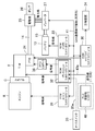
図1は、本実施形態に係る電動塵芥車1の一部ブロック図である。電動塵芥車1は、走行アシスト用と塵芥積込装置23の駆動用との両方の電源となるハイブリッドバッテリ13と、インバータ装置27とを備えている。インバータ装置27からの電力により、電動機25が所定の回転数で駆動され、それに伴ってこの電動機25と連結された油圧ポンプ26が駆動される。設置場所は特に限定されないが、電動塵芥車1は、取り外すことによりハイブリッドバッテリ13の電力線を切り離すサービスプラグ15を備えている。詳しくは図示しないが、油圧ポンプ26の高圧油は、アキュムレータ及び制御バルブを介して油圧モータ23c、揺動シリンダ23d等に供給され、これらの油圧アクチュエータ23c,23dが駆動される。作動油は、作動油タンクに戻され、サンクションフィルタを通った作動油が再び油圧ポンプ26に供給されるようになっている。
FIG. 1 is a partial block diagram of the electric dust wheel 1 according to the present embodiment. The electric dust truck 1 includes a
エンジンEの動力は、クラッチC、トランスミッションTを介してPTO装置24に伝達される。図3に示すように、PTO装置24が接続状態(オン状態)の場合、PTO装置24に伝達された動力は、PTOシャフト14、ギヤボックス28を介して電動機25又は油圧ポンプ26に伝達される。このギヤボックス28なしで電動機25と油圧ポンプ26とが直結の構成でもよい。一方、PTO装置24が切断状態(オフ状態)となる走行時には、トランスミッションTの駆動力は、デフ(ディファレンシャルギア)29を介して車輪11bに伝達される。
The power of the engine E is transmitted to the
以上より、油圧ポンプ26は以下の状態で駆動され得る。具体的には、エンジンEからの動力でPTO装置を介して油圧ポンプ26が駆動されるPTOモードと、ハイブリッドバッテリ13の電力による電動機25からの動力で駆動される電動モードである。
From the above, the
そして図1に示すように、電動塵芥車1は、制御装置としてベース車両10の制御を行うハイブリッドコントロールモジュール30と、トランスミッションTの全般を制御するトランスミッションコントロールモジュール32と、車両に搭載された塵芥収集装置20の制御を行う架装側制御装置としてのPLC(programmable logic controller)40と、PTOスイッチ35と、トランスミッションコントロールモジュール32からの信号を受けてPTOを制御するPTOコントローラ36とを備えている。
As shown in FIG. 1, the electric dust truck 1 includes a
ハイブリッドコントロールモジュール30は、エアコン制御、インバータ装置27へのトルク指示、電動機25の回転数指示などを含むベース車両10の電気系統全般を制御する役割を果たす。また、ハイブリッドコントロールモジュール30は、PTO装置24で油圧ポンプ26を駆動するPTOモード又は電動機25で油圧ポンプ26を駆動する電動モードに切替制御するようになっている。
The
エンジンコントロールモジュール31は、ハイブリッドコントロールモジュール30とCAN通信線41で双方向通信可能であり、主としてエンジンEの制御を行う。
The
PLC40は、塵芥収集装置20の駆動時の動作を制御する。PTOスイッチ35は、PTO装置24のオンオフ信号をトランスミッションコントロールモジュール32に送信する役割を果たす。PLC40とトランスミッションコントロールモジュール32とをつなぐ信号線40a、及び、PTOスイッチ35とトランスミッションコントロールモジュール32とをつなぐ信号線35aは、一方向信号線となっている。
The
トランスミッションコントロールモジュール32は、ハイブリッドコントロールモジュール30とCAN通信線41で双方向通信可能に接続され、ハイブリッドコントロールモジュール30が駆動可能か否かを確認する機能を有する。
The
バッテリコントローラ33は、ハイブリッドコントロールモジュール30とCAN通信線41で双方向通信可能に接続され、ハイブリッドバッテリ13の制御を行う。
The battery controller 33 is connected to the
ハイブリッドコントロールモジュール30は、インバータ装置27とCAN通信線41で双方向通信可能に接続されているので、モータコントローラは設けられていない。
Since the
ハイブリッドコントロールモジュール30は、ハイブリッドバッテリ13やインバータ装置27の電気系統に異常が生じた場合に、ディスプレイ、ブザーなどの警報装置34に信号を送って表示、音等により、オペレータに異常を知らせるように構成されている。
When an abnormality occurs in the electrical system of the
そして、ハイブリッドコントロールモジュール30が駆動可能な場合には、ハイブリッドコントロールモジュール30が直接PTO装置24のオンオフ制御を行うようになっている。一方、ハイブリッドコントロールモジュール30が駆動可能でない場合には、トランスミッションコントロールモジュール32が直接PTO装置24のオンオフ制御を行うように構成されている。
Then, when the
すなわち、トランスミッションコントロールモジュール32は、サービスプラグ15が取り外された場合にハイブリッドコントロールモジュール30が駆動可能でないと判断し、直接PTO装置24のオンオフ制御を行うように構成されている。
That is, the
次に、本実施形態に係る電動塵芥車1の制御の流れについて説明する。 Next, the flow of control of the electric dust wheel 1 according to the present embodiment will be described.
まず、トランスミッションコントロールモジュール32は、ハイブリッドコントロールモジュール30が駆動可能か否かを確認する。
First, the
次いで、サービスプラグ15が取り付けられた状態であることによりハイブリッドコントロールモジュール30が駆動可能と判断された場合には、ハイブリッドコントロールモジュール30がトランスミッションコントロールモジュール32を介してPTO装置24のオンオフ制御を行う。
Next, when it is determined that the
一方、サービスプラグ15が取り外された状態であることによりハイブリッドコントロールモジュール30が駆動可能でないと判断された場合には、トランスミッションコントロールモジュール32がハイブリッドコントロールモジュール30を介さずに直接PTO装置24のオンオフ制御を行う。
On the other hand, when it is determined that the
例えば、PTOスイッチ35からPTO装置24のON信号が発信されると、トランスミッションコントロールモジュール32は、電動モードではなく、PTOモードとしてPTO装置24を駆動し、油圧ポンプ26を回転させる。そして、オペレータの操作により、塵芥収集装置20が作動する。
For example, when the ON signal of the
このように、ハイブリッドバッテリ13やインバータ装置27等の電気系統に異常がある場合などにサービスプラグ15が取り外されてハイブリッドコントロールモジュール30が駆動可能でない場合、PTOスイッチ35からPTO装置24のオンオフ信号を受けても、図4に示すような従来の構成では、そのオンオフ制御が行えなかったが、本実施形態では、トランスミッションコントロールモジュール32が直接PTO装置24のオンオフ制御を行うようにしているので、PTO装置24を動かして油圧ポンプ26を駆動し、作業を行うことができる。一方、ハイブリッドコントロールモジュール30が駆動可能な場合には、トランスミッションコントロールモジュール32を介してPTO装置24のオンオフ制御を行うので、PTO装置24か電動機25で油圧ポンプ26を駆動して作業を行うことができる。
In this way, when the
本実施形態では、ハイブリッドコントロールモジュール30が駆動可能でない場合でも、トランスミッションコントロールモジュール32がハイブリッドコントロールモジュール30の異常を検知してハイブリッドコントロールモジュール30に代わってPTO装置24のオンオフ制御できるので、PTOスイッチ35からの信号を受けてPTO装置24をオンオフ制御できる。
In the present embodiment, even when the
本実施形態では、ハイブリッドバッテリ13やインバータ装置27等の電気系統に異常がある場合には、警報装置34からの警報によりオペレータがすぐに電気系統の異常を知ることができる。これにより、オペレータはサービスプラグ15をすぐに取り外してハイブリッドバッテリ13の電力が他に影響を及ぼさないようにすることができ、サービスプラグ15が取り外されても自動でトランスミッションコントロールモジュール32が直接PTO装置24をオンオフ制御してPTO駆動で作業を行うことができる。その結果、電気系統の異常により電動機25での作業が中断しても、すぐに当該現場において作業を再開することができる。
In the present embodiment, when there is an abnormality in the electric system such as the
以上説明したように、本実施形態に係る電動塵芥車1によると、ハイブリッドコントロールモジュール30が駆動可能でない場合に、トランスミッションコントロールモジュール32が直接PTO装置24のオンオフ制御を行うようにしたので、サービスプラグ15が取り外されても、PTO装置24のオンオフ制御を行うことができる。
As described above, according to the electric dust wheel 1 according to the present embodiment, when the
なお、以上の実施形態は、本質的に好ましい例示であって、本発明、その適用物や用途の範囲を制限することを意図するものではない。 It should be noted that the above embodiments are essentially preferable examples, and are not intended to limit the scope of the present invention, its applications and applications.
例えば、上記実施形態では、電動作業車両は、電動塵芥車としたが、これに限定されず、エンジンに駆動されるPTO装置と、バッテリと、バッテリの電力により駆動される電動機と、PTO装置又は電動機に駆動される油圧ポンプとを備えた高所作業車、脱着車、車両運搬車等の電動作業車両なら何でもよい。 For example, in the above embodiment, the electric work vehicle is an electric dust vehicle, but the present invention is not limited to this, and the PTO device driven by the engine, the battery, the electric motor driven by the electric power of the battery, the PTO device, or the like. Any electric work vehicle such as an aerial work platform, a desorption vehicle, or a vehicle carrier equipped with a hydraulic pump driven by an electric motor may be used.
上記実施形態では、電動機25は、PTO装置24の下流側に設けたが、クラッチCとトランスミッションTとの間に設けられていてもよい。
In the above embodiment, the
さらに、上記実施形態では、ベース車両10は、ハイブリッド車両としているが、電動機25の駆動は、油圧ポンプ26の駆動にのみ用いるように構成してもよい。
Further, in the above embodiment, the
1 電動塵芥車(電動作業車両)
10 ベース車両
11 シャシフレーム
11a 車輪
11b 車輪
12 キャブ
13 ハイブリッドバッテリ(バッテリ)
14 PTOシャフト
20 塵芥収集装置(架装物)
21 塵芥収容箱
22 塵芥投入箱
22a 塵芥投入口
22b 扉
22c 操作スイッチ
23 塵芥積込装置
23a 回転板
23b 押込板
23c 油圧モータ
23d 揺動シリンダ
24 PTO装置
25 電動機
26 油圧ポンプ
27 インバータ装置
28 ギヤボックス
29 デフ
30 ハイブリッドコントロールモジュール(制御装置)
31 エンジンコントロールモジュール
32 トランスミッションコントロールモジュール(制御装置)
33 バッテリコントローラ
34 警報装置
35 PTOスイッチ
36 PTOコントローラ
40 PLC(架装側制御装置、制御装置)
40a 信号線
41 CAN通信線
E エンジン
T トランスミッション
C クラッチ
1 Electric dust truck (electric work vehicle)
10 base vehicle
11 chassis frame
11a wheels
11b wheels
12 cabs
13 Hybrid battery (battery)
14 PTO shaft
20 Dust collection device (framework)
21 Garbage storage box
22 Garbage input box
22a Dust inlet
22b door
22c operation switch
23 Dust loading device
23a rotating plate
23b Push-in plate
23c hydraulic motor
23d swing cylinder
24 PTO device
25 electric motor
26 hydraulic pump
27 Inverter device
28 gearbox
29 diff
30 Hybrid control module (control device)
31 engine control module
32 Transmission control module (control device)
33 Battery controller
34 Alarm device
35 PTO switch
36 PTO controller
40 PLC (Attachment side control device, control device)
40a signal line
41 CAN communication line
E engine
T transmission
C clutch
Claims (5)
上記ベース車両に搭載された架装物と、
上記ベース車両に搭載されたエンジンと、
上記エンジンに駆動されるPTO装置と、
上記エンジンの動力を上記PTO装置に伝えるトランスミッションと、
バッテリと、
上記バッテリの電力により駆動される電動機と、
上記PTO装置又は上記電動機に駆動される油圧ポンプと、
制御装置とを備えた電動作業車両において、
上記制御装置は、
上記トランスミッションを制御するトランスミッションコントロールモジュールと、
上記架装物を制御する架装側制御装置と、
上記PTO装置のオンオフ信号を上記トランスミッションコントロールモジュールに送信するPTOスイッチと、
上記ベース車両の全体の制御を行うハイブリッドコントロールモジュールとを備え、
上記ハイブリッドコントロールモジュールが駆動可能な場合には、上記ハイブリッドコントロールモジュールが直接上記PTO装置のオンオフ制御を行い、
上記ハイブリッドコントロールモジュールが駆動可能でない場合には、上記トランスミッションコントロールモジュールが直接上記PTO装置のオンオフ制御を行うように構成されている
ことを特徴とする電動作業車両。 A base vehicle that can run and
The fixtures mounted on the above base vehicle and
With the engine mounted on the above base vehicle,
The PTO device driven by the above engine and
A transmission that transmits the power of the engine to the PTO device,
With the battery
An electric motor driven by the power of the above battery and
With the hydraulic pump driven by the PTO device or the electric motor,
In an electric work vehicle equipped with a control device
The above control device
The transmission control module that controls the above transmission and
The erection side control device that controls the above erection and
A PTO switch that transmits an on / off signal of the PTO device to the transmission control module, and
Equipped with a hybrid control module that controls the entire base vehicle
When the hybrid control module can be driven, the hybrid control module directly controls the on / off control of the PTO device.
An electric work vehicle characterized in that the transmission control module is configured to directly perform on / off control of the PTO device when the hybrid control module is not driveable.
上記トランスミッションコントロールモジュールは、上記ハイブリッドコントロールモジュールが駆動可能か否かを確認し、駆動可能でないと判断した場合に直接上記PTO装置のオンオフ制御を行うように構成されている
ことを特徴とする電動作業車両。 In the electric work vehicle according to claim 1,
The transmission control module is configured to directly perform on / off control of the PTO device when it is confirmed whether or not the hybrid control module can be driven and it is determined that the hybrid control module cannot be driven. vehicle.
取り外すことにより上記バッテリの電力線を切り離すサービスプラグをさらに備え、
上記トランスミッションコントロールモジュールは、上記サービスプラグが取り外された場合に上記ハイブリッドコントロールモジュールが駆動可能でないと判断し、直接上記PTO装置のオンオフ制御を行うように構成されている
ことを特徴とする電動作業車両。 In the electric work vehicle according to claim 2.
It also has a service plug that disconnects the power line of the battery by removing it.
The transmission control module is an electric work vehicle configured to determine that the hybrid control module cannot be driven when the service plug is removed and directly perform on / off control of the PTO device. ..
上記ベース車両に搭載された架装物と、
上記ベース車両に搭載されたエンジンと、
上記エンジンに駆動されるPTO装置と、
上記エンジンの動力を上記PTO装置に伝えるトランスミッションと、
バッテリと、
上記バッテリの電力により駆動される電動機と、
上記PTO装置又は上記電動機に駆動される油圧ポンプと、
上記トランスミッションを制御するトランスミッションコントロールモジュールと、
上記架装物を制御する架装側制御装置と、
上記PTOのオンオフ信号を上記トランスミッションコントロールモジュールに送信するPTOスイッチと、
上記ベース車両の全体の制御を行うハイブリッドコントロールモジュールとを備えた電動作業車両の制御方法において、
上記トランスミッションコントロールモジュールは、上記ハイブリッドコントロールモジュールが駆動可能か否かを確認し、
上記ハイブリッドコントロールモジュールが駆動可能と判断された場合には、上記ハイブリッドコントロールモジュールが直接上記PTO装置のオンオフ制御を行い、
上記ハイブリッドコントロールモジュールが駆動可能でないと判断された場合には、上記トランスミッションコントロールモジュールが直接上記PTO装置のオンオフ制御を行う
ことを特徴とする電動作業車両の制御方法。 A base vehicle that can run and
The fixtures mounted on the above base vehicle and
With the engine mounted on the above base vehicle,
The PTO device driven by the above engine and
A transmission that transmits the power of the engine to the PTO device,
With the battery
An electric motor driven by the power of the above battery and
With the hydraulic pump driven by the PTO device or the electric motor,
The transmission control module that controls the above transmission and
The erection side control device that controls the above erection and
A PTO switch that transmits the PTO on / off signal to the transmission control module, and
In the control method of the electric work vehicle provided with the hybrid control module that controls the entire base vehicle,
The transmission control module confirms whether the hybrid control module can be driven, and confirms whether or not the hybrid control module can be driven.
When it is determined that the hybrid control module can be driven, the hybrid control module directly controls the on / off control of the PTO device.
A control method for an electric work vehicle, wherein when it is determined that the hybrid control module cannot be driven, the transmission control module directly controls on / off of the PTO device.
上記ベース車両に搭載された架装物と、
上記ベース車両に搭載されたエンジンと、
上記エンジンに駆動されるPTO装置と、
上記エンジンの動力を上記PTO装置に伝えるトランスミッションと、
バッテリと、
上記バッテリの電力により駆動される電動機と、
上記PTO装置又は上記電動機に駆動される油圧ポンプとを備えた電動作業車両に設けられる制御装置において、
上記トランスミッションを制御するトランスミッションコントロールモジュールと、
上記架装物を制御する架装側制御装置と、
上記PTO装置のオンオフ信号を上記トランスミッションコントロールモジュールに送信するPTOスイッチと、
上記ベース車両の全体の制御を行うハイブリッドコントロールモジュールとを備え、
上記ハイブリッドコントロールモジュールが駆動可能な場合には、上記ハイブリッドコントロールモジュールが直接上記PTO装置のオンオフ制御を行い、
上記ハイブリッドコントロールモジュールが駆動可能でない場合には、上記トランスミッションコントロールモジュールが直接上記PTO装置のオンオフ制御を行うように構成されている
ことを特徴とする制御装置。 A base vehicle that can run and
The fixtures mounted on the above base vehicle and
With the engine mounted on the above base vehicle,
The PTO device driven by the above engine and
A transmission that transmits the power of the engine to the PTO device,
With the battery
An electric motor driven by the power of the above battery and
In a control device provided in an electric work vehicle provided with the PTO device or a hydraulic pump driven by the electric motor.
The transmission control module that controls the above transmission and
The erection side control device that controls the above erection and
A PTO switch that transmits an on / off signal of the PTO device to the transmission control module, and
Equipped with a hybrid control module that controls the entire base vehicle
When the hybrid control module can be driven, the hybrid control module directly controls the on / off control of the PTO device.
A control device characterized in that the transmission control module is configured to directly perform on / off control of the PTO device when the hybrid control module is not driveable.
Priority Applications (1)
| Application Number | Priority Date | Filing Date | Title |
|---|---|---|---|
| JP2016192164A JP6849367B2 (en) | 2016-09-29 | 2016-09-29 | Electric work vehicle, its control method and its control device |
Applications Claiming Priority (1)
| Application Number | Priority Date | Filing Date | Title |
|---|---|---|---|
| JP2016192164A JP6849367B2 (en) | 2016-09-29 | 2016-09-29 | Electric work vehicle, its control method and its control device |
Publications (2)
| Publication Number | Publication Date |
|---|---|
| JP2018052369A JP2018052369A (en) | 2018-04-05 |
| JP6849367B2 true JP6849367B2 (en) | 2021-03-24 |
Family
ID=61835025
Family Applications (1)
| Application Number | Title | Priority Date | Filing Date |
|---|---|---|---|
| JP2016192164A Active JP6849367B2 (en) | 2016-09-29 | 2016-09-29 | Electric work vehicle, its control method and its control device |
Country Status (1)
| Country | Link |
|---|---|
| JP (1) | JP6849367B2 (en) |
Families Citing this family (2)
| Publication number | Priority date | Publication date | Assignee | Title |
|---|---|---|---|---|
| AT17804U1 (en) * | 2021-05-31 | 2023-03-15 | Josef Brosowitsch Ing Dipl Ing Mmst | Waste bin emptying device with hybrid drive and energy recovery |
| AT525124A1 (en) * | 2021-05-31 | 2022-12-15 | Brosowitsch Dipl Ing Josef | Waste bin emptying device with hybrid drive and energy recovery |
Family Cites Families (5)
| Publication number | Priority date | Publication date | Assignee | Title |
|---|---|---|---|---|
| JP4305541B2 (en) * | 2007-03-28 | 2009-07-29 | トヨタ自動車株式会社 | Control device for hybrid vehicle |
| JP5500782B2 (en) * | 2008-04-25 | 2014-05-21 | 新明和工業株式会社 | Work vehicle |
| JP6121156B2 (en) * | 2012-12-21 | 2017-04-26 | 極東開発工業株式会社 | Work vehicle bodywork |
| JP6384911B2 (en) * | 2014-08-18 | 2018-09-05 | 新明和工業株式会社 | Work vehicle |
| JP6465344B2 (en) * | 2014-12-25 | 2019-02-06 | 極東開発工業株式会社 | Work vehicle bodywork |
-
2016
- 2016-09-29 JP JP2016192164A patent/JP6849367B2/en active Active
Also Published As
| Publication number | Publication date |
|---|---|
| JP2018052369A (en) | 2018-04-05 |
Similar Documents
| Publication | Publication Date | Title |
|---|---|---|
| JP5500782B2 (en) | Work vehicle | |
| JP5826037B2 (en) | Electric tractor | |
| JP3611731B2 (en) | Auxiliary drive device for vehicle | |
| WO2012035928A1 (en) | Hybrid work vehicle | |
| US10286920B2 (en) | Working machine and method for operating said working machine | |
| US9702121B2 (en) | State information display for work machine, caution-sign displaying method for work machine, and caution-sign displaying program for work machine | |
| JP6849367B2 (en) | Electric work vehicle, its control method and its control device | |
| WO2017158760A1 (en) | Work vehicle | |
| US9776496B2 (en) | Work machine, in particular dump truck or truck, having an electric drive | |
| JP2003009607A (en) | Motor-driven fram machine | |
| JP2013241179A (en) | Hybrid wheel loader | |
| JP5956386B2 (en) | Hybrid work machine | |
| KR101297649B1 (en) | Combined operation structure of MDPS and compressor | |
| KR20190024257A (en) | Hydraulic power driving system for cargo vehicles | |
| JP6773478B2 (en) | Electric work vehicle, its control method and its control device | |
| JP5923246B2 (en) | Garbage truck | |
| JP6715123B2 (en) | Electric work vehicle and its control device | |
| JP6744166B2 (en) | Electric work vehicle and its control device | |
| JP3314886B2 (en) | Hydraulic drive system abnormality detection device for four-wheel traveling device | |
| JP2019537539A (en) | Method and apparatus for preliminary driving of a vehicle | |
| CN109319693A (en) | Hydrostatic lift truck chassis and three-wheel foklift truck with it | |
| JP2014121952A (en) | Control apparatus, vehicle, and control method | |
| JP2014121951A (en) | Control apparatus, vehicle, and control method | |
| JP6715124B2 (en) | Electric work vehicle and its control device | |
| CN206202066U (en) | A kind of automatic rotating shaft upset rear engine cover |
Legal Events
| Date | Code | Title | Description |
|---|---|---|---|
| A621 | Written request for application examination |
Free format text: JAPANESE INTERMEDIATE CODE: A621 Effective date: 20190705 |
|
| A977 | Report on retrieval |
Free format text: JAPANESE INTERMEDIATE CODE: A971007 Effective date: 20200526 |
|
| A131 | Notification of reasons for refusal |
Free format text: JAPANESE INTERMEDIATE CODE: A131 Effective date: 20200728 |
|
| A521 | Request for written amendment filed |
Free format text: JAPANESE INTERMEDIATE CODE: A523 Effective date: 20200924 |
|
| TRDD | Decision of grant or rejection written | ||
| A01 | Written decision to grant a patent or to grant a registration (utility model) |
Free format text: JAPANESE INTERMEDIATE CODE: A01 Effective date: 20210216 |
|
| A61 | First payment of annual fees (during grant procedure) |
Free format text: JAPANESE INTERMEDIATE CODE: A61 Effective date: 20210304 |
|
| R150 | Certificate of patent or registration of utility model |
Ref document number: 6849367 Country of ref document: JP Free format text: JAPANESE INTERMEDIATE CODE: R150 |
|
| R250 | Receipt of annual fees |
Free format text: JAPANESE INTERMEDIATE CODE: R250 |