JP6847471B2 - Sludge scraper - Google Patents
Sludge scraper Download PDFInfo
- Publication number
- JP6847471B2 JP6847471B2 JP2019231129A JP2019231129A JP6847471B2 JP 6847471 B2 JP6847471 B2 JP 6847471B2 JP 2019231129 A JP2019231129 A JP 2019231129A JP 2019231129 A JP2019231129 A JP 2019231129A JP 6847471 B2 JP6847471 B2 JP 6847471B2
- Authority
- JP
- Japan
- Prior art keywords
- pond
- endless chain
- width direction
- sliding contact
- sludge
- Prior art date
- Legal status (The legal status is an assumption and is not a legal conclusion. Google has not performed a legal analysis and makes no representation as to the accuracy of the status listed.)
- Active
Links
- 239000010802 sludge Substances 0.000 title claims description 74
- XLYOFNOQVPJJNP-UHFFFAOYSA-N water Substances O XLYOFNOQVPJJNP-UHFFFAOYSA-N 0.000 claims description 137
- 238000007790 scraping Methods 0.000 claims description 111
- 230000001105 regulatory effect Effects 0.000 claims description 43
- 238000011144 upstream manufacturing Methods 0.000 description 78
- 238000004804 winding Methods 0.000 description 12
- 230000004048 modification Effects 0.000 description 9
- 238000012986 modification Methods 0.000 description 9
- 230000000694 effects Effects 0.000 description 5
- 238000010586 diagram Methods 0.000 description 4
- 238000004062 sedimentation Methods 0.000 description 4
- 238000007667 floating Methods 0.000 description 3
- 239000011347 resin Substances 0.000 description 3
- 229920005989 resin Polymers 0.000 description 3
- 229910001220 stainless steel Inorganic materials 0.000 description 3
- 239000010935 stainless steel Substances 0.000 description 3
- 238000005452 bending Methods 0.000 description 2
- 239000000470 constituent Substances 0.000 description 2
- 239000002184 metal Substances 0.000 description 2
- NJPPVKZQTLUDBO-UHFFFAOYSA-N novaluron Chemical compound C1=C(Cl)C(OC(F)(F)C(OC(F)(F)F)F)=CC=C1NC(=O)NC(=O)C1=C(F)C=CC=C1F NJPPVKZQTLUDBO-UHFFFAOYSA-N 0.000 description 2
- 239000010865 sewage Substances 0.000 description 2
- 238000009434 installation Methods 0.000 description 1
- 230000007257 malfunction Effects 0.000 description 1
- 239000000463 material Substances 0.000 description 1
- 238000000034 method Methods 0.000 description 1
- 239000000126 substance Substances 0.000 description 1
Images


Landscapes
- Devices For Conveying Motion By Means Of Endless Flexible Members (AREA)
- Removal Of Floating Material (AREA)
Description
本発明は、汚泥が含まれた水を受け入れ該水が流れる間に該水に含まれている汚泥が池底部に沈殿する沈殿池に設けられる汚泥かき寄せ装置に関する。 The present invention relates to a sludge collecting device provided in a settling basin that receives water containing sludge and causes the sludge contained in the water to settle at the bottom of the pond while the water flows.
汚泥かき寄せ装置として、受け入れた水が流れる水流方向に直交する池幅方向に延在したかき寄せ部材を有する無端チェーンを備えたものが知られている。この汚泥かき寄せ装置では、無端チェーンを正転走行させることで沈殿池の池底側と水面側でかき寄せ部材を循環移動させている。水面側における水流方向の上流側には、無端チェーンの一部が巻き掛けられ、無端チェーンを循環移動させるための駆動力を無端チェーンに伝達する駆動輪が配置されている。また、水面側における水流方向の下流側には、無端チェーンの一部が巻き掛けられ、無端チェーンの走行に追従して回転する従動輪が配置されている。かき寄せ部材は、沈殿池の池底部を走行するときには池底に沈殿した汚泥をかき寄せ、水面側を走行するときには水面に浮かんだスカムをかき寄せるものである。また、沈殿池の水面側には、水流方向に延在し、無端チェーンが水面側を走行する際にかき寄せ部材の池底側が摺接するレール部材が設けられている。 As a sludge scraping device, a sludge scraping device including an endless chain having a scraping member extending in the pond width direction orthogonal to the water flow direction in which the received water flows is known. In this sludge scraping device, the scraping member is circulated and moved on the bottom side and the water surface side of the settling basin by rotating the endless chain in the normal direction. A part of the endless chain is wound on the upstream side in the water flow direction on the water surface side, and a driving wheel for transmitting the driving force for circulating the endless chain to the endless chain is arranged. Further, on the downstream side in the water flow direction on the water surface side, a part of the endless chain is wound around, and a driven wheel that rotates following the running of the endless chain is arranged. The scraping member scrapes the sludge that has settled on the bottom of the pond when traveling on the bottom of the sedimentation basin, and scrapes the scum floating on the water surface when traveling on the water surface side. Further, on the water surface side of the settling basin, a rail member that extends in the water flow direction and is in sliding contact with the pond bottom side of the scraping member when the endless chain travels on the water surface side is provided.
無端チェーンは、循環方向に多少の余裕を持たせて設置される。これは、余裕のない張りつめた状態で無端チェーンを設置すると、無端チェーンを走行させるための駆動力が増大し、誤動作してしまう虞があるためである。循環方向に余裕を持たせることで、無端チェーンには設置された当初から多少のたるみが生じている。また、無端チェーンは、走行開始後しばらくの期間は伸びが発生しやすく、その結果、設置したときよりある程度の期間までは徐徐にたるみが増大する傾向がある。 The endless chain is installed with some margin in the circulation direction. This is because if the endless chain is installed in a tight and taut state, the driving force for running the endless chain increases and there is a risk of malfunction. By giving a margin in the circulation direction, the endless chain has some slack from the beginning when it is installed. In addition, the endless chain tends to stretch for a while after the start of traveling, and as a result, the slack tends to gradually increase until a certain period of time after installation.
ところで、汚泥かき寄せ装置が設置された沈殿池では、地震の影響で、無端チェーンが駆動輪や従動輪といった回転輪から脱輪してしまうことがある。無端チェーンが回転輪から脱輪してしまうのは、地震による揺れの直接的影響よりも、むしろ地震によって沈殿池内の水面付近の水が大きく波打つスロッシングの影響の方が大きいことが分かってきた。スロッシングが発生すると、無端チェーンの水面側部分(以下、チェーン水面側部分と称することがある)が大きく揺れ動き、その揺れの力が、無端チェーンの、回転輪に巻き掛けられた部分に伝わることで無端チェーンが回転輪から脱輪してしまうことがある。 By the way, in a settling basin where a sludge collecting device is installed, the endless chain may be derailed from rotating wheels such as driving wheels and trailing wheels due to the influence of an earthquake. It has been found that the reason why the endless chain derails from the rotating wheel is not the direct effect of the shaking caused by the earthquake, but rather the effect of sloshing, in which the water near the water surface in the settling pond is greatly rippling due to the earthquake. When sloshing occurs, the water surface side part of the endless chain (hereinafter sometimes referred to as the water surface side part of the chain) sways greatly, and the swaying force is transmitted to the part of the endless chain that is wound around the rotating wheel. The endless chain may come off the rotating wheel.
この地震対策として、チェーン水面側部分の上方向への振れを抑制するための上方向規制部を無端チェーンに設けた汚泥かき寄せ装置が提案されている(例えば、特許文献1参照。)。この特許文献1のレール部材は、チェーン水面側部分が上方向に振れると上方向規制部が池底側から当接する当接部を有している。この当接部は、水面側に配置された駆動輪と従動輪の間で、池幅方向に見たときに(駆動輪の回転軸が延在する方向に見たときに)、駆動輪とは水流方向(長手方向)に大きく間隔をあけて配置されている。この特許文献1に記載された汚泥かき寄せ装置は、スロッシングによる揺れによってチェーン水面側部分が上方向に大きく振れそうになったときに、上方向規制部とレール部材が当接するように構成することで、チェーン水面側部分における上方への振れを抑制しようとするものである。特許文献1の汚泥かき寄せ装置では、循環移動している無端チェーンに設けられた上方向規制部がレール部材の当接部よりも池底側(下方)に入り込む必要がある。 As a countermeasure against this earthquake, a sludge scraping device has been proposed in which an upward regulating portion for suppressing upward swing of the water surface side portion of the chain is provided on the endless chain (see, for example, Patent Document 1). The rail member of Patent Document 1 has a contact portion in which the upward regulating portion abuts from the pond bottom side when the water surface side portion of the chain swings upward. This contact portion is between the drive wheel and the trailing wheel arranged on the water surface side, and when viewed in the pond width direction (when viewed in the direction in which the rotation axis of the drive wheel extends), the contact portion is formed with the drive wheel. Are arranged at large intervals in the water flow direction (longitudinal direction). The sludge scraping device described in Patent Document 1 is configured so that the upward regulating portion and the rail member come into contact with each other when the water surface side portion of the chain is likely to swing significantly upward due to the shaking caused by sloshing. , It is intended to suppress the upward runout in the water surface side portion of the chain. In the sludge scraping device of Patent Document 1, it is necessary that the upward regulating portion provided on the circularly moving endless chain enters the pond bottom side (lower side) of the contact portion of the rail member.
ここで、チェーン水面側部分では、駆動輪に巻き掛けられた部分よりも循環方向下流側にたるみが生じ、無端チェーンが上方向に撓んでしまうなど無端チェーンの挙動が不安定になることがある。特許文献1の汚泥かき寄せ装置の当接部は、池幅方向に見たときに(駆動輪の回転軸が延在する方向に見たときに)、駆動輪とは水流方向(長手方向)に大きく間隔をあけて配置されているため、当接部と駆動輪との間で、無端チェーンが上方向に撓むことがある。無端チェーンが上方向に撓む量が大きいと、上方向規制部も当接部と同一高さ或いは当接部よりも上方に位置してしまう虞がある。上方向規制部が当接部と同一高さにあると上方向規制部と当接部とが衝突してしまい、上方向規制部或いはレール部材が破損してしまう可能性がある。また、上方向規制部が当接部の下方に入り込まないと、無端チェーンの振れ抑制効果が得られず、無端チェーンが回転輪から脱輪してしまう虞がある。 Here, on the water surface side portion of the chain, slack may occur on the downstream side in the circulation direction from the portion wound around the drive wheels, and the behavior of the endless chain may become unstable, such as the endless chain bending upward. .. The contact portion of the sludge scraping device of Patent Document 1 is in the water flow direction (longitudinal direction) with the drive wheel when viewed in the pond width direction (when viewed in the direction in which the rotation axis of the drive wheel extends). Since they are arranged at a large distance, the endless chain may bend upward between the contact portion and the drive wheel. If the amount of the endless chain flexing upward is large, the upward regulating portion may be located at the same height as the abutting portion or above the abutting portion. If the upward regulating portion is at the same height as the abutting portion, the upward regulating portion and the abutting portion may collide with each other, and the upward regulating portion or the rail member may be damaged. Further, if the upward regulating portion does not enter below the contact portion, the effect of suppressing the runout of the endless chain cannot be obtained, and there is a possibility that the endless chain may come off from the rotating wheel.
本発明は上記事情に鑑み、地震が発生しても、無端チェーンが回転輪から脱輪することを確実に防止できる汚泥かき寄せ装置を提供することを目的とする。 In view of the above circumstances, it is an object of the present invention to provide a sludge scraping device capable of surely preventing an endless chain from coming off from a rotating wheel even if an earthquake occurs.
上記目的を解決する本発明の汚泥かき寄せ装置は、
汚泥が含まれた水を受け入れ該水が流れる間に該水に含まれている汚泥が池底部に沈殿する沈殿池に設けられ、該池底部に沈殿した汚泥を池幅方向に延在したかき寄せ部材によってかき寄せる汚泥かき寄せ装置において、
前記かき寄せ部材を間をあけて複数有し、走行することで前記池底部側と水面側で該かき寄せ部材を循環させる無端チェーンと、
水面側で前記水が流れる水流方向に延在し、前記無端チェーンが走行する際に前記かき寄せ部材の池底側が摺接するレール部材と、
前記無端チェーンが巻き掛けられ、該無端チェーンに駆動力を伝えて該無端チェーンを走行させる駆動輪とを備え、
前記かき寄せ部材は、前記レール部材に摺接するシューと、前記無端チェーンの振れを規制する規制部材とを備えたものであり、
前記駆動輪は、放射方向に突出した歯を有するものであり、
前記レール部材は、前記シューと接する摺接部を有するものであり、
前記規制部材は、前記摺接部から下方向に間隔をあけて該摺接部と前記池幅方向に重なって配置され、前記無端チェーンの水面側部分が上方向に振れると該摺接部に当接する、該池幅方向に突出した池幅方向突出部を有するものであり、
前記無端チェーンは、前記池幅方向に距離をあけて配置された一対のリンク板を有するリンク部材が連結されたものであり、
前記間隔は、前記駆動輪の歯と前記リンク部材が噛合した状態における該リンク部材を構成する前記リンク板の下端から該歯の先端までのオーバラップ距離よりも短いことを特徴とする。
The sludge scraping device of the present invention that solves the above object is
It is provided in a settling basin that receives water containing sludge and the sludge contained in the water settles at the bottom of the pond while the water flows. In a sludge scraping device that scrapes by members
An endless chain that has a plurality of the scraping members at intervals and circulates the scraping members on the bottom side of the pond and the water surface side by running.
A rail member that extends in the direction of the water flow on the water surface side and is in sliding contact with the pond bottom side of the scraping member when the endless chain travels.
The endless chain is wound around the endless chain, and the endless chain is provided with a driving wheel that transmits a driving force to run the endless chain.
The scraping member includes a shoe that is in sliding contact with the rail member and a regulating member that regulates the runout of the endless chain.
The drive wheels have teeth protruding in the radial direction.
The rail member has a sliding contact portion in contact with the shoe, and has a sliding contact portion.
The restricting member is arranged so as to overlap the sliding contact portion in the pond width direction with a downward interval from the sliding contact portion, and when the water surface side portion of the endless chain swings upward, the sliding contact portion is subjected to. It has a pond width direction protrusion that abuts and protrudes in the pond width direction.
The endless chain is formed by connecting link members having a pair of link plates arranged at a distance in the pond width direction.
The interval is shorter than the overlap distance from the lower end of the link plate constituting the link member to the tip of the tooth in a state where the teeth of the drive wheel and the link member are in mesh with each other.
また、本発明の汚泥かき寄せ装置において、
前記間隔は、前記オーバラップ距離の半分以下であってもよい。
Further, in the sludge scraping device of the present invention,
The interval may be less than half of the overlap distance.
本発明の汚泥かき寄せ装置によれば、地震が発生しても、無端チェーンが回転輪から脱輪することを確実に防止できる。 According to the sludge scraping device of the present invention, it is possible to reliably prevent the endless chain from coming off the rotating wheel even if an earthquake occurs.
以下、図面を参照して本発明の実施の形態を説明する。 Hereinafter, embodiments of the present invention will be described with reference to the drawings.
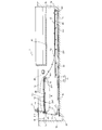
図1は、本発明の一実施形態である汚泥かき寄せ装置が設置された沈殿池の側断面図である。 FIG. 1 is a side sectional view of a settling basin in which a sludge scraping device according to an embodiment of the present invention is installed.
図1に示す沈殿池1は、上流壁1aと、下流壁1bと、一対の側壁1cによって囲まれた、平面視で略長方形状をした池である。この沈殿池1は、長手方向の一端側(図1では左側)から汚水や雨水などの汚泥が含まれた水を受け入れ、受け入れた水に含まれる汚泥を池底部1dに沈殿させ、他端側(図1では右側)から排水する。以下、図1における左側を上流側と称し、図1における右側を下流側と称し、図1における左側から右側に向かう方向を水流方向と称することがある。また、図1において紙面に直交する方向を池幅方向と称することがある。なお、図1は、沈殿池を池幅方向に見た図である。
The settling basin 1 shown in FIG. 1 is a pond having a substantially rectangular shape in a plan view and is surrounded by an
図1に示すように、この沈殿池1には、本実施形態の汚泥かき寄せ装置10と、スカム除去装置30と、排水樋40と、汚泥ピット50が設けられている。排水樋40は沈殿池1の下流側部分に設けられている。また、汚泥ピット50は沈殿池1の上流側部分に設けられている。
As shown in FIG. 1, the settling basin 1 is provided with the
本実施形態の汚泥かき寄せ装置10は、無端チェーン11を備えている。この無端チェーン11は、沈殿池1の池幅方向の両端部それぞれに設けられ、沈殿池1内を走行する一対のチェーン本体101と、その一対のチェーン本体101に掛け渡され、池幅方向に延在した複数のかき寄せ部材12とを備えている。池幅方向の両端部に設けられたチェーン本体101それぞれは、池底部1d側の池底軌道T1と、沈殿池1の下流側で池底軌道T1から水面Wに向かって延びた下流側軌道T2と、沈殿池1の上流側で池底軌道T1から水面Wに向かって延びた上流側軌道T3と、水面W側の水面軌道T4がつながった周回軌道を形成した環状のチェーンである。チェーン本体101が周回軌道を走行することで、かき寄せ部材12は、池底部1d側と水面W側を循環する。図1では、チェーン本体101が周回軌道で示されている。
The
各軌道T1〜T4の両端部分には、スプロケット14〜17が配置されている。各スプロケット14〜17には、チェーン本体101の一部が巻き掛けられており、チェーン本体101の、各スプロケット14〜17に巻き掛けられた巻掛部分は、スプロケット14〜17に噛み合っている。
スプロケット14は、水面軌道T4の上流側に配置されている。以下の説明では、このスプロケット14を駆動スプロケット14と称することがある。この駆動スプロケット14の中心部分には、駆動軸141が固定されている。駆動軸141は、池幅方向に延在し、一対の側壁1cそれぞれに固定された軸受142(図4参照)によって回転自在に支持されている。図1に示す駆動軸141は、駆動チェーン211によってモータ21と接続されている。モータ21が回転することで、駆動軸141を介して駆動スプロケット14も回転する。本実施形態の駆動スプロケット14は、無端チェーン11に駆動力を伝えて無端チェーン11を走行させる駆動輪の一例に相当する。
The
モータ21は、図1における時計回り方向と反時計回り方向の両方向に回転可能なモータである。モータ21は、通常は図1における時計回りに回転駆動する。モータ21の時計回り方向の回転にともない、駆動スプロケット14は、時計回りに回転し、無端チェーン11を時計回りに走行させる。以下、駆動スプロケット14が図1における時計回りに回転することを正転駆動と称し、無端チェーン11が図1における時計回りに走行することを正転走行と称することがある。駆動スプロケット14が正転駆動すると、無端チェーン11の、水面軌道T4にある部分(以下、水面軌道部分11aと称することがある)は、上流側から下流側に向かって走行する。
The
また、モータ21はトルクリミッタ機能を有している。例えば、池底部1dを走行しているチェーン本体101に取り付けられたかき寄せ部材12に異物が噛み込んでしまい、モータ21に過剰な負荷がかかると、トルクリミッタ機能が働き、モータ21は一旦停止する。そして、異物の噛み込みを解除するために、モータ21は少しの時間だけ逆転(図1における反時計回りに回転)する。モータ21の逆転に伴って、駆動スプロケット14は図1における反時計回りに回転し、無端チェーン11を反時計回りに走行(いわゆる、寸逆動作)させる。以下、駆動スプロケット14が図1における反時計回りに回転することを逆転駆動と称し、無端チェーン11が図1において反時計回りに走行することを逆転走行と称することがある。駆動スプロケット14が逆転駆動すると、水面軌道部分11aは、下流側から上流側に向かって走行する。
Further, the
その他のスプロケット15〜17は、無端チェーン11の走行に追従して回転する従動スプロケットである。スプロケット15〜17の中心部分には固定軸151,161,171が通されている。各固定軸151,161,171は軸回りに回転不能に固定配置されている。スプロケット15〜17はいずれも、その固定軸151,161,171に対して回動自在なものである。各スプロケット14〜17は、駆動軸141や固定軸151,161,171を回転軸として回転する回転輪である。スプロケット15は、水面軌道T4の下流側に配置されている。以下の説明では、スプロケット15を中間スプロケット15と称することがある。この中間スプロケット15は、本発明における従動輪の一例に相当する。
The
かき寄せ部材12は、チェーン本体101の周回軌道全周にわたって、循環方向に均等あるいは略均等に間隔をあけて複数取り付けられている。沈殿池1の池底部1dには、池底部1dに沿って沈殿池1の長手方向に延在する池底レール23が固定されている。かき寄せ部材12は、池底軌道T1では池底レール23にガイドされて移動することで池底部1dに沈殿した汚泥をかき寄せるものである。
A plurality of the
また、沈殿池1の下流側であって池底部1dから所定の高さ位置には、池底部1dとほぼ平行であって沈殿池1の長手方向に延在する下流側リターンレール25が固定されている。この下流側リターンレール25は、一対の側壁1cそれぞれに複数固定された下流側台座251に取り付けられている。無端チェーン11が正転走行している場合、チェーン本体101に取り付けられたかき寄せ部材12は、下流側軌道T2における下流側では下流側リターンレール25にガイドされて移動する。
Further, a
さらに、沈殿池1の上流側であって水面W近傍には、水面Wに沿って水流方向に延在した上流側リターンレール24が固定されている。本実施形態における上流側リターンレール24は、本発明におけるレール部材の一例に相当する。この上流側リターンレール24は、一対の側壁1cそれぞれに複数固定された上流側台座247に取り付けられている。チェーン本体101に取り付けられたかき寄せ部材12は、水面軌道T4では上流側リターンレール24にガイドされて移動する。この上流側リターンレール24については、後に詳述する。
Further, an
無端チェーン11が正転走行すると、池底軌道T1に位置しているかき寄せ部材12は、下流側から上流側に向かって池底部1dに沿って移動する。池底部1dに沈殿した汚泥は、池底部1dを移動するかき寄せ部材12によって上流側の汚泥ピット50に向けてかき寄せられる。汚泥ピット50にかき寄せられた汚泥は、図示しない汚泥ポンプによって沈殿池1の外部に排出される。
When the
沈殿池1の水面Wにはスカムが浮遊している。無端チェーン11が正転走行すると、水面軌道T4に位置しているかき寄せ部材12は、上流側から下流側に向かって水面Wに沿って移動する。水面Wに浮遊するスカムは、水面軌道T4を移動するかき寄せ部材12によって下流側のスカム除去装置30に向けてかき寄せられる。スカム除去装置30側にかき寄せられたスカムは、沈殿池1内の水とともにスカム除去装置30によって沈殿池1の外部に排出される。また、スカムと汚泥とが除去された沈殿池1内の水は、スカム除去装置の下をくぐって排水樋40に流れ込み、排水樋40から図示しない排水路に流れ、沈殿池1の外部に排水される。
A scum is floating on the water surface W of the settling basin 1. When the
チェーン本体101は、チェーン本体101を走行させるための駆動力が増大することを防止するために、沈殿池1に設置された当初から、循環方向に適度に余裕のある状態で設置される。チェーン本体101には、その余裕分に応じた量のたるみが生じている。また、走行開始後しばらくの期間、チェーン本体101は、チェーン本体101のなじみやクリープ現象などによって伸びが発生しやすく、その結果、設置したときよりも徐徐にたるみが増大する傾向がある。なお、無端チェーン11をある程度走行させた後は、伸びの発生は殆どなくなる。
The
無端チェーン11が走行すると、無端チェーン11の、池底軌道T1に位置している部分に、かき寄せ部材12が汚泥をかき寄せることで生じる走行負荷が加わる。無端チェーン11が正転走行している場合、チェーン本体101の、池底軌道T1および上流側軌道T3に位置している部分では、上記走行負荷に応じた張力が発生している。一方、チェーン本体101の、下流側軌道T2および水面軌道T4に位置している部分には、たるみが生じる。図1は、下流側軌道T2および水面軌道T4に位置している部分にたるみが生じた状態を示している。
When the
図2は、図1のA部を拡大した部分拡大図である。図2では、一部を除いて、チェーン本体101を一点鎖線で示している。
FIG. 2 is a partially enlarged view of part A of FIG. 1. In FIG. 2, the chain
チェーン本体101は、複数のリンク部材110が連結された金属製のチェーンである。なお、チェーン本体101として樹脂製のチェーンを用いてもよい。各リンク部材110は、図示しない連結ピンで連結されている。本実施形態では、チェーン本体101の循環方向に連結された20個のリンク部材110おきに、ステー113が設けられたリンク部材110’が配置されている。このステー113は、リンク部材110とかき寄せ部材12とを結合するためのものである。ステー113とかき寄せ部材12は、図示しないネジで結合されている。
The
図2に示すように、上流側リターンレール24は、上側部分の摺接部240と、下側部分の取付部241とから構成されている。なお、本実施形態では、摺接部240が本発明における当接部を兼ねている。この摺接部240は、水平部242と駆動輪側傾斜部243と従動輪側傾斜部244とを有する。水平部242は、池幅方向に見たときに、駆動スプロケット14の近傍から中間スプロケット15の近傍まで水平に延在している。駆動輪側傾斜部243は、水平部242の、駆動スプロケット14側端部から上流側に向けて上方に傾斜してしている。この駆動輪側傾斜部243は、駆動スプロケット14のピッチ円にほぼ沿った円弧状に形成されている。駆動輪側傾斜部243の上流側端面は、池幅方向に見たときに、駆動スプロケット14の上端にある駆動輪頂上部分の鉛直線上に位置している。ただし、駆動輪側傾斜部243を、図2に一点鎖線で示すように駆動輪頂上部分の位置を超えて上流側まで延在したものにしてもよい。また、駆動輪頂上部分の位置よりも下流側までの短めのものとしてもよい。また、駆動輪側傾斜部243は、上流側に向かって上方に傾斜していればよく、例えば直線状に形成してもよい。
As shown in FIG. 2, the
従動輪側傾斜部244は、水平部242の、中間スプロケット15側端部から下流側に向かって上方に傾斜してしている。この従動輪側傾斜部244は、中間スプロケット15のピッチ円にほぼ沿った円弧状に形成されている。従動輪側傾斜部244の下流側端面は、池幅方向に見たときに、中間スプロケット15の上端にある中間輪頂上部分の鉛直線上に位置している。ただし、従動輪側傾斜部244を、図2に二点鎖線で示すように中間輪頂上部分の位置を超えて下流側まで延在したものにしてもよい。また、中間輪頂上部分の位置よりも上流側までの短めのものとしてもよい。また、従動輪側傾斜部244は、下流側に向かって上方に傾斜していればよく、例えば直線状に形成してもよい。
The driven wheel side inclined
さらに、本実施形態では、水平部242と駆動輪側傾斜部243と従動輪側傾斜部244とを一体に形成しているが、各部を分割して形成し、多少の隙間を設けて配置してもよい。分割して形成し、隙間を設けて配置した場合、熱などで各部が膨張しても、その隙間で膨張分を吸収することができる。また、水平部242を複数に分割して形成し、多少の隙間を設けて配置してもよい。隙間を設ける場合、チェーン本体101の周回軌道に沿ったリンク部材110の長さよりもその隙間を広くすると、その隙間にリンク部材110が入り込んでしまう虞がある。リンク部材110が隙間に入り込むことを防止するために、その隙間は、リンク部材110の上記長さよりも狭くすることが望ましい。
Further, in the present embodiment, the
上述したように、正転走行している無端チェーン11の水面軌道部分11aには、たるみが生じている。本実施形態では、このたるみを利用し、水面軌道部分11aの駆動輪頂上部分と中間輪頂上部分の間にある部分が、駆動スプロケット14において上端になる位置と中間スプロケット15において上端になる位置を結ぶ直線よりも池底側を走行するようにしている。より厳密には、駆動スプロケット14のピッチ円上端である駆動輪頂上部分と、中間スプロケット15のピッチ円上端である中間輪頂上部分を結んだ直線S(図2では細線で示されている)よりも、水面軌道部分11aの、駆動輪頂上部分と中間輪頂上部分の間にある部分の軌道が池底側を走行するようにしている。このようにすることで、駆動スプロケット14と中間スプロケット15へチェーン本体101が巻き掛けられている巻掛角度は、たるみのない場合と比較して増加する。巻掛角度が大きい程、チェーン本体101は、駆動スプロケット14や中間スプロケット15から脱輪しにくくなる。本実施形態では、駆動スプロケット14への巻掛角度は全体では約100度であり、駆動輪頂上部分よりも下流側では約20度巻き掛けられている。また、中間スプロケット15の巻掛角度は全体では約50度であり、中間輪頂上部よりも上流側では約20度巻き掛けられている。すなわち、本実施形態では、たるみを利用することで、駆動スプロケット14と中間スプロケット15それぞれの巻掛角度を約20度程度増加させている。
As described above, the water
なお、上流側リターンレール24の水平部242が存在している部分では、かき寄せ部材12は水平部242によってガイドされている。このため、この部分では、水平部242の位置よりも池底側にかき寄せ部材12が垂れ下がることはない。また、かき寄せ部材12が垂れ下がらないので、水平部242が存在している部分では、チェーン本体101も所定高さよりも池底側に垂れ下がることはない。
In the portion of the
図2に示すように、かき寄せ部材12は、フライト板121と一対のリターンシュー122と一対の規制部材123とを有する。フライト板121は、池幅方向に見たときに略コの字状をしたステンレス製のものである。リターンシュー122および規制部材123は、フライト板121の池幅方向の両端部それぞれに池幅方向中央を基準にして線対称に取り付けられている。規制部材123とリターンシュー122は、図示しないネジによって着脱可能にフライト板121に固定されている。
As shown in FIG. 2, the scraping
図3は、図2のB−B断面図である。この図3では、かき寄せ部材12と上流側リターンレール24と上流側台座247が示されている。
FIG. 3 is a cross-sectional view taken along the line BB of FIG. In FIG. 3, the scraping
図3に示すように、上流側リターンレール24は、断面全体として上下を逆にしたL字状をしており、上流側リターンレール24の摺接部240と取付部241は一体に形成されている。本実施形態では、上流側リターンレール24の断面形状は、上流側リターンレール24の長手方向全長に渡って同一形状をしている。この上流側リターンレール24は、池幅方向の両端部それぞれに池幅方向中央を基準にして線対称に取り付けられている。上流側リターンレール24の取付部241は、上流側台座247に図示しないネジで固定されている。リターンシュー122は、水面軌道T4に位置しているかき寄せ部材12の池底側に取り付けられた樹脂製のものである。水面軌道T4に位置しているかき寄せ部材12は、リターンシュー122のシュー下面122aが、上流側リターンレール24の摺接部240の上面である摺接部上面240aに摺接することで、上流側リターンレール24にガイドされながら移動する。
As shown in FIG. 3, the
規制部材123は、長方形のベース部1231と、ベース部1231よりも下方に突出した下方突出部1232と、下方突出部1232の先端から池幅方向に突出した池幅方向突出部1233とを有する。下方突出部1232と池幅方向突出部1233とは、一体に形成されたステンレス製の丸棒であり、ベース部1231に溶接されることでそのベース部1231に固定されている。また、下方突出部1232と池幅方向突出部1233は、全体として左右を逆にしたL字状をしている。池幅方向突出部1233は、上流側リターンレール24の摺接部240の下面である摺接部下面240bよりも下方で、摺接部240とは上下方向に間隔をあけ、上から見たときに摺接部240に重なるように摺接部240に対向して配置されている。
The regulating
池幅方向突出部1233の突出端面1233aは、上流側リターンレール24の取付部241の側面241aとは池幅方向に間隔をあけ、取付部241に対向して配置されている。地震によるスロッシングが発生し、水面軌道部分11aが池幅方向に振れると、上流側リターンレール24の取付部241の側面241aに規制部材123の池幅方向突出部1233の突出端面1233aが当接する。取付部241の側面241aと突出端面1233aが当接することで、水面軌道T4に位置しているかき寄せ部材12は、池幅方向に大きく振れることが抑制されている。すなわち、突出端面1233aは、横方向規制部の一例に相当する。
The
なお、図3では、かき寄せ部材12の、池幅方向の一端側と、その一端側にある上流側リターンレール24とが示されているが、かき寄せ部材12の、池幅方向の他端側にも池幅方向中央を基準にして線対称に規制部材123が配置されている。また、池幅方向の他端側には、上流側リターンレール24が池幅方向中央を基準にして線対称に配置されている。図3に示す一端側の規制部材123および上流側リターンレール24によって、水面軌道T4に位置しているかき寄せ部材12は、図3における左側へ大きく振れることが抑制されている。一方、他端側の規制部材123および他端側の上流側リターンレール24によって、水面軌道T4に位置しているかき寄せ部材12は、図3における右側へ大きく振れることも抑制されている。
In FIG. 3, one end side of the scraping
また、水面軌道部分11aが上方向に振れると、上流側リターンレール24の摺接部下面240bに池幅方向突出部1233の突出上面1233bが池底側から当接する。摺接部下面240bと突出上面1233bが当接することで、水面軌道T4に位置しているかき寄せ部材12は、上方向に大きく振れることが抑制されている。すなわち、突出上面1233bは、本発明における上方向規制部の一例に相当する。
Further, when the water
本実施形態では、摺接部下面240bと突出上面1233bの高さ方向の間隔L1は、14mmに設定されている。この間隔L1の設定方法については後述する。また、本実施形態では、池幅方向突出部1233と摺接部240との池幅方向の重なり幅L2は、20mmに設定されている。この重なり幅L2は、チェーン本体101のチェーン内寸L3(図4参照)から駆動スプロケット14の歯厚L4(図4参照)を引いた値(ここでは8mm)以上の幅にすればよい。この幅にすることで、無端チェーンが駆動スプロケット14或いは中間スプロケット15から外れない限り、間隔L1よりも上方にかき寄せ部材12が振れたときに池幅方向突出部1233と摺接部240とを当接させることができる。なお、池幅方向突出部1233と摺接部240とを確実に当接させるために、重なり幅L2は上記値(L3−L4)の倍以上の幅にすることが好ましい。
In the present embodiment, the height distance L1 between the
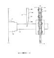
図4は、図2のC−C断面図である。この図4は、駆動スプロケット14の中心を通る鉛直線に沿った断面図である。図4では、かき寄せ部材12が駆動スプロケット14の上端にある状態が示されている。また、図1に示されている駆動チェーン211は図示省略されている。なお、図4には、上流側リターンレール24の上流側端面が示されており、この上流側端面にはハッチングが施されている。
FIG. 4 is a cross-sectional view taken along the line CC of FIG. FIG. 4 is a cross-sectional view taken along a vertical line passing through the center of the
チェーン本体101を構成するリンク部材110は、池幅方向に対向する左右一対のリンク板111と、その左右一対のリンク板111をつなげたバレル部112とから構成されている。リンク板111の下端が駆動スプロケット14の歯先よりも半径方向外側(図4では上方)に位置してしまうと、チェーン本体101が駆動スプロケット14から外れてしまう虞がある。また、バレル部112の下端が駆動スプロケット14の歯先よりも半径方向外側に位置してしまうと、駆動スプロケット14の歯先にバレル部112が乗り上げてしまう虞がある。本実施形態では、摺接部下面240bと突出上面1233bの高さ方向の間隔L1を、リンク板111の下端から駆動スプロケット14の歯先までのオーバーラップ距離L5(ここでは46mm)および、バレル部112の下端から駆動スプロケット14の歯先までの噛合距離L6(ここでは33mm)よりも短くしている。これにより、チェーン本体101が駆動スプロケット14から外れてしまう虞や、駆動スプロケット14の歯先にバレル部112が乗り上げてしまう虞を低減している。なお、これらの虞をより確実に低減するために、高さ方向の間隔L1は、オーバーラップ距離L5の半分以下の間隔にすることが好ましく、噛合距離L6の半分以下の間隔にすることがより好ましい。
The
上述したように、駆動輪側傾斜部243の上流側端面は、池幅方向に見たときに、駆動スプロケット14の上端にある駆動輪頂上部分の鉛直線上(図4では紙面と同一面上)に設けられている。駆動輪頂上部分では、チェーン本体101は、駆動スプロケット14に巻き掛けられている。チェーン本体101の、駆動スプロケット14への巻掛部分では、駆動負荷が作用しチェーン本体101が上方に撓む虞が殆どなく、チェーン本体101の挙動が安定しやすい。また、チェーン本体101の、駆動スプロケット14に巻き掛けられている部分は、駆動スプロケット14との間で摩擦負荷も生じているので、上方に撓む虞はより低くなっている。本実施形態では、チェーン本体101が上方に撓む虞が殆どない部分まで駆動輪側傾斜部243が延在しているので、その巻掛部分に取り付けられたかき寄せ部材12の池幅方向突出部1233を上流側リターンレール24の摺接部240の下方に確実に入り込ませることができる。
As described above, the upstream end surface of the drive wheel side inclined
また、同様に、従動輪側傾斜部244を設けることで、逆転走行しているかき寄せ部材12の池幅方向突出部1233も摺接部240の下方に確実に入り込ませることができる。
Similarly, by providing the driven wheel side inclined
さらに、池幅方向突出部1233が摺接部240の下方に入り込んだ状態では、かき寄せ部材12は、上方に移動することが抑制され、摺接部240の形状に沿って移動する。チェーン本体101の水面軌道部分11aに取り付けられたかき寄せ部材12が上方に移動することが抑制されることで、水面軌道部分11aも上方に移動することが抑制され、水面軌道部分11aが上方に撓むことはない。その結果、チェーン本体101の、駆動輪側傾斜部243と従動輪側傾斜部244を通過する部分が、上方に撓んで駆動スプロケット14および中間スプロケット15への巻掛角度が減少することがなくなり、その巻掛角度を維持することができる。なお、チェーン本体101が逆転走行した場合、チェーン本体101の走行負荷に応じた張力が水面軌道部分11aに加わる。このとき、水面軌道部分11aは、張力によって上方に移動しようとするが、上方への移動は摺接部240によって抑制されているので、水面軌道部分11aは、摺接部240に沿った軌道で循環移動する。すなわち、チェーン本体101が逆転走行した場合でも、駆動スプロケット14および中間スプロケット15への巻掛角度を維持することができる。つまり、本実施形態の摺接部240は、駆動スプロケット14および中間スプロケット15への巻掛角度を維持する巻掛角度維持部材としても機能する。
Further, when the pond
以上説明したように本実施形態によれば、駆動輪側傾斜部243を設けているので、正転走行しているチェーン本体101に取り付けられたかき寄せ部材12の池幅方向突出部1233を、摺接部240の下方に、確実に入り込ませることができる。池幅方向突出部1233を摺接部240の下方に入り込ませることで、振れを抑制する効果を得ることができる。その結果、地震によるスロッシングが発生しても駆動スプロケット14および中間スプロケット15からチェーン本体101が脱輪することを確実に防止できる。さらに、既設の汚泥かき寄せ装置に対しては、上流側リターンレール24を取り替え、規制部材123をかき寄せ部材12に取り付けるだけでよいので、安価にチェーン本体101が脱輪することを確実に防止できる汚泥かき寄せ装置を提供するこができる。
As described above, according to the present embodiment, since the drive wheel side inclined
また、従動輪側傾斜部244を設けているので、逆転走行している場合にも、チェーン本体101に取り付けられたかき寄せ部材12の池幅方向突出部1233を、上流側リターンレール24の下方に、確実に入り込ませることができる。
Further, since the driven wheel side inclined
続いて、本実施形態の変形例について説明する。以下の説明では、これまで説明した構成要素の名称と同じ名称の構成要素には、これまで用いた符号と同じ符号を付して説明する。また、既に説明した汚泥かき寄せ装置の説明と重複する説明は省略することがある。 Subsequently, a modified example of the present embodiment will be described. In the following description, components having the same names as the components described so far will be described with the same reference numerals as those used so far. In addition, a description that overlaps with the description of the sludge scraping device that has already been described may be omitted.
図5は、本実施形態の第1の変形例を示す図である。図5は、沈殿池1の上方から駆動スプロケット14付近を見た平面図である。また、図5では、図の下側が上流側であり、図の上側が下流側である。
FIG. 5 is a diagram showing a first modification of the present embodiment. FIG. 5 is a plan view of the vicinity of the
先の実施形態では、上流側リターンレール24の断面形状は、上流側リターンレール24の長手方向全長に渡って同一形状をしていたが、変形例では、駆動輪側傾斜部243における上流側端部の形状が先の実施形態とは異なる。図5に示すように、この変形例の駆動輪側傾斜部243は、最も上流側にある部分の池幅方向の幅が、取付部241の厚みとほぼ同一の幅になっている。また、その上流側にある部分から下流側に向かって所定の幅になるまで徐徐に幅広になっており、所定の幅になった後は一定の幅で下流側に向かって延在している。すなわち、この変形例の駆動輪側傾斜部243における上流側端面240cは、池幅方向に対して下流側に傾斜した傾斜面になっている。なお、所定の幅は、先の実施形態における摺接部240の池幅方向の幅と同一の幅である。上流側端面240cを下流側に傾斜させることで、万一、池幅方向突出部1233が上流側端面240cに衝突することがあっても、池幅方向突出部1233が池幅方向に逃げて衝突の力が分散するので、上流側リターンレール24および規制部材123が破損する可能性を低減させることができる。
In the previous embodiment, the cross-sectional shape of the
なお、従動輪側傾斜部244も、最も下流側にある部分を取付部241の厚みとほぼ同一の幅に形成し、その最も下流側にある部分から、所定の幅になるまで上流側に向かって徐徐に幅広になるようにしてもよい。こうすることで、逆転走行時に、万一、従動輪側傾斜部244と池幅方向突出部1233とが衝突しても、上流側リターンレール24および規制部材123が破損する可能性を低減させることができる。
The driven wheel side inclined
図6は、本実施形態の第2の変形例を示す図である。 FIG. 6 is a diagram showing a second modification of the present embodiment.
先の実施形態では、上下を逆にしたL字状断面の上流側リターンレール24を用い、摺接部240が当接部を兼ねた構成としていた。第2の変形例では、摺接部240とは別に、池幅方向に突出する当接部249が設けられている。また、この変形例では、規制部材123の下方突出部1232と池幅方向突出部1233は、全体としてL字状をしている。池幅方向突出部1233は、上流側リターンレール24の当接部249の下面である当接部下面249aよりも下方で、上流側リターンレール24の当接部249とは上下方向に間隔をあけ、上から見たときに当接部249に重なるように当接部249に対向して配置されている。
In the previous embodiment, the
この第2の変形例では、水面軌道部分11aが上方向に振れると、上流側リターンレール24の当接部下面249aに池幅方向突出部1233の突出上面1233bが池底側から当接する。なお、この第2の変形例では、摺接部240の池幅方向における突出方向に対し、反対方向に突出した当接部249を設けた例を示したが、摺接部240と同一方向に突出した当接部249を設けてもよい。例えば、上流側リターンレール24の断面をF字状やE字状に形成してもよい。
In this second modification, when the water
続いて、チェーン本体にいわゆるノッチチェーンを用いる例について説明する。 Subsequently, an example in which a so-called notch chain is used for the chain body will be described.
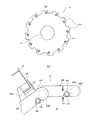
図7(a)は、ノッチチェーンを用いる場合に使用されるピン付きスプロケットを示す図であり、図7(b)は、ノッチチェーンの一部が図7(a)に示すピン付きスプロケットに巻き掛けられた様子を示す図である。 FIG. 7 (a) is a diagram showing a pinned sprocket used when a notch chain is used, and FIG. 7 (b) shows a part of the notch chain wound around the pinned sprocket shown in FIG. 7 (a). It is a figure which shows the state of being hung.
図7(a)に示すピン付きスプロケット81は、駆動軸141に固定されている。このピン付きスプロケット81の各歯811それぞれには、ピン812が設けられている。このピン812は、各歯811からピン付きスプロケット81の厚み方向に突出したものである。図7(b)に示すように、ノッチチェーン83は、図4に示す金属製のチェーン本体101と同じく、複数のリンク部材830が連結されたチェーンである。リンク部材830は、池幅方向に対向する一対のリンク板8301と、そのリンク板8301をつなげるバレル部8302とから構成された樹脂製のものである。リンク部材830には、ノッチ部835が設けられている。このノッチ部835に、ピン付きスプロケット81に設けられたピン812が係合している。ノッチ部835とピン812が係合することでピン付きスプロケット81の回転駆動力がリンク部材830に伝わり、ノッチチェーン83が周回軌道を走行する。また、ノッチチェーン83の循環方向に連結された20個のリンク部材830おきに、ステー8303が設けられたリンク部材830’が配置されている。このステー8303には、かき寄せ部材12が取り付けられている。
The pinned
ノッチチェーン83を用いる場合、図3に示す摺接部下面240bと突出上面1233bの高さ方向の間隔L1を、図7(b)に示すノッチ部835とピン812との引っ掛かり高さL8よりも狭い間隔にすることが望ましい。こうすることで、ノッチ部835とピン812との係合が解除されてしまう虞が低減する。この虞を確実に低減するために、高さ方向の間隔L1は、引っ掛かり高さL8の半分以下の間隔にすることが好ましい。
When the
本発明は上述の実施の形態に限られることなく特許請求の範囲に記載した範囲で種々の変更を行うことができる。例えば、本実施形態では、リターンシュー122と規制部材123とを別部材にしているが、リターンシュー122に下方突出部1232と池幅方向突出部1233を設けて、規制部材123を省略してもよい。また、取付部241の高さを上流側リターンレール24の長手方向の一部で変化させてもよい。また、池幅方向突出部1233をチェーン本体101に設けてもよい。
The present invention is not limited to the above-described embodiment, and various modifications can be made within the scope of the claims. For example, in the present embodiment, the
なお、以上説明した各変形例の記載それぞれにのみ含まれている構成要件であっても、その構成要件を他の変形例に適用してもよい。 It should be noted that even if the constituent requirements are included only in the description of each of the modified examples described above, the constituent requirements may be applied to other modified examples.
これまでに説明した汚泥かき寄せ装置は、汚泥が含まれた水を受け入れ該水が流れる間に該水に含まれている汚泥が池底部に沈殿する沈殿池に設けられ、該池底部に沈殿した汚泥を池幅方向に延在したかき寄せ部材によってかき寄せる汚泥かき寄せ装置において、
前記かき寄せ部材を間隔をあけて複数有し、走行することで前記池底部側と水面側で該かき寄せ部材を循環させる無端チェーンと、
水面側で前記水が流れる水流方向に延在し、前記無端チェーンが走行する際に前記かき寄せ部材の池底側が摺接するレール部材とを備え、
前記かき寄せ部材は、
前記池幅方向に延在したフライト板と、
前記レール部材に摺接するシューと、
前記無端チェーンの水面側部分が振れると前記レール部材に当接し、該無端チェーンの振れを規制する規制部材とを備えたものであり、
前記規制部材と前記シューは、重ねられた状態で前記フライト板に固定されたものであることを特徴とする。
The sludge scraping device described so far is provided in a settling basin that receives water containing sludge and causes the sludge contained in the water to settle at the bottom of the pond while the water flows, and settles at the bottom of the pond. In a sludge scraping device that scrapes sludge with a scraping member that extends in the width direction of the pond.
An endless chain that has a plurality of the scraping members at intervals and circulates the scraping members on the bottom side of the pond and the water surface side by running.
It is provided with a rail member that extends in the direction of the water flow on the water surface side and is in sliding contact with the pond bottom side of the scraping member when the endless chain travels.
The scraping member is
The flight board extending in the width direction of the pond and
A shoe that slides into the rail member and
When the water surface side portion of the endless chain swings, it comes into contact with the rail member and includes a regulating member that regulates the swing of the endless chain.
The regulating member and the shoe are fixed to the flight plate in a stacked state.
また、これまでに説明した汚泥かき寄せ装置は、汚泥が含まれた水を受け入れ該水が流れる間に該水に含まれている汚泥が池底部に沈殿する沈殿池に設けられ、該池底部に沈殿した汚泥を池幅方向に延在したかき寄せ部材によってかき寄せる汚泥かき寄せ装置において、
前記かき寄せ部材を間隔をあけて複数有し、走行することで前記池底部側と水面側で該かき寄せ部材を循環させる無端チェーンと、
水面側で前記水が流れる水流方向に延在し、前記無端チェーンが走行する際に前記かき寄せ部材の池底側が摺接するレール部材とを備え、
前記かき寄せ部材は、
前記池幅方向に延在したフライト板と、
前記レール部材に摺接するシューと、
前記無端チェーンの水面側部分が振れると前記レール部材に当接し、該無端チェーンの振れを規制する規制部材とを備えたものであり、
前記規制部材と前記シューは、重ねられた状態で前記フライト板に固定されたものであり、
前記規制部材は、前記フライト板との間に前記シューを挟んで該フライト板に着脱可能に固定されたものであることを特徴としてもよい。
Further, the sludge scraping device described so far is provided in a settling basin that receives water containing sludge and the sludge contained in the water settles at the bottom of the pond while the water flows, and is provided at the bottom of the pond. In a sludge scraping device that scrapes the settled sludge by a scraping member extending in the width direction of the pond.
An endless chain that has a plurality of the scraping members at intervals and circulates the scraping members on the bottom side of the pond and the water surface side by running.
It is provided with a rail member that extends in the direction of the water flow on the water surface side and is in sliding contact with the pond bottom side of the scraping member when the endless chain travels.
The scraping member is
The flight board extending in the width direction of the pond and
A shoe that slides into the rail member and
When the water surface side portion of the endless chain swings, it comes into contact with the rail member and includes a regulating member that regulates the swing of the endless chain.
The regulating member and the shoe are fixed to the flight plate in a state of being overlapped with each other.
The regulating member may be characterized in that the shoe is sandwiched between the regulation member and the flight plate and is detachably fixed to the flight plate.
また、この汚泥かき寄せ装置において、前記規制部材は、前記無端チェーンの水面側部分が上方向に振れることを規制する上方向規制部を有するものであってもよい。 Further, in this sludge scraping device, the regulating member may have an upward regulating portion that regulates the water surface side portion of the endless chain from swinging upward.
また、この汚泥かき寄せ装置において、前記規制部材は、前記無端チェーンの水面側部分が前記池幅方向に振れることを規制する横方向規制部を有するものであってもよい。 Further, in this sludge scraping device, the regulating member may have a lateral regulating portion that regulates the water surface side portion of the endless chain from swinging in the pond width direction.
また、これまでに説明した汚泥かき寄せ装置は、汚泥が含まれた水を受け入れ該水が流れる間に該水に含まれている汚泥が池底部に沈殿する沈殿池に設けられ、該池底部に沈殿した汚泥を池幅方向に延在したかき寄せ部材によってかき寄せる汚泥かき寄せ装置におい
て、
前記かき寄せ部材を間隔をあけて複数有し、走行することで前記池底部側と水面側で該かき寄せ部材を循環させる無端チェーンと、
水面側で前記水が流れる水流方向に延在し、前記無端チェーンが走行する際に前記かき寄せ部材の池底側が摺接するレール部材とを備え、
前記かき寄せ部材は、
前記池幅方向に延在したフライト板と、
前記レール部材に摺接するシューと、
前記無端チェーンの振れを規制する規制部材とを備えたものであり、
前記レール部材は、断面がL字状をしたL字状部分を有するものであり、
前記規制部材は、前記無端チェーンの水面側部分が振れると前記L字状部分に当接するL字状の棒材を有するものであることを特徴としてもよい。
Further, the sludge scraping device described so far is provided in a settling basin that receives water containing sludge and the sludge contained in the water settles at the bottom of the pond while the water flows, and is provided at the bottom of the pond. In a sludge scraping device that scrapes the settled sludge by a scraping member extending in the width direction of the pond.
An endless chain that has a plurality of the scraping members at intervals and circulates the scraping members on the bottom side of the pond and the water surface side by running.
It is provided with a rail member that extends in the direction of the water flow on the water surface side and is in sliding contact with the pond bottom side of the scraping member when the endless chain travels.
The scraping member is
The flight board extending in the width direction of the pond and
A shoe that slides into the rail member and
It is provided with a regulating member that regulates the runout of the endless chain.
The rail member has an L-shaped portion having an L-shaped cross section.
The regulating member may be characterized by having an L-shaped rod member that comes into contact with the L-shaped portion when the water surface side portion of the endless chain swings.
また、これまでに説明した汚泥かき寄せ装置は、汚泥が含まれた水を受け入れ該水が流れる間に該水に含まれている汚泥が池底部に沈殿する沈殿池に設けられ、該池底部に沈殿した汚泥を池幅方向に延在したかき寄せ部材によってかき寄せる汚泥かき寄せ装置において、
前記かき寄せ部材を間隔をあけて複数有し、走行することで前記池底部側と水面側で該かき寄せ部材を循環させる無端チェーンと、
水面側で前記水が流れる水流方向に延在し、前記無端チェーンが走行する際に前記かき寄せ部材の池底側が摺接するレール部材と、
前記無端チェーンが巻き掛けられ、該無端チェーンに駆動力を伝えて該無端チェーンを走行させる駆動輪とを備え、
前記かき寄せ部材は、
前記池幅方向に延在したフライト板と、
前記レール部材に摺接するシューと、
前記無端チェーンの振れを規制する規制部材とを備えたものであり、
前記レール部材は、断面がL字状をしたL字状部分を有するものであり、
前記規制部材は、前記無端チェーンの水面側部分が振れると前記L字状部分に当接するL字状の棒材を有するものであり、
前記無端チェーンは、前記池幅方向に距離をあけて配置された一対のリンク板を有するリンク部材が連結されたものであり、
前記L字状の棒材は、下方に突出した下方突出部と前記池幅方向に突出した池幅方向突出部で構成されたものであり、
前記L字状部分は、前記池幅方向突出部と前記池幅方向に重なって配置され、前記無端チェーンの水面側部分が上方向に振れると該池幅方向突出部が池底側から当接する当接部を有するものであり、
前記池幅方向突出部と前記当接部の前記池幅方向の重なり幅は、前記一対のリンク板の前記距離から前記駆動輪の歯厚を引いた値以上の幅であることを特徴とする。
Further, the sludge scraping device described so far is provided in a settling basin that receives water containing sludge and the sludge contained in the water settles at the bottom of the pond while the water flows, and is provided at the bottom of the pond. In a sludge scraping device that scrapes the settled sludge by a scraping member extending in the width direction of the pond.
An endless chain that has a plurality of the scraping members at intervals and circulates the scraping members on the bottom side of the pond and the water surface side by running.
A rail member that extends in the direction of the water flow on the water surface side and is in sliding contact with the pond bottom side of the scraping member when the endless chain travels.
The endless chain is wound around the endless chain, and the endless chain is provided with a driving wheel that transmits a driving force to run the endless chain.
The scraping member is
The flight board extending in the width direction of the pond and
A shoe that slides into the rail member and
It is provided with a regulating member that regulates the runout of the endless chain.
The rail member has an L-shaped portion having an L-shaped cross section.
The regulating member has an L-shaped rod material that comes into contact with the L-shaped portion when the water surface side portion of the endless chain swings.
The endless chain is formed by connecting link members having a pair of link plates arranged at a distance in the pond width direction.
The L-shaped bar is composed of a downward projecting portion protruding downward and a pond width direction projecting portion projecting in the pond width direction.
The L-shaped portion is arranged so as to overlap the pond width direction protrusion and the pond width direction, and when the water surface side portion of the endless chain swings upward, the pond width direction protrusion abuts from the pond bottom side. It has a contact part and has a contact part.
The overlap width of the protrusion in the pond width direction and the contact portion in the pond width direction is equal to or greater than the value obtained by subtracting the tooth thickness of the drive wheel from the distance of the pair of link plates. ..
また、上記汚泥かき寄せ装置において、前記L字状の棒材は、ステンレス製のものであってもよい。 Further, in the sludge scraping device, the L-shaped bar may be made of stainless steel.
また、汚泥が含まれた水を受け入れ該水が流れる間に該水に含まれている汚泥が池底部に沈殿する沈殿池に設けられ、該池底部に沈殿した汚泥を池幅方向に延在したかき寄せ部材によってかき寄せる汚泥かき寄せ装置において、
前記かき寄せ部材を間隔をあけて複数有し、走行することで前記池底部側と水面側で該かき寄せ部材を循環させる無端チェーンと、
前記水が流れる水流方向の上流側における水面側に設けられたものであって、前記無端チェーンが巻き掛けられ、該無端チェーンに駆動力を伝えて該無端チェーンを走行させる駆動輪と、
前記水流方向の下流側における水面側に設けられたものであって、前記無端チェーンが巻き掛けられ、該無端チェーンの走行に追従して回転自在な従動輪と、
水面側で前記水流方向に延在し、前記無端チェーンが走行する際に前記かき寄せ部材の池底側が摺接するレール部材とを備え、
前記かき寄せ部材は、水面側部分が上方向に振れると前記レール部材に池底側から当接する上方向規制部を有するものであり、
前記レール部材は、前記無端チェーンの水面側部分が上方向に振れると前記上方向規制部が池底側から当接する当接部を有するものであり、
前記当接部は、前記駆動輪の近傍から前記従動輪に向けて水平に延びた水平部と、該水平部の該駆動輪側端部から前記水流方向の上流側に向けて上方に傾斜した駆動輪側傾斜部とを有するものであり、
前記駆動輪側傾斜部は、前記駆動輪のピッチ円にほぼ沿った円弧状に形成されているものであってもよい。
In addition, the sludge contained in the sludge is received and the sludge contained in the water is settled in the sedimentation basin while the water flows, and the sludge settled in the bottom of the pond extends in the width direction of the pond. In the sludge scraping device that scrapes by the scraping member
An endless chain that has a plurality of the scraping members at intervals and circulates the scraping members on the bottom side of the pond and the water surface side by running.
A drive wheel provided on the water surface side on the upstream side in the water flow direction in which the water flows, in which the endless chain is wound and a driving force is transmitted to the endless chain to run the endless chain.
A driven wheel provided on the water surface side on the downstream side in the water flow direction, around which the endless chain is wound, and which can rotate following the running of the endless chain.
It is provided with a rail member that extends in the water flow direction on the water surface side and is in sliding contact with the pond bottom side of the scraping member when the endless chain travels.
The scraping member has an upward regulating portion that abuts on the rail member from the pond bottom side when the water surface side portion swings upward.
The rail member has an abutting portion where the upward regulating portion abuts from the pond bottom side when the water surface side portion of the endless chain swings upward.
The abutting portion is a horizontal portion extending horizontally from the vicinity of the driving wheel toward the driven wheel, and the abutting portion is inclined upward from the drive wheel side end portion of the horizontal portion toward the upstream side in the water flow direction. It has a drive wheel side inclined portion, and has a drive wheel side inclined portion.
The inclined portion on the drive wheel side may be formed in an arc shape substantially along the pitch circle of the drive wheel.
前記無端チェーンは、駆動輪と従動輪の間にはたるみが生じている。この汚泥かき寄せ装置によれば、駆動輪の近傍から水流方向の上流側にむけて上方に傾斜し、駆動輪のピッチ円にほぼ沿った円弧状に形成された駆動輪側傾斜部を設けているので上記たるみがあっても、当接部の下方に上方向規制部を確実に入り込ませることができる。上方向規制部を当接部の下方に入り込ませることで、振れを抑制する効果を確実に得ることができる。その結果、回転輪から無端チェーンが脱輪してしまうことを防止できる。 The endless chain has slack between the driving wheels and the driven wheels. According to this sludge scraping device, a drive wheel side inclined portion is provided which is inclined upward from the vicinity of the drive wheels toward the upstream side in the water flow direction and is formed in an arc shape substantially along the pitch circle of the drive wheels. Therefore, even if there is the above-mentioned slack, the upward regulating portion can be surely inserted below the contact portion. By inserting the upward regulating portion below the contact portion, the effect of suppressing runout can be reliably obtained. As a result, it is possible to prevent the endless chain from coming off from the rotating wheel.
また、前記上方向規制部は、前記当接部よりも、池底側に該当接部とは上下方向に間隔をあけて設けられ、該当接部に対向したものであってもよい。 Further, the upward regulating portion may be provided on the bottom side of the pond with a vertical interval from the contact portion and face the contact portion.
また、前記駆動輪側傾斜部は、前記駆動輪側端部から、前記駆動輪において上端になる位置を超えて前記水流方向の上流側に延在したものであってもよい。 Further, the inclined portion on the drive wheel side may extend from the end portion on the drive wheel side to the upstream side in the water flow direction beyond the position at the upper end of the drive wheel.
また、前記駆動輪側傾斜部は、前記駆動輪側端部から、前記駆動輪において上端になる位置よりも手前の位置まで前記水流方向の上流側に延在したものであってもよい。 Further, the inclined portion on the drive wheel side may extend from the end portion on the drive wheel side to a position in front of the position at the upper end of the drive wheel on the upstream side in the water flow direction.
また、前記水平部は、前記従動輪の近傍まで延びたものであり、
前記当接部は、前記池幅方向に見たときに、前記水平部の前記従動輪側端部から前記水流方向の下流側に向けて上方に傾斜した従動輪側傾斜部を有するものであってもよい。
Further, the horizontal portion extends to the vicinity of the driven wheel.
The contact portion has a driven wheel side inclined portion that is inclined upward from the driven wheel side end portion of the horizontal portion toward the downstream side in the water flow direction when viewed in the pond width direction. You may.
従動輪の近傍から従動輪側に向けて上方に傾斜した従動輪側傾斜部を設けているので、従動輪側から駆動輪側に無端チェーンの水面側部分が走行する場合でも、当接部の下方に上方向規制部を確実に入り込ませることができる。 Since the driven wheel side inclined portion inclined upward from the vicinity of the driven wheel toward the driven wheel side is provided, even when the water surface side portion of the endless chain runs from the driven wheel side to the drive wheel side, the contact portion The upward regulation part can be surely inserted downward.
また、前記駆動輪は、前記無端チェーンを該駆動輪側から前記従動輪側に向かって走行させる正転駆動と、該無端チェーンを該正転駆動とは反対側に向かって走行させる逆転駆動とを行うものであってもよい。 Further, the drive wheels include a forward rotation drive in which the endless chain travels from the drive wheel side toward the driven wheel side, and a reverse rotation drive in which the endless chain travels toward the side opposite to the normal rotation drive. May be the one that does.
また、前記従動輪側傾斜部は、前記従動輪側端部から、前記従動輪において上端になる位置を超えて前記水流方向の下流側に延在したものであってもよい。 Further, the driven wheel side inclined portion may extend from the driven wheel side end portion to the downstream side in the water flow direction beyond the position at the upper end of the driven wheel.
また、前記従動輪側傾斜部は、前記従動輪側端部から、前記従動輪において上端になる位置よりも手前の位置まで前記水流方向の下流側に延在したものであってもよい。 Further, the driven wheel side inclined portion may extend from the driven wheel side end portion to a position before the upper end position of the driven wheel on the downstream side in the water flow direction.
1 沈殿池
1d 池底部
10 汚泥かき寄せ装置
11 無端チェーン
12 かき寄せ部材
14 駆動スプロケット
15 中間スプロケット
24 上流側リターンレール
240 摺接部
242 水平部
243 駆動輪側傾斜部
244 従動輪側傾斜部
249 当接部
1233a 突出端面
1233b 突出上面
W 水面
1 Settling
Claims (2)
前記かき寄せ部材を間をあけて複数有し、走行することで前記池底部側と水面側で該かき寄せ部材を循環させる無端チェーンと、
水面側で前記水が流れる水流方向に延在し、前記無端チェーンが走行する際に前記かき寄せ部材の池底側が摺接するレール部材と、
前記無端チェーンが巻き掛けられ、該無端チェーンに駆動力を伝えて該無端チェーンを走行させる駆動輪とを備え、
前記かき寄せ部材は、前記レール部材に摺接するシューと、前記無端チェーンの振れを規制する規制部材とを備えたものであり、
前記駆動輪は、放射方向に突出した歯を有するものであり、
前記レール部材は、前記シューと接する摺接部を有するものであり、
前記規制部材は、前記摺接部から下方向に間隔をあけて該摺接部と前記池幅方向に重なって配置され、前記無端チェーンの水面側部分が上方向に振れると該摺接部に当接する、該池幅方向に突出した池幅方向突出部を有するものであり、
前記無端チェーンは、前記池幅方向に距離をあけて配置された一対のリンク板を有するリンク部材が連結されたものであり、
前記間隔は、前記駆動輪の歯と前記リンク部材が噛合した状態における該リンク部材を構成する前記リンク板の下端から該歯の先端までのオーバラップ距離よりも短いことを特徴とする汚泥かき寄せ装置。 It is provided in a settling basin that receives water containing sludge and the sludge contained in the water settles at the bottom of the pond while the water flows. In a sludge scraping device that scrapes by members
An endless chain that has a plurality of the scraping members at intervals and circulates the scraping members on the bottom side of the pond and the water surface side by running.
A rail member that extends in the direction of the water flow on the water surface side and is in sliding contact with the pond bottom side of the scraping member when the endless chain travels.
The endless chain is wound around the endless chain, and the endless chain is provided with a driving wheel that transmits a driving force to run the endless chain.
The scraping member includes a shoe that is in sliding contact with the rail member and a regulating member that regulates the runout of the endless chain.
The drive wheels have teeth protruding in the radial direction.
The rail member has a sliding contact portion in contact with the shoe, and has a sliding contact portion.
The restricting member is arranged so as to overlap the sliding contact portion in the pond width direction with a downward interval from the sliding contact portion, and when the water surface side portion of the endless chain swings upward, the sliding contact portion is subjected to. It has a pond width direction protrusion that abuts and protrudes in the pond width direction.
The endless chain is formed by connecting link members having a pair of link plates arranged at a distance in the pond width direction.
The sludge scraping device is characterized in that the distance is shorter than the overlap distance from the lower end of the link plate constituting the link member to the tip of the tooth in a state where the teeth of the drive wheel and the link member are in mesh with each other. ..
Priority Applications (1)
| Application Number | Priority Date | Filing Date | Title |
|---|---|---|---|
| JP2019231129A JP6847471B2 (en) | 2019-12-23 | 2019-12-23 | Sludge scraper |
Applications Claiming Priority (1)
| Application Number | Priority Date | Filing Date | Title |
|---|---|---|---|
| JP2019231129A JP6847471B2 (en) | 2019-12-23 | 2019-12-23 | Sludge scraper |
Related Parent Applications (1)
| Application Number | Title | Priority Date | Filing Date |
|---|---|---|---|
| JP2018227983A Division JP6653846B2 (en) | 2018-12-05 | 2018-12-05 | Sludge scraper |
Publications (2)
| Publication Number | Publication Date |
|---|---|
| JP2020040070A JP2020040070A (en) | 2020-03-19 |
| JP6847471B2 true JP6847471B2 (en) | 2021-03-24 |
Family
ID=69797316
Family Applications (1)
| Application Number | Title | Priority Date | Filing Date |
|---|---|---|---|
| JP2019231129A Active JP6847471B2 (en) | 2019-12-23 | 2019-12-23 | Sludge scraper |
Country Status (1)
| Country | Link |
|---|---|
| JP (1) | JP6847471B2 (en) |
Family Cites Families (5)
| Publication number | Priority date | Publication date | Assignee | Title |
|---|---|---|---|---|
| FI963435A0 (en) * | 1996-09-03 | 1996-09-03 | Finnchain Oy | In the case of franking and scraping |
| JP4897147B2 (en) * | 2001-03-15 | 2012-03-14 | 日立機材株式会社 | Chain structure |
| JP4536595B2 (en) * | 2005-05-26 | 2010-09-01 | 荏原エンジニアリングサービス株式会社 | Sludge scraping machine |
| JP4435244B2 (en) * | 2008-04-23 | 2010-03-17 | 株式会社日立プラントテクノロジー | Chain tooth skip prevention device in sludge scraping machine. |
| JP2011005400A (en) * | 2009-06-24 | 2011-01-13 | Finnketju Invest Oy | Device used as sludge scraper |
-
2019
- 2019-12-23 JP JP2019231129A patent/JP6847471B2/en active Active
Also Published As
| Publication number | Publication date |
|---|---|
| JP2020040070A (en) | 2020-03-19 |
Similar Documents
| Publication | Publication Date | Title |
|---|---|---|
| JP5895260B2 (en) | Sludge scraping device | |
| JP5906538B2 (en) | Sludge scraping device | |
| JP4536595B2 (en) | Sludge scraping machine | |
| JP5615768B2 (en) | Sludge scraping machine | |
| JP7440117B2 (en) | Sludge scraping device | |
| JP5065513B1 (en) | Sludge scraping machine | |
| JP6175719B2 (en) | Sludge scraping device | |
| JP6574619B2 (en) | Sludge scraping machine | |
| JP5727075B1 (en) | Return flight side guide shoe and chain flight type sludge scraper equipped with the return route side guide shoe | |
| JP6847471B2 (en) | Sludge scraper | |
| JP6653846B2 (en) | Sludge scraper | |
| JP2015205275A (en) | Sludge scraper | |
| JP2016137490A (en) | Sludge scraping-up device | |
| JP6476399B2 (en) | Sludge scraping device | |
| JP6449379B2 (en) | Sludge scraping device | |
| JP6839875B2 (en) | Sludge scraper | |
| JP6465225B1 (en) | Sludge scraping machine | |
| JP6678921B2 (en) | Sludge scraping device | |
| JP5842283B2 (en) | Sludge scraping device | |
| JP7336076B2 (en) | Sludge collector | |
| JP2018130667A (en) | Sludge scraper | |
| JP2005224665A (en) | Sludge-scraping machine | |
| JP5734728B2 (en) | Sludge scraping machine | |
| JP2019069449A (en) | Sludge scraper | |
| JP6955785B2 (en) | Power transmission device |
Legal Events
| Date | Code | Title | Description |
|---|---|---|---|
| A621 | Written request for application examination |
Free format text: JAPANESE INTERMEDIATE CODE: A621 Effective date: 20191223 |
|
| A977 | Report on retrieval |
Free format text: JAPANESE INTERMEDIATE CODE: A971007 Effective date: 20201217 |
|
| TRDD | Decision of grant or rejection written | ||
| A01 | Written decision to grant a patent or to grant a registration (utility model) |
Free format text: JAPANESE INTERMEDIATE CODE: A01 Effective date: 20210202 |
|
| A61 | First payment of annual fees (during grant procedure) |
Free format text: JAPANESE INTERMEDIATE CODE: A61 Effective date: 20210224 |
|
| R150 | Certificate of patent or registration of utility model |
Ref document number: 6847471 Country of ref document: JP Free format text: JAPANESE INTERMEDIATE CODE: R150 |
|
| R250 | Receipt of annual fees |
Free format text: JAPANESE INTERMEDIATE CODE: R250 |