JP6842421B2 - Seals for solid polymer electrolyte fuel cells - Google Patents
Seals for solid polymer electrolyte fuel cells Download PDFInfo
- Publication number
- JP6842421B2 JP6842421B2 JP2017542151A JP2017542151A JP6842421B2 JP 6842421 B2 JP6842421 B2 JP 6842421B2 JP 2017542151 A JP2017542151 A JP 2017542151A JP 2017542151 A JP2017542151 A JP 2017542151A JP 6842421 B2 JP6842421 B2 JP 6842421B2
- Authority
- JP
- Japan
- Prior art keywords
- electrode assembly
- membrane electrode
- frame
- seal
- reservoir
- Prior art date
- Legal status (The legal status is an assumption and is not a legal conclusion. Google has not performed a legal analysis and makes no representation as to the accuracy of the status listed.)
- Active
Links
- 239000000446 fuel Substances 0.000 title claims description 29
- 239000005518 polymer electrolyte Substances 0.000 title description 7
- 239000007787 solid Substances 0.000 title description 7
- 239000012528 membrane Substances 0.000 claims description 91
- 239000011324 bead Substances 0.000 claims description 76
- 239000000463 material Substances 0.000 claims description 52
- 238000000034 method Methods 0.000 claims description 41
- 238000007789 sealing Methods 0.000 claims description 18
- 239000003566 sealing material Substances 0.000 claims description 16
- 229920000554 ionomer Polymers 0.000 claims description 7
- 239000012815 thermoplastic material Substances 0.000 claims description 7
- 238000001746 injection moulding Methods 0.000 claims description 6
- 238000005304 joining Methods 0.000 claims description 6
- 239000003792 electrolyte Substances 0.000 claims description 5
- 230000009969 flowable effect Effects 0.000 description 25
- 229920001971 elastomer Polymers 0.000 description 22
- 239000000806 elastomer Substances 0.000 description 21
- 239000012530 fluid Substances 0.000 description 10
- 239000007788 liquid Substances 0.000 description 9
- 238000009792 diffusion process Methods 0.000 description 8
- 239000003054 catalyst Substances 0.000 description 7
- 229920001296 polysiloxane Polymers 0.000 description 7
- 239000000376 reactant Substances 0.000 description 7
- 239000006185 dispersion Substances 0.000 description 5
- -1 electrodes Substances 0.000 description 5
- 238000002347 injection Methods 0.000 description 5
- 239000007924 injection Substances 0.000 description 5
- 229920001187 thermosetting polymer Polymers 0.000 description 5
- 230000015556 catabolic process Effects 0.000 description 4
- 150000001875 compounds Chemical class 0.000 description 4
- 238000006731 degradation reaction Methods 0.000 description 4
- 229920001169 thermoplastic Polymers 0.000 description 4
- 239000004416 thermosoftening plastic Substances 0.000 description 3
- BQCIDUSAKPWEOX-UHFFFAOYSA-N 1,1-Difluoroethene Chemical compound FC(F)=C BQCIDUSAKPWEOX-UHFFFAOYSA-N 0.000 description 2
- 229920000181 Ethylene propylene rubber Polymers 0.000 description 2
- 101100337414 Mus musculus Golga3 gene Proteins 0.000 description 2
- 229920002367 Polyisobutene Polymers 0.000 description 2
- 239000000853 adhesive Substances 0.000 description 2
- 230000001070 adhesive effect Effects 0.000 description 2
- 230000008901 benefit Effects 0.000 description 2
- 239000006227 byproduct Substances 0.000 description 2
- 238000006243 chemical reaction Methods 0.000 description 2
- 230000006866 deterioration Effects 0.000 description 2
- KPUWHANPEXNPJT-UHFFFAOYSA-N disiloxane Chemical class [SiH3]O[SiH3] KPUWHANPEXNPJT-UHFFFAOYSA-N 0.000 description 2
- 239000013536 elastomeric material Substances 0.000 description 2
- 238000004519 manufacturing process Methods 0.000 description 2
- 229910052751 metal Inorganic materials 0.000 description 2
- 239000002184 metal Substances 0.000 description 2
- 230000001590 oxidative effect Effects 0.000 description 2
- 229920001343 polytetrafluoroethylene Polymers 0.000 description 2
- 239000004810 polytetrafluoroethylene Substances 0.000 description 2
- 229920002725 thermoplastic elastomer Polymers 0.000 description 2
- 229920000557 Nafion® Polymers 0.000 description 1
- 239000004952 Polyamide Substances 0.000 description 1
- 239000004698 Polyethylene Substances 0.000 description 1
- 239000004642 Polyimide Substances 0.000 description 1
- 239000004743 Polypropylene Substances 0.000 description 1
- VYPSYNLAJGMNEJ-UHFFFAOYSA-N Silicium dioxide Chemical class O=[Si]=O VYPSYNLAJGMNEJ-UHFFFAOYSA-N 0.000 description 1
- 230000002378 acidificating effect Effects 0.000 description 1
- 239000000956 alloy Substances 0.000 description 1
- 229910045601 alloy Inorganic materials 0.000 description 1
- 230000006835 compression Effects 0.000 description 1
- 238000007906 compression Methods 0.000 description 1
- 238000011109 contamination Methods 0.000 description 1
- 239000002826 coolant Substances 0.000 description 1
- 230000005611 electricity Effects 0.000 description 1
- HQQADJVZYDDRJT-UHFFFAOYSA-N ethene;prop-1-ene Chemical group C=C.CC=C HQQADJVZYDDRJT-UHFFFAOYSA-N 0.000 description 1
- 229920001973 fluoroelastomer Polymers 0.000 description 1
- 229920005560 fluorosilicone rubber Polymers 0.000 description 1
- 230000014509 gene expression Effects 0.000 description 1
- 238000005470 impregnation Methods 0.000 description 1
- 239000007800 oxidant agent Substances 0.000 description 1
- 230000037361 pathway Effects 0.000 description 1
- BASFCYQUMIYNBI-UHFFFAOYSA-N platinum Chemical compound [Pt] BASFCYQUMIYNBI-UHFFFAOYSA-N 0.000 description 1
- 229920001084 poly(chloroprene) Polymers 0.000 description 1
- 229920002647 polyamide Polymers 0.000 description 1
- 229920000728 polyester Polymers 0.000 description 1
- 229920000573 polyethylene Polymers 0.000 description 1
- 239000011112 polyethylene naphthalate Substances 0.000 description 1
- 229920001721 polyimide Polymers 0.000 description 1
- 229920000642 polymer Polymers 0.000 description 1
- 229920001155 polypropylene Polymers 0.000 description 1
- 229920002635 polyurethane Polymers 0.000 description 1
- 239000004814 polyurethane Substances 0.000 description 1
- 230000002265 prevention Effects 0.000 description 1
- 230000001603 reducing effect Effects 0.000 description 1
- 229920002379 silicone rubber Polymers 0.000 description 1
- 239000004945 silicone rubber Substances 0.000 description 1
- 239000000243 solution Substances 0.000 description 1
- 239000004634 thermosetting polymer Substances 0.000 description 1
Images


Classifications
-
- H—ELECTRICITY
- H01—ELECTRIC ELEMENTS
- H01M—PROCESSES OR MEANS, e.g. BATTERIES, FOR THE DIRECT CONVERSION OF CHEMICAL ENERGY INTO ELECTRICAL ENERGY
- H01M8/00—Fuel cells; Manufacture thereof
- H01M8/02—Details
- H01M8/0271—Sealing or supporting means around electrodes, matrices or membranes
- H01M8/0273—Sealing or supporting means around electrodes, matrices or membranes with sealing or supporting means in the form of a frame
-
- B—PERFORMING OPERATIONS; TRANSPORTING
- B29—WORKING OF PLASTICS; WORKING OF SUBSTANCES IN A PLASTIC STATE IN GENERAL
- B29C—SHAPING OR JOINING OF PLASTICS; SHAPING OF MATERIAL IN A PLASTIC STATE, NOT OTHERWISE PROVIDED FOR; AFTER-TREATMENT OF THE SHAPED PRODUCTS, e.g. REPAIRING
- B29C45/00—Injection moulding, i.e. forcing the required volume of moulding material through a nozzle into a closed mould; Apparatus therefor
- B29C45/0046—Details relating to the filling pattern or flow paths or flow characteristics of moulding material in the mould cavity
-
- B—PERFORMING OPERATIONS; TRANSPORTING
- B29—WORKING OF PLASTICS; WORKING OF SUBSTANCES IN A PLASTIC STATE IN GENERAL
- B29C—SHAPING OR JOINING OF PLASTICS; SHAPING OF MATERIAL IN A PLASTIC STATE, NOT OTHERWISE PROVIDED FOR; AFTER-TREATMENT OF THE SHAPED PRODUCTS, e.g. REPAIRING
- B29C45/00—Injection moulding, i.e. forcing the required volume of moulding material through a nozzle into a closed mould; Apparatus therefor
- B29C45/14—Injection moulding, i.e. forcing the required volume of moulding material through a nozzle into a closed mould; Apparatus therefor incorporating preformed parts or layers, e.g. injection moulding around inserts or for coating articles
- B29C45/14336—Coating a portion of the article, e.g. the edge of the article
- B29C45/14344—Moulding in or through a hole in the article, e.g. outsert moulding
-
- H—ELECTRICITY
- H01—ELECTRIC ELEMENTS
- H01M—PROCESSES OR MEANS, e.g. BATTERIES, FOR THE DIRECT CONVERSION OF CHEMICAL ENERGY INTO ELECTRICAL ENERGY
- H01M8/00—Fuel cells; Manufacture thereof
- H01M8/02—Details
- H01M8/0271—Sealing or supporting means around electrodes, matrices or membranes
- H01M8/028—Sealing means characterised by their material
-
- H—ELECTRICITY
- H01—ELECTRIC ELEMENTS
- H01M—PROCESSES OR MEANS, e.g. BATTERIES, FOR THE DIRECT CONVERSION OF CHEMICAL ENERGY INTO ELECTRICAL ENERGY
- H01M8/00—Fuel cells; Manufacture thereof
- H01M8/02—Details
- H01M8/0271—Sealing or supporting means around electrodes, matrices or membranes
- H01M8/0286—Processes for forming seals
-
- B—PERFORMING OPERATIONS; TRANSPORTING
- B29—WORKING OF PLASTICS; WORKING OF SUBSTANCES IN A PLASTIC STATE IN GENERAL
- B29K—INDEXING SCHEME ASSOCIATED WITH SUBCLASSES B29B, B29C OR B29D, RELATING TO MOULDING MATERIALS OR TO MATERIALS FOR MOULDS, REINFORCEMENTS, FILLERS OR PREFORMED PARTS, e.g. INSERTS
- B29K2021/00—Use of unspecified rubbers as moulding material
- B29K2021/006—Thermosetting elastomers
-
- Y—GENERAL TAGGING OF NEW TECHNOLOGICAL DEVELOPMENTS; GENERAL TAGGING OF CROSS-SECTIONAL TECHNOLOGIES SPANNING OVER SEVERAL SECTIONS OF THE IPC; TECHNICAL SUBJECTS COVERED BY FORMER USPC CROSS-REFERENCE ART COLLECTIONS [XRACs] AND DIGESTS
- Y02—TECHNOLOGIES OR APPLICATIONS FOR MITIGATION OR ADAPTATION AGAINST CLIMATE CHANGE
- Y02E—REDUCTION OF GREENHOUSE GAS [GHG] EMISSIONS, RELATED TO ENERGY GENERATION, TRANSMISSION OR DISTRIBUTION
- Y02E60/00—Enabling technologies; Technologies with a potential or indirect contribution to GHG emissions mitigation
- Y02E60/30—Hydrogen technology
- Y02E60/50—Fuel cells
Landscapes
- Engineering & Computer Science (AREA)
- Manufacturing & Machinery (AREA)
- Life Sciences & Earth Sciences (AREA)
- Sustainable Development (AREA)
- Sustainable Energy (AREA)
- Chemical & Material Sciences (AREA)
- Chemical Kinetics & Catalysis (AREA)
- Electrochemistry (AREA)
- General Chemical & Material Sciences (AREA)
- Mechanical Engineering (AREA)
- Fuel Cell (AREA)
Description
本発明は、シールされた膜電極アセンブリおよびシールを膜電極アセンブリに提供する方法に関する。 The present invention relates to a sealed membrane electrode assembly and a method of providing the seal to the membrane electrode assembly.
燃料電池は、燃料と酸化剤流体とが電気化学的に反応し、電気を発生させるデバイスである。種々の商業用途のために開発されているあるタイプの燃料電池は、固体ポリマー電解質燃料電池であり、それは、2つの電極の間に配置された好適なイオノマー材料(例えば、Nafion(登録商標))から成る固体ポリマー電解質を備えている膜電極アセンブリ(MEA)を採用する。各電極は、固体ポリマー電解質に隣接して位置する、適切な触媒を備えている。触媒は、例えば、金属ブラック、合金、または支持された金属触媒(炭素上の白金等)であり得る。触媒は、触媒層内に配置され得、触媒層は、典型的には、固体ポリマー電解質のために使用されるそれに類似し得るイオノマーを含む。流体拡散層(多孔質の電気的に伝導性のシート材料)が、典型的には、機械的支持、電流収集、および/または反応物質分散のために、電極に隣接して採用される。ガス状反応物質の場合、そのような流体拡散層は、ガス拡散層と称される。触媒層が、ガス拡散層上に組み込まれる場合、ユニットは、ガス拡散電極と称される。 A fuel cell is a device in which a fuel and an oxidant fluid react electrochemically to generate electricity. One type of fuel cell being developed for a variety of commercial applications is a solid polymer electrolyte fuel cell, which is a suitable ionomer material placed between two electrodes (eg, Nafion®). A Membrane Electrode Assembly (MEA) with a solid polymer electrolyte consisting of is employed. Each electrode is equipped with a suitable catalyst located adjacent to the solid polymer electrolyte. The catalyst can be, for example, a metal black, an alloy, or a supported metal catalyst (such as platinum on carbon). The catalyst can be placed within the catalyst layer and the catalyst layer comprises ionomers that can typically be similar to those used for solid polymer electrolytes. A fluid diffusion layer (a porous, electrically conductive sheet material) is typically employed adjacent to the electrodes for mechanical support, current collection, and / or reactant dispersion. In the case of gaseous reactants, such a fluid diffusion layer is referred to as the gas diffusion layer. When the catalyst layer is incorporated on a gas diffusion layer, the unit is referred to as a gas diffusion electrode.
商業用途のために、複数の燃料電池が、概して、より多くの出力電圧を送達するために、直列にスタックされる。セパレータプレートが、典型的には、固体ポリマー電解質燃料電池内のガス拡散電極層に隣接して採用され、1つの電池をスタック内の別の電池から分離する。入口および出口ポート、流体分散プレナム、および多数の流体チャネルを含む流体分散特徴が、典型的には、反応物質流体を電極に分散させ、反応副産物をそこから除去するために、電極に隣接したセパレータプレートの表面内に形成される。セパレータプレートはまた、電気および熱伝導のための経路ならびに機械的支持および寸法上の安定性をMEAに提供する。 For commercial use, multiple fuel cells are generally stacked in series to deliver more output voltage. A separator plate is typically employed adjacent to the gas diffusion electrode layer in the solid polymer electrolyte fuel cell to separate one battery from another in the stack. Fluid dispersion features, including inlet and outlet ports, fluid dispersion plenum, and numerous fluid channels, typically have a separator adjacent to the electrode to disperse the reactant fluid in the electrode and remove reaction by-products from it. Formed within the surface of the plate. Separator plates also provide the MEA with pathways for electrical and thermal conduction as well as mechanical support and dimensional stability.
組み立てられた燃料電池では、MEA内の多孔性ガス拡散層は、反応物質ガスが誤った電極に漏出することを防止するために、または反応物質ガスと燃料電池スタックを包囲する大気との間の漏出を防止するために、その周縁において、その隣接するセパレータプレートに対して適度にシールされなければならない。これは、MEAが、典型的には、比較的に大型の薄いシートであり、したがって、シールが、有意な周囲の長さにわたって必要とされ得、燃料電池スタックが、典型的には、多数のMEAをシールすることを伴うので、困難であり得る。したがって、通常、MEA縁シールの設計は、大量生産と信頼性のある高品質の漏出防止シールとを提供すべきである。これを達成する種々の方法が、当技術分野で提案されている。 In the assembled fuel cell, the porous gas diffusion layer in the MEA is used to prevent the reactant gas from leaking to the wrong electrode, or between the reactant gas and the atmosphere surrounding the fuel cell stack. To prevent leakage, it must be adequately sealed at its periphery to its adjacent separator plate. This is because the MEA is typically a relatively large thin sheet and therefore a seal may be required over a significant perimeter and a fuel cell stack is typically numerous. It can be difficult as it involves sealing the MEA. Therefore, the design of MEA edge seals should typically provide mass production and reliable, high quality leak prevention seals. Various methods for achieving this have been proposed in the art.
ある従来技術のシール方法は、MEAと大気との間に信頼性のあるシールをもたらすために、MEAを包囲し、アノードおよびカソードのセパレータプレート間に有意に圧縮され得るシールガスケットの使用を伴う。アノードをカソードから分離するシールは、ガスケットシール材料をMEAの縁の中に含浸させ、包囲するガスケットにこれらの含浸された縁を取り付けるか、または統合することによって、得られることができる。米国特許第6,057,054号(特許文献1)は、直線切りMEAを使用する実施形態を開示している(膜電解質、電極、およびガス拡散層の縁は、同一場所において、すなわち、直線切り縁において、整列させられ、終端する)。しかしながら、そのようなアプローチは、概して、ガスケットと同一材料が、縁含浸のために使用されることを要求し、さらに、厳密な許容誤差、故に、生産上の困難性を要求し得る。 One prior art sealing method involves the use of a sealing gasket that surrounds the MEA and can be significantly compressed between the anode and cathode separator plates to provide a reliable seal between the MEA and the atmosphere. A seal that separates the anode from the cathode can be obtained by impregnating the gasket sealing material into the edges of the MEA and attaching or integrating these impregnated edges to the surrounding gasket. U.S. Pat. No. 6,057,054 discloses an embodiment using straight-cut MEA (the edges of the membrane electrolyte, electrodes, and gas diffusion layer are co-located, i.e. straight. Aligned and terminated at the incisal edge). However, such an approach generally requires that the same material as the gasket be used for edge impregnation, and may also require tight tolerances and therefore production difficulties.
他の従来技術のシール方法は、要求されるシールをもたらすために、2つ以上の圧縮可能ガスケットを採用し得る。例えば、フレーム付きMEAを採用する実施形態が提案されており、フレームが包囲する単一ガスケットに接合されないが、代わりに、2つの包囲する圧縮可能ガスケットの間に挿入される。したがって、一方の包囲するガスケットは、アノードフレームと隣接するセパレータプレートとの間のアノードをシールする一方、他方の包囲するガスケットは、カソードフレームとその隣接するセパレータプレートとの間のカソードをシールする。しかしながら、対向するガスケットが、互いに対して整列からずれる場合、困難が生じ得、したがって、再び、厳密な許容誤差が、要求され得る。 Other prior art sealing methods may employ two or more compressible gaskets to provide the required sealing. For example, an embodiment adopting a framed MEA has been proposed in which the frame is not joined to the surrounding single gasket, but instead is inserted between the two surrounding compressible gaskets. Thus, one surrounding gasket seals the anode between the anode frame and the adjacent separator plate, while the other surrounding gasket seals the cathode between the cathode frame and its adjacent separator plate. However, if the opposing gaskets are out of alignment with each other, difficulties can arise and therefore again tight tolerances can be required.
いくつかの従来のシール方法では、多成分シールリムが、MEAの縁をシールするために使用され得る。米国特許公開第2009/0220834号(特許文献2)は、フレームが、MEAの縁に適用され得、リム構成要素が、2つの異なる接合手段を用いて接合されることを開示している。MEAのリム構造は、接着剤および物理的係止の両方によって互いに接合される、少なくとも2つの材料(シール材料AおよびフレームB)を備えている。フレームBは、少なくとも1つの穿孔を有し、それを通して、シール材料が浸透し、互いにかみ合った接続を確立する。複数の穿孔が提供される場合、それらの間の典型的距離は、0.1〜100mmの範囲内である。フレーム内の穿孔の数およびサイズは、個々の構成要素間の接着接続の要求される強度に依存するであろう。このシール構造では、シール材料AおよびフレームBは両方とも、MEA構成要素のうちの少なくとも1つと接触する。シール材料Aは、熱可塑性ポリマー、熱硬化性ポリマー、またはシリコーンゴム等のエラストマーであり得る。 In some conventional sealing methods, a multi-component sealing rim can be used to seal the edges of the MEA. U.S. Patent Publication No. 2009/0220834 discloses that the frame can be applied to the edges of the MEA and the rim components are joined using two different joining means. The MEA rim structure comprises at least two materials (seal material A and frame B) that are joined together by both adhesive and physical locking. The frame B has at least one perforation through which the sealing material penetrates and establishes a meshing connection with each other. If multiple perforations are provided, the typical distance between them is in the range of 0.1 to 100 mm. The number and size of perforations in the frame will depend on the required strength of the adhesive connection between the individual components. In this sealing structure, both the sealing material A and the frame B are in contact with at least one of the MEA components. The sealing material A can be an elastomer such as a thermoplastic polymer, a thermosetting polymer, or a silicone rubber.
しかしながら、シリコーン等のいくつかのシール材料は、膜電極アセンブリを汚染することが示されている。例えば、米国特許公開第2005/0089746号(特許文献3)は、シリコーンがシール材料として使用されるとき、流動性シロキサンが、膜の中に移行し得、そこで、次いで、化学的に酸化され、二酸化ケイ素誘導体を形成し得ることを示唆している。この汚染は、その後、膜内の内部亀裂および燃料電池の最終的故障につながり得る。さらに、シールフレーム上への液体注入可能材料の射出成形は、制御が困難であり、金型内の液体注入可能材料の分散を正確に調整することも困難である。したがって、燃料電池環境内で劣化するシリコーンおよび他のシール材料をMEAから物理的に分離しながら、液体注入成形可能材料を使用して、多成分または混成シールを形成する改良された方法の必要性が、残っている。 However, some sealing materials, such as silicone, have been shown to contaminate the membrane electrode assembly. For example, U.S. Patent Publication No. 2005/089746 (Patent Document 3) states that when silicone is used as a sealing material, fluid siloxane can migrate into the film, where it is then chemically oxidized. It suggests that silicon dioxide derivatives can be formed. This contamination can then lead to internal cracks in the membrane and final failure of the fuel cell. In addition, injection molding of the liquid injectable material onto the seal frame is difficult to control and it is also difficult to accurately adjust the dispersion of the liquid injectable material in the mold. Therefore, there is a need for an improved method of forming multi-component or hybrid seals using liquid injection moldable materials while physically separating silicone and other seal materials that deteriorate in the fuel cell environment from the MEA. However, it remains.
本発明は、アノードとカソードとの間に配置されているイオノマー電解質を含む膜電極アセンブリを含む固体ポリマー電解質燃料電池に適用可能である。 The present invention is applicable to solid polymer electrolyte fuel cells that include a membrane electrode assembly containing an ionomer electrolyte located between the anode and cathode.
一実施形態では、膜電極アセンブリをシールする方法は、フレームを膜電極アセンブリの周縁の周囲に提供し、フレーム付き膜電極アセンブリを形成することであって、フレームは、第1の側と、反対の第2の側とを含む、ことと、貫通孔をフレーム内に提供することであって、貫通孔は、膜電極アセンブリから離れ間隔を置かれている、ことと、フレーム付き膜電極アセンブリをシール金型の中に設置することであって、シール金型は、リザーバ領域、シールビーズ領域、およびリザーバ領域をシールビーズ領域に流動的に接続する少なくとも1つの湯道領域を含む、ことと、流動処理可能シール材料をフレーム内の貫通孔と整列させられている、シール金型におけるリザーバ領域の中に給送することであって、液体注入可能シール材料が、貫通孔を通してフレームの第1および第2の側に給送される、ことと、流動処理可能シール材料をリザーバ領域からシールビーズ領域に少なくとも1つの湯道領域を通して給送し、それによって、少なくとも1つの湯道およびシールビーズをフレームの第1の側に形成することとを含み、少なくとも1つの湯道領域の水力直径は、リザーバ領域の水力直径より小さい。フレームは、熱可塑性材料を含む。流動処理可能シール材料は、熱硬化性液体射出成形可能化合物を含む。 In one embodiment, the method of sealing the membrane electrode assembly is to provide a frame around the periphery of the membrane electrode assembly to form a framed membrane electrode assembly, wherein the frame is opposite to the first side. The through-holes are spaced apart from the membrane electrode assembly and that the through-holes are spaced apart from the membrane electrode assembly and that the through-holes are provided in the frame, including the second side of the framed membrane electrode assembly. Being placed in a seal mold, the seal mold comprises a reservoir region, a seal bead region, and at least one runner region that fluidly connects the reservoir region to the seal bead region. The flow processable seal material is fed into the reservoir area in the seal mold, which is aligned with the through holes in the frame, and the liquid injectable seal material is the first and through the through holes in the frame. It is fed to the second side and the flowable seal material is fed from the reservoir region to the seal bead region through at least one runway region, thereby frame at least one runner and seal bead. The hydraulic diameter of at least one runway region is smaller than the hydraulic diameter of the reservoir region, including forming on the first side of the reservoir region. The frame contains a thermoplastic material. The flow treatable seal material comprises a thermosetting liquid injection moldable compound.
方法は、少なくとも1つの湯道およびシールビーズをフレームの反対の第2の側に形成することを含む。フレームの反対の第2の側の湯道およびシールビーズは、フレームの第1の側の湯道およびシールビーズと同時に形成される。 The method comprises forming at least one runway and seal beads on the opposite second side of the frame. The runner and seal beads on the opposite second side of the frame are formed at the same time as the runner and seal beads on the first side of the frame.
いくつかの実施形態では、フレームを膜電極アセンブリの周縁の周囲に提供することは、複数のフレーム部材を膜電極アセンブリの周縁に接合することを含む。 In some embodiments, providing the frame around the periphery of the membrane electrode assembly comprises joining a plurality of frame members to the periphery of the membrane electrode assembly.
フレームは、少なくとも1つのマニホールドをフレーム付き膜電極アセンブリの周縁上に形成する。フレーム内の貫通孔は、膜電極アセンブリおよびマニホールドからオフセットされる。本願の方法を通してフレーム上に形成されるシールビーズは、フレーム内のマニホールドを包囲する。リザーバ、湯道、およびシールビーズは、膜電極アセンブリから物理的に分離される。 The frame forms at least one manifold on the periphery of the framed membrane electrode assembly. Through holes in the frame are offset from the membrane electrode assembly and manifold. Seal beads formed on the frame through the methods of the present application surround the manifold within the frame. The reservoir, runner, and seal beads are physically separated from the membrane electrode assembly.
好ましい実施形態では、湯道およびリザーバは、シールビーズより断面高さにおいて低い。例えば、少なくとも1つの湯道の断面高さは、シールビーズの断面高さの約半分未満であることができる。 In a preferred embodiment, the runner and reservoir are lower in cross-sectional height than the seal beads. For example, the cross-sectional height of at least one runner can be less than about half the cross-sectional height of the seal beads.
方法はさらに、液体注入可能シール材料を硬化させることを含む。 The method further comprises curing the liquid injectable sealing material.
本発明はまた、膜電極アセンブリの周縁の周囲に提供され、フレーム付き膜電極アセンブリを形成するフレームであって、第1の側と、反対の第2の側とを含むフレームと、膜電極アセンブリから離れ間隔を置かれている、フレーム内の貫通孔と、第1の側からフレームの反対の第2の側まで延びている、貫通孔内のリザーバと、フレームの第1の側の少なくとも1つの湯道およびシールビーズであって、流動処理可能シール材料から作製されている湯道およびシールビーズとを含む燃料電池のためのシールされた膜電極アセンブリを開示する。各湯道の水力直径は、リザーバの水力直径より小さい。フレーム付き膜電極アセンブリのフレームは、好ましくは、熱可塑性材料から作製される。湯道およびシールビーズのための流動処理可能シール材料は、熱硬化性液体射出成形可能化合物を含むことができる。 The present invention also provides a frame around the periphery of the membrane electrode assembly to form a framed membrane electrode assembly, the frame comprising a first side and an opposite second side, and the membrane electrode assembly. A through hole in the frame that is spaced away from and a reservoir in the through hole that extends from the first side to the second side opposite the frame, and at least one on the first side of the frame. Disclosed is a sealed membrane electrode assembly for a fuel cell that includes one runway and seal beads, the runner and seal beads made from a flowable seal material. The hydraulic diameter of each runway is smaller than the hydraulic diameter of the reservoir. The frame of the framed membrane electrode assembly is preferably made from a thermoplastic material. Flowable sealable materials for runways and seal beads can include thermosetting liquid injection moldable compounds.
フレーム付き膜電極アセンブリの各湯道および各リザーバは、好ましくは、シールビーズの断面高さより断面高さが低く、好ましくは、それらが接続されるシールビーズの断面高さの約半分未満の断面高さを有する。 Each runner and each reservoir of the framed membrane electrode assembly preferably has a cross-sectional height lower than the cross-sectional height of the seal beads, preferably less than about half the cross-sectional height of the seal beads to which they are connected. Has a bead.
シールされた膜電極アセンブリはさらに、少なくとも1つのマニホールドを膜電極アセンブリの周縁上のフレーム内に備え、シールビーズは、各マニホールドを包囲する。 The sealed membrane electrode assembly further comprises at least one manifold in the frame on the periphery of the membrane electrode assembly, and the sealing beads surround each manifold.
好ましい実施形態では、貫通孔は、膜電極アセンブリおよびマニホールドからオフセットされる。 In a preferred embodiment, the through hole is offset from the membrane electrode assembly and manifold.
好ましい実施形態では、シールされた膜電極アセンブリはまた、少なくとも1つの湯道およびシールビーズをフレームの反対の第2の側に含む。 In a preferred embodiment, the sealed membrane electrode assembly also comprises at least one runway and seal beads on the opposite second side of the frame.
本発明のこれらおよび他の側面は、添付の図および以下の発明を実施するための形態に照らして明白であろう。
例えば、本願は以下の項目を提供する。
(項目1)
アノードとカソードとの間に配置されているイオノマー電解質を備えている膜電極アセンブリをシールする方法であって、前記方法は、
フレームを前記膜電極アセンブリの周縁の周囲に提供することによって、フレーム付き膜電極アセンブリを形成することであって、前記フレームは、第1の側と、反対の第2の側とを備えている、ことと、
貫通孔を前記フレーム内に提供することであって、前記貫通孔は、前記膜電極アセンブリから離れ間隔を置かれている、ことと、
前記フレーム付き膜電極アセンブリをシール金型の中に設置することであって、前記シール金型は、リザーバ領域、シールビーズ領域、および前記リザーバ領域を前記シールビーズ領域に流動的に接続する少なくとも1つの湯道領域を備えている、ことと、
流動処理可能シール材料を前記シール金型における前記リザーバ領域の中に給送することであって、前記リザーバ領域は、前記フレーム内の貫通孔と整列させられている、ことと、
前記流動処理可能シール材料を前記フレームの前記第1および第2の側と相互作用するように前記貫通孔を通して給送することと、
前記流動処理可能シール材料を前記リザーバ領域から前記シールビーズ領域に前記少なくとも1つの湯道領域を通して給送することによって、少なくとも1つの湯道およびシールビーズを前記フレームの第1の側に形成することと
を含み、
前記少なくとも1つの湯道領域の水力直径は、前記リザーバ領域の水力直径より小さい、
方法。
(項目2)
前記フレームは、熱可塑性材料を備えている、項目1に記載の方法。
(項目3)
前記流動処理可能シール材料は、熱硬化性液体射出成形可能化合物を備えている、項目1に記載の方法。
(項目4)
前記フレームを前記膜電極アセンブリの周縁の周囲に提供することは、複数のフレーム部材を前記膜電極アセンブリの周縁に接合することを含む、項目1に記載の方法。
(項目5)
少なくとも1つのマニホールドを前記フレーム付き膜電極アセンブリの周縁上に形成することをさらに含む、項目1に記載の方法。
(項目6)
前記貫通孔を前記膜電極アセンブリおよび前記少なくとも1つのマニホールドからオフセットさせることをさらに含む、項目5に記載の方法。
(項目7)
前記シールビーズは、前記少なくとも1つのマニホールドを包囲する、項目5に記載の方法。
(項目8)
前記リザーバ、前記少なくとも1つの湯道、および前記シールビーズは、前記膜電極アセンブリから物理的に分離されている、項目1に記載の方法。
(項目9)
前記少なくとも1つの湯道および前記リザーバは、前記シールビーズより断面高さにおいて低い、項目1に記載の方法。
(項目10)
前記少なくとも1つの湯道の断面高さは、前記シールビーズの断面高さの約半分未満である、項目1に記載の方法。
(項目11)
少なくとも1つの湯道およびシールビーズを前記フレームの前記反対の第2の側に形成することをさらに含む、項目1に記載の方法。
(項目12)
前記フレームの前記反対の第2の側の前記少なくとも1つの湯道およびシールビーズは、前記フレームの前記第1の側の前記少なくとも1つの湯道および前記シールビーズと同時に形成される、項目11に記載の方法。
(項目13)
前記流動処理可能シール材料を硬化させることをさらに含む、項目1に記載の方法。
(項目14)
項目1に記載の方法によって作製される燃料電池のためのシールされた膜電極アセンブリ。
(項目15)
燃料電池のためのシールされた膜電極アセンブリであって、前記シールされた膜電極アセンブリは、
フレーム付き膜電極アセンブリを形成するために膜電極アセンブリの周縁の周囲に提供されているフレームであって、前記フレームは、第1の側と、反対の第2の側とを備えている、フレームと、
前記フレーム内の貫通孔であって、前記貫通孔は、前記膜電極アセンブリから離れ間隔を置かれている、貫通孔と、
前記貫通孔におけるリザーバであって、前記リザーバは、前記フレームの前記第1の側から前記反対の第2の側まで延びている、リザーバと、
前記フレームの前記第1の側の少なくとも1つの湯道およびシールビーズであって、前記少なくとも1つの湯道およびシールビーズは、流動処理可能シール材料から作製されている、湯道およびシールビーズと
を備え、
前記少なくとも1つの湯道の水力直径は、前記リザーバの水力直径より小さい、
シールされた膜電極アセンブリ。
(項目16)
前記フレームは、熱可塑性材料を備えている、項目15に記載のシールされた膜電極アセンブリ。
(項目17)
前記流動処理可能シール材料は、熱硬化性液体射出成形可能化合物を備えている、項目15に記載のシールされた膜電極アセンブリ。
(項目18)
前記少なくとも1つの湯道および前記リザーバは、前記シールビーズより断面高さにおいて低い、項目15に記載のシールされた膜電極アセンブリ。
(項目19)
前記少なくとも1つの湯道の断面高さは、前記シールビーズの断面高さの約半分未満である、項目15に記載のシールされた膜電極アセンブリ。
(項目20)
少なくとも1つのマニホールドを前記膜電極アセンブリの周縁上のフレーム内にさらに備え、前記シールビーズは、前記少なくとも1つのマニホールドを包囲する、項目15に記載のシールされた膜電極アセンブリ。
(項目21)
前記貫通孔は、膜電極アセンブリおよび前記少なくとも1つのマニホールドからオフセットされている、項目20に記載のシールされた膜電極アセンブリ。
(項目22)
少なくとも1つの湯道およびシールビーズを前記フレームの前記反対の第2の側にさらに備えている、項目15に記載のシールされた膜電極アセンブリ。
These and other aspects of the invention will be apparent in light of the accompanying figures and the embodiments for carrying out the invention below.
For example, the present application provides the following items.
(Item 1)
A method of sealing a membrane electrode assembly with an ionomer electrolyte located between the anode and the cathode, said method.
By providing a frame around the periphery of the membrane electrode assembly, a framed membrane electrode assembly is formed, wherein the frame comprises a first side and an opposite second side. , That and
By providing the through holes in the frame, the through holes are spaced apart from the membrane electrode assembly.
The framed membrane electrode assembly is placed in a seal mold, wherein the seal mold fluidly connects the reservoir region, the seal bead region, and the reservoir region to the seal bead region. It has two runner areas, and
The flow-processable seal material is fed into the reservoir region of the seal mold, the reservoir region being aligned with the through holes in the frame.
Feeding the flowable seal material through the through holes so as to interact with the first and second sides of the frame.
Forming at least one runner and seal beads on the first side of the frame by feeding the flowable seal material from the reservoir region to the seal bead region through the at least one runway region. When
Including
The hydraulic diameter of the at least one runway region is smaller than the hydraulic diameter of the reservoir region.
Method.
(Item 2)
The method of item 1, wherein the frame comprises a thermoplastic material.
(Item 3)
The method according to item 1, wherein the flow-treatable seal material comprises a thermosetting liquid injection moldable compound.
(Item 4)
The method of item 1, wherein providing the frame around the periphery of the membrane electrode assembly comprises joining a plurality of frame members to the periphery of the membrane electrode assembly.
(Item 5)
The method of item 1, further comprising forming at least one manifold on the periphery of the framed membrane electrode assembly.
(Item 6)
5. The method of item 5, further comprising offsetting the through hole from the membrane electrode assembly and the at least one manifold.
(Item 7)
5. The method of item 5, wherein the seal beads surround the at least one manifold.
(Item 8)
The method of item 1, wherein the reservoir, the at least one runway, and the seal beads are physically separated from the membrane electrode assembly.
(Item 9)
The method of item 1, wherein the at least one runway and the reservoir are lower in cross-sectional height than the seal beads.
(Item 10)
The method according to item 1, wherein the cross-sectional height of the at least one runner is less than about half the cross-sectional height of the seal beads.
(Item 11)
The method of item 1, further comprising forming at least one runway and seal beads on the opposite second side of the frame.
(Item 12)
Item 11. The at least one runner and the seal bead on the opposite second side of the frame are formed at the same time as the at least one runner and the seal bead on the first side of the frame. The method described.
(Item 13)
The method of item 1, further comprising curing the flowable seal material.
(Item 14)
A sealed membrane electrode assembly for a fuel cell made by the method of item 1.
(Item 15)
A sealed membrane electrode assembly for a fuel cell, said sealed membrane electrode assembly.
A frame provided around the periphery of a membrane electrode assembly to form a framed membrane electrode assembly, wherein the frame comprises a first side and an opposite second side. When,
Through holes in the frame, the through holes are spaced apart from the membrane electrode assembly, and
A reservoir in the through hole, wherein the reservoir extends from the first side of the frame to the opposite second side.
At least one runner and seal bead on the first side of the frame, wherein the at least one runner and seal bead are made from a flowable seal material, with the runner and seal bead.
With
The hydraulic diameter of the at least one runner is smaller than the hydraulic diameter of the reservoir.
Sealed membrane electrode assembly.
(Item 16)
The sealed membrane electrode assembly according to item 15, wherein the frame comprises a thermoplastic material.
(Item 17)
The sealed membrane electrode assembly of item 15, wherein the flow treatable seal material comprises a thermosetting liquid injection moldable compound.
(Item 18)
The sealed membrane electrode assembly according to item 15, wherein the at least one runner and the reservoir are lower in cross-sectional height than the seal beads.
(Item 19)
The sealed membrane electrode assembly according to item 15, wherein the cross-sectional height of the at least one runner is less than about half the cross-sectional height of the seal beads.
(Item 20)
The sealed membrane electrode assembly according to item 15, wherein at least one manifold is further provided in a frame on the periphery of the membrane electrode assembly, and the seal beads surround the at least one manifold.
(Item 21)
The sealed membrane electrode assembly according to item 20, wherein the through hole is offset from the membrane electrode assembly and the at least one manifold.
(Item 22)
The sealed membrane electrode assembly of item 15, further comprising at least one runway and sealing beads on the opposite second side of the frame.
以下の説明では、ある具体的詳細が、本発明の種々の実施形態の完全理解を提供するために記載される。しかしながら、当業者は、本発明が、これらの詳細を伴わずに実践され得ることを理解するであろう。他の事例では、燃料電池、燃料電池スタック、および燃料電池システムに関連付けられた周知の構造は、本発明の実施形態の説明を不必要に曖昧にすることを回避するために、詳細に図示または説明されていない。 In the following description, certain specific details are provided to provide a complete understanding of the various embodiments of the invention. However, those skilled in the art will appreciate that the present invention can be practiced without these details. In other cases, well-known structures associated with fuel cells, fuel cell stacks, and fuel cell systems are illustrated in detail or illustrated in detail to avoid unnecessarily obscuring the description of embodiments of the invention. Not explained.
文脈によって別様に要求されない限り、明細書および続く請求項全体を通して、単語「comprise(〜を備えている)」ならびに「comprises」および「comprising」等のその変形例は、制限のない包含的意味において、すなわち、「〜を含むが、それに限定されない」ものとして解釈されるものとする。 Unless otherwise required by the context, throughout the specification and subsequent claims, the words "comprise" and its variants such as "comprises" and "comprising" have an unrestricted inclusive meaning. In other words, it shall be interpreted as "including, but not limited to,".
本明細書全体を通して「一実施形態」または「ある実施形態」という言及は、その実施形態に関連して説明される、特定の特徴、構造、または特性が、本発明の少なくとも1つの実施形態内に含まれることを意味する。したがって、本明細書全体を通した種々の場所における語句「一実施形態では」または「ある実施形態では」の表出は、必ずしも、同一実施形態を指すわけではない。さらに、特定の特徴、構造、または特性は、1つ以上の実施形態において、任意の好適な様式で組み合わせられ得る。 References throughout the specification as "one embodiment" or "an embodiment" have specific features, structures, or properties that are described in connection with that embodiment within at least one embodiment of the invention. Means to be included in. Therefore, the expressions "in one embodiment" or "in certain embodiments" in various places throughout the specification do not necessarily refer to the same embodiment. In addition, certain features, structures, or properties can be combined in any suitable manner in one or more embodiments.
米国特許出願公開第2005/0089746号に記載されるように、シリコーン等の流動処理可能エラストマーは、特に、燃料電池の寿命にわたって、燃料電池内で見出される酸性、酸化性、還元性環境内で化学的に安定しない場合がある。特に、劣化は、シール材料がMEAの活性エリアに近接するMEAの領域内に限定されているように思えた。したがって、流動処理可能エラストマーを、MEAから、より具体的には、電極およびイオノマー膜から離れるように、物理的に分離することが好ましい。 As described in US Patent Application Publication No. 2005/809746, flowable elastomers such as silicones are chemically treated in acidic, oxidizing, reducing environments found in fuel cells, especially over the life of the fuel cell. It may not be stable. In particular, the degradation appeared to be limited to the area of MEA where the sealing material was close to the active area of MEA. Therefore, it is preferred to physically separate the flowable elastomer from the MEA, more specifically away from the electrodes and ionomer membranes.
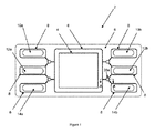
図1は、フレーム付きMEA2の平面図を示す。フレーム付きMEA2は、アノードとカソードとの間に配置されているイオノマー電解質を備えているMEA4と、エラストマーシール8をその表面上に伴うフレーム6とを有する。図1では、MEAの片側、例えば、アノード側が、示されている。フレーム6は、その活性エリアの周囲のMEA4の周縁を流動的にシールし、それによって、反応物質は、MEAの各側に隔離され、さらに、フレーム6は、アノードをカソードから電気的に隔離し、燃料電池スタック内の隣接するMEA間を電気的に隔離する。フレーム6はまた、反応物質、反応副産物、および冷却剤をMEA3に提供し、そこから排出するマニホールド10a、10b、12a、12b、14a、14bを形成する。エラストマーシール8が、フレーム6の表面上に形成され、MEA4の活性エリアならびにマニホールド10a、10b、12a、12b、14a、14bの周囲を包囲し、燃料電池を形成するとき、隣接するアノードセパレータ(図示せず)に対して流動的にシールする。MEAの周縁を熱可塑性フレームでシールし、次いで、エラストマー材料がMEAから物理的に分離されるように、フレーム上にエラストマーシールビーズを提供することによって、シールのエラストマー材料の劣化に起因するMEA劣化は、実質的に低減させられる。
FIG. 1 shows a plan view of the MEA2 with a frame. The framed MEA2 has a MEA4 with an ionomer electrolyte disposed between the anode and the cathode, and a frame 6 with an
図2は、図1の断面A−Aにおけるシール領域の断面図である。後節で論じられるであろうように、貫通孔24が、フレーム6を通して形成され、これは、流動処理可能シール材料で充填され、リザーバ26a、26bをフレーム6の第1の側および反対の第2の側に形成する。いくつかの実施形態では、フレーム6は、膜電極アセンブリの周縁に接合される2つ以上の重ねられたフレーム部材から成る層状構造を有することができる。湯道28a、28bも、フレーム6上に同じ流動処理可能シール材料から形成され、それは、リザーバ26a、26bからエラストマーシールビーズ8a、8bまで延びている。貫通孔24は、フレーム6内に提供されるMEA4およびマニホールドからオフセットされる(すなわち、それと整列させられない)。
FIG. 2 is a cross-sectional view of a seal region in cross section AA of FIG. As will be discussed in a later section, a through
フレーム付きMEAを形成するために、フレーム6が、最初に、MEAの周縁においてMEAの両側に設置され、次いで、熱および/または圧力によって接合され、フレーム付きMEAを形成する。貫通孔が、MEAおよびマニホールドから離れた場所において、フレーム内に提供される。貫通孔は、接合前または後に提供され得るが、貫通孔が接合前に形成される場合、整列は、より困難になる。フレーム付きMEAは、次いで、流動処理可能材料をフレーム上に射出成形するために、シール金型の中に設置される。 To form a framed MEA, frames 6 are first placed on either side of the MEA at the periphery of the MEA and then joined by heat and / or pressure to form a framed MEA. Through holes are provided in the frame at a location away from the MEA and manifold. Through-holes can be provided before or after joining, but alignment becomes more difficult if through-holes are formed before joining. The framed MEA is then placed in a seal mold for injection molding of the flowable material onto the frame.
図3は、エラストマーシールビーズをフレーム付きMEA上に形成するための例示的シール金型30a、30bの断面図を示す。給送スロット32が、流動処理可能シール材料をフレーム6の貫通孔24からシール領域34a、34bにリザーバ領域36a、36bおよび湯道領域38a、38bを通して給送するために提供される。MEAのための結果として生じるシールは、フレームの貫通孔と整列させられるリザーバと、フレームの両側のリザーバに流動的に接続される複数の湯道と、湯道のうちの少なくとも1つに流動的に接続されるエラストマーシールビーズとを含む。エラストマーシールビーズは、図1に示されるように、MEAおよび/またはマニホールドを包囲する。
FIG. 3 shows a cross-sectional view of
前で記載されるように、エラストマーシールをフレーム上に提供するための熱可塑性フレーム上への流動処理可能材料の射出成形は、制御が困難であり、金型内の流動処理可能材料の分散を正確に調整することが困難である。しかしながら、本発明者らは、湯道領域の水力直径がリザーバ領域未満である場合、シール金型におけるリザーバ領域および湯道領域を使用して、流動処理可能材料をフレーム上にフレーム内の貫通孔を通して直接提供することによって、解決策を発見した。方法は、いくつかの利点を有する。 As described earlier, injection molding of a flowable material onto a thermoplastic frame to provide an elastomeric seal on the frame is difficult to control and disperses the flowable material in the mold. It is difficult to adjust accurately. However, when the hydraulic diameter of the runner region is less than the reservoir region, we use the reservoir region and runner region in the seal mold to place a flowable material on the frame through holes in the frame. Discovered a solution by providing directly through. The method has several advantages.
第1に、流動処理可能材料は、流動処理可能材料をMEAおよびマニホールドから間隔を置かれたフレームの領域内のシールフレーム内の貫通孔を通して給送することによって(すなわち、貫通孔は、MEAまたはマニホールドと接触しない)、1つのステップにおいて、かつ金型の片側のみから、フレームの両側に容易に提供されることができる。これは、流動処理可能材料をフレーム上に提供する2ステップアプローチ(エラストマーシールを2つの別個のステップにおいて積層の各側に射出成形する)の必要性、または単一ステップにおいて、流動処理可能材料を上部および底部金型の両方から提供する必要性を排除する。さらに、流動処理可能材料は、MEAと接触せず、したがって、シリコーン等の材料を使用する場合、燃料電池動作中に形成される流動性シロキサンに起因する膜劣化が、低減または排除される。加えて、エラストマーシールは、燃料電池組立中にフレームと隣接する流場プレートとの間に設置される別個のエラストマーシールとしてではなく、フレームの両側に直接提供されるので、エラストマーシールを燃料電池の中に設置し、シールをフレームと流場プレートとの間で整列させる別個のステップ、およびそれに関連付けられた難点は、排除される。 First, the flow processable material is fed through a through hole in the seal frame within the area of the frame spaced from the MEA and manifold (ie, the through hole is MEA or It can be easily provided on both sides of the frame in one step (without contacting the manifold) and from only one side of the mold. This is the need for a two-step approach (injection molding the elastomer seal on each side of the laminate in two separate steps) to provide the flowable material on the frame, or in a single step, the flowable material. Eliminate the need to provide from both top and bottom molds. Further, the flow treatable material does not come into contact with the MEA, and therefore when a material such as silicone is used, film deterioration due to the fluid siloxane formed during fuel cell operation is reduced or eliminated. In addition, since the elastomer seal is provided directly on both sides of the frame, rather than as a separate elastomer seal installed between the frame and the adjacent flow field plate during fuel cell assembly, the elastomer seal is provided on the fuel cell. The separate step of installing inside and aligning the seal between the frame and the flow field plate, and the difficulties associated with it, are eliminated.
第2に、リザーバ領域は、流動処理可能材料の流動が、処理中、貫通孔を通って、フレームの第1および第2の側の湯道の中へより均一であるように、湯道と比較して低流動抵抗を提供するように寸法を決定される。リザーバが、小さすぎる、または存在しない(すなわち、リザーバが使用されない)場合、流動が、フレームの第2の側の湯道よりフレームの第1の側の湯道を通ってはるかに高速に進み、フレームの両側の湯道内に不均一な充填を生じさせるであろうことが可能である。例えば、リザーバは、フレームの片側において約1ミリメートルの直径および約150ミクロンの断面高さ(または厚さ)から、約5ミリメートルの直径および約1ミリメートルの断面高さ(または厚さ)に及び得る。加えて、リザーバ直径は、貫通孔直径より大きく、フレーム内の貫通孔とシール金型との間の不整列許容誤差を可能にする。リザーバは、フレームのためのある物理的「係止」特徴を提供し得るが、小サイズのリザーバは、提供され得る物理的「係止」量を限定する。 Second, the reservoir region is with the runner so that the flow of the flowable material is more uniform during the treatment through the through holes into the runways on the first and second sides of the frame. Dimensioned to provide comparatively low flow resistance. If the reservoir is too small or absent (ie, the reservoir is not used), the flow will proceed much faster through the runner on the first side of the frame than the runner on the second side of the frame. It is possible that non-uniform filling will occur in the runways on both sides of the frame. For example, the reservoir can range from a diameter of about 1 millimeter and a cross-sectional height (or thickness) of about 150 microns on one side of the frame to a diameter of about 5 millimeters and a cross-sectional height (or thickness) of about 1 millimeter. .. In addition, the reservoir diameter is larger than the through hole diameter, allowing for misalignment tolerance between the through hole in the frame and the seal mold. The reservoir may provide some physical "locking" feature for the frame, but the smaller size reservoir limits the amount of physical "locking" that can be provided.
第3に、流動処理可能材料が提供されるリザーバより小さい水力直径を伴う湯道領域を使用することによって、シールビーズ領域の中へのシリコーン材料のより優れた調整制御を可能にする。なぜなら、湯道の著しい圧力降下が、注入器から上部湯道(湯道28a)およびエラストマーシールビーズ8aへの流動の抵抗と、注入器から底部湯道(湯道28b)およびエラストマーシールビーズ8bへの流動の抵抗とを等化するからである。
Third, by using a runner region with a smaller hydraulic diameter than the reservoir in which the flowable material is provided, it allows for better adjustment control of the silicone material into the seal bead region. This is because the significant pressure drop in the runner is the resistance of flow from the injector to the upper runner (
当業者は、湯道およびリザーバが、製造中の流動処理可能材料の改良された制御を提供ように寸法を決定され、したがって、必ずしも、シール機能を隣接する流場プレートに対して提供するように寸法を決定されないことを理解するであろう。湯道およびリザーバは、流場プレートに対してシールしないので、湯道およびリザーバは、MEAの活性エリアならびにマニホールドを包囲するエラストマーシールビーズより短い。いくつかの実施形態では、湯道およびリザーバは、シールビーズ応力および寿命に影響を及ぼさないように、燃料電池スタック圧縮下、隣接する流場プレートに物理的に接触しない。例えば、湯道は、リザーバおよびシールより断面において短く、典型的には、シールビーズの高さの約半分未満であるが、流動処理可能材料がシール領域に給送される前に湯道内で硬化するほど小さくあるべきではない。例えば、湯道の断面高さは、少なくとも約50ミクロンであるが、約1.5ミリメートル未満であるべきである。具体的実施形態では、湯道の断面高さは、約50ミクロン〜約500ミクロンである。加えて、前述のように、湯道の寸法は、その水力直径がリザーバの水力直径未満となるように構成されるようなものである。さらに、貫通孔も、流動処理可能材料がリザーバ領域の中に注入されるとき、流動分散に影響を及ぼすことを回避するために、湯道が発生させるものと比較して、非常にわずかな流動制限を発生させるように寸法を決定されるべきである。例えば、貫通孔直径は、約200ミクロン〜4ミリメートルに及び得る。具体的実施形態では、貫通孔直径は、約400ミクロン〜約2ミリメートルに及び得る。 Those skilled in the art will appreciate that the runners and reservoirs are sized to provide improved control of the flowable material being manufactured and therefore necessarily provide sealing functionality to adjacent flow field plates. You will understand that the dimensions are not determined. Since the runway and reservoir do not seal against the flow field plate, the runway and reservoir are shorter than the elastomer seal beads that surround the active area of the MEA and the manifold. In some embodiments, the runner and reservoir do not physically contact adjacent flow field plates under fuel cell stack compression so as not to affect seal bead stress and life. For example, the runner is shorter in cross section than the reservoir and seal, typically less than about half the height of the seal beads, but hardens in the runway before the flowable material is fed into the seal area. It shouldn't be as small as it does. For example, the cross-sectional height of the runner should be at least about 50 microns, but less than about 1.5 millimeters. In a specific embodiment, the cross-sectional height of the runner is about 50 microns to about 500 microns. In addition, as mentioned above, the dimensions of the runner are such that its hydraulic diameter is configured to be less than the hydraulic diameter of the reservoir. In addition, the through-holes also have very little flow compared to what the runner creates to avoid affecting the flow dispersion when the flowable material is injected into the reservoir area. The dimensions should be determined to give rise to restrictions. For example, through-hole diameters can range from about 200 microns to 4 millimeters. In a specific embodiment, the through-hole diameter can range from about 400 microns to about 2 millimeters.
MEAおよびマニホールドをシールするために、いくつかの貫通孔が、フレームの非活性部分全体を通して使用され得る。当業者は、MEAおよびマニホールドの周縁の周囲のシールビーズの経路長ならびに湯道のサイズに依存するであろう、貫通孔の場所および貫通孔の各々におけるリザーバの各々から延びている湯道の数を容易に決定するであろう。2つ以上の湯道が、同一リザーバから延びている場合、湯道は、限定ではないが、シールビーズまでの距離およびシールビーズの体積等、それらが接続されるシールの部分のための所望の流動特性に応じて、互いに異なって寸法を決定され得る。さらに、フレームの両側の湯道は、同一サイズである必要も、整列させられる必要もない。 Several through holes can be used throughout the inactive portion of the frame to seal the MEA and manifold. Those skilled in the art will depend on the path length of the seal beads around the perimeter of the MEA and manifold and the size of the runner, the location of the through hole and the number of runways extending from each of the reservoirs at each of the through holes. Will be easily determined. If more than one runner extends from the same reservoir, the runner is the desired portion of the seal to which they are connected, such as, but not limited to, the distance to the seal beads and the volume of the seal beads. Depending on the flow characteristics, they can be sized differently from each other. Moreover, the runways on both sides of the frame need not be the same size or aligned.
任意の好適な材料が、フレームおよび流動処理可能シール材料のために使用され得る。例えば、フレームは、ポリエチレン、ポリプロピレン、ポリテトラフルオロエチレン(PTFE)、フッ化ビニリデン(PVDF)、ポリエチレンナフタレート(PEN)、ポリアミド、ポリイミド、ポリウレタン、およびポリエステル等の熱可塑性材料、ならびにフレーム材料として好適であろう当技術分野において公知の他の材料であり得る。フレームは、典型的には、シート、テープ、フィルム、または予備成形物として供給され、厚さ約25ミクロン〜約300ミクロンを有し得る。エラストマーシールのための流動処理可能シール材料は、シリコーン、エチレンプロピレンジエンターポリマー(EPDM)、フッ素ゴム、ペルフルオロゴム、クロロプレンゴム、フルオロシリコーンエラストマー、ポリイソブチレン(PIB)、エチレンプロピレンゴム(EPR)、および熱可塑性ゴム(TPR)、ならびに流動処理可能シール材料として好適であろう当技術分野において公知の他の材料であり得る。MEAの周縁を熱可塑性フレームでシールし、次いで、エラストマー材料がMEAから物理的に分離されるように、エラストマーシールビーズをフレーム上に提供することによって、エラストマーシール材料の劣化に関連するMEA劣化は、実質的に低減させられる。 Any suitable material can be used for the frame and flow processable sealing material. For example, the frame is suitable as a thermoplastic material such as polyethylene, polypropylene, polytetrafluoroethylene (PTFE), vinylidene fluoride (PVDF), polyethylene naphthalate (PEN), polyamide, polyimide, polyurethane, and polyester, and as a frame material. It may be another material known in the art. The frame is typically supplied as a sheet, tape, film, or preform and can have a thickness of about 25 microns to about 300 microns. Flowable sealable materials for elastomer seals are silicone, ethylene propylene dienter polymer (EPDM), fluororubber, perfluoro rubber, chloroprene rubber, fluorosilicone elastomer, polyisobutylene (PIB), ethylene propylene rubber (EPR), and It can be thermoplastic rubber (TPR), as well as other materials known in the art that would be suitable as flowable sealable materials. By sealing the periphery of the MEA with a thermoplastic frame and then providing the elastomer seal beads on the frame so that the elastomer material is physically separated from the MEA, the MEA degradation associated with the degradation of the elastomer seal material is , Substantially reduced.
本明細書で言及され、および/または出願データシートに列挙される、前述の米国特許、米国特許出願公開、米国特許出願、外国特許、外国特許出願、および非特許刊行物は全て、参照することによってその全体として本明細書に組み込まれる。 See all US patents, US patent application publications, US patent applications, foreign patents, foreign patent applications, and non-patent publications mentioned herein and / or listed in the application datasheet. Incorporated herein as a whole.
本発明の特定の要素、実施形態、および用途が、図示および説明されたが、本発明は、修正が、特に、前述の教示に照らして、本開示の精神および範囲から逸脱することなく、当業者によって成され得るため、それらに限定されないことを理解されたい。 Although specific elements, embodiments, and uses of the invention have been illustrated and described, the invention does not deviate from the spirit and scope of the present disclosure, in particular in the light of the teachings described above. It should be understood that it is not limited to those that can be done by one of ordinary skill in the art.
本願はまた、2015年2月12日に出願され、参照することによってその全体として本明細書に組み込まれる、米国仮特許出願第62/115,548の利益を主張するものである。 This application also claims the benefit of US Provisional Patent Application No. 62 / 115,548, which was filed on February 12, 2015 and is incorporated herein by reference in its entirety.
Claims (19)
フレームを前記膜電極アセンブリの周縁の周囲に提供することによって、フレーム付き膜電極アセンブリを形成することであって、前記フレームは、第1の側と、反対の第2の側とを備えている、ことと、
貫通孔を前記フレーム内に提供することであって、前記貫通孔は、前記膜電極アセンブリから間隔を置かれている、ことと、
前記フレーム付き膜電極アセンブリをシール金型の中に設置することであって、前記シール金型は、リザーバ領域と、シールビーズ領域と、前記リザーバ領域を前記シールビーズ領域に流動的に接続する少なくとも1つの湯道領域とを備えている、ことと、
射出成形用のシール材料を前記シール金型における前記リザーバ領域の中に給送することであって、前記リザーバ領域は、前記フレーム内の貫通孔と整列させられている、ことと、
前記シール材料を前記フレームの前記第1の側および前記第2の側と相互作用するように前記貫通孔を通して給送することと、
前記シール材料を前記リザーバ領域から前記少なくとも1つの湯道領域を介して前記シールビーズ領域に給送することによって、リザーバと少なくとも1つの湯道とシールビーズとを前記フレームの前記第1の側に形成することと
を含み、
前記リザーバおよび前記少なくとも1つの湯道および前記シールビーズは、前記膜電極アセンブリとは接触しておらず、
前記少なくとも1つの湯道領域および前記リザーバ領域のそれぞれは、前記膜電極アセンブリを含む平面に垂直な流れ方向における水力直径を有し、前記少なくとも1つの湯道領域の水力直径は、前記リザーバ領域の水力直径より小さく、
前記リザーバは、前記シール材料の硬化生成物であり、
前記フレームは、前記膜電極アセンブリの周縁をシールし、前記シールビーズは、前記シールビーズが前記膜電極アセンブリとは接触しないように前記フレーム上に提供される、方法。 A method of sealing a membrane electrode assembly with an ionomer electrolyte located between the anode and the cathode, said method.
By providing a frame around the periphery of the membrane electrode assembly, a framed membrane electrode assembly is formed, wherein the frame comprises a first side and an opposite second side. , That and
By providing a through hole within the frame, the through hole is spaced from the membrane electrode assembly.
The framed membrane electrode assembly is placed in a seal mold, wherein the seal mold fluidly connects the reservoir region, the seal bead region, and the reservoir region to the seal bead region. It has one runway area, and
By feeding the seal material for injection molding into the reservoir region in the seal mold, the reservoir region is aligned with the through holes in the frame.
Feeding the sealing material through the through hole so as to interact with the first side and the second side of the frame.
By feeding the sealing material from the reservoir region through the at least one runway region to the seal bead region, the reservoir, at least one runner and the seal bead are brought to the first side of the frame. Including forming
The reservoir and the at least one runner and the seal beads are not in contact with the membrane electrode assembly.
Each of the at least one runway region and the reservoir region has a hydraulic diameter in a flow direction perpendicular to the plane including the membrane electrode assembly, and the hydraulic diameter of the at least one runway region is the reservoir region. Smaller than hydraulic diameter,
The reservoir is a cured product of the sealing material.
The method, wherein the frame seals the periphery of the membrane electrode assembly, and the seal beads are provided on the frame so that the seal beads do not come into contact with the membrane electrode assembly .
フレーム付き膜電極アセンブリを形成するために膜電極アセンブリの周縁の周囲に提供されているフレームであって、前記フレームは、第1の側と、反対の第2の側とを備えている、フレームと、
前記フレーム内の貫通孔であって、前記貫通孔は、前記膜電極アセンブリから間隔を置かれている、貫通孔と、
前記貫通孔におけるリザーバであって、前記リザーバは、前記フレームの前記第1の側から前記反対の第2の側まで延びている、リザーバと、
前記フレームの前記第1の側の少なくとも1つの湯道およびシールビーズであって、前記少なくとも1つの湯道および前記シールビーズは、射出成形用のシール材料から作製されている、少なくとも1つの湯道およびシールビーズと
を備え、
前記リザーバおよび前記少なくとも1つの湯道および前記シールビーズは、前記膜電極アセンブリとは接触しておらず、
前記少なくとも1つの湯道および前記リザーバのそれぞれは、前記膜電極アセンブリを含む平面に垂直な流れ方向における水力直径を有し、前記少なくとも1つの湯道の水力直径は、前記リザーバの水力直径より小さく、
前記リザーバは、前記シール材料の硬化生成物であり、
前記フレームは、前記膜電極アセンブリの周縁をシールし、前記シールビーズは、前記シールビーズが前記膜電極アセンブリとは接触しないように前記フレーム上に提供される、シールされた膜電極アセンブリ。 A sealed membrane electrode assembly for a fuel cell, said sealed membrane electrode assembly.
A frame provided around the periphery of a membrane electrode assembly to form a framed membrane electrode assembly, wherein the frame comprises a first side and an opposite second side. When,
A through-hole in the frame, the through-hole being spaced from the membrane electrode assembly, and a through-hole.
A reservoir in the through hole, wherein the reservoir extends from the first side of the frame to the opposite second side.
At least one runner and seal beads on the first side of the frame, wherein the at least one runner and the seal beads are made of a sealing material for injection molding. And with seal beads,
The reservoir and the at least one runner and the seal beads are not in contact with the membrane electrode assembly.
Each of the at least one runway and the reservoir has a hydraulic diameter in a flow direction perpendicular to the plane containing the membrane electrode assembly, and the hydraulic diameter of the at least one runway is smaller than the hydraulic diameter of the reservoir. ,
The reservoir is a cured product of the sealing material.
A sealed membrane electrode assembly, wherein the frame seals the periphery of the membrane electrode assembly, and the seal beads are provided on the frame so that the seal beads do not come into contact with the membrane electrode assembly.
Applications Claiming Priority (3)
| Application Number | Priority Date | Filing Date | Title |
|---|---|---|---|
| US201562115548P | 2015-02-12 | 2015-02-12 | |
| US62/115,548 | 2015-02-12 | ||
| PCT/US2016/017516 WO2016130781A1 (en) | 2015-02-12 | 2016-02-11 | Seal for solid polymer electrolyte fuel cell |
Publications (2)
| Publication Number | Publication Date |
|---|---|
| JP2018510458A JP2018510458A (en) | 2018-04-12 |
| JP6842421B2 true JP6842421B2 (en) | 2021-03-17 |
Family
ID=55485328
Family Applications (1)
| Application Number | Title | Priority Date | Filing Date |
|---|---|---|---|
| JP2017542151A Active JP6842421B2 (en) | 2015-02-12 | 2016-02-11 | Seals for solid polymer electrolyte fuel cells |
Country Status (7)
| Country | Link |
|---|---|
| US (1) | US11088373B2 (en) |
| EP (1) | EP3257097B1 (en) |
| JP (1) | JP6842421B2 (en) |
| CN (1) | CN107534166B (en) |
| CA (1) | CA2976351C (en) |
| DK (1) | DK3257097T3 (en) |
| WO (1) | WO2016130781A1 (en) |
Families Citing this family (5)
| Publication number | Priority date | Publication date | Assignee | Title |
|---|---|---|---|---|
| JP7031620B2 (en) * | 2018-03-28 | 2022-03-08 | 豊田合成株式会社 | Manufacturing method of seal member for fuel cell and rubber composition for molding |
| CN109390610B (en) * | 2018-10-15 | 2021-05-25 | 南京大学昆山创新研究院 | Fuel cell membrane electrode production and packaging process |
| CN111572070A (en) * | 2020-05-22 | 2020-08-25 | 青岛开疆拓土农业装备科技有限公司 | Sealing mechanism of automatic intelligent greenhouse film repairing device |
| CN114551927B (en) * | 2021-12-21 | 2022-12-06 | 武汉众宇动力系统科技有限公司 | Membrane electrode assembly for proton exchange membrane fuel cell and glue injection sealing method thereof |
| DE102022119198A1 (en) | 2022-08-01 | 2024-02-01 | Schaeffler Technologies AG & Co. KG | Cell stack plate and method of attaching a gasket to a plate |
Family Cites Families (10)
| Publication number | Priority date | Publication date | Assignee | Title |
|---|---|---|---|---|
| EP1156546B1 (en) | 1997-07-16 | 2003-10-08 | Ballard Power Systems Inc. | Method of making a resilient seal for membrane electrode assembly (MEA) in an electrochemical fuel cell |
| DE69818874T2 (en) | 1997-07-16 | 2004-05-19 | Ballard Power Systems Inc., Burnaby | Process for producing an elastic seal for the membrane electrode arrangement (mea) in an electrochemical fuel cell |
| JP4439966B2 (en) | 2003-04-02 | 2010-03-24 | パナソニック株式会社 | Fuel cell electrolyte membrane structure, fuel cell electrolyte membrane-electrode assembly structure, and fuel cell |
| CN1536698B (en) | 2003-04-02 | 2010-12-15 | 松下电器产业株式会社 | Electrolyte film structure for fuel cell, MEA structure and fuel cell |
| US20050089746A1 (en) | 2003-10-23 | 2005-04-28 | Ballard Power Systems Inc. | Prevention of membrane contamination in electrochemical fuel cells |
| DE102006004748A1 (en) | 2006-02-02 | 2007-08-16 | Umicore Ag & Co. Kg | Membrane electrode unit with multi-component sealing edge |
| EP1826849A1 (en) * | 2006-02-24 | 2007-08-29 | Auto-Juntas, S.A. Unipersonal | Membrane electrode assembly with reinforced sealing structure |
| WO2008129840A1 (en) * | 2007-03-30 | 2008-10-30 | Panasonic Corporation | Polymer electrolyte fuel cell and electrode/film/frame assembly manufacturing method |
| JP5440775B2 (en) | 2009-10-30 | 2014-03-12 | Nok株式会社 | Fuel cell component and manufacturing method thereof |
| JP2014092191A (en) * | 2012-11-01 | 2014-05-19 | Nok Corp | Base material integrated type seal and metal mold for manufacturing the same |
-
2016
- 2016-02-11 CA CA2976351A patent/CA2976351C/en active Active
- 2016-02-11 EP EP16708527.3A patent/EP3257097B1/en active Active
- 2016-02-11 JP JP2017542151A patent/JP6842421B2/en active Active
- 2016-02-11 CN CN201680017562.4A patent/CN107534166B/en active Active
- 2016-02-11 WO PCT/US2016/017516 patent/WO2016130781A1/en active Application Filing
- 2016-02-11 US US15/550,758 patent/US11088373B2/en active Active
- 2016-02-11 DK DK16708527.3T patent/DK3257097T3/en active
Also Published As
| Publication number | Publication date |
|---|---|
| JP2018510458A (en) | 2018-04-12 |
| WO2016130781A1 (en) | 2016-08-18 |
| CN107534166B (en) | 2021-01-05 |
| CA2976351A1 (en) | 2016-08-18 |
| CA2976351C (en) | 2023-10-03 |
| US11088373B2 (en) | 2021-08-10 |
| EP3257097A1 (en) | 2017-12-20 |
| EP3257097B1 (en) | 2021-12-15 |
| CN107534166A (en) | 2018-01-02 |
| US20180034074A1 (en) | 2018-02-01 |
| DK3257097T3 (en) | 2022-01-17 |
Similar Documents
| Publication | Publication Date | Title |
|---|---|---|
| JP6842421B2 (en) | Seals for solid polymer electrolyte fuel cells | |
| US9484581B2 (en) | Integrally molded gasket for a fuel cell assembly | |
| US8703360B2 (en) | Method for producing an electrode-membrane-frame assembly | |
| US8399150B2 (en) | Integrated fuel cell assembly and method of making | |
| JP5638508B2 (en) | Manufacturing method of electrolyte membrane / electrode structure with resin frame for fuel cell | |
| JP5855540B2 (en) | Electrolyte membrane / electrode structure with resin frame for fuel cells | |
| EP3167505B1 (en) | Fuel cell assemblies with improved reactant flow | |
| JP5855442B2 (en) | Manufacturing method of electrolyte membrane / electrode structure with resin frame for fuel cell | |
| KR102269499B1 (en) | Fuel cell sub-assembly and method of making it | |
| EP3357118B1 (en) | Fuel cell sub-assembly | |
| KR20180017039A (en) | Electrochemical device and method for manufacturing electrochemical unit for electrochemical device | |
| US20080166617A1 (en) | Fuel cell and cell assembly for fuel cell | |
| US9680166B2 (en) | Integrated gas diffusion layer with sealing function and method of making the same | |
| US11171341B2 (en) | Fuel cell and method of manufacturing fuel cell | |
| CA2861978A1 (en) | Fuel cell with sealing structure between the frame and separator | |
| EP2668689B1 (en) | Fuel cell seal | |
| JP2016095902A (en) | Fuel battery and manufacturing method for the same | |
| KR101822246B1 (en) | Fuel cell stack | |
| US10074869B2 (en) | Fuel cell | |
| JP5809614B2 (en) | Fuel cell stack | |
| CN116895780A (en) | Enhanced sealed fuel cell assembly |
Legal Events
| Date | Code | Title | Description |
|---|---|---|---|
| A621 | Written request for application examination |
Free format text: JAPANESE INTERMEDIATE CODE: A621 Effective date: 20181220 |
|
| A977 | Report on retrieval |
Free format text: JAPANESE INTERMEDIATE CODE: A971007 Effective date: 20191030 |
|
| A131 | Notification of reasons for refusal |
Free format text: JAPANESE INTERMEDIATE CODE: A131 Effective date: 20191105 |
|
| A601 | Written request for extension of time |
Free format text: JAPANESE INTERMEDIATE CODE: A601 Effective date: 20200205 |
|
| A521 | Request for written amendment filed |
Free format text: JAPANESE INTERMEDIATE CODE: A523 Effective date: 20200310 |
|
| A131 | Notification of reasons for refusal |
Free format text: JAPANESE INTERMEDIATE CODE: A131 Effective date: 20200702 |
|
| A521 | Request for written amendment filed |
Free format text: JAPANESE INTERMEDIATE CODE: A523 Effective date: 20200910 |
|
| TRDD | Decision of grant or rejection written | ||
| A01 | Written decision to grant a patent or to grant a registration (utility model) |
Free format text: JAPANESE INTERMEDIATE CODE: A01 Effective date: 20210202 |
|
| A61 | First payment of annual fees (during grant procedure) |
Free format text: JAPANESE INTERMEDIATE CODE: A61 Effective date: 20210219 |
|
| R150 | Certificate of patent or registration of utility model |
Ref document number: 6842421 Country of ref document: JP Free format text: JAPANESE INTERMEDIATE CODE: R150 |
|
| R250 | Receipt of annual fees |
Free format text: JAPANESE INTERMEDIATE CODE: R250 |