EP3167505B1 - Fuel cell assemblies with improved reactant flow - Google Patents
Fuel cell assemblies with improved reactant flow Download PDFInfo
- Publication number
- EP3167505B1 EP3167505B1 EP15736595.8A EP15736595A EP3167505B1 EP 3167505 B1 EP3167505 B1 EP 3167505B1 EP 15736595 A EP15736595 A EP 15736595A EP 3167505 B1 EP3167505 B1 EP 3167505B1
- Authority
- EP
- European Patent Office
- Prior art keywords
- flow field
- oxidant
- transition region
- fuel
- gas diffusion
- Prior art date
- Legal status (The legal status is an assumption and is not a legal conclusion. Google has not performed a legal analysis and makes no representation as to the accuracy of the status listed.)
- Active
Links
Images

Classifications
-
- H—ELECTRICITY
- H01—ELECTRIC ELEMENTS
- H01M—PROCESSES OR MEANS, e.g. BATTERIES, FOR THE DIRECT CONVERSION OF CHEMICAL ENERGY INTO ELECTRICAL ENERGY
- H01M8/00—Fuel cells; Manufacture thereof
- H01M8/02—Details
- H01M8/0202—Collectors; Separators, e.g. bipolar separators; Interconnectors
- H01M8/0258—Collectors; Separators, e.g. bipolar separators; Interconnectors characterised by the configuration of channels, e.g. by the flow field of the reactant or coolant
- H01M8/026—Collectors; Separators, e.g. bipolar separators; Interconnectors characterised by the configuration of channels, e.g. by the flow field of the reactant or coolant characterised by grooves, e.g. their pitch or depth
-
- H—ELECTRICITY
- H01—ELECTRIC ELEMENTS
- H01M—PROCESSES OR MEANS, e.g. BATTERIES, FOR THE DIRECT CONVERSION OF CHEMICAL ENERGY INTO ELECTRICAL ENERGY
- H01M8/00—Fuel cells; Manufacture thereof
- H01M8/02—Details
- H01M8/0202—Collectors; Separators, e.g. bipolar separators; Interconnectors
- H01M8/0204—Non-porous and characterised by the material
- H01M8/0206—Metals or alloys
-
- H—ELECTRICITY
- H01—ELECTRIC ELEMENTS
- H01M—PROCESSES OR MEANS, e.g. BATTERIES, FOR THE DIRECT CONVERSION OF CHEMICAL ENERGY INTO ELECTRICAL ENERGY
- H01M8/00—Fuel cells; Manufacture thereof
- H01M8/02—Details
- H01M8/0202—Collectors; Separators, e.g. bipolar separators; Interconnectors
- H01M8/0258—Collectors; Separators, e.g. bipolar separators; Interconnectors characterised by the configuration of channels, e.g. by the flow field of the reactant or coolant
-
- H—ELECTRICITY
- H01—ELECTRIC ELEMENTS
- H01M—PROCESSES OR MEANS, e.g. BATTERIES, FOR THE DIRECT CONVERSION OF CHEMICAL ENERGY INTO ELECTRICAL ENERGY
- H01M8/00—Fuel cells; Manufacture thereof
- H01M8/02—Details
- H01M8/0202—Collectors; Separators, e.g. bipolar separators; Interconnectors
- H01M8/0267—Collectors; Separators, e.g. bipolar separators; Interconnectors having heating or cooling means, e.g. heaters or coolant flow channels
-
- H—ELECTRICITY
- H01—ELECTRIC ELEMENTS
- H01M—PROCESSES OR MEANS, e.g. BATTERIES, FOR THE DIRECT CONVERSION OF CHEMICAL ENERGY INTO ELECTRICAL ENERGY
- H01M8/00—Fuel cells; Manufacture thereof
- H01M8/02—Details
- H01M8/0271—Sealing or supporting means around electrodes, matrices or membranes
- H01M8/0273—Sealing or supporting means around electrodes, matrices or membranes with sealing or supporting means in the form of a frame
-
- H—ELECTRICITY
- H01—ELECTRIC ELEMENTS
- H01M—PROCESSES OR MEANS, e.g. BATTERIES, FOR THE DIRECT CONVERSION OF CHEMICAL ENERGY INTO ELECTRICAL ENERGY
- H01M8/00—Fuel cells; Manufacture thereof
- H01M8/10—Fuel cells with solid electrolytes
- H01M8/1007—Fuel cells with solid electrolytes with both reactants being gaseous or vaporised
-
- H—ELECTRICITY
- H01—ELECTRIC ELEMENTS
- H01M—PROCESSES OR MEANS, e.g. BATTERIES, FOR THE DIRECT CONVERSION OF CHEMICAL ENERGY INTO ELECTRICAL ENERGY
- H01M8/00—Fuel cells; Manufacture thereof
- H01M8/24—Grouping of fuel cells, e.g. stacking of fuel cells
- H01M8/241—Grouping of fuel cells, e.g. stacking of fuel cells with solid or matrix-supported electrolytes
- H01M8/242—Grouping of fuel cells, e.g. stacking of fuel cells with solid or matrix-supported electrolytes comprising framed electrodes or intermediary frame-like gaskets
-
- H—ELECTRICITY
- H01—ELECTRIC ELEMENTS
- H01M—PROCESSES OR MEANS, e.g. BATTERIES, FOR THE DIRECT CONVERSION OF CHEMICAL ENERGY INTO ELECTRICAL ENERGY
- H01M8/00—Fuel cells; Manufacture thereof
- H01M8/24—Grouping of fuel cells, e.g. stacking of fuel cells
- H01M8/2465—Details of groupings of fuel cells
- H01M8/2483—Details of groupings of fuel cells characterised by internal manifolds
-
- H—ELECTRICITY
- H01—ELECTRIC ELEMENTS
- H01M—PROCESSES OR MEANS, e.g. BATTERIES, FOR THE DIRECT CONVERSION OF CHEMICAL ENERGY INTO ELECTRICAL ENERGY
- H01M8/00—Fuel cells; Manufacture thereof
- H01M8/10—Fuel cells with solid electrolytes
- H01M2008/1095—Fuel cells with polymeric electrolytes
-
- Y—GENERAL TAGGING OF NEW TECHNOLOGICAL DEVELOPMENTS; GENERAL TAGGING OF CROSS-SECTIONAL TECHNOLOGIES SPANNING OVER SEVERAL SECTIONS OF THE IPC; TECHNICAL SUBJECTS COVERED BY FORMER USPC CROSS-REFERENCE ART COLLECTIONS [XRACs] AND DIGESTS
- Y02—TECHNOLOGIES OR APPLICATIONS FOR MITIGATION OR ADAPTATION AGAINST CLIMATE CHANGE
- Y02E—REDUCTION OF GREENHOUSE GAS [GHG] EMISSIONS, RELATED TO ENERGY GENERATION, TRANSMISSION OR DISTRIBUTION
- Y02E60/00—Enabling technologies; Technologies with a potential or indirect contribution to GHG emissions mitigation
- Y02E60/30—Hydrogen technology
- Y02E60/50—Fuel cells
Definitions
- This invention relates to the flow of reactants in fuel cell assemblies for solid polymer electrolyte fuel cell stacks.
- it relates to designs and methods for improving the flow of reactants in the transition regions of the flow field plates for such fuel cells.
- Fuel cells electrochemically convert fuel and oxidant reactants, (e.g. hydrogen and oxygen or air respectively), to generate electric power.
- oxidant reactants e.g. hydrogen and oxygen or air respectively
- One type of fuel cell is a solid polymer electrolyte fuel cell which generally employs a proton conducting polymer membrane electrolyte between cathode and anode electrodes.
- the electrodes contain appropriate catalysts and typically also comprise conductive particles, binder, and material to modify wettability.
- a structure comprising a proton conducting polymer membrane sandwiched between two electrodes is known as a membrane electrode assembly (MEA).
- MEA membrane electrode assembly
- Such assemblies can be prepared in an efficient manner by appropriately coating catalyst mixtures onto the polymer membrane, and thus is commonly known as a catalyst coated membranes (CCM).
- CCM catalyst coated membranes
- Anode and cathode gas diffusion layers are usually employed adjacent their respective electrodes on either side of a catalyst coated membrane.
- the gas diffusion layers serve to uniformly distribute reactants to and remove by-products from the catalyst electrodes.
- Fuel and oxidant flow field plates are then typically provided adjacent their respective gas diffusion layers and the combination of all these components represents a typical individual fuel cell assembly.
- the flow field plates comprise flow fields that usually contain numerous fluid distribution channels.
- the flow field plates serve multiple functions including: distribution of reactants to the gas diffusion layers, removal of by-products therefrom, structural support and containment, and current collection. Often, the fuel and oxidant flow field plates are assembled into a unitary bipolar plate in order to incorporate a coolant flow field therebetween and/or for other assembly purposes.
- Fuel cell stacks can be further connected in arrays of interconnected stacks in series and/or parallel for use in automotive applications and the like.
- Stacks designed to achieve high power density typically circulate liquid coolant throughout the stack in order to remove heat quickly and efficiently.
- coolant flow fields comprising numerous coolant channels are also typically incorporated in the flow field plates of the cells in the stacks.
- the coolant flow fields are typically formed on the electrochemically inactive surfaces of both the anode side and cathode side flow field plates and, by appropriate design, a sealed coolant flow field is created when both anode and cathode side plates are mated together into a bipolar plate assembly.
- Conventional frames for MEAs typically comprise two polymeric films that are bonded to and sandwich the membrane or catalyst coated membrane at the edge. The frame is then used as a gasket for sealing purposes. Often the gas diffusion layers employed with such designs extend beyond the active area of the electrodes in order to mechanically assist in other peripheral seals. In these designs, elastomeric seals for external sealing of the fuel cell assembly may either be molded onto the bipolar plate or molded discretely and then preassembled to the bipolar plate.
- the polymeric films employed can be thermoplastics (e.g. polyethylene) or polymers coated with suitable adhesive (e.g. heat activated adhesive).
- a series of ports are generally provided at opposing ends of the individual cells such that when the cells are stacked together they form manifolds for these fluids.
- Further required design features then are passageways in the plates to distribute the bulk fluids in these formed manifolds to and from the various channels in the reactant and coolant flow fields in the plates.
- these passageway regions are referred to as the transition regions.
- the transition regions can themselves comprise numerous fluid distribution channels, e.g. oxidant and/or fuel transition channels.
- US20130089802 discloses certain exemplary port and transition region constructions in the prior art.
- Another desirable feature in the flow field plates can include the use of what are known in the art as backfeed ports.
- Such ports allow for bulk fluids to initially be distributed from the formed manifolds to the "back" or inactive sides of the flow field plates and then subsequently to be fed to the active side of the plates through the backfeed ports.
- a reactant backfeed port is thus fluidly connected to a manifold port for that reactant via some suitable passage formed in the coolant surface of the plate.
- the reactant backfeed port is also fluidly connected to the reactant flow field on the reactant surface of the plate via the passageways of the associated transition region.
- US20080113254 for instance discloses exemplary flow field plate constructions incorporating backfeed features.
- the present invention provides for improved flow distribution of reactants in the transition regions of flow field plates for solid polymer electrolyte fuel cells and series stacks of such cells.
- the flow of reactant is shared more evenly amongst the plurality of channels in the flow fields in the active areas of the fuel cells. This is accomplished by increasing the height of support features in the transition regions and also optionally increasing the depth of the transition regions such that the support feature height and transition region depth are increased to be out of plane with respect to the landings in the reactant flow fields.
- the invention is particularly suitable for fuel cells employing metal flow field plates or plates in which no adhesives are employed in the transition regions.
- Relevant fuel cell assemblies for such fuel cell stacks comprise a membrane electrode assembly, a frame, cathode and anode gas diffusion layers, oxidant and fuel flow field plates, and an edge seal for the assembly.
- the membrane electrode assembly comprises a solid polymer electrolyte membrane electrolyte, a cathode on one side of the membrane electrolyte, and an anode on the other side of the membrane electrolyte.
- the frame is attached to the periphery of the membrane electrode assembly and can be made of plastic, e.g. polyethylene naphthalate.
- the cathode gas diffusion layer is adjacent to the cathode, and in a like manner, the anode gas diffusion layer adjacent to the anode.
- the oxidant flow field plate is adjacent to the cathode gas diffusion layer and comprises an oxidant flow field comprising a plurality of channels separated by landings on the side adjacent to the cathode gas diffusion layer, an oxidant port (and typically other ports as well), and a transition region between the oxidant flow field and the oxidant port in which the transition region has a depth and comprises support features.
- essentially all of the cathode gas diffusion layer is adjacent the oxidant flow field (i.e. the cathode gas diffusion layer is absent from the transition region).
- the fuel flow field plate is adjacent to the anode gas diffusion layer and comprises a fuel flow field comprising a plurality of channels separated by landings on the side adjacent to the anode gas diffusion layer, a fuel port (and typically other ports as well), and a transition region between the fuel flow field and the fuel port in which the transition region has a depth and comprises support features.
- essentially all of the anode gas diffusion layer is adjacent the fuel flow field (i.e. the anode gas diffusion layer is absent from the transition region).
- the seal is for sealing the frame to the oxidant and fuel flow field plates at an edge seal location and can be made of an elastomer, e.g. silicone.
- the support features in the transition region of at least one of the oxidant and fuel flow field plates are taller than the landings in the flow field of the at least one flow field plate.
- the depth of the transition region of the at least one flow field plate can also be greater than the depth of the channels in the flow field of the at least one flow field plate.
- the invention is particularly suitable for embodiments in which the at least one flow field plate is made of metal and/or for embodiments in which the transition region of the at least one flow field plate comprises no adhesive.
- improvements are made to the flow in both the oxidant and the fuel flow field plates in the fuel cell assembly.
- the support features in the transition regions of each of the oxidant and fuel flow field plates are taller than the landings in the respective flow fields of each of the oxidant and fuel flow field plates.
- the method of the invention comprises increasing the height of the support features in the transition region of at least one of, and preferably both, the oxidant and fuel flow field plates such that the increased support features are taller than the landings in the flow field of the at least one flow field plate.
- the method can comprise increasing the depth of the transition region of the at least one flow field plate, and preferably both plates, such that the depth of the deeper transition region is greater than the depth of the channels in the flow field of the at least one flow field plate.
- the height of the support features and the depth of the transition region are increased such that the total distance between the taller support features and deeper transition region is increased by an amount in the range from about 25 to 70%.
- the height of the support features and the depth of the transition region is increased such that the total distance between the taller support features and deeper transition region is increased by an amount in the range from about 100 to 400 micrometers.
- transition region is used herein with reference to a region in between the channels in the reactant flow fields and the reactant ports in a fuel cell flow field plate. In this region, fluid flow transitions from a single, large body of flow into a multiplicity of small channel flow streams.
- a transition region generally comprises features in order to appropriately transition the flow of reactants and by-products between the distributed flow required in the flow fields and the bulk flow occurring at the ports. The transition region is generally not considered as an electrochemically active part of the fuel cell.
- phrases such as "wherein essentially all of the cathode gas diffusion layer is adjacent the oxidant flow field" are used herein in context with the gas diffusion layers and refer to the alignment of these layers with respect to the flow fields and consequently also with respect to the transition regions.
- the gas diffusion layers are intended to completely oppose their respective flow fields and thus they do not deliberately extend into the transition region spaces.
- tolerances in manufacture and assembly there will not always be perfect alignment in practice.
- such phrases are intended to include some misalignment of these components as long as the functions and benefits of the invention are obtained.
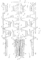
- FIG. 1 A top view of an exemplary oxidant flow field plate for a solid polymer electrolyte fuel cell is shown in Figure 1 to illustrate the typical flow in a transition region.
- Figure 1 shows a top view of the oxidant flow field side of this plate in the vicinity of the oxidant inlet end.
- oxidant flow field 2 On the visible side of oxidant flow field plate 1 is oxidant flow field 2 comprising a plurality of oxidant channels separated by landings (these features are quite small in Figure 1 and have not been identified with reference numerals).
- a coolant flow field (not visible in Figure 1 ).
- Oxidant flow field,plate 1 comprises oxidant inlet port 3, fuel inlet port 4, coolant inlet port 5, and backfeed port 6. Seals 7 surround the various ports and the periphery of the plate at an edge seal location and serves several sealing functions including sealing the frame of a framed MEA (not present in Figure 1 ) to plate 1. Transition region 8 occupies the space between backfeed port 6 and oxidant flow field 2. In the embodiment pictured in Figure 1 , transition region 8 comprises numerous cone shaped support features 9 which serve to support the frame of a framed MEA.
- the numerous oxidant ports 3 in the stacked fuel cells form an oxidant inlet manifold. Oxidant is supplied to this inlet manifold and is thus distributed to each oxidant port 3 in the fuel cell stack. Oxidant flows from oxidant port 3 to backfeed port 6 and into transition region 8 where it spreads out to be distributed to the channel inlets in oxidant flow field 2.
- the flow of oxidant is qualitatively indicated by arrows in Figure 1 .
- the incoming oxidant has further to travel through transition region 8 in order to access the uppermost channels in oxidant flow field 2 than it has to travel to access the lowermost channels in oxidant flow field 2. This results in an uneven flow of oxidant to the various channels. However the extent to which the flow is uneven depends on the resistance offered by the transition region to the flow of oxidant through it. The larger the hydraulic diameter is for the transition region, the lesser the resistance is to flow.
- Figure 2 shows a cross-sectional view of a bipolar plate comprising the oxidant flow field plate 1 of Figure 1 .
- the view is an enlarged isometric view in the transition region of oxidant flow field plate 1.
- fuel flow field plate 10 appears underneath and is welded to oxidant flow field plate 1.
- the visible portion of fuel flow field plate 10 is also a transition region, namely transition region 11 for the fuel.
- transition region 11 comprises a plurality of support features 12 that are shaped differently from cone-shaped support features 9 in transition region 8. (In other embodiments, support features 9 and 12 may be shaped similarly.)
- cone-shaped support features 9 are at the same height in plate 1 as the landings in flow field 2 (i.e.
- the tops of support features 9 are in the same plane as the flow field landings). Also in conventional fuel cells, the depth of transition region 8 can be at the same height as the channels in flow field 2 (i.e. the base of transition region 8 is in the same plane as the bottoms of the flow field channels).
- the effective hydraulic diameter of transition 8 is increased by increasing the height of support features 9 to be above the plane of the landings in flow field 2.
- the depth of transition region 8 can optionally be increased as well (i.e. the base of transition region 8 is lowered to be below the plane of the channels in flow field 2).
- the oxidant is better distributed throughout transition region 8 and the sharing of flow amongst the channels in flow field 2 is improved.
- Figure 3 illustrates how this can be accomplished in a practical embodiment for use in fuel cell stacks.
- Figure 3 shows a schematic cross-sectional view of the end of a fuel cell assembly comprising an oxidant flow field plate similar to that shown in Figure 1 as it would appear in an assembled fuel cell stack. The view is near the oxidant inlet port and the section has been taken along the section A-A indicated in Figure 1 . Note also that portions of adjacent fuel cell assemblies also appear in Figure 3 .
- Fuel cell assembly 20 includes MEA 21 which consists of solid polymer membrane electrolyte 22 which has been coated on opposing sides with cathode and anode catalysts to create anode 23 and cathode 24 respectively.
- Cathode gas diffusion layer 25 and anode gas diffusion layer 26 are located adjacent cathode 23 and anode 24 respectively.
- cathode gas diffusion layer 25 terminates at the same point as cathode 23 and thus is essentially coextensive with cathode 23.
- cathode gas diffusion layer 25 does not extend into oxidant transition region 40.
- anode gas diffusion layer 26 terminates at the same point as anode 24 and thus is essentially coextensive with anode 24.
- anode diffusion layer 26 does not extend into fuel transition region 41.
- MEA 21 is framed with a two piece frame which extends from within MEA 21, through transition regions 40, 41, and beyond the sealing region which includes seal 32 for oxidant flow field plate 30 and seal 33 for anode flow field plate 31.
- Frame piece 27 and frame piece 28 sandwich membrane electrolyte 21 near the edge 29 of MEA 21 and are generally bonded thereto. Outside MEA 21, frame pieces 27 and 28 are bonded together directly.
- Fuel cell assembly 20 also includes oxidant flow field plate 30 and fuel flow field plate 31 which are located adjacent cathode gas diffusion layer 25 and anode gas diffusion layer 26 respectively.
- the cross-sectional view of Figure 3 cuts through oxidant backfeed port 34, oxidant port 51, and oxidant vias 52a and 52b (which appear on either side of fuel cell assembly 20 and fluidly connect oxidant port 51 to backfeed port 34 and to backfeed port 34a in the adjacent fuel cell assembly above). Note that in order to focus on the relevant structures of the inventive fuel cell assembly, Figure 3 shows only a partial section of the end of the fuel cell stack. The structure on the outside of oxidant port 51 (which would appear further to the right if present in Figure 3 ) has been omitted.
- oxidant flow field plate 30a is similar to oxidant flow field plate 30
- fuel flow field plate 31b is similar to fuel flow field plate 31
- seal 32a is similar to seal 32
- seal 33b is similar to seal 33.
- oxidant flow field plate 30a and fuel flow field plate 31 create coolant flow field 50a therebetween.
- the mated pair consisting of oxidant flow field plate 30 and fuel flow field plate 31b creates coolant flow field 50b therebetween.
- Oxidant flow field plate 30 has an oxidant flow field formed therein which is made up of numerous parallel, linear oxidant channels separated by oxidant landings 35. The base of the oxidant channels between landings 35 are not visible in Figure 3 . However, the height of oxidant flow field plate 30 near the entrance 37 of the oxidant channels is at the same height as the base of the oxidant channels themselves.
- fuel flow field plate 31 has a fuel flow field formed therein which is made up of numerous parallel, linear fuel channels separated by fuel landings 36. Again, the base of the fuel channels between landings 36 are not visible in Figure 3 . But again, the height of fuel flow field plate 31 near the entrance 38 of the fuel channels is at the same height as the base of the fuel channels themselves.
- Oxidant transition region 40 has a base 44 with numerous support features 42 provided thereon for purposes of supporting the two piece frame comprising pieces 27, 28.
- fuel transition region 41 has a base 45 with numerous support features 43 provided thereon for purposes of supporting the two piece frame comprising pieces 27, 28 on the side opposite support features 42.
- Similar support features 42a, 43b and transition region bases 44a, 45b are shown in the adjacent fuel cell assemblies in Figure 3 .
- the support features in at least one of the oxidant and fuel flow field plates is taller than the landings in the flow field of that plate.
- Figure 3 illustrates these various dimensions in an embodiment where the support features in both oxidant and fuel flow field plates are taller than their respective landings.
- support features 42a in oxidant flow field plate 30a are taller than landings 35a in the plate's flow field by an amount x.
- support features 43b in oxidant flow field plate 31b are taller than landings 36b in the plate's flow field by an amount y.
- the ability to form taller support features in the transition regions is possible only if gas diffusion layers 25, 26 do not extend into and through the transition regions, and are instead essentially adjacent their respective flow fields. And preferably, the design is such that the gas diffusion layers are essentially coextensive with their respective electrodes.
- Figure 3 also exemplifies an embodiment in which the depths of the transition regions are greater than the depths of the channels in the associated flow fields.
- base 44a of the oxidant transition region in oxidant flow field plate 30a is deeper than that of base 37a of the associated oxidant flow field channels by an amount m.
- base 45b of the fuel transition region in fuel flow field plate 31b is deeper than that of base 38b of the associated fuel flow field channels by an amount n.
- these total distances can be increased by an amount in the range from about 25 to 70% and/or an amount in the range from about 100 to 400 micrometers.
- the invention therefore provides other potential advantages along with improvement in reactant flow and flow sharing between flow field channels.
Description
- This invention relates to the flow of reactants in fuel cell assemblies for solid polymer electrolyte fuel cell stacks. In particular, it relates to designs and methods for improving the flow of reactants in the transition regions of the flow field plates for such fuel cells.
- Fuel cells electrochemically convert fuel and oxidant reactants, (e.g. hydrogen and oxygen or air respectively), to generate electric power. One type of fuel cell is a solid polymer electrolyte fuel cell which generally employs a proton conducting polymer membrane electrolyte between cathode and anode electrodes. The electrodes contain appropriate catalysts and typically also comprise conductive particles, binder, and material to modify wettability. A structure comprising a proton conducting polymer membrane sandwiched between two electrodes is known as a membrane electrode assembly (MEA). Such assemblies can be prepared in an efficient manner by appropriately coating catalyst mixtures onto the polymer membrane, and thus is commonly known as a catalyst coated membranes (CCM).
- Anode and cathode gas diffusion layers are usually employed adjacent their respective electrodes on either side of a catalyst coated membrane. The gas diffusion layers serve to uniformly distribute reactants to and remove by-products from the catalyst electrodes. Fuel and oxidant flow field plates are then typically provided adjacent their respective gas diffusion layers and the combination of all these components represents a typical individual fuel cell assembly. The flow field plates comprise flow fields that usually contain numerous fluid distribution channels. The flow field plates serve multiple functions including: distribution of reactants to the gas diffusion layers, removal of by-products therefrom, structural support and containment, and current collection. Often, the fuel and oxidant flow field plates are assembled into a unitary bipolar plate in order to incorporate a coolant flow field therebetween and/or for other assembly purposes. Because the output voltage of a single cell is of order of 1V, a plurality of such fuel cell assemblies is usually stacked together in series for commercial applications. Fuel cell stacks can be further connected in arrays of interconnected stacks in series and/or parallel for use in automotive applications and the like.
- Along with water, heat is a significant by-product from the electrochemical reactions taking place within the fuel cell. Means for cooling a fuel cell stack is thus generally required. Stacks designed to achieve high power density (e.g. automotive stacks) typically circulate liquid coolant throughout the stack in order to remove heat quickly and efficiently. To accomplish this, coolant flow fields comprising numerous coolant channels are also typically incorporated in the flow field plates of the cells in the stacks. The coolant flow fields are typically formed on the electrochemically inactive surfaces of both the anode side and cathode side flow field plates and, by appropriate design, a sealed coolant flow field is created when both anode and cathode side plates are mated together into a bipolar plate assembly.
- Numerous seals are required in typical fuel cell stack construction, and achieving adequate, reliable seals in a manner suitable for commercial, high volume manufacture is challenging. Around the periphery of the MEAs, pressurized fuel and oxidant gases must be separated from each other (i.e. gas shorting around the edges of the membrane must be prevented) and also prevented from leaking to the external environment. Frames are commonly used to seal working fluids at the edges of MEAs.
- Conventional frames for MEAs typically comprise two polymeric films that are bonded to and sandwich the membrane or catalyst coated membrane at the edge. The frame is then used as a gasket for sealing purposes. Often the gas diffusion layers employed with such designs extend beyond the active area of the electrodes in order to mechanically assist in other peripheral seals. In these designs, elastomeric seals for external sealing of the fuel cell assembly may either be molded onto the bipolar plate or molded discretely and then preassembled to the bipolar plate. The polymeric films employed can be thermoplastics (e.g. polyethylene) or polymers coated with suitable adhesive (e.g. heat activated adhesive).
- To provide both reactants and the coolant to and from the individual cells in the stack, a series of ports are generally provided at opposing ends of the individual cells such that when the cells are stacked together they form manifolds for these fluids. Further required design features then are passageways in the plates to distribute the bulk fluids in these formed manifolds to and from the various channels in the reactant and coolant flow fields in the plates. Herein, these passageway regions are referred to as the transition regions. The transition regions can themselves comprise numerous fluid distribution channels, e.g. oxidant and/or fuel transition channels.
US20130089802 discloses certain exemplary port and transition region constructions in the prior art. - Another desirable feature in the flow field plates can include the use of what are known in the art as backfeed ports. Such ports allow for bulk fluids to initially be distributed from the formed manifolds to the "back" or inactive sides of the flow field plates and then subsequently to be fed to the active side of the plates through the backfeed ports. A reactant backfeed port is thus fluidly connected to a manifold port for that reactant via some suitable passage formed in the coolant surface of the plate. And the reactant backfeed port is also fluidly connected to the reactant flow field on the reactant surface of the plate via the passageways of the associated transition region.
US20080113254 for instance discloses exemplary flow field plate constructions incorporating backfeed features. - It is generally preferable to supply and remove the reactant and coolant streams as uniformly or evenly as possible to and from their respective flow fields. This is to achieve uniform use of the active areas in the electrodes and provide even cooling of the plates, and thus avoid hot spots, non-uniform water distribution and management issues, and so on. However, it is challenging to distribute large volumes of fluid from single inlet manifolds uniformly to the numerous flow field channels and uniformly from the numerous flow field channels back to single outlet manifolds. This gets even more challenging as fuel cell and stack dimensions decrease as designers strive to improve power density from fuel cell stacks. As these dimensions shrink, the hydraulic size available for the transition regions also shrinks. Thus it gets increasingly difficult to distribute fluids to and from the numerous channels without experiencing significant pressure differences over the channel inlets and outlets, and hence it is increasingly difficult to achieve a desired uniformity in the distributions of the various fluids.
- Consequently there is a continuing need for new designs and methods to improve the reactant flows and make them more uniform, particularly in the transition areas in such fuel cells. This invention fulfills these needs and provides further related advantages.
- The present invention provides for improved flow distribution of reactants in the transition regions of flow field plates for solid polymer electrolyte fuel cells and series stacks of such cells. The flow of reactant is shared more evenly amongst the plurality of channels in the flow fields in the active areas of the fuel cells. This is accomplished by increasing the height of support features in the transition regions and also optionally increasing the depth of the transition regions such that the support feature height and transition region depth are increased to be out of plane with respect to the landings in the reactant flow fields. The invention is particularly suitable for fuel cells employing metal flow field plates or plates in which no adhesives are employed in the transition regions.
- Relevant fuel cell assemblies for such fuel cell stacks comprise a membrane electrode assembly, a frame, cathode and anode gas diffusion layers, oxidant and fuel flow field plates, and an edge seal for the assembly. Further, the membrane electrode assembly comprises a solid polymer electrolyte membrane electrolyte, a cathode on one side of the membrane electrolyte, and an anode on the other side of the membrane electrolyte. The frame is attached to the periphery of the membrane electrode assembly and can be made of plastic, e.g. polyethylene naphthalate. The cathode gas diffusion layer is adjacent to the cathode, and in a like manner, the anode gas diffusion layer adjacent to the anode. The oxidant flow field plate is adjacent to the cathode gas diffusion layer and comprises an oxidant flow field comprising a plurality of channels separated by landings on the side adjacent to the cathode gas diffusion layer, an oxidant port (and typically other ports as well), and a transition region between the oxidant flow field and the oxidant port in which the transition region has a depth and comprises support features. In these relevant fuel cell assemblies, essentially all of the cathode gas diffusion layer is adjacent the oxidant flow field (i.e. the cathode gas diffusion layer is absent from the transition region). Again in a like manner, the fuel flow field plate is adjacent to the anode gas diffusion layer and comprises a fuel flow field comprising a plurality of channels separated by landings on the side adjacent to the anode gas diffusion layer, a fuel port (and typically other ports as well), and a transition region between the fuel flow field and the fuel port in which the transition region has a depth and comprises support features. And again, in these relevant fuel cell assemblies, essentially all of the anode gas diffusion layer is adjacent the fuel flow field (i.e. the anode gas diffusion layer is absent from the transition region). The seal is for sealing the frame to the oxidant and fuel flow field plates at an edge seal location and can be made of an elastomer, e.g. silicone. In the present invention, the support features in the transition region of at least one of the oxidant and fuel flow field plates are taller than the landings in the flow field of the at least one flow field plate. In addition, the depth of the transition region of the at least one flow field plate can also be greater than the depth of the channels in the flow field of the at least one flow field plate.
- The invention is particularly suitable for embodiments in which the at least one flow field plate is made of metal and/or for embodiments in which the transition region of the at least one flow field plate comprises no adhesive. Preferably, improvements are made to the flow in both the oxidant and the fuel flow field plates in the fuel cell assembly. Preferably therefore the support features in the transition regions of each of the oxidant and fuel flow field plates are taller than the landings in the respective flow fields of each of the oxidant and fuel flow field plates.
- Compared to convention fuel cells then, the method of the invention comprises increasing the height of the support features in the transition region of at least one of, and preferably both, the oxidant and fuel flow field plates such that the increased support features are taller than the landings in the flow field of the at least one flow field plate. In addition, the method can comprise increasing the depth of the transition region of the at least one flow field plate, and preferably both plates, such that the depth of the deeper transition region is greater than the depth of the channels in the flow field of the at least one flow field plate. In certain practical embodiments, the height of the support features and the depth of the transition region are increased such that the total distance between the taller support features and deeper transition region is increased by an amount in the range from about 25 to 70%. Also, in certain practical the height of the support features and the depth of the transition region is increased such that the total distance between the taller support features and deeper transition region is increased by an amount in the range from about 100 to 400 micrometers.
- These and other aspects of the invention are evident upon reference to the attached Figures and following detailed description.
-
-
Figure 1 shows a top view of the oxidant flow field side of an exemplary oxidant flow field plate for a solid polymer electrolyte fuel cell in the vicinity of the oxidant inlet end. -
Figure 2 shows a cross-sectional view of a bipolar plate which comprises the oxidant flow field plate ofFigure 1 . The view is an enlarged isometric view in the transition region of the oxidant flow field plate. -
Figure 3 shows a schematic cross-sectional view of the end of a fuel cell assembly comprising an oxidant flow field plate similar to that shown inFigure 1 as it would appear in a fuel cell stack. The view is near the oxidant inlet port. - Herein, the following definitions have been used. In a quantitative context, the term "about" should be construed as being in the range up to plus 10% and down to minus 10%.
- The term "transition region" is used herein with reference to a region in between the channels in the reactant flow fields and the reactant ports in a fuel cell flow field plate. In this region, fluid flow transitions from a single, large body of flow into a multiplicity of small channel flow streams. A transition region generally comprises features in order to appropriately transition the flow of reactants and by-products between the distributed flow required in the flow fields and the bulk flow occurring at the ports. The transition region is generally not considered as an electrochemically active part of the fuel cell.
- Phrases such as "wherein essentially all of the cathode gas diffusion layer is adjacent the oxidant flow field" are used herein in context with the gas diffusion layers and refer to the alignment of these layers with respect to the flow fields and consequently also with respect to the transition regions. In particular, the gas diffusion layers are intended to completely oppose their respective flow fields and thus they do not deliberately extend into the transition region spaces. However, due to tolerances in manufacture and assembly, there will not always be perfect alignment in practice. Thus, such phrases are intended to include some misalignment of these components as long as the functions and benefits of the invention are obtained.
- A top view of an exemplary oxidant flow field plate for a solid polymer electrolyte fuel cell is shown in
Figure 1 to illustrate the typical flow in a transition region. Specifically,Figure 1 shows a top view of the oxidant flow field side of this plate in the vicinity of the oxidant inlet end. On the visible side of oxidant flowfield plate 1 is oxidant flow field 2 comprising a plurality of oxidant channels separated by landings (these features are quite small inFigure 1 and have not been identified with reference numerals). On the opposite side of oxidant flowfield plate 1 is a coolant flow field (not visible inFigure 1 ). - Oxidant flow field,
plate 1 comprisesoxidant inlet port 3, fuel inlet port 4, coolant inlet port 5, and backfeed port 6.Seals 7 surround the various ports and the periphery of the plate at an edge seal location and serves several sealing functions including sealing the frame of a framed MEA (not present inFigure 1 ) toplate 1. Transition region 8 occupies the space between backfeed port 6 and oxidant flow field 2. In the embodiment pictured inFigure 1 , transition region 8 comprises numerous cone shaped support features 9 which serve to support the frame of a framed MEA. - When assembled into a fuel cell stack, the
numerous oxidant ports 3 in the stacked fuel cells form an oxidant inlet manifold. Oxidant is supplied to this inlet manifold and is thus distributed to eachoxidant port 3 in the fuel cell stack. Oxidant flows fromoxidant port 3 to backfeed port 6 and into transition region 8 where it spreads out to be distributed to the channel inlets in oxidant flow field 2. The flow of oxidant is qualitatively indicated by arrows inFigure 1 . As is evident from the design shown here, the incoming oxidant has further to travel through transition region 8 in order to access the uppermost channels in oxidant flow field 2 than it has to travel to access the lowermost channels in oxidant flow field 2. This results in an uneven flow of oxidant to the various channels. However the extent to which the flow is uneven depends on the resistance offered by the transition region to the flow of oxidant through it. The larger the hydraulic diameter is for the transition region, the lesser the resistance is to flow. -
Figure 2 shows a cross-sectional view of a bipolar plate comprising the oxidantflow field plate 1 ofFigure 1 . The view is an enlarged isometric view in the transition region of oxidant flowfield plate 1. InFigure 2 , fuelflow field plate 10 appears underneath and is welded to oxidant flowfield plate 1. The visible portion of fuelflow field plate 10 is also a transition region, namely transition region 11 for the fuel. InFigure 2 , transition region 11 comprises a plurality of support features 12 that are shaped differently from cone-shaped support features 9 in transition region 8. (In other embodiments, support features 9 and 12 may be shaped similarly.) In conventional fuel cells, cone-shaped support features 9 are at the same height inplate 1 as the landings in flow field 2 (i.e. the tops of support features 9 are in the same plane as the flow field landings). Also in conventional fuel cells, the depth of transition region 8 can be at the same height as the channels in flow field 2 (i.e. the base of transition region 8 is in the same plane as the bottoms of the flow field channels). - In the present invention, the effective hydraulic diameter of transition 8 is increased by increasing the height of support features 9 to be above the plane of the landings in flow field 2. In addition, the depth of transition region 8 can optionally be increased as well (i.e. the base of transition region 8 is lowered to be below the plane of the channels in flow field 2). By so doing, the oxidant is better distributed throughout transition region 8 and the sharing of flow amongst the channels in flow field 2 is improved.
Figure 3 illustrates how this can be accomplished in a practical embodiment for use in fuel cell stacks. -
Figure 3 shows a schematic cross-sectional view of the end of a fuel cell assembly comprising an oxidant flow field plate similar to that shown inFigure 1 as it would appear in an assembled fuel cell stack. The view is near the oxidant inlet port and the section has been taken along the section A-A indicated inFigure 1 . Note also that portions of adjacent fuel cell assemblies also appear inFigure 3 . -
Fuel cell assembly 20 includesMEA 21 which consists of solidpolymer membrane electrolyte 22 which has been coated on opposing sides with cathode and anode catalysts to create anode 23 and cathode 24 respectively. Cathode gas diffusion layer 25 and anodegas diffusion layer 26 are located adjacent cathode 23 and anode 24 respectively. As shown inFigure 3 , cathode gas diffusion layer 25 terminates at the same point as cathode 23 and thus is essentially coextensive with cathode 23. Importantly, cathode gas diffusion layer 25 does not extend intooxidant transition region 40. In a like manner, anodegas diffusion layer 26 terminates at the same point as anode 24 and thus is essentially coextensive with anode 24. Again importantly,anode diffusion layer 26 does not extend into fuel transition region 41. -
MEA 21 is framed with a two piece frame which extends from withinMEA 21, throughtransition regions 40, 41, and beyond the sealing region which includesseal 32 for oxidantflow field plate 30 and seal 33 for anodeflow field plate 31.Frame piece 27 andframe piece 28sandwich membrane electrolyte 21 near theedge 29 ofMEA 21 and are generally bonded thereto. OutsideMEA 21,frame pieces -
Fuel cell assembly 20 also includes oxidantflow field plate 30 and fuelflow field plate 31 which are located adjacent cathode gas diffusion layer 25 and anodegas diffusion layer 26 respectively. The cross-sectional view ofFigure 3 cuts through oxidant backfeed port 34,oxidant port 51, andoxidant vias 52a and 52b (which appear on either side offuel cell assembly 20 and fluidly connectoxidant port 51 to backfeed port 34 and to backfeed port 34a in the adjacent fuel cell assembly above). Note that in order to focus on the relevant structures of the inventive fuel cell assembly,Figure 3 shows only a partial section of the end of the fuel cell stack. The structure on the outside of oxidant port 51 (which would appear further to the right if present inFigure 3 ) has been omitted. - To assist in illustrating the invention, the plates and seals adjacent
fuel cell assembly 20 are also shown inFigure 3 . These plates and seals are of similar construction to those infuel cell assembly 20 and belong to adjacent fuel cell assemblies in the fuel cell stack. Thus, oxidant flow field plate 30a is similar to oxidant flowfield plate 30, fuel flow field plate 31b is similar to fuelflow field plate 31,seal 32a is similar to seal 32, and seal 33b is similar to seal 33. Mated together, oxidant flow field plate 30a and fuelflow field plate 31 create coolant flow field 50a therebetween. In a like manner, the mated pair consisting of oxidant flowfield plate 30 and fuel flow field plate 31b creates coolant flow field 50b therebetween. - Oxidant
flow field plate 30 has an oxidant flow field formed therein which is made up of numerous parallel, linear oxidant channels separated byoxidant landings 35. The base of the oxidant channels betweenlandings 35 are not visible inFigure 3 . However, the height of oxidant flowfield plate 30 near theentrance 37 of the oxidant channels is at the same height as the base of the oxidant channels themselves. In a like manner, fuelflow field plate 31 has a fuel flow field formed therein which is made up of numerous parallel, linear fuel channels separated byfuel landings 36. Again, the base of the fuel channels betweenlandings 36 are not visible inFigure 3 . But again, the height of fuelflow field plate 31 near the entrance 38 of the fuel channels is at the same height as the base of the fuel channels themselves. Also shown in the adjacent fuel cell assemblies inFigure 3 areoxidant landings 35a andentrance 37a to the oxidant channels formed in adjacent oxidant flow field plate 30a, along with fuel landings 36b andentrance 38b to the fuel channels formed in adjacent fuel flow field plate 31b. -
Oxidant transition region 40 has a base 44 with numerous support features 42 provided thereon for purposes of supporting the two pieceframe comprising pieces frame comprising pieces Figure 3 . - In the present invention, the support features in at least one of the oxidant and fuel flow field plates is taller than the landings in the flow field of that plate.
Figure 3 illustrates these various dimensions in an embodiment where the support features in both oxidant and fuel flow field plates are taller than their respective landings. As shown, support features 42a in oxidant flow field plate 30a are taller thanlandings 35a in the plate's flow field by an amount x. Also as shown, support features 43b in oxidant flow field plate 31b are taller than landings 36b in the plate's flow field by an amount y. As is evident in this Figure, the ability to form taller support features in the transition regions is possible only if gas diffusion layers 25, 26 do not extend into and through the transition regions, and are instead essentially adjacent their respective flow fields. And preferably, the design is such that the gas diffusion layers are essentially coextensive with their respective electrodes. -
Figure 3 also exemplifies an embodiment in which the depths of the transition regions are greater than the depths of the channels in the associated flow fields. For instance, base 44a of the oxidant transition region in oxidant flow field plate 30a is deeper than that ofbase 37a of the associated oxidant flow field channels by an amount m. Also, base 45b of the fuel transition region in fuel flow field plate 31b is deeper than that ofbase 38b of the associated fuel flow field channels by an amount n. - Increasing the heights of the support features and increasing the depths of the transition regions increases the total distance available for fluid flow in the transition regions. This improves the flow of reactants therein and thus improves the sharing of flow in the channels in the reactant flow fields. In
Figure 3 , the total distance between taller support features 42a and base 44a of the deeper transition region is represented by the amount z. The total distance between taller support features 43 andbase 45 of the deeper transition region is represented by the amount w. In practical embodiments, particularly for automotive purposes, it is expected that these total distances between the taller support features and deeper transition regions can be increased significantly compared to conventional embodiments in which x = y = m = n = 0. For instance, it is expected that these total distances can be increased by an amount in the range from about 25 to 70% and/or an amount in the range from about 100 to 400 micrometers. While not evident in the static depiction ofFigure 3 , it can be advantageous to design the oxidant and fuel flow field plates such that opposing support features 42 and 43 are sufficiently tall that they actually interfere somewhat on assembly. By so doing, a spring loaded tension is provided after assembly that pinches and holds theframe comprising pieces - The invention therefore provides other potential advantages along with improvement in reactant flow and flow sharing between flow field channels.
Claims (15)
- A fuel cell assembly for a solid polymer electrolyte fuel cell stack comprising:a membrane electrode assembly comprising a solid polymer electrolyte membrane electrolyte, a cathode on one side of the membrane electrolyte, and an anode on the other side of the membrane electrolyte;a frame attached to the periphery of the membrane electrode assembly;a cathode gas diffusion layer adjacent to the cathode;an anode gas diffusion layer adjacent to the anode;an oxidant flow field plate adjacent to the cathode gas diffusion layer and comprising:an oxidant flow field comprising a plurality of channels separated by landings on the side adjacent to the cathode gas diffusion layer wherein essentially all of the cathode gas diffusion layer is adjacent the oxidant flow field;an oxidant port;a transition region between the oxidant flow field and the oxidant port wherein the transition region has a depth and comprises support features;a fuel flow field plate adjacent to the anode gas diffusion layer and comprisinga fuel flow field comprising a plurality of channels separated by landings on the side adjacent to the anode gas diffusion layer wherein essentially all of the anode gas diffusion layer is adjacent the fuel flow field;a fuel port;a transition region between the fuel flow field and the fuel port wherein the transition region has a depth and comprises support features; anda seal for sealing the frame to the oxidant and fuel flow field plates at an edge seal location;characterized in that the support features in the transition region of at least one of the oxidant and fuel flow field plates are taller than the landings in the flow field of the at least one flow field plate.
- The fuel cell assembly of claim 1 wherein the depth of the transition region of the at least one flow field plate is greater than the depth of the channels in the flow field of the at least one flow field plate.
- The fuel cell assembly of claim 1 wherein the at least one flow field plate is made of metal.
- The fuel cell assembly of claim 1 wherein the transition region of the at least one flow field plate comprises no adhesive.
- The fuel cell assembly of claim 3 wherein the transition region of the at least one flow field plate comprises no adhesive.
- The fuel cell assembly of claim 1 wherein the support features in the transition regions of each of the oxidant and fuel flow field plates are taller than the landings in the respective flow fields of each of the oxidant and fuel flow field plates.
- A solid polymer electrolyte fuel cell stack comprising a series stack of a plurality of the fuel cell assemblies of claim 1.
- A method of improving the flow sharing within a flow field in a fuel cell assembly for a solid polymer electrolyte fuel cell stack wherein the fuel cell assembly comprises:a membrane electrode assembly comprising a solid polymer electrolyte membrane electrolyte, a cathode on one side of the membrane electrolyte, and an anode on the other side of the membrane electrolyte;a frame attached to the periphery of the membrane electrode assembly;a cathode gas diffusion layer adjacent to the cathode;an anode gas diffusion layer adjacent to the anode;an oxidant flow field plate adjacent to the cathode gas diffusion layer and comprising:an oxidant flow field comprising a plurality of channels separated by landings on the side adjacent to the cathode gas diffusion layer wherein essentially all of the cathode gas diffusion layer is adjacent the oxidant flow field;an oxidant port;a transition region between the oxidant flow field and the oxidant port whereinthe transition region has a depth and comprises support features;a fuel flow field plate adjacent to the anode gas diffusion layer and comprisinga fuel flow field comprising a plurality of channels separated by landings on the side adjacent to the anode gas diffusion layer wherein essentially all of the anode gas diffusion layer is adjacent the fuel flow field;a fuel port;a transition region between the fuel flow field and the fuel port wherein the transition region has a depth and comprises support features; anda seal for sealing the frame to the oxidant and fuel flow field plates at an edge seal location;the method comprising increasing the height of the support features in the transition region of at least one of the oxidant and fuel flow field plates such that the increased support features are taller than the landings in the flow field of the at least one flow field plate.
- The method of claim 8 comprising increasing the depth of the transition region of the at least one flow field plate such that the depth of the deeper transition region is greater than the depth of the channels in the flow field of the at least one flow field plate.
- The method of claim 8 wherein the at least one flow field plate is made of metal.
- The method of claim 8 wherein no adhesive is employed in the transition region of the at least one flow field plate.
- The method of claim 10 wherein no adhesive is employed in the transition region of the at least one flow field plate.
- The method of claim 8 comprising increasing the heights of the support features in the transition regions of each of the oxidant and fuel flow field plates such that the increased support features are taller than the landings in the respective flow fields of each of the oxidant and fuel flow field plates.
- The method of claim 9 wherein increasing the height of the support features and increasing the depth of the transition region increases the total distance between the taller support features and deeper transition region by an amount in the range from about 25 to 70%.
- The method of claim 9 wherein increasing the height of the support features and increasing the depth of the transition region increases the total distance between the taller support features and deeper transition region by an amount in the range from about 100 to 400 micrometers.
Applications Claiming Priority (2)
| Application Number | Priority Date | Filing Date | Title |
|---|---|---|---|
| US201462023168P | 2014-07-10 | 2014-07-10 | |
| PCT/IB2015/001060 WO2016005801A1 (en) | 2014-07-10 | 2015-06-24 | Fuel cell assemblies with improved reactant flow |
Publications (2)
| Publication Number | Publication Date |
|---|---|
| EP3167505A1 EP3167505A1 (en) | 2017-05-17 |
| EP3167505B1 true EP3167505B1 (en) | 2019-02-20 |
Family
ID=53541860
Family Applications (1)
| Application Number | Title | Priority Date | Filing Date |
|---|---|---|---|
| EP15736595.8A Active EP3167505B1 (en) | 2014-07-10 | 2015-06-24 | Fuel cell assemblies with improved reactant flow |
Country Status (4)
| Country | Link |
|---|---|
| US (1) | US10826083B2 (en) |
| EP (1) | EP3167505B1 (en) |
| JP (1) | JP6517843B2 (en) |
| WO (1) | WO2016005801A1 (en) |
Cited By (1)
| Publication number | Priority date | Publication date | Assignee | Title |
|---|---|---|---|---|
| DE102022116193B3 (en) | 2022-06-29 | 2023-08-10 | Schaeffler Technologies AG & Co. KG | Bipolar plate and method of making a bipolar plate |
Families Citing this family (8)
| Publication number | Priority date | Publication date | Assignee | Title |
|---|---|---|---|---|
| KR102483895B1 (en) * | 2016-01-21 | 2022-12-30 | 삼성전자주식회사 | Electrochemical cell, battery module comprising the same, and battery pack comprising the same |
| USD844562S1 (en) * | 2016-10-05 | 2019-04-02 | General Electric Company | Fuel cell |
| CN108134109B (en) * | 2017-12-29 | 2023-11-07 | 上海神力科技有限公司 | Bipolar plate structure of fuel cell |
| CN111971834A (en) * | 2018-01-17 | 2020-11-20 | 努威拉燃料电池有限责任公司 | Electrochemical cell with improved fluid flow design |
| FR3109473A1 (en) * | 2020-04-21 | 2021-10-22 | L'air Liquide, Societe Anonyme Pour L'etude Et L’Exploitation Des Procedes Georges Claude | Bipolar plate of fuel cell with advanced heat transfer fluid circuit |
| CN113809351B (en) * | 2020-06-11 | 2023-08-22 | 上海轩玳科技有限公司 | Proton exchange membrane hydrogen fuel cell structure and sealing method |
| CN113839060A (en) * | 2020-06-24 | 2021-12-24 | 未势能源科技有限公司 | Fuel cell unit and fuel cell stack structure |
| EP4199160A1 (en) * | 2021-12-14 | 2023-06-21 | AVL List GmbH | Plate device for a fuel stack and fuel cell device comprising the same |
Family Cites Families (14)
| Publication number | Priority date | Publication date | Assignee | Title |
|---|---|---|---|---|
| JP4151314B2 (en) | 2001-06-18 | 2008-09-17 | トヨタ自動車株式会社 | Fuel cell |
| US7687182B2 (en) * | 2005-10-07 | 2010-03-30 | Gm Global Technology Operations, Inc. | Pressurized coolant for stamped plate fuel cell without diffusion media in the inactive feed region |
| JP5077620B2 (en) | 2005-12-16 | 2012-11-21 | トヨタ自動車株式会社 | Fuel cell separator |
| WO2008030504A1 (en) | 2006-09-07 | 2008-03-13 | Bdf Ip Holdings Ltd. | Apparatus and method for managing fluids in a fuel cell stack |
| US7851105B2 (en) * | 2007-06-18 | 2010-12-14 | Daimler Ag | Electrochemical fuel cell stack having staggered fuel and oxidant plenums |
| JP5208059B2 (en) * | 2009-06-25 | 2013-06-12 | 本田技研工業株式会社 | Fuel cell |
| US8372556B2 (en) | 2010-02-08 | 2013-02-12 | GM Global Technology Operations LLC | Conductive porous spacers for nested stamped plate fuel cell |
| JP5445986B2 (en) * | 2010-03-17 | 2014-03-19 | 日産自動車株式会社 | Fuel cell |
| JP5516917B2 (en) * | 2010-06-15 | 2014-06-11 | 日産自動車株式会社 | Fuel cell |
| JP2012203999A (en) * | 2011-03-23 | 2012-10-22 | Toyota Motor Corp | Fuel cell and manufacturing method thereof |
| JP5422700B2 (en) * | 2011-06-16 | 2014-02-19 | 本田技研工業株式会社 | Fuel cell |
| US8722271B2 (en) | 2011-10-10 | 2014-05-13 | Daimler Ag | Flow field plate with relief ducts for fuel cell stack |
| DE202012004926U1 (en) | 2012-05-16 | 2013-08-19 | Reinz-Dichtungs-Gmbh | Electrochemical system |
| JP6150040B2 (en) | 2013-03-22 | 2017-06-21 | 日産自動車株式会社 | Fuel cell and fuel cell stack |
-
2015
- 2015-06-24 EP EP15736595.8A patent/EP3167505B1/en active Active
- 2015-06-24 US US15/324,794 patent/US10826083B2/en active Active
- 2015-06-24 WO PCT/IB2015/001060 patent/WO2016005801A1/en active Application Filing
- 2015-06-24 JP JP2016575731A patent/JP6517843B2/en active Active
Non-Patent Citations (1)
| Title |
|---|
| None * |
Cited By (2)
| Publication number | Priority date | Publication date | Assignee | Title |
|---|---|---|---|---|
| DE102022116193B3 (en) | 2022-06-29 | 2023-08-10 | Schaeffler Technologies AG & Co. KG | Bipolar plate and method of making a bipolar plate |
| WO2024002407A1 (en) | 2022-06-29 | 2024-01-04 | Schaeffler Technologies AG & Co. KG | Bipolar plate and method for producing a bipolar plate |
Also Published As
| Publication number | Publication date |
|---|---|
| US20170200957A1 (en) | 2017-07-13 |
| JP6517843B2 (en) | 2019-05-22 |
| US10826083B2 (en) | 2020-11-03 |
| EP3167505A1 (en) | 2017-05-17 |
| WO2016005801A1 (en) | 2016-01-14 |
| JP2017525098A (en) | 2017-08-31 |
Similar Documents
| Publication | Publication Date | Title |
|---|---|---|
| EP3167505B1 (en) | Fuel cell assemblies with improved reactant flow | |
| US8551671B2 (en) | Fuel cell fluid sealing structure | |
| US9799898B2 (en) | Fuel cell | |
| US9012105B2 (en) | Membrane electrode assembly for fuel cell | |
| US20140329168A1 (en) | Hybrid bipolar plate assembly for fuel cells | |
| US20090042086A1 (en) | Fuel cell | |
| JP5643146B2 (en) | Fuel cell | |
| US20060024560A1 (en) | Separator and cell using the same for use in solid polymer electrolyte fuel cell | |
| JP6446130B2 (en) | Bipolar plate assembly with integral seal for fuel cells | |
| US8846264B2 (en) | Fuel cell comprising offset connection channels | |
| CA2889861C (en) | Fuel-cell single cell | |
| US7534518B2 (en) | Cell for solid polymer electrolyte fuel cell with improved gas flow sealing | |
| CN101395751A (en) | Cell stack and fuel cell with the same | |
| US9318753B2 (en) | Fuel cell | |
| US9831516B2 (en) | Fuel cell | |
| US20080113248A1 (en) | Fuel cell | |
| US20140011114A1 (en) | Fuel cell seal | |
| JP5703186B2 (en) | Electrolyte membrane / electrode structure with resin frame for fuel cell and production method thereof | |
| WO2017216621A2 (en) | Fuel cell stacks with bent perimeter flow field plates | |
| US20160104901A1 (en) | Method for making complex bipolar plates for fuel cells using extrusion | |
| KR101822246B1 (en) | Fuel cell stack | |
| JP2016095902A (en) | Fuel battery and manufacturing method for the same | |
| JP7205381B2 (en) | Fuel cell manufacturing method | |
| US20220411945A1 (en) | Electrochemical device | |
| JP6174524B2 (en) | Fuel cell |
Legal Events
| Date | Code | Title | Description |
|---|---|---|---|
| STAA | Information on the status of an ep patent application or granted ep patent |
Free format text: STATUS: THE INTERNATIONAL PUBLICATION HAS BEEN MADE |
|
| PUAI | Public reference made under article 153(3) epc to a published international application that has entered the european phase |
Free format text: ORIGINAL CODE: 0009012 |
|
| STAA | Information on the status of an ep patent application or granted ep patent |
Free format text: STATUS: REQUEST FOR EXAMINATION WAS MADE |
|
| 17P | Request for examination filed |
Effective date: 20161202 |
|
| AK | Designated contracting states |
Kind code of ref document: A1 Designated state(s): AL AT BE BG CH CY CZ DE DK EE ES FI FR GB GR HR HU IE IS IT LI LT LU LV MC MK MT NL NO PL PT RO RS SE SI SK SM TR |
|
| AX | Request for extension of the european patent |
Extension state: BA ME |
|
| DAV | Request for validation of the european patent (deleted) | ||
| DAX | Request for extension of the european patent (deleted) | ||
| GRAP | Despatch of communication of intention to grant a patent |
Free format text: ORIGINAL CODE: EPIDOSNIGR1 |
|
| STAA | Information on the status of an ep patent application or granted ep patent |
Free format text: STATUS: GRANT OF PATENT IS INTENDED |
|
| INTG | Intention to grant announced |
Effective date: 20180828 |
|
| GRAS | Grant fee paid |
Free format text: ORIGINAL CODE: EPIDOSNIGR3 |
|
| GRAA | (expected) grant |
Free format text: ORIGINAL CODE: 0009210 |
|
| STAA | Information on the status of an ep patent application or granted ep patent |
Free format text: STATUS: THE PATENT HAS BEEN GRANTED |
|
| AK | Designated contracting states |
Kind code of ref document: B1 Designated state(s): AL AT BE BG CH CY CZ DE DK EE ES FI FR GB GR HR HU IE IS IT LI LT LU LV MC MK MT NL NO PL PT RO RS SE SI SK SM TR |
|
| REG | Reference to a national code |
Ref country code: GB Ref legal event code: FG4D |
|
| REG | Reference to a national code |
Ref country code: CH Ref legal event code: EP |
|
| REG | Reference to a national code |
Ref country code: DE Ref legal event code: R096 Ref document number: 602015024886 Country of ref document: DE |
|
| REG | Reference to a national code |
Ref country code: AT Ref legal event code: REF Ref document number: 1099373 Country of ref document: AT Kind code of ref document: T Effective date: 20190315 |
|
| REG | Reference to a national code |
Ref country code: IE Ref legal event code: FG4D |
|
| REG | Reference to a national code |
Ref country code: LT Ref legal event code: MG4D |
|
| REG | Reference to a national code |
Ref country code: NL Ref legal event code: MP Effective date: 20190220 |
|
| PG25 | Lapsed in a contracting state [announced via postgrant information from national office to epo] |
Ref country code: FI Free format text: LAPSE BECAUSE OF FAILURE TO SUBMIT A TRANSLATION OF THE DESCRIPTION OR TO PAY THE FEE WITHIN THE PRESCRIBED TIME-LIMIT Effective date: 20190220 Ref country code: NO Free format text: LAPSE BECAUSE OF FAILURE TO SUBMIT A TRANSLATION OF THE DESCRIPTION OR TO PAY THE FEE WITHIN THE PRESCRIBED TIME-LIMIT Effective date: 20190520 Ref country code: LT Free format text: LAPSE BECAUSE OF FAILURE TO SUBMIT A TRANSLATION OF THE DESCRIPTION OR TO PAY THE FEE WITHIN THE PRESCRIBED TIME-LIMIT Effective date: 20190220 Ref country code: PT Free format text: LAPSE BECAUSE OF FAILURE TO SUBMIT A TRANSLATION OF THE DESCRIPTION OR TO PAY THE FEE WITHIN THE PRESCRIBED TIME-LIMIT Effective date: 20190620 Ref country code: SE Free format text: LAPSE BECAUSE OF FAILURE TO SUBMIT A TRANSLATION OF THE DESCRIPTION OR TO PAY THE FEE WITHIN THE PRESCRIBED TIME-LIMIT Effective date: 20190220 |
|
| PG25 | Lapsed in a contracting state [announced via postgrant information from national office to epo] |
Ref country code: LV Free format text: LAPSE BECAUSE OF FAILURE TO SUBMIT A TRANSLATION OF THE DESCRIPTION OR TO PAY THE FEE WITHIN THE PRESCRIBED TIME-LIMIT Effective date: 20190220 Ref country code: NL Free format text: LAPSE BECAUSE OF FAILURE TO SUBMIT A TRANSLATION OF THE DESCRIPTION OR TO PAY THE FEE WITHIN THE PRESCRIBED TIME-LIMIT Effective date: 20190220 Ref country code: HR Free format text: LAPSE BECAUSE OF FAILURE TO SUBMIT A TRANSLATION OF THE DESCRIPTION OR TO PAY THE FEE WITHIN THE PRESCRIBED TIME-LIMIT Effective date: 20190220 Ref country code: IS Free format text: LAPSE BECAUSE OF FAILURE TO SUBMIT A TRANSLATION OF THE DESCRIPTION OR TO PAY THE FEE WITHIN THE PRESCRIBED TIME-LIMIT Effective date: 20190620 Ref country code: GR Free format text: LAPSE BECAUSE OF FAILURE TO SUBMIT A TRANSLATION OF THE DESCRIPTION OR TO PAY THE FEE WITHIN THE PRESCRIBED TIME-LIMIT Effective date: 20190521 Ref country code: BG Free format text: LAPSE BECAUSE OF FAILURE TO SUBMIT A TRANSLATION OF THE DESCRIPTION OR TO PAY THE FEE WITHIN THE PRESCRIBED TIME-LIMIT Effective date: 20190520 Ref country code: RS Free format text: LAPSE BECAUSE OF FAILURE TO SUBMIT A TRANSLATION OF THE DESCRIPTION OR TO PAY THE FEE WITHIN THE PRESCRIBED TIME-LIMIT Effective date: 20190220 |
|
| REG | Reference to a national code |
Ref country code: AT Ref legal event code: MK05 Ref document number: 1099373 Country of ref document: AT Kind code of ref document: T Effective date: 20190220 |
|
| PG25 | Lapsed in a contracting state [announced via postgrant information from national office to epo] |
Ref country code: DK Free format text: LAPSE BECAUSE OF FAILURE TO SUBMIT A TRANSLATION OF THE DESCRIPTION OR TO PAY THE FEE WITHIN THE PRESCRIBED TIME-LIMIT Effective date: 20190220 Ref country code: EE Free format text: LAPSE BECAUSE OF FAILURE TO SUBMIT A TRANSLATION OF THE DESCRIPTION OR TO PAY THE FEE WITHIN THE PRESCRIBED TIME-LIMIT Effective date: 20190220 Ref country code: ES Free format text: LAPSE BECAUSE OF FAILURE TO SUBMIT A TRANSLATION OF THE DESCRIPTION OR TO PAY THE FEE WITHIN THE PRESCRIBED TIME-LIMIT Effective date: 20190220 Ref country code: CZ Free format text: LAPSE BECAUSE OF FAILURE TO SUBMIT A TRANSLATION OF THE DESCRIPTION OR TO PAY THE FEE WITHIN THE PRESCRIBED TIME-LIMIT Effective date: 20190220 Ref country code: RO Free format text: LAPSE BECAUSE OF FAILURE TO SUBMIT A TRANSLATION OF THE DESCRIPTION OR TO PAY THE FEE WITHIN THE PRESCRIBED TIME-LIMIT Effective date: 20190220 Ref country code: IT Free format text: LAPSE BECAUSE OF FAILURE TO SUBMIT A TRANSLATION OF THE DESCRIPTION OR TO PAY THE FEE WITHIN THE PRESCRIBED TIME-LIMIT Effective date: 20190220 Ref country code: SK Free format text: LAPSE BECAUSE OF FAILURE TO SUBMIT A TRANSLATION OF THE DESCRIPTION OR TO PAY THE FEE WITHIN THE PRESCRIBED TIME-LIMIT Effective date: 20190220 Ref country code: AL Free format text: LAPSE BECAUSE OF FAILURE TO SUBMIT A TRANSLATION OF THE DESCRIPTION OR TO PAY THE FEE WITHIN THE PRESCRIBED TIME-LIMIT Effective date: 20190220 |
|
| REG | Reference to a national code |
Ref country code: DE Ref legal event code: R097 Ref document number: 602015024886 Country of ref document: DE |
|
| RAP2 | Party data changed (patent owner data changed or rights of a patent transferred) |
Owner name: FORD MOTOR COMPANY Owner name: NISSAN MOTOR CO., LTD. Owner name: DAIMLER AG |
|
| PG25 | Lapsed in a contracting state [announced via postgrant information from national office to epo] |
Ref country code: SM Free format text: LAPSE BECAUSE OF FAILURE TO SUBMIT A TRANSLATION OF THE DESCRIPTION OR TO PAY THE FEE WITHIN THE PRESCRIBED TIME-LIMIT Effective date: 20190220 Ref country code: PL Free format text: LAPSE BECAUSE OF FAILURE TO SUBMIT A TRANSLATION OF THE DESCRIPTION OR TO PAY THE FEE WITHIN THE PRESCRIBED TIME-LIMIT Effective date: 20190220 |
|
| PLBE | No opposition filed within time limit |
Free format text: ORIGINAL CODE: 0009261 |
|
| STAA | Information on the status of an ep patent application or granted ep patent |
Free format text: STATUS: NO OPPOSITION FILED WITHIN TIME LIMIT |
|
| PG25 | Lapsed in a contracting state [announced via postgrant information from national office to epo] |
Ref country code: AT Free format text: LAPSE BECAUSE OF FAILURE TO SUBMIT A TRANSLATION OF THE DESCRIPTION OR TO PAY THE FEE WITHIN THE PRESCRIBED TIME-LIMIT Effective date: 20190220 |
|
| 26N | No opposition filed |
Effective date: 20191121 |
|
| PG25 | Lapsed in a contracting state [announced via postgrant information from national office to epo] |
Ref country code: MC Free format text: LAPSE BECAUSE OF FAILURE TO SUBMIT A TRANSLATION OF THE DESCRIPTION OR TO PAY THE FEE WITHIN THE PRESCRIBED TIME-LIMIT Effective date: 20190220 |
|
| REG | Reference to a national code |
Ref country code: CH Ref legal event code: PL |
|
| GBPC | Gb: european patent ceased through non-payment of renewal fee |
Effective date: 20190624 |
|
| PG25 | Lapsed in a contracting state [announced via postgrant information from national office to epo] |
Ref country code: SI Free format text: LAPSE BECAUSE OF FAILURE TO SUBMIT A TRANSLATION OF THE DESCRIPTION OR TO PAY THE FEE WITHIN THE PRESCRIBED TIME-LIMIT Effective date: 20190220 |
|
| REG | Reference to a national code |
Ref country code: BE Ref legal event code: MM Effective date: 20190630 |
|
| PG25 | Lapsed in a contracting state [announced via postgrant information from national office to epo] |
Ref country code: TR Free format text: LAPSE BECAUSE OF FAILURE TO SUBMIT A TRANSLATION OF THE DESCRIPTION OR TO PAY THE FEE WITHIN THE PRESCRIBED TIME-LIMIT Effective date: 20190220 |
|
| PG25 | Lapsed in a contracting state [announced via postgrant information from national office to epo] |
Ref country code: IE Free format text: LAPSE BECAUSE OF NON-PAYMENT OF DUE FEES Effective date: 20190624 Ref country code: GB Free format text: LAPSE BECAUSE OF NON-PAYMENT OF DUE FEES Effective date: 20190624 |
|
| PG25 | Lapsed in a contracting state [announced via postgrant information from national office to epo] |
Ref country code: BE Free format text: LAPSE BECAUSE OF NON-PAYMENT OF DUE FEES Effective date: 20190630 Ref country code: CH Free format text: LAPSE BECAUSE OF NON-PAYMENT OF DUE FEES Effective date: 20190630 Ref country code: LI Free format text: LAPSE BECAUSE OF NON-PAYMENT OF DUE FEES Effective date: 20190630 Ref country code: LU Free format text: LAPSE BECAUSE OF NON-PAYMENT OF DUE FEES Effective date: 20190624 |
|
| PG25 | Lapsed in a contracting state [announced via postgrant information from national office to epo] |
Ref country code: FR Free format text: LAPSE BECAUSE OF NON-PAYMENT OF DUE FEES Effective date: 20190630 |
|
| REG | Reference to a national code |
Ref country code: DE Ref legal event code: R081 Ref document number: 602015024886 Country of ref document: DE Owner name: FORD MOTOR COMPANY, 48126 DEARBORN, US Free format text: FORMER OWNERS: DAIMLER AG, 70327 STUTTGART, DE; FORD MOTOR COMPANY, DEARBORN, MICH., US; NISSAN MOTOR CO., LTD., YOKOHAMA-SHI, KANAGAWA, JP Ref country code: DE Ref legal event code: R081 Ref document number: 602015024886 Country of ref document: DE Owner name: CELLCENTRIC GMBH & CO. KG, DE Free format text: FORMER OWNERS: DAIMLER AG, 70327 STUTTGART, DE; FORD MOTOR COMPANY, DEARBORN, MICH., US; NISSAN MOTOR CO., LTD., YOKOHAMA-SHI, KANAGAWA, JP Ref country code: DE Ref legal event code: R082 Ref document number: 602015024886 Country of ref document: DE Representative=s name: JENSEN & SON, GB Ref country code: DE Ref legal event code: R081 Ref document number: 602015024886 Country of ref document: DE Owner name: DAIMLER AG, DE Free format text: FORMER OWNERS: DAIMLER AG, 70327 STUTTGART, DE; FORD MOTOR COMPANY, DEARBORN, MICH., US; NISSAN MOTOR CO., LTD., YOKOHAMA-SHI, KANAGAWA, JP Ref country code: DE Ref legal event code: R081 Ref document number: 602015024886 Country of ref document: DE Owner name: NISSAN MOTOR CO., LTD., YOKOHAMA-SHI, JP Free format text: FORMER OWNERS: DAIMLER AG, 70327 STUTTGART, DE; FORD MOTOR COMPANY, DEARBORN, MICH., US; NISSAN MOTOR CO., LTD., YOKOHAMA-SHI, KANAGAWA, JP Ref country code: DE Ref legal event code: R081 Ref document number: 602015024886 Country of ref document: DE Owner name: FORD MOTOR COMPANY, DEARBORN, US Free format text: FORMER OWNERS: DAIMLER AG, 70327 STUTTGART, DE; FORD MOTOR COMPANY, DEARBORN, MICH., US; NISSAN MOTOR CO., LTD., YOKOHAMA-SHI, KANAGAWA, JP Ref country code: DE Ref legal event code: R082 Ref document number: 602015024886 Country of ref document: DE Representative=s name: JENSENS IP LIMITED, IE |
|
| REG | Reference to a national code |
Ref country code: DE Ref legal event code: R082 Ref document number: 602015024886 Country of ref document: DE Representative=s name: WALLINGER RICKER SCHLOTTER TOSTMANN PATENT- UN, DE Ref country code: DE Ref legal event code: R082 Ref document number: 602015024886 Country of ref document: DE Representative=s name: JENSENS IP LIMITED, IE |
|
| PG25 | Lapsed in a contracting state [announced via postgrant information from national office to epo] |
Ref country code: CY Free format text: LAPSE BECAUSE OF FAILURE TO SUBMIT A TRANSLATION OF THE DESCRIPTION OR TO PAY THE FEE WITHIN THE PRESCRIBED TIME-LIMIT Effective date: 20190220 |
|
| PG25 | Lapsed in a contracting state [announced via postgrant information from national office to epo] |
Ref country code: HU Free format text: LAPSE BECAUSE OF FAILURE TO SUBMIT A TRANSLATION OF THE DESCRIPTION OR TO PAY THE FEE WITHIN THE PRESCRIBED TIME-LIMIT; INVALID AB INITIO Effective date: 20150624 Ref country code: MT Free format text: LAPSE BECAUSE OF FAILURE TO SUBMIT A TRANSLATION OF THE DESCRIPTION OR TO PAY THE FEE WITHIN THE PRESCRIBED TIME-LIMIT Effective date: 20190220 |
|
| REG | Reference to a national code |
Ref country code: DE Ref legal event code: R081 Ref document number: 602015024886 Country of ref document: DE Owner name: NISSAN MOTOR CO., LTD., YOKOHAMA-SHI, JP Free format text: FORMER OWNERS: DAIMLER AG, STUTTGART, DE; FORD MOTOR COMPANY, DEARBORN, MICH., US; NISSAN MOTOR CO., LTD., YOKOHAMA-SHI, KANAGAWA, JP Ref country code: DE Ref legal event code: R081 Ref document number: 602015024886 Country of ref document: DE Owner name: FORD MOTOR COMPANY, 48126 DEARBORN, US Free format text: FORMER OWNERS: DAIMLER AG, STUTTGART, DE; FORD MOTOR COMPANY, DEARBORN, MICH., US; NISSAN MOTOR CO., LTD., YOKOHAMA-SHI, KANAGAWA, JP Ref country code: DE Ref legal event code: R081 Ref document number: 602015024886 Country of ref document: DE Owner name: CELLCENTRIC GMBH & CO. KG, DE Free format text: FORMER OWNERS: DAIMLER AG, STUTTGART, DE; FORD MOTOR COMPANY, DEARBORN, MICH., US; NISSAN MOTOR CO., LTD., YOKOHAMA-SHI, KANAGAWA, JP Ref country code: DE Ref legal event code: R082 Ref document number: 602015024886 Country of ref document: DE Representative=s name: WALLINGER RICKER SCHLOTTER TOSTMANN PATENT- UN, DE |
|
| PG25 | Lapsed in a contracting state [announced via postgrant information from national office to epo] |
Ref country code: MK Free format text: LAPSE BECAUSE OF FAILURE TO SUBMIT A TRANSLATION OF THE DESCRIPTION OR TO PAY THE FEE WITHIN THE PRESCRIBED TIME-LIMIT Effective date: 20190220 |
|
| PGFP | Annual fee paid to national office [announced via postgrant information from national office to epo] |
Ref country code: DE Payment date: 20230620 Year of fee payment: 9 |