JP6839701B2 - Lighting equipment with flexible circuit strips wrapped around a support - Google Patents
Lighting equipment with flexible circuit strips wrapped around a support Download PDFInfo
- Publication number
- JP6839701B2 JP6839701B2 JP2018510963A JP2018510963A JP6839701B2 JP 6839701 B2 JP6839701 B2 JP 6839701B2 JP 2018510963 A JP2018510963 A JP 2018510963A JP 2018510963 A JP2018510963 A JP 2018510963A JP 6839701 B2 JP6839701 B2 JP 6839701B2
- Authority
- JP
- Japan
- Prior art keywords
- tubular support
- strip
- base
- light source
- base surface
- Prior art date
- Legal status (The legal status is an assumption and is not a legal conclusion. Google has not performed a legal analysis and makes no representation as to the accuracy of the status listed.)
- Active
Links
Images


Classifications
-
- F—MECHANICAL ENGINEERING; LIGHTING; HEATING; WEAPONS; BLASTING
- F21—LIGHTING
- F21K—NON-ELECTRIC LIGHT SOURCES USING LUMINESCENCE; LIGHT SOURCES USING ELECTROCHEMILUMINESCENCE; LIGHT SOURCES USING CHARGES OF COMBUSTIBLE MATERIAL; LIGHT SOURCES USING SEMICONDUCTOR DEVICES AS LIGHT-GENERATING ELEMENTS; LIGHT SOURCES NOT OTHERWISE PROVIDED FOR
- F21K9/00—Light sources using semiconductor devices as light-generating elements, e.g. using light-emitting diodes [LED] or lasers
- F21K9/20—Light sources comprising attachment means
- F21K9/23—Retrofit light sources for lighting devices with a single fitting for each light source, e.g. for substitution of incandescent lamps with bayonet or threaded fittings
- F21K9/232—Retrofit light sources for lighting devices with a single fitting for each light source, e.g. for substitution of incandescent lamps with bayonet or threaded fittings specially adapted for generating an essentially omnidirectional light distribution, e.g. with a glass bulb
-
- F—MECHANICAL ENGINEERING; LIGHTING; HEATING; WEAPONS; BLASTING
- F21—LIGHTING
- F21K—NON-ELECTRIC LIGHT SOURCES USING LUMINESCENCE; LIGHT SOURCES USING ELECTROCHEMILUMINESCENCE; LIGHT SOURCES USING CHARGES OF COMBUSTIBLE MATERIAL; LIGHT SOURCES USING SEMICONDUCTOR DEVICES AS LIGHT-GENERATING ELEMENTS; LIGHT SOURCES NOT OTHERWISE PROVIDED FOR
- F21K9/00—Light sources using semiconductor devices as light-generating elements, e.g. using light-emitting diodes [LED] or lasers
- F21K9/20—Light sources comprising attachment means
- F21K9/23—Retrofit light sources for lighting devices with a single fitting for each light source, e.g. for substitution of incandescent lamps with bayonet or threaded fittings
-
- F—MECHANICAL ENGINEERING; LIGHTING; HEATING; WEAPONS; BLASTING
- F21—LIGHTING
- F21K—NON-ELECTRIC LIGHT SOURCES USING LUMINESCENCE; LIGHT SOURCES USING ELECTROCHEMILUMINESCENCE; LIGHT SOURCES USING CHARGES OF COMBUSTIBLE MATERIAL; LIGHT SOURCES USING SEMICONDUCTOR DEVICES AS LIGHT-GENERATING ELEMENTS; LIGHT SOURCES NOT OTHERWISE PROVIDED FOR
- F21K99/00—Subject matter not provided for in other groups of this subclass
-
- F—MECHANICAL ENGINEERING; LIGHTING; HEATING; WEAPONS; BLASTING
- F21—LIGHTING
- F21V—FUNCTIONAL FEATURES OR DETAILS OF LIGHTING DEVICES OR SYSTEMS THEREOF; STRUCTURAL COMBINATIONS OF LIGHTING DEVICES WITH OTHER ARTICLES, NOT OTHERWISE PROVIDED FOR
- F21V23/00—Arrangement of electric circuit elements in or on lighting devices
- F21V23/06—Arrangement of electric circuit elements in or on lighting devices the elements being coupling devices, e.g. connectors
-
- F—MECHANICAL ENGINEERING; LIGHTING; HEATING; WEAPONS; BLASTING
- F21—LIGHTING
- F21V—FUNCTIONAL FEATURES OR DETAILS OF LIGHTING DEVICES OR SYSTEMS THEREOF; STRUCTURAL COMBINATIONS OF LIGHTING DEVICES WITH OTHER ARTICLES, NOT OTHERWISE PROVIDED FOR
- F21V29/00—Protecting lighting devices from thermal damage; Cooling or heating arrangements specially adapted for lighting devices or systems
- F21V29/50—Cooling arrangements
- F21V29/70—Cooling arrangements characterised by passive heat-dissipating elements, e.g. heat-sinks
- F21V29/83—Cooling arrangements characterised by passive heat-dissipating elements, e.g. heat-sinks the elements having apertures, ducts or channels, e.g. heat radiation holes
-
- F—MECHANICAL ENGINEERING; LIGHTING; HEATING; WEAPONS; BLASTING
- F21—LIGHTING
- F21K—NON-ELECTRIC LIGHT SOURCES USING LUMINESCENCE; LIGHT SOURCES USING ELECTROCHEMILUMINESCENCE; LIGHT SOURCES USING CHARGES OF COMBUSTIBLE MATERIAL; LIGHT SOURCES USING SEMICONDUCTOR DEVICES AS LIGHT-GENERATING ELEMENTS; LIGHT SOURCES NOT OTHERWISE PROVIDED FOR
- F21K9/00—Light sources using semiconductor devices as light-generating elements, e.g. using light-emitting diodes [LED] or lasers
- F21K9/60—Optical arrangements integrated in the light source, e.g. for improving the colour rendering index or the light extraction
- F21K9/66—Details of globes or covers forming part of the light source
-
- F—MECHANICAL ENGINEERING; LIGHTING; HEATING; WEAPONS; BLASTING
- F21—LIGHTING
- F21Y—INDEXING SCHEME ASSOCIATED WITH SUBCLASSES F21K, F21L, F21S and F21V, RELATING TO THE FORM OR THE KIND OF THE LIGHT SOURCES OR OF THE COLOUR OF THE LIGHT EMITTED
- F21Y2103/00—Elongate light sources, e.g. fluorescent tubes
- F21Y2103/10—Elongate light sources, e.g. fluorescent tubes comprising a linear array of point-like light-generating elements
-
- F—MECHANICAL ENGINEERING; LIGHTING; HEATING; WEAPONS; BLASTING
- F21—LIGHTING
- F21Y—INDEXING SCHEME ASSOCIATED WITH SUBCLASSES F21K, F21L, F21S and F21V, RELATING TO THE FORM OR THE KIND OF THE LIGHT SOURCES OR OF THE COLOUR OF THE LIGHT EMITTED
- F21Y2107/00—Light sources with three-dimensionally disposed light-generating elements
- F21Y2107/30—Light sources with three-dimensionally disposed light-generating elements on the outer surface of cylindrical surfaces, e.g. rod-shaped supports having a circular or a polygonal cross section
-
- F—MECHANICAL ENGINEERING; LIGHTING; HEATING; WEAPONS; BLASTING
- F21—LIGHTING
- F21Y—INDEXING SCHEME ASSOCIATED WITH SUBCLASSES F21K, F21L, F21S and F21V, RELATING TO THE FORM OR THE KIND OF THE LIGHT SOURCES OR OF THE COLOUR OF THE LIGHT EMITTED
- F21Y2107/00—Light sources with three-dimensionally disposed light-generating elements
- F21Y2107/40—Light sources with three-dimensionally disposed light-generating elements on the sides of polyhedrons, e.g. cubes or pyramids
-
- F—MECHANICAL ENGINEERING; LIGHTING; HEATING; WEAPONS; BLASTING
- F21—LIGHTING
- F21Y—INDEXING SCHEME ASSOCIATED WITH SUBCLASSES F21K, F21L, F21S and F21V, RELATING TO THE FORM OR THE KIND OF THE LIGHT SOURCES OR OF THE COLOUR OF THE LIGHT EMITTED
- F21Y2115/00—Light-generating elements of semiconductor light sources
- F21Y2115/10—Light-emitting diodes [LED]
- F21Y2115/15—Organic light-emitting diodes [OLED]
-
- F—MECHANICAL ENGINEERING; LIGHTING; HEATING; WEAPONS; BLASTING
- F21—LIGHTING
- F21Y—INDEXING SCHEME ASSOCIATED WITH SUBCLASSES F21K, F21L, F21S and F21V, RELATING TO THE FORM OR THE KIND OF THE LIGHT SOURCES OR OF THE COLOUR OF THE LIGHT EMITTED
- F21Y2115/00—Light-generating elements of semiconductor light sources
- F21Y2115/30—Semiconductor lasers
Description
本発明は、固体照明(SSL)技術に基づく照明装置に関する。 The present invention relates to a lighting device based on solid-state lighting (SSL) technology.
現在、白熱照明器具を、エネルギ効率及び動作寿命の理由から、SSL技術に基づく照明器具に置き換える傾向が強まっている。SSL型の照明装置の一例は、中国特許出願第103775983号に開示されているランプである。このランプは、幾つかの側板と天板とを含む筒形の基板上に取り付けられた発光ダイオード(LED)を有する。 Currently, there is an increasing tendency to replace incandescent luminaires with luminaires based on SSL technology for energy efficiency and operating life reasons. An example of an SSL-type lighting device is a lamp disclosed in Chinese Patent Application No. 1037759883. The lamp has light emitting diodes (LEDs) mounted on a tubular substrate that includes several side plates and a top plate.
SSL技術に基づく照明装置の開発に取り組んできた努力にもかかわらず、このような照明装置の開発に関連する様々な技術的課題に対する革新的な解決策を見つけることを目的とした更なる努力が必要である。例えば、製造プロセスに著しいコストを加える複雑な設計に頼ることなく均一な配光を達成する仕方が関連する問題である。 Despite efforts to develop luminaires based on SSL technology, further efforts aimed at finding innovative solutions to the various technical challenges associated with the development of such luminaires. is necessary. For example, how to achieve uniform light distribution without resorting to complex designs that add significant cost to the manufacturing process is a related issue.
本発明の一般な目的は、SSL技術に基づく改善された又は代替的な照明装置を提供することにある。具体的な目的は、高度の配光均一性、低い製造コスト及び容易な製造を含む。 A general object of the present invention is to provide an improved or alternative luminaire based on SSL technology. Specific objectives include a high degree of light distribution uniformity, low manufacturing cost and easy manufacturing.
一実施例によれば、光透過性ハウジングとハウジングの内部に配置された固体光源キャリアとを有する照明装置が提供される。キャリアは、2つの多角形ベース面と複数の側面とを有する筒状の支持体と、複数の固体光源が取り付けられた可撓性回路ストリップとを含む。ストリップは、ストリップが各ベース面を少なくとも1回は超えて延在するように、支持体の周りに巻かれている。 According to one embodiment, there is provided a lighting device having a light transmitting housing and a solid light source carrier disposed inside the housing. The carrier includes a tubular support having two polygonal base surfaces and a plurality of sides, and a flexible circuit strip to which a plurality of solid light sources are attached. The strips are wrapped around the support so that the strips extend beyond each base surface at least once.
本発明は、可撓性回路ストリップと多角形筒形とを組み合わせて使用することにより、幾つかの全く別個の技術的要件を同時に満たすことができるという認識に基づいている。多角形は、光源が多くの空間方向に光を放射して、均一な光分布が達成されるように、可撓性ストリップを筒状支持体の周りにしっかりと巻き付けることを可能にする。ストリップを筒状の支持体の周りに巻き付けることは、幾つかの簡単なステップを必要とする迅速なプロセスによって行うことができる。また、可撓性回路ストリップは、ロールツーロール処理のような安価な方法で製造することができ、これは、照明装置の製造コストを低く維持するのに役立つ。 The present invention is based on the recognition that the combined use of flexible circuit strips and polygonal cylinders can simultaneously meet several completely distinct technical requirements. The polygon allows the flexible strip to be tightly wrapped around the tubular support so that the light source emits light in many spatial directions and a uniform light distribution is achieved. Wrapping the strip around a tubular support can be done by a rapid process that requires a few simple steps. Flexible circuit strips can also be manufactured by inexpensive methods such as roll-to-roll processing, which helps keep the manufacturing cost of the luminaire low.
筒状支持体は、典型的には、まっすぐな筒(a right cylinder)であり、直角プリズムであっても良い。ベース面は、典型的には凸多角形であり、正多角形であっても良い。側面及びベース面は、「開放されている」又は「閉じられている」ものであることができることに留意されたい。閉じた表面とは実際の物理的な表面を意味し、開放された表面とは想像上の純粋に幾何学的な表面を意味する。開放された表面は、例えば、表面の境界を規定するフレーム又はメッシュ構造によって規定され得る。気体は、開放された表面を通って流れることができるが、閉じた表面を通って流れることはできない。 The tubular support is typically a straight cylinder and may be a right angle prism. The base surface is typically a convex polygon and may be a regular polygon. Note that the sides and base surface can be "open" or "closed". A closed surface means the actual physical surface, and an open surface means an imaginary purely geometric surface. The open surface can be defined, for example, by a frame or mesh structure that defines the boundaries of the surface. Gas can flow through open surfaces, but not through closed surfaces.
ここを通る気体の流れを可能にするようにベース面の少なくとも1つを開放することは、対流が筒状支持体を通って流れることを可能にすることによって照明装置の冷却を改善するのを助けることができる。全ての側面及びベース面を開放している、支持フレーム又はメッシュ構造は、可撓性回路ストリップからの特に効率的な対流熱伝達を可能にすることができる。 Opening at least one of the base surfaces to allow the flow of gas through it improves the cooling of the luminaire by allowing convection to flow through the tubular support. I can help. A support frame or mesh structure with all sides and base surfaces open can allow particularly efficient convective heat transfer from flexible circuit strips.
一実施例によれば、ストリップは各側面を横切って延在する。これにより光が多くの方向に放射されることが可能になり、何かしらが光分布の均一性が向上する。 According to one embodiment, the strip extends across each side. This allows the light to be radiated in many directions, which in some way improves the uniformity of the light distribution.
一実施例によれば、ストリップは各側面を1回だけ横切って延在する。これにより、ストリップが必要以上に長くならずに多くの方向に光を放射することが可能になる。従って、照明装置の技術的性能を犠牲にすることなく、材料のコストを低く保つことができる。 According to one embodiment, the strip extends across each side only once. This allows the strip to emit light in many directions without being unnecessarily long. Therefore, the cost of the material can be kept low without sacrificing the technical performance of the luminaire.
一実施例によれば、少なくとも1つの固体光源が各側面のストリップ上に取り付けられる。これは、光が多くの方向に放出されることを確実にする簡単な仕方である。各側面上のストリップ上に取り付けられた固体光源の数は容易に変化することができ、従って意図するアプリケーションのための照明装置の光強度を最適化することは容易である。 According to one embodiment, at least one solid light source is mounted on the strips on each side. This is an easy way to ensure that the light is emitted in many directions. The number of solid-state light sources mounted on the strips on each side can easily vary, so it is easy to optimize the light intensity of the luminaire for the intended application.
一実施例によれば、照明装置は、照明装置を機械的及び電気的に接続するためのコネクタを更に有する。少なくとも1つの固体光源が、コネクタから離れる方を向いているベース面上のストリップに取り付けられる。ベース面の一方又は両方によって光源を配することによって、光が側面に垂直に放射されることを確実にすることは容易である。これにより、照明装置の上部の「ダークスポット」を低減することができる。 According to one embodiment, the luminaire further comprises connectors for mechanically and electrically connecting the luminaire. At least one solid-state light source is attached to the strip on the base surface facing away from the connector. By arranging the light sources on one or both of the base surfaces, it is easy to ensure that the light is radiated perpendicular to the sides. This makes it possible to reduce the "dark spots" at the top of the luminaire.
一実施例によれば、側面の数は7であり、筒形支持体の高さとベース面の半径との比は3.5未満である。例えば、照明装置内部の或る空間制約を満たすために、細長い筒状の支持体が必要とされる場合には、7つの側面が適している。 According to one embodiment, the number of sides is 7, and the ratio of the height of the tubular support to the radius of the base surface is less than 3.5. For example, if an elongated tubular support is required to meet certain spatial constraints inside the luminaire, seven sides are suitable.
一実施例によれば、側面の数は8であり、筒形支持体の高さとベース面の半径との比は2未満である。小型で広い筒形の支持体が必要な場合は、8つの側面が適している。 According to one embodiment, the number of sides is eight and the ratio of the height of the tubular support to the radius of the base surface is less than two. If you need a small, wide tubular support, eight sides are suitable.
一実施例によれば、側面の数は9であり、ベース面の半径に対する筒形支持体の高さの比は3未満である。照明装置に均一に分布された光を生成させる1つの仕方は、多数の側面を有する筒形支持体を使用することであり、9つの側面はほとんどのアプリケーションに対して十分に均一な光分布をもたらす。 According to one embodiment, the number of sides is 9, and the ratio of the height of the tubular support to the radius of the base surface is less than 3. One way to generate a uniformly distributed light in a luminaire is to use a tubular support with multiple sides, with nine sides providing a sufficiently uniform light distribution for most applications. Bring.
第2の見地によれば、照明装置を製造する方法が提供される。この方法は、2つの多角形ベース面と複数の側面とを有する筒支持体を設けるステップと、支持体の周りに可撓性回路ストリップを巻き付けるステップとを含む。幾つかの固体光源がストリップ上に取り付けられている。ストリップを筒形支持体の周りに巻き付けるステップは、ベース面に垂直な第1の軸と、前記第1の軸に垂直な第2の軸との周りで筒形支持体を回転させるステップを含む。第2の見地の効果及びフィーチャは、第1の見地と同様である。本発明は、特許請求の範囲に記載されたフィーチャの全ての可能な組み合わせに関する。 From a second point of view, a method of manufacturing a luminaire is provided. The method comprises providing a tubular support having two polygonal base surfaces and a plurality of sides, and wrapping a flexible circuit strip around the support. Several solid light sources are mounted on the strip. The step of winding the strip around a cylindrical support comprises a first and a shaft perpendicular to the base surface, the step of rotating the tubular support around a second axis perpendicular to the first axis .. The effects and features of the second perspective are similar to those of the first perspective. The present invention relates to all possible combinations of features described in the claims.
図1は、固体光源キャリア1(以下、簡略化のために「キャリア」と呼ぶ)の一例を示す。キャリア1は、2つのベース面2a、2bと幾つかの側面2cとを有する筒状支持体2を含む。筒状の支持体2は、切断されて筒状に折り曲げられた平坦な金属片からなる。ベース面2a、2b及び側面2cは全て閉じられているが、これは他の実施例では当てはまらない。例えば、ベース面2a、2b及び側面2cをそれぞれ開放する及び閉じても良く、ベース面2a、2b及び側面2cを全て開放しても良い。
FIG. 1 shows an example of a solid light source carrier 1 (hereinafter, referred to as a “carrier” for simplification). The carrier 1 includes a tubular support 2 having two
2つのベース面2a、2bは、同じ形状及び大きさを有する。より正確には、ベース面2a、2bは、7辺を有する凸多角形である。多角形は規則的な多角形であり、即ち全ての辺が同じ長さを有し、隣接する辺間の角度は全て同じである。ベース面2a、2bの辺の数は、他の実施例では7とは異なっていても良い。例えば、辺の数は、3、4、5、7、8、9又は11つであっても良い。ベース面2a、2bの辺の数は、Nが最も近い整数に切り下げられた(N−1)/2に対して素であるような数Nであっても良い。
The two
側面2cは、長方形であり、これらの全てが同じ形状及び大きさを有する。側面2cの数は、ベース面2a、2bの辺の数に等しいので、この実施例では側面2cの数は7である。他の実施例では、側面2cの数は、例えば3、4、5、7、8、9又は11つであっても良い。側面5cの数は、Nが最も近い整数に切り下げられた(N−1)/2に対して素であるような数Nであっても良い。側面2cは、筒状支持体2の外側面又は外側小面(lateral surfaces or lateral faces)と称され得る。 The side surface 2c is rectangular and all of them have the same shape and size. Since the number of side surfaces 2c is equal to the number of sides of the base surfaces 2a and 2b, the number of side surfaces 2c is 7 in this embodiment. In other embodiments, the number of side surfaces 2c may be, for example, 3, 4, 5, 7, 8, 9 or 11. The number on the side surface 5c may be a number N such that N is prime to (N-1) / 2 rounded down to the nearest integer. The side surface 2c may be referred to as a lateral surface or lateral faces of the tubular support 2.
可撓性の回路ストリップ3(以下、簡略化のために「ストリップ」と呼ぶ)が筒形支持体2の周りに巻かれている。ストリップ3は、筒形支持体3の輪郭を辿り、切れ目、ループ又はしわを有しない。ストリップ3は、ストリップ3が各側面2c一度横切って延在するように、筒状支持体2に巻き付けられる。ストリップ3は、ストリップ3の幅及び筒形支持体2の大きさが許せば、他の実施例では、各側面2cにわたって2回以上延在するように巻かれても良い。ストリップ3が、1からNまで連続して番号付けされたN個の側面2c(図示の例ではN=7)を有すると仮定すると、側面番号Mからベース面2a、2bの1つを横切って、最も近い整数に切り捨てられた側面番号M+(N−1)/2まで延在する。勿論、側面2a、2bの数は、Nを法として計算される。別の言い方をすれば、ストリップ3は、多角形辺の数が偶数の場合にはベース面の多角形の一方の側にから反対側の側まで進み、多角形辺の数が奇数の場合は「ほぼ」対抗する側に進む。このようにしてストリップ3を包むことにより、背の高い筒状の支持体2を得ることができる。
A flexible circuit strip 3 (hereinafter referred to as a "strip" for brevity) is wrapped around the tubular support 2. The strip 3 follows the contour of the tubular support 3 and has no cuts, loops or wrinkles. The strip 3 is wrapped around the tubular support 2 so that the strip 3 extends once across each side surface 2c. The strip 3 may be wound so as to extend more than once over each side surface 2c in other embodiments, if the width of the strip 3 and the size of the tubular support 2 allow. Assuming strip 3 has N consecutively numbered side surfaces 2c from 1 to N (N = 7 in the illustrated example), it traverses one of the base surfaces 2a and 2b from the side number M. , Extends to side number M + (N-1) / 2, truncated to the nearest integer. Of course, the numbers of
ストリップ3は、各側面2cの境界と角度θを成すという意味において傾斜している。角度θの値は、ストリップ3の幅w、筒形支持体2の高さh及びベース面2a、2bの半径rに依存する。ここで、半径rは、ベース面2a、2bの中心から2つの多角形辺が接する角までの距離として定義される。図2〜4に関連して以下に更に説明するように、高さh、半径r及び幅wの値には、一定の制限が適用され得る。 The strip 3 is inclined in the sense that it forms an angle θ with the boundary of each side surface 2c. The value of the angle θ depends on the width w of the strip 3, the height h of the tubular support 2, and the radius r of the base surfaces 2a and 2b. Here, the radius r is defined as the distance from the center of the base surfaces 2a and 2b to the angle where the two polygonal sides meet. Certain restrictions may be applied to the values of height h, radius r and width w, as will be further described below in connection with FIGS. 2-4.
ストリップ3はストリップ3の第1の端部を側面2cの1つに取り付け、筒形支持体2を第1の軸線A及び第2の軸線Bの周りで回転させ、ストリップ3の第2端部を別の側面2cに移動させる。第1の軸線Aは、ここでは、筒形支持体2の中心の長手方向の軸であり、ベース面2a、2bに対して垂直である。ここで、第2の軸線Bは、第1の軸線Aに対して垂直である。ストリップ3の巻き付けは、次いで、筒形支持体2を第2の軸線Bの周りに何回か回転させる一方で、第1の軸線Aの周りにゆっくりと回転させることによって達成される。 The strip 3 has a first end of the strip 3 attached to one of the side surfaces 2c, a tubular support 2 rotated around a first axis A and a second axis B, and a second end of the strip 3. To another side surface 2c. The first axis A is, here, the axis in the longitudinal direction of the center of the tubular support 2, and is perpendicular to the base surfaces 2a and 2b. Here, the second axis B is perpendicular to the first axis A. Winding of the strip 3 is then achieved by rotating the tubular support 2 several times around the second axis B, while slowly rotating it around the first axis A.
ストリップ3は、ストリップ3に取り付けられた幾つかの固体光源4(以下、簡潔にするために「光源」と呼ぶ)を電気的に接続するように構成されている。ストリップ3は、例えば、導電性パターンが印刷された可撓性プラスチック基板を有することができる。光源4は、例えば、半導体LED、有機LED、ポリマーLED、又はレーザダイオードであっても良い。光源4の全ては、同じ色の光(例えば白色光)を放射するように構成されてもよく、又は異なる光源4が異なる色の光を放射するように構成されても良い。光源4は、ベース面2a、2bの各々によって1つの光源4と各側面2cによって1つの光源4とが設けられるように、ストリップ3上に取り付けられる。勿論、光源4は、意図されたアプリケーションの配光要件に依存して、他の多くの仕方で取り付けられることができる。例えば、ベース面2a、2b及び側面2cの一部又は全部によって2つ以上の光源4が設けられても良い。 The strip 3 is configured to electrically connect several solid light sources 4 (hereinafter referred to as "light sources" for brevity) attached to the strip 3. The strip 3 can have, for example, a flexible plastic substrate on which a conductive pattern is printed. The light source 4 may be, for example, a semiconductor LED, an organic LED, a polymer LED, or a laser diode. All of the light sources 4 may be configured to emit light of the same color (eg, white light), or different light sources 4 may be configured to emit light of different colors. The light source 4 is mounted on the strip 3 so that each of the base surfaces 2a and 2b provides one light source 4 and each side surface 2c provides one light source 4. Of course, the light source 4 can be mounted in many other ways, depending on the light distribution requirements of the intended application. For example, two or more light sources 4 may be provided by a part or all of the base surfaces 2a and 2b and the side surfaces 2c.
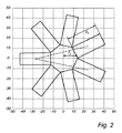
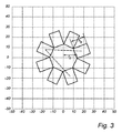
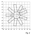
図2〜図4を参照すると共に、図1を続けて参照すると、筒形支持体2の高さh及び半径rに適用され得る或る制限が議論される。図2、図3、図4の多角形は、それぞれ、7、8、9つの辺を持っている。各多角形は、添え字を有するrで示される半径を有し、当該多角形の半径は多角形の中心と2つの多角形の辺が交わる角との間の距離として定義される。1つの同じ図の全ての長方形は等しく、この長さは添え字を有するhで示されている。 With reference to FIGS. 2 to 4 and continuing with reference to FIG. 1, certain restrictions that can be applied to the height h and radius r of the tubular support 2 are discussed. The polygons of FIGS. 2, 3 and 4 have 7, 8 and 9 sides, respectively. Each polygon has a radius represented by r with a subscript, and the radius of the polygon is defined as the distance between the center of the polygon and the angle where the sides of the two polygons intersect. All rectangles in one same figure are equal and this length is indicated by h with a subscript.
ストリップ3を筒形支持体2の周りに巻く有利な仕方は、ストリップ3を側面の中心上に通過させることである。このことをストリップ3が多角形の角上で折り返されることなく可能にするために、筒形支持体2の高さhは、ストリップ3のベース面2a、2bの所与の半径rに対する及び所定の幅wに対する閾値未満でなければならない。これは、図2〜4に示されており、これらの図から、長さh7、h8、h9が増大され、半径r7、r8、r9が変更されない場合、破線が、2つの多角形の辺が交差する角に接近し、最終的に接触することが明らかである。破線は、1つの長方形の中心から、図2及び図4においては「ほぼ」反対側の長方形の中心まで、図3においては反対側の長方形の隣にある長方形まで進行する。比h/rは、それぞれ、7、8、9の辺を有するベース面2a、2bの場合、通常、3.5未満、2未満、及び3未満である。勿論、ストリップ3の幅が小さいほど、比h/rは、ストリップ3が多角形の角上に折り畳まれることなく、大きくなる。
An advantageous way to wrap the strip 3 around the tubular support 2 is to pass the strip 3 over the center of the side surface. To allow this without the strip 3 folding over the corners of the polygon, the height h of the tubular support 2 is defined and relative to a given radius r of the base surfaces 2a, 2b of the strip 3. Must be less than the threshold for the width w of. This is shown in Figures 2-4, from which the dashed lines are 2 if the lengths h 7 , h 8 and h 9 are increased and the radii r 7 , r 8 and r 9 are unchanged. It is clear that the sides of the two polygons approach the intersecting corners and eventually make contact. The dashed line travels from the center of one rectangle to the center of the "nearly" opposite rectangle in FIGS. 2 and 4 and to the rectangle next to the opposite rectangle in FIG. The ratio h / r is usually less than 3.5, less than 2, and less than 3 in the case of
図5は、レトロフィットA60電球のような、電球の形態の照明装置10を示す。照明装置10は、照明装置10の中心軸である光軸OAを有する。照明装置10によって生成される照明は、この例では、光軸OAを中心として実質的に回転対称である。照明装置1の端部にはコネクタ2が配されている。コネクタ2は、照明装置1をランプソケットに機械的かつ電気的に接続される。ここに示すコネクタ11は、ネジベースであるが、別の例では、バヨネット式の電球マウントのような、他のタイプのコネクタであっても良い。コネクタ11は、典型的には金属製である。照明装置10は、この中心がコネクタ11に対して光軸OAに沿って変位される透光ハウジング12(以下、簡潔にするために「ハウジング」と呼ぶ)を有する。ハウジング12は、例えば、ガラス又はプラスチックで作られることができる。ここに示したハウジング12は、円形の頭部と筒形の首部とによって形成された梨状の形状を有し、当該頭部及び当該首部は、ぞれぞれ、コネクタ11に対して遠位及び近位である。勿論、ハウジング12は、他の例では、筒形状のような異なる形状を有しても良い。この例では、ハウジング12は気体、例えばヘリウム又はヘリウムと酸素との混合物で充填されているので、照明装置10は気体充填された電球である。これは、他の例において、そうであるかもしれず又はそうでないかもしれない。
FIG. 5 shows a
図1に関連して説明したものと同様のキャリア1は、ハウジング12内の光軸OA上に中心が合わせられている。キャリア1は光軸OAに中心を合わせられており、光軸OAは2つのベース面2a、2bに垂直であると共に側面2cに平行である。光軸OAは、キャリア1の第1の軸Aと一致する。この例では、上部ベース面2a、即ちコネクタ11に対して遠位にあるベース面が閉じられているのに対し、底部ベース面2b、即ちコネクタ11に対して近位にあるベース面は開放されている。側面2cは閉じられている。上面2aによって1つの光源4が設けられており、側面2cによって1つの光源4が設けられている。
The carrier 1 similar to that described in connection with FIG. 1 is centered on the optical axis OA in the
留め具13は、「スパイダ」と呼ばれることもあり、キャリア1を、製造中に照明装置10に気体を導入することができる管である照明装置10の排気管14に取り付ける。排気管14は、キャリア1の下方から延在している。このことは、ストリップ3が、コネクタ11の近位にあるベース面2bの中心を覆わないように筒状支持体2の周りに巻かれているため、可能である。排気管14は、排気管14よりも大きな直径を有すると共にハウジング12に封止されているステム要素15と一体化されている。ステム要素8及び排気管7は、典型的にはガラス製である。接触ワイヤ16はステム要素15に固定されている。接触ワイヤ16は、ステム要素15から突出し、キャリア1の光源4に電力を供給するためにキャリア1をドライバ17に電気的に接続する。ドライバ17は、この例では、コネクタ11の内側に配されているが、別の例ではハウジング12の内側に配されていても良い。ドライバ17とコネクタ11との間には、ドライバ17の一部をコネクタ11から電気的に絶縁する絶縁要素18が配されている。
The
照明装置10は、電源に接続された電気ソケットにコネクタ11を差し込むことによって動作され、これによりドライバ17は、接触ワイヤ16及びキャリア1を介して、光源4に電力を供給し、光源4はエンベロープ12を介して透過される光を発する。上部のベース面2a上の光源4は、コネクタ11から離れる方向に、光軸OAに沿って光を発し、側面2cによる光源4は、光軸OAに対して垂直に光を発する。
The
当業者であれば、本発明は決して上述の好ましい実施例に限定されるものではないことを理解する。逆に、添付の特許請求の範囲の範囲内で多くの変更及び変形が可能である。例えば、キャリア1の辺の数は異なっていてもよく、半径と高さとの関係は示されたものとは異なっていても良い。更に、不規則な多角形を含む他の種類の多角形ベース面2a、2bも考えられ得る。2つのベース面2a、2bは、やはり実質的に筒形の形状を維持しながら、僅かに異なるサイズ又は形状を有することができる。
Those skilled in the art will appreciate that the present invention is by no means limited to the preferred embodiments described above. Conversely, many modifications and modifications are possible within the scope of the appended claims. For example, the number of sides of carrier 1 may be different, and the relationship between radius and height may be different from what is shown. In addition, other types of
Claims (9)
前記ハウジングの内部に配された固体光源キャリアと、
を有する照明装置であって、
前記固体光源キャリアは、
2つの多角形ベース面と、複数の側面であって少なくとも第1の側面及び第2の側面と、を有する筒状支持体と、
これに取り付けられた複数の固体光源を持つ可撓性の回路ストリップであって、前記回路ストリップは、当該回路ストリップが、少なくとも1回各ベース面を横切って延在すると共に少なくとも1回各側面を横切って延在し、前記回路ストリップが、前記ベース面を横切って第1の側面から第2の側面まで延在するように、当該筒状支持体の周りに巻き付けられている、回路ストリップと、
を含んでいる、照明装置。 With a translucent housing
A solid light source carrier arranged inside the housing and
It is a lighting device with
The solid light source carrier is
A tubular support having two polygonal base surfaces and a plurality of side surfaces having at least a first side surface and a second side surface.
A flexible circuit strip with multiple solid-state light sources attached to it, said circuit strip extending at least once across each base surface and at least once on each side surface. A circuit strip that extends across and is wrapped around the tubular support such that the circuit strip extends across the base surface from a first side surface to a second side surface.
Including, lighting equipment.
Applications Claiming Priority (3)
| Application Number | Priority Date | Filing Date | Title |
|---|---|---|---|
| EP15183800 | 2015-09-04 | ||
| EP15183800.0 | 2015-09-04 | ||
| PCT/EP2016/070110 WO2017036924A1 (en) | 2015-09-04 | 2016-08-25 | Lighting device with a flexible circuit strip wrapped around a support |
Publications (3)
| Publication Number | Publication Date |
|---|---|
| JP2018526786A JP2018526786A (en) | 2018-09-13 |
| JP2018526786A5 JP2018526786A5 (en) | 2019-09-26 |
| JP6839701B2 true JP6839701B2 (en) | 2021-03-10 |
Family
ID=54065727
Family Applications (1)
| Application Number | Title | Priority Date | Filing Date |
|---|---|---|---|
| JP2018510963A Active JP6839701B2 (en) | 2015-09-04 | 2016-08-25 | Lighting equipment with flexible circuit strips wrapped around a support |
Country Status (6)
| Country | Link |
|---|---|
| US (1) | US10465856B2 (en) |
| EP (1) | EP3344911B8 (en) |
| JP (1) | JP6839701B2 (en) |
| CN (1) | CN108027121A (en) |
| RU (1) | RU2713450C2 (en) |
| WO (1) | WO2017036924A1 (en) |
Families Citing this family (2)
| Publication number | Priority date | Publication date | Assignee | Title |
|---|---|---|---|---|
| US11761594B2 (en) * | 2019-01-29 | 2023-09-19 | Xiamen Eco Lighting Co. Ltd. | Lighting apparatus |
| WO2020234241A1 (en) | 2019-05-20 | 2020-11-26 | Signify Holding B.V. | A light source comprising a substrate and a heat sink structure |
Family Cites Families (22)
| Publication number | Priority date | Publication date | Assignee | Title |
|---|---|---|---|---|
| DE69936375T2 (en) | 1998-09-17 | 2008-02-28 | Koninklijke Philips Electronics N.V. | LED LIGHT |
| US6580228B1 (en) * | 2000-08-22 | 2003-06-17 | Light Sciences Corporation | Flexible substrate mounted solid-state light sources for use in line current lamp sockets |
| US7728345B2 (en) * | 2001-08-24 | 2010-06-01 | Cao Group, Inc. | Semiconductor light source for illuminating a physical space including a 3-dimensional lead frame |
| JP2009037795A (en) * | 2007-07-31 | 2009-02-19 | Toshiba Lighting & Technology Corp | Lamp device |
| JP5354209B2 (en) * | 2010-01-14 | 2013-11-27 | 東芝ライテック株式会社 | Light bulb shaped lamp and lighting equipment |
| JP2011249534A (en) | 2010-05-26 | 2011-12-08 | Daisho Denshi Co Ltd | Flexible wiring board, light-emitting module, manufacturing method of light-emitting module, and manufacturing method of flexible wiring board |
| JP2012124106A (en) * | 2010-12-10 | 2012-06-28 | Sodick Co Ltd | Manufacturing method of substrate and led lighting device |
| JP5750297B2 (en) * | 2011-04-19 | 2015-07-15 | 日本メクトロン株式会社 | Substrate assembly and lighting device |
| US8757839B2 (en) | 2012-04-13 | 2014-06-24 | Cree, Inc. | Gas cooled LED lamp |
| RU2517965C2 (en) * | 2012-10-05 | 2014-06-10 | Николай Титович Краснов | Led lamp and lamp base, method for manufacturing thereof |
| EP2914900B1 (en) * | 2012-11-02 | 2019-07-10 | The Wand Lite Company Limited | Lighting device |
| US9528689B2 (en) * | 2013-03-13 | 2016-12-27 | Palo Alto Research Center Incorporated | LED lighting device with cured structural support |
| US9618190B2 (en) * | 2013-08-09 | 2017-04-11 | Sumitomo Electric Printed Circuits, Inc. | LED module including flexible printed circuit board with adhesive layers and LED lighting fixture |
| CN203442690U (en) | 2013-09-24 | 2014-02-19 | 北京铨富光电科技有限公司 | Aluminum substrate bending structure for fixedly mounting lamp beads of LED (Light Emitting Diode) |
| JP6261119B2 (en) * | 2013-12-26 | 2018-01-17 | 岩崎電気株式会社 | Light source support for LED lamp and assembly thereof |
| CN203731137U (en) * | 2014-01-16 | 2014-07-23 | 张斌杰 | LED bulb capable of achieving large-angle illumination |
| CN103775983B (en) * | 2014-02-14 | 2017-01-04 | 深圳市裕富照明有限公司 | LED manufacture method |
| JP2015153705A (en) * | 2014-02-18 | 2015-08-24 | パナソニックIpマネジメント株式会社 | Illumination light source and illumination device |
| CN203718718U (en) * | 2014-03-18 | 2014-07-16 | 吴为生 | LED top lamp radiator |
| CN203823499U (en) * | 2014-04-02 | 2014-09-10 | 厦门市东林电子有限公司 | Integrated heat dissipation type LED bulb |
| CN204387763U (en) * | 2015-01-20 | 2015-06-10 | 王志根 | 360 ° of emitting bulbs |
| CN204554423U (en) * | 2015-02-17 | 2015-08-12 | 佛山电器照明股份有限公司 | A kind of bulb with single-ended seven substrate LED luminescence units |
-
2016
- 2016-08-25 JP JP2018510963A patent/JP6839701B2/en active Active
- 2016-08-25 CN CN201680051054.8A patent/CN108027121A/en active Pending
- 2016-08-25 US US15/755,163 patent/US10465856B2/en not_active Expired - Fee Related
- 2016-08-25 EP EP16757237.9A patent/EP3344911B8/en not_active Not-in-force
- 2016-08-25 RU RU2018111801A patent/RU2713450C2/en active
- 2016-08-25 WO PCT/EP2016/070110 patent/WO2017036924A1/en active Application Filing
Also Published As
| Publication number | Publication date |
|---|---|
| CN108027121A (en) | 2018-05-11 |
| US20180245743A1 (en) | 2018-08-30 |
| RU2018111801A (en) | 2019-10-07 |
| US10465856B2 (en) | 2019-11-05 |
| RU2018111801A3 (en) | 2019-11-21 |
| JP2018526786A (en) | 2018-09-13 |
| WO2017036924A1 (en) | 2017-03-09 |
| EP3344911B1 (en) | 2019-02-27 |
| EP3344911A1 (en) | 2018-07-11 |
| EP3344911B8 (en) | 2019-04-17 |
| RU2713450C2 (en) | 2020-02-05 |
Similar Documents
| Publication | Publication Date | Title |
|---|---|---|
| US10638612B2 (en) | Carrier for solid-state lighting devices intended for a light bulb | |
| JP3148721U (en) | LED lighting device | |
| WO2016058539A1 (en) | Substrate used for led encapsulation, three-dimensional led encapsulation, bulb comprising three-dimensional led encapsulation and manufacturing method therefor | |
| TW201723380A (en) | Light emitting diode lamp | |
| US20130235578A1 (en) | Illumination device and assembling method thereof | |
| JP3164034U (en) | LED lighting device | |
| JP6839701B2 (en) | Lighting equipment with flexible circuit strips wrapped around a support | |
| JP6425066B2 (en) | lighting equipment | |
| EP3308071B1 (en) | Light bulb with solid-state lighting devices | |
| EP3320258B1 (en) | Lighting module and lighting device comprising the lighting module | |
| EP3349261B1 (en) | Multilevel light emitting led substrate and package, and bulb | |
| KR101756331B1 (en) | Led lighting device | |
| KR20110102634A (en) | Optical lens and lighting apparautus | |
| JP7155458B1 (en) | lighting device | |
| KR101683596B1 (en) | Omnidirectional illuminator | |
| JP2012018767A (en) | Led lighting device | |
| JP2022514109A (en) | LED filament configuration | |
| JP2014082141A (en) | Bulb type luminaire | |
| JP2016139547A (en) | Lighting device and circuit board | |
| TWM500208U (en) | Structure of LED lamp | |
| KR20100022270A (en) | Electric bulb using external electrode fluorescent lamp |
Legal Events
| Date | Code | Title | Description |
|---|---|---|---|
| A521 | Request for written amendment filed |
Free format text: JAPANESE INTERMEDIATE CODE: A523 Effective date: 20190815 |
|
| A621 | Written request for application examination |
Free format text: JAPANESE INTERMEDIATE CODE: A621 Effective date: 20190815 |
|
| A977 | Report on retrieval |
Free format text: JAPANESE INTERMEDIATE CODE: A971007 Effective date: 20200715 |
|
| A131 | Notification of reasons for refusal |
Free format text: JAPANESE INTERMEDIATE CODE: A131 Effective date: 20200728 |
|
| A521 | Request for written amendment filed |
Free format text: JAPANESE INTERMEDIATE CODE: A523 Effective date: 20201009 |
|
| TRDD | Decision of grant or rejection written | ||
| A01 | Written decision to grant a patent or to grant a registration (utility model) |
Free format text: JAPANESE INTERMEDIATE CODE: A01 Effective date: 20210120 |
|
| A61 | First payment of annual fees (during grant procedure) |
Free format text: JAPANESE INTERMEDIATE CODE: A61 Effective date: 20210215 |
|
| R150 | Certificate of patent or registration of utility model |
Ref document number: 6839701 Country of ref document: JP Free format text: JAPANESE INTERMEDIATE CODE: R150 |