JP6838548B2 - Coil parts and their manufacturing methods - Google Patents
Coil parts and their manufacturing methods Download PDFInfo
- Publication number
- JP6838548B2 JP6838548B2 JP2017235386A JP2017235386A JP6838548B2 JP 6838548 B2 JP6838548 B2 JP 6838548B2 JP 2017235386 A JP2017235386 A JP 2017235386A JP 2017235386 A JP2017235386 A JP 2017235386A JP 6838548 B2 JP6838548 B2 JP 6838548B2
- Authority
- JP
- Japan
- Prior art keywords
- wiring
- pipe
- coil
- main body
- resin
- Prior art date
- Legal status (The legal status is an assumption and is not a legal conclusion. Google has not performed a legal analysis and makes no representation as to the accuracy of the status listed.)
- Active
Links
- 238000004519 manufacturing process Methods 0.000 title claims description 14
- 229920005989 resin Polymers 0.000 claims description 45
- 239000011347 resin Substances 0.000 claims description 45
- 239000000758 substrate Substances 0.000 claims description 13
- 238000007747 plating Methods 0.000 claims description 8
- 238000000034 method Methods 0.000 claims description 6
- 239000004020 conductor Substances 0.000 description 12
- 239000000919 ceramic Substances 0.000 description 5
- 239000000463 material Substances 0.000 description 4
- 239000002184 metal Substances 0.000 description 4
- 229910052751 metal Inorganic materials 0.000 description 4
- 230000001681 protective effect Effects 0.000 description 4
- 238000009751 slip forming Methods 0.000 description 3
- RYGMFSIKBFXOCR-UHFFFAOYSA-N Copper Chemical compound [Cu] RYGMFSIKBFXOCR-UHFFFAOYSA-N 0.000 description 2
- 239000004696 Poly ether ether ketone Substances 0.000 description 2
- 239000004697 Polyetherimide Substances 0.000 description 2
- 239000004642 Polyimide Substances 0.000 description 2
- BQCADISMDOOEFD-UHFFFAOYSA-N Silver Chemical compound [Ag] BQCADISMDOOEFD-UHFFFAOYSA-N 0.000 description 2
- MCMNRKCIXSYSNV-UHFFFAOYSA-N Zirconium dioxide Chemical compound O=[Zr]=O MCMNRKCIXSYSNV-UHFFFAOYSA-N 0.000 description 2
- 229910052802 copper Inorganic materials 0.000 description 2
- 239000010949 copper Substances 0.000 description 2
- PCHJSUWPFVWCPO-UHFFFAOYSA-N gold Chemical compound [Au] PCHJSUWPFVWCPO-UHFFFAOYSA-N 0.000 description 2
- 229910052737 gold Inorganic materials 0.000 description 2
- 239000010931 gold Substances 0.000 description 2
- 229920002530 polyetherether ketone Polymers 0.000 description 2
- 229920001601 polyetherimide Polymers 0.000 description 2
- 229920001721 polyimide Polymers 0.000 description 2
- 229910052709 silver Inorganic materials 0.000 description 2
- 239000004332 silver Substances 0.000 description 2
- 238000004804 winding Methods 0.000 description 2
- 239000004593 Epoxy Substances 0.000 description 1
- 239000004952 Polyamide Substances 0.000 description 1
- 239000004962 Polyamide-imide Substances 0.000 description 1
- PNEYBMLMFCGWSK-UHFFFAOYSA-N aluminium oxide Inorganic materials [O-2].[O-2].[O-2].[Al+3].[Al+3] PNEYBMLMFCGWSK-UHFFFAOYSA-N 0.000 description 1
- 229910010293 ceramic material Inorganic materials 0.000 description 1
- 230000003247 decreasing effect Effects 0.000 description 1
- 238000010586 diagram Methods 0.000 description 1
- KZHJGOXRZJKJNY-UHFFFAOYSA-N dioxosilane;oxo(oxoalumanyloxy)alumane Chemical compound O=[Si]=O.O=[Si]=O.O=[Al]O[Al]=O.O=[Al]O[Al]=O.O=[Al]O[Al]=O KZHJGOXRZJKJNY-UHFFFAOYSA-N 0.000 description 1
- 239000003822 epoxy resin Substances 0.000 description 1
- 239000011521 glass Substances 0.000 description 1
- 238000009413 insulation Methods 0.000 description 1
- 239000006247 magnetic powder Substances 0.000 description 1
- 238000000465 moulding Methods 0.000 description 1
- 229910052863 mullite Inorganic materials 0.000 description 1
- 230000000149 penetrating effect Effects 0.000 description 1
- 229920002647 polyamide Polymers 0.000 description 1
- 229920002312 polyamide-imide Polymers 0.000 description 1
- 229920000647 polyepoxide Polymers 0.000 description 1
- 239000000843 powder Substances 0.000 description 1
- 229910000679 solder Inorganic materials 0.000 description 1
- 229910000859 α-Fe Inorganic materials 0.000 description 1
Images


Classifications
-
- H—ELECTRICITY
- H01—ELECTRIC ELEMENTS
- H01F—MAGNETS; INDUCTANCES; TRANSFORMERS; SELECTION OF MATERIALS FOR THEIR MAGNETIC PROPERTIES
- H01F27/00—Details of transformers or inductances, in general
- H01F27/28—Coils; Windings; Conductive connections
- H01F27/2804—Printed windings
-
- H—ELECTRICITY
- H01—ELECTRIC ELEMENTS
- H01F—MAGNETS; INDUCTANCES; TRANSFORMERS; SELECTION OF MATERIALS FOR THEIR MAGNETIC PROPERTIES
- H01F17/00—Fixed inductances of the signal type
- H01F17/0006—Printed inductances
-
- H—ELECTRICITY
- H01—ELECTRIC ELEMENTS
- H01F—MAGNETS; INDUCTANCES; TRANSFORMERS; SELECTION OF MATERIALS FOR THEIR MAGNETIC PROPERTIES
- H01F17/00—Fixed inductances of the signal type
- H01F17/0006—Printed inductances
- H01F17/0013—Printed inductances with stacked layers
-
- H—ELECTRICITY
- H01—ELECTRIC ELEMENTS
- H01F—MAGNETS; INDUCTANCES; TRANSFORMERS; SELECTION OF MATERIALS FOR THEIR MAGNETIC PROPERTIES
- H01F17/00—Fixed inductances of the signal type
- H01F17/04—Fixed inductances of the signal type with magnetic core
- H01F17/06—Fixed inductances of the signal type with magnetic core with core substantially closed in itself, e.g. toroid
- H01F17/062—Toroidal core with turns of coil around it
-
- H—ELECTRICITY
- H01—ELECTRIC ELEMENTS
- H01F—MAGNETS; INDUCTANCES; TRANSFORMERS; SELECTION OF MATERIALS FOR THEIR MAGNETIC PROPERTIES
- H01F27/00—Details of transformers or inductances, in general
- H01F27/24—Magnetic cores
-
- H—ELECTRICITY
- H01—ELECTRIC ELEMENTS
- H01F—MAGNETS; INDUCTANCES; TRANSFORMERS; SELECTION OF MATERIALS FOR THEIR MAGNETIC PROPERTIES
- H01F27/00—Details of transformers or inductances, in general
- H01F27/28—Coils; Windings; Conductive connections
- H01F27/2895—Windings disposed upon ring cores
-
- H—ELECTRICITY
- H01—ELECTRIC ELEMENTS
- H01F—MAGNETS; INDUCTANCES; TRANSFORMERS; SELECTION OF MATERIALS FOR THEIR MAGNETIC PROPERTIES
- H01F27/00—Details of transformers or inductances, in general
- H01F27/28—Coils; Windings; Conductive connections
- H01F27/29—Terminals; Tapping arrangements for signal inductances
- H01F27/292—Surface mounted devices
-
- H—ELECTRICITY
- H01—ELECTRIC ELEMENTS
- H01F—MAGNETS; INDUCTANCES; TRANSFORMERS; SELECTION OF MATERIALS FOR THEIR MAGNETIC PROPERTIES
- H01F41/00—Apparatus or processes specially adapted for manufacturing or assembling magnets, inductances or transformers; Apparatus or processes specially adapted for manufacturing materials characterised by their magnetic properties
- H01F41/02—Apparatus or processes specially adapted for manufacturing or assembling magnets, inductances or transformers; Apparatus or processes specially adapted for manufacturing materials characterised by their magnetic properties for manufacturing cores, coils, or magnets
- H01F41/04—Apparatus or processes specially adapted for manufacturing or assembling magnets, inductances or transformers; Apparatus or processes specially adapted for manufacturing materials characterised by their magnetic properties for manufacturing cores, coils, or magnets for manufacturing coils
- H01F41/041—Printed circuit coils
-
- H—ELECTRICITY
- H01—ELECTRIC ELEMENTS
- H01F—MAGNETS; INDUCTANCES; TRANSFORMERS; SELECTION OF MATERIALS FOR THEIR MAGNETIC PROPERTIES
- H01F41/00—Apparatus or processes specially adapted for manufacturing or assembling magnets, inductances or transformers; Apparatus or processes specially adapted for manufacturing materials characterised by their magnetic properties
- H01F41/02—Apparatus or processes specially adapted for manufacturing or assembling magnets, inductances or transformers; Apparatus or processes specially adapted for manufacturing materials characterised by their magnetic properties for manufacturing cores, coils, or magnets
- H01F41/04—Apparatus or processes specially adapted for manufacturing or assembling magnets, inductances or transformers; Apparatus or processes specially adapted for manufacturing materials characterised by their magnetic properties for manufacturing cores, coils, or magnets for manufacturing coils
- H01F41/10—Connecting leads to windings
-
- H—ELECTRICITY
- H01—ELECTRIC ELEMENTS
- H01F—MAGNETS; INDUCTANCES; TRANSFORMERS; SELECTION OF MATERIALS FOR THEIR MAGNETIC PROPERTIES
- H01F17/00—Fixed inductances of the signal type
- H01F17/0006—Printed inductances
- H01F17/0013—Printed inductances with stacked layers
- H01F2017/002—Details of via holes for interconnecting the layers
-
- H—ELECTRICITY
- H01—ELECTRIC ELEMENTS
- H01F—MAGNETS; INDUCTANCES; TRANSFORMERS; SELECTION OF MATERIALS FOR THEIR MAGNETIC PROPERTIES
- H01F27/00—Details of transformers or inductances, in general
- H01F27/28—Coils; Windings; Conductive connections
- H01F27/2804—Printed windings
- H01F2027/2814—Printed windings with only part of the coil or of the winding in the printed circuit board, e.g. the remaining coil or winding sections can be made of wires or sheets
Description
本発明は、コイル部品およびその製造方法に関する。 The present invention relates to coil parts and methods for manufacturing the same.
従来、コイル部品としては、特開2015−173189号公報(特許文献1)に記載されたものがある。このコイル部品は、コイルコアと、コアの周囲に螺旋状に巻回されたコイル電極とを有する。 Conventionally, as a coil component, there is one described in Japanese Patent Application Laid-Open No. 2015-173189 (Patent Document 1). This coil component has a coil core and coil electrodes spirally wound around the core.
コイル電極は、コアの外側に配列された複数の第1柱状導体と、コアの内側に配列された複数の第2柱状導体と、第1柱状導体および第2柱状導体の一端をそれぞれ接続する複数の第1接続部材と、第1柱状導体および第2柱状導体の他端をそれぞれ接続する複数の第2接続部材とを有する。第1接続部材および第2接続部材の一方は、ボンディングワイヤにより形成されている。 The coil electrodes include a plurality of first columnar conductors arranged outside the core, a plurality of second columnar conductors arranged inside the core, and a plurality of coil electrodes connecting one ends of the first columnar conductor and the second columnar conductor, respectively. It has a first connecting member of the above, and a plurality of second connecting members connecting the other ends of the first columnar conductor and the second columnar conductor. One of the first connecting member and the second connecting member is formed of a bonding wire.
ところで、前記従来のコイル部品では、第1接続部材および第2接続部材の一方は、ボンディングワイヤにより形成されているので、第1接続部材および第2接続部材の一方と第1柱状導体および第2柱状導体とは、はんだにより接続されている。このため、接続部材と柱状導体の接合面が発生し、接続部材と柱状導体の接合強度は弱くなる。これにより、熱付加等によりストレスが加わると、接続部材と柱状導体の断線が発生する可能性がある。 By the way, in the conventional coil component, one of the first connecting member and the second connecting member is formed of a bonding wire, so that one of the first connecting member and the second connecting member, the first columnar conductor, and the second connecting member are formed. The columnar conductor is connected by solder. Therefore, a joint surface between the connecting member and the columnar conductor is generated, and the joint strength between the connecting member and the columnar conductor is weakened. As a result, when stress is applied due to heat addition or the like, disconnection between the connecting member and the columnar conductor may occur.
そこで、本開示の課題は、コイルの断線を低減できるコイル部品およびその製造方法を提供することにある。 Therefore, an object of the present disclosure is to provide a coil component capable of reducing disconnection of the coil and a method for manufacturing the coil component.
前記課題を解決するため、本開示の一態様であるコイル部品は、
樹脂を含み、孔部を有する本体部と、
前記本体部に設けられたコイルと、
前記孔部の内部に配置された筒状のパイプと
を備え、
前記コイルは、前記パイプの内部に埋め込まれる内部配線と、前記本体部から露出する外部配線とを含み、前記内部配線と前記外部配線は、一体に連続している。
In order to solve the above problems, the coil component according to one aspect of the present disclosure is
The main body, which contains resin and has holes,
With the coil provided in the main body
A tubular pipe arranged inside the hole is provided.
The coil includes an internal wiring embedded inside the pipe and an external wiring exposed from the main body portion, and the internal wiring and the external wiring are integrally continuous.
ここで、外部配線の本体部からの露出とは、外部配線が本体部に覆われていない部分を有することを意味し、当該部分はコイル部品の外部へ露出していてもよいし、他の部材へ露出していてもよい。孔部とは、孔部の内側に他の部材が埋め込まれていてもよく、この場合も孔部という。 Here, the exposure of the external wiring from the main body means that the external wiring has a portion not covered by the main body, and the portion may be exposed to the outside of the coil component or other parts. It may be exposed to the member. The hole portion may be another member embedded in the inside of the hole portion, and is also referred to as a hole portion in this case.
本開示のコイル部品によれば、内部配線と外部配線は、一体に連続しているので、内部配線と外部配線の接合面がなく、内部配線と外部配線の断線を低減できる。 According to the coil component of the present disclosure, since the internal wiring and the external wiring are integrally continuous, there is no joint surface between the internal wiring and the external wiring, and the disconnection between the internal wiring and the external wiring can be reduced.
また、コイル部品の一実施形態では、前記外部配線は、前記本体部の天面から露出する天面側の外部配線と、前記本体部の底面から露出する底面側の外部配線とを含み、前記天面側の外部配線と前記内部配線は、一体に連続し、前記底面側の外部配線と前記内部配線は、一体に連続している。 Further, in one embodiment of the coil component, the external wiring includes an external wiring on the top surface side exposed from the top surface of the main body portion and an external wiring on the bottom surface side exposed from the bottom surface of the main body portion. The external wiring on the top surface side and the internal wiring are integrally continuous, and the external wiring on the bottom surface side and the internal wiring are integrally continuous.
前記実施形態によれば、内部配線と天面側の外部配線と底面側の外部配線は、一体に連続しているので、内部配線と外部配線の接合面がなく、内部配線と外部配線の断線を低減できる。 According to the above embodiment, since the internal wiring, the external wiring on the top surface side, and the external wiring on the bottom surface side are integrally continuous, there is no joint surface between the internal wiring and the external wiring, and the internal wiring and the external wiring are disconnected. Can be reduced.
また、コイル部品の一実施形態では、前記内部配線は、筒状であり、前記内部配線の内部に、樹脂が埋め込まれている。 Further, in one embodiment of the coil component, the internal wiring is tubular, and a resin is embedded inside the internal wiring.
前記実施形態によれば、筒状の内部配線の内部に樹脂が埋め込まれているので、内部配線の熱膨張を低減できる。 According to the above embodiment, since the resin is embedded inside the tubular internal wiring, the thermal expansion of the internal wiring can be reduced.
また、コイル部品の一実施形態では、前記パイプは、樹脂を含む。 Further, in one embodiment of the coil component, the pipe contains a resin.
前記実施形態によれば、パイプは樹脂を含むので、パイプと本体部の熱膨張率などの特性を同じにでき、パイプと本体部の密着性が良好となる。 According to the above embodiment, since the pipe contains a resin, the characteristics such as the coefficient of thermal expansion of the pipe and the main body can be made the same, and the adhesion between the pipe and the main body becomes good.
また、コイル部品の一実施形態では、前記樹脂は、導電性樹脂である。 Further, in one embodiment of the coil component, the resin is a conductive resin.
前記実施形態によれば、パイプの樹脂は、導電性樹脂であるので、内部配線を低抵抗化にできる。 According to the above embodiment, since the resin of the pipe is a conductive resin, the internal wiring can have a low resistance.
また、コイル部品の一実施形態では、前記パイプは、セラミックを含む。 Also, in one embodiment of the coil component, the pipe comprises ceramic.
前記実施形態によれば、パイプはセラミックを含むので、パイプと内部配線の熱膨張率などの特性を近づけることができ、パイプと内部配線の密着性が良好となる。 According to the above embodiment, since the pipe contains ceramic, the characteristics such as the coefficient of thermal expansion of the pipe and the internal wiring can be brought close to each other, and the adhesion between the pipe and the internal wiring is improved.
また、コイル部品の一実施形態では、前記本体部内に設けられた円環状のコアを有し、前記コイルは、前記コアに巻回されている。 Further, in one embodiment of the coil component, the coil component has an annular core provided in the main body portion, and the coil is wound around the core.
前記実施形態によれば、製造工程が複雑になりがちなトロイダルコイルで、製造効率を低減することなくコイルを形成できる。 According to the above embodiment, a toroidal coil whose manufacturing process tends to be complicated can be formed without reducing the manufacturing efficiency.
また、コイル部品の製造方法の一実施形態では、
基板上のコイルに対応する位置に筒状のパイプを立てる工程と、
前記基板上の前記パイプを前記パイプの内面を露出させた状態で樹脂でモールドして、前記パイプが内部に配置された孔部を有する本体部を形成する工程と、
前記パイプの内面と前記樹脂の外面にめっきによりコイルの配線を形成する工程と
を備える。
Further, in one embodiment of the method for manufacturing coil parts,
The process of erecting a tubular pipe at the position corresponding to the coil on the board,
A step of molding the pipe on the substrate with a resin with the inner surface of the pipe exposed to form a main body portion having a hole in which the pipe is arranged inside.
A step of forming coil wiring by plating on the inner surface of the pipe and the outer surface of the resin is provided.
前記実施形態によれば、パイプの内面と樹脂の外面にめっきによりコイルの配線を形成するので、本体部に埋め込まれる内部配線と本体部から露出する外部配線を一体に連続して形成できる。これにより、内部配線と外部配線の接合面がなく、内部配線と外部配線の断線を低減できる。 According to the above embodiment, since the coil wiring is formed on the inner surface of the pipe and the outer surface of the resin by plating, the internal wiring embedded in the main body portion and the external wiring exposed from the main body portion can be integrally and continuously formed. As a result, there is no joint surface between the internal wiring and the external wiring, and disconnection between the internal wiring and the external wiring can be reduced.
本開示の一態様であるコイル部品およびその製造方法によれば、コイルの断線を低減できる。 According to the coil component and the manufacturing method thereof, which is one aspect of the present disclosure, the disconnection of the coil can be reduced.
以下、本開示の一態様を図示の実施の形態により詳細に説明する。 Hereinafter, one aspect of the present disclosure will be described in detail with reference to the illustrated embodiment.
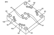
図1は、本発明の一実施形態のコイル部品を示す斜視図である。図2は、コイル部品の断面図である。図3Aは、コイル部品の分解斜視図である。図3Bは、図3Aの一部拡大図である。 FIG. 1 is a perspective view showing a coil component according to an embodiment of the present invention. FIG. 2 is a cross-sectional view of the coil component. FIG. 3A is an exploded perspective view of the coil component. FIG. 3B is a partially enlarged view of FIG. 3A.
図1と図2と図3Aと図3Bに示すように、コイル部品1は、本体部2と、本体部2内に設けられた円環状のコア3と、本体部2に設けられコア3に巻回された第1コイル41および第2コイル42と、第1コイル41および第2コイル42に電気的に接続された第1、第2、第3および第4外部電極51,52,53,54とを有する。
As shown in FIGS. 1, 2, 3A, and 3B, the
本体部2は、樹脂を含む。樹脂材料としては、例えば、エポキシ系樹脂であるが、ポリエーテルエーテルケトン、ポリイミド、ポリアミドまたはポリエーテルイミドなどであってもよい。本体部2は、直方体形状であり、本体部2の表面は、天面21と底面22と4つの側面23とから構成される。天面21は、コイル部品1を実装基板に実装する側の面である。
The
コア3は、例えば、フェライトなどのセラミックコア、または、金属系コアから構成される。コア3は、中心軸方向に対向する上端面および下端面を有する。上端面は、本体部2の天面21に対向する。下端面は、本体部2の底面22に対向する。なお、コア3の形状は、平面視、円形以外に、楕円形や矩形や多角形であってもよい。また、コア3の断面形状も図示したような矩形形状に限られず、円形や楕円形、多角形であってもよい。
The
本体部2は、天面21から底面22に貫通する複数の第1孔部201、第2孔部202および第3孔部203を有する。第1孔部201は、コア3の径方向内側に配置され、第2孔部202は、コア3の径方向外側に配置され、第3孔部203は、本体部2の四隅に配置される。
The
第1から第4外部電極51〜54は、例えば、銅、金または銀などの金属から構成される。第1外部電極51と第3外部電極53は、本体部2の天面21に設けられている。第2外部電極52と第4外部電極54は、本体部2の天面21に設けられている。
The first to fourth
第1コイル41と第2コイル42は、例えば、銅、金または銀などの金属から構成される。第1コイル41と第2コイル42は、互いに対向して配置される。第1コイル41のコア3に対する巻回方向と第2コイル42のコア3に対する巻回方向とは、逆方向となる。第1コイル41の巻回数と第2コイル42の巻回数とは、同じである。
The
第1コイル41の一端は、第1外部電極51に接続され、第1コイル41の他端は、第2外部電極52に接続される。第2コイル42の一端は、第3外部電極53に接続され、第2コイル42の他端は、第4外部電極54に接続される。コイル部品1は、第1、第3外部電極51,53を入力端子(出力端子)、第2、第4外部電極52,54を出力端子(入力端子)とするコモンモードチョークコイルを構成する。
One end of the
第1コイル41は、本体部2の第1孔部201に埋め込まれる第1配線411と、本体部2の第2孔部202に埋め込まれる第2配線412と、本体部2の天面21から露出する第3配線413と、本体部2の底面22から露出する第4配線414とを含む。
The
ここで、第3と第4配線413,414の本体部2からの露出とは、第3と第4配線413,414が本体部2に覆われていない部分を有することを意味し、当該部分はコイル部品1の外部へ露出していてもよいし、他の部材へ露出していてもよい。第1配線411および第2配線412は、特許請求の範囲の「内部配線」の一例である。第3配線413および第4配線414は、特許請求の範囲の「外部配線」の一例である。
Here, the exposure of the third and
第1配線411と第3配線413、第1配線411と第4配線414、第2配線412と第3配線413、および、第2配線412と第4配線414は、それぞれ、一体に連続している。第1から第4配線411〜414は、例えば、めっきにより形成される。したがって、第1、第2配線411,412(内部配線)と第3、第4配線413,414(外部配線)の接合面がなく、第1、第2配線411,412と第3、第4配線413,414の断線を低減できる。
The
第1配線411と本体部2の第1孔部201の内面との間には、第1パイプ61が存在している。つまり、第1パイプ61は、本体部2の第1孔部201に挿入され、第1配線411は、第1パイプ61の内面に設けられている。この場合、第1パイプ61の内面の粗さは、本体部2の第1孔部201の内面の粗さよりも小さいことが好ましく、この場合、第1孔部201の内面の粗さを第1パイプ61により吸収できて、第1配線411の厚みを均一に薄く形成できる。
A
第2配線412と本体部2の第2孔部202の内面との間には、第2パイプ62が存在している。つまり、第2パイプ62は、本体部2の第2孔部202に挿入され、第2配線412は、第2パイプ62の内面に設けられている。この場合、第2パイプ62の内面の粗さは、本体部2の第2孔部202の内面の粗さよりも小さいことが好ましく、この場合、第2孔部202の内面の粗さを第2パイプ62により吸収できて、第2配線412の厚みを均一に薄く形成できる。
A
第1、第2パイプ61,62は、例えば、樹脂またはセラミックを含む。第1、第2パイプ61,62が樹脂を含む場合、第1、第2パイプ61,62と本体部2の熱膨張率などの特性を同じにでき、第1、第2パイプ61,62と本体部2の密着性が良好となる。第1、第2パイプ61,62がセラミックを含む場合、第1、第2パイプ61,62と第1、第2配線411,412の熱膨張率などの特性を近づけることができ、第1、第2パイプ61,62と第1、第2配線411,412の密着性が良好となる。
The first and
第1、第2パイプ61,62の樹脂材料としては、例えば、ポリエーテルエーテルケトン、ポリイミド、ポリアミドまたはポリエーテルイミドである。第1、第2パイプ61,62のセラミック材料としては、例えば、アルミナ、ムライト、ジルコニアまたはサイアロンである。第1、第2パイプ61,62は、第1、第2孔部201,202の内面に沿った形状であり、これによれば、第1、第2パイプ61,62の厚みを均一に薄くでき、樹脂材料の量を低減できる。
Examples of the resin material of the first and
第1、第2配線411,412は、筒状であり、第1、第2配線411,412の内部に、樹脂8が埋め込まれている。したがって、樹脂8が第1、第2配線411,412の熱膨張を低減できる。なお、樹脂8を設けないで、第1、第2配線411,412の内部を中空としてもよい。また、樹脂8は金属粉などの導電体を含有させた樹脂である導電性樹脂であってもよく、この場合、第1、第2配線411,412を低抵抗化することができる。
The first and
第2コイル42は、第1コイル41と同様に、第1配線421、第2配線422、第3配線423および第4配線424を含む。第1、第2配線421,422(内部配線)と第3、第4配線423,424(外部配線)は、一体に連続している。第1配線421と本体部2の第1孔部201の内面との間には、第1パイプ61が存在し、第2配線422と本体部2の第2孔部202の内面との間には、第2パイプ62が存在している。
The
本体部2の四隅の第3孔部203には、第3パイプ63が挿入されている。第3パイプ63は、第1、第2パイプ61,62と同じ材料からなる。四隅の第3パイプ63の内面のそれぞれには、第1から第4接続配線151〜154が設けられている。
A
第1接続配線151は、天面21の第1外部電極51に接続している。第2接続配線152は、天面21の第2外部電極52に接続している。第3接続配線153は、天面21の第3外部電極53に接続している。第4接続配線154は、天面21の第4外部電極54に接続している。
The
第1接続配線151と第1外部電極51、第2接続配線152と第2外部電極52、第3接続配線153と第3外部電極53、および、第4接続配線154と第4外部電極54は、それぞれ、一体に連続している。
The
図4は、コイル41,42の接続状態を説明する説明図である。図3Aと図3Bと図4に示すように、第1コイル41は、複数の配線411,412,413,414が接続されてなる。
FIG. 4 is an explanatory diagram illustrating a connection state of the
第1配線411と第2配線412は、筒状に形成されている。第1配線411は、コア3の径方向内側に、コア3の中心軸に沿って配置されている。第2配線412は、コア3の径方向外側に、コア3の中心軸に沿って配置されている。第1配線411と第2配線412は、本体部2内に埋め込まれている。
The
第3配線413と第4配線414は、膜状に形成されている。第3配線413は、コア3の上端面に、コア3の中心軸に直交する平面に沿って配置されている。第4配線414は、コア3の下端面に、コア3の中心軸に直交する平面に沿って配置されている。
The
そして、第3配線413の一端が第1配線411の一端に接続され、第1配線411の他端が第4配線414の一端に接続され、第4配線414の他端が3本の第2配線412の一端に接続され、3本の第2配線412の他端が他の第3配線413の一端に接続される。これを繰り返すことにより、第3配線413、第1配線411、第4配線414および第2配線412は、コア3に螺旋状に巻回される。つまり、1組の第3配線413、第1配線411、第4配線414および第2配線412によって、1ターンの単位要素が構成される。
Then, one end of the
第1外部電極51は、第3配線413に接続されている。第1外部電極51は、第3配線413に一体に連続している。第1外部電極51と第3配線413は、例えば、めっきにより形成される。これにより、第1外部電極51と第3配線413の接合面がなく、第1外部電極51と第3配線413の断線を低減できる。
The first
第2コイル42は、第1コイル41と同様に、複数の配線421,422,423,424が接続されてなる。つまり、第1配線421は、コア3の径方向内側に配置され、第2配線422は、コア3の径方向外側に配置されている。第3配線423は、コア3の上端面に配置され、第4配線424は、コア3の下端面に配置されている。
Similar to the
そして、第3配線423、第1配線421、第4配線424および第2配線422は、順に接続されて、コア3に螺旋状に巻回される。第3外部電極53は、第3配線423に一体に連続しており、第3外部電極53と第3配線423の接合面がなく、第3外部電極53と第3配線423の断線を低減できる。
Then, the
第1コイル41の第3配線413と第2コイル42の第3配線423は、上側の保護シート7に覆われている。第1コイル41の第4配線414と第2コイル42の第4配線424は、下側の保護シート7に覆われている。保護シート7は、絶縁性を有し、絶縁樹脂であってもよいし、ガラスエポキシなどの基板であってもよい。したがって、本体部2から露出する配線の絶縁性を簡易に向上できる。
The
次に、コイル部品1の製造方法について説明する。
図5Aに示すように、樹脂を含む基板100上のコイル41,42に対応する位置にパイプ61,62を立てる。つまり、第1コイル41の第1配線411と第2コイル42の第1配線421に対応する位置に、第1パイプ61を立て、第1コイル41の第2配線412と第2コイル42の第2配線422に対応する位置に、第2パイプ62を立てる。また、基板100の四隅に、第1から第4接続配線151〜154に対応する位置に第3パイプ63を立てる。
Next, a method of manufacturing the
As shown in FIG. 5A, the
図5Bに示すように、基板100上にコア3を設置する。このとき、コア3の径方向内側に第1パイプ61が配置され、コア3の径方向外側に第2パイプ62が配置される。
As shown in FIG. 5B, the
図5Cに示すように、基板100上のパイプ61,62,63とコア3を樹脂120でモールドする。このとき、パイプ61,62,63の内面を露出させた状態とする。その後、表裏面を研削し、所定の厚みにする。このとき、基板100を全て研削し、パイプ61,62,63の端面を樹脂120から露出させる。
As shown in FIG. 5C, the
図5Dに示すように、パイプ61,62,63の内面と樹脂120の外面にめっきによりコイルの配線を形成する。具体的に述べると、第1パイプ61内に、第1配線411,421を設け、第2パイプ62内に、第2配線412,422を設け、第3パイプ63内に、第1から第4接続配線151〜154を設ける。樹脂120の外面に、第3配線413,423および第4配線414,424を設ける。したがって、内部配線(第1配線411,421および第2配線412,422)と外部配線(第3配線413,423および第4配線414,424)を一体に連続して形成できる。これにより、内部配線と外部配線の接合面がなく、内部配線と外部配線の断線を低減できる。
As shown in FIG. 5D, coil wiring is formed by plating on the inner surface of the
また、コイルの配線と同時に、めっきにより第1から第4外部電極51〜54を形成する。これにより、第1、第3外部電極51,53と外部配線(第3配線413,423)を一体に連続して形成できる。このように、内部配線と外部配線と外部電極をめっきにより形成するので、内部配線と外部配線と外部電極を一括して形成でき、製造時間を短縮できる。
Further, at the same time as wiring the coil, the first to fourth
その後、第3配線413,423および第4配線414,424を覆うように樹脂120の上下面に保護シート7を設けて、図1に示すコイル部品1を製造する。本体部2は、樹脂120から構成される。なお、図5Cにおいて、基板100の一部を研削しないで残してもよく、このとき、本体部2は、基板100と樹脂120から構成される。
After that, the protective sheet 7 is provided on the upper and lower surfaces of the
なお、本開示は上述の実施形態に限定されず、本開示の要旨を逸脱しない範囲で設計変更可能である。 The present disclosure is not limited to the above-described embodiment, and the design can be changed without departing from the gist of the present disclosure.
前記実施形態では、コイルの数量は、2つであるが、1つまたは3つ以上であってもよい。また、外部電極の数量は、コイルの数量に応じて、増減してもよい。 In the above embodiment, the number of coils is two, but it may be one or three or more. Further, the number of external electrodes may be increased or decreased according to the number of coils.
前記実施形態では、コイルは、本体部の天面から露出する外部配線(第3、第4配線)を含み、内部配線(第1、第2配線)と外部配線は、一体に連続しているが、コイルは、本体部の底面または天面および底面の両方から露出する外部配線を含み、内部配線と外部配線は、一体に連続するようにしてもよい。 In the above embodiment, the coil includes external wiring (third and fourth wiring) exposed from the top surface of the main body, and the internal wiring (first and second wiring) and the external wiring are integrally continuous. However, the coil may include external wiring exposed from the bottom surface of the main body or both the top surface and the bottom surface, and the internal wiring and the external wiring may be integrally continuous.
前記実施形態では、コアを設けているが、コアを省略するようにしてもよい。このとき、本体部に、例えば、磁性粉を混合するようにしてもよい。 In the above embodiment, the core is provided, but the core may be omitted. At this time, for example, magnetic powder may be mixed in the main body.
前記実施形態では、外部電極は、本体部の天面に設けられているが、本体部の側面に、本体部の天面から底面に向かって延在する凹部を設け、外部電極を、凹部内に配置し、外部電極と凹部の内面との間に、壁層を介在するようにしてもよい。このとき、外部電極および壁層は、円筒状のパイプをその軸方向からみて中心角度90°に切断した円弧形状であってもよく、その他の任意の中心角度で切断した形状であってもよいし、円弧でなく、多角形を任意の中心角度に切断した形状であってもよい。 In the above embodiment, the external electrode is provided on the top surface of the main body portion, but a recess extending from the top surface of the main body portion toward the bottom surface is provided on the side surface of the main body portion, and the external electrode is provided in the recess. A wall layer may be interposed between the external electrode and the inner surface of the recess. At this time, the external electrode and the wall layer may have an arc shape obtained by cutting a cylindrical pipe at a central angle of 90 ° when viewed from the axial direction thereof, or may have a shape cut at any other central angle. However, it may be a shape obtained by cutting a polygon at an arbitrary center angle instead of an arc.
1 コイル部品
2 本体部
21 天面
22 底面
23 側面
25 凹部
201〜203 第1〜第3孔部
3 コア
41 第1コイル
411,412 第1、第2配線(内部配線)
413,414 第3、第4配線(外部配線)
42 第2コイル
421,422 第1、第2配線(内部配線)
423,424 第3、第4配線(外部配線)
51〜54 第1〜第4外部電極
61〜63 第1〜第3パイプ
8 樹脂
100 基板
120 樹脂
151〜154 第1〜第4接続配線
1
413,414 3rd and 4th wiring (external wiring)
42
423,424 3rd and 4th wiring (external wiring)
51-54 1st to 4th external electrodes 61-63 1st to
Claims (4)
前記本体部に設けられたコイルと、
前記孔部の内部に配置された筒状の第1パイプ、第2パイプおよび第3パイプと、
前記本体部内に設けられ、前記コイルが巻回された円環状のコアと、
前記コイルに電気的に接続された外部電極と
を備え、
前記コイルは、前記第1パイプおよび前記第2パイプの内部に埋め込まれる内部配線と、前記本体部から露出する外部配線と、前記第3パイプの内部に設けられ前記外部電極に接続する接続配線とを含み、前記内部配線と前記外部配線は、一体に連続し、
前記第1パイプは、前記コアの径方向内側に配置され、
前記第2パイプは、前記コアの径方向外側に配置され、
前記第3パイプは、前記本体部の四隅に配置され、
前記内部配線は、筒状であり、前記内部配線の内部に、樹脂が埋め込まれ、
前記第1パイプおよび前記第2パイプは、樹脂を含む、コイル部品。 A rectangular parallelepiped body containing resin and having holes,
With the coil provided in the main body
Cylindrical first pipe, second pipe and third pipe arranged inside the hole,
An annular core provided in the main body and around which the coil is wound,
The coil is provided with an external electrode electrically connected to the coil.
The coil includes internal wiring embedded in the first pipe and the second pipe, external wiring exposed from the main body, and connection wiring provided inside the third pipe and connected to the external electrode. Including, the internal wiring and the external wiring are integrally continuous,
The first pipe is arranged radially inside the core.
The second pipe is arranged radially outside the core.
The third pipe is arranged at the four corners of the main body and is arranged.
The internal wiring is tubular, and resin is embedded inside the internal wiring.
The first pipe and the second pipe are coil parts containing a resin.
前記基板上の前記第1、前記第2および前記第3パイプを前記第1、前記第2および前記第3パイプの内面を露出させた状態で樹脂でモールドして、前記第1、前記第2および前記第3パイプが内部に配置された孔部を有する本体部を形成する工程と、
前記第1、前記第2および前記第3パイプの内面と前記樹脂の外面にめっきによりコイルの配線を形成する工程と
を備え、
前記コイルの配線は、前記第1パイプおよび前記第2パイプの内部に埋め込まれる内部配線と、前記本体部から露出する外部配線と、前記第3パイプの内部に設けられ前記外部電極に接続する接続配線とを含み、前記内部配線と前記外部配線は、一体に連続し、
前記内部配線は、筒状であり、前記内部配線の内部に、樹脂が埋め込まれ、
前記第1パイプおよび前記第2パイプは、樹脂を含む、コイル部品の製造方法。 A process in which the tubular first pipe and the second pipe are erected at positions corresponding to the coils on the substrate, and the tubular third pipes are erected at the four corners on the substrate.
The first, second, and third pipes on the substrate are molded with resin with the inner surfaces of the first, second, and third pipes exposed, and the first, second, and second pipes are molded with a resin. And the step of forming the main body portion having the hole portion in which the third pipe is arranged inside.
A step of forming coil wiring by plating on the inner surface of the first, second and third pipes and the outer surface of the resin is provided .
The wiring of the coil includes an internal wiring embedded inside the first pipe and the second pipe, an external wiring exposed from the main body, and a connection provided inside the third pipe and connected to the external electrode. The internal wiring and the external wiring are integrally continuous, including the wiring.
The internal wiring is tubular, and resin is embedded inside the internal wiring.
A method for manufacturing a coil component, wherein the first pipe and the second pipe contain a resin.
Priority Applications (2)
| Application Number | Priority Date | Filing Date | Title |
|---|---|---|---|
| JP2017235386A JP6838548B2 (en) | 2017-12-07 | 2017-12-07 | Coil parts and their manufacturing methods |
| US16/201,847 US11562846B2 (en) | 2017-12-07 | 2018-11-27 | Coil component and method for manufacturing the same |
Applications Claiming Priority (1)
| Application Number | Priority Date | Filing Date | Title |
|---|---|---|---|
| JP2017235386A JP6838548B2 (en) | 2017-12-07 | 2017-12-07 | Coil parts and their manufacturing methods |
Publications (2)
| Publication Number | Publication Date |
|---|---|
| JP2019102755A JP2019102755A (en) | 2019-06-24 |
| JP6838548B2 true JP6838548B2 (en) | 2021-03-03 |
Family
ID=66696385
Family Applications (1)
| Application Number | Title | Priority Date | Filing Date |
|---|---|---|---|
| JP2017235386A Active JP6838548B2 (en) | 2017-12-07 | 2017-12-07 | Coil parts and their manufacturing methods |
Country Status (2)
| Country | Link |
|---|---|
| US (1) | US11562846B2 (en) |
| JP (1) | JP6838548B2 (en) |
Family Cites Families (32)
| Publication number | Priority date | Publication date | Assignee | Title |
|---|---|---|---|---|
| JPH0248155B2 (en) * | 1984-06-29 | 1990-10-24 | Hitachi Condenser | INSATSUHAISENBANNOSEIZOHOHO |
| ATE101301T1 (en) * | 1990-09-04 | 1994-02-15 | Gw Elektronik Gmbh | METHOD OF MAKING AN RF MAGNETIC COIL ARRANGEMENT IN CHIP CONSTRUCTION. |
| JPH07122451A (en) | 1993-10-20 | 1995-05-12 | Toho Aen Kk | Manufacture of surface mounting type coil component |
| JP2001127435A (en) * | 1999-10-26 | 2001-05-11 | Ibiden Co Ltd | Multilayer printed wiring board and method of production |
| DE10024824A1 (en) * | 2000-05-19 | 2001-11-29 | Vacuumschmelze Gmbh | Inductive component and method for its production |
| US6918173B2 (en) * | 2000-07-31 | 2005-07-19 | Ceratech Corporation | Method for fabricating surface mountable chip inductor |
| JP2003332132A (en) * | 2002-05-16 | 2003-11-21 | Fdk Corp | Laminated chip component and its manufacturing method |
| US7158005B2 (en) * | 2005-02-10 | 2007-01-02 | Harris Corporation | Embedded toroidal inductor |
| US7304558B1 (en) * | 2007-01-18 | 2007-12-04 | Harris Corporation | Toroidal inductor design for improved Q |
| US7375611B1 (en) * | 2007-04-19 | 2008-05-20 | Harris Corporation | Embedded step-up toroidal transformer |
| US8358193B2 (en) | 2010-05-26 | 2013-01-22 | Tyco Electronics Corporation | Planar inductor devices |
| JP2013069844A (en) * | 2011-09-22 | 2013-04-18 | Mitsubishi Electric Corp | Printed wiring board and method of manufacturing the same |
| JP2014038884A (en) | 2012-08-10 | 2014-02-27 | Murata Mfg Co Ltd | Electronic component and method for manufacturing electronic component |
| DE102012216101B4 (en) * | 2012-09-12 | 2016-03-24 | Festo Ag & Co. Kg | Method for producing a coil integrated in a substrate, method for producing a multilayer printed circuit board and electronic device |
| JP5741615B2 (en) * | 2013-03-14 | 2015-07-01 | Tdk株式会社 | Electronic component and manufacturing method thereof |
| JP5737313B2 (en) * | 2013-03-28 | 2015-06-17 | Tdk株式会社 | Electronic component and manufacturing method thereof |
| WO2015133361A1 (en) * | 2014-03-04 | 2015-09-11 | 株式会社村田製作所 | Coil part, coil module, and coil part production method |
| JP6409292B2 (en) | 2014-03-12 | 2018-10-24 | 株式会社村田製作所 | Coil device |
| JP6381432B2 (en) * | 2014-05-22 | 2018-08-29 | 新光電気工業株式会社 | Inductor, coil substrate, and method of manufacturing coil substrate |
| JP6119918B2 (en) * | 2014-05-27 | 2017-04-26 | 富士電機株式会社 | Winding component mounting structure and power conversion device equipped with the mounting structure |
| JP6323553B2 (en) * | 2014-06-11 | 2018-05-16 | 株式会社村田製作所 | Coil parts |
| JP6406354B2 (en) * | 2014-10-09 | 2018-10-17 | 株式会社村田製作所 | Inductor parts |
| KR102052766B1 (en) * | 2014-12-08 | 2019-12-09 | 삼성전기주식회사 | Chip electronic component |
| JP6447090B2 (en) | 2014-12-18 | 2019-01-09 | 株式会社村田製作所 | Coil parts |
| US20160181007A1 (en) * | 2014-12-19 | 2016-06-23 | Murata Manufacturing Co., Ltd. | Coil component and method of making the same |
| JP6583542B2 (en) | 2016-04-01 | 2019-10-02 | 株式会社村田製作所 | Common mode choke coil |
| KR101883046B1 (en) * | 2016-04-15 | 2018-08-24 | 삼성전기주식회사 | Coil Electronic Component |
| US9799722B1 (en) * | 2016-10-05 | 2017-10-24 | Cyntec Co., Ltd. | Inductive component and package structure thereof |
| CN110121753A (en) * | 2016-12-28 | 2019-08-13 | 株式会社村田制作所 | Inductor and DC-DC converter |
| JP6631584B2 (en) * | 2017-04-20 | 2020-01-15 | 株式会社村田製作所 | Inductor and method of manufacturing inductor |
| US11488763B2 (en) * | 2018-04-29 | 2022-11-01 | Shennan Circuits Co., Ltd. | Integrated transformer and electronic device |
| US11450472B2 (en) * | 2018-04-29 | 2022-09-20 | Shennan Circuits Co., Ltd. | Electromagnetic device and method for manufacturing the same |
-
2017
- 2017-12-07 JP JP2017235386A patent/JP6838548B2/en active Active
-
2018
- 2018-11-27 US US16/201,847 patent/US11562846B2/en active Active
Also Published As
| Publication number | Publication date |
|---|---|
| JP2019102755A (en) | 2019-06-24 |
| US11562846B2 (en) | 2023-01-24 |
| US20190180917A1 (en) | 2019-06-13 |
Similar Documents
| Publication | Publication Date | Title |
|---|---|---|
| US11557427B2 (en) | Coil component | |
| US10446313B2 (en) | Electronic component | |
| US10847312B2 (en) | Coil component | |
| JP6716865B2 (en) | Coil parts | |
| KR101831379B1 (en) | Electromagnetic coil structure having a flat conductive track, magnetic core and magneto electronic angle sensor | |
| JP6399010B2 (en) | Coil parts | |
| JP6962129B2 (en) | Multilayer coil parts and their manufacturing methods | |
| JP6716866B2 (en) | Coil parts | |
| JP6365692B2 (en) | Coil parts | |
| JP2008198740A (en) | Winding coil | |
| JP2004103624A (en) | Transformer and its manufacturing method | |
| JP6838548B2 (en) | Coil parts and their manufacturing methods | |
| JP6838547B2 (en) | Coil parts and their manufacturing methods | |
| US20180114628A1 (en) | Wire-wound inductor | |
| JP7450331B2 (en) | Coil devices and pulse transformers | |
| JP2021141159A (en) | Coil device | |
| JP2021048319A (en) | Inductor component and manufacturing method of the inductor component | |
| JP7160523B2 (en) | Coil parts and electronic devices | |
| JP7302562B2 (en) | wire wound inductor components | |
| JP6912980B2 (en) | Inductor | |
| JP2017017141A (en) | Coil component | |
| JP6432674B2 (en) | Inductor parts | |
| WO2017188076A1 (en) | Inductor component | |
| JP2022149637A (en) | Coil component and manufacturing method of coil component | |
| JP2019102787A (en) | Coil component and electronic equipment |
Legal Events
| Date | Code | Title | Description |
|---|---|---|---|
| A621 | Written request for application examination |
Free format text: JAPANESE INTERMEDIATE CODE: A621 Effective date: 20190610 |
|
| A977 | Report on retrieval |
Free format text: JAPANESE INTERMEDIATE CODE: A971007 Effective date: 20200130 |
|
| A131 | Notification of reasons for refusal |
Free format text: JAPANESE INTERMEDIATE CODE: A131 Effective date: 20200225 |
|
| A521 | Request for written amendment filed |
Free format text: JAPANESE INTERMEDIATE CODE: A523 Effective date: 20200407 |
|
| A131 | Notification of reasons for refusal |
Free format text: JAPANESE INTERMEDIATE CODE: A131 Effective date: 20200811 |
|
| A521 | Request for written amendment filed |
Free format text: JAPANESE INTERMEDIATE CODE: A523 Effective date: 20200924 |
|
| TRDD | Decision of grant or rejection written | ||
| A01 | Written decision to grant a patent or to grant a registration (utility model) |
Free format text: JAPANESE INTERMEDIATE CODE: A01 Effective date: 20210112 |
|
| A61 | First payment of annual fees (during grant procedure) |
Free format text: JAPANESE INTERMEDIATE CODE: A61 Effective date: 20210125 |
|
| R150 | Certificate of patent or registration of utility model |
Ref document number: 6838548 Country of ref document: JP Free format text: JAPANESE INTERMEDIATE CODE: R150 |