JP6837477B2 - Painting booth with replacement filter system - Google Patents
Painting booth with replacement filter system Download PDFInfo
- Publication number
- JP6837477B2 JP6837477B2 JP2018510391A JP2018510391A JP6837477B2 JP 6837477 B2 JP6837477 B2 JP 6837477B2 JP 2018510391 A JP2018510391 A JP 2018510391A JP 2018510391 A JP2018510391 A JP 2018510391A JP 6837477 B2 JP6837477 B2 JP 6837477B2
- Authority
- JP
- Japan
- Prior art keywords
- housing
- booth
- filter
- filter module
- frame
- Prior art date
- Legal status (The legal status is an assumption and is not a legal conclusion. Google has not performed a legal analysis and makes no representation as to the accuracy of the status listed.)
- Active
Links
Images


Classifications
-
- B—PERFORMING OPERATIONS; TRANSPORTING
- B05—SPRAYING OR ATOMISING IN GENERAL; APPLYING FLUENT MATERIALS TO SURFACES, IN GENERAL
- B05B—SPRAYING APPARATUS; ATOMISING APPARATUS; NOZZLES
- B05B14/00—Arrangements for collecting, re-using or eliminating excess spraying material
- B05B14/40—Arrangements for collecting, re-using or eliminating excess spraying material for use in spray booths
- B05B14/43—Arrangements for collecting, re-using or eliminating excess spraying material for use in spray booths by filtering the air charged with excess material
-
- B—PERFORMING OPERATIONS; TRANSPORTING
- B01—PHYSICAL OR CHEMICAL PROCESSES OR APPARATUS IN GENERAL
- B01D—SEPARATION
- B01D46/00—Filters or filtering processes specially modified for separating dispersed particles from gases or vapours
- B01D46/0002—Casings; Housings; Frame constructions
- B01D46/0005—Mounting of filtering elements within casings, housings or frames
- B01D46/0006—Filter elements or cartridges installed in a drawer-like manner
-
- B—PERFORMING OPERATIONS; TRANSPORTING
- B01—PHYSICAL OR CHEMICAL PROCESSES OR APPARATUS IN GENERAL
- B01D—SEPARATION
- B01D46/00—Filters or filtering processes specially modified for separating dispersed particles from gases or vapours
- B01D46/0002—Casings; Housings; Frame constructions
-
- Y—GENERAL TAGGING OF NEW TECHNOLOGICAL DEVELOPMENTS; GENERAL TAGGING OF CROSS-SECTIONAL TECHNOLOGIES SPANNING OVER SEVERAL SECTIONS OF THE IPC; TECHNICAL SUBJECTS COVERED BY FORMER USPC CROSS-REFERENCE ART COLLECTIONS [XRACs] AND DIGESTS
- Y02—TECHNOLOGIES OR APPLICATIONS FOR MITIGATION OR ADAPTATION AGAINST CLIMATE CHANGE
- Y02P—CLIMATE CHANGE MITIGATION TECHNOLOGIES IN THE PRODUCTION OR PROCESSING OF GOODS
- Y02P70/00—Climate change mitigation technologies in the production process for final industrial or consumer products
- Y02P70/10—Greenhouse gas [GHG] capture, material saving, heat recovery or other energy efficient measures, e.g. motor control, characterised by manufacturing processes, e.g. for rolling metal or metal working
Description
本発明は、スプレーしぶきを除去するフィルターを交換するためのシステムが設けられた塗料吹き付けブースに関する。 The present invention relates to a paint spray booth provided with a system for replacing a filter that removes spray spray.
通常、塗料吹き付けブースには、スプレーしぶき、すなわち霧状となった過剰の塗料をブースの外側に運び出すため、作業領域を通過する空気流が供給される。スプレーしぶきが巻き込まれる空気は、これが環境へと放出されるか、あるいはブースに向けて導入される可能性がある前に、塗料を必ず取り除かなければならず、この理由のため、空気流は適当なろ過システムを通過するようにされる。 Typically, paint spray booths are supplied with airflow through the work area to carry excess paint, or mist, to the outside of the booth. The air entrained by the spray spray must be depainted before it can be released into the environment or introduced towards the booth, and for this reason the airflow is appropriate. It is made to pass through a flexible filtration system.
フィルターを用いるシステムは、これらが塗料で満たされるようになるので、詰まってしまい、定期的に交換されなければならない。これは、ブースが少なからぬ期間に亙って機能しないという結果をしばしばもたらす。さらに、このフィルター交換作業は複雑であって「汚染された」領域にてしばしば作業せざるを得ない整備要員にとって厄介である可能性がある。 Systems that use filters become clogged as they become filled with paint and must be replaced on a regular basis. This often results in booths failing over a considerable period of time. Moreover, this filter replacement operation can be cumbersome for maintenance personnel who are often forced to work in "contaminated" areas due to their complexity.
本発明の大まかな目的は、スプレーしぶき除去フィルターの交換を容易にするための手段を有するろ過システムを持ったブースを提供することである。 A general object of the present invention is to provide a booth with a filtration system having means for facilitating replacement of the spray spray removal filter.
この目的に鑑み、本発明により見出されたアイデアは、塗料が内側に吹き付けられると共にスプレーしぶきを排除するための空気流が供給される塗料吹き付けチャンバーを具えた塗料吹き付けブースであって、前記塗料のスプレーしぶきを前記空気流からろ過して分離するため、このブースの少なくとも1つのフィルターユニットへと前記空気流が運ばれ、前記フィルターユニットは、複数の交換可能なフィルターモジュールを具え、それぞれのフィルターモジュールは、前記フィルターユニットのハウジングの内側に取り出し可能に収容され、このブースは、前記複数のフィルターモジュールのそれぞれを、そのハウジングと、前記フィルターモジュールを当該ブースに入れるか、該ブースから出すための出し入れ領域との間で取り出して移送するためのレールシステムを具えており、前記レールシステムは、前記ハウジングの内側に拘束される作業位置と取り出し位置との間を移動可能である取り出し可能なフレームをそれぞれのハウジングのために具え、前記フレームにはまた、対応するフィルターモジュールが取り付けられると共に前記取り出し可能なフレームが前記作業位置にある場合に前記ハウジングの内側に収容されるように意図されるキャリッジを支持する第1の組のレール部が設けられており、前記レールシステムは、前記第1の組のレール部から前記フレームの取り出し方向に間隔をあけた第2の組のレール部をさらに具え、これら第1および第2の組は、前記フレームの取り出し方向に対して交差する水平方向に延在し、前記第2の組は、前記取り出し可能なフレームが前記作業位置にある場合、前記ハウジングの外側に留まっているように意図され、前記取り出し可能なフレームの前記レール部の第1および第2の組は、対応する前記取り出し可能なフレームと前記出し入れ領域との間のフィルターモジュールの移動のための通路の一部を形成することを特徴とするブースを提供することである。
In view of this object, the idea found by the present invention is a paint spray booth with a paint spray module in which the paint is sprayed inward and an air stream is supplied to eliminate the spray spray. The airflow is carried to at least one filter unit in the booth to filter and separate the spray spray from the airflow, which is equipped with a plurality of replaceable filter modules, each of which has a filter. The module is retractably housed inside the housing of the filter unit, and the booth is for each of the plurality of filter modules to be put into or out of the housing and the filter module. It is equipped with a rail system for taking out and transferring to and from the taking-out area, the rail system providing a removable frame that is movable between a working position constrained inside the housing and a taking-out position. Provided for each housing, the frame also includes a carriage intended to be housed inside the housing when the corresponding filter module is mounted and the removable frame is in the working position. A first set of rails to support is provided, and the rail system further comprises a second set of rails spaced from the first set of rails in the frame removal direction. These first and second sets extend in a horizontal direction intersecting the take-out direction of the frame, and the second set of the housing when the take-out frame is in the working position. The first and second sets of rails of the removable frame are intended to remain outward for the movement of the filter module between the corresponding removable frame and the access area. to provide a booth characterized that you of forming part of the passage.
本発明の画期的な原理および従来技術と比較したその利点をより明瞭に例示するため、これらの原理を適用した実施形態の一実施例が添付図面を用いて以下に記述されよう。 In order to more clearly illustrate the groundbreaking principles of the present invention and their advantages over prior art, an embodiment of an embodiment to which these principles are applied will be described below with reference to the accompanying drawings.
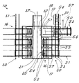
図面に関し、図1は、概ね10によって表された本発明による塗料吹き付けブースを示している。 With respect to the drawings, FIG. 1 shows a paint spray booth according to the invention, approximately represented by 10.
このブースは、対象物12(例えば自動車の車体)に吹き付けるためのチャンバー11を具えている。吹き付けられる対象物を周知の連続移送システム13によってチャンバー11へと移送することが都合が良い。
This booth is equipped with a
このチャンバー11には、塗装される対象物の表面に塗料を吹き付けるように操作される周知の塗料吹き付け器具(図示せず)が設けられている。この塗料吹き付け器具をスプレーガンが設けられた周知のロボットアームの形態で実現することが都合良く可能である。
The
スプレーしぶきをチャンバー11から排除するための空気は、ブースの内側に循環される。チャンバーを通る空気の連続流を生じさせるため、例えば適当な空気循環ファン(図示せず)を本質的に周知の技術によって提供することが都合が良い。
The air for removing the spray spray from the
空気流の循環のため、チャンバー11の床14を、チャンバーの空気がここを通って引き込まれる格子で構成することが都合が良い。従って、チャンバーの天井には、塗料の吹き付け作業中に上端から下方へとチャンバーを垂直に通過する連続した空気流を生ずるように、対応した空気入口15が設けられている。チャンバー11を出た空気流は、スプレーしぶきを留めておく少なくとも1つのフィルターユニット16に運ばれる。このフィルターユニットは、対応するハウジング18の内側にそれぞれ収容される交換可能な複数のフィルターモジュール17を具えることが都合が良く、フィルターモジュールのための台座を形成するハウジングは、チャンバーからの空気の入口と、ろ過後の空気を放電させる出口との間にこれを結合する。
Due to the circulation of airflow, it is convenient to construct the
特に、空気がフィルターに入ることを可能にするための通路21と、出口24とをそれぞれのハウジング18に設けることが都合が良い。
In particular, it is convenient to provide a
図1に示した実施形態において、フィルターユニットをブースの鉛直中央平面に対し、鏡像配置にて相互に対向して全部で2つ配することが都合が良い。この平面は、ブースの前後に延在する方向を画成する移送システム13の移動方向に対して平行であることが都合が良い。空気が床14を通って引かれるブースの実施形態において、このフィルターユニットまたは複数のフィルターユニット16を床14の下に直接配することが好ましい。
In the embodiment shown in FIG. 1, it is convenient to arrange two filter units in total facing each other in a mirror image arrangement with respect to the vertical central plane of the booth. It is convenient that this plane is parallel to the moving direction of the
図示した実施形態において、概ねT字形状の断面を有するチャンバー19があることが都合が良く、これは床14の下で水平に延在してそこから空気を導入するための上部ヘッダー20を、フィルターモジュールに沿って延在すると共にフィルターへの空気の流入を可能にする通路21を形成するT字の垂直部分と共に画成する。通路21の内側には、適切な開口25を設けた個々のハウジング18にあるフィルターモジュールの入口22が相互に並んで配置されている。同様に、個々のハウジング18におけるフィルターモジュールの出口23は、ハウジング18により形成され、かつ(好ましくはハウジングの底の)出口24に結合されたチャンバーに通じている。
In the illustrated embodiment, it is convenient to have a
図示した実施形態において、フィルターモジュールは、両側に配置された入口と出口とを持つ平行六面体形状を有することが都合が良い。これらフィルターは、種々の適当な種類のものであって良く、例えば板紙から作られる使い捨て式のものもまた、可能である。 In the illustrated embodiment, it is convenient for the filter module to have a parallelepiped shape with inlets and outlets located on both sides. These filters may be of various suitable types, including disposable ones made from paperboard, for example.
それぞれのハウジング18の出口24は、ブースから空気を排出するための流路27に(好ましくは一つ以上の、例えば「ポケット」式のさらなるフィルター26を介して)結合することが都合が良い。この流路27は、最終的に空気を外部に排出し、かつ/または浄化した空気の再利用のため、これをチャンバー11へと運んで戻すことができる。
It is convenient for the
また、ハウジングの出口24には、フィルターモジュールを出る空気流を絞り、かつ/または閉止するための制御ゲート28を設けることが都合が良い。
Further, it is convenient to provide a
図1において、ブースへの空気流は、矢印によって概略的に表されている。それで、チャンバー11の底から通路21へと通る空気は、すべてのフィルターモジュールへと並列に導入される。それぞれのモジュールへと通った後、空気はハウジング18(それぞれ箱型の筐体の形態にあることが都合が良い)へと入り、そして排出流路27に達するように出口24から出る。
In FIG. 1, the airflow to the booth is schematically represented by arrows. Therefore, the air passing from the bottom of the
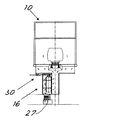
また、図2にて明瞭に見ることができるように、本発明によるブースは、複数のフィルターモジュール17のそれぞれを、そのハウジングと、これらフィルターモジュールをブースに入れるか、またはブースから出すための出し入れ領域31との間で取り出して移送するためのレールシステム30を具えている。
Also, as can be clearly seen in FIG. 2, the booth according to the present invention puts each of the plurality of
このレールシステムは、高架式のものであって、それぞれのハウジング18のために、ガイド51(好ましくは高架式のもの)に対して滑動する取り出し可能なフレーム50を具えていることが都合が良い。そしてまた、この取り出し可能なフレームは、第1の組のレール部52と、第2の組のレール部53とを具えている。これら両方の組は、ガイド51にあるフレームの取り出し方向に対して交差する水平方向に延在している。
The rail system is of elevated type and is conveniently equipped with a
第1の組52は、ハウジング18の内側に収容されてフィルターモジュール17が取り付けられるキャリッジ54を支持するように意図されている。その代わり、第2の組はハウジングの外側にとどまっている。
The
図2に明瞭に見ることができるように、同じフレーム50のレール部の組は、相互に間隔をあけられ、フレーム50が使用または作業位置にある場合(例えば図2の下)、第1の組のレール部52は、対応するフィルターモジュール17が作業位置へともたらされるように、対応するハウジング18の内側に挿入されるのに対し、第2の組のレール部53は固定部55に対し位置調整され、取り付け/取り外し領域31の方に向けられた完全な外部レール通路を(ブースの他のフレーム50の組のレール部と共に)もたらすようになっている。
As can be clearly seen in FIG. 2, the rail sets of the
同様に、フレームが取り出された場合、(例えば図2の右上に見ることができるように)、第1の組のレール部52は、出し入れ領域31の方に向けた完全な外部レール通路を(ブースの他のフレーム50のレール部の組と共に)もたらすように、固定部55に対して位置を調整される。
Similarly, when the frame is removed (eg, as can be seen in the upper right of FIG. 2), the first set of
このようにして、取り出し可能なフレームの第1および第2の組のレール部は、対応する取り出し可能なフレームと、出し入れ領域との間のフィルターモジュールの移動のためのレール通路部を代わりに形成する。 In this way, the first and second sets of rails of the removable frame instead form rail passages for the movement of the filter module between the corresponding removable frame and the access area. To do.
フレームの取り出しのため、それぞれのハウジングはまた、閉止した時に気密となる対応したドア56を具えている。このドア56は、図2の上側に示すように、それぞれのハウジングに蝶番で取り付けられたドアであってよく、あるいはまた、ハウジングを閉止するか、これを開く間仕切り位置にそれぞれ対応した使用中の作業位置と取り出し位置との間をフレームと共に移動するように、レールの組の間に取り付けられた(図2に破線で示す)間仕切り57であってもよい。
For frame retrieval, each housing is also equipped with a
ハウジング18へと空気を流入させるための側(すなわちハウジングの入口開口25)には、フィルターモジュールへと空気を導入する開口を閉止するための手段もまた、設けられている。この手段は、(図2の左上に示した)休止位置と、各フィルターモジュールへと流入させるための開口の1つをこれがそれぞれ閉止する作業位置との間を移動するように、通路に沿って移動する可動間仕切り37(本質的に知られ、従って図示しない手段、例えばチェーン伝動システムにより電動化されていることが都合が良い)を具えていることが都合がよい。この方法において、フィルターモジュールを交換することが必要となった場合、このモジュールへの空気入口を閉止するように間仕切りを移動させ、そしてフレーム50をそのガイド51に対して外側に滑動させることによって、モジュールがハウジングから取り出される。また、ハウジングからの空気のための出口24をゲート28によって閉止することが都合が良い。このようにして、交換されるハウジングを完全にブースの空気流から隔離することができ、ブースの作業を妨げない。
Means for closing the opening for introducing air into the filter module are also provided on the side for allowing air to flow into the housing 18 (ie, the inlet opening 25 of the housing). This means moves along the aisle between a dormant position (shown in the upper left of FIG. 2) and a working position where it closes one of the openings for entry into each filter module. It is convenient to have a moving movable partition 37 (which is essentially known and therefore conveniently electrified by means not shown, such as a chain transmission system). In this method, if it becomes necessary to replace the filter module, by moving the partition to close the air inlet to this module and sliding the
そのレール部52を有する取り出されたモジュールが固定部55に対してひとたび位置調整されると、フィルターモジュールを、そのキャリッジ54と共に領域31に関してレールに沿って滑動させることができ、必要に応じてこれを洗浄または廃棄するために取り外すことができる。
Once the ejected module having the
そして次に、上述した取り出しのための処置の逆がハウジングへと導入されるように、新たなモジュールをレール部に装着して空のハウジングへと移送することができる。 The new module can then be mounted on the rails and transferred to the empty housing so that the reverse of the removal procedure described above is introduced into the housing.
例えば、図示しない適当な周知のエレベーターまたはコンベアーを使って例えば倉庫からこれらのモジュールを取り出し、これらを出し入れ領域31から、およびこれらの領域へと動かすことができる。例えば、板紙から作られた互換性のあるフィルターの場合、出し入れ領域はまた、使用済みモジュールのための本質的に知られた種類の適当な圧縮器具を都合良く具えることも可能である。
For example, suitable well-known elevators or conveyors (not shown) can be used, for example, to remove these modules from a warehouse and move them from and out of the
フィルターモジュールは、ハウジング18と入り側通路21との間の連通開口25の外周端縁36に対してその端縁がシール状態で密着する入口側を有することが都合が良い。この方法において、これは塗料吹き付けチャンバーからフィルターを通る空気流の気密性および循環を確実にするため、端縁36に対してフィルターを載せるだけで足りる。例えば、閉止または作業位置にあるドアまたはフレームを用いてモジュールに加えられるスラスト力によって、シール接触を確実にすることができ、あるいはさらなる周知の拘束手段を設けて作業位置にモジュールを保持するために作動させることができる。
It is convenient that the filter module has an inlet side in which the edge of the
図3は、作業者によるフィルターモジュール17の取り出しおよび交換のための作業の破断正面図をより大きく詳細に示している。
FIG. 3 shows in greater detail a fractured front view of the work for removal and replacement of the
鏡像構成の2つのフィルターユニットを持つ実施形態が特に有利であると考えられているけれども、それにも拘らず、例えば処理される空気流がより制限されている場合、単一のフィルターユニットを用いることもまた可能である。これは、例えば図4に示されており、フィルターへと空気を運ぶための本質的にT字形のチャンバーは、入り側通路の片側にだけフィルターモジュールを有し、従って単一のフィルター移送および移動システムが設けられている。残余に関し、塗料吹き付けブースの構造は、上述したものと同一であってよい。 An embodiment having two filter units in a mirror image configuration is considered to be particularly advantageous, but nevertheless, for example, if the airflow to be processed is more restricted, use a single filter unit. Is also possible. This is shown, for example, in FIG. 4, where the essentially T-shaped chamber for carrying air to the filter has a filter module on only one side of the entry aisle, thus a single filter transfer and transfer. A system is provided. With respect to the residue, the structure of the paint spray booth may be the same as described above.
この時点で、あらかじめ定めた目的がどのように達成されているかが明確である。本発明によるブースに関し、プラントを停止する必要すらなく、フィルターを周期的に容易かつ迅速に交換することが可能である。空気流が複数のフィルターを用いて分けられるため、一つのフィルターをその取り出しおよび交換のために閉止しても、作業全体のために必要な空気流の時間を過度に減らさない。このレールシステムのおかげで、作業者は交換作業をより容易かつ少ない労力で行うことができる。しかしながら、この移動システムは、単純で強く、かつ相対的に低コストである。 At this point, it is clear how the predetermined objectives have been achieved. With respect to the booth according to the present invention, the filters can be replaced easily and quickly periodically without even having to shut down the plant. Since the airflow is divided using multiple filters, closing one filter for its removal and replacement does not excessively reduce the airflow time required for the entire operation. Thanks to this rail system, workers can perform replacement work more easily and with less effort. However, this mobile system is simple, strong, and relatively low cost.
本発明の革新的な原理を適用した上の一実施形態の説明は、これらの革新的な原理の実施例として明かにもたらされ、従ってここで請求された権利の範囲を限定するように見なしてはならない。 The description of an embodiment in which the innovative principles of the present invention have been applied is clearly provided as an example of these innovative principles and is therefore considered to limit the scope of rights claimed herein. must not.
例えば、ここで当業者が容易に想像することができるように、出し入れ領域を、新たなフィルターが届く入り側領域と、使用済みのフィルターが移送される出側領域とに分けることができる。これらの領域は、例えばレール部52または53および固定部55によって形成された2つの移動通路の両端部にあってよい。
For example, as can be easily imagined by those skilled in the art, the in / out area can be divided into an entry area where a new filter reaches and an exit area where a used filter is transferred. These regions may be at both ends of the two moving passages formed by, for example, the
移動システムはまた、自動的または半自動的であってよい。例えば、これらが使用または作業位置と、取り出し位置との間でこれらの制御された移動のために電動化されるように、フレーム50を都合良く設計することができる。
The mobile system may also be automatic or semi-automatic. For example, the
フィルターの交換を所定の作業周期に従ってプログラムされた時間にて周期的に行うことができ、あるいは適当なセンサーをまた、設けることもでき、このセンサーは、ある一定量よりも多くまで詰まっていることをこれが検出した場合にフィルターの交換を要求する。全部の交換作業中に、フィルターモジュールはまた、すべてのフィルターモジュールが完全に交換されるまで、一回に付き1つずつ(あるいは対応付けられた独立した自動化システムを持つ2つのフィルターユニットの場合、対で)連続的に交換することができる。従って、交換のために必要とされる全期間に亙り、塗料吹き付けブースを機能させるように保つことができる。 The filter can be replaced periodically at a time programmed according to a predetermined working cycle, or a suitable sensor can also be provided, which is packed to more than a certain amount. If this is detected, request a filter replacement. During the entire replacement operation, the filter modules will also be replaced one at a time (or in the case of two filter units with an associated independent automation system) until all filter modules have been completely replaced. Can be exchanged continuously (in pairs). Therefore, the paint spray booth can be kept functional for the entire period required for replacement.
可燃性材料で作られた使い捨てフィルターの場合、使用済みフィルターの高温焼却のための方法を考えることができ、この方法は、フィルターそれ自体およびこれに含まれる塗料を燃料の少なくとも一部として用いる。フィルターを除去することに加え、この燃焼を燃焼蒸気からの熱回収のために有効利用することが可能である。 For disposable filters made of flammable materials, a method for high temperature incineration of used filters can be considered, which uses the filter itself and the paint contained therein as at least part of the fuel. In addition to removing the filter, this combustion can be effectively used for heat recovery from combustion vapor.
Claims (8)
Applications Claiming Priority (3)
| Application Number | Priority Date | Filing Date | Title |
|---|---|---|---|
| IT102015000047636 | 2015-09-01 | ||
| ITUB2015A003320A ITUB20153320A1 (en) | 2015-09-01 | 2015-09-01 | Spray booth with filter change system |
| PCT/IB2016/055226 WO2017037644A1 (en) | 2015-09-01 | 2016-09-01 | Painting booth with change filter system |
Publications (3)
| Publication Number | Publication Date |
|---|---|
| JP2018531777A JP2018531777A (en) | 2018-11-01 |
| JP2018531777A5 JP2018531777A5 (en) | 2019-08-15 |
| JP6837477B2 true JP6837477B2 (en) | 2021-03-03 |
Family
ID=54542466
Family Applications (1)
| Application Number | Title | Priority Date | Filing Date |
|---|---|---|---|
| JP2018510391A Active JP6837477B2 (en) | 2015-09-01 | 2016-09-01 | Painting booth with replacement filter system |
Country Status (13)
| Country | Link |
|---|---|
| US (1) | US10350627B2 (en) |
| EP (1) | EP3344364B1 (en) |
| JP (1) | JP6837477B2 (en) |
| CN (1) | CN107921348B (en) |
| BR (1) | BR112018003960A2 (en) |
| CA (1) | CA2996394A1 (en) |
| ES (1) | ES2806273T3 (en) |
| IT (1) | ITUB20153320A1 (en) |
| MA (1) | MA47183A (en) |
| MX (1) | MX2018002570A (en) |
| RS (1) | RS60637B1 (en) |
| SI (1) | SI3344364T1 (en) |
| WO (1) | WO2017037644A1 (en) |
Families Citing this family (12)
| Publication number | Priority date | Publication date | Assignee | Title |
|---|---|---|---|---|
| DE102013222301B4 (en) | 2013-11-04 | 2024-01-25 | Dürr Systems Ag | Filter system for separating impurities from a raw gas stream containing impurities, painting system and method for separating impurities from a raw gas stream containing impurities |
| JP6576323B2 (en) * | 2016-12-14 | 2019-09-18 | 株式会社大気社 | Painting drying equipment |
| JP6905550B2 (en) * | 2019-06-19 | 2021-07-21 | トリニティ工業株式会社 | Paint mist removal device and painting equipment |
| IT201900025015A1 (en) * | 2019-12-20 | 2021-06-20 | Geico Spa | Painting booth with manual filter change system |
| IT201900025045A1 (en) * | 2019-12-20 | 2021-06-20 | Geico Spa | Painting booth with filter transport system |
| JP2021133269A (en) | 2020-02-25 | 2021-09-13 | トリニティ工業株式会社 | Paint mist removal device and painting equipment |
| DE102020204126A1 (en) * | 2020-03-30 | 2021-09-30 | Volkswagen Aktiengesellschaft | Device for closing at least one opening when changing at least one filter element in an exhaust air filter system and a painting system with such |
| DE102020205792A1 (en) * | 2020-05-07 | 2021-11-11 | Dürr Systems Ag | Filter system, painting system and process for separating impurities |
| US11878316B2 (en) * | 2020-12-15 | 2024-01-23 | Gallagher-Kaiser Corporation | Sliding drawer dry filtration system for a paint booth |
| CN112827694A (en) * | 2021-01-07 | 2021-05-25 | 昆山丰巧机械有限公司 | Line paint spraying machine with high recycling rate |
| CN114918085B (en) * | 2022-05-09 | 2023-02-21 | 江苏长虹智能装备股份有限公司 | Dry-type carton paint spraying chamber for large-scale rail transit vehicle body spraying |
| CN116078077B (en) * | 2023-04-07 | 2023-07-21 | 杭州智和净化科技有限公司 | Automatic replacement device and automatic replacement method for dry type filter module |
Family Cites Families (16)
| Publication number | Priority date | Publication date | Assignee | Title |
|---|---|---|---|---|
| JPS6021365U (en) * | 1983-07-15 | 1985-02-14 | トヨタ自動車株式会社 | Wet painting booth |
| DE3705634A1 (en) * | 1987-02-21 | 1988-09-01 | Metallgesellschaft Ag | METHOD AND DEVICE FOR CLEANING EXHAUST AIR FROM PAINT OR PAINT SPRAYING CABINS |
| JPH02160066A (en) * | 1988-12-14 | 1990-06-20 | Matsuo Sangyo Kk | Coating booth of electrostatic powder coating equipment |
| JPH0829277B2 (en) * | 1989-06-23 | 1996-03-27 | トリニティ工業株式会社 | Paint booth with air supply |
| US5487766A (en) * | 1994-05-24 | 1996-01-30 | Vannier; Mervin R. | Portable air filtration apparatus |
| CA2126802C (en) * | 1994-06-27 | 1999-08-17 | Hermann Ophardt | Powder paint booth backflow filter apparatus |
| JP3621765B2 (en) * | 1995-09-19 | 2005-02-16 | 日本無機株式会社 | Air filter mounting device |
| JPH11290736A (en) * | 1998-04-08 | 1999-10-26 | Hitachi Building Systems Co Ltd | Malodor removing device for coating work |
| DE102007040153A1 (en) * | 2007-08-24 | 2009-02-26 | Dürr Systems GmbH | Method and apparatus for separating overspray of a liquid coating material |
| JP5222178B2 (en) * | 2009-02-17 | 2013-06-26 | 株式会社大気社 | Painting booth equipment |
| DE102009055192A1 (en) * | 2009-12-22 | 2011-06-30 | Dürr Systems GmbH, 74321 | Filter device for separating paint overspray |
| DE102010032144A1 (en) * | 2010-07-24 | 2012-01-26 | Eisenmann Ag | Treatment unit and facility for surface treatment of objects |
| JP5515178B2 (en) * | 2010-08-19 | 2014-06-11 | 株式会社大気社 | Exhaust equipment |
| JP5828864B2 (en) * | 2013-06-12 | 2015-12-09 | 本田技研工業株式会社 | Dry painting equipment |
| DE102013011107A1 (en) * | 2013-07-03 | 2014-08-07 | Eisenmann Ag | Method for operating a surface treatment system and device for separating overspray |
| DE102013222301B4 (en) | 2013-11-04 | 2024-01-25 | Dürr Systems Ag | Filter system for separating impurities from a raw gas stream containing impurities, painting system and method for separating impurities from a raw gas stream containing impurities |
-
2015
- 2015-09-01 IT ITUB2015A003320A patent/ITUB20153320A1/en unknown
-
2016
- 2016-09-01 CA CA2996394A patent/CA2996394A1/en not_active Abandoned
- 2016-09-01 CN CN201680046464.3A patent/CN107921348B/en not_active Expired - Fee Related
- 2016-09-01 RS RS20200809A patent/RS60637B1/en unknown
- 2016-09-01 WO PCT/IB2016/055226 patent/WO2017037644A1/en active Application Filing
- 2016-09-01 JP JP2018510391A patent/JP6837477B2/en active Active
- 2016-09-01 SI SI201630839T patent/SI3344364T1/en unknown
- 2016-09-01 EP EP16779183.9A patent/EP3344364B1/en active Active
- 2016-09-01 ES ES16779183T patent/ES2806273T3/en active Active
- 2016-09-01 MA MA047183A patent/MA47183A/en unknown
- 2016-09-01 MX MX2018002570A patent/MX2018002570A/en unknown
- 2016-09-01 BR BR112018003960A patent/BR112018003960A2/en active Search and Examination
- 2016-09-01 US US15/754,018 patent/US10350627B2/en active Active
Also Published As
| Publication number | Publication date |
|---|---|
| MX2018002570A (en) | 2018-11-09 |
| RS60637B1 (en) | 2020-09-30 |
| CN107921348B (en) | 2020-11-10 |
| US10350627B2 (en) | 2019-07-16 |
| ES2806273T3 (en) | 2021-02-17 |
| EP3344364A1 (en) | 2018-07-11 |
| JP2018531777A (en) | 2018-11-01 |
| CA2996394A1 (en) | 2017-03-09 |
| MA47183A (en) | 2019-11-13 |
| ITUB20153320A1 (en) | 2017-03-01 |
| CN107921348A (en) | 2018-04-17 |
| WO2017037644A1 (en) | 2017-03-09 |
| BR112018003960A2 (en) | 2018-09-25 |
| SI3344364T1 (en) | 2020-09-30 |
| EP3344364B1 (en) | 2020-04-15 |
| US20180236476A1 (en) | 2018-08-23 |
Similar Documents
| Publication | Publication Date | Title |
|---|---|---|
| JP6837477B2 (en) | Painting booth with replacement filter system | |
| JP6816115B2 (en) | Painting booth with automatic filter system | |
| RU2697452C2 (en) | Filtration unit, painting unit and operating method of filter unit | |
| JP2018531778A5 (en) | ||
| JP2018531777A5 (en) | ||
| KR20100124728A (en) | Device and method for supplying air to an application zone of a painting line | |
| WO2021124181A1 (en) | Painting booth with filter transport system | |
| KR20180050283A (en) | Painting Booth with Filter Change System | |
| US10072861B2 (en) | Clean work device | |
| CN214554782U (en) | Processing apparatus | |
| KR101057489B1 (en) | Dry air shower unit with cartridge filter | |
| WO2021124178A1 (en) | Painting booth with manual filter-changing system | |
| WO2021124183A1 (en) | Painting booth with improved system for replacement of the filters | |
| KR20070033877A (en) | Mould for making inserts from polyurethane foam with a built-in substance for depositing a separating agent | |
| CA3189394A1 (en) | Dry filter module for use in spray booth | |
| CN113457288A (en) | Device and painting installation comprising such a device |
Legal Events
| Date | Code | Title | Description |
|---|---|---|---|
| A521 | Written amendment |
Free format text: JAPANESE INTERMEDIATE CODE: A523 Effective date: 20180315 |
|
| A521 | Written amendment |
Free format text: JAPANESE INTERMEDIATE CODE: A523 Effective date: 20190703 |
|
| A621 | Written request for application examination |
Free format text: JAPANESE INTERMEDIATE CODE: A621 Effective date: 20190703 |
|
| A977 | Report on retrieval |
Free format text: JAPANESE INTERMEDIATE CODE: A971007 Effective date: 20200526 |
|
| A131 | Notification of reasons for refusal |
Free format text: JAPANESE INTERMEDIATE CODE: A131 Effective date: 20200818 |
|
| A521 | Written amendment |
Free format text: JAPANESE INTERMEDIATE CODE: A523 Effective date: 20201007 |
|
| TRDD | Decision of grant or rejection written | ||
| A01 | Written decision to grant a patent or to grant a registration (utility model) |
Free format text: JAPANESE INTERMEDIATE CODE: A01 Effective date: 20210112 |
|
| A61 | First payment of annual fees (during grant procedure) |
Free format text: JAPANESE INTERMEDIATE CODE: A61 Effective date: 20210209 |
|
| R150 | Certificate of patent or registration of utility model |
Ref document number: 6837477 Country of ref document: JP Free format text: JAPANESE INTERMEDIATE CODE: R150 |