JP6832274B6 - How to control the scattering of incident light and the articles formed by it - Google Patents
How to control the scattering of incident light and the articles formed by it Download PDFInfo
- Publication number
- JP6832274B6 JP6832274B6 JP2017517764A JP2017517764A JP6832274B6 JP 6832274 B6 JP6832274 B6 JP 6832274B6 JP 2017517764 A JP2017517764 A JP 2017517764A JP 2017517764 A JP2017517764 A JP 2017517764A JP 6832274 B6 JP6832274 B6 JP 6832274B6
- Authority
- JP
- Japan
- Prior art keywords
- recesses
- micrometers
- laser
- orthodontic appliance
- pattern
- Prior art date
- Legal status (The legal status is an assumption and is not a legal conclusion. Google has not performed a legal analysis and makes no representation as to the accuracy of the status listed.)
- Active
Links
Images


Classifications
-
- A—HUMAN NECESSITIES
- A61—MEDICAL OR VETERINARY SCIENCE; HYGIENE
- A61C—DENTISTRY; APPARATUS OR METHODS FOR ORAL OR DENTAL HYGIENE
- A61C7/00—Orthodontics, i.e. obtaining or maintaining the desired position of teeth, e.g. by straightening, evening, regulating, separating, or by correcting malocclusions
- A61C7/12—Brackets; Arch wires; Combinations thereof; Accessories therefor
- A61C7/20—Arch wires
-
- B—PERFORMING OPERATIONS; TRANSPORTING
- B23—MACHINE TOOLS; METAL-WORKING NOT OTHERWISE PROVIDED FOR
- B23K—SOLDERING OR UNSOLDERING; WELDING; CLADDING OR PLATING BY SOLDERING OR WELDING; CUTTING BY APPLYING HEAT LOCALLY, e.g. FLAME CUTTING; WORKING BY LASER BEAM
- B23K26/00—Working by laser beam, e.g. welding, cutting or boring
- B23K26/36—Removing material
- B23K26/361—Removing material for deburring or mechanical trimming
-
- G—PHYSICS
- G02—OPTICS
- G02B—OPTICAL ELEMENTS, SYSTEMS OR APPARATUS
- G02B5/00—Optical elements other than lenses
- G02B5/02—Diffusing elements; Afocal elements
- G02B5/0205—Diffusing elements; Afocal elements characterised by the diffusing properties
- G02B5/021—Diffusing elements; Afocal elements characterised by the diffusing properties the diffusion taking place at the element's surface, e.g. by means of surface roughening or microprismatic structures
- G02B5/0215—Diffusing elements; Afocal elements characterised by the diffusing properties the diffusion taking place at the element's surface, e.g. by means of surface roughening or microprismatic structures the surface having a regular structure
-
- G—PHYSICS
- G02—OPTICS
- G02B—OPTICAL ELEMENTS, SYSTEMS OR APPARATUS
- G02B5/00—Optical elements other than lenses
- G02B5/02—Diffusing elements; Afocal elements
- G02B5/0205—Diffusing elements; Afocal elements characterised by the diffusing properties
- G02B5/021—Diffusing elements; Afocal elements characterised by the diffusing properties the diffusion taking place at the element's surface, e.g. by means of surface roughening or microprismatic structures
- G02B5/0221—Diffusing elements; Afocal elements characterised by the diffusing properties the diffusion taking place at the element's surface, e.g. by means of surface roughening or microprismatic structures the surface having an irregular structure
-
- G—PHYSICS
- G02—OPTICS
- G02B—OPTICAL ELEMENTS, SYSTEMS OR APPARATUS
- G02B5/00—Optical elements other than lenses
- G02B5/02—Diffusing elements; Afocal elements
- G02B5/0205—Diffusing elements; Afocal elements characterised by the diffusing properties
- G02B5/0257—Diffusing elements; Afocal elements characterised by the diffusing properties creating an anisotropic diffusion characteristic, i.e. distributing output differently in two perpendicular axes
-
- G—PHYSICS
- G02—OPTICS
- G02B—OPTICAL ELEMENTS, SYSTEMS OR APPARATUS
- G02B5/00—Optical elements other than lenses
- G02B5/02—Diffusing elements; Afocal elements
- G02B5/0268—Diffusing elements; Afocal elements characterized by the fabrication or manufacturing method
-
- G—PHYSICS
- G02—OPTICS
- G02B—OPTICAL ELEMENTS, SYSTEMS OR APPARATUS
- G02B5/00—Optical elements other than lenses
- G02B5/02—Diffusing elements; Afocal elements
- G02B5/0273—Diffusing elements; Afocal elements characterized by the use
- G02B5/0278—Diffusing elements; Afocal elements characterized by the use used in transmission
-
- G—PHYSICS
- G02—OPTICS
- G02F—OPTICAL DEVICES OR ARRANGEMENTS FOR THE CONTROL OF LIGHT BY MODIFICATION OF THE OPTICAL PROPERTIES OF THE MEDIA OF THE ELEMENTS INVOLVED THEREIN; NON-LINEAR OPTICS; FREQUENCY-CHANGING OF LIGHT; OPTICAL LOGIC ELEMENTS; OPTICAL ANALOGUE/DIGITAL CONVERTERS
- G02F1/00—Devices or arrangements for the control of the intensity, colour, phase, polarisation or direction of light arriving from an independent light source, e.g. switching, gating or modulating; Non-linear optics
- G02F1/01—Devices or arrangements for the control of the intensity, colour, phase, polarisation or direction of light arriving from an independent light source, e.g. switching, gating or modulating; Non-linear optics for the control of the intensity, phase, polarisation or colour
- G02F1/23—Devices or arrangements for the control of the intensity, colour, phase, polarisation or direction of light arriving from an independent light source, e.g. switching, gating or modulating; Non-linear optics for the control of the intensity, phase, polarisation or colour for the control of the colour
- G02F1/25—Devices or arrangements for the control of the intensity, colour, phase, polarisation or direction of light arriving from an independent light source, e.g. switching, gating or modulating; Non-linear optics for the control of the intensity, phase, polarisation or colour for the control of the colour as to hue or predominant wavelength
-
- B—PERFORMING OPERATIONS; TRANSPORTING
- B23—MACHINE TOOLS; METAL-WORKING NOT OTHERWISE PROVIDED FOR
- B23K—SOLDERING OR UNSOLDERING; WELDING; CLADDING OR PLATING BY SOLDERING OR WELDING; CUTTING BY APPLYING HEAT LOCALLY, e.g. FLAME CUTTING; WORKING BY LASER BEAM
- B23K2101/00—Articles made by soldering, welding or cutting
- B23K2101/32—Wires
Description
歯科矯正療法は、転位(又は、歪んだ)歯の管理下治療に関する、歯科の専門領域である。一般に、そのような治療は、1つ以上の歯科矯正装置を使用して、軽度の持続的な力を、歯に対して慎重に適用することを伴う。これらの力は、周囲の骨構造の変化を刺激することにより、歯を、口腔内のそれらの適正な位置へと、徐々に方向付ける。歯科矯正療法は、衛生状態を維持する容易さ、顔貌の改善、並びに咬合機能の改善を含めた、多くの利益をもたらし得る。 Orthodontic therapy is a specialized area of dentistry for the controlled treatment of dislocated (or distorted) teeth. In general, such treatment involves the careful application of mild, sustained force to the teeth using one or more orthodontic appliances. These forces gradually orient the teeth to their proper position in the oral cavity by stimulating changes in the surrounding bone structure. Orthodontic therapy can provide many benefits, including ease of maintaining hygiene, improved facial appearance, and improved occlusal function.
固定式装置、つまり「ブレース」は、歯科矯正治療の1つのタイプを表すものであり、ブラケットと呼ばれる小さいスロット付き装置が歯に取り付けられる。次いで、弾性のU字形状(すなわち放物線状)のアーチワイヤが、それらのブラケットのスロット内に定置される。ブラケットに結紮されると、アーチワイヤは、治療の過程で歯をそれらの適正な位置に誘導する軌道としての役割を果たす。治療の開始時には、アーチワイヤは、結紮を容易にするため、また歯がほぐれる際に、歯に加えられる力を比較的小さく保つためにも、小さい断面寸法を有する傾向がある。治療の後期には、歯は、それらの標的位置に接近し、漸進的に、より大きい(かつ、より堅固な)ワイヤを使用することにより、関連する歯に対する施術者の制御を改善することが可能となる。 A fixed device, or "brace," represents a type of orthodontic treatment in which a small slotted device called a bracket is attached to the tooth. Elastic U-shaped (ie, parabolic) archwires are then placed in the slots of those brackets. When ligated to the bracket, the archwire acts as a trajectory that guides the teeth to their proper position during the course of treatment. At the beginning of treatment, the archwire tends to have a small cross-sectional dimension to facilitate ligation and to keep the force applied to the tooth relatively small when the tooth is loosened. In the later stages of treatment, the teeth may approach their target location and gradually improve the practitioner's control over the associated teeth by using larger (and stiffer) wires. It will be possible.
歯科矯正用ブラケットは、金属(例えば、ステンレススチール)、プラスチック(例えば、ポリカーボネート)、並びに単結晶及び多結晶酸化アルミニウムなどのセラミック材料といった幅広く異なる材料から作製することができる。アーチワイヤもまた、ステンレススチール、チタン、並びに、ニッケル−チタン、及び銅−ニッケル−チタンの合金などの形状記憶合金を含む、様々な金属又は金属合金材料から作製することができる。 Orthodontic brackets can be made from a wide variety of different materials such as metals (eg, stainless steel), plastics (eg, polycarbonate), and ceramic materials such as single crystal and polycrystalline aluminum oxide. Archwires can also be made from a variety of metal or metal alloy materials, including stainless steel, titanium, and shape memory alloys such as nickel-titanium and copper-nickel-titanium alloys.
多くの歯科矯正装置、及びとりわけ金属アーチワイヤは依然として、一部の患者及び歯科医にとって審美的に魅力的ではないが、これは少なくとも一部において、金属的な光沢と、患者のエナメル質の色(白色など)との目立ちやすいコントラストによるものである。ここ数十年で、口腔内の金属の外観を最小化する傾向のある、歯科矯正審美ブラケットを使用することへの関心が高まっている。例えば、半透明で、その下の歯の色になるセラミックの歯科矯正ブラケットが開発されている。半透明のプラスチックブラケット及び歯の色のプラスチックブラケットもまた既知である。 Many orthodontic appliances, and especially metal archwires, are still not aesthetically appealing to some patients and dentists, but this is, at least in part, metallic luster and the color of the patient's enamel. This is due to the conspicuous contrast with (white, etc.). In recent decades, there has been increasing interest in using orthodontic aesthetic brackets, which tend to minimize the appearance of metal in the oral cavity. For example, ceramic orthodontic brackets that are translucent and have the color of the underlying teeth have been developed. Translucent plastic brackets and tooth-colored plastic brackets are also known.
歯科矯正審美ブラケットの使用は、口腔内における大幅に改善された外観を呈し得る。多くの場合、アーチワイヤは、見えやすい唯一の金属構成要素である。そこで、この、金属的外観の最後の要因を低減するか、又は排除することが望ましい。 The use of orthodontic aesthetic brackets can provide a significantly improved appearance in the oral cavity. Archwires are often the only metal component that is easily visible. Therefore, it is desirable to reduce or eliminate this last factor of metallic appearance.
非金属の審美層でコーティングされた歯科矯正アーチワイヤが、過去に提案されてきた。例えば、米国特許第5,454,716号(Banerjeeら)、及び国際公開第97/29712号(Sjoegren)は、歯の色と適合する薄い着色層でコーティングされた、歯科矯正アーチワイヤを記載している。他のコーティングした歯科矯正アーチワイヤは、米国特許第4,050,156号(Chasanoffら)、及び同第3,504,438号(Anthonyら)に記載されている。米国特許第4,731,018号(Adelleら)は、金属部分及びプラスチック部分を備え、プラスチック部分が唇側を向くように構成されている、アーチワイヤを記載している。 Orthodontic arch wires coated with a non-metallic aesthetic layer have been proposed in the past. For example, U.S. Pat. Nos. 5,454,716 (Banerjee et al.) And WO 97/29712 (Sjoegren) describe orthodontic archwires coated with a light colored layer that matches the color of the teeth. ing. Other coated orthodontic archwires are described in US Pat. Nos. 4,050,156 (Chasanoff et al.) And 3,504,438 (Anthony et al.). U.S. Pat. No. 4,731,018 (Adelle et al.) Describes an archwire comprising a metal portion and a plastic portion, the plastic portion being configured to face the labial side.
金属歯科矯正物品の外観を改善しようとするこれまでの試みも、物品の1つ以上の表面に美観用金属を堆積又は導入することを特徴としてきた。米国特許第8,778,444号(Kim)は、白色又はアイボリーカラーを付与するための、金属又は他の保護成分での表面コーティングに先立って、金属ワイヤの表面を物理的、又は化学的にエッチングすることを記載している。アーチワイヤはその後、透明な金属材料が退色するのを防ぎ、ワイヤと歯の統一性を保ち得るために、表面を透明なパリレン膜でコーティングされる。同様に、米国特許第8,726,510号(Voudouris)は、美観用コーティングの接着を向上させるため、非平坦な表面質感を生成するように、自己結紮式ブラケットクリップに大規模な、レーザーで形成したクレータを使用することを、報告している。 Previous attempts to improve the appearance of metal orthodontic articles have also been characterized by the deposition or introduction of aesthetic metal on one or more surfaces of the article. U.S. Pat. No. 8,778,444 (Kim) physically or chemically coats the surface of a metal wire prior to surface coating with a metal or other protective ingredient to impart a white or ivory color. Describes etching. The arch wire is then coated with a clear parylene film to prevent the clear metal material from fading and to maintain the integrity of the wire and teeth. Similarly, U.S. Pat. No. 8,726,510 (Voodouris) uses a large, laser on a self-ligating bracket clip to produce a non-flat surface texture in order to improve the adhesion of the aesthetic coating. It reports the use of formed craters.
米国特許第5,882,193号(Wool)は、アーチワイヤに補助部品を取り付ける手段について説明しており、アーチワイヤの表面が最初に、酸化還元剤による処理によって、脱酸素される。清浄化した表面がその後、貴金属、例えば、金、プラチナ、ロジウム、及びパラジウムでめっきされる。めっきされた表面は、主に補助的取り付けのために、はんだ付け可能、又はろう付け可能な表面をもたらす一方で、いくらかの審美的な改善をもたらすことができる。 U.S. Pat. No. 5,882,193 (Wool) describes a means of attaching an auxiliary component to an archwire, the surface of the archwire being first deoxidized by treatment with an oxidative reducing agent. The cleaned surface is then plated with precious metals such as gold, platinum, rhodium, and palladium. The plated surface can provide some aesthetic improvement while providing a solderable or brazable surface, primarily for auxiliary mounting.
コーティング材料により付与される効果に主に依存することにより、このような方法は、特に、話す間、咀嚼する間、及び頭部の他の動きの間に歯科用アーチの相対向きが変わると、依然として間違いなく外観が金属的である歯科矯正装置を生じる。したがって、金属的な光沢を最小化する一方で、広範な視野角において、歯の色の外観を実質的に保持する装置が必要とされている。 By relying primarily on the effects imparted by the coating material, such methods, especially when the relative orientation of the dental arch changes during speaking, chewing, and other movements of the head, It still undoubtedly results in orthodontic appliances that are metallic in appearance. Therefore, there is a need for a device that substantially retains the appearance of tooth color over a wide viewing angle while minimizing metallic luster.
本開示は、生じる鏡面反射及び光沢がより少なく、かつ依然として多数の入射角において、高強度の反射光をもたらす、加工された、構造化金属表面を提示する。構造化された金属表面は、多数の視野角において、拡散反射を増加させ、より高強度の光を受けることにつながる加工されたトポグラフィーを含む。このような表面とかかわる観察者は、入射光のより強い「白い」反射と、特に、歯科矯正、及び他の口腔用途における、審美的外観の改善とを知覚する傾向にある。 The present disclosure presents a processed, structured metal surface that produces less specular reflection and gloss, and still provides high intensity reflected light at a large number of angles of incidence. The structured metal surface contains processed topography that increases diffuse reflection and leads to higher intensity light at multiple viewing angles. Observers with such surfaces tend to perceive a stronger "white" reflection of incident light and an improvement in aesthetic appearance, especially in orthodontics and other oral applications.
一態様において、本開示は、金属を含む外面と、外面に設けられた複数の凹部とを含み、複数の凹部を含む表面が、14以下の合計CIEクロマ、及び0°の入射角かつ70°の視野角において少なくとも20の最小L*値を呈する、歯科矯正装置を提示する。 In one aspect, the present disclosure includes an outer surface containing metal and a plurality of recesses provided on the outer surface, the surface including the plurality of recesses having a total CIE chroma of 14 or less, and an angle of view of 0 ° and 70 °. We present an orthodontic appliance that exhibits a minimum L * value of at least 20 in the viewing angle of.
別の態様において、本開示は、金属を含む外面と、外面に設けられた、加工された複数の特徴部とを含み、加工された複数の特徴部を含む表面が、14以下の合計CIEクロマ、0°の入射角かつ70°の視野角において少なくとも20の最小L*値を呈する、歯科矯正装置を提示する。 In another aspect, the present disclosure includes a metal-containing outer surface and a plurality of processed features provided on the outer surface, the total CIE chroma having a surface including the processed features of 14 or less. , Presents an orthodontic appliance that exhibits a minimum L * value of at least 20 at an incident angle of 0 ° and a viewing angle of 70 °.
別の態様において、本開示は、金属を含む外面と、表面に設けられた、加工された複数の特徴部とを有する本体を含む装置を提示する。加工された表面は、散漫散乱試験により測定したときに、14未満の合計CIEクロマにおける少なくとも0.2の拡散L*最小70/最大15比率、0°の入射角かつ70°の視野角における少なくとも20の最小L*値を呈する。 In another aspect, the present disclosure presents a device comprising a body comprising a metal-containing outer surface and a plurality of machined features provided on the surface. The processed surface has a diffusion L * minimum 70 / maximum 15 ratio of at least 0.2 in a total CIE chroma less than 14 as measured by a diffuse scattering test, at least at an incident angle of 0 ° and a viewing angle of 70 °. It exhibits a minimum L * value of 20.
別の態様において、本開示は、金属を含む外面と、表面内に画定された複数の凹部とを含む装置を提示する。凹部は、表面から少なくとも0.5マイクロメートルの平均深さを有し、かつ重複するアレイとして配列され、凹部の大部分は、境界領域において隣接する凹部と重複する。 In another aspect, the present disclosure presents a device comprising an outer surface containing metal and a plurality of recesses defined within the surface. The recesses have an average depth of at least 0.5 micrometers from the surface and are arranged as overlapping arrays, with most of the recesses overlapping adjacent recesses in the boundary region.
更に別の態様において、本開示は物品の審美的外観を改善するための方法を提示しており、方法は、外面を有し、外面が金属を含む物品を準備することと、散漫散乱試験により測定したときに、表面が、少なくとも0.2の拡散L*最小70/最大15比率を呈するように、表面の少なくとも一部をアブレーションして表面上に複数の特徴部を形成することと、を含む。 In yet another embodiment, the present disclosure presents a method for improving the aesthetic appearance of an article by preparing an article having an outer surface and having a metal outer surface and by a diffuse scattering test. Ablating at least a portion of the surface to form a plurality of features on the surface so that the surface exhibits a diffusion L * minimum 70 / maximum 15 ratio of at least 0.2 when measured. Including.
本明細書で使用される「幾何形状」は、加工された特徴部の寸法及び形状を指す。 As used herein, "geometric shape" refers to the dimensions and shape of a machined feature.
本明細書で使用される「特徴部」は、表面の基準面から外に突出する量又は表面内に突出する凹量によって画定される、認識可能な幾何学形状を有する構造又は特徴部である。 As used herein, a "feature" is a structure or feature having a recognizable geometric shape that is defined by an amount that projects outward from or inward the reference plane of the surface. ..
本明細書に使用されるとき、「加工されたミクロ構造」及び「加工された特徴部」とは、表面内に意図的に形成され、表面と統合された構造を意味する。加工されたミクロ構造又は加工された特徴部は、表面への粒子のランダム適用、噴霧、接着剤結合などにより形成される構造とは異なる。 As used herein, "processed microstructure" and "processed feature" mean a structure that is intentionally formed within a surface and integrated with the surface. The processed microstructure or processed feature is different from the structure formed by random application of particles to the surface, spraying, adhesive bonding, etc.
本明細書に使用されるとき、用語「加工された表面」及び「構造化表面」とは一般的に、加工された特徴部を備える表面を指すものとして使用される。 As used herein, the terms "processed surface" and "structured surface" are generally used to refer to a surface with a processed feature.
本明細書において使用するとき、用語「ピッチ」とは、加工された表面上の隣接する構造部(例えば、凹部)の間の、平均的な重心同士の間隔を意味する。 As used herein, the term "pitch" means the distance between the average centers of gravity between adjacent structural parts (eg, recesses) on a machined surface.
本明細書において使用されるとき、用語「高さ」、「底部」、及び「頂部」は、単に例示目的のためであり、必ずしも、表面及びミクロ構造の向き又は表面とミクロ構造との関係を規定するものではない。例えば、表面内に突出する特徴部の「高さ」は、作製された凹部の「深さ」と同一とみなし、この凹部の「頂部」を「底部」とみなすことができる。したがって、用語「高さ」及び「深さ」、並びに、「頂部」及び「底部」は、互換可能とみなすべきである。 As used herein, the terms "height," "bottom," and "top" are for illustrative purposes only and do not necessarily refer to the orientation of the surface and microstructure or the relationship between the surface and the microstructure. It does not specify. For example, the "height" of the feature portion protruding into the surface can be regarded as the same as the "depth" of the produced recess, and the "top" of the recess can be regarded as the "bottom". Therefore, the terms "height" and "depth", as well as "top" and "bottom" should be considered compatible.
「備える、含む(comprises)」という用語及びこれらの変形は、本説明及び特許請求の範囲に記載される場合、限定的な意味を有するものではない。 The terms "comprises" and their variations have no limiting meaning as used in this description and the claims.
「好ましい」及び「好ましくは」なる語は、特定の状況において特定の効果をもたらすことができる本発明の実施形態を指す。しかしながら、同じ又は他の状況において他の実施形態が好ましい場合もある。更にまた、1つ以上の好ましい実施形態への言及は、その他の実施形態が有用でないことを含意するものではなく、本発明の範囲からその他の実施形態を排除することを目的とするものではない。 The terms "favorable" and "preferably" refer to embodiments of the invention that can produce a particular effect in a particular situation. However, other embodiments may be preferred in the same or other circumstances. Furthermore, reference to one or more preferred embodiments does not imply that the other embodiments are not useful and is not intended to exclude other embodiments from the scope of the invention. ..
本明細書で記載される全ての数は、「約」なる用語によって修飾されるとみなされなければならない。 All numbers described herein shall be considered modified by the term "about".
本明細書にて用いる際、「a」、「an」、「the」、「少なくとも1つの」、及び「1つ以上の」は、互換可能に用いられる。したがって、例えば、「1つの」凹部のパターンを含む加工された表面とは、「1つ以上の」パターンを含む加工された表面として解釈することができる。 As used herein, "a", "an", "the", "at least one", and "one or more" are used interchangeably. Thus, for example, a processed surface containing a "one" recessed pattern can be interpreted as a processed surface containing "one or more" patterns.
また本明細書では、端点による数値範囲の記述は、その範囲内に包含される全ての数を含む(例えば、1〜5は、1、1.5、2、2.75、3、3.80、4、5などを含む)。 Further, in the present specification, the description of the numerical range by the end points includes all the numbers included in the range (for example, 1 to 5 are 1, 1.5, 2, 2.75, 3, 3. 80, 4, 5, etc.).
特性又は属性に対する修飾語として本明細書で使用する場合、用語「一般に」とは、特に具体的に定義されていない限り、この特性又は属性が、当業者によって容易に認識されると思われるが、絶対的な精度又は完全な一致を必要とするものではないこと(例えば、定量化可能な特性の場合、+/−20%の範囲内)を意味している。用語「実質的に」とは、特に具体的に定義されていない限り、高度の近似(例えば、定量化可能な特性の場合、+/−10%の範囲内)を意味するが、やはり、絶対的な精度又は完全な一致を必要とするものではない。同一、等しい、均一な、一定の、厳密に、などの用語は、絶対的な精度又は完全な一致を必要とするものではなく、特定の状況に適用可能な、通常の許容誤差又は計測誤差の範囲内にあるものと理解される。 As used herein as a modifier to a property or attribute, the term "generally" is considered to be readily recognized by those skilled in the art unless specifically defined otherwise. It means that it does not require absolute accuracy or perfect match (eg, within +/- 20% for quantifiable properties). The term "substantially" means a high degree of approximation (eg, in the range of +/- 10% for quantifiable properties) unless specifically defined, but again absolute. It does not require any precision or perfect match. Terms such as identical, equal, uniform, constant, exact, etc. do not require absolute precision or exact match, but of the usual margins of error or measurement errors applicable to a particular situation. It is understood to be within range.
本開示の上述の「課題を解決するための手段」は、開示された各実施形態又は本発明の全ての実施を記載しようと意図していない。以下の説明は、例示的な実施形態をより具体的に示す。本出願全体を通していくつかの箇所で、例の一覧によって指針が提示されており、これらの例は、様々な組合せで使用することができる。いずれの場合でも、記載した一覧は、代表的な群としてのみ役立つものであり、包括的な一覧として解釈されるべきではない。 The above-mentioned "means for solving a problem" of the present disclosure is not intended to describe each disclosed embodiment or all embodiments of the present invention. The following description shows more specific exemplary embodiments. Guidance is provided by a list of examples in several places throughout the application, and these examples can be used in various combinations. In any case, the listed list is only useful as a representative group and should not be construed as a comprehensive list.
本開示は図面を参照して更に説明されるが、複数の図面を通して対応する参照記号は対応する部分を示す。
いくつかの記載される実施形態における層は、単に例示目的のものであり、いかなる要素の相対的若しくは他の厚さ、又は絶対位置も、絶対的に定義することを意図するものではない。上記で特定された図は、本開示の幾つかの実施形態を記載するものであるが、本説明で言及されるように、他の実施形態もまた想到される。全ての場合に、本開示は、限定することによってではなく、例示することによって本発明を提示する。多数の他の修正案及び実施形態を、当業者によって考案することができ、それらは、本発明の原理の範囲及び趣旨の範囲内に含まれることを理解されたい。 The layers in some described embodiments are for illustrative purposes only, and the relative or other thickness, or absolute position of any element is not intended to be absolutely defined. The figures identified above describe some embodiments of the present disclosure, but other embodiments are also conceivable, as referred to herein. In all cases, the present disclosure presents the invention by way of illustration, not by limitation. It will be appreciated that a number of other modifications and embodiments can be devised by those skilled in the art, which are within the scope and gist of the principles of the invention.
加工された表面
本開示は、生じる鏡面反射及び光沢がより少なく、かつ依然として広範な入射角において、高強度の反射光をもたらす、加工された、構造化金属表面を提示する。構造化された金属表面は、拡散反射を増加させる加工されたトポグラフィーを含み、これはより高強度の光が広範な視野角で知覚されることにつながる。このような表面とかかわる観察者は、入射光の強い「白い」反射と、特に、歯科矯正、及び他の口腔用途における、審美的外観の改善とを知覚する傾向にある。有利なことに、以下の方法及び概念による構造の形成が、基材又は基材を含む物品の機械的性能に対するなんらかの悪影響を排除するか、又は実質的に低減する。
Processed Surfaces The present disclosure presents a processed, structured metal surface that produces less specular reflection and gloss, and still provides high intensity reflected light at a wide angle of incidence. The structured metal surface contains processed topography that increases diffuse reflection, which leads to higher intensity light being perceived over a wider viewing angle. Observers with such surfaces tend to perceive a strong "white" reflection of incident light and an improvement in aesthetic appearance, especially in orthodontics and other oral applications. Advantageously, the formation of the structure by the following methods and concepts eliminates or substantially reduces any adverse effects on the mechanical performance of the substrate or articles containing the substrate.
構造化表面領域は、局所デカルトx−y−z座標系を定義するために使用され得る、垂直な面内方向にほぼ沿って延びる。構造化表面領域のトポグラフィーは、ひいては、構造化表面と平行に位置する基準面(x−y平面)に対する厚さ方向(z軸)に沿ったずれとして表現することができる。基材の加工された、又は構造化された表面領域はまた、概して平均隆起に関して記載することができる。構造化表面領域の平均隆起は、i)突出特徴部、又は貫入特徴部を有さず、ii)構造化表面領域内の基材の主要表面輪郭と平行な、関連する仮想表面として定義することができる。基材の主表面輪郭は、構造化表面領域の突出特徴部及び貫入特徴部の形状にかかわらず、基材表面の表面形状と称することができる。構造は典型的には、2つの垂直な面内方向に沿って大きさが制限されており、すなわち、構造化表面を平面図で見たときに、個別の構造は典型的には、いずれの面内方向においても線形に無限に延びていない。本開示の加工された表面領域は、貫入特徴部、及びいくつかの実施形態においては突出特徴部を含む。加工された表面領域の突出特徴部は、概して構造化表面領域の平均隆起の上にある表面点を有する特徴部として記載することができる。構造化表面領域の貫入特徴部(例えば、凹んだ特徴部)は、概して構造化表面領域の平均隆起の下にある表面点を有する特徴部として記載することができる。本明細書におけるいくつかの内容では、突出特徴部及び貫入特徴部は、一般的にトポグラフィー特徴部と称される特徴部である。 The structured surface area extends approximately along the vertical in-plane direction, which can be used to define a local Cartesian x-yz coordinate system. The topography of the structured surface region can be expressed as a deviation along the thickness direction (z axis) with respect to the reference plane (xy plane) located parallel to the structured surface. Processed or structured surface areas of the substrate can also be generally described with respect to average ridges. The average ridge of the structured surface area should be defined as i) having no protruding or penetrating features and ii) an associated virtual surface parallel to the main surface contour of the substrate within the structured surface area. Can be done. The main surface contour of the base material can be referred to as the surface shape of the base material surface regardless of the shapes of the protruding feature portion and the intrusion feature portion of the structured surface region. The structures are typically sized along two vertical in-plane directions, i.e., when the structured surface is viewed in plan view, the individual structures are typically either. It does not extend linearly and infinitely even in the in-plane direction. The processed surface area of the present disclosure includes a penetrating feature and, in some embodiments, a protruding feature. The protruding features of the processed surface region can generally be described as features having surface points above the average ridge of the structured surface region. An intrusive feature of a structured surface region (eg, a recessed feature) can generally be described as a feature having surface points below the average ridge of the structured surface region. In some content herein, the protruding feature and the intrusive feature are features commonly referred to as topographic features.
貫入特徴部を有する加工された表面又は加工された表面領域は、凹んだ特徴部又は凹部と称され得る。凹んだ特徴部は、例えば、凹部、ウェル、空洞、凹み、ポケット、チャネル等と称され得る。凹んだ特徴部は、直径、半径、深さ、長さ、及び幅等の寸法を伴う容積を有することができる。凹んだ特徴部の底部とは、一般的に平均隆起の最も近くに位置する点を有する凹んだ特徴部内の位置を指すことができ、一方で平均隆起から最も遠い、凹部の表面又は領域は頂点と考えられる。いくつかの実施形態では、凹んだ特徴部は、隣接した突出特徴部によって別の凹んだ特徴部から分離させることができる。 A machined surface or machined surface area with intrusion features can be referred to as a recessed feature or recess. The recessed feature may be referred to as, for example, a recess, a well, a cavity, a recess, a pocket, a channel, or the like. The recessed feature can have a volume with dimensions such as diameter, radius, depth, length, and width. The bottom of the recessed feature can generally refer to a position within the recessed feature that has the point closest to the average ridge, while the surface or region of the recess that is farthest from the average ridge is the apex. it is conceivable that. In some embodiments, the recessed feature can be separated from another recessed feature by an adjacent protruding feature.
各トポグラフィー特徴部の底部は、様々な断面形状を備えてもよく、平行四辺形、丸みを帯びた角を有する平行四辺形、長方形、四角形、円形、半円形、楕円形、半楕円形、三角形、台形、星形、他の多角形(例えば、六角形)等、及びそれらの組み合わせが挙げられるが、それらに限定されない。不規則形状の底部(平行四辺形又は円形ではない底部)では、関連する断面寸法は、相当する面積の円の直径であると理解されよう。 The bottom of each topography feature may have a variety of cross-sectional shapes, including parallelograms, parallelograms with rounded corners, rectangles, rectangles, circles, semicircles, ellipses, semi-ellips, Examples include, but are not limited to, triangles, trapezoids, stars, other polygons (eg, hexagons), and combinations thereof. For irregularly shaped bottoms (parallelogram or non-circular bottoms), the relevant cross-sectional dimensions will be understood to be the diameter of a circle of corresponding area.
構造化表面領域の突出特徴部は、他の平坦な表面領域から離れる逸脱又は偏位を表す特徴部であり得る。いくつかの本開示において望ましい実施形態において、突出特徴部は、凹んだ特徴部を分離する。いくつかの実施形態では、構造化表面領域の形状は、階層的であると記載することができる。例えば、構造化表面領域内において、凹んだ特徴部は、凹んだ特徴部の表面又は壁上、凹んだ特徴部の隆起した領域、及び凹んだ特徴部内に位置付けられる、無作為な、部分的に無作為な、又は正確に離間された特徴部を有することができる。凹んだ特徴部の表面は例えば、凹んだ特徴部自体の特性よりも、より短い高さ、又はより短い幅の規模の突出特徴部を含んでもよい。 The protruding features of the structured surface region can be features that represent deviations or deviations away from other flat surface regions. In some preferred embodiments of the present disclosure, the protruding features separate the recessed features. In some embodiments, the shape of the structured surface area can be described as hierarchical. For example, within a structured surface area, the recessed features are randomly, partially located on the surface or wall of the recessed features, in the raised areas of the recessed features, and within the recessed features. It can have random or precisely spaced features. The surface of the recessed feature may include, for example, a protruding feature on a scale shorter in height or width than the characteristics of the recessed feature itself.
いくつかの実施形態では、トポグラフィー特徴部は、構造化表面領域にわたる規則的アレイ(例えば、1次元アレイ又は2次元アレイ、例えば、正方形アレイ、六角形アレイ、又は他の規則的なアレイ)として分布している。いくつかの実施形態では、構造化表面は、凹部の配列パターンを含む。「凹部の配列パターン」とは、所定の位置に配列された、ある程度の規則性を有して配列された、又は任意の所望の様式で配列された、複数の凹部である。例えば、凹部の配列パターンには、配列された列パターン、配列された正方格子パターンなどの配列された格子パターン、配列されたジグザクパターン、又は配列された放射状パターンを挙げることができる。凹部の配列パターンは、表面全体に均等に形成される必要はなく、物品表面の一部分のみに形成されてもよい。凹部のパターンは、物品の任意の部分にわたって変化してもよく、又は変化しなくてもよい。例えば、同様の又は異なるパターンを同一平面内に使用することができる。パターン内の凹部は同様の寸法及び形状のものであることができ、又は異なる寸法及び形状を有することができる。 In some embodiments, the topography features are as regular arrays over a structured surface area (eg, one-dimensional or two-dimensional arrays, such as square arrays, hexagonal arrays, or other regular arrays). It is distributed. In some embodiments, the structured surface comprises an array pattern of recesses. A "recessed arrangement pattern" is a plurality of recesses arranged at predetermined positions, arranged with a certain degree of regularity, or arranged in any desired manner. For example, the array pattern of the recess may include an array pattern such as an array column pattern, an array square lattice pattern, an array zigzag pattern, or an array radial pattern. The arrangement pattern of the recesses does not have to be formed evenly over the entire surface, but may be formed only on a part of the surface of the article. The pattern of the recesses may or may not change over any part of the article. For example, similar or different patterns can be used in the same plane. The recesses in the pattern can be of similar size and shape, or can have different sizes and shapes.
いくつかの実施形態では、構造化表面領域の特徴部は、規則的に繰り返して、無作為に等、又はこれらの組み合わせで存在し得る。他の実施形態では、特徴部は、構造化表面領域の面積全体の一部分にわたって存在するか、又は構造化表面領域の面積全体にわたって存在することができる。いくつかの実施形態では、特徴部は、構造化表面領域の凹んだ特徴部に存在するか、構造化表面領域の突出特徴部上に存在する等、又はこれらの組み合わせで存在することができる。 In some embodiments, the features of the structured surface area may be present, regularly repeating, randomly, etc., or a combination thereof. In other embodiments, the features can be present over a portion of the entire area of the structured surface area or can be present over the entire area of the structured surface area. In some embodiments, the features may be present in the recessed features of the structured surface region, on the protruding features of the structured surface region, or in combination thereof.
突出部であるか凹部であるかにかかわらず、構造部はいくつかの場合においては、密集している、すなわち、隣接する構造部の多く又はほとんどの、少なくとも一部が、実質的に接するか、一致するか、又は実質的に重複して配列されていることがある。構造部は、構造化表面上において、不規則に、又は不均一に分散していてもよい。いくつかの場合において、構造部の一部、ほとんど、又は実質的に全て(例えば、>90%、又は>95%、又は>99%)が湾曲しているか、又は丸いか、又は別の形で湾曲した底部表面を含み得る。所与の構造部の大きさは、平面図における同等の円形の直径(ECD)として表現することができ、構造化表面の構造部は、例えば70マイクロメートル未満、又は60マイクロメートル未満、又は5〜50マイクロメートルの範囲の平均ECDを有してもよい。構造化表面領域、及び構造部はまた、本明細書の他所において記載される他のパラメータにより特徴付ける(例えば、深さ又は高さの、特徴的な横方向直径、例えばECDに対するアスペクト比によって)こともできる。 In some cases, the structures, whether protruding or recessed, are dense, i.e., whether many or most, at least some, of adjacent structures are substantially in contact. , May match or may be arranged in a substantially duplicate manner. The structural parts may be irregularly or unevenly dispersed on the structured surface. In some cases, some, most, or virtually all of the structural parts (eg,> 90%, or> 95%, or> 99%) are curved, round, or otherwise shaped. May include a curved bottom surface. The size of a given structural part can be expressed as an equivalent circular diameter (ECD) in plan view, and the structural part of the structured surface is, for example, less than 70 micrometers, or less than 60 micrometers, or 5 It may have an average ECD in the range of ~ 50 micrometers. Structured surface areas, and structural parts, are also characterized by other parameters described elsewhere herein (eg, by characteristic lateral diameter of depth or height, eg, aspect ratio to ECD). You can also.
本開示の一実現形態による、加工された表面110は、図1及び図2に例示されており、金属基材100内の少なくとも一部へと突出する、複数の別個の加工された凹部120を含む。金属基材100は、平坦であるか、実質的に平坦であるか、又は変化のあるトポグラフィー(例えば、起伏)を含むことがある。基材として使用するのに好適な金属は、ステンレススチール合金、クロム−コバルト−モリブデン合金、チタン合金、ジルコニウム合金、形状記憶ニッケル−チタン合金、超弾性ニッケル−チタン合金、アルミニウム合金、銅合金、及びこれらの組み合わせが挙げられるが、これらに限定されない。加工された表面の所望の用途に応じて、追加的な金属が使用されてもよい。基材100の厚さは、加工された表面の意図される用途によって、変えることができる。有利なことに、以下に更に記載されるように、加工された特徴部は典型的には、基材と同じ材料から作製される。
The
加工された凹部120は、隣接する凹部120の間に、画定された間隔又はピッチを有するアレイとして配列されている。任意の所与の領域の凹部構成は、ピッチ126(すなわち、隣接する特徴部の重心同士の平均的な距離)が少なくとも5マイクロメートル、他の実施形態においては少なくとも15マイクロメートル、他の実施形態においては少なくとも20マイクロメートル、他の実施形態においては、少なくとも25マイクロメートル、及び更に他の実施形態においては、少なくとも30マイクロメートルとなるように選択される。いくつかの実施形態において、ピッチ126は、70マイクロメートル以下、一部の実施形態では60マイクロメートル以下、一部の実施形態では50マイクロメートル以下、一部の実施形態では45マイクロメートル以下である。凹部の断面直径によって、この範囲外の特徴部のピッチを有する、加工された表面は、鏡面反射を十分に低減させず、又は十分なトポグラフィーの階層をもたらさず、光沢又は金属的外観を生じる、トポグラフィーを生じ得る。理論により束縛されることを意図せず、ピッチが大きすぎる場合、知覚される明るさ、及び光沢は、特に特徴部の形状(例えば、直径、高さ)が小さい場合に、加工された構造部よりも、パターニングされていない表面に依存する。以下に記載される方法によってレーザーエネルギーを導入することによって凹部が形成される場合、5マイクロメートル未満のピッチは、高い反復率で所与の表面に過剰な熱エネルギーを導入する結果となり得る。この過剰な熱エネルギーの導入は、いくつかの状況においては、金属を酸化させ、かつ/又は粒子構造を歪め、加工された表面及び生じる物品の機械的特性を潜在的に変えることがある。
The machined recesses 120 are arranged as an array with defined spacing or pitch between
参照のために、デカルトx−y−z座標系が、図1に含まれている。基材はx−y面に概ね平行に延び、システムの光軸はz軸に相当し得る。加工された凹部120の格子アレイは、ほぼx軸に沿った横方向、及びほぼy軸に沿った長手方向を含む。アレイ又はパターン内の隣接する凹部の間のピッチは、横方向及び長手方向の両方において同じであり得る。他の潜在的に有利な実施形態において、長手方向に沿ったピッチは、横方向に沿ったピッチよりも小さく、その逆もある。横方向に沿ったピッチと、長手方向に沿ったピッチとの比率は、本明細書においては、間隔の比率として定義される。いくつかの状況において、特に、以下に記載される方法により多数のパターンが重複する場合、間隔の比率は1:1でないことが望ましく、これは、1:1という間隔の比率が、表面において知覚可能な、可視のモワレパターンを生じることがあり、所望の美的外観から離れる恐れがあるためである。いくつかの実施形態において、間隔の比率は、0.7:1、いくつかの実施形態において、0.9:1、いくつかの実施形態において、1.1:1、いくつかの実施形態において、1.3:1、及び更に他の実施形態においては、1.5:1である。
For reference, a Cartesian x-yz coordinate system is included in FIG. The substrate extends approximately parallel to the xy plane and the optical axis of the system may correspond to the z axis. The grid array of machined
図1に見られるように、隣接する凹部120の境界領域123が、直接隣接しているか、又は僅かに重複している(すなわち、非重複領域において、凹部の別個の直径が計算され得る)という意味において、示される実施形態の加工された凹部120は、立方体アレイで配列されている。加工された凹部120は本質的には別個であり、隣接する凹部120の間に隙間空間130を含んでいる。隙間空間130は、この実現形態において、これがいずれのトポグラフィー的な、又は階層的な特徴を有さないという意味において、パターニングされていない。理論により束縛されることなく、隣接する凹部の間のパターニングされていない、元のままの金属基材は、いくつかの状況において、パターニングされていない領域は、入射光の更なる鏡面反射(すなわち、光沢)を生じるため、基材又は物品の外観に悪影響を与え得る。
As seen in FIG. 1, the
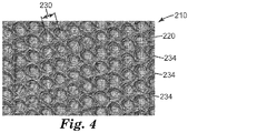
密集したアレイにおいては、パターニングされていない表面領域の効果は、低減されるか、又は更に最小化され得る。図4の光学顕微鏡画像に示されるように、加工された表面は、六角形の密集したアレイの凹部の配列を含み、隣接する凹部の間の隙間空間を更に最小化してもよい。 In a dense array, the effect of unpatterned surface areas can be reduced or even minimized. As shown in the light microscope image of FIG. 4, the machined surface may include an array of recesses in a hexagonal dense array to further minimize the clearance space between adjacent recesses.
平坦な金属表面の、入射光の鏡面反射を生じ、光沢を増加させる傾向により、複数の凹部内に含まれる加工された表面の面積は、典型的には、隙間空間内に画定される面積よりも実質的に大きい。いくつかの実施形態において、加工された表面の面積の75%が凹部内に含まれ、いくつかの実施形態において、少なくとも80%、いくつかの実施形態において少なくとも85%、いくつかの実施形態において少なくとも90%、更に追加的な実施形態において面積の少なくとも95%が、凹部内に含まれる。 Due to the tendency of flat metal surfaces to specularly reflect incident light and increase gloss, the area of the processed surface contained within the plurality of recesses is typically greater than the area defined in the interstitial space. Is also substantially large. In some embodiments, 75% of the area of the processed surface is contained within the recess, at least 80% in some embodiments, at least 85% in some embodiments, in some embodiments. At least 90%, and in additional embodiments at least 95% of the area, is contained within the recess.
一般に、凹部120は、加工された表面110に隣接する底部121、及び底部121から深さ124だけ分離した底面又は頂点122を含む。凹部120は典型的には、外周又は境界付近の深さが、中央付近における深さより小さくなるように、球面又は凹みを含む。本明細書で使用するとき、用語「球面」は、表面が球体の一部分であると考慮され得ること、又は表面がほぼ球面曲率を有することを意味する。一部の球面は、ドーム形又は半球形であると考慮され得る。その他の球面は、半球よりも小さい球の部分を包含することができる。いくつかの実現形態において、凹部120の球面曲率はほぼ連続的であり、よって凹部は、加工された表面に垂直、又は実質的に垂直(例えば、80〜89°)である、側壁を欠いている。このような実現形態における、一般的な球面曲率は、凹部内の階層的な突出特徴部と別個であるものと考えることができる。
Generally, the
加工された各凹部120の底部121は、様々な断面形状を備えてもよく、これには平行四辺形、丸みを帯びた角を有する平行四辺形、長方形、四角形、円形、半円形、楕円形、半楕円形、三角形、台形、星形、他の多角形(例えば、六角形)等、及びそれらの組み合わせが挙げられるが、それらに限定されない。断面形状にかかわらず、加工された各特徴部は、底部121において最大の断面寸法を含む。好ましい本実現形態において、底部121の最大断面寸法は、80マイクロメートル以下、いくつかの実施形態において70マイクロメートル以下、いくつかの実施形態において60マイクロメートル以下であり得る。最大の断面寸法は、少なくとも10マイクロメートル、いくつかの実施形態では、少なくとも15マイクロメートル、いくつかの実施形態では、少なくとも20マイクロメートルあってもよい。以下の実施例で説明されるように、この範囲外の最大断面寸法を有する凹部は、裸眼で知覚可能である、及び/又は基材表面の不十分な修正を生じ得るかのいずれかである。
The
凹部120は典型的には、ピッチ又は最大断面寸法127以下の深さを含むが、いくつかの実施形態においては、凹部深さは、ピッチ又は最大断面寸法よりもはるかに小さい。一般的に、複数の凹部の各凹部は、少なくとも0.5マイクロメートルである深さを有する。いくつかの実施形態において、凹部は、少なくとも1マイクロメートル、他の実施形態において、少なくとも1.5マイクロメートル、他の実施形態において、少なくとも2マイクロメート、他の実施形態において、少なくとも3マイクロメート、他の実施形態において、少なくとも5マイクロメートの深さを有する。いくつかの実施形態において、凹部深さは、30マイクロメートル以下、一部の実施形態では25マイクロメートル以下、一部の実施形態では20マイクロメートル以下、一部の実施形態では15マイクロメートル以下である。30マイクロメートル超の深さを有する凹部は、特定の光の波長を捕捉し、表面において得られる強度が不十分となり、十分に白く見えなくなる。しかしながら、複数の凹部のうちの、全ての凹部が、上記の深さの範囲内であることが必要とされるわけではないことに留意する。
The
複数の凹部における各凹部120は、特定のアスペクト比を含む。実質的にミクロ構造の高さにわたって規則的(例えば、ユークリッド)及び不規則的(例えば、非ユークリッド)断面形状を含む凹部では、アスペクト比は底部における最大断面寸法(例えば、幅、長さ、直径)に対する深さの比率として本明細書において定義される。不規則形状の底部(平行四辺形又は円形ではない底部)では、最大断面寸法は、相当する面積の円の直径であると理解されよう。凹部の形状にかかわらず、複数の凹部の、各凹部は典型的には、0.75以下であり、かつ少なくとも0.08のアスペクト比を含む。
Each
先に簡潔に記載されたように、複数の凹部120のいくつかの凹部は、上部又は内部に、階層的な突出特徴部を含み得る。突出特徴部は、典型的にはサブミクロンの規模であるか、又は少なくとも、凹部120の断面寸法127、又は深さ124よりも明らかに小さい高さ及び断面寸法を含む。いくつかの実施形態において、これらの階層的な特徴部は、凹部120を形成するために使用される方法、特に、以下に更に記載されるような、レーザーアブレーションを特徴とする方法の結果として形成され得る。他の実現形態において、突出特徴部は、表面にミクロスケール及びナノスケールの構造部を配置するための既知の方法により、凹部の形成の後に追加されてもよい。突出特徴部は、光の拡散反射を向上させることがあり、さもなければ加工された表面110の審美的外観を損ない得る、元来知覚可能な特徴部のパターンと干渉することがある。
As briefly described above, some recesses of the plurality of
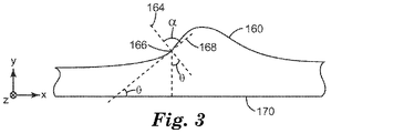
本開示の加工された表面は、例えば、付随する加工された特徴部の、傾斜分布、及び表面粗さによって、特徴付けることができる。加工された表面の代表的な部分は、共焦点走査型レーザー顕微鏡(50倍〜150倍対物レンズ)を使用して特徴を説明することができ、説明されている。図3は、加工された表面を含む物品の一部の、概略側面図である。特に、図3は、特徴部の表面にわたって傾斜分布を有する、加工された特徴部160を示している。例えば、ミクロ構造は、位置166において傾斜θを有し、θは、位置166における加工された特徴部表面と垂直である(α=90度)法線164と、同一の位置で特徴部表面に接する接線168との間の角度である。傾斜θはまた、接線168と物品170の平坦な主表面との間の角度でもある。
The processed surface of the present disclosure can be characterized by, for example, the slope distribution and surface roughness of the accompanying processed features. Representative parts of the machined surface can be characterized and described using a confocal scanning laser scanning microscope (50x to 150x objective lens). FIG. 3 is a schematic side view of a portion of the article, including the processed surface. In particular, FIG. 3 shows a processed
構造化表面の傾斜は、x方向に沿って、及び更に、y方向に沿ってとることができ、
式1:X傾斜=(ΔH(x,y))/Δx、及び
式2:Y傾斜=(ΔH(x,y))/Δy
式中、H(x,y)は、表面の高さプロファイルである。
The slope of the structured surface can be taken along the x direction and further along the y direction.
Equation 1: X inclination = (ΔH (x, y)) / Δx, and Equation 2: Y inclination = (ΔH (x, y)) / Δy
In the formula, H (x, y) is the height profile of the surface.
平均x傾斜及びy傾斜は、各ピクセルを中心として1.65マイクロメートルの間隔で評価した。別の実施形態では、この間隔は、一定間隔を用いる限り、2マイクロメートル、又は3マイクロメートルなどより大きく選択されてもよい。x及びy傾斜の分布は、0.5度のビンサイズで生成された。x傾斜及びy傾斜のデータから、勾配規模を決定することが可能である。これは、次のように理解できる。
式3:勾配規模=√(((ΔH(x,y))/Δx)^2+((ΔH(x,y))/Δy)^2)
次に、平均勾配規模は、各ピクセルを中心として1.65μm×1.65μmの四角形で評価可能であった。勾配規模分布は、0.5度のビンサイズで生成した。x傾斜、y傾斜の角度値、及び上記の値に対応する勾配規模の角度の値を見出すためには、等式1、2、及び3の値の逆正接を用いる必要があることを理解するべきである。勾配規模は、x傾斜とy傾斜とを組み合わせたものに相当する。したがって勾配規模は、一般的な勾配規模として理解されてよい。
The average x-slope and y-slope were evaluated at intervals of 1.65 micrometers around each pixel. In another embodiment, this interval may be chosen to be greater than 2 micrometers, or even 3 micrometers, as long as constant intervals are used. Distributions of x and y slopes were generated with a bin size of 0.5 degrees. It is possible to determine the slope scale from the x-slope and y-slope data. This can be understood as follows.
Equation 3: Gradient scale = √ (((ΔH (x, y)) / Δx) ^ 2 + ((ΔH (x, y)) / Δy) ^ 2)
Next, the average gradient scale could be evaluated by a quadrangle of 1.65 μm × 1.65 μm centered on each pixel. Gradient scale distributions were generated with a bin size of 0.5 degrees. Understand that it is necessary to use the inverse tangents of the values of equations 1, 2, and 3 to find the angle values of x-slope, y-slope, and the angle of gradient scale corresponding to the above values. Should be. The gradient scale corresponds to a combination of x-inclination and y-inclination. Therefore, the gradient scale may be understood as a general gradient scale.
例えば、加工された特徴部が、デカルト、又は通常の傾斜分布を有するときなど、いくつかの場合において、x傾斜分布とy傾斜分布との間の最小半値全幅(FWHM)は、少なくとも10°、他の実施形態においては少なくとも20°、及び更に他の実施形態においては、少なくとも30°である。少なくとも20°の最小FWHMは、拡散反射した光の強度を増加させる傾向にある、様々な特徴を示す。他の代表的な傾斜分布としては、ローレンツ分布、放物線状分布、及び様々な分布の組み合わせが挙げられる。 In some cases, for example, when the machined feature has a Cartesian or normal slope distribution, the minimum full width at half maximum (FWHM) between the x slope distribution and the y slope distribution is at least 10 °. In other embodiments it is at least 20 °, and in yet other embodiments it is at least 30 °. A minimum FWHM of at least 20 ° exhibits various features that tend to increase the intensity of diffusely reflected light. Other typical slope distributions include Lorentz distributions, parabolic distributions, and combinations of various distributions.
傾斜分布及び傾斜規模の最小FWHMに加えて、加工された表面の表面粗さもまた、光反射特性に影響し得る。表面粗さは表面の粗さの尺度であることは、自明である。表面粗さは、マイクロメートル範囲の特徴部を解像することができる、共焦点顕微鏡などの技術を使用して測定することができる。表面粗さを表す場合には、平均粗さ(Ra)又はRMS粗さ(Rq)のいずれかが使用できるが、Rqが本明細書においては好ましい。Rqは画像データ平均面からの高さの偏差の二乗平均平方根であり、
式4:Rq=√((ΣH_i^2)/N)
(式中、Nは点の総数、Hはそれぞれの点における高さ(平均高さに対する相対値)である)で表される。
In addition to the minimum FWHM of slope distribution and slope scale, the surface roughness of the processed surface can also affect the light reflection characteristics. It is self-evident that surface roughness is a measure of surface roughness. Surface roughness can be measured using techniques such as confocal microscopy, which can resolve features in the micrometer range. When expressing the surface roughness, either the average roughness (Ra) or the RMS roughness (Rq) can be used, but Rq is preferable in the present specification. Rq is the root mean square of the height deviation from the average plane of the image data.
Equation 4: Rq = √ ((ΣH_i ^ 2) / N)
(In the formula, N is the total number of points, and H is the height (relative value to the average height) at each point).
ノイズ及び表面の起伏による影響を最小化しながら、加工された表面の粗さを調べるために、生データのフーリエ解析を使用することができる。高空間周波数フィルタを使用して、起伏を排除することができる。あるいは、ローパス空間周波数フィルタを使用して、測定器具により生じるノイズを排除することができる。ローパス空間周波数フィルタを使用する際に、ローパスフィルタと共にハイパス空間周波数フィルタを使用してサンプルの表面高さマップにおける起伏及びノイズを取り除いてもよい(すなわち、バンドパスフィルタ)。典型的には、当該技術分野において既知であるように、デカルトフーリエフィルタウィンドウを使用して、リンギングアーティファクトを防ぐ。例えば、ASME standard B46.1−2009:”Surface Texture:Surface Roughness,Waviness,and Lay”、及びISO 25178−2:2012を参照のこと。当該技術分野において通常の技術を有する者であれば理解されることであるが、粗さの測定は、典型的には、意味のある測定とするためには、サンプルにおいてくずや欠陥(例えば、意図していない泡、凹み、擦り傷等)がない領域で実施するべきである。Bruker Corp.,Santa Barbara,CAより入手可能な、商品名「VISION」等のソフトウェアプログラムを使用してもよい。また、MathWorks,Natick,MAより入手可能な商品名「MATLAB」のプログラム等のデータ処理ソフトウェアを使用してもよい。 Fourier analysis of the raw data can be used to examine the roughness of the machined surface while minimizing the effects of noise and surface undulations. High spatial frequency filters can be used to eliminate undulations. Alternatively, a low-pass spatial frequency filter can be used to eliminate noise generated by the instrument. When using a lowpass spatial frequency filter, a highpass spatial frequency filter may be used in conjunction with the lowpass filter to remove undulations and noise in the sample surface height map (ie, bandpass filter). Typically, as is known in the art, a Cartesian Fourier filter window is used to prevent ringing artifacts. See, for example, ASME standard B46.1-2009: "Surface Texture: Surface Roughness, Wavines, and Lay", and ISO 25178-2: 2012. As will be understood by anyone with ordinary skill in the art, roughness measurements typically include debris and defects (eg, eg) in the sample in order to be a meaningful measurement. It should be performed in an area free of unintended bubbles, dents, scratches, etc.). Bruker Corp. , Santa Barbara, CA may use software programs such as trade name "VISION". Further, data processing software such as a program of the trade name "MATLAB" available from MathWorks, Natick, and MA may be used.
一実施形態では、デカルトフーリエフィルタを使用して、加工された表面のRq値は、0.5、0.8、1、1.5、又は更に2マイクロメートルである。本発明における好ましい状況において、加工された表面のRq値は少なくとも1マイクロメートルである。 In one embodiment, using a Cartesian Fourier filter, the Rq value of the machined surface is 0.5, 0.8, 1, 1.5, or even 2 micrometers. In the preferred situation in the present invention, the Rq value of the processed surface is at least 1 micrometer.
本開示の別の実施形態による加工された表面210は、図4の光学顕微鏡画像に示されている。加工された表面210は、凹部底部234において修正された断面寸法を有する、分断された凹部220の配列を含んでいる。本開示による分断された凹部220は、隣接する凹部の間の境界領域の重複の結果であり得る。このような重複を生じさせるため、分断された凹部220は、ピッチ230よりも大きな予測直径に基づいて形成される。本明細書において使用されるとき、「予測直径」とは、加工された表面を形成するのに使用される、選択された方法及びプロセスパラメータによる、単一の凹部の底部における直径又はECDを意味する。例えば、以下に記載される方法によるレーザーアブレーションにより形成された凹部220は、40マイクロメートルの予測直径を有し得る。多数の凹部220が、30マイクロメートルのピッチで、金属表面の横方向に沿って配列される場合、隣接する凹部220の間におよそ10マイクロメートルの重複が生じる。追加的な重複領域は、長手方向の隣接する凹部によっても形成され得る。重複領域は、別個の凹部の間に形成される突出又は貫入特徴部を生じることがあり、あるいは裸眼には凹部の一部として、又は隙間空間として見えることがある。
The processed
分断された凹部の概念が図5に更に例示されている。図5は、予測直径334を有する複数の球形凹部320を示している。凹部は線形のグリッドアレイとして配列され、加工された表面310の縁部領域350上に配置されていない任意の凹部320は、x及びy方向に、1つ以上の隣接する凹部320を有する。アレイ内におけるいくつかの凹部320は、多数の隣接する凹部の間に複数の重複する境界領域323を含み、複数の重複する境界領域によって画定される、別個の内部凹部321を生じる。別個の内部凹部321はしたがって、予測直径よりも小さい断面寸法を含む。隣接する凹部の間の実質的な重複による分断によって、深さ、容積、曲率、傾斜分布、及び底部における断面寸法が挙げられるがこれらに限定されない、凹部の1つ以上の特徴を修正することができる。
The concept of the divided recess is further illustrated in FIG. FIG. 5 shows a plurality of
少なくとも部分的に、表面粗さの増加ために、本開示の加工された表面は、垂直に入射する照明に対して70°の視野角において少なくとも20の最小L*値を呈することがある。本明細書において使用されるとき、視野角(すなわち、散乱角)は、サンプル垂線(すなわち、図3の直線164)に対して測定される。白色度は、色空間の比較的狭い空間内に位置付けられる、高い視感反射率、及び低い純度の、色の属性である。明度とは、色がどれだけ明るいか、又は暗いかに関する、色の全体的強度を表す。Commission Internationale de l’Eclairage L*a*b*評価システムにおいて、白色は、その高い明度によって区別され、完全に白い外観を有する表面は、100の(又は特定の視野角において測定した場合はそれより大きい)L*を有する。典型的には白色とみなされなくても、光が垂直に入射する状態で、表面に対し実質的に垂直な角度で見たときには、多くの金属は、比較的高いL*を有する。しかしながら、視野角が垂直から10°よりもずれると、明度が低減し、生じるL*値の劇的な低下につながる。これとは対照的に、本開示による加工された表面のL*値は、視野角が垂直から変化しても、50を上回り続けることができる。いくつかの実施形態において、30°の散乱角におけるL*値は、60超であり、いくつかの実施形態においては75超であり、更に他の実施形態においては80超である。
Due to the increased surface roughness, at least in part, the processed surface of the present disclosure may exhibit a minimum L * value of at least 20 at a viewing angle of 70 ° with respect to vertically incident illumination. As used herein, the viewing angle (ie, scattering angle) is measured relative to the sample perpendicular (ie,
いくつかの実現形態において、本開示の加工された表面では、表面に対し垂直な入射角におけるL*値は、ステンレススチールの場合よりも低くなる。しかしながら、とりわけ、本開示の加工された表面によりもたらされる反射強度は、視野角の変化に伴って実質的に低下せず、比較的高いL比につながる。本明細書で使用されるとき、「L比」又は「L*比」とは、70°の視野角における最小L*値と、15°の視野角における最大L*との間の、L*値である。低い、又は計算不可能なL比を呈する表面は、視野角、つまり入射光の角度が、実質的に垂直な視野に対して回転すると、特に表面が黒色であるとき、明度の劇的な変化を生じ得る。エッチング、及び他の方法で平坦化されていないステンレススチールは例えば、0のL比を呈し得る。中程度から高いL比を有する表面は、視野角に応じて、より均一な明度(すなわち、L*)を呈する。本開示の加工された表面は、美観用コーティングがなくても、いくつかの実現形態において少なくとも0.1、いくつかの実施形態において少なくとも0.2、いくつかの実施形態において少なくとも0.3、他の実施形態において少なくとも0.4、他の実施形態において少なくとも0.6のL比値を呈することがあり、以下の実施例に概説される。 In some embodiments, the processed surface of the present disclosure has a lower L * value at an angle of incidence perpendicular to the surface than in stainless steel. However, in particular, the reflection intensity provided by the processed surface of the present disclosure does not substantially decrease with the change in viewing angle, leading to a relatively high L ratio. As used herein, "L ratio" or "L * ratio" is the L * between the minimum L * value at a viewing angle of 70 ° and the maximum L * at a viewing angle of 15 °. The value. Surfaces with low or uncalculable L ratios have dramatic changes in brightness when the viewing angle, or angle of incident light, is rotated with respect to a field of view that is substantially vertical, especially when the surface is black. Can occur. Stainless steel that has not been etched and otherwise flattened can exhibit, for example, an L ratio of 0. Surfaces with a medium to high L ratio exhibit more uniform brightness (ie, L *), depending on the viewing angle. The processed surface of the present disclosure is at least 0.1 in some embodiments, at least 0.2 in some embodiments, and at least 0.3 in some embodiments, even without an aesthetic coating. It may exhibit an L ratio value of at least 0.4 in other embodiments and at least 0.6 in other embodiments and is outlined in the examples below.
別の態様において、本開示は、レーザーエネルギーを使用して、表面に、ミクロスケールの、加工された特徴部のパターンを形成する方法を提示する。このプロセスのフロー図は、図6に示される。工程500において、金属表面を有する物品が提示され、表面がレーザー源又はスキャナに対して向けられる。金属表面上の汚染は、この時点で、当該技術分野において既知の方法で除去されてもよい。工程510において、第1特徴部パターンに関するレーザーパターンパラメータは、表面上にアブレーションにより形成された特徴部の最初の位置、間隔、及び大きさを制御するように規定される。関連するパターンパラメータは、1)標的位置(すなわち、レーザーエネルギーを受ける表面の標的部位)の間の、x方向及びy方向両方における距離(すなわち、間隔)と、2)加工された特徴部を含むことになる、金属表面の部分又は範囲と、3)レーザー出力及び/又は波長と、4)基材に対するレーザービームの焦点位置と、5)表面に向けられたレーザーエネルギー(パルス)の反復率とを含む。第1特徴パターンとしては、デカルトグリッドアレイ、六角形アレイ、及び他の構造化及び非構造化アレイが挙げられるが、これらに限定されない。次に、工程520において、レーザービームは、所定の移動経路で、物品の表面を横断する。他の実現形態において、表面は、レーザービームに対して移動し得る。この工程520において、レーザー源は、所定の第1特徴部パターンパラメータに従って、所定の時間間隔でレーザーエネルギーを放出し(すなわち、パルスを生成する)、これにより、表面上に、第1特徴部パターンの第1部分を形成する。第1部分は、第1特徴部パターン、及び基材表面上における第1特徴部パターンの所望の向きによって、一般的に、水平、垂直、斜め、正弦曲線、螺旋、又は他の線形若しくは非線形の一連の特徴部であり得る。一度、初期の線又は一連の特徴部が形成されると、プロセスは工程530に進み、ここでレーザービームは、第1パターンパラメータ(例えば、ピッチ)に従って第1の一連の特徴部からオフセットされ、レーザービームは、レーザービームと基材との間の相対向きを同じとしながら、表面を再び横断して進み、第2の、第1特徴パターンの続き部分を形成する。この、パターン部分を形成するプロセスは、加工される特徴部の第1パターンが、金属表面の所望の部分に生成されるまで反復される。
In another aspect, the present disclosure presents a method of using laser energy to form a microscale, machined feature pattern on a surface. A flow diagram of this process is shown in FIG. In
任意により、工程500〜530に概説されるプロセスは、工程540〜560に説明される第1特徴部パターンと少なくとも部分的に重複する、追加的な特徴パターンを形成するために使用され得る。本開示における好ましい状況において、工程540において選択される追加的な特徴部パターンは、第1特徴部パターンの、レーザーパターンパラメータの少なくとも一部を維持するか、又はこれに近似する。しかしながら、レーザーパターンの表面に対する向きは、特徴部パターンの間で、又はそれ同士で、修正することができる。いくつかの実施形態において、表面に対するレーザービームの移動経路の位置は回転されてもよく、これはレーザーパターンの回転を生じる。図9に示される1つの代表的なプロセスにおいて、レーザービームは、第1特徴部パターン910の形成において、y方向で表面を横断し、長手方向の線920にほぼ沿って一連の特徴部を生じる。しかしながら、第2特徴部パターン930の形成の前に、パターンパラメータは、レーザービームの意図される移動経路が90°回転されるように、修正される。図9に例示されるように、この回転は、第2特徴パターン930の形成にあたり、ビームが表面をx方向に移動し、表面をレーザーエネルギーに、横方向の線940に沿って暴露することを確実にする。第1及び第2特徴部パターンのパラメータが、パターンの回転の前に、x方向において同じピッチ、かつy方向において同じピッチを含む場合、x及びy方向における第2特徴部パターンのピッチは、第1特徴部パターンのx及びy方向ピッチと反対となる。換言すると、第1特徴部パターンにおける特徴部の間のピッチはx方向において20マイクロメートルであり、かつy方向において25マイクロメートルであり、レーザーパターンを90°回転させることによって、第2特徴部パターンがx方向で25マイクロメートルのピッチを、y方向で20マイクロメートルのピッチを含むようになる。別の実現形態において、パターンパラメータ、及び/又は特徴部の間隔における同じ特性を生じるために、表面を、レーザービームに対して例えば、90°回転させることができる。
Optionally, the process outlined in steps 500-530 can be used to form an additional feature pattern that at least partially overlaps the first feature pattern described in steps 540-560. In the preferred context of the present disclosure, the additional feature pattern selected in
あるいは、第2特徴部パターンは、例えば、x方向における第2パターンのピッチは、y方向における第1パターンのピッチと等しいという意味において、第1特徴部パターンの鏡像を含み得る。 Alternatively, the second feature pattern may include, for example, a mirror image of the first feature pattern in the sense that the pitch of the second pattern in the x direction is equal to the pitch of the first pattern in the y direction.
第1及び第2パターンのピッチの修正は、加工された特徴部の顕著な分断を生じ得る。いくつかの実現形態において、この分断は、予測断面寸法(典型的には直径)を超える、特徴部の境界領域の重複によって生じる。隣接する特徴部の間の実質的な重複による分断は、深さ、容積、曲率、傾斜分布、及び底部における断面寸法が挙げられるがこれらに限定されない、1つ以上の特徴を修正することができる。更に、凹部の分断は、隙間空間及び凹部内の突出特徴部を形成することができる。図14及び図21に見られるように、隣接する特徴部の間の重複領域の範囲によって、生じる加工された表面は、選択される第1特徴部パターンの、いずれかの規則的な特徴にかかわらず、不規則な特徴部を含むように見えることがある。有利なことに、突出及び貫入特徴部はより高度な散乱反射を生じるため、特徴部の分断は金属表面の光沢及び他の予測される光学的特徴を低減することができる。分断した構造は、いくつかの実現形態において、基準面における同等の円形の直径(ECD)によって、かつ平均隆起に対する平均高さによって特徴付けることができる。 Modifying the pitch of the first and second patterns can result in significant fragmentation of the machined features. In some embodiments, this fragmentation is caused by overlapping feature boundary regions that exceed the predicted cross-sectional dimensions (typically diameter). Substantial overlap between adjacent features can modify one or more features, including but not limited to depth, volume, curvature, slope distribution, and cross-sectional dimensions at the bottom. .. Further, the division of the recess can form a gap space and a protruding feature portion in the recess. As seen in FIGS. 14 and 21, the range of overlapping regions between adjacent features causes the machined surface to be subject to any regular feature of the first feature pattern selected. However, it may appear to contain irregular features. Advantageously, the projecting and penetrating features produce a higher degree of diffuse reflection, so fragmentation of the features can reduce the gloss of the metal surface and other expected optical features. The fragmented structure can be characterized in some implementations by the equivalent circular diameter (ECD) on the reference plane and by the average height relative to the average ridge.
他の実施形態において、実質的な分断は、同じアブレーション周期で、より高いレーザーエネルギーで実行されてもよい。例えば、第1特徴部パターンにおける凹部は、2.25Wの平均電力において実質的に重複しない。他のパターンのパラメータが、一定に維持され、電力が例えば、3.9Wまで増加されると、基材表面におけるより高いエネルギーのために、隣接する凹部は、境界領域で実質的に重複する。より高いエネルギーは、より大きな予測断面寸法を備える、凹部を生じる。 In other embodiments, the substantial fragmentation may be performed with the same ablation period and with higher laser energy. For example, the recesses in the first feature pattern do not substantially overlap at an average power of 2.25 W. When the parameters of the other patterns are kept constant and the power is increased to, for example, 3.9 W, the adjacent recesses substantially overlap at the boundary region due to the higher energy on the substrate surface. Higher energy results in recesses with larger predicted cross-sectional dimensions.
金属又は他のコーティングが、以下に記載の方法に従って、加工された特徴部の表面に含まれる場合、これは予測断面寸法を、最終的な状態において所望されるものよりも大きな寸法まで増加させるために有利であり得る。いくつかの状況において、コーティングの厚さは、いくつかの凹部又は特徴部の充填を生じ、特徴部の深さ、及び他の特徴を低減することによって、表面を本質的に平坦にすることがある。この挙動は、加工される特徴部の寸法を増加させるようにレーザーパターンを調節することによって、無効にするか、ないしは別の方法で調節することができる。 If a metal or other coating is included on the surface of the feature processed according to the method described below, this will increase the predicted cross-sectional dimensions to greater than desired in the final state. Can be advantageous to. In some situations, the thickness of the coating can result in filling of some recesses or features, reducing the depth of the features, and other features, thereby essentially flattening the surface. is there. This behavior can be disabled or otherwise adjusted by adjusting the laser pattern to increase the dimensions of the feature to be machined.
コーティング厚さを考慮するにあたり、加工された特徴部の、初期の幅(wi)の、厚さ(t)のコーティングを堆積した後の、最終的な幅(wf)に対する関係は、以下のようにして少なくとも大まかに決定することができる。球形の加工された特徴部を、円形の区分の一部とみなし、特徴部の幅は、中心角度θを形成する弦を画定し、
wi=2(R+t)sin(0.5θ)、wf=2Rsin(0.5θ)
wi=(R+t)wf/R、であり、式中、R=最終的な加工された特徴部の半径である。
Upon consideration of the coating thickness, of the processed features, the initial width of the (w i), after depositing a coating of thickness (t), relationship to the final width (w f), the following It can be decided at least roughly as follows. The spherically machined feature is considered part of the circular section, and the width of the feature defines the chords that form the central angle θ.
w i = 2 (R + t) sin (0.5θ), w f = 2Rsin (0.5θ)
w i = (R + t) w f / R, and in the equation, R = the radius of the final processed feature.
加工された特徴部の、初期の深さ(di)の、厚さ(t)のコーティングを堆積した後の、最終的な深さ(df)に対する関係は、
R=df+0.5wfcot(0.5θ) R+t=di+0.5wicot(0.5θ)df=R−0.5(4R2−wf 2)0.5
di=R+t−(R−df)wi/wf=R+t−(R−df)(R+t)/R
例えば、10マイクロメートル厚さのコーティングを備えた、加工された凹部の所望の最終的な幅及び半径が、それぞれ30マイクロメートル及び20マイクロメートルである場合、加工された凹部の初期の幅は45マイクロメートルであるはずである。加工された特徴部の最終的な深さが6.78マイクロメートルである場合、対応する初期深さは、10.17マイクロメートルである。
Of the processed features, the initial depth (d i), after depositing a coating of thickness (t), the relationship final depth to (d f), the
R = d f + 0.5w f cot (0.5θ) R + t = d i + 0.5w i cot (0.5θ) d f = R-0.5 (4R 2 -w f 2) 0.5
d i = R + t- (R -df) w i / w f = R + t- (R-d f) (R + t) / R
For example, if the desired final width and radius of the machined recess with a 10 micrometer thick coating is 30 micrometers and 20 micrometers, respectively, the initial width of the machined recess is 45. It should be a micrometer. If the final depth of the machined feature is 6.78 micrometers, the corresponding initial depth is 10.17 micrometers.
方法のいくつかの実施形態において、レーザーエネルギーは、例えば、ファイバーレーザーなどのレーザー源を使用して生成される。物品表面700のレーザーアブレーションは、図7に示されるようなレーザーシステムを使用して実行することができる。いくつかの実施形態において、システム600は、レーザー源602、レーザービームデリバリファイバー604、及びコントローラー608を含む。レーザー源602は、レーザーエネルギーのパルスを生成するように構成されている。可動スキャナ605、典型的には光学スキャナは、標的位置に対してレーザービーム610を位置付けるように構成されている。レーザーデリバリファイバー604はレーザー源602に光学的に接続され、レーザー源602により生成されるレーザーエネルギー610を、スキャナ605を通じて標的基材へと向けるように構成されている。コントローラー608は、パターニングソフトウェアからの出力信号、又はユーザーによるスキャナ若しくは基材の位置の直接操作に基づいて、レーザー源602及びスキャナ605を制御するように構成されている。レーザー源602は、レーザーエネルギーを生成するために使用される、1つ以上のレーザー源を備えてもよい。システム600はまた、所望の焦点サイズを有する、レーザービームを生成するために、ビーム拡大器614などの、従来的な構成要素を備えてもよい。いくつかの実施形態において、レーザーエネルギーは、およそ532nm(緑色)の波長を有する。およそ400〜475nm(青色)の波長、約355nm(近紫外線)の波長を有するレーザーエネルギー、又はおよそ1000〜1100nm(近赤外線)の波長を有するレーザーエネルギーなど、他の波長のレーザーエネルギー610も使用することができる。基材表面に形成される、凹部又は他の特徴部の形状に応じて、これらの、及び他の波長のレーザービーム610を使用することができる。
In some embodiments of the method, laser energy is generated using a laser source, such as a fiber laser. Laser ablation of the
いくつかの実施形態において、レーザー源602によって生成されるレーザービーム610は任意により、従来的な光学アイソレータ612を備える、レーザービームデリバリファイバー604に光学的に接続される。レーザービームデリバリファイバー604は更に、レーザービームを成形及び供給するための、いずれかの従来的な光学構成要素を含んでもよい。レーザーファイバー604の遠位端は、レーザーエネルギー610を横方向に(すなわち、サイドファイアレーザー)、レーザーファイバー604の軸に沿って(すなわち、エンドファイアレーザー)、又は他の従来的な方法で、放出するための光学構成要素を含んでもよい。示される実現形態において、光学アイソレータ612がスキャナポート620の軸と実質的に垂直に向けられるときに、光学アイソレータ612の遠位端616から放出されるレーザービーム610は、ミラー618を介してポート620へと向けられてもよい。このような構成は、いくつかの状況において、光学アイソレータ612が、システムの他の構成要素と不注意で衝突しないように保護することができる。別の実現形態において、ビーム610は、ポート620の軸と平行に放出されてもよい。
In some embodiments, the
コントローラー608を使用して調節することができる、関連レーザー源パラメータは、電力レベル設定、パルス幅設定、パルス繰り返し率設定、及び他のレーザー源設定を含む。いくつかの実施形態において、コントローラーは、スキャンパラメータ(例えば、速度、角度など)を制御するために、ネットワークを介したソフトウェアプログラムへのアクセスを含むか、又はアクセスを有する。例えば、コントローラーは、SCANLAB America,St.Charles,ILから入手可能なLaserDESK(登録商標)ソフトウェアプログラムを含んでもよい。
Related laser source parameters that can be adjusted using
工程520〜530を再び参照し、選択された初期間隔に従って、金属表面の少なくとも一部に沿って(例えば、横方向)、第1の一連の特徴部が形成される。一連の特徴部は、表面を固定して維持し、レーザービームの位置を変化させるか、又はその逆を行うことによって、形成され得る。典型的な状況において、一連の小さな凹部が形成される際の連続する凹部の間の距離は、スキャン速度、及びレーザーの繰り返し率に依存する。
式5:d=v/f=[m/s]/[1/s]=[m]
式中、v=スキャン速度、
d=凹部同士の間隔、
f=レーザー繰り返し率、である。
With reference to steps 520-530 again, a first series of features is formed along at least a portion of the metal surface (eg, laterally) according to the initial spacing selected. A series of features can be formed by fixing and maintaining the surface and repositioning the laser beam or vice versa. In a typical situation, the distance between successive recesses when a series of small recesses is formed depends on the scanning speed and the laser repeat rate.
Equation 5: d = v / f = [m / s] / [1 / s] = [m]
In the formula, v = scan speed,
d = spacing between recesses,
f = laser repetition rate.
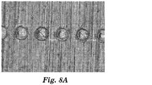
一連の特徴部は、凹部の線形のアレイ(図8Aに示される)を形成することができ、アレイ内の隣接する凹部同士のピッチは、選択されるレーザービームパラメータ、特に繰り返し率及びスキャン速度によって、初期特徴部の間隔と異なる。次に、第2の一連の凹部が形成され、各凹部は、y方向の既定のピッチに従って、第1の一連の凹部から離間している。第3の一連の凹部の形成が、図8Bに示されている。追加的な一連の特徴部の形成が、基材表面の所望の部分にわたって、第1の特徴部パターンが完成するまで反復される。 A series of features can form a linear array of recesses (shown in FIG. 8A), where the pitch between adjacent recesses in the array depends on the laser beam parameters selected, especially the repeat rate and scan rate. , It is different from the interval of the initial feature part. Next, a second series of recesses is formed, each recess separated from the first series of recesses according to a predetermined pitch in the y direction. The formation of a third series of recesses is shown in FIG. 8B. The formation of an additional series of features is repeated over the desired portion of the substrate surface until the first feature pattern is complete.
線形のアレイに加えて、他のパターンが形成されてもよい。凹部は、正弦曲線、螺旋、スペックル、フラクタル、及び他の多くのパターンで形成することができる。他の実現形態において、レーザービームは、非周期的に移動され、表面に対して発射される。 In addition to the linear array, other patterns may be formed. The recesses can be formed with sinusoidal curves, spirals, speckles, fractals, and many other patterns. In other embodiments, the laser beam is moved aperiodically and fired at a surface.
第1特徴部パターンと少なくとも部分的に重複する追加的な特徴部パターンは、典型的にはいくつかのパターンパラメータを修正することによって、工程540〜560に形成され得る。図6に例示されるレーザーパターニングプロセスは、2つの重複する特徴部パターンの形成のみを想定しているが、当業者は、任意の数の重複パターンが形成され得ることを理解するであろう。例えば、3つ、4つ、6つ、及び8つの重複する凹部のアレイ及びパターンを有する、表面の実質的な分断を形成することが可能である。本開示において好ましい状況では、各パターン形成の後、表面に対するレーザーパターンの向き(すなわち、レーザービームの移動経路の相対位置)は修正される(例えば、回転される)。 Additional feature patterns that at least partially overlap the first feature pattern can be formed in steps 540-560, typically by modifying some pattern parameters. Although the laser patterning process illustrated in FIG. 6 assumes only the formation of two overlapping feature patterns, one of ordinary skill in the art will appreciate that any number of overlapping patterns can be formed. For example, it is possible to form a substantial partition of the surface with an array and pattern of three, four, six, and eight overlapping recesses. In a preferred situation in the present disclosure, after each pattern formation, the orientation of the laser pattern with respect to the surface (ie, the relative position of the laser beam's path of travel) is modified (eg, rotated).
いくつかの実施形態において、レーザーの焦点は、標的基材の表面より下の点へと調節されてもよい。いくつかの実現形態において、焦点は、物品表面の少なくとも50マイクロメートル下にある。他の実現形態において、焦点は、表面の約200マイクロメートル下にある。基材の表面の下に焦点を調節することにより、形成される凹部又は他の特徴部の大きさを増大させることができる。他の実施形態において、レーザーの焦点は、物品表面に、又はその少し上に調節される。 In some embodiments, the focus of the laser may be adjusted to a point below the surface of the target substrate. In some embodiments, the focus is at least 50 micrometers below the surface of the article. In other embodiments, the focal point is about 200 micrometers below the surface. By adjusting the focus below the surface of the substrate, the size of the recesses or other features formed can be increased. In other embodiments, the focus of the laser is adjusted to or just above the surface of the article.
ミクロスケールの特徴部のパターンの形成は、アシストガスの存在下で行うことができる。アブレーションを行うために使用される、生成されるガスの種類は、既定の加工条件によって様々であり得るが、アルゴン(Ar)、酸素(O2)、及び窒素(N2)、ヘリウム、二酸化炭素(CO2)のうちの1種、又はこれらのうちの少なくとも2種の混合ガスを使用することができる。本明細書において好ましい状況では、アブレーションする表面における酸素の生成を最小化するために不活性ガスが使用される。 The pattern of the feature portion of the microscale can be formed in the presence of the assist gas. The type of gas produced used to perform the ablation may vary depending on the prescribed processing conditions, but argon (Ar), oxygen (O 2 ), and nitrogen (N 2 ), helium, carbon dioxide. One of (CO 2 ), or a mixed gas of at least two of these, can be used. In the preferred situation herein, an inert gas is used to minimize the production of oxygen on the ablated surface.
別の実施形態において、加工された表面は、キャスティング、コーティング、及び/又は圧縮加工技術を含むがそれらに限定されない様々なミクロ複製法を含む、様々な方法によって形成することができる。例えば、加工された表面は、(1)第1特徴部パターンを有するツールを使用して、溶解した熱可塑性樹脂をキャスティングすること、(2)第1特徴部パターンを有するツール上に流体をコーティングし、その流体を凝固させ、生じたフィルムを除去すること、(3)熱可塑性フィルムにニップロールを通過させて第1特徴部パターンを有するツールに対して圧縮すること(すなわち、エンボス加工)、及び/又は(4)揮発性溶媒中のポリマーの溶液又は分散液を第1特徴部パターンを有するツールに接触させ、例えば、蒸発により溶媒を除去すること、の中の少なくとも1つによって形成することができる。ツールは、所望のトポグラフィーのツール材料及び特徴に部分的に依存して選択される、当業者に周知の多くの技法のうちの任意のものを用いて形成することができる。代表的な技術としては、エッチング(例、化学的エッチング、機械的エッチング、又はレーザーアブレーションなどの他のアブレーション手段、電子ビーム、又は反応性イオンエッチング、及びこれらの組み合わせ)、フォトリソグラフィー、ステレオリソグラフィー、マイクロマシニング、ローレット切り(例えば、切削ローレット切り又は酸補助型ローレット切り)、スコーリング、切削など、又はこれらの組み合わせが挙げられる。 In another embodiment, the processed surface can be formed by a variety of methods, including various micro-replication methods including, but not limited to, casting, coating, and / or compression processing techniques. For example, the processed surface can be (1) cast a melted thermoplastic resin using a tool with a first feature pattern, and (2) coat a fluid on the tool with a first feature pattern. Then, the fluid is solidified and the resulting film is removed, (3) the thermoplastic film is passed through a nip roll and compressed against a tool having a first feature pattern (ie, embossing), and / Or (4) a solution or dispersion of the polymer in a volatile solvent may be formed by contacting a tool with a first feature pattern and removing the solvent by, for example, at least one of them. it can. The tool can be formed using any of the many techniques well known to those of skill in the art, which are selected in part depending on the tool material and characteristics of the desired topography. Typical techniques include etching (eg, other ablation means such as chemical etching, mechanical etching, or laser ablation, electron beam, or reactive ion etching, and combinations thereof), photolithography, stereolithography, Micromachining, lorlet cutting (eg, cutting lorlet cutting or acid-assisted lorlet cutting), scoring, cutting, etc., or a combination thereof can be mentioned.
加工された表面を形成するための代替的な方法としては、熱可塑性押出し、パルス状電子ビームアブレーション、硬化性液体コーティング法、及び、硬化させることもできる熱可塑性層のエンボス加工が挙げられる。加工された表面110を形成するための基板材料及び様々なプロセスに関する更なる情報は、例えば、HalversonらのPCT国際公開第2007/070310号、及び米国特許出願公開第2007/0134784号、及び同第2003/0235677号(Hanschenら)、PCT国際公開第2004/000569号(Grahamら)、米国特許第6,386,699号(Ylitaloら)、Johnstonらの、米国特許出願公開第2002/0128578号、及び米国特許第6,420,622号、同第6,867,342号、同第7,223,364号、及び同第7,309,519号(Scholzら)に見出すことができる。
Alternative methods for forming the processed surface include thermoplastic extrusion, pulsed electron beam ablation, curable liquid coating, and embossing of a thermoplastic layer that can also be cured. Further information on substrate materials and various processes for forming the processed
最後の任意の工程として、審美性を更に向上させるために、本開示の加工された表面に、美観用コーティングが塗布されてもよい。好適な美観用コーティングは、銀(Ag)、亜鉛(Zn)、すず(Sn)、インジウム(In)、プラチナ(Pt)、タングステン(W)、ニッケル(Ni)、クロム(Cr)、アルミニウム(Al)、パラジウム(Pd)、金(Au)、及びロジウム(Rh)のうちの1種又は少なくとも2種の混合であり得る。加工された表面にコーティングが適用される場合、電気めっき、スパッタリング、蒸着、スピンコーティング、ディップコーティング、ロールツーロールコーティング等の任意の適切なコーティング法、又は任意の他の数の好適な方法によって適用されてもよい。好適な方法としては、国際公開第2009/045036号(Kim)により想到されるもの、加えて、LemkuhlらによるAdvances in Electrochemical Science and Engineering,177−226の、The Principles and Techniques of Electrolytic Aluminum Deposition and Dissolution in Organoaluminum Electrolytes(3d.ed.,Heinz Gerischer et al.,1994)、並びに米国特許第4,101,386号、及び同第4,948,475号(Dotzerら)に記載される、アルミニウムの電気めっき法が挙げられる。いくつかの実施形態において、一般的にこれらの方法に従って堆積される電気めっきしたアルミニウムは、歯科矯正装置、又は他の物品における加工された特徴部に加えて、又はその代わりに提供されてもよい。 As a final optional step, an aesthetic coating may be applied to the processed surface of the present disclosure to further improve aesthetics. Suitable aesthetic coatings are silver (Ag), zinc (Zn), tin (Sn), indium (In), platinum (Pt), tungsten (W), nickel (Ni), chromium (Cr), aluminum (Al). ), Palladium (Pd), gold (Au), and rhodium (Rh), or a mixture of at least two. When the coating is applied to the processed surface, it is applied by any suitable coating method such as electroplating, sputtering, vapor deposition, spin coating, dip coating, roll-to-roll coating, or any other number of suitable methods. May be done. Suitable methods are those conceived by International Publication No. 2009/0405036 (Kim), as well as the Advances in Electrochemical Science and Engineering by Lemkuhl et al., 177-226, The Principles Aluminum. Aluminum electricity described in Organoaluminum Electrolytes (3d. Ed., Heinz Gerischer et al., 1994), and US Pat. Nos. 4,101,386 and 4,948,475 (Dotzer et al.). The plating method can be mentioned. In some embodiments, electroplated aluminum, which is generally deposited according to these methods, may be provided in addition to or in place of the machined features in the orthodontic appliance, or other article. ..
美観用金属コーティングは、典型的には、約0.1〜50マイクロメートルの範囲の、いくつかの実施形態においては、0.5〜10マイクロメートルの範囲、及び更に他の実施形態においては、2〜3マイクロメートルの範囲の、厚さを有する。別の実施形態において、美観用金属コーティングは、約0.1〜0.3マイクロメートルの厚さを有する。ナノスケールの厚さを有するコーティングは、いくつかの状況において、加工された特徴部によりぴったりと合うように形成され、所望の光学的効果のより小さい分断を生じる。 Aesthetic metal coatings typically range from about 0.1 to 50 micrometers, in some embodiments 0.5 to 10 micrometers, and in yet other embodiments. It has a thickness in the range of 2-3 micrometers. In another embodiment, the aesthetic metal coating has a thickness of about 0.1 to 0.3 micrometers. Coatings with nanoscale thickness are formed to fit the machined features more closely in some situations, resulting in less fragmentation of the desired optical effect.
いくつかの実現形態において、基材上の酸素又は窒素などの表面汚染物質は、美観用コーティング(例えば、貴金属)の堆積プロセスが開始される前に、洗浄プロセスによって除去される。洗浄プロセスのために、イオンスパッタリング技術が使用されてもよい。表面上の酸素は、強酸塩、又は酸そのものの溶液などの、還元剤によって除去されてもよい。ステンレススチールなどの、いくつかの不活性表面又はめっき不可能な表面は、塩酸により、酸素のない状態(活性)となる。ニッケルチタン合金などの、形状記憶合金は、例えば、フッ化水素アンモニウムなどの還元剤によって、その表面を活性化させることができる。 In some embodiments, surface contaminants such as oxygen or nitrogen on the substrate are removed by a cleaning process before the deposition process of the aesthetic coating (eg, noble metal) is initiated. Ion sputtering techniques may be used for the cleaning process. Oxygen on the surface may be removed by a reducing agent, such as a strong acid salt or a solution of the acid itself. Some inert or non-platable surfaces, such as stainless steel, are oxygen-free (active) by hydrochloric acid. The surface of shape memory alloys such as nickel titanium alloys can be activated by a reducing agent such as ammonium hydrogen fluoride.
汚染物質を除去するように処理されると、上記の技術によって、加工された表面全体がめっきされ得、又は加工された表面の特定の領域が、局所用ブラシ又は小面積めっき装置によってコーティングされ得る。コーティングが、加工された表面に配置されると、これは陽極酸化されるか、不動態化されるか、又は当該技術分野において既知のバリアフィルムによって保護され得る。 Once treated to remove contaminants, the techniques described above may allow the entire machined surface to be plated, or specific areas of the machined surface to be coated with a topical brush or small area plating apparatus. .. When the coating is placed on the processed surface, it can be anodized, passivated, or protected by a barrier film known in the art.
本発明の加工された表面は、多数の歯科矯正及び口腔ケア装置において使用するのに好適である。特に有利な1つの実現形態において、歯科矯正用アーチワイヤは、1つ以上の加工された表面を含むように加工される。中央湾曲部分1020と、中央湾曲部分1020の相対する両端部へと延びる第1端部1030及び第2端部1040とを含む、代表的な水平歯科矯正アーチワイヤ1000が、図10に示されている。
The processed surface of the present invention is suitable for use in a large number of orthodontic and oral care devices. In one particularly advantageous embodiment, the orthodontic arch wire is machined to include one or more machined surfaces. A representative horizontal orthodontic
アーチワイヤ1000の断面図が図11に例示されている。本実施形態において、図11に示される断面形状は、アーチワイヤ1000のその全長に沿った、典型的な断面形状である。アーチワイヤは例えば、ほぼ矩形の断面形状、円形の断面形状、又は卵型の断面形状を有するが、他の断面構成も可能であることが理解される。アーチワイヤ1000の断面形状は、典型的には、その全長に沿って実質的に均一である。しかしながら、アーチワイヤの断面形状が、アーチワイヤの長さに沿ってある部分から次の部分まで変化するアーチワイヤなど、他の実施形態も可能である。
A cross-sectional view of the
図11に示される、アーチワイヤ1000の代表的な断面形状の四辺、1012、1014、1016、1018は、矩形を示している。咬合面1014と歯肉面1018とは、ほぼ平坦かつ互いに平行であり、頬唇面1012と舌側面1016とは平坦かつ互いに平行である。辺1014と辺1018との間の間隔は典型的には、ブラケット、又はバッカルチューブなどの歯科矯正装置の、アーチワイヤスロット内、又は経路内に係合フィットするように選択される。咬合面及び歯肉面の識別は、アーチワイヤが、上顎又は下顎歯列弓のいずれに設置されるかによる、ということが当業者には理解される。
The four sides, 1012, 1014, 1016, and 1018 of the typical cross-sectional shape of the
いくつかの実施形態において、4つの面全てが、加工された表面を含むように、アブレーションないしは別の方法で処理される。他の実現形態において、3つの面のみが、審美的な、加工された表面を含む。例えば、頬唇面1012、咬合面1014、及び歯肉面1018のみが加工された表面を含み、舌側面1016は処理されていなくてもよい。更に他の実現形態において、頬唇面1012のみが、本開示の加工された表面を含むように処理される。
In some embodiments, all four surfaces are ablated or otherwise treated to include a machined surface. In other embodiments, only three faces include an aesthetic, machined surface. For example, the
いくつかの実施形態において、中央部分1020のみが、本開示の加工された表面を含む。他の実施形態において、中央部分1020、並びに端部1030、1040の一方又は両方が加工された表面を含む。
In some embodiments, only the
別の実施形態において、加工された表面は、歯科矯正ブラケット、バッカルチューブ、アーチワイヤスロットライナー、自己結紮式クリップ、及び他のラッチ、修復材、リプレースメント(replacement)、インレー、オンレー、ベニア、全体及び部分クラウン、ブリッジ、インプラント、インプラントアバットメント、コーピング、前方充填、後方充填、及びキャビティライナー、並びにブリッジフレームワークを含むがこれに限定されない、多くの歯科用、及び歯科矯正用構成要素上に形成することができる。 In another embodiment, the machined surface is an orthodontic bracket, buccal tube, archwire slot liner, self-ligating clip, and other latches, restorations, replacements, inlays, onlays, veneers, whole and Form on many dental and orthodontic components including, but not limited to, partial crowns, bridges, implants, implant abutments, copings, anterior fillings, posterior fillings, and cavity liners, as well as bridge frameworks. be able to.
実施形態
1.金属を含む外面と、外面に設けられた、複数の凹部とを含み、
複数の凹部を含む面は、14以下の合計CIEクロマ、及び散漫散乱試験により測定したときに、0°の入射角かつ70°の視野角において少なくとも20の最小L*値を呈する、歯科矯正装置。
2.少なくとも1つの凹部の形状が、凹状である、実施形態1に記載の歯科矯正装置。
3.複数の凹部の平均深さが、少なくとも0.5マイクロメートルであり、かつ20マイクロメートル以下である、実施形態2に記載の歯科矯正装置。
4.隣接する凹部アレイの間のピッチが、少なくとも15マイクロメートルであり、かつ60マイクロメートル以下である、実施形態1に記載の歯科矯正装置。
5.アレイ内の隣接する凹部の間のピッチが、少なくとも20マイクロメートルであり、かつ40マイクロメートル以下である、実施形態4に記載の歯科矯正装置。
6.凹部は、横方向軸及び長手方向軸を有するアレイとして配列され、横方向軸に沿った隣接する凹部の間のピッチは、長手方向軸に沿った隣接する凹部の間のピッチよりも大きい、実施形態4又は5に記載の歯科矯正装置。
7.複数の凹部の、各凹部は断面寸法を有する底部を含み、寸法は少なくとも5マイクロメートルであり、かつ60マイクロメートル以下である、実施形態1に記載の歯科矯正装置。
8.断面寸法は直径を含み、直径は少なくとも20マイクロメートルであり、かつ40マイクロメートル以下である、実施形態7に記載の歯科矯正装置。
9.底部の直径はピッチよりも大きい、実施形態8に記載の歯科矯正装置。
10.直径は少なくとも25マイクロメートルであり、かつ35マイクロメートル以下であり、ピッチは少なくとも25マイクロメートルであり、かつ35マイクロメートル以下である、実施形態8に記載の歯科矯正装置。
11.凹部の平均深さと、底部における凹部の平均断面寸法との比率は、少なくとも1:1.5である、実施形態1〜10のいずれか1つに記載の歯科矯正装置。
12.凹部の深さの平均と、底部における凹部の平均断面寸法との比率は、少なくとも1:2である、実施形態1〜11のいずれか1つに記載の歯科矯正装置。
13.複数の凹部の少なくとも2つの凹部は、規則的アレイとして配列されている、実施形態1に記載の歯科矯正装置。
14.線形アレイ内のいずれか2つの凹部の境界領域が実質的に重複しない、実施形態13に記載の歯科矯正装置。
15.表面は、アレイ内のいずれか2つの凹部の間に隙間空間を含む、実施形態14に記載の歯科矯正装置。
16.凹部の間の隙間空間は実質的に平坦である、実施形態15に記載の歯科矯正装置。
17.凹部の間の隙間空間は1つ以上の突出特徴部を含む、実施形態15に記載の歯科矯正装置。
18.少なくとも1つの凹部が、凹部の底面に突出特徴部を含む、実施形態13に記載の歯科矯正装置。
19.凹部が、凹状のウェルの規則的なアレイとして配列されており、各ウェルが、少なくとも部分的に表面により画定された底部を含み、各底部は、少なくとも20マイクロメートルであり、かつ50マイクロメートル以下の最大寸法を含む、実施形態1の歯科矯正装置。
20.凹部表面は、少なくとも30の最小L*値を呈する、
実施形態1に記載の歯科矯正装置。
21.凹部表面は、少なくとも50の最小L*値を呈する、実施形態20に記載の歯科矯正装置。
22.凹部表面は、少なくとも60の最小L*値を呈する、実施形態21に記載の歯科矯正装置。
23.表面は少なくとも2つのアレイを含み、各アレイは複数の凹部を含み、凹部は、表面の一部にわたり不規則に配置されている、実施形態1に記載の歯科矯正装置。
24.装置がアーチワイヤである、実施形態1〜23のいずれか1つに記載の歯科矯正装置。
25.装置が歯科矯正クリップを備える、実施形態1〜24のいずれか1つに記載の歯科矯正装置。
26.装置は、底部と、底部から外側に延びる本体とを備え、本体は細長いスロットを画定し、加工された表面は、本体の少なくとも一部の上に配置されている、実施形態1〜25のいずれか1つに記載の歯科矯正装置。
27.金属を含む外面を有する本体と、表面に設けられた加工された複数の特徴部とを備え、表面は、散漫散乱試験により測定したときに、14未満の合計CIEクロマにおける少なくとも0.2の拡散L*最小70/最大15比率、0°の入射角かつ70°の視野角における少なくとも20の最小L*値を呈する、装置。
28.散漫散乱試験により測定したときに、表面は、少なくとも0.4の拡散L*最小70/最大15比率を呈する、実施形態24に記載の装置。
29.散漫散乱試験により測定したときに、表面は、少なくとも0.5の拡散L*最小70/最大15比率を呈する、実施形態28に記載の装置。
30.表面は、いずれの美観用コーティングもなしに、L*最小70/最大15比率を呈する、実施形態1〜29のいずれか1つに記載の装置。
31.金属を含む外面と、表面内に画定された複数の凹部と、を含み、各凹部は表面から少なくとも0.5マイクロメートルの深さを有し、凹部の大部分が、境界領域において隣接する凹部と重複するように、凹部は重複するアレイとして配列されている、装置。
32.複数の凹部のうちの、少なくとも1つの凹部は、少なくとも1つの他の凹部と共にユニットセルとして配列され、ユニットセル内の凹部の間のピッチは、少なくとも20マイクロメートルであり、かつ50マイクロメートル以下である、実施形態31に記載の装置。
33.ユニットセル内の隣接する凹部の間のピッチは、少なくとも25マイクロメートルであり、かつ40マイクロメートル以下である、実施形態32に記載の歯科矯正装置。
34.ユニットセル内のいずれかの隣接する凹部の間の表面の少なくとも一部は、実質的に平坦である、実施形態32に記載の装置。
35.重複する境界領域は、表面内の、一連の別個の突出特徴部を含む、実施形態31に記載の装置。
36.散漫散乱試験により測定したときに、表面は、少なくとも0.4の拡散L*最小70/最大15比率を呈する、実施形態1〜35のいずれか一項に記載の装置。
37.散漫散乱試験により測定したときに、表面は、少なくとも0.6の拡散L*最小70/最大15比率を呈する、実施形態1〜36のいずれか一項に記載の装置。
38.表面は、散漫散乱試験により測定したときに、70°の視野角において少なくとも50の最小L*値を呈する、実施形態26に記載の装置。
39.少なくとも1つの凹部が、約10マイクロメートルの深さを含む、実施形態1〜38のいずれか1つに記載の装置。
40.物品の審美的外観を改善するための方法であって、外面を有し、外面が金属を含む物品を準備することと、散漫散乱試験により測定したときに、表面が、少なくとも0.2の拡散L*最小70/最大15比率を呈するように、表面の少なくとも一部をアブレーションして表面上に複数の特徴部を形成することと、を含む、方法。
41.複数の特徴部が表面内に複数の凹部を含む、実施形態40に記載の方法。
42.凹部の少なくともいくつかが重複して、突出特徴部を形成する、実施形態40に記載の方法。
43.凹部が、表面に規則的に配列されている、実施形態1〜42のいずれか1つに記載の方法。
44.隣接する凹部の間の表面の領域は、突出特徴部を含む、実施形態43に記載の方法。
45.表面の少なくとも一部をアブレーションすることは、凹部の第1パターンを形成することを含み、第1パターンは、アレイの隣接する凹部の間に、少なくとも10マイクロメートルであり、かつ100マイクロメートル以下のピッチを有する、実施形態1〜44のいずれかの方法。
46.第1パターンは、パターンの隣接する凹部の間に、少なくとも20マイクロメートルであり、かつ60マイクロメートル以下のピッチを含む、実施形態45に記載の方法。
47.凹部は、横方向軸及び長手方向軸を有するアレイとして配列され、横方向軸に沿った隣接する凹部の間のピッチは、長手方向軸に沿った隣接する凹部の間のピッチよりも大きい、実施形態45に記載の方法。
48.凹部の第1パターンは、グリッドアレイとして配列され、グリッドは隣接する凹部の間の垂直及び水平方向の間隔を有し、水平方向の間隔は、垂直方向の間隔とは異なる、実施形態44に記載の方法。
49.水平方向の間隔は、垂直方向の間隔よりも大きい、実施形態47又は48に記載の方法。
50.表面の一部をアブレーションすることは更に、第2パターンに従って一連の凹部を形成することを更に含み、第2パターンは、第1パターンと実質的に同様である、実施形態1〜49のいずれか1つに記載の方法。
51.表面をアブレーションすることは、表面を、レーザービームに周期的に暴露することを含む、実施形態1〜50のいずれか1つに記載の方法。
52.レーザービームは、0.1〜500nsのパルス持続時間を有し、表面に周期的に作用する、実施形態51に記載の方法。
53.表面をアブレーションすることは、表面に対するレーザーの焦点を選択することを含み、焦点は、物品の表面より上又は下である、実施形態51に記載の方法。
54.焦点は、物品の表面よりも少なくとも100マイクロメートル下にある、実施形態53に記載の方法。
55.焦点は、表面よりも約200マイクロメートル下にある、実施形態54に記載の方法。
56.物品は歯科矯正アーチワイヤである、実施形態1〜55のいずれか1つに記載の方法。
57.物品を準備することは、アーチワイヤをスプールから巻き出すことを含む、実施形態56に記載の方法。
58.物品は、アーチワイヤを受容するための、少なくとも1つの凹部を有するクリップである、実施形態1〜57のいずれか1つに記載の方法。
59.特徴部は、別個の凹部、及び細長い突出部を含み、突出部は、別個の凹部の間で不規則的に配列されている、実施形態1〜58のいずれか1つに記載の方法。
60.別個の凹部は、凹レンズ状の構造を含み、凹部は、
レンズの頂部付近に別個の突出特徴部を含む、実施形態59に記載の方法。
61.表面をアブレーションすることは、表面の少なくとも一部にわたり、第1アレイとして、特徴部の第1パターンを形成することと、第1パターンの少なくとも2つの凹部の形状寸法が変更されるように、第1パターンの一部を分断することと、を含む、実施形態1〜60のいずれか1つに記載の方法。
62.第1パターンの一部を分断することは、第2アレイに特徴部の第2パターンを形成することを含み、特徴部の第2パターンは、第1パターンからオフセットされ、第2アレイの特徴部が、第1アレイの特徴部と少なくとも部分的に重複する、実施形態61に記載の方法。
63.表面をアブレーションすることは、表面を第1パターンの向きでレーザーエネルギーに周期的に暴露することと、第2パターンの向きを規定するように、表面に対するレーザーの移動経路を修正することと、表面を第2パターンの向きでレーザーエネルギーに周期的に暴露することと、を含む、実施形態61に記載の方法。
64.第2の向きは、第1の向きに対して垂直である、実施形態63に記載の方法。
65.第2の向きは、第1の向きからの角回転を示し、角回転は斜角を含む、実施形態63に記載の方法。
66.表面のアブレーションは、不活性ガスの存在下で行われる、実施形態1〜65のいずれか1つに記載の方法。
67.金属は、ステンレススチール、アルミニウム、チタン、βチタン、ニッケルチタン、及びこれらの合金のうちの少なくとも1つを含む、実施形態1〜66のいずれか1つに記載の方法。
68.表面は、散漫散乱試験により測定したときに、少なくとも0.2の拡散L*最小70/最大15比率、及び0°の入射角かつ70°の視野角において少なくとも20の最小L*値を呈する、実施形態1〜67のいずれか1つに記載の方法。
69.表面は、散漫散乱試験により測定したときに、少なくとも0.4の拡散L*最小70/最大15比率を呈する、実施形態1〜68のいずれか一項に記載の方法。
70.表面は、いずれの美観用金属もポリマーコーティングもなしに、拡散L*値最小70/最大15比率を呈する、実施形態68又は69に記載の方法。
71.表面は、14以下の合計CIEクロマ、及び散漫散乱試験により測定したときに、0°の入射角かつ70°の視野角において少なくとも20の最小L*値を呈する、実施形態70に記載の方法。
72.表面は、14以下の合計CIEクロマ、及び散漫散乱試験により測定したときに、0°の入射角かつ70°の視野角において少なくとも50の最小L*値を呈する、実施形態71に記載の歯科矯正装置。
73.金属を含む外面と、外面に電気めっきした金属コーティングと、を備え、コーティングした表面は、14以下の合計CIEクロマ、及び散漫散乱試験により測定したときに、0°の入射角かつ70°の視野角において少なくとも20の最小L*値を呈する、歯科矯正装置。
74.装置は歯科矯正アーチワイヤである、実施形態73に記載の歯科矯正用装置。
75.電気めっきした金属コーティングは、アルミニウム及びロジウムのうちの少なくとも一方を含む、実施形態73又は74に記載の歯科矯正装置。
Embodiment 1. Includes an outer surface containing metal and a plurality of recesses provided on the outer surface.
Orthodontic appliances that have a total CIE chroma of 14 or less and a minimum L * value of at least 20 at an incident angle of 0 ° and a viewing angle of 70 ° when measured by a diffuse scattering test. ..
2. The orthodontic appliance according to the first embodiment, wherein the shape of at least one recess is concave.
3. 3. The orthodontic appliance according to embodiment 2, wherein the average depth of the plurality of recesses is at least 0.5 micrometer and 20 micrometers or less.
4. The orthodontic appliance according to embodiment 1, wherein the pitch between adjacent recessed arrays is at least 15 micrometers and not more than 60 micrometers.
5. The orthodontic appliance according to embodiment 4, wherein the pitch between adjacent recesses in the array is at least 20 micrometers and 40 micrometers or less.
6. The recesses are arranged as an array with lateral and longitudinal axes, and the pitch between adjacent recesses along the transverse axis is greater than the pitch between adjacent recesses along the longitudinal axis. The orthodontic apparatus according to form 4 or 5.
7. The orthodontic appliance according to embodiment 1, wherein each of the plurality of recesses includes a bottom having a cross-sectional dimension, the dimension of which is at least 5 micrometers and not more than 60 micrometers.
8. The orthodontic appliance according to embodiment 7, wherein the cross-sectional dimensions include a diameter, the diameter being at least 20 micrometers and not more than 40 micrometers.
9. The orthodontic appliance according to embodiment 8, wherein the diameter of the bottom is larger than the pitch.
10. The orthodontic appliance according to embodiment 8, wherein the orthodontic appliance has a diameter of at least 25 micrometers and is 35 micrometers or less and a pitch of at least 25 micrometers and is 35 micrometers or less.
11. The orthodontic appliance according to any one of embodiments 1 to 10, wherein the ratio of the average depth of the recesses to the average cross-sectional dimension of the recesses at the bottom is at least 1: 1.5.
12. The orthodontic appliance according to any one of embodiments 1 to 11, wherein the ratio of the average depth of the recesses to the average cross-sectional dimension of the recesses at the bottom is at least 1: 2.
13. The orthodontic appliance according to embodiment 1, wherein at least two recesses of the plurality of recesses are arranged as a regular array.
14. 13. The orthodontic appliance of embodiment 13, wherein the boundary regions of any two recesses in the linear array do not substantially overlap.
15. The orthodontic appliance according to embodiment 14, wherein the surface comprises a gap space between any two recesses in the array.
16. The orthodontic appliance according to embodiment 15, wherein the gap space between the recesses is substantially flat.
17. The orthodontic appliance according to embodiment 15, wherein the gap space between the recesses includes one or more protruding features.
18. The orthodontic appliance according to embodiment 13, wherein at least one recess includes a protruding feature on the bottom surface of the recess.
19. The recesses are arranged as a regular array of concave wells, where each well contains a bottom that is at least partially defined by the surface, each bottom being at least 20 micrometers and no more than 50 micrometers. The orthodontic appliance of Embodiment 1.
20. The concave surface exhibits a minimum L * value of at least 30.
The orthodontic appliance according to the first embodiment.
21. The orthodontic appliance according to embodiment 20, wherein the surface of the recess exhibits a minimum L * value of at least 50.
22. The orthodontic appliance according to embodiment 21, wherein the surface of the recess exhibits a minimum L * value of at least 60.
23. The orthodontic appliance of embodiment 1, wherein the surface comprises at least two arrays, each array comprising a plurality of recesses, the recesses being irregularly arranged over a portion of the surface.
24. The orthodontic appliance according to any one of embodiments 1 to 23, wherein the apparatus is an arch wire.
25. The orthodontic appliance according to any one of embodiments 1 to 24, wherein the device comprises an orthodontic clip.
26. The apparatus comprises any of embodiments 1-25, comprising a bottom and a body extending outward from the bottom, the body defining an elongated slot, and a machined surface located on at least a portion of the body. Orthodontic appliance according to one.
27. It comprises a body with an outer surface containing metal and a plurality of machined features provided on the surface, the surface having a diffusion of at least 0.2 in a total CIE chroma less than 14 as measured by a diffuse scattering test. An apparatus that exhibits an L * minimum 70 / maximum 15 ratio, a minimum L * value of at least 20 at an incident angle of 0 ° and a viewing angle of 70 °.
28. The apparatus of embodiment 24, wherein the surface exhibits a diffusion L * minimum 70 / maximum 15 ratio of at least 0.4 when measured by a diffuse scattering test.
29. 28. The apparatus of embodiment 28, wherein the surface exhibits a diffusion L * minimum 70 / maximum 15 ratio of at least 0.5 when measured by a diffuse scattering test.
30. The device according to any one of embodiments 1-29, wherein the surface exhibits an L * minimum 70 / maximum 15 ratio without any aesthetic coating.
31. Includes an outer surface containing metal and a plurality of recesses defined within the surface, each recess having a depth of at least 0.5 micrometers from the surface, most of which are adjacent recesses in the boundary region. The recesses are arranged as overlapping arrays so that they overlap with the device.
32. Of the plurality of recesses, at least one recess is arranged as a unit cell together with at least one other recess, and the pitch between the recesses in the unit cell is at least 20 micrometers and no more than 50 micrometers. A device according to embodiment 31.
33. The orthodontic appliance according to embodiment 32, wherein the pitch between adjacent recesses in the unit cell is at least 25 micrometers and not more than 40 micrometers.
34. 32. The apparatus of embodiment 32, wherein at least a portion of the surface between any adjacent recesses in the unit cell is substantially flat.
35. 31. The apparatus of embodiment 31, wherein the overlapping boundary region comprises a series of distinct protruding features within the surface.
36. The apparatus according to any one of embodiments 1 to 35, wherein the surface exhibits a diffusion L * minimum 70 / maximum 15 ratio of at least 0.4 when measured by a diffuse scattering test.
37. The apparatus according to any one of embodiments 1-36, wherein the surface exhibits a diffusion L * minimum 70 / maximum 15 ratio of at least 0.6 when measured by a diffuse scattering test.
38. 26. The apparatus of embodiment 26, wherein the surface exhibits a minimum L * value of at least 50 at a viewing angle of 70 ° when measured by a diffuse scattering test.
39. The device according to any one of embodiments 1-38, wherein at least one recess comprises a depth of about 10 micrometers.
40. A method for improving the aesthetic appearance of an article, in which an article having an outer surface and having a metal outer surface is prepared and the surface is diffused by at least 0.2 when measured by a diffuse scattering test. A method comprising ablating at least a portion of a surface to form a plurality of features on the surface so as to exhibit an L * minimum 70 / maximum 15 ratio.
41. The method of embodiment 40, wherein the plurality of features include a plurality of recesses in the surface.
42. 40. The method of embodiment 40, wherein at least some of the recesses overlap to form a protruding feature.
43. The method according to any one of embodiments 1-42, wherein the recesses are regularly arranged on the surface.
44. The method of embodiment 43, wherein the area of the surface between the adjacent recesses comprises a protruding feature.
45. Ablation of at least a portion of the surface involves forming a first pattern of recesses, the first pattern being at least 10 micrometers and no more than 100 micrometers between adjacent recesses in the array. The method of any of embodiments 1-44, having a pitch.
46. The method of embodiment 45, wherein the first pattern comprises a pitch of at least 20 micrometers and no more than 60 micrometers between adjacent recesses of the pattern.
47. The recesses are arranged as an array with lateral and longitudinal axes, and the pitch between adjacent recesses along the transverse axis is greater than the pitch between adjacent recesses along the longitudinal axis. The method according to form 45.
48. The first pattern of recesses is arranged as a grid array, wherein the grid has vertical and horizontal spacing between adjacent recesses, the horizontal spacing being different from the vertical spacing, according to embodiment 44. the method of.
49. The method of embodiment 47 or 48, wherein the horizontal spacing is greater than the vertical spacing.
50. Ablation of a portion of the surface further comprises forming a series of recesses according to the second pattern, wherein the second pattern is substantially similar to the first pattern, any of embodiments 1-49. The method described in one.
51. The method of any one of embodiments 1-50, wherein ablating the surface comprises periodically exposing the surface to a laser beam.
52. 51. The method of embodiment 51, wherein the laser beam has a pulse duration of 0.1 to 500 ns and acts periodically on the surface.
53. The method of embodiment 51, wherein ablating the surface comprises selecting the focus of the laser on the surface, the focus being above or below the surface of the article.
54. 53. The method of embodiment 53, wherein the focus is at least 100 micrometers below the surface of the article.
55. The method of embodiment 54, wherein the focal point is about 200 micrometers below the surface.
56. The method according to any one of embodiments 1-55, wherein the article is an orthodontic arch wire.
57. 25. The method of embodiment 56, wherein preparing the article comprises unwinding the arch wire from the spool.
58. The method of any one of embodiments 1-57, wherein the article is a clip having at least one recess for receiving the archwire.
59. The method of any one of embodiments 1-58, wherein the features include separate recesses and elongated protrusions, the protrusions being irregularly arranged between the separate recesses.
60. The separate recesses include a concave lens-like structure, the recesses are
25. The method of embodiment 59, wherein a separate protruding feature is included near the top of the lens.
61. Ablation of the surface is such that forming a first pattern of features as a first array over at least a portion of the surface and changing the shape and dimensions of at least two recesses of the first pattern. The method according to any one of embodiments 1-60, comprising dividing a portion of one pattern.
62. Dividing a part of the first pattern includes forming a second pattern of the feature portion in the second array, the second pattern of the feature portion is offset from the first pattern, and the feature portion of the second array is formed. 61. The method of embodiment 61, wherein the method overlaps at least partially with the features of the first array.
63. Ablating the surface means periodically exposing the surface to laser energy in the orientation of the first pattern, modifying the path of movement of the laser with respect to the surface to define the orientation of the second pattern, and the surface. 61. The method of embodiment 61, comprising periodically exposing the laser energy to laser energy in a second pattern orientation.
64. The method of embodiment 63, wherein the second orientation is perpendicular to the first orientation.
65. The method according to embodiment 63, wherein the second orientation indicates an angular rotation from the first orientation, and the angular rotation includes an oblique angle.
66. The method according to any one of embodiments 1-65, wherein the surface ablation is performed in the presence of an inert gas.
67. The method according to any one of embodiments 1-66, wherein the metal comprises at least one of stainless steel, aluminum, titanium, β titanium, nickel titanium, and alloys thereof.
68. The surface exhibits a diffusion L * minimum 70 / maximum 15 ratio of at least 0.2 and a minimum L * value of at least 20 at an incident angle of 0 ° and a viewing angle of 70 ° when measured by a diffuse scattering test. The method according to any one of embodiments 1-67.
69. The method according to any one of embodiments 1-68, wherein the surface exhibits a diffusion L * minimum 70 / maximum 15 ratio of at least 0.4 when measured by a diffuse scattering test.
70. 28. The method of embodiment 68 or 69, wherein the surface exhibits a diffusion L * value minimum 70 / maximum 15 ratio without any aesthetic metal or polymer coating.
71. The method of embodiment 70, wherein the surface exhibits a total CIE chroma of 14 or less, and a minimum L * value of at least 20 at an incident angle of 0 ° and a viewing angle of 70 ° when measured by a diffuse scattering test.
72. Orthodontics according to embodiment 71, wherein the surface exhibits a total CIE chroma of 14 or less, and a minimum L * value of at least 50 at an incident angle of 0 ° and a viewing angle of 70 ° when measured by a diffuse scattering test. apparatus.
73. An outer surface containing metal and an electroplated metal coating on the outer surface are provided, and the coated surface has a total CIE chroma of 14 or less and a field of view of 0 ° and a field of view of 70 ° as measured by a diffuse scattering test. An orthodontic appliance that exhibits a minimum L * value of at least 20 at the angle.
74. The orthodontic apparatus according to embodiment 73, wherein the apparatus is an orthodontic arch wire.
75. The orthodontic appliance according to embodiment 73 or 74, wherein the electroplated metal coating comprises at least one of aluminum and rhodium.
本開示の利点は、以下の実施例によって更に例示されるが、これらの実施例において列挙された特定の材料及びその量は、他の諸条件及び詳細と同様に本発明を過度に制限するものと解釈されるべきではない。特に指示がない限り、全ての部及び百分率は重量基準である。 The advantages of the present disclosure are further illustrated by the following examples, but the particular materials listed in these examples and their amounts, as well as other conditions and details, overly limit the invention. Should not be interpreted as. Unless otherwise stated, all parts and percentages are weight-based.
実施例
以下により詳細に記載されるように、様々な金属基材はレーザーアブレーションプロセスにかけられ、レーザーにより処理された基材は典型的な金属表面とは対照的に、一般的には白色の、光沢のない外観を呈した。いずれかの特定の理論に拘束されることなく、これらの望ましい光学的効果は、レーザーアブレーションプロセスにおいて形成される、表面の質感の結果である。特に、非平坦化表面は、入射光のより少ない鏡面反射、及びより多い散漫散乱を生じ、典型的な金属表面により一般的に観察される「光沢」が大幅に減少し、表面は、より広範な視野角において、明らかにより白い。
Examples As described in more detail below, various metal substrates are subjected to a laser ablation process, and the laser treated substrate is generally white, as opposed to a typical metal surface. It had a dull appearance. Without being bound by any particular theory, these desirable optical effects are the result of the surface texture formed in the laser ablation process. In particular, unflattened surfaces produce less specular reflection of incident light and more diffuse scattering, significantly reducing the "gloss" commonly observed with typical metal surfaces, and the surface is more extensive. Clearly whiter at a wide viewing angle.
サンプル調製
レーザー設定
1061nmの波長で動作する40Wパルスファイバーレーザー(SPI Lasers,Southampton(UK)から入手可能、部品番号SP−40P−0508−001)で実験が行われ、ビーム品質係数(M2)は、約3.15であった。このレーザーは、ビームデリバリファイバーの端部に載置されたファラデー光学アイソレータで背面反射から保護された。出力、パルス持続時間、及び反復率などのパラメータは変動可能であった。表1は、40Wのパルスファイバーレーザーにおける、事前に構成された電気パルス持続時間を示している。電気パルス持続時間は、レーザーの実際の光学パルスと実質的に同様であるべきである。

レーザービームは、100mmテレセントリックf−θ合焦レンズを備える、市販の2Dガルバノレーザースキャナヘッド(ScanLab America,Inc.,Naperville,ILから入手可能な、hurrySCAN(登録商標)20)に向けられた。以下に更に記載されるレーザーパターニングプロセスにおいて、X、Y、及びZ方向での位置付けを可能にするため、スキャナが、3Dガントリシステム(Aerotech,Inc.,Pittsburg,PAから入手可能)に取り付けられた。局所的にくずがある、作業領域の汚染を最小化するために、排気システム(Fumex,Inc.,Kennesaw,GAから入手可能なFA−2)が使用された。いくつかの場合において、レーザーパターン表面の酸化を防止するため(特に、高いレーザー出力において)、かつ局所的なくずが作業領域に入るのを防ぐために、圧縮窒素の局部アシストガス(約140L/分の体積流量)が使用された。 The laser beam was directed at a commercially available 2D galvano laser scanner head (HurrySCAN® 20 available from ScanLab America, Inc., Naperville, IL) equipped with a 100 mm telecentric f-θ focusing lens. A scanner was attached to a 3D gantry system (available from Aerotech, Inc., Pittsburgh, PA) to allow positioning in the X, Y, and Z directions in the laser patterning process further described below. .. An exhaust system (FA-2 available from Fumex, Inc., Kennesaw, GA) was used to minimize contamination of the work area with locally debris. In some cases, a locally assisted gas of compressed nitrogen (approximately 140 L / min) to prevent oxidation of the surface of the laser pattern (especially at high laser power) and to prevent local debris from entering the working area. Volumetric flow rate) was used.
ビームは、7倍ビームエキスパンダによって拡大され、ビーム直径は、スキャナに入る前に、およそ1.1mmからおよそ7.7mmに拡大された。処理された基材の画像は、高倍率及び顕微鏡測定が実現可能な、顕微鏡(Keyence Corp.,Itasca,ILから入手可能な、VHX−2000)によって記録された。ファイバーレーザーシステムのブロック図が図7に示される。 The beam was magnified by a 7x beam expander and the beam diameter was magnified from about 1.1 mm to about 7.7 mm before entering the scanner. Images of the treated substrate were recorded by a microscope (Keyence Corp., Itasca, available from IL, VHX-2000) capable of high magnification and microscopic measurements. A block diagram of the fiber laser system is shown in FIG.
基材
304及び316ステンレススチール(Xylem Co.,Inc.,Chanhassen,MNから入手可能な「304SS」、及び「316SS」)又はニチノール(「NiTi」、Nitinol Devices&Components,Inc.,Fremont,CA)の矩形の金属シムストッククーポン(約0.33〜0.39mm×約12.7×約50.8mm)が、レーザーパターニングの実験において基材として使用された。基材はレーザーパターニングの前に、磁気チャックを介してプロセス用プラットフォームへとクランプされた。クーポンの小さな正方形部分(約10mm×10mm)が、以下に概説されるパラメータに従ってパターニングされた。パターニング後、基材は、超音波酸浴槽内で清浄化された。
Rectangle of substrates 304 and 316 stainless steel ("304SS" and "316SS" available from Xylem Co., Inc., Chanhassen, MN) or Nitinol ("NiTi", Nitinol Devices & Components, Inc., Fremont, CA) Metal shimstock coupons (about 0.33-0.39 mm x about 12.7 x about 50.8 mm) were used as substrates in laser patterning experiments. The substrate was clamped to the process platform via a magnetic chuck prior to laser patterning. A small square portion of the coupon (about 10 mm x 10 mm) was patterned according to the parameters outlined below. After patterning, the substrate was cleaned in an ultrasonic acid bath.
レーザーパターニングパラメータ
I.単一パスパターニング
実施例S1、S3〜S7、S10、及びS12は、NiTi又は304SSクーポンを基材として利用した。基材は、パターンを加工するために、LaserDESKソフトウェア(ScanLab AG)を使用して、一連のほぼ平行な「ライン」で、レーザーパターニングされた。各「ライン」は、パターニングした表面上の、線形の一連の凹状特徴部として構成されている。物品表面上で横方向に延びるこのような「ライン」の図が図8Aに示されている。パターニング中、所与の「ライン」内の隣接する特徴部の間の間隔は、スキャン速度及びレーザーの繰り返し率の両方の関数であった。レーザービームのスキャン速度と、繰り返し率と、隣接する特徴部間の間隔との関係は式5に示され、式中、vはスキャン速度であり、dは特徴部間の間隔であり、fはレーザー繰り返し率である。
式5:d=v/f=[m/s]/[1/s]=[m]
Laser patterning parameters I. Single-pass patterning Examples S1, S3 to S7, S10, and S12 used NiTi or 304SS coupons as substrates. Substrate were laser patterned in a series of nearly parallel "lines" using LaserDESK software (ScanLab AG) to process the pattern. Each "line" is configured as a series of linear concave features on a patterned surface. A diagram of such a "line" extending laterally on the surface of the article is shown in FIG. 8A. During patterning, the spacing between adjacent features within a given "line" was a function of both scan rate and laser repeat rate. The relationship between the scanning speed of the laser beam, the repetition rate, and the distance between adjacent feature parts is shown in Equation 5. In the formula, v is the scan speed, d is the distance between the feature parts, and f is. Laser repetition rate.
Equation 5: d = v / f = [m / s] / [1 / s] = [m]
特徴部の大きさは、合焦光学系(f−θレンズ)に入るビームの直径、ビームの品質係数、及びパルスエネルギー(レーザー出力)に依存する。したがって、特徴部の大きさは、容易に変更することができる。図8Aは、1m/sラインスキャン速度、30kHzの繰り返し率、及び0の波形(約250nmのパルス持続時間)で、2.25Wで、40Wファイバーレーザーを使用して形成された、単一ラインの(すなわち、一連の)凹部でパターニングされた、304SS表面の1000倍画像を示している。実験により判定された特徴部の大きさから、パターニングされた表面の光学的特徴に対するその効果について、特徴部間の様々な間隔が評価された。 The size of the feature depends on the diameter of the beam entering the focusing optical system (f−θ lens), the quality coefficient of the beam, and the pulse energy (laser output). Therefore, the size of the feature portion can be easily changed. FIG. 8A shows a single line formed using a 40 W fiber laser at 2.25 W with a 1 m / s line scan rate, a repeat rate of 30 kHz, and a 0 waveform (pulse duration of about 250 nm). It shows a 1000x image of the 304SS surface patterned with (ie, a series of) recesses. From the size of the feature determined by the experiment, various spacings between the feature were evaluated for its effect on the optical features of the patterned surface.
初期の観察により、一定のパラメータにおいて、単一パスパターニングは、所望の広範な視野角において、表面が十分に白くない、サンプル基材をもたらすことが示された。これは、いくつかの用途において、更なるパターニング及び特徴部の分断が望ましい可能性があることを示している。 Initial observations have shown that, at certain parameters, single-pass patterning results in a sample substrate whose surface is not sufficiently white at the desired wide viewing angle. This indicates that in some applications, further patterning and fragmentation of features may be desirable.
II.ツーパスパターニング
以下のように、実施例S2、S8、S9、S11、及びS13の304SS及びNiTiクーポンにツーパスパターンが形成された。各実施例の基材の約10mm×10mm部分が、一連の平行なラインとしてパターニングされ、レーザーパターンが90°回転され、パターニングプロセスが、同じ約10mm×10mm部分の上に繰り返された。図9は、ツーパスパターニングのシーケンスを例示しており、パスの間でレーザーパターンが90°回転している(基材の加工された部分のみが例示されている)。第1特徴部パターン910の初期「ライン」920は、回転前に、物品表面900の長手方向に延びている。パターンが90°回転され、レーザービームの移動経路が変更され、第2パターン930の一連の「ライン」940が、横方向に伸びている。
II. Two-pass patterning As shown below, a two-pass pattern was formed on the 304SS and NiTi coupons of Examples S2, S8, S9, S11, and S13. Approximately 10 mm x 10 mm portions of the substrate of each example were patterned as a series of parallel lines, the laser pattern was rotated 90 °, and the patterning process was repeated on the same approximately 10 mm x 10 mm portion. FIG. 9 illustrates a two-pass patterning sequence in which the laser pattern is rotated 90 ° between passes (only the processed portion of the substrate is illustrated). The initial "line" 920 of the
一般的に、間隔の比率が選択され、対応する特徴部間の間隔が、所望のピッチ、及びレーザーの繰り返し率をかけることによって達成されるスキャン速度(式5に示される)に従い、計算された。1.1の間隔の比率、及び30μmのピッチが、以下に示される計算において使用された。
式5:d=1.1×30[μm]=33[μm/pulse]→v=33[μm/pulse]×30,000[pulse/sec]=0.99[m/s]
In general, the spacing ratio was selected and the spacing between the corresponding features was calculated according to the desired pitch and the scan rate achieved by multiplying the laser repeat rate (shown in Equation 5). .. A ratio of 1.1 intervals and a pitch of 30 μm were used in the calculations shown below.
Equation 5: d = 1.1 × 30 [μm] = 33 [μm / pulse] → v = 33 [μm / pulse] × 30,000 [pulse / sec] = 0.99 [m / s]
ツーパスレーザーパターニングの概要が表2に示されている。
スキャナを制御するために使用されるLaserDESKソフトウェアは、スキャン速度、ピッチ、レーザー遅延、及びスキャンの間のジャンプ速度などの関連するパラメータを含み、可変入力としてピッチ及び生じるスキャン速度を有する。特徴部の大きさ(例えば、直径、ECD、及び深さ)は、レーザーの入力によって変更することができる。いくつかの実施形態において、隣接する特徴部が密集し、顕著な干渉(すなわち、重複する特徴部の境界領域)が示され、有効特徴部直径、又はECDが小さくなる。 The LaserDESK software used to control the scanner includes related parameters such as scan speed, pitch, laser delay, and jump speed between scans, and has pitch and resulting scan speed as variable inputs. The size of the features (eg, diameter, ECD, and depth) can be changed by laser input. In some embodiments, adjacent feature areas are densely packed, exhibiting significant interference (ie, overlapping feature boundary regions), resulting in a smaller effective feature diameter, or ECD.
表3は、実験中に試験されるサンプルS1〜S21の概要を示している。全てのパターニングしたサンプルは1.1:1の間隔比を含む。第1パターンのx方向におけるピッチは、表3で最初に記録されている。
表面コーティング
実施例S8〜S17において、パターニングされた基材は、光学品質及び他の品質を更に向上させるために、更に金属コーティングプロセスにかけられた(超音波洗浄の後)。電子ビーム/熱蒸発器(K.J.Lesker Co.,Jefferson Hills,PA)を使用して、アルミニウム(Al)コーティング(約75nm又は約150nm厚さ)が、選択されたパターニングされた基材(S10〜S17)に適用された。アルミニウムは、およそ3×10⁻⁵Torrのチャンバ圧力で、外部ガスの不在下で、毎秒15オングストロームの割合で堆積された。LemkuhlらによるAdvances in Electrochemical Science and Engineering,177,204〜211の、The Principles and Techniques of Electrolytic Aluminum Deposition and Dissolution in Organoaluminum Electrolytes(3d.ed.,Heinz Gerischer et al.,1994)、並びに米国特許第4,101,386号、及び同第4,948,475号(Dotzerら)に概略が記載される、電気めっき方法を使用して、アルミニウム(AL)コーティング(約5〜20μm厚さ)が、パターニングされていない基材(S19〜S21)に適用された。ロジウム(Rh)コーティング(約0.4〜2.0μm厚さ)がまた、従来的な電気めっきにより適用された(Prodigy Surface Tech.,Santa Clara,CA)。
Surface Coating In Examples S8-S17, the patterned substrate was further subjected to a metal coating process (after ultrasonic cleaning) to further improve optical and other qualities. Using an electron beam / thermal evaporator (KJ Lesser Co., Jefferson Hills, PA), an aluminum (Al) coating (about 75 nm or about 150 nm thick) is applied to the selected patterned substrate (about 75 nm or about 150 nm thick). It was applied to S10 to S17). Aluminum was deposited at a rate of 15 angstroms per second in the absence of external gas at a chamber pressure of approximately 3 × 10⁻⁵ Torr. Advances by Lemkuhl et al in Electrochemical Science and Engineering, of 177,204~211, The Principles and Techniques of Electrolytic Aluminum Deposition and Dissolution in Organoaluminum Electrolytes (3d.ed., Heinz Gerischer et al., 1994), as well as US Patent No. 4 , 101, 386, and 4,948,475 (Dotzer et al.), The aluminum (AL) coating (approximately 5-20 μm thick) is patterned using the electroplating method. It was applied to the base materials (S19 to S21) that were not used. A rhodium (Rh) coating (approximately 0.4-2.0 μm thickness) was also applied by conventional electroplating (Producty Surface Tech., Santa Clara, CA).
光学測定
光沢測定
本明細書で使用するとき、光沢とは、表面が正反射方向に可視光を反射する能力である。Novo−Curve Gloss Meter (Rhopoint Instruments,East Sussex,UK)を使用して、60°の入射角において、光沢測定が行われ、標準的な試験方法に従った(ASTM D523、ISO 2813、DIN 67530、及びJIS Z 8741)。報告された結果は、所定のサンプルに関する2つの測定値の平均であり、サンプルは、測定間で90°回転させた。
Optical measurement Gloss measurement As used herein, gloss is the ability of a surface to reflect visible light in the specular direction. Gloss measurements were taken at an incident angle of 60 ° using Novo-Curve Gloss Meter (Rhopoint Instruments, East Sussex, UK) and followed standard test methods (ASTM D523, ISO 2813, DIN 67530, And JIS Z 8741). The reported result was the average of two measurements for a given sample, and the sample was rotated 90 ° between measurements.
散漫散乱試験
色双方向散乱分布関数(Color bidirectional scattering distribution function)(BRDF)の測定値は、以下の設定を使用して、IS−SA Imaging Sphere(Radiant Vision Systems,Redmond,WAから入手可能)により得られた。入射角:0°、ビニング:1×1、カラー:XYZカラー、NDフィルタ:100%、開口部:(S1〜S18は6mm、S19〜S21は10mm)、ビームサイズ:最小設定、ホールフィル(Hole fill):オン、暗露光補正(Force Dark Exposure):オン、露出設定:ブライトスポット、彩度:75%、データエクスポート解像度:2°。サンプルは開口部に固定された。
Diffuse Scatter Test Color bidirectional scattering distribution function (BRDF) measurements are taken by IS-SA Imaging Phase (available from Radiant Vision Systems, Redmond, WA) using the following settings: Obtained. Incident angle: 0 °, binning: 1x1, color: XYZ color, ND filter: 100%, opening: (6 mm for S1 to S18, 10 mm for S19 to S21), beam size: minimum setting, hole fill (Hole) fill): On, Force Dark Exposure: On, Exposure setting: Bright spot, Saturation: 75%, Data export resolution: 2 °. The sample was fixed in the opening.
全ての場合において、0°の入射角において、正反射性の光が排除された状態で、各サンプルのBRDFが測定された。色の測定は、Commission Internationale de l’Eclairage L*a*b*スコアリングシステムに基づいて行われた。0°入射光BRDFの垂直方向及び水平方向断面に沿って、CIE L*及び合計CIEクロマが計算された。合計CIEクロマは、合計CIE a*及び合計CIE b*の二乗平均根と等しく、色空間におけるL*軸からの距離である。これは、色の彩度を表す。ゼロのクロマは無色である。完璧なランバート反射板は、全ての入射角及び散乱(すなわち、視野)角に関して、1/πと等しいBRDFを有する、基準白色となるように選択された。エクスポートされたデータから、視野角の関数として、最小及び最大CIE L*もまた計算された。CIE L*は、方位角と関連して変化し得る。最小及び最大CIE L*は、所与の各視野角において、全ての方位角に関して適宜計算された。測定されるCIE L*は、特定の視野角のみに関するものであるため、100超である可能性もあることに留意されたい。散乱パターンの非対称性により、合計積算値ではなく、視野角の関数として、最小及び最大CIE L*を見ることが有益であった。 In all cases, the BRDF of each sample was measured at an angle of incidence of 0 ° with specular light excluded. Color measurements were made based on the Commission International de l'Eclairage L * a * b * scoring system. The CIE L * and total CIE chroma were calculated along the vertical and horizontal cross sections of the 0 ° incident light BRDF. The total CIE chroma is equal to the root mean square of the total CIE a * and total CIE b * and is the distance from the L * axis in the color space. This represents the saturation of the color. Zero chroma is colorless. The perfect Lambertian reflector was selected to be a reference white with a BRDF equal to 1 / π for all angles of incidence and scattering (ie, field of view). From the exported data, the minimum and maximum CIE L * were also calculated as a function of viewing angle. CIE L * can change in relation to azimuth. The minimum and maximum CIE L * were appropriately calculated for all azimuth angles at each given viewing angle. Note that the CIE L * measured may be greater than 100 as it is only for a particular viewing angle. Due to the asymmetry of the scattering pattern, it was useful to see the minimum and maximum CIE L * as a function of the viewing angle rather than the total integrated value.
共焦点走査型レーザー顕微鏡法(CSLM)
代表的なサンプルは、共焦点走査型レーザー顕微鏡法(50倍対物レンズ)を使用して、特徴を明らかにした。Keyence VK−9710(Keyence Corporation of America,Itasca,ILから利用可能である)は、以下の設定で、サンプルS1〜S17に関して使用された。リアルピーク検出(RPD):オン、モード:表面プロファイル、領域:平坦、品質:超精密、対物レンズ50倍及び150倍、光学ゾーン:1.0倍、タイリング:2×2。サンプルS19〜S21に関し、同じ設定で、KeyenceVK−X200が使用された。各サンプルに関して2つの高さプロファイルが得られた。可能な限り、視野は、トポグラフィーの良好なサンプリングを生じるように選択された。傾斜分析は、表面高さプロファイルに対して適用された。傾斜分布を計算するため、MATLABソフトウェア(MathWorks,Natick,MA)が使用された。
Confocal scanning laser microscopy (CSLM)
Representative samples were characterized using confocal scanning laser microscopy (50x objective). Keyence VK-9710 (available from Keyence Corporation of America, Itasca, IL) was used for samples S1-S17 with the following settings. Real Peak Detection (RPD): On, Mode: Surface Profile, Area: Flat, Quality: Ultra-Precision, Objective Lens 50x and 150x, Optical Zone: 1.0x, Tiling: 2x2. For samples S19-S21, KeyenceVK-X200 was used with the same settings. Two height profiles were obtained for each sample. Wherever possible, the field of view was chosen to produce good sampling of topography. Slope analysis was applied to the surface height profile. MATLAB software (MathWorks, Natick, MA) was used to calculate the slope distribution.
平均x傾斜及びy傾斜は、各ピクセルを中心として1.65マイクロメートルの間隔で評価した。勾配の大きさは、x及びy傾斜データから判定され、各ピクセルを中心とした、1.65μm×1.65μmの四角形内で評価された。勾配の大きさの分布、加えて、x傾斜及びy傾斜分布は、0.5°のビンサイズ内で生成された。 The average x-slope and y-slope were evaluated at intervals of 1.65 micrometers around each pixel. The magnitude of the gradient was determined from the x and y gradient data and evaluated within a 1.65 μm × 1.65 μm quadrangle centered on each pixel. Gradient magnitude distributions, as well as x- and y-gradient distributions, were generated within a bin size of 0.5 °.
結果
表4は、サンプルS1〜S21に関し、合計CIEクロマ、加えて、それぞれ入射角0°における、70°の散乱角度の最小L*(L最小70)、並びに70°の散乱角度における最小L*の15°の散乱角における最大L*に対する比率(L最小70/L最大15)を示している。
表5は、サンプルS1〜S17、及びS19〜S21に関し、二乗平均根表面粗さ(Rq)、x傾斜分布及びy傾斜分布の半値全幅(FWHM)間の最小値、並びに最頻値及び平均値として傾斜の勾配の大きさ(Δx=1.5波長)を示している。
表6は、サンプルS1〜S9及びS12〜S18の光沢測定を示している。
レーザーパターニングした歯科矯正アーチワイヤ
レーザーパターニングした304SS及びNiTi歯科矯正アーチワイヤプロトタイプが、以下のように調製された。同様の長さの真っ直ぐで矩形のワイヤ(304SS、又はNiTi、0.46mm×0.64mm×約180〜250mm)が一緒にまとめられ、平坦な基材に取り付けられ、隣接するワイヤの側壁が接触するようにする。矩形のワイヤは、各ワイヤに関してパターニングされる各表面が、レーザービームの焦点位置に対して同じ高さとなるように向けられる(換言すると、パターニングされる、まとめた矩形のワイヤの表面の集合が、実質的に平坦であった)。ワイヤをまとめたアセンブリの表面の約10mm×10mmの部分が、2パス、30μmピッチ、及び3.25W(パスの間にパターンを90°回転させる)で、上記と同様の方法でレーザーパターニングされた。ワイヤをまとめたアセンブリはその後動かされ(並進)、レーザーパターニングは、隣接する約10mm×10mmパターンが約40μm重複するようにして、隣接するパターニングされていない領域にわたって繰り返された。矩形のアーチワイヤの追加的な表面が、単純に、平坦な基材からワイヤを除去し、ワイヤを90°回転させて新しい表面を暴露し、ワイヤを再びまとめ、まとめたワイヤを平坦な基材に再取り付けし、パターニングを繰り返すことによって、パターニングされた。パターニングした矩形の304SSワイヤは、歯科矯正アーチワイヤに好適なアーチ形状へと、手で成形された。パターニングした矩形のNiTiワイヤは、従来的な方法を使用して、高温でアーチ形状に固定された形状であってもよい。最後に、360°完全にパターニングした、NiTiの丸いワイヤ(0.46mm)は、NiTi矩形ワイヤに関して記載されたのと同様の方法で、ただしワイヤは、新しいパターニングされていない表面を暴露するために約120°回転させ(かつパターニングを繰り返し)て、調製された。
Laser-patterned orthodontic archwires Laser-patterned 304SS and NiTi orthodontic archwire prototypes were prepared as follows. Straight, rectangular wires of similar length (304SS, or NiTi, 0.46 mm x 0.64 mm x about 180-250 mm) are bundled together, attached to a flat substrate, and the side walls of adjacent wires contact. To do. The rectangular wires are oriented so that each surface patterned with respect to each wire is at the same height with respect to the focal position of the laser beam (in other words, a collection of patterned, grouped rectangular wire surfaces. It was substantially flat). Approximately 10 mm x 10 mm of the surface of the wire assembly was laser patterned in the same manner as above with 2 passes, 30 μm pitch, and 3.25 W (rotating the pattern 90 ° between passes). .. The wire assembly was then moved (translated) and laser patterning was repeated over adjacent non-patterned areas, with adjacent approximately 10 mm × 10 mm patterns overlapping by approximately 40 μm. The additional surface of the rectangular arch wire simply removes the wire from the flat substrate, rotates the wire 90 ° to expose the new surface, reassembles the wire, and puts the bundled wire into a flat substrate. It was patterned by reattaching it to the wire and repeating the patterning. The patterned rectangular 304SS wire was hand molded into an arch shape suitable for orthodontic arch wire. The patterned rectangular NiTi wire may have a shape fixed in an arch shape at high temperatures using conventional methods. Finally, a 360 ° fully patterned, NiTi round wire (0.46 mm) is in the same manner as described for NiTi rectangular wire, except that the wire is to expose a new unpatterned surface. It was prepared by rotating about 120 ° (and repeating patterning).
本明細書に引用される特許、特許文献、及び刊行物の完全な開示内容は、それぞれが個々に組み込まれたのと同様に、それら全体が参照により援用される。本発明の範囲及び趣旨を逸脱することなく、本発明の様々な修正及び改変が当業者には明らかとなるであろう。本発明は、本明細書に記載された例示的な実施形態及び実施例によって過度に限定されることを意図するものではなく、そのような実施例及び実施形態は、例としてのみ提示されるものであり、本発明の範囲は、以下のように本明細書に記載される、請求項によってのみ限定されることを意図するものである点を理解されたい。
以下、本発明の具体的態様について説明する。
〔態様1〕
金属を含む外面と、
前記外面に設けられた、加工された複数の特徴部とを含み、
前記複数の特徴部を含む表面は、14以下の合計CIEクロマ、及び散漫散乱試験により測定したときに、0°の入射角かつ70°の視野角において少なくとも20の最小L*値を呈する、歯科矯正装置。
〔態様2〕
前記加工された特徴部は、前記外面に複数の凹部を含む、態様1に記載の歯科矯正装置。
〔態様3〕
前記複数の凹部の平均深さが、少なくとも0.5マイクロメートルであり、かつ20マイクロメートル以下である、態様2に記載の歯科矯正装置。
〔態様4〕
隣接する凹部の間のピッチが、少なくとも15マイクロメートルであり、かつ60マイクロメートル以下である、態様2に記載の歯科矯正装置。
〔態様5〕
前記凹部は、横方向軸及び長手方向軸を有するアレイとして配列され、前記横方向軸に沿った前記隣接する凹部の間のピッチは、前記長手方向軸に沿った隣接する凹部の間のピッチよりも大きい、態様4に記載の歯科矯正装置。
〔態様6〕
前記断面寸法は直径を含み、前記直径は少なくとも25マイクロメートルであり、かつ35マイクロメートル以下であり、前記ピッチは少なくとも25マイクロメートルであり、かつ35マイクロメートル以下である、態様5に記載の歯科矯正装置。
〔態様7〕
前記複数の凹部は規則的なアレイとして配列され、前記表面は、アレイ内のいずれか2つの凹部の間の隙間空間を含み、かつ前記凹部の間の隙間空間は、1つ以上の突出特徴部を含む、態様2に記載の歯科矯正装置。
〔態様8〕
少なくとも1つの凹部が、前記凹部の底面に突出特徴部を含む、態様2に記載の歯科矯正装置。
〔態様9〕
前記装置がアーチワイヤである、態様1〜8のいずれか一項に記載の歯科矯正装置。
〔態様10〕
前記表面は、いずれの美観用コーティングなしに、少なくとも0.4の拡散L*最小70/最大15比率を呈する、態様1〜9のいずれか一項に記載の歯科矯正装置。
〔態様11〕
金属を含む外面と、
前記表面内に画定された複数の凹部と、を含み、前記複数の凹部は前記表面から少なくとも0.5マイクロメートルの深さを有し、前記凹部の大部分が、境界領域において隣接する凹部と重複するように、前記凹部は重複するアレイとして配列されている、装置。
〔態様12〕
前記複数の凹部のうちの、前記少なくとも1つの凹部は、少なくとも1つの他の凹部と共にユニットセルとして配列され、前記ユニットセル内の凹部の間のピッチは、少なくとも20マイクロメートルであり、かつ50マイクロメートル以下である、態様11に記載の装置。
〔態様13〕
前記重複する境界領域は、前記表面内の、一連の別個の突出特徴部を含む、態様11に記載の装置。
〔態様14〕
少なくとも1つの凹部が、約10マイクロメートルの深さを含む、態様2〜13のいずれか一項に記載の装置。
〔態様15〕
物品の審美的外観を改善する方法であって、
外面を有し、前記外面が金属を含む物品を準備することと、
散漫散乱試験により測定したときに、前記表面が、少なくとも0.2の拡散L*最小70/最大15比率を呈するように、前記表面の少なくとも一部をアブレーションして前記表面上に複数の特徴部を形成することと、を含む、方法。
〔態様16〕
前記複数の特徴部が前記表面内に複数の凹部を含む、態様15に記載の方法。
〔態様17〕
前記凹部の少なくともいくつかが重複して、突出特徴部を形成する、態様16に記載の方法。
〔態様18〕
前記表面の少なくとも一部をアブレーションすることは、凹部の第1パターンを形成することを含み、前記第1パターンは、前記アレイの隣接する凹部の間に、少なくとも10マイクロメートルであり、かつ100マイクロメートル以下のピッチを有する、態様15〜17のいずれか一項に記載の方法。
〔態様19〕
前記凹部は、横方向軸及び長手方向軸を有するアレイとして配列され、前記横方向軸に沿った前記隣接する凹部の間のピッチは、前記長手方向軸に沿った隣接する凹部の間のピッチよりも大きい、態様18に記載の方法。
〔態様20〕
前記表面の一部をアブレーションすることは、第2パターンに従って一連の凹部を形成することを更に含み、前記第2パターンは、前記第1パターンと実質的に同様である、態様15〜19のいずれか一項に記載の方法。
〔態様21〕
前記特徴部は、別個の凹部を含み、各別個の凹部は凹レンズ状の構造を含み、前記凹部は、前記レンズの頂部付近に別個の突出特徴部を含む、態様15に記載の方法。
〔態様22〕
前記表面をアブレーションすることは、
前記表面の少なくとも一部にわたり、第1アレイとして、特徴部の第1パターンを形成することと、
前記第1パターンの少なくとも2つの凹部の形状寸法が変更されるように、前記第1パターンの一部を分断することと、を含む、態様15〜21のいずれか一項に記載の方法。
〔態様23〕
前記第1パターンの一部を分断することは、第2アレイに特徴部の第2パターンを形成することを含み、前記特徴部の第2パターンは、前記第1パターンからオフセットされ、前記第2アレイの前記特徴部が、前記第1アレイの特徴部と少なくとも部分的に重複する、態様22に記載の方法。
〔態様24〕
前記表面は、散漫散乱試験により測定したときに、少なくとも0.2の拡散L*最小70/最大15比率、及び0°の入射角かつ70°の視野角において少なくとも20の最小L*値を呈し、前記表面は、いずれの美観用金属又はポリマーコーティングもなしに、前記拡散L*最小70/最大15比率を呈する、態様15〜23のいずれか一項に記載の方法。
〔態様25〕
前記表面は、14以下の合計CIEクロマ、及び前記散漫散乱試験により測定したときに、0°の入射角かつ70°の視野角において少なくとも20の最小L*値を呈する、態様15〜24のいずれか一項に記載の方法。
〔態様26〕
金属を含む外面と、前記外面に電気めっきした金属コーティングと、を備え、前記表面は、14以下の合計CIEクロマ、及び散漫散乱試験により測定したときに、0°の入射角かつ70°の視野角において少なくとも20の最小L*値を呈する、歯科矯正装置。
〔態様27〕
前記装置は歯科矯正アーチワイヤである、態様26に記載の歯科矯正用装置。
〔態様28〕
前記電気めっきした金属コーティングは、アルミニウム及びロジウムのうちの少なくとも一方を含む、態様26又は27に記載の歯科矯正装置。
〔態様29〕
前記表面は、複数の設計された凹部を含み、前記電気めっきした金属コーティングは、前記複数の凹部上に配置される、態様26〜28の歯科矯正装置。
〔態様30〕
前記複数の凹部のうちの、前記少なくとも1つの凹部は、少なくとも2つの他の凹部とのユニットセルとして配列され、前記ユニットセル内の前記凹部の間のピッチは、少なくとも20マイクロメートル、かつ50マイクロメートル以下である、態様29に記載の装置。
The complete disclosures of the patents, patent documents, and publications cited herein are incorporated by reference in their entirety, as if they were individually incorporated. Various modifications and modifications of the present invention will be apparent to those skilled in the art without departing from the scope and gist of the present invention. The present invention is not intended to be overly limited by the exemplary embodiments and examples described herein, and such examples and embodiments are presented by way of example only. It should be understood that the scope of the present invention is intended to be limited only by the claims described herein as follows.
Hereinafter, specific embodiments of the present invention will be described.
[Aspect 1]
The outer surface containing metal and
Including a plurality of processed feature portions provided on the outer surface.
The surface containing the plurality of features exhibits a total CIE chroma of 14 or less, and a minimum L * value of at least 20 at an incident angle of 0 ° and a viewing angle of 70 ° when measured by a diffuse scattering test. Orthodontic device.
[Aspect 2]
The orthodontic appliance according to aspect 1, wherein the processed feature portion includes a plurality of recesses on the outer surface.
[Aspect 3]
The orthodontic appliance according to aspect 2, wherein the average depth of the plurality of recesses is at least 0.5 micrometers and 20 micrometers or less.
[Aspect 4]
The orthodontic appliance according to aspect 2, wherein the pitch between adjacent recesses is at least 15 micrometers and not more than 60 micrometers.
[Aspect 5]
The recesses are arranged as an array having a lateral axis and a longitudinal axis, and the pitch between the adjacent recesses along the transverse axis is greater than the pitch between the adjacent recesses along the longitudinal axis. The orthodontic appliance according to aspect 4, which is also large.
[Aspect 6]
The dentistry according to aspect 5, wherein the cross-sectional dimensions include a diameter, the diameter being at least 25 micrometers and not less than 35 micrometers, and the pitch being at least 25 micrometers and not more than 35 micrometers. Orthodontic device.
[Aspect 7]
The plurality of recesses are arranged as a regular array, the surface includes a gap space between any two recesses in the array, and the gap space between the recesses is one or more protruding features. 2. The orthodontic appliance according to aspect 2.
[Aspect 8]
The orthodontic appliance according to aspect 2, wherein at least one recess includes a protruding feature on the bottom surface of the recess.
[Aspect 9]
The orthodontic appliance according to any one of aspects 1 to 8, wherein the apparatus is an arch wire.
[Aspect 10]
The orthodontic appliance according to any one of aspects 1-9, wherein the surface exhibits a diffusion L * minimum 70 / maximum 15 ratio of at least 0.4 without any aesthetic coating.
[Aspect 11]
The outer surface containing metal and
A plurality of recesses defined within the surface, the plurality of recesses having a depth of at least 0.5 micrometers from the surface, most of the recesses with adjacent recesses in a boundary region. A device in which the recesses are arranged as overlapping arrays so that they overlap.
[Aspect 12]
Of the plurality of recesses, the at least one recess is arranged as a unit cell together with at least one other recess, and the pitch between the recesses in the unit cell is at least 20 micrometers and 50 micrometers. The device according to
[Aspect 13]
The device of
[Aspect 14]
The device according to any one of aspects 2 to 13, wherein at least one recess comprises a depth of about 10 micrometers.
[Aspect 15]
A way to improve the aesthetic appearance of an article
Preparing an article that has an outer surface and the outer surface contains metal,
A plurality of features on the surface by ablating at least a portion of the surface so that the surface exhibits a diffusion L * minimum 70 / maximum 15 ratio of at least 0.2 when measured by a diffuse scattering test. The method of forming and including.
[Aspect 16]
The method according to aspect 15, wherein the plurality of feature portions include a plurality of recesses in the surface.
[Aspect 17]
16. The method of aspect 16, wherein at least some of the recesses overlap to form a protruding feature.
[Aspect 18]
Ablation of at least a portion of the surface involves forming a first pattern of recesses, the first pattern of which is at least 10 micrometers and 100 micrometers between adjacent recesses of the array. The method according to any one of aspects 15 to 17, having a pitch of meters or less.
[Aspect 19]
The recesses are arranged as an array having a lateral axis and a longitudinal axis, and the pitch between the adjacent recesses along the transverse axis is greater than the pitch between the adjacent recesses along the longitudinal axis. The method according to aspect 18, which is also large.
[Aspect 20]
Ablation of a portion of the surface further comprises forming a series of recesses according to the second pattern, wherein the second pattern is substantially similar to the first pattern, any of aspects 15-19. The method described in item 1.
[Aspect 21]
10. The method of aspect 15, wherein the features include separate recesses, each separate recess comprising a concave lens-like structure, the recess comprising a separate protruding feature near the top of the lens.
[Aspect 22]
Ablating the surface
To form the first pattern of the feature portion as the first array over at least a part of the surface.
The method according to any one of aspects 15 to 21, comprising dividing a part of the first pattern so that the shape and dimensions of at least two recesses of the first pattern are changed.
[Aspect 23]
Dividing a part of the first pattern includes forming a second pattern of the feature portion in the second array, and the second pattern of the feature portion is offset from the first pattern to form the second pattern. 22. The method of aspect 22, wherein the features of the array overlap at least partially with features of the first array.
[Aspect 24]
The surface exhibits a diffusion L * minimum 70 / maximum 15 ratio of at least 0.2 and a minimum L * value of at least 20 at an incident angle of 0 ° and a viewing angle of 70 ° when measured by a diffuse scattering test. The method according to any one of aspects 15-23, wherein the surface exhibits the diffusion L * minimum 70 / maximum 15 ratio without any aesthetic metal or polymer coating.
[Aspect 25]
Any of aspects 15-24, wherein the surface exhibits a total CIE chroma of 14 or less, and a minimum L * value of at least 20 at an incident angle of 0 ° and a viewing angle of 70 ° as measured by the diffuse scattering test. The method described in item 1.
[Aspect 26]
It comprises an outer surface containing metal and an electroplated metal coating on the outer surface, the surface having a total CIE chroma of 14 or less, and a field of view of 0 ° and a 70 ° field of view as measured by a diffuse scattering test. An orthodontic appliance that exhibits a minimum L * value of at least 20 at the angle.
[Aspect 27]
The orthodontic device according to aspect 26, wherein the device is an orthodontic arch wire.
[Aspect 28]
The orthodontic appliance according to aspect 26 or 27, wherein the electroplated metal coating comprises at least one of aluminum and rhodium.
[Aspect 29]
The orthodontic appliance of aspects 26-28, wherein the surface comprises a plurality of designed recesses, and the electroplated metal coating is disposed on the plurality of recesses.
[Aspect 30]
Of the plurality of recesses, the at least one recess is arranged as a unit cell with at least two other recesses, and the pitch between the recesses in the unit cell is at least 20 micrometers and 50 micrometers. 29. The device of aspect 29, which is less than or equal to a meter.
Claims (11)
前記外面に設けられた、加工された複数の特徴部とを含み、前記加工された複数の特徴部は、前記外面に複数の凹部を含み、前記複数の凹部の平均深さが、少なくとも0.5マイクロメートルであり、かつ20マイクロメートル以下であり、隣接する凹部の間のピッチが、少なくとも15マイクロメートルであり、かつ60マイクロメートル以下であり、前記加工された外面の面積の少なくとも75%が前記複数の凹部内に含まれ、
前記複数の特徴部を含む表面は、14以下の合計CIEクロマ、及び散漫散乱試験により測定したときに、0°の入射角かつ70°の視野角において少なくとも20の最小L*値を呈する加工された表面を提供する、歯科矯正装置。 With arch wires or brackets that have an outer surface containing metal,
The plurality of processed feature portions provided on the outer surface include a plurality of processed feature portions, and the plurality of processed feature portions include a plurality of recesses on the outer surface, and the average depth of the plurality of recesses is at least 0. 5 micrometers and 20 micrometers or less, the pitch between adjacent recesses is at least 15 micrometers and 60 micrometers or less, and at least 75% of the area of the machined outer surface Included in the plurality of recesses
The surface containing the plurality of features is processed to exhibit a minimum L * value of at least 20 at an incident angle of 0 ° and a viewing angle of 70 ° when measured by a total CIE chroma of 14 or less and a diffuse scattering test. An orthodontic appliance that provides a clean surface.
Applications Claiming Priority (3)
| Application Number | Priority Date | Filing Date | Title |
|---|---|---|---|
| US201462059370P | 2014-10-03 | 2014-10-03 | |
| US62/059,370 | 2014-10-03 | ||
| PCT/US2015/053576 WO2016054427A1 (en) | 2014-10-03 | 2015-10-01 | Methods for managing the scattering of incident light and articles created therefrom |
Publications (4)
| Publication Number | Publication Date |
|---|---|
| JP2017538455A JP2017538455A (en) | 2017-12-28 |
| JP2017538455A5 JP2017538455A5 (en) | 2018-11-08 |
| JP6832274B2 JP6832274B2 (en) | 2021-02-24 |
| JP6832274B6 true JP6832274B6 (en) | 2021-03-24 |
Family
ID=55631547
Family Applications (1)
| Application Number | Title | Priority Date | Filing Date |
|---|---|---|---|
| JP2017517764A Active JP6832274B6 (en) | 2014-10-03 | 2015-10-01 | How to control the scattering of incident light and the articles formed by it |
Country Status (6)
| Country | Link |
|---|---|
| US (1) | US10543061B2 (en) |
| EP (1) | EP3201685A4 (en) |
| JP (1) | JP6832274B6 (en) |
| CN (1) | CN106796381A (en) |
| BR (1) | BR112017006724A2 (en) |
| WO (1) | WO2016054427A1 (en) |
Families Citing this family (7)
| Publication number | Priority date | Publication date | Assignee | Title |
|---|---|---|---|---|
| JP2018207140A (en) * | 2017-05-30 | 2018-12-27 | セイコーエプソン株式会社 | Scanner and method for producing scan data |
| AU2018307762C1 (en) | 2017-07-25 | 2022-02-10 | 3M Innovative Properties Company | Water-resistant polymer-based dental articles |
| WO2019055458A1 (en) * | 2017-09-13 | 2019-03-21 | Corning Incorporated | Black deadfront for displays and related display device and methods |
| US11065960B2 (en) | 2017-09-13 | 2021-07-20 | Corning Incorporated | Curved vehicle displays |
| KR20210011966A (en) * | 2018-05-18 | 2021-02-02 | 케어스트림 덴탈 테크놀로지 톱코 리미티드 | Dental 3D scanner using angle-based tone matching |
| US10278794B1 (en) * | 2018-09-28 | 2019-05-07 | 3D Med Ag | Systems and methods for making orthodontic brackets |
| EP3796265A1 (en) * | 2019-09-23 | 2021-03-24 | Siemens Healthcare GmbH | Implicit surface shading in medical volumetric rendering |
Family Cites Families (94)
| Publication number | Priority date | Publication date | Assignee | Title |
|---|---|---|---|---|
| DE1796573U (en) | 1959-05-11 | 1959-09-24 | Ver Aluminiumfabriken Ristau P | CLOSING PLUGS FOR CONTAINERS OF ALL KINDS. |
| US3504438A (en) | 1966-07-27 | 1970-04-07 | Harold P Wittman | Dental apparatus and methods |
| DE2045350A1 (en) | 1970-09-14 | 1972-03-16 | Saline Power Systems Inc | Primary element with anode made of a magnesium-lithium alloy |
| US4101386A (en) | 1971-05-07 | 1978-07-18 | Siemens Aktiengesellschaft | Methods of coating and surface finishing articles made of metals and their alloys |
| US4050156A (en) | 1976-06-28 | 1977-09-27 | Daniel Chasanoff | Dental appliance |
| US4107844A (en) | 1976-11-15 | 1978-08-22 | Kurz Craven H | Orthodontic appliance |
| US4219617A (en) | 1978-08-09 | 1980-08-26 | Melvin Wallshein | Ceramic orthodontic bracket |
| JPH0612927Y2 (en) | 1984-04-30 | 1994-04-06 | 株式会社東京機械製作所 | Water removing device for measuring rolls such as mesh rolls |
| US4731018A (en) | 1986-12-29 | 1988-03-15 | Trident Laboratories, Inc. | Orthodontic arch wires |
| EP0309831A1 (en) | 1987-09-29 | 1989-04-05 | Siemens Aktiengesellschaft | Ion barrier on metals and non-metals |
| JPH0438948Y2 (en) | 1987-12-03 | 1992-09-11 | ||
| AU615276B2 (en) | 1988-04-11 | 1991-09-26 | Unitek Corporation | Aesthetic orthodontic arch wires |
| JPH04237532A (en) | 1991-01-22 | 1992-08-26 | Nippon Steel Corp | Manufacture of composite wire |
| FR2681181A1 (en) | 1992-01-28 | 1993-03-12 | Alsthom Cge Alcatel | Process for texturising a YBa2Cu3O7-x wire |
| US6419491B1 (en) * | 1993-11-02 | 2002-07-16 | Bio-Lok International, Inc. | Dental implant system with repeating microgeometric surface patterns |
| CN2194079Y (en) | 1994-03-07 | 1995-04-12 | 薛跃 | Cigarette with laser anti-false golden wire mark |
| US5597302A (en) * | 1994-10-14 | 1997-01-28 | Minnesota Mining And Manufacturing Company | Aesthetic plastic orthodontic bracket with load bearing framework |
| JP2844317B2 (en) | 1994-11-15 | 1999-01-06 | 鈴木金属工業株式会社 | Dental materials |
| JP3443999B2 (en) | 1995-01-25 | 2003-09-08 | 株式会社神戸製鋼所 | Extra fine steel wire with excellent corrosion fatigue properties |
| JP3621737B2 (en) | 1995-02-17 | 2005-02-16 | トミー株式会社 | Orthodontic bracket |
| SE505952C2 (en) | 1996-02-15 | 1997-10-27 | Oxeludden Ab | Process for surface treatment of metal parts intended for dental use as well as metal parts made by the process |
| US5759029A (en) | 1996-09-04 | 1998-06-02 | Sun Medical Co., Ltd. | Esthetic orthondontic wire |
| US6420622B1 (en) | 1997-08-01 | 2002-07-16 | 3M Innovative Properties Company | Medical article having fluid control film |
| US6299438B1 (en) * | 1997-09-30 | 2001-10-09 | Implant Sciences Corporation | Orthodontic articles having a low-friction coating |
| US6030209A (en) | 1997-10-15 | 2000-02-29 | Jeneric/Pentron Incorporated | Method for accurately preparing the color of a dental restoration |
| US5882193A (en) | 1998-03-31 | 1999-03-16 | Wool; Arthur L. | Plated orthodontic appliance |
| JP2002205164A (en) | 1998-04-13 | 2002-07-23 | Sanmei:Kk | Shape memory superelastic article and method of manufacturing it |
| AU742184B2 (en) | 1998-04-29 | 2001-12-20 | 3M Innovative Properties Company | Receptor sheet for inkjet printing having an embossed surface |
| DE29924586U1 (en) | 1998-09-09 | 2003-12-24 | Minnesota Mining And Manufacturing Company, Saint Paul | Orthodontic archwire for dental surgery has rectangular cross-section with rounded corners, flat lingual side and recesses on 3 other sides with tooth colored coating in recesses |
| US6095809A (en) | 1998-09-09 | 2000-08-01 | 3M Innovative Properties Company | Orthodontic archwire having reduced stiffness |
| US7309519B2 (en) | 1998-10-05 | 2007-12-18 | 3M Innovative Properties Company | Friction control articles for healthcare applications |
| US7223364B1 (en) | 1999-07-07 | 2007-05-29 | 3M Innovative Properties Company | Detection article having fluid control film |
| FR2798581B1 (en) | 1999-09-22 | 2002-02-22 | Mircea Dimitri Cavaf | GALVANOPLASTIC DEPOSITS OF METALS FROM THE PLATINUM MINE ON BRACKETS OR ORTHODONTICS ATTACHMENTS, THEIR ACCESSORIES AND AUXILIARIES IN NI, CR, CO AND TI AND THEIR ALLOYS |
| TW548467B (en) | 2001-04-19 | 2003-08-21 | Alps Electric Co Ltd | Liquid crystal display device with improved viewing angle property and portable electronic apparatus using the same |
| JP2003015129A (en) * | 2001-04-19 | 2003-01-15 | Alps Electric Co Ltd | Liquid crystal display device and portable electronic apparatus |
| US6764709B2 (en) | 2001-11-08 | 2004-07-20 | Scimed Life Systems, Inc. | Method for making and measuring a coating on the surface of a medical device using an ultraviolet laser |
| US20030235677A1 (en) | 2002-06-25 | 2003-12-25 | 3M Innovative Properties Company | Complex microstructure film |
| US20030235678A1 (en) | 2002-06-25 | 2003-12-25 | Graham Paul D. | Complex microstructure film |
| DE10252529B3 (en) | 2002-11-08 | 2004-08-19 | Rheinisch-Westfälisch- Technische Hochschule Aachen | Medical/dental hand instrument, for coating surfaces with a protective layer, has a ring jet for a flow of particles and a laser beam to deposit a molten flow on the surface |
| FR2848810B1 (en) | 2002-12-19 | 2005-11-11 | Pol Jean Marie Robert Thiry | ORTHODONTIC WIRE WITH HIGH MECHANICAL CHARACTERISTICS AND LOW FRICTION IN THE ATTACHES |
| JP2004236772A (en) * | 2003-02-04 | 2004-08-26 | Tomii Kk | Implement for correction of dentition and manufacturing method for the same |
| US6984261B2 (en) | 2003-02-05 | 2006-01-10 | 3M Innovative Properties Company | Use of ceramics in dental and orthodontic applications |
| US8617004B2 (en) | 2007-02-16 | 2013-12-31 | Acushnet Company | Golf ball with translucent cover |
| US6875949B2 (en) | 2003-03-19 | 2005-04-05 | Edison Welding Institute | Method of welding titanium and titanium based alloys to ferrous metals |
| JP4639036B2 (en) | 2003-04-30 | 2011-02-23 | トミー株式会社 | Surface treatment method for medical base material, surface treated medical base material, and dental treatment member comprising the base material |
| US7666522B2 (en) | 2003-12-03 | 2010-02-23 | IMDS, Inc. | Laser based metal deposition (LBMD) of implant structures |
| US7001672B2 (en) | 2003-12-03 | 2006-02-21 | Medicine Lodge, Inc. | Laser based metal deposition of implant structures |
| US20070178422A1 (en) | 2004-03-08 | 2007-08-02 | Ceramic Sciences, Inc. | Orthodontic bracket |
| US8371851B2 (en) | 2004-03-12 | 2013-02-12 | Ivoclar Vivadent Ag | Dental implant abutment |
| US20050214709A1 (en) | 2004-03-29 | 2005-09-29 | National Tsing Hua University | Metallic archwires and dental crowns of various colors and their preparation methods |
| US7704073B2 (en) | 2004-03-29 | 2010-04-27 | National Tsing Hua University | Orthodontic archwires of various colors and their preparation methods |
| JP4475458B2 (en) | 2004-05-12 | 2010-06-09 | 国立大学法人広島大学 | Dental article and method for producing the same |
| JP2006192199A (en) | 2005-01-17 | 2006-07-27 | Chikami Miltec Inc | Dental metal wire, method for forming thin film on dental metal appliance, and dental wire and dental appliance formed with thin film by this method |
| US20060166159A1 (en) * | 2005-01-25 | 2006-07-27 | Norbert Abels | Laser shaping of green metal body used in manufacturing an orthodontic bracket |
| US20070134784A1 (en) | 2005-12-09 | 2007-06-14 | Halverson Kurt J | Microreplicated microarrays |
| JP5437636B2 (en) * | 2005-12-14 | 2014-03-12 | スリーエム イノベイティブ プロパティズ カンパニー | Orthodontic articles coated with zirconium oxide |
| KR100738912B1 (en) | 2005-12-19 | 2007-07-12 | 프리켓 주식회사 | The braces and the method for surface treatment of the same |
| US20070172788A1 (en) | 2006-01-20 | 2007-07-26 | Hill Ii Charles F | Hybrid orthodontic archwire |
| CN100476034C (en) | 2006-03-24 | 2009-04-08 | 吉林大学 | Device for increasing non smooth surface of metallic workpiece |
| JP2008086633A (en) | 2006-10-04 | 2008-04-17 | Maruemu Works Co Ltd | Orthodontic wire |
| JP5276829B2 (en) | 2006-12-19 | 2013-08-28 | 新日鐵住金ステンレス株式会社 | Conductive clear coated stainless steel sheet |
| CN101245459A (en) | 2007-02-12 | 2008-08-20 | 杜建伟 | Method for coating on high heat conduction metallic face of such as copper and aluminum |
| PL382449A1 (en) | 2007-05-17 | 2008-11-24 | Politechnika Łódzka Instytut Inżynierii Materiałowej | Method for applying phosphate and hydroxylapatite coats on metallic basis, especially implants used in medicine and veterinary medicine |
| JP2009017996A (en) | 2007-07-11 | 2009-01-29 | Shungo Watabe | Orthodontic material |
| WO2009045036A1 (en) | 2007-10-01 | 2009-04-09 | In Jae Kim | Method for manufacturing wire for correcting a set of teeth |
| TW200920796A (en) | 2007-11-12 | 2009-05-16 | Onid Technology Corp | Transparent aqueous nanometer sol-gel paint composition without reducing visible light and sunlight transmittance of transparent substrates and coating method thereof |
| JP5539894B2 (en) | 2007-11-19 | 2014-07-02 | スリーエム イノベイティブ プロパティズ カンパニー | Method for manufacturing article having recess |
| US7714217B2 (en) | 2007-12-21 | 2010-05-11 | Innovatech, Llc | Marked precoated strings and method of manufacturing same |
| US7811623B2 (en) | 2007-12-21 | 2010-10-12 | Innovatech, Llc | Marked precoated medical device and method of manufacturing same |
| CN201164095Y (en) | 2008-01-17 | 2008-12-17 | 梁永东 | Colorful laser holographic metallic products |
| CN101219008A (en) | 2008-01-17 | 2008-07-16 | 梁永东 | Colorful laser holography metallic products and manufacturing method thereof |
| TW200932197A (en) | 2008-01-22 | 2009-08-01 | Nat Univ Tsing Hua | Metallic dental devices with tooth colors and their preparation methods |
| AT506347B1 (en) | 2008-01-30 | 2010-09-15 | Pbd Patent & Business Dev Ag | ORTHODONTIC BZW. DENTAL COMPONENTS |
| JP5451768B2 (en) | 2008-11-11 | 2014-03-26 | ユニバーシティ オブ フロリダ リサーチファウンデーション インコーポレイティッド | Method for patterning a surface and article comprising the surface |
| KR101033025B1 (en) | 2008-11-21 | 2011-05-09 | 대니비엠티 주식회사 | method for manufacturing wire for correcting a set of teeth |
| US20100255447A1 (en) | 2009-04-07 | 2010-10-07 | University Of Arkansas | Advanced bio-compatible polymer surface coatings for implants and tissue engineering scaffolds |
| KR101683938B1 (en) | 2009-06-02 | 2016-12-07 | 쓰리엠 이노베이티브 프로퍼티즈 컴파니 | Light redirecting film and display using this film |
| DE102009025555A1 (en) | 2009-06-12 | 2010-12-16 | Bernhard Förster Gmbh | Arched archs for orthodontics |
| DE202009008570U1 (en) | 2009-06-17 | 2009-08-27 | Bernhard Förster Gmbh | Arched archs for orthodontics |
| KR101039638B1 (en) | 2009-08-10 | 2011-06-09 | 휴비트 주식회사 | Method for coating the surface of an orthodontic bracket |
| DE102010004741B4 (en) | 2010-01-14 | 2023-02-23 | Schott Ag | Process for manufacturing a composite material and kitchen utensil |
| CN201622769U (en) | 2010-03-18 | 2010-11-03 | 南京金陵金箔股份有限公司 | Double-faced-color laser anti-counterfeiting bracing wire |
| KR101136551B1 (en) | 2010-04-30 | 2012-04-17 | 주식회사 에이엠 테크 | Method for manufacturing wire for correcting a set of teeth using dispersion plating |
| WO2012021438A1 (en) * | 2010-08-11 | 2012-02-16 | 3M Innovative Properties Company | Aesthetic and abrasion resistant coated dental articles and methods of making the same |
| JP2013538616A (en) * | 2010-08-30 | 2013-10-17 | スリーエム イノベイティブ プロパティズ カンパニー | Coated dental article and related manufacturing method |
| CN201855312U (en) | 2010-10-28 | 2011-06-08 | 张家昌 | Orthodontic bracket system |
| CN202015260U (en) | 2011-01-10 | 2011-10-26 | 北京圣玛特科技有限公司 | Orthodontic bracket with metal layers |
| KR101200810B1 (en) | 2011-01-14 | 2012-11-13 | (주)케라모스 | Orthodontic Appliance Comprising Bracket and Wire, and Surface Treatment Method Thereof |
| JP2013147439A (en) | 2012-01-18 | 2013-08-01 | Nagoya Institute Of Technology | Method for whitely coating titanium alloy |
| KR101442727B1 (en) | 2012-02-13 | 2014-09-23 | 주식회사 잉크테크 | Metho for forming patter used by laser etching |
| CN104854484B (en) | 2012-12-14 | 2017-05-24 | 3M创新有限公司 | Brightness enhancing film with embedded diffuser |
| US20140227653A1 (en) | 2013-02-12 | 2014-08-14 | Spire Corporation | Coated Orthodontic Appliance |
| KR101297644B1 (en) | 2013-04-27 | 2013-08-19 | 대니비엠티 주식회사 | Method of making coated metallic orthodontic arch wire |
| WO2015088976A1 (en) | 2013-12-13 | 2015-06-18 | 3M Innovative Properties Company | Metal based dental article having a coating |
-
2015
- 2015-10-01 EP EP15847590.5A patent/EP3201685A4/en not_active Withdrawn
- 2015-10-01 CN CN201580053650.5A patent/CN106796381A/en active Pending
- 2015-10-01 JP JP2017517764A patent/JP6832274B6/en active Active
- 2015-10-01 BR BR112017006724A patent/BR112017006724A2/en not_active Application Discontinuation
- 2015-10-01 WO PCT/US2015/053576 patent/WO2016054427A1/en active Application Filing
- 2015-10-01 US US15/513,365 patent/US10543061B2/en active Active
Also Published As
| Publication number | Publication date |
|---|---|
| WO2016054427A1 (en) | 2016-04-07 |
| US20170245962A1 (en) | 2017-08-31 |
| JP2017538455A (en) | 2017-12-28 |
| CN106796381A (en) | 2017-05-31 |
| JP6832274B2 (en) | 2021-02-24 |
| US10543061B2 (en) | 2020-01-28 |
| EP3201685A4 (en) | 2018-05-30 |
| BR112017006724A2 (en) | 2017-12-19 |
| EP3201685A1 (en) | 2017-08-09 |
Similar Documents
| Publication | Publication Date | Title |
|---|---|---|
| JP6832274B6 (en) | How to control the scattering of incident light and the articles formed by it | |
| US11298211B2 (en) | Variable direction tooth attachments | |
| Cha et al. | The effect of five mechanical instrumentation protocols on implant surface topography and roughness: A scanning electron microscope and confocal laser scanning microscope analysis | |
| US6994550B2 (en) | Vapor deposited titanium and titanium-nitride layers for dental devices | |
| US20070178422A1 (en) | Orthodontic bracket | |
| JP5478658B2 (en) | Implants and implant components | |
| US8694142B2 (en) | Direct manufacturing method of selective laser melting of customized tongue-side orthodontic support grooves | |
| EP3342367A1 (en) | Method for manufacturing customized orthodontic square wire | |
| US8764444B2 (en) | Dental fixture | |
| MX2010008061A (en) | Aesthetic orthodontic bracket and method of making same. | |
| US9943467B2 (en) | Coated dental articles and related methods of manufacture | |
| WO2015088976A1 (en) | Metal based dental article having a coating | |
| EP3273902A1 (en) | Dental scan post and manufacturing process thereof | |
| JP4475458B2 (en) | Dental article and method for producing the same | |
| CA2580558A1 (en) | Rotary dental tool and method of manufacture | |
| Üreyen Kaya et al. | Atomic force microscopy and energy dispersive X‐ray spectrophotometry analysis of reciprocating and continuous rotary nickel‐titanium instruments following root canal retreatment | |
| EP1977717A1 (en) | Orthodontic bracket | |
| RU2808378C1 (en) | Dental diamond separating disc with wear-resistant nano-coating | |
| EP2468211A1 (en) | Improved prosthetic attachment | |
| JP6991480B2 (en) | White structure and its manufacturing method | |
| Chandel et al. | Evaluation of the hardness of different orthodontic wires: A comparative study | |
| EP3890648B1 (en) | Dental crown having a three-dimensional printed highly retentive layer and methods of making the same | |
| Huda et al. | Slot deformation of various stainless steel bracket due to the torque force of the beta-titanium wire | |
| CN117015355A (en) | Implantable medical device including zirconia layer and method of making the same | |
| JP7441508B2 (en) | Antibacterial partial denture and its manufacturing method |
Legal Events
| Date | Code | Title | Description |
|---|---|---|---|
| A521 | Written amendment |
Free format text: JAPANESE INTERMEDIATE CODE: A523 Effective date: 20180928 |
|
| A621 | Written request for application examination |
Free format text: JAPANESE INTERMEDIATE CODE: A621 Effective date: 20180928 |
|
| A131 | Notification of reasons for refusal |
Free format text: JAPANESE INTERMEDIATE CODE: A131 Effective date: 20190730 |
|
| A977 | Report on retrieval |
Free format text: JAPANESE INTERMEDIATE CODE: A971007 Effective date: 20190726 |
|
| A521 | Written amendment |
Free format text: JAPANESE INTERMEDIATE CODE: A523 Effective date: 20191025 |
|
| A131 | Notification of reasons for refusal |
Free format text: JAPANESE INTERMEDIATE CODE: A131 Effective date: 20200407 |
|
| A521 | Written amendment |
Free format text: JAPANESE INTERMEDIATE CODE: A523 Effective date: 20200702 |
|
| TRDD | Decision of grant or rejection written | ||
| A01 | Written decision to grant a patent or to grant a registration (utility model) |
Free format text: JAPANESE INTERMEDIATE CODE: A01 Effective date: 20210105 |
|
| A61 | First payment of annual fees (during grant procedure) |
Free format text: JAPANESE INTERMEDIATE CODE: A61 Effective date: 20210201 |
|
| R150 | Certificate of patent or registration of utility model |
Ref document number: 6832274 Country of ref document: JP Free format text: JAPANESE INTERMEDIATE CODE: R150 |