JP6828552B2 - Vehicle control device - Google Patents
Vehicle control device Download PDFInfo
- Publication number
- JP6828552B2 JP6828552B2 JP2017062792A JP2017062792A JP6828552B2 JP 6828552 B2 JP6828552 B2 JP 6828552B2 JP 2017062792 A JP2017062792 A JP 2017062792A JP 2017062792 A JP2017062792 A JP 2017062792A JP 6828552 B2 JP6828552 B2 JP 6828552B2
- Authority
- JP
- Japan
- Prior art keywords
- clutch
- speed
- engine
- operating
- coasting control
- Prior art date
- Legal status (The legal status is an assumption and is not a legal conclusion. Google has not performed a legal analysis and makes no representation as to the accuracy of the status listed.)
- Expired - Fee Related
Links
Images


Classifications
-
- Y—GENERAL TAGGING OF NEW TECHNOLOGICAL DEVELOPMENTS; GENERAL TAGGING OF CROSS-SECTIONAL TECHNOLOGIES SPANNING OVER SEVERAL SECTIONS OF THE IPC; TECHNICAL SUBJECTS COVERED BY FORMER USPC CROSS-REFERENCE ART COLLECTIONS [XRACs] AND DIGESTS
- Y02—TECHNOLOGIES OR APPLICATIONS FOR MITIGATION OR ADAPTATION AGAINST CLIMATE CHANGE
- Y02T—CLIMATE CHANGE MITIGATION TECHNOLOGIES RELATED TO TRANSPORTATION
- Y02T10/00—Road transport of goods or passengers
- Y02T10/60—Other road transportation technologies with climate change mitigation effect
Landscapes
- Hydraulic Clutches, Magnetic Clutches, Fluid Clutches, And Fluid Joints (AREA)
Description
本発明は、車両の制御装置に関する。 The present invention relates to a vehicle control device.
従来、走行用の駆動力源であるエンジンを備える車両を制御する車両の制御装置が知られている(たとえば、特許文献1参照)。 Conventionally, a vehicle control device for controlling a vehicle including an engine as a driving force source for traveling is known (see, for example, Patent Document 1).
特許文献1に記載された車両の制御装置は、車両走行中にエンジンと駆動輪との間に設けられたクラッチを解放して惰性走行(フリーラン)させる惰行制御を実行可能に構成されている。具体的には、車両走行中に惰行制御が開始されると、クラッチが解放されるとともに、エンジンが自動的に停止される。その後、惰行制御が終了されると、クラッチが係合されるとともに、エンジンが自動的に再始動される。このように、惰行制御を行うことにより、燃費の改善を図ることが可能である。
The vehicle control device described in
ここで、従来の車両の制御装置では、惰行制御が終了され、クラッチが係合されるときの係合速度について考慮されておらず、改善の余地がある。たとえば、ブレーキペダルが緩やかに操作されて惰行制御が終了されるときに、クラッチが係合して急速にエンジンブレーキがかかると、運転者に違和感を与えるおそれがある。 Here, in the conventional vehicle control device, the engagement speed when the coasting control is terminated and the clutch is engaged is not considered, and there is room for improvement. For example, if the clutch is engaged and the engine brake is applied rapidly when the brake pedal is gently operated and the coasting control is terminated, the driver may feel uncomfortable.
本発明は、上記の課題を解決するためになされたものであり、本発明の目的は、惰行制御の終了時に運転者に違和感を与えるのを抑制することが可能な車両の制御装置を提供することである。 The present invention has been made to solve the above problems, and an object of the present invention is to provide a vehicle control device capable of suppressing giving a driver a sense of discomfort at the end of coasting control. That is.
本発明による車両の制御装置は、車両走行中にエンジンと駆動輪との間に設けられたクラッチを解放して惰性走行させる惰行制御を実行可能なものであり、惰行制御の実行中に操作部材が操作され、惰行制御が終了される場合に、操作部材に対する操作態様に応じてクラッチの係合速度を調整するように構成されている。操作部材は、ブレーキペダルおよびステアリングホイールのうちの少なくとも1つを含む。操作態様は、操作速度、操作量および操作力のうちの少なくとも1つを含む。車両の制御装置は、ブレーキペダルが操作部材に含まれる場合に、惰行制御の実行中にブレーキペダルが操作されて惰行制御が終了されるときに、ブレーキペダルに対する操作態様が大きいほどクラッチの係合速度を大きくするように構成されている。車両の制御装置は、ステアリングホイールが操作部材に含まれる場合に、惰行制御の実行中にステアリングホイールが操作されて惰行制御が終了されるときに、ステアリングホイールに対する操作態様が大きいほどクラッチの係合速度を大きくするように構成されている。 The vehicle control device according to the present invention can execute coasting control by releasing the clutch provided between the engine and the drive wheels during vehicle traveling to coast the vehicle, and is an operating member during execution of coasting control. Is operated, and when the coasting control is terminated, the engagement speed of the clutch is adjusted according to the operation mode with respect to the operating member. The operating member includes at least one of Burekipeda Le us and the steering wheel. The operating mode includes at least one of operating speed, operating amount and operating force. In the vehicle control device, when the brake pedal is included in the operating member, when the brake pedal is operated during the execution of the coasting control and the coasting control is terminated, the larger the operation mode with respect to the brake pedal, the more the clutch is engaged. It is configured to increase speed . Vehicles of the control device, when the steering wheel is included in the operation member, when being steering wheel operation during coasting control coasting control is ended, engagement of the clutch as the operation mode for the steering wheel is large It is configured to increase the combined speed.
このように構成することによって、操作部材に対する操作態様に応じてクラッチの係合速度を調整することにより、エンジンブレーキやエンジンからの駆動力の立ち上がりを調整することができるので、運転者に違和感を与えるのを抑制することができる。 With this configuration, the engine brake and the rise of the driving force from the engine can be adjusted by adjusting the engagement speed of the clutch according to the operation mode with respect to the operating member, which makes the driver feel uncomfortable. It can be suppressed to give.
本発明の車両の制御装置によれば、惰行制御の終了時に運転者に違和感を与えるのを抑制することができる。 According to the vehicle control device of the present invention, it is possible to suppress the driver from feeling uncomfortable at the end of coasting control.
以下、本発明の一実施形態を図面に基づいて説明する。 Hereinafter, an embodiment of the present invention will be described with reference to the drawings.
まず、図1および図2を参照して、本発明の一実施形態によるECU5を備える車両100について説明する。
First, the
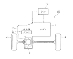
車両100は、図1に示すように、エンジン1と、変速機2と、デファレンシャル装置3と、駆動輪(前輪)4と、ECU5とを備えている。この車両100は、たとえばFF(フロントエンジン・フロントドライブ)方式であり、エンジン1の出力が変速機2を介してデファレンシャル装置3に伝達され、左右の駆動輪4に分配されるようになっている。
As shown in FIG. 1, the
−エンジン−
エンジン(内燃機関)1は、走行用の駆動力源であり、たとえば多気筒ガソリンエンジンである。エンジン1は、スロットルバルブのスロットル開度(吸入空気量)、燃料噴射量、点火時期などにより運転状態を制御可能に構成されている。
-Engine-
The engine (internal combustion engine) 1 is a driving force source for traveling, and is, for example, a multi-cylinder gasoline engine. The
−変速機−
変速機2は、エンジン1と駆動輪4との間の動力伝達経路に設けられており、入力軸の回転を変速して出力軸に出力するように構成されている。この変速機2では、入力軸がエンジン1に連結され、出力軸がデファレンシャル装置3などを介して駆動輪4に連結されている。また、変速機2にはクラッチ21が設けられ、そのクラッチ21によりエンジン1と駆動輪4とが選択的に連結されるようになっている。具体的には、クラッチ21が係合された場合に、エンジン1と駆動輪4との間の動力伝達経路が接続され、クラッチ21が解放された場合に、エンジン1と駆動輪4との間の動力伝達経路が切断される。
-Transmission-
The
−ECU−
ECU5は、エンジン1の運転制御および変速機2の変速制御などを行うように構成されている。具体的には、ECU5は、図2に示すように、CPU51と、ROM52と、RAM53と、バックアップRAM54と、入力インターフェース55と、出力インターフェース56とを含んでいる。なお、ECU5は、本発明の「車両の制御装置」の一例である。
-ECU-
The ECU 5 is configured to perform operation control of the
CPU51は、ROM52に記憶された各種制御プログラムやマップに基づいて演算処理を実行する。ROM52には、各種制御プログラムや、それら各種制御プログラムを実行する際に参照されるマップなどが記憶されている。RAM53は、CPU51による演算結果や各センサの検出結果などを一時的に記憶するメモリである。バックアップRAM54は、イグニッションをオフする際に保存すべきデータなどを記憶する不揮発性のメモリである。
The
入力インターフェース55には、クランクポジションセンサ61、アクセル開度センサ62、スロットル開度センサ63、車速センサ64、ブレーキペダルセンサ65および操舵角センサ66などが接続されている。
A
クランクポジションセンサ61は、エンジン1の回転速度(角速度)を算出するために設けられている。アクセル開度センサ62は、アクセルペダル62aの踏込量(アクセル操作量)を検出するために設けられている。スロットル開度センサ63は、スロットルバルブのスロットル開度を検出するために設けられている。車速センサ64は、車両100の車速を算出するために設けられている。ブレーキペダルセンサ65は、ブレーキペダル65aの踏込量(ブレーキ操作量)を検出するために設けられている。操舵角センサ66は、ステアリングホイール66aの操舵角(ステアリング操作量)を検出するために設けられている。なお、アクセルペダル62a、ブレーキペダル65aおよびステアリングホイール66aは、本発明の「操作部材」の一例である。
The
出力インターフェース56には、インジェクタ71、イグナイタ72、スロットルモータ73および油圧制御装置74などが接続されている。インジェクタ71は、燃料噴射弁であり、燃料噴射量を調整可能である。イグナイタ72は、点火プラグによる点火時期を調整するために設けられている。スロットルモータ73は、スロットルバルブのスロットル開度を調整するために設けられている。油圧制御装置74は、変速機2の変速比を変更したり、クラッチ21のトルク容量(クラッチトルク)を調整してクラッチ21の状態(係合および解放)を制御するために設けられている。
An
そして、ECU5は、各センサの検出結果などに基づいて、スロットル開度、燃料噴射量および点火時期などを制御することにより、エンジン1の運転状態を制御可能に構成されている。また、ECU5は、油圧制御装置74を用いて変速機2の変速制御を実行可能に構成されている。
The ECU 5 is configured to be able to control the operating state of the
ここで、本実施形態では、ECU5は、車両走行中にクラッチ21を解放して惰性走行(フリーラン)させる惰行制御を実行可能に構成されている。この惰行制御時には、油圧制御装置74によりクラッチ21が解放されるとともに、エンジン1の運転が停止される。このため、惰行制御を行うことにより、燃費の改善を図ることが可能である。
Here, in the present embodiment, the ECU 5 is configured to be capable of executing coasting control in which the
具体的に、ECU5は、車両走行中にアクセル操作が解除され、惰行制御が開始される場合に、クラッチ21を解放させるとともに、エンジン1を自動的に停止させる。そして、ECU5は、惰行制御の実行中に、ブレーキ操作、アクセル操作またはステアリング操作がされ、惰行制御が終了される場合に、クラッチ21を係合させるとともに、エンジン1を自動的に再始動させる。本実施形態では、この惰行制御の終了時に、ブレーキペダル65a、アクセルペダル62aおよびステアリングホイール66aに対する操作態様に応じてクラッチ21の係合速度が調整されるようになっている。なお、クラッチ21の係合速度が変更されると、クラッチ21の係合が完了されるまでの時間が変更される。
Specifically, the ECU 5 releases the
−惰行制御の終了−
次に、図3を参照して、本実施形態の車両100における惰行制御の終了時の動作について説明する。なお、以下のフローは所定の時間間隔毎に繰り返し行われる。また、以下の各ステップはECU5により実行される。
-End of coasting control-
Next, with reference to FIG. 3, the operation at the end of coasting control in the
まず、図3のステップS1において、惰行制御の実行中であるか否かが判断される。そして、惰行制御の実行中であると判断された場合には、ステップS2に移る。その一方、惰行制御の実行中ではないと判断された場合には、リターンに移る。 First, in step S1 of FIG. 3, it is determined whether or not coasting control is being executed. Then, when it is determined that the coasting control is being executed, the process proceeds to step S2. On the other hand, if it is determined that coasting control is not being executed, the process proceeds to return.
次に、ステップS2において、ブレーキ操作がされたか否かが判断される。このブレーキ操作がされたか否かは、たとえばブレーキペダルセンサ65の検出結果に基づいて判断される。そして、ブレーキ操作がされたと判断された場合には、惰行制御が終了されるため、エンジン1が再始動され、ステップS3に移る。その一方、ブレーキ操作がされていないと判断された場合には、ステップS4に移る。
Next, in step S2, it is determined whether or not the brake operation has been performed. Whether or not this brake operation has been performed is determined based on, for example, the detection result of the
ステップS3では、ブレーキ操作に応じてクラッチ21の係合速度が調整される。たとえば、ブレーキペダル65aに対する操作速度(踏込速度)が大きいほど、クラッチ21の係合速度が大きくされる。このため、ブレーキペダル65aに対する操作速度が大きい場合には、クラッチ21が急速に係合され、エンジンブレーキが急速に立ち上がる。一方、ブレーキペダル65aに対する操作速度が小さい場合には、クラッチ21が緩やかに係合され、エンジンブレーキが徐々に立ち上がる。したがって、運転者の意図が反映されるブレーキ操作に応じて、エンジンブレーキの立ち上がり(上昇度合い)を調整することにより、運転者に違和感を与えるのを抑制することが可能である。その後、リターンに移る。
In step S3, the engagement speed of the clutch 21 is adjusted according to the brake operation. For example, the higher the operating speed (stepping speed) with respect to the
また、ステップS4において、アクセル操作がされたか否かが判断される。このアクセル操作がされたか否かは、たとえばアクセル開度センサ62の検出結果に基づいて判断される。そして、アクセル操作がされたと判断された場合には、惰行制御が終了されるため、エンジン1が再始動され、ステップS5に移る。その一方、アクセル操作がされていないと判断された場合には、ステップS6に移る。
Further, in step S4, it is determined whether or not the accelerator operation has been performed. Whether or not this accelerator operation has been performed is determined based on, for example, the detection result of the
ステップS5では、アクセル操作に応じてクラッチ21の係合速度が調整される。たとえば、アクセルペダル62aに対する操作速度(踏込速度)が大きいほど、クラッチ21の係合速度が大きくされる。このため、アクセルペダル62aに対する操作速度が大きい場合には、クラッチ21が急速に係合され、エンジン1からの駆動力が急速に立ち上がる。一方、アクセルペダル62aに対する操作速度が小さい場合には、クラッチ21が緩やかに係合され、エンジン1からの駆動力が徐々に立ち上がる。したがって、運転者の意図が反映されるアクセル操作に応じて、エンジン1からの駆動力の立ち上がり(上昇度合い)を調整することにより、運転者に違和感を与えるのを抑制することが可能である。その後、リターンに移る。
In step S5, the engagement speed of the clutch 21 is adjusted according to the accelerator operation. For example, the higher the operating speed (depressing speed) with respect to the
また、ステップS6において、ステアリング操作がされたか否かが判断される。このステアリング操作がされたか否かは、たとえば操舵角センサ66の検出結果に基づいて判断される。そして、ステアリング操作がされたと判断された場合には、惰行制御が終了されるため、エンジン1が再始動され、ステップS7に移る。その一方、ステアリング操作がされていないと判断された場合には、惰行制御が継続され、リターンに移る。
Further, in step S6, it is determined whether or not the steering operation has been performed. Whether or not this steering operation has been performed is determined based on, for example, the detection result of the
ステップS7では、ステアリング操作に応じてクラッチ21の係合速度が調整される。たとえば、ステアリングホイール66aに対する操作速度(操舵速度)が大きいほど、クラッチ21の係合速度が大きくされる。このため、ステアリングホイール66aに対する操作速度が大きい場合には、クラッチ21が急速に係合され、エンジンブレーキまたはエンジン1からの駆動力が急速に立ち上がる。一方、ステアリングホイール66aに対する操作速度が小さい場合には、クラッチ21が緩やかに係合され、エンジンブレーキまたはエンジン1からの駆動力が徐々に立ち上がる。したがって、運転者の意図が反映されるステアリング操作に応じて、エンジンブレーキまたはエンジン1からの駆動力の立ち上がり(上昇度合い)を調整することにより、運転者に違和感を与えるのを抑制することが可能である。なお、エンジンブレーキが立ち上がるかエンジン1からの駆動力が立ち上がるかは、エンジン1の運転状態によって異なる。その後、リターンに移る。
In step S7, the engagement speed of the clutch 21 is adjusted according to the steering operation. For example, the higher the operating speed (steering speed) with respect to the steering wheel 66a, the higher the engaging speed of the clutch 21. Therefore, when the operating speed with respect to the steering wheel 66a is high, the clutch 21 is rapidly engaged, and the driving force from the engine brake or the
−効果−
本実施形態では、上記のように、ブレーキペダル65a、アクセルペダル62aおよびステアリングホイール66aに対する操作態様に応じてクラッチ21の係合速度を調整することによって、エンジンブレーキやエンジン1からの駆動力の立ち上がり(上昇度合い)を調整することができるので、惰行制御の終了時に運転者に違和感を与えるのを抑制することができる。すなわち、惰行制御の終了時においてクラッチ21が係合する際に、運転者の意図に応じた加減速とすることができる。
-Effect-
In the present embodiment, as described above, by adjusting the engagement speed of the clutch 21 according to the operation mode with respect to the
−他の実施形態−
なお、今回開示した実施形態は、すべての点で例示であって、限定的な解釈の根拠となるものではない。したがって、本発明の技術的範囲は、上記した実施形態のみによって解釈されるものではなく、特許請求の範囲の記載に基づいて画定される。また、本発明の技術的範囲には、特許請求の範囲と均等の意味および範囲内でのすべての変更が含まれる。
-Other embodiments-
It should be noted that the embodiment disclosed this time is an example in all respects and does not serve as a basis for a limited interpretation. Therefore, the technical scope of the present invention is not construed solely by the above-described embodiments, but is defined based on the description of the claims. In addition, the technical scope of the present invention includes all modifications within the meaning and scope equivalent to the claims.
たとえば、本実施形態では、車両100がFFである例を示したが、これに限らず、車両が、FR(フロントエンジン・リアドライブ)であってもよいし、4輪駆動であってもよい。
For example, in the present embodiment, the example in which the
また、本実施形態では、走行用の駆動力源としてエンジン1のみが設けられる例を示したが、これに限らず、走行用の駆動力源としてエンジンおよび電動モータが設けられていてもよい。
Further, in the present embodiment, an example in which only the
また、本実施形態では、エンジン1が多気筒ガソリンエンジンである例を示したが、これに限らず、エンジンがディーゼルエンジンなどであってもよい。
Further, in the present embodiment, an example in which the
また、本実施形態において、変速機2は、有段変速機であってもよいし、無段変速機であってもよい。また、エンジン1と駆動輪4とを切断するクラッチ21が変速機2に設けられる例を示したが、これに限らず、エンジンと駆動輪とを切断するクラッチが変速機の外部に設けられていてもよい。
Further, in the present embodiment, the
また、本実施形態では、惰行制御時にエンジン1が停止される例を示したが、これに限らず、惰行制御時にエンジンが運転されるようにしてもよい。
Further, in the present embodiment, the example in which the
また、本実施形態において、惰行制御の開始条件としてその他の条件が設定されていてもよい。たとえば、惰行制御の開始条件として、ブレーキペダル65aが踏まれていないことやステアリングホイール66aが操舵されていないことなどが設定されていてもよい。
Further, in the present embodiment, other conditions may be set as the start condition of coasting control. For example, as a start condition of coasting control, it may be set that the
また、本実施形態では、惰行制御の終了条件として3つの条件(ブレーキ操作、アクセル操作およびステアリング操作)が設定される例を示したが、これに限らず、惰行制御の終了条件として、3つの条件のうち少なくともいずれか1つが設定されていればよい。また、惰行制御の終了条件としてその他の条件が設定されていてもよい。 Further, in the present embodiment, an example in which three conditions (brake operation, accelerator operation and steering operation) are set as the end condition of the coasting control is shown, but the present invention is not limited to this, and three conditions are set as the end condition of the coasting control. At least one of the conditions may be set. In addition, other conditions may be set as the end condition of coasting control.
また、本実施形態のステップS3では、ブレーキペダル65aに対する操作速度が大きいほど、クラッチ21の係合速度を大きくする例を示したが、これに限らず、ブレーキペダルに対する操作量(踏込量)が大きいほど、クラッチの係合速度を大きくしてもよいし、ブレーキペダルに対する操作力(踏込力)が大きいほど、クラッチの係合速度を大きくしてもよい。また、ブレーキペダルに対する操作速度(操作量、操作力)が所定値以上の場合に、クラッチの係合速度を第1速度に設定し、ブレーキペダルに対する操作速度(操作量、操作力)が所定値未満の場合に、クラッチの係合速度を第1速度よりも小さい第2速度に設定するようにしてもよい。また、操作速度、操作量および操作力を適宜組み合わせて係合速度を判断するようにしてもよい。なお、操作速度、操作量および操作力は、本発明の「操作態様」の一例である。
Further, in step S3 of the present embodiment, an example is shown in which the engagement speed of the clutch 21 is increased as the operation speed with respect to the
また、本実施形態のステップS5では、アクセルペダル62aに対する操作速度が大きいほど、クラッチ21の係合速度を大きくする例を示したが、これに限らず、アクセルペダルに対する操作量(踏込量)が大きいほど、クラッチの係合速度を大きくしてもよいし、アクセルペダルに対する操作力(踏込力)が大きいほど、クラッチの係合速度を大きくしてもよい。また、アクセルペダルに対する操作速度(操作量、操作力)が所定値以上の場合に、クラッチの係合速度を第1速度に設定し、アクセルペダルに対する操作速度(操作量、操作力)が所定値未満の場合に、クラッチの係合速度を第1速度よりも小さい第2速度に設定するようにしてもよい。また、操作速度、操作量および操作力を適宜組み合わせて係合速度を判断するようにしてもよい。なお、操作速度、操作量および操作力は、本発明の「操作態様」の一例である。
Further, in step S5 of the present embodiment, an example is shown in which the engaging speed of the clutch 21 is increased as the operating speed with respect to the
また、本実施形態のステップS7では、ステアリングホイール66aに対する操作速度が大きいほど、クラッチ21の係合速度を大きくする例を示したが、これに限らず、ステアリングホイールに対する操作量(操舵角)が大きいほど、クラッチの係合速度を大きくしてもよいし、ステアリングホイールに対する操作力(操舵トルク)が大きいほど、クラッチの係合速度を大きくしてもよい。また、ステアリングホイールに対する操作速度(操作量、操作力)が所定値以上の場合に、クラッチの係合速度を第1速度に設定し、ステアリングホイールに対する操作速度(操作量、操作力)が所定値未満の場合に、クラッチの係合速度を第1速度よりも小さい第2速度に設定するようにしてもよい。また、操作速度、操作量および操作力を適宜組み合わせて係合速度を判断するようにしてもよい。なお、操作速度、操作量および操作力は、本発明の「操作態様」の一例である。 Further, in step S7 of the present embodiment, an example is shown in which the engagement speed of the clutch 21 is increased as the operation speed with respect to the steering wheel 66a is increased, but the operation amount (steering angle) with respect to the steering wheel is not limited to this. The larger the clutch, the higher the clutch engagement speed, and the larger the operating force (steering torque) on the steering wheel, the higher the clutch engagement speed. When the operating speed (operating amount, operating force) with respect to the steering wheel is equal to or higher than a predetermined value, the engaging speed of the clutch is set to the first speed, and the operating speed (operating amount, operating force) with respect to the steering wheel is a predetermined value. If it is less than, the engaging speed of the clutch may be set to a second speed smaller than the first speed. Further, the engagement speed may be determined by appropriately combining the operation speed, the operation amount, and the operation force. The operating speed, operating amount, and operating force are examples of the "operating mode" of the present invention.
また、本実施形態において、ECU5が複数のECUにより構成されていてもよい。
Further, in the present embodiment, the
本発明は、車両走行中にエンジンと駆動輪との間に設けられたクラッチを解放して惰性走行させる惰行制御を実行可能な車両の制御装置に利用可能である。 INDUSTRIAL APPLICABILITY The present invention can be used as a vehicle control device capable of performing coasting control in which a clutch provided between an engine and a drive wheel is released during vehicle traveling to coast the vehicle.
1 エンジン
4 駆動輪
5 ECU(車両の制御装置)
21 クラッチ
62a アクセルペダル(操作部材)
65a ブレーキペダル(操作部材)
66a ステアリングホイール(操作部材)
100 車両
1
21
65a Brake pedal (operating member)
66a Steering wheel (operation member)
100 vehicles
Claims (1)
前記惰行制御の実行中に操作部材が操作され、前記惰行制御が終了される場合に、前記操作部材に対する操作態様に応じて前記クラッチの係合速度を調整するように構成されており、
前記操作部材は、ブレーキペダルおよびステアリングホイールのうちの少なくとも1つを含み、
前記操作態様は、操作速度、操作量および操作力のうちの少なくとも1つを含み、
前記ブレーキペダルが前記操作部材に含まれる場合に、前記惰行制御の実行中に前記ブレーキペダルが操作されて前記惰行制御が終了されるときに、前記ブレーキペダルに対する前記操作態様が大きいほど前記クラッチの係合速度を大きくするように構成され、
前記ステアリングホイールが前記操作部材に含まれる場合に、前記惰行制御の実行中に前記ステアリングホイールが操作されて前記惰行制御が終了されるときに、前記ステアリングホイールに対する前記操作態様が大きいほど前記クラッチの係合速度を大きくするように構成されていることを特徴とする車両の制御装置。 It is a vehicle control device configured to be capable of performing inertial control by releasing a clutch provided between an engine and a drive wheel while the vehicle is running to allow the vehicle to coast.
When the operating member is operated during the execution of the coasting control and the coasting control is terminated, the engagement speed of the clutch is adjusted according to the operation mode with respect to the operating member.
The operating member includes at least one of Burekipeda Le us and the steering wheel,
The operating mode includes at least one of operating speed, operating amount and operating force.
When the brake pedal is included in the operating member, when the brake pedal is operated during the execution of the coasting control and the coasting control is terminated, the larger the operation mode with respect to the brake pedal, the more the clutch Configured to increase engagement speed ,
If the previous SL steering wheel is included in the operating member, wherein during coasting control when the coasting control steering wheel is operated is terminated, the clutch as the operation mode with respect to the steering wheel is large A vehicle control device characterized in that it is configured to increase the engagement speed of the wheel.
Priority Applications (1)
| Application Number | Priority Date | Filing Date | Title |
|---|---|---|---|
| JP2017062792A JP6828552B2 (en) | 2017-03-28 | 2017-03-28 | Vehicle control device |
Applications Claiming Priority (1)
| Application Number | Priority Date | Filing Date | Title |
|---|---|---|---|
| JP2017062792A JP6828552B2 (en) | 2017-03-28 | 2017-03-28 | Vehicle control device |
Publications (2)
| Publication Number | Publication Date |
|---|---|
| JP2018165530A JP2018165530A (en) | 2018-10-25 |
| JP6828552B2 true JP6828552B2 (en) | 2021-02-10 |
Family
ID=63922535
Family Applications (1)
| Application Number | Title | Priority Date | Filing Date |
|---|---|---|---|
| JP2017062792A Expired - Fee Related JP6828552B2 (en) | 2017-03-28 | 2017-03-28 | Vehicle control device |
Country Status (1)
| Country | Link |
|---|---|
| JP (1) | JP6828552B2 (en) |
Families Citing this family (2)
| Publication number | Priority date | Publication date | Assignee | Title |
|---|---|---|---|---|
| US11542991B2 (en) * | 2019-08-14 | 2023-01-03 | Autodyn Sys Inc. | Clutch system interlocking with accelerator and brake pedal |
| KR102262239B1 (en) * | 2019-10-07 | 2021-06-11 | 오토딘시스 주식회사 | Novel structure for clutch assembly |
Family Cites Families (2)
| Publication number | Priority date | Publication date | Assignee | Title |
|---|---|---|---|---|
| JP5616155B2 (en) * | 2010-07-30 | 2014-10-29 | いすゞ自動車株式会社 | Coasting control device |
| US10173683B2 (en) * | 2014-08-06 | 2019-01-08 | Nissan Motor Co., Ltd. | Vehicle control device and vehicle control method |
-
2017
- 2017-03-28 JP JP2017062792A patent/JP6828552B2/en not_active Expired - Fee Related
Also Published As
| Publication number | Publication date |
|---|---|
| JP2018165530A (en) | 2018-10-25 |
Similar Documents
| Publication | Publication Date | Title |
|---|---|---|
| JP6253000B1 (en) | Vehicle control device | |
| JP6253001B1 (en) | Vehicle control device | |
| JP6900908B2 (en) | Vehicle control device | |
| JP6970384B2 (en) | Vehicle control device | |
| US11433879B2 (en) | Vehicle control system | |
| JP6828552B2 (en) | Vehicle control device | |
| JP2014114751A (en) | Vehicular control device | |
| US20180266547A1 (en) | Automatic transmission controller | |
| JP5098921B2 (en) | Control device for internal combustion engine | |
| JP2946881B2 (en) | Throttle valve control device for internal combustion engine | |
| JP2009185738A (en) | Vehicle control apparatus and vehicle control method | |
| JP6350318B2 (en) | Electronic control unit | |
| JP7080443B2 (en) | Vehicle control method, vehicle system and vehicle control device | |
| JP2005163856A (en) | Automotive drive control device | |
| JP3147741B2 (en) | Transmission control device for continuously variable transmission | |
| JP6870463B2 (en) | Vehicle control device | |
| JP2016176495A (en) | Transmission control device | |
| JP6007816B2 (en) | Vehicle control device | |
| JP2013217271A (en) | Vehicle control device | |
| WO2016194068A1 (en) | Control device for internal combustion engine for vehicle | |
| JP4305266B2 (en) | Control device for internal combustion engine | |
| JP5913178B2 (en) | Automatic stop control device for internal combustion engine | |
| JP2018034765A (en) | Vehicular control apparatus | |
| JP2014185557A (en) | Control device of vehicle | |
| JP6725986B2 (en) | Engine control device and control method |
Legal Events
| Date | Code | Title | Description |
|---|---|---|---|
| A621 | Written request for application examination |
Free format text: JAPANESE INTERMEDIATE CODE: A621 Effective date: 20190724 |
|
| A977 | Report on retrieval |
Free format text: JAPANESE INTERMEDIATE CODE: A971007 Effective date: 20200622 |
|
| A131 | Notification of reasons for refusal |
Free format text: JAPANESE INTERMEDIATE CODE: A131 Effective date: 20200707 |
|
| A521 | Request for written amendment filed |
Free format text: JAPANESE INTERMEDIATE CODE: A523 Effective date: 20200722 |
|
| A131 | Notification of reasons for refusal |
Free format text: JAPANESE INTERMEDIATE CODE: A131 Effective date: 20201006 |
|
| A521 | Request for written amendment filed |
Free format text: JAPANESE INTERMEDIATE CODE: A523 Effective date: 20201110 |
|
| TRDD | Decision of grant or rejection written | ||
| A01 | Written decision to grant a patent or to grant a registration (utility model) |
Free format text: JAPANESE INTERMEDIATE CODE: A01 Effective date: 20201222 |
|
| A61 | First payment of annual fees (during grant procedure) |
Free format text: JAPANESE INTERMEDIATE CODE: A61 Effective date: 20210104 |
|
| R151 | Written notification of patent or utility model registration |
Ref document number: 6828552 Country of ref document: JP Free format text: JAPANESE INTERMEDIATE CODE: R151 |
|
| LAPS | Cancellation because of no payment of annual fees |