JP6818496B2 - Image processing device for endoscopes, endoscope device, operation method of image processing device for endoscope, and image processing program - Google Patents
Image processing device for endoscopes, endoscope device, operation method of image processing device for endoscope, and image processing program Download PDFInfo
- Publication number
- JP6818496B2 JP6818496B2 JP2016198383A JP2016198383A JP6818496B2 JP 6818496 B2 JP6818496 B2 JP 6818496B2 JP 2016198383 A JP2016198383 A JP 2016198383A JP 2016198383 A JP2016198383 A JP 2016198383A JP 6818496 B2 JP6818496 B2 JP 6818496B2
- Authority
- JP
- Japan
- Prior art keywords
- image
- endoscope
- installation state
- subject image
- unit
- Prior art date
- Legal status (The legal status is an assumption and is not a legal conclusion. Google has not performed a legal analysis and makes no representation as to the accuracy of the status listed.)
- Active
Links
Images


Classifications
-
- A—HUMAN NECESSITIES
- A61—MEDICAL OR VETERINARY SCIENCE; HYGIENE
- A61B—DIAGNOSIS; SURGERY; IDENTIFICATION
- A61B1/00—Instruments for performing medical examinations of the interior of cavities or tubes of the body by visual or photographical inspection, e.g. endoscopes; Illuminating arrangements therefor
- A61B1/00002—Operational features of endoscopes
- A61B1/00004—Operational features of endoscopes characterised by electronic signal processing
- A61B1/00009—Operational features of endoscopes characterised by electronic signal processing of image signals during a use of endoscope
-
- A—HUMAN NECESSITIES
- A61—MEDICAL OR VETERINARY SCIENCE; HYGIENE
- A61B—DIAGNOSIS; SURGERY; IDENTIFICATION
- A61B1/00—Instruments for performing medical examinations of the interior of cavities or tubes of the body by visual or photographical inspection, e.g. endoscopes; Illuminating arrangements therefor
- A61B1/00002—Operational features of endoscopes
- A61B1/00043—Operational features of endoscopes provided with output arrangements
- A61B1/00045—Display arrangement
- A61B1/00048—Constructional features of the display
-
- A—HUMAN NECESSITIES
- A61—MEDICAL OR VETERINARY SCIENCE; HYGIENE
- A61B—DIAGNOSIS; SURGERY; IDENTIFICATION
- A61B1/00—Instruments for performing medical examinations of the interior of cavities or tubes of the body by visual or photographical inspection, e.g. endoscopes; Illuminating arrangements therefor
- A61B1/00064—Constructional details of the endoscope body
- A61B1/00105—Constructional details of the endoscope body characterised by modular construction
-
- A—HUMAN NECESSITIES
- A61—MEDICAL OR VETERINARY SCIENCE; HYGIENE
- A61B—DIAGNOSIS; SURGERY; IDENTIFICATION
- A61B1/00—Instruments for performing medical examinations of the interior of cavities or tubes of the body by visual or photographical inspection, e.g. endoscopes; Illuminating arrangements therefor
- A61B1/04—Instruments for performing medical examinations of the interior of cavities or tubes of the body by visual or photographical inspection, e.g. endoscopes; Illuminating arrangements therefor combined with photographic or television appliances
- A61B1/042—Instruments for performing medical examinations of the interior of cavities or tubes of the body by visual or photographical inspection, e.g. endoscopes; Illuminating arrangements therefor combined with photographic or television appliances characterised by a proximal camera, e.g. a CCD camera
-
- A—HUMAN NECESSITIES
- A61—MEDICAL OR VETERINARY SCIENCE; HYGIENE
- A61B—DIAGNOSIS; SURGERY; IDENTIFICATION
- A61B1/00—Instruments for performing medical examinations of the interior of cavities or tubes of the body by visual or photographical inspection, e.g. endoscopes; Illuminating arrangements therefor
- A61B1/00002—Operational features of endoscopes
- A61B1/00043—Operational features of endoscopes provided with output arrangements
- A61B1/00045—Display arrangement
- A61B1/0005—Display arrangement combining images e.g. side-by-side, superimposed or tiled
-
- A—HUMAN NECESSITIES
- A61—MEDICAL OR VETERINARY SCIENCE; HYGIENE
- A61B—DIAGNOSIS; SURGERY; IDENTIFICATION
- A61B1/00—Instruments for performing medical examinations of the interior of cavities or tubes of the body by visual or photographical inspection, e.g. endoscopes; Illuminating arrangements therefor
- A61B1/00163—Optical arrangements
- A61B1/00188—Optical arrangements with focusing or zooming features
-
- H—ELECTRICITY
- H04—ELECTRIC COMMUNICATION TECHNIQUE
- H04N—PICTORIAL COMMUNICATION, e.g. TELEVISION
- H04N23/00—Cameras or camera modules comprising electronic image sensors; Control thereof
- H04N23/60—Control of cameras or camera modules
- H04N23/68—Control of cameras or camera modules for stable pick-up of the scene, e.g. compensating for camera body vibrations
- H04N23/682—Vibration or motion blur correction
- H04N23/683—Vibration or motion blur correction performed by a processor, e.g. controlling the readout of an image memory
Description
本発明は、内視鏡用画像処理装置、内視鏡装置、内視鏡用画像処理装置の作動方法、及び画像処理プログラムに関する。 The present invention relates to an image processing device for an endoscope, an endoscope device, an operation method of an image processing device for an endoscope, and an image processing program.
従来、医療分野において、撮像素子を用いて生体内等の被検体を撮像し、当該被検体を観察する内視鏡装置が知られている(例えば、特許文献1参照)。
図12は、従来の内視鏡装置100の構成を示す図である。具体的に、図12は、従来の内視鏡装置100を用いて手術を行う際の手術室のレイアウトの一例を示す図である。
特許文献1に記載の内視鏡装置100(医療装置)は、図12に示すように、被検体SB内に挿入され、被写体像を取り込む内視鏡101と、内視鏡101の接眼部に着脱自在に接続され、被写体像を撮像して撮像画像を生成する内視鏡用撮像装置102(カメラヘッド)と、内視鏡用撮像装置102にて撮像された撮像画像を処理して映像信号を生成する制御装置103(ビデオプロセッサ装置)と、制御装置103にて処理された映像信号に基づく観察画像を表示する表示装置104(モニタ装置)とを備える。
Conventionally, in the medical field, an endoscope device that uses an image sensor to image a subject in a living body or the like and observes the subject is known (see, for example, Patent Document 1).
FIG. 12 is a diagram showing a configuration of a
As shown in FIG. 12, the endoscope device 100 (medical device) described in
そして、図12では、側臥位でベッドBDに横たわった被検体SBに対して、助手D3が内視鏡101を被検体SB内に脇腹から挿入し、表示装置104に表示された観察画像を観察しながら、執刀医D1が電気メス装置202を用いて手術を行っている状況を示している。
ここで、ベッドBDの周囲には、図12に示すように、制御装置103及び表示装置104の他、複数の器材台201、電気メス装置202、麻酔装置203、及び周辺機器204等が配置される。そして、執刀医D1、助手D2,D3、ナースD4、及び麻酔科医D5は、ベッドBDの周囲において、上述した各部材103,104,201〜204を避けた空間に立つこととなる。
Then, in FIG. 12, the assistant D3 inserts the
Here, as shown in FIG. 12, in addition to the
近年では、内視鏡装置100において、40インチ以上の大型の画面サイズで構成された表示装置104を採用する傾向にある。
このように大型の画面サイズで構成された表示装置104を配置した場合には、表示装置104の横幅が特に大きいため、当該表示装置104の近傍に立つ人の動線(図12の例では助手D2がベッドBDの周囲から抜ける動線)を阻害することとなる。
すなわち、表示装置104等の設置場所を移動しなければ、当該人の動線を確保することができない。また、当該人の動線を確保した後は、表示装置104等を改めて元の設置場所(図12の例では執刀医D1が観察画像を観察し易い場所)に移動する必要がある。
したがって、表示装置104等の設置場所を移動する煩雑な作業が必要となり、利便性の向上を図ることができない、という問題がある。
In recent years, in the
When the
That is, the flow line of the person cannot be secured unless the installation location of the
Therefore, there is a problem that complicated work for moving the installation location of the
本発明は、上記に鑑みてなされたものであって、利便性の向上を図ることができる内視鏡用画像処理装置、内視鏡装置、内視鏡用画像処理装置の作動方法、及び画像処理プログラムを提供することを目的とする。 The present invention has been made in view of the above, and an image processing device for an endoscope, an endoscopic device, an operating method of an image processing device for an endoscope, and an image, which can improve convenience. The purpose is to provide a processing program.
上述した課題を解決し、目的を達成するために、本発明に係る内視鏡用画像処理装置は、内視鏡にて取り込まれた被写体像を含む撮像画像を処理して映像信号を生成するとともに、当該映像信号に基づく観察画像を表示する画像表示部に当該映像信号を出力する内視鏡用画像処理装置であって、前記画像表示部は、前記観察画像を表示する表示画面における第1の辺が当該第1の辺に交差する第2の辺よりも短く構成されているとともに、前記第1の辺が鉛直方向に沿う第1の設置状態と前記第2の辺が鉛直方向に沿う第2の設置状態とにそれぞれ設置可能に構成され、当該内視鏡用画像処理装置は、前記画像表示部が前記第1の設置状態及び前記第2の設置状態のいずれの設置状態で設置されているかを認識する設置状態認識部と、前記観察画像内の前記被写体像が前記画像表示部の設置状態に対応した姿勢となる前記映像信号を生成する映像信号生成部と、前記撮像画像内での前記被写体像の大きさを判別する被写体像判別部と、前記設置状態認識部による認識結果、及び前記被写体像判別部による判別結果に基づいて、前記被写体像の拡大縮小率を設定する倍率設定部とを備え、前記映像信号生成部は、前記倍率設定部にて設定された拡大縮小率で前記被写体像の大きさを拡大縮小した前記映像信号を生成することを特徴とする。 In order to solve the above-mentioned problems and achieve the object, the image processing apparatus for an endoscope according to the present invention processes an captured image including a subject image captured by the endoscope to generate a video signal. At the same time, it is an image processing device for an endoscope that outputs the video signal to an image display unit that displays an observation image based on the video signal, and the image display unit is the first on a display screen that displays the observation image. The side is shorter than the second side that intersects the first side, and the first installation state in which the first side is along the vertical direction and the second side are along the vertical direction. The image processing device for an endoscope is configured so that it can be installed in each of the second installation states, and the image display unit is installed in either the first installation state or the second installation state. In the installation state recognition unit that recognizes whether or not the image is displayed, a video signal generation unit that generates the video signal in which the subject image in the observation image has a posture corresponding to the installation state of the image display unit, and the captured image. Magnification setting for setting the enlargement / reduction ratio of the subject image based on the subject image discrimination unit that discriminates the size of the subject image, the recognition result by the installation state recognition unit, and the discrimination result by the subject image discrimination unit. The video signal generation unit is characterized in that it generates the video signal in which the size of the subject image is enlarged or reduced at the enlargement / reduction ratio set by the magnification setting unit .
本発明に係る内視鏡用画像処理装置は、上記発明において、前記倍率設定部は、前記撮像画像内での前記被写体像の大きさが前記表示画面における前記第1の辺の長さ寸法に対応する閾値以下である場合には、前記第1の設置状態での前記被写体像の拡大縮小率と前記第2の設置状態での前記被写体像の拡大縮小率とを同一の値に設定することを特徴とする。 In the image processing apparatus for an endoscope according to the present invention, in the above invention, in the magnification setting unit, the size of the subject image in the captured image is set to the length dimension of the first side on the display screen. When it is equal to or less than the corresponding threshold value, the enlargement / reduction ratio of the subject image in the first installation state and the enlargement / reduction ratio of the subject image in the second installation state are set to the same value. It is characterized by.
本発明に係る内視鏡用画像処理装置は、上記発明において、前記倍率設定部は、前記撮像画像内での前記被写体像の大きさが前記表示画面における前記第1の辺の長さ寸法に対応する閾値を超える場合には、前記第1の設置状態での前記被写体像の拡大縮小率よりも前記第2の設置状態での前記被写体像の拡大縮小率を小さい値に設定することを特徴とする。 In the image processing apparatus for an endoscope according to the present invention, in the above invention, in the magnification setting unit, the size of the subject image in the captured image is set to the length dimension of the first side on the display screen. When the corresponding threshold value is exceeded, the enlargement / reduction ratio of the subject image in the second installation state is set to a smaller value than the enlargement / reduction ratio of the subject image in the first installation state. And.
本発明に係る内視鏡用画像処理装置は、上記発明において、前記撮像画像内での前記被写体像の位置を判別する被写体像判別部を備え、前記映像信号生成部は、前記画像表示部が前記第1の設置状態に設置されている場合には、前記撮像画像内での前記被写体像の位置に基づいて、前記観察画像内の中央領域に前記被写体像を位置付けた前記映像信号を生成することを特徴とする。 In the above invention, the image processing apparatus for an endoscope according to the present invention includes a subject image discriminating unit that discriminates the position of the subject image in the captured image, and the video signal generation unit includes the image display unit. When installed in the first installation state, the video signal in which the subject image is positioned in the central region in the observation image is generated based on the position of the subject image in the captured image. It is characterized by that.
本発明に係る内視鏡用画像処理装置は、上記発明において、前記撮像画像内での前記被写体像の位置を判別する被写体像判別部を備え、前記映像信号生成部は、前記画像表示部が前記第2の設置状態に設置されている場合には、前記撮像画像内での前記被写体像の位置に基づいて、前記観察画像内の上方領域に前記被写体像を位置付けた前記映像信号を生成することを特徴とする。 In the above invention, the image processing apparatus for an endoscope according to the present invention includes a subject image discriminating unit that discriminates the position of the subject image in the captured image, and the video signal generation unit includes the image display unit. When installed in the second installation state, the video signal in which the subject image is positioned in the upper region in the observation image is generated based on the position of the subject image in the captured image. It is characterized by that.
本発明に係る内視鏡装置は、被検体内に挿入され、被写体像を取り込む内視鏡と、前記内視鏡の接眼部に着脱自在に接続され、前記被写体像を撮像して撮像画像を生成する内視鏡用撮像装置と、前記内視鏡用撮像装置の動作を制御する制御装置と、上述した内視鏡用画像処理装置と、前記内視鏡用画像処理装置から出力される映像信号に基づく観察画像を表示する画像表示部を有する表示装置とを備えることを特徴とする。 The endoscope device according to the present invention is detachably connected to an endoscope which is inserted into a subject and captures a subject image and is detachably connected to an eyepiece of the endoscope, and images the subject image to capture an image. Is output from the endoscope imaging device, the control device that controls the operation of the endoscope imaging device, the above-mentioned endoscope image processing device, and the endoscope image processing device. It is characterized by including a display device having an image display unit that displays an observation image based on a video signal.
本発明に係る内視鏡装置は、上記発明において、前記内視鏡用画像処理装置は、前記制御装置に設けられていることを特徴とする。 The endoscope device according to the present invention is characterized in that, in the above invention, the endoscope image processing device is provided in the control device.
本発明に係る内視鏡装置は、上記発明において、前記内視鏡用画像処理装置は、前記表示装置に設けられていることを特徴とする。 The endoscope device according to the present invention is characterized in that, in the above invention, the endoscope image processing device is provided in the display device.
本発明に係る内視鏡用画像処理装置の画像処理方法は、内視鏡にて取り込まれた被写体像を含む撮像画像を処理して映像信号を生成するとともに、当該映像信号に基づく観察画像を表示する画像表示部に当該映像信号を出力する内視鏡用画像処理装置の画像処理方法であって、前記画像表示部は、前記観察画像を表示する表示画面における第1の辺が当該第1の辺に交差する第2の辺よりも短く構成されているとともに、前記第1の辺が鉛直方向に沿う第1の設置状態と前記第2の辺が鉛直方向に沿う第2の設置状態とにそれぞれ設置可能に構成され、当該内視鏡用画像処理装置の画像処理方法は、前記画像表示部が前記第1の設置状態及び前記第2の設置状態のいずれの設置状態で設置されているかを認識する設置状態認識ステップと、前記観察画像内の前記被写体像が前記画像表示部の設置状態に対応した姿勢となる前記映像信号を生成する映像信号生成ステップとを含むことを特徴とする。
本発明に係る内視鏡用画像処理装置の画像処理方法は、上記発明において、前記撮像画像内での前記被写体像の大きさを判別する被写体像判別ステップと、前記設置状態認識ステップによる認識結果、及び前記被写体像判別ステップによる判別結果に基づいて、前記被写体像の拡大縮小率を設定する倍率設定ステップとを含み、前記映像信号生成ステップでは、前記倍率設定ステップにて設定された拡大縮小率で前記被写体像の大きさを拡大縮小した前記映像信号を生成することを特徴とする。
The image processing method of the image processing apparatus for an endoscope according to the present invention processes an captured image including a subject image captured by the endoscope to generate a video signal, and also produces an observation image based on the video signal. An image processing method of an image processing device for an endoscope that outputs the video signal to the image display unit to be displayed. In the image display unit, the first side of the display screen for displaying the observation image is the first side. It is configured to be shorter than the second side that intersects the side of the image, and the first side is in the first installation state along the vertical direction and the second side is in the second installation state along the vertical direction. The image processing method of the image processing device for an endoscope is such that the image display unit is installed in either the first installation state or the second installation state. It is characterized by including an installation state recognition step for recognizing the above and a video signal generation step for generating the video signal in which the subject image in the observation image is in a posture corresponding to the installation state of the image display unit.
The image processing method of the image processing apparatus for an endoscope according to the present invention is the recognition result by the subject image discrimination step for discriminating the size of the subject image in the captured image and the installation state recognition step in the above invention. , And a magnification setting step for setting the enlargement / reduction ratio of the subject image based on the determination result by the subject image determination step. In the video signal generation step, the enlargement / reduction ratio set in the magnification setting step is included. It is characterized in that the video signal is generated by enlarging / reducing the size of the subject image.
本発明に係る画像処理プログラムは、上述した内視鏡用画像処理装置の画像処理方法を当該内視鏡用画像処理装置に実行させることを特徴とする。 The image processing program according to the present invention is characterized in that the image processing method of the above-mentioned image processing apparatus for an endoscope is executed by the image processing apparatus for an endoscope.
本発明に係る内視鏡用画像処理装置は、内視鏡にて取り込まれた被写体像を含む撮像画像を処理して映像信号を生成し、当該映像信号を画像表示部に出力する。そして、画像表示部は、当該映像信号に基づく観察画像を表示する。ここで、画像表示部は、表示画面における第1の辺(以下、短辺と記載)が鉛直方向に沿う第1の設置状態(以下、横置き状態と記載)と表示画面における第2の辺(以下、長辺と記載)が鉛直方向に沿う第2の設置状態(以下、縦置き状態と記載)とにそれぞれ設置可能に構成されている。そして、内視鏡用画像処理装置は、画像表示部の設置状態(横置き状態または縦置き状態)を認識し、観察画像内の被写体像が画像表示部の設置状態に対応した姿勢となる映像信号を生成する。
すなわち、画像表示部を横置き状態から縦置き状態に変更すれば、表示画面の短辺が横方向となることで横幅が小さくなり、画像表示部の近傍に立つ人の動線を確保することができる。また、画像表示部を横置き状態から縦置き状態に変更しても、観察画像内の被写体像は、画像表示部の設置状態に対応した姿勢(被写体像の上下方向が鉛直方向に沿う姿勢)となる。このため、画像表示部の近傍に立つ人の動線を確保した後、画像表示部を縦置き状態から横置き状態に改めて変更する必要がない。
したがって、本発明に係る内視鏡用画像処理装置によれば、画像表示部の設置場所を移動する煩雑な作業を不要とし、利便性の向上を図ることができる、という効果を奏する。
The image processing apparatus for an endoscope according to the present invention processes an captured image including a subject image captured by the endoscope to generate a video signal, and outputs the video signal to an image display unit. Then, the image display unit displays an observation image based on the video signal. Here, the image display unit has a first installation state (hereinafter referred to as a horizontal installation state) in which the first side (hereinafter referred to as a short side) on the display screen is along the vertical direction and a second side on the display screen. (Hereinafter referred to as the long side) is configured to be able to be installed in the second installation state (hereinafter referred to as the vertical installation state) along the vertical direction. Then, the image processing device for the endoscope recognizes the installed state (horizontal or vertical) of the image display unit, and the subject image in the observed image is in a posture corresponding to the installed state of the image display unit. Generate a signal.
That is, if the image display unit is changed from the horizontal installation state to the vertical installation state, the short side of the display screen becomes the horizontal direction, so that the horizontal width becomes smaller and the flow line of the person standing in the vicinity of the image display unit is secured. Can be done. Even if the image display unit is changed from the horizontal installation state to the vertical installation state, the subject image in the observation image has a posture corresponding to the installation state of the image display unit (the vertical direction of the subject image is along the vertical direction). It becomes. Therefore, it is not necessary to change the image display unit from the vertical installation state to the horizontal installation state again after securing the flow line of the person standing in the vicinity of the image display unit.
Therefore, according to the image processing apparatus for an endoscope according to the present invention, it is possible to eliminate the complicated work of moving the installation location of the image display unit and improve the convenience.
また、本発明に係る内視鏡装置は、上述した内視鏡用画像処理装置を備えるため、上述した内視鏡用画像処理装置と同様の効果を奏する。さらに、本発明に係る内視鏡用画像処理装置の画像処理方法は、上述した内視鏡用画像処理装置が実行する方法であるため、上述した内視鏡用画像処理装置と同様の効果を奏する。また、本発明に係る画像処理プログラムは、上述した内視鏡用画像処理装置にて実行されるプログラムであるため、上述した内視鏡用画像処理装置と同様の効果を奏する。 Further, since the endoscope device according to the present invention includes the above-mentioned image processing device for an endoscope, it has the same effect as the above-mentioned image processing device for an endoscope. Further, since the image processing method of the endoscope image processing device according to the present invention is a method executed by the above-mentioned endoscope image processing device, the same effect as that of the above-mentioned endoscope image processing device can be obtained. Play. Further, since the image processing program according to the present invention is a program executed by the above-mentioned image processing device for an endoscope, it has the same effect as the above-mentioned image processing device for an endoscope.
以下に、図面を参照して、本発明を実施するための形態(以下、実施の形態)について説明する。なお、以下に説明する実施の形態によって本発明が限定されるものではない。さらに、図面の記載において、同一の部分には同一の符号を付している。 Hereinafter, embodiments for carrying out the present invention (hereinafter referred to as embodiments) will be described with reference to the drawings. The present invention is not limited to the embodiments described below. Further, in the description of the drawings, the same parts are designated by the same reference numerals.
(実施の形態1)
〔内視鏡装置の概略構成〕
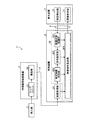
図1は、本発明の実施の形態1に係る内視鏡装置1の概略構成を示す図である。図2は、内視鏡装置1の構成を示すブロック図である。なお、図2では、説明の便宜上、光源装置3、ライトガイド4、及び第3伝送ケーブル10の図示を省略している。
内視鏡装置1は、医療分野において用いられ、生体内等の被検体を観察する装置である。この内視鏡装置1は、図1または図2に示すように、挿入部2と、光源装置3(図1)と、ライトガイド4(図1)と、内視鏡用撮像装置5と、第1伝送ケーブル6と、表示装置7と、第2伝送ケーブル8と、制御装置9と、第3伝送ケーブル10(図1)とを備える。
(Embodiment 1)
[Outline configuration of endoscope device]
FIG. 1 is a diagram showing a schematic configuration of an
The
挿入部2は、本発明に係る内視鏡としての機能を有する。本実施の形態1では、挿入部2は、硬性内視鏡で構成されている。すなわち、挿入部2は、硬質または少なくとも一部が軟質で細長形状を有し、生体内に挿入される。この挿入部2内には、1または複数のレンズを用いて構成され、被写体像を集光する光学系が設けられている。
光源装置3は、ライトガイド4の一端が接続され、制御装置9による制御の下、当該ライトガイド4の一端に生体内を照明するための光を供給する。
ライトガイド4は、一端が光源装置3に着脱自在に接続されるとともに、他端が挿入部2に着脱自在に接続される。そして、ライトガイド4は、光源装置3から供給された光を一端から他端に伝達し、挿入部2に供給する。挿入部2に供給された光は、当該挿入部2の先端から出射され、生体内に照射される。生体内に照射された光(被写体像)は、挿入部2内の光学系により集光される。
The
One end of the
One end of the
内視鏡用撮像装置5は、挿入部2の基端(接眼部21(図1))に着脱自在に接続される。そして、内視鏡用撮像装置5は、制御装置9による制御の下、挿入部2にて集光された被写体像を撮像し、当該撮像による撮像信号(画像信号)を出力する。この内視鏡用撮像装置5は、図2に示すように、レンズユニット51と、撮像部52とを備える。
レンズユニット51は、挿入部2にて集光された被写体像を撮像部52の撮像面に結像する。そして、レンズユニット51は、内視鏡用撮像装置5に設けられた駆動用モータ(図示略)により光軸方向に移動し、焦点距離やピントを調整可能とする。
撮像部52は、制御装置9による制御の下、生体内を撮像する。この撮像部52は、挿入部2にて集光され、レンズユニット51が結像した被写体像を受光して電気信号に変換するCCD(Charge Coupled Device)またはCMOS(Complementary Metal Oxide Semiconductor)等の撮像素子(図示略)、及び当該撮像素子からの電気信号(アナログ信号)に対して信号処理(A/D変換等)を行って画像信号を出力する信号処理部(図示略)等が一体形成されたセンサチップを用いて構成され、A/D変換後の画像信号(デジタル信号)を出力する。なお、上述した信号処理部は、撮像素子と一体形成せずに別体としても構わない。
The
The
The
第1伝送ケーブル6は、一端がコネクタCN1(図1)を介して制御装置9に着脱自在に接続され、他端がコネクタCN2(図1)を介して内視鏡用撮像装置5に接続される。そして、第1伝送ケーブル6は、内視鏡用撮像装置5から出力される画像信号を制御装置9に伝送するとともに、制御装置9から出力される制御信号、同期信号、クロック、及び電力等を内視鏡用撮像装置5にそれぞれ伝送する。
なお、第1伝送ケーブル6を介した内視鏡用撮像装置5から制御装置9への画像信号の伝送は、当該画像信号を光信号で伝送してもよく、あるいは、電気信号で伝送しても構わない。第1伝送ケーブル6を介した制御装置9から内視鏡用撮像装置5への制御信号、同期信号、クロックの伝送も同様である。
One end of the
The image signal may be transmitted from the endoscopic
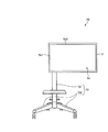
図3A及び図3Bは、表示装置7を示す図である。
表示装置7は、制御装置9にて処理された映像信号に基づく観察画像を表示する。この表示装置7は、図2、図3Aまたは図3Bに示すように、画像表示部71と、支持台72(図3A,図3B)と、状態検出部73と(図2)を備える。
画像表示部71は、液晶または有機EL(Electro Luminescence)等を用いた表示ディスプレイで構成され、表示画面Sc(図3A,図3B)に観察画像を表示する。本実施の形態1では、表示画面Scは、40インチ以上の画面サイズで構成されている。また、表示画面Scのアスペクト比(第2の辺Sc2(以下、長辺Sc2と記載)の長さ寸法と第1の辺Sc1(以下、短辺Sc1と記載)の長さ寸法との比)は、例えば、16:9で構成されている。
3A and 3B are views showing the
The
The
支持台72は、画像表示部71を支持する部分であり、図3Aまたは図3Bに示すように、支柱721と、複数の脚部722とを備える。
支柱721は、鉛直方向に沿う柱状部材で構成され、上端側で画像表示部71における背面の略中心位置に接続する。そして、支柱721は、画像表示部71を回動可能に支持する。具体的に、支柱721は、表示画面Scにおける短辺Sc1が鉛直方向に沿う第1の設置状態(図3A(以下、横置き状態と記載))と長辺Sc2が鉛直方向に沿う第2の設置状態(図3B(以下、縦置き状態と記載))とにそれぞれ回動可能(設置可能)に画像表示部71を支持する。
なお、画像表示部71の設置状態については、手動にて変更する構成としてもよく、あるいは、モータ及びフットスイッチ等を設け、当該フットスイッチへの操作に応じて当該モータが駆動することにより画像表示部71の設置状態を変更する構成を採用しても構わない。
複数の脚部722は、支柱721の下端から当該支柱721に略直交する方向にそれぞれ延在し、床面に当接する部分である。
The
The
The installation state of the
The plurality of
状態検出部73は、画像表示部71の設置状態(横置き状態または縦置き状態)を検出し、当該検出した結果に応じた検出信号を出力する。この状態検出部73としては、重力センサ、姿勢センサ、加速度センサ、あるいは、支柱721と画像表示部71との接続部分に設けられたエンコーダや回転角検出スイッチ等を例示することができる。
The
第2伝送ケーブル8は、一端が表示装置7に着脱自在に接続され、他端が制御装置9に着脱自在に接続される。そして、第2伝送ケーブル8は、制御装置9にて処理された映像信号を表示装置7に伝送するとともに、画像表示部71の設置状態(横置き状態または縦置き状態)に関する検出信号を制御装置9に伝送する。
One end of the
制御装置9は、CPU(Central Processing Unit)等を含んで構成され、メモリ(図示略)に記録されたプログラム(画像処理プログラムを含む)にしたがって、第1〜第3伝送ケーブル6,8,10を介して、光源装置3、内視鏡用撮像装置5、及び表示装置7の動作を統括的に制御する。この制御装置9は、図2に示すように、画像取得部91と、内視鏡用画像処理装置92とを備える。すなわち、本実施の形態1では、本発明に係る内視鏡用画像処理装置92は、制御装置9に設けられている。
画像取得部91は、内視鏡用撮像装置5(撮像部52)に被写体像を撮像させるとともに、当該撮像部52からの画像信号(撮像画像)を取得する。そして、画像取得部91は、取得した撮像画像を内視鏡用画像処理装置92に出力する。
内視鏡用画像処理装置92は、内視鏡用撮像装置5から取得した撮像画像に対して所定の処理を施すことで画像表示部71の設置状態(横置き状態または縦置き状態)に応じた映像信号を生成して出力する。
なお、内視鏡用画像処理装置92の詳細な構成については、後述する。
The
The
The endoscope
The detailed configuration of the endoscope
第3伝送ケーブル10は、一端が光源装置3に着脱自在に接続され、他端が制御装置9に着脱自在に接続される。そして、第3伝送ケーブル10は、制御装置9からの制御信号を光源装置3に伝送する。
One end of the
〔内視鏡用画像処理装置の構成〕
次に、内視鏡用画像処理装置92の構成について図2を参照して説明する。
内視鏡用画像処理装置92は、図2に示すように、設置状態認識部921と、被写体像判別部922と、倍率設定部923と、映像信号生成部924とを備える。
設置状態認識部921は、第2伝送ケーブル8を介して表示装置7(状態検出部73)から入力した検出信号に基づいて、画像表示部71の設置状態(横置き状態または縦置き状態)を認識する。
[Configuration of image processing device for endoscopes]
Next, the configuration of the
As shown in FIG. 2, the endoscope
The installation
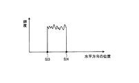
図4、図5A、及び図5Bは、被写体像判別部922の機能を説明する図である。具体的に、図4は、撮像部52にて撮像された撮像画像PFの一例を示す図である。図5Aは、図4に示した撮像画像PF中の水平ラインL1での輝度分布を示す図である。図5Bは、図4に示した撮像画像PF中の水平ラインL2での輝度分布を示す図である。
被写体像判別部922は、画像取得部91にて取得された撮像画像PF(図4)に基づいて、当該撮像画像PF内での被写体像SI(図4)(例えば、被写体像SIの位置SIO(図4)及び大きさ)を判別する。
なお、撮像部52にて撮像された撮像画像PF内の被写体像SIは、図4に示すように、略円形である。このため、被写体像判別部922は、撮像画像PF内での被写体像SIの大きさとして、当該被写体像SIの直径DM(図4)を判別する。
4, 5A, and 5B are diagrams for explaining the function of the subject
The subject
The subject image SI in the captured image PF captured by the
具体的に、被写体像判別部922は、図4に示すように、撮像画像PF内の複数本(本実施の形態1では2本)の水平ラインL1,L2での輝度分布を検出する。ここで、撮像画像PFにおいて、被写体像SIの領域は、他の領域(図4中、斜線を付した領域(何も映っていない領域)よりも明るくなっている。すなわち、水平ラインL1での輝度分布は、図5Aに示すように、被写体像SIの境界と交わる2点の交点SI1,SI2の間で輝度が高くなり、その他の部分で輝度が低くなる。水平ラインL2での輝度分布も同様に、図5Bに示すように、被写体像SIの境界と交わる2点の交点SI3,SI4の間で輝度が高くなり、その他の部分で輝度が低くなる。このため、被写体像判別部922は、水平ラインL1,L2での輝度分布を検出することにより、被写体像SIの境界との交点SI1〜SI4を認識することができる。そして、被写体像判別部922は、当該交点SI1〜SI4の曲率中心を算出することで、撮像画像PF内での被写体像SIの中心位置SIOを判別(算出)する。また、被写体像判別部922は、当該中心位置SIOといずれかの交点SI1〜SI4との距離を算出することで、撮像画像PF内での被写体像SIの直径DMを判別(算出)する。
Specifically, as shown in FIG. 4, the subject
倍率設定部923は、設置状態認識部921による認識結果、及び被写体像判別部922による判別結果に基づいて、被写体像SIの拡大縮小率を設定する。
具体的に、倍率設定部923は、画像表示部71が横置き状態で設置されている場合には、被写体像SIの拡大縮小率をデフォルト値(例えば、「1(拡大縮小しない値)」)に設定する。そして、倍率設定部923は、撮像画像PF内での被写体像SIの直径DMが表示画面Scにおける短辺Sc1の長さ寸法に対応する閾値(以下、基準閾値と記載)以下であって、かつ、画像表示部71が縦置き状態で設置されている場合には、被写体像SIの拡大縮小率を画像表示部71が横置き状態で設置されている場合と同一の値(デフォルト値(例えば、「1」))に設定する。一方、倍率設定部923は、撮像画像PF内での被写体像SIの直径DMが基準閾値を超える場合であって、かつ、画像表示部71が縦置き状態で設置されている場合には、被写体像SIの拡大縮小率をデフォルト値よりも小さい値(例えば、「9/16(撮像画像PFのアスペクト比(16:9)に応じた値)」)に設定する。
The
Specifically, when the
映像信号生成部924は、画像取得部91にて取得された撮像画像PFに対して種々の画像処理を施す。当該画像処理としては、例えば、ゲイン調整、ホワイトバランス調整、ガンマ補正、輪郭強調補正等の既知の画像処理の他、被写体像SIの拡大縮小調整、偏心補正、回転補正、及び位置移動補正等を挙げることができる。
ここで、上述した被写体像SIの拡大縮小調整は、以下の通りである。
映像信号生成部924は、倍率設定部923にて設定された拡大縮小率により、被写体像判別部922で判別された被写体像SIの拡大縮小調整を行う。
The video
Here, the above-mentioned enlargement / reduction adjustment of the subject image SI is as follows.
The video
また、上述した被写体像SIの偏心補正は、以下の通りである。
生体内に照射され、当該生体からの反射光による被写体像は、挿入部2の先端に設けられた対物光学系(図示略)、挿入部2内に設けられ当該対物光学系から接眼部21へと被写体像を伝送する像伝送光学系(図示略)、接眼部21内に設けられた接眼光学系(図示略)、及びレンズユニット51を介して、撮像部52にて撮像される。この際、対物光学系、像伝送光学系、接眼光学系、及びレンズユニット51の光軸がずれている場合等には、図4に示すように、被写体像SIの中心位置SIOが撮像画像PFの中心位置PFOからずれる(偏心する)場合がある。このように被写体像SIが偏心している場合には、表示画面Scにおいても偏心する(中心位置SIOが表示画面Scの中心位置からずれる)こととなる。
そこで、映像信号生成部924は、被写体像判別部922で判別された被写体像SIを移動させ、被写体像SIの中心位置SIOを撮像画像PFの中心位置PFOに一致(表示画面Scの中心位置に一致)させる処理(被写体像SIの偏心補正)を行う。
Further, the eccentricity correction of the subject image SI described above is as follows.
The subject image emitted into the living body and reflected by the reflected light from the living body is obtained from the objective optical system (not shown) provided at the tip of the
Therefore, the video
さらに、上述した被写体像SIの回転補正は、以下の通りである。
画像表示部71が横置き状態や縦置き状態で設置された場合には、当該画像表示部71の設置状態に対応させて、被写体像SIの上下方向が鉛直方向に沿うように調整する必要がある。
そこで、映像信号生成部924は、設置状態認識部921にて画像表示部71が縦置き状態で設置されていると認識された場合には、被写体像SIの姿勢が画像表示部71の縦置き状態に対応した姿勢(被写体像SIの上下方向が鉛直方向に沿う姿勢)となるように被写体像判別部922で判別された被写体像SIを90°回転させる処理(被写体像SIの回転補正)を行う。
なお、画像表示部71が横置き状態で設置されている場合には、上述した回転補正を行わなくても、被写体像SIの上下方向は鉛直方向(短辺Sc1の延在方向)に沿うように設定されている。このため、映像信号生成部924は、設置状態認識部921にて画像表示部71が横置き状態で設置されていると認識された場合には、被写体像SIの回転補正を行わない。
Further, the rotation correction of the subject image SI described above is as follows.
When the
Therefore, when the installation
When the
また、上述した被写体像SIの位置移動補正は、以下の通りである。
映像信号生成部924は、設置状態認識部921にて画像表示部71が縦置き状態で設置されていると認識された場合には、上述した回転補正を行うとともに、回転補正後の撮像画像PF内において、縦置き状態で設置された画像表示部71における表示画面Scの上方領域に対応する領域に、被写体像判別部922で判別された被写体像SIを位置付ける処理(被写体像SIの位置移動補正)を行う。
そして、映像信号生成部924は、上述した画像処理後の撮像画像PFに応じた映像信号を生成し、第2伝送ケーブル8を介して、当該映像信号を画像表示部71に出力する。
Further, the position movement correction of the subject image SI described above is as follows.
When the installation
Then, the video
〔内視鏡用画像処理装置の動作〕
次に、上述した内視鏡用画像処理装置92の動作(画像処理方法)について説明する。
図6は、内視鏡用画像処理装置92の動作を示すフローチャートである。
先ず、画像取得部91は、撮像部52に被写体像SIを撮像させるとともに、当該撮像部52にて撮像された撮像画像PFを取得する(ステップS1)。そして、画像取得部91は、取得した撮像画像PFを被写体像判別部922及び映像信号生成部924にそれぞれ出力する。
[Operation of image processing device for endoscopes]
Next, the operation (image processing method) of the above-described endoscope
FIG. 6 is a flowchart showing the operation of the endoscope
First, the
次に、被写体像判別部922は、画像取得部91にて取得された撮像画像PFに基づいて、当該撮像画像PF内での被写体像SIを判別する(ステップS2)。これにより、撮像画像PF内での被写体像SIの中心位置SIO及び直径DMが判別(算出)される。
次に、映像信号生成部924は、被写体像SIの中心位置SIOが撮像画像PFの中心位置PFOからずれている(位置ずれ有)か否かを判断する(ステップS3)。
位置ずれが有ると判断した場合(ステップS3:Yes)には、映像信号生成部924は、画像取得部91にて取得された撮像画像PFにおいて、被写体像SIの偏心補正を行う(ステップS4)。
Next, the subject
Next, the video
When it is determined that there is a misalignment (step S3: Yes), the video
位置ずれが無いと判断された場合(ステップS3:No)、または、ステップS4の後、設置状態認識部921は、第2伝送ケーブル8を介して状態検出部73から入力した検出信号に基づいて、画像表示部71の設置状態(横置き状態または縦置き状態)を認識する(ステップS5:設置状態認識ステップ)。
次に、設置状態認識部921は、画像表示部71が横置き状態で設置されているか否かを判断する(ステップS6)。
横置き状態で設置されていると判断された場合(ステップS6:Yes)には、倍率設定部923は、被写体像SIの拡大縮小率をデフォルト値(例えば、「1」)に設定する(ステップS7)。
ステップS7の後、映像信号生成部924は、偏心補正(ステップS4)を施した撮像画像PF、または、偏心補正を施していない撮像画像PFにおいて、ステップS7で設定された拡大縮小率により、被写体像SIの拡大縮小調整を行う(ステップS8)。この後、内視鏡用画像処理装置92は、ステップS15に移行する。
When it is determined that there is no misalignment (step S3: No), or after step S4, the installation
Next, the installation
When it is determined that the device is installed in the horizontal position (step S6: Yes), the
After step S7, the video
一方、縦置き状態で設置されていると判断された場合(ステップS6:No)には、倍率設定部923は、撮像画像PF内での被写体像SIの直径DMが基準閾値を超えるか否かを判断する(ステップS9)。
被写体像SIの直径DMが基準閾値を超えると判断した場合(ステップS9:Yes)には、倍率設定部923は、被写体像SIの拡大縮小率をデフォルト値よりも小さい値(例えば、「9/16」)に設定する(ステップS10)。
一方、被写体像SIの直径DMが基準閾値以下であると判断した場合(ステップS9:No)には、倍率設定部923は、被写体像SIの拡大縮小率をデフォルト値(例えば、「1」)に設定する(ステップS11)。
ステップS10またはS11の後、映像信号生成部924は、偏心補正(ステップS4)を施した撮像画像PF、または、偏心補正を施していない撮像画像PFにおいて、ステップS10またはS11で設定された拡大縮小率により、被写体像SIの拡大縮小調整を行う(ステップS12)。
On the other hand, when it is determined that the image is installed vertically (step S6: No), the
When it is determined that the diameter DM of the subject image SI exceeds the reference threshold value (step S9: Yes), the
On the other hand, when it is determined that the diameter DM of the subject image SI is equal to or less than the reference threshold value (step S9: No), the
After step S10 or S11, the video
ステップS12の後、映像信号生成部924は、拡大縮小調整(ステップS12)後の撮像画像PFにおいて、被写体像SIの回転補正を行う(ステップS13)とともに、被写体像SIの位置移動補正を行う(ステップS14)。
ステップS8またはS14の後、映像信号生成部924は、上述した画像処理が施された撮像画像PFに応じた映像信号を生成し、第2伝送ケーブル8を介して、当該映像信号を画像表示部71に出力する(ステップS15)。
以上説明したステップS13及びS15は、本発明に係る映像信号生成ステップに相当する。
After step S12, the video
After step S8 or S14, the video
The steps S13 and S15 described above correspond to the video signal generation step according to the present invention.
なお、映像信号生成部924が行う各種画像処理のうち、被写体像SIの偏心補正(ステップS4)、拡大縮小調整(ステップS8,S12)、回転補正(ステップS13)、及び位置移動補正(ステップS14)を行うタイミングは、図6に示したタイミングに限られず、その他のタイミングで実行しても構わない。また、他の画像処理(例えば、ゲイン調整、ホワイトバランス調整、ガンマ補正、輪郭強調補正等)については、いずれのタイミングで実行しても構わない。すなわち、当該他の画像処理をステップS15のタイミングで実行してもよく、あるいは、ステップS4よりも前のタイミングで実行しても構わない。
Among the various image processes performed by the video
〔表示形態の具体例〕
以上説明した内視鏡用画像処理装置92の動作により画像表示部71に表示される観察画像の具体例について説明する。
以下、挿入部2が細径の内視鏡である場合の表示形態、及び挿入部2が太径の内視鏡である場合の表示形態を順に説明する。
[Specific example of display form]
A specific example of the observation image displayed on the
Hereinafter, a display form when the
〔挿入部が細径の内視鏡である場合の表示形態〕
図7A及び図7Bは、挿入部2が細径の内視鏡である場合に、内視鏡用画像処理装置92の動作により画像表示部71に表示される観察画像OFの一例を示す図である。なお、図7A及び図7Bでは、被写体像SIの上下方向が分かるように、便宜上、被写体像SI内に「A」の文字を記載している。
挿入部2が細径の内視鏡である場合には、当該挿入部2で取り込まれた被写体像SIは、その直径が小さいものとなる(直径DMが基準閾値以下(ステップS9:No))。このため、被写体像SI全体は、撮像画像PFの画像領域からはみ出すことなく、当該画像領域内に位置することとなる。
[Display form when the insertion part is a small-diameter endoscope]
7A and 7B are diagrams showing an example of an observation image OF displayed on the
When the
そして、画像表示部71が横置き状態で設置されている場合(ステップS6:Yes)には、以下の映像信号が生成及び出力される(ステップS15)。
すなわち、当該映像信号は、被写体像SIの位置ずれ(ステップS3:Yes)に応じて当該被写体像SIの偏心補正(ステップS4)が行われており、かつ、被写体像SIの回転補正(ステップS13)が行われていない映像信号である。
このため、横置き状態で設置された画像表示部71には、当該映像信号に基づいて、図7Aに示す観察画像OFが表示される。
すなわち、当該観察画像OFでは、被写体像SIの中心位置SIOが表示画面Scの中心位置ScOに位置するとともに、円形の被写体像SI全体が表示画面Sc内に位置する。また、当該観察画像OFでは、被写体像SIは、その上下方向が短辺Sc1(鉛直方向)に沿った姿勢となる。
Then, when the
That is, in the video signal, the eccentricity correction (step S4) of the subject image SI is performed according to the positional deviation of the subject image SI (step S3: Yes), and the rotation correction of the subject image SI (step S13). ) Is not performed.
Therefore, the observation image OF shown in FIG. 7A is displayed on the
That is, in the observation image OF, the center position SIO of the subject image SI is located at the center position ScO of the display screen Sc, and the entire circular subject image SI is located within the display screen Sc. Further, in the observation image OF, the subject image SI has a posture in which the vertical direction thereof is along the short side Sc1 (vertical direction).
一方、画像表示部71が縦置き状態で設置されている場合(ステップS6:No)には、以下の映像信号が生成及び出力される(ステップS15)。
すなわち、当該映像信号は、被写体像SIの位置ずれ(ステップS3:Yes)に応じて当該被写体像SIの偏心補正(ステップS4)が行われているとともに、被写体像SIの回転補正(ステップS13)及び位置移動補正(ステップS14)が行われた映像信号である。また、当該映像信号は、画像表示部71が横置き状態で設置された場合と同一の拡大縮小率(デフォルト値(例えば、「1」)で被写体像SIの拡大縮小調整(ステップS12)が行われた映像信号である。
このため、縦置き状態で設置された画像表示部71には、当該映像信号に基づいて、図7Bに示す観察画像OFが表示される。
すなわち、当該観察画像OFでは、円形の被写体像SI全体が表示画面Sc内に位置するとともに、被写体像SIの中心位置SIOが表示画面Scの上方領域に位置する。また、当該観察画像OFでは、被写体像SIは、その上下方向が長辺Sc2(鉛直方向)に沿った姿勢となる。さらに、当該観察画像OFでは、被写体像SIの大きさは、画像表示部71が横置き状態で設置された場合での被写体像SIの大きさと同一となる。
On the other hand, when the
That is, the video signal is subjected to eccentricity correction (step S4) of the subject image SI according to the positional deviation of the subject image SI (step S3: Yes), and rotation correction of the subject image SI (step S13). And the video signal for which the position movement correction (step S14) has been performed. Further, the video signal is subjected to the enlargement / reduction adjustment (step S12) of the subject image SI at the same enlargement / reduction ratio (default value (for example, "1")) as when the
Therefore, the observation image OF shown in FIG. 7B is displayed on the
That is, in the observation image OF, the entire circular subject image SI is located in the display screen Sc, and the center position SIO of the subject image SI is located in the upper region of the display screen Sc. Further, in the observation image OF, the subject image SI has a posture in which the vertical direction thereof is along the long side Sc2 (vertical direction). Further, in the observation image OF, the size of the subject image SI is the same as the size of the subject image SI when the
〔挿入部が太径の内視鏡である場合の表示形態〕
図8A及び図8Bは、挿入部2が太径の内視鏡である場合に、内視鏡用画像処理装置92の動作により画像表示部71に表示される観察画像OFの一例を示す図である。なお、図8A及び図8Bでは、図7A及び図7Bと同様に、被写体像SIの上下方向が分かるように、便宜上、被写体像SI内に「A」の文字を記載している。
挿入部2が太径の内視鏡である場合には、当該挿入部2で取り込まれた被写体像SIは、その直径が大きいものとなる(直径DMが基準閾値を超える(ステップS9:Yes))。このため、被写体像SIは、円形の上下部分が撮像画像PFの画像領域からそれぞれはみ出したものとなる。
[Display form when the insertion part is a large-diameter endoscope]
8A and 8B are diagrams showing an example of an observation image OF displayed on the
When the
そして、画像表示部71が横置き状態で設置されている場合(ステップS6:Yes)には、以下の映像信号が生成及び出力される(ステップS15)。
すなわち、当該映像信号は、被写体像SIの位置ずれ(ステップS3:Yes)に応じて当該被写体像SIの偏心補正(ステップS4)が行われており、かつ、被写体像SIの回転補正(ステップS13)が行われていない映像信号である。
このため、横置き状態で設置された画像表示部71には、当該映像信号に基づいて、図8Aに示す観察画像OFが表示される。
すなわち、当該観察画像OFでは、円形の上下部分がそれぞれカットされた被写体像SI全体が表示画面Sc内に位置するとともに、被写体像SIの中心位置SIOが表示画面Scの中心位置ScOに位置する。また、当該観察画像OFでは、被写体像SIは、その上下方向が短辺Sc1(鉛直方向)に沿った姿勢となる。
Then, when the
That is, in the video signal, the eccentricity correction (step S4) of the subject image SI is performed according to the positional deviation of the subject image SI (step S3: Yes), and the rotation correction of the subject image SI (step S13). ) Is not performed.
Therefore, the observation image OF shown in FIG. 8A is displayed on the
That is, in the observation image OF, the entire subject image SI in which the upper and lower circular portions are cut is located in the display screen Sc, and the center position SIO of the subject image SI is located in the center position ScO of the display screen Sc. Further, in the observation image OF, the subject image SI has a posture in which the vertical direction thereof is along the short side Sc1 (vertical direction).
一方、画像表示部71が縦置き状態で設置されている場合(ステップS6:No)には、以下の映像信号が生成及び出力される(ステップS15)。
すなわち、当該映像信号は、被写体像SIの位置ずれ(ステップS3:Yes)に応じて当該被写体像SIの偏心補正(ステップS4)が行われているとともに、被写体像SIの回転補正(ステップS13)及び位置移動補正(ステップS14)が行われた映像信号である。また、当該映像信号は、画像表示部71が横置き状態で設置された場合よりも小さい値の拡大縮小率(例えば、「9/16」)で被写体像SIの拡大縮小調整(ステップS12)が行われた映像信号である。
このため、縦置き状態で設置された画像表示部71には、当該映像信号に基づいて、図8Bに示す観察画像OFが表示される。
すなわち、当該観察画像OFでは、円形の上下部分がそれぞれカットされた被写体像SI全体が表示画面Sc内に位置するととともに、被写体像SIの中心位置SIOが表示画面Scの上方領域に位置する。また、当該観察画像OFでは、被写体像SIは、その上下方向が長辺Sc2(鉛直方向)に沿った姿勢となる。さらに、当該観察画像OFでは、被写体像SIの大きさは、画像表示部71が横置き状態で設置された場合での被写体像SIの大きさよりも小さいものとなる。
On the other hand, when the
That is, the video signal is subjected to eccentricity correction (step S4) of the subject image SI according to the positional deviation of the subject image SI (step S3: Yes), and rotation correction of the subject image SI (step S13). This is a video signal for which position movement correction (step S14) has been performed. Further, in the video signal, the enlargement / reduction adjustment (step S12) of the subject image SI is performed at a enlargement / reduction ratio (for example, “9/16”) of a value smaller than that when the
Therefore, the observation image OF shown in FIG. 8B is displayed on the
That is, in the observation image OF, the entire subject image SI with the upper and lower circular portions cut off is located in the display screen Sc, and the center position SIO of the subject image SI is located in the upper region of the display screen Sc. Further, in the observation image OF, the subject image SI has a posture in which the vertical direction thereof is along the long side Sc2 (vertical direction). Further, in the observation image OF, the size of the subject image SI is smaller than the size of the subject image SI when the
例えば、ステップS10において、被写体像SIの拡大縮小率を画像表示部71が横置き状態で設置されている場合と同一の拡大縮小率(デフォルト値(例えば、「1」)に設定した場合には、円形の上下部分がそれぞれカットされた被写体像SI全体が表示画面Sc内に収まらない(被写体像SIの左右部分が表示画面Scからはみ出す)ものとなる。
本実施の形態1では、円形の上下部分がそれぞれカットされた被写体像SI全体を表示画面Sc内に収めるために、ステップS9を実行し、直径DMが基準閾値を超える場合(ステップS9:Yes)には、被写体像SIの拡大縮小率をデフォルト値よりも小さい値に設定している(ステップS10)。すなわち、被写体像SIを画像表示部71が横置き状態で設置されている場合での被写体像SIに対して縮小している(ステップS12)。
For example, in step S10, when the enlargement / reduction ratio of the subject image SI is set to the same enlargement / reduction ratio (default value (for example, “1”) as when the
In the first embodiment, step S9 is executed in order to fit the entire subject image SI in which the upper and lower portions of the circle are cut into the display screen Sc, and the diameter DM exceeds the reference threshold value (step S9: Yes). Is set to a value smaller than the default value of the enlargement / reduction ratio of the subject image SI (step S10). That is, the subject image SI is reduced with respect to the subject image SI when the
以上説明した本実施の形態1に係る内視鏡用画像処理装置92は、挿入部2にて取り込まれた被写体像SIを含む撮像画像PFを処理して映像信号を生成し、当該映像信号を画像表示部71に出力する。そして、画像表示部71は、当該映像信号に基づく観察画像OFを表示する。ここで、画像表示部71は、横置き状態と縦置き状態とにそれぞれ設置可能に構成されている。そして、内視鏡用画像処理装置92は、画像表示部71の設置状態(横置き状態または縦置き状態)を認識し、観察画像OF内の被写体像SIが画像表示部71の設置状態に対応した姿勢となる映像信号を生成する。
すなわち、画像表示部71を横置き状態から縦置き状態に変更すれば、表示画面Scの短辺Sc1が横方向となることで横幅が小さくなり、画像表示部71の近傍に立つ人の動線を確保することができる。また、画像表示部71を横置き状態から縦置き状態に変更しても、観察画像OF内の被写体像SIは、画像表示部71の設置状態に対応した姿勢(被写体像SIの上下方向が鉛直方向に沿う姿勢)となる。このため、画像表示部71の近傍に立つ人の動線を確保した後、画像表示部71を縦置き状態から横置き状態に改めて変更する必要がない。
したがって、本実施の形態1に係る内視鏡用画像処理装置92によれば、画像表示部71の設置場所を移動する煩雑な作業を不要とし、利便性の向上を図ることができる、という効果を奏する。
The endoscope
That is, if the
Therefore, according to the
また、本実施の形態1に係る内視鏡用画像処理装置92では、撮像画像PF内での被写体像SIの直径DMが基準閾値以下である場合には、横置き状態での被写体像SIの拡大縮小率と縦置き状態での被写体像SIの拡大縮小率とを同一の値としている。
このため、例えば、細径の内視鏡で構成された挿入部2にて取り込まれた被写体像SIを観察する場合において、画像表示部71を横置き状態から縦置き状態に変更しても、被写体像SIの大きさを不要に小さくすることなく、横置き状態と縦置き状態とで同一の大きさの被写体像SIを観察することができる。
Further, in the endoscope
Therefore, for example, when observing the subject image SI captured by the
また、本実施の形態1に係る内視鏡用画像処理装置92では、撮像画像PF内での被写体像SIの直径DMが基準閾値を超える場合には、横置き状態での被写体像SIの拡大縮小率よりも縦置き状態での被写体像SIの拡大縮小率を小さい値としている。すなわち、画像表示部71を横置き状態から縦置き状態に変更した場合であって、被写体像SIが表示画面Sc内に収まらないと判断した場合に限り、横置き状態での被写体像SIに対して縦置き状態での被写体像SIの大きさを縮小している。
このため、例えば、太径の内視鏡で構成された挿入部2にて取り込まれた被写体像SIを観察する場合において、画像表示部71を横置き状態から縦置き状態に変更しても、被写体像SI全体を観察することができる。
Further, in the endoscope
Therefore, for example, when observing the subject image SI captured by the
また、本実施の形態1に係る内視鏡用画像処理装置92では、被写体像SIの偏心補正及び位置移動補正を実行した映像信号を生成する。
このため、画像表示部71を横置き状態で設置した場合には、表示画面Scの中心領域に被写体像SIが位置付けられる。一方、画像表示部71を縦置き状態で設置した場合には、表示画面Scの上方領域に被写体像SIが位置付けられる。したがって、画像表示部71を横置き状態及び縦置き状態のいずれの設置状態で設置した場合であっても、被写体像SIを観察し易い表示形態を実現することができる。
Further, the endoscope
Therefore, when the
(実施の形態2)
次に、本発明の実施の形態2について説明する。
以下では、上述した実施の形態1と同様の構成には同一符号を付し、その詳細な説明は省略または簡略化する。
図9は、本発明の実施の形態2に係る内視鏡装置1Aの構成を示すブロック図である。なお、図9では、説明の便宜上、図2と同様に、光源装置3、ライトガイド4、及び第3伝送ケーブル10の図示を省略している。
上述した実施の形態1に係る内視鏡装置1では、内視鏡用画像処理装置92は、制御装置9に設けられていた。
これに対して本実施の形態2に係る内視鏡装置1Aでは、図9に示すように、制御装置9の代わりに内視鏡用画像処理装置92を省略した制御装置9Aを採用し、表示装置7の代わりに内視鏡用画像処理装置92を搭載した表示装置7Aを採用している。
(Embodiment 2)
Next,
In the following, the same components as those in the first embodiment will be designated by the same reference numerals, and detailed description thereof will be omitted or simplified.
FIG. 9 is a block diagram showing the configuration of the
In the
On the other hand, in the
制御装置9Aでは、内視鏡用画像処理装置92の省略に伴い、図9に示すように、画像処理部93を採用している。
画像処理部93は、画像取得部91にて取得された撮像画像PFに対して種々の画像処理を施す。当該画像処理としては、例えば、ゲイン調整、ホワイトバランス調整、ガンマ補正、輪郭強調補正等の既知の画像処理を挙げることができる。そして、画像処理部93は、第2伝送ケーブル8を介して、当該画像処理後の撮像画像PFに応じた信号を表示装置7A(内視鏡用画像処理装置92)に出力する。
In the control device 9A, the
The
なお、表示装置7Aに搭載された内視鏡用画像処理装置92は、制御装置9Aから出力された信号に対して、上述した実施の形態1で説明した処理と同様の処理(上述した画像処理部93が実行する画像処理を除く)を実行する。
The endoscope
以上説明した本実施の形態2のように内視鏡用画像処理装置92を表示装置7Aに設けた場合であっても、上述した実施の形態1と同様の効果を奏する。
Even when the endoscope
(その他の実施の形態)
ここまで、本発明を実施するための形態を説明してきたが、本発明は上述した実施の形態1,2によってのみ限定されるべきものではない。
上述した実施の形態1,2では、本発明に係る内視鏡用画像処理装置92を制御装置9や表示装置7Aに搭載していたが、これに限られない。例えば、本発明に係る内視鏡用画像処理装置92を制御装置及び表示装置とは別体となるモジュールで構成し、当該制御装置及び表示装置間の信号伝送路に設けた構成を採用しても構わない。
(Other embodiments)
Although the embodiments for carrying out the present invention have been described so far, the present invention should not be limited only to the above-described first and second embodiments.
In the above-described first and second embodiments, the endoscope
上述した実施の形態1,2では、本発明に係る内視鏡として、硬性内視鏡で構成された挿入部2を採用していたが、これに限られず、接眼部を有する内視鏡であれば、軟性内視鏡で構成しても構わない。
In the above-described first and second embodiments, the
図10A及び図10Bは、本発明の実施の形態1,2の変形例を示す図である。具体的に、図10A及び図10Bは、図7A及び図7Bにそれぞれ対応した図である。
上述した実施の形態1,2において、図10Aまたは図10Bに示すように、観察画像OF内の被写体像SIを除く領域BIに各種情報(例えば、被検体情報(例えばID、生年月日、名前等)、挿入部2の識別情報(例えばIDや検査対応項目)、及び検査内容等)を表示するように構成しても構わない。
10A and 10B are diagrams showing modified examples of
In the above-described first and second embodiments, as shown in FIGS. 10A or 10B, various information (for example, subject information (for example, ID, date of birth, name)) is stored in the region BI excluding the subject image SI in the observation image OF. Etc.), the identification information of the insertion unit 2 (for example, ID and inspection corresponding items), inspection contents, etc.) may be displayed.
図11A及び図11Bは、本発明の実施の形態1,2の変形例を示す図である。具体的に、図11A及び図11Bは、図3A及び図3Bにそれぞれ対応した図である。
上述した実施の形態1,2では、画像表示部71は、その背面の略中心位置が支柱721に接続され、当該背面の略中心位置を中心として回動可能に構成されていたが、これに限られず、図11Aまたは図11Bに示す表示装置7Bを採用しても構わない。
表示装置7Bでは、画像表示部71は、その背面において長手方向の一端側が支柱721に接続され、当該長手方向の一端側を中心として回動可能に構成されている。
このように構成した場合には、図3Bと図11Bとを比較して分かるように、画像表示部71を横置き状態から縦置き状態に変更した場合において、画像表示部71の横方向片側(図3B,図11B中、右側)の空間を大きく空けることができる。したがって、画像表示部71の近傍に立つ人の動線を十分に確保することができる。
11A and 11B are diagrams showing modified examples of
In the above-described first and second embodiments, the
In the
In the case of such a configuration, as can be seen by comparing FIG. 3B and FIG. 11B, when the
上述した実施の形態1,2では、被写体像SIの直径DMが基準閾値を超える場合には、画像表示部71が縦置き状態で設置された場合での被写体像SIの拡大縮小率を横置き状態で設置された場合での被写体像SIの拡大縮小率よりも小さい値に設定していたが、これに限られない。例えば、ユーザ操作により、画像表示部71が縦置き状態で設置された場合での被写体像SIの拡大縮小率を横置き状態で設置された場合での被写体像SIの拡大縮小率よりも小さい値とする場合と、同一の値とする場合とを切替可能に構成しても構わない。
In the first and second embodiments described above, when the diameter DM of the subject image SI exceeds the reference threshold value, the enlargement / reduction ratio of the subject image SI when the
上述した実施の形態1,2において、被写体像SIの直径DMが基準閾値を超える場合には、画像表示部71における横置き状態から縦置き状態への設置状態の変更を規制する構成を採用しても構わない。また、当該場合には、横置き状態から縦置き状態への設置状態の変更を禁止するメッセージ等を画像表示部71に表示させる構成を採用しても構わない。
In the first and second embodiments described above, when the diameter DM of the subject image SI exceeds the reference threshold value, a configuration is adopted in which the change of the installation state from the horizontal installation state to the vertical installation state in the
上述した実施の形態1,2では、画像表示部71が縦置き状態に設置された場合に限り、被写体像SIの回転補正を行っていたが、これに限られない。例えば、画像表示部71を横置き状態から縦置き状態に変更する際での回転角度を順次、検出し、当該回転角度に応じた回転補正を順次、実行する構成を採用しても構わない。このように構成した場合には、横置き状態から縦置き状態に変更する間に表示される観察画像OFは、常時、被写体像SIの上下方向が鉛直方向に沿うものとなる。
In the above-described first and second embodiments, the rotation correction of the subject image SI is performed only when the
また、処理フローは、上述した実施の形態1,2で説明したフローチャート(図6)における処理の順序に限られず、矛盾のない範囲で変更しても構わない。
さらに、本明細書においてフローチャートを用いて説明した処理のアルゴリズムは、プログラムとして記述することが可能である。このようなプログラムは、コンピュータ内部の記録部に記録してもよいし、コンピュータ読み取り可能な記録媒体に記録してもよい。プログラムの記録部または記録媒体への記録は、コンピュータまたは記録媒体を製品として出荷する際に行ってもよく、あるいは、通信ネットワークを介したダウンロードにより行ってもよい。
Further, the processing flow is not limited to the order of processing in the flowcharts (FIG. 6) described in the above-described first and second embodiments, and may be changed within a consistent range.
Further, the processing algorithm described by using the flowchart in the present specification can be described as a program. Such a program may be recorded in a recording unit inside the computer, or may be recorded in a computer-readable recording medium. Recording of the program on the recording unit or recording medium may be performed when the computer or recording medium is shipped as a product, or may be performed by downloading via a communication network.
1,1A 内視鏡装置
2 挿入部(内視鏡)
3 光源装置
4 ライトガイド
5 内視鏡用撮像装置
6 第1伝送ケーブル
7,7A,7B 表示装置
8 第2伝送ケーブル
9,9A 制御装置
10 第3伝送ケーブル
51 レンズユニット
52 撮像部
71 画像表示部
72 支持台
73 状態検出部
91 画像取得部
92 内視鏡用画像処理装置
93 画像処理部
100 内視鏡装置
101 内視鏡
102 内視鏡用撮像装置
103 制御装置
104 表示装置
201 器材台
202 電気メス装置
203 麻酔装置
204 周辺機器
721 支柱
722 脚部
921 設置状態認識部
922 被写体像判別部
923 倍率設定部
924 映像信号生成部
BD ベッド
BI 領域
CN1,CN2 コネクタ
D1 執刀医
D2,D3 助手
D4 ナース
D5 麻酔科医
DM 直径
L1,L2 水平ライン
OF 観察画像
PF 撮像画像
PFO 中心位置
SB 被検体
Sc 表示画面
Sc1 短辺(第1の辺)
Sc2 長辺(第2の辺)
ScO 中心位置
SI 被写体像
SI1〜SI4 交点
SIO 中心位置
1,
3
Sc2 long side (second side)
ScO center position SI subject image SI1 to SI4 intersection SIO center position
Claims (15)
前記画像表示部は、
前記観察画像を表示する表示画面における第1の辺が当該第1の辺に交差する第2の辺よりも短く構成されているとともに、前記第1の辺が鉛直方向に沿う第1の設置状態と前記第2の辺が鉛直方向に沿う第2の設置状態とにそれぞれ設置可能に構成され、
当該内視鏡用画像処理装置は、
前記画像表示部が前記第1の設置状態及び前記第2の設置状態のいずれの設置状態で設置されているかを認識する設置状態認識部と、
前記観察画像内の前記被写体像が前記画像表示部の設置状態に対応した姿勢となる前記映像信号を生成する映像信号生成部と、
前記撮像画像内での前記被写体像の大きさを判別する被写体像判別部と、
前記設置状態認識部による認識結果、及び前記被写体像判別部による判別結果に基づいて、前記被写体像の拡大縮小率を設定する倍率設定部とを備え、
前記映像信号生成部は、
前記倍率設定部にて設定された拡大縮小率で前記被写体像の大きさを拡大縮小した前記映像信号を生成する
ことを特徴とする内視鏡用画像処理装置。 An image for an endoscope that processes a captured image including a subject image captured by an endoscope to generate a video signal, and outputs the video signal to an image display unit that displays an observation image based on the video signal. It ’s a processing device,
The image display unit
The first side of the display screen for displaying the observation image is shorter than the second side intersecting the first side, and the first side is in the vertical direction. And the second side is configured to be able to be installed in the second installation state along the vertical direction.
The image processing device for the endoscope is
An installation state recognition unit that recognizes whether the image display unit is installed in the first installation state or the second installation state.
A video signal generation unit that generates the video signal in which the subject image in the observation image has a posture corresponding to the installation state of the image display unit.
A subject image discriminating unit that discriminates the size of the subject image in the captured image,
A magnification setting unit for setting the enlargement / reduction ratio of the subject image based on the recognition result by the installation state recognition unit and the discrimination result by the subject image discrimination unit is provided.
The video signal generation unit
An image processing device for an endoscope, which generates the video signal in which the size of the subject image is enlarged or reduced at the enlargement / reduction ratio set by the magnification setting unit.
前記撮像画像内での前記被写体像の大きさが前記表示画面における前記第1の辺の長さ寸法に対応する閾値以下である場合には、前記第1の設置状態での前記被写体像の拡大縮小率と前記第2の設置状態での前記被写体像の拡大縮小率とを同一の値に設定する
ことを特徴とする請求項1に記載の内視鏡用画像処理装置。 The magnification setting unit
When the size of the subject image in the captured image is equal to or less than the threshold value corresponding to the length dimension of the first side on the display screen, the subject image is enlarged in the first installation state. The image processing apparatus for an endoscope according to claim 1, wherein the reduction ratio and the enlargement / reduction ratio of the subject image in the second installation state are set to the same value.
前記撮像画像内での前記被写体像の大きさが前記表示画面における前記第1の辺の長さ寸法に対応する閾値を超える場合には、前記第1の設置状態での前記被写体像の拡大縮小率よりも前記第2の設置状態での前記被写体像の拡大縮小率を小さい値に設定する
ことを特徴とする請求項1または2に記載の内視鏡用画像処理装置。 The magnification setting unit
When the size of the subject image in the captured image exceeds the threshold value corresponding to the length dimension of the first side on the display screen, the subject image is enlarged or reduced in the first installation state. The image processing apparatus for an endoscope according to claim 1 or 2, wherein the enlargement / reduction ratio of the subject image in the second installation state is set to a value smaller than the ratio.
前記映像信号生成部は、
前記画像表示部が前記第1の設置状態に設置されている場合には、前記撮像画像内での前記被写体像の位置に基づいて、前記観察画像内の中央領域に前記被写体像を位置付けた前記映像信号を生成する
ことを特徴とする請求項1〜3のいずれか一つに記載の内視鏡用画像処理装置。 A subject image discriminating unit for discriminating the position of the subject image in the captured image is provided.
The video signal generation unit
When the image display unit is installed in the first installation state, the subject image is positioned in the central region of the observation image based on the position of the subject image in the captured image. The image processing apparatus for an endoscope according to any one of claims 1 to 3, wherein an image signal is generated.
前記映像信号生成部は、
前記画像表示部が前記第2の設置状態に設置されている場合には、前記撮像画像内での前記被写体像の位置に基づいて、前記観察画像内の上方領域に前記被写体像を位置付けた前記映像信号を生成する
ことを特徴とする請求項1〜4のいずれか一つに記載の内視鏡用画像処理装置。 A subject image discriminating unit for discriminating the position of the subject image in the captured image is provided.
The video signal generation unit
When the image display unit is installed in the second installation state, the subject image is positioned in an upper region in the observation image based on the position of the subject image in the captured image. The image processing apparatus for an endoscope according to any one of claims 1 to 4, wherein an image signal is generated.
前記内視鏡の接眼部に着脱自在に接続され、前記被写体像を撮像して撮像画像を生成する内視鏡用撮像装置と、
前記内視鏡用撮像装置の動作を制御する制御装置と、
請求項1〜5のいずれか一つに記載の内視鏡用画像処理装置と、
前記内視鏡用画像処理装置から出力される映像信号に基づく観察画像を表示する画像表示部を有する表示装置とを備える
ことを特徴とする内視鏡装置。 An endoscope that is inserted into the subject and captures the subject image,
An image pickup device for an endoscope that is detachably connected to the eyepiece of the endoscope and images the subject image to generate an image.
A control device that controls the operation of the endoscope imaging device, and
The image processing apparatus for an endoscope according to any one of claims 1 to 5.
An endoscope device including a display device having an image display unit for displaying an observation image based on a video signal output from the image processing device for an endoscope.
前記制御装置に設けられている
ことを特徴とする請求項6に記載の内視鏡装置。 The image processing device for an endoscope is
The endoscope device according to claim 6, wherein the endoscope device is provided in the control device.
前記表示装置に設けられている
ことを特徴とする請求項6に記載の内視鏡装置。 The image processing device for an endoscope is
The endoscope device according to claim 6, wherein the display device is provided.
前記画像表示部は、
前記観察画像を表示する表示画面における第1の辺が当該第1の辺に交差する第2の辺よりも短く構成されているとともに、前記第1の辺が鉛直方向に沿う第1の設置状態と前記第2の辺が鉛直方向に沿う第2の設置状態とにそれぞれ設置可能に構成され、
前記内視鏡用画像処理装置は、
前記画像表示部が前記第1の設置状態及び前記第2の設置状態のいずれの設置状態で設置されているかを認識する設置状態認識部と、
前記観察画像内の前記被写体像が前記画像表示部の設置状態に対応した姿勢となる前記映像信号を生成する映像信号生成部とを備え、
当該内視鏡用画像処理装置の作動方法は、
前記設置状態認識部が、前記画像表示部が前記第1の設置状態及び前記第2の設置状態のいずれの設置状態で設置されているかを認識する設置状態認識ステップと、
前記映像信号生成部が、前記観察画像内の前記被写体像が前記画像表示部の設置状態に対応した姿勢となる前記映像信号を生成する映像信号生成ステップとを含む
ことを特徴とする内視鏡用画像処理装置の作動方法。 An image for an endoscope that processes a captured image including a subject image captured by an endoscope to generate a video signal, and outputs the video signal to an image display unit that displays an observation image based on the video signal. It is a method of operating the processing device.
The image display unit
The first side of the display screen for displaying the observation image is shorter than the second side intersecting the first side, and the first side is in the vertical direction. And the second side is configured to be able to be installed in the second installation state along the vertical direction.
The image processing device for an endoscope is
An installation state recognition unit that recognizes whether the image display unit is installed in the first installation state or the second installation state.
A video signal generation unit that generates the video signal in which the subject image in the observation image is in a posture corresponding to the installation state of the image display unit is provided.
The operation method of the image processing device for the endoscope is as follows.
An installation state recognition step in which the installation state recognition unit recognizes whether the image display unit is installed in the first installation state or the second installation state.
The endoscope is characterized in that the video signal generation unit includes a video signal generation step of generating the video signal in which the subject image in the observation image is in a posture corresponding to the installation state of the image display unit. How to operate the image processing device.
前記撮像画像内での前記被写体像の大きさを判別する被写体像判別部と、
前記設置状態認識部による認識結果、及び前記被写体像判別部による判別結果に基づいて、前記被写体像の拡大縮小率を設定する倍率設定部とをさらに備え、
当該内視鏡用画像処理装置の作動方法は、
前記被写体像判別部が、前記撮像画像内での前記被写体像の大きさを判別する被写体像判別ステップと、
前記倍率設定部が、前記設置状態認識ステップによる認識結果、及び前記被写体像判別ステップによる判別結果に基づいて、前記被写体像の拡大縮小率を設定する倍率設定ステップとを含み、
前記映像信号生成ステップでは、
前記倍率設定ステップにて設定された拡大縮小率で前記被写体像の大きさを拡大縮小した前記映像信号を生成する
ことを特徴とする請求項9に記載の内視鏡用画像処理装置の作動方法。 The image processing device for an endoscope is
A subject image discriminating unit that discriminates the size of the subject image in the captured image,
Further provided with a magnification setting unit for setting the enlargement / reduction ratio of the subject image based on the recognition result by the installation state recognition unit and the discrimination result by the subject image discrimination unit.
The operation method of the image processing device for the endoscope is as follows.
A subject image determination step in which the subject image determination unit determines the size of the subject image in the captured image, and
The magnification setting unit includes a magnification setting step for setting the enlargement / reduction ratio of the subject image based on the recognition result by the installation state recognition step and the discrimination result by the subject image discrimination step.
In the video signal generation step,
The method of operating an image processing apparatus for an endoscope according to claim 9, wherein the video signal in which the size of the subject image is enlarged or reduced at the enlargement / reduction ratio set in the magnification setting step is generated. ..
ことを特徴とする画像処理プログラム。 An image processing program comprising causing the endoscope image processing apparatus to execute the operation method of the endoscope image processing apparatus according to claim 9 or 10.
前記画像表示部は、
前記観察画像を表示する表示画面における第1の辺が当該第1の辺に交差する第2の辺よりも短く構成されているとともに、前記第1の辺が鉛直方向に沿う第1の設置状態と前記第2の辺が鉛直方向に沿う第2の設置状態とにそれぞれ設置可能に構成され、
当該内視鏡用画像処理装置は、
前記画像表示部が前記第1の設置状態及び前記第2の設置状態のいずれの設置状態で設置されているかを認識する設置状態認識部と、
前記観察画像内の前記被写体像が前記画像表示部の設置状態に対応した姿勢となる前記映像信号を生成する映像信号生成部とを備える
ことを特徴とする内視鏡用画像処理装置。 An image for an endoscope that processes a captured image including a subject image captured by an endoscope to generate a video signal, and outputs the video signal to an image display unit that displays an observation image based on the video signal. It ’s a processing device,
The image display unit
The first side of the display screen for displaying the observed image is shorter than the second side intersecting the first side, and the first side is in the vertical direction. And the second side is configured to be able to be installed in the second installation state along the vertical direction.
The image processing device for the endoscope is
An installation state recognition unit that recognizes whether the image display unit is installed in the first installation state or the second installation state.
An image processing apparatus for an endoscope, comprising: a video signal generation unit that generates a video signal in which the subject image in the observation image has a posture corresponding to an installation state of the image display unit.
ことを特徴とする請求項12に記載の内視鏡用画像処理装置。 The image processing apparatus for an endoscope according to claim 12, wherein information is displayed in regions having different sizes depending on the installation state of the image display unit.
前記表示画面の中央領域に前記被写体像を表示し、前記中央領域の少なくとも左右の一方に情報を表示し、
前記第2の設置状態では、
前記表示画面の上部領域に前記被写体像を表示し、前記表示画面の下部領域に情報を表示する
ことを特徴とする請求項12に記載の内視鏡用画像処理装置。 In the first installation state,
The subject image is displayed in the central region of the display screen, and information is displayed on at least one of the left and right sides of the central region.
In the second installation state,
The image processing apparatus for an endoscope according to claim 12, wherein the subject image is displayed in the upper region of the display screen, and information is displayed in the lower region of the display screen.
被検体情報、前記内視鏡の識別情報、及び検査内容の少なくとも1つである
ことを特徴とする請求項13または14に記載の内視鏡用画像処理装置。 The above information is
The image processing apparatus for an endoscope according to claim 13 or 14 , characterized in that it is at least one of subject information, identification information of the endoscope, and examination contents.
Priority Applications (3)
| Application Number | Priority Date | Filing Date | Title |
|---|---|---|---|
| JP2016198383A JP6818496B2 (en) | 2016-10-06 | 2016-10-06 | Image processing device for endoscopes, endoscope device, operation method of image processing device for endoscope, and image processing program |
| US15/710,207 US10729308B2 (en) | 2016-10-06 | 2017-09-20 | Image processing device for endoscope, endoscope device, image processing method of image processing device for endoscope, and image processing program |
| US16/907,333 US11744438B2 (en) | 2016-10-06 | 2020-06-22 | Image processing device for endoscope, endoscope device, image processing method of image processing device for endoscope, and image processing program |
Applications Claiming Priority (1)
| Application Number | Priority Date | Filing Date | Title |
|---|---|---|---|
| JP2016198383A JP6818496B2 (en) | 2016-10-06 | 2016-10-06 | Image processing device for endoscopes, endoscope device, operation method of image processing device for endoscope, and image processing program |
Publications (3)
| Publication Number | Publication Date |
|---|---|
| JP2018057656A JP2018057656A (en) | 2018-04-12 |
| JP2018057656A5 JP2018057656A5 (en) | 2019-11-07 |
| JP6818496B2 true JP6818496B2 (en) | 2021-01-20 |
Family
ID=61830338
Family Applications (1)
| Application Number | Title | Priority Date | Filing Date |
|---|---|---|---|
| JP2016198383A Active JP6818496B2 (en) | 2016-10-06 | 2016-10-06 | Image processing device for endoscopes, endoscope device, operation method of image processing device for endoscope, and image processing program |
Country Status (2)
| Country | Link |
|---|---|
| US (2) | US10729308B2 (en) |
| JP (1) | JP6818496B2 (en) |
Families Citing this family (6)
| Publication number | Priority date | Publication date | Assignee | Title |
|---|---|---|---|---|
| US10980397B1 (en) * | 2020-02-21 | 2021-04-20 | Ambu A/S | Video processing device |
| US11109741B1 (en) | 2020-02-21 | 2021-09-07 | Ambu A/S | Video processing apparatus |
| US11166622B2 (en) | 2020-02-21 | 2021-11-09 | Ambu A/S | Video processing apparatus |
| US10835106B1 (en) | 2020-02-21 | 2020-11-17 | Ambu A/S | Portable monitor |
| CN113256625A (en) * | 2021-06-29 | 2021-08-13 | 北京天星博迈迪医疗器械有限公司 | Electronic equipment and recognition device |
| CN114466145B (en) * | 2022-01-30 | 2024-04-12 | 北京字跳网络技术有限公司 | Video processing method, device, equipment and storage medium |
Family Cites Families (11)
| Publication number | Priority date | Publication date | Assignee | Title |
|---|---|---|---|---|
| US6690410B1 (en) * | 1999-06-09 | 2004-02-10 | Olympus Optical Co., Ltd. | Image processing unit with expandable image signal processing capability and endoscopic imaging system |
| US20020033836A1 (en) * | 2000-06-06 | 2002-03-21 | Smith Scott R. | Device and method for changing the orientation and configuration of a display of an electronic device |
| KR100411631B1 (en) * | 2001-10-18 | 2003-12-18 | 주식회사 메디미르 | Fluorescence endoscope apparatus and a method for imaging tissue within a body using the same |
| JP4297649B2 (en) | 2002-05-31 | 2009-07-15 | オリンパス株式会社 | MEDICAL DEVICE AND MEDICAL DEVICE CONTROL METHOD |
| JP2004240118A (en) | 2003-02-05 | 2004-08-26 | Honko Mfg Co Ltd | Display device and advertising method using the device |
| US20040201595A1 (en) * | 2003-04-11 | 2004-10-14 | Microsoft Corporation | Self-orienting display |
| US20040263424A1 (en) * | 2003-06-30 | 2004-12-30 | Okuley James M. | Display system and method |
| JP4882301B2 (en) | 2005-07-28 | 2012-02-22 | ソニー株式会社 | Display device, display control method, program, and recording medium |
| JP5315902B2 (en) | 2008-10-01 | 2013-10-16 | 富士通株式会社 | Information processing apparatus and display control method |
| JP5842422B2 (en) | 2011-07-13 | 2016-01-13 | 株式会社Jvcケンウッド | Touch panel operating device, touch panel operating device control method, and program |
| JP5921404B2 (en) | 2012-09-28 | 2016-05-24 | 株式会社東芝 | Information display device, information display method, and program |
-
2016
- 2016-10-06 JP JP2016198383A patent/JP6818496B2/en active Active
-
2017
- 2017-09-20 US US15/710,207 patent/US10729308B2/en active Active
-
2020
- 2020-06-22 US US16/907,333 patent/US11744438B2/en active Active
Also Published As
| Publication number | Publication date |
|---|---|
| US11744438B2 (en) | 2023-09-05 |
| US20200315425A1 (en) | 2020-10-08 |
| US10729308B2 (en) | 2020-08-04 |
| JP2018057656A (en) | 2018-04-12 |
| US20180098684A1 (en) | 2018-04-12 |
Similar Documents
| Publication | Publication Date | Title |
|---|---|---|
| JP6818496B2 (en) | Image processing device for endoscopes, endoscope device, operation method of image processing device for endoscope, and image processing program | |
| CN108697304B (en) | Medical information processing device, medical information processing method, and medical information processing system | |
| US10701339B2 (en) | Image processing device and image processing method | |
| JP7226325B2 (en) | Focus detection device and method, and program | |
| EP3705018A1 (en) | Surgical arm system and surgical arm control system | |
| US11503980B2 (en) | Surgical system and surgical imaging device | |
| US20220008156A1 (en) | Surgical observation apparatus, surgical observation method, surgical light source device, and surgical light irradiation method | |
| WO2021171465A1 (en) | Endoscope system and method for scanning lumen using endoscope system | |
| JP2021003531A (en) | Surgery support system, control device, and control method | |
| EP3603562B1 (en) | Medical observation apparatus and observation field correction method | |
| CN110536629B (en) | Surgical image processing apparatus, image processing method, and surgical system | |
| WO2018179979A1 (en) | Control device, external device, medical observation system, control method, display method, and program | |
| US11883120B2 (en) | Medical observation system, medical signal processing device, and medical signal processing device driving method | |
| JP7092111B2 (en) | Imaging device, video signal processing device and video signal processing method | |
| US20210278653A1 (en) | Control device and medical observation system | |
| US11778325B2 (en) | Image processing apparatus, image processing method, and image processing program | |
| WO2017145606A1 (en) | Image processing device, image processing method, and endoscope system | |
| WO2020009127A1 (en) | Medical observation system, medical observation device, and medical observation device driving method | |
| WO2018043205A1 (en) | Medical image processing device, medical image processing method, and program | |
| JP2021145726A (en) | Medical image processing device, medical observation system, and method of operating medical image processing device | |
| CN113613540A (en) | Image processing system, image processing apparatus, and image processing method |
Legal Events
| Date | Code | Title | Description |
|---|---|---|---|
| A521 | Request for written amendment filed |
Free format text: JAPANESE INTERMEDIATE CODE: A523 Effective date: 20190925 |
|
| A621 | Written request for application examination |
Free format text: JAPANESE INTERMEDIATE CODE: A621 Effective date: 20190925 |
|
| A977 | Report on retrieval |
Free format text: JAPANESE INTERMEDIATE CODE: A971007 Effective date: 20200825 |
|
| A131 | Notification of reasons for refusal |
Free format text: JAPANESE INTERMEDIATE CODE: A131 Effective date: 20200908 |
|
| A521 | Request for written amendment filed |
Free format text: JAPANESE INTERMEDIATE CODE: A523 Effective date: 20201008 |
|
| A131 | Notification of reasons for refusal |
Free format text: JAPANESE INTERMEDIATE CODE: A131 Effective date: 20201020 |
|
| A521 | Request for written amendment filed |
Free format text: JAPANESE INTERMEDIATE CODE: A523 Effective date: 20201104 |
|
| TRDD | Decision of grant or rejection written | ||
| A01 | Written decision to grant a patent or to grant a registration (utility model) |
Free format text: JAPANESE INTERMEDIATE CODE: A01 Effective date: 20201208 |
|
| A61 | First payment of annual fees (during grant procedure) |
Free format text: JAPANESE INTERMEDIATE CODE: A61 Effective date: 20201228 |
|
| R150 | Certificate of patent or registration of utility model |
Ref document number: 6818496 Country of ref document: JP Free format text: JAPANESE INTERMEDIATE CODE: R150 |