US11503980B2 - Surgical system and surgical imaging device - Google Patents
Surgical system and surgical imaging device Download PDFInfo
- Publication number
- US11503980B2 US11503980B2 US16/621,888 US201816621888A US11503980B2 US 11503980 B2 US11503980 B2 US 11503980B2 US 201816621888 A US201816621888 A US 201816621888A US 11503980 B2 US11503980 B2 US 11503980B2
- Authority
- US
- United States
- Prior art keywords
- image
- surgical
- display device
- camera
- display
- Prior art date
- Legal status (The legal status is an assumption and is not a legal conclusion. Google has not performed a legal analysis and makes no representation as to the accuracy of the status listed.)
- Active, expires
Links
Images


Classifications
-
- A—HUMAN NECESSITIES
- A61—MEDICAL OR VETERINARY SCIENCE; HYGIENE
- A61B—DIAGNOSIS; SURGERY; IDENTIFICATION
- A61B1/00—Instruments for performing medical examinations of the interior of cavities or tubes of the body by visual or photographical inspection, e.g. endoscopes; Illuminating arrangements therefor
- A61B1/313—Instruments for performing medical examinations of the interior of cavities or tubes of the body by visual or photographical inspection, e.g. endoscopes; Illuminating arrangements therefor for introducing through surgical openings, e.g. laparoscopes
-
- A—HUMAN NECESSITIES
- A61—MEDICAL OR VETERINARY SCIENCE; HYGIENE
- A61B—DIAGNOSIS; SURGERY; IDENTIFICATION
- A61B1/00—Instruments for performing medical examinations of the interior of cavities or tubes of the body by visual or photographical inspection, e.g. endoscopes; Illuminating arrangements therefor
- A61B1/00002—Operational features of endoscopes
- A61B1/00004—Operational features of endoscopes characterised by electronic signal processing
- A61B1/00006—Operational features of endoscopes characterised by electronic signal processing of control signals
-
- A—HUMAN NECESSITIES
- A61—MEDICAL OR VETERINARY SCIENCE; HYGIENE
- A61B—DIAGNOSIS; SURGERY; IDENTIFICATION
- A61B1/00—Instruments for performing medical examinations of the interior of cavities or tubes of the body by visual or photographical inspection, e.g. endoscopes; Illuminating arrangements therefor
- A61B1/00002—Operational features of endoscopes
- A61B1/00004—Operational features of endoscopes characterised by electronic signal processing
- A61B1/00009—Operational features of endoscopes characterised by electronic signal processing of image signals during a use of endoscope
- A61B1/000095—Operational features of endoscopes characterised by electronic signal processing of image signals during a use of endoscope for image enhancement
-
- A—HUMAN NECESSITIES
- A61—MEDICAL OR VETERINARY SCIENCE; HYGIENE
- A61B—DIAGNOSIS; SURGERY; IDENTIFICATION
- A61B1/00—Instruments for performing medical examinations of the interior of cavities or tubes of the body by visual or photographical inspection, e.g. endoscopes; Illuminating arrangements therefor
- A61B1/00002—Operational features of endoscopes
- A61B1/00011—Operational features of endoscopes characterised by signal transmission
- A61B1/00018—Operational features of endoscopes characterised by signal transmission using electrical cables
-
- A—HUMAN NECESSITIES
- A61—MEDICAL OR VETERINARY SCIENCE; HYGIENE
- A61B—DIAGNOSIS; SURGERY; IDENTIFICATION
- A61B1/00—Instruments for performing medical examinations of the interior of cavities or tubes of the body by visual or photographical inspection, e.g. endoscopes; Illuminating arrangements therefor
- A61B1/00002—Operational features of endoscopes
- A61B1/00043—Operational features of endoscopes provided with output arrangements
- A61B1/00045—Display arrangement
-
- A—HUMAN NECESSITIES
- A61—MEDICAL OR VETERINARY SCIENCE; HYGIENE
- A61B—DIAGNOSIS; SURGERY; IDENTIFICATION
- A61B1/00—Instruments for performing medical examinations of the interior of cavities or tubes of the body by visual or photographical inspection, e.g. endoscopes; Illuminating arrangements therefor
- A61B1/00163—Optical arrangements
- A61B1/00172—Optical arrangements with means for scanning
-
- A—HUMAN NECESSITIES
- A61—MEDICAL OR VETERINARY SCIENCE; HYGIENE
- A61B—DIAGNOSIS; SURGERY; IDENTIFICATION
- A61B1/00—Instruments for performing medical examinations of the interior of cavities or tubes of the body by visual or photographical inspection, e.g. endoscopes; Illuminating arrangements therefor
- A61B1/00163—Optical arrangements
- A61B1/00188—Optical arrangements with focusing or zooming features
-
- A—HUMAN NECESSITIES
- A61—MEDICAL OR VETERINARY SCIENCE; HYGIENE
- A61B—DIAGNOSIS; SURGERY; IDENTIFICATION
- A61B1/00—Instruments for performing medical examinations of the interior of cavities or tubes of the body by visual or photographical inspection, e.g. endoscopes; Illuminating arrangements therefor
- A61B1/04—Instruments for performing medical examinations of the interior of cavities or tubes of the body by visual or photographical inspection, e.g. endoscopes; Illuminating arrangements therefor combined with photographic or television appliances
- A61B1/045—Control thereof
-
- G—PHYSICS
- G02—OPTICS
- G02B—OPTICAL ELEMENTS, SYSTEMS OR APPARATUS
- G02B23/00—Telescopes, e.g. binoculars; Periscopes; Instruments for viewing the inside of hollow bodies; Viewfinders; Optical aiming or sighting devices
- G02B23/24—Instruments or systems for viewing the inside of hollow bodies, e.g. fibrescopes
-
- H—ELECTRICITY
- H04—ELECTRIC COMMUNICATION TECHNIQUE
- H04N—PICTORIAL COMMUNICATION, e.g. TELEVISION
- H04N7/00—Television systems
- H04N7/18—Closed-circuit television [CCTV] systems, i.e. systems in which the video signal is not broadcast
Definitions
- the present technology relates to a surgical system and a surgical imaging device, and more particularly, to a surgical system and a surgical imaging device enabled to reduce latency.
- Patent Document 1 discloses an endoscopic surgical system that displays an image for each of a main surgeon and a sub-surgeon in a display direction depending on a standing position of each of the main surgeon and the sub-surgeon.
- Transmission of the image from the endoscope to the display device is performed serially such as raster scan. Therefore, to invert and display the image on the display device, it has been necessary to store one image in a memory in the display device.
- the image inversion function is provided in the display device, it has been necessary for the display device to wait for completion of storage of one image in the memory and then perform scanning for display. In other words, a delay (latency) has occurred of a transmission time for one screen.
- the present technology has been made in view of such a situation, and it is intended to reduce the latency.
- a surgical system of the present technology includes: a surgical imaging device that generates a surgical image by imaging the inside of a living body; a signal processing device that performs predetermined signal processing on the surgical image; and a display device that displays the surgical image on which the signal processing is performed, in which the surgical imaging device generates the surgical image on the basis of scan information indicating a scan order of the surgical image.
- the signal processing device can be caused to perform the signal processing on the surgical image on the basis of the scan information
- the display device can be caused to display the surgical image on the basis of the scan information
- a scan information generation unit can be further provided that generates the scan information depending on a top and bottom direction of the surgical image to be displayed on the display device.
- the display device can be provided with: a user interface that accepts specification of the top and bottom direction of the surgical image to be displayed on the display device; and the scan information generation unit, and the scan information generation unit can be caused to generate the scan information on the basis of the specification of the top and bottom direction of the surgical image accepted by the user interface.
- the signal processing device can be provided with: a user interface that accepts specification of the top and bottom direction of the surgical image to be displayed on the display device; and the scan information generation unit, and the scan information generation unit can be caused to generate the scan information on the basis of the specification of the top and bottom direction of the surgical image accepted by the user interface.
- the surgical imaging device can be provided with: a user interface that accepts specification of the top and bottom direction of the surgical image to be displayed on the display device; and the scan information generation unit, and the scan information generation unit can be caused to generate the scan information on the basis of the specification of the top and bottom direction of the surgical image accepted by the user interface.
- a controller can be further provided that controls each device constituting the surgical system is further provided, and the controller can be provided with: a user interface that accepts specification of the top and bottom direction of the surgical image to be displayed on the display device; and the scan information generation unit, and the scan information generation unit can be caused to generate the scan information on the basis of the specification of the top and bottom direction of the surgical image accepted by the user interface.
- a plurality of the display devices can be provided, and the user interface can be caused to accept specification of the top and bottom direction of the surgical image displayed on each of the plurality of display devices.
- a scan information generation unit can be further provided that generates the scan information on the basis of a positional relationship among a user, the surgical imaging device, and the display device.
- a detection device can be further provided that generates top and bottom information indicating a direction of the top and bottom of the surgical imaging device on the basis of the direction of gravity detected in the surgical imaging device, and the scan information generation unit can be further provided that generates the scan information on the basis of the top and bottom information.
- a surgical imaging device of the present technology includes an imaging unit that generates a surgical image by imaging the inside of a living body, in which the imaging unit generates the surgical image on the basis of scan information indicating a scan order of the surgical image corresponding to the top and bottom direction of the surgical image to be displayed on a display device.
- the surgical image is generated on the basis of the scan information indicating the scan order of the surgical image.
- the latency can be reduced.
- the effect described here is not necessarily limited, and can be any effect described in the present disclosure.
- FIG. 1 is a diagram schematically illustrating an overall configuration of an operation room system.
- FIG. 2 is a diagram illustrating a display example of an operation screen on a centralized operation panel.
- FIG. 3 is a diagram illustrating an example of a state of surgery to which the operation room system is applied.
- FIG. 4 is a block diagram illustrating an example of a functional configuration of a camera head and a CCU.
- FIG. 5 is a block diagram illustrating a functional configuration example of an endoscopic surgical system to which the present technology is applied.
- FIG. 6 is a diagram illustrating an appearance configuration example of a display device.
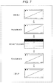
- FIG. 7 is a diagram for explaining a flow of conventional image inversion.
- FIG. 8 is a diagram for explaining latency in the conventional image inversion.
- FIG. 9 is a diagram for explaining a flow of image inversion of the present technology.
- FIG. 10 is a diagram for explaining latency in the image inversion of the present technology.
- FIG. 11 is a block diagram illustrating another functional configuration example of the endoscopic surgical system.
- FIG. 12 is a block diagram illustrating yet another functional configuration example of the endoscopic surgical system.
- FIG. 13 is a block diagram illustrating yet another functional configuration example of the endoscopic surgical system.
- FIG. 14 is a block diagram illustrating yet another functional configuration example of the endoscopic surgical system.
- FIG. 15 is a diagram illustrating an appearance configuration example of a system controller.
- FIG. 16 is a diagram for explaining a relationship between a scan order of an imaging device and latency.
- FIG. 17 is a block diagram illustrating yet another functional configuration example of the endoscopic surgical system.
- FIG. 18 is a block diagram illustrating yet another functional configuration example of the endoscopic surgical system.
- FIG. 19 is a diagram illustrating an example of scanning a zoom area of an image sensor.
- FIG. 20 is a block diagram illustrating yet another functional configuration example of the endoscopic surgical system.
- FIG. 21 is a diagram for explaining a scan method that does not depend on a top and bottom direction.
- FIGS. 22A and 22B are diagrams illustrating an example of another scan order.
- FIG. 1 is a diagram schematically illustrating an overall configuration of an operation room system 10 to which a technology according to the present disclosure can be applied.
- the operation room system 10 includes devices installed in an operation room, the devices being connected to each other to be able to cooperate with each other via an audiovisual controller (AV controller) 17 and an operation room control device 19 .
- AV controller audiovisual controller
- FIG. 1 illustrates various devices 11 for endoscopic surgery, a ceiling camera 97 that is provided on the ceiling of the operation room and images an area at hand of a surgeon, an operation room camera 99 that is provided on the ceiling of the operation room and images a state of the entire operation room, a plurality of display devices 13 A to 13 D, a recorder 15 , a patient bed 93 , and an illumination 101 .
- the devices 11 belongs to an endoscopic surgical system 23 as described later, and includes an endoscope, a display device that displays an image captured by the endoscope, and the like.
- Each device that belongs to the endoscopic surgical system 23 is also called a medical device.
- the display devices 13 A to 13 D, the recorder 15 , the patient bed 93 , and the illumination 101 are devices provided in, for example, the operation room, separately from the endoscopic surgical system 23 .
- Each device that does not belong to the endoscopic surgical system 23 is also called a non-medical device.
- the audiovisual controller 17 and/or the operation room control device 19 controls operations of these medical devices and non-medical devices in cooperation with each other.
- the audiovisual controller 17 comprehensively controls processing regarding image display in the medical devices and non-medical devices.
- the devices 11 , the ceiling camera 97 , and the operation room camera 99 each are a device (hereinafter also referred to as a transmission source device) having a function of transmitting information (hereinafter also referred to as display information) to be displayed during surgery.
- the display devices 13 A to 13 D each are a device (hereinafter also referred to as an output destination device) that outputs the display information.
- the recorder 15 is a device corresponding to both the transmission source device and the output destination device.
- the audiovisual controller 17 has functions of controlling operations of the transmission source device and the output destination device, to acquire the display information from the transmission source device and transmit the display information to the output destination device for display or recording.
- the display information is various images captured during the surgery, and various types of information regarding the surgery (for example, patient's physical information, the past examination results, information about a surgical method, and the like).
- the audiovisual controller 17 causes at least one of the display devices 13 A to 13 D that are output destination devices to display the acquired display information (in other words, images captured during the surgery, and various types of information regarding the surgery).
- the display device 13 A is a display device suspended from the ceiling of the operation room
- the display device 13 B is a display device installed on a wall surface of the operation room.
- the display device 13 C is a display device installed on a desk in the operation room
- the display device 13 D is a mobile device (for example, a tablet personal computer (PC)) having a display function.
- PC personal computer
- the operation room system 10 may include devices outside the operation room.
- the devices outside the operation room are, for example, a server connected to a network built inside and outside a hospital, a PC used by a medical staff, a projector installed in a conference room of the hospital, and the like.
- the audiovisual controller 17 can also cause a display device of another hospital to display the display information via a video conference system or the like, for telemedicine.
- the operation room control device 19 comprehensively controls processing other than the processing regarding the image display in the non-medical devices.
- the operation room control device 19 controls drive of the patient bed 93 , the ceiling camera 97 , the operation room camera 99 , and the illumination 101 .
- the operation room system 10 is provided with a centralized operation panel 21 .
- a user can give an instruction about image display to the audiovisual controller 17 via the centralized operation panel 21 , or an instruction about operation of the non-medical device to the operation room control device 19 .
- the centralized operation panel 21 is configured as a touch panel provided on the display surface of the display device.
- FIG. 2 is a diagram illustrating a display example of an operation screen on the centralized operation panel 21 .
- the operation screen is illustrated corresponding to a case where the operation room system 10 is provided with two display devices.
- An operation screen 103 is provided with a transmission source selection area 105 , a preview area 107 , and a control area 111 .
- the transmission source devices included in the operation room system 10 and respective thumbnail screens representing the display information of the transmission source devices are displayed in association with each other.
- the user can select the display information to be displayed on the display device from any of the transmission source devices displayed in the transmission source selection area 105 .
- previews are displayed of screens displayed on the respective two display devices (Monitor 1 and Monitor 2 ) that are output destination devices.
- four images are PinP-displayed in one display device.
- the four images correspond to the display information transmitted from the transmission source device selected in the transmission source selection area 105 .
- one is displayed relatively large as a main image, and the remaining three are displayed relatively small as sub-images.
- the user can switch the main image and the sub-images with each other by appropriately selecting one of four areas in which the respective images are displayed.
- a status display area 109 is provided below an area in which the four images are displayed, and a status regarding the surgery (for example, an elapsed time of the surgery, the patient's physical information, and the like) is displayed as appropriate.
- the control area 111 is provided with a transmission source operation area 113 in which graphical user interface (GUI) components are displayed for performing operation to the transmission source device, and an output destination operation area 115 in which GUI components are displayed for performing operation to the output destination device to which the display information is output.
- GUI graphical user interface
- the GUI components are provided for performing various operations (pan, tilt, and zoom) to a camera in the transmission source device having an imaging function.
- the user can operate the operation of the camera in the transmission source device by appropriately selecting these GUI components.
- the GUI components are provided for performing various operations (swap, flip, color adjustment, contrast adjustment, switching between 2D display and 3D display) to a display on the display device that is the output destination device.
- the user can operate the display on the display device by appropriately selecting these GUI components.
- the operation screen displayed on the centralized operation panel 21 is not limited to the example of FIG. 2 , and the user may be capable of operation input to each device controlled by the audiovisual controller 17 and the operation room control device 19 included in the operation room system 10 via the centralized operation panel 21 .
- FIG. 3 is a diagram illustrating an example of a state of the surgery to which the operation room system 10 described above is applied.
- the ceiling camera 97 and the operation room camera 99 are provided on the ceiling of the operation room, and can image the state of the area at hand of a surgeon (doctor) 91 who performs treatment on an affected part of a patient 5185 on the patient bed 93 , and the entire operation room.
- the ceiling camera 97 and the operation room camera 99 are provided with a magnification adjustment function, a focal length adjustment function, an imaging direction adjustment function, and the like.
- the illumination 101 is provided on the ceiling of the operation room, and irradiates at least the area at hand of the surgeon 91 .
- the illumination 101 is enabled to appropriately adjust the amount of irradiation light, the wavelength (color) of the irradiation light, the irradiation direction of the light, and the like.
- the endoscopic surgical system 23 , the patient bed 93 , the ceiling camera 97 , the operation room camera 99 , and the illumination 101 are connected to each other to be able to cooperate with each other via the audiovisual controller 17 and the operation room control device 19 .
- the centralized operation panel 21 is provided in the operation room, and as described above, the user can appropriately operate these devices existing in the operation room via the centralized operation panel 21 .
- the endoscopic surgical system 23 includes an endoscope 25 , other surgical tools 41 , a support arm device 51 that supports the endoscope 25 , and a cart 61 on which various devices are mounted for endoscopic surgery.
- trocars 49 a to 49 d punctures the abdominal wall. Then, a lens barrel 27 of the endoscope 25 and the other surgical tools 41 are inserted into a body cavity of the patient 95 from the trocars 49 a to 49 d .
- a pneumoperitoneum tube 43 , an energy treatment tool 45 , and forceps 47 are inserted into the body cavity of the patient 95 as the other surgical tools 41 .
- the energy treatment tool 45 is a treatment tool that performs incision and peeling of tissue, sealing of a blood vessel, or the like by a high-frequency current or ultrasonic vibration.
- the surgical tools 41 illustrated are merely examples, and various surgical tools generally used in endoscopic surgery may be used as the surgical tools 41 , for example, tweezers, a retractor, and the like.
- An image of a surgical portion in the body cavity of the patient 95 imaged by the endoscope 25 is displayed on a display device 65 .
- the surgeon 91 performs a treatment, for example, excising the affected part, or the like, by using the energy treatment tool 45 and the forceps 47 while viewing the image of the surgical portion displayed on the display device 65 in real time.
- the pneumoperitoneum tube 43 , the energy treatment tool 45 , and the forceps 47 are supported by the surgeon 91 , an assistant, or the like during the surgery.
- the support arm device 51 includes an arm 55 extending from a base 53 .
- the arm 55 includes joints 57 a , 57 b , and 57 c and links 59 a and 59 b , and is driven by control of an arm control device 69 .
- the endoscope 25 is supported by the arm 55 , and its position and posture are controlled. As a result, stable position fixing can be implemented of the endoscope 25 .
- the endoscope 25 includes the lens barrel 27 in which an area of a predetermined length from the distal end is inserted into the body cavity of the patient 95 , and a camera head 29 connected to the proximal end of the lens barrel 27 .
- the endoscope 25 configured as a so-called rigid scope including a rigid lens barrel 27 is illustrated, but the endoscope 25 may be configured as a so-called flexible scope including a flexible lens barrel 27 .
- the endoscope 25 may be a forward-viewing endoscope, or may be an oblique-viewing endoscope, or a side-viewing endoscope.
- An optical system and an imaging element are provided inside the camera head 29 , and reflected light (observation light) from the observation target is focused on the imaging element by the optical system.
- the observation light is photoelectrically converted by the imaging element, and an electric signal corresponding to the observation light, that is, an image signal corresponding to the observation image is generated.
- the image signal is transmitted as RAW data to a camera control unit (CCU) 63 .
- CCU camera control unit
- the camera head 29 may be provided with a plurality of the imaging elements.
- a plurality of relay optical systems is provided inside the lens barrel 27 to guide the observation light to each of the plurality of imaging elements.
- Various devices are mounted on the cart 137 .
- the CCU 63 includes a central processing unit (CPU), a graphics processing unit (GPU), and the like, and comprehensively controls operation of the endoscope 25 and the display device 65 . Specifically, the CCU 63 performs, on the image signal received from the camera head 29 , various types of image processing for displaying an image based on the image signal, for example, development processing (demosaic processing), and the like. The CCU 63 provides the display device 65 with the image signal on which the image processing is performed. Furthermore, the audiovisual controller 17 of FIG. 1 is connected to the CCU 63 . The CCU 63 also provides the audiovisual controller 17 with the image signal on which the image processing is performed.
- CPU central processing unit
- GPU graphics processing unit
- the CCU 63 transmits a control signal to the camera head 29 to control its drive.
- the control signal can include information regarding imaging conditions such as the magnification and the focal length.
- the information regarding the imaging conditions may be input via an input device 71 , or may be input via the centralized operation panel 21 described above.
- the display device 65 displays the image based on the image signal on which the image processing is performed by the CCU 63 , by the control of the CCU 63 .
- the endoscope 25 is compatible with high-resolution imaging, for example, 4K (the number of horizontal pixels 3840 ⁇ the number of vertical pixels 2160), 8K (the number of horizontal pixels 7680 ⁇ the number of vertical pixels 4320), and the like, and/or in a case where the endoscope 25 is compatible with 3D display, as the display device 65 , corresponding to each case, a display device is used capable of high-resolution display and/or 3D display.
- the display device 65 is compatible with the high-resolution imaging such as 4K or 8K, a more immersive feeling can be obtained by using a display device having a size of greater than or equal to 55 inches. Furthermore, a plurality of the display devices 65 having different resolutions and sizes may be provided depending on applications.
- the light source device 67 includes a light source, for example, a light emitting diode (LED) or the like, and supplies irradiation light for imaging the surgical portion to the endoscope 25 .
- a light source for example, a light emitting diode (LED) or the like.
- the arm control device 69 includes a processor, for example, a CPU or the like, and controls drive of the arm 55 of the support arm device 51 in accordance with a predetermined control method by operating in accordance with a predetermined program.
- the input device 71 is an input interface to the endoscopic surgical system 23 .
- the user can input various types of information and instructions to the endoscopic surgical system 23 via the input device 71 .
- the user inputs various types of information regarding the surgery, such as the patient's physical information and information about the surgical method, via the input device 71 .
- the user inputs, via the input device 71 , an instruction to drive the arm 55 , an instruction to change the imaging conditions (type of irradiation light, magnification, focal length, and the like) by the endoscope 25 , an instruction to drive the energy treatment tool 45 , and the like.
- the type of the input device 71 is not limited, and the input device 71 may be any of various known input devices.
- the input device 71 for example, a mouse, a keyboard, a touch panel, a switch, a foot switch 81 and/or a lever and the like can be applied.
- the touch panel may be provided on the display surface of the display device 65 .
- the input device 71 may be a device worn by the user, for example, a glasses-type wearable device, a head mounted display (HMD), or the like. In this case, various inputs are performed depending on the user's gesture and line-of-sight detected by these devices. Furthermore, the input device 71 may include a camera enabled to detect the user's movement, and various inputs may be performed depending on the user's gesture and line-of-sight detected from a video captured by the camera. Moreover, the input device 71 may include a microphone enabled to pick up a user's voice, and various inputs may be performed by voice via the microphone.
- a device worn by the user for example, a glasses-type wearable device, a head mounted display (HMD), or the like. In this case, various inputs are performed depending on the user's gesture and line-of-sight detected by these devices. Furthermore, the input device 71 may include a camera enabled to detect the user's movement, and various inputs may be performed depending on the user's gesture
- the input device 71 is enabled to input various information without contact, whereby in particular the user (for example, the surgeon 91 ) belonging to a clean area can operate a device belonging to an unclean area without contact. Furthermore, since the user can operate the device without releasing the user's hand from the surgical tool, convenience of the user is improved.
- a treatment tool control device 73 controls drive of the energy treatment tool 45 for cauterization of tissue, incision, sealing of blood vessels, or the like.
- a pneumoperitoneum device 75 injects a gas into the body cavity via the pneumoperitoneum tube 43 to inflate the body cavity of the patient 95 , for the purpose of securing a visual field by the endoscope 25 and securing a working space of the surgeon.
- a recorder 77 is a device enabled to record various types of information regarding the surgery.
- a printer 79 is a device enabled to print various types of information regarding the surgery in various formats such as text, image, graph, and the like.
- FIG. 4 is a block diagram illustrating an example of a functional configuration of the camera head 29 and the CCU 63 .
- the camera head 29 includes, as its functions, a lens unit 31 , an imaging unit 33 , a drive unit 35 , a communication unit 37 , and a camera head control unit 39 .
- the CCU 63 includes, as its functions, a communication unit 83 , an image processing unit 85 , and a control unit 87 .
- the camera head 29 and the CCU 63 are communicably connected to each other by a transmission cable 89 .
- the lens unit 31 is an optical system provided at a connection portion with the lens barrel 27 .
- the observation light taken in from the distal end of the lens barrel 27 is guided to the camera head 29 and is incident on the lens unit 31 .
- the lens unit 31 includes a plurality of lenses combined including a zoom lens and a focus lens. Optical characteristics of the lens unit 31 are adjusted so that the observation light is focused on the light receiving surface of the imaging element of the imaging unit 33 . Furthermore, positions on the optical axis of the zoom lens and the focus lens are movable to adjust the magnification and focus of a captured image.
- the imaging unit 33 includes an imaging element, and is arranged at the subsequent stage of the lens unit 31 .
- the observation light passing through the lens unit 31 is focused on the light receiving surface of the imaging element, and an image signal corresponding to the observation image is generated by photoelectric conversion.
- the image signal generated by the imaging unit 33 is provided to the communication unit 37 .
- an element is used capable of color imaging having a Bayer array, for example, a complementary metal oxide semiconductor (CMOS) image sensor, or the like.
- CMOS complementary metal oxide semiconductor
- an element may be used compatible with imaging of the high-resolution image of greater than or equal to 4K, for example.
- the image of the surgical portion is obtained with high resolution, whereby the surgeon 91 can grasp a state of the surgical portion in more detail, and can perform the surgery more smoothly.
- the imaging element constituting the imaging unit 33 includes a pair of imaging elements for acquiring image signals for the right-eye and left-eye to cope with 3D display.
- the 3D display is performed, whereby the surgeon 91 can grasp the depth of living tissue in the surgical portion more accurately.
- the imaging unit 33 includes the multi-chip type, a plurality of systems of the lens units 31 is provided corresponding to respective imaging elements.
- the imaging unit 33 does not necessarily have to be provided in the camera head 29 .
- the imaging unit 33 may be provided immediately after the objective lens, inside the lens barrel 27 .
- the drive unit 35 includes an actuator and moves the zoom lens and the focus lens of the lens unit 31 by a predetermined distance along the optical axis by control of the camera head control unit 39 . As a result, the magnification and focus of the captured image by the imaging unit 33 can be appropriately adjusted.
- the communication unit 37 includes a communication device for transmitting/receiving various types of information to/from the CCU 63 .
- the communication unit 37 transmits the image signal obtained from the imaging unit 33 as RAW data to the CCU 63 via the transmission cable 89 .
- the image signal is preferably transmitted by optical communication. This is because it is required that a moving image of the surgical portion is displayed in real time as much as possible for safer and more reliable surgery since the surgeon 91 performs the surgery while observing a state of the affected part with the captured image during the surgery.
- the communication unit 37 is provided with a photoelectric conversion module that converts an electric signal into an optical signal.
- the image signal is converted into an optical signal by the photoelectric conversion module, and then transmitted to the CCU 63 via the transmission cable 89 .
- the communication unit 37 receives the control signal for controlling the drive of the camera head 29 from the CCU 63 .
- the control signal includes information regarding imaging conditions, for example, information that specifies the frame rate of the captured image, information that specifies the exposure value at the time of imaging, and/or information that specifies the magnification and focus of the captured image, and the like.
- the communication unit 37 provides the received control signal to the camera head control unit 39 .
- the control signal from the CCU 63 may also be transmitted by optical communication.
- the communication unit 37 is provided with a photoelectric conversion module that converts an optical signal into an electric signal, and the control signal is converted into an electric signal by the photoelectric conversion module and then provided to the camera head control unit 39 .
- the above-described imaging conditions such as the frame rate, the exposure value, the magnification, and the focus are automatically set by the control unit 87 of the CCU 63 on the basis of the image signal acquired. That is, a so-called auto exposure (AE) function, auto-focus (AF) function, and auto white balance (AWB) function are installed in the endoscope 25 .
- AE auto exposure
- AF auto-focus
- AVB auto white balance
- the camera head control unit 39 controls the drive of the camera head 29 on the basis of the control signal from the CCU 63 received via the communication unit 37 .
- the camera head control unit 39 controls drive of the imaging element of the imaging unit 33 on the basis of the information that specifies the frame rate of the captured image and/or the information that specifies the exposure at the time of imaging.
- the camera head control unit 39 appropriately moves the zoom lens and focus lens of the lens unit 31 via the drive unit 35 on the basis of the information that specifies the magnification and focus of the captured image.
- the camera head control unit 39 may further have a function of storing information for identifying the lens barrel 27 and the camera head 29 .
- the camera head 29 can be made to have resistance to autoclave sterilization by arranging the lens unit 31 , the imaging unit 33 , and the like in a sealed structure with high airtightness and waterproofness.
- the communication unit 83 includes a communication device for transmitting/receiving various types of information to/from the camera head 29 .
- the communication unit 83 receives the image signal transmitted via the transmission cable 89 from the camera head 29 .
- the image signal can be suitably transmitted by optical communication.
- the communication unit 83 is provided with a photoelectric conversion module that converts an optical signal into an electric signal.
- the communication unit 83 provides the image signal converted into the electric signal to the image processing unit 85 .
- the communication unit 83 transmits the control signal for controlling the drive of the camera head 29 to the camera head 29 .
- the control signal may also be transmitted by optical communication.
- the image processing unit 85 performs various types of image processing on the image signal that is RAW data transmitted from the camera head 29 .
- Examples of the image processing includes various types of known signal processing, for example, development processing, image quality enhancement processing (such as band enhancement processing, super-resolution processing, noise reduction (NR) processing and/or camera shake correction processing), and/or enlargement processing (electronic zoom processing), and the like.
- image processing unit 85 performs detection processing on the image signal for performing AE, AF, and AWB.
- the image processing unit 85 includes a processor such as a CPU or GPU, and the image processing and detection processing described above are performed by the processor operating in accordance with a predetermined program. Note that, in a case where the image processing unit 85 includes a plurality of GPUs, the image processing unit 85 appropriately divides information related to the image signal and performs the image processing in parallel by the plurality of GPUs.
- the control unit 87 performs various controls regarding imaging of the surgical portion by the endoscope 25 and display of the captured image. For example, the control unit 87 generates the control signal for controlling the drive of the camera head 29 .
- the control unit 87 in a case where the imaging conditions are input by the user, the control unit 87 generates the control signal on the basis of the input by the user.
- the control unit 87 in a case where the AE function, the AF function, and the AWB function are installed in the endoscope 25 , the control unit 87 generates the control signal by appropriately calculating the optimum exposure value, focal length, and white balance depending on a result of the detection processing by the image processing unit 85 .
- control unit 87 causes the display device 65 to display the image of the surgical portion on the basis of the image signal on which the image processing is performed by the image processing unit 85 .
- the control unit 87 recognizes various objects in the surgical portion image by using various image recognition technologies. For example, the control unit 87 detects color, a shape of an edge, and the like of the object included in the surgical portion image, thereby being able to recognize the surgical tools 41 such as the forceps 47 , a specific body part, bleeding, mist at the time of using the energy treatment tool 45 , or the like.
- the control unit 87 causes the display device 65 to superimpose and display various types of surgery assistance information on the image of the surgical portion by using the recognition result.
- the surgery assistance information is superimposed and displayed, and presented to the surgeon 91 , whereby the surgery can be performed more safely and reliably.
- the transmission cable 89 connecting the camera head 29 and the CCU 63 together is an electric signal cable adaptable to communication of electric signals, an optical fiber adaptable to optical communication, or a composite cable thereof.
- communication is performed by wire using the transmission cable 89 , but communication between the camera head 29 and the CCU 63 may be performed wirelessly. In a case where the communication between the two is performed wirelessly, it is not necessary to install the transmission cable 89 in the operation room, so that a situation is eliminated where the movement of the medical staff in the operation room is hindered by the transmission cable 89 .
- An endoscopic surgical system 200 of FIG. 5 includes an imaging device 201 , a signal processing device 202 , and a display device 203 .
- the imaging device 201 corresponds to the camera head 29 described above and, as a surgical imaging device, acquires data (image signal) of a captured image by imaging a living body.
- the acquired image signal is transmitted to the signal processing device 202 .
- a surgical portion image (a surgical image in which the inside of the living body is captured) is acquired that is an image of a surgical portion in a body cavity.
- the signal processing device 202 corresponds to the CCU 63 described above, and performs predetermined signal processing on the image signal transmitted from the imaging device 201 .
- the image signal on which the signal processing is performed is transmitted to the display device 203 .
- the display device 203 corresponds to the display device 65 described above, and displays the captured image on the basis of the image signal transmitted from the signal processing device 202 .
- the display device 203 includes a user interface (UI) 211 that accepts user's operation.
- UI user interface
- the UI 211 accepts specification of the top and bottom direction of the captured image to be displayed on the display device 203 .
- FIG. 6 illustrates an appearance configuration example of the display device 203 .
- the display device 203 includes a display unit 221 and an operation button 222 .
- the display unit 221 displays the captured image that is captured by the imaging device 201 and on which the signal processing is performed by the signal processing device 202 .
- the operation button 222 is one of the UIs 211 described above, and accepts the specification of the top and bottom direction of the captured image to be displayed on the display unit 221 by being operated by the user.
- the display unit 221 may be configured as a touch panel, and a button for accepting the specification of the top and bottom direction may be displayed on the display unit 221 .
- the display device 203 further includes a scan information generation unit 212 .
- the scan information generation unit 212 generates scan information indicating a scan order of the captured image on the basis of the specification of the top and bottom direction accepted by the UI 211 .
- the generated scan information is supplied to the imaging device 201 and the signal processing device 202 .
- the imaging device 201 When the scan information is supplied from the scan information generation unit 212 , the imaging device 201 generates the captured image on the basis of the scan information.
- the signal processing device 202 When the scan information is supplied from the scan information generation unit 212 , the signal processing device 202 performs signal processing on the captured image on the basis of the scan information. Furthermore, when the scan information is generated by the scan information generation unit 212 , the display device 203 displays the captured image on the basis of the scan information.
- the display device in a case where a direction of the top and bottom of an image to be displayed on a display device is opposite to a direction of the top and bottom determined by the direction of gravity, depending on a direction of the top and bottom of an endoscope inserted into an abdominal cavity, the display device has conventionally inverted and displayed the image.
- invert and display means that the image is rotated by 180 degrees and displayed.
- FIG. 7 illustrates a flow of image inversion in a conventional endoscopic surgical system in a case where the direction of the top and bottom of the image to be displayed on the display device is opposite to the direction of the top and bottom determined by the direction of gravity.
- the imaging device acquires pixel data by scanning from the upper left to the upper right, from the lower left to the lower right of the captured image in a dot sequential manner, and sequentially transmits the pixel data to the signal processing device.
- the signal processing device performs signal processing by scanning from the top to the bottom of the captured image in a block sequential manner, for example, and transmits, to the display device, data of a block in which the signal processing is finished in the dot sequential manner.
- the signal processing is performed in the block sequential manner, but the signal processing may be performed in a line sequential manner or the dot sequential manner.
- the scan order from the upper left to the upper right, from the lower left to the lower right, or the scan order from the top to the bottom is referred to as a forward direction scan order.
- the display device performs display by scanning from the upper left to the upper right, from the lower left to the lower right of the captured image in the dot sequential manner.
- the signal processing device starts transmission sequentially from data on the lower side in the vertical direction of the image to be inverted and displayed on the display device.
- the display device wants to start scanning from data on the upper side in the vertical direction of the image to be inverted and displayed, but the data is transmitted last from the signal processing device.
- the imaging device 201 performs scanning in a scan order opposite to the forward direction scan order (hereinafter, referred to as a backward direction scan order as appropriate).
- a backward direction scan order as appropriate.
- the imaging device 201 acquires pixel data by scanning from the lower right to the lower left, from the upper right to the upper left of the captured image in the dot sequential manner, and sequentially transmits the pixel data to the signal processing device.
- the signal processing device 202 performs scanning in the backward direction scan order on the basis of the scan information.
- the signal processing device 202 performs signal processing by scanning from the bottom to the top of the captured image in the block sequential manner, for example, and transmits, to the display device, data of a block in which the signal processing is finished in the dot sequential manner.
- the signal processing device 202 starts transmission sequentially from data on the upper side in the vertical direction of the image to be inverted and displayed on the display device 203 .
- the display device 203 can start scanning from the data on the upper side in the vertical direction of the image to be inverted and displayed.
- respective scan orders for imaging, signal processing, and display are determined depending on the top and bottom direction of the captured image to be displayed on the display device 203 , so that the display device 203 can perform scanning for display without waiting for completion of storage of one image in the memory.
- the latency from imaging to display can be reduced as compared with the conventional one illustrated in FIG. 8 .
- the respective scan orders for imaging, signal processing, and display are determined depending on the top and bottom direction of the captured image to be displayed on the display device 203 , whereby a function can be implemented of vertically mirror-inverting and displaying the captured image, in addition to a function of rotating by 180 degrees and displaying the captured image.
- the latency from imaging to display can be reduced even in such a configuration.
- the display device 203 may have the conventional inversion display function (in other words, perform scanning for display after waiting for completion of storage of one image in the memory). Furthermore, in this case, the display device 203 may have, as the inversion display function, the function of vertically mirror-inverting and displaying the captured image, in addition to the function of rotating by 180 degrees and displaying the captured image.
- the signal processing device 202 includes a UI 231 and a scan information generation unit 232 .
- the UI 231 and the scan information generation unit 232 respectively have the same functions as those of the UI 211 and the scan information generation unit 212 of FIG. 5 .
- FIG. 12 is a diagram illustrating a second modification of the endoscopic surgical system to which the present technology is applied.
- the imaging device 201 includes a UI 251 and a scan information generation unit 252 .
- the UI 251 and the scan information generation unit 252 respectively have the same functions as those of the UI 211 and the scan information generation unit 212 of FIG. 5 .
- FIG. 13 is a diagram illustrating a third modification of the endoscopic surgical system to which the present technology is applied.
- a system controller 301 is provided in addition to devices from the imaging device 201 to the display device 203 .
- the system controller 301 corresponds to, for example, the audiovisual controller 17 in the operation room system 10 described above, and controls operations of the devices from the imaging device 201 to the display device 203 .
- the signal processing device 202 , the display device 203 , and the system controller 301 are connected to each other via a network 302 .
- an endoscopic surgical system 200 D of FIG. 14 two display devices 203 - 1 and 203 - 2 are provided.
- the UI 311 of the system controller 301 accepts specification of the top and bottom direction of the captured image to be displayed on each of the display devices 203 - 1 and 203 - 2 .
- FIG. 15 illustrates an appearance configuration example of the system controller 301 .
- the system controller 301 includes operation buttons 321 and 322 .
- the operation button 321 is one of the UIs 311 described above, and accepts the specification of the top and bottom direction of the captured image to be displayed on the display device 203 - 1 by being operated by the user.
- the operation button 322 is also one of the UIs 311 described above, and accepts the specification of the top and bottom direction of the captured image to be displayed on the display device 203 - 2 by being operated by the user.
- a display unit including a touch panel may be provided in the system controller 301 , and buttons for accepting the specifications of the top and bottom directions may be displayed on the display unit.
- the UI 311 may be provided on the operation screen ( FIG. 2 ) on the centralized operation panel 21 .
- the display devices 203 - 1 and 203 - 2 only need to display the captured images in the order scanned by the imaging device 201 , and can perform scanning for display without waiting for completion of storage of one image in the memory, that is, with a latency of 0V.
- the display device 203 - 1 In a case where the scan order of the imaging device 201 is the forward direction, the display device 203 - 1 only needs to display the captured image in the order scanned by the imaging device 201 , and can perform scanning for display with a latency of 0V.
- the display device 203 - 1 may intentionally display the display image with a delay of 1V.
- the display device 203 - 2 In a case where the scan order of the imaging device 201 is the forward direction, the display device 203 - 2 only needs to display the captured image in the order scanned by the imaging device 201 , and can perform scanning for display with a latency of 0V.
- the display device 203 - 1 displays the captured image in the reverse order of the order scanned by the imaging device 201 , it is necessary to perform scanning for display after waiting for completion of storage of one image in the memory by the conventional inversion display function. Thus, a latency of 1V occurs.
- the display device 203 - 2 may intentionally display the display image with a delay of 1V.
- the display devices 203 - 1 and 203 - 2 only need to display captured images in the order scanned by the imaging device 201 , and can perform scanning for display with a latency of 0V.
- the latency of each display device can be adjusted depending on the inversion instructions of the top and bottom direction in the two display devices and the scan order of the imaging device.
- FIG. 17 is a diagram illustrating a fifth modification of the endoscopic surgical system to which the present technology is applied.
- an intra-operation room (OR) camera 331 is newly provided in addition to the configuration of the endoscopic surgical system 200 D of FIG. 14 .
- the intra-OR camera 331 corresponds to, for example, the operation room camera 99 in the operation room system 10 described above, and images a state of the entire operation room.
- the signal processing device 202 , the display device 203 , the system controller 301 , and the intra-OR camera 331 are connected to each other via the network 302 .
- the scan information generation unit 312 of FIG. 17 detects a positional relationship among the user (surgeon), the imaging device 201 , and the display devices 203 - 1 and 203 - 2 from an image captured by the intra-OR camera 331 , and generates scan information on the basis of the detection result.
- respective scan orders for imaging, signal processing, and display can be determined depending on the positional relationship among the surgeon, the imaging device 201 , and the display devices 203 - 1 and 203 - 2 in the operation room.
- FIG. 18 is a diagram illustrating a sixth modification of the endoscopic surgical system to which the present technology is applied.
- an imaging device 201 F is provided instead of the imaging device 201 of the endoscopic surgical system 200 of FIG. 5 .
- the imaging device 201 F is configured as a three-chip camera, and includes an optical block 351 , an imaging unit 352 , and a preprocessing unit 353 .
- the optical block 351 includes an imaging lens, a focus mechanism, a shutter mechanism, an aperture mechanism, and the like.
- the imaging unit 352 includes a color separation prism that separates light incident from the optical block into color components of R, G, and B, and three imaging elements (image sensors) that output electric signals corresponding to respective light intensities of the color components.
- the preprocessing unit 353 performs predetermined signal processing such as noise reduction, automatic gain control, and A/D conversion on an analog signal from the imaging unit 352 , and outputs the signal as digital data.
- the imaging device 201 F When scan information is supplied from the scan information generation unit 212 , the imaging device 201 F generates a captured image on the basis of the scan information. Specifically, the imaging device 201 F performs imaging on the basis of the scan information from the scan information generation unit 212 so that the scan orders for images on the three image sensors are the same as each other.
- the scan order of each image sensor is determined by a direction in which each image sensor is fixed and the number of times of reflection in an optical path from a subject to the image sensor.
- the imaging device 201 F is configured as a multi-chip camera, but may be configured as a stereo camera that generates images for the right-eye and left-eye to cope with 3D display. In this case, the imaging device 201 F performs imaging on the basis of the scan information from the scan information generation unit 212 so that the scan orders for images on a pair of the image sensors are the same as each other.
- the imaging device 201 has a digital zoom function, and partially drives an image sensor during zooming.
- FIG. 19 illustrates a pixel area of the image sensor included in the imaging device 201 of this example.
- a captured image is generated corresponding to a pixel area 372 necessary for zoom display on a pixel area 371 of the image sensor, and data of the captured image is transmitted.
- pixel data is acquired in the scan order based on scan information.
- the latency can be reduced compared with a case where data of a captured image corresponding to the entire pixel area 371 is transmitted.
- the frame rate of the captured image is greater than or equal to 120 fps.
- the latency can be reduced to about half. In a case where signal processing is performed in pipeline, the effect of latency reduction is greater.
- FIG. 20 is a diagram illustrating another functional configuration example of the endoscopic surgical system.
- an imaging device 201 G including an acceleration sensor 391 is provided instead of the imaging device 201 of the endoscopic surgical system 200 C of FIG. 13 .
- a detection device 392 is newly provided.
- the signal processing device 202 , the display device 203 , the system controller 301 , and the detection device 392 are connected to each other via the network 302 .
- the detection device 392 detects the direction of gravity on the basis of a signal output from the acceleration sensor 391 . On the basis of the detection result, the detection device 392 generates top and bottom information indicating a direction of the top and bottom of the imaging device 201 G, and supplies the top and bottom information to the scan information generation unit 312 via the network 302 .
- the scan information generation unit 312 of FIG. 20 generates scan information on the basis of the top and bottom information from the detection device 392 .
- respective scan orders for imaging, signal processing, and display can be determined depending on the direction of the top and bottom of the imaging device 201 G.
- scanning may be performed of a plurality of patterns for one image, as illustrated in FIG. 21 .
- the imaging device acquires pixel data by scanning each area obtained by dividing the captured image into four areas, in the dot sequential manner from the center of the captured image toward the four corners, and sequentially transmits the pixel data to the signal processing device.
- scanning is performed from the lower right to the upper left in the upper left area obtained by dividing the captured image into four areas, and from the lower left to the upper right in the upper right area. Furthermore, scanning is performed from the upper right to the lower left in the lower left area, and from the upper left to the lower right in the lower right area.
- the signal processing device performs signal processing by scanning each area obtained by dividing the captured image into four areas, in the dot sequential manner from the center of the captured image toward the four corners, similarly to the imaging device.
- the display device performs display by scanning each area obtained by dividing the captured image into four areas, in the dot sequential manner from the center of the captured image toward the four corners, similarly to the imaging device.
- the display device Even in a case where inversion is specified of the top and bottom direction of the captured image to be displayed on the display device, the display device only needs to display the captured image in the order scanned by the imaging device, and can perform scanning for display without waiting for completion of storage of one image in the memory.
- the scan order in the vertical direction of the captured image is determined by the scan information.
- the scan order in the vertical direction is a scan order from the upper left to the upper right, from the lower left to the lower right of the captured image in the dot sequential manner, or a scan order from the top to the bottom of the captured image in the line sequential manner or the block sequential manner.
- the scan order in the left-right direction of the captured image may be determined by the scan information. Specifically, scanning may be performed in a scan order from the upper left to the lower left, from the upper right to the lower right of the captured image in the dot sequential manner, or in a scan order from the left to the right of the captured image in the line sequential manner or the block sequential manner.
- the imaging device performs scanning in the scan order from the upper left to the lower left, from the upper right to the lower right of the captured image in the dot sequential manner on the basis of the scan information, as illustrated in FIG. 22A , or, conversely, performs scanning in a scan order from the lower right to the upper right, from the lower left to the upper left of the captured image in the dot sequential manner, as illustrated in FIG. 22B .
- the display device comes to have, as an inversion display function, a function of rotating by 180 degrees and displaying the captured image, and a function of mirror-inverting in the left-right direction and displaying the captured image.
- FIG. 23 illustrates an example in which a scan method at the time of data transmission from the signal processing device to the display device does not match a scan method in the display device.
- latencies of 0.5V occur respectively when a scan method of the signal processing device is converted to the scan method at the time of data transmission to the display device, and when the scan method at the time of data transmission to the display device is converted to the scan method in the display device.
- the latency can be reduced by matching the scan method at the time of data transmission from the signal processing device to the display device with the scan method in the display device.
- the example has been described of the operation room system 10 to which the technology according to the present disclosure can be applied.
- the surgical system to which the operation room system 10 is applied is the endoscopic surgical system 23
- the configuration of the operation room system 10 is not limited to such an example.
- the operation room system 10 may be applied to an inspection flexible endoscopic surgical system or a microscopic surgical system instead of the endoscopic surgical system 23 .
- the present technology can also adopt the following configurations.
- a surgical system including:
- a surgical imaging device that generates a surgical image by imaging the inside of a living body
- a display device that displays the surgical image on which the signal processing is performed, in which
- the surgical imaging device generates the surgical image on the basis of scan information indicating a scan order of the surgical image.
- the surgical system according to (1) in which the signal processing device performs the signal processing on the surgical image on the basis of the scan information, and
- the display device displays the surgical image on the basis of the scan information.
- a scan information generation unit that generates the scan information depending on the top and bottom direction of the surgical image to be displayed on the display device.
- the display device includes: a user interface that accepts specification of the top and bottom direction of the surgical image to be displayed on the display device; and the scan information generation unit, and
- the scan information generation unit generates the scan information on the basis of the specification of the top and bottom direction of the surgical image accepted by the user interface.
- the signal processing device includes: a user interface that accepts specification of the top and bottom direction of the surgical image to be displayed on the display device; and the scan information generation unit, and
- the scan information generation unit generates the scan information on the basis of the specification of the top and bottom direction of the surgical image accepted by the user interface.
- the surgical imaging device includes: a user interface that accepts specification of the top and bottom direction of the surgical image to be displayed on the display device; and the scan information generation unit, and the scan information generation unit generates the scan information on the basis of the specification of the top and bottom direction of the surgical image accepted by the user interface.
- the surgical system according to (3) further including a controller that controls each device constituting the surgical system, in which
- the controller includes: a user interface that accepts specification of the top and bottom direction of the surgical image to be displayed on the display device; and the scan information generation unit, and
- the scan information generation unit generates the scan information on the basis of the specification of the top and bottom direction of the surgical image accepted by the user interface.
- the user interface accepts specification of the top and bottom direction of the surgical image displayed on each of the plurality of display devices.
- the surgical system according to (1) further including
- a scan information generation unit that generates the scan information on the basis of a positional relationship among a user, the surgical imaging device, and the display device.
- the image is configured as a camera including a plurality of image sensors, and
- the surgical system according to (1) further including:
- a detection device that generates top and bottom information indicating a direction of the top and bottom of the surgical imaging device on the basis of the direction of gravity detected in the surgical imaging device;
- the scan information generation unit that generates the scan information on the basis of the top and bottom information.
- the scan information determines the scan order in the vertical direction of the surgical image.
- the scan information determines the scan order in the left-right direction of the surgical image.
- a surgical imaging device including
- an imaging unit that generates a surgical image by imaging the inside of a living body, in which
- the imaging unit generates the surgical image on the basis of scan information indicating a scan order of the surgical image corresponding to the top and bottom direction of the surgical image to be displayed on a display device.
Abstract
Description
- Patent Document 1: Japanese Patent Application Laid-Open No. 2014-200547
- 10 Operation room system
- 23 Endoscopic surgical system
- 29 Camera head
- 33 Imaging unit
- 63 CCU
- 65 Display device
- 85 Image processing unit
- 200, 200A to 200G Endoscopic surgical system
- 201 Imaging device
- 202 Signal processing device
- 203 Display device
- 211 UI
- 212 Scan information generation unit
- 231 UI
- 232 Scan information generation unit
- 251 UI
- 252 Scan information generation unit
- 301 System controller
- 311 UI
- 312 Scan information generation unit
- 331 Intra-OR Camera
- 352 Imaging unit
- 392 Detection device
Claims (13)
Applications Claiming Priority (4)
| Application Number | Priority Date | Filing Date | Title |
|---|---|---|---|
| JP2017-121132 | 2017-06-21 | ||
| JP2017121132A JP2019004978A (en) | 2017-06-21 | 2017-06-21 | Surgery system and surgical image capture device |
| JPJP2017-121132 | 2017-06-21 | ||
| PCT/JP2018/021808 WO2018235608A1 (en) | 2017-06-21 | 2018-06-07 | Surgery system and surgical image capture device |
Publications (2)
| Publication Number | Publication Date |
|---|---|
| US20200113413A1 US20200113413A1 (en) | 2020-04-16 |
| US11503980B2 true US11503980B2 (en) | 2022-11-22 |
Family
ID=64735945
Family Applications (1)
| Application Number | Title | Priority Date | Filing Date |
|---|---|---|---|
| US16/621,888 Active 2038-12-16 US11503980B2 (en) | 2017-06-21 | 2018-06-07 | Surgical system and surgical imaging device |
Country Status (4)
| Country | Link |
|---|---|
| US (1) | US11503980B2 (en) |
| JP (1) | JP2019004978A (en) |
| CN (1) | CN110740677A (en) |
| WO (1) | WO2018235608A1 (en) |
Families Citing this family (4)
| Publication number | Priority date | Publication date | Assignee | Title |
|---|---|---|---|---|
| JPWO2020203167A1 (en) * | 2019-03-29 | 2020-10-08 | ||
| US11029908B2 (en) * | 2019-08-28 | 2021-06-08 | Himax Display, Inc. | Head mounted display apparatus |
| JP2021145788A (en) * | 2020-03-17 | 2021-09-27 | ソニー・オリンパスメディカルソリューションズ株式会社 | Control unit and medical observation system |
| US20230290285A1 (en) * | 2020-09-07 | 2023-09-14 | Sony Group Corporation | Display processing device, display processing method, storage medium, and information processing device |
Citations (12)
| Publication number | Priority date | Publication date | Assignee | Title |
|---|---|---|---|---|
| US20020147384A1 (en) | 2001-04-10 | 2002-10-10 | Olympus Optical Co., Ltd. | Surgery support system and surgery support method |
| US20040210105A1 (en) * | 2003-04-21 | 2004-10-21 | Hale Eric Lawrence | Method for capturing and displaying endoscopic maps |
| US20080159653A1 (en) * | 2006-12-28 | 2008-07-03 | Microvision | Rotation compensation and image stabilization system |
| WO2011040769A2 (en) | 2009-10-01 | 2011-04-07 | 주식회사 이턴 | Surgical image processing device, image-processing method, laparoscopic manipulation method, surgical robot system and an operation-limiting method therefor |
| JP2011211553A (en) | 2010-03-30 | 2011-10-20 | Fujifilm Corp | Cmos imaging element, and endoscope device including the same |
| JP2012137665A (en) | 2010-12-27 | 2012-07-19 | Olympus Corp | Endoscope apparatus |
| JP2013162874A (en) | 2012-02-10 | 2013-08-22 | Hoya Corp | Electronic endoscope system |
| US20130342667A1 (en) * | 2012-06-26 | 2013-12-26 | Olympus Corporation | Endoscope apparatus, reproducing apparatus, displaying method and inspection report generating apparatus |
| JP2014200547A (en) | 2013-04-08 | 2014-10-27 | 学校法人同志社 | Endoscope system |
| US20160174822A1 (en) | 2014-12-18 | 2016-06-23 | Endochoice, Inc. | Multiple Viewing Element Endoscope System Having Multiple Sensor Motion Synchronization |
| WO2016129162A1 (en) | 2015-02-12 | 2016-08-18 | ソニー株式会社 | Image processing device, image processing method, program, and image processing system |
| WO2017038241A1 (en) | 2015-08-28 | 2017-03-09 | 富士フイルム株式会社 | Instrument operation device, instrument operation method, and electronic instrument system |
Family Cites Families (1)
| Publication number | Priority date | Publication date | Assignee | Title |
|---|---|---|---|---|
| US9718190B2 (en) * | 2006-06-29 | 2017-08-01 | Intuitive Surgical Operations, Inc. | Tool position and identification indicator displayed in a boundary area of a computer display screen |
-
2017
- 2017-06-21 JP JP2017121132A patent/JP2019004978A/en active Pending
-
2018
- 2018-06-07 US US16/621,888 patent/US11503980B2/en active Active
- 2018-06-07 WO PCT/JP2018/021808 patent/WO2018235608A1/en active Application Filing
- 2018-06-07 CN CN201880038931.7A patent/CN110740677A/en active Pending
Patent Citations (14)
| Publication number | Priority date | Publication date | Assignee | Title |
|---|---|---|---|---|
| US20020147384A1 (en) | 2001-04-10 | 2002-10-10 | Olympus Optical Co., Ltd. | Surgery support system and surgery support method |
| US20040210105A1 (en) * | 2003-04-21 | 2004-10-21 | Hale Eric Lawrence | Method for capturing and displaying endoscopic maps |
| US20080159653A1 (en) * | 2006-12-28 | 2008-07-03 | Microvision | Rotation compensation and image stabilization system |
| WO2011040769A2 (en) | 2009-10-01 | 2011-04-07 | 주식회사 이턴 | Surgical image processing device, image-processing method, laparoscopic manipulation method, surgical robot system and an operation-limiting method therefor |
| JP2011211553A (en) | 2010-03-30 | 2011-10-20 | Fujifilm Corp | Cmos imaging element, and endoscope device including the same |
| JP2012137665A (en) | 2010-12-27 | 2012-07-19 | Olympus Corp | Endoscope apparatus |
| JP2013162874A (en) | 2012-02-10 | 2013-08-22 | Hoya Corp | Electronic endoscope system |
| US20130342667A1 (en) * | 2012-06-26 | 2013-12-26 | Olympus Corporation | Endoscope apparatus, reproducing apparatus, displaying method and inspection report generating apparatus |
| JP2014200547A (en) | 2013-04-08 | 2014-10-27 | 学校法人同志社 | Endoscope system |
| US20160174822A1 (en) | 2014-12-18 | 2016-06-23 | Endochoice, Inc. | Multiple Viewing Element Endoscope System Having Multiple Sensor Motion Synchronization |
| WO2016100731A1 (en) | 2014-12-18 | 2016-06-23 | Endochoice, Inc. | Multiple viewing element endoscope system having multiple sensor motion synchronization |
| WO2016129162A1 (en) | 2015-02-12 | 2016-08-18 | ソニー株式会社 | Image processing device, image processing method, program, and image processing system |
| US20180027165A1 (en) | 2015-02-12 | 2018-01-25 | Sony Corporation | Image processing device, image processing method, program and image processing system |
| WO2017038241A1 (en) | 2015-08-28 | 2017-03-09 | 富士フイルム株式会社 | Instrument operation device, instrument operation method, and electronic instrument system |
Non-Patent Citations (2)
| Title |
|---|
| International Search Report and Written Opinion of PCT Application No. PCT/JP2018/021808, dated Aug. 21, 2018, 09 pages of ISRWO. |
| Office Action for CN Patent Application No. 201880038931.7, dated Dec. 24, 2021, 11 pages of English Translation and 08 pages of Office Action. |
Also Published As
| Publication number | Publication date |
|---|---|
| WO2018235608A1 (en) | 2018-12-27 |
| US20200113413A1 (en) | 2020-04-16 |
| JP2019004978A (en) | 2019-01-17 |
| CN110740677A (en) | 2020-01-31 |
Similar Documents
| Publication | Publication Date | Title |
|---|---|---|
| US11503980B2 (en) | Surgical system and surgical imaging device | |
| CN110832842B (en) | Imaging apparatus and image generating method | |
| EP3534620B1 (en) | Signal processing device and method, and program | |
| US20190339836A1 (en) | Information processing apparatus, method, and program | |
| US11653824B2 (en) | Medical observation system and medical observation device | |
| WO2020179485A1 (en) | Imaging device and switch | |
| US11694725B2 (en) | Information processing apparatus and information processing method | |
| US20220008156A1 (en) | Surgical observation apparatus, surgical observation method, surgical light source device, and surgical light irradiation method | |
| US20210019921A1 (en) | Image processing device, image processing method, and program | |
| CN110945399B (en) | Signal processing apparatus, imaging apparatus, signal processing method, and memory | |
| US11729519B2 (en) | Video signal processing apparatus, video signal processing method, and image-capturing apparatus | |
| US10694141B2 (en) | Multi-camera system, camera, camera processing method, confirmation device, and confirmation device processing method | |
| US11496662B2 (en) | Image processing apparatus, image processing method, and image pickup system for displaying information associated with an image | |
| US11483473B2 (en) | Surgical image processing apparatus, image processing method, and surgery system | |
| US20220148128A1 (en) | Image processing apparatus, image processing method, and program | |
| US11039067B2 (en) | Image pickup apparatus, video signal processing apparatus, and video signal processing method | |
| US11910105B2 (en) | Video processing using a blended tone curve characteristic | |
| JP7230923B2 (en) | Information processing device, information processing method and program |
Legal Events
| Date | Code | Title | Description |
|---|---|---|---|
| FEPP | Fee payment procedure |
Free format text: ENTITY STATUS SET TO UNDISCOUNTED (ORIGINAL EVENT CODE: BIG.); ENTITY STATUS OF PATENT OWNER: LARGE ENTITY |
|
| STPP | Information on status: patent application and granting procedure in general |
Free format text: APPLICATION DISPATCHED FROM PREEXAM, NOT YET DOCKETED |
|
| AS | Assignment |
Owner name: SONY CORPORATION, JAPAN Free format text: ASSIGNMENT OF ASSIGNORS INTEREST;ASSIGNOR:HAYASHI, TSUNEO;REEL/FRAME:052051/0499 Effective date: 20200129 |
|
| STPP | Information on status: patent application and granting procedure in general |
Free format text: DOCKETED NEW CASE - READY FOR EXAMINATION |
|
| STPP | Information on status: patent application and granting procedure in general |
Free format text: NON FINAL ACTION MAILED |
|
| STPP | Information on status: patent application and granting procedure in general |
Free format text: RESPONSE TO NON-FINAL OFFICE ACTION ENTERED AND FORWARDED TO EXAMINER |
|
| STPP | Information on status: patent application and granting procedure in general |
Free format text: FINAL REJECTION MAILED |
|
| STPP | Information on status: patent application and granting procedure in general |
Free format text: RESPONSE AFTER FINAL ACTION FORWARDED TO EXAMINER |
|
| STPP | Information on status: patent application and granting procedure in general |
Free format text: ADVISORY ACTION MAILED |
|
| STPP | Information on status: patent application and granting procedure in general |
Free format text: AWAITING TC RESP., ISSUE FEE NOT PAID |
|
| STPP | Information on status: patent application and granting procedure in general |
Free format text: NOTICE OF ALLOWANCE MAILED -- APPLICATION RECEIVED IN OFFICE OF PUBLICATIONS |
|
| STPP | Information on status: patent application and granting procedure in general |
Free format text: PUBLICATIONS -- ISSUE FEE PAYMENT VERIFIED |
|
| STCF | Information on status: patent grant |
Free format text: PATENTED CASE |