JP6817536B2 - Conveyor device and image forming device - Google Patents
Conveyor device and image forming device Download PDFInfo
- Publication number
- JP6817536B2 JP6817536B2 JP2016230918A JP2016230918A JP6817536B2 JP 6817536 B2 JP6817536 B2 JP 6817536B2 JP 2016230918 A JP2016230918 A JP 2016230918A JP 2016230918 A JP2016230918 A JP 2016230918A JP 6817536 B2 JP6817536 B2 JP 6817536B2
- Authority
- JP
- Japan
- Prior art keywords
- guide member
- roller
- opening
- closing guide
- transport
- Prior art date
- Legal status (The legal status is an assumption and is not a legal conclusion. Google has not performed a legal analysis and makes no representation as to the accuracy of the status listed.)
- Active
Links
Images

Classifications
-
- B—PERFORMING OPERATIONS; TRANSPORTING
- B65—CONVEYING; PACKING; STORING; HANDLING THIN OR FILAMENTARY MATERIAL
- B65H—HANDLING THIN OR FILAMENTARY MATERIAL, e.g. SHEETS, WEBS, CABLES
- B65H5/00—Feeding articles separated from piles; Feeding articles to machines
- B65H5/36—Article guides or smoothers, e.g. movable in operation
- B65H5/38—Article guides or smoothers, e.g. movable in operation immovable in operation
-
- B—PERFORMING OPERATIONS; TRANSPORTING
- B65—CONVEYING; PACKING; STORING; HANDLING THIN OR FILAMENTARY MATERIAL
- B65H—HANDLING THIN OR FILAMENTARY MATERIAL, e.g. SHEETS, WEBS, CABLES
- B65H5/00—Feeding articles separated from piles; Feeding articles to machines
- B65H5/06—Feeding articles separated from piles; Feeding articles to machines by rollers or balls, e.g. between rollers
- B65H5/062—Feeding articles separated from piles; Feeding articles to machines by rollers or balls, e.g. between rollers between rollers or balls
-
- B—PERFORMING OPERATIONS; TRANSPORTING
- B65—CONVEYING; PACKING; STORING; HANDLING THIN OR FILAMENTARY MATERIAL
- B65H—HANDLING THIN OR FILAMENTARY MATERIAL, e.g. SHEETS, WEBS, CABLES
- B65H2402/00—Constructional details of the handling apparatus
- B65H2402/50—Machine elements
- B65H2402/54—Springs, e.g. helical or leaf springs
-
- B—PERFORMING OPERATIONS; TRANSPORTING
- B65—CONVEYING; PACKING; STORING; HANDLING THIN OR FILAMENTARY MATERIAL
- B65H—HANDLING THIN OR FILAMENTARY MATERIAL, e.g. SHEETS, WEBS, CABLES
- B65H2402/00—Constructional details of the handling apparatus
- B65H2402/60—Coupling, adapter or locking means
-
- B—PERFORMING OPERATIONS; TRANSPORTING
- B65—CONVEYING; PACKING; STORING; HANDLING THIN OR FILAMENTARY MATERIAL
- B65H—HANDLING THIN OR FILAMENTARY MATERIAL, e.g. SHEETS, WEBS, CABLES
- B65H2403/00—Power transmission; Driving means
- B65H2403/50—Driving mechanisms
- B65H2403/51—Cam mechanisms
- B65H2403/513—Cam mechanisms involving elongated cam, i.e. parallel to linear transport path
-
- B—PERFORMING OPERATIONS; TRANSPORTING
- B65—CONVEYING; PACKING; STORING; HANDLING THIN OR FILAMENTARY MATERIAL
- B65H—HANDLING THIN OR FILAMENTARY MATERIAL, e.g. SHEETS, WEBS, CABLES
- B65H2404/00—Parts for transporting or guiding the handled material
- B65H2404/10—Rollers
- B65H2404/14—Roller pairs
- B65H2404/144—Roller pairs with relative movement of the rollers to / from each other
-
- B—PERFORMING OPERATIONS; TRANSPORTING
- B65—CONVEYING; PACKING; STORING; HANDLING THIN OR FILAMENTARY MATERIAL
- B65H—HANDLING THIN OR FILAMENTARY MATERIAL, e.g. SHEETS, WEBS, CABLES
- B65H2404/00—Parts for transporting or guiding the handled material
- B65H2404/10—Rollers
- B65H2404/15—Roller assembly, particular roller arrangement
- B65H2404/152—Arrangement of roller on a movable frame
- B65H2404/1521—Arrangement of roller on a movable frame rotating, pivoting or oscillating around an axis, e.g. parallel to the roller axis
-
- B—PERFORMING OPERATIONS; TRANSPORTING
- B65—CONVEYING; PACKING; STORING; HANDLING THIN OR FILAMENTARY MATERIAL
- B65H—HANDLING THIN OR FILAMENTARY MATERIAL, e.g. SHEETS, WEBS, CABLES
- B65H2404/00—Parts for transporting or guiding the handled material
- B65H2404/60—Other elements in face contact with handled material
- B65H2404/61—Longitudinally-extending strips, tubes, plates, or wires
- B65H2404/611—Longitudinally-extending strips, tubes, plates, or wires arranged to form a channel
-
- B—PERFORMING OPERATIONS; TRANSPORTING
- B65—CONVEYING; PACKING; STORING; HANDLING THIN OR FILAMENTARY MATERIAL
- B65H—HANDLING THIN OR FILAMENTARY MATERIAL, e.g. SHEETS, WEBS, CABLES
- B65H2801/00—Application field
- B65H2801/03—Image reproduction devices
-
- B—PERFORMING OPERATIONS; TRANSPORTING
- B65—CONVEYING; PACKING; STORING; HANDLING THIN OR FILAMENTARY MATERIAL
- B65H—HANDLING THIN OR FILAMENTARY MATERIAL, e.g. SHEETS, WEBS, CABLES
- B65H2801/00—Application field
- B65H2801/03—Image reproduction devices
- B65H2801/06—Office-type machines, e.g. photocopiers
Landscapes
- Engineering & Computer Science (AREA)
- Mechanical Engineering (AREA)
- Delivering By Means Of Belts And Rollers (AREA)
- Feeding Of Articles By Means Other Than Belts Or Rollers (AREA)
Description
この発明は、用紙等のシートを搬送する搬送装置と、それを備えた複写機、プリンタ、ファクシミリ、又は、それらの複合機や印刷機等の画像形成装置と、に関するものである。 The present invention relates to a transport device for transporting sheets such as paper, and a copying machine, a printer, a facsimile, or an image forming device such as a multifunction device or a printing machine provided with the transport device.
従来から、複写機やプリンタ等の画像形成装置において、シートが搬送される搬送経路を2つのガイド板(ガイド部材)を対向させて形成した搬送装置が知られている(例えば、特許文献1参照。)。 Conventionally, in an image forming apparatus such as a copying machine or a printer, a conveying device in which two guide plates (guide members) are opposed to each other to form a conveying path for conveying a sheet has been known (see, for example, Patent Document 1). .).
一方、特許文献1には、2つのガイド板によって形成した搬送経路にシートが詰まってしまったときに、そのシート(ジャム紙)を取り除くことができるように、操作レバーの回動操作に連動して、2つのガイド板のうちの一方のガイド板(開閉ガイド部材)を支軸を中心にして回動させるように構成した搬送装置が開示されている。詳しくは、ユーザーは、操作レバーの回動操作に連動して一方のガイド板(開閉ガイド部材)を回動させて、他方のガイド板(固定ガイド部材)との間に隙間を形成して、その隙間に手を入れてシート(ジャム紙)を取り除くことになる。 On the other hand, in Patent Document 1, when a sheet is clogged in the transport path formed by the two guide plates, the sheet (jam paper) can be removed in conjunction with the rotation operation of the operation lever. A transport device is disclosed in which one of the two guide plates (opening / closing guide member) is configured to rotate about a support shaft. Specifically, the user rotates one guide plate (opening / closing guide member) in conjunction with the rotation operation of the operation lever to form a gap with the other guide plate (fixed guide member). You will put your hand in the gap and remove the sheet (jam paper).
上述した従来の搬送装置は、操作レバーの回動操作に連動して回動する開閉ガイド部材の範囲が小さくて、2つのガイド部材の間に形成される隙間が大きくならないため、搬送経路に詰まったシート(ジャム紙)を取り除く作業が難しくなっていた。 In the conventional transfer device described above, the range of the opening / closing guide member that rotates in conjunction with the rotation operation of the operation lever is small, and the gap formed between the two guide members does not increase, so that the transfer path is clogged. It was difficult to remove the sheet (jam paper).
この発明は、上述のような課題を解決するためになされたもので、操作レバーの回動によって開閉ガイド部材を比較的大きく回動させることができる、搬送装置、及び、画像形成装置を提供することにある。 The present invention has been made to solve the above-mentioned problems, and provides a transport device and an image forming device capable of relatively large rotation of an opening / closing guide member by rotation of an operation lever. There is.
この発明における搬送装置は、シートを搬送する搬送装置であって、当該搬送装置に固定して設置された固定ガイド部材と、前記固定ガイド部材に対向してシートが搬送される搬送経路を形成して、前記搬送経路を開閉できるように支軸を中心に回動可能に設置された開閉ガイド部材と、前記開閉ガイド部材の開閉動作をおこなうために回転軸を中心に回動される操作レバーと、を備え、前記操作レバーの回動が開始されてから回動角度が所定値を超えた後に、閉鎖状態にあった前記開閉ガイド部材が開放状態に変化するように構成され、前記開閉ガイド部材は、搬送ガイド面に対して反対側の面に、前記操作レバーにおいて前記回転軸から離れた位置に回転可能に保持されたコロが当接する当接部材が設置され、前記操作レバーは、前記コロと、前記コロを前記当接部材に当接する方向に向けて付勢する付勢部材と、を具備し、前記当接部材は、前記コロが嵌合して前記操作レバーの回動を制限する凹部と、前記付勢部材の付勢力に抗するように前記凹部と前記コロとの嵌合が解除されて前記操作レバーの回動が開始されてから回動角度が前記所定値に達するまで、前記コロが摺接する摺接部と、を具備したものである。 The transport device in the present invention is a transport device for transporting a sheet, and forms a fixed guide member fixedly installed on the transport device and a transport path for transporting the sheet facing the fixed guide member. An opening / closing guide member that is rotatably installed around a support shaft so that the transport path can be opened / closed, and an operating lever that is rotated around a rotating shaft to open / close the opening / closing guide member. the provided, after the rotation angle from the rotation is initiated of said operating lever exceeds a predetermined value, the opening and closing guide member that was in the closed state is arranged to change an open state, the opening and closing guide member Is provided with a contact member on the surface opposite to the transport guide surface, which is brought into contact with a roller rotatably held at a position away from the rotation axis of the operation lever, and the operation lever is attached to the roller. And an urging member that urges the roller in a direction of contacting the abutting member, and the abutting member restricts the rotation of the operating lever by fitting the roller. From the time when the recess and the roller are released from the fitting so as to resist the urging force of the urging member and the rotation of the operating lever is started, until the rotation angle reaches the predetermined value. It is provided with a sliding contact portion with which the roller is in sliding contact .
本発明によれば、操作レバーの回動によって開閉ガイド部材を比較的大きく回動させることができる、搬送装置、及び、画像形成装置を提供することができる。 According to the present invention, it is possible to provide a transport device and an image forming device that can rotate the opening / closing guide member relatively large by rotating the operating lever.
以下、この発明を実施するための形態について、図面を参照して詳細に説明する。なお、各図中、同一又は相当する部分には同一の符号を付しており、その重複説明は適宜に簡略化ないし省略する。 Hereinafter, embodiments for carrying out the present invention will be described in detail with reference to the drawings. In each figure, the same or corresponding parts are designated by the same reference numerals, and the duplicated description thereof will be appropriately simplified or omitted.
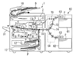
まず、図1にて、画像形成装置1における全体の構成・動作について説明する。
図1において、1は画像形成装置としての複写機、2は原稿Dの画像情報を光学的に読み込む原稿読込部、3は原稿読込部2で読み込んだ画像情報に基いた露光光Lを感光体ドラム5上に照射する露光部、を示す。
また、4は感光体ドラム5上にトナー像(画像)を形成する作像部、7は感光体ドラム5上に形成されたトナー像をシートP(シート)に転写する転写部(画像形成部)、10はセットされた原稿Dを原稿読込部2に搬送する原稿搬送部(自動原稿搬送装置)、を示す。
また、12、13は転写紙等のシートPが収納された給紙カセット(給送装置)、17は転写部7に向けてシートPを搬送するレジストローラ(タイミングローラ)、を示す。
また、20はシートP上に担持されたトナー像(未定着画像)を定着する定着装置、21は定着装置20に設置された定着ローラ、22は定着装置20に設置された加圧ローラ、31は装置本体1から排紙されたシートPが積載される排紙トレイ、60は大容量のシートPが収納される給送装置(大容量給送装置)、を示す。
First, FIG. 1 describes the overall configuration and operation of the image forming apparatus 1.
In FIG. 1, 1 is a copying machine as an image forming apparatus, 2 is a document reading unit that optically reads image information of a document D, and 3 is a photoconductor that emits exposure light L based on the image information read by the document reading unit 2. An exposed portion to be irradiated on the drum 5 is shown.
Further, 4 is an image forming unit that forms a toner image (image) on the photoconductor drum 5, and 7 is a transfer unit (image forming unit) that transfers the toner image formed on the photoconductor drum 5 to the sheet P (sheet). ), 10 indicates a document transfer unit (automatic document transfer device) that transports the set document D to the document reading unit 2.
Further, 12 and 13 indicate a paper feed cassette (feeding device) containing a sheet P such as transfer paper, and 17 indicates a resist roller (timing roller) that conveys the sheet P toward the transfer unit 7.
Further, 20 is a fixing device for fixing the toner image (unfixed image) supported on the sheet P, 21 is a fixing roller installed in the
図1を参照して、画像形成装置1における、通常の画像形成時の動作について説明する。
まず、原稿Dは、原稿搬送部10の搬送ローラによって、原稿台から図中の矢印方向に搬送(給送)されて、原稿読込部2上を通過する。このとき、原稿読込部2では、上方を通過する原稿Dの画像情報が光学的に読み取られる。
そして、原稿読込部2で読み取られた光学的な画像情報は、電気信号に変換された後に、露光部3(書込部)に送信される。そして、露光部3からは、その電気信号の画像情報に基づいたレーザ光等の露光光Lが、作像部4の感光体ドラム5上に向けて発せられる。
With reference to FIG. 1, the operation of the image forming apparatus 1 during normal image forming will be described.
First, the document D is conveyed (fed) from the document table in the direction of the arrow in the drawing by the transfer roller of the
Then, the optical image information read by the document reading unit 2 is converted into an electric signal and then transmitted to the exposure unit 3 (writing unit). Then, the exposure light L, such as a laser beam, based on the image information of the electric signal is emitted from the
一方、作像部4において、感光体ドラム5は図中の時計方向に回転しており、所定の作像プロセス(帯電工程、露光工程、現像工程)を経て、感光体ドラム5上に画像情報に対応した画像(トナー像)が形成される。
その後、感光体ドラム5上に形成された画像は、画像形成部としての転写部7で、レジストローラ17により搬送されたシートP上に転写される。
On the other hand, in the image forming unit 4, the photoconductor drum 5 is rotated clockwise in the drawing, and after undergoing a predetermined image forming process (charging step, exposure step, developing step), image information is displayed on the photoconductor drum 5. An image (toner image) corresponding to is formed.
After that, the image formed on the photoconductor drum 5 is transferred to the sheet P conveyed by the resist roller 17 by the transfer unit 7 as the image forming unit.
一方、転写部7(画像形成部)に搬送されるシートPは、次のように動作する。
まず、画像形成装置本体1の複数の給紙カセット12、13のうち、1つの給紙カセットが自動又は手動で選択される(例えば、最上段の給紙カセット12が選択されたものとする。)。そして、給紙カセット12に収納されたシートPの最上方の1枚が、給紙機構52(フィードローラ、ピックアップローラ、バックアップローラ、等で構成されている。)によって給送されて、搬送経路に向けて搬送される。その後、シートPは、複数の搬送ローラが配設された搬送経路を通過して、レジストローラ17の位置に達する。
なお、装置本体1の側方に設置された大容量の給送装置60(大容量給送装置)が選択された場合には、給送装置60の2つの給紙カセット61、62のうち、いずれか一方に積載された複数のシートPのうち最上方のシートPが、搬送ベルト63によって給送されて、複数の搬送ローラ対73、74が設置された搬送経路を経由した後に、装置本体1の入口ローラ55によって装置本体1内に搬送されて、その後にレジストローラ17の位置に達することになる。
On the other hand, the sheet P conveyed to the transfer unit 7 (image forming unit) operates as follows.
First, it is assumed that one of the plurality of
When the large-capacity feeding device 60 (large-capacity feeding device) installed on the side of the device main body 1 is selected, of the two
レジストローラ17の位置に達したシートPは、感光体ドラム5上に形成された画像と位置合わせをするためにタイミングを合わせて、転写部7(画像形成部)に向けて搬送される。
そして、転写工程後のシートPは、転写部7の位置を通過した後に、搬送経路を経て定着装置20に達する。定着装置20に達したシートPは、定着ローラ21と加圧ローラ22との間に送入されて、定着ローラ21から受ける熱と双方の部材21、22から受ける圧力とによってトナー像が定着される(定着工程である)。トナー像が定着された定着工程後のシートPは、定着ローラ21と加圧ローラ22との間(定着ニップである。)から送出された後に、画像形成装置本体1から排出されて、出力画像として排紙トレイ31上に積載されることになる。
こうして、一連の画像形成プロセスが完了する。
The sheet P that has reached the position of the resist roller 17 is conveyed toward the transfer unit 7 (image forming unit) at the same timing in order to align with the image formed on the photoconductor drum 5.
Then, the sheet P after the transfer step reaches the
In this way, a series of image forming processes is completed.
次に、本実施の形態において特徴的な、搬送装置70について詳述する。
図1に示すように、本実施の形態において、特徴的な搬送装置70は、大容量給送装置60に内設されている。
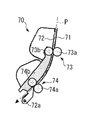
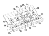
搬送装置70は、シートPを搬送するものである。図2に示すように、搬送装置70には、複数の搬送ローラ対73、74が、一点鎖線で示す搬送経路に沿って設置されている。搬送ローラ対73、74は、駆動機構によって所定方向(図2の反時計方向である。)に回転駆動される駆動ローラ73a、74aと、駆動ローラ73a、74aに当接して図2の時計方向に従動回転する従動ローラ73b、74bと、で構成されている。従動ローラ73b、74bは、駆動ローラ73a、74aとともに搬送ローラ対73、74を形成して、搬送経路においてシートPを挟持・搬送することになる。
Next, the
As shown in FIG. 1, in the present embodiment, the
The
また、図2〜図5等を参照して、搬送装置70には、固定ガイド部材71と、開閉ガイド部材72と、が設置されている。
固定ガイド部材71は、金属材料(又は、樹脂材料)で形成された板状部材であって、搬送装置70の筐体に固定して設置されている。固定ガイド部材71には、駆動ローラ73a、74aが回転可能に保持されている。駆動ローラ73a、74aは、ローラ部の一部が、固定ガイド部材71に形成された開口を介して搬送経路側(開閉ガイド部材72側)に突出するように設置されている。
開閉ガイド部材72は、金属材料(又は、樹脂材料)で形成された板状部材であって、固定ガイド部材71に対向してシートPが搬送される搬送経路を形成している。開閉ガイド部材72には、従動ローラ73b、74bが回転可能に保持されている。従動ローラ73b、74bは、ローラ部の一部が、開閉ガイド部材72に形成された開口を介して搬送経路側(固定ガイド部材71側)に突出するように設置されている。
Further, referring to FIGS. 2 to 5 and the like, the
The fixed
The opening /
2つのガイド部材71、72は、その対向距離(シートPの厚さよりも長くて最適化された距離である。)が搬送経路に沿ってほぼ一定になるように設置されている。そして、2つのガイド部材71、72によって形成された搬送経路において、シートPは、2つのガイド部材71、72に案内されながら、搬送ローラ対73、74によって図2の矢印方向に挟持・搬送されることになる。
なお、本実施の形態では、2つのガイド部材71、72によって、開閉ガイド部材72の側に凹状に湾曲する搬送経路が形成されている。
The two
In the present embodiment, the two
ここで、開閉ガイド部材72は、固定ガイド部材71との間に形成される搬送経路を開閉できるように、支軸72aを中心に回動可能に、搬送装置70の筐体に保持されている。搬送装置70には、開閉ガイド部材72の開閉動作をおこなうために回転軸75aを中心に回動される操作レバー75(図3、図7等を参照できる。)が設置されている。
Here, the opening /
開閉ガイド部材72は、通常の画像形成動作時には、「閉鎖状態」であって、搬送経路が閉鎖された状態(図2、図3、図7(A)等の状態であって、固定ガイド部材71との間に搬送経路が形成された状態である。)になる。
そして、開閉ガイド部材72は、主として搬送経路にシートPが詰まったときに、操作レバー75の回動操作によって、支軸72aを中心に図2の反時計方向に回動されて、「開放状態」になる。開閉ガイド部材72の開放状態は、搬送経路が開放された状態であって、図7(E)等に示すように固定ガイド部材71との間に搬送経路が形成されておらず、大きな隙間X(スペース)が形成された状態である。
The opening /
Then, when the seat P is clogged mainly in the transport path, the opening /
具体的に、搬送装置70における搬送経路にシートPが詰まると(ジャムが発生すると)、その状態が搬送経路に設置された紙検知センサ(フォトセンサ)によって検知されて、その情報が表示パネル(画像形成装置本体1の外装部に設置されている。)に表示される。そして、ユーザーは、そのシートP(ジャム紙)を搬送経路から取り除くために、まず、大容量給送装置60の開閉ドアー64(図1を参照できる。)を開放して、搬送装置70の搬送経路を露呈させる。その後、ユーザーは、操作レバー75の把持部80(図3等を参照できる。)を把持して、操作レバー75を図7の時計方向に回動させて、開閉ガイド部材72を開放状態にして、そこに形成された隙間Xに手を入れてシートP(ジャム紙)を取り除くことになる。そして、シートP(ジャム紙)が取り除かれた後に、ユーザーは、操作レバー75の把持部80を把持して、操作レバー75を図7の反時計方向に回動させて、開閉ガイド部材72を閉鎖状態にして、さらに開閉ドアー64を閉鎖する。こうして、一連のジャム処理作業が終了することになる。
Specifically, when the sheet P is clogged in the transport path of the transport device 70 (when a jam occurs), the state is detected by a paper detection sensor (photo sensor) installed in the transport path, and the information is displayed on the display panel (photo sensor). It is displayed on the exterior of the image forming apparatus main body 1). Then, in order to remove the sheet P (jam paper) from the transport path, the user first opens the opening / closing door 64 (see FIG. 1) of the large-
ここで、本実施の形態における搬送装置70は、操作レバー75の回動が開始されてから回動角度が所定値(本実施の形態では、45°程度である。)を超えた後に、閉鎖状態にあった開閉ガイド部材72が開放状態に変化するように構成されている。
詳しくは、閉鎖状態にある開閉ガイド部材72を開放するときには、図7(A)に示す基準位置にある操作レバー75を時計方向に回動させることになる。しかし、図7(A)に示す基準位置から操作レバー75の回動が開始されて、暫くの間は、操作レバー75が回動していても、開閉ガイド部材72は閉鎖状態を維持している。そして、操作レバー75の回動がある程度進んだ後に、図7(D)、(E)に示すように、閉鎖状態にあった開閉ガイド部材72が開放状態に変化することになる。
すなわち、閉鎖状態の開閉ガイド部材72は、操作レバー75の回動が開始された後に、タイミングをずらして図7の反時計方向に回動されることになる。
Here, the
Specifically, when the opening /
That is, the opening /
さらに詳しくは、操作レバー75は、搬送装置70の筐体に、回転軸75aを中心にして回動可能に保持されている。操作レバー75は、開閉ガイド部材72の内側(搬送ガイド面に対して反対側の面に対向する側である。)に設置されている。
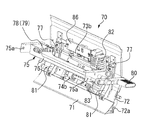
図3、図4等に示すように、操作レバー75は、レバー本体76、コロ77、軸部78、付勢部材としての圧縮スプリング79、把持部80、等で構成されている。操作レバー75は、図7に示すように、回転軸75aに直交する断面でみたときに、回転軸75aから開閉ガイド部材72の側に向けて径方向に延在するように形成されている。
More specifically, the operating
As shown in FIGS. 3 and 4, the operating
レバー本体76は、板金を組み合わせて形成されたものであって、操作レバー75の筐体として機能するものである。
コロ77は、操作レバー75において回転軸75aから離れた位置に回転可能に、レバー本体76に保持されている。具体的に、本実施の形態では、2つのコロ77が、幅方向(シートPの搬送方向に直交する方向であって、図2の紙面垂直方向である。)の両端部にそれぞれ設置されている。コロ77は、レバー本体76において半径方向(回転軸75aを中心にする円における半径方向である。)に移動可能に保持された軸部78の先端部に、回転可能に保持されている。軸部78は、一端側がレバー本体76に接続されて他端側が軸部78に接続された圧縮スプリング79(付勢部材)によって半径方向に付勢されている。これにより、コロ77は、圧縮スプリング79(付勢部材)によって、後述する当接部材81に当接する方向(回転軸75aから離れる方向である。)に付勢されることになる。
把持部80は、レバー本体76の幅方向一端側(図1の開閉ドアー64が開閉される操作側である。)に設置されていて、レバー本体76、コロ77、軸部78、圧縮スプリング79などの構成部品とともに回転軸75aを中心にして一体的に回動できるように構成されている。把持部80は、搬送装置70における他の部材と干渉せずに回動できるように、幅方向一端側に突出する位置に設置されている。そして、ユーザーは、このように構成された把持部80を把持した状態で、把持部80を回転軸75aを中心にして回動させることで、操作レバー75を一体的に回動させることになる。
The
The
The
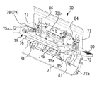
図3〜図7等に示すように、開閉ガイド部材72には、当接部材81、従動ローラ73b、74b、モータ駆動機構、モータカバー82、83、等が設置されている。
As shown in FIGS. 3 to 7, the opening /
当接部材81は、開閉ガイド部材72における搬送ガイド面に対して反対側の面に設置されていて、操作レバー75のコロ77が当接するものである。
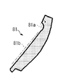
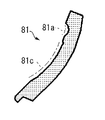
ここで、図6等を参照して、当接部材81には、コロ77が当接する部分に、凹部81aと摺接部81bとが形成されている。
The
Here, referring to FIG. 6 and the like, the
当接部材81の凹部81aは、操作レバー75のコロ77が嵌合して操作レバー75の回動を制限するものである。すなわち、図7(A)に示すように、コロ77が凹部81aに嵌合した状態は、開閉ガイド部材72が閉鎖状態であって、操作レバー75が回動停止して保持された状態である。コロ77が凹部81aに嵌合した状態は圧縮スプリング79の付勢力によって維持されて、その付勢力に抗するような力が作用しない限り、操作レバー75が勝手に回動することはなく、図7(A)に示す状態が維持されることになる。
なお、凹部81aは、コロ77が嵌合されたり嵌合解除されたりできるように、コロ77の外周形状に合わせて円弧凹面状(中心角が180°以下の円弧である。)に形成されている。
The
The
当接部材81の摺接部81bは、圧縮スプリング79(付勢部材)の付勢力に抗するように凹部81aとコロ77との嵌合が解除されて操作レバー75の回動が開始されてから回動角度が所定値(本実施の形態では、45°程度である。)に達するまで、コロ77が摺接する部分である。このようにコロ77が摺接部81bに摺接した状態は、圧縮スプリング79(付勢部材)の付勢力によってコロ77を介して当接部材81が押圧されている状態であって、操作レバー75が回動しているものの開閉ガイド部材72が閉鎖状態になる。そして、操作レバー75の回動角度が上述した所定値を超えてコロ77が摺接部81bから離れた状態になったときに、圧縮スプリング79の付勢力によってコロ77を介して当接部材81が押圧されている状態が解除されて、後述する引張スプリング95(付勢手段)の付勢力によって開閉ガイド部材72が閉鎖状態から開放状態に変化することになる。
なお、本実施の形態において、摺接部81bは、平面ではあるものの、その始端部から終端部にかけて、操作レバー75の回転軸75aからの距離が大きく変化しないように形成されている。
また、摺接部81bの終端部は、概ね、支軸72aと回転軸75aとを結ぶ仮想直線と、当接部材81の当接面と、が交差する位置である。すなわち、この摺接部81bの終端部の位置をコロ77が通過したときには、圧縮スプリング79によって付勢されたコロ77によって、当接部材81(開閉ガイド部材72)に支軸72aを中心にして反時計方向に回動される力が作用することになる。
The sliding
In the present embodiment, although the sliding
Further, the end portion of the sliding
ここで、図7を参照して、搬送装置70には、開閉ガイド部材72が開放状態になるように回動する方向に付勢する付勢手段としての引張スプリング95が設置されている。
詳しくは、付勢手段としての引張スプリング95は、その一端側のフックが開閉ガイド部材72(支軸72aから充分に離れた部分である。)に接続されて、その他端側のフックが搬送装置70の筐体に接続されている。
これにより、図7(A)〜(C)に示すように、圧縮スプリング79の付勢力によってコロ77を介して当接部材81(開閉ガイド部材72)が固定ガイド部材71の側に向けて押圧されている状態であるときには、その押圧力が引張スプリング95の付勢力に抗するように作用して、開閉ガイド部材72は閉鎖されるになる。これに対して、図7(D)、(E)に示すように、圧縮スプリング79の付勢力によってコロ77を介して当接部材81(開閉ガイド部材72)が固定ガイド部材71の側に向けて押圧されている状態が解除されているときには、引張スプリング95の付勢力によって開閉ガイド部材72は開放されることになる。
Here, referring to FIG. 7, the
Specifically, the
As a result, as shown in FIGS. 7A to 7C, the contact member 81 (opening / closing guide member 72) is pressed toward the fixed
また、図7を参照して、搬送装置70には、図7(A)等に示すように搬送経路が閉鎖された状態において開閉ガイド部材72と固定ガイド部材71との対向距離が所定距離になるように制限するストッパ部71aが設けられている。
詳しくは、固定ガイド部材71には、搬送経路を通過するシートPに干渉しない幅方向端部の位置に、開閉ガイド部材72の側に向けて突起するようにストッパ部71aが形成されている。
これにより、図7(A)〜(C)に示すように、圧縮スプリング79の付勢力によってコロ77を介して当接部材81(開閉ガイド部材72)が固定ガイド部材71の側に向けて押圧されている状態であるときには、開閉ガイド部材72が固定ガイド部材71のストッパ部71aに突き当たった状態でその付勢が規制されて、2つのガイド部材71、72の対向距離が最適化された状態で開閉ガイド部材72が閉鎖されるになる。
Further, referring to FIG. 7, in the
Specifically, the fixed
As a result, as shown in FIGS. 7A to 7C, the contact member 81 (opening / closing guide member 72) is pressed toward the fixed
なお、本実施の形態では、金属材料で形成された開閉ガイド部材72とは別部品として、当接部材81を樹脂材料で形成して、当接部材81をネジ締結によって開閉ガイド部材72に固定して設置している。
これに対して、当接部材81を、開閉ガイド部材72に一体的に形成することもできる。例えば、開閉ガイド部材72と当接部材81とを射出成型によって樹脂材料で一体的に形成することもできる。このように構成した場合には、搬送装置70における部品点数を少なくすることができる。
In the present embodiment, the
On the other hand, the
以下、図7(A)〜(E)を用いて、閉鎖状態にある開閉ガイド部材72が開放状態になるまでの動作について説明する。
開閉ガイド部材72は、操作レバー75が図7(A)〜(E)の順に動作することで、開放されることになる。
まず、操作レバー75は、図7(A)に示す保持状態(凹部81aとコロ77とが嵌合した状態である。)から、回動方向の力が加えられると、図7(B)に示すように、コロ77が圧縮スプリング79の付勢力に抗するように凹部81aを乗り越えて黒矢印方向(回転軸75aに近づく方向である。)に移動する。ユーザーの側からすると、圧縮スプリング79の付勢力に抗するように凹部81aを乗り越えるとき(又は、乗り入れるとき)に、クリック感を感じることになり、凹部81aとコロ77との嵌合解除(又は、嵌合)をおこなうときの操作レバー75の操作性が向上することになる。
その後、操作レバー75の時計方向の回動が進められると、図7(C)に示すように、コロ77が摺接部81bの表面を滑動することになる。このような状態は、圧縮スプリング79の付勢力によってコロ77を介して当接部材81が押圧されている状態であって、操作レバー75が回動しているものの開閉ガイド部材72が閉鎖状態になっている。
そして、操作レバー75の時計方向の回動がさらに進められると、図7(D)に示すように、コロ77が摺接部81bの位置を抜けて当接部材81の突起部の位置に達すると、圧縮スプリング79の付勢力によってコロ77を介して当接部材81が押圧されている状態が解除されて、引張スプリング95(付勢手段)の付勢力によって開閉ガイド部材72が支軸72aを中心にして反時計方向に回動し始めることになる。
そして、操作レバー75の時計方向の回動がさらに進められると、図7(E)に示すように、コロ77が当接部材81にまったく当接しない状態になって、引張スプリング95の付勢力によって開閉ガイド部材72が支軸72aを中心にしてさらに反時計方向に回動して、搬送装置70の筐体に形成された受部に当接する位置で回動が規制されることになる。そして、この状態のとき、図7(E)に示すように、開放状態にある開閉ガイド部材72と、固定ガイド部材71と、の間に形成される隙間Xは非常に大きなものになる。一方、操作レバー75も、搬送装置70の筐体に形成された受部に当接する位置で、その回転軸75aを中心にした時計方向の回動が規制されることになる。こうして、閉鎖状態にある開閉ガイド部材72が開放状態になるまでの動作が終了することになり、ユーザーは、図7(E)に示すように形成された大きな隙間Xに手を入れて、搬送経路に詰まったシートP(ジャム紙)を取り除くことになる。
なお、図7(E)に示すように開放状態にある開閉ガイド部材72を図7(A)に示す閉鎖状態になるまでの動作については、上述した手順とは逆の手順の操作がおこなわれることになる。
Hereinafter, with reference to FIGS. 7A to 7E, the operation until the opening /
The opening /
First, the operating
After that, when the clockwise rotation of the operating
Then, when the clockwise rotation of the operating
Then, when the clockwise rotation of the operating
Regarding the operation of the opening /
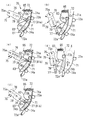
ここで、本実施の形態では、開閉ガイド部材72にモータ駆動機構が設置されている。モータ駆動機構は、所定のタイミングで従動ローラ73b、74bを固定ガイド部材71に設置された駆動ローラ73a、74aから遠ざかる方向に移動させるものである。モータ駆動機構は、2つの従動ローラ73b、74bに対応して2つ設けられている。
詳しくは、図3〜図5を参照して、モータ駆動機構は、モータ84、85、ブラケット86、タイミングベルト87、88、カム89、90、搖動レバー91、92、等で構成されている。また、開閉ガイド部材72には、モータ84、85を覆うモータカバー82、83が設置されている。
本実施の形態では、画像形成動作において、搬送装置70の上流側の位置に設置された可動ローラ対(シートPを挟持した状態で幅方向に移動可能に構成された搬送ローラ対であって、例えば、レジストローラ17である。)によってシートPの幅方向の位置ズレ補正(横レジスト補正)をおこなうときなどに、その補正されるシートPの後端側を搬送ローラ対73、74で挟持してシートPの負荷になり補正精度を低下させないように、モータ駆動機構によって駆動ローラ73a、74aに対して従動ローラ73b、74bが離間されることになる。具体的に、そのようなタイミングのとき、モータ84、85が動作して、モータ84、85の駆動力がタイミングベルト87、88を介してカム89、90が設置されたシャフトに伝達される。これにより、カム89、90が回転して搖動レバー91、92を搖動させて、ブラケット86を介して駆動ローラ73a、74aの側に付勢されている従動ローラ73b、74bを付勢力に抗する方向に移動させる。これにより、搬送装置70の搬送経路において、従動ローラ73b、74bが駆動ローラ73a、74aから離間することになる。
Here, in the present embodiment, the motor drive mechanism is installed on the opening /
For details, with reference to FIGS. 3 to 5, the motor drive mechanism includes
In the present embodiment, in the image forming operation, a movable roller pair (a transport roller pair configured to be movable in the width direction while sandwiching the sheet P) installed at a position on the upstream side of the
以上説明したように、本実施の形態における搬送装置70は、基準位置にあった操作レバー75の回動が開始されて、操作レバー75の回動角度が所定値を超えた後に、閉鎖状態の開閉ガイド部材72が開放状態に変化するように構成されている。これにより、比較的狭い空間であっても、操作レバー75の回動によって開閉ガイド部材72を比較的大きな範囲で回動させることができる。そのため、開放状態の開閉ガイド部材72と、固定ガイド部材71と、の間に形成される隙間X(スペース)も大きなものになって、搬送経路に詰まったシートP(ジャム紙)を取り除く作業が容易になる。
また、操作レバー75の回動が開始された後に、タイミングをずらして開閉ガイド部材72が回動されるため、開閉ガイド部材72が操作レバー75に干渉して回動不良が生じる不具合が生じにくくなる。特に、本実施の形態では、図3に示すように、モータカバー82、83が、操作レバー75に対して比較的近い位置に設置されているため、そのように回動するタイミングをずらすことによって干渉を避ける効果が大きくなる。
As described above, the
Further, since the opening /
なお、上述したように開閉ガイド部材72が閉鎖状態から開放状態に変化する回動位置に対応した操作レバー75の回動角度(所定値)は、30°以上であることが好ましい。操作レバー75の回動角度(所定値)が30°未満であると、開閉ガイド部材72の回動範囲が充分に大きくならずに、シートP(ジャム紙)を取り除くための隙間Xを充分に確保することができないためである。
また、上述した操作レバー75の回動角度(所定値)は、90°以下であることが好ましい。操作レバー75の回動角度(所定値)が90°を超えると、操作レバー75の回動範囲が大きくなり過ぎて、ユーザーが操作レバー75を操作しにくくなるためである。
As described above, the rotation angle (predetermined value) of the operating
Further, the rotation angle (predetermined value) of the
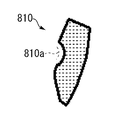
図8は、上述した操作レバー75の回動角度(所定値)がゼロ(又は、それに近い角度)になるように設定された当接部材810を示す側面図である。すなわち、図8の当接部材810には、操作レバー75のコロ77が嵌合する凹部810aが形成されているものの、本実施の形態のものとは異なり摺接部が形成されていない。したがって、そのような当接部材810を用いた場合には、図9(A)、(B)に示すように、基準位置にあった操作レバー75の回動が開始された直後に、閉鎖状態の開閉ガイド部材72が開放状態に変化することになる。
そのため、操作レバー75の回動によって開閉ガイド部材72を小さな範囲でしか回動させることができず、開放状態の開閉ガイド部材72と、固定ガイド部材71と、の間に形成される隙間X(スペース)も小さなものになって、搬送経路に詰まったシートP(ジャム紙)を取り除く作業が難しくなる。
また、操作レバー75の回動が開始された直後に、開閉ガイド部材72が回動されるため、開閉ガイド部材72が操作レバー75に干渉して回動不良が生じやすくなる。特に、本実施の形態のものと同様に、モータカバー82、83が、操作レバー75に対して比較的近い位置に設置されている場合には、図9(B)の破線で囲んだ部分Wに示すように、開放状態において一方のモータカバー82が操作レバー75に干渉してしまうことになる。
本実施の形態では、先に説明したように、操作レバー75の回動が開始された後に、タイミングをずらして開閉ガイド部材72が回動されるため、これらのような不具合の発生を軽減することができる。
FIG. 8 is a side view showing the
Therefore, the opening /
Further, since the opening /
In the present embodiment, as described above, after the rotation of the operating
<変形例>
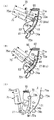
図10は、変形例としての当接部材81を示す側面図であって、本実施の形態における図6に相当する図である。また、図11は、変形例としての操作レバー75の回動にともなう開閉ガイド部材72の動作を示す図であって、本実施の形態における図7に相当する図である。
図10、図11に示すように、変形例における当接部材81は、摺接部81cの摺接面が、操作レバー75の回転軸75aからの距離Rが一定になるように円弧凹面状に形成されている。
このような構成により、図11(A)に示すように、操作レバー75のコロ77が、当接部材81の凹部81aに嵌合しているときには、操作レバー75の回転軸75aからコロ77と凹部81aとの接触点までの距離がM1となる。そして、操作レバー75の時計方向の回動が開始されて、コロ77が凹部81aを乗り越えるときには、その距離が距離M1よりも一時的に短くなる。
その後、図11(B)に示すように、操作レバー75のコロ77が、当接部材81の摺接部81cを滑動するときには、操作レバー75の回転軸75aからコロ77と凹部81aとの接触点までの距離がM3で常に一定となる。そのため、コロ77が摺接部81cを摺動するときの摩擦抵抗の変動が少なくなって、ユーザーは操作レバー75をスムーズに回動操作することができる。
そして、図11(C)に示すように、操作レバー75の回動がさらに進められて、操作レバー75のコロ77が当接部材81から離間すると、本実施の形態のものと同様に開閉ガイド部材72が固定ガイド部材71との間に大きな隙間Xをあけて開放されることになる。
<Modification example>
FIG. 10 is a side view showing the
As shown in FIGS. 10 and 11, the
With such a configuration, as shown in FIG. 11A, when the
After that, as shown in FIG. 11B, when the
Then, as shown in FIG. 11C, when the rotation of the operating
以上説明したように、本実施の形態における搬送装置70は、固定ガイド部材71と、搬送経路を開閉できるように支軸72aを中心に回動可能に設置された開閉ガイド部材72と、開閉ガイド部材72の開閉動作をおこなうために回転軸75aを中心に回動される操作レバー75と、が設けられている。そして、操作レバー75の回動が開始されてから回動角度が所定値を超えた後に、閉鎖状態にあった開閉ガイド部材72が開放状態に変化するように構成されている。
これにより、操作レバー75の回動によって開閉ガイド部材72を比較的大きく回動させることができる。
As described above, the
As a result, the opening /
なお、本実施の形態では、モノクロの画像形成装置1に設置される搬送装置70に対して本発明を適用したが、カラーの画像形成装置に設置される搬送装置に対しても当然に本発明を適用することができる。
また、本実施の形態では、電子写真方式の画像形成装置1に設置される搬送装置70に対して本発明を適用したが、本発明の適用はこれに限定されることなく、その他の方式の画像形成装置(例えば、インクジェット方式の画像形成装置や、孔版印刷機などである。)に設置される搬送装置に対しても本発明を適用することができる。
また、本実施の形態では、画像形成装置1における大容量給送装置60の一部に設置される搬送装置70に対して本発明を適用したが、その他の部分に設置される搬送装置に対しても開閉ガイド部材が設置されたものであれば当然に本発明を適用することができるし、搬送装置としての原稿搬送部10(自動原稿搬送装置)に対しても当然に本発明を適用することができる。
そして、それらのような場合であっても、本実施の形態のものと同様の効果を得ることができる。
In the present embodiment, the present invention is applied to the
Further, in the present embodiment, the present invention is applied to the
Further, in the present embodiment, the present invention is applied to the
And even in such a case, the same effect as that of the present embodiment can be obtained.
なお、本発明が本実施の形態に限定されず、本発明の技術思想の範囲内において、本実施の形態の中で示唆した以外にも、本実施の形態は適宜変更され得ることは明らかである。また、前記構成部材の数、位置、形状等は本実施の形態に限定されず、本発明を実施する上で好適な数、位置、形状等にすることができる。 It is clear that the present invention is not limited to the present embodiment, and within the scope of the technical idea of the present invention, the present embodiment may be appropriately modified in addition to the suggestions in the present embodiment. is there. Further, the number, position, shape, etc. of the constituent members are not limited to the present embodiment, and can be a suitable number, position, shape, etc. for carrying out the present invention.
なお、本願において、「シート」とは、通常の紙(用紙)の他に、コート紙、ラベル紙、OHPシート、フィルム等のシート状の記録媒体のすべてを含み、さらには搬送装置としての自動原稿搬送装置において搬送される原稿をも含むものと定義する。 In the present application, the "sheet" includes all sheet-shaped recording media such as coated paper, label paper, OHP sheet, and film in addition to ordinary paper (paper), and is also an automatic transfer device. It is defined as including the documents transported by the document transport device.
また、本願において、「コロ」が「摺接部」を摺接(又は、滑動)する状態とは、コロが回転しながら摺接部の表面を移動する状態をも含むものと定義する。 Further, in the present application, the state in which the "roller" slides (or slides) the "sliding contact portion" is defined to include a state in which the roller moves on the surface of the sliding contact portion while rotating.
1 画像形成装置(画像形成装置本体)、
60 給送装置(大容量給送装置)、
70 搬送装置、
71 固定ガイド部材(固定ガイド板)、
71a ストッパ部、
72 開閉ガイド部材(開閉ガイド板)、
72a 支軸、
73、74 搬送ローラ対、
73a、74a 駆動ローラ、
73b、74b 従動ローラ、
75 操作レバー、
75a 回転軸、
76 レバー本体、
77 コロ、 78 軸部、
79 圧縮スプリング(付勢部材)、
80 把持部、
81 当接部材、
81a 凹部、 81b、81c 摺接部、
82、83 モータカバー、
84、85 モータ(モータ駆動機構)、
86 ブラケット(モータ駆動機構)、
87、88 タイミングベルト(モータ駆動機構)、
89、90 カム(モータ駆動機構)、
91、92 搖動レバー(モータ駆動機構)、
95 引張スプリング(付勢手段)、
P シート。
1 Image forming apparatus (image forming apparatus main body),
60 Feeding device (large capacity feeding device),
70 Conveyor,
71 Fixed guide member (fixed guide plate),
71a stopper part,
72 Open / close guide member (open / close guide plate),
72a support shaft,
73, 74 Conveyor roller pairs,
73a, 74a drive rollers,
73b, 74b driven roller,
75 operating lever,
75a rotating shaft,
76 lever body,
77 rollers, 78 shafts,
79 compression spring (biasing member),
80 grip,
81 Contact member,
81a recess, 81b, 81c sliding contact,
82, 83 motor cover,
84, 85 motors (motor drive mechanism),
86 bracket (motor drive mechanism),
87, 88 Timing belt (motor drive mechanism),
89, 90 cams (motor drive mechanism),
91, 92 Swing lever (motor drive mechanism),
95 Tension spring (urging means),
P sheet.
Claims (9)
当該搬送装置に固定して設置された固定ガイド部材と、
前記固定ガイド部材に対向してシートが搬送される搬送経路を形成して、前記搬送経路を開閉できるように支軸を中心に回動可能に設置された開閉ガイド部材と、
前記開閉ガイド部材の開閉動作をおこなうために回転軸を中心に回動される操作レバーと、
を備え、
前記操作レバーの回動が開始されてから回動角度が所定値を超えた後に、閉鎖状態にあった前記開閉ガイド部材が開放状態に変化するように構成され、
前記開閉ガイド部材は、搬送ガイド面に対して反対側の面に、前記操作レバーにおいて前記回転軸から離れた位置に回転可能に保持されたコロが当接する当接部材が設置され、
前記操作レバーは、前記コロと、前記コロを前記当接部材に当接する方向に向けて付勢する付勢部材と、を具備し、
前記当接部材は、
前記コロが嵌合して前記操作レバーの回動を制限する凹部と、
前記付勢部材の付勢力に抗するように前記凹部と前記コロとの嵌合が解除されて前記操作レバーの回動が開始されてから回動角度が前記所定値に達するまで、前記コロが摺接する摺接部と、
を具備したことを特徴とする搬送装置。 A transport device that transports sheets.
A fixed guide member fixedly installed on the transfer device and
An opening / closing guide member that forms a transport path for transporting the sheet facing the fixed guide member and is rotatably installed around a support shaft so that the transport path can be opened / closed.
An operation lever that is rotated around a rotation axis to open and close the opening / closing guide member,
With
The opening / closing guide member, which was in the closed state, is configured to change to the open state after the rotation angle exceeds a predetermined value after the rotation of the operating lever is started .
The opening / closing guide member is provided with a contact member on the surface opposite to the transport guide surface, to which a roller rotatably held at a position distant from the rotation axis of the operation lever abuts.
The operating lever includes the roller and an urging member that urges the roller in a direction of contacting the contact member.
The contact member is
A recess in which the roller fits to limit the rotation of the operating lever,
From the time when the recess and the roller are disengaged so as to resist the urging force of the urging member and the rotation of the operating lever is started until the rotation angle reaches the predetermined value, the roller With the sliding contact part that slides
A transport device characterized by being provided with .
前記コロが前記摺接部に摺接した状態は、前記操作レバーが回動しているものの前記開閉ガイド部材が閉鎖状態であり、In the state where the roller is in sliding contact with the sliding contact portion, the opening / closing guide member is closed although the operating lever is rotating.
前記操作レバーの回動角度が前記所定値を超えて前記コロが前記摺接部から離れた状態になったときに、前記開閉ガイド部材が閉鎖状態から開放状態に変化することを特徴とする請求項1に記載の搬送装置。A claim characterized in that when the rotation angle of the operating lever exceeds the predetermined value and the roller is separated from the sliding contact portion, the opening / closing guide member changes from the closed state to the open state. Item 1. The transport device according to item 1.
前記搬送経路が閉鎖された状態において前記開閉ガイド部材と前記固定ガイド部材との対向距離が所定距離になるように制限するストッパ部と、A stopper portion that limits the facing distance between the opening / closing guide member and the fixed guide member to a predetermined distance when the transport path is closed.
を備えたことを特徴とする請求項1又は請求項2に記載の搬送装置。The transport device according to claim 1 or 2, wherein the transport device is provided with.
前記開閉ガイド部材は、The opening / closing guide member
前記駆動ローラに当接して従動回転して、前記駆動ローラとともに搬送ローラ対を形成して前記搬送経路においてシートを搬送する従動ローラと、A driven roller that comes into contact with the drive roller and rotates driven to form a transport roller pair together with the drive roller to transport the sheet in the transport path.
所定のタイミングで前記従動ローラを前記駆動ローラから遠ざかる方向に移動させるモータ駆動機構と、A motor drive mechanism that moves the driven roller in a direction away from the drive roller at a predetermined timing,
を具備したことを特徴とする請求項1〜請求項5のいずれかに記載の搬送装置。The transport device according to any one of claims 1 to 5, wherein the transport device is provided with.
当該搬送装置に固定して設置された固定ガイド部材と、A fixed guide member fixedly installed on the transfer device and
前記固定ガイド部材に対向してシートが搬送される搬送経路を形成して、前記搬送経路を開閉できるように支軸を中心に回動可能に設置された開閉ガイド部材と、An opening / closing guide member that forms a transport path for transporting the sheet facing the fixed guide member and is rotatably installed around a support shaft so that the transport path can be opened / closed.
前記開閉ガイド部材の開閉動作をおこなうために回転軸を中心に回動される操作レバーと、An operation lever that is rotated around a rotation axis to open and close the opening / closing guide member,
を備え、With
前記操作レバーの回動が開始されてから回動角度が所定値を超えた後に、閉鎖状態にあった前記開閉ガイド部材が開放状態に変化するように構成され、The opening / closing guide member, which was in the closed state, is configured to change to the open state after the rotation angle exceeds a predetermined value after the rotation of the operating lever is started.
前記固定ガイド部材は、所定方向に回転駆動される駆動ローラを具備し、The fixed guide member includes a drive roller that is rotationally driven in a predetermined direction.
前記開閉ガイド部材は、The opening / closing guide member
前記駆動ローラに当接して従動回転して、前記駆動ローラとともに搬送ローラ対を形成して前記搬送経路においてシートを搬送する従動ローラと、A driven roller that comes into contact with the drive roller and rotates driven to form a transport roller pair together with the drive roller to transport the sheet in the transport path.
所定のタイミングで前記従動ローラを前記駆動ローラから遠ざかる方向に移動させるモータ駆動機構と、A motor drive mechanism that moves the driven roller in a direction away from the drive roller at a predetermined timing,
を具備したことを特徴とする搬送装置。A transport device characterized by being provided with.
Priority Applications (2)
| Application Number | Priority Date | Filing Date | Title |
|---|---|---|---|
| JP2016230918A JP6817536B2 (en) | 2016-11-29 | 2016-11-29 | Conveyor device and image forming device |
| US15/818,689 US10124973B2 (en) | 2016-11-29 | 2017-11-20 | Sheet conveying device and image forming apparatus incorporating the sheet conveying device |
Applications Claiming Priority (1)
| Application Number | Priority Date | Filing Date | Title |
|---|---|---|---|
| JP2016230918A JP6817536B2 (en) | 2016-11-29 | 2016-11-29 | Conveyor device and image forming device |
Publications (2)
| Publication Number | Publication Date |
|---|---|
| JP2018087064A JP2018087064A (en) | 2018-06-07 |
| JP6817536B2 true JP6817536B2 (en) | 2021-01-20 |
Family
ID=62192726
Family Applications (1)
| Application Number | Title | Priority Date | Filing Date |
|---|---|---|---|
| JP2016230918A Active JP6817536B2 (en) | 2016-11-29 | 2016-11-29 | Conveyor device and image forming device |
Country Status (2)
| Country | Link |
|---|---|
| US (1) | US10124973B2 (en) |
| JP (1) | JP6817536B2 (en) |
Families Citing this family (9)
| Publication number | Priority date | Publication date | Assignee | Title |
|---|---|---|---|---|
| WO2019078869A1 (en) * | 2017-10-19 | 2019-04-25 | Hewlett-Packard Development Company, L.P. | GUIDES FOR BRIDGE MODULE |
| JP7338131B2 (en) * | 2018-04-03 | 2023-09-05 | 富士フイルムビジネスイノベーション株式会社 | MEDIUM CONVEYING DEVICE, IMAGE READING DEVICE AND IMAGE FORMING DEVICE |
| JP7099035B2 (en) | 2018-04-27 | 2022-07-12 | セイコーエプソン株式会社 | Soft magnetic powder, powder magnetic core, magnetic element and electronic equipment |
| JP7306010B2 (en) | 2019-03-26 | 2023-07-11 | 株式会社リコー | Binding device, post-processing device and image forming system |
| JP7215291B2 (en) | 2019-03-28 | 2023-01-31 | 株式会社リコー | Additional folding device, post-processing device, and image forming system |
| JP7275750B2 (en) | 2019-03-28 | 2023-05-18 | 株式会社リコー | Sheet stacking device, post-processing device and image forming system |
| JP7544479B2 (en) * | 2019-12-27 | 2024-09-03 | グローリー株式会社 | Paper handling equipment |
| JP7780715B2 (en) * | 2021-12-24 | 2025-12-05 | 株式会社リコー | Conveyance mechanism and image forming apparatus |
| US20240375900A1 (en) * | 2023-05-09 | 2024-11-14 | Naoki Hoshi | Conveyor and image forming apparatus |
Family Cites Families (17)
| Publication number | Priority date | Publication date | Assignee | Title |
|---|---|---|---|---|
| JPS63151461U (en) * | 1987-03-24 | 1988-10-05 | ||
| JPH0262341A (en) * | 1988-08-26 | 1990-03-02 | Hitachi Ltd | Paper feeding device |
| US4908674A (en) * | 1989-02-22 | 1990-03-13 | Mita Industrial Co., Ltd. | Image forming apparatus |
| KR0135731Y1 (en) * | 1996-02-13 | 1999-05-15 | 김광호 | Apparatus for removing jammed paper from ink jet printer |
| JP3712305B2 (en) * | 1997-02-03 | 2005-11-02 | 株式会社リコー | Image forming apparatus |
| JPH10324435A (en) * | 1997-05-27 | 1998-12-08 | Oki Electric Ind Co Ltd | Medium processing device |
| JP2001278503A (en) * | 2000-03-31 | 2001-10-10 | Minolta Co Ltd | Sheet conveying equipment |
| JP3546024B2 (en) * | 2001-03-27 | 2004-07-21 | 京セラミタ株式会社 | Paper transport device |
| JP4993681B2 (en) | 2006-10-26 | 2012-08-08 | 株式会社リコー | Image forming apparatus |
| JP4438796B2 (en) | 2006-12-28 | 2010-03-24 | 村田機械株式会社 | Image forming apparatus |
| JP5022146B2 (en) * | 2007-08-31 | 2012-09-12 | 株式会社リコー | Opening and closing device, equipment, image forming device |
| JP5064999B2 (en) * | 2007-12-27 | 2012-10-31 | キヤノン株式会社 | Sheet processing device |
| JP4646008B2 (en) * | 2008-06-30 | 2011-03-09 | 株式会社沖データ | Medium conveying apparatus and image forming apparatus |
| JP2010254451A (en) | 2009-04-27 | 2010-11-11 | Ricoh Co Ltd | Paper conveying apparatus and image forming apparatus |
| JP6010959B2 (en) * | 2012-03-26 | 2016-10-19 | ブラザー工業株式会社 | Sheet conveying apparatus and image recording apparatus |
| US8820740B2 (en) * | 2012-04-10 | 2014-09-02 | Kabushiki Kaisha Toshiba | Sheet conveying apparatus |
| JP2016132570A (en) * | 2015-01-22 | 2016-07-25 | 理想科学工業株式会社 | Paper transport device |
-
2016
- 2016-11-29 JP JP2016230918A patent/JP6817536B2/en active Active
-
2017
- 2017-11-20 US US15/818,689 patent/US10124973B2/en not_active Expired - Fee Related
Also Published As
| Publication number | Publication date |
|---|---|
| US10124973B2 (en) | 2018-11-13 |
| US20180148286A1 (en) | 2018-05-31 |
| JP2018087064A (en) | 2018-06-07 |
Similar Documents
| Publication | Publication Date | Title |
|---|---|---|
| JP6817536B2 (en) | Conveyor device and image forming device | |
| JP4501990B2 (en) | Sheet conveying apparatus and image forming apparatus | |
| CN114815544B (en) | Sheet conveying device, image reading device, and imaging device | |
| JP6296850B2 (en) | Image forming apparatus | |
| US8708329B2 (en) | Document conveying device and image forming apparatus including the same | |
| JP2013184754A (en) | Sheet conveyer, and image forming device | |
| JP5409676B2 (en) | Fixing apparatus and image forming apparatus | |
| JP2013177245A (en) | Sheet detecting device, sheet conveying device and image forming device | |
| US9511971B2 (en) | Sheet post-processing device and sheet post-processing method | |
| JP5095341B2 (en) | Image forming apparatus | |
| JP2018108873A (en) | Conveying apparatus, medium discharging apparatus, and image forming apparatus | |
| JP2014224885A (en) | Fixing apparatus, image forming apparatus, and sheet detection mechanism | |
| CN103359558A (en) | Recording medium ejection device and image forming apparatus | |
| US10725425B2 (en) | Image forming apparatus | |
| US10649400B2 (en) | Image forming apparatus with features that suppress deformation of door caused by counterforce from cartridge | |
| JPH08185076A (en) | Image forming device | |
| JP6293244B2 (en) | Sheet conveying apparatus and image forming apparatus | |
| JP7631110B2 (en) | Image forming apparatus and sheet conveying apparatus | |
| CN112748650B (en) | Sheet conveying device and image forming device | |
| JP2012163727A (en) | Rotating door mechanism and image forming apparatus | |
| JP2019034807A (en) | Sheet conveying device, image reading device and image forming device | |
| JP2018150151A (en) | Sheet discharging apparatus and image forming apparatus having the same | |
| JP6708408B2 (en) | Sheet discharge device and image forming apparatus | |
| JP5127407B2 (en) | Lid opening / closing structure of image forming apparatus | |
| JP5156558B2 (en) | Sheet conveying device, sheet feeding device and image forming apparatus including the same |
Legal Events
| Date | Code | Title | Description |
|---|---|---|---|
| A621 | Written request for application examination |
Free format text: JAPANESE INTERMEDIATE CODE: A621 Effective date: 20190806 |
|
| A977 | Report on retrieval |
Free format text: JAPANESE INTERMEDIATE CODE: A971007 Effective date: 20200421 |
|
| A131 | Notification of reasons for refusal |
Free format text: JAPANESE INTERMEDIATE CODE: A131 Effective date: 20200521 |
|
| A521 | Request for written amendment filed |
Free format text: JAPANESE INTERMEDIATE CODE: A523 Effective date: 20200714 |
|
| TRDD | Decision of grant or rejection written | ||
| A01 | Written decision to grant a patent or to grant a registration (utility model) |
Free format text: JAPANESE INTERMEDIATE CODE: A01 Effective date: 20201125 |
|
| A61 | First payment of annual fees (during grant procedure) |
Free format text: JAPANESE INTERMEDIATE CODE: A61 Effective date: 20201208 |
|
| R151 | Written notification of patent or utility model registration |
Ref document number: 6817536 Country of ref document: JP Free format text: JAPANESE INTERMEDIATE CODE: R151 |