JP6817455B2 - Internal combustion engine valve timing controller - Google Patents
Internal combustion engine valve timing controller Download PDFInfo
- Publication number
- JP6817455B2 JP6817455B2 JP2019542001A JP2019542001A JP6817455B2 JP 6817455 B2 JP6817455 B2 JP 6817455B2 JP 2019542001 A JP2019542001 A JP 2019542001A JP 2019542001 A JP2019542001 A JP 2019542001A JP 6817455 B2 JP6817455 B2 JP 6817455B2
- Authority
- JP
- Japan
- Prior art keywords
- output shaft
- rotating body
- motor
- motor output
- internal combustion
- Prior art date
- Legal status (The legal status is an assumption and is not a legal conclusion. Google has not performed a legal analysis and makes no representation as to the accuracy of the status listed.)
- Expired - Fee Related
Links
- 238000002485 combustion reaction Methods 0.000 title claims description 33
- 230000002093 peripheral effect Effects 0.000 claims description 106
- 239000010687 lubricating oil Substances 0.000 claims description 30
- 238000001514 detection method Methods 0.000 claims description 21
- 230000005540 biological transmission Effects 0.000 claims description 11
- 239000003921 oil Substances 0.000 claims description 8
- 229920005989 resin Polymers 0.000 claims description 8
- 239000011347 resin Substances 0.000 claims description 8
- 239000000463 material Substances 0.000 claims description 5
- 229920003002 synthetic resin Polymers 0.000 claims description 3
- 239000000057 synthetic resin Substances 0.000 claims description 3
- 229910052751 metal Inorganic materials 0.000 description 17
- 239000002184 metal Substances 0.000 description 17
- XEEYBQQBJWHFJM-UHFFFAOYSA-N Iron Chemical compound [Fe] XEEYBQQBJWHFJM-UHFFFAOYSA-N 0.000 description 13
- 210000004210 tooth component Anatomy 0.000 description 12
- 238000011109 contamination Methods 0.000 description 11
- 239000007769 metal material Substances 0.000 description 7
- 230000008595 infiltration Effects 0.000 description 5
- 238000001764 infiltration Methods 0.000 description 5
- 238000003780 insertion Methods 0.000 description 5
- 230000037431 insertion Effects 0.000 description 5
- 229910052742 iron Inorganic materials 0.000 description 5
- 239000000696 magnetic material Substances 0.000 description 5
- 239000000853 adhesive Substances 0.000 description 3
- 230000001070 adhesive effect Effects 0.000 description 3
- 239000000470 constituent Substances 0.000 description 3
- 238000007789 sealing Methods 0.000 description 3
- 229910000838 Al alloy Inorganic materials 0.000 description 2
- 238000005452 bending Methods 0.000 description 2
- 230000000694 effects Effects 0.000 description 2
- 238000004519 manufacturing process Methods 0.000 description 2
- 238000000465 moulding Methods 0.000 description 2
- 238000005096 rolling process Methods 0.000 description 2
- 230000004308 accommodation Effects 0.000 description 1
- 239000000956 alloy Substances 0.000 description 1
- 230000004323 axial length Effects 0.000 description 1
- 230000015572 biosynthetic process Effects 0.000 description 1
- 239000000356 contaminant Substances 0.000 description 1
- 230000008878 coupling Effects 0.000 description 1
- 238000010168 coupling process Methods 0.000 description 1
- 238000005859 coupling reaction Methods 0.000 description 1
- 238000002788 crimping Methods 0.000 description 1
- 230000003247 decreasing effect Effects 0.000 description 1
- 230000005674 electromagnetic induction Effects 0.000 description 1
- 239000000446 fuel Substances 0.000 description 1
- 230000020169 heat generation Effects 0.000 description 1
- 230000010354 integration Effects 0.000 description 1
- 230000002452 interceptive effect Effects 0.000 description 1
- 238000000034 method Methods 0.000 description 1
- 230000000149 penetrating effect Effects 0.000 description 1
- 230000035515 penetration Effects 0.000 description 1
- 230000001105 regulatory effect Effects 0.000 description 1
- 238000009751 slip forming Methods 0.000 description 1
- XLYOFNOQVPJJNP-UHFFFAOYSA-N water Substances O XLYOFNOQVPJJNP-UHFFFAOYSA-N 0.000 description 1
- 238000003466 welding Methods 0.000 description 1
- 238000004804 winding Methods 0.000 description 1
Images


Classifications
-
- F—MECHANICAL ENGINEERING; LIGHTING; HEATING; WEAPONS; BLASTING
- F01—MACHINES OR ENGINES IN GENERAL; ENGINE PLANTS IN GENERAL; STEAM ENGINES
- F01L—CYCLICALLY OPERATING VALVES FOR MACHINES OR ENGINES
- F01L1/00—Valve-gear or valve arrangements, e.g. lift-valve gear
- F01L1/34—Valve-gear or valve arrangements, e.g. lift-valve gear characterised by the provision of means for changing the timing of the valves without changing the duration of opening and without affecting the magnitude of the valve lift
- F01L1/344—Valve-gear or valve arrangements, e.g. lift-valve gear characterised by the provision of means for changing the timing of the valves without changing the duration of opening and without affecting the magnitude of the valve lift changing the angular relationship between crankshaft and camshaft, e.g. using helicoidal gear
- F01L1/352—Valve-gear or valve arrangements, e.g. lift-valve gear characterised by the provision of means for changing the timing of the valves without changing the duration of opening and without affecting the magnitude of the valve lift changing the angular relationship between crankshaft and camshaft, e.g. using helicoidal gear using bevel or epicyclic gear
-
- F—MECHANICAL ENGINEERING; LIGHTING; HEATING; WEAPONS; BLASTING
- F01—MACHINES OR ENGINES IN GENERAL; ENGINE PLANTS IN GENERAL; STEAM ENGINES
- F01L—CYCLICALLY OPERATING VALVES FOR MACHINES OR ENGINES
- F01L1/00—Valve-gear or valve arrangements, e.g. lift-valve gear
- F01L1/34—Valve-gear or valve arrangements, e.g. lift-valve gear characterised by the provision of means for changing the timing of the valves without changing the duration of opening and without affecting the magnitude of the valve lift
- F01L1/344—Valve-gear or valve arrangements, e.g. lift-valve gear characterised by the provision of means for changing the timing of the valves without changing the duration of opening and without affecting the magnitude of the valve lift changing the angular relationship between crankshaft and camshaft, e.g. using helicoidal gear
- F01L1/356—Valve-gear or valve arrangements, e.g. lift-valve gear characterised by the provision of means for changing the timing of the valves without changing the duration of opening and without affecting the magnitude of the valve lift changing the angular relationship between crankshaft and camshaft, e.g. using helicoidal gear making the angular relationship oscillate, e.g. non-homokinetic drive
Landscapes
- Engineering & Computer Science (AREA)
- Mechanical Engineering (AREA)
- General Engineering & Computer Science (AREA)
- Valve Device For Special Equipments (AREA)
Description
本発明は、例えば吸気弁や排気弁の開閉タイミングを制御する内燃機関のバルブタイミング制御装置に関する。 The present invention relates to, for example, a valve timing control device for an internal combustion engine that controls the opening / closing timing of an intake valve or an exhaust valve.
内燃機関のバルブタイミング制御装置としては、以下の特許文献1に記載されているものが知られている。
As a valve timing control device for an internal combustion engine, the one described in
このバルブタイミング制御装置は、制御トルクを出力する出力回転体を有する電動モータと、前記出力回転体から制御トルクが伝達される入力回転体と、を有する位相変更機構を備えている。そして、この位相変更機構は、前記入力回転体の回転状態にしたがってクランクシャフトとカムシャフトの相対回転位相を変更するようになっている。 This valve timing control device includes a phase changing mechanism having an electric motor having an output rotating body that outputs control torque and an input rotating body to which control torque is transmitted from the output rotating body. Then, this phase changing mechanism is adapted to change the relative rotation phase of the crankshaft and the camshaft according to the rotation state of the input rotating body.
また、前記出力回転体と入力回転体とを、相対変位可能でかつトルク伝達可能に連結する可動軸継手機(オルダムカップリング)を備えている。この可動軸継手機は、前記入力回転体に設けられて外部に開口した固定孔と、前記出力回転体の外周に設けられて、前記固定孔の内周部に固定される第一継手部材と、を有している。前記第一継手部材は、前記固定孔に固定される第一固定部と、前記固定孔の内周側に配置される筒部とを有している。 Further, it is provided with a movable shaft joint machine (Oldham coupling) that connects the output rotating body and the input rotating body so as to be relatively displaceable and torque can be transmitted. This movable shaft joint machine includes a fixing hole provided in the input rotating body and opened to the outside, and a first joint member provided in the outer periphery of the output rotating body and fixed to the inner peripheral portion of the fixing hole. ,have. The first joint member has a first fixing portion fixed to the fixing hole and a tubular portion arranged on the inner peripheral side of the fixing hole.
また、前記筒部の内周側にてモータ軸に固定される第二固定部と、モータ軸と筒部との間の径方向隙間にて貫通部及び第二固定部よりも強度が低い低強度部を有する第二継手部材と、を有し、これらを組み合わせて構成されている。 Further, the strength is lower than that of the penetrating portion and the second fixing portion in the radial gap between the second fixing portion fixed to the motor shaft on the inner peripheral side of the cylinder portion and the motor shaft and the cylinder portion. It has a second joint member having a strength portion, and is configured by combining these.
しかしながら、特許文献のバルブタイミング制御装置にあっては、前記可動軸継手機おける第一継手部材の第一固定部を固定孔に組み付ける際に、回転位置を調整しながら組み付けなければならない。このため、組付作業が煩雑になるおそれがある。 However, in the valve timing control device of the patent document, when assembling the first fixing portion of the first joint member in the movable shaft joint machine to the fixing hole, it is necessary to assemble while adjusting the rotation position. Therefore, the assembly work may become complicated.
本発明は、前記従来の技術的課題に鑑みて案出されたもので、電動モータと減速機構との間に継手機構が存在しないので、各構成部材の組付作業能率の向上が図り得る内燃機関のバルブタイミング制御装置を提供することを一つの目的としている。 The present invention has been devised in view of the above-mentioned conventional technical problems, and since there is no joint mechanism between the electric motor and the reduction mechanism, the internal combustion engine can improve the assembling work efficiency of each component member. One purpose is to provide a valve timing controller for an engine.
本願請求項1に記載の発明は、とりわけ、位相変更機構は、電動モータの環状のステータコイルを有し、機関の固定部材に固定されるモータステータと、
前記ステータコイルの内周側に配置され、前記電動モータの前記モータ出力軸に固定される永久磁石と、前記モータ出力軸に一体に設けられ、前記減速機構の一部を構成する伝達軸部材と、を備え、
前記電動モータと前記減速機構が前記モータ出力軸の回転軸方向において隙間を介して対向配置され、
前記隙間は、前記モータ出力軸の回転軸の直角方向外側に開口し、
前記モータ出力軸は、ステータコイルの内周側で前記カムシャフトの回転軸方向に延びる円筒状に形成され、
前記永久磁石は、前記モータ出力軸の外周に固定されていることを特徴としている。
According to the first aspect of the present invention, in particular, the phase changing mechanism includes a motor stator having an annular stator coil of an electric motor and fixed to a fixing member of an engine.
A permanent magnet arranged on the inner peripheral side of the stator coil and fixed to the motor output shaft of the electric motor, and a transmission shaft member integrally provided on the motor output shaft and forming a part of the reduction mechanism. With,
The electric motor and the reduction mechanism are arranged so as to face each other with a gap in the rotation axis direction of the motor output shaft.
The gap opens outward in the direction perpendicular to the rotation axis of the motor output shaft.
The motor output shaft is formed in a cylindrical shape extending in the rotation axis direction of the camshaft on the inner peripheral side of the stator coil.
The permanent magnet is characterized in that it is fixed to the outer periphery of the motor output shaft.
本発明の好ましい態様によれば、継手機構が存在しないことから、各構成部材の組立作業能率の向上が図れる。 According to a preferred embodiment of the present invention, since the joint mechanism does not exist, the efficiency of assembling work of each component can be improved.
以下、本発明に係る内燃機関のバルブタイミング制御装置の実施形態を図面に基づいて詳述する。本実施形態では、バルブタイミング制御装置を吸気側に適用したものを示しているが、排気側に適用することも可能である。
〔第1実施形態〕
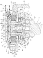
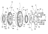
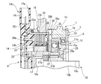
図1は第1実施形態におけるバルブタイミング制御装置の縦断面図、図2は本実施形態に供される主要な構成部材を示す分解図、図3は本実施形態に供される減速機構を示す分解斜視図、図4は図2のA−A線断面図である。Hereinafter, embodiments of the valve timing control device for an internal combustion engine according to the present invention will be described in detail with reference to the drawings. In the present embodiment, the valve timing control device is applied to the intake side, but it can also be applied to the exhaust side.
[First Embodiment]
FIG. 1 is a vertical cross-sectional view of the valve timing control device according to the first embodiment, FIG. 2 is an exploded view showing the main components used in the present embodiment, and FIG. 3 shows a deceleration mechanism used in the present embodiment. An exploded perspective view, FIG. 4 is a sectional view taken along line AA of FIG.
バルブタイミング制御装置は、図1及び図2に示すように、駆動回転体であるタイミングスプロケット1と、シリンダヘッド01上に軸受02を介して回転自在に支持されたカムシャフト2と、タイミングスプロケット1とカムシャフト2との間に配置されて、機関運転状態に応じて両者1,2の相対回転位相を変更する位相変更機構3と、該位相変更機構3の前端に配置された固定部材であるカバー部材4と、を備えている。
As shown in FIGS. 1 and 2, the valve timing control device includes a
タイミングスプロケット1は、全体が金属材である鉄系金属によって環状一体に形成されており、円環状のスプロケット本体1aと、該スプロケット本体1aの外周に一体に設けられて、巻回されたタイミングチェーン31を介して内燃機関のクランクシャフトからの回転力を受ける歯車部1bと、を備えている。
The
また、バルブタイミング制御装置の外周には、内燃機関のシリンダブロックとシリンダヘッド01に結合された固定部材であるチェーンケース22が設けられている。このチェーンケース22は、本実施形態では内燃機関の一部になっている。
Further, on the outer periphery of the valve timing control device, a
スプロケット本体1aの前端側には、後述する減速機構13の一部を構成する円環状の内歯構成部5が一体に設けられている。この内歯構成部5は、スプロケット本体1aの外周に一体に設けられていると共に、内周には波形状の複数の内歯5aが形成されている。
On the front end side of the
スプロケット本体1aとカムシャフト2の軸方向の一端部2aに固定された後述する従動回転体である従動部材9との間には、1つの大径ボールベアリング6が介装されている。この大径ボールベアリング6は、タイミングスプロケット1を従動部材9(カムシャフト2)の外周に相対回転自在に軸受けしている。
One large-diameter ball bearing 6 is interposed between the
さらに、スプロケット本体1aの内歯構成部5と反対側の後端面には、保持プレート8が固定されている。この保持プレート8は、図3にも示すように、金属板材によって円環状に形成され、外径がスプロケット本体1aの外径とほぼ同一に設定されている。また、保持プレート8は、中央に有する中央孔8aの内径が大径ボールベアリング6の外輪6aの内径よりも小さく形成されて、内周部の内側面が外輪6aの軸方向の他端面に微小隙間を介して軸方向から対峙している。
Further, a
また、保持プレート8の中央孔8aの内周縁所定位置には、径方向内側、つまり中心軸方向に向かって突出したストッパ凸部8bが一体に設けられている。このストッパ凸部8bは、ほぼ逆台形状に形成されて、先端面8cが後述するアダプタ11のストッパ凹溝11cの円弧状内周面に沿った円弧状に形成されている。
Further, at a predetermined position on the inner peripheral edge of the
内歯構成部5を含むスプロケット本体1aと保持プレート8の各外周部には、複数本(本実施形態では6本)のボルト7が挿通する6つのボルト挿通孔1c、8dが周方向のほぼ等間隔位置に貫通形成されている。
Six
カムシャフト2は、外周に図外の吸気弁を開作動させる一気筒当たり2つの駆動カムを有している。また、カムシャフト2は、回転軸方向の位相変更機構3側の一端部には、軸受02を介して軸方向の位置決めを行うフランジ部2aが一体に設けられている。また、カムシャフト2は、一端部の内部軸方向に雌ねじ部2bが形成されており、この雌ねじ部2bに螺着するカムボルト10によってアダプタ11を介して従動部材9が軸方向から締結固定されている。さらに、カムシャフト2の一端部前端には、従動部材9とアダプタ11との回転方向の位置決めを行う位置決め用のピン2dが回転軸方向から圧入固定されている。
The
従動部材9は、鉄系金属によって一体に形成され、図1〜図3に示すように、後端側(カムシャフト2側)に形成された円板状の固定端部9aと、該固定端部9aの内周前端面から軸方向へ突出した円筒部9bと、から主として構成されている。
The driven
固定端部9aは、外側面がカムシャフト2の一端部2aの前端面側に対向配置されている。また、固定端部9aの外側面のほぼ中央位置には、アダプタ11の後述する凸状の内周部11bが嵌合する円環状の嵌合溝9dが形成されている。また、この嵌合溝9dの底面には、位置決め用のピン2cが軸方向から挿入される位置決め用の穴9eが形成されている。
The outer surface of the
円筒部9bは、図1に示すように、固定端部9aを含む内部軸心方向にカムボルト10の軸部10bが挿通されるボルト挿通孔9cを有している。また、円筒部9bの外周側には、後述する小径ボールベアリング33とニードルベアリング34が軸方向に並列に設けられている。
As shown in FIG. 1, the
カムボルト10は、図1に示すように、頭部10aの軸方向端面が小径ボールベアリング33の内輪を軸方向から支持している。また、軸部10bの外周には、カムシャフト2の雌ねじ部2bに螺着する雄ねじ部10cが形成されている。
As shown in FIG. 1, the
アダプタ11は、図1〜図3に示すように、一定の肉厚を有する円盤状の金属板をプレス成形によって縦断面ほぼクランク状に折曲形成されており、フランジ状の外周部11aと、後述する電動モータ12方向へ突出した有底円筒状の内周部11bと、から構成されている。
As shown in FIGS. 1 to 3, the
外周部11aは、外径が従動部材9の固定端部9aの外径よりも僅かに大きく形成されている。そして、電動モータ12側の内側面の外周側が、大径ボールベアリング6の内輪6bの軸方向他端面に当接して軸方向外側への移動を規制するようになっている。
The outer diameter of the outer
外周部11aは、外周面に保持プレート8のストッパ凸部8bが係入するストッパ凹溝11cが円周方向に沿って形成されている。このストッパ凹溝11cは、円周方向へ所定長さの円弧状に形成されている。このストッパ凹溝11cの円弧状の長さ範囲で回動したストッパ凸部8bの両側面8e、8fが、周方向の対向面にそれぞれ当接するようになっている。これによって、タイミングスプロケット1に対するカムシャフト2の最大進角側、あるいは最大遅角側の相対回転位置を機械的に規制するようになっている。
The outer
内周部11bは、電動モータ12側に突出した有底円筒状の凸状に形成され、反対側の凹溝にカムシャフト2の一端部2aが軸方向から嵌合している。また、内周部11bの中央位置には、前記カムボルト10の軸部10bが挿通する挿通孔11dが貫通形成されている。
The inner
内周部11bは、従動部材9の固定端部9aの嵌合溝9d内に軸方向から圧入によって嵌合している。内周部11bは、嵌合溝9f内に嵌合した状態でカムボルト10によってカムシャフト2の一端部2aと従動部材9の固定端部9aとの間に挟持状態に結合されている。
The inner
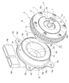
図5は本実施形態のバルブタイミング制御装置を電動モータ側から視た分解斜視図、図6は本実施形態のバルブタイミング制御装置を減速機構側から視た分解斜視図、図7は本実施形態のバルブタイミング制御装置を組み付けた状態を示す斜視図である。 FIG. 5 is an exploded perspective view of the valve timing control device of the present embodiment as viewed from the electric motor side, FIG. 6 is an exploded perspective view of the valve timing control device of the present embodiment as viewed from the reduction mechanism side, and FIG. 7 is an exploded perspective view of the present embodiment. It is a perspective view which shows the state which assembled the valve timing control device of.
位相変更機構3は、従動部材9の円筒部9bの前端側に配置された電動モータ12と、該電動モータ12の回転速度を減速してカムシャフト2に伝達する減速機構13と、から主として構成されている。
The
電動モータ12は、いわゆるブラシレスDCモータであって、チェーンケース22に固定されるモータステータ14と、該モータステータ14の内部に設けられたステータコイル15及び該ステータコイル15に電流を供給する給電部と、ステータコイル15の内周側に配置された入力回転軸であるモータ出力軸16と、該モータ出力軸16の外周に固定された円筒状の永久磁石17と、を有している。
The
モータステータ14は、主として合成樹脂材の樹脂部によって一体に形成されており、タイミングスプロケット1方向へ突出し、内部にステータコイル15がモールド固定されている円筒状の固定部14aと、該固定部14aの軸方向の外側の一端に一体に設けられた支持部14bと、該支持部14bの径方向外側に一体に設けられたコネクタ部14cと、を備えている。
The
固定部14aは、径方向の肉厚がステータコイル15の径方向幅よりも僅かに大きく形成されて、このステータコイル15全体が内部にモールドされている。また、この固定部14aは、内部に円形状の収容空間14dが形成されていると共に、該収容空間14dの内周面14eの内径Dが永久磁石17の外径よりも僅かに大きく形成されている。また、収容空間14dの内周面14eと永久磁石17(後述する磁石カバー27)の外周面との間には、円筒状のエアギャップGが形成されている。また、固定部14aは、減速機構13側の一端部の内周縁に環状凹溝14jが形成されている。
The fixing
さらに、固定部14aの外周面には、金属材である例えば鉄系金属、あるいはアルミニウム合金からなるケースである円筒部材18が一体的に固定されている。この円筒部材18は、筒状本体18aのコネクタ部14c側の軸方向一端縁にモータ出力軸16の回転軸心から径方向外側に延出したフランジ部18bが形成されている。また、このフランジ部18bの外周縁には、複数(本実施形態では4つ)の突出部18cが円周方向のほぼ等間隔位置に設けられている。
Further, a
この4つの突出部18cは、ほぼ円弧状に形成されていると共に、中央にボルト挿入孔18dがそれぞれ貫通形成されている。この各ボルト挿入孔18dには、円筒部材18を介して固定部14aをチェーンケース22に固定する取付ボルト19がそれぞれ挿入されるようになっている。
The four
筒状本体18aとフランジ部18bの折曲箇所の外面には、チェーンケース22との間をシールするシール部材であるシールリング20が設けられている。
A
支持部14bは、薄肉円盤状に形成されて、外側には後述する回転位置検出機構21の検出部23を収容支持する円盤凹状の空間部Sが形成されている。また、支持部14bは、中央に検出部23の回転センサ23aを収容する有底円筒状の凹壁14fが一体に設けられている。
The
空間部Sは、外側開口端が円盤状の蓋部24によって閉塞されている。この蓋部24は、外周部24aが支持部14bの空間部Sを構成する外周壁の開口縁に形成された環状溝に圧入によって固定されている。なお、蓋部24の支持部14bに対する固定方法としては、圧入の他に接着剤あるいはビスなどを用いて固定することも可能である。
The outer open end of the space portion S is closed by a disk-shaped
コネクタ部14cは、固定部14aの外周面から径方向外側へ平行に突出した給電用コネクタ14gと、信号用コネクタ14hと、を有している。給電用コネクタ14gは、内部の端子14iが図外のコントロールユニットに雌端子を介して電源であるバッテリーに接続されている。一方、信号用コネクタ14hは、図外の内部の端子がコントロールユニットに雌端子を介して接続され、回転センサ23aで検出された回転角信号をコントロールユニットに出力するようになっている。
The
ステータコイル15は、複数の積層板によって形成された円環状の鉄心コア15bと、該鉄心コア15bの外周に巻回されたコイル部15aと、を有している。鉄心ロータ18は、複数の磁極を持つ磁性材によって形成され、外周側がコイル部15aのコイル線を巻回させるスロットを有するボビンとして構成されている。
The
コイル部15aは、各外端部15c、15cが検出部23の回路基板23bに配設された図外のバスバーによって接続されている。
The
給電部は、給電用コネクタ14gと回路基板23bのバスバーなどによって構成されている。
The power feeding unit is composed of a
モータ出力軸16は、金属材によって円筒状に形成されて、内周面の先端側寄りに回転軸方向へ突出した円筒壁16aを一体に有している。また、モータ出力軸16は、回転軸方向の一端部、つまり、円筒壁16aの先端側に円環状の圧入用の溝16bが形成されている。一方、モータ出力軸16の溝16bと軸方向で反対側の位置には、減速機構13の一部を構成する伝達軸部材である偏心軸部25が一体に結合されている。
The
また、モータ出力軸16の圧入用の溝16b内には、モータ出力軸16の回転位置を検出する回転位置検出機構21の一部を構成する被検出部26が固定されている。
Further, in the press-fitting
また、円筒壁16aの軸方向の一端面が、小径ボールベアリング33の外輪とニードルベアリング34の保持器を軸方向から支持している。
Further, one end surface of the
各永久磁石17は、モータ出力軸16の円筒壁16aの形成位置の外周側に配置されて、各内周面がモータ出力軸16の外周面に接着剤によって固定されている。この各永久磁石17は、円周方向に所定隙間をもって配設されて全体が円筒状に形成され、円周方向に複数の磁極を有している。
Each
また、この各永久磁石17は、各外周面全体が円環状の磁石カバー27によって覆われている。この磁石カバー27は、例えば非磁性材の薄肉金属材をプレス成形によって横断面ほぼ逆凹状に折曲形成されている。また、この磁石カバー27は、内周縁がモータ出力軸16の外周面に例えば圧着などによって固定されている。この磁石カバー27は、各永久磁石17の磁力線の漏れや不要の発熱などの損失を抑制している。
Further, the entire outer peripheral surface of each of the
モータ出力軸16と偏心軸部25は、カムボルト10の軸部10bの外周面に設けられた小径ボールベアリング33及び円筒部9bの外周面に設けられて小径ボールベアリング33の軸方向側部に配置されたニードルベアリング34によって回転自在に支持されている。
The
前述した回転位置検出機構21は、モータステータ14の支持部14bに支持された検出部23と、モータ出力軸16の先端部に固定された被検出部26と、から構成されている。
The above-mentioned rotation
検出部23は、被検出部26に凹壁14fを介して軸方向から対向する回転センサ23aと、支持部14bの外面に接着剤などによって固定され、バスバーが配設された回路基板23bと、該回路基板23bに設けられた複数の集積回路23cなどの複数の電子部品と、を有している。
The
被検出部26は、センサーターゲットであるほぼ円盤状のマグネットセンサによって構成されて、磁力を介してモータ出力軸16の回転位置を回転センサ23aに出力するようになっている。また、被検出部26は、モータ出力軸16側の一側面中央に、モータ出力軸16の圧入用の溝16bに圧入可能な円盤状の突部26aが一体に設けられている。外周面が圧入用の溝16bの内周面に回転軸方向から圧入してモータ出力軸16に一体的に固定されている。
The detected
そして、検出部23は、被検出部26からの回転位置情報信号を検出してモータ出力軸16の回転角度を複数の集積回路23cが検出するようになっている。各集積回路23cは、検出したモータ出力軸16の回転角度位置信号をコントロールユニットに出力するようになっている。
Then, the
コントロールユニットは、図外のクランク角センサやエアーフローメータ、水温センサ、アクセル開度センサなど各種のセンサ類からの情報信号に基づいて現在の機関運転状態を検出し、これに基づいて機関制御を行っている。また、コントロールユニットは、前記各情報信号や回転位置検出機構21に基づいて、コイル部15aに通電してモータ出力軸16の回転制御を行い、減速機構13によってカムシャフト2のタイミングスプロケット1に対する相対回転位相を制御するようになっている。
The control unit detects the current engine operating state based on information signals from various sensors such as a crank angle sensor, air flow meter, water temperature sensor, and accelerator opening sensor (not shown in the figure), and controls the engine based on this. Is going. Further, the control unit energizes the
減速機構13は、図1〜図4に示すように、偏心回転運動を行う偏心軸部25と、該偏心軸部25の外周に設けられた中径ボールベアリング28と、該中径ボールベアリング28の外周に設けられ、内歯構成部5の各内歯5a内に転動自在に保持されたローラ29と、該ローラ29を転動方向に保持しつつ径方向の移動を許容する保持器30と、該保持器30と一体の前述した従動部材9と、から主として構成されている。
As shown in FIGS. 1 to 4, the
偏心軸部25は、モータ出力軸16の後端部に回転軸方向から一体に設けられた円筒状に形成されている。つまり、偏心軸部25は、電動モータ12のモータ出力軸16に継手機構などを用いることなく、軸方向から直結されている。また、偏心軸部25は、外周面に形成されたカム面25aの回転軸心Yがモータ出力軸16の回転軸心Xから径方向へ僅かに偏心している。
The
中径ボールベアリング28は、ニードルベアリング34の径方向位置で全体がほぼオーバーラップする状態に配置されている。また、中径ボールベアリング28は、内輪28aと、外輪28b、該両輪28a、28bとの間に介装されたボール28cと、該ボール28cを保持するケージと、から構成されている。
The medium-
内輪28aは、偏心軸部25の外周面に圧入固定されているのに対して、外輪28bは、軸方向で固定されることなくフリーな状態になっている。つまり、この外輪28bは、軸方向の電動モータ12側の一端面がどの部位にも接触せず、また軸方向の他端面がこれに対向する保持器30の背面との間に形成された微小なクリアランスを介してフリーな状態になっている。
The
外輪28bは、外周面に各ローラ29の外周面が転動自在に当接している。また、外輪28bの外周面と保持器30のローラ保持部30aの内面との間に、円環状のクリアランスが形成されている。このクリアランスを介して中径ボールベアリング28全体が、偏心軸部25の偏心回転に伴って径方向へ偏心動可能になっている。
The outer peripheral surface of each
保持器30は、固定端部9aの外周部に一体に設けられている。この保持器30は、固定端部9aの外周部前端から前方へ断面ほぼL字形状に折曲形成されて、固定端部9aの外周部前端側に径方向に沿って延出した円環状の伝達基部と、該伝達基部の外端からほぼ軸直角方向へ延出した円筒状のローラ保持部30aと、から主として構成されている。
The
ローラ保持部30aは、先端部が内歯構成部5の内歯5aに沿って電動モータ12の方向へ延出している。ローラ保持部30aは、周方向のほぼ等間隔位置に複数のローラ29をそれぞれ転動自在に保持するほぼ長方形状の複数のローラ保持孔30bが形成されている。このローラ保持孔30bは、先端部側が閉塞されて前後方向に細長い長方形状に形成され、その全体の数(ローラ29の数)が内歯構成部5の内歯5aの全体の歯数よりも少なくなっており、これによって、所定の減速比を得るようになっている。
The tip of the
各ローラ29は、鉄系金属によって形成され、中径ボールベアリング28の偏心動に伴って径方向へ移動しつつ内歯構成部5の内歯5aに嵌入している、また各ローラ29は、保持器30のローラ保持孔30bの両側縁によって周方向にガイドされつつ径方向へ揺動運動するようになっている。
Each
また、減速機構13は、図1に示すように、電動モータ12と隙間S1を介して軸方向から対向配置されている。すなわち、減速機構13は、モータ出力軸16を挟んで中径ボールベアリング28(内歯構成部5を含む)の外側面とモータステータ14(永久磁石17を含む)の対向側面との間に円環状の隙間S1が形成されている。この隙間S1は、モータ出力軸16の軸方向に所定の幅を有し、この隙間S1を介して電動モータ12と減速機構13が離間して配置されている。
Further, as shown in FIG. 1, the
減速機構13は、潤滑油供給通路を介して内部に潤滑油が供給されるようになっている。潤滑油供給通路は、機関のメインオイルギャラリーから分岐されてシリンダヘッド01内からカムシャフト2の内部に形成された図外の油通路と、アダプタ11の内周部11bと従動部材9の固定端部9aを幅方向に沿って連続的に貫通形成されて、前記油通路と連通する油通路孔32a、32bと、を有している。メインオイルギャラリーは、図外のオイルポンプの吐出通路に連通している。
The
チェーンケース22は、例えばアルミニウム合金材によって一体に形成されている。このチェーンケース22は、シリンダヘッド01とシリンダブロックの前端側にタイミングスプロケット1や、タイミングチェーン31及び減速機構13全体を覆うように上下方向に沿って配置固定されている。このチェーンケース22は、前端部22aに円筒部材18が挿入可能な円形孔22bが貫通形成されている。また、チェーンケース22の前端部22aには、ボス部22cが形成されている。このボス部22cには、4本の取付ボルト19の雄ねじ部19aが螺着する4つの雌ねじ孔22dが形成されている。さらに、チェーンケース22の前端部22aの先端部には、シールリング20を保持する円環状のシール溝22eが形成されている。モータステータ14は、円筒部材18が円形孔22b内に軸方向から挿入されることによって、全体がチェーンケース22に位置決めされるようになっている。
〔本実施形態の作動〕
以下、本実施形態におけるバルブタイミング制御装置の作動について簡単に説明する。まず、機関のクランクシャフトの回転駆動に伴ってタイミングチェーン31を介してタイミングスプロケット1が従動部材9の外周側で大径ボールベアリング6を介して回転する。その回転力が内歯構成部5に伝達されて、該内歯構成部5の回転力が各ローラ29から保持器30及び従動部材9を経由してカムシャフト2に伝達される。これによって、カムシャフト2のカムが吸気弁を開閉作動させる。The
[Operation of this embodiment]
Hereinafter, the operation of the valve timing control device in the present embodiment will be briefly described. First, the
機関始動後の所定の機関運転時には、コントロールユニットからの制御電流が電動モータ12のステータコイル15のコイル部15aに通電されてモータ出力軸16が正逆回転駆動される。このモータ出力軸16の回転力が、偏心軸部25に伝達されて減速機構13の作動によりカムシャフト2に対し減速された回転力が伝達される。
During a predetermined engine operation after the engine is started, the control current from the control unit is applied to the
これにより、カムシャフト2がタイミングスプロケット1に対して正逆相対回転して相対回転位相が変換される。したがって、吸気弁は、開閉タイミングを進角側あるいは遅角側に変換制御されるのである。
As a result, the
このように、吸気弁の開閉タイミングが進角側あるいは遅角側へ連続的に変換されて、機関の燃費や出力などの機関性能の向上が図れる。 In this way, the opening / closing timing of the intake valve is continuously converted to the advance angle side or the retard angle side, and the engine performance such as the fuel efficiency and output of the engine can be improved.
そして、本実施形態では、ブラシレスの電動モータ12のモータ出力軸16と減速機構13の偏心軸部25を、継手機構などを用いずに軸方向から一体かつ直接的に結合した。このため、電動モータ12と減速機構13との組立作業が容易になり、該組立作業能率の向上が図れる。
Then, in the present embodiment, the
しかも、電動モータ12と減速機構13との一体化によって、装置全体の構造が簡素化される。このため、製造作業能率も向上する。
Moreover, the integration of the
また、本実施形態では、潤滑油供給通路から減速機構13の内部に流入した潤滑油や該潤滑油に混入した金属コンタミなどは、電動モータ12や減速機構13の回転遠心力によって隙間S1から外部へ排出される。このため、各永久磁石17の外周面への金属コンタミなどの付着を効果的に抑制することが可能になる。
Further, in the present embodiment, the lubricating oil that has flowed into the
各永久磁石17は、非磁性材の磁石カバー27によって全体が覆われていることから、該永久磁石17の外周面へ金属コンタミなどがさらに付着し難くなる。
Since the entire
また、磁石カバー27を設けたことによって、各構成部材を組み立てる際における各永久磁石17と他の部品との直接的な干渉を抑制できる。つまり、例えば、予めモータ出力軸16の外周に固定された各永久磁石17を、モータステータ14の固定部14a内に軸方向から挿入する際に、固定部14aの開口縁などに対して干渉するとしても、永久磁石17は干渉することなく磁石カバー27が直接干渉する。したがって、永久磁石17の損傷などが抑制される。
Further, by providing the
また、減速機構13の各部材から偏心軸部25の内部へ流入した潤滑油は、ニードルベアリング34や小径ボールベアリング33を潤滑するが、その後は、被検出部26によって各永久磁石17方向へのリークが抑制される。
Further, the lubricating oil that has flowed into the
ステータコイル15は、モータステータ14内に樹脂モールドされていることから、例えば各永久磁石17の外周面に付着した金属コンタミによる損傷などの発生を抑制できる。つまり、ステータコイル15のコイル部15aの内周部が露出している場合は、各永久磁石17の外周面に付着した金属コンタミなどにより、モータ出力軸16の回転中においてエアギャップGを介してコイル部15aの内周部表面が損傷するおそれがある。しかし、ステータコイル15全体が樹脂モールドされていることから、金属コンタミなどによる損傷の発生を抑制できる。
Since the
また、被検出部26は、モータ出力軸16の圧入用の溝16bに突部26aを介して軸方向から圧入固定されるようになっているため、モータ出力軸16に対する円周方向の位置決めを精度良く行うことができる。この結果、検出部23による回転位置検出精度が高くなる。
〔第2実施形態〕
図8は本発明の第2実施形態を示し、基本構造は第1実施形態と同じであるが、回転位置検出機構21の被検出部26の取り付け構造が異なっている。Further, since the detected
[Second Embodiment]
FIG. 8 shows a second embodiment of the present invention, and the basic structure is the same as that of the first embodiment, but the mounting structure of the detected
すなわち、モータ出力軸16は、回転軸方向のカバー部材4側の一端部の内周面に雌ねじ部16cが形成されている。一方、被検出部26は、円盤状の本体の背面側に円環状の突起部26bが一体に設けられている。この突起部26bは、外周面に前記雌ねじ部16cに螺着する雄ねじ部26cが形成されている。したがって、被検出部26は、モータ出力軸16の一端部に雌雄ねじ部16c、26cを介してねじ込み固定されるようになっている。
That is, the
この実施形態によれば、第1実施形態と同様な作用効果が得られると共に、被検出部26がモータ出力軸16にねじ込み固定されるので、より確実な固定状態が得られる。また、雌雄ねじ部16c、26cによってモータ出力軸16との間のシール性が向上する。
〔第3実施形態〕
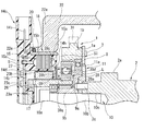
図9は第3実施形態を示し、電動モータ12と減速機構13との間の隙間S1内に、遮蔽板35が設けられている。また、内歯構成部5の電動モータ12側の一端部外周に、隙間S1の外周部を覆う筒状部36が設けられている。According to this embodiment, the same effect as that of the first embodiment can be obtained, and the detected
[Third Embodiment]
FIG. 9 shows a third embodiment, in which a
遮蔽板35は、隙間S1内において、モータ出力軸16の外周面から固定部14a側に延びる第1プレート37と、円筒部材18の減速機構13側の一端部内周面から各永久磁石17側へ延びる第2プレート38と、を有している。
In the gap S1, the shielding
第1プレート37は、薄肉円環状の例えば非磁性材からなる金属材によって円環状に形成され、内周縁がモータ出力軸16の外周面に例えば圧入などによって固定されている。また、第1プレート37は、外周部37aが各永久磁石17の軸方向の一端部17a(磁石カバー27の一側面27a)を覆う形で固定部14aの一端部の環状凹溝14jまで延びている。
The
第2プレート38は、薄肉円環状の例えば非磁性材からなる金属材によって円環状に形成され、外周縁が円筒部材18の一端部内周面に例えば圧入などによって固定されている。また、第2プレート38は、固定部14aの一端面全体を覆う形で永久磁石17方向へ延びていると共に、内周部38aがクランク状に折曲形成されている。この内周部38aは、環状凹溝14jの外面を覆うように配置されていると共に、第1プレート37の外周部37aよりも内側に非接触状態で配置されている。したがって、第1プレート37の外周部37aと第2プレート38の内周部38aが、環状凹溝14jの前側において径方向からオーバーラップしている。これによって、第1プレート37の外周部37aと第2プレート38の内周部38aとの間にラビリンス状の環状隙間が形成されている。
The second plate 38 is formed in an annular shape by a thin-walled annular metal material such as a non-magnetic material, and the outer peripheral edge is fixed to the inner peripheral surface of one end of the
筒状部36は、軸方向の一端部36aが内歯構成部5の前端面外周に例えば圧入や溶接などによって固定されている。一方、他端部36bは、円筒部材18の筒状本体18aの減速機構13側の一端側を覆うように配置されている。
In the
したがって、この実施形態によれば、減速機構13内に供給された潤滑油は、第1プレート37と第2プレート38によって各永久磁石17やモータステータ14方向へのリークが効果的に抑制される。特に、両プレート37,38の環状隙間によってラビリンスシール機能が発揮されることから、潤滑油や潤滑油内に混入した金属コンタミが各永久磁石17などへの流入を十分に抑制することが可能になる。
Therefore, according to this embodiment, the lubricating oil supplied into the
なお、第1プレート37と第2プレート38は、非接触状態になっているので、モータ出力軸16の回転に影響を与えることがない。
Since the
また、タイミングスプロケット1やタイミングチェーン31の回転に伴って飛散した潤滑油は、筒状部36によって隙間S1内への流入を効果的に阻止される。このため、外部から各永久磁石17やモータステータ14内への潤滑油や金属コンタミの浸入が阻止されて、特に金属コンタミの各永久磁石17への付着をさらに抑制することが可能になる。
Further, the lubricating oil scattered with the rotation of the
この結果、遮蔽板35(第1、第2プレート37,38)と筒状部36との内外二重のシール機能によって、エアギャップG内への金属コンタミの浸入が抑制されることから、各永久磁石17とステータコイル15との磁力の低下を抑えることができる。
As a result, the intrusion of metal contamination into the air gap G is suppressed by the double sealing function of the inside and outside of the shielding plate 35 (first and
なお、筒状部36を廃止して、遮蔽板35のみで構成することも可能である。この場合も外部から隙間S1内に浸入した潤滑油などを第1,第2プレート37,38によって各永久磁石17方向への浸入を抑制できる。
〔第4実施形態〕
図10は本発明の第4実施形態を示し、モータ出力軸16の隙間S1内に位置する外周面に遮蔽板39が設けられている。It is also possible to abolish the
[Fourth Embodiment]
FIG. 10 shows a fourth embodiment of the present invention, in which a
この遮蔽板39は、金属板材によって縦断面ほぼL字形状に形成され、モータ出力軸16の外周面に固定された基部39aと、該基部39aの軸方向一端から固定部14aの環状凹溝14j方向へ径方向に沿って延びた円盤状の遮蔽部39bと、を有している。
The shielding
基部39aは、円筒状に形成されて、内周面がモータ出力軸16の外周面に圧入により固定されている。遮蔽部39bは、径方向の幅長さLが環状凹溝14j付近まで延びて、外周部39cが環状凹溝14j内に入り込んでいる。
The
したがって、減速機構13内に供給された潤滑油は、遮蔽板39によって各永久磁石17方向への浸入が抑制される。特に、遮蔽板39の遮蔽部39bの外周部39cが環状凹溝14j内に入り込んでいることから、減速機構13側からエアギャップGや各永久磁石17方向への潤滑油の浸入を効果的に抑制できる。
Therefore, the lubricating oil supplied into the
さらに、減速機構13から遮蔽板39方向へ流入した潤滑油の大部分は、遮蔽部39bの減速機構13側の一側面39dに付着し、ここから遠心力によって隙間S1から外部へ飛散する。このため、各永久磁石17方向への浸入をさらに抑制することができる。
〔第5実施形態〕
図11は第5実施形態を示し、遮蔽板40の構造をさらに変更したものである。Further, most of the lubricating oil flowing from the
[Fifth Embodiment]
FIG. 11 shows a fifth embodiment, in which the structure of the shielding
すなわち、遮蔽板40は、隙間S1内に配置されて、縦断面ほぼコ字形状に形成されている。遮蔽板40は、図中、縦断面コ字形状に折曲形成されてモータ出力軸16の外周に固定された基部40aと、該基部40aからモータ出力軸16の径方向外側へ延びた円盤状の遮蔽部40bと、該遮蔽部40bの外周縁に一体に有し、カバー部材4方向へ折曲形成されたフランジ状の外周部40cと、を備えている。
That is, the shielding
基部40aは、内周面がモータ出力軸16の外周面の圧入によって固定されていると共に、その軸方向の幅長さが隙間S1の幅長さとほぼ同一に形成されている。
The inner peripheral surface of the
遮蔽部40bは、外周部40cを含む全体の径方向の幅長さL2が円筒部材18の筒状本体18aの外径よりも大きく設定されている。
The width and length L2 of the entire radial direction including the outer
外周部40cは、その軸方向の長さ(幅長さ)Wが筒状本体18aの減速機構13側の一部を覆う長さに設定されている。また、この外周部40cは、ほぼ全体がチェーンケース22の前端部22aの円形孔22bの一部に形成された円環溝に先端部40dから挿入配置されている。
The outer
したがって、減速機構13内から各永久磁石17方向へ流入しようする潤滑油は、隙間S1内で遮蔽板40の遮蔽部40bの減速機構13側の一側面に付着して、そのまま遠心力によって隙間S1から外部に排出される。また、タイミングスプロケット1などの回転に伴って外部で飛散した潤滑油は、一部が隙間S1内に流入しようとすると、遮蔽板40の外周部40cや遮蔽部40bによって阻止される。これによって、各永久磁石17方向への浸入を十分に抑制することができる。
Therefore, the lubricating oil that flows from the
特に、外周部40cは、筒状本体18aの外周面軸方向の一方を覆っていることから、さらに各永久磁石17方向への浸入を効果的に抑制することができる。また、外周部40cは、先端部40dがチェーンケース22のシール溝22e内に入り込んでいるので、潤滑油に対する遮蔽効果が大きくなって、潤滑油の各永久磁石17方向への浸入を十分に抑制することができる。
〔第6実施形態〕
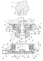
図12は第6実施形態を示し、これはモータステータ14の支持部14bと蓋部24との間の空間部S内に検出部23の他に図外のVTCコントローラ41が収容保持されている。In particular, since the outer
[Sixth Embodiment]
FIG. 12 shows a sixth embodiment, in which a VTC controller 41 (not shown) is housed and held in the space S between the
このVTCコントローラ41は、コントロールユニットからの制御信号を入力して電動モータ12のコイル部15aに給電用コネクタ14gから通電して、電動モータ12を回転駆動制御するようになっている。
The VTC controller 41 inputs a control signal from the control unit to energize the
この実施形態によれば、モータステータ14の内部にVTCコントローラ41も収容したことから、他の所に配置する場合に比較して配線などの取り回しが容易になる。これによって、製造作業や組立作業能率の向上が図れる。
According to this embodiment, since the VTC controller 41 is also housed inside the
本発明は、前記各実施形態の構成に限定されるものではなく、例えば、減速機構13としては例えば遊星歯車式などであっても良い。また、回転位置検出機構21としては、例えば電磁誘導型やポテンショメータなどであっても良い。
The present invention is not limited to the configuration of each of the above-described embodiments, and the
さらに、ブラシレス電動モータ12の構造もさらに変更することも可能である。但し、この電動モータ12と減速機構13とは、軸継手などの継手機構を介さずに連結されている。
Further, the structure of the brushless
以上説明した実施形態に基づく内燃機関のバルブタイミング制御装置としては、例えば、以下に述べる態様のものが考えられる。 As the valve timing control device for the internal combustion engine based on the embodiment described above, for example, the one described below can be considered.
すなわち、本発明における好ましい態様としては、クランクシャフトからの回転力が伝達される駆動回転体と、カムシャフトに固定される従動回転体と、電動モータの回転を減速機構によって減速して前記駆動回転体と従動回転体の相対回転位相を変更する位相変更機構と、を備え、
前記位相変更機構は、
前記電動モータの環状のステータコイル及び前記ステータコイルに給電可能な給電部を有し、機関の固定部材に固定されるモータステータと、前記ステータコイルの内周側に配置され、前記電動モータのモータ出力軸に固定される永久磁石と、前記モータ出力軸に一体に設けられ、前記減速機構の一部を構成する伝達軸部材と、を備えている。That is, as a preferred embodiment in the present invention, the drive rotating body to which the rotational force from the crankshaft is transmitted, the driven rotating body fixed to the cam shaft, and the rotation of the electric motor are decelerated by the reduction mechanism to reduce the drive rotation. It is equipped with a phase change mechanism that changes the relative rotation phase of the body and the driven rotating body.
The phase change mechanism is
A motor stator having an annular stator coil of the electric motor and a feeding portion capable of supplying power to the stator coil and fixed to a fixing member of the engine, and a motor of the electric motor arranged on the inner peripheral side of the stator coil. It includes a permanent magnet fixed to the output shaft and a transmission shaft member integrally provided with the motor output shaft and forming a part of the speed reduction mechanism.
さらに好ましくは、前記電動モータと減速機構が前記モータ出力軸の回転軸方向において隙間を介して対向配置され、前記隙間は、前記モータ出力軸の回転軸の直角方向外側に開口している。 More preferably, the electric motor and the reduction mechanism are arranged to face each other with a gap in the rotation axis direction of the motor output shaft, and the gap is open to the outside in the direction perpendicular to the rotation axis of the motor output shaft.
この発明によれば、潤滑油や該潤滑油に混入したコンタミが遠心力によって隙間から外部に排出される。 According to the present invention, the lubricating oil and the contamination mixed in the lubricating oil are discharged to the outside through the gap by centrifugal force.
さらに好ましくは、前記モータ出力軸は、ステータコイルの内周側で前記カムシャフトの回転軸方向に延びる円筒状に形成され、前記永久磁石は、前記モータ出力軸の外周に固定されている。 More preferably, the motor output shaft is formed in a cylindrical shape extending in the rotation axis direction of the camshaft on the inner peripheral side of the stator coil, and the permanent magnet is fixed to the outer periphery of the motor output shaft.
さらに好ましくは、前記モータ出力軸は、前記カムシャフトの回転軸方向の前記減速機構と反対側の開口端部に被検出部を有し、前記モータステータの前記カムシャフトの回転軸方向において前記被検出部と対向する部位に、前記被検出部の回転角度を検出する検出部を有している。 More preferably, the motor output shaft has a detected portion at an opening end portion opposite to the deceleration mechanism in the rotation axis direction of the camshaft, and the motor output shaft is covered in the rotation axis direction of the camshaft of the motor stator. A detection unit that detects the rotation angle of the detected unit is provided at a portion facing the detection unit.
さらに好ましくは、前記被検出部は、前記モータ出力軸の開口端部を塞いでいる。 More preferably, the detected portion closes the open end portion of the motor output shaft.
この発明によれば、減速機構などを潤滑した潤滑油がモータ出力軸内に流入しても、被検出部によって潤滑油が永久磁石とステータコイルの間へのリークを抑制できる。 According to the present invention, even if the lubricating oil that lubricates the reduction mechanism or the like flows into the motor output shaft, the lubricating oil can be suppressed from leaking between the permanent magnet and the stator coil by the detected portion.
さらに好ましくは、前記モータステータ及び前記各永久磁石の前記カムシャフトの回転軸方向における前記減速機構側のそれぞれの一端部を覆う遮蔽板を有している。 More preferably, it has a shielding plate that covers one end of the motor stator and each of the permanent magnets on the reduction mechanism side in the rotation axis direction of the camshaft.
この発明によれば、遮蔽板によって減速機構側から電動モータ側(永久磁石など)への潤滑油に混入した鉄系コンタミの浸入を抑制する。 According to the present invention, the shielding plate suppresses the infiltration of iron-based contaminants mixed in the lubricating oil from the reduction mechanism side to the electric motor side (permanent magnet, etc.).
さらに好ましくは、前記遮蔽板は、前記モータ出力軸の外周から永久磁石の一端部側へ延びる第1プレートと、前記モータステータの一端部側から前記永久磁石の一端部方向へ延びる第2プレートと、を有し、
前記第1プレートと第2プレートは、前記モータ出力軸の回転軸方向において少なくとも一部がオーバーラップして配置されている。More preferably, the shielding plate includes a first plate extending from the outer periphery of the motor output shaft toward one end of the permanent magnet, and a second plate extending from one end of the motor stator toward one end of the permanent magnet. Have,
At least a part of the first plate and the second plate overlap each other in the rotation axis direction of the motor output shaft.
さらに好ましくは、前記永久磁石の外面を覆う磁石カバーを有している。これによって、各構成部品を組み付ける際に、永久磁石が他部品に干渉して損傷するのを抑制できる。 More preferably, it has a magnet cover that covers the outer surface of the permanent magnet. As a result, when assembling each component, it is possible to prevent the permanent magnet from interfering with and damaging other components.
さらに好ましくは、前記モータステータは、外周部が前記機関の固定部材に設けられた孔に軸方向から嵌め込まれている。 More preferably, the outer peripheral portion of the motor stator is fitted into a hole provided in the fixing member of the engine from the axial direction.
これによって、固定部材であるチェーンケースに対するモータステータの位置決めが可能になる。 This makes it possible to position the motor stator with respect to the chain case which is a fixing member.
さらに好ましくは、前記モータ出力軸は、円筒状に形成され、前記カムシャフトの回転軸方向の前記減速機構と反対側の位置に被検出部を有し、前記モータステータは、前記被検出部の回転角度を検出可能な検出部を有し、前記減速機構は、機関へ潤滑油を供給する潤滑油供給通路と連通する油通路を有し、前記減速機構と前記モータ出力軸の内部が連通している。 More preferably, the motor output shaft is formed in a cylindrical shape, has a detected portion at a position opposite to the deceleration mechanism in the rotation axis direction of the camshaft, and the motor stator is the detected portion. The speed reduction mechanism has a detection unit capable of detecting a rotation angle, and the speed reduction mechanism has an oil passage that communicates with a lubricating oil supply passage that supplies lubricating oil to the engine, and the speed reduction mechanism and the inside of the motor output shaft communicate with each other. ing.
さらに好ましくは、前記モータステータは、合成樹脂材によって形成された樹脂部を有し、前記樹脂部内に前記ステータコイルが埋め込まれている。 More preferably, the motor stator has a resin portion formed of a synthetic resin material, and the stator coil is embedded in the resin portion.
これによって、永久磁石とステータコア(モータステータ)との間に、金属材のコンタミが挟まった場合に、ステータコイルが露出していると、該ステータコイルが損傷や破損するおそれがあるが、該ステータコイルがモータステータの樹脂部に樹脂モールドされていることから、損傷などの発生を抑制できる。 As a result, if a metal material is caught between the permanent magnet and the stator core (motor stator) and the stator coil is exposed, the stator coil may be damaged or damaged. Since the coil is resin-molded in the resin portion of the motor stator, it is possible to suppress the occurrence of damage and the like.
さらに好ましくは、前記モータステータは、前記樹脂部を保持するケースを有し、このケースと該ケースが固定される機関の固定部材との間に、シール部材が設けられている。 More preferably, the motor stator has a case for holding the resin portion, and a seal member is provided between the case and the fixing member of the engine to which the case is fixed.
さらに好ましくは、前記減速機構は、前記モータステータ側の端部外周に、前記カムシャフトの回転軸方向に沿って前記ステータコイル側へ延びる筒状部を有し、前記筒状部は、前記モータステータの外周部と少なくとも一部がオーバーラップするように配置されている。 More preferably, the speed reduction mechanism has a tubular portion extending toward the stator coil side along the rotation axis direction of the camshaft on the outer periphery of the end portion on the motor stator side, and the tubular portion is the motor. It is arranged so that at least a part of the outer periphery of the stator overlaps.
これによって、筒状部によって減速機構や駆動回転体の外側から永久磁石方向への潤滑油の浸入を抑制できる。 As a result, the tubular portion can suppress the infiltration of lubricating oil from the outside of the speed reduction mechanism or the drive rotating body toward the permanent magnet.
さらに好ましくは、前記モータステータは、機関を制御するエンジンコントロールユニットからの信号を受信し、該受信された信号に基づいて前記ステータコイルへの供給電流を制御するVTCコントローラを有している。 More preferably, the motor stator has a VTC controller that receives a signal from the engine control unit that controls the engine and controls the supply current to the stator coil based on the received signal.
別の好ましい態様として、内部にステータコイルが設けられ、内燃機関のシリンダヘッドまたはチェーンケースに固定されるモータステータと、外周に永久磁石が固定される入力回転軸を有し、前記ステータコイルの磁力によって前記入力回転軸が回転してクランクシャフトとカムシャフトの相対回転位相を変更する電動モータと、を備えた位相変更機構であって、
この位相変更機構は、前記カムシャフトに連結され、かつ、入力回転軸と一体の伝達軸部材を有すると共に、前記モータステータと非接触な減速機構を備えている。As another preferred embodiment, the motor stator is provided with a stator coil inside and is fixed to the cylinder head or chain case of the internal combustion engine, and has an input rotation shaft to which a permanent magnet is fixed on the outer periphery, and the magnetic force of the stator coil is provided. A phase change mechanism including an electric motor that changes the relative rotation phase of the crankshaft and the camshaft by rotating the input rotation shaft.
This phase changing mechanism has a transmission shaft member that is connected to the camshaft and is integrated with the input rotation shaft, and also includes a reduction mechanism that is in non-contact with the motor stator.
Claims (11)
カムシャフトに固定される従動回転体と、
電動モータのモータ出力軸の回転を減速機構によって減速して前記駆動回転体と従動回転体の相対回転位相を変更する位相変更機構と、を備えた内燃機関のバルブタイミング制御装置であって、
前記位相変更機構は、
前記電動モータの環状のステータコイルを有し、機関の固定部材に固定されるモータステータと、
前記ステータコイルの内周側に配置され、前記電動モータの前記モータ出力軸に固定される永久磁石と、
前記モータ出力軸に一体に設けられ、前記減速機構の一部を構成する伝達軸部材と、
を備え、
前記電動モータと前記減速機構が前記モータ出力軸の回転軸方向において隙間を介して対向配置され、
前記隙間は、前記モータ出力軸の回転軸の直角方向外側に開口し、
前記モータ出力軸は、ステータコイルの内周側で前記カムシャフトの回転軸方向に延びる円筒状に形成され、
前記永久磁石は、前記モータ出力軸の外周に固定されていることを特徴とする内燃機関のバルブタイミング制御装置。 A drive rotating body to which the rotational force from the crankshaft is transmitted,
A driven rotating body fixed to the camshaft,
A valve timing control device for an internal combustion engine, comprising a phase changing mechanism for decelerating the rotation of the motor output shaft of an electric motor by a deceleration mechanism to change the relative rotation phase between the driving rotating body and the driven rotating body.
The phase change mechanism is
A motor stator having an annular stator coil of the electric motor and fixed to a fixing member of the engine,
A permanent magnet arranged on the inner peripheral side of the stator coil and fixed to the motor output shaft of the electric motor, and
A transmission shaft member integrally provided with the motor output shaft and forming a part of the speed reduction mechanism.
With
The electric motor and the reduction mechanism are arranged so as to face each other with a gap in the rotation axis direction of the motor output shaft.
The gap opens outward in the direction perpendicular to the rotation axis of the motor output shaft.
The motor output shaft is formed in a cylindrical shape extending in the rotation axis direction of the camshaft on the inner peripheral side of the stator coil.
A valve timing control device for an internal combustion engine, wherein the permanent magnet is fixed to the outer periphery of the motor output shaft .
前記モータ出力軸は、前記カムシャフトの回転軸方向の前記減速機構と反対側の開口端部に被検出部を有し、
前記モータステータの前記カムシャフトの回転軸方向において前記被検出部と対向する部位に、前記被検出部の回転角度を検出する検出部を有することを特徴とする内燃機関のバルブタイミング制御装置。 In the valve timing control device for an internal combustion engine according to claim 1.
The motor output shaft has a detected portion at an opening end portion opposite to the deceleration mechanism in the rotation axis direction of the camshaft.
A valve timing control device for an internal combustion engine, characterized in that a detection unit for detecting the rotation angle of the detected portion is provided at a portion of the motor stator facing the detected portion in the rotation axis direction of the camshaft .
前記被検出部は、前記モータ出力軸の開口端部を塞ぐことを特徴とする内燃機関のバルブタイミング制御装置。 In the valve timing control device for an internal combustion engine according to claim 2.
The detected portion is a valve timing control device for an internal combustion engine, characterized in that the open end portion of the motor output shaft is closed .
前記永久磁石の外面を覆う磁石カバーを有することを特徴とする内燃機関のバルブタイミング制御装置。 In the valve timing control device for an internal combustion engine according to claim 1 .
A valve timing control device for an internal combustion engine, characterized by having a magnet cover that covers the outer surface of the permanent magnet .
前記モータステータは、外周部が前記機関の固定部材に設けられた孔に軸方向から嵌め込まれることを特徴とする内燃機関のバルブタイミング制御装置。 In the valve timing control device for an internal combustion engine according to claim 1 .
The motor stator is a valve timing control device for an internal combustion engine, wherein the outer peripheral portion is fitted into a hole provided in a fixing member of the engine from the axial direction .
前記モータステータは、機関を制御するエンジンコントロールユニットからの信号を受信し、該受信された信号に基づいて前記ステータコイルへの供給電流を制御するVTCコントローラを有することを特徴とする内燃機関のバルブタイミング制御装置。 In the valve timing control device for an internal combustion engine according to claim 1.
A valve of an internal combustion engine, wherein the motor stator has a VTC controller that receives a signal from an engine control unit that controls an engine and controls a supply current to the stator coil based on the received signal. Timing control device.
カムシャフトに固定される従動回転体と、
電動モータのモータ出力軸の回転を減速機構によって減速して前記駆動回転体と従動回転体の相対回転位相を変更する位相変更機構と、を備えた内燃機関のバルブタイミング制御装置であって、
前記位相変更機構は、
前記電動モータの環状のステータコイルを有し、機関の固定部材に固定されるモータステータと、
前記ステータコイルの内周側に配置され、前記電動モータの前記モータ出力軸に固定される永久磁石と、
前記モータ出力軸に一体に設けられ、前記減速機構の一部を構成する伝達軸部材と、
を備え、
前記モータステータ及び前記各永久磁石の前記カムシャフトの回転軸方向における前記減速機構側のそれぞれの一端部を覆う遮蔽板を有し、
前記遮蔽板は、前記モータ出力軸の外周から永久磁石の一端部側へ延びる第1プレートと、前記モータステータの一端部側から前記永久磁石の一端部方向へ延びる第2プレートと、を有し、
前記第1プレートと第2プレートは、前記モータ出力軸の回転軸方向において少なくとも一部がオーバーラップして配置されていることを特徴とする内燃機関のバルブタイミング制御装置。 A drive rotating body to which the rotational force from the crankshaft is transmitted,
A driven rotating body fixed to the camshaft,
A valve timing control device for an internal combustion engine, comprising a phase changing mechanism that decelerates the rotation of the motor output shaft of an electric motor by a reduction mechanism to change the relative rotation phase of the driving rotating body and the driven rotating body.
The phase change mechanism is
A motor stator having an annular stator coil of the electric motor and fixed to a fixing member of the engine,
A permanent magnet arranged on the inner peripheral side of the stator coil and fixed to the motor output shaft of the electric motor, and
A transmission shaft member integrally provided with the motor output shaft and forming a part of the speed reduction mechanism.
With
It has a shielding plate that covers one end of the motor stator and each of the permanent magnets on the reduction mechanism side in the rotation axis direction of the camshaft.
The shielding plate has a first plate extending from the outer periphery of the motor output shaft toward one end of the permanent magnet, and a second plate extending from one end of the motor stator toward one end of the permanent magnet. ,
A valve timing control device for an internal combustion engine , wherein at least a part of the first plate and the second plate are arranged so as to overlap each other in the rotation axis direction of the motor output shaft .
カムシャフトに固定される従動回転体と、
電動モータのモータ出力軸の回転を減速機構によって減速して前記駆動回転体と従動回転体の相対回転位相を変更する位相変更機構と、を備えた内燃機関のバルブタイミング制御装置であって、
前記位相変更機構は、
前記電動モータの環状のステータコイルを有し、機関の固定部材に固定されるモータステータと、
前記ステータコイルの内周側に配置され、前記電動モータの前記モータ出力軸に固定される永久磁石と、
前記モータ出力軸に一体に設けられ、前記減速機構の一部を構成する伝達軸部材と、
を備え、
前記モータ出力軸は、円筒状に形成され、前記カムシャフトの回転軸方向の前記減速機構と反対側の位置に被検出部を有し、
前記モータステータは、前記被検出部の回転角度を検出可能な検出部を有し、
前記減速機構は、機関へ潤滑油を供給する潤滑油供給通路と連通する油通路を有し、
前記減速機構と前記モータ出力軸の内部が連通していることを特徴とする内燃機関のバルブタイミング制御装置。 A drive rotating body to which the rotational force from the crankshaft is transmitted,
A driven rotating body fixed to the camshaft,
A valve timing control device for an internal combustion engine, comprising a phase changing mechanism for decelerating the rotation of the motor output shaft of an electric motor by a deceleration mechanism to change the relative rotation phase between the driving rotating body and the driven rotating body.
The phase change mechanism is
A motor stator having an annular stator coil of the electric motor and fixed to a fixing member of the engine,
A permanent magnet arranged on the inner peripheral side of the stator coil and fixed to the motor output shaft of the electric motor, and
A transmission shaft member integrally provided with the motor output shaft and forming a part of the speed reduction mechanism.
With
The motor output shaft is formed in a cylindrical shape, and has a detected portion at a position opposite to the deceleration mechanism in the rotation axis direction of the camshaft.
The motor stator has a detection unit capable of detecting the rotation angle of the detected unit.
The speed reduction mechanism has an oil passage that communicates with a lubricating oil supply passage that supplies lubricating oil to the engine.
A valve timing control device for an internal combustion engine, characterized in that the reduction mechanism and the inside of the motor output shaft communicate with each other .
カムシャフトに固定される従動回転体と、
電動モータのモータ出力軸の回転を減速機構によって減速して前記駆動回転体と従動回転体の相対回転位相を変更する位相変更機構と、を備えた内燃機関のバルブタイミング制御装置であって、
前記位相変更機構は、
前記電動モータの環状のステータコイルを有し、機関の固定部材に固定されるモータステータと、
前記ステータコイルの内周側に配置され、前記電動モータの前記モータ出力軸に固定される永久磁石と、
前記モータ出力軸に一体に設けられ、前記減速機構の一部を構成する伝達軸部材と、
を備え、
前記モータステータは、合成樹脂材によって形成された樹脂部を有し、前記樹脂部内に前記ステータコイルが埋め込まれていると共に、前記樹脂部を保持するケースを有し、このケースと該ケースが固定される機関の固定部材との間に、シール部材が設けられていることを特徴とする内燃機関のバルブタイミング制御装置。 A drive rotating body to which the rotational force from the crankshaft is transmitted,
A driven rotating body fixed to the camshaft,
A valve timing control device for an internal combustion engine, comprising a phase changing mechanism for decelerating the rotation of the motor output shaft of an electric motor by a deceleration mechanism to change the relative rotation phase between the driving rotating body and the driven rotating body.
The phase change mechanism is
A motor stator having an annular stator coil of the electric motor and fixed to a fixing member of the engine,
A permanent magnet arranged on the inner peripheral side of the stator coil and fixed to the motor output shaft of the electric motor, and
A transmission shaft member integrally provided with the motor output shaft and forming a part of the speed reduction mechanism.
With
The motor stator has a resin portion formed of a synthetic resin material, the stator coil is embedded in the resin portion, and the motor stator has a case for holding the resin portion, and the case and the case are fixed. A valve timing control device for an internal combustion engine, characterized in that a seal member is provided between the fixing member and the fixing member of the engine.
カムシャフトに固定される従動回転体と、
電動モータのモータ出力軸の回転を減速機構によって減速して前記駆動回転体と従動回転体の相対回転位相を変更する位相変更機構と、を備えた内燃機関のバルブタイミング制御装置であって、
前記位相変更機構は、
前記電動モータの環状のステータコイルを有し、機関の固定部材に固定されるモータステータと、
前記ステータコイルの内周側に配置され、前記電動モータの前記モータ出力軸に固定される永久磁石と、
前記モータ出力軸に一体に設けられ、前記減速機構の一部を構成する伝達軸部材と、
を備え、
前記減速機構は、前記モータステータ側の端部外周に、前記カムシャフトの回転軸方向に沿って前記ステータコイル側へ延びる筒状部を有し、
前記筒状部は、前記モータステータの外周部と少なくとも一部がオーバーラップするように配置されていることを特徴とする内燃機関のバルブタイミング制御装置。 A drive rotating body to which the rotational force from the crankshaft is transmitted,
A driven rotating body fixed to the camshaft,
A valve timing control device for an internal combustion engine, comprising a phase changing mechanism for decelerating the rotation of the motor output shaft of an electric motor by a deceleration mechanism to change the relative rotation phase between the driving rotating body and the driven rotating body.
The phase change mechanism is
A motor stator having an annular stator coil of the electric motor and fixed to a fixing member of the engine,
A permanent magnet arranged on the inner peripheral side of the stator coil and fixed to the motor output shaft of the electric motor, and
A transmission shaft member integrally provided with the motor output shaft and forming a part of the speed reduction mechanism.
With
The speed reduction mechanism has a tubular portion extending toward the stator coil side along the rotation axis direction of the camshaft on the outer periphery of the end portion on the motor stator side.
A valve timing control device for an internal combustion engine, wherein the tubular portion is arranged so as to overlap at least a part of the outer peripheral portion of the motor stator .
クランクシャフトからの回転力が伝達される駆動回転体と、
カムシャフトに固定される従動回転体と、
内部にステータコイルを有し、内燃機関の固定部材に固定され、前記駆動回転体の回転軸に沿った方向において前記駆動回転体側に開口部を有するモータステータと、
前記開口部を通って前記モータステータの内側に挿入し、外周に永久磁石が固定された入力回転軸と、
前記駆動回転体と前記従動回転体の間に設けられ、前記駆動回転体に対して前記入力回転軸が相対回転することで、前記駆動回転体と前記従動回転体との間の相対回転位相を調整する減速機構と、
を有することを特徴とする内燃機関のバルブタイミング制御装置。 It is a valve timing control device for internal combustion engines.
A drive rotating body to which the rotational force from the crankshaft is transmitted,
A driven rotating body fixed to the camshaft,
A motor stator having a stator coil inside, fixed to a fixing member of an internal combustion engine, and having an opening on the drive rotating body side in a direction along the rotation axis of the driving rotating body.
An input rotation shaft that is inserted inside the motor stator through the opening and has a permanent magnet fixed to the outer circumference.
It is provided between the drive rotating body and the driven rotating body, and the input rotating shaft rotates relative to the driving rotating body to obtain a relative rotation phase between the driving rotating body and the driven rotating body. The deceleration mechanism to adjust and
A valve timing control device for an internal combustion engine, characterized by having .
Applications Claiming Priority (3)
| Application Number | Priority Date | Filing Date | Title |
|---|---|---|---|
| JP2017174442 | 2017-09-12 | ||
| JP2017174442 | 2017-09-12 | ||
| PCT/JP2018/032531 WO2019054218A1 (en) | 2017-09-12 | 2018-09-03 | Valve timing control device for internal combustion engine |
Publications (2)
| Publication Number | Publication Date |
|---|---|
| JPWO2019054218A1 JPWO2019054218A1 (en) | 2020-10-08 |
| JP6817455B2 true JP6817455B2 (en) | 2021-01-20 |
Family
ID=65722784
Family Applications (1)
| Application Number | Title | Priority Date | Filing Date |
|---|---|---|---|
| JP2019542001A Expired - Fee Related JP6817455B2 (en) | 2017-09-12 | 2018-09-03 | Internal combustion engine valve timing controller |
Country Status (2)
| Country | Link |
|---|---|
| JP (1) | JP6817455B2 (en) |
| WO (1) | WO2019054218A1 (en) |
Families Citing this family (1)
| Publication number | Priority date | Publication date | Assignee | Title |
|---|---|---|---|---|
| WO2023042613A1 (en) * | 2021-09-14 | 2023-03-23 | Ntn株式会社 | Electric actuator |
Family Cites Families (3)
| Publication number | Priority date | Publication date | Assignee | Title |
|---|---|---|---|---|
| JP2012016236A (en) * | 2010-07-05 | 2012-01-19 | Shinano Kenshi Co Ltd | Permanent magnet rotor |
| JP6314816B2 (en) * | 2014-12-18 | 2018-04-25 | 株式会社デンソー | Valve timing adjustment device |
| JP6436056B2 (en) * | 2015-10-30 | 2018-12-12 | 株式会社デンソー | Engine control device |
-
2018
- 2018-09-03 WO PCT/JP2018/032531 patent/WO2019054218A1/en not_active Ceased
- 2018-09-03 JP JP2019542001A patent/JP6817455B2/en not_active Expired - Fee Related
Also Published As
| Publication number | Publication date |
|---|---|
| JPWO2019054218A1 (en) | 2020-10-08 |
| WO2019054218A1 (en) | 2019-03-21 |
Similar Documents
| Publication | Publication Date | Title |
|---|---|---|
| US8443772B2 (en) | Electric valve timing control device of internal combustion engine | |
| US8899197B2 (en) | Valve-timing control apparatus for internal combustion engine | |
| US8245678B2 (en) | Variable valve timing control apparatus of internal combustion engine | |
| US8978610B2 (en) | Valve timing control apparatus for internal combustion engine | |
| CN104533563A (en) | Variable valve actuation apparatus of internal combustion engine | |
| JP6236362B2 (en) | Valve timing control device and variable valve operating device for internal combustion engine | |
| JP6817455B2 (en) | Internal combustion engine valve timing controller | |
| JP6381455B2 (en) | Valve timing control device for internal combustion engine | |
| JP2016048053A (en) | Valve timing control device and valve timing control system for internal combustion engine | |
| JP6263462B2 (en) | Valve timing control device for internal combustion engine | |
| US9556757B2 (en) | Valve timing control apparatus for internal combustion engine | |
| CN114402123A (en) | Valve timing control device for internal combustion engine | |
| JP6542661B2 (en) | Valve timing control system for internal combustion engine | |
| JP7264803B2 (en) | Engine crank angle detector | |
| JP2016098780A (en) | Internal combustion engine valve timing control system | |
| JP2024149929A (en) | Brushless motor and valve timing control device for internal combustion engine | |
| JP2024054435A (en) | Valve timing control device for internal combustion engine | |
| CN112840106B (en) | Valve timing control device for internal combustion engine | |
| JP2024065122A (en) | Valve timing control device for internal combustion engine | |
| JP2018003805A (en) | Internal combustion engine valve timing control device and assembly method for valve timing control device | |
| JP2024125442A (en) | Valve timing control device for internal combustion engine | |
| JP2020143635A (en) | Camshaft structure | |
| JP2019044616A (en) | Valve timing adjusting device | |
| JPWO2019054185A1 (en) | Internal combustion engine valve timing controller | |
| JP2020056357A (en) | Valve timing control device for internal combustion engine |
Legal Events
| Date | Code | Title | Description |
|---|---|---|---|
| A621 | Written request for application examination |
Free format text: JAPANESE INTERMEDIATE CODE: A621 Effective date: 20200302 |
|
| A521 | Request for written amendment filed |
Free format text: JAPANESE INTERMEDIATE CODE: A821 Effective date: 20200302 |
|
| A131 | Notification of reasons for refusal |
Free format text: JAPANESE INTERMEDIATE CODE: A131 Effective date: 20201006 |
|
| A521 | Request for written amendment filed |
Free format text: JAPANESE INTERMEDIATE CODE: A523 Effective date: 20201202 |
|
| TRDD | Decision of grant or rejection written | ||
| A01 | Written decision to grant a patent or to grant a registration (utility model) |
Free format text: JAPANESE INTERMEDIATE CODE: A01 Effective date: 20201208 |
|
| A61 | First payment of annual fees (during grant procedure) |
Free format text: JAPANESE INTERMEDIATE CODE: A61 Effective date: 20201224 |
|
| R150 | Certificate of patent or registration of utility model |
Ref document number: 6817455 Country of ref document: JP Free format text: JAPANESE INTERMEDIATE CODE: R150 |
|
| S533 | Written request for registration of change of name |
Free format text: JAPANESE INTERMEDIATE CODE: R313533 |
|
| R350 | Written notification of registration of transfer |
Free format text: JAPANESE INTERMEDIATE CODE: R350 |
|
| LAPS | Cancellation because of no payment of annual fees |