JP6815252B2 - Electrophoto 3D printing using a foldable substrate - Google Patents
Electrophoto 3D printing using a foldable substrate Download PDFInfo
- Publication number
- JP6815252B2 JP6815252B2 JP2017068099A JP2017068099A JP6815252B2 JP 6815252 B2 JP6815252 B2 JP 6815252B2 JP 2017068099 A JP2017068099 A JP 2017068099A JP 2017068099 A JP2017068099 A JP 2017068099A JP 6815252 B2 JP6815252 B2 JP 6815252B2
- Authority
- JP
- Japan
- Prior art keywords
- platen
- foldable
- itb
- medium sheet
- station
- Prior art date
- Legal status (The legal status is an assumption and is not a legal conclusion. Google has not performed a legal analysis and makes no representation as to the accuracy of the status listed.)
- Active
Links
- 239000000758 substrate Substances 0.000 title description 38
- 238000010146 3D printing Methods 0.000 title description 12
- 239000000463 material Substances 0.000 claims description 221
- 238000012546 transfer Methods 0.000 claims description 66
- 230000006641 stabilisation Effects 0.000 claims description 31
- 238000011105 stabilization Methods 0.000 claims description 31
- 239000002904 solvent Substances 0.000 claims description 21
- 239000004793 Polystyrene Substances 0.000 claims description 8
- 229920002223 polystyrene Polymers 0.000 claims description 8
- 238000009751 slip forming Methods 0.000 claims description 4
- 239000011148 porous material Substances 0.000 claims description 3
- 239000004033 plastic Substances 0.000 claims 2
- 238000000034 method Methods 0.000 description 91
- 230000008569 process Effects 0.000 description 42
- 238000007639 printing Methods 0.000 description 24
- 238000010168 coupling process Methods 0.000 description 21
- 239000002245 particle Substances 0.000 description 21
- 230000008878 coupling Effects 0.000 description 20
- 238000005859 coupling reaction Methods 0.000 description 20
- 239000000843 powder Substances 0.000 description 18
- 239000000203 mixture Substances 0.000 description 12
- 238000007493 shaping process Methods 0.000 description 11
- 229920000642 polymer Polymers 0.000 description 9
- 238000010438 heat treatment Methods 0.000 description 7
- 238000011161 development Methods 0.000 description 6
- 238000012545 processing Methods 0.000 description 6
- 239000003086 colorant Substances 0.000 description 5
- 230000008018 melting Effects 0.000 description 5
- 238000002844 melting Methods 0.000 description 5
- 238000000465 moulding Methods 0.000 description 5
- 239000000126 substance Substances 0.000 description 5
- 239000001993 wax Substances 0.000 description 5
- PPBRXRYQALVLMV-UHFFFAOYSA-N Styrene Chemical compound C=CC1=CC=CC=C1 PPBRXRYQALVLMV-UHFFFAOYSA-N 0.000 description 4
- 238000004873 anchoring Methods 0.000 description 4
- 238000011282 treatment Methods 0.000 description 4
- NIXOWILDQLNWCW-UHFFFAOYSA-M Acrylate Chemical compound [O-]C(=O)C=C NIXOWILDQLNWCW-UHFFFAOYSA-M 0.000 description 3
- 238000006243 chemical reaction Methods 0.000 description 3
- 239000006260 foam Substances 0.000 description 3
- 230000006870 function Effects 0.000 description 3
- 238000004519 manufacturing process Methods 0.000 description 3
- 238000005259 measurement Methods 0.000 description 3
- 230000002441 reversible effect Effects 0.000 description 3
- 238000003860 storage Methods 0.000 description 3
- CYUZOYPRAQASLN-UHFFFAOYSA-N 3-prop-2-enoyloxypropanoic acid Chemical compound OC(=O)CCOC(=O)C=C CYUZOYPRAQASLN-UHFFFAOYSA-N 0.000 description 2
- CQEYYJKEWSMYFG-UHFFFAOYSA-N butyl acrylate Chemical compound CCCCOC(=O)C=C CQEYYJKEWSMYFG-UHFFFAOYSA-N 0.000 description 2
- 238000004891 communication Methods 0.000 description 2
- 239000002131 composite material Substances 0.000 description 2
- 238000000151 deposition Methods 0.000 description 2
- 238000001035 drying Methods 0.000 description 2
- 230000009477 glass transition Effects 0.000 description 2
- 238000003475 lamination Methods 0.000 description 2
- 238000004093 laser heating Methods 0.000 description 2
- 230000003287 optical effect Effects 0.000 description 2
- 239000002243 precursor Substances 0.000 description 2
- 230000002378 acidificating effect Effects 0.000 description 1
- 230000003044 adaptive effect Effects 0.000 description 1
- 238000007259 addition reaction Methods 0.000 description 1
- 230000004931 aggregating effect Effects 0.000 description 1
- 238000004220 aggregation Methods 0.000 description 1
- 230000002776 aggregation Effects 0.000 description 1
- -1 alicyclic epoxides Chemical class 0.000 description 1
- 125000001931 aliphatic group Chemical group 0.000 description 1
- 229920003231 aliphatic polyamide Polymers 0.000 description 1
- 230000008901 benefit Effects 0.000 description 1
- 230000015572 biosynthetic process Effects 0.000 description 1
- 239000004566 building material Substances 0.000 description 1
- 239000003990 capacitor Substances 0.000 description 1
- 239000000969 carrier Substances 0.000 description 1
- 239000003795 chemical substances by application Substances 0.000 description 1
- 239000011248 coating agent Substances 0.000 description 1
- 238000000576 coating method Methods 0.000 description 1
- 239000004020 conductor Substances 0.000 description 1
- 238000004132 cross linking Methods 0.000 description 1
- 238000001723 curing Methods 0.000 description 1
- 230000003247 decreasing effect Effects 0.000 description 1
- 230000008021 deposition Effects 0.000 description 1
- 230000000694 effects Effects 0.000 description 1
- 230000005611 electricity Effects 0.000 description 1
- 239000000839 emulsion Substances 0.000 description 1
- 238000004880 explosion Methods 0.000 description 1
- 239000010408 film Substances 0.000 description 1
- 239000006261 foam material Substances 0.000 description 1
- 239000011888 foil Substances 0.000 description 1
- 229920006258 high performance thermoplastic Polymers 0.000 description 1
- 238000012804 iterative process Methods 0.000 description 1
- 238000005304 joining Methods 0.000 description 1
- 238000010030 laminating Methods 0.000 description 1
- 239000004816 latex Substances 0.000 description 1
- 229920000126 latex Polymers 0.000 description 1
- 239000007788 liquid Substances 0.000 description 1
- 239000012778 molding material Substances 0.000 description 1
- ORQBXQOJMQIAOY-UHFFFAOYSA-N nobelium Chemical compound [No] ORQBXQOJMQIAOY-UHFFFAOYSA-N 0.000 description 1
- 238000004806 packaging method and process Methods 0.000 description 1
- 230000002093 peripheral effect Effects 0.000 description 1
- 230000002085 persistent effect Effects 0.000 description 1
- 239000000049 pigment Substances 0.000 description 1
- 239000002984 plastic foam Substances 0.000 description 1
- 238000006116 polymerization reaction Methods 0.000 description 1
- 238000013404 process transfer Methods 0.000 description 1
- 230000009467 reduction Effects 0.000 description 1
- 229920006012 semi-aromatic polyamide Polymers 0.000 description 1
- 239000007787 solid Substances 0.000 description 1
- 239000003381 stabilizer Substances 0.000 description 1
- 230000001360 synchronised effect Effects 0.000 description 1
- 229920001059 synthetic polymer Polymers 0.000 description 1
- 229920001169 thermoplastic Polymers 0.000 description 1
- 239000004416 thermosoftening plastic Substances 0.000 description 1
- 239000010409 thin film Substances 0.000 description 1
- 230000001052 transient effect Effects 0.000 description 1
- 238000009281 ultraviolet germicidal irradiation Methods 0.000 description 1
- 238000005406 washing Methods 0.000 description 1
- 229920003169 water-soluble polymer Polymers 0.000 description 1
Images


Classifications
-
- B—PERFORMING OPERATIONS; TRANSPORTING
- B29—WORKING OF PLASTICS; WORKING OF SUBSTANCES IN A PLASTIC STATE IN GENERAL
- B29C—SHAPING OR JOINING OF PLASTICS; SHAPING OF MATERIAL IN A PLASTIC STATE, NOT OTHERWISE PROVIDED FOR; AFTER-TREATMENT OF THE SHAPED PRODUCTS, e.g. REPAIRING
- B29C64/00—Additive manufacturing, i.e. manufacturing of three-dimensional [3D] objects by additive deposition, additive agglomeration or additive layering, e.g. by 3D printing, stereolithography or selective laser sintering
- B29C64/10—Processes of additive manufacturing
- B29C64/141—Processes of additive manufacturing using only solid materials
- B29C64/153—Processes of additive manufacturing using only solid materials using layers of powder being selectively joined, e.g. by selective laser sintering or melting
-
- B—PERFORMING OPERATIONS; TRANSPORTING
- B29—WORKING OF PLASTICS; WORKING OF SUBSTANCES IN A PLASTIC STATE IN GENERAL
- B29C—SHAPING OR JOINING OF PLASTICS; SHAPING OF MATERIAL IN A PLASTIC STATE, NOT OTHERWISE PROVIDED FOR; AFTER-TREATMENT OF THE SHAPED PRODUCTS, e.g. REPAIRING
- B29C64/00—Additive manufacturing, i.e. manufacturing of three-dimensional [3D] objects by additive deposition, additive agglomeration or additive layering, e.g. by 3D printing, stereolithography or selective laser sintering
- B29C64/10—Processes of additive manufacturing
- B29C64/188—Processes of additive manufacturing involving additional operations performed on the added layers, e.g. smoothing, grinding or thickness control
-
- B—PERFORMING OPERATIONS; TRANSPORTING
- B29—WORKING OF PLASTICS; WORKING OF SUBSTANCES IN A PLASTIC STATE IN GENERAL
- B29C—SHAPING OR JOINING OF PLASTICS; SHAPING OF MATERIAL IN A PLASTIC STATE, NOT OTHERWISE PROVIDED FOR; AFTER-TREATMENT OF THE SHAPED PRODUCTS, e.g. REPAIRING
- B29C64/00—Additive manufacturing, i.e. manufacturing of three-dimensional [3D] objects by additive deposition, additive agglomeration or additive layering, e.g. by 3D printing, stereolithography or selective laser sintering
- B29C64/20—Apparatus for additive manufacturing; Details thereof or accessories therefor
- B29C64/205—Means for applying layers
- B29C64/223—Foils or films, e.g. for transferring layers of building material from one working station to another
-
- B—PERFORMING OPERATIONS; TRANSPORTING
- B29—WORKING OF PLASTICS; WORKING OF SUBSTANCES IN A PLASTIC STATE IN GENERAL
- B29C—SHAPING OR JOINING OF PLASTICS; SHAPING OF MATERIAL IN A PLASTIC STATE, NOT OTHERWISE PROVIDED FOR; AFTER-TREATMENT OF THE SHAPED PRODUCTS, e.g. REPAIRING
- B29C64/00—Additive manufacturing, i.e. manufacturing of three-dimensional [3D] objects by additive deposition, additive agglomeration or additive layering, e.g. by 3D printing, stereolithography or selective laser sintering
- B29C64/20—Apparatus for additive manufacturing; Details thereof or accessories therefor
- B29C64/264—Arrangements for irradiation
- B29C64/268—Arrangements for irradiation using laser beams; using electron beams [EB]
- B29C64/273—Arrangements for irradiation using laser beams; using electron beams [EB] pulsed; frequency modulated
-
- B—PERFORMING OPERATIONS; TRANSPORTING
- B29—WORKING OF PLASTICS; WORKING OF SUBSTANCES IN A PLASTIC STATE IN GENERAL
- B29C—SHAPING OR JOINING OF PLASTICS; SHAPING OF MATERIAL IN A PLASTIC STATE, NOT OTHERWISE PROVIDED FOR; AFTER-TREATMENT OF THE SHAPED PRODUCTS, e.g. REPAIRING
- B29C64/00—Additive manufacturing, i.e. manufacturing of three-dimensional [3D] objects by additive deposition, additive agglomeration or additive layering, e.g. by 3D printing, stereolithography or selective laser sintering
- B29C64/40—Structures for supporting 3D objects during manufacture and intended to be sacrificed after completion thereof
-
- B—PERFORMING OPERATIONS; TRANSPORTING
- B29—WORKING OF PLASTICS; WORKING OF SUBSTANCES IN A PLASTIC STATE IN GENERAL
- B29C—SHAPING OR JOINING OF PLASTICS; SHAPING OF MATERIAL IN A PLASTIC STATE, NOT OTHERWISE PROVIDED FOR; AFTER-TREATMENT OF THE SHAPED PRODUCTS, e.g. REPAIRING
- B29C65/00—Joining or sealing of preformed parts, e.g. welding of plastics materials; Apparatus therefor
- B29C65/02—Joining or sealing of preformed parts, e.g. welding of plastics materials; Apparatus therefor by heating, with or without pressure
-
- B—PERFORMING OPERATIONS; TRANSPORTING
- B29—WORKING OF PLASTICS; WORKING OF SUBSTANCES IN A PLASTIC STATE IN GENERAL
- B29C—SHAPING OR JOINING OF PLASTICS; SHAPING OF MATERIAL IN A PLASTIC STATE, NOT OTHERWISE PROVIDED FOR; AFTER-TREATMENT OF THE SHAPED PRODUCTS, e.g. REPAIRING
- B29C67/00—Shaping techniques not covered by groups B29C39/00 - B29C65/00, B29C70/00 or B29C73/00
- B29C67/0003—Moulding articles between moving mould surfaces, e.g. turning surfaces
-
- B—PERFORMING OPERATIONS; TRANSPORTING
- B33—ADDITIVE MANUFACTURING TECHNOLOGY
- B33Y—ADDITIVE MANUFACTURING, i.e. MANUFACTURING OF THREE-DIMENSIONAL [3-D] OBJECTS BY ADDITIVE DEPOSITION, ADDITIVE AGGLOMERATION OR ADDITIVE LAYERING, e.g. BY 3-D PRINTING, STEREOLITHOGRAPHY OR SELECTIVE LASER SINTERING
- B33Y10/00—Processes of additive manufacturing
-
- B—PERFORMING OPERATIONS; TRANSPORTING
- B33—ADDITIVE MANUFACTURING TECHNOLOGY
- B33Y—ADDITIVE MANUFACTURING, i.e. MANUFACTURING OF THREE-DIMENSIONAL [3-D] OBJECTS BY ADDITIVE DEPOSITION, ADDITIVE AGGLOMERATION OR ADDITIVE LAYERING, e.g. BY 3-D PRINTING, STEREOLITHOGRAPHY OR SELECTIVE LASER SINTERING
- B33Y30/00—Apparatus for additive manufacturing; Details thereof or accessories therefor
-
- B—PERFORMING OPERATIONS; TRANSPORTING
- B33—ADDITIVE MANUFACTURING TECHNOLOGY
- B33Y—ADDITIVE MANUFACTURING, i.e. MANUFACTURING OF THREE-DIMENSIONAL [3-D] OBJECTS BY ADDITIVE DEPOSITION, ADDITIVE AGGLOMERATION OR ADDITIVE LAYERING, e.g. BY 3-D PRINTING, STEREOLITHOGRAPHY OR SELECTIVE LASER SINTERING
- B33Y40/00—Auxiliary operations or equipment, e.g. for material handling
- B33Y40/20—Post-treatment, e.g. curing, coating or polishing
-
- B—PERFORMING OPERATIONS; TRANSPORTING
- B33—ADDITIVE MANUFACTURING TECHNOLOGY
- B33Y—ADDITIVE MANUFACTURING, i.e. MANUFACTURING OF THREE-DIMENSIONAL [3-D] OBJECTS BY ADDITIVE DEPOSITION, ADDITIVE AGGLOMERATION OR ADDITIVE LAYERING, e.g. BY 3-D PRINTING, STEREOLITHOGRAPHY OR SELECTIVE LASER SINTERING
- B33Y70/00—Materials specially adapted for additive manufacturing
-
- G—PHYSICS
- G03—PHOTOGRAPHY; CINEMATOGRAPHY; ANALOGOUS TECHNIQUES USING WAVES OTHER THAN OPTICAL WAVES; ELECTROGRAPHY; HOLOGRAPHY
- G03G—ELECTROGRAPHY; ELECTROPHOTOGRAPHY; MAGNETOGRAPHY
- G03G13/00—Electrographic processes using a charge pattern
-
- G—PHYSICS
- G03—PHOTOGRAPHY; CINEMATOGRAPHY; ANALOGOUS TECHNIQUES USING WAVES OTHER THAN OPTICAL WAVES; ELECTROGRAPHY; HOLOGRAPHY
- G03G—ELECTROGRAPHY; ELECTROPHOTOGRAPHY; MAGNETOGRAPHY
- G03G15/00—Apparatus for electrographic processes using a charge pattern
-
- G—PHYSICS
- G03—PHOTOGRAPHY; CINEMATOGRAPHY; ANALOGOUS TECHNIQUES USING WAVES OTHER THAN OPTICAL WAVES; ELECTROGRAPHY; HOLOGRAPHY
- G03G—ELECTROGRAPHY; ELECTROPHOTOGRAPHY; MAGNETOGRAPHY
- G03G15/00—Apparatus for electrographic processes using a charge pattern
- G03G15/14—Apparatus for electrographic processes using a charge pattern for transferring a pattern to a second base
- G03G15/16—Apparatus for electrographic processes using a charge pattern for transferring a pattern to a second base of a toner pattern, e.g. a powder pattern, e.g. magnetic transfer
- G03G15/1625—Apparatus for electrographic processes using a charge pattern for transferring a pattern to a second base of a toner pattern, e.g. a powder pattern, e.g. magnetic transfer on a base other than paper
-
- G—PHYSICS
- G03—PHOTOGRAPHY; CINEMATOGRAPHY; ANALOGOUS TECHNIQUES USING WAVES OTHER THAN OPTICAL WAVES; ELECTROGRAPHY; HOLOGRAPHY
- G03G—ELECTROGRAPHY; ELECTROPHOTOGRAPHY; MAGNETOGRAPHY
- G03G15/00—Apparatus for electrographic processes using a charge pattern
- G03G15/22—Apparatus for electrographic processes using a charge pattern involving the combination of more than one step according to groups G03G13/02 - G03G13/20
- G03G15/221—Machines other than electrographic copiers, e.g. electrophotographic cameras, electrostatic typewriters
- G03G15/224—Machines for forming tactile or three dimensional images by electrographic means, e.g. braille, 3d printing
-
- B—PERFORMING OPERATIONS; TRANSPORTING
- B29—WORKING OF PLASTICS; WORKING OF SUBSTANCES IN A PLASTIC STATE IN GENERAL
- B29C—SHAPING OR JOINING OF PLASTICS; SHAPING OF MATERIAL IN A PLASTIC STATE, NOT OTHERWISE PROVIDED FOR; AFTER-TREATMENT OF THE SHAPED PRODUCTS, e.g. REPAIRING
- B29C35/00—Heating, cooling or curing, e.g. crosslinking or vulcanising; Apparatus therefor
- B29C35/02—Heating or curing, e.g. crosslinking or vulcanizing during moulding, e.g. in a mould
- B29C35/08—Heating or curing, e.g. crosslinking or vulcanizing during moulding, e.g. in a mould by wave energy or particle radiation
- B29C35/0805—Heating or curing, e.g. crosslinking or vulcanizing during moulding, e.g. in a mould by wave energy or particle radiation using electromagnetic radiation
- B29C2035/0838—Heating or curing, e.g. crosslinking or vulcanizing during moulding, e.g. in a mould by wave energy or particle radiation using electromagnetic radiation using laser
-
- B—PERFORMING OPERATIONS; TRANSPORTING
- B29—WORKING OF PLASTICS; WORKING OF SUBSTANCES IN A PLASTIC STATE IN GENERAL
- B29K—INDEXING SCHEME ASSOCIATED WITH SUBCLASSES B29B, B29C OR B29D, RELATING TO MOULDING MATERIALS OR TO MATERIALS FOR MOULDS, REINFORCEMENTS, FILLERS OR PREFORMED PARTS, e.g. INSERTS
- B29K2025/00—Use of polymers of vinyl-aromatic compounds or derivatives thereof as moulding material
- B29K2025/04—Polymers of styrene
- B29K2025/06—PS, i.e. polystyrene
-
- B—PERFORMING OPERATIONS; TRANSPORTING
- B29—WORKING OF PLASTICS; WORKING OF SUBSTANCES IN A PLASTIC STATE IN GENERAL
- B29K—INDEXING SCHEME ASSOCIATED WITH SUBCLASSES B29B, B29C OR B29D, RELATING TO MOULDING MATERIALS OR TO MATERIALS FOR MOULDS, REINFORCEMENTS, FILLERS OR PREFORMED PARTS, e.g. INSERTS
- B29K2077/00—Use of PA, i.e. polyamides, e.g. polyesteramides or derivatives thereof, as moulding material
-
- B—PERFORMING OPERATIONS; TRANSPORTING
- B29—WORKING OF PLASTICS; WORKING OF SUBSTANCES IN A PLASTIC STATE IN GENERAL
- B29K—INDEXING SCHEME ASSOCIATED WITH SUBCLASSES B29B, B29C OR B29D, RELATING TO MOULDING MATERIALS OR TO MATERIALS FOR MOULDS, REINFORCEMENTS, FILLERS OR PREFORMED PARTS, e.g. INSERTS
- B29K2105/00—Condition, form or state of moulded material or of the material to be shaped
- B29K2105/25—Solid
- B29K2105/251—Particles, powder or granules
-
- B—PERFORMING OPERATIONS; TRANSPORTING
- B29—WORKING OF PLASTICS; WORKING OF SUBSTANCES IN A PLASTIC STATE IN GENERAL
- B29K—INDEXING SCHEME ASSOCIATED WITH SUBCLASSES B29B, B29C OR B29D, RELATING TO MOULDING MATERIALS OR TO MATERIALS FOR MOULDS, REINFORCEMENTS, FILLERS OR PREFORMED PARTS, e.g. INSERTS
- B29K2105/00—Condition, form or state of moulded material or of the material to be shaped
- B29K2105/25—Solid
- B29K2105/253—Preform
- B29K2105/256—Sheets, plates, blanks or films
-
- B—PERFORMING OPERATIONS; TRANSPORTING
- B29—WORKING OF PLASTICS; WORKING OF SUBSTANCES IN A PLASTIC STATE IN GENERAL
- B29K—INDEXING SCHEME ASSOCIATED WITH SUBCLASSES B29B, B29C OR B29D, RELATING TO MOULDING MATERIALS OR TO MATERIALS FOR MOULDS, REINFORCEMENTS, FILLERS OR PREFORMED PARTS, e.g. INSERTS
- B29K2825/00—Use of polymers of vinyl-aromatic compounds or derivatives thereof as mould material
- B29K2825/04—Polymers of styrene
- B29K2825/06—PS, i.e. polystyrene
-
- B—PERFORMING OPERATIONS; TRANSPORTING
- B29—WORKING OF PLASTICS; WORKING OF SUBSTANCES IN A PLASTIC STATE IN GENERAL
- B29K—INDEXING SCHEME ASSOCIATED WITH SUBCLASSES B29B, B29C OR B29D, RELATING TO MOULDING MATERIALS OR TO MATERIALS FOR MOULDS, REINFORCEMENTS, FILLERS OR PREFORMED PARTS, e.g. INSERTS
- B29K2877/00—Use of PA, i.e. polyamides, e.g. polyesteramides or derivatives thereof, as mould material
-
- B—PERFORMING OPERATIONS; TRANSPORTING
- B29—WORKING OF PLASTICS; WORKING OF SUBSTANCES IN A PLASTIC STATE IN GENERAL
- B29K—INDEXING SCHEME ASSOCIATED WITH SUBCLASSES B29B, B29C OR B29D, RELATING TO MOULDING MATERIALS OR TO MATERIALS FOR MOULDS, REINFORCEMENTS, FILLERS OR PREFORMED PARTS, e.g. INSERTS
- B29K2995/00—Properties of moulding materials, reinforcements, fillers, preformed parts or moulds
- B29K2995/0003—Properties of moulding materials, reinforcements, fillers, preformed parts or moulds having particular electrical or magnetic properties, e.g. piezoelectric
- B29K2995/001—Electrostatic
-
- B—PERFORMING OPERATIONS; TRANSPORTING
- B29—WORKING OF PLASTICS; WORKING OF SUBSTANCES IN A PLASTIC STATE IN GENERAL
- B29K—INDEXING SCHEME ASSOCIATED WITH SUBCLASSES B29B, B29C OR B29D, RELATING TO MOULDING MATERIALS OR TO MATERIALS FOR MOULDS, REINFORCEMENTS, FILLERS OR PREFORMED PARTS, e.g. INSERTS
- B29K2995/00—Properties of moulding materials, reinforcements, fillers, preformed parts or moulds
- B29K2995/0037—Other properties
- B29K2995/0059—Degradable
Landscapes
- Engineering & Computer Science (AREA)
- Chemical & Material Sciences (AREA)
- Materials Engineering (AREA)
- Manufacturing & Machinery (AREA)
- Physics & Mathematics (AREA)
- Mechanical Engineering (AREA)
- Optics & Photonics (AREA)
- General Physics & Mathematics (AREA)
- Plasma & Fusion (AREA)
- Health & Medical Sciences (AREA)
- Toxicology (AREA)
- Combination Of More Than One Step In Electrophotography (AREA)
Description
本願明細書におけるシステム及び方法は、一般に、静電印刷プロセスを使用する3次元(3D)印刷プロセスに関する。 The systems and methods herein relate to three-dimensional (3D) printing processes that use electrostatic printing processes in general.
3次元印刷は、例えば、インクジェット又は静電プリンタを使用して物体を生成することができる。1つの例示的な3段階プロセスにおいて、粉末材料が薄層で印刷され、UV硬化性液体が粉末材料上に印刷され、最後に各層がUV光源を使用して硬化される。これらのステップは、層毎に繰り返される。支持材料は、一般に、3D印刷が完了した後に造形材料から選択的にリンスされることができる酸性、塩基性又は水溶性ポリマーを含む。 Three-dimensional printing can produce objects using, for example, an inkjet or electrostatic printer. In one exemplary three-step process, the powder material is printed in thin layers, a UV curable liquid is printed on the powder material, and finally each layer is cured using a UV light source. These steps are repeated layer by layer. Supporting materials generally include acidic, basic or water-soluble polymers that can be selectively rinsed from the modeling material after 3D printing is complete.
静電(電子写真)プロセスは、(感光体ベルト又はドラムなどの)中間面に材料を転写する2次元ディジタル画像を生成する周知の手段である。電子写真画像が転写される方法の進歩は、印刷システムの速度、効率及びディジタル特性を活用することができる。 Electrostatic (electrophotographing) processes are a well-known means of producing two-dimensional digital images that transfer material to an intermediate surface (such as a photoconductor belt or drum). Advances in the way electrophotographic images are transferred can take advantage of the speed, efficiency and digital characteristics of printing systems.
例示的な3次元(3D)プリンタは、他の要素のうち、中間転写ベルト(ITB)と、ITBに第1の材料を静電的に転写するように配置された第1の感光体と、第1の材料がITB上に位置するITBの位置に第2の材料を静電的に転写するように配置された第2の感光体とを含む。第2の材料は、第1の材料を溶解する溶剤とは異なる溶剤に溶解する。第1及び第2の材料の各層は、ITBの別個の領域上にあり、パターン化される。 An exemplary three-dimensional (3D) printer includes, among other elements, an intermediate transfer belt (ITB) and a first photoconductor arranged to electrostatically transfer the first material to the ITB. The first material includes a second photoconductor arranged so as to electrostatically transfer the second material to the position of the ITB located on the ITB. The second material dissolves in a solvent different from the solvent that dissolves the first material. Each layer of the first and second materials is on a separate area of the ITB and is patterned.
また、プラテンは、ITBに対して移動し、折り畳み可能な媒体シートをプラテンに供給するようにシートフィーダが配置される。折り畳み可能な媒体は、第1の材料及び第2の材料の層よりも相対的に低い密度を有する多孔質材料を含み、例えば、95%を超える空隙率を有するポリスチレン又はプラスチックの発泡体とすることができる。 Also, the platen moves relative to the ITB and the sheet feeder is arranged to supply the platen with a foldable medium sheet. The foldable medium comprises a porous material having a density relatively lower than that of the first material and the second material layer, for example a polystyrene or plastic foam having a porosity of more than 95%. be able to.
プラテンは、繰り返しITBに接触するプラテン上に配置された折り畳み可能な媒体シートを有するようにITBに向かって移動する。ITBは、プラテンがITBとともに折り畳み可能な媒体シートに接触するたびに、シートに第1及び第2の材料の層を転写し、折り畳み可能な媒体シート上に第1及び第2の材料の層の独立した積層を連続的に形成する。 The platen moves towards the ITB to have a foldable medium sheet placed on the platen that repeatedly contacts the ITB. The ITB transfers the layers of the first and second materials to the sheet each time the platen contacts the foldable medium sheet with the ITB, and the layers of the first and second materials are placed on the foldable medium sheet. Continuously form independent laminates.
また、安定化ステーションがプラテンに隣接している。プラテンは、ITBが各層を折り畳み可能な媒体シートに転写し、第1及び第2の材料の各層を独立して安定させるたびに、安定化ステーションへと移動することができる。 Also, the stabilization station is adjacent to the platen. The platen can be moved to the stabilization station each time the ITB transfers each layer to a foldable medium sheet and independently stabilizes each layer of the first and second materials.
プラットフォームは、プラテンから独立した積層を受け取り、層の独立した積層の3D構造を連続的に形成するように配置される。また、結合ステーションは、プラットフォーム上の前記折り畳み可能な媒体シートを介して独立した積層を互いに結合するために3D構造に熱及び/又は圧力及び/又は光を印加するように配置される。より具体的には、結合ステーションは、プラットフォーム上の折り畳み可能な媒体シートを介していかなる以前に転写された独立した積層に対して独立した積層をそれぞれ独立して結合するためにプラテンが独立した積層のそれぞれをプラットフォームに転写するたびに光及び/又は熱を印加する。 The platform receives a platen-independent stack and is arranged to continuously form a 3D structure of the layers' independent stacks. Also, the coupling station is arranged to apply heat and / or pressure and / or light to the 3D structure to bond the independent laminates together via the foldable medium sheet on the platform. More specifically, the binding station is a platen-independent stack to independently bond the independent stacks to any previously transferred independent stack via a foldable medium sheet on the platform. Light and / or heat is applied each time each of the is transferred to the platform.
本構造はまた、プラテンから3D構造を受けるように配置された支持材料除去ステーションを含むことができる。支持材料除去ステーションは、第1の材料のみから構成された3D構造を残すように、第1の材料に影響を与えることなく第2の材料を溶解する溶剤を塗布する。 The structure can also include a supporting material removal station arranged to receive the 3D structure from the platen. The support material removal station applies a solvent that dissolves the second material without affecting the first material so as to leave a 3D structure composed only of the first material.
方法の観点で提示されるように、本願明細書における様々な例示的な方法は、ITBに第1の材料を自動的に静電的に転写し、また、第1の材料がITB上に位置するITBの位置に第2の材料を自動的に静電的に転写する。第1及び第2の材料の各層は、ITBの別個の領域上にあり、パターン化される。同様に、第2の材料は、第1の材料を溶解する溶剤とは異なる溶剤に溶解する。 As presented in terms of methods, various exemplary methods herein automatically electrostatically transfer the first material to the ITB and also position the first material on the ITB. The second material is automatically electrostatically transferred to the position of the ITB. Each layer of the first and second materials is on a separate area of the ITB and is patterned. Similarly, the second material dissolves in a different solvent than the solvent that dissolves the first material.
そのような方法は、さらに、シートフィーダを使用して折り畳み可能な媒体シートをプラテンに自動的に供給する。さらに、これらの方法は、折り畳み可能な媒体シートに第1及び第2の材料の層を転写するためにITBに接触するプラテン上に配置された折り畳み可能な媒体シートを有するように、ITBに向けてプラテンを自動的に移動させる。この後、本方法は、第1及び第2の材料の各層を独立して安定化させるようにプラテンを安定化ステーションへと自動的に移動させる。そのような方法は、ITBが折り畳み可能媒体シートに各層を転写するたびに、折り畳み可能媒体シート上に第1及び第2の材料の層を連続的に形成するようにITBに繰り返し接触する折り畳み可能媒体シートを有するように、ITBに向けてプラテンを移動させるプロセスを自動的に繰り返し、これらの方法は、プラテンを安定化ステーションへと移動させるプロセスを自動的に繰り返す。 Such a method also automatically supplies the platen with a foldable medium sheet using a sheet feeder. In addition, these methods are directed towards the ITB so that they have a foldable medium sheet placed on a platen that contacts the ITB to transfer layers of the first and second materials to the foldable medium sheet. And move the platen automatically. After this, the method automatically moves the platen to the stabilization station so that each layer of the first and second materials is stabilized independently. Such a method is foldable in which each time the ITB transfers each layer to a foldable medium sheet, it repeatedly contacts the ITB to continuously form layers of first and second materials on the foldable medium sheet. The process of moving the platen towards the ITB is automatically repeated to have the medium sheet, and these methods automatically repeat the process of moving the platen to the stabilization station.
後の処理において、これらの方法は、その上に層を有する折り畳み可能な媒体シートをプラットフォームに自動的に供給し、層の独立した積層の3D構造を連続的に形成する。その後、これらの方法は、3D構造に対して熱及び/又は圧力及び/又は光を自動的に印加し、結合ステーションを使用してプラットフォーム上の折り畳み可能な媒体シートを介して独立した積層を互いに結合する。より具体的には、結合プロセスは、プラットフォーム上に3D構造の独立した積層のうちの以前に転写されたいずれかのものに独立した積層のそれぞれを独立して結合するように、プラテンが独立した積層のそれぞれをプラットフォームに転写するたびに、熱及び/又は圧力及び/又は光を印加する。 In a later process, these methods automatically feed the platform with a foldable medium sheet with layers on it to continuously form a 3D structure of independent layers of layers. These methods then automatically apply heat and / or pressure and / or light to the 3D structure and use a coupling station to stack independent layers over a foldable medium sheet on the platform. Join. More specifically, the binding process is platen-independent so that each of the independent stacks is independently bonded to one of the previously transferred independent stacks of 3D structures on the platform. Heat and / or pressure and / or light is applied each time each of the laminates is transferred to the platform.
また、そのような方法は、3D構造を支持材料除去ステーションへと自動的に供給し、支持材料除去ステーションにおいて第1の材料のみから構成された3D構造を残すように、第1の材料に影響を与えることなく第2の材料を溶解する溶剤を塗布する。 Also, such a method affects the first material so that the 3D structure is automatically supplied to the support material removal station, leaving the 3D structure composed only of the first material at the support material removal station. A solvent that dissolves the second material is applied without giving.
これらの及び他の特徴は、以下の詳細な説明に記載されるか又はそれから明らかである。 These and other features are described or apparent from the detailed description below.
様々な例示的なシステム及び方法が添付図面を参照して以下に詳細に記載される。 Various exemplary systems and methods are described in detail below with reference to the accompanying drawings.
上述したように、静電印刷プロセスは、2次元(2D)ディジタル画像を生成する周知の手段であり、本願明細書における方法及び装置は、(3D印刷のための)3D物品の製造のためにそのような処理を使用する。しかしながら、静電プロセス(特にITBを使用するプロセス)を使用して3D印刷を行う場合、ITBからプラテンに材料を転写するのに使用される高温のために熱管理が困難である。ここで、ITBは、現像装置に戻る前に冷却される。さらに、静電プロセスを使用する3D印刷により、印刷される材料が非常に薄い場合その機械的完全性を損なうことがあり、転写プロセスは、材料に損傷を与えることができる剥離せん断力を課すことがある。 As mentioned above, the electrostatic printing process is a well-known means of producing two-dimensional (2D) digital images, and the methods and devices herein are for the production of 3D articles (for 3D printing). Use such processing. However, when 3D printing is performed using an electrostatic process (particularly a process using ITB), thermal control is difficult due to the high temperatures used to transfer the material from the ITB to the platen. Here, the ITB is cooled before returning to the developing apparatus. In addition, 3D printing using an electrostatic process can impair its mechanical integrity if the material to be printed is very thin, and the transfer process imposes peeling shear forces that can damage the material. There is.
そのような問題に対処するために、本願明細書における装置及び方法は、ITBから折り畳み可能な媒体(例えば、ポリスチレンなどの「ベース構造」)に造形及び支持材料の現像層を繰り返し静電的に転写し、いくつかの造形/支持層の独立した積層として折り畳み可能媒体上に一連のポリマー層を形成する。そのような独立した積層は、折り畳み可能な媒体シートを介して互いに定着され、支持材料を除去する溶剤塗布のために最終的に出力されるより大きな積層を形成し、造形材料の3D物品のみを残す。このようにして、造形材料のみから構成された3D構造が形成される。 To address such issues, the devices and methods herein include repeating and electrostatically shaping and developing layers of supporting material on a foldable medium (eg, a "base structure" such as polystyrene) from the ITB. Transfer to form a series of polymer layers on a foldable medium as an independent stack of several build / support layers. Such independent laminates form a larger laminate that is anchored to each other via a foldable medium sheet and is ultimately output for solvent application to remove the supporting material, and only the 3D article of modeling material. leave. In this way, a 3D structure composed only of the modeling material is formed.
それゆえに、本願明細書に記載されたシステム及び方法は、3D印刷のための画像形成された粉末層の受容体/担体として高多孔質な折り畳み可能な基材を使用することを中心としている。造形及び支持材料からなる粉末材料の層は、静電印刷プロセスを使用して現像される。この粉末層は、特別な折り畳み可能な基材上に転写される。複数の粉末層が基材上に堆積されることができる。そして、この粉末層を有する基材は、積層/定着ステーションに移動され、既存の部品と定着され、ある所定の厚さだけ造形量を増加させる。 Therefore, the systems and methods described herein are centered around the use of highly porous foldable substrates as receptors / carriers for image-formed powder layers for 3D printing. A layer of powder material consisting of a molding and supporting material is developed using an electrostatic printing process. This powder layer is transferred onto a special foldable substrate. Multiple powder layers can be deposited on the substrate. Then, the base material having the powder layer is moved to the lamination / fixing station and fixed with the existing parts to increase the molding amount by a certain predetermined thickness.
本願明細書におけるシステム及び方法によって行われる典型的なプロセスは、造形及び支持材料の粉末を使用して粉末層を現像/形成する。造形材料及び支持材料は、2つの別個のステーションを使用して現像され、感光体又は中間面上に均一層を形成する。そして、本プロセスは、折り畳み可能な基材に粉末層を転写する。この転写プロセスは、材料とITBとの間の電荷差に基づいて現像ステーションからITBに材料を引き込む静電的な転写とすることができる。 A typical process performed by the systems and methods herein is to develop / form a powder layer using powders of shaping and supporting materials. The build material and support material are developed using two separate stations to form a uniform layer on the photoconductor or intermediate surface. The process then transfers the powder layer to a foldable substrate. This transfer process can be an electrostatic transfer that draws the material from the developing station into the ITB based on the charge difference between the material and the ITB.
さらに、そのような処理は、必要に応じて、基材上の粉末層を安定化させることができる。そのような安定化プロセスにおいて、本願明細書におけるシステム及び方法は、粒子−粒子弱結合を可能とするように、例えば、パルス加熱(フラッシュ、レーザ、IRなど)を使用して粉末粒子を放電する。また、レーザ又はフラッシュ光は、(「爆発」又はブルーミングなどの)その後の静電効果によって妨げられない弱く結合した層を形成するように、基材上の粒子を迅速に軽く焼結するために使用されることができる。安定化プロセスは、基材上で安定であり且つ別個のシートとして単独で完全性を独立した維持することさえもできる材料を残す。 In addition, such treatment can stabilize the powder layer on the substrate, if desired. In such a stabilization process, the systems and methods herein use, for example, pulse heating (flash, laser, IR, etc.) to discharge powder particles to allow particle-particle weak coupling. .. Also, the laser or flash light is used to quickly and lightly sinter the particles on the substrate so as to form a weakly bonded layer that is not hindered by subsequent electrostatic effects (such as "explosion" or blooming). Can be used. The stabilization process leaves a material that is stable on the substrate and can even maintain its integrity independently as a separate sheet.
それゆえに、安定化ステーションは、トナー層を安定化させるために多くのことを行うことができる。例えば、安定化ステーションは、トナーを放電することができる。トナー上の電荷は、トナーを互いに反発させ、外乱を引き起こすことがある。したがって、安定化ステーションは、空気イオン化、コロナ装置などの放電方法及び装置を含むことができる。さらに、安定化ステーションは、折り畳み可能な基材に多大な損傷を与えることなく、造形及び支持材料を一体に弱く結合又は焼結させる。他の例において、安定化ステーションは、造形及び支持材料の層に(軽い圧力で又は圧力なしで)印加されるパルス状加熱を提供することができる。それゆえに、安定化ステーションは、フラッシュ光加熱、レーザ加熱などを提供することができる。さらに、安定化装置は、多くの異なる安定化動作を実行する複数の別個のユニット又は複合装置であってもよい。 Therefore, the stabilization station can do many things to stabilize the toner layer. For example, the stabilization station can discharge the toner. The charge on the toner can cause the toner to repel each other and cause disturbance. Therefore, the stabilization station can include discharge methods and devices such as air ionization, corona devices. In addition, the stabilization station integrally weakly bonds or sinters the build and support materials without causing significant damage to the foldable substrate. In another example, the stabilization station can provide pulsed heating applied (with or without pressure) to the build and support layer. Therefore, the stabilization station can provide flash light heating, laser heating, and the like. In addition, the stabilizer may be a plurality of separate units or composites that perform many different stabilization operations.
本プロセスは、所望の厚さに到達するために必要に応じて繰り返されることができる。例えば、プロセスは、約10Xの層厚を形成することができ(ここで、Xは、単位のない測定値を表すか、又は、ミリメートル、ミクロン、オングストロームなどの従来のスケールを表す)、層の繰り返し静電印刷を介して、システム及び方法は、最大で1000X又はそれ以上の層を造形することができる。層厚は、粉末層の転写及びその後の積層/定着プロセスのために最適化される。層が薄すぎるとより多くの基材を消費し、熱効率が悪くなるが、層が厚すぎると転写の問題及びその後の熱伝導の問題並びに部品品質の問題が発生する。 The process can be repeated as needed to reach the desired thickness. For example, the process can form a layer thickness of about 10X (where X represents a unitless measurement or a conventional scale such as millimeter, micron, angstrom, etc.) of the layer. Through repeated electrostatic printing, the system and method can form layers up to 1000X or more. The layer thickness is optimized for the transfer of the powder layer and the subsequent laminating / fixing process. If the layer is too thin, more substrate is consumed and the thermal efficiency is deteriorated, but if the layer is too thick, transfer problems and subsequent heat conduction problems and component quality problems occur.
本願明細書に記載されたシステム及び方法は、部分的に造形されたベース部分の上部に(折り畳み可能な基材によって)新たな層群を積層し、熱及び圧力によって既存の部分と新たな層群を定着する。例えば、これは、輻射ヒータ、対流ヒータ、高温ロール、高温プレートなどを使用して行うことができる。熱は熱プラスチックを軟化させ、圧力は粒子間の固着を確実にする。 The systems and methods described herein superimpose a new group of layers (with a foldable substrate) on top of a partially shaped base portion, with existing parts and new layers by heat and pressure. Settle the group. For example, this can be done using a radiant heater, a convection heater, a hot roll, a hot plate and the like. Heat softens the thermoplastic and pressure ensures adhesion between the particles.
そして、システム及び方法は、3D部品全体が完全に形成されるまでそのような処理を繰り返す。そして、支持材料及び支持材料内の基材材料を除去するために後処理が使用されることができる。支持材料の選択に基づいて、溶剤ベースのプロセスは、典型的には、支持材料を除去するために使用される。このプロセスを利用してシステム性能を最適化するために、折り畳み可能な基材材料は、定着条件下で高多孔質であり且つ折り畳み可能であるように選択される。折り畳み可能な基材材料の多孔度は、コスト及び性能上の問題のために基材材料の使用の最小化を確実にする。折り畳み可能性はまた、部品の堅固な造形を可能とする。折り畳み可能な基材は、システムの基材処理部を通過し且つ積層/定着ステーションへと非歪み粉末層を提示するために機械的及び寸法的に安定化するように選択される。 The system and method then repeat such processing until the entire 3D component is completely formed. Post-treatment can then be used to remove the support material and the substrate material within the support material. Based on the choice of supporting material, solvent-based processes are typically used to remove the supporting material. To utilize this process to optimize system performance, the foldable substrate material is selected to be highly porous and foldable under fixing conditions. The porosity of the foldable substrate material ensures the minimization of the use of the substrate material due to cost and performance issues. Foldability also allows for solid shaping of parts. The foldable substrate is selected to be mechanically and dimensionally stabilized to pass through the substrate treatment section of the system and present the unstrained powder layer to the stacking / fixing station.
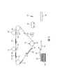
例えば、図1に示されるように、本願明細書における例示的な3次元(3D)プリンタは、他の要素のうち、ローラー112上に支持された中間転写ベルト110(ITB)と、第1の印刷要素116と、第2の印刷要素114と、ITB110に隣接する(表面又はベルトとすることができる)プラテン118とを含む。さらに、シートフィーダ126は、折り畳み可能な媒体シート108を維持する。そのような構造は、プラテン118に隣接して配置された安定化ステーション120を含む。また、プラットフォーム146が含まれ、結合ステーション122は、光、圧力及び/又は熱を印加するように配置される。本構造はまた、支持材料除去ステーション148を含むことができる。
For example, as shown in FIG. 1, the exemplary three-dimensional (3D) printer herein includes, among other elements, an intermediate transfer belt 110 (ITB) supported on a
図1に示されるように、(例えば、感光体とすることができる)第1の印刷要素116は、ITB110に第1の材料104(例えば、(例えば、帯電した3Dトナー)乾燥粉末、ポリマーワックス材料などの造形材料)を(ベルトと転写される粉末材料との間の電荷差によって)静電的に転写するように配置され、(例えば、感光体ともすることができる)第2の印刷要素114は、第1の材料104が位置するITB110上に位置するITB110の位置に第2の材料105(例えば、ここでも乾燥粉末、ポリマーワックス材料(例えば、帯電した3Dトナー)などの支持材料)を同様に静電的に転写するように配置される。
As shown in FIG. 1, the first printing element 116 (which can be, for example, a photoconductor) is the
支持材料105は、印刷された3D構造が印刷プロセスにおいて使用される支持材料105から分離されるのを可能とするように、造形材料104に影響を及ぼさない異なる溶剤に溶解する。図面において、造形材料104及び支持材料105の組み合わせが要素102として示されており、現像層と称される。造形材料104及び支持材料105の現像層102は、ITB110の別個の領域上にあり、その層(及びその関連する支持要素)における3D構造の要素に対応してパターン化され、3D構造は、現像層102によって造形される。
The
図1に示されるように、シートフィーダ126は、周知のグラバー、ローラー、ニップ、ベルト(全て一般に項目126によって図示される)などを使用して、プラテン118に配置され、折り畳み可能な媒体シート108をプラテン118に供給する。この例において、プラテン118は、折り畳み可能な媒体シート108をさらに移動させ且つ折り畳み可能な媒体シート108を保持する真空ベルトであり、後続の処理中に配置される。
As shown in FIG. 1, the
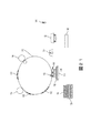
図2における縦矢印によって示されるように、プラテン118は、ITB110と接触させるプラテン118上に配置された折り畳み可能な媒体シート108を有するように、((全て一般に項目118によって図示される)モータ、歯車、プーリー、ケーブル、ガイドなどを使用して)ITB110に向かって移動する。ITB110は、プラテン118がITB110とともに折り畳み可能な媒体シート108に接触するたびに、造形材料104及び支持材料105の現像層102のいずれかを折り畳み可能な媒体シート108に転写し、折り畳み可能な媒体シート108上に造形材料104及び支持材料105の現像層102を連続的に形成する。
As indicated by the vertical arrows in FIG. 2, the
そのような造形材料及び支持材料は、それぞれの別個の現像装置114、116によってITB上にパターンで印刷され、所定長を有する特定のパターンを表すように現像層102においてともに結合される。それゆえに、現像層102のそれぞれは、(ITB110の隣の矢印によって表される)ITB110が移動しているプロセス方向の方に向けられた前縁134と、前縁134に対向する後縁136とを有する。
Such shaping and supporting materials are printed in a pattern on the ITB by their respective separate developing
より具体的には、図2に示されるように、転写定着ニップ130において、転写定着ニップ130内の現像層102の前縁134は、プラテン118の対応する位置に転写され始める。それゆえに、図2において、プラテン118は、現像層102の前縁134が転写定着ニップ130のローラーの最も低い位置にある位置においてITB110上の現像層102に接触するように移動する。それゆえに、この例において、現像層102の後縁136は、まだ転写定着ニップ130に到達しておらず、したがって、まだプラテン118に転写されていない。
More specifically, as shown in FIG. 2, in the transfer fixing nip 130, the
図3に示されるように、プラテン118は、汚すことなく、現像層102がプラテン118上にきれいに転写するのを可能とするように、プラテン真空ベルトを移動又は回転させることによってITB110と同期して移動する(ITB110と同じ速度で且つ同じ方向に移動する)。図3において、現像層102の後縁136は、まだ転写定着ニップ130に到達しておらず、したがってプラテン118に転写されていない又は部分106を部分的に形成した唯一の部分である。そして、ITB110がプロセス方向に移動するのにともない、プラテン118は、現像層102の後縁136が転写定着ニップ130のローラーの底部に到達するまで、ITB110と同じ速度で且つ同じ方向に移動し、その時点で、図4に示されるように、プラテン118は、ITB110から離れ且つ安定化ステーション120にわたって移動する。安定化ステーション120は、粒子−粒子の弱い結合を可能とするように、非接触(例えば、パルス式ヒータ(フラッシュ、レーザ、IRなど))、又は、定着器ローラーなどの加圧ヒータとすることができる。
As shown in FIG. 3, the
例えば、安定化ステーション120は、下層の現像層102又は折り畳み可能な媒体108に影響を及ぼすことなく、上部現像層102にのみ影響を及ぼすように、制限された時間及び制限された深さだけ熱のみを提供する非常に制御可能な抵抗性又は照明装置を備えることができる。そのような非常に制御可能な抵抗性又は照明装置は、例えば、制限された露光時間の間に点滅するレーザ又は赤外線光源を含むことができる。したがって、上述したように、安定化ステーション120は、トナー層を安定化させるために多くのことを行うことができる。例えば、安定化ステーション120は、トナーを放電することができ、空気イオン化、コロナ装置などの放電方法及び装置を含むことができる。さらに、安定化ステーション120は、折り畳み可能な基材108をはるかに損傷させすぎることなく、造形及び支持材料を一体に弱く結合又は焼結させる。他の例において、安定化ステーション120は、パルス状加熱、フラッシュ光加熱、レーザ加熱などを提供することができる。したがって、安定化ステーション120は、多くの異なる安定化動作を実行する複数の別個のユニット又は複合装置であってもよい。
For example, the
図5に示されるように、安定化ステーション120は、下層の現像層102又は折り畳み可能な媒体108に影響を及ぼすことなく、上部現像層102にのみ短時間熱を印加することができる。したがって、安定化ステーション120は、上部現像層102に物理的に接触しないが、上部現像層102内でのみ粒子−粒子の弱い結合を促進するように最小量の溶融を提供するために上部現像層102に短時間だけ熱を供給するように(これはまた、上部現像層102の電荷を低減する)且つ上部現像層102をすぐ隣接する下層の現像層102又は折り畳み可能な媒体108に結合するように制御されることができる。
As shown in FIG. 5, the
プラテン118は、折り畳み可能な媒体108への堆積直後に現像層102のそれぞれを独立して安定化させるように、折り畳み可能な媒体シート108にITB110が現像層102のそれぞれを転写するたびに、安定化ステーション120を移動させることができる。他の代替において、プラテン118は、複数の現像層102が同時に安定化されるのを可能とするように、特定数(例えば、2、3、4など)の現像層102が折り畳み可能な媒体シート108上に配置された後に安定化ステーション120へと移動するのみとすることができる。
The
それゆえに、図6に示されるように、複数の現像層102を折り畳み可能な媒体シート108に堆積して安定化させるために図2から図5における処理が繰り返される。現像層102の積層106が成長するのにともない、図6に示されるように、積層106の上部に追加の現像層102が形成され、そのような追加の現像層102は、図7に示されるように、積層106内の全ての現像層102を一体に定着するように安定化ステーション120によって安定化される。
Therefore, as shown in FIG. 6, the processes of FIGS. 2 to 5 are repeated in order to deposit and stabilize the plurality of developing
図8は、現像層102が造形材料104の一部及び支持材料105の一部を含むことができる方法、最も低い現像層102が折り畳み可能な媒体108に接合される方法、並びに、連続した各現像層102が単一の折り畳み可能な媒体シート108上に現像層102の積層106を形成するために(例えば、層102と折り畳み可能な媒体シート108との間にある)下方の直前の隣接する現像層102に接触して接合される方法を示す拡大図である。
FIG. 8 shows a method in which the developing
上述したように、(識別番号102を使用して、図8における粒子として示される(縮尺どおりには描かれていない))現像層102内の造形材料104及び支持材料105の粒子は、粉末の帯電粒子であり、図8は、負に帯電した粒子として(又はそれらは正に帯電されることができる)これらの項目を示している。当業者にとって理解されるように、印刷要素114、116は、ITB110に静電的に転写するそのような粒子を有するために粒子102に電荷を供給する。電荷発生器132は、プラテン118の反対側に逆電荷152(この場合は正の電荷)を形成するために使用されることができ、この逆電荷152は、ITB110から積層106の上部に帯電粒子102を引き出す。
As mentioned above, the particles of the shaping
しかしながら、ある時点において、積層106の高さは、図8に示されるように、帯電粒子102を引き付けるための逆電荷152の能力よりも大きい帯電した(造形及び支持)粒子102の間の距離を形成する(また、この高さは、様々な電荷の強度に応じて変化する)。積層106の高さがこの点(又はその前)に到達すると、処理は、図9に示されるように、プラットフォーム146に折り畳み可能な媒体シート108及び積層106を転写する。
However, at some point, the height of the
それゆえに、図9に示されるように、プラットフォーム146は、プラテン118から独立した積層106を受けるように配置される。また、結合ステーション122は、図10から図13に示されるように、プラットフォーム146上の折り畳み可能な媒体シートを介して独立した積層106において現像層102を互いに結合するために3D構造に熱及び/又は圧力及び/又は光を印加するように構成されている。結合ステーションのヒータ、照明及び他の要素122の選択的使用は、現像層102の化学的構成に応じて変化する。折り畳み可能な媒体108及び現像層の各独立した積層106は、独立した積層106がプラットフォーム146に(又はプラットフォーム146上の以前に結合された独立した積層106の上部に存在する独立した積層106に)転写された直後に、図10から図13に示されるように結合ステーションによって個々に結合されることができ、又は、独立した積層106の高さ、それらの化学的構成、結合ステーション122によって加えられる温度及び圧力などに応じて、群(一度に2回、一度に3回など)に独立した積層106を結合するように処理されることができる。
Therefore, as shown in FIG. 9, the
図11は、結合を行うために、輻射ヒータ、対流ヒータ、高温加圧ロール、高温加圧プレートなどを含むことができる図10に示される結合ステーションの動作の拡大図である。図10及び図11に示される例において、結合ステーション122は、加熱された加圧ローラーを有し、プラットフォーム146は、ローラーが回転するのにともない(図における矢印によって示されるように)同期して移動し、(各現像層102内の造形及び支持材料のパターンの歪みを回避するように制御された温度及び圧力を使用して)現像層102を互いに定着するように加熱及び加圧する。この同期移動は、現像装置116、114によって印刷された支持及び造形材料(102)のパターンを歪み又は汚れなしに定着及び結合させる。
FIG. 11 is an enlarged view of the operation of the coupling station shown in FIG. 10, which can include a radiant heater, a convection heater, a high temperature pressurizing roll, a high temperature pressurizing plate, etc. for coupling. In the example shown in FIGS. 10 and 11, the
図13は、図12に示される結合ステーション122の動作の拡大図である。図12及び図13に示されるように、プラットフォーム146が結合ステーションを通過した後、折り畳み可能な媒体シート108の厚さは、(例えば、10倍以上、100倍以上、1000倍以上など)大幅に低減している。これは、図11及び図13における折り畳み可能な媒体の上部シート108の厚さを比較することによってわかる(縮尺どおりには描かれていない)。
FIG. 13 is an enlarged view of the operation of the
さらに、折り畳み可能な媒体シート108のそれぞれのいずれかの側における現像層102は、図13に示されるように、折り畳み可能な媒体108が結合後にほとんど残らないことから、折り畳み可能な媒体シート108を介して結合する(折り畳み可能な媒体の上部シート108は、結合後に若干破壊された外観を有する)。折り畳み可能な媒体シート108を介した現像層102の結合は、折り畳み可能な媒体シート108が高多孔質である(例えば、65%、80%、95%以上などの孔を含む)ことから且つ折り畳み可能な媒体シート108が大きい測定値だけ厚さが低減している(例えば、折り畳み可能な媒体シート108の厚さは、図10から図13に示される結合ステーション122の動作によって大きさのオーダー(例えば、1/2、1/5、1/10、1/100、1/1000など、元の厚さ)だけ低減することができる)ことから生じる。いくつかの状況において、折り畳み可能な媒体108の一部(又は全部)は、結合ステーションの動作によって周囲層に気化又は合体され、外観又は構造的強度の目的のために本構造から折り畳み可能な媒体シート108を本質的になくす。
Further, the developing
折り畳み可能な基材108は、静電粉末層の転写を容易とし且つ多層造形を可能とするように導電性/半導電性材料から構成されることができる。折り畳み可能な基材材料108は、溶融時には、必要に応じて、部品強度を確保するために、造形材料104(の同様の材料特性を有する)と適合するように選択されることができる。さらにまた、折り畳み可能な基材材料108は、溶融時には、必要に応じて、支持材料105が造形材料104及び折り畳み可能な基材材料108の双方から容易に除去/溶解されるのを可能とするように支持材料105(に対して異なる材料特性を有する)とは不適合であるように選択されることができる。
The
折り畳み可能な基材108は、結合ステーション122によって加えられる定着条件下で折り畳まれることから、折り畳み可能な基材108は、薄膜層の形状を保持しなくてもよい。多孔質構造の利得/セル特性のために、溶融時に、折り畳み可能な基材108は、不連続な島になることができる(図13に示されるように、折り畳み可能な媒体108の上部シートは、結合後に若干破壊された外観を有する)。
Since the
さらに、支持材料105の意図的な材料の不一致により、折り畳み可能な基材108の液滴形成が促進され得る。他の状況において、造形材料104が不適合である(しかし、支持材料105とは潜在的に適合する)ように折り畳み可能な基材108の材料を選択することにより、折り畳み可能な基材材料108は、結合プロセス中に支持材料105に移動する分散した小液滴に変換することができる。これは、支持材料と折り畳み可能な基材108の現在低減した材料を接合し、それにより、最終溶剤の支持材料105内の基材材料108の容易な除去を可能とする。したがって、材料の選択に応じて、基材108は、結合中に支持材料105に移動するように造形材料104が基材材料108に混じり合わないように選択された場合には、視覚的にではなく若しくは造形材料104に構造的影響を及ぼすことなく造形材料104内の最終構造物に残ることができ、又は、支持材料105によって除去されることができる。
In addition, the intentional material mismatch of the supporting
折り畳み可能な材料108の例は、双方とも、開放発泡体及び閉鎖発泡体並びに95%〜98%の範囲の多孔度を有するポリスチレンから構成された発泡体材料である。折り畳み可能な材料108はまた、折り畳み可能材料108が結合中に造形材料と1つになるのを可能とするように造形材料104の高多孔質発泡体とすることができる。
Examples of the
1つの例において、約100〜200X(Xは、ここでも任意の測定単位である)の厚さの折り畳み可能な材料108は、本願明細書に記載された処理を行うのに機械的に十分である。98%の多孔度により、折り畳み可能な基材108は、溶融後に不連続な島(又は液滴)の僅か2〜4Xの薄層に変換される(例えば、100倍減少(元の厚さの1/100))。さらに、例示的な200倍の価値の造形及び支持材料が、積層及び定着前に各折り畳み可能な基材108上に堆積される場合、折り畳み可能な基材材料108に対する3D印刷材料の比は、100:1又は100:2であり、結合後に残っている折り畳み可能な基材材料108の量は、構造又は外観において重要ではないことを示している。溶融した基材材料108は、連続膜を形成することができず、代わりに、表面張力によって小液滴に破壊されることがある。ポリマー支持体材料105にまばらに分散したポリスチレンの例示的な小液滴は、外観又は強度に影響しない。造形材料104がポリスチレンと適合しない場合であっても、そのような小さい比率のポリスチレン液滴の存在は、造形部品の強度に影響を与えない。
In one example, a
折り畳み可能な基材108として使用可能な材料の他の例は、以下の高性能熱可塑性発泡体である:これらの材料は、一般に>95%の多孔度を有する脂肪族又は半芳香族ポリアミドなどの合成ポリマーとすることができる。したがって、造形材料104の基本化学物質は、発泡基材108の基本化学物質と同じにすることができる。これは、造形物と基材108との間の完全な適合性を保証することができ、造形完全性を保証する。さらに、折り畳み可能な基材108はまた、例えば、電気(導電性)、熱、色などの多くの異なる方法で製造された3D部品の特性を変更するように選択されることができる。
Other examples of materials that can be used as the
実際に、結合ステーション122の動作は、裸眼に視認可能な大きさ未満に折り畳み可能な媒体シート108の厚さを低減することができ、残っている(もしあれば)折り畳み可能な媒体シート108の一部を介した現像層102の接続は、折り畳み可能な媒体シート108によって分離されたそのような現像層102が折り畳み可能な媒体シート108が存在しない場合と同じ強度で結合されるのを可能とする。これは、最終構造物の外観又は強度に影響を与えることなく、折り畳み可能な媒体シート108(又はその一部)が最終構造物に残るのを可能とする。
In fact, the operation of the
結合ステーションはまた、図10及び図13における波線によって示されるように、光ベース硬化を行うことができる。他の結合と同様に、光ベース硬化は、一度に1つの独立した積層106上で行うことができ、又は、独立した積層106は、バッチで光ベース硬化を施すことができる。さらに、光ベース硬化は、熱圧着ベース結合とは異なる時間に結合ステーション122によって行うことができる。また、結合及び定着機能は、異なる位置に配置された別個のステーションによって行うことができ、示された結合ステーション122は例にすぎない。
The coupling station can also perform light-based curing, as indicated by the wavy lines in FIGS. 10 and 13. As with other bonds, light-based curing can be performed on one
造形材料104及び支持材料105は、UV硬化性トナーを含むことができる。結合ステーション122は、そのガラス転移温度とそれらの融点との間の温度まで材料を加熱した後に、材料内のポリマーを架橋するようにUV光を印加することによってそのような材料を結合し、それにより、剛性構造を形成する。当業者は、他の造形及び支持材料が他の結合及び硬化処理並びに硬化要素を利用すること、及び、前述したものが1つの限定された例としてのみ提示されていることを理解するであろう。本願明細書における装置及び方法は、現在知られているか又は将来開発されるかにかかわらず、全てのそのような結合方法及び要素に適用可能である。
The
図14に示されるように、処理は、プラットフォーム146に繰り返し転写される新たな独立した積層106を形成し続け、この繰り返し処理は、独立した積層106のそれぞれにおける現像層102を、互いに且つプラットフォーム146上の以前に転写されたいかなる3D構造の独立した積層106に対して結合し、図15に示されるように独立した積層106の3D構造を連続的に形成する。図15は、独立した積層106の蓄積内の支持材料105及び造形材料104の部分を示すオーバーレイを図示していることに留意されたい。そのようなものは、視認可能であってもなくてもよく、そのような造形及び支持材料が配置されることができる1つの例示的な方法を示すために図示されているにすぎない。
As shown in FIG. 14, the process continued to form new
図15に示されている独立した積層106の3D構造は、外部溶剤槽を使用した支持材料105の手動除去を可能とするように出力されることができ、又は、図16から図18に示されるように処理を進めることができる。より具体的には、図16において、造形材料104に影響を与えることなく支持材料105を溶解する溶剤156を塗布するように支持材料除去ステーション148が配置される。ここでも、上述したように、利用される溶剤は、造形材料104及び支持材料105の化学的構成に依存する。図17は、支持材料105の約半分が残っており且つ造形材料104の一部が支持材料105の残りの積層から突出する処理を図示している。図18は、支持材料除去ステーション148が全ての支持材料105を溶解するのに十分な溶剤156を塗布して残っている造形材料104のみを残し、造形材料104のみから構成された完成した3D構造を残した後の処理を図示している。
The 3D structure of the
図19及び図20は、図2に示される転写定着ニップ130の代わりに平面転写定着ステーション138を含む本願明細書における代替の3D静電印刷構造を図示している。図19に示されるように、平面転写定着ステーション138は、ローラー112間にあり且つプラテン118に平行なITB110の平面部である。図20示されるように、この構造により、平面転写定着ステーション138に接触するようにプラテン118が移動するとき、現像層102の全ては、プラテン118に又は部分的に形成された積層106に同時に転写され、図2及び図3に示される回転転写定着プロセスを回避する。
19 and 20 illustrate an alternative 3D electrostatic printing structure in the present specification that includes a planar
同様に、図21に示されるように、本願明細書において記載されるように動作する全ての他の要素を有し、ITB110の代わりにドラム178が使用されることができる。それゆえに、ドラム178は、上述したように、現像ステーション114、116からの材料を受ける中間転写面とすることができ、又は、感光体とすることができ、電荷の潜像を維持して現像装置254からの材料を受けることにより、以下に記載される感光体256として動作することができる。
Similarly, as shown in FIG. 21, a
図22は、本願明細書における例示的な方法を図示するフローチャートである。項目170において、これらの様々な例示的な方法は、ITBに第1及び第2の材料を自動的に静電的に転写する。項目170において、第2の材料は、第1の材料上に(例えば、第1の材料が既にITB上に位置するITBの位置に)転写される。ここでも、第2の材料は、第1の材料を溶解する溶剤に対して異なる溶剤に溶解する。第1及び第2の材料の層は、ITBの別個の領域上にあり且つパターン化される。
FIG. 22 is a flowchart illustrating an exemplary method in the present specification. In
項目172において、そのような方法は、シートフィーダを使用してプラテンに折り畳み可能な媒体シートをさらに自動的に供給する。さらに、項目174において、これらの方法は、折り畳み可能な媒体シートに第1及び第2の材料の層を転写するようにITBに接触するプラテン上に配置された折り畳み可能な媒体シートを有するようにITBに向かってプラテンを自動的に移動させる。
In
この後、項目176において、本方法は、現像層を安定化させ且つ折り畳み可能な媒体シートに現像層を接合するように安定化ステーションへとプラテンを自動的に移動させる。項目176から項目174への矢印によって示されるように、そのような方法は、ITBに繰り返し接触する折り畳み可能な媒体シートを有するようにITBに向かってプラテンを移動させるというプロセスを自動的に繰り返し、折り畳み可能な媒体シート上に第1及び第2の材料の層を連続的に形成し、ITBが折り畳み可能な媒体シートに各層を転写するたびに、これらの方法は、独立して安定化させ且つ折り畳み可能な媒体シート上の以前に形成され現像層に新たな現像層のそれぞれを連続的に接合するように安定化ステーションへとプラテンを移動させるというプロセスを自動的に繰り返す。
Then, in
そして、項目178において、これらの方法は、層の独立した積層の3D構造を連続的に形成するようにプラットフォームへと独立した積層を自動的に供給する。項目180において、これらの方法は、結合ステーションを使用してプラットフォーム上に折り畳み可能な媒体シートを介して独立した積層を互いに接合するように3D構造に熱及び/又は圧力及び/又は光を自動的に印加する。より具体的には、項目180における結合プロセスは、プラットフォーム上の3D構造の独立した積層のうちの以前に転写されたいずれかのものに独立した積層のそれぞれを独立して結合するようにプラテンがプラットフォームに独立した積層のそれぞれを転写するたびに、熱及び/又は圧力及び/又は光を印加する。
Then, in
また、項目182において、これらの方法は、支持材料除去ステーションへと3D構造を自動的に供給し、支持材料除去ステーションにおいて第1の材料のみから構成された3D構造を残すように、第1の材料に影響を与えることなく、第2の材料を溶解する溶剤をそこに塗布することができる。
Also, in
図23は、本願明細書における3D印刷装置204の多くの要素を図示している。3D印刷装置204は、コントローラ/有形プロセッサ224と、有形プロセッサ224及び印刷装置204の外部のコンピュータ化ネットワークに動作可能に接続された通信ポート(入力/出力)214とを含む。また、印刷装置204は、グラフィカルユーザインターフェース(GUI)アセンブリ212などの少なくとも1つのアクセサリ機能要素を含む。ユーザは、グラフィカルユーザインターフェース又はコントロールパネル212からメッセージ、命令及びメニューオプションを受信し且つそれを介して命令を入力することができる。
FIG. 23 illustrates many elements of the
入力/出力装置214は、3D印刷装置204との間の通信に使用され、(現在知られているか又は将来開発されるかにかかわらず、任意の形態の)有線又は無線装置を備える。有形プロセッサ224は、印刷装置204の様々な動作を制御する。(光、磁気、キャパシタベースなどであり、一時的信号とは異なる)持続性で有形のコンピュータ記憶媒体装置210は、有形プロセッサ224によって読み取り可能であり、コンピュータ化装置が本願明細書において記載されるものなどの様々な機能を実行するのを可能とするように有形プロセッサ224が実行する命令を記憶する。それゆえに、図23に示されるように、本体ハウジングは、電源218によって交流(AC)電源220から供給される電力で動作する1つ以上の機能要素を有する。電源218は、共通電力変換ユニット、電力記憶素子(例えば、電池など)などを含むことができる。
The input /
3D印刷装置204は、上述したようにプラテン上に造形及び支持材料の連続層を堆積させる少なくとも1つのマーキング装置(印刷エンジン)240を含み、(画像データの処理に特化されていることから汎用コンピュータとは異なる)専用画像プロセッサ224に動作可能に接続される。また、印刷装置204は、(電源218を介して)外部電源220から供給される電力で同様に動作する少なくとも1つのアクセサリ機能要素(スキャナ232など)を含むことができる。
The
1つ以上の印刷エンジン240は、現在知られているか又は将来開発されるかにかかわらず、造形材料及び支持材料(トナーなど)を塗布する任意のマーキング装置を例示するように意図され、例えば、(図24に示されるように)中間転写ベルト110を使用する装置を含むことができる。
One or
それゆえに、図24に示されるように、図23に示される印刷エンジン240のそれぞれは、1つ以上の潜在的に異なる(例えば、異なる色、異なる材料など)造形材料現像ステーション116や、1つ以上の潜在的に異なる(例えば、異なる色、異なる材料など)支持材料現像ステーション114などを利用することができる。現像ステーション114、116は、現在知られているか又は将来開発されるかにかかわらず、個々の静電マーキングステーション、個々のインクジェットステーション、個々のドライインクステーションなどの任意の形態の現像ステーションとすることができる。現像ステーション114、116のそれぞれは、(潜在的には中間転写ベルト110の状態から独立している)単一のベルト回転中に順次中間転写ベルト110の同じ位置に材料のパターンを転写し、それにより、十分且つ完全な画像が中間転写ベルト110に転写される前に中間転写ベルト110が通過しなければならない回数を減少させる。
Therefore, as shown in FIG. 24, each of the
中間転写ベルト110に隣接して配置された(又は潜在的に接触して)1つの例示的な個々の静電現像ステーション114、116が図25に示されている。個々の静電現像ステーション114、116のそれぞれは、内部感光体256上に均一な電荷を形成する独自の充電ステーション258と、感光体上において均一な電荷をパターン化された電荷にパターン化する内部露光装置260と、感光体256に造形又は支持材料を転写する内部現像装置254とを含む。そして、造形又は支持材料のパターンは、感光体256から中間転写ベルト110に転写され、折り畳み可能な媒体シート108に中間転写ベルトを最終的に形成する。図24は、回転ベルト(110)に隣接又は接触する5つの現像ステーションを図示しているが、当業者によって理解されるように、そのような装置は、任意数のマーキングステーション(例えば、2、3、5、8、11など)を使用することができる。
One exemplary individual
いくつかの例示的な構造が添付図面に示されているが、当業者は、図面が簡略化された概略図であること、及び、以下に提示される特許請求の範囲が、図示されていない(又は潜在的には多いか少ない)がそのような装置及びシステムによって一般に利用されるより多くの特徴を包含することを理解するであろう。したがって、特許出願人は、以下に提示される特許請求の範囲が添付図面によって限定されるようには意図しておらず、代わりに、添付図面は、単に特許請求の範囲に記載された特徴が実装されることができるいくつかの方法を例示するために提供されるにすぎない。 Although some exemplary structures are shown in the accompanying drawings, those skilled in the art will not show that the drawings are simplified schematics and that the claims presented below are scoped. It will be appreciated that (or potentially more or less) embraces more features commonly used by such devices and systems. Therefore, the patent applicant does not intend to limit the scope of the claims presented below by the accompanying drawings, and instead, the attached drawings simply have the features described in the claims. It is provided only to illustrate some of the methods that can be implemented.
米国特許第8,488,994号明細書に示されるように、電子写真方式を使用した3D部品を印刷するための積層造形システムが知られている。システムは、表面を有する感光体要素と、現像ステーションとを含み、現像ステーションは、感光体要素の表面上に材料の現像層を転写するように構成されている。システムはまた、回転可能な感光体要素の表面から現像層を受けるように構成された転写媒体と、受けた層の少なくとも一部から3D部品を印刷するために層毎の様式で転写要素から現像層を受けるように構成されたプラテンとを含む。 As shown in US Pat. No. 8,488,994, a laminate modeling system for printing 3D parts using electrophotographic methods is known. The system includes a photoconductor element having a surface and a developing station, which is configured to transfer a developing layer of material onto the surface of the photoconductor element. The system also develops from the transfer element in a layer-by-layer fashion to print the 3D component from at least a portion of the transfer medium configured to receive the development layer from the surface of the rotatable photoconductor element. Includes platens configured to receive layers.
UV硬化性トナーに関して、米国特許第7,250,238号明細書に開示されているように、印刷プロセスにおいてUV硬化性トナー組成物を利用する方法であるため、UV硬化性トナー組成物を提供することが知られている。米国特許第7,250,238号明細書は、実施形態において硬化されることができ、約100nmから約400nmを有するUV光などのUV照射に対する露光によるものである、トナーの生成を可能とする様々なトナーエマルジョン凝集プロセスを開示している。米国特許第7,250,238号明細書において、生成されたトナー組成物は、温度感受性包装及びフォイルシールの製造などの様々な印刷用途に利用されることができる。米国特許第7,250,238号明細書において、実施形態は、任意の着色剤、任意のワックス、スチレンから生成されたポリマー、及び、ブチルアクリレート、カルボキシエチルアクリレート及びUV光硬化性アクリレートオリゴマーからなる群から選択されるアクリレートから構成されるUV硬化性トナー組成物に関する。さらに、これらの態様は、顔料、任意のワックス及びUV硬化性脂環式エポキシドから生成されるポリマーなどの着色剤から構成されるトナー組成物に関する。 As for UV curable toner, as disclosed in US Pat. No. 7,250,238, the UV curable toner composition is provided because it is a method of utilizing the UV curable toner composition in the printing process. It is known to do. U.S. Pat. No. 7,250,238 allows the production of toner, which can be cured in embodiments and is by exposure to UV irradiation such as UV light having about 100 nm to about 400 nm. Various toner emulsion aggregation processes are disclosed. In US Pat. No. 7,250,238, the toner composition produced can be used in a variety of printing applications, such as in the manufacture of temperature sensitive packaging and foil seals. In US Pat. No. 7,250,238, an embodiment comprises any colorant, any wax, a polymer produced from styrene, and butyl acrylate, carboxyethyl acrylate and UV photocurable acrylate oligomers. It relates to a UV curable toner composition composed of an acrylate selected from the group. Further, these aspects relate to toner compositions composed of pigments, optional waxes and colorants such as polymers produced from UV curable alicyclic epoxides.
さらに、米国特許第7,250,238号明細書は、スチレン、ブチルアクリレート、カルボキシエチルアクリレート及びUV硬化性アクリレートから形成されたポリマーを含有するラテックスを着色剤及びワックスと混合することと、必要に応じて凝集を引き起こして第2の混合物中に分散されたトナー前駆体粒子を形成するためにこの混合物に凝集剤を添加することと、トナー粒子を形成するようにポリマーのガラス転移温度(Tg)以上の温度までトナー前駆体粒子を加熱することと、必要に応じてトナー粒子を洗浄することと、必要に応じてトナー粒子を乾燥させることとを含むUV硬化性トナー組成物を形成する方法を開示している。さらなる態様は、この方法によって製造されたトナー粒子に関する。 In addition, US Pat. No. 7,250,238 requires that a latex containing a polymer formed from styrene, butyl acrylate, carboxyethyl acrylate and UV curable acrylate be mixed with a colorant and a wax. Adding an aggregating agent to the mixture to form the toner precursor particles dispersed in the second mixture, and the glass transition temperature (Tg) of the polymer to form the toner particles accordingly. A method for forming a UV curable toner composition, which comprises heating the toner precursor particles to the above temperature, washing the toner particles as needed, and drying the toner particles as needed. It is disclosed. A further aspect relates to toner particles produced by this method.
いくつかの例示的な構造が添付図面に図示されているが、当業者は、図面が簡略化された概略図であること、及び、以下に提示される特許請求の範囲が、図示されていない(又は潜在的には多いか少ない)がそのような装置及びシステムによって一般に利用されるより多くの特徴を包含することを理解するであろう。したがって、特許出願人は、以下に提示される特許請求の範囲が添付図面によって限定されるようには意図しておらず、代わりに、添付図面は、単に特許請求の範囲に記載された特徴が実装されることができるいくつかの方法を例示するために提供されるにすぎない。 Although some exemplary structures are illustrated in the accompanying drawings, those skilled in the art will not show that the drawings are simplified schematics and that the claims presented below are scoped. It will be appreciated that (or potentially more or less) embraces more features commonly used by such devices and systems. Therefore, the patent applicant does not intend to limit the scope of the claims presented below by the accompanying drawings, and instead, the attached drawings simply have the features described in the claims. It is provided only to illustrate some of the methods that can be implemented.
多くのコンピュータ化装置が上述されている。チップベースの中央処理装置(CPU)と、(グラフィックユーザインターフェース(GUI)、メモリ、コンパレータ、有形プロセッサなどを含む)入力/出力装置とを含むコンピュータ化装置は、米国テキサス州ラウンドロックのデルコンピュータ及び米国カリフォルニア州クパチーノのアップルコンピュータ社などの製造業者によって製造された周知且つ容易に入手可能な装置である。そのようなコンピュータ化装置は、一般に、入力/出力装置と、電源と、有形プロセッサと、電子記憶メモリと、配線などを含み、その詳細は、読者が本願明細書に記載されたシステム及び方法の顕著な態様に集中するのを可能とするように本願明細書からは省略される。同様に、プリンタ、複写機、スキャナ及び他の同様の周辺機器は、米国コネティカット州ノーウォークのゼロックス社から入手可能であり、そのような装置の詳細は、簡潔性及び読者の集中の目的のために本願明細書においては記載されない。 Many computerized devices are mentioned above. Computerized equipment, including a chip-based central processing unit (CPU) and input / output equipment (including a graphic user interface (GUI), memory, comparator, tangible processor, etc.), is available from Dell Computer in Roundlock, Texas, USA. A well-known and readily available device manufactured by manufacturers such as Apple Computer, Inc., Cupacino, California, USA. Such computerized devices generally include input / output devices, power supplies, tangible processors, electronic storage memory, wiring, etc., the details of which are described by the reader in the systems and methods described herein. It is omitted from the present specification to allow concentration in a prominent aspect. Similarly, printers, copiers, scanners and other similar peripherals are available from Xerox, Inc., Norwalk, Connecticut, USA, and details of such equipment are for the purpose of brevity and reader concentration. Is not described in the specification of the present application.
本願明細書において使用されるプリンタ又は印刷装置という用語は、任意の目的のために印刷出力機能を実行する、ディジタル複写機、製本機、ファクシミリ装置、複合機などの任意の装置を包含する。プリンタ、印刷エンジンなどの詳細は、周知であり、本開示が提示された顕著な特徴に集中されるのを維持するように本願明細書においては詳細に記載されない。本願明細書におけるシステム及び方法は、カラーで、モノクロで印刷する、又は、カラー若しくはモノクロ画像データを扱うシステム及び方法を包含することができる。全ての前述したシステム及び方法は、特に静電及び/又は乾式電子写真方式装置及び/又はプロセスに適用可能である。 As used herein, the term printer or printing device includes any device, such as a digital copier, bookbinding machine, facsimile machine, multifunction device, that performs a print output function for any purpose. Details such as printers, printing engines, etc. are well known and are not described in detail herein to keep the disclosure focused on the salient features presented. The systems and methods herein can include systems and methods for printing in color and monochrome, or for handling color or monochrome image data. All the systems and methods described above are particularly applicable to electrostatic and / or dry electrophotographic devices and / or processes.
本発明の目的のために、定着(fixing)という用語は、乾燥、硬化、重合、架橋、結合若しくは付加反応又はコーティングの他の反応を意味する。さらに、本願明細書において使用される「右(right)」、「左(left)」、「垂直(vertical)」、「水平(horizontal)」、「上部(top)」、「下部(bottom)」、「上(upper)」、「下(lower)」、「下方(under)」、「下方(below)」、「下にある(underlying)」、「上(over)」、「上にある(overlying)」、「平行(parallel)」、「垂直(perpendicular)」などの用語は、(特に断らない限り)それらが図面において配向されて図示されるときの相対位置であると理解される。「接触(touching)」、「上(on)」、「直接接触(in direct contact)」、「当接(abutting)」、「直接隣接(directly adjacent to)」などの用語は、(記載された要素を分離する他の要素なしで)少なくとも1つの要素において他の要素に物理的に接触することを意味する。さらに、自動化された(automated)又は自動的に(automatically)という用語は、(機械又はユーザによって)処理が開始されると、1つ以上の機械がいかなるユーザからのさらなる入力なしで処理を行うことを意味する。本願明細書における図面において、同一の識別符号は、同一又は同様の項目を識別する。
For the purposes of the present invention, the term fixing means drying, curing, polymerization, cross-linking, bonding or addition reactions or other reactions of coating. Further, as used in the present specification, "right", "left", "vertical", "horizontal", "top", "bottom". , "Upper", "lower", "lower", "lower", "underlying", "over", "above (upper)", "lower", "lower", "lower", "lower" Terms such as "overlying", "parallel", and "perpendicular" are understood (unless otherwise specified) to be relative positions when they are oriented and illustrated in the drawings. Terms such as "touching", "on", "direct contact", "abutting", and "directly adaptive to" have been described. Means physical contact with another element in at least one element (without any other element separating the elements). Further, the term automated or automatically means that once a process is initiated (by a machine or user), one or more machines perform the process without further input from any user. Means. In the drawings in the specification of the present application, the same identification code identifies the same or similar items.
Claims (10)
前記中間転写面に対して移動するプラテンと、
前記プラテンに折り畳み可能な媒体シートを供給するように配置されたシートフィーダと、
プラットフォームと、
結合ステーションと、
を備え、
前記プラテンが前記中間転写面に向かって繰り返し移動し、前記プラテン上に配置された前記折り畳み可能な媒体シートを前記中間転写面に繰り返し接触させ、
前記プラテンが前記折り畳み可能な媒体シートを前記中間転写面に接触させるたびに、前記中間転写面が、前記折り畳み可能な媒体シートに前記第1の材料及び前記第2の材料の層を転写して前記折り畳み可能な媒体シート上に前記第1の材料及び前記第2の材料の層の独立した積層を連続的に形成し、
前記プラットフォームが、前記独立した積層を前記プラテンから受けとり、前記折り畳み可能な媒体シート上に前記第1の材料及び前記第2の材料の前記層の独立した積層の3D構造を連続的に形成するように配置され、
前記結合ステーションが前記3D構造に熱、圧力及び/又は光を印加して、前記プラットフォーム上で前記折り畳み可能な媒体シートを介して前記独立した積層を互いに結合するように配置されている、
3次元(3D)プリンタ。 An intermediate transfer surface having layers of a first material and a second material, wherein the layers of the first material and the second material are on separate regions of the intermediate transfer surface and are patterned. Intermediate transfer surface and
A platen that moves with respect to the intermediate transfer surface,
A sheet feeder arranged to supply a foldable medium sheet to the platen ,
Platform and
Join station and
With
The platen repeatedly moves toward the intermediate transfer surface, and the foldable medium sheet arranged on the platen is repeatedly brought into contact with the intermediate transfer surface.
Each time the platen contacts the foldable medium sheet with the intermediate transfer surface, the intermediate transfer surface transfers layers of the first material and the second material onto the foldable medium sheet. Independent layers of the first material and the second material are continuously formed on the foldable medium sheet.
The platform receives the independent laminate from the platen and continuously forms a 3D structure of the independent laminate of the first material and the second material on the foldable medium sheet. Placed in
The binding station is arranged to apply heat, pressure and / or light to the 3D structure to bond the independent laminates to each other via the foldable medium sheet on the platform.
A three-dimensional (3D) printer.
前記支持材料除去ステーションは、前記第1の材料のみから構成された前記3D構造を残すように、前記第1の材料に影響を与えることなく前記第2の材料を溶解する溶剤を塗布する、請求項1に記載の3Dプリンタ。 Further equipped with a supporting material removal station arranged to receive the 3D structure from the platform.
The supporting material removal station is claimed to apply a solvent that dissolves the second material without affecting the first material so as to leave the 3D structure composed only of the first material. Item 1. The 3D printer according to item 1.
前記ITBに第1の材料を静電的に転写するように配置された第1の感光体と、
前記第1の材料が前記ITB上に位置する前記ITBの位置に第2の材料を静電的に転写するように配置された第2の感光体であって、前記第2の材料が前記第1の材料を溶解する溶剤に対して異なる溶剤において溶解する第2の感光体と、
前記ITBに対して移動するプラテンと、
前記プラテンに折り畳み可能な媒体シートを供給するように配置されたシートフィーダと、
前記プラテンに隣接する安定化ステーションと、
プラットフォームと、
結合ステーションと、
を備え、
前記プラテンが前記ITBに向かって繰り返し移動し、前記プラテン上に配置された折り畳み可能な媒体シートを前記ITBに繰り返し接触させ、
前記プラテンが前記折り畳み可能な媒体シートを前記ITBに接触させるたびに、前記ITBが、前記折り畳み可能な媒体シートに前記第1の材料及び前記第2の材料の層を静電的に転写し、前記折り畳み可能な媒体シート上に前記第1の材料及び前記第2の材料の層を連続的に形成し、
前記第1の材料及び前記第2の材料の前記層が前記ITBの別個の領域上にあり且つパターン化され、
前記ITBが前記第1の材料及び前記第2の材料の前記各層を前記折り畳み可能な媒体シートに転写するたびに、前記プラテンが前記安定化ステーションへと移動し、前記折り畳み可能な媒体シート上に前記第1の材料及び前記第2の材料の前記各層を独立して安定化させ、
前記プラットフォームが、前記独立した積層を前記プラテンから受けとり、前記折り畳み可能な媒体シート上に前記第1の材料及び前記第2の材料の前記層の独立した積層の3D構造を連続的に形成するように配置され、
前記結合ステーションが、前記3D構造に熱、圧力及び/又は光を印加し、前記プラットフォーム上で、前記折り畳み可能な媒体シートを介して前記独立した積層を互いに結合するように配置されている、
3次元(3D)プリンタ。 Intermediate transfer belt (ITB) and
A first photoconductor arranged so as to electrostatically transfer the first material to the ITB,
The first material is a second photoconductor arranged so as to electrostatically transfer the second material to the position of the ITB located on the ITB, and the second material is the second material. A second photoconductor that dissolves in a different solvent than the solvent that dissolves the first material,
The platen that moves with respect to the ITB,
A sheet feeder arranged to supply a foldable medium sheet to the platen ,
With the stabilization station adjacent to the platen,
Platform and
Join station and
With
The platen repeatedly moves toward the ITB, and a foldable medium sheet placed on the platen is repeatedly brought into contact with the ITB.
Each time the platen brings the foldable medium sheet into contact with the ITB, the ITB electrostatically transfers the layers of the first and second materials onto the foldable medium sheet. Layers of the first material and the second material are continuously formed on the foldable medium sheet.
The first material and the layer of the second material are on and patterned in separate regions of the ITB.
Each time the ITB transfers the layers of the first material and the second material to the foldable medium sheet, the platen moves to the stabilization station and onto the foldable medium sheet. Independently stabilize the first material and the layers of the second material.
The platform receives the independent laminate from the platen and continuously forms a 3D structure of the independent laminate of the first material and the second material on the foldable medium sheet. Placed in
The binding station is arranged to apply heat, pressure and / or light to the 3D structure and bond the independent laminates to each other via the foldable medium sheet on the platform.
A three-dimensional (3D) printer.
前記支持材料除去ステーションは、前記第1の材料のみから構成された前記3D構造を残すように、前記第1の材料に影響を与えることなく前記第2の材料を溶解する溶剤を塗布する、請求項6に記載の3Dプリンタ。 Further equipped with a supporting material removal station arranged to receive the 3D structure from the platform.
The supporting material removal station is claimed to apply a solvent that dissolves the second material without affecting the first material so as to leave the 3D structure composed only of the first material. Item 6. The 3D printer according to item 6.
Applications Claiming Priority (2)
| Application Number | Priority Date | Filing Date | Title |
|---|---|---|---|
| US15/098,726 | 2016-04-14 | ||
| US15/098,726 US10040250B2 (en) | 2016-04-14 | 2016-04-14 | Electro-photographic 3-D printing using collapsible substrate |
Publications (3)
| Publication Number | Publication Date |
|---|---|
| JP2017193170A JP2017193170A (en) | 2017-10-26 |
| JP2017193170A5 JP2017193170A5 (en) | 2020-05-07 |
| JP6815252B2 true JP6815252B2 (en) | 2021-01-20 |
Family
ID=58501393
Family Applications (1)
| Application Number | Title | Priority Date | Filing Date |
|---|---|---|---|
| JP2017068099A Active JP6815252B2 (en) | 2016-04-14 | 2017-03-30 | Electrophoto 3D printing using a foldable substrate |
Country Status (5)
| Country | Link |
|---|---|
| US (1) | US10040250B2 (en) |
| EP (1) | EP3231582B1 (en) |
| JP (1) | JP6815252B2 (en) |
| KR (1) | KR102136516B1 (en) |
| CN (1) | CN107297896B (en) |
Families Citing this family (4)
| Publication number | Priority date | Publication date | Assignee | Title |
|---|---|---|---|---|
| US10894299B2 (en) * | 2017-11-13 | 2021-01-19 | General Electric Company | Fixed bed large scale additive manufacturing using foil-based build materials |
| US11273608B2 (en) * | 2018-06-07 | 2022-03-15 | Sakuu Corporation | Multi-material three-dimensional printer |
| US11167375B2 (en) | 2018-08-10 | 2021-11-09 | The Research Foundation For The State University Of New York | Additive manufacturing processes and additively manufactured products |
| US20220355542A1 (en) * | 2019-07-03 | 2022-11-10 | Evolve Additive Solutions, Inc. | Selective deposition-based additive manufacturing using dissimilar materials |
Family Cites Families (25)
| Publication number | Priority date | Publication date | Assignee | Title |
|---|---|---|---|---|
| EP0738583B1 (en) * | 1993-12-29 | 1998-10-14 | Kira Corporation | Sheet laminate forming method |
| JPH09216290A (en) * | 1996-02-09 | 1997-08-19 | Ricoh Co Ltd | Shaping of three-dimensional matter |
| JPH09216291A (en) * | 1996-02-09 | 1997-08-19 | Ricoh Co Ltd | Three-dimensional matter and method and apparatus for forming the same |
| US6376148B1 (en) * | 2001-01-17 | 2002-04-23 | Nanotek Instruments, Inc. | Layer manufacturing using electrostatic imaging and lamination |
| US7250238B2 (en) | 2003-12-23 | 2007-07-31 | Xerox Corporation | Toners and processes thereof |
| US7261542B2 (en) * | 2004-03-18 | 2007-08-28 | Desktop Factory, Inc. | Apparatus for three dimensional printing using image layers |
| US7270408B2 (en) | 2005-01-14 | 2007-09-18 | Xerox Corporation | Low level cure transfuse assist for printing with radiation curable ink |
| JP4888238B2 (en) | 2007-06-13 | 2012-02-29 | セイコーエプソン株式会社 | 3D modeling apparatus and 3D modeling method |
| US7851549B2 (en) | 2007-12-13 | 2010-12-14 | Xerox Corporation | Curable polyester latex made by phase inversion emulsification |
| US20100140852A1 (en) | 2008-12-04 | 2010-06-10 | Objet Geometries Ltd. | Preparation of building material for solid freeform fabrication |
| US8470231B1 (en) | 2009-06-01 | 2013-06-25 | Stratasys Ltd. | Three-dimensional printing process for producing a self-destructible temporary structure |
| US8668859B2 (en) | 2010-08-18 | 2014-03-11 | Makerbot Industries, Llc | Automated 3D build processes |
| US8879957B2 (en) | 2011-09-23 | 2014-11-04 | Stratasys, Inc. | Electrophotography-based additive manufacturing system with reciprocating operation |
| US20130186558A1 (en) * | 2011-09-23 | 2013-07-25 | Stratasys, Inc. | Layer transfusion with heat capacitor belt for additive manufacturing |
| US8488994B2 (en) | 2011-09-23 | 2013-07-16 | Stratasys, Inc. | Electrophotography-based additive manufacturing system with transfer-medium service loops |
| EP2917025A1 (en) | 2012-11-09 | 2015-09-16 | Evonik Röhm GmbH | Use and production of coated filaments for extrusion-based 3d printing processes |
| CN104870171A (en) | 2012-11-09 | 2015-08-26 | 赢创工业集团股份有限公司 | Multicoloured extrusion-based 3d printing |
| US9418503B2 (en) | 2013-03-15 | 2016-08-16 | Virginia Tech Intellectual Properties, Inc. | 3D printing vending machine |
| US9523934B2 (en) | 2013-07-17 | 2016-12-20 | Stratasys, Inc. | Engineering-grade consumable materials for electrophotography-based additive manufacturing |
| US9481131B2 (en) | 2013-07-18 | 2016-11-01 | Mitsubishi Electric Research Laboratories, Inc. | Method and apparatus for printing 3D objects using additive manufacturing and material extruder with translational and rotational axes |
| JP2017501910A (en) | 2013-11-18 | 2017-01-19 | チャン、カイ−ジュイ | Color or multi-material 3D printer |
| US9744730B2 (en) | 2013-11-22 | 2017-08-29 | Stratasys, Inc. | Magnetic platen assembly for additive manufacturing system |
| JP6355063B2 (en) * | 2013-12-18 | 2018-07-11 | 株式会社リコー | Solid shape manufacturing method and solid shape manufacturing apparatus |
| JP2015131439A (en) * | 2014-01-14 | 2015-07-23 | コニカミノルタ株式会社 | Three-dimensional molding device and three-dimensional molding method |
| WO2015133641A1 (en) * | 2014-03-07 | 2015-09-11 | Canon Kabushiki Kaisha | Method of producing three-dimensional shaped article |
-
2016
- 2016-04-14 US US15/098,726 patent/US10040250B2/en active Active
-
2017
- 2017-03-28 KR KR1020170039370A patent/KR102136516B1/en active IP Right Grant
- 2017-03-30 JP JP2017068099A patent/JP6815252B2/en active Active
- 2017-03-30 CN CN201710203197.2A patent/CN107297896B/en active Active
- 2017-04-07 EP EP17165611.9A patent/EP3231582B1/en active Active
Also Published As
| Publication number | Publication date |
|---|---|
| EP3231582B1 (en) | 2019-08-28 |
| US20170297267A1 (en) | 2017-10-19 |
| US10040250B2 (en) | 2018-08-07 |
| CN107297896B (en) | 2020-02-21 |
| KR20170117873A (en) | 2017-10-24 |
| EP3231582A1 (en) | 2017-10-18 |
| CN107297896A (en) | 2017-10-27 |
| KR102136516B1 (en) | 2020-08-13 |
| JP2017193170A (en) | 2017-10-26 |
Similar Documents
| Publication | Publication Date | Title |
|---|---|---|
| JP6796551B2 (en) | Electrostatic 3D printer with flattening material and mechanical planer | |
| JP6815252B2 (en) | Electrophoto 3D printing using a foldable substrate | |
| JP6800063B2 (en) | 3D printer | |
| KR102136447B1 (en) | Hybrid electrostatic 3-d printer using laser fusing | |
| CN107364122B (en) | Electrostatic three-dimensional developing device using materials with different melting points | |
| CN107297895B (en) | Electrophotographic 3-D printing using dissolvable paper | |
| US10086558B2 (en) | 3-D electrostatic printer using track bound platens and registration system | |
| CN107364124B (en) | 3-D printing using intermediate transfer belt and curable polymer | |
| CN107364123B (en) | Electrostatic 3-D printer using addressable UV cross-linking | |
| US10213958B2 (en) | Electrostatic 3-D printing system having acoustic transfer and corotron |
Legal Events
| Date | Code | Title | Description |
|---|---|---|---|
| RD02 | Notification of acceptance of power of attorney |
Free format text: JAPANESE INTERMEDIATE CODE: A7422 Effective date: 20170407 |
|
| RD04 | Notification of resignation of power of attorney |
Free format text: JAPANESE INTERMEDIATE CODE: A7424 Effective date: 20170630 |
|
| A521 | Request for written amendment filed |
Free format text: JAPANESE INTERMEDIATE CODE: A523 Effective date: 20200326 |
|
| A621 | Written request for application examination |
Free format text: JAPANESE INTERMEDIATE CODE: A621 Effective date: 20200326 |
|
| A871 | Explanation of circumstances concerning accelerated examination |
Free format text: JAPANESE INTERMEDIATE CODE: A871 Effective date: 20200326 |
|
| A977 | Report on retrieval |
Free format text: JAPANESE INTERMEDIATE CODE: A971007 Effective date: 20200706 |
|
| A975 | Report on accelerated examination |
Free format text: JAPANESE INTERMEDIATE CODE: A971005 Effective date: 20200716 |
|
| A131 | Notification of reasons for refusal |
Free format text: JAPANESE INTERMEDIATE CODE: A131 Effective date: 20200728 |
|
| A521 | Request for written amendment filed |
Free format text: JAPANESE INTERMEDIATE CODE: A523 Effective date: 20201022 |
|
| TRDD | Decision of grant or rejection written | ||
| A01 | Written decision to grant a patent or to grant a registration (utility model) |
Free format text: JAPANESE INTERMEDIATE CODE: A01 Effective date: 20201124 |
|
| A61 | First payment of annual fees (during grant procedure) |
Free format text: JAPANESE INTERMEDIATE CODE: A61 Effective date: 20201222 |
|
| R150 | Certificate of patent or registration of utility model |
Ref document number: 6815252 Country of ref document: JP Free format text: JAPANESE INTERMEDIATE CODE: R150 |
|
| R250 | Receipt of annual fees |
Free format text: JAPANESE INTERMEDIATE CODE: R250 |