JP6796551B2 - Electrostatic 3D printer with flattening material and mechanical planer - Google Patents
Electrostatic 3D printer with flattening material and mechanical planer Download PDFInfo
- Publication number
- JP6796551B2 JP6796551B2 JP2017099495A JP2017099495A JP6796551B2 JP 6796551 B2 JP6796551 B2 JP 6796551B2 JP 2017099495 A JP2017099495 A JP 2017099495A JP 2017099495 A JP2017099495 A JP 2017099495A JP 6796551 B2 JP6796551 B2 JP 6796551B2
- Authority
- JP
- Japan
- Prior art keywords
- flattening
- platen
- layer
- station
- itb
- Prior art date
- Legal status (The legal status is an assumption and is not a legal conclusion. Google has not performed a legal analysis and makes no representation as to the accuracy of the status listed.)
- Expired - Fee Related
Links
Images


Classifications
-
- B—PERFORMING OPERATIONS; TRANSPORTING
- B22—CASTING; POWDER METALLURGY
- B22F—WORKING METALLIC POWDER; MANUFACTURE OF ARTICLES FROM METALLIC POWDER; MAKING METALLIC POWDER; APPARATUS OR DEVICES SPECIALLY ADAPTED FOR METALLIC POWDER
- B22F10/00—Additive manufacturing of workpieces or articles from metallic powder
-
- G—PHYSICS
- G03—PHOTOGRAPHY; CINEMATOGRAPHY; ANALOGOUS TECHNIQUES USING WAVES OTHER THAN OPTICAL WAVES; ELECTROGRAPHY; HOLOGRAPHY
- G03G—ELECTROGRAPHY; ELECTROPHOTOGRAPHY; MAGNETOGRAPHY
- G03G15/00—Apparatus for electrographic processes using a charge pattern
- G03G15/14—Apparatus for electrographic processes using a charge pattern for transferring a pattern to a second base
- G03G15/16—Apparatus for electrographic processes using a charge pattern for transferring a pattern to a second base of a toner pattern, e.g. a powder pattern, e.g. magnetic transfer
- G03G15/1605—Apparatus for electrographic processes using a charge pattern for transferring a pattern to a second base of a toner pattern, e.g. a powder pattern, e.g. magnetic transfer using at least one intermediate support
-
- B—PERFORMING OPERATIONS; TRANSPORTING
- B22—CASTING; POWDER METALLURGY
- B22F—WORKING METALLIC POWDER; MANUFACTURE OF ARTICLES FROM METALLIC POWDER; MAKING METALLIC POWDER; APPARATUS OR DEVICES SPECIALLY ADAPTED FOR METALLIC POWDER
- B22F10/00—Additive manufacturing of workpieces or articles from metallic powder
- B22F10/20—Direct sintering or melting
- B22F10/28—Powder bed fusion, e.g. selective laser melting [SLM] or electron beam melting [EBM]
-
- B—PERFORMING OPERATIONS; TRANSPORTING
- B22—CASTING; POWDER METALLURGY
- B22F—WORKING METALLIC POWDER; MANUFACTURE OF ARTICLES FROM METALLIC POWDER; MAKING METALLIC POWDER; APPARATUS OR DEVICES SPECIALLY ADAPTED FOR METALLIC POWDER
- B22F12/00—Apparatus or devices specially adapted for additive manufacturing; Auxiliary means for additive manufacturing; Combinations of additive manufacturing apparatus or devices with other processing apparatus or devices
- B22F12/60—Planarisation devices; Compression devices
- B22F12/63—Rollers
-
- B—PERFORMING OPERATIONS; TRANSPORTING
- B22—CASTING; POWDER METALLURGY
- B22F—WORKING METALLIC POWDER; MANUFACTURE OF ARTICLES FROM METALLIC POWDER; MAKING METALLIC POWDER; APPARATUS OR DEVICES SPECIALLY ADAPTED FOR METALLIC POWDER
- B22F12/00—Apparatus or devices specially adapted for additive manufacturing; Auxiliary means for additive manufacturing; Combinations of additive manufacturing apparatus or devices with other processing apparatus or devices
- B22F12/60—Planarisation devices; Compression devices
- B22F12/67—Blades
-
- B—PERFORMING OPERATIONS; TRANSPORTING
- B22—CASTING; POWDER METALLURGY
- B22F—WORKING METALLIC POWDER; MANUFACTURE OF ARTICLES FROM METALLIC POWDER; MAKING METALLIC POWDER; APPARATUS OR DEVICES SPECIALLY ADAPTED FOR METALLIC POWDER
- B22F12/00—Apparatus or devices specially adapted for additive manufacturing; Auxiliary means for additive manufacturing; Combinations of additive manufacturing apparatus or devices with other processing apparatus or devices
- B22F12/80—Plants, production lines or modules
- B22F12/82—Combination of additive manufacturing apparatus or devices with other processing apparatus or devices
- B22F12/86—Serial processing with multiple devices grouped
-
- B—PERFORMING OPERATIONS; TRANSPORTING
- B29—WORKING OF PLASTICS; WORKING OF SUBSTANCES IN A PLASTIC STATE IN GENERAL
- B29C—SHAPING OR JOINING OF PLASTICS; SHAPING OF MATERIAL IN A PLASTIC STATE, NOT OTHERWISE PROVIDED FOR; AFTER-TREATMENT OF THE SHAPED PRODUCTS, e.g. REPAIRING
- B29C64/00—Additive manufacturing, i.e. manufacturing of three-dimensional [3D] objects by additive deposition, additive agglomeration or additive layering, e.g. by 3D printing, stereolithography or selective laser sintering
- B29C64/10—Processes of additive manufacturing
- B29C64/106—Processes of additive manufacturing using only liquids or viscous materials, e.g. depositing a continuous bead of viscous material
-
- B—PERFORMING OPERATIONS; TRANSPORTING
- B29—WORKING OF PLASTICS; WORKING OF SUBSTANCES IN A PLASTIC STATE IN GENERAL
- B29C—SHAPING OR JOINING OF PLASTICS; SHAPING OF MATERIAL IN A PLASTIC STATE, NOT OTHERWISE PROVIDED FOR; AFTER-TREATMENT OF THE SHAPED PRODUCTS, e.g. REPAIRING
- B29C64/00—Additive manufacturing, i.e. manufacturing of three-dimensional [3D] objects by additive deposition, additive agglomeration or additive layering, e.g. by 3D printing, stereolithography or selective laser sintering
- B29C64/10—Processes of additive manufacturing
- B29C64/188—Processes of additive manufacturing involving additional operations performed on the added layers, e.g. smoothing, grinding or thickness control
-
- B—PERFORMING OPERATIONS; TRANSPORTING
- B29—WORKING OF PLASTICS; WORKING OF SUBSTANCES IN A PLASTIC STATE IN GENERAL
- B29C—SHAPING OR JOINING OF PLASTICS; SHAPING OF MATERIAL IN A PLASTIC STATE, NOT OTHERWISE PROVIDED FOR; AFTER-TREATMENT OF THE SHAPED PRODUCTS, e.g. REPAIRING
- B29C64/00—Additive manufacturing, i.e. manufacturing of three-dimensional [3D] objects by additive deposition, additive agglomeration or additive layering, e.g. by 3D printing, stereolithography or selective laser sintering
- B29C64/20—Apparatus for additive manufacturing; Details thereof or accessories therefor
- B29C64/205—Means for applying layers
- B29C64/214—Doctor blades
-
- B—PERFORMING OPERATIONS; TRANSPORTING
- B29—WORKING OF PLASTICS; WORKING OF SUBSTANCES IN A PLASTIC STATE IN GENERAL
- B29C—SHAPING OR JOINING OF PLASTICS; SHAPING OF MATERIAL IN A PLASTIC STATE, NOT OTHERWISE PROVIDED FOR; AFTER-TREATMENT OF THE SHAPED PRODUCTS, e.g. REPAIRING
- B29C64/00—Additive manufacturing, i.e. manufacturing of three-dimensional [3D] objects by additive deposition, additive agglomeration or additive layering, e.g. by 3D printing, stereolithography or selective laser sintering
- B29C64/40—Structures for supporting 3D objects during manufacture and intended to be sacrificed after completion thereof
-
- B—PERFORMING OPERATIONS; TRANSPORTING
- B33—ADDITIVE MANUFACTURING TECHNOLOGY
- B33Y—ADDITIVE MANUFACTURING, i.e. MANUFACTURING OF THREE-DIMENSIONAL [3D] OBJECTS BY ADDITIVE DEPOSITION, ADDITIVE AGGLOMERATION OR ADDITIVE LAYERING, e.g. BY 3D PRINTING, STEREOLITHOGRAPHY OR SELECTIVE LASER SINTERING
- B33Y10/00—Processes of additive manufacturing
-
- G—PHYSICS
- G03—PHOTOGRAPHY; CINEMATOGRAPHY; ANALOGOUS TECHNIQUES USING WAVES OTHER THAN OPTICAL WAVES; ELECTROGRAPHY; HOLOGRAPHY
- G03G—ELECTROGRAPHY; ELECTROPHOTOGRAPHY; MAGNETOGRAPHY
- G03G15/00—Apparatus for electrographic processes using a charge pattern
- G03G15/14—Apparatus for electrographic processes using a charge pattern for transferring a pattern to a second base
- G03G15/16—Apparatus for electrographic processes using a charge pattern for transferring a pattern to a second base of a toner pattern, e.g. a powder pattern, e.g. magnetic transfer
- G03G15/1625—Apparatus for electrographic processes using a charge pattern for transferring a pattern to a second base of a toner pattern, e.g. a powder pattern, e.g. magnetic transfer on a base other than paper
-
- G—PHYSICS
- G03—PHOTOGRAPHY; CINEMATOGRAPHY; ANALOGOUS TECHNIQUES USING WAVES OTHER THAN OPTICAL WAVES; ELECTROGRAPHY; HOLOGRAPHY
- G03G—ELECTROGRAPHY; ELECTROPHOTOGRAPHY; MAGNETOGRAPHY
- G03G15/00—Apparatus for electrographic processes using a charge pattern
- G03G15/14—Apparatus for electrographic processes using a charge pattern for transferring a pattern to a second base
- G03G15/16—Apparatus for electrographic processes using a charge pattern for transferring a pattern to a second base of a toner pattern, e.g. a powder pattern, e.g. magnetic transfer
- G03G15/163—Apparatus for electrographic processes using a charge pattern for transferring a pattern to a second base of a toner pattern, e.g. a powder pattern, e.g. magnetic transfer using the force produced by an electrostatic transfer field formed between the second base and the electrographic recording member, e.g. transfer through an air gap
-
- G—PHYSICS
- G03—PHOTOGRAPHY; CINEMATOGRAPHY; ANALOGOUS TECHNIQUES USING WAVES OTHER THAN OPTICAL WAVES; ELECTROGRAPHY; HOLOGRAPHY
- G03G—ELECTROGRAPHY; ELECTROPHOTOGRAPHY; MAGNETOGRAPHY
- G03G15/00—Apparatus for electrographic processes using a charge pattern
- G03G15/22—Apparatus for electrographic processes using a charge pattern involving the combination of more than one step according to groups G03G13/02 - G03G13/20
- G03G15/221—Machines other than electrographic copiers, e.g. electrophotographic cameras, electrostatic typewriters
- G03G15/224—Machines for forming tactile or three dimensional images by electrographic means, e.g. braille, 3d printing
-
- G—PHYSICS
- G03—PHOTOGRAPHY; CINEMATOGRAPHY; ANALOGOUS TECHNIQUES USING WAVES OTHER THAN OPTICAL WAVES; ELECTROGRAPHY; HOLOGRAPHY
- G03G—ELECTROGRAPHY; ELECTROPHOTOGRAPHY; MAGNETOGRAPHY
- G03G15/00—Apparatus for electrographic processes using a charge pattern
- G03G15/22—Apparatus for electrographic processes using a charge pattern involving the combination of more than one step according to groups G03G13/02 - G03G13/20
- G03G15/225—Apparatus for electrographic processes using a charge pattern involving the combination of more than one step according to groups G03G13/02 - G03G13/20 using contact-printing
-
- B—PERFORMING OPERATIONS; TRANSPORTING
- B22—CASTING; POWDER METALLURGY
- B22F—WORKING METALLIC POWDER; MANUFACTURE OF ARTICLES FROM METALLIC POWDER; MAKING METALLIC POWDER; APPARATUS OR DEVICES SPECIALLY ADAPTED FOR METALLIC POWDER
- B22F10/00—Additive manufacturing of workpieces or articles from metallic powder
- B22F10/60—Treatment of workpieces or articles after build-up
- B22F10/62—Treatment of workpieces or articles after build-up by chemical means
-
- B—PERFORMING OPERATIONS; TRANSPORTING
- B22—CASTING; POWDER METALLURGY
- B22F—WORKING METALLIC POWDER; MANUFACTURE OF ARTICLES FROM METALLIC POWDER; MAKING METALLIC POWDER; APPARATUS OR DEVICES SPECIALLY ADAPTED FOR METALLIC POWDER
- B22F12/00—Apparatus or devices specially adapted for additive manufacturing; Auxiliary means for additive manufacturing; Combinations of additive manufacturing apparatus or devices with other processing apparatus or devices
- B22F12/10—Auxiliary heating means
- B22F12/17—Auxiliary heating means to heat the build chamber or platform
-
- B—PERFORMING OPERATIONS; TRANSPORTING
- B22—CASTING; POWDER METALLURGY
- B22F—WORKING METALLIC POWDER; MANUFACTURE OF ARTICLES FROM METALLIC POWDER; MAKING METALLIC POWDER; APPARATUS OR DEVICES SPECIALLY ADAPTED FOR METALLIC POWDER
- B22F12/00—Apparatus or devices specially adapted for additive manufacturing; Auxiliary means for additive manufacturing; Combinations of additive manufacturing apparatus or devices with other processing apparatus or devices
- B22F12/20—Cooling means
-
- B—PERFORMING OPERATIONS; TRANSPORTING
- B22—CASTING; POWDER METALLURGY
- B22F—WORKING METALLIC POWDER; MANUFACTURE OF ARTICLES FROM METALLIC POWDER; MAKING METALLIC POWDER; APPARATUS OR DEVICES SPECIALLY ADAPTED FOR METALLIC POWDER
- B22F12/00—Apparatus or devices specially adapted for additive manufacturing; Auxiliary means for additive manufacturing; Combinations of additive manufacturing apparatus or devices with other processing apparatus or devices
- B22F12/30—Platforms or substrates
- B22F12/33—Platforms or substrates translatory in the deposition plane
-
- B—PERFORMING OPERATIONS; TRANSPORTING
- B22—CASTING; POWDER METALLURGY
- B22F—WORKING METALLIC POWDER; MANUFACTURE OF ARTICLES FROM METALLIC POWDER; MAKING METALLIC POWDER; APPARATUS OR DEVICES SPECIALLY ADAPTED FOR METALLIC POWDER
- B22F12/00—Apparatus or devices specially adapted for additive manufacturing; Auxiliary means for additive manufacturing; Combinations of additive manufacturing apparatus or devices with other processing apparatus or devices
- B22F12/50—Means for feeding of material, e.g. heads
- B22F12/52—Hoppers
-
- B—PERFORMING OPERATIONS; TRANSPORTING
- B22—CASTING; POWDER METALLURGY
- B22F—WORKING METALLIC POWDER; MANUFACTURE OF ARTICLES FROM METALLIC POWDER; MAKING METALLIC POWDER; APPARATUS OR DEVICES SPECIALLY ADAPTED FOR METALLIC POWDER
- B22F12/00—Apparatus or devices specially adapted for additive manufacturing; Auxiliary means for additive manufacturing; Combinations of additive manufacturing apparatus or devices with other processing apparatus or devices
- B22F12/50—Means for feeding of material, e.g. heads
- B22F12/55—Two or more means for feeding material
-
- B—PERFORMING OPERATIONS; TRANSPORTING
- B29—WORKING OF PLASTICS; WORKING OF SUBSTANCES IN A PLASTIC STATE IN GENERAL
- B29C—SHAPING OR JOINING OF PLASTICS; SHAPING OF MATERIAL IN A PLASTIC STATE, NOT OTHERWISE PROVIDED FOR; AFTER-TREATMENT OF THE SHAPED PRODUCTS, e.g. REPAIRING
- B29C64/00—Additive manufacturing, i.e. manufacturing of three-dimensional [3D] objects by additive deposition, additive agglomeration or additive layering, e.g. by 3D printing, stereolithography or selective laser sintering
- B29C64/20—Apparatus for additive manufacturing; Details thereof or accessories therefor
- B29C64/205—Means for applying layers
- B29C64/223—Foils or films, e.g. for transferring layers of building material from one working station to another
-
- B—PERFORMING OPERATIONS; TRANSPORTING
- B29—WORKING OF PLASTICS; WORKING OF SUBSTANCES IN A PLASTIC STATE IN GENERAL
- B29C—SHAPING OR JOINING OF PLASTICS; SHAPING OF MATERIAL IN A PLASTIC STATE, NOT OTHERWISE PROVIDED FOR; AFTER-TREATMENT OF THE SHAPED PRODUCTS, e.g. REPAIRING
- B29C64/00—Additive manufacturing, i.e. manufacturing of three-dimensional [3D] objects by additive deposition, additive agglomeration or additive layering, e.g. by 3D printing, stereolithography or selective laser sintering
- B29C64/30—Auxiliary operations or equipment
- B29C64/386—Data acquisition or data processing for additive manufacturing
- B29C64/393—Data acquisition or data processing for additive manufacturing for controlling or regulating additive manufacturing processes
-
- B—PERFORMING OPERATIONS; TRANSPORTING
- B29—WORKING OF PLASTICS; WORKING OF SUBSTANCES IN A PLASTIC STATE IN GENERAL
- B29K—INDEXING SCHEME ASSOCIATED WITH SUBCLASSES B29B, B29C OR B29D, RELATING TO MOULDING MATERIALS OR TO MATERIALS FOR MOULDS, REINFORCEMENTS, FILLERS OR PREFORMED PARTS, e.g. INSERTS
- B29K2105/00—Condition, form or state of moulded material or of the material to be shaped
- B29K2105/25—Solid
- B29K2105/251—Particles, powder or granules
-
- B—PERFORMING OPERATIONS; TRANSPORTING
- B29—WORKING OF PLASTICS; WORKING OF SUBSTANCES IN A PLASTIC STATE IN GENERAL
- B29K—INDEXING SCHEME ASSOCIATED WITH SUBCLASSES B29B, B29C OR B29D, RELATING TO MOULDING MATERIALS OR TO MATERIALS FOR MOULDS, REINFORCEMENTS, FILLERS OR PREFORMED PARTS, e.g. INSERTS
- B29K2995/00—Properties of moulding materials, reinforcements, fillers, preformed parts or moulds
- B29K2995/0003—Properties of moulding materials, reinforcements, fillers, preformed parts or moulds having particular electrical or magnetic properties, e.g. piezoelectric
- B29K2995/001—Electrostatic
-
- B—PERFORMING OPERATIONS; TRANSPORTING
- B33—ADDITIVE MANUFACTURING TECHNOLOGY
- B33Y—ADDITIVE MANUFACTURING, i.e. MANUFACTURING OF THREE-DIMENSIONAL [3D] OBJECTS BY ADDITIVE DEPOSITION, ADDITIVE AGGLOMERATION OR ADDITIVE LAYERING, e.g. BY 3D PRINTING, STEREOLITHOGRAPHY OR SELECTIVE LASER SINTERING
- B33Y30/00—Apparatus for additive manufacturing; Details thereof or accessories therefor
-
- B—PERFORMING OPERATIONS; TRANSPORTING
- B33—ADDITIVE MANUFACTURING TECHNOLOGY
- B33Y—ADDITIVE MANUFACTURING, i.e. MANUFACTURING OF THREE-DIMENSIONAL [3D] OBJECTS BY ADDITIVE DEPOSITION, ADDITIVE AGGLOMERATION OR ADDITIVE LAYERING, e.g. BY 3D PRINTING, STEREOLITHOGRAPHY OR SELECTIVE LASER SINTERING
- B33Y50/00—Data acquisition or data processing for additive manufacturing
- B33Y50/02—Data acquisition or data processing for additive manufacturing for controlling or regulating additive manufacturing processes
-
- Y—GENERAL TAGGING OF NEW TECHNOLOGICAL DEVELOPMENTS; GENERAL TAGGING OF CROSS-SECTIONAL TECHNOLOGIES SPANNING OVER SEVERAL SECTIONS OF THE IPC; TECHNICAL SUBJECTS COVERED BY FORMER USPC CROSS-REFERENCE ART COLLECTIONS [XRACs] AND DIGESTS
- Y02—TECHNOLOGIES OR APPLICATIONS FOR MITIGATION OR ADAPTATION AGAINST CLIMATE CHANGE
- Y02P—CLIMATE CHANGE MITIGATION TECHNOLOGIES IN THE PRODUCTION OR PROCESSING OF GOODS
- Y02P10/00—Technologies related to metal processing
- Y02P10/25—Process efficiency
Landscapes
- Engineering & Computer Science (AREA)
- Chemical & Material Sciences (AREA)
- Materials Engineering (AREA)
- Manufacturing & Machinery (AREA)
- Physics & Mathematics (AREA)
- General Physics & Mathematics (AREA)
- Mechanical Engineering (AREA)
- Optics & Photonics (AREA)
- Plasma & Fusion (AREA)
Description
本願明細書におけるシステム及び方法は、一般に、静電印刷プロセスを使用する3次元(3D)印刷プロセスに関する。 The systems and methods herein relate to three-dimensional (3D) printing processes that use electrostatic printing processes in general.
3次元印刷は、例えば、インクジェットプリンタを使用して物体を生成することができる。1つの例示的なプロセスにおいて、プラテンは、プラテン上に造形及び支持材料の層を形成するようにインクジェットに対して移動し、各層は、UV光源を使用して硬化される。これらのステップは、層毎に繰り返される。支持材料は、一般に、3D印刷が完了した後に造形材料から選択的にすすがれることができる酸性、塩基性又は水溶性ポリマーを含む。 In 3D printing, for example, an object can be generated using an inkjet printer. In one exemplary process, the platen moves relative to the inkjet to form layers of build and support material on the platen, and each layer is cured using a UV light source. These steps are repeated layer by layer. Supporting materials generally include acidic, basic or water-soluble polymers that can be selectively rinsed from the modeling material after 3D printing is complete.
静電(電子写真)プロセスは、材料を(感光体ベルト又はドラムなどの)中間面に転写する2次元ディジタル画像を生成する周知の手段である。電子写真像が転写される方法の進歩は、印刷システムの速度、効率及びディジタル特性を活用することができる。 Electrostatic (electrophotographing) processes are a well-known means of producing two-dimensional digital images that transfer material to an intermediate surface (such as a photoconductor belt or drum). Advances in the way electrophotographic images are transferred can take advantage of the speed, efficiency and digital characteristics of printing systems.
例示的な3次元(3D)プリンタは、他の要素のうち、ドラム又は中間転写ベルト(ITB)などの中間転写面と、ITBに対して造形及び支持材料を(例えば、静電的に又は機械的に)転写するように配置された造形及び支持材料現像ステーションとを含む。造形及び支持材料現像ステーションは、造形及び支持材料の層をITBに転写する。 An exemplary three-dimensional (3D) printer has other elements, such as an intermediate transfer surface such as a drum or intermediate transfer belt (ITB), and a build and support material for the ITB (eg, electrostatically or mechanically). Includes modeling and support material development stations arranged to transfer. The modeling and supporting material development station transfers the layers of modeling and supporting material to the ITB.
転写定着ステーションは、ITBに隣接しており、平坦面を有するプラテンは、ITBに繰り返し接触するように配置される。プラテンは、ITBに対して移動し、ITBは、プラテンの平坦面上の層の独立した積層を連続的に形成するように、プラテンが転写定着ステーションにおいてITB上の層の1つに接触するたびにプラテンの平坦面に造形及び支持材料の層を転写する。さらに、定着ステーションは、層を一体に定着するために独立した積層に熱及び圧力を印加するように配置され、硬化ステーションは、(例えば、造形材料におけるポリマーを架橋するように)独立した積層に熱及び紫外線光を印加するように配置される。 The transfer fixation station is adjacent to the ITB, and the platen having a flat surface is arranged so as to repeatedly contact the ITB. The platen moves relative to the ITB, and each time the platen contacts one of the layers on the ITB at the transfer fixation station, the ITB continuously forms an independent stack of layers on the flat surface of the platen. Transfer the layer of shaping and supporting material to the flat surface of the platen. In addition, the fixing stations are arranged to apply heat and pressure to the independent laminates to anchor the layers together, and the curing stations are placed in the independent laminates (eg, to crosslink the polymer in the build material). Arranged to apply heat and ultraviolet light.
そのような構造により、ITBとは別個のディスペンサ(例えば、スプレー、ホッパー、シュートなど)が独立した積層上の最上層に平坦化材料を堆積させるように配置される。さらに、同様にITBとは別個の機械的プレーナーが平坦化材料の上部をプラテンの平坦面に平行にするように独立した積層上の平坦化材料に接触して平坦化するように配置されている。機械的プレーナーは、独立した積層上の平坦化材料の厚さを低減させる。機械的プレーナーは、プラテンの平坦面に平行な方向においてプラテンに対して移動する細長構造(例えば、ブレード、ローラー、逆回転ローラーなど)を含む。 With such a structure, a dispenser separate from the ITB (eg, spray, hopper, chute, etc.) is arranged to deposit the flattening material on the top layer of the independent laminate. In addition, a mechanical planer, also separate from the ITB, is arranged to contact and flatten the flattening material on a separate laminate so that the top of the flattening material is parallel to the flat surface of the platen. .. The mechanical planer reduces the thickness of the flattening material on independent laminates. The mechanical planer includes an elongated structure (eg, a blade, a roller, a counter-rotating roller, etc.) that moves relative to the platen in a direction parallel to the flat surface of the platen.
機械的プレーナーは、平坦化材料を独立した積層に定着するように平坦化材料を平坦化した後、プラテンは定着ステーションへと移動する。平坦化材料は、造形材料と比較的容易に接合するように選択され、支持材料とは比較的容易には接合しない。換言すれば、造形材料は、平坦化材料を引き付ける一方で、支持材料は、平坦化材料をはね返す。それゆえに、定着後、平坦化材料は、造形材料と定着されるが、支持材料の分散領域にのみ残る。平坦化材料の分散部分は、支持材料が造形材料から除去されるときに除去されるが、造形材料と定着する平坦化材料の部分は、造形材料とともに最終構造物に残る。 The mechanical planer flattens the flattening material so that it anchors in a separate laminate, after which the platen moves to the fixing station. The flattening material is selected to be relatively easily joined to the modeling material and not to the supporting material relatively easily. In other words, the modeling material attracts the flattening material, while the supporting material repels the flattening material. Therefore, after fixing, the flattening material is fixed with the shaping material, but remains only in the dispersed region of the supporting material. The dispersed portion of the flattening material is removed when the supporting material is removed from the build material, while the portion of the flattening material that anchors with the build material remains in the final structure along with the build material.
これらの及び他の特徴は、以下の詳細な説明に記載されているか又はそれから明らかである。 These and other features are described or apparent from the detailed description below.
様々な例示的なシステム及び方法が添付図面を参照して以下に詳細に記載される。 Various exemplary systems and methods are described in detail below with reference to the accompanying drawings.
上述したように、静電印刷プロセスは、2次元(2D)ディジタル画像を生成する周知の手段であり、本願明細書における方法及び装置は、(3D印刷用)3D物品の製造のためにそのような処理を使用する。しかしながら、静電プロセス(特に、ITBを使用するもの)を使用して3D印刷を行う場合、各層の厚さの均一性及び表面特性は、良好に形成された正確な最終3D部品を生成するように制御される必要がある。層が互いに重ね合わされると、個々の層の厚さの不均一性又は部品と支持材料との間の誤った位置合わせは、不均一性の相加的性質のために不正な及び/又は好ましくない最終部品を形成する。 As mentioned above, the electrostatic printing process is a well-known means of producing two-dimensional (2D) digital images, and the methods and devices herein are such for the production of 3D articles (for 3D printing). Processing is used. However, when performing 3D printing using electrostatic processes (especially those using ITB), the thickness uniformity and surface properties of each layer ensure that a well-formed and accurate final 3D component is produced. Needs to be controlled. When the layers are superposed on each other, the non-uniformity of the thickness of the individual layers or the misalignment between the part and the supporting material is incorrect and / or preferably due to the additive nature of the non-uniformity. Form no final part.
そのような問題を考慮して、本願明細書における装置は、最終部品の寸法精度及び部品間の再現性を確保するために平坦化プロセスを実行する。本願明細書における装置は、電子写真法を使用した3D印刷アーキテクチャにおける部品均一性を改善するために平坦化粉末材料及び対応する平坦化プロセスを使用する。 With such problems in mind, the apparatus herein performs a flattening process to ensure dimensional accuracy of the final part and reproducibility between parts. The apparatus herein uses a flattening powder material and a corresponding flattening process to improve component uniformity in a 3D printing architecture using electrophotographic methods.
良好な現像及び転写特性を提供するために、造形及び支持材料の粒径分布は、均一な層の厚さを確保するために密で安定していなければならない。しかしながら、より大きなサイズの粒子は、転写定着アセンブリにおいて処理されなければならない空洞及び不均一性を各層に形成する。個々の層における小さな誤差は、数千の層が一体に定着された後、より大きな寸法誤差に累積する。例えば、10cmの高さの部品を構築するために各層のたった1%の誤差(例えば、約10μmの厚さの層を使用)は、1mm程度の誤差をもたらす。 In order to provide good development and transfer properties, the particle size distribution of the build and support material must be dense and stable to ensure a uniform layer thickness. However, larger size particles form cavities and inhomogeneities in each layer that must be processed in the transfer fixation assembly. Small errors in individual layers accumulate in larger dimensional errors after thousands of layers have been anchored together. For example, an error of only 1% in each layer to build a 10 cm high component (eg, using a layer about 10 μm thick) results in an error of about 1 mm.
本願明細書における装置により、造形及び支持材料とは異なる第3の粉末材料(平坦化粉末)は、部分的に造形/定着された部品の上部に塗布された後、(例えば、ブレード又はロールによって)正確な高さに装置を除去する。それゆえに、余分な平坦化粉末を除去するために機械的装置(例えば、機械的プレーナー)が使用され、部分的に造形部品についての平坦上面を形成する。そして、平坦化粉末は、その後の3D造形プロセスの準備が整った構造物の一部(造形及び支持材料の双方)になるように定着される。 By the apparatus herein, a third powder material (flattened powder) that is different from the shaping and supporting material is applied on top of the partially shaped / fixed part and then (eg, by a blade or roll). ) Remove the device to the correct height. Therefore, mechanical devices (eg, mechanical planers) are used to remove excess flattening powder, partially forming a flat top surface for the shaped part. The flattened powder is then fixed to be part of the structure (both the build and support material) ready for the subsequent 3D build process.
本願明細書における構造により、典型的な一連のステップは、造形及び支持材料の粉末を使用して粉末層を現像/形成することを含む。造形材料及び支持材料は、感光体上又は中間面上に均一層を形成するように2つ以上の別個のステーションを使用して現像されることができる。そして、粉末層は、部分的に造形部品(又は第1の層である場合には基材)に転写定着される。そのようなプロセスは、必要に応じて、表面の凹凸が過度にならないように所望の厚さに到達するように繰り返される。 Due to the structure herein, a typical sequence of steps involves developing / forming a powder layer using powders of shaping and supporting materials. The shaping material and supporting material can be developed using two or more separate stations to form a uniform layer on the photoconductor or on the intermediate surface. Then, the powder layer is partially transferred and fixed to the modeling part (or the base material in the case of the first layer). Such a process is repeated, if necessary, to reach the desired thickness without excessive surface irregularities.
あらゆる凹凸を補償するために、本願明細書における装置は、平坦化粉末の厚い層を塗布する。平坦化粉末は、帯電させる必要がなく、スプレー、ホッパーなどの多くの方法で塗布されることができる。そして、平坦化粉末層は、ブレード、ロール、一対の逆回転ロールなどの機械的装置を使用して平坦化される。最後に、平坦化粉末は、積層の残りの部分に定着される。これは、上造形面のいかなる凹凸も是正し、3D造形プロセスは、良好な部品精度で継続することができる。 To compensate for any irregularities, the apparatus herein applies a thick layer of flattening powder. The flattening powder does not need to be charged and can be applied by many methods such as spraying and hoppers. The flattened powder layer is then flattened using mechanical devices such as blades, rolls, and a pair of counter-rotating rolls. Finally, the flattening powder is anchored to the rest of the laminate. This corrects any irregularities on the top molding surface and the 3D molding process can be continued with good component accuracy.
そして、支持材料及び支持材料内の平坦化材料を除去するために処理が行われる。支持材料の選択に基づいて、支持材料を除去するために溶媒ベースのプロセスが使用されることができる。平坦化材料が支持材料の除去に悪影響を及ぼさないようにするために、平坦化粉末材料は、溶融時に造形材料と適合するように選択される。これは、部品強度を確保するためである。一例において、平坦化粉末の基材は、造形材料と同じとすることができる。 Then, a treatment is performed to remove the support material and the flattening material in the support material. Based on the choice of supporting material, a solvent-based process can be used to remove the supporting material. In order to prevent the flattening material from adversely affecting the removal of the supporting material, the flattening powder material is selected to be compatible with the shaping material upon melting. This is to ensure the strength of the parts. In one example, the substrate of the flattened powder can be the same as the modeling material.
支持材料の容易な除去を容易とするために、平坦化材料は、平坦化材料が支持材料において膜又は大きなクラスタを形成するのを防止するように選択される。材料設計の観点から、平坦化材料は、溶融時に支持材料と適合しないため、平坦化材料は薄膜を形成しない。 To facilitate easy removal of the support material, the flattening material is selected to prevent the flattening material from forming a film or large clusters in the support material. From the point of view of material design, the flattening material does not form a thin film because it is incompatible with the supporting material when melted.
これは、平坦化材料が比較的高い表面張力を有し、表面張力によって支持材料内の離散して分離された島を形成するように、比較的低い表面エネルギ及び接触角を有するように支持材料を選択することによって達成されることができる。90°未満の接触角(ヤング方程式あたり)は、表面の濡れ性が良好であり且つ流体が表面の広い領域にわたって広がることを示している一方で、90°よりも大きい接触角は、一般に、表面の濡れ性が好ましくないことを意味するため、流体は、表面との接触を最小限にし且つコンパクトな液滴を形成する。平坦化粉末は、平坦化材料に支持材料上で高い表面張力を有させ、支持材料上に液滴を形成させ、支持材料と接合しない(その逆は、平坦化材料及び造形材料に関して真である)ように、支持材料に対して高い接触角(例えば、60°、75°、90°などよりも大きい)を有するように選択される。 This is because the flattening material has a relatively high surface tension and the supporting material has a relatively low surface energy and contact angle so that the surface tension forms discretely separated islands within the supporting material. Can be achieved by selecting. Contact angles less than 90 ° (per Young equation) indicate good surface wettability and fluid spread over a large area of the surface, while contact angles greater than 90 ° generally indicate the surface. The fluid forms compact droplets with minimal contact with the surface, as it means that the wettability of the fluid is unfavorable. The flattening powder causes the flattening material to have a high surface tension on the supporting material, forms droplets on the supporting material and does not bond with the supporting material (and vice versa) for the flattening material and the shaping material. ), It is selected to have a high contact angle with respect to the supporting material (eg, greater than 60 °, 75 °, 90 °, etc.).
支持材料及び平坦化材料の選択によるこの表面張力(接触角)効果により、支持材料内の平坦化材料の液滴(又は孤立した島)形成が促進される。さらに、その後の層形成中において、平坦化材料が大量の非相溶性の支持材料流体によって取り囲まれている領域において平坦化材料の分散が促進される。これは、支持材料内にある平坦化材料の部分を容易に除去するのを可能とする。 This surface tension (contact angle) effect of the choice of support material and flattening material promotes the formation of droplets (or isolated islands) of the flattening material within the support material. In addition, during subsequent layer formation, dispersion of the flattening material is promoted in the region where the flattening material is surrounded by a large amount of incompatible supporting material fluid. This makes it possible to easily remove the portion of the flattening material within the supporting material.
平坦化粉末の粒子サイズは、性能について最適化されるように選択され、造形/支持材料のものとは大きく異なることがある。より具体的には、平坦化材料の粒子サイズは、予想される凹凸及び平坦化ギャップに関して選択される。平坦化粉末の粒子サイズは、少数の平坦化粉末粒子層(例えば、1〜3層)のみが平坦化ギャップを満たすように選択される。 The particle size of the flattened powder is selected to be optimized for performance and can vary significantly from that of the build / support material. More specifically, the particle size of the flattening material is selected with respect to the expected irregularities and flattening gaps. The particle size of the flattened powder is selected so that only a small number of flattened powder particle layers (eg, 1-3 layers) fill the flattening gap.
あるいは、平坦化装置表面と造形面のピークとの間のギャップが1つの全層(1つの粒子直径)よりも小さくなるように材料が選択されることができる。この状況において、造形面のピークよりも著しく低い表面のみが平坦化材料を受けることになる。このプロセスは、最小量の平坦化材料を使用し、支持材除去への潜在的な影響を最小限に抑える。それゆえに、より大きな粒子サイズの平坦化材料は、より少ない平坦化材料を使用する。しかしながら、より小さな粒子サイズの平坦化は、より良好な平坦化精度を確実にする。 Alternatively, the material can be selected such that the gap between the surface of the flattening device and the peak of the build surface is smaller than one whole layer (one particle diameter). In this situation, only the surface significantly below the peak of the build surface will receive the flattening material. This process uses a minimal amount of flattening material to minimize the potential impact on support removal. Therefore, flattening materials with larger particle sizes use less flattening material. However, flattening of smaller particle sizes ensures better flattening accuracy.
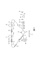
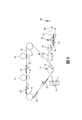
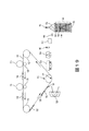
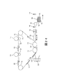
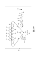
例えば、図1に示されるように、本願明細書における例示的な3次元(3D)プリンタは、他の要素のうち、ローラー112上に支持された中間転写ベルト110(ITB)などの中間転写面と、第1の印刷要素(例えば、現像装置116)と、第2の印刷要素(例えば、現像装置114)とを含む。それゆえに、図1に示されるように、第1の印刷要素116は、(潜在的に乾燥した)粉末ポリマー−ワックス材料(例えば、帯電した3Dトナー)などの第1の材料104である造形材料を((例えば、電荷発生器128によって生成される)ベルトと転写される材料との間の電荷差によって)ITB110に静電的に転写するように配置される。(例えば、同様に感光体とすることができる)第2の印刷要素114はまた、第2の材料105(例えば、同様に粉末ポリマー−ワックス材料(例えば、帯電した3Dトナー)などの支持材料)を第1の材料104がITB110上に位置するITB110の位置に静電的に転写するように配置される。
For example, as shown in FIG. 1, the exemplary three-dimensional (3D) printer in the present specification is an intermediate transfer surface such as an intermediate transfer belt 110 (ITB) supported on a
支持材料105は、印刷された3D構造104が完全な3D物品が完成した後に支持材料105から分離されるのを可能とするように造形材料104に影響を及ぼさない溶媒に溶解する。図面において、造形材料104及び支持材料105の組み合わせは、要素102として示されており、時には「現像層」と称されることがある。造形材料104及び支持材料105の現像層102は、ITB110の別個の領域上にあり、その層(及びその関連する支持要素)における3D構造の要素に対応してパターン化され、現像層102毎に3D構造が造形される。
The
さらに、(表面又はベルトとすることができる)プラテン118は、ITB110に隣接している。造形及び支持材料のパターン化された層102は、現像装置114、116から中間転写ベルト110に転写され、最終的に転写定着ステーション130においてプラテン118に転写される。
In addition, the platen 118 (which can be a surface or belt) is adjacent to the
図1に示されるように、転写定着ステーション130は、ITB110に隣接している。転写定着ステーション130は、ITB110の一方側にITB110を支持するローラー112を含む。転写定着ステーション130は、ITB110が転写定着ステーション130へと移動するのにともない層102を受けるように配置される。より具体的には、造形材料現像ステーション116、支持材料現像ステーション114及び転写定着ステーション130は、ITB110がプロセス方向に移動しているとき、ITB110上の層102が、造形材料及び支持材料現像ステーション114、116を最初に通過した後に、転写定着ステーション130を通過するように、ITB110に対して配置される。
As shown in FIG. 1, the
図1にさらに示されるように、そのような構造は、転写定着ヒータ120、定着ステーション126、硬化ステーション124及び冷却ステーション140を含むことができる。定着ステーション126は、プラテン118又はプラテン118上に存在する層に対して最近転写定着された層102を定着するために圧力及び/熱を印加する。硬化ステーション124は、層を硬化させるように光源を使用して光(例えば、UV光)を及び/又はヒータを使用して熱を印加するように配置される。冷却ステーション140は、ちょうど定着及び硬化された層上に潜在的に冷却された空気を吹き付ける。本構造はまた、支持材料除去ステーション148を含むことができる。
As further shown in FIG. 1, such a structure can include a
図1はまた、ITB110とは別個であり且つプラテン118上の独立した積層上の上層に平坦化材料を堆積させるように配置されたディスペンサ142(例えば、スプレー、ホッパー、シュートなど)を示している。さらに、機械的プレーナー144はまた、ITB110とは別個であり、平坦化材料の上部をプラテン118の平坦面に平行にするように独立した積層上に平坦化材料を接触させて平坦化するように配置される。機械的プレーナー144は、独立した積層上の平坦化材料の厚さを低減させる。機械的プレーナー144は、細長構造(例えば、ブレード、ローラー、逆回転ローラーなど)を備え、プラテン118の平坦面に平行な方向において機械的プレーナー144とプラテン118との間の相対移動が存在する。
FIG. 1 also shows a dispenser 142 (eg, spray, hopper, chute, etc.) that is separate from the
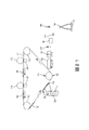
図2における垂直矢印によって示されるように、プラテン118は、プラテン118をITB110と接触させるようにITB110に向かって(モータ、ギア、プーリ、ケーブル、ガイドなどを使用して(全て一般物品118によって示されている))移動する。現像層102及びITB110は、必要に応じて、転写定着前に現像層102を「粘着性」状態にするのをさらに助けるようにヒータ120によって局所的に加熱されることができる。一例において、現像層102は、支持材料(及び潜在的に造形材料)が粘着性になるのを可能とするように、ガラス転移温度(Tg)よりも高いが支持材料の融点又は溶融温度(Tm)よりも低い温度に加熱されることができる。
As indicated by the vertical arrows in FIG. 2, the
プラテン118はまた、必要に応じて、ヒータ120によってほぼ同じ温度に加熱されることができ、その後、ITB−プラテンニップ(転写定着ニップ130)を通って平行移動するのにともない粘着層102と同期して接触されることができる。それにより、ITB110は、プラテン118上に造形材料104及び支持材料105の現像層102を連続的に形成するように、プラテン118がITB110に接触するたびに、造形材料104及び支持材料105の現像層102のうちの一方をプラテン118に転写する。
The
したがって、それぞれの別個の現像装置114、116によってITB上に所定パターンで静電的に印刷された造形及び支持材料は、所定長を有する特定のパターンを表すように現像層102において一体に組み合わされる。それゆえに、図2に示されるように、現像層102のそれぞれは、(ITB110の隣にある矢印によって表される)ITB110が移動している処理方向に向かって配向された前縁134と、前縁134に対向する後縁136とを有する。
Therefore, the shaped and supporting materials electrostatically printed on the ITB in a predetermined pattern by the respective separate developing
より具体的には、図2に示されるように、転写定着ニップ130において、転写定着ニップ130内の現像層102の前縁134は、プラテン118の対応する位置に転写され始める。それゆえに、図2において、プラテン118は、現像層102の前縁134が転写定着ニップ130のローラーの最低位置にある位置においてITB110上の現像層102に接触するように移動する。それゆえに、この例において、現像層102の後縁136は、まだ転写定着ニップ130に到達しておらず、したがって、プラテン118にまだ転写されていない。
More specifically, as shown in FIG. 2, in the transfer fixing nip 130, the
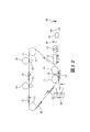
図3に示されるように、プラテン118は、汚れなく、現像層102が清浄にプラテン118上に転写するのを可能とするように、プラテン真空ベルトを移動又は回転させることによってITB110と同期して移動する(ITB110と同じ速度で且つ同じ方向に移動する)。図3において、現像層102の後縁136は、まだ転写定着ニップ130に到達しておらず、したがってプラテン118に転写されていない唯一の部分である。
As shown in FIG. 3, the
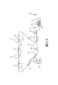
そして、ITB110が処理方向に移動するのにともない、プラテン118は、図4に示されるように、プラテン118がITB110から離れ且つ定着ステーション126にわたって移動する地点において現像層102の後縁136が転写定着ニップ130のローラーの底部に到達するまで、ITB110と同じ速度で且つ同じ方向に移動する。定着ステーション126は、非接触(例えば、赤外線(IR))ヒータ、又は層102を加熱して加圧する定着ローラーなどの加圧ヒータとすることができる。定着ステーション126が加圧ローラーである場合、プラテン118は、ローラーが回転して現像層102をプラテン118に定着するように加熱及び加圧するのに同期して移動する。このプラテン118とITB110(及び加熱ローラー126)との間の同期移動は、歪み又は汚れなく、現像装置116、114によって印刷された支持及び造形材料(102)のパターンをITB110から正確に転写させてプラテン118上の他層102に定着させる。
Then, as the
図5に示されるように、プラテンは、独立した積層106内の現像層102をプラテン118上で互いに結合するために3D構造物に光及び/又は熱を印加する硬化ステーション124へと移動する。ヒータ、光及び結合ステーション124における他の要素の選択的使用は、現像層102の化学的構成に応じて変化する。一例において、造形材料104及び支持材料105は、UV硬化性トナーとすることができる。したがって、図5に示されるように、一例において、定着ステーション126は、それらのガラス転移温度とそれらの溶融温度との間の温度に材料102を加熱した後に、材料102内のポリマーを架橋させるようにUV光を印加することによってそのような材料102を定着することができ、それにより、剛性構造を形成することができる。当業者は、他の造形及び支持材料が他の結合処理及び結合要素を利用し且つ前述のものが1つの限定された例として提示されているにすぎないことを理解するであろう。本願明細書における装置及び方法は、現在知られているか又は将来開発されるかにかかわらず、そのような結合方法及び要素の全てに適用可能である。
As shown in FIG. 5, the platen moves to a curing
さらに、図6に示されるように、冷却ステーション140(又は処理中の冷却休止さえも)は、層102を転写する間にプラテン118上の層102を冷却するために使用されることができる。冷却ステーションは、図6に示されるように、プラテン118上の層102上に空気(潜在的に冷却されて除湿された空気)を吹き付けることができる。
In addition, as shown in FIG. 6, the cooling station 140 (or even the cooling pause during processing) can be used to cool the
プラテン118は、ITB110が現像層102のそれぞれを独立して定着、硬化、冷却するように現像層102のそれぞれをプラテン118に転写するたびに、定着ステーション126、硬化ステーション124及び冷却ステーション140へと移動することができる。他の代替例において、プラテン118は、複数の現像層102が同時に定着、硬化及び冷却されるのを可能とするように、プラテン118上に配置された特定数(例えば、2、3、4など)の現像層102が配置された後に、定着ステーション126、硬化ステーション124及び冷却ステーション140へと移動することができるにすぎない。
The
処理中のこの時点で、プラテン118は、ITB110から次層102を受けるように転写定着ニップ130に戻ることができるか、又は、プラテンは、(より詳細には後述する)ディスペンサ142及び機械的プレーナー144へと移動することができる。それゆえに、図7に示されるように、複数の現像層102を積層106に定着するために図2〜図6における処理が繰り返される。現像層102の積層106が成長するのにともない、図7に示されるように、積層106の上部に追加の現像層102が形成され、そのような追加の現像層102は、定着ステーション126(図8)によって加圧加熱され、硬化ステーション124(図9)によって硬化され、冷却ステーション140(図10)によって冷却される。
At this point during processing, the
図11及び図12に示される処理は、プラテン118上に転写定着される各層について実行されることができるか、又は、特定数(例えば、10、50、200、1000層など)の層102がプラテン118に転写された後に実行されることができる。図11に示されるように、ITB110とは別個のディスペンサ142(同様に、スプレー、ホッパー、シュート、静電装置など)は、プラテン118上の独立した積層106内の上層102上に平坦化材料108を堆積させる。さらに、図12に示されるように、機械的プレーナー144はまた、ITB110とは別個であり、平坦化材料108の上部をプラテン118の平坦面に平行にするように独立した積層106上の平坦化材料108と接触して平坦化する。
The process shown in FIGS. 11 and 12 can be performed on each layer transfer-fixed on the
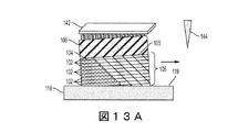
そのような処理は、図13A〜図15Bにおける拡大図に示されている。より具体的には、図13Aは、ディスペンサ142が独立した積層106の上部に平坦化材料108を堆積させることを示している。同様に、ディスペンサ142は、独立した積層106の上部に平坦化材料108をスプレー、重力供給、静電的転写などすることができる。図13Aは、独立した積層106が1つ以上の層102から構成され、各層が造形材料104及び支持材料105を含むことができることを示していることに留意されたい。また、積層106における少なくとも上層は、図13Aにおけるプラテン118の上部119と平行ではないことにも留意されたい。
Such processing is shown in the enlarged views in FIGS. 13A-15B. More specifically, FIG. 13A shows that the
図13A及び図13Bは、機械的プレーナー144がブレード又は他の突起とすることができることを示している。図13Bは、平坦化材料108の上部109をプラテン118の上部119に平行とするように、機械的プレーナー144が機械的プレーナー144とプラテン118との間の相対移動に基づいて平坦化材料108の一部を除去することを示している。図13Bは、プラテン118が(固定位置にあることができる)機械的プレーナー144を通過することができることを示している。あるいは、機械的プレーナー144は、プラテン118の平坦面119に平行な方向において機械的プレーナー144とプラテン118との間の相対移動を生じさせるようにプラテン118を通過することができる。
13A and 13B show that the
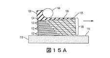
したがって、機械的プレーナー144は、独立した積層106上の平坦化材料108の厚さを低減させる。図14は、追加層102が平坦化材料108上に堆積された後の独立した積層106を示している。図14からわかるように、平坦化材料108は、プラテン118の上部119に平行な層102を使用して印刷される3D構造物全体を成長させるために、追加層102がプラテン118の上部119に平行な面109に転写定着されるのを可能とする。図13A〜図13Bに示されるように、機械的プレーナー144は、細長構造(例えば、ブレード)とすることができるか、又は、図15Aに示されるように、機械的プレーナー144は、ローラーとすることができるか、又は、図15Bに示されるように、逆回転ローラーとすることができるなどである。
Therefore, the
図16に示されるように、機械的プレーナー144が平坦化材料108を平坦化した後、プラテン118は、機械的プレーナー144が平坦化材料108を平坦化して平坦化材料108を独立した積層106に定着させた後、定着ステーション126へと移動する。平坦化材料108は、比較的容易に造形材料104と接合し、支持材料105と比較的容易に接合しないように選択される。換言すれば、造形材料104は、平坦化材料108を引き付けるが、支持材料105は、平坦化材料108を混じり合わせない。
As shown in FIG. 16, after the
それゆえに、図17に示されるように、定着後、平坦化材料108は、造形材料104と定着されるが、支持材料105の分散領域にのみ残る。(支持材料105を接触する)平坦化材料108のそれらの分散部分は、支持材料105が造形材料104から除去されるときに除去される一方で、造形材料104と定着する平坦化材料108の部分は、造形材料104とともに最終構造物に残る。
Therefore, as shown in FIG. 17, after fixing, the flattening
上述した処理は、図18に示されるように、造形及び支持材料104、105の独立した積層106を形成するために複数回繰り返される。図18は、独立した積層106の累積内の支持材料105及び造形材料104の部分を示すオーバーレイを示している。そのようなものは、視認可能であってもなくてもよく、そのような造形及び支持材料を配置されることができる1つの例示的な方法を示すために示されているにすぎない。
The process described above is repeated multiple times to form an
独立した積層106の3D構造物は、外部加熱浴を使用して支持材料105を手動で除去するのを可能とするように出力されることができるか、又は、図19〜図21に示されるように処理を進めることができる。より具体的には、図19において、支持材料除去ステーション148は、プラテン118上のここで接合された3Dの独立した積層106を受けるように配置される。支持材料除去ステーション148は、造形材料104に影響を与えずに支持材料105を溶解する溶媒156を加える。同様に、上述したように、利用される溶媒は、造形材料104及び支持材料105の化学的構成に依存する。図20は、支持材料105の約半分が残り且つ造形材料104の一部が支持材料105の残りの積層から突出する処理を示している。図21は、支持材料除去ステーション148が全ての支持材料105を溶解するのに十分な溶媒156を加えた後の処理を示しており、造形材料104のみが残っており、造形材料104のみから構成された完成した3D構造物を残している。
The 3D structure of the
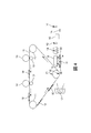
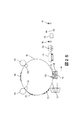
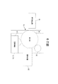
図22〜図24は、図1に示される転写定着ニップ130の代わりに平面転写定着ステーション138を含む代替的な3D静電印刷構造を示している。図22に示されるように、平面転写定着ステーション138は、ローラー112の間にあり且つプラテン118に平行なITB110の平面部である。図22に示されるように、この構造により、プラテン118が平面転写定着ステーション138に接触するように移動すると、現像層102の全てがプラテン118又は部分的に形成された積層106に同時に転写定着され、図2及び図3に示される回転転写定着プロセスを回避する。図23は、ディスペンサ142が平坦化材料108を分配することを示しており、図24は、上述したように、機械的プレーナーがプラテン118の上面119と平行である積層106の内部に層102を保持するように平坦化材料108を平坦化することを示している。
22-24 show an alternative 3D electrostatic printing structure that includes a planar
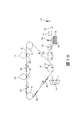
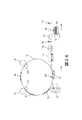
同様に、図25に示されるように、ドラム158は、本願明細書において記載されるように動作する全ての他の要素とともに、ITB110の代わりに使用されることができる。それゆえに、ドラム158は、上述したように、現像ステーション114、116からの材料を受ける中間転写面とすることができ、又は、感光体とすることができ、電荷の潜像を保持して現像装置254からの材料を受けることによって以下に記載される感光体256が動作するのにともない動作する。上述したように、ディスペンサ142は、平坦化材料108を分配し、図26に示されるように、機械的プレーナーは、上述したように、積層106内の層102をプラテン118の上面119と平行に保つように平坦化材料108を平坦化する。
Similarly, as shown in FIG. 25, the
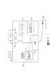
図27は、本願明細書における3D印刷装置204の多くの要素を示している。3D印刷装置204は、コントローラ/有形プロセッサ224と、有形プロセッサ224及び印刷装置204の外部のコンピュータ化ネットワークに動作可能に接続された通信ポート(入力/出力)214とを含む。また、印刷装置204は、グラフィカルユーザインターフェース(GUI)アセンブリ212などの少なくとも1つのアクセサリ機能要素を含むことができる。ユーザは、グラフィカルユーザインターフェース又はコントロールパネル212からメッセージ、命令及びメニューオプションを受信し、グラフィカルユーザインターフェース又はコントロールパネル212を介して命令を入力することができる。
FIG. 27 shows many elements of the
入力/出力装置214は、3D印刷装置204との間の通信に使用され、(現在知られているか又は将来開発されるかにかかわらず、任意の形態の)有線装置又は無線装置を備える。有形プロセッサ224は、印刷装置204の様々な動作を制御する。持続性で有形のコンピュータ記憶媒体装置210(光学的、磁気的、キャパシタベースなどであり、一時的信号とは異なる)は、有形プロセッサ224によって読み取り可能であり、コンピュータ化装置が本願明細書において記載されるものなどの様々な機能を実行するのを可能とするように有形プロセッサ224が実行する命令を記憶する。それゆえに、図27に示されるように、本体ハウジングは、電源218によって交流(AC)電源220から供給される電力で動作する1つ以上の機能的要素を有する。電源218は、共通電力変換ユニット、蓄電素子(例えば、電池など)などを備えることができる。
The input /
3D印刷装置204は、上述したようにプラテン上に造形及び支持材料の連続層を堆積させる少なくとも1つのマーキング装置(印刷エンジン)240を含み、(画像データを処理するために特化されていることから汎用コンピュータとは異なる)特殊画像プロセッサ224に動作可能に接続されている。また、印刷装置204は、(電源218を介して)外部電源220から供給される電力で同様に動作する(スキャナ232などの)少なくとも1つのアクセサリ機能要素を含むことができる。
The
1つ以上の印刷エンジン240は、現在知られているか又は将来開発されるかにかかわらず、例えば、(図28に示されるように)中間転写ベルト110を使用する装置を含むことができる、造形及び支持材料(トナーなど)を塗布する任意のマーキング装置を説明するように意図される。
One or
それゆえに、図28に示されるように、図27に示される印刷エンジン240のそれぞれは、1つ以上の潜在的に異なる(例えば、異なる色、異なる材料など)造形材料現像ステーション116、1つ以上の潜在的に異なる(例えば、異なる色、異なる材料など)支持材料現像ステーション114などを利用することができる。現像ステーション114、116は、現在知られているか又は将来開発されるかにかかわらず、個々の静電マーキングステーション、個々のインクジェットステーション、個々のドライインクステーションなど、任意の形態の現像ステーションとすることができる。現像ステーション114、116のそれぞれは、(中間転写ベルト110の状態とは潜在的に独立して)単一ベルト回転中に順次中間転写ベルト110の同一位置に材料のパターンを転写し、それにより、完全且つ完全な像が中間転写ベルト110に転写される前に中間転写ベルト110が構成しなければならない経路数を削減する。図28は、回転ベルト(110)に隣接するか又は接触する5つの現像ステーションを示しているが、当業者によって理解されるように、そのような装置は、任意数(例えば、2、3、5、8、11など)のマーキングステーションを使用することができる。
Therefore, as shown in FIG. 28, each of the
中間転写ベルト110に隣接して(又は潜在的に接触して)配置された1つの例示的な個々の静電現像ステーション114、116が図29に示されている。個々の静電現像ステーション114、116のそれぞれは、内部感光体256上に均一な電荷を生成する独自の充電ステーション258と、均一な電荷を電荷潜像にパターン形成する内部露光装置260と、電荷潜像に一致するパターンで感光体256に造形又は支持材料を転写する内部現像装置254とを含む。そして、造形又は支持材料のパターンは、通常は中間転写ベルト110の反対側に電荷発生器128によって形成される、造形又は支持材料の電荷に対する中間転写ベルト110の逆電荷によって感光体256から中間転写ベルト110へと引き出される。
One exemplary individual
米国特許第8,488,994号明細書に示されるように、電子写真法を使用した3D部品を印刷するための積層造形システムが知られている。このシステムは、表面を有する感光体要素と、感光体要素の表面上に材料の現像層を現像するように構成された現像ステーションとを含む。このシステムはまた、回転可能な感光体要素の表面から現像層を受けるように構成された転写媒体と、受けた層の少なくとも一部から3D部品を印刷するために層毎に転写要素から現像層を受けるように構成されるプラテンとを含む。 As shown in US Pat. No. 8,488,994, a layered modeling system for printing 3D parts using electrophotographic methods is known. The system includes a photoconductor element having a surface and a developing station configured to develop a developing layer of material on the surface of the photoconductor element. The system also includes a transfer medium configured to receive a development layer from the surface of a rotatable photoconductor element and a development layer from the transfer element layer by layer to print a 3D component from at least a portion of the received layer. Includes platens configured to receive.
米国特許第7,250,238号明細書に開示されるようなUV硬化性トナーに関して、印刷プロセスにおいてUV硬化性トナー組成物を利用する方法と同様にUV硬化性トナー組成物を提供することが知られている。米国特許第7,250,238号明細書は、実施形態において約100nmから約400nmのUV光などのUV放射線にさらすことによって硬化可能なトナーの生成を可能とする様々なトナーエマルジョン凝集プロセスを開示している。米国特許第7,250,238号明細書において、生成されたトナー組成物は、温度感受性包装及びホイルシールの製造などの様々な印刷用途において利用されることができる。米国特許第7,250,238号明細書において、実施形態は、任意の着色剤、任意のワックス、スチレンから生成されるポリマー、並びに、ブチルアクリレート、カルボキシエチルアクリレート及びUV光硬化性アクリレートオリゴマーからなる群から選択されるアクリレートを含むUV硬化性トナー組成物に関する。さらに、これらの態様は、顔料、任意のワックス、及びUV硬化性脂環式エポキシドから生成されたポリマーなどの着色剤からなるトナー組成物に関する。 With respect to UV curable toners as disclosed in US Pat. No. 7,250,238, it is possible to provide UV curable toner compositions as well as methods that utilize UV curable toner compositions in the printing process. Are known. U.S. Pat. No. 7,250,238 discloses various toner emulsion agglomeration processes that allow the production of curable toners by exposure to UV radiation, such as UV light from about 100 nm to about 400 nm, in embodiments. doing. In US Pat. No. 7,250,238, the toner composition produced can be used in a variety of printing applications, such as the manufacture of temperature sensitive packaging and foil seals. In US Pat. No. 7,250,238, embodiments consist of any colorant, any wax, a polymer produced from styrene, and butyl acrylate, carboxyethyl acrylate and UV photocurable acrylate oligomers. The present invention relates to a UV curable toner composition containing an acrylate selected from the group. Further, these aspects relate to toner compositions consisting of pigments, optional waxes, and colorants such as polymers produced from UV curable alicyclic epoxides.
さらに、米国特許第7,250,238号明細書は、スチレン、ブチルアクリレート、カルボキシエチルアクリレート、及びUV硬化アクリレートから形成されるポリマーを含有するラテックスを着色剤及びワックスと混合することと、必要に応じて第2の混合物に分散されたトナー前駆体粒子の凝集及び形成を引き起こすようにこの混合物に凝集剤を添加することと、トナー粒子を形成するためにポリマーのガラス転移温度(Tg)以上の温度までトナー前駆体粒子を加熱することと、必要に応じてトナー粒子を洗浄することと、必要に応じてトナー粒子を乾燥させることとを含むUV硬化性トナー組成物を形成する方法を開示している。さらなる態様は、この方法によって製造されたトナー粒子に関する。 In addition, US Pat. No. 7,250,238 requires that a latex containing a polymer formed from styrene, butyl acrylate, carboxyethyl acrylate, and UV curable acrylate be mixed with a colorant and wax. Add a flocculant to the mixture to cause aggregation and formation of the toner precursor particles dispersed in the second mixture accordingly, and above the glass transition temperature (Tg) of the polymer to form the toner particles. Disclosed is a method of forming a UV curable toner composition comprising heating the toner precursor particles to a temperature, cleaning the toner particles as needed, and drying the toner particles as needed. ing. A further aspect relates to toner particles produced by this method.
いくつかの例示的な構造が添付図面に示されているが、当業者は、図面は簡略化された概略図であり、以下に提示される特許請求の範囲は図示されていない(又は潜在的に多くはない)がそのような装置及びシステムとともに一般的に利用されるより多くの特徴を包含することを理解するであろう。したがって、特許出願人は、以下に提示される特許請求の範囲が添付図面によって限定されることを意図しておらず、代わりに、添付図面は、特許請求された特徴が実施されることができるいくつかの方法を例示するために提供されるにすぎない。 Although some exemplary structures are shown in the accompanying drawings, those skilled in the art will appreciate that the drawings are simplified schematics and the claims presented below are not shown (or potentially). It will be appreciated that (not many) include more features commonly used with such devices and systems. Therefore, the patent applicant does not intend to limit the scope of the claims presented below by the accompanying drawings, and instead, the attached drawings can carry out the claimed features. It is provided only to illustrate some methods.
多くのコンピュータ化された装置が上述されている。チップベースの中央処理装置(CPU)と、(グラフィックユーザインターフェース(GUI)、メモリ、コンパレータ、有形プロセッサなどを含む)入力/出力装置とを含むコンピュータ化装置は、米国テキサス州ラウンドロックのデルコンピュータ及び米国カリフォルニア州クパチーノのアップルコンピュータ社などの製造業者によって製造された周知且つ容易に入手可能な装置である。そのようなコンピュータ化装置は、一般に、入力/出力装置、電源、有形プロセッサ、電子記憶メモリ、配線などを含み、読者が本願明細書に記載されるシステム及び方法の顕著な態様にフォーカスするのを可能とするように、その詳細は本願明細書から省略されている。同様に、プリンタ、複写機、スキャナ及び他の類似の周辺機器は、米国コネチカット州ノーウォークのゼロックス社から入手可能であり、そのような装置の詳細は、簡潔性及び読者のフォーカスの目的のために本願明細書においては記載されない。 Many computerized devices are mentioned above. Computerized equipment, including a chip-based central processing unit (CPU) and input / output equipment (including a graphic user interface (GUI), memory, comparator, tangible processor, etc.), is available from Dell Computer in Roundlock, Texas, USA. A well-known and readily available device manufactured by manufacturers such as Apple Computer in Cupaccino, California, USA. Such computerized devices generally include input / output devices, power supplies, tangible processors, electronic storage memory, wiring, etc., and allow the reader to focus on prominent aspects of the systems and methods described herein. The details are omitted from the specification of the present application so as to be possible. Similarly, printers, copiers, scanners and other similar peripherals are available from Xerox, Inc., Norwalk, Connecticut, USA, and details of such equipment are for the purposes of brevity and reader focus. Is not described in the specification of the present application.
本願明細書において使用されるプリンタ又は印刷装置という用語は、任意の目的のために印刷出力機能を実行するディジタル複写機、製本機、ファクシミリ装置、複合機などの任意の装置を包含する。プリンタや印刷エンジンなどの詳細は周知であり、提示された顕著な特徴にフォーカスされた本開示を維持するために本願明細書においては詳細に記載されない。本願明細書におけるシステム及び方法は、カラー、モノクロで印刷する又はカラー若しくはモノクロ画像データを処理するシステム及び方法を包含することができる。全ての上述したシステム及び方法は、静電及び/又は電子写真装置及び/又はプロセスに特に適用可能である。 As used herein, the term printer or printing device includes any device such as a digital copier, bookbinding machine, facsimile machine, multifunction device, etc. that performs a print output function for any purpose. Details such as printers and printing engines are well known and are not described in detail herein in order to maintain the present disclosure focused on the salient features presented. The systems and methods herein can include systems and methods for printing in color, monochrome or processing color or monochrome image data. All the systems and methods described above are particularly applicable to electrostatic and / or electrophotographic devices and / or processes.
本発明の目的のために、定着という用語は、乾燥、硬化、重合、架橋、結合、又は付加反応若しくはコーティングの他の反応を意味する。さらに、本願明細書において使用される「右(right)」、「左(left)」、「垂直(vertical)」、「水平(horizontal)」、「上部(top)」、「底部(bottom)」、「上(upper)」、「下(lower)」、「下方(under)」、「下(below)」、「下層(underlying)」、「上(over)」、「上層(overlying)」、「平行(parallel)」、「垂直(perpendicular)」などの用語は、(特に断らない限り)それらが図面において配向及び図示されるように相対的位置であると理解される。「接触(touching)」、「上(on)」、「直接接触(in direct contact)」、「当接(abutting)」、「直接隣接(directly adjacent to)」などの用語は、少なくとも1つの要素が(記載された要素を分離する他の要素なしで)他の要素に物理的に接触することを意味する。さらに、自動化又は自動的にという用語は、(機械又はユーザによって)処理が開始されると、1つ以上の機械がユーザからのさらなる入力なしで処理を行うことを意味する。本願明細書における図面において、同一の識別符号は、同一又は類似の項目を識別する。 For the purposes of the present invention, the term fixing means drying, curing, polymerization, cross-linking, bonding, or addition reaction or other reaction of coating. Further, as used in the present specification, "right", "left", "vertical", "horizontal", "top", "bottom". , "Upper", "lower", "lower", "lower", "underlying", "over", "overlying", Terms such as "parallel" and "perpendicular" are understood (unless otherwise specified) to be oriented and relative positions as illustrated in the drawings. Terms such as "touching", "on", "direct contact", "abutting", and "directly adaptive to" are at least one element. Means physical contact with other elements (without other elements separating the described elements). Further, the term automated or automatic means that when a process is initiated (by a machine or user), one or more machines perform the process without further input from the user. In the drawings herein, the same identification code identifies the same or similar item.
上記開示された及び他の特徴及び機能又はその代替例は、多くの他の異なるシステム又は用途に望ましくは組み合わせることができることが理解されるであろう。様々な現在予見できない又は予測されない代替例、変更例、変形例又は改良は、当業者によって後に行われることができ、以下の特許請求の範囲に包含されるようにも意図される。特定の請求項自体に具体的に定義されない限り、本願明細書におけるシステム及び方法のステップ又は構成要素は、任意の特定の順序、数、位置、大きさ、形状、角度、色又は材料に対する限定として任意の上記例から暗示又は取り込まれることはできない。 It will be appreciated that the disclosed and other features and functions or alternatives thereof can preferably be combined with many other different systems or applications. Various currently unforeseen or unpredictable alternatives, modifications, variations or improvements can be made later by one of ordinary skill in the art and are also intended to be included in the claims below. Unless specifically defined in the particular claim itself, the steps or components of a system and method herein are limited to any particular order, number, position, size, shape, angle, color or material. It cannot be implied or incorporated from any of the above examples.
Claims (17)
中間転写面と、
前記中間転写面に造形材料を転写するように配置された造形材料現像ステーションと、
前記中間転写面に支持材料を転写するように配置された支持材料現像ステーションであって、前記造形材料現像ステーション及び前記支持材料現像ステーションが前記中間転写面に前記造形材料及び前記支持材料の層を転写する、支持材料現像ステーションと、
前記中間転写面に接触するように配置された平坦面を有するプラテンであって、前記平坦面が前記中間転写面上の前記層の1つに接触するのにともない、前記平坦面に前記造形材料及び前記支持材料の層が転写されるプラテンと、
前記層上に平坦化材料を堆積させるように配置されたディスペンサと、
前記プラテン上の前記層上の前記平坦化材料に接触して平坦化する機械的プレーナーであって、前記機械的プレーナーは、前記プラテンの前記平坦面と平行な方向において前記プラテンに相対的に移動する構造を含んで、前記平坦化材料のある部位を除去し且つ前記平坦化材料の他の部位を前記層の上部に残し、前記平坦化材料の上部を前記プラテンの前記平坦面と平行にする機械的プレーナーとを備える、3Dプリンタ。 In a three-dimensional (3D) printer
Intermediate transfer surface and
A modeling material development station arranged so as to transfer the modeling material to the intermediate transfer surface,
A support material development station arranged so as to transfer a support material to the intermediate transfer surface, wherein the modeling material development station and the support material development station put a layer of the modeling material and the support material on the intermediate transfer surface. Support material development station to transfer,
Wherein a platen having arranged flat surface so as to contact with the intermediate transfer surface, with the flat surface that contacts the one of the layer on the intermediate transfer surface, the shaped into the flat surface material And the platen to which the layer of the supporting material is transferred,
With a dispenser arranged to deposit the flattening material on the layer ,
A mechanical planer that contacts and flattens the flattening material on the layer on the platen, the mechanical planner moving relative to the platen in a direction parallel to the flat surface of the platen. The part of the flattening material is removed and the other part of the flattening material is left on the upper part of the layer so that the upper part of the flattening material is parallel to the flat surface of the platen. A 3D printer with a mechanical platen.
中間転写面と、
前記中間転写面に造形材料を静電的に転写するように配置された造形材料現像ステーションと、
前記中間転写面に支持材料を静電的に転写するように配置された支持材料現像ステーションであって、前記造形材料現像ステーション及び前記支持材料現像ステーションが前記中間転写面に前記造形材料及び前記支持材料の層を転写する、支持材料現像ステーションと、
前記中間転写面に隣接する転写定着ステーションと、
前記中間転写面に繰り返し接触するように配置された平坦面を有するプラテンであって、前記平坦面上に前記層の独立した積層を連続的に形成するように前記転写定着ステーションにおいて前記中間転写面上の前記層の1つに接触するたびに、前記造形材料及び前記支持材料の層が前記平坦面に転写されるように前記中間転写面に対して移動するプラテンと、
前記層を一体に定着するために前記積層に熱及び圧力を印加するように配置された定着ステーションと、
前記積層上に平坦化材料を堆積させるように配置されたディスペンサと、
前記積層上の前記平坦化材料に接触して平坦化する機械的プレーナーであって、前記機械的プレーナーは、前記プラテンの前記平坦面と平行な方向において前記プラテンに相対的に移動する構造を含んで、前記平坦化材料のある部位を除去し且つ前記平坦化材料の他の部位を前記積層の上部に残し、前記平坦化材料の上部を前記プラテンの前記平坦面と平行にする機械的プレーナーとを備え、
前記プラテンが、前記機械的プレーナーが前記平坦化材料を前記積層に定着させるように前記平坦化材料を平坦化した後に前記定着ステーションへと移動する、3Dプリンタ。 In a three-dimensional (3D) printer
Intermediate transfer surface and
A modeling material development station arranged so as to electrostatically transfer the modeling material to the intermediate transfer surface,
A support material developing station arranged so as to electrostatically transfer a support material to the intermediate transfer surface, wherein the modeling material developing station and the supporting material developing station are arranged on the intermediate transfer surface to perform the modeling material and the support. A supporting material development station that transfers layers of material,
A transfer fixing station adjacent to the intermediate transfer surface,
A platen having a arranged flat surface in contact repeatedly with the intermediate transfer surface, before Symbol the intermediate transfer in the transfer and fixing station to continuously form an independent stacking of the layers on the flat surface each time in contact with one of the layer on the surface, a platen which moves relative to the intermediate transfer surface as the layer of build material and the support material is transferred before Symbol flat surface,
A fixing station which is arranged to apply heat and pressure to the front miracle layer to fix the layer together,
With a dispenser arranged to deposit the flattening material on the laminate ,
A mechanical planar flattening in contact prior to the planarization material on miracle layer, the mechanical planar is moved relative to the platen in said flat surface parallel to the direction of the platen structure To remove some parts of the flattening material and leave other parts of the flattening material on top of the laminate , mechanically to make the top of the flattening material parallel to the flat surface of the platen. Equipped with a planer
The platen is moved to the fixing station after the mechanical planar was planarizing the planarization material so as to fix the planarization material before miracle layer, 3D printer.
中間転写ベルト(ITB)と、
前記ITBに造形材料を静電的に転写するように配置された造形材料現像ステーションと、
前記ITBに支持材料を静電的に転写するように配置された支持材料現像ステーションであって、前記造形材料現像ステーション及び前記支持材料現像ステーションが前記ITBに前記造形材料及び前記支持材料の層を転写する、支持材料現像ステーションと、
前記ITBに隣接する転写定着ステーションと、
前記ITBに繰り返し接触するように配置された平坦面を有するプラテンであって、前記平坦面上に前記層の独立した積層を連続的に形成するように、前記転写定着ステーションにおいて前記ITB上の前記層の1つに接触するたびに前記造形材料及び前記支持材料の層が前記平坦面に転写されるように前記ITBに対して移動するプラテンと、
前記層を一体に定着するために前記積層に熱及び圧力を印加するように配置された定着ステーションと、
前記造形材料におけるポリマーを架橋するために前記積層に熱及び紫外線光を印加するように配置された硬化ステーションと、
前記ITBとは別個であり且つ前記積層に平坦化材料を堆積させるように配置されたディスペンサと、
前記ITBとは別個に配置され且つ前記積層上の前記平坦化材料に接触して平坦化する機械的プレーナーであって、前記機械的プレーナーは、前記プラテンの前記平坦面と平行な方向において前記プラテンに相対的に移動する構造を含んで、前記平坦化材料のある部位を除去し且つ前記平坦化材料の他の部位を前記積層の上部に残し、前記平坦化材料の上部を前記プラテンの前記平坦面と平行にする機械的プレーナーとを備え、
前記プラテンが、前記機械的プレーナーが前記平坦化材料を前記積層に定着させるように前記平坦化材料を平坦化した後に前記定着ステーションへと移動する、3Dプリンタ。 In a three-dimensional (3D) printer
Intermediate transfer belt (ITB) and
A modeling material development station arranged so as to electrostatically transfer the modeling material to the ITB,
A support material development station arranged so as to electrostatically transfer the support material to the ITB, wherein the modeling material development station and the support material development station provide the ITB with layers of the modeling material and the support material. Support material development station to transfer,
A transcription fixation station adjacent to the ITB,
A platen having a flat surface arranged to repeatedly contact the ITB, before Symbol to continuously form an independent stacking of the layers on a flat surface, on the ITB at the transfuse station a platen which moves relative to the ITB as the previous layer SL build material and the support material is transferred before Symbol flat surface each time in contact with one of said layers,
A fixing station which is arranged to apply heat and pressure to the front miracle layer to fix the layer together,
A curing station arranged to apply heat and ultraviolet light before miracle layer to crosslink the polymer in the build material,
A dispenser that is separate from the ITB and is arranged to deposit the flattening material on the laminate .
A mechanical planar to the flattening in contact with the flattening material on separately arranged and pre miracle layer and the ITB, the mechanical planar, in the flat surface parallel to the direction of said platen Including a structure that moves relative to the platen, some parts of the flattening material are removed and other parts of the flattening material are left on top of the laminate , and the top of the flattening material is of the platen. A mechanical planer that is parallel to the flat surface is provided.
The platen is moved to the fixing station after the mechanical planar was planarizing the planarization material so as to fix the planarization material before miracle layer, 3D printer.
Applications Claiming Priority (2)
| Application Number | Priority Date | Filing Date | Title |
|---|---|---|---|
| US15/175,476 | 2016-06-07 | ||
| US15/175,476 US10076869B2 (en) | 2016-06-07 | 2016-06-07 | Electrostatic 3-D printer using leveling material and mechanical planer |
Publications (3)
| Publication Number | Publication Date |
|---|---|
| JP2017217904A JP2017217904A (en) | 2017-12-14 |
| JP2017217904A5 JP2017217904A5 (en) | 2020-07-02 |
| JP6796551B2 true JP6796551B2 (en) | 2020-12-09 |
Family
ID=59009601
Family Applications (1)
| Application Number | Title | Priority Date | Filing Date |
|---|---|---|---|
| JP2017099495A Expired - Fee Related JP6796551B2 (en) | 2016-06-07 | 2017-05-19 | Electrostatic 3D printer with flattening material and mechanical planer |
Country Status (5)
| Country | Link |
|---|---|
| US (1) | US10076869B2 (en) |
| EP (1) | EP3255504B1 (en) |
| JP (1) | JP6796551B2 (en) |
| KR (1) | KR102159480B1 (en) |
| CN (1) | CN107471637B (en) |
Families Citing this family (12)
| Publication number | Priority date | Publication date | Assignee | Title |
|---|---|---|---|---|
| US10625292B2 (en) * | 2016-10-11 | 2020-04-21 | Xerox Corporation | System and method for finishing the surface of three-dimensional (3D) objects formed by additive manufacturing systems |
| US11273608B2 (en) * | 2018-06-07 | 2022-03-15 | Sakuu Corporation | Multi-material three-dimensional printer |
| WO2020222090A1 (en) | 2019-05-01 | 2020-11-05 | Io Tech Group Ltd. | Method to electrically connect chip with top connectors using 3d printing |
| US11446750B2 (en) | 2020-02-03 | 2022-09-20 | Io Tech Group Ltd. | Systems for printing solder paste and other viscous materials at high resolution |
| US11622451B2 (en) | 2020-02-26 | 2023-04-04 | Io Tech Group Ltd. | Systems and methods for solder paste printing on components |
| US12275187B2 (en) | 2020-06-03 | 2025-04-15 | Sakuu Corporation | 3D printer with pressure-assisted fluid extraction |
| US11260581B2 (en) * | 2020-06-03 | 2022-03-01 | Sakuu Corporation | Jetted material printer with pressure-assisted fluid extraction |
| US11497124B2 (en) | 2020-06-09 | 2022-11-08 | Io Tech Group Ltd. | Methods for printing conformal materials on component edges at high resolution |
| US11691332B2 (en) | 2020-08-05 | 2023-07-04 | Io Tech Group Ltd. | Systems and methods for 3D printing with vacuum assisted laser printing machine |
| WO2023192591A1 (en) * | 2022-03-31 | 2023-10-05 | Evolve Additive Solutions, Inc. | Additive manufacturing materials and methods with improved color |
| US12005640B2 (en) | 2022-06-03 | 2024-06-11 | Sakuu Corporation | Method and system of using gradual drying in multi-material 3D printing |
| WO2025057054A1 (en) * | 2023-09-11 | 2025-03-20 | Landa Labs (2012) Ltd | Method and apparatus for 3d printing |
Family Cites Families (24)
| Publication number | Priority date | Publication date | Assignee | Title |
|---|---|---|---|---|
| US6206672B1 (en) * | 1994-03-31 | 2001-03-27 | Edward P. Grenda | Apparatus of fabricating 3 dimensional objects by means of electrophotography, ionography or a similar process |
| US6066285A (en) | 1997-12-12 | 2000-05-23 | University Of Florida | Solid freeform fabrication using power deposition |
| AU2003286397A1 (en) | 2002-12-03 | 2004-06-23 | Objet Geometries Ltd. | Process of and apparatus for three-dimensional printing |
| US6775504B2 (en) | 2002-12-16 | 2004-08-10 | Xerox Corporation | Developer member adapted for depositing developer material on an imaging surface |
| US7250238B2 (en) | 2003-12-23 | 2007-07-31 | Xerox Corporation | Toners and processes thereof |
| US7270408B2 (en) | 2005-01-14 | 2007-09-18 | Xerox Corporation | Low level cure transfuse assist for printing with radiation curable ink |
| JP2008225417A (en) * | 2007-03-16 | 2008-09-25 | Fujitsu Ltd | Manufacturing method of structure |
| WO2008120183A1 (en) | 2007-04-01 | 2008-10-09 | Objet Geometries Ltd. | Method and system for three-dimensional fabrication |
| US7851549B2 (en) | 2007-12-13 | 2010-12-14 | Xerox Corporation | Curable polyester latex made by phase inversion emulsification |
| US20100140852A1 (en) | 2008-12-04 | 2010-06-10 | Objet Geometries Ltd. | Preparation of building material for solid freeform fabrication |
| US8470231B1 (en) | 2009-06-01 | 2013-06-25 | Stratasys Ltd. | Three-dimensional printing process for producing a self-destructible temporary structure |
| US8488994B2 (en) * | 2011-09-23 | 2013-07-16 | Stratasys, Inc. | Electrophotography-based additive manufacturing system with transfer-medium service loops |
| US9904223B2 (en) | 2011-09-23 | 2018-02-27 | Stratasys, Inc. | Layer transfusion with transfixing for additive manufacturing |
| US20130186558A1 (en) | 2011-09-23 | 2013-07-25 | Stratasys, Inc. | Layer transfusion with heat capacitor belt for additive manufacturing |
| US8879957B2 (en) * | 2011-09-23 | 2014-11-04 | Stratasys, Inc. | Electrophotography-based additive manufacturing system with reciprocating operation |
| JP2016501136A (en) | 2012-11-09 | 2016-01-18 | エボニック インダストリーズ アクチエンゲゼルシャフトEvonik Industries AG | Multicolor extrusion 3D printing |
| CN108381909B (en) | 2012-11-09 | 2021-05-25 | 赢创运营有限公司 | Use and preparation of coated filaments for extrusion 3D printing processes |
| US10702453B2 (en) * | 2012-11-14 | 2020-07-07 | Xerox Corporation | Method and system for printing personalized medication |
| US9144940B2 (en) * | 2013-07-17 | 2015-09-29 | Stratasys, Inc. | Method for printing 3D parts and support structures with electrophotography-based additive manufacturing |
| JP2017501910A (en) | 2013-11-18 | 2017-01-19 | チャン、カイ−ジュイ | Color or multi-material 3D printer |
| US9744730B2 (en) | 2013-11-22 | 2017-08-29 | Stratasys, Inc. | Magnetic platen assembly for additive manufacturing system |
| US10144175B2 (en) * | 2014-03-18 | 2018-12-04 | Evolve Additive Solutions, Inc. | Electrophotography-based additive manufacturing with solvent-assisted planarization |
| EP3323599B1 (en) * | 2015-07-14 | 2019-06-19 | Mimaki Engineering Co., Ltd. | Forming device and forming method |
| US10105902B2 (en) * | 2016-04-18 | 2018-10-23 | Evolve Additive Solutions, Inc. | Electrophotography-based additive manufacturing with part molding |
-
2016
- 2016-06-07 US US15/175,476 patent/US10076869B2/en active Active
-
2017
- 2017-05-18 CN CN201710354765.9A patent/CN107471637B/en not_active Expired - Fee Related
- 2017-05-18 KR KR1020170061488A patent/KR102159480B1/en not_active Expired - Fee Related
- 2017-05-19 JP JP2017099495A patent/JP6796551B2/en not_active Expired - Fee Related
- 2017-06-02 EP EP17174395.8A patent/EP3255504B1/en active Active
Also Published As
| Publication number | Publication date |
|---|---|
| EP3255504B1 (en) | 2019-09-04 |
| CN107471637A (en) | 2017-12-15 |
| CN107471637B (en) | 2020-05-05 |
| JP2017217904A (en) | 2017-12-14 |
| US10076869B2 (en) | 2018-09-18 |
| EP3255504A1 (en) | 2017-12-13 |
| US20170348908A1 (en) | 2017-12-07 |
| KR102159480B1 (en) | 2020-09-25 |
| KR20170138342A (en) | 2017-12-15 |
Similar Documents
| Publication | Publication Date | Title |
|---|---|---|
| JP6796551B2 (en) | Electrostatic 3D printer with flattening material and mechanical planer | |
| JP6824100B2 (en) | Electrostatic 3D developer using materials with different melting points | |
| JP6800063B2 (en) | 3D printer | |
| JP6739396B2 (en) | Electrostatic 3D Printer with Layer and Mechanical Planer | |
| KR102154471B1 (en) | Electro-photographic 3-d printing using dissolvable paper | |
| CN107457987B (en) | Electrostatic 3-D printer using an aerosol applicator to control layer topography | |
| US10086558B2 (en) | 3-D electrostatic printer using track bound platens and registration system | |
| JP6815252B2 (en) | Electrophoto 3D printing using a foldable substrate | |
| US10005230B2 (en) | Electrostatic 3-D printer controlling layer thickness using feedback loop to transfer device | |
| JP6785183B2 (en) | Electrostatic 3D printer with addressable UV cross-linking | |
| US10183443B2 (en) | Electrostatic 3-D printer controlling layer thickness using feedback loop to development device | |
| US10213958B2 (en) | Electrostatic 3-D printing system having acoustic transfer and corotron |
Legal Events
| Date | Code | Title | Description |
|---|---|---|---|
| RD02 | Notification of acceptance of power of attorney |
Free format text: JAPANESE INTERMEDIATE CODE: A7422 Effective date: 20170616 |
|
| RD04 | Notification of resignation of power of attorney |
Free format text: JAPANESE INTERMEDIATE CODE: A7424 Effective date: 20170828 |
|
| A521 | Request for written amendment filed |
Free format text: JAPANESE INTERMEDIATE CODE: A523 Effective date: 20200518 |
|
| A621 | Written request for application examination |
Free format text: JAPANESE INTERMEDIATE CODE: A621 Effective date: 20200518 |
|
| A871 | Explanation of circumstances concerning accelerated examination |
Free format text: JAPANESE INTERMEDIATE CODE: A871 Effective date: 20200518 |
|
| A975 | Report on accelerated examination |
Free format text: JAPANESE INTERMEDIATE CODE: A971005 Effective date: 20200601 |
|
| A131 | Notification of reasons for refusal |
Free format text: JAPANESE INTERMEDIATE CODE: A131 Effective date: 20200623 |
|
| A521 | Request for written amendment filed |
Free format text: JAPANESE INTERMEDIATE CODE: A523 Effective date: 20200831 |
|
| TRDD | Decision of grant or rejection written | ||
| A01 | Written decision to grant a patent or to grant a registration (utility model) |
Free format text: JAPANESE INTERMEDIATE CODE: A01 Effective date: 20201020 |
|
| A61 | First payment of annual fees (during grant procedure) |
Free format text: JAPANESE INTERMEDIATE CODE: A61 Effective date: 20201116 |
|
| R150 | Certificate of patent or registration of utility model |
Ref document number: 6796551 Country of ref document: JP Free format text: JAPANESE INTERMEDIATE CODE: R150 |
|
| R250 | Receipt of annual fees |
Free format text: JAPANESE INTERMEDIATE CODE: R250 |
|
| LAPS | Cancellation because of no payment of annual fees |