JP6800063B2 - 3D printer - Google Patents
3D printer Download PDFInfo
- Publication number
- JP6800063B2 JP6800063B2 JP2017062883A JP2017062883A JP6800063B2 JP 6800063 B2 JP6800063 B2 JP 6800063B2 JP 2017062883 A JP2017062883 A JP 2017062883A JP 2017062883 A JP2017062883 A JP 2017062883A JP 6800063 B2 JP6800063 B2 JP 6800063B2
- Authority
- JP
- Japan
- Prior art keywords
- station
- platen
- layer
- itb
- solvent
- Prior art date
- Legal status (The legal status is an assumption and is not a legal conclusion. Google has not performed a legal analysis and makes no representation as to the accuracy of the status listed.)
- Active
Links
- 239000000463 material Substances 0.000 claims description 231
- 238000012546 transfer Methods 0.000 claims description 194
- 239000002904 solvent Substances 0.000 claims description 114
- 238000000034 method Methods 0.000 claims description 65
- 239000011248 coating agent Substances 0.000 claims description 28
- 238000000576 coating method Methods 0.000 claims description 28
- 230000008569 process Effects 0.000 claims description 28
- 238000011161 development Methods 0.000 claims description 24
- 229920000642 polymer Polymers 0.000 claims description 22
- 239000012778 molding material Substances 0.000 claims description 6
- 238000009751 slip forming Methods 0.000 claims description 6
- 238000007493 shaping process Methods 0.000 claims description 4
- 239000010410 layer Substances 0.000 description 142
- 238000007639 printing Methods 0.000 description 38
- 238000004873 anchoring Methods 0.000 description 10
- 239000000203 mixture Substances 0.000 description 10
- 239000002245 particle Substances 0.000 description 10
- 238000010146 3D printing Methods 0.000 description 9
- 238000012545 processing Methods 0.000 description 9
- 238000010168 coupling process Methods 0.000 description 8
- 230000008878 coupling Effects 0.000 description 7
- 238000005859 coupling reaction Methods 0.000 description 7
- 239000003086 colorant Substances 0.000 description 5
- 239000001993 wax Substances 0.000 description 5
- PPBRXRYQALVLMV-UHFFFAOYSA-N Styrene Chemical compound C=CC1=CC=CC=C1 PPBRXRYQALVLMV-UHFFFAOYSA-N 0.000 description 4
- 239000000853 adhesive Substances 0.000 description 4
- 230000001070 adhesive effect Effects 0.000 description 4
- 238000010438 heat treatment Methods 0.000 description 4
- 239000000843 powder Substances 0.000 description 4
- 238000011282 treatment Methods 0.000 description 4
- NIXOWILDQLNWCW-UHFFFAOYSA-M Acrylate Chemical compound [O-]C(=O)C=C NIXOWILDQLNWCW-UHFFFAOYSA-M 0.000 description 3
- 238000010521 absorption reaction Methods 0.000 description 3
- 230000009477 glass transition Effects 0.000 description 3
- 238000004519 manufacturing process Methods 0.000 description 3
- 238000003860 storage Methods 0.000 description 3
- CYUZOYPRAQASLN-UHFFFAOYSA-N 3-prop-2-enoyloxypropanoic acid Chemical compound OC(=O)CCOC(=O)C=C CYUZOYPRAQASLN-UHFFFAOYSA-N 0.000 description 2
- CQEYYJKEWSMYFG-UHFFFAOYSA-N butyl acrylate Chemical compound CCCCOC(=O)C=C CQEYYJKEWSMYFG-UHFFFAOYSA-N 0.000 description 2
- 238000006243 chemical reaction Methods 0.000 description 2
- 238000004891 communication Methods 0.000 description 2
- 238000001035 drying Methods 0.000 description 2
- 229920006351 engineering plastic Polymers 0.000 description 2
- 230000006870 function Effects 0.000 description 2
- 238000002844 melting Methods 0.000 description 2
- 230000008018 melting Effects 0.000 description 2
- 239000002243 precursor Substances 0.000 description 2
- 239000000126 substance Substances 0.000 description 2
- 230000002378 acidificating effect Effects 0.000 description 1
- 230000003044 adaptive effect Effects 0.000 description 1
- 238000007259 addition reaction Methods 0.000 description 1
- 239000012790 adhesive layer Substances 0.000 description 1
- 238000005054 agglomeration Methods 0.000 description 1
- 230000004931 aggregating effect Effects 0.000 description 1
- 230000002776 aggregation Effects 0.000 description 1
- -1 alicyclic epoxides Chemical class 0.000 description 1
- 239000007864 aqueous solution Substances 0.000 description 1
- 230000008901 benefit Effects 0.000 description 1
- 239000003990 capacitor Substances 0.000 description 1
- 239000003795 chemical substances by application Substances 0.000 description 1
- 229920006037 cross link polymer Polymers 0.000 description 1
- 238000004132 cross linking Methods 0.000 description 1
- 238000001723 curing Methods 0.000 description 1
- 238000000151 deposition Methods 0.000 description 1
- 230000000694 effects Effects 0.000 description 1
- 239000000839 emulsion Substances 0.000 description 1
- 239000011888 foil Substances 0.000 description 1
- 239000004816 latex Substances 0.000 description 1
- 229920000126 latex Polymers 0.000 description 1
- 239000007788 liquid Substances 0.000 description 1
- 238000000465 moulding Methods 0.000 description 1
- ORQBXQOJMQIAOY-UHFFFAOYSA-N nobelium Chemical compound [No] ORQBXQOJMQIAOY-UHFFFAOYSA-N 0.000 description 1
- 230000003287 optical effect Effects 0.000 description 1
- 238000004806 packaging method and process Methods 0.000 description 1
- 230000002093 peripheral effect Effects 0.000 description 1
- 230000002085 persistent effect Effects 0.000 description 1
- 239000000049 pigment Substances 0.000 description 1
- 238000006116 polymerization reaction Methods 0.000 description 1
- 230000009467 reduction Effects 0.000 description 1
- 239000011347 resin Substances 0.000 description 1
- 229920005989 resin Polymers 0.000 description 1
- 239000000243 solution Substances 0.000 description 1
- 239000007921 spray Substances 0.000 description 1
- 230000008961 swelling Effects 0.000 description 1
- 230000001360 synchronised effect Effects 0.000 description 1
- 230000001052 transient effect Effects 0.000 description 1
- 238000009281 ultraviolet germicidal irradiation Methods 0.000 description 1
- 238000005406 washing Methods 0.000 description 1
- 229920003169 water-soluble polymer Polymers 0.000 description 1
Images


Classifications
-
- B—PERFORMING OPERATIONS; TRANSPORTING
- B29—WORKING OF PLASTICS; WORKING OF SUBSTANCES IN A PLASTIC STATE IN GENERAL
- B29C—SHAPING OR JOINING OF PLASTICS; SHAPING OF MATERIAL IN A PLASTIC STATE, NOT OTHERWISE PROVIDED FOR; AFTER-TREATMENT OF THE SHAPED PRODUCTS, e.g. REPAIRING
- B29C64/00—Additive manufacturing, i.e. manufacturing of three-dimensional [3D] objects by additive deposition, additive agglomeration or additive layering, e.g. by 3D printing, stereolithography or selective laser sintering
- B29C64/10—Processes of additive manufacturing
- B29C64/165—Processes of additive manufacturing using a combination of solid and fluid materials, e.g. a powder selectively bound by a liquid binder, catalyst, inhibitor or energy absorber
-
- B—PERFORMING OPERATIONS; TRANSPORTING
- B29—WORKING OF PLASTICS; WORKING OF SUBSTANCES IN A PLASTIC STATE IN GENERAL
- B29C—SHAPING OR JOINING OF PLASTICS; SHAPING OF MATERIAL IN A PLASTIC STATE, NOT OTHERWISE PROVIDED FOR; AFTER-TREATMENT OF THE SHAPED PRODUCTS, e.g. REPAIRING
- B29C64/00—Additive manufacturing, i.e. manufacturing of three-dimensional [3D] objects by additive deposition, additive agglomeration or additive layering, e.g. by 3D printing, stereolithography or selective laser sintering
- B29C64/10—Processes of additive manufacturing
- B29C64/141—Processes of additive manufacturing using only solid materials
- B29C64/153—Processes of additive manufacturing using only solid materials using layers of powder being selectively joined, e.g. by selective laser sintering or melting
-
- B—PERFORMING OPERATIONS; TRANSPORTING
- B29—WORKING OF PLASTICS; WORKING OF SUBSTANCES IN A PLASTIC STATE IN GENERAL
- B29C—SHAPING OR JOINING OF PLASTICS; SHAPING OF MATERIAL IN A PLASTIC STATE, NOT OTHERWISE PROVIDED FOR; AFTER-TREATMENT OF THE SHAPED PRODUCTS, e.g. REPAIRING
- B29C64/00—Additive manufacturing, i.e. manufacturing of three-dimensional [3D] objects by additive deposition, additive agglomeration or additive layering, e.g. by 3D printing, stereolithography or selective laser sintering
- B29C64/20—Apparatus for additive manufacturing; Details thereof or accessories therefor
- B29C64/205—Means for applying layers
- B29C64/223—Foils or films, e.g. for transferring layers of building material from one working station to another
-
- B—PERFORMING OPERATIONS; TRANSPORTING
- B33—ADDITIVE MANUFACTURING TECHNOLOGY
- B33Y—ADDITIVE MANUFACTURING, i.e. MANUFACTURING OF THREE-DIMENSIONAL [3-D] OBJECTS BY ADDITIVE DEPOSITION, ADDITIVE AGGLOMERATION OR ADDITIVE LAYERING, e.g. BY 3-D PRINTING, STEREOLITHOGRAPHY OR SELECTIVE LASER SINTERING
- B33Y10/00—Processes of additive manufacturing
-
- B—PERFORMING OPERATIONS; TRANSPORTING
- B33—ADDITIVE MANUFACTURING TECHNOLOGY
- B33Y—ADDITIVE MANUFACTURING, i.e. MANUFACTURING OF THREE-DIMENSIONAL [3-D] OBJECTS BY ADDITIVE DEPOSITION, ADDITIVE AGGLOMERATION OR ADDITIVE LAYERING, e.g. BY 3-D PRINTING, STEREOLITHOGRAPHY OR SELECTIVE LASER SINTERING
- B33Y30/00—Apparatus for additive manufacturing; Details thereof or accessories therefor
-
- G—PHYSICS
- G03—PHOTOGRAPHY; CINEMATOGRAPHY; ANALOGOUS TECHNIQUES USING WAVES OTHER THAN OPTICAL WAVES; ELECTROGRAPHY; HOLOGRAPHY
- G03G—ELECTROGRAPHY; ELECTROPHOTOGRAPHY; MAGNETOGRAPHY
- G03G15/00—Apparatus for electrographic processes using a charge pattern
- G03G15/06—Apparatus for electrographic processes using a charge pattern for developing
-
- G—PHYSICS
- G03—PHOTOGRAPHY; CINEMATOGRAPHY; ANALOGOUS TECHNIQUES USING WAVES OTHER THAN OPTICAL WAVES; ELECTROGRAPHY; HOLOGRAPHY
- G03G—ELECTROGRAPHY; ELECTROPHOTOGRAPHY; MAGNETOGRAPHY
- G03G15/00—Apparatus for electrographic processes using a charge pattern
- G03G15/14—Apparatus for electrographic processes using a charge pattern for transferring a pattern to a second base
- G03G15/16—Apparatus for electrographic processes using a charge pattern for transferring a pattern to a second base of a toner pattern, e.g. a powder pattern, e.g. magnetic transfer
- G03G15/1625—Apparatus for electrographic processes using a charge pattern for transferring a pattern to a second base of a toner pattern, e.g. a powder pattern, e.g. magnetic transfer on a base other than paper
-
- G—PHYSICS
- G03—PHOTOGRAPHY; CINEMATOGRAPHY; ANALOGOUS TECHNIQUES USING WAVES OTHER THAN OPTICAL WAVES; ELECTROGRAPHY; HOLOGRAPHY
- G03G—ELECTROGRAPHY; ELECTROPHOTOGRAPHY; MAGNETOGRAPHY
- G03G15/00—Apparatus for electrographic processes using a charge pattern
- G03G15/22—Apparatus for electrographic processes using a charge pattern involving the combination of more than one step according to groups G03G13/02 - G03G13/20
- G03G15/221—Machines other than electrographic copiers, e.g. electrophotographic cameras, electrostatic typewriters
- G03G15/224—Machines for forming tactile or three dimensional images by electrographic means, e.g. braille, 3d printing
-
- B—PERFORMING OPERATIONS; TRANSPORTING
- B29—WORKING OF PLASTICS; WORKING OF SUBSTANCES IN A PLASTIC STATE IN GENERAL
- B29K—INDEXING SCHEME ASSOCIATED WITH SUBCLASSES B29B, B29C OR B29D, RELATING TO MOULDING MATERIALS OR TO MATERIALS FOR MOULDS, REINFORCEMENTS, FILLERS OR PREFORMED PARTS, e.g. INSERTS
- B29K2105/00—Condition, form or state of moulded material or of the material to be shaped
- B29K2105/25—Solid
- B29K2105/251—Particles, powder or granules
Landscapes
- Engineering & Computer Science (AREA)
- Chemical & Material Sciences (AREA)
- Materials Engineering (AREA)
- Manufacturing & Machinery (AREA)
- Physics & Mathematics (AREA)
- General Physics & Mathematics (AREA)
- Optics & Photonics (AREA)
- Mechanical Engineering (AREA)
- Combination Of More Than One Step In Electrophotography (AREA)
- Electrostatic Charge, Transfer And Separation In Electrography (AREA)
- Textile Engineering (AREA)
Description
本願明細書におけるシステム及び方法は、一般に、静電印刷プロセスを使用する3次元(3D)印刷プロセスに関する。 The systems and methods herein relate to three-dimensional (3D) printing processes that use electrostatic printing processes in general.
3次元印刷は、例えば、インクジェット又は静電プリンタを使用して物体を生成することができる。1つの例示的な3段階プロセスにおいて、粉末材料が薄層で印刷され、UV硬化性液体が粉末材料上に印刷され、最後に各層がUV光源を使用して硬化される。これらのステップは、層毎に繰り返される。支持材料は、一般に、3D印刷が完了した後に造形材料から選択的にリンスされることができる酸性、塩基性又は水溶性ポリマーを含む。 Three-dimensional printing can produce objects using, for example, an inkjet or electrostatic printer. In one exemplary three-step process, the powder material is printed in thin layers, a UV curable liquid is printed on the powder material, and finally each layer is cured using a UV light source. These steps are repeated layer by layer. Supporting materials generally include acidic, basic or water-soluble polymers that can be selectively rinsed from the modeling material after 3D printing is complete.
静電(電子写真)プロセスは、(感光体ベルト又はドラムなどの)中間面に材料を転写する2次元ディジタル画像を生成する周知の手段である。電子写真画像が転写される方法の進歩は、印刷システムの速度、効率及びディジタル特性を活用することができる。 Electrostatic (electrophotographing) processes are a well-known means of producing two-dimensional digital images that transfer material to an intermediate surface (such as a photoconductor belt or drum). Advances in the way electrophotographic images are transferred can take advantage of the speed, efficiency and digital characteristics of printing systems.
例示的な3次元(3D)プリンタは、他の要素のうち、中間転写ベルト(ITB)又はドラムなどの中間転写面と、ITBに対して造形材料(例えば、紫外線(UV)硬化性造形材料)を静電的に転写するように配置された造形材料現像ステーションと、UV硬化性造形材料がITB上に位置するITBの位置に支持材料を静電的に転写するように配置された支持材料現像ステーションとを含む。支持材料は、UV硬化性造形材料を溶解する溶剤とは異なる溶剤に溶解する。造形材料現像ステーション及び支持材料現像ステーションは、UV硬化性造形材料及び支持材料の層をプラテンに転写し、各層は、ITBの別個の領域上にあり、パターン化される。 An exemplary three-dimensional (3D) printer has other elements, such as an intermediate transfer surface (ITB) or drum, and a modeling material for the ITB (eg, ultraviolet (UV) curable modeling material). A modeling material development station arranged to electrostatically transfer the UV curable modeling material, and a supporting material developing station arranged to electrostatically transfer the supporting material to the position of the ITB where the UV curable modeling material is located on the ITB. Including stations. The supporting material dissolves in a solvent different from the solvent that dissolves the UV curable modeling material. The modeling material developing station and the supporting material developing station transfer layers of UV curable modeling material and supporting material to the platen, and each layer is on a separate area of the ITB and is patterned.
また、そのような構造は、ITB上の層を溶剤にさらすようにITBに隣接して配置される溶剤塗布ステーションを含む。溶剤は、支持材料に影響を与えることなく、造形材料を粘着性にするように選択される。溶剤は、支持材料に影響を及ぼすことなく、造形材料のポリマー間の結合を形成し、これは、溶剤にさらされた後に層を粘着性にし、ITBからプラテン上の層への層の転写を促進する。 Such a structure also includes a solvent coating station located adjacent to the ITB so as to expose the layer on the ITB to a solvent. The solvent is selected to make the modeling material sticky without affecting the supporting material. The solvent forms a bond between the polymers of the modeling material without affecting the supporting material, which makes the layer sticky after exposure to the solvent and transfers the layer from the ITB to the layer on the platen. Facilitate.
また、転写定着ステーションがITBに隣接している。転写定着ステーションは、ITBを支持するITBの第1の側にローラーを含む。転写定着ステーションは、ITBが溶剤塗布ステーションから転写定着ステーションを通過して移動するのにともない、溶剤にさらした後に層を受けるように配置される。より具体的には、造形材料現像ステーション、支持材料現像ステーション、溶剤塗布ステーション及び転写定着ステーションは、ITBがプロセス方向に移動しているときに、ITB上の点が造形材料及び支持材料現像ステーションを最初に通過した後に溶剤塗布ステーションを通過し、そして、転写定着ステーションを通過するように、ITBに対して配置される。 In addition, the transfer fixing station is adjacent to the ITB. The transfer fixation station includes a roller on the first side of the ITB that supports the ITB. The transfer fixing station is arranged to receive the layer after being exposed to the solvent as the ITB moves from the solvent coating station through the transfer fixing station. More specifically, the modeling material developing station, the supporting material developing station, the solvent coating station and the transfer fixing station have a point on the ITB as the modeling material and supporting material developing station when the ITB is moving in the process direction. It is placed relative to the ITB so that it passes through the solvent coating station after the first pass and then through the transfer fixation station.
さらに、プラテンは、ITBに対して移動する。ITBは、転写定着ステーションにおけるITBの第2の側(第1の側とは反対側)の層の1つにプラテンが接触するたびにUV硬化性造形材料及び支持材料の層をプラテンに転写し、プラテン上に層の独立した積層を連続的に形成する。また、そのような構造は、プラテン上の層に溶剤を塗布するように配置された第2の溶剤ステーションを含むことができ、これは、次層を受けるようにプラテンが転写ステーションに戻る前にプラテン上の上層を粘着性にする。 In addition, the platen moves relative to the ITB. The ITB transfers a layer of UV curable modeling material and supporting material to the platen each time the platen comes into contact with one of the layers on the second side (opposite the first side) of the ITB at the transfer fixation station. , Form an independent stack of layers on the platen continuously. Such a structure can also include a second solvent station arranged to apply the solvent to the layer on the platen, which is before the platen returns to the transfer station to receive the next layer. Make the upper layer on the platen sticky.
そのような構造はまた、プラテンに隣接してヒータを含むこともできる。プラテンは、必要に応じて転写定着ステーションからヒータへと移動し、層を加熱して各層を一体に接合することができる。加圧ローラーがまた、ヒータに隣接して配置されることもできる。それゆえに、プラテンは、各層を一体に押圧するように加圧ローラーに対して移動することができる。さらに、互いに層を硬化させるために3D構造に対してUV光を印加するように硬化ステーションが配置されることができる。さらに、異なる構成において、プラテンは、各層が転写定着ニップにおいてプラテンに転写された後又は予め設定された数の層が転写定着ニップにおいてプラテンに転写された後、転写定着ニップからヒータ、加圧ローラー及び硬化ステーションへと移動することができる。 Such a structure can also include a heater adjacent to the platen. The platen can be moved from the transfer fixation station to the heater as needed to heat the layers and join the layers together. Pressurizing rollers can also be placed adjacent to the heater. Therefore, the platen can move with respect to the pressurizing rollers so as to press each layer integrally. In addition, curing stations can be arranged to apply UV light to the 3D structure to cure the layers together. Further, in different configurations, the platen is charged from the transfer anchoring nip to the heater, pressurizing roller after each layer is transferred to the platen at the transfer anchoring nip or after a preset number of layers have been transferred to the platen at the transfer anchoring nip. And can be moved to the curing station.
そのような構造はまた、プラテン上に3D構造を受けるように配置された支持材料除去ステーションを含むことができる。支持材料除去ステーションは、UV硬化性造形材料のみから構成された3D構造を残すように、UV硬化性造形材料に影響を与えることなく支持材料を溶解する溶剤を塗布する。 Such a structure can also include a supporting material removal station arranged to receive the 3D structure on the platen. The support material removal station applies a solvent that dissolves the support material without affecting the UV curable build material so as to leave a 3D structure composed only of the UV curable build material.
本願明細書における様々な方法は、上述した構造によって動作し、造形材料現像ステーションを使用して造形材料を中間転写面に静電的に転写し、支持材料現像ステーションを使用して支持材料を中間転写面に静電的に転写する。造形材料及び支持材料を静電的に転写するプロセスは、造形材料及び支持材料の層を中間転写面に転写し、各層は、ITBの別個の領域上にあり、パターン化される。 The various methods herein operate by the structures described above, using a modeling material development station to electrostatically transfer the modeling material to the intermediate transfer surface, and using a supporting material developing station to intermediate the supporting material. Electrostatically transfer to the transfer surface. The process of electrostatically transferring the build material and support material transfers the layers of the build material and support material to an intermediate transfer surface, where each layer is on a separate area of the ITB and is patterned.
そのような方法はまた、支持材料に影響を与えることなく、造形材料を粘着性にするように溶剤塗布ステーションを使用して中間転写面上の造形及び支持材料の層を溶剤にさらす。そして、そのような方法は、転写定着ステーションへと中間転写面を移動させ(同様に、転写定着ステーションは、溶剤にさらされた後に層を受けるように配置される)、プラテンを中間転写面上の層の1つに接触させるように中間転写面へとプラテンを移動させる。中間転写面は、プラテンが転写定着ステーションにおいて中間転写面上の層と接触するたびに、造形材料及び支持材料の層をプラテンに転写し、プラテン上に造形及び支持材料の層の独立した積層を連続的に形成する。 Such a method also exposes the form and layer of support material on the intermediate transfer surface to solvent using a solvent application station to make the form material sticky without affecting the support material. Such a method then moves the intermediate transfer surface to the transfer fixation station (similarly, the transfer fixation station is arranged to receive the layer after exposure to the solvent) and the platen is placed on the intermediate transfer surface. The platen is moved to the intermediate transfer surface so that it is in contact with one of the layers of. The intermediate transfer surface transfers the layers of modeling material and supporting material to the platen each time the platen contacts the layer on the intermediate transfer surface at the transfer fixing station, and an independent stack of layers of modeling and supporting material is formed on the platen. Form continuously.
溶剤は、支持材料に影響を与えることなく、造形材料のポリマー間の結合を形成し、溶剤にさらされた後に粘着性である層は、中間転写面からプラテン上の層への層の転写を促進する。 The solvent forms bonds between the polymers of the modeling material without affecting the supporting material, and the layer, which is sticky after exposure to the solvent, transfers the layer from the intermediate transfer surface to the layer on the platen. Facilitate.
そのような方法は、必要に応じて転写定着ステーションからヒータへとプラテンを移動させ、層を加熱して各層を一体に接合することができ、また、加圧ローラーに対してプラテンを移動させて各層を一体に押圧することができる。さらに、これらの方法は、プラテンが転写ステーションへと移動する前にプラテン上の上層を粘着性にするように、第2の溶剤ステーションを使用してプラテン上の層に溶剤を塗布することができる。異なる構成において、これらの方法は、各層が転写定着ニップにおいてプラテンに転写された後又は予め設定された数の層が転写定着ニップにおいてプラテンに転写された後、転写定着ニップからヒータ、加圧ローラー及び/又は硬化ステーションへとプラテンを移動させることができる。 Such a method can move the platen from the transfer fixation station to the heater as needed to heat the layers and join the layers together, and also move the platen relative to the pressurizing roller. Each layer can be pressed integrally. In addition, these methods allow the solvent to be applied to the layer on the platen using a second solvent station so that the upper layer on the platen becomes sticky before it is transferred to the transfer station. .. In different configurations, these methods allow the transfer anchoring nip to heater, pressurizing roller after each layer has been transferred to the platen at the transfer anchoring nip or after a preset number of layers have been transferred to the platen at the transfer anchoring nip. The platen can be transferred to and / or the curing station.
そのような方法はまた、プラテンを配置された支持材料除去ステーションへと移動させ、UV硬化性造形材料のみから構成された3D構造を残すように、異なる溶剤(UV硬化性造形材料に影響を与えることなく支持材料を溶解するもの)を塗布することができる。 Such a method also affects different solvents (UV curable molding materials) so as to move the platen to a supported material removal station where it is placed and leave a 3D structure composed entirely of UV curable build materials. (Those that dissolve the supporting material) can be applied without.
これらの及び他の特徴は、以下の詳細な説明に記載されるか又はそれから明らかである。 These and other features are described or apparent from the detailed description below.
様々な例示的なシステム及び方法が添付図面を参照して以下に詳細に記載される。 Various exemplary systems and methods are described in detail below with reference to the accompanying drawings.
上述したように、静電印刷プロセスは、2次元(2D)ディジタル画像を生成する周知の手段であり、本願明細書における方法及び装置は、(3D印刷のための)3D物品の製造のためにそのような処理を使用する。しかしながら、静電プロセス(特にITBを使用するプロセス)を使用して3D印刷を行う場合、ITBからプラテンに材料を転写するのに使用される高温のために熱管理が困難である。ここで、ITBは、現像装置に戻る前に冷却される。さらに、静電プロセスを使用する3D印刷により、印刷される材料が非常に薄い場合その機械的完全性を損なうことがあり、転写プロセスは、材料に損傷を与える剥離せん断力を課すことがある。 As mentioned above, the electrostatic printing process is a well-known means of producing two-dimensional (2D) digital images, and the methods and devices herein are for the production of 3D articles (for 3D printing). Use such processing. However, when 3D printing is performed using an electrostatic process (particularly a process using ITB), thermal control is difficult due to the high temperatures used to transfer the material from the ITB to the platen. Here, the ITB is cooled before returning to the developing apparatus. In addition, 3D printing using an electrostatic process can impair its mechanical integrity if the material being printed is very thin, and the transfer process can impose peeling shear forces that damage the material.
そのような問題に対処するために、潜像がITBに転写されると、画像は、造形粒子を粘着性にさせ且つ一体に結合する溶剤によって処理されるが、支持材料は、溶剤によってほとんど影響を受けない。溶剤処理ステップは、スプレー、蒸気などの形態とすることができる。溶剤にさらすことは、潜像が溶剤にさらされる滞留時間を制御することによって制御される。並行して、以前転写定着された積層に対する第2の溶剤処理は、必要に応じて積層内の上層を同様に粘着性にする。これは、現像された層に提供されるものと同様の第2の溶剤処理領域の下方において(その上に少なくとも1つの以前転写定着されて現像された層を有する)造形プラットフォームを平行移動することによって達成される。溶剤をさらすことが完了した後、造形部分及びIBTは、転写定着ニップにおいて位置合わせされ、造形材料は、造形部分の表面に転写される。 To address such issues, when the latent image is transferred to the ITB, the image is treated with a solvent that makes the shaped particles sticky and binds together, while the supporting material is largely affected by the solvent. Do not receive. The solvent treatment step can be in the form of a spray, steam or the like. Exposure to solvent is controlled by controlling the residence time at which the latent image is exposed to solvent. In parallel, a second solvent treatment on the previously transfer-fixed laminate will also make the upper layers within the laminate sticky, if necessary. This translates the modeling platform below a second solvent-treated area similar to that provided for the developed layer (with at least one previously transfer-fixed and developed layer on it). Achieved by. After the solvent exposure is complete, the build and IBT are aligned at the transfer anchoring nip and the build material is transferred to the surface of the build.
したがって、本開示は、従来の静電プリンタから形成された複数の乾燥粉末潜像を(層毎に)積層するように低温転写及び定着プロセスを使用して3D印刷物体を形成する方法を提示する。この低温定着装置及びプロセスを使用することは、従来の(熱及び圧力を使用する)定着プロセスによって使用される複雑な熱管理及び高耐熱性要素の解決策をなくす。また、これらの方法及び装置は、従来の高熱装置において経験される熱勾配によって生じる印刷物体の反りをなくす。 Therefore, the present disclosure presents a method of forming a 3D printed object using a low temperature transfer and fixing process such that multiple dry powder latent images formed from a conventional electrostatic printer are laminated (layer by layer). .. The use of this low temperature fixing device and process eliminates the complex thermal management and heat resistant element solutions used by conventional (using heat and pressure) fixing processes. In addition, these methods and devices eliminate the warpage of the printed object caused by the thermal gradient experienced in conventional high heat devices.
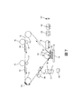
例えば、図1に示されるように、本願明細書における例示的な3次元(3D)プリンタは、他の要素のうち、ローラー112に支持された中間転写ベルト110(ITB)と、第1の印刷要素(例えば、現像装置116)と、第2の印刷要素(例えば、現像装置114)とを含む。それゆえに、図1に示されるように、第1の印刷要素116は、((例えば、電荷生成部128によって生成された)ベルトと転写される材料との間の電荷差によって)(潜在的に乾燥した)粉末ポリマー・ワックス材料(例えば、帯電した3Dトナー)などの造形材料である第1の材料104をITB110に対して静電的に転写するように配置される。(例えば、感光体ともすることができる)第2の印刷要素114はまた、第2の材料105(例えば、同様に粉末ポリマー・ワックス材料(例えば、帯電した3Dトナー)などの支持材料)を第1の材料104がITB110上に位置するITB110の位置に静電的に転写するように配置される。
For example, as shown in FIG. 1, the exemplary three-dimensional (3D) printer herein includes, among other elements, an intermediate transfer belt 110 (ITB) supported by a
支持材料105は、完全な3D物品が完成した後に印刷された3D構造が支持材料105から分離されるのを可能とするように、造形材料104に影響を及ぼさない溶剤に溶解する。図面において、造形材料104及び支持材料105の組み合わせが要素102として示されており、時には「現像層」と称されることがある。造形材料104及び支持材料105の現像層102は、ITB110の別個の領域上にあり、その層(及びその関連する支持要素)における3D構造の要素に対応してパターン化され、3D構造は、現像層102によって造形される。
The
また、これらの構造は、1つ以上の溶剤塗布ステーション144、146を含む。1つの溶剤塗布ステーション144は、ITB110上の層102を溶剤にさらすようにITB110に隣接して配置される。溶剤塗布ステーション144において使用される溶剤は、支持材料105に影響を与えることなく、造形材料104を粘着性にするように選択される。
Also, these structures include one or more
さらに、(表面又はベルトとすることができる)プラテン118は、ITB110に隣接している。この例において、プラテン118は、真空ベルトである。造形材料及び支持材料のパターン化された層102は、現像装置114、116から中間転写ベルト110に転写され、最終的に転写定着ステーション130においてプラテン118に転写される。溶剤塗布ステーション144において塗布される溶剤は、支持材料105に影響を及ぼすことなく、造形材料104のポリマー間の結合を形成し、これは、溶剤にさらした後に層102を粘着性にし、後の図面に示されるように、ITB110からプラテン118上の既存の層102への層の転写を促進する。
In addition, the platen 118 (which can be a surface or belt) is adjacent to the
図1に示されるように、転写定着ステーション130は、ITB110に隣接している。転写定着ステーション130は、ITB110の一方側にITB110を支持するローラー112を含む。転写定着ステーション130は、ITB110が溶剤塗布ステーション144から転写定着ステーション130へと移動するのにともない、溶剤にさらした後に層102を受けるように配置される。より具体的には、造形材料現像ステーション116、支持材料現像ステーション114、溶剤塗布ステーション144及び転写定着ステーション130は、ITB110がプロセス方向に移動しているときに、ITB110上の層102が造形材料及び支持材料現像ステーション114、116を最初に通過した後に溶剤塗布ステーション144を通過し、そして、転写定着ステーション130を通過するように、ITB110に対して配置される。
As shown in FIG. 1, the
図1にさらに示されるように、そのような構造は、ヒータ120、126及び結合ステーション122、124を含むことができる。結合ステーション122、124は、光源124を使用して光(例えば、UV光)を及び/又はヒータ122を使用して熱を加えるように配置される。本構造はまた、以下に記載される支持材料除去ステーション148を含むことができる。
As further shown in FIG. 1, such a structure can include
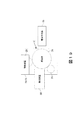
図2における縦矢印によって示されるように、プラテン118は、プラテン118をITB110と接触させるように、((全て項目118によって図示される)モータ、歯車、プーリー、ケーブル、ガイドなどを使用して)ITB110に向かって移動する。上述したように、溶剤塗布ステーション144において塗布された溶剤は、支持材料105に影響を与えることなく、造形材料104のポリマー間に結合を形成し、これは、溶剤にさらされた後に層102を粘着性にする。溶剤塗布ステーション144は、熱なしで使用されることができるが、現像層102及びITB110は、必要に応じて、転写定着前に現像層102を「粘着性」状態にするのをさらに助けるためにヒータ120によって局所的に加熱される。1つの例において、現像層102は、ガラス転移温度(Tg)よりも高い温度まで加熱されることができるが、トナー樹脂の融点又は定着温度Tmが不粘着性になる。
As indicated by the vertical arrows in FIG. 2, the
プラテン118はまた、必要に応じて、ほぼ同じ温度までヒータ120によって加熱された後、ITB−プラテンニップ(転写定着ニップ130)を通って平行移動する際に粘着層102と同期して接触されることができる。それにより、ITB110は、プラテン118がITB110に接触するたびに、造形材料104及び支持材料105の現像層102のいずれかをプラテン118に転写し、プラテン118上に造形材料104及び支持材料105の現像層102を連続的に形成する。
The
ここでも、ヒータ120は、溶剤塗布ステーション144内の溶剤が現像層102を粘着性にする唯一の要素であるのを可能とするようになくすことができる。さらに、ヒータ120が現像層102及び/又はITB110を加熱するために使用される場合、粘着性の現像層102を生成するために行われる熱量は、より少ない熱であり、いかなる溶剤処理もなく現像層102を粘着性にするために利用されるであろう。したがって、溶剤は、現像層102を粘着性にするために単独で使用されることができ、粘着性の一致を達成するためにヒータ120が溶剤塗布ステーション144と組み合わせて利用される場合、利用される熱量は、溶剤塗布ステーション144内よりも少ない。
Again, the
したがって、それぞれの別個の現像装置114、116によってITB上のパターンで印刷された造形材料及び支持材料は、所定長を有する特定のパターンを表すように現像層102においてともに結合される。それゆえに、図2に示されるように、現像層102のそれぞれは、(ITB110の隣の矢印によって表される)ITB110が移動しているプロセス方向の方に向けられた前縁134と、前縁134に対向する後縁136とを有する。
Therefore, the modeling material and the supporting material printed in the pattern on the ITB by the respective separate developing
より具体的には、図2に示されるように、転写定着ニップ130において、転写定着ニップ130内の現像層102の前縁134は、プラテン118の対応する位置に転写され始める。それゆえに、図2において、プラテン118は、現像層102の前縁134が転写定着ニップ130のローラーの最も低い位置にある位置においてITB110上の現像層102に接触するように移動する。それゆえに、この例において、現像層102の後縁136は、まだ転写定着ニップ130に到達しておらず、したがって、まだプラテン118に転写されていない。
More specifically, as shown in FIG. 2, in the transfer fixing nip 130, the
図3に示されるように、プラテン118は、汚すことなく、現像層102がプラテン118上にきれいに転写するのを可能とするように、プラテン真空ベルトを移動又は回転させることによってITB110と同期して移動する(ITB110と同じ速度で且つ同じ方向に移動する)。図3において、現像層102の後縁136は、まだ転写定着ニップ130に到達しておらず、したがってプラテン118に転写されていない唯一の部分である。そして、ITB110がプロセス方向に移動するのにともない、プラテン118は、現像層102の後縁136が転写定着ニップ130のローラーの底部に到達するまで、ITB110と同じ速度で且つ同じ方向に移動し、その時点で、図4に示されるように、プラテン118は、ITB110から離れ且つヒータ126にわたって移動する(ヒータ126は、非接触(例えば、赤外線(IR)ヒータ又は定着ローラーなどの加圧ヒータ)とすることができる)。
As shown in FIG. 3, the
図4及び図5に示されるように、ヒータ126が加圧ローラーである場合、プラテン118は、ローラーが回転するのに同期して移動し、現像層102をプラテン118に定着するように加熱及び加圧する。このプラテン118とITB110(及びヒータローラー126)との間の同期移動は、歪み又は汚れを生じることなく、ITB110からプラテン118に正確に転写されるように現像装置116、114によって印刷される支持及び造形材料のパターン(102)を生じさせる。
As shown in FIGS. 4 and 5, when the
プラテン118は、現像層102のそれぞれを独立して加熱して現像層102のそれぞれをプラテン118及びプラテン118上の以前に転写されたいずれかの現像層102に連続的に接合するように、ITB110が現像層102のそれぞれをプラテン118に転写するたびに、ヒータ126及び結合ステーション122、124へと移動することができる。他の代替例において、プラテン118は、複数の現像層102がプラテン118に且つ互いに同時に定着されるのを可能とするように、特定数(例えば、2、3、4など)の現像層102がプラテン118上に配置された後に、ヒータ126及び結合ステーション122、124へと移動することができるのみである。
The
図6に示されるように、次の現像層102を取得するために転写定着ステーション130に戻る前に、プラテン118は、必要に応じて、第2の溶剤塗布ステーション146へと移動することができる。これは、プラテン118上の上部現像層102を粘着性にするように、第2の溶剤塗布ステーション146がプラテン118上の現像層102に同じ(又はおそらく異なる)溶剤を塗布するのを可能とする。そして、ITB110上の次の粘着性の現像層102を取得するためにプラテン118上の粘着性の現像層102が転写定着ステーション130へと移動したとき、双方の層の粘着性は、ITB110からプラテン118上の既存の層102への現像層102の転写を促進する。
As shown in FIG. 6, the
それゆえに、図7に示されるように、複数の現像層102を積層106に定着するために図2から図6における処理が繰り返される。現像層102の積層106が成長するのにともない、図7に示されるように、積層106の上部に追加の現像層102が形成され、そのような追加の現像層102は、図8に示されるように、積層106内の全ての現像層102を一体に定着するようにヒータ126によって加圧加熱される。
Therefore, as shown in FIG. 7, the processes of FIGS. 2 to 6 are repeated in order to fix the plurality of developing
図9に示されるように、結合ステーション122、124は、独立した積層106において現像層102を結合/硬化させるように、3D構造に光及び/又は熱を印加するように構成されている。結合ステーションのヒータ、光及び他の要素122、124は、現像層102の化学的構成に応じて変化する。
As shown in FIG. 9, the
1つの例において、造形材料104は、UV硬化性トナーを含むことができる。したがって、図9に示されるように、1つの例において、結合ステーション122、124は、そのガラス転移温度とそれらの融点との間の温度まで材料102を加熱した後に、材料102内の架橋ポリマーにUV光を印加することによってそのような材料102を結合することができ、それにより、剛性構造を形成する。当業者は、他の造形及び支持材料が他の結合処理及び結合要素を利用すること、及び、前述したものが1つの限定された例としてのみ提示されていることを理解するであろう。本願明細書における装置及び方法は、現在知られているか又は将来開発されるかにかかわらず、全てのそのような結合方法及び要素に適用可能である。
In one example, the
1つの例において、結合ステーション122、124は、ITB110が現像層102のそれぞれをプラテン118に転写するたびに、又は、1回のみなどのより少ない頻度で(例えば、積層106の全体が完全に形成されたとき)、そのような光及び/又は熱を潜在的に印加することができる。さらに、図9は、独立した積層106の蓄積内の支持材料105及び造形材料104の部分を示すオーバーレイを図示している。そのようなものは、視認可能であってもなくてもよく、そのような造形及び支持材料が配置されることができる1つの例示的な方法を示すために図示されているにすぎない。
In one example, the
独立した積層106の3D構造は、外部溶剤槽を使用した支持材料105の手動除去を可能とするように出力されることができ、又は、図10から図12に示されるように処理を進めることができる。より具体的には、図10において、プラテン118上の現在結合された3D独立積層106を受けるように支持材料除去ステーション148が配置される。支持材料除去ステーション148は、溶剤塗布ステーション144、146内の溶剤とは異なる溶剤156を塗布する。支持材料除去ステーション148によって塗布された溶剤は、造形材料104に影響を与えることなく、支持材料105を溶解するように選択される。ここでも、上述したように、利用される溶剤は、造形材料104及び支持材料105の化学的構成に依存する。図11は、支持材料105の約半分が残っており且つ造形材料104の一部が支持材料105の残りの積層から突出する処理を図示している。図12は、支持材料除去ステーション148が全ての支持材料105を溶解するのに十分な溶剤156を塗布して造形材料104のみを残し、造形材料104のみから構成された完成した3D構造を残した後の処理を図示している。
The 3D structure of the
図13から図15は、図1に示される転写定着ニップ130の代わりに平面転写定着ステーション138を含む代替の3D静電印刷構造を図示している。図13に示されるように、平面転写定着ステーション138は、ローラー112間にあり且つプラテン118に平行なITB110の平面部である。図14に示されるように、この構造により、平面転写定着ステーション138に接触するようにプラテン118が移動するとき、現像層102の全ては、プラテン118に又は部分的に形成された積層106に同時に転写され、図2及び図3に示される回転転写定着プロセスを回避する。図15は、プラテン118上の上部現像層102を粘着性にするために第2の溶剤塗布ステーション146が使用されることができることを示している。
13 to 15 illustrate an alternative 3D electrostatic printing structure that includes a planar
同様に、図16に示されるように、本願明細書において記載されるように動作する全ての他の要素を有し、ITB110の代わりにドラム158が使用されることができる。それゆえに、ドラム158は、上述したように、現像ステーション114、116からの材料を受ける中間転写面とすることができ、又は、感光体とすることができ、電荷の潜像を維持して現像装置254からの材料を受けることにより、以下に記載される感光体256として動作することができる。
Similarly, as shown in FIG. 16, the
図17は、本願明細書における3D印刷装置204の多くの要素を図示している。3D印刷装置204は、コントローラ/有形プロセッサ224と、有形プロセッサ224及び印刷装置204の外部のコンピュータ化ネットワークに動作可能に接続された通信ポート(入力/出力)214とを含む。また、印刷装置204は、グラフィカルユーザインターフェース(GUI)アセンブリ212などの少なくとも1つのアクセサリ機能要素を含む。ユーザは、グラフィカルユーザインターフェース又はコントロールパネル212からメッセージ、命令及びメニューオプションを受信し且つそれを介して命令を入力することができる。
FIG. 17 illustrates many elements of the
入力/出力装置214は、3D印刷装置204との間の通信に使用され、(現在知られているか又は将来開発されるかにかかわらず、任意の形態の)有線又は無線装置を備える。有形プロセッサ224は、印刷装置204の様々な動作を制御する。(光、磁気、キャパシタベースなどであり、一時的信号とは異なる)持続性で有形のコンピュータ記憶媒体装置210は、有形プロセッサ224によって読み取り可能であり、コンピュータ化装置が本願明細書において記載されるものなどの様々な機能を実行するのを可能とするように有形プロセッサ224が実行する命令を記憶する。それゆえに、図17に示されるように、本体ハウジングは、電源218によって交流(AC)電源220から供給される電力で動作する1つ以上の機能要素を有する。電源218は、共通電力変換ユニット、電力記憶素子(例えば、電池など)などを含むことができる。
The input /
3D印刷装置204は、上述したようにプラテン上に造形及び支持材料の連続層を堆積させる少なくとも1つのマーキング装置(印刷エンジン)240を含み、(画像データの処理に特化されていることから汎用コンピュータとは異なる)専用画像プロセッサ224に動作可能に接続される。また、印刷装置204は、(電源218を介して)外部電源220から供給される電力で同様に動作する少なくとも1つのアクセサリ機能要素(スキャナ232など)を含むことができる。
The
1つ以上の印刷エンジン240は、現在知られているか又は将来開発されるかにかかわらず、造形材料及び支持材料(トナーなど)を塗布する任意のマーキング装置を例示するように意図され、例えば、(図18に示されるように)中間転写ベルト110を使用する装置を含むことができる。
One or
それゆえに、図18に示されるように、図17に示される印刷エンジン240のそれぞれは、1つ以上の潜在的に異なる(例えば、異なる色、異なる材料など)造形材料現像ステーション116や、1つ以上の潜在的に異なる(例えば、異なる色、異なる材料など)支持材料現像ステーション114などを利用することができる。現像ステーション114、116は、現在知られているか又は将来開発されるかにかかわらず、個々の静電マーキングステーション、個々のインクジェットステーション、個々のドライインクステーションなどの任意の形態の現像ステーションとすることができる。現像ステーション114、116のそれぞれは、(潜在的には中間転写ベルト110の状態から独立している)単一のベルト回転中に順次中間転写ベルト110の同じ位置に材料のパターンを転写し、それにより、十分且つ完全な画像が中間転写ベルト110に転写される前に中間転写ベルト110が通過しなければならない回数を減少させる。図18は、回転ベルト(110)に隣接するか又は接触している5つの現像ステーションを図示しているが、当業者によって理解されるように、そのような装置は、任意数のマーキングステーション(例えば、2、3、5、8、11など)を使用することができる。
Therefore, as shown in FIG. 18, each of the
中間転写ベルト110に隣接して(又は潜在的に接触して)配置された1つの例示的な個々の静電現像ステーション114、116が図19に示されている。個々の静電現像ステーション114、116のそれぞれは、内部感光体256上に均一な電荷を形成するそれ自体の帯電ステーション258と、均一な電荷を潜像にパターン形成する内部露光装置260と、帯電潜像に一致するパターンで感光体256に造形又は支持材料を転写する内部現像装置254とを含む。そして、造形又は支持材料のパターンは、通常は中間転写ベルト110とは反対側の電荷生成部128によって生成される造形又は支持材料の電荷に対する中間転写ベルト110の逆電荷によって感光体256から中間転写ベルト110へと引き付けられる。
One exemplary individual
図20は、本願明細書において実行される方法の処理を示すフローチャートである。より具体的には、そのような処理は、これらの方法が造形材料及び支持材料現像ステーションを使用して中間転写面に造形及び支持材料を静電的に転写する項目170において開始する。これらのプロセスは、中間転写面に造形材料及び支持材料の層を転写し、各層は、ITBの別個の領域上にあり、パターン化される。
FIG. 20 is a flowchart showing the processing of the method executed in the present specification. More specifically, such processing begins at
項目172において、そのような方法は、支持材料に影響を与えることなく、造形材料を粘着性にするように、溶剤塗布ステーションを使用して中間転写面上の造形及び支持材料の層を溶剤にさらす。さらに、現像された層及び以前に転写された層は、必要に応じて、項目174において、層の粘着性を促進するために加熱されることができる。
In
そして、転写定着ニップにおいて転写定着する前に、そのような方法は、項目176において、転写定着ステーション(ここでも、転写定着ステーションは、溶剤に対してさらした後に層を受けるように配置される)を越えて中間転写面を移動させ、中間転写面上の層のいずれかにプラテンを接触させるようにプラテンを中間転写面まで移動させる。中間転写面は、項目176においてプラテンが転写定着ステーションにおいて中間転写面上の層に接触するたびに、プラテンに造形材料及び支持材料の層を転写し、プラテン上に造形及び支持材料の層の独立した積層を連続的に形成する。溶剤は、支持材料に影響を与えることなく、造形材料のポリマー間の結合を形成し、溶剤(及び任意の熱)に対してさらした後の粘着性の層は、項目176において、中間転写面からプラテン上の層への層の転写を促進する。
Then, prior to transfer fixation at the transfer fixation nip, such a method, in
そのような方法は、項目178において、必要に応じて、層を加熱して各層を一体に結合するように、転写定着ステーションからヒータへとプラテンを移動させることができる。同様に、項目178において、これらの方法は、各層を一体に押圧するように、加圧ローラーへとプラテンを移動させることができる。さらに、項目180において、これらの方法は、プラテンが転写ステーションへと移動する前に同様にプラテン上の上層を粘着性にするように、第2の溶剤ステーションを使用してプラテン上の積層された層に同じ(又は異なる)溶剤を塗布することができる。
In
項目182は、硬化ステーションを使用して現像層の積層を硬化させるこれらの方法を示している。異なる構成において、これらの方法は、各層が転写定着ニップにおいてプラテンに転写された後、又は、予め設定された数の層が転写定着ニップにおいてプラテンに転写された後、ヒータ又は加圧ローラー(178)を使用して層を結合し、及び/又は、硬化ステーション(182)を使用して層を硬化させる。したがって、現像層の群(潜在的には全て)は、同時に結合される(178)及び/又は硬化される(182)ことができ、又は、そのような結合及び硬化は、層毎に行うことができ、図20に示される動作の順序は厳守されるものではない。
項目182に示されるように、そのような方法はまた、配置された支持材料除去ステーションへとプラテンを移動させ、UV硬化性造形材料のみから構成された3D構造を残すように、異なる溶剤(UV硬化性造形材料に影響を与えることなく支持材料を溶解するもの)を塗布することができる。
As shown in
図21は、現像層102が造形材料104の一部及び支持材料105の一部を含むことができる方法、並びに、最も低い現像層102がプラテン118に接合される方法、並びに、連続した各現像層102がプラテン118上の現像層102の積層106を形成するために下方の直前の隣接する現像層102に接触して接合される方法を示す拡大図である。上述したように、(識別番号102を使用して、図21において(縮尺どおりには描かれていない)粒子として示される)現像層102内の造形材料104及び支持材料105の粒子は、粘着性の上部現像層102を接合する粉末の粘着性粒子である。
FIG. 21 shows a method in which the developing
図22は、エンジニアリングプラスチック及び溶剤の適合性を図示するチャートである。図22において、A=攻撃なし、おそらく僅かな吸収、機械的特性にほとんど影響しない;B=吸収による僅かな攻撃、いくつかの腫れ及び機械的に小さな減少の可能性が高い;C=かなりの吸収の中程度の攻撃、材料は制限された寿命を有する;D=材料は短期間で分解又は溶解する;*=利用可能なデータなしであり、水溶液が示されており、重量%としての濃度が与えられている。造形材料、支持材料及び溶剤の選択は、溶剤が造形材料に影響を与え、支持材料を溶解又は軟化させ、支持材料を溶剤に抵抗させるように選択されることができる。造形材料は、部品使用ケースのために必要な所要の機械的特性を有するように選択される。 FIG. 22 is a chart illustrating the compatibility of engineering plastics and solvents. In FIG. 22, A = no attack, probably slight absorption, little effect on mechanical properties; B = slight attack by absorption, likely some swelling and mechanically small reductions; C = significant Moderate attack of absorption, material has limited lifespan; D = material decomposes or dissolves in a short period of time; * = no data available, aqueous solution shown, concentration as% by weight Is given. The choice of modeling material, supporting material and solvent can be selected such that the solvent affects the modeling material, dissolves or softens the supporting material, and makes the supporting material resistant to the solvent. The build material is selected to have the required mechanical properties required for the part use case.
いくつかの例示的な構造が添付図面に示されているが、当業者は、図面が簡略化された概略図であること、及び、以下に提示される特許請求の範囲が、図示されていない(又は潜在的には多いか少ない)がそのような装置及びシステムによって一般に利用されるより多くの特徴を包含することを理解するであろう。したがって、特許出願人は、以下に提示される特許請求の範囲が添付図面によって限定されるようには意図しておらず、代わりに、添付図面は、単に特許請求の範囲に記載された特徴が実装されることができるいくつかの方法を例示するために提供されるにすぎない。 Although some exemplary structures are shown in the accompanying drawings, those skilled in the art will not show that the drawings are simplified schematics and that the claims presented below are scoped. It will be appreciated that (or potentially more or less) embraces more features commonly used by such devices and systems. Therefore, the patent applicant does not intend to limit the scope of the claims presented below by the accompanying drawings, and instead, the attached drawings simply have the features described in the claims. It is provided only to illustrate some of the methods that can be implemented.
米国特許第8,488,994号明細書に示されるように、電子写真方式を使用した3D部品を印刷するための積層造形システムが知られている。システムは、表面を有する感光体要素と、現像ステーションとを含み、現像ステーションは、感光体要素の表面上に材料の現像層を転写するように構成されている。システムはまた、回転可能な感光体要素の表面から現像層を受けるように構成された転写媒体と、受けた層の少なくとも一部から3D部品を印刷するために層毎の様式で転写要素から現像層を受けるように構成されたプラテンとを含む。 As shown in US Pat. No. 8,488,994, a laminate modeling system for printing 3D parts using electrophotographic methods is known. The system includes a photoconductor element having a surface and a developing station, which is configured to transfer a developing layer of material onto the surface of the photoconductor element. The system also develops from the transfer element in a layer-by-layer fashion to print the 3D component from at least a portion of the transfer medium configured to receive the development layer from the surface of the rotatable photoconductor element. Includes platens configured to receive layers.
UV硬化性トナーに関して、米国特許第7,250,238号明細書に開示されているように、印刷プロセスにおいてUV硬化性トナー組成物を利用する方法であるため、UV硬化性トナー組成物を提供することが知られている。米国特許第7,250,238号明細書は、実施形態において硬化されることができ、約100nmから約400nmを有するUV光などのUV照射に対する露光によるものである、トナーの生成を可能とする様々なトナーエマルジョン凝集プロセスを開示している。米国特許第7,250,238号明細書において、生成されたトナー組成物は、温度感受性包装及びフォイルシールの製造などの様々な印刷用途に利用されることができる。米国特許第7,250,238号明細書において、実施形態は、任意の着色剤、任意のワックス、スチレンから生成されたポリマー、及び、ブチルアクリレート、カルボキシエチルアクリレート及びUV光硬化性アクリレートオリゴマーからなる群から選択されるアクリレートから構成されるUV硬化性トナー組成物に関する。さらに、これらの態様は、顔料、任意のワックス及びUV硬化性脂環式エポキシドから生成されるポリマーなどの着色剤から構成されるトナー組成物に関する。 As for UV curable toner, as disclosed in US Pat. No. 7,250,238, the UV curable toner composition is provided because it is a method of utilizing the UV curable toner composition in the printing process. It is known to do. U.S. Pat. No. 7,250,238 allows the production of toner, which can be cured in embodiments and is by exposure to UV irradiation such as UV light having about 100 nm to about 400 nm. Various toner emulsion agglomeration processes are disclosed. In US Pat. No. 7,250,238, the toner composition produced can be used in a variety of printing applications, such as in the manufacture of temperature sensitive packaging and foil seals. In US Pat. No. 7,250,238, an embodiment comprises any colorant, any wax, a polymer produced from styrene, and butyl acrylate, carboxyethyl acrylate and UV photocurable acrylate oligomers. It relates to a UV curable toner composition composed of an acrylate selected from the group. Further, these aspects relate to toner compositions composed of pigments, optional waxes and colorants such as polymers produced from UV curable alicyclic epoxides.
さらに、米国特許第7,250,238号明細書は、スチレン、ブチルアクリレート、カルボキシエチルアクリレート及びUV硬化性アクリレートから形成されたポリマーを含有するラテックスを着色剤及びワックスと混合することと、必要に応じて凝集を引き起こして第2の混合物中に分散されたトナー前駆体粒子を形成するためにこの混合物に凝集剤を添加することと、トナー粒子を形成するようにポリマーのガラス転移温度(Tg)以上の温度までトナー前駆体粒子を加熱することと、必要に応じてトナー粒子を洗浄することと、必要に応じてトナー粒子を乾燥させることとを含むUV硬化性トナー組成物を形成する方法を開示している。さらなる態様は、この方法によって製造されたトナー粒子に関する。 In addition, US Pat. No. 7,250,238 requires that a latex containing a polymer formed from styrene, butyl acrylate, carboxyethyl acrylate and UV curable acrylate be mixed with a colorant and wax. Adding an aggregating agent to the mixture to form the toner precursor particles dispersed in the second mixture, and the glass transition temperature (Tg) of the polymer to form the toner particles accordingly. A method for forming a UV curable toner composition, which comprises heating the toner precursor particles to the above temperature, washing the toner particles as needed, and drying the toner particles as needed. It is disclosed. A further aspect relates to toner particles produced by this method.
いくつかの例示的な構造が添付図面に図示されているが、当業者は、図面が簡略化された概略図であること、及び、以下に提示される特許請求の範囲が、図示されていない(又は潜在的には多いか少ない)がそのような装置及びシステムによって一般に利用されるより多くの特徴を包含することを理解するであろう。したがって、特許出願人は、以下に提示される特許請求の範囲が添付図面によって限定されるようには意図しておらず、代わりに、添付図面は、単に特許請求の範囲に記載された特徴が実装されることができるいくつかの方法を例示するために提供されるにすぎない。 Although some exemplary structures are illustrated in the accompanying drawings, those skilled in the art will not show that the drawings are simplified schematics and that the claims presented below are scoped. It will be appreciated that (or potentially more or less) embraces more features commonly used by such devices and systems. Therefore, the patent applicant does not intend to limit the scope of the claims presented below by the accompanying drawings, and instead, the attached drawings simply have the features described in the claims. It is provided only to illustrate some of the methods that can be implemented.
多くのコンピュータ化装置が上述されている。チップベースの中央処理装置(CPU)と、(グラフィックユーザインターフェース(GUI)、メモリ、コンパレータ、有形プロセッサなどを含む)入力/出力装置とを含むコンピュータ化装置は、米国テキサス州ラウンドロックのデルコンピュータ及び米国カリフォルニア州クパチーノのアップルコンピュータ社などの製造業者によって製造された周知且つ容易に入手可能な装置である。そのようなコンピュータ化装置は、一般に、入力/出力装置と、電源と、有形プロセッサと、電子記憶メモリと、配線などを含み、その詳細は、読者が本願明細書に記載されたシステム及び方法の顕著な態様に集中するのを可能とするように本願明細書からは省略される。同様に、プリンタ、複写機、スキャナ及び他の同様の周辺機器は、米国コネティカット州ノーウォークのゼロックス社から入手可能であり、そのような装置の詳細は、簡潔性及び読者の集中の目的のために本願明細書においては記載されない。 Many computerized devices are mentioned above. Computerized equipment, including a chip-based central processing unit (CPU) and input / output equipment (including a graphic user interface (GUI), memory, comparator, tangible processor, etc.), is available from Dell Computer in Roundlock, Texas, USA. A well-known and readily available device manufactured by manufacturers such as Apple Computer in Cupaccino, California, USA. Such computerized devices generally include input / output devices, power supplies, tangible processors, electronic storage memory, wiring, etc., the details of which are described by the reader in the systems and methods described herein. It is omitted from the present specification to allow concentration in a prominent aspect. Similarly, printers, copiers, scanners and other similar peripherals are available from Xerox, Inc., Norwalk, Connecticut, USA, and details of such equipment are for the purpose of brevity and reader concentration. Is not described in the specification of the present application.
本願明細書において使用されるプリンタ又は印刷装置という用語は、任意の目的のために印刷出力機能を実行する、ディジタル複写機、製本機、ファクシミリ装置、複合機などの任意の装置を包含する。プリンタ、印刷エンジンなどの詳細は、周知であり、本開示が提示された顕著な特徴に集中されるのを維持するように本願明細書においては詳細に記載されない。本願明細書におけるシステム及び方法は、カラーで、モノクロで印刷する、又は、カラー若しくはモノクロ画像データを扱うシステム及び方法を包含することができる。全ての前述したシステム及び方法は、特に静電及び/又は乾式電子写真方式装置及び/又はプロセスに適用可能である。 As used herein, the term printer or printing device includes any device, such as a digital copier, bookbinding machine, facsimile machine, multifunction device, that performs a print output function for any purpose. Details such as printers, printing engines, etc. are well known and are not described in detail herein to keep the disclosure focused on the salient features presented. The systems and methods herein can include systems and methods for printing in color and monochrome, or for handling color or monochrome image data. All the systems and methods described above are particularly applicable to electrostatic and / or dry electrophotographic devices and / or processes.
本発明の目的のために、定着(fixing)という用語は、乾燥、硬化、重合、架橋、結合若しくは付加反応又はコーティングの他の反応を意味する。さらに、本願明細書において使用される「右(right)」、「左(left)」、「垂直(vertical)」、「水平(horizontal)」、「上部(top)」、「下部(bottom)」、「上(upper)」、「下(lower)」、「下方(under)」、「下方(below)」、「下にある(underlying)」、「上(over)」、「上にある(overlying)」、「平行(parallel)」、「垂直(perpendicular)」などの用語は、(特に断らない限り)それらが図面において配向されて図示されるときの相対位置であると理解される。「接触(touching)」、「上(on)」、「直接接触(in direct contact)」、「当接(abutting)」、「直接隣接(directly adjacent to)」などの用語は、(記載された要素を分離する他の要素なしで)少なくとも1つの要素において他の要素に物理的に接触することを意味する。さらに、自動化された(automated)又は自動的に(automatically)という用語は、(機械又はユーザによって)処理が開始されると、1つ以上の機械がいかなるユーザからのさらなる入力なしで処理を行うことを意味する。本願明細書における図面において、同一の識別符号は、同一又は同様の項目を識別する。 For the purposes of the present invention, the term fixing means drying, curing, polymerization, cross-linking, bonding or addition reactions or other reactions of coating. Further, as used in the present specification, "right", "left", "vertical", "horizontal", "top", "bottom". , "Upper", "lower", "lower", "lower", "underlying", "over", "above (upper)", "lower", "lower", "lower", "lower" Terms such as "overlying", "parallel", and "perpendicular" are understood (unless otherwise specified) to be relative positions when they are oriented and illustrated in the drawings. Terms such as "touching," "on," "direct contact," "abutting," and "directly adaptive to" have been described. Means physical contact with another element in at least one element (without any other element separating the elements). In addition, the term automated or automatically means that when processing is initiated (by a machine or user), one or more machines perform the processing without further input from any user. Means. In the drawings in the specification of the present application, the same identification code identifies the same or similar items.
Claims (16)
前記中間転写面に造形材料を静電的に転写するように配置された造形材料現像ステーションと、
前記中間転写面に支持材料を静電的に転写するように配置された支持材料現像ステーションであって、前記造形材料現像ステーション及び前記支持材料現像ステーションが前記中間転写面に前記造形材料及び前記支持材料の層を転写する、支持材料現像ステーションと、
前記層を粘着性にする溶剤に対して前記中間転写面上に前記層をさらすように配置された第1の溶剤塗布ステーションと、
前記中間転写面に隣接する転写定着ステーションであって、前記中間転写面が前記転写定着ステーションを通過するのにともない、前記溶剤に対してさらした後に前記層を受けるように配置された転写定着ステーションと、
前記中間転写面に対して移動するプラテンであって、前記プラテン上に前記層の独立した積層を連続的に形成するように、前記プラテンが前記転写定着ステーションにおいて前記中間転写面上の前記層のいずれかに接触するたびに、前記中間転写面が前記造形材料及び前記支持材料の層を前記プラテンに転写するプラテンと、
前記プラテンが前記転写定着ステーションへと移動する前に前記プラテン上の上層を粘着性にするように前記プラテン上の前記層に前記溶剤を塗布するように配置された第2の溶剤塗布ステーションと、
前記プラテンに隣接するヒータであって、前記層を加熱して一体に前記各層を接合するように前記プラテンが前記転写定着ステーションから前記ヒータへと移動するヒータと、
前記ヒータに隣接する加圧ローラーであって、一体に前記各層を押圧するように前記プラテンが前記加圧ローラーへと移動する加圧ローラーと、
前記層を硬化するように前記層にUV光を印加するように配置された硬化ステーションと、
を備える、3次元(3D)プリンタ。 An intermediate transfer surface and a modeling material development station arranged so as to electrostatically transfer the modeling material to the intermediate transfer surface,
A support material developing station arranged so as to electrostatically transfer a support material to the intermediate transfer surface, wherein the modeling material developing station and the supporting material developing station are arranged on the intermediate transfer surface to perform the modeling material and the support. A supporting material development station that transfers layers of material,
A first solvent application station arranged so as to expose the layer on the intermediate transfer surface to a solvent that makes the layer sticky.
A transfer fixing station adjacent to the intermediate transfer surface, which is arranged so as to receive the layer after being exposed to the solvent as the intermediate transfer surface passes through the transfer fixing station. When,
A platen that moves with respect to the intermediate transfer surface, the platen of the layer on the intermediate transfer surface at the transfer fixation station so that an independent stack of the layers is continuously formed on the platen. Each time it comes into contact with any of the plates, the intermediate transfer surface transfers the layers of the molding material and the supporting material to the platen.
A second solvent application station arranged to apply the solvent to the layer on the platen so as to make the upper layer on the platen sticky before the platen moves to the transfer fixation station.
A heater adjacent to the platen, wherein the platen moves from the transfer fixing station to the heater so as to heat the layers and integrally join the layers.
A pressurizing roller adjacent to the heater, the pressurizing roller in which the platen moves to the pressurizing roller so as to integrally press the respective layers.
A curing station arranged to apply UV light to the layer to cure the layer,
A three-dimensional (3D) printer equipped with.
前記ITBに造形材料を静電的に転写するように配置された造形材料現像ステーションと、
前記造形材料が前記ITB上に位置する前記ITBの位置に支持材料を静電的に転写するように配置された支持材料現像ステーションであって、前記支持材料が前記造形材料を溶解する溶剤に対して異なる溶剤において溶解し、前記造形材料現像ステーション及び前記支持材料現像ステーションが前記ITBに前記造形材料及び前記支持材料の層を転写し、前記各層が前記ITBの別個の領域上にあり、パターン化されている支持材料現像ステーションと、
前記層を粘着性にする溶剤に対して前記ITB上の前記層をさらすように配置された第1の溶剤塗布ステーションと、
前記ITBに隣接する転写定着ステーションであって、前記ITBの第1の側に前記ITBを支持するローラーを備え、前記ITBが前記転写定着ステーションを通過するのにともない、前記溶剤に対してさらした後に前記層を受けるように配置された転写定着ステーションと、
前記ITBに対して移動するプラテンであって、前記プラテンが前記転写定着ステーションにおける前記ITBの第2の側において前記層のいずれかに接触するたびに、前記ITBが前記造形材料及び前記支持材料の層を前記プラテンに転写し、前記プラテン上に前記層の独立した積層を連続的に形成し、前記第1の側が前記第2の側とは反対側であるプラテンと、
前記プラテンが前記転写定着ステーションへと移動する前に前記プラテン上の上層を粘着性にするように前記プラテン上の前記層に前記溶剤を塗布するように配置された第2の溶剤塗布ステーションと、
前記プラテンに隣接するヒータであって、前記層を加熱して一体に前記各層を接合するように前記プラテンが前記転写定着ステーションから前記ヒータへと移動するヒータと、
前記ヒータに隣接する加圧ローラーであって、一体に前記各層を押圧するように前記プラテンが前記加圧ローラーへと移動する加圧ローラーと、
前記層を硬化するように前記層にUV光を印加するように配置された硬化ステーションと、
を備える、3次元(3D)プリンタ。 Intermediate transfer belt (ITB) and
A modeling material development station arranged so as to electrostatically transfer the modeling material to the ITB,
A support material developing station in which the modeling material is arranged so as to electrostatically transfer the support material to the position of the ITB located on the ITB, with respect to a solvent in which the support material dissolves the modeling material. The modeling material development station and the supporting material developing station transfer the layers of the modeling material and the supporting material to the ITB, and each layer is on a separate region of the ITB and patterned. Supporting material development station and
A first solvent coating station arranged to expose the layer on the ITB to a solvent that makes the layer sticky.
A transfer fixing station adjacent to the ITB, provided with a roller supporting the ITB on the first side of the ITB, and exposed to the solvent as the ITB passes through the transfer fixing station. A transfer fixation station arranged to receive the layer later,
A platen that moves relative to the ITB, where each time the platen contacts any of the layers on the second side of the ITB at the transfer fixation station, the ITB of the shaping material and the supporting material. A platen in which the layer is transferred to the platen, an independent laminate of the layers is continuously formed on the platen, and the first side is opposite to the second side.
A second solvent application station arranged to apply the solvent to the layer on the platen so as to make the upper layer on the platen sticky before the platen moves to the transfer fixation station.
A heater adjacent to the platen, wherein the platen moves from the transfer fixing station to the heater so as to heat the layers and integrally join the layers.
A pressurizing roller adjacent to the heater, the pressurizing roller in which the platen moves to the pressurizing roller so as to integrally press the respective layers.
A curing station arranged to apply UV light to the layer to cure the layer,
A three-dimensional (3D) printer equipped with.
前記ITBに紫外線(UV)硬化性造形材料を静電的に転写するように配置された造形材料現像ステーションと、
前記UV硬化性造形材料が前記ITB上に位置する前記ITBの位置に支持材料を静電的に転写するように配置された支持材料現像ステーションであって、前記支持材料が前記UV硬化性造形材料を溶解する溶剤に対して異なる溶剤において溶解し、前記造形材料現像ステーション及び前記支持材料現像ステーションが前記ITBに前記UV硬化性造形材料及び前記支持材料の層を転写し、前記各層が前記ITBの別個の領域上にあり、パターン化されている支持材料現像ステーションと、
前記支持材料に影響を与えることなく、前記造形材料を粘着性にする溶剤に対して前記ITB上の前記層をさらすように配置された第1の溶剤塗布ステーションと、
前記ITBに隣接する転写定着ステーションであって、前記ITBの第1の側に前記ITBを支持するローラーを備え、前記ITBが前記転写定着ステーションを通過するのにともない、前記溶剤に対してさらした後に前記層を受けるように配置された転写定着ステーションと、
前記ITBに対して移動するプラテンであって、前記プラテンが前記転写定着ステーションにおける前記ITBの第2の側において前記層のいずれかに接触するたびに、前記ITBが前記UV硬化性造形材料及び前記支持材料の層を前記プラテンに転写し、前記プラテン上に前記層の独立した積層を連続的に形成し、前記第1の側が前記第2の側とは反対側であるプラテンと、
前記プラテンが前記転写定着ステーションへと移動する前に前記プラテン上の上層を粘着性にするように前記プラテン上の前記層に前記溶剤を塗布するように配置された第2の溶剤塗布ステーションと、
前記プラテンに隣接するヒータであって、前記層を加熱して一体に前記各層を接合するように前記プラテンが前記転写定着ステーションから前記ヒータへと移動するヒータと、
前記ヒータに隣接する加圧ローラーであって、一体に前記各層を押圧するように前記プラテンが前記加圧ローラーへと移動する加圧ローラーと、
前記層を硬化するように前記層にUV光を印加するように配置された硬化ステーションと
を備える、3次元(3D)プリンタ。 Intermediate transfer belt (ITB) and
A modeling material development station arranged so as to electrostatically transfer an ultraviolet (UV) curable modeling material to the ITB,
A support material developing station in which the UV curable modeling material is arranged so as to electrostatically transfer the support material to the position of the ITB located on the ITB, and the support material is the UV curable modeling material. The modeling material development station and the support material development station transfer the layers of the UV curable modeling material and the support material to the ITB, and each layer of the ITB is dissolved in a different solvent. With a supporting material development station, which is on a separate area and is patterned,
A first solvent coating station arranged to expose the layer on the ITB to a solvent that makes the modeling material sticky without affecting the supporting material.
A transfer fixing station adjacent to the ITB, provided with a roller supporting the ITB on the first side of the ITB, and exposed to the solvent as the ITB passes through the transfer fixing station. A transfer fixation station arranged to receive the layer later,
A platen that moves relative to the ITB, where each time the platen contacts any of the layers on the second side of the ITB at the transfer fixation station, the ITB is subjected to the UV curable modeling material and said. A platen in which a layer of support material is transferred to the platen, an independent laminate of the layers is continuously formed on the platen, and the first side is opposite to the second side.
A second solvent application station arranged to apply the solvent to the layer on the platen so as to make the upper layer on the platen sticky before the platen moves to the transfer fixation station.
A heater adjacent to the platen, wherein the platen moves from the transfer fixing station to the heater so as to heat the layers and integrally join the layers.
A pressurizing roller adjacent to the heater, the pressurizing roller in which the platen moves to the pressurizing roller so as to integrally press the respective layers.
A three-dimensional (3D) printer comprising a curing station arranged to apply UV light to the layer to cure the layer.
第1のポリマーを含む造形材料を維持するように特に構成され、前記中間転写面に造形材料を静電的に転写するように配置された造形材料現像ステーションと、
前記第1のポリマーとは異なる第2のポリマーを含む支持材料を維持するように特に構成され、前記中間転写面に前記支持材料を静電的に転写するように配置された支持材料現像ステーションであって、前記造形材料現像ステーション及び前記支持材料現像ステーションが前記中間転写面に前記造形材料及び前記支持材料の層を転写する、支持材料現像ステーションと、
前記支持材料の前記第2のポリマーに影響を及ぼすことなく、前記造形材料の前記第1のポリマー間の結合を形成する溶剤を維持するように特に構成され、前記層を粘着性にする溶剤に対して前記中間転写面上に前記層をさらすように配置された第1の溶剤塗布ステーションと、
前記中間転写面に隣接する転写定着ステーションであって、前記中間転写面が前記転写定着ステーションを通過するのにともない、前記溶剤に対してさらした後に前記層を受けるように配置された転写定着ステーションと、
前記中間転写面に対して移動するプラテンであって、前記プラテン上に前記層の独立した積層を連続的に形成するように、前記プラテンが前記転写定着ステーションにおいて前記中間転写面上の前記層のいずれかに接触するたびに、前記中間転写面が前記造形材料及び前記支持材料の層を前記プラテンに転写するプラテンと、
前記プラテンが前記転写定着ステーションへと移動する前に前記プラテン上の上層を粘着性にするように前記プラテン上の前記層に前記溶剤を塗布するように配置された第2の溶剤塗布ステーションと、
前記プラテンに隣接するヒータであって、前記層を加熱して一体に前記各層を接合するように前記プラテンが前記転写定着ステーションから前記ヒータへと移動するヒータと、
前記ヒータに隣接する加圧ローラーであって、一体に前記各層を押圧するように前記プラテンが前記加圧ローラーへと移動する加圧ローラーと、
前記層を硬化するように前記層にUV光を印加するように配置された硬化ステーションと、
を備える、3次元(3D)プリンタ。 A modeling material development station specifically configured to maintain a modeling material containing an intermediate transfer surface and a first polymer, and arranged to electrostatically transfer the modeling material to the intermediate transfer surface.
In a supporting material developing station specifically configured to maintain a supporting material containing a second polymer different from the first polymer and arranged to electrostatically transfer the supporting material to the intermediate transfer surface. A support material development station, wherein the modeling material development station and the support material development station transfer a layer of the modeling material and the support material to the intermediate transfer surface.
A solvent that is specifically configured to maintain a solvent that forms a bond between the first polymers of the modeling material without affecting the second polymer of the supporting material, making the layer sticky. On the other hand, a first solvent application station arranged so as to expose the layer on the intermediate transfer surface, and
A transfer fixing station adjacent to the intermediate transfer surface, which is arranged so as to receive the layer after being exposed to the solvent as the intermediate transfer surface passes through the transfer fixing station. When,
A platen that moves with respect to the intermediate transfer surface, the platen of the layer on the intermediate transfer surface at the transfer fixation station so that an independent stack of the layers is continuously formed on the platen. Each time it comes into contact with any of the plates, the intermediate transfer surface transfers the layers of the molding material and the supporting material to the platen.
A second solvent application station arranged to apply the solvent to the layer on the platen so as to make the upper layer on the platen sticky before the platen moves to the transfer fixation station.
A heater adjacent to the platen, wherein the platen moves from the transfer fixing station to the heater so as to heat the layers and integrally join the layers.
A pressurizing roller adjacent to the heater, wherein the platen moves to the pressurizing roller so as to integrally press the respective layers.
A curing station arranged to apply UV light to the layer to cure the layer,
A three-dimensional (3D) printer equipped with.
Applications Claiming Priority (2)
| Application Number | Priority Date | Filing Date | Title |
|---|---|---|---|
| US15/098,825 | 2016-04-14 | ||
| US15/098,825 US10369744B2 (en) | 2016-04-14 | 2016-04-14 | Electrostatic 3-D development apparatus using cold fusing |
Publications (3)
| Publication Number | Publication Date |
|---|---|
| JP2017191314A JP2017191314A (en) | 2017-10-19 |
| JP2017191314A5 JP2017191314A5 (en) | 2020-05-07 |
| JP6800063B2 true JP6800063B2 (en) | 2020-12-16 |
Family
ID=58501400
Family Applications (1)
| Application Number | Title | Priority Date | Filing Date |
|---|---|---|---|
| JP2017062883A Active JP6800063B2 (en) | 2016-04-14 | 2017-03-28 | 3D printer |
Country Status (5)
| Country | Link |
|---|---|
| US (2) | US10369744B2 (en) |
| EP (1) | EP3231580B1 (en) |
| JP (1) | JP6800063B2 (en) |
| KR (1) | KR102136446B1 (en) |
| CN (1) | CN107297899B (en) |
Families Citing this family (8)
| Publication number | Priority date | Publication date | Assignee | Title |
|---|---|---|---|---|
| WO2018092123A1 (en) * | 2016-11-17 | 2018-05-24 | Orbotech Ltd. | Hybrid, multi-material 3d printing |
| KR102032993B1 (en) * | 2017-12-28 | 2019-11-08 | 주식회사 에스에프에이 | Three dimensional printing apparatus and three dimensional printing method using the same |
| US11731352B2 (en) * | 2019-03-29 | 2023-08-22 | Xerox Corporation | Apparatus and method for fabricating multi-polymer composite structures |
| KR20220004975A (en) | 2019-05-01 | 2022-01-12 | 아이오 테크 그룹 엘티디. | How to use 3D printing to electrically connect a chip to a top connector |
| WO2020236610A1 (en) * | 2019-05-17 | 2020-11-26 | Evolve Additive Solutions, Inc. | Layer transfusion sequencing for selective deposition-based additive manufacturing |
| US11446750B2 (en) | 2020-02-03 | 2022-09-20 | Io Tech Group Ltd. | Systems for printing solder paste and other viscous materials at high resolution |
| US11497124B2 (en) | 2020-06-09 | 2022-11-08 | Io Tech Group Ltd. | Methods for printing conformal materials on component edges at high resolution |
| US11691332B2 (en) | 2020-08-05 | 2023-07-04 | Io Tech Group Ltd. | Systems and methods for 3D printing with vacuum assisted laser printing machine |
Family Cites Families (31)
| Publication number | Priority date | Publication date | Assignee | Title |
|---|---|---|---|---|
| US4752352A (en) * | 1986-06-06 | 1988-06-21 | Michael Feygin | Apparatus and method for forming an integral object from laminations |
| US5876550A (en) * | 1988-10-05 | 1999-03-02 | Helisys, Inc. | Laminated object manufacturing apparatus and method |
| US5127037A (en) | 1990-08-15 | 1992-06-30 | Bynum David K | Apparatus for forming a three-dimensional reproduction of an object from laminations |
| US5362427A (en) * | 1993-05-10 | 1994-11-08 | Mitchell Jr Porter H | Method and apparatus for manufacturing an article using a support structure for supporting an article during manufacture therefor |
| US6206672B1 (en) * | 1994-03-31 | 2001-03-27 | Edward P. Grenda | Apparatus of fabricating 3 dimensional objects by means of electrophotography, ionography or a similar process |
| US5997795A (en) * | 1997-05-29 | 1999-12-07 | Rutgers, The State University | Processes for forming photonic bandgap structures |
| US6066285A (en) * | 1997-12-12 | 2000-05-23 | University Of Florida | Solid freeform fabrication using power deposition |
| JPH11272125A (en) * | 1998-03-24 | 1999-10-08 | Murata Mfg Co Ltd | Electrophotographic device |
| US6376148B1 (en) * | 2001-01-17 | 2002-04-23 | Nanotek Instruments, Inc. | Layer manufacturing using electrostatic imaging and lamination |
| US7250238B2 (en) | 2003-12-23 | 2007-07-31 | Xerox Corporation | Toners and processes thereof |
| US7261542B2 (en) | 2004-03-18 | 2007-08-28 | Desktop Factory, Inc. | Apparatus for three dimensional printing using image layers |
| US7270408B2 (en) | 2005-01-14 | 2007-09-18 | Xerox Corporation | Low level cure transfuse assist for printing with radiation curable ink |
| US7906061B2 (en) * | 2005-05-03 | 2011-03-15 | 3D Systems, Inc. | Bubble-free cross-sections for use in solid imaging |
| US7851549B2 (en) | 2007-12-13 | 2010-12-14 | Xerox Corporation | Curable polyester latex made by phase inversion emulsification |
| US20100140852A1 (en) | 2008-12-04 | 2010-06-10 | Objet Geometries Ltd. | Preparation of building material for solid freeform fabrication |
| US8470231B1 (en) | 2009-06-01 | 2013-06-25 | Stratasys Ltd. | Three-dimensional printing process for producing a self-destructible temporary structure |
| US20130186558A1 (en) | 2011-09-23 | 2013-07-25 | Stratasys, Inc. | Layer transfusion with heat capacitor belt for additive manufacturing |
| US8488994B2 (en) | 2011-09-23 | 2013-07-16 | Stratasys, Inc. | Electrophotography-based additive manufacturing system with transfer-medium service loops |
| CN104640686B (en) | 2012-09-05 | 2018-01-30 | 阿普雷奇亚制药公司 | 3 D-printing system and apparatus assembly |
| CN104870171A (en) | 2012-11-09 | 2015-08-26 | 赢创工业集团股份有限公司 | Multicoloured extrusion-based 3d printing |
| EP2917025A1 (en) | 2012-11-09 | 2015-09-16 | Evonik Röhm GmbH | Use and production of coated filaments for extrusion-based 3d printing processes |
| US9523934B2 (en) | 2013-07-17 | 2016-12-20 | Stratasys, Inc. | Engineering-grade consumable materials for electrophotography-based additive manufacturing |
| JP2017501910A (en) | 2013-11-18 | 2017-01-19 | チャン、カイ−ジュイ | Color or multi-material 3D printer |
| US9744730B2 (en) | 2013-11-22 | 2017-08-29 | Stratasys, Inc. | Magnetic platen assembly for additive manufacturing system |
| GB2521386A (en) | 2013-12-18 | 2015-06-24 | Ibm | Improvements in 3D printing |
| US10144175B2 (en) | 2014-03-18 | 2018-12-04 | Evolve Additive Solutions, Inc. | Electrophotography-based additive manufacturing with solvent-assisted planarization |
| US9505058B2 (en) | 2014-05-16 | 2016-11-29 | Xerox Corporation | Stabilized metallic nanoparticles for 3D printing |
| US9527992B2 (en) | 2014-08-29 | 2016-12-27 | Creopop Pte. Ltd. | Composition for 3D printing |
| EP3245255B1 (en) * | 2015-01-12 | 2019-05-15 | PolyOne Corporation | Support material for 3d printing of polymer compounds |
| US10272664B2 (en) * | 2015-01-14 | 2019-04-30 | Xactiv, Inc. | Fabrication of 3D objects via multiple build platforms |
| US10272618B2 (en) * | 2015-02-23 | 2019-04-30 | Xactiv, Inc. | Fabrication of 3D objects via electrostatic powder deposition |
-
2016
- 2016-04-14 US US15/098,825 patent/US10369744B2/en active Active
-
2017
- 2017-03-22 KR KR1020170036171A patent/KR102136446B1/en active IP Right Grant
- 2017-03-28 JP JP2017062883A patent/JP6800063B2/en active Active
- 2017-03-30 CN CN201710204482.6A patent/CN107297899B/en active Active
- 2017-04-07 EP EP17165636.6A patent/EP3231580B1/en active Active
-
2019
- 2019-05-31 US US16/427,399 patent/US11130282B2/en active Active
Also Published As
| Publication number | Publication date |
|---|---|
| US20190283318A1 (en) | 2019-09-19 |
| KR102136446B1 (en) | 2020-08-26 |
| EP3231580A1 (en) | 2017-10-18 |
| US10369744B2 (en) | 2019-08-06 |
| US11130282B2 (en) | 2021-09-28 |
| JP2017191314A (en) | 2017-10-19 |
| US20170297288A1 (en) | 2017-10-19 |
| CN107297899A (en) | 2017-10-27 |
| KR20170117871A (en) | 2017-10-24 |
| CN107297899B (en) | 2021-01-15 |
| EP3231580B1 (en) | 2020-06-10 |
Similar Documents
| Publication | Publication Date | Title |
|---|---|---|
| JP6800063B2 (en) | 3D printer | |
| JP6796551B2 (en) | Electrostatic 3D printer with flattening material and mechanical planer | |
| JP6824100B2 (en) | Electrostatic 3D developer using materials with different melting points | |
| JP6757689B2 (en) | Electrophoto 3D printing using meltable paper | |
| US10086558B2 (en) | 3-D electrostatic printer using track bound platens and registration system | |
| JP6815252B2 (en) | Electrophoto 3D printing using a foldable substrate | |
| US10350828B2 (en) | 3-D printing using intermediate transfer belt and curable polymers | |
| JP6785183B2 (en) | Electrostatic 3D printer with addressable UV cross-linking | |
| US10213958B2 (en) | Electrostatic 3-D printing system having acoustic transfer and corotron |
Legal Events
| Date | Code | Title | Description |
|---|---|---|---|
| RD02 | Notification of acceptance of power of attorney |
Free format text: JAPANESE INTERMEDIATE CODE: A7422 Effective date: 20170411 |
|
| RD04 | Notification of resignation of power of attorney |
Free format text: JAPANESE INTERMEDIATE CODE: A7424 Effective date: 20170629 |
|
| A521 | Request for written amendment filed |
Free format text: JAPANESE INTERMEDIATE CODE: A523 Effective date: 20200326 |
|
| A621 | Written request for application examination |
Free format text: JAPANESE INTERMEDIATE CODE: A621 Effective date: 20200326 |
|
| A871 | Explanation of circumstances concerning accelerated examination |
Free format text: JAPANESE INTERMEDIATE CODE: A871 Effective date: 20200326 |
|
| A975 | Report on accelerated examination |
Free format text: JAPANESE INTERMEDIATE CODE: A971005 Effective date: 20200617 |
|
| A131 | Notification of reasons for refusal |
Free format text: JAPANESE INTERMEDIATE CODE: A131 Effective date: 20200630 |
|
| A521 | Request for written amendment filed |
Free format text: JAPANESE INTERMEDIATE CODE: A523 Effective date: 20200929 |
|
| TRDD | Decision of grant or rejection written | ||
| A01 | Written decision to grant a patent or to grant a registration (utility model) |
Free format text: JAPANESE INTERMEDIATE CODE: A01 Effective date: 20201027 |
|
| A61 | First payment of annual fees (during grant procedure) |
Free format text: JAPANESE INTERMEDIATE CODE: A61 Effective date: 20201124 |
|
| R150 | Certificate of patent or registration of utility model |
Ref document number: 6800063 Country of ref document: JP Free format text: JAPANESE INTERMEDIATE CODE: R150 |
|
| R250 | Receipt of annual fees |
Free format text: JAPANESE INTERMEDIATE CODE: R250 |