JP6811697B2 - Laser cutting device and laser cutting method - Google Patents
Laser cutting device and laser cutting method Download PDFInfo
- Publication number
- JP6811697B2 JP6811697B2 JP2017182319A JP2017182319A JP6811697B2 JP 6811697 B2 JP6811697 B2 JP 6811697B2 JP 2017182319 A JP2017182319 A JP 2017182319A JP 2017182319 A JP2017182319 A JP 2017182319A JP 6811697 B2 JP6811697 B2 JP 6811697B2
- Authority
- JP
- Japan
- Prior art keywords
- pressure wave
- jet
- laser cutting
- wave
- cutting device
- Prior art date
- Legal status (The legal status is an assumption and is not a legal conclusion. Google has not performed a legal analysis and makes no representation as to the accuracy of the status listed.)
- Active
Links
Images


Classifications
-
- B—PERFORMING OPERATIONS; TRANSPORTING
- B23—MACHINE TOOLS; METAL-WORKING NOT OTHERWISE PROVIDED FOR
- B23K—SOLDERING OR UNSOLDERING; WELDING; CLADDING OR PLATING BY SOLDERING OR WELDING; CUTTING BY APPLYING HEAT LOCALLY, e.g. FLAME CUTTING; WORKING BY LASER BEAM
- B23K26/00—Working by laser beam, e.g. welding, cutting or boring
- B23K26/16—Removal of by-products, e.g. particles or vapours produced during treatment of a workpiece
-
- B—PERFORMING OPERATIONS; TRANSPORTING
- B23—MACHINE TOOLS; METAL-WORKING NOT OTHERWISE PROVIDED FOR
- B23K—SOLDERING OR UNSOLDERING; WELDING; CLADDING OR PLATING BY SOLDERING OR WELDING; CUTTING BY APPLYING HEAT LOCALLY, e.g. FLAME CUTTING; WORKING BY LASER BEAM
- B23K26/00—Working by laser beam, e.g. welding, cutting or boring
- B23K26/36—Removing material
- B23K26/38—Removing material by boring or cutting
-
- B—PERFORMING OPERATIONS; TRANSPORTING
- B23—MACHINE TOOLS; METAL-WORKING NOT OTHERWISE PROVIDED FOR
- B23K—SOLDERING OR UNSOLDERING; WELDING; CLADDING OR PLATING BY SOLDERING OR WELDING; CUTTING BY APPLYING HEAT LOCALLY, e.g. FLAME CUTTING; WORKING BY LASER BEAM
- B23K26/00—Working by laser beam, e.g. welding, cutting or boring
- B23K26/14—Working by laser beam, e.g. welding, cutting or boring using a fluid stream, e.g. a jet of gas, in conjunction with the laser beam; Nozzles therefor
- B23K26/142—Working by laser beam, e.g. welding, cutting or boring using a fluid stream, e.g. a jet of gas, in conjunction with the laser beam; Nozzles therefor for the removal of by-products
-
- B—PERFORMING OPERATIONS; TRANSPORTING
- B23—MACHINE TOOLS; METAL-WORKING NOT OTHERWISE PROVIDED FOR
- B23K—SOLDERING OR UNSOLDERING; WELDING; CLADDING OR PLATING BY SOLDERING OR WELDING; CUTTING BY APPLYING HEAT LOCALLY, e.g. FLAME CUTTING; WORKING BY LASER BEAM
- B23K26/00—Working by laser beam, e.g. welding, cutting or boring
- B23K26/14—Working by laser beam, e.g. welding, cutting or boring using a fluid stream, e.g. a jet of gas, in conjunction with the laser beam; Nozzles therefor
- B23K26/1435—Working by laser beam, e.g. welding, cutting or boring using a fluid stream, e.g. a jet of gas, in conjunction with the laser beam; Nozzles therefor involving specially adapted flow control means
- B23K26/1436—Working by laser beam, e.g. welding, cutting or boring using a fluid stream, e.g. a jet of gas, in conjunction with the laser beam; Nozzles therefor involving specially adapted flow control means for pressure control
Description
本発明は、レーザー切断装置及びレーザー切断方法に関する。 The present invention relates to a laser cutting device and a laser cutting method.
大型の機械装置を解体する場合や、多数の穴あけ加工を行う場合には、レーザー切断装置を用いた熱加工が好適に用いられる。レーザー切断装置は、レーザー光による熱エネルギーによって対象物を切断・加工する。一方で、正確な切断を行うためには、切断によって生じた溶融部(ドロス)を除去するための手段も必要となる。このように、ドロスを除去しながらレーザー切断を行うことができる装置の具体例として、下記特許文献1に記載されたものが知られている。特許文献1に記載された装置は、レーザー光照射装置と、溶断部に向かってそれぞれ圧力波を照射する複数の超音波源を有する圧力波照射装置とを備えている。特許文献1では、圧力波のせん断力によって、溶断部に付着したドロスが除去できるとされている。 When dismantling a large mechanical device or performing a large number of drilling processes, thermal processing using a laser cutting device is preferably used. The laser cutting device cuts and processes an object by the thermal energy generated by the laser beam. On the other hand, in order to perform accurate cutting, a means for removing the molten portion (dross) generated by the cutting is also required. As a specific example of an apparatus capable of performing laser cutting while removing dross as described above, the one described in Patent Document 1 below is known. The device described in Patent Document 1 includes a laser light irradiation device and a pressure wave irradiation device having a plurality of ultrasonic sources that irradiate pressure waves toward the fusing portion. Patent Document 1 states that the dross adhering to the fusing portion can be removed by the shearing force of the pressure wave.
しかしながら、上記特許文献1に記載された装置では、複数の超音波源から供給される各圧力波の外周部がそれぞれ外気に曝されているため、各圧力波と外気との間でせん断力が生じてしまう。せん断力が生じると、各圧力波は減衰する。このため、所望の強さの圧力波を得られず、ドロスを十分に除去できなくなる可能性がある。 However, in the apparatus described in Patent Document 1, since the outer peripheral portion of each pressure wave supplied from a plurality of ultrasonic sources is exposed to the outside air, a shearing force is generated between each pressure wave and the outside air. It will occur. When shear force is generated, each pressure wave is attenuated. Therefore, it is possible that a pressure wave of a desired intensity cannot be obtained and the dross cannot be sufficiently removed.
本発明は上記課題を解決するためになされたものであって、ドロスを効率的に除去することが可能なレーザー切断装置及びレーザー切断方法を提供することを目的とする。 The present invention has been made to solve the above problems, and an object of the present invention is to provide a laser cutting device and a laser cutting method capable of efficiently removing dross.
第一の態様によれば、レーザー切断装置は、レーザー光を照射するレーザー光照射装置と、前記レーザー光による溶断部又は被切断部に向かってそれぞれ圧力波を照射する複数の圧力波源を備える圧力波照射部と、前記各圧力波の外周側に沿って前記溶断部又は被切断部に向かう噴流をそれぞれ噴射する噴流噴射部と、を備える。 According to the first aspect, the laser cutting device includes a laser light irradiating device that irradiates a laser beam and a plurality of pressure wave sources that irradiate a pressure wave toward a fusing portion or a cut portion by the laser light. A wave irradiation unit and a jet injection unit that injects a jet flow toward the fusing portion or the cut portion along the outer peripheral side of each pressure wave are provided.
この構成によれば、噴流噴射部から噴射された噴流によって、圧力波と外気との間で生じるせん断力を低減することができる。したがって、圧力波が減衰する可能性を低減することができる。特に、溶断部、又は被切断部が比較的に遠距離に配置されている場合であっても、強度を維持したまま、圧力波を到達させることができる。これにより、正確な切断又は溶断を行うことができる。 According to this configuration, it is possible to reduce the shearing force generated between the pressure wave and the outside air due to the jet flow injected from the jet flow injection unit. Therefore, the possibility that the pressure wave is attenuated can be reduced. In particular, even when the fusing portion or the cut portion is arranged at a relatively long distance, the pressure wave can be reached while maintaining the strength. As a result, accurate cutting or fusing can be performed.
また、第二の態様によれば、前記噴流噴射部は、前記各圧力波の周囲を囲むようにして、前記噴流を噴射してもよい。 Further, according to the second aspect, the jet jet unit may inject the jet stream so as to surround the circumference of each of the pressure waves.
この構成によれば、噴流が圧力波の周囲を囲むようにして噴射されることから、圧力波と外気との間で生じるせん断力の発生を、圧力波の周囲全体にわたって低減することができる。 According to this configuration, since the jet flow is injected so as to surround the circumference of the pressure wave, the generation of shearing force generated between the pressure wave and the outside air can be reduced over the entire circumference of the pressure wave.
また、第三の態様によれば、前記噴流噴射部は、前記噴流が噴射される方向から見て円形をなす複数のノズル部を有してもよい。 Further, according to the third aspect, the jet injection portion may have a plurality of nozzle portions having a circular shape when viewed from the direction in which the jet is injected.
この構成によれば、ノズル部が円形をなしていることから、圧力波を周囲から囲むとともに、周方向の全域にわたって均一な噴流を発生させることができる。これにより、圧力波と外気との間で生じるせん断力の発生を、圧力波の周囲全体にわたって低減することができる。 According to this configuration, since the nozzle portion has a circular shape, it is possible to surround the pressure wave from the surroundings and generate a uniform jet flow over the entire circumferential direction. As a result, the generation of shearing force generated between the pressure wave and the outside air can be reduced over the entire circumference of the pressure wave.
また、第四の態様によれば、前記噴流は、不活性ガスであってもよい。 Further, according to the fourth aspect, the jet may be an inert gas.
この構成によれば、噴流として不活性ガスが用いられる。この場合、噴流が周囲空間の流体(空気)を遮断するため、溶断部又は被切断部において化学反応(酸化反応など)が生じる可能性を低減することができる。これにより、さらに安全に装置を運用することができる。 According to this configuration, an inert gas is used as the jet. In this case, since the jet stream blocks the fluid (air) in the surrounding space, the possibility of a chemical reaction (oxidation reaction or the like) occurring in the fusing portion or the cut portion can be reduced. As a result, the device can be operated more safely.
また、第五の態様によれば、レーザー切断方法は、レーザー光を照射して生じる被加工物に溶断部又は被切断部に圧力波を照射してドロスを除去すると共に、前記圧力波の外周側に沿って前記溶断部又は被切断部に向かう噴流を噴射する工程、を含む。 Further, according to the fifth aspect, in the laser cutting method, the work piece generated by irradiating the laser beam is irradiated with a pressure wave at the fusing portion or the cut portion to remove dross, and the outer circumference of the pressure wave is obtained. The step of injecting a jet stream toward the fusing portion or the cut portion along the side is included.
この方法によれば、圧力波の外周側に沿って噴射された噴流によって、圧力波と外気との間で生じるせん断力を低減することができる。したがって、圧力波が減衰する可能性を低減することができる。 According to this method, the shearing force generated between the pressure wave and the outside air can be reduced by the jet flow injected along the outer peripheral side of the pressure wave. Therefore, the possibility that the pressure wave is attenuated can be reduced.
本発明によれば、ドロスを効率的に除去することが可能なレーザー切断装置及びレーザー切断方法を提供することができる。 According to the present invention, it is possible to provide a laser cutting device and a laser cutting method capable of efficiently removing dross.
本発明の実施形態について、図面を参照して説明する。図1に示されるように、本実施形態に係るレーザー切断装置1は、レーザー光Lのエネルギーによって、対象物Sを溶断又は切断したり、対象物Sに穴あけ加工を施したりする装置である。レーザー切断装置1は、レーザー光照射装置2と、圧力波照射部3と、噴流噴射部4と、を備える。
An embodiment of the present invention will be described with reference to the drawings. As shown in FIG. 1, the laser cutting device 1 according to the present embodiment is a device that uses the energy of the laser beam L to cut or cut the object S or to drill a hole in the object S. The laser cutting device 1 includes a laser
レーザー光照射装置2は、レーザー発振装置21と、加工ヘッド22と、を有している。レーザー発振装置21はレーザー光Lを発生させる。加工ヘッド22は、レーザー発振装置21で発生したレーザー光Lを、対象物Sの溶断部C、又は被切断部Cに照射する。加工ヘッド22は、略円形の基板10の中心位置に配置されている。
The laser
圧力波照射部3は、空気を振動させて圧力波Wを発生させる。圧力波Wは、溶断部C、又は被切断部Cに付与される。圧力波Wが付与されることで、レーザー切断によって生じた溶融部であるドロスDが吹き飛ばされる。
圧力波照射部3は、加工ヘッド22を中心に、基板10の周方向に沿って並ぶ複数の圧力波源30を備える。各圧力波源30は、溶断部C、又は被切断部Cに向かって、それぞれ圧力波Wを照射する。
図1に示されるように、本実施形態では、圧力波照射部3は、基板10の周方向に沿って並ぶ8個の圧力波源30を備えるが、圧力波源30の数や並びは、どのように構成されてもよい。
各圧力波源30は、アレイ状に配列された複数の圧力波振動子31をそれぞれ有する。
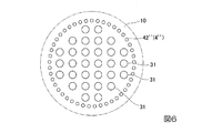
本実施形態において、圧力波Wは、超音波である。圧力波振動子31としては、例えば超音波振動子が好適に用いられる。各圧力波源30における複数の圧力波振動子31は、図2に示されるように、格子状に配列されるとともに、外形が円環状をなすように、基板10上で間隔をあけて配列されている。
The pressure
The pressure
As shown in FIG. 1, in the present embodiment, the pressure
Each
In this embodiment, the pressure wave W is an ultrasonic wave. As the
複数の圧力波源30からは、互いの振動が同期した状態で、溶断部C、又は被切断部Cに向かってそれぞれ圧力波Wが照射される。
本実施形態では、溶断部C、又は被切断部Cにおいて、互いの圧力波Wが集束され、指向性が高められるように、複数の圧力波源30が配置されている。
集束された圧力波Wは、溶断部C、又は被切断部Cで生じたドロスDを吹き飛ばすエネルギーを有している。
From the plurality of
In the present embodiment, a plurality of
The focused pressure wave W has energy to blow off the dross D generated in the fusing portion C or the cut portion C.
噴流噴射部4は、各圧力波Wの周囲を気体の噴流Fによって覆うことで、当該圧力波Wを外気から保護する。噴流噴射部4は、気体を貯留するタンク41と、基板10上に形成された複数のノズル部42と、タンク41及び各ノズル部42を接続する供給管43と、を有する。
供給管43の一端は、タンク41に接続されている。供給管43の他端は、複数に分岐されており、各ノズル部42にそれぞれ接続されている。これにより、タンク41に貯留された気体は、供給管43を介して、各ノズル部42に供給される。
The
One end of the
図3に示されるように、噴流噴射部4は、各圧力波Wの外周側に沿って溶断部C、又は被切断部Cに向かう噴流Fを噴射する。
噴流Fの気体としては、空気の他、窒素、アルゴン等の不活性ガスが用いられる。
本実施形態において、各ノズル部42は、基板10に形成されている。各ノズル部42は、供給管43側から溶断部C、又は被切断部C側に向かって基板10を貫通する開口を有する開口部である。各ノズル部42は、各圧力波源30にそれぞれ設けられる。各ノズル部42は、各圧力波源30を外周側から囲むように、それぞれ円形のスリット状に開口している。タンク41から圧送された気体は、各ノズル部42を通過する際に噴流Fとなって溶断部C、又は被切断部Cに向かう。この時、各噴流Fは各圧力波源30から照射される圧力波Wをそれぞれ外周側から囲むようにして流れる。
As shown in FIG. 3, the
As the gas of the jet F, in addition to air, an inert gas such as nitrogen or argon is used.
In this embodiment, each
このような構成によって、レーザー切断装置1は、対象物Sにレーザー光Lを照射して生じる溶断部C、又は被切断部Cに圧力波Wを照射すると共に、圧力波Wの外周側に沿って溶断部C又は被切断部Cに向かう噴流Fを噴射する工程を含むレーザー切断方法を実施する。 With such a configuration, the laser cutting device 1 irradiates the fusing portion C or the cut portion C generated by irradiating the object S with the laser beam L with the pressure wave W, and along the outer peripheral side of the pressure wave W. A laser cutting method including a step of injecting a jet F toward the fusing portion C or the cut portion C is carried out.
対象物Sにレーザー光Lを照射することで、当該対象物Sには溶断部C、又は被切断部Cが生じる。この時、溶断部C、又は被切断部Cには、対象物Sが溶融したドロスも生じる。各圧力波源30から圧力波Wが照射されると、このドロスが圧力波Wによって除去される。ここで、圧力波Wが直接的に外気に曝されている場合、圧力波Wと外気との間でせん断力が生じてしまう。せん断力が生じると、最外周部の圧力波Wが減衰してしまう。そこで、本実施形態では、各圧力波Wの外周側に沿ってそれぞれ噴流Fが噴射される。この噴流Fによって圧力波Wと外気との間で生じるせん断力が低減される。
By irradiating the object S with the laser beam L, a fusing portion C or a cut portion C is generated in the object S. At this time, a dross in which the object S is melted also occurs in the fusing portion C or the cut portion C. When the pressure wave W is irradiated from each
以上、説明したように、上述の構成によれば、噴流噴射部4から噴射された噴流Fによって、圧力波Wと外気との間で生じるせん断力を低減することができる。したがって、圧力波Wが減衰する可能性を低減することができる。
As described above, according to the above configuration, the jet flow F injected from the jet
特に、溶断部C、又は被切断部Cが比較的に遠距離に配置されている場合であっても、強度を維持したまま、圧力波Wを到達させることができる。これにより、正確な切断又は溶断を行うことができる。
図4には、噴流Fを噴射した場合の圧力波Wの減衰特性曲線PAと、噴流Fを噴射しなかった場合の圧力波Wの減衰特性曲線PBとが示される。図4に示されるように、噴流Fを噴射しなかった場合に比べて、本実施形態のように噴流Fを噴射した場合の方が、伝搬距離に対する圧力波Wの減衰を抑制することができる。
このように、本実施形態のレーザー切断装置1は、比較的遠距離まで圧力波Wの圧力レベル(圧力強度)を維持させることができる。
In particular, even when the fusing portion C or the cut portion C is arranged at a relatively long distance, the pressure wave W can be reached while maintaining the strength. As a result, accurate cutting or fusing can be performed.
FIG. 4 shows a damping characteristic curve PA of the pressure wave W when the jet F is injected and a damping characteristic curve PB of the pressure wave W when the jet F is not injected. As shown in FIG. 4, the attenuation of the pressure wave W with respect to the propagation distance can be suppressed when the jet F is injected as in the present embodiment as compared with the case where the jet F is not injected. ..
As described above, the laser cutting device 1 of the present embodiment can maintain the pressure level (pressure intensity) of the pressure wave W over a relatively long distance.
さらに、上述の構成によれば、噴流Fが各圧力波Wの周囲を囲むようにして噴射されることから、圧力波Wと外気との間で生じるせん断力の発生を、圧力波Wの周囲全体にわたって低減することができる。 Further, according to the above configuration, since the jet F is injected so as to surround the circumference of each pressure wave W, the generation of the shearing force generated between the pressure wave W and the outside air is generated over the entire circumference of the pressure wave W. It can be reduced.
また、上述の構成によれば、ノズル部42が円形をなしていることから、各圧力波Wを周囲から囲むとともに、周方向の全域にわたって均一な噴流Fを発生させることができる。これにより、圧力波Wと外気との間で生じるせん断力の発生を、圧力波Wの周囲全体にわたって低減することができる。
Further, according to the above configuration, since the
加えて、上述の構成によれば、噴流Fを形成する気体として不活性ガスが用いられる。したがって、溶断部C、又は被切断部Cに残留した熱が噴流Fに伝播した場合でも、噴流F中で不用意な化学反応が生じる可能性を低減することができる。これにより、さらに安全に装置を運用することができる。 In addition, according to the above configuration, an inert gas is used as the gas forming the jet F. Therefore, even when the heat remaining in the fusing portion C or the cut portion C propagates to the jet F, the possibility of an inadvertent chemical reaction occurring in the jet F can be reduced. As a result, the device can be operated more safely.
以上、本発明の実施形態について図面を参照して説明した。なお、本発明の要旨を逸脱しない限りにおいて、上記の構成に種々の変更や改修を施すことが可能である。 The embodiments of the present invention have been described above with reference to the drawings. It should be noted that various changes and modifications can be made to the above configuration as long as the gist of the present invention is not deviated.
例えば、上記実施形態では、圧力波振動子31が格子状かつ円環状に配列されている例について説明した。しかしながら、圧力波振動子31の配置は上記実施形態によっては限定されず、全体として矩形状をなしていたり、多角形状をなしていたりしてもよい。
For example, in the above embodiment, an example in which the
また、圧力波振動子31は超音波振動子に限定されず、可聴領域の音波を発生させる素子を圧力波振動子として用いることも可能である。この場合、圧力波Wとして可聴領域の音波が用いられる。
Further, the
また、上記実施形態では、噴流Fが圧力波Wの周囲を囲んでいるが、噴流Fは圧力波Wの周囲を完全に囲んでもよいし、部分的に囲んでもよい。変形例として、せん断力の発生を低減できるなら、噴流Fは、圧力波Wの周囲の一部に設けられてもよい。 Further, in the above embodiment, the jet F F surrounds the pressure wave W, but the jet F may completely surround the pressure wave W or may partially surround the pressure wave W. As a modification, the jet F may be provided in a part around the pressure wave W as long as the generation of shearing force can be reduced.
また、上記実施形態では、ノズル部42は、各圧力波源30を外周側から囲むように、円形のスリット状の開口を有している。変形例として、図5に示される噴流噴射部4’のノズル部42’のように、ノズル部は、各圧力波源30を外周側から囲むように、各圧力波源30の周囲に沿って並べられた複数の円弧のスリット状の開口を有していてもよい。他の変形例として、図6に示される噴流噴射部4’’のノズル部42’’のように、ノズル部は、各圧力波源30を外周側から囲むように、各圧力波源30の周囲に沿って並べられた複数の穴を有していてもよい。この場合、穴の形状は、円形であってもよく、多角形であってもよい。
Further, in the above embodiment, the
また、上記実施形態では、ノズル部42は、基板10に形成されている。変形例として、ノズル部は、基板10とは別に、基板10と溶断部C、又は被切断部Cとの間に設けられてもよい。
Further, in the above embodiment, the
1 レーザー切断装置
2 レーザー光照射装置
3 圧力波照射部
4 噴流噴射部
4’ 噴流噴射部
4’’ 噴流噴射部
10 基板
21 レーザー発振装置
22 加工ヘッド
30 圧力波源
31 圧力波振動子
41 タンク
42 ノズル部
42’ ノズル部
42’’ ノズル部
43 供給管
C 溶断部、又は被切断部
F 噴流
S 対象物
L レーザー光
W 圧力波
1
Claims (5)
前記レーザー光を照射して生じる前記対象物の溶断部又は被切断部に向かってそれぞれ圧力波を照射する複数の圧力波源を備える圧力波照射部と、
前記各圧力波の外周側に沿って前記溶断部又は前記被切断部に向かう噴流をそれぞれ噴射する噴流噴射部と、
を備え、
前記各圧力波が、超音波又は可聴領域の音波であるレーザー切断装置。 A laser light irradiation device that irradiates an object with laser light,
A pressure wave irradiation unit having a plurality of pressure wave sources that irradiate pressure waves toward the fusing portion or the cut portion of the object generated by irradiating the laser beam , respectively.
A jet injection portion that injects a jet flow toward the fusing portion or the cut portion along the outer peripheral side of each pressure wave, and a jet injection portion.
Equipped with a,
Wherein each pressure wave, a laser cutting device Ru wave der ultrasound or audible range.
を含み、
前記各圧力波が、超音波又は可聴領域の音波であるレーザー切断方法。 A plurality of pressure waves are irradiated to the fusing portion or the cut portion of the object generated by irradiating the object with a laser beam to remove dross, and the fusing portion or the said portion is along the outer peripheral side of each pressure wave. The process of injecting jets toward the part to be cut,
Only including,
A laser cutting method in which each pressure wave is an ultrasonic wave or a sound wave in an audible region .
Priority Applications (3)
| Application Number | Priority Date | Filing Date | Title |
|---|---|---|---|
| JP2017182319A JP6811697B2 (en) | 2017-09-22 | 2017-09-22 | Laser cutting device and laser cutting method |
| US16/135,146 US10882138B2 (en) | 2017-09-22 | 2018-09-19 | Laser cutting apparatus and laser cutting method |
| FR1858513A FR3071426A1 (en) | 2017-09-22 | 2018-09-20 | LASER CUTTING APPARATUS AND LASER CUTTING METHOD |
Applications Claiming Priority (1)
| Application Number | Priority Date | Filing Date | Title |
|---|---|---|---|
| JP2017182319A JP6811697B2 (en) | 2017-09-22 | 2017-09-22 | Laser cutting device and laser cutting method |
Publications (2)
| Publication Number | Publication Date |
|---|---|
| JP2019055422A JP2019055422A (en) | 2019-04-11 |
| JP6811697B2 true JP6811697B2 (en) | 2021-01-13 |
Family
ID=65807137
Family Applications (1)
| Application Number | Title | Priority Date | Filing Date |
|---|---|---|---|
| JP2017182319A Active JP6811697B2 (en) | 2017-09-22 | 2017-09-22 | Laser cutting device and laser cutting method |
Country Status (3)
| Country | Link |
|---|---|
| US (1) | US10882138B2 (en) |
| JP (1) | JP6811697B2 (en) |
| FR (1) | FR3071426A1 (en) |
Family Cites Families (15)
| Publication number | Priority date | Publication date | Assignee | Title |
|---|---|---|---|---|
| DE107226C (en) | ||||
| DD107226A1 (en) * | 1973-10-10 | 1974-07-20 | ||
| JPH0630828B2 (en) * | 1986-09-19 | 1994-04-27 | 株式会社日立製作所 | Laser processing method and apparatus |
| JP2005014075A (en) * | 2003-06-27 | 2005-01-20 | Shin Nippon Koki Co Ltd | Laser beam machining method and laser beam machining device |
| DE102005049010B4 (en) | 2005-10-11 | 2009-06-10 | Fachhochschule Oldenburg/Ostfriesland/Wilhelmshaven | Method for cutting workpieces with a laser beam |
| JP4930594B2 (en) * | 2007-08-03 | 2012-05-16 | 三菱電機株式会社 | Laser processing nozzle |
| JP5039757B2 (en) * | 2009-08-21 | 2012-10-03 | 株式会社アマダ | Laser processing head in laser processing equipment |
| US9168612B2 (en) * | 2011-01-28 | 2015-10-27 | Gas Technology Institute | Laser material processing tool |
| JP5889555B2 (en) | 2011-07-05 | 2016-03-22 | 小池酸素工業株式会社 | Laser cutting method and laser cutting apparatus |
| KR101904797B1 (en) | 2011-09-15 | 2018-10-05 | 니폰 덴키 가라스 가부시키가이샤 | Glass plate cutting method and glass plate cutting device |
| JP5907019B2 (en) * | 2011-09-15 | 2016-04-20 | 日本電気硝子株式会社 | Thin glass cutting method and thin glass |
| JP6201751B2 (en) * | 2013-12-27 | 2017-09-27 | 住友ベークライト株式会社 | Covering tape for packaging |
| JP6312476B2 (en) * | 2014-03-19 | 2018-04-18 | 三菱重工業株式会社 | Laser cutting device |
| JP6348877B2 (en) | 2015-05-25 | 2018-06-27 | 日立Geニュークリア・エナジー株式会社 | Thermal cutting apparatus and method |
| JP2017104891A (en) * | 2015-12-10 | 2017-06-15 | 三菱重工業株式会社 | Laser cutting device |
-
2017
- 2017-09-22 JP JP2017182319A patent/JP6811697B2/en active Active
-
2018
- 2018-09-19 US US16/135,146 patent/US10882138B2/en active Active
- 2018-09-20 FR FR1858513A patent/FR3071426A1/en active Pending
Also Published As
| Publication number | Publication date |
|---|---|
| FR3071426A1 (en) | 2019-03-29 |
| JP2019055422A (en) | 2019-04-11 |
| US10882138B2 (en) | 2021-01-05 |
| US20190091801A1 (en) | 2019-03-28 |
Similar Documents
| Publication | Publication Date | Title |
|---|---|---|
| KR102239315B1 (en) | Laser Welding Apparatus And Method for Welding Using the Same | |
| WO2013002165A1 (en) | Device and method for cutting brittle member, and cut brittle member | |
| JP5639046B2 (en) | Laser processing apparatus and laser processing method | |
| WO2009053031A9 (en) | Method for boring bottle-like holes having a defined geometry by means of pulsed laser radiation | |
| JP6704029B2 (en) | Processing nozzle and processing equipment | |
| JP6749308B2 (en) | LASER LAMINATION MODELING APPARATUS AND LASER LAMINATION METHOD | |
| JP6811697B2 (en) | Laser cutting device and laser cutting method | |
| JP5873978B2 (en) | Laser processing method and nozzle manufacturing method | |
| JP2015231629A (en) | Laser weld device and laser weld method | |
| JP7291510B2 (en) | Laser processing method | |
| JP4123390B2 (en) | Hybrid machining apparatus and hybrid machining method | |
| JP2012066265A (en) | Laser processing method | |
| JP6312476B2 (en) | Laser cutting device | |
| JP6805710B2 (en) | Laser welding equipment and laser welding method | |
| JP5970360B2 (en) | Laser processing apparatus, laser processing system, and laser processing method | |
| JP2003285186A (en) | Laser beam machining device | |
| JP2008207234A (en) | Underwater repair welding method | |
| JP6378885B2 (en) | Laser processing apparatus and laser processing method | |
| JP2015134364A (en) | Laser processing apparatus and laser processing method | |
| JP6841390B1 (en) | Laser machining equipment and laser machining method | |
| JP6212051B2 (en) | High power fiber laser outflow hole drilling apparatus and method of using high power fiber laser outflow hole drilling apparatus | |
| JP6985642B2 (en) | Laser welding equipment and laser welding method | |
| WO2016031546A1 (en) | Laser processing head and laser processing machine | |
| JP6249276B2 (en) | Method for forming fuel nozzle hole of fuel nozzle member | |
| JP2009039749A (en) | Laser beam machining apparatus and laser beam machining method |
Legal Events
| Date | Code | Title | Description |
|---|---|---|---|
| A621 | Written request for application examination |
Free format text: JAPANESE INTERMEDIATE CODE: A621 Effective date: 20190212 |
|
| A977 | Report on retrieval |
Free format text: JAPANESE INTERMEDIATE CODE: A971007 Effective date: 20200116 |
|
| A131 | Notification of reasons for refusal |
Free format text: JAPANESE INTERMEDIATE CODE: A131 Effective date: 20200128 |
|
| A131 | Notification of reasons for refusal |
Free format text: JAPANESE INTERMEDIATE CODE: A131 Effective date: 20200623 |
|
| A521 | Written amendment |
Free format text: JAPANESE INTERMEDIATE CODE: A523 Effective date: 20200806 |
|
| A131 | Notification of reasons for refusal |
Free format text: JAPANESE INTERMEDIATE CODE: A131 Effective date: 20200908 |
|
| A521 | Written amendment |
Free format text: JAPANESE INTERMEDIATE CODE: A523 Effective date: 20201105 |
|
| TRDD | Decision of grant or rejection written | ||
| A01 | Written decision to grant a patent or to grant a registration (utility model) |
Free format text: JAPANESE INTERMEDIATE CODE: A01 Effective date: 20201201 |
|
| A61 | First payment of annual fees (during grant procedure) |
Free format text: JAPANESE INTERMEDIATE CODE: A61 Effective date: 20201215 |
|
| R150 | Certificate of patent or registration of utility model |
Ref document number: 6811697 Country of ref document: JP Free format text: JAPANESE INTERMEDIATE CODE: R150 |