JP6811498B2 - Implants and methods for long bone fixation - Google Patents
Implants and methods for long bone fixation Download PDFInfo
- Publication number
- JP6811498B2 JP6811498B2 JP2019513063A JP2019513063A JP6811498B2 JP 6811498 B2 JP6811498 B2 JP 6811498B2 JP 2019513063 A JP2019513063 A JP 2019513063A JP 2019513063 A JP2019513063 A JP 2019513063A JP 6811498 B2 JP6811498 B2 JP 6811498B2
- Authority
- JP
- Japan
- Prior art keywords
- elongated member
- bone
- implant according
- implant
- distal end
- Prior art date
- Legal status (The legal status is an assumption and is not a legal conclusion. Google has not performed a legal analysis and makes no representation as to the accuracy of the status listed.)
- Active
Links
- 210000000988 bone and bone Anatomy 0.000 title claims description 285
- 239000007943 implant Substances 0.000 title claims description 283
- 238000000034 method Methods 0.000 title description 63
- 230000007246 mechanism Effects 0.000 claims description 118
- 238000003780 insertion Methods 0.000 claims description 44
- 230000037431 insertion Effects 0.000 claims description 44
- 208000010392 Bone Fractures Diseases 0.000 claims description 26
- 230000010339 dilation Effects 0.000 claims description 26
- 229910001000 nickel titanium Inorganic materials 0.000 claims description 14
- 238000002627 tracheal intubation Methods 0.000 claims description 13
- 239000000463 material Substances 0.000 claims description 12
- HLXZNVUGXRDIFK-UHFFFAOYSA-N nickel titanium Chemical compound [Ti].[Ti].[Ti].[Ti].[Ti].[Ti].[Ti].[Ti].[Ti].[Ti].[Ti].[Ni].[Ni].[Ni].[Ni].[Ni].[Ni].[Ni].[Ni].[Ni].[Ni].[Ni].[Ni].[Ni].[Ni] HLXZNVUGXRDIFK-UHFFFAOYSA-N 0.000 claims description 6
- 239000012781 shape memory material Substances 0.000 claims description 5
- 210000002105 tongue Anatomy 0.000 description 28
- 229910052751 metal Inorganic materials 0.000 description 27
- 239000002184 metal Substances 0.000 description 27
- 239000000919 ceramic Substances 0.000 description 20
- 229920000642 polymer Polymers 0.000 description 20
- 206010017076 Fracture Diseases 0.000 description 19
- 239000007787 solid Substances 0.000 description 13
- 238000004873 anchoring Methods 0.000 description 11
- 238000005304 joining Methods 0.000 description 11
- 239000003550 marker Substances 0.000 description 11
- 210000000236 metacarpal bone Anatomy 0.000 description 11
- 229920003295 Radel® Polymers 0.000 description 10
- 238000005520 cutting process Methods 0.000 description 9
- 238000013016 damping Methods 0.000 description 9
- HZEWFHLRYVTOIW-UHFFFAOYSA-N [Ti].[Ni] Chemical compound [Ti].[Ni] HZEWFHLRYVTOIW-UHFFFAOYSA-N 0.000 description 8
- 210000003109 clavicle Anatomy 0.000 description 8
- 230000001054 cortical effect Effects 0.000 description 8
- 210000002082 fibula Anatomy 0.000 description 8
- 239000010935 stainless steel Substances 0.000 description 7
- 229910001220 stainless steel Inorganic materials 0.000 description 7
- 238000000926 separation method Methods 0.000 description 5
- 230000007704 transition Effects 0.000 description 4
- 238000003466 welding Methods 0.000 description 4
- RTAQQCXQSZGOHL-UHFFFAOYSA-N Titanium Chemical compound [Ti] RTAQQCXQSZGOHL-UHFFFAOYSA-N 0.000 description 3
- 239000012634 fragment Substances 0.000 description 3
- 230000009467 reduction Effects 0.000 description 3
- 239000003826 tablet Substances 0.000 description 3
- 239000010936 titanium Substances 0.000 description 3
- 229910052719 titanium Inorganic materials 0.000 description 3
- 206010019114 Hand fracture Diseases 0.000 description 2
- 229910001069 Ti alloy Inorganic materials 0.000 description 2
- 239000000853 adhesive Substances 0.000 description 2
- 230000001070 adhesive effect Effects 0.000 description 2
- 210000003484 anatomy Anatomy 0.000 description 2
- 238000013459 approach Methods 0.000 description 2
- 230000036760 body temperature Effects 0.000 description 2
- 210000001185 bone marrow Anatomy 0.000 description 2
- 239000003795 chemical substances by application Substances 0.000 description 2
- 238000005553 drilling Methods 0.000 description 2
- 230000035876 healing Effects 0.000 description 2
- 238000002513 implantation Methods 0.000 description 2
- 230000006698 induction Effects 0.000 description 2
- 230000008569 process Effects 0.000 description 2
- 230000005855 radiation Effects 0.000 description 2
- 238000001356 surgical procedure Methods 0.000 description 2
- 210000002435 tendon Anatomy 0.000 description 2
- 230000001225 therapeutic effect Effects 0.000 description 2
- 208000032544 Cicatrix Diseases 0.000 description 1
- 208000006735 Periostitis Diseases 0.000 description 1
- 230000003213 activating effect Effects 0.000 description 1
- 238000004026 adhesive bonding Methods 0.000 description 1
- 238000005452 bending Methods 0.000 description 1
- 239000000560 biocompatible material Substances 0.000 description 1
- 230000006835 compression Effects 0.000 description 1
- 238000007906 compression Methods 0.000 description 1
- 230000007423 decrease Effects 0.000 description 1
- 230000003247 decreasing effect Effects 0.000 description 1
- 210000003275 diaphysis Anatomy 0.000 description 1
- 230000000694 effects Effects 0.000 description 1
- 210000002745 epiphysis Anatomy 0.000 description 1
- 238000001125 extrusion Methods 0.000 description 1
- 230000006870 function Effects 0.000 description 1
- 230000002452 interceptive effect Effects 0.000 description 1
- 210000001872 metatarsal bone Anatomy 0.000 description 1
- 230000000399 orthopedic effect Effects 0.000 description 1
- 230000037361 pathway Effects 0.000 description 1
- 210000003460 periosteum Anatomy 0.000 description 1
- 230000008439 repair process Effects 0.000 description 1
- 231100000241 scar Toxicity 0.000 description 1
- 230000037387 scars Effects 0.000 description 1
- 238000010008 shearing Methods 0.000 description 1
- 238000004904 shortening Methods 0.000 description 1
- 210000004872 soft tissue Anatomy 0.000 description 1
- 210000000278 spinal cord Anatomy 0.000 description 1
- 210000001519 tissue Anatomy 0.000 description 1
- 210000000623 ulna Anatomy 0.000 description 1
- 230000002747 voluntary effect Effects 0.000 description 1
Images


Classifications
-
- A—HUMAN NECESSITIES
- A61—MEDICAL OR VETERINARY SCIENCE; HYGIENE
- A61B—DIAGNOSIS; SURGERY; IDENTIFICATION
- A61B17/00—Surgical instruments, devices or methods, e.g. tourniquets
- A61B17/56—Surgical instruments or methods for treatment of bones or joints; Devices specially adapted therefor
- A61B17/58—Surgical instruments or methods for treatment of bones or joints; Devices specially adapted therefor for osteosynthesis, e.g. bone plates, screws, setting implements or the like
- A61B17/68—Internal fixation devices, including fasteners and spinal fixators, even if a part thereof projects from the skin
- A61B17/72—Intramedullary pins, nails or other devices
- A61B17/7233—Intramedullary pins, nails or other devices with special means of locking the nail to the bone
- A61B17/7258—Intramedullary pins, nails or other devices with special means of locking the nail to the bone with laterally expanding parts, e.g. for gripping the bone
- A61B17/7266—Intramedullary pins, nails or other devices with special means of locking the nail to the bone with laterally expanding parts, e.g. for gripping the bone with fingers moving radially outwardly
-
- A—HUMAN NECESSITIES
- A61—MEDICAL OR VETERINARY SCIENCE; HYGIENE
- A61B—DIAGNOSIS; SURGERY; IDENTIFICATION
- A61B17/00—Surgical instruments, devices or methods, e.g. tourniquets
- A61B17/56—Surgical instruments or methods for treatment of bones or joints; Devices specially adapted therefor
- A61B17/58—Surgical instruments or methods for treatment of bones or joints; Devices specially adapted therefor for osteosynthesis, e.g. bone plates, screws, setting implements or the like
- A61B17/68—Internal fixation devices, including fasteners and spinal fixators, even if a part thereof projects from the skin
- A61B17/72—Intramedullary pins, nails or other devices
- A61B17/7233—Intramedullary pins, nails or other devices with special means of locking the nail to the bone
-
- A—HUMAN NECESSITIES
- A61—MEDICAL OR VETERINARY SCIENCE; HYGIENE
- A61B—DIAGNOSIS; SURGERY; IDENTIFICATION
- A61B17/00—Surgical instruments, devices or methods, e.g. tourniquets
- A61B17/56—Surgical instruments or methods for treatment of bones or joints; Devices specially adapted therefor
- A61B17/58—Surgical instruments or methods for treatment of bones or joints; Devices specially adapted therefor for osteosynthesis, e.g. bone plates, screws, setting implements or the like
- A61B17/68—Internal fixation devices, including fasteners and spinal fixators, even if a part thereof projects from the skin
- A61B17/72—Intramedullary pins, nails or other devices
- A61B17/7291—Intramedullary pins, nails or other devices for small bones, e.g. in the foot, ankle, hand or wrist
-
- A—HUMAN NECESSITIES
- A61—MEDICAL OR VETERINARY SCIENCE; HYGIENE
- A61B—DIAGNOSIS; SURGERY; IDENTIFICATION
- A61B17/00—Surgical instruments, devices or methods, e.g. tourniquets
- A61B17/56—Surgical instruments or methods for treatment of bones or joints; Devices specially adapted therefor
- A61B17/58—Surgical instruments or methods for treatment of bones or joints; Devices specially adapted therefor for osteosynthesis, e.g. bone plates, screws, setting implements or the like
- A61B17/68—Internal fixation devices, including fasteners and spinal fixators, even if a part thereof projects from the skin
- A61B17/80—Cortical plates, i.e. bone plates; Instruments for holding or positioning cortical plates, or for compressing bones attached to cortical plates
-
- A—HUMAN NECESSITIES
- A61—MEDICAL OR VETERINARY SCIENCE; HYGIENE
- A61B—DIAGNOSIS; SURGERY; IDENTIFICATION
- A61B17/00—Surgical instruments, devices or methods, e.g. tourniquets
- A61B17/56—Surgical instruments or methods for treatment of bones or joints; Devices specially adapted therefor
- A61B17/58—Surgical instruments or methods for treatment of bones or joints; Devices specially adapted therefor for osteosynthesis, e.g. bone plates, screws, setting implements or the like
- A61B17/88—Osteosynthesis instruments; Methods or means for implanting or extracting internal or external fixation devices
- A61B17/8863—Apparatus for shaping or cutting osteosynthesis equipment by medical personnel
-
- A—HUMAN NECESSITIES
- A61—MEDICAL OR VETERINARY SCIENCE; HYGIENE
- A61B—DIAGNOSIS; SURGERY; IDENTIFICATION
- A61B17/00—Surgical instruments, devices or methods, e.g. tourniquets
- A61B17/56—Surgical instruments or methods for treatment of bones or joints; Devices specially adapted therefor
- A61B17/58—Surgical instruments or methods for treatment of bones or joints; Devices specially adapted therefor for osteosynthesis, e.g. bone plates, screws, setting implements or the like
- A61B17/88—Osteosynthesis instruments; Methods or means for implanting or extracting internal or external fixation devices
- A61B17/8872—Instruments for putting said fixation devices against or away from the bone
-
- A—HUMAN NECESSITIES
- A61—MEDICAL OR VETERINARY SCIENCE; HYGIENE
- A61B—DIAGNOSIS; SURGERY; IDENTIFICATION
- A61B17/00—Surgical instruments, devices or methods, e.g. tourniquets
- A61B17/56—Surgical instruments or methods for treatment of bones or joints; Devices specially adapted therefor
- A61B17/58—Surgical instruments or methods for treatment of bones or joints; Devices specially adapted therefor for osteosynthesis, e.g. bone plates, screws, setting implements or the like
- A61B17/88—Osteosynthesis instruments; Methods or means for implanting or extracting internal or external fixation devices
- A61B17/8875—Screwdrivers, spanners or wrenches
-
- A—HUMAN NECESSITIES
- A61—MEDICAL OR VETERINARY SCIENCE; HYGIENE
- A61B—DIAGNOSIS; SURGERY; IDENTIFICATION
- A61B17/00—Surgical instruments, devices or methods, e.g. tourniquets
- A61B17/56—Surgical instruments or methods for treatment of bones or joints; Devices specially adapted therefor
- A61B17/58—Surgical instruments or methods for treatment of bones or joints; Devices specially adapted therefor for osteosynthesis, e.g. bone plates, screws, setting implements or the like
- A61B17/88—Osteosynthesis instruments; Methods or means for implanting or extracting internal or external fixation devices
- A61B17/92—Impactors or extractors, e.g. for removing intramedullary devices
- A61B17/921—Impactors or extractors, e.g. for removing intramedullary devices for intramedullary devices
-
- A—HUMAN NECESSITIES
- A61—MEDICAL OR VETERINARY SCIENCE; HYGIENE
- A61B—DIAGNOSIS; SURGERY; IDENTIFICATION
- A61B17/00—Surgical instruments, devices or methods, e.g. tourniquets
- A61B17/16—Bone cutting, breaking or removal means other than saws, e.g. Osteoclasts; Drills or chisels for bones; Trepans
- A61B17/1604—Chisels; Rongeurs; Punches; Stamps
-
- A—HUMAN NECESSITIES
- A61—MEDICAL OR VETERINARY SCIENCE; HYGIENE
- A61B—DIAGNOSIS; SURGERY; IDENTIFICATION
- A61B17/00—Surgical instruments, devices or methods, e.g. tourniquets
- A61B17/16—Bone cutting, breaking or removal means other than saws, e.g. Osteoclasts; Drills or chisels for bones; Trepans
- A61B17/17—Guides or aligning means for drills, mills, pins or wires
- A61B17/1717—Guides or aligning means for drills, mills, pins or wires for applying intramedullary nails or pins
-
- A—HUMAN NECESSITIES
- A61—MEDICAL OR VETERINARY SCIENCE; HYGIENE
- A61B—DIAGNOSIS; SURGERY; IDENTIFICATION
- A61B17/00—Surgical instruments, devices or methods, e.g. tourniquets
- A61B17/56—Surgical instruments or methods for treatment of bones or joints; Devices specially adapted therefor
- A61B17/58—Surgical instruments or methods for treatment of bones or joints; Devices specially adapted therefor for osteosynthesis, e.g. bone plates, screws, setting implements or the like
- A61B17/68—Internal fixation devices, including fasteners and spinal fixators, even if a part thereof projects from the skin
- A61B17/72—Intramedullary pins, nails or other devices
- A61B17/7216—Intramedullary pins, nails or other devices for bone lengthening or compression
- A61B17/7225—Intramedullary pins, nails or other devices for bone lengthening or compression for bone compression
-
- A—HUMAN NECESSITIES
- A61—MEDICAL OR VETERINARY SCIENCE; HYGIENE
- A61B—DIAGNOSIS; SURGERY; IDENTIFICATION
- A61B17/00—Surgical instruments, devices or methods, e.g. tourniquets
- A61B17/56—Surgical instruments or methods for treatment of bones or joints; Devices specially adapted therefor
- A61B17/58—Surgical instruments or methods for treatment of bones or joints; Devices specially adapted therefor for osteosynthesis, e.g. bone plates, screws, setting implements or the like
- A61B17/68—Internal fixation devices, including fasteners and spinal fixators, even if a part thereof projects from the skin
- A61B17/72—Intramedullary pins, nails or other devices
- A61B17/7233—Intramedullary pins, nails or other devices with special means of locking the nail to the bone
- A61B17/7258—Intramedullary pins, nails or other devices with special means of locking the nail to the bone with laterally expanding parts, e.g. for gripping the bone
- A61B17/7275—Intramedullary pins, nails or other devices with special means of locking the nail to the bone with laterally expanding parts, e.g. for gripping the bone with expanding cylindrical parts
Description
(関連出願の引用)
本願は、米国仮特許出願第62/385,044号(2016年9月8日出願、代理人事件番号44057−714.101)および米国仮特許出願第62/450,700号(2017年1月26日出願、代理人事件番号44057−714.102)の非仮出願であり、それらの利益を主張し、上記出願の全内容は、それらの全体において参照により本明細書に引用される。
(Citation of related application)
This application applies to US Provisional Patent Application No. 62 / 385,044 (filed September 8, 2016, Agent Case No. 44057-714.101) and US Provisional Patent Application No. 62 / 450,700 (January 2017). It is a non-provisional application of Agent Case No. 44057-714.102) filed on the 26th, claiming their interests, and the entire contents of the above applications are incorporated herein by reference in their entirety.
長骨の骨折は、現在、プレートを含む種々の内部固定デバイスを用いて治療され、プレートは、髄管の内側に伸びるねじ、釘、またはワイヤ、および/または、骨折した骨の両端を一緒に付着させるねじを用いて、骨の表面に固定される。一般に、上でリストアップされる方法またはその他を使用する骨折固定は、縦方向(骨の長軸に沿った)安定性、横方向(骨の長軸を横切る)安定性、および回転(骨の長軸を中心とした)安定性を提供し得る。骨折固定は、治癒中および治癒後の正常な機能も保ち得る。 Long bone fractures are currently treated with a variety of internal fixation devices, including plates, which plate together with screws, nails, or wires that extend inward of the medullary canal, and / or both ends of the fractured bone. It is fixed to the surface of the bone using the screws to be attached. In general, fracture fixation using the methods listed above or others is longitudinal (along the long axis of the bone) stability, lateral (crossing the long axis of the bone), and rotational (of the bone). It can provide stability (centered on the long axis). Fracture fixation can also maintain normal function during and after healing.
プレートは、長骨骨折を治療する1つの伝統的方法である。プレートは、骨の長さに沿って設置され、ねじは、骨の長さと実質的に垂直に、骨折の各側で骨の中に挿入される。そのような方法は、プレート設置のために必要とされる大きい軟組織切開に起因して、他の一般的な方法と比較すると比較的侵襲性である。プレートは、困難な骨折パターンを扱うことができるが、しかしながら、この方法を用いた適切なアラインメントおよび修復は、骨折タイプと医師の技能との組に強く依存する。プレートは、中手骨等のより小型の骨において追加の問題を有する。これらの骨の中のプレートは、プレートの隆起表面、腱の有病率、および緊密な生体構造に起因する腱癒着に関する問題を有する可能性がより高く、それは、手術後に手の可動域の問題を引き起こし得る。この方法は、他の方法よりも大きい瘢痕も生成する。 Plates are one traditional method of treating long bone fractures. The plate is placed along the length of the bone and the screws are inserted into the bone on each side of the fracture, substantially perpendicular to the length of the bone. Such methods are relatively invasive when compared to other common methods due to the large soft tissue incision required for plate placement. Plates can handle difficult fracture patterns, however, proper alignment and repair using this method strongly depends on the combination of fracture type and physician skill. Plates have additional problems with smaller bones such as the metacarpal bones. Plates in these bones are more likely to have problems with tendon adhesions due to the raised surface of the plate, the prevalence of tendons, and the tight biostructure, which is a problem with hand range of motion after surgery Can cause. This method also produces larger scars than other methods.
ねじは、骨折を治療するための別の方法である。この方法では、1つまたは複数のねじが、骨折を横断して骨に付着させられる。この方法はプレートほど侵襲性ではないが、それは、螺旋骨折および斜骨折に対してのみで行われることができ、技術的に困難な手技である。 Screws are another way to treat fractures. In this method, one or more screws are attached to the bone across the fracture. Although this method is not as invasive as the plate, it is a technically difficult procedure that can only be performed for spiral and oblique fractures.
髄内固定は、骨の骨膜を妨害することなく長骨骨折を治療するための別の伝統的方法であり、髄内釘またはワイヤを使用して骨折を付着させる。そのような方法は、閉鎖様式で遂行され得、骨折した骨は、治癒中、機能的に使用され得る(ある場合、体重を支えることを含む)。髄内釘またはワイヤの挿入のための外科的アプローチは、各骨に対してわずかに変動し、整形外科文献でよく説明されている。 Intramedullary fixation is another traditional method for treating long bone fractures without interfering with the periosteum of the bone, using intramedullary nails or wires to attach the fracture. Such methods can be performed in a closed fashion and the fractured bone can be used functionally during healing (including, in some cases, supporting weight). Surgical approaches for intramedullary nail or wire insertion vary slightly for each bone and are well described in the orthopedic literature.
従来の髄内固定方法に関連付けられる課題のうちのいくつかは、回転安定性の欠如、および/または、釘およびワイヤの望ましくない移動を含む。髄内固定方法は、より大型の骨のために釘を横断する相互係止ねじを導入し、いくつかの不利点を生成し得る。
具体的には、長骨のための従来の髄内固定釘は、釘の端部において係止され得る剛性構造を含み、ネジが、骨壁および釘自体を通して横方向に適用される。このステップは、手術の複雑性を大いに増加させ、余分な切開を要求し、追加のX線を要求する。
Some of the challenges associated with traditional intramedullary fixation methods include lack of rotational stability and / or undesired movement of nails and wires. Intramedullary fixation methods can introduce interlocking screws across the nail for larger bones and create some disadvantages.
Specifically, conventional intramedullary fixation nails for long bones include a rigid structure that can be locked at the end of the nail, where the screw is applied laterally through the bone wall and the nail itself. This step greatly increases the complexity of the surgery, requires an extra incision, and requires additional x-rays.
したがって、既存の治療の課題のうちのいくつかを克服する改良された骨折固定デバイスおよび方法を提供することが望ましいであろう。本明細書に説明される実施形態は、これらの課題のうちの少なくともいくつかに対処する。 Therefore, it would be desirable to provide improved fracture fixation devices and methods that overcome some of the existing therapeutic challenges. The embodiments described herein address at least some of these challenges.
本開示は、概して、医療デバイスおよび方法に関し、より具体的には、長骨の固定のためのインプラントおよび方法に関する。 The present disclosure relates generally to medical devices and methods, and more specifically to implants and methods for long bone fixation.
インプラントの一実施形態は、遠位端および近位端を伴う細長い部材を備えている。遠位端は、骨折を伴う長骨の髄腔の中に挿入されたときに形状を変化させる遠位先端を備え得る。遠位先端は、骨の一方の端部およびインプラントの近位端を骨の他方の端部に固定するための種々の係止機構のうちの1つの回転および平行移動を防止するように設計され得る。 One embodiment of the implant comprises an elongated member with distal and proximal ends. The distal end may comprise a distal tip that changes shape when inserted into the medullary space of a long bone with a fracture. The distal tip is designed to prevent rotation and translation of one of the various locking mechanisms for anchoring one end of the bone and the proximal end of the implant to the other end of the bone. obtain.
係止機構は、近位端に向かって長骨の長さに沿って表面に隣接して取り付けられたプレートを備え得る。係止機構は、プレートを骨に固定する1つ以上のピンをさらに備え得る。追加の係止機構は、プレートの使用を伴い、または伴わずに、インプラントの近位端を骨に係止し得る。これらの解決策は、カニューレを挿入される係止ねじ、または細長い部材の露出区分を骨の表面にステープル留めすることを含み得る。代替として、または組み合わせて、細長い部材は、拡張する近位端を使用して、骨の内側で固定され得る。この端部は、形状記憶ワイヤであり、挿入時に即時に拡張し得るか、外側シースの除去時に拡張され得るか、または外科医の助けを借りて拡張され得る。 The locking mechanism may include a plate mounted adjacent to the surface along the length of the long bone towards the proximal end. The locking mechanism may further include one or more pins that secure the plate to the bone. An additional locking mechanism can lock the proximal end of the implant to the bone with or without the use of a plate. These solutions may include locking screws into which the cannula is inserted, or staples of exposed sections of elongated members to the surface of the bone. Alternatively or in combination, the elongated member can be anchored inside the bone using the expanding proximal end. This end is a shape memory wire that can be expanded immediately upon insertion, on removal of the outer sheath, or with the help of a surgeon.
随意に、任意の実施形態では、細長い部材は、骨生体構造のためにサイズを決定され得るか、または長さに切断され得る。 Optionally, in any embodiment, the elongated member can be sized for bone biostructure or cut to length.
随意に、任意の実施形態では、固定インプラントの遠位先端は、2つ以上のアームが、長骨の中に遠位先端を定着させるための増大された外形を有する弓形形状に拡張し得るように、遠位端から近位に延びている1つ以上のスロットを有し得る。遠位端は、長骨の中に遠位先端を定着させるための増大された外形を有する弓形形状に拡張し得るその長さに沿った切り抜きを有し得る。 Optionally, in any embodiment, the distal tip of the fixed implant can be extended into a bow shape with two or more arms having an increased profile for anchoring the distal tip in the long bone. Can have one or more slots extending proximally from the distal end. The distal end may have a cut along its length that can be extended into an arcuate shape with an increased profile for anchoring the distal tip in the long bone.
随意に、任意の実施形態では、固定インプラントの遠位先端は、長骨の中に遠位先端を定着させるための増大された外形を有する弓形形状に拡張し得る。弓形形状は、限定ではないが、リング、波状形状、J字形状、または牧杖を含む、任意の形状であり得る。遠位先端は、改良された骨固定のための1つ以上の溝を有し得る。 Optionally, in any embodiment, the distal tip of the fixed implant can be extended into an arcuate shape with an increased profile for anchoring the distal tip in the long bone. The bow shape can be any shape, including, but not limited to, a ring, a wavy shape, a J-shape, or a cane. The distal tip may have one or more grooves for improved bone fixation.
随意に、任意の実施形態では、固定インプラントの遠位端は、長骨の中に遠位先端を定着させるための増大された外形を有する半径方向に拡張するコイルを備え得る。 Optionally, in any embodiment, the distal end of the fixed implant may include a radially expanding coil with an increased profile for anchoring the distal tip within the long bone.
随意に、任意の実施形態では、係止機構は、細長い部材を骨に圧縮するプレートを備え得る。 Optionally, in any embodiment, the locking mechanism may include a plate that compresses an elongated member into bone.
随意に、任意の実施形態では、係止機構は、1つの方向に自由に細長い部材を受け取り、反対方向に平行移動を阻止するように構成されている横断孔および内部タンを伴うプレートを備え得る。 Optionally, in any embodiment, the locking mechanism may comprise a plate with a transverse hole and an internal tongue that is configured to receive freely elongated members in one direction and prevent translation in the opposite direction. ..
随意に、任意の実施形態では、係止機構は、細長い部材を受け取り、横断孔がオフセットされるときに剪断力を用いて細長い部材を保持するように構成され得る横断孔を伴う2つの結合されたプレートを備え得る。 Optionally, in any embodiment, the locking mechanism is coupled with two cross-holes that can be configured to receive the strip and hold the strip using shear forces when the cross-hole is offset. Shear plate may be provided.
随意に、任意の実施形態では、係止機構は、骨ねじと、その間に細長い部材をクランプ締めするように骨ねじとねじ式で係合される位置決めねじとを備え得る。固定デバイスの埋め込みは、位置決めねじを骨ねじとねじ式で係合させ、それによって、その間に固定インプラントを係合させることによって、係止機構を用いてデバイスを係止することを含み得る。 Optionally, in any embodiment, the locking mechanism may include a bone screw and a positioning screw that is screwed into the bone screw so as to clamp an elongated member in between. Implantation of the fixation device may include locking the device using a locking mechanism by screwing the positioning screw to the bone screw, thereby engaging the fixation implant in between.
随意に、任意の実施形態では、係止機構は、インプラントの近位端を受け取り、保持し、骨に定着するように構成されているアンカを備え得る。 Optionally, in any embodiment, the locking mechanism may comprise an anchor configured to receive, hold and anchor to the bone at the proximal end of the implant.
随意に、任意の実施形態では、係止機構は、固定を提供するための近位端上の1つ以上の拡張端を備え得る。近位端構成は、遠位端拡張構成に関連するような本明細書に説明される任意の形態をとり得る。 Optionally, in any embodiment, the locking mechanism may include one or more extended ends on the proximal end to provide fixation. The proximal end configuration can take any form as described herein as related to the distal end dilated configuration.
随意に、任意の実施形態では、固定インプラントを埋め込む方法は、インプラントを拡張することを含み得る。インプラントは、体温まで加熱されたときに拡張することができる形状記憶ワイヤを使用して拡張され得るインプラントは、自然にその拡張状態にあり、拘束下で挿入され得るか、または、インプラントは、ピン、ねじ山付き機構等を使用して、外科医によって手動で拡張され得る。さらに、インプラントは、その拡張された形状を維持するように塑性的に変形させられ得る。 Optionally, in any embodiment, the method of implanting a fixed implant may include expanding the implant. Implants can be expanded when heated to body temperature Implants can be expanded using shape memory wires The implant is naturally in its expanded state and can be inserted under restraint, or the implant is a pin Can be manually extended by the surgeon, using a threaded mechanism, etc. In addition, the implant can be plastically deformed to maintain its expanded shape.
随意に、任意の実施形態では、インプラントは、限定ではないが、髄内管にアクセスするための錐、進入点を示すためのマーカ、髄内管に空間を作成するためのリーマ、その非拡張状態でインプラントを髄内管の中に挿入するためのシースを伴う挿入装置、定位置に挿入装置およびインプラントを嵌入するための嵌入アタッチメント、係止機構を挿入するためのドライバ、およびインプラントを長さに切断するためのカッタを含み得るカスタム器具の組を使用して埋め込まれ得る。 Optionally, in any embodiment, the implant is, but not limited to, a cone to access the intramedullary canal, a marker to indicate an entry point, a reamer to create space in the intramedullary canal, and its non-expansion. Insertion device with sheath for inserting the implant into the intramedullary canal in the state, insertion device and fitting attachment for fitting the implant in place, driver for inserting the locking mechanism, and length of the implant Can be implanted using a set of custom instruments that may include a cutter for cutting into.
随意に、任意の実施形態では、インプラントは、限定ではないが、係止機構を覆ってスナップ嵌めし、係止機構の周囲で骨をリーミングし、髄内管からインプラントを引き出す除去器具を含み得る1つ以上のカスタム器具を用いて除去され得る。 Optionally, in any embodiment, the implant may include, but is not limited to, a removal device that covers and snaps into the locking mechanism, reams the bone around the locking mechanism, and pulls the implant out of the intramedullary canal. It can be removed using one or more custom instruments.
随意に、任意の実施形態では、細長い部材は、骨を一緒に圧縮するために収縮または短縮し得る。 Optionally, in any embodiment, the elongated member can contract or shorten to compress the bone together.
これらおよび他の実施形態は、添付の図面に関連する以下の説明でさらに詳細に説明される。
本発明は、例えば、以下を提供する。
(項目1)
長骨骨折の安定性を提供するための長骨インプラントであって、前記インプラントは、
前記骨の縦軸と実質的に平行に位置付けられるように構成された細長い部材を備え、前記細長い部材は、遠位端と、近位端と、縦軸とを備え、
前記遠位端は、半径方向により広くなるように拡張可能である遠位先端を備え、前記遠位先端は、前記骨に係合し、前記遠位端を定着させるように構成され、
前記近位端は、前記細長い部材を前記骨に固定するように構成された係止機構を備えている、
インプラント。
(項目2)
前記細長い部材は、曲げ可能、拡張可能、および緊張可能なニチノール拡張可能部材から形成されている、項目1に記載のインプラント。
(項目3)
前記係止機構は、第1のプレートを備え、前記第1のプレートは、前記細長い部材が前記骨の表面にクランプ締めされるように、前記骨の前記近位端の外面に隣接して取り付けられるように構成されている、項目1に記載のインプラント。
(項目4)
前記係止機構の前記第1のプレートは、下面上の陥凹と、前記第1のプレートの中に配置された2つ以上の貫通孔とをさらに備え、前記2つ以上の貫通孔は、骨ねじを受け取るように構成されている、項目3に記載のインプラント。
(項目5)
前記第1のプレートは、前記陥凹が前記細長い部材を受け取り、前記第1のプレートが前記骨の外面に固定されるように、前記細長い部材の近位端を覆って設置されるように構成されている、項目4に記載のインプラント。
(項目6)
前記第1のプレートは、追加された回転安定性および平行移動安定性のために、前記細長い部材の近位端を前記骨の外面に固定するように構成されている、項目5に記載のインプラント。
(項目7)
前記係止機構の前記第1のプレートは、前記第1のプレートの中に配置された貫通孔と、前記貫通孔の中に配置されたタンとをさらに備え、前記タンは、前記貫通孔の中心に向かって半径方向内向きに延び、前記タンは、前記細長い部材と係合するように構成されている、項目3に記載のインプラント。
(項目8)
前記細長い部材は、より大きい直径の1つ以上の円周方向ノッチを備えている、項目7に記載のインプラント。
(項目9)
前記細長い部材のノッチは、近位から遠位に前記第1のプレートのタンを自由に通過するが、遠位から近位に通過することを制限されるように構成されている、項目8に記載のインプラント。
(項目10)
タンを伴う前記第1のプレートは、追加された回転安定性および平行移動安定性のために、前記細長い部材の近位端を前記骨の外面に固定するように構成されている、項目8に記載のインプラント。
(項目11)
前記係止機構は、第1のプレートと、前記第1のプレートに結合される第2のプレートとを備え、前記第2のプレートは、前記骨の前記近位端の外面に取り付けられるように構成されている、項目1に記載のインプラント。
(項目12)
前記第1および第2のプレートの各々は、前記細長い部材の近位端を受け取るように構成された角度付き横断貫通孔を備えている、項目11に記載のインプラント。
(項目13)
前記第2のプレートは、前記角度付き横断貫通孔の片側に沿ったオフセットスロットを備え、前記オフセットスロットは、減衰効果を提供する、項目12に記載のインプラント。
(項目14)
前記第1および第2のプレートは、それらの角度付き横断貫通孔がそれらの開放状態において整列し、前記細長い部材の近位端が自由に通過することを可能にするように構成されている、項目12に記載のインプラント。
(項目15)
前記第1および第2のプレートは、それらの角度付き横断貫通孔がそれらの閉鎖状態においてオフセットされ、前記細長い中空部材の移動を制限するように構成されている、項目12に記載のインプラント。
(項目16)
前記第1および第2のプレートは、篏合オス型およびメス型レールを備え、前記篏合オス型およびメス型レールは、前記結合されたプレートが1次元において互いに横切ってスライドすることを可能にするように構成されている、項目12に記載のインプラント。
(項目17)
前記レールは、前記貫通孔が前記細長い部材に対して剪断力を提供し、前記細長い部材を定位置でクランプ締めするように、前記第2のプレートが前記第1のプレートに対してその開放状態から閉鎖状態までスライドすることを可能にするように構成されている、項目16に記載のインプラント。
(項目18)
1つ以上のレールが、係止特徴を備え、前記係止特徴は、前記第1および第2のプレートをそれらの閉鎖状態に維持するように構成されている、項目16に記載のインプラント。
(項目19)
前記レールは、ダブテール形状を備えている、項目18に記載のインプラント。
(項目20)
前記レール上の前記係止特徴は、ラッチを備えている、項目18に記載のインプラント。
(項目21)
前記プレートは、追加された回転安定性および平行移動安定性のために、前記細長い部材の近位端を前記骨の外面に固定するように構成されている、項目16に記載のインプラント。
(項目22)
前記第1のプレートは、1つ以上の貫通孔を備え、前記1つ以上の貫通孔は、前記プレートを前記骨の外面に固定するための骨ねじを受け取るように構成されている、項目11に記載のインプラント。
(項目23)
前記係止機構は、一緒に結合された骨構成要素と係止構成要素とを備え、それらは、前記骨の近位端に取り付けられるように構成されている、項目1に記載のインプラント。
(項目24)
前記骨構成要素および係止構成要素は、プレス嵌め篏合特徴を通して結合されるように構成されている、項目23に記載のインプラント。
(項目25)
前記骨構成要素および係止構成要素は、ねじ式で係合するように構成されている、項目23に記載のインプラント。
(項目26)
前記骨構成要素は、カニューレを挿入されるねじを備え、前記ねじは、前記細長い部材を受け取るように構成され、前記ねじは、固定のために骨とねじ式で係合する、項目23に記載のインプラント。
(項目27)
前記骨構成要素は、係止構成要素と篏合し、前記係止構成要素を圧縮するように構成された形状の内部カニューレ挿入管を備えている、項目26に記載のインプラント。
(項目28)
前記内部カニューレ挿入管は、内向きにテーパ状である、項目27に記載のインプラント。
(項目29)
前記内部カニューレ挿入管は、タブ特徴を備えている、項目27に記載のインプラント。
(項目30)
前記係止構成要素は、前記骨構成要素の内側に嵌まるように構成され、前記係止構成要素は、前記細長い部材を受け取るためにカニューレを挿入される、項目23に記載のインプラント。
(項目31)
前記係止構成要素は、1つ以上の特徴を備え、前記1つ以上の特徴は、前記骨ねじの内部カニューレ挿入管と相互作用し、前記係止構成要素が狭くなり、前記細長い部材を把持することを引き起こすように構成されている、項目30に記載のインプラント。
(項目32)
前記把持特徴は、前記係止構成要素の周りに円周方向に構成されているタブを備えている、項目31に記載のインプラント。
(項目33)
前記把持特徴は、前記係止構成要素本体から主軸と平行に延びているタンを備え、前記タンは、前記係止構成要素の周りに円周方向に構成されている、項目31に記載のインプラント。
(項目34)
前記骨構成要素は、中空の内部ねじ山付きねじ頭を伴うねじであり、前記ねじは、貫通孔を備え、前記貫通孔は、前記主軸と垂直であり、前記ねじ頭を貫通するように構成されている、項目23に記載のインプラント。
(項目35)
前記係止構成要素は、外部ねじ山付きワッシャである、項目23に記載のインプラント。
(項目36)
前記骨構成要素貫通孔は、前記細長い部材を受け取るように構成され、前記骨構成要素頭部は、前記係止構成要素が前記骨構成要素にねじ式で係合するとき、前記係止構成要素が前記細長い部材を圧縮するように、前記係止構成要素を受け取るように構成されている、項目34および35のいずれかに記載のインプラント。
(項目37)
前記骨構成要素および係止構成要素は、追加された回転安定性および平行移動安定性のために、前記細長い部材の運動を制限するように構成されている、項目23に記載のインプラント。
(項目38)
前記係止機構は、前記骨の近位端に取り付けられるように構成されているアンカを備えている、項目1に記載のインプラント。
(項目39)
前記アンカは、前記細長い部材を受け取るためにカニューレを挿入され、固定のために骨の中に駆動されるように構成されている、項目38に記載のインプラント。
(項目40)
前記アンカは、増加した固定のために1つ以上の半径方向に広がるウィングを備えている、項目38に記載のインプラント。
(項目41)
前記アンカは、前記アンカの周りに円周方向に構成された1つ以上の圧着タブを備え、前記1つ以上の圧着タブは、骨との接触時に内向きに曲がり、前記細長い部材を把持することによって、前記アンカに対する前記細長い部材の移動を防止する、項目38に記載のインプラント。
(項目42)
前記アンカは、前記アンカの周りに円周方向に構成された1つ以上の回転防止タブを備え、前記1つ以上の回転防止タブは、前記骨を把持することによってアンカ回転を防止する外部突出を有する、項目38に記載のインプラント。
(項目43)
前記アンカは、追加された回転安定性および平行移動安定性のために、前記細長い部材の運動を制限するように構成されている、項目38に記載のインプラント。
(項目44)
前記係止機構は、半径方向に拡張し、前記骨の近位端に定着する前記細長い部材の近位端を備えている、項目1に記載のインプラント。
(項目45)
前記細長い部材の近位端は、拡張状態と、非拡張状態とを有する、項目44に記載のインプラント。
(項目46)
前記細長い部材の近位端は、自然にその拡張状態にあり、前記細長い部材の近位端は、拡張が抑止された状態で埋め込まれる、項目44に記載のインプラント。
(項目47)
前記細長い部材の近位端は、自然にその非拡張状態にある、項目44に記載のインプラント。
(項目48)
前記細長い部材の近位端は、手動で拡張可能である、項目47に記載のインプラント。
(項目49)
前記細長い部材は、前記遠位先端における隣接したアーム間にスライド可能に配置されたピンを用いて拡張され、前記ピンの作動は、互いから離れるように前記アームを拡張し、前記近位先端を拡張する、項目48に記載のインプラント。
(項目50)
前記細長い部材の近位端は、形状記憶材料を備え、前記形状記憶材料は、前記材料の温度性質を通して拡張される、項目47に記載のインプラント。
(項目51)
前記細長い部材の近位端は、塑性変形を通して拡張される、項目47に記載のインプラント。
(項目52)
前記細長い部材は、前記近位端から遠位に延びている1つ以上の貫通スロットを備え、前記1つ以上の貫通スロットは、弓形形状に曲がることができる2つ以上のアームを形成するように構成されている、項目44に記載のインプラント。
(項目53)
前記延びているアームは、改良された骨固定のために1つ以上の溝を備えている、項目52に記載のインプラント。
(項目54)
前記細長い部材の近位端は、前記部材の長さに沿った任意の点および前記部材の周りに円周における任意の点における1つ以上の切り抜きを備え、前記1つ以上の切り抜きは、弓形形状に曲がることができる1つ以上の延長された部分を形成するように構成されている、項目44に記載のインプラント。
(項目55)
前記延びている部分は、改良された骨固定のために1つ以上の溝を備えている、項目54に記載のインプラント。
(項目56)
前記細長い部材の近位端は、円錐形状に拡張される半径方向に拡張可能なコイルを備えている、項目44に記載のインプラント。
(項目57)
前記細長い部材の前記近位コイルは、前記細長い部材に溶接されている、項目56に記載のインプラント。
(項目58)
前記細長い部材の前記近位コイルは、接着剤を使用して前記細長い部材に取り付けられている、項目56に記載のインプラント。
(項目59)
前記近位端の半径方向拡張は、追加された回転安定性および平行移動安定性のために、前記細長い部材の運動を制限するように構成されている、項目44に記載のインプラント。
(項目60)
前記細長い部材の遠位端は、拡張状態と、非拡張状態とを有する、項目1に記載のインプラント。
(項目61)
前記細長い部材の遠位端は、自然にその拡張状態にあり、前記細長い部材の遠位端は、拡張が抑止された状態で埋め込まれる、項目1に記載のインプラント。
(項目62)
前記細長い部材の遠位端は、自然にその非拡張状態にある、項目1に記載のインプラント。
(項目63)
前記細長い部材の遠位端は、手動で拡張可能である、項目1に記載のインプラント。
(項目64)
前記細長い部材は、前記遠位先端における隣接したアーム間にスライド可能に配置されたピンを用いて拡張され、前記ピンの作動は、互いから離れるように前記アームを拡張し、前記遠位先端を拡張する、項目63に記載のインプラント。
(項目65)
前記細長い部材の遠位端は、形状記憶材料を備え、前記形状記憶材料は、前記材料の温度性質を通して拡張される、項目1に記載のインプラント。
(項目66)
前記細長い部材の遠位端は、塑性変形を通して拡張される、項目1に記載のインプラント。
(項目67)
前記細長い部材は、前記遠位端から近位に延びている1つ以上の貫通スロットを備え、前記1つ以上の貫通スロットは、弓形形状に曲がることができる2つ以上のアームを形成するように構成されている、項目1に記載のインプラント。
(項目68)
前記延びているアームは、改良された骨固定のために1つ以上の溝を備えている、項目67に記載のインプラント。
(項目69)
前記細長い部材の遠位端は、前記部材の長さに沿った任意の点および前記部材の周りに円周における任意の点における1つ以上の切り抜きを備え、前記1つ以上の切り抜きは、弓形形状に曲がることができる1つ以上の延長された部分を形成するように構成されている、項目1に記載のインプラント。
(項目70)
前記延びている部分は、改良された骨固定のために1つ以上の溝を備えている、項目68に記載のインプラント。
(項目71)
前記細長い部材の遠位端は、曲線形状に構成されている、項目1に記載のインプラント。
(項目72)
前記遠位端は、円形形状に構成されている、項目71に記載のインプラント。
(項目73)
前記遠位端は、蛇行した正弦曲線形状に構成されている、項目71に記載のインプラント。
(項目74)
前記遠位端は、湾曲またはJ字形状に構成されている、項目71に記載のインプラント。
(項目75)
前記細長い部材の遠位端は、円錐形状に拡張される半径方向に拡張可能なコイルを備えている、項目1に記載のインプラント。
(項目76)
前記細長い部材の前記遠位コイルは、前記細長い部材に溶接されている、項目75に記載のインプラント。
(項目77)
前記細長い部材の前記遠位コイルは、接着剤を使用して前記細長い部材に取り付けられている、項目75に記載のインプラント。
(項目78)
前記細長い部材は、前記細長い部材の長さを調節するために縦方向に拡張可能かつ短縮可能であり、それによって、前記遠位端と近位端とを互いに向かって内向きに引き寄せ、骨折整復を補助する、項目1に記載のインプラント。
(項目79)
前記細長い部材は、2つの入れ子式構成要素を備えている、項目78に記載のインプラント。
(項目80)
前記2つの構成要素は、ラチェット機構を用いて一緒に結合され、前記ラチェット機構は、前記2つの細長い部材が互いに対して入れ子式に短縮されることを可能にするが、互いに対して入れ子式に延長されることを可能にしない、項目79に記載のインプラント。
(項目81)
前記細長い部材は、その中心に沿った縦方向スロットを備え、前記縦方向スロットは、中心部分が半径方向外向きに拡張し、前記近位端と遠位端とを引き込むことを可能にする、項目78に記載のインプラント。
(項目82)
前記細長い部材は、その端部において半径方向に拡張される中空織物メッシュを備えている、項目1に記載のインプラント。
(項目83)
前記細長い部材は、入れ子式管状構成要素と、留め具構成要素とを備え、前記管状構成要素の近位端は、壁が半径方向外向きに広がるように崩れる、項目1に記載のインプラント。
(項目84)
前記構成要素は、ねじ式で係合される、項目83に記載のインプラント。
(項目85)
前記細長い部材は、その縦軸に沿って配置された1つ以上の拡張部材を備えている、項目1に記載のインプラント。
(項目86)
前記拡張部材の各々は、近位または遠位に面する弓形形状に拡張することができる、項目85に記載のインプラント。
(項目87)
長骨骨折固定のための器具セットであって、前記器具セットは、
錐器具と、
リーマ器具と、
挿入装置器具と、
ドライバ器具と、
カッタ器具と、
除去器具と
のうちのいずれか1つを備えている、器具セット。
(項目88)
前記錐器具は、ハンドルと、鋭い尖端を伴うシャフトとを備えている、項目87に記載の器具。
(項目89)
前記錐器具の尖端は、曲線状である、項目88に記載の器具。
(項目90)
前記リーマ器具は、ハンドルと、一方の端部上に切断溝を伴うシャフトとを備えている、項目87に記載の器具。
(項目91)
前記挿入装置器具は、前記細長い部材を受け取るカニューレ挿入管を備えている、項目87に記載の器具。
(項目92)
前記挿入装置器具は、一方の端部上に中空シースを備えている、項目91に記載の器具。
(項目93)
前記中空シースは、前記先端上にリーミング溝を有する、項目92に記載の器具。
(項目94)
前記中空シースは、可撓な部材である、項目92に記載の器具。
(項目95)
前記中空シースは、前記細長い部材を受け取り、その非拡張形態で前記細長い部材を拘束するように構成されている、項目92に記載の器具。
(項目96)
前記挿入装置は、前記細長い部材に対してクランプ締めするための特徴を備えている、項目91に記載の器具。
(項目97)
前記クランプ締め特徴は、ねじ山付きノブによって作動される、項目91に記載の器具。
(項目98)
前記ドライバ器具は、1つ以上の駆動端を備えている、項目87に記載の器具。
(項目99)
前記ドライバ器具は、トルクス(登録商標)ドライバを備えている、項目98に記載の器具。
(項目100)
前記ドライバ器具は、ねじ山付きドライバを備えている、項目98に記載の器具。
(項目101)
前記カッタ器具は、剪断力を用いてワイヤまたはロッドを切断するために相互作用する1つ以上の構成要素を備えている、項目87に記載の器具。
(項目102)
前記除去器具は、前記係止機構に係合し、前記係止機構の周囲の骨をリーミングする1つ以上の特徴を備えている、項目87に記載の器具。
(項目103)
順行性または逆行性様式で患者の骨折した長骨の髄内管の中へインプラントを送達する方法であって、前記方法は、
前記骨にアクセスするための切開を作成することと、
前記骨折した骨を整復し、回転整列させることと、
前記骨の髄内管にアクセスすることと、
前記骨の長軸に沿って前記髄内管の中に前記インプラントを挿入することと、
前記髄内管の壁と係合するように前記インプラントの遠位端を半径方向に拡張することと、
前記インプラントの近位端を前記骨に係止することと
を含む、方法。
(項目104)
前記髄内管にアクセスすることは、錐器具を用いて前記骨を通して孔を開けることを含む、項目103に記載の方法。
(項目105)
前記髄内管にアクセスすることは、前記骨を通して孔を開けることを含む、項目103に記載の方法。
(項目106)
前記骨は、40〜45度の角度でアクセスされる、項目104または105に記載の方法。
(項目107)
髄内管の中に前記インプラントを挿入することは、挿入装置器具を用いて行われる、項目103に記載の方法。
(項目108)
前記挿入装置器具は、前記髄内管を通して経路を切り開くためのリーミング特徴を備えている、項目107に記載の方法。
(項目109)
前記挿入装置器具は、その非拡張状態で前記インプラントを挿入するためのシースを備えている、項目107に記載の方法。
(項目110)
前記挿入装置器具を半径方向に後退させることは、前記髄内管の壁と係合するように前記インプラントの遠位端を拡張する、項目107に記載の方法。
(項目111)
前記挿入装置器具およびインプラント後退させることは、前記骨折した長骨の骨折をさらに整復する、項目107に記載の方法。
(項目112)
前記挿入装置器具は、前記インプラントが前記髄内管の中に設置された後、完全に除去される、項目107に記載の方法。
(項目113)
ドライバ器具は、前記係止機構を前記細長い部材の近位端に結合する、項目107に記載の方法。
(項目114)
ドライバ器具は、前記係止機構を前記骨の近位端に取り付ける、項目107に記載の方法。
(項目115)
前記インプラントは、手動で半径方向に拡張される、項目103に記載の方法。
(項目116)
手動拡張は、一対のアーム間にピンを配置することと、前記ピンを近位に移動させ、それによって、前記アームを半径方向外向きに広げさせることとを含む、項目115に記載の方法。
(項目117)
手動拡張は、ねじ山付き機構を作動させ、それによって、前記遠位先端を半径方向に拡張することを含み、前記作動させることは、前記骨の外側で実施される、項目115に記載の方法。
(項目118)
前記インプラントは、カッタ器具を用いて切断される、項目103に記載の方法。
(項目119)
前記インプラントは、前記骨の外面と同一平面であるように切断される、項目103に記載の方法。
(項目120)
前記細長い部材の遠位端は、骨幹内で拡張する、項目103に記載の方法。
(項目121)
前記細長い部材の遠位端は、骨幹端内で拡張する、項目103に記載の方法。
(項目122)
前記細長い部材の遠位端は、骨端内で拡張する、項目103に記載の方法。
These and other embodiments will be described in more detail in the following description relating to the accompanying drawings.
The present invention provides, for example,:
(Item 1)
A long bone implant for providing stability of a long bone fracture, said implant.
It comprises an elongated member configured to be positioned substantially parallel to the longitudinal axis of the bone, the elongated member comprising a distal end, a proximal end, and a vertical axis.
The distal end comprises a distal tip that is expandable to be wider in the radial direction, the distal tip being configured to engage the bone and anchor the distal end.
The proximal end comprises a locking mechanism configured to secure the elongated member to the bone.
Implant.
(Item 2)
The implant according to item 1, wherein the elongated member is made of a bendable, expandable, and tensionable nitinol expandable member.
(Item 3)
The locking mechanism comprises a first plate that attaches adjacent to the outer surface of the proximal end of the bone such that the elongated member is clamped to the surface of the bone. The implant according to item 1, which is configured to be.
(Item 4)
The first plate of the locking mechanism further comprises a recess on the lower surface and two or more through holes arranged in the first plate, the two or more through holes. The implant according to item 3, which is configured to receive a bone screw.
(Item 5)
The first plate is configured to cover the proximal end of the elongated member so that the recess receives the elongated member and the first plate is secured to the outer surface of the bone. The implant according to
(Item 6)
5. The implant of item 5, wherein the first plate is configured to secure the proximal end of the elongated member to the outer surface of the bone for additional rotational and translational stability. ..
(Item 7)
The first plate of the locking mechanism further includes a through hole arranged in the first plate and a tongue arranged in the through hole, and the tongue is a tongue of the through hole. The implant according to item 3, wherein the tongue extends radially inward toward the center and is configured to engage the elongated member.
(Item 8)
7. The implant of
(Item 9)
(Item 10)
(Item 11)
The locking mechanism comprises a first plate and a second plate coupled to the first plate so that the second plate is attached to the outer surface of the proximal end of the bone. The implant according to item 1, which is configured.
(Item 12)
11. The implant of
(Item 13)
12. The implant according to
(Item 14)
The first and second plates are configured such that their angled cross-through holes are aligned in their open state, allowing the proximal end of the elongated member to pass freely. The implant according to
(Item 15)
The implant according to
(Item 16)
The first and second plates feature a combined male and female rail, which allows the combined plates to slide across each other in one dimension. The implant according to
(Item 17)
The rail is open so that the second plate is open to the first plate such that the through holes provide shearing force to the elongated member and clamp the elongated member in place. 16. The implant according to
(Item 18)
The implant according to
(Item 19)
The implant according to item 18, wherein the rail has a dovetail shape.
(Item 20)
The implant according to item 18, wherein the locking feature on the rail comprises a latch.
(Item 21)
16. The implant of
(Item 22)
(Item 23)
The implant according to item 1, wherein the locking mechanism comprises a bone component and a locking component coupled together, which are configured to be attached to the proximal end of the bone.
(Item 24)
23. The implant of
(Item 25)
23. The implant of
(Item 26)
23. The bone component comprises a screw into which a cannula is inserted, wherein the screw is configured to receive the elongated member, and the screw is screwed to the bone for fixation. Implant.
(Item 27)
26. The implant of
(Item 28)
27. The implant of
(Item 29)
27. The implant according to
(Item 30)
23. The implant of
(Item 31)
The locking component comprises one or more features that interact with the internal cannulation tube of the bone screw to narrow the locking component and grip the elongated member. 30. The implant according to
(Item 32)
31. The implant according to
(Item 33)
31. The implant of
(Item 34)
The bone component is a screw with a hollow internal threaded screw head, the screw comprising a through hole, the through hole being perpendicular to the spindle and configured to penetrate the screw head. 23. The implant according to
(Item 35)
23. The implant according to
(Item 36)
The bone component through hole is configured to receive the elongated member, and the bone component head is the locking component when the locking component is screwed into the bone component. 34. The implant of any of
(Item 37)
23. The implant of
(Item 38)
The implant according to item 1, wherein the locking mechanism comprises an anchor configured to be attached to the proximal end of the bone.
(Item 39)
38. The implant of
(Item 40)
38. The implant according to
(Item 41)
The anchor comprises one or more crimp tabs configured in the circumferential direction around the anchor, the one or more crimp tabs bending inward upon contact with the bone to grip the elongated member. 38. The implant according to
(Item 42)
The anchor comprises one or more anti-rotation tabs formed around the anchor in a circumferential direction, the one or more anti-rotation tabs externally projecting to prevent anchor rotation by gripping the bone. 38. The implant according to
(Item 43)
38. The implant of
(Item 44)
The implant according to item 1, wherein the locking mechanism comprises a proximal end of the elongated member that extends radially and anchors to the proximal end of the bone.
(Item 45)
44. The implant of
(Item 46)
44. The implant of
(Item 47)
44. The implant of
(Item 48)
47. The implant of
(Item 49)
The elongated member is extended with a pin slidably arranged between adjacent arms at the distal tip, and the actuation of the pin extends the arm away from each other and extends the proximal tip. The implant according to item 48, which expands.
(Item 50)
47. The implant of
(Item 51)
47. The implant of
(Item 52)
The elongated member comprises one or more through-slots extending distally from the proximal end so that the one or more through-slots form two or more arms that can be bent in a bow shape. 44. The implant according to
(Item 53)
52. The implant of
(Item 54)
The proximal end of the elongated member comprises one or more cutouts at any point along the length of the member and at any point in the circumference around the member, the one or more cutouts being arched. 44. The implant of
(Item 55)
54. The implant of item 54, wherein the extending portion comprises one or more grooves for improved bone fixation.
(Item 56)
44. The implant of
(Item 57)
56. The implant of item 56, wherein the proximal coil of the elongated member is welded to the elongated member.
(Item 58)
56. The implant of item 56, wherein the proximal coil of the elongated member is attached to the elongated member using an adhesive.
(Item 59)
44. The implant of
(Item 60)
The implant according to item 1, wherein the distal end of the elongated member has an expanded state and a non-expanded state.
(Item 61)
The implant according to item 1, wherein the distal end of the elongated member is naturally in its expanded state, and the distal end of the elongated member is implanted in a state in which expansion is suppressed.
(Item 62)
The implant according to item 1, wherein the distal end of the elongated member is naturally in its non-expanded state.
(Item 63)
The implant according to item 1, wherein the distal end of the elongated member is manually expandable.
(Item 64)
The elongated member is extended with a pin slidably arranged between adjacent arms at the distal tip, and the actuation of the pin extends the arm away from each other to extend the distal tip. The implant according to
(Item 65)
The implant according to item 1, wherein the distal end of the elongated member comprises a shape memory material, which is extended through the temperature properties of the material.
(Item 66)
The implant according to item 1, wherein the distal end of the elongated member is expanded through plastic deformation.
(Item 67)
The elongated member comprises one or more through slots extending proximally from the distal end, such that the one or more through slots form two or more arms that can be bent in a bow shape. The implant according to item 1, which is configured in.
(Item 68)
67. The implant according to item 67, wherein the extending arm comprises one or more grooves for improved bone fixation.
(Item 69)
The distal end of the elongated member comprises one or more cutouts at any point along the length of the member and at any point in the circumference around the member, the one or more cutouts being arched. The implant according to item 1, which is configured to form one or more extended portions that can bend into a shape.
(Item 70)
The implant of item 68, wherein the extending portion comprises one or more grooves for improved bone fixation.
(Item 71)
The implant according to item 1, wherein the distal end of the elongated member is configured in a curved shape.
(Item 72)
The implant according to
(Item 73)
The implant according to
(Item 74)
The implant according to
(Item 75)
The implant according to item 1, wherein the distal end of the elongated member comprises a radially expandable coil that expands into a conical shape.
(Item 76)
The implant of item 75, wherein the distal coil of the elongated member is welded to the elongated member.
(Item 77)
The implant of item 75, wherein the distal coil of the elongated member is attached to the elongated member using an adhesive.
(Item 78)
The elongated member is vertically expandable and shortenable to adjust the length of the elongated member, thereby pulling the distal and proximal ends inward toward each other for fracture reduction. The implant according to item 1, which assists.
(Item 79)
The implant according to
(Item 80)
The two components are coupled together using a ratchet mechanism, which allows the two elongated members to be nested relative to each other, but nested relative to each other. The implant according to
(Item 81)
The elongated member comprises a longitudinal slot along its center, which allows the central portion to extend radially outwards to retract the proximal and distal ends. The implant according to
(Item 82)
The implant of item 1, wherein the elongated member comprises a hollow woven mesh that extends radially at its ends.
(Item 83)
The implant according to item 1, wherein the elongated member comprises a nested tubular component and a fastener component, the proximal end of the tubular component collapsing so that the wall extends outward in the radial direction.
(Item 84)
83. The implant of item 83, wherein the components are screwed together.
(Item 85)
The implant according to item 1, wherein the elongated member comprises one or more expansion members arranged along its vertical axis.
(Item 86)
85. The implant of item 85, wherein each of the dilators can be dilated into a bow facing proximal or distal.
(Item 87)
An instrument set for fixing long bone fractures, the instrument set is
With a cone tool
With reamer equipment
Insertion device and equipment
With driver equipment
Cutter equipment and
With removal equipment
An instrument set with any one of them.
(Item 88)
87. The device of item 87, wherein the cone device comprises a handle and a shaft with a sharp tip.
(Item 89)
88. The device of
(Item 90)
87. The device of item 87, wherein the reamer device comprises a handle and a shaft with a cutting groove on one end.
(Item 91)
87. The instrument of item 87, wherein the insertion device instrument comprises a cannula intubation tube that receives the elongated member.
(Item 92)
The device of
(Item 93)
92. The device of
(Item 94)
The device according to
(Item 95)
92. The device of
(Item 96)
91. The device of
(Item 97)
The instrument of
(Item 98)
87. The device of item 87, wherein the driver device comprises one or more drive ends.
(Item 99)
The device according to
(Item 100)
The appliance according to
(Item 101)
87. The device of item 87, wherein the cutter device comprises one or more components that interact to cut a wire or rod using shear forces.
(Item 102)
87. The device of item 87, wherein the removing device has one or more features that engage with the locking mechanism and ream the bone around the locking mechanism.
(Item 103)
A method of delivering an implant into the intramedullary canal of a fractured long bone of a patient in an antegrade or retrograde manner, said method.
Making an incision to access the bone and
The fractured bone is reduced and rotationally aligned.
Accessing the intramedullary canal of the bone and
Inserting the implant into the intramedullary canal along the long axis of the bone and
Radial extension of the distal end of the implant to engage with the wall of the intramedullary canal
To lock the proximal end of the implant to the bone
Including methods.
(Item 104)
103. The method of
(Item 105)
103. The method of
(Item 106)
The method of item 104 or 105, wherein the bone is accessed at an angle of 40-45 degrees.
(Item 107)
The method of
(Item 108)
10. The method of item 107, wherein the insertion device instrument comprises a reaming feature for opening a pathway through the intramedullary canal.
(Item 109)
107. The method of item 107, wherein the insertion device instrument comprises a sheath for inserting the implant in its non-expanded state.
(Item 110)
10. The method of item 107, wherein retracting the insertion device device in the radial direction expands the distal end of the implant to engage the wall of the intramedullary canal.
(Item 111)
The method of item 107, wherein retracting the insertion device and implant further reduces the fracture of the fractured long bone.
(Item 112)
10. The method of item 107, wherein the insertion device instrument is completely removed after the implant has been placed in the intramedullary canal.
(Item 113)
107. The method of item 107, wherein the driver appliance couples the locking mechanism to the proximal end of the elongated member.
(Item 114)
The method of item 107, wherein the driver appliance attaches the locking mechanism to the proximal end of the bone.
(Item 115)
103. The method of
(Item 116)
The method of item 115, wherein the manual extension comprises arranging a pin between the pair of arms and moving the pin proximally, thereby causing the arm to extend radially outward.
(Item 117)
The method of item 115, wherein the manual dilation comprises activating a threaded mechanism, thereby expanding the distal tip in the radial direction, wherein the actuation is performed outside the bone. ..
(Item 118)
The method of
(Item 119)
103. The method of
(Item 120)
103. The method of
(Item 121)
103. The method of
(Item 122)
103. The method of
開示されるデバイス、送達システム、または方法の具体的実施形態が、ここで、図面を参照して説明されるであろう。本詳細な説明の中には、任意の特定の構成要素、特徴、またはステップが本発明に不可欠であると含意することを意図するものはない。
開示されるデバイスおよび使用方法の具体的実施形態が、ここで、図面を参照して説明されるであろう。この詳細な説明の中には、任意の特定の構成要素、特徴、またはステップが本発明に不可欠であることを暗示することを意図するものはない。 Specific embodiments of the disclosed devices and methods of use will be described herein with reference to the drawings. Nothing in this detailed description is intended to imply that any particular component, feature, or step is essential to the present invention.
既存の治療の課題のうちのいくつかを克服する改良された骨折固定デバイスおよび方法を提供することが望ましいであろう。例えば、回転安定性および縦方向安定性の両方を骨折した骨に提供する髄内デバイスを提供することが望ましいであろう。加えて、垂直ねじを追加することなく回転安定性を提供する髄内デバイスを提供することが望ましいであろう。本明細書に説明される実施形態は、これらの課題のうちの少なくともいくつかに対処する。 It would be desirable to provide improved fracture fixation devices and methods that overcome some of the existing therapeutic challenges. For example, it would be desirable to provide an intramedullary device that provides both rotational and longitudinal stability to the fractured bone. In addition, it would be desirable to provide an intramedullary device that provides rotational stability without the addition of vertical threads. The embodiments described herein address at least some of these challenges.
図1は、長骨95の実施形態を示す。図1は、随意の特徴を伴う実施形態を図示し、そのうちのいずれかは、随意に使用され得るか、または本明細書で議論される他の実施形態の他の特徴と置換され得る。長骨のいくつかの実施形態は、骨の表面を構成する皮質骨96と、長骨95の端部に位置するより軟質の海綿骨97と、骨の長軸の中心を通って伸び、骨髄を含む髄腔98とを備えている。長骨95のいくつかの実施形態は、限定されないが、中手骨、中足骨、指骨、尺骨、橈骨、鎖骨、および腓骨を含み得る。
FIG. 1 shows an embodiment of the
図2は、長骨固定のためのインプラントの例示的実施形態の側面図を示す。図2は、随意の特徴を伴う実施形態を図示し、そのうちのいずれかが、随意に使用され得るか、または本明細書で議論される他の実施形態の他の特徴と置換され得る。 FIG. 2 shows a side view of an exemplary embodiment of an implant for long bone fixation. FIG. 2 illustrates embodiments with optional features, one of which may be used voluntarily or may be replaced with other features of other embodiments discussed herein.
ある場合、図2で提供されるようなインプラントの実施形態は、安定性を提供するために長骨(描写せず)の中に埋め込まれ得る。インプラントは、細長い部材1と、係止機構2とを備え得、係止機構2は、ねじ山付き構成要素3および駆動構成要素4を備えている。インプラントは、患者の局所生体構造に従ってサイズを決定され得る。
In some cases, implant embodiments as provided in FIG. 2 may be implanted in the long bone (not depicted) to provide stability. The implant may include an elongated member 1 and a locking mechanism 2, which includes a threaded component 3 and a
細長い部材1は、好ましくは、近位端および遠位端を伴う円形である。細長い部材1は、卵形断面、正方形断面、および任意の他の形状でもあり得る。細長い部材1は、その長さにわたり種々の断面を有し得る。細長い部材1の近位端は、器具(描写せず)と相互作用、する少なくとも1つの平面を有し得る。細長い部材1は、好ましくは、中実部材であるが、中空でもあり得る。細長い部材1は、異なる長骨用途および種々の患者生体構造に備えて、種々の長さで利用可能であり得る。ある場合、細長い部材1は、鎖骨での使用のために100mm〜150mmの長さを有し得る。ある場合、細長い部材1は、腓骨での使用のために320〜370mmの長さを有し得る。細長い部材1は、埋め込み中の長さに切断され得る。細長い部材1は、異なる長骨用途および種々の患者生体構造を考慮するために種々の直径を有し得る。細長い部材1は、好ましくは、1mm〜5mmの直径を有する。より好ましくは、細長い部材1は、1.5mm〜3.5mmの直径を有し得る。細長い部材1は、好ましくは、その全長にわたり剛体である。細長い部材1は、その長さの一部または全体に沿って可撓であり得る。細長い部材1は、ニチノールであり得る。細長い部材1は、ニッケルチタンまたは任意の金属であり得る。さらに、近位および遠位端についての詳細は、以降で議論される。 The elongated member 1 is preferably circular with proximal and distal ends. The elongated member 1 can have an oval cross section, a square cross section, and any other shape. The elongated member 1 can have various cross sections over its length. The proximal end of the elongated member 1 may have at least one plane that interacts with the instrument (not depicted). The elongated member 1 is preferably a solid member, but can also be hollow. The elongated member 1 may be available in different lengths for different long bone applications and different patient biostructures. In some cases, the elongated member 1 may have a length of 100 mm to 150 mm for use in the clavicle. In some cases, the elongated member 1 may have a length of 320-370 mm for use in the fibula. The elongated member 1 can be cut to the length being embedded. The elongated member 1 may have different diameters to account for different long bone applications and different patient biostructures. The elongated member 1 preferably has a diameter of 1 mm to 5 mm. More preferably, the elongated member 1 can have a diameter of 1.5 mm to 3.5 mm. The elongated member 1 is preferably a rigid body over its entire length. The elongated member 1 can be flexible along part or all of its length. The elongated member 1 can be nitinol. The elongated member 1 can be nickel titanium or any metal. In addition, details about the proximal and distal ends are discussed below.
係止機構2は、好ましくは、管状である。係止機構2は、任意の形状であり得る。係止機構2は、好ましくは、カニューレを挿入される。係止機構2は、細長い部材1の上をスライドすることができるような内径を有し得る。係止機構2は、一様な外径を有し得る。係止機構2は、種々の外径を有するようにテーパ状であり得る。係止機構2は、好ましくは、1mm〜10mmの外径を有する。より好ましくは、係止機構2は、1.5mm〜5.5mmの外径を有する。係止機構3は、ねじ山付き構成要素3を有し得る。係止機構3は、本願でさらに詳細に説明されるような構成要素の任意の他の構成も有し得る。ねじ山付き構成要素3は、骨と係合する外部ねじ山を有し得る。ねじ山は、ねじ山付き構成要素3の全長に及び得る。ねじ山は、ねじ山付き構成要素3の長さにわたり部分的に及び得る。ねじ山付き構成要素3は、0.2〜1mmのピッチを有し得る。より好ましくは、ねじ山付き構成要素3は、0.3mm〜0.6mmのピッチを有し得る。ねじ山付き構成要素3は、海綿骨ねじ山外形を有し得る。ねじ山付き構成要素3は、皮質骨ねじ山外形を有し得る。ねじ山付き構成要素3は、その長さに沿って種々のねじ山外形を有し得る。係止機構3は、駆動構成要素4を有し得る。駆動構成要素4は、弾丸型先端を有し得る。駆動構成要素4は、その間の材料の可撓性を増加させるためのスロットを放射状に有し得る。
The locking mechanism 2 is preferably tubular. The locking mechanism 2 can have any shape. The locking mechanism 2 is preferably a cannula inserted. The locking mechanism 2 may have an inner diameter such that it can slide on the elongated member 1. The locking mechanism 2 may have a uniform outer diameter. The locking mechanism 2 may be tapered so as to have various outer diameters. The locking mechanism 2 preferably has an outer diameter of 1 mm to 10 mm. More preferably, the locking mechanism 2 has an outer diameter of 1.5 mm to 5.5 mm. The locking mechanism 3 may have a threaded component 3. The locking mechanism 3 may also have any other configuration of components as described in more detail herein. The threaded component 3 may have an external thread that engages the bone. The thread may span the entire length of the threaded component 3. The threads may partially extend over the length of the threaded component 3. The threaded component 3 can have a pitch of 0.2 to 1 mm. More preferably, the threaded component 3 can have a pitch of 0.3 mm to 0.6 mm. The threaded component 3 may have a cancellous bone thread outer shape. The threaded component 3 may have a cortical bone threaded outline. The threaded component 3 may have various threaded contours along its length. The locking mechanism 3 may have a
駆動構成要素4は、細長いシャフト1の近位端の上をスライドし得る。ねじ山付き構成要素3は、駆動構成要素4の近位端の上をスライドし得る。ねじ山付き構成要素3および駆動構成要素4は、ねじ山付き構成要素3が駆動構成要素4の上をスライドすると、駆動構成要素4上の間隙が狭くなり、内径を減少させ、細長いシャフト1と駆動構成要素4との間に緊密な嵌め合いを生成するようにサイズを決定され得る。このようにして、細長いシャフト1は、係止機構2によって軸方向および半径方向に制限され得る。ねじ山付き構成要素3は、駆動構成要素2上にスナップ嵌めし得る。ねじ山付き構成要素3は、任意の方法で駆動構成要素2上に係止し、2つの構成要素間の回転整列を維持し得る。係止機構2の構成要素のより詳細な説明は、本願において以降で説明されるであろう。
The
図3は、拡張されていない遠位端を伴う細長い部材の例示的実施形態の側面図を示す。図3は、随意の特徴を伴う実施形態を図示し、そのうちのいずれかが、随意に使用され得るか、または本明細書で議論される他の実施形態の他の特徴と置換され得る。具体的には、図3の細長い部材は、図2の細長い部材に類似する。細長い部材1は、縦軸5と、遠位端6と、溝7とを備えている。遠位端6は、先端においてテーパ状であり得る。遠位端6は、近位端に向かって縦方向に延びているスリットによって2つ以上の部品に区分され得る。遠位端6の区分された部品は、スリットが存在しないように互いに当接し得る。遠位端6のスリットは、好ましくは、その長さに沿って5mm〜30mm近位に延びている。より好ましくは、遠位端6のスリットは、5mm〜15mm延びている。遠位端6のスリットは、好ましくは、0mm〜2mmの幅を有する。分割された遠位端6は、レリーフ特徴16を有し得る。レリーフ特徴16は、円形の切り抜きであり得る。遠位端6は、切断、ワイヤEDM、または任意の他の分離の方法によって区分され得る。細長い部材1の遠位端6は、遠位端6は、拡張状態と非拡張状態とを有し得、埋め込まれたとき、長骨(描写せず)の端部における海綿骨の内側で拡張し得る。遠位端6は、自然に拡張状態であり得る。遠位端6は、自然に非拡張状態であり得る。遠位端6は、自己拡張式であり得る。遠位端6は、機械、温度、または他の操作を通して拡張され得る。図2は、その非拡張状態における細長い部材1の図面を示す。その非拡張状態における細長い部材1は、一定の全体的外径を有し得る。細長い部材1の遠位端6は、海綿骨を握持することを補助するための1つ以上の溝7を有し得る。溝7は、円周方向リングであり得る。溝7は、鋭い返しであり得る。溝7は、任意の形状の切り抜きであり得る。溝7は、遠位部分に沿って軸方向に配置され得る。
FIG. 3 shows a side view of an exemplary embodiment of an elongated member with an unextended distal end. FIG. 3 illustrates embodiments with optional features, any of which may be used voluntarily or may be replaced with other features of other embodiments discussed herein. Specifically, the elongated member of FIG. 3 is similar to the elongated member of FIG. The elongated member 1 includes a vertical axis 5, a distal end 6, and a
図4は、拡張された遠位端を伴う細長い部材の別の例示的実施形態の側面図を示す。図4は、随意の特徴を伴う実施形態を図示し、そのうちのいずれかが、随意に使用され得るか、または本明細書で議論される他の実施形態の他の特徴と置換され得る。具体的には、図4の細長い部材1は、その拡張状態における図2および図3の細長い部材に類似する。遠位端6の先端は、その拡張状態において互いから離れるように半径方向外向きに広がり得る。遠位端6の先端は、弓形形状を有し得る。遠位端6は、任意の他の形状を有し得る。その拡張状態における遠位端6の先端間の距離は、好ましくは、5mm〜30mmである。より好ましくは、遠位端6間の距離は、5mm〜15mmであり得る。好ましい拡張方法が、本明細書に開示される。 FIG. 4 shows a side view of another exemplary embodiment of an elongated member with an extended distal end. FIG. 4 illustrates embodiments with optional features, any of which may be used voluntarily or may be replaced with other features of other embodiments discussed herein. Specifically, the elongated member 1 of FIG. 4 is similar to the elongated member of FIGS. 2 and 3 in its expanded state. The tips of the distal ends 6 may extend radially outward away from each other in their expanded state. The tip of the distal end 6 may have an arcuate shape. The distal end 6 may have any other shape. The distance between the tips of the distal ends 6 in that expanded state is preferably 5 mm to 30 mm. More preferably, the distance between the distal ends 6 can be 5 mm to 15 mm. Preferred extensions are disclosed herein.
図5は、駆動構成要素の例示的実施形態の斜視図を示す。図5は、随意の特徴を伴う実施形態を図示し、そのうちのいずれかが、随意に使用され得るか、または本明細書で議論される他の実施形態の他の特徴と置換され得る。具体的には、図5に示される駆動構成要素は、本明細書に開示される実施形態のうちのいずれかと共に使用され得る図2に説明されるような駆動構成要素4に類似する。駆動構成要素4は、駆動構成要素が細長い部材(描写せず)の上をスライドすることを可能にする孔8と、係止機構がレンチまたは他の駆動デバイスによって駆動されることを可能にする六角形に押し出された外側本体12と、好ましくは、駆動構成要素4の全長に沿って延び、孔8が直径を減少させ、細長い部材に対する握持を維持することを可能にする間隙9とを備えている。駆動構成要素4はまた、その外面上に複数のタブ41を有し得る。好ましくは、1〜6つのタブ41がある。より好ましくは、1〜4つのタブ41がある。タブ41は、三角形であり得る。タブ41は、任意の他の形状であり得る。タブ41は、駆動構成要素4の周囲に円周方向に位置し得る。タブ41は、駆動構成要素41の遠位端の近傍に位置し得る。タブ41は、厚い部分が遠位に位置するように向けられ得る。タブ41は、駆動構成要素4の長軸と実質的に平行に向けられ得る。
FIG. 5 shows a perspective view of an exemplary embodiment of the drive component. FIG. 5 illustrates embodiments with optional features, one of which may be used voluntarily or may be replaced with other features of other embodiments discussed herein. Specifically, the drive component shown in FIG. 5 is similar to the
図6は、ねじ山付き構成要素の例示的実施形態の斜視図を示す。図6は、随意の特徴を伴う実施形態を図示し、そのうちのいずれかが、随意に使用され得るか、または本明細書で議論される他の実施形態の他の特徴と置換され得る。具体的には、図6に示されるねじ山付き構成要素は、本明細書に開示される実施形態のうちのいずれかと共に使用され得る図2に説明されるようなねじ山付き構成要素3に類似する。ねじ山付き構成要素3は、円形の孔42を有し得る。ねじ山付き構成要素3は、任意の形状の孔42を有し得る。孔42は、駆動構成要素(描写せず)を受け取るようにサイズを決定され得る。ねじ山付き構成要素3は、骨の近位端と係合するための外部ねじ山11を備え得る。ねじ山付き構成要素3は、1つ以上の内部陥凹13も備え得る。陥凹13は、駆動構成要素(描写せず)上のタブを受け取るようにサイズを決定および成形され得る。陥凹13は、タブと係合し、ねじ山付き構成要素3に対する駆動構成要素の回転移動を防止し得る。
FIG. 6 shows a perspective view of an exemplary embodiment of a threaded component. FIG. 6 illustrates embodiments with optional features, any of which may be used voluntarily or may be replaced with other features of other embodiments discussed herein. Specifically, the threaded component shown in FIG. 6 may be a threaded component 3 as described in FIG. 2 which may be used with any of the embodiments disclosed herein. Similar. The threaded component 3 may have a
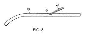
図7は、拡張された遠位端を伴う細長い部材の例示的実施形態の側面図を示す。図7は、随意の特徴を伴う実施形態を図示し、そのうちのいずれかが、随意に使用され得るか、または本明細書で議論される他の実施形態の他の特徴と置換され得る。本実施形態は、縦軸14を伴う線型部分と、埋め込み後に湾曲することができる曲線遠位端15とを有する細長い部材88を備えている。細長い部材88は、好ましくは、近位端および遠位端15を伴う管状である。細長い部材88は、卵形断面、正方形断面、および任意の他の形状でもあり得る。細長い部材88は、好ましくは、中実部材であるが、中空でもあり得る。細長い部材88は、異なる長骨用途および種々の患者生体構造を提供するために、種々の長さで利用可能であり得る。ある場合、細長い部材88は、鎖骨での使用のために100mm〜150mmの長さを有し得る。ある場合、細長い部材88は、腓骨での使用のために320〜370mmの長さを有し得る。細長い部材88は、埋め込み中の長さに切断され得る。細長い部材88は、異なる長骨用途および種々の患者生体構造を考慮するために種々の直径を有し得る。細長い部材88は、好ましくは、1mm〜5mmの直径を有する。より好ましくは、細長い部材88は、1.5mm〜3.5mmの直径を有し得る。細長い部材88は、好ましくは、その全長にわたり剛体である。細長い部材88は、その長さの一部または全体に沿って可撓であり得る。細長い部材88は、ニチノールであり得る。細長い部材88は、ニッケルチタンまたは任意の金属であり得る。細長い部材88は、自己拡張式または自己湾曲式であり得る。遠位端15は、好ましくは、5mm〜30mm近位に湾曲する。より好ましくは、遠位端6の湾曲は、5mm〜15mm延びている。遠位端15は、好ましくは、2mm〜20mm外向きに湾曲する。より好ましくは、遠位端15は、2mm〜8mm外向きに湾曲する。細長い部材88の遠位端15は、拡張状態と非拡張状態とを有し得、遠位端15が埋め込まれたとき、長骨(描写せず)の端部における海綿骨の内側で拡張または湾曲し得る。遠位端15は、自然に拡張状態であり得る。遠位端15は、自然に非拡張状態であり得る。遠位端6は、機械、温度、または他の操作を通して拡張され得る。
FIG. 7 shows a side view of an exemplary embodiment of an elongated member with an extended distal end. FIG. 7 illustrates embodiments with optional features, any of which may be used voluntarily or may be replaced with other features of other embodiments discussed herein. The present embodiment includes an
図8は、長骨固定のためのインプラントの別の例示的実施形態の側面図を示す。図8は、随意の特徴を伴う実施形態を図示し、そのうちのいずれかが、随意に使用され得るか、または本明細書で議論される他の実施形態の他の特徴と置換され得る。図8で見られるような長骨固定のためのインプラントは、図7に示される細長い部材88と、本実施形態または本明細書に説明される任意の他の実施形態で使用され得る随意の係止機構とを備えている。係止機構は、ピン39と、アンカ40とを備えている。細長い部材88は、線形部分上に位置する複数の係止機構を備え得る。係止機構は、細長い部材88の周囲に放射状に位置し得る。係止機構は、細長い部材88の周りに軸方向に位置し得る。係止機構は、軸方向および細長い部材88の周りに放射状に位置し得る。係止機構は、骨の内側で拡張し、平行移動安定性および回転安定性を提供することができる。アンカ40は、半径方向外向きに拡張するアームであり得る。アンカ40は、管状であり得る。アンカ40は、長方形断面または任意の他の形状を有し得る。アンカ40は、好ましくは、長さ5mm〜30mmである。より好ましくは、アンカ40は、長さ10mm〜20mmである。アンカ40は、ピン39によって細長い部材88に結合され得る。アンカ40は、ピン39の周りに回転し得る。アンカ40は、自然にその拡張状態であり得る。アンカ40は、自然にその非拡張状態であり得る。細長い部材88は、その非拡張状態におけるアンカ40を伴って髄内管の中に挿入され得る。アンカ40は、髄内管の内側でその拡張状態に移行し得る。アンカ40は、アンカ40が髄内壁に接触するように拡張し得る。アンカ40は、骨に定着することによって、平行移動安定性および/または回転安定性を提供し得る。アンカ40は、自己拡張式であり得る。アンカ40は、手動で拡張され得る。ピン39は、アンカ40をその拡張状態で維持するようにばね負荷され得る。ピン39は、アンカ40をその拡張状態で維持するための任意の機構を有し得る。アンカ40は、その非拡張状態時、細長い部材88に対して平坦になり得る。ピン39およびアンカ40は、細長い部材88の近位端の近傍に位置し得る。ピン39およびアンカ40は、好ましくは、近位端から5mm〜100mmにある。より好ましくは、ピン39およびアンカ40は、近位端から5mm〜30mmにある。
FIG. 8 shows a side view of another exemplary embodiment of an implant for long bone fixation. FIG. 8 illustrates embodiments with optional features, any of which may be used voluntarily or may be replaced with other features of other embodiments discussed herein. Implants for long bone fixation as seen in FIG. 8 have an elongated
図9は、長骨固定のためのインプラントの別の例示的実施形態の側面図を示す。図9は、随意の特徴を伴う実施形態を図示し、そのうちのいずれかが、随意に使用され得るか、または本明細書で議論される他の実施形態の他の特徴と置換され得る。図9で見られるような長骨固定のためのインプラントは、1つ以上の広がった部材10、38を伴う細長い部材89を備えている。細長い部材89は、近位端の近傍に複数の広がった部材10を備え得る。近位の広がった部材10は、好ましくは、近位端から5mm〜20mmにある。より好ましくは、広がった部材10は、近位端から5mm〜10mmにある。細長い部材89は、遠位端の近傍に複数の広がった部材38を備え得る。遠位の広がった部材38は、好ましくは、遠位端から5mm〜20mmにある。より好ましくは、広がった部材38は、遠位端から5mm〜10mmにある。広がった部材10、38は、細長い部材89の周囲に放射状に位置し得る。広がった部材10、38は、細長い部材89の周りに軸方向に位置し得る。広がった部材10、38は、細長い部材89の周りに放射状および軸方向に位置し得る。広がった部材は、前方または後方に面し得る。広がった部材10、38は、全体的直径が全体を通して同一であるように、広がった部材10、38が細長い部材89と同一平面である非拡張状態を有し得る。広がった部材10、38は、拡張状態を有し得、広がった部材10、38は、半径方向外向きに曲がる。広がった部材10、38は、弓形形状に拡張し得る。広がった部材10、38は、任意の他の形状で拡張し得る。広がった部材10、38は、全て同一の形状およびサイズであり得る。広がった部材10、38は、種々の形状およびサイズであり得る。近位の広がった部材10は、好ましくは、外向きに2mm〜20mm延びている。より好ましくは、近位の広がった部材10は、外向きに10mm〜15mm延びている。遠位の広がった部材38は、好ましくは、外向きに2mm〜20mm延びている。より好ましくは、遠位の広がった部材38は、外向きに5mm〜10mm延びている。広がった部材10、38は、自然にそれらの拡張状態であり得る。広がった部材10、38は、自然にそれらの非拡張状態であり得る。細長い部材89は、それらの非拡張状態における広がった部材10、38を伴って髄内管の中に挿入され得る。広がった部材10、38は、髄内管の内側でそれらの拡張状態に移行し得る。広がった部材10、38は、広がった部材10、38が髄内壁に接触するように拡張し得る。広がった部材10、38は、骨に定着することによって、平行移動安定性および/または回転安定性を提供し得る。広がった部材10、38は、自己拡張式であり得る。広がった部材10、38は、体温まで加熱されたときに拡張し得る。広がった部材10、38は、機械、温度、または他の操作を通して拡張され得る。
FIG. 9 shows a side view of another exemplary embodiment of an implant for long bone fixation. FIG. 9 illustrates embodiments with optional features, any of which can be used voluntarily or can be replaced with other features of other embodiments discussed herein. Implants for long bone fixation as seen in FIG. 9 include an
図10は、長骨固定のためのインプラントの別の例示的実施形態の上面図を示す。図10は、随意の特徴を伴う実施形態を図示し、そのうちのいずれかが、随意に使用され得るか、または本明細書で議論される他の実施形態の他の特徴と置換され得る。具体的には、図10は、同じ細長い部材89と、1つ以上の広がった部材10、38とを備えている図9に説明されるような実施形態の実施形態を示す。複数の広がった部材10、38は、髄腔に沿ったいくつかの場所に沿って骨を握持し得る。該部材10、38は、前方または後方のいずれかに延び得る。ある場合、この例示的実施形態では、遠位の広がった部材38のための3つの軸方向位置および2つの半径方向位置と、近位の広がった部材10のための1つの軸方向位置および2つの半径方向位置とがある。図8は、それらの拡張状態における広がった部材10、38を示す。
FIG. 10 shows a top view of another exemplary embodiment of an implant for long bone fixation. FIG. 10 illustrates embodiments with optional features, any of which may be used voluntarily or may be replaced with other features of other embodiments discussed herein. Specifically, FIG. 10 shows an embodiment of an embodiment as described in FIG. 9, which comprises the same
図11は、係止機構の例示的実施形態の斜視図を示す。図11は、随意の特徴を伴う実施形態を図示し、そのうちのいずれかが、随意に使用され得るか、または本明細書で議論される他の実施形態の他の特徴と置換され得る。図11に示されるような係止機構は、本明細書に開示される実施形態のうちのいずれかと共に使用され、陥凹45を伴うプレート23と、少なくとも2つのねじ24を受け取るための少なくとも2つの貫通孔31とを備えている。プレート23は、平坦な下面と、上面とを有し得る。プレート23は、骨表面を模倣するための下面と、上面とを有し得る。プレート23は、任意の外形の下面と、上面とを有し得る。プレート23は、錠剤形であり得る。プレート23は、長方形であり得る。プレート23は、任意の他の形状であり得る。プレート23は、その下面上に陥凹45を有し得る。陥凹45は、プレートの長さに延び得る。陥凹45は、プレート23上で中心に置かれ得る。陥凹45は、ねじ24を受け取るための2つの貫通孔31が陥凹45の外側にあるように、プレート23上のいずれかの場所に位置付けられ得る。陥凹45は、卵形または円形形状であり得る。陥凹45は、細長い部材1の一部を受け取るように成形され得る。貫通孔31は、ねじ24を受け取るようにサイズを決定され得る。貫通孔31は、各端部に位置し得る。貫通孔31は、上面上に面取りを有し得る。ねじ24は、ねじ山25および頭部26を伴うシャフトを備え得る。ねじ24は、骨と係合するための外部ねじ山25を有し得る。ねじ山25は、ねじ24シャフトの全長に及び得る。ねじ山25は、ねじ24シャフトの長さにわたり部分的に及び得る。ねじ山25は、0.2〜1mmのピッチを有し得る。より好ましくは、ねじ山25は、0.3mm〜0.6mmのピッチを有し得る。ねじ山25は、海綿骨ねじ山外形を有し得る。ねじ山25は、皮質骨ねじ山外形を有し得る。ねじ山25は、その長さに沿って種々のねじ山外形を有し得る。頭部26は、ねじの駆動を可能にする陥凹27を備え得る。陥凹27は、六角頭工具を受け取るように六角形に成形され得る。陥凹27は、任意の他の形状を有し得る。プレート23の陥凹45は、プレート23と骨の外面との間で細長い部材1の一部を挟むことによって、細長い部材1の一部を骨にクランプ締めし得る。
FIG. 11 shows a perspective view of an exemplary embodiment of the locking mechanism. FIG. 11 illustrates embodiments with optional features, any of which may be used voluntarily or may be replaced with other features of other embodiments discussed herein. A locking mechanism as shown in FIG. 11 is used with any of the embodiments disclosed herein, with a
図12−14は、本明細書に説明される実施形態のうちのいずれかと共に使用され得る係止機構の実施形態を示す。図12−14の各々は、随意の特徴を伴う実施形態を図示し、そのうちのいずれかが、随意に使用され得るか、または本明細書で議論される他の実施形態の他の特徴と置換され得る。図12は、係止機構の例示的実施形態の側面図を示す。図13は、プレートの例示的実施形態の底面図を示す。図14は、剪断クランプの例示的実施形態の断面図を示す。 FIG. 12-14 shows an embodiment of a locking mechanism that can be used with any of the embodiments described herein. Each of FIGS. 12-14 illustrates embodiments with optional features, any of which may be used voluntarily or replaces other features of other embodiments discussed herein. Can be done. FIG. 12 shows a side view of an exemplary embodiment of the locking mechanism. FIG. 13 shows a bottom view of an exemplary embodiment of the plate. FIG. 14 shows a cross-sectional view of an exemplary embodiment of a shear clamp.
図12−14は、ねじ24と、プレート28と、剪断クランプ30とを備えている。プレート23は、平坦な下面と、上面とを有し得る。プレート28は、骨表面を模倣するための下面と、上面とを有し得る。プレート28は、任意の外形の下面と、上面とを有し得る。プレート28は、錠剤形であり得る。プレート28は、長方形であり得る。プレート28は、任意の他の形状であり得る。剪断クランプ30は、プレート28の形状に対応する形状を有し得る。剪断クランプ30は、同一平面上に位置するように、骨の突きぎりされた部分の中に嵌め入るように成形され得る。図12に示されるように、剪断クランプ30およびプレート28は、1つ以上のレール32に取り付き得る。プレート28は、剪断クランプ30の上に位置し得る。レール23は、遠位端から近位端に向かって及び得る。レール23は、プレート28の長さの一部に及び得る。レール23は、剪断クランプ30の全長に及び得る。剪断クランプ30は、メス型レールを有し得、プレート28は、オス型レールを有し得る。代替として、剪断クランプ30は、オス型レールを有し得、プレート28は、メス型レールを有し得る。レール32は、篏合形状であり得る。図14に示されるように、レール32は、形状がダブテールであり得る。レール32は、任意の他の篏合形状でもあり得る。レール32は、剪断クランプがプレート28の長さに沿ってスライドすることを可能にする。プレート28は、斜めに向けられた丸い孔33を有し得る。孔33は、好ましくは、30度〜60度の角度でオフセットされる。より好ましくは、孔33は、40度〜50度の角度でオフセットされる。孔33は、細長い部材1とのスライド嵌めを有するようにサイズを決定され得る。剪断クランプ30は、斜めに向けられた孔34を有し得る。孔34は、プレート28の孔33と同一のサイズおよび角度向きを有し得る。孔33、34は、剪断クランプ30がプレート28のレール23上の開始位置にあると、孔が整列させられるように、プレート28および剪断クランプ30上に位置付けられ得る。孔33、34は、図12に示されるように、剪断クランプ30がプレート28のレール23の終了位置に到達すると、孔33、34がオフセットされるように、プレート28および剪断クランプ30上に位置付けられ得る。孔33、34が整列させられると、細長い部材1は、自由に通過し得る。孔33、34がオフセットされると、細長い部材1は、剪断力によって挟まれ得る。細長い部材1への剪断力は、回転および平行移動運動を防止し得る。プレート28および剪断クランプ30は、図15および16に説明される係止特徴によって一緒に定位置に係止されることが可能であり得る。プレート28は、近位端の近傍に設置された丸い貫通孔31を有し得る。貫通孔31は、好ましくは、プレートに直交する。貫通孔31は、ねじ24を受け取るようにサイズを決定され得る。貫通孔31は、上面上で面取りされ得る。ねじ24は、ねじ山25および頭部(描写せず)を伴うシャフトを備え得る。ねじ24は、骨と係合するための外部ねじ山25を有し得る。ねじ山25は、ねじ24シャフトの全長に及び得る。ねじ山25は、ねじ24シャフトの長さにわたり部分的に及び得る。ねじ山25は、0.2〜1mmのピッチを有し得る。より好ましくは、ねじ山25は、0.3mm〜0.6mmのピッチを有し得る。ねじ山25は、海綿骨ねじ山外形を有し得る。ねじ山25は、皮質骨ねじ山外形を有し得る。ねじ山25は、その長さに沿って種々のねじ山外形を有し得る。頭部は、ねじの駆動を可能にする陥凹(描写せず)を備え得る。陥凹は、六角頭工具を受け取るように六角形に成形され得る。陥凹は、任意の他の形状を有し得る。ねじ24は、係止機構を骨の外向き表面に固定し得る。
FIG. 12-14 includes a
図15および16は、本明細書に説明される実施形態のうちのいずれかと共に使用され得るそれらが一緒に結合されたときの図12−14に説明されるような実施形態を示す。図15および16の各々は、随意の特徴を伴う実施形態を図示し、そのうちのいずれかが、随意に使用され得るか、または本明細書で議論される他の実施形態の他の特徴と置換され得る。図15は、プレートの別の例示的実施形態の底面図を示す。図16は、剪断クランプの別の例示的実施形態の上面図を示す。 15 and 16 show embodiments as described in FIGS. 12-14 when they are combined together, which may be used with any of the embodiments described herein. Each of FIGS. 15 and 16 illustrates embodiments with optional features, any of which may be used voluntarily or replaces other features of other embodiments discussed herein. Can be done. FIG. 15 shows a bottom view of another exemplary embodiment of the plate. FIG. 16 shows a top view of another exemplary embodiment of the shear clamp.
一実施形態として、本実施形態では、プレート28上のレール32は、(図15に示されるような)ラッチ36を備え、剪断クランプ30上のレール32は、該ラッチ36を受け取るための(図16に示されるような)凹状切り抜き37を備えている。ラッチ36は、角度付き縁を伴う辺縁であり得る。ラッチ36は、跳ね出し、跳ね返るように可撓であり得る。凹状切り抜き37は、角度付き縁が凹状切り抜き37と篏合するように、ラッチ36に対応する形状であり得る。ラッチ36が凹状切り抜き37と係合すると、プレート28に対する剪断クランプ30の線形運動は、抑止され得る。
In one embodiment, in this embodiment, the
図17は、剪断クランプの別の例示的実施形態の上面図を示す。図17は、随意の特徴を伴う実施形態を図示し、そのうちのいずれかが、随意に使用され得るか、または本明細書で議論される他の実施形態の他の特徴と置換され得る。具体的には、図17は、図16に説明されるように、レール32、凹状切り抜き37、および孔34を伴う剪断クランプ30の実施形態を示す。本実施形態では、剪断クランプ30は、卵形であり得る。本実施形態では、実施形態は、減衰スロット41を備え得る。減衰スロット41は、孔34より遠位にあり得る。減衰スロット41は、C字形で孔34をオフセットし得る。減衰スロット41は、蛇行パターンで孔34をオフセットし得る。減衰スロット41は、任意の形状であり得る。減衰スロット41は、好ましくは、孔34を1mm〜10mmオフセットする。より好ましくは、減衰スロット41は、孔34を1mm〜3mmオフセットする。減衰スロット41は、剪断クランプ30上の凹状切り抜き37へのプレート(描写せず)上のラッチの係止中、剪断クランプ30の偏向を可能にし得る。
FIG. 17 shows a top view of another exemplary embodiment of the shear clamp. FIG. 17 illustrates embodiments with optional features, any of which may be used voluntarily or may be replaced with other features of other embodiments discussed herein. Specifically, FIG. 17 shows an embodiment of a
図18は、係止機構の別の例示的実施形態の斜視図を示す。図18は、随意の特徴を伴う実施形態を図示し、そのうちのいずれかが、随意に使用され得るか、または本明細書で議論される他の実施形態の他の特徴と置換され得る。具体的には、図18は、本明細書に説明される任意の実施形態と共に使用され得る係止機構の別の実施形態を示す。係止機構は、円筒体を有し得る。係止機構は、任意の形状であり得る。係止機構は、円筒体の長さに及ぶ丸い孔43を備え得る。孔43は、本明細書に説明される細長い部材のうちのいずれか(描写せず)をスライド可能に受け取るようにサイズを決定され得る。孔43と細長い部材との間の緊密な嵌め合いは、平行移動安定性および回転安定性を提供し得る。本実施形態は、複数のウィング44を備え得る。ウィング44は、平坦な平面要素であり得る。ウィング44は、円筒形状体から半径方向外向きに延び得る。好ましくは、180度間隔を置かれた2つのウィングがあるが、より多いまたは少ないウィング44を有し得る。ウィング44は、骨の中に挿入されたとき、回転安定性を提供し得る。
FIG. 18 shows a perspective view of another exemplary embodiment of the locking mechanism. FIG. 18 illustrates embodiments with optional features, any of which may be used voluntarily or may be replaced with other features of other embodiments discussed herein. Specifically, FIG. 18 shows another embodiment of the locking mechanism that can be used with any of the embodiments described herein. The locking mechanism may have a cylindrical body. The locking mechanism can have any shape. The locking mechanism may include a
図19は、係止機構の別の例示的実施形態の斜視図を示す。図19は、随意の特徴を伴う実施形態を図示し、そのうちのいずれかが、随意に使用され得るか、または本明細書で議論される他の実施形態の他の特徴と置換され得る。具体的には、図19は、本明細書に説明される任意の実施形態と共に使用され得る係止機構の別の実施形態を示す。係止機構は、円筒体を有し得る。係止機構は、任意の形状であり得る。本実施形態は、丸い孔45を備え得る。孔45は、係止機構の長さに延び得る。孔45は、本明細書に説明される細長い部材のうちのいずれか(描写せず)をスライド可能に受け取るようにサイズを決定され得る。本実施形態は、圧着タブ47のうちの1つ以上のものを備え得る。圧着タブ47は、タブ45の両側のスロットにより形成され得る。圧着タブ47は、内向きに曲がるように可撓性であり得る。圧着タブ47は、厚さが近位から遠位に増加するように、角度付き外表面を有し得る。圧着タブ47は、係止機構の長さにわたり部分的に、近位端から及び得る。圧着タブ47は、係止機構の周囲に放射状に位置し得る。好ましくは、3〜6つの圧着タブ47がある。より好ましくは、係止機構の円周の周囲に均等に間隔を置かれた3〜5つの圧着タブ47がある。圧着タブ47は、孔45を通過する細長い部材を把持するように内向きに押され得る。圧着タブ47は、係止機構に対する細長い部材の平行移動または回転運動を防止し得る。係止機構は、1つ以上の回転防止タブ46を備え得る。回転防止タブ46は、圧着タブ47を上回る厚さを有し得る。回転防止タブ46は、三角形断面形状を有し得る。回転防止タブ46は、任意の断面形状を有し得る。回転防止タブ46は、テーパ状であり得る。回転防止タブ46は、係止機構の長さにわたって及び得る。回転防止タブ46は、係止機構の長さにわたり部分的に及び得る。回転防止タブ46は、圧着タブ47の間に位置付けられ得る。回転防止タブ46は、係止機構の周囲に放射状に位置し得る。好ましくは、3〜6つの回転防止タブ46がある。より好ましくは、係止機構の円周の周囲に均等に間隔を置かれた3〜5つの回転防止タブ46がある。回転防止タブ46は、剛体であり得る。回転防止タブ46は、骨と係合し、骨に対する係止機構の回転運動を防止し得る。
FIG. 19 shows a perspective view of another exemplary embodiment of the locking mechanism. FIG. 19 illustrates embodiments with optional features, any of which may be used voluntarily or may be replaced with other features of other embodiments discussed herein. Specifically, FIG. 19 shows another embodiment of the locking mechanism that can be used with any of the embodiments described herein. The locking mechanism may have a cylindrical body. The locking mechanism can have any shape. The present embodiment may include a
図20A−20Bは、骨折した骨を治療するためのインプラントの別の実施形態を示す。図20Aおよび20Bの各々は、随意の特徴を伴う実施形態を図示し、そのうちのいずれかが、随意に使用され得るか、または本明細書で議論される他の実施形態の他の特徴と置換され得る。図20Aは、拡張前のインプラントの別の例示的実施形態の側面図を示す。図20Bは、拡張後のインプラントの別の例示的実施形態の側面図を示す。 20A-20B show another embodiment of an implant for treating a fractured bone. Each of FIGS. 20A and 20B illustrates embodiments with optional features, any of which may be used voluntarily or replaces other features of other embodiments discussed herein. Can be done. FIG. 20A shows a side view of another exemplary embodiment of the implant before expansion. FIG. 20B shows a side view of another exemplary embodiment of the expanded implant.
インプラントは、遠位端6および近位端55を伴う細長い部材90を備え得る。細長い部材90は、好ましくは、円形である。細長い部材90は、卵形断面、正方形断面、および任意の他の形状でもあり得る。細長い部材90は、好ましくは、中実部材であるが、中空でもあり得る。細長い部材90は、異なる長骨用途および種々の患者生体構造を提供するために、種々の長さで利用可能であり得る。ある場合、細長い部材90は、鎖骨での使用のために100mm〜150mmの長さを有し得る。ある場合、細長い部材90は、腓骨での使用のために320〜370mmの長さを有し得る。細長い部材90は、埋め込み中の長さに切断され得る。細長い部材90は、異なる長骨用途および種々の患者生体構造を考慮するために種々の直径を有し得る。細長い部材90は、好ましくは、1mm〜5mmの直径を有する。より好ましくは、細長い部材90は、1.5mm〜3.5mmの直径を有し得る。細長い部材90は、好ましくは、その全長にわたり剛体である。細長い部材90は、その長さの一部または全体に沿って可撓であり得る。細長い部材90は、ニチノールであり得る。細長い部材90は、ニッケルチタンまたは任意の金属であり得る。遠位端6は、先端においてテーパ状であり得る。近位端55は、先端においてテーパ状であり得る。遠位端6および近位端55は、本明細書に説明される拡張および骨接触のための特徴を有し得る。遠位端6および近位端55は、同じ特徴を有し得る。遠位端6および近位端55は、種々の形状および/またはサイズの特徴を有し得る。端部6、55は、反対端に向かって縦方向に延びているスリットによって2つ以上の部品に区分され得る。端部6、55の区分された部品は、スリットが存在しないように互いに当接し得る。端部6、55のスリットは、好ましくは、その長さに沿って5mm〜30mm延びている。より好ましくは、端部6、55のスリットは、5mm〜15mm延びている。端部6、55は、切断、ワイヤEDM、または任意の他の分離の方法によって区分され得る。細長い部材90の端部6、55は、拡張状態と、非拡張状態とを有し得、端部6、55が埋め込まれたとき、端部6、55は、長骨(描写せず)の端部における海綿骨の内側で拡張し得る。端部6、55は、自然に拡張状態であり得る。端部6、55は、自然に非拡張状態であり得る。端部6、55は、自己拡張式であり得る。端部6、55は、機械、温度、または他の操作を通して拡張され得る。図20Aは、その非拡張状態における細長い部材90を示す。その非拡張状態における細長い部材90は、細長い部材90の長さにわたって一定の直径を有し得る。細長い部材90の端部6、55は、海綿骨を握持することを補助するための1つ以上の溝7を有し得る。溝7は、円周方向リングであり得る。溝7は、鋭い返しであり得る。溝7は、任意の形状の切り抜きであり得る。溝7は、遠位部分に沿って軸方向に配置され得る。図20Bは、その拡張状態における細長い部材90を示す。端部6、55の先端は、その拡張状態において互いから離れるように半径方向外向きに広がり得る。端部6、55の先端は、弓形形状を有し得る。端部6、55は、任意の他の形状を有し得る。その拡張状態における端部6、55の先端間の距離は、好ましくは、5mm〜30mmである。より好ましくは、端部6、55の間の距離は、5mm〜15mmであり得る。
The implant may include an
図21A−21Bは、本明細書に開示される細長い部材のうちのいずれかと共に使用され得る図20A−20Bに説明される実施形態の遠位端を示す。図21Aおよび21Bの各々は、随意の特徴を伴う実施形態を図示し、そのうちのいずれかが、随意に使用され得るか、または本明細書で議論される他の実施形態の他の特徴と置換され得る。図21Aは、拡張前のインプラントの別の例示的実施形態の遠位端の側面図を示す。図21Bは、拡張後のインプラントの別の例示的実施形態の遠位端の側面図を示す。図21A−21Bは、細長い部材90の端部を拡張するための方法の実施形態を示す。細長い部材90は、ピン60を使用して、外科医によって手動で拡張され得る遠位先端6を備え得る。ピン60は、遠位端6のアーム間に挿入され得る。ピン60は、事前に組み立てられ、アーム間に配置され得る。ピン60は、それらの拡張状態までアームを半径方向外向きに押すように、近位端に向かって移動させられ得る。遠位端6は、塑性的に変形し、その拡張状態を維持し得る。拡張後、ピン60は、除去され得る。図21Aは、その非拡張状態における遠位端6を示し、図21Bは、その拡張状態における遠位端6を示す。細長い部材90の遠位端6は、拡張状態と、非拡張状態とを有し得、端部6が埋め込まれたとき、遠位端6は、長骨(描写せず)の端部における海綿骨の内側で拡張し得る。
21A-21B shows the distal end of the embodiment described in FIGS. 20A-20B that can be used with any of the elongated members disclosed herein. Each of FIGS. 21A and 21B illustrates embodiments with optional features, one of which may be used optionally or replaces other features of other embodiments discussed herein. Can be done. FIG. 21A shows a side view of the distal end of another exemplary embodiment of the implant before dilation. FIG. 21B shows a side view of the distal end of another exemplary embodiment of the implant after dilation. FIG. 21A-21B shows an embodiment of a method for expanding the end of an
図22A−22Bは、骨折した骨を治療するためのインプラントの別の実施形態を示す。図22Aおよび22Bの各々は、随意の特徴を伴う実施形態を図示し、そのうちのいずれかが、随意に使用され得るか、または本明細書で議論される他の実施形態の他の特徴と置換され得る。図22Aは、拡張前のインプラントの別の例示的実施形態の側面図を示す。図22Bは、拡張後のインプラントの別の例示的実施形態の側面図を示す。 22A-22B show another embodiment of an implant for treating a fractured bone. Each of FIGS. 22A and 22B illustrates embodiments with optional features, one of which may be used optionally or replaces other features of other embodiments discussed herein. Can be done. FIG. 22A shows a side view of another exemplary embodiment of the implant before dilation. FIG. 22B shows a side view of another exemplary embodiment of the expanded implant.
インプラントは、遠位端6、近位端55、および拡張中心57を伴う細長い部材69を備え得る。細長い部材69は、好ましくは、円形である。細長い部材69は、卵形断面、正方形断面、および任意の他の形状でもあり得る。細長い部材69は、好ましくは、中実部材であるが、中空でもあり得る。細長い部材69は、異なる長骨用途および種々の患者生体構造を提供するために、種々の長さで利用可能であり得る。ある場合、細長い部材69は、鎖骨での使用のために100mm〜150mmの長さを有し得る。ある場合、細長い部材69は、腓骨での使用のために320〜370mmの長さを有し得る。細長い部材69は、埋め込み中の長さに切断され得る。細長い部材69は、異なる長骨用途および種々の患者生体構造を考慮するために種々の直径を有し得る。細長い部材69は、好ましくは、1mm〜5mmの直径を有する。より好ましくは、細長い部材69は、1.5mm〜3.5mmの直径を有し得る。細長い部材69は、好ましくは、その全長にわたり剛体である。細長い部材69は、その長さの一部または全体に沿って可撓であり得る。細長い部材69は、ニッケルチタンまたは任意の金属であり得る。遠位端6は、先端においてテーパ状であり得る。近位端55は、先端においてテーパ状であり得る。遠位端6および近位端55は、本明細書に説明される拡張および骨接触のための特徴を有し得る。遠位端6および近位端55は、同じ特徴を有し得る。遠位端6および近位端55は、種々の形状および/またはサイズの特徴を有し得る。端部6、55は、反対端に向かって縦方向に延びているスリットによって2つ以上の部品に区分され得る。端部6、55の区分された部品は、スリットが存在しないように互いに当接し得る。端部6、55のスリットは、好ましくは、その長さに沿って5mm〜30mm延びている。より好ましくは、端部6、55のスリットは、5mm〜15mm延びている。端部6、55は、切断、ワイヤEDM、または任意の他の分離の方法によって区分され得る。細長い部材90の端部6、55は、海綿骨を握持することを補助するための1つ以上の溝7を有し得る。溝7は、円周方向リングであり得る。溝7は、鋭い返しであり得る。溝7は、任意の形状の切り抜きであり得る。溝7は、遠位部分に沿って軸方向に配置され得る。拡張中心57は、近位端から遠位端までの途中に位置付けられ得る。拡張中心57は、細長い部材69の長さに沿った任意の点に位置付けられ得る。拡張中心57は、反対端に向かって縦方向に延びているスリットによって2つ以上の部品に区分され得る。拡張中心57の区分された部品は、スリットが存在しないように互いに当接し得る。拡張中心57のスリットは、好ましくは、5mm〜30mm延びている。より好ましくは、拡張中心57のスリットは、5mm〜15mm延びている。拡張中心57は、切断、ワイヤEDM、または任意の他の分離の方法によって区分され得る。細長い部材69の端部6、55および拡張中心57は、端部6、55および中心57が埋め込まれたとき、長骨(描写せず)の端部における海綿骨の内側で拡張し得るように、拡張状態と、非拡張状態とを有し得る。端部6、55および中心57は、自然に拡張状態であり得る。端部6、55および中心57は、自然に非拡張状態であり得る。端部6、55および中心57は、自己拡張式であり得る。端部6、55および中心57は、機械、温度、または他の操作を通して拡張され得る。図22Aは、その非拡張状態における細長い部材69を示す。その非拡張状態における細長い部材69は、細長い部材69の長さに沿って一定の直径を有し得る。図22Bは、その拡張状態における細長い部材69を示す。細長い部材69は、埋め込み後に拡張され得る。端部6、55の先端は、その拡張状態において互いから離れるように半径方向外向きに広がり得る。端部6、55の先端は、骨の髄内管表面に接触し得る。端部6、55の先端は、弓形形状を有し得る。端部6、55は、任意の他の形状を有し得る。その拡張状態における端部6、55の先端間の距離は、好ましくは、5mm〜30mmである。より好ましくは、端部6、55の間の距離は、5mm〜15mmであり得る。拡張中心57は、その拡張状態において分岐した中心区分の中に半径方向外向きに広がり得る。中心57は、卵形形状を有し得る。中心57は、凸状外面および凹状内面を伴う任意の他の形状をとり得る。中心57の拡張距離は、好ましくは、5mm〜30mmである。より好ましくは、拡張距離は、5mm〜15mmであり得る。拡張された中心57は、2つの骨片を一緒に圧縮することを補助し得る。拡張中心57は、遠位6および近位端55と同時に拡張され得る。拡張中心57は、遠位6および近位端55の後に拡張され得る。中心57拡張は、遠位6および近位端55が互いに向かって内向きに引き寄せるようにし、骨折をさらに整復し得る。
The implant may include an
図23A−23Bは、骨折した骨を治療するためのインプラントの別の実施形態を示す。図23Aおよび23Bの各々は、随意の特徴を伴う実施形態を図示し、そのうちのいずれかが、随意に使用され得るか、または本明細書で議論される他の実施形態の他の特徴と置換され得る。図23Aは、拡張前のインプラントの別の例示的実施形態の側面図を示す。図23Bは、拡張後のインプラントの別の例示的実施形態の側面図を示す。 23A-23B show another embodiment of the implant for treating a fractured bone. Each of FIGS. 23A and 23B illustrates embodiments with optional features, any of which may be used optionally or replace other features of other embodiments discussed herein. Can be done. FIG. 23A shows a side view of another exemplary embodiment of the implant before dilation. FIG. 23B shows a side view of another exemplary embodiment of the implant after expansion.
インプラントは、遠位構成要素58および近位構成要素59を伴う細長い部材61を備え得る。遠位構成要素58は、半径方向内向きに延びている内部歯63を伴う内部チャネル62を有し得る。内部チャネル21は、遠位構成要素58の長さに部分的に及び得る。近位構成要素59は、半径方向外向きに延びている外部歯66を含み得るシャフト65を有し得る。外部歯66は、内部歯63と係合するようにサイズを決定され、位置付けられ得る。歯63、66は、シャフト65が遠位構成要素58のチャネル62の中に入れ子式に挿入されることを可能にし得る。シャフト65は、チャネル62の中に挿入し得、それによって、外部歯66と内部歯63とは、互いに係合し、近位端59がチャネル62から外に後退することを防止するように互いに係止する。細長い部材61は、好ましくは、円形である。細長い部材61は、卵形断面、正方形断面、および任意の他の形状でもあり得る。細長い部材61は、異なる長骨用途および種々の患者生体構造を提供するために、種々の長さで利用可能であり得る。ある場合、細長い部材61は、鎖骨での使用のために100mm〜150mmの長さを有し得る。ある場合、細長い部材61は、腓骨での使用のために320〜370mmの長さを有し得る。細長い部材61は、埋め込み中の長さに切断され得る。細長い部材61は、異なる長骨用途および種々の患者生体構造を考慮するために種々の直径を有し得る。細長い部材61は、好ましくは、1mm〜5mmの直径を有する。より好ましくは、細長い部材61は、1.5mm〜3.5mmの直径を有し得る。細長い部材61は、好ましくは、その全長にわたり剛体である。細長い部材61は、その長さの一部または全体に沿って可撓であり得る。細長い部材61は、ニッケルチタンまたは任意の金属であり得る。遠位構成要素58は、拡張する遠位端60を備え得る。近位構成要素59は、拡張する近位端64を備え得る。遠位端60および近位端64は、本明細書に説明される拡張および骨接触のための特徴を有し得る。遠位端60および近位端64は、同じ特徴を有し得る。遠位端60および近位端64は、種々の形状および/またはサイズの特徴を有し得る。端部60、64は、反対端に向かって縦方向に延びているスリットによって2つ以上の部品に区分され得る。端部60、64の区分された部品は、スリットが存在しないように互いに当接し得る。端部60、64のスリットは、好ましくは、その長さに沿って5mm〜30mm延びている。より好ましくは、端部60、64のスリットは、5mm〜15mm延びている。端部60、64は、切断、ワイヤEDM、または任意の他の分離の方法によって区分され得る。細長い部材61の端部60、64は、拡張状態と、非拡張状態とを有し得、端部60、64が埋め込まれたとき、端部60、64は、長骨(描写せず、図1に説明されるように)の端部における海綿骨の内側で拡張し得る。端部60、64は、自然に拡張状態であり得る。端部60、64は、自然に非拡張状態であり得る。端部60、64は、自己拡張式であり得る。端部60、64は、機械、温度、または他の操作を通して拡張され得る。その非拡張状態における細長い部材61は、細長い部材61のシャフトの直径に類似する直径を有し得る。端部60、64の先端は、その拡張状態において互いから離れるように半径方向外向きに広がり得る。端部60、64の先端は、弓形形状を有し得る。端部60、64は、任意の他の形状を有し得る。その拡張状態における端部60、64の先端間の距離は、好ましくは、5mm〜30mmである。より好ましくは、端部60、64の間の距離は、5mm〜15mmであり得る。端部60、64が拡張し、骨に定着させられた後、シャフト65は、2つの骨片を圧縮するように、さらにチャネル62の中に挿入され得る。図23Aは、近位構成要素59が遠位構成要素58の中に前進させられる前のインプラントを示し、図23Bは、近位構成要素59が遠位構成要素58の中に前進させられ、それによって、デバイスの全体的長さを短縮し、圧縮力が骨折した骨に加えられ、それによって、骨片を一緒に圧縮することを可能にした後のインプラントを示す。
The implant may include an
図24は、係止機構の別の例示的実施形態の側面図を示す。図24は、随意の特徴を伴う実施形態を図示し、そのうちのいずれかが、随意に使用され得るか、または本明細書で議論される他の実施形態の他の特徴と置換され得る。具体的には、図24は、本明細書に説明される実施形態のうちのいずれかと共に使用され得る係止機構の別の実施形態を示す。係止機構は、プレート91と、環状フランジ92と、孔93と、タン94とを備え得る。プレート91は、平坦な下面と、上面とを有し得る。プレート91は、骨表面を模倣するための下面と、上面とを有し得る。プレート91は、任意の外形の下面と、上面とを有し得る。プレート91は、錠剤形であり得る。プレート91は、長方形であり得る。プレート91は、任意の他の形状であり得る。プレート91は、プレート91を通して全体に延びている斜めに向けられた丸い孔93を有し得る。孔93は、好ましくは、30度〜60度の角度でオフセットされる。より好ましくは、孔93は、40度〜50度の角度でオフセットされる。孔93は、孔の中の任意の点に位置するタン94を有し得る。タン94は、孔93の壁から内向きに垂直に延びている、孔91の周囲に円周方向に位置する複数のタブであり得る。タン94は、孔93の壁からある角度で内向きに延びている、孔91の周囲に円周方向に位置する複数のタブであり得る。タン94は、孔93の壁から内向きに垂直に延びている、孔93の壁の周囲に円周方向に配置されるフランジであり得る。タン94は、孔93の壁からある角度で内向きに延びている、孔91の壁の周囲に円周方向に配置されるフランジであり得る。タン94は、偏向するように可撓性であり得る。環状フランジ92は、本明細書に開示される細長い部材の実施形態のうちのいずれかに取り付けられ得る。環状フランジ92は、近位端の近傍に取り付けられ得る。環状フランジ92は、溶接、接合、プレス嵌め、または任意の他の接合方法によって取り付けられ得る。タン94は、細長い部材が孔93を通して髄内管の中に挿入されているとき、偏向し得るが、次いで、偏向していない位置まで跳ね返り、環状フランジ92が孔から退出することを防止する。タン94はまた、孔93および骨から外への細長い部材の後退も防止し得る。
FIG. 24 shows a side view of another exemplary embodiment of the locking mechanism. FIG. 24 illustrates embodiments with optional features, any of which may be used voluntarily or may be replaced with other features of other embodiments discussed herein. Specifically, FIG. 24 shows another embodiment of the locking mechanism that can be used with any of the embodiments described herein. The locking mechanism may include a
図25A−25Bは、骨折した骨を治療するためのインプラントの別の実施形態を示す。図25Aおよび25Bの各々は、随意の特徴を伴う実施形態を図示し、そのうちのいずれかが、随意に使用され得るか、または本明細書で議論される他の実施形態の他の特徴と置換され得る。図25Aは、拡張前のインプラントの別の例示的実施形態の側面図を示す。図25Bは、拡張後のインプラントの別の例示的実施形態の側面図を示す。 25A-25B show another embodiment of an implant for treating a fractured bone. Each of FIGS. 25A and 25B illustrates an embodiment with optional features, any of which may be used optionally or replaces other features of other embodiments discussed herein. Can be done. FIG. 25A shows a side view of another exemplary embodiment of the implant before expansion. FIG. 25B shows a side view of another exemplary embodiment of the expanded implant.
インプラントは、髄腔の中への挿入時に拡張することができるメッシュ管71を備え得る。メッシュは、編組パターンで織成され得る。メッシュは、拡張する形状記憶材料から作製され得る。メッシュは、チタン、生体適合性プラスチック、または他の生体適合性材料から成る他の圧縮されたメッシュから作製され得る。管71は、自己拡張し得る。管71は、自然にその拡張状態であり得る。挿入中、拘束具が、メッシュを圧潰構成で保持し得、外側シース等の拘束具が除去されると、メッシュは、自己拡張する。管は、髄腔の中へ、骨の端部と係合するように拡張し得る。図25Aは、その非拡張状態におけるインプラントを示し、図25Bは、その拡張状態におけるインプラントを示す。拡張状態では、管は、骨の髄管の内面に一致し、骨片を一緒に保持することに役立ち得る。
The implant may include a
図26A−26Bは、インプラントの別の実施形態を示す。図26Aおよび26Bの各々は、随意の特徴を伴う実施形態を図示し、そのうちのいずれかが、随意に使用され得るか、または本明細書で議論される他の実施形態の他の特徴と置換され得る。図26Aは、拡張前のインプラントの別の例示的実施形態の側面図を示す。図26Bは、拡張後のインプラントの別の例示的実施形態の側面図を示す。 26A-26B show another embodiment of the implant. Each of FIGS. 26A and 26B illustrates embodiments with optional features, any of which may be used voluntarily or replaces other features of other embodiments discussed herein. Can be done. FIG. 26A shows a side view of another exemplary embodiment of the implant before dilation. FIG. 26B shows a side view of another exemplary embodiment of the implant after expansion.
インプラントは、遠位および/または近位端上に拡張可能コイル72を伴う細長い部材73を備えている。細長い部材73は、好ましくは、近位端および遠位端を伴う円形である。細長い部材73は、卵形断面、正方形断面、および任意の他の形状でもあり得る。細長い部材73は、好ましくは、中実部材であるが、中空でもあり得る。細長い部材73は、異なる長骨用途および種々の患者生体構造を提供するために、種々の長さで利用可能であり得る。ある場合、細長い部材73は、鎖骨での使用のために100mm〜150mmの長さを有し得る。ある場合、細長い部材73は、腓骨での使用のために320〜370mmの長さを有し得る。細長い部材73は、異なる長骨用途および種々の患者生体構造を考慮するために種々の直径を有し得る。細長い部材73は、好ましくは、1mm〜5mmの直径を有する。より好ましくは、細長い部材73は、1.5mm〜3.5mmの直径を有し得る。細長い部材73は、好ましくは、その全長にわたり剛体である。細長い部材73は、その長さの一部または全体に沿って可撓であり得る。細長い部材73は、ニッケルチタンまたは任意の金属であり得る。拡張可能コイル72は、増加する放射パターンを伴うコイル状である単一のワイヤであり得る。拡張可能コイル72は、増加する放射パターンを伴ってコイル状である複数のワイヤであり得る。拡張可能コイル72は、好ましくは、直径0.2mm〜3mmの中実ワイヤから作製される。より好ましくは、拡張可能コイル72は、直径0.2mm〜0.5mmの中実ワイヤから作製される。コイル72は、管状構造から作製され得る。拡張可能コイル72は、螺旋パターンで織成された複数のワイヤであり得る。コイル72は、溶接、機械的機構、または他の接合方法によって、細長い部材73の近位および遠位端に取り付けられ得る。コイル72は、拡張状態と、非拡張状態とを有し得、遠位および近位端が埋め込まれたとき、コイル72は、長骨(描写せず)の端部における海綿骨の内側で拡張し得る。コイル72は、自然に拡張状態であり得る。コイル72は、自然に非拡張状態であり得る。コイル72は、自己拡張式であり得る。コイル72は、機械、温度、または他の操作を通して拡張され得る。その非拡張状態におけるコイル72は、細長い部材73のシャフトの直径に類似する直径を有し得る。その拡張状態におけるコイル72は、好ましくは、5mm〜30mmの最大直径を有する。より好ましくは、コイル72は、5mm〜15mmの最大直径を有する。拡張可能コイル72は、拡張時に直径が増加し得、それは、骨を握持して安定させるために、海綿骨および骨の端部における髄腔の壁の中に拡張し得る。遠位および近位コイル72は、同時に拡張し得る。遠位コイル72は、最初に拡張し得、その後、近位コイルが続く。近位コイル72は、最初に拡張し得、その後、遠位コイルが続く。図26Aは、その非拡張状態におけるインプラントを示し、図26Bは、その拡張状態におけるインプラントを示す。
The implant comprises an
図27A−27Cは、骨折した骨を治療するためのインプラントの別の実施形態を示す。図27A−27Cの各々は、随意の特徴を伴う実施形態を図示し、そのうちのいずれかが、随意に使用され得るか、または本明細書で議論される他の実施形態の他の特徴と置換され得る。図27Aは、拡張前のインプラントの別の例示的実施形態の側面図を示す。図27Bは、拡張前のインプラントの別の例示的実施形態の詳細図を示す。図27Cは、拡張後のインプラントの別の例示的実施形態の側面図を示す。 27A-27C show another embodiment of an implant for treating a fractured bone. Each of FIGS. 27A-27C illustrates embodiments with optional features, any of which may be used optionally or replace other features of other embodiments discussed herein. Can be done. FIG. 27A shows a side view of another exemplary embodiment of the implant before expansion. FIG. 27B shows a detailed view of another exemplary embodiment of the implant before dilation. FIG. 27C shows a side view of another exemplary embodiment of the implant after expansion.
インプラントは、管状構成要素74と、留め具構成要素80とを備え得る。管状構成要素74は、円形であり得る。管状構成要素74は、任意の形状であり得る。管状構成要素74は、その長さに沿って延びている管腔を有し得る。管状構成要素74は、側壁78を伴う切り抜き77を有し得る。切り抜き77は、シャフト全体を通して延び得る。切り抜き77は、形状が長方形であり得る。切り抜き77は、各側に側壁78があるように、任意の形状であり得る。側壁78は、可撓であり得る。側壁78は、曲がる傾向があるスポットを有し得る。管状構成要素74は、遠位端79を有し得る。遠位端79の管腔は、内部ねじ山付きであり得る(描写せず)。頭部80、ロッド81、およびねじ山82を備えているボルト等の留め具は、管74の中心を通してスライド可能に配置され、遠位端79の内部ねじ山とねじ式で係合され得る。留め具が遠位端79の中に通ると、遠位端は、近位端に向かって引かれ得、側壁78は、管74にねじ式で係合する留め具からの圧縮に起因して、半径方向外向きに拡張し始め得る。それらの拡張状態において、側壁78は、三角形のウィングであり得る。それらの拡張状態において、側壁78は、任意の形状であり得る。拡張された側壁78は、骨の中へのアンカとしての役割を果たし、移動を防止し、回転および平行移動安定性を提供する。図27Aは、その非圧縮状態におけるインプラントを示し、図27Bは、インプラントの遠位部分の詳細図を示し、図27Cは、その圧縮または拡張状態におけるインプラントを示す。シャフトの近位端は、本明細書に開示される任意の定着方法を用いて定着させられ得る。
The implant may include a
図28A−28Cは、本明細書に開示される実施形態のうちのいずれかで使用され得る骨の中に先端を定着させるための異なる先端幾何学形状を有する固定インプラントの代替実施形態を図示する。図28A−28Cの各々は、随意の特徴を伴う実施形態を図示し、そのうちのいずれかが、随意に使用され得るか、または本明細書で議論される他の実施形態の他の特徴と置換され得る。図28Aは、髄内管内の拡張後のインプラントの別の例示的実施形態の側面図を示す。図28Bは、髄内管内の拡張後のインプラントの別の例示的実施形態の側面図を示す。図28Cは、髄内管内の拡張後のインプラントの別の例示的実施形態の側面図を示す。 FIGS. 28A-28C illustrate alternative embodiments of fixed implants with different tip geometries for anchoring the tip in bone that may be used in any of the embodiments disclosed herein. .. Each of FIGS. 28A-28C illustrates embodiments with optional features, one of which may be used voluntarily or replaces other features of other embodiments discussed herein. Can be done. FIG. 28A shows a side view of another exemplary embodiment of the implant after dilation within the intramedullary canal. FIG. 28B shows a side view of another exemplary embodiment of the implant after dilation within the intramedullary canal. FIG. 28C shows a side view of another exemplary embodiment of the implant after dilation within the intramedullary canal.
インプラントは、細長い本体141を含む。細長い部材141は、好ましくは、近位端および遠位端を伴う円形である。細長い部材141は、好ましくは、髄内管98に適合するように成形され、骨幹端99に適合するための端部142を有する。細長い部材141は、卵形断面、正方形断面、および任意の他の形状でもあり得る。細長い部材141は、好ましくは、中実部材であるが、中空でもあり得る。細長い部材141は、異なる長骨用途および種々の患者生体構造を提供するために、種々の長さで利用可能であり得る。ある場合、細長い部材141は、鎖骨での使用のために100mm〜150mmの長さを有し得る。ある場合、細長い部材141は、腓骨での使用のために320〜370mmの長さを有し得る。細長い部材141は、埋め込み中の長さに切断され得る。細長い部材141は、異なる長骨用途および種々の患者生体構造を考慮するために種々の直径を有し得る。細長い部材141は、好ましくは、1mm〜5mmの直径を有する。より好ましくは、細長い部材141は、1.5mm〜3.5mmの直径を有し得る。先端142は、形状が変動し得る。ある場合、それは、円の中心が主軸に比較的近く位置するように、図37Aに示されるように円形形状であり得る。先端142は、主軸の両側に材料があるように、図28Bおよび28Cに示されるような複数の曲がりを有し得る。図37Aでは、円は、閉鎖リングまたは開放リングであり得る。図28Bでは、曲がりは、正弦曲線であるか、または別様に1つ以上の頂点および谷を伴う波状パターンを形成し得る。図28Cでは、先端142は、湾曲またはJ字形パターンを形成し得る。細長い部材1の先端142は、拡張状態と、非拡張状態とを有し得、埋め込まれたとき、先端142は、骨幹端99の内側で拡張し得る。先端142は、自然に拡張状態であり得る。先端142は、自然に非拡張状態であり得る。先端142は、自己拡張式であり得る。先端142は、機械、温度、または他の操作を通して拡張され得る。細長い部材141は、本明細書に開示される任意の係止機構と対にされ得ることに留意されたい。細長い部材141は、好ましくは、その全長にわたり剛体である。細長い部材141は、その長さの一部または全体に沿って可撓であり得る。細長い部材141は、ニッケルチタンまたは任意の金属であり得る。
The implant includes an
図29A−29Dは、本明細書に説明される固定インプラント1のうちのいずれかと共に使用され得る係止機構の別の例示的実施形態を図示する。図29A−29Dの各々は、随意の特徴を伴う実施形態を図示し、そのうちのいずれかが、随意に使用され得るか、または本明細書で議論される他の実施形態の他の特徴と置換され得る。係止機構は、骨アンカ100と、位置決めねじ110とを備え得る。図29Aは、ねじ山付き構成要素の別の例示的実施形態の斜視図を示す。図29Bは、係止構成要素の別の例示的実施形態の斜視図を示す。図29Cは、係止機構の別の例示的実施形態の側面図を示す。図29Dは、髄内管内のインプラントの別の例示的実施形態の側面図を示す。
FIGS. 29A-29D illustrate another exemplary embodiment of a locking mechanism that can be used with any of the fixed implants 1 described herein. Each of FIGS. 29A-29D illustrates embodiments with optional features, any of which may be used voluntarily or replaces other features of other embodiments discussed herein. Can be done. The locking mechanism may include a
図29Aは、骨アンカ100の実施形態を示す。アンカ100は、その軸が髄内管の軸と実質的に垂直であるか、または別様にそれを横断するように、骨(描写せず)の中に打ち込まれることができるテーパ状または尖端を伴う円筒形であり得る。アンカ100は、骨に係合し、骨の中のアンカ100の設置後の移動に抵抗するためのその外面上の1つ以上の円周方向溝101もしくは返し付き領域を備え得る。アンカ100は、細長い部材(描写せず)を受け取るためのアンカの主軸と実質的に垂直な貫通孔102と、位置決めねじ(描写せず)を受け取るためのアンカの主軸と一致した内部ねじ山103とも備え得る。
FIG. 29A shows an embodiment of the
図29Bは、位置決めねじ110の実施形態を示す。位置決めねじ110は、アンカ(描写せず)と係合する外部ねじ山111と、ドライバ(描写せず)と係合するための六角ソケットまたは同等の駆動特徴112とを備え得る。
FIG. 29B shows an embodiment of the
図29Cは、図29Aに説明されるような骨アンカ100と、図29Bに説明されるような位置決めねじ110とを示し、細長い中空部材1を伴う。位置決めねじ110は、遠位面または底面113をさらに備え得る。底面113は、細長い部材1に係合し、アンカ100に対する細長い部材1の運動を防止し得る。使用時、細長い部材1は、骨(描写せず)の中に配置され得、アンカ100は、骨とねじ式で係合し得る。細長い部材1は、アンカ上の孔102の中に挿入され得、位置決めねじ110は、細長い部材1を保持し、移動を防止するように、骨アンカ100とねじ式で係合され得る。
FIG. 29C shows the
図29Dは、図29A−Cに説明される実施形態を示す。アンカ100および位置決めねじ110は、好ましくは、治療されている骨の外面と同一平面であるか、または骨の外面の下方にあるかのいずれかであるように、十分に深く骨500の中に駆動される。細長い部材1の遠位端は、本明細書に説明される遠位定着特徴のうちのいずれかを用いて骨に定着させられ得る。
FIG. 29D shows the embodiments described in FIGS. 29A-C. The
図30A−30Fは、本明細書に説明される固定インプラントのうちのいずれかと共に使用され得る係止機構の別の実施形態を示す。図30A−30Fの各々は、随意の特徴を伴う実施形態を図示し、そのうちのいずれかが、随意に使用され得るか、または本明細書で議論される他の実施形態の他の特徴と置換され得る。係止機構は、骨ねじ120と、係止ねじ130とから成り得る。図30Aは、ねじ山付き構成要素の別の例示的実施形態の斜視図を示す。図30Bは、ねじ山付き構成要素の別の例示的実施形態の側面図を示す。図30Cは、係止構成要素の別の例示的実施形態の斜視図を示す。図30Dは、係止構成要素の別の例示的実施形態の側面図を示す。図30Eは、係止機構およびインプラントの別の例示的実施形態の側面図を示す。図30Fは、髄内管内のインプラントの別の例示的実施形態の側面図を示す。
FIG. 30A-30F shows another embodiment of the locking mechanism that can be used with any of the fixed implants described herein. Each of FIGS. 30A-30F illustrates embodiments with optional features, any of which may be used voluntarily or replaces other features of other embodiments discussed herein. Can be done. The locking mechanism may consist of a
図30Aおよび30Bは、それぞれ、骨ねじ120の斜視図および前断面図を示す。骨ねじ120は、形状が円錐形であり得るが、任意の他の形状であり得る。骨ねじ120は、カニューレを挿入され得、それが細長い部材(描写せず)上にスライドすることを可能にする。骨ねじ120は、好ましくは、2mm〜10mmの長さを有する。より好ましくは、骨ねじ120は、3mm〜9mmの長さを有する。骨ねじ120カニューレ挿入管は、好ましくは、細長い部材とスライド嵌めを有するようにサイズを決定される。骨ねじ120は、好ましくは、1mm〜8mmの内径を有する。より好ましくは、内径は、2mm〜7mmである。骨ねじ120は、ドライバと係合するためのスロット121または類似特徴も備え得る。骨ねじ120は、外部骨ねじ山122を備え得る。外部ねじ山122は、骨(描写せず)に固定するためのねじ軸の長さの大部分に沿って延び得る。外部ねじ山122は、全長に延び得る。骨ねじ120は、ねじ軸の部分的長さに沿って内部ねじ山123も備え、それは、係止ねじ(描写せず)を受け取り得る。骨ねじ120は、ねじ軸の隣接する部分的長さに沿って内部テーパ状表面124を備え得る。骨ねじ120は、チタン、チタン合金、または任意の金属であり得る。骨ねじ120は、ポリマーまたはセラミックであり得る。
30A and 30B show a perspective view and a front sectional view of the
図30Cおよび30Dは、それぞれ、係止ねじ130の斜視および正面図を示す。係止ねじ130も、細長い部材(描写せず)の上をスライドするようにカニューレを挿入され得る。係止ねじ130は、頭部131と、円筒体132と、テーパ状端136とを備え得る。本体132は、骨ねじ(描写せず)上の内部ねじ山と係合するようにサイズを決定される外部ねじ山133を備え得る。テーパ状端136は、複数のタブ134から成り得る。複数のタブ134は、好ましくは、形状が実質的に長方形であり、好ましくは、主軸と平行に延び、主軸の周囲に円周方向にパターン化される。頭部131は、ドライバと係合するTorx T15ソケット135または類似特徴を備え得る。係止ねじ130は、複数の部品で作製され得るか、または一体的に形成され得る。係止ねじ130は、チタン、チタン合金、または任意の金属であり得る。係止ねじ130は、ポリマーまたはセラミックであり得る。
30C and 30D show a perspective view and a front view of the locking
図30Eは、細長い部材1上に骨ねじ120および係止ねじ130を伴う係止機構の前断面図を示す。骨ねじ120は、外部ねじ山122が周辺の骨(描写せず)に係合するように、細長い部材1を覆って駆動され得る。係止ねじ130は、係止ねじ130の外部ねじ山133が骨ねじ120の内部ねじ山123とねじ式で係合する状態で、骨ねじ120に向かってトルクス(登録商標)ソケット135によって駆動され得る。タブ134は、骨ねじ120の内部表面124にぶつかり、内向きに曲がり、細長い部材1上にクランプ締めして定位置でそれを保持し、移動を防止し得る。係止ねじ130の頭部131は、係止ねじ130が骨ねじ120を通り過ぎて駆動されることを防止し得る。
FIG. 30E shows a front sectional view of a locking mechanism with a
図30Fは、長骨500上の埋め込み構成を示す。骨ねじ120および係止ねじ130は、治療されている骨500の外面の下方に配置され得るか、またはそれらは、骨の外面と同一平面であり得る。細長い部材1の遠位端は、本明細書に説明される遠位定着特徴のうちのいずれかを用いて骨に定着させられ得る。
FIG. 30F shows an implant configuration on the
図31は、錐の例示的実施形態の側面図を示す。図31は、随意の特徴を伴う実施形態を図示し、そのうちのいずれかが、随意に使用され得るか、または本明細書で議論される他の実施形態の他の特徴と置換され得る。具体的には、図31は、骨の皮質殻を穿刺するための錐205の実施形態を示す。錐205は、一方の端部上の先端201と他方の端部上のハンドル202とを伴うシャフト200を備え得る。シャフト200は、その全長に沿って円形であり得る。シャフト200は、任意の形状であり得る。シャフト200は、好ましくは、中実部材であるが、中空でもあり得る。シャフト200は、好ましくは、100mm〜300mmの長さを有する。より好ましくは、シャフト200は、120mm〜160mmの長さを有する。シャフト200は、長さマーキングを有し得る。シャフト200は、その長さにわたって一様な直径を有し得る。シャフト200は、ハンドル202から先端201まで減少する直径を有し得る。シャフト200は、好ましくは、2mm〜15mmの直径を有する。より好ましくは、シャフト200は、3mm〜10mmの直径を有する。先端201は、シャフト200の一方の端部上に配置され得る。先端201は、鋭い尖端204を有し得る。尖端204は、骨の皮質殻を穿刺し得る。先端201は、好ましくは、5mm〜15mmの長さを有する。より好ましくは、先端201は、7mm〜12mmの長さを有する。先端201は、鋭い先端において終端するその長さに沿った長方形断面を有し得る。先端201は、任意の形状であり得る。先端201は、その縦軸に沿って直線状であり得る。先端201は、曲線状であり得る。先端201は、好ましくは、2mm〜10mmの最大直径または幅を有する。より好ましくは、先端201は、2mm〜6mmの最大直径または幅を有する。シャフト200および先端201は、1つの部品として製造され得る。シャフト200および先端201は、機械的機構、接合、または2つの部品を隣接させる任意の他の方法によって接合され得る。シャフト200および先端201は、好ましくは、同一の材料であるが、異なる材料でもあり得る。シャフト200および先端201は、ステンレス鋼または任意の他の金属、ポリマー、もしくはセラミックであり得る。ハンドル202は、シャフト200の他方の端部上に配置され得る。ハンドル202は、円筒形状であり得る。ハンドル202は、任意の形状であり得る。ハンドル202は、好ましくは、長さが40mm〜100mmである。より好ましくは、ハンドル202は、50mm〜70mmの長さを有する。ハンドル202は、好ましくは、20mm〜100mmの直径を有する。より好ましくは、ハンドル202は、40mm〜60mmの直径を有する。ハンドル202は、周囲に円周方向に位置する複数の溝203を有し、より容易な取り扱いを提供し得る。好ましくは、4〜10個の溝203がある。より好ましくは、5〜7つの溝203がある。溝203は、形状が卵形であり得る。溝203は、任意の形状であり得る。溝203は、好ましくは、長さが30mm〜90mmである。より好ましくは、溝203は、長さが40mm〜60mmである。ハンドル202は、レーデルまたは任意のタイプのポリマーであり得る。ハンドル202は、金属またはセラミックであり得る。ハンドル202およびシャフト200は、機械的機構、接合、プレス嵌め、または2つの部品を隣接させる任意の他の方法によって接合され得る。
FIG. 31 shows a side view of an exemplary embodiment of a cone. FIG. 31 illustrates embodiments with optional features, any of which may be used voluntarily or may be replaced with other features of other embodiments discussed herein. Specifically, FIG. 31 shows an embodiment of a
図32は、マーカの例示的実施形態の斜視図を示す。図32は、随意の特徴を伴う実施形態を図示し、そのうちのいずれかが、随意に使用され得るか、または本明細書で議論される他の実施形態の他の特徴と置換され得る。具体的には、図32は、骨の皮質殻の中への進入経路を維持するためのマーカ213の実施形態を示す。マーカ213は、誘導端210と、1つ以上のウィング211とを備えている。誘導端210は、C字形断面を伴う細長い部材であり得る。誘導端210は、他の器具に適応する形状およびサイズを有し得る。誘導端210は、曲線状であり得る。誘導端210は、直線状であり得る。誘導端210の一方の端部に取り付けられる、1つ以上のウィング211があり得る。ウィング211は、その形状によって作成される経路に干渉しないように、両側に、または誘導端210の周囲に距離を置いて位置付けられ得る。ウィング211は、縦軸に沿った直線シャフトであり得る。ウィング211は、それらの長さに部分的に沿った縦軸に沿って直線状であり得る。ウィング211は、それらの長さに沿った任意の点において縦軸から外向きに曲がり得る。ウィング211は、好ましくは、10度〜50度の角度で外向きに曲がる。より好ましくは、ウィング211は、15度〜30度の角度で外向きに曲がる。ウィング211は、それらの長さに沿って一様な断面を有し得る。ウィング211は、それらの長さに沿って1つの形状から別の形状に移行する断面を有し得る。ウィング211は、円形、卵形、長方形、または任意の他の形状であり得る。ウィング211は、ウィング211の長さにわたる複数の溝212を有し、より容易な取り扱いを提供し得る。好ましくは、5〜15個の溝212がある。より好ましくは、5〜10個の溝212がある。溝212は、形状が卵形であり得る。溝212は、任意の形状であり得る。溝212は、好ましくは、0.5mm〜5mmの幅を有する。より好ましくは、溝212は、1mm〜3mmの幅を有する。マーカ213は、レーデルまたは任意のタイプのポリマーであり得る。マーカ213は、金属またはセラミックであり得る。
FIG. 32 shows a perspective view of an exemplary embodiment of the marker. FIG. 32 illustrates embodiments with optional features, any of which can be used voluntarily or can be replaced with other features of other embodiments discussed herein. Specifically, FIG. 32 shows an embodiment of
図33は、錐およびマーカの例示的実施形態の側面図を示す。図33は、随意の特徴を伴う実施形態を図示し、そのうちのいずれかが、随意に使用され得るか、または本明細書で議論される他の実施形態の他の特徴と置換され得る。具体的には、図33は、図31に説明されるような錐205の実施形態および図32に説明されるようなマーカ213の実施形態を示す。図33は、マーカ213が錐205と相互作用し得る方法を示す。錐205は、皮質骨(描写せず)を穿刺し得、マーカ213は、穿刺された骨の位置をマークするように錐205の周囲に挿入され得る。マーカ213は、錐205および/または他の器具を受け取るようにサイズを決定ならびに成形され得る。
FIG. 33 shows side views of exemplary embodiments of cones and markers. FIG. 33 illustrates embodiments with optional features, any of which can be used voluntarily or can be replaced with other features of other embodiments discussed herein. Specifically, FIG. 33 shows an embodiment of the
図34は、リーマの例示的実施形態の側面図を示す。図34は、随意の特徴を伴う実施形態を図示し、そのうちのいずれかが、随意に使用され得るか、または本明細書で議論される他の実施形態の他の特徴と置換され得る。具体的には、図34は、リーマ224の実施形態を示す。リーマ224は、一方の端部上の先端222と他方の端部上のハンドル221とを伴うシャフト220を備え得る。シャフト220は、好ましくは、シャフト200の全長に沿ってカニューレを挿入される。シャフト220は、その長さに部分的に沿ってカニューレを挿入され得る。シャフト220は、その長さに沿って一様な外径を有し得る。シャフト220は、その長さにわたって可変外径を有し得る。シャフト220の外径は、好ましくは、1mm〜6mmである。より好ましくは、シャフト220の直径は、2mm〜5mmである。シャフト220は、ステンレス鋼または任意の他の金属であり得る。シャフト220は、任意のポリマーまたはセラミックであり得る。シャフト220の先端222は、先端222の長さに沿って外部切断溝を有し得る。溝は、骨の髄管をリーミングするために設計され得る。先端222は、好ましくは、3mm〜10mmの長さを有する。より好ましくは、先端222は、4mm〜6mmの長さを有する。ハンドル221は、シャフト220の他方の端部上に配置され得る。ハンドル221は、形状が円筒形であり得る。ハンドル221は、任意の他の形状であり得る。ハンドル221は、その長さにわたって一様な直径を有し得る。ハンドル221は、シャフト220の直径に向かって傾斜する、減少する直径を有し得る。ハンドル221は、好ましくは、1mm〜100mmの直径を有する。より好ましくは、ハンドル221は、3mm〜60mmの直径を有する。ハンドル221は、好ましくは、長さが40mm〜100mmである。より好ましくは、ハンドル221は、50mm〜70mmの長さを有する。ハンドル221は、周囲に円周方向に位置する複数の溝223を有し、より容易な取り扱いを提供し得る。好ましくは、4〜15個の溝223がある。より好ましくは、5〜12個の溝223がある。溝223は、形状が卵形であり得る。溝223は、任意の形状であり得る。溝223は、好ましくは、長さが30mm〜90mmである。より好ましくは、溝223は、長さが40mm〜60mmである。ハンドル221は、レーデルまたは任意のタイプのポリマーであり得る。ハンドル221は、金属またはセラミックであり得る。ハンドル221およびシャフト220は、機械的機構、接合、プレス嵌め、または2つの部品を隣接させる任意の他の方法によって接合され得る。
FIG. 34 shows a side view of an exemplary embodiment of a reamer. FIG. 34 illustrates embodiments with optional features, any of which may be used voluntarily or may be replaced with other features of other embodiments discussed herein. Specifically, FIG. 34 shows an embodiment of the
図35A−35Bは、挿入装置245の実施形態を示す。図35Aおよび35Bの各々は、随意の特徴を伴う実施形態を図示し、そのうちのいずれかが、随意に使用され得るか、または本明細書で議論される他の実施形態の他の特徴と置換され得る。図35Aは、挿入装置の例示的実施形態の側面図を示す。図35Bは、挿入装置の例示的実施形態の断面図を示す。挿入装置245は、シース230と、ハンドル231と、係止ノブ232と、軸方向ノブ233と、ハンドル先端234とを備え得る。シース230は、その全長の全体を通してカニューレ挿入管を有する管状であり得る。シース230は、好ましくは、可撓性である。シース230は、剛体でもあり得る。シース先端240は、鋸状の縁を有し得る。シース先端240は、骨の髄管をリーミングする切断溝の外形に類似する外形を有し得る。シース先端240は、シース230と実質的に平行であり得る。シース先端240は、曲線状であり得る。シース230の長さは、好ましくは、100mm〜400mmである。シース230の長さは、患者の生体構造および骨のタイプに依存し得る。シース230の外径は、好ましくは、1mm〜10mmである。より好ましくは、シース230の外径は、好ましくは、2mm〜5mmである。シース230の内径は、好ましくは、0.5mm〜8mmである。より好ましくは、シース230の内径は、1mm〜5mmである。シース230は、ニッケルチタンであり得る。シース230は、任意の金属、ポリマー、またはセラミックであり得る。
35A-35B show an embodiment of the
ハンドル231は、好ましくは、円筒形である。ハンドル231は、任意の形状であり得る。ハンドル231は、内部ねじ山235を伴う中空であり得る。ねじ山235は、1mm〜3mmのピッチを有し得る。ねじ山235は、標準外形を有し得る。ハンドル231は、その全長にわたり一様な外径を有し得る。ハンドル231は、一方の端部において減少する外径を有し得る。ハンドル231外径は、好ましくは、15mm〜60mmである。より好ましくは、ハンドル231外径は、20mm〜50mmである。ハンドル231は、その全長にわたり一様な内径を有し得る。ハンドル231は、一方の端部において減少する内径を有し得る。ハンドル231内径は、好ましくは、3mm〜20mmである。より好ましくは、内径は、5mm〜10mmである。ハンドル231は、その外径の周囲に円周方向に複数の溝238を有し、より容易な取り扱いを提供し得る。好ましくは、2〜10個の溝238がある。より好ましくは、3〜6つの溝238がある。溝238は、形状が卵形であり得る。溝238は、任意の形状であり得る。溝238は、ハンドル231の内径を貫いて切断し、視認孔を作成し得る。溝238は、好ましくは、長さが30mm〜90mmである。より好ましくは、溝238は、長さが40mm〜60mmである。ハンドル231は、レーデルまたは任意のタイプのポリマーであり得る。ハンドル231は、金属またはセラミックであり得る。
The
係止ノブ232は、シャフト242と、上端243とを有し得る。係止ノブ232は、円筒形であり得る。係止ノブ232は、カニューレを挿入され得る。係止ノブ232は、好ましくは、1.5mm〜10mmの内径を有する。より好ましくは、内径は、3mm〜6mmである。シャフト242は、外部ねじ山236を有し得る。シャフト242は、その全長に沿ってねじ山付きであり得る。シャフト242は、その長さに部分的に沿ってねじ山付きであり得る。外部ねじ山236は、ハンドル231の内部ねじ山235と篏合するようにサイズを決定され得る。シャフト242は、好ましくは、2mm〜8mmの長さを有する。より好ましくは、シャフト242は、2mm〜5mmの長さを有し得る。シャフト242は、端部においてテーパ状であり得る。上端243は、好ましくは、10mm〜30mmの直径を有する。より好ましくは、上端243は、15mm〜25mmの直径を有する。上端243は、好ましくは、7mm〜20mmの長さを有する。より好ましくは、上端243は、7mm〜12mmの長さを有する。上端243は、その外径の周囲に円周方向に複数の溝239を有し、より容易な取り扱いを提供し得る。好ましくは、8〜30個の溝239がある。より好ましくは、10〜20個の溝239がある。溝239は、形状が卵形であり得る。溝239は、任意の形状であり得る。溝239は、好ましくは、長さが5mm〜15mmである。より好ましくは、溝239は、長さが5mm〜10mmである。係止ノブ232は、レーデルまたは任意のタイプのポリマーであり得る。係止ノブ232は、金属またはセラミックであり得る。
The locking
軸方向ノブ233は、平坦な卵形形状であり得る。軸方向ノブ233は、任意の形状であり得る。軸方向ノブ233は、内側カニューレ挿入管244を有し得る。内側カニューレ挿入管244は、円形であり得る。内側カニューレ挿入管244は、増加した回転制御のために細長い部材(描写せず)上の平面と相互作用するための1つ以上の平面を有し得る。内側カニューレ挿入管244は、任意の形状であり得る。内側カニューレ挿入管244は、軸方向ノブ233の長さにわたり部分的に及び得る。軸方向ノブ233の長さは、好ましくは、10mm〜50mmである。より好ましくは、長さは、20mm〜40mmである。軸方向ノブ233の幅は、好ましくは、10mm〜50mmである。より好ましくは、幅は、20mm〜40mmである。軸方向ノブ233は、レーデルまたは任意のタイプのポリマーであり得る。軸方向ノブ233は、金属またはセラミックであり得る。
The
ハンドル先端234は、円筒形であり得る。ハンドル先端234は、カニューレを挿入され得る。ハンドル先端234は、好ましくは、1.5mm〜10mmの内径を有する。より好ましくは、内径は、3mm〜6mmである。ハンドル先端234は、外部ねじ山237を有し得る。外部ねじ山237は、ハンドル先端234の長さに部分的に沿って延び得る。外部ねじ山237は、その全長に沿って延び得る。外部ねじ山237は、ハンドル231の内部ねじ山235と篏合するようにサイズを決定され得る。ハンドル先端234は、好ましくは、10mm〜70mmの長さを有する。より好ましくは、ハンドル先端234は、20mm〜60mmの長さを有する。ハンドル先端234は、いずれか一方または両方の端部においてテーパ状であり得る。ハンドル先端234の外径は、その長さにわたって一定であり得る。ハンドル先端234の外径は、その長さにわたって可変であり得る。外径は、好ましくは、2mm〜40mmである。より好ましくは、外径は、2mm〜30mmである。ハンドル先端234は、一方の端部に複数のタン241を有し得る。タン241は、可撓な部材を作成するために、材料の間のスロットによって形成され得る。好ましくは、2〜8つのタン241がある。より好ましくは、3〜6つのタン241がある。外側から内側への圧力を用いて、タン241は、内向きに崩れ得る。タン241は、好ましくは、5mm〜15mmの長さを有する。より好ましくは、タンは、5mm〜10mmの長さを有する。ハンドル先端241は、レーデルまたは任意のタイプのポリマーであり得る。ハンドル先端241は、金属またはセラミックであり得る。
The
挿入装置245は、ハンドル231の一方の端部の中にねじ式で挿入されているハンドル先端234と組み立てられ得る。シース230は、それが途中まで通過するように、ハンドル先端234の内側管腔に先端でない端部を通すことによって挿入され得る。シース230は、機械的係止、接合、溶接、または任意の他の接着方法を使用することによって、ハンドル先端234に接着され得る。係止ノブ232は、ハンドル231の他方の端部の中にねじ式で挿入され得る。本明細書に説明される細長い部材1の任意の実施形態が、使用され得る。細長い部材1の近位端は、シース230の先端240を通して、ハンドル231、ハンドル先端234を通して挿入され、係止ノブ232を通り過ぎて延び得る。細長い部材1の近位端は、ハンドル231を通してシース230の先端240の端部まで挿入され得る。細長い部材1の遠位端(描写せず)は、その非拡張状態で留まるように、シース230の中に挿入され得る。軸方向ノブ233は、容易な取り扱いのために、その内側カニューレ挿入管244を介して細長い部材1上にスライドし得る。係止ノブ232の上端243は、時計回り方向にねじられ、係止ノブ232にハンドル231内部ねじ山235を横断させ得る。係止ノブ232の内側カニューレ挿入管は、ハンドル先端234のタン241の外面と接触し、外側から内側への力を提供し得、それは、タン241に細長い部材1上でクランプ締めさせ得る。したがって、細長い部材1は、軸方向および半径方向移動を制限され得る。
The
使用中、挿入装置245は、骨(描写せず)の髄管の中へ強制的に押し込まれ得る。定位置に来ると、係止ノブ232の上端243は、ハンドル先端234のタン241を解放し、細長い部材1を解放するように、反時計回りにねじられ得る。細長い部材1が、骨(描写せず)の中で定位置に手動で保持され得る一方で、挿入装置245は、除去され、細長い部材1が髄内管内で拡張することを可能にする。
During use, the
図36は、嵌入付属品の例示的実施形態の斜視図を示す。図36は、随意の特徴を伴う実施形態を図示し、そのうちのいずれかが、随意に使用され得るか、または本明細書で議論される他の実施形態の他の特徴と置換され得る。具体的には、図36は、嵌入アタッチメント262の実施形態を示す。嵌入アタッチメント262は、2つのアーム250、258と、クロスバー251と、ナット252と、ねじ260とを備えている。アーム250、258は、作業端254と、ハンドル255とを有し得る。作業端254およびハンドル255は、実質的に平行であるが、好ましくは、10mm〜50mmオフセットされる。より好ましくは、それらは、15mm〜30mmオフセットされる。作業端254は、好ましくは、40mm〜70mmの長さを有する。より好ましくは、作業端254は、45mm〜65mmの長さを有する。作業端254は、その長さに沿って変動する断面形状およびサイズを有し得る。作業端254は、長方形断面または任意の他の形状を有し得る。作業端254は、器具クランプ256と、ワイヤクランプ257のうちの1つ以上のものとを有し得る。器具クランプ256は、半円形状の孔であり得る。器具クランプ256は、アーム250、258の厚さ全体を通して及び得る。器具クランプ256は、2つのアーム250、258の作業端254が一緒になると、クランプ256が円形になるように、作業端254の内部端(すなわち、ハンドル255がオフセットされる側面)上に配置され得る。器具クランプ256は、本明細書に開示される任意の器具と相互作用するか、またはそれをクランプ締めするようにサイズを決定され得る。器具クランプ256は、好ましくは、10mm〜60mmの直径を有する。より好ましくは、直径は、15mm〜40mmである。器具クランプ256は、1つ以上のクランプ延長部263を有し得る。延長部263は、クランプ256の側面から1つの方向に延び得る。延長部263は、形状が長方形であり得る。延長部263は、任意の形状であり得る。延長部263は、内向きに延びている構成要素264を備え得る。内向きに延びている構成要素264は、本明細書に開示される任意の器具と係合するようにサイズを決定および構成され得る。構成要素264は、器具を拘束し、器具と嵌入アタッチメント262との間に回転整列を生成し得る。好ましくは、種々のサイズの1〜5つのワイヤクランプ257がある。ワイヤクランプ257は、半円形状の孔であり得る。ワイヤクランプ257は、アーム250、258の厚さを部分的に通して及び得る。ワイヤクランプ257は、2つのアーム250、258の作業端254が一緒になると、クランプ257が円形になるように、作業端254の内部端上に配置され得る。ワイヤクランプ257は、好ましくは、1mm〜5mmの直径を有する。より好ましくは、ワイヤクランプ257は、1mm〜4mmの直径を有する。器具クランプ256とワイヤクランプ257とは、互いに一直線に位置付けられ得る。ハンドル255は、好ましくは、50mm〜200mmの長さを有する。より好ましくは、ハンドル255は、100mm〜150mmの長さを有する。ハンドル255は、その長さに沿って変動する断面形状およびサイズを有し得る。ハンドル255は、長方形断面または任意の他の形状を有し得る。ハンドル255は、その長さに沿って曲線状であり得るか、または直線状であり得る。ハンドル255は、その内部表面においてえぐり出され得る。ハンドル255は、その長さに沿って複数の溝259を有し、より容易な取り扱いを提供し得る。溝259は、好ましくは、5mm〜20mmの幅を有する。より好ましくは、溝259は、5mm〜15mmの幅を有する。好ましくは、長さに沿って均等に間隔を置かれた3〜10個の溝259がある。より好ましくは、4〜8つの溝259がある。アーム250、258は、丸いねじ孔253を有し得る。ねじ孔253は、アーム250、258の厚さ全体を通して及び得る。ねじ孔253は、全長に沿って内部ねじ山付きであり得る。ねじ孔253は、それらの長さに部分的に沿ってねじ山付きであり得る。
FIG. 36 shows a perspective view of an exemplary embodiment of the fitting accessory. FIG. 36 illustrates embodiments with optional features, any of which may be used voluntarily or may be replaced with other features of other embodiments discussed herein. Specifically, FIG. 36 shows an embodiment of the
クロスバー251は、円筒形であり得る。クロスバー251は、好ましくは、中実部材であるが、中空でもあり得る。クロスバー251は、好ましくは、2mm〜10mmの直径を有する。より好ましくは、直径は、3mm〜7mmである。クロスバー251は、好ましくは、30mm〜100mmの長さを有する。より好ましくは、長さは、55mm〜75mmである。クロスバー251は、外部ねじ山を有し得る。クロスバー251は、その全長に沿って外部にねじ山付きであり得る。クロスバー251は、部分的にねじ山付きであり得る。
The
ナット252は、円筒形であり得る。ナット252は、その軸と平行な丸い貫通孔を有し得る。ナット252の内部表面は、内部ねじ山を有し得る。ナット252は、その全長に沿って内部ねじ山を有し得る。ねじ山は、クロスバー251の外部ねじ山と篏合するようにサイズを決定および成形され得る。ナット252は、その全長に沿って一様な外径を有し得る。ナット252は、可変外径を有し得る。ナット252の外径は、好ましくは、5mm〜25mmである。より好ましくは、外径は、12mm〜20mmである。
The
ねじ260は、ねじ孔253に適合し、アーム150、158の厚さに及ぶようにサイズを決定される、標準ねじであり得る。
The
嵌入アタッチメント262は、ねじ260を用いてアーム150、158をねじ留めすることによって組み立てられ得る。ねじ260は、回転軸としての役割を果たし得る。クロスバー251は、ピン261を用いて第2のアーム258の中に挿入され得る。ピン261は、プレス嵌め、接着、または、任意の他の取付方法を使用して固定され得る。クロスバー251は、第1のアーム250とねじ式で係合し得る。クロスバー251は、クロスバー251の端部上にナット252を締める(ねじ式で係合する)ことによって固定され得る。嵌入アタッチメント262は、ステンレス鋼または任意の他の金属であり得る。嵌入アタッチメント262は、ポリマーまたはセラミックであり得る。
The
図37A−37Bは、ドライバ280の実施形態を示す。図37Aおよび37Bの各々は、随意の特徴を伴う実施形態を図示し、そのうちのいずれかが、随意に使用され得るか、または本明細書で議論される他の実施形態の他の特徴と置換され得る。図37Aは、ドライバの例示的実施形態の側面図を示す。図37Bは、ドライバの例示的実施形態の断面図を示す。ドライバ280は、本体270と、ノブ271とを備え得る。本体270は、第1の駆動端272と、第2の駆動端276とを有し得る。本体270は、円筒形であり得る。本体270は、任意の形状であり得る。本体270は、好ましくは、100mm〜200mmの長さを有する。より好ましくは、本体270の長さは、120mm〜180mmである。本体270は、好ましくは、カニューレを挿入される。本体270は、好ましくは、0.5mm〜4.5mmの内径を有する。より好ましくは、内径は、1mm〜4mmである。本体270の外径は、その長さに沿って変動し得る。外径は、好ましくは、2mm〜50mmに及ぶ。より好ましくは、外径は、2mm〜40mmに及ぶ。第1の駆動端272は、トルクス(登録商標)形状を有し得る。第1の駆動端272は、六角形を有し得る。第1の駆動端272は、駆動要素として使用されることができる任意の形状を有し得る。第1の駆動端272は、わずかに内向きに圧縮し、受け取り特徴(描写せず)とのプレス嵌めを提供することができるようにスロット付きであり得る。第2の駆動端276は、係合特徴273を有し得る。係合特徴273は、スロット頭部に係合し得る押出スロットであり得る。係合特徴273は、任意の形状であり得る。本体270は、本体273の周りに円周方向に、かつ長さに沿って軸方向に複数の溝274を有し得る。溝274は、卵形であり得る。溝274は、任意の形状であり得る。溝274は、表面を充填し、より容易な取り扱いを提供するようにサイズを決定および間隔を置かれ得る。本体270上に複数の切り抜き275があり得る。切り抜き275は、本体の周囲に円周方向に位置し得る。切り抜き275は、好ましくは、第2の駆動端276から20mm〜60mmである。好ましくは、1〜3つの切り抜き275がある。
37A-37B show embodiments of
ノブ271は、頭部277と、シャフト278とを有し得る。頭部277は、円筒形であり得る。頭部277は、任意の形状であり得る。頭部277は、その中心軸を通して貫通孔を有し得る。貫通孔は、好ましくは、1mm〜8mmの直径を有する。より好ましくは、直径は、1mm〜6mmである。頭部277は、好ましくは、10mm〜20mmの長さを有する。より好ましくは、頭部277は、12mm〜18mmの長さを有する。頭部277は、好ましくは、10mm〜35mmの外径を有する。より好ましくは、頭部277は、15mm〜30mmの外径を有する。頭部277は、その直径の周囲に円周方向に位置する複数の溝279を有し、より容易な取り扱いを提供し得る。好ましくは、表面の周りに均等に間隔を置かれた4〜12個の溝279がある。より好ましくは、表面の周りに均等に間隔を置かれた6〜10個の溝279がある。溝279は、形状が卵形であり得る。溝279は、任意の形状であり得る。シャフト278は、円筒形であり得る。シャフト278は、カニューレを挿入され得る。シャフト278は、好ましくは、0.5mm〜5.5mmの内径を有する。より好ましくは、内径は、1mm〜5mmである。シャフト278は、好ましくは、1mm〜8mmの外径を有する。より好ましくは、外径は、1mm〜6mmである。シャフト278は、好ましくは、20mm〜70mmの長さを有する。より好ましくは、シャフト278は、30mm〜60mmの長さを有する。シャフト278は、その長さに部分的に沿って、一方の端部において外部にねじ山付きであり得る。外部ねじ山は、係止機構(描写せず)のねじ山と篏合するようにサイズを決定され得る。シャフト278の非ねじ山付き端部は、頭部277の貫通孔の中に配置され得る。頭部277およびシャフト278は、一緒に製造され得る。頭部277およびシャフト278は、接合、溶接、プレス嵌め、または2つの構成要素を接合するための任意の他の方法によって接合され得る。
The
ドライバ280は、ノブ271の頭部277が本体270の切り抜き275の中に位置付けられ、シャフト277が本体270のカニューレ挿入管の中に配置され、シャフト277のねじ山付き端部が本体270の第2の駆動端276を通り過ぎて延びているように、組み立てられ得る。ドライバ280は、本明細書に開示される任意の実施形態の係止機構を挿入するために使用され得る。
In the
図38Aは、カッタの例示的実施形態の斜視図を示す。図38Bは、カッタの例示的実施形態の断面図を示す。図38Aおよび38Bの各々は、随意の特徴を伴う実施形態を図示し、そのうちのいずれかが、随意に使用され得るか、または本明細書で議論される他の実施形態の他の特徴と置換され得る。図38Aおよび図38Bは、レンチ290と、ボルト291と、キャップ292と、本体293と、ハンドル294とを備えているカッタ307の実施形態を図示する。レンチ290は、旋回端295、シャフト299、およびハンドル296を伴う細長い部材である。レンチ290は、好ましくは、形状が円筒形であるが、任意の形状であり得る。レンチ290は、好ましくは、中実である。レンチ290は、好ましくは、剛体である。レンチ290は、好ましくは、100mm〜400mmの長さを有する。より好ましくは、レンチ290は、200mm〜300mmの長さを有する。レンチ290は、その長さにわたって一様な直径を有し得る。レンチ290は、その長さにわたって可変直径を有し得る。レンチ290は、好ましくは、5mm〜50mmの直径を有する。より好ましくは、レンチ290は、10mm〜40mmの直径を有する。旋回端295は、貫通孔297を有し得る。貫通孔297は、駆動機構として作用するように六角形として成形され得る。貫通孔297は、任意の他の形状であり得る。旋回端295およびシャフト299は、ステンレス鋼であり得る。旋回端295およびシャフト299は、任意の金属、ポリマー、またはセラミックであり得る。ハンドル296は、その直径の周囲に円周方向に位置する複数の溝298を有し、より容易な取り扱いを提供し得る。好ましくは、表面の周りに均等に間隔を置かれた3〜12個の溝298がある。より好ましくは、表面の周りに均等に間隔を置かれた5〜10個の溝298がある。溝298は、形状が卵形であり得る。溝298は、任意の形状であり得る。ハンドル296は、レーデルまたは任意のポリマーであり得る。ハンドル296は、金属またはセラミックであり得る。ハンドル296は、接合、プレス嵌め、または任意の他のプロセスによって結合され得る。
FIG. 38A shows a perspective view of an exemplary embodiment of the cutter. FIG. 38B shows a cross-sectional view of an exemplary embodiment of the cutter. Each of FIGS. 38A and 38B illustrates embodiments with optional features, any of which may be used optionally or replace other features of other embodiments discussed herein. Can be done. 38A and 38B illustrate an embodiment of a
ボルト291は、好ましくは、円筒である。ボルト291は、その長さにわたり部分的に及ぶ駆動形状300を有し得る。駆動形状300は、六角形または任意の他の形状であり得る。駆動形状300は、レンチ290上の貫通孔297と篏合し得る。ボルト291は、ボルト291の全長を横断する1つ以上の丸い孔301を有し得る。ボルト291は、中実であり得る。ボルト291は、基部を残して中空化され得る。ボルト291は、非駆動形状300端上でテーパ状であり得る。ボルト291は、ステンレス鋼であり得る。ボルト291は、任意の金属、ポリマー、またはセラミックであり得る。
The
キャップ292は、好ましくは、円筒形である。キャップ292は、丸い貫通孔302を有し得る。内部表面は、部分的にねじ山付き304であり得る。キャップ292は、その直径の周囲に円周方向に位置する複数の溝303を有し、より容易な取り扱いを提供し得る。好ましくは、表面の周りに均等に間隔を置かれた3〜12個の溝303がある。より好ましくは、表面の周りに均等に間隔を置かれた3〜10個の溝303がある。溝303は、形状が卵形であり得る。溝303は、任意の形状であり得る。キャップ292は、ステンレス鋼であり得る。キャップ292は、任意の金属、ポリマー、またはセラミックであり得る。
The
本体293は、好ましくは、円筒形である。本体293は、好ましくは、100mm〜400mmの長さを有する。より好ましくは、本体293は、150mm〜350mmの長さを有する。本体293は、その長さにわたって種々の直径を有し得る。本体293は、好ましくは、20mm〜100mmの外径を有する。より好ましくは、本体293は、40mm〜80mmの外径を有する。本体293は、基部を残して中空化され得る。本体293は、その長さに部分的に沿って外部にねじ山付き306であり得る。本体293は、複数の貫通孔305を有し得る。複数の貫通孔305は、ボルト292の貫通孔301と整列させられ得る。本体293は、ステンレス鋼であり得る。本体293は、任意の金属、ポリマー、またはセラミックであり得る。
The
ハンドル294は、好ましくは、形状が円筒形であるが、任意の形状であり得る。ハンドル294は、好ましくは、中実である。ハンドル294は、好ましくは、剛体である。ハンドル294は、好ましくは、100mm〜400mmの長さを有する。より好ましくは、ハンドル294は、200mm〜300mmの長さを有する。ハンドル294は、その長さにわたって一様な直径を有し得る。ハンドル294は、その長さにわたって可変直径を有し得る。ハンドル294は、好ましくは、5mm〜50mmの直径を有する。より好ましくは、ハンドル294は、10mm〜40mmの直径を有する。ハンドル294は、その直径の周囲に円周方向に位置する複数の溝298を有し、より容易な取り扱いを提供し得る。好ましくは、表面の周りに均等に間隔を置かれた3〜12個の溝298がある。より好ましくは、表面の周りに均等に間隔を置かれた5〜10個の溝298がある。溝298は、形状が卵形であり得る。溝298は、任意の形状であり得る。ハンドル294は、全体を通して同一の材料であり得る、または異なる材料を有し得る。ハンドル294は、レーデルまたは任意のポリマーであり得る。ハンドル294は、金属またはセラミックであり得る。
The
ハンドル294は、接合、プレス嵌め、または任意の他のプロセスによって本体293に結合され得る。ハンドル294は、恒久的に本体293に結合され得る。カッタ307は、一時的に組み立てられ、分解され得る。ボルト291は、中空化された本体293の中に挿入され得る。ボルト291は、キャップ292を本体293にねじ式で係合させることによって、本体293の中に拘束され得る。本体293およびボルト291上の貫通孔301、305は、細長い部材(描写せず)が通され得るように整列させられ得る。レンチ290は、ボルト291にわたって設置され、孔301、305が整列からオフセットに移行するように時計回りに旋回され得る。細長い部材上の剪断力は、細長い部材が切断されることを引き起こし得る。
The
図39は、除去工具の例示的実施形態の斜視図を示す。図39は、随意の特徴を伴う実施形態を図示し、そのうちのいずれかが、随意に使用され得るか、または本明細書で議論される他の実施形態の他の特徴と置換され得る。図39は、シャフト310と、タブ313と、ハンドル311とを備えている除去工具317の実施形態である。シャフト310は、好ましくは、管状であるが、任意の形状であり得る。シャフト310は、好ましくは、剛体である。シャフト310は、好ましくは、50mm〜200mmの長さを有する。より好ましくは、シャフト310は、100mm〜150mmの長さを有する。シャフト310は、好ましくは、5mm〜20mmの外径を有する。より好ましくは、シャフト310は、5mm〜15mmの外径を有する。シャフト310は、好ましくは、3mm〜17mmの内径を有する。より好ましくは、シャフト310は、3mm〜12mmの内径を有する。シャフト310の一方の端部は、リーミング縁314を有し得る。リーミング縁314は、骨をリームするための鋸状の形状を有し得る。
FIG. 39 shows a perspective view of an exemplary embodiment of the removal tool. FIG. 39 illustrates embodiments with optional features, any of which may be used voluntarily or may be replaced with other features of other embodiments discussed herein. FIG. 39 is an embodiment of a
タブ313は、好ましくは、管状であるが、任意の形状であり得る。タブ313は、好ましくは、60mm〜210mmの長さを有する。より好ましくは、タブ313は、110mm〜160mmの長さを有する。タブ313は、好ましくは、3mm〜17mmの外径を有する。より好ましくは、タブ313は、3mm〜12mmの外径を有する。タブ313は、好ましくは、2mm〜16mmの内径を有する。より好ましくは、タブ313は、2mm〜11mmの内径を有する。端部のうちの一方は、タブ313の周囲に円周方向に位置するその長さにわたり部分的に延びている複数のスロット312を有し得る。スロット312は、その間の材料が可撓であることを可能にし得る。
The
ハンドル311は、好ましくは、円筒形であり、中空化されるが、任意の形状であり得る。ハンドル311は、好ましくは、30mm〜100mmの長さを有する。より好ましくは、ハンドル311は、40mm〜90mmの長さを有する。ハンドル311は、好ましくは、10mm〜30mmの外径を有する。より好ましくは、ハンドル311は、15mm〜25mmの外径を有する。ハンドル311は、好ましくは、3mm〜10mmの内径を有する。より好ましくは、ハンドル311は、5mm〜8mmの内径を有する。ハンドル311は、その直径の周囲に円周方向に位置する複数の溝315を有し、より容易な取り扱いを提供し得る。好ましくは、表面の周りに均等に間隔を置かれた3〜12個の溝315がある。より好ましくは、表面の周りに均等に間隔を置かれた5〜10個の溝315がある。溝315は、形状が卵形であり得る。溝315は、任意の形状であり得る。ハンドル311は、レーデルまたは任意のポリマーであり得る。ハンドル311は、金属またはセラミックであり得る。
The
タブ313は、シャフト310の中に挿入され得る。シャフト310は、ハンドル311に結合され得る。シャフト310は、ねじ式係合を解除されるにつれ、シャフト310が縦方向に移動するように、ハンドル311とねじ式で係合され得る。使用時、タブ313は、係止機構(描写せず)の周囲で閉鎖し得る。ハンドル311上のボタンが、タブ313を狭くするために使用され得る。シャフト310は、リーミング縁314が骨(描写せず)に接近するように縦方向に移動し得る。ハンドル311は、除去器具317を回転させ、周辺エリアをリーミングするために使用され得る。ハンドル311は、骨から係止機構およびインプラント(描写せず)を引き出すために使用され得る。
The
図40−47は、患者の骨折した中手骨500の中へインプラントの図2に説明されるような実施形態を送達する例示的方法を図示する。図40−47の各々は、随意の特徴を伴う実施形態を図示し、そのうちのいずれかが、随意に使用され得るか、または本明細書で議論される他の実施形態の他の特徴と置換され得る。
FIG. 40-47 illustrates an exemplary method of delivering an embodiment of an implant into a fractured
図40は、骨にアクセスするために作成される切開の側面図を示す。具体的には、図40は、骨を露わにするために患者の手の中の組織を通して、骨折した中手骨500の近位端に加えられた切開51を図示する。
FIG. 40 shows a side view of the incision made to access the bone. Specifically, FIG. 40 illustrates an
図41は、整復された骨折の側面図を示す。具体的には、図41は、骨折片を軸方向に後退させ、それを定位置に押し返すことによって、または当業者に公知である他の方法によって行われることができる骨折52の整復を示す。
FIG. 41 shows a side view of the reduced fracture. Specifically, FIG. 41 shows reduction of a
図42は、インプラントを受け取るための孔を骨に作成する錐の側面図を示す。具体的には、図42は、中手骨500の髄内管501にアクセスするように切開(描写せず)に通された錐205の使用を図示する。
FIG. 42 shows a side view of a cone that creates a hole in the bone to receive an implant. Specifically, FIG. 42 illustrates the use of a
図43は、挿入装置の助けを借りて挿入されているインプラントの側面図を示す。具体的には、図43は、挿入装置245の助けを借りた中手骨500の髄内管501の中への細長い部材1の挿入の側面図を示す。
FIG. 43 shows a side view of the implant being inserted with the help of an insertion device. Specifically, FIG. 43 shows a side view of the insertion of the elongated member 1 into the
図44は、挿入装置の助けを借りて挿入されているインプラントの上面図を示す。具体的には、図44は、挿入装置245およびシース53が髄内管501内で圧縮状態の遠位端6を伴う細長い部材1を保つ中手骨500の上面図を示す。
FIG. 44 shows a top view of the implant being inserted with the help of an insertion device. Specifically, FIG. 44 shows a top view of the
図45は、後退する挿入装置および拡張するインプラントの上面図を示す。具体的には、図45は、髄内管501内の細長い部材1の遠位端6の半径方向拡張を可能にするようにシース53を近位に後退させた後の挿入装置245の後退を伴う、中手骨500の上面図を示す。遠位端6は、図2に説明されるように拡張し、骨に定着し得る。挿入装置245およびシース53は、完全に除去され得る。
FIG. 45 shows a top view of the retracting insertion device and the expanding implant. Specifically, FIG. 45 shows the retraction of the
図46は、ドライバによって長骨の中に駆動されている係止機構の側面図を示す。具体的には、図46は、細長い部材1の両端において細長い部材1を骨500に取り付けるために中手皮質骨500の中へ係止機構2を駆動するための駆動工具50の使用を図示する。
FIG. 46 shows a side view of the locking mechanism driven into the long bone by a driver. Specifically, FIG. 46 illustrates the use of a
図47は、係止機構の挿入後のインプラントの側面図を示す。具体的には、図47は、細長い部材1が中手骨500と同一平面であり得、係止機構2が中手骨500の表面の完全に下方にあるように、中手骨500の髄内管501内の最終的なインプラント位置を示す。
FIG. 47 shows a side view of the implant after insertion of the locking mechanism. Specifically, FIG. 47 shows the spinal cord of the
Claims (61)
骨の縦軸と実質的に平行に位置付けられるように構成されたモノリシックな細長い部材であって、前記モノリシックな細長い部材は、遠位端と、近位端と、縦軸とを備えている、モノリシックな細長い部材と、
一緒に結合された骨構成要素と係止構成要素とを備えている係止ねじ機構であって、前記係止ねじ機構は、前記モノリシックな細長い部材の前記近位端を受け取るように構成されている、係止ねじ機構と
を備え、前記骨構成要素は、カニューレを挿入されるねじを備えており、前記ねじは、前記モノリシックな細長い部材を受け取るように構成され、固定のために前記骨とねじ式で係合するように構成され、
前記遠位端は、半径方向により広くなるように拡張可能である遠位先端を備え、前記遠位先端は、前記骨に係合し、前記遠位端を定着させるように構成され、
前記係止ねじ機構は、前記モノリシックな細長い部材を前記骨に固定するように構成される、
インプラント。 A long bone implant for providing stability of a long bone fracture, said implant.
An elongated member monolithic configured to longitudinal axis is substantially positioned parallel bone, the monolithic elongate member has a distal end, a proximal end, and a longitudinal axis, With a monolithic elongated member
A locking screw mechanism comprising a bone component and a locking component coupled together, the locking screw mechanism being configured to receive the proximal end of the monolithic elongated member. With the locking screw mechanism
The bone component comprises a screw into which a cannula is inserted, the screw being configured to receive the monolithic elongated member and screwing into the bone for fixation. Consists of
The distal end comprises a distal tip that is expandable to be wider in the radial direction, the distal tip being configured to engage the bone and anchor the distal end.
The locking screw mechanism, Ru is configured the monolithic elongate member so as to fix to the bone,
Implant.
骨の縦軸と実質的に平行に位置付けられるように構成されたモノリシックな細長い部材であって、前記モノリシックな細長い部材は、遠位端と、近位端と、縦軸とを備えている、モノリシックな細長い部材と、
一緒に結合された骨構成要素と係止構成要素とを備えている係止ねじ機構であって、前記係止ねじ機構は、前記モノリシックな細長い部材の前記近位端を受け取るように構成されている、係止ねじ機構と
を備え、前記骨構成要素は、前記骨に係合するように構成され、
前記遠位端は、半径方向により広くなるように拡張可能である遠位先端を備え、前記遠位先端は、前記骨に係合し、前記遠位端を定着させるように構成され、
前記係止構成要素は、前記骨構成要素の内側に嵌まるように構成され、前記係止構成要素は、前記モノリシックな細長い部材を受け取るためにカニューレを挿入され、
前記係止ねじ機構は、前記モノリシックな細長い部材を前記骨に固定するように構成される、インプラント。 A long bone implant for providing stability of a long bone fracture, said implant.
A monolithic elongated member configured to be positioned substantially parallel to the vertical axis of the bone, said monolithic elongated member comprising a distal end, a proximal end, and a vertical axis. With a monolithic elongated member
A locking screw mechanism comprising a bone component and a locking component coupled together, the locking screw mechanism being configured to receive the proximal end of the monolithic elongated member. With the locking screw mechanism
The bone component is configured to engage the bone.
The distal end comprises a distal tip that is expandable to be wider in the radial direction, the distal tip being configured to engage the bone and anchor the distal end.
The locking component is configured to fit inside the bone component, and the locking component is cannulated to receive the monolithic elongated member .
The locking screw mechanism is an implant configured to secure the monolithic elongated member to the bone .
Applications Claiming Priority (5)
| Application Number | Priority Date | Filing Date | Title |
|---|---|---|---|
| US201662385044P | 2016-09-08 | 2016-09-08 | |
| US62/385,044 | 2016-09-08 | ||
| US201762450700P | 2017-01-26 | 2017-01-26 | |
| US62/450,700 | 2017-01-26 | ||
| PCT/US2017/050781 WO2018049232A1 (en) | 2016-09-08 | 2017-09-08 | Implant and method for long bone fixation |
Related Child Applications (1)
| Application Number | Title | Priority Date | Filing Date |
|---|---|---|---|
| JP2020150443A Division JP2020195840A (en) | 2016-09-08 | 2020-09-08 | Implant and method for long bone fixation |
Publications (3)
| Publication Number | Publication Date |
|---|---|
| JP2019526377A JP2019526377A (en) | 2019-09-19 |
| JP2019526377A5 JP2019526377A5 (en) | 2020-10-22 |
| JP6811498B2 true JP6811498B2 (en) | 2021-01-13 |
Family
ID=61561665
Family Applications (2)
| Application Number | Title | Priority Date | Filing Date |
|---|---|---|---|
| JP2019513063A Active JP6811498B2 (en) | 2016-09-08 | 2017-09-08 | Implants and methods for long bone fixation |
| JP2020150443A Pending JP2020195840A (en) | 2016-09-08 | 2020-09-08 | Implant and method for long bone fixation |
Family Applications After (1)
| Application Number | Title | Priority Date | Filing Date |
|---|---|---|---|
| JP2020150443A Pending JP2020195840A (en) | 2016-09-08 | 2020-09-08 | Implant and method for long bone fixation |
Country Status (6)
| Country | Link |
|---|---|
| US (3) | US10813673B2 (en) |
| EP (1) | EP3509515A4 (en) |
| JP (2) | JP6811498B2 (en) |
| AU (3) | AU2017323632B2 (en) |
| CA (1) | CA3033091A1 (en) |
| WO (1) | WO2018049232A1 (en) |
Families Citing this family (6)
| Publication number | Priority date | Publication date | Assignee | Title |
|---|---|---|---|---|
| US9724138B2 (en) * | 2011-09-22 | 2017-08-08 | Arthrex, Inc. | Intermedullary devices for generating and applying compression within a body |
| EP3509515A4 (en) * | 2016-09-08 | 2020-09-02 | Meduloc, LLC | Implant and method for long bone fixation |
| WO2020187463A1 (en) * | 2019-03-15 | 2020-09-24 | Augustin Betz | Connecting device for connecting two bone parts |
| US11439445B2 (en) * | 2019-03-19 | 2022-09-13 | Dynorif, Llc | Methods of bone reduction and fixation |
| US20230015097A1 (en) * | 2021-07-15 | 2023-01-19 | Blue Sky Technologies, LLC | Anchor |
| CN115177346B (en) * | 2022-07-01 | 2023-11-03 | 无锡市第九人民医院 | Columnar elastic intramedullary nail convenient to implant and take out |
Family Cites Families (73)
| Publication number | Priority date | Publication date | Assignee | Title |
|---|---|---|---|---|
| US3799239A (en) | 1968-11-26 | 1974-03-26 | Siderurgie Fse Inst Rech | Method for continuous casting of metal |
| DE2109162B1 (en) * | 1971-02-26 | 1972-05-25 | Fischer Artur | Sleeve-shaped support element for long bone fractures |
| DE2112139B2 (en) * | 1971-03-13 | 1973-02-01 | Fischer, Artur, 7241 Tumhngen | SLEEVE-SHAPED CONNECTOR FOR COMPRESSION OSTEOSYNTHESIS IN TUBE BONE Fractures |
| DE2112138B1 (en) * | 1971-03-13 | 1972-05-25 | Artur Fischer | Sleeve-shaped support element for tubular bone fractures |
| IL48826A (en) * | 1976-01-13 | 1978-08-31 | Aginsky Yacov | Intramedullary compression nail for the treatment of bone fractures |
| IL54022A (en) * | 1978-02-12 | 1980-02-29 | Aginsky Yacov | Intramedullary retraction nail for fixation of comminuted fractured bones |
| DE9101035U1 (en) * | 1991-01-30 | 1991-04-18 | Howmedica Gmbh, 2314 Schoenkirchen, De | |
| DE4423210A1 (en) | 1994-07-01 | 1996-01-04 | Sigurd Dr Kesler | Fixation and positioning system for intramedullary force carriers |
| DE19607517C1 (en) * | 1996-02-28 | 1997-04-10 | Lutz Biedermann | Bone screw for osteosynthesis |
| GR1003032B (en) * | 1996-07-10 | 1998-12-16 | Intramedullary, flexible fracture fixation device, using bi-axial pre-stressing. | |
| RU2296526C2 (en) * | 1998-10-26 | 2007-04-10 | Икспэндинг Ортопедикс Инк. | Expandable orthopedic device |
| US6554833B2 (en) * | 1998-10-26 | 2003-04-29 | Expanding Orthopedics, Inc. | Expandable orthopedic device |
| EP1227765B1 (en) * | 1999-11-11 | 2005-05-04 | SYNTHES AG Chur | Radially expandable intramedullary nail |
| US6733531B1 (en) * | 2000-10-20 | 2004-05-11 | Sdgi Holdings, Inc. | Anchoring devices and implants for intervertebral disc augmentation |
| US6575973B1 (en) * | 2000-10-26 | 2003-06-10 | Safedrip Ltd. | Self locking intramedullary nail |
| US6488684B2 (en) * | 2001-04-25 | 2002-12-03 | Dale G. Bramlet | Intramedullary nail |
| JP4175899B2 (en) * | 2001-05-23 | 2008-11-05 | オーソゴン テクノロジーズ 2003 リミテッド | Magnetically driven intramedullary device |
| US20100312292A1 (en) * | 2001-10-18 | 2010-12-09 | Orthoip, Llc | Lagwire system and method for the fixation of bone fractures |
| US9060809B2 (en) * | 2001-10-18 | 2015-06-23 | Orthoip, Llc | Lagwire system and method for the fixation of bone fractures |
| US7695471B2 (en) * | 2003-04-18 | 2010-04-13 | The University Of Hong Kong | Fixation device |
| US7632277B2 (en) * | 2004-03-29 | 2009-12-15 | Woll Bioorthopedics Llc | Orthopedic intramedullary fixation system |
| ES2323273T3 (en) * | 2004-03-31 | 2009-07-10 | Orthofix S.R.L. | INTRAMEDULAR KEY THAT INCLUDES MATERIAL ELEMENTS WITH FORM MEMORY. |
| US8979846B2 (en) * | 2004-04-12 | 2015-03-17 | Navin N Thakkar | Flexible nail assembly for fractures of long bones |
| US20060229617A1 (en) * | 2005-02-25 | 2006-10-12 | Orthomechanics Ltd. | Intramedullary devices and methods of deploying the same |
| CA2608693A1 (en) * | 2005-05-18 | 2006-11-23 | Sonoma Orthopedic Products, Inc. | Minimally invasive actuable bone fixation devices, systems and methods of use |
| US9060820B2 (en) * | 2005-05-18 | 2015-06-23 | Sonoma Orthopedic Products, Inc. | Segmented intramedullary fracture fixation devices and methods |
| US8961516B2 (en) * | 2005-05-18 | 2015-02-24 | Sonoma Orthopedic Products, Inc. | Straight intramedullary fracture fixation devices and methods |
| US7785326B2 (en) * | 2005-10-14 | 2010-08-31 | Green Daniel W | System for intramedullary rod fixation and method therefor |
| US7458949B2 (en) | 2006-04-03 | 2008-12-02 | David Castillo | Flexible tether member connecting a knee brace to a boot |
| EP1905367A1 (en) * | 2006-09-28 | 2008-04-02 | Orthofix S.r.l. | Intramedullary osteosynthesis device |
| JP4978906B2 (en) * | 2006-10-17 | 2012-07-18 | 周 中村 | Fracture fixation device for femoral trochanteric fracture |
| EP2094177A2 (en) * | 2006-11-22 | 2009-09-02 | Sonoma Orthopedic Products, Inc. | Fracture fixation device, tools and methods |
| DE602008006537D1 (en) * | 2007-03-02 | 2011-06-09 | Spinealign Medical Inc | FRACTURE-FIXATION SYSTEM |
| EP2129309A2 (en) * | 2007-03-22 | 2009-12-09 | Novalign Orthopaedics, Inc. | Segmented intramedullary structure |
| WO2009091811A1 (en) | 2008-01-14 | 2009-07-23 | Brenzel Michael P | Apparatus and methods for fracture repair |
| WO2009152273A1 (en) * | 2008-06-10 | 2009-12-17 | Sonoma Orthopedic Products, Inc. | Fracture fixation device, tools and methods |
| EP2133034B1 (en) * | 2008-06-13 | 2011-12-28 | Orthofix S.r.l. | Intramedullary nail to be inserted into a fractured long bone |
| EP2344058A4 (en) * | 2008-07-23 | 2014-03-19 | Univ Louisville Res Found | Device and method to prevent hip fractures |
| CA2738478A1 (en) * | 2008-09-26 | 2010-04-01 | Sonoma Orthopedic Products, Inc. | Bone fixation device, tools and methods |
| WO2010135156A1 (en) * | 2009-05-21 | 2010-11-25 | Novalign Orthopaedics, Inc. | Snap and twist segmented intramedullary system, apparatus and associated methods |
| WO2011031495A2 (en) * | 2009-08-25 | 2011-03-17 | K-Comp, Llc | Bone compression system |
| US8545499B2 (en) * | 2009-09-28 | 2013-10-01 | Zimmer, Inc. | Expandable intramedullary rod |
| US9579132B2 (en) * | 2010-02-24 | 2017-02-28 | William R. Krause | Flexible intramedullary nail |
| WO2011153454A2 (en) * | 2010-06-03 | 2011-12-08 | The University Of North Carolina At Chapel Hill | Threaded elastic intramedullary nails devices and methods |
| WO2012010184A1 (en) * | 2010-07-22 | 2012-01-26 | Norman Zschech | Intramedullary nail |
| CA2810829A1 (en) * | 2010-09-09 | 2012-03-15 | Synthes Usa, Llc | Surgical nail |
| ES2552254T3 (en) * | 2010-11-17 | 2015-11-26 | Hyprevention | Implantable device for the preventive or curative treatment of fractures of the femur, associated ancillary |
| WO2012074991A1 (en) * | 2010-11-30 | 2012-06-07 | Amit Sinha | Bone compression and fixation devices |
| EP2471478A1 (en) * | 2010-12-31 | 2012-07-04 | ORTHOFIX S.r.l. | Intramedullary nail with shape memory elements for long bones |
| WO2012107913A2 (en) * | 2011-02-13 | 2012-08-16 | Carbofix Orthopedics Ltd. | Flexible transparent bone implant |
| US9028496B2 (en) * | 2011-04-12 | 2015-05-12 | William L. Tontz | Device for establishing supportive forces in the bony structure of a skeleton |
| US9968349B2 (en) * | 2011-04-13 | 2018-05-15 | Conmed Corporation | System and method for securing tissue to bone |
| US9033984B2 (en) * | 2011-06-20 | 2015-05-19 | DePuy Synthes Products, Inc. | Clavicle nail with lateral expanding and actuated portion |
| US8337495B1 (en) * | 2011-08-16 | 2012-12-25 | Powlan Roy Y | Distal locking intramedullary nail |
| US9724138B2 (en) * | 2011-09-22 | 2017-08-08 | Arthrex, Inc. | Intermedullary devices for generating and applying compression within a body |
| WO2013071432A1 (en) * | 2011-11-14 | 2013-05-23 | The University Of British Columbia | Intramedullary fixation system for management of pelvic and acetabular fractures |
| EP2819620A4 (en) * | 2012-02-29 | 2015-11-04 | 206 Ortho Inc | Method and apparatus for treating bone fractures, including the use of composite implants |
| WO2014075165A1 (en) * | 2012-11-14 | 2014-05-22 | British Columbia Cancer Agency Branch | Cannulated hammer drill attachment |
| US10883532B2 (en) * | 2013-03-14 | 2021-01-05 | William R. Krause | Flexible shaft for use as an internal splint for industrial application |
| US20160051295A1 (en) * | 2013-04-11 | 2016-02-25 | K. N. Medical. Co., Ltd. | Osteosynthesis device |
| TWI523634B (en) * | 2013-12-02 | 2016-03-01 | 財團法人金屬工業研究發展中心 | Bone fracture fixation device |
| ES2764093T3 (en) * | 2013-12-17 | 2020-06-02 | Stichting Katholieke Univ | Intramedullary device for middiaphyseal clavicle fractures |
| US9498266B2 (en) * | 2014-02-12 | 2016-11-22 | Wright Medical Technology, Inc. | Intramedullary implant, system, and method for inserting an implant into a bone |
| US9545274B2 (en) * | 2014-02-12 | 2017-01-17 | Wright Medical Technology, Inc. | Intramedullary implant, system, and method for inserting an implant into a bone |
| CA2978697A1 (en) * | 2014-03-06 | 2015-09-11 | The University Of British Columbia | Shape adaptable intramedullary fixation device |
| PT3160370T (en) * | 2014-06-25 | 2021-04-06 | Acumed Llc | Bone fixation with a pin and a collar |
| US9814499B2 (en) * | 2014-09-30 | 2017-11-14 | Arthrex, Inc. | Intramedullary fracture fixation devices and methods |
| EP3206608B1 (en) * | 2014-10-14 | 2023-07-05 | The University of British Columbia | Systems for intramedullary bone fixation |
| FR3028407B1 (en) * | 2014-11-14 | 2020-10-02 | Clariance | SECURE GUIDANCE DEVICE |
| WO2016175729A1 (en) * | 2015-04-29 | 2016-11-03 | Tst Rakor Ve Tibbi̇ Aletler Sanayi̇ Ve Ti̇caret Ltd. Şti̇. | Telescopic nail |
| US9913727B2 (en) * | 2015-07-02 | 2018-03-13 | Medos International Sarl | Expandable implant |
| EP3509515A4 (en) * | 2016-09-08 | 2020-09-02 | Meduloc, LLC | Implant and method for long bone fixation |
| EP4321117A2 (en) * | 2017-10-09 | 2024-02-14 | Acumed LLC | System for bone fixation using a nail locked to an encircling anchor |
-
2017
- 2017-09-08 EP EP17849660.0A patent/EP3509515A4/en active Pending
- 2017-09-08 US US15/699,821 patent/US10813673B2/en active Active
- 2017-09-08 WO PCT/US2017/050781 patent/WO2018049232A1/en unknown
- 2017-09-08 AU AU2017323632A patent/AU2017323632B2/en active Active
- 2017-09-08 CA CA3033091A patent/CA3033091A1/en active Pending
- 2017-09-08 JP JP2019513063A patent/JP6811498B2/en active Active
-
2020
- 2020-09-04 US US17/012,852 patent/US11622796B2/en active Active
- 2020-09-08 JP JP2020150443A patent/JP2020195840A/en active Pending
-
2022
- 2022-01-10 AU AU2022200106A patent/AU2022200106B2/en active Active
-
2023
- 2023-03-27 US US18/126,723 patent/US20230285058A1/en active Pending
- 2023-08-24 AU AU2023219904A patent/AU2023219904A1/en active Pending
Also Published As
| Publication number | Publication date |
|---|---|
| CA3033091A1 (en) | 2018-03-15 |
| AU2017323632B2 (en) | 2021-11-04 |
| US10813673B2 (en) | 2020-10-27 |
| AU2017323632A1 (en) | 2019-03-07 |
| JP2019526377A (en) | 2019-09-19 |
| US11622796B2 (en) | 2023-04-11 |
| JP2020195840A (en) | 2020-12-10 |
| US20230285058A1 (en) | 2023-09-14 |
| US20180078293A1 (en) | 2018-03-22 |
| EP3509515A1 (en) | 2019-07-17 |
| AU2022200106B2 (en) | 2023-05-25 |
| US20200397488A1 (en) | 2020-12-24 |
| AU2023219904A1 (en) | 2023-09-14 |
| AU2022200106A1 (en) | 2022-02-03 |
| EP3509515A4 (en) | 2020-09-02 |
| WO2018049232A1 (en) | 2018-03-15 |
Similar Documents
| Publication | Publication Date | Title |
|---|---|---|
| JP6811498B2 (en) | Implants and methods for long bone fixation | |
| JP6929256B2 (en) | Systems and methods for intramedullary nail implantation | |
| US10448984B2 (en) | Humeral head fixation device for osteoporotic bone | |
| US7632277B2 (en) | Orthopedic intramedullary fixation system | |
| US6524313B1 (en) | Intramedullary nail system | |
| US9724141B2 (en) | Bolt apparatus | |
| US8876822B2 (en) | Intramedullary nail system with tang fixation after lock screw placement | |
| US20110184472A1 (en) | Expandable Bone Support | |
| US20120165880A1 (en) | Bone fracture treatment devices and methods of their use | |
| EP3281593A1 (en) | An orthopaedic device | |
| JP2019526377A5 (en) | ||
| US11219476B2 (en) | Surgical systems, kits and methods for setting bone segments | |
| IES85130Y1 (en) | A bolt apparatus |
Legal Events
| Date | Code | Title | Description |
|---|---|---|---|
| A521 | Request for written amendment filed |
Free format text: JAPANESE INTERMEDIATE CODE: A523 Effective date: 20200908 |
|
| A621 | Written request for application examination |
Free format text: JAPANESE INTERMEDIATE CODE: A621 Effective date: 20200908 |
|
| A871 | Explanation of circumstances concerning accelerated examination |
Free format text: JAPANESE INTERMEDIATE CODE: A871 Effective date: 20200908 |
|
| A975 | Report on accelerated examination |
Free format text: JAPANESE INTERMEDIATE CODE: A971005 Effective date: 20201118 |
|
| TRDD | Decision of grant or rejection written | ||
| A01 | Written decision to grant a patent or to grant a registration (utility model) |
Free format text: JAPANESE INTERMEDIATE CODE: A01 Effective date: 20201124 |
|
| A61 | First payment of annual fees (during grant procedure) |
Free format text: JAPANESE INTERMEDIATE CODE: A61 Effective date: 20201208 |
|
| R150 | Certificate of patent or registration of utility model |
Ref document number: 6811498 Country of ref document: JP Free format text: JAPANESE INTERMEDIATE CODE: R150 |
|
| R250 | Receipt of annual fees |
Free format text: JAPANESE INTERMEDIATE CODE: R250 |