US6488684B2 - Intramedullary nail - Google Patents
Intramedullary nail Download PDFInfo
- Publication number
- US6488684B2 US6488684B2 US09/841,939 US84193901A US6488684B2 US 6488684 B2 US6488684 B2 US 6488684B2 US 84193901 A US84193901 A US 84193901A US 6488684 B2 US6488684 B2 US 6488684B2
- Authority
- US
- United States
- Prior art keywords
- tang
- axial bore
- elongated body
- proximal end
- assembly
- Prior art date
- Legal status (The legal status is an assumption and is not a legal conclusion. Google has not performed a legal analysis and makes no representation as to the accuracy of the status listed.)
- Expired - Fee Related
Links
Images


Classifications
-
- A—HUMAN NECESSITIES
- A61—MEDICAL OR VETERINARY SCIENCE; HYGIENE
- A61B—DIAGNOSIS; SURGERY; IDENTIFICATION
- A61B17/00—Surgical instruments, devices or methods, e.g. tourniquets
- A61B17/56—Surgical instruments or methods for treatment of bones or joints; Devices specially adapted therefor
- A61B17/58—Surgical instruments or methods for treatment of bones or joints; Devices specially adapted therefor for osteosynthesis, e.g. bone plates, screws, setting implements or the like
- A61B17/68—Internal fixation devices, including fasteners and spinal fixators, even if a part thereof projects from the skin
- A61B17/72—Intramedullary pins, nails or other devices
- A61B17/7216—Intramedullary pins, nails or other devices for bone lengthening or compression
- A61B17/7225—Intramedullary pins, nails or other devices for bone lengthening or compression for bone compression
-
- A—HUMAN NECESSITIES
- A61—MEDICAL OR VETERINARY SCIENCE; HYGIENE
- A61B—DIAGNOSIS; SURGERY; IDENTIFICATION
- A61B17/00—Surgical instruments, devices or methods, e.g. tourniquets
- A61B17/56—Surgical instruments or methods for treatment of bones or joints; Devices specially adapted therefor
- A61B17/58—Surgical instruments or methods for treatment of bones or joints; Devices specially adapted therefor for osteosynthesis, e.g. bone plates, screws, setting implements or the like
- A61B17/68—Internal fixation devices, including fasteners and spinal fixators, even if a part thereof projects from the skin
- A61B17/72—Intramedullary pins, nails or other devices
- A61B17/7233—Intramedullary pins, nails or other devices with special means of locking the nail to the bone
- A61B17/7258—Intramedullary pins, nails or other devices with special means of locking the nail to the bone with laterally expanding parts, e.g. for gripping the bone
- A61B17/7266—Intramedullary pins, nails or other devices with special means of locking the nail to the bone with laterally expanding parts, e.g. for gripping the bone with fingers moving radially outwardly
Definitions
- the present invention generally relates to an intramedullary nail system for reducing and fixing bone portions across a fracture therebetween providing a means of fixation through the use of tangs, screws or a combination of both.
- bones In its most basic construct bones are formed of a relatively soft, spongy cancellous material surrounded by a much harder cortex. The cancellous bone yields under relatively low loading, while the much more dense cortical bone supports much higher loading.
- the long bones There have been a number of techniques used historically for treatment of fractures of the femur, humerus or tibia (referred to as the long bones). In early parts of this century, patients were merely placed in bed-or in traction for prolonged periods, frequently resulting in deformity or death.
- the Smith-Peterson nail was introduced. This device was inserted into the intramedullary canal of the femur resulting in immediate fixation of hip fractures, early mobilization of the patient, and a lower morbidity and mortality. A number of nails have been introduced for intramedullary fracture fixation of long bones, including the Jewett Nail and Enders Nail.
- Newer devices and inventions explored additions to the nail to eliminate the need to locate the distal screw holes and improve the fixation. These newer devices are commonly classified as “expanding devices” and expand in size after placement to fill the intramedullary cavity. In the early 1980s, the Brooker-Wills Nail came on the scene and others soon followed. Freedland, U.S. Pat. Nos. 4,632,101, 4,862,883 and 4,721,103, Chemello, U.S. Pat. No. 6,077,264, and Davis, U.S. Pat. No. 5,057,103, describe methods of fixation which provide points which contact the internal cortical wall.
- Bolesky U.S. Pat. No. 4,275,717, was the first to discuss engagement within the cortical wall.
- Bolesky's invention does not address controlled penetration into the wall and required permanent implantation of the actuation rod.
- Bolesky does not address the fundamental problem of the actuation rod's protrusion extramedullarly into the surrounding musculature.
- Bramlet et al describe a surgical anchor which has deployable tangs. These tangs are simple in design, internally positioned, yet easily deployed into, and if desired through, cortical bone providing improved purchase for compression of a proximal femur fracture, especially in osteogenic bone. These tangs are just as easily retracted should the device require explantation.
- the intramedullary nail system according to this invention is especially suitable for installation within the medullary canal of a fractured long bone, such as a femur, humerus, or tibia and subsequently interlocking the nail and bone thereby preventing axial translation and axial rotation.
- a fractured long bone such as a femur, humerus, or tibia
- the intramedullary nail is, preferably, roughly circular in cross section and elongated although any number of cross sectional shapes may be used.
- the nail is, preferably, cannulated and anatomically curved to fit the shape of a bone.
- the cannulated intramedullary nail allows passage of one or more anchoring tang assemblies. These anchoring tang assemblies are inserted from the proximal end and telescoped through the axial bore towards the distal end by a insertion/deployment/retraction instrument.
- An alternate embodiment has a retracted tang mounted on a tang assembly that is permanently placed within the intramedullary nail and is deployed and retracted by the above mentioned instrument.
- the proximal end of the nail contains a securing arrangement for a tool for driving and extracting the nail.
- the tool advantageously cooperates with a slot in the proximal end of the nail so that the desired angular disposition of the nail is indicated and easily maintained during insertion of the nail.
- the anchoring tang assembly When the intramedullary nail is placed into position, the anchoring tang assembly is actuated to deploy the tangs outwardly from their stowed position through the portals and into the cortical bone.
- the interlocking of the intramedullary nail to the cortical shell of the long bone may be achieved, at least once, using at least one screw or at least one tang assembly.
- several tang assemblies would be positioned longitudinally within the nail based on the fracture location and the surgeon's assessment for proper fixation. The tangs are deployed to any desired position thereby achieving a desired fixation and rotation prevention based upon the quality of the bone. Should the system require additional load carrying capability, cortical screws may be placed to further secure the nail with the surrounding bone.
- the anchoring tang assembly contains arcuate shaped tangs that are permanently attached to the tang assembly body. These tangs are initially formed into a prescribed position for storage. As the assembly is actuated, the tangs deploy and are formed into their final shape through interaction with the portal in the nail.
- the end cap preferably contains a coating of ultra-high molecular weight polyethylene (UHMWPE) within the threads. This provides constant positive engagement between the end cap external threads and the intramedullary nail internal threads preventing loosening of the end cap due to bodily forces.
- UHMWPE ultra-high molecular weight polyethylene
- the tangs are completely reversible.
- the end cap is removed and the tang assembly insertion/deployment/retraction instrument is inserted through the axial bore.
- a force is exerted on the instrument against the tang body causing the body to move longitudinally resulting in the tangs engaging the portal and pulling away from the bone and returning inside the nail.
- the tang assembly is free to slide within the intramedullary nail.
- Force is continually applied, to the instrument, telescoping the instrument and tang assembly further along the nail until another tang assembly is encountered.
- the first tang assembly will “nest” with the second tang assembly.
- the entire assemblage telescopes through the axial bore until the last tang assembly has been retracted and rests against the bottom of the axial bore of the intramedullary nail. The nail can then be extracted from the bone.
- the intramedullary nail system is combined into a kit which includes several intramedullary nails of differing lengths and/or diameters and/or shapes, each having an axial bore, radial bores and portals which allow passage of different sized locking screws and anchoring tangs through the nails into the surrounding bone.
- the intramedullary nails have a distal end and a proximal end with internal threads in the proximal end.
- Several like-sized end caps are provided in the kit, each with external threads to cooperate with the internal threads in the proximal ends of the nails.
- Different sized tang assemblies are in the kit for selective telescoping movement through like-sized axial bores of the several nails.
- the tang assemblies may differ in diameter and/or in the length of the tangs carried by the tang assemblies.
- several different sized cortical screws for use in conjunction with the nails.
- One or more insertion/deployment/retraction instruments are provided in the kit to manipulate the tang assemblies in the axial bore of a nail to deploy the tangs through the portals into a bone.
- the instrument is of a length that it may be manipulated at the proximal end of the nail to deploy or retract tangs at the distal end of the nail.
- the kit allows the surgeon flexibility in selecting the proper nail system for the fracture presented by the patient.
- the entire kit may be sterilized and presented in the operating room or some choices may be made earlier as to the elements to be used in a particular situation.
- a system that offers the ease of insertion and superior performance of existing intramedullary nails while minimizing the surgical insult to the human body and eliminates the need for distal screw targeting.
- Such a system would include a simple, effective and controllable fixation device which allows greater purchase of the bony fragments, provides a means of rotational stability in the femoral shaft, and offers to minimize, if not eliminate the need for additional distal incisions to locate and place locking screws.
- This system would be designed to allow the surgeon a choice of penetration distance within the femoral shaft and fixation based upon the injuries presented and the desired level of treatment. Finally, this system would allow explantation to occur as easily as implantation.
- FIG. 1 is a perspective view, partially in cross section, of the intramedullary system placed in a bone;
- FIG. 2 is a perspective view, in partial longitudinal cross section, showing cortical screws
- FIG. 3A is a perspective of the intramedullary nail and tang assembly of FIG. 1;
- FIG. 3B is a longitudinal cross section of the nail shown in FIG. 3A;
- FIG. 4A is a longitudinal cross section of the nail showing the nested tang assemblies
- FIG. 4B is an enlarged partial cross section of FIG. 4A;
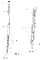
- FIG. 5A is a side perspective of the intramedullary nail
- FIG. 5B is a front perspective of FIG. 5A
- FIG. 5C is a longitudinal cross section along line 5 C— 5 C of FIG. 5B;
- FIG. 6A is an enlargement of a deployed tang assembly of FIG. 3A;
- FIG. 6B is an enlargement of tang assembly of FIG. 6A in the stowed state
- FIG. 6C is a top view of FIG. 6B
- FIG. 7A is a top view of the end cap of FIG. 3A.
- FIG. 7B is a perspective of the end cap of FIG. 7 A.
- the individual components of the assembly are constructed of implantable grade stainless steel alloys in the preferred embodiment but could also be constructed of implantable grade titanium alloys as well. These components consist of the nail body 1 , the tang assembly 2 , the end cap 3 , and the optional cortical screws 4 .
- the nail body, of FIGS. 5 A, B, C is anatomically designed for antegrade insertion into the intramedullary canal of a long bone.
- retrograde insertion into the intramedullary canal is possible with a nail body of similar function, but different anatomical shape.
- the proximal outside diameter W of the nail body 1 is greater than the distal outside diameter M to improve the fit within the proximal bone. Applications within other long bones may result in the proximal outside diameter W being equal to the distal outside diameter M.
- Along the length of the nail body 1 are multiple sets of four tang portals 5 , as shown in FIGS. 3A and 3B.
- a lesser or greater number of circumferential tangs and portals may be employed with the intramedullary nail system (not shown).
- Each set of four tang portals 5 are located on a 90 degree radial spacing penetrating from the leading outside diameter M into the distal bore 6 , on axes which form an angle J to the distal outside diameter M. This angle J is critical to the proper formation and exit of the tang 16 .
- the clearance holes 9 of FIG. 5C pass through the distal outside surface and wall into the distal bore 6 and continue on the same axis through the opposite wall and outer diameter. Their diameter is such as to allow passage of the threaded portion of the cortical screw 4 shown in FIG. 2.
- a frusto-conical surface 10 (FIG.
- the bore 11 serves three purposes: It provides clearance through the leading end of the nail body 1 for passage of a guide pin, used during fracture alignment and installation of the nail body 1 into the intramedullary canal, it provides a sliding fit for the forward protrusion 18 (FIG. 6A) of tang assembly 2 , and it acts as a “vent” hole for any organic material within the bore 6 which is being pushed ahead of the tang assembly 2 during tang assembly 2 installation. It must be noted that the forward most clearance holes 9 also intersect the frusto-conical feature 10 and will act as vents for organic material during tang assembly 2 insertion after the protrusion 18 has engaged and filled bore 11 .
- the internal threads 13 at the trailing end of the nail body 1 provide for instrument interface, as do slots 14 .
- the threads 13 are used for attachment and the slots 14 for radial alignment.
- the internal threads 13 also engage the external threads 23 shown in FIG. 7A of end cap 3 .
- the tang assembly 2 has four equally sized and radially spaced tangs 16 which are preformed to radius R.
- the radius R (FIG. 6B) on each tang 16 results in a dimension between the trailing ends of opposing legs which is greater than the outside diameter of tang body 15 and the bore diameter 6 of nail body 1 .
- the tang body 15 is circular in cross section and sized for a sliding fit within nail body bore 6 with a leading edge chamfer 17 which transitions into the leading protrusion 18 which has a square cross section and leading end taper 19 .
- Tang body 15 contains an internally threaded bore 20 which is the instrument interface for the insertion/deployment/retraction instrument 25 used to insert and deploy the tang 16 of tang assembly 2 . It must be noted that threaded bore 20 is not needed for tang retraction.
- FIG. 6A illustrates the deployed shape of tang assembly 2 which is the shape it assumes after the tangs have been forced through the tang portals 5 of nail body 1 .
- Insertion/deployment of the tang assemblies 2 occurs after insertion of the nail body into the intramedullary canal.
- the insertion/deployment instrument is threaded into the threaded bore 20 of the most distal tang assembly 2 .
- the most distal tang assembly 2 is now inserted through nail body proximal bore 7 and into nail body distal bore 6 . Since the distance between opposing tangs 16 is greater than the bore diameter 6 due to radius R, the interference with bore 6 forces the tangs 16 inward in an elastic manner and insertion continues. As the tang travels down bore 6 , any organic material which has accumulated in bore 6 is pushed ahead and forced out through bore 11 of nail body 1 and through clearance holes 9 .
- the tangs 16 are formed in such a manner as to emerge almost perpendicular to the femoral cortex at a final radius S.
- Continued translation of the tang assembly 2 causes the tangs 16 to penetrate the femoral cortex.
- tang leading protrusion 18 is still engaged by the nail body bore 11 thus preventing rotation of tang assembly 2 in bore 6 during deployment and preventing unwanted twisting of the tangs 16 .
- the tang assembly 2 can be deployed fully or partially and is self locking in any position due to the almost perpendicular entry angle into the cortex. After deployment, the insertion/deployment instrument is unthreaded from tang threaded bore 20 and removed.
- FIG. 3B shows the tang assembly 2 in the fully deployed position having translated a distance from point A FIG. 4B to point B FIG. 3 B.
- the tangs 16 are fully retractable. Tangs 16 are retracted by applying a force on the tang assembly 2 with instrumentation in the opposite direction as deployment until the tang assembly 2 comes to rest at points C and A FIG. 4 B.
- FIG. 1, 3 A and 3 B show deployment of multiple tang assemblies 2 .
- Distal fixation of the nail body 1 can be accomplished without use of tang assembly 2 .
- the cortical screws 4 are placed through the lateral femoral cortex and through clearance holes 9 in the nail body 1 , then through the medial femoral cortex FIG. 2 .
- the cortical screws are not used in conjunction with distal tang fixation and cannot be passed through clearance holes 9 if there is a tang assembly 2 inserted into nail body 1 at that location.
- End cap 3 is inserted into the proximal end of nail body 1 until external threads 23 (FIG. 7B) contact the internal threads 13 of nail body 1 .
- the end cap 3 is then rotated clockwise by means of hexagonal recess 21 to engage the threads.
- End cap 3 contains a coating of ultra high molecular weight polyethylene (UHMWP) 24 which acts as a thread locking element to help prevent unwanted loosening of end cap 3 .
- UHMWP ultra high molecular weight polyethylene
- the top surface 22 of end cap 3 is rounded to provide an anatomic fit with the surrounding bone, thus eliminating irritation against the surrounding musculature.
Abstract
Description
Claims (14)
Priority Applications (2)
| Application Number | Priority Date | Filing Date | Title |
|---|---|---|---|
| US09/841,939 US6488684B2 (en) | 2001-04-25 | 2001-04-25 | Intramedullary nail |
| PCT/US2002/015036 WO2002085228A1 (en) | 2001-04-25 | 2002-04-25 | Intramedullary nail |
Applications Claiming Priority (1)
| Application Number | Priority Date | Filing Date | Title |
|---|---|---|---|
| US09/841,939 US6488684B2 (en) | 2001-04-25 | 2001-04-25 | Intramedullary nail |
Publications (2)
| Publication Number | Publication Date |
|---|---|
| US20020161369A1 US20020161369A1 (en) | 2002-10-31 |
| US6488684B2 true US6488684B2 (en) | 2002-12-03 |
Family
ID=25286117
Family Applications (1)
| Application Number | Title | Priority Date | Filing Date |
|---|---|---|---|
| US09/841,939 Expired - Fee Related US6488684B2 (en) | 2001-04-25 | 2001-04-25 | Intramedullary nail |
Country Status (2)
| Country | Link |
|---|---|
| US (1) | US6488684B2 (en) |
| WO (1) | WO2002085228A1 (en) |
Cited By (52)
| Publication number | Priority date | Publication date | Assignee | Title |
|---|---|---|---|---|
| US20020103488A1 (en) * | 2000-04-10 | 2002-08-01 | Lower Jerry L. | Intramedullary nail with snap-in window |
| US6679890B2 (en) * | 2001-08-28 | 2004-01-20 | Joseph Y. Margulies | Method and apparatus for augmentation of the femoral neck |
| US6786908B2 (en) * | 1999-04-09 | 2004-09-07 | Depuy Orthopaedics, Inc. | Bone fracture support implant with non-metal spacers |
| US20050177158A1 (en) * | 2004-02-09 | 2005-08-11 | Doubler Robert L. | Intramedullary screw and tang for orthopedic surgery |
| US20050261684A1 (en) * | 2002-11-08 | 2005-11-24 | Shaolian Samuel M | Transpedicular intervertebral disk access methods and devices |
| US20060064164A1 (en) * | 2000-03-07 | 2006-03-23 | Thelen Sarah L | Method and apparatus for reducing femoral fractures |
| US20060084997A1 (en) * | 2004-10-05 | 2006-04-20 | Michigan State University, A Michigan Corporation | Devices and methods for interlocking surgical screws and nails |
| US20060095039A1 (en) * | 2004-01-20 | 2006-05-04 | Mutchler Austin W | Intramedullary nail and associated method |
| WO2006079184A1 (en) * | 2005-01-31 | 2006-08-03 | Ian Ross Griggs | Improved intramedullary bone device |
| US20060229617A1 (en) * | 2005-02-25 | 2006-10-12 | Orthomechanics Ltd. | Intramedullary devices and methods of deploying the same |
| US20080177395A1 (en) * | 2007-01-19 | 2008-07-24 | Albert Stinnette | Socket and prosthesis for joint replacement |
| US20080177334A1 (en) * | 2007-01-19 | 2008-07-24 | Alexa Medical, Llc | Screw and method of use |
| US20080262495A1 (en) * | 2004-03-31 | 2008-10-23 | Orthofix S.R.L | Intramedullary Nail Comprising Elements of Shape-Memory Material |
| WO2009002890A1 (en) * | 2007-06-22 | 2008-12-31 | Anthem Orthopaedics Van, Llc | Intramedullary rod with pivotable fastener and method for using same |
| US20090099566A1 (en) * | 2007-10-10 | 2009-04-16 | Maness Megan A | Modular stem inserter |
| US20090306666A1 (en) * | 2005-10-31 | 2009-12-10 | Czartoski Timothy J | Intramedullary nail with oblique openings |
| US7655009B2 (en) | 2003-12-01 | 2010-02-02 | Smith & Nephew, Inc. | Humeral nail |
| US7713271B2 (en) | 2000-09-22 | 2010-05-11 | Piper Medical, Inc. | Intramedullary interlocking fixation devices for the distal radius |
| US20100137863A1 (en) * | 2006-04-06 | 2010-06-03 | Halifax Biomedical Inc. | Intramedullary rod with vent |
| US20100140124A1 (en) * | 2008-12-09 | 2010-06-10 | Zimmer, Inc. | Method and apparatus for packaging medical devices |
| US20100174284A1 (en) * | 2008-10-15 | 2010-07-08 | Zimmer, Gmbh | Intramedullary nail |
| US20100179551A1 (en) * | 2007-05-25 | 2010-07-15 | Zimmer, Gmbh | Reinforced intramedullary nail |
| US7828802B2 (en) | 2004-01-16 | 2010-11-09 | Expanding Orthopedics, Inc. | Bone fracture treatment devices and methods of their use |
| US7846162B2 (en) | 2005-05-18 | 2010-12-07 | Sonoma Orthopedic Products, Inc. | Minimally invasive actuable bone fixation devices |
| US7909825B2 (en) | 2006-11-22 | 2011-03-22 | Sonoma Orthepedic Products, Inc. | Fracture fixation device, tools and methods |
| US20110137356A1 (en) * | 2008-08-12 | 2011-06-09 | Uso-Ck, Llc | Bone compression device and methods |
| US20110208188A1 (en) * | 2010-02-19 | 2011-08-25 | Hossam Abdel Salam El Sayed Mohamed | Intramedullary device and method of use |
| US8034056B2 (en) | 2004-07-15 | 2011-10-11 | Wright Medical Technology, Inc. | Guide assembly for intramedullary fixation and method of using the same |
| US8287541B2 (en) | 2005-05-18 | 2012-10-16 | Sonoma Orthopedic Products, Inc. | Fracture fixation device, tools and methods |
| KR101235983B1 (en) * | 2004-03-31 | 2013-02-21 | 오쏘 휙스 에스.알.엘. | Intramedullary nail comprising elements of shape-memory material |
| US20130096558A1 (en) * | 2003-03-14 | 2013-04-18 | J. Dean Cole | Percutaneous Fixator and Method of Insertion |
| US20130123857A1 (en) * | 2011-09-15 | 2013-05-16 | Lutz Biedermann | Bone anchoring device |
| US8460293B2 (en) | 2010-12-31 | 2013-06-11 | Orthofix S.R.L. | Intramedullary nail with shape memory elements for elongated bones |
| US8491584B1 (en) | 2012-04-13 | 2013-07-23 | Orthopedic Designs North America, Inc. | Intramedullary nail system with tang fixation |
| USRE44501E1 (en) | 2005-02-18 | 2013-09-17 | Smith & Nephew, Inc. | Hindfoot nail |
| US8551106B2 (en) | 2011-09-30 | 2013-10-08 | Arthrocare Corporation | Method and apparatus for installation of intramedullary medical device |
| RU2498783C1 (en) * | 2012-04-28 | 2013-11-20 | Запир Гулмадович Запиров | Elongation, compression and shortening apparatus for treating human and animal tubular bone fractures with short distal fragment |
| US8771283B2 (en) | 2007-12-17 | 2014-07-08 | Wright Medical Technology, Inc. | Guide assembly for intramedullary fixation and method of using the same |
| US8790343B2 (en) | 2008-10-11 | 2014-07-29 | Epix Orthopaedics, Inc. | Intramedullary rod with pivotable and fixed fasteners and method for using same |
| US8876822B2 (en) | 2012-04-13 | 2014-11-04 | Orthopedic Designs North American, Inc. | Intramedullary nail system with tang fixation after lock screw placement |
| US8961516B2 (en) | 2005-05-18 | 2015-02-24 | Sonoma Orthopedic Products, Inc. | Straight intramedullary fracture fixation devices and methods |
| US9060820B2 (en) | 2005-05-18 | 2015-06-23 | Sonoma Orthopedic Products, Inc. | Segmented intramedullary fracture fixation devices and methods |
| US9155574B2 (en) | 2006-05-17 | 2015-10-13 | Sonoma Orthopedic Products, Inc. | Bone fixation device, tools and methods |
| US9320555B2 (en) | 2013-01-31 | 2016-04-26 | Stryker European Holdings I, Llc | Modular lag screw |
| US9433449B2 (en) | 2012-04-13 | 2016-09-06 | Orthopedic Designs North America, Inc | Intramedullary nail system including tang-deployment screw with male interface |
| US9451971B2 (en) | 2004-07-15 | 2016-09-27 | Agilent Technologies, Inc. | Intramedullary fixation assembly and devices and methods for installing the same |
| US9770278B2 (en) | 2014-01-17 | 2017-09-26 | Arthrex, Inc. | Dual tip guide wire |
| US9814499B2 (en) | 2014-09-30 | 2017-11-14 | Arthrex, Inc. | Intramedullary fracture fixation devices and methods |
| US9861418B2 (en) | 2012-02-08 | 2018-01-09 | Epix Orthopaedics, Inc. | Implant insertion device with continuously adjustable targeting assembly |
| US9907597B2 (en) | 2008-08-12 | 2018-03-06 | Charles E. Kollmer | Bone compression system and associated methods |
| US10123828B2 (en) | 2013-03-15 | 2018-11-13 | Epix Orthopaedics, Inc. | Implantable device with pivotable fastener and self-adjusting set screw |
| US11426220B2 (en) | 2017-10-11 | 2022-08-30 | Howmedica Osteonics Corp. | Humeral fixation plate guides |
Families Citing this family (24)
| Publication number | Priority date | Publication date | Assignee | Title |
|---|---|---|---|---|
| US7780710B2 (en) * | 2004-01-23 | 2010-08-24 | Depuy Products, Inc. | System for stabilization of fractures of convex articular bone surfaces including subchondral support structure |
| US7938850B2 (en) | 2002-05-30 | 2011-05-10 | Depuy Products, Inc. | Nail plate |
| CA2500845C (en) | 2002-10-03 | 2012-07-31 | Virginia Tech Intellectual Properties, Inc. | Magnetic targeting device |
| US20050055024A1 (en) | 2003-09-08 | 2005-03-10 | James Anthony H. | Orthopaedic implant and screw assembly |
| US7780667B2 (en) | 2003-09-08 | 2010-08-24 | Smith & Nephew, Inc. | Orthopaedic plate and screw assembly |
| US7799030B2 (en) | 2003-09-08 | 2010-09-21 | Smith & Nephew, Inc. | Orthopaedic plate and screw assembly |
| JP4790634B2 (en) * | 2004-01-23 | 2011-10-12 | デピュイ・プロダクツ・インコーポレイテッド | System for fixing fractures of convex articular bone surfaces having a subchondral support structure |
| US7896886B2 (en) | 2005-01-28 | 2011-03-01 | Depuy Products, Inc. | Nail plate and implantation jig therefor |
| US8128670B2 (en) * | 2005-04-15 | 2012-03-06 | Biodynamics Llc | Surgical expansion fasteners |
| US8568413B2 (en) * | 2008-12-18 | 2013-10-29 | Sonoma Orthopedic Products, Inc. | Bone fixation device, tools and methods |
| US8900321B2 (en) * | 2006-03-20 | 2014-12-02 | Zimmer, Inc. | Implant anchoring device |
| CA2682298C (en) * | 2007-02-23 | 2015-04-28 | Zimmer Gmbh | Implant for fracture treatment |
| US7918853B2 (en) | 2007-03-20 | 2011-04-05 | Smith & Nephew, Inc. | Orthopaedic plate and screw assembly |
| US20100274246A1 (en) * | 2007-05-10 | 2010-10-28 | Oren Globerman | Expandable intramedullary nail for small bone fixation |
| WO2009009772A1 (en) * | 2007-07-11 | 2009-01-15 | Sonoma Orthopedic Products, Inc. | Fracture fixation devices and methods incorporating a membrane |
| WO2010123879A1 (en) * | 2009-04-20 | 2010-10-28 | Virginia Tech Intellectual Properties, Inc. | Intramedullary nail targeting device |
| BRPI1011556A2 (en) | 2009-06-30 | 2016-03-29 | Smith & Nephew Inc | orthopedic implant and fixation assembly |
| BR112013005612A2 (en) | 2010-09-09 | 2016-05-03 | Synthes Gmbh | surgical rod |
| CN104083199B (en) * | 2014-07-25 | 2017-03-29 | 杨涛 | A kind of self-locking compress intramedullary nail for making fracture two ends fluid-tight engagement |
| ITUB20154732A1 (en) * | 2015-10-20 | 2017-04-20 | Univ Degli Studi Di Messina | ENDOMIDOLLAR PROSTHESIS. |
| JP6811498B2 (en) | 2016-09-08 | 2021-01-13 | メダロック, エルエルシー | Implants and methods for long bone fixation |
| US10639484B2 (en) * | 2017-10-19 | 2020-05-05 | Pacesetter, Inc. | Implantable electronic device employing coated lead retaining setscrews |
| RU2712803C1 (en) * | 2019-06-14 | 2020-01-31 | федеральное государственное автономное образовательное учреждение высшего образования "Казанский (Приволжский) федеральный университет" (ФГАОУ ВО КФУ) | Intramedullary expanding rod for osteosynthesis of tubular bones |
| US11344343B2 (en) * | 2020-04-20 | 2022-05-31 | Ideas In Surgery, Inc. | Cannulated compression device |
Citations (10)
| Publication number | Priority date | Publication date | Assignee | Title |
|---|---|---|---|---|
| US4653487A (en) * | 1986-01-29 | 1987-03-31 | Maale Gerhard E | Intramedullary rod assembly for cement injection system |
| FR2606269A1 (en) * | 1986-11-07 | 1988-05-13 | Laffay Jean Pierre | Lockable centromedullary nail for osteosynthesis of long bones, and accessory for its extraction |
| US4862883A (en) | 1988-04-21 | 1989-09-05 | Yosef Freeland | Interlocking intramedullary nail |
| US5810820A (en) | 1994-05-20 | 1998-09-22 | Santori; Francesco Saverio | Endomedullar device for nailing long distance |
| US5849004A (en) * | 1996-07-17 | 1998-12-15 | Bramlet; Dale G. | Surgical anchor |
| US5879352A (en) * | 1994-10-14 | 1999-03-09 | Synthes (U.S.A.) | Osteosynthetic longitudinal alignment and/or fixation device |
| US5971986A (en) | 1996-07-23 | 1999-10-26 | Santori; Francesco Saverio | Intramedullary device for pinning bones |
| US5976139A (en) | 1996-07-17 | 1999-11-02 | Bramlet; Dale G. | Surgical fastener assembly |
| US6077264A (en) | 1996-04-05 | 2000-06-20 | Chemello; Antonio | Intramedullary nail for the osteosynthesis of bone fractures |
| US6126661A (en) | 1997-01-20 | 2000-10-03 | Orthofix S.R.L. | Intramedullary cavity nail and kit for the treatment of fractures of the hip |
Family Cites Families (9)
| Publication number | Priority date | Publication date | Assignee | Title |
|---|---|---|---|---|
| DE2260839C2 (en) * | 1972-12-13 | 1975-02-13 | Ludger Dr. 4403 Hiltrup Schilgen | Device for the treatment of separated long bones by means of pressure osteosynthesis |
| IL54025A0 (en) | 1978-02-12 | 1978-04-30 | Aginsky Yacov | Connector for fractured bones |
| US4453539A (en) | 1982-03-01 | 1984-06-12 | The University Of Toledo | Expandable intramedullary nail for the fixation of bone fractures |
| US4590930A (en) | 1983-06-22 | 1986-05-27 | Lloyd A. Kurth | Fixation device and process for an intramedullary nail |
| DE3413690A1 (en) * | 1984-04-11 | 1985-10-17 | Gerhard 8170 Bad Tölz Dawidowski | Depression/retraction tool for a compression nail for bone fractures |
| US4721103A (en) | 1985-01-31 | 1988-01-26 | Yosef Freedland | Orthopedic device |
| US4632101A (en) | 1985-01-31 | 1986-12-30 | Yosef Freedland | Orthopedic fastener |
| US5057103A (en) | 1990-05-01 | 1991-10-15 | Davis Emsley A | Compressive intramedullary nail |
| IT1296954B1 (en) * | 1997-12-11 | 1999-08-03 | Ortomedical S P A | ENDOMIDOLLAR NAIL FOR USE IN OSTEOSYNTHESIS FOR THE SURGICAL TREATMENT OF DIAPHYSOMETAPISARY FRACTURES OF FEMORE AND TIBIA, |
-
2001
- 2001-04-25 US US09/841,939 patent/US6488684B2/en not_active Expired - Fee Related
-
2002
- 2002-04-25 WO PCT/US2002/015036 patent/WO2002085228A1/en not_active Application Discontinuation
Patent Citations (10)
| Publication number | Priority date | Publication date | Assignee | Title |
|---|---|---|---|---|
| US4653487A (en) * | 1986-01-29 | 1987-03-31 | Maale Gerhard E | Intramedullary rod assembly for cement injection system |
| FR2606269A1 (en) * | 1986-11-07 | 1988-05-13 | Laffay Jean Pierre | Lockable centromedullary nail for osteosynthesis of long bones, and accessory for its extraction |
| US4862883A (en) | 1988-04-21 | 1989-09-05 | Yosef Freeland | Interlocking intramedullary nail |
| US5810820A (en) | 1994-05-20 | 1998-09-22 | Santori; Francesco Saverio | Endomedullar device for nailing long distance |
| US5879352A (en) * | 1994-10-14 | 1999-03-09 | Synthes (U.S.A.) | Osteosynthetic longitudinal alignment and/or fixation device |
| US6077264A (en) | 1996-04-05 | 2000-06-20 | Chemello; Antonio | Intramedullary nail for the osteosynthesis of bone fractures |
| US5849004A (en) * | 1996-07-17 | 1998-12-15 | Bramlet; Dale G. | Surgical anchor |
| US5976139A (en) | 1996-07-17 | 1999-11-02 | Bramlet; Dale G. | Surgical fastener assembly |
| US5971986A (en) | 1996-07-23 | 1999-10-26 | Santori; Francesco Saverio | Intramedullary device for pinning bones |
| US6126661A (en) | 1997-01-20 | 2000-10-03 | Orthofix S.R.L. | Intramedullary cavity nail and kit for the treatment of fractures of the hip |
Cited By (97)
| Publication number | Priority date | Publication date | Assignee | Title |
|---|---|---|---|---|
| US6786908B2 (en) * | 1999-04-09 | 2004-09-07 | Depuy Orthopaedics, Inc. | Bone fracture support implant with non-metal spacers |
| US7485119B2 (en) | 2000-03-07 | 2009-02-03 | Zimmer Technology, Inc. | Method and apparatus for reducing femoral fractures |
| US20060064164A1 (en) * | 2000-03-07 | 2006-03-23 | Thelen Sarah L | Method and apparatus for reducing femoral fractures |
| US6808527B2 (en) * | 2000-04-10 | 2004-10-26 | Depuy Orthopaedics, Inc. | Intramedullary nail with snap-in window insert |
| US20020103488A1 (en) * | 2000-04-10 | 2002-08-01 | Lower Jerry L. | Intramedullary nail with snap-in window |
| US7713271B2 (en) | 2000-09-22 | 2010-05-11 | Piper Medical, Inc. | Intramedullary interlocking fixation devices for the distal radius |
| US8100910B2 (en) | 2000-09-22 | 2012-01-24 | Piper Medical, Inc. | Intramedullary interlocking fixation devices for the distal radius |
| US8092453B2 (en) | 2000-09-22 | 2012-01-10 | Piper Medical, Inc. | Intramedullary interlocking fixation devices for the distal radius |
| US6679890B2 (en) * | 2001-08-28 | 2004-01-20 | Joseph Y. Margulies | Method and apparatus for augmentation of the femoral neck |
| US20050261684A1 (en) * | 2002-11-08 | 2005-11-24 | Shaolian Samuel M | Transpedicular intervertebral disk access methods and devices |
| US8048081B2 (en) * | 2002-11-08 | 2011-11-01 | Warsaw Orthopedic, Inc. | Transpedicular intervertebral disk access methods and devices |
| US20130096558A1 (en) * | 2003-03-14 | 2013-04-18 | J. Dean Cole | Percutaneous Fixator and Method of Insertion |
| US10383666B2 (en) * | 2003-03-14 | 2019-08-20 | J. Dean Cole | Percutaneous fixator and method of insertion |
| US9198699B2 (en) * | 2003-03-14 | 2015-12-01 | J. Dean Cole | Percutaneous fixator and method of insertion |
| US20160081726A1 (en) * | 2003-03-14 | 2016-03-24 | J. Dean Cole | Percutaneous Fixator and Method of Insertion |
| US11202662B2 (en) | 2003-03-14 | 2021-12-21 | J. Dean Cole | Percutaneous fixator and method of insertion |
| US7655009B2 (en) | 2003-12-01 | 2010-02-02 | Smith & Nephew, Inc. | Humeral nail |
| US7828802B2 (en) | 2004-01-16 | 2010-11-09 | Expanding Orthopedics, Inc. | Bone fracture treatment devices and methods of their use |
| US7947043B2 (en) * | 2004-01-20 | 2011-05-24 | Depuy Products, Inc. | Intramedullary nail and associated method |
| US20060095039A1 (en) * | 2004-01-20 | 2006-05-04 | Mutchler Austin W | Intramedullary nail and associated method |
| US8157801B2 (en) | 2004-02-09 | 2012-04-17 | Doubler Robert L | Intramedullary screw and tang for orthopedic surgery |
| US20050177158A1 (en) * | 2004-02-09 | 2005-08-11 | Doubler Robert L. | Intramedullary screw and tang for orthopedic surgery |
| KR101235983B1 (en) * | 2004-03-31 | 2013-02-21 | 오쏘 휙스 에스.알.엘. | Intramedullary nail comprising elements of shape-memory material |
| US20080262495A1 (en) * | 2004-03-31 | 2008-10-23 | Orthofix S.R.L | Intramedullary Nail Comprising Elements of Shape-Memory Material |
| US8162942B2 (en) * | 2004-03-31 | 2012-04-24 | Orthofix S.R.L. | Intramedullary nail comprising elements of shape-memory material |
| AU2010226866B2 (en) * | 2004-03-31 | 2012-04-05 | Orthofix S.R.L. | Intramedullary nail comprising elements of shape-memory material |
| AU2010226867B2 (en) * | 2004-03-31 | 2012-04-05 | Orthofix S.R.L. | Intramedullary nail comprising elements of shape-memory material |
| US9451971B2 (en) | 2004-07-15 | 2016-09-27 | Agilent Technologies, Inc. | Intramedullary fixation assembly and devices and methods for installing the same |
| US8034056B2 (en) | 2004-07-15 | 2011-10-11 | Wright Medical Technology, Inc. | Guide assembly for intramedullary fixation and method of using the same |
| US8435238B2 (en) * | 2004-10-05 | 2013-05-07 | Michigan State University | Devices and methods for interlocking surgical screws and nails |
| US20060084997A1 (en) * | 2004-10-05 | 2006-04-20 | Michigan State University, A Michigan Corporation | Devices and methods for interlocking surgical screws and nails |
| US9072553B2 (en) * | 2004-10-05 | 2015-07-07 | The Board Of Trustees Of Michigan State University | Devices and methods for interlocking surgical screws and nails |
| US20140309637A1 (en) * | 2004-10-05 | 2014-10-16 | Board Of Trustees Of Michigan State University | Devices and methods for interlocking surgical screws and nails |
| US8034054B2 (en) | 2005-01-31 | 2011-10-11 | Ian Ross Griggs | Intramedullary bone device |
| WO2006079184A1 (en) * | 2005-01-31 | 2006-08-03 | Ian Ross Griggs | Improved intramedullary bone device |
| US20080312657A1 (en) * | 2005-01-31 | 2008-12-18 | Ian Ross Griggs | Intramedullary Bone Device |
| USRE44501E1 (en) | 2005-02-18 | 2013-09-17 | Smith & Nephew, Inc. | Hindfoot nail |
| USRE46008E1 (en) | 2005-02-18 | 2016-05-24 | Smith & Nephew, Inc. | Hindfoot nail |
| USRE46078E1 (en) | 2005-02-18 | 2016-07-26 | Smith & Nephew, Inc. | Hindfoot nail |
| US20060229617A1 (en) * | 2005-02-25 | 2006-10-12 | Orthomechanics Ltd. | Intramedullary devices and methods of deploying the same |
| US7846162B2 (en) | 2005-05-18 | 2010-12-07 | Sonoma Orthopedic Products, Inc. | Minimally invasive actuable bone fixation devices |
| US7914533B2 (en) | 2005-05-18 | 2011-03-29 | Sonoma Orthopedic Products, Inc. | Minimally invasive actuable bone fixation devices |
| US7942875B2 (en) | 2005-05-18 | 2011-05-17 | Sonoma Orthopedic Products, Inc. | Methods of using minimally invasive actuable bone fixation devices |
| US8961516B2 (en) | 2005-05-18 | 2015-02-24 | Sonoma Orthopedic Products, Inc. | Straight intramedullary fracture fixation devices and methods |
| US9060820B2 (en) | 2005-05-18 | 2015-06-23 | Sonoma Orthopedic Products, Inc. | Segmented intramedullary fracture fixation devices and methods |
| US8287541B2 (en) | 2005-05-18 | 2012-10-16 | Sonoma Orthopedic Products, Inc. | Fracture fixation device, tools and methods |
| US8287539B2 (en) | 2005-05-18 | 2012-10-16 | Sonoma Orthopedic Products, Inc. | Fracture fixation device, tools and methods |
| US8679121B2 (en) * | 2005-10-31 | 2014-03-25 | Biomet C.V. | Intramedullary nail with oblique openings |
| US10010355B2 (en) | 2005-10-31 | 2018-07-03 | Biomet C.V. | Intramedullary nail with oblique openings |
| US20090306666A1 (en) * | 2005-10-31 | 2009-12-10 | Czartoski Timothy J | Intramedullary nail with oblique openings |
| US9005201B2 (en) * | 2006-04-06 | 2015-04-14 | Halifax Biomedical Inc. | Intramedullary rod with vent |
| US20100137863A1 (en) * | 2006-04-06 | 2010-06-03 | Halifax Biomedical Inc. | Intramedullary rod with vent |
| US9155574B2 (en) | 2006-05-17 | 2015-10-13 | Sonoma Orthopedic Products, Inc. | Bone fixation device, tools and methods |
| US7909825B2 (en) | 2006-11-22 | 2011-03-22 | Sonoma Orthepedic Products, Inc. | Fracture fixation device, tools and methods |
| US8439917B2 (en) | 2006-11-22 | 2013-05-14 | Sonoma Orthopedic Products, Inc. | Fracture fixation device, tools and methods |
| US9259250B2 (en) | 2006-11-22 | 2016-02-16 | Sonoma Orthopedic Products, Inc. | Fracture fixation device, tools and methods |
| US20080177334A1 (en) * | 2007-01-19 | 2008-07-24 | Alexa Medical, Llc | Screw and method of use |
| US20080177395A1 (en) * | 2007-01-19 | 2008-07-24 | Albert Stinnette | Socket and prosthesis for joint replacement |
| US8317845B2 (en) | 2007-01-19 | 2012-11-27 | Alexa Medical, Llc | Screw and method of use |
| US7909882B2 (en) | 2007-01-19 | 2011-03-22 | Albert Stinnette | Socket and prosthesis for joint replacement |
| US9597129B2 (en) | 2007-05-25 | 2017-03-21 | Zimmer Gmbh | Reinforced intramedullary nail |
| US20100179551A1 (en) * | 2007-05-25 | 2010-07-15 | Zimmer, Gmbh | Reinforced intramedullary nail |
| WO2009002890A1 (en) * | 2007-06-22 | 2008-12-31 | Anthem Orthopaedics Van, Llc | Intramedullary rod with pivotable fastener and method for using same |
| US20090048600A1 (en) * | 2007-06-22 | 2009-02-19 | Anthem Orthopaedics Van, Llc | Intramedullary rod with pivotable fastener and method for using same |
| US8906023B2 (en) | 2007-06-22 | 2014-12-09 | Epix Orthopaedics, Inc. | Intramedullary rod for pivoting a fastener |
| US10687871B2 (en) | 2007-06-22 | 2020-06-23 | Epix Orthopaedics, Inc. | Intramedullary rod for pivoting a fastener |
| KR101503665B1 (en) | 2007-06-22 | 2015-03-18 | 이픽스 오소페딕스, 인코포레이티드 | Intramedullary rod for pivoting a fastener |
| US9861403B2 (en) | 2007-06-22 | 2018-01-09 | Epix Orthopaedics, Inc. | Method for pivoting a fastener |
| US20090099566A1 (en) * | 2007-10-10 | 2009-04-16 | Maness Megan A | Modular stem inserter |
| US8771283B2 (en) | 2007-12-17 | 2014-07-08 | Wright Medical Technology, Inc. | Guide assembly for intramedullary fixation and method of using the same |
| US9662153B2 (en) | 2007-12-17 | 2017-05-30 | Wright Medical Technology, Inc. | Guide assembly for intramedullary fixation and method of using the same |
| US20110137356A1 (en) * | 2008-08-12 | 2011-06-09 | Uso-Ck, Llc | Bone compression device and methods |
| US9907597B2 (en) | 2008-08-12 | 2018-03-06 | Charles E. Kollmer | Bone compression system and associated methods |
| US9247963B2 (en) | 2008-08-12 | 2016-02-02 | Charles Kollmer | Bone compression device and methods |
| US8790343B2 (en) | 2008-10-11 | 2014-07-29 | Epix Orthopaedics, Inc. | Intramedullary rod with pivotable and fixed fasteners and method for using same |
| US9474557B2 (en) | 2008-10-15 | 2016-10-25 | Zimmer Gmbh | Intramedullary nail |
| US20100174284A1 (en) * | 2008-10-15 | 2010-07-08 | Zimmer, Gmbh | Intramedullary nail |
| US8668695B2 (en) | 2008-10-15 | 2014-03-11 | Zimmer Gmbh | Intramedullary nail |
| US20100140124A1 (en) * | 2008-12-09 | 2010-06-10 | Zimmer, Inc. | Method and apparatus for packaging medical devices |
| US8006839B2 (en) * | 2008-12-09 | 2011-08-30 | Zimmer, Inc. | Method and apparatus for packaging medical devices |
| US8052685B2 (en) * | 2010-02-19 | 2011-11-08 | Hossam Abdel Salam El Sayed Mohamed | Intramedullary device and method of use |
| US20110208188A1 (en) * | 2010-02-19 | 2011-08-25 | Hossam Abdel Salam El Sayed Mohamed | Intramedullary device and method of use |
| US8460293B2 (en) | 2010-12-31 | 2013-06-11 | Orthofix S.R.L. | Intramedullary nail with shape memory elements for elongated bones |
| US9308035B2 (en) * | 2011-09-15 | 2016-04-12 | Biedermann Technologies Gmbh & Co. Kg | Bone anchoring device |
| US20130123857A1 (en) * | 2011-09-15 | 2013-05-16 | Lutz Biedermann | Bone anchoring device |
| US8551106B2 (en) | 2011-09-30 | 2013-10-08 | Arthrocare Corporation | Method and apparatus for installation of intramedullary medical device |
| US9861418B2 (en) | 2012-02-08 | 2018-01-09 | Epix Orthopaedics, Inc. | Implant insertion device with continuously adjustable targeting assembly |
| US8876822B2 (en) | 2012-04-13 | 2014-11-04 | Orthopedic Designs North American, Inc. | Intramedullary nail system with tang fixation after lock screw placement |
| US9433449B2 (en) | 2012-04-13 | 2016-09-06 | Orthopedic Designs North America, Inc | Intramedullary nail system including tang-deployment screw with male interface |
| US8491584B1 (en) | 2012-04-13 | 2013-07-23 | Orthopedic Designs North America, Inc. | Intramedullary nail system with tang fixation |
| RU2498783C1 (en) * | 2012-04-28 | 2013-11-20 | Запир Гулмадович Запиров | Elongation, compression and shortening apparatus for treating human and animal tubular bone fractures with short distal fragment |
| US9320555B2 (en) | 2013-01-31 | 2016-04-26 | Stryker European Holdings I, Llc | Modular lag screw |
| US10123828B2 (en) | 2013-03-15 | 2018-11-13 | Epix Orthopaedics, Inc. | Implantable device with pivotable fastener and self-adjusting set screw |
| US9770278B2 (en) | 2014-01-17 | 2017-09-26 | Arthrex, Inc. | Dual tip guide wire |
| US9814499B2 (en) | 2014-09-30 | 2017-11-14 | Arthrex, Inc. | Intramedullary fracture fixation devices and methods |
| US10548648B2 (en) | 2014-09-30 | 2020-02-04 | Arthrex, Inc. | Intramedullary fracture fixation devices and methods |
| US11426220B2 (en) | 2017-10-11 | 2022-08-30 | Howmedica Osteonics Corp. | Humeral fixation plate guides |
Also Published As
| Publication number | Publication date |
|---|---|
| WO2002085228A1 (en) | 2002-10-31 |
| US20020161369A1 (en) | 2002-10-31 |
Similar Documents
| Publication | Publication Date | Title |
|---|---|---|
| US6488684B2 (en) | Intramedullary nail | |
| CA2444914C (en) | Fermoral nail intamedullary system | |
| US6648889B2 (en) | Intramedullary hip nail with bifurcated lock | |
| US20220047313A1 (en) | Systems and methods for intramedullary nail implantation | |
| US7763023B2 (en) | Intramedullary nail system and method for fixation of a fractured bone | |
| US11730524B2 (en) | Systems and methods for intramedullary nail implantation | |
| US4940467A (en) | Variable length fixation device | |
| AU2002309801A1 (en) | Fermoral nail intamedullary system | |
| US8137348B2 (en) | Apparatus for treating a fractured bone | |
| US8876822B2 (en) | Intramedullary nail system with tang fixation after lock screw placement | |
| US20080119856A1 (en) | Intramedullary nail system and method for fixation of a fractured bone | |
| US10092332B2 (en) | Intramedullary nails | |
| EP1638473A2 (en) | Plate device | |
| WO1989006940A1 (en) | Variable length fixation device | |
| US11801078B2 (en) | Systems and methods for intramedullary nail implantation | |
| US20190388129A1 (en) | Systems and methods for anisotropy restoring femoroplasty | |
| EP3449855B1 (en) | Systems for intramedullary nail implantation | |
| AU2002356834A1 (en) | Intramedullary hip nail with bifurcated lock |
Legal Events
| Date | Code | Title | Description |
|---|---|---|---|
| AS | Assignment |
Owner name: ORTHOPEDIC DESIGNS, INC., FLORIDA Free format text: ASSIGNMENT OF ASSIGNORS INTEREST;ASSIGNORS:BRAMLET, DALE G.;STERGHOS, PETER M.;SODEIKA, JOHN A.;AND OTHERS;REEL/FRAME:013634/0844 Effective date: 20021231 |
|
| FEPP | Fee payment procedure |
Free format text: PAT HOLDER CLAIMS SMALL ENTITY STATUS, ENTITY STATUS SET TO SMALL (ORIGINAL EVENT CODE: LTOS); ENTITY STATUS OF PATENT OWNER: SMALL ENTITY |
|
| FPAY | Fee payment |
Year of fee payment: 4 |
|
| SULP | Surcharge for late payment | ||
| FPAY | Fee payment |
Year of fee payment: 8 |
|
| AS | Assignment |
Owner name: ORTHOPEDIC DESIGNS NORTH AMERICA, INC., FLORIDA Free format text: ASSIGNMENT OF ASSIGNORS INTEREST;ASSIGNOR:ORTHOPEDIC DESIGNS, INC.;REEL/FRAME:026313/0705 Effective date: 20110517 |
|
| REMI | Maintenance fee reminder mailed | ||
| LAPS | Lapse for failure to pay maintenance fees | ||
| STCH | Information on status: patent discontinuation |
Free format text: PATENT EXPIRED DUE TO NONPAYMENT OF MAINTENANCE FEES UNDER 37 CFR 1.362 |
|
| FP | Lapsed due to failure to pay maintenance fee |
Effective date: 20141203 |