JP6810160B2 - How to finish the manufacture of insulation strips for doors, windows or façade elements, and composite profile materials for doors, windows or façade elements, and roll-in heads for insulation strips for doors, windows or façade elements. - Google Patents
How to finish the manufacture of insulation strips for doors, windows or façade elements, and composite profile materials for doors, windows or façade elements, and roll-in heads for insulation strips for doors, windows or façade elements. Download PDFInfo
- Publication number
- JP6810160B2 JP6810160B2 JP2018555618A JP2018555618A JP6810160B2 JP 6810160 B2 JP6810160 B2 JP 6810160B2 JP 2018555618 A JP2018555618 A JP 2018555618A JP 2018555618 A JP2018555618 A JP 2018555618A JP 6810160 B2 JP6810160 B2 JP 6810160B2
- Authority
- JP
- Japan
- Prior art keywords
- roll
- head
- sheet
- heat insulating
- longitudinal direction
- Prior art date
- Legal status (The legal status is an assumption and is not a legal conclusion. Google has not performed a legal analysis and makes no representation as to the accuracy of the status listed.)
- Active
Links
- 239000000463 material Substances 0.000 title claims description 128
- 239000002131 composite material Substances 0.000 title claims description 41
- 238000009413 insulation Methods 0.000 title claims description 34
- 238000004519 manufacturing process Methods 0.000 title claims description 4
- 230000007704 transition Effects 0.000 claims description 46
- 239000007769 metal material Substances 0.000 claims description 33
- 238000005520 cutting process Methods 0.000 claims description 32
- 238000002844 melting Methods 0.000 claims description 15
- 230000008018 melting Effects 0.000 claims description 15
- 239000011810 insulating material Substances 0.000 claims description 13
- 230000008859 change Effects 0.000 claims description 11
- 238000000034 method Methods 0.000 claims description 11
- 229910000831 Steel Inorganic materials 0.000 claims description 7
- 239000010959 steel Substances 0.000 claims description 7
- 229920001169 thermoplastic Polymers 0.000 claims description 5
- 239000004416 thermosoftening plastic Substances 0.000 claims description 5
- 238000005452 bending Methods 0.000 claims description 4
- 230000001419 dependent effect Effects 0.000 claims description 3
- 238000003825 pressing Methods 0.000 claims description 3
- 229910052751 metal Inorganic materials 0.000 description 116
- 239000002184 metal Substances 0.000 description 116
- 239000004033 plastic Substances 0.000 description 21
- 229920003023 plastic Polymers 0.000 description 21
- 230000013011 mating Effects 0.000 description 10
- 229910052782 aluminium Inorganic materials 0.000 description 8
- XAGFODPZIPBFFR-UHFFFAOYSA-N aluminium Chemical compound [Al] XAGFODPZIPBFFR-UHFFFAOYSA-N 0.000 description 8
- 230000004048 modification Effects 0.000 description 6
- 238000012986 modification Methods 0.000 description 6
- 229910000838 Al alloy Inorganic materials 0.000 description 4
- 238000005553 drilling Methods 0.000 description 4
- 150000002739 metals Chemical class 0.000 description 4
- 230000001154 acute effect Effects 0.000 description 3
- 239000006261 foam material Substances 0.000 description 3
- 239000010410 layer Substances 0.000 description 3
- 238000001125 extrusion Methods 0.000 description 2
- 238000003466 welding Methods 0.000 description 2
- -1 AW7068 or AW7075 Inorganic materials 0.000 description 1
- 229910001335 Galvanized steel Inorganic materials 0.000 description 1
- 239000000853 adhesive Substances 0.000 description 1
- 230000001070 adhesive effect Effects 0.000 description 1
- 229910045601 alloy Inorganic materials 0.000 description 1
- 239000000956 alloy Substances 0.000 description 1
- 229920001222 biopolymer Polymers 0.000 description 1
- 239000011248 coating agent Substances 0.000 description 1
- 238000000576 coating method Methods 0.000 description 1
- 230000000295 complement effect Effects 0.000 description 1
- 238000011161 development Methods 0.000 description 1
- 230000018109 developmental process Effects 0.000 description 1
- 230000004907 flux Effects 0.000 description 1
- 239000006260 foam Substances 0.000 description 1
- 239000011888 foil Substances 0.000 description 1
- 239000008397 galvanized steel Substances 0.000 description 1
- 239000003365 glass fiber Substances 0.000 description 1
- 230000001788 irregular Effects 0.000 description 1
- 239000000203 mixture Substances 0.000 description 1
- 230000035515 penetration Effects 0.000 description 1
- 229920001470 polyketone Polymers 0.000 description 1
- 229920000642 polymer Polymers 0.000 description 1
- 239000011148 porous material Substances 0.000 description 1
- 230000003014 reinforcing effect Effects 0.000 description 1
- 238000005096 rolling process Methods 0.000 description 1
- 239000010935 stainless steel Substances 0.000 description 1
- 229910001220 stainless steel Inorganic materials 0.000 description 1
- 239000002344 surface layer Substances 0.000 description 1
- 239000012815 thermoplastic material Substances 0.000 description 1
Images


Classifications
-
- E—FIXED CONSTRUCTIONS
- E06—DOORS, WINDOWS, SHUTTERS, OR ROLLER BLINDS IN GENERAL; LADDERS
- E06B—FIXED OR MOVABLE CLOSURES FOR OPENINGS IN BUILDINGS, VEHICLES, FENCES OR LIKE ENCLOSURES IN GENERAL, e.g. DOORS, WINDOWS, BLINDS, GATES
- E06B3/00—Window sashes, door leaves, or like elements for closing wall or like openings; Layout of fixed or moving closures, e.g. windows in wall or like openings; Features of rigidly-mounted outer frames relating to the mounting of wing frames
- E06B3/04—Wing frames not characterised by the manner of movement
- E06B3/263—Frames with special provision for insulation
- E06B3/26301—Frames with special provision for insulation with prefabricated insulating strips between two metal section members
- E06B3/26303—Frames with special provision for insulation with prefabricated insulating strips between two metal section members with thin strips, e.g. defining a hollow space between the metal section members
-
- E—FIXED CONSTRUCTIONS
- E06—DOORS, WINDOWS, SHUTTERS, OR ROLLER BLINDS IN GENERAL; LADDERS
- E06B—FIXED OR MOVABLE CLOSURES FOR OPENINGS IN BUILDINGS, VEHICLES, FENCES OR LIKE ENCLOSURES IN GENERAL, e.g. DOORS, WINDOWS, BLINDS, GATES
- E06B3/00—Window sashes, door leaves, or like elements for closing wall or like openings; Layout of fixed or moving closures, e.g. windows in wall or like openings; Features of rigidly-mounted outer frames relating to the mounting of wing frames
- E06B3/04—Wing frames not characterised by the manner of movement
- E06B3/263—Frames with special provision for insulation
- E06B3/273—Frames with special provision for insulation with prefabricated insulating elements held in position by deformation of portions of the metal frame members
-
- E—FIXED CONSTRUCTIONS
- E06—DOORS, WINDOWS, SHUTTERS, OR ROLLER BLINDS IN GENERAL; LADDERS
- E06B—FIXED OR MOVABLE CLOSURES FOR OPENINGS IN BUILDINGS, VEHICLES, FENCES OR LIKE ENCLOSURES IN GENERAL, e.g. DOORS, WINDOWS, BLINDS, GATES
- E06B3/00—Window sashes, door leaves, or like elements for closing wall or like openings; Layout of fixed or moving closures, e.g. windows in wall or like openings; Features of rigidly-mounted outer frames relating to the mounting of wing frames
- E06B3/04—Wing frames not characterised by the manner of movement
- E06B3/263—Frames with special provision for insulation
- E06B3/26301—Frames with special provision for insulation with prefabricated insulating strips between two metal section members
- E06B3/26305—Connection details
- E06B2003/26314—Provisions for reducing the shift between the strips and the metal section members
-
- E—FIXED CONSTRUCTIONS
- E06—DOORS, WINDOWS, SHUTTERS, OR ROLLER BLINDS IN GENERAL; LADDERS
- E06B—FIXED OR MOVABLE CLOSURES FOR OPENINGS IN BUILDINGS, VEHICLES, FENCES OR LIKE ENCLOSURES IN GENERAL, e.g. DOORS, WINDOWS, BLINDS, GATES
- E06B3/00—Window sashes, door leaves, or like elements for closing wall or like openings; Layout of fixed or moving closures, e.g. windows in wall or like openings; Features of rigidly-mounted outer frames relating to the mounting of wing frames
- E06B3/04—Wing frames not characterised by the manner of movement
- E06B3/263—Frames with special provision for insulation
- E06B2003/26349—Details of insulating strips
- E06B2003/2635—Specific form characteristics
-
- E—FIXED CONSTRUCTIONS
- E06—DOORS, WINDOWS, SHUTTERS, OR ROLLER BLINDS IN GENERAL; LADDERS
- E06B—FIXED OR MOVABLE CLOSURES FOR OPENINGS IN BUILDINGS, VEHICLES, FENCES OR LIKE ENCLOSURES IN GENERAL, e.g. DOORS, WINDOWS, BLINDS, GATES
- E06B3/00—Window sashes, door leaves, or like elements for closing wall or like openings; Layout of fixed or moving closures, e.g. windows in wall or like openings; Features of rigidly-mounted outer frames relating to the mounting of wing frames
- E06B3/04—Wing frames not characterised by the manner of movement
- E06B3/263—Frames with special provision for insulation
- E06B2003/26349—Details of insulating strips
- E06B2003/26369—Specific material characteristics
- E06B2003/26372—Specific material characteristics with coatings
-
- E—FIXED CONSTRUCTIONS
- E06—DOORS, WINDOWS, SHUTTERS, OR ROLLER BLINDS IN GENERAL; LADDERS
- E06B—FIXED OR MOVABLE CLOSURES FOR OPENINGS IN BUILDINGS, VEHICLES, FENCES OR LIKE ENCLOSURES IN GENERAL, e.g. DOORS, WINDOWS, BLINDS, GATES
- E06B3/00—Window sashes, door leaves, or like elements for closing wall or like openings; Layout of fixed or moving closures, e.g. windows in wall or like openings; Features of rigidly-mounted outer frames relating to the mounting of wing frames
- E06B3/04—Wing frames not characterised by the manner of movement
- E06B3/263—Frames with special provision for insulation
- E06B2003/26349—Details of insulating strips
- E06B2003/26369—Specific material characteristics
- E06B2003/26374—Specific material characteristics with parts of differing nature
-
- E—FIXED CONSTRUCTIONS
- E06—DOORS, WINDOWS, SHUTTERS, OR ROLLER BLINDS IN GENERAL; LADDERS
- E06B—FIXED OR MOVABLE CLOSURES FOR OPENINGS IN BUILDINGS, VEHICLES, FENCES OR LIKE ENCLOSURES IN GENERAL, e.g. DOORS, WINDOWS, BLINDS, GATES
- E06B3/00—Window sashes, door leaves, or like elements for closing wall or like openings; Layout of fixed or moving closures, e.g. windows in wall or like openings; Features of rigidly-mounted outer frames relating to the mounting of wing frames
- E06B3/04—Wing frames not characterised by the manner of movement
- E06B3/263—Frames with special provision for insulation
- E06B2003/26396—Frames with special provision for insulation specially adapted for sheet metal frames
Landscapes
- Engineering & Computer Science (AREA)
- Civil Engineering (AREA)
- Structural Engineering (AREA)
- Pressure Welding/Diffusion-Bonding (AREA)
- Shaping Of Tube Ends By Bending Or Straightening (AREA)
- Joining Of Corner Units Of Frames Or Wings (AREA)
- Wing Frames And Configurations (AREA)
- Securing Of Glass Panes Or The Like (AREA)
- Special Wing (AREA)
- Building Environments (AREA)
- Roof Covering Using Slabs Or Stiff Sheets (AREA)
Description
本発明は、ドア、窓又はファサード要素のための断熱ストリップと、そのような断熱ストリップを備えた、ドア、窓又はファサード要素のためのコンポジットプロファイル材と、ドア、窓又はファサード要素のための断熱ストリップのロールインヘッドの製造を仕上げる方法と、に関する。 The present invention comprises insulating strips for doors, windows or façade elements, composite profile materials for doors, windows or façade elements with such insulating strips, and insulation for doors, windows or façade elements. On how to finish the production of roll-in heads for strips.
ドア、窓又はファサード要素等のための断熱複合プロファイル材が周知である。このような断熱複合プロファイル材は、通常、断熱され、1つ又は複数の断熱ストリップによって機械的に接続された2つのプロファイル材を備える。このような断熱ストリップは、低熱伝導率のプラスチック材料からなり、2つのプロファイル材の良好な断熱を提供する。断熱ストリップは、断熱ストリップのロールインヘッドをプロファイル材の対応する溝にロールインすることによってプロファイル材に接続することができる。このロールイン技術が、国際公開第84/03326A1号の図1〜3に例示的に示されている。 Insulation composite profile materials for doors, windows or façade elements are well known. Such adiabatic composite profiling material typically comprises two profiling materials that are insulated and mechanically connected by one or more adiabatic strips. Such insulation strips are made of low thermal conductivity plastic material and provide good insulation of the two profile materials. The insulation strip can be connected to the profile material by rolling the roll-in head of the insulation strip into the corresponding groove in the profile material. This roll-in technique is illustrated exemplary in FIGS. 1-3326A1 of WO 84/03326A1.
複合プロファイル材の縦方向におけるこのようなロールイン接続のせん断強度は、特に1.5m以上の側部長さを有するより大型のドア、窓又はファサード要素にとって重要である。 The shear strength of such roll-in connections in the longitudinal direction of the composite profile material is especially important for larger doors, windows or façade elements with side lengths of 1.5 m or greater.
独国特許第36 33 392C1号及び独国特許出願公開第36 33 933A1号は、断熱ストリップに接続された金属プロファイル材との嵌合を提供するために、断熱ストリップのプラスチック本体に埋め込まれた金属要素を備えた断熱ストリップを開示している。 German Patent No. 36 33 392C1 and German Patent Application Publication No. 36 33 933A1 are metals embedded in the plastic body of the insulation strip to provide mating with the metal profile material connected to the insulation strip. Insulation strips with elements are disclosed.
独国特許出願公開第29 37 454A1号及び独国特許出願公開第39 39 968A1号は、断熱ストリップと金属プロファイル材との間のせん断強度を高めるために、断熱ストリップのプラスチック本体に金属ワイヤ又は金属シートが埋め込まれた断熱ストリップを有する複合プロファイル材を開示している。 German Patent Application Publication No. 29 37 454A1 and German Patent Application Publication No. 39 39 968A1 have metal wires or metals on the plastic body of the insulation strip to increase the shear strength between the insulation strip and the metal profile material. Disclosed is a composite profile material having an insulating strip with embedded sheets.
欧州特許出願公開第0 085 410A2号は、低融点(金属形プロファイル材の融点よりも低い)を有する金属で作製できる複合プロファイル材のせん断強度を高めるために、ワイヤ、ストリップ、又は、フォイル(foil)を備えた断熱ストリップを開示している。 European Patent Application Publication No. 0805 410A2 describes wires, strips, or foils to increase the shear strength of composite profile materials that can be made of metals with a low melting point (lower than the melting point of metal profile materials). ) Is disclosed.
欧州特許出願公開第0 032 408A2号、欧州特許出願公開第2 045 430A1号、スイス国特許第354 573号、独国特許第AS25 52 700(ファミリー、英国特許第1 523 676号)、独国特許第OS28 30 798号及び独国特許出願公開第37 42 416A1号は、ドア、窓又はファサード要素のための複合プロファイル材のせん断強度を高めるさらなる技術を開示している。 European Patent Application Publication No. 0032 408A2, European Patent Application Publication No. 2045 430A1, Swiss Patent No. 354 573, German Patent No. AS25 52 700 (Family, British Patent No. 1 523 676), German Patent OS 28 30 798 and Publication of German Patent Application No. 37 42 416A1 disclose additional techniques for increasing the shear strength of composite profile materials for doors, windows or façade elements.
独国特許出願公開第32 36 357A1号は、断熱ストリップの端部に金属層を有する断熱ストリップを備えた、ドア、窓又はファサード要素のための複合プロファイル材を開示している。溝の金属層に面する表面は、ローレットパターンを備え得る。 German Patent Application Publication No. 32 36 357A1 discloses a composite profile material for doors, windows or façade elements with a heat insulating strip having a metal layer at the end of the heat insulating strip. The surface of the groove facing the metal layer may include a knurled pattern.
本発明の目的は、ドア、窓又はファサード要素のための複合プロファイル材において、高せん断強度を保証するための改良された技術を提供することである。 It is an object of the present invention to provide improved techniques for ensuring high shear strength in composite profile materials for doors, windows or façade elements.
この目的は、請求項1、2若しくは3に記載の断熱ストリップ、又は、請求項18に記載の複合プロファイル材、又は、請求項19に記載の方法によって達成される。
This object is achieved by the insulating strip according to
本発明のさらなる発展形態は、従属請求項に記載されている。 Further developments of the present invention are described in the dependent claims.
断熱ストリップのロールインヘッド表面の少なくとも一部に金属シートを配置することができる。ロールインヘッド及び金属プロファイル材に関するせん断強度は、金属シートに設けられた穿孔及びフラップのような表面変化によって高められる。 A metal sheet can be placed on at least a portion of the roll-in head surface of the insulation strip. Shear strength for roll-in heads and metal profile materials is enhanced by surface changes such as perforations and flaps provided in the metal sheet.
断熱ストリップのストリップ本体及びロールインヘッドは、通常、例えば押出成形によって一体形成されるが、例えば、接着、溶接等によって異なる部品からの組み立ても可能である。金属シートは、シートがロールインヘッドに完全に埋め込まれる必要がないので、押出成形後にロールインヘッドに取り付けることができる。 The strip body and roll-in head of the heat insulating strip are usually integrally formed by, for example, extrusion molding, but can be assembled from different parts by, for example, adhesion, welding, or the like. The metal sheet can be attached to the roll-in head after extrusion because the sheet does not need to be completely embedded in the roll-in head.
ロールインヘッドの表面内への突起形態の金属シートの表面変化によって、ロールインヘッドでの金属シートのしっかりした適合を提供することができる。このような突起は、穿孔及び/又はフラップをロールインヘッドの材料内に押し込むことによって達成することができる。 The surface changes of the metal sheet in the form of protrusions into the surface of the roll-in head can provide a firm fit of the metal sheet in the roll-in head. Such protrusions can be achieved by pushing perforations and / or flaps into the material of the roll-in head.
さらなる特徴及び利点は、図面を参照して例示的な実施形態の説明から得られる。 Further features and advantages can be obtained from the description of exemplary embodiments with reference to the drawings.
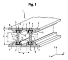
図1は、長手方向zに垂直な平面における断面を有する、一実施形態によるドア、窓又はファサード要素のための複合プロファイル材1の部分斜視図を示す。複合プロファイル材1は、長手方向zに沿って延びている。複合プロファイル材1の長手方向zに沿った断面は、実質的に一定である。 FIG. 1 shows a partial perspective view of a composite profile material 1 for a door, window or façade element according to one embodiment, having a cross section in a plane perpendicular to the longitudinal direction z. The composite profile material 1 extends along the longitudinal direction z. The cross section of the composite profile material 1 along the longitudinal direction z is substantially constant.
複合プロファイル材1は、2つのプロファイル材2を備えている。2つのプロファイル材2は、長手方向zに垂直な高さ方向yにおいて互いに対向するように配置され、高さ方向yにおいて距離dだけ離間している。距離dは、1cm〜25cmの範囲内であることができる。プロファイル材2の壁厚tは、1mm〜20mmの範囲内であることができる。 The composite profile material 1 includes two profile materials 2. The two profile materials 2 are arranged so as to face each other in the height direction y perpendicular to the longitudinal direction z, and are separated by a distance d in the height direction y. The distance d can be in the range of 1 cm to 25 cm. The wall thickness t of the profile material 2 can be in the range of 1 mm to 20 mm.
プロファイル材2は、アルミニウム等の金属材料からなる。プロファイル材2の金属材料は、通常、比較的純粋なアルミニウムについては80N/mm2の下限、高強度アルミニウム合金については600N/mm2の上限の範囲内の引張強度と、比較的純粋なアルミニウムについての30N/mm2の下限、500N/mm2の上限の範囲内の降伏強さと、を有する。EN AW6060、EN AW6061、EN AW6063のような、窓、ドア又はファサード要素のためのコンポジットプロファイル材に使用される典型的なアルミニウム合金の典型的な値は、180〜260N/mm2の引張強度及び160〜230N/mm2の降伏強度である。 The profile material 2 is made of a metal material such as aluminum. The metal material of the profile material 2 is usually a tensile strength within the lower limit of 80 N / mm2 for relatively pure aluminum and an upper limit of 600 N / mm2 for high-strength aluminum alloys, and 30 N for relatively pure aluminum. It has a lower limit of / mm2 and a yield strength within the upper limit of 500 N / mm2. Typical values for typical aluminum alloys used in composite profile materials for windows, doors or façade elements, such as EN AW6060, EN AW6061, EN AW6063, are tensile strengths of 180-260 N / mm2 and 160. The yield strength is ~ 230 N / mm2.
プロファイル材2は、2つの断熱ストリップ3によって互いに接続されている。断熱ストリップ3は、高さ方向y及び長手方向zに垂直な幅方向xにおいて距離wだけ離間されている。距離wは、1cm〜20cmの範囲内であることができる。断熱ストリップ3の高さ方向yにおける高さhは、実質的にプロファイル材2間の距離dに対応する。
The profile material 2 is connected to each other by two
各断熱ストリップ3は、それぞれ、ストリップ本体4を備える。高さ方向yにおける2つのプロファイル材2のほぼ中間の領域におけるストリップ本体4の厚さは、例えば1mm〜10mmの範囲内である。ストリップ本体4は、PA66GF25などの1W/(mK)以下、又は好ましくは0.1W/(mK)以下の低熱伝導率λを有するプラスチック材料からなる。
Each
各断熱ストリップ3は、それぞれ、2つのロールインヘッド5を備える。ロールインヘッド5は、ストリップ本体4の高さ方向yの長手方向縁部に形成されている。ロールインヘッド5は、ストリップ本体4と一体形成され、ストリップ本体4と同じ材料からなる。
Each
ロールインヘッド5は、図1に示す断面において鳩尾(ダブテール)形状である。ロールインヘッド5の断面は、長手方向zに沿って実質的に一定である。
The roll-in
各ロールインヘッド5の断面は実質的に台形である。台形の2つの平行な辺のうちの短底は、高さ方向yにおいてストリップ本体4に一体的に接続されている。台形の2つの平行な辺のうちの長底は、短底と反対側に位置し、ロールインヘッド5が接続されているプロファイル材2と高さ方向yにおいて対向している。長底は、断熱ストリップ3の高さ方向yにおける外縁部に位置している。台形の側方の非平行な辺である台形の脚部は、ストリップ本体4からプロファイル材2に向かって高さ方向yに沿って幅方向xに広がる。脚部と長底との間の角度は鋭角(<90°)である。脚部と短底との間の角度は鈍角(>90°)である。
The cross section of each roll-in
ロールインヘッド5の鳩尾形状の断面は、高さ方向yにおいて、プロファイル材2からストリップ本体4に向かって先細になっている。即ち、ロールインヘッド5の鳩尾形状の断面は、高さ方向yにおいて、ストリップ本体4からプロファイル材2に向かって広がっている。幅方向xにおけるロールインヘッド5の厚さは、高さ方向yに沿って、ストリップ本体4からプロファイル材2に対向する断熱ストリップ3の外縁部に向かって増加する。
The dovetail-shaped cross section of the roll-in
2つのロールインヘッド5の一方のロールインヘッド5を図1の2つのプロファイル材2の一方の溝6に挿入し、2つのロールインヘッド5の他方のロールインヘッド5を図1の2つのプロファイル材2の他方の溝6に挿入する。溝6の断面形状は、対応するロールインヘッド5の鳩尾形断面形状と実質的に相補的である。
One roll-in
各溝6は、ハンマー7と相手部材8とによって区切られている。高さ方向yにおけるハンマー7の自由端部9は、ロールインヘッド5を溝6内に挿入することができるように、複合プロファイル材1が組み立てられていない状態において幅方向xに相手部材8から離間している。ロールインヘッド5を溝6の中に挿入した後に、自由端9がロールインヘッド5を相手部材8に押し付けて溝6に押し込むように、自由端部9がロールインヘッド5及び相手部材8の方へと曲げられる。ロールインヘッド5は溝6に嵌合される。ハンマー7の自由端部9が曲がる前において、ロールインヘッド5と対応する溝6の間には、ロールインヘッド5を長手方向zに沿って溝6に挿入することを可能にする隙間がある。
Each groove 6 is separated by a hammer 7 and a mating member 8. The free end 9 of the hammer 7 in the height direction y from the mating member 8 in the width direction x in a state where the composite profile material 1 is not assembled so that the roll-in
図2は、図1に示す断面と同じ平面における断面を有する、ロールインヘッド5領域における断熱ストリップ3の一方の部分斜視図を示す。
FIG. 2 shows one partial perspective view of the
図2に示すように、ロールインヘッド5は、鳩尾形状の3つの側面に3つの表面10、11、12を備える。3つの表面10、11、12のうちの第1の表面11は、高さ方向yにおけるロールインヘッド5の鳩尾様形状の遠位外縁部側にある台形の長底に相当する。3つの表面10、11、12のうちの2つの第2の表面10、12は、幅方向xにおけるロールインヘッド5の鳩尾形状の側面にある台形の脚部に相当する。第2の表面10、12は、ロールインヘッド5の鳩尾形状の遠位外縁部側に対して側方にある。第1の表面11は、溝6に面している。2つの第2の表面10、12のうちの一方はハンマー7と対向しており、2つの第2の表面10、12のうちの他方は相手部材8と対向している。
As shown in FIG. 2, the roll-in
鳩尾形状の遠位外縁部側にある幅方向xのロールインヘッド5の幅uは、2mm〜10mmの範囲内である。ロールインヘッド5の高さ方向yにおける高さsは、1mm〜10mmの範囲内である。
The width u of the roll-in
金属シート13が、ロールインヘッド5の3つの表面10、11、12を覆っている。金属シート13は、300N/mm2〜2000N/mm2又はそれ以上の範囲内の引張強度、及び、150N/mm2〜1000N/mm2又はそれ以上の範囲内の降伏強度を有する、鋼又は高強度アルミニウム合金等の金属材料からなる。いずれにしても、金属シート13の金属材料の引張強度は、プロファイル材2の金属材料の引張強度よりも大きくなるように選択され、金属シート13の金属材料の降伏強度は、プロファイル材2の金属材料の降伏強度よりも大きくなるように選択される。金属シート13の厚さは、0.05mm〜1mmの範囲内である。
The
金属シート13は、ロールインヘッド5の第1の表面11と第2の表面10、12との間の2つの移行縁部14、15周りで曲げられる。金属シート13は、ロールインヘッド5の3つの表面10、11、12を覆う。金属シート13は、第2の表面10、12の全体を覆う必要がある。金属シート13は、対応する移行縁部14、15からストリップ本体4に向かって、1mm〜10mmの範囲の距離にわたって延びる第2の表面10、12のそれぞれの一部を覆ってもよい。金属シート13は、ロールインヘッド5に押し付けられ、ロールインヘッド5上を長手方向zに沿って延びている。
The
ロールインヘッド5が圧入状態で溝6に設置されたときに、ロールインヘッド5と反対側を向いている金属シート13の外表面は、溝6、ハンマー7、及び、相手部材8の表面のそれぞれに接触する。金属シート13の外表面は、ハンマー7がロールインヘッド5及び金属シート13に押し付けられることにより、溝6、ハンマー7及び相手部材8のそれぞれの表面に押し付けられる。
When the roll-in
金属シート13の外表面は、ローレットパターン16を備える。ローレットパターン16の溝の深さは、0.01〜2.0mm、好ましくは0.01〜1.0mm、又は0.05〜2.0mm、又は0.1〜0.7mm、又は0.2mm〜0.5mm、又は0.5mm〜2.0mm、又は1.0mm〜2.0mmの範囲内である。ローレットパターン16の溝は、金属シート13の外表面に沿って長手方向zに対して実質的に垂直に延びている。ローレットパターン16の溝は、0.1mm〜10mmの範囲内の長手方向の幅を有する。ロールインヘッド5上に金属シート13を配置する前に、金属シート13の外表面にローレットパターン16を形成することができる。ローレットパターン16は、ローレットホイールを用いて形成することができる。好ましくは、ローレットホイールのピークは鋭い。好ましくは、円周方向におけるローレットホイールのピークの幅は、0.1mm〜0.5mmの範囲内、又は0.1mm〜0.2mmの範囲内である。ローレットパターン16は、金属シート13の外表面と、金属シート13と接触する溝6、ハンマー7及び相手部材8それぞれの表面との間のせん断強度を高める。
The outer surface of the
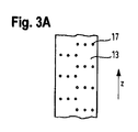
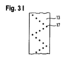
金属シート13は、クリンチング及び/又は穿孔によって形成された穴17を備える。ロールインヘッド5に金属シート13を配置した後、穴17が形成される。穴17は金属シート13を貫通している。穴17は実質的に円形である。
The
穴17は、穿孔カッターを使用して形成できる。切断方向に垂直な方向における穿孔カッターのピークの幅は、0.05mm〜10mmの範囲内、又は0.1mm〜1.0mmの範囲内であることができる。金属シート13及びロールインヘッド5の表面内への穿孔カッターのピークの貫入深さは、0.05mm、0.1mm、0.2mm、0.3mm、0.4mm、0.5mm、0.6mm、0.7mm、0.8mm、0.9mm、又は1.0mmの下限及び2mm以上の上限を有する範囲内であることができる。
The
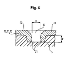
図4は、ロールインヘッド5の表面10、11、12に垂直な平面内における穴17の周りが金属シート13で覆われた領域の断面図を示す。穴17の直径qは、0.2mm〜2mm、好ましくは0.2mm〜0.5mmの範囲内、例えば0.3mm又は0.4mmである。穴17の縁21は、ロールインヘッド5のプラスチック材料内に突出する。プラスチック材料内への穴17の縁21の突出深さpは、0.05mm、0.1mm、0.2mm、0.3mm、0.4mm、0.5mm、0.6mm、0.7mm、0.8mm、0.9mm、又は1.0mmの下限、及び1mm、2mm以上の上限を有する範囲内である。ロールインヘッド5のプラスチック材料内に突出する穴17の縁21は、ロールインヘッド5の対応する表面10、11、12に平行な平面において、金属シート13とロールインヘッド5との嵌合を提供する。
FIG. 4 shows a cross-sectional view of a region in which the
金属シート13は、ロールインヘッド5の長手方向zにおいて移行縁部14、15に沿って形成されるフラップ18を備える。各フラップ18は、長手方向zに沿って延びる2つの平行な長手方向切断縁部19と、長手方向切断縁部19に垂直な1つの横方向切断縁部20と、を備える。本文脈中の「平行」という用語は、平行な配置を包含しており、2つの長手方向切断縁部19間の角度の20°、5°、1°、又は0.1°までの変動を許容する。本文脈中の「垂直」という用語は、垂直な配置を包含しており、横方向切断縁部20と各長手方向切断縁部19と間の角度の20°、5°、1°、又は0.1°までの変動を許容する。移行縁部14、15のそれぞれに沿う各フラップ18の長手方向切断縁部19の一方は、対応する移行縁部14、15に隣接する第2の表面10、12のうちの対応する一方を覆う金属シート13の部分に形成される。長手方向切断縁部19の他方は、第1の表面11を覆う金属シート13の部分に形成される。横方向切断縁部20は、金属シート13に沿って移行縁部14、15の対応する一方を横切って延びている。横方向切断縁部20は、フラップ18の長手方向切断縁部19の、長手方向zの一方の側又は他方の側の端部に接続されている。横方向切断縁部20の長さは、1mm〜10mmの範囲内である。各長手方向切断縁部19の長さは、1mm〜10mmの範囲内である。長手方向zにおいて各移行縁部14、15の各々に沿って隣接するフラップ18間の距離は、5mm〜30mmの範囲内である。
The
横方向切断縁部20が長手方向切断縁部19に接続されている、長手方向zにおける各フラップ18の側部は、各移行縁部14、15に沿って長手方向zに隣接する任意の2つのフラップ18に対して交互になる。移行縁部14、15の一方に沿った2つの隣接するフラップ18はいずれも、互いに対称である。横方向切断縁部20は、互いに対向しているか、又は互いの反対側にある2つの隣接するフラップ18の長手方向zの両側に配置されている。
The side of each
フラップ18は、金属シート13をロールインヘッド5に配置した後に横方向切断縁部20が長手方向切断縁部19に接続されているフラップの側部にある移行縁部14、15に沿ったロールインヘッド5のプラスチック材料内へと押し込まれる。ロールインヘッド5のプラスチック材料内に押し込まれたフラップ18の横方向切断縁部20は、金属シート13とロールインヘッド5との間に嵌合及び高せん断強度を提供する。プラスチック材料内への横方向切断縁部20の突出深さは、穴17の突出深さpと同じ範囲にすることができる。横方向切断縁部20は、長手方向zにおけるフラップ18の交互の側部に形成されている。即ち、フラップ18の交互の側部がロールインヘッド5のプラスチック材料内に押し込まれるため、長手方向zに沿った両方向における高せん断強度が提供される。
The
ロールインヘッド5の表面10、11、12のうちの1つを覆う金属シート13の各部分は、長手方向zに延びる2列の穴17を備える。
Each portion of the
図3A〜図3Lはそれぞれ、ロールインヘッド5の表面10、11、12のうちの1つを覆う、長手方向zに延びる金属シート13の一部の平面図を示す。即ち、図3A〜図3Lは、それぞれ、金属シート13の3つの部分のうちの1つを示す。穴17は金属シート13の当該部分に異なるパターンで配置されている。隣接する穴17同士の距離は、1mm〜20mmの範囲内、又は、2mm〜10mmの範囲内である。
3A to 3L show a plan view of a part of the
図3Aは、長手方向zに垂直且つ金属シート13の部分の表面に平行な方向において金属シート13の部分の両側(この図では左側及び右側)に、3つの円形穴17の群が交互に配置された金属シート13の部分を示す。各群の穴17は、長手方向zに垂直な方向に直線状に配置されている。各群の中央側にある最も内側の穴17は、長手方向zに垂直な方向において、金属シート13の部分の両縁部間の略中央に配置されている。パターンは、それぞれが3つのカッターを有する2つの切断ツールによって形成することができる。
In FIG. 3A, a group of three
図3Bは、図3Aに示す金属シート13の部分と同様の部分を示す。長手方向zに垂直な方向における各群の個々の穴17同士の距離は、図3Aに示す金属シート13の部分よりも大きい。このパターンは、6つのカッターを有する1つの切断ツールによって形成することができる。
FIG. 3B shows a portion similar to the portion of the
図3Cは、細長スリット状穴17を有する金属シート13の部分を示す。各穴17は、長手方向zに沿って1mm〜10mmの範囲内の長さを有する。各穴17は、長手方向zに垂直な方向に0.2mm〜2mmの範囲内の幅を有する。穴17は、2列に配置されており、それぞれ長手方向zに沿って延びている。2列のうちの一方は、長手方向zに垂直な方向において、金属シート13の部分の両縁部間の略中央に位置している。他方は、長手方向zに垂直な方向において、一方の列と金属シート13の部分の左縁部との間の略中央に位置している。
FIG. 3C shows a portion of the
図3Dは、細長スリット状穴17を有する金属シート13の部分を示す。各穴17は、長手方向zに垂直に1mm〜10mmの範囲内の長さを有する。穴17は、長手方向zに垂直な方向において、金属シート13の部分の縁部に沿って2列で配置されている。穴17は、2列に交互に配置されている。2列のうちのいずれかに、長手方向zに沿った各位置に1つのみの穴17がある。
FIG. 3D shows a portion of the
図3Eは、図3Cに示す金属シート13の部分に対応する部分を示す。但し、円形穴17が細長穴17の代わりに使用される。
FIG. 3E shows a portion corresponding to the portion of the
図3Fは、図3Eに示す金属シート13の部分に対応する部分を示す。ただし、この金属シート13の部分は、長手方向zに沿って延びる4列の円形穴17を備える。長手方向zに垂直な方向において、金属シート13の両側に2つの列がある。穴17は、長手方向zに沿って、両側の2つの列に交互に配置されている。
FIG. 3F shows a portion corresponding to the portion of the
図3Gは、3つの円形穴17の群を有する金属シート13の部分を示す。各群の穴17は、長手方向zに垂直な方向において、金属シート13の部分の両縁部間の対角線状に配置されている。
FIG. 3G shows a portion of the
図3Hは、図3Gに示す金属シート13の部分に対応する金属シート13の部分を示す。但し、細長スリット状穴17が図3Gに示す円形穴17の代わりに使用される。
FIG. 3H shows a portion of the
図3Iは、長手方向zに沿って金属シート13の部分の縁部間においてジグザグ線で配置された円形穴17を有する金属シート13の部分を示す。ジグザグ線の各脚は、金属シート13の部分全体に略対角線状に延びている。
FIG. 3I shows a portion of the
図3Jは、長手方向zに沿って金属シート13の部分の縁部間で、ジグザグ線で配置された細長スリット状穴17を有する金属シート13の部分を示す。ジグザグ線の脚は、金属シート13の部分全体に、長手方向zに垂直に、及び、略対角線状にそれぞれ交互に延びている。
FIG. 3J shows a portion of the
図3Kは、長手方向zに沿って延びる2列で配置された細長スリット状穴17を有する金属シート13の部分を示す。各列の細長スリット状穴17は、長手方向zに沿って、及び長手方向zに垂直に交互に延びている。
FIG. 3K shows a portion of the
図3Lは、金属シート13の部分全体に対角線状で配置された細長スリット状穴17を有する金属シート13の部分を示す。各列の細長スリット状穴17の延びる方向は、互いに垂直な2つの対角線方向間で互い違いになっている。
FIG. 3L shows a portion of the
穴17は、上記のパターンで配置される必要はなく、異なるパターンで配置されてもよいし、又は、ランダムに配置されてもよい。ロールインヘッド5の表面10、11、12のうちの1つを覆う金属シート13の各部分は、同じパターンの穴17を備えていてもよいし、又は、異なるパターンの穴17を備えていてもよい。
The
表面10、11、12のうちの1つを覆う金属シート13の全ての部分が穴17を備えている必要はない。これらの部分のうちの1つ又は2つのみが穴17を備えていてもよい。金属シート13はフラップ18を備えてもよいが、穴17は備えなくてもよい。金属シート13は穴17を備えてもよいが、フラップ18は備えなくてもよい。
It is not necessary that all parts of the
フラップ18は、必ずしも移行縁部14、15に沿って配置される必要はない。ロールインヘッド5の表面10、11、12のうちの1つを覆う金属シート13の各部分は、フラップ18を備えていてもよい。
The
ロールインヘッド5とは反対側を向く金属シート13の外表面は、必ずしもローレットパターン16を備えていなくてもよい。ロールインヘッド5の表面10、11、12に接触している、ロールインヘッド5に面する金属シート13の内表面は、ローレットパターンを備えていてもよい。金属シート13の内表面及び/又は外表面の溝は、長手方向zに対して斜めに延びることができる。
The outer surface of the
図5Aは、図1及び図2のように、長手方向zに垂直な平面x−yにおける断熱ストリップ3のうちの1つのロールインヘッド5のうちの一方の部分断面図を示す。
FIG. 5A shows a partial cross-sectional view of one of the roll-in
上記のように、ロールインヘッド5の鳩尾形状の断面は、ストリップ本体4からプロファイル材2に向かって高さ方向yに広がっている。ロールインヘッド5のプロファイル材2を向く断熱ストリップ3の遠位外縁部における(第1の)厚さa2は、ロールインヘッド5からストリップ本体4までの移行部におけるロールインヘッド5の(第2の)厚さa1よりも大きい。遠位外縁部におけるロールインヘッド5の厚さa2は、ロールインヘッド5からストリップ本体4までの移行部におけるロールインヘッド5の厚さa1の1.2倍、ロールインヘッド5からストリップ本体4までの移行部におけるロールインヘッド5の厚さa1の1.5倍、又は、ロールインヘッド5からストリップ本体4までの移行部におけるロールインヘッド5の厚さa1の1.8倍の下限と、ロールインヘッド5からストリップ本体4までの移行部におけるロールインヘッド5の厚さa1の2倍、又は、ロールインヘッド5からストリップ本体4までの移行部におけるロールインヘッド5の厚さa1の4倍の上限と、を有する範囲内であることができる。
As described above, the dovetail-shaped cross section of the roll-in
ロールインヘッド5の実質的に台形の断面の底辺及び/又は脚部は、直線、又は、曲面又はくぼみ等であることができる。底辺及び/又は脚は、例えば、1つ又は複数の凹み及び/又はノッチを備えることができる。
The bottom and / or legs of the substantially trapezoidal cross section of the roll-in
ロールインヘッドの断面形状が、ロールインヘッドからストリップ本体4までの移行部におけるロールインヘッドの(第2の)厚さa1よりも大きい、ロールインヘッドからストリップ本体4までの移行部と遠位外縁部との間の(第1の)厚さa2を備える限り、ロールインヘッド5の断面形状は、図1、図2及び図5Aに示す形状とは異なるものとすることができる。(第1の)厚さa2は、ロールインヘッドの遠位外縁部に位置していてもよいし、又は、ロールインヘッドからストリップ本体4までの移行部とロールインヘッドの高さ方向yにおける遠位外縁部との間のどこかに位置していてもよい。図5B〜図5Hは、ロールインヘッドの別の断面形状の例を示しており、(第1の)厚さa2がロールインヘッドの遠位外縁部に位置している。即ち、ロールインヘッドの断面形状は、ロールインヘッドからストリップ本体4までの移行部よりも遠位外縁部において幅広である。ロールインヘッドの遠位外縁部における(第1の)厚さa2は、ロールインヘッドの最大厚であり得る。代替的に、(第1の)厚さa2は、ロールインヘッドからストリップ本体までの移行部とロールインヘッドの高さ方向yにおける遠位外縁部との間に位置することができる。この場合、(第1の)厚さa2は、高さ方向yにおけるロールインヘッドからストリップ本体までの移行部よりも、ロールインヘッドの遠位外縁部の近くに位置することができる。
The cross-sectional shape of the roll-in head is larger than the (second) thickness a1 of the roll-in head at the transition portion from the roll-in head to the
図5Bは、図5Aに示す鳩尾形の断面形状の変形例であるロールインヘッド5bの断面形状を示す。ロールインヘッド5bは、ロールインヘッド5bの遠位外縁部にある長底、及び、2つの脚部を有する非対称断面形状を備える。2つの脚は異なる長さを有する。ストリップ本体4に対する幅方向xの長底の突出長さは、ロールインヘッド5bの幅方向xの一方の側の方が他方の側よりも大きい。一方の側の突出長さは、他方の側の突出長さの1.2〜4倍の範囲内とすることができる。幅方向xにおけるロールインヘッド5bの一方の側の脚部の起点、即ち、脚部がストリップ本体4の実質的にまっすぐな表面から角度が付く点から、長底までの高さ方向yにおける第1の距離は、他方の側の脚部の起点から長底までの高さ方向yの第2の距離と同じであることができる、又は、それより大きくなることができる。第1の距離は、第2の距離の1〜4倍の範囲内であることができる。ロールインヘッド5bからストリップ本体4までの移行部は、ロールインヘッド5bの長底からさらに離れた側における脚の起点によって画定される。2つの脚と長底との間の角度は、同じであってもよいし、又は、互いに異なっていてもよい。
FIG. 5B shows the cross-sectional shape of the roll-in
図5Cは、図5Aに示す台形の断面形状の変形例であるロールインヘッド5cの断面形状を示す。図5Aに示す断面形状とは異なり、ロールインヘッド5cの台形断面形状の2つの脚部のうちの一方の脚部と長底との間の角度と、2つの脚部のうちの一方の脚部と短底との間の角度と、は直角(約90°)である。
FIG. 5C shows the cross-sectional shape of the roll-in
図5Dは、図5Aに示す台形断面形状の他の変形例であるロールインヘッド5dの断面形状を示す。図5Aに示す断面形状とは異なり、ロールインヘッド5dの台形断面形状の2つの脚部のうちの一方の脚部と長底との間の角度は鈍角(>90°)であり、2つの脚の一方の脚部と短底との間の角度は鋭角(<90°)である。
FIG. 5D shows the cross-sectional shape of the roll-in
図5Eは、図5Aに示す台形断面形状の他の変形例であるロールインヘッド5eの断面形状を示す。図5Aに示す断面形状とは異なり、ロールインヘッド5eの台形の長底辺はノッチを備える。ノッチの高さ方向yの深さは、ロールインヘッド5eの高さ方向yの高さの0.8倍までとすることができる。図5Eに示すノッチの断面形状は三角形である。しかしながら、ノッチは、異なる断面形状を有することができる。
FIG. 5E shows the cross-sectional shape of the roll-in
図5Fは、矩形形状を含むロールインヘッド5fの段付き断面形状を示す。矩形形状は、ストリップ本体4の一方の側でストリップ本体4に対して幅方向wに突出する。ロールインヘッド5fからストリップ本体4までの移行部におけるロールインヘッド5fの厚さa1は、ストリップ本体4の厚さに相当する。
FIG. 5F shows a stepped cross-sectional shape of the roll-in
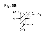
図5Gは、図5Fに示す段付きロールインヘッド5fの変形例であるロールインヘッド5gの断面形状を示す。ロールインヘッド5gの断面形状は、ストリップ本体4から幅方向xに突出した矩形形状の角に別の段を備える。
FIG. 5G shows a cross-sectional shape of the roll-in
図5Hは、ロールインヘッド5hの不規則な断面形状を示す。ロールインヘッド5hの断面形状は非対称であり、プロファイル材2に面するロールインヘッド5hの遠位外縁部にノッチを備える。
FIG. 5H shows an irregular cross-sectional shape of the roll-in
図5A〜図5Hに示されていないが、金属シート13は、ロールインヘッド5、5b、5c、5d、5e、5f、5g、5hのそれぞれの表面の少なくとも一部に設けられている。金属シート13は、例えば、長底及び/又は一方若しくは両方の脚部に設けることができる。
Although not shown in FIGS. 5A-5H, the
ロールインヘッドの断面形状の角は丸くすることができる。 The corners of the cross-sectional shape of the roll-in head can be rounded.
プロファイル材2の金属材料は、金属シート13の金属材料よりも低い引張強度を有する。従って、ロールインヘッド5が溝6にロールインされるとき、溝6、ハンマー7及び/又は相手部材8の表面は、ハンマー7のロールインヘッド5及び金属シート30への圧力により変形されることができ、それによってせん断強度が高められる。プロファイル材2の金属材料は、ローレットパターン16、穴17、及び/又は、フラップ18に流入し、それによってせん断強度を高めることができる。
The metal material of the profile material 2 has a lower tensile strength than the metal material of the
金属シート13の穿孔及び/又はクリンチングの方法に応じて、水平及び/又は垂直方向の材料フラックスを制御することができる。
The horizontal and / or vertical material flux can be controlled depending on the method of drilling and / or clinching the
70N/mm以上の断熱複合プロファイル材1のせん断強度は、断熱ストリップ3を用いて得ることができる。
The shear strength of the heat insulating composite profile material 1 of 70 N / mm or more can be obtained by using the
本開示は、上述の実施形態に限定されない。異なる実施形態の特徴を組み合わせることができ、さらなる修正を適用することができる。 The present disclosure is not limited to the embodiments described above. The features of different embodiments can be combined and further modifications can be applied.
金属シート13の金属材料は、ステンレス鋼、亜鉛メッキ鋼、AW7068又はAW7075等のアルミニウム合金、及び他の金属又は合金を含む群から選択することができる。ロールインヘッド5を溝6に導入することは、金属シート13の金属材料がアルミニウムを含まない場合に容易になる。金属シートの金属材料の引張強度は、500N/mm2より高くてもよいし、又は、700N/mm2より高くてもよい。
The metal material of the
断熱ストリップ3は、PA、PBT、PA−PBE、PET、PMI、PVC、ポリケトン、PP又はPUR等のプラスチック材料で作製できる。断熱ストリップ3は、熱可塑性材料で作製できる。断熱ストリップ3は、ガラス繊維等の補強要素を備えることができ、及び/又は、再生可能資源に基づくバイオポリマーで作製できる。再生可能資源に基づくことができるポリマーの例は、PA5.5、PA5.10、PA6.10、PA6.6、PA4.10、PA10.10、PA11、PA10.12である。
The
断熱ストリップ3は、発泡プラスチック材料、気泡プラスチック材料、及び/又は、多孔質プラスチック材料を備えることができる。断熱ストリップ3の材料は、完全に又は部分的に発泡させることができる。ストリップ本体4の材料は、完全に又は部分的に発泡させることができる。ストリップ本体4は、非発泡材料の層によって囲まれた発泡コアを備えることができる。ロールインヘッド5の材料は発泡されていてもよいし、そうでなくてもよい。ロールインヘッド5は、ストリップ本体4と一体形成されてもよく、又は別個に形成され、例えば接着剤によってストリップ本体4に接合されてもよい。ロールインヘッド5とストリップ本体4とが一体形成されている場合、それらは非発泡材料のカバーで囲まれた発泡材料の共通コアを備えることができる。欧州特許第1 242 709 B2号の図1に示す細孔を有する独立気泡プラスチック材料のコアと、コンパクトな非多孔質プラスチック材料の表面層とを含む断熱ストリップを使用することができる。
The
ロールインヘッド5は、ストリップ本体4とは異なるプラスチック材料で作製できる。
The roll-in
ロールインヘッド5の断面形状は、金属シート13の表面変化によって生じ、及び/又はそれを受ける凹みを除いて、長手方向zに沿って一定である。
The cross-sectional shape of the roll-in
シート13の材料は、断熱ストリップ3のコーティング又はニス処理中の最高温度よりも高い融点又は融解温度を有することができる。シート13の材料の融点は、400K、500K、550K、600K、750K、1000K、又は、それ以上であってよい。
The material of the
シート13の材料の融点は、断熱ストリップ3のプラスチック材料の融点よりも少なくとも50K(ケルビン)、100K、150K、200K、250K、300K、500K、又は1000K高くすることができる。断熱ストリップ3のプラスチック材料の融点は、例えば、PA6.6の場合は533K、PA6.10の場合は513K、又はPA11の場合は471Kとすることができる。プラスチック材料の融点のさらなる値は、文献から得ることができる。
The melting point of the material of the
金属シート13をロールインヘッド5に埋め込まれた金属要素にレーザ溶接することにより、金属シート13をロールインヘッド5に接合することができる。
The
フラップ18は、レーザ又は切断ホイールを用いて金属シート13に切り込むことができる。金属シート13をロールインヘッド5上に配置する前又は後に、フラップ18を金属シート13に切り込むことができる。
The
上記実施形態に示す断熱ストリップ3の代わりに、他の断熱ストリップを使用してもよい。断熱ストリップは、3つ以上のロールインヘッド5を備えていてもよく、及び/又は、上記実施形態に示す各断熱ストリップ3よりも幅方向xに幅広であってもよい。プロファイル材2は、1つの断熱ストリップのみによって接続されてもよい。
Other heat insulating strips may be used instead of the
本明細書及び/又は特許請求の範囲に開示されたすべての特徴は、実施形態及び/又は特許請求の範囲における特徴の構成から独立している請求された主題を限定する目的のためのみならず、原開示の目的のためにも、互いから分離且つ独立して開示されることが意図されていることに特に留意されたい。すべての値範囲又はエンティティの群の表示は、請求される発明を限定する目的のためのみならず、原開示の目的のためにも、特に値範囲の限界として、可能な限りすべての中間の値又は中間のエンティティを開示することにも特に留意されたい。 All features disclosed herein and / or the claims are not only for the purpose of limiting the claimed subject matter that is independent of the composition of the features in the embodiments and / or claims. It should be noted in particular that, for the purposes of the original disclosure, it is intended to be disclosed separately and independently of each other. The representation of all value ranges or groups of entities is not only for the purpose of limiting the claimed invention, but also for the purposes of the original disclosure, especially as the limit of the value range, all intermediate values possible. Or pay particular attention to disclosing intermediate entities.
(態様)
1.ドア、窓又はファサード要素のための複合プロファイル材(1)の複数のプロファイル材(2、2)を接続するための断熱ストリップ(3)であって、
前記複数のプロファイル材(2、2)のうちの少なくとも1つ前記プロファイル材は、第1の引張強度及び/又は第1の降伏強度を有する金属材料からなり、前記断熱ストリップ(3)とロールイン接続するための少なくとも1つのロールイン溝(6)を有しており、
前記断熱ストリップ(3)は、
断熱材料からなり、長手方向(z)に延びているストリップ本体(4)と、
前記ストリップ本体(4)の長手方向縁部にあるロールインヘッド(5)であって、
前記長手方向(z)に垂直な平面(x−y)において、前記少なくとも1つのロールイン溝(6)に挿入されるように適合された断面形状を有し、
ロールインヘッド(5)から前記ストリップ本体(4)への移行部における前記ロールインヘッド(5)の前記断面形状の第2の厚さ(a1)よりも大きい、前記少なくとも1つのロールイン溝(6)に面する前記ロールインヘッド(5)の遠位外縁部に対向する前記ロールインヘッド(5)の前記断面形状の第1の厚さ(a2)を有する、
前記ロールインヘッドと、
前記ロールインヘッド(5)の表面(10、11、12)の少なくとも一部を覆い、表面変化部(16、17、18)を有するシート(13)と、
を備え、
前記シート(13)は、第2の引張強度及び又は第2の降伏強度を有する金属材料からなるか、又は、当該金属材料からなる部分を備え、
第2の引張強度、第2の降伏強度は、それぞれ、第1の引張強度、第1の降伏強度よりも大きい、
断熱ストリップ。
2.ドア、窓又はファサード要素のための複合プロファイル材(1)の複数のプロファイル材(2、2)を接続するための断熱ストリップ(3)であって、
前記複数のプロファイル材(2、2)のうちの少なくとも1つ前記プロファイル材は、アルミニウム材料からなり、前記断熱ストリップ(3)とロールイン接続するための少なくとも1つのロールイン溝(6)を有しており、
前記断熱ストリップ(3)は、
断熱材料からなり、長手方向(z)に延びているストリップ本体(4)と、
前記ストリップ本体(4)の長手方向縁部にあるロールインヘッド(5)であって、
前記長手方向(z)に垂直な平面(x−y)において、前記少なくとも1つのロールイン溝(6)に挿入されるように適合された断面形状を有し、
ロールインヘッド(5)から前記ストリップ本体(4)への移行部における前記ロールインヘッド(5)の前記断面形状の第2の厚さ(a1)よりも大きい、前記少なくとも1つのロールイン溝(6)に面する前記ロールインヘッド(5)の遠位外縁部に対向する前記ロールインヘッド(5)の前記断面形状の第1の厚さ(a2)を有する、
前記ロールインヘッドと、
前記ロールインヘッド(5)の表面(10、11、12)の少なくとも一部を覆い、表面変化部(16、17、18)を有するシート(13)と、
を備え、
前記シート(13)は、鋼からなるか、又は、鋼からなる部分を備える、
断熱ストリップ。
3.ロールインヘッド(5)から離れているシート(13)の表面は、ローレットパターン(16)を備える、態様1又は2に記載の断熱ストリップ。
4.ストリップ本体(4)は、熱可塑性断熱材料からなる、態様1〜3のいずれか1つに記載の断熱ストリップ。
以下の項目は、国際出願時の特許請求の範囲に記載の要素である。
(項目1)
ドア、窓又はファサード要素のための複合プロファイル材(1)の複数のプロファイル材(2、2)を接続するための断熱ストリップ(3)であって、
前記複数のプロファイル材(2、2)のうちの少なくとも1つの前記プロファイル材は、第1の引張強度を有するアルミニウム材料からなり、前記断熱ストリップ(3)とロールイン接続するための少なくとも1つのロールイン溝(6)を有しており、
前記断熱ストリップ(3)は、
断熱材料からなり、長手方向(z)に延びているストリップ本体(4)と、
前記ストリップ本体(4)の長手方向縁部にあるロールインヘッド(5)であって、
前記長手方向(z)に垂直な平面(x−y)において、前記少なくとも1つのロールイン溝(6)に挿入されるように適合された断面形状を有し、
前記ロールインヘッド(5)から前記ストリップ本体(4)への移行部における前記ロールインヘッド(5)の前記断面形状の第2の厚さ(a1)よりも大きい、前記少なくとも1つのロールイン溝(6)に面する前記ロールインヘッド(5)の遠位外縁部に対向する前記ロールインヘッド(5)の前記断面形状の第1の厚さ(a2)を有する、
前記ロールインヘッドと、
前記ロールインヘッド(5)の表面(10、11、12)の少なくとも一部を覆い、表面変化部(16、17、18)を有するシート(13)と、
を備え、
前記シート(13)は、300N/mm2以上の第2の引張強度を有する金属材料からなるか、又は、前記金属材料からなる部分を備える、
断熱ストリップ。
(項目2)
ドア、窓又はファサード要素のための複合プロファイル材(1)の複数のプロファイル材(2、2)を接続するための断熱ストリップ(3)であって、
前記複数のプロファイル材(2、2)のうちの少なくとも1つの前記プロファイル材は、第1の引張強度を有するアルミニウム材料からなり、前記断熱ストリップ(3)とロールイン接続するための少なくとも1つのロールイン溝(6)を有しており、
前記断熱ストリップ(3)は、
断熱材料からなり、長手方向(z)に延びているストリップ本体(4)と、
前記ストリップ本体(4)の長手方向縁部にあるロールインヘッド(5)であって、
前記長手方向(z)に垂直な平面(x−y)において、前記少なくとも1つのロールイン溝(6)に挿入されるように適合された断面形状を有し、
前記ロールインヘッド(5)から前記ストリップ本体(4)への移行部における前記ロールインヘッド(5)の前記断面形状の第2の厚さ(a1)よりも大きい、前記少なくとも1つのロールイン溝(6)に面する前記ロールインヘッド(5)の遠位外縁部に対向する前記ロールインヘッド(5)の前記断面形状の第1の厚さ(a2)を有する、
前記ロールインヘッドと、
前記ロールインヘッド(5)の表面(10、11、12)の少なくとも一部を覆い、前記ロールインヘッド(5)の前記表面(10、11、12)に突出する表面変化部(16、17、18)を有するシート(13)と、を備え、
前記ロールインヘッド(5)の前記表面(10、11、12)内への前記表面変化部(16、17、18)の突出深さ(p)は、0.05mm以上である、
断熱ストリップ。
(項目3)
ドア、窓又はファサード要素のための複合プロファイル材(1)の複数のプロファイル材(2、2)を接続するための断熱ストリップ(3)であって、
前記複数のプロファイル材(2、2)のうちの少なくとも1つの前記プロファイル材は、第1の引張強度を有するアルミニウム材料からなり、前記断熱ストリップ(3)とロールイン接続するための少なくとも1つのロールイン溝(6)を有しており、
前記断熱ストリップ(3)は、
熱可塑性断熱材料からなり、長手方向(z)に延びているストリップ本体(4)と、
前記ストリップ本体(4)の長手方向縁部にあるロールインヘッド(5)であって、
前記長手方向(z)に垂直な平面(x−y)において、前記少なくとも1つのロールイン溝(6)に挿入されるように適合された断面形状を有し、
前記ロールインヘッド(5)から前記ストリップ本体(4)への移行部における前記ロールインヘッド(5)の前記断面形状の第2の厚さ(a1)よりも大きい、前記少なくとも1つのロールイン溝(6)に面する前記ロールインヘッド(5)の遠位外縁部に対向する前記ロールインヘッド(5)の前記断面形状の第1の厚さ(a2)を有する、
前記ロールインヘッドと、
前記ロールインヘッド(5)の表面(10、11、12)の少なくとも一部を覆い、表面変化部(16、17、18)を有するシート(13)と、
を備え、
前記シート(13)は、金属材料からなるか、又は、前記金属材料からなる部分を備え、
前記シート(13)の前記金属材料の融解温度は、前記ストリップ本体(4)の前記熱可塑性断熱材料の融解温度よりも少なくとも50K高い、
断熱ストリップ。
(項目4)
前記シート(13)は、第2の引張強度を有する金属材料からなるか、又は、前記金属材料からなる部分を備える、項目2又は3に記載の断熱ストリップ。
(項目5)
前記シート(13)の前記金属材料の融解温度は、前記ストリップ本体(4)の前記断熱材料の融解温度よりも少なくとも50K高い、項目1又は4に記載の断熱ストリップ。
(項目6)
前記第2の引張強度は前記第1の引張強度よりも高い、項目1、項目3〜5のいずれか一項に記載の断熱ストリップ。
(項目7)
前記シート(13)は、鋼からなるか、又は、鋼からなる部分を備える、項目1、項目3〜6のいずれか一項に記載の断熱ストリップ。
(項目8)
前記第2の引張強度は、300N/mm2以上である、項目4〜7のいずれか一項に記載の断熱ストリップ。
(項目9)
前記表面変化部(16、17、18)は、穿孔(17)、フラップ(18)、突起、ローレット(16)、及び、やすり状表面を含む表面変化の群から選択される1又は複数の変化部である、項目1〜8のいずれか一項に記載の断熱ストリップ。
(項目10)
前記ロールインヘッド(5)の前記長手方向(z)に垂直な前記断面形状は、前記ロールインヘッド(5)の前記遠位外縁部側に第1の表面(11)を有し、
前記シート(13)は、前記第1の表面(11)の少なくとも一部を覆う、項目1〜9のいずれか一項に記載の断熱ストリップ。
(項目11)
前記ロールインヘッド(5)の前記長手方向(z)に垂直な前記断面形状は、前記ロールインヘッド(5)の前記遠位外縁部の側方に複数の第2の表面(10、12)を有し、
前記シート(13)は、前記複数の第2の表面(10、12)のうちの1つの前記第2の表面(10、12)の少なくとも一部を覆う、項目1〜10のいずれか一項に記載の断熱ストリップ。
(項目12)
前記シート(13)は、前記第1の表面(11)と前記複数の第2の表面(10、12)のうちの1つの前記第2の表面(10、12)との間における前記ロールインヘッド(5)の第1の移行縁部(14)、及び/又は、前記第1の表面(11)と前記複数の第2の表面(10、12)のうちの他方の前記第2の表面(10、12)との間における前記ロールインヘッド(5)の第2の移行縁部(15)を覆う、項目10に従属する項目11に記載の断熱ストリップ。
(項目13)
前記シート(13)は、前記第1の移行縁部(14)を覆う領域、及び/又は、前記第2の移行縁部(15)を覆う領域に、複数のフラップ(18)を備える、項目12に記載の断熱ストリップ。
(項目14)
前記第1の移行縁部(14)を覆う前記領域、及び/又は、前記第2の移行縁部(15)を覆う前記領域における前記複数のフラップ(18)は、それぞれ、前記長手方向(z)に延びる2つの平行な長手方向切断縁部(19)と、前記長手方向切断縁部(19)に垂直に延びる横方向切断縁部(20)によって形成され、
前記横方向切断縁部(20)は、前記フラップ(18)を形成するために、前記長手方向(z)における前記長手方向切断縁部(19)の2つの側部のうちの一方の側部で前記2つの縦方向切断縁部(19)に接続され、
前記横方向切断縁部(20)が前記2つの縦方向切断縁部(19)に接続されている前記長手方向(z)における前記2つの側部のうちの前記一方の側部は、前記長手方向(z)において隣接する2つのフラップでは交互である、項目13に記載の断熱ストリップ。
(項目15)
前記表面変化部(17、18)は、穿孔(17)及び/又はフラップ(18)を備え、
前記ロールインヘッド(5)の前記表面(10、11、12)内への前記穿孔(17)及び/又は前記フラップ(18)の縁部(21)の突出深さ(p)は、0.2mm〜2mmの範囲内である、項目1〜14のいずれか一項に記載の断熱ストリップ。
(項目16)
前記ロールインヘッド(5)の前記断面形状の前記第1の厚さ(a2)は、前記少なくとも1つのロールイン溝(6)に面する前記ロールインヘッド(5)の前記遠位外縁部に位置する、項目1〜15のいずれか一項に記載の断熱ストリップ。
(項目17)
前記ストリップ本体(4)は、熱可塑性断熱材料からなる、項目1〜16のいずれか一項に記載の断熱ストリップ。
(項目18)
ドア、窓又はファサード要素のための複合プロファイル材(1)であって、
項目1〜17のいずれか一項に記載の複数のプロファイル材(2、2)、及び、少なくとも1つの断熱ストリップ(3)を備え、
前記複数のプロファイル材(2、2)のうちの少なくとも1つ前記プロファイル材(2)は、第1の引張強度を有する金属材料からなり、前記少なくとも1つの断熱ストリップ(3)とのロールイン接続のための少なくとも1つのロールイン溝(6)を有し、
前記断熱ストリップ(3)の前記ロールインヘッド(5)は、ロールインによって、前記1つのプロファイル材(2)に接続される、複合プロファイル材。
(項目19)
ドア、窓又はファサード要素のための複合プロファイル材(1)の複数のプロファイル材(2、2)を接続するための断熱ストリップ(3)のロールインヘッド(5)の製造を仕上げる方法であって、
前記複数のプロファイル材(2、2)のうちの少なくとも1つの前記プロファイル材(2)は、金属材料からなり、前記断熱ストリップ(3)とロールイン接続するための少なくとも1つのロールイン溝(6)を有し、
前記断熱ストリップ(3)は、
断熱材料からなり、長手方向(z)に延びているストリップ本体(4)と、
前記ストリップ本体(4)の長手方向縁部にあり、前記長手方向(z)に垂直な平面(x−y)において、前記少なくとも1つのロールイン溝(6)に挿入されるように適合された断面形状をする前記ロールインヘッド(5)と、
を備え、
前記方法は、
前記ロールインヘッド(5)を有する前記断熱ストリップ(4)を提供するステップと、
金属材料からなるか、又は、前記金属材料を少なくとも備えるシート(13)を提供するステップと、
前記シート(13)の側部の少なくとも一方の側部において、前記シート(13)の表面をローレット加工するステップと、
前記シート(13)のローレット表面が前記ロールインヘッド(5)から離れるように、前記ロールインヘッド(5)の表面(10、11、12)に、前記シート(13)を配置するステップと、
前記ロールインヘッド(5)の移行縁部(14、15)周辺で前記シート(13)を曲げるステップと、
前記シート(13)を前記ロールインヘッド(5)に押しつけるステップと
を備え、
フラップ(18)は、前記配置するステップの前又は後において、前記シート(13)に任意で切り込まれ、前記任意のフラップ(18)は、前記曲げるステップの後に前記ロールインヘッド(5)内に押しつけられ、及び/又は、前記シート(13)には、前記配置するステップの後に前記穴(17)が任意で穿孔される、
方法。
(Aspect)
1. 1. A heat insulating strip (3) for connecting a plurality of profile materials (2, 2) of a composite profile material (1) for a door, window or façade element.
At least one of the plurality of profile materials (2, 2) The profile material is made of a metal material having a first tensile strength and / or a first yield strength, and rolls in with the heat insulating strip (3). It has at least one roll-in groove (6) for connecting and
The heat insulating strip (3)
A strip body (4) made of heat insulating material and extending in the longitudinal direction (z),
A roll-in head (5) at the longitudinal edge of the strip body (4).
It has a cross-sectional shape adapted to be inserted into the at least one roll-in groove (6) in a plane (xy) perpendicular to the longitudinal direction (z).
The at least one roll-in groove (a1) larger than the second thickness (a1) of the cross-sectional shape of the roll-in head (5) at the transition portion from the roll-in head (5) to the strip body (4). It has a first thickness (a2) of the cross-sectional shape of the roll-in head (5) facing the distal outer edge of the roll-in head (5) facing 6).
With the roll-in head
A sheet (13) that covers at least a part of the surface (10, 11, 12) of the roll-in head (5) and has a surface change portion (16, 17, 18).
With
The sheet (13) is made of a metal material having a second tensile strength and / or a second yield strength, or includes a portion made of the metal material.
The second tensile strength and the second yield strength are larger than the first tensile strength and the first yield strength, respectively.
Insulation strip.
2. 2. A heat insulating strip (3) for connecting a plurality of profile materials (2, 2) of a composite profile material (1) for a door, window or façade element.
At least one of the plurality of profile materials (2, 2) The profile material is made of an aluminum material and has at least one roll-in groove (6) for roll-in connection with the heat insulating strip (3). And
The heat insulating strip (3)
A strip body (4) made of heat insulating material and extending in the longitudinal direction (z),
A roll-in head (5) at the longitudinal edge of the strip body (4).
It has a cross-sectional shape adapted to be inserted into the at least one roll-in groove (6) in a plane (xy) perpendicular to the longitudinal direction (z).
The at least one roll-in groove (a1) larger than the second thickness (a1) of the cross-sectional shape of the roll-in head (5) at the transition portion from the roll-in head (5) to the strip body (4). It has a first thickness (a2) of the cross-sectional shape of the roll-in head (5) facing the distal outer edge of the roll-in head (5) facing 6).
With the roll-in head
A sheet (13) that covers at least a part of the surface (10, 11, 12) of the roll-in head (5) and has a surface change portion (16, 17, 18).
With
The sheet (13) is made of steel or comprises a portion made of steel.
Insulation strip.
3. 3. The heat insulating strip according to aspect 1 or 2, wherein the surface of the sheet (13) away from the roll-in head (5) comprises a knurled pattern (16).
4. The heat insulating strip according to any one of aspects 1 to 3, wherein the strip body (4) is made of a thermoplastic heat insulating material.
The following items are the elements described in the claims at the time of international filing.
(Item 1)
A heat insulating strip (3) for connecting a plurality of profile materials (2, 2) of a composite profile material (1) for a door, window or façade element.
At least one of the plurality of profile materials (2, 2) is made of an aluminum material having a first tensile strength, and at least one roll for roll-in connection with the heat insulating strip (3). It has an in-groove (6) and has an in-groove (6).
The heat insulating strip (3)
A strip body (4) made of heat insulating material and extending in the longitudinal direction (z),
A roll-in head (5) at the longitudinal edge of the strip body (4).
It has a cross-sectional shape adapted to be inserted into the at least one roll-in groove (6) in a plane (xy) perpendicular to the longitudinal direction (z).
The at least one roll-in groove larger than the second thickness (a1) of the cross-sectional shape of the roll-in head (5) at the transition portion from the roll-in head (5) to the strip body (4). It has a first thickness (a2) of the cross-sectional shape of the roll-in head (5) facing the distal outer edge of the roll-in head (5) facing (6).
With the roll-in head
A sheet (13) that covers at least a part of the surface (10, 11, 12) of the roll-in head (5) and has a surface change portion (16, 17, 18).
With
The sheet (13) is made of a metal material having a second tensile strength of 300 N / mm2 or more, or includes a portion made of the metal material.
Insulation strip.
(Item 2)
A heat insulating strip (3) for connecting a plurality of profile materials (2, 2) of a composite profile material (1) for a door, window or façade element.
At least one of the plurality of profile materials (2, 2) is made of an aluminum material having a first tensile strength, and at least one roll for roll-in connection with the heat insulating strip (3). It has an in-groove (6) and has an in-groove (6).
The heat insulating strip (3)
A strip body (4) made of heat insulating material and extending in the longitudinal direction (z),
A roll-in head (5) at the longitudinal edge of the strip body (4).
It has a cross-sectional shape adapted to be inserted into the at least one roll-in groove (6) in a plane (xy) perpendicular to the longitudinal direction (z).
The at least one roll-in groove larger than the second thickness (a1) of the cross-sectional shape of the roll-in head (5) at the transition portion from the roll-in head (5) to the strip body (4). It has a first thickness (a2) of the cross-sectional shape of the roll-in head (5) facing the distal outer edge of the roll-in head (5) facing (6).
With the roll-in head
A surface change portion (16, 17) that covers at least a part of the surface (10, 11, 12) of the roll-in head (5) and projects to the surface (10, 11, 12) of the roll-in head (5). , 18) and the sheet (13).
The protrusion depth (p) of the surface changing portion (16, 17, 18) into the surface (10, 11, 12) of the roll-in head (5) is 0.05 mm or more.
Insulation strip.
(Item 3)
A heat insulating strip (3) for connecting a plurality of profile materials (2, 2) of a composite profile material (1) for a door, window or façade element.
At least one of the plurality of profile materials (2, 2) is made of an aluminum material having a first tensile strength, and at least one roll for roll-in connection with the heat insulating strip (3). It has an in-groove (6) and has an in-groove (6).
The heat insulating strip (3)
A strip body (4) made of thermoplastic insulation and extending in the longitudinal direction (z),
A roll-in head (5) at the longitudinal edge of the strip body (4).
It has a cross-sectional shape adapted to be inserted into the at least one roll-in groove (6) in a plane (xy) perpendicular to the longitudinal direction (z).
The at least one roll-in groove larger than the second thickness (a1) of the cross-sectional shape of the roll-in head (5) at the transition portion from the roll-in head (5) to the strip body (4). It has a first thickness (a2) of the cross-sectional shape of the roll-in head (5) facing the distal outer edge of the roll-in head (5) facing (6).
With the roll-in head
A sheet (13) that covers at least a part of the surface (10, 11, 12) of the roll-in head (5) and has a surface change portion (16, 17, 18).
With
The sheet (13) is made of a metal material or includes a portion made of the metal material.
The melting temperature of the metal material of the sheet (13) is at least 50K higher than the melting temperature of the thermoplastic insulating material of the strip body (4).
Insulation strip.
(Item 4)
The heat insulating strip according to
(Item 5)
The heat insulating strip according to
(Item 6)
The heat insulating strip according to any one of
(Item 7)
The heat insulating strip according to any one of
(Item 8)
The heat insulating strip according to any one of
(Item 9)
The surface change portion (16, 17, 18) is one or more changes selected from the group of surface changes including perforations (17), flaps (18), protrusions, knurls (16), and file-like surfaces. The heat insulating strip according to any one of items 1 to 8, which is a part.
(Item 10)
The cross-sectional shape perpendicular to the longitudinal direction (z) of the roll-in head (5) has a first surface (11) on the distal outer edge side of the roll-in head (5).
The heat insulating strip according to any one of items 1 to 9, wherein the sheet (13) covers at least a part of the first surface (11).
(Item 11)
The cross-sectional shape perpendicular to the longitudinal direction (z) of the roll-in head (5) comprises a plurality of second surfaces (10, 12) lateral to the distal outer edge of the roll-in head (5). Have,
Any one of items 1 to 10, wherein the sheet (13) covers at least a part of the second surface (10, 12) of one of the plurality of second surfaces (10, 12). Insulation strip as described in.
(Item 12)
The sheet (13) rolls in between the first surface (11) and one of the plurality of second surfaces (10, 12), the second surface (10, 12). The first transition edge (14) of the head (5) and / or the second surface of the first surface (11) and the plurality of second surfaces (10, 12). The heat insulating strip according to
(Item 13)
The sheet (13) includes a plurality of flaps (18) in a region covering the first transition edge portion (14) and / or a region covering the second transition edge portion (15). The heat insulating strip according to 12.
(Item 14)
The region covering the first transition edge (14) and / or the plurality of flaps (18) in the region covering the second transition edge (15) are respectively in the longitudinal direction (z). ), And a lateral cutting edge (20) extending perpendicular to the longitudinal cutting edge (19).
The lateral cutting edge (20) is one side of two sides of the longitudinal cutting edge (19) in the longitudinal direction (z) in order to form the flap (18). Connected to the two longitudinal cutting edges (19)
The one side of the two sides in the longitudinal direction (z), where the lateral cutting edge (20) is connected to the two longitudinal cutting edges (19), is the longitudinal. 13. The insulating strip of
(Item 15)
The surface change portions (17, 18) include perforations (17) and / or flaps (18).
The protrusion depth (p) of the perforation (17) and / or the edge (21) of the flap (18) into the surface (10, 11, 12) of the roll-in head (5) is 0. The heat insulating strip according to any one of items 1 to 14, which is in the range of 2 mm to 2 mm.
(Item 16)
The first thickness (a2) of the cross-sectional shape of the roll-in head (5) extends to the distal outer edge of the roll-in head (5) facing at least one roll-in groove (6). The insulating strip according to any one of items 1 to 15, which is located.
(Item 17)
The heat insulating strip according to any one of items 1 to 16, wherein the strip body (4) is made of a thermoplastic heat insulating material.
(Item 18)
Composite profile material (1) for doors, windows or façade elements
The plurality of profile materials (2, 2) according to any one of items 1 to 17 and at least one heat insulating strip (3) are provided.
At least one of the plurality of profile materials (2, 2) The profile material (2) is made of a metal material having a first tensile strength, and is a roll-in connection with the at least one heat insulating strip (3). Has at least one roll-in groove (6) for
The roll-in head (5) of the heat insulating strip (3) is a composite profile material connected to the one profile material (2) by roll-in.
(Item 19)
A method of finishing the manufacture of roll-in heads (5) of insulation strips (3) for connecting multiple profile materials (2, 2) of composite profile material (1) for doors, windows or façade elements. ,
At least one of the plurality of profile materials (2, 2) is made of a metal material, and at least one roll-in groove (6) for roll-in connection with the heat insulating strip (3). )
The heat insulating strip (3)
A strip body (4) made of heat insulating material and extending in the longitudinal direction (z),
Fitted to be inserted into the at least one roll-in groove (6) at the longitudinal edge of the strip body (4) and in a plane (xy) perpendicular to the longitudinal direction (z). The roll-in head (5) having a cross-sectional shape and
With
The method is
The step of providing the insulating strip (4) having the roll-in head (5), and
A step of providing a sheet (13) made of or comprising at least the metallic material.
A step of knurling the surface of the sheet (13) on at least one side of the side of the sheet (13).
A step of arranging the sheet (13) on the surface (10, 11, 12) of the roll-in head (5) so that the knurled surface of the sheet (13) is separated from the roll-in head (5).
A step of bending the sheet (13) around the transition edges (14, 15) of the roll-in head (5), and
With the step of pressing the sheet (13) against the roll-in head (5)
With
The flap (18) is optionally cut into the sheet (13) before or after the placement step, and the optional flap (18) is in the roll-in head (5) after the bending step. And / or the sheet (13) is optionally perforated with the hole (17) after the placing step.
Method.
Claims (13)
複数のプロファイル材(2、2)と、
少なくとも1つの断熱ストリップ(3)と、を備え、
前記複数のプロファイル材(2、2)のうちの少なくとも1つの前記プロファイル材は、第1の引張強度を有する金属材料からなり、前記少なくとも1つの断熱ストリップ(3)とロールイン接続するための少なくとも1つのロールイン溝(6)を有しており、
前記断熱ストリップ(3)は、
断熱材料からなり、長手方向(z)に延びているストリップ本体(4)と、
前記ストリップ本体(4)の長手方向縁部にあるロールインヘッド(5)であって、
前記長手方向(z)に垂直な平面(x−y)において、前記少なくとも1つのロールイン溝(6)に挿入されるように適合された断面形状を有し、
前記ロールインヘッド(5)から前記ストリップ本体(4)への移行部における前記ロールインヘッド(5)の前記断面形状の第2の厚さ(a1)よりも大きい、前記少なくとも1つのロールイン溝(6)に面する前記ロールインヘッド(5)の遠位外縁部に対向する前記ロールインヘッド(5)の前記断面形状の第1の厚さ(a2)を有する、
前記ロールインヘッドと、
前記ロールインヘッド(5)の表面(10、11、12)の少なくとも一部を覆い、表面変化部(16、17、18)を有するシート(13)と、
を備え、
前記プロファイル材(2)と前記断熱ストリップ(3)とが接続されている状態において、前記ロールインヘッド(5)は、前記ロールイン溝(6)内に配置されており、
前記シート(13)は、300N/mm2以上の第2の引張強度を有する金属材料からなるか、又は、前記第2の引張強度を有する前記金属材料からなる部分を備え、
前記第2の引張強度は前記第1の引張強度よりも高い、
複合プロファイル材(1)。 Composite profile material (1) for doors, windows or façade elements
With multiple profile materials (2, 2),
With at least one insulating strip (3),
At least one of the plurality of profile materials (2, 2) is made of a metal material having a first tensile strength, and at least for roll-in connection with the at least one heat insulating strip (3). It has one roll-in groove (6) and has one roll-in groove (6).
The heat insulating strip (3)
A strip body (4) made of heat insulating material and extending in the longitudinal direction (z),
A roll-in head (5) at the longitudinal edge of the strip body (4).
It has a cross-sectional shape adapted to be inserted into the at least one roll-in groove (6) in a plane (xy) perpendicular to the longitudinal direction (z).
The at least one roll-in groove larger than the second thickness (a1) of the cross-sectional shape of the roll-in head (5) at the transition portion from the roll-in head (5) to the strip body (4). It has a first thickness (a2) of the cross-sectional shape of the roll-in head (5) facing the distal outer edge of the roll-in head (5) facing (6).
With the roll-in head
A sheet (13) that covers at least a part of the surface (10, 11, 12) of the roll-in head (5) and has a surface change portion (16, 17, 18).
With
In a state where the profile material (2) and the heat insulating strip (3) are connected, the roll-in head (5) is arranged in the roll-in groove (6) .
The sheet (13) is made of a metal material having a second tensile strength of 300 N / mm2 or more, or includes a portion made of the metal material having the second tensile strength.
The second tensile strength is higher than the first tensile strength.
Composite profile material (1).
前記シート(13)は、前記第1の表面(11)の少なくとも一部を覆う、請求項1〜4のいずれか一項に記載の複合プロファイル材(1)。 The cross-sectional shape perpendicular to the longitudinal direction (z) of the roll-in head (5) has a first surface (11) on the distal outer edge side of the roll-in head (5).
The composite profile material (1) according to any one of claims 1 to 4, wherein the sheet (13) covers at least a part of the first surface (11).
前記シート(13)は、前記複数の第2の表面(10、12)のうちの1つの前記第2の表面(10、12)の少なくとも一部を覆う、請求項1〜5のいずれか一項に記載の複合プロファイル材(1)。 The cross-sectional shape perpendicular to the longitudinal direction (z) of the roll-in head (5) comprises a plurality of second surfaces (10, 12) lateral to the distal outer edge of the roll-in head (5). Have,
Any one of claims 1 to 5, wherein the sheet (13) covers at least a part of the second surface (10, 12) of one of the plurality of second surfaces (10, 12). The composite profile material (1) according to the item.
前記横方向切断縁部(20)は、前記フラップ(18)を形成するために、前記長手方向(z)における前記長手方向切断縁部(19)の2つの側部のうちの一方の側部で前記2つの縦方向切断縁部(19)に接続され、
前記横方向切断縁部(20)が前記2つの縦方向切断縁部(19)に接続されている前記長手方向(z)における前記2つの側部のうちの前記一方の側部は、前記長手方向(z)において隣接する2つのフラップでは交互である、請求項8に記載の複合プロファイル材(1)。 The region covering the first transition edge (14) and / or the plurality of flaps (18) in the region covering the second transition edge (15) are respectively in the longitudinal direction (z). ), And a lateral cutting edge (20) extending perpendicular to the longitudinal cutting edge (19).
The lateral cutting edge (20) is one side of two sides of the longitudinal cutting edge (19) in the longitudinal direction (z) in order to form the flap (18). Connected to the two longitudinal cutting edges (19)
The one side portion of the two side portions in the longitudinal direction (z) in which the lateral cutting edge portion (20) is connected to the two longitudinal cutting edge portions (19) is the longitudinal portion. The composite profile material (1) according to claim 8, wherein the two flaps adjacent to each other in the direction (z) alternate.
前記ロールインヘッド(5)の前記表面(10、11、12)内への前記穿孔(17)及び/又は前記フラップ(18)の縁部(21)の突出深さ(p)は、0.2mm〜2mmの範囲内である、請求項1〜9のいずれか一項に記載の複合プロファイル材(1)。 The surface change portions (17, 18) include perforations (17) and / or flaps (18).
The protrusion depth (p) of the perforation (17) and / or the edge (21) of the flap (18) into the surface (10, 11, 12) of the roll-in head (5) is 0. The composite profile material (1) according to any one of claims 1 to 9, which is in the range of 2 mm to 2 mm.
前記複数のプロファイル材(2、2)のうちの少なくとも1つの前記プロファイル材(2)は、金属材料からなり、前記断熱ストリップ(3)とロールイン接続するための少なくとも1つのロールイン溝(6)を有し、
前記断熱ストリップ(3)は、
断熱材料からなり、長手方向(z)に延びているストリップ本体(4)と、
前記ストリップ本体(4)の長手方向縁部にあるロールインヘッド(5)であって、
前記長手方向(z)に垂直な平面(x−y)において、前記少なくとも1つのロールイン溝(6)に挿入されるように適合された断面形状を有し、
前記ロールインヘッド(5)から前記ストリップ本体(4)への移行部における前記ロールインヘッド(5)の前記断面形状の第2の厚さ(a1)よりも大きい、前記少なくとも1つのロールイン溝(6)に面する前記ロールインヘッド(5)の遠位外縁部に対向する前記ロールインヘッド(5)の前記断面形状の第1の厚さ(a2)を有する、
ロールインヘッド(5)と、
を備え、
前記方法は、
前記ロールインヘッド(5)を有する前記断熱ストリップ(4)を提供するステップと、
300N/mm2以上の第2の引張強度を有する金属材料からなるか、又は、前記第2の引張強度を有する前記金属材料を少なくとも備えるシート(13)を提供するステップと、
前記シート(13)の側部の少なくとも一方の側部において、前記シート(13)の表面をローレット加工するステップと、
前記シート(13)のローレット表面が前記ロールインヘッド(5)から離れるように、前記ロールインヘッド(5)の表面(10、11、12)に、前記シート(13)を配置するステップと、
前記ロールインヘッド(5)の移行縁部(14、15)周辺で前記シート(13)を曲げるステップと、
前記シート(13)を前記ロールインヘッド(5)に押しつけるステップと
を備え、
フラップ(18)は、前記配置するステップの前又は後において、前記シート(13)に任意で切り込まれ、前記任意のフラップ(18)は、前記曲げるステップの後に前記ロールインヘッド(5)内に押しつけられ、及び/又は、前記シート(13)には、前記配置するステップの後に前記穴(17)が任意で穿孔される、
方法。 A method of finishing the manufacture of roll-in heads (5) of insulation strips (3) for connecting multiple profile materials (2, 2) of composite profile material (1) for doors, windows or façade elements. ,
At least one of the plurality of profile materials (2, 2) is made of a metal material, and at least one roll-in groove (6) for roll-in connection with the heat insulating strip (3). )
The heat insulating strip (3)
A strip body (4) made of heat insulating material and extending in the longitudinal direction (z),
A roll-in head (5) at the longitudinal edge of the strip body (4).
It has a cross-sectional shape adapted to be inserted into the at least one roll-in groove (6) in a plane (xy) perpendicular to the longitudinal direction (z).
The at least one roll-in groove larger than the second thickness (a1) of the cross-sectional shape of the roll-in head (5) at the transition portion from the roll-in head (5) to the strip body (4). It has a first thickness (a2) of the cross-sectional shape of the roll-in head (5) facing the distal outer edge of the roll-in head (5) facing (6).
Roll-in head (5) and
With
The method is
The step of providing the insulating strip (4) having the roll-in head (5), and
A step of providing a sheet (13) made of a metal material having a second tensile strength of 300 N / mm2 or more, or having at least the metal material having the second tensile strength.
A step of knurling the surface of the sheet (13) on at least one side of the side of the sheet (13).
A step of arranging the sheet (13) on the surface (10, 11, 12) of the roll-in head (5) so that the knurled surface of the sheet (13) is separated from the roll-in head (5).
A step of bending the sheet (13) around the transition edges (14, 15) of the roll-in head (5), and
A step of pressing the sheet (13) against the roll-in head (5) is provided.
The flap (18) is optionally cut into the sheet (13) before or after the placement step, and the optional flap (18) is in the roll-in head (5) after the bending step. And / or the sheet (13) is optionally perforated with the hole (17) after the placing step.
Method.
Applications Claiming Priority (3)
| Application Number | Priority Date | Filing Date | Title |
|---|---|---|---|
| EP16167098.9 | 2016-04-26 | ||
| EP16167098 | 2016-04-26 | ||
| PCT/EP2017/059806 WO2017186722A1 (en) | 2016-04-26 | 2017-04-25 | Insulating strip for door, window or façade elements, composite profile for door, window or façade elements, and method for finishing manufacturing of a roll-in head of an insulating strip for door, window or façade elements |
Publications (3)
| Publication Number | Publication Date |
|---|---|
| JP2019516033A JP2019516033A (en) | 2019-06-13 |
| JP2019516033A5 JP2019516033A5 (en) | 2020-04-16 |
| JP6810160B2 true JP6810160B2 (en) | 2021-01-06 |
Family
ID=55854645
Family Applications (1)
| Application Number | Title | Priority Date | Filing Date |
|---|---|---|---|
| JP2018555618A Active JP6810160B2 (en) | 2016-04-26 | 2017-04-25 | How to finish the manufacture of insulation strips for doors, windows or façade elements, and composite profile materials for doors, windows or façade elements, and roll-in heads for insulation strips for doors, windows or façade elements. |
Country Status (11)
| Country | Link |
|---|---|
| US (1) | US10858877B2 (en) |
| EP (1) | EP3303748B1 (en) |
| JP (1) | JP6810160B2 (en) |
| KR (1) | KR102182673B1 (en) |
| CN (1) | CN109312596B (en) |
| AU (1) | AU2017257229B2 (en) |
| CA (1) | CA3021283C (en) |
| ES (1) | ES2742158T3 (en) |
| PT (1) | PT3303748T (en) |
| SG (1) | SG11201809008WA (en) |
| WO (1) | WO2017186722A1 (en) |
Families Citing this family (8)
| Publication number | Priority date | Publication date | Assignee | Title |
|---|---|---|---|---|
| DE102016119580A1 (en) * | 2016-10-13 | 2018-04-19 | Ensinger Gmbh | Plastic profile for a metal-plastic composite profile |
| DE102017107684A1 (en) * | 2017-04-10 | 2018-10-11 | Ensinger Gmbh | Insulating profile, in particular for the production of window, door and facade elements, and method for its production |
| DE102018124779A1 (en) * | 2018-10-08 | 2020-04-09 | Ensinger Gmbh | Process for producing an insulating profile |
| CN110374460A (en) * | 2019-08-20 | 2019-10-25 | 湖北亮达铝业科技有限公司 | A kind of heat insulation broken bridge aluminum profile |
| US11248412B2 (en) * | 2019-11-18 | 2022-02-15 | Rehme Custom Doors & Lighting, Inc. | Metallic fenestration systems with improved thermal performance and methods of manufacturing same |
| DE102020109830A1 (en) | 2020-04-08 | 2021-10-14 | Ensinger Gmbh | Process for the production of a composite profile |
| DE102020114544A1 (en) * | 2020-05-29 | 2021-12-02 | Salamander Industrie-Produkte Gmbh | Extrusion profile, method for producing an extrusion profile and door and / or window system |
| CN114323891B (en) * | 2020-09-30 | 2024-05-14 | 宝山钢铁股份有限公司 | Die for forming width characteristic forming limit of roll stamping and evaluation method |
Family Cites Families (27)
| Publication number | Priority date | Publication date | Assignee | Title |
|---|---|---|---|---|
| CH354573A (en) | 1958-02-11 | 1961-05-31 | Eltreva Ag | Frame made of metal profile rails for windows and doors |
| US3093217A (en) * | 1960-07-13 | 1963-06-11 | Marmet Corp | Insulating unit for curtain wall |
| US4194284A (en) | 1975-11-25 | 1980-03-25 | Otto Fuchs Kg | Method of making insulated construction element |
| DE2552700C2 (en) * | 1975-11-25 | 1980-06-19 | Otto Fuchs Kg, 5882 Meinerzhagen | Composite profile, especially for windows, doors and facades |
| DE2745166C2 (en) | 1976-10-15 | 1986-09-11 | Otto Fuchs Kg, 5882 Meinerzhagen | Composite profile, especially for windows, doors and facades |
| DE2812128C3 (en) | 1978-03-20 | 1984-07-05 | Helmar Dr.Dr. 8530 Neustadt Nahr | Heat-insulating profile body |
| DE2830798C3 (en) | 1978-07-13 | 1981-11-05 | Technoform, Caprano + Brunnhofer KG, 3501 Fuldabrück | Composite profile |
| DE2937454C2 (en) | 1979-09-15 | 1985-08-08 | SCHÜCO Heinz Schürmann GmbH & Co, 4800 Bielefeld | Composite profile, in particular for windows, doors and facades, and a method for producing the composite profile |
| DE3203631A1 (en) | 1982-02-03 | 1983-08-11 | Wilfried Dipl.-Ing. 7031 Nufringen Ensinger | Method for connecting the metallic inner and outer parts of a composite profile |
| EP0085410B2 (en) * | 1982-02-03 | 1993-09-08 | Wilfried Ensinger | Process for joining the metallic inner and outer parts of a composite profile member |
| DE3236357A1 (en) | 1982-10-01 | 1984-04-05 | Wilfried Dipl.-Ing. 7031 Nufringen Ensinger | Process for connecting the metallic inner and outer parts of a composite section by an insulating web of plastic |
| DE3373509D1 (en) | 1983-02-23 | 1987-10-15 | Hasselbacher Annemarie | Heat insulating connection device for metal sections |
| DE3407121A1 (en) * | 1984-02-28 | 1985-09-05 | Wilfried Dipl.-Ing. 7031 Nufringen Ensinger | Composite profile, in particular for frames of windows, doors and facade elements |
| DE3633392A1 (en) | 1986-10-01 | 1988-04-14 | Dieter Oelkers | Device for fastening handlebars on the steering column of a bicycle |
| DE3633933A1 (en) | 1986-10-04 | 1988-04-14 | Caprano & Brunnhofer | Plastic profiled bar with at least one incorporated force-introducing element |
| DE3633932C1 (en) | 1986-10-04 | 1988-05-11 | Caprano & Brunnhofer | Process for producing a plastic profiled bar with connecting strips for a composite profile |
| DE3742416A1 (en) | 1987-12-15 | 1989-06-29 | Caprano & Brunnhofer | Process and apparatus for producing a profiled bar from thermoplastic material |
| DE3939968A1 (en) | 1989-12-02 | 1991-06-06 | Schueco Int Gmbh & Co | COMPOSITE PROFILE, ESPECIALLY FOR WINDOWS, DOORS AND FACADES |
| AT1339U1 (en) * | 1996-03-04 | 1997-03-25 | Bug Alutechnic Aktiengesellsch | WINDOW |
| DE19962964A1 (en) * | 1999-12-24 | 2001-07-05 | Wilfried Ensinger | Full or hollow chamber plastic profiles |
| DE102004038868A1 (en) * | 2004-08-10 | 2006-02-23 | Hydro Building Systems Gmbh | Thermally insulated profile for windows, doors, facade elements and the like comprises thermal insulating elements which are located between profile elements, and are made of two materials with different strengths |
| ATE448383T1 (en) * | 2004-09-09 | 2009-11-15 | Technoform Caprano Brunnhofer | SPACER PROFILE FOR A SPACER FRAME FOR AN INSULATING WINDOW UNIT AND INSULATING WINDOW UNIT |
| ITMI20071932A1 (en) | 2007-10-05 | 2009-04-06 | Norsk Hydro As | HALF-SHAPED TO MAKE THERMAL OR SIMILAR CUTTING WINDOWS, RELATED PROFILE AND RELATIVE ASSEMBLY PROCESS |
| CH704363A1 (en) * | 2011-01-14 | 2012-07-31 | Jansen Ag | Composite profile for windows, doors and facades, and method for its manufacture. |
| DE102011110899A1 (en) * | 2011-08-17 | 2013-02-21 | Technoform Bautec Holding Gmbh | Paintable insulating bar for a composite profile for window, door or façade elements |
| DE102015007611A1 (en) * | 2015-06-15 | 2016-12-15 | Technoform Bautec Holding Gmbh | insulating |
| EP3156579A1 (en) * | 2015-10-16 | 2017-04-19 | RP Technik GmbH Profilsysteme | Heat isolating profile and composite profile for facades, windows and doors |
-
2017
- 2017-04-25 AU AU2017257229A patent/AU2017257229B2/en active Active
- 2017-04-25 EP EP17718951.1A patent/EP3303748B1/en active Active
- 2017-04-25 CA CA3021283A patent/CA3021283C/en active Active
- 2017-04-25 ES ES17718951T patent/ES2742158T3/en active Active
- 2017-04-25 WO PCT/EP2017/059806 patent/WO2017186722A1/en unknown
- 2017-04-25 JP JP2018555618A patent/JP6810160B2/en active Active
- 2017-04-25 PT PT17718951T patent/PT3303748T/en unknown
- 2017-04-25 SG SG11201809008WA patent/SG11201809008WA/en unknown
- 2017-04-25 KR KR1020187034243A patent/KR102182673B1/en active IP Right Grant
- 2017-04-25 US US16/096,464 patent/US10858877B2/en active Active
- 2017-04-25 CN CN201780025997.8A patent/CN109312596B/en active Active
Also Published As
| Publication number | Publication date |
|---|---|
| AU2017257229B2 (en) | 2019-10-17 |
| KR102182673B1 (en) | 2020-11-25 |
| KR20190022492A (en) | 2019-03-06 |
| US10858877B2 (en) | 2020-12-08 |
| SG11201809008WA (en) | 2018-11-29 |
| WO2017186722A1 (en) | 2017-11-02 |
| PT3303748T (en) | 2019-08-30 |
| CN109312596A (en) | 2019-02-05 |
| US20190119973A1 (en) | 2019-04-25 |
| ES2742158T3 (en) | 2020-02-13 |
| CN109312596B (en) | 2021-03-26 |
| JP2019516033A (en) | 2019-06-13 |
| EP3303748A1 (en) | 2018-04-11 |
| AU2017257229A1 (en) | 2018-11-15 |
| NZ747355A (en) | 2023-12-22 |
| EP3303748B1 (en) | 2019-06-12 |
| CA3021283C (en) | 2020-11-24 |
| CA3021283A1 (en) | 2017-11-02 |
Similar Documents
| Publication | Publication Date | Title |
|---|---|---|
| JP6810160B2 (en) | How to finish the manufacture of insulation strips for doors, windows or façade elements, and composite profile materials for doors, windows or façade elements, and roll-in heads for insulation strips for doors, windows or façade elements. | |
| US7797908B2 (en) | Metal framing member | |
| US5720144A (en) | Metal beams with thermal break and methods | |
| US3214875A (en) | Wall supporting and fastening means | |
| CA2775987C (en) | Thin-walled, cold formed lightweight structural profile element and method for producing such a profile element | |
| CA2777635C (en) | A composite panel | |
| US20180291635A1 (en) | Building Panel | |
| CA2861259C (en) | Rigid insulating panel and rigid insulation panel assembly | |
| JP2019516033A5 (en) | ||
| JP7148684B2 (en) | cross corner finish | |
| WO2016202438A1 (en) | Insulating element | |
| JP4500777B2 (en) | Exterior packaging material, manufacturing method thereof, and connection structure thereof | |
| GB2060731A (en) | Building panels | |
| JP3120818U (en) | Grating | |
| JP2001098847A (en) | Heat insulation structural angle | |
| JP4466254B2 (en) | Plastic bubble sheet and manufacturing method thereof | |
| JPH077477Y2 (en) | Joint material | |
| CN215907185U (en) | Multifunctional layered composite board | |
| US2060060A (en) | Dividing strip | |
| JP3137582B2 (en) | Manufacturing method of heat insulation mold | |
| JP2923471B2 (en) | Manufacturing method of heat insulation mold | |
| JP3817243B2 (en) | Thermal insulation board for building and thermal insulation construction method using the same | |
| CN112942667A (en) | Connecting anchor for multi-layer concrete slab and multi-layer concrete slab | |
| JPH07217065A (en) | Metal grating | |
| JPH0423068B2 (en) |
Legal Events
| Date | Code | Title | Description |
|---|---|---|---|
| A521 | Request for written amendment filed |
Free format text: JAPANESE INTERMEDIATE CODE: A523 Effective date: 20190117 |
|
| A521 | Request for written amendment filed |
Free format text: JAPANESE INTERMEDIATE CODE: A523 Effective date: 20190227 |
|
| A521 | Request for written amendment filed |
Free format text: JAPANESE INTERMEDIATE CODE: A523 Effective date: 20200306 |
|
| A621 | Written request for application examination |
Free format text: JAPANESE INTERMEDIATE CODE: A621 Effective date: 20200306 |
|
| A871 | Explanation of circumstances concerning accelerated examination |
Free format text: JAPANESE INTERMEDIATE CODE: A871 Effective date: 20200306 |
|
| A975 | Report on accelerated examination |
Free format text: JAPANESE INTERMEDIATE CODE: A971005 Effective date: 20200605 |
|
| A131 | Notification of reasons for refusal |
Free format text: JAPANESE INTERMEDIATE CODE: A131 Effective date: 20200616 |
|
| A521 | Request for written amendment filed |
Free format text: JAPANESE INTERMEDIATE CODE: A523 Effective date: 20200904 |
|
| TRDD | Decision of grant or rejection written | ||
| A01 | Written decision to grant a patent or to grant a registration (utility model) |
Free format text: JAPANESE INTERMEDIATE CODE: A01 Effective date: 20201201 |
|
| A61 | First payment of annual fees (during grant procedure) |
Free format text: JAPANESE INTERMEDIATE CODE: A61 Effective date: 20201210 |
|
| R150 | Certificate of patent or registration of utility model |
Ref document number: 6810160 Country of ref document: JP Free format text: JAPANESE INTERMEDIATE CODE: R150 |
|
| R250 | Receipt of annual fees |
Free format text: JAPANESE INTERMEDIATE CODE: R250 |