JP6809569B2 - Game machine - Google Patents
Game machine Download PDFInfo
- Publication number
- JP6809569B2 JP6809569B2 JP2019123309A JP2019123309A JP6809569B2 JP 6809569 B2 JP6809569 B2 JP 6809569B2 JP 2019123309 A JP2019123309 A JP 2019123309A JP 2019123309 A JP2019123309 A JP 2019123309A JP 6809569 B2 JP6809569 B2 JP 6809569B2
- Authority
- JP
- Japan
- Prior art keywords
- ball
- symbol
- special symbol
- value
- control device
- Prior art date
- Legal status (The legal status is an assumption and is not a legal conclusion. Google has not performed a legal analysis and makes no representation as to the accuracy of the status listed.)
- Active
Links
- 238000010304 firing Methods 0.000 claims description 160
- 238000005520 cutting process Methods 0.000 claims description 23
- 238000000034 method Methods 0.000 description 630
- 230000008569 process Effects 0.000 description 621
- 230000000694 effects Effects 0.000 description 220
- 238000012545 processing Methods 0.000 description 192
- 230000005856 abnormality Effects 0.000 description 152
- 238000001514 detection method Methods 0.000 description 108
- 238000003860 storage Methods 0.000 description 71
- 230000004048 modification Effects 0.000 description 53
- 238000012986 modification Methods 0.000 description 53
- 230000008859 change Effects 0.000 description 39
- 238000012544 monitoring process Methods 0.000 description 32
- 238000010586 diagram Methods 0.000 description 25
- 230000002093 peripheral effect Effects 0.000 description 25
- 230000002159 abnormal effect Effects 0.000 description 20
- 238000004519 manufacturing process Methods 0.000 description 16
- 239000002184 metal Substances 0.000 description 14
- 230000005540 biological transmission Effects 0.000 description 13
- 230000007246 mechanism Effects 0.000 description 13
- 230000007547 defect Effects 0.000 description 12
- 238000012937 correction Methods 0.000 description 11
- 230000006870 function Effects 0.000 description 10
- 230000007257 malfunction Effects 0.000 description 10
- 230000009467 reduction Effects 0.000 description 10
- 230000001965 increasing effect Effects 0.000 description 9
- 239000011521 glass Substances 0.000 description 7
- 239000011347 resin Substances 0.000 description 7
- 229920005989 resin Polymers 0.000 description 7
- 239000004973 liquid crystal related substance Substances 0.000 description 6
- 238000003825 pressing Methods 0.000 description 6
- 238000007789 sealing Methods 0.000 description 6
- 238000005286 illumination Methods 0.000 description 5
- 239000000463 material Substances 0.000 description 5
- 230000001105 regulatory effect Effects 0.000 description 5
- 230000004044 response Effects 0.000 description 5
- 230000001276 controlling effect Effects 0.000 description 4
- 230000006378 damage Effects 0.000 description 4
- 230000001681 protective effect Effects 0.000 description 4
- 238000005096 rolling process Methods 0.000 description 4
- 229920000178 Acrylic resin Polymers 0.000 description 3
- 239000004925 Acrylic resin Substances 0.000 description 3
- 230000009471 action Effects 0.000 description 3
- 230000001154 acute effect Effects 0.000 description 3
- 238000007599 discharging Methods 0.000 description 3
- 229920001971 elastomer Polymers 0.000 description 3
- 239000000284 extract Substances 0.000 description 3
- 230000002265 prevention Effects 0.000 description 3
- 230000007704 transition Effects 0.000 description 3
- JOYRKODLDBILNP-UHFFFAOYSA-N Ethyl urethane Chemical compound CCOC(N)=O JOYRKODLDBILNP-UHFFFAOYSA-N 0.000 description 2
- 230000001174 ascending effect Effects 0.000 description 2
- 230000004397 blinking Effects 0.000 description 2
- 239000003086 colorant Substances 0.000 description 2
- 238000012790 confirmation Methods 0.000 description 2
- 230000005489 elastic deformation Effects 0.000 description 2
- 238000009434 installation Methods 0.000 description 2
- 230000007774 longterm Effects 0.000 description 2
- 230000008450 motivation Effects 0.000 description 2
- 230000000737 periodic effect Effects 0.000 description 2
- 238000007747 plating Methods 0.000 description 2
- 229920000515 polycarbonate Polymers 0.000 description 2
- 239000004417 polycarbonate Substances 0.000 description 2
- 230000001360 synchronised effect Effects 0.000 description 2
- VYZAMTAEIAYCRO-UHFFFAOYSA-N Chromium Chemical compound [Cr] VYZAMTAEIAYCRO-UHFFFAOYSA-N 0.000 description 1
- 229920000742 Cotton Polymers 0.000 description 1
- YCKRFDGAMUMZLT-UHFFFAOYSA-N Fluorine atom Chemical compound [F] YCKRFDGAMUMZLT-UHFFFAOYSA-N 0.000 description 1
- 239000004677 Nylon Substances 0.000 description 1
- 241000287127 Passeridae Species 0.000 description 1
- 229920000122 acrylonitrile butadiene styrene Polymers 0.000 description 1
- 230000006399 behavior Effects 0.000 description 1
- 238000005452 bending Methods 0.000 description 1
- 230000008901 benefit Effects 0.000 description 1
- 230000000903 blocking effect Effects 0.000 description 1
- 230000003111 delayed effect Effects 0.000 description 1
- 238000013461 design Methods 0.000 description 1
- 239000000428 dust Substances 0.000 description 1
- 230000008030 elimination Effects 0.000 description 1
- 238000003379 elimination reaction Methods 0.000 description 1
- 230000002708 enhancing effect Effects 0.000 description 1
- 239000005357 flat glass Substances 0.000 description 1
- 229910052731 fluorine Inorganic materials 0.000 description 1
- 239000011737 fluorine Substances 0.000 description 1
- 230000004927 fusion Effects 0.000 description 1
- 230000006872 improvement Effects 0.000 description 1
- 230000006698 induction Effects 0.000 description 1
- 230000002452 interceptive effect Effects 0.000 description 1
- 230000009191 jumping Effects 0.000 description 1
- 229920001778 nylon Polymers 0.000 description 1
- 229920000728 polyester Polymers 0.000 description 1
- 238000011084 recovery Methods 0.000 description 1
- 230000008439 repair process Effects 0.000 description 1
- 229920002379 silicone rubber Polymers 0.000 description 1
- 230000000087 stabilizing effect Effects 0.000 description 1
- 229910001220 stainless steel Inorganic materials 0.000 description 1
- 239000010935 stainless steel Substances 0.000 description 1
- 239000000758 substrate Substances 0.000 description 1
- 229920002725 thermoplastic elastomer Polymers 0.000 description 1
- 230000001052 transient effect Effects 0.000 description 1
- 239000002023 wood Substances 0.000 description 1
Images


Description
本発明は、パチンコ機に代表される遊技機に関するものである。 The present invention relates to a gaming machine represented by a pachinko machine.
従来より、発射装置によって発射された遊技球を遊技領域内で落下させ、その遊技領域に設けられた入賞口に遊技球が入球することにより、遊技者に特典を付与する遊技機が知られている。 Conventionally, there has been known a game machine that gives a player a privilege by dropping a game ball launched by a launching device in a game area and entering the game ball into a winning opening provided in the game area. ing.
しかしながら、上述した従来の遊技機では、発射装置によって発射された遊技球数以上に特典を得ようとする不正遊技が行われてしまうという問題があった。 However, in the above-mentioned conventional game machine, there is a problem that an illegal game is performed in order to obtain a privilege more than the number of game balls launched by the launching device.
本発明は、上記例示した問題点を解決するためになされたものであり、不正遊技を抑制することができる遊技機を提供することを目的とする。 The present invention has been made to solve the above-exemplified problems, and an object of the present invention is to provide a game machine capable of suppressing illegal games.
この目的を達成するために本発明の遊技機は、遊技球を発射させることが可能な発射手段と、その発射手段により発射される遊技球の発射強度を可変させることが可能な可変手段と、前記発射手段によって第1の発射強度で遊技球が発射された場合に、その遊技球が流下可能な第1の領域と、前記発射手段によって前記第1の発射強度よりも小さい第2の発射強度で遊技球が発射された場合に、その遊技球が流下可能な第2の領域と、その第2の領域を流下する遊技球が通過可能な特定領域と、その特定領域を遊技球が通過したことに基づいて、所定の遊技価値を付与することが可能な付与手段と、前記発射手段によって発射された遊技球を前記第2の領域に誘導することが可能な誘導部材と、糸状部材が付着された遊技球が前記第2の発射強度で発射された場合に、その糸状部材を切断することが可能に形成された切断手段と、を備え、前記切断手段は、前記発射手段によって発射された遊技球を前記第1の領域または前記第2の領域まで誘導することが可能な発射経路内に突出しない位置に設けられ、前記特定領域に前記糸状部材が付着された遊技球を通過させる場合に、前記糸状部材が前記切断手段と前記誘導部材とに当接されることが可能に構成され、前記糸状部材が前記誘導部材に当接することにより、前記誘導部材が、前記発射経路を塞ぐ方向または前記発射経路を開放する方向に向かって弾性変形されることが可能に構成されているものである。 In order to achieve this object, the gaming machine of the present invention includes a launching means capable of launching a game ball, a variable means capable of varying the firing intensity of the gaming ball launched by the launching means, and a variable means capable of launching the game ball. When the game ball is launched by the launching means at the first firing intensity, the first region where the game ball can flow down and the second firing intensity smaller than the first firing intensity by the launching means. When the game ball is launched in, the second area where the game ball can flow down, the specific area where the game ball flowing down the second area can pass, and the game ball pass through the specific area. Based on this, an imparting means capable of imparting a predetermined game value, a guiding member capable of guiding the game ball launched by the launching means to the second region, and a filamentous member adhere to each other. The cutting means is provided with a cutting means formed so as to be able to cut the filamentous member when the game ball is fired at the second firing intensity, and the cutting means is fired by the firing means. When the game ball is provided at a position where it does not protrude into the launch path capable of guiding the game ball to the first region or the second region, and the game ball to which the filamentous member is attached is passed through the specific region. The filamentous member is configured to be able to come into contact with the cutting means and the guiding member, and when the filamentous member comes into contact with the guiding member, the guiding member closes the firing path or It is configured so that it can be elastically deformed in the direction of opening the firing path .
本発明の遊技機によれば、遊技球を発射させることが可能な発射手段と、その発射手段により発射される遊技球の発射強度を可変させることが可能な可変手段と、前記発射手段によって第1の発射強度で遊技球が発射された場合に、その遊技球が流下可能な第1の領域と、前記発射手段によって前記第1の発射強度よりも小さい第2の発射強度で遊技球が発射された場合に、その遊技球が流下可能な第2の領域と、その第2の領域を流下する遊技球が通過可能な特定領域と、その特定領域を遊技球が通過したことに基づいて、所定の遊技価値を付与することが可能な付与手段と、前記発射手段によって発射された遊技球を前記第2の領域に誘導することが可能な誘導部材と、糸状部材が付着された遊技球が前記第2の発射強度で発射された場合に、その糸状部材を切断することが可能に形成された切断手段と、を備え、前記切断手段は、前記発射手段によって発射された遊技球を前記第1の領域または前記第2の領域まで誘導することが可能な発射経路内に突出しない位置に設けられ、前記特定領域に前記糸状部材が付着された遊技球を通過させる場合に、前記糸状部材が前記切断手段と前記誘導部材とに当接されることが可能に構成され、前記糸状部材が前記誘導部材に当接することにより、前記誘導部材が、前記発射経路を塞ぐ方向または前記発射経路を開放する方向に向かって弾性変形されることが可能に構成されているものである。よって、不正遊技を抑制することができるという効果がある。 According to the game machine of the present invention, a launching means capable of launching a game ball, a variable means capable of varying the firing intensity of the game ball launched by the launching means, and the launching means are used. When a game ball is launched with a firing intensity of 1, the game ball is launched at a first region where the game ball can flow down and a second firing intensity smaller than the first firing intensity by the firing means. When this is done, based on the second region where the game ball can flow down, the specific area where the game ball flowing down the second area can pass, and the game ball passing through the specific area. An imparting means capable of imparting a predetermined game value, a guiding member capable of guiding the game ball launched by the launching means to the second region, and a game ball to which a filamentous member is attached The cutting means is provided with a cutting means formed so as to be able to cut the filamentous member when the ball is fired at the second firing intensity, and the cutting means cuts the game ball fired by the firing means into the second. When a game ball is provided at a position that does not project into a launch path capable of guiding to the first region or the second region and the filamentous member is attached to the specific region, the filamentous member is formed. It is configured so that the cutting means and the guiding member can be brought into contact with each other, and when the filamentous member comes into contact with the guiding member, the guiding member opens a direction of blocking the firing path or opening the firing path. It is configured so that it can be elastically deformed in the direction in which it is formed. Therefore, there is an effect that illegal games can be suppressed.
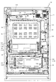
以下、本発明の第1実施形態について、添付図面を参照して説明する。図1は、第1の実施形態におけるパチンコ機10の正面図であり、図2はパチンコ機10の前面枠14及び下皿ユニット15を取り外した状態におけるパチンコ機10の正面図であり、図3はファール球入球通路606の拡大図であり、図4はファール球入球通路606に糸付遊技球が侵入した際の動作説明図であり、図5はパチンコ機10の背面図である。
Hereinafter, the first embodiment of the present invention will be described with reference to the accompanying drawings. FIG. 1 is a front view of the
パチンコ機10は、図1に示すように、略矩形状に組み合わせた木枠により外殻が形成される外枠11と、その外枠11と略同一の外形形状に形成され外枠11に対して開閉可能に支持された内枠12とを備えている。外枠11には、内枠12を支持するために正面視(図1参照)左側の上下2カ所に金属製のヒンジ18が取り付けられ、そのヒンジ18が設けられた側を開閉の軸として内枠12が正面手前側へ開閉可能に支持されている。
As shown in FIG. 1, the
内枠12には、多数の釘や入賞口63,64等を有する遊技盤13(図2参照)が裏面側から着脱可能に装着される。この遊技盤13の前面を球が流下することにより弾球遊技が行われる。なお、内枠12には、球を遊技盤13の前面領域に発射する球発射ユニット112a(図2参照)やその球発射ユニット112aから発射された球を遊技盤13の前面領域まで誘導する発射レール801等が取り付けられている。
A game board 13 (see FIG. 2) having a large number of nails, winning
内枠12の前面側には、その前面上側を覆う前面枠14と、その下側を覆う下皿ユニット15とが設けられている。前面枠14及び下皿ユニット15を支持するために正面視(図1参照)左側の上下2カ所に金属製のヒンジ19が取り付けられ、そのヒンジ19が設けられた側を開閉の軸として前面枠14及び下皿ユニット15が正面手前側へ開閉可能に支持されている。なお、内枠12の施錠と前面枠14の施錠とは、シリンダ錠20の鍵穴21に専用の鍵を差し込んで所定の操作を行うことでそれぞれ解除される。
On the front side of the
前面枠14は、装飾用の樹脂部品や電気部品等を組み付けたものであり、その略中央部には略楕円形状に開口形成された窓部14cが設けられている。前面枠14の裏面側には2枚の板ガラスを有するガラスユニット16が配設され、そのガラスユニット16を介して遊技盤13の前面がパチンコ機10の正面側に視認可能となっている。
The
前面枠14には、球を貯留する機能を有する上皿17が前方へ張り出して上面を開放した略箱状に形成されており、この上皿17に賞球や貸出球などが排出される。上皿17の底面は正面視(図1参照)右側に下降傾斜して形成され、その傾斜により上皿17に投入された球が、球を球発射ユニット112aへ供給するための球供給通路(図示せず)を通過し、供給球発射ユニット112aへと案内される。また、上皿17の上面には、枠ボタン22が設けられている。この枠ボタン22は、例えば、後述する第3図柄表示装置81(図2参照)で表示される演出のステージを変更したり、スーパーリーチの演出内容を変更したりする場合などに、遊技者により操作される。
On the
ステージとは、第3図柄表示装置81に表示される各種演出に統一性を持たせた演出モードのことで、本パチンコ機10では「街中ステージ」,「空ステージ」,「島ステージ」の3つのステージが設けられている。そして、後述する第1入球口64への入球(始動入賞)に伴って行われる変動演出やリーチ演出などの各種演出は、それぞれのステージに与えられたテーマに合わせて行われるように設計されている。ステージの変更は、変動演出が行われていない期間や高速変動中に遊技者によって枠ボタン22が操作された場合に行われ、枠ボタン22が操作される度に「街中ステージ」→「空ステージ」→「島ステージ」→「街中ステージ」→・・・の順で繰り返し変更される。また、電源投入後の直後は、初期ステージとして「街中ステージ」が設定される。
The stage is a production mode in which various effects displayed on the third
一方、第3図柄表示装置81には、ノーマルリーチ演出が開始された場合に、ノーマルリーチからスーパーリーチに発展させるときは、ノーマルリーチ中にスーパーリーチの演出態様の選択画面が表示されるように構成されており、その選択画面が表示されている間に、枠ボタン22が遊技者に操作されると、スーパーリーチ時の演出内容が変更される。
On the other hand, the third
前面枠14には、その周囲(例えばコーナー部分)に各種ランプ等の発光手段が設けられている。これら発光手段は、大当たり時や所定のリーチ時等における遊技状態の変化に応じて、点灯又は点滅することにより発光態様が変更制御され、遊技中の演出効果を高める役割を果たす。窓部14cの周縁には、LED等の発光手段を内蔵した電飾部29〜33が設けられている。パチンコ機10においては、これら電飾部29〜33が大当たりランプ等の演出ランプとして機能し、大当たり時やリーチ演出時等には内蔵するLEDの点灯や点滅によって各電飾部29〜33が点灯または点滅して、大当たり中である旨、或いは大当たり一歩手前のリーチ中である旨が報知される。また、前面枠14の正面視(図1参照)左上部には、LED等の発光手段が内蔵され賞球の払い出し中とエラー発生時とを表示可能な表示ランプ34が設けられている。
The
また、右側の電飾部32下側には、前面枠14の裏面側を視認できるように裏面側より透明樹脂を取り付けて小窓35が形成され、遊技盤13前面の貼着スペースK1(図2参照)に貼付される証紙等はパチンコ機10の前面から視認可能とされている。また、パチンコ機10においては、より煌びやかさを醸し出すために、電飾部29〜33の周りの領域にクロムメッキを施したABS樹脂製のメッキ部材36が取り付けられている。
Further, on the lower side of the illuminated
窓部14cの下方には、貸球操作部40が配設されている。貸球操作部40には、度数表示部41と、球貸しボタン42と、返却ボタン43とが設けられている。パチンコ機10の側方に配置されるカードユニット(球貸しユニット)(図示せず)に紙幣やカード等を投入した状態で貸球操作部40が操作されると、その操作に応じて球の貸出が行われる。具体的には、度数表示部41はカード等の残額情報が表示される領域であり、内蔵されたLEDが点灯して残額情報として残額が数字で表示される。球貸しボタン42は、カード等(記録媒体)に記録された情報に基づいて貸出球を得るために操作されるものであり、カード等に残額が存在する限りにおいて貸出球が上皿17に供給される。返却ボタン43は、カードユニットに挿入されたカード等の返却を求める際に操作される。なお、カードユニットを介さずに球貸し装置等から上皿17に球が直接貸し出されるパチンコ機、いわゆる現金機では貸球操作部40が不要となるが、この場合には、貸球操作部40の設置部分に飾りシール等を付加して部品構成は共通のものとしても良い。カードユニットを用いたパチンコ機と現金機との共通化を図ることができる。
A ball
上皿17の下側に位置する下皿ユニット15には、その中央部に上皿17に貯留しきれなかった球を貯留するための下皿50が上面を開放した略箱状に形成されている。下皿50の右側には、球を遊技盤13の前面へ打ち込むために遊技者によって操作される操作ハンドル51が配設され、かかる操作ハンドル51の内部には球発射ユニット112aの駆動を許可するためのタッチセンサ51aと、押下操作している期間中には球の発射を停止する押しボタン式の打ち止めスイッチ51bと、操作ハンドル51の回動操作量を電気抵抗の変化により検出する可変抵抗器で形成される操作量検出スイッチ51cとが内蔵されている。操作ハンドル51が遊技者によって右回りに回転操作されると、タッチセンサ51aがオンされると共に可変抵抗器の抵抗値(操作量検出スイッチ51cの検出結果)が操作量に対応して変化し、操作ハンドル51の回動操作量に応じて変化する可変抵抗器の抵抗値(操作量検出スイッチ51cの検出結果)に対応した強さで球が発射され、これにより遊技者の操作に対応した飛び量で遊技盤13の前面へ球が打ち込まれる。また、操作ハンドル51が遊技者により操作されていない状態においては、タッチセンサ51aおよび打ち止めスイッチ51bがオフとなっている。
In the
下皿50の正面下方部には、下皿50に貯留された球を下方へ排出する際に操作するための球抜きレバー52が設けられている。この球抜きレバー52は、常時、右方向に付勢されており、その付勢に抗して左方向へスライドさせることにより、下皿50の底面に形成された底面口が開口して、その底面口から球が自然落下して排出される。かかる球抜きレバー52の操作は、通常、下皿50の下方に下皿50から排出された球を受け取る箱(一般に「千両箱」と称される)を置いた状態で行われる。下皿50の右方には、上述したように操作ハンドル51が配設され、下皿50の左方には灰皿53が取り付けられている。
A
図2に示すように、遊技盤13は、正面視略正方形状に切削加工した木製のベース板60に、球案内用の多数の釘や風車およびレール61,62、一般入賞口63、第1入球口64、可変入賞装置65、可変表示装置ユニット80等を組み付けて構成され、その周縁部が内枠12の裏面側に取り付けられる。一般入賞口63、第1入球口64、可変入賞装置65、可変表示装置ユニット80は、ルータ加工によってベース板60に形成された貫通穴に配設され、遊技盤13の前面側から木ネジ等により固定されている。また、遊技盤13の前面中央部分は、前面枠14の窓部14c(図1参照)を通じて内枠12の前面側から視認することができる。以下に、主に図2を参照して、遊技盤13の構成について説明する。
As shown in FIG. 2, the
遊技盤13の前面には、帯状の金属板を略円弧状に屈曲加工して形成した外レール62が内枠12に設けられるレール取付部に配設され、その外レール62の内側位置には外レール62と同様に帯状の金属板で形成した円弧状の内レール61が植立される。この内レール61と外レール62とにより遊技盤13の前面外周が囲まれ、遊技盤13とガラスユニット16(図1参照)とにより前後が囲まれることにより、遊技盤13の前面には、球の挙動により遊技が行われる遊技領域が形成される。遊技領域は、遊技盤13の前面であって2本のレール61,62と円弧部材70とにより区画して形成される略円形状の領域(入賞口等が配設され、発射された球が流下する領域)である。
On the front surface of the
図2を参照して発射領域701を説明する。発射領域701は、内レール61と、外レール62(一部、案内部材605も含む)とにより左右方向が、遊技盤13の前面とガラスユニット16(図1参照)とにより前後方向が囲まれる領域であって、遊技領域の左側に内レール61を隔てて形成される略円弧状の経路である。
The
外レール62は、長尺状のステンレス製の金属帯で構成されており、内枠12に配設された樹脂(摩擦抵抗の小さいフッ素入りのポリカーボネート)成型されたレール取付部に取り付けられている。特に、内レールと所定の間隔を開けて対向している面は一枚の金属帯で形成されており、球発射ユニット112aによって発射された遊技球が発射経路を通過する際に、金属帯の継ぎ目に接触し発射方向や発射強度に影響が出ないようにしている。
The
尚、外レール62の構成として内レール61同様に遊技盤13に植立させてもよい。
The
発射経路701は、内枠12の下皿ユニット15に設けられる球発射ユニットから発射された遊技球を遊技盤13上部から遊技領域へ案内するために設けられたものである。この発射経路701の始端部と、上述した発射レール801の終端部との間には隙間802が形成され、隙間802に落下した遊技球は、後述するファール球通路800bを流下し上皿17へと返却される。一方、内レール61と外レール62との間に形成される発射経路の終端部は、遊技領域と連通する第1開口部603を有し、球発射ユニット112aにより発射された遊技球は第1開口部603を通過し、遊技領域へと到達する。
The
発射経路701の通路幅は始端部では遊技球が2球通過可能な間隔を有しており、案内部材605を通過する位置に向けて徐々に狭くなるように形成されており、案内部材605を通過する位置では、遊技球が1球通過可能な通路幅まで狭くなっている。そして、案内部材605を通過した後は、再び遊技球が2球通過可能な幅まで広くなり、そこから終端部に向けて再度徐々に狭くなるように形成されている。案内部材605通過位置で通路幅が狭くなる理由については後述する。
The width of the passage of the
第1開口部603の近傍には、戻り球防止部材68が取り付けられている。戻り球防止部材68は、遊技盤13の上部へ案内された球が再度球案内通路内に戻ってしまうといった事態を防止するものである。また、発射経路701には、後述するファール球入球通路606の開口部となる第2開口部604や、発射経路701内を通過する遊技球を検知する発射球検知スイッチ208bが設けられている。外レール62の先端部(図2の右上部)には、球の最大飛翔部分に対応する位置に返しゴム69が取り付けられ、所定以上の勢いで発射された球は、返しゴム69に当たって、勢いが減衰されつつ中央部側へ跳ね返される。また、内レール61の右下側の先端部と外レール62の右上側の先端部との間には、レール間を繋ぐ円弧を内面側に設けて形成された樹脂製の円弧部材70によって固定されている。
A return
球発射ユニット112aは、上皿17から供給された遊技球を遊技盤13に設けられる遊技領域に向けて発射させる機構をユニット化したものである。球発射ユニット122aは、発射ソレノイド、発射レール801、球送り機構、位置決め部材といった各部材から構成され、金属製平板をプレス加工したベース板に組み付けられる。各部材を組み付けたベース板は、内枠12に対してネジにより固定される。
The
球発射ユニット112aを構成する各部材の取り付け位置および球発射ユニット112aの内枠への取り付け位置がパチンコ機10毎に若干の誤差が出てしまうと、遊技盤13への遊技球の発射角度及び発射強度が異なってしまうため、精度の高い取り付けが求められる。そこで、ベース板には各部材を取り付けるための締結穴と各部材の位置を固定するためのボスが設けることで精度の高い取り付けを可能としている。更に、ベース板を内枠に取り付けるためのネジ穴を複数(6個)設け、内枠に対して高い精度で取り付けられることになる。
If the mounting position of each member constituting the
発射ソレノイドはリニアソレノイドをケース部材に収容したユニット構成である。発射ソレノイドには、発射レール801と長手方向を平行にして配設される金属製のプランジャと、プランジャの先端を覆う樹脂製のキャップとが設けられる。キャップの材質としては本実施形態においてはポリエステル系熱可塑性エラストマーが採用されている。遊技者が操作ハンドル51を回動操作した状態中には、発射ソレノイドは、所定時間(0.6秒)毎に励磁と非励磁とを繰り返し行い、これに対応してプランジャの出没が繰り返される。プランジャが突出したときには、後述する位置決め部材によって発射レール801上に位置決めされた遊技球は、発射レールの指向する斜め上方に向けて発射される。なお、操作ハンドル51に連動する可変抵抗器が発射ソレノイドに結線されており、操作ハンドル51の操作量に基づいてプランジャの突出速度が調整され、遊技球の発射速度ひいては飛び量が操作ハンドル51の回動量により調整される。
The firing solenoid has a unit configuration in which a linear solenoid is housed in a case member. The firing solenoid is provided with a metal plunger arranged in parallel with the firing
発射レールは発射ソレノイドにより発射された直後の遊技球を案内するものであり、遊技盤13の前面に設けられる発射領域701に向けて遊技球が発射されるよう所定の発射角度(20度)を有したものである。発射レールは断面M字状に形成され、中央の溝部を遊技球が通過することで、遊技球のばらつきを抑える形状になっている。更に、遊技球のばらつきを抑え、より安定した遊技球を発射領域701へ供給するために、発射レール801の長さを、発射ソレノイド取付位置から下皿ユニット15に覆われる領域の上端部まで到達する100mmにしている。発射レール801終端部と発射領域701の間には後述する隙間802が設けられている。
The launch rail guides the game ball immediately after being launched by the launch solenoid, and sets a predetermined launch angle (20 degrees) so that the game ball is launched toward the
球送り機構は、上皿17から連続して供給される遊技球を1球ずつ、発射レール801の始端部に送出するものである。この球送り機構は、発射ソレノイドを覆うようにしてベース板に取り付けられるものであり、その内部に金属片とその金属片を吸着する電磁石とを備えており、電磁石が励磁されることにより金属片が上方に移動し、電磁石が非励磁となると自重によって下方に移動する機構を有している。その機構には、金属片が上方に移動している間、上皿17から供給される遊技球を1球収容可能な収容部が設けられている。そして、電磁石が非励磁となり、自重によって金属片が下方に移動すると、上述した収容部が発射レール801への誘導通路と連通し、収容部に収容されていた遊技球が発射レール801に向けて流下していく。
The ball feeding mechanism sends the game balls continuously supplied from the
位置決め部材は、発射レール801の始端部上に載置される遊技球を支持するものであって、遊技球の発射位置を若干変更することができるものである。位置決め部材は偏心軸によってベース板に取り付けられる円柱状の部材であり、その円柱状部材を、偏心軸を軸心に回動させることで位置決め部材と発射レールとの間の距離を変更することができる構成となっている。
The positioning member supports the game ball placed on the starting end portion of the
本パチンコ機10では、球が第1入球口64へ入球した場合に特別図柄(第1図柄)の抽選が行われ、球が第2入球口67を通過した場合に普通図柄(第2図柄)の抽選が行われる。第1入球口64への入球に対して行われる特別図柄の抽選では、特別図柄の大当たりか否かの当否判定が行われると共に、特別図柄の大当たりと判定された場合にはその大当たり種別の判定も行われる。特別図柄の大当たりになると、パチンコ機10が特別遊技状態へ移行すると共に、通常時には閉鎖されている特定入賞口65aが所定時間(例えば、30秒経過するまで、或いは、球が10個入賞するまで)開放され、その開放が16回(16ラウンド)繰り返される。その結果、その特定入賞口65aに多量の球が入賞するので、通常時より多量の賞球の払い出しが行われる。特別図柄の大当たり種別としては、「大当たりA」、「大当たりB」の2種類が設けられており、特別遊技状態の終了後には大当たり終了後の付加価値として、これらの大当たり種別に応じた遊技上の価値(遊技価値)が遊技者に付与される。
In the
また、特別図柄(第1図柄)の抽選が行われると、第1図柄表示装置37において特別図柄の変動表示が開始されて、所定時間(例えば、11秒〜60秒など)が経過した後に、抽選結果を示す特別図柄が停止表示される。第1図柄表示装置37において変動表示が行われている間に球が第1入球口64へ入球すると、その入球回数は最大4回まで保留され、その保留球数が第1図柄表示装置37により示されると共に、第3図柄表示装置81においても示される。第1図柄表示装置37において変動表示が終了した場合に、第1入球口64についての保留球数が残っていれば、次の特別図柄の抽選が行われると共に、その抽選に応じた変動表示が開始される。尚、パチンコ機10が特別遊技状態へ移行すると開閉される特別入賞口65aは、第1入球口64の直ぐ下に設けられている。よって、特別遊技状態中は、遊技者が特別入賞口65aに入賞させようとして球を打つので、第1入球口64にも球が多く入球する。従って、殆どの場合、パチンコ機10が特別遊技状態に移行している間に、第1入球口64についての保留球数は最大(4回)になる。
Further, when the special symbol (first symbol) is drawn, the first
一方、第2入球口67における球の通過に対して行われる普通図柄の抽選では、普通図柄の当たりか否かの当否判定が行われる。普通図柄の当たりになると、所定時間(例えば、0.2秒または1秒)だけ第1入球口64に付随する電動役物が開放され、第1入球口64へ球が入球し易い状態になる。つまり、普通図柄の当たりになると、球が第1入球口64へ入球し易くなり、その結果、特別図柄の抽選が行われ易くなる。
On the other hand, in the lottery of the normal symbol performed for the passage of the ball at the
また、普通図柄(第2図柄)の抽選が行われると、第2図柄表示装置83において普通図柄の変動表示が開始されて、所定時間(例えば、3秒や30秒など)が経過した後に、抽選結果を示す普通図柄が停止表示される。第2図柄表示装置83において変動表示が行われている間に球が第2入球口67を通過すると、その通過回数は最大4回まで保留され、その保留球数が第1図柄表示装置37により表示されると共に、第2図柄保留ランプ84においても示される。第2図柄表示装置83において変動表示が終了した場合に、第2入球口67についての保留球数が残っていれば、次の普通図柄の抽選が行われると共に、その抽選に応じた変動表示が開始される。
Further, when the lottery of the normal symbol (second symbol) is performed, the variable display of the normal symbol is started on the second
上述したように、特別図柄の大当たり種別としては、「大当たりA」、「大当たりB」の2種類が設けられている。「大当たりA」、「大当たりB」になるといずれも、ラウンド数が16ラウンドの特別遊技状態(16R大当たり)となる。その後、「大当たりA」では大当たり終了後の付加価値として、その大当たり終了後から次の大当たりが発生するまでの間はパチンコ機10が特別図柄の高確率状態(特別図柄の確変状態)が付与される。一方、「大当たりB」では大当たり終了後の付加価値として、その大当たり終了後から特別図柄の抽選が100回終了するまでの間は普通図柄の当たり確率がアップし、普通図柄の変動時間が短く設定される時短状態が付与される。
As described above, there are two types of special symbols, "big hit A" and "big hit B". In both cases of "big hit A" and "big hit B", the number of rounds is 16 rounds in a special gaming state (16R big hit). After that, in "Big hit A", as an added value after the end of the big hit, the
ここで、「特別図柄の高確率状態」とは、特別図柄の大当たり確率がアップした状態、いわゆる特別図柄の高確率状態(特別図柄の確変中)をいい、換言すれば、特別遊技状態(16R大当たり)へ移行し易い遊技の状態のことである。対して、「特別図柄の高確率状態」でない場合を「特別図柄の低確率状態」といい、これは特別図柄の確変状態よりも大当たり確率が低い状態、即ち、特別図柄の大当たり確率が通常の状態(特別図柄の通常状態)のことを示す。また、「普通図柄の時短状態」(普通図柄の時短中)とは、普通図柄の当たり確率がアップして、変動時間が短くなり、第1入賞口64に付随する電動役物の開放時間が長く、開放回数が多くなる、第1入球口64へ球が入球し易い遊技の状態のことをいう。対して、「普通図柄の時短状態」でない時を「普通図柄の通常状態」といい、これは普通図柄の当たり確率が通常の状態、即ち、時短中よりも当たり確率が低い状態のことを示す。
Here, the "high probability state of the special symbol" means a state in which the jackpot probability of the special symbol is increased, that is, a so-called high probability state of the special symbol (during the probability change of the special symbol), in other words, a special game state (16R). It is a state of the game that is easy to shift to (big hit). On the other hand, the case where it is not the "high probability state of the special symbol" is called the "low probability state of the special symbol", which means that the jackpot probability is lower than the probability variation state of the special symbol, that is, the jackpot probability of the special symbol is normal. Indicates a state (normal state of a special symbol). In addition, the "normal symbol time reduction state" (normal symbol time reduction) means that the probability of hitting the normal symbol increases, the fluctuation time becomes shorter, and the opening time of the electric accessory attached to the first winning
以後、特別図柄の大当たり終了後からパチンコ機10が特別図柄の高確率状態になっている期間、即ち、大当たり終了後から次の大当たりが発生するまでの間のことを、特別図柄の確変期間と称す。また、特別図柄の大当たり終了後からパチンコ機10が普通図柄の時短状態になっている期間、即ち、大当たり終了後から特別図柄の抽選が所定回数(100回)終了するまでの間のことを、普通図柄の時短期間と称す(単に、時短期間とも言う)。尚、説明を分かり易くするために、特別図柄の抽選回数を用いて普通図柄の時短期間を示す。例えば、所定回数が100回であれば、普通図柄の時短期間が100回であると記載する。
After that, the period from the end of the jackpot of the special symbol to the period when the
なお、大当たりの種別に応じてラウンド数を変えても良いし、大当たりの種別の一部のみラウンド数を変えても良い。また、例えば、大当たりの種別に応じて「普通図柄の時短状態」となる期間を変える代わりに、第1入球口64に付随する電動役物(図示せず)を開放する時間や、1回の普通図柄の当たりで電動役物を開放する回数を変更するものとしても良い。また、本実施形態では、大当たり終了後に、「特別図柄の高確率状態」および「普通図柄の時短状態」となるが、「特別図柄の高確率状態」が終了した後に、「普通図柄の時短状態」となるように構成しても良い。
The number of rounds may be changed according to the type of jackpot, or the number of rounds may be changed only for a part of the type of jackpot. Also, for example, instead of changing the period during which the "normal symbol time is shortened" depending on the type of jackpot, the time to open the electric accessory (not shown) attached to the
また、時短状態の継続期間は任意に定めればよい。例えば、大当たり種別が「大当たりA」になると、その「大当たりA」終了後から特別図柄の抽選が30回終了するまで普通図柄の時短状態が継続され、「大当たりB」になると、その「大当たりB」終了後から特別図柄の抽選が60回終了するまで普通図柄の時短状態が継続されるようにしても良い。また、特別図柄の抽選回数に代えて、所定時間(例えば、2分から5分など)が経過するまで、普通図柄の時短状態が継続されるようにしても良い。 In addition, the duration of the time saving state may be arbitrarily determined. For example, when the jackpot type is "big hit A", the time saving state of the normal symbol is continued from the end of the "big hit A" until the lottery of the special symbol is completed 30 times, and when it becomes "big hit B", the "big hit B" is reached. The time saving state of the normal symbol may be continued from the end until the lottery of the special symbol is completed 60 times. Further, instead of the number of lottery of the special symbol, the time saving state of the normal symbol may be continued until a predetermined time (for example, 2 minutes to 5 minutes) elapses.
本パチンコ機10では、電源などの投入等により初期設定が行われると、必ず「特別図柄の低確率状態」に設定される。なお、これに限られず、「特別図柄の高確率状態」に設定される場合があっても良い。
In the
また、特別図柄の大当たりになって、「普通図柄の通常状態」から「普通図柄の時短状態」へ移行すると、その状態は、その特別図柄の大当たり終了後から特別図柄の抽選が時短回数(100回)終了するまで継続される。一方、特別図柄の大当たりになった後、時短回数分の特別図柄の抽選が終了するまでに、新たな特別図柄の大当たりにならないと、「普通図柄の通常状態」に戻る。この時短回数は、上述したように、特別図柄の大当たり種別によって定められており、大当たり種別が「大当たりB」であれば、所定回数は100回となる。 In addition, when the special symbol becomes a jackpot and shifts from the "normal state of the normal symbol" to the "time saving state of the normal symbol", the lottery of the special symbol is performed in a reduced time (100) after the jackpot of the special symbol ends. Times) Continues until the end. On the other hand, after the jackpot of the special symbol is reached, if the jackpot of a new special symbol is not reached by the time the lottery of the special symbol for the short time is completed, the process returns to the "normal state of the normal symbol". As described above, the number of time reductions is determined by the jackpot type of the special symbol, and if the jackpot type is "big hit B", the predetermined number of times is 100 times.
そして、「普通図柄の時短状態」が継続されている間に、新たに特別図柄の大当たりになると、「普通図柄の時短状態」はさらに、その新たな特別図柄の大当たり終了後から、その新たな大当たり種別に対応する回数分の特別図柄の抽選が終了するまで継続される。例えば、「大当たりB」になって「普通図柄の時短状態」に移行した後、10回目の特別図柄の抽選で「大当たりB」になると、「普通図柄の時短状態」はさらに、その「大当たりB」終了後から特別図柄の抽選が100回行われるまで継続される。即ち、本実施形態では、「普通図柄の時短状態」が継続されている間に、新たに特別図柄の大当たりになると、その度に、その新たな特別図柄の大当たり種別に応じて時短期間(「普通図柄の時短状態」の継続期間)が更新される。 Then, if a new special symbol jackpot is reached while the "normal symbol time reduction state" is being continued, the "normal symbol time reduction state" will be further changed after the end of the new special symbol jackpot. It will continue until the lottery for the number of special symbols corresponding to the jackpot type is completed. For example, if it becomes "big hit B" and shifts to "normal symbol time saving state" and then becomes "big hit B" in the 10th special symbol lottery, the "normal symbol time saving state" is further changed to that "big hit B". After the end, the lottery of special symbols will continue until 100 times. That is, in the present embodiment, when a new special symbol jackpot is reached while the "normal symbol time saving state" is being continued, the time saving period ("" The duration of "the time saving state of the normal symbol") is updated.
遊技領域の正面視右側上部(図2の右側上部)には、発光手段である複数の発光ダイオード(以下、「LED」と略す。)37aと7セグメント表示器37bとが設けられた第1図柄表示装置37が配設されている。第1図柄表示装置37は、後述する主制御装置110で行われる各制御に応じた表示がなされるものであり、主にパチンコ機10の遊技状態の表示が行われる。複数のLED37aは、第1入球口64への入球(始動入賞)に伴って行われる特別図柄の抽選が実行中であるか否かを点灯状態により示すことによって変動表示を行ったり、変動終了後の停止図柄として、その特別図柄の抽選結果に応じた特別図柄(第1図柄)を点灯状態により示したり、第1入球口64に入球された球のうち変動が未実行である球(保留球)の数である保留球数を点灯状態により示すものである。
A first symbol provided with a plurality of light emitting diodes (hereinafter, abbreviated as "LED") 37a and a 7-
この第1図柄表示装置37において特別図柄(第1図柄)の変動表示が行われている間に球が第1入球口64へ入球した場合、その入球回数は最大4回まで保留され、その保留球数は第1図柄表示装置37により示されると共に、第3図柄表示装置81においても示される。なお、本実施形態においては、第1入球口64への入球は、最大4回まで保留されるように構成したが、最大保留回数は4回に限定されるものでなく、3回以下、又は、5回以上の回数(例えば、8回)に設定しても良い。
If a ball enters the
7セグメント表示器37bは、大当たり中のラウンド数やエラー表示を行うものである。なお、LED37aは、それぞれのLEDの発光色(例えば、赤、緑、青)が異なるよう構成され、その発光色の組み合わせにより、少ないLEDでパチンコ機10の各種遊技状態(特別図柄の高確率状態や、普通図柄の時短中など)を表示することができる。また、LED37aには、変動終了後の停止図柄として特別図柄の抽選結果が大当たりであるか否かが示されるだけでなく、大当たりである場合はその大当たり種別(大当たりA、大当たりB)に応じた特別図柄(第1図柄)が示される。
The 7-
また、遊技領域には、球が入賞することにより5個から15個の球が賞球として払い出される複数の一般入賞口63が配設されている。また、遊技領域の中央部分には、可変表示装置ユニット80が配設されている。可変表示装置ユニット80には、液晶ディスプレイ(以下単に「表示装置」と略す。)で構成された第3図柄表示装置81と、LEDで構成された第2図柄表示装置83とが設けられている。この可変表示装置ユニット80には、第3図柄表示装置81の外周を囲むようにして、センターフレーム86が配設されている。
Further, in the game area, a plurality of general winning
第3図柄表示装置81は、第1図柄表示装置37の表示に応じた装飾的な表示を行うものである。例えば、第1入球口64へ球が入球(始動入賞)すると、それをトリガとして、第1図柄表示装置37において特別図柄(第1図柄)の変動表示が実行される。更に、第3図柄表示装置81では、その特別図柄の変動表示に同期して、その特別図柄の変動表示に対応する第3図柄の変動表示が行われる。
The third
第3図柄表示装置81は、8インチサイズの大型の液晶ディスプレイで構成されるものであり、後述する表示制御装置114によって表示内容が制御されることにより、例えば左、中及び右の3つの図柄列が表示される。各図柄列は複数の図柄によって構成され、これらの図柄が図柄列毎に縦スクロールして第3図柄表示装置81の表示画面上にて第3図柄が可変表示されるようになっている。本実施形態では、主制御装置110の制御に伴った遊技状態の表示が第1図柄表示装置37で行われるのに対して、第3図柄表示装置81はその第1図柄表示装置37の表示に応じた装飾的な表示が行われる。なお、表示装置に代えて、例えば、リール等を用いて第3図柄表示装置81を構成するようにしても良い。
The third
ここで、第3図柄表示装置81の表示内容について説明する。第3図柄は、「0」から「9」の数字を付した10種類の主図柄により構成されている。各主図柄は、木箱よりなる後方図柄の上に「0」から「9」の数字を付して構成され、そのうち奇数番号(1,3,5,7,9)を付した主図柄は、木箱の前面ほぼ一杯に大きな数字が付加されている。これに対し、偶数番号(0,2,4,6,8)を付した主図柄は、木箱の前面ほぼ一杯にかんな、風呂敷、ヘルメット等のキャラクタを模した付属図柄が付加されており、付属図柄の右下側に偶数の数字が緑色で小さく、且つ、付属図柄の前側に表示されるように付加されている。
Here, the display contents of the third
また、本実施形態のパチンコ機10においては、後述する主制御装置110(図4参照)により行われる特別図柄の抽選結果が大当たりであった場合に、同一の主図柄が揃う変動表示が行われ、その変動表示が終わった後に大当たりが発生するよう構成されている。一方、特別図柄の抽選結果が外れであった場合は、同一の主図柄が揃わない変動表示が行われる。
Further, in the
例えば、特別図柄の抽選結果が「大当たりA」であれば、偶数番号である「0,2,4,6,8」が付加された主図柄が揃う変動表示が行われる。また、「大当たりB」であれば、「7」を除く奇数番号である「1,3,5,9」が付加された主図柄が揃う変動表示が行われる。一方、特別図柄の抽選結果が外れであれば、同一番号の主図柄が揃わない変動表示が行われる。 For example, if the lottery result of the special symbol is "big hit A", the variable display is performed in which the main symbols to which the even numbers "0, 2, 4, 6, 8" are added are aligned. Further, in the case of "big hit B", a variable display is performed in which the main symbols to which the odd numbers "1, 3, 5, 9" excluding "7" are added are aligned. On the other hand, if the lottery result of the special symbol is out of order, a variable display is performed in which the main symbols having the same number are not aligned.
第3図柄表示装置81の表示画面は、大きくは上下に2分割され、下側の2/3が第3図柄を変動表示する主表示領域Dm、それ以外の上側の1/3が予告演出、キャラクタおよび保留球数などを表示する副表示領域Dsとなっている。
The display screen of the third
主表示領域Dmは、左・中・右の3つの表示領域Dm1〜Dm3に区分けされており、その3つの表示領域Dm1〜Dm3に、それぞれ3つの図柄列Z1,Z2,Z3が表示される。各図柄列Z1〜Z3には、上述した第3図柄が規定の順序で表示される。即ち、各図柄列Z1〜Z3には、数字の昇順または降順に主図柄が配列され、各図柄列Z1〜Z3毎に周期性をもって上から下へとスクロールして変動表示が行われる。特に、左図柄列Z1においては主図柄の数字が降順に現れるように配列され、中図柄列Z2及び右図柄列Z3においては主図柄の数字が昇順に現れるように配列されている。 The main display area Dm is divided into three display areas Dm1 to Dm3 on the left, middle, and right, and three symbol columns Z1, Z2, and Z3 are displayed in the three display areas Dm1 to Dm3, respectively. In each of the symbol rows Z1 to Z3, the above-mentioned third symbols are displayed in a specified order. That is, the main symbols are arranged in the ascending or descending order of the numbers in each of the symbol rows Z1 to Z3, and the variable display is performed by scrolling from top to bottom with periodicity for each of the symbol rows Z1 to Z3. In particular, in the left symbol row Z1, the numbers of the main symbols are arranged so as to appear in descending order, and in the middle symbol row Z2 and the right symbol row Z3, the numbers of the main symbols appear in ascending order.
また、主表示領域Dmには、各図柄列Z1〜Z3毎に上・中・下の3段に第3図柄が表示される。この主表示領域Dmの中段部が有効ラインL1として設定されており、毎回の遊技に際して、左図柄列Z1→右図柄列Z3→中図柄列Z2の順に、有効ラインL1上に第3図柄が停止表示される。その第3図柄の停止時に有効ラインL1上に大当たり図柄の組合せ(本実施形態では、同一の主図柄の組合せ)で揃えば大当たりとして大当たり動画が表示される。 Further, in the main display area Dm, the third symbol is displayed in the upper, middle, and lower three rows for each symbol row Z1 to Z3. The middle part of this main display area Dm is set as the effective line L1, and the third symbol is stopped on the effective line L1 in the order of the left symbol row Z1 → the right symbol row Z3 → the middle symbol row Z2 in each game. Is displayed. When the third symbol is stopped, if the combination of jackpot symbols (in the present embodiment, the same combination of main symbols) is aligned on the effective line L1, the jackpot moving image is displayed as a jackpot.
一方、副表示領域Dsは、主表示領域Dmよりも上方に横長に設けられており、さらに左右方向に3つの小領域Ds1〜Ds3に等区分されている。このうち、小領域Ds1は、第1入球口64に入球された球のうち変動が未実行である球(保留球)の数である保留球数を表示する領域であり、小領域Ds2およびDs3は、予告演出画像を表示する領域である。
On the other hand, the sub-display area Ds is provided horizontally above the main display area Dm, and is further divided into three small areas Ds1 to Ds3 in the left-right direction. Of these, the small area Ds1 is an area for displaying the number of reserved balls, which is the number of balls (reserved balls) that have not been changed among the balls entered in the
実際の表示画面では、主表示領域Dmに第3図柄の主図柄が合計9個表示される。副表示領域Dsにおいては、右の小領域Ds3に動画が表示され、通常より大当たりへ遷移し易い状態であることが遊技者に示唆される。中央の小領域Ds2では、通常は、所定のキャラクタ(本実施形態ではハチマキを付けた少年)が所定動作をし、時として所定動作とは別の特別な動作をしたり、別のキャラクタが現出する等して予告演出が行われる。 On the actual display screen, a total of nine main symbols of the third symbol are displayed in the main display area Dm. In the sub-display area Ds, the moving image is displayed in the small area Ds3 on the right, suggesting to the player that the transition to the jackpot is easier than usual. In the central small area Ds2, a predetermined character (a boy with a headband in the present embodiment) usually performs a predetermined action, and sometimes a special action different from the predetermined action is performed, or another character appears. A notice will be produced by issuing it.
一方、第3図柄表示装置81(第1図柄表示装置37)にて変動表示が行われている間に球が第1入球口64へ入球した場合、その入球回数は最大4回まで保留され、その保留球数は第1図柄表示装置37により示されると共に、副表示領域Dsの小領域Ds1においても示される。小領域Ds1には、保留球数1球につき1つの保留球数図柄が表示され、その保留球数図柄の表示数に応じて、保留球数が表示される。即ち、小領域Ds1に1つの保留球数図柄が表示されている場合は、保留球数が1球であることを示し、4つの保留球数図柄が表示されている場合は、保留球数が4球であることを示す。また、小領域Ds1に保留球数図柄が表示されていない場合は、保留球数が0球である、即ち、保留球が存在しないことを示す。
On the other hand, if a ball enters the first
なお、本実施形態においては、第1入球口64への入球は、最大4回まで保留されるように構成したが、最大保留球数は4回に限定されるものでなく、3回以下、又は、5回以上の回数(例えば、8回)に設定しても良い。また、小領域Ds1における保留球数図柄の表示に代えて、保留球数を第3図柄表示装置81の一部に数字で、或いは、4つに区画された領域を保留球数分だけ異なる態様(例えば、色や点灯パターン)にして表示するようにしても良い。また、第1図柄表示装置37により保留球数が示されるので、第3図柄表示装置81に保留球数を表示させないものとしてもよい。更に、可変表示装置ユニット80に、保留球数を示す保留ランプを最大保留数分の4つ設け、点灯状態の保留ランプの数に応じて、保留球数を表示するものとしてもよい。
In the present embodiment, the ball entering the first
主制御装置110では、第1入球口64へ球が入球(始動入賞)すると、それをトリガとして、特別図柄の抽選が行われ、その後、第1図柄表示装置37において特別図柄(第1図柄)の変動表示が実行される。主制御装置110から音声ランプ制御装置113へ変動パターンコマンドおよび停止種別コマンドが送信され、その結果、第3図柄表示装置81では、第1図柄表示装置37の変動表示に応じて第3図柄の変動表示が行われる。
In the
第3図柄表示装置81において第3図柄の変動表示が行われる場合には、まず、第3図柄の高速変動表示が開始され、その後、予め定められた時間(例えば、10秒〜60秒など)が経過すると、第3図柄の中速変動表示へ切り替わり、更に、第3図柄の低速変動表示へ切り替わる。ここで、特別図柄の抽選結果が大当たりである場合には、同一番号の主図柄(第3図柄)が揃う停止表示が行われ変動演出が終了し、続けて、大当たり演出が開始される。一方、特別図柄の抽選結果が外れである場合には、同一番号の主図柄(第3図柄)が揃わない停止表示が行われて変動演出が終了し、保留されている始動入賞があれば、次の特別図柄の抽選が行われると共に、次の変動演出が開始される。
When the variation display of the third symbol is performed on the third
大当たり演出は、オープニング演出が行われる期間と、ラウンド演出が行われる期間と、エンディング演出が行われる期間との3つの期間に分けられる。オープニング演出は、これからパチンコ機10が特別遊技状態へ移行して、通常時には閉鎖されている特定入賞口65aが繰り返し開放されることを遊技者に報知して、遊技者の期待感を高めるための演出であり、ラウンド演出は、これから開始されるラウンド数を遊技者に報知するための演出である。また、エンディング演出は、特別遊技状態の終了を遊技者に報知すると共に、大当たり終了後に遊技者に付与される遊技価値(普通図柄の時短期間)を遊技者に報知する(時短期間表示を行う)、または、保留されている特別図柄の抽選において抽選結果が大当たりとなることを遊技者に報知する(確定演出表示を行う)ための演出である。尚、エンディング演出において、遊技価値(普通図柄の時短期間)が遊技者に報知されることを「時短期間表示」が行われると称し、保留されている特別図柄の抽選において抽選結果が大当たりとなることが遊技者に報知されることを「確定演出表示」が行われると称す。
The jackpot production is divided into three periods: a period in which the opening production is performed, a period in which the round production is performed, and a period in which the ending production is performed. The opening effect is to notify the player that the
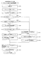
第3図柄表示装置81において大当たり演出が行われる場合には、図5(a)に示すように、まず、第3図柄の停止表示がなされるタイミングに合わせて、主制御装置110から音声ランプ制御装置113へオープニングコマンドが送信される。その結果、第3図柄表示装置81では、変動演出に続けて、オープニング演出が開始される。
When the jackpot effect is performed in the third
次に、オープニング演出が終了するタイミングに合わせて、主制御装置110から音声ランプ制御装置113へ第1ラウンドを示すラウンド数コマンドが送信される。その結果、第3図柄表示装置81では、オープニング演出に続けて、第1ラウンドに対応するラウンド演出が開始される。本実施形態では、パチンコ機10が特別遊技状態へ移行した後、その状態は、特定入賞口65aの開閉が16回繰り返されるまで(16ラウンド)継続される。
Next, a round number command indicating the first round is transmitted from the
第1ラウンドが開始され、特定入賞口65aが開放された後、所定時間(例えば、30秒経過するまで、或いは、球が10個入賞するまで)が経過すると、特定入賞口65aが閉鎖されると共に、第1ラウンドが終了する。すると、直ぐに第2ラウンドの開始タイミングとなり、主制御装置110から音声ランプ制御装置113へ第2ラウンドを示すラウンド数コマンドが送信される。その結果、第3図柄表示装置81では、第1ラウンドに対応するラウンド演出に続けて、第2ラウンドに対応するラウンド演出が開始される。第2ラウンドが開始されると、第1ラウンドの場合と同様に、特定入賞口65aの開閉制御が行われる。その後は、新たなラウンドが開始されるタイミングとなる毎に、新たなラウンド数を示すラウンド数コマンドが主制御装置110から音声ランプ制御装置113へ送信されると共に、特定入賞口65aの開閉制御が行われる。これにより、第1ラウンドから第16ラウンドまでの各ラウンド演出が順番に実行される。
After the first round is started and the specific winning opening 65a is opened, the specific winning opening 65a is closed when a predetermined time (for example, until 30 seconds elapse or until 10 balls are won). At the same time, the first round ends. Then, the start timing of the second round is immediately reached, and the round number command indicating the second round is transmitted from the
そして、特定入賞口65aの開閉が16回(16ラウンド)終了したタイミングに合わせて、主制御装置110から音声ランプ制御装置113へエンディングコマンドが送信される。その結果、第3図柄表示装置81では、エンディング演出が開始される。上述したように、エンディング演出では、特別遊技状態の終了が遊技者に報知されると共に、時短期間表示が行われる(大当たり終了後に遊技者に付与される遊技価値(普通図柄の時短期間)が遊技者に報知される)、または、確定演出表示が行われる(保留されている特別図柄の抽選において抽選結果が大当たりとなることが遊技者に報知される)。エンディング演出において「時短期間表示」が行われるか、「確定演出表示」が行われるかは、今回の特別図柄の大当たり種別や、保留されている特別図柄の大当たり種別や、図示しないカウンタの値などに基づいて選択される。
Then, an ending command is transmitted from the
第3図柄表示装置81において「時短期間表示」が行われる場合には、例えば、図5(b)に示すように、第3図柄表示装置81の画面右下に、「チャンス100回」(期間情報の一例)と表示される。この画面は、特別図柄の抽選がなされ、抽選結果が「大当たりB」である場合に表示されるものであり、大当たり終了後から特別図柄の抽選が100回終了するまでは、普通図柄の時短状態が継続されることを意味する。遊技者は、この画面が表示されると、これから普通図柄の時短状態が継続される期間(普通図柄の時短期間)を容易に認識することができる。
When the "time saving period display" is performed in the third
尚、普通図柄の時短期間が長ければ長い程、球が第2入球口67を通過する機会が多くなるので、普通図柄の抽選が行われる機会が多くなり、普通図柄の当たりになる機会も多くなる。よって、普通図柄の大当たりとなって電動役物が開放される機会も多くなるので、球が第1入球口64へ入球し易くなり、特別図柄の抽選が行われ易くなる。従って、表示される普通図柄の時短期間が長いほど、特別図柄の大当たりになるという期待感を強く、遊技者に対して持たせることができるので、遊技者の遊技への参加意欲を高めることができる。故に、遊技者に遊技への参加意欲を継続して持たせることができる。
In addition, the longer the time reduction period of the normal symbol, the more chances that the ball will pass through the
また、第1入球口64は、球が入球すると5個の球が賞球として払い出される入賞口であるので、普通図柄の大当たりとなって電動役物が開放され、球が第1入球口64へ入り易くなると賞球が多くなる。これにより、パチンコ機10は、遊技を行っても、持ち玉が減りにくい状態、又は、持ち玉が減らない状態になるので、遊技者は、持ち玉が減りにくい状態、又は、持ち玉が減らない状態で特別図柄の大当たりを得られるという期間感を得ることができる。従って、遊技者の遊技への参加意欲を高めることができるので、遊技者に遊技への参加意欲を継続して持たせることができる。
Further, since the
一方、第3図柄表示装置81において「確定演出表示」が行われる場合には、例えば、第3図柄表示装置81の画面右下に、「スーパーチャンス!」(別の情報一例)と表示される。この画面は、保留されている特別図柄の抽選うち、何れかの抽選がなされた場合に抽選結果が必ず大当たりとなることを意味する。遊技者は、この画面が表示されると、保留されている特別図柄の抽選において特別図柄の大当たりになることを認識できるので、確実に特別図柄の大当たりになるという期待感を、遊技者に対して持たせることができる。よって、遊技者の遊技への参加意欲を高めることができるので、遊技者に遊技への参加意欲を継続して持たせることができる。
On the other hand, when the "fixed effect display" is performed on the third
図2に戻って、説明を続ける。第2図柄表示装置83は、球が第2入球口67を通過することに伴って行われる普通図柄の抽選が実行中であるか否かを点灯状態により示すことによって変動表示を行ったり、変動終了後の停止図柄として、その普通図柄の抽選結果に応じた普通図柄(第2図柄)を点灯状態により示すものである。
Returning to FIG. 2, the description will be continued. The second
より具体的には、第2図柄表示装置83では、球が第2入球口67を通過する毎に、第2図柄としての「○」の図柄と「×」の図柄とを交互に点灯させる変動表示が行われる。パチンコ機10は、第2図柄表示装置83における変動表示が所定図柄(本実施形態においては「○」の図柄)で停止すると、第1入球口64に付随する電動役物が所定時間だけ作動状態となり(開放される)、その結果、第1入球口64に球が入り易い状態となるように構成されている。球が第2入球口67を通過した通過回数は最大4回まで保留され、その保留球数が上述した第1図柄表示装置37により表示されると共に第2図柄保留ランプ84においても点灯表示される。第2図柄保留ランプ84は、最大保留数分の4つ設けられ、第3図柄表示装置81の下方に左右対称に配設されている。
More specifically, in the second
なお、普通図柄(第2図柄)の変動表示は、本実施形態のように、第2図柄表示装置83において複数のランプの点灯と非点灯を切り換えることにより行うものの他、第1図柄表示装置37及び第3図柄表示装置81の一部を使用して行うようにしても良い。同様に、第2図柄保留ランプ84の点灯を第3図柄表示装置81の一部で行うようにしても良い。また、第2入球口67における球の通過は、第1入球口64と同様に、最大保留球数は4回に限定されるものでなく、3回以下、又は、5回以上の回数(例えば、8回)に設定しても良い。また、第1図柄表示装置37により保留球数が示されるので、第2図柄保留ランプ84により点灯表示を行わないものとしても良い。
The variation display of the normal symbol (second symbol) is performed by switching the lighting and non-lighting of a plurality of lamps in the second
可変表示装置ユニット80の下方には、球が入球し得る第1入球口64が配設されている。この第1入球口64へ球が入球すると遊技盤13の裏面側に設けられる第1入球口スイッチ(図示せず)がオンとなり、その第1入球口スイッチのオンに起因して主制御装置110で特別図柄の抽選がなされ、その抽選結果に応じた表示が第1図柄表示装置37のLED37aで示される。また、第1入球口64は、球が入球すると5個の球が賞球として払い出される入賞口の1つにもなっている。
Below the variable
第1入球口64の下方には可変入賞装置65が配設されており、その略中央部分に横長矩形状の特定入賞口(大開放口)65aが設けられている。パチンコ機10においては、主制御装置110で行われる特別図柄の抽選が大当たりとなると、所定時間(変動時間)が経過した後に、大当たりの停止図柄となるよう第1図柄表示装置37のLED37aを点灯させると共に、その大当たりに対応した第3図柄の停止図柄を第3図柄表示装置81に表示させて、大当たりの発生が示される。その後、通常時より多量の賞球の払い出しが行われる特別遊技状態(16ラウンドの大当たり)に遊技状態が遷移する。この特別遊技状態として、通常時には閉鎖されている特定入賞口65aが、所定時間(例えば、30秒経過するまで、或いは、球が10個入賞するまで)開放される。
A variable winning
この特定入賞口65aは、所定時間が経過すると閉鎖され、その閉鎖後、再度、その特定入賞口65aが所定時間開放される。この特定入賞口65aの開閉動作は、16回(16ラウンド)繰り返し可能にされている。この開閉動作が行われている状態が、遊技者にとって有利な特別遊技状態の一形態であり、遊技者には、遊技上の価値(遊技価値)の付与として通常時より多量の賞球の払い出しが行われる。 The specific winning opening 65a is closed after a lapse of a predetermined time, and after the closing, the specific winning opening 65a is opened again for a predetermined time. The opening / closing operation of the specific winning opening 65a can be repeated 16 times (16 rounds). The state in which this opening / closing operation is performed is a form of a special gaming state that is advantageous for the player, and a larger amount of prize balls than usual is paid out to the player as a game value (game value). Is done.
可変入賞装置65は、具体的には、特定入賞口65aを覆う横長矩形状の開閉板と、その開閉板の下辺を軸として前方側に開閉駆動するための大開放口ソレノイド(図示せず)とを備えている。特定入賞口65aは、通常時は、球が入賞できないか又は入賞し難い閉状態になっている。大当たりの際には大開放口ソレノイドを駆動して開閉板を前面下側に傾倒し、球が特定入賞口65aに入賞しやすい開状態を一時的に形成し、その開状態と通常時の閉状態との状態を交互に繰り返すように作動する。
Specifically, the variable winning
なお、上記した形態に特別遊技状態は限定されるものではない。特定入賞口65aとは別に開閉される大開放口を遊技領域に設け、第1図柄表示装置37において大当たりに対応したLED37aが点灯した場合に、特定入賞口65aが所定時間開放され、その特定入賞口65aの開放中に、球が特定入賞口65a内へ入賞することを契機として特定入賞口65aとは別に設けられた大開放口が所定時間、所定回数開放される遊技状態を特別遊技状態として形成するようにしても良い。
The special gaming state is not limited to the above-described form. A large opening that opens and closes separately from the specific winning opening 65a is provided in the game area, and when the
遊技盤13の下側における左右の隅部には、証紙や識別ラベル等を貼着するための貼着スペースK1が設けられ、貼着スペースK1に貼られた証紙等は、前面枠14の小窓35(図1参照)を通じて視認することができる。
Attachment spaces K1 for attaching certificate stamps, identification labels, etc. are provided in the left and right corners on the lower side of the
更に、遊技盤13には、アウト口66が設けられている。いずれの入賞口63,64,65aにも入球しなかった球はアウト口66を通って図示しない球排出路へと案内される。遊技盤13には、球の落下方向を適宜分散、調整等するために多数の釘が植設されているとともに、風車等の各種部材(役物)が配設されている。
Further, the
次に、図2および図3を参照して内枠13の前面側に設けられる通路形成部材800について説明する。通路形成部材800は、内枠12に組み付けられるユニット基部と、下皿ユニット15に組み付けられるユニットカバーとから構成され、内枠12に対して下皿ユニット15を閉鎖状態にすることで遊技球が1球通過可能な通路幅を確保した状態で形成されるものである。このような構成とすることで、通路形成部材800内で球詰まりが発生したとしても内枠12から下皿ユニット15を開状態にするだけで通路内を容易に点検することが可能となる。このように複数の部材を閉状態にすることで玉通路を形成する構成を採用する際には、一方の部材に遊技球が通過する通過面を、他方の部材に通路を構成するその他の面を設けるとよい、このようにすることで、遊技球が球通路を通過する際に各部材の継ぎ目に接触し球流れが不安定になることを防ぐことが可能となる。本実施形態では複雑な球通路であっても通路内の点検を容易に行うことが可能であるため、ユニット基部とユニットカバーとをそれぞれ樹脂成型品(ポリカーボネート)で成型している。
Next, the
なお、通路形成部材800は、その全てを上述した構成にする必要はなく、球通路の一部であってもよい。また、ユニット基部とユニットカバーとを組み付けて球通路を構成可能であればよく、ユニット基部に対してユニットカバーを取り付ける構成であってもよい。
The
通路形成部材800には、上皿17(図1参照)が満タンのときに遊技球を下皿50へ排出するための下皿排出通路800aと、遊技領域に届かない、又は、一旦遊技領域に到達したが釘等に衝突した後に再度発射経路701へと侵入した遊技球(以下、ファール球と称す。)を上皿17へ排出するためのファール球通路800bと、球抜きスイッチ(図示せず)を操作する球抜き操作時に、発射レール801上の遊技球を下皿50へ排出するための発射球排出通路800cが形成される。この通路形成部材800は、下皿排出通路800aとファール球通路800bと発射球排出通路800cとを一体的に形成するものであり、これにより、各通路を別々の部材で形成するより、構成を単純にして部品コストを低減したり、部品点数を少なくして組み立てコストを低減したり、或いは、部品をコンパクトに形成して他の部品のレイアウトを容易にしたりすることができる。また、複数の通路をまとめて樹脂成型するため、各通路の位置関係について精度を高めることが可能となる。
The
特に、下皿排出通路800aを流下する遊技球と発射球排出通路800cを流下する遊技球とが合流する合流部も予め樹脂成型されているため、下皿排出通路800aを流下する遊技球が優先して下皿へ流下するように、発射球排出通路800cよりも上方から下皿排出口50aに流下する構成を確実に且つ容易に実現することができる。
In particular, since the confluence of the game ball flowing down the lower
発射レール801と、遊技盤13前面の内レール61と外レール62とで形成される発射経路701との間には、約40mmの隙間802が形成され、この隙間から落下したファール球を受け入れるようにファール球通路800bが設けられている。ファール球通路800bに受け入れられたファール球は上皿排出口17aより上皿17へと排出される。
A
通路形成部材800の右側端部には、発射レール801の下流側と下皿排出口50aとを繋ぐ遊技球の通路である発射球排出通路800cが形成されている。発射球排出通路800cの入口には開閉可能なシャッタ機構(図示せず)が設けられており、上皿17に設けられる球抜きスイッチ(図示せず)を操作することにより、シャッタ機構が開状態となり発射レール上に位置する遊技球が発射球排出通路800cへと排出され下皿50へと返却するよう構成されている。
At the right end of the
なお、本実施形態ではファール球通路800bを流下した遊技球を上皿17へ誘導するように構成されているが、上皿17ではなく球発射ユニット112aに直接誘導するようにしてもよい。このようにすることで、ファール球が発生したとしても迅速に再度発射させることができる。
In the present embodiment, the game ball flowing down the
次に、遊技盤13に設けられる発射経路701のうち、発射経路701の左下側に設けられるファール球入球通路606近傍の構成について、図2及び図3を用いて説明をする。ファール球入球通路606はファール球が流下する通路であり、外レール62と案内部材605と遊技盤13に立設された入球通路形成部材607とによって幅方向が区画され、遊技盤13と、ガラスユニット16によってその前後面が区画形成される通路である。第2開口部604によって発射経路701から分岐した遊技球が流下する空間である。ファール球入球通路606内を流下したファール球は、通路内に設けられたファール入賞口601へ入球する。上述したように、ファール球入球通路606はその前面をガラスユニット16が形成しているため、通路内を目視確認することができる。また、ガラスユニット16が取り付けられている前面枠14を開状態にすることで、通路内の点検を容易に行うことができる。
Next, among the
第2開口部604は、円弧状に形成されている発射経路701の外周側を構成する外レール62と案内部材605との間に形成される。この第2開口部604は、発射経路701内を発射球が左上方に発射される領域(以下、左下弦領域と称す)の外周側、つまり、ファール球が自重によって流下する際に発射経路701の外周側に当接する位置(以下、左下弦位置と称す)に設けられる。このように第2開口部604を左下弦位置に設けたのは、発射経路701の終端部付近で発生したファール球が、第2開口部604へ自重によって侵入可能とするためである。尚、第2開口部604を発射経路701の終端部付近、つまり、発射された遊技球が右上方に移動する領域(以下、左上弦領域と称す)に設ける場合は、ファール球が自重によって流下する際に当接する位置が発射経路701の内周側(内レール61)となる(以下、左上弦位置と称す)。本実施形態では発射経路701が遊技球を左上側に向かって発射させるよう左円弧状の形状となっているが、本実施形態以外の円弧状構成を採用した場合であっても、ファール球が自重によって当接する側に第2開口部604を設けることで、ファール球の入球を容易に行うことが可能となる。
The
次に図3を参照して第2開口部604近傍の構成について説明する。図3は図2に記載されているパチンコ機10における領域IIを拡大した図面である。第2開口部604の案内部材605側(図3右側)には、ファール球を第2開口部へ誘導するための誘導部材602が設けられている。誘導部材602は弾性部材(ウレタン)によって形成され、その取付基部602aが遊技盤13にネジで固定されている。取付基部602aは案内部材605の保護部605bに覆われているため、遊技球が衝突することが無い。この誘導部材602は、ファール球を受け止めるために発射経路701の幅方向略半分程度まで延設されており、ファール球が発射経路701始端部まで流下することを防いでいる。又、球発射ユニット112aによって発射された遊技球は案内部材605の傾斜面605aを転動した後、誘導部材602に接触することとなるが、案内部材605の傾斜面605aの先端部が誘導部材602の取付基部602aを覆うように形成される保護部となっているため、発射された遊技球が接触するのは誘導部材602の先端部となる。誘導部材602は弾性部材で形成されており、球発射ユニット112aから発射された遊技球と接触した際にその先端部がファール球入球通路606内へ侵入する方向へ弾性変形(図3の点線図参照)し、第2開口部604の一部を覆う状態となる。この状態では誘導部材602は第2開口部と対峙し、第2開口部604の開口幅が狭くなる。
Next, the configuration in the vicinity of the
よって、球発射ユニット112aから発射された遊技球が誘導部材602近傍を通過する際には、誘導部材602が弾性変形するため著しく発射力が落ちることが無い。また、誘導部材が弾性変形することで第2開口部604の開口幅が狭くなるため、第2開口部に落下することも無くスムーズに発射を行うことを可能としている。そして、発射された遊技球が通過した後、誘導部材602はもとの位置に弾性復帰する。
Therefore, when the game ball launched from the
次に、誘導部材602がファール球と衝突した際の説明をする。誘導部材602、はその先端部が案内部材605の傾斜面605aと外レール62の傾斜面始端部とを繋いだ直線よりも発射経路701側へ突出するよう構成されている。また、外レール62の傾斜面の第2開口部604側への延長線が第2開口部604内に向かうよう外レール62と第2開口部604が形成されている。このように構成されている箇所において、外レール62側から流下してくるファール球は次の何れかの経路を辿って第2開口部604へ侵入することになる。
Next, the case where the
誘導部材602に接触することなく第2開口部604へ侵入する場合は、その勢いのままファール入賞口601へと到達することを防ぐための突出部605aによってファール球の流下速度を落としてからファール入賞口601へ到達する。一方、誘導部材602に接触した後に第2開口部へ侵入する場合は、ファール球から受ける外力によって誘導部材が発射経路701内に侵入する方向へ弾性変形する。この弾性変形によってファール球の流下速度を落とした後にファール入賞口601へ到達する。
When entering the
なお、ファール球から受ける外力によって誘導部材602が発射経路701内に侵入する方向へ弾性変形したとしても、案内部材605の保護部605bが誘導部材602の変化を制限しているため、ファール球から受ける外力によって発射経路701が塞がれることはなく、第2開口部604の開口幅が広くなる程度(図3の誘導部材602と保護部605bとの間の隙間が無くなる程度)にのみ誘導部材602が弾性変形するだけである。そのように弾性変形した状態であっても球発射ユニット112aによって発射された遊技球が発射経路701を通過できるよう案内部材605を通過した直後の発射経路701の通路幅は遊技球が2個通過可能な幅となっている。
Even if the
このような構成を用いることにより、ファール球を受け止めてファール球入球通路606へと誘導する機能と、球発射ユニット112aから発射される遊技球をスムーズに通過させる機能とを両立させることが可能となる。更に、誘導部材602とは別部材である案内部材605を用いて誘導部材602の弾性変形を制限しているため、誘導部材602を一方向(ファール球入球通路606内に侵入する方向)には変化し易く、他方向(発射経路を塞ぐ方向)には変化し難い材質にするといった複雑な技術を用いる必要をなくすことができる。
By using such a configuration, it is possible to achieve both the function of receiving the foul ball and guiding it to the foul
なお、誘導部材602は上述した構成に限ることなく、球発射ユニット112aから発射される遊技球を阻止することなく、且つ、ファール球を第2開口部へと誘導する機能を奏する構成であればよく、例えば取付基部602aを回転可能で且つ原点位置に復帰可能なバネ構成とし、その取付基部602aによって板状部材を軸支する可変構成や、遊技球発射方向にのみ回転可能な回転体を用いた構成でもよい。
The
また、可変しない構成であっても上記機能を奏する構成であればよく、例えば発射球の発射方向に沿って徐々に先細りとなる誘導通路を設けることで、ファール球が球発射ユニット112a側へ流下するのを阻止する構成としてもよい。尚、本実施形態では弾性部材としてウレタンを用いたが反発弾性が優れた材質であればよくその他ゴム(シリコンゴム等)を用いてもよい。また誘導部材602の取付位置を内レール61側にしてもよい。
Further, even if the configuration is not variable, it may be a configuration that fulfills the above function. For example, by providing a guide passage that gradually tapers along the launch direction of the launch ball, the foul ball flows down to the
ファール球入球通路606内には、詳細は後述するが案内部材605に一体的に形成された突起部605cがファール入賞口601を覆うように設けられており、ファール球がファール入賞口601に勢いよく衝突することを防いでいる。
In the foul
ファール球入球通路606を流下したファール球は、ファール入賞口601に入球し、他の入賞口に入賞した遊技球と同様に、回収通路(図示せず)を流下した後、遊技盤13裏面に設けられたアウト口(図示せず)へ排出される。ファール入賞スイッチ208aは、ファール入賞口601に入球したファール球を検知するものであり、その検知結果は後述する賞球払出処理(図示せず)や入球異常判定処理(図23のS1004)に使用される。
The foul ball that has flowed down the foul
発射球検知スイッチ208bは、発射経路701を通過した遊技球を検知する近接スイッチであり、その検知結果は後述する入球異常判定処理(図23のS1004)に使用される。発射球検知スイッチ208bは、発射された遊技球を検知可能とし、且つファール球が逆流してこない位置である誘導部材602近傍に設けられている。
The launch
尚、発射球検知スイッチ208bとして遊技球が通過する方向も検出可能なスイッチにすることで、検知した遊技球が発射された遊技球なのか、発射経路701を逆流したファール球なのかを判定することが可能となるため、発射球検知スイッチ208bの取付位置を自由にすることができる。遊技球の通過方向を検知可能なスイッチとしては、遊技球が一列で通過する通路部と、遊技球の通過方向に沿って設けられる複数の検知部を備え、各検知部の検知順序(変化パターン)を検出することで遊技球の通過方向を検出する技術が考えられ、具体的には、磁界の変化や磁界の変化に対応した電気信号を検知するものが考えられる。
By setting the launch
本実施形態では、発射経路701に対してファール球入球通路606が鋭角となるように構成されている。これは、発射経路701内における遊技球の流れ及びファール入賞口601に対する不正対策を行うための構成であり、詳細は後述する。
In the present embodiment, the foul
ここで、球発射ユニット112aによって発射される遊技球の流れについて説明をする。球発射ユニット112aによって発射された遊技球は、発射レール801上を転動し、その勢いで隙間802を飛び越えて案内部材605の傾斜面605aを転動する。その後、案内部材605の傾斜面605aを転動する遊技球は、第2開口部604を飛び越え、外レール62に沿って戻り球防止部材68が設けられる第1開口部603を経て遊技領域へと打ち出される。
Here, the flow of the game ball launched by the
球発射ユニット112aによって発射された遊技球のうち、ファール球の流れは、ファール球が発生した箇所によって異なる。発射経路701の終端側でファール球が発生した場合は、誘導部材602によってファール球入球通路606内へ誘導され、ファール球入球通路内に設けられたファール入賞口601へ入球する。詳細は後述するが、ファール入賞口601への入球に基づく払出数(賞球数)は1球に設定されており、ファール入賞口601に遊技球が入球することに基づいて、払出制御装置111より遊技球が1球上皿17へ払い出される。
Among the game balls launched by the
一方、発射経路701の始端側、具体的には、ファール球入球通路606への分岐口となる第2開口部604よりも発射経路701の始端側で発生したファール球は、隙間802に落下し、ファール球通路800bを経て上皿17へ返却される。
On the other hand, the foul ball generated on the start end side of the
本実施形態では、ファール球は第2開口部604又は隙間802によって分岐され、いずれも上皿17へ遊技球が供給される構成となっているため、遊技者はファール球の発生に基づいて遊技球が上皿へ供給されるため、そのまま再度発射することができる。又、ファール球を分岐させる構成(第2開口部604、隙間802)が発射経路701の異なる位置に2つ設けられているため、ファール球が発生した箇所に近い側でファール球を発射経路701から分岐させることで、ファール球を分岐させる構成が1つしかない場合に比べ、ファール球が発射経路701に滞在する期間を短くすることができる。よって、球発射ユニット112aによって発射された遊技球が発射経路701内に滞在するファール球と衝突してしまい新たなファール球が発生するという悪循環を阻止することが可能となる。
In the present embodiment, the foul ball is branched by the
更に、ファール球を遊技盤13上で発射経路から分岐する構成としてファール球入球通路606を用いているため、従来のように遊技盤13側から前面枠14に向けてファール球を返却する専用の通路を設ける必要がなくなる。よって、前面枠側では限られた遊技機内スペースをその他の部材(例えば、装飾部材や枠ボタン)を設置するためのスペースとして有効活用することができる。また、遊技盤13側では前面枠14側と連通するようにファール球専用通路を設ける必要がなくなることから、遊技盤13の設計自由度が増し、遊技者にとって興趣を向上させることができるパチンコ機10を提供することが可能となる。
Further, since the foul
ここで、発射経路701近傍に設けられる各部材の特徴的な構成について説明する。発射レール801上の傾斜角は、発射された遊技球が確実に隙間802を飛び越えるよう、案内部材605の傾斜面605aの最下端部よりも上側に遊技球が到達するよう設計されている(約20度)。案内部材605の傾斜面605aの傾斜角は、発射レール801上の傾斜角よりも急傾斜(約30度)となるように設計されており、傾斜面605aの流下方向延長線上に隙間802を位置させているため、案内部材605上を流下するファール球は隙間802へ落下することになる。また、案内部材605の傾斜面605a上を転動した発射球が、第2開口部604を飛び越えるように設計されている。具体的には、傾斜面605aを発射方向に向けて延長した延長線A(図4参照)が外レール62の下端より上方に到達するように構成されている。
Here, a characteristic configuration of each member provided in the vicinity of the
また、外レール62の下端延長線上に第2開口部604を臨むよう設計されている。よって、外レール62に沿って流下したファール球が確実に第2開口部604に落下するよう構成されている。つまり、案内部材605の傾斜面605aの遊技球発射方向(転動方向)に対してファール球入球通路606が鋭角となるように、また、外レール62に沿って流下したファール球の流下方向に対して、ファール球入球通路606(第2開口部604)がその延長線上に位置するように、発射経路701に対してファール球入球通路606が屈曲形成されている。
Further, it is designed so that the
このような構成とすることで、発射球が通過する領域と隙間802及び第2開口部604とを異なる位置に設けることができ、発射球が落下することなく、且つファール球は落下するようにすることができる。尚、各通路に段差を設けても同様の効果を奏することが可能である。
With such a configuration, the region through which the launch ball passes and the
また、本実施形態では発射経路701の通路幅が、案内部材605の保護部605bと内レール61とが対向する位置で狭くなるよう設計されている。これは、発射経路終端部側で発生したファール球が発射経路始端側へ流下することなく、確実にファール球入球通路606へと流下させるためのものである。
Further, in the present embodiment, the passage width of the
なお、本実施形態では、ファール球入球通路606を遊技盤13の左下側に設けている。これは、ファール球を従来のように直接返却するのではなく、賞球を払い出すことによって対応する際に、遊技者に違和感を与えないためである。つまり、ファール球の入球によって遊技球が上皿17に払い出されることから、あたかもファール入賞口601に入賞した球が上皿に戻ってきたと思われるように、上皿17(詳しくは、上皿に遊技球が排出される箇所)の上方且つ近傍である遊技盤13の左下側に設けたものである。
In the present embodiment, the foul
以上説明したように、発射経路701内でのファール球の処理にファール球入球通路606を用いることで、ファール球を遊技者に返却する専用通路を形成する必要がなくなるが、悪意を持った遊技者がファール球入球通路606に設けられたファール入賞口601に糸付の遊技球を入球させ、糸を操作することで不正に遊技球を獲得する虞があった。そこで、上述した不正を防止するための構成を図4、図5を用いて説明する。
As described above, by using the foul
図5(a)は、糸状体である糸610が取り付けられた遊技球がファール球入球通路606内のファール入賞スイッチ208aに到達している状態を表す図であり、図5(b)は、糸610を遊技者が引っ張ることで、矢印611方向へ糸610が移動した後の状態を表す図である。
FIG. 5A is a diagram showing a state in which the game ball to which the
図5(a)は、糸610が取り付けられた遊技球が、球発射ユニット112aによって発射され、その遊技球がファール入賞口601内のファール入賞スイッチ208aに到達した状態を示すものである。糸610が取り付けられた遊技球は、通常の遊技球同様に上皿17から投入され、球発射ユニット112aによって発射される。
FIG. 5A shows a state in which the game ball to which the
なお、このような不正遊技に用いられる糸610は、球発射ユニット112a内で構造物に引っかかることの無い細さで、且つ、遊技球の重量に耐えることのできる素材のものが用いられる。具体的には、ピアノ線、釣り糸(ナイロン製)、綿糸等である。
The
本実施形態では、上述したように案内部材605の傾斜面605aを転動する遊技球の遊技球発射方向(転動方向)に対してファール球入球通路606が鋭角となるように屈曲形成されており、遊技球がファール入賞口601(ファール入賞スイッチ208a)に到達したときには、遊技球に取り付けられた糸610は略V字(又は略U字)状になっている(図5の(a)参照)。
In the present embodiment, as described above, the foul
図5(a)において、誘導部材602は略V字形状となっている糸610の内側に当接しており、糸610より遊技球の荷重を受け、その先端部がファール球入球通路606側に屈曲している。
In FIG. 5A, the
また、糸610は案内部材605の突起部605cにも当接している。これについて図4を用いて説明する。突起部605aはファール入賞口601を覆うように構成されており、その先端部(図4の線B)は、ファール入賞口601の端部(図4の線C)よりも左側に突出している(線Cよりも線Bが左にある)。よって、略V字状になっている糸610の一部が突起部605aに当接することになる。なお、図4の線Bは突出部605cの先端位置に当接する垂直線であり、図4の線Cはファール入賞口601の一端(突出部605cが突出している側の一端)と当接する垂直線である。
The
図5(b)は、図5(a)の状態から遊技者が糸610を操作し、矢印611方向(遊技球の発射方向の反対方向)に糸610が移動した状態を示すものである。この状態では、糸610が取り付けられた遊技球がファール入賞スイッチ208aの上方に位置することになる。このように、図5(a)と図5(b)の状態とを交互に繰り返すことにより、遊技球1球を用いて入賞スイッチを複数回検知させ不正に遊技球を獲得するという行為を行うことになる。
FIG. 5B shows a state in which the player operates the
次に、図5(b)を用いて、図5(a)と異なる点の説明を行う。糸610が取り付けられた遊技球の位置が上述したように変化する以外に、誘導部材602の屈曲状態が大きく異なっている。これは、誘導部材602が糸610の移動によって発生する摩擦エネルギーに屈し、糸610の移動方向に屈曲したためである。つまり、糸610が遊技球の発射方向の反対方向に動くことにより、誘導部材602がファール球と衝突した際の外力よりも強い外力を受けたためである。なお、ここでいう外力とは、誘導部材602が受ける全ての力や、誘導部材602の一部が受ける力といった概念的に用いるものであって、糸610の移動によって、誘導部材602の先端面のうち、糸610と当接している1点が外力を受けているため、誘導部材602の先端が大きく弾性変形するものである。
Next, the points different from FIG. 5 (a) will be described with reference to FIG. 5 (b). In addition to the position of the game ball to which the
このように誘導部材602が糸610の移動に伴って弾性変形させることで、糸610の移動と遊技球の移動とが連動しなくなり、不正遊技を困難にさせることが可能となる。尚、弾性変形する際に、糸610の全長が短くなるよう弾性変形させることで、糸610を引っ張っても遊技球の位置が移動させないようにすることが可能となる。このような構成としては、糸610の移動によって発生する摩擦エネルギーによって縮小する部材が考えられる。
By elastically deforming the
更に、本実施形態では糸610の移動に伴って誘導部材602の先端部が発射経路701を塞ぐように屈曲するため、糸610を用いた不正行為を行っている最中に通常遊技が行われたとしても、球発射ユニット112aによって発射された遊技球が誘導部材602(又は、糸610)と接触し、発射された遊技球が正常に遊技領域へと到達することを制限することができる。
Further, in the present embodiment, since the tip of the guiding
なお、本実施形態では誘導部材602が糸610の移動を制限したり、糸610を操作しながら通常遊技を行うときに遊技球の発射を制限したりする機能を有しているが、誘導部材602とは別に不正対策部材として新たな部材を用いてもよい。
In the present embodiment, the guiding
尚、突起部605cに糸610を切断可能な切断手段を設けてもよい。このようにすることで、突起部605cと当接する位置で糸610が切断され上述した不正を未然に防ぐことが可能となる。切断手段としては、糸610が移動する際の摩擦力と圧力とを利用して切断を行うものが考えられる。また、誘導部材が設けられている部位にも切断手段を設けてもよい。このようにすることで、糸610が当接する2箇所に切断手段を設けることが可能となり、より不正遊技を防止することが可能となる。
The
なお、突起部605cに検知スイッチを設け、所定時間以上の当接状態を検知できるようにしてもよい。このようにすることでも、糸付遊技球がファール球入球通路606に侵入していることを監視することができる。このような検知スイッチの設置個所はこれに限らず遊技球が長時間当接することがなく、糸610が当接する箇所であればどこでもよい。また、誘導部材602が糸610によって弾性変形し、発射経路701の反対側の壁(内レール61)に接触したことを検知する検知スイッチを設けてもよいし、発射経路701(案内部材605と内レール61とが対向する箇所)に糸610が存在することを検知するセンサを設けてもよい。このセンサは、発射経路701に沿って複数の検知部を設け、複数のセンサが所定期間以上連続して物体を検知していることを判別できるものであればよく、このようにすることで、遊技球の通過や検知部に付着したごみによって誤検知されることを防止することができる。
A detection switch may be provided on the
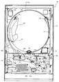
図5に示すように、パチンコ機10の背面側には、制御基板ユニット90,91と、裏パックユニット94とが主に備えられている。制御基板ユニット90は、主基板(主制御装置110)と音声ランプ制御基板(音声ランプ制御装置113)と表示制御基板(表示制御装置114)とが搭載されてユニット化されている。制御基板ユニット91は、払出制御基板(払出制御装置111)と発射制御基板(発射制御装置112)と電源基板(電源装置115)とカードユニット接続基板116とが搭載されてユニット化されている。
As shown in FIG. 5, the
裏パックユニット94は、保護カバー部を形成する裏パック92と払出ユニット93とがユニット化されている。また、各制御基板には、各制御を司る1チップマイコンとしてのMPU、各種機器との連絡をとるポート、各種抽選の際に用いられる乱数発生器、時間計数や同期を図る場合などに使用されるクロックパルス発生回路等が、必要に応じて搭載されている。
In the
なお、主制御装置110、音声ランプ制御装置113及び表示制御装置114、払出制御装置111及び発射制御装置112、電源装置115、カードユニット接続基板116は、それぞれ基板ボックス100〜104に収納されている。基板ボックス100〜104は、ボックスベースと該ボックスベースの開口部を覆うボックスカバーとを備えており、そのボックスベースとボックスカバーとが互いに連結されて、各制御装置や各基板が収納される。
The
また、基板ボックス100(主制御装置110)及び基板ボックス102(払出制御装置111及び発射制御装置112)は、ボックスベースとボックスカバーとを封印ユニット(図示せず)によって開封不能に連結(かしめ構造による連結)している。また、ボックスベースとボックスカバーとの連結部には、ボックスベースとボックスカバーとに亘って封印シール(図示せず)が貼着されている。この封印シールは、脆性な素材で構成されており、基板ボックス100,102を開封するために封印シールを剥がそうとしたり、基板ボックス100,102を無理に開封しようとすると、ボックスベース側とボックスカバー側とに切断される。よって、封印ユニット又は封印シールを確認することで、基板ボックス100,102が開封されたかどうかを知ることができる。
Further, in the board box 100 (main control device 110) and the board box 102 (
払出ユニット93は、裏パックユニット94の最上部に位置して上方に開口したタンク130と、タンク130の下方に連結され下流側に向けて緩やかに傾斜するタンクレール131と、タンクレール131の下流側に縦向きに連結されるケースレール132と、ケースレール132の最下流部に設けられ、払出モータ216(図6参照)の所定の電気的構成により球の払出を行う払出装置133とを備えている。タンク130には、遊技ホールの島設備から供給される球が逐次補給され、払出装置133により必要個数の球の払い出しが適宜行われる。尚、払出装置133によって払い出された球は、球流下経路(図示せず)によって上皿排出口17aを介して上皿17へと払い出される。タンクレール131には、当該タンクレール131に振動を付加するためのバイブレータ134が取り付けられている。なお、払出装置133によって払い出された球が流下する球流下経路の流下先を、上皿17だけではなく、球発射ユニット112aへ遊技球を供給する球供給通路(図示せず)や、球発射ユニット112aへと流下するようにしてもよいし、それら経路を複数設け、流路切替機構によって流下先を切り替える構成にしてもよい。この場合、上述したファール球入賞口601に入球した遊技球に基づく賞球の払い出しのみ球供給通路や球発射ユニット112aに流下するように流路切替機構を作動させるとよい。こうすることで、ファール球の発生によって付与された遊技球を用いて迅速に遊技を行うことが可能となる。
The
また、払出制御装置111には状態復帰スイッチ120が設けられ、発射制御装置112には可変抵抗器の操作つまみ121が設けられ、電源装置115にはRAM消去スイッチ122が設けられている。状態復帰スイッチ120は、例えば、払出モータ216(図6参照)部の球詰まり等、払出エラーの発生時に球詰まりを解消(正常状態への復帰)するために操作される。操作つまみ121は、発射ソレノイドの発射力を調整するために操作される。RAM消去スイッチ122は、パチンコ機10を初期状態に戻したい場合に電源投入時に操作される。
Further, the
以上、本第1実施形態に用いられるパチンコ機10の構成について説明をしたが、本パチンコ機10は、発射経路701内で発生したファール球を、誘導部材602によってファール球入球通路606へと誘導し、そのファール球入球通路606内に設けたファール入賞口601にファール球が入球するよう構成されている。そして、ファール球入賞口601への入球に基づき払出制御装置111から遊技球が1球払い出され、上皿17へと付与される。このような構成を用いることにより、ファール球への対応として上皿17へと遊技球を返却するための専用通路を設ける必要がなく、パチンコ機10を製造するコストを下げることができる。また、本パチンコ機10のように、従来よりパチンコ機10が有している、入賞口への入球に基づく賞球払出機構を用いることで、より効果を奏することが可能となる。
The configuration of the
なお、本実施形態では1球のファール球が検知された場合に、賞球を1球払い出す構成を用いているが、検知されたファール球と等価となる遊技価値を遊技者に付与できればよく、例えば、持ち球をデジタル管理する遊技機であれば、そのデジタルに対して遊技球1球と同価値の信号を送るようなものでもよい。また、使用される遊技球数と特別図柄1の1回の変動との遊技価値を予め対応付けておき、ファール球が検知された数を計数し、所定数に到達した際に、当該遊技球数と等価となる遊技価値として特別図柄1を変動させるようにしてもよい。
In the present embodiment, when one foul ball is detected, one prize ball is paid out. However, it is sufficient if the player can be given a game value equivalent to the detected foul ball. For example, in the case of a game machine that digitally manages a holding ball, a signal having the same value as one game ball may be sent to the digital. In addition, the number of game balls used and the game value of one change of the
更に、本実施形態では、ファール球をファール球入球通路へと誘導する誘導部材602が、ファール球と当接することで第2開口部604の開口幅が広がる方向へと弾性変形するよう設けられているため、ファール球を効率よくファール球入球通路へと誘導することが可能となる。また、ファール球が誘導部材602に当接していない状態では、ファール球が当接している状態よりも第2開口部604の開口幅が狭くなるため、球発射ユニット112aによって発射された遊技球が第2開口部604に入り難くすることが可能となる。
Further, in the present embodiment, the guiding
<第1実施形態における遊技機の電気的構成について>
次に、図6を参照して、本パチンコ機10の電気的構成について説明する。図6は、パチンコ機10の電気的構成を示すブロック図である。
<About the electrical configuration of the gaming machine in the first embodiment>
Next, the electrical configuration of the
主制御装置110には、演算装置である1チップマイコンとしてのMPU201が搭載されている。MPU201には、該MPU201により実行される各種の制御プログラムや固定値データを記憶したROM202と、そのROM202内に記憶される制御プログラムの実行に際して各種のデータ等を一時的に記憶するためのメモリであるRAM203と、そのほか、割込回路やタイマ回路、データ送受信回路などの各種回路が内蔵されている。なお、払出制御装置111と主制御装置110との間はデータ送受信回路によって双方向に送受信可能に構成されているが、音声ランプ制御装置113などのサブ制御装置に対しては、主制御装置110からサブ制御装置へ一方向にのみ送信される。
The
主制御装置110では、特別図柄の抽選、普通図柄の抽選、第1図柄表示装置37における表示の設定、第2図柄表示装置83における表示の設定、および、第3図柄表示装置81における表示の設定といったパチンコ機10の主要な処理を実行する。そして、RAM203には、これらの処理を制御するための各種カウンタが設けられている。
In the
ここで、図7を参照して、主制御装置110のRAM203内に設けられるカウンタ等について説明する。これらのカウンタ等は、特別図柄の抽選、普通図柄の抽選、第1図柄表示装置37における表示の設定、第2図柄表示装置83における表示の設定、および、第3図柄表示装置81における表示の設定などを行うために、主制御装置110のMPU201で使用される。
Here, with reference to FIG. 7, a counter and the like provided in the
特別図柄の抽選や、第1図柄表示装置37および第3図柄表示装置81の表示の設定には、特別図柄の抽選に使用する第1当たり乱数カウンタC1と、特別図柄の大当たり種別を選択するために使用する第1当たり種別カウンタC2と、特別図柄における外れの停止種別を選択するために使用する停止種別選択カウンタC3と、第1当たり乱数カウンタC1の初期値設定に使用する第1初期値乱数カウンタCINI1と、変動パターン選択に使用する変動種別カウンタCS1とが用いられる。また、普通図柄の抽選には、第2当たり乱数カウンタC4が用いられ、第2当たり乱数カウンタC4の初期値設定には第2初期値乱数カウンタCINI2が用いられる。これら各カウンタは、更新の都度、前回値に1が加算され、最大値に達した後0に戻るループカウンタとなっている。
To set the display of the special symbol lottery and the display of the first
各カウンタは、例えば、タイマ割込処理(図12参照)の実行間隔である2ミリ秒間隔で更新され、また、一部のカウンタは、メイン処理(図21参照)の中で不定期に更新されて、その更新値がRAM203の所定領域に設定されたカウンタ用バッファに適宜格納される。RAM203には、1つの実行エリアと4つの保留エリア(保留第1〜第4エリア)とからなる特別図柄保留球格納エリア203aが設けられており、これらの各エリアには、第1入球口64への入球タイミングに合わせて、第1当たり乱数カウンタC1、第1当たり種別カウンタC2及び停止種別選択カウンタC3の各値がそれぞれ格納される。また、RAM203には、1つの実行エリアと4つの保留エリア(保留第1〜第4エリア)とからなる普通図柄保留球格納エリア203bが設けられており、これらの各エリアには、球が左右何れかの第2入球口(スルーゲート)67を通過したタイミングに合わせて、第2当たり乱数カウンタC4の値が格納される。
Each counter is updated, for example, at intervals of 2 milliseconds, which is the execution interval of the timer interrupt process (see FIG. 12), and some counters are updated irregularly in the main process (see FIG. 21). Then, the updated value is appropriately stored in the counter buffer set in the predetermined area of the
各カウンタについて詳しく説明する。第1当たり乱数カウンタC1は、所定の範囲(例えば、0〜399)内で順に1ずつ加算され、最大値(例えば、0〜399の値を取り得るカウンタの場合は399)に達した後0に戻る構成となっている。特に、第1当たり乱数カウンタC1が1周した場合、その時点の第1初期値乱数カウンタCINI1の値が当該第1当たり乱数カウンタC1の初期値として読み込まれる。 Each counter will be described in detail. The first random number counter C1 is incremented by 1 in order within a predetermined range (for example, 0 to 399), and after reaching the maximum value (for example, 399 in the case of a counter capable of taking a value of 0 to 399), it is 0. It is configured to return to. In particular, when the first random number counter C1 makes one round, the value of the first initial value random number counter CINI1 at that time is read as the initial value of the first random number counter C1.
また、第1初期値乱数カウンタCINI1は、第1当たり乱数カウンタC1と同一範囲で更新されるループカウンタとして構成される。即ち、例えば、第1当たり乱数カウンタC1が0〜399の値を取り得るループカウンタである場合には、第1初期値乱数カウンタCINI1もまた、0〜399の範囲のループカウンタである。この第1初期値乱数カウンタCINI1は、タイマ割込処理(図12参照)の実行毎に1回更新されると共に、メイン処理(図21参照)の残余時間内で繰り返し更新される。 Further, the first initial value random number counter CINI1 is configured as a loop counter updated in the same range as the first random number counter C1. That is, for example, when the first random number counter C1 is a loop counter capable of taking a value of 0 to 399, the first initial value random number counter CINI1 is also a loop counter in the range of 0 to 399. The first initial value random number counter CINI1 is updated once for each execution of the timer interrupt process (see FIG. 12), and is repeatedly updated within the remaining time of the main process (see FIG. 21).
第1当たり乱数カウンタC1の値は、例えば定期的に(本実施形態ではタイマ割込処理毎に1回)更新され、球が第1入球口64に入賞したタイミングでRAM203の特別図柄保留球格納エリア203aに格納される。そして、特別図柄の大当たりとなる乱数の値は、主制御装置110のROM202に格納される特別図柄大当たり乱数テーブル(図示せず)によって設定されており、第1当たり乱数カウンタC1の値が、特別図柄大当たり乱数テーブルによって設定された大当たりとなる乱数の値と一致する場合に、特別図柄の大当たりと判定する。また、この特別図柄大当たり乱数テーブルは、特別図柄の低確率時(特別図柄の低確率状態である期間)用と、その低確率時より特別図柄の大当たりとなる確率の高い高確率時(特別図柄の高確率状態である期間)用との2種類に分けられ、それぞれに含まれる大当たりとなる乱数の個数が異なって設定されている。このように、大当たりとなる乱数の個数を異ならせることにより、特別図柄の低確率時と特別図柄の高確率時とで、大当たりとなる確率が変更される。尚、特別図柄の高確率時用の第1当たり乱数テーブルと、特別図柄の低確率時用の第1当たり乱数テーブルとは、それぞれ図示しないが主制御装置110のROM202内に設けられている(図6(a)参照)。
The value of the first random number counter C1 is updated periodically (once for each timer interrupt process in this embodiment), and the special symbol holding ball of the
第1当たり種別カウンタC2は、特別図柄の大当たりとなった場合に、第1図柄表示装置37の表示態様を決定するものであり、所定の範囲(例えば、0〜99)内で順に1ずつ加算され、最大値(例えば、0〜99の値を取り得るカウンタの場合は99)に達した後0に戻る構成となっている。第1当たり種別カウンタC2の値は、例えば、定期的に(本実施形態ではタイマ割込処理毎に1回)更新され、球が第1入球口64に入賞したタイミングでRAM203の特別図柄保留球格納エリア203aに格納される。
The first hit type counter C2 determines the display mode of the first
ここで、特別図柄保留球格納エリア203aに格納された第1当たり乱数カウンタC1の値が、特別図柄の大当たりとなる乱数でなければ、即ち、特別図柄の外れとなる乱数であれば、第1図柄表示装置37に表示される停止図柄に対応した表示態様は、特別図柄の外れ時のものとなる。
Here, if the value of the first hit random number counter C1 stored in the special symbol holding
一方で、特別図柄保留球格納エリア203aに格納された第1当たり乱数カウンタC1の値が、特別図柄の大当たりとなる乱数であれば、第1図柄表示装置37に表示される停止図柄に対応した表示態様は、特別図柄の大当たり時のものとなる。この場合、その大当たり時の具体的な表示態様は、同じ特別図柄保留球格納エリア203aに格納されている第1当たり種別カウンタC2の値が示す表示態様となる。
On the other hand, if the value of the first hit random number counter C1 stored in the special symbol holding
本実施形態のパチンコ機10における第1当たり乱数カウンタC1は、0〜399の範囲の2バイトのループカウンタとして構成されている。そして、図9(a)に示すように、この第1当たり乱数カウンタC1において、特別図柄の低確率時に、特別図柄の大当たりとなる乱数値は1個であり、その乱数値である「0」は、低確率時用の特別図柄大当たり乱数テーブルに格納されている。このように特別図柄の低確率時には、乱数値の総数が400ある中で、大当たりとなる乱数値の総数が1なので、特別図柄の大当たりとなる確率は、「1/400」となる。
The first random number counter C1 in the
一方で、特別図柄の高確率時に、特別図柄の大当たりとなる乱数値は10個あり、その値である「0〜9」は、高確率時用の特別図柄大当たり乱数テーブルに格納されている。このように特別図柄の高確率時には、乱数値の総数が400ある中で、大当たりとなる乱数値の総数が10なので、特別図柄の大当たりとなる確率は、「1/40」となる。 On the other hand, when the special symbol has a high probability, there are 10 random numbers that serve as jackpots for the special symbol, and the values "0 to 9" are stored in the special symbol jackpot random number table for the high probability. As described above, when the probability of the special symbol is high, the total number of random numbers that will be the jackpot is 10 while the total number of random numbers is 400, so the probability of the special symbol being the jackpot is "1/40".
なお、低確率時用の特別図柄大当たり乱数テーブルに格納されている大当たりとなる乱数値と、高確率時用の特別図柄大当たり乱数テーブルに格納されている大当たりとなる乱数値とで、重複した値とならないように、それぞれの大当たりとなる乱数値を設定してもよい。ここで、大当たりとなる乱数値としてパチンコ機10の状況にかかわらず常に用いられる値が存在すれば、その乱数値が外部より入力されて、不正に大当たりを引き当てられやすくなるおそれがある。これに対して、状況に応じて(即ち、パチンコ機10が特別図柄の高確率状態か、特別図柄の低確率状態かに応じて)、大当たりとなる乱数値を変えることで、特別図柄の大当たりとなる乱数値が予測され難くすることができるので、不正に対する抑制を図ることができる。
It should be noted that the random number value that is the jackpot stored in the special symbol jackpot random number table for low probability and the random number value that is the jackpot stored in the special symbol jackpot random number table for high probability are duplicated values. A random number value that is a big hit may be set so as not to be. Here, if there is a value that is always used as a random value for the jackpot regardless of the situation of the
また、本実施形態のパチンコ機10における第1当たり種別カウンタC2の値は、0〜99の範囲のループカウンタとして構成されている。そして、図9(b)に示すように、この第1当たり種別カウンタC2において、乱数値が「0〜49」であった場合の大当たり種別は、「大当たりA」となる。また、乱数値が「50〜99」であった場合の大当たり種別は、「大当たりB」となる。
Further, the value of the first type counter C2 in the
このように、本実施形態のパチンコ機10は、第1当たり種別カウンタC2が示す乱数の値によって、2種類の当たり種別(大当たりA、大当たりB)が決定されるように構成されている。尚、第1当たり種別カウンタC2の値(乱数値)から、特別図柄の大当たり種別を決定するための乱数値は、第1当たり種別選択テーブル202bにより設定されており、このテーブルは、主制御装置110のROM202内に設けられている。
As described above, the
停止種別選択カウンタC3は、例えば0〜99の範囲内で順に1ずつ加算され、最大値(つまり99)に達した後0に戻る構成となっている。本実施形態では、停止種別選択カウンタC3によって、第3図柄表示装置81で表示される外れ時の停止種別が選択され、リーチが発生した後、最終停止図柄がリーチ図柄の前後に1つだけずれて停止する「前後外れリーチ」(例えば98,99)と、同じくリーチ発生した後、最終停止図柄がリーチ図柄の前後以外で停止する「前後外れ以外リーチ」(例えば90〜97の範囲)と、リーチ発生しない「完全外れ」(例えば0〜89の範囲)との3つの停止(演出)パターンが選択される。停止種別選択カウンタC3の値は、例えば定期的に(本実施形態ではタイマ割込処理毎に1回)更新され、球が第1入球口64に入賞したタイミングでRAM203の特別図柄保留球格納エリア203aに格納される。
The stop type selection counter C3 is configured to be incremented by 1 in order within the range of 0 to 99, and return to 0 after reaching the maximum value (that is, 99). In the present embodiment, the stop type selection counter C3 selects the stop type at the time of disconnection displayed by the third
尚、停止種別選択カウンタC3の値(乱数値)から、特別図柄の停止種別を決定するための乱数値は、停止種別選択テーブル(図示せず)により設定されており、このテーブルは、主制御装置110のROM202内に設けられている。また、本実施形態ではこのテーブルを、特別図柄の高確率時用と、特別図柄の低確率時用とに分けており、テーブルに応じて、外れの停止種別ごとに設定される乱数値の範囲を変えている。これは、パチンコ機10が特別図柄の高確率状態であるか、特別図柄の低確率状態であるか等に応じて、停止種別の選択比率を変更するためである。
From the value (random value) of the stop type selection counter C3, the random number value for determining the stop type of the special symbol is set by the stop type selection table (not shown), and this table is the main control. It is provided in the
例えば、高確率状態では、大当たりが発生し易いため必要以上にリーチ演出が選択されないように、「完全外れ」の停止種別に対応した乱数値の範囲が0〜89と広い高確率時用のテーブルが選択され、「完全外れ」が選択され易くなる。このテーブルは、「前後外れリーチ」が98,99と狭くなると共に「前後外れ以外リーチ」も90〜97と狭くなり、「前後外れリーチ」や「前後外れ以外リーチ」が選択され難くなる。また、低確率状態であれば、第1入球口64への球の入球時間を確保するために「完全外れ」の停止種別に対応した乱数値の範囲が0〜79と狭い低確率時用のテーブルが選択され、「完全外れ」が選択され難くなる。
For example, in a high-probability state, a table for high-probability times has a wide range of random numbers from 0 to 89 corresponding to the stop type of "completely off" so that the reach effect is not selected more than necessary because a big hit is likely to occur. Is selected, and "completely off" is easily selected. In this table, the "reach outside the front and rear" is narrowed to 98,99, and the "reach other than the front and rear" is also narrowed to 90 to 97, making it difficult to select "reach outside the front and rear" or "reach other than the front and rear". Further, in the low probability state, the range of the random number value corresponding to the stop type of "completely off" is narrow as 0 to 79 in order to secure the ball entry time to the
この停止種別選択テーブルは、「前後外れ以外リーチ」の停止種別に対応した乱数値の範囲が80〜97と広くなり、「前後外れ以外リーチ」が選択され易くなっている。よって、低確率状態では、演出時間の長いリーチ表示を多く行うことできるので、第1入球口64への球の入球時間を確保でき、第3図柄表示装置81による変動表示が継続して行われ易くなる。尚、後者のテーブルにおいても、「前後外れリーチ」の停止種別に対応した乱数値の範囲は98,99に設定される。
In this stop type selection table, the range of random value corresponding to the stop type of "reach other than front and rear deviation" is widened to 80 to 97, and "reach other than front and rear deviation" can be easily selected. Therefore, in the low-probability state, it is possible to perform many reach displays with a long effect time, so that the ball entry time to the
変動種別カウンタCS1は、例えば0〜198の範囲内で順に1ずつ加算され、最大値(つまり198)に達した後0に戻る構成となっている。変動種別カウンタCS1によって、いわゆるノーマルリーチ、スーパーリーチ等の大まかな表示態様が決定される。表示態様の決定は、具体的には、図柄変動の変動時間の決定である。変動種別カウンタCS1により決定された変動時間に基づいて、音声ランプ制御装置113や表示制御装置114により第3図柄表示装置81で表示される第3図柄のリーチ種別や細かな図柄変動態様が決定される。変動種別カウンタCS1の値は、後述するメイン処理(図21参照)が1回実行される毎に1回更新され、当該メイン処理内の残余時間内でも繰り返し更新される。尚、変動種別カウンタCS1の値(乱数値)から、図柄変動の変動時間を一つ決定する乱数値を格納した変動パターンテーブル(図10参照)は、主制御装置110のROM202内に設けられている。
The variation type counter CS1 is configured to be incremented by 1 in order within the range of 0 to 198, and return to 0 after reaching the maximum value (that is, 198). The variable type counter CS1 determines a rough display mode such as so-called normal reach and super reach. Specifically, the determination of the display mode is the determination of the fluctuation time of the symbol variation. Based on the fluctuation time determined by the variation type counter CS1, the reach type and the detailed symbol variation mode of the third symbol displayed on the third
変動パターンテーブルには、例えば、外れ用の変動パターンとして、「外れ(長時間用)」、「外れ(短時間用)」、「外れノーマルリーチ」各種、「外れスーパーリーチ」各種、「外れスペシャルリーチ」各種が規定され、大当たりA・大当たりB共用の変動パターンとして、「共用ノーマルリーチ」各種、「共用スーパーリーチ」各種、「共用スペシャルリーチ」各種が規定され、当たり・外れ共用の変動パターンとして、「共用ノーマルリーチ」各種、「共用スーパーリーチ」各種、「共用スペシャルリーチ」各種が規定されている。そして、変動パターンテーブルに規定された各種変動パターンから、抽選結果や、停止種別(大当たりの場合には大当たり種別)に応じて変動パターンが選定される。 In the variation pattern table, for example, as variation patterns for disconnection, "disengagement (for long time)", "disengagement (for short time)", "disengagement normal reach", "disengagement super reach", "disengagement special reach" Various types are specified, and various types of "shared normal reach", "shared super reach", and "shared special reach" are specified as fluctuation patterns for both jackpot A and jackpot B, and as fluctuation patterns for both hit and miss, " Various types of "shared normal reach", various types of "shared super reach", and various types of "shared special reach" are stipulated. Then, from the various fluctuation patterns defined in the fluctuation pattern table, the fluctuation pattern is selected according to the lottery result and the stop type (in the case of a jackpot, the jackpot type).
第2当たり乱数カウンタC4は、例えば0〜239の範囲内で順に1ずつ加算され、最大値(つまり239)に達した後0に戻るループカウンタとして構成されている。また、第2当たり乱数カウンタC4が1周した場合、その時点の第2初期値乱数カウンタCINI2の値が当該第2当たり乱数カウンタC4の初期値として読み込まれる。第2当たり乱数カウンタC4の値は、本実施形態ではタイマ割込処理毎に、例えば定期的に更新され、球が左右何れかの第2入球口(スルーゲート)67を通過したことが検知された時に取得され、RAM203の普通図柄保留球格納エリア203bに格納される。
The second random number counter C4 is configured as a loop counter in which, for example, 1 is sequentially added in the range of 0 to 239, the maximum value (that is, 239) is reached, and then the counter returns to 0. Further, when the second hit random number counter C4 makes one round, the value of the second initial value random number counter CINI2 at that time is read as the initial value of the second hit random number counter C4. In the present embodiment, the value of the second random number counter C4 is updated periodically, for example, for each timer interrupt process, and it is detected that the ball has passed through either the left or right second entry port (through gate) 67. When this is done, it is acquired and stored in the normal symbol holding
そして、普通図柄の当たりとなる乱数の値は、主制御装置のROM202に格納される第2当たり乱数テーブル202cによって設定されており、第2当たり乱数カウンタC4の値が、第2当たり乱数テーブル202cによって設定された当たりとなる乱数の値と一致する場合に、普通図柄の当たりと判定する。また、この第2当たり乱数テーブル202cは、普通図柄の低確率時(普通図柄の通常状態である期間)用と、その低確率時より普通図柄の当たりとなる確率の高い高確率時(普通図柄の時短状態である期間)用との2種類に分けられ、それぞれに含まれる大当たりとなる乱数の個数が異なって設定されている。このように、当たりとなる乱数の個数を異ならせることにより、普通図柄の低確率時と普通図柄の高確率時とで、当たりとなる確率が変更される。
Then, the value of the random number that is a hit of the normal symbol is set by the second hit random number table 202c stored in the
図9(c)に示すように、普通図柄の低確率時に、普通図柄の当たりとなる乱数値は24個あり、その範囲は「5〜28」となっている。これら乱数値は、低確率時用の第2当たり乱数テーブル202cに格納されている。このように普通図柄の低確率時には、乱数値の総数が240ある中で、大当たりとなる乱数値の総数が24なので、特別図柄の大当たりとなる確率は、「1/10」となる。 As shown in FIG. 9 (c), there are 24 random numbers that hit the normal symbol at a low probability of the normal symbol, and the range is "5 to 28". These random number values are stored in the second random number table 202c for low probability. As described above, when the probability of a normal symbol is low, the total number of random numbers that become a jackpot is 24 while the total number of random numbers is 240, so the probability of a jackpot of a special symbol is "1/10".
パチンコ機10が普通図柄の低確率時である場合に、球が第2入球口67を通過すると、第2当たり乱数カウンタC4の値が取得されると共に、第2図柄表示装置83において普通図柄の変動表示が30秒間実行される。そして、取得された第2当たり乱数カウンタC4の値が「5〜28」の範囲であれば当選と判定されて、第2図柄表示装置83における変動表示が終了した後に、停止図柄(第2図柄)として「○」の図柄が点灯表示されると共に、第1入球口64に付随する電動役物が「0.2秒間×1回」だけ開放される。尚、本実施形態では、パチンコ機10が普通図柄の低確率時である場合に、普通図柄の当たりとなったら第1入球口64が「0.2秒間×1回」だけ開放されるが、開放時間や回数は任意に設定すれば良い。例えば、「0.5秒間×2回」開放しても良い。
When the
一方で、普通図柄の高確率時に、普通図柄の大当たりとなる乱数値は200個あり、その範囲は「5〜204」となっている。これらの乱数値は、高確率時用の第2当たり乱数テーブル202cに格納されている。このように特別図柄の低確率時には、乱数値の総数が240ある中で、大当たりとなる乱数値の総数が200なので、特別図柄の大当たりとなる確率は、「1/1.2」となる。 On the other hand, when there is a high probability of a normal symbol, there are 200 random values that are big hits of the normal symbol, and the range is "5 to 204". These random number values are stored in the second random number table 202c for high probability. As described above, when the probability of the special symbol is low, the total number of random numbers that will be the jackpot is 200 while the total number of random numbers is 240, so the probability of the special symbol being the jackpot is "1 / 1.2".
パチンコ機10が普通図柄の高確率時である場合に、球が第2入球口67を通過すると、第2当たり乱数カウンタC4の値が取得されると共に、第2図柄表示装置83において普通図柄の変動表示が3秒間実行される。そして、取得された第2当たり乱数カウンタC4の値が「5〜204」の範囲であれば当選と判定されて、第2図柄表示装置83における変動表示が終了した後に、停止図柄(第2図柄)として「○」の図柄が点灯表示されると共に、第1入球口64が「1秒間×2回」開放される。このように、普通図柄の高確率時には、普通図柄の低確率時と比較して、変動表示の時間が「30秒→3秒」と非常に短くなり、更に、第1入球口64の解放期間が「0.2秒×1回→1秒間×2回」と非常に長くなるので、第1入球口64へ球が入球し易い状態となる。尚、第2当たり乱数カウンタC4の値(乱数値)から、普通図柄の当たりか否かを判定する乱数値を格納したテーブル(図示せず)は、ROM202内に設けられている。尚、本実施形態では、パチンコ機10が普通図柄の高確率時である場合に、普通図柄の当たりとなったら第1入球口64が「1秒間×2回」だけ開放されるが、開放時間や回数は任意に設定すれば良い。例えば、「3秒間×3回」開放しても良い。
When the
第2初期値乱数カウンタCINI2は、第2当たり乱数カウンタC4と同一範囲で更新されるループカウンタとして構成され(値=0〜239)、タイマ割込処理(図12参照)毎に1回更新されると共に、メイン処理(図21参照)の残余時間内で繰り返し更新される。 The second initial value random number counter CINI2 is configured as a loop counter that is updated in the same range as the second random number counter C4 (value = 0 to 239), and is updated once for each timer interrupt process (see FIG. 12). At the same time, it is repeatedly updated within the remaining time of the main process (see FIG. 21).
このように、RAM203には種々のカウンタ等が設けられており、主制御装置110では、このカウンタ等の値に応じて大当たり抽選や第1図柄表示装置37および第3図柄表示装置81における表示の設定、第2図柄表示装置83における表示結果の抽選といったパチンコ機10の主要な処理を実行することができる。
As described above, the
図6に戻り、説明を続ける。主制御装置110のMPU201には、MPU201により実行される各種の制御プログラムや固定値データを記憶したROM202が設けられている。また、主制御装置110のMPU201に設けられるRAM203は、図7に図示した各種カウンタのほか、MPU201の内部レジスタの内容やMPU201により実行される制御プログラムの戻り先番地などが記憶されるスタックエリアと、各種のフラグおよびカウンタ、I/O等の値が記憶される作業エリア(作業領域)とを有している。
Returning to FIG. 6, the description will be continued. The
なお、RAM203は、パチンコ機10の電源の遮断後においても電源装置115からバックアップ電圧が供給されてデータを保持(バックアップ)できる構成となっており、RAM203に記憶されるデータは、すべてバックアップされる。
The
停電などの発生により電源が遮断されると、その電源遮断時(停電発生時を含む。以下同様)のスタックポインタや、各レジスタの値がRAM203に記憶される。一方、電源投入時(停電解消による電源投入を含む。以下同様)には、RAM203に記憶される情報に基づいて、パチンコ機10の状態が電源遮断前の状態に復帰される。RAM203への書き込みはメイン処理(図21参照)によって電源遮断時に実行され、RAM203に書き込まれた各値の復帰は電源投入時の立ち上げ処理(図20参照)において実行される。なお、MPU201のNMI端子(ノンマスカブル割込端子)には、停電等の発生による電源遮断時に、停電監視回路252からの停電信号SG1が入力されるように構成されており、その停電信号SG1がMPU201へ入力されると、停電時処理としてのNMI割込処理(図19参照)が即座に実行される。
When the power supply is cut off due to the occurrence of a power failure or the like, the stack pointer at the time of the power failure (including the time when the power failure occurs; the same applies hereinafter) and the value of each register are stored in the
ここで、図8〜10を参照して、主制御装置110のMPU201に設けられるROM202とRAM203との詳細について説明する。図8(a)は、このROM202の内容を模式的に示した模式図である。図8(a)に示した通り、ROM202には、第1当たり乱数テーブル202aと、第1当たり種別選択テーブル202bと、第2当たり乱数テーブル202cと、変動パターンテーブル202dとが少なくとも設けられている。これら各種テーブルの詳細については、図9および図10を参照して後述する。
Here, the details of the
図8(b)は、RAM203の内容を模式的に示した模式図である。RAM203は、図8に示すように、特別図柄保留球格納エリア203aと、普通図柄保留球格納エリア203bと、特別図柄保留球数カウンタ203cと、普通図柄保留球数カウンタ203dと、確変フラグ203eと、時短中カウンタ203fと、特図変動開始フラグ203gと、入球フラグ203hと、発射フラグ203iと、入球数カウンタ203jと、発射球数カウンタ203kと、タイマカウンタ203mと、タイマカウント中フラグ203nと、その他メモリエリア203zとを有している。
FIG. 8B is a schematic diagram schematically showing the contents of the
特別図柄保留球格納エリア203aは、1つの実行エリアと、4つの保留エリア(保留第1エリア〜保留第4エリア)とを有しており、これらの各エリアには、第1当たり乱数カウンタC1、第1当たり種別カウンタC2、及び停止種別選択カウンタC3の各値がそれぞれ格納される。
The special symbol holding
より具体的には、球が第1入球口64へ入賞(始動入賞)したタイミングで、各カウンタC1〜C3の各値が取得され、その取得されたデータが、4つの保留エリア(保留第1エリア〜保留第4エリア)の空いているエリアの中で、エリア番号(第1〜第4)の小さいエリアから順番に記憶される。つまり、エリア番号の小さいエリアほど、時間的に古い入賞に対応するデータが記憶され、保留第1エリアには、時間的に最も古い入賞に対応するデータが記憶される。尚、4つの保留エリアの全てにデータが記憶されている場合には、新たに何も記憶されない。 More specifically, at the timing when the ball wins the first ball opening 64 (starting prize), each value of each counter C1 to C3 is acquired, and the acquired data is stored in four holding areas (holding number). Among the vacant areas (1st area to 4th area on hold), the areas with the smallest area numbers (1st to 4th) are stored in order. That is, the smaller the area number, the data corresponding to the time-old winning prize is stored, and the data corresponding to the time-oldest winning prize is stored in the reserved first area. If data is stored in all four holding areas, nothing is newly stored.
その後、主制御装置110において、特別図柄の抽選が行われる場合には、特別図柄保留球格納エリア203aの保留第1エリアに記憶されている各カウンタC1〜C3の各値が、実行エリアへシフトされ(移動させられ)、その実行エリアに記憶された各カウンタC1〜C3の各値に基づいて、特別図柄の抽選などの判定が行われる。
After that, when the special symbol lottery is performed in the
尚、保留第1エリアから実行エリアへデータをシフトすると、保留第1エリアが空き状態となる。そこで、他の保留エリア(保留第2エリア〜保留第4エリア)に記憶されている入賞のデータを、エリア番号の1小さい保留エリア(保留第1エリア〜保留第3エリア)に詰めるシフト処理が行われる。本実施形態では、特別図柄保留球格納エリア203aにおいて、入賞のデータが記憶されている保留エリア(第2保留エリア〜第4保留エリア)についてのみデータのシフトが行われる。
When the data is shifted from the hold 1st area to the execution area, the hold 1st area becomes empty. Therefore, a shift process is performed in which the winning data stored in the other holding areas (holding 2nd area to holding 4th area) is packed into the holding area (holding 1st area to holding 3rd area) having the smaller area number. Will be done. In the present embodiment, in the special symbol holding
なお、球が第1入球口64へ入賞(始動入賞)し、その始動入賞に応じて各カウンタC1〜C3の各値が取得されると直ちに、本来の特別図柄の大当たり抽選とは別に、その取得された各カウンタC1〜C3の各値から、本来の抽選が行われた場合に得られる各種情報を予測(推定)してもよい。このように、本来の特別図柄の抽選が行われる前に、始動入賞に対応するデータ(各カウンタC1〜C3の各値)に基づいて、本来の抽選が行われた場合に得られる各種情報を予測することを、以後、特別図柄の抽選結果を先読みすると記載する。なお、各種情報としては、当否、停止種別、変動パターンなどが該当する。 In addition to the original special symbol jackpot lottery, as soon as the ball wins the first ball opening 64 (starting prize) and each value of each counter C1 to C3 is acquired according to the starting winning. From the acquired values of the counters C1 to C3, various information obtained when the original lottery is performed may be predicted (estimated). In this way, before the original special symbol lottery is performed, various information obtained when the original lottery is performed based on the data corresponding to the starting prize (each value of each counter C1 to C3) is obtained. It is described that the prediction is to pre-read the lottery result of the special symbol thereafter. The various types of information include hit / fail, stop type, fluctuation pattern, and the like.
特別図柄保留球数カウンタ203cは、第1入球口64への入球(始動入賞)に基づいて第1図柄表示装置37で行われる特別図柄(第1図柄)の変動表示(第3図柄表示装置81で行われる変動表示)の保留球数(待機回数)を最大4回まで計数するカウンタである。この特別図柄保留球数カウンタ203cは、初期値がゼロに設定されており、第1入球口64へ球が入球して変動表示の保留球数が増加する毎に、最大値4まで1加算される(図16のS504参照)。一方、特別図柄保留球数カウンタ203cは、新たに特別図柄の変動表示が実行される毎に、1減算される(図14のS305参照)。
The special symbol reserved
この特別図柄保留球数カウンタ203cの値(特別図柄における変動表示の保留回数N)は、保留球数コマンドによって音声ランプ制御装置113に通知される(図14のS306、図16のS505参照)。保留球数コマンドは、特別図柄保留球数カウンタ203cの値が変更される度に、主制御装置110から音声ランプ制御装置113に対して送信されるコマンドである。
The value of the special symbol reserved
音声ランプ制御装置113は、特別図柄保留球数カウンタ203cの値が変更される度に、主制御装置110より送信される保留球数コマンドによって、主制御装置110に保留された変動表示の保留球数そのものの値を取得することができる。これにより、音声ランプ制御装置113の特別図柄保留球数カウンタ223bによって管理される変動表示の保留球数が、ノイズ等の影響によって、主制御装置110に保留された実際の変動表示の保留球数からずれてしまった場合であっても、次に受信する保留球数コマンドによって、そのずれを修正することができる。
The voice
尚、音声ランプ制御装置113は、保留球数コマンドに基づいて保留球数を管理し、保留球数が変化する度に表示制御装置114に対して、保留球数を通知するための表示用保留球数コマンドを送信する。表示制御装置114は、この表示用保留球数コマンドによって通知された保留球数を基に、第3図柄表示装置81に保留球数図柄を表示すると共に、保留球数を示す第2図柄保留ランプ84を点灯させる。
The voice
普通図柄保留球数カウンタ203dは、第2入球口67における球の通過に基づいて第2図柄表示装置83で行われる普通図柄(第2図柄)の変動表示の保留球数(待機回数)を最大4回まで計数するカウンタである。この普通図柄保留球数カウンタ203dは、初期値がゼロに設定されており、球が第2入球口67を通過して変動表示の保留球数が増加する毎に、最大値4まで1加算される(図18のS704参照)。一方、普通図柄保留球数カウンタ203dは、新たに普通図柄(第2図柄)の変動表示が実行される毎に、1減算される(図17のS605参照)。
The normal symbol reserved
球が左右何れかの第2入球口67を通過した場合に、この普通図柄保留球数カウンタ203dの値(普通図柄における変動表示の保留回数M)が4未満であれば、第2当たり乱数カウンタC4の値が取得され、その取得されたデータが、普通図柄保留球格納エリア203bに記憶される(図18のS705)。一方、球が左右何れかの第2入球口67を通過した場合に、この普通図柄保留球数カウンタ203dの値が4であれば、普通図柄保留球格納エリア203bには新たに何も記憶されない(図18のS703:No)。
When the ball passes through either the left or right
確変フラグ203eは、パチンコ機10が特別図柄の確変状態(特別図柄の高確率状態)であるか否かを示すフラグであり、確変フラグ203eの値がオンであれば、パチンコ機10が特別図柄の確変状態であることを示し、確変フラグ203eの値がオフであれば、パチンコ機10が特別図柄の通常状態(特別図柄の低確率状態)であることを示す。この確変フラグ203eは、初期値がオフに設定されており、大当たり制御処理において大当たりA(確変大当たり)の終了時にオンに設定される(図21のS1005参照)。その後、次の大当たりの開始が設定される際にオフに設定される(図14のS313)。
The
MPU201によって特別図柄変動開始処理(図15参照)が実行されると、特別図柄の抽選が行われる。特別図柄変動開始処理では、確変フラグ203eの値が参照され、その値がオンであれば、高確率時用の特別図柄大当たり乱数テーブルに基づいて、特別図柄の抽選が行われる一方、確変フラグ203eの値がオフであれば、低確率時用の特別図柄大当たり乱数テーブルに基づいて、特別図柄の抽選が行われる(図15のS403,S404参照)。
When the special symbol variation start process (see FIG. 15) is executed by the
時短中カウンタ203fは、パチンコ機10が普通図柄の時短状態であるか否かを示すカウンタであり、時短中カウンタ203fの値が1以上であれば、パチンコ機10が普通図柄の時短状態であることを示し、時短中カウンタ203fの値が0であれば、パチンコ機10が普通図柄の通常状態であることを示す。この時短中カウンタ203fは、初期値がゼロに設定されており、大当たり制御処理において大当たりB(時短大当たり)の終了時に100が設定される(図21のS1005参照)。即ち、大当たりBになった場合には、時短中カウンタ203fの値が幾つであるかに関わらず、新たに100が設定される。
The time saving
普通図柄の当たりの抽選が行われる場合には、時短中カウンタ203fの値が参照され、その値が1以上であれば、高確率時用の第2当たり乱数テーブル202cに基づいて、普通図柄の抽選が行われる一方、時短中カウンタ203fの値が0であれば、低確率時用の第2当たり乱数テーブル202cに基づいて、普通図柄の抽選が行われる(図17のS610,S611参照)。
When a lottery for winning a normal symbol is performed, the value of the time saving /
特図変動開始フラグ203gは、特別図柄の変動を開始するタイミングであるか否かを示すフラグであり、特図変動開始フラグ203gがオンであれば、特別図柄の変動を開始するタイミングであることを示し、特図変動開始フラグ203gがオフであれば、特別図柄の変動を開始するタイミングではないことを示すものである。この特図変動開始フラグ203gは、特別図柄変動開始処理において変動パターンコマンドが設定されると共に、オンに設定される(図15のS412参照)。そして、外部出力処理において参照され(図21のS1001)、当該処理において特図変動開始フラグ203gがオンであると判別された場合、即ち、特別図柄の変動開始タイミングであると判別された場合に(図22のS1101:Yes)、変動パターンコマンドを音声ランプ制御装置113に向けて送信すると共に(図22のS1103参照)、オフに設定されるものである(図22のS1102参照)。
The special symbol
入球フラグ203hは、ファール入賞口601へ遊技球が入球したか否かを示すフラグであり、入球フラグ203hがオンであれば、ファール入賞口601へ遊技球が入球し、ファール入賞スイッチ208aによって遊技球が検知されたことを示し、入球フラグ203hがオフであれば、ファール入賞口601へ遊技球が入球していないことを示すものである。この入球フラグ203hは、主制御装置110のタイマ割込処理で実行されるスイッチ読み込み処理において、ファール入賞スイッチ208aがオンであると判別された場合にオンに設定される(図13のS202)。そして、主制御装置110のメイン処理で実行される入球異常判定処理において参照され(図23のS1206参照)、入球フラグ203hがオンであると判別された場合に(図23のS1206:Yes)、入球数カウンタ203jを1加算すると共に(図23のS1207)、オフに設定される(図23のS1208)。
The
即ち、ファール入賞口601へ遊技球が入球することに基づいて入球フラグ203hがオンに設定され、主制御装置110のメイン処理では、この入球フラグ203hがオンであるか否かに基づいて、ファール入賞口601へ遊技球が入球した場合の処理を実行することが可能となる。
That is, the
発射フラグ203iは、遊技球が発射されたか否かを示すフラグであり、発射フラグ203iがオンであれば、遊技球が発射され、発射球検知スイッチ208bによって遊技球が検知されたことを示し、発射フラグ203iがオフであれば、遊技球が発射されていないことを示すものである。この発射フラグ203iは、主制御装置110のタイマ割込み処理で実行されるスイッチ読み込み処理において、発射球検知スイッチ208bがオンであると判別された場合にオンに設定される(図13のS206参照)。そして、主制御装置110のメイン処理で実行される入球異常判定処理において参照され(図23のS1209)、発射フラグ203iがオンであると判別された場合に(図23のS1209:Yes)、発射球数カウンタ203kを1加算すると共に、オフに設定される(図23のS1211)。
The
即ち、遊技球が発射されることに基づいて発射フラグ203iがオンに設定され、主制御装置110のメイン処理では、この発射フラグ203iがオンであるか否かに基づいて、遊技球が発射された場合の処理を実行することが可能となる。
That is, the
入球数カウンタ203jは、ファール入賞口601への入球の異常を判定する期間(入球異常判定期間)であるファール入賞口601へ遊技球が入球した後の所定時間(本実施形態では20秒)において、ファール入賞口601へ入球した遊技球の数をカウントするために用いられるカウンタである。この入球数カウンタ203jは、主制御装置110のメイン処理で実行される入球異常判定処理において、上述した入球フラグ203hがオンである場合に、1加算されるものである(図23のS1207参照)。そして、入球異常判定期間(20秒)の経過後(図23のS1216:Yes)、または、異常であると判別されエラー処理が実行された後に(図23のS1213またはS1215の実行後)、0にリセットされるものである(図23のS1217参照)。
The number of balls entered
詳細は後述するが、本実施形態では、入球異常判定期間(20秒)において、入球数カウンタ203jの値が所定値Y(本実施形態では10)より多いと判別された場合に(図23のS1214:Yes)、エラー処理が実行される(図23のS1215参照)。ここで、所定値Y(10)は、遊技を行うに際し、遊技者が普通に遊技を実行しようとしていれば、所定時間(20秒)内にファール入賞口601へ入球しない値に設定している。よって、ファール入賞口601へ遊技球が入球した後の所定時間(20秒)において、入球数カウンタの値が所定値Y(10)より多くなる場合には、遊技者が普通に遊技を実行していない、即ち、不正にファール入賞口601へ入球させるなどの不正行為が実行されていると考えられる。そこで、この場合には、上述したようにエラー処理を実行し、不正行為が実行されていることを報知できるように構成している。
Details will be described later, but in the present embodiment, when it is determined that the value of the
発射球数カウンタ203kは、ファール入賞口601への入球の異常を判定する期間(入球異常判定期間)であるファール入賞口601へ遊技球が入球した後の所定時間(本実施形態では20秒)において、球発射ユニット112aから発射された遊技球のうち、発射球検知スイッチ208bを通過した遊技球、即ち、球発射ユニット112aによって発射されて遊技球のうち、発射不良等によって隙間802へ落下した遊技球以外の遊技球(以下、正常に発射された遊技球と称す)をカウントするために用いられるカウンタである。この発射数数カウンタ203kは、主制御装置110のメイン処理で実行される入球異常判定処理において、上述した発射フラグ203iがオンである場合に、1加算されるものである(図23のS1210)。そして、入球異常判定期間(20秒)経過後(図23のS1216:Yes)、または、異常であると判別されエラー処理が実行された後に(図23のS1213またはS1215の実行後)、0にリセットされるものである(図23のS1217参照)。
The number of launched balls counter 203k is a predetermined time after the game ball enters the foul winning opening 601 (in the present embodiment), which is a period for determining an abnormality of the ball entering the foul winning opening 601 (ball entry abnormality determination period). In 20 seconds), among the game balls launched from the
詳細は後述するが、本実施形態では、入球異常判定期間(20秒)において、発射球数カウンタ203kの値に所定値X(本実施形態では2)を加えた値よりも入球数カウンタ203jの値が多い場合、即ち、正常に発射された遊技球の数とファール入賞口601へ入球した遊技球の数とを比較した結果、ファール入賞口601へ入球した遊技球のほうが2球より多い(3球以上多い)と判別された場合に(図23のS1212:Yes)、エラー処理が実行される(図23のS1213)。
Although the details will be described later, in the present embodiment, the number of balls entered counter is higher than the value obtained by adding the predetermined value X (2 in the present embodiment) to the value of the number of launched balls counter 203k in the ball entry abnormality determination period (20 seconds). When the value of 203j is large, that is, as a result of comparing the number of game balls launched normally and the number of game balls that have entered the
この入球異常判定処理では、通常の遊技では発生し得ない、発射球数よりも特定の入賞口への入賞球数のほうが多いという事態を検知し、特定の入賞口(ファール入賞口601)へ不正に遊技球を入球するなどの不正行為が行われていることを監視することができる。 In this ball entry abnormality determination process, it is detected that the number of winning balls to a specific winning opening is larger than the number of launched balls, which cannot occur in a normal game, and the specific winning opening (Fal winning opening 601) is detected. It is possible to monitor that fraudulent acts such as illegally entering a game ball are being performed.
ここで、上述した入球異常判定処理において、所定値Xを設けた理由を説明する。本実施形態では、ファール入賞口601への遊技球の入球を契機として入球異常判定を開始し、発射球数カウンタ203kと入球数カウンタ203jとをカウントするようにしている。このため、入球異常判定が開始される契機となる遊技球は発射球数カウンタ203kにてカウントされていない。また、入球異常判定が開始されたタイミングにおいて、既に球発射ユニット112aによって発射された遊技球が発射通路701内に残っており、その遊技球がファール入賞口601へ入球する可能性も考えられる。このような想定内の誤差を鑑み、所定値Xを設け、明らかな異常状態が検知された場合にエラー処理が実行されるように構成している。これにより、不正行為が実行されていないにも関わらず、発射球数カウンタ203kの値よりも入球数カウンタ203jの値のほうが多くなってしまうような上述したケースではエラー処理が実行されず、不要なエラー報知を抑制することができる。なお、所定値Xは上述したものに限られず、2よりも小さい値(例えば1)でも良いし、2よりも大きい値(例えば5)でも良い。また、所定値Xを設定しなくてもよい。
Here, the reason why the predetermined value X is provided in the above-mentioned ball entry abnormality determination process will be described. In the present embodiment, the ball entry abnormality determination is started with the entry of the game ball into the
ここで、入球異常判定処理において、入球数カウンタ203jと発射球数カウンタ203kとが加算されるのは、ファール入賞口601へ遊技球が入球したことに基づいて入球フラグ203hがオンとなり、タイマカウント中フラグ203nがオンとなった場合である。これにより、入球異常判定期間(20秒)にのみ、異常判定に必要な入球数カウンタ203jと発射数カウンタ203kとによるカウント処理を実行することができるので、入球異常判定期間以外における遊技機の処理負荷を軽減することができる。なお、発射数カウンタ203kによるカウント処理を常時行うようにし、入球異常判定が行われている期間内にカウントした球数を取り出す構成にしてもよい。
Here, in the ball entry abnormality determination process, the
また、本実施形態では、入球数カウンタ203jと発射球数カウンタ203kとを主制御装置110のメイン処理で実行される処理において加算するように構成したが、これに限られず、例えば、主制御装置110の割り込み処理で実行される処理など、その他の処理において加算するように構成してもよい。
Further, in the present embodiment, the number of incoming balls counter 203j and the number of launched balls counter 203k are added in the process executed in the main process of the
タイマカウンタ203mは、主制御装置110のメイン処理で実行される入球異常判定処理において、入球異常判定期間であるファール入賞口601へ遊技球が入球した後の所定時間(本実施形態では20秒)を計測するために用いられるカウンタである。なお、所定時間は20秒に限られず、これよりも短い10秒としても良いし、これよりも長い30秒としても良く、タイマカウンタ203mに設定される値を変更することにより変更可能となっている。
The
このタイマカウンタ203mは、主制御装置110のメイン処理で実行される入球異常判定処理において、タイマカウント中フラグ203nがオフであり、入球フラグ203hがオンである場合に、5000(20秒に相当)が設定される(図23のS1204)。そして、タイマカウント中フラグ203mがオンである場合に、入球異常判定処理が実行される毎に1ずつ減算され(図23のS1202)、タイマカウンタ203mが0になった場合に(図23のS1216:Yes)、所定時間経過後の処理が実行される(図23のS1217〜S1218参照)。ここで、入球異常判定処理は、主制御装置110のメイン処理で4ms毎に実行される処理であるので、タイマカウンタ203mは4ms毎に1減算されることとなる。即ち、タイマカウンタ203mに5000が設定されている場合は20秒後に0となり、所定時間(20秒)経過後の処理が実行される(図23のS1217〜S1218参照)。
The
また、タイマカウンタ203mは、入球異常判定期間(20秒)において異常であると判定され、エラー処理が実行された場合(図23のS1213またはS1215が実行された場合)には、所定時間(20秒)の経過を待たずに入球異常判定を終了するので、エラー処理の実行後に0にリセットされる。
Further, when the
タイマカウント中フラグ203nは、主制御装置110のメイン処理で実行される入球異常判定処理において、入球異常判定を行う期間(上述したファール入賞口601へ遊技球が入球した後の所定時間)であるか否かを示すフラグである。このタイマカウント中フラグ203nは、主制御装置110のメイン処理で実行される入球異常判定処理において、タイマカウント中フラグ203nがオフであり、入球フラグ203hがオンである場合に、上述したタイマカウンタ203mが設定されると共に、オンに設定される(図23のS1205参照)。そして、入球異常判定処理が実行される毎に参照され(図23のS1201)、入球異常判定期間(20秒)が経過しタイマカウンタ203mが0となった場合に、オフに設定される(図23のS1218)。また、入球異常判定期間(20秒)において異常であると判定され、エラー処理が実行された場合(図23のS1213またはS1215が実行された場合)には、所定時間(20秒)の経過を待たずに入球異常判定を終了するので、上述したタイマカウンタ203mと同様に、エラー処理の実行後にオフに設定される(図23のS1218)。
The
その他メモリエリア203zは、遊技に必要なその他のデータや、カウンタ、フラグ等が設定(記憶)されるものである。
In the
次に、図9および図10を参照して、ROM202の内容の詳細について説明する。図8(a)に示した通り、ROM202には、第1当たり乱数テーブル202aと、第1当たり種別選択テーブル202bと、第2当たり乱数テーブル202cと、変動パターンテーブル202dとが少なくとも設けられている。
Next, the details of the contents of the
第1当たり乱数テーブル202a(図9(a)参照)は、上述した通り、特別図柄の大当たりとなる乱数の値が規定されたテーブルである。この第1当たり乱数テーブル202aに規定されている乱数値と、第1当たり乱数カウンタC1の値とが一致する場合に、特別図柄の大当たりと判定する。また、この第1当たり乱数テーブル202aには、特別図柄の低確率時に特別図柄の大当たりか否かを判別するためのテーブル(低確率時用の第1当たり乱数テーブル202a)と、特別図柄の高確率時に特別図柄の大当たりか否かを判別するためのテーブル(高確率時用の第1当たり乱数テーブル202a)とが設けられており、それぞれのテーブルに含まれる大当たりとなる乱数の個数が異なっている。このように、大当たりとなる乱数の個数を異ならせることにより、特別図柄の低確率時と特別図柄の高確率時とで、大当たりとなる確率が変更される。 As described above, the first random number table 202a (see FIG. 9A) is a table in which the values of random numbers that serve as jackpots for special symbols are defined. When the random number value defined in the first random number table 202a and the value of the first random number counter C1 match, it is determined that the special symbol is a big hit. Further, the first random number table 202a includes a table for determining whether or not the special symbol is a big hit when the special symbol has a low probability (first random number table 202a for a low probability) and a high value of the special symbol. There is a table (first random number table 202a for high probability) for determining whether or not it is a big hit of a special symbol at the time of probability, and the number of random numbers that are big hits included in each table is different. There is. In this way, by making the number of random numbers to be a big hit different, the probability of being a big hit is changed between the low probability time of the special symbol and the high probability time of the special symbol.
第1当たり種別選択テーブル202b(図9(b)参照)は、大当たりAと大当たりBとがそれぞれ選択可能となるように設定されている。具体的には、大当たりAの判定値として第1当たり種別カウンタC2の値「0〜49」が、大当たりBの判定値として「50〜99」が設定されている。 The first hit type selection table 202b (see FIG. 9B) is set so that the jackpot A and the jackpot B can be selected respectively. Specifically, the value "0 to 49" of the first hit type counter C2 is set as the determination value of the jackpot A, and "50 to 99" is set as the determination value of the jackpot B.
第2当たり乱数テーブル202c(図9(c)参照)は、普通図柄の当たり判定値が記憶されているデータテーブルである。図9(c)に示した通り、普通図柄の低確率時(普通図柄の通常状態中)は、第2当たり乱数カウンタバッファに格納された第2当たり乱数カウンタC4の値が「5〜28」の範囲の場合に普通図柄の当たりと判定される。また、普通図柄の高確率時(普通図柄の時短状態中)は、第2当たり乱数バッファカウンタに格納された第2当たり乱数カウンタC4の値が「5〜204」の範囲の場合に普通図柄の当たりと判定される。なお、上述の通り、普通図柄の当たりと判定された場合は、第2図柄表示装置における変動表示が終了した後に、停止図柄(第2図柄)として「○」の図柄が点灯表示されると共に、電動役物が所定時間だけ開放される。 The second hit random number table 202c (see FIG. 9C) is a data table in which the hit determination value of the normal symbol is stored. As shown in FIG. 9C, when the probability of the normal symbol is low (during the normal state of the normal symbol), the value of the second random number counter C4 stored in the second random number counter buffer is “5-28”. In the case of the range of, it is judged to be a hit of a normal symbol. In addition, when the probability of the normal symbol is high (during the time saving state of the normal symbol), when the value of the second random number counter C4 stored in the second random number buffer counter is in the range of "5 to 204", the normal symbol It is judged as a hit. As described above, when it is determined that the normal symbol is a hit, after the variation display on the second symbol display device is completed, the symbol "○" is lit and displayed as the stop symbol (second symbol). The electric accessory is released for a predetermined time.
次に、図10を参照して、変動パターンテーブル202dの詳細について説明する。変動パターンテーブル202d(図10(a)参照)は、変動パターンの表示態様を決定するために用いられるデータテーブルであり、変動種別カウンタCS1の値毎に表示態様が規定されている。この変動パターンテーブル202dには、特別図柄の抽選結果に対応した複数の異なるテーブルが規定されている。具体的には、図10(a)に示すように、大当たり用変動パターンテーブル202d1(図10(b)参照)と、外れ用(通常)変動パターンテーブル202d2(図10(c)参照)と、外れ用(確変)変動パターンテーブル202d3(図10(d)参照)とが少なくとも規定されている。なお、図示は省略したが、このほかにも、時短遊技状態における変動パターンテーブルや特別図柄保留球数格納エリア203aに格納されている値に応じた変動パターンテーブル等が設定されている。
Next, the details of the variation pattern table 202d will be described with reference to FIG. The variation pattern table 202d (see FIG. 10A) is a data table used for determining the display mode of the variation pattern, and the display mode is defined for each value of the variation type counter CS1. In this variation pattern table 202d, a plurality of different tables corresponding to the lottery results of special symbols are defined. Specifically, as shown in FIG. 10A, the jackpot variation pattern table 202d1 (see FIG. 10B) and the off (normal) variation pattern table 202d2 (see FIG. 10C). At least the deviation pattern table 202d3 (see FIG. 10D) is specified. Although not shown, a variation pattern table in the time-saving game state, a variation pattern table according to the value stored in the special symbol reserved ball
次に、大当たり用変動パターンテーブル202d1について説明する。図10(b)は、この大当たり用変動パターンテーブル202d1の内容を模式的に示した模式図である。大当たり用変動パターンテーブル202d1は、特別図柄の抽選結果が大当たりである場合に、選択される変動パターンの種別(変動時間)が設定されたデータテーブルである。大当たりの変動パターンとしては、ノーマルリーチ各種(30秒)、スーパーリーチ各種(60秒)、スペシャルリーチ(90秒)がそれぞれ設定されている。各変動パターンに対して、それぞれ変動種別カウンタCS1の値が判定値として設定されている。 Next, the jackpot variation pattern table 202d1 will be described. FIG. 10B is a schematic diagram schematically showing the contents of the jackpot variation pattern table 202d1. The jackpot variation pattern table 202d1 is a data table in which the type (fluctuation time) of the variation pattern to be selected is set when the lottery result of the special symbol is a jackpot. As the jackpot fluctuation pattern, various normal reach (30 seconds), various super reach (60 seconds), and special reach (90 seconds) are set respectively. For each fluctuation pattern, the value of the fluctuation type counter CS1 is set as a determination value.
具体的には、ノーマルリーチ各種(30秒)の変動パターンについては、「0〜50」が、スーパーリーチ各種(60秒)の変動パターンについては、「51〜179」が、スペシャルリーチ各種(90秒)の変動パターンについては、「180〜198」がそれぞれ変動種別カウンタCS1の判定値として設定される。主制御装置110のMPU201は、特別図柄の抽選結果が大当たりとなる場合の変動パターンを選択する時には、取得している変動種別カウンタCS1の値に対応する判定値が設定されている変動パターンを大当たり用変動パターンテーブル202d1より選択する。
Specifically, for the fluctuation patterns of various normal reach (30 seconds), "0 to 50", and for the fluctuation patterns of various super reach (60 seconds), "51 to 179", various special reach (90 seconds). ), Each of "180 to 198" is set as a determination value of the variation type counter CS1. When the
図10(c)は、外れ用(通常)変動パターンテーブル202d2の内容を模式的に示した模式図である。外れ用(通常)変動パターンテーブル202d2は、特別図柄の抽選結果が外れである場合に、選択される変動パターンの種別(変動時間)が設定されたデータテーブルである。特別図柄の抽選結果が外れである場合には、上述したように、図示しない停止種別選択テーブルより停止種別が完全外れ(非リーチ)であるか、リーチ外れ(リーチ共通)であるかが停止種別選択カウンタC3の値によって決定される。具体的には、停止種別選択カウンタC3の値が「0〜79」の範囲にあれば、完全外れを設定し、「80〜99」の範囲にあれば外れリーチを設定する。 FIG. 10 (c) is a schematic diagram schematically showing the contents of the deviation pattern table 202d2 for detachment (normal). The deviation pattern table 202d2 is a data table in which the type (variation time) of the variation pattern to be selected is set when the lottery result of the special symbol is deviation. If the lottery result of the special symbol is out of order, as described above, the stop type is completely out of reach (non-reach) or out of reach (common to reach) from the stop type selection table (not shown). It is determined by the value of the selection counter C3. Specifically, if the value of the stop type selection counter C3 is in the range of "0 to 79", the complete deviation is set, and if the value is in the range of "80 to 99", the deviation reach is set.
ここで、変動パターン種別が、完全外れである場合には、変動時間の比較的に短い短外れ(7秒)と変動時間の長い長外れ(10秒)が設定されている。短外れ(7秒)に対しては、「0〜98」が、長外れ(10秒)に対しては、「99〜198」が変動種別カウンタCS1の判定値として設定されている。 Here, when the fluctuation pattern type is a complete deviation, a short deviation (7 seconds) with a relatively short fluctuation time and a long deviation (10 seconds) with a long fluctuation time are set. For a short deviation (7 seconds), "0 to 98" is set as a determination value, and for a long deviation (10 seconds), "99 to 198" is set as a determination value of the variation type counter CS1.
また、外れリーチに対しては、外れのノーマルリーチ各種(30秒)に対して「0〜149」が、外れのスーパーリーチ各種(60秒)に対して「150〜197」が、外れのスペシャルリーチ各種(90秒)に対して「198」が、変動種別カウンタCS1の判定値として設定されている。 In addition, for the off-reach, "0-149" is for various out-of-normal reach (30 seconds), and "150-197" is for various out-of-order super reach (60 seconds). "198" is set as a determination value of the variation type counter CS1 for each type (90 seconds).
このように、主制御装置110のMPU201は、通常遊技状態時に特別図柄の抽選結果が外れである場合には、停止種別が決定され、外れ用(通常)変動パターンテーブル202d2より取得している変動種別選択カウンタCS1の値に基づいて、外れ用(通常)変動パターンテーブル202d2より変動パターンを選択する。
As described above, in the
図10(d)は、外れ用(確変)変動パターンテーブル202d3の内容を模式的に示した模式図である。この外れ用(確変)変動パターンテーブル202d3は、遊技状態が確変遊技状態である場合に、外れとなる特別図柄の変動パターンを選択するためのデータテーブルである。この外れ用(確変)変動パターンテーブル202d3では、設定されている変動種別選択カウンタCS1の値が、上述した外れ用(通常)変動パターンテーブル202d2とは異なる点で相違する。 FIG. 10D is a schematic diagram schematically showing the contents of the deviation pattern table 202d3 for deviation (probability variation). The deviation pattern table 202d3 is a data table for selecting a variation pattern of a special symbol that is out of alignment when the gaming state is the probability variation gaming state. The deviation (probability variation) variation pattern table 202d3 differs from the deviation (normal) variation pattern table 202d2 described above in that the value of the variation type selection counter CS1 is set.
なお、上述したように、遊技状態が確変遊技状態である場合には、図示しない停止種別選択テーブルにより停止種別選択カウンタC3の値が「0〜89」の範囲にあれば、完全外れが決定され、「90〜99」の範囲にあれば外れリーチが決定される。 As described above, when the gaming state is the probabilistic gaming state, if the value of the stop type selection counter C3 is in the range of "0 to 89" by the stop type selection table (not shown), complete deviation is determined. , If it is in the range of "90 to 99", the out-of-reach is determined.
このように、通常遊技状態よりも確変遊技状態である場合には、外れである場合にリーチとなる確率が低く設定されている。よって、確変時に外れの変動時間が長くなってしまい、大当たりとなるまでの期間が長くなってしまうことを抑制できる。よって、大当たりし易い確変遊技状態時に遊技が間延びしてしまい、遊技者が退屈に感じる不具合を抑制できる。 As described above, in the case of the probabilistic gaming state than in the normal gaming state, the probability of reaching is set lower when the game is out of the game. Therefore, it is possible to prevent the fluctuation time of the deviation from becoming long at the time of the probability change and the period until the jackpot becomes long. Therefore, it is possible to suppress a problem that the player feels bored because the game is delayed in the probabilistic game state where it is easy to hit the jackpot.
図6に戻り、説明を続ける。主制御装置110のMPU201には、アドレスバス及びデータバスで構成されるバスライン204を介して入出力ポート205が接続されている。入出力ポート205には、払出制御装置111、音声ランプ制御装置113、第1図柄表示装置37、第2図柄表示装置83、第2図柄保留ランプ84、特定入賞口65aの開閉板の下辺を軸として前方側に開閉駆動するための大開放口ソレノイドや電動役物を駆動するためのソレノイドなどからなるソレノイド209、外部出力端子板261が接続され、MPU201は、入出力ポート205を介してこれらに対し各種コマンドや制御信号を送信する。
Returning to FIG. 6, the description will be continued. An input /
また、入出力ポート205には、払出制御装置111の入出力ポート215や、ファール入賞スイッチ208a、発射球検知スイッチ208b、その他図示しないスイッチ群やセンサ群208cなどからなる各種スイッチ208や、電源装置115に設けられた後述のRAM消去スイッチ回路253が接続され、MPU201は、入出力ポート215及び発射制御装置112を介して操作ハンドル51に設けられるタッチセンサ51a、打ち止めスイッチ51及び、操作量検知スイッチ51cから出力される信号や、各種スイッチ208から出力される信号や、RAM消去スイッチ回路253より出力されるRAM消去信号SG2に基づいて各種処理を実行する。
Further, the input /
払出制御装置111は、払出モータ216を駆動させて賞球や貸出球の払出制御を行うものである。演算装置であるMPU211は、そのMPU211により実行される制御プログラムや固定値データ等を記憶したROM212と、ワークメモリ等として使用されるRAM213とを有している。
The
払出制御装置111のRAM213は、主制御装置110のRAM203と同様に、MPU211の内部レジスタの内容やMPU211により実行される制御プログラムの戻り先番地などが記憶されるスタックエリアと、各種のフラグおよびカウンタ、I/O等の値が記憶される作業エリア(作業領域)とを有している。RAM213は、パチンコ機10の電源の遮断後においても電源装置115からバックアップ電圧が供給されてデータを保持(バックアップ)できる構成となっており、RAM213に記憶されるデータは、すべてバックアップされる。なお、主制御装置110のMPU201と同様、MPU211のNMI端子にも、停電等の発生による電源遮断時に停電監視回路252から停電信号SG1が入力されるように構成されており、その停電信号SG1がMPU211へ入力されると、停電時処理としてのNMI割込処理(図19参照)が即座に実行される。
Like the
払出制御装置111のMPU211には、アドレスバス及びデータバスで構成されるバスライン214を介して入出力ポート215が接続されている。入出力ポート215には、主制御装置110や払出モータ216、発射制御装置112、外部出力端子板261などがそれぞれ接続されている。また、図示はしないが、払出制御装置111には、払い出された賞球を検出するための賞球検出スイッチが接続されている。なお、該賞球検出スイッチは、払出制御装置111に接続されるが、主制御装置110には接続されていない。
An input /
外部出力端子板261は、上述したように、主制御装置110の入出力ポート205と、払出制御装置111の入出力ポート215とに接続されており、それぞれの入出力ポートから信号を受信する。受信する信号としては、例えば、主制御装置110の異常を示す異常信号、主制御装置110にて行われる処理によってエラーと判定された状態を示すエラー信号、主制御装置110において入賞を検知したことを示す入賞検知信号、払出制御装置111において賞球の払い出しをしたことを示す賞球払出信号などが挙げられる。
As described above, the external
本実施形態では、ファール球が入球する入賞口であるファール球入賞口601に設けられるファール入賞スイッチ208bの検知結果に基づく入賞検知信号及び賞球払出信号を、その他の入賞口に設けられる各種スイッチの検知結果に基づく入賞検知信号及び賞球払出信号と区別して出力されるよう構成されている。これは、ホールコンピュータ側でパチンコ機10の遊技結果を分析する際に、一般的に、使用した遊技球の総数(アウト総数)と払い出された遊技球の総数(セーフ総数)との割合を算出(ベース算出)するが、遊技に使用されなかったファール球に基づく賞球払出数を加えてしまうと、正確なベース値を算出することが出来なくなるからである。よって、ホールコンピュータ側でファール球に基づく賞球払出数を除去できるよう出力形態を別にしているのである。
In the present embodiment, various winning detection signals and prize ball payout signals based on the detection result of the foul winning
これらの信号は、外部出力端子板261に設けられた信号を受信するために設けられた複数のポートのうち、対応するポートに各制御装置(110,111)より送信される。各ポートで受信した信号は、ホールコンピュータ262により参照される。なお、本実施形態では、各種信号に対応する複数のポートを備えるように構成したが、これに限られず、各種信号に識別子を付加し、1つのポートで送受信するようにしてもよい。受信した信号は識別子により、どの情報を示す信号であるかを識別可能である。これにより、外部出力端子板261に備えるポートの数を削減し、製品コストを低減することができる。
These signals are transmitted from each control device (110, 111) to the corresponding port among the plurality of ports provided for receiving the signal provided on the external
発射制御装置112は、主制御装置110により球の発射の指示がなされた場合に、操作量検出スイッチ51cにより検出される操作ハンドル51の回転操作量に応じた球の打ち出し強さとなるよう球発射ユニット112aを制御するものである。球発射ユニット112aは、図示しない発射ソレノイドおよび電磁石を備えており、その発射ソレノイドおよび電磁石は、所定条件が整っている場合に駆動が許可される。具体的には、遊技者が操作ハンドル51に触れていることをタッチセンサ51aにより検出し、球の発射を停止させるための打ち止めスイッチ51bがオフ(操作されていないこと)を条件に、操作ハンドル51の回動量に対応して発射ソレノイドが励磁され、操作ハンドル51の操作量に応じた強さで球が発射される。
When the
音声ランプ制御装置113は、音声出力装置226における音声の出力、ランプ表示装置(電飾部29〜33、表示ランプ34など)227における点灯および消灯の出力、変動演出(変動表示)などの表示制御装置114で行われる第3図柄表示装置81の表示態様の設定などを制御するものである。演算装置であるMPU221は、そのMPU221により実行される制御プログラムや固定値データ等を記憶したROM222と、ワークメモリ等として使用されるRAM223とを有している。
The voice
音声ランプ制御装置113のMPU221には、アドレスバス及びデータバスで構成されるバスライン224を介して入出力ポート225が接続されている。入出力ポート225には、主制御装置110、表示制御装置114、音声出力装置226、ランプ表示装置227、枠ボタン22などがそれぞれ接続されている。
An input /
音声ランプ制御装置113は、枠ボタン22からの入力を監視し、遊技者によって枠ボタン22が操作された場合は、第3図柄表示装置81で表示されるステージを変更したり、スーパーリーチ時の演出内容を変更したりするように、音声出力装置226、ランプ表示装置227を制御し、また、表示制御装置114へ指示する。ステージが変更される場合は、変更後のステージに応じた背面画像を第3図柄表示装置81に表示させるべく、変更後のステージに関する情報を含めた背面画像変更コマンドを表示制御装置114へ送信する。ここで、背面画像とは、第3図柄表示装置81に表示させる主要な画像である第3図柄の背面側に表示される画像のことである。
The voice
音声ランプ制御装置113は、主制御装置110からのコマンドや、音声ランプ制御装置113に接続された各種装置等の状況に応じてエラーを判定し、そのエラーの種別を含めてエラーコマンドを表示制御装置114へ送信する。表示制御装置114では、受信したエラーコマンドによって示されるエラー種別(例えば、振動エラー)に応じたエラーメッセージ画像を第3図柄表示装置81に遅滞無く表示させる制御が行われる。
The voice
ここで、図11を参照して、音声ランプ制御装置113のROM222とRAM223の内容について説明する。図11(a)は、ROM222の内容を模式的に示した模式図である。音声ランプ制御装置113のROM222には、変動パターンテーブル222aが少なくとも設けられている。
Here, the contents of
変動パターンテーブル222aは、図示しない変動パターン選択用のカウンタ値に各変動パターンの種別(外れ、リーチ外れ、リーチ各種等)に対応した変動パターンがそれぞれ設定されている。音声ランプ制御装置113は、主制御装置110より受信した変動パターンコマンドが示す変動パターン種別、当否判定結果、取得した選択用のカウンタ値に基づいて、詳細な変動パターンを選択する。これにより、変動時間や変動パターンの種別等の大まかな情報は厳守しつつ、音声ランプ制御装置113が多種多様の変動態様を選択することができる。よって、同じ変動表示態様等が頻繁に表示されることが防止でき、遊技者が早期に飽きてしまう不具合を抑制できる。
In the fluctuation pattern table 222a, fluctuation patterns corresponding to the types of fluctuation patterns (off, out of reach, various types of reach, etc.) are set in counter values for selecting fluctuation patterns (not shown). The voice
図11(b)は、音声ランプ制御装置113におけるRAM223の内容を模式的に示した模式図である。音声ランプ制御装置113のRAM223には、入賞情報格納エリア223aと、特別図柄保留球数カウンタ223bと、変動開始フラグ223cと、停止種別選択フラグ223dと、電源断処理中フラグ223xと、電源断フラグ223yと、その他メモリエリア223zとが少なくとも設けられている。
FIG. 11B is a schematic diagram schematically showing the contents of the
入賞情報格納エリア223aは、1つの実行エリアと、4つのエリア(第1エリア〜第4エリア)とを有しており、これらの各エリアには、入賞情報がそれぞれ格納される。本パチンコ機10では、主制御装置110において始動入賞となった場合に、その始動入賞に応じて取得された第1当たり乱数カウンタC1、第1当たり種別カウンタC2及び停止種別選択カウンタC3の各値から、その始動入賞に対応する特別図柄の抽選が行われた場合に得られる各種情報(当否、停止種別、変動パターン)が主制御装置110において予測(推定)され、その予測された各種情報が、主制御装置110から音声ランプ制御装置113へ入賞情報コマンドによって通知される。
The winning
音声ランプ制御装置113では、入賞情報コマンドが受信されると、その入賞情報コマンドにより通知された各種情報(当否、停止種別、変動パターン)が入賞情報として抽出されて、その入賞情報が、入賞情報格納エリア223aに記憶される。より具体的には、抽出された入賞情報が、4つのエリア(第1エリア〜第4エリア)の空いているエリアの中で、エリア番号(第1〜第4)の小さいエリアから順番に記憶される。つまり、エリア番号の小さいエリアほど、時間的に古い入賞に対応するデータが記憶され、第1エリアには、時間的に最も古い入賞に対応するデータが記憶される。
When the winning information command is received, the voice
特別図柄保留球数カウンタ223bは、主制御装置110の特別図柄保留球数カウンタ203cと同様に、第1図柄表示装置37(および第3図柄表示装置81)で行われる変動演出(変動表示)であって、主制御装置110において保留されている変動演出の保留球数(待機回数)を最大4回まで計数するカウンタである。
The special symbol reservation
上述したように、音声ランプ制御装置113は、主制御装置110に直接アクセスして、主制御装置110のRAM203に格納されている特別図柄保留球数カウンタ203cの値を取得することができない。よって、音声ランプ制御装置113では、主制御装置110から送信される保留球数コマンドに基づいて保留球数をカウントし、特別図柄保留球数カウンタ223bにて、その保留球数を管理するようになっている。
As described above, the voice
具体的には、主制御装置110では、第1入球口64への入球によって変動表示の保留球数が加算された場合、又は、主制御装置110において特別図柄における変動表示が実行されて保留球数が減算された場合に、加算後または減算後の特別図柄保留球数カウンタ203cの値を示す保留球数コマンドを、音声ランプ制御装置113へ送信する。
Specifically, in the
音声ランプ制御装置113は、主制御装置110より送信される保留球数コマンドを受信すると、その保留球数コマンドから、主制御装置110の特別図柄保留球数カウンタ203cの値を取得して、特別図柄保留球数カウンタ223bに格納する。このように、音声ランプ制御装置113では、主制御装置110より送信される保留球数コマンドに従って、特別図柄保留球数カウンタ223bの値を更新するので、主制御装置110の特別図柄保留球数カウンタ203cと同期させながら、その値を更新することができる。
When the voice
特別図柄保留球数カウンタ223bの値は、第3図柄表示装置81における保留球数図柄の表示および図示しない保留球数を示すLEDの点灯に用いられる。即ち、音声ランプ制御装置113は、保留球数コマンドの受信に応じて、そのコマンドにより示される保留球数を特別図柄保留球数カウンタ223bに格納し、LEDの点灯制御を行うと共に、格納後の特別図柄保留球数カウンタ223bの値を表示制御装置114に通知するべく、表示用保留球数コマンドを表示制御装置114に対して送信する。
The value of the special symbol reserved
表示制御装置114では、この表示用保留球数コマンドを受信すると、そのコマンドにより示される保留球数の値、即ち、音声ランプ制御装置113の特別図柄保留球数カウンタ223bの値分の保留球数図柄を第3図柄表示装置81に表示するように、画像の描画を制御する。上述したように、特別図柄保留球数カウンタ223bは、主制御装置110の特別図柄保留球数カウンタ203aと同期しながら、その値が変更される。従って、第3図柄表示装置81に表示される保留球数図柄の数も、主制御装置110の特別図柄保留球数カウンタ203aの値に同期させながら、変化させることができる。よって、第3図柄表示装置81には、変動表示が保留されている保留球の数を正確に表示させることができる。
When the
変動開始フラグ223cは、主制御装置110から送信される変動パターンコマンドを受信した場合にオンされ(図26のS1502参照)、第3図柄表示装置81における変動表示の設定がなされるときにオフされる(図27のS1602参照)。変動開始フラグ223cがオンになると、受信した変動パターンコマンドから抽出された変動パターンに基づいて、表示用変動パターンコマンドが設定される。
The
ここで設定された表示用変動パターンコマンドは、RAM223に設けられたコマンド送信用のリングバッファに記憶され、MPU221により実行されるメイン処理(図25参照)のコマンド出力処理(S1402)の中で、表示制御装置114に向けて送信される。表示制御装置114では、この表示用変動パターンコマンドを受信することによって、この表示用変動パターンコマンドによって示される変動パターンで、第3図柄表示装置81において第3図柄の変動表示が行われるように、その変動演出の表示制御が開始される。
The display variation pattern command set here is stored in the command transmission ring buffer provided in the
停止種別選択フラグ223dは、主制御装置110から送信される停止種別コマンドを受信した場合にオンされ(図26のS1505参照)、第3図柄表示装置81における停止種別の設定がなされるときにオフされる(図27のS1607参照)。
The stop
電源断処理中フラグ223xは、主制御装置110が電源断を検知すると音声ランプ制御装置113へ電源断コマンドが送られ、音声ランプ制御装置113がその電源断コマンドを受信すると、電源断フラグ223yがオンに設定され、電源断処理が実行される(図25のS1416参照)。そして、電源断処理が終了すると、電源断処理中フラグ223xがオフに設定される(図25のS1417参照)。この電源断処理中フラグ223xは、立ち上げ処理で参照され(図24のS1302参照)、オンである場合は、電源断処理の実行中で電源断となった(即ち、RAM破壊されている)と判断し、RAM破壊のチェックをすることなく、RAM破壊された場合の処理を実行する。
The power-
電源断フラグ223yは、主制御装置110が電源断を検知すると音声ランプ制御装置113へ電源断コマンドが送られ、音声ランプ制御装置113がその電源断コマンドを受信すると、電源断フラグ223yがオンに設定され、電源断処理が実行される(図25のS1416参照)。そして、音声ランプ制御装置113の立ち上げ処理(図24)において、電源断フラグ223yがオンの場合に、RAMの作業領域がクリアされ、電源断フラグ223yがオフに設定される(図24のS1310参照)。
Regarding the power off
その他メモリエリア223zは、その他、主制御装置110より受信したコマンドを、そのコマンドに対応した処理が行われるまで一時的に記憶するコマンド記憶領域(図示せず)などを有している。なお、コマンド記憶領域はリングバッファで構成され、FIFO(First In First Out)方式によってデータの読み書きが行われる。音声ランプ制御装置113のコマンド判定処理(図26参照)が実行されると、コマンド記憶領域に記憶された未処理のコマンドのうち、最初に格納されたコマンドが読み出され、コマンド判定処理によって、そのコマンドが解析されて、そのコマンドに応じた処理が行われる。
The
表示制御装置114は、音声ランプ制御装置113及び第3図柄表示装置81が接続され、音声ランプ制御装置113より受信したコマンドに基づいて、第3図柄表示装置81における第3図柄の変動表示(変動演出)を制御するものである。この表示制御装置114は公知の物であるため、その詳細な説明を省略する。
The
電源装置115は、パチンコ機10の各部に電源を供給するための電源部251と、停電等による電源遮断を監視する停電監視回路252と、RAM消去スイッチ122(図5参照)が設けられたRAM消去スイッチ回路253とを有している。電源部251は、図示しない電源経路を通じて、各制御装置110〜114等に対して各々に必要な動作電圧を供給する装置である。その概要としては、電源部251は、外部より供給される交流24ボルトの電圧を取り込み、各種スイッチ208などの各種スイッチや、ソレノイド209などのソレノイド、モータ等を駆動するための12ボルトの電圧、ロジック用の5ボルトの電圧、RAMバックアップ用のバックアップ電圧などを生成し、これら12ボルトの電圧、5ボルトの電圧及びバックアップ電圧を各制御装置110〜114等に対して必要な電圧を供給する。
The
停電監視回路252は、停電等の発生による電源遮断時に、主制御装置110のMPU201及び払出制御装置111のMPU211の各NMI端子へ停電信号SG1を出力するための回路である。停電監視回路252は、電源部251から出力される最大電圧である直流安定24ボルトの電圧を監視し、この電圧が22ボルト未満になった場合に停電(電源断、電源遮断)の発生と判断して、停電信号SG1を主制御装置110及び払出制御装置111へ出力する。停電信号SG1の出力によって、主制御装置110及び払出制御装置111は、停電の発生を認識し、NMI割込処理を実行する。なお、電源部251は、直流安定24ボルトの電圧が22ボルト未満になった後においても、NMI割込処理の実行に充分な時間の間、制御系の駆動電圧である5ボルトの電圧の出力を正常値に維持するように構成されている。よって、主制御装置110及び払出制御装置111は、NMI割込処理(図19参照)を正常に実行し完了することができる。
The power
RAM消去スイッチ回路253は、RAM消去スイッチ122(図5参照)が押下された場合に、主制御装置110へ、バックアップデータをクリアさせるためのRAM消去信号SG2を出力するための回路である。主制御装置110は、パチンコ機10の電源投入時に、RAM消去信号SG2を入力した場合に、バックアップデータをクリアすると共に、払出制御装置111においてバックアップデータをクリアさせるための払出初期化コマンドを払出制御装置111に対して送信する。
The RAM erase
<第1実施形態における主制御装置の制御処理について>
次に、図12から図23のフローチャートを参照して、主制御装置110内のMPU201により実行される各制御処理を説明する。かかるMPU201の処理としては大別して、電源投入に伴い起動される立ち上げ処理と、その立ち上げ処理後に実行されるメイン処理と、定期的に(本実施形態では2m秒間隔で)起動されるタイマ割込処理と、NMI端子への停電信号SG1の入力により起動されるNMI割込処理とがあり、説明の便宜上、はじめにタイマ割込処理とNMI割込処理とを説明し、その後、立ち上げ処理とメイン処理とを説明する。
<Regarding the control process of the main control device in the first embodiment>
Next, each control process executed by the
図12は、主制御装置110内のMPU201により実行されるタイマ割込処理を示すフローチャートである。タイマ割込処理は、例えば2ミリ秒毎に実行される定期処理である。タイマ割込処理では、まず各種入賞スイッチの読み込み処理を実行する(S101)。即ち、主制御装置110に接続されている各種スイッチ(ファール入賞スイッチ208a、発射球検知スイッチ208bなど)の状態を読み込むと共に、当該スイッチの状態に応じた処理を実行する。詳細な内容については、図13を参照して後述する。
FIG. 12 is a flowchart showing a timer interrupt process executed by the
次に、第1初期値乱数カウンタCINI1と第2初期値乱数カウンタCINI2の更新を実行する(S102)。具体的には、第1初期値乱数カウンタCINI1を1加算すると共に、そのカウンタ値が最大値(本実施形態では399)に達した際、0にクリアする。そして、第1初期値乱数カウンタCINI1の更新値を、RAM203の該当するバッファ領域に格納する。同様に、第2初期値乱数カウンタCINI2を1加算すると共に、そのカウンタ値が最大値(本実施形態では239)に達した際、0にクリアし、その第2初期値乱数カウンタCINI2の更新値をRAM203の該当するバッファ領域に格納する。
Next, the first initial value random number counter CINI1 and the second initial value random number counter CINI2 are updated (S102). Specifically, the first initial value random number counter CINI1 is added by 1, and when the counter value reaches the maximum value (399 in the present embodiment), it is cleared to 0. Then, the updated value of the first initial value random number counter CINI1 is stored in the corresponding buffer area of the
更に、第1当たり乱数カウンタC1、第1当たり種別カウンタC2、停止種別選択カウンタC3及び第2当たり乱数カウンタC4の更新を実行する(S103)。具体的には、第1当たり乱数カウンタC1、第1当たり種別カウンタC2、停止種別選択カウンタC3及び第2当たり乱数カウンタC4をそれぞれ1加算すると共に、それらのカウンタ値が最大値(本実施形態ではそれぞれ、399,99,99,239)に達した際、それぞれ0にクリアする。そして、各カウンタC1〜C4の更新値を、RAM203の該当するバッファ領域に格納する。
Further, the first hit random number counter C1, the first hit type counter C2, the stop type selection counter C3, and the second hit random number counter C4 are updated (S103). Specifically, the first per random number counter C1, the first per type counter C2, the stop type selection counter C3, and the second per random number counter C4 are each added by 1, and their counter values are the maximum values (in the present embodiment). When they reach 399, 99, 99, 239), they clear to 0, respectively. Then, the updated values of the counters C1 to C4 are stored in the corresponding buffer area of the
次に、第1図柄表示装置37において表示を行うための処理であると共に、第3図柄表示装置81による第3図柄の変動パターンなどを設定する特別図柄変動処理を実行し(S104)、次いで、第1入球口64への入賞(始動入賞)に伴う始動入賞処理を実行する(S105)。尚、特別図柄変動処理、及び、始動入賞処理の詳細は、図14〜図16を参照して後述する。
Next, a process for displaying on the first
始動入賞処理を実行した後は、第2図柄表示装置83において表示を行うための処理である普通図柄変動処理を実行し(S106)、第2入球口(スルーゲート)67における球の通過に伴うスルーゲート通過処理を実行する(S107)。尚、普通図柄変動処理、及び、スルーゲート通過処理の詳細は、図18を参照して後述する。スルーゲート通過処理を実行した後は、発射制御処理を実行し(S108)、更に、定期的に実行すべきその他の処理を実行して(S109)、タイマ割込処理を終了する。なお、発射制御処理は、遊技者が操作ハンドル51に触れていることをタッチセンサ51aにより検出し、且つ、発射を停止させるための打ち止めスイッチ51bが操作されていないことを条件に、球の発射のオン/オフを決定する処理である。主制御装置110は、球の発射がオンである場合に、発射制御装置112に対して球の発射指示をする。
After the start winning process is executed, the normal symbol variation process, which is a process for displaying on the second
次に、図13を参照して、主制御装置110内のMPU201により実行されるスイッチ読み込み処理(S101)について説明する。図13は、このスイッチ読み込み処理(S101)を示すフローチャートである。このスイッチ読み込み処理(S101)は、タイマ割込処理(図12参照)の中で実行され、主制御装置110の入出力ポート205に接続されている各種スイッチの状態を読み込み、各種スイッチの状態に応じた処理を実行するための処理である。
Next, the switch reading process (S101) executed by the
このスイッチ読み込み処理では、まず、ファール入賞スイッチ208aがオンであるか否かを判別する(S201)。ファール入賞スイッチ208aがオンとなるのは、ファール入賞口601へ遊技球が入球し、ファール入賞スイッチ208aを遊技球が通過した場合である。S201の処理において、ファール入賞スイッチ208aがオンであると判別された場合(S201:Yes)、入球フラグ203hをオンに設定し(S202)、ファール入賞コマンドを設定して(S203)、S204の処理へ移行する。
In this switch reading process, first, it is determined whether or not the foul winning
S202の処理において入球フラグ203hをオンに設定することにより、主制御装置110のメイン処理で実行される入球異常判定処理(図23参照)において、ファール入賞口601へ遊技球が入球したことを検知することができる。また、S203の処理において設定されるファール入賞コマンドは、RAM203に設けられたコマンド送信用のリングバッファに記憶され、MPU201により実行されるメイン処理(図21参照)の外部出力処理(S1001)の中で、払出制御装置111に向けて送信される。払出制御装置111では、ファール入賞コマンドを受信すると、コマンドに対応した数(本実施形態では1球)の遊技球を払い出すように払出モータ216を制御する。
By setting the
一方、S201の処理において、ファール入賞スイッチ208aがオフであると判別された場合は(S201:No)、S202およびS203の処理をスキップして、S204の処理へ移行する。
On the other hand, in the process of S201, if it is determined that the foul winning
S201またはS203の処理を終えると、タイマカウント中フラグ203nがオンであるか否かを判別する(S204)。タイマカウント中フラグ203nがオンとなるのは、後述する入球異常判定処理(図23参照)において入球フラグがオンであると判別されたときであり(図23のS1204)、入賞口601への入球の異常を判定する期間(入球異常判定期間)が経過するまでオンの状態が継続される。なお、本実施形態では入球異常判定期間を20秒としている。S204において、タイマカウント中フラグ203nがオンであると判別された場合は(S204:Yes)、次いで、発射球検知スイッチ208bがオンであるか否かを判別する(S205)。発射球検知スイッチ208bがオンとなるのは、遊技球が発射され、発射球検知スイッチ208bを遊技球が通過した場合である。S205の処理において、発射球検知スイッチ208bがオンであると判別された場合は(S205:Yes)、発射フラグ203iをオンに設定して(S206)、S207の処理へ移行する。
When the processing of S201 or S203 is completed, it is determined whether or not the
即ち、タイマカウント中フラグ203nがオンとなっている間に、発射球検知スイッチ208bによって遊技球が検出された場合に(S205:Yes)、発射フラグ203iがオンに設定されることとなる(S206)。これにより、発射球数のカウントが必要となる入球異常判定を行う期間にのみ、発射球検知スイッチの状態を読み込むようにできるので、処理負荷を軽減することができる。なお、他の処理において発射球数をカウントしたり、発射球を検知したりする場合にはこれに限られず、入球異常判定期間以外においても発射球検知スイッチの状態を読み込むように構成してもよい。
That is, if a game ball is detected by the launch
一方、S204の処理において、タイマカウント中フラグ203nがオンでないと判別された場合(S204:No)と、発射球検知スイッチ208bがオンでないと判別された場合(S205:No)には、S206の処理をスキップして、S207の処理へ移行する。
On the other hand, in the processing of S204, when it is determined that the
S207の処理では、その他スイッチの読み込み処理を実行する(S207)。その他のスイッチとしては、例えば、上述した各種入球口(第1入球口64、第2入球口67)や各種入賞口(一般入賞口63、特定入賞口65a)への入球を検知する入球センサや、払出制御装置111及び発射制御装置112を介して入力されるタッチセンサ51a、打ち止めスイッチ51b、操作量検知スイッチ51cが挙げられる。入球センサにより各種入球口や各種入賞口の遊技球の入球が検知されると、その入球した入球口または入賞口に基づいて検出情報(入賞検知情報)が保存される。ここで保存された入賞検知情報は、主制御装置110のメイン処理で実行される外部出力処理(図22参照)で参照され、入賞検知情報に基づく賞球コマンドが払出制御装置111に送信されることにより、入球口または入賞口への入球に基づく賞球の払い出しが行われる。また、タッチセンサ51a、打ち止めスイッチ51b、操作量検知スイッチ51cの検知結果に基づいて発射許可信号や発射指示信号を発射制御装置に向けて送信する。
In the process of S207, the read process of the other switch is executed (S207). As other switches, for example, it is detected that a ball enters the above-mentioned various entry ports (first entry opening 64, second entry opening 67) and various winning openings (general winning
なお、上述した各種スイッチ208(ファール入賞スイッチ208a、発射球検知スイッチ208b、その他スイッチ208c)は、スイッチ読み込み処理において読み込みされた後にオフに設定されるものである。これにより、スイッチの状態を連続して読み込みしてしまうことによる不具合を防止することができる。
The various switches 208 (foul winning
また、本実施形態では、ファール入賞口601へ遊技球が入球したか否かを、上述した2ms毎に実行されるスイッチ読み込み処理で検出するように構成している。即ち、ファール入賞スイッチ208aの状態を2ms毎に検出することで、遊技球が通過したか否かを判別している。ここで、ファール入賞スイッチ208aを遊技球が1球通過するのに2ms以上の時間が必要である。よって、ファール入賞スイッチ208aの状態をスイッチ読み込み処理で検出する間(2ms間)において、ファール入賞スイッチ208aを遊技球が2球以上通過してしまい、通過した遊技球の数を算出できない(取りこぼしてしまう)ことを抑制できる。なお、本実施形態では、主制御装置110のタイマ割込処理において、ファール入賞スイッチ208aの状態を検出するように構成したが、これに限られず、例えば、主制御装置110のメイン処理など、他の処理で検出するようにしても良い。また、ファール入賞スイッチ208aの状態を検出する間隔は、ファール入賞スイッチ208aを遊技球が1球通過する時間などに応じて、適宜変更してもよい。
Further, in the present embodiment, it is configured to detect whether or not a game ball has entered the
さらに、本実施形態のファール入賞スイッチ208aは、遊技球が連なって通過する場合にも、1球毎に信号を出力することができるように構成されている。具体的には、ファール入賞スイッチ208aは、遊技球の(直径11mm)より一回り大きな貫通穴(直径12mm)が形成されており、遊技球が2球同時に通過不可能な構造となっている。よって、遊技球が連なって通過する場合には、遊技球は通過方向に対して水平方向に連なって通過することとなる。ここで、ファール入賞スイッチ208aには、遊技球が通過することで変化する磁界を検出し、磁界の大きさに応じた電気信号を出力する検出部が設けられている。変化する磁界は、検出部の検出範囲にある遊技球の体積に応じて変化するものであり、検出部の検出範囲は、遊技球の通過方向に対して遊技球の直径(11mm)よりも狭い範囲となるよう構成されている。これにより、遊技球が1球通過する毎に磁界は「弱」から「強」へと変化し、その後再度「弱」へと変化する。その結果、遊技球が連なって通過することになったとしても、磁界(に対応する電気信号)が1球通過する毎に「弱」へと変化することとなるので、遊技球が連なって通過する場合でも、1球毎に遊技球の通過を検出し、信号を出力することができる。
Further, the
次に、図14を参照して、主制御装置110内のMPU201により実行される特別図柄変動処理(S104)について説明する。図14は、この特別図柄変動処理(S104)を示すフローチャートである。この特別図柄変動処理(S104)は、タイマ割込処理(図12参照)の中で実行され、第1図柄表示装置37において行う特別図柄(第1図柄)の変動表示や、第3図柄表示装置81において行う第3図柄の変動表示などを制御するための処理である。
Next, the special symbol variation processing (S104) executed by the
この特別図柄変動処理では、まず、今現在が、特別図柄の大当たり中であるか否かを判定する(S301)。特別図柄の大当たり中としては、第1図柄表示装置37及び第3図柄表示装置81において特別図柄の大当たり(特別図柄の大当たり遊技中も含む)を示す表示がなされている最中と、特別図柄の大当たり遊技終了後の所定時間の最中とが含まれる。判定の結果、特別図柄の大当たり中であれば(S301:Yes)、そのまま本処理を終了する。
In this special symbol variation processing, first, it is determined whether or not the special symbol is currently in the jackpot (S301). Among the special symbol jackpots, the first
特別図柄の大当たり中でなければ(S301:No)、第1図柄表示装置37の表示態様が変動中であるか否かを判定し(S302)、第1図柄表示装置37の表示態様が変動中でなければ(S302:No)、特別図柄保留球数カウンタ203cの値(特別図柄における変動表示の保留回数N)を取得する(S303)。次に、特別図柄保留球数カウンタ203cの値(N)が0よりも大きいか否かを判別し(S304)、特別図柄保留球数カウンタ203cの値(N)が0であれば(S304:No)、そのまま本処理を終了する。
If it is not during the big hit of the special symbol (S301: No), it is determined whether or not the display mode of the first
一方、特別図柄保留球数カウンタ203cの値(N)が0でなければ(S304:Yes)、特別図柄保留球数カウンタ203cの値(N)を1減算し(S305)、演算により変更された特別図柄保留球数カウンタ203cの値を示す保留球数コマンドを設定する(S306)。ここで設定された保留球数コマンドは、RAM203に設けられたコマンド送信用のリングバッファに記憶され、MPU201により実行される後述のメイン処理(図21参照)の外部出力処理(S1001)の中で、音声ランプ制御装置113に向けて送信される。音声ランプ制御装置113は、保留球数コマンドを受信すると、その保留球数コマンドから特別図柄保留球数カウンタ203cの値を抽出し、抽出した値をRAM223の特別図柄保留球数カウンタ223bに格納する。
On the other hand, if the value (N) of the special symbol reserved
S306の処理により保留球数コマンドを設定した後は、特別図柄保留球格納エリア203aに格納されたデータをシフトする(S307)。S307の処理では、特別図柄保留球格納エリア203aの保留第1エリア〜保留第4エリアに格納されているデータを、実行エリア側に順にシフトさせる処理を行う。より具体的には、保留第1エリア→実行エリア、保留第2エリア→保留第1エリア、保留第3エリア→保留第2エリア、保留第4エリア→保留第3エリアといった具合に各エリア内のデータをシフトする。データをシフトした後は、第1図柄表示装置37において変動表示を開始するための特別図柄変動開始処理を実行する(S308)。なお、特別図柄変動開始処理については、図15を参照して後述する。
After setting the hold ball number command by the process of S306, the data stored in the special symbol hold
S302の処理において、第1図柄表示装置37の表示態様が変動中であれば(S302:Yes)、第1図柄表示装置37において実行している変動表示の変動時間が経過したか否かを判別する(S309)。第1図柄表示装置37において実行される変動表示の変動時間は、変動種別カウンタCS1により選択された変動パターンに応じて決められており(変動パターンコマンドに応じて決められており)、この変動時間が経過していなければ(S309:No)、本処理を終了する。
In the process of S302, if the display mode of the first
一方、S309の処理において、実行している変動表示の変動時間が経過していれば(S309:Yes)、第1図柄表示装置37の停止図柄に対応した表示態様を設定する(S310)。停止図柄の設定は、図15を参照して後述する特別図柄変動開始処理(S308)によって予め行われる。この特別図柄変動開始処理が実行されると、特別図柄保留球格納エリア203aの実行エリアに格納された各種カウンタの値に基づいて、特別図柄の抽選が行われる。より具体的には、第1当たり乱数カウンタC1の値に応じて特別図柄の大当たりか否かが決定されると共に、特別図柄の大当たりである場合には、第1当たり種別カウンタC2の値に応じて大当たりAとなるか、大当たりBとなるかが決定される。
On the other hand, in the process of S309, if the fluctuation time of the variable display being executed has elapsed (S309: Yes), the display mode corresponding to the stop symbol of the first
尚、本実施形態では、大当たりAになる場合には、第1図柄表示装置37において青色のLEDを点灯させ、大当たりBになる場合には赤色のLEDを点灯させる。また、外れである場合には赤色のLEDと緑色のLEDとを点灯させる。なお、各LEDの表示は、次の変動表示が開始される場合に点灯が解除されるが、変動の停止後数秒間のみ点灯させるものとしても良い。
In the present embodiment, when the jackpot A is reached, the blue LED is turned on in the first
S310の処理が終了した後は、第1図柄表示装置37において実行中の変動表示が開始されたときに、特別図柄変動開始処理によって行われた特別図柄の抽選結果(今回の抽選結果)が、特別図柄の大当たりであるかを判定する(S311)。今回の抽選結果が特別図柄の大当たりであれば(S311:Yes)、大当たり種別に基づいて大当たりデータを設定する(S312)。そして、特別図柄の大当たりの開始を設定し(S313)、S316の処理へ移行する。
After the processing of S310 is completed, when the variation display being executed by the first
S311の処理において、今回の抽選結果が特別図柄の外れであれば(S311:No)、時短中カウンタ203fの値が1以上であるかを判定し(S314)、時短中カウンタ203fの値が1以上であれば(S314:Yes)、時短中カウンタ203fの値を1減算して(S315)、S316の処理へ移行する。一方、時短中カウンタ203fの値が0であれば(S314:No)、S315の処理をスキップして、S316の処理へ移行する。
In the process of S311, if the result of the lottery this time is out of the special symbol (S311: No), it is determined whether the value of the time saving
S313またはS315の処理を終えると、停止コマンドを設定し(S316)、本処理を終了する。ここで設定された停止コマンドは、RAM203に設けられたコマンド送信用のリングバッファに記憶され、MPU201により実行される後述のメイン処理(図21参照)の外部出力処理(S1001)の中で、音声ランプ制御装置113に向けて送信される。音声ランプ制御装置113は、停止コマンドを受信すると、実行中の変動表示を、停止種別コマンドにより受信した停止種別で停止させる処理を実行する。
When the processing of S313 or S315 is completed, the stop command is set (S316), and the main processing is terminated. The stop command set here is stored in the ring buffer for command transmission provided in the
次に、図15を参照して、主制御装置110内のMPU201により実行される特別図柄変動開始処理(S308)について説明する。図15は、特別図柄変動開始処理(S308)を示したフローチャートである。この特別図柄変動開始処理(S308)は、タイマ割込処理(図12参照)の特別図柄変動処理(図14参照)の中で実行される処理であり、特別図柄保留球格納エリア203aの実行エリアに格納された各種カウンタの値に基づいて、「特別図柄の大当たり」又は「特別図柄の外れ」の抽選(当否判定)を行うと共に、第1図柄表示装置37および第3図柄表示装置81で行われる変動演出の演出パターン(変動演出パターン)を決定するための処理である。
Next, the special symbol variation start process (S308) executed by the
特別図柄変動開始処理では、まず、特別図柄保留球格納エリア203aの実行エリアに格納されている第1当たり乱数カウンタC1、第1当たり種別カウンタC2、及び、停止種別選択カウンタC3の各値を取得する(S401)。
In the special symbol fluctuation start processing, first, each value of the first random number counter C1, the first hit type counter C2, and the stop type selection counter C3 stored in the execution area of the special symbol holding
次に、RAM203の確変フラグ203eがオンであるか否かを判定する(S402)。確変フラグ203eがオンであれば、パチンコ機10が特別図柄の確変状態であることを示し、確変フラグ203eの値がオフであれば、パチンコ機10が特別図柄の通常状態であることを示す。
Next, it is determined whether or not the
確変フラグ203eの値がオンである場合は(S402:Yes)、パチンコ機10が特別図柄の確変状態であるので、S401の処理で取得した第1当たり乱数カウンタC1の値と、高確率時用の特別図柄大当たり乱数テーブルとに基づいて、特別図柄の大当たりか否かの抽選結果を取得する(S403)。具体的には、第1当たり乱数カウンタC1の値を、高確率時用の特別図柄大当たり乱数テーブルに格納されている乱数値と1つ1つ比較する。上述したように、特別図柄の大当たりとなる乱数値としては、「0〜9」の10個が設定されており、第1当たり乱数カウンタC1の値と、これらの当たりとなる乱数値とが一致する場合に、特別図柄の大当たりであると判定する。特別図柄の抽選結果を取得したら、S405の処理へ移行する。
When the value of the
一方、S402の処理において、確変フラグ203eがオフである場合は(S402:No)、パチンコ機10が特別図柄の通常状態であるので、S401の処理で取得した第1当たり乱数カウンタC1の値と、低確率時用の特別図柄大当たり乱数テーブルとに基づいて、特別図柄の大当たりか否かの抽選結果を取得する(S404)。具体的には、第1当たり乱数カウンタC1の値を、低確率時用の特別図柄大当たり乱数テーブルに格納されている乱数値と1つ1つ比較する。特別図柄の大当たりとなる乱数値としては、「0」の1個が設定されており、第1当たり乱数カウンタC1の値と、当たりとなる乱数値とが一致する場合に、特別図柄の大当たりであると判定する。特別図柄の抽選結果を取得したら、S405の処理へ移行する。
On the other hand, in the processing of S402, when the
そして、S403またはS404の処理によって取得した特別図柄の抽選結果が、特別図柄の大当たりであるかを判定し(S405)、特別図柄の大当たりであると判定された場合には(S405:Yes)、S401の処理で取得した第1当たり種別カウンタC2の値に基づいて、大当たり時の表示態様を設定する(S406)。より具体的には、S401の処理で取得した第1当たり種別カウンタC2の値と、特別図柄大当たり種別テーブルに格納されている乱数値とを比較し、2種類ある特別図柄の大当たり(大当たりA、大当たりB)のうち、大当たり種別が何であるかを判定する。上述したように、第1当たり種別カウンタC2の値が「0〜49」の範囲にあれば、大当たりA(16R確変大当たり)であると判定し、「50〜99」の範囲にあれば、大当たりB(16R時短大当たり)であると判定する(図9(b)参照)。 Then, it is determined whether the lottery result of the special symbol acquired by the processing of S403 or S404 is a jackpot of the special symbol (S405), and if it is determined to be a jackpot of the special symbol (S405: Yes). Based on the value of the first hit type counter C2 acquired in the process of S401, the display mode at the time of big hit is set (S406). More specifically, the value of the first hit type counter C2 acquired in the processing of S401 is compared with the random number value stored in the special symbol jackpot type table, and the jackpots of the two types of special symbols (big hit A, Of the jackpot B), it is determined what the jackpot type is. As described above, if the value of the first hit type counter C2 is in the range of "0 to 49", it is determined that it is a jackpot A (16R probability variation jackpot), and if it is in the range of "50 to 99", it is a jackpot. It is determined that it is B (16R time saving jackpot) (see FIG. 9B).
このS406の処理では、判定された大当たり種別(大当たりA、大当たりB)に応じて、第1図柄表示装置37の表示態様(LED37aの点灯状態)が設定される。また、大当たり種別に対応した停止図柄を、第3図柄表示装置81において停止表示させるべく、大当たり種別(大当たりA、大当たりB)が停止種別として設定される。
In the process of S406, the display mode (lighting state of the
次に、大当たり時の変動パターンを決定する(S407)。S407の処理で変動パターンが設定されると、第1図柄表示装置37における変動演出の変動時間(表示時間)が設定されると共に、第3図柄表示装置81において大当たり図柄で停止するまでの第3図柄の変動時間が決定される。このとき、RAM203のカウンタ用バッファに格納されている変動種別カウンタCS1の値を確認し、変動種別カウンタCS1の値に基づいてノーマルリーチ、スーパーリーチ等の図柄変動の変動時間を決定する。なお、変動種別カウンタCS1の数値と変動時間との関係は、テーブル等により予め規定されている。
Next, the fluctuation pattern at the time of big hit is determined (S407). When the variation pattern is set in the process of S407, the variation time (display time) of the variation effect in the first
例えば、外れ用の変動パターンとしては、「外れ(長時間用)」、「外れ(短時間用)」、「外れノーマルリーチ」各種、「外れスーパーリーチ」各種、「外れスペシャルリーチ」各種が規定され、大当たり用の変動パターンとしては、「共用ノーマルリーチ」各種、「共用スーパーリーチ」各種、「共用スペシャルリーチ」各種が規定され、当たり・外れ共用の変動パターンとしては、「共用ノーマルリーチ」各種、「共用スーパーリーチ」各種、「共用スペシャルリーチ」各種が規定されている。 For example, as the variation pattern for disconnection, "disengagement (for long time)", "disengagement (for short time)", "disengagement normal reach", "disengagement super reach", and "disengagement special reach" are defined. , Various types of "shared normal reach", various types of "shared super reach", and various types of "shared special reach" are defined as fluctuation patterns for jackpots, and various types of "shared normal reach" and "shared" are defined as fluctuation patterns for hit / miss sharing. Various types of "super reach" and various types of "shared special reach" are stipulated.
S405の処理において、特別図柄の外れであると判定された場合には(S405:No)、外れ時の表示態様を設定する(S408)。S408の処理では、第1図柄表示装置37の表示態様を外れ図柄に対応した表示態様に設定すると共に、特別図柄保留球格納エリア203aの実行エリアに格納されている停止種別選択カウンタC3の値に基づいて、第3図柄表示装置81において表示させる停止種別として、前後外れリーチであるか、前後外れ以外リーチであるか、完全外れであるかを設定する。
In the process of S405, when it is determined that the special symbol is out of alignment (S405: No), the display mode at the time of deviation is set (S408). In the process of S408, the display mode of the first
ここでは、パチンコ機10が特別図柄の確変状態であれば、S401の処理で取得した停止種別選択カウンタC3の値と、高確率時用の停止種別選択テーブルに格納されている乱数値とを比較して、停止種別を設定する。具体的には、停止種別選択カウンタC3の値が「0〜89」の範囲にあれば、完全外れを設定し、「90〜97」の範囲にあれば前後外れ以外リーチを設定し、「98,99」であれば前後外れリーチを設定する。一方、パチンコ機10が特別図柄の通常状態であれば、停止種別選択カウンタC3の値と、低確率時用の停止種別選択テーブルに格納されている乱数値とを比較して、停止種別を設定する。具体的には、停止種別選択カウンタC3の値が「0〜79」の範囲にあれば、完全外れを設定し、「80〜97」の範囲にあれば前後外れ以外リーチを設定し、「98,99」であれば前後外れリーチを設定する。
Here, if the
次に、外れ時の変動パターンを決定する(S409)。ここでは、第1図柄表示装置37の表示時間が設定されると共に、第3図柄表示装置81において外れ図柄で停止するまでの第3図柄の変動時間が決定される。このとき、S407の処理と同様に、RAM203のカウンタ用バッファに格納されている変動種別カウンタCS1の値を確認し、変動種別カウンタCS1の値に基づいてノーマルリーチ、スーパーリーチ等の図柄変動の変動時間を決定する。
Next, the fluctuation pattern at the time of disconnection is determined (S409). Here, the display time of the first
S407の処理またはS409の処理が終わると、次に、S407の処理またはS409の処理で決定した変動パターンを表示制御装置114へ通知するための変動パターンコマンドを設定する(S410)。次いで、S406又はS408の処理で設定された停止種別を表示制御装置114へ通知するための停止種別コマンドを設定する(S411)。これらの変動パターンコマンドおよび停止種別コマンドは、RAM203に設けられたコマンド送信用のリングバッファに記憶され、メイン処理(図21参照)のS1001の処理で、これらのコマンドが音声ランプ制御装置113に送信される。音声ランプ制御装置113は、停止種別コマンドをそのまま表示制御装置114へ送信する。S411の処理が終わると、特別図柄の変動を開始するタイミングであることを示す特図変動開始フラグ203gをオンに設定して(S412)、特別図柄変動処理へ戻る。
When the processing of S407 or the processing of S409 is completed, next, a variation pattern command for notifying the
S412の処理において設定された特図変動開始フラグ203gによって、外部出力処理(図22参照)において特別図柄の変動開始タイミングであることが判別され(図22のS1101参照)、特別図柄の変動開始タイミングであると判別された場合に(図22のS1101:Yes)、S4010処理でRAM203に設けられたコマンド送信用のリングバッファに記憶された変動パターンコマンドが音声ランプ制御装置113に向けて送信される(図22のS1103参照)。音声ランプ制御装置113は、受信した変動パターンコマンドに基づく表示用変動パターンコマンドを表示制御装置114に向けて送信する。表示制御装置114が表示用変動パターンコマンドを受信することで、受信したコマンドに基づく変動演出が第3図柄表示装置81に表示されることとなる。
The special symbol
次に、図16のフローチャートを参照して、主制御装置110内のMPU201により実行される始動入賞処理(S105)を説明する。図16は、この始動入賞処理(S105)を示すフローチャートである。この始動入賞処理(S105)は、タイマ割込処理(図12参照)の中で実行され、第1入球口64への入賞(始動入賞)の有無を判断し、始動入賞があった場合に、各種乱数カウンタが示す値の保留処理を実行するための処理である。
Next, the start winning process (S105) executed by the
始動入賞処理が実行されると、まず、球が第1入球口64に入賞(始動入賞)したか否かを判定する(S501)。ここでは、第1入球口64への入球を3回のタイマ割込処理にわたって検出する。そして、球が第1入球口64に入賞したと判別されると(S501:Yes)、特別図柄保留球数カウンタ203cの値(特別図柄における変動表示の保留回数N)を取得する(S502)。そして、特別図柄保留球数カウンタ203cの値(N)が上限値(本実施形態では4)未満であるか否かを判定する(S503)。
When the start winning process is executed, first, it is determined whether or not the ball has won a prize (starting prize) in the first ball opening 64 (S501). Here, the ball entering the first
そして、第1入球口64への入賞がないか(S501:No)、或いは、第1入球口64への入賞があっても特別図柄保留球数カウンタ203cの値(N)が4未満でなければ(S503:No)、そのまま本処理を終了する。一方、第1入球口64への入賞があり(S501:Yes)、且つ、特別図柄保留球数カウンタ203cの値(N)が4未満であれば(S503:Yes)、特別図柄保留球数カウンタ203cの値(N)を1加算する(S504)。そして、演算により変更された特別図柄保留球数カウンタ203cの値を示す保留球数コマンドを設定する(S505)。
Then, whether or not there is a prize in the first ball opening 64 (S501: No), or even if there is a prize in the first ball opening 64, the value (N) of the special symbol reserved
ここで設定された保留球数コマンドは、RAM203に設けられたコマンド送信用のリングバッファに記憶され、MPU201により実行される後述のメイン処理(図21参照)の外部出力処理で実行されるその他コマンド処理(図22のS1108参照)の中で、音声ランプ制御装置113に向けて送信される。音声ランプ制御装置113は、保留球数コマンドを受信すると、その保留球数コマンドから特別図柄保留球数カウンタ203cの値を抽出し、抽出した値をRAM223の特別図柄保留球数カウンタ223bに格納する。
The reserved ball count command set here is stored in the ring buffer for command transmission provided in the
S505の処理により保留球数コマンドを設定した後は、上述したタイマ割込処理のS103で更新した第1当たり乱数カウンタC1、第1当たり種別カウンタC2及び停止種別選択カウンタC3の各値を、RAM203の特別図柄保留球格納エリア203aの空き保留エリア(保留第1エリア〜保留第4エリア)のうち最初のエリアに格納し(S506)、本処理を終了する。尚、S506の処理では、特別図柄保留球カウンタ203cの値を参照し、その値が0であれば、保留第1エリアを最初のエリアとする。同様に、その値が1であれば保留第2エリアを、その値が2であれば保留第3エリアを、その値が3であれば保留第4エリアを、それぞれ最初のエリアとする。
After setting the hold ball number command by the processing of S505, the values of the first random number counter C1, the first hit type counter C2, and the stop type selection counter C3 updated in S103 of the timer interrupt processing described above are set to RAM 203. It is stored in the first area (S506) of the empty hold areas (hold 1st area to hold 4th area) of the special symbol hold
なお、この始動入賞処理において、始動入賞に基づいて取得された各種乱数カウンタが示す値から、特別図柄における抽選結果を予め音声ランプ制御装置113へ送信するように構成してもよい。これにより、当該変動以降の抽選結果に基づいた演出を行うことが可能となり、遊技者の興趣を向上させることができる。
In this start winning process, the lottery result of the special symbol may be transmitted to the voice
次に、図17を参照して、主制御装置110内のMPU201により実行される普通図柄変動処理(S106)について説明する。図17は、この普通図柄変動処理(S106)を示すフローチャートである。この普通図柄変動処理(S106)は、タイマ割込処理(図12参照)の中で実行され、第2図柄表示装置83において行う第2図柄の変動表示や、電動役物の開放時間などを制御するための処理である。
Next, the normal symbol variation processing (S106) executed by the
この普通図柄変動処理では、まず、今現在が、普通図柄(第2図柄)の当たり中であるか否かを判定する(S601)。普通図柄(第2図柄)の当たり中としては、第2図柄表示装置83において当たりを示す表示がなされている最中と、電動役物の開閉制御がなされている最中とが含まれる。判定の結果、普通図柄(第2図柄)の当たり中であれば(S601:Yes)、そのまま本処理を終了する。
In this normal symbol variation processing, first, it is determined whether or not the normal symbol (second symbol) is currently being hit (S601). The hitting of the normal symbol (second symbol) includes a state in which the display indicating the hit is being made on the second
一方、普通図柄(第2図柄)の当たり中でなければ(S601:No)、第2図柄表示装置83の表示態様が変動中であるか否かを判定し(S602)、第2図柄表示装置83の表示態様が変動中でなければ(S602:No)、普通図柄保留球数カウンタ203dの値(普通図柄における変動表示の保留回数M)を取得する(S603)。次に、普通図柄保留球数カウンタ203dの値(M)が0よりも大きいか否かを判別し(S604)、普通図柄保留球数カウンタ203dの値(M)が0であれば(S604:No)、そのまま本処理を終了する。一方、普通図柄保留球数カウンタ203dの値(M)が0でなければ(S604:Yes)、普通図柄保留球数カウンタ203dの値(M)を1減算する(S605)。
On the other hand, if the normal symbol (second symbol) is not hit (S601: No), it is determined whether or not the display mode of the second
次に、普通図柄保留球格納エリア203bに格納されたデータをシフトする(S606)。S606の処理では、普通図柄保留球格納エリア203bの保留第1エリア〜保留第4エリアに格納されているデータを、実行エリア側に順にシフトさせる処理を行う。より具体的には、保留第1エリア→実行エリア、保留第2エリア→保留第1エリア、保留第3エリア→保留第2エリア、保留第4エリア→保留第3エリアといった具合に各エリア内のデータをシフトする。データをシフトした後は、普通図柄保留球格納エリア203bの実行エリアに格納されている第2当たり乱数カウンタC4の値を取得する(S607)。
Next, the data stored in the normal symbol holding
次に、RAM203の時短中カウンタ203fの値が1以上であるかを判定する(S608)。尚、時短中カウンタ203fは、パチンコ機10が普通図柄の時短状態であるか否かを示すカウンタであり、時短中カウンタ203fの値が1以上であれば、パチンコ機10が普通図柄の時短状態であることを示し、時短中カウンタ203fの値が0であれば、パチンコ機10が普通図柄の通常状態であることを示す。
Next, it is determined whether or not the value of the
時短中カウンタ203fの値が1以上である場合は(S608:Yes)、今現在が、特別図柄の大当たり中であるか否かを判定する(S609)。特別図柄の大当たり中としては、第1図柄表示装置37及び第3図柄表示装置81において特別図柄の大当たり(特別図柄の大当たり遊技中も含む)を示す表示がなされている最中と、特別図柄の大当たり遊技終了後の所定時間の最中とが含まれる。判定の結果、特別図柄の大当たり中であれば(S609:Yes)、S611の処理に移行する。本実施形態では、特別図柄の大当たり中は、普通図柄の抽選が当たりとなり難くなるように構成されている。これは、特別図柄の大当たり中(即ち、特別遊技状態中)は、遊技者は特定入賞口65aに入賞させようとして球を打つ。しかし、第1入球口64に付随する電動役物が開放されると、特定入賞口65aに入賞させようとした球が、第1入球口64に入ることとなる。よって、第1入球口64に付随する電動役物が開放されることを抑制し、特定入賞口65aに入賞させやすい状態とするためである。尚、特定入賞口65aは、第1入球口64の直ぐ下に設けられているので、特別図柄の大当たり中に第1入球口64に球が入ることを抑制していても、第1入球口64には球が多く入球する。その結果、殆どの場合、パチンコ機10が特別遊技状態に移行している間に、第1入球口64についての保留球数は最大(4回)になる。
When the value of the time saving /
S609の処理において、特別図柄の大当たり中でなければ(S609:No)、パチンコ機10が特別図柄の大当たり中でなくて、パチンコ機10が普通図柄の時短状態であるので、S607の処理で取得した第2当たり乱数カウンタC4の値と、高確率時用の第2当たり乱数テーブル202cと基づいて、普通図柄の当たりか否かの抽選結果を取得する(S610)。具体的には、第2当たり乱数カウンタC4の値と、高確率時用の第2当たり乱数テーブル202cに格納されている乱数値と比較する。上述したように、第2当たり種別カウンタC4の値が「5〜204」の範囲にあれば、普通図柄の当たりであると判定し、「0〜4,205〜239」の範囲にあれば、普通図柄の外れであると判定する(図9(c)参照)。
In the processing of S609, if it is not during the jackpot of the special symbol (S609: No), the
S608の処理において、時短中カウンタ203fの値が0である場合は(S608:No)、S611の処理へ移行する。S611の処理では、パチンコ機10が特別図柄の大当たり中であるか、又は、パチンコ機10が普通図柄の通常状態であるので、S607の処理で取得した第2当たり乱数カウンタC4の値と、低確率時用の第2当たり乱数テーブル202cとに基づいて、普通図柄の当たりか否かの抽選結果を取得する(S611)。具体的には、第2当たり乱数カウンタC4の値と、低確率時用の第2当たり乱数テーブル202cに格納されている乱数値と比較する。上述したように、第2当たり種別カウンタC4の値が「5〜28」の範囲にあれば、普通図柄の当たりであると判定し、「0〜4,29〜239」の範囲にあれば、普通図柄の外れであると判定する(図9(c)参照)。
In the process of S608, when the value of the time saving /
次に、S610またはS611の処理によって取得した普通図柄の抽選結果が、普通図柄の当たりであるかを判定し(S612)、普通図柄の当たりであると判定された場合には(S612:Yes)、当たり時の表示態様を設定する(S613)。このS613の処理では、第2図柄表示装置83における変動表示が終了した後に、停止図柄(第2図柄)として「○」の図柄が点灯表示されるように設定する。
Next, it is determined whether the lottery result of the ordinary symbol acquired by the processing of S610 or S611 is a hit of the ordinary symbol (S612), and if it is determined to be a hit of the ordinary symbol (S612: Yes). , The display mode at the time of hit is set (S613). In the process of S613, after the variation display in the second
そして、時短中カウンタ203fの値が1以上であるかを判定し(S614)、時短中カウンタ203fの値が1以上であれば(S614:Yes)、今現在が、特別図柄の大当たり中であるか否かを判定する(S615)。判定の結果、特別図柄の大当たり中であれば(S615:Yes)、S617の処理に移行する。本実施形態では、特別図柄の大当たり中は、球が第1入球口64に入ることをできるだけ抑制するために、普通図柄の当たりになった場合でも、普通図柄の外れとなった場合と同様に、電動役物の開放回数および開放時間が設定される。
Then, it is determined whether the value of the time saving
S615の処理において、特別図柄の大当たり中でなければ(S615:No)、パチンコ機10が特別図柄の大当たり中でなくて、パチンコ機10が普通図柄の時短状態であるので、第1入球口64に付随する電動役物の開放期間を1秒間に設定すると共に、その開放回数を2回に設定し(S616)、S619の処理へ移行する。S614の処理において、時短中カウンタ203fの値が0である場合は(S614:No)、S617の処理へ移行する。S617の処理では、パチンコ機10が特別図柄の大当たり中であるか、又は、パチンコ機10が普通図柄の通常状態であるので、第1入球口64に付随する電動役物の開放期間を0.2秒間に設定すると共に、その開放回数を1回に設定し(S617)、S619の処理へ移行する。
In the processing of S615, if the special symbol is not in the jackpot (S615: No), the
S612の処理において、普通図柄の外れであると判定された場合には(S612:No)、外れ時の表示態様を設定する(S618)。このS618の処理では、第2図柄表示装置83における変動表示が終了した後に、停止図柄(第2図柄)として「×」の図柄が点灯表示されるように設定する。外れ時の表示態様の設定が終了したら、S619の処理へ移行する。
In the process of S612, when it is determined that the normal symbol is out of alignment (S612: No), the display mode at the time of deviation is set (S618). In the process of S618, after the variation display in the second
S619の処理では、時短中カウンタ203fの値が1以上であるかを判定し(S619)、時短中カウンタ203fの値が1以上であれば(S619:Yes)、第2図柄表示装置83における変動表示の変動時間を3秒間に設定して(S620)、本処理を終了する。一方、時短中カウンタ203fの値が0であれば(S619:No)、第2図柄表示装置83における変動表示の変動時間を30秒間に設定して(S621)、本処理を終了する。このように、特別図柄の大当たり中を除き、普通図柄の高確率時には、普通図柄の低確率時と比較して、変動表示の時間が「30秒→3秒」と非常に短くなり、更に、第1入球口64に付随する電動役物の開放期間が「0.2秒×1回→1秒間×2回」と非常に長くなるので、第1入球口64へ球が入球し易い状態となる。
In the process of S619, it is determined whether the value of the time saving
S602の処理において、第2図柄表示装置83の表示態様が変動中であれば(S602:Yes)、第2図柄表示装置83において実行している変動表示の変動時間が経過したか否かを判別する(S622)。尚、ここでの変動時間は、第2図柄表示装置83において変動表示が開始される前に、S620の処理またはS621の処理によって予め設定された時間である。
In the process of S602, if the display mode of the second
S622の処理において、変動時間が経過していなければ(S622:No)、本処理を終了する。一方、S622の処理において、実行している変動表示の変動時間が経過していれば(S622:Yes)、第2図柄表示装置83の停止表示を設定する(S623)。S623の処理では、普通図柄の抽選が当たりとなって、S613の処理により表示態様が設定されていれば、第2図柄としての「○」図柄が、第2図柄表示装置83において停止表示(点灯表示)されるように設定される。一方、普通図柄の抽選が外れとなって、S618の処理により表示態様が設定されていれば、第2図柄としての「×」図柄が、第2図柄表示装置83において停止表示(点灯表示)されるように設定される。S623の処理により、停止表示が設定されると、次にメイン処理(図21参照)の第2図柄表示更新処理(S1007参照)が実行された場合に、第2図柄表示装置83における変動表示が終了し、S613の処理またはS618の処理で設定された表示態様で、停止図柄(第2図柄)が第2図柄表示装置83に停止表示(点灯表示)される。
In the process of S622, if the fluctuation time has not elapsed (S622: No), this process ends. On the other hand, in the process of S622, if the fluctuation time of the fluctuation display being executed has elapsed (S622: Yes), the stop display of the second
次に、第2図柄表示装置83において実行中の変動表示が開始されたときに、普通図柄変動処理によって行われた普通図柄の抽選結果(今回の抽選結果)が、普通図柄の当たりであるかを判定する(S624)。今回の抽選結果が普通図柄の当たりであれば(S624:Yes)、第1入球口64に付随する電動役物の開閉制御開始を設定し(S625)、本処理を終了する。S625の処理によって、電動役物の開閉制御開始が設定されると、次にメイン処理(図21参照)の電動役物開閉処理(S1005参照)が実行された場合に、電動役物の開閉制御が開始され、S616の処理またはS617の処理で設定された開放時間および開放回数が終了するまで電動役物の開閉制御が継続される。一方、S624の処理において、今回の抽選結果が普通図柄の外れであれば(S624:No)、S625の処理をスキップして、本処理を終了する。
Next, when the variable display being executed by the second
次に、図18のフローチャートを参照して、主制御装置110内のMPU201により実行されるスルーゲート通過処理(S107)を説明する。図18は、このスルーゲート通過処理(S107)を示すフローチャートである。このスルーゲート通過処理(S107)は、タイマ割込処理(図12参照)の中で実行され、第2入球口67における球の通過の有無を判断し、球の通過があった場合に、第2当たり乱数カウンタC4が示す値を取得し保留するための処理である。
Next, the through-gate passage process (S107) executed by the
スルーゲート通過処理では、まず、球が第2入球口67を通過したか否かを判定する(S701)。ここでは、第2入球口67における球の通過を3回のタイマ割込処理にわたって検出する。そして、球が第2入球口67を通過したと判定されると(S701:Yes)、普通図柄保留球数カウンタ203dの値(普通図柄における変動表示の保留回数M)を取得する(S702)。そして、普通図柄保留球数カウンタ203dの値(M)が上限値(本実施形態では4)未満であるか否かを判定する(S703)。
In the through gate passing process, first, it is determined whether or not the ball has passed through the second entry port 67 (S701). Here, the passage of the ball at the
球が第2入球口67を通過していないか(S701:No)、或いは、球が第2入球口67を通過していても普通図柄保留球数カウンタ203dの値(M)が4未満でなければ(S703:No)、本処理を終了する。一方、球が第2入球口67を通過し(S701:Yes)、且つ、普通図柄保留球数カウンタ203dの値(M)が4未満であれば(S703:Yes)、普通図柄保留球数カウンタ203dの値(M)を1加算する(S704)。そして、上述したタイマ割込処理のS103で更新した第2当たり乱数カウンタC4の値を、RAM203の普通図柄保留球格納エリア203bの空き保留エリア(保留第1エリア〜保留第4エリア)のうち最初のエリアに格納して(S705)、本処理を終了する。尚、S705の処理では、普通図柄保留球カウンタ203dの値を参照し、その値が0であれば、保留第1エリアを最初のエリアとする。同様に、その値が1であれば保留第2エリアを、その値が2であれば保留第3エリアを、その値が3であれば保留第4エリアを、それぞれ最初のエリアとする。
Whether the ball has passed through the second entry port 67 (S701: No), or even if the ball has passed through the
図19は、主制御装置110内のMPU201により実行されるNMI割込処理を示すフローチャートである。NMI割込処理は、停電の発生等によるパチンコ機10の電源遮断時に、主制御装置110のMPU201により実行される処理である。このNMI割込処理により、電源断の発生情報がRAM203に記憶される。即ち、停電の発生等によりパチンコ機10の電源が遮断されると、停電信号SG1が停電監視回路252から主制御装置110内のMPU201のNMI端子に出力される。すると、MPU201は、実行中の制御を中断してNMI割込処理を開始し、電源断の発生情報の設定として、電源断の発生情報をRAM203に記憶し(S801)、NMI割込処理を終了する。
FIG. 19 is a flowchart showing an NMI interrupt process executed by the
なお、上記のNMI割込処理は、払出発射制御装置111でも同様に実行され、かかるNMI割込処理により、電源断の発生情報がRAM213に記憶される。即ち、停電の発生等によりパチンコ機10の電源が遮断されると、停電信号SG1が停電監視回路252から払出制御装置111内のMPU211のNMI端子に出力され、MPU211は実行中の制御を中断して、NMI割込処理を開始するのである。
The above NMI interrupt process is also executed in the payout
次に、図20を参照して、主制御装置110に電源が投入された場合に主制御装置110内のMPU201により実行される立ち上げ処理について説明する。図20は、この立ち上げ処理を示すフローチャートである。この立ち上げ処理は電源投入時のリセットにより起動される。立ち上げ処理では、まず、電源投入に伴う初期設定処理を実行する(S901)。例えば、スタックポインタに予め決められた所定値を設定する。次いで、サブ側の制御装置(音声ランプ制御装置113、払出制御装置111等の周辺制御装置)が動作可能な状態になるのを待つために、ウエイト処理(本実施形態では1秒)を実行する(S902)。そして、RAM203のアクセスを許可する(S903)。
Next, with reference to FIG. 20, a start-up process executed by the
その後は、電源装置115に設けたRAM消去スイッチ122(図5参照)がオンされているか否かを判別し(S904)、オンされていれば(S904:Yes)、処理をS912へ移行する。一方、RAM消去スイッチ122がオンされていなければ(S904:No)、更にRAM203に電源断の発生情報が記憶されているか否かを判別し(S905)、記憶されていなければ(S905:No)、前回の電源遮断時の処理が正常に終了しなかった可能性があるので、この場合も、処理をS912へ移行する。
After that, it is determined whether or not the RAM erase switch 122 (see FIG. 5) provided in the
RAM203に電源断の発生情報が記憶されていれば(S905:Yes)、RAM判定値を算出し(S906)、算出したRAM判定値が正常でなければ(S907:No)、即ち、算出したRAM判定値が電源遮断時に保存したRAM判定値と一致しなければ、バックアップされたデータは破壊されているので、かかる場合にも処理をS912へ移行する。なお、メイン処理(図21参照)のS1015の処理で後述する通り、RAM判定値は、例えばRAM203の作業領域アドレスにおけるチェックサム値である。このRAM判定値に代えて、RAM203の所定のエリアに書き込まれたキーワードが正しく保存されているか否かによりバックアップの有効性を判断するようにしても良い。
If the power cutoff occurrence information is stored in the RAM 203 (S905: Yes), the RAM determination value is calculated (S906), and if the calculated RAM determination value is not normal (S907: No), that is, the calculated RAM If the determination value does not match the RAM determination value saved when the power is cut off, the backed up data has been destroyed, and the process is shifted to S912 even in such a case. As will be described later in the process of S1015 of the main process (see FIG. 21), the RAM determination value is, for example, a checksum value at the work area address of the
S912の処理では、サブ側の制御装置(周辺制御装置)となる払出制御装置111を初期化するために払出初期化コマンドを送信する(S912)。払出制御装置111は、この払出初期化コマンドを受信すると、RAM213のスタックエリア以外のエリア(作業領域)をクリアし、初期値を設定して、遊技球の払い出し制御を開始可能な状態となる。主制御装置110は、払出初期化コマンドの送信後は、RAM203の初期化処理(S913,S914)を実行する。
In the process of S912, a payout initialization command is transmitted in order to initialize the
上述したように、本パチンコ機10では、例えばホールの営業開始時など、電源投入時にRAMデータを初期化する場合にはRAM消去スイッチ122を押しながら電源が投入される。従って、立ち上げ処理の実行時にRAM消去スイッチ122が押されていれば、RAMの初期化処理(S913,S914)を実行する。また、電源断の発生情報が設定されていない場合や、RAM判定値(チェックサム値等)によりバックアップの異常が確認された場合も同様に、RAM203の初期化処理(S913,S914)を実行する。RAMの初期化処理(S913,S914)では、RAM203の使用領域を0クリアし(S913)、その後、RAM203の初期値を設定する(S914)。RAM203の初期化処理の実行後は、S910の処理へ移行する。
As described above, in the
一方、RAM消去スイッチ122がオンされておらず(S904:No)、電源断の発生情報が記憶されており(S905:Yes)、更にRAM判定値(チェックサム値等)が正常であれば(S907:Yes)、RAM203にバックアップされたデータを保持したまま、電源断の発生情報をクリアする(S908)。次に、サブ側の制御装置(周辺制御装置)を駆動電源遮断時の遊技状態に復帰させるための復電時の払出復帰コマンドを送信し(S909)、S910の処理へ移行する。払出制御装置111は、この払出復帰コマンドを受信すると、RAM213に記憶されたデータを保持したまま、遊技球の払い出し制御を開始可能な状態となる。
On the other hand, if the RAM erase
S910の処理では、演出許可コマンドを音声ランプ制御装置113へ送信し、音声ランプ制御装置113および表示制御装置114に対して各種演出の実行を許可する。次いで、割込みを許可して(S911)、後述するメイン処理に移行する。
In the process of S910, the effect permission command is transmitted to the voice
次に、図21を参照して、上記した立ち上げ処理後に主制御装置110内のMPU201により実行されるメイン処理について説明する。図21は、このメイン処理を示すフローチャートである。このメイン処理では遊技の主要な処理が実行される。その概要として、4m秒周期の定期処理としてS1001〜S1008の各処理が実行され、その残余時間でS1011,S1012のカウンタ更新処理が実行される構成となっている。
Next, with reference to FIG. 21, the main process executed by the
メイン処理においては、まず、タイマ割込処理(図12参照)の実行中に、RAM203に設けられたコマンド送信用のリングバッファに記憶されたコマンド等の出力データをサブ側の各制御装置(周辺制御装置)に送信する外部出力処理を実行する(S1001)。
In the main process, first, during the execution of the timer interrupt process (see FIG. 12), the output data such as commands stored in the ring buffer for command transmission provided in the
ここで、図22を参照して、外部出力処理(S1001)の詳細について説明する。図22は、外部出力処理(S1001)を示すフローチャートである。この外部出力処理(S1001)は、メイン処理(図21参照)の中で実行され、タイマ割込処理(図12参照)におけるS101のスイッチ読み込み処理で設定した各種フラグや入賞検知情報の有無に基づく処理を行うための処理である。 Here, the details of the external output processing (S1001) will be described with reference to FIG. 22. FIG. 22 is a flowchart showing the external output process (S1001). This external output process (S1001) is executed in the main process (see FIG. 21), and is based on the presence / absence of various flags and prize detection information set in the switch read process of S101 in the timer interrupt process (see FIG. 12). It is a process for performing the process.
外部出力処理では、まず、特図変動開始フラグ203gがオンであるか否かを判別する(S1101)。S1101の処理において、特図変動開始フラグ203gがオンであると判別されると(S1101:Yes)、特別図柄の変動を開始するタイミングとなり、上述した特別図柄変動開始処理(図15参照)によって変動パターンコマンドが設定されているので、特別変動開始フラグ203gをオフに設定し(S1102)、コマンド送信用のリングバッファに保存されている変動パターンコマンドを音声ランプ制御装置113へ向けて送信する(S1103)。そして、S1104の処理へ移行する。
In the external output processing, first, it is determined whether or not the special figure
一方、S1101の処理において、特図変動開始フラグ203gがオフであると判別されると(S1101:No)、特別図柄の変動を開始するタイミングではないので、S1102およびS1103の処理をスキップして、S1104の処理へ移行する。
On the other hand, in the processing of S1101, when it is determined that the special symbol
S1104の処理では、ファール入賞コマンドがあるか否かを判別し(S1104)、ファール入賞コマンドがあると判別された場合には(S1104:Yes)、払出制御装置111に対してファール入賞コマンドを送信すると共に、外部出力端子板261のファール球入賞コマンドに該当する端子に信号を出力する(S1105)。払出制御装置111では、ファール入賞コマンドを受信すると、コマンドに応じた賞球(本実施形態では1球)を払い出すように払出モータ216が制御される。一方、S1104の処理において、ファール入賞コマンドがないと判別された場合は(S1104:No)、S1105の処理をスキップして、S1106の処理へ移行する。
In the process of S1104, it is determined whether or not there is a foul winning command (S1104), and if it is determined that there is a foul winning command (S1104: Yes), the foul winning command is transmitted to the
S1106の処理では、エラーコマンドがあるか否かを判別し(S1106)、エラーコマンドがあると判別された場合には(S1106:Yes)、エラーコマンドを音声ランプ制御装置113に送信すると共に、外部出力端子板261のエラーコマンドに該当する端子に信号を出力する(S1107)。ここで、エラーコマンドとしては、後述する入球異常判定処理(図23参照)において設定されるエラーコマンド(図23のS1213またはS1215)などがある。なお、エラーコマンドの種別に応じてエラーコマンドを送信する先を変更してもよく、例えば、賞球の払い出しを停止させるためのエラーコマンドを払出制御手段111に送信するように構成してもよい。これにより、不正行為を検知した場合に賞球の払い出しを停止させるエラーコマンドを払出制御装置111に送信することで、払出制御装置111による払い出しを停止することができる。
In the process of S1106, it is determined whether or not there is an error command (S1106), and if it is determined that there is an error command (S1106: Yes), the error command is transmitted to the voice
一方、S1106の処理において、エラーコマンドが無いと判別された場合は(S1106:No)、S1107の処理をスキップして、S1108の処理へ移行する。 On the other hand, if it is determined that there is no error command in the process of S1106 (S1106: No), the process of S1107 is skipped and the process proceeds to the process of S1108.
S1108の処理では、上述したコマンド以外のコマンドを送信する。上述したコマンド以外のコマンドとしては、例えば、スイッチ読み込み処理(図12のS101参照)で検出した入賞検知情報に基づいて、入賞検知情報があれば払出制御装置111に対して獲得球数に対応する賞球コマンドを送信する。また、特別図柄変動処理(図14参照)や始動入賞処理(図16参照)で設定された保留球数コマンドを音声ランプ制御装置113に送信する。さらに、始動入賞処理で設定された入賞情報コマンドを音声ランプ制御装置113に送信する。また、上述したS1103の処理により変動パターンコマンドが送信された場合は、その後、第3図柄表示装置81による第3図柄の変動表示を停止するための停止種別コマンドを音声ランプ制御装置113に送信する。
In the process of S1108, a command other than the above-mentioned command is transmitted. As a command other than the above-mentioned command, for example, based on the winning detection information detected in the switch reading process (see S101 in FIG. 12), if there is winning detection information, it corresponds to the number of acquired balls for the
図21に戻り、説明を続ける。S1001の処理を終えると、次いで、第1変動種別カウンタCS1の値を更新する(S1002)。具体的には、第1変動種別カウンタCS1を1加算すると共に、そのカウンタ値が最大値(本実施形態では198)に達した際、0にクリアする。そして、第1変動種別カウンタCS1の更新値を、RAM203の該当するバッファ領域に格納する。
Returning to FIG. 21, the description will be continued. When the processing of S1001 is completed, the value of the first variation type counter CS1 is then updated (S1002). Specifically, the first variation type counter CS1 is added by 1, and when the counter value reaches the maximum value (198 in the present embodiment), it is cleared to 0. Then, the update value of the first variation type counter CS1 is stored in the corresponding buffer area of the
第1変動種別カウンタCS1の更新が終わると、払出制御装置111より受信した賞球計数信号や払出異常信号を読み込み(S1003)、次いで、ファール入賞口601へ不正に遊技球を入球させるなどの不正行為を検知するための入球異常判定処理を実行する(S1004)。
When the update of the first variable type counter CS1 is completed, the prize ball counting signal and the payout abnormality signal received from the
ここで、図23を参照して、入球異常判定処理(S1004)の詳細について説明する。図23は、入球異常判定処理(S1004)を示すフローチャートである。この入球異常判定処理(S1004)は、主制御装置110のMPU201により実行されるメイン処理の中で実行され、発射された遊技球の数と、ファール入賞口601へ入球した遊技球の数とに基づいて、ファール入賞口601への異常入球や不正行為を検出する処理である。
Here, the details of the ball entry abnormality determination process (S1004) will be described with reference to FIG. 23. FIG. 23 is a flowchart showing the ball entry abnormality determination process (S1004). This ball entry abnormality determination process (S1004) is executed in the main process executed by the
入球異常判定処理では、まず、タイマカウント中フラグ203nがオンであるか否かを判別する(S1201)。タイマカウント中フラグ203nは、後述するS1205の処理によりオンに設定され、所定時間(本実施形態では20秒)経過した後にオフに設定されるものである(S1218)。S1201の処理において、タイマカウント中フラグ203nがオンであると判別された場合は(S1201:Yes)、所定時間を計測するためのタイマカウンタ203mを1減算し、S1206の処理へ移行する。
In the ball entry abnormality determination process, first, it is determined whether or not the
一方、タイマカウント中フラグ203nがオフであると判別された場合は(S1201:No)、ファール入賞口601へ遊技球が入球したか否かを判別するために、入球フラグ203hがオンであるか否かを判別する(S1203)。S1203の処理において、入球フラグ203hがオンでないと判別された場合は(S1203:No)、ファール入賞口601への遊技球の入球はなく、入球異常判定を行う期間ではないため、そのまま処理を終了する。
On the other hand, when it is determined that the
S1203の処理において、入球フラグ203hがオンであると判別された場合は(S1203:Yes)、入球異常判定を開始するために、タイマカウンタ203mを5000(20秒に相当)に設定し(S1204)、タイマカウント中フラグ203nをオンに設定して(S1205)、S1206の処理へ移行する。
If it is determined in the process of S1203 that the
S1202またはS1205の処理を終えると、入球フラグ203hがオンであるか否かを判別する(S1206)。S1206の処理において、入球フラグ203hがオンであると判別される場合は(S1206:Yes)、入球異常判定期間においてファール入賞口601へ遊技球が入球した場合であるので、入球数カウンタ203jを1加算し(S1207)、入球フラグ203hをオフに設定して(S1208)、S1209の処理へ移行する。一方、S1206の処理において、入球フラグ203hがオフであると判別された場合は(S1206:No)、S1207およびS1208の処理をスキップして、S1209の処理へ移行する。
When the processing of S1202 or S1205 is completed, it is determined whether or not the
S1209の処理では、発射フラグ203iがオンであるか否かを判別する(S1209)。S1209の処理において、発射フラグ203iがオンであると判別される場合は(S1209:Yes)、入球異常判定期間において、遊技球が発射された場合であるので、発射球数カウンタ203kを1加算し(S1210)、発射フラグ203iをオフに設定して(S1211)、S1212の処理へ移行する。一方、S1209の処理において、発射フラグ203iがオフであると判別された場合は(S1209:No)、S1210およびS1211の処理をスキップしてS1212の処理へ移行する。
In the process of S1209, it is determined whether or not the firing
次に、ファール入賞口601へ入球した遊技球数に対応する入球数カウンタ203jと、発射された遊技球数に対応する発射球数カウンタ203kとに基づき、入球異常を判定する。具体的には、発射球数カウンタ203kの値に所定値X(本実施形態では2)を加えた値よりも入球数カウンタ203jの値が多いか否かを判別する(S1212)。S1212の処理は、正常に発射された遊技球の数とファール入賞口601へ入球した遊技球の数とを比較した結果、ファール入賞口601へ入球した遊技球のほうが正常に発射された遊技球より2球多い(3球以上多い)か否かを判別するものである。多いと判別された場合は(S1212:Yes)、ファール入賞口601へ不正に遊技球を入球するなどの不正行為が行われている場合であるとして、エラーコマンドを設定して(S1213)、S1217の処理へ移行する。
Next, the ball entry abnormality is determined based on the
ここで、上述した入球異常判定処理において、所定値Xを設けた理由を説明する。本実施形態では、ファール入賞口601への遊技球の入球を契機として入球異常判定を開始し、発射球数カウンタ203kと入球数カウンタ203jとをカウントするようにしている。このため、入球異常判定が開始される契機となる遊技球は発射球数カウンタ203kにてカウントされていない。また、入球異常判定が開始されたタイミングにおいて、既に球発射ユニット112aによって発射された遊技球が発射通路701内に残っており、その遊技球がファール入賞口601へ入球する可能性も考えられる。このような想定内の誤差を鑑み、所定値Xを設け、明らかな異常状態が検知された場合にエラー処理が実行されるように構成している。これにより、不正行為が実行されていないにも関わらず、発射球数カウンタ203kの値よりも入球数カウンタ203jの値のほうが多くなってしまうような上述したケースではエラー処理が実行されず、不要なエラー報知を抑制することができる。なお、所定値Xは上述したものに限られず、2よりも小さい値(例えば1)でも良いし、2よりも大きい値(例えば5)でも良い。また、所定値Xを設定しなくてもよい。
Here, the reason why the predetermined value X is provided in the above-mentioned ball entry abnormality determination process will be described. In the present embodiment, the ball entry abnormality determination is started with the entry of the game ball into the
S1213の処理において設定されるエラーコマンドは、上述した外部出力処理(図22参照)において音声ランプ制御装置113に送信されると共に、エラーコマンドに対応する外部出力端子板261の該当端子に信号が出力される。これにより、音声ランプ制御装置113では、当該エラーコマンドを受信することにより、発射球数に対してファール入賞数が多いことを示唆する音声出力と画面表示とを実行することができる。また、外部出力端子板261に出力された信号はホールコンピュータ262によって検知されるので、発射球数に対してファール入賞数が多いことを、ホールコンピュータ262を通じてホールの従業員などに報知することができる。
The error command set in the process of S1213 is transmitted to the voice
一方、S1212の処理において、多くないと判別された場合は(S1212:No)、次いで、入球数カウンタ203jの値が10より多いか否かを判別する(S1214)。入球数カウンタ203jの値が所定値Y(本実施形態では10)より多くなる場合は(S1214:Yes)、発射された遊技球の数よりもファール入賞口601へ遊技球が入球した数が多くなってはいないが、ファール入賞口601への入球数が多い場合である。ここで、遊技を行うに際し、遊技者が普通に遊技を実行しようとしていれば、所定時間(20秒)内にファール入賞口601へ10球より多くの遊技球は入球しない。よって、この場合には、エラーコマンドを設定し(S1215)、S1217の処理へ移行する。
On the other hand, in the process of S1212, if it is determined that the number is not large (S1212: No), then it is determined whether or not the value of the
S1215の処理によって設定されたエラーコマンドは、上述した外部出力処理(図22参照)において音声ランプ制御装置113に送信されると共に、エラーコマンドに対応する外部出力端子板261の該当端子に信号が出力される。これにより、音声ランプ制御装置113では、当該エラーコマンドを受信することにより、ファール入賞数が多いことを示唆する音声出力と画面表示とを実行することができる。また、外部出力端子板261に出力された信号はホールコンピュータ262によって検知されるので、ファール入賞数が多いことを、ホールコンピュータ262を通じてホールの従業員などに報知することができる。
The error command set by the processing of S1215 is transmitted to the voice
S1214の処理において、入球数カウンタ203jが所定値Y(10)以下であると判別された場合は(S1214:No)、入球異常判定期間の終了タイミングであるかを判別するために、タイマカウンタ203mが0であるか否かを判別する(S1216)。タイマカウンタ203mが0であると判別された場合は(S1216:Yes)、入球異常判定期間(20秒)の終了タイミングであるので、S1217の処理へ移行し、タイマカウンタ203mが0でないと判別された場合は(S1216:No)、継続して入球異常判定を実行するので、そのまま本処理を終了する。
In the process of S1214, when it is determined that the
S1213,S1215またはS1216の処理を終えると、各種カウンタ値をリセットする(S1217)。具体的には、S1213またはS1215の処理によりエラーコマンドを設定した場合や、S1216の処理により入球異常判定期間の終了タイミングであると判別された場合(S1216:Yes)は、入球異常判定を終了するため、入球数カウンタ203j、発射球数カウンタ203kおよびタイマカウンタ203mを0にリセットする。次いで、タイマカウント中フラグ203nをオフに設定し(S1218)、本処理を終了する。
When the processing of S1213, S1215 or S1216 is completed, various counter values are reset (S1217). Specifically, when an error command is set by the processing of S1213 or S1215, or when it is determined by the processing of S1216 that it is the end timing of the ball entry abnormality determination period (S1216: Yes), the ball entry abnormality determination is performed. To finish, the number of incoming balls counter 203j, the number of launched
このように、本実施形態の入球異常判定処理(S1004)では、入球異常判定期間(20秒)において、異常であると判定された場合に、エラーコマンドを設定するように構成している。これにより、異常の発生を早期に検知することができる。なお、これに限らず、入球異常判定期間(20秒)を経過した後に、異常であるか否かを判別するように構成してもよい。この場合、入球異常判定期間(20秒)分の異常判定に必要な情報を取得した後に異常を判定することができるため、異常判定の精度を高めることができ、不必要な異常の報知を抑制することができる。 As described above, the ball entry abnormality determination process (S1004) of the present embodiment is configured to set an error command when it is determined to be abnormal during the ball entry abnormality determination period (20 seconds). .. As a result, the occurrence of an abnormality can be detected at an early stage. Not limited to this, it may be configured to determine whether or not there is an abnormality after the ball entry abnormality determination period (20 seconds) has elapsed. In this case, since the abnormality can be determined after acquiring the information necessary for the abnormality determination for the ball entry abnormality determination period (20 seconds), the accuracy of the abnormality determination can be improved, and unnecessary abnormality notification can be performed. It can be suppressed.
さらに、本実施形態では、入球異常判定処理(S1004)においてファール入賞口601へ入球した遊技球の数と、発射された遊技球の数とをカウントするようにしたが、これに限られず、例えば、タイマ割込処理で実行される処理など、他の処理においてカウントするようにしても良い。
Further, in the present embodiment, the number of game balls entered into the
また、入球異常判定の方法は上述した方法や組み合わせに限られるものではなく、例えばS1212とS1214との異常判定のうちいずれか一方のみで異常判定するようにしても良いし、他の異常判定などを加えるようにしてもよい。他の異常判定とは、例えば、ファール入賞口601へ遊技球が入球する間隔が、遊技球の発射可能間隔(本実施形態では0.6秒)よりも平均的に早い場合を判定するものなどが挙げられる。
Further, the method of determining the ball entry abnormality is not limited to the above-mentioned method or combination, and for example, the abnormality determination may be performed by only one of the abnormality determinations of S1212 and S1214, or the other abnormality determination may be performed. Etc. may be added. The other abnormality determination is, for example, determining the case where the interval at which the game ball enters the
さらに、入球異常判定を開始する契機はファール入賞口601への遊技球の入球を契機とするものに限られず、例えば、所定時間毎に計測するものでも良い。
Further, the trigger for starting the ball entry abnormality determination is not limited to the trigger for entering the game ball into the
また、本実施形態では、ファール入賞口601へ入球した遊技球と発射された遊技球とをカウントすることで異常を判定するように構成したが、これに限られず、各入球口(第1入球口64や第2入球口67など)やアウト口66へ入球する遊技球をカウントした結果を用いて異常判定するようにしてもよい。例えば、発射された遊技球のカウント数に対して、ファール入賞口601へ入球した遊技球のカウント数と、ファール入賞口601へ入球せず遊技領域に打ち出された遊技球のカウント数との合計値が一致していない場合に異常と判定するようにしてもよい。
Further, in the present embodiment, the abnormality is determined by counting the game balls that have entered the
さらに、継続してファール入賞口601への入球があり、入球異常判定が再度実行される場合(入球異常判定期間終了後に再度入球異常判定期間となる場合)には、不正行為が行われている可能性が高い。一方、遊技開始直後に初めて入球異常判定期間となる場合は、遊技者が打ち始める際に誤ってファール入賞させてしまった可能性が高い。そこで、遊技が開始されてから初回の入球異常判定では、入球異常であると判定する閾値を高く(例えば、S1214で15球以上を異常と判定)して、異常判定となりにくくし、初回でない入球異常判定では、入球異常であると判定する閾値を低く(例えば、S1214で5球以上を異常と判定)して、異常判定となりやすくしてもよい。これにより、不必要なエラー報知を抑制しつつ、精度良く不正行為を検知することができる。なお、これに限られず、初回よりも初回以降の入球異常判定の判定する項目を増やす(例えば、初回はS1212のみで、初回移行はS1212とS1214とで判定)ようにしてもよいし、初回以降の入球異常判定において段階的に閾値や判定項目を変更するようにしてもよい。また、タイマカウンタが0となった後(図23のS1216:Yes)、タイマカウントフラグオン中(入球異常判定期間中)に入球カウンタ数が、所定値Y(本実施形態では10)より少ない所定値Z(例えば5)より多いか否かを判別する処理を加えてもよい。これらの処理によっても、不必要なエラー報知を抑制しつつ、精度良く不正行為を検知することができるとの効果を向上させることができる。
Furthermore, if there is a continuous entry into the
また、本実施形態では、エラーコマンドの設定が一つであったが、不正遊技が行われている可能性の高低に応じて複数段階でエラーコマンドの設定を行ってもよい。このような場合は、上述した入球異常判定処理に加え、その判別値(判定値)を低く設定したパターンでも判定を行えばよい。このようにすることで、不正遊技が行われている旨を出力する以外に、遊技者が誤って操作ハンドル51を操作している状況や、操作ハンドル51の不具合といった軽度のエラーコマンドを設定し、音声ランプ制御装置113に送信することで、音声又は液晶表示にて遊技説明(「もっと操作ハンドルを回してください」)を行ったり、操作ハンドルの不具合を報知したりすることが可能となる。
Further, in the present embodiment, the error command is set only once, but the error command may be set in a plurality of stages according to the high or low possibility that the illegal game is being performed. In such a case, in addition to the above-described ball entry abnormality determination process, the determination may be performed using a pattern in which the determination value (determination value) is set low. By doing so, in addition to outputting the fact that an illegal game is being performed, a minor error command such as a situation where the player is erroneously operating the operation handle 51 or a malfunction of the operation handle 51 is set. By transmitting to the voice
具体的には、遊技者が操作ハンドル51を操作して発射強度を変更するタイミング(遊技開始時、右打遊技開始時、右打遊技終了時等)を入球異常処理が開始されるタイミングとし、そこから所定期間の間にファール入賞口601に入球した遊技球をカウントする。カウントした値が所定値より多い場合は、発射装置の不具合の恐れがあるためその旨を出力可能にする。このような構成にすることで不正遊技の監視のみならず、操作ハンドル51の不具合も判別できるようになる。なお、操作ハンドル51の不具合判別と不正遊技の監視を両方とも行う場合は、入球異常判定処理の判定結果を時系列に複数記憶し、判別するとよい。つまり、操作ハンドル51の不具合によるファール入賞口601への入球の場合は、操作ハンドル51を修理しない限り繰り返し発生するものであり、不正遊技によるファール入賞口601への入球の場合は、限られた特定期間内に発生するものだからである。
Specifically, the timing at which the player operates the operation handle 51 to change the firing intensity (at the start of the game, at the start of the right-handed game, at the end of the right-handed game, etc.) is set as the timing at which the ball entry abnormality processing is started. , The game balls that have entered the
望ましくは、不正遊技に基づく入球異常判定は、入球異常判定をする判定値を厳しく、且つ、判定に用いる期間を短くし、操作ハンドル51の不具合に基づく入球異常判定は、入球異常判定をする判定値を不正遊技の判定を行う値より甘く、且つ、判定に用いる期間を長くするとよい。このようにすることで両者とも判定を行うことが可能となる。 Desirably, the ball entry abnormality determination based on the illegal game has a strict determination value for determining the ball entry abnormality and shortens the period used for the determination, and the ball entry abnormality determination based on the defect of the operation handle 51 is the ball entry abnormality. It is preferable that the determination value for the determination is sweeter than the value for determining the illegal game and the period used for the determination is longer. By doing so, both can be determined.
また、発射強度を変更するタイミングを入球異常処理が開始されるタイミングとしているが、望ましくは、発射強度が変更されてから所定時間経過後に入球異常処理が開始されるようにするとよい。所定時間経過後とする理由は、これは、発射強度が変更される前に発射された遊技球を検知することを防ぐと共に、発射強度を変更する前に発射された遊技球と発射強度が変更された後に発射された遊技球とが衝突することにより、意図しない領域へ遊技球が到達してしまい、このような遊技球を検知することを防ぐためである。 Further, the timing of changing the firing intensity is set as the timing at which the ball entry abnormality processing is started, but it is desirable that the ball entry abnormality processing is started after a predetermined time elapses after the firing intensity is changed. The reason for the lapse of a predetermined time is that this prevents the game ball fired before the firing intensity is changed and the firing intensity is changed with the game ball fired before the firing intensity is changed. This is to prevent the game ball from reaching an unintended area due to the collision with the game ball launched after being played, and detecting such a game ball.
なお、操作ハンドル51の不具合を判定するタイミングは上述したタイミングに限らず、常時行ってもよいし、発射強度が所定値以上となるよう発射指示がされている状態中におこなってもよい。 The timing for determining the defect of the operation handle 51 is not limited to the above-mentioned timing, and may be always performed, or may be performed while the firing instruction is given so that the firing intensity becomes equal to or higher than a predetermined value.
また、操作ハンドルの不具合が判定された際の外部への報知内容を遊技状態(大当たり中か否か等)に応じて変更すると良い。例えば、大当たり中であれば早急に店員に来てもらえるように報知優先度を高めると良い。このように報知内容を変える処理は、入球異常判定の判定結果に基づく情報と遊技機の遊技状態に基づく情報とを用いて主制御装置が行ってもよいし、それぞれの情報を取得した音声ランプ制御装置が行ってもよい。さらに、操作ハンドルの不具合が大当たり中に判定されたことに基づく情報を記憶する記憶手段を設けてもよい。 In addition, it is preferable to change the content of notification to the outside when a malfunction of the operation handle is determined according to the game state (whether or not it is a big hit, etc.). For example, if you are hitting a jackpot, you should raise the notification priority so that the clerk can come as soon as possible. The process of changing the notification content in this way may be performed by the main control device using information based on the determination result of the ball entry abnormality determination and information based on the game state of the game machine, or the voice obtained from each information. A lamp controller may do this. Further, a storage means for storing information based on the determination that the operation handle malfunction is determined during the jackpot may be provided.
上述した入球異常判定処理では、ファール入賞口601への入球数を計数し、その計数結果を基に入球異常判定を行っていたが、と同様の目的を達成するために、以下のような制御を行うことも考えられる。
In the above-mentioned ball entry abnormality determination process, the number of balls entered into the
つまり、主制御装置110のMPU201に設けられるRAM203から入球フラグ203hと発射フラグ203iを常に読み込み、各フラグがオンされたタイミングに基づいて、入球異常判定を行ってもよい。
That is, the
具体的には、発射フラグ203iがオンされていない状態で入球フラグ203hがオンとなった場合を入球異常と判定するとよい。これは、遊技球が発射されていないにも関わらず、ファール入賞口601へ遊技球が入球された状態を判定しているものである。
Specifically, the case where the
また、遊技球が発射されてからファール入賞口601に到達するまでには所定時間(約2秒)を有するため、発射フラグ203iがオンとなったタイミングの、所定時間前に発射フラグ203iがオンとなっているか否かを判定するようにするとよい。こうすることで、より確実に入球異常を判定することができる。
Further, since it takes a predetermined time (about 2 seconds) from the launch of the game ball to the arrival at the
さらに、ファール入賞口601へ遊技球が入球されたタイミング、つまり入球フラグ203hがオンとなったタイミングで所定時間の計時を開始し、所定時間(0.6秒)が経過するまでに、ファール入賞口601へ遊技球が入球したことを判定するようにするとよい。このようにすることで、操作ハンドル51による遊技球の発射間隔(0.6秒)よりも短いタイミングで遊技球がファール入賞口601へ入球している状態を検知することが可能となる。
Further, the time counting of the predetermined time is started at the timing when the game ball is entered into the
なお、ファール球が連続して発生した場合、発射経路701内でファール球が数珠つなぎとなることも考えられるため、所定時間は適宜設定すればよく、0.6秒より短くしてもよい。また、所定時間内に遊技球がファール入賞口601へ入球した状態が複数回検知されたことに基づいて入球異常を判定してもよい。このようにすることで不正遊技を監視する精度をより高めることができる。
When the foul balls are continuously generated, it is possible that the foul balls are connected in a string in the
また、発射された遊技球が遊技領域に到達したことを検知する遊技領域到達球検知スイッチ(図示せず)を発射経路701の終端部付近に設け、ファール入賞スイッチ208a、発射球検知スイッチ208b、遊技領域到達球検知スイッチの3つのスイッチの検知結果に基づいて、発射された遊技球の通過状況を検知するようにしてもよい。このようにすることで、ファール入賞スイッチ208aの検知結果が通常遊技によるものなのか、不正遊技によるものなのかを監視する精度をより高めることができる。
Further, a game area arrival ball detection switch (not shown) for detecting that the launched game ball has reached the game area is provided near the end of the
具体的には、発射球検知スイッチ208aにて検知された遊技球は、その所定時間後にはファール入賞スイッチ208aまたは、遊技領域到達球検知スイッチのいずれかを通過することになる。よって、発射球検知スイッチ208aが遊技球を検知したタイミングで所定時間の計時を開始し、その所定時間内にファール入賞スイッチ208a又は遊技領域到達球検知スイッチが遊技球を検知した場合は、その検知は正常であると判定し、それ以外のタイミング、つまり、その所定時間内に、ファール入賞スイッチ208a及び遊技領域到達球検知スイッチの両方が遊技球を検知した場合と、その所定時間外にファール球入賞スイッチ208が遊技球を検知した場合において、上述した入球異常判定処理を開始する。このようにすることで、発射球検知スイッチ208aが検知した遊技球が遊技領域へ到達している状態、つまり、正常な遊技を行いながら、不正遊技を行っていることも判定することが可能となる。
Specifically, the game ball detected by the launch
なお、このような制御を用いる場合は、発射球検知スイッチ208bの検知結果を格納するエリアを複数(4球分記憶可能)設けるとよい。これは、発射球検知スイッチ208bにて検知されてから、ファール入賞スイッチ208aまたは、遊技領域到達球検知スイッチを通過するまでの間に、新たなに発射された遊技球が発射球検知スイッチ208bを通過するためである。
When such control is used, it is preferable to provide a plurality of areas (which can store four balls) for storing the detection result of the launch
以上説明したように、発射経路の各位置に遊技球の通過を検知するスイッチを設け、各スイッチの検知状況を検知することで、各スイッチの検知結果を計数する機能を持たずしても、本実施形態に記載されている入球異常判定処理と同様の目的、効果を奏することが可能である。なお、上述した制御の説明について、本実施形態の入球異常判定処理(図23参照)と同様の箇所については説明を省略しているが、本実施形態の入球異常判定処理(図23参照)に組み込んでもよいし、独立して設けてもよい。 As described above, even if a switch for detecting the passage of the game ball is provided at each position of the launch path and the detection status of each switch is detected, the detection result of each switch is not counted. It is possible to achieve the same purpose and effect as the ball entry abnormality determination process described in the present embodiment. Regarding the description of the control described above, the same parts as those of the ball entry abnormality determination process (see FIG. 23) of the present embodiment are omitted, but the ball entry abnormality determination process of the present embodiment (see FIG. 23). ), Or it may be provided independently.
図21に戻り、説明を続ける。S1004の処理を終えると、次いで、特別図柄の大当たり状態である場合に、大当たり演出の実行や、可変入賞装置65の特定入賞口65aを開放または閉鎖するための大当たり制御処理を実行する(S1005)。大当たり制御処理では、大当たり状態のラウンド毎に特定入賞口65aを開放し、特定入賞口65aの最大開放時間が経過したか、球が規定数入賞したかを判定する。そして、これら何れかの条件が成立すると特定入賞口65aを閉鎖する。この特定入賞口65aの開放と閉鎖とを所定ラウンド数繰り返し実行する。尚、本実施形態では、大当たり制御処理(S1005)をメイン処理において実行しているが、タイマ割込処理において実行しても良い。
Returning to FIG. 21, the description will be continued. After the processing of S1004 is completed, next, when the special symbol is in the jackpot state, the jackpot effect is executed, and the jackpot control process for opening or closing the specific winning opening 65a of the variable winning
大当たり制御処理(S1005)では、特別図柄の大当たり状態に基づくコマンドを設定する。例えば、特別図柄の大当たりが開始される場合にはオープニングコマンドを設定し、特別図柄の大当たりが終了される場合にはエンディングコマンドを設定する。 In the jackpot control process (S1005), a command based on the jackpot state of the special symbol is set. For example, when the jackpot of a special symbol is started, an opening command is set, and when the jackpot of a special symbol is finished, an ending command is set.
ここで設定された大当たり関連のコマンドは、RAM203に設けられたコマンド送信用のリングバッファに記憶され、MPU201により実行されるメイン処理(図21参照)の外部出力処理(S1001)の中で、音声ランプ制御装置113に向けて送信される。音声ランプ制御装置113は、大当たり関連のコマンドを受信すると、対応する表示用コマンドを表示制御装置114へ送信する。表示制御装置114によって表示用コマンドが受信されると、第3図柄表示装置81において対応する大当たり関連の演出が表示される。
The jackpot-related commands set here are stored in the ring buffer for command transmission provided in the
また、大当たり遊技において新たなラウンドの開始タイミングであるかを判定された場合は特定入賞口65aを開放する。なお、新たなラウンドの開始タイミングであると判定された場合に、ラウンド数を示すラウンド数コマンドを設定し、音声ランプ制御装置113に向けて送信するようにしてもよい。これにより、音声ランプ制御装置113において新たなラウンドの開始タイミングを判別することができ、新たなラウンドの開始に合わせて楽曲や演出を変更することができる。
In addition, when it is determined whether it is the start timing of a new round in the jackpot game, the specific winning opening 65a is opened. When it is determined that it is the start timing of a new round, a round number command indicating the number of rounds may be set and transmitted to the voice
また、大当たり遊技の終了時には、実行されていた特別図柄の大当たりの種別に基づいて、確変フラグ203eと時短中カウンタ203fとの設定を行う。具体的には、大当たりA(確変大当たり)による大当たり遊技が実行されていた場合は、確変フラグ203eをオンに設定し、大当たりB(時短大当たり)による大当たり遊技が実行されていた場合は、時短中カウンタ203fを100に設定する。これにより、大当たりAに基づき確変遊技状態が付与され、大当たりBに基づき時短遊技状態が付与される。
Further, at the end of the jackpot game, the
次に、第1入球口64に付随する電動役物の開閉制御を行う電動役物開閉処理を実行する(S1006)。電動役物開閉処理では、普通図柄変動処理(図17参照)のS625の処理によって電動役物の開閉制御開始が設定された場合に、電動役物の開閉制御を開始する。尚、この電動役物の開閉制御は、普通図柄変動処理におけるS616の処理またはS617の処理で設定された開放時間および開放回数が終了するまで継続される。
Next, the electric accessory opening / closing process for controlling the opening / closing of the electric accessory associated with the first
次に、第1図柄表示装置37の表示を更新する第1図柄表示更新処理を実行する(S1007)。第1図柄表示更新処理では、特別図柄変動開始処理(図15参照)のS407の処理またはS409の処理によって変動パターンが設定された場合に、その変動パターンに応じた変動表示を、第1図柄表示装置37において開始する。本実施形態では、第1図柄表示装置37のLED37aの内、変動が開始されてから変動時間が経過するまでは、例えば、現在点灯しているLEDが赤であれば、その赤のLEDを消灯すると共に緑のLEDを点灯させ、緑のLEDが点灯していれば、その緑のLEDを消灯すると共に青のLEDを点灯させ、青のLEDが点灯していれば、その青のLEDを消灯すると共に赤のLEDを点灯させる。
Next, the first symbol display update process for updating the display of the first
なお、メイン処理は4ミリ秒毎に実行されるが、そのメイン処理の実行毎にLEDの点灯色を変更すると、LEDの点灯色の変化を遊技者が確認することができない。そこで、遊技者がLEDの点灯色の変化を確認することができるように、メイン処理が実行される毎にカウンタ(図示せず)を1カウントし、そのカウンタが100に達した場合に、LEDの点灯色の変更を行う。即ち、0.4s毎にLEDの点灯色の変更を行う。尚、カウンタの値は、LEDの点灯色が変更されたら、0にリセットされる。 The main process is executed every 4 milliseconds, but if the LED lighting color is changed each time the main process is executed, the player cannot confirm the change in the LED lighting color. Therefore, a counter (not shown) is counted by 1 each time the main process is executed so that the player can confirm the change in the lighting color of the LED, and when the counter reaches 100, the LED is displayed. Change the lighting color of. That is, the lighting color of the LED is changed every 0.4 s. The value of the counter is reset to 0 when the lighting color of the LED is changed.
また、第1図柄表示更新処理では、特別図柄変動開始処理(図15参照)のS407の処理またはS409の処理によって設定された変動パターンに対応する変動時間が終了した場合に、第1図柄表示装置37において実行されている変動表示を終了し、特別図柄変動開始処理(図15参照)のS406の処理またはS408の処理によって設定された表示態様で、停止図柄(第1図柄)を第1図柄表示装置37に停止表示(点灯表示)する。
Further, in the first symbol display update process, when the variation time corresponding to the variation pattern set by the process of S407 or the process of S409 of the special symbol variation start process (see FIG. 15) ends, the first symbol display device The stop symbol (first symbol) is displayed as the first symbol in the display mode set by the processing of S406 or the processing of S408 of the special symbol variation start processing (see FIG. 15) after ending the variation display executed in 37. A stop display (lighting display) is displayed on the
次に、第2図柄表示装置83の表示を更新する第2図柄表示更新処理を実行する(S1008)。第2図柄表示更新処理では、普通図柄変動開始処理(図17参照)のS620の処理またはS621の処理によって第2図柄の変動時間が設定された場合に、第2図柄表示装置83において変動表示を開始する。これにより、第2図柄表示装置83では、第2図柄としての「○」の図柄と「×」の図柄とを交互に点灯させる変動表示が行われる。また、第2図柄表示更新処理では、普通図柄変動処理(図17参照)のS623の処理によって第2図柄表示装置83の停止表示が設定された場合に、第2図柄表示装置83において実行されている変動表示を終了し、普通図柄変動開始処理(図17参照)のS613の処理またはS618の処理によって設定された表示態様で、停止図柄(第2図柄)を第2図柄表示装置83に停止表示(点灯表示)する。
Next, the second symbol display update process for updating the display of the second
その後は、RAM203に電源断の発生情報が記憶されているか否かを判別し(S1009)、RAM203に電源断の発生情報が記憶されていなければ(S1009:No)、停電監視回路252から停電信号SG1は出力されておらず、電源は遮断されていない。よって、かかる場合には、次のメイン処理の実行タイミングに至ったか否か、即ち今回のメイン処理の開始から所定時間(本実施形態では4m秒)が経過したか否かを判別し(S1010)、既に所定時間が経過していれば(S1010:Yes)、処理をS1001へ移行し、上述したS1001以降の各処理を繰り返し実行する。
After that, it is determined whether or not the power outage occurrence information is stored in the RAM 203 (S1009), and if the power outage occurrence information is not stored in the RAM 203 (S1009: No), the power failure signal from the power
一方、今回のメイン処理の開始から未だ所定時間が経過していなければ(S1010:No)、所定時間に至るまで間、即ち、次のメイン処理の実行タイミングに至るまでの残余時間内において、第1初期値乱数カウンタCINI1、第2初期値乱数カウンタCINI2及び変動種別カウンタCS1の更新を繰り返し実行する(S1011,S1012)。 On the other hand, if the predetermined time has not yet elapsed from the start of the main process this time (S1010: No), the first is within the period until the predetermined time is reached, that is, within the remaining time until the execution timing of the next main process is reached. 1 The initial value random number counter CINI1, the second initial value random number counter CINI2, and the variation type counter CS1 are repeatedly updated (S1011, S1012).
まず、第1初期値乱数カウンタCINI1と第2初期値乱数カウンタCINI2との更新を実行する(S1011)。具体的には、第1初期値乱数カウンタCINI1と第2初期値乱数カウンタCINI2を1加算すると共に、そのカウンタ値が最大値(本実施形態では399、239)に達した際、0にクリアする。そして、第1初期値乱数カウンタCINI1と第2初期値乱数カウンタCINI2の更新値を、RAM203の該当するバッファ領域にそれぞれ格納する。次に、変動種別カウンタCS1の更新を、S1002の処理と同一の方法によって実行する(S1012)。
First, the first initial value random number counter CINI1 and the second initial value random number counter CINI2 are updated (S1011). Specifically, the first initial value random number counter CINI1 and the second initial value random number counter CINI2 are added by 1, and when the counter value reaches the maximum value (399, 239 in the present embodiment), it is cleared to 0. .. Then, the updated values of the first initial value random number counter CINI1 and the second initial value random number counter CINI2 are stored in the corresponding buffer areas of the
ここで、S1001〜S1008の各処理の実行時間は遊技の状態に応じて変化するため、次のメイン処理の実行タイミングに至るまでの残余時間は一定でなく変動する。故に、かかる残余時間を使用して第1初期値乱数カウンタCINI1と第2初期値乱数カウンタCINI2の更新を繰り返し実行することにより、第1初期値乱数カウンタCINI1と第2初期値乱数カウンタCINI2(即ち、第1当たり乱数カウンタC1の初期値、第2当たり乱数カウンタC4の初期値)をランダムに更新することができ、同様に変動種別カウンタCS1についてもランダムに更新することができる。 Here, since the execution time of each process of S1001 to S1008 changes according to the state of the game, the remaining time until the execution timing of the next main process is not constant and fluctuates. Therefore, by repeatedly updating the first initial value random number counter CINI1 and the second initial value random number counter CINI2 using the remaining time, the first initial value random number counter CINI1 and the second initial value random number counter CINI2 (that is, , The initial value of the first random number counter C1 and the initial value of the second random number counter C4) can be randomly updated, and similarly, the variable type counter CS1 can also be updated randomly.
また、S1009の処理において、RAM203に電源断の発生情報が記憶されていれば(S1009:Yes)、停電の発生または電源のオフにより電源が遮断され、停電監視回路252から停電信号SG1が出力された結果、図19のNMI割込処理が実行されたということなので、S1013以降の電源遮断時の処理が実行される。まず、各割込処理の発生を禁止し(S1013)、電源が遮断されたことを示す電源断コマンドを他の制御装置(払出制御装置111や音声ランプ制御装置113等の周辺制御装置)に対して送信する(S1014)。そして、RAM判定値を算出して、その値を保存し(S1015)、RAM203のアクセスを禁止して(S1016)、電源が完全に遮断して処理が実行できなくなるまで無限ループを継続する。ここで、RAM判定値は、例えば、RAM203のバックアップされるスタックエリア及び作業エリアにおけるチェックサム値である。
Further, in the processing of S1009, if the power outage occurrence information is stored in the RAM 203 (S1009: Yes), the power is cut off due to the occurrence of a power failure or the power is turned off, and the power failure signal SG1 is output from the power
なお、S1009の処理は、S1001〜S1008で行われる遊技の状態変化に対応した一連の処理の終了時、又は、残余時間内に行われるS1011とS1012の処理の1サイクルの終了時となるタイミングで実行されている。よって、主制御装置110のメイン処理において、各設定が終わったタイミングで電源断の発生情報を確認しているので、電源遮断の状態から復帰する場合には、立ち上げ処理の終了後、処理をS1001の処理から開始することができる。即ち、立ち上げ処理において初期化された場合と同様に、処理をS1001の処理から開始することができる。よって、電源遮断時の処理において、MPU201が使用している各レジスタの内容をスタックエリアへ退避したり、スタックポインタの値を保存したりしなくても、立ち上げ処理(図20参照)の初期設定の処理(S901)において、スタックポインタが所定値(初期値)に設定されることで、S1001の処理から開始することができる。従って、主制御装置110の制御負担を軽減することができると共に、主制御装置110が誤動作したり暴走したりすることなく正確な制御を行うことができる。
The processing of S1009 is performed at the end of a series of processing corresponding to the state change of the game performed in S1001 to S1008, or at the end of one cycle of the processing of S1011 and S1012 performed within the remaining time. It is running. Therefore, in the main process of the
<第1実施形態における音声ランプ制御装置の制御処理について>
次に、図24から図27を参照して、音声ランプ制御装置113内のMPU221により実行される各制御処理を説明する。かかるMPU221の処理としては大別して、電源投入に伴い起動される立ち上げ処理と、その立ち上げ処理後に実行されるメイン処理とがある。
<Regarding the control process of the audio lamp control device in the first embodiment>
Next, with reference to FIGS. 24 to 27, each control process executed by the
まず、図24を参照して、音声ランプ制御装置113内のMPU221により実行される立ち上げ処理を説明する。図24は、この立ち上げ処理を示したフローチャートである。この立ち上げ処理は電源投入時に起動される。
First, the start-up process executed by the
立ち上げ処理が実行されると、まず、電源投入に伴う初期設定処理を実行する(S1301)。具体的には、スタックポインタに予め決められた所定値を設定する。その後、電源断処理中フラグ223xがオンしているか否かによって、今回の立ち上げ処理が瞬間的な電圧降下(瞬間的な停電、所謂「瞬停」)によって、S1416の電源断処理(図25参照)の実行途中に開始されたものであるか否かが判断される(S1302)。図25を参照して後述する通り、音声ランプ制御装置113は、主制御装置110から電源断コマンドを受信すると(図25のS1314参照)、S1416の電源断処理を実行する。かかる電源断処理の実行前に、電源断処理中フラグ223xがオンされ、該電源断処理の終了後に、電源断処理中フラグ223xはオフされる。よって、S1416の電源断処理が実行途中であるか否かは、電源断処理中フラグ223xの状態によって判断できる。
When the start-up process is executed, first, the initial setting process associated with the power-on is executed (S1301). Specifically, a predetermined value is set in the stack pointer. After that, depending on whether or not the power-
電源断処理中フラグ223xがオフであれば(S1302:No)、今回の立ち上げ処理は、電源が完全に遮断された後に開始されたか、瞬間的な停電が生じた後であってS1416の電源断処理の実行を完了した後に開始されたか、或いは、ノイズなどによって音声ランプ制御装置113のMPU221にのみリセットがかかって(主制御装置110からの電源断コマンドを受信することなく)開始されたものである。よって、これらの場合には、RAM223のデータが破壊されているか否かを確認する(S1303)。
If the power off processing
RAM223のデータ破壊の確認は、次のように行われる。即ち、RAM223の特定の領域には、S1306の処理によって「55AAh」のキーワードとしてのデータが書き込まれている。よって、その特定領域に記憶されるデータをチェックし、該データが「55AAh」であればRAM223のデータ破壊は無く、逆に「55AAh」でなければRAM223のデータ破壊を確認することができる。RAM223のデータ破壊が確認されれば(S1303:Yes)、S1304へ移行して、RAM223の初期化を開始する。一方、RAM223のデータ破壊が確認されなければ(S1303:No)、S1308へ移行する。
Confirmation of data corruption in
なお、今回の立ち上げ処理が、電源が完全に遮断された後に開始された場合には、RAM223の特定領域に「55AAh」のキーワードは記憶されていないので(電源断によってRAM223の記憶は喪失するから)、RAM223のデータ破壊と判断され(S1303:Yes)、S1304へ移行する。一方、今回の立ち上げ処理が、瞬間的な停電が生じた後であってS1416の電源断処理の実行を完了した後に開始されたか、或いは、ノイズなどによって音声ランプ制御装置113のMPU221にのみリセットがかかって開始された場合には、RAM223の特定領域には「55AAh」のキーワードが記憶されているので、RAM223のデータは正常と判断されて(S1303:No)、S1308へ移行する。
If the start-up process is started after the power is completely cut off, the keyword "55AAh" is not stored in the specific area of the RAM 223 (the memory of the
電源断処理中フラグがオンであれば(S1302:Yes)、今回の立ち上げ処理は、瞬間的な停電が生じた後であって、S1416の電源断処理の実行途中に、音声ランプ制御装置113のMPU221にリセットがかかって開始されたものである。かかる場合は電源断処理の実行途中なので、RAM223の記憶状態は必ずしも正しくない。よって、かかる場合には制御を継続することはできないので、処理をS1304へ移行して、RAM223の初期化を開始する。
If the power off processing flag is on (S1302: Yes), the start-up process this time is after a momentary power failure occurs, and during the execution of the power off process of S1416, the voice
S1304の処理では、RAM223の全範囲の記憶領域をチェックする(S1304)。チェック方法としては、まず、1バイト毎に「0FFh」を書き込み、それを1バイト毎に読み出して「0FFh」であるか否かを確認し、「0FFh」であれば正常と判別する。かかる1バイト毎の書き込み及び確認を、「0FFh」に次いで、「55h」、「0AAh」、「00h」の順に行う。このRAM223の読み書きチェックにより、RAM223のすべての記憶領域が0クリアされる。
In the process of S1304, the storage area of the entire range of the
RAM223のすべての記憶領域について、読み書きチェックが正常と判別されれば(S1305:Yes)、RAM223の特定領域に「55AAh」のキーワードを書き込んで、RAM破壊チェックデータを設定する(S1306)。この特定領域に書き込まれた「55AAh」のキーワードを確認することにより、RAM223にデータ破壊があるか否かがチェックされる。一方、RAM223のいずれかの記憶領域で読み書きチェックの異常が検出されれば(S1305:No)、RAM223の異常を報知して(S1307)、電源が遮断されるまで無限ループする。RAM223の異常は、表示ランプ34により報知される。なお、音声出力装置226により音声を出力してRAM223の異常報知を行うようにしても良いし、表示制御装置114にエラーコマンドを送信して、第3図柄表示装置81にエラーメッセージを表示させるようにしてもよい。
If it is determined that the read / write check is normal for all the storage areas of the RAM 223 (S1305: Yes), the keyword "55AAh" is written in the specific area of the
S1308の処理では、電源断フラグ223yがオンされているか否かを判別する(S1308)。電源断フラグ223yはS1416の電源断処理の実行時にオンされる(図25のS1416参照)。つまり、電源断フラグ223yは、S1416の電源断処理が実行される前にオンされるので、電源断フラグがオンされた状態でS1308の処理に至るのは、今回の立ち上げ処理が、瞬間的な停電が生じた後であってS1416の電源断処理の実行を完了した状態で開始された場合である。従って、かかる場合には(S1308:Yes)、音声ランプ制御装置113の各処理を初期化するためにRAMの作業エリアをクリアし(S1309)、電源断フラグ223yをオフに設定する(S1310)。その後、RAM223の初期値を設定した後(S1311)、割込み許可を設定して(S1312)、メイン処理へ移行する。なお、RAM223の作業エリアとしては、主制御装置110から受信したコマンド等を記憶する領域以外の領域をいう。
In the process of S1308, it is determined whether or not the power off
一方、電源断フラグ223yがオフされた状態でS1308の処理に至るのは、今回の立ち上げ処理が、例えば電源が完全に遮断された後に開始されたためにS1304からS1306の処理を経由してS1308の処理へ至ったか、或いは、ノイズなどによって音声ランプ制御装置113のMPU221にのみリセットがかかって(主制御装置110からの電源断コマンドを受信することなく)開始された場合である。よって、かかる場合には(S1308:No)、RAM223の作業領域のクリア処理であるS1309およびS1310をスキップして、処理をS1311へ移行し、RAM223の初期値を設定した後(S1311)、割込み許可を設定して(S1312)、メイン処理へ移行する。
On the other hand, the process of S1308 is reached with the
なお、S1309のクリア処理をスキップするのは、S1304からS1306の処理を経由してS1308の処理へ至った場合には、S1304の処理によって、既にRAM223のすべての記憶領域はクリアされているし、ノイズなどによって音声ランプ制御装置113のMPU221にのみリセットがかかって、立ち上げ処理が開始された場合には、RAM223の作業領域のデータをクリアせず保存しておくことにより、音声ランプ制御装置113の制御を継続できるからである。
It should be noted that the clearing process of S1309 is skipped because when the processing of S1308 is reached via the processing of S1304 to S1306, all the storage areas of the
次に、図25を参照して、音声ランプ制御装置113の立ち上げ処理後に音声ランプ制御装置113内のMPU221により実行されるメイン処理について説明する。図25は、このメイン処理を示したフローチャートである。メイン処理が実行されると、まず、メイン処理が開始されてから、又は、今回のS1401の処理が実行されてから1m秒以上が経過したか否かが判別され(S1401)、1m秒以上経過していなければ(S1401:No)、S1402〜S1411の処理を行わずにS1412の処理へ移行する。S1401の処理で、1m秒経過したか否かを判別するのは、S1402〜S1411が主に表示(演出)に関する処理であり、短い周期(1m秒以内)で編集する必要がないのに対して、S1412のコマンド判定処理や、S1413の変動表示設定処理や、S1413およびS1414のカウンタ値を更新する処理を短い周期で実行する方が好ましいからである。S1412の処理が短い周期で実行されることにより、主制御装置110から送信されるコマンドの受信洩れを防止でき、S1413の処理が短い周期で実行されることにより、コマンド判定処理によって受信されたコマンドに基づき、変動演出に関する設定を遅滞なく行うことができる。
Next, with reference to FIG. 25, the main process executed by the
S1401の処理で1m秒以上経過していれば(S1401:Yes)、まず、S1403〜S1413の処理によって設定された、表示制御装置114に対する各種コマンドを、表示制御装置114に対して送信する(S1402)。次いで、表示ランプ34の点灯態様の設定や後述するS1408の処理で編集されるランプの点灯態様となるよう各ランプの出力を設定し(S1403)、その後電源投入報知処理を実行する(S1404)。電源投入報知処理は、電源が投入された場合に所定の時間(例えば30秒)電源が投入されたことを知らせる報知を行うものであり、その報知は音声出力装置226やランプ表示装置227により行われる。また、第3図柄表示装置81の画面において電源が供給されたことを報知するようコマンドを表示制御装置114に送信するものとしても良い。なお、電源投入時でなければ、電源投入報知処理による報知は行わずにS1405の処理へ移行する。
If 1 msec or more has passed in the process of S1401 (S1401: Yes), first, various commands for the
S1405の処理では客待ち演出処理が実行され、その後、保留個数表示更新処理が実行される(S1406)。客待ち演出処理では、パチンコ機10が遊技者により遊技されない時間が所定時間経過した場合に、第3図柄表示装置81の表示をタイトル画面に切り替える設定などが行われ、その設定がコマンドとして表示制御装置114に送信される。保留個数表示更新処理では、特別図柄保留球数カウンタ223bの値に応じて保留ランプ(図示せず)を点灯させる処理が行われる。
In the process of S1405, the customer waiting effect process is executed, and then the hold quantity display update process is executed (S1406). In the customer waiting effect processing, when a predetermined time elapses when the
その後、枠ボタン入力監視・演出処理が実行される(S1407)。この枠ボタン入力監視・演出処理では、演出効果を高めるために遊技者に操作される枠ボタン22が押されたか否かの入力を監視し、枠ボタン22の入力が確認された場合に対応した演出を行うよう設定する処理である。この処理では、枠ボタン22の遊技者による操作が検出されると、表示制御装置114に対して枠ボタン22が操作されたことを通知する枠ボタン操作コマンドを設定する。
After that, the frame button input monitoring / effect processing is executed (S1407). In this frame button input monitoring / effect processing, the input of whether or not the
また、変動演出が未実行の期間や、高速変動期間中に枠ボタン22が押された場合は、ステージを変更する処理を行い、表示制御装置114に対する背面画像変更コマンドを設定する。この背面画像変更コマンドに、変更後のステージに対応する背面画像の種別に関する情報を含めることにより、表示制御装置114において、第3図柄表示装置81に表示される背面画像を、ステージに応じた画像に変更する処理が行われる。また、変動表示開始時に予告キャラが出現した場合に枠ボタン22を押すことで今回の変動による大当たりの期待値を表示したり、リーチ演出中に枠ボタン22を押すことで大当たりへの期待感を持てる演出に変更したり、枠ボタン22を複数のリーチ演出のうち1のリーチ演出を選択するための決定ボタンとしても良い。なお、枠ボタン22が配設されていない場合には、S1407の処理は省略される。
Further, when the
枠ボタン入力監視・演出処理が終わると、ランプ編集処理を実行し(S1408)、その後音編集・出力処理を実行する(S1409)。ランプ編集処理では、第3図柄表示装置81で行われる表示に対応するよう電飾部29〜33の点灯パターンなどが設定される。音編集・出力処理では、第3図柄表示装置81で行われる表示に対応するよう音声出力装置226の出力パターンなどが設定され、その設定に応じて音声出力装置226から音が出力される。
When the frame button input monitoring / effect processing is completed, the lamp editing process is executed (S1408), and then the sound editing / output processing is executed (S1409). In the lamp editing process, the lighting patterns of the
S1409の処理後、液晶演出実行管理処理が実行され(S1410)、S1411の処理へ移行する。液晶演出実行管理処理では、主制御装置110から送信される変動パターンコマンドに基づいて第3図柄表示装置81で行われる変動表示に要する時間と同期した時間が設定される。この液晶演出実行監視処理で設定された時間に基づいてS1408のランプ編集処理が実行される。なお、S1409の音編集・出力処理も第3図柄表示装置81で行われる変動表示に要する時間と同期した時間で実行される。
After the process of S1409, the liquid crystal effect execution management process is executed (S1410), and the process proceeds to the process of S1411. In the liquid crystal effect execution management process, a time synchronized with the time required for the fluctuation display performed by the third
S1410の処理後、主制御装置110より受信したコマンドに応じた処理を行うコマンド判定処理が実行される(S1411)。このコマンド判定処理の詳細については、図26を参照して後述する。S1412の処理を終えると、第3図柄表示装置81において変動演出を実行させるために、変動表示設定処理を実行する(S1412)。具体的には、主制御装置110より受信した変動パターンコマンドに基づいて表示用変動パターンコマンドが生成されて設定される。その結果、そのコマンドが表示制御装置114に送信される。尚、この変動表示設定処理の詳細については、図27を参照して後述する。
After the processing of S1410, a command determination processing that performs processing according to the command received from the
S1412の処理が終わると、ワークRAM233に電源断の発生情報が記憶されているか否かを判別する(S1413)。電源断の発生情報は、主制御装置110から電源断コマンドを受信した場合に記憶される。S1413の処理で電源断の発生情報が記憶されていれば(S1413:Yes)、電源断フラグ223y及び電源断処理中フラグ223xを共にオンして(S1415)、電源断処理を実行する(S1416)。電源断処理の実行後は、電源断処理中フラグ223xをオフし(S1417)、その後、処理を、無限ループする。電源断処理では、割込処理の発生を禁止すると共に、各出力ポートをオフして、音声出力装置226およびランプ表示装置227からの出力をオフする。また、電源断の発生情報の記憶も消去する。
When the processing of S1412 is completed, it is determined whether or not the power failure occurrence information is stored in the work RAM 233 (S1413). The power-off occurrence information is stored when a power-off command is received from the
一方、S1413の処理で電源断の発生情報が記憶されていなければ(S1413:No)、RAM223に記憶されるキーワードに基づき、RAM223が破壊されているか否かが判別され(S1414)、RAM223が破壊されていなければ(S1414:No)、S1401の処理へ戻り、繰り返しメイン処理が実行される。一方、RAM223が破壊されていれば(S1414:Yes)、以降の処理の実行を停止させるために、処理を無限ループする。ここで、RAM破壊と判別されて無限ループするとメイン処理が実行されないので、その後、第3図柄表示装置81による表示が変化しない。よって、遊技者は、異常が発生したことを知ることができるので、ホールの店員などを呼びパチンコ機10の修復などを頼むことができる。また、RAM223が破壊されていると確認された場合に、音声出力装置226やランプ表示装置227によりRAM破壊の報知を行うものとしても良い。
On the other hand, if the power failure occurrence information is not stored in the process of S1413 (S1413: No), it is determined whether or not the
次に、図26を参照して、音声ランプ制御装置113内のMPU221により実行されるコマンド判定処理(S1411)について説明する。図26は、このコマンド判定処理(S1411)を示したフローチャートである。このコマンド判定処理(S1411)は、音声ランプ制御装置113内のMPU221により実行されるメイン処理(図25参照)の中で実行され、上述したように、主制御装置110から受信したコマンドを判定する。また、この処理では、主制御装置110から保留球数コマンドを受信した場合に、第3図柄表示装置81による連続予告演出の開始の決定も行う。
Next, the command determination process (S1411) executed by the
コマンド判定処理では、まず、RAM223に設けられたコマンド記憶領域から、未処理のコマンドのうち主制御装置110より受信した最初のコマンドを読み出し、解析して、主制御装置110より変動パターンコマンドを受信したか否かを判定する(S1501)。変動パターンコマンドを受信した場合には(S1501:Yes)、RAM223に設けられた変動開始フラグ223cをオンし(S1502)、また、受信した変動パターンコマンドから変動パターン種別を抽出して(S1503)、メイン処理に戻る。ここで抽出された変動パターン種別は、RAM223に記憶され、後述の変動表示設定処理(図27参照)が実行される場合に参照される。そして、表示制御装置114に対して変動演出の開始とその変動パターン種別を通知する表示用変動パターンコマンドを設定するために用いられる。
In the command determination process, first, the first unprocessed command received from the
一方、変動パターンコマンドを受信していない場合には(S1501:No)、次いで、主制御装置110より停止種別コマンドを受信したか否かを判定する(S1504)。そして、停止種別コマンドを受信した場合には(S1504:Yes)、RAM223の停止種別選択フラグ223dをオンに設定し(S1505)、受信した停止種別コマンドから停止種別を抽出して(S1506)、メイン処理に戻る。ここで抽出された停止種別は、RAM223に記憶され、後述の変動表示設定処理(図27参照)が実行される場合に参照される。そして、表示制御装置114に対して変動演出の停止種別を通知する表示用停止種別コマンドを設定するために用いられる。
On the other hand, if the variation pattern command has not been received (S1501: No), then it is determined whether or not the stop type command has been received from the main controller 110 (S1504). Then, when the stop type command is received (S1504: Yes), the stop
一方、停止種別コマンドを受信していない場合には(S1504:No)、次いで、主制御装置110よりエラーコマンドを受信したか否かを判定する(S1507)。そして、エラーコマンドを受信した場合には(S1507:Yes)、受信したコマンドに応じたエラー処理(表示用エラーコマンドの設定など)を実行し(S1508)、本処理を終了する。 On the other hand, if the stop type command has not been received (S1504: No), then it is determined whether or not an error command has been received from the main controller 110 (S1507). Then, when an error command is received (S1507: Yes), error processing (setting of a display error command, etc.) corresponding to the received command is executed (S1508), and this processing is terminated.
ここで、本実施形態におけるエラーコマンドとしては、上述した主制御装置110で実行される入球異常判定処理(図23参照)において、発射球数に対してファール入賞数が多いと判別された場合に設定されるエラーコマンド(S1213)と、ファール入賞口601への入球数が多いと判別された場合に設定されるエラーコマンド(S1215)とが少なくとも用意されている。
Here, as an error command in the present embodiment, when it is determined that the number of foul winnings is larger than the number of launched balls in the ball entry abnormality determination process (see FIG. 23) executed by the
具体的に、S1508の処理では、S1213の処理により設定されたエラーコマンドを受信した場合は、「発射数よりもファール数が多くなっています」との音声を出力するよう設定すると共に、「発射数よりもファール数が多くなっています」との文字を第3図柄表示装置81に表示させるための表示用エラーコマンドを設定する。また、S1215の処理により設定されたエラーコマンドを受信した場合は、「ファール数が多いです」との音声を出力するよう設定すると共に、「ファール数が多いです」との文字を第3図柄表示装置81に表示させるための表示用エラーコマンドを設定する。なお、これに限られず、設定される音声をアラーム音(例えば、「ピーピーピー」という音)にしても良いし、第3図柄表示装置81に文字ではなく特定の画像(例えば、異常発生を示す画像)を表示するようにしてもよい。
Specifically, in the processing of S1508, when the error command set by the processing of S1213 is received, it is set to output the voice "The number of fouls is larger than the number of shots" and "Fire". Set a display error command to display the characters "The number of fouls is larger than the number" on the third
また、本実施形態では、異常の発生を周囲の遊技者に認識可能な態様で報知するように構成したが、これに限られず、ホールの従業員にのみ認識可能な態様で報知する(例えば、特定のLEDが発光する)ようにしてもよいし、音声や画面表示での報知は行わず、ホールコンピュータでのみ異常の発生を報知するようにしてもよい。これにより、遊技者に不正の監視を行っていることを感知されることなく、不正の監視を行うことができる。 Further, in the present embodiment, the occurrence of the abnormality is notified to the surrounding players in a recognizable manner, but the present invention is not limited to this, and the occurrence of the abnormality is notified only to the employees of the hall in a recognizable manner (for example,. A specific LED may emit light), or the occurrence of an abnormality may be notified only by the hall computer without notifying by voice or screen display. As a result, fraud monitoring can be performed without the player being perceived as performing fraud monitoring.
ここで設定された表示用エラーマンドは、RAM223に設けられたコマンド送信用のリングバッファに記憶され、MPU221により実行されるメイン処理(図25参照)のコマンド出力処理(S1402)の中で、表示制御装置114に向けて送信される。表示制御装置114は、表示用エラーコマンドを受信すると、第3図柄表示装置81においてコマンドに対応したエラー表示を開始する。
The display error mand set here is stored in the command transmission ring buffer provided in the
一方、S1507の処理において、エラーコマンドを受信していない場合には(S1507:No)、その他のコマンドを受信したか否かを判定し、その受信したコマンドに応じた処理を実行して(S1509)、メイン処理に戻る。その他のコマンドが、音声ランプ制御装置113で用いるコマンドであればそのコマンドに対応した処理を行い、処理結果をRAM223に記憶し、表示制御装置114で用いるコマンドであればそのコマンドを表示制御装置114に送信するように、コマンドの設定を行う。その他のコマンドとしては、例えば、上述したオープニングコマンド、保留球数コマンドなどがある。
On the other hand, in the process of S1507, if the error command is not received (S1507: No), it is determined whether or not another command has been received, and the process corresponding to the received command is executed (S1509). ), Return to the main process. If the other command is a command used by the voice
次に、図27を参照して、音声ランプ制御装置113内のMPU221により実行される変動表示設定処理(S1412)について説明する。図27は、この変動表示設定処理(S1412)を示したフローチャートである。この変動表示設定処理(S1412)は、音声ランプ制御装置113内のMPU221により実行されるメイン処理(図25参照)の中で実行され、第3図柄表示装置81において変動演出を実行させるために、主制御装置110より受信した変動パターンコマンドに基づいて表示用変動パターンコマンドを生成し設定する。
Next, with reference to FIG. 27, the variation display setting process (S1412) executed by the
変動表示設定処理では、まず、RAM223に設けられた変動開始フラグ223cがオンか否かを判別する(S1601)。そして、変動開始フラグ223cがオンではない(即ち、オフである)と判別された場合(S1601:No)、主制御装置110より変動パターンコマンドを受信していない状態であるので、S1606の処理へ移行する。一方、変動開始フラグ223cがオンであると判別された場合(S1601:Yes)、変動開始フラグ223cをオフし(S1602)、次いで、コマンド判定処理(図26参照)のS1303の処理において、変動パターンコマンドから抽出した変動演出における変動パターン種別を、RAM223より取得する(S1603)。
In the variation display setting process, first, it is determined whether or not the
そして、取得した変動パターン種別に基づいて、表示制御装置114へ通知するための表示用変動パターンコマンドを生成して、そのコマンドを表示制御装置114へ送信するために設定する(S1604)。表示制御装置114では、この表示用変動パターンコマンドを受信することによって、この表示用変動パターンコマンドによって示される変動パターンで、第3図柄表示装置81において第3図柄の変動表示が行われるように、その変動演出の表示制御が開始される。
Then, based on the acquired variation pattern type, a display variation pattern command for notifying the
S1604の処理を終えると、入賞情報格納エリア223aに格納されたデータをシフトする(S1605)。S1605の処理では、入賞情報格納エリア223aの第1エリア〜第4エリアに格納されているデータを、実行エリア側に順にシフトさせる処理を行う。より具体的には、第1エリア→実行エリア、第2エリア→第1エリア、第3エリア→第2エリア、第4エリア→第3エリアといった具合に各エリア内のデータをシフトする。データをシフトした後は、S1606の処理へ移行する。
When the processing of S1604 is completed, the data stored in the winning
S1606の処理では、RAM233に設けられた停止種別選択フラグ223dがオンか否かを判別する(S1606)。そして、停止種別選択フラグ223dがオフであると判別された場合(S1606:No)、主制御装置110より停止種別コマンドを受信していない状態であるので、この変動表示設定処理を終了し、メイン処理に戻る。一方、停止種別選択フラグ223dがオンであると判別された場合(S1606:Yes)、停止種別選択フラグ223dをオフし(S1607)、次いで、コマンド判定処理(図26参照)のS1506の処理において、停止種別コマンドから抽出された変動演出における停止種別を、RAM223より取得する(S1608)。
In the process of S1606, it is determined whether or not the stop
次いで、設定された停止種別に基づいて、表示制御装置114へ通知するための表示用停止種別コマンドを生成して、そのコマンドを表示制御装置114へ送信するために設定し(S1609)、本処理を終了する。表示制御装置114では、この表示用停止種別コマンドを受信することによって、この表示用停止種別コマンドによって示される停止種別に応じた停止図柄が、第3図柄表示装置81で停止表示されるように、変動演出の停止表示が制御される。
Next, based on the set stop type, a display stop type command for notifying the
以上、説明したように、本第1実施形態では、遊技者が遊技を行う際に発生するファール球の取り扱いについて、ファール入賞口601を設け、賞球によって払い出すことで再度遊技を行える状況を提供しているため、従来のようにファール球を返却するための専用の通路を設ける必要が無くなる分、その空いたスペースを別の機構に用いることが可能となり、遊技機を設計する際の自由度を上げることが可能となる。特に、ファール入賞口601を遊技盤13に設け、払出制御装置111、上皿17、球発射ユニット112aを内枠12側に設ける場合においては、遊技盤13側から内枠12側へと部品を跨ぐようにファール球を返却する通路を設ける必要があり、そのような遊技機においては更に効果的である。
As described above, in the first embodiment, regarding the handling of the foul ball generated when the player plays the game, a
また、発射経路701内において、ファール球の自重流下を利用した位置にファール入賞口601を設けることで発射経路701からファール球を容易に分岐させることができる。
Further, in the
更に、球発射ユニット112aによって発射される遊技球が通過する領域を避けるようにファール入賞口601への分岐経路を設けたため、遊技に支障を与えることがない。
Further, since the branch path to the
また、遊技領域に設けられる入賞口に比べ、球発射ユニット112aに近い位置にファール入賞口601を設けたとしても、糸付遊技球による不正を防止するための構造や、その不正を監視する制御を備えているため、不正に対応することができる。
Further, even if the
<第1変形例>
次に、図28を参照して、第1変形例におけるパチンコ機10について説明する。図28はパチンコ機10の前面枠14及び下皿ユニット15を取り外した状態におけるパチンコ機10の正面図である。第1変形例では、上述した第1実施形態に対し、第2開口部604の位置の変更、案内部材の撤去及びファール入賞口601へ入球可能な遊技球の経路増加の点で相違し、その他の点で同一である。同一の部分については、同一の符号を付して、又は図示を省略して、その詳細な説明も省略する。特に、遊技盤13には上述した第1実施形態と同様の各種構成が搭載されているが図示を省略している。
<First modification>
Next, the
本第1変形例では、第2開口部604が発射経路701の内周側に設けられており、第2開口部604を流下したファール球が遊技領域内に設けられたファール入賞口601へと入球する構成になっている。又、発射経路701の第1開口部603から遊技領域に到達した遊技球のうち、発射強度が極めて弱い遊技球が内レール61の内周側に設けられる特別流路を流下しファール入賞口601へ入賞可能となっている。
In this first modification, the
発射経路701内の遊技球の流れを説明する。球発射ユニット112aにより発射された遊技球は、発射レール801から隙間802を飛び越え外レール62へと到達し、その後、外レール62に沿って遊技領域へと導かれる。つまり、本第1変形例では発射された遊技球が発射経路の外周側に沿って遊技球が通過していくものであることから、発射された遊技球が侵入し得ない発射経路内周側に第2開口部を設けている。
The flow of the game ball in the
上述したように、本第1変形例では発射された遊技球が転動する位置に第2開口部604を設けていないため、案内部材605を設ける必要が無くなる。
As described above, in the first modification, since the
発射経路701の終端側で発生したファール球は発射経路を流下した後、誘導部材602によって第2開口部604へと誘導されることになる。
The foul ball generated on the terminal side of the
以上、説明したように本第1変形例では、ファール球が入球可能なファール入賞口601を設ける構成において、球発射ユニット112aによって発射された遊技球を円滑に遊技領域へと到達させるために新たな構成を加える必要が無い。また、遊技領域に到達した遊技球であっても極めて発射強度が弱く遊技に適さない位置に発射されてしまった遊技球をファール球同様に取り扱うことが可能となる。なお、第2開口部604より上方で発生したファール球をより確実に第2開口部604へ誘導するには、左上弦位置に第2開口部604を設けると良い。そうすることで、ファール球の自重流下が作用し、より確実に第2開口部604へと流下することになる。
As described above, in the first modification, in the configuration in which the
<第2変形例>
次に、図29、30を参照して、第2変形例におけるパチンコ機10について説明する。図29はパチンコ機10の前面枠14及び下皿ユニット15を取り外した状態におけるパチンコ機10の正面図であり、図30はファール球入球通路606の構成を説明する図である。第2変形例では、上述した第1実施形態に対し、第2開口部604の位置の変更、案内部材を撤去した点で相違し、その他の点で同一である。同一の部分については、同一の符号を付して、又は図示を省略して、その詳細な説明も省略する。特に、遊技盤13には上述した第1実施形態と同様の各種構成が搭載されているが図示を省略している。
<Second modification>
Next, the
本第2変形例では、第2開口部604が発射経路701の内周側に設けられており、第2開口部604を流下したファール球が遊技領域内に設けられたファール入賞口601へと入球する構成になっている。また、ファール球入球通路606が遊技盤13の裏側を通って遊技領域に設けられたファール入賞口601へファール球を誘導する構成になっている(図30参照)。なお、遊技盤13は透過性の高いアクリル樹脂で構成されており、遊技盤13の裏側を流下する遊技球を遊技者は視認可能に構成されている。
In this second modification, the
発射経路701内の遊技球の流れを説明する。球発射ユニット112aにより発射された遊技球は、発射レール801から隙間802を飛び越え外レール62へと到達し、その後、外レール62に沿って遊技領域へと導かれる。つまり、本第2変形例では発射された遊技球が発射経路の外周側に沿って遊技球が通過していくものであることから、発射された遊技球が侵入し得ない発射経路内周側に第2開口部を設けている。
The flow of the game ball in the
上述したように、本第2変形例では発射された遊技球が転動する位置に第2開口部604を設けていないため、案内部材605を設ける必要が無くなる。
As described above, in the second modification, since the
発射経路701の終端側で発生したファール球は発射経路を流下した後、誘導部材602によって第2開口部604へと誘導されることになる。次に、誘導部材602によって誘導された遊技球が遊技領域内に設けられたファール入賞口601へと流下していく構成について図30を用いて説明を行う。
The foul ball generated on the terminal side of the
図30(a)は、図29のXXIXの領域を拡大した図であり、図30(b)は、図30(a)のXXXa−XXXa線における断面図であり、図30(c)は、図30(a)のXXXb−XXXb線における断面図である。発射領域701の終端側で発生したファール球は、誘導部材602と内レール61との間を流下し、球受部材606aの上に誘導される。球受部材606aは図30(a)正面視で右側、つまり内レール61方向に向かって下り傾斜が形成されると共に、遊技盤13に設けられる第2開口部604側に向かって下り傾斜が形成される(図30(c)参照)。よって、球受部材606a上の遊技球は、形成された下り傾斜に沿って遊技盤13に設けられた第2開口部604を通過する(図30(b)参照)。第2開口部604を通過した遊技球は遊技盤13の裏側に設けられた通路606cを転動し、遊技盤13の遊技領域に設けられた排出口600dから遊技領域へと排出されファール球入賞口601へと導かれる。尚、本第2変形例では、遊技盤が透過性の高いアクリル樹脂で成型されていると共に、通路606cも同じ部材で成型されているため、通路606cを通過する遊技球が遊技盤13の前面側から視認可能に構成されている。
30 (a) is an enlarged view of the region of XXIX of FIG. 29, FIG. 30 (b) is a cross-sectional view taken along the line XXXa-XXXa of FIG. 30 (a), and FIG. 30 (c) is a sectional view. 30 (a) is a cross-sectional view taken along the line XXXb-XXXb. The foul ball generated on the terminal side of the
本第2変形例のようにファール球をファール入賞口601へと誘導する構造を遊技盤13の前面ではなく、裏面に設けることにより、限られた遊技盤13の前面スペース、つまり遊技領域の範囲が広がるため、遊技の興趣を向上させるための工夫を搭載しやすくなる。
By providing a structure for guiding the foul ball to the
なお、本第2変形例では第2開口部604を発射経路701内の内周側に設け、ファール入賞口601を遊技盤13の遊技領域内に設けたが、別の場所に設けてもよい。例えば、第2開口部604を発射経路701内の外周側に設け、ファール入賞口601を遊技盤13の右下領域に設けてもよい(図32参照)。このようにすることで、遊技盤13前面に設けられた遊技領域にファール球を入球させるためのファール入賞口601を設ける必要が無くなる。また、遊技盤13の裏側を通過する通路606cの距離を長くすることでファール入賞口601を狙った不正行為を防止することができる。
In this second modification, the
また、発射経路701を前後方向(奥行き方向)に遊技球が2球通過可能な奥行きで構成し、球発射ユニット112aによって発射される遊技球が奥側(遊技盤13側)に遊技球が1球通過可能な間隔を維持した状態で発射できるように構成してもよい。このようにすることで、遊技盤13に開口部を設ける場合においては、発射経路701の通路幅方向を狭くすることができ、遊技盤13の左右方向(幅方向)を有効に使用することが出来る。
Further, the
<第3変形例>
次に、図31を参照して、第3変形例におけるパチンコ機10について説明する。図31はパチンコ機10の前面枠14及び下皿ユニット15を取り外した状態におけるパチンコ機10の正面図である。第3変形例では、上述した第1実施形態に対し、第2開口部604の位置の変更、案内部材を撤去した点で相違し、その他の点で同一である。同一の部分については、同一の符号を付して、又は図示を省略して、その詳細な説明も省略する。特に、遊技盤13には上述した第1実施形態と同様の各種構成が搭載されているが図示を省略している。
<Third modification example>
Next, the
本第3変形例では、第2開口部604が発射経路701の内周側に設けられており、第2開口部604を流下したファール球が第1内レール61aと第2内レール61bとの間に形成された第2開口部604を通過し、ファール入賞口601へと入球する構成になっている。
In the third modification, the
発射経路701内の遊技球の流れを説明する。球発射ユニット112aにより発射された遊技球は、発射レール801から隙間802を飛び越え外レール62へと到達し、その後、外レール62に沿って遊技領域へと導かれる。つまり、本第3変形例では発射された遊技球が発射経路の外周側に沿って遊技球が通過していくものであることから、発射された遊技球が侵入し得ない発射経路内周側に第2開口部を設けている。
The flow of the game ball in the
上述したように、本第2変形例では発射された遊技球が転動する位置に第2開口部604を設けていないため、案内部材605を設ける必要が無くなる。
As described above, in the second modification, since the
更に、内レール61を第1内レール61aと第2内レール61bとに分けて構成し、遊技球が1球通過できる程度の隙間を、第1内レール61aの下端部と第2内レール61bの上端部との間に設けることで、その隙間が第2開口部604を形成することとなり、誘導部材602を用いることなくファール球をファール入賞口601へと入球させることが可能となる。
Further, the
<第4変形例>
次に、図32を参照して、第4変形例におけるパチンコ機10について説明する。図32はパチンコ機10の前面枠14及び下皿ユニット15を取り外した状態におけるパチンコ機10の正面図である。第4変形例では、上述した第2変形例の更なる変形例であり、第2開口部604の位置、ファール入賞口601の位置を変更した点及び案内部材605を追加した点で相違し、その他の点で同一である。同一の部分については、同一の符号を付して、又は図示を省略して、その詳細な説明も省略する。特に、遊技盤13には上述した第1実施形態と同様の各種構成が搭載されているが図示を省略している。
<Fourth modification>
Next, the
本第4変形例では、第2開口部604が発射経路701内の外周側に設けられており、第2開口部604を流下したファール球が遊技盤13の右下領域に設けられたファール入賞口601へと入球する構成になっている。また、ファール球入球通路606が遊技盤13の裏側を通って遊技領域に設けられたファール入賞口601へファール球を誘導する構成になっている(図30参照)。なお、遊技盤13は透過性の高いアクリル樹脂で構成されており、遊技盤13の裏側を流下する遊技球を遊技者は視認可能に構成されている。また、遊技盤の裏側に設けられる通路606cを遊技盤13の左端部から右端部にかけて設けているため、球発射ユニット112aからファール入賞口601までの遊技球経路を、遊技領域に設けられるその他入賞口(図示せず)より長くすることができ、ファール入賞口601への不正行為を防止することが可能となる。
In the fourth modification, the
発射経路701内の遊技球の流れを説明する。球発射ユニット112aにより発射された遊技球は、発射レール801から隙間802を飛び越え案内部材605へと到達し、その後、案内部材605沿って転動した遊技球が第2開口部604を飛び越え遊技領域へと導かれる。つまり、本第4変形例では発射された遊技球が案内部材605によって第2開口部604へ落下しないよう案内されて遊技領域へと到達するものである。発射経路701内の終端部側で発生したファール球は、自重流下によって発射経路701の左下弦位置に設けられた第2開口部を通過する。
The flow of the game ball in the
本第4変形例のようにファール球をファール入賞口601へと誘導する構造を遊技盤13の前面ではなく、裏面に設けることにより、限られた遊技盤13の前面スペース、つまり遊技領域の範囲が広がるため、遊技の興趣を向上させるための工夫を搭載しやすくなる。
By providing a structure for guiding the foul ball to the
また、このようにすることで、遊技盤13前面に設けられた遊技領域にファール球を入球させるためのファール入賞口601を設ける必要が無くなる。また、遊技盤13の裏側を通過する通路606cの距離を長くすることでファール入賞口601を狙った不正行為を防止することができる。
Further, by doing so, it is not necessary to provide the
<第5変形例>
次に、図33を参照して、第5変形例におけるパチンコ機10について説明する。図33はパチンコ機10の前面枠14及び下皿ユニット15を取り外した状態におけるパチンコ機10の正面図である。第5変形例では、上述した第1実施形態に対して、球発射ユニット903を設置する位置の変更およびそれに伴う変更を行った点で相違し、その他の点で同一である。同一の部分については、同一の符号を付して、又は図示を省略して、その詳細な説明も省略する。特に、遊技盤13には上述した第1実施形態と同様の各種構成が搭載されているが図示を省略している。
<Fifth modification>
Next, the
本第5変形例に記載されているパチンコ機10は、遊技に使用した遊技球が回収経路901によって回収され、回収された遊技球を揚送リフト902によってパチンコ機10の左上に設けられる球発射ユニット903へと揚送し、発射ソレノイド904によって遊技領域へと遊技球を発射する方式の遊技機である。
In the
このようなパチンコ機10では、遊技球を遊技領域に到達させるための発射経路701を設ける必要が無く、遊技盤13の前面を遊技領域として最大限に活かすことが可能となる。しかし、パチンコ機10の左上に設けられる発射ソレノイドから遊技球を発射させる構成であるため、発射された遊技球を安定させるための部材(第1実施形態では発射レール801)を設けるスペースが無く、発射された遊技球にばらつきが生じる虞があった。そこで、遊技領域内の遊技に適さない遊技球が流下する特定領域にファール入賞口601を設けている。このようにすることで、遊技者が所定の箇所を狙ったにも関わらず、その所定箇所ではない特定領域に発射されてしまった遊技球を無駄な1球とすることなく、再度遊技が行えるようにすることができる。
In such a
<第6変形例>
次に、図34を参照して、第6変形例におけるパチンコ機10について説明する。図34はパチンコ機10の前面枠14及び下皿ユニット15を取り外した状態におけるパチンコ機10の正面図である。第6変形例は、ファール球入賞口601を、ファール球を入球させる目的以外に、遊技領域を自重落下する遊技球による遊技の結果、再度遊技を行わせるようにする機能(所謂、リプレイ機能)を備え、新たな遊技性を提供することが可能なパチンコ機10である。第6変形例は、上述した第1変形例の更なる変形例であり、第2開口部604、及び誘導部材602の数、遊技領域602を自重落下する遊技球がファール入賞口601へと入球するまでの経路を変更した点で相違し、その他の点で同一である。同一の部分については、同一の符号を付して、又は図示を省略して、その詳細な説明も省略する。特に、遊技盤13には上述した第1実施形態と同様の各種構成が搭載されているが図示を省略している。
<6th modification>
Next, the
本第6変形例では、第2開口部604を複数(2つ)設けており、発射経路701内で発生したファール球をいち早く発射経路701から分岐させることで、球発射ユニット112aによって発射された遊技球と衝突することを防いでいる。また、遊技領域から自重落下した遊技球が第2開口部604から発射経路701内へ侵入することを防ぐと共に、誘導部材602の破損を防止するための緩衝部材608が、第2開口部604に設けられている。
In this sixth modification, a plurality (two) of
本第6変形例の特徴的な発射経路701内の遊技球の流れを説明する。球発射ユニット112aにより発射された遊技球は、発射レール801から隙間802を飛び越え案内部材605へと到達し、その後、案内部材605沿って転動した遊技球が第2開口部604を飛び越え遊技領域へと導かれる。つまり、本第4変形例では発射された遊技球が案内部材605によって第2開口部604へ落下しないよう案内されて遊技領域へと到達するものである。発射経路701内の終端部側で発生したファール球は、自重流下によって発射経路701の左下弦位置に設けられた第2開口部を通過する。
The flow of the game ball in the
以上、複数の変形例を示したが、これに限ることなく別の構成を用いてもよい。例えば、発射経路701を構成する内レール61や外レール62にファール入賞口601を構成する部材を一体的に設けてもよいし、発射経路701内にファール入賞口601を設けてもよい。
Although a plurality of modified examples have been shown above, the present invention is not limited to this, and another configuration may be used. For example, the
<第2実施形態>
次に、図35から図37を参照して、第2実施形態におけるパチンコ機10について説明する。上述した第1実施形態及び第1実施形態の変形例である第1変形例から第6変形例では、ファール球が入球可能なファール入賞口601を設け、遊技領域へと到達しない発射強度で発射された遊技球が、ファール入賞口601への入球に基づく賞球によって遊技者へ返却されるよう構成されている。
<Second Embodiment>
Next, the
上述した第1実施形態では、ファール入賞口601への入球数と、発射した遊技球の数とに基づいて、ファール入賞口601へ不正に入球させるなどの不正行為を検出できるよう構成している。これに対し、本第2実施形態では、第1実施形態の制御処理に加え、所定条件成立時に発射強度をファール球となるよう調整するよう構成している。
In the first embodiment described above, based on the number of balls entered into the
具体的には、確変遊技状態や時短遊技状態といった遊技領域の右側へ発射させることを前提としている遊技状態(右打ち遊技状態)において、操作ハンドル51の操作量が遊技球を遊技領域の右側へ発射するのに不足する強度(本制御例では、操作量が80%以下)である場合に、発射される遊技球がファール球となる発射強度(本制御例では、操作量が20%に対応する発射強度)に調整する。 Specifically, in a game state (right-handed game state) that is premised on firing to the right side of the game area such as a probabilistic game state or a time-saving game state, the operation amount of the operation handle 51 moves the game ball to the right side of the game area. When the strength is insufficient to fire (in this control example, the operation amount is 80% or less), the game ball to be launched becomes a foul ball (in this control example, the operation amount corresponds to 20%). Adjust to the firing intensity).
これにより、右打ち遊技状態であるにも関わらず、遊技者の操作ミスなどで遊技球が遊技領域の左側に発射されてしまうことがなく、遊技球が不必要に消費されたり、意図しない入賞を招いたりといった、遊技者に対する不利益を抑制することができる。 As a result, the game ball is not fired to the left side of the game area due to an operation error of the player even though the game is in a right-handed game state, and the game ball is unnecessarily consumed or an unintended prize is won. It is possible to suppress disadvantages to the player, such as inviting.
<第2実施形態における遊技機の電気的構成について>
まず、図35を参照して、本第2実施形態におけるパチンコ機10の電気的構成について説明する。図35は、パチンコ機10の電気的構成における主制御装置110のRAM203を示すブロック図である。本第2実施形態では、上述した第1実施形態に対し、主制御装置110のRAM203の一部内容が変更されている点で相違し、その他の点で同一である。具体的には、主制御装置110のRAM203に発射許可フラグ203r、ハンドル操作量203sが新たに設けられた点で相違する。その他の点は同一であり、同一の部分には同一の符号を付して、その説明を省略する。
<About the electrical configuration of the gaming machine in the second embodiment>
First, with reference to FIG. 35, the electrical configuration of the
発射許可フラグ203rは、発射を許可するか否かを示すフラグであり、発射許可フラグ203rがオンである場合は、発射を許可することを示し、一方、発射許可フラグ203rがオフである場合は、発射を許可しないことを示す。この発射許可フラグ203rは、主制御装置110のタイマ割込処理で実行されるスイッチ読み込み処理(図36参照)において、タッチセンサ51aがオンで、かつ、打ち止めスイッチ51bがオフである場合に、オンに設定される(図36のS222)。そして、主制御装置110のタイマ割込処理で実行される発射制御処理(図37参照)で参照され、発射許可フラグ203rがオンである場合に、遊技球を球発射ユニット112aから発射させるために、払出制御装置111へと発射コマンドを送信する。払出制御装置111は発射コマンドを受信すると、発射制御装置112に対してコマンドに基づいて発射コマンドを送信し、発射制御装置112は受信した発射コマンドに基づいて遊技球を発射するように球発射ユニット112aを制御する。
The firing permission flag 203r is a flag indicating whether or not to permit firing, and when the firing permission flag 203r is on, it indicates that firing is permitted, while when the firing permission flag 203r is off, it indicates that firing is permitted. , Indicates that firing is not permitted. The firing permission flag 203r is turned on when the
操作量格納エリア203sは、操作ハンドル51の操作量を格納するための領域であり、0〜100の値が格納される。この値は操作ハンドル51の可動範囲(可動可能な角度)に対する操作位置(原点位置からの角度)を百分率で示したものである。例えば、操作量格納エリア203sの値が0である場合は、操作ハンドル51が操作されていない(原点位置である)ことを示し、操作量格納エリア203sの値が100である場合は、操作ハンドル51が全開に操作されている(操作可能上限位置である)ことを示す。
The operation amount storage area 203s is an area for storing the operation amount of the
この操作量格納エリア203sは、主制御装置110のタイマ割込処理で実行されるスイッチ読み込み処理(図36参照)において、タッチセンサ51aがオンで、かつ、打ち止めスイッチ51bがオフである場合に、上述した発射許可フラグ203rがオンに設定されると共に(図36のS222参照)、操作量検知スイッチ51cが操作量格納エリア203sに格納される(図36のS223参照)。そして、主制御装置110のタイマ割込処理で実行される発射制御処理(図37参照)で参照され、操作量格納エリア203sの値に基づいて、発射コマンドが設定される(図37のS2005参照)。また、本制御例では、右打ち遊技状態であり、かつ、操作量格納エリア203sの値が30から80の範囲である場合には、操作量格納エリア203sの値が20であるとして、発射コマンドが設定される。これにより、操作ハンドル51の操作量が遊技球を遊技領域の右側へ発射するのに不足する強度(本制御例では、操作量が80%以下)である場合に、発射される遊技球がファール球となるよう(本制御例では、操作量が20%となるよう)に発射強度を調整することができる。
The manipulated variable storage area 203s is stored when the
<第2実施形態における主制御装置の制御処理について>
次に、図36および図37を参照して、本第2実施形態における主制御装置110の制御処理について説明する。本第2実施形態は、上述した第1実施形態に対し、スイッチ読み込み処理と発射制御処理との一部処理を変更した点で相違し、その他の部分は同一である。同一の部分には、同一の符号を付して、その詳細な説明を省略する。
<Regarding the control process of the main control device in the second embodiment>
Next, the control process of the
まず、図36を参照して、主制御装置110内のMPU201により実行されるスイッチ読み込み処理(S101)の詳細について説明する。図36は、スイッチ読み込み処理(S101)を示すフローチャートである。本第2実施形態では、上述した第1実施形態に比べ、タッチセンサ51aおよび打ち止めフラグ51bの状態に基づいて発射許可フラグ203rと操作量格納エリア203sの値とを設定するように構成した点で相違し、その他の部分は同一である。同一の部分には同一の符号を付して、その詳細な説明は省略する。
First, with reference to FIG. 36, the details of the switch reading process (S101) executed by the
スイッチ読み込み処理では、まず、第1実施形態と同様にS201からS206の処理を実行する。次いで、タッチセンサ51aがオンであるか否かを判別する(S220)。S220の処理において、タッチセンサ51aがオンでないと判別された場合は(S220:No)、遊技者の操作に基づかないで、遊技球が発射されようとしている場合であり、不正に遊技球が発射されようとしている可能性が高いため、遊技球の発射を許可しないようにS221からSS223の処理をスキップして、S207の処理へ移行する。
In the switch reading process, first, the processes S201 to S206 are executed as in the first embodiment. Next, it is determined whether or not the
一方、S220の処理において、タッチセンサ51aがオンであると判別された場合は(S220:Yes)、遊技者の操作に基づいて遊技球が発射されようとしている場合であるので、次いで、打ち止めスイッチ51bがオフであるか否かを判別する(S221)。S221の処理において、打ち止めスイッチ51bがオンであると判別された場合は(S221)、遊技者が遊技球の発射を一時停止させるために、打ち止めスイッチ51bをオンに操作している場合であるので、遊技球の発射を許可しないようにS222およびSS223の処理をスキップして、S207の処理へ移行する。
On the other hand, in the process of S220, when it is determined that the
S221の処理において、打ち止めスイッチ51がオフであると判別された場合は(S221:No)、遊技球の発射を許可するために、S222の処理へ移行する。S222の処理では、発射許可フラグ203rをオンに設定し(S222)、操作量検知スイッチ51cの値を操作量格納エリア203sへ格納し(S223)、S207の処理へ移行する。
If it is determined in the process of S221 that the
S207の処理では、上述した第1実施形態と同様に、その他のスイッチの読み取り処理を実行し、本処理を終了する。 In the process of S207, as in the first embodiment described above, the read process of other switches is executed, and this process is terminated.
次に、図37を参照して、主制御装置110内のMPU201により実行される発射制御処理(S108)の詳細について説明する。図108は、発射制御処理(S108)を示すフローチャートである。本第2実施形態では、上述した第1実施形態に比べ、遊技状態が右打ち遊技状態である場合に、遊技球の発射強度を調整するように構成した点で相違し、その他の部分は同一である。同一の部分について、本制御例で処理の詳細を明示した部分があるため、その部分についても説明する。
Next, with reference to FIG. 37, the details of the launch control process (S108) executed by the
発射制御処理では、まず、発射許可フラグ203rがオンであるか否かを判別する(S2001)。発射許可フラグ203rは、上述したように、スイッチ読み込み処理(図36参照)において、タッチセンサ51aがオンであり、かつ、打ち止めスイッチ51bがオフである場合に、オンに設定されるものである(図36のS222参照)。
In the firing control process, first, it is determined whether or not the firing permission flag 203r is on (S2001). As described above, the firing permission flag 203r is set to be on when the
S2001の処理において、発射許可フラグ203rがオフであると判別された場合は(S2001:No)、遊技者による操作ハンドル51の操作がない場合や、不正に遊技球が発射されようとしている場合などであり、遊技球を発射しない場合であるため、そのまま処理を終了する。 In the process of S2001, when it is determined that the launch permission flag 203r is off (S2001: No), there is no operation of the operation handle 51 by the player, or the game ball is about to be launched illegally. Since it is a case where the game ball is not fired, the process ends as it is.
一方、S2001の処理において、発射許可フラグ203rがオンであると判別された場合は(S2001:Yes)、遊技球を発射するために、S2002の処理へ移行する。S2002の処理では、右打ち遊技状態であるか否かを判別する(S2002)。具体的には、本制御例では、大当たりA(16R確変大当たり)に基づく大当たり遊技の終了後に、確変フラグ203eがオンに設定されることで確変遊技状態が付与され、大当たりB(16R時短大当たり)に基づく大当たり遊技の終了後に、時短中カウンタ203fが100に設定されることで時短遊技状態が付与される。この確変遊技状態または時短遊技状態では、遊技球を遊技領域の右側へ発射することで遊技者が遊技となる右打ち遊技状態となるため、確変フラグ203eがオンであるか、時短中カウンタ203fが1以上であるかによって、右打ち遊技状態であるか否かを判別する。
On the other hand, if it is determined in the process of S2001 that the launch permission flag 203r is on (S2001: Yes), the process proceeds to the process of S2002 in order to launch the game ball. In the process of S2002, it is determined whether or not the game is in a right-handed game state (S2002). Specifically, in this control example, after the jackpot game based on the jackpot A (16R probability variation jackpot) is completed, the
S2002の処理において、右打ち遊技状態でないと判別された場合は(S2002:No)、通常の発射制御を実行するべく、操作量格納エリア203sの値に基づいて発射コマンドを設定して、S2006の処理へ移行する。 If it is determined in the processing of S2002 that the game is not in the right-handed game state (S2002: No), a firing command is set based on the value of the manipulated variable storage area 203s in order to execute normal firing control, and S2006 Move to processing.
一方、S2002の処理において、右打ち遊技状態であると判別された場合は(S2002:Yes)、遊技球の発射強度を調整する必要があるか否かを判別するために、操作量格納エリア203sの値が30から80の範囲であるか否かを判別する(S2003)。ここで、操作量格納エリア203sの値が30未満である場合(即ち、操作ハンドル51の操作量が30%未満の場合)は、発射強度が弱く、発射した遊技球が遊技領域へ到達せずに、ファール入賞口601へ入球する場合である。また、操作量格納エリア203sの値が80以上の場合(即ち、操作ハンドル51の操作量が80%以上の場合)は、発射強度が強く、発射した遊技球が遊技領域の右側へ発射される場合である。
On the other hand, in the process of S2002, when it is determined that the game is in the right-handed game state (S2002: Yes), the operation amount storage area 203s is used to determine whether or not it is necessary to adjust the firing intensity of the game ball. It is determined whether or not the value of is in the range of 30 to 80 (S2003). Here, when the value of the operation amount storage area 203s is less than 30 (that is, when the operation amount of the operation handle 51 is less than 30%), the firing intensity is weak and the launched game ball does not reach the game area. In the case of entering the
操作量格納エリア203sの値が30から80の範囲である場合(即ち、操作ハンドル51の操作量が30%以上80%未満の場合)は、発射した遊技球が遊技領域へは到達するものの、遊技領域の右側までは到達しない(または、し難い)、遊技領域の左側へ発射される場合である。 When the value of the operation amount storage area 203s is in the range of 30 to 80 (that is, when the operation amount of the operation handle 51 is 30% or more and less than 80%), the launched game ball reaches the game area, but This is a case where the ball does not reach the right side of the game area (or is difficult to reach) and is fired to the left side of the game area.
そこで、S2003の処理において、操作量格納エリア203sの値が30から80の範囲であると判別された場合には(S2003:Yes)、操作量格納エリアの値を20として発射コマンドを設定し(S2004)、S2006の処理へ移行する。これにより、操作ハンドル51の操作量が、発射した遊技球が遊技領域の左側へ発射されることになる操作量(30%〜80%)である場合には、操作量が20%に調整された発射強度(即ち、ファール球となる発射強度)で遊技球が発射されることとなる。よって、右打ち遊技状態において、遊技領域の左側へ不必要に遊技球が発射され、意図しない入賞を防ぐことができる。また、ファール球となった遊技球は、ファール入賞口601へ入球し、賞球(1球)として返却されることとなるので、不必要な遊技球の発射(遊技領域の左側への発射)により、遊技球が不必要に消費されることもない。
Therefore, in the process of S2003, when it is determined that the value of the manipulated variable storage area 203s is in the range of 30 to 80 (S2003: Yes), the firing command is set with the value of the manipulated variable storage area set to 20 (S 2003: Yes). S2004), the process proceeds to S2006. As a result, when the operation amount of the operation handle 51 is the operation amount (30% to 80%) at which the launched game ball is launched to the left side of the game area, the operation amount is adjusted to 20%. The game ball is fired at the same firing strength (that is, the firing strength of the foul ball). Therefore, in the right-handed game state, the game ball is unnecessarily fired to the left side of the game area, and it is possible to prevent an unintended winning. In addition, the game ball that has become a foul ball enters the
なお、本制御例では、20%の発射強度に調整するように構成したが、これに限られず、ファール球となりファール入賞口601へ入球するように調整する発射強度を適宜変更しても良い。また、遊技領域の右側へ発射される発射強度や、ファール球となる発射強度は遊技盤13の構成によって異なる場合があるので、例えば、操作量格納エリア203sの値が40から70の範囲の場合に、発射強度を調整するように構成してもよい。
In this control example, the firing intensity is adjusted to 20%, but the firing intensity is not limited to this, and the firing intensity adjusted so as to become a foul ball and enter the
一方、S2003の処理において、操作量格納エリア203sの値が30から80の範囲でないと判別された場合は(S2003:No)、発射強度が弱く、発射した遊技球が遊技領域へ到達せずファール入賞口601へ入球する場合、または、発射強度が強く、発射した遊技球が遊技領域の右側へ発射される場合であるので、通常の発射制御を実行するべく、操作量格納エリア203sの値に基づいて発射コマンドを設定して、S2006の処理へ移行する。
On the other hand, in the processing of S2003, when it is determined that the value of the manipulated variable storage area 203s is not in the range of 30 to 80 (S2003: No), the firing intensity is weak and the launched game ball does not reach the game area and fouls. When entering the winning
S2004またはS2005の処理を終えると、発射許可フラグ203rをオフに設定し(S2006)、本処理を終了する。 When the processing of S2004 or S2005 is finished, the firing permission flag 203r is set to off (S2006), and this processing is finished.
以上、説明したように、本第2実施形態では、右打ち遊技状態において、操作ハンドル51の操作量が遊技球を遊技領域の右側へ発射するのに不足する強度(本制御例では、操作量が80%以下)である場合に、発射される遊技球がファール球となる発射強度(本制御例では、操作量が20%に対応する発射強度)に調整する。これにより、右打ち遊技状態であるにも関わらず、遊技者の操作ミスなどで遊技球が遊技領域の左側に発射されてしまうことがなく、遊技球が不必要に消費されたり、意図しない入賞を招いたりといった、遊技者に対する不利益を抑制することができる。 As described above, in the second embodiment, in the right-handed gaming state, the operating amount of the operation handle 51 is insufficient to launch the game ball to the right side of the game area (in this control example, the operating amount). Is 80% or less), the firing intensity is adjusted so that the game ball to be launched becomes a foul ball (in this control example, the firing intensity corresponds to an operation amount of 20%). As a result, the game ball is not fired to the left side of the game area due to an operation error of the player even though the game is in a right-handed game state, and the game ball is unnecessarily consumed or an unintended prize is won. It is possible to suppress disadvantages to the player, such as inviting.
また、遊技領域内に賞球が1球の入賞口を設け、遊技球を発射する方向が特定される遊技状態(例えば、右打状態)において、特定された方向以外に遊技球を発射してしまう発射強度が設定されている間は、発射制御処理によって強制的に賞球が1球の入賞口に入球する発射強度に変更するようにしてもよい。このように、発射制御処理によって発射強度が補正されている間は、遊技者に対して操作ハンドル51の操作が正しい発射強度となるように遊技案内をするとよい。そうすることで、遊技者はいち早く適切な発射強度になるように操作ハンドル51を操作することができる。 In addition, in a game state (for example, a right-handed state) in which a winning opening for one prize ball is provided in the game area and the direction in which the game ball is launched is specified, the game ball is launched in a direction other than the specified direction. While the firing intensity is set, the firing strength may be forcibly changed so that the winning ball enters the winning opening of one ball by the firing control process. In this way, while the firing intensity is corrected by the firing control process, it is preferable to guide the player to the game so that the operation of the operation handle 51 has the correct firing intensity. By doing so, the player can quickly operate the operation handle 51 so as to obtain an appropriate firing intensity.
なお、本制御例では、主制御装置110において発射強度の調整をするように構成したが、これに限られず、発射制御装置112で調整するようにしても良いし、払出制御装置111で調整するようにしても良い。これにより、主制御装置110の処理負荷を軽減することができる。
In this control example, the
また、本制御例では、右打ち遊技状態の場合に、遊技球の発射強度を調整するように構成したが、これに限られず、左打ち遊技状態の場合に、遊技球の発射強度を調整するようにし、遊技者の操作ミスなどによって遊技球が遊技領域の右側へ発射されるようにしてもよく、遊技状態に応じて調整する発射強度を変更してもよい(例えば、左打ち遊技時は左打ちとなるよう調整し、右打ち遊技時は右打ちとなるよう調整)。 Further, in this control example, the firing intensity of the game ball is adjusted in the case of the right-handed game state, but the present invention is not limited to this, and the firing intensity of the game ball is adjusted in the case of the left-handed game state. In this way, the game ball may be launched to the right side of the game area due to an operation error of the player, or the firing intensity to be adjusted according to the game state may be changed (for example, during a left-handed game). Adjust to be left-handed, and adjust to right-handed during right-handed games).
さらに、本制御例では、遊技状態に応じて発射強度を調整するように構成したが、これに限られず、球発射ユニット112aの状態に応じて発射強度を調整するように構成してもよい。具体的には、球発射ユニット112aにおいて球を発射する準備が整っておらず(電気素子の過渡応答や制御処理による遅延など)、例えば、操作ハンドル51の操作量が60%であるにも関わらず、50%の発射強度でしか遊技球を発射できない場合に、発射強度を20%となるよう調整して、ファール球となるようにする。これにより、遊技球が遊技者の意図しない発射強度で遊技領域へ発射されることを抑制し、遊技球が不必要に消費されたり、意図しない入賞を招いたりといった、遊技者に対する不利益を抑制することができる。
Further, in this control example, the firing intensity is adjusted according to the gaming state, but the present invention is not limited to this, and the firing intensity may be adjusted according to the state of the
また、特定の大当たり(例えば、大当たりA)が付与された場合に、上述した発射強度の調整を行うようにしてもよい。これにより、大当たりにより付与される特典のバリエーションを増やすことができ、遊技者の興趣を向上させることができる。 Further, when a specific jackpot (for example, jackpot A) is given, the above-mentioned firing intensity may be adjusted. As a result, the variation of the benefits given by the jackpot can be increased, and the interest of the player can be improved.
なお、上述した各実施形態及び変形例にて主制御装置110にて様々な判定処理に基づく出力処理を行っているが、出力された情報は全て、音声ランプ制御装置113又は外部出力端子板261に出力可能に構成されているものであり、また、主制御装置110以外にて判定処理を行う場合も、その判定結果に基づく情報は全て、音声ランプ制御装置113又は外部出力端子板261に出力可能に構成されているものである。また、出力された情報を識別可能に外部に報知可能であり、報知を行う手段としては、音声ランプ制御装置113に接続されている各種装置(LCD、スピーカ等)や、主制御装置110に直接接続されている表示部等がある。
In each of the above-described embodiments and modifications, the
なお、本発明を上記各実施形態とは異なるタイプのパチンコ機等に実施してもよい。例えば、一度大当たりすると、それを含めて複数回(例えば2回、3回)大当たり状態が発生するまで、大当たり期待値が高められるようなパチンコ機(通称、2回権利物、3回権利物と称される)として実施してもよい。また、大当たり図柄が表示された後に、所定の領域に球を入賞させることを必要条件として遊技者に所定の遊技価値を付与する特別遊技を発生させるパチンコ機として実施してもよい。また、Vゾーン等の特別領域を有する入賞装置を有し、その特別領域に球を入賞させることを必要条件として特別遊技状態となるパチンコ機に実施してもよい。更に、パチンコ機以外にも、アレパチ、雀球、スロットマシン、いわゆるパチンコ機とスロットマシンとが融合した遊技機などの各種遊技機として実施するようにしても良い。 The present invention may be implemented in a pachinko machine or the like of a type different from each of the above embodiments. For example, once a jackpot is hit, a pachinko machine (commonly known as a two-time right item, a three-time right item) that raises the expected value of the jackpot until multiple times (for example, two or three times) a big hit state occurs. It may be carried out as). Further, after the jackpot symbol is displayed, it may be implemented as a pachinko machine that generates a special game that gives a player a predetermined game value on the condition that a ball is won in a predetermined area. Further, it may be carried out on a pachinko machine that has a winning device having a special area such as a V zone and is in a special gaming state on the condition that a ball is won in the special area. Further, in addition to the pachinko machine, it may be implemented as various game machines such as an ale-pachi, a sparrow ball, a slot machine, a so-called pachinko machine and a slot machine.
なお、スロットマシンは、例えばコインを投入して図柄有効ラインを決定させた状態で操作レバーを操作することにより図柄が変動され、ストップボタンを操作することにより図柄が停止されて確定される周知のものである。従って、スロットマシンの基本概念としては、「複数の識別情報からなる識別情報列を変動表示した後に識別情報を確定表示する表示装置を備え、始動用操作手段(例えば操作レバー)の操作に起因して識別情報の変動表示が開始され、停止用操作手段(例えばストップボタン)の操作に起因して、或いは、所定時間経過することにより、識別情報の変動表示が停止して確定表示され、その停止時の識別情報の組合せが特定のものであることを必要条件として、遊技者に所定の遊技価値を付与する特別遊技を発生させるスロットマシン」となり、この場合、遊技媒体はコイン、メダル等が代表例として挙げられる。 It should be noted that, for example, in a slot machine, the symbol is changed by operating the operation lever in a state where a coin is inserted and the symbol effective line is determined, and the symbol is stopped and confirmed by operating the stop button. It is a thing. Therefore, the basic concept of the slot machine is "provided with a display device for displaying the identification information in a variable manner after displaying the identification information string composed of a plurality of identification information in a variable manner, and the operation of the starting operation means (for example, the operation lever) is caused. The variable display of the identification information is started, and the variable display of the identification information is stopped and confirmed and displayed due to the operation of the stop operation means (for example, the stop button) or after a predetermined time has elapsed. It becomes a "slot machine that generates a special game that gives a player a predetermined game value, provided that the combination of time identification information is specific". In this case, the game medium is represented by coins, medals, etc. Take as an example.
また、パチンコ機とスロットマシンとが融合した遊技機の具体例としては、複数の図柄からなる図柄列を変動表示した後に図柄を確定表示する表示装置を備えており、球打出用のハンドルを備えていないものが挙げられる。この場合、所定の操作(ボタン操作)に基づく所定量の球の投入の後、例えば操作レバーの操作に起因して図柄の変動が開始され、例えばストップボタンの操作に起因して、或いは、所定時間経過することにより、図柄の変動が停止され、その停止時の確定図柄がいわゆる大当たり図柄であることを必要条件として遊技者に所定の遊技価値を付与する特別遊技が発生させられ、遊技者には、下部の受皿に多量の球が払い出されるものである。かかる遊技機をスロットマシンに代えて使用すれば、遊技ホールでは球のみを遊技価値として取り扱うことができるため、パチンコ機とスロットマシンとが混在している現在の遊技ホールにおいてみられる、遊技価値たるメダルと球との別個の取扱による設備上の負担や遊技機設置個所の制約といった問題を解消し得る。 Further, as a specific example of a gaming machine in which a pachinko machine and a slot machine are fused, a display device for variably displaying a symbol sequence consisting of a plurality of symbols and then confirming the symbol is provided, and a handle for launching a ball is provided. Some are not. In this case, after a predetermined amount of balls are thrown in based on a predetermined operation (button operation), the symbol variation is started, for example, due to the operation of the operation lever, and for example, due to the operation of the stop button or a predetermined amount. As time elapses, the fluctuation of the symbol is stopped, and a special game is generated that gives the player a predetermined game value on the condition that the confirmed symbol at the time of the stop is a so-called jackpot symbol, and the player is given a predetermined game value. Is for paying out a large amount of balls to the lower saucer. If such a game machine is used instead of a slot machine, only the ball can be treated as a game value in the game hall, which is a game value seen in the current game hall where pachinko machines and slot machines are mixed. It is possible to solve problems such as the burden on equipment due to the separate handling of medals and balls and restrictions on the locations where game machines are installed.
以上、上記実施形態に基づき本発明を説明したが、本発明は上記形態に何ら限定されるものではなく、本発明の趣旨を逸脱しない範囲内で種々の変形改良が可能であることは容易に推察できるものである。 Although the present invention has been described above based on the above-described embodiment, the present invention is not limited to the above-described embodiment, and it is easy to make various modifications and improvements within a range that does not deviate from the gist of the present invention. It can be inferred.
上記各実施形態、変形例の全部または一部をそれぞれ組み合わせて構成してもよい。また、主制御装置110、音声ランプ制御装置113等のサブ制御装置で構成したが、それに限らず、全ての機能を主制御装置110に集約して構成しても良い。
Each of the above embodiments and modifications may be combined in whole or in part. Further, although it is composed of sub-control devices such as the
以下に、本発明の遊技機に加えて上述した実施形態に含まれる各種発明の概念を示す。 The concepts of various inventions included in the above-described embodiments in addition to the gaming machine of the present invention are shown below.
<特徴A群>(ファール球入賞)
遊技球が流下可能な遊技領域と、その遊技領域に向けて遊技球を発射するための発射手段と、その発射手段によって発射された発射球を前記遊技領域まで導くことが可能な経路を有した発射経路と、前記発射球のうち、前記遊技領域に到達することなく前記発射経路を逆流した遊技球を、前記発射経路から特定領域へと誘導する誘導手段と、前記特定領域に誘導された遊技球が入球可能な特定入球手段と、その特定入球手段に遊技球が1球入球する毎に、少なくともその1球と等価となる遊技価値を付与する付与手段とを備えたことを特徴とする遊技機A1。
<Characteristic A group> (Far ball winning)
It has a game area where the game ball can flow down, a launching means for launching the game ball toward the game area, and a path capable of guiding the launch ball launched by the launching means to the game area. A launch path, a guiding means for guiding a game ball that has flowed back through the launch path without reaching the game area, and a game guided to the specific area from the launch path. It is provided with a specific entry means capable of entering a ball and a granting means for imparting a game value equivalent to at least one ball each time a game ball enters the specific entry means. Characteristic gaming machine A1.
従来より、パチンコ機等の遊技機は、遊技領域に遊技球を発射するための発射装置と、その発射手段によって発射された遊技球のうち、遊技領域に到達しなかった遊技球(所謂、ファール球)を回収する球回収装置を備えている。そして、この球回収装置によって回収された遊技球は遊技機内に設けられた球経路を流下し、再度遊技者に返却される遊技機が知られている(特開平9−308730号公報)。この場合、ファール球を遊技者に返却するための球経路を別途設ける必要があり、ファール球を遊技者に返却するための専用の球経路を設けるスペースを、限られた遊技機内スペースの中に確保するため遊技機内が煩雑になるという問題があった。また、製造コストが上がるという問題があった。 Conventionally, a gaming machine such as a pachinko machine has a launching device for launching a gaming ball into a gaming area and a gaming ball launched by the launching means, which has not reached the gaming area (so-called foul). It is equipped with a ball collection device that collects balls). Then, it is known that the game ball collected by this ball collecting device flows down the ball path provided in the game machine and is returned to the player again (Japanese Patent Laid-Open No. 9-308730). In this case, it is necessary to separately provide a ball path for returning the foul ball to the player, and a space for providing a dedicated ball path for returning the foul ball to the player is provided in the limited space inside the game machine. There was a problem that the inside of the game machine became complicated to secure it. In addition, there is a problem that the manufacturing cost increases.
遊技機A1によれば、遊技領域に到達することなく発射経路を逆流した遊技球を特定入球手段へと入球させ、その入球に基づいて少なくともその1球と等価となる遊技価値を遊技者に付与することが可能となるため、ファール球を遊技者に返却するための球経路を遊技機内に別途設ける必要が無くなり、遊技機内の構造を簡略化することができるという効果がある。また、遊技機内にファール球を遊技者に返却するための専用の球経路を設けるスペースを確保する必要も無くすことができる。 According to the game machine A1, a game ball that has flowed back through the launch path without reaching the game area is made to enter a specific ball entry means, and based on the entry, a game value equivalent to at least one ball is played. Since it can be given to a person, it is not necessary to separately provide a ball path for returning the foul ball to the player in the game machine, and there is an effect that the structure in the game machine can be simplified. Further, it is possible to eliminate the need to secure a space for providing a dedicated ball path for returning the foul ball to the player in the game machine.
遊技機A1において、前記誘導手段は、遊技球を前記特定領域へ誘導可能な第1状態と前記特定領域への誘導を規制する第2状態とに可変可能な誘導片を有し、その誘導片は、常には、前記第1状態で前記発射経路に配置されており、前記発射手段から前記遊技領域へと発射された遊技球と当接することにより前記第2状態に可変されるものであることを特徴とする遊技機A2。 In the game machine A1, the guiding means has a guiding piece that can be changed into a first state in which the game ball can be guided to the specific region and a second state in which guidance to the specific region is restricted. Is always arranged in the launch path in the first state, and is changed to the second state by abutting with a game ball launched from the launch means to the game area. A game machine A2 characterized by.
遊技機A2によれば、遊技機A1の奏する効果に加え、以下の効果を奏する。即ち、発射手段から遊技領域へと発射された遊技球が誘導手段と当接することにより、誘導手段が特定領域への誘導を規制する第2状態に可変されるため、発射手段から遊技領域へと発射された遊技球が特定領域へと誘導されてしまう事態を防ぐことができる。よって、通常の遊技に支障を来すことなく、ファール球を特定領域へと誘導することができるという効果がある。 According to the game machine A2, in addition to the effect played by the game machine A1, the following effects are played. That is, when the game ball launched from the launching means into the game area comes into contact with the guiding means, the guiding means is changed to the second state that regulates the guidance to the specific area, so that the launching means moves to the game area. It is possible to prevent a situation in which the launched game ball is guided to a specific area. Therefore, there is an effect that the foul ball can be guided to a specific area without interfering with the normal game.
遊技機A2において、前記発射経路には、前記特定領域と連通する特定開口部が形成され、前記誘導片は、前記第2状態において前記特定開口部に前記逆流した遊技球を誘導する位置に配置されるものであることを特徴とする遊技機A3。 In the game machine A2, a specific opening communicating with the specific region is formed in the launch path, and the guide piece is arranged at a position for guiding the game ball that has flowed back into the specific opening in the second state. A game machine A3 characterized in that it is to be played.
遊技機A3によれば、遊技機A2の奏する効果に加え、誘導手段が、発射手段から遊技領域へと発射された遊技球が特定領域へと誘導されることを規制する第2状態であっても、ファール球を特定領域へと導くことができるという効果がある。 According to the game machine A3, in addition to the effect of the game machine A2, the guiding means is a second state in which the game ball launched from the launching means to the game area is regulated to be guided to a specific area. Also, it has the effect of being able to guide the foul ball to a specific area.
遊技機A1からA3のいずれかにおいて、前記発射手段に供給する遊技球を貯留可能な貯留部を有した貯留手段と、その貯留手段から前記発射手段へと遊技球を供給可能な供給手段とを有し、前記付与手段は、前記遊技価値として、前記貯留手段に1球以上の遊技球を払い出すものであることを特徴とする遊技機A4。 In any of the game machines A1 to A3, a storage means having a storage unit capable of storing the game balls to be supplied to the launching means, and a supply means capable of supplying the game balls from the storage means to the launching means. A4 game machine A4, characterized in that the granting means pays out one or more game balls to the storage means as the game value.
遊技機A4によれば、遊技機A1からA3のいずれかが奏する効果に加え、以下の効果を奏する。即ち、従来より遊技機に設けられている入賞口への入球に基づく遊技球の払い出しを行う機構を利用することが可能となり、遊技機内の構造を簡略化することができるという効果がある。また、付与された遊技球に触れることなく再度発射手段によって発射させることができるため、遊技者が煩わしく感じることがないという効果がある。 According to the game machine A4, in addition to the effect played by any of the game machines A1 to A3, the following effects are played. That is, it is possible to use a mechanism for paying out the game ball based on the ball entering the winning opening, which has been conventionally provided in the game machine, and there is an effect that the structure inside the game machine can be simplified. Further, since the ball can be re-launched by the launching means without touching the given game ball, there is an effect that the player does not feel annoyed.
遊技機A1からA4のいずれかにおいて、前記付与手段は、前記特定入球手段に遊技球が1球入球する毎に1球の遊技球を払い出すものであることを特徴とする遊技機A5。 In any of the game machines A1 to A4, the granting means pays out one game ball each time one game ball enters the specific ball entry means. ..
遊技機A5によれば、遊技機A1からA4のいずれかが奏する効果に加え、特定入球手段に遊技球が1球入球する毎に1球の遊技球を払い出すため、遊技者に違和感を与えないようにすることができるという効果がある。 According to the game machine A5, in addition to the effect of any of the game machines A1 to A4, one game ball is paid out every time one game ball enters the specific ball entry means, which makes the player feel uncomfortable. It has the effect of not giving.
遊技機A2からA5のいずれかにおいて、前記付与手段より払い出された遊技球が流下する払出流路を有し、前記払出流路は、前記特定入球手段に入球したことに基づいて払い出された遊技球が流下する第1流路と、その第1流路とは異なり流下する遊技球を前記貯留手段へと案内する第2流路とを少なくとも有し、前記第1流路は、前記貯留手段を介さずに前記発射手段へと遊技球を案内するように形成されていることを特徴とする遊技機A6。 In any of the game machines A2 to A5, the game ball paid out from the granting means has a payout flow path to which the game ball flows down, and the payout flow path pays out based on the ball entering the specific ball entry means. The first flow path has at least a first flow path through which the ejected game ball flows down and a second flow path that guides the flowing game ball to the storage means unlike the first flow path. The game machine A6 is formed so as to guide the game ball to the launching means without going through the storage means.
遊技機A6によれば、遊技機A2からA5のいずれかの奏する効果に加え、特定入球手段によって付与された遊技球を即座に発射させることができるという効果がある。 According to the game machine A6, in addition to the effect of any of the game machines A2 to A5, there is an effect that the game ball given by the specific ball entry means can be immediately launched.
遊技機A1からA6のいずれかにおいて、前記遊技領域を有する遊技盤と、その遊技盤を着脱可能に構成された枠体と、を有し、前記発射手段は、前記枠体に配置され、前記特定領域は、前記遊技盤に形成されているものであることを特徴とする遊技機A7。 In any of the game machines A1 to A6, a game board having the game area and a frame body formed so that the game board can be attached and detached are provided, and the launching means is arranged on the frame body and described as described above. The game machine A7, characterized in that the specific area is formed on the game board.
遊技機A7によれば、遊技機A1からA6のいずれかにおいて奏する効果に加え、以下の効果を奏する。即ち、遊技盤側で発生したファール球は遊技盤に設けた特定領域内の特定入球手段に入球し、付与手段によって付与された遊技球を発射手段によって発射させることとなる。よって、従来のように遊技盤と枠体とを跨ぐファール球の返却経路を設ける必要がなくなり、遊技機内の構造を簡略化することができるという効果がある。 According to the game machine A7, in addition to the effect played by any of the game machines A1 to A6, the following effects are played. That is, the foul ball generated on the game board side enters the specific ball entry means in the specific area provided on the game board, and the game ball given by the giving means is launched by the launching means. Therefore, it is not necessary to provide a return route for the foul ball straddling the game board and the frame as in the conventional case, and there is an effect that the structure inside the game machine can be simplified.
遊技機A7において、前記枠体には、前記貯留手段と、前記付与手段の少なくとも一部と、前記第1流路と前記第2流路とが配置されているものであることを特徴とする遊技機A8。 In the game machine A7, the frame body is characterized in that the storage means, at least a part of the granting means, and the first flow path and the second flow path are arranged. Game machine A8.
遊技機A8によれば、遊技機A7の奏する効果に加え、以下の効果を奏する。即ち、付与手段によって付与された遊技球が発射手段によって発射されるまでの経路を枠体内で完結させることができる。よって、遊技機内の構造を簡略化することができるという効果がある。 According to the game machine A8, in addition to the effect of the game machine A7, the following effects are played. That is, the path until the game ball given by the giving means is launched by the launching means can be completed in the frame. Therefore, there is an effect that the structure inside the game machine can be simplified.
遊技機A1からA8のいずれかにおいて、前記発射経路は、遊技球が通過可能な幅で対面して円弧状に立設された壁部で形成されるものであり、前記発射手段は、前記壁部のうち、外周側の壁部に沿って遊技球を前記遊技領域へと発射するものであり、前記誘導手段は、前記内周側を沿って前記発射経路を逆流する遊技球を前記特定領域へと誘導するものであることを特徴とする遊技機A9。 In any of the game machines A1 to A8, the launch path is formed by a wall portion erected in an arc shape facing each other with a width through which the game ball can pass, and the launch means is the wall. Among the portions, the game ball is launched into the game area along the wall portion on the outer peripheral side, and the guiding means launches the game ball that flows backward along the launch path along the inner peripheral side into the specific area. A game machine A9 characterized by being guided to.
遊技機A9によれば、遊技機A1からA9のいずれかの奏する効果に加え、ファール球と発射手段によって発射された遊技球との衝突を避けることができるという効果がある。 According to the game machine A9, in addition to the effect of any one of the game machines A1 to A9, there is an effect that the collision between the foul ball and the game ball launched by the launching means can be avoided.
遊技機A9において、前記壁部は、前記内周側の壁部が前記外周側の壁部に対して短く形成されているものであることを特徴とする遊技機A10。 In the game machine A9, the wall portion is characterized in that the wall portion on the inner peripheral side is formed shorter than the wall portion on the outer peripheral side.
遊技機A10によれば、遊技機A9の奏する効果に加え、ファール球を効率よく特定領域へと誘導することができるという効果がある。 According to the game machine A10, in addition to the effect of the game machine A9, there is an effect that the foul ball can be efficiently guided to a specific region.
遊技機A1において、前記発射経路は、遊技球が前後方向に遊技球2球が通過可能な奥行きで構成されており、前記発射手段は、遊技球を前記遊技領域へと遊技球を発射する場合には、奥行き側に1球通過可能な経路に沿って遊技球を発射するものであることを特徴とする遊技機A11。 In the game machine A1, the launch path is configured to have a depth at which the game ball can pass two game balls in the front-rear direction, and the launch means launches the game ball into the game area. The game machine A11 is characterized in that a game ball is launched along a path through which one ball can pass on the depth side.
遊技機A11によれば、遊技機A1からA8のいずれかの奏する効果に加え、ファール球と発射手段によって発射された遊技球との衝突を避けることができるという効果がある。 According to the game machine A11, in addition to the effect of any one of the game machines A1 to A8, there is an effect that the collision between the foul ball and the game ball launched by the launching means can be avoided.
遊技機A11において、前記発射手段は、前記奥行き側に遊技球が1球通過可能な経路を沿って遊技球が前記遊技領域へと到達可能な発射力で発射することが可能なものであることを特徴とする遊技機A12。 In the game machine A11, the launching means is capable of launching the game ball with a firing force that allows the game ball to reach the game area along a path through which one game ball can pass on the depth side. A game machine A12 characterized by.
遊技機A12によれば、遊技機A11の奏する効果に加え、ファール球と発射手段によって発射された遊技球とが衝突しないように遊技球を発射させることができるという効果がある。 According to the game machine A12, in addition to the effect played by the game machine A11, there is an effect that the game ball can be launched so that the foul ball and the game ball launched by the launching means do not collide with each other.
<特徴B群>(遊技球の通過を検知して異常を判断)
遊技球が流下可能な遊技領域と、その遊技領域に向けて遊技球を発射可能な発射手段と、その発射手段によって発射された発射球を前記遊技領域まで誘導可能な経路を有した発射経路と、前記発射球を検知可能な第1検知手段と、前記発射球のうち、前記遊技領域に到達する前に前記発射経路を逆流した遊技球を検知可能な第2検知手段と、前記第1検知手段の検知結果および前記第2検知手段の検知結果に基づき、所定条件の成立を判定する判定手段と、その判定手段によって所定条件が成立されたことに基づいた情報を出力する出力手段とを備えたことを特徴とする遊技機B1。
<Characteristic B group> (Detects the passage of a game ball and determines an abnormality)
A game area in which the game ball can flow down, a launching means capable of launching the game ball toward the game area, and a launch path having a path capable of guiding the launch ball launched by the launch means to the game area. The first detection means capable of detecting the launch ball, the second detection means capable of detecting the game ball that has flowed back in the launch path before reaching the game area, and the first detection means. A determination means for determining the establishment of a predetermined condition based on the detection result of the means and the detection result of the second detection means, and an output means for outputting information based on the establishment of the predetermined condition by the determination means. A game machine B1 characterized by that.
ここで、従来より、発射装置によって発射された遊技球を遊技領域内で落下させ、その遊技領域に設けられた入賞口に遊技球が入球することにより、遊技者に特典を付与する遊技機が知られている(特開2007−252627号公報)。このような遊技機において、発射装置によって発射された遊技球数以上に特典を得ようとする不正遊技が行われてしまうという問題があった。 Here, conventionally, a game machine that gives a privilege to a player by dropping a game ball launched by a launching device in a game area and entering the game ball into a winning opening provided in the game area. Is known (Japanese Unexamined Patent Publication No. 2007-252627). In such a game machine, there is a problem that an illegal game is performed in order to obtain a privilege more than the number of game balls fired by the launcher.
遊技機B1によれば、以下の効果を奏する。即ち、発射球とファール球とを検知し、その検知結果に基づいて所定条件が成立している場合に、所定条件が成立されたことに基づく情報を出力することができる。よって、出力された情報によって不正遊技が行われたことを監視することができるという効果がある。 According to the game machine B1, the following effects are obtained. That is, when the launch ball and the foul ball are detected and a predetermined condition is satisfied based on the detection result, information based on the establishment of the predetermined condition can be output. Therefore, there is an effect that it is possible to monitor that an illegal game has been performed based on the output information.
遊技機B1において前記所定条件とは、前記第1検知手段が遊技球を検知していないにも関わらず、前記第2検知手段が遊技球を検知したものであることを特徴とする遊技機B2。 In the game machine B1, the predetermined condition is the game machine B2 characterized in that the second detection means detects the game ball even though the first detection means does not detect the game ball. ..
遊技機B2によれば、遊技機B1の奏する効果に加え、遊技球が発射されていないにもかかわらずファール球が検知されたという不正遊技を監視することができるという効果がある。 According to the game machine B2, in addition to the effect played by the game machine B1, there is an effect that it is possible to monitor an illegal game in which a foul ball is detected even though the game ball has not been fired.
遊技機B1またはB2において、所定時間を計時可能な計時手段と、その計時手段による計時を開始する計時開始手段とを備え、前記判定手段は、前記計時開始手段によって計時が開始されてから所定時間の間に前記所定条件が成立したことを判定するものであることを特徴とする遊技機B3。 The game machine B1 or B2 includes a time measuring means capable of measuring a predetermined time and a time measuring start means for starting the time by the time measuring means, and the determination means is a predetermined time after the time is started by the time measuring start means. The gaming machine B3, which determines that the predetermined condition is satisfied during the period.
遊技機B3によれば、遊技機B1またはB2の奏する効果に加え、以下の効果を奏する。即ち、発射手段によって発射された遊技球を検知するタイミングと、その遊技球がファール球となって検知されるタイミングとの時間差を考慮した判定を行うことができる。よって、不正遊技の監視精度を高めることができるという効果がある。 According to the game machine B3, in addition to the effects of the game machines B1 or B2, the following effects are obtained. That is, it is possible to make a determination in consideration of the time difference between the timing of detecting the game ball launched by the launching means and the timing of detecting the game ball as a foul ball. Therefore, there is an effect that the monitoring accuracy of fraudulent games can be improved.
遊技機B3において、前記計時開始手段は、前記第2検知手段が遊技球を検知したことにより計時を開始するものであって、前記所定条件とは、前記計時手段によって計時される所定時間の間に前記第2検知手段が遊技球を検知したものであることを特徴とする遊技機B4。 In the game machine B3, the timekeeping start means starts the timekeeping when the second detection means detects the game ball, and the predetermined condition is the time period measured by the timekeeping means. The game machine B4, wherein the second detection means detects a game ball.
遊技機B4によれば、遊技機B3の奏する効果に加え、常時計時を行う必要が無くなり、無駄な処理を減らすことができるという効果がある。 According to the game machine B4, in addition to the effect of the game machine B3, there is an effect that it is not necessary to perform timekeeping and unnecessary processing can be reduced.
遊技機B1からB4のいずれかにおいて、前記発射手段によって発射された遊技球のうち、前記遊技領域に到達する前に前記発射経路を逆流した遊技球を、前記発射経路から特定領域へと誘導する誘導手段を備え、前記第2検知手段は、前記特定領域内に設けられることを特徴とする遊技機B5。 In any of the game machines B1 to B4, among the game balls launched by the launching means, the game balls that have regurgitated the launch path before reaching the game area are guided from the launch path to the specific area. A gaming machine B5 comprising guiding means, wherein the second detecting means is provided in the specific area.
遊技機B5によれば、遊技機B1からB4のいずれかの奏する効果に加え、ファール球のみを確実に検知することができるという効果がある。 According to the game machine B5, in addition to the effect of any of the game machines B1 to B4, there is an effect that only the foul ball can be reliably detected.
遊技機B5において、前記発射経路から前記特定領域へと遊技球を分岐する分岐口を備え、前記第1検知手段は、前記発射経路のうち前記分岐口の直前に設けられることを特徴とする遊技機B6。 The game machine B5 is provided with a branch port for branching a game ball from the launch path to the specific region, and the first detection means is provided immediately before the branch port in the launch path. Machine B6.
遊技機B6によれば、遊技機B5の奏する効果に加え、以下の効果を奏する。即ち、発射経路内で発生したファール球は分岐口を通過し特定領域に誘導される。よって、第1検知手段が発射経路内を逆流した遊技球を検知することがなく、確実に発射手段によって発射された遊技球を検知することができるという効果がある。 According to the game machine B6, in addition to the effects of the game machine B5, the following effects are obtained. That is, the foul ball generated in the launch path passes through the branch port and is guided to a specific region. Therefore, there is an effect that the first detection means does not detect the game ball that has flowed back in the launch path, and the game ball that has been launched by the launch means can be reliably detected.
遊技機B1またはB6において、前記第2検知手段は、前記発射球のうち、前記遊技領域に到達する前に前記発射経路を逆流した遊技球が入球可能な特定入球手段への入球を検知するものであって、前記第2検知手段によって遊技球が検知される毎に、少なくともその1球と等価となる遊技価値を付与する付与手段とを備えたことを特徴とする遊技機B7。 In the game machine B1 or B6, the second detecting means enters a specific ball entering means among the launching balls, which can be entered by a game ball that has flowed back through the launch path before reaching the game area. The gaming machine B7 is characterized in that each time a gaming ball is detected by the second detecting means, the gaming machine B7 is provided with a giving means for imparting a game value equivalent to at least one of the balls.
遊技機B7によれば、遊技機B1からB6のいずれかの奏する効果に加え、第2検知手段を特定入球手段への入球を検知する手段と共通化することができるという効果がある。 According to the game machine B7, in addition to the effect of any of the game machines B1 to B6, there is an effect that the second detection means can be shared with the means for detecting the entry into the specific entry means.
<特徴C群>(ファール球を計数することで異常監視)
遊技球が流下可能な遊技領域と、その遊技領域に遊技球を発射可能な発射手段と、その発射手段によって発射された発射球を前記遊技領域まで誘導することが可能な経路を有した発射経路と、前記発射球のうち、前記遊技領域に到達する前に前記発射経路を逆流した遊技球を検知可能な検知手段と、その検知手段の検知結果に基づき前記逆流した遊技球を計数する計数手段と、所定期間内における前記計数手段による計数結果が、前記所定の計数結果となったことに基づく情報を出力する出力手段と、を備えたことを特徴とする遊技機C1。
<Characteristic C group> (Abnormality monitoring by counting foul balls)
A launch path having a game area in which the game ball can flow down, a launching means capable of launching the game ball into the game area, and a path capable of guiding the launch ball launched by the launching means to the game area. A detection means capable of detecting a game ball that has flowed back in the launch path before reaching the game area, and a counting means that counts the game ball that has flowed back based on the detection result of the detection means. The gaming machine C1 is provided with an output means for outputting information based on the fact that the counting result by the counting means within a predetermined period has become the predetermined counting result.
ここで、従来より、発射装置によって発射された遊技球を遊技領域内で落下させ、その遊技領域に設けられた入賞口に遊技球が入球することにより、遊技者に特典を付与する遊技機が知られている(特開2007−252627号公報)。このような遊技機において、発射装置によって発射された遊技球数以上に特典を得ようとする不正遊技が行われてしまうという問題があった。 Here, conventionally, a game machine that gives a privilege to a player by dropping a game ball launched by a launching device in a game area and entering the game ball into a winning opening provided in the game area. Is known (Japanese Unexamined Patent Publication No. 2007-252627). In such a game machine, there is a problem that an illegal game is performed in order to obtain a privilege more than the number of game balls fired by the launcher.
遊技機C1によれば、以下の効果を奏する。即ち、ファール球を計数し、その計数結果が所定の計数結果となったことに基づく情報を出力することができる。よって、出力された情報によって不正遊技が行われたことを監視することができるという効果がある。 According to the game machine C1, the following effects are obtained. That is, it is possible to count foul spheres and output information based on the fact that the counting result is a predetermined counting result. Therefore, there is an effect that it is possible to monitor that an illegal game has been performed based on the output information.
遊技機C1において、前記計数手段による計数結果が、前記所定の計数結果として予め定められた第1の計数結果となったときは、前記所定期間の経過を待つことなく前記第1の計数結果となったことに基づく情報を出力するものであることを特徴とする遊技機C2。 In the game machine C1, when the counting result by the counting means becomes the first counting result predetermined as the predetermined counting result, the first counting result and the first counting result are obtained without waiting for the elapse of the predetermined period. A game machine C2 characterized in that it outputs information based on what has become.
遊技機C2によれば、遊技機C1の奏する効果に加え、以下の効果を奏する。即ち、計数結果が第1の計数結果となった場合に、即座に情報を出力することができる。よって、不正遊技が行われていることを即座に把握することができるという効果がある。 According to the game machine C2, in addition to the effect played by the game machine C1, the following effects are played. That is, when the counting result becomes the first counting result, the information can be output immediately. Therefore, there is an effect that it is possible to immediately grasp that an illegal game is being performed.
遊技機C1またはC2において、前記所定期間の経過後、前記所定期間内における前記計数手段による計数結果が、前記所定の計数結果として予め定められた第1の計数結果よりも少ない第2の計数結果となったときは、前記第2の計数結果となったことに基づく情報を出力するものであることを特徴とする遊技機C3。 In the game machine C1 or C2, after the lapse of the predetermined period, the counting result by the counting means within the predetermined period is less than the first counting result predetermined as the predetermined counting result. When becomes, the gaming machine C3 is characterized in that it outputs information based on the result of the second counting result.
遊技機C3によれば、遊技機C1またはC2の奏する効果に加え、短期的な不正遊技と長期的な不正遊技の両方を監視することができるという効果がある。 According to the game machine C3, in addition to the effect played by the game machine C1 or C2, there is an effect that both short-term fraudulent games and long-term fraudulent games can be monitored.
遊技機C1からC3のいずれかにおいて、前記発射手段によって発射された発射球を検知可能な発射球検知手段と、その発射球検知手段の検知結果に基づき前記発射球を計数する発射球計数手段とを備え、前記出力手段は、所定期間内における前記計数手段による計数結果が、前記発射球計数手段による計数結果よりも多くなったことに基づく情報を出力するものであることを特徴とする遊技機C4。 In any of the game machines C1 to C3, a launch ball detecting means capable of detecting a launch ball launched by the launch means, and a launch ball counting means for counting the launch balls based on the detection result of the launch ball detecting means. The game machine is characterized in that the output means outputs information based on the fact that the counting result by the counting means within a predetermined period is larger than the counting result by the launching ball counting means. C4.
遊技機C4によれば、遊技機C1からC3のいずれかの奏する効果に加え、以下の効果を奏する。即ち、所定期間内に計数されたファール球の計数結果と発射手段によって発射された遊技球の計数結果と比較することが可能となる。よって、不正遊技の監視精度を高めることができるという効果がある。 According to the gaming machine C4, in addition to the effect of any of the gaming machines C1 to C3, the following effects are exhibited. That is, it is possible to compare the counting result of the foul ball counted within the predetermined period with the counting result of the game ball launched by the launching means. Therefore, there is an effect that the monitoring accuracy of fraudulent games can be improved.
遊技機C4において、前記発射球数計数手段による計数結果に所定数を加えた補正数を算出する補正数算出手段を備え、前記出力手段は、所定期間内における前記計数手段による計数結果が、前記補正数よりも多くなったことに基づく情報を出力するものであることを特徴とする遊技機C5。 The game machine C4 includes a correction number calculating means for calculating a correction number obtained by adding a predetermined number to the counting result by the launching ball number counting means, and the output means is such that the counting result by the counting means within a predetermined period is the result. The gaming machine C5 is characterized in that it outputs information based on the number of corrections.
遊技機C5によれば、遊技機C4の奏する効果に加え、以下の効果を奏する。即ち、発射球検知手段を通過しているが、検知手段を通過していないタイミングのファール球が発生していたとしても、異常と判断されないよう許容誤差範囲として所定数を加えた補正を行うことができる。よって、不正遊技の監視精度を高めることができるという効果がある。 According to the game machine C5, in addition to the effect played by the game machine C4, the following effects are played. That is, even if a foul ball at a timing that has passed through the launch ball detection means but has not passed through the detection means has occurred, correction is performed by adding a predetermined number as an allowable error range so that it is not judged to be abnormal. Can be done. Therefore, there is an effect that the monitoring accuracy of fraudulent games can be improved.
<特徴D群>(入球セキュリティの構造対策)
遊技球が流下可能な遊技領域と、その遊技領域に遊技球を発射可能な発射手段と、その発射手段によって発射された遊技球を前記遊技領域まで誘導することが可能な経路を有した発射経路と、前記発射経路に設けられた前記遊技領域に到達できずに前記発射経路を逆流した遊技球が入球可能な開口部と、前記開口部に入球した遊技球が入球可能な入球手段と、その入球手段に遊技球が入球したことに基づいて、入球した遊技球と等価の遊技価値を遊技者に付与する付与手段と、前記開口部より下方から前記発射経路に向けて突出した突出片とを有するものであることを特徴とする遊技機D1。
<Feature D group> (Structural measures for ball entry security)
A launch path having a game area in which the game ball can flow down, a launching means capable of launching the game ball into the game area, and a path capable of guiding the game ball launched by the launching means to the game area. An opening in which a game ball that has flowed back through the launch path without reaching the game area provided in the launch path can enter, and an opening in which a game ball that has entered the opening can enter. Means, granting means for giving the player a game value equivalent to the entered game ball based on the game ball entering the ball entering means, and toward the launch path from below the opening. A game machine D1 characterized by having a protruding piece.
従来より、発射装置によって発射された遊技球を遊技領域内で落下させ、その遊技領域に設けられた入賞口に遊技球が入球することにより、遊技者に特典を付与する遊技機が知られている(特開2007−252627号公報)。このような遊技機において、発射装置によって発射された遊技球数以上に特典を得ようとするために、糸状体を付けた遊技球を操作し、複数回入球検知させるという不正遊技が行われるという問題があった。 Conventionally, there has been known a game machine that gives a player a privilege by dropping a game ball launched by a launching device in a game area and entering the game ball into a winning opening provided in the game area. (Japanese Patent Laid-Open No. 2007-252627). In such a game machine, in order to obtain a privilege more than the number of game balls launched by the launching device, an illegal game is performed in which the game balls with filaments are operated to detect the entry of balls multiple times. There was a problem.
遊技機D1によれば、遊技球に付けられた糸状体が当接する突出片によって、不正遊技を行われ難くさせることができるという効果がある。 According to the game machine D1, there is an effect that it is possible to make it difficult for an illegal game to be performed by the protruding piece that the filamentous body attached to the game ball comes into contact with.
遊技機D1において、前記突出片は、前記開口部の略開口幅で構成され、前記開口部と対峙する位置まで突出して配置されているものであることを特徴とする遊技機D2。 In the game machine D1, the protruding piece is formed by a substantially opening width of the opening, and is arranged so as to project to a position facing the opening.
遊技機D2によれば、遊技機D1の奏する効果に加え確実に糸状体を当接させることができるという効果がある。 According to the game machine D2, in addition to the effect played by the game machine D1, there is an effect that the filamentous bodies can be reliably brought into contact with each other.
遊技機D1またはD2において、前記突出片は、弾性体で形成されており、前記逆流した遊技球を受けた場合には、その逆流した遊技球を受けて前記開口部へと遊技球を誘導し、前記逆流した遊技球より受ける以上の外力が前記遊技球の発射方向とは反対の方向に受けることに基づいて、前記反対方向へと弾性変形するものであることを特徴とする遊技機D3。 In the game machine D1 or D2, the protruding piece is formed of an elastic body, and when the backflowing game ball is received, the backflowing game ball is received and the game ball is guided to the opening. The game machine D3 is characterized in that it is elastically deformed in the opposite direction based on the external force received from the backflowing game ball being received in the direction opposite to the launch direction of the game ball.
遊技機D3によれば、遊技機D1またはD2の奏する効果に加え、糸状体が当接する突出片が弾性変形するため、不正遊技を行われ難くさせることができるという効果がある。 According to the game machine D3, in addition to the effect of the game machine D1 or D2, the protruding piece with which the filamentous body comes into contact is elastically deformed, so that there is an effect that it is difficult to perform an illegal game.
遊技機D1からD3のいずれかにおいて、前記突出片の少なくとも先端部には、所定の切断力を有した切断手段が備えられていることを特徴とする遊技機D4。 A game machine D4 in any of the game machines D1 to D3, wherein at least the tip end portion of the protruding piece is provided with a cutting means having a predetermined cutting force.
遊技機D4によれば、遊技機D1からD3のいずれかの奏する効果に加え、切断手段によって糸状体を切断可能とすることで、不正遊技を防止することができるという効果がある。 According to the game machine D4, in addition to the effect of any one of the game machines D1 to D3, there is an effect that illegal game can be prevented by making it possible to cut the filamentous body by the cutting means.
遊技機D1からD4のいずれかにおいて、前記開口部と連通され、前記入球手段に前記開口部より入球した遊技球を前記入球手段へと案内する案内流路を有し、その案内通路には、前記開口部側より突出する突出部が形成されていることを特徴とする遊技機D5。 In any of the game machines D1 to D4, the game machine has a guide passage that is communicated with the opening and guides the game ball that has entered the ball entry means from the opening to the entry means, and the guide passage thereof. D5 is characterized in that a protruding portion protruding from the opening side is formed in the game machine D5.
遊技機D5によれば、遊技機D1からD4の何れかの奏する効果に加え、糸状体が当接する部位を複数にすることにより、より不正遊技を行われ難くすることができるという効果がある。 According to the game machine D5, in addition to the effect of any of the game machines D1 to D4, there is an effect that it is possible to make it more difficult to perform an illegal game by forming a plurality of parts where the filaments come into contact with each other.
遊技機D5において、前記入球手段は、前記遊技球が入球する入球部の上部に前記突出部が位置するように配置されていることを特徴とする遊技機D6。 In the game machine D5, the ball entry means is arranged so that the protrusion is located above the ball entry portion into which the game ball enters.
遊技機D6によれば、遊技機D5の奏する効果に加え、確実に糸状体が当接させる部位を設けることができるという効果がある。 According to the game machine D6, in addition to the effect of the game machine D5, there is an effect that a portion to be surely brought into contact with the filamentous body can be provided.
遊技機D5またはD6において、前記突出部の一端には、切断力を有する特定切断手段が備えられていることを特徴とする遊技機D7。 In the game machine D5 or D6, the game machine D7 is characterized in that one end of the protruding portion is provided with a specific cutting means having a cutting force.
遊技機D7によれば、遊技機D5またはD6の奏する効果に加え、特定切断手段によって糸状体を切断可能とすることで、不正遊技を防止することができるという効果がある。 According to the game machine D7, in addition to the effect of the game machine D5 or D6, there is an effect that illegal games can be prevented by making it possible to cut the filamentous body by a specific cutting means.
遊技機D3において、前記弾性体は、前記逆流した遊技球より受ける以上の外力が前記遊技球の発射方向とは反対の方向に受けることに基づいて、前記発射経路を遊技球が通過することを規制する規制位置まで弾性変形するものであることを特徴とする遊技機D8。 In the game machine D3, the elastic body receives an external force more than that received from the backflowing game ball in a direction opposite to the launch direction of the game ball, so that the game ball passes through the launch path. A game machine D8 characterized in that it elastically deforms to a regulated position to be regulated.
遊技機D8によれば、遊技機D3の奏する効果に加え、以下の効果を奏するものである。即ち、不正遊技を行っていることが発見されないよう通常の遊技を行いながら不正遊技を行っている遊技者がいたとしても、糸状体の操作によって、突出片が発射経路を塞ぐように弾性変形するため発射手段によって発射された遊技球が正常に遊技領域へと到達しなくなる。よって、不正遊技と通常遊技とを同時に行うことを困難にさせることができるという効果がある。 According to the game machine D8, in addition to the effect played by the game machine D3, the following effects are played. That is, even if there is a player who is performing an illegal game while performing a normal game so that it is not discovered that the illegal game is being performed, the protruding piece is elastically deformed so as to block the launch path by operating the filamentous body. Therefore, the game ball launched by the launching means does not normally reach the game area. Therefore, there is an effect that it is possible to make it difficult to perform an illegal game and a normal game at the same time.
<特徴E群>(発射装置の不具合を監視)
遊技球が流下可能な遊技領域と、発射強度を可変可能であり、所定の発射強度で発射した場合に前記遊技領域へと遊技球を到達させることが可能な発射手段と、その発射手段に対して、任意の発射強度で発射を行うことを指示する発射指示手段と、前記発射手段によって発射された遊技球を前記遊技領域まで誘導することが可能な経路を有した発射経路と、前記発射手段によって発射された遊技球のうち、前記遊技領域に到達する前に前記発射経路を逆流した遊技球が入球可能な特定入球手段と、前記発射指示手段により、前記所定の発射強度以上の指示が行われている場合に、前記特定入球手段への入球に基づく所定条件の成立により異常処理を実行する異常処理実行手段とを備えたことを特徴とする遊技機E1。
<Feature E group> (Monitoring the malfunction of the launcher)
For a game area in which the game ball can flow down, a launching means capable of causing the game ball to reach the game area when the game ball is fired at a predetermined firing strength, and a launching means thereof. A launching instruction means for instructing to launch at an arbitrary firing intensity, a launching path having a path capable of guiding the game ball launched by the launching means to the gaming area, and the launching means. Among the game balls launched by the above, the specific entry means capable of entering the game ball that has flowed back through the launch path before reaching the game area, and the launch instruction means, the instruction of the predetermined launch intensity or higher. The gaming machine E1 is provided with an abnormal processing executing means for executing an abnormal processing by satisfying a predetermined condition based on the entry of a ball into the specific ball entering means.
ここで、発射装置によって発射された遊技球を遊技領域内で落下させ、その遊技領域に設けられた入賞口に遊技球が入球したことに基づいて、遊技者に特典を付与する遊技機が知られている(特開2007−252627号公報)。このような遊技機において、発射装置に不具合が生じていると、遊技者は所望の位置に遊技機を発射させることができず、特典が付与されなくなるという虞があった。 Here, a game machine that drops a game ball launched by a launching device in the game area and gives a privilege to the player based on the fact that the game ball enters the winning opening provided in the game area. It is known (Japanese Unexamined Patent Publication No. 2007-252627). In such a game machine, if there is a problem with the launching device, the player may not be able to launch the game machine at a desired position, and there is a risk that the privilege will not be given.
遊技機E1によれば、遊技領域まで到達する発射強度で発射指示を行っているにも関わらず、ファール球が入球可能な特定入球手段への入球に基づく条件が成立した場合に、異常処理を実行可能にすることができる。よって、発射手段の不具合を監視することができるという効果がある。 According to the game machine E1, when the condition based on the entry into the specific entry means capable of entering the foul ball is satisfied even though the launch instruction is given with the launch intensity reaching the game area. Abnormal processing can be made executable. Therefore, there is an effect that a defect of the launching means can be monitored.
遊技機E1において、遊技者が操作可能な操作手段と、その操作手段の操作量に基づいて、前記発射指示手段により指示される前記発射強度を可変させる可変制御手段と、を備えたことを特徴とする遊技機E2。 The game machine E1 is characterized by including an operating means that can be operated by the player and a variable control means that changes the firing intensity instructed by the firing instruction means based on the amount of operation of the operating means. Game machine E2.
遊技機E2によれば、遊技機E1の奏する効果に加え、操作手段と可変制御手段とを備えた遊技機においても、発射手段の不具合を監視することができるという効果がある。 According to the game machine E2, in addition to the effect of the game machine E1, there is an effect that a defect of the launching means can be monitored even in the game machine provided with the operation means and the variable control means.
遊技機E1またはE2において、前記特定入球手段に入球した遊技球を計数する計数手段と、その計数手段により所定期間に所定数以上の入球が計数されたかを判別する判別手段と、を有し、前記所定条件は、前記判別手段により前記所定数以上の入球が計数された場合に成立するものであることを特徴とする遊技機E3。 In the game machine E1 or E2, a counting means for counting the game balls that have entered the specific ball-entry means and a determining means for determining whether a predetermined number or more of the balls have been counted in a predetermined period by the counting means. The gaming machine E3 is characterized in that the predetermined condition is satisfied when a predetermined number or more of incoming balls are counted by the discriminating means.
遊技機E3によれば、遊技機E1またはE2の奏する効果に加え、以下の効果を奏する。即ち、発射手段によって発射された遊技球が発射手段の不具合以外の要因で偶発的に特定入球手段に入球する場合が考えられる。しかし、発射手段に不具合が発生した場合は、その状態が継続される。よって、所定数以上の入球が計数された場合に異常処理を実行することで、発射手段の不具合を監視する精度を高めることができるという効果がある。 According to the game machine E3, in addition to the effects of the game machines E1 or E2, the following effects are obtained. That is, it is conceivable that the game ball launched by the launching means accidentally enters the specific ball entering means due to a factor other than the malfunction of the launching means. However, if there is a problem with the launching means, that state will continue. Therefore, there is an effect that the accuracy of monitoring the defect of the launching means can be improved by executing the abnormality processing when a predetermined number or more of the incoming balls are counted.
遊技機E2またはE3において、前記可変制御手段により指示される前記発射強度が可変されたかを判定する判定手段と、その判定手段により可変されたと判定されたことに基づいて、所定期間が経過するまでの間、前記異常処理の実行を規制する規制手段を有することを特徴とする遊技機E4。 In the game machine E2 or E3, until a predetermined period elapses based on the determination means for determining whether the firing intensity instructed by the variable control means has been changed and the determination that the firing intensity has been changed by the determination means. The gaming machine E4, characterized in that it has a regulatory means for regulating the execution of the abnormal processing during the period.
遊技機E4によれば、遊技機E2またはE3の奏する効果に加え、以下の効果を奏する。即ち、急激な操作によって発射強度が可変された直後は、速度が異なる遊技球が発射経路を通過することになるため、発射された遊技球が衝突する可能性がある。つまり、発射手段が正常であっても発射特定入球手段へ遊技球が入球する可能性がある。よって、発射強度が可変されてから所定期間が経過するまでは異常処理の実行を規制することにより、発射手段の不具合を監視する精度を高めることができるという効果がある。 According to the game machine E4, in addition to the effects of the game machines E2 or E3, the following effects are obtained. That is, immediately after the firing intensity is changed by a sudden operation, game balls having different velocities pass through the firing path, so that the launched game balls may collide. That is, even if the launching means is normal, there is a possibility that the game ball enters the launching specific entry means. Therefore, there is an effect that the accuracy of monitoring the defect of the launching means can be improved by restricting the execution of the abnormal processing from the variable firing intensity to the elapse of a predetermined period.
遊技機E1からE4のいずれかにおいて、前記異常処理実行手段は、前記異常処理として、外部に対して異常を示す異常信号を出力する処理を実行するものであることを特徴とする遊技機E5。 In any of the game machines E1 to E4, the game machine E5 is characterized in that the abnormality processing executing means executes a process of outputting an abnormality signal indicating an abnormality to the outside as the abnormality processing.
遊技機E5によれば、遊技機E1からE4のいずれかの奏する効果に加え、外部に発射装置の不具合に関する異常信号を出力することができるという効果がある。 According to the game machine E5, in addition to the effect of any of the game machines E1 to E4, there is an effect that an abnormal signal related to a malfunction of the launching device can be output to the outside.
遊技機E1からE5のいずれかにおいて、前記異常処理実行手段は、前記異常処理として、異常を示す報知態様を報知するものであることを特徴とする遊技機E6。 In any of the game machines E1 to E5, the game machine E6 is characterized in that the abnormality processing executing means notifies the notification mode indicating an abnormality as the abnormality processing.
遊技機E6によれば、遊技機E1からE5のいずれかの奏する効果に加え、外部に発射送致の不具合を報知することができるという効果がある。 According to the game machine E6, in addition to the effect of any one of the game machines E1 to E5, there is an effect that a defect of launching and sending can be notified to the outside.
遊技機E1からE6のいずれかにおいて、前記特定入球手段に遊技球が入球したことに基づいて、遊技者に遊技球1球と等価の遊技価値を付与する遊技価値付与手段とを有するものであることを特徴とする遊技機E7。 Any of the game machines E1 to E6 has a game value-giving means for giving the player a game value equivalent to one game ball based on the game ball entering the specific ball-entry means. The game machine E7 characterized by being.
遊技機E7によれば、遊技機E1からE6のいずれかの奏する効果に加え、以下の効果を奏することができる。即ち、発射装置の不具合を検知するために用いる特定入球手段を用いて遊技価値を付与することができる。よって、遊技球を検知する手段を減らすことができるという効果がある。 According to the game machine E7, in addition to the effect of any of the game machines E1 to E6, the following effects can be obtained. That is, the game value can be imparted by using the specific ball entry means used for detecting the malfunction of the launching device. Therefore, there is an effect that the means for detecting the game ball can be reduced.
遊技機E1からE7のいずれかにおいて、前記異常処理実行手段は、前記操作手段の操作量が所定操作量以上である場合に、前記特定入球手段に遊技球が入球すると前記異常処理を実行するものであることを特徴とする遊技機E8。 In any of the game machines E1 to E7, the abnormality processing executing means executes the abnormality processing when the game ball enters the specific ball entry means when the operation amount of the operation means is equal to or more than a predetermined operation amount. A game machine E8 characterized by being a game machine.
遊技機E8によれば、遊技機E1からE7のいずれかの奏する効果に加え、特定の条件における発射手段の不具合を監視することができるという効果がある。 According to the game machine E8, in addition to the effect of any of the game machines E1 to E7, there is an effect that a defect of the launching means under a specific condition can be monitored.
遊技機E5からE8のいずれかにおいて、遊技者にとって有利となる有利状態であることを判定する判定手段とを備え、前記異常処理実行手段は、前記判定手段の判定結果に基づいて前記異常処理の内容を異ならせるものであることを特徴とする遊技機E9。 In any of the game machines E5 to E8, the abnormality processing executing means includes a determination means for determining an advantageous state that is advantageous to the player, and the abnormality processing execution means performs the abnormality processing based on the determination result of the determination means. A game machine E9 characterized in that the contents are different.
遊技機E9によれば、遊技機E5からE8のいずれかの奏する効果に加え、遊技状態によって異常処理の内容を異ならせることができる。よって、例えば、大当たり中では異常信号の優先度を上げるといったことが可能となる。 According to the game machine E9, in addition to the effect of any one of the game machines E5 to E8, the content of the abnormality handling can be different depending on the game state. Therefore, for example, it is possible to raise the priority of the abnormal signal during the jackpot.
遊技機E3からE9のいずれかにおいて、前記所定条件は、前記判別手段により前記所定数以上の入球が計数されたことが連続して判別された場合に成立するものであることを特徴とする遊技機E10。 In any of the game machines E3 to E9, the predetermined condition is satisfied when it is continuously determined by the determination means that a predetermined number or more of incoming balls have been counted. Game machine E10.
遊技機E10によれば、遊技機E3からE9のいずれかの奏する効果に加え、以下の効果を奏する。即ち、発射手段に不具合が発生した場合は、発射手段を修理しない限りその状態が継続するため、判別手段によって連続して判別されるものである。よって、発射手段の不具合を監視する精度を高めることができるという効果がある。 According to the game machine E10, in addition to the effect of any of the game machines E3 to E9, the following effects are played. That is, when a defect occurs in the launching means, the state continues unless the launching means is repaired, so that the discriminating means continuously discriminates. Therefore, there is an effect that the accuracy of monitoring the defect of the launching means can be improved.
<特徴F群>(意図しない位置へと遊技球が発射された場合にリプレイ)
遊技球が流下可能な遊技領域と、その遊技領域に向けて遊技球を発射可能であって、供給される電力量によって発射強度を可変可能な発射手段と、所定の操作に基づいて、第1の発射強度で発射を行うことを指示する発射指示手段と、前記供給される電力量が前記第1の発射強度で発射を行うために必要な電力量より少ない場合に、前記第1の発射強度よりも弱い第2の発射強度以下へと発射強度を補正する発射強度補正手段と、その発射強度補正手段によって補正された前記第2の発射強度以下で遊技球を発射することにより入球可能な特定入球手段と、その特定入球手段に遊技球が1球入球する毎に、少なくともその1球と等価となる遊技価値を付与する付与手段とを備えたことを特徴とする遊技機F1。
<Characteristic F group> (Replay when the game ball is launched to an unintended position)
Based on a game area in which the game ball can flow down, a firing means capable of firing the game ball toward the game area, and the firing intensity can be changed according to the amount of electric energy supplied, and a predetermined operation, the first When the amount of power supplied is less than the amount of power required for firing at the first firing intensity, the first firing intensity is indicated by the firing instruction means for instructing the firing at the firing intensity of. It is possible to enter by launching a game ball with a firing intensity correction means that corrects the firing intensity to be lower than the second firing intensity, which is weaker than the second firing intensity, and the second firing intensity or less corrected by the firing intensity correcting means. A gaming machine F1 provided with a specific ball-entry means and a granting means for imparting a game value equivalent to at least one ball each time a game ball enters the specific ball-entry means. ..
ここで、特定の状態(大当たり状態)となった場合に、発射装置の発射強度を調整して遊技領域の所定箇所を狙う遊技性を備えた遊技機が知られている(特開2007−252627号公報)。このような遊技機では、上述した特定の状態中に、所定箇所以外に遊技球が発射されてしまうと無駄に遊技球が消化されてしまうだけであり、このような遊技球の発射は遊技者に不満を与えるものであった。 Here, there is known a gaming machine having a game property of adjusting the firing intensity of a launching device to aim at a predetermined position in a gaming area when a specific state (big hit state) is reached (Japanese Patent Laid-Open No. 2007-252627). Issue). In such a game machine, if the game ball is fired at a place other than a predetermined place during the above-mentioned specific state, the game ball is only unnecessarily digested, and the launch of such a game ball is performed by the player. Was dissatisfied with.
遊技機F1によれば、発射指示手段によって指示される発射強度で遊技球を発射できない場合は、それよりも弱い発射強度に補正をし、補正された発射強度で遊技球が発射されることになる。そして、その発射された遊技球と等価となる遊技価値が付与されるため、無駄に遊技球が消化されてしまうことが無くなる。よって、遊技者の不満を解消することができるという効果がある。 According to the game machine F1, if the game ball cannot be launched with the launch intensity specified by the launch instruction means, the launch intensity is corrected to be weaker than that, and the game ball is launched with the corrected launch intensity. Become. Then, since the game value equivalent to the launched game ball is given, the game ball is not wasted. Therefore, there is an effect that the dissatisfaction of the player can be resolved.
遊技機F1において、前記特定入球手段は、前記発射手段によって発射された発射球のうち、前記遊技領域に到達することなく前記発射経路を逆流した遊技球が誘導される誘導部に設けられ、前記第2の発射強度とは、前記発射球が前記遊技領域に到達するために必要な発射強度よりも弱いものであることを特徴とする遊技機F2。 In the game machine F1, the specific ball-entry means is provided in a guiding portion of the launching balls launched by the launching means, in which the gaming balls that flow backward in the launch path without reaching the gaming area are guided. The game machine F2 is characterized in that the second firing intensity is weaker than the firing intensity required for the launch ball to reach the gaming region.
遊技機F2によれば、遊技機F1の奏する効果に加え、以下の効果を奏する。即ち、補正された発射強度によって発射された遊技球は遊技領域に到達することなく特定入球手段へと入球される。よって、遊技領域内の遊技に影響を与えることなく、確実に発射された無駄玉と等価の遊技価値を遊技者に付与することができるという効果がある。 According to the game machine F2, in addition to the effect played by the game machine F1, the following effects are played. That is, the game ball launched by the corrected firing intensity is entered into the specific ball entry means without reaching the game area. Therefore, there is an effect that the player can be given a game value equivalent to the wasted ball that is surely fired without affecting the game in the game area.
遊技機F1において、前記特定入球手段は、前記遊技領域のうち前記第1の発射強度で発射された遊技球が入球困難な特定領域に設けられ、前記第2の発射強度とは、前記発射球が前記遊技領域に到達するために必要な発射強度よりも強いものであることを特徴とする遊技機F3。 In the game machine F1, the specific ball-entry means is provided in a specific area of the game area where it is difficult for a game ball launched at the first launch intensity to enter, and the second launch intensity is the said. The gaming machine F3, characterized in that the launching ball is stronger than the firing intensity required to reach the gaming area.
遊技機F3によれば、遊技機F1の奏する効果に加え、以下の効果を奏する。即ち、補正された発射強度によって発射された遊技球は遊技領域内に設けられた特定入球手段に入球可能なものである。よって、遊技領域内に設けられている入球手段を用いて発射された無駄玉と等価の遊技価値を遊技者に付与することができるという効果がある。 According to the game machine F3, in addition to the effect played by the game machine F1, the following effects are played. That is, the game ball launched by the corrected firing intensity can enter the specific ball entry means provided in the game area. Therefore, there is an effect that the player can be given a game value equivalent to the wasted ball fired by using the ball entry means provided in the game area.
遊技機F2において、前記特定入球手段への入球に基づいて、異常の判定を行う異常判定手段を備え、前記発射強度補正手段によって、発射強度が補正されている間の前記特定入球手段への入球は前記異常の判定から除外するものであることを特徴とする遊技機F4。 The game machine F2 is provided with an abnormality determining means for determining an abnormality based on the entry into the specific entry means, and the specific entry means while the launch intensity is corrected by the launch intensity correction means. The gaming machine F4, characterized in that the entry into the ball is excluded from the determination of the abnormality.
遊技機F4によれば、遊技機F2の奏する効果に加え、意図的に特定入球口へと入球させた入球結果を異常判定手段による判定から除外するため、異常判定手段の精度を高めることができるという効果がある。 According to the game machine F4, in addition to the effect played by the game machine F2, the result of the ball entering the specific ball entrance is excluded from the judgment by the abnormality determination means, so that the accuracy of the abnormality determination means is improved. It has the effect of being able to.
遊技機F1からF4において、前記発射手段は、押圧操作をすることにより第1の発射強度へと発射強度を変化可能な操作部を備え、前記所定の操作とは、前記操作部を操作することであることを特徴とする遊技機F5。 In the game machines F1 to F4, the launching means includes an operation unit capable of changing the firing intensity to the first firing intensity by performing a pressing operation, and the predetermined operation is to operate the operating unit. The game machine F5 characterized by being.
遊技機F5によれば、遊技機F1からF4のいずれかの奏する効果に加え、単純な操作によって発射強度が変化するような操作部の操作に対して、発射手段への必要電力量の供給が間に合わないといった事態にも対応することができるという効果がある。 According to the game machine F5, in addition to the effect of any of the game machines F1 to F4, the required amount of electric power is supplied to the launching means for the operation of the operation unit whose firing intensity is changed by a simple operation. It has the effect of being able to respond to situations such as not being in time.
遊技機F1からF5のいずれかにおいて、前記発射強度補正手段が発射強度を補正していることに基づく情報を出力する出力手段を備えたことを特徴とする遊技機F6。 The game machine F6 is characterized in that any one of the game machines F1 to F5 includes an output means for outputting information based on the fact that the firing intensity correction means corrects the firing intensity.
遊技機F6によれば、遊技機F1からF5のいずれかの奏する効果に加え、補正された強度によって発射が行われていることに基づく情報を出力することで、例えば、遊技者が把握するように表示を行うことで、遊技者が困惑する事態を防ぐことができるという効果がある。 According to the game machine F6, in addition to the effect of any of the game machines F1 to F5, by outputting information based on the fact that the firing is performed with the corrected intensity, for example, the player can grasp it. There is an effect that it is possible to prevent the player from being confused by displaying the information on.
遊技機F6において、前記出力手段によって出力された情報に基づいて、遊技者が認識可能な態様で報知を行う報知手段を備えたことを特徴とする遊技機F7。 The game machine F6 is characterized in that the game machine F6 is provided with a notification means for notifying in a manner recognizable by the player based on the information output by the output means.
遊技機F7によれば、遊技機F6の奏する効果に加え、補正された強度によって発射が行われていることを遊技者が認識することができるため、遊技者が困惑する事態を防ぐことができるという効果がある。 According to the game machine F7, in addition to the effect of the game machine F6, the player can recognize that the firing is performed by the corrected intensity, so that the situation where the player is confused can be prevented. There is an effect.
遊技機F1からF7のいずれかにおいて、前記特定入球手段への遊技球の入球に基づく特定入球情報と、前記遊技領域に設けられる入球手段への遊技球の入球に基づく入球情報とを、それぞれ外部に出力可能な外部出力手段を備えたことを特徴とする遊技機F8。 In any of the game machines F1 to F7, the specific entry information based on the entry of the game ball into the specific entry means and the entry based on the entry of the game ball into the entry means provided in the game area. The gaming machine F8 is provided with external output means capable of outputting information to the outside.
遊技機F8によれば、遊技機F1からF7のいずれかの奏する効果に加えて、以下の効果を奏する。つまり、入球情報と特定入球情報とをそれぞれ出力することで、情報の受け手側が遊技の結果として得られた入球情報と、遊技者に遊技球を返却する意味合いで得られた入球情報とを分けて管理することができる。よって、遊技機の状況を的確に判断することを可能にすることができるという効果がある。 According to the game machine F8, in addition to the effect played by any of the game machines F1 to F7, the following effects are played. That is, by outputting the ball entry information and the specific ball entry information, respectively, the ball entry information obtained as a result of the game by the recipient of the information and the ball entry information obtained in the sense of returning the game ball to the player. Can be managed separately. Therefore, there is an effect that it is possible to accurately judge the situation of the game machine.
前記各遊技機は、パチンコ遊技機であることを特徴とする遊技機Z1。中でも、パチンコ遊技機の基本構成としては操作ハンドルを備え、その操作ハンドルの操作に応じて球を所定の遊技領域へ発射し、球が遊技領域内の所定の位置に配設された入賞口に入賞(又は入賞口を通過)することを必要条件として、表示手段において動的表示されている識別情報が所定時間後に確定停止されるものが挙げられる。また、特別遊技状態の発生時には、遊技領域内の所定の位置に配設された可変入賞装置(特定入賞口)が所定の態様で開放されて球を入賞可能とし、その入賞個数に応じた有価価値(景品球のみならず、磁気カードへ書き込まれるデータ等も含む)が付与されるものが挙げられる。 Each of the gaming machines is a gaming machine Z1 characterized by being a pachinko gaming machine. Among them, the basic configuration of the pachinko gaming machine is provided with an operation handle, and the ball is launched into a predetermined game area according to the operation of the operation handle, and the ball is placed in a predetermined position in the game area. As a prerequisite for winning a prize (or passing through a winning opening), the identification information dynamically displayed by the display means may be fixedly stopped after a predetermined time. In addition, when a special gaming state occurs, a variable winning device (specific winning opening) arranged at a predetermined position in the gaming area is opened in a predetermined manner to enable a ball to be won, and is valuable according to the number of winnings. Some are given value (including not only prize balls but also data written on a magnetic card).
前記各遊技機は、スロットマシンであることを特徴とする遊技機Z2。中でも、スロットマシンの基本構成としては、「複数の識別情報からなる識別情報列を動的表示した後に識別情報を確定表示する可変表示手段を備え、始動用操作手段(例えば操作レバー)の操作に起因して識別情報の動的表示が開始され、停止用操作手段(ストップボタン)の操作に起因して、或いは、所定時間経過することにより、識別情報の動的表示が停止され、その停止時の確定識別情報が特定識別情報であることを必要条件として、遊技者に有利な特別遊技状態を発生させる特別遊技状態発生手段とを備えた遊技機」となる。この場合、遊技媒体はコイン、メダル等が代表例として挙げられる。 The game machine Z2, wherein each of the game machines is a slot machine. Among them, the basic configuration of the slot machine is "provided with a variable display means for dynamically displaying an identification information string composed of a plurality of identification information and then confirming and displaying the identification information, and for operating a starting operation means (for example, an operation lever). Due to this, the dynamic display of the identification information is started, and the dynamic display of the identification information is stopped due to the operation of the stop operation means (stop button) or after a predetermined time has elapsed, and when the stop is performed. It is a game machine provided with a special game state generating means for generating a special game state advantageous to the player, provided that the definite identification information of the above is the specific identification information. In this case, coins, medals, and the like are typical examples of the game medium.
前記各遊技機は、パチンコ遊技機とスロットマシンとを融合させたものであることを特徴とする遊技機Z3。中でも、融合させた遊技機の基本構成としては、「複数の識別情報からなる識別情報列を動的表示した後に識別情報を確定表示する可変表示手段を備え、始動用操作手段(例えば操作レバー)の操作に起因して識別情報の変動が開始され、停止用操作手段(例えばストップボタン)の操作に起因して、或いは、所定時間経過することにより、識別情報の動的表示が停止され、その停止時の確定識別情報が特定識別情報であることを必要条件として、遊技者に有利な特別遊技状態を発生させる特別遊技状態発生手段とを備え、遊技媒体として球を使用すると共に、前記識別情報の動的表示の開始に際しては所定数の球を必要とし、特別遊技状態の発生に際しては多くの球が払い出されるように構成されている遊技機」となる。
<その他>
従来より、発射装置によって発射された遊技球を遊技領域内で落下させ、その遊技領域に設けられた入賞口に遊技球が入球することにより、遊技者に特典を付与する遊技機が知られている(例えば、特許文献1:特開2007−252627号公報)。
しかしながら、上述した従来の遊技機では、発射装置によって発射された遊技球数以上に特典を得ようとする不正遊技が行われてしまうという問題があった。
本技術的思想は、上記例示した問題点を解決するためになされたものであり、不正遊技を監視することができる遊技機を提供することを目的とする。
<手段>
この目的を達成するために技術的思想1の遊技機は、遊技球が流下可能な遊技領域と、その遊技領域に遊技球を発射可能な発射手段と、その発射手段によって発射された発射球を前記遊技領域まで誘導することが可能な経路を有した発射経路と、前記発射球のうち、前記遊技領域に到達する前に前記発射経路を逆流した遊技球を検知可能な検知手段と、その検知手段の検知結果に基づき前記逆流した遊技球を計数する計数手段と、所定期間内における前記計数手段による計数結果が、所定の計数結果となったことに基づく情報を出力する出力手段と、を備える。
技術的思想2の遊技機は、技術的思想1記載の遊技機において、前記計数手段による計数結果が、前記所定の計数結果として予め定められた第1の計数結果となったときは、前記所定期間の経過を待つことなく前記第1の計数結果となったことに基づく情報を出力するものである。
技術的思想3の遊技機は、技術的思想2記載の遊技機において、前記所定期間の経過後、前記所定期間内における前記計数手段による計数結果が、前記所定の計数結果として予め定められた第1の計数結果よりも少ない第2の計数結果となったときは、前記第2の計数結果となったことに基づく情報を出力するものである。
技術的思想4の遊技機は、技術的思想1から3のいずれかに記載の遊技機において、前記発射手段によって発射された発射球を検知可能な発射球検知手段と、その発射球検知手段の検知結果に基づき前記発射球を計数する発射球計数手段とを備え、前記出力手段は、所定期間内における前記計数手段による計数結果が、前記発射球計数手段による計数結果よりも多くなったことに基づく情報を出力するものである。
技術的思想5の遊技機は、技術的思想1から4のいずれかに記載の遊技機において、前記発射球数計数手段による計数結果に所定数を加えた補正数を算出する補正数算出手段を備え、前記出力手段は、所定期間内における前記計数手段による計数結果が、前記補正数よりも多くなったことに基づく情報を出力するものである。
<効果>
技術的思想1記載の遊技機によれば、以下の効果を奏する。即ち、発射球のうち、遊技領域に到達する前に発射経路を逆流した遊技球を計数し、その計数結果が所定の計数結果となったことに基づく情報を出力することができる。よって、出力された情報によって不正遊技が行われたことを監視することができるという効果がある。
技術的思想2記載の遊技機によれば、技術的思想1の奏する効果に加え、以下の効果を奏する。即ち、計数結果が第1の計数結果となった場合に、即座に情報を出力することができる。よって、不正遊技が行われていることを即座に把握することができるという効果がある。
技術的思想3記載の遊技機によれば、技術的思想2の奏する効果に加え、短期的な不正遊技と長期的な不正遊技の両方を監視することができるという効果がある。
技術的思想4記載の遊技機によれば、技術的思想1から3のいずれかの奏する効果に加え、以下の効果を奏する。即ち、所定期間内に計数された、発射球のうち遊技領域に到達する前に発射経路を逆流した遊技球の計数結果と、発射手段によって発射された発射球の計数結果とを比較することが可能となる。よって、不正遊技の監視精度を高めることができるという効果がある。
技術的思想5記載の遊技機によれば、技術的思想4の奏する効果に加え、以下の効果を奏する。即ち、発射球検知手段を通過しているが、検知手段を通過していないタイミングの、発射球のうち遊技領域に到達する前に発射経路を逆流した遊技球が発生していたとしても、異常と判断されないよう許容誤差範囲として所定数を加えた補正を行うことができる。よって、不正遊技の監視精度を高めることができるという効果がある。
The gaming machine Z3 is characterized in that each of the gaming machines is a fusion of a pachinko gaming machine and a slot machine. Among them, as a basic configuration of the fused gaming machine, "a variable display means for dynamically displaying an identification information string composed of a plurality of identification information and then confirming the identification information is provided, and a starting operation means (for example, an operation lever). The variation of the identification information is started due to the operation of, and the dynamic display of the identification information is stopped due to the operation of the stop operation means (for example, the stop button) or after a predetermined time elapses. A special game state generating means for generating a special game state advantageous to the player is provided on the condition that the definite identification information at the time of stopping is the specific identification information, the ball is used as the game medium, and the identification information is described. A game machine that requires a predetermined number of balls to start the dynamic display of the game, and is configured to pay out a large number of balls when a special game state occurs. "
<Others>
Conventionally, a game machine has been known in which a game ball launched by a launching device is dropped in a game area, and the game ball enters a winning opening provided in the game area to give a privilege to a player. (For example, Patent Document 1: Japanese Patent Application Laid-Open No. 2007-252627).
However, in the above-mentioned conventional game machine, there is a problem that an illegal game is performed in order to obtain a privilege more than the number of game balls launched by the launching device.
The technical idea has been made to solve the above-exemplified problems, and an object thereof is to provide a game machine capable of monitoring illegal games.
<Means>
In order to achieve this purpose, the game machine of the
The gaming machine of the
The gaming machine of the technical idea 3 is the gaming machine described in the
The game machine of the
The game machine of the
<Effect>
According to the game machine described in
According to the gaming machine described in
According to the gaming machine described in Technical Thought 3, in addition to the effect of
According to the gaming machine described in
According to the gaming machine described in
10 パチンコ機(遊技機)
111 払出制御装置(付与手段)
112 発射制御装置(可変手段)
112a 球発射ユニット(発射手段)
602 誘導部材
605c 突起部(切断手段)
606 ファール球入球通路(第2の領域)
701 発射経路
10 Pachinko machine (game machine)
111 Payout control device (granting means)
112 Launch control device (variable means)
112a Ball launch unit (launching means)
602
606 Foul ball entry passage (second area)
701 Launch path
Claims (1)
その発射手段により発射される遊技球の発射強度を可変させることが可能な可変手段と、
前記発射手段によって第1の発射強度で遊技球が発射された場合に、その遊技球が流下可能な第1の領域と、
前記発射手段によって前記第1の発射強度よりも小さい第2の発射強度で遊技球が発射された場合に、その遊技球が流下可能な第2の領域と、
その第2の領域を流下する遊技球が通過可能な特定領域と、
その特定領域を遊技球が通過したことに基づいて、所定の遊技価値を付与することが可能な付与手段と、
前記発射手段によって発射された遊技球を前記第2の領域に誘導することが可能な誘導部材と、
糸状部材が付着された遊技球が前記第2の発射強度で発射された場合に、その糸状部材を切断することが可能に形成された切断手段と、を備え、
前記切断手段は、前記発射手段によって発射された遊技球を前記第1の領域または前記第2の領域まで誘導することが可能な発射経路内に突出しない位置に設けられ、
前記特定領域に前記糸状部材が付着された遊技球を通過させる場合に、前記糸状部材が前記切断手段と前記誘導部材とに当接されることが可能に構成され、
前記糸状部材が前記誘導部材に当接することにより、前記誘導部材が、前記発射経路を塞ぐ方向または前記発射経路を開放する方向に向かって弾性変形されることが可能に構成されていることを特徴とする遊技機。 A launching means that can launch a game ball,
A variable means capable of changing the firing intensity of the game ball launched by the launching means,
When the game ball is launched with the first firing intensity by the launching means, the first region where the game ball can flow down and
When the game ball is launched by the launching means with a second firing intensity smaller than the first firing intensity, the second region where the game ball can flow down and
A specific area through which the game ball flowing down the second area can pass, and
A granting means capable of granting a predetermined game value based on the passage of the game ball through the specific area, and
A guiding member capable of guiding the game ball launched by the launching means to the second region, and
A cutting means formed so as to be able to cut the filamentous member when the gaming ball to which the filamentous member is attached is launched at the second firing intensity.
The cutting means is provided at a position that does not project into the firing path capable of guiding the game ball launched by the launching means to the first region or the second region .
When the game ball to which the filamentous member is attached is passed through the specific region, the filamentous member can be brought into contact with the cutting means and the guiding member.
When the filamentous member comes into contact with the guiding member, the guiding member can be elastically deformed in a direction of closing the firing path or opening the firing path. A game machine to be.
Priority Applications (1)
| Application Number | Priority Date | Filing Date | Title |
|---|---|---|---|
| JP2019123309A JP6809569B2 (en) | 2019-07-02 | 2019-07-02 | Game machine |
Applications Claiming Priority (1)
| Application Number | Priority Date | Filing Date | Title |
|---|---|---|---|
| JP2019123309A JP6809569B2 (en) | 2019-07-02 | 2019-07-02 | Game machine |
Related Parent Applications (1)
| Application Number | Title | Priority Date | Filing Date |
|---|---|---|---|
| JP2015018042A Division JP6550769B2 (en) | 2015-01-31 | 2015-01-31 | Game machine |
Related Child Applications (1)
| Application Number | Title | Priority Date | Filing Date |
|---|---|---|---|
| JP2020204054A Division JP2021037394A (en) | 2020-12-09 | 2020-12-09 | Game machine |
Publications (3)
| Publication Number | Publication Date |
|---|---|
| JP2019193851A JP2019193851A (en) | 2019-11-07 |
| JP2019193851A5 JP2019193851A5 (en) | 2020-06-18 |
| JP6809569B2 true JP6809569B2 (en) | 2021-01-06 |
Family
ID=68469488
Family Applications (1)
| Application Number | Title | Priority Date | Filing Date |
|---|---|---|---|
| JP2019123309A Active JP6809569B2 (en) | 2019-07-02 | 2019-07-02 | Game machine |
Country Status (1)
| Country | Link |
|---|---|
| JP (1) | JP6809569B2 (en) |
Cited By (1)
| Publication number | Priority date | Publication date | Assignee | Title |
|---|---|---|---|---|
| JP2021037395A (en) * | 2020-12-09 | 2021-03-11 | 株式会社三洋物産 | Game machine |
-
2019
- 2019-07-02 JP JP2019123309A patent/JP6809569B2/en active Active
Cited By (1)
| Publication number | Priority date | Publication date | Assignee | Title |
|---|---|---|---|---|
| JP2021037395A (en) * | 2020-12-09 | 2021-03-11 | 株式会社三洋物産 | Game machine |
Also Published As
| Publication number | Publication date |
|---|---|
| JP2019193851A (en) | 2019-11-07 |
Similar Documents
| Publication | Publication Date | Title |
|---|---|---|
| JP6809570B2 (en) | Game machine | |
| JP6550905B2 (en) | Game machine | |
| JP6634679B2 (en) | Gaming machine | |
| JP6241115B2 (en) | Game machine | |
| JP2009261793A (en) | Game machine | |
| JP6550904B2 (en) | Game machine | |
| JP6879392B2 (en) | Pachinko machine | |
| JP6891948B2 (en) | Pachinko machine | |
| JP6809569B2 (en) | Game machine | |
| JP2021120053A (en) | Game machine | |
| JP6528426B2 (en) | Gaming machine | |
| JP6481390B2 (en) | Game machine | |
| JP6648404B2 (en) | Gaming machine | |
| JP6780692B2 (en) | Game machine | |
| JP2021037394A (en) | Game machine | |
| JP2021037395A (en) | Game machine | |
| JP6550769B2 (en) | Game machine | |
| JP6550770B2 (en) | Game machine | |
| JP2008011876A (en) | Game machine | |
| JP6835142B2 (en) | Game machine | |
| JP6558472B2 (en) | Game machine | |
| JP2008011875A (en) | Game machine | |
| JP5920428B2 (en) | Game machine | |
| JP6337485B2 (en) | Game machine | |
| JP5464206B2 (en) | Game machine |
Legal Events
| Date | Code | Title | Description |
|---|---|---|---|
| A521 | Request for written amendment filed |
Free format text: JAPANESE INTERMEDIATE CODE: A523 Effective date: 20190702 |
|
| A621 | Written request for application examination |
Free format text: JAPANESE INTERMEDIATE CODE: A621 Effective date: 20190731 |
|
| A521 | Request for written amendment filed |
Free format text: JAPANESE INTERMEDIATE CODE: A523 Effective date: 20200427 |
|
| A131 | Notification of reasons for refusal |
Free format text: JAPANESE INTERMEDIATE CODE: A131 Effective date: 20200728 |
|
| A521 | Request for written amendment filed |
Free format text: JAPANESE INTERMEDIATE CODE: A523 Effective date: 20200928 |
|
| TRDD | Decision of grant or rejection written | ||
| A01 | Written decision to grant a patent or to grant a registration (utility model) |
Free format text: JAPANESE INTERMEDIATE CODE: A01 Effective date: 20201110 |
|
| A61 | First payment of annual fees (during grant procedure) |
Free format text: JAPANESE INTERMEDIATE CODE: A61 Effective date: 20201123 |
|
| R150 | Certificate of patent or registration of utility model |
Ref document number: 6809569 Country of ref document: JP Free format text: JAPANESE INTERMEDIATE CODE: R150 |
|
| R250 | Receipt of annual fees |
Free format text: JAPANESE INTERMEDIATE CODE: R250 |