JP6794944B2 - Power control unit and battery unit - Google Patents
Power control unit and battery unit Download PDFInfo
- Publication number
- JP6794944B2 JP6794944B2 JP2017128618A JP2017128618A JP6794944B2 JP 6794944 B2 JP6794944 B2 JP 6794944B2 JP 2017128618 A JP2017128618 A JP 2017128618A JP 2017128618 A JP2017128618 A JP 2017128618A JP 6794944 B2 JP6794944 B2 JP 6794944B2
- Authority
- JP
- Japan
- Prior art keywords
- switch
- start signal
- input
- control device
- storage battery
- Prior art date
- Legal status (The legal status is an assumption and is not a legal conclusion. Google has not performed a legal analysis and makes no representation as to the accuracy of the status listed.)
- Active
Links
- 238000004891 communication Methods 0.000 claims description 57
- 230000002159 abnormal effect Effects 0.000 claims description 48
- 230000005856 abnormality Effects 0.000 claims description 38
- 230000004913 activation Effects 0.000 claims description 27
- 238000000034 method Methods 0.000 description 27
- 230000008569 process Effects 0.000 description 21
- HBBGRARXTFLTSG-UHFFFAOYSA-N Lithium ion Chemical compound [Li+] HBBGRARXTFLTSG-UHFFFAOYSA-N 0.000 description 20
- 229910001416 lithium ion Inorganic materials 0.000 description 20
- 239000002253 acid Substances 0.000 description 10
- 238000012545 processing Methods 0.000 description 8
- 230000006870 function Effects 0.000 description 7
- 230000003071 parasitic effect Effects 0.000 description 7
- 239000004065 semiconductor Substances 0.000 description 7
- 238000010248 power generation Methods 0.000 description 6
- 230000000630 rising effect Effects 0.000 description 5
- 230000005611 electricity Effects 0.000 description 4
- 230000007423 decrease Effects 0.000 description 3
- 238000010586 diagram Methods 0.000 description 3
- 238000007599 discharging Methods 0.000 description 3
- 239000007858 starting material Substances 0.000 description 3
- PXHVJJICTQNCMI-UHFFFAOYSA-N Nickel Chemical compound [Ni] PXHVJJICTQNCMI-UHFFFAOYSA-N 0.000 description 2
- 230000000694 effects Effects 0.000 description 2
- 238000012805 post-processing Methods 0.000 description 2
- 230000004044 response Effects 0.000 description 2
- UFHFLCQGNIYNRP-UHFFFAOYSA-N Hydrogen Chemical compound [H][H] UFHFLCQGNIYNRP-UHFFFAOYSA-N 0.000 description 1
- 230000008859 change Effects 0.000 description 1
- 238000002485 combustion reaction Methods 0.000 description 1
- 238000003745 diagnosis Methods 0.000 description 1
- 230000009977 dual effect Effects 0.000 description 1
- 229910052739 hydrogen Inorganic materials 0.000 description 1
- 239000001257 hydrogen Substances 0.000 description 1
- 230000007659 motor function Effects 0.000 description 1
- 229910052759 nickel Inorganic materials 0.000 description 1
- 238000002360 preparation method Methods 0.000 description 1
- 238000011084 recovery Methods 0.000 description 1
- 230000001172 regenerating effect Effects 0.000 description 1
- 230000001105 regulatory effect Effects 0.000 description 1
- 239000000758 substrate Substances 0.000 description 1
Images


Classifications
-
- B—PERFORMING OPERATIONS; TRANSPORTING
- B60—VEHICLES IN GENERAL
- B60R—VEHICLES, VEHICLE FITTINGS, OR VEHICLE PARTS, NOT OTHERWISE PROVIDED FOR
- B60R16/00—Electric or fluid circuits specially adapted for vehicles and not otherwise provided for; Arrangement of elements of electric or fluid circuits specially adapted for vehicles and not otherwise provided for
- B60R16/02—Electric or fluid circuits specially adapted for vehicles and not otherwise provided for; Arrangement of elements of electric or fluid circuits specially adapted for vehicles and not otherwise provided for electric constitutive elements
- B60R16/03—Electric or fluid circuits specially adapted for vehicles and not otherwise provided for; Arrangement of elements of electric or fluid circuits specially adapted for vehicles and not otherwise provided for electric constitutive elements for supply of electrical power to vehicle subsystems or for
- B60R16/033—Electric or fluid circuits specially adapted for vehicles and not otherwise provided for; Arrangement of elements of electric or fluid circuits specially adapted for vehicles and not otherwise provided for electric constitutive elements for supply of electrical power to vehicle subsystems or for characterised by the use of electrical cells or batteries
-
- H—ELECTRICITY
- H02—GENERATION; CONVERSION OR DISTRIBUTION OF ELECTRIC POWER
- H02J—CIRCUIT ARRANGEMENTS OR SYSTEMS FOR SUPPLYING OR DISTRIBUTING ELECTRIC POWER; SYSTEMS FOR STORING ELECTRIC ENERGY
- H02J7/00—Circuit arrangements for charging or depolarising batteries or for supplying loads from batteries
- H02J7/0029—Circuit arrangements for charging or depolarising batteries or for supplying loads from batteries with safety or protection devices or circuits
- H02J7/0031—Circuit arrangements for charging or depolarising batteries or for supplying loads from batteries with safety or protection devices or circuits using battery or load disconnect circuits
-
- H—ELECTRICITY
- H02—GENERATION; CONVERSION OR DISTRIBUTION OF ELECTRIC POWER
- H02J—CIRCUIT ARRANGEMENTS OR SYSTEMS FOR SUPPLYING OR DISTRIBUTING ELECTRIC POWER; SYSTEMS FOR STORING ELECTRIC ENERGY
- H02J7/00—Circuit arrangements for charging or depolarising batteries or for supplying loads from batteries
- H02J7/14—Circuit arrangements for charging or depolarising batteries or for supplying loads from batteries for charging batteries from dynamo-electric generators driven at varying speed, e.g. on vehicle
- H02J7/1423—Circuit arrangements for charging or depolarising batteries or for supplying loads from batteries for charging batteries from dynamo-electric generators driven at varying speed, e.g. on vehicle with multiple batteries
-
- H—ELECTRICITY
- H02—GENERATION; CONVERSION OR DISTRIBUTION OF ELECTRIC POWER
- H02J—CIRCUIT ARRANGEMENTS OR SYSTEMS FOR SUPPLYING OR DISTRIBUTING ELECTRIC POWER; SYSTEMS FOR STORING ELECTRIC ENERGY
- H02J7/00—Circuit arrangements for charging or depolarising batteries or for supplying loads from batteries
- H02J7/34—Parallel operation in networks using both storage and other dc sources, e.g. providing buffering
-
- H—ELECTRICITY
- H02—GENERATION; CONVERSION OR DISTRIBUTION OF ELECTRIC POWER
- H02J—CIRCUIT ARRANGEMENTS OR SYSTEMS FOR SUPPLYING OR DISTRIBUTING ELECTRIC POWER; SYSTEMS FOR STORING ELECTRIC ENERGY
- H02J2310/00—The network for supplying or distributing electric power characterised by its spatial reach or by the load
- H02J2310/40—The network being an on-board power network, i.e. within a vehicle
-
- H—ELECTRICITY
- H02—GENERATION; CONVERSION OR DISTRIBUTION OF ELECTRIC POWER
- H02J—CIRCUIT ARRANGEMENTS OR SYSTEMS FOR SUPPLYING OR DISTRIBUTING ELECTRIC POWER; SYSTEMS FOR STORING ELECTRIC ENERGY
- H02J7/00—Circuit arrangements for charging or depolarising batteries or for supplying loads from batteries
- H02J7/34—Parallel operation in networks using both storage and other dc sources, e.g. providing buffering
- H02J7/342—The other DC source being a battery actively interacting with the first one, i.e. battery to battery charging
-
- H—ELECTRICITY
- H02—GENERATION; CONVERSION OR DISTRIBUTION OF ELECTRIC POWER
- H02J—CIRCUIT ARRANGEMENTS OR SYSTEMS FOR SUPPLYING OR DISTRIBUTING ELECTRIC POWER; SYSTEMS FOR STORING ELECTRIC ENERGY
- H02J9/00—Circuit arrangements for emergency or stand-by power supply, e.g. for emergency lighting
- H02J9/04—Circuit arrangements for emergency or stand-by power supply, e.g. for emergency lighting in which the distribution system is disconnected from the normal source and connected to a standby source
- H02J9/06—Circuit arrangements for emergency or stand-by power supply, e.g. for emergency lighting in which the distribution system is disconnected from the normal source and connected to a standby source with automatic change-over, e.g. UPS systems
- H02J9/061—Circuit arrangements for emergency or stand-by power supply, e.g. for emergency lighting in which the distribution system is disconnected from the normal source and connected to a standby source with automatic change-over, e.g. UPS systems for DC powered loads
Landscapes
- Engineering & Computer Science (AREA)
- Power Engineering (AREA)
- Mechanical Engineering (AREA)
- Charge And Discharge Circuits For Batteries Or The Like (AREA)
- Electric Propulsion And Braking For Vehicles (AREA)
- Control Of Charge By Means Of Generators (AREA)
- Business, Economics & Management (AREA)
- Emergency Management (AREA)
Description
本発明は、電源制御装置及び電池ユニットに関するものである。 The present invention relates to a power supply control device and a battery unit.
従来、例えば車両に搭載される車載電源システムとして、発電機(例えば、ISGなど)に対して鉛蓄電池とリチウムイオン蓄電池とが並列接続されているとともに、電気負荷に対してそれら鉛蓄電池とリチウムイオン蓄電池とが並列接続されているシステムがある(例えば、特許文献1)。この車載電源システムでは、2つの蓄電池を使い分けながら各種電気負荷に対して電力が供給されるとともに、発電機からの電力により各蓄電池が適宜充電されるようになっている。 Conventionally, for example, as an in-vehicle power supply system mounted on a vehicle, a lead storage battery and a lithium ion storage battery are connected in parallel to a generator (for example, ISG), and the lead storage battery and the lithium ion are connected to an electric load. There is a system in which a storage battery is connected in parallel (for example, Patent Document 1). In this in-vehicle power supply system, electric power is supplied to various electric loads while using two storage batteries properly, and each storage battery is appropriately charged by the electric power from the generator.
より具体的には、鉛蓄電池と発電機とを接続する電気経路には、電源制御用のスイッチが設けられており、車両のイグニッションスイッチ(IGスイッチ)により生じる起動信号が入力されて電源制御装置が起動されると、その電源制御装置により電源制御用のスイッチのオンオフ制御が実施される。そしてこれにより、各蓄電池の充放電が行われるようになっている。 More specifically, a switch for power control is provided in the electric path connecting the lead-acid battery and the generator, and a start signal generated by the ignition switch (IG switch) of the vehicle is input to the power control device. When is activated, the power control device executes on / off control of the switch for power control. As a result, each storage battery is charged and discharged.
ところで、電源制御装置では、例えばコネクタが外れたり断線が生じたりすると、IGスイッチのオン中であっても意に反して起動信号の入力が停止されることが考えられる。例えば車両走行中には振動によりコネクタが外れて起動信号の入力が停止されることが考えられる。この場合、電源制御装置の動作が停止されてスイッチ制御が不可になることや、次回の車両始動時において電源制御装置を起動できなくなることが考えられる。そして、電源制御用のスイッチが開放状態のままになると、車両走行中にあっても発電機による鉛蓄電池の充電が不可になり、いわゆるバッテリ上がりの状態になることが懸念される。 By the way, in the power supply control device, for example, if the connector is disconnected or the wire is broken, it is conceivable that the input of the start signal is unexpectedly stopped even while the IG switch is on. For example, it is conceivable that the connector is disconnected due to vibration while the vehicle is running, and the input of the start signal is stopped. In this case, it is conceivable that the operation of the power supply control device is stopped and the switch control becomes impossible, or that the power supply control device cannot be started at the next vehicle start. If the power control switch remains open, the lead-acid battery cannot be charged by the generator even while the vehicle is running, and there is a concern that the battery will run out.
なお、特許文献1に記載された電源システムでは、鉛蓄電池と発電機とを接続する経路上のスイッチに並列にノーマリクローズリレーが設けられ、制御装置の制御停止状態において、ノーマリクローズリレーを介して発電機による鉛蓄電池の充電が可能になっている。しかしながら、ノーマリクローズリレーは例えば暗電流供給を目的として設けられており、十分な充電電力が供給できないことが考えられる。また、ノーマリクローズリレーを介しての充電を可能にするには、体格を大きくする必要があり、それに伴うコスト増加が懸念される。また、システムコストの削減を図るには、上記スイッチに並列に設けられるノーマリクローズリレー自体を無くすことが望ましいと考えられる。
In the power supply system described in
本発明は、上記課題に鑑みてなされたものであり、その主たる目的は、電源システムのコスト低減を図りつつ、起動信号異常時に適正な対処を実施することができる電源制御装置及び電池ユニットを提供することにある。 The present invention has been made in view of the above problems, and a main object thereof is to provide a power supply control device and a battery unit capable of taking appropriate measures in the event of an abnormality in a start signal while reducing the cost of the power supply system. To do.
以下、上記課題を解決するための手段、及びその作用効果について説明する。なお以下においては、理解の容易のため、発明の実施の形態において対応する構成の符号を括弧書き等で適宜示すが、この括弧書き等で示した具体的構成に限定されるものではない。 Hereinafter, means for solving the above problems and their actions and effects will be described. In the following, for the sake of easy understanding, the reference numerals of the corresponding configurations in the embodiment of the invention are appropriately shown in parentheses or the like, but the present invention is not limited to the specific configurations shown in the parentheses or the like.
第1の手段では、
発電機(16)に対して並列接続される第1蓄電池(11)及び第2蓄電池(12)と、前記第1蓄電池及び前記第2蓄電池を接続する電気経路において前記発電機との接続点(N1)よりも前記第1蓄電池の側に設けられるスイッチ(SW1)と、を備える電源システムに適用され、外部からの起動信号の入力に伴い起動され、前記スイッチの開閉を制御する電源制御装置(40)であって、
前記起動信号が正常に入力されていない起動信号異常時であるか否かを判定する異常判定部と、
前記起動信号異常時であると判定された場合に、前記スイッチを閉状態に操作する異常時操作部と、
を備える。
In the first means
A connection point between the first storage battery (11) and the second storage battery (12) connected in parallel to the generator (16) and the generator in the electric path connecting the first storage battery and the second storage battery ( A power supply control device (SW1) that is applied to a power supply system including a switch (SW1) provided closer to the first storage battery than N1), is activated by an input of an activation signal from the outside, and controls the opening and closing of the switch. 40) And
An abnormality determination unit that determines whether or not the activation signal is abnormally input, and an abnormality determination unit.
An abnormal operation unit that operates the switch in the closed state when it is determined that the start signal is abnormal.
To be equipped.
第1蓄電池及び第2蓄電池を備える電源システムでは、これら蓄電池に対して発電機からの電力供給が可能になっている一方、各蓄電池を適宜使い分けるために、第1蓄電池と第2蓄電池とを接続する電気経路にスイッチが設けられている。このスイッチは、外部からの起動信号の入力に伴い起動される電源制御装置により開閉(すなわちオンオフ)されるが、意に反して起動信号の入力が途絶えると、電源制御装置によるスイッチ制御が不可になり、発電機から第1蓄電池への電力供給、すなわち第1蓄電池の充電が不可になる。そのため、第1蓄電池において過度に蓄電量が低下することが懸念される。 In a power supply system including a first storage battery and a second storage battery, power can be supplied from the generator to these storage batteries, while the first storage battery and the second storage battery are connected in order to properly use each storage battery. A switch is provided in the electrical path. This switch is opened and closed (that is, turned on and off) by the power control device that is activated by the input of the start signal from the outside, but if the input of the start signal is interrupted unexpectedly, the switch control by the power control device becomes impossible. Therefore, the power supply from the generator to the first storage battery, that is, the charging of the first storage battery becomes impossible. Therefore, there is a concern that the amount of electricity stored in the first storage battery will be excessively reduced.
この点、上記構成では、電源制御装置に対して起動信号が正常に入力されていない起動信号異常時であるか否かが判定され、起動信号異常時であると判定された場合に、スイッチが閉状態に操作される。これにより、意に反して起動信号の入力が途絶えても、発電機から第1蓄電池への電力供給、すなわち第1蓄電池の充電が可能になり、第1蓄電池での蓄電量の低下を抑制できる。また、かかる構成では、上記スイッチに並列に設けられるノーマリクローズリレー等が不要になることから、コスト増加を抑制できる。その結果、電源システムのコスト低減を図りつつ、起動信号異常時に適正な対処を実施することができる。 In this regard, in the above configuration, it is determined whether or not the start signal is abnormally input to the power control device, and when it is determined that the start signal is abnormal, the switch is switched. Operated in the closed state. As a result, even if the input of the start signal is unexpectedly interrupted, it is possible to supply electric power from the generator to the first storage battery, that is, to charge the first storage battery, and it is possible to suppress a decrease in the amount of electricity stored in the first storage battery. .. Further, in such a configuration, since a normally closed relay or the like provided in parallel with the switch is not required, an increase in cost can be suppressed. As a result, it is possible to take appropriate measures when the start signal is abnormal while reducing the cost of the power supply system.
第2の手段では、通信線を介して他の制御装置(50)との通信が可能であり、前記異常判定部は、前記他の制御装置との通信が行われている状況下において前記起動信号の入力が停止された場合に、前記起動信号異常時であると判定する。 In the second means, communication with another control device (50) is possible via a communication line, and the abnormality determination unit is activated in a situation where communication with the other control device is being performed. When the signal input is stopped, it is determined that the start signal is abnormal.
複数の制御装置どうしで通信が行われるシステムでは、通信の有無により当該システムが起動状態であるか否かを判断することが可能となる。つまり、通信が行われる状況でありながら起動信号が入力されない場合に、その起動信号の入力に関して異常が生じた旨を判定できる。これにより、起動信号異常時であることを適正に判定でき、ひいては当該異常の発生時おいて適正な対処を実現できる。 In a system in which communication is performed between a plurality of control devices, it is possible to determine whether or not the system is in the activated state depending on the presence or absence of communication. That is, when the activation signal is not input even though the communication is performed, it can be determined that an abnormality has occurred in the input of the activation signal. As a result, it is possible to properly determine that the start signal is abnormal, and by extension, it is possible to take appropriate measures when the abnormality occurs.
第3の手段では、車両に搭載され、前記車両の電源スイッチ(18)の投入に伴い前記通信線を介して通信が行われる一方、前記電源スイッチの投入に伴い前記電源制御装置に対して前記起動信号が出力される車載電源システムに適用され、前記異常時操作部は、前記異常判定部により起動信号異常時であると判定された後において、前記通信が行われている状況であることに基づいて前記スイッチを閉状態とし、前記通信が行われていない状況であることに基づいて前記スイッチを開状態とする。 In the third means, the device is mounted on a vehicle and communicates via the communication line when the power switch (18) of the vehicle is turned on, while the power control device is turned on when the power switch is turned on. It is applied to an in-vehicle power supply system that outputs a start signal, and the operation unit at the time of abnormality is in a state where the communication is performed after the abnormality determination unit determines that the start signal is abnormal. Based on this, the switch is closed, and the switch is opened based on the situation where the communication is not performed.
車両においては、ユーザによる車両の使用に応じて電源スイッチ(IGスイッチ)がオンオフされる。この場合、電源スイッチのオン中、すなわち車両走行中は、発電機による第1蓄電池の充電を可能にすべく第1蓄電池と発電機とが接続された状態にするのが望ましい。これに対し、電源スイッチのオフ中、すなわち車両停止中は、発電機による第1蓄電池の充電が行われないため、第1蓄電池と発電機との接続が遮断されていてもよい。この観点から、起動信号異常時であると判定された後において、通信が行われている状況であることに基づいてスイッチを閉状態とし、通信が行われていない状況であることに基づいてスイッチを開状態とするようにした。これにより、車両停止中において、スイッチを閉状態にするために要する消費電力の削減が可能となる。 In the vehicle, the power switch (IG switch) is turned on and off according to the use of the vehicle by the user. In this case, it is desirable that the first storage battery and the generator are connected so as to enable the generator to charge the first storage battery while the power switch is on, that is, while the vehicle is running. On the other hand, when the power switch is off, that is, when the vehicle is stopped, the generator does not charge the first storage battery, so that the connection between the first storage battery and the generator may be cut off. From this point of view, after it is determined that the start signal is abnormal, the switch is closed based on the situation where communication is being performed, and the switch is based on the situation where communication is not being performed. Was made open. As a result, it is possible to reduce the power consumption required to close the switch while the vehicle is stopped.
第4の手段では、車両に搭載され、前記車両の電源スイッチ(18)の投入に伴い前記通信線を介して通信が行われる一方、前記電源スイッチの投入に伴い前記電源制御装置に対して前記起動信号が出力される車載電源システムに適用され、前記起動信号異常時であると判定された後において、前記他の制御装置との通信が行われていない状況下において前記起動信号が入力されたことに基づいて、前記起動信号の入力が正常復帰した旨を判定する復帰判定部を備える。 In the fourth means, the vehicle is mounted on the vehicle, and communication is performed via the communication line when the power switch (18) of the vehicle is turned on, while the power control device is referred to when the power switch is turned on. The start signal is applied to an in-vehicle power supply system to which a start signal is output, and after it is determined that the start signal is abnormal, the start signal is input in a situation where communication with the other control device is not performed. Based on this, a return determination unit for determining that the input of the start signal has returned to normal is provided.
起動信号異常が生じた場合には、電源スイッチのオフ後にコネクタが差し直され、これにより起動信号異常が解消されることがあると考えられる。この場合、次回の電源スイッチのオン操作時には、正常に起動信号が入力されることになるため、電源制御装置において起動信号の入力が正常復帰したことの判定が可能となる。ここで、単に起動信号の入力再開を以て正常復帰を判定するのではなく、通信が行われていない状況での入力再開を以て正常復帰を判定する構成にしたため、車両の電源スイッチの投入直後(オン操作直後)であって通信開始前の時点で正常復帰の判定が行われる。そのため、起動信号異常が生じた後において、例えばコネクタでの接触不良により起動信号の入力及び入力停止が繰り返される状態では正常復帰の旨が判定されないことになり、電源スイッチのオフ操作を経た後において、復帰判定を適正に実施することができる。 If an abnormality occurs in the start-up signal, the connector may be re-plugged after the power switch is turned off, which may eliminate the abnormality in the start-up signal. In this case, since the start signal is normally input at the next power switch on operation, it is possible to determine that the input of the start signal has returned to normal in the power control device. Here, instead of simply determining the normal return by restarting the input of the start signal, the normal return is judged by restarting the input in a situation where communication is not being performed. Therefore, immediately after the power switch of the vehicle is turned on (on operation). Immediately after), the judgment of normal return is made before the start of communication. Therefore, after an abnormality in the start-up signal occurs, for example, if the start-up signal is repeatedly input and stopped due to poor contact at the connector, it is not determined that the normal state is restored, and after the power switch is turned off, , The return judgment can be properly performed.
第5の手段では、前記起動信号異常時であると判定された後、次に前記起動信号が入力された場合に、その起動信号の入力が継続される時間が所定時間以上になることに基づいて、前記起動信号の入力が正常復帰した旨を判定する復帰判定部を備える。 The fifth means is based on the fact that when the activation signal is next input after it is determined that the activation signal is abnormal, the time for which the activation signal input is continued is longer than a predetermined time. Therefore, a return determination unit for determining that the input of the start signal has returned to normal is provided.
例えばコネクタの結合が不十分な状態では、コネクタでの接触不良に起因して、起動信号の入力及び入力停止が繰り返し生じることがあると考えられる。この点、上記構成によれば、起動信号異常時であると判定された後、次に起動信号が入力された場合に、その起動信号の入力が継続される時間が所定時間以上になることに基づいて、起動信号の入力が正常復帰した旨が判定される。言い換えれば、起動信号異常時であると判定された後、次に起動信号が入力されても、その入力の継続時間が所定時間未満であれば、起動信号の入力が正常復帰したとは判定されない。これにより、復帰判定を適正に実施することができる。 For example, in a state where the connector is insufficiently connected, it is considered that input and input stop of the start signal may occur repeatedly due to poor contact at the connector. In this regard, according to the above configuration, when the start signal is input next after it is determined that the start signal is abnormal, the time for which the start signal input is continued is longer than a predetermined time. Based on this, it is determined that the input of the start signal has returned to normal. In other words, even if the start signal is input next after it is determined that the start signal is abnormal, it is not determined that the start signal input has returned to normal if the duration of the input is less than the predetermined time. .. As a result, the return determination can be properly performed.
第6の手段では、前記起動信号を複数系統でそれぞれ入力する構成を有し、前記異常判定部は、前記複数系統の起動信号のうち一部の起動信号だけで入力が停止された場合に、前記起動信号異常時であると判定する。 The sixth means has a configuration in which the activation signals are input to each of a plurality of systems, and the abnormality determination unit receives when the input is stopped only by a part of the activation signals of the plurality of systems. It is determined that the start signal is abnormal.
複数系統で電源制御装置に起動信号がそれぞれ入力される構成では、例えばコネクタの一部が外れることによって、一部の起動信号の入力が停止され、その他の起動信号の入力は継続されることが生じうる。したがって、複数系統の起動信号のうち一部の起動信号だけで入力が停止されたことを判定することで、起動信号異常時であると適正に判定できる。 In a configuration in which start signals are input to the power control device in multiple systems, for example, when a part of the connector is disconnected, the input of some start signals may be stopped and the input of other start signals may be continued. Can occur. Therefore, by determining that the input is stopped only by a part of the activation signals of the plurality of systems, it can be properly determined that the activation signal is abnormal.
第7の手段では、前記スイッチを第1スイッチ(SW1)として備えるとともに、前記電気経路において前記接続点よりも前記第2蓄電池の側に設けられる第2スイッチ(SW2)を備える電源システムに適用され、前記異常時操作部は、前記起動信号異常時であると判定された場合に、前記第1スイッチを閉状態、前記第2スイッチを開状態に操作する。 The seventh means is applied to a power supply system including the switch as a first switch (SW1) and a second switch (SW2) provided on the side of the second storage battery with respect to the connection point in the electric path. When it is determined that the start signal is abnormal, the abnormal operation unit operates the first switch in the closed state and the second switch in the open state.
起動信号異常時であると判定された場合に、第1蓄電池と発電機とを繋ぐ経路の第1スイッチを閉状態に操作し、第2蓄電池と発電機とを繋ぐ経路の第2スイッチを開状態に操作するようにした。これにより、起動信号異常時であるとの判定後において、第2蓄電池の充放電を規制しつつ、発電機による第1蓄電池の充電を適宜実施することができる。 When it is determined that the start signal is abnormal, the first switch of the path connecting the first storage battery and the generator is operated in the closed state, and the second switch of the path connecting the second storage battery and the generator is opened. I tried to operate to the state. As a result, after the determination that the start signal is abnormal, the charging and discharging of the second storage battery can be regulated, and the first storage battery can be appropriately charged by the generator.
また、前記電源制御装置と、前記第1蓄電池が接続される第1端子(P1)と、前記発電機が接続される第2端子(P2)と、前記起動信号が入力される信号入力端子(PA)と、前記第1端子と前記第2端子とを接続する接続経路に設けられる前記スイッチと、前記第2蓄電池と、を備える電池ユニット(手段8)においても、上記と同様に、電源システムのコスト低減を図りつつ、起動信号異常時に適正な対処を実施することができる。 In addition, the power control device, the first terminal (P1) to which the first storage battery is connected, the second terminal (P2) to which the generator is connected, and the signal input terminal (P2) to which the start signal is input ( Similarly, in the battery unit (means 8) including the PA), the switch provided in the connection path connecting the first terminal and the second terminal, and the second storage battery, the power supply system It is possible to take appropriate measures when the start signal is abnormal while reducing the cost.
以下、実施形態を図面に基づいて説明する。本実施形態では、エンジン(内燃機関)を駆動源として走行する車両において当該車両の各種機器に電力を供給する車載電源システムを具体化するものとしている。なお、以下の各実施形態相互において、互いに同一又は均等である部分には、図中、同一符号を付しており、同一符号の部分についてはその説明を援用する。 Hereinafter, embodiments will be described with reference to the drawings. In the present embodiment, in a vehicle traveling with an engine (internal combustion engine) as a drive source, an in-vehicle power supply system that supplies electric power to various devices of the vehicle is embodied. In each of the following embodiments, parts that are the same or equal to each other are designated by the same reference numerals in the drawings, and the description thereof will be incorporated for the parts having the same reference numerals.
(第1実施形態)
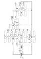
図1に示すように、本電源システムは、第1蓄電池としての鉛蓄電池11と第2蓄電池としてのリチウムイオン蓄電池12とを有する2電源システムである。各蓄電池11,12からはスタータ13や、各種の電気負荷14,15、回転電機16への給電が可能となっている。また、各蓄電池11,12に対しては回転電機16による充電が可能となっている。本システムでは、回転電機16に対して並列に鉛蓄電池11及びリチウムイオン蓄電池12が接続されるとともに、電気負荷14,15に対して並列に鉛蓄電池11及びリチウムイオン蓄電池12が接続されている。
(First Embodiment)
As shown in FIG. 1, this power supply system is a dual power supply system having a
図示による具体的な説明は割愛するが、リチウムイオン蓄電池12は、収容ケースに収容されて基板一体の電池ユニットUとして構成されている。電池ユニットUは、出力端子P1,P2,P3,P4を有しており、このうち出力端子P1,P4に鉛蓄電池11とスタータ13と電気負荷14とが接続され、出力端子P2に回転電機16が接続され、出力端子P3に電気負荷15が接続されている。なお、出力端子P1が第1端子に相当し、出力端子P2が第2端子に相当する。
Although a specific description by illustration is omitted, the lithium
各電気負荷14,15は、各蓄電池11,12から供給される供給電力の電圧について要求が相違するものである。このうち電気負荷15には、供給電力の電圧が一定又は少なくとも所定範囲内で変動するよう安定であることが要求される定電圧要求負荷が含まれる。これに対し、電気負荷14は、定電圧要求負荷以外の一般的な電気負荷である。電気負荷15は被保護負荷とも言える。また、電気負荷15は電源失陥が許容されない負荷であり、電気負荷14は、電気負荷15に比べて電源失陥が許容される負荷であるとも言える。
The electric loads 14 and 15 have different requirements for the voltage of the supplied power supplied from the
定電圧要求負荷である電気負荷15の具体例としては、ナビゲーション装置やオーディオ装置、メータ装置、エンジンECU等の各種ECUが挙げられる。この場合、供給電力の電圧変動が抑えられることで、上記各装置において不要なリセット等が生じることが抑制され、安定動作が実現可能となっている。電気負荷15として、電動ステアリング装置やブレーキ装置等の走行系アクチュエータが含まれていてもよい。また、電気負荷14の具体例としては、シートヒータやリヤウインドウのデフロスタ用ヒータ、ヘッドライト、フロントウインドウのワイパ、空調装置の送風ファン等が挙げられる。
Specific examples of the
回転電機16は、3相交流モータとそのモータの駆動を制御するモータ制御部とを有するモータ機能付き発電機であり、機電一体型のISG(Integrated Starter Generator)として構成されている。回転電機16は、エンジン出力軸や車軸の回転により発電(回生発電)を行う発電機能と、エンジン出力軸に回転力を付与する力行機能とを備えている。回転電機16の力行機能により、例えばアイドリングストップ制御において、自動停止されているエンジンの再始動が行われる。回転電機16は、発電電力を各蓄電池11,12や電気負荷14,15に供給する。
The rotary
次に、電池ユニットUの電気的構成について説明する。 Next, the electrical configuration of the battery unit U will be described.
電池ユニットUには、ユニット内電気経路として、出力端子P1とリチウムイオン蓄電池12とを繋ぐ第1電気経路L1を有しており、その第1電気経路L1の中間点である接続点N1に出力端子P2が接続されている。この場合、第1電気経路L1は、鉛蓄電池11とリチウムイオン蓄電池12とを電気的に繋ぐ経路であり、第1電気経路L1上の接続点N1に回転電機16が接続されている。第1電気経路L1において、接続点N1よりも鉛蓄電池11の側に第1スイッチSW1が設けられ、接続点N1よりもリチウムイオン蓄電池12の側に第2スイッチSW2が設けられている。第1電気経路L1とN1−P2間の電気経路とは、回転電機16に対する入出力電流を流すことを想定した大電流経路であり、この経路を介して、各蓄電池11,12及び回転電機16の間の相互の通電が行われる。
The battery unit U has a first electric path L1 connecting the output terminal P1 and the lithium
また、第1電気経路L1には、出力端子P1及び第1スイッチSW1の間の分岐点N3と、第2スイッチSW2及びリチウムイオン蓄電池12の間の分岐点N4との間に、第2電気経路L2が並列に設けられており、その第2電気経路L2の中間点である接続点N2に出力端子P3が接続されている。第2電気経路L2において、接続点N2よりも鉛蓄電池11の側に第3スイッチSW3が設けられ、接続点N2よりもリチウムイオン蓄電池12の側に第4スイッチSW4が設けられている。第2電気経路L2とN2−P3間の電気経路とは、第1電気経路L1側と比べて小電流を流すことを想定した小電流経路(すなわち、第1電気経路L1に比べて許容電流が小さい小電流経路)であり、この経路を介して、各蓄電池11,12から電気負荷15への通電が行われる。
Further, in the first electric path L1, a second electric path is provided between the branch point N3 between the output terminal P1 and the first switch SW1 and the branch point N4 between the second switch SW2 and the lithium
電源システムの作動状態において、第1スイッチSW1及び第2スイッチSW2が選択的に閉状態に操作されることで、第1電気経路L1を介して、鉛蓄電池11及びリチウムイオン蓄電池12の少なくともいずれかと回転電機16との間で通電が行われる。また、第3スイッチSW3及び第4スイッチSW4が選択的に閉状態に操作されることで、第2電気経路L2を介して、鉛蓄電池11及びリチウムイオン蓄電池12の少なくともいずれかと電気負荷15との間で通電が行われる。
By selectively operating the first switch SW1 and the second switch SW2 in the closed state in the operating state of the power supply system, at least one of the
各スイッチSW1〜SW4は、それぞれMOSFET等の半導体スイッチング素子を用いて構成されており、言うなればノーマリオープン式のスイッチである。具体的には、例えば第1スイッチSW1は、寄生ダイオードの向きを互いに逆にして直列接続された半導体スイッチング素子からなるスイッチ部21と、同じく寄生ダイオードの向きを互いに逆にして直列接続された半導体スイッチング素子からなるスイッチ部22とを有し、これら各スイッチ部21,22が並列接続されることで構成されている。他のスイッチも同様の構成を有している。すなわち、第2スイッチSW2は、スイッチ部23,24が並列接続されることで構成され、第3スイッチSW3は、スイッチ部25,26が並列接続されることで構成され、第4スイッチSW4は、スイッチ部27,28が並列接続されることで構成されている。
Each of the switches SW1 to SW4 is configured by using a semiconductor switching element such as a MOSFET, so to speak, it is a normally open type switch. Specifically, for example, the first switch SW1 is a
上記の各スイッチ部21〜28では、寄生ダイオードの向きを互いに逆にする一対の半導体スイッチング素子をそれぞれ有することから、例えば第1スイッチSW1がオフ(開放)となった場合、つまり各半導体スイッチング素子がオフとなった場合において、寄生ダイオードを通じて電流が流れることが完全に遮断される。つまり、各電気経路L1,L2において意図せず電流が流れることを回避できる。
Since each of the
なお、図1では、寄生ダイオードが互いにアノード同士で接続されるようにしたが、寄生ダイオードのカソード同士が接続されるようにしてもよい。半導体スイッチング素子として、MOSFETに代えて、IGBTやバイポーラトランジスタ等を用いることも可能である。IGBTやバイポーラトランジスタを用いた場合には、上記寄生ダイオードの代わりとなるダイオードを各半導体スイッチング素子にそれぞれ並列に接続させればよい。 In FIG. 1, the parasitic diodes are connected to each other by the anodes, but the cathodes of the parasitic diodes may be connected to each other. As the semiconductor switching element, it is also possible to use an IGBT, a bipolar transistor, or the like instead of the MOSFET. When an IGBT or a bipolar transistor is used, a diode instead of the parasitic diode may be connected to each semiconductor switching element in parallel.
また、電池ユニットUには、出力端子P4と出力端子P3とを繋ぐバイパス経路L3が設けられ、そのバイパス経路L3上にバイパスリレー31が設けられている。つまり、バイパスリレー31は、第3スイッチSW3に並列に設けられている。バイパスリレー31は、ノーマリクローズ式のメカニカルリレースイッチである。バイパス経路L3の延長線上にはヒューズ32が設けられている。なお、ヒューズ32は、ユニット内部のバイパス経路L3に設けられていてもよい。バイパスリレー31を閉鎖することで、第3スイッチSW3がオフであっても鉛蓄電池11と電気負荷15とが電気的に接続される。例えば、車両の電源スイッチであるIGスイッチ(イグニッションスイッチ)がオフされている状態では、各スイッチSW1〜SW4がオフ(閉鎖)されており、かかる状態では、バイパスリレー31を介して電気負荷15に対して暗電流が供給される。
Further, the battery unit U is provided with a bypass path L3 connecting the output terminal P4 and the output terminal P3, and a
電池ユニットUは、各スイッチSW1〜SW4、及びバイパスリレー31のオンオフ(開閉)を制御する電源制御装置40を備えている。電源制御装置40は、CPU、ROM、RAM、入出力インターフェース等を含むマイコンにより構成されている。電源制御装置40は、IGスイッチのオン状態、すなわちシステム作動状態で、電気負荷15や回転電機16への通電要求に応じて、各スイッチSW1〜SW4を開閉いずれかの状態に操作するとともに、バイパスリレー31を開状態とする。この場合、電源制御装置40は、各スイッチSW1〜SW4のいずれかを閉鎖させる際にはスイッチ指令信号をオン信号とし、開放させる際にはスイッチ指令信号をオフ信号とする。また、電源制御装置40は、バイパスリレー31を開放させる際にはリレー指令信号をオン信号とし、閉鎖させる際にはリレー指令信号をオフ信号とする。
The battery unit U includes switches SW1 to SW4 and a power
電源制御装置40には、電池ユニット外の制御装置としてECU50が接続されている。電源制御装置40及びECU50は、CAN等の通信ネットワーク(通信線)により接続されて相互に通信可能となっており、電源制御装置40及びECU50に記憶される各種データが互いに共有できるものとなっている。ECU50は、電源制御装置40に対して上位制御装置となっており、各蓄電池11,12の蓄電状態や車両の運転状態等に基づいて、電源制御装置40に対して、各スイッチSW1〜SW4やバイパスリレー31の開閉制御に関する指令を出力する。これにより、本電源システムにおいて、鉛蓄電池11とリチウムイオン蓄電池12とを選択的に用いて充放電が実施される。
An
ところで、電源制御装置40は、電池ユニットUの外部からの起動信号の入力に伴い起動される。具体的には、電池ユニットUの信号入力端子PAには、IGスイッチ18を介して鉛蓄電池11が接続されており、IGスイッチ18がオン操作されることに伴い、ハイレベルの起動信号が信号入力端子PAを介して電源制御装置40に入力される。そして、例えば起動信号の立ち上がりエッジを検出することに基づいて、電源制御装置40が起動される。
By the way, the power
また、電源制御装置40では、IGスイッチ18のオフ操作により起動信号がローレベルになることに伴い作動が停止される。ただしこの場合、起動信号の立ち下がり後において所定期間で作動状態が継続され、その所定期間内において所定の後処理が実施される。この後処理では、例えば各スイッチの故障診断等が適宜実施される。
Further, in the power
なお、ECU50等、他の制御装置も同様に、IGスイッチ18がオン操作されることに伴い起動されるようになっており、各制御装置の起動に伴い相互の通信が可能になっている。
Similarly, other control devices such as the
ここで、電池ユニットUでは、例えばコネクタが外れたり断線が生じたりすると、IGスイッチ18のオン中において意に反して起動信号の入力が停止されてしまう。この場合、電源制御装置40の作動が停止されることで、電源制御装置40によるスイッチ制御が不可になり、回転電機16による各蓄電池11,12の充電が不可になる。そしてこれにより、鉛蓄電池11での蓄電量の低下が生じて、いわゆるバッテリ上がりが生じ、それに起因して車両が走行不可になることが懸念される。
Here, in the battery unit U, for example, if the connector is disconnected or a wire break occurs, the input of the start signal is unexpectedly stopped while the
また、IGスイッチ18のオン中に意に反して起動信号の入力が停止された場合には、IGスイッチ18がオフ操作された後、再びIGスイッチ18がオン操作される際に、起動信号がハイレベルにならず(入力が途絶えたままになり)、電源制御装置40が停止されたままになることが考えられる。かかる場合、やはり鉛蓄電池11の充電が行われないことに起因して、車両が走行不可になることが懸念される。
Further, if the input of the start signal is unexpectedly stopped while the
そこで本実施形態では、起動信号が正常に入力されていない起動信号異常時であるか否かを判定するとともに、起動信号異常時であると判定された場合に、電池ユニットU内の各スイッチSW1〜SW4のうち、第1スイッチSW1を閉状態に操作するようにした。本実施形態では、電源制御装置40の機能により異常判定部と異常時操作部とが実現される。起動信号異常の判定に関して、電源制御装置40は、ECU50との通信が行われている状況下において起動信号の入力が停止された場合に、起動信号異常時であると判定する。
Therefore, in the present embodiment, it is determined whether or not the start signal is abnormal when the start signal is not normally input, and when it is determined that the start signal is abnormal, each switch SW1 in the battery unit U is determined. Of ~ SW4, the first switch SW1 is operated in the closed state. In the present embodiment, the function of the power
図2は、電池ユニットUにおけるスイッチ制御の処理手順を示すフローチャートであり、本処理は、電源制御装置40により所定周期で繰り返し実施される。
FIG. 2 is a flowchart showing a process procedure for switch control in the battery unit U, and this process is repeatedly performed by the power
図2において、ステップS11では、起動信号異常が生じているか否かを示すエラーフラグFが0であるか否かを判定する。なお、エラーフラグFが0であることは、起動信号異常が生じていないことを示し、エラーフラグFが1であることは、起動信号異常が生じていることを示す。F=0であればステップS12に進み、F=1であればステップS19に進む。 In FIG. 2, in step S11, it is determined whether or not the error flag F indicating whether or not the start signal abnormality has occurred is 0. When the error flag F is 0, it means that the start signal abnormality has not occurred, and when the error flag F is 1, it means that the start signal abnormality has occurred. If F = 0, the process proceeds to step S12, and if F = 1, the process proceeds to step S19.
エラーフラグFが0である場合において、ステップS12では、起動信号がローレベルになっているか否かを判定する。そして、起動信号がハイレベルであれば(ステップS12がNOであれば)、ステップS13に進む。ステップS13では、各スイッチSW1〜SW4の制御として通常制御を実施する。通常処理では、各蓄電池11,12の状態や、上位制御装置であるECU50からの指令に基づいて、各スイッチSW1〜SW4の開閉が制御される。
When the error flag F is 0, in step S12, it is determined whether or not the start signal is at a low level. Then, if the start signal is at a high level (if step S12 is NO), the process proceeds to step S13. In step S13, normal control is performed as control of each switch SW1 to SW4. In the normal process, the opening and closing of the switches SW1 to SW4 is controlled based on the states of the
また、起動信号がローレベルであれば(ステップS12がYESであれば)、ステップS14に進む。ステップS14では、通信ネットワークによる通信が行われている状況であるか否かを判定する。そして、通信が行われていない状況であれば(ステップS14がNOであれば)、ステップS15に進む。ステップS15では、電源制御装置40自身について作動停止の処理が行われる。
If the start signal is low level (YES in step S12), the process proceeds to step S14. In step S14, it is determined whether or not communication is being performed by the communication network. Then, if there is no communication (if step S14 is NO), the process proceeds to step S15. In step S15, the operation of the power
また、起動信号がローレベルであり、かつ通信が行われている場合(ステップS12,S14が共にYESの場合)には、ステップS16に進む。ステップS16では、各スイッチSW1〜SW4のうち第1スイッチSW1を閉状態にし、その他の第2〜第4スイッチSW2〜SW4を開状態にする。続くステップS17では、起動信号異常が生じているとして、エラーフラグFに1をセットする。ただしこの場合、起動信号がローレベルに立ち下げられていても、電源制御装置40の作動が停止されることはなく、その作動状態が継続される。
If the start signal is at a low level and communication is being performed (when both steps S12 and S14 are YES), the process proceeds to step S16. In step S16, the first switch SW1 of the switches SW1 to SW4 is closed, and the other switches SW2 to SW4 are opened. In the following step S17, it is assumed that an abnormality in the start signal has occurred, and the error flag F is set to 1. However, in this case, even if the start signal is lowered to a low level, the operation of the power
続くステップS18では、起動信号発生の旨を通信ネットワークを介してECU50等に通知する。なお、起動信号発生の旨を音や表示等によりドライバに通知してもよい。ECU50等では、起動信号発生の旨の通知に基づいて、回転電機16の力行駆動や発電を制限するとよい。
In the following step S18, the
また、エラーフラグFが1である場合において、ステップS19では、通信が行われている状況であるか否かを判定する。そして、通信が行われている状況であれば、ステップS20に進んで第1スイッチSW1の閉状態(オン状態)を維持し、通信が行われていない状況であれば、ステップS21に進んで第1スイッチSW1を開状態(オフ状態)に移行させる。 Further, when the error flag F is 1, in step S19, it is determined whether or not communication is being performed. Then, if communication is being performed, the process proceeds to step S20 to maintain the closed state (on state) of the first switch SW1, and if communication is not being performed, the process proceeds to step S21. 1 Switch SW1 is shifted to the open state (off state).
また、エラーフラグFが1であり、かつ通信が行われていない状況において、ステップS22では、起動信号の立ち上がりエッジが検出されたか否かを判定する。そして、起動信号の立ち上がりエッジが検出されたことを条件に、ステップS23では、起動信号の入力が正常復帰したとみなして、エラーフラグFを0にリセットする。 Further, in the situation where the error flag F is 1 and communication is not performed, in step S22, it is determined whether or not the rising edge of the start signal is detected. Then, on condition that the rising edge of the start signal is detected, in step S23, it is considered that the input of the start signal has returned to normal, and the error flag F is reset to 0.
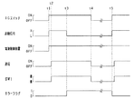
図3は、上記のスイッチ制御をより具体的に示すタイムチャートである。ここでは、IGスイッチ18のオン操作後において起動信号の入力が意図せず停止される場合を想定するものとなっている。
FIG. 3 is a time chart showing the above switch control more specifically. Here, it is assumed that the input of the start signal is unintentionally stopped after the
図3において、タイミングt1では、IGスイッチ18のオン操作に伴い起動信号がハイレベルに立ち上がり、それに伴い電源制御装置40が起動される。その後、タイミングt2では、通信ネットワークにおける通信が開始される。また、タイミングt2以降において、各スイッチSW1〜SW4が適宜開閉される。なお、図3では便宜上、第1スイッチSW1が常時閉となる状態を示している。
In FIG. 3, at the timing t1, the start signal rises to a high level when the
その後、タイミングt3では、例えばコネクタが外れることに起因して、起動信号の入力が停止される。このとき、通信は継続されている状態でありながら起動信号がローレベルになることに基づいて、起動信号異常が生じたことが判定され、エラーフラグFに1がセットされる。 After that, at the timing t3, the input of the start signal is stopped, for example, because the connector is disconnected. At this time, it is determined that an abnormality has occurred in the start signal based on the fact that the start signal becomes low level while the communication is continued, and the error flag F is set to 1.
タイミングt3以降、電源制御装置40の作動が停止されることが禁じられ、その電源制御装置40の作動状態下において、スイッチSW1〜SW4のうち第1スイッチSW1のみが閉状態で維持される。第1スイッチSW1が閉状態で維持されることにより、IGスイッチ18のオン中、すなわち車両走行中において、充電要求に応じて回転電機16による鉛蓄電池11の充電が可能となっている。
After the timing t3, the operation of the power
その後、タイミングt4でIGスイッチ18がオフされると、通信が停止される。そして、その通信停止に伴い、第1スイッチSW1が開放(オフ)される。ただし、タイミングt4以降において、電源制御装置40は作動状態のまま維持される。IGスイッチ18のオフ中、すなわち車両停止中には、回転電機16による発電(鉛蓄電池11の充電)が行われないことから、第1スイッチSW1を開放していてもバッテリ電力面での支障は無く、第1スイッチSW1を開放することでの消費電力低減が図られている。
After that, when the
その後、タイミングt5では、IGスイッチ18が再びオン操作される。このとき、前回のIGオフ後において、例えばユーザによりコネクタの差し直しが行われていると、図示のようにタイミングt5において起動信号が正常に入力される。したがって、その起動信号の立ち上がりエッジに基づいて、起動信号の入力が正常復帰したとみなされ、エラーフラグFが0にリセットされる。
After that, at the timing t5, the
なお、図3の事例とは異なり、コネクタが外れている場合に、その状態がIGオフ中もそのまま放置されることもあると考えられる。かかる場合には、次回のIGオン時において、起動信号の入力(立ち上がりエッジの入力)が行われないことになる。しかしながら、上記のとおり起動信号異常が生じたと判定された場合に、それ以降において電源制御装置40が作動状態で維持されるため、次回のIGオン後(図3のタイミングt5以降)において回転電機16による鉛蓄電池11の充電が可能となっている。
In addition, unlike the case of FIG. 3, when the connector is disconnected, it is considered that the state may be left as it is even while the IG is off. In such a case, the start signal is not input (the rising edge is input) at the next time the IG is turned on. However, when it is determined that the start signal abnormality has occurred as described above, the power
以上詳述した本実施形態によれば、以下の優れた効果が得られる。 According to the present embodiment described in detail above, the following excellent effects can be obtained.
電源制御装置40に対して起動信号が正常に入力されていない起動信号異常時であるか否かを判定し、起動信号異常時であると判定された場合に、第1スイッチSW1を閉状態に操作する構成とした。これにより、意に反して電源制御装置40に対する起動信号の入力が途絶えても、回転電機16から鉛蓄電池11への電力供給、すなわち鉛蓄電池11の充電が可能になり、鉛蓄電池11での蓄電量の低下を抑制できる。また、かかる構成では、第1スイッチSW1に並列に設けられるノーマリクローズリレー等が不要になることから、コスト増加を抑制できる。その結果、電源システムのコスト低減を図りつつ、起動信号異常時に適正な対処を実施することができる。
It is determined whether or not the start signal is abnormally input to the
ECU50(他の制御装置)との通信が行われている状況下において起動信号の入力が停止された場合に、起動信号異常時であると判定する構成とした。この場合、通信の有無によりシステム起動状態であるか否かを判断することで、起動信号異常時であることを適正に判定でき、ひいては当該異常の発生時おいて適正な対処を実現できる。 When the input of the start signal is stopped under the condition that the communication with the ECU 50 (another control device) is being performed, it is determined that the start signal is abnormal. In this case, by determining whether or not the system is in the activated state based on the presence or absence of communication, it is possible to appropriately determine that the activation signal is abnormal, and by extension, it is possible to take appropriate measures when the abnormality occurs.
上記のように通信状況を参照して起動信号異常を判定することにより、異常判定のための信号線等の追加が無くても、所望とする異常判定を適正に実施することができる。 By determining the activation signal abnormality with reference to the communication status as described above, the desired abnormality determination can be appropriately performed without adding a signal line or the like for the abnormality determination.
起動信号異常時であると判定された後において、通信が行われていれば第1スイッチSW1を閉状態とし、通信が行われていなければ第1スイッチSW1を開状態とする構成とした。これにより、車両停止中において、第1スイッチSW1を閉状態にしておくために要する消費電力の削減が可能となる。 After it is determined that the start signal is abnormal, the first switch SW1 is closed if communication is being performed, and the first switch SW1 is opened if communication is not being performed. As a result, it is possible to reduce the power consumption required to keep the first switch SW1 in the closed state while the vehicle is stopped.
起動信号異常が生じた場合には、IGスイッチ18のオフ後にコネクタが差し直され、これにより起動信号異常が解消されることがあると考えられる。この場合、次回のIGスイッチ18のオン操作時には、正常に起動信号が入力されることになるため、電源制御装置40において起動信号の入力が正常復帰したことの判定が可能となる。ここで、単に起動信号の入力再開を以て正常復帰を判定するのではなく、通信が行われていない状況での入力再開を以て正常復帰を判定する構成にしたため、IGスイッチ18の投入直後(オン操作直後)であって通信開始前の時点で正常復帰の判定が行われる。そのため、起動信号異常が生じた後において、例えばコネクタでの接触不良により起動信号の入力及び入力停止が繰り返される状態では正常復帰の旨が判定されないことになり、IGスイッチ18のオフ操作を経た後において、復帰判定を適正に実施することができる。
When a start signal abnormality occurs, it is considered that the connector may be reconnected after the
起動信号異常時であると判定された場合に、第1スイッチSW1を閉状態に操作し、第2スイッチSW2を開状態に操作するようにした。これにより、起動信号異常時であるとの判定後において、リチウムイオン蓄電池12の充放電を規制しつつ、回転電機16による鉛蓄電池11の充電を適宜実施することができる。
When it is determined that the start signal is abnormal, the first switch SW1 is operated in the closed state and the second switch SW2 is operated in the open state. As a result, after the determination that the start signal is abnormal, the lead-
以下に、他の実施形態を第1実施形態との相違点を中心に説明する。 Hereinafter, other embodiments will be described with a focus on differences from the first embodiment.
(第2実施形態)
本実施形態では、起動信号異常時であると判定された後の正常復帰判定について以下の構成を採用する。つまり、電源制御装置40は、起動信号異常時であると判定された後、次に起動信号が入力された場合に、その起動信号の入力が継続される時間が所定時間以上になることに基づいて、起動信号の入力が正常復帰した旨を判定する。
(Second Embodiment)
In the present embodiment, the following configuration is adopted for the normal return determination after the determination that the start signal is abnormal. That is, the
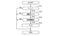
図4は、正常復帰判定の処理手順を示すフローチャートであり、本処理は、電源制御装置40により所定周期で繰り返し実施される。なお、図4は、スイッチ制御の一連の処理のうち正常復帰判定に関する処理のみを示している。
FIG. 4 is a flowchart showing a processing procedure for determining normal return, and this processing is repeatedly performed by the power
図4において、ステップS31では、エラーフラグFが1であるか否かを判定し、F=1であれば、後続のステップS32に進む。ステップS32では、起動信号がハイレベルであるか否かを判定する。また、起動信号がハイレベルである場合に、ステップS33では、起動信号がハイレベルになってからの継続時間が所定時間TA以上になったか否かを判定する。そして、ステップS33がYESである場合に、起動信号の入力が正常復帰したとみなして、エラーフラグFを0にリセットする。 In FIG. 4, in step S31, it is determined whether or not the error flag F is 1, and if F = 1, the process proceeds to the subsequent step S32. In step S32, it is determined whether or not the start signal is at a high level. Further, when the start signal is at a high level, in step S33, it is determined whether or not the duration after the start signal reaches the high level is TA or more for a predetermined time. Then, when the step S33 is YES, it is considered that the input of the start signal has returned to normal, and the error flag F is reset to 0.
図5は、正常復帰判定の処理をより具体的に示すタイムチャートである。なお、図5では、上述の図3と同様に、タイミングt1で起動信号の入力に伴い電源制御装置40が起動され、タイミングt2以降、通信ネットワークにおける通信が行われる。また、タイミングt3で、起動信号の入力が意図せず停止され、タイミングt4でIGスイッチ18がオフされる。
FIG. 5 is a time chart showing the process of determining the normal return more specifically. In FIG. 5, similarly to FIG. 3 described above, the power
ここでは特に、起動信号の入力が意図せず停止された後、IGスイッチ18がオフされる前において、すなわちタイミングt3〜t4の期間内において、タイミングt11で起動信号が再入力される。そして、起動信号の再入力後、起動信号がハイレベルのまま所定時間TAが経過することにより、その経過タイミングであるタイミングt12で、エラーフラグFが0にリセットされる。
Here, in particular, after the input of the start signal is unintentionally stopped, before the
ただし、図示は略すが、起動信号の再入力後、所定時間TAが経過する前に、起動信号の入力が再び停止される場合には、エラーフラグFが1のまま保持される。つまり、起動信号異常時であると判定された後、次に起動信号が入力されても、その入力の継続時間が所定時間TA未満であれば、起動信号の入力が正常復帰したとは判定されないようになっている。 However, although not shown, if the input of the start signal is stopped again after the start signal is re-input and before the predetermined time TA elapses, the error flag F is kept at 1. That is, even if the start signal is input next after it is determined that the start signal is abnormal, it is not determined that the input of the start signal has returned to normal if the duration of the input is less than the predetermined time TA. It has become like.
上記構成によれば、例えばコネクタでの接触不良により起動信号の入力及び入力停止が繰り返される状態では正常復帰の旨が判定されない。これにより、復帰判定を適正に実施することができる。 According to the above configuration, for example, in a state where input and input stop of the start signal are repeated due to poor contact at the connector, it is not determined that normal recovery is achieved. As a result, the return determination can be properly performed.
(第3実施形態)
本実施形態では、電源制御装置40に対して起動信号を複数系統でそれぞれ入力する構成とし、複数系統の起動信号のうち一部の起動信号だけで入力が停止された場合に、起動信号異常時であると判定することとしている。
(Third Embodiment)
In the present embodiment, the start-up signals are input to the power
図6は、本実施形態における電源システムの構成を示す回路図である。なお、本実施形態における電源システムは上記図1と概ね同じであるが、図6では構成の一部を省略して示している。 FIG. 6 is a circuit diagram showing the configuration of the power supply system according to the present embodiment. The power supply system in this embodiment is substantially the same as that in FIG. 1, but a part of the configuration is omitted in FIG.
図6において、電池ユニットUには、2つの信号入力端子PA1,PA2が設けられており、その各信号入力端子PA1,PA2がIGスイッチ18に接続されている。電源制御装置40には、各信号入力端子PA1,PA2を介して起動信号S1,S2がそれぞれ入力される。その他の構成は図1と同じである。ちなみに、電池ユニットUに設けられるコネクタでは、複数のピン配列において、信号入力端子PA1としてのピンと、信号入力端子PA2としてのピンとが互いに離れた位置に設けられているとよい。又は、信号入力端子PA1,PA2が異なるコネクタにそれぞれ設けられていてもよい。
In FIG. 6, the battery unit U is provided with two signal input terminals PA1 and PA2, and the respective signal input terminals PA1 and PA2 are connected to the
図7は、スイッチ制御の処理手順を示すフローチャートであり、本処理は、上記図2に置き換えて、電源制御装置40により所定周期で繰り返し実施される。図7では、図2との相違点として、ステップS12,S14の処理に代えて、ステップS41,S42の処理が設けられている。
FIG. 7 is a flowchart showing a processing procedure of switch control, and this processing is repeatedly executed by the power
図7では、エラーフラグFが0である場合において、ステップS41で、起動信号S1,S2が共にハイレベルになっているか否かを判定する。また、ステップS42では、起動信号S1,S2が共にローレベルになっているか否かを判定する。そして、起動信号S1,S2が共にハイレベルであれば(ステップS41がYESであれば)、ステップS13において、各スイッチSW1〜SW4の制御として通常制御を実施する。また、起動信号S1,S2が共にローレベルであれば(ステップS42がYESであれば)、ステップS15において、電源制御装置40自身を作動停止の状態に移行させる。
In FIG. 7, when the error flag F is 0, it is determined in step S41 whether or not both the start signals S1 and S2 are at a high level. Further, in step S42, it is determined whether or not both the start signals S1 and S2 are at the low level. Then, if both the start signals S1 and S2 are at a high level (if step S41 is YES), normal control is performed as control of the switches SW1 to SW4 in step S13. If both the start signals S1 and S2 are at a low level (YES in step S42), the power
また、起動信号S1,S2のいずれか一方のみがローレベルであれば(ステップS41,S42が共にNOであれば)、ステップS16において、各スイッチSW1〜SW4のうち第1スイッチSW1を閉状態、その他の第2〜第4スイッチSW2〜SW4を開状態にするとともに、続くステップS17において、エラーフラグFに1をセットする。この場合、既述のとおり、起動信号がローレベルに立ち下げられていても、電源制御装置40の作動が停止されることはなく、その作動状態が継続される。
If only one of the start signals S1 and S2 is at a low level (if both steps S41 and S42 are NO), in step S16, the first switch SW1 of the switches SW1 to SW4 is closed. The other second to fourth switches SW2 to SW4 are opened, and in the following step S17, the error flag F is set to 1. In this case, as described above, even if the start signal is lowered to a low level, the operation of the power
電源制御装置40に2系統で起動信号S1,S2がそれぞれ入力される構成では、例えばコネクタの一部が外れることによって、一部の起動信号の入力が停止され、他の起動信号の入力は継続されることが生じうる。したがって、2系統の起動信号S1,S2のうち一部の起動信号だけで入力が停止されたことを判定することで、起動信号異常時であると適正に判定できる。
In the configuration in which the start signals S1 and S2 are input to the
なお、起動信号S1,S2のうち一方をメイン起動信号、他方をサブ起動信号としておき、メイン起動信号がハイレベルである場合に、サブ起動信号に関係なく通常処理を実施し、メイン起動信号がローレベルであり、かつサブ起動信号がハイレベルである場合に、起動信号異常であると判定する(エラーフラグF=1とする)構成であってもよい。また、2系統で起動信号が電源制御装置40に入力される構成以外に、3つ以上の系統で起動信号が電源制御装置40に入力される構成であってもよい。
One of the start signals S1 and S2 is set as the main start signal and the other is set as the sub start signal. When the main start signal is at a high level, normal processing is performed regardless of the sub start signal, and the main start signal is used. When the level is low and the sub-start signal is high level, it may be determined that the start signal is abnormal (error flag F = 1). Further, in addition to the configuration in which the start-up signal is input to the power
(他の実施形態)
上記実施形態を例えば次のように変更してもよい。
(Other embodiments)
The above embodiment may be changed as follows, for example.
・電源制御装置40において、他の制御装置(ECU50)との通信が行われている状況下で起動信号の入力が停止された場合に、起動信号異常時であると判定する判定処理(図2参照)と、複数系統の起動信号のうち一部の起動信号だけで入力が停止された場合に、起動信号異常時であると判定する判定処理(図7参照)との両方が実施される構成であってもよい。つまり、電源制御装置40は、上記2つの判定処理のいずれかで起動信号異常時であると判定された場合に、第1スイッチSW1を閉状態に操作する。
-In the power
・上記実施形態では、起動信号異常時であると判定された後において、通信が行われていれば第1スイッチSW1を閉状態とし、通信が行われていなければ第1スイッチSW1を開状態としたが、これを変更し、起動信号異常時であると判定された後には、通信状況にかかわらず、第1スイッチSW1を閉状態に保持する構成としてもよい。 -In the above embodiment, after it is determined that the start signal is abnormal, the first switch SW1 is closed if communication is being performed, and the first switch SW1 is opened if communication is not being performed. However, after changing this and determining that the start signal is abnormal, the first switch SW1 may be held in the closed state regardless of the communication status.
・IGスイッチ18のオフ中、すなわち車両停止中において、定期的に強制起動信号を生じさせ、電源制御装置40で強制起動信号により異常判定を実施する構成としてもよい。ここで、IGスイッチ18のオフ中に起動信号異常が生じていると判定された場合には、次回のIGオンに備えて、第1スイッチSW1を閉鎖(オン)するとよい。
-While the
・車両の電源スイッチは、IGスイッチ18以外であってもよく、例えばACCスイッチ(アクセサリスイッチ)であってもよい。また、ACCスイッチのオン操作に伴い電源制御装置40に対して起動信号が出力される構成であってもよい。IGスイッチのオン操作に伴い起動信号が出力される系統と、ACCスイッチのオン操作に伴い起動信号が出力される系統とを設け、それら各系統から電源制御装置40に起動信号が入力される構成であってもよい。
-The power switch of the vehicle may be other than the
・上記実施形態では、電池ユニットUにおいて、電気負荷を駆動するための第3スイッチSW3及び第4スイッチSW4を設けたが、この構成を変更してもよい。例えば、これらスイッチSW3,SW4を設けずに電池ユニットUを構成してもよい。更に言えば、電池ユニットUに、各スイッチSW1〜SW4のうち第1スイッチSW1のみを設ける構成であってもよい。 -In the above embodiment, the battery unit U is provided with the third switch SW3 and the fourth switch SW4 for driving the electric load, but this configuration may be changed. For example, the battery unit U may be configured without providing these switches SW3 and SW4. Furthermore, the battery unit U may be configured to provide only the first switch SW1 of the switches SW1 to SW4.
・電源システムは、第1蓄電池及び第2蓄電池として鉛蓄電池11とリチウムイオン蓄電池12とを備えるものに限られない。例えば、鉛蓄電池11及びリチウムイオン蓄電池12のいずれかの代わりに、ニッケル水素蓄電池など他の二次電池を用いる構成としてもよい。また、第1蓄電池及び第2蓄電池をいずれも鉛蓄電池又はリチウムイオン蓄電池にすることも可能である。ただし、第2蓄電池として、充放電効率の高い高効率蓄電池を用いることが望ましい。
-The power supply system is not limited to the one including the
・上記実施形態では、発電機として発電機能と力行機能とを有する回転電機16を用いたが、これを変更し、発電機能のみを有するオルタネータ等の発電機を用いることも可能である。
-In the above embodiment, the rotary
・車載電源システムに限定されず、車載以外の電源システムに本発明を適用することも可能である。 -The present invention is not limited to the in-vehicle power supply system, and the present invention can be applied to a power supply system other than the in-vehicle power supply system.
11…鉛蓄電池(第1蓄電池)、12…リチウムイオン蓄電池(第2蓄電池)、16…回転電機(発電機)、40…電源制御装置、SW1…第1スイッチ。 11 ... lead storage battery (first storage battery), 12 ... lithium ion storage battery (second storage battery), 16 ... rotary electric machine (generator), 40 ... power supply control device, SW1 ... first switch.
Claims (8)
前記起動信号が正常に入力されていない起動信号異常時であるか否かを判定する異常判定部と、
前記起動信号異常時であると判定された場合に、前記スイッチを閉状態に操作する異常時操作部と、
を備える電源制御装置。 A connection point between the first storage battery (11) and the second storage battery (12) connected in parallel to the generator (16) and the generator in the electric path connecting the first storage battery and the second storage battery ( A power supply control device (SW1) that is applied to a power supply system including a switch (SW1) provided closer to the first storage battery than N1), is activated by an input of an activation signal from the outside, and controls the opening and closing of the switch. 40) And
An abnormality determination unit that determines whether or not the activation signal is abnormally input, and an abnormality determination unit.
An abnormal operation unit that operates the switch in the closed state when it is determined that the start signal is abnormal.
Power control unit equipped with.
前記異常判定部は、前記他の制御装置との通信が行われている状況下において前記起動信号の入力が停止された場合に、前記起動信号異常時であると判定する請求項1に記載の電源制御装置。 Communication with another control device (50) is possible via the communication line,
The abnormality determination unit according to claim 1, wherein when the input of the activation signal is stopped in a situation where communication with the other control device is being performed, the abnormality determination unit determines that the activation signal is abnormal. Power control device.
前記異常時操作部は、前記異常判定部により起動信号異常時であると判定された後において、前記通信が行われている状況であることに基づいて前記スイッチを閉状態とし、前記通信が行われていない状況であることに基づいて前記スイッチを開状態とする請求項2に記載の電源制御装置。 It is mounted on a vehicle, and communication is performed via the communication line when the power switch (18) of the vehicle is turned on, while the start signal is output to the power control device when the power switch is turned on. Applies to in-vehicle power supply systems
After the abnormality determination unit determines that the start signal is abnormal, the abnormality operation unit closes the switch based on the situation in which the communication is being performed, and the communication is performed. The power supply control device according to claim 2, wherein the switch is opened based on the fact that the situation has not been changed.
前記起動信号異常時であると判定された後において、前記他の制御装置との通信が行われていない状況下において前記起動信号が入力されたことに基づいて、前記起動信号の入力が正常復帰した旨を判定する復帰判定部を備える請求項2又は3に記載の電源制御装置。 It is mounted on a vehicle, and communication is performed via the communication line when the power switch (18) of the vehicle is turned on, while the start signal is output to the power control device when the power switch is turned on. Applies to in-vehicle power supply systems
After it is determined that the start signal is abnormal, the input of the start signal returns to normal based on the fact that the start signal is input in a situation where communication with the other control device is not performed. The power supply control device according to claim 2 or 3, further comprising a return determination unit for determining that the result has been achieved.
前記異常判定部は、前記複数系統の起動信号のうち一部の起動信号だけで入力が停止された場合に、前記起動信号異常時であると判定する請求項1乃至5のいずれか1項に記載の電源制御装置。 It has a configuration in which the start signals are input to each of a plurality of systems.
The abnormality determination unit according to any one of claims 1 to 5, which determines that the activation signal is abnormal when the input is stopped only by a part of the activation signals of the plurality of systems. The power control device described.
前記異常時操作部は、前記起動信号異常時であると判定された場合に、前記第1スイッチを閉状態、前記第2スイッチを開状態に操作する請求項1乃至6のいずれか1項に記載の電源制御装置。 It is applied to a power supply system including the switch as a first switch (SW1) and a second switch (SW2) provided on the side of the second storage battery with respect to the connection point in the electric path.
According to any one of claims 1 to 6, the operation unit at the time of abnormality operates the first switch in the closed state and the second switch in the open state when it is determined that the activation signal is abnormal. The power control device described.
前記第1蓄電池が接続される第1端子(P1)と、
前記発電機が接続される第2端子(P2)と、
前記起動信号が入力される信号入力端子(PA)と、
前記第1端子と前記第2端子とを接続する接続経路に設けられる前記スイッチと、
前記第2蓄電池と、
を備える電池ユニット。 The power supply control device according to any one of claims 1 to 7.
The first terminal (P1) to which the first storage battery is connected and
The second terminal (P2) to which the generator is connected and
A signal input terminal (PA) to which the start signal is input and
The switch provided in the connection path connecting the first terminal and the second terminal,
With the second storage battery
Battery unit with.
Priority Applications (4)
| Application Number | Priority Date | Filing Date | Title |
|---|---|---|---|
| JP2017128618A JP6794944B2 (en) | 2017-06-30 | 2017-06-30 | Power control unit and battery unit |
| PCT/JP2018/022951 WO2019003966A1 (en) | 2017-06-30 | 2018-06-15 | Power supply control device and battery unit |
| CN201880043738.2A CN110832729B (en) | 2017-06-30 | 2018-06-15 | Power supply control device and battery unit |
| US16/730,286 US11273777B2 (en) | 2017-06-30 | 2019-12-30 | Power supply control apparatus and battery unit |
Applications Claiming Priority (1)
| Application Number | Priority Date | Filing Date | Title |
|---|---|---|---|
| JP2017128618A JP6794944B2 (en) | 2017-06-30 | 2017-06-30 | Power control unit and battery unit |
Publications (2)
| Publication Number | Publication Date |
|---|---|
| JP2019013085A JP2019013085A (en) | 2019-01-24 |
| JP6794944B2 true JP6794944B2 (en) | 2020-12-02 |
Family
ID=64741477
Family Applications (1)
| Application Number | Title | Priority Date | Filing Date |
|---|---|---|---|
| JP2017128618A Active JP6794944B2 (en) | 2017-06-30 | 2017-06-30 | Power control unit and battery unit |
Country Status (4)
| Country | Link |
|---|---|
| US (1) | US11273777B2 (en) |
| JP (1) | JP6794944B2 (en) |
| CN (1) | CN110832729B (en) |
| WO (1) | WO2019003966A1 (en) |
Families Citing this family (3)
| Publication number | Priority date | Publication date | Assignee | Title |
|---|---|---|---|---|
| JP7239159B2 (en) * | 2019-02-28 | 2023-03-14 | Fkk株式会社 | dimmer |
| JP7207144B2 (en) * | 2019-05-09 | 2023-01-18 | 株式会社デンソー | vehicle power system |
| WO2023095342A1 (en) * | 2021-11-29 | 2023-06-01 | 日産自動車株式会社 | Power supply system and method for controlling power supply system |
Family Cites Families (12)
| Publication number | Priority date | Publication date | Assignee | Title |
|---|---|---|---|---|
| JPH05459Y2 (en) * | 1988-05-11 | 1993-01-07 | ||
| US6163082A (en) * | 1996-06-13 | 2000-12-19 | Hitachi, Ltd. | Power supplying apparatus for a vehicle and an intensive wiring apparatus |
| US6057666A (en) * | 1997-09-17 | 2000-05-02 | Johnson Controls Technology Company | Method and circuit for controlling charging in a dual battery electrical system |
| JPH1199889A (en) * | 1997-09-30 | 1999-04-13 | Tokico Ltd | Electronic control device for vehicle |
| US7420295B2 (en) * | 2002-08-01 | 2008-09-02 | Gs Yuasa Corporation | Power unit for conveyance and conveyance provided with the power unit |
| JP5234052B2 (en) * | 2010-04-27 | 2013-07-10 | 株式会社デンソー | Power supply |
| JP5617826B2 (en) * | 2011-11-24 | 2014-11-05 | 株式会社デンソー | Vehicle control device |
| JP5477409B2 (en) * | 2012-03-12 | 2014-04-23 | 株式会社デンソー | Power system |
| US9855905B2 (en) * | 2012-10-29 | 2018-01-02 | Sanyo Electric Co., Ltd. | Vehicle power supply device |
| JP6221796B2 (en) | 2014-02-07 | 2017-11-01 | 株式会社デンソー | Battery unit and power supply system |
| JP5977855B1 (en) * | 2015-03-31 | 2016-08-24 | 富士重工業株式会社 | Vehicle power supply |
| KR102410515B1 (en) * | 2017-12-07 | 2022-06-20 | 현대자동차주식회사 | Control apparatus and control method of the same |
-
2017
- 2017-06-30 JP JP2017128618A patent/JP6794944B2/en active Active
-
2018
- 2018-06-15 CN CN201880043738.2A patent/CN110832729B/en active Active
- 2018-06-15 WO PCT/JP2018/022951 patent/WO2019003966A1/en active Application Filing
-
2019
- 2019-12-30 US US16/730,286 patent/US11273777B2/en active Active
Also Published As
| Publication number | Publication date |
|---|---|
| US20200136424A1 (en) | 2020-04-30 |
| CN110832729A (en) | 2020-02-21 |
| WO2019003966A1 (en) | 2019-01-03 |
| JP2019013085A (en) | 2019-01-24 |
| CN110832729B (en) | 2023-12-05 |
| US11273777B2 (en) | 2022-03-15 |
Similar Documents
| Publication | Publication Date | Title |
|---|---|---|
| US10855100B2 (en) | Power supply control apparatus and battery unit | |
| JP6221796B2 (en) | Battery unit and power supply system | |
| JP6260422B2 (en) | Battery unit | |
| WO2017163959A1 (en) | Power supply system and method for controlling same | |
| JP6090195B2 (en) | Battery unit | |
| JP6627732B2 (en) | Power supply circuit device | |
| CN110352545B (en) | Power supply system | |
| JP6794944B2 (en) | Power control unit and battery unit | |
| JP6468138B2 (en) | Power supply | |
| JP6642496B2 (en) | Power supply and power supply system | |
| JP6406328B2 (en) | Power supply device and battery unit | |
| WO2018061681A1 (en) | Power supply system and battery unit | |
| WO2018110243A1 (en) | Battery unit, and power supply system | |
| JP6724675B2 (en) | Switch control device, power supply unit and power supply system | |
| WO2018074545A1 (en) | Power supply device | |
| WO2020209132A1 (en) | Control device for power supply device | |
| JP7098911B2 (en) | Power system | |
| WO2017065161A1 (en) | Power supply device and cell unit | |
| JP7421871B2 (en) | Vehicle power supply device | |
| JP6260728B2 (en) | Battery unit | |
| JP7073619B2 (en) | Power control unit, battery unit and power system | |
| JP2020063007A (en) | Vehicle backup power supply device |
Legal Events
| Date | Code | Title | Description |
|---|---|---|---|
| A621 | Written request for application examination |
Free format text: JAPANESE INTERMEDIATE CODE: A621 Effective date: 20190823 |
|
| TRDD | Decision of grant or rejection written | ||
| A01 | Written decision to grant a patent or to grant a registration (utility model) |
Free format text: JAPANESE INTERMEDIATE CODE: A01 Effective date: 20201013 |
|
| A61 | First payment of annual fees (during grant procedure) |
Free format text: JAPANESE INTERMEDIATE CODE: A61 Effective date: 20201026 |
|
| R151 | Written notification of patent or utility model registration |
Ref document number: 6794944 Country of ref document: JP Free format text: JAPANESE INTERMEDIATE CODE: R151 |
|
| R250 | Receipt of annual fees |
Free format text: JAPANESE INTERMEDIATE CODE: R250 |