JP6724675B2 - Switch control device, power supply unit and power supply system - Google Patents
Switch control device, power supply unit and power supply system Download PDFInfo
- Publication number
- JP6724675B2 JP6724675B2 JP2016178963A JP2016178963A JP6724675B2 JP 6724675 B2 JP6724675 B2 JP 6724675B2 JP 2016178963 A JP2016178963 A JP 2016178963A JP 2016178963 A JP2016178963 A JP 2016178963A JP 6724675 B2 JP6724675 B2 JP 6724675B2
- Authority
- JP
- Japan
- Prior art keywords
- switch
- state
- power supply
- power
- electric load
- Prior art date
- Legal status (The legal status is an assumption and is not a legal conclusion. Google has not performed a legal analysis and makes no representation as to the accuracy of the status listed.)
- Active
Links
Images


Landscapes
- Control Of Charge By Means Of Generators (AREA)
- Direct Current Feeding And Distribution (AREA)
Description
本発明は、電源システムのスイッチを制御するスイッチ制御装置、並びに、当該スイッチ制御装置を備える電池ユニット、及び電源システムに関するものである。 The present invention relates to a switch control device that controls a switch of a power supply system, a battery unit including the switch control device, and a power supply system.
例えば車両に搭載される車載電源システムとして、複数の蓄電池(例えば鉛蓄電池、リチウムイオン蓄電池)を用い、これら複数の蓄電池を使い分けながら車載の各種負荷に対して電力を供給する構成が知られている。例えば特許文献1に記載の技術では、発電機と各蓄電池とを接続する複数の給電経路それぞれにスイッチが設けられている。そして、複数の蓄電池それぞれの充電率に基づいて複数のスイッチのいずれかをオンにすることで、発電機からいずれかの蓄電池に対して充電を行うようにしている。 For example, a configuration is known in which a plurality of storage batteries (for example, a lead storage battery and a lithium-ion storage battery) are used as an in-vehicle power supply system mounted in a vehicle, and electric power is supplied to various in-vehicle loads while properly using the plurality of storage batteries. .. For example, in the technique described in Patent Document 1, a switch is provided in each of a plurality of power supply paths that connect a generator and each storage battery. Then, one of the plurality of switches is turned on based on the charging rate of each of the plurality of storage batteries, so that the storage battery is charged from the generator.
また、各蓄電池に対して並列に第1負荷及び第2負荷を接続し、各蓄電池から第1電気負荷及び第2電気負荷に対して給電を可能としている。この場合、第1蓄電池及び第2蓄電池から第2電気負荷に対してはそれぞれスイッチを介して電力を供給する構成としている。 In addition, the first load and the second load are connected in parallel to each storage battery, and the power can be supplied from each storage battery to the first electric load and the second electric load. In this case, electric power is supplied from the first storage battery and the second storage battery to the second electric load via the respective switches.
ここで、特許文献1に記載のモータジェネレータは、電気負荷としても動作するものである。以下、特許文献1に記載のモータジェネレータを「第1電気負荷」とし、他の電気負荷を「第2電気負荷」とする。また、第1蓄電池(第1電源)から第1電気負荷に対して電力を供給する経路に設けられている第1メインリレーを「第1スイッチ」とし、第2蓄電池(第2電源)から第1電気負荷に対して電力を供給する経路に設けられている第1電池切替スイッチを「第2スイッチ」とし、第1蓄電池から第2電気負荷に対して電力を供給する経路に設けられている第2メインリレーを「第3スイッチ」とし、第2蓄電池から第2電気負荷に対して電力を供給する経路に設けられている第2電池切替スイッチを「第4スイッチ」とする。 Here, the motor generator described in Patent Document 1 also operates as an electric load. Hereinafter, the motor generator described in Patent Document 1 will be referred to as a “first electric load”, and the other electric loads will be referred to as a “second electric load”. In addition, the first main relay provided in the path that supplies power from the first storage battery (first power supply) to the first electric load is referred to as a “first switch”, and the second storage battery (second power supply) is connected to the first main relay. The first battery changeover switch provided on the path for supplying electric power to one electrical load is referred to as a "second switch", and is provided on the path for supplying electric power from the first storage battery to the second electric load. The second main relay is referred to as a “third switch”, and the second battery changeover switch provided on the path for supplying electric power from the second storage battery to the second electric load is referred to as a “fourth switch”.
第1スイッチと第4スイッチとをオン状態とし、第2スイッチと第3スイッチとをオフ状態とすることで、第1蓄電池から第1電気負荷に電力を供給し、第2蓄電池から第2電気負荷に電力を供給する状態とすることができる。当該状態を第1状態とする。また、第2スイッチと第3スイッチとをオン状態とし、第1スイッチと第4スイッチとをオフ状態とすることで、第1蓄電池から第2電気負荷に電力を供給し、第2蓄電池から第1電気負荷に電力を供給する状態とすることができる。当該状態を第2状態とする。 By turning on the first switch and the fourth switch and turning off the second switch and the third switch, electric power is supplied from the first storage battery to the first electric load, and the second storage battery outputs the second electric power. It can be in a state of supplying power to the load. This state is referred to as a first state. Further, by turning on the second switch and the third switch and turning off the first switch and the fourth switch, electric power is supplied from the first storage battery to the second electric load, and the second storage battery supplies the electric power. One electric load can be brought into a state of supplying electric power. This state is referred to as a second state.
ここで、第1状態から第2状態への切り替え時において、第1電気負荷又は第2電気負荷と蓄電池との接続が瞬断されて、第1電気負荷又は第2電気負荷に電源失陥が生じることが懸念される。即ち、第2スイッチのオフ状態からオン状態への切り替えが、第1スイッチのオン状態からオフ状態への切り替えに遅れると、第1スイッチ及び第2スイッチがともにオフ状態とされる状態が生じる。これにより、第1電気負荷と第1蓄電池及び第2蓄電池の両方との接続が瞬断され、第1電気負荷において電源失陥が生じることになる。また、第3スイッチのオフ状態からオン状態への切り替えが、第4スイッチのオン状態からオフ状態への切り替えに遅れると、第3スイッチ及び第4スイッチがともにオフ状態とされる状態が生じる。これにより、第2電気負荷と第1蓄電池及び第2蓄電池の両方との接続が瞬断され、第2電気負荷において電源失陥が生じることになる。 Here, at the time of switching from the first state to the second state, the connection between the first electric load or the second electric load and the storage battery is momentarily disconnected, and a power failure occurs in the first electric load or the second electric load. There is concern that it will occur. That is, if the switching of the second switch from the off state to the on state is delayed from the switching of the first switch from the on state to the off state, a state occurs in which both the first switch and the second switch are in the off state. As a result, the connection between the first electric load and both the first storage battery and the second storage battery is momentarily cut off, causing a power failure in the first electric load. Further, when the switching of the third switch from the off state to the on state is delayed from the switching of the fourth switch from the on state to the off state, a state occurs in which both the third switch and the fourth switch are in the off state. As a result, the connection between the second electric load and both the first storage battery and the second storage battery is momentarily cut off, causing a power failure in the second electric load.
そこで、第2スイッチのオン状態への切り替えが第1スイッチのオフ状態への切り替えに遅れることを抑制する制御を実施し、また、第3スイッチのオン状態への切り替えが第4スイッチのオフ状態への切り替えに遅れることを抑制する制御を実施する構成が考えられる。つまり、第2スイッチのオン状態への切り替えを、第1スイッチのオフ状態への切り替えと同時、又は、第1スイッチのオフ状態への切り替えより早く実施し、第3スイッチのオン状態への切り替えを、第4スイッチのオフ状態への切り替えと同時、又は、第4スイッチのオフ状態への切り替えより早く実施する。当該制御により、第1状態から第2状態への切り替え時において、第1スイッチ及び第2スイッチの少なくとも一方がオン状態とされるため、第1蓄電池及び第2蓄電池の少なくとも一方から第1電気負荷への電力供給が継続される。同様に、第1状態から第2状態への切り替え時において、第3スイッチ及び第4スイッチの少なくとも一方がオン状態とされるため、第1蓄電池及び第2蓄電池の少なくとも一方から第2電気負荷への電力供給が継続される。これにより、第1電気負荷及び第2電気負荷のそれぞれにおける電源失陥という不都合を抑制することが可能になる。 Therefore, the control for suppressing the switching of the second switch to the ON state from being delayed from the switching of the first switch to the OFF state is performed, and the switching to the ON state of the third switch is performed to the OFF state of the fourth switch. A configuration is conceivable in which the control for suppressing the delay in switching to is executed. That is, the switching of the second switch to the on state is performed at the same time as the switching of the first switch to the off state, or faster than the switching of the first switch to the off state, and the switching of the third switch to the on state is performed. Is performed simultaneously with the switching of the fourth switch to the off state or earlier than the switching of the fourth switch to the off state. By the control, at the time of switching from the first state to the second state, at least one of the first switch and the second switch is turned on, so that at least one of the first storage battery and the second storage battery is connected to the first electric load. The power supply to Similarly, at the time of switching from the first state to the second state, at least one of the third switch and the fourth switch is turned on, so that at least one of the first storage battery and the second storage battery is transferred to the second electric load. Power supply is continued. This makes it possible to suppress the inconvenience of power failure in each of the first electric load and the second electric load.
上記制御を実施する場合、4つのスイッチうち、1つのスイッチのみがオフ状態とされ、他の3つのスイッチがオン状態とされている状態が想定される。例えば、第2スイッチがオフ状態とされ、他のスイッチがオン状態とされていると、第2スイッチを迂回して、第2蓄電池→第4スイッチ→第3スイッチ→第1スイッチ→第1電気負荷の順に電流が流れることになる。ここで、上述した通り、第3,4スイッチは第1蓄電池及び第2蓄電池のそれぞれから第2電気負荷に対して電流が流れる経路上に設けられたスイッチである。例えば、第1電気負荷の消費電流が第2電気負荷の消費電流より大きいような場合に、第3スイッチ及び第4スイッチに本来流れると想定される電流より大きな電流が流れるという不都合が懸念される。 When performing the above control, it is assumed that only one of the four switches is in the off state and the other three switches are in the on state. For example, when the second switch is turned off and the other switches are turned on, the second switch is bypassed and the second storage battery→the fourth switch→the third switch→the first switch→the first electric power. The current will flow in the order of the load. Here, as described above, the third and fourth switches are switches provided on the path through which the current flows from each of the first storage battery and the second storage battery to the second electric load. For example, when the current consumption of the first electric load is larger than the current consumption of the second electric load, there is a concern that a current larger than the current supposed to flow through the third switch and the fourth switch may flow. ..
本発明は上記課題に鑑みてなされたものであり、第1電源及び第2電源から第1電気負荷及び第2電気負荷へスイッチを介して電力を供給する電源システムのスイッチを制御するスイッチ制御装置において、スイッチの状態変更に伴って生じうる不都合を抑制することを主たる目的とする。 The present invention has been made in view of the above problems, and a switch control device that controls a switch of a power supply system that supplies power from a first power supply and a second power supply to a first electric load and a second electric load via a switch. In the above, the main purpose is to suppress the inconvenience that may occur when the state of the switch is changed.
第1の構成は、第1電源(11)と第2電源(12)とを備え、第1電気負荷(17)と第2電気負荷(15)とに対して前記第1電源及び前記第2電源の少なくとも一方から電力を供給し、前記第1電源から前記第1電気負荷に電力供給する第1経路(L1)に設けられた第1スイッチ(21)と、前記第2電源から前記第1電気負荷に電力供給する第2経路(L2)に設けられた第2スイッチ(22)と、前記第1電源から前記第2電気負荷に電力供給する第3経路(L3)に設けられた第3スイッチ(23)と、前記第2電源から前記第2電気負荷に電力供給する第4経路(L4)に設けられた第4スイッチ(24)と、を備え、前記第1〜前記第4スイッチにより前記第1〜前記第4経路をそれぞれ独立して開閉可能である電源システムに含まれ、前記第1〜前記第4スイッチの開閉制御を実施するスイッチ制御装置(30)であって、前記第1スイッチ及び前記第4スイッチをオン状態、前記第2スイッチ及び前記第3スイッチをオフ状態とする第1状態から、前記第2スイッチ及び前記第3スイッチをオン状態、前記第1スイッチ及び前記第4スイッチをオフ状態とする第2状態へ切り替える際、前記第1状態から、前記第1スイッチ、前記第2スイッチ、前記第3スイッチ、及び前記第4スイッチを全てオン状態とする第3状態へ切り替えた後、前記第2状態へと切り替える制御を実施し、前記第1電気負荷の消費電流量は、前記第2電気負荷の消費電流量より大きく、前記第2スイッチは、前記第3スイッチ及び前記第4スイッチに比べて、許容電流量が大きいものであり、前記第1状態から前記第3状態へ切り替える際、前記第2スイッチ及び前記第3スイッチを同時にオン状態とするか、又は、前記第3スイッチより先に前記第2スイッチをオン状態にする。 The first configuration includes a first power source (11) and a second power source (12), and the first power source and the second power source (17) and the second electrical load (15) are provided. A first switch (21) provided in a first path (L1) that supplies power from at least one of power sources and that supplies power from the first power source to the first electric load, and the first switch from the second power source. A second switch (22) provided on a second path (L2) for supplying electric power to the electric load, and a third switch (22) provided on a third path (L3) for supplying electric power from the first power source to the second electric load. A switch (23) and a fourth switch (24) provided on a fourth path (L4) for supplying electric power from the second power source to the second electric load. A switch control device (30) included in a power supply system capable of opening and closing the first to fourth paths independently of each other, for performing opening and closing control of the first to fourth switches. From the first state in which the switch and the fourth switch are turned on and the second switch and the third switch are turned off, the second switch and the third switch are turned on, the first switch and the fourth switch are turned on. When switching to a second state in which the switch is turned off, the first state is switched to a third state in which all of the first switch, the second switch, the third switch, and the fourth switch are turned on. After that, the control for switching to the second state is performed, the current consumption of the first electric load is larger than the current consumption of the second electric load, and the second switch is the third switch and the third switch. The allowable current amount is larger than that of the fourth switch, and when the first state is switched to the third state, the second switch and the third switch are simultaneously turned on or the second switch is turned on. The second switch is turned on before the three switches.
上記構成によれば、スイッチの状態を第1状態から第2状態へ切り替えることで、第1電気負荷への電力供給源を第1電源から第2電源に切り替え、第2電気負荷への電力供給源を第2電源から第1電源に切り替える。ここで、第1状態から第2状態への切り替えの際に、いったん第1状態から第3状態へと切り替えた後に、第2状態へと切り替える構成とした。 According to the above configuration, by switching the state of the switch from the first state to the second state, the power supply source to the first electric load is switched from the first power supply to the second power supply, and the power is supplied to the second electric load. Switching the source from the second power source to the first power source. Here, when the first state is switched to the second state, the configuration is such that the first state is once switched to the third state and then the second state is switched.
第1状態では、第1電源から第1電気負荷に対する電力供給が行われ、第2電源から第2電気負荷に対する電力供給が行われる。続いて、第3状態では、第1電源及び第2電源から第1電気負荷及び第2電気負荷のそれぞれに対する電力供給が行われる。そして、第2状態では、第2電源から第1電気負荷に対する電力供給が行われ、第1電源から第2電気負荷に対する電力供給が行われる。即ち、第3状態を介して第1状態から第2状態への切り替えを実施することで、第1電源及び第2電源の少なくとも一方から、第1電気負荷及び第2電気負荷のそれぞれへの電力供給を継続できる。これにより、第1電気負荷及び第2電気負荷のそれぞれにおける電源失陥という不都合を抑制することが可能になる。 In the first state, power is supplied from the first power supply to the first electric load, and power is supplied from the second power supply to the second electric load. Subsequently, in the third state, power is supplied from the first power supply and the second power supply to the first electric load and the second electric load, respectively. Then, in the second state, power is supplied from the second power source to the first electric load, and power is supplied from the first power source to the second electric load. That is, by switching from the first state to the second state via the third state, the electric power from at least one of the first power source and the second power source to each of the first electric load and the second electric load is increased. The supply can be continued. This makes it possible to suppress the inconvenience of power failure in each of the first electric load and the second electric load.
さらに、本構成では、第1電気負荷の消費電流量が第2電気負荷の消費電流量より大きい。そこで、第1電気負荷に対して電流が流れる第2経路に設けられている第2スイッチの許容電流量を、第2電気負荷に対して電流が流れる第3,4経路に設けられている第3,4スイッチの許容電流量に比べて大きくしている。ここで、第1状態から第3状態への切り替え時において、第2スイッチより第3スイッチが先にオン状態とされると、第2電源から第1電気負荷に対して、第4経路、第3経路、及び第1経路を介して電流が流れることが懸念される。 Further, in this configuration, the current consumption of the first electric load is larger than the current consumption of the second electric load. Therefore, the permissible current amount of the second switch provided in the second path through which the current flows with respect to the first electric load is set to the third and fourth paths provided with current through the second electric load. It is set larger than the allowable current amount of the 3 and 4 switches. Here, at the time of switching from the first state to the third state, if the third switch is turned on earlier than the second switch, the second path from the second power source to the first electric load, the fourth path, There is a concern that current will flow through the three paths and the first path.
そこで、第2スイッチより第3スイッチが先にオン状態とされることを抑制し、第2スイッチに比べて許容電流量の小さな第3スイッチ及び第4スイッチを介して、第2電源から第1電気負荷に電流が流れることを抑制する。これにより、第3スイッチ及び第4スイッチを介して大電流が流れ、第3経路及び第4経路に損傷などが生じることを抑制できる。つまり、本構成によれば、スイッチの状態変更に伴って生じうる不都合を抑制することが可能となる。 Therefore, it is possible to prevent the third switch from being turned on earlier than the second switch, and the first switch from the second power source may be provided via the third switch and the fourth switch having a smaller allowable current amount than the second switch. Suppressing the flow of current through the electric load. As a result, it is possible to prevent a large current from flowing through the third switch and the fourth switch and damage to the third path and the fourth path. That is, according to this configuration, it is possible to suppress the inconvenience that may occur when the state of the switch is changed.
第2の構成は、前記第1スイッチは、前記第3スイッチ及び前記第4スイッチに比べて、許容電流量が大きいものであり、前記第3状態から前記第2状態へ切り替える際、前記第1スイッチ及び前記第4スイッチを同時にオフ状態とするか、又は、前記第1スイッチより先に前記第4スイッチをオフ状態にする。 In a second configuration, the first switch has a larger allowable current amount than the third switch and the fourth switch, and when switching from the third state to the second state, the first switch The switch and the fourth switch are turned off at the same time, or the fourth switch is turned off before the first switch.
上記構成とすることで、第1電源から第1電気負荷に対して、第4経路、第3経路、及び第2経路を介して電流が流れることを抑制する。即ち、第1スイッチに比べて許容電流量の小さな第3スイッチ及び第4スイッチを介して、第1電源から第1電気負荷に電流が流れることを抑制する。これにより、第3スイッチ及び第4スイッチに大電流が流れ、第3経路及び第4経路に損傷などが生じることを抑制できる。 By setting it as the said structure, it suppresses that an electric current flows into a 1st electric load from a 1st power supply through a 4th path|route, a 3rd path|route, and a 2nd path|route. That is, the current is suppressed from flowing from the first power source to the first electric load via the third switch and the fourth switch, which have a smaller allowable current amount than the first switch. Accordingly, it is possible to prevent a large current from flowing through the third switch and the fourth switch and damaging the third path and the fourth path.
第3の構成は、第1電源(11)と第2電源(12)とを備え、第1電気負荷(17)と第2電気負荷(15)とに対して前記第1電源及び前記第2電源の少なくとも一方から電力を供給し、前記第1電源から前記第1電気負荷に電力供給する第1経路(L1)に設けられた第1スイッチ(21)と、前記第2電源から前記第1電気負荷に電力供給する第2経路(L2)に設けられた第2スイッチ(22)と、前記第1電源から前記第2電気負荷に電力供給する第3経路(L3)に設けられた第3スイッチ(23)と、前記第2電源から前記第2電気負荷に電力供給する第4経路(L4)に設けられた第4スイッチ(24)と、を備え、前記第1〜前記第4スイッチにより前記第1〜前記第4経路をそれぞれ独立して開閉可能である電源システムに含まれ、前記第1〜前記第4スイッチの開閉制御を実施するスイッチ制御装置(30)であって、前記第1スイッチ及び前記第4スイッチをオン状態、前記第2スイッチ及び前記第3スイッチをオフ状態とする第1状態から、前記第2スイッチ及び前記第3スイッチをオン状態、前記第1スイッチ及び前記第4スイッチをオフ状態とする第2状態へ切り替える際、前記第1状態から、前記第1スイッチ、前記第2スイッチ、前記第3スイッチ、及び前記第4スイッチを全てオン状態とする第3状態へ切り替えた後、前記第2状態へと切り替える制御を実施し、前記第1電気負荷の消費電流量は、前記第2電気負荷の消費電流量より大きく、前記第1スイッチは、前記第3スイッチ及び前記第4スイッチに比べて、許容電流量が大きいものであり、前記第3状態から前記第2状態へ切り替える際、前記第1スイッチ及び前記第4スイッチを同時にオフ状態とするか、又は、前記第1スイッチより先に前記第4スイッチをオフ状態にする。 The third configuration includes a first power source (11) and a second power source (12), and the first power source and the second power source (17) and the second electrical load (15) are used. A first switch (21) provided in a first path (L1) that supplies power from at least one of power sources and that supplies power from the first power source to the first electric load, and the first switch from the second power source. A second switch (22) provided on a second path (L2) for supplying electric power to the electric load, and a third switch (22) provided on a third path (L3) for supplying electric power from the first power source to the second electric load. A switch (23) and a fourth switch (24) provided on a fourth path (L4) for supplying electric power from the second power source to the second electric load. A switch control device (30) included in a power supply system capable of opening and closing the first to fourth paths independently of each other, for performing opening and closing control of the first to fourth switches. From the first state in which the switch and the fourth switch are turned on and the second switch and the third switch are turned off, the second switch and the third switch are turned on, the first switch and the fourth switch are turned on. When switching to a second state in which the switch is turned off, the first state is switched to a third state in which all of the first switch, the second switch, the third switch, and the fourth switch are turned on. After that, control is performed to switch to the second state, the current consumption of the first electric load is larger than the current consumption of the second electric load, and the first switch is the third switch and the third switch. The allowable current amount is larger than that of the fourth switch, and when switching from the third state to the second state, the first switch and the fourth switch are simultaneously turned off, or the first switch and the fourth switch are turned off. The fourth switch is turned off before the first switch.
第3の構成は、第1の構成と同様に、スイッチの状態を第1状態から第2状態へ切り替えることで、第1電気負荷への電力供給源を第1電源から第2電源に切り替え、第2電気負荷への電力供給源を第2電源から第1電源に切り替える。ここで、第1状態から第2状態への切り替えの際に、いったん第1状態から第3状態へと切り替えた後に、第2状態へと切り替える構成とした。 Similarly to the first configuration, the third configuration switches the state of the switch from the first state to the second state, thereby switching the power supply source to the first electric load from the first power source to the second power source, The power supply source to the second electric load is switched from the second power supply to the first power supply. Here, when the first state is switched to the second state, the configuration is such that the first state is once switched to the third state and then the second state is switched.
第1状態では、第1電源から第1電気負荷に対する電力供給が行われ、第2電源から第2電気負荷に対する電力供給が行われる。続いて、第3状態では、第1電源及び第2電源から第1電気負荷及び第2電気負荷のそれぞれに対する電力供給が行われる。そして、第2状態では、第2電源から第1電気負荷に対する電力供給が行われ、第1電源から第2電気負荷に対する電力供給が行われる。即ち、第3状態を介して第1状態から第2状態への切り替えを実施することで、第1電源及び第2電源の少なくとも一方から、第1電気負荷及び第2電気負荷のそれぞれへの電力供給を継続できる。これにより、第1電気負荷及び第2電気負荷のそれぞれにおける電源失陥という不都合を抑制することが可能になる。 In the first state, power is supplied from the first power supply to the first electric load, and power is supplied from the second power supply to the second electric load. Subsequently, in the third state, power is supplied from the first power supply and the second power supply to the first electric load and the second electric load, respectively. Then, in the second state, power is supplied from the second power source to the first electric load, and power is supplied from the first power source to the second electric load. That is, by switching from the first state to the second state via the third state, the electric power from at least one of the first power source and the second power source to each of the first electric load and the second electric load is increased. The supply can be continued. This makes it possible to suppress the inconvenience of power failure in each of the first electric load and the second electric load.
そして、第2の構成と同様に、第1電源から第1電気負荷に対して、第4経路、第3経路、及び第2経路を介して電流が流れることを抑制する。即ち、第1スイッチに比べて許容電流量の小さな第3スイッチ及び第4スイッチを介して、第1電源から第1電気負荷に電流が流れることを抑制する。これにより、第3スイッチ及び第4スイッチに大電流が流れ、第3経路及び第4経路に損傷などが生じることを抑制できる。 Then, similarly to the second configuration, the current is suppressed from flowing from the first power source to the first electric load via the fourth path, the third path, and the second path. That is, the current is suppressed from flowing from the first power source to the first electric load via the third switch and the fourth switch, which have a smaller allowable current amount than the first switch. Accordingly, it is possible to prevent a large current from flowing through the third switch and the fourth switch and damaging the third path and the fourth path.
第4の構成は、第1乃至第3のいずれかの構成において、前記第1電源及び前記第2電源はともに蓄電池であって、前記第2電源の内部抵抗は、前記第1電源の内部抵抗に比べて小さいものであって、前記第2経路の抵抗は、前記第1経路の抵抗に比べて小さい。 In a fourth configuration according to any one of the first to third configurations, the first power source and the second power source are both storage batteries, and the internal resistance of the second power source is the internal resistance of the first power source. And the resistance of the second path is smaller than the resistance of the first path.
上記構成によれば、第3状態において、第1電源から第1電気負荷に対して流れる電流量と、第2電源から第1電気負荷に対して流れる電流量とを比較した場合に、第2電源から第1電気負荷に対して流れる電流量が大きくなる。その結果、第1電源及び第2電源の内部抵抗に起因する電圧降下が小さくなる。これにより、第2電気負荷の入力電圧の低下を抑制し、第2電気負荷における電源失陥を抑制できる。 According to the above configuration, in the third state, when the amount of current flowing from the first power source to the first electric load and the amount of current flowing from the second power source to the first electric load are compared, The amount of current flowing from the power source to the first electric load increases. As a result, the voltage drop due to the internal resistance of the first power supply and the second power supply is reduced. As a result, it is possible to suppress a decrease in the input voltage of the second electric load and suppress a power failure in the second electric load.
第5の構成は、第4の構成において、前記第1スイッチ及び前記第2スイッチは、それぞれ複数の半導体スイッチング素子が並列接続されて構成されており、前記第2スイッチを構成する並列接続された前記半導体スイッチング素子の数が、前記第1スイッチを構成する並列接続された前記半導体スイッチング素子の数より多いことで、前記第2経路の抵抗は、前記第1経路の抵抗に比べて小さい。 According to a fifth configuration, in the fourth configuration, the first switch and the second switch are each configured by connecting a plurality of semiconductor switching elements in parallel, and are connected in parallel to configure the second switch. Since the number of the semiconductor switching elements is larger than the number of the semiconductor switching elements connected in parallel that form the first switch, the resistance of the second path is smaller than the resistance of the first path.
第2スイッチを構成する並列接続された半導体スイッチング素子の数を、第1スイッチを構成する並列接続された前記半導体スイッチング素子の数より多くすることで、第2経路の抵抗を、第1経路の抵抗に比べて小さくする。これにより、第3状態における第2電気負荷への出力電圧の低下を抑制できる。加えて、第2電源から第1電気負荷への電力供給時における電力損失を低減できる。 By making the number of semiconductor switching elements connected in parallel that form the second switch larger than the number of semiconductor switching elements that are connected in parallel that form the first switch, the resistance of the second path is increased. Make it smaller than the resistance. Accordingly, it is possible to suppress the decrease in the output voltage to the second electric load in the third state. In addition, it is possible to reduce power loss when power is supplied from the second power source to the first electric load.
第6の構成は、第4又は第5の構成において、前記第1電源は鉛蓄電池であり、前記第2電源はリチウムイオン蓄電池である。 In a sixth configuration according to the fourth or fifth configuration, the first power supply is a lead storage battery and the second power supply is a lithium ion storage battery.
第1電源として鉛蓄電池を用い、第2電源としてリチウムイオン蓄電池を用いることで、第2電源の内部抵抗を第1電源の内部抵抗より小さくする。 By using a lead storage battery as the first power supply and using a lithium ion storage battery as the second power supply, the internal resistance of the second power supply is made smaller than the internal resistance of the first power supply.
第7の構成は、第1乃至第6のいずれかの構成において、前記第2電源の出力容量が所定値未満である場合に、前記第1状態から前記第2状態への切り替えを禁止する。 In the seventh configuration, in any one of the first to sixth configurations, switching from the first state to the second state is prohibited when the output capacity of the second power supply is less than a predetermined value.
第1電気負荷は、第2電気負荷より消費電力量が大きい。そこで、第2電源の出力容量が所定値未満である場合に、第2電気負荷から第2電気負荷に電力を供給する第1状態から、第2電気負荷から第1電気負荷に電力を供給する第2状態への切り替えを禁止する。当該構成によれば、第1電気負荷における電源失陥を抑制できる。 The first electric load consumes more power than the second electric load. Therefore, when the output capacity of the second power supply is less than the predetermined value, the power is supplied from the second electric load to the first electric load from the first state in which the electric power is supplied from the second electric load to the second electric load. Switching to the second state is prohibited. According to the said structure, the power failure in the 1st electric load can be suppressed.
第8の構成は、第1乃至第7のいずれかの構成において、前記第1電気負荷は、電動機としての機能を有する回転電機である。 An eighth configuration is the rotating electrical machine according to any one of the first to seventh configurations, in which the first electric load has a function as an electric motor.
第1電気負荷は、具体的には、電動機としての機能を有する回転電機である。なお、回転電機は、発電機としての機能を有するものであってもよい。 The first electric load is specifically a rotating electric machine having a function as an electric motor. The rotating electric machine may have a function as a generator.
第9の構成は、第8の構成において、前記回転電機の駆動の開始時に前記第1〜前記第4スイッチの状態を前記第1状態とし、その後、前記回転電機の駆動の継続中に前記第1スイッチ〜前記第4スイッチの状態を前記第2状態へと切り替えるものである。 In a ninth configuration according to the eighth configuration, the states of the first to fourth switches are set to the first state at the start of driving the rotating electric machine, and then the first state is set while the driving of the rotating electric machine is continued. The state of the first switch to the fourth switch is switched to the second state.
回転電機の駆動を継続する場合に、第1電気負荷に対する電力供給源を第1電源から第2電源へ切り替える制御を実施する。この際、スイッチの状態を第1状態から第2状態へ切り替える際に、第3状態を経由することで電源失陥を抑制することができる。さらに、第3スイッチ及び第4スイッチに大電流が流れ、第3スイッチ及び第4スイッチに損傷などが生じることを抑制できる。 When the drive of the rotating electric machine is continued, control is performed to switch the power supply source for the first electric load from the first power supply to the second power supply. At this time, when the state of the switch is switched from the first state to the second state, the power failure can be suppressed by passing through the third state. Furthermore, it is possible to prevent a large current from flowing through the third switch and the fourth switch and damaging the third switch and the fourth switch.
また、第1電源と第2電源がともに蓄電池であって、第1電源に比べて第2電源の内部抵抗が小さい第4の構成の電源システムに対して、本構成を適用することで電源システムとしての電力効率を向上させることができる。 In addition, by applying this configuration to the power supply system of the fourth configuration in which both the first power supply and the second power supply are storage batteries and the internal resistance of the second power supply is smaller than that of the first power supply, the power supply system As a result, the power efficiency can be improved.
また、回転電機の駆動の開始時とは、例えば、エンジンを有する車両におけるアイドリングストップ再始動時のことである。また、回転電機の駆動の継続とは、例えば、エンジン出力軸に対するトルクアシストの実施、又は、エンジンを停止し、かつ、回転電機を駆動しての車両の走行のことである。 The start of driving the rotating electric machine is, for example, the restart of idling stop in a vehicle having an engine. Further, the continuation of driving of the rotating electric machine means, for example, execution of torque assist for the engine output shaft, or running of the vehicle with the engine stopped and the rotating electric machine driven.
第10の構成は、第8又は第9の構成において、前記電源システムは、車両に搭載されるとともに、前記スイッチ制御装置以外の制御装置(40)を有し、前記スイッチ制御装置は、前記スイッチ制御装置以外の制御装置の指令に応じて、前記第1状態から前記第2状態への切り替えを実施する。 In a tenth configuration according to the eighth or ninth configuration, the power supply system is mounted on a vehicle and has a control device (40) other than the switch control device, and the switch control device is the switch. Switching from the first state to the second state is performed according to a command from a control device other than the control device.
スイッチ制御装置が、スイッチ制御装置以外の制御装置の指令に応じて、第1状態から第2状態への切り替えを実施する場合に、第3状態を介して切り替えを実施することで、第1電気負荷及び第2電気負荷のそれぞれにおける電源失陥という不都合を抑制することが可能になる。また、第1の構成や第3の構成に本構成を適用した場合、第3スイッチ及び第4スイッチを介して大電流が流れ、第3経路及び第4経路に損傷などが生じることを抑制できる。 When the switch control device performs switching from the first state to the second state in response to a command from a control device other than the switch control device, by performing switching through the third state, the first electrical It is possible to suppress the inconvenience of power failure in each of the load and the second electric load. In addition, when the present configuration is applied to the first configuration and the third configuration, it is possible to prevent a large current from flowing through the third switch and the fourth switch and damaging the third route and the fourth route. ..
第11の構成は、第10の構成において、前記車両は、エンジン(18)を有し、前記スイッチ制御装置以外の制御装置は、前記エンジン及び前記回転電機のうち前記エンジン及び前記回転電機に駆動力を分担させる第1走行状態と、前記エンジン及び前記回転電機のうち前記回転電機のみに駆動力を負担させる第2走行状態とを、前記車両の走行状態に基づいて切り替える走行用制御装置(40)であって、前記第1走行状態から前記第2走行状態への切り替えを実施する場合に、前記制御装置に対し、前記第1状態から前記第2状態への切り替えを指令する。 In an eleventh configuration according to the tenth configuration, the vehicle has an engine (18), and a control device other than the switch control device drives the engine and the rotary electric machine of the engine and the rotary electric machine. A traveling control device (40) that switches between a first traveling state in which the force is shared and a second traveling state in which only the rotating electric machine of the engine and the rotating electric machine bears the driving force based on the traveling state of the vehicle. ), when the switching from the first traveling state to the second traveling state is performed, the control device is instructed to switch from the first state to the second state.
第1走行状態(HV走行状態)から第2走行状態(EV走行状態)へ切り替える場合に、第1電気負荷に対する電力供給源を第1電源から第2電源へ切り替える制御を実施する。また、第1電源に比べて第2電源の内部抵抗が小さい第3の構成の電源システムに対して、本構成を適用することで、電源システムとしての電力効率を向上させることができる。 When switching from the first traveling state (HV traveling state) to the second traveling state (EV traveling state), control is performed to switch the power supply source for the first electric load from the first power source to the second power source. Further, by applying this configuration to the power supply system of the third configuration in which the internal resistance of the second power supply is smaller than that of the first power supply, the power efficiency of the power supply system can be improved.
第12の構成は、前記第1電源に接続されるとともに、前記第2電源を内部に備え、前記第1電気負荷と前記第2電気負荷とに対して前記第1電源及び前記第2電源の少なくとも一方から電力を供給し、前記第1〜前記第4経路と、前記第1〜前記第4スイッチと、を内部に備え、前記第1〜前記第4スイッチにより前記第1〜前記第4経路をそれぞれ独立して開閉可能である電源ユニット(U)であって、第1乃至第11の構成のいずれかに記載の前記スイッチ制御装置を内部に備える。 A twelfth configuration is connected to the first power supply and internally includes the second power supply, and the first power supply and the second power supply with respect to the first electric load and the second electric load. Power is supplied from at least one side, the first to fourth paths and the first to fourth switches are provided inside, and the first to fourth paths are provided by the first to fourth switches. Is a power supply unit (U) that can be opened and closed independently of each other and internally includes the switch control device according to any one of the first to eleventh configurations.
電源ユニットに対して、第1乃至第11の構成のいずれかに記載のスイッチ制御装置を適用することで、第1乃至第11の構成のいずれかにおける効果を得ることができる。さらに、電源ユニットは、第2電源と、第1〜第4経路と、第1〜第4スイッチと、制御装置とを内部に備える。言い換えると、第2電源と、第1〜第4経路と、第1〜第4スイッチと、制御装置とを電源ユニットとして一体化する。当該構成によって、例えば、車両などへの電源システムの取り付けを簡略化することができる。また、例えば、第1電源を電源ユニットの外部に設ける構成とすれば、第1電源に異常や劣化などが生じた場合に、電源ユニットについて分解する必要がなく、第1電源を取り替える工程を簡略化することができる。 By applying the switch control device according to any one of the first to eleventh configurations to the power supply unit, it is possible to obtain the effect in any of the first to eleventh configurations. Furthermore, the power supply unit internally includes a second power supply, first to fourth paths, first to fourth switches, and a control device. In other words, the second power supply, the first to fourth paths, the first to fourth switches, and the control device are integrated as a power supply unit. With this configuration, for example, mounting of the power supply system on a vehicle or the like can be simplified. Further, for example, if the first power supply is provided outside the power supply unit, it is not necessary to disassemble the power supply unit when the first power supply has abnormality or deterioration, and the process of replacing the first power supply is simplified. Can be converted.
第13の構成は、前記第1電源と前記第2電源とを備え、前記第1電気負荷と前記第2電気負荷とに対して前記第1電源及び前記第2電源の少なくとも一方から電力を供給し、前記第1〜前記第4経路と、前記第1〜前記第4スイッチと、を備え、前記第1〜前記第4スイッチにより前記第1〜前記第4経路をそれぞれ独立して開閉可能である電源システムであって、第1乃至第11の構成のいずれかに記載の前記スイッチ制御装置を備える。 A thirteenth configuration includes the first power supply and the second power supply, and supplies power to the first electric load and the second electric load from at least one of the first power supply and the second power supply. The first to the fourth paths and the first to the fourth switches are provided, and the first to the fourth paths can be independently opened and closed by the first to the fourth switches. A certain power supply system, comprising the switch control device according to any one of the first to eleventh configurations.
電源システムに対して、第1乃至第11の構成のいずれかに記載のスイッチ制御装置を適用することで、第1乃至第11の構成のいずれかにおける効果を得ることができる。 By applying the switch control device according to any one of the first to eleventh configurations to the power supply system, the effect in any of the first to eleventh configurations can be obtained.
以下、本発明を具体化した実施形態を図面に基づいて説明する。本実施形態の車載電源装置が搭載される車両は、エンジン(内燃機関)を駆動源として走行するものであり、いわゆるアイドリングストップ機能を有している。 Hereinafter, embodiments embodying the present invention will be described with reference to the drawings. A vehicle on which the vehicle-mounted power supply device of the present embodiment is mounted travels using an engine (internal combustion engine) as a drive source and has a so-called idling stop function.
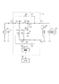
図1に示すように、本電源システムは、「第1電源」としての鉛蓄電池11と「第2電源」としてのリチウムイオン蓄電池12とを有する2電源システムであり、各蓄電池11,12からはスタータモータ13や、電気負荷15や回転電機17への給電が可能となっている。また、各蓄電池11,12に対しては回生発電を行う回転電機17による充電が可能となっている。両蓄電池11,12のうちリチウムイオン蓄電池12は、図示しない筐体(収容ケース)に収容されることで電池ユニットU(電源ユニット)として構成されている。電池ユニットUの詳細な構成については後述する。
As shown in FIG. 1, this power supply system is a two-power supply system having a
鉛蓄電池11は周知の汎用蓄電池である。これに対し、リチウムイオン蓄電池12は、鉛蓄電池11に比べて、充放電における電力損失が少なく、出力密度、及びエネルギ密度の高い高密度蓄電池である。リチウムイオン蓄電池12は、鉛蓄電池11に比べて充放電時のエネルギ効率が高い蓄電池であるとよい。
The
電池ユニットUには外部端子として第1端子T1、第2端子T2、第3端子T3が設けられており、第1端子T1には鉛蓄電池11とスタータモータ13とが接続され、第2端子T2には回転電機17が接続され、第3端子T3には電気負荷15が接続されている。スタータモータ13は、後述するアイドリングストップ再始動時以外の通常のエンジン18の始動時において、エンジン18の出力軸に回転力を付与することでエンジン18を始動する。
The battery unit U is provided with a first terminal T1, a second terminal T2, and a third terminal T3 as external terminals. The
第3端子T3に接続される電気負荷15には、供給電力の電圧が一定又は少なくとも所定範囲内で変動するよう安定であることが要求される定電圧要求負荷が含まれる。電気負荷15は被保護負荷とも言え、言い換えると、電気負荷15は電源失陥が許容されない負荷である。定電圧要求負荷である電気負荷15の具体例としては、ナビゲーション装置やオーディオ装置、メータ装置、エンジンECU等の各種ECUが挙げられる。この場合、供給電力の電圧変動が抑えられることで、上記各装置において不要なリセット等が生じることが抑制され、安定動作が実現可能となっている。
The
なお、第1端子T1及び第2端子T2に対し、定電圧要求負荷以外の一般的な電気負荷を接続させる構成としてもよい。当該一般的な電気負荷の具体例としては、ヘッドライト、フロントウインドシールド等のワイパ、空調装置の送風ファン等が挙げられる。 Note that a general electric load other than the constant voltage required load may be connected to the first terminal T1 and the second terminal T2. Specific examples of the general electric load include a headlight, a wiper such as a front windshield, a blower fan of an air conditioner, and the like.
回転電機17は、エンジン18の出力軸に駆動連結されている。回転電機17は、モータ(電動機)として、エンジン18の出力軸に回転力を付与する力行動作を実施する。具体的には、回転電機17は、モータとして、アイドリングストップ再始動時において、エンジン18の出力軸に回転力を付与することでエンジン18を再始動する。また、回転電機17は、モータとして、車両の走行中において、エンジン18の出力軸に回転力を付与することでアシスト走行やいわゆるEV(Electric Vehicle)走行を実施する。アシスト走行とは、エンジン18を燃焼状態とした上で回転電機17がエンジン18の出力軸に回転力を付与することであり、EV走行とは、エンジン18を非燃焼状態とした上で回転電機17がエンジン18の出力軸に回転力を付与することである。モータとしての回転電機17が「第1電気負荷」に相当し、定電圧要求負荷である電気負荷15が「第2電気負荷」に相当する。回転電機17は、いわゆるISG(Integrated Starter Generator)である。
The rotating
また、回転電機17は、オルタネータ(交流発電機)として、エンジン18の出力軸の回転を動力として発電する。回転電機17の発電電力により各蓄電池11,12が充電される。
Further, the rotating
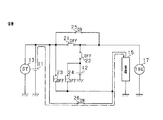
次に、電池ユニットU内の回路構成を説明する。電池ユニットUの内部には、電気経路として、第1端子T1と第2端子T2とを相互に接続する第1経路L1が設けられている。この第1経路L1を介して、鉛蓄電池11から回転電機17への電力供給、及び、回転電機17から鉛蓄電池11への電力供給が実施される。また、電池ユニットUの内部には、電気経路として、リチウムイオン蓄電池12と第2端子T2とを相互に接続する第2経路L2が設けられている。この第2経路L2を介して、リチウムイオン蓄電池12から回転電機17への電力供給、及び、回転電機17からリチウムイオン蓄電池12への電力供給が実施される。
Next, the circuit configuration in the battery unit U will be described. Inside the battery unit U, a first path L1 that connects the first terminal T1 and the second terminal T2 to each other is provided as an electric path. Power is supplied from the
第1経路L1と第2経路L2とは、第1接続点N1で接続しており、第1接続点N1と第2端子T2とを接続する経路は、第1経路L1であり、かつ、第2経路L2である。第1経路L1上には第1スイッチ21が設けられており、より具体的には、第1経路L1上において、第1端子T1と第1接続点N1との間に第1スイッチ21が設けられている。第2経路L2上には第2スイッチ22が設けられており、より具体的には、第2経路L2上において、リチウムイオン蓄電池12と第1接続点N1との間に第2スイッチ22が設けられている。
The first route L1 and the second route L2 are connected at a first connection point N1, and the route connecting the first connection point N1 and the second terminal T2 is the first route L1 and There are two routes L2. The
第1〜第4スイッチ21〜24は、MOSFET等の半導体スイッチにより構成されている。なお、各スイッチ21〜24をそれぞれ2つ一組のMOSFETで構成し、各一組のMOSFETの寄生ダイオードが互いに逆向きになるように直列に接続されているとよい。即ち、各一組のMOSFETの寄生ダイオードのカソード電極同士、又は、アノード電極同士が互いに接続されているとよい。この互いに逆向きの寄生ダイオードによって、各スイッチ21〜24をオフ状態とした場合にそのスイッチが設けられた経路に流れる電流が完全に遮断される。
The first to
上記構成では、回転電機17に対して鉛蓄電池11からの電力供給とリチウムイオン蓄電池12からの電力供給とが選択的に実施可能となっている。この場合、第1スイッチ21をオン、第2スイッチ22をオフにすることで鉛蓄電池11から回転電機17への電力供給が可能となり、第1スイッチ21をオフ、第2スイッチ22をオンにすることでリチウムイオン蓄電池12から回転電機17への電力供給が可能となる。
In the above configuration, the electric power supply from the
また、電池ユニットUの内部には、電気経路として、第1端子T1と第3端子T3とを相互に接続する第3経路L3が設けられている。この第3経路L3を介して、鉛蓄電池11から電気負荷15への電力供給が実施される。また、電池ユニットUの内部には、電気経路として、リチウムイオン蓄電池12と第3端子T3とを相互接続する第4経路L4が設けられている。この第4経路L4を介して、リチウムイオン蓄電池12から電気負荷15への電力供給が実施される。
Further, inside the battery unit U, a third path L3 that connects the first terminal T1 and the third terminal T3 to each other is provided as an electric path. Electric power is supplied from the
第3経路L3と第1経路L1とは、第2接続点N2で接続しており、第2接続点N2と第1端子T1とを接続する経路は、第1経路L1であり、かつ、第3経路L3である。第3経路上には、第3スイッチ23が設けられており、より具体的には、第3経路L3上において、第2接続点N2と第3端子T3との間に第3スイッチ23が設けられている。また、第1スイッチ21は、第2接続点N2よりも第1接続点N1側に設けられている。言い換えると、第1スイッチ21は、第2接続点N2と第1接続点N1との間に設けられている。
The third path L3 and the first path L1 are connected at the second connection point N2, and the path connecting the second connection point N2 and the first terminal T1 is the first path L1 and It is 3 routes L3. The
第2経路L2と第4経路L4とは、第3接続点N3で接続しており、第3接続点N3とリチウムイオン蓄電池12とを接続する経路は、第2経路L2であり、かつ、第4経路L4である。また、第3経路L3と第4経路L4とは、第4接続点N4で接続しており、第4接続点N4と第3端子T3とを接続する経路は、第3経路L3であり、かつ、第4経路L4である。第4経路上には、第4スイッチ24が設けられており、より具体的には、第4経路L4上において、第3接続点N3と第4接続点N4との間に第4スイッチ24が設けられている。また、第2スイッチ22は、第3接続点N3よりも第1接続点N1側に設けられている。言い換えると、第2スイッチ22は、第3接続点N3と第1接続点N1との間に設けられている。また、第3スイッチ23は、第4接続点N4よりも第2接続点N2側に設けられている。言い換えると、第3スイッチ23は、第2接続点N2と第4接続点N4との間に設けられている。
The second route L2 and the fourth route L4 are connected at a third connection point N3, and the route connecting the third connection point N3 and the lithium
以上に示したように電池ユニットU内の回路構成は、第1スイッチ21〜第4スイッチ24により第1経路L1〜第4経路L4をそれぞれ独立して開閉可能なものとなっている。なお、図1に示す構成では、例えば、第1端子T1と第2接続点N2との間の経路が第1経路L1及び第2経路L2に共有されており、各電気経路L1〜L4が一部の経路を互いに共有する構成としているが、当該構成を変更してもよい。具体的には、第1端子T1と第2端子T2とを直接接続する経路を第1経路L1としてもよい。リチウムイオン蓄電池12の正極端子と第2端子T2とを直接接続する経路を第2経路L2としてもよい。第1端子T1と第3端子T3とを直接接続する経路を第3経路L3としてもよい。リチウムイオン蓄電池12の正極端子と第3端子T3とを直接接続する経路を第4経路L4としてもよい。リチウムイオン蓄電池12の正極端子と、端子T1〜T3とを互いに直接的に接続する構成では、第2端子T2が第1接続点N1に相当し、第1端子T1が第2接続点N2に相当し、リチウムイオン蓄電池12の正極端子が第3接続点N3に相当し、第3端子T3が第4接続点N4に相当する。
As described above, the circuit configuration in the battery unit U can open and close the first path L1 to the fourth path L4 independently by the
第1経路L1及び第2経路L2は、発電時における回転電機17の発電電力や、力行動作時における回転電機17の駆動電力といった比較的大きな電力が流れる大電力経路となり、第3経路L3及び第4経路L4は、第1経路L1及び第2経路L2に比べて小さい電力が流れる小電力経路となっている。また、第1経路L1及び第2経路L2に設けられているスイッチ21,22は、第1経路L1及び第2経路L2の許容電流量を大きくするべく、複数の半導体スイッチング素子が並列接続されて構成されている。より具体的には、スイッチ21,22は、互いに逆向きに直列接続された2つ一組のMOSFETが複数並列接続されて構成されている。
The first path L1 and the second path L2 are large power paths through which relatively large power flows such as generated power of the rotary
また、電池ユニットUには、第1〜第4スイッチ21〜24を介さずに、鉛蓄電池11を電気負荷15及び回転電機17に対して接続可能とするバイパス経路L5,L6が設けられている。具体的には、電池ユニットUの内部には、電気経路として、第1スイッチ21を迂回して第1端子T1と第2端子T2とを接続する第1バイパス経路L5が設けられている。また、電池ユニットUの内部には、電気経路として、第3スイッチ23を迂回して第1端子と第3端子T3とを接続する第2バイパス経路L6が設けられている。そして、第1バイパス経路L5上には第1バイパススイッチ25が設けられ、第2バイパス経路L6上には第2バイパススイッチ26が設けられている。各バイパススイッチ25,26は、例えば常閉式のリレースイッチである。
In addition, the battery unit U is provided with bypass paths L5 and L6 that allow the
第1バイパススイッチ25がオン(閉鎖)されることで、第1スイッチ21がオフ(開放)であっても鉛蓄電池11と回転電機17とが電気的に接続される。また、第2バイパススイッチ26がオンされることで、第3スイッチ23がオフであっても鉛蓄電池11と電気負荷15とが接続される。
Since the
また、電池ユニットUは、電池制御手段を構成する制御部30(スイッチ制御装置)を有しており、各スイッチ21〜26や制御部30は、例えば、同一の基板に実装された状態で筐体内に収容されている。なお、各スイッチ21〜26は複数の基板に分けて実装されるものでもよく、また、各スイッチ21〜26は基板に実装されない態様、具体的には、収容ケース(筐体)に直接実装される態様のものでもよい。
Further, the battery unit U has a control unit 30 (switch control device) that constitutes a battery control unit, and the
制御部30には、電池ユニットU外のECU40が接続されている。つまり、制御部30と、ECU40を含む各種制御装置とは、CAN等の通信ネットワークにより接続されて相互に通信可能となっており、制御部30、及び、ECU40を含む各種制御装置に記憶される各種データが互いに共有できるものとなっている。ECU40は、アイドリングストップ制御を実施する機能を有する電子制御装置(走行用制御装置)である。アイドリングストップ制御は、周知のとおり所定の自動停止条件の成立によりエンジン18を自動停止させ、かつその自動停止状態下で所定の再始動条件の成立によりエンジン18を再始動させるものである。ECU40は、回転電機17の制御を実施するものであり、「電源システム」に含まれるものである。
An
制御部30は、各スイッチ21〜26のオンオフ(開閉)の切り替え制御、即ち、開閉制御を実施する。この場合、制御部30は、車両の走行状態や各蓄電池11,12の蓄電状態に基づいて、各スイッチ21〜26のオンオフを制御する。これにより、鉛蓄電池11とリチウムイオン蓄電池12とを選択的に用いて充放電が実施される。
The
制御部30が実施する各蓄電池11,12の蓄電状態に基づく充放電制御について簡単に説明する。制御部30は、鉛蓄電池11及びリチウムイオン蓄電池12の端子電圧又は開放電圧の検出値を逐次取得するとともに、図示しない電流検出手段により検出される鉛蓄電池11、リチウムイオン蓄電池12の通電電流を逐次取得する。また、制御部30は図示しない温度検出部により検出される鉛蓄電池11及びリチウムイオン蓄電池12の温度を逐次取得する。制御部30は、これらの取得値に基づいて鉛蓄電池11、リチウムイオン蓄電池12のSOC(残存容量)を算出するとともに、そのSOCが所定の使用範囲内に保持されるようにリチウムイオン蓄電池12への充電量及び放電量を制御する。
The charging/discharging control based on the power storage state of each of the
次に、車両状態と電池ユニットUにおける各スイッチ21〜26の状態とについて、図2乃至6を用いて説明する。図2乃至6では、エンジン18、制御部30及びECU40を省略している。上述した通り、回転電機17はECU40によって制御され、スイッチ21〜26はそれぞれ制御部30によって制御される。なお図2乃至6において、図6以外は、車両システムの電源オン状態(IGオン状態)を示しており、バイパススイッチ25,26がともにオフ状態とされている。
Next, the vehicle state and the states of the
図2は回生状態を、図3はエンジン走行状態、アシスト走行状態、並びに、アイドリングストップ制御のエンジン自動停止状態、及び、エンジン再始動状態を示している。エンジン走行状態とは、エンジン18及び回転電機17のうちエンジン18にのみが車両の駆動力を負担している状態である。即ち、エンジン走行状態とは、エンジン18において燃料噴射(燃料消費)が実施されているとともに、回転電機17における回生動作及び力行動作の両方が停止されている状態である。アシスト走行状態とは、上述した通り、エンジン18及び回転電機17が駆動力を分担している状態である。即ち、アシスト走行状態とは、エンジン18において燃料噴射が実施されているとともに、回転電機17において力行動作が実施されている状態である。
2 shows a regenerative state, and FIG. 3 shows an engine running state, an assist running state, an engine automatic stop state of idling stop control, and an engine restart state. The engine running state is a state in which only the engine 18 of the engine 18 and the rotary
図4はEV走行状態を、図5はリチウムイオン蓄電池12の充放電停止状態を、図6は停車状態を示している。EV走行状態とは、エンジン18及び回転電機17のうち回転電機17のみが駆動力を負担している状態である。即ち、EV走行状態とは、エンジン18において燃料噴射が停止されているとともに、回転電機17において力行動作が実施されている状態である。
FIG. 4 shows an EV running state, FIG. 5 shows a charging/discharging stopped state of the lithium
車両の減速時には、回転電機17による回生発電が行われる。この場合、図2に示すように、制御部30は、スイッチ21,22を共にオンとし、回転電機17の回生発電による電力を鉛蓄電池11及びリチウムイオン蓄電池12に供給している。これにより、各蓄電池11,12が適宜充電される。また、制御部30は、第3スイッチ23をオフ、第4スイッチ24をオンとしており、電気負荷15に対しては第2スイッチ22及び第4スイッチ24を介して回転電機17から電力供給が行われる。なお、回生発電時における回転電機17の出力電圧によっては、回転電機17とリチウムイオン蓄電池12との両方から電気負荷15に対して電力供給が行われる。なお、第3スイッチ23をオン、第4スイッチ24をオフとして、電気負荷15に対して第1スイッチ21及び第3スイッチ23を介して回転電機17から電力供給を行っても良い。また、回生発電時における回転電機17の出力電圧によっては、回転電機17と鉛蓄電池11との両方から電気負荷15に対して電力供給が行われる。
During deceleration of the vehicle, regenerative electric power is generated by the rotating
エンジン走行時、及び、アシスト走行時には、図3に示すように、制御部30は、第1スイッチ21をオン、第2スイッチ22をオフとする。当該状態では、鉛蓄電池11のSOC(残存容量)が所定の閾値より低い場合、回転電機17においてエンジン18の出力を利用して発電を行い、鉛蓄電池11における充電を実施する。また、制御部30は、第3スイッチ23をオフ、第4スイッチ24をオンとしており、電気負荷15に対してはリチウムイオン蓄電池12から電力供給が行われる。なお、アイドリングストップ制御においてエンジン18が自動停止された状態にあっても、図3と同じ状態で各スイッチ21〜24が制御される。
As shown in FIG. 3, the
アイドリングストップ制御におけるエンジン自動停止中にエンジン再始動条件が成立すると、ECU40は、回転電機17によるエンジン始動を実施する。ここで、車両におけるブレーキペダルの踏込み解除操作や、アクセルペダルの踏込み操作が実施されることで、エンジン再始動条件が成立する。アイドリングストップ制御におけるエンジン再始動時には、図3に示す状態で各スイッチ21〜24が制御されることで、鉛蓄電池11から回転電機17に対して電力が供給され、回転電機17によるエンジン始動が行われる。このとき、回転電機17に対しては鉛蓄電池11から電力が供給され、電気負荷15に対してはリチウムイオン蓄電池12から電力が供給されるため、電気負荷15への供給電力において電圧変動が生じないものとなっている。
When the engine restart condition is satisfied during the engine automatic stop in the idling stop control, the
EV走行時には、図4に示すように、制御部30は、第1スイッチ21をオフ、第2スイッチ22をオンに切り替え、リチウムイオン蓄電池12から回転電機17へ電力を供給する。また、制御部30は、スイッチ21,22のオンオフの反転に合わせて、スイッチ23,24のオンオフの反転を実施し、第3スイッチ23をオン、第4スイッチ24をオフに切り替え、鉛蓄電池11から電気負荷15へ電力を供給する。
During EV running, as shown in FIG. 4, the
制御部30は、エンジン自動停止後のエンジン再始動時には、エンジン18における燃料噴射を停止している状態で、図3に示す状態から図4に示す状態への切り替えを実施し、エンジン18及び回転電機17のうち回転電機17のみに駆動力を負担させる。制御部30は、エンジン自動停止後のエンジン再始動時には、第1〜第4スイッチ21〜24を図3に示す状態とすることで、鉛蓄電池11から回転電機17へ電力を供給し、その後、第1〜第4スイッチ21〜24を図4に示す状態とすることで、リチウムイオン蓄電池12から回転電機17へ電力を供給する。エンジン再始動時において当該制御を実施することで、回生発電によってリチウムイオン蓄電池12に蓄積されている電力を積極的に利用することが可能になり、燃費向上効果を得ることができる。
When the engine is restarted after the engine is automatically stopped, the
車両システムの起動直後においてリチウムイオン蓄電池12のSOCの算出が完了していない場合や、低温時には、制御部30は、リチウムイオン蓄電池12の充放電を停止する。また、制御部30は、回転電機17の力行動作時においてリチウムイオン蓄電池12が低SOC(過放電状態)である場合や、回転電機17の回生発電時においてリチウムイオン蓄電池12が高SOC(過充電状態)である場合も同様に、リチウムイオン蓄電池12の充放電を停止する。この場合、図5に示すように、制御部30は、第1スイッチ21をオン、第2スイッチ22をオフにするとともに、第3スイッチ23をオン、第4スイッチ24をオフにしており、鉛蓄電池11から電気負荷15へ電力を供給する。また、回生発電時には、回転電機17から両蓄電池11,12のうち鉛蓄電池11にのみが充電される。
When the calculation of the SOC of the lithium
また、車両の停車時、すなわち車両システムの電源オフ時(IGオフ時)には、制御部30は、図6に示すように、第1〜第4スイッチ21〜24をいずれもオフにするとともに、バイパススイッチ25,26をともにオンにしている。第1〜第4スイッチ21〜24は、常開式の半導体スイッチング素子であり、バイパススイッチ25,26は常閉式のリレースイッチを用いているため、制御部30が各スイッチの駆動を停止することで、第1〜第4スイッチ21〜24はいずれもオフにされ、バイパススイッチ25,26はともにオンにされる。これにより、電気負荷15に対して鉛蓄電池11から電力供給が行われる。この場合、車両の停車中において電気負荷15に対して暗電流やバックアップ電流が鉛蓄電池11から供給されるため、リチウムイオン蓄電池12が過剰放電状態になることを回避できる。
When the vehicle is stopped, that is, when the vehicle system is powered off (IG is off), the
車両の運転状態下においては、制御部30によって上記の各状態が適宜切り替えられる。この際、図3に示す状態から、図4に示す状態への切り替えが行われる場合、又はその逆の切り替えが行われる場合には、スイッチ21,22のオンオフの反転と、スイッチ23,24のオンオフの反転とが制御部30によって実施される。
Under the operating condition of the vehicle, the above-mentioned respective states are appropriately switched by the
図3に示す状態(第1状態)から、図4に示す状態(第2状態)への切り替えは、例えば、エンジン再始動状態からEV走行状態への切り替え時に行われる。ここで、エンジン再始動状態が「回転電機17の駆動の開始時」に相当し、その後のEV走行状態が「回転電機17の駆動の継続中」に相当する。また、第1状態から第2状態への切り替えは、例えば、アシスト走行状態(HV走行状態)からEV走行状態への切り替え時に実施される。ここで、アシスト走行状態が、エンジン18及び回転電機17に駆動力を分担させる「第1走行状態」に相当し、EV走行状態が、エンジン18及び回転電機17のうち回転電機17のみに駆動力を負担させる「第2走行状態」に相当する。
Switching from the state (first state) shown in FIG. 3 to the state (second state) shown in FIG. 4 is performed, for example, at the time of switching from the engine restart state to the EV traveling state. Here, the engine restart state corresponds to "at the start of driving of the rotating
ここで、第1状態から第2状態への切り替え、及び、第2状態から第1状態への切り替え時において、定電圧要求負荷である電気負荷15に対して、供給電力が中断されることなく継続的に安定供給される必要がある。
Here, at the time of switching from the first state to the second state and at the time of switching from the second state to the first state, the power supply to the
そこで、本実施形態の制御部30は、第1状態から第2状態への切り替えの際、図7に示すように、一時的に第1〜第4スイッチ21〜24を全てオン状態(第3状態)とする。即ち、制御部30は、スイッチ21,24がオン、スイッチ22,23がオフとされている第1状態から、スイッチ22,23をオンにして第3状態にする。その後、制御部30は、スイッチ21,24をオフにして第2状態にする。このように第1〜第4スイッチ21〜24の切り替えを制御部30が実施することで、電気負荷15への給電がリチウムイオン蓄電池12から鉛蓄電池11へと切り替わる前に、電気負荷15への給電が蓄電池11,12の少なくとも一方によって行われる。また、回転電機17への給電が鉛蓄電池11からリチウムイオン蓄電池12へと切り替わる前に、回転電機17への給電が蓄電池11,12の少なくとも一方によって行われる。これにより、制御部30による第1〜第4スイッチ21〜24の第1状態から第2状態への切り替えにおいて、蓄電池11,12から電気負荷15及び回転電機17に対する電力供給が瞬断し、電気負荷15及び回転電機17における電源失陥が生じることを抑制することができる。
Therefore, when switching from the first state to the second state, the
さらに、第1状態から第3状態への切り替えの際、仮に、第2スイッチ22より先に第3スイッチ23がオンされると、スイッチ21,23,24がオン、第2スイッチ22がオフとされている状態が生じる。この場合、第4経路L4、第3経路L3、第1経路L1を介して、リチウムイオン蓄電池12と回転電機17とが接続状態とされる。つまり、リチウムイオン蓄電池12から回転電機17に対し、第4経路L4、第3経路L3、第1経路L1の順に電流が流れることになる。
Furthermore, when the
第3状態から第2状態への切り替えの際、仮に、第4スイッチ24より先に第1スイッチ21がオフされると、スイッチ22,23,24がオン、第1スイッチ21がオフとされている状態が生じる。この場合、第3経路L3、第4経路L4、第2経路L2を介して、鉛蓄電池11と回転電機17とが接続状態とされる。つまり、鉛蓄電池11から回転電機17に対し、第3経路L3、第4経路L4、第2経路L2の順に電流が流れることになる。
At the time of switching from the third state to the second state, if the
ここで、経路L3,L4は、経路L1,L2に比べて許容電流量が小さいため、リチウムイオン蓄電池12から回転電機17に流れる大電流が経路L3,L4に流れると、経路L3,L4において損傷が生じることが懸念される。ここで、経路L3,L4における損傷とは、例えば、経路L3,L4を構成する配線における損傷や、スイッチ23,24における損傷のことである。また、スイッチ21,23,24がオン状態にされ、スイッチ22がオフ状態にされていると、スイッチ23,24を介してリチウムイオン蓄電池12から回転電機17に対して大電流が流れることで、第4経路L4の抵抗成分に起因して大きな電圧降下が生じる。つまり、リチウムイオン蓄電池12と第4接続点N4との間(第4経路L4)に大電流が流れることで、第4経路L4の配線抵抗や第4スイッチ24のオン抵抗による電圧降下に伴って第4接続点N4の電圧が低下する。このため、電気負荷15に対して供給される入力電圧が低下することが懸念される。同様に、スイッチ22,23,24がオン状態にされ、スイッチ21がオフ状態にされていると、スイッチ23,24を介して鉛蓄電池11から回転電機17に対して大電流が流れることで、第3経路L3の抵抗成分に起因して大きな電圧降下が生じる。つまり、鉛蓄電池11と第4接続点N4との間(第3経路L3)に大電流が流れることで、第3経路L3の配線抵抗や第3スイッチ23のオン抵抗による電圧降下に伴って第4接続点N4の電圧が低下する。このため、電気負荷15に対して供給される入力電圧が低下することが懸念される。
Here, since the paths L3 and L4 have a smaller allowable current amount than the paths L1 and L2, when a large current flowing from the lithium
そこで、制御部30は、第1状態から第3状態への切り替えの際、第2スイッチ22より先に第3スイッチ23をオンに切り替えることを抑制する。つまり、制御部30は、第2スイッチ22と第3スイッチ23とを同時にオンに切り替えるか、又は、第3スイッチ23より先に第2スイッチ22をオンに切り替える。同様に、制御部30は、第3状態から第2状態への切り替えの際、第4スイッチ24より先に第1スイッチ21をオフに切り替えることを抑制する。つまり、制御部30は、第1スイッチ21と第4スイッチ24とを同時にオフに切り替えるか、又は、第1スイッチ21より先に第4スイッチ24をオフに切り替える。これらの制御により、経路L3,L4を介して、蓄電池11,12から回転電機17に大電流が流れることを抑制することができる。
Therefore, when switching from the first state to the third state, the
同様に、本実施形態の制御部30は、第2状態から第1状態への切り替えの際、図7に示すように、一時的に第1〜第4スイッチ21〜24を全てオン状態(第3状態)とする。即ち、制御部30は、スイッチ22,23がオン、スイッチ21,24がオフとされている第2状態から、スイッチ21,24をオンにして第3状態にする。その後、制御部30は、スイッチ22,23をオフにして第1状態にする。このように第1〜第4スイッチ21〜24の切り替えを制御部30が実施することで、電気負荷15への給電が鉛蓄電池11からリチウムイオン蓄電池12へと切り替わる前に、電気負荷15への給電が蓄電池11,12の少なくとも一方によって行われる。また、回転電機17への給電がリチウムイオン蓄電池12から鉛蓄電池11へと切り替わる前に、回転電機17への給電が蓄電池11,12の少なくとも一方によって行われる。これにより、制御部30による第1〜第4スイッチ21〜24の第2状態から第1状態への切り替えにおいて、蓄電池11,12から電気負荷15及び回転電機17に対する電力供給が瞬断し、電気負荷15及び回転電機17における電源失陥が生じることを抑制することができる。
Similarly, when switching from the second state to the first state, the
第1状態と第2状態との切り替えにおいて、電源失陥に伴って回転電機17の動作が停止すると、当該回転電機17の動作停止に伴う駆動力不足を補うためにエンジン18において燃料噴射を実施する必要が生じる。制御部30の制御によって電源失陥に伴う回転電機17の動作停止を抑制することで、エンジン18における燃料噴射を抑制することができ、燃費向上効果を得ることができる。また、電気負荷15及び回転電機17に対する蓄電池11,12からの電力供給が瞬断されることに伴って生じるサージの発生を抑制することができ、電気負荷15や回転電機17や電気経路L1〜L4や第1〜第4スイッチ21〜24における損傷を抑制することができる。
In the switching between the first state and the second state, when the operation of the rotary
また、電気負荷15に対する蓄電池11,12からの電力供給が瞬断された後、第1〜第4スイッチ21〜24が第2状態とされて、電気負荷15と鉛蓄電池11とが接続されると鉛蓄電池11から電気負荷15(電気負荷15の容量成分)に対して大きな電流が流れ込むことになる。また、回転電機17に対する蓄電池11,12からの電力供給が瞬断された後、第1〜第4スイッチ21〜24が第2状態とされて、回転電機17とリチウムイオン蓄電池12とが接続されるとリチウムイオン蓄電池12から回転電機17(回転電機17の容量成分)に対して大きな電流が流れ込むことになる。制御部30の制御によって蓄電池11,12から電気負荷15及び回転電機17に対する電力供給の瞬断が抑制されることで、瞬断後の再接続時における蓄電池11,12から電気負荷15及び回転電機17に対する大電流の流れ込みが抑制される。これにより、電気負荷15や回転電機17や電気経路L1〜L4や第1〜第4スイッチ21〜24における損傷が抑制される。
Moreover, after the power supply from the
そして、制御部30は、第1〜第4スイッチ21〜24を第2状態から第3状態へ切り替える際、第1スイッチ21より先に第4スイッチ24をオンに切り替えることを抑制する。つまり、制御部30は、第1スイッチ21とスイッチ24とを同時にオンに切り替えるか、又は、第4スイッチ24より先に第1スイッチ21をオンに切り替える。同様に、制御部30は、第1〜第4スイッチ21〜24を第3状態から第1状態へ切り替える際、第3スイッチ23より先に第2スイッチ22をオフに切り替えることを抑制する。つまり、制御部30は、第2スイッチ22と第3スイッチ23とを同時にオフに切り替えるか、又は、第2スイッチ22より先に第3スイッチ23をオフに切り替える。これらの制御部30による制御により、蓄電池11,12から回転電機17に、経路L3,L4を介して大電流が流れることが抑制される。
Then, when switching the first to
ここで、制御部30が第3状態を介して第1状態と第2状態との切り替えを行う場合、両蓄電池11,12から回転電機17に電力が供給されている状態で、両蓄電池11,12の少なくとも一方から電気負荷15に対して電力が供給されている状態となる。この際、両蓄電池11,12から回転電機17に対して大電流が流れ、両蓄電池11,12の内部抵抗や配線抵抗における電圧降下に伴って、両蓄電池11,12から電気負荷15に対する入力電圧が大きく低下することが懸念される。
Here, when the
以下、図8,9を用いて、制御部30が第3状態を介して第1状態と第2状態との切り替えを行う場合の電気負荷15に対する入力電圧の低下について説明する。以下の説明では、蓄電池11,12から回転電機17に流れる電流量に比べ、蓄電池11,12から電気負荷15に流れる電流量が小さいため、蓄電池11,12から電気負荷15に流れる電流量を0とみなしている。また、両蓄電池11,12の開放電圧を同一とみなしている。また、図8,9における説明では、蓄電池11,12から回転電機17や電気負荷15までの抵抗成分には、蓄電池11,12それぞれの内部抵抗を含むものとする。
Hereinafter, the reduction of the input voltage to the
図8,9の縦軸が電圧の高さを表し、横軸が蓄電池11,12から回転電機17に流れる電流量を表す。図8,9における点Aが鉛蓄電池11の開放電圧、点Bがリチウムイオン蓄電池12、点Cが回転電機17の入力電圧、点Dが電気負荷15の入力電圧を表している。
The vertical axis of FIGS. 8 and 9 represents the voltage height, and the horizontal axis represents the amount of current flowing from the
図8は第1状態を表すものであり、鉛蓄電池11が回転電機17に電力供給を行い、リチウムイオン蓄電池12が電気負荷15に電力供給を行っている。鉛蓄電池11のみで回転電機17に電力供給を行っているため、鉛蓄電池11の開放端電圧から、回転電機17の消費電流量と、鉛蓄電池11から回転電機17までの抵抗成分との積を引いた値が回転電機17の入力電圧に相当する。
FIG. 8 shows the first state, in which the
図8では、点A−点C間の横軸方向の距離が鉛蓄電池11から回転電機17への出力電流を表し、点A−点C間の縦方向の距離が鉛蓄電池11から回転電機17までの抵抗成分による電圧降下を表し、点A−点Cを結ぶ直線の傾きが鉛蓄電池11から回転電機17までの抵抗成分を表している。また、リチウムイオン蓄電池12から電気負荷15に流れる電流量を0とみなしているため、リチウムイオン蓄電池12から回転電機17までの抵抗成分による電圧降下が0となり、図8では、点Bと点Dとが一致している。
In FIG. 8, the distance between the points A and C in the horizontal axis represents the output current from the
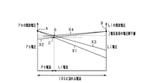
図9は、第3状態を表すものであり、両蓄電池11,12が回転電機17及び電気負荷15に電力供給を行っている。ここで、図1の第1接続点N1と回転電機17との間の配線抵抗を0とみなすと、第1接続点N1の電圧が回転電機17の入力電圧に相当する。また、リチウムイオン蓄電池12から電気負荷15に流れる電流量を0とみなしているため、図1の第2接続点N2及び第3接続点N3の電圧が電気負荷15の入力電圧に相当する。
FIG. 9 shows the third state, in which both
図9の点A−点C間の横軸方向の距離が鉛蓄電池11から回転電機17への出力電流を表し、点A−点C間の縦方向の距離が鉛蓄電池11から回転電機17まで(第1接続点N1まで)の抵抗成分による電圧降下を表し、点A−点Cを結ぶ直線X1の傾きが鉛蓄電池11から回転電機17まで(第1接続点N1まで)の抵抗成分を表している。同様に、点B−点C間の横軸方向の距離がリチウムイオン蓄電池12から回転電機17への出力電流を表し、点B−点C間の縦方向の距離がリチウムイオン蓄電池12から回転電機17まで(第1接続点N1まで)の抵抗成分による電圧降下を表し、点B−点Cを結ぶ直線X2の傾きがリチウムイオン蓄電池12から回転電機17まで(第1接続点N1まで)の抵抗成分を表している。
The horizontal distance between points A and C in FIG. 9 represents the output current from the
言い換えると、点Aを通るように、鉛蓄電池11から回転電機17までの抵抗成分に相当する傾きの直線X1を引き、点Bを通るように、リチウムイオン蓄電池12から回転電機17までの抵抗成分に相当する傾きの直線X2を引いた場合、直線X1と直線X2との交点が点Cに相当する。両蓄電池11,12から回転電機17に対して出力される電流量は、両蓄電池11、12と第1接続点N1との間の抵抗値に逆比例する。
In other words, a straight line X1 having a slope corresponding to the resistance component from the
ここで、電気負荷15に流れる電流量を0とみなしているため、鉛蓄電池11から回転電機17に対して流れる電流量と、鉛蓄電池11から第2接続点N2に流れる電流量とは、一致する。同様に、リチウムイオン蓄電池12から回転電機17に流れる電流量と、リチウムイオン蓄電池12から第3接続点N3に流れる電流量とは一致する。つまり、点A−点C間の横軸方向の距離と、点A−点D間の横軸方向の距離とは一致する。また、点B−点C間の横軸方向の距離と、点B−点D間の横軸方向の距離とは一致する。
Here, since the amount of current flowing through the
点A−点D間の縦方向の距離が鉛蓄電池11から電気負荷15まで(第2接続点N2まで)の抵抗成分による電圧降下を表し、点A−点Dを結ぶ直線X3の傾きが鉛蓄電池11から電気負荷15まで(第2接続点N2まで)の抵抗成分を表している。同様に、点B−点D間の縦方向の距離がリチウムイオン蓄電池12から電気負荷15まで(第3接続点N3まで)の抵抗成分による電圧降下を表し、点B−点Dを結ぶ直線X4の傾きがリチウムイオン蓄電池12から電気負荷15まで(第2接続点N2まで)の抵抗成分を表している。
The vertical distance between points A and D represents the voltage drop due to the resistance component from the
ここで、点A−点D間の縦方向の距離、即ち、点B−点D間の縦方向の距離である蓄電池11,12から電気負荷15までの間で生じる電圧降下によって、電気負荷15の入力電圧が電気負荷15の動作可能電圧を下回り、電気負荷15が電源失陥となることが懸念される。一般に、リチウムイオン蓄電池12の内部抵抗は、鉛蓄電池11の内部抵抗に比べて小さい。このため、第3状態において、リチウムイオン蓄電池12の出力電流を大きく、鉛蓄電池11の出力電流を小さくすることで、蓄電池11,12から電気負荷15までの間で生じる電圧降下を小さくすることができる。
Here, due to the voltage drop that occurs between the
そこで、本実施形態では、リチウムイオン蓄電池12と第1接続点N1との間(第2経路L2)の抵抗を、鉛蓄電池11と第1接続点N1との間(第1経路L1)の抵抗に比べて小さくする。これにより、第3状態におけるリチウムイオン蓄電池12の出力電流を大きく、鉛蓄電池11の出力電流を小さくする。より具体的には、第2スイッチ22を構成する並列接続された半導体スイッチング素子の数を、第1スイッチ21を構成する並列接続された半導体スイッチング素子の数より多くすることで、第2経路L2の抵抗を第1経路L1の抵抗に比べて小さくする。
Therefore, in the present embodiment, the resistance between the lithium
また、本実施形態の制御部30は、第3状態を介しての第1状態から第2状態への切り替えの際、第3状態において、第3スイッチ23における電圧を取得する。そして、制御部30は、第3スイッチ23における電圧に基づいて、第1状態から第2状態への切り替えの可否を判断する。具体的には、第3スイッチ23における電圧に基づいて、鉛蓄電池11が電気負荷15に対して電気負荷15が動作可能な出力容量を供給可能であるか否かを判定する。制御部30は、電気負荷15が動作可能な出力容量を鉛蓄電池11のみによって供給可能であると判定した場合、第3状態から第2状態への切り替えを実施する。これとは反対に、制御部30は、電気負荷15が動作可能な出力容量を鉛蓄電池11のみによって供給可能でないと判定した場合、第3状態から第2状態への切り替えを禁止し、第3状態から第1状態に戻す制御を実施する。換言すれば、制御部30は、鉛蓄電池11の出力容量が、電気負荷15が動作可能な出力容量(所定値)未満である場合、第1状態から第2状態への切り替えを禁止する。なお、制御部30が、スイッチ23に流れる電流に基づいて、鉛蓄電池11の出力容量が「所定値」未満であるかの判断(第1状態から第2状態への切り替えの可否の判断)を行う構成としてもよい。
Moreover, the
同様に、制御部30は、第3状態を介しての第2状態から第1状態への切り替えの際、第3状態において、第4スイッチ24における電圧を取得する。そして、制御部30は、スイッチ24における電圧に基づいて、第2状態から第1状態への切り替えの可否を判断する。具体的には、第4スイッチ24における電圧に基づいて、リチウムイオン蓄電池12が電気負荷15に対して電気負荷15が動作可能な出力容量を供給可能であるか否かを判定する。制御部30は、電気負荷15が動作可能な出力容量をリチウムイオン蓄電池12のみによって供給可能であると判定した場合、第3状態から第1状態への切り替えを実施する。これとは反対に、制御部30は、電気負荷15が動作可能な出力容量をリチウムイオン蓄電池12のみによって供給可能でないと判定した場合、第3状態から第1状態への切り替えを禁止し、第3状態から第2状態に戻す制御を実施する。換言すれば、制御部30は、リチウムイオン蓄電池12の出力容量が、電気負荷15が動作可能な出力容量(所定値)未満である場合、第1状態から第2状態への切り替えを禁止する。なお、制御部30が、スイッチ24に流れる電流に基づいて、リチウムイオン蓄電池12の出力容量が「所定値」未満であるかの判断(第2状態から第1状態への切り替えの可否の判断)を行う構成としてもよい。
Similarly, when switching from the second state to the first state via the third state, the
ここで、制御部30は、第3スイッチ23を構成する互いに逆方向に直列接続されたMOSFET同士の接続点の電圧(中間電圧)を第3スイッチ23の電圧として取得する。同様に、制御部30は、第4スイッチ24を構成する互いに逆方向に直列接続されたMOSFET同士の接続点の電圧(中間電圧)を第4スイッチ24の電圧として取得する。
Here, the
図10に本実施形態のスイッチ切り替え処理を表すフローチャートを示す。本処理は、制御部30が所定周期毎に実施する。
FIG. 10 shows a flowchart showing the switch switching process of this embodiment. This processing is executed by the
ステップS01において、ECU40から第1状態から第2状態への切り替え指令が入力されているか否かを判断する。ここで、ECU40は、例えば、アイドリングストップ再始動時のエンジン再始動後のEV走行開始時に第1状態から第2状態への切り替えを指令する。ECU40は、例えば、エンジン18を燃焼状態とさせるエンジン走行状態又はアシスト走行状態からEV走行状態への切り替え時においても、第1状態から第2状態への切り替えを指令する。
In step S01, it is determined whether a command to switch from the first state to the second state is input from the
第1状態から第2状態への切り替え指令が入力されている場合(S01:YES)、ステップS02において、第2スイッチ22をオン状態とする。ステップS03において、第2スイッチ22がオン状態となるまで待機する。ステップS04において、第3スイッチ23をオン状態とする。つまり、ステップS02乃至S04によって、第1状態から第3状態への切り替えを実施する。
When the instruction to switch from the first state to the second state is input (S01: YES), the
ステップS05において、第3スイッチ23の電圧を取得する。ステップS06において、スイッチ23の電圧が所定の閾値以上であるかを判定する。ここで、当該所定の閾値は、鉛蓄電池11が電気負荷15に対して、電気負荷15が動作可能な出力容量を供給可能であるか否かを判定するための閾値である。
In step S05, the voltage of the
ステップS06において、第3スイッチ23の電圧が閾値以上である場合(S06:YES)、ステップS07において、第4スイッチ24をオフ状態とする。ステップS08において、第4スイッチ24がオフ状態となるまで待機する。ステップS09において、第1スイッチ21をオフ状態とし、処理を終了する。つまり、ステップS07乃至S09によって、第3状態から第2状態への切り替えを実施する。
When the voltage of the
ステップS06において、スイッチ23の電圧が閾値未満である場合(S06:NO)、即ち、鉛蓄電池11の出力容量が所定値未満である場合、第1状態から第2状態への切り替えを禁止し、ステップS10乃至S12によって、第3状態から第1状態への切り替えを実施する。ステップS10において、第3スイッチ23をオフ状態とする。ステップS11において、第3スイッチ23がオフ状態となるまで待機する。ステップS12において、スイッチ22をオフ状態とし、処理を終了する。
In step S06, when the voltage of the
ステップS01において、ECU40から第1状態から第2状態への切り替え指令が入力されていない場合(S01:NO)、ステップS13において、EUC40から第2状態から第1状態への切り替え指令が入力されているか否かを判定する。ステップS13において、ECU40から第2状態から第1状態への切り替え指令が入力されていない場合(S13:NO)、そのまま処理を終了する。ECU40は、例えば、EV走行からエンジン走行への切り替え時に、第2状態から第1状態への切り替えを指令する。
In step S01, when the switching instruction from the first state to the second state is not input from the ECU 40 (S01: NO), the switching instruction from the second state to the first state is input from the
第2状態から第1状態への切り替え指令が入力されている場合(S13:YES)、ステップS14において、第1スイッチ21をオン状態とする。ステップS15において、第1スイッチ21がオン状態となるまで待機する。ステップS16において、第4スイッチ24をオン状態とする。つまり、ステップS14乃至S16によって、第1状態から第3状態への切り替えを実施する。
When the instruction to switch from the second state to the first state is input (S13: YES), the
ステップS17において、第4スイッチ24の電圧を取得する。ステップS18において、第4スイッチ24の電圧が所定の閾値以上であるかを判定する。ここで、当該所定の閾値は、リチウムイオン蓄電池12が電気負荷15に対して、電気負荷15が動作可能な出力容量を供給可能であるか否かを判定するための閾値である。
In step S17, the voltage of the
ステップS18において、第4スイッチ24の電圧が閾値以上である場合(S18:YES)、ステップS19において、第3スイッチ23をオフ状態とする。ステップS20において、第3スイッチ23がオフ状態となるまで待機する。ステップS21において、第2スイッチ22をオフ状態とし、処理を終了する。つまり、ステップS19乃至S21によって、第3状態から第2状態への切り替えを実施する。
When the voltage of the
ステップS18において、第4スイッチ24の電圧が閾値未満である場合(S18:NO)、即ち、リチウムイオン蓄電池12の出力容量が所定値未満である場合、第2状態から第1状態への切り替えを禁止し、ステップS22乃至S24によって、第3状態から第2状態への切り替えを実施する。ステップS22において、第4スイッチ24をオフ状態とする。ステップS23において、第4スイッチ24がオフ状態となるまで待機する。ステップS24において、第1スイッチ21をオフ状態とし、処理を終了する。
In step S18, when the voltage of the
(他の実施形態)
・「第1電源」は鉛蓄電池以外であってもよく、「第2電源」はリチウムイオン蓄電池以外であってもよい。例えば、「第1電源」と「第2電源」とがともに鉛蓄電池であってもよいし、ともにリチウムイオン蓄電池であってもよい。また、ニッケル水素蓄電池などの他の種類の蓄電池であってもよい。また、「第1電源」及び「第2電源」は、例えば、DCDCコンバータなどであってもよい。
(Other embodiments)
The "first power supply" may be other than the lead storage battery, and the "second power supply" may be other than the lithium ion storage battery. For example, both the “first power source” and the “second power source” may be lead storage batteries, or both may be lithium ion storage batteries. Further, it may be another type of storage battery such as a nickel hydrogen storage battery. The “first power supply” and the “second power supply” may be, for example, a DCDC converter.
・バイパススイッチ25,26を省略する構成であってもよい。また、バイパススイッチ25,26として半導体スイッチを採用してもよい。 The bypass switches 25 and 26 may be omitted. Further, semiconductor switches may be used as the bypass switches 25 and 26.
・第1〜第4スイッチ21〜24として、MOSFETに代えて、IGBTなどを用いてもよい。なお、第1〜第4スイッチ21〜24としてIGBTを採用する場合、カソード電極同士、又は、アノード電極同士が互いに接続されている一組のダイオードが、対応する第1〜第4スイッチ21〜24それぞれに並列接続される構成とするとよい。
-As the 1st-4th switches 21-24, you may use IGBT etc. instead of MOSFET. When the IGBT is adopted as the first to
さらに言えば、第1〜第4スイッチ21〜24としては半導体スイッチング素子に限定されない。オンからオフへ、オフからオンへのスイッチの状態切り替え速さが、停車からEV走行への切り替えなどの車両の走行状態の切り替えなどに対応することができるのであれば、第1〜第4スイッチ21〜24としては例えば機械式のリレースイッチを用いてもよい。
Furthermore, the first to
・第3スイッチ23において、第3経路L3が常に遮断状態となる常時開異常が生じている場合や、第3経路L3における断線が生じた場合、第3経路L3及び第3スイッチ23の代わりに、第2バイパス経路L6及び第2バイパススイッチ26を用いることができる。ここで、第2バイパス経路L6を「第3経路」とみなし、第2バイパススイッチ26を「第3スイッチ」とみなす。そして、制御部30が、第3スイッチ23における制御と同様の制御を第2バイパススイッチ26に実施することで、電気負荷15における電力の瞬断や、第4経路L4及び第2バイパス経路L6を介して大電流が流れることを抑制できる。これにより、第2バイパス経路L6の許容電流量が、第1経路L1及び第2経路L2に比べて小さい場合における第2バイパス経路L6の損傷を抑制することができる。
In the
・上記実施形態では、電池ユニットUは、その収容ケースの内部に、第1経路L1〜第4経路L4、第1スイッチ21〜第4スイッチ24、「第2電源」としてのリチウムイオン蓄電池12、及び、「制御装置」としての制御部30を備え、一体化されている構成とした。この一体化の構成を省略してもよい。即ち、第1経路L1〜第4経路L4、第1スイッチ21〜第4スイッチ24、リチウムイオン蓄電池12、及び、制御部30は、一体化されていなくてもよい。
-In the said embodiment, the battery unit U has the 1st path|route L1-the 4th path|route L4, the 1st switch 21-the
例えば、一部の構成のみが一体化されている構成であってもよい。具体的には、第1経路L1〜第4経路L4、第1スイッチ21〜第4スイッチ24、及び、制御部30を内部に備えるスイッチユニットを設け、当該スイッチユニットに対して、鉛蓄電池11、リチウムイオン蓄電池12、電気負荷15、及び、回転電機17を接続する構成としてもよい。
For example, it may be a configuration in which only some of the components are integrated. Specifically, a switch unit including the first path L1 to the fourth path L4, the
・上記実施形態における制御部30は、各蓄電池11,12のSOC(残存容量)に基づいて、スイッチ21〜26の状態の切り替えを実施するとともに、ECU40の指令に基づいて、スイッチ21〜26の状態の切り替えを実施する構成とした。これを変更し、制御部30から、ECU40の指令に基づいてスイッチ21〜26の切り替えを実施する構成を省略してもよい。当該構成では、制御部30が、回転電機17から、回転電機17が回生動作を行っているか、力行動作を行っているか、又は、停止しているかに係る情報(回転電機17の動作状態)を取得する構成とするとよい。即ち、制御部30は、各蓄電池11,12のSOC(残存容量)に加え、回転電機17の動作状態を取得し、その取得した情報に基づいて、スイッチ21〜26の状態の切り替えを実施する構成とするとよい。また、制御部30が、ECU40の機能の一部である回転電機17の制御機能を有する構成としてもよい。また、制御部30は、ECU40以外の制御装置、例えば、回転電機17の制御機能のみを有する制御装置の指令に基づいて、スイッチ21〜26の状態の切り替えを実施する構成であってもよい。
The
また、各蓄電池11,12のSOC(残存容量)に基づいて、スイッチ21〜26の状態の切り替えを実施する構成を、制御部30から省略してもよい。即ち、ECU40などの制御部30以外の制御装置が、各蓄電池11,12のSOC(残存容量)を取得し、その取得値に基づいて、制御部30に対してスイッチ21〜26の状態の切り替えを指令するようなものであってもよい。
In addition, the configuration that switches the states of the
制御部30以外の制御装置からの指令に基づいて、制御部30がスイッチ21〜26の状態を切り替える構成では、他の制御装置から制御部30に対してスイッチ21〜26を第1状態と第2状態との間で切り替える指令がなされた場合に、制御部30が第3状態を介して第1状態と第2状態との切り替えを実施する構成とするとよい。さらに、制御部30は、第1状態と第2状態との切り替え時において、第1〜第4スイッチ21〜24のうち、第1スイッチ21のみがオフとされている状態や、第2スイッチ22のみがオフとされている状態が生じないように第1〜第4スイッチ21〜24の切り替えを行うとよい。
In the configuration in which the
11…鉛蓄電池(第1電源)、12…リチウムイオン蓄電池(第2電源)、15…電気負荷(第2電気負荷)、17…回転電機(第1電気負荷)、21…第1スイッチ、22…第2スイッチ、23…第3スイッチ、24…第4スイッチ、30…制御部(制御装置)、L1…第1経路、L2…第2経路、L3…第3経路、L4…第4経路。 11... Lead storage battery (first power supply), 12... Lithium ion storage battery (second power supply), 15... Electric load (second electric load), 17... Rotating electric machine (first electric load), 21... First switch, 22 ... 2nd switch, 23... 3rd switch, 24... 4th switch, 30... Control part (control device), L1... 1st path, L2... 2nd path, L3... 3rd path, L4... 4th path.
Claims (13)
前記第1電源から前記第1電気負荷に電力供給する第1経路(L1)に設けられた第1スイッチ(21)と、前記第2電源から前記第1電気負荷に電力供給する第2経路(L2)に設けられた第2スイッチ(22)と、前記第1電源から前記第2電気負荷に電力供給する第3経路(L3)に設けられた第3スイッチ(23)と、前記第2電源から前記第2電気負荷に電力供給する第4経路(L4)に設けられた第4スイッチ(24)と、を備え、前記第1〜前記第4スイッチにより前記第1〜前記第4経路をそれぞれ独立して開閉可能である電源システムに含まれ、前記第1〜前記第4スイッチの開閉制御を実施するスイッチ制御装置(30)であって、
前記第1スイッチ及び前記第4スイッチをオン状態、前記第2スイッチ及び前記第3スイッチをオフ状態とする第1状態から、前記第2スイッチ及び前記第3スイッチをオン状態、前記第1スイッチ及び前記第4スイッチをオフ状態とする第2状態へ切り替える際、前記第1状態から、前記第1スイッチ、前記第2スイッチ、前記第3スイッチ、及び前記第4スイッチを全てオン状態とする第3状態へ切り替えた後、前記第2状態へと切り替える制御を実施し、
前記第1電気負荷の消費電流量は、前記第2電気負荷の消費電流量より大きく、
前記第2スイッチは、前記第3スイッチ及び前記第4スイッチに比べて、許容電流量が大きいものであり、
前記第1状態から前記第3状態へ切り替える際、前記第2スイッチ及び前記第3スイッチを同時にオン状態とするか、又は、前記第3スイッチより先に前記第2スイッチをオン状態にするスイッチ制御装置。 A first power supply (11) and a second power supply (12) are provided, and power is supplied from at least one of the first power supply and the second power supply to the first electric load (17) and the second electric load (15). Supply
A first switch (21) provided in a first path (L1) for supplying power from the first power supply to the first electric load, and a second path (21) for supplying power from the second power supply to the first electric load ( A second switch (22) provided in L2), a third switch (23) provided in a third path (L3) for supplying power from the first power supply to the second electric load, and the second power supply A fourth switch (24) provided on a fourth path (L4) for supplying electric power to the second electric load from the first to the fourth switches, respectively. A switch control device (30) included in a power supply system that can be opened and closed independently, for performing opening and closing control of the first to fourth switches,
From the first state in which the first switch and the fourth switch are turned on and the second switch and the third switch are turned off, the second switch and the third switch are turned on, the first switch and A third state in which all of the first switch, the second switch, the third switch, and the fourth switch are turned on from the first state when switching to the second state where the fourth switch is turned off After switching to the state, control is performed to switch to the second state,
The current consumption of the first electric load is larger than the current consumption of the second electric load,
The second switch has a larger allowable current amount than the third switch and the fourth switch,
Switch control for turning on the second switch and the third switch at the same time when switching from the first state to the third state, or for turning on the second switch before the third switch apparatus.
前記第3状態から前記第2状態へ切り替える際、前記第1スイッチ及び前記第4スイッチを同時にオフ状態とするか、又は、前記第1スイッチより先に前記第4スイッチをオフ状態にする請求項1に記載のスイッチ制御装置。 The first switch has a larger allowable current amount than the third switch and the fourth switch,
When switching from the third state to the second state, the first switch and the fourth switch are simultaneously turned off, or the fourth switch is turned off before the first switch. 1. The switch control device according to 1.
前記第1電源から前記第1電気負荷に電力供給する第1経路(L1)に設けられた第1スイッチ(21)と、前記第2電源から前記第1電気負荷に電力供給する第2経路(L2)に設けられた第2スイッチ(22)と、前記第1電源から前記第2電気負荷に電力供給する第3経路(L3)に設けられた第3スイッチ(23)と、前記第2電源から前記第2電気負荷に電力供給する第4経路(L4)に設けられた第4スイッチ(24)と、を備え、前記第1〜前記第4スイッチにより前記第1〜前記第4経路をそれぞれ独立して開閉可能である電源システムに含まれ、前記第1〜前記第4スイッチの開閉制御を実施するスイッチ制御装置(30)であって、
前記第1スイッチ及び前記第4スイッチをオン状態、前記第2スイッチ及び前記第3スイッチをオフ状態とする第1状態から、前記第2スイッチ及び前記第3スイッチをオン状態、前記第1スイッチ及び前記第4スイッチをオフ状態とする第2状態へ切り替える際、前記第1状態から、前記第1スイッチ、前記第2スイッチ、前記第3スイッチ、及び前記第4スイッチを全てオン状態とする第3状態へ切り替えた後、前記第2状態へと切り替える制御を実施し、
前記第1電気負荷の消費電流量は、前記第2電気負荷の消費電流量より大きく、
前記第1スイッチは、前記第3スイッチ及び前記第4スイッチに比べて、許容電流量が大きいものであり、
前記第3状態から前記第2状態へ切り替える際、前記第1スイッチ及び前記第4スイッチを同時にオフ状態とするか、又は、前記第1スイッチより先に前記第4スイッチをオフ状態にするスイッチ制御装置。 A first power supply (11) and a second power supply (12) are provided, and power is supplied from at least one of the first power supply and the second power supply to the first electric load (17) and the second electric load (15). Supply
A first switch (21) provided in a first path (L1) for supplying power from the first power supply to the first electric load, and a second path (21) for supplying power from the second power supply to the first electric load ( A second switch (22) provided in L2), a third switch (23) provided in a third path (L3) for supplying power from the first power supply to the second electric load, and the second power supply A fourth switch (24) provided on a fourth path (L4) for supplying electric power to the second electric load from the first to the fourth switches, respectively. A switch control device (30) included in a power supply system that can be opened and closed independently, for performing opening and closing control of the first to fourth switches,
From the first state in which the first switch and the fourth switch are turned on and the second switch and the third switch are turned off, the second switch and the third switch are turned on, the first switch and A third state in which all of the first switch, the second switch, the third switch, and the fourth switch are turned on from the first state when switching to the second state where the fourth switch is turned off After switching to the state, control is performed to switch to the second state,
The current consumption of the first electric load is larger than the current consumption of the second electric load,
The first switch has a larger allowable current amount than the third switch and the fourth switch,
Switch control for turning off the first switch and the fourth switch at the same time when switching from the third state to the second state, or for turning off the fourth switch before the first switch apparatus.
前記第2電源の内部抵抗は、前記第1電源の内部抵抗に比べて小さいものであって、
前記第2経路の抵抗は、前記第1経路の抵抗に比べて小さい請求項1乃至3のいずれか1項に記載のスイッチ制御装置。 The first power source and the second power source are both storage batteries,
The internal resistance of the second power supply is smaller than the internal resistance of the first power supply,
The switch control device according to claim 1, wherein the resistance of the second path is smaller than the resistance of the first path.
前記第2スイッチを構成する並列接続された前記半導体スイッチング素子の数が、前記第1スイッチを構成する並列接続された前記半導体スイッチング素子の数より多いことで、前記第2経路の抵抗は、前記第1経路の抵抗に比べて小さい請求項4に記載のスイッチ制御装置。 Each of the first switch and the second switch is configured by connecting a plurality of semiconductor switching elements in parallel,
Since the number of the semiconductor switching elements that are connected in parallel that configure the second switch is greater than the number of the semiconductor switching elements that are connected in parallel that configure the first switch, the resistance of the second path is The switch control device according to claim 4, wherein the resistance is smaller than the resistance of the first path.
前記スイッチ制御装置は、前記スイッチ制御装置以外の制御装置の指令に応じて、前記第1状態から前記第2状態への切り替えを実施する請求項8又は9に記載のスイッチ制御装置。 The power supply system is mounted on a vehicle and has a control device (40) other than the switch control device,
The switch control device according to claim 8 or 9, wherein the switch control device switches from the first state to the second state in response to a command from a control device other than the switch control device.
前記スイッチ制御装置以外の制御装置は、
前記エンジン及び前記回転電機のうち前記エンジン及び前記回転電機に駆動力を分担させる第1走行状態と、前記エンジン及び前記回転電機のうち前記回転電機のみに駆動力を負担させる第2走行状態とを、前記車両の走行状態に基づいて切り替える走行用制御装置(40)であって、
前記第1走行状態から前記第2走行状態への切り替えを実施する場合に、前記制御装置に対し、前記第1状態から前記第2状態への切り替えを指令する請求項10に記載のスイッチ制御装置。 The vehicle has an engine (18),
The control device other than the switch control device,
A first running state in which the engine and the rotary electric machine share the driving force among the engine and the rotary electric machine; and a second running state in which the driving power is shared only in the rotary electric machine among the engine and the rotary electric machine. A traveling control device (40) for switching based on a traveling state of the vehicle,
The switch control device according to claim 10, wherein when the switching from the first traveling state to the second traveling state is performed, the control device is instructed to switch from the first state to the second state. ..
前記第1〜前記第4経路と、前記第1〜前記第4スイッチと、を内部に備え、前記第1〜前記第4スイッチにより前記第1〜前記第4経路をそれぞれ独立して開閉可能である電源ユニット(U)であって、
請求項1乃至11のいずれか1項に記載の前記スイッチ制御装置を内部に備える電源ユニット。 The second power source is connected to the first power source and the second power source is provided inside, and power is supplied from at least one of the first power source and the second power source to the first electrical load and the second electrical load. Then
The first to the fourth paths and the first to the fourth switches are provided inside, and the first to the fourth paths can independently open and close the first to the fourth paths. A power supply unit (U),
A power supply unit comprising the switch control device according to any one of claims 1 to 11 therein.
前記第1〜前記第4経路と、前記第1〜前記第4スイッチと、を備え、前記第1〜前記第4スイッチにより前記第1〜前記第4経路をそれぞれ独立して開閉可能である電源システムであって、
請求項1乃至11のいずれか1項に記載の前記スイッチ制御装置を備える電源システム。 The first power supply and the second power supply, and supplies power to the first electric load and the second electric load from at least one of the first power supply and the second power supply,
A power supply comprising the first to fourth paths and the first to fourth switches, and the first to fourth switches can independently open and close the first to fourth paths, respectively. A system,
A power supply system comprising the switch control device according to claim 1.
Priority Applications (1)
| Application Number | Priority Date | Filing Date | Title |
|---|---|---|---|
| JP2016178963A JP6724675B2 (en) | 2016-09-13 | 2016-09-13 | Switch control device, power supply unit and power supply system |
Applications Claiming Priority (1)
| Application Number | Priority Date | Filing Date | Title |
|---|---|---|---|
| JP2016178963A JP6724675B2 (en) | 2016-09-13 | 2016-09-13 | Switch control device, power supply unit and power supply system |
Publications (2)
| Publication Number | Publication Date |
|---|---|
| JP2018046635A JP2018046635A (en) | 2018-03-22 |
| JP6724675B2 true JP6724675B2 (en) | 2020-07-15 |
Family
ID=61696136
Family Applications (1)
| Application Number | Title | Priority Date | Filing Date |
|---|---|---|---|
| JP2016178963A Active JP6724675B2 (en) | 2016-09-13 | 2016-09-13 | Switch control device, power supply unit and power supply system |
Country Status (1)
| Country | Link |
|---|---|
| JP (1) | JP6724675B2 (en) |
Families Citing this family (2)
| Publication number | Priority date | Publication date | Assignee | Title |
|---|---|---|---|---|
| JP6765392B2 (en) | 2018-02-05 | 2020-10-07 | 株式会社デンソーテン | Power control device and power control method |
| JP7021661B2 (en) * | 2019-04-12 | 2022-02-17 | 株式会社デンソー | Power supply controller |
Family Cites Families (2)
| Publication number | Priority date | Publication date | Assignee | Title |
|---|---|---|---|---|
| JP6244987B2 (en) * | 2014-03-05 | 2017-12-13 | 株式会社デンソー | Power system |
| JP6380171B2 (en) * | 2015-03-06 | 2018-08-29 | 株式会社デンソー | Power system |
-
2016
- 2016-09-13 JP JP2016178963A patent/JP6724675B2/en active Active
Also Published As
| Publication number | Publication date |
|---|---|
| JP2018046635A (en) | 2018-03-22 |
Similar Documents
| Publication | Publication Date | Title |
|---|---|---|
| US10059286B2 (en) | Electric power source system | |
| JP6221796B2 (en) | Battery unit and power supply system | |
| JP6090199B2 (en) | Battery unit | |
| JP6260422B2 (en) | Battery unit | |
| WO2018088111A1 (en) | Power supply control apparatus and battery unit | |
| JP6244987B2 (en) | Power system | |
| JP6090195B2 (en) | Battery unit | |
| CN110192320B (en) | Power supply device and power supply system | |
| WO2017043641A1 (en) | Power source apparatus | |
| JP6406328B2 (en) | Power supply device and battery unit | |
| JPWO2016181495A1 (en) | Power system | |
| JP2016187236A (en) | Battery system control device | |
| JP6903951B2 (en) | Power system | |
| JP6724675B2 (en) | Switch control device, power supply unit and power supply system | |
| WO2018061681A1 (en) | Power supply system and battery unit | |
| JP2018139462A (en) | Power unit | |
| JP6696401B2 (en) | Power supply | |
| CN110167776B (en) | Battery unit and power supply system | |
| WO2020209132A1 (en) | Control device for power supply device | |
| JP7098911B2 (en) | Power system | |
| JP2016220427A (en) | Power supply device | |
| WO2017065161A1 (en) | Power supply device and cell unit | |
| JP6260728B2 (en) | Battery unit | |
| JP7073619B2 (en) | Power control unit, battery unit and power system | |
| WO2018131367A1 (en) | Power supply device and power supply system |
Legal Events
| Date | Code | Title | Description |
|---|---|---|---|
| A621 | Written request for application examination |
Free format text: JAPANESE INTERMEDIATE CODE: A621 Effective date: 20190618 |
|
| A977 | Report on retrieval |
Free format text: JAPANESE INTERMEDIATE CODE: A971007 Effective date: 20200514 |
|
| TRDD | Decision of grant or rejection written | ||
| A01 | Written decision to grant a patent or to grant a registration (utility model) |
Free format text: JAPANESE INTERMEDIATE CODE: A01 Effective date: 20200526 |
|
| A61 | First payment of annual fees (during grant procedure) |
Free format text: JAPANESE INTERMEDIATE CODE: A61 Effective date: 20200608 |
|
| R151 | Written notification of patent or utility model registration |
Ref document number: 6724675 Country of ref document: JP Free format text: JAPANESE INTERMEDIATE CODE: R151 |
|
| R250 | Receipt of annual fees |
Free format text: JAPANESE INTERMEDIATE CODE: R250 |