JP6793011B2 - Vehicle suspension structure - Google Patents

Vehicle suspension structure Download PDF

Info

Publication number
JP6793011B2
JP6793011B2 JP2016217092A JP2016217092A JP6793011B2 JP 6793011 B2 JP6793011 B2 JP 6793011B2 JP 2016217092 A JP2016217092 A JP 2016217092A JP 2016217092 A JP2016217092 A JP 2016217092A JP 6793011 B2 JP6793011 B2 JP 6793011B2
Authority
JP
Japan
Prior art keywords
state
vibration
axis
bush
shaft member
Prior art date
Legal status (The legal status is an assumption and is not a legal conclusion. Google has not performed a legal analysis and makes no representation as to the accuracy of the status listed.)
Active
Application number
JP2016217092A
Other languages
Japanese (ja)
Other versions
JP2018076882A (en
Inventor
上田 健
健 上田
Current Assignee (The listed assignees may be inaccurate. Google has not performed a legal analysis and makes no representation or warranty as to the accuracy of the list.)
Toyo Tire Corp
Original Assignee
Toyo Tire Corp
Priority date (The priority date is an assumption and is not a legal conclusion. Google has not performed a legal analysis and makes no representation as to the accuracy of the date listed.)
Filing date
Publication date
Application filed by Toyo Tire Corp filed Critical Toyo Tire Corp
Priority to JP2016217092A priority Critical patent/JP6793011B2/en
Publication of JP2018076882A publication Critical patent/JP2018076882A/en
Application granted granted Critical
Publication of JP6793011B2 publication Critical patent/JP6793011B2/en
Active legal-status Critical Current
Anticipated expiration legal-status Critical

Links

Images

Landscapes

  • Vehicle Body Suspensions (AREA)
  • Springs (AREA)

Description

本発明は車両のサスペンション構造に関し、特に乗り心地を向上できる車両のサスペンション構造に関するものである。 The present invention relates to a vehicle suspension structure, and more particularly to a vehicle suspension structure capable of improving riding comfort.

車輪を回転可能に支持する車輪支持部材と車体との間に配置されるリンクを車輪支持部材や車体に取り付けるときに防振ブッシュが使われる。防振ブッシュは軸部材と筒部材とをゴム弾性体が結合する非線形特性ばねである。特許文献1には、車両の乗り心地向上のため、走行時に生じる特定の荷重によってゴム弾性体が圧縮される部分にすぐりを設ける技術が開示されている。 Anti-vibration bushes are used when attaching a link arranged between a wheel support member that rotatably supports a wheel and a vehicle body to the wheel support member or the vehicle body. The anti-vibration bush is a non-linear characteristic spring in which a rubber elastic body connects a shaft member and a tubular member. Patent Document 1 discloses a technique of providing a stirrup at a portion where a rubber elastic body is compressed by a specific load generated during traveling in order to improve the riding comfort of a vehicle.

特開2005−249022号公報Japanese Unexamined Patent Publication No. 2005-249022

しかし、非線形特性ばねである防振ブッシュは、車輪に接地荷重が作用した状態では、荷重−たわみ曲線において線形領域から非線形領域へと変化し易くなるので、さらに荷重が入力されると、ばねが硬くなり易い。その結果、リンクを介して車輪から車体へ振動が伝わり易くなるので、乗り心地が低下し易いという問題点がある。 However, the anti-vibration bush, which is a non-linear characteristic spring, tends to change from the linear region to the non-linear region in the load-deflection curve when a ground contact load is applied to the wheel. Therefore, when a further load is input, the spring becomes It tends to be hard. As a result, vibration is easily transmitted from the wheels to the vehicle body via the link, so that there is a problem that the riding comfort is likely to be lowered.

本発明は上述した問題点を解決するためになされたものであり、乗り心地を向上できる車両のサスペンション構造を提供することを目的としている。 The present invention has been made to solve the above-mentioned problems, and an object of the present invention is to provide a suspension structure of a vehicle capable of improving riding comfort.

課題を解決するための手段および発明の効果Means for Solving Problems and Effects of Invention

この目的を達成するために請求項1記載の車両のサスペンション構造によれば、車輪を回転可能に支持する車輪支持部材と車体との間にリンクが配置され、車輪支持部材や車体とリンクとを防振ブッシュが結合する。防振ブッシュは軸部材の径方向の外側に筒部材が配置され、筒部材の内周面と軸部材の外周面とをゴム弾性体が結合する。 According to the suspension structure of the vehicle according to claim 1 in order to achieve this object, a link is arranged between the wheel support member that rotatably supports the wheel and the vehicle body, and the wheel support member or the vehicle body and the link are connected. The anti-vibration bush is combined. In the anti-vibration bush, a tubular member is arranged on the outer side in the radial direction of the shaft member, and a rubber elastic body connects the inner peripheral surface of the tubular member and the outer peripheral surface of the shaft member.

防振ブッシュは、車輪に接地荷重が作用しない第1状態から車輪に接地荷重が作用する第2状態への推移に伴い、軸部材の軸線の方向と直交する第1方向に荷重が作用する。防振ブッシュは、第1状態から第2状態への推移に伴い、第1方向の荷重に対する荷重−たわみ曲線において、線形領域の中央に近づく。その結果、第2状態では防振ブッシュの線形特性を確保できる。防振ブッシュの軟らかいばね特性によって、通常の走行時に車輪から車体へ入力される振動を減衰できるので、乗り心地を向上できる効果がある。 In the anti-vibration bush, the load acts in the first direction orthogonal to the axial direction of the shaft member as the transition from the first state in which the ground contact load does not act on the wheels to the second state in which the ground contact load acts on the wheels. The anti-vibration bush approaches the center of the linear region in the load-deflection curve with respect to the load in the first direction as the transition from the first state to the second state. As a result, the linear characteristics of the anti-vibration bush can be ensured in the second state. Due to the soft spring characteristics of the anti-vibration bush, the vibration input from the wheels to the vehicle body during normal driving can be dampened, which has the effect of improving ride comfort.

振ブッシュは、ゴム弾性体のうち第2状態において圧縮される第1部の第1方向における厚さが、ゴム弾性体のうち第2状態において引っ張られる第2部の第1方向における厚さよりも厚い。ゴム弾性体の第1方向における厚さを利用して防振ブッシュの線形領域を確保するので、防振ブッシュの製造を容易にできる効果がある。 Vibration isolating bushing has a thickness in a first direction of the first portion is compressed in the second state of the rubber elastic body, than the thickness in the first direction of the second part is pulled in the second state of the rubber elastic body Is also thick. Since by utilizing the thickness in the first direction of the rubber elastic body to secure the linear region of the vibration damping bushing, there is an effect of the production of anti-vibration bushes easily.

請求項3記載の車両のサスペンション構造によれば、防振ブッシュは、第1状態から第2状態への推移に伴い、軸部材の軸線の位置が筒部材の軸線の位置に近づく。従って防振ブッシュは、筒部材の軸線の位置に対して軸部材の軸線の位置をずらすことにより、第1方向におけるゴム弾性体の厚さが設定される。よって、請求項1又は2の効果に加え、防振ブッシュの製造をさらに容易にできる効果がある。 According to the suspension structure of the vehicle according to claim 3, the position of the axis of the shaft member of the anti-vibration bush approaches the position of the axis of the tubular member as the state changes from the first state to the second state. Therefore, in the anti-vibration bush, the thickness of the rubber elastic body in the first direction is set by shifting the position of the axis of the shaft member with respect to the position of the axis of the cylinder member. Therefore, in addition to the effect of claim 1 or 2, there is an effect that the production of the vibration-proof bushing can be further facilitated.

請求項4記載の車両のサスペンション構造によれば、防振ブッシュは、第1方向に位置するゴム弾性体の軸方向の長さが、軸部材の軸線の方向と第1方向とに直交する第2方向に位置するゴム弾性体の軸方向の長さよりも短い。その結果、防振ブッシュに第1方向の荷重が作用するときのコンプライアンスを増加できるので、請求項1から3のいずれかの効果に加え、乗り心地を向上できる効果がある。 According to the vehicle suspension structure according to claim 4, in the anti-vibration bush, the axial length of the rubber elastic body located in the first direction is orthogonal to the axial direction of the shaft member and the first direction. It is shorter than the axial length of the rubber elastic body located in two directions. As a result, the compliance when the load in the first direction acts on the anti-vibration bush can be increased, so that there is an effect of improving the riding comfort in addition to the effect of any one of claims 1 to 3.

本発明の第1実施の形態におけるサスペンション構造の模式図である。It is a schematic diagram of the suspension structure in the 1st Embodiment of this invention. 車輪に接地荷重が作用しない第1状態における防振ブッシュの正面図である。It is a front view of the anti-vibration bush in the 1st state that the ground load does not act on a wheel. 図2のIII−III線における防振ブッシュの断面図である。It is sectional drawing of the anti-vibration bush in line III-III of FIG. 図2のIV−IV線における防振ブッシュの断面図である。It is sectional drawing of the vibration isolation bush in line IV-IV of FIG. 車輪に接地荷重が作用する第2状態における防振ブッシュの正面図である。It is a front view of the anti-vibration bush in the 2nd state in which a ground load acts on a wheel. 図5のVI−VI線における防振ブッシュの断面図である。It is sectional drawing of the anti-vibration bush in the VI-VI line of FIG. (a)は第1状態における防振ブッシュの模式図であり、(b)は第2状態における防振ブッシュの模式図であり、(c)は防振ブッシュの荷重−たわみ曲線である。(A) is a schematic diagram of the vibration-proof bush in the first state, (b) is a schematic diagram of the vibration-proof bush in the second state, and (c) is a load-deflection curve of the vibration-proof bush. (a)は第1状態における従来の防振ブッシュの模式図であり、(b)は第2状態における従来の防振ブッシュの模式図であり、(c)は防振ブッシュの荷重−たわみ曲線である。(A) is a schematic diagram of a conventional anti-vibration bush in the first state, (b) is a schematic diagram of a conventional anti-vibration bush in the second state, and (c) is a load-deflection curve of the anti-vibration bush. Is. 第2実施の形態におけるサスペンション構造に設けられる防振ブッシュの正面図である。It is a front view of the anti-vibration bush provided in the suspension structure in 2nd Embodiment. 図9のX−X線における防振ブッシュの断面図である。It is sectional drawing of the anti-vibration bush in line XX of FIG. 図9のXI−XI線における防振ブッシュの断面図である。It is sectional drawing of the vibration-proof bush in line XI-XI of FIG.

以下、本発明の好ましい実施形態について添付図面を参照して説明する。図1は本発明の第1実施の形態におけるサスペンション構造10の模式図である。図1では、車両の右後輪の部分が図示されている。本実施の形態におけるサスペンション構造10はマルチリンク式サスペンションであり、車軸11に車輪12が結合し、アクスルハウジング13が車輪12を支持する。アクスルハウジング13は、車輪12を回転可能に支持する車輪支持部材である。 Hereinafter, preferred embodiments of the present invention will be described with reference to the accompanying drawings. FIG. 1 is a schematic view of the suspension structure 10 according to the first embodiment of the present invention. In FIG. 1, the right rear wheel portion of the vehicle is illustrated. The suspension structure 10 in the present embodiment is a multi-link suspension, in which the wheels 12 are coupled to the axle 11 and the axle housing 13 supports the wheels 12. The axle housing 13 is a wheel support member that rotatably supports the wheels 12.

アクスルハウジング13は、第1リンク21から第5リンク25によって車体20に対して移動可能に位置決めされている。第1リンク21は、防振ブッシュ30を介してアクスルハウジング13の上部に連結されると共に、防振ブッシュ31を介して車体20に連結されている。第2リンク22は、防振ブッシュ(図示せず)を介してアクスルハウジング13の上部に連結されると共に、防振ブッシュ32を介して車体20に連結されている。第3リンク23は、防振ブッシュ(図示せず)を介してアクスルハウジング13の中央部に連結されると共に、防振ブッシュ33を介して車体20に連結されている。 The axle housing 13 is movably positioned with respect to the vehicle body 20 by the first link 21 to the fifth link 25. The first link 21 is connected to the upper part of the axle housing 13 via the vibration-proof bush 30 and is connected to the vehicle body 20 via the vibration-proof bush 31. The second link 22 is connected to the upper part of the axle housing 13 via a vibration-proof bush (not shown) and is connected to the vehicle body 20 via a vibration-proof bush 32. The third link 23 is connected to the central portion of the axle housing 13 via a vibration-proof bush (not shown) and is connected to the vehicle body 20 via a vibration-proof bush 33.

第4リンク24は、防振ブッシュ34を介してアクスルハウジング13の下部に連結されると共に、防振ブッシュ35を介して車体20に連結されている。第5リンク25は、防振ブッシュ36を介してアクスルハウジング13の下部に連結されると共に、防振ブッシュ(図示せず)を介して車体20に連結されている。第4リンク24は、車体20に連結されたショックアブソーバ26に組み付けられたコイルスプリング27によって下方に付勢されている。 The fourth link 24 is connected to the lower part of the axle housing 13 via the anti-vibration bush 34 and is connected to the vehicle body 20 via the anti-vibration bush 35. The fifth link 25 is connected to the lower part of the axle housing 13 via a vibration-proof bush 36, and is also connected to the vehicle body 20 via a vibration-proof bush (not shown). The fourth link 24 is urged downward by a coil spring 27 assembled to a shock absorber 26 connected to the vehicle body 20.

サスペンション構造10は、車輪12に接地荷重が作用しない状態(以下「第1状態」と称す)から車輪12に接地荷重が作用する状態(以下「第2状態」と称す)へ推移すると、車体20に対して車輪12が鉛直上側へ回転するモーメントMが作用する。このときは、リンクを介して防振ブッシュ30〜36に径方向の荷重が作用する。これらの防振ブッシュ30〜36を代表して、防振ブッシュ30について説明する。 When the suspension structure 10 changes from a state in which a ground contact load does not act on the wheels 12 (hereinafter referred to as "first state") to a state in which a ground contact load acts on the wheels 12 (hereinafter referred to as "second state"), the vehicle body 20 A moment M in which the wheel 12 rotates vertically upward acts on the wheel 12. At this time, a radial load acts on the anti-vibration bushes 30 to 36 via the link. The anti-vibration bush 30 will be described on behalf of these anti-vibration bushes 30 to 36.

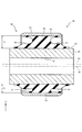
図2は、車輪12に接地荷重が作用しない第1状態における防振ブッシュ30の正面図である。防振ブッシュ30は、軸部材40と、軸部材40の径方向の外側に配置される筒部材50と、筒部材50と軸部材40とを結合するゴム弾性体60とを備えている。 FIG. 2 is a front view of the vibration isolator bush 30 in the first state in which no ground contact load acts on the wheels 12. The anti-vibration bush 30 includes a shaft member 40, a tubular member 50 arranged on the outer side in the radial direction of the shaft member 40, and a rubber elastic body 60 that connects the tubular member 50 and the shaft member 40.

軸部材40は、軸線41を中心とする断面円形の穴部42が軸線41に沿って貫通する金属製の部材である。軸部材40は、軸線41の方向(図2紙面垂直方向)に亘って、軸線41と外周面43との距離が同一の円筒状に形成されている。軸線41と直交する断面において、軸部材40の外周面43は軸線41を中心とする円形である。軸部材40は、穴部42に挿通されたボルト(図示せず)が、アクスルハウジング13(図1参照)に設けられたブラケット(図示せず)に固定されることにより、車両の略前後方向(図1紙面垂直方向)へ軸線41を向けてアクスルハウジング13に取り付けられる。 The shaft member 40 is a metal member through which a hole 42 having a circular cross section centered on the axis 41 penetrates along the axis 41. The shaft member 40 is formed in a cylindrical shape having the same distance between the shaft line 41 and the outer peripheral surface 43 over the direction of the axis line 41 (direction perpendicular to the paper surface in FIG. 2). In the cross section orthogonal to the axis 41, the outer peripheral surface 43 of the shaft member 40 is a circle centered on the axis 41. The shaft member 40 has a bolt (not shown) inserted through the hole 42 fixed to a bracket (not shown) provided in the axle housing 13 (see FIG. 1) in a substantially front-rear direction of the vehicle. It is attached to the axle housing 13 with the axis 41 facing (FIG. 1, vertical direction on the paper).

筒部材50は、軸部材40よりも直径が大きく軸部材40よりも薄肉の金属製の部材である。筒部材50は、軸線51の方向(図2紙面垂直方向)の長さが、軸部材40の軸線41の方向の長さより小さく設定されている。筒部材50は、軸線51の方向に亘って、軸線51と内周面52との距離が同一の円筒状に形成されている。軸線51と直交する断面において、筒部材50の内周面52は軸線51を中心とする円形である。筒部材50は、第1リンク21(図1参照)に圧入されることにより、車両の略前後方向(図1紙面垂直方向)へ軸線51を向けて第1リンク21に取り付けられる。 The tubular member 50 is a metal member having a diameter larger than that of the shaft member 40 and thinner than that of the shaft member 40. The length of the tubular member 50 in the direction of the axis 51 (direction perpendicular to the paper surface in FIG. 2) is set to be smaller than the length in the direction of the axis 41 of the shaft member 40. The tubular member 50 is formed in a cylindrical shape in which the distance between the axis 51 and the inner peripheral surface 52 is the same over the direction of the axis 51. In the cross section orthogonal to the axis 51, the inner peripheral surface 52 of the tubular member 50 is a circle centered on the axis 51. By press-fitting the tubular member 50 into the first link 21 (see FIG. 1), the tubular member 50 is attached to the first link 21 with the axis 51 directed in the substantially front-rear direction (vertical direction on the paper in FIG. 1) of the vehicle.

ゴム弾性体60は、軸部材40の外周面43と筒部材50の内周面52とに加硫接着されている。ゴム弾性体60によって筒部材50に対して軸部材40が弾性支持される防振ブッシュ30は、径方向の荷重に対して非線形のばね特性をもち、径方向の荷重が大きくなると硬くなる。従って、車輪12に接地荷重が作用しない第1状態から車輪12に接地荷重が作用する第2状態へ推移すると、防振ブッシュ30は、ばね特性が硬くなる傾向がある。 The rubber elastic body 60 is vulcanized and adhered to the outer peripheral surface 43 of the shaft member 40 and the inner peripheral surface 52 of the tubular member 50. The vibration-proof bush 30 in which the shaft member 40 is elastically supported by the rubber elastic body 60 with respect to the tubular member 50 has a spring characteristic that is non-linear with respect to a radial load, and becomes harder as the radial load increases. Therefore, when the transition from the first state in which the ground contact load does not act on the wheel 12 to the second state in which the ground contact load acts on the wheel 12, the anti-vibration bush 30 tends to have hard spring characteristics.

第1状態から第2状態への推移に伴うばね特性の硬さの変化を抑制するために、防振ブッシュ30は、筒部材50の軸線51の位置が、軸部材40の軸線41に対して軸線41の方向(図2紙面垂直方向)と直交する第1方向(矢印X方向)へずれている。第1方向は、第1状態から第2状態への推移に伴い、防振ブッシュ30に作用する荷重の方向である。第1方向(矢印X方向)及び軸線41の方向と直交する方向(矢印Y方向)が、第2方向である。 In order to suppress the change in the hardness of the spring characteristics accompanying the transition from the first state to the second state, the position of the axis 51 of the tubular member 50 of the anti-vibration bush 30 is relative to the axis 41 of the shaft member 40. It is deviated in the first direction (arrow X direction) orthogonal to the direction of the axis 41 (vertical direction on the paper in FIG. 2). The first direction is the direction of the load acting on the anti-vibration bush 30 with the transition from the first state to the second state. The first direction (arrow X direction) and the direction orthogonal to the direction of the axis 41 (arrow Y direction) are the second directions.

ゴム弾性体60は、軸線41,51を含む平面(図2紙面に垂直な平面)と直交する仮想平面のうちの軸線51を含む仮想平面53を境に、便宜上、第1部61と第2部62とに分けられる。第1部61は、第1状態から第2状態への推移に伴い圧縮される部分であり、第2部62は、第1状態から第2状態への推移に伴い引っ張られる部分である。 The rubber elastic body 60 has the first part 61 and the second part for convenience, with the virtual plane 53 including the axis 51 of the virtual plane orthogonal to the plane including the axes 41 and 51 (the plane perpendicular to the paper surface in FIG. 2) as a boundary. It is divided into parts 62. The first part 61 is a part that is compressed with the transition from the first state to the second state, and the second part 62 is a part that is pulled with the transition from the first state to the second state.

第1部61及び第2部62は、軸線51と直交する断面(図2紙面に平行な断面)において、軸線41,51と直交する直線上における外周面43と内周面52との間の第1部61の厚さT1(第1方向における距離、図3参照)が、同じ直線上における外周面43と内周面52との間の第2部62の厚さT2(第1方向における距離、図3参照)より厚く設定される。 The first part 61 and the second part 62 have a cross section orthogonal to the axis 51 (a cross section parallel to the paper surface of FIG. 2) between the outer peripheral surface 43 and the inner peripheral surface 52 on a straight line orthogonal to the axes 41 and 51. The thickness T1 of the first part 61 (distance in the first direction, see FIG. 3) is the thickness T2 of the second part 62 (in the first direction) between the outer peripheral surface 43 and the inner peripheral surface 52 on the same straight line. The distance is set thicker than (see Fig. 3).

図3は図2のIII−III線における防振ブッシュ30の断面図であり、図4は図2のIV−IV線における防振ブッシュ30の断面図である。図5は車輪12に接地荷重が作用する第2状態における防振ブッシュ30の正面図であり、図6は図5のVI−VI線における防振ブッシュ30の断面図である。 3 is a cross-sectional view of the anti-vibration bush 30 taken along the line III-III of FIG. 2, and FIG. 4 is a cross-sectional view of the anti-vibration bush 30 taken along the line IV-IV of FIG. FIG. 5 is a front view of the vibration isolation bush 30 in the second state in which a ground contact load acts on the wheel 12, and FIG. 6 is a cross-sectional view of the vibration isolation bush 30 in the VI-VI line of FIG.

図3及び図4に示すように、ゴム弾性体60は、軸線51の方向の内側へ向かって凹むすぐり部63が、第1部61及び第2部62の軸線51の方向の両側の端面に形成されている。すぐり部63は、各端面において第1部61及び第2部62の周方向に連続する。 As shown in FIGS. 3 and 4, in the rubber elastic body 60, the curly portions 63 recessed inward in the direction of the axis 51 are formed on both end faces of the first portion 61 and the second portion 62 in the direction of the axis 51. It is formed. The curly portion 63 is continuous in the circumferential direction of the first portion 61 and the second portion 62 at each end face.

図3及び図4に示す無荷重時の状態(第1状態)では、軸線41,51を含む面で切断した防振ブッシュ30の断面において、第1部61におけるすぐり部63の長さ(ゴム弾性体60の表面に沿った沿面距離)は、第2部62におけるすぐり部63の長さ(ゴム弾性体60の表面に沿った沿面距離)よりも長い。また、図3に示す第1方向(矢印X方向)におけるすぐり部63の長さは、図4に示す第2方向(矢印Y方向)におけるすぐり部63の長さよりも長い。従って防振ブッシュ30は、無荷重時において、第1方向(矢印X方向)に位置するゴム弾性体60の軸線51の方向における長さは、第2方向(矢印Y方向)に位置するゴム弾性体60の軸線51の方向における長さよりも短い。 In the no-load state (first state) shown in FIGS. 3 and 4, in the cross section of the vibration-proof bush 30 cut on the surface including the axes 41 and 51, the length of the curving portion 63 (rubber) in the first portion 61. The creepage distance along the surface of the elastic body 60) is longer than the length of the curving portion 63 in the second part 62 (the creepage distance along the surface of the rubber elastic body 60). Further, the length of the curving portion 63 in the first direction (arrow X direction) shown in FIG. 3 is longer than the length of the curving portion 63 in the second direction (arrow Y direction) shown in FIG. Therefore, when no load is applied to the anti-vibration bush 30, the length of the rubber elastic body 60 located in the first direction (arrow X direction) in the direction of the axis 51 is the rubber elasticity located in the second direction (arrow Y direction). It is shorter than the length in the direction of the axis 51 of the body 60.

防振ブッシュ30は、ゴム弾性体60が、第2部62から第1部61へと第1方向(矢印X方向)に沿って第1リンク21(図1参照)に固定されている。サスペンション構造10が、車輪12に接地荷重が作用しない第1状態から車輪12に接地荷重が作用する第2状態へ推移すると、図5及び図6に示すように、第1部61が第1方向へ圧縮される一方で第2部62が第1方向へ引っ張られて、軸部材40の軸線41の位置と筒部材50の軸線51の位置とが近づく。本実施の形態では、第2状態において、車両の自重のみが負荷されている状態で、防振ブッシュ30は、軸部材40の軸線41の位置と筒部材50の軸線51の位置とが一致する。 In the anti-vibration bush 30, the rubber elastic body 60 is fixed to the first link 21 (see FIG. 1) along the first direction (arrow X direction) from the second part 62 to the first part 61. When the suspension structure 10 changes from the first state in which the ground contact load does not act on the wheels 12 to the second state in which the ground contact load acts on the wheels 12, the first part 61 moves in the first direction as shown in FIGS. 5 and 6. While being compressed to, the second portion 62 is pulled in the first direction, and the position of the axis 41 of the shaft member 40 and the position of the axis 51 of the tubular member 50 come close to each other. In the second embodiment, in the second state, the position of the axis 41 of the shaft member 40 and the position of the axis 51 of the tubular member 50 of the vibration isolator bush 30 coincide with each other in a state where only the weight of the vehicle is loaded. ..

次に図7及び図8を参照して防振ブッシュ30のばね特性について説明する。図7(a)は第1状態における防振ブッシュ30の模式図であり、図7(b)は第2状態における防振ブッシュ30の模式図であり、図7(c)は防振ブッシュ30の荷重−たわみ曲線である。図8(a)は第1状態における従来の防振ブッシュ70の模式図であり、図8(b)は第2状態における従来の防振ブッシュ100の模式図であり、図8(c)は防振ブッシュ100の荷重−たわみ曲線である。 Next, the spring characteristics of the anti-vibration bush 30 will be described with reference to FIGS. 7 and 8. FIG. 7A is a schematic view of the vibration-proof bush 30 in the first state, FIG. 7B is a schematic view of the vibration-proof bush 30 in the second state, and FIG. 7C is a vibration-proof bush 30. Load-deflection curve. 8 (a) is a schematic view of the conventional anti-vibration bush 70 in the first state, FIG. 8 (b) is a schematic view of the conventional anti-vibration bush 100 in the second state, and FIG. 8 (c) is a schematic view. It is a load-deflection curve of the anti-vibration bush 100.

なお、従来の防振ブッシュ100は、無荷重時において軸部材40の軸線41と筒部材50の軸線51とが一致している以外は、第1実施の形態で説明した防振ブッシュ30と同様に構成されている。図7(c)及び図8(c)の荷重−たわみ曲線において、横軸は第1方向におけるたわみ量であり、縦軸は第1方向の荷重である。横軸は正の向き(図の右向き)が第1方向(矢印X方向)であり、負の向き(図の左向き)が反第1方向である。防振ブッシュ30,100は、荷重−たわみ曲線において、特性が変化し始める変曲点P1,P2を有する非線形特性ばねである。 The conventional anti-vibration bush 100 is the same as the anti-vibration bush 30 described in the first embodiment, except that the axis 41 of the shaft member 40 and the axis 51 of the tubular member 50 coincide with each other when no load is applied. It is configured in. In the load-deflection curve of FIGS. 7 (c) and 8 (c), the horizontal axis is the amount of deflection in the first direction, and the vertical axis is the load in the first direction. On the horizontal axis, the positive direction (right direction in the figure) is the first direction (arrow X direction), and the negative direction (left direction in the figure) is the anti-first direction. The anti-vibration bushes 30 and 100 are non-linear characteristic springs having inflection points P1 and P2 at which the characteristics begin to change in the load-deflection curve.

図8(a)に示すように従来の防振ブッシュ100は、第1状態において軸部材40の軸線41と筒部材50の軸線51とが一致する。図8(b)に示すように、防振ブッシュ100に第1方向(矢印X方向)の荷重が作用する第2状態では、筒部材50の軸線51の位置から軸部材40の軸線41が第1方向(矢印X方向)へたわみ量+aだけ離れる。図8(c)に示す荷重−たわみ曲線では、第1状態S1から第2状態S2への推移に伴い、たわみ量が変曲点P1,P2間の線形領域Lの中央から+aだけ変曲点P2へ近づく。その結果、車輪12(図1参照)に接地荷重が作用した第2状態S2では、防振ブッシュ100は線形特性から非線形特性へと変化し易くなるので、ばねが硬くなり易い。その結果、ハーシュネス(振動)等が悪化し、乗り心地が低下し易い。 As shown in FIG. 8A, in the conventional anti-vibration bush 100, the axis 41 of the shaft member 40 and the axis 51 of the tubular member 50 coincide with each other in the first state. As shown in FIG. 8B, in the second state in which the load in the first direction (arrow X direction) acts on the vibration isolator bush 100, the axis 41 of the shaft member 40 is the third from the position of the axis 51 of the tubular member 50. It is separated by the amount of deflection + a in one direction (arrow X direction). In the load-deflection curve shown in FIG. 8C, the amount of deflection changes by + a from the center of the linear region L between the inflection points P1 and P2 as the first state S1 changes to the second state S2. Approach P2. As a result, in the second state S2 in which the ground contact load is applied to the wheel 12 (see FIG. 1), the vibration isolator bush 100 tends to change from a linear characteristic to a non-linear characteristic, so that the spring tends to become stiff. As a result, harshness (vibration) and the like deteriorate, and the riding comfort tends to deteriorate.

これに対し防振ブッシュ30は、図7(a)に示すように、第1状態において軸部材40の軸線41に対して筒部材50の軸線51が第1方向(矢印X方向)へ−aだけずれているので、その分だけゴム弾性体60の第1部61の厚さT1が第2部62の厚さT2よりも厚い。図7(b)に示すように、防振ブッシュ30に第1方向(矢印X方向)の荷重が作用する第2状態では、第1部61が圧縮されて軸部材40の軸線41が筒部材50の軸線51の位置に近づく(本実施の形態では、軸部材40の軸線41の位置が筒部材50の軸線51の位置と一致する)。 On the other hand, in the anti-vibration bush 30, as shown in FIG. 7A, in the first state, the axis 51 of the tubular member 50 is in the first direction (arrow X direction) with respect to the axis 41 of the shaft member 40. The thickness T1 of the first portion 61 of the rubber elastic body 60 is thicker than the thickness T2 of the second portion 62 by that amount. As shown in FIG. 7B, in the second state in which the load in the first direction (arrow X direction) acts on the vibration isolator bush 30, the first portion 61 is compressed and the axis 41 of the shaft member 40 is a tubular member. It approaches the position of the axis 51 of 50 (in the present embodiment, the position of the axis 41 of the shaft member 40 coincides with the position of the axis 51 of the tubular member 50).

図7(c)に示す荷重−たわみ曲線では、第1状態S1におけるたわみ量は、線形領域Lの中央から−aだけ線形領域Lの端の変曲点P1の近くにあり、第1状態S1から第2状態S2への推移に伴い、変曲点P1の近くから線形領域Lの中央へ近づく。その結果、車輪12(図1参照)に接地荷重が作用した第2状態S2では、線形特性を確保できる。防振ブッシュ30の軟らかいばね特性によって、通常の走行時に車輪12から車体20へ入力される振動を減衰できるので、乗り心地を向上できる。 In the load-deflection curve shown in FIG. 7C, the amount of deflection in the first state S1 is near the inflection point P1 at the end of the linear region L by −a from the center of the linear region L, and the first state S1 As the transition from the second state to the second state S2, the distance from the vicinity of the inflection point P1 approaches the center of the linear region L. As a result, the linear characteristic can be ensured in the second state S2 in which the ground contact load is applied to the wheel 12 (see FIG. 1). Due to the soft spring characteristics of the anti-vibration bush 30, the vibration input from the wheels 12 to the vehicle body 20 during normal running can be damped, so that the riding comfort can be improved.

防振ブッシュ30は、第1状態から第2状態への推移に伴い、軸部材40の軸線41の位置が筒部材50の軸線51の位置に近づくように配置されている。そのため、防振ブッシュ30は、筒部材50の軸線51の位置に対して軸部材40の軸線41の位置をずらした状態で加硫成形型(図示せず)に取り付けられ、ゴム弾性体60が成形され、ゴム弾性体60が軸部材40及び筒部材50に接着される。従来から使われている軸部材40と筒部材50とを用いて防振ブッシュ30を製造できるので、防振ブッシュ30の製造を容易にできる。 The anti-vibration bush 30 is arranged so that the position of the axis 41 of the shaft member 40 approaches the position of the axis 51 of the tubular member 50 as the transition from the first state to the second state occurs. Therefore, the anti-vibration bush 30 is attached to the vulcanization mold (not shown) in a state where the position of the axis 41 of the shaft member 40 is shifted from the position of the axis 51 of the tubular member 50, and the rubber elastic body 60 is attached. After being molded, the rubber elastic body 60 is adhered to the shaft member 40 and the tubular member 50. Since the vibration-proof bush 30 can be manufactured by using the shaft member 40 and the cylinder member 50 that have been conventionally used, the vibration-proof bush 30 can be easily manufactured.

防振ブッシュ30は、第1方向(矢印X方向)におけるゴム弾性体60の軸方向の長さが、第2方向(矢印Y方向)におけるゴム弾性体60の軸方向の長さよりも短いので、線形領域Lにおける荷重−たわみ曲線の傾きを小さくできる。第1方向(矢印X方向)のばね定数を小さくできるので、防振ブッシュ30に第1方向(矢印X方向)の荷重が作用するときのコンプライアンスを増加し、乗り心地を向上できる。 Since the axial length of the rubber elastic body 60 in the first direction (arrow X direction) of the anti-vibration bush 30 is shorter than the axial length of the rubber elastic body 60 in the second direction (arrow Y direction). The slope of the load-deflection curve in the linear region L can be reduced. Since the spring constant in the first direction (arrow X direction) can be reduced, compliance when a load in the first direction (arrow X direction) acts on the vibration isolator bush 30 can be increased, and riding comfort can be improved.

防振ブッシュ30は、ゴム弾性体60の第1部61の厚さT1(図3参照)が第2部62の厚さT2より厚く設定されている。第1方向(矢印X方向)の荷重によって圧縮される第1部61の厚さT1が厚いので、第1部61にすぐり部63を形成するスペースを確保できる。従って、防振ブッシュ30の第1方向における線形特性のチューニングをし易くできる。 In the anti-vibration bush 30, the thickness T1 (see FIG. 3) of the first portion 61 of the rubber elastic body 60 is set to be thicker than the thickness T2 of the second portion 62. Since the thickness T1 of the first portion 61 compressed by the load in the first direction (arrow X direction) is thick, a space for forming the superior portion 63 can be secured in the first portion 61. Therefore, it is possible to easily tune the linear characteristics of the anti-vibration bush 30 in the first direction.

次に図9から図11を参照して第2実施の形態について説明する。第1実施の形態では、第1状態において防振ブッシュ30の軸部材40の軸線41の位置と筒部材50の軸線51の位置とが異なる場合について説明した。これに対し第2実施の形態では、軸部材80の軸線81(穴部82の中心)の位置と筒部材50の軸線51の位置とを一致させた防振ブッシュ70について説明する。なお、第1実施の形態で説明した部分と同一の部分については、同一の符号を付して以下の説明を省略する。 Next, a second embodiment will be described with reference to FIGS. 9 to 11. In the first embodiment, the case where the position of the axis 41 of the shaft member 40 of the vibration isolation bush 30 and the position of the axis 51 of the tubular member 50 are different in the first state has been described. On the other hand, in the second embodiment, the vibration isolation bush 70 in which the position of the axis 81 (center of the hole 82) of the shaft member 80 and the position of the axis 51 of the tubular member 50 are matched will be described. The same parts as those described in the first embodiment are designated by the same reference numerals, and the following description will be omitted.

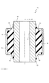
図9は第2実施の形態におけるサスペンション構造に設けられる防振ブッシュ70の正面図であり、図10は図9のX−X線における防振ブッシュ70の断面図であり、図11は図9のXI−XI線における防振ブッシュ70の断面図である。図9から図11は、車輪12に接地荷重が作用しない第1状態における防振ブッシュ70が図示されている。防振ブッシュ70は、第1実施の形態で説明したサスペンション構造10の防振ブッシュ30に代えて、第1リンク21に取り付けられる。 9 is a front view of the vibration-proof bush 70 provided in the suspension structure according to the second embodiment, FIG. 10 is a cross-sectional view of the vibration-proof bush 70 in line XX of FIG. 9, and FIG. 11 is FIG. It is sectional drawing of the vibration isolation bush 70 in the XI-XI line of. 9 to 11 show the vibration isolation bush 70 in the first state in which the ground contact load does not act on the wheel 12. The anti-vibration bush 70 is attached to the first link 21 in place of the anti-vibration bush 30 of the suspension structure 10 described in the first embodiment.

図9に示すように防振ブッシュ70は、軸部材80と、軸部材80の径方向の外側に配置される筒部材50と、筒部材50と軸部材80とを結合するゴム弾性体90とを備えている。軸部材80は、軸線81を中心とする断面円形の穴部82が軸線81に沿って貫通する金属製の部材である。 As shown in FIG. 9, the anti-vibration bush 70 includes a shaft member 80, a tubular member 50 arranged radially outside the shaft member 80, and a rubber elastic body 90 that connects the tubular member 50 and the shaft member 80. It has. The shaft member 80 is a metal member through which a hole 82 having a circular cross section centered on the axis 81 penetrates along the axis 81.

軸部材80は、軸線81と直交する断面において、外周面83が円形に形成されており、外周面83の円の中心と軸線81とがずれている。その結果、軸部材80は、穴部82の径方向の外側の軸部材80の厚さ(外周面83と穴部82との距離)が薄い薄肉部84、及び、穴部82の径方向の外側の軸部材80の厚さ(外周面83と穴部82との距離)が厚い厚肉部85が形成される。厚肉部85は、穴部82を挟んで薄肉部84の反対側に位置する。軸部材80は、穴部82に挿通されたボルト(図示せず)が、アクスルハウジング13(図1参照)に設けられたブラケット(図示せず)に固定されることにより、車両の略前後方向(図1紙面垂直方向)へ軸線81を向けてアクスルハウジング13に取り付けられる。 In the shaft member 80, the outer peripheral surface 83 is formed in a circular shape in a cross section orthogonal to the axis 81, and the center of the circle of the outer peripheral surface 83 and the axis 81 are deviated from each other. As a result, the shaft member 80 has a thin portion 84 having a thin thickness (distance between the outer peripheral surface 83 and the hole 82) on the outer side of the shaft member 80 in the radial direction of the hole 82, and a radial portion of the hole 82. A thick portion 85 having a large thickness (distance between the outer peripheral surface 83 and the hole portion 82) of the outer shaft member 80 is formed. The thick portion 85 is located on the opposite side of the thin portion 84 with the hole 82 interposed therebetween. The shaft member 80 is provided in the substantially front-rear direction of the vehicle by fixing a bolt (not shown) inserted through the hole 82 to a bracket (not shown) provided in the axle housing 13 (see FIG. 1). It is attached to the axle housing 13 with the axis 81 directed in the direction perpendicular to the paper surface (FIG. 1).

ゴム弾性体90は、軸部材80の外周面83と筒部材50の内周面52とに加硫接着されている。ゴム弾性体90によって筒部材50に対して軸部材80が弾性支持される防振ブッシュ70は、径方向の荷重において非線形のばね特性をもつ。 The rubber elastic body 90 is vulcanized and adhered to the outer peripheral surface 83 of the shaft member 80 and the inner peripheral surface 52 of the tubular member 50. The vibration-proof bush 70 in which the shaft member 80 is elastically supported by the rubber elastic body 90 with respect to the tubular member 50 has a non-linear spring characteristic in a radial load.

防振ブッシュ70は、無荷重時に、筒部材50の軸線51の位置と軸部材80の軸線81の位置とが一致するように軸部材80及び筒部材50が配置される。また、防振ブッシュ70は、軸部材80の薄肉部84及び厚肉部85が、第1方向(矢印X方向)に沿って配置される。第1方向は、車輪12に接地荷重が作用しない第1状態から車輪12に接地荷重が作用する第2状態への推移に伴い防振ブッシュ70に作用する荷重の方向である。 In the anti-vibration bush 70, the shaft member 80 and the cylinder member 50 are arranged so that the position of the axis 51 of the cylinder member 50 and the position of the axis 81 of the shaft member 80 coincide with each other when no load is applied. Further, in the vibration isolation bush 70, the thin portion 84 and the thick portion 85 of the shaft member 80 are arranged along the first direction (arrow X direction). The first direction is the direction of the load acting on the vibration isolator bush 70 as the transition from the first state in which the ground contact load does not act on the wheel 12 to the second state in which the ground contact load acts on the wheel 12.

ゴム弾性体90は、薄肉部84と筒部材50とに加硫接着される第1部91と、厚肉部85と筒部材50とに加硫接着される第2部92とを備えている。第1部91は、防振ブッシュ70に作用する第1方向(矢印X方向)の荷重によって圧縮される部分であり、第2部92は、第1方向の荷重によって引っ張られる部分である。第1部91及び第2部92は、軸線81と直交する断面(図9紙面に平行な断面)において、軸線51,81と直交する直線上における外周面83と内周面52との間の第1部91の厚さT1(第1方向における距離、図10参照)が、同じ直線上における外周面83と内周面52との間の第2部92の厚さT2(第1方向における距離、図10参照)より厚く設定される。 The rubber elastic body 90 includes a first part 91 that is vulcanized and bonded to the thin-walled portion 84 and the cylinder member 50, and a second part 92 that is vulcanized and bonded to the thick-walled portion 85 and the cylinder member 50. .. The first part 91 is a part compressed by the load in the first direction (arrow X direction) acting on the vibration isolator bush 70, and the second part 92 is a part pulled by the load in the first direction. The first part 91 and the second part 92 have a cross section orthogonal to the axis 81 (a cross section parallel to the paper surface of FIG. 9) between the outer peripheral surface 83 and the inner peripheral surface 52 on a straight line orthogonal to the axes 51 and 81. The thickness T1 of the first part 91 (distance in the first direction, see FIG. 10) is the thickness T2 of the second part 92 (in the first direction) between the outer peripheral surface 83 and the inner peripheral surface 52 on the same straight line. The distance is set thicker than (see FIG. 10).

図10及び図11に示すように、ゴム弾性体90は、軸線51の方向の内側へ向かって凹むすぐり部93が、第1部91及び第2部92の軸線51の方向の両側の端面に形成されている。すぐり部93は、各端面において第1部91及び第2部92の周方向に連続する。 As shown in FIGS. 10 and 11, in the rubber elastic body 90, the curly portions 93 recessed inward in the direction of the axis 51 are formed on both end faces of the first portion 91 and the second portion 92 in the direction of the axis 51. It is formed. The curly portion 93 is continuous in the circumferential direction of the first portion 91 and the second portion 92 at each end face.

図10及び図11に示す無荷重時の状態(第1状態)では、軸線51,81を含む面で切断した防振ブッシュ70の断面において、第1部91におけるすぐり部93の長さ(ゴム弾性体90の表面に沿った沿面距離)は、第2部92におけるすぐり部93の長さ(ゴム弾性体90の表面に沿った沿面距離)よりも長い。また、図10に示す第1方向(矢印X方向)におけるすぐり部93の長さは、図11に示す第2方向(矢印Y方向)におけるすぐり部93の長さよりも長い。従って防振ブッシュ70は、無荷重時において、第1方向(矢印X方向)に位置するゴム弾性体90の軸線51の方向における長さは、第2方向(矢印Y方向)に位置するゴム弾性体90の軸線51の方向における長さよりも短い。 In the no-load state (first state) shown in FIGS. 10 and 11, in the cross section of the vibration-proof bush 70 cut on the surface including the axes 51 and 81, the length of the curving portion 93 in the first portion 91 (rubber). The creepage distance along the surface of the elastic body 90) is longer than the length of the curving portion 93 in the second part 92 (the creepage distance along the surface of the rubber elastic body 90). Further, the length of the curving portion 93 in the first direction (arrow X direction) shown in FIG. 10 is longer than the length of the curving portion 93 in the second direction (arrow Y direction) shown in FIG. Therefore, when no load is applied to the anti-vibration bush 70, the length of the rubber elastic body 90 located in the first direction (arrow X direction) in the direction of the axis 51 is the rubber elasticity located in the second direction (arrow Y direction). It is shorter than the length in the direction of the axis 51 of the body 90.

防振ブッシュ70は、ゴム弾性体90が、第2部92から第1部91へと第1方向(矢印X方向)を向くように第1リンク21(図1参照)に固定されている。サスペンション構造10が、車輪12に接地荷重が作用しない第1状態から車輪12に接地荷重が作用する第2状態へ推移すると、第1部91が第1方向(矢印X方向)へ圧縮される一方で第2部92が第1方向へ引っ張られて、軸部材80の軸線81の位置が筒部材50の軸線51の位置から離れる。 The vibration-proof bush 70 is fixed to the first link 21 (see FIG. 1) so that the rubber elastic body 90 faces the first direction (arrow X direction) from the second part 92 to the first part 91. When the suspension structure 10 changes from the first state in which the ground load does not act on the wheels 12 to the second state in which the ground load acts on the wheels 12, the first part 91 is compressed in the first direction (arrow X direction). The second part 92 is pulled in the first direction, and the position of the axis 81 of the shaft member 80 is separated from the position of the axis 51 of the tubular member 50.

防振ブッシュ70は、第1状態においてゴム弾性体90の第1部91の厚さT1が第2部92の厚さT2よりも厚いので、荷重−たわみ曲線において(図7(c)参照)、第1状態S1から第2状態S2への推移に伴い、たわみ量が変曲点P1の近くから線形領域Lの中央へ近づく。その結果、車輪12(図1参照)に接地荷重が作用した第2状態では、線形特性を確保できる。防振ブッシュ70は、第1実施の形態で説明した防振ブッシュ30と同様に、通常の走行時に車輪12から車体20へ入力される振動を減衰できるので、乗り心地を向上できる。 Since the thickness T1 of the first part 91 of the rubber elastic body 90 is thicker than the thickness T2 of the second part 92 in the first state, the anti-vibration bush 70 has a load-deflection curve (see FIG. 7C). As the transition from the first state S1 to the second state S2, the amount of deflection approaches the center of the linear region L from the vicinity of the inflection point P1. As a result, the linear characteristic can be ensured in the second state in which the ground contact load is applied to the wheel 12 (see FIG. 1). Similar to the vibration-proof bush 30 described in the first embodiment, the vibration-proof bush 70 can attenuate the vibration input from the wheels 12 to the vehicle body 20 during normal traveling, so that the riding comfort can be improved.

以上、実施の形態に基づき本発明を説明したが、本発明は上記実施の形態に何ら限定されるものではなく、本発明の趣旨を逸脱しない範囲内で種々の改良変形が可能であることは容易に推察できるものである。例えば、防振ブッシュ30,70の軸部材40,80、筒部材50及びゴム弾性体60,90の形状や寸法等は一例であり、適宜設定できる。 Although the present invention has been described above based on the embodiments, the present invention is not limited to the above-described embodiments, and various improvements and modifications can be made without departing from the spirit of the present invention. It can be easily inferred. For example, the shapes and dimensions of the shaft members 40, 80, the tubular members 50, and the rubber elastic bodies 60, 90 of the anti-vibration bushes 30 and 70 are examples and can be set as appropriate.

上記各実施の形態では、サスペンション構造10の一例としてマルチリンク式サスペンションの場合を説明したが、必ずしもこれに限られるものではなく、他の構造を任意に採用することは当然可能である。他の構造としては、例えばデュアルリンク式サスペンション、ダブルウィッシュボーン式サスペンション、ストラット式サスペンションが挙げられる。 In each of the above embodiments, the case of the multi-link suspension has been described as an example of the suspension structure 10, but the present invention is not necessarily limited to this, and it is naturally possible to arbitrarily adopt another structure. Other structures include, for example, dual link suspensions, double wishbone suspensions, and strut suspensions.

上記各実施の形態では、車輪支持部材の一例としてアクスルハウジング13の場合を説明したが、必ずしもこれに限られるものではない。車輪12を回転可能に支持するナックル等の他の車輪支持部材を用いることは当然可能である。 In each of the above embodiments, the case of the axle housing 13 has been described as an example of the wheel support member, but the present invention is not necessarily limited to this. Of course, it is possible to use other wheel support members such as knuckles that rotatably support the wheels 12.

上記各実施の形態では、車両の幅方向(左右方向)に配置されたリンク(第1リンク21)と車輪支持部材(アクスルハウジング13)とを結合し、車両の略前後方向に軸線41を向けた防振ブッシュ30,70について説明したが、必ずしもこれに限られるものではない。例えば、第1リンク21と車体20とを防振ブッシュ30,70で結合すること、第1リンク21以外の他のリンク(第2リンク22から第5リンク25)に防振ブッシュ30,70を配置すること等は当然可能である。また、車両の前後方向に配置されるリンクであって車輪支持部材と車体とを連結するトレーリングリンク等に、車両の略左右方向に軸線41を向けて防振ブッシュ30,70を配置することは当然可能である。 In each of the above embodiments, the link (first link 21) arranged in the width direction (left-right direction) of the vehicle and the wheel support member (axle housing 13) are connected, and the axis 41 is directed substantially in the front-rear direction of the vehicle. Although the anti-vibration bushes 30 and 70 have been described, the present invention is not necessarily limited to this. For example, the first link 21 and the vehicle body 20 are connected by the anti-vibration bushes 30, 70, and the anti-vibration bushes 30, 70 are connected to other links (second link 22 to fifth link 25) other than the first link 21. Of course, it is possible to arrange them. Further, the anti-vibration bushes 30 and 70 are arranged on a trailing link or the like which is a link arranged in the front-rear direction of the vehicle and connects the wheel support member and the vehicle body with the axis 41 directed substantially in the left-right direction of the vehicle. Is of course possible.

上記各実施の形態では、防振ブッシュ30,70の軸部材40,80及び筒部材50が金属製の場合について説明したが、必ずしもこれに限られるものではない。軸部材40,80及び筒部材50のいずれか又は全てを合成樹脂製にすることは当然可能である。また、上記各実施の形態では、一体物の軸部材40,80や筒部材50について説明したが、必ずしもこれに限られるものではない。軸部材40,80や筒部材50をそれぞれ複数の部材に分割し、その複数の部材を突き合わせて軸部材40,80や筒部材50を構成することは当然可能である。 In each of the above embodiments, the case where the shaft members 40, 80 and the tubular member 50 of the anti-vibration bushes 30 and 70 are made of metal has been described, but the present invention is not necessarily limited to this. Of course, it is possible that any or all of the shaft members 40, 80 and the tubular member 50 are made of synthetic resin. Further, in each of the above embodiments, the shaft members 40 and 80 and the tubular member 50 of the integral body have been described, but the present invention is not necessarily limited to these. Of course, it is possible to divide the shaft members 40, 80 and the tubular member 50 into a plurality of members, and to abut the plurality of members to form the shaft members 40, 80 and the tubular member 50.

上記各実施の形態ではゴム弾性体60,90の第1部61,91及び第2部62,92が同種のゴム材で形成される場合について説明したが、必ずしもこれに限られるものではない。第1部61,91と第2部62,92とをばね定数の異なる異種のゴム材で形成することは当然可能である。 In each of the above embodiments, the cases where the first parts 61, 91 and the second parts 62, 92 of the rubber elastic bodies 60 and 90 are formed of the same type of rubber material have been described, but the present invention is not necessarily limited to this. Of course, it is possible to form the first part 61, 91 and the second part 62, 92 with different types of rubber materials having different spring constants.

上記各実施の形態ではゴム弾性体60,90の第1部61,91及び第2部62,92に形状の同じすぐり部63,93を形成する場合について説明したが、必ずしもこれに限られるものではない。第1部61,91及び第2部62,92のすぐり部63,93の形状を異ならせることは当然可能である。第1部61,91及び第2部62,92のゴム材の種類やすぐり部63,93の形状を異ならせることで、第1部61,91や第2部62,92のばね定数を異ならせることができる。その結果、荷重−たわみ曲線の線形領域Lの傾きを適宜設定できる。 In each of the above embodiments, the case where the curly portions 63 and 93 having the same shape are formed in the first portions 61 and 91 and the second portions 62 and 92 of the rubber elastic bodies 60 and 90 has been described, but the present invention is not necessarily limited to this. is not. Of course, it is possible to make the shapes of the curly portions 63, 93 of the first part 61, 91 and the second part 62, 92 different. If the spring constants of the first part 61, 91 and the second part 62, 92 are different by changing the type of rubber material of the first part 61, 91 and the second part 62, 92 and the shape of the curly part 63, 93. Can be made. As a result, the slope of the linear region L of the load-deflection curve can be appropriately set.

上記各実施の形態では、防振ブッシュ30,70の軸部材40,80や筒部材50の外周面43,83や内周面52が円筒状の場合について説明したが、必ずしもこれに限られるものではない。外周面43,83や内周面52から径方向に突出する凸部を外周面43,83や内周面52に設けることは当然可能である。凸部を設けることにより、荷重−たわみ曲線の変曲点P1,P2の位置を適宜設定できる。また、軸部材40,80と筒部材50との間に中間筒を配置し、中間筒にゴム弾性体60,90を接着することは当然可能である。中間筒を設けることにより、荷重−たわみ曲線の変曲点P1,P2の位置や線形領域Lの傾きを適宜設定できる。 In each of the above embodiments, the case where the shaft members 40, 80 of the vibration isolator bushes 30 and 70, the outer peripheral surfaces 43, 83 and the inner peripheral surface 52 of the tubular member 50 are cylindrical has been described, but the present invention is not necessarily limited to this. is not. Of course, it is possible to provide the outer peripheral surfaces 43, 83 and the inner peripheral surface 52 with convex portions protruding in the radial direction from the outer peripheral surfaces 43, 83 and the inner peripheral surface 52. By providing the convex portion, the positions of the inflection points P1 and P2 of the load-deflection curve can be appropriately set. Further, it is naturally possible to arrange an intermediate cylinder between the shaft members 40 and 80 and the cylinder member 50 and to bond the rubber elastic bodies 60 and 90 to the intermediate cylinder. By providing the intermediate cylinder, the positions of the inflection points P1 and P2 of the load-deflection curve and the slope of the linear region L can be appropriately set.

10 サスペンション構造
12 車輪
13 アクスルハウジング(車輪支持部材)
20 車体
21 第1リンク(リンク)
30,70 防振ブッシュ
40,80 軸部材
41,81 軸線
43,83 外周面
50 筒部材
51 軸線
52 内周面
60,90 ゴム弾性体
61,91 第1部
62,92 第2部
L 線形領域
10 Suspension structure 12 Wheels 13 Axle housing (wheel support member)
20 Body 21 1st link (link)
30,70 Anti-vibration bush 40,80 Shaft member 41,81 Axis line 43,83 Outer peripheral surface 50 Cylindrical member 51 Axis line 52 Inner peripheral surface 60,90 Rubber elastic body 61,91 Part 1 Part 62,92 Part 2 L Linear region

Claims (4)

車輪を回転可能に支持する車輪支持部材と車体との間に配置されるリンクと、
前記車輪支持部材や前記車体と前記リンクとを結合する防振ブッシュと、を備え、
前記防振ブッシュは、軸部材と、前記軸部材の径方向の外側に配置される筒部材と、前記筒部材の内周面と前記軸部材の外周面とを結合するゴム弾性体と、を備え、
前記防振ブッシュは、前記車輪に接地荷重が作用しない、前記軸部材の位置と前記筒部材の位置とが相対的に変位しない第1状態から前記車輪に接地荷重が作用する第2状態への推移に伴い、前記軸部材の軸線の方向と直交する第1方向に荷重が作用し、
前記ゴム弾性体は、前記第2状態において圧縮される第1部と、前記第2状態において引っ張られる第2部と、を備え、
前記軸部材は、前記軸部材を前記軸線の方向に貫通する穴部が設けられ、
前記第1部に結合する薄肉部と、
前記第2部に結合すると共に、前記薄肉部の径方向の厚さより径方向の厚さが厚い厚肉部と、を備え、
前記防振ブッシュは、前記第1状態において、前記第1部の前記第1方向における厚さが、前記第2部の前記第1方向における厚さよりも厚く設定され、
前記第1方向の荷重に対する荷重−たわみ曲線において、前記第1状態から前記第2状態への推移に伴い、線形領域の中央に近づくことを特徴とする車両のサスペンション構造。
A link placed between the wheel support member that rotatably supports the wheel and the vehicle body,
A wheel support member and a vibration-proof bush that connects the vehicle body and the link are provided.
The anti-vibration bush includes a shaft member, a tubular member arranged on the outer side in the radial direction of the shaft member, and a rubber elastic body that connects an inner peripheral surface of the tubular member and an outer peripheral surface of the shaft member. Prepare,
The anti-vibration bush changes from a first state in which a ground load does not act on the wheel and the position of the shaft member and the position of the tubular member do not relatively displace to a second state in which the ground load acts on the wheel. Along with the transition, a load acts in the first direction orthogonal to the direction of the axis of the shaft member, and the load acts.
The rubber elastic body includes a first part that is compressed in the second state and a second part that is pulled in the second state.
The shaft member is provided with a hole portion that penetrates the shaft member in the direction of the axis line.
The thin-walled part that is bonded to the first part,
A thick portion that is bonded to the second portion and has a thickness in the radial direction that is thicker than the radial thickness of the thin portion is provided.
In the first state, the anti-vibration bush is set so that the thickness of the first part in the first direction is thicker than the thickness of the second part in the first direction.
A vehicle suspension structure characterized in that, in a load-deflection curve with respect to a load in the first direction, the vehicle approaches the center of a linear region as the transition from the first state to the second state occurs.
前記第1状態において、前記穴部の中心の位置と前記筒部材の軸線の位置とが一致していることを特徴とする請求項1記載の車両のサスペンション構造。The vehicle suspension structure according to claim 1, wherein in the first state, the position of the center of the hole and the position of the axis of the tubular member coincide with each other. 前記防振ブッシュは、前記第1状態から前記第2状態への推移に伴い、前記軸部材の前記軸線の位置が、前記筒部材の軸線の位置に近づくことを特徴とする請求項1又は記載の車両のサスペンション構造。 The vibration damping bushing is accompanied from the first state to transition to the second state, the axis position of the axis of the member, according to claim 1 or 2, characterized in that approaching the position of the axis of said tubular member suspension structure for a vehicle according to. 前記防振ブッシュは、前記第1方向に位置する前記ゴム弾性体の軸方向の長さが、前記軸部材の前記軸線の方向と前記第1方向とに直交する第2方向に位置する前記ゴム弾性体の軸方向の長さよりも短いことを特徴とする請求項1から3のいずれかに記載の車両のサスペンション構造。 The anti-vibration bush is the rubber whose axial length of the rubber elastic body located in the first direction is located in a second direction orthogonal to the direction of the axis of the shaft member and the first direction. The vehicle suspension structure according to any one of claims 1 to 3, wherein the length is shorter than the axial length of the elastic body.
JP2016217092A 2016-11-07 2016-11-07 Vehicle suspension structure Active JP6793011B2 (en)

Priority Applications (1)

Application Number Priority Date Filing Date Title
JP2016217092A JP6793011B2 (en) 2016-11-07 2016-11-07 Vehicle suspension structure

Applications Claiming Priority (1)

Application Number Priority Date Filing Date Title
JP2016217092A JP6793011B2 (en) 2016-11-07 2016-11-07 Vehicle suspension structure

Publications (2)

Publication Number Publication Date
JP2018076882A JP2018076882A (en) 2018-05-17
JP6793011B2 true JP6793011B2 (en) 2020-12-02

Family

ID=62149165

Family Applications (1)

Application Number Title Priority Date Filing Date
JP2016217092A Active JP6793011B2 (en) 2016-11-07 2016-11-07 Vehicle suspension structure

Country Status (1)

Country Link
JP (1) JP6793011B2 (en)

Families Citing this family (1)

* Cited by examiner, † Cited by third party
Publication number Priority date Publication date Assignee Title
JP2022052088A (en) * 2020-09-23 2022-04-04 山下ゴム株式会社 Torque rod

Family Cites Families (5)

* Cited by examiner, † Cited by third party
Publication number Priority date Publication date Assignee Title
JPS5821764Y2 (en) * 1978-05-17 1983-05-09 トヨタ自動車株式会社 Push assembly for 4-link wheel suspension
JPS61199406U (en) * 1985-06-03 1986-12-13
JP3796767B2 (en) * 1995-05-26 2006-07-12 日産自動車株式会社 Bushing and vehicle suspension mounting structure
JP3770170B2 (en) * 2001-12-10 2006-04-26 東海ゴム工業株式会社 Anti-vibration bush
JP4319069B2 (en) * 2004-03-03 2009-08-26 本田技研工業株式会社 Suspension bush

Also Published As

Publication number Publication date
JP2018076882A (en) 2018-05-17

Similar Documents

Publication Publication Date Title
KR101312710B1 (en) Mono axia damping joint for assembling automotive chassis parts
KR101372085B1 (en) Rubber bush for suspension of vehicle
JP7140767B2 (en) Bush arrangement structure
CN111002775B (en) Bushing and suspension device for vehicle
JP4751743B2 (en) Suspension bush and double joint type suspension mechanism using the same
JP7233045B2 (en) Bush and vehicle suspension device
CN115899137A (en) Vehicle pillar insulator
JP6793011B2 (en) Vehicle suspension structure
JP2017067293A (en) Chassis bearing
JP3978177B2 (en) Lower arm assembly
EP3297860B1 (en) Link assembly for longitudinal arm vehicle suspension
JP2020106073A (en) Design method of inter-ring bush
KR20170063066A (en) Sliding bush for suspension of vehicle
KR102417331B1 (en) Insulator for suspension
KR20080025248A (en) Bush for vehicle
JP4358874B2 (en) Anti-vibration bush
KR102563031B1 (en) strut mount of suspension for vehicle
JP3823688B2 (en) Suspension member mount with to collect action
WO2019004972A2 (en) A stabilizer bar bush
KR102512791B1 (en) Stabilizer bar bush
KR102226548B1 (en) Insulator of suspension for vehicle and manufacture method of insulator
US20230150326A1 (en) Suspension
JPS6234039Y2 (en)
JPH06280914A (en) Cylindrical vibration-proof bush
JP2008019927A (en) Vibration damping bush, and multi-ring type suspension device having the same

Legal Events

Date Code Title Description
A621 Written request for application examination

Free format text: JAPANESE INTERMEDIATE CODE: A621

Effective date: 20190919

A977 Report on retrieval

Free format text: JAPANESE INTERMEDIATE CODE: A971007

Effective date: 20200707

A131 Notification of reasons for refusal

Free format text: JAPANESE INTERMEDIATE CODE: A131

Effective date: 20200728

A521 Written amendment

Free format text: JAPANESE INTERMEDIATE CODE: A523

Effective date: 20200924

TRDD Decision of grant or rejection written
A01 Written decision to grant a patent or to grant a registration (utility model)

Free format text: JAPANESE INTERMEDIATE CODE: A01

Effective date: 20201104

A61 First payment of annual fees (during grant procedure)

Free format text: JAPANESE INTERMEDIATE CODE: A61

Effective date: 20201109

R150 Certificate of patent or registration of utility model

Ref document number: 6793011

Country of ref document: JP

Free format text: JAPANESE INTERMEDIATE CODE: R150