JP6789679B2 - Heat retention control method for recording device and recording head - Google Patents
Heat retention control method for recording device and recording head Download PDFInfo
- Publication number
- JP6789679B2 JP6789679B2 JP2016113798A JP2016113798A JP6789679B2 JP 6789679 B2 JP6789679 B2 JP 6789679B2 JP 2016113798 A JP2016113798 A JP 2016113798A JP 2016113798 A JP2016113798 A JP 2016113798A JP 6789679 B2 JP6789679 B2 JP 6789679B2
- Authority
- JP
- Japan
- Prior art keywords
- heat retention
- heater
- recording
- nozzles
- temperature information
- Prior art date
- Legal status (The legal status is an assumption and is not a legal conclusion. Google has not performed a legal analysis and makes no representation as to the accuracy of the status listed.)
- Active
Links
Images


Description
本発明は、記録装置及び記録ヘッドの保温制御方法に関し、特に、画像データに基づき記録ヘッドに設けられた各インク吐出口からインク滴を吐出し、記録媒体に画像を記録する記録装置及び記録ヘッドの保温制御方法に関する。 The present invention relates to a method for controlling heat retention of a recording device and a recording head, and in particular, a recording device and a recording head that eject ink droplets from each ink ejection port provided on the recording head based on image data and record an image on a recording medium. Regarding the heat retention control method.
インクジェット記録装置には、高速で高品位な画像形成が求められており、それには画像を形成するインク滴を安定的に吐出するため、インク滴を吐出する、複数の電気熱変換体(ヒータ)を備える記録ヘッドの保温管理を適切に行う必要がある。その保温管理は一般的に、記録ヘッドに設けられたダイオードセンサで記録ヘッドの温度を検知し、その検知温度に応じて、記録ヘッドに設けられたサブヒータを用いて記録ヘッドを加熱するよう制御することが含まれる。 High-speed and high-quality image formation is required for an inkjet recording device, and in order to stably eject ink droplets forming an image, a plurality of electrothermal converters (heaters) that eject ink droplets are required. It is necessary to properly manage the heat retention of the recording head provided with the above. The heat retention management generally detects the temperature of the recording head by a diode sensor provided in the recording head, and controls to heat the recording head by using a sub-heater provided in the recording head according to the detected temperature. That is included.
そして、このサブヒータの数を多くして、記録ヘッド内の温度分布を細かく制御することで、より高品位な画像形成を実現している。但し、この場合、制御対象となるサブヒータの数を多くすると、その増加に伴って処理負荷も増大するので、高速処理が必要とされる画像形成では、記録ヘッドの保温制御自体にかかる時間が懸念される。 Then, by increasing the number of sub-heaters and finely controlling the temperature distribution in the recording head, higher quality image formation is realized. However, in this case, if the number of sub-heaters to be controlled is increased, the processing load also increases as the number of sub-heaters to be controlled increases. Therefore, in image formation that requires high-speed processing, there is concern about the time required for the heat retention control itself of the recording head. Will be done.
そこで特許文献1では、記録装置内のメモリに記憶されたこれから印刷の用いられる記録データに基づいて、記録される画素の有効数をカウントし、有効画素率を測定する。そして、この有効画素率が所定値以下の場合のみに記録中における記録ヘッドの保温制御を実行している。これにより、記録データからほぼリアルタイムに記録ヘッドの保温の仕方を予測して、インク吐出中に温度低下が見られる記録ヘッドの箇所のみに対して、サブヒータの保温制御を実行することができる。
Therefore, in
しかしながら、記録ヘッドの温度は、インク吐出による熱量だけで決まるのでなく、環境温度や記録ヘッドを構成するヒータボード部材自体の温度などにも影響を受ける。そのため、記録データからサブヒータの保温パラメータを予測する精度を高めることは困難であり、温度バラつきを抑えた保温制御が必要な記録ヘッドの場合には、記録データに基づいた保温制御は適していない。 However, the temperature of the recording head is determined not only by the amount of heat generated by ink ejection, but also by the environmental temperature and the temperature of the heater board member itself constituting the recording head. Therefore, it is difficult to improve the accuracy of predicting the heat retention parameter of the sub-heater from the recorded data, and in the case of a recording head that requires heat retention control that suppresses temperature variation, the heat retention control based on the recorded data is not suitable.
本発明は上記従来例に鑑みてなされたもので、記録ヘッド内の温度バラつきが少ない保温制御を高速に実行が可能な記録装置及び記録ヘッドの保温制御方法を提供することを目的としている。 The present invention is intended to provide the has been made in view of the prior art, temperature retaining control method capable record apparatus and a recording head executes the temperature variation is less heat keeping control at high speed in the recording head.
上記目的を達成するために本発明の記録装置は次のような構成を含む。 In order to achieve the above object, the recording device of the present invention includes the following configuration.
即ち、
インクを吐出するための熱エネルギーを発生する電気熱変換体を備えた複数のノズルを第1の方向に配列したノズル列を複数、前記第1の方向とは異なる第2の方向に配列したヒータボードを含む記録ヘッドを用い、インクを記録媒体に吐出して記録を行う記録装置であって、
前記ヒータボードに配置された複数のノズル列おのおのに関し、前記第1の方向に配列した複数のノズルを、互いに近接する複数のノズルで構成される複数のグループに分割し、該分割されたグループごとに当該グループの近傍にヒータと温度検出センサとを設け、保温エリアを形成し、
前記複数のノズル列それぞれに含まれる複数のノズルは時分割駆動され、
前記温度検出センサを選択する選択手段と、
1カラムの記録動作が終了するたびに前記選択手段で選択された前記温度検出センサにより検出された温度情報が順次格納され、前記保温エリアすべてから得られた温度情報を前記保温エリアそれぞれに関して複数回の取得分、格納する記憶手段と、
前記記憶手段に格納された温度情報を前記保温エリアごとに平均化する平均化手段と、
前記平均化手段により平均化された温度情報を用いて、予め定められた、温度情報とPWM値との関係を示す第1のテーブルを参照して、対応する保温エリアのヒータを駆動するためのPWM値を取得する取得手段と、
前記時分割駆動のための記録信号に基づいて前記保温エリアそれぞれにおいて駆動されるノズルの数をカウントし、該カウントされたノズルの数を用いて、予め定められた、ノズル数とPWM値との関係を示す第2のテーブルを参照して、前記PWM値を修正する修正手段と、
前記取得手段により取得され、前記修正手段により修正されたPWM値を用いて前記対応する保温エリアのヒータをPWM制御により駆動する駆動手段と、を有することを特徴とする。
That is,
A heater in which a plurality of nozzle rows in which a plurality of nozzles provided with an electrothermal converter for generating heat energy for ejecting ink are arranged in a first direction are arranged in a second direction different from the first direction. A recording device that uses a recording head including a board to eject ink onto a recording medium for recording.
Regarding each of the plurality of nozzle rows arranged on the heater board, the plurality of nozzles arranged in the first direction are divided into a plurality of groups composed of a plurality of nozzles adjacent to each other, and each of the divided groups. A heater and a temperature detection sensor are provided in the vicinity of the group to form a heat retention area.
The plurality of nozzles included in each of the plurality of nozzle trains are time-division-driven.
A selection means for selecting the temperature detection sensor and
Each time the recording operation of one column is completed, the temperature information detected by the temperature detection sensor selected by the selection means is sequentially stored, and the temperature information obtained from all the heat retention areas is stored a plurality of times for each of the heat retention areas. Acquisition amount, storage means to store,
An averaging means that averages the temperature information stored in the storage means for each heat retention area, and
Using the temperature information averaged by the averaging means, the heater in the corresponding heat retention area is driven with reference to a predetermined first table showing the relationship between the temperature information and the PWM value. An acquisition means for acquiring the PWM value and
The number of nozzles driven in each of the heat retention areas is counted based on the recording signal for the time division drive, and the number of nozzles counted is used to determine the number of nozzles and the PWM value. With reference to the second table showing the relationship, the correction means for correcting the PWM value, and
It is characterized by having a drive means for driving a heater in the corresponding heat retaining area by PWM control using a PWM value acquired by the acquisition means and corrected by the correction means .
また本発明を他の側面から見れば、インクを吐出するための熱エネルギーを発生する電気熱変換体を備えた複数のノズルを第1の方向に配列したノズル列を複数、前記第1の方向とは異なる第2の方向に配列したヒータボードを含む記録ヘッドを用い、インクを記録媒体に吐出して記録を行う記録装置における記録ヘッドの保温制御方法であって、前記ヒータボードに配置された複数のノズル列おのおのに関し、前記第1の方向に配列した複数のノズルを、互いに近接する複数のノズルで構成される複数のグループに分割し、該分割されたグループごとに当該グループの近傍にヒータと温度検出センサとを設け、保温エリアを形成し、前記複数のノズル列それぞれに含まれる複数のノズルは時分割駆動され、前記温度検出センサを選択する選択工程と、1カラムの記録動作が終了するたびに前記選択工程で選択された前記温度検出センサにより検出された温度情報を記憶手段に順次格納し、前記保温エリアすべてから得られた温度情報を前記保温エリアそれぞれに関して複数回の取得分、前記記憶手段に格納する記憶工程と、前記記憶手段に格納された温度情報を前記保温エリアごとに平均化する平均化工程と、前記平均化工程により平均化された温度情報を用いて、予め定められた、温度情報とPWM値との関係を示す第1のテーブルを参照して、対応する保温エリアのヒータを駆動するためのPWM値を取得する取得工程と、前記時分割駆動のための記録信号に基づいて前記保温エリアそれぞれにおいて駆動されるノズルの数をカウントし、該カウントされたノズルの数を用いて、予め定められた、ノズル数とPWM値との関係を示す第2のテーブルを参照して、前記PWM値を修正する修正工程と、前記取得工程により取得され、前記修正工程により修正されたPWM値を用いて前記対応する保温エリアのヒータをPWM制御により駆動する駆動工程と、を有することを特徴とする記録ヘッドの保温制御方法を備える。 Further, when the present invention is viewed from another aspect, a plurality of nozzle rows in which a plurality of nozzles provided with an electrothermal converter that generates heat energy for ejecting ink are arranged in the first direction are arranged in the first direction. It is a heat retention control method of a recording head in a recording apparatus that discharges ink to a recording medium and records using a recording head including a heater board arranged in a second direction different from that of the heater board. With respect to each of the plurality of nozzle rows, the plurality of nozzles arranged in the first direction are divided into a plurality of groups composed of a plurality of nozzles adjacent to each other, and each of the divided groups has a heater in the vicinity of the group. And a temperature detection sensor are provided to form a heat retention area, and a plurality of nozzles included in each of the plurality of nozzle rows are driven by time division, and the selection step of selecting the temperature detection sensor and the recording operation of one column are completed. Each time, the temperature information detected by the temperature detection sensor selected in the selection step is sequentially stored in the storage means, and the temperature information obtained from all the heat retention areas is acquired a plurality of times for each of the heat retention areas. Predetermined using a storage step stored in the storage means, an averaging step of averaging the temperature information stored in the storage means for each heat retaining area, and temperature information averaged by the averaging step. The acquisition step of acquiring the PWM value for driving the heater in the corresponding heat retention area with reference to the first table showing the relationship between the temperature information and the PWM value, and the recording for the time-division drive. A second table showing a predetermined relationship between the number of nozzles and the PWM value is displayed by counting the number of nozzles driven in each of the heat insulating areas based on the signal and using the counted number of nozzles. With reference to the correction step of correcting the PWM value, and the drive step of driving the heater of the corresponding heat retention area by PWM control using the PWM value acquired by the acquisition step and corrected by the correction step. The recording head is provided with a heat retention control method .
従って本発明によれば、記録ヘッドの細かい温度管理による高品位印刷を高速かつ安定的に実現することができるという効果がある。 Therefore, according to the present invention, there is an effect that high-quality printing can be realized at high speed and stably by finely controlling the temperature of the recording head.
以下添付図面を参照して本発明の実施例について、さらに具体的かつ詳細に説明する。 Hereinafter, examples of the present invention will be described in more detail and in detail with reference to the accompanying drawings.
なお、この明細書において、「記録」(「プリント」という場合もある)とは、文字、図形等有意の情報を形成する場合のみならず、有意無意を問わない。また人間が視覚で知覚し得るように顕在化したものであるか否かを問わず、広く記録媒体上に画像、模様、パターン等を形成する、または媒体の加工を行う場合も表すものとする。 In this specification, "record" (sometimes referred to as "print") is not limited to the case of forming significant information such as characters and figures, and may be significant or involuntary. It also refers to the case where an image, pattern, pattern, etc. is widely formed on a recording medium or the medium is processed, regardless of whether or not it is manifested so that it can be visually perceived by humans. ..
また、「記録媒体」とは、一般的な記録装置で用いられる紙のみならず、広く、布、プラスチック・フィルム、金属板、ガラス、セラミックス、木材、皮革等、インクを受容可能なものも表すものとする。 The term "recording medium" refers not only to paper used in general recording devices, but also to a wide range of media such as cloth, plastic film, metal plate, glass, ceramics, wood, and leather that can accept ink. Shall be.
さらに、「インク」(「液体」と言う場合もある)とは、上記「記録(プリント)」の定義と同様広く解釈されるべきものである。従って、記録媒体上に付与されることによって、画像、模様、パターン等の形成または記録媒体の加工、或いはインクの処理(例えば記録媒体に付与されるインク中の色剤の凝固または不溶化)に供され得る液体を表すものとする。 Further, "ink" (sometimes referred to as "liquid") should be broadly interpreted as in the definition of "recording (printing)" above. Therefore, by being applied onto the recording medium, the image, pattern, pattern, etc. are formed, the recording medium is processed, or the ink is processed (for example, the colorant in the ink applied to the recording medium is solidified or insolubilized). It shall represent a liquid that can be produced.
またさらに、「記録要素(又は記録素子又はノズル)」とは、特にことわらない限り吐出口ないしこれに連通する液路およびインク吐出に利用されるエネルギーを発生する素子を総括して言うものとする。 Furthermore, "recording element (or recording element or nozzle)" is a general term for the ejection port, the liquid passage communicating with the ejection port, and the element that generates energy used for ink ejection, unless otherwise specified. To do.
以下に用いる記録ヘッド用基板(ヘッド基板)とは、シリコン半導体からなる単なる基体を指し示すものではなく、各素子や配線等が設けられた構成を差し示すものである。 The recording head substrate (head substrate) used below does not indicate a simple substrate made of a silicon semiconductor, but indicates a configuration in which each element, wiring, or the like is provided.
さらに、基板上とは、単に素子基板の上を指し示すだけでなく、素子基板の表面、表面近傍の素子基板内部側をも示すものである。また、本発明でいう「作り込み(built-in)」とは、別体の各素子を単に基体表面上に別体として配置することを指し示している言葉ではなく、各素子を半導体回路の製造工程等によって素子板上に一体的に形成、製造することを示すものである。 Further, the term “on the substrate” means not only the top of the element substrate but also the surface of the element substrate and the inside side of the element substrate in the vicinity of the surface. Further, the term "built-in" as used in the present invention does not mean that each element of a separate body is simply arranged as a separate body on the surface of a substrate, but that each element is manufactured as a semiconductor circuit. It indicates that it is integrally formed and manufactured on the element plate by a process or the like.
図1は本発明の代表的な実施例であるインクジェット記録ヘッド(以下、記録ヘッド)を用いて記録を行なう記録装置の構成の概要を示す外観斜視図である。 FIG. 1 is an external perspective view showing an outline of a configuration of a recording device that records using an inkjet recording head (hereinafter, recording head) which is a typical embodiment of the present invention.
図1に示すようにインクジェット記録装置(以下、記録装置)1はインクジェット方式に従ってインクを吐出して記録を行なうインクジェット記録ヘッド(以下、記録ヘッド)3をキャリッジ2に搭載し、キャリッジ2を矢印A方向に往復移動させて記録を行う。記録紙などの記録媒体Pを給紙機構5を介して給紙し、記録位置まで搬送し、その記録位置において記録ヘッド3から記録媒体Pにインクを吐出することで記録を行なう。
As shown in FIG. 1, the inkjet recording device (hereinafter, recording device) 1 mounts an inkjet recording head (hereinafter, recording head) 3 for ejecting ink and recording according to an inkjet method on a
記録装置1のキャリッジ2には記録ヘッド3を搭載するのみならず、記録ヘッド3に供給するインクを貯留するインクタンク6を装着する。インクタンク6はキャリッジ2に対して着脱自在になっている。
Not only the
図1に示した記録装置1はカラー記録が可能であり、そのためにキャリッジ2にはマゼンタ(M)、シアン(C)、イエロ(Y)、ブラック(K)のインクを夫々、収容した4つのインクカートリッジを搭載している。これら4つのインクカートリッジは夫々独立に着脱可能である。
The
この実施例の記録ヘッド3は、熱エネルギーを利用してインクを吐出するインクジェット方式を採用している。このため、電気熱変換体を備えている。この電気熱変換体は各吐出口のそれぞれに対応して設けられ、記録信号に応じて対応する電気熱変換体にパルス電圧を印加することによって対応する吐出口からインクを吐出する。
The
また、キャリッジ2の移動方向に沿って、スケール7が設けられている。スケール7には一定の間隔でスリットが設けられており、キャリッジ2に搭載されたエンコーダ(不図示)がキャリッジ2の移動に応じて、そのスリットを読み取ることでエンコーダ信号を生成する。このエンコーダ信号はキャリッジ2の移動方向のキャリッジ位置(即ち、記録ヘッドの位置)を表わす信号である。このエンコーダ信号の周期(エンコーダ信号間隔)に基づいてキャリッジの移動速度が算出され、また、このエンコーダ信号がインク吐出のためのタイミング制御のための信号として用いられる。
Further, a
なお、この実施例では、記録ヘッドを搭載したキャリッジを往復移動させて記録を行う記録装置を例として用いているが、本発明はこれにより限定されるものではない。本発明は、例えば、記録媒体の幅と同じか、それ以上の長さの記録幅をもつフルライン記録ヘッドを用い、記録媒体のみを搬送して記録を行う構成の記録装置を用いる場合にも適用可能である。 In this embodiment, a recording device for recording by reciprocating a carriage equipped with a recording head is used as an example, but the present invention is not limited thereto. The present invention also uses, for example, a recording device having a configuration in which a full-line recording head having a recording width equal to or longer than the width of the recording medium is used and only the recording medium is conveyed for recording. Applicable.
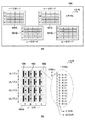
図2は記録ヘッドのヘッド基板の概略レイアウトと、ヒータボードの内部構成を示す図である。 FIG. 2 is a diagram showing a schematic layout of a head substrate of a recording head and an internal configuration of a heater board.
図2(a)に示すように、記録ヘッド3のヘッド基板には4つのヒータボード101A〜101Dが実装されている。各ヒータボードの内部構成は同じであり、図2(b)にはそのうちの1つ、ヒータボード101Aを例示している。図2(b)に示すように、ヒータボード101AにはC/M/Y/Kで示された4色のインクに対応したノズル列が設けられている。各ノズル列は、図2(b)の右側に破線で囲まれた部分を拡大して示すように、Even列とOdd列のノズル列により構成され、Even列とOdd列を合わせて並べたノズルは1200dpiピッチ間隔で512個のノズルが配列される。そして、これらノズルからのインク吐出は時分割に実行される。
As shown in FIG. 2A, four
図2(b)に示す実施例では、時分割数を4としており、時分割ブロックがBLK0〜3で示されている。なお、説明の便宜上、以降の説明ではノズル列方向をY方向と呼び、ノズル列に直交する方向をX方向とする。これらの方向を図1に示す記録装置との関係で言えば、X方向が記録媒体の搬送方向(副走査方向)、X方向がキャリッジの移動方向(主走査方向)となる。また、記録解像度は1200dpiとして扱う。 In the embodiment shown in FIG. 2B, the number of time divisions is 4, and the time division blocks are indicated by BLK0 to 3. For convenience of explanation, in the following description, the nozzle row direction is referred to as the Y direction, and the direction orthogonal to the nozzle row is referred to as the X direction. Speaking of these directions in relation to the recording device shown in FIG. 1, the X direction is the transport direction of the recording medium (secondary scanning direction), and the X direction is the moving direction of the carriage (main scanning direction). The recording resolution is treated as 1200 dpi.
また、図2(b)に示すように、ヒータボード101Aは各ノズル列内を128ノズル毎の均等に分割することで、4つの保温エリア102を有している。これら128ノズルは図2(b)から分かるように、互いに近接した連続したノズルであって、この近接し連続した複数のノズルをグループと呼ぶ。これは、各ヒータボードには16個の保温エリアが存在することを意味し、記録ヘッド(即ち、ヘッド基板)全体では64個の保温エリアが存在することを意味する。そして、保温エリア毎に(即ち、グループ毎に)、ダイオードセンサ(温度検出センサ)103(以下、Diセンサ)とサブヒータ104を1つずつ備えている。
Further, as shown in FIG. 2B, the
従って、記録ヘッド全体では64個のDiセンサ103と64個のサブヒータ104が存在することになる。
Therefore, there are 64 Di-
なお、ヘッド基板100に実装されるヒータボードの数、ヘッド基板のDiセンサの数、保温エリアの数は上記の値に限定されるものではなく、異なる値であっても構わない。
The number of heater boards mounted on the
また、図2(a)に示した4つのヒータボードの間には糊代となるノズルは存在せず、1200dpiピッチで正確に記録ヘッド上に貼り合わされているものとするが、一定数のノズルを糊代として貼り合わせる構成であっても構わない。 Further, it is assumed that there is no nozzle serving as a glue margin between the four heater boards shown in FIG. 2 (a) and the nozzles are accurately bonded to the recording head at a pitch of 1200 dpi, but a certain number of nozzles are used. May be used as a glue margin for bonding.
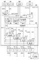
図3は図1に示す記録装置の制御構成の概略を示すブロック図である。なお、図3ではキャリッジ2を移動させたり、記録媒体を搬送させたりする制御構成については、公知であるとして、その記載は省略している。
FIG. 3 is a block diagram showing an outline of a control configuration of the recording device shown in FIG. In FIG. 3, the control configuration for moving the
図3に示すように、記録装置1は、エンコーダ201とDRAM202とROM203とコントローラ204と前述のヒータボード101A〜101BとA/D変換器213とを備える。
As shown in FIG. 3, the
そして、コントローラ204は、吐出データ生成部205とCPU206と吐出タイミング生成部207とDiデジタル値格納メモリ208とサブヒータのPWM値変換テーブル209と保温制御部210とヒータボードデータ転送部211A〜Dとを備える。CPU206はROM203に格納されたプログラムを読み込んで実行したり、各モータなどのドライバ(不図示)を駆動して記録装置全体の動作を制御する。
Then, the
また、ROM203には、CPU206が実行する各種制御プログラムの他に記録装置の各種動作に必要な固定データを格納する。例えば、記録装置の記録(印刷)処理を実行するプログラムを記憶する。
Further, the
DRAM202はCPU206がプログラムを実行するために必要であり、CPU206の作業領域として用いられたり、種々の受信データの一時的格納領域として用いられたり、各種設定データを記憶させたりする。この実施例では、後述するように、DRAM202は、吐出データ生成部205の出力結果を一時的に格納する。なお、図3では、1つのDRAM202が図示されているのみであるが、複数のDRAMを実装しても良いし、例えば、DRAMとSRAMとを混載し、アクセス速度の異なる複数のメモリからなるようにしてもよい。
The
吐出データ生成部205は、パーソナルコンピュータ(PC)、デジタルカメラ等のホスト200から画像データ(IDATA)を受信し、これを記録ヘッド3の構成に合わせた吐出データ(DDATA)に並び替え、DRAM202に一時的に格納する。また、吐出データ(DDATA)を生成する際に、一定画素単位であるドットカウントエリア毎に吐出データ内に基づくインク吐出量をカウントして生成したドットカウントデータ(DCNT)もDRAM202に格納する。なお、ドットカウントエリアの画素単位は、吐出データ生成部205の処理単位により決まるものであるが、この実施例では、X方向16画素、Y方向16画素のエリアとする。
The discharge
吐出タイミング生成部207は、エンコーダ201から記録ヘッド3と記録媒体Pの相対位置を判断するための情報である位置情報(ENC)を受信し、CPU206により設定されたタイミングに従って、吐出タイミング(DTMG)を生成する。また、その相対位置に応じて、保温制御単位経過フラグ(EFLG)も生成し、これをCPU206に出力する。
The discharge
4つのヒータボードデータ転送部211A〜211Dは、吐出タイミング(DTMG)に合わせて、DRAM202から吐出データ(DDATA)と読出す。また、これとともに、後述する保温制御部210から受信するDi選択情報(Di−SEL)とサブヒータのPWM値情報(PWM)を用いて、ヒータボード101A〜101Dにヘッドデータ(HDATA)を転送する。なお、図3から分かるように、ヒータボードデータ転送部211A〜211Dはヒータボード101A〜101Dにそれぞれ、対応するヘッドデータ(HDATA)を転送する。
The four heater board data transfer
ヒータボード101A〜101Dは、ヘッドデータ(HDATA)に含まれる吐出データを用いて各ノズルからインク吐出を行うとともに、ヒータボード内のDiセンサの出力としてDiアナログ値(Di−A)をA/D変換器213に出力する。なお、ヒータボード101AからDiアナログ値(Di−A:アナログ温度情報)を読出す時は、ヒータボード101B〜Dは各Diセンサからの温度情報を入力する。また、ヒータボード101BからDiアナログ値(Di−A)を読出す時は、ヒータボード101A、101C、101Dは各Diセンサからの温度情報を入力する。このように、ヒータボード101A〜101Dのいずれか1つのみをDiアナログ値の出力状態にすることで、4つのヒータボード101A〜101DからA/D変換器213への入力信号線を1本としている。これにより、ヘッド基板上での信号線数を削減することができる。
The
A/D変換器213は、後述する保温制御部210からのA/D変換タイミング信号(ADCTMG)を受けて、Diアナログ値(Di−A)をDiデジタル値(Di−D:デジタル温度情報)に変換して、保温制御部210に出力する。
The A /
保温制御部210は、受信したDiデジタル値(Di−D)をDiデジタル値格納メモリ208に格納するとともに、CPU206からの保温実行情報(KTINFO)を受信する。そして、保温実行が必要であると判断された保温エリアに対しては、Diデジタル値格納メモリ208に蓄積されたDiデジタル値(Di−D)を読出し、PWM値変換テーブル209を用いて保温エリア毎のサブヒータのPWM値を生成する。また、吐出タイミング(DTMG)を用いて、各ヒータボードに外部出力させるダイオードを選択するDi選択情報(Di−SEL)をヒータボード毎に生成する。これらPWM値情報(PWM)とDi選択情報(Di−SEL)は、ヒータボードデータ転送部211A〜211Dに出力される。
The heat
なお、図3に示すコントローラ204において、CPU206とDiデジタル値格納メモリとPWM値変換テーブル209とを除く各部はASICなどの専用ハードウェアで構成される。即ち、吐出データ生成部205、吐出タイミング生成部207、保温制御部210、ヒータボードデータ転送部211A〜211DはASICなどのハードウェアである。
In the
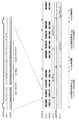
図4は保温制御単位を説明する図である。 FIG. 4 is a diagram illustrating a heat retention control unit.
図4において、矩形状の領域が保温制御単位を示しており、その単位はY方向にはヒータボードの保温エリア単位である128画素とし、X方向には保温制御の実施可否を切り替える単位として1024画素としている。 In FIG. 4, a rectangular area indicates a heat retention control unit, and the unit is 128 pixels, which is a heat retention area unit of the heater board in the Y direction, and 1024 as a unit for switching whether or not the heat retention control can be performed in the X direction. It is a pixel.
この実施例では上述のように、ドットカウント単位はX方向/Y方向ともに16画素であることから、ドットカウントエリアをX方向に64個(=1024/16)、Y方向に8個(=128/16)まとめた単位が保温制御単位となる。 In this embodiment, as described above, since the dot count unit is 16 pixels in both the X direction and the Y direction, 64 dot count areas (= 1024/16) in the X direction and 8 dots in the Y direction (= 128). / 16) The combined unit is the heat retention control unit.
図5は保温制御の処理を示すフローチャートである。 FIG. 5 is a flowchart showing the heat retention control process.
まず、ステップS301では、吐出データ生成部205がホスト200から画像データ(IDATA)を受信する。画像データ(IDATA)には、画像データと画像データを記録装置内で処理するためのヘッダ情報が含まれている。
First, in step S301, the discharge
次に、ステップS302では、画像データ(IDATA)に含まれるヘッダ情報をCPU206で解析し、その内容に応じて必要な画像処理を画像データに対して実行する。これにより、画像データをヒータボード101A〜101Dでインク吐出するための吐出データ(DDATA)に変換する。また、吐出データ(DDATA)への変換後、一定画素単位(16×16画素)であるドットカウントエリア毎に吐出データ内のインク吐出量をカウントしてドットカウントデータ(DCNT)を生成する。
Next, in step S302, the
さらに、ステップS303では、CPU206がDRAM202からドットカウントデータ(DCNT)を読出し、保温制御単位の吐出数に集計する。ここで、ステップS303における集計とは、ドットカウントエリア毎のインク吐出数をCPU206で加算していくことで、保温制御単位の吐出数として算出することを意味している。また、吐出タイミング生成部207から保温制御単位経過フラグ(EFLG)が生成されるタイミングとは、保温制御単位のX方向画素である1024画素分が経過したタイミングとなる。
Further, in step S303, the
ステップS304では、保温エリア毎に、ステップS303で集計した保温制御単位の吐出数が保温処理を実行する閾値に達しているか否かを調べる。この実施例では、インク吐出数が1以上であれば保温処理を実行するものと判断する。ここで、当該保温エリアで保温処理を実行すると判断した場合、処理はステップS305に進み、保温処理を実行しないと判断した場合、処理はステップS308に進む。 In step S304, it is checked whether or not the number of discharges of the heat retention control unit totaled in step S303 has reached the threshold value for executing the heat retention process for each heat retention area. In this embodiment, it is determined that the heat retention treatment is executed when the number of ink ejected is 1 or more. Here, if it is determined that the heat insulating treatment is to be executed in the heat insulating area, the process proceeds to step S305, and if it is determined that the heat insulating process is not executed, the process proceeds to step S308.
ステップS305では、保温制御部210がDiデジタル値格納メモリ208からDiデジタル値(Di−D)を読出し、PWM値変換テーブル209を使用して、ヒータボードエリア毎のサブヒータを駆動するためのPWM値を決定する。そして、ステップS306で、吐出タイミング生成部207からの吐出タイミング信号(DTMG)の受信を待ち合わせ、吐出タイミング信号(DTMG)を受信すると処理はステップS307に進む。ステップS307では、ヒータボードデータ転送部211A〜211Dが、DRAM202からの吐出データ(DDATA)を、保温制御部210からDi選択情報(Di−SEL)及びPWM値情報(PWM)を受信する。そして、これらをヘッドデータ(HDATA)として対応するヒータボード101A〜101Dに送信する。その後、処理はステップS310に進む。
In step S305, the heat
一方、ステップS308では、吐出タイミング生成部207からの吐出タイミング信号(DTMG)の受信を待ち合わせ、吐出タイミング信号(DTMG)を受信すると、処理はステップS309に進む。ステップS309では、ヒータボードデータ転送部211A〜211Dが、DRAM202からの吐出データ(DDATA)を、保温制御部210からDi選択情報(Di−SEL)を受信する。そして、これらをヘッドデータ(HDATA)として対応するヒータボード101A〜101Dに送信する。その後、処理はステップS310に進む。
On the other hand, in step S308, when the reception of the discharge timing signal (DTMG) from the discharge
ステップS310では、印刷終了であるかどうかを調べ、印刷続行であると判断した場合には、処理はステップS311に進み、吐出タイミング生成部207からの保温制御単位経過フラグ(EFLG)を受信を受信しているかどうかを調べる。ここで、保温制御単位経過フラグ(EFLG)を受信を受信していると判断された場合、処理はステップS303に戻り、保温制御単位経過フラグ(EFLG)を受信を受信していないと判断された場合、処理はステップS304に戻る。
In step S310, it is checked whether or not printing is completed, and if it is determined that printing is continuing, the process proceeds to step S311 and the heat retention control unit progress flag (EFLG) received from the discharge
一方、ステップS310において、印刷終了と判断された場合には、処理を終了する。 On the other hand, if it is determined in step S310 that printing is complete, the process is terminated.
図6は記録動作のために実行されるヘッドデータ処理を示すタイムチャートである。 FIG. 6 is a time chart showing the head data processing executed for the recording operation.
図6に示されるように、ヒータボード101A〜101Dそれぞれへ転送されるヘッドデータ(HDATA)には、ラッチ信号(LATCH)と転送クロック(CLK)と転送データ(DATA)がある。
As shown in FIG. 6, the head data (HDATA) transferred to each of the
まず、ラッチ信号(LATCH)の立ち上がり周期内の挙動について説明する。 First, the behavior of the latch signal (LATCH) within the rising cycle will be described.
ヒータボード101A〜101Dは、ラッチ信号(LATCH)のパルスが立ち上がる度に、転送クロック(CLK)のパルスの立ち上がり/立ち下がりの両エッジで転送データ(DATA)の情報を取り込む。そして、その情報の内容に応じて記録媒体に対してノズルからインク吐出を行うとともに、サブヒータによる保温とDiセンサによるヒータボードの温度情報の出力を行っている。
The
ラッチ信号(LATCH)は、この実施例ではヒータボードのノズルを時分割駆動するための時分割数が4であるので、1ノズル列あたり4回のラッチ信号が発生する。転送データ(DATA)は、次の3つの情報を含む。即ち、
(1)ノズル列を時分割数4で分割したブロック単位吐出データ(BLK−DDATA)と、
(2)4つのヒータボードから温度情報を出力するDiセンサを選択するDi選択情報(Di−SEL)と、
(3)ヒータボード内の保温エリア毎のサブヒータに対するON/OFF情報(SUBH−ON/OFF)である。
As for the latch signal (LATCH), since the number of time divisions for driving the nozzles of the heater board in time division is 4 in this embodiment, the latch signal is generated four times per nozzle row. The transferred data (DATA) includes the following three pieces of information. That is,
(1) Block unit discharge data (BLK-DDATA) obtained by dividing the nozzle train by the number of time divisions of 4,
(2) Di selection information (Di-SEL) for selecting a Di sensor that outputs temperature information from four heater boards, and
(3) ON / OFF information (SUBH-ON / OFF) for the sub-heater for each heat retaining area in the heater board.
ここで、ブロック単位吐出データ(BLK−DDATA)は、512ノズルを4分割した各色128ノズルの吐出ON/OFF情報と、ノズルからインク滴を吐出するために必要なヒートパルス情報とを含む。Di選択情報(D−SEL)は、保温制御部210から4つのヒータボードデータ転送部211A〜211Dに対して送信されるDi選択情報を各ヒータボードが解釈できるようにフォーマット変換した情報である。この実施例では、各ヒータボード内のDiセンサ数は16個であるので、ヒータボードからDiセンサ出力を行うか否かを示す1ビットの情報と、どのDiセンサの温度情報を出力するかを示す4ビットの情報とで合わせて5ビットで構成される。
Here, the block unit ejection data (BLK-DDATA) includes ejection ON / OFF information of 128 nozzles of each color obtained by dividing 512 nozzles into four, and heat pulse information required for ejecting ink droplets from the nozzles. The Di selection information (D-SEL) is information in which the Di selection information transmitted from the heat
サブヒータON/OFF情報(SUBH−ON/OFF)は、保温エリア毎に保温制御部210からヒータボードデータ転送部211A〜211Dに対して送信されるサブヒータのPWM値情報(PWM)を時系列に変換した情報である。例えば、ある保温エリアのPWM値情報(PWM)としてDuty:60%と入力された場合、まずPWM単位を5%刻みで制御できる20ビットの情報として、“11111111111100000000”に変換する。そして、これをラッチ信号(LATCH)のパルスが立ち上がる度に1ビットずつ使用し、20回のラッチ信号のパルス立ち上がり経過後は、再び先頭の1ビットから使用する。これにより、20回のラッチ信号、即ち、5カラム(=20ラッチ/時分割4)の印刷周期でDuty:60%のサブヒータPWM制御を行う。
The sub-heater ON / OFF information (SUBH-ON / OFF) converts the PWM value information (PWM) of the sub-heater transmitted from the heat
この実施例では、各ヒータボード内のサブヒータ数は16個であるので、サブヒータON/OFF情報(SUBH−ON/OFF)には、各保温エリアで1ビットずつの計16ビットの情報が含まれている。 In this embodiment, the number of sub-heaters in each heater board is 16, so the sub-heater ON / OFF information (SUBH-ON / OFF) includes a total of 16 bits of information, one bit in each heat retaining area. ing.
ラッチ信号(LATCH)のパルスの立ち上がり周期をA/D変換ラッチ単位であるk回を繰り返した後、転送クロック(CLK)と転送データ(DATA)の転送動作を止めて、AD変換期間を設ける。そして、この期間内に、A/D変換器213は、AD変換タイミング信号(ADCTMG)の受信に応じて、Diアナログ値(Di−A)をDiデジタル値(Di−A)に変換する。この実施例では、1カラム(ラッチ信号数としてはヒータボード時分割数である4回分)につき1度、A/D変換を実行するため、図6にはk=4の例を図示している。そして、この4回分のヘッドデータ(HDATA)転送におけるDi選択情報(Di−SEL)は全て同じ値となる。
After repeating the rising cycle of the pulse of the latch signal (LATCH) k times, which is the A / D conversion latch unit, the transfer operation of the transfer clock (CLK) and the transfer data (DATA) is stopped, and an AD conversion period is provided. Then, within this period, the A /
なお、転送クロック(CLK)と転送データ(DATA)の転送動作停止中にA/D変換を実行しているのは、ヘッドデータ(HDATA)の転送による転送ノイズがDiアナログ値(Di−A)に与える影響が大きいためである。従って、転送ノイズ影響を十分小さくできる構成である場合にはA/D変換は任意のタイミングで実行してもよい。 It should be noted that the reason why the A / D conversion is executed while the transfer operation of the transfer clock (CLK) and the transfer data (DATA) is stopped is that the transfer noise due to the transfer of the head data (HDATA) is the Di analog value (Di-A). This is because it has a large effect on. Therefore, the A / D conversion may be executed at an arbitrary timing if the configuration is such that the influence of transfer noise can be sufficiently reduced.
図7はDiデジタル値(Di−D)の保持構成を示す図である。 FIG. 7 is a diagram showing a holding configuration of a Di digital value (Di-D).
図7(a)は、ヘッドデータ転送によりA/D変換を4つのヒータボード内の保温エリア毎に存在する64個のDiセンサからの温度情報が順次出力され、保温制御部210に入力されるDiデジタル値(Di−D)を時系列に並べた状態を示している。また、図7(b)は、Diデジタル値(Di−D)をDiデジタル値格納メモリ208に格納する様子を模式的に示しており、Diデジタル値格納メモリ208は内部的に4つの格納領域208A〜208Dに分割される。メモリを4つの領域に分割している理由は、Diセンサ検出誤差を小さくするために、Diデジタル値(Di−D)の情報を保温制御部210が使用する際に、過去4回分の移動平均を計算して平均化するようにしているためである。なお、Diデジタル値格納メモリ208には、過去4回分ではなく、3回、或いは、5回以上など任意の複数回の取得分の情報を格納しても良い。
In FIG. 7A, A / D conversion is sequentially output by head data transfer from 64 Di sensors existing in each heat retention area in the four heater boards, and input to the heat
図7(b)によれば、(N)周目のエリア1〜エリア64までのDiデジタル値は順次、格納領域208Aに格納される。そして、(N+1)周目のDiデジタル値は格納領域208Bへ、(N+2)周目のDiデジタル値は格納領域208Cへ、(N+2)周目のDiデジタル値は格納領域208Dへと、同様に格納される。
According to FIG. 7B, the Di digital values from the
なお、取得するデータが(N+4)周目になると、再び格納領域208Aに格納される。これは(N+4)周目の情報で(N)周目の情報を上書きしていることを意味する。同様に、(N+5)周目は(N+1)周目を、(N+6)周目は(N+2)周目をといったように温度情報を上書きしていく。これにより、Diデジタル値(Di−D)の移動平均を取得したい場合、Diデジタル値格納メモリ208にはその時点での過去4回分のDiデジタル値が格納されているので、保温制御部210は常に最新の情報を用いてDiデジタル値の移動平均を算出できる。
When the acquired data reaches the (N + 4) lap, it is stored in the
図8は保温制御部210の処理概要を説明する図である。
FIG. 8 is a diagram illustrating a processing outline of the heat
図8(a)は保温制御部210の処理内容を示すフローチャートであり、図5で説明したフローチャートのステップS305の詳細な処理内容である。また、図8(b)はPWM値変換テーブル209が保持している変換テーブルの例を示す図である。
FIG. 8A is a flowchart showing the processing contents of the heat
図8(a)によれば、まず、ステップS700では、保温エリア毎に、Diデジタル値格納メモリ208の4つの格納領域208A〜208DからDiデジタル値を1つずつ読出し、各々に対し移動平均を算出し、最新状態の平均Diデジタル値を生成する。
According to FIG. 8A, first, in step S700, the Di digital values are read out one by one from the four
次に、ステップS701では、保温エリア毎に、平均Diデジタル値をPWM値変換テーブル209を用いて、サブヒータのPWM値情報(PWM)に変換する。図7(b)に示す例であれば、PWM値変換テーブル209は、平均Diデジタル値が120から140までの範囲ならば、サブヒータのPWM値情報(PWM)は60%と変換される。 Next, in step S701, the average Di digital value is converted into the PWM value information (PWM) of the sub-heater by using the PWM value conversion table 209 for each heat retention area. In the example shown in FIG. 7B, in the PWM value conversion table 209, if the average Di digital value is in the range of 120 to 140, the PWM value information (PWM) of the subheater is converted to 60%.
そして、ステップS702では、ヒータボードデータ転送部211A〜211Dに保温エリア毎のPWM値情報(PWM)を通知する。その後、図5に示すフローチャートで説明したとおり、ヒータボードデータ転送部211A〜211Dにおいてヒータボード内の保温エリア毎のサブヒータに対するON/OFF情報(SUBH−ON/OFF)に変換され、各ヒータボード1に転送される。
Then, in step S702, the heater board data transfer
従って以上説明した実施例に従えば、各保温エリアに対して、各ヒータボードの各Diセンサからの温度情報をDiデジタル値として読取り、それに応じたサブヒータPWM制御を行って保温制御を実現することができる。 Therefore, according to the above-described embodiment, the temperature information from each Di sensor of each heater board is read as a Di digital value for each heat retention area, and the sub-heater PWM control corresponding to the temperature information is performed to realize the heat retention control. Can be done.
さらに以上説明した保温制御構成によれば、保温実行情報以外の処理にCPUが介在しておらず、Diセンサの温度情報からサブヒータを駆動するPWM値を生成しヒータボードに転送する制御はコントローラ内部のハードウェアで実施している。これにより、高速に数多くのDiセンサからの温度情報とサブヒータの駆動制御を扱うことが可能になり、ヒータボード内部を細かく保温エリアに区分して、きめの細かい制御を行うことにより記録ヘッドの温度バラつきを少なくする保温制御が実現される。 Further, according to the heat retention control configuration described above, the CPU does not intervene in the processing other than the heat retention execution information, and the control that generates the PWM value for driving the sub-heater from the temperature information of the Di sensor and transfers it to the heater board is inside the controller. It is implemented with the hardware of. This makes it possible to handle temperature information from a large number of Di sensors and drive control of sub-heaters at high speed, and the temperature of the recording head is controlled by finely dividing the inside of the heater board into heat retention areas and performing fine control. Heat retention control that reduces variation is realized.
<他の実施例>
前述の実施例では、サブヒータのPWM値情報を、Diデジタル値(Di−D)のみに基づいて値を決定した。これは、サブヒータによる保温制御周期をヒータボードのDiセンサからの温度情報を読出周期未満にはできないということを意味している。これは、Diセンサからの温度情報の読出周期が、サブヒータによる保温制御周期よりも十分に速い場合には適した構成であるが。しかしながら、例えば、A/D変換器のA/D変換処理に時間がかかるといった理由などにより、Diセンサからの温度情報の読出周期が長い構成には適さない。
<Other Examples>
In the above-described embodiment, the PWM value information of the sub-heater is determined based only on the Di digital value (Di-D). This means that the heat retention control cycle by the sub-heater cannot be set to less than the read cycle of the temperature information from the Di sensor of the heater board. This is a suitable configuration when the reading cycle of the temperature information from the Di sensor is sufficiently faster than the heat retention control cycle by the sub-heater. However, it is not suitable for a configuration in which the reading cycle of temperature information from the Di sensor is long, for example, because the A / D conversion process of the A / D converter takes time.
この実施例では、このような場合でも、十分に高速な保温制御を行う例について説明する。 In this embodiment, an example in which sufficiently high-speed heat retention control is performed even in such a case will be described.
この実施例では、図6に示したヘッドデータ処理で示したAD変換ラッチ単位が、例えば、40ラッチ、即ち、k=40であるとする。この場合、ノズル列の時分割数を4とすると、40ラッチは10カラム分に相当する。 In this embodiment, it is assumed that the AD conversion latch unit shown in the head data processing shown in FIG. 6 is, for example, 40 latches, that is, k = 40. In this case, assuming that the number of time divisions of the nozzle row is 4, 40 latches correspond to 10 columns.
図9は他の実施例に従うヒータボードデータ転送部の処理概要を説明する図である。 FIG. 9 is a diagram illustrating an outline of processing of the heater board data transfer unit according to another embodiment.
図9(a)はヒータボードデータ転送部211A〜211Dの処理内容であり、この処理は、図5のフローチャートを参照して説明したステップS307の処理となる。また、図9(b)は変動PWM値変換テーブルの例を示す図である。
FIG. 9A shows the processing contents of the heater board data transfer
図9(a)によれば、まず、ステップS800では、ヒータボードデータ転送部211A〜211Dが、DRAM202からの吐出データ(DDATA)を、保温制御部210からDi選択情報(Di−SEL)及びPWM値情報(PWM)を受信する。
According to FIG. 9A, first, in step S800, the heater board data transfer
次に、ステップS801では、吐出データ(DDATA)を、保温エリア毎(128ノズル毎)に分割し、図9(b)に示すような変動PWM値変換テーブルを用いて、サブヒータの変動PWM値情報(PWM’)を生成する。図9(b)の例であれば、その変動PWM値変換テーブルを用いると、保温エリア内のインク吐出数(インク吐出するノズル数)が30個から40個までの範囲ならば、その保温エリア内のインク吐出数はサブヒータの変動PWM値情報で10%に変換される。 Next, in step S801, the discharge data (DDATA) is divided into each heat retention area (every 128 nozzles), and the fluctuation PWM value information of the subheater is used by using the fluctuation PWM value conversion table as shown in FIG. 9B. (PWM') is generated. In the case of FIG. 9B, if the variable PWM value conversion table is used and the number of ink ejected (the number of nozzles ejecting ink) in the heat insulating area is in the range of 30 to 40, the heat insulating area is used. The number of ink ejected in the ink is converted to 10% by the fluctuation PWM value information of the sub-heater.
次に、ステップS802では、保温制御部210からのPWM値情報(PWM)に変動PWM値情報(PWM’)を加算し、加算後PWM値情報(PWM+PWM’)を生成する。例えば、PWM値情報(PWM)が60%であって、変動PWM値情報(PWM’)が10%であれば、加算後PWM値情報(PWM+PWM’)は70%となる。
Next, in step S802, the variable PWM value information (PWM') is added to the PWM value information (PWM) from the heat
最後に、ステップS803では、ラッチ信号(LATCH)毎に、加算後PWM値情報(PWM+PWM’)からサブヒータON/OFF情報(SUBH−ON/OFF)を生成する。これとともに、吐出データ(DDATA)からブロック単位吐出データ(BLK−DDATA)を生成し、Di選択情報(Di−SEL)とともに各ヒータボードに送信する。 Finally, in step S803, the sub-heater ON / OFF information (SUBH-ON / OFF) is generated from the PWM value information (PWM + PWM') after addition for each latch signal (LATCH). At the same time, block unit discharge data (BLK-DDATA) is generated from the discharge data (DDATA) and transmitted to each heater board together with Di selection information (Di-SEL).
従って、以上説明した実施例に従えば、X方向に10カラム単位ではDiセンサによるサブヒータ制御を実行して高精度にPWM値を決定し、1カラム単位では吐出データに基づく変動分のPWM値を加算してPWM値を修正することができる。これにより、ある程度の温度変化を吐出データにより予測することで、Diセンサからの温度情報の読出周期よりも、短い周期でサブヒータによる保温制御を実現することができる。 Therefore, according to the above-described embodiment, the sub-heater control by the Di sensor is executed in the X direction in units of 10 columns to determine the PWM value with high accuracy, and in units of 1 column, the PWM value of the fluctuation based on the discharge data is determined. The PWM value can be corrected by adding. As a result, by predicting a certain temperature change from the discharge data, it is possible to realize the heat retention control by the sub-heater in a cycle shorter than the cycle of reading the temperature information from the Di sensor.
なお、上述した実施例では、単機能の記録装置を例として説明したが本発明はこれによって限定されるものではない。例えば、説明した記録装置に画像読取装置(スキャナ装置)とを備える多機能プリンタ(複写機)としても良いし、さらに複写機にファクシミリ機能を加えた複合機としても良い。 In the above-described embodiment, a single-function recording device has been described as an example, but the present invention is not limited thereto. For example, it may be a multifunction printer (copier) provided with an image reading device (scanner device) in the recording device described above, or it may be a multifunction device in which a facsimile function is added to the copying machine.
3 記録ヘッド、101 ヘッド基板、101A〜101D ヒータボード、
204 コントローラ、205、吐出データ生成部、206 CPU、
207 吐出タイミング生成部、210 保温制御部、
211A〜211D ヒータボードデータ転送部、213 A/D変換器
3 Recording head, 101 head board, 101A-101D heater board,
204 controller, 205, discharge data generator, 206 CPU,
207 Discharge timing generator, 210 Heat retention control unit,
211A to 211D Heater board data transfer unit, 213 A / D converter
Claims (6)
前記ヒータボードに配置された複数のノズル列おのおのに関し、前記第1の方向に配列した複数のノズルを、互いに近接する複数のノズルで構成される複数のグループに分割し、該分割されたグループごとに当該グループの近傍にヒータと温度検出センサとを設け、保温エリアを形成し、
前記複数のノズル列それぞれに含まれる複数のノズルは時分割駆動され、
前記温度検出センサを選択する選択手段と、
1カラムの記録動作が終了するたびに前記選択手段で選択された前記温度検出センサにより検出された温度情報が順次格納され、前記保温エリアすべてから得られた温度情報を前記保温エリアそれぞれに関して複数回の取得分、格納する記憶手段と、
前記記憶手段に格納された温度情報を前記保温エリアごとに平均化する平均化手段と、
前記平均化手段により平均化された温度情報を用いて、予め定められた、温度情報とPWM値との関係を示す第1のテーブルを参照して、対応する保温エリアのヒータを駆動するためのPWM値を取得する取得手段と、
前記時分割駆動のための記録信号に基づいて前記保温エリアそれぞれにおいて駆動されるノズルの数をカウントし、該カウントされたノズルの数を用いて、予め定められた、ノズル数とPWM値との関係を示す第2のテーブルを参照して、前記PWM値を修正する修正手段と、
前記取得手段により取得され、前記修正手段により修正されたPWM値を用いて前記対応する保温エリアのヒータをPWM制御により駆動する駆動手段と、を有することを特徴とする記録装置。 A heater in which a plurality of nozzle rows in which a plurality of nozzles provided with an electrothermal converter for generating heat energy for ejecting ink are arranged in a first direction are arranged in a second direction different from the first direction. A recording device that uses a recording head including a board to eject ink onto a recording medium for recording.
Regarding each of the plurality of nozzle rows arranged on the heater board, the plurality of nozzles arranged in the first direction are divided into a plurality of groups composed of a plurality of nozzles adjacent to each other, and each of the divided groups. A heater and a temperature detection sensor are provided in the vicinity of the group to form a heat retention area.
The plurality of nozzles included in each of the plurality of nozzle trains are time-division-driven.
A selection means for selecting the temperature detection sensor and
Each time the recording operation of one column is completed, the temperature information detected by the temperature detection sensor selected by the selection means is sequentially stored, and the temperature information obtained from all the heat retention areas is stored a plurality of times for each of the heat retention areas. Acquisition amount, storage means to store,
An averaging means that averages the temperature information stored in the storage means for each heat retention area, and
Using the temperature information averaged by the averaging means, the heater in the corresponding heat retention area is driven with reference to a predetermined first table showing the relationship between the temperature information and the PWM value. An acquisition means for acquiring the PWM value and
The number of nozzles driven in each of the heat retention areas is counted based on the recording signal for the time division drive, and the number of nozzles counted is used to determine the number of nozzles and the PWM value. With reference to the second table showing the relationship, the correction means for correcting the PWM value, and
A recording device comprising: a driving means which drives a heater of the corresponding heat-retaining area by PWM control using a PWM value acquired by the acquiring means and corrected by the modifying means .
前記記憶手段には前記デジタル温度情報が格納されることを特徴とする請求項1又は2に記載の記録装置。 It has a conversion means for inputting analog temperature information detected by the temperature detection sensor for each heat retention area and converting it into digital temperature information.
The recording device according to claim 1 or 2, wherein the digital temperature information is stored in the storage means .
前記ヒータボードに配置された複数のノズル列おのおのに関し、前記第1の方向に配列した複数のノズルを、互いに近接する複数のノズルで構成される複数のグループに分割し、該分割されたグループごとに当該グループの近傍にヒータと温度検出センサとを設け、保温エリアを形成し、
前記複数のノズル列それぞれに含まれる複数のノズルは時分割駆動され、
前記温度検出センサを選択する選択工程と、
1カラムの記録動作が終了するたびに前記選択工程で選択された前記温度検出センサにより検出された温度情報を記憶手段に順次格納し、前記保温エリアすべてから得られた温度情報を前記保温エリアそれぞれに関して複数回の取得分、前記記憶手段に格納する記憶工程と、
前記記憶手段に格納された温度情報を前記保温エリアごとに平均化する平均化工程と、
前記平均化工程により平均化された温度情報を用いて、予め定められた、温度情報とPWM値との関係を示す第1のテーブルを参照して、対応する保温エリアのヒータを駆動するためのPWM値を取得する取得工程と、
前記時分割駆動のための記録信号に基づいて前記保温エリアそれぞれにおいて駆動されるノズルの数をカウントし、該カウントされたノズルの数を用いて、予め定められた、ノズル数とPWM値との関係を示す第2のテーブルを参照して、前記PWM値を修正する修正工程と、
前記取得工程により取得され、前記修正工程により修正されたPWM値を用いて前記対応する保温エリアのヒータをPWM制御により駆動する駆動工程と、を有することを特徴とする記録ヘッドの保温制御方法。 A heater in which a plurality of nozzle rows in which a plurality of nozzles provided with an electrothermal converter for generating heat energy for ejecting ink are arranged in a first direction are arranged in a second direction different from the first direction. A method for controlling heat retention of a recording head in a recording device that uses a recording head including a board to eject ink onto a recording medium for recording.
With respect to each of the plurality of nozzle rows arranged on the heater board, the plurality of nozzles arranged in the first direction are divided into a plurality of groups composed of a plurality of nozzles adjacent to each other, and each of the divided groups. A heater and a temperature detection sensor are provided in the vicinity of the group to form a heat retention area.
The plurality of nozzles included in each of the plurality of nozzle trains are time-division-driven.
The selection process for selecting the temperature detection sensor and
Each time the recording operation of one column is completed, the temperature information detected by the temperature detection sensor selected in the selection step is sequentially stored in the storage means, and the temperature information obtained from all the heat retention areas is stored in each of the heat retention areas. With respect to the storage process of storing a plurality of acquisitions in the storage means,
An averaging step of averaging the temperature information stored in the storage means for each heat retaining area, and
Using the temperature information averaged by the averaging step, referring to a predetermined first table showing the relationship between the temperature information and the PWM value, for driving the heater in the corresponding heat retention area. The acquisition process to acquire the PWM value and
The number of nozzles driven in each of the heat retention areas is counted based on the recording signal for the time division drive, and the number of nozzles counted is used to determine the number of nozzles and the PWM value. With reference to the second table showing the relationship, the correction step of correcting the PWM value and
A method for controlling heat retention of a recording head , which comprises a drive step of driving a heater in the corresponding heat retention area by PWM control using a PWM value acquired by the acquisition step and corrected by the correction step .
Priority Applications (1)
| Application Number | Priority Date | Filing Date | Title |
|---|---|---|---|
| JP2016113798A JP6789679B2 (en) | 2016-06-07 | 2016-06-07 | Heat retention control method for recording device and recording head |
Applications Claiming Priority (1)
| Application Number | Priority Date | Filing Date | Title |
|---|---|---|---|
| JP2016113798A JP6789679B2 (en) | 2016-06-07 | 2016-06-07 | Heat retention control method for recording device and recording head |
Publications (3)
| Publication Number | Publication Date |
|---|---|
| JP2017217823A JP2017217823A (en) | 2017-12-14 |
| JP2017217823A5 JP2017217823A5 (en) | 2019-07-18 |
| JP6789679B2 true JP6789679B2 (en) | 2020-11-25 |
Family
ID=60657112
Family Applications (1)
| Application Number | Title | Priority Date | Filing Date |
|---|---|---|---|
| JP2016113798A Active JP6789679B2 (en) | 2016-06-07 | 2016-06-07 | Heat retention control method for recording device and recording head |
Country Status (1)
| Country | Link |
|---|---|
| JP (1) | JP6789679B2 (en) |
Families Citing this family (3)
| Publication number | Priority date | Publication date | Assignee | Title |
|---|---|---|---|---|
| JP7158959B2 (en) | 2018-08-31 | 2022-10-24 | キヤノン株式会社 | Recording device and recording method |
| JP2022131595A (en) | 2021-02-26 | 2022-09-07 | 京セラドキュメントソリューションズ株式会社 | inkjet head |
| JP2022168534A (en) | 2021-04-26 | 2022-11-08 | 京セラドキュメントソリューションズ株式会社 | Ink jet head |
-
2016
- 2016-06-07 JP JP2016113798A patent/JP6789679B2/en active Active
Also Published As
| Publication number | Publication date |
|---|---|
| JP2017217823A (en) | 2017-12-14 |
Similar Documents
| Publication | Publication Date | Title |
|---|---|---|
| US7901020B2 (en) | Printing apparatus and printing method | |
| JP6789679B2 (en) | Heat retention control method for recording device and recording head | |
| JP4218083B2 (en) | Inkjet printer | |
| JP5213328B2 (en) | Recording head, head cartridge, and recording apparatus | |
| US7401882B2 (en) | Printing apparatus and method of controlling printing therein | |
| JP4785375B2 (en) | Inkjet recording head substrate, recording head, head cartridge, and recording apparatus | |
| JP4539182B2 (en) | Printing apparatus, computer program, printing system, and printing method | |
| JP6163959B2 (en) | Liquid ejection device | |
| JP2006289859A (en) | Recorder and method for controlling record | |
| JP4735161B2 (en) | Printing apparatus, printing method, program, and printing system | |
| JP5017202B2 (en) | Recording head and recording apparatus using the recording head | |
| JP4650033B2 (en) | Printing apparatus, printing method, program, and printing system | |
| JP4701967B2 (en) | Head drive apparatus and head drive method for ink jet printer | |
| US6793304B2 (en) | Printing apparatus | |
| JP2009090659A (en) | Recording device and data processing method | |
| JP5501127B2 (en) | Recording apparatus and recording control method | |
| JP2003175650A (en) | Imaging apparatus | |
| JP7381222B2 (en) | Element substrate, liquid ejection head, and recording device | |
| JP2008012732A (en) | Printer, printing method and program | |
| JP2009029044A (en) | Image forming apparatus, image forming method, and image forming program | |
| JP4604570B2 (en) | Adjustment pattern forming method, adjustment pattern, printing method, and printing apparatus | |
| JP6477789B2 (en) | Liquid ejection device | |
| JP4865534B2 (en) | Substrate for liquid discharge head and liquid discharge head | |
| JP5332086B2 (en) | Printing apparatus, printing method, and program | |
| JP2006159551A (en) | Inkjet recorder |
Legal Events
| Date | Code | Title | Description |
|---|---|---|---|
| A521 | Written amendment |
Free format text: JAPANESE INTERMEDIATE CODE: A523 Effective date: 20190605 |
|
| A621 | Written request for application examination |
Free format text: JAPANESE INTERMEDIATE CODE: A621 Effective date: 20190605 |
|
| A977 | Report on retrieval |
Free format text: JAPANESE INTERMEDIATE CODE: A971007 Effective date: 20200311 |
|
| A131 | Notification of reasons for refusal |
Free format text: JAPANESE INTERMEDIATE CODE: A131 Effective date: 20200323 |
|
| A521 | Written amendment |
Free format text: JAPANESE INTERMEDIATE CODE: A523 Effective date: 20200520 |
|
| TRDD | Decision of grant or rejection written | ||
| A01 | Written decision to grant a patent or to grant a registration (utility model) |
Free format text: JAPANESE INTERMEDIATE CODE: A01 Effective date: 20201005 |
|
| A61 | First payment of annual fees (during grant procedure) |
Free format text: JAPANESE INTERMEDIATE CODE: A61 Effective date: 20201104 |
|
| R151 | Written notification of patent or utility model registration |
Ref document number: 6789679 Country of ref document: JP Free format text: JAPANESE INTERMEDIATE CODE: R151 |