JP6785786B2 - Systems and methods for heart valve treatment - Google Patents
Systems and methods for heart valve treatment Download PDFInfo
- Publication number
- JP6785786B2 JP6785786B2 JP2017549001A JP2017549001A JP6785786B2 JP 6785786 B2 JP6785786 B2 JP 6785786B2 JP 2017549001 A JP2017549001 A JP 2017549001A JP 2017549001 A JP2017549001 A JP 2017549001A JP 6785786 B2 JP6785786 B2 JP 6785786B2
- Authority
- JP
- Japan
- Prior art keywords
- mitral valve
- valve
- anchor
- assembly
- anchor assembly
- Prior art date
- Legal status (The legal status is an assumption and is not a legal conclusion. Google has not performed a legal analysis and makes no representation as to the accuracy of the status listed.)
- Active
Links
Images


Classifications
-
- A—HUMAN NECESSITIES
- A61—MEDICAL OR VETERINARY SCIENCE; HYGIENE
- A61F—FILTERS IMPLANTABLE INTO BLOOD VESSELS; PROSTHESES; DEVICES PROVIDING PATENCY TO, OR PREVENTING COLLAPSING OF, TUBULAR STRUCTURES OF THE BODY, e.g. STENTS; ORTHOPAEDIC, NURSING OR CONTRACEPTIVE DEVICES; FOMENTATION; TREATMENT OR PROTECTION OF EYES OR EARS; BANDAGES, DRESSINGS OR ABSORBENT PADS; FIRST-AID KITS
- A61F2/00—Filters implantable into blood vessels; Prostheses, i.e. artificial substitutes or replacements for parts of the body; Appliances for connecting them with the body; Devices providing patency to, or preventing collapsing of, tubular structures of the body, e.g. stents
- A61F2/02—Prostheses implantable into the body
- A61F2/24—Heart valves ; Vascular valves, e.g. venous valves; Heart implants, e.g. passive devices for improving the function of the native valve or the heart muscle; Transmyocardial revascularisation [TMR] devices; Valves implantable in the body
- A61F2/2409—Support rings therefor, e.g. for connecting valves to tissue
-
- A—HUMAN NECESSITIES
- A61—MEDICAL OR VETERINARY SCIENCE; HYGIENE
- A61F—FILTERS IMPLANTABLE INTO BLOOD VESSELS; PROSTHESES; DEVICES PROVIDING PATENCY TO, OR PREVENTING COLLAPSING OF, TUBULAR STRUCTURES OF THE BODY, e.g. STENTS; ORTHOPAEDIC, NURSING OR CONTRACEPTIVE DEVICES; FOMENTATION; TREATMENT OR PROTECTION OF EYES OR EARS; BANDAGES, DRESSINGS OR ABSORBENT PADS; FIRST-AID KITS
- A61F2/00—Filters implantable into blood vessels; Prostheses, i.e. artificial substitutes or replacements for parts of the body; Appliances for connecting them with the body; Devices providing patency to, or preventing collapsing of, tubular structures of the body, e.g. stents
- A61F2/02—Prostheses implantable into the body
- A61F2/24—Heart valves ; Vascular valves, e.g. venous valves; Heart implants, e.g. passive devices for improving the function of the native valve or the heart muscle; Transmyocardial revascularisation [TMR] devices; Valves implantable in the body
- A61F2/2412—Heart valves ; Vascular valves, e.g. venous valves; Heart implants, e.g. passive devices for improving the function of the native valve or the heart muscle; Transmyocardial revascularisation [TMR] devices; Valves implantable in the body with soft flexible valve members, e.g. tissue valves shaped like natural valves
- A61F2/2418—Scaffolds therefor, e.g. support stents
-
- A—HUMAN NECESSITIES
- A61—MEDICAL OR VETERINARY SCIENCE; HYGIENE
- A61F—FILTERS IMPLANTABLE INTO BLOOD VESSELS; PROSTHESES; DEVICES PROVIDING PATENCY TO, OR PREVENTING COLLAPSING OF, TUBULAR STRUCTURES OF THE BODY, e.g. STENTS; ORTHOPAEDIC, NURSING OR CONTRACEPTIVE DEVICES; FOMENTATION; TREATMENT OR PROTECTION OF EYES OR EARS; BANDAGES, DRESSINGS OR ABSORBENT PADS; FIRST-AID KITS
- A61F2/00—Filters implantable into blood vessels; Prostheses, i.e. artificial substitutes or replacements for parts of the body; Appliances for connecting them with the body; Devices providing patency to, or preventing collapsing of, tubular structures of the body, e.g. stents
- A61F2/02—Prostheses implantable into the body
- A61F2/24—Heart valves ; Vascular valves, e.g. venous valves; Heart implants, e.g. passive devices for improving the function of the native valve or the heart muscle; Transmyocardial revascularisation [TMR] devices; Valves implantable in the body
- A61F2/2427—Devices for manipulating or deploying heart valves during implantation
- A61F2/2436—Deployment by retracting a sheath
-
- A—HUMAN NECESSITIES
- A61—MEDICAL OR VETERINARY SCIENCE; HYGIENE
- A61F—FILTERS IMPLANTABLE INTO BLOOD VESSELS; PROSTHESES; DEVICES PROVIDING PATENCY TO, OR PREVENTING COLLAPSING OF, TUBULAR STRUCTURES OF THE BODY, e.g. STENTS; ORTHOPAEDIC, NURSING OR CONTRACEPTIVE DEVICES; FOMENTATION; TREATMENT OR PROTECTION OF EYES OR EARS; BANDAGES, DRESSINGS OR ABSORBENT PADS; FIRST-AID KITS
- A61F2/00—Filters implantable into blood vessels; Prostheses, i.e. artificial substitutes or replacements for parts of the body; Appliances for connecting them with the body; Devices providing patency to, or preventing collapsing of, tubular structures of the body, e.g. stents
- A61F2/02—Prostheses implantable into the body
- A61F2/24—Heart valves ; Vascular valves, e.g. venous valves; Heart implants, e.g. passive devices for improving the function of the native valve or the heart muscle; Transmyocardial revascularisation [TMR] devices; Valves implantable in the body
- A61F2/2427—Devices for manipulating or deploying heart valves during implantation
- A61F2/2439—Expansion controlled by filaments
-
- A—HUMAN NECESSITIES
- A61—MEDICAL OR VETERINARY SCIENCE; HYGIENE
- A61F—FILTERS IMPLANTABLE INTO BLOOD VESSELS; PROSTHESES; DEVICES PROVIDING PATENCY TO, OR PREVENTING COLLAPSING OF, TUBULAR STRUCTURES OF THE BODY, e.g. STENTS; ORTHOPAEDIC, NURSING OR CONTRACEPTIVE DEVICES; FOMENTATION; TREATMENT OR PROTECTION OF EYES OR EARS; BANDAGES, DRESSINGS OR ABSORBENT PADS; FIRST-AID KITS
- A61F2250/00—Special features of prostheses classified in groups A61F2/00 - A61F2/26 or A61F2/82 or A61F9/00 or A61F11/00 or subgroups thereof
- A61F2250/0058—Additional features; Implant or prostheses properties not otherwise provided for
- A61F2250/006—Additional features; Implant or prostheses properties not otherwise provided for modular
Description
関連出願の相互参照
本出願は、2015年3月19日に出願した米国仮出願第62/135,276号の利益を主張するものである。以前の出願の開示は、本出願の開示の一部とみなされ(、参照により本出願の開示に組み込まれ)ている。
Cross-reference to related applications This application claims the interests of US Provisional Application Nos. 62 / 135,276 filed on March 19, 2015. Disclosures of previous applications are considered part of the disclosures of this application (by reference, incorporated into the disclosures of this application).
本明細書は、経カテーテル技術を使用してインプラントされ得る人工僧帽弁などの、人工心臓弁に関する。 The present specification relates to artificial heart valves, such as artificial mitral valves, which can be implanted using transcatheter technology.
弁逆流の長期的臨床影響は、心臓血管関係の疾病率および死亡率への無視できない寄与要因として認識されている。したがって、僧帽弁を治療することを意図している多くの療法に関して、逆流を大幅に低減するか、またはなくすことが1つの主要目的である。僧帽弁における逆流をなくすことによって、左心室に対する有害な容量負荷の影響は、減衰され得る。僧帽弁逆流(MR)の容量負荷は、前方一回拍出量および心拍出量を維持しようとして一回総拍出量を発生させるために等張性収縮の際に必要になる過剰な運動エネルギーに関係する。これは、また、心臓周期、等容性収縮の最もエネルギー消費の高い部分において漏れのある弁の圧力ポテンシャルエネルギー散逸にも関係する。それに加えて、MR低減のための療法は、左心房および肺血管系内の高まった圧力を低下させ、肺水腫(うっ血)および息切れ症状を軽減する効果を有し得る。MR低減のためのそのような療法は、左心室(LV)の充満プロファイル、およびMRにより結果として生じ得る拘束性LV血行動態(restrictive LV physiology)に対してプラス効果も有し得る。これらの病態生理学問題は、MR療法の潜在的利点を示しているが、システムが複雑になること、およびMRレベルまたはグレードを超える病巣に対する療法が必要になることも示している。 The long-term clinical effects of regurgitation have been recognized as a non-negligible contributor to cardiovascular morbidity and mortality. Therefore, for many therapies intended to treat the mitral valve, one primary goal is to significantly reduce or eliminate regurgitation. By eliminating regurgitation in the mitral valve, the effects of adverse volume loading on the left ventricle can be dampened. The volumetric load of mitral regurgitation (MR) is the excess required during isotonic contraction to generate a single total stroke in an attempt to maintain anterior stroke and cardiac output. It is related to kinetic energy. This is also related to the pressure potential energy dissipation of the leaking valve in the heart cycle, the most energy consuming part of the isotonic contraction. In addition, therapies for reducing MR may have the effect of reducing increased pressure in the left atrium and pulmonary vascular system, reducing pulmonary edema (congestion) and shortness of breath. Such therapies for MR reduction may also have a positive effect on the filling profile of the left ventricle (LV) and the restrictive LV physiology that may result from MR. While these pathophysiological problems show the potential benefits of MR therapy, they also show the complexity of the system and the need for therapy for lesions above MR levels or grades.
MRを治療するいくつかの療法は、他の(非MR)既存の病的状態を悪化させ得るか、または新たな病的状態を引き起こし得る。管理される状態のうちの1つは、左室流出路(LVOT)閉塞、または高LVOT圧力勾配の発生である。人工弁システムのいくつかの実装は、LVOTを物理的に閉塞する場合があり、MR低減のいくつかの利点は、それによって、消散し得るか、または失われ得る。さらに、人工弁システムのいくつかの実装において、自然僧帽弁弁尖の収縮期前方運動(SAM)は、LVOT閉塞または高LVOT圧力勾配の発生を引き起こし得る。たとえば、いくつかの場合において、SAMは、収縮期における自然僧帽弁の前尖のLVOT内への侵入である。 Some therapies that treat MR can exacerbate other (non-MR) existing pathological conditions or cause new pathological conditions. One of the controlled conditions is the occurrence of a left ventricular outflow tract (LVOT) obstruction or a high LVOT pressure gradient. Some implementations of prosthetic valve systems may physically block the LVOT, and some benefits of MR reduction may thereby be dissipated or lost. Moreover, in some implementations of the prosthetic valve system, systolic anterior movement (SAM) of the natural mitral valve leaflet can cause LVOT occlusion or the development of high LVOT pressure gradients. For example, in some cases, SAM is the invasion of the anterior leaflet of the natural mitral valve into the LVOT during systole.
人工弁が自然弁尖の取り外しまたは他の拘束なしで自然僧帽弁内にインプラントされるときに、前尖は、ベルヌーイ力を介して、前尖をLVOTの方へ、LVOT内に実際に「引く」ことができる異なる流動状態にさらされ得る。前尖がLVOT内の奥まで引き込み過ぎる場合、流出に著しく干渉する危険性があり、著しい臨床的問題を生じる。したがって、SAMの潜在的可能性を最小にする特徴部を人工弁システム上に組み込む潜在的利点がある。 When the prosthetic valve is implanted into the natural mitral valve without removal of the spontaneous valve leaflet or other restraint, the anterior leaflet actually "directs the anterior leaflet towards the LVOT and into the LVOT via Bernoulli force. Can be exposed to different fluid states that can be "pulled". If the anterior leaflet pulls too far into the LVOT, there is a risk of significant interference with the outflow, causing significant clinical problems. Therefore, there is a potential advantage of incorporating features on the prosthetic valve system that minimize the potential of the SAM.
本明細書は、経カテーテル技術を使用してインプラントされ得る人工僧帽弁などの、人工心臓弁を説明する。たとえば、本明細書で説明されている経カテーテル僧帽弁送達システムおよび方法のいくつかの実施形態は、僧帽弁の自然解剖学的構造と連携して接合し、固定するように配備され得る。それに加えて、本明細書では、特定の実施形態において、自然僧帽弁の前尖のSAMによってLVOTの完全なまたは部分的な閉塞の潜在的可能性を低減するか、または防ぐように構成されている人工心臓弁システムおよび技術を説明している。 This specification describes a prosthetic heart valve, such as a prosthetic mitral valve that can be implanted using transcatheter technology. For example, some embodiments of the transcatheter mitral valve delivery system and method described herein may be deployed to join and immobilize in conjunction with the natural anatomy of the mitral valve. .. In addition, in certain embodiments, the SAM of the anterior leaflet of the natural mitral valve is configured to reduce or prevent the potential for complete or partial occlusion of the LVOT. Describes the artificial heart valve system and technology that is being used.
いくつかの実装において、人工僧帽弁は、弁アセンブリおよびアンカーアセンブリを備える。アンカーアセンブリは、弁アセンブリと選択的に結合するように構成され得る。弁アセンブリは、拡張可能弁フレームおよび拡張可能弁フレームに取り付けられた閉塞器を備え得る。アンカーアセンブリは、収縮期前方運動(SAM)封じ込め部材(containment member)を備える拡張可能アンカーフレームを具備し得る。SAM封じ込め部材は、拡張可能アンカーフレームが自然僧帽弁と係合したときに自然僧帽弁の前尖の背後(大動脈側)に少なくとも部分的に配設されるように構成され得る。 In some implementations, the artificial mitral valve comprises a valve assembly and an anchor assembly. The anchor assembly may be configured to selectively connect with the valve assembly. The valve assembly may include an expandable valve frame and a blocker attached to the expandable valve frame. The anchor assembly may include an expandable anchor frame with a systolic forward movement (SAM) containment member. The SAM containment member may be configured to be at least partially disposed behind the anterior leaflet (aortic side) of the natural mitral valve when the expandable anchor frame engages the natural mitral valve.
そのような人工僧帽弁は、適宜、次の特徴のうちの1つまたは複数を含み得る。いくつかの実施形態において、アンカーアセンブリは、自然僧帽弁の弁輪の近くの組織と係合するように構成されている複数の弁輪下突出部を備える。弁アセンブリの外向きの周とSAM封じ込め部材との間に空間が画成され得る。そのような空間は、人工僧帽弁システムが自然僧帽弁と係合したときに前尖を緩く収容するように構成され得る。特定の実施形態において、SAM封じ込め部材は、拡張可能アンカーフレームの第1の部分から延在する第1の端部および拡張可能アンカーフレームの第2の部分から延在する第2の端部を有する細長部材を備える。様々な実施形態において、SAM封じ込め部材はアタッチメント要素(attachment element)をさらに備える。人工僧帽弁システムは、アンカーアセンブリを配備するための送達システムをさらに備え得る。送達システムは、アタッチメント要素と係合するように構成されているカテーテルを備え得る。いくつかの実施形態において、人工僧帽弁システムは、アンカーアセンブリを配備するための送達システムをさらに備え得る。送達システムは、アタッチメント要素と係合するように構成されている制御線を備え得る。様々な実施形態において、SAM封じ込め部材は、拡張可能アンカーフレームのハブから延在する細長部材を備え、細長部材は第1の幅を定める。適宜、SAM封じ込め部材は、細長部材から延在する端部を備え得る。端部は、細長部材の第1の幅よりも大きい第2の幅を定めるものとしてよく、端部は、拡張可能アンカーフレームが自然僧帽弁と係合したときに前尖の背後に配設されるように構成され得る。人工僧帽弁システムの特定の実施形態において、拡張可能アンカーフレームは、単一のSAM封じ込め部材を備え得る。 Such an artificial mitral valve may optionally include one or more of the following features: In some embodiments, the anchor assembly comprises a plurality of subvalar protrusions that are configured to engage tissue near the annulus of the natural mitral valve. A space can be defined between the outward circumference of the valve assembly and the SAM containment member. Such a space may be configured to loosely accommodate the anterior leaflet when the artificial mitral valve system engages with the natural mitral valve. In certain embodiments, the SAM containment member has a first end extending from a first portion of the expandable anchor frame and a second end extending from a second portion of the expandable anchor frame. Equipped with an elongated member. In various embodiments, the SAM containment member further comprises an attachment element. The artificial mitral valve system may further include a delivery system for deploying the anchor assembly. The delivery system may include a catheter that is configured to engage the attachment element. In some embodiments, the artificial mitral valve system may further comprise a delivery system for deploying the anchor assembly. The delivery system may include a control line that is configured to engage the attachment element. In various embodiments, the SAM containment member comprises an elongated member extending from the hub of the expandable anchor frame, the elongated member defining a first width. Optionally, the SAM containment member may comprise an end extending from the elongated member. The end may define a second width that is greater than the first width of the elongated member, and the end is located behind the anterior leaflet when the expandable anchor frame engages the natural mitral valve. Can be configured to be. In certain embodiments of the artificial mitral valve system, the expandable anchor frame may comprise a single SAM containment member.
別の実装において、人工僧帽弁システムは、閉塞器が結合されている拡張可能フレームと、自然僧帽弁内の拡張可能フレームの経カテーテル配備のための送達システムとを備える。拡張可能フレームは、拡張可能フレームが自然僧帽弁と係合したときに自然僧帽弁の前尖の背後に少なくとも部分的に配設されるように構成されている収縮期前方運動(SAM)封じ込め部材を備え得る。SAM封じ込め部材は、アタッチメント要素を備え得る。送達システムは、アタッチメント要素と解放可能に結合可能であるものとしてよい。 In another implementation, the artificial mitral valve system comprises an expandable frame to which an occlusion is coupled and a delivery system for transcatheter deployment of the expandable frame within the natural mitral valve. The expandable frame is configured to be at least partially disposed behind the anterior leaflet of the natural mitral valve when the expandable frame engages with the natural mitral valve. It may be equipped with a containment member. The SAM containment member may include an attachment element. The delivery system may be liable to be freely coupled with the attachment element.
そのような人工僧帽弁システムは、適宜、次の特徴のうちの1つまたは複数を含み得る。いくつかの実施形態において、アタッチメント要素は、小穴を備える。適宜、小穴は小穴ネジ山を備える。いくつかの実施形態において、送達システムは、小穴ネジ山と補完し合うネジ山を有する部材を備える。特定の実施形態において、送達システムは、小穴と係合する制御線を備える。様々な実施形態において、SAM封じ込め部材は、拡張可能フレームのハブから延在する細長部材を備える。細長部材は、第1の幅を定める。特定の実施形態において、SAM封じ込め部材は、細長部材から延在する端部を備え、端部は、細長部材の第1の幅よりも大きい第2の幅を定める。端部は、拡張可能アンカーフレームが自然僧帽弁と係合したときに前尖の背後に配設されるように構成され得る。適宜、拡張可能フレームは、単一のSAM封じ込め部材を備える。 Such an artificial mitral valve system may optionally include one or more of the following features: In some embodiments, the attachment element comprises a small hole. As appropriate, the small holes are provided with small hole threads. In some embodiments, the delivery system comprises a member having threads that complement the small hole threads. In certain embodiments, the delivery system comprises a control line that engages a small hole. In various embodiments, the SAM containment member comprises an elongated member extending from the hub of the expandable frame. The elongated member determines the first width. In certain embodiments, the SAM containment member comprises an end extending from the elongated member, the end defining a second width that is greater than the first width of the elongated member. The ends may be configured to be disposed behind the anterior leaflet when the expandable anchor frame engages the natural mitral valve. As appropriate, the expandable frame comprises a single SAM containment member.
別の実装において、患者の自然僧帽弁内に人工僧帽弁システムを配備するための方法は、患者体内で人工僧帽弁送達システムの送達シースを、送達シースの遠位端が自然僧帽弁に隣接して位置決めされるようにナビゲートするステップと、人工僧帽弁システムのアンカーアセンブリを送達シースの遠位端から、アンカーアセンブリが少なくとも部分的に拡張するように表出させるステップであって、アンカーアセンブリは人工僧帽弁システムの弁アセンブリと選択的に嵌合するように構成されている、ステップと、アンカーアセンブリを自然僧帽弁と係合させるステップと、アンカーアセンブリを自然僧帽弁と係合させた後、収縮期前方運動(SAM)封じ込め部材を、SAM封じ込め部材が自然僧帽弁の前尖の背後に少なくとも部分的に配設されるように配備するステップとを含む。 In another implementation, a method for deploying an artificial mitral valve system within a patient's natural mitral valve is to provide the delivery sheath of the artificial mitral valve delivery system within the patient and the distal end of the delivery sheath to the natural mitral valve. A step of navigating to be positioned adjacent to the valve and a step of exposing the anchor assembly of the artificial mitral valve system from the distal end of the delivery sheath so that the anchor assembly is at least partially dilated. The anchor assembly is configured to selectively fit the valve assembly of the artificial mitral valve system, the step and the step of engaging the anchor assembly with the natural mitral valve, and the anchor assembly with the natural mitral valve. After engaging with the valve, the systolic anterior motion (SAM) containment member comprises deploying the SAM containment member at least partially behind the anterior leaflet of the natural mitral valve.
そのような方法は、次の特徴のうちの1つまたは複数を適宜含み得る。方法は、SAM封じ込め部材を配備した後に、弁アセンブリをアンカーアセンブリと嵌合させるステップをさらに含み得る。いくつかの実施形態において、方法は、SAM封じ込め部材を配備する前に、弁アセンブリをアンカーアセンブリと嵌合させるステップをさらに含み得る。特定の実装において、アンカーアセンブリが自然僧帽弁と係合したときに、およびSAM封じ込め部材を配備する前に、自然僧帽弁の自然弁尖は、アンカーアセンブリからの著しい干渉を受けることなく機能し続ける。様々な実装において、アンカーアセンブリが自然僧帽弁と係合したときに、およびSAM封じ込め部材を配備した後に、自然僧帽弁の自然弁尖は、アンカーアセンブリからの著しい干渉を受けることなく機能し続ける。適宜、アンカーアセンブリは、各々アンカー足部を有する1つまたは複数の弁輪下支持アームを備える。いくつかの実装において、アンカーアセンブリを自然僧帽弁と係合させるステップは、自然僧帽弁の弁輪下溝内に各アンカー足部を配設するステップを含む。いくつかの実施形態において、方法は、弁アセンブリをアンカーアセンブリと嵌合させるステップをさらに含むものとしてよく、前尖はSAM封じ込め部材と弁アセンブリの外面との間に緩く収容される。適宜、SAM封じ込め部材は、前尖の背後に少なくとも部分的に配設されるように付勢される。SAM封じ込め部材を配備するステップは、SAM封じ込め部材を人工僧帽弁送達システムの部材から、SAM封じ込め部材が前尖の背後に少なくとも部分的に配設されることになるように自由に自己再構成できるように脱着するステップを含み得る。いくつかの実施形態において、SAM封じ込め部材を配備するステップは、人工僧帽弁送達システムの部材を使用してSAM封じ込め部材を前尖の背後に少なくとも一部は配設されるように偏向させるステップを含む。 Such a method may optionally include one or more of the following features: The method may further include mating the valve assembly with the anchor assembly after deploying the SAM containment member. In some embodiments, the method may further include mating the valve assembly with the anchor assembly prior to deploying the SAM containment member. In certain implementations, when the anchor assembly engages the natural mitral valve and before deploying the SAM containment member, the natural mitral valve leaflet functions without significant interference from the anchor assembly. Continue to do. In various implementations, when the anchor assembly engages the natural mitral valve and after deploying the SAM containment member, the natural mitral valve leaflet functions without significant interference from the anchor assembly. to continue. As appropriate, the anchor assembly comprises one or more under-valve support arms, each with an anchor foot. In some implementations, the step of engaging the anchor assembly with the natural mitral valve involves disposing each anchor foot within the annulus inferior groove of the natural mitral valve. In some embodiments, the method may further comprise the step of fitting the valve assembly to the anchor assembly, with the anterior leaflets loosely accommodated between the SAM containment member and the outer surface of the valve assembly. As appropriate, the SAM containment member is urged to be at least partially disposed behind the anterior leaflet. The step of deploying the SAM containment member is free to self-reconstruct the SAM containment member from the member of the artificial mitral valve delivery system so that the SAM containment member is at least partially disposed behind the anterior leaflet. It may include a step of desorption as possible. In some embodiments, the step of deploying the SAM containment member is to use a member of the artificial mitral valve delivery system to deflect the SAM containment member so that it is at least partially disposed behind the anterior leaflet. including.
別の実装において、患者の自然僧帽弁内への人工僧帽弁の経カテーテル配備の方法は、人工僧帽弁を自然僧帽弁と係合させるステップと、人工僧帽弁を自然僧帽弁と係合させた後に、人工僧帽弁の収縮期前方運動(SAM)封じ込め部材を、SAM封じ込め部材が自然僧帽弁の前尖の背後に少なくとも部分的に配設されるように配備するステップとを含む。この方法のいくつかの実装において、前尖は、SAM封じ込め部材と人工僧帽弁の外面との間に緩く収容される。適宜、SAM封じ込め部材は、前尖の背後に少なくとも部分的に配設されるように付勢される。SAM封じ込め部材を配備するステップは、SAM封じ込め部材を送達システム部材から、SAM封じ込め部材が前尖の背後に少なくとも部分的に配設されることになるように自由に自己再構成できるように脱着するステップを含み得る。いくつかの実装において、SAM封じ込め部材の一部分は前尖または腱索の1つまたは複数の外側縁を係合させて、前尖を広げるか、または幅広にするようにし、それによって前尖の移動を制限する。 In another implementation, the method of transcathetering the artificial mitral valve into the patient's natural mitral valve involves engaging the artificial mitral valve with the natural mitral valve and engaging the artificial mitral valve with the natural mitral valve. After engaging with the valve, a systolic anterior motion (SAM) containment member of the artificial mitral valve is deployed such that the SAM containment member is at least partially disposed behind the anterior leaflet of the natural mitral valve. Including steps. In some implementations of this method, the anterior leaflet is loosely contained between the SAM containment member and the outer surface of the artificial mitral valve. As appropriate, the SAM containment member is urged to be at least partially disposed behind the anterior leaflet. The step of deploying the SAM containment member detaches the SAM containment member from the delivery system member so that the SAM containment member can be freely self-reconfigured so that it is at least partially disposed behind the anterior leaflet. May include steps. In some implementations, a portion of the SAM containment member engages one or more lateral edges of the anterior leaflet or chordae tendineae to widen or widen the anterior leaflet, thereby moving the anterior leaflet. To limit.
別の実装において、人工僧帽弁システムのアンカーアセンブリは、径方向に圧縮された送達状態と拡張可能アンカーフレームが自然僧帽弁と係合するように構成されている径方向拡張配備済み状態との間で調整可能である拡張可能アンカーフレームを備える。アンカーアセンブリは、人工僧帽弁システムのその後送達可能な弁アセンブリと選択的に嵌合するように構成され得る。拡張可能アンカーフレームは、拡張可能アンカーフレームが自然僧帽弁と係合したときに自然僧帽弁の前尖の背後に少なくとも部分的に配設されるように構成されている収縮期前方運動(SAM)封じ込め部材を備え得る。 In another implementation, the anchor assembly of the artificial mitral valve system is in a radially compressed delivery state and in a radially extended deployed state in which the expandable anchor frame is configured to engage the natural mitral valve. It has an expandable anchor frame that can be adjusted between. The anchor assembly may be configured to selectively fit with the subsequently deliverable valve assembly of the artificial mitral valve system. The expandable anchor frame is configured to be at least partially disposed behind the anterior leaflet of the natural mitral valve when the expandable anchor frame engages the natural mitral valve (systolic anterior movement). SAM) Containment member may be provided.
そのようなアンカーアセンブリは、次の特徴のうちの1つまたは複数を適宜含み得る。いくつかの実装において、SAM封じ込め部材は、拡張可能アンカーフレームの第1の部分から延在する第1の端部および拡張可能アンカーフレームの第2の部分から延在する第2の端部を有する細長部材を備える。適宜、SAM封じ込め部材は、送達システムの一部と解放可能に係合するように構成されているアタッチメント要素をさらに備える。特定の実施形態において、アタッチメント要素は、小穴を備える。様々な実施形態において、SAM封じ込め部材は、拡張可能アンカーフレームのほぼ中央下側にあるハブから延在する細長部材を備える。細長部材は、第1の幅を定める。いくつかの実施形態において、SAM封じ込め部材は、細長部材から延在する端部を備える。特定の実施形態において、端部は、細長部材の第1の幅よりも大きい第2の幅を定める。適宜、端部は、拡張可能アンカーフレームが自然僧帽弁と係合したときに前尖の背後に配設されるように構成される。いくつかの実施形態において、拡張可能アンカーフレームは、単一のSAM封じ込め部材を備える。 Such an anchor assembly may optionally include one or more of the following features: In some implementations, the SAM containment member has a first end extending from a first portion of the expandable anchor frame and a second end extending from a second portion of the expandable anchor frame. Equipped with an elongated member. As appropriate, the SAM containment member further comprises an attachment element configured to be releasably engaged with a portion of the delivery system. In certain embodiments, the attachment element comprises a small hole. In various embodiments, the SAM containment member comprises an elongated member extending from a hub approximately centrally below the expandable anchor frame. The elongated member determines the first width. In some embodiments, the SAM containment member comprises an end extending from the elongated member. In certain embodiments, the ends define a second width that is greater than the first width of the elongated member. Optionally, the ends are configured to be disposed behind the anterior leaflet when the expandable anchor frame engages the natural mitral valve. In some embodiments, the expandable anchor frame comprises a single SAM containment member.
本明細書で説明されている実施形態のうちのいくつかまたはすべては、次の利点のうちの1つまたは複数を提供することができる。第1に、本明細書で提示されている人工僧帽弁システムのいくつかの実施形態は、安全であり、信頼性が高く、様々な異なる能力水準の外科医および/またはインターベンション心臓専門医によって繰り返し可能である完全に経皮的/経カテーテル的な僧帽弁交換手術において使用できる。たとえば、いくつかの実装において、人工僧帽弁システムは、弁/閉塞器構造がその後係合する信頼性の高い一貫したアンカー/基板を確定することができる。したがって、人工僧帽弁システムは、自然僧帽弁の幾何学的形状/機構を使用して十分な保持能力を生み出すように特に設計され得る。特定の一態様において、自然僧帽弁弁輪の下に見られる解剖学的溝は、人工僧帽弁システムを固定するための部位として利用することができ、それでも、固定構造は、僧帽弁の自然弁尖機能を維持する仕方で配備され、それによって、人工僧帽弁システムのコンポーネントのインプラントを完全に分離し、段階化する能力をもたらし得る。したがって、本明細書で説明されている人工僧帽弁システムのいくつかの実施形態は、著しく侵襲性の低い方法も採用しながら、様々な患者および医師に広く利用可能である信頼性の高い、繰り返し可能な、簡素化された手技でインプラントされるように構成される。 Some or all of the embodiments described herein can provide one or more of the following advantages: First, some embodiments of the artificial mitral valve system presented herein are safe, reliable, and repeated by surgeons and / or intervention cardiologists of various different competence levels. Can be used in possible fully percutaneous / transcatheter mitral valve replacement surgery. For example, in some implementations, the artificial mitral valve system can establish a reliable and consistent anchor / substrate to which the valve / occlusion structure subsequently engages. Therefore, artificial mitral valve systems can be specifically designed to produce sufficient holding capacity using the geometry / mechanism of natural mitral valves. In certain embodiments, the anatomical groove found under the natural mitral valve annulus can be used as a site for anchoring the artificial mitral valve system, yet the fixation structure is the mitral valve. Deployed in a manner that maintains the natural valve leaflet function of the mitral valve system, which may provide the ability to completely separate and stage the implants of the components of the artificial mitral valve system. Therefore, some embodiments of the artificial mitral valve system described herein are reliable, widely available to a variety of patients and physicians, while also adopting significantly less invasive methods. It is configured to be implanted with a repeatable, simplified procedure.
第2に、特定の実施形態において、人工僧帽弁システムは、インプラント部位に別々に送達される2つの異なる拡張可能なコンポーネント(たとえば、アンカーアセンブリおよび弁アセンブリ)を備えるものとしてよく、コンポーネントは両方とも、僧帽弁のところで自然心臓組織に当接し、係合することができる。たとえば、第1のコンポーネント(たとえば、アンカーアセンブリ)は、自然僧帽弁の弁輪のところにあるか、またはその近くにある心臓組織と係合するように構成されるものとしてよく、第2のコンポーネント(たとえば、弁アセンブリ)は、僧帽弁の自然弁尖との封止接触面を形成するように構成され得る。 Second, in certain embodiments, the artificial mitral valve system may comprise two different expandable components (eg, anchor assembly and valve assembly) that are delivered separately to the implant site, both components. Both can abut and engage with natural heart tissue at the mitral valve. For example, the first component (eg, the anchor assembly) may be configured to engage with the heart tissue at or near the annulus of the natural mitral valve, the second. The component (eg, valve assembly) may be configured to form a sealing contact surface with the natural valve leaflet of the mitral valve.
第3に、本明細書で説明されている人工僧帽弁システムのいくつかの実施形態は、SAM封じ込め部材特徴を備えるように構成される。本明細書では複数の種類のSAM封じ込め部材が説明される。SAM封じ込め部材は、自然僧帽弁前尖が外向きに「パタンと出る」、および/またはベンチュリ効果でLVOT内に引き込まれる潜在的可能性を低減するか、防ぐことができる。したがって、SAM封じ込め部材は、LVOTの完全なまたは部分的な閉塞の危険性を低減し得る。いくつかの患者シナリオにおいて、心不全などの、将来の有害健康事象を被る潜在的可能性が、それによって低減される。 Third, some embodiments of the artificial mitral valve system described herein are configured to include SAM containment features. A plurality of types of SAM containment members are described herein. The SAM containment member can reduce or prevent the potential for the anterior leaflet of the natural mitral valve to "pattern" outward and / or be drawn into the LVOT by the Venturi effect. Therefore, the SAM containment member can reduce the risk of complete or partial occlusion of the LVOT. In some patient scenarios, it reduces the potential for future adverse health events, such as heart failure.
本発明の1つまたは複数の実施形態の詳細は、付属の図面および以下の説明で述べられる。本発明の他の特徴、目的、および利点は、説明および図面、さらに請求項から明白になるであろう。 Details of one or more embodiments of the present invention will be described in the accompanying drawings and the following description. Other features, objectives, and advantages of the present invention will become apparent from the description and drawings, as well as the claims.
様々な図面内の類似の参照記号は、類似の要素を示す。 Similar reference symbols in various drawings indicate similar elements.
本開示は、人工僧帽弁システムなどの、人工心臓弁システム、ならびに経カテーテルシステムおよび人工心臓弁システムをインプラントするための方法の実施形態を説明している。いくつかの実施形態において、人工僧帽弁システムは、僧帽弁の自然解剖学的構造と連携して(および適宜、アンカーコンポーネントが配備された後であっても自然僧帽弁弁尖の腱索の継続する自然機能を可能にする仕方で)接触し、固定するように配備され得る。以下でより詳しく説明されているように、図1〜図7および図15〜図34は、経カテーテル僧帽弁送達システムおよび自然僧帽弁の解剖学的構造と連携して接触し、固定するように人工僧帽弁システムを配備することができる方法を説明している。また、図9〜図12および図20〜図34において、人工僧帽弁SAM封じ込め部材の複数の実施形態が説明され、この実施形態によって、前尖がLVOT内に外向きに「パタンと出る」か、または引き込まれてLVOTの閉塞を生じるのを人工弁が防ぐ。 The present disclosure describes embodiments of artificial heart valve systems, such as artificial mitral valve systems, as well as methods for implanting transcatheter and artificial heart valve systems. In some embodiments, the artificial mitral valve system works in conjunction with the natural anatomy of the mitral valve (and, as appropriate, the tendineae of the natural mitral valve leaflet, even after the anchor component has been deployed It can be deployed to contact and secure (in a way that allows the cord to continue its natural function). As described in more detail below, FIGS. 1-7 and 15-34 cooperate with the transcatheter mitral valve delivery system and the anatomical structure of the natural mitral valve to contact and immobilize. Explains how an artificial mitral valve system can be deployed. Also, in FIGS. 9-12 and 20-34, a plurality of embodiments of the artificial mitral valve SAM containment member are described, which "pattern" the anterior leaflets outward into the LVOT. Alternatively, the prosthetic valve prevents it from being pulled in and causing blockage of the LVOT.
図1を参照すると、患者の心臓10にアクセスするために、例示的な経カテーテル僧帽弁送達システム100がナビゲートされて、患者の血管系内に通され得る。経カテーテル送達システム100は、経皮的な血管切開、または低侵襲技術(開胸外科手術なし)を使用して鼓動している心臓10内の人工僧帽弁のインプラントを円滑にする。いくつかの実装において、経カテーテル送達システム100は、X線透視法、心エコー図法、核磁気共鳴映像法、コンピュータ断層撮影法(CT)、および同様のものなどの、1つまたは複数のイメージングモダリティと併せて使用される。
With reference to FIG. 1, an exemplary transcatheter mitral
心臓10(後方からの透視で見た断面で図示されている)は、右心房12、右心室14、左心房16、および左心室18を含む。三尖弁13は、右心房12を右心室14から分離する。僧帽弁17は、左心房16を左心室18から分離する。心房中隔15は、右心房12を左心房16から分離する。下大静脈11は、右心房12と合流する。心臓10のこの図はいくぶん図案化されていることを理解されたい。同じことが、図2〜図4にも言える。図1〜図4は、いくつかの実装において使用されている僧帽弁17へのアプローチの一般的な図となっている。しかし、図5およびそれ以降の交連断面図は、心臓10に関して人工僧帽弁の配向をより正確に示している。
The heart 10 (shown in a rear-view perspective) includes the
図示されている実施形態において、送達システム100は、ガイドワイヤ110と、一次偏向可能カテーテル120と、アンカー送達シース130とを備える。送達システム100の追加のコンポーネントについて以下でさらに説明される。アンカー送達シース130は、一次偏向可能カテーテル120の内腔内に摺動可能に(および回転可能に)配設される。ガイドワイヤ110は、アンカー送達シース130の内腔内に摺動可能に配設される。この図では、アンカー送達シース130は、一次偏向可能カテーテル120に関して部分的に伸長されており、これにより、裾広がり部分132は、以下でさらに説明されているように外向きに拡張することができる。
In the illustrated embodiment, the
図示されている実装において、ガイドワイヤ110は、心臓10内で、送達システム100の他のコンポーネントの前に取り付けられる。いくつかの実施形態では、ガイドワイヤ110は、約0.035インチ(約0.89mm)の直径を有する。いくつかの実施形態において、ガイドワイヤ110は、約0.032インチから約0.038インチ(約0.8mmから約0.97mm)の範囲内の直径を有する。いくつかの実施形態において、ガイドワイヤ110は、0.032インチ(約0.80mm)未満または0.038インチ(約0.97mm)超の直径を有する。いくつかの実施形態において、ガイドワイヤ110は、限定はしないが、ニチノール、ステンレス鋼、高張力ステンレス鋼、および同様のもの、ならびにこれらの組合せなどの材料から作られる。ガイドワイヤ110は、様々な先端部設計(たとえば、J字型先端部、真っ直ぐな先端部など)、テーパー、コーティング、カバー、放射線不透過性(RO)マーカー、および他の特徴を備え得る。いくつかの実施形態において、ガイドワイヤ110は、ガイドワイヤ110の他の部分と比較して異なる横剛性、コラム強さ、潤滑性、および/または他の物理的特性を持つ1つまたは複数の部分を有する。
In the implementation shown, the
いくつかの実装において、ガイドワイヤ110は、患者の大腿静脈内に経皮的に挿入される。ガイドワイヤ110は、下大静脈11内に、および右心房12内に導かれる。心房中隔15内に開口部を形成した後(たとえば、卵円窩の経中隔穿刺)、ガイドワイヤ110は、左心房16内に導かれる。最後に、ガイドワイヤ110は、僧帽弁17に通され、左心室18内に導かれる。いくつかの実装において、ガイドワイヤ110は、他の解剖学的経路に沿って心臓10内に取り付けられ得る。その後、ガイドワイヤ110は、送達システム100の他のコンポーネントが載るレールとして働く。
In some implementations, the
図示されている実装において、一次偏向可能カテーテル120は、ガイドワイヤ110上に押して載せることによって取り付けられる。いくつかの実装において、拡張器先端部は、一次偏向可能カテーテル120がガイドワイヤ110上で前進するときに一次偏向可能カテーテル120と併せて使用される。代替的に、バルーンカテーテルは、初期拡張手段として使用することも可能である。一次偏向可能カテーテル120の遠位端が左心房16に到達した後、拡張器先端部は、引っ込められ得る。いくつかの実施形態において、一次偏向可能カテーテル120の遠位端部分は、操縦可能である。操縦を使用することで、一次偏向可能カテーテル120の遠位端部分は、患者の解剖学的構造をナビゲートするために望み通りに配向され得る。たとえば、一次偏向可能カテーテル120は、一次偏向可能カテーテル120を下大静脈11から心房中隔15にナビゲートするために右心房12内で角度を付けられるものとしてよい。
In the implementation shown, the primary
いくつかの実施形態において、一次偏向可能カテーテル120は、約28Fr(9.3mm)、または約30Fr(10.0mm)の外径を有する。いくつかの実施形態において、一次偏向可能カテーテル120は、約26Frから約34Fr(約8.7mmから約11.3mm)の範囲内の外径を有する。いくつかの実施形態において、一次偏向可能カテーテル120は、約20Frから約28Fr(約6.7mmから約9.3mm)の範囲内の外径を有する。
In some embodiments, the primary
一次偏向可能カテーテル120は、チューブ状ポリマーまたは金属材料を含み得る。たとえば、いくつかの実施形態において、一次偏向可能カテーテル120は、限定はしないが、ポリテトラフルオロエチレン(PTFE)、フッ素化エチレンプロピレン(FEP)、HYTREL(登録商標)、ナイロン、PICOFLEX(登録商標)、PEBAX(登録商標)、TECOFLEX(登録商標)、および同様のもの、ならびにこれらの組合せなどの、ポリマー材料から作られ得る。代替的実施形態において、一次偏向可能カテーテル120は、限定はしないが、ニチノール、ステンレス鋼、ステンレス鋼合金、チタン、チタン合金、および同様のもの、ならびにこれらの組合せなどの金属材料から作られ得る。いくつかの実施形態において、一次偏向可能カテーテル120は、そのようなポリマーおよび金属材料(たとえば、金属編組、コイル強化、補強部材、および同様のもの、ならびにこれらの組合せを備えるポリマー層)の組合せから作られ得る。いくつかの実施形態において、一次偏向可能カテーテル120は、溝付きチューブを備えることができる。
The primary
例示的な送達システム100は、アンカー送達シース130も備える。いくつかの実装において、一次偏向可能カテーテル120が左心房16内の遠位端により位置決めされた後、アンカー送達シース130は、一次偏向可能カテーテル120の内腔内に(ガイドワイヤ110上で)取り付けられ、一次偏向可能カテーテル120に通されて前進する。以下でさらに説明されているように、いくつかの実施形態において、アンカー送達シース130は、送達システム100の人工弁アンカーアセンブリおよび他のコンポーネントを事前装填される。
The
いくつかの実施形態において、アンカー送達シース130は、一次偏向可能カテーテル120に関して上で説明されている材料から作られ得る。いくつかの実施形態において、アンカー送達シース130は、約20Frから約28Fr(約6.7mmから約9.3mm)の範囲内の外径を有する。いくつかの実施形態において、アンカー送達シース130は、約14Frから約24Fr(約4.7mmから約8.0mm)の範囲内の外径を有する。
In some embodiments, the
図示されている実施形態において、アンカー送達シース130は、裾広がり遠位端部分132を備える。いくつかの実施形態において、そのような裾広がり遠位端部分132は含まれない。裾広がり遠位端部分132は、一次偏向可能カテーテル120内に拘束されたときにより背の低い輪郭になるまでつぶれることができる。裾広がり遠位端部分132が、一次偏向可能カテーテル120から表出されたときに、裾広がり遠位端部分132は自己拡張して裾広がり形状になるものとしてよい。いくつかの実施形態において、裾広がり遠位端部分132の材料は、ひだまたは折り目を備えており、連続的な裾広がり端部であり得るか、または花びらのようないくつかのセクションに分離されるものとしてよく、拘束力(一次偏向可能カテーテル120内の封じ込めなどからの)が存在しない場合に裾広がり遠位端部分132を付勢して裾広がり構成を取らせる1つまたは複数の弾力性のある要素を備え得る。裾広がり遠位端部分132は、たとえば、アンカーアセンブリが裾広がり遠位端部分132から表出された後にアンカー送達シース130の内腔内にアンカーアセンブリを再び捕らえるうえで有利であり得る。
In the illustrated embodiment, the
いくつかの実施形態において、裾広がり遠位端部分132の最大外径は、約30Frから約34Fr(約10.0mmから約11.3mm)の範囲内である。いくつかの実施形態において、裾広がり遠位端部分132の最大外径は、約32Frから約44Fr(約10.7mmから約14.7mm)の範囲内である。いくつかの実施形態において、裾広がり遠位端部分132の最大外径は、約24Frから約30Fr(約8.0mmから約10.0mm)の範囲内である。いくつかの実施形態において、裾広がり遠位端部分132の最大外径は、約24Fr(約8.0mm)未満または約44Fr(約14.7mm)超である。
In some embodiments, the maximum outer diameter of the hem-spreading
図2を参照すると、例示的な送達システム100の追加のコンポーネントは、近位制御シース140、二次偏向可能カテーテル150、および遠位プッシャーカテーテル160を備え得る。近位制御シース140は、アンカー送達シース130の内腔内に摺動可能に配設される。二次偏向可能カテーテル150は、近位制御シース140の内腔内に摺動可能に配設される。遠位プッシャーカテーテル160は、二次偏向可能カテーテル150の内腔内に摺動可能に配設される。送達システム100のこれらのコンポーネントは、アンカーアセンブリ200の位置および配向を制御するために操作者である臨床医によって操作され得る。アンカーアセンブリ200は、ガイドワイヤ110上に摺動可能に配設される。
With reference to FIG. 2, additional components of the
送達システム100のいくつかの実装において、近位制御シース140、二次偏向可能カテーテル150、遠位プッシャーカテーテル160、およびアンカーアセンブリ200のうちの1つまたは複数は、図1に示されているようにアンカー送達シース130を一次偏向可能カテーテル120内に前進させて入れる前にアンカー送達シース130内にすでに装填されている。すなわち、いくつかの場合において、近位制御シース140、二次偏向可能カテーテル150、遠位プッシャーカテーテル160、および/またはアンカーアセンブリ200は、アンカー送達シース130が一次偏向可能カテーテル120内に遠位から前進して入り図1に示されている配置構成を取るときにアンカー送達シース130内にすでに取り付けられている。他の実装では、近位制御シース140、二次偏向可能カテーテル150、遠位プッシャーカテーテル160、およびアンカーアセンブリ200のうちの1つまたは複数は、アンカー送達シース130が一次偏向可能カテーテル120内に前進して入り図1に示されている配置構成を取った後にアンカー送達シース130内に遠位から前進して入る。
In some implementations of the
遠位プッシャーカテーテル160は、アンカーアセンブリ200のハブ210と解放可能に結合される。アンカーアセンブリ200の近位端も、1つまたは複数の制御線142によって近位制御シース140に解放可能に結合される。図示されている実施形態は1本の制御線142を備えているが、いくつかの実施形態では、2本、3本、4本、5本、または5本を超える制御線が備えられる。
The
いくつかの実施形態において、アンカーアセンブリ200の位置は、遠位プッシャーカテーテル160および/または近位制御シース140の位置を操作することによって制御され得る。たとえば、図示された実施形態において、アンカーアセンブリ200は、遠位プッシャーカテーテル160および/または近位制御シース140をアンカー送達シース130に相対的に移動することによってアンカー送達シース130から(図2に示されているように)表出され得る。いくつかの実装において、アンカーアセンブリ200の表出は、一般的に遠位プッシャーカテーテル160および/または近位制御シース140の位置を維持しながらアンカー送達シース130を近位に引き戻すことによって引き起こされる。いくつかの実装において、アンカーアセンブリ200の表出は、遠位プッシャーカテーテル160および/または近位制御シース140の位置を遠位に伸長しながらアンカー送達シース130を近位に引き戻すことの組合せによって引き起こされる。
In some embodiments, the position of the
アンカーアセンブリ200がアンカー送達シース130の閉鎖部分から姿を現したときに、アンカーアセンブリ200は、背の低い送達構成から部分的に拡張された構成(図2に示されているような)に拡張する。アンカーアセンブリ200の拡張の程度は、遠位プッシャーカテーテル160に関する近位制御シース140の相対的位置決めによって少なくとも部分的に制御され得る。たとえば、近位制御シース140は、遠位プッシャーカテーテル160に相対的に近位に移動されると、アンカーアセンブリ200は、軸方向には引き伸ばされ、径方向には収縮する。逆に、近位制御シース140は、遠位プッシャーカテーテル160に相対的に遠位に移動されると、アンカーアセンブリ200は、軸方向には短縮され、径方向には引き伸ばされる。いくつかの実装において、アンカーアセンブリ200の径方向サイズのこの制御は、以下でさらに説明されているように、自然僧帽弁17内にアンカーアセンブリ200を配備するプロセスにおいて臨床医によって使用される。以下でさらに説明されているように、制御線142は、アンカーアセンブリ200のある程度の径方向拡張を制御するためにも使用され得る(遠位プッシャーカテーテル160に関して近位制御シース140の相対的距離を変更することなく)。
When the
本明細書において実現されている人工僧帽弁は、アンカーアセンブリ200と分離可能な弁アセンブリ(たとえば、図37参照)からなると理解されるべきである。アンカーアセンブリ200は、弁アセンブリの配備の前に自然僧帽弁17内で接触する配置構成に配備される。別の言い方をすると、アンカーアセンブリ200を自然僧帽弁17内にインプラントした後に、弁アセンブリは、アンカーアセンブリ200内、および自然僧帽弁17内に配備され得る(以下でさらに説明されているように)。したがって、本明細書において実現されている人工僧帽弁は、段階的インプラント方法を使用して配備されると言うことができる。すなわち、アンカーアセンブリ200は、1つの段階で配備され、弁アセンブリは、その後段階で配備される。いくつかの実施形態において、以下でさらに説明されているように、SAM封じ込め部材はこの配備方法の一環として配備される。いくつかの実装において、弁アセンブリの配備は、アンカーアセンブリ200の配備の直後(たとえば、同じ医療的手技において)行われる。いくつかの実装において、弁アセンブリの配備は、アンカーアセンブリ200の配備から数時間、数日、数週間、さらには数ヶ月後であっても(たとえば、その後の医療的手技において)行われる。
It should be understood that the artificial mitral valve implemented herein consists of an
本明細書で実現されている人工僧帽弁の段階的インプラント方法は、アンカーアセンブリ200それ自体が自然僧帽弁17内にインプラントされたときに、自然僧帽弁17は、本質的に、心臓血管生理に著しい影響を及ぼすことなくアンカーアセンブリ200のインプラントの前のように機能し続けることにより容易にされる。それは、以下でさらに説明されているように、アンカーアセンブリ200が、自然僧帽弁17の弁尖または腱索に実質的に干渉することなく自然僧帽弁17の構造的態様内で接触し、固定するからである。
The stepwise implant method of the artificial mitral valve realized herein is that when the
なおも図2を参照すると、図示されている配置構成において、二次偏向可能カテーテル150の遠位端部分は、アンカーアセンブリ200内に部分的に内部配置される。二次偏向可能カテーテル150は、二次偏向可能カテーテル150の遠位端部分を可逆的に曲げるように操作者である臨床医によって操作され得る。二次偏向可能カテーテル150が臨床医によって曲げられると、送達システム100の他のコンポーネントは、二次偏向可能カテーテル150とともに曲がるものとしてよい。たとえば、遠位プッシャー160および近位制御シース140のうちの1つまたは複数は、偏向可能カテーテル150の曲がりに応じて曲がり得る。アンカーアセンブリ200は、遠位プッシャー160および近位制御シース140に結合されるので、アンカーアセンブリ200は、次いで、二次偏向可能カテーテル150を曲げることによって回転させることができる。
Still referring to FIG. 2, in the illustrated arrangement configuration, the distal end portion of the secondary
図3を参照すると、上で説明されているように、二次偏向可能カテーテル150は、アンカーアセンブリ200が左心房16内にある間に関節動作して(操縦される、偏向される、曲げられる、湾曲するなどとも称される)、アンカーアセンブリ200を横方向に枢動(パン、回転など)させることができる。アンカーアセンブリ200のそのような回転は、たとえば、アンカーアセンブリ200を、自然僧帽弁17内にアンカーアセンブリ200をインプラントする準備として自然僧帽弁17と所望の関係を有するように配向するうえで有利である。いくつかの実装において、長手方向軸が一般的に自然僧帽弁17に対して一般的に垂直になるようにアンカーアセンブリ200を配向することが望ましい。心房16内で部分的にまたは完全に拡張したアンカーアセンブリ200を横方向に枢動させることは、まだ送達シース内に拘束されている間にアンカーアセンブリ200を横方向に枢動させなければならないことに対して有利であり得るが、それは後者のアセンブリが比較的大きく、剛性の高いカテーテルアセンブリだからである。
With reference to FIG. 3, as described above, the secondary
アンカーアセンブリ200を自然僧帽弁17と係合する準備のため、操作者である臨床医は、アンカーフレーム200が自然僧帽弁17を損傷することなく自然僧帽弁17を通過できるようにアンカーフレーム200の径方向サイズを操作し得る。たとえば、臨床医は、遠位プッシャーカテーテル160に相対的に近位に近位制御シース140を移動して、アンカーアセンブリ200を径方向に収縮させることができる。アンカーアセンブリ200が径方向に収縮されている状態で、アンカーフレーム200は、自然僧帽弁17を損傷することなく自然僧帽弁17内を安全に通過できる。
In preparation for engaging the
図4を参照すると、二次偏向可能カテーテル150が図3に関して説明されているように曲げられた構成に保持されている間に、遠位プッシャーカテーテル160および近位制御シース140は、同時に前進させることができる。遠位プッシャーカテーテル160がアンカーアセンブリ200のハブ210に解放可能に結合されているので、ならびに近位制御シース140が1つまたは複数のワイヤ142aおよび142bを介してアンカーアセンブリ200の近位端に解放可能に結合されているので、遠位プッシャーカテーテル160および近位制御シース140をほぼ同時に前進させるとその結果、アンカーアセンブリ200が前進する。アンカーアセンブリ200は、アンカーアセンブリ200の近位端が左心房16内にある間にアンカーアセンブリ200の遠位端が左心室18内にあるように前進させられる。したがって、アンカーアセンブリ200のいくつかの部分は、自然僧帽弁17の各側に付いている。
Referring to FIG. 4, the
図示されている実施形態において、アンカーアセンブリ200は、4つのアンカー足部、すなわち、外側前足部220a、外側後足部220b、内側後足部220c、および内側前足部220dを備える。いくつかの実施形態において、より少ない、またはより多いアンカー足部が含まれ得る(たとえば、2つ、3つ、5つ、6つ、または6つよりも多い)。いくつかの実施形態において、アンカー足部220a、220b、220c、および220dは、自然僧帽弁17の組織を貫通することなく自然僧帽弁17の弁輪下溝19と接触するように構成されているアンカーアセンブリ200の一部分である。したがって、アンカー足部220a、220b、220c、および220dは、一般的に足に相当する非外傷性表面を有する。しかしながら、いくつかの実施形態において、アンカー足部220a、220b、220c、および220dのうちの1つまたは複数は、組織を貫通するように構成されており、バーブ、コイル、フック、および同様のものなどのアンカー特徴部を有し得る。
In the illustrated embodiment, the
図4の配置構成において、アンカー足部220a、220b、220c、および220dは、弁輪下溝19の下に位置決めされる。この配置構成において、アンカーアセンブリ200の径方向サイズは、アンカー足部220a、220b、220c、および220dを弁輪下溝19とアライメントするように大きくすることができる。たとえば、臨床医は、遠位プッシャーカテーテル160に相対的に遠位に近位制御シース140を移動して、アンカーアセンブリ200を径方向に拡張し、アンカー足部220a、220b、220c、および220dを弁輪下溝19とアライメントすることができる。そのようなアライメントは、アンカー足部220a、220b、220c、および220dを弁輪下溝19内に据え付ける準備として実行され得る。
In the arrangement configuration of FIG. 4, the
図5を参照すると、心臓10の交連断面図は、図4に示されているように自然僧帽弁17に関して同じ配置構成によるアンカーアセンブリ200の別の斜視図を形成している。心臓10のこの交連断面図は、僧帽弁17の2つの交連と交差する線に平行である左心房16および左心室18を通る平面に沿って僧帽弁17を通るように切り取られた断面図である(以下の図8に関してさらに説明されているように)。次の図5〜図7および図13〜図17において、心臓10の交連断面図は、本明細書で実現される送達システム100および人工僧帽弁を配備するための方法を説明するために使用される。図5〜図7および図13〜図17の図は、アンカーアセンブリ200の良好な視覚化が得られるようにわずかに傾けられる。
With reference to FIG. 5, the commissural cross section of the
アンカー足部220a、220b、220c、および220dは、弁輪下溝19の下に位置決めされる。この位置において、アンカー足部220a、220b、220c、および220dは、自然僧帽弁17の弁尖の収縮期および拡張期移動の下で位置決めされる。この配向において、アンカー足部220a、220b、220c、および220dは、弁輪下溝19内にアンカー足部220a、220b、220c、および220dを据え付ける準備として弁輪下溝19とアライメントされ得る。
The
この図では、例示的なSAM封じ込め部材212の一部分が見えている。図示されている実施形態において、SAM封じ込め部材212は、アンカーアセンブリ200から延在する。たとえば、SAM封じ込め部材212は、アンカーアセンブリ200の第1の部分から延在する第1の端部およびアンカーアセンブリ200の第2の部分から延在する第2の端部を有する細長部材を備える。特定の実施形態において、SAM封じ込め部材212は、アンカーアセンブリ200の一部として一体形成される。特定の実施形態において、SAM封じ込め部材212、またはその一部は、アンカーアセンブリ200から別に形成され、その後、アンカーアセンブリ200に取り付けられ得る。
In this figure, a part of the exemplary
SAM封じ込め部材212は、図示されているように配備前構成において配置構成され得る。以下でさらに説明されているように、SAM封じ込め部材212は、SAM封じ込め部材212が自然僧帽弁の前尖がLVOTを閉塞するのを物理的に防ぐように配備済み構成に合わせて再構成され得る。いくつかの実施形態において、SAM封じ込め部材212は、SAM封じ込め部材212が拘束されていないときに配備済み構成に自己再構成するように付勢される。SAM封じ込め部材212の1つの特定の実施形態で図示されているが、複数のSAM封じ込め部材の実施形態が企図され、本開示の範囲内にあることは理解されるべきである。
The
図6を参照すると、遠位プッシャー160および近位制御シース140は、二次偏向可能カテーテル150および一次偏向可能カテーテル120に関して同時に引き込まれ得る。その結果、アンカー足部220a、220b、220c、および220dは、弁輪下溝19内に据え付けられることになる。この位置において、アンカー足部220a、220b、220c、および220dは、自然僧帽弁17の弁尖の収縮期および拡張期移動の下で位置決めされ、アンカーアセンブリ200の他の構造は、弁尖の移動を妨げない。したがって、説明されているようにアンカーアセンブリ200が僧帽弁17の構造に結合された状態で、僧帽弁17は、アンカーアセンブリ200の留置の前に行っていたように機能し続けることができる。それに加えて、アンカーアセンブリ200が自然僧帽弁17と接触する仕方が、結果として、自然僧帽弁17の変形を引き起こすことがない。SAM封じ込め部材212が配備前構成を取っていれば、SAM封じ込め部材212は、自然僧帽弁17の自然機能に影響を及ぼさない。したがって、自然僧帽弁17は、アンカーアセンブリ200の留置の前に行っていたように機能し続けることができる。
With reference to FIG. 6, the
図7を参照すると、アンカーアセンブリ200が自然僧帽弁17内に係合されている状態で、送達システム100のコンポーネントは、アンカーアセンブリ200から引き抜かれ得る。たとえば、制御線142は、アンカーアセンブリ200の近位端から脱着できる。その後、近位制御シース140は引き抜かれ得る。二次偏向可能カテーテル150も引き抜かれ得る。実際、そのように望まれる場合には、近位制御シース140、二次偏向可能カテーテル150、およびアンカー送達シース130は、一次偏向可能カテーテル120から完全に引き抜くことができる。対照的に、いくつかの実装において、遠位プッシャーカテーテル160は、アンカーアセンブリ200のハブ210に取り付けられたままであり有利である。(およびいくつかの実装においてSAM封じ込め部材212に取り付けられたままである)。以下でさらに説明されるように、いくつかの実装において、遠位プッシャーカテーテル160は、アンカーアセンブリ200の内部に配備される弁アセンブリが載るレールとして使用され得る。しかしながら、いくつかの実装において、アンカーアセンブリ200は、送達システム100から完全に脱着され、送達システム100は、患者から取り外される。アンカーアセンブリ200の配備の後、数分、数時間、数日、数週間、または数ヶ月の期間が過ぎてから、人工僧帽弁の取り付けを完了するために弁アセンブリがアンカーアセンブリ200内に取り付けられ得る。
With reference to FIG. 7, the components of the
図示されている実装において、SAM封じ込め部材212は、その配備前構成にて依然として拘束されたままである。以下でさらに説明されているように、いくつかの実施形態において、SAM封じ込め部材212の図示されている実施形態は、弁アセンブリをアンカーアセンブリ200内に取り付けた後に配備される。代替的に、以下でさらに説明されているように、SAM封じ込め部材212のいくつかの実施形態において、SAM封じ込め部材212は、弁アセンブリをアンカーアセンブリ200内に取り付ける前に配備される。
In the implementation shown, the
図8を参照すると、自然僧帽弁17の解剖学的構造は、アンカーアセンブリ200をそれと係合させるために利用され得るいくつかの一貫した、予測可能な構造的特徴部を、患者身体上を横切る形で備える。たとえば、自然僧帽弁17は、前述の弁輪下溝19を備える。それに加えて、自然僧帽弁17は、D字形弁輪28、前交連30a、後交連30b、左線維三角134a、および右線維三角134bを備える。さらに、自然僧帽弁17は、前尖20および三部構成の後尖22を備える。後尖22は、外側弁帆24a、中央弁帆24b、および内側弁帆24cを備える。後尖22および前尖20の自由縁は、接合線32の途中で出会う。
With reference to FIG. 8, the anatomy of the natural
D字形弁輪28は、延在し、関節動作する前尖20および後尖22の出所となる構造を画成する。左線維三角134aおよび右線維三角134bは、前尖20の左および右端部の近くに、ならびに一般的に、後尖22の外側および内側弁帆24aおよび24cに隣接して配置される。弁輪下溝19は、後尖22に沿って左線維三角134aと右線維三角134bとの間で弁輪28に沿って走っている。
The D-shaped
強い、安定した固定場所を得るために、高コラーゲン弁輪三角134aおよび134bのところ、またはその近くの領域に一般的に依存し得る。三角134aおよび134bのところ、または近くの領域の筋肉組織も、アンカーアセンブリ200の安定性および遊走抵抗を高める良好な組織成長侵入基板を形成する。したがって、三角134aおよび134bのところ、またはその近くの領域は、左前アンカーゾーン34aおよび右前アンカーゾーン34dをそれぞれ画成する。左前アンカーゾーン34aおよび右前アンカーゾーン34dは、外側前足部220aおよび内側前足部220dをそれぞれ留置するための有利な標的位置をもたらす。
In order to obtain a strong, stable fixation site, one may generally rely on areas at or near the high
図9も参照すると、アンカーアセンブリ200の図示されている実施形態は、外側後足部220bおよび内側後足部220cも備える。すでに説明されているように、外側後足部220bおよび内側後足部220cも、アンカーアセンブリ200をバランスよく、傷を付けることなく自然僧帽弁17に結合するように弁輪下溝19内に有利に位置決めされ得る。したがって、左後アンカーゾーン34bおよび右後アンカーゾーン34cは、弁輪下溝19内に画成される。左後アンカーゾーン34bおよび右後アンカーゾーン34cは、外側後足部220bおよび内側後足部220cをそれぞれ受け入れることができる。いくつかの実装において、左後アンカーゾーン34bおよび右後アンカーゾーン34cの配置は、弁輪下溝19内にそのまま残っている間に図示されている配置から変わることがある。図示されているアンカーアセンブリ200は、本開示の範囲内で実現されるアンカーアセンブリの1つの非制限的な例にすぎないことは理解されるであろう。
Also with reference to FIG. 9, the illustrated embodiment of the
いくつかの実施形態において、アンカーアセンブリ200は、弁輪上構造および弁輪下構造を備える。たとえば、アンカーアセンブリ200の弁輪下構造は、前述のアンカー足部220a、220b、220c、および220dと、SAM封じ込め部材212と、ハブ210とを備える。いくつかの実施形態において、上で説明されているように、ハブ210は、送達システム100に対する接続構造として機能する(たとえば、図2参照)。それに加えて、ハブ210は、外側前弁輪下支持アーム230a、外側後弁輪下支持アーム230b、内側後弁輪下支持アーム230c、および内側前弁輪下支持アーム230dがアンカー足部220a、220b、220c、および220dまでそれぞれ延在する安定化構造コンポーネントとして機能することができる。
In some embodiments, the
図示されている実施形態において、SAM封じ込め部材212は、外側前アーム213aと内側前アーム213dとを備える。外側前アーム213aは、外側前弁輪下支持アーム230aから延在する。内側前アーム213dは、内側前弁輪下支持アーム230dから延在する。いくつかの実施形態において、SAM封じ込め部材212の一部分は、アンカーアセンブリ200上の他の領域から延在し得る。
In the illustrated embodiment, the
図示されている実施形態などの、いくつかの実施形態において、アンカーアセンブリ200の弁輪上構造は、外側前心房保持特徴部240a、外側後心房保持特徴部240b、内側後心房保持特徴部240c、および内側前心房保持特徴部240d、前アンカーアーチ部250a、左アンカーアーチ部250b、後アンカーアーチ部250c、および右アンカーアーチ部250d、ならびに接続ブリッジ260を備える。前アンカーアーチ部250a、左アンカーアーチ部250b、後アンカーアーチ部250c、および右アンカーアーチ部250dは、互いに連結され、アンカーアセンブリ200の弁輪上構造要素として働く起伏のある弁輪上リング250を形成する。以下でさらに説明されるように、弁輪上リング250は、弁アセンブリを受け入れ、係合するように構成されているアンカーアセンブリ200の内部内の空間への開口部も画成する。心房保持特徴部240a、240b、240c、および240dは、僧帽弁輪の上の棚状弁輪上組織表面と接触し、それによって、それぞれアンカー足部220a、220b、220c、および220dの一般的に反対側にある弁輪上領域内のアンカーアセンブリ200を安定化するように構成されている。
In some embodiments, such as those illustrated, the annulus structure of the
いくつかの実施形態において、接続ブリッジ260は、弁(図示せず)が閉じられ、収縮期に加圧された血液を遮断しているときに随伴する人工弁アセンブリにかかる垂直方向の力から安定性および疲労抵抗を高める。アンカーアセンブリ200は、アーチ部に隣接するフレーム部分内に1つまたは複数の小穴226も備えることができ、これらはアセンブリの送達および取り出しのための追加の制御ポイントとなるか、または位置的送達フレームを固定するために使用されることも可能である。
In some embodiments, the connecting
図示されている実施形態などの、いくつかの実施形態において、アンカーアセンブリ200の弁輪上構造および弁輪下構造は、外側前弁輪間接続部270a、外側後弁輪間接続部270b、内側後弁輪間接続部270c、および内側前弁輪間接続部270dによって相互接続される。たとえば、外側前弁輪間接続部270aは、外側前アンカー足部220aを外側前心房保持特徴部240aと接続する。それに加えて、外側前弁輪間接続部270aは、外側前アンカー足部220aを前アンカーアーチ部250aおよび左アンカーアーチ部250bと接続する。図示されている実施形態において、他の弁輪間接続部270b、270c、および270dの各々は、弁輪上構造および弁輪下構造の一部分を外側前弁輪間接続部270aと似た仕方で相互接続する。たとえば、外側後弁輪間接続部270bは、外側後アンカー足部220bを左アンカーアーチ部250bおよび後アンカーアーチ部250cと接続し、内側後弁輪間接続部270cは、内側後アンカー足部220cを後アンカーアーチ部250cおよび右アンカーアーチ部250dと接続し、内側前弁輪間接続部270dは、内側前アンカー足部220dを右アンカーアーチ部250dおよび前アンカーアーチ部250aと接続する。
In some embodiments, such as those illustrated, the
いくつかの実施形態において、SAM封じ込め部材212を含むアンカーアセンブリ200の細長部材は、切断され、拡張され、ハブ210に接続されている前駆体材料の単一個片(たとえば、シートもしくはチューブ)から形成される。たとえば、いくつかの実施形態は、レーザカットされた(または機械加工された、化学的にエッチングされた、ウォータージェットカットされた、など)チューブから製作され、次いで、拡張され、最終的な拡張されたサイズおよび形状にヒートセットされる。いくつかの実施形態において、SAM封じ込め部材212を含むアンカーアセンブリ200は、ハブ210とおよび互いと連結された複数の細長部材(たとえば、ワイヤもしくは切断部材)から複合材として製作され、アンカーアセンブリ200を形成する。
In some embodiments, the elongated member of the
アンカーアセンブリ200の細長部材は、様々な材料および材料の組合せから構成され得る。いくつかの実施形態において、ニチノール(NiTi)は、アンカーアセンブリ200の細長部材の材料として使用されるが、ステンレス鋼、L605鋼、ポリマー、MP35N鋼、ステンレス鋼、チタン、コバルト/クロム合金、ポリマー材料、Pyhnox、Elgiloy、または他の適切な生体適合性材料、およびこれらの組合せなどの他の材料も使用できる。NiTiは、超弾性特性を有するので、アンカーアセンブリ200の細長部材の特によい候補材料であるが、それは、たとえば、NiTiが所望の形状にヒートセットできるからである。すなわち、NiTiは、アンカーアセンブリ200がアンカー送達シース130から外に配備されたときなどアンカーアセンブリ200が無拘束であるときに所望の形状に自己拡張する傾向を有するようにヒートセットできる。たとえば、NiTiから作られたアンカーアセンブリ200は、アンカーアセンブリ200を弾性的につぶすかまたは「押しつぶし」て背の低い送達構成にし、図9に示されているような拡張された構成に再構成することを可能にするバネの性質を有し得る。アンカーアセンブリ200は、アンカーアセンブリ200が患者の自然僧帽弁内に配備されるときにアンカーアセンブリ200が周囲組織の凹凸形状に即応できるように一般的な形状適合性、耐疲労性、および伸縮性を有するものとしてよい。
The elongated member of the
いくつかの実施形態において、アンカーアセンブリ200を形成する細長部材のうちの1つまたは複数の直径または幅/厚さは、約0.008”から約0.015”(約0.20mmから約0.40mm)、または約0.009”から約0.030”(約0.23mmから約0.76mm)、または約0.01”から約0.06”(約0.25mmから約1.52mm)、または約0.02”から約0.10”(約0.51mmから約2.54mm)、または約0.06”から約0.20”(約1.52mmから約5.08mm)の範囲内にあるものとしてよい。いくつかの実施形態において、アンカーアセンブリ200を形成する細長部材は、より小さい、またはより大きい直径または幅/厚さを有するものとしてよい。いくつかの実施形態において、アンカーアセンブリ200を形成する細長部材の各々は、本質的に同じ直径または幅/厚さを有する。いくつかの実施形態において、アンカーアセンブリ200を形成する細長部材のうちの1つまたは複数は、アンカーアセンブリ200の他の細長部材のうちの1つまたは複数と異なる直径または幅/厚さを有する。いくつかの実施形態において、アンカーアセンブリ200を形成する細長部材のうちの1つまたは複数の細長部材の1つまたは複数の部分は、アンカーアセンブリ200の細長部材の全長に沿ってテーパーを付けられている、広くされている、狭められている、湾曲している、放射状である、波状である、螺旋状である、角度を付けられている、ならびに/または他の何らかの非直線的でありおよび/もしくは一貫していないものとしてよい。そのような特徴および技術は、また、本明細書で実現されている人工僧帽弁の弁アセンブリとともに組み込まれ得る。
In some embodiments, the diameter or width / thickness of one or more of the elongated members forming the
いくつかの実施形態において、アンカーアセンブリ200を形成する細長部材は、特定の領域内でアンカーアセンブリ200によって加えられる力の変化を円滑にし、いくつかの領域内でのアンカーアセンブリ200の柔軟性を加減し、遊走抵抗を高め、および/または配備の準備として圧縮(押しつぶすことができる)のプロセスとアンカーアセンブリ200の配備における拡張のプロセスを制御するように直径、厚さ、および/または幅が変化し得る。
In some embodiments, the elongated members forming the
いくつかの実施形態において、アンカーアセンブリ200を形成する細長部材のうちの細長部材の1つまたは複数は、円形断面を有し得る。いくつかの実施形態において、アンカーアセンブリ200を形成する細長部材のうちの1つまたは複数は、矩形の断面形状、または矩形ではない別の断面形状を有し得る。アンカーアセンブリ200を形成する細長部材が有し得る断面形状の例は、編組またはより線構造物によって形成された不規則な断面形状、および同様のものを含む、円形、C字形、正方形、卵形、矩形、楕円形、三角形、D字形、台形を含む。いくつかの実施形態において、アンカーアセンブリ200を形成する細長部材のうちの1つまたは複数は、本質的に平坦であってよい(すなわち、幅対厚さの比が約2:1、約3:1、約4:1、約5:1、または約5:1よりも大きい)。いくつかの例において、アンカーアセンブリ200を形成する細長部材のうちの1つまたは複数は、芯なし研削技術を使用して形成されるものとしてよく、細長部材の直径は細長部材の長さに沿って変わる。
In some embodiments, one or more of the elongated members forming the
アンカーアセンブリ200は、人工僧帽弁デバイスの1つまたは複数の望ましい機能的性能特性を増強することに向けられている特徴を備え得る。たとえば、アンカーアセンブリ200のいくつかの特徴は、人工僧帽弁デバイスの形状適合性を高めることに向けられ得る。そのような特徴は、たとえば、不規則な組織凹凸形状および/または動的に変化可能な組織凹凸形状にデバイスが形状適合できるようにすることによって人工僧帽弁デバイスの改善された性能をいっそう高めることができる。そのような形状適合性特性は、人工僧帽弁デバイスの有効性および耐久性に関する性能を実現するうえで有利であり得る。アンカーアセンブリ200のいくつかの実施形態において、アンカーアセンブリ200のいくつかの部分は、同じアンカーアセンブリ200の他の部分よりも形状適合性が高くなるように設計される。すなわち、単一のアンカーアセンブリ200の形状適合性は、アンカーアセンブリ200の様々な領域において異なるように設計され得る。
The
いくつかの実施形態において、アンカーアセンブリ200は、生体内放射線撮像視認性を高めるための特徴を備える。いくつかの実施形態において、アンカー足部220a、220b、220c、および220d、および/またはSAM封じ込め部材212のうちの1つまたは複数などのアンカーアセンブリ200の一部分は、それらに取り付けられた1つまたは複数の放射線不透過性マーカーを有し得る。いくつかの実施形態において、アンカーアセンブリ200の一部または全部は、放射線不透過性コーティングでコーティングされる(たとえば、スパッタコーティングされる)。
In some embodiments, the
なおも図8および図9を参照すると、上で説明されているように、アンカー足部220a、220b、220c、および220dは、僧帽弁17の弁輪下溝19と係合するサイズおよび形状を有する。いくつかの実施形態において、前足部220aおよび220dは、約30mmから約45mm、または約20mmから約35mm、または約40mmから約55mmの範囲内の距離だけ互いに相隔てて並ぶ。いくつかの実施形態において、後足部220bおよび220cは、約20mmから約30mm、または約10mmから約25mm、または約25mmから約40mmの範囲内の距離だけ互いに相隔てて並ぶ。
Still referring to FIGS. 8 and 9, as described above, the
いくつかの実施形態において、アンカー足部220a、220b、220c、および220dは、約8mmから約12mmの範囲内、または約12mmを超える高さを有する。いくつかの実施形態において、アンカー足部220a、220b、220c、および220dは、約6mm2から約24mm2の範囲内の溝係合表面積(布地で覆われているとき)を有する。いくつかの実施形態において、アンカー足部220a、220b、220c、および220dは各々、本質的に同じ溝係合表面積を有する。特定の実施形態において、アンカー足部220a、220b、220c、および220dのうちの1つまたは複数は、他のアンカー足部220a、220b、220c、および220dのうちの1つまたは複数と異なる溝係合表面積を有する。アンカー足部220a、220b、220c、および220dは、約1.5mmから約4.0mm以上の範囲の幅、および約3mmから約6mm以上の範囲内の長さを有することができる。アンカー足部220a、220b、220c、および220dは、アンカーアセンブリ200が、アンカーアセンブリが僧帽弁部位に固定された後であっても僧帽弁の腱索、自然僧帽弁弁尖、および乳頭筋の自然機能を著しく損なうことがないようなサイズおよび形状を有する。
In some embodiments, the
すでに説明されているように、アンカーアセンブリ200は、自然僧帽弁17の機能実行への干渉を回避するように設計されている。したがって、アンカーアセンブリ200は、アンカーのインプラントから弁のインプラントまでの期間中に(その時間が分程度であろうと、数日もしくは数ヶ月であろうと)弁17の機能を劣化させることなく、交換弁アセンブリを中に配備する少し前に自然僧帽弁17内にインプラントすることができる。アンカーアセンブリ200と自然僧帽弁17との間のそのような干渉を回避するために、弁輪間接続部270a、270b、270c、270dは、ほぼ接合線32を通過する。より具体的には、外側前弁輪間接続部270aは、前交連30aに隣接する接合線32を通過する。同様にして、内側前弁輪間接続部270dは、後交連30bに隣接する接合線32を通過する。いくつかの実装において、外側後弁輪間接続部270bおよび内側後弁輪間接続部270cは、自然接合線32から後方に付勢される部位における自然僧帽弁17を通過する。後尖22は、外側後弁輪間接続部270bおよび内側後弁輪間接続部270cの周りに沿うように包み込み、僧帽弁17の封止を円滑にする傾向を有し、アンカーアセンブリ200はそれに結合される。
As previously described, the
図9および図10を参照すると、SAM封じ込め部材212の配備前および配備済み構成がそれぞれ図示されている。SAM封じ込め部材212(図10に図示されている)の配備済み構成は、この実施形態において、外側前アーム213aおよび内側前アーム213dが結合されていること、およびアタッチメント要素214(この実施形態では小穴214)が外側前アーム213aおよび内側前アーム213dの接合部の近くに配設されていることを明らかにしている。以下でさらに説明されているように、小穴214は、SAM封じ込め部材212の構成および配備を制御するために使用できるアタッチメント要素を形成する。いくつかの実施形態において、他の種類のアタッチメント要素214(小穴214の代替的形態としての)は、SAM封じ込め部材212上に備えられ得る。たとえば、いくつかの実施形態において、1つまたは複数の突起部、ボール端、陥凹部、クリップ、壊れやすい要素、偏向可能要素、曲がり、および同様のもの、ならびにこれらの組合せは、SAM封じ込め部材212上にアタッチメント要素214として備えられ得る。
With reference to FIGS. 9 and 10, the pre-deployment and pre-deployment configurations of the
図示されている実施形態において、SAM封じ込め部材212は、配備済み構成で配置構成されることをそれが自然に求めるように付勢される。したがって、以下でさらに説明されているように、いくつかの実施形態において、SAM封じ込め部材212がその配備前構成の拘束から解放されると、SAM封じ込め部材212は、配備済み構成(またはそれに近い構成)に自然に独りでに再構成(すなわち「自己再構成」)する。いくつかの実施形態において、SAM封じ込め部材212がその配備済み構成を取ろうとする傾向を有するように付勢を徐々に行うために形状固定プロセスが使用される。代替的に、またはそれに加えて、以下でさらに説明されているように、いくつかの実施形態において、SAM封じ込め部材212はSAM封じ込め部材212の配備時に1つまたは複数の力を加えることによって偏向されて配備済み構成を取り得る。
In the illustrated embodiment, the
いくつかの実装において、SAM封じ込め部材212が配備されている間に、外側前アーム213aおよび/または内側前アーム213dは、SAMが生じる可能性を低減するように前尖および/または腱索と係合し得る。係合は、外側前アーム213aおよび/または内側前アーム213dの長さに沿った任意の場所で、およびその接合部で、なされてよい。たとえば、いくつかの実装において、外側前弁輪下支持アーム230aおよび/または内側前弁輪下支持アーム230dの近くにある外側前アーム213aおよび/または内側前アーム213dの部分は、実際には、前尖および/または腱索の外側縁と係合して、外側縁のところの前尖を広げるか、または幅広にして、それによってその移動を制限し、さらにSAMの生じる可能性を低減することができる。
In some implementations, while the
図11を参照すると、アンカーアセンブリ200は、それに加えて、または代替的に、SAM封じ込め部材216の別の例示的な実施形態を備えてよい。図示されている実施形態において、SAM封じ込め部材216は、ハブ210に取り付けられて固定され、ハブ210から全体的に前方の上の方向に延在する。
With reference to FIG. 11, the
SAM封じ込め部材216は、ハブ210に取り付けられているアーム部分217と、アーム部分217から延在する端部218とを備える。図示されている実施形態では、アーム部分217は単一の細長部材であるが、いくつかの実施形態では、アーム部分217は2つまたはそれ以上の細長部材を備える。
The
いくつかの実施形態において、図示されている実施形態のように、細長部材のアーム部分217から延在する端部218は、アーム部分217の幅よりも広い幅を定める。以下でさらに説明されているように、端部218は、アンカーアセンブリ200が自然僧帽弁と係合したときに前尖の背後に配設されるように構成される。本明細書で使用されているように、前尖の「背後」とは、弁尖が開いているときに自然僧帽弁弁尖の大動脈側を指す。
In some embodiments, as in the illustrated embodiment, the
図示されている実施形態において、端部218は、第1の細長部材219a、第2の細長部材219b、および第3の細長部材219c(これ以降「3つの細長部材219a〜c」と総称される)を備える。3つの細長部材219a〜cは、アーム部分217から扇形に広がる。3つの細長部材219a〜cは、それによってまとめて、原位置で僧帽弁の前尖の後ろと接触する広い領域を画成するか、または包含する。いくつかの実施形態において、1つまたは複数の相互接続するストラットは、3つの細長部材219a〜cの間に延在し得る。いくつかの実施形態において、3つの細長部材219a〜cの扇形に広がる配置構成は、3つの細長部材219a〜cの自然な、または無拘束の配置構成である。以下でさらに説明されているように、SAM封じ込め部材216の配備の前に、3つの細長部材219a〜cは、薄型送達シースの内腔内に封じ込められるように互いの方へ圧縮され得る。内腔から出現した後、3つの細長部材219a〜cは、自然に互いから分かれて図示されているように扇形に広がる配置構成を取るものとしてよい。
In the illustrated embodiment, the
端部218の図示されている実施形態は、扇形に広がる配置構成でアーム部分217から延在する3つの細長部材219a〜cを備えているが、端部218の様々な他の構成も企図されている。たとえば、いくつかの実施形態において、単一の細長部材は、端部218を構成する。そのような細長部材は、アーム部分217よりも幅が広いか、狭いか、または同じ幅であってよい。いくつかの実施形態において、端部は、V字型またはU字型、および同様の形状に配置構成された2つの細長部材を有し得る。いくつかの実施形態において、端部は、4つ以上の細長部材を備え得る。いくつかの実施形態において、端部は、円形、卵形、三角形、矩形、および同様の形状などの輪になった部材であってよい。いくつかの実施形態において、端部218は、全体的に平面状である。いくつかの実施形態において、端部218は、平面ではなくむしろ起伏を有する。上で説明されている3つの細長部材219a〜cと同様に、端部218の他の構成は送達シース内に封じ込められるように圧縮することができ、送達シースから出現した後に、自己膨張してより大きい(たとえば、広がりのより大きいまたは幅広の)配備済み構成を取ることができる。
The illustrated embodiment of the
端部218の図示されている実施形態の3つの細長部材219a〜cは各々球根状の自由端を備えるが、いくつかの実施形態では、そのような球根状の自由端は含まれない。図示されている実施形態において、3つの細長部材219a〜cの球根状の自由端は小穴を含む。しかしながら、いくつかの実施形態では、そのような小穴は含まれない。
Each of the three
図12を参照すると、いくつかの実施形態において、アンカーアセンブリ200は、アンカーアセンブリ200の1つまたは複数の部分に配設されている被覆材270を含む。被覆材270は、様々な利点をもたらし得る。たとえば、いくつかの実装において、被覆材270は、組織成長侵入および/または内皮化を円滑にし、それによって、アンカーアセンブリ200の遊走抵抗を高め、血液接触要素上の血栓形成を防ぐことができる。別の例では、以下でさらに説明されているように、被覆材270は、アンカーアセンブリ200と中に受け入れられる弁アセンブリとの間の結合を円滑にするために使用され得る。被覆材270は、また、アンカーアセンブリ200と弁アセンブリ300との間の摩耗および/または腐食を防ぐか、または最小限度に抑える。被覆材270は、また、アンカーアセンブリ200と弁アセンブリ300との間の摩耗および/または擦過を防ぐか、または最小限度に抑える。被覆材270は、また、弁外側組織摩耗関係の擦り切れも防ぎ、耐久性を高めるようにカフ材を支持する。被覆材270は、また、弁アセンブリのカフ材に加えて冗長封止も行い得る。
Referring to FIG. 12, in some embodiments, the
図示されている実施形態において、被覆材270は本質的にSAM封じ込め部材212を含むアンカーアセンブリ200全体上に配設される(小穴214を除くが、いくつかの実施形態では、小穴214は本質的に被覆材270によって被覆され得る)。いくつかの実施形態において、被覆材270は、アンカーアセンブリ200の1つまたは複数の部分に配設され、アンカーアセンブリ200の1つまたは複数の他の部分は、被覆材270を配設されていない。図示されている実施形態は、被覆材270を含むが、被覆材270は、すべての実施形態において必要というわけではない。いくつかの実施形態において、被覆材270のうちの2つまたはそれ以上の部分は、互いから分離され、および/または区別することができ、アンカーアセンブリ200上に配設され得る。すなわち、いくつかの実施形態において、被覆材270の特定のタイプは、アンカーアセンブリ200のいくつかの領域上に配設され、異なるタイプの被覆材270は、アンカーアセンブリ200の他の領域上に配設される。
In the illustrated embodiment, the dressing 270 is essentially disposed over the
いくつかの実施形態において、被覆材270、またはその一部は、延伸ポリテトラフルオロエチレン(ePTFE)ポリマーなどの、フッ素重合体を含む。いくつかの実施形態において、被覆材270、またはその一部は、ポリエステル、シリコーン、ウレタン、ELAST−EON(商標)(シリコーンおよびウレタンポリマー)、別の生体適合性ポリマー、DACRON(登録商標)、ポリエチレンテレフタレート(PET)、共重合体、またはこれらの組合せおよび部分的組合せを含む。いくつかの実施形態において、被覆材270は、限定はしないが、押し出し成形、延伸、熱処理、焼結、編み、編組、織り、化学処理、および同様のものなどの、技術を使用して製造される。いくつかの実施形態において、被覆材270、またはその一部は、生物組織を含む。たとえば、いくつかの実施形態において、被覆材270は、限定はしないが、ウシ、ブタ、ヒツジ、またはウマの心膜などの自然組織を含むことができる。いくつかのそのような実施形態において、組織は、グルタルアルデヒド、ホルムアルデヒド、またはトリグリシジルアミン(TGA)溶液、または他の好適な組織架橋剤を使用して化学的に処理される。
In some embodiments, the dressing 270, or a portion thereof, comprises a fluoropolymer, such as a stretched polytetrafluoroethylene (ePTFE) polymer. In some embodiments, the
図示されている実施形態において、被覆材270は、アンカーアセンブリ200の内部および外部に配設される。いくつかの実施形態において、被覆材270は、アンカーアセンブリ200の外部だけに配設される。いくつかの実施形態において、被覆材270は、アンカーアセンブリ200の内部だけに配設される。いくつかの実施形態において、アンカーアセンブリ200のいくつかの部分は、アンカーアセンブリ200の他の部分と異なる仕方で被覆材270によって覆われる。
In the illustrated embodiment, the covering
いくつかの実施形態において、被覆材270は、接着材を使用してアンカーアセンブリ200の少なくともいくつかの部分に取り付けられる。いくつかの実施形態において、エポキシは、被覆材270をアンカーアセンブリ200、またはその一部分に取り付けるために接着剤として使用される。いくつかの実施形態において、ラッピング、スティッチング、ラッシング、バンディング、および/またはクリップ、ならびに同様のものは、被覆材270をアンカーアセンブリ200に取り付けるために使用され得る。いくつかの実施形態において、被覆材270をアンカーアセンブリ200に取り付けるために技術の組合せが使用される。
In some embodiments, the dressing 270 is attached to at least some portion of the
いくつかの実施形態において、被覆材270、またはその一部分は、アンカーアセンブリ200の耐久性のある封止および/または補足的な固定強度のための組織成長侵入足場を提供する微孔構造を有する。いくつかの実施形態において、被覆材270は、被覆材270を通る血液の通過を阻害または低減する隔膜材料から作られる。いくつかの実施形態において、被覆材270、またはその一部分は、被覆材270への組織成長侵入および/または内皮化を阻害または防止する材料組成および/または構成を有する。
In some embodiments, the dressing 270, or a portion thereof, has a microporous structure that provides a tissue growth invasion scaffold for durable sealing and / or supplemental fixation strength of the
いくつかの実施形態において、被覆材270は、被覆材270のいくつかの物理的特性を増強する1つまたは複数の化学的または物理的プロセスによって修正され得る。たとえば、被覆材270の湿潤性およびエコー透過性を改善するために親水性コーディングが被覆材270に施され得る。いくつかの実施形態において、被覆材270は、内皮細胞付着、内皮細胞移動、内皮細胞増殖、および血栓症に対する抵抗のうちの1つまたは複数を促進するか、または阻害する化学部分で修正され得る。いくつかの実施形態において、被覆材270は、共有結合したヘパリンで修正され得るか、またはその場で放出される1つまたは複数の製剤物質を含浸され得る。
In some embodiments, the dressing 270 can be modified by one or more chemical or physical processes that enhance some of the physical properties of the
いくつかの実施形態において、被覆材270は、被覆材270を通る流体流を調節し、および/または被覆材270への組織成長侵入の傾向に影響を及ぼすように事前穿孔されている。いくつかの実施形態において、被覆材270は、被覆材270をより堅くするか、または表面テクスチャを加えるように処理される。いくつかの実施形態において、被覆材270の選択された部分は、そのように処理され、被覆材270の他の部分は、そのように処理されない。有益な機械的特性および組織応答相互作用をもたらすために他の被覆材270の材料処理技術も採用され得る。いくつかの実施形態において、被覆材270の一部分は、生体内放射線画像化を強化するために1つまたは複数の放射線不透過性マーカーを付着されている。
In some embodiments, the dressing 270 is pre-drilled to regulate fluid flow through the dressing 270 and / or to influence the tendency of tissue growth invasion into the
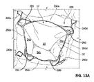
次に図13Aおよび図14Aを参照すると、自然僧帽弁17内にインプラントされたアンカーアセンブリ200が図示されている。図13Bおよび図14Bは、それぞれ図13Aおよび図14Aに対応する写真である。図13Aでは、僧帽弁17は、閉鎖状態にあるように図示されている。図14Aでは、僧帽弁17は、開放状態にあるように図示されている。これらの図は、僧帽弁17の方を見たときの左心房の斜視図からのものである。たとえば、図14Aにおいて、腱索40は、僧帽弁17の開いている弁尖を通して見える。
Next, referring to FIGS. 13A and 14A, the
これらの図は、自然僧帽弁17と関係するアンカーアセンブリ200の弁輪上構造および弁輪下構造を示している。たとえば、図13Aの自然僧帽弁17の閉鎖状態は、外側前心房保持特徴部240a、外側後心房保持特徴部240b、内側後心房保持特徴部240c、および内側前心房保持特徴部240dなどの弁輪上構造が見えるようにし得る。それに加えて、前アンカーアーチ部250a、左アンカーアーチ部250b、後アンカーアーチ部250c、右アンカーアーチ部250d、および接続ブリッジ260は、見えている。しかしながら、弁輪下構造は、図13Aには見えていないが、それは、そのような構造が、前尖20ならびに三部構成の後尖24a、24b、および24cによって遮られて見えないからである。
These figures show the superior and inferior annulus structure of the
対照的に、図14Aにおいて、アンカーアセンブリ200のいくつかの弁輪下構造は、僧帽弁17が開いているので見える。たとえば、弁輪下支持アーム230a、230b、230c、および230dならびにハブ210は、開放僧帽弁17を通して見える。それでもなお、アンカー足部220a、220b、220c、および220dは、自然僧帽弁17の弁輪下溝内に配置されているので、見えないままである。それに加えて、この図にはSAM封じ込め部材(弁輪下構造物である)は見えていない。
In contrast, in FIG. 14A, some subvalvular structures of the
図15を参照すると、アンカーアセンブリ200を自然僧帽弁17内にインプラントした後に(たとえば、上で説明されている図1〜図7に従って実行されるように)、アンカーアセンブリ200内に弁アセンブリを配備するために送達システム100の弁送達シース170が使用され得る。図7を参照しつつ上で説明されているように、遠位プッシャーカテーテル160がアンカーアセンブリ200のハブ210と結合された状態で、遠位プッシャーカテーテル160は、弁アセンブリをアンカーアセンブリ200の内部に誘導するために使用され得る。
Referring to FIG. 15, after implanting the
図示されている実施形態において、SAM封じ込め部材212は、その配備前構成において拘束されている。しかしながら、他のいくつかのSAM封じ込め部材の実施形態(たとえば、図27〜図33を参照しつつ以下でさらに説明されているように)では、SAM封じ込め部材は、弁アセンブリをアンカーアセンブリ200内に取り付ける前に配備され得る。概して、SAM封じ込め部材の実施形態の設計に応じて、SAM封じ込め部材が潜在的に前尖の機能に干渉し得る場合、弁がインプラントされてSAM封じ込め部材が配備されるまで待つのが好ましいと思われる。しかし、SAM封じ込め部材が弁尖機能に干渉しないか、または干渉する可能性が低い場合、SAM封じ込め部材は、弁がインプラントされる前に配備され得る(アンカーが弁インプラントとは別の手術でインプラントされる状況に対しては有益な場合がある)。
In the illustrated embodiment, the
いくつかの実装において、一次偏向可能カテーテル120が左心房16内の遠位端により位置決めされた状態で、弁送達シース170は、一次偏向可能カテーテル120の内腔内に(遠位プッシャーカテーテル160上で)取り付けられ、一次偏向可能カテーテル120に通されて前進する。以下でさらに説明されているように、いくつかの実施形態において、弁送達シース170は、送達システム100の人工弁アセンブリおよび他のコンポーネントを事前装填される。一次偏向可能カテーテル120は、アンカーアセンブリ200を送達するために使用された同じカテーテルであってよいか、または異なるカテーテルであってもよい(が、それでも簡単のために本明細書では一次偏向可能カテーテル120と称される)。
In some implementations, the
いくつかの実施形態において、弁送達シース170は、一次偏向可能カテーテル120に関して上で説明されている材料から作られ得る。いくつかの実施形態において、弁送達シース170は、約20Frから約28Fr(約6.7mmから約9.3mm)の範囲内の外径を有する。いくつかの実施形態において、弁送達シース170は、約14Frから約24Fr(約4.7mmから約8.0mm)の範囲内の外径を有する。
In some embodiments, the
図示されている実施形態において、弁送達シース170は、裾広がり遠位端部分172を備える。いくつかの実施形態において、そのような裾広がり遠位端部分172は含まれない。裾広がり遠位端部分172は、一次偏向可能カテーテル120内に拘束されたときにより背の低い輪郭になるまでつぶれることができる。裾広がり遠位端部分172が、一次偏向可能カテーテル120から表出されたときに、裾広がり遠位端部分172は自己拡張して裾広がり形状になるものとしてよい。いくつかの実施形態において、裾広がり遠位端部分172の材料は、ひだまたは折り目を備えており、連続的な裾広がり端部であり得るか、または花びらのようないくつかのセクションに分離されるものとしてよく、拘束力(一次偏向可能カテーテル120内の封じ込めなどからの)が存在しない場合に裾広がり遠位端部分172を付勢して裾広がり構成を取らせる1つまたは複数の弾力性のある要素を備え得る。裾広がり遠位端部分172は、たとえば、弁アセンブリが裾広がり遠位端部分172から表出された後に弁送達シース170の内腔内に弁アセンブリを再び捕らえるうえで有利であり得る。
In the illustrated embodiment, the
いくつかの実施形態において、裾広がり遠位端部分172の最大外径は、約30Frから約34Fr(約10.0mmから約11.3mm)の範囲内である。いくつかの実施形態において、裾広がり遠位端部分172の最大外径は、約32Frから約44Fr(約10.7mmから約14.7mm)の範囲内である。いくつかの実施形態において、裾広がり遠位端部分172の最大外径は、約24Frから約30Fr(約8.0mmから約10.0mm)の範囲内である。いくつかの実施形態において、裾広がり遠位端部分172の最大外径は、約24Fr(約8.0mm)未満または約44Fr(約14.7mm)超である。
In some embodiments, the maximum outer diameter of the hem-spreading
図16を参照すると、いくつかの実装において、弁送達シース170は、一次偏向可能カテーテル120内に引き込まれ得るが、弁送達カテーテル180は、弁アセンブリ300を弁送達シース170の内腔から表出させるために実質的に静止状態に保持される。弁送達シース170および弁送達カテーテル180は、例示的な送達システム100のいくつかの実施形態における追加のコンポーネントである。
Referring to FIG. 16, in some implementations, the
弁アセンブリ300は、弁送達カテーテル180に解放可能に結合され、背の低い構成に保持され得る。いくつかの実施形態において、弁アセンブリ300の遠位端および近位端は両方とも、弁送達カテーテル180に解放可能に結合されている。いくつかの実施形態において、弁アセンブリ300の遠位端または近位端のうちの一方だけ、弁送達カテーテル180に解放可能に結合されている。特定の実施形態において、弁アセンブリ300の1つまたは複数の部分を弁送達カテーテル180に解放可能に結合するために1本またはそれ以上の本数の制御線が含まれ得る。
The
図17および図18を参照すると、送達システム100は、左心房16内の弁アセンブリ300の外側枢動(パニング、回転など)を実行するために操作者である臨床医によって操作され得る。弁アセンブリ300の回転は、弁アセンブリ300のアライメントを一次偏向可能カテーテル120の遠位端部分とともに一般的に軸方向であることからアンカーアセンブリ200とともに一般的に軸方向であることに変化させる(弁アセンブリ300をアンカーアセンブリ200の内部内に取り付ける準備として)。
With reference to FIGS. 17 and 18, the
いくつかの実装において、弁アセンブリ300の前述の回転は、次のように実行され得る。図17に示されているように、弁送達カテーテル180に対する一次偏向可能カテーテル120からの影響があるため、弁アセンブリ300の軸は、一次偏向可能カテーテル300の軸は、一次偏向可能カテーテル120の遠位端部分の軸と最初に一般的アライメント状態にある。この配置構成から、弁アセンブリ300を回転させるために臨床医によって遠位プッシャーカテーテル160と弁送達カテーテル180との間の同時対抗運動が実行され得る。すなわち、遠位プッシャーカテーテル160が近位に引かれると、弁送達カテーテル180は、遠位に押される。その対抗運動の結果として、弁アセンブリ300は、左心房16の閉鎖部分によって必要に応じて、相対的な狭い半径で回転する。その後、弁送達カテーテル180は、弁アセンブリ300が、図18に示されているようにアンカーアセンブリ200の内部内に同軸上に位置決めされるようにさらに前進させられ得る。
In some implementations, the aforementioned rotation of the
次に図19も参照すると、いくつかの実施形態において、弁アセンブリ300およびアンカーアセンブリ200は、弁アセンブリ300の拡張前または拡張時に、互いに同軸上で、直線上で(軸に沿って)、および回転可能にアライメントされており、その結果、弁アセンブリ300およびアンカーアセンブリ200が係合する。
Then also referring to FIG. 19, in some embodiments, the
上で説明されているように、弁アセンブリ300とアンカーアセンブリ200の間の同軸上のアライメントは、弁送達カテーテル180が遠位プッシャーカテーテル160上に摺動可能に配設されることで達成される。弁アセンブリ300とアンカーアセンブリ200の間の直線上のアライメントは、弁送達カテーテル180の遠位端特徴部182とアンカーアセンブリ200のハブ210との相互作用によって達成され得る。たとえば、いくつかの実施形態において、遠位端特徴部182とハブ210とが当接すると、その結果、弁アセンブリ300とアンカーアセンブリ200との間の適切な直線上のアライメントが行われ得る。
As described above, the coaxial alignment between the
弁アセンブリ300とアンカーアセンブリ200との間の相対的な回転可能なアライメント(軸の周りの)は、様々な仕方で達成され得る。たとえば、いくつかの実施形態において、弁送達カテーテル180は、遠位プッシャーカテーテル160に機械的に合わせられ、弁アセンブリ300とアンカーカテーテル200との間の所望の回転可能なアライメントを摺動可能に固定する。いくつかの実施形態において、他のタイプの機械的特徴部(たとえば、ピン/穴、突起部/受容部など)は、弁アセンブリ300とアンカーアセンブリ200との間の所望の回転可能/スピンアライメントを円滑にするために備えられ得る。代替的に、またはそれに加えて、放射線不透過性マーカーが、弁アセンブリ300および(SAM封じ込め部材212を含む)アンカーアセンブリ200の相対的な回転する向き(軸の周りの)を示す配置および/またはパターンで弁アセンブリ300およびアンカーアセンブリ200上に備えられ得る。いくつかの実施形態において、(たとえば、弁送達カテーテル180が「トルク伝達可能」であるときに)弁送達カテーテル180は、弁アセンブリ300の最終的な拡張の前に、アンカーアセンブリ200に関してマーカーが適切な位置に来るまで軸の周りに回転させられ得る。蛍光透視法は、放射線不透過性マーカーの、ならびにそれに対応して弁アセンブリ300および(SAM封じ込め部材212を含む)アンカーアセンブリ200の、所望の相対的な配向を達成するために使用できる。
Relative rotatable alignment (around the axis) between the
図示されている実装において、SAM封じ込め部材212は、依然としてその配備前構成のままである。したがって、SAM封じ込め部材212の図示されている実施形態は、弁アセンブリ300がアンカーアセンブリ200内に係合された後に配備される。しかしながら、SAM封じ込め部材のいくつかの代替的実施形態については(以下でさらに説明されているように)、SAM封じ込め部材は、弁アセンブリ300をアンカーアセンブリ200内に係合させる前に配備される。
In the implementation shown, the
図20および図21を参照すると、アンカーアセンブリ200のSAM封じ込め部材212は、配備前構成および配備済み構成にて構成され得る。図20は、配備前構成を取るSAM封じ込め部材212を示しており、図21は、配備済み構成を取るSAM封じ込め部材212を示している。以下でさらに説明されているように、いくつかの実施形態において、SAM封じ込め部材212の配備は、アンカーアセンブリ200の後に、および弁アセンブリ300が自然僧帽弁内に取り付けられた後に行われる(図1〜図19を参照しつつ上で説明されているように)。ここで、簡単のため、弁アセンブリ300は図示されていない。SAM封じ込め部材212を配備するこの技術は、結果として、SAM封じ込め部材212を自然僧帽弁前尖の前方に(本明細書では「背後に」とも称される)位置決めする。したがって、配備されたSAM封じ込め部材212は、自然僧帽弁前尖がLVOTを閉塞するのを阻止し、および/または防ぐ物理的障壁として働く。
With reference to FIGS. 20 and 21, the
SAM封じ込め部材212の配備は、すべて本開示の範囲内にある様々なメカニズムおよび技術を使用することによって制御されながら実行され得ることが企図される。そのようなSAM封じ込めおよび配備メカニズムおよび技術の複数の非制限的な例が、本明細書において提示されている。
It is contemplated that the deployment of the
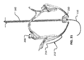
上で説明されているように、いくつかの実施形態において、経カテーテル僧帽弁送達システム100は、遠位プッシャーカテーテル160とガイドワイヤ110とを備える。いくつかの実施形態において、ガイドワイヤ110は、遠位プッシャーカテーテル160の内腔内に摺動可能に配設され、ガイドワイヤ110は、遠位プッシャーカテーテル160の遠位端から遠位に外へ延在し得る。図示されている実施形態と同様に、いくつかの実施形態において、ガイドワイヤ120は、SAM封じ込め部材212の小穴214を貫通することができる。
As described above, in some embodiments, the transcatheter mitral
図20および図21に図示されている例示的な実施形態において、遠位プッシャーカテーテル160は、ネジ山付き遠位端162を備え、そこからガイドワイヤ110が遠位に延在し得る。図示されているように、いくつかの実施形態において、ネジ山付き遠位端162は、SAM封じ込め部材212の小穴214内の補完し合う雌ネジと嵌合することができる。したがって、ネジ山付き遠位端162は、選択的にねじ込まれて小穴214と係合し、選択的に逆に回されることで小穴214との係合を外すことができる。別の言い方をすると、いくつかの実施形態において、遠位プッシャーカテーテル160は、SAM封じ込め部材212と解放可能に係合可能である。アンカーアセンブリ200を配備するプロセスを実行している臨床医は、それによって、SAM封じ込め部材212の配備を制御することができる。言い換えると、遠位プッシャーカテーテル160を回すことによって、臨床医は、小穴214にねじ込まれているネジ山付き遠位端162を取り外し、SAM封じ込め部材212を解放するか、または配備することができる。
In an exemplary embodiment illustrated in FIGS. 20 and 21, the
ネジ山付き遠位端162が小穴214と結合されると、SAM封じ込め部材212は、その配備前構成において拘束されている(図20)。ネジ山付き遠位端162が小穴214との結合から外されると、SAM封じ込め部材212は、遠位プッシャーカテーテル160による拘束から解放され、SAM封じ込め部材212は、次いで、その自然な配備済み構成を自由に求めることができる(図21)。
When the threaded
いくつかの実装において、SAM封じ込め部材212が配備されている間に、SAM封じ込め部材212の一部分は、SAMの生じる可能性を低減するように前尖および/または腱索と係合し得る。係合は、外側前アーム213aおよび/または内側前アーム213dの長さに沿った任意の場所で、およびその接合部で、なされてよい(たとえば、図10を参照)。たとえば、いくつかの実装において、外側前弁輪下支持アーム230aおよび/または内側前弁輪下支持アーム230dの近くにある外側前アーム213aおよび/または内側前アーム213dの部分は、実際には、前尖および/または腱索の外側縁と係合して、外側縁のところの前尖を広げるか、または幅広にして、それによってその移動を制限し、さらにSAMの生じる可能性を低減することができる。
In some implementations, while the
図22〜図24を参照すると、人工僧帽弁400が自然僧帽弁17と係合している間(上で説明されているように)の、SAM封じ込め部材212の配備プロセスについて、次にさらに説明される。図22は、遠位プッシャーカテーテル160から取り外した後、ただし、SAM封じ込め部材212がその拘束された配備前構成から実質的に移動する前の、SAM封じ込め部材212の位置を示している。図23は、自然な配備済み構成に移動している(または自己偏向している)ときのSAM封じ込め部材212の暫定的位置を示している。図24は、SAM封じ込め部材212が前尖20の背後に(すなわち、前尖20の大動脈側に)少なくとも部分的に配設される配備済み構成を取るSAM封じ込め部材212の位置を示している。したがって、この一連の図は、遠位プッシャーカテーテル160から事後減結合するSAM封じ込め部材212の配備プロセス(すなわち、「自己再構成」プロセス)を図示している。
With reference to FIGS. 22-24, the process of deploying the
これらの図は、人工僧帽弁400(弁アセンブリ300と結合されているか、または嵌合しているアンカーアセンブリ200を含む)、遠位プッシャーカテーテル160およびガイドワイヤ110(送達システムのコンポーネント部材である)、患者の自然僧帽弁17、ならびに自然僧帽弁17の前尖20の図を含む。この実装では、SAM封じ込め部材212の配備は、人工僧帽弁400(弁アセンブリ300と結合されているか、または嵌合しているアンカーアセンブリ200を含む)が自然僧帽弁17と動作可能位置で係合した後に行われることに留意されたい。代替的に、いくつかの実装において、SAM封じ込め部材212の配備は、アンカーアセンブリ200が自然僧帽弁17と係合した後、ただし、弁アセンブリ300がアンカーアセンブリ200と結合/嵌合する前に、行うことができる。
These figures are the artificial mitral valve 400 (including the
いくつかの実施形態において、ガイドワイヤ110は、SAM封じ込め部材212のアタッチメント要素と係合する。たとえば、図示されている実施形態において、ガイドワイヤ110は、SAM封じ込め部材212の小穴214に螺合される。したがって、遠位プッシャーカテーテル160をSAM封じ込め部材212から脱着した後も、ガイドワイヤ110は、SAM封じ込め部材212と摺動可能に係合したままである。
In some embodiments, the
いくつかの実装において、ガイドワイヤ110が遠位プッシャーカテーテル160から脱着した後にSAM封じ込め部材212と係合したままであり得るという事実により、ガイドワイヤ110はSAM封じ込め部材212の配備に対して何らかの制御を行うために使用され得る。たとえば、ガイドワイヤ110を異なる側面柔軟性のある2つ以上の部分を有するように製作することによって、SAM封じ込め部材212の自己再構成は、ガイドワイヤ110の長手方向位置決めによって少なくとも部分的に制御されるか、または影響を受け得る。そのような一例では、ガイドワイヤ110は、遠位先端部から近位にあるより剛性の高い部分よりも高い側面柔軟性を有する遠位先端部を有する。したがって、ガイドワイヤ110のより剛性の高い部分がSAM封じ込め部材212と係合したときに、ガイドワイヤ110は、SAM封じ込め部材212をその完全配備済み構成へ移動しないように拘束または部分的に拘束する。しかしながら、ガイドワイヤ110が(近位に)引き戻され、ガイドワイヤ110のより側面柔軟性の高い部分がSAM封じ込め部材212と係合したときに、SAM封じ込め部材212を付勢してその自然配備済み構成に自己再構成することで、ガイドワイヤ110からの側面抵抗に打ち勝つことができる。したがって、SAM封じ込め部材212に対してガイドワイヤ110を臨床医が選択的に位置決めすることによって、SAM封じ込め部材212の配備は、臨床医によって少なくとも部分的に制御され得る。
In some implementations, the
図23に示されているように、いくつかの実装において、SAM封じ込め部材212が再構成を始める(または部分的に再構成される)と、ガイドワイヤ110は、それによって、自然前尖20の後ろと有利に接触する位置に偏向され得る。その結果、ガイドワイヤ110は、前尖20を人工僧帽弁400の方へ径方向内向きに引くか、または拘束し、それにより、SAM封じ込め部材212の配備時に前尖20を捕らえやすくする働きをし得る。
As shown in FIG. 23, in some implementations, when the
図24に示されているように、SAM封じ込め部材212が配備済み構成で構成されたときに、SAM封じ込め部材212の少なくとも一部は、自然僧帽弁17の前尖20の背後に配設される。いくつかの実装において、前尖20は、SAM封じ込め部材212と弁アセンブリ300の外面との間に画成されている空間内に緩く収容される。したがって、前尖20の収縮期前方運動(SAM)の潜在的可能性は、管理されるか、または制御される。すなわち、前尖20は、LVOT閉塞を引き起こすこと、またはSAM封じ込め部材212を前尖20の背後に位置決めすることによる高LVOT圧力勾配の発生を生じないよう拘束される。
As shown in FIG. 24, when the
図25および図26を参照すると、いくつかの実施形態において、送達システム100の制御線164(たとえば、図1〜図7および図15〜図19を参照)は、SAM封じ込め部材212と脱着可能に結合することができ、それにより、臨床医はSAM封じ込め部材212の配備を制御することができる。たとえば、いくつかの実施形態において、制御線164は、SAM封じ込め部材212のアタッチメント要素と結合される(いくつかの実施形態では制御線164を小穴214にねじ込んで通すことなどによって)。
With reference to FIGS. 25 and 26, in some embodiments, the
いくつかの実施形態において、制御線164は、遠位プッシャーカテーテル160の内腔内に摺動可能に配設される。特定の実施形態において、制御線164は、遠位プッシャーカテーテル160の外部に配設される。
In some embodiments, the
いくつかの実施形態において、制御線164の2つの端部は、臨床医操作者が制御線164の位置を長手方向で調整し、それによってSAM封じ込め部材212の配備位置決めを制御することができるように患者の体外に位置決めされ得る(図25を図26と比較することによって示されているように)。たとえば、制御線164の両端は、SAM封じ込め部材212をその配備前構成(図25)に位置決めするように引っ張られ、および/または近位に拘束され得るが、制御線164の一端または両端も、SAM封じ込め部材212の、その配備済み構成(図26)への再構成を円滑にするか、または促すように遠位に移動され得るか、または移動することを許され得る。
In some embodiments, the two ends of the
制御線164を使用することで、臨床医は、SAM封じ込め部材212の配備を正確に制御することができることは理解されるであろう。たとえば、臨床医は、それによって、SAM封じ込め部材212の再構成のペースを制御することができる。さらに、SAM封じ込め部材212が配備されるか、または部分的に配備された後、臨床医は、SAM封じ込め部材212を逆配備する(すなわち、SAM封じ込め部材212が配備前構成に部分的にまたは完全に戻るように制御線164を近位に引く)ことができる。このようにして、SAM封じ込め部材212の配備プロセスは、可逆で繰り返し可能である(制御線164がSAM封じ込め部材212と結合されたままである限り)。
It will be appreciated that by using the
臨床医操作者が、SAM封じ込め部材212が十分満足のゆくように構成されたとみなしたとき(たとえば、SAM封じ込め部材212の少なくとも一部が前尖の背後に位置決めされるように)、臨床医は、次いで、制御線164の一端を引き、制御線164の他端を解放するようにできる。制御線164の一端を引き続けることによって、制御線164は、最終的に、SAM封じ込め部材212から脱着する(たとえば、逆に回してねじ込みを外す)ことができる。
When the clinician operator considers the
図27〜図34を参照すると、いくつかの実装において、SAM封じ込め部材216(図11を参照)は、アンカーアセンブリ200が自然僧帽弁17と係合している間に配備され得る(上で説明されているように)。いくつかの実装において、SAM封じ込め部材216の配備プロセスは、弁アセンブリ300の配備の前に行われ得ることは理解されるであろう(たとえば、図34に示されているように)。代替的に、いくつかの実装において、SAM封じ込め部材216の配備プロセスは、弁アセンブリ300がアンカーアセンブリ200と嵌合した後に行われ得る。図27〜図34に示されている実施形態は、人工弁アセンブリ300の実装の前に配備するのに最適であるが、それは、ハブ210から出て来る設計は前尖の通常の機能にほとんど影響を及ぼさず、前尖が弁アセンブリ300をインプラントする前に本質的に通常通りに機能し続けることを許すからである。
Referring to FIGS. 27-34, in some implementations, the SAM containment member 216 (see FIG. 11) may be deployed while the
図27、図29、および図30は、シース166内の配備前構成にあるSAM封じ込め部材216の位置を示している。図31および図32は、シース166から出現した後、ただし、シース166から変形力を受け入れる前に、その部分的配備済み構成を取るSAM封じ込め部材216の位置を示す。図28、図33、および図34は、シース166を介して印加される変形力によって変形された後の配備済み構成にあるSAM封じ込め部材216の位置を示している。
27, 29, and 30 show the location of the
SAM封じ込め部材216は、細長い要素のアーム部分217(アンカーアセンブリ200のハブ210に取り付けられている)と、アーム部分217から延在する端部218とを備える。いくつかの実施形態において、細長部材のアーム部分217から延在する端部218は、アーム部分217の幅よりも広い幅を定める。以下でさらに説明されているように、端部218は、アンカーアセンブリ200が自然僧帽弁と係合したときに前尖の背後に配設されるように構成される。
The
図27、図29、および図30に示されているように、いくつかの実施形態において、SAM封じ込め部材216は、配備前構成に配置構成されてよく、これは経カテーテル送達に適している薄型構成のシース166の内腔内に摺動可能に配設される。いくつかの実施形態において、遠位プッシャーカテーテル160も、シース166内に摺動可能に配設される。SAM封じ込め部材216がこの配備前構成で拘束されている場合に、アンカーアセンブリ200は、図29に示されているように、自然僧帽弁17内で拡張され、係合させられ得る。
As shown in FIGS. 27, 29, and 30, in some embodiments, the
いくつかの実装において、アンカーアセンブリ200を自然僧帽弁17と係合させた後に、SAM封じ込め部材216の配備プロセスが実行できる。第1に、図31および図32に示されているように、シース166は、臨床医操作者によって近位に引っ張られ、それにより、SAM封じ込め部材216がシース166内の封じ込めから出現するようにできる。シース166が引き戻されたときに、いくつかの実施形態において、SAM封じ込め部材216の自然な付勢は、SAM封じ込め部材216が偏向してシース166内の前の位置から径方向に離れることを引き起こす。それに加えて、対角線で拘束するシース166を取り外すことで、いくつかの実施形態において、端部218は拡張して端部218の自然な拘束されていない構成になる。たとえば、図示されている実施形態において、3つの細長部材219a〜cは、アーム部分217の幅よりも広い幅を定めるように外側に扇形に広がる。
In some implementations, the process of deploying the
いくつかの実施形態において、SAM封じ込め部材216の配備プロセスの次のステップは、SAM封じ込め部材216のさらなる径方向偏向を含み、それにより、端部218は前尖20の背後に配設されるようになる。このステップは、図28および図33に示されており、蛍光透視の下で実行することができる(本明細書で説明されている他の配備ステップのうちのいくつかまたはすべてが実行できるように)。
In some embodiments, the next step in the process of deploying the
いくつかの実装において、SAM封じ込め部材216のさらなる径方向偏向のこのステップは、少なくとも一部は、シース166からの力をアーム部分217に印加することによって実行される。すなわち、いくつかの実施形態において、シース166は、アーム部分217と接合するように、また結果としてSAM封じ込め部材216の径方向偏向を引き起こす力をそれに印加するように構成されている遠位端167を備える。たとえば、いくつかの実施形態において、臨床医操作者がシース166を遠位に押すと、遠位端167はアーム部分217を圧迫して、SAM封じ込め部材216の径方向偏向を引き起こす。
In some implementations, this step of further radial deflection of the
いくつかの実施形態において、端部218が前尖20の背後に配設されるようにSAM封じ込め部材216を偏向させることが、シース166によって力が印加される結果としてSAM封じ込め部材216の塑性変形によって生じる。様々な実施形態において、端部218が前尖20の背後に配設されるようにSAM封じ込め部材216を偏向させることが、SAM封じ込め部材216がシース166から出現することが許された後、さらなる力がシース166によって印加されることなく、SAM封じ込め部材216の自然な付勢によって生じる。特定の実施形態において、端部218が前尖20の背後に配設されるようにSAM封じ込め部材216を偏向させることは、SAM封じ込め部材216がシース166から出現することが許された後のSAM封じ込め部材216の自然な付勢と、シース166によってアーム部分217に力が印加された結果としてのそれに対するさらなる付勢との組合せによって達成される。
In some embodiments, deflecting the
いくつかの実装において、端部218が弁尖20の背後に配設されるようにSAM封じ込め部材216を配備した後に、弁アセンブリ300は、次いで、図34に示されているようにアンカーアセンブリ200と嵌合するように配備される。代替的に、いくつかの実装において、SAM封じ込め部材216は、弁アセンブリ300がアンカーアセンブリ200と嵌合するように配備された後、端部218が弁尖20の背後に配設されるように配備される。いくつかの実装において、前尖20は、SAM封じ込め部材216と弁アセンブリ300の外面との間に画成されている空間内に緩く収容される。いくつかの実装において、前尖20は、SAM封じ込め部材216と弁アセンブリ300の外面との間に画成されている空間内にぴったり収容されるか、または軽く圧縮される。
In some implementations, after deploying the
図35および図36を参照すると、被覆材または弁/閉塞器弁尖なしで例示的な弁アセンブリ300が図示されている。したがって、弁アセンブリ300の弁アセンブリフレーム301が示されている。図35は、弁アセンブリフレーム301の前側面図であり、図36は、弁アセンブリフレーム301の底面図である。弁アセンブリ300は、アンカーフレーム200を参照して上で説明されている様々な材料および製造技術のうちのどれかを使用して製作され得る(たとえば、図9参照)。図示されている弁アセンブリ300は、本開示の範囲内で実現される弁アセンブリの1つの非制限的な例にすぎないことは理解されるであろう。
With reference to FIGS. 35 and 36, an
弁アセンブリ300は、近位端部分302と遠位端部分304とを備える。弁アセンブリは、裾広がりの外部スカート部分303を備え、内部オリフィス部分305を画成する。弁アセンブリ300が、自然僧帽弁内にインプラントされたときに、近位端部分302は、弁輪上(左心房内)に配置され、遠位端部分304は、弁輪下(左心室内)に配置される。近位端部分302は、以下でさらに説明されているように、弁アセンブリ300の一般的に円形の入口オリフィスを画成する。
The
図示されている実施形態において、弁アセンブリ300は、遠位方向に沿って一般的に外向きに裾広がりになっている。別の言い方をすると、遠位端部分304は、近位端部分302と比較して外向きに裾広がりになっている。したがって、近位端部分302は、遠位端部分304と比較してより小さい外形を画成する。しかしながら、遠位端部分304のいくつかの領域は、内向きに弓なりに曲がる。特に、たとえば、弁アセンブリ300の後交連角330aおよび前交連角330bは内向きに弓なりに曲がり得る。近位端部分302と比較した遠位端部分304の外向きの裾広がりは、弁アセンブリ300の輪郭に対する構成の単なる一例であることは理解されるであろう。いくつかの実施形態において、たとえば、段部(最大の外周を有する弁アセンブリ300の部分)は、弁アセンブリ300の中間の近くに配置される。
In the illustrated embodiment, the
弁アセンブリ300は、後交連角330aと前交連角330bとの間に前側部306も備える。弁アセンブリ300が、自然僧帽弁内にインプラントされたときに、前側部306は、僧帽弁の前尖に面する。遠位端部分304の前側部306は、一般的に平坦な表面を画成するが、遠位端部分304の他の側部は、丸くなっている。したがって、遠位端部分304の周は、一般的にD字形である。遠位端部分304の周がD字形であるため、弁アセンブリ300は自然僧帽弁と接触し、封止するのに有利な外形を備える。以下でさらに説明されているように、封止は遠位端部分304のD字形の周と自然僧帽弁の弁尖との間の、およびいくつかの実施形態において、自然弁輪を有するスカート部303の領域内のD字形の周の間の接合によって達成される。
The
図示されている実施形態において、弁アセンブリ300の近位端部分302は、その近位端部分302のところで起伏のあるリングを一緒に画成する3つの心房弁尖アーチ部310a、310b、および310cを備える。弁尖アーチ部310a、310b、および310cの各々は、それぞれ、取付穴312a、312b、および312cを有する頂点を備える。いくつかの実施形態において、取付穴312a、312b、および312cは、弁アセンブリ300の近位端を送達カテーテル(たとえば、図16〜図18の弁送達カテーテル180)に結合するために使用される。
In the illustrated embodiment, the
弁アセンブリ300は、また、3つの弁尖アーチ部310a、310b、および310cの交差点から遠位に各々延在する3つの交連支柱320a、320b、および320cも備える。交連支柱320a、320b、および320cは、互いに約120°離れて配設されている。交連支柱320a、320b、および320cは、各々、縫合することなどによって、弁尖の取り付けに使用され得る一連の穴を有する。3つの弁尖アーチ部310a、310b、および310cならびに3つの交連支柱320a、320b、および320cは、3つの人工弁弁尖が三葉閉塞器を備えるために取り付けられた弁アセンブリ300上の領域である(たとえば、図38〜図41参照)。
The
図36に最もよく示されているように、3つの弁尖アーチ部310a、310b、および310cならびに3つの交連支柱320a、320b、および320cは、三葉閉塞器構造物に対する一般的に円筒形のフレームを画成する。そのようなものとして、弁アセンブリ300は、三葉閉塞器に対する実証済みの有利なフレーム構成を形成する。三葉閉塞器は、拡張期に開放流を、収縮期に流れの閉塞をもたらす。
As best shown in FIG. 36, the three
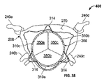
図37を参照すると、例示的な人工僧帽弁400の分解図はアンカーアセンブリ200および弁アセンブリ300を含んでいる。この図は、アンカーアセンブリ200および弁アセンブリ300の後側面図になっている。
Referring to FIG. 37, an exploded view of an exemplary artificial
弁アセンブリ300は、被覆材340を備えている。被覆材340は、被覆材270を参照して上で説明されている技術のうちのどれかを使用して、材料のうちのどれかから作られ、製作され得る。それに加えて、いくつかの実施形態において、被覆材340は、限定はしないが、ウシ、ブタ、ヒツジ、またはウマの心膜などの自然組織を含むことができる。いくつかのそのような実施形態において、組織は、グルタルアルデヒド、ホルムアルデヒド、またはトリグリシジルアミン溶液、または他の好適な架橋剤を使用して化学的に架橋される。
The
弁アセンブリ300およびアンカーアセンブリ200が一緒に結合されたときに、弁アセンブリ300は、アンカーアセンブリ200の内部内で幾何学的に連動状態にある(たとえば、いくつかの実施形態において、アンカーアセンブリ200の弁輪上リングおよび内部空間内の弁アセンブリ300のテーパー付き形状による)。特に、いくつかの実施形態において、弁アセンブリ300は、弁輪上リング250と弁輪下支持アーム230a、230b、230c、および230dとの間の内部空間内に収容される。上で説明されているように、弁アセンブリ300とアンカーアセンブリ200との間の連動する配置構成は、弁アセンブリ300をアンカーアセンブリ200の内部内の背の低い構成に位置決めし、次いで、アンカーアセンブリ200の内部内で弁アセンブリ300の拡張を許すことによって達成される(たとえば、図18および図19参照)。
When the
図38および図39を参照すると、例示的な人工僧帽弁400の配備された構成は、アンカーアセンブリ200内で係合している弁アセンブリ300を含む。図38は、人工僧帽弁400の上面(心房)図であり、図39は、人工僧帽弁400の底面(心室)図である。
With reference to FIGS. 38 and 39, the deployed configuration of the exemplary artificial
図示されている実施形態などの、いくつかの実施形態において、弁アセンブリ300は、人工僧帽弁400の閉塞機能を実行する3つの弁尖350a、350b、および350cを備える。3つの弁尖350a、350b、および350cの尖部は、3つの心房弁尖アーチ部310a、310b、および310cに固定され、および3つの交連支柱320a、320b、および320cに固定される(図35および図36参照)。3つの弁尖350a、350b、および350cの自由縁は、収縮期に互いに接合によって封止し、拡張期に開くことができる。
In some embodiments, such as those illustrated, the
3つの弁尖350a、350b、および350cは、天然材料または合成材料からなるものとしてよい。たとえば、3つの弁尖350a、350b、および350cは、限定はしないが、ウシ、ブタ、ヒツジ、またはウマの心膜などの自然組織を含む、被覆材340を参照して上で説明されている材料のうちのどれかからなるものとしてよい。いくつかのそのような実施形態において、組織は、グルタルアルデヒド、ホルムアルデヒド、またはトリグリシジルアミン溶液、または他の好適な架橋剤を使用して化学的に架橋される。いくつかの実施形態において、弁尖350a、350b、および350cは、約0.005”から約0.020”(約0.13mmから約0.51mm)、または約0.008”から約0.012”(約0.20mmから約0.31mm)の範囲内の厚さを有する。いくつかの実施形態において、弁尖350a、350b、および350cは、約0.005”(約0.13mm)未満、または約0.020”(約0.51mm)超の厚さを有する。
The three
いくつかの実施形態において、人工僧帽弁400の閉塞機能は、三葉閉塞器とは別の構成を使用して実行され得る。たとえば、二葉、四葉、または機械弁構造物は、いくつかの実施形態において使用され得る。
In some embodiments, the occlusive function of the artificial
いくつかの実施形態において、SAM封じ込め部材は、アンカーアセンブリ200の一部として含まれる(たとえば、図10および図11を参照)。図示されている実施形態において、SAM封じ込め部材は含まれない。 In some embodiments, the SAM containment member is included as part of the anchor assembly 200 (see, eg, FIGS. 10 and 11). In the illustrated embodiment, the SAM containment member is not included.
図40および図41を参照すると、自然僧帽弁17内にインプラントされた人工僧帽弁400が図示されている。図40では、人工僧帽弁400は、閉鎖(閉塞)状態にあるように図示されている。図41では、人工僧帽弁400は、開放状態にあるように図示されている。これらの図は、僧帽弁17の方を見たときの左心房の斜視図からのものである。たとえば、図41において、ハブ210およびアンカーアセンブリ200の弁輪下支持アーム230a、230b、230c、および230dは、人工僧帽弁400の開放弁尖350a、350b、および350cを通して見えるが、図40において、ハブ210および弁輪下支持アーム230a、230b、230c、および230dは、閉鎖弁尖350a、350b、および350cがハブ210を視界から遮っているので見えない。
With reference to FIGS. 40 and 41, the artificial
これで本発明の多数の実施形態が説明された。それでもなお、本発明の範囲から逸脱することなく様々な修正を加えることができることは理解されるであろう。したがって、他の実施形態は、下記の請求項の範囲内に収まる。 This has described a number of embodiments of the present invention. Nevertheless, it will be appreciated that various modifications can be made without departing from the scope of the invention. Therefore, other embodiments fall within the scope of the following claims.
10 心臓
11 下大静脈
12 右心房
13 三尖弁
14 右心室
15 心房中隔
16 左心房
17 僧帽弁、自然僧帽弁
18 左心室
19 弁輪下溝
20 前尖
22 三部構成の後尖
24a 外側弁帆
24b 中央弁帆
24c 内側弁帆
25a 前領域
25b 後領域
25c 交連領域
28 D字形弁輪
30a 前交連
30b 後交連
32 接骨線
34a 左前アンカーゾーン
34b 左後アンカーゾーン
34c 右後アンカーゾーン
34d 右前アンカーゾーン
100 経カテーテル僧帽弁送達システム
110 ガイドワイヤ
120 一次偏向可能カテーテル
130 アンカー送達シース
132 裾広がり部分
134a 左線維三角
134b 右線維三角
140 近位制御シース
142 制御線
150 二次偏向可能カテーテル
160 遠位プッシャーカテーテル
162 ネジ山付き遠位端
164 制御線
166 シース
167 遠位端
170 弁送達シース
172 裾広がり遠位端部分
180 弁送達カテーテル
182 遠位端特徴部
200 アンカーアセンブリ
210 ハブ
212 SAM封じ込め部材
213a 外側前アーム
213d 内側前アーム
214 小穴、他の種類のアタッチメント要素
216 SAM封じ込め部材
217 アーム部分
218 端部
219a 第1の細長部材
219b 第2の細長部材
219c 第3の細長部材
220a 外側前足部
220b 外側後足部
220c 内側後足部
220d 内側前足部
226 小穴
230a 外側前弁輪下支持アーム
230b 外側後弁輪下支持アーム
230c 内側後弁輪下支持アーム
230d 内側前弁輪下支持アーム
240a 外側前心房保持特徴部
240b 外側後心房保持特徴部
240c 内側後心房保持特徴部
240d 内側前心房保持特徴部
250 起伏のある弁輪上リング
250a 前アンカーアーチ部
250b 左アンカーアーチ部
250c 後アンカーアーチ部
250d 右アンカーアーチ部
260 接続ブリッジ
270 被覆材
270a 外側前弁輪間接続部
270b 外側後弁輪間接続部
270c 内側後弁輪間接続部
270d 内側前弁輪間接続部
300 弁アセンブリ
301 弁アセンブリフレーム
302 近位端部分
303 裾広がりの外部スカート部分
304 遠位端部分
305 内部オリフィス部分
306 前側部
310a、310b、310c 心房弁尖アーチ部
312a、312b、312c 取付穴
320a、320b、320c 交連支柱
330a 後交連角
330b 前交連角
340 被覆材
350a、350b、350c 弁尖
400 人工僧帽弁
10 Heart 11 Inferior aorta 12 Right atrium 13 Tricuspid valve 14 Right ventricle 15 Atrial septum 16 Left atrium 17 Pilot valve, natural mitral valve 18 Left ventricle 19 Lower annulus groove 20 Anterior leaflet 22 Three-part posterior leaflet 24a Outer valve sail 24b Central valve sail 24c Inner valve sail 25a Front area 25b Rear area 25c Correlation area 28 D-shaped annulus 30a Front crossing 30b Rear mating 32 Osteopathic line 34a Left front anchor zone 34b Left rear anchor zone 34c Right rear anchor zone 34d Right front Anchor Zone 100 Transcatheter Pilot Valve Delivery System 110 Guide Wire 120 Primary Deflection Catheter 130 Anchor Delivery Sheath 132 Hem Spread 134a Left Fiber Triangle 134b Right Fiber Triangle 140 Proximal Control Sheath 142 Control Line 150 Secondary Deflection Cauter 160 Far Position pusher catheter 162 threaded distal end 164 control line 166 sheath 167 distal end 170 valve delivery sheath 172 hem widening distal end 180 valve delivery catheter 182 distal end feature 200 anchor assembly 210 hub 212 SAM containment member 213a Outer front arm 213d Inner front arm 214 Small hole, other types of attachment elements 216 SAM containment member 217 Arm part 218 End 219a First elongated member 219b Second elongated member 219c Third elongated member 220a Outer forefoot 220b Outer Hindfoot 220c Inner hindfoot 220d Medial forefoot 226 Small hole 230a Outer anterior annulus lower support arm 230b Outer posterior annulus lower support arm 230c Inner posterior annulus lower support arm 230d Inner anterior annulus lower support arm 240a Retention feature 240b Lateral posterior atrioventricular feature 240c Medial posterior atrial retention feature 240d Medial anterior atrioventricular ring 250a Anterior annulus ring 250a Front anchor arch 250b Left anchor arch 250c Rear anchor arch 250d Right anchor Arch 260 Connection Bridge 270 Covering Material 270a Outer Front Valve Ring Connection 270b Outer Rear Valve Ring Connection 270c Inner Rear Valve Ring Connection 270d Inner Front Valve Ring Connection 300 Valve Assembly 301 Valve Assembly Frame 302 Proximal Edge part 303 Wide hem External skirt part 304 Distal end part 305 Internal orifice part 306 Front side part 310a, 310b, 310c Atrial valve apex arch part 312a, 312b, 312c Mounting holes 320a, 320b, 320c Commissure strut 330a Posterior commissure angle 330b Anterior commissure angle 340 Covering material 350a, 350b, 350c Valve tip 400 Artificial mitral valve
Claims (10)
拡張可能アンカーフレームを備えるアンカーアセンブリであって、前記弁アセンブリと選択的に結合するように構成され、前記拡張可能アンカーフレームは、
前記拡張可能アンカーフレームが自然僧帽弁と係合したときに前記自然僧帽弁の前尖の背後に少なくとも部分的に配設されるように構成されている収縮期前方運動(SAM)封じ込め部材と、
前記拡張可能アンカーフレームの端に配置されたハブ部材と、
前記ハブ部材に取り付けられて前記ハブ部材から延在する複数の細長部材であって、各細長部材は、前記拡張可能アンカーフレームが前記自然僧帽弁と係合したときに前記自然僧帽弁の弁輪の近くの心室組織と係合するように構成されている弁輪下突出部を含む、複数の細長部材と
を備え、前記SAM封じ込め部材は、前記複数の細長部材のうち隣接する二つの細長部材に取り付けられて該二つの細長部材の間で延在する、アンカーアセンブリと
を備える人工僧帽弁システム。 A valve assembly with an expandable valve frame and a blocker attached to the expandable valve frame.
An anchor assembly comprising an expandable anchor frame, the expandable anchor frame being configured to selectively couple with the valve assembly.
A systolic anterior movement (SAM) containment member configured to be at least partially disposed behind the anterior leaflet of the natural mitral valve when the expandable anchor frame engages the natural mitral valve. and,
With the hub member arranged at the end of the expandable anchor frame,
A plurality of elongated members attached to the hub member and extending from the hub member, each elongated member of the natural mitral valve when the expandable anchor frame engages with the natural mitral valve. With multiple elongated members, including an annulus subprojection that is configured to engage ventricular tissue near the annulus.
The SAM containment member is an artificial mitral valve comprising an anchor assembly and an anchor assembly that is attached to two adjacent elongated members of the plurality of elongated members and extends between the two elongated members. Valve system.
拡張可能アンカーフレームであって、径方向に圧縮された送達状態と前記拡張可能アンカーフレームが自然僧帽弁と係合するように構成されている径方向拡張配備済み状態との間で調整可能であり、前記アンカーアセンブリは前記人工僧帽弁システムのその後送達可能な弁アセンブリと選択的に嵌合するように構成されている、拡張可能アンカーフレームを備え、
前記拡張可能アンカーフレームは、
前記拡張可能アンカーフレームが前記自然僧帽弁と係合したときに前記自然僧帽弁の前尖の背後に少なくとも部分的に配設されるように構成されている収縮期前方運動(SAM)封じ込め部材と、
前記拡張可能アンカーフレームの端に配置されたハブ部材と、
前記ハブ部材に取り付けられて前記ハブ部材から延在する複数の細長部材であって、各細長部材は、前記拡張可能アンカーフレームが前記自然僧帽弁と係合したときに前記自然僧帽弁の弁輪の近くの心室組織と係合するように構成されている弁輪下突出部を含む、複数の細長部材と
を備え、
前記SAM封じ込め部材は、前記複数の細長部材のうち隣接する二つの細長部材に取り付けられて該二つの細長部材の間で延在する、
アンカーアセンブリ。 Anchor assembly for the artificial mitral valve system
An expandable anchor frame that is adjustable between a radially compressed delivery state and a radially extended deployed state in which the expandable anchor frame is configured to engage the natural mitral valve. The anchor assembly comprises an expandable anchor frame that is configured to selectively fit with the subsequently deliverable valve assembly of the artificial mitral valve system.
The expandable anchor frame is
Systolic anterior motion (SAM) containment configured to be at least partially disposed behind the anterior leaflet of the natural mitral valve when the expandable anchor frame engages with the natural mitral valve. Members and
With the hub member arranged at the end of the expandable anchor frame,
A plurality of elongated members attached to the hub member and extending from the hub member, each elongated member of the natural mitral valve when the expandable anchor frame engages with the natural mitral valve. It comprises a plurality of elongated members and an elongated member, including an annulus subprojection that is configured to engage ventricular tissue near the annulus .
The SAM containment member is attached to two adjacent elongated members among the plurality of elongated members and extends between the two elongated members.
Anchor assembly.
Applications Claiming Priority (3)
| Application Number | Priority Date | Filing Date | Title |
|---|---|---|---|
| US201562135276P | 2015-03-19 | 2015-03-19 | |
| US62/135,276 | 2015-03-19 | ||
| PCT/US2016/022774 WO2016149453A1 (en) | 2015-03-19 | 2016-03-17 | Systems and methods for heart valve therapy |
Publications (3)
| Publication Number | Publication Date |
|---|---|
| JP2018509220A JP2018509220A (en) | 2018-04-05 |
| JP2018509220A5 JP2018509220A5 (en) | 2019-05-09 |
| JP6785786B2 true JP6785786B2 (en) | 2020-11-18 |
Family
ID=56919397
Family Applications (1)
| Application Number | Title | Priority Date | Filing Date |
|---|---|---|---|
| JP2017549001A Active JP6785786B2 (en) | 2015-03-19 | 2016-03-17 | Systems and methods for heart valve treatment |
Country Status (9)
| Country | Link |
|---|---|
| US (3) | US10449039B2 (en) |
| EP (1) | EP3270827B1 (en) |
| JP (1) | JP6785786B2 (en) |
| CN (1) | CN107613908B (en) |
| AU (1) | AU2016233216B2 (en) |
| BR (1) | BR112017019934B1 (en) |
| CA (1) | CA2980163A1 (en) |
| IL (1) | IL254533A0 (en) |
| WO (1) | WO2016149453A1 (en) |
Families Citing this family (73)
| Publication number | Priority date | Publication date | Assignee | Title |
|---|---|---|---|---|
| WO2010117680A1 (en) | 2009-03-30 | 2010-10-14 | Cardiovantage Medical, Inc. | Sutureless valve prostheses and devices and methods for delivery |
| US8870950B2 (en) | 2009-12-08 | 2014-10-28 | Mitral Tech Ltd. | Rotation-based anchoring of an implant |
| WO2011111047A2 (en) | 2010-03-10 | 2011-09-15 | Mitraltech Ltd. | Prosthetic mitral valve with tissue anchors |
| US9763657B2 (en) | 2010-07-21 | 2017-09-19 | Mitraltech Ltd. | Techniques for percutaneous mitral valve replacement and sealing |
| US11653910B2 (en) | 2010-07-21 | 2023-05-23 | Cardiovalve Ltd. | Helical anchor implantation |
| CN103997990A (en) | 2011-06-21 | 2014-08-20 | 托尔福公司 | Prosthetic heart valve devices and associated systems and methods |
| US20140324164A1 (en) | 2011-08-05 | 2014-10-30 | Mitraltech Ltd. | Techniques for percutaneous mitral valve replacement and sealing |
| US8852272B2 (en) | 2011-08-05 | 2014-10-07 | Mitraltech Ltd. | Techniques for percutaneous mitral valve replacement and sealing |
| EP2739214B1 (en) | 2011-08-05 | 2018-10-10 | Cardiovalve Ltd | Percutaneous mitral valve replacement and sealing |
| WO2013021374A2 (en) | 2011-08-05 | 2013-02-14 | Mitraltech Ltd. | Techniques for percutaneous mitral valve replacement and sealing |
| US11202704B2 (en) | 2011-10-19 | 2021-12-21 | Twelve, Inc. | Prosthetic heart valve devices, prosthetic mitral valves and associated systems and methods |
| EP3943047B1 (en) | 2011-10-19 | 2023-08-30 | Twelve, Inc. | Device for heart valve replacement |
| US9039757B2 (en) | 2011-10-19 | 2015-05-26 | Twelve, Inc. | Prosthetic heart valve devices, prosthetic mitral valves and associated systems and methods |
| AU2012325813A1 (en) | 2011-10-19 | 2014-04-03 | Twelve, Inc. | Prosthetic heart valve devices, prosthetic mitral valves and associated systems and methods |
| ES2934670T3 (en) | 2013-01-24 | 2023-02-23 | Cardiovalve Ltd | Ventricularly Anchored Prosthetic Valves |
| US11259923B2 (en) | 2013-03-14 | 2022-03-01 | Jc Medical, Inc. | Methods and devices for delivery of a prosthetic valve |
| US11406497B2 (en) | 2013-03-14 | 2022-08-09 | Jc Medical, Inc. | Heart valve prosthesis |
| JP2016512077A (en) | 2013-03-14 | 2016-04-25 | カーディオヴァンテージ・メディカル・インク | Embolization protection device and method of use |
| US10524910B2 (en) | 2014-07-30 | 2020-01-07 | Mitraltech Ltd. 3 Ariel Sharon Avenue | Articulatable prosthetic valve |
| US9750607B2 (en) | 2014-10-23 | 2017-09-05 | Caisson Interventional, LLC | Systems and methods for heart valve therapy |
| EP3253333B1 (en) | 2015-02-05 | 2024-04-03 | Cardiovalve Ltd | Prosthetic valve with axially-sliding frames |
| US9974651B2 (en) | 2015-02-05 | 2018-05-22 | Mitral Tech Ltd. | Prosthetic valve with axially-sliding frames |
| WO2016149453A1 (en) | 2015-03-19 | 2016-09-22 | Caisson Interventional, LLC | Systems and methods for heart valve therapy |
| US10456243B2 (en) * | 2015-10-09 | 2019-10-29 | Medtronic Vascular, Inc. | Heart valves prostheses and methods for percutaneous heart valve replacement |
| CN109091272B (en) | 2015-11-06 | 2021-10-22 | 麦克尔有限公司 | Mitral valve prosthesis |
| US10531866B2 (en) | 2016-02-16 | 2020-01-14 | Cardiovalve Ltd. | Techniques for providing a replacement valve and transseptal communication |
| GB201613219D0 (en) | 2016-08-01 | 2016-09-14 | Mitraltech Ltd | Minimally-invasive delivery systems |
| CN109789018B (en) | 2016-08-10 | 2022-04-26 | 卡迪尔维尔福股份有限公司 | Prosthetic valve with coaxial frame |
| US10716667B2 (en) | 2017-01-20 | 2020-07-21 | Medtronic Vascular, Inc. | Transcatheter delivery systems and delivery catheters for prosthetic mitral valve delivery, and methods for prosthetic mitral valve delivery using a retrograde approach |
| US10561495B2 (en) | 2017-01-24 | 2020-02-18 | 4C Medical Technologies, Inc. | Systems, methods and devices for two-step delivery and implantation of prosthetic heart valve |
| US10702378B2 (en) | 2017-04-18 | 2020-07-07 | Twelve, Inc. | Prosthetic heart valve device and associated systems and methods |
| US10709591B2 (en) | 2017-06-06 | 2020-07-14 | Twelve, Inc. | Crimping device and method for loading stents and prosthetic heart valves |
| US10786352B2 (en) | 2017-07-06 | 2020-09-29 | Twelve, Inc. | Prosthetic heart valve devices and associated systems and methods |
| US10729541B2 (en) | 2017-07-06 | 2020-08-04 | Twelve, Inc. | Prosthetic heart valve devices and associated systems and methods |
| US11793633B2 (en) | 2017-08-03 | 2023-10-24 | Cardiovalve Ltd. | Prosthetic heart valve |
| US10575948B2 (en) | 2017-08-03 | 2020-03-03 | Cardiovalve Ltd. | Prosthetic heart valve |
| US11246704B2 (en) | 2017-08-03 | 2022-02-15 | Cardiovalve Ltd. | Prosthetic heart valve |
| US10888421B2 (en) | 2017-09-19 | 2021-01-12 | Cardiovalve Ltd. | Prosthetic heart valve with pouch |
| US10537426B2 (en) | 2017-08-03 | 2020-01-21 | Cardiovalve Ltd. | Prosthetic heart valve |
| US11304806B2 (en) | 2017-09-19 | 2022-04-19 | Cardiovalve Ltd. | Prosthetic valve with atrial tissue anchors having variable flexibility and ventricular tissue anchors having constant flexibility |
| GB201720803D0 (en) | 2017-12-13 | 2018-01-24 | Mitraltech Ltd | Prosthetic Valve and delivery tool therefor |
| CN116211548A (en) | 2018-01-07 | 2023-06-06 | 苏州杰成医疗科技有限公司 | Prosthetic heart valve delivery system |
| CN210697902U (en) | 2018-01-07 | 2020-06-09 | 苏州杰成医疗科技有限公司 | Heart valve prosthesis |
| GB201800399D0 (en) | 2018-01-10 | 2018-02-21 | Mitraltech Ltd | Temperature-control during crimping of an implant |
| WO2019165213A1 (en) * | 2018-02-22 | 2019-08-29 | Medtronic Vascular, Inc. | Prosthetic heart valve delivery systems and methods |
| WO2019195860A2 (en) | 2018-04-04 | 2019-10-10 | Vdyne, Llc | Devices and methods for anchoring transcatheter heart valve |
| GB2574576B (en) * | 2018-05-01 | 2022-07-20 | The David J Wheatley Discretionary Trust | Heart valve |
| EP3796876B1 (en) | 2018-05-22 | 2022-07-27 | Boston Scientific Scimed, Inc. | Percutaneous papillary muscle relocation |
| US11857441B2 (en) | 2018-09-04 | 2024-01-02 | 4C Medical Technologies, Inc. | Stent loading device |
| US11278437B2 (en) | 2018-12-08 | 2022-03-22 | Vdyne, Inc. | Compression capable annular frames for side delivery of transcatheter heart valve replacement |
| US11071627B2 (en) | 2018-10-18 | 2021-07-27 | Vdyne, Inc. | Orthogonally delivered transcatheter heart valve frame for valve in valve prosthesis |
| US10321995B1 (en) | 2018-09-20 | 2019-06-18 | Vdyne, Llc | Orthogonally delivered transcatheter heart valve replacement |
| US11344413B2 (en) | 2018-09-20 | 2022-05-31 | Vdyne, Inc. | Transcatheter deliverable prosthetic heart valves and methods of delivery |
| US10595994B1 (en) | 2018-09-20 | 2020-03-24 | Vdyne, Llc | Side-delivered transcatheter heart valve replacement |
| US11109969B2 (en) | 2018-10-22 | 2021-09-07 | Vdyne, Inc. | Guidewire delivery of transcatheter heart valve |
| CN109199640B (en) * | 2018-10-24 | 2020-06-12 | 宁波健世生物科技有限公司 | Artificial valve prosthesis |
| US10653522B1 (en) | 2018-12-20 | 2020-05-19 | Vdyne, Inc. | Proximal tab for side-delivered transcatheter heart valve prosthesis |
| US11253359B2 (en) | 2018-12-20 | 2022-02-22 | Vdyne, Inc. | Proximal tab for side-delivered transcatheter heart valves and methods of delivery |
| US11273032B2 (en) | 2019-01-26 | 2022-03-15 | Vdyne, Inc. | Collapsible inner flow control component for side-deliverable transcatheter heart valve prosthesis |
| US11185409B2 (en) | 2019-01-26 | 2021-11-30 | Vdyne, Inc. | Collapsible inner flow control component for side-delivered transcatheter heart valve prosthesis |
| WO2020181154A2 (en) | 2019-03-05 | 2020-09-10 | Vdyne, Inc. | Tricuspid regurgitation control devices for orthogonal transcatheter heart valve prosthesis |
| US20200281720A1 (en) * | 2019-03-08 | 2020-09-10 | Neovasc Tiara Inc. | Retrievable prosthesis delivery system |
| US11076956B2 (en) | 2019-03-14 | 2021-08-03 | Vdyne, Inc. | Proximal, distal, and anterior anchoring tabs for side-delivered transcatheter mitral valve prosthesis |
| US10631983B1 (en) | 2019-03-14 | 2020-04-28 | Vdyne, Inc. | Distal subannular anchoring tab for side-delivered transcatheter valve prosthesis |
| US10758346B1 (en) | 2019-03-14 | 2020-09-01 | Vdyne, Inc. | A2 clip for side-delivered transcatheter mitral valve prosthesis |
| US11173027B2 (en) | 2019-03-14 | 2021-11-16 | Vdyne, Inc. | Side-deliverable transcatheter prosthetic valves and methods for delivering and anchoring the same |
| US11452599B2 (en) | 2019-05-02 | 2022-09-27 | Twelve, Inc. | Fluid diversion devices for hydraulic delivery systems and associated methods |
| JP2022530764A (en) | 2019-05-04 | 2022-07-01 | ブイダイン,インコーポレイテッド | Tightening device and method for deploying a laterally delivered artificial heart valve with a native annulus. |
| WO2020227686A1 (en) * | 2019-05-09 | 2020-11-12 | Caisson Interventional Llc | Anchor configurations for prosthetic heart valves |
| JP2022544707A (en) | 2019-08-20 | 2022-10-20 | ブイダイン,インコーポレイテッド | Devices and methods for delivery and retrieval of laterally deliverable transcatheter valve prostheses |
| EP4021445A4 (en) | 2019-08-26 | 2023-09-20 | Vdyne, Inc. | Side-deliverable transcatheter prosthetic valves and methods for delivering and anchoring the same |
| US11234813B2 (en) | 2020-01-17 | 2022-02-01 | Vdyne, Inc. | Ventricular stability elements for side-deliverable prosthetic heart valves and methods of delivery |
| US11931253B2 (en) | 2020-01-31 | 2024-03-19 | 4C Medical Technologies, Inc. | Prosthetic heart valve delivery system: ball-slide attachment |
Family Cites Families (201)
| Publication number | Priority date | Publication date | Assignee | Title |
|---|---|---|---|---|
| US4680031A (en) | 1982-11-29 | 1987-07-14 | Tascon Medical Technology Corporation | Heart valve prosthesis |
| DK124690D0 (en) | 1990-05-18 | 1990-05-18 | Henning Rud Andersen | FAT PROTECTION FOR IMPLEMENTATION IN THE BODY FOR REPLACEMENT OF NATURAL FLEET AND CATS FOR USE IN IMPLEMENTING A SUCH FAT PROTECTION |
| US5163955A (en) | 1991-01-24 | 1992-11-17 | Autogenics | Rapid assembly, concentric mating stent, tissue heart valve with enhanced clamping and tissue alignment |
| US5662704A (en) | 1995-12-01 | 1997-09-02 | Medtronic, Inc. | Physiologic mitral valve bioprosthesis |
| US5855601A (en) | 1996-06-21 | 1999-01-05 | The Trustees Of Columbia University In The City Of New York | Artificial heart valve and method and device for implanting the same |
| DE19624948A1 (en) | 1996-06-24 | 1998-01-02 | Adiam Medizintechnik Gmbh & Co | Prosthetic heart valve |
| EP0850607A1 (en) | 1996-12-31 | 1998-07-01 | Cordis Corporation | Valve prosthesis for implantation in body channels |
| US5984959A (en) | 1997-09-19 | 1999-11-16 | United States Surgical | Heart valve replacement tools and procedures |
| US6332893B1 (en) | 1997-12-17 | 2001-12-25 | Myocor, Inc. | Valve to myocardium tension members device and method |
| ATE449581T1 (en) | 1997-12-29 | 2009-12-15 | The Cleveland Clinic Foundation | SYSTEM FOR THE MINIMALLY INVASIVE INTRODUCTION OF A HEART VALVE BIOPROSTHESIS |
| US6530952B2 (en) | 1997-12-29 | 2003-03-11 | The Cleveland Clinic Foundation | Bioprosthetic cardiovascular valve system |
| US6425916B1 (en) | 1999-02-10 | 2002-07-30 | Michi E. Garrison | Methods and devices for implanting cardiac valves |
| CA2369641C (en) | 1999-04-09 | 2009-02-10 | Evalve, Inc. | Methods and apparatus for cardiac valve repair |
| US7147663B1 (en) | 1999-04-23 | 2006-12-12 | St. Jude Medical Atg, Inc. | Artificial heart valve attachment apparatus and methods |
| US6309417B1 (en) | 1999-05-12 | 2001-10-30 | Paul A. Spence | Heart valve and apparatus for replacement thereof |
| US6790229B1 (en) | 1999-05-25 | 2004-09-14 | Eric Berreklouw | Fixing device, in particular for fixing to vascular wall tissue |
| US6296662B1 (en) | 1999-05-26 | 2001-10-02 | Sulzer Carbiomedics Inc. | Bioprosthetic heart valve with balanced stent post deflection |
| CA2381787A1 (en) | 1999-09-10 | 2001-03-22 | Patricia Ellen Thorpe | Endovascular treatment for chronic venous insufficiency |
| US7018406B2 (en) | 1999-11-17 | 2006-03-28 | Corevalve Sa | Prosthetic valve for transluminal delivery |
| US6458153B1 (en) | 1999-12-31 | 2002-10-01 | Abps Venture One, Ltd. | Endoluminal cardiac and venous valve prostheses and methods of manufacture and delivery thereof |
| US6769434B2 (en) | 2000-06-30 | 2004-08-03 | Viacor, Inc. | Method and apparatus for performing a procedure on a cardiac valve |
| US6454799B1 (en) | 2000-04-06 | 2002-09-24 | Edwards Lifesciences Corporation | Minimally-invasive heart valves and methods of use |
| US6358277B1 (en) | 2000-06-21 | 2002-03-19 | The International Heart Institute Of Montana Foundation | Atrio-ventricular valvular device |
| US6419696B1 (en) | 2000-07-06 | 2002-07-16 | Paul A. Spence | Annuloplasty devices and related heart valve repair methods |
| US6893459B1 (en) | 2000-09-20 | 2005-05-17 | Ample Medical, Inc. | Heart valve annulus device and method of using same |
| US6733525B2 (en) | 2001-03-23 | 2004-05-11 | Edwards Lifesciences Corporation | Rolled minimally-invasive heart valves and methods of use |
| FR2826863B1 (en) | 2001-07-04 | 2003-09-26 | Jacques Seguin | ASSEMBLY FOR PLACING A PROSTHETIC VALVE IN A BODY CONDUIT |
| FR2828263B1 (en) | 2001-08-03 | 2007-05-11 | Philipp Bonhoeffer | DEVICE FOR IMPLANTATION OF AN IMPLANT AND METHOD FOR IMPLANTATION OF THE DEVICE |
| US6893460B2 (en) | 2001-10-11 | 2005-05-17 | Percutaneous Valve Technologies Inc. | Implantable prosthetic valve |
| US6949122B2 (en) | 2001-11-01 | 2005-09-27 | Cardiac Dimensions, Inc. | Focused compression mitral valve device and method |
| US7179282B2 (en) | 2001-12-05 | 2007-02-20 | Cardiac Dimensions, Inc. | Device and method for modifying the shape of a body organ |
| US8123801B2 (en) | 2001-12-21 | 2012-02-28 | QuickRing Medical Technologies, Ltd. | Implantation system for annuloplasty rings |
| US7578843B2 (en) | 2002-07-16 | 2009-08-25 | Medtronic, Inc. | Heart valve prosthesis |
| US7217287B2 (en) | 2002-08-28 | 2007-05-15 | Heart Leaflet Technologies, Inc. | Method of treating diseased valve |
| AU2003277115A1 (en) | 2002-10-01 | 2004-04-23 | Ample Medical, Inc. | Device and method for repairing a native heart valve leaflet |
| US7316708B2 (en) | 2002-12-05 | 2008-01-08 | Cardiac Dimensions, Inc. | Medical device delivery system |
| US8551162B2 (en) | 2002-12-20 | 2013-10-08 | Medtronic, Inc. | Biologically implantable prosthesis |
| US7201772B2 (en) | 2003-07-08 | 2007-04-10 | Ventor Technologies, Ltd. | Fluid flow prosthetic device |
| US7160322B2 (en) | 2003-08-13 | 2007-01-09 | Shlomo Gabbay | Implantable cardiac prosthesis for mitigating prolapse of a heart valve |
| US20050075712A1 (en) | 2003-10-06 | 2005-04-07 | Brian Biancucci | Minimally invasive valve replacement system |
| US7186265B2 (en) | 2003-12-10 | 2007-03-06 | Medtronic, Inc. | Prosthetic cardiac valves and systems and methods for implanting thereof |
| US7854761B2 (en) | 2003-12-19 | 2010-12-21 | Boston Scientific Scimed, Inc. | Methods for venous valve replacement with a catheter |
| US8603160B2 (en) * | 2003-12-23 | 2013-12-10 | Sadra Medical, Inc. | Method of using a retrievable heart valve anchor with a sheath |
| US7381219B2 (en) | 2003-12-23 | 2008-06-03 | Sadra Medical, Inc. | Low profile heart valve and delivery system |
| US8182528B2 (en) | 2003-12-23 | 2012-05-22 | Sadra Medical, Inc. | Locking heart valve anchor |
| US7959666B2 (en) | 2003-12-23 | 2011-06-14 | Sadra Medical, Inc. | Methods and apparatus for endovascularly replacing a heart valve |
| US7445631B2 (en) | 2003-12-23 | 2008-11-04 | Sadra Medical, Inc. | Methods and apparatus for endovascularly replacing a patient's heart valve |
| US8840663B2 (en) | 2003-12-23 | 2014-09-23 | Sadra Medical, Inc. | Repositionable heart valve method |
| US7748389B2 (en) | 2003-12-23 | 2010-07-06 | Sadra Medical, Inc. | Leaflet engagement elements and methods for use thereof |
| US8828078B2 (en) | 2003-12-23 | 2014-09-09 | Sadra Medical, Inc. | Methods and apparatus for endovascular heart valve replacement comprising tissue grasping elements |
| US7780725B2 (en) | 2004-06-16 | 2010-08-24 | Sadra Medical, Inc. | Everting heart valve |
| US7871435B2 (en) | 2004-01-23 | 2011-01-18 | Edwards Lifesciences Corporation | Anatomically approximate prosthetic mitral heart valve |
| US7597711B2 (en) | 2004-01-26 | 2009-10-06 | Arbor Surgical Technologies, Inc. | Heart valve assembly with slidable coupling connections |
| US7470285B2 (en) | 2004-02-05 | 2008-12-30 | Children's Medical Center Corp. | Transcatheter delivery of a replacement heart valve |
| EP1734903B2 (en) | 2004-03-11 | 2022-01-19 | Percutaneous Cardiovascular Solutions Pty Limited | Percutaneous heart valve prosthesis |
| WO2005107650A2 (en) | 2004-05-05 | 2005-11-17 | Direct Flow Medical, Inc. | Unstented heart valve with formed in place support structure |
| CA2578259A1 (en) | 2004-08-27 | 2006-03-09 | Cook Incorporated | Placement of multiple intraluminal medical devices within a body vessel |
| EP1804725A1 (en) | 2004-10-02 | 2007-07-11 | Christoph Hans Huber | Methods and devices for repair or replacement of heart valves or adjacent tissue without the need for full cardiopulmonary support |
| KR20070094888A (en) | 2004-11-19 | 2007-09-27 | 메드트로닉 인코포레이티드 | Method and apparatus for treatment of cardiac valves |
| US20060195186A1 (en) | 2005-02-28 | 2006-08-31 | Drews Michael J | Connectors for two piece heart valves and methods for implanting such heart valves |
| US7722666B2 (en) | 2005-04-15 | 2010-05-25 | Boston Scientific Scimed, Inc. | Valve apparatus, system and method |
| US7914569B2 (en) | 2005-05-13 | 2011-03-29 | Medtronics Corevalve Llc | Heart valve prosthesis and methods of manufacture and use |
| WO2006127756A2 (en) | 2005-05-24 | 2006-11-30 | Edwards Lifesciences Corporation | Rapid deployment prosthetic heart valve |
| JP5119148B2 (en) | 2005-06-07 | 2013-01-16 | ダイレクト フロウ メディカル、 インク. | Stentless aortic valve replacement with high radial strength |
| US20070027533A1 (en) | 2005-07-28 | 2007-02-01 | Medtronic Vascular, Inc. | Cardiac valve annulus restraining device |
| DE102005051849B4 (en) | 2005-10-28 | 2010-01-21 | JenaValve Technology Inc., Wilmington | Device for implantation and attachment of heart valve prostheses |
| DE102005052628B4 (en) | 2005-11-04 | 2014-06-05 | Jenavalve Technology Inc. | Self-expanding, flexible wire mesh with integrated valvular prosthesis for the transvascular heart valve replacement and a system with such a device and a delivery catheter |
| US7632308B2 (en) | 2005-11-23 | 2009-12-15 | Didier Loulmet | Methods, devices, and kits for treating mitral valve prolapse |
| EP2583640B1 (en) | 2006-02-16 | 2022-06-22 | Venus MedTech (HangZhou), Inc. | Minimally invasive replacement heart valve |
| US7648527B2 (en) | 2006-03-01 | 2010-01-19 | Cook Incorporated | Methods of reducing retrograde flow |
| JP5102279B2 (en) | 2006-03-10 | 2012-12-19 | メドトロニック,インコーポレイテッド | Artificial valve introducer, method for producing the same and method for using the same |
| US7625403B2 (en) | 2006-04-04 | 2009-12-01 | Medtronic Vascular, Inc. | Valved conduit designed for subsequent catheter delivered valve therapy |
| US7524331B2 (en) | 2006-04-06 | 2009-04-28 | Medtronic Vascular, Inc. | Catheter delivered valve having a barrier to provide an enhanced seal |
| US7727276B2 (en) | 2006-04-14 | 2010-06-01 | Machiraju Venkat R | System and method for heart valve replacement |
| WO2007130880A1 (en) | 2006-04-29 | 2007-11-15 | Arbor Surgical Technologies, Inc | Guide shields for multiple component prosthetic heart valve assemblies and apparatus and methods for using them |
| US20070282429A1 (en) | 2006-06-01 | 2007-12-06 | Hauser David L | Prosthetic insert for improving heart valve function |
| WO2007149933A2 (en) | 2006-06-21 | 2007-12-27 | Aortx, Inc. | Prosthetic valve implantation systems |
| US8449605B2 (en) | 2006-06-28 | 2013-05-28 | Kardium Inc. | Method for anchoring a mitral valve |
| US8430926B2 (en) | 2006-08-11 | 2013-04-30 | Japd Consulting Inc. | Annuloplasty with enhanced anchoring to the annulus based on tissue healing |
| US8348996B2 (en) | 2006-09-19 | 2013-01-08 | Medtronic Ventor Technologies Ltd. | Valve prosthesis implantation techniques |
| US8834564B2 (en) | 2006-09-19 | 2014-09-16 | Medtronic, Inc. | Sinus-engaging valve fixation member |
| US8029556B2 (en) | 2006-10-04 | 2011-10-04 | Edwards Lifesciences Corporation | Method and apparatus for reshaping a ventricle |
| US8163011B2 (en) | 2006-10-06 | 2012-04-24 | BioStable Science & Engineering, Inc. | Intra-annular mounting frame for aortic valve repair |
| FR2906998B1 (en) | 2006-10-16 | 2009-04-10 | Perouse Soc Par Actions Simpli | IMPLANT INTENDED TO BE PLACED IN A BLOOD CIRCULATION CONDUIT. |
| US7935144B2 (en) | 2006-10-19 | 2011-05-03 | Direct Flow Medical, Inc. | Profile reduction of valve implant |
| EP2088965B1 (en) | 2006-12-05 | 2012-11-28 | Valtech Cardio, Ltd. | Segmented ring placement |
| AU2007329243B2 (en) | 2006-12-06 | 2014-04-03 | Medtronic CV Luxembourg S.a.r.l | System and method for transapical delivery of an annulus anchored self-expanding valve |
| US8236045B2 (en) | 2006-12-22 | 2012-08-07 | Edwards Lifesciences Corporation | Implantable prosthetic valve assembly and method of making the same |
| US8133270B2 (en) | 2007-01-08 | 2012-03-13 | California Institute Of Technology | In-situ formation of a valve |
| WO2008103295A2 (en) | 2007-02-16 | 2008-08-28 | Medtronic, Inc. | Replacement prosthetic heart valves and methods of implantation |
| US8070802B2 (en) | 2007-02-23 | 2011-12-06 | The Trustees Of The University Of Pennsylvania | Mitral valve system |
| US20080208327A1 (en) | 2007-02-27 | 2008-08-28 | Rowe Stanton J | Method and apparatus for replacing a prosthetic valve |
| US7896915B2 (en) | 2007-04-13 | 2011-03-01 | Jenavalve Technology, Inc. | Medical device for treating a heart valve insufficiency |
| FR2916959B1 (en) | 2007-06-08 | 2009-09-04 | Perouse Soc Par Actions Simpli | NECESSARY TO BE IMPLANTED IN A BLOOD CIRCULATION CONDUIT |
| US7606625B2 (en) | 2007-06-15 | 2009-10-20 | Abbott Cardiovascular Systems Inc. | Method and device for aligning a stent with a stent support |
| BRPI0813773A2 (en) | 2007-06-26 | 2017-05-16 | St Jude Medical | apparatus for providing a protein heart valve in a patient. |
| DE102007043830A1 (en) | 2007-09-13 | 2009-04-02 | Lozonschi, Lucian, Madison | Heart valve stent |
| WO2009045334A1 (en) | 2007-09-28 | 2009-04-09 | St. Jude Medical, Inc. | Collapsible/expandable prosthetic heart valves with native calcified leaflet retention features |
| US9532868B2 (en) | 2007-09-28 | 2017-01-03 | St. Jude Medical, Inc. | Collapsible-expandable prosthetic heart valves with structures for clamping native tissue |
| WO2009045331A1 (en) | 2007-09-28 | 2009-04-09 | St. Jude Medical, Inc. | Two-stage collapsible/expandable prosthetic heart valves and anchoring systems |
| WO2009052188A1 (en) | 2007-10-15 | 2009-04-23 | Edwards Lifesciences Corporation | Transcatheter heart valve with micro-anchors |
| US8157853B2 (en) | 2008-01-24 | 2012-04-17 | Medtronic, Inc. | Delivery systems and methods of implantation for prosthetic heart valves |
| US8317858B2 (en) | 2008-02-26 | 2012-11-27 | Jenavalve Technology, Inc. | Stent for the positioning and anchoring of a valvular prosthesis in an implantation site in the heart of a patient |
| US9241792B2 (en) | 2008-02-29 | 2016-01-26 | Edwards Lifesciences Corporation | Two-step heart valve implantation |
| FR2930137B1 (en) | 2008-04-18 | 2010-04-23 | Corevalve Inc | TREATMENT EQUIPMENT FOR A CARDIAC VALVE, IN PARTICULAR A MITRAL VALVE. |
| US20090276040A1 (en) | 2008-05-01 | 2009-11-05 | Edwards Lifesciences Corporation | Device and method for replacing mitral valve |
| US8323335B2 (en) | 2008-06-20 | 2012-12-04 | Edwards Lifesciences Corporation | Retaining mechanisms for prosthetic valves and methods for using |
| US8287591B2 (en) | 2008-09-19 | 2012-10-16 | Edwards Lifesciences Corporation | Transformable annuloplasty ring configured to receive a percutaneous prosthetic heart valve implantation |
| EP2901966B1 (en) | 2008-09-29 | 2016-06-29 | Edwards Lifesciences CardiAQ LLC | Heart valve |
| EP2358297B1 (en) | 2008-11-21 | 2019-09-11 | Percutaneous Cardiovascular Solutions Pty Limited | Heart valve prosthesis |
| US8308798B2 (en) | 2008-12-19 | 2012-11-13 | Edwards Lifesciences Corporation | Quick-connect prosthetic heart valve and methods |
| WO2010085649A1 (en) | 2009-01-22 | 2010-07-29 | St. Jude Medical | Post-operative adjustment tool, minimally invasive attachment apparatus, and adjustable tricuspid ring |
| US20100217382A1 (en) | 2009-02-25 | 2010-08-26 | Edwards Lifesciences | Mitral valve replacement with atrial anchoring |
| US9301863B2 (en) | 2009-03-10 | 2016-04-05 | Medtronic Vascular, Inc. | Prosthesis delivery apparatus and methods |
| US8021420B2 (en) | 2009-03-12 | 2011-09-20 | Medtronic Vascular, Inc. | Prosthetic valve delivery system |
| JP2012520716A (en) | 2009-03-17 | 2012-09-10 | ミトラシスト メディカル リミテッド | Artificial valve having a folding valve and its delivery method |
| EP3081195B1 (en) | 2009-04-10 | 2018-10-03 | Lon Sutherland Annest | An implantable scaffolding containing an orifice for use with a prosthetic or bio-prosthetic valve |
| US8414644B2 (en) | 2009-04-15 | 2013-04-09 | Cardiaq Valve Technologies, Inc. | Vascular implant and delivery system |
| EP2429455B8 (en) | 2009-04-29 | 2021-12-15 | Edwards Lifesciences Corporation | Apparatus for replacing a diseased cardiac valve |
| US8348998B2 (en) | 2009-06-26 | 2013-01-08 | Edwards Lifesciences Corporation | Unitary quick connect prosthetic heart valve and deployment system and methods |
| CA2767035C (en) | 2009-07-02 | 2015-07-21 | The Cleveland Clinic Foundation | Apparatus and method for replacing a diseased cardiac valve |
| US8652203B2 (en) | 2010-09-23 | 2014-02-18 | Cardiaq Valve Technologies, Inc. | Replacement heart valves, delivery devices and methods |
| TWI407347B (en) * | 2009-10-09 | 2013-09-01 | Egalax Empia Technology Inc | Method and device for position detection |
| US8277502B2 (en) | 2009-10-29 | 2012-10-02 | Valtech Cardio, Ltd. | Tissue anchor for annuloplasty device |
| US8449599B2 (en) | 2009-12-04 | 2013-05-28 | Edwards Lifesciences Corporation | Prosthetic valve for replacing mitral valve |
| US20110319988A1 (en) | 2009-12-08 | 2011-12-29 | Avalon Medical, Ltd. | Device and System for Transcatheter Mitral Valve Replacement |
| US8870950B2 (en) | 2009-12-08 | 2014-10-28 | Mitral Tech Ltd. | Rotation-based anchoring of an implant |
| US20110208293A1 (en) | 2010-02-23 | 2011-08-25 | Medtronic, Inc. | Catheter-Based Heart Valve Therapy System with Sizing Balloon |
| US9522062B2 (en) | 2010-02-24 | 2016-12-20 | Medtronic Ventor Technologies, Ltd. | Mitral prosthesis and methods for implantation |
| US9226826B2 (en) | 2010-02-24 | 2016-01-05 | Medtronic, Inc. | Transcatheter valve structure and methods for valve delivery |
| US8795354B2 (en) | 2010-03-05 | 2014-08-05 | Edwards Lifesciences Corporation | Low-profile heart valve and delivery system |
| WO2011111047A2 (en) | 2010-03-10 | 2011-09-15 | Mitraltech Ltd. | Prosthetic mitral valve with tissue anchors |
| SE535140C2 (en) | 2010-03-25 | 2012-04-24 | Jan Otto Solem | An implantable device, kit and system for improving cardiac function, including means for generating longitudinal movement of the mitral valve |
| US8652204B2 (en) | 2010-04-01 | 2014-02-18 | Medtronic, Inc. | Transcatheter valve with torsion spring fixation and related systems and methods |
| US20110257721A1 (en) | 2010-04-15 | 2011-10-20 | Medtronic, Inc. | Prosthetic Heart Valves and Delivery Methods |
| US8623075B2 (en) | 2010-04-21 | 2014-01-07 | Medtronic, Inc. | Transcatheter prosthetic heart valve delivery system and method with controlled expansion of prosthetic heart valve |
| US8579964B2 (en) | 2010-05-05 | 2013-11-12 | Neovasc Inc. | Transcatheter mitral valve prosthesis |
| WO2011147849A1 (en) | 2010-05-25 | 2011-12-01 | Jenavalve Technology Inc. | Prosthetic heart valve and transcatheter delivered endoprosthesis comprising a prosthetic heart valve and a stent |
| US9561102B2 (en) | 2010-06-02 | 2017-02-07 | Medtronic, Inc. | Transcatheter delivery system and method with controlled expansion and contraction of prosthetic heart valve |
| US8282051B2 (en) | 2010-06-15 | 2012-10-09 | Honeywell International Inc. | Armrest assembly |
| KR20120004677A (en) | 2010-07-07 | 2012-01-13 | (주) 태웅메디칼 | Using two kinds of tissue heart valve prostheses and manufacturing methods |
| US8657872B2 (en) | 2010-07-19 | 2014-02-25 | Jacques Seguin | Cardiac valve repair system and methods of use |
| US9132009B2 (en) | 2010-07-21 | 2015-09-15 | Mitraltech Ltd. | Guide wires with commissural anchors to advance a prosthetic valve |
| EP2600798B1 (en) | 2010-08-03 | 2015-10-28 | Cook Medical Technologies LLC | Two valve caval stent for functional replacement of incompetent tricuspid valve |
| US9039759B2 (en) | 2010-08-24 | 2015-05-26 | St. Jude Medical, Cardiology Division, Inc. | Repositioning of prosthetic heart valve and deployment |
| EP2422748B1 (en) | 2010-08-31 | 2016-01-27 | Biotronik AG | Medical implant, particularly valve implant, for implantation in an animal and/or human body and method, particularly production method, for producing an implantation apparatus for the medical implant |
| US10105224B2 (en) | 2010-09-01 | 2018-10-23 | Mvalve Technologies Ltd. | Cardiac valve support structure |
| EP2611391B1 (en) | 2010-09-01 | 2017-11-22 | Mvalve Technologies Ltd. | Cardiac valve support structure |
| US8641757B2 (en) | 2010-09-10 | 2014-02-04 | Edwards Lifesciences Corporation | Systems for rapidly deploying surgical heart valves |
| CN103153232B (en) | 2010-10-21 | 2016-09-21 | 美敦力公司 | There is the mitral of low ventricle profile |
| US20140025163A1 (en) | 2011-01-25 | 2014-01-23 | Emory University | Systems, devices and methods for surgical and precutaneous replacement of a valve |
| EP2688516B1 (en) | 2011-03-21 | 2022-08-17 | Cephea Valve Technologies, Inc. | Disk-based valve apparatus |
| US9308087B2 (en) | 2011-04-28 | 2016-04-12 | Neovasc Tiara Inc. | Sequentially deployed transcatheter mitral valve prosthesis |
| US9554897B2 (en) | 2011-04-28 | 2017-01-31 | Neovasc Tiara Inc. | Methods and apparatus for engaging a valve prosthesis with tissue |
| US8968394B2 (en) | 2011-05-12 | 2015-03-03 | Edwards Lifesciences Corporation | Mitral heart valve holder and storage system |
| US9289282B2 (en) | 2011-05-31 | 2016-03-22 | Edwards Lifesciences Corporation | System and method for treating valve insufficiency or vessel dilatation |
| US8852272B2 (en) | 2011-08-05 | 2014-10-07 | Mitraltech Ltd. | Techniques for percutaneous mitral valve replacement and sealing |
| WO2013131069A1 (en) | 2012-03-02 | 2013-09-06 | Mehr Medical Llc | Prostheses |
| US9549817B2 (en) | 2011-09-22 | 2017-01-24 | Transmural Systems Llc | Devices, systems and methods for repairing lumenal systems |
| US9039757B2 (en) | 2011-10-19 | 2015-05-26 | Twelve, Inc. | Prosthetic heart valve devices, prosthetic mitral valves and associated systems and methods |
| EP2787926B1 (en) | 2011-12-09 | 2022-07-06 | Edwards Lifesciences Corporation | Prosthetic heart valve improved commissure supports |
| US20130184811A1 (en) | 2012-01-13 | 2013-07-18 | Tendyne Holdings, Inc. | Device and Method for Replacing Mitral Valve |
| CN104220027B (en) * | 2012-01-31 | 2017-11-07 | 米特拉尔维尔福科技有限责任公司 | Bicuspid valve parking device, system and method |
| US20150094802A1 (en) | 2012-02-28 | 2015-04-02 | Mvalve Technologies Ltd. | Single-ring cardiac valve support |
| GB2500432A (en) | 2012-03-22 | 2013-09-25 | Stephen Brecker | Replacement heart valve with resiliently deformable securing means |
| US9295547B2 (en) | 2012-03-28 | 2016-03-29 | Medtronic Vascular Galway | Prosthesis for transcatheter valve implantation |
| US9427315B2 (en) * | 2012-04-19 | 2016-08-30 | Caisson Interventional, LLC | Valve replacement systems and methods |
| US9011515B2 (en) | 2012-04-19 | 2015-04-21 | Caisson Interventional, LLC | Heart valve assembly systems and methods |
| EP2852354B1 (en) | 2012-05-20 | 2020-05-13 | Tel Hashomer Medical Research Infrastructure And Services Ltd. | Prosthetic mitral valve |
| CN104487026B (en) | 2012-07-12 | 2016-11-02 | 波士顿科学国际有限公司 | Little profile heart valve delivery system |
| US8926690B2 (en) | 2012-08-13 | 2015-01-06 | Medtronic, Inc. | Heart valve prosthesis |
| EP2895111B1 (en) | 2012-09-14 | 2023-08-09 | Boston Scientific Scimed, Inc. | Mitral valve inversion prostheses |
| US8628571B1 (en) | 2012-11-13 | 2014-01-14 | Mitraltech Ltd. | Percutaneously-deliverable mechanical valve |
| EP2742911A1 (en) | 2012-12-17 | 2014-06-18 | Hans Reiner Figulla | Valve prosthesis for replacing an atrioventricular valve |
| US9066801B2 (en) | 2013-01-08 | 2015-06-30 | Medtronic, Inc. | Valve prosthesis and method for delivery |
| US20140200662A1 (en) | 2013-01-16 | 2014-07-17 | Mvalve Technologies Ltd. | Anchoring elements for intracardiac devices |
| ES2934670T3 (en) | 2013-01-24 | 2023-02-23 | Cardiovalve Ltd | Ventricularly Anchored Prosthetic Valves |
| US9439763B2 (en) * | 2013-02-04 | 2016-09-13 | Edwards Lifesciences Corporation | Prosthetic valve for replacing mitral valve |
| US9168129B2 (en) | 2013-02-12 | 2015-10-27 | Edwards Lifesciences Corporation | Artificial heart valve with scalloped frame design |
| US20160000564A1 (en) | 2013-02-20 | 2016-01-07 | Mvalve Technologies Ltd. | Delivery systems for cardiac valve support devices |
| US10583002B2 (en) * | 2013-03-11 | 2020-03-10 | Neovasc Tiara Inc. | Prosthetic valve with anti-pivoting mechanism |
| US9119713B2 (en) | 2013-03-11 | 2015-09-01 | St. Jude Medical, Cardiology Division, Inc. | Transcatheter valve replacement |
| EP2777616B1 (en) * | 2013-03-14 | 2020-08-19 | Edwards Lifesciences CardiAQ LLC | Prosthesis for atraumatically grasping intralumenal tissue |
| AU2014233505B2 (en) * | 2013-03-15 | 2019-09-12 | Twelve, Inc. | Prosthetic heart valve devices, prosthetic mitral valves and associated systems and methods |
| US9572665B2 (en) | 2013-04-04 | 2017-02-21 | Neovasc Tiara Inc. | Methods and apparatus for delivering a prosthetic valve to a beating heart |
| US20140358224A1 (en) * | 2013-05-30 | 2014-12-04 | Tendyne Holdlings, Inc. | Six cell inner stent device for prosthetic mitral valves |
| US9610159B2 (en) | 2013-05-30 | 2017-04-04 | Tendyne Holdings, Inc. | Structural members for prosthetic mitral valves |
| US9561103B2 (en) | 2013-07-17 | 2017-02-07 | Cephea Valve Technologies, Inc. | System and method for cardiac valve repair and replacement |
| US9393111B2 (en) | 2014-01-15 | 2016-07-19 | Sino Medical Sciences Technology Inc. | Device and method for mitral valve regurgitation treatment |
| US8932358B1 (en) | 2013-10-07 | 2015-01-13 | Daniel Nehls | Anterior intervertebral spacer and integrated plate assembly and methods of use |
| US9421094B2 (en) | 2013-10-23 | 2016-08-23 | Caisson Interventional, LLC | Methods and systems for heart valve therapy |
| EP3062744B1 (en) | 2013-10-28 | 2020-01-22 | Tendyne Holdings, Inc. | Prosthetic heart valve and systems for delivering the same |
| US9072604B1 (en) | 2014-02-11 | 2015-07-07 | Gilberto Melnick | Modular transcatheter heart valve and implantation method |
| CA2937849C (en) | 2014-02-21 | 2023-04-11 | Mitral Valve Technologies Sarl | Devices, systems and methods for delivering a prosthetic mitral valve and anchoring device |
| EP2921139B1 (en) | 2014-03-18 | 2018-11-21 | Nvt Ag | Heartvalve implant |
| US9668858B2 (en) | 2014-05-16 | 2017-06-06 | St. Jude Medical, Cardiology Division, Inc. | Transcatheter valve with paravalvular leak sealing ring |
| EP3142605A1 (en) | 2014-05-16 | 2017-03-22 | St. Jude Medical, Cardiology Division, Inc. | Stent assembly for use in prosthetic heart valves |
| US9974647B2 (en) * | 2014-06-12 | 2018-05-22 | Caisson Interventional, LLC | Two stage anchor and mitral valve assembly |
| US10195026B2 (en) | 2014-07-22 | 2019-02-05 | Edwards Lifesciences Corporation | Mitral valve anchoring |
| US10058424B2 (en) | 2014-08-21 | 2018-08-28 | Edwards Lifesciences Corporation | Dual-flange prosthetic valve frame |
| WO2016149453A1 (en) | 2015-03-19 | 2016-09-22 | Caisson Interventional, LLC | Systems and methods for heart valve therapy |
-
2016
- 2016-03-17 WO PCT/US2016/022774 patent/WO2016149453A1/en active Application Filing
- 2016-03-17 CN CN201680028742.2A patent/CN107613908B/en active Active
- 2016-03-17 US US15/072,588 patent/US10449039B2/en active Active
- 2016-03-17 CA CA2980163A patent/CA2980163A1/en active Pending
- 2016-03-17 EP EP16765717.0A patent/EP3270827B1/en active Active
- 2016-03-17 AU AU2016233216A patent/AU2016233216B2/en active Active
- 2016-03-17 BR BR112017019934-3A patent/BR112017019934B1/en active IP Right Grant
- 2016-03-17 JP JP2017549001A patent/JP6785786B2/en active Active
-
2017
- 2017-09-17 IL IL254533A patent/IL254533A0/en unknown
-
2019
- 2019-10-01 US US16/590,215 patent/US11497600B2/en active Active
-
2022
- 2022-11-14 US US18/055,372 patent/US20230088407A1/en active Pending
Also Published As
| Publication number | Publication date |
|---|---|
| US20230088407A1 (en) | 2023-03-23 |
| BR112017019934B1 (en) | 2023-01-17 |
| CA2980163A1 (en) | 2016-09-22 |
| BR112017019934A2 (en) | 2018-06-12 |
| US20160270911A1 (en) | 2016-09-22 |
| US10449039B2 (en) | 2019-10-22 |
| EP3270827A4 (en) | 2018-12-05 |
| CN107613908A (en) | 2018-01-19 |
| US20200038177A1 (en) | 2020-02-06 |
| AU2016233216A1 (en) | 2017-10-12 |
| WO2016149453A1 (en) | 2016-09-22 |
| EP3270827A1 (en) | 2018-01-24 |
| US11497600B2 (en) | 2022-11-15 |
| IL254533A0 (en) | 2017-11-30 |
| CN107613908B (en) | 2020-03-10 |
| EP3270827B1 (en) | 2023-12-20 |
| JP2018509220A (en) | 2018-04-05 |
| AU2016233216B2 (en) | 2020-08-20 |
Similar Documents
| Publication | Publication Date | Title |
|---|---|---|
| JP6785786B2 (en) | Systems and methods for heart valve treatment | |
| US11439506B2 (en) | Systems and methods for heart valve therapy | |
| US10939998B2 (en) | Systems and methods for heart valve therapy | |
| EP3017792B1 (en) | Systems for heart valve therapy | |
| JP6727218B2 (en) | System and method for heart valve therapy |
Legal Events
| Date | Code | Title | Description |
|---|---|---|---|
| A521 | Request for written amendment filed |
Free format text: JAPANESE INTERMEDIATE CODE: A523 Effective date: 20190318 |
|
| A621 | Written request for application examination |
Free format text: JAPANESE INTERMEDIATE CODE: A621 Effective date: 20190318 |
|
| A131 | Notification of reasons for refusal |
Free format text: JAPANESE INTERMEDIATE CODE: A131 Effective date: 20200127 |
|
| A977 | Report on retrieval |
Free format text: JAPANESE INTERMEDIATE CODE: A971007 Effective date: 20200124 |
|
| A521 | Request for written amendment filed |
Free format text: JAPANESE INTERMEDIATE CODE: A523 Effective date: 20200414 |
|
| TRDD | Decision of grant or rejection written | ||
| A01 | Written decision to grant a patent or to grant a registration (utility model) |
Free format text: JAPANESE INTERMEDIATE CODE: A01 Effective date: 20200928 |
|
| A61 | First payment of annual fees (during grant procedure) |
Free format text: JAPANESE INTERMEDIATE CODE: A61 Effective date: 20201027 |
|
| R150 | Certificate of patent or registration of utility model |
Ref document number: 6785786 Country of ref document: JP Free format text: JAPANESE INTERMEDIATE CODE: R150 |
|
| R250 | Receipt of annual fees |
Free format text: JAPANESE INTERMEDIATE CODE: R250 |