BR112017019934B1 - PROSTHETIC MITRAL VALVE SYSTEM AND ANCHOR ASSEMBLY OF A PROSTHETIC MITRAL VALVE SYSTEM - Google Patents
PROSTHETIC MITRAL VALVE SYSTEM AND ANCHOR ASSEMBLY OF A PROSTHETIC MITRAL VALVE SYSTEM Download PDFInfo
- Publication number
- BR112017019934B1 BR112017019934B1 BR112017019934-3A BR112017019934A BR112017019934B1 BR 112017019934 B1 BR112017019934 B1 BR 112017019934B1 BR 112017019934 A BR112017019934 A BR 112017019934A BR 112017019934 B1 BR112017019934 B1 BR 112017019934B1
- Authority
- BR
- Brazil
- Prior art keywords
- mitral valve
- anchor
- containment member
- anchor assembly
- assembly
- Prior art date
Links
Images


Classifications
-
- A—HUMAN NECESSITIES
- A61—MEDICAL OR VETERINARY SCIENCE; HYGIENE
- A61F—FILTERS IMPLANTABLE INTO BLOOD VESSELS; PROSTHESES; DEVICES PROVIDING PATENCY TO, OR PREVENTING COLLAPSING OF, TUBULAR STRUCTURES OF THE BODY, e.g. STENTS; ORTHOPAEDIC, NURSING OR CONTRACEPTIVE DEVICES; FOMENTATION; TREATMENT OR PROTECTION OF EYES OR EARS; BANDAGES, DRESSINGS OR ABSORBENT PADS; FIRST-AID KITS
- A61F2/00—Filters implantable into blood vessels; Prostheses, i.e. artificial substitutes or replacements for parts of the body; Appliances for connecting them with the body; Devices providing patency to, or preventing collapsing of, tubular structures of the body, e.g. stents
- A61F2/02—Prostheses implantable into the body
- A61F2/24—Heart valves ; Vascular valves, e.g. venous valves; Heart implants, e.g. passive devices for improving the function of the native valve or the heart muscle; Transmyocardial revascularisation [TMR] devices; Valves implantable in the body
- A61F2/2409—Support rings therefor, e.g. for connecting valves to tissue
-
- A—HUMAN NECESSITIES
- A61—MEDICAL OR VETERINARY SCIENCE; HYGIENE
- A61F—FILTERS IMPLANTABLE INTO BLOOD VESSELS; PROSTHESES; DEVICES PROVIDING PATENCY TO, OR PREVENTING COLLAPSING OF, TUBULAR STRUCTURES OF THE BODY, e.g. STENTS; ORTHOPAEDIC, NURSING OR CONTRACEPTIVE DEVICES; FOMENTATION; TREATMENT OR PROTECTION OF EYES OR EARS; BANDAGES, DRESSINGS OR ABSORBENT PADS; FIRST-AID KITS
- A61F2/00—Filters implantable into blood vessels; Prostheses, i.e. artificial substitutes or replacements for parts of the body; Appliances for connecting them with the body; Devices providing patency to, or preventing collapsing of, tubular structures of the body, e.g. stents
- A61F2/02—Prostheses implantable into the body
- A61F2/24—Heart valves ; Vascular valves, e.g. venous valves; Heart implants, e.g. passive devices for improving the function of the native valve or the heart muscle; Transmyocardial revascularisation [TMR] devices; Valves implantable in the body
- A61F2/2412—Heart valves ; Vascular valves, e.g. venous valves; Heart implants, e.g. passive devices for improving the function of the native valve or the heart muscle; Transmyocardial revascularisation [TMR] devices; Valves implantable in the body with soft flexible valve members, e.g. tissue valves shaped like natural valves
- A61F2/2418—Scaffolds therefor, e.g. support stents
-
- A—HUMAN NECESSITIES
- A61—MEDICAL OR VETERINARY SCIENCE; HYGIENE
- A61F—FILTERS IMPLANTABLE INTO BLOOD VESSELS; PROSTHESES; DEVICES PROVIDING PATENCY TO, OR PREVENTING COLLAPSING OF, TUBULAR STRUCTURES OF THE BODY, e.g. STENTS; ORTHOPAEDIC, NURSING OR CONTRACEPTIVE DEVICES; FOMENTATION; TREATMENT OR PROTECTION OF EYES OR EARS; BANDAGES, DRESSINGS OR ABSORBENT PADS; FIRST-AID KITS
- A61F2/00—Filters implantable into blood vessels; Prostheses, i.e. artificial substitutes or replacements for parts of the body; Appliances for connecting them with the body; Devices providing patency to, or preventing collapsing of, tubular structures of the body, e.g. stents
- A61F2/02—Prostheses implantable into the body
- A61F2/24—Heart valves ; Vascular valves, e.g. venous valves; Heart implants, e.g. passive devices for improving the function of the native valve or the heart muscle; Transmyocardial revascularisation [TMR] devices; Valves implantable in the body
- A61F2/2427—Devices for manipulating or deploying heart valves during implantation
- A61F2/2436—Deployment by retracting a sheath
-
- A—HUMAN NECESSITIES
- A61—MEDICAL OR VETERINARY SCIENCE; HYGIENE
- A61F—FILTERS IMPLANTABLE INTO BLOOD VESSELS; PROSTHESES; DEVICES PROVIDING PATENCY TO, OR PREVENTING COLLAPSING OF, TUBULAR STRUCTURES OF THE BODY, e.g. STENTS; ORTHOPAEDIC, NURSING OR CONTRACEPTIVE DEVICES; FOMENTATION; TREATMENT OR PROTECTION OF EYES OR EARS; BANDAGES, DRESSINGS OR ABSORBENT PADS; FIRST-AID KITS
- A61F2/00—Filters implantable into blood vessels; Prostheses, i.e. artificial substitutes or replacements for parts of the body; Appliances for connecting them with the body; Devices providing patency to, or preventing collapsing of, tubular structures of the body, e.g. stents
- A61F2/02—Prostheses implantable into the body
- A61F2/24—Heart valves ; Vascular valves, e.g. venous valves; Heart implants, e.g. passive devices for improving the function of the native valve or the heart muscle; Transmyocardial revascularisation [TMR] devices; Valves implantable in the body
- A61F2/2427—Devices for manipulating or deploying heart valves during implantation
- A61F2/2439—Expansion controlled by filaments
-
- A—HUMAN NECESSITIES
- A61—MEDICAL OR VETERINARY SCIENCE; HYGIENE
- A61F—FILTERS IMPLANTABLE INTO BLOOD VESSELS; PROSTHESES; DEVICES PROVIDING PATENCY TO, OR PREVENTING COLLAPSING OF, TUBULAR STRUCTURES OF THE BODY, e.g. STENTS; ORTHOPAEDIC, NURSING OR CONTRACEPTIVE DEVICES; FOMENTATION; TREATMENT OR PROTECTION OF EYES OR EARS; BANDAGES, DRESSINGS OR ABSORBENT PADS; FIRST-AID KITS
- A61F2/00—Filters implantable into blood vessels; Prostheses, i.e. artificial substitutes or replacements for parts of the body; Appliances for connecting them with the body; Devices providing patency to, or preventing collapsing of, tubular structures of the body, e.g. stents
- A61F2/02—Prostheses implantable into the body
- A61F2/24—Heart valves ; Vascular valves, e.g. venous valves; Heart implants, e.g. passive devices for improving the function of the native valve or the heart muscle; Transmyocardial revascularisation [TMR] devices; Valves implantable in the body
-
- A—HUMAN NECESSITIES
- A61—MEDICAL OR VETERINARY SCIENCE; HYGIENE
- A61F—FILTERS IMPLANTABLE INTO BLOOD VESSELS; PROSTHESES; DEVICES PROVIDING PATENCY TO, OR PREVENTING COLLAPSING OF, TUBULAR STRUCTURES OF THE BODY, e.g. STENTS; ORTHOPAEDIC, NURSING OR CONTRACEPTIVE DEVICES; FOMENTATION; TREATMENT OR PROTECTION OF EYES OR EARS; BANDAGES, DRESSINGS OR ABSORBENT PADS; FIRST-AID KITS
- A61F2/00—Filters implantable into blood vessels; Prostheses, i.e. artificial substitutes or replacements for parts of the body; Appliances for connecting them with the body; Devices providing patency to, or preventing collapsing of, tubular structures of the body, e.g. stents
- A61F2/82—Devices providing patency to, or preventing collapsing of, tubular structures of the body, e.g. stents
- A61F2/86—Stents in a form characterised by the wire-like elements; Stents in the form characterised by a net-like or mesh-like structure
-
- A—HUMAN NECESSITIES
- A61—MEDICAL OR VETERINARY SCIENCE; HYGIENE
- A61F—FILTERS IMPLANTABLE INTO BLOOD VESSELS; PROSTHESES; DEVICES PROVIDING PATENCY TO, OR PREVENTING COLLAPSING OF, TUBULAR STRUCTURES OF THE BODY, e.g. STENTS; ORTHOPAEDIC, NURSING OR CONTRACEPTIVE DEVICES; FOMENTATION; TREATMENT OR PROTECTION OF EYES OR EARS; BANDAGES, DRESSINGS OR ABSORBENT PADS; FIRST-AID KITS
- A61F2250/00—Special features of prostheses classified in groups A61F2/00 - A61F2/26 or A61F2/82 or A61F9/00 or A61F11/00 or subgroups thereof
- A61F2250/0058—Additional features; Implant or prostheses properties not otherwise provided for
- A61F2250/006—Additional features; Implant or prostheses properties not otherwise provided for modular
Abstract
SISTEMAS E MÉTODOS PARA TERAPIA DE VÁLVULA DE CORAÇÃO. As válvulas mitrais protéticas aqui descritas podem ser desdobradas usando um sistema de distribuição da válvula mitral do transcateter e técnica para interfacear e ancorar em cooperação com as estruturas anatômicas de uma válvula mitral nativa. Este documento descreve desenhos de válvula do coração protética e tácnicas para controle do fluxo de sangue através do via de saída ventricular esquerda. Por exemplo, este documento descreve desenhos de válvula do coração protética e técnicas que reduzem ou impedem obstruções da via de saída ventricular esquerda que podem, de outro modo, resultar do movimento anterior sistólico de uma cúspide anterior da válvula mitral nativa.SYSTEMS AND METHODS FOR HEART VALVE THERAPY. The prosthetic mitral valves described here can be deployed using a transcatheter mitral valve delivery system and technique for interfacing and anchoring in cooperation with the anatomical structures of a native mitral valve. This document describes prosthetic heart valve designs and techniques for controlling blood flow through the left ventricular outflow tract. For example, this document describes prosthetic heart valve designs and techniques that reduce or prevent left ventricular outflow tract obstructions that may otherwise result from systolic anterior motion of an anterior leaflet of the native mitral valve.
Description
[0001] Este pedido reivindica o benefício do Pedido Provisório dos Estados Unidos No. de Série 62/135.276, depositado em 19 de março de 2015. A descrição do pedido anterior é considerada parte de (e é incorporada por referência na) descrição deste pedido.[0001] This application claims the benefit of United States Provisional Application No. of Serial 62/135,276, filed March 19, 2015. The description of the foregoing application is considered part of (and is incorporated by reference into) the description of this application.
[0002] Este documento se relaciona a válvulas de coração protéticas, tais como válvulas mitrais protéticas que podem ser implantadas usando técnicas de transcateter.[0002] This document relates to prosthetic heart valves, such as prosthetic mitral valves that can be implanted using transcatheter techniques.
[0003] O efeito clínico de longo prazo de regurgitação de válvula é reconhecido como um contribuidor significante para morbidez e mortalidade cardiovascular relacionada. Desse modo, para muitas terapias pretendidas para tratar a válvula mitral, um objetivo primário é reduzir significantemente ou eliminar a regurgitação. Por eliminação da regurgitação da válvula mitral, os efeitos de sobrecarga de volume destrutivos no ventrículo esquerdo podem ser atenuados. A sobrecarga de volume de regurgitação mitral (MR) se relaciona a energia cinética excessiva requerida durante contração isotônica para gerar volume de derrame total em uma tentativa de manter o volume de derrame em avanço e saída cardíaca. Ela também se relaciona à dissipação de energia potencial de pressão da válvula de vazamento durante a porção de mais consumo de energia da contração isovolumétrica do ciclo cardíaco. Adicionalmente, terapias para redução de MR podem ter o efeito de reduzir as pressões elevadas no átrio esquerdo e edema pulmonar de redução da vasculatura pulmonar (congestão) e brevidade de sintomatologia da respiração. Tais terapias para redução de MR podem também ter um efeito positivo no perfil de enchimento do ventrículo esquerdo (LV), e a fisiológica de LV restritivo que pode resultar com MR. Estes problemas patofisiológicos indicam os benefícios potenciais da terapia de MR, mas também indicam a complexidade do sistema e a necessidade de uma terapia para focar além do nível ou grau de MR.[0003] The long-term clinical effect of valve regurgitation is recognized as a significant contributor to cardiovascular related morbidity and mortality. Thus, for many therapies intended to treat the mitral valve, a primary goal is to significantly reduce or eliminate regurgitation. By eliminating mitral valve regurgitation, the destructive volume overload effects on the left ventricle can be mitigated. Mitral regurgitation (MR) volume overload relates to excessive kinetic energy required during isotonic contraction to generate full stroke volume in an attempt to maintain stroke volume in cardiac advance and output. It also relates to the dissipation of leak valve pressure potential energy during the most energy-consuming portion of the isovolumetric contraction of the cardiac cycle. Additionally, MR-lowering therapies may have the effect of reducing elevated left atrial pressures and reducing pulmonary edema of the pulmonary vasculature (congestion) and brevity of respiratory symptomatology. Such MR-lowering therapies may also have a positive effect on the left ventricular (LV) filling profile, and the restrictive LV physiology that can result with MR. These pathophysiological issues indicate the potential benefits of MR therapy, but also indicate the complexity of the system and the need for a therapy to focus beyond the level or grade of MR.
[0004] Algumas terapias para tratamento de MR podem piorar outras condições patológicas existentes (nãoDMR) ou criar novas condições patológicas. Uma das condições a ser controlada é obstrução do trato de saída ventricular esquerda (LVOT), ou criação de gradientes de pressão de LVOT altos. Algumas implementações de sistemas de válvula protética podem obstruir fisicamente o LVOT, e alguns benefícios de redução de MR podem, desse modo, serem dissipados ou perdidos. Adicionalmente, em algumas implementações de sistemas de válvula protética, o movimento anterior sistólico (SAM) da cúspide da válvula mitral nativa (s) pode causar obstrução do LVOT ou a criação de gradientes de pressão de LVOT altos. Por exemplo, em alguns casos, SAM é a incursão de uma cúspide anterior da válvula mitral nativa no LVOT durante sístole.[0004] Some therapies for treating MR may worsen other existing pathological conditions (non-RMD) or create new pathological conditions. One of the conditions to be managed is left ventricular outflow tract obstruction (LVOT), or creation of high LVOT pressure gradients. Some implementations of prosthetic valve systems may physically obstruct the LVOT, and some MR reduction benefits may thereby be dissipated or lost. Additionally, in some implementations of prosthetic valve systems, systolic anterior motion (SAM) of the native mitral valve leaflet(s) may cause LVOT obstruction or the creation of high LVOT pressure gradients. For example, in some cases, MAS is the incursion of an anterior leaflet of the native mitral valve into the LVOT during systole.
[0005] Quando uma válvula protética é implantada em uma válvula mitral nativa sem remoção ou outra restrição da tricúspide de válvula nativa, a cúspide anterior pode ser exposta a condições de fluxo diferentes que podem realmente “puxar” a cúspide anterior, via forças de Bernoulli, em direção e dentro do LVOT. Se a cúspide anterior é retirada muito distante no LVOT, existe risco dela significantemente interferir com o escoamento, criando um problema clínico significante. Existe, portanto, um benefício potencial para incorporar características em um sistema de válvula protética para minimizar o potencial para SAM.[0005] When a prosthetic valve is implanted into a native mitral valve without removal or other restriction of the native valve tricuspid, the anterior leaflet may be exposed to different flow conditions that may actually “pull” the anterior leaflet, via Bernoulli forces , towards and within the LVOT. If the anterior leaflet is withdrawn too far into the LVOT, there is a risk that it will significantly interfere with outflow, creating a significant clinical problem. There is therefore a potential benefit to incorporating features into a prosthetic valve system to minimize the potential for SAM.
[0006] SUMÁRIO[0006] SUMMARY
[0007] Este documento descreve válvulas de coração protéticas, tais como válvulas mitrais protéticas que podem ser implantadas usando técnicas de transcateter. Por exemplo, algumas concretizações de um sistema de distribuição da válvula mitral do transcateter e método aqui descritos podem ser desdobrados para interfacear e ancorar em cooperação com as estruturas anatômicas nativas de uma válvula mitral. Em adição, este documento descreve sistemas e métodos de válvula de coração protética que, em concretizações particulares, são configurados para reduzir ou impedir o potencial para bloqueios total ou parcial do LVOT por SAM da cúspide anterior da válvula mitral nativa.[0007] This document describes prosthetic heart valves such as prosthetic mitral valves that can be implanted using transcatheter techniques. For example, some embodiments of a transcatheter mitral valve delivery system and method described herein can be deployed to interface and anchor in cooperation with the native anatomical structures of a mitral valve. In addition, this document describes prosthetic heart valve systems and methods that, in particular embodiments, are configured to reduce or prevent the potential for full or partial LVOT blockages by SAM of the anterior leaflet of the native mitral valve.
[0008] Em algumas implementações, uma válvula mitral protética inclui um conjunto da válvula e um conjunto de âncora. O conjunto de âncora pode ser configurado para acoplar seletivamente com o conjunto da válvula. O conjunto da válvula pode compreender uma estrutura de válvula expansível e um manguito fixado à estrutura de válvula expansível. O conjunto de âncora pode compreender uma estrutura de âncora expansível compreendendo um membro de contenção do movimento anterior sistólico (SAM). O membro de contenção do SAM pode ser configurado para ser pelo menos parcialmente disposto atrás de (em lado aórtico de) uma cúspide anterior de uma válvula mitral nativa quando a estrutura de âncora expansível é engatada com a válvula mitral nativa.[0008] In some implementations, a prosthetic mitral valve includes a valve assembly and an anchor assembly. The anchor assembly can be configured to selectively mate with the valve assembly. The valve assembly may comprise an expandable valve structure and a cuff attached to the expandable valve structure. The anchor assembly may comprise an expandable anchor structure comprising a systolic anterior motion (SAM) restraining member. The SAM containment member may be configured to be at least partially disposed behind (on the aortic side of) an anterior leaflet of a native mitral valve when the expandable anchor structure is engaged with the native mitral valve.
[0009] Tal válvula mitral protética pode opcionalmente incluir uma ou mais das seguintes características. Em algumas concretizações, o conjunto de âncora compreende uma pluralidade de projeções subanulares configuradas para engatarem o tecido próximo ao ânulo da válvula mitral nativa. Um espaço pode ser definido entre uma periferia que faceia externamente do conjunto da válvula e o membro de contenção do SAM. Tal espaço pode ser configurado para conter livremente a cúspide anterior quando o sistema de válvula mitral protética é engatado com a válvula mitral nativa. Em concretizações particulares, o membro de contenção do SAM compreende um membro alongado com uma primeira extremidade que se prolonga de uma primeira porção da estrutura de âncora expansível e uma segunda extremidade que se prolonga de uma segunda porção da estrutura de âncora expansível. Em várias concretizações, o membro de contenção do SAM compreende adicionalmente um elemento de fixação. O sistema de válvula mitral protética pode compreender adicionalmente um sistema de distribuição para desdobramento do conjunto de âncora. O sistema de distribuição pode compreender um cateter configurado para engatar com o elemento de fixação. Em algumas concretizações, o sistema de válvula mitral protética pode compreender adicionalmente um sistema de distribuição para desdobramento do conjunto de âncora. O sistema de distribuição pode compreender um fio de controle configurado para engatar com o elemento de fixação. Em várias concretizações, o membro de contenção do SAM compreende um membro alongado que se prolonga de um hub da estrutura de âncora expansível, e no qual o membro alongado define uma primeira largura. Opcionalmente, o membro de contenção do SAM pode incluir uma porção terminal que se prolonga a partir do membro alongado. A porção terminal pode definir uma segunda largura que é maior do que a primeira largura do membro alongado, e a porção terminal pode ser configurada para ser disposta além da cúspide anterior quando a estrutura de âncora expansível é engatada com a válvula mitral nativa. Em concretizações particulares do sistema de válvula mitral protética, a estrutura de âncora expansível pode incluir um único membro de contenção do SAM.[0009] Such a prosthetic mitral valve may optionally include one or more of the following features. In some embodiments, the anchor assembly comprises a plurality of subannular projections configured to engage tissue proximal to the annulus of the native mitral valve. A space may be defined between an externally facing periphery of the valve assembly and the SAM containment member. Such a space can be configured to freely contain the anterior leaflet when the prosthetic mitral valve system is engaged with the native mitral valve. In particular embodiments, the SAM containment member comprises an elongate member with a first end extending from a first portion of the expandable anchor structure and a second end extending from a second portion of the expandable anchor structure. In various embodiments, the SAM containment member additionally comprises a fastener. The prosthetic mitral valve system may further comprise a delivery system for deploying the anchor assembly. The delivery system may comprise a catheter configured to engage with the fastener. In some embodiments, the prosthetic mitral valve system may further comprise a delivery system for deploying the anchor assembly. The delivery system may comprise a control wire configured to engage with the fastener. In various embodiments, the SAM containment member comprises an elongate member extending from an expandable anchor structure hub, and in which the elongate member defines a first width. Optionally, the SAM containment member can include an end portion extending from the elongate member. The terminal portion can define a second width that is greater than the first width of the elongated limb, and the terminal portion can be configured to be disposed beyond the anterior cusp when the expandable anchor structure is engaged with the native mitral valve. In particular embodiments of the prosthetic mitral valve system, the expandable anchor structure can include a single SAM containment member.
[0010] Em outra implementação, um sistema de válvula mitral protética compreende uma estrutura expansível com um manguito acoplado a esta, e um sistema de distribuição para desdobramento do transcateter da estrutura expansível no interior da válvula mitral nativa. A estrutura expansível pode compreender um membro de contenção do movimento anterior sistólico (SAM) que é configurado para ser pelo menos parcialmente disposto atrás de uma cúspide anterior da válvula mitral nativa quando a estrutura expansível é engatada com a válvula mitral nativa. O membro de contenção do SAM pode compreender um elemento de fixação. O sistema de distribuição pode ser liberavelmente acoplável com o elemento de fixação.[0010] In another implementation, a prosthetic mitral valve system comprises an expandable frame with a cuff attached thereto, and a delivery system for transcatheter deployment of the expandable frame within the native mitral valve. The expandable structure may comprise a systolic anterior motion (SAM) restraining member that is configured to be at least partially disposed behind an anterior leaflet of the native mitral valve when the expandable structure is engaged with the native mitral valve. The SAM containment member may comprise a fastener. The distribution system can be freely coupled with the fastening element.
[0011] Tal sistema de válvula mitral protética pode opcionalmente incluir uma ou mais das seguintes características. Em algumas concretizações, o elemento de fixação compreende um ilhós. Opcionalmente, o ilhós inclui roscas do ilhós. Em algumas concretizações, o sistema de distribuição compreende um membro com roscas que são complementares com as roscas do ilhós. Em concretizações particulares, o sistema de distribuição compreende um fio de controle que engara com o ilhós. Em várias concretizações, o membro de contenção do SAM compreende um membro alongado que se prolonga de um hub da estrutura expansível. O membro alongado define uma primeira largura. Em concretizações particulares, o membro de contenção do SAM inclui uma porção terminal que se prolonga a partir do membro alongado, e a porção terminal define uma segunda largura que é maior do que a primeira largura do membro alongado. A porção terminal pode ser configurada para ser disposta além da cúspide anterior quando a estrutura de âncora expansível é engatada com a válvula mitral nativa. Opcionalmente, a estrutura expansível inclui um único membro de contenção do SAM.[0011] Such a prosthetic mitral valve system may optionally include one or more of the following features. In some embodiments, the fastener comprises an eyelet. Optionally, the eyelet includes eyelet threads. In some embodiments, the delivery system comprises a member with threads that are complementary with the eyelet threads. In particular embodiments, the delivery system comprises a control wire that engages with the grommet. In various embodiments, the SAM containment member comprises an elongate member extending from a hub of the expandable frame. The elongated member defines a first width. In particular embodiments, the SAM containment member includes an end portion extending from the elongate member, and the end portion defines a second width that is greater than the first width of the elongate member. The terminal portion can be configured to be disposed beyond the anterior cusp when the expandable anchor structure is engaged with the native mitral valve. Optionally, the expandable frame includes a single SAM containment member.
[0012] Em outra implementação, um método para desdobramento de um sistema de válvula mitral protética no interior da válvula mitral nativa de um paciente inclui: navegar uma bainha de distribuição de um sistema de distribuição da válvula mitral protética no interior do paciente tal que uma extremidade distal da bainha de distribuição está posicionada adjacente à válvula mitral nativa; expressar um conjunto de âncora do sistema de válvula mitral protética a partir da extremidade distal da bainha de distribuição, tal que o conjunto de âncora pelo menos parcialmente expande, o conjunto de âncora configurado para se unir seletivamente com um conjunto da válvula do sistema de válvula mitral protética; engatar o conjunto de âncora com a válvula mitral nativa; e após engatamento do conjunto de âncora com a válvula mitral nativa, desdobrar um membro de contenção do movimento anterior sistólico (SAM), tal que o membro de contenção do SAM torna-se pelo menos parcialmente disposto atrás de uma cúspide anterior da válvula mitral nativa.[0012] In another implementation, a method for deploying a prosthetic mitral valve delivery system within a patient's native mitral valve includes: navigating a delivery sheath of a prosthetic mitral valve delivery system within the patient such that a distal end of the delivery sheath is positioned adjacent to the native mitral valve; expressing a prosthetic mitral valve system anchor assembly from the distal end of the delivery sheath such that the anchor assembly at least partially expands, the anchor assembly configured to selectively mate with a valve assembly of the valve system prosthetic mitral valve; engage the anchor assembly with the native mitral valve; and after engaging the anchor assembly with the native mitral valve, deploying a systolic anterior motion (SAM) restraining member such that the SAM restraining member becomes at least partially disposed behind an anterior leaflet of the native mitral valve .
[0013] Tal método pode opcionalmente incluir uma ou mais das seguintes características. O método pode adicionalmente compreender, após desdobramento do membro de contenção do SAM, unir o conjunto da válvula com o conjunto de âncora. Em algumas concretizações, o método pode adicionalmente compreender, antes do desdobramento do membro de contenção do SAM, unir o conjunto da válvula com o conjunto de âncora. Em implementações complementares, quando o conjunto de âncora é engatado com a válvula mitral nativa, e antes do desdobramento do membro de contenção do SAM, as cúspides nativas da válvula mitral nativa continuam a funcionar sem interferência significante do conjunto de âncora. Em várias implementações, no qual quando o conjunto de âncora é engatado com a válvula mitral nativa, e após desdobramento do membro de contenção do SAM, as cúspides nativas da válvula mitral nativa continuam a funcionar sem interferência significante do conjunto de âncora. Opcionalmente, o conjunto de âncora compreende um ou mais braços de suporte subanulares cada um tendo um pé da âncora. Em algumas implementações, o engatamento do conjunto de âncora com a válvula mitral nativa compreende dispor cada pé da âncora no interior da calha subanular da válvula mitral nativa. Em algumas concretizações, o método pode compreender adicionalmente unir o conjunto da válvula com o conjunto de âncora, no qual a cúspide anterior está livremente contida entre o membro de contenção do SAM e uma superfície exterior do conjunto da válvula. Opcionalmente, o membro de contenção do SAM é inclinado para ser pelo menos parcialmente disposto além da cúspide anterior. O desdobramento do membro de contenção do SAM pode compreender o destacamento do membro de contenção do SAM de um membro do sistema de distribuição da válvula mitral protética tal que o membro de contenção do SAM está livre para se auto reconfigurar para tornar-se pelo menos parcialmente disposto além da cúspide anterior. Em algumas concretizações, o desdobramento do membro de contenção do SAM compreende usar um membro do sistema de distribuição da válvula mitral protética para defletir o membro de contenção do SAM para ser pelo menos parcialmente disposto além da cúspide anterior.[0013] Such a method may optionally include one or more of the following features. The method may further comprise, after deploying the SAM containment member, joining the valve assembly with the anchor assembly. In some embodiments, the method may further comprise, prior to deployment of the SAM containment member, joining the valve assembly with the anchor assembly. In complementary implementations, when the anchor assembly is engaged with the native mitral valve, and prior to deployment of the SAM containment member, the native leaflets of the native mitral valve continue to function without significant interference from the anchor assembly. In various implementations, where when the anchor assembly is engaged with the native mitral valve, and after deployment of the SAM containment member, the native cusps of the native mitral valve continue to function without significant interference from the anchor assembly. Optionally, the anchor assembly comprises one or more subannular support arms each having an anchor foot. In some implementations, engaging the anchor assembly with the native mitral valve comprises disposing each foot of the anchor within the subannular trough of the native mitral valve. In some embodiments, the method may further comprise joining the valve assembly to the anchor assembly, in which the anterior cusp is freely contained between the SAM containment member and an exterior surface of the valve assembly. Optionally, the SAM containment member is angled to be at least partially disposed beyond the anterior cusp. Deploying the SAM containment member may comprise detaching the SAM containment member from a member of the prosthetic mitral valve delivery system such that the SAM containment member is free to self-reconfigure to become at least partially placed beyond the anterior cusp. In some embodiments, deploying the SAM containment member comprises using a member of the prosthetic mitral valve delivery system to deflect the SAM containment member to be at least partially deployed beyond the anterior leaflet.
[0014] Em outra implementação, um método para desdobramento do transcateter de uma válvula mitral protética no interior da válvula mitral nativa de um paciente inclui engatar a válvula mitral protética com a válvula mitral nativa, e após engatamento da válvula mitral protética com a válvula mitral nativa, desdobramento de um membro de contenção do movimento anterior sistólico (SAM) da válvula mitral protética tal que o membro de contenção do SAM torna-se pelo menos parcialmente disposto atrás de uma cúspide anterior da válvula mitral nativa. Em algumas implementações do método, a cúspide anterior está livremente contida entre o membro de contenção do SAM e uma superfície exterior da válvula mitral protética. Opcionalmente, o membro de contenção do SAM é inclinado para ser pelo menos parcialmente disposto além da cúspide anterior. O desdobramento do membro de contenção do SAM pode compreender o destacamento do membro de contenção do SAM de um membro do sistema de distribuição, tal que o membro de contenção do SAM está livre para se auto reconfigurar para tornar-se pelo menos parcialmente disposto além da cúspide anterior. Em algumas implementações, porções do membro de contenção do SAM engatam uma ou mais bordas laterais da cúspide anterior ou cordas para difundir ou ampliar a cúspide anterior para, desse modo, restringir o movimento da cúspide anterior.[0014] In another implementation, a method for transcatheter deployment of a prosthetic mitral valve within a patient's native mitral valve includes engaging the prosthetic mitral valve with the native mitral valve, and then engaging the prosthetic mitral valve with the mitral valve native, deployment of a systolic anterior motion (SAM) restraining member of the prosthetic mitral valve such that the SAM restraining member becomes at least partially disposed behind an anterior leaflet of the native mitral valve. In some implementations of the method, the anterior leaflet is freely contained between the SAM containment member and an outer surface of the prosthetic mitral valve. Optionally, the SAM containment member is angled to be at least partially disposed beyond the anterior cusp. Deploying the SAM containment member may comprise detaching the SAM containment member from a distribution system member such that the SAM containment member is free to self-reconfigure to become at least partially deployed beyond the anterior cusp. In some implementations, portions of the SAM containment member engage one or more lateral edges of the anterior cusp or chords to spread or widen the anterior cusp to thereby restrict movement of the anterior cusp.
[0015] Em outra implementação, um conjunto de âncora de um sistema de válvula mitral protética inclui uma estrutura de âncora expansível que é ajustável entre uma condição de distribuição radialmente comprimida e uma condição desdobrada radialmente expandida em que a estrutura de âncora expansível é configurada para engatar com a válvula mitral nativa. O conjunto de âncora pode ser configurado para seletivamente se unir com um conjunto da válvula subsequentemente distribuível de um sistema de válvula mitral protética. A estrutura de âncora expansível pode incluir um membro de contenção do movimento anterior sistólico (SAM) que é configurado para ser pelo menos parcialmente disposto atrás de uma cúspide anterior da válvula mitral nativa quando a estrutura de âncora expansível é engatada com a válvula mitral nativa.[0015] In another implementation, an anchor assembly of a prosthetic mitral valve system includes an expandable anchor structure that is adjustable between a radially compressed delivery condition and a radially expanded unfolded condition in which the expandable anchor structure is configured to engage with the native mitral valve. The anchor assembly can be configured to selectively mate with a subsequently distributable valve assembly of a prosthetic mitral valve system. The expandable anchor structure may include a systolic anterior motion (SAM) restraining member that is configured to be at least partially disposed behind an anterior leaflet of the native mitral valve when the expandable anchor structure is engaged with the native mitral valve.
[0016] Tal conjunto de âncora pode opcionalmente incluir uma ou mais das seguintes características. Em algumas concretizações, o membro de contenção do SAM compreende um membro alongado com uma primeira extremidade que se prolonga de uma primeira porção da estrutura de âncora expansível, e uma segunda extremidade que se prolonga de uma segunda porção da estrutura de âncora expansível. Opcionalmente, o membro de contenção do SAM compreende adicionalmente um elemento de fixação configurado para liberavelmente engatar com uma porção de um sistema de distribuição. Em concretizações particulares, o elemento de fixação compreende um ilhós. Em várias concretizações, o membro de contenção do SAM compreende um membro alongado que se prolonga de um hub geralmente central, inferior da estrutura de âncora expansível. O membro alongado define uma primeira largura. Em algumas concretizações, o membro de contenção do SAM inclui uma porção terminal que se prolonga a partir do membro alongado. Em concretizações particulares, a porção terminal define uma segunda largura que é maior do que a primeira largura do membro alongado. Opcionalmente, a porção terminal é configurada para ser disposta além da cúspide anterior quando a estrutura de âncora expansível é engatada com a válvula mitral nativa. Em algumas concretizações, a estrutura de âncora expansível inclui um único membro de contenção do SAM.[0016] Such an anchor set may optionally include one or more of the following features. In some embodiments, the SAM containment member comprises an elongate member with a first end extending from a first portion of the expandable anchor structure, and a second end extending from a second portion of the expandable anchor structure. Optionally, the SAM containment member further comprises a fastener configured to releasably engage with a portion of a delivery system. In particular embodiments, the fastening element comprises an eyelet. In various embodiments, the SAM containment member comprises an elongate member extending from a generally central, lower hub of the expandable anchor structure. The elongated member defines a first width. In some embodiments, the SAM containment member includes an end portion extending from the elongate member. In particular embodiments, the end portion defines a second width that is greater than the first width of the elongate member. Optionally, the terminal portion is configured to be disposed beyond the anterior leaflet when the expandable anchor structure is engaged with the native mitral valve. In some embodiments, the expandable anchor structure includes a single SAM containment member.
[0017] Algumas ou todas das concretizações aqui descritas podem proporcionar uma ou mais das seguintes vantagens. Primeiro, algumas concretizações dos sistemas de válvulas mitrais protéticas aqui proporcionados podem ser usados em um procedimento de substituição mitral completamente percutâneo/transcateter que é seguro, confiável, e repetível por cirurgiões e/ou cardiologistas de intervenção de uma variedade de níveis de perícia diferentes. Por exemplo, em algumas implementações, o sistema de válvula mitral protética pode estabelecer uma âncora/substrato seguro e consistente a qual a estrutura de válvula/manguito subsequentemente engata. Desse modo, o sistema de válvula mitral protética pode ser especificamente designado para fazer uso da geometria/mecânicas da válvula mitral nativa para criar capacidade de retenção suficiente. Em um aspecto particular, a calha anatômica encontrada abaixo de um ânulo da válvula mitral nativa pode ser utilizada como um local para ancoragem do sistema de válvula mitral protética, ainda a estrutura de ancoragem pode ser desdobrada em uma maneira que mantém a função da cúspide nativa da válvula mitral, proporcionando, desse modo, a capacidade de separar completamente e estagiar a implantação dos componentes do sistema de válvula mitral protética. Consequentemente, algumas concretizações dos sistemas de válvulas mitrais protéticas aqui descritos são configuradas para serem implantadas em um procedimento seguro, repetível, e simplificado que é amplamente aplicável a uma variedade de pacientes e médicos, enquanto que também empregando um método significantemente menos invasivos.[0017] Some or all of the embodiments described herein may provide one or more of the following advantages. First, some embodiments of the prosthetic mitral valve systems provided herein can be used in a completely percutaneous/transcatheter mitral replacement procedure that is safe, reliable, and repeatable by surgeons and/or interventional cardiologists of a variety of different skill levels. For example, in some implementations, the prosthetic mitral valve system may establish a secure and consistent anchor/substrate to which the valve/cuff structure subsequently engages. In this way, the prosthetic mitral valve system can be specifically designed to make use of the geometry/mechanics of the native mitral valve to create sufficient retention capacity. In a particular aspect, the anatomical trough found below a native mitral valve annulus can be utilized as a site for anchoring the prosthetic mitral valve system, yet the anchoring structure can be deployed in a manner that maintains the function of the native cusp. of the mitral valve, thereby providing the ability to completely separate and stage the implantation of the components of the prosthetic mitral valve system. Consequently, some embodiments of the prosthetic mitral valve systems described herein are configured to be implanted in a safe, repeatable, and simplified procedure that is widely applicable to a variety of patients and clinicians, while also employing a significantly less invasive method.
[0018] Segundo, em concretizações particulares, o sistema de válvula mitral protética pode incluir dois componentes expansíveis diferentes (por exemplo, um conjunto de âncora e um conjunto da válvula) que são separadamente distribuídos ao local de implantação, e ambos componentes pode contra apoiar e engatar com o tecido do coração nativo da válvula mitral. Por exemplo, o primeiro componente (por exemplo, o conjunto de âncora) pode ser configurado para engatar com o tecido do coração que está em ou próximo ao ânulo da válvula mitral nativa, e o segundo componente (por exemplo, o conjunto da válvula) pode ser configurado para proporcionar uma interface de vedação com tricúspides de válvula nativa da válvula mitral.[0018] Second, in particular embodiments, the prosthetic mitral valve system may include two different expandable components (e.g., an anchor assembly and a valve assembly) that are separately delivered to the implantation site, and both components may counter-support and engage with heart tissue native to the mitral valve. For example, the first component (e.g., the anchor assembly) can be configured to engage with heart tissue that is at or near the annulus of the native mitral valve, and the second component (e.g., the valve assembly) can be configured to provide a sealing interface with the native valve tricuspids of the mitral valve.
[0019] Terceiro, algumas concretizações dos sistemas de válvulas mitrais protéticas aqui descritos são configurados com uma característica do membro de contenção do SAM. Múltiplos tipos de membros de contenção do SAM são aqui descritos. Os membros de contenção do SAM podem reduzir ou impedir o potencial de uma cúspide anterior da válvula mitral natural para “fluxo” para fora e/ou de ser retirada por um efeito Venturi no LVOT. Consequentemente, os membros de contenção do SAM podem reduzir o risco de bloqueios total ou parcial do LVOT. Em alguns cenários do paciente, o potencial para sofrer de eventos de saúde adversos futuros, tal como insuficiência cardíaca, é, desse modo, reduzido.[0019] Third, some embodiments of the prosthetic mitral valve systems described herein are configured with a SAM containment member feature. Multiple types of SAM containment members are described here. Containment members of the SAM can reduce or prevent the potential for a natural mitral valve anterior cusp to “flow” out and/or to be withdrawn by a Venturi effect in the LVOT. Consequently, SAM containment members can reduce the risk of full or partial LVOT blocks. In some patient scenarios, the potential for suffering from future adverse health events, such as heart failure, is thereby reduced.
[0020] Os detalhes de uma ou mais concretizações da invenção não são colocadas nos desenhos acompanhantes e a descrição abaixo. Outras características, objetivos, vantagens da invenção serão aparentes da descrição e desenhos, e das reivindicações.[0020] The details of one or more embodiments of the invention are not set forth in the accompanying drawings and description below. Other features, objects, advantages of the invention will be apparent from the description and drawings, and from the claims.
[0021] DESCRIÇÃO DOS DESENHOS[0021] DESCRIPTION OF THE DRAWINGS
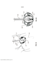
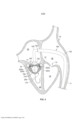
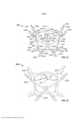
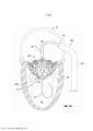
[0022] A FIG. 1 é uma vista em perspectiva de uma porção de um sistema de desdobramento da válvula mitral protética em uma vista em corte transversal de um coração humano nativo, de acordo com algumas concretizações.[0022] FIG. 1 is a perspective view of a portion of a prosthetic mitral valve deployment system in a cross-sectional view of a native human heart, in accordance with some embodiments.
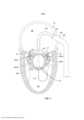
[0023] A FIG. 2 mostra uma vista em perspectiva de um conjunto de âncora da válvula mitral protética no átrio esquerdo do coração após o conjunto de âncora ter emergido de uma bainha de distribuição da âncora do sistema de desdobramento da FIG. 1[0023] FIG. 2 shows a perspective view of a prosthetic mitral valve anchor assembly in the left atrium of the heart after the anchor assembly has emerged from an anchor delivery sheath of the deployment system of FIG. 1
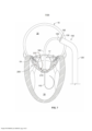
[0024] A FIG. 3 mostra uma vista em perspectiva do conjunto de âncora da FIG. 2 após ser girado no átrio esquerdo de modo a orientar o conjunto de âncora geralmente perpendicular à válvula mitral nativa.[0024] FIG. 3 shows a perspective view of the anchor assembly of FIG. 2 after being rotated in the left atrium so as to orient the anchor assembly generally perpendicular to the native mitral valve.
[0025] A FIG. 4 mostra uma vista em perspectiva do conjunto de âncora da FIG. 3 após ser parcialmente avançado através da válvula mitral nativa de modo a posicionar projeções do conjunto de âncora abaixo de uma calha subanular da válvula mitral nativa.[0025] FIG. 4 shows a perspective view of the anchor assembly of FIG. 3 after being partially advanced through the native mitral valve so as to position projections of the anchor assembly below a subannular trough of the native mitral valve.
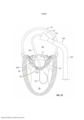
[0026] A FIG. 5 mostra uma vista em perspectiva do conjunto de âncora em um arranjo similar conforme mostrado na FIG. 4, mas em uma vista em corte transversal do coração (a partir do lado esquerdo do coração).[0026] FIG. 5 shows a perspective view of the anchor assembly in a similar arrangement as shown in FIG. 4, but in a cross-sectional view of the heart (from the left side of the heart).
[0027] A FIG. 6 mostra uma vista em perspectiva do conjunto de âncora da FIG. 5 após ser retraído de modo a posicionar as projeções do conjunto de âncora na calha subanular da válvula mitral nativa.[0027] FIG. 6 shows a perspective view of the anchor assembly of FIG. 5 after being retracted to position the projections of the anchor assembly in the subannular trough of the native mitral valve.
[0028] A FIG. 7 mostra uma vista em perspectiva do conjunto de âncora da FIG. 6 após a retração de alguns membros do sistema de desdobramento.[0028] FIG. 7 shows a perspective view of the anchor assembly of FIG. 6 after the retraction of some members of the deployment system.
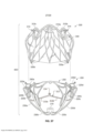
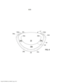
[0029] A FIG. 8 é uma vista de topo de uma válvula mitral nativa, e representa um perímetro de calha da calha subanular da FIG. 7 (sem o conjunto de âncora).[0029] FIG. 8 is a top view of a native mitral valve, and depicts a gutter perimeter of the subannular gutter of FIG. 7 (without anchor assembly).
[0030] A FIG. 9 mostra uma vista de topo em perspectiva de um conjunto de âncora de exemplo das FIGURAS 2-7, incluindo um membro de contenção do SAM de exemplo em uma configuração pré- desdobrada, de acordo com algumas concretizações.[0030] FIG. 9 shows a top perspective view of an example anchor assembly of FIGURES 2-7, including an example SAM containment member in a pre-deployed configuration, in accordance with some embodiments.
[0031] A FIG. 10 mostra uma vista de topo em perspectiva do conjunto de âncora de exemplo da FIG. 9, com o membro de contenção do SAM é uma configuração desdobrada, de acordo com algumas concretizações.[0031] FIG. 10 shows a top perspective view of the example anchor assembly of FIG. 9, with the SAM containment member is a deployed configuration, in accordance with some embodiments.
[0032] A FIG. 11 mostra uma vista de topo em perspectiva de um conjunto de âncora de exemplo, incluindo outro membro de contenção do SAM de exemplo em uma configuração desdobrada, de acordo com algumas concretizações.[0032] FIG. 11 shows a top perspective view of an example anchor assembly including another example SAM containment member in an unfolded configuration, in accordance with some embodiments.
[0033] A FIG. 12 mostra uma vista de topo em perspectiva do conjunto de âncora da FIG. 10 com um material de cobertura disposto nas porções da estrutura de âncora.[0033] FIG. 12 shows a top perspective view of the anchor assembly of FIG. 10 with a covering material disposed on portions of the anchor structure.
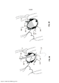
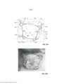
[0034] A FIG. 13A mostra uma vista de topo em perspectiva do conjunto de âncora da FIG. 10 implantado no interior de uma válvula mitral nativa (com as tricúspides da válvula mitral nativa em um estado fechado), e a FIG. 13B mostra uma vista de topo anatômica correspondente do conjunto de âncora da FIG. 13A.[0034] FIG. 13A shows a top perspective view of the anchor assembly of FIG. 10 implanted within a native mitral valve (with the tricuspids of the native mitral valve in a closed state), and FIG. 13B shows a corresponding anatomical top view of the anchor assembly of FIG. 13A.
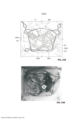
[0035] A FIG. 14A mostra uma vista de topo em perspectiva do conjunto de âncora da FIG. 10 implantado no interior da válvula mitral nativa da FIG. 13A (com a válvula mitral nativa tricúspide em um estado aberto), e a FIG. 14B mostra uma vista de topo anatômica correspondente do conjunto de âncora da FIG. 14A.[0035] FIG. 14A shows a top perspective view of the anchor assembly of FIG. 10 implanted within the native mitral valve of FIG. 13A (with the tricuspid native mitral valve in an open state), and FIG. 14B shows a corresponding anatomical top view of the anchor assembly of FIG. 14A.
[0036] A FIG. 15 mostra uma vista em perspectiva do conjunto de âncora da FIG. 7 implantado no interior da válvula mitral nativa e um conjunto da válvula bainha de distribuição que se prolonga no átrio esquerdo.[0036] FIG. 15 shows a perspective view of the anchor assembly of FIG. 7 implanted within the native mitral valve and a valve distribution sheath assembly extending into the left atrium.
[0037] A FIG. 16 mostra uma vista em perspectiva de um conjunto da válvula no átrio esquerdo após emergência parcial a partir do conjunto da válvula bainha de distribuição das FIG. 15. O conjunto da válvula é configurado em um primeiro arranjo (parcialmente expandido).[0037] FIG. 16 shows a perspective view of a valve assembly in the left atrium after partial emergence from the manifold valve assembly of FIGS. 15. The valve assembly is configured in a first (partially expanded) arrangement.
[0038] A FIG. 17 mostra uma vista em perspectiva do conjunto da válvula da FIG. 16 com o sistema de desdobramento da válvula sendo manipulado na preparação para a instalação do conjunto da válvula no conjunto de âncora.[0038] FIG. 17 shows a perspective view of the valve assembly of FIG. 16 with the valve deployment system being manipulated in preparation for installing the valve assembly into the anchor assembly.
[0039] A FIG. 18 mostra uma vista em perspectiva do conjunto da válvula da FIG. 17 (enquanto que ainda no primeiro (parcialmente expandido) arranjo) sendo posicionado no interior do conjunto de âncora.[0039] FIG. 18 shows a perspective view of the valve assembly of FIG. 17 (while still in the first (partially expanded) arrangement) being positioned within the anchor assembly.
[0040] A FIG. 19 mostra uma vista em perspectiva do conjunto da válvula da FIG. 18, com o conjunto da válvula expandido no interior do conjunto de âncora, e destacado a partir do sistema de desdobramento, mas antes do desdobramento do membro de contenção do SAM.[0040] FIG. 19 shows a perspective view of the valve assembly of FIG. 18, with the valve assembly expanded within the anchor assembly, and detached from the deployment system, but prior to deployment of the SAM containment member.
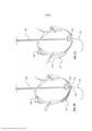
[0041] A FIG. 20 mostra uma vista lateral do conjunto de âncora da FIG. 9 com um membro de contenção do SAM acoplado com um sistema de desdobramento de exemplo em uma configuração pré- desdobrada, de acordo com algumas concretizações.[0041] FIG. 20 shows a side view of the anchor assembly of FIG. 9 with a SAM containment member coupled with an exemplary deployment system in a pre-deployed configuration, in accordance with some embodiments.
[0042] A FIG. 21 mostra o conjunto de âncora da FIG. 20 com o membro de contenção do SAM em uma configuração desdobrada, de acordo com algumas concretizações.[0042] FIG. 21 shows the anchor assembly of FIG. 20 with the SAM containment member in an unfolded configuration, in accordance with some embodiments.
[0043] A FIG. 22 mostra uma vista lateral esquemática de uma válvula mitral nativa acoplada com o conjunto de âncora da FIG. 9, e o sistema de desdobramento da FIG. 20, com o membro de contenção do SAM em uma primeira configuração parcialmente desdobrada, de acordo com algumas concretizações.[0043] FIG. 22 shows a schematic side view of a native mitral valve coupled with the anchor assembly of FIG. 9, and the deployment system of FIG. 20, with the SAM containment member in a first partially unfolded configuration, in accordance with some embodiments.
[0044] A FIG. 23 mostra outra vista lateral esquemática da válvula mitral nativa acoplada com o conjunto de âncora como na FIG. 22, e o sistema de desdobramento da FIG. 20, com o membro de contenção do SAM em uma segunda configuração parcialmente desdobrada, de acordo com algumas concretizações.[0044] FIG. 23 shows another schematic side view of the native mitral valve coupled with the anchor assembly as in FIG. 22, and the deployment system of FIG. 20, with the SAM containment member in a second partially unfolded configuration, in accordance with some embodiments.
[0045] A FIG. 24 mostra outra vista lateral esquemática da válvula mitral nativa acoplada com o conjunto de âncora como nas FIGURAS 22 e 23, com o membro de contenção do SAM em uma configuração desdobrada, de acordo com algumas concretizações.[0045] FIG. 24 shows another schematic side view of the native mitral valve coupled with the anchor assembly as in FIGURES 22 and 23, with the SAM containment member in an unfolded configuration, in accordance with some embodiments.
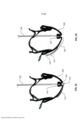
[0046] A FIG. 25 mostra uma vista lateral do conjunto de âncora da FIG. 9 com um membro de contenção do SAM acoplado com outro sistema de desdobramento de exemplo em uma configuração pré- desdobrada, de acordo com algumas concretizações.[0046] FIG. 25 shows a side view of the anchor assembly of FIG. 9 with a SAM containment member coupled with another exemplary deployment system in a pre-deployed configuration, in accordance with some embodiments.
[0047] A FIG. 26 mostra o conjunto de âncora da FIG. 25 com o membro de contenção do SAM em uma configuração desdobrada, enquanto que ainda acoplado com o sistema de desdobramento, de acordo com algumas concretizações.[0047] FIG. 26 shows the anchor assembly of FIG. 25 with the SAM containment member in a deployed configuration, while still coupled with the deployment system, in accordance with some embodiments.
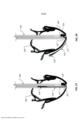
[0048] A FIG. 27 mostra uma vista lateral do conjunto de âncora da FIG. 11 com um membro de contenção do SAM acoplado com outro sistema de desdobramento de exemplo em uma configuração pré- desdobrada, de acordo com algumas concretizações.[0048] FIG. 27 shows a side view of the anchor assembly of FIG. 11 with a SAM containment member coupled with another exemplary deployment system in a pre-deployed configuration, in accordance with some embodiments.
[0049] A FIG. 28 mostra o conjunto de âncora da FIG. 27 com o membro de contenção do SAM em uma configuração desdobrada, de acordo com algumas concretizações.[0049] FIG. 28 shows the anchor assembly of FIG. 27 with the SAM containment member in an unfolded configuration, according to some embodiments.
[0050] A FIG. 29 mostra uma vista lateral esquemática de uma válvula mitral nativa acoplada com o conjunto de âncora da FIG. 11, e o sistema de desdobramento da FIG. 27, com o membro de contenção do SAM em uma configuração pré-desdobrada, de acordo com algumas concretizações.[0050] FIG. 29 shows a schematic side view of a native mitral valve coupled with the anchor assembly of FIG. 11, and the deployment system of FIG. 27, with the SAM containment member in a pre-deployed configuration, according to some embodiments.
[0051] A FIG. 30 mostra uma vista anterior lateral do conjunto de âncora da FIG. 11, e o sistema de desdobramento da FIG. 27 com o membro de contenção do SAM em uma configuração pré-desdobrada como na FIG. 29, de acordo com algumas concretizações.[0051] FIG. 30 shows a front side view of the anchor assembly of FIG. 11, and the deployment system of FIG. 27 with the SAM containment member in a pre-deployed configuration as in FIG. 29, according to some embodiments.
[0052] A FIG. 31 mostra outra vista lateral esquemática da válvula mitral nativa acoplada com o conjunto de âncora como nas FIG. 29, e o sistema de desdobramento da FIG. 27, com o membro de contenção do SAM em uma configuração parcialmente desdobrada, de acordo com algumas concretizações.[0052] FIG. 31 shows another schematic side view of the native mitral valve coupled with the anchor assembly as in FIGS. 29, and the deployment system of FIG. 27, with the SAM containment member in a partially deployed configuration, in accordance with some embodiments.
[0053] A FIG. 32 mostra uma vista frontal do conjunto de âncora da FIG. 11 e o sistema de desdobramento da FIG. 27 com o membro de contenção do SAM em uma configuração parcialmente desdobrada como na FIG. 31, de acordo com algumas concretizações.[0053] FIG. 32 shows a front view of the anchor assembly of FIG. 11 and the deployment system of FIG. 27 with the SAM containment member in a partially unfolded configuration as in FIG. 31, according to some embodiments.
[0054] A FIG. 33 mostra outra vista lateral esquemática da válvula mitral nativa acoplada com o conjunto de âncora como na FIG. 29, e o sistema de desdobramento da FIG. 27, com o membro de contenção do SAM em uma configuração parcialmente desdobrada, de acordo com algumas concretizações.[0054] FIG. 33 shows another schematic side view of the native mitral valve coupled with the anchor assembly as in FIG. 29, and the deployment system of FIG. 27, with the SAM containment member in a partially deployed configuration, in accordance with some embodiments.
[0055] A FIG. 34 mostra outra vista lateral esquemática da válvula mitral nativa acoplada com o conjunto de âncora como na FIG. 29, com o membro de contenção do SAM em uma configuração totalmente desdobrada, de acordo com algumas concretizações.[0055] FIG. 34 shows another schematic side view of the native mitral valve coupled with the anchor assembly as in FIG. 29, with the SAM containment member in a fully deployed configuration, in accordance with some embodiments.
[0056] A FIG. 35 mostra uma vista anterior lateral de uma estrutura de válvula de um conjunto da válvula das FIGURAS 16-19, de acordo com algumas concretizações.[0056] FIG. 35 shows a front side view of a valve structure of a valve assembly of FIGURES 16-19, in accordance with some embodiments.
[0057] A FIG. 36 mostra uma vista de fundo da estrutura de válvula da FIG. 35.[0057] FIG. 36 shows a bottom view of the valve structure of FIG. 35.
[0058] A FIG. 37 é uma vista lateral posterior explodida de um conjunto de âncora e conjunto da válvula das FIGURAS 16-19, de acordo com algumas concretizações.[0058] FIG. 37 is an exploded rear side view of an anchor and valve assembly assembly of FIGURES 16-19, in accordance with some embodiments.
[0059] A FIG. 38 é uma vista de topo de um sistema de válvula mitral protética de exemplo que inclui um conjunto da válvula engatado com um conjunto de âncora, de acordo com algumas concretizações.[0059] FIG. 38 is a top view of an exemplary prosthetic mitral valve system that includes a valve assembly engaged with an anchor assembly, in accordance with some embodiments.
[0060] A FIG. 39 é uma vista de fundo do sistema de válvula mitral protética de exemplo da FIG. 38.[0060] FIG. 39 is a bottom view of the exemplary prosthetic mitral valve system of FIG. 38.
[0061] A FIG. 40 mostra uma vista de topo do sistema de válvula mitral protética da FIG. 38 implantado no interior da válvula mitral nativa. A porção do manguito do sistema de válvula mitral protética é mostrada em um estado fechado.[0061] FIG. 40 shows a top view of the prosthetic mitral valve system of FIG. 38 implanted inside the native mitral valve. The cuff portion of the prosthetic mitral valve system is shown in a closed state.
[0062] A FIG. 41 mostra uma vista de topo do sistema de válvula mitral protética da FIG. 38 implantado no interior da válvula mitral nativa. A porção do manguito do sistema de válvula mitral protética é mostrada em um estado aberto.[0062] FIG. 41 shows a top view of the prosthetic mitral valve system of FIG. 38 implanted inside the native mitral valve. The cuff portion of the prosthetic mitral valve system is shown in an open state.
[0063] Símbolos de referência similares nos vários desenhos indicam elementos similares.[0063] Similar reference symbols in the various drawings indicate similar elements.
[0064] DESCRIÇÃO DETALHADA DAS CONCRETIZAÇÕES ILUSTRATIVAS[0064] DETAILED DESCRIPTION OF THE ILLUSTRATIVE EMBODIMENTS
[0065] Esta descrição descreve concretizações de um sistema de válvula de coração protética, tal como sistema de válvulas mitrais protéticas, e sistemas e métodos de transcateter para implantação de sistemas de válvula de coração prostético. Em algumas concretizações, o sistema de válvula mitral protética pode ser desdobrado para interfacear e ancorar em cooperação com as estruturas anatômicas nativas de uma válvula mitral (e, opcionalmente, em uma maneira que permite a função natural continuada das cordas tendineae das tricúspides da válvula mitral nativa mesmo após o componente de âncora ser desdobrado). Conforme descrito em maiores detalhes abaixo, as FIGURAS 1-7 e 15-34 descrevem um sistema de distribuição da válvula mitral do transcateter e método pelo qual o sistema de válvula mitral protética pode ser desdobrado para interfacear e ancorar em cooperação com as estruturas anatômicas de uma válvula mitral nativa. Também, nas FIGURAS 9-12 e 20-34, concretizações múltiplas de membros de contenção do SAM de válvula mitral protética são descritas pela qual as válvulas protéticas impedem uma cúspide anterior nativa de “flopping”, ou sendo retirado no LVOT para criar uma obstrução do LVOT.[0065] This disclosure describes embodiments of a prosthetic heart valve system, such as prosthetic mitral valve systems, and transcatheter systems and methods for implanting prosthetic heart valve systems. In some embodiments, the prosthetic mitral valve system can be deployed to interface and anchor in cooperation with the native anatomical structures of a mitral valve (and, optionally, in a manner that allows for continued natural function of the chordae tendineae of the tricuspids of the mitral valve). native even after the anchor component is unfolded). As described in greater detail below, FIGURES 1-7 and 15-34 depict a transcatheter mitral valve delivery system and method by which the prosthetic mitral valve system can be deployed to interface and anchor in cooperation with the anatomical structures of a native mitral valve. Also, in FIGURES 9-12 and 20-34, multiple embodiments of prosthetic mitral valve SAM containment members are depicted whereby the prosthetic valves prevent a native anterior cusp from flopping, or being withdrawn into the LVOT to create an obstruction. of the LVOT.
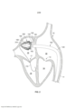
[0066] Referindo-se à FIG. 1, um sistema de distribuição da válvula mitral do transcateter de exemplo 100 pode ser navegado através de um vasculatura do paciente para obter acesso ao coração do paciente 10. O sistema de distribuição de transcatater 100 facilita a implantação de uma válvula mitral protética em um coração em batimento 10 usando um corte de vaso percutâneo, ou técnica minimamente invasiva (sem cirurgia de peito aberto). Em algumas implementações, o sistema de distribuição de transcateter 100 é usado em conjunto com uma ou mais modalidades de imagem, tais como fluoroscopia de raio-X, ecocardiografia, imagem de ressonância magnética, tomografia computadorizada (CT), e similares.[0066] Referring to FIG. 1, an example transcatheter mitral
[0067] O coração 10 (representado em corte transversal de uma perspectiva posterior) inclui um átrio direito 12, um ventrículo direito 14, um átrio esquerdo 16, e um ventrículo esquerdo 18. Uma válvula tricúspide 13 separa o átrio direito 12 a partir do ventrículo direito 14. Uma válvula mitral 17 separa o átrio esquerdo 16 do ventrículo esquerdo 18. Um septo atrial 15 separa o átrio direito 12 a partir do átrio esquerdo 16. Uma veia cava inferior 11 é confluente com o átrio direito 12. Deve ser compreendido que esta representação do coração 10 é um tanto estilizada. O mesmo é verdadeiro para as FIGURAS 2-4. As FIGURAS 1-4 proporcionam representações gerais da abordagem para a válvula mitral 17 que é usada em algumas implementações. Mas, as vistas em seção transversal da FIG. 5 e, em seguida, mais precisamente representam a orientação das válvulas mitrais protéticas em relação ao coração 10.[0067] The heart 10 (depicted in cross-section from a posterior perspective) includes a
[0068] Na concretização representada, o sistema de distribuição 100 inclui um fio-guia 110, um cateter deflectível primário 120, e uma bainha de distribuição da âncora 130. Componentes adicionais do sistema de distribuição 100 serão descritos adicionalmente abaixo. A bainha de distribuição da âncora 130 é deslizável (e rotacionalmente) disposta no interior de um lúmen do cateter deflectível primário 120. O fio-guia 110 é deslizavelmente disposto no interior de um lúmen da bainha de distribuição da âncora 130. Nesta representação, a bainha de distribuição da âncora 130 foi parcialmente prolongada relativo ao cateter deflectível primário 120, permitindo que uma porção alargada 132 se prolongue para fora, conforme descrito adicionalmente abaixo.[0068] In the depicted embodiment, the
[0069] Na implementação representada, o fio-guia 110 é instalado no coração 10 antes dos outros componentes do sistema de distribuição 100. Em algumas concretizações, o fio-guia 110 tem um diâmetro de cerca de 0,035 polegada (cerca de 0,89 mm). Em algumas concretizações, o fio-guia 110 tem um diâmetro em uma faixa de cerca de 0,032 polegada a cerca de 0,038 polegada (cerca de 0,8 mm a cerca de 0,97 mm). Em algumas concretizações, o fio-guia 110 tem um diâmetro menor do que 0,032 polegada (cerca de 0,80 mm), ou maior do que 0,038 polegada (cerca de 0,97 mm). Em algumas concretizações, o fio-guia 110 é produzido de materiais tais como, mas não limitados a, nitinol, aço inoxidável, aço inoxidável de resistência de alta tensão, e similares, e combinações destes. O fio-guia 110 pode incluir vários desenhos de ponta (por exemplo, ponta J, ponta reta, etc.), conicidades, revestimentos, coberturas, marcadores radiopacos (RO), e outras características. Em algumas concretizações, o fio-guia 110 tem uma ou mais porções com rigidez lateral diferente, resistências de coluna, lubricidade, e/ou outras propriedades físicas em comparação a outras porções do fio-guia 110.[0069] In the illustrated implementation, the
[0070] Em algumas implementações, o fio-guia 110 é percutaneamente inserido em uma veia femoral do paciente. O fio-guia 110 é direcionado para a veia cava inferior 11 e no átrio direito 12. Após criação de uma abertura no septo atrial 15 (por exemplo, uma punção trans-septal da fossa ovalis), o fio-guia 110 é direcionado no átrio esquerdo 16. Por último, o fio-guia 110 é direcionado através da válvula mitral 17 e no ventrículo esquerdo 18. Em algumas implementações, o fio-guia 110 pode ser instalado no coração 10 ao longo de outras trajetórias anatômicas. O fio-guia 110, em seguida, serve como um trilho sobre o qual outros componentes do sistema de distribuição 100 são passados.[0070] In some implementations, the
[0071] Na implementação representada, o cateter deflectível primário 120 é instalado por impulsionamento do mesmo sobre o fio- guia 110. Em algumas implementações, uma ponta dilatadora é usada em conjunto com o cateter deflectível primário 120 à medida que o cateter deflectível primário 120 é avançado sobre o fio-guia 110. Alternativamente, um cateter de balão pode ser usado como meio de dilatação inicial. Após a extremidade distal do cateter deflectível primário 120 alcançar o átrio esquerdo 16, a ponta dilatadora pode ser retirada. Em algumas concretizações, a porção terminal distal do cateter deflectível primário 120 é direcionável. Usando direcionamento, a porção terminal distal do cateter deflectível primário 120 pode ser orientada conforme desejado de modo a navegar a anatomia do paciente. Por exemplo, o cateter deflectível primário 120 pode ser angulado no interior do átrio direito 12 para navegar o cateter deflectível primário 120 a partir da veia cava inferior 11 para o septo atrial 15.[0071] In the depicted implementation, the primary
[0072] Em algumas concretizações, o cateter deflectível primário 120 tem um diâmetro externo de cerca de 28 Fr (cerca de 9,3 mm), ou cerca de 30 Fr (cerca de 10,0 mm). Em algumas concretizações, o cateter deflectível primário 120 tem um diâmetro externo na faixa de cerca de 26 Fr a cerca de 34 Fr (cerca de 8,7 mm a cerca de 11,3 mm). Em algumas concretizações, o cateter deflectível primário 120 tem um diâmetro externo na faixa de cerca de 20 Fr a cerca de 28 Fr (cerca de 6,7 mm a cerca de 9,3 mm).[0072] In some embodiments, the primary
[0073] O cateter deflectível primário 120 pode compreender um material tubular polimérico ou metálico. Por exemplo, em algumas concretizações, o cateter deflectível primário 120 pode ser produzido de materiais poliméricos, tais como, mas não limitados a, politetrafluoroetileno (PTFE), etileno propileno fluorinatado (FEP), HYTREL®, nylon, PICOFLEX®, PEBAX®, TECOFLEX®, e similares, e combinações destes. Em concretizações alternativas, o cateter deflectível primário 120 pode ser produzido de materiais metálicos, tais como, mas não limitados a, nitinol, aço inoxidável, ligas de aço inoxidável, titânio, ligas de titânio, e similares, e combinações destes. Em algumas concretizações, o cateter deflectível primário 120 pode ser produzido de combinações de tais materiais poliméricos e metálicos (por exemplo, camadas de polímero membros de enrijecimento, reforço de espira, com metal abradado, e similares, e combinações destes). Em algumas concretizações, o cateter deflectível primário 120 pode compreender um tubo ranhurado.[0073] The primary
[0074] O sistema de distribuição de exemplo 100 também inclui a bainha de distribuição da âncora 130. Em algumas implementações, após o cateter deflectível primário 120 ser posicionado em sua extremidade distal no átrio esquerdo 16, a bainha de distribuição da âncora 130 é instalada em um lúmen do cateter deflectível primário 120 (sobre o fio-guia 110), e avançada através do cateter deflectível primário 120. Conforme descrito adicionalmente abaixo, em algumas concretizações, a bainha de distribuição da âncora 130 é pré-carregada com um conjunto de âncora da válvula protética e outros componentes do sistema de distribuição 100.[0074] The
[0075] Em algumas concretizações, a bainha de distribuição da âncora 130 pode ser produzida a partir dos materiais descritos acima com referência ao cateter deflectível primário 120. Em algumas concretizações, a bainha de distribuição da âncora 130 tem um diâmetro externo na faixa de cerca de 20 Fr a cerca de 28 Fr (cerca de 6,7 mm a cerca de 9,3 mm). Em algumas concretizações, a bainha de distribuição da âncora 130 tem um diâmetro externo na faixa de cerca de 14 Fr a cerca de 24 Fr (cerca de 4,7 mm a cerca de 8,0 mm).[0075] In some embodiments, the
[0076] Na concretização representada, a bainha de distribuição da âncora 130 inclui uma porção terminal distal alargada 132. Em algumas concretizações, nenhuma tal porção terminal distal alargada 132 é incluída. A porção terminal distal alargada 132 pode colapsar à um perfil inferior quando confinada no interior do cateter deflectível primário 120. Quando a porção terminal distal alargada 132 é expressa a partir do cateter deflectível primário 120, a porção terminal distal alargada 132 pode se autoexpandir à forma alargada. Em algumas concretizações, o material da porção terminal distal alargada 132 inclui pregas ou dobras, pode ser uma extremidade alargada continua, ou pode ser separada em seções, tais como pétalas de flor, e pode incluir um ou mais elementos resilientes que inclinam a porção terminal distal alargada 132 para assumir a configuração alargada na ausência de forças de restrição (tal como da contenção no interior do cateter deflectível primário 120). A porção terminal distal alargada 132 pode ser vantajosa, por exemplo, para recaptura do conjunto de âncora no interior do lúmen da bainha de distribuição da âncora 130 após o conjunto de âncora ter sido expresso a partir da porção terminal distal alargada 132.[0076] In the depicted embodiment, the
[0077] Em algumas concretizações, o diâmetro externo máximo da porção terminal distal alargada 132 está em uma faixa de cerca de 30 Fr a cerca de 34 Fr (cerca de 10,0 mm a cerca de 11,3 mm). Em algumas concretizações, o diâmetro externo máximo da porção terminal distal alargada 132 está em uma faixa de cerca de 32 Fr a cerca de 44 Fr (cerca de 10,7 mm a cerca de 14,7 mm). Em algumas concretizações, o diâmetro externo máximo da porção terminal distal alargada 132 está em uma faixa de cerca de 24 Fr a cerca de 30 Fr (cerca de 8,0 mm a cerca de 10,0 mm). Em algumas concretizações, o diâmetro externo máximo da porção terminal distal alargada 132 é menor do que cerca de 24 Fr (cerca de 8,0 mm), ou maior do que cerca de 44 Fr (cerca de 14,7 mm).[0077] In some embodiments, the maximum outside diameter of the widened
[0078] Referindo-se à FIG. 2, componentes adicionais do sistema de distribuição de exemplo 100 podem incluir uma blindagem de controle proximal 140, um cateter deflectível secundário 150, e um cateter impulsionador distal 160. A blindagem de controle proximal 140 é deslizavelmente disposta no interior de um lúmen da bainha de distribuição da âncora 130. O cateter deflectível secundário 150 é deslizavelmente disposto no interior de um lúmen da blindagem de controle proximal 140. O cateter impulsionador distal 160 é deslizavelmente disposto no interior de um lúmen do cateter deflectível secundário 150. Estes componentes do sistema de distribuição 100 podem ser manipulados por um operador clínico para controlar a posição e orientação de um conjunto de âncora 200. O conjunto de âncora 200 é deslizavelmente disposto sobre o fio-guia 110.[0078] Referring to FIG. 2, additional components of the
[0079] Em algumas implementações do sistema de distribuição 100, uma ou mais das blindagens de controle proximal 140, o cateter deflectível secundário 150, o cateter impulsionador distal 160, e o conjunto de âncora 200, foram carregados na bainha de distribuição da âncora 130 antes do avanço da bainha de distribuição da âncora 130 no cateter deflectível primário 120, conforme mostrado na FIG. 1. Isto é, em alguns casos, a blindagem de controle proximal 140, o cateter deflectível secundário 150, o cateter impulsionador distal 160, e/ou o conjunto de âncora 200, já estão instalados na bainha de distribuição da âncora 130 à medida que a bainha de distribuição da âncora 130 é distalmente avançada no cateter deflectível primário 120, para alcançar o arranjo mostrado na FIG. 1. Em outras implementações, uma ou mais das blindagens de controle proximal 140, o cateter deflectível secundário 150, o cateter impulsionador distal 160, e o conjunto de âncora 200, são distalmente avançados na bainha de distribuição da âncora 130 após a bainha de distribuição da âncora 130 ter sido avançada no cateter deflectível primário 120 para alcançar o arranjo mostrado na FIG. 1.[0079] In some implementations of the
[0080] O cateter impulsionador distal 160 é liberavelmente acoplado com um hub 210 do conjunto de âncora 200. A extremidade proximal do conjunto de âncora 200 é também liberavelmente acoplado à blindagem de controle proximal 140 por um ou mais fios de controle 142. Enquanto que a concretização representada inclui um fio de controle 142, em algumas concretizações, dois, três, quatro, cindo, ou mais do que cinco fios de controle estão incluídos.[0080] The
[0081] Em algumas concretizações, a posição do conjunto de âncora 200 pode ser controlado pela manipulação das posições do cateter impulsionador distal 160 e/ou da blindagem de controle proximal 140. Por exemplo, na concretização representada, o conjunto de âncora 200 pode ser expresso a partir da bainha de distribuição da âncora 130 (conforme mostrado na FIG. 2) pelo movimento do cateter impulsionador distal 160 e/ou a blindagem de controle proximal 140 distalmente em relação à bainha de distribuição da âncora 130. Em algumas implementações, a expressão do conjunto de âncora 200 é causada por puxamento proximalmente de volta da bainha de distribuição da âncora 130, enquanto que mantendo geralmente as posições do cateter impulsionador distal 160 e/ou a blindagem de controle proximal 140. Em algumas implementações, a expressão do conjunto de âncora 200 é causada por uma combinação de puxamento proximalmente de volta da bainha de distribuição da âncora 130, enquanto que distalmente prolongando as posições do cateter impulsionador distal 160 e/ou da blindagem de controle proximal 140.[0081] In some embodiments, the position of the
[0082] À medida que o conjunto de âncora 200 emerge a partir dos confinamentos da bainha de distribuição da âncora 130, o conjunto de âncora 200 se expande de uma configuração de distribuição de baixo perfil para uma configuração parcialmente expandida (conforme mostrado na FIG. 2). A extensão de expansão do conjunto de âncora 200 pode ser pelo menos parcialmente controlada pelo posicionamento relativo da blindagem de controle proximal 140 em relação ao cateter impulsionador distal 160. Por exemplo, à medida que a blindagem de controle proximal 140 é movida proximalmente em relação ao cateter impulsionador distal 160, o conjunto de âncora 200 é axialmente alongado e radialmente contraído. Inversamente, à medida que a blindagem de controle proximal 140 é movida distalmente em relação ao cateter impulsionador distal 160, o conjunto de âncora 200 é axialmente encurtado e radialmente expandido. Em algumas implementações, este controle do tamanho radial do conjunto de âncora 200 é usado por um médico durante o processo de desdobramento do conjunto de âncora 200 no interior da válvula mitral nativa 17, conforme descrito adicionalmente abaixo. Conforme descrito adicionalmente abaixo, o fio de controle 142 pode também ser usado para controlar alguma expansão radial do conjunto de âncora 300 (sem mudança da distância relativa da blindagem de controle proximal 140 em relação ao cateter impulsionador distal 160).[0082] As the
[0083] Deve ser compreendido que as válvulas mitrais protéticas aqui proporcionadas são compreendidas de um conjunto de âncora 200 e um conjunto da válvula separável (por exemplo, refere-se à FIG. 37). O conjunto de âncora 200 é desdobrado à um arranjo que interfaceia no interior da válvula mitral nativa 17 através do desdobramento do conjunto da válvula. Dito diferentemente, após implantação do conjunto de âncora 200 no interior da válvula mitral nativa 17, o conjunto da válvula pode, em seguida, ser desdobrado no interior do conjunto de âncora 200 e no interior da válvula mitral nativa 17 (conforme descrito adicionalmente abaixo). Portanto, pode ser referido que as válvulas mitrais protéticas aqui proporcionadas são desdobradas usando um método de implantação em estágios. Isto é, o conjunto de âncora 200 é desdobrado em um estágio, e o conjunto da válvula é desdobrado em um estágio subsequente. Em algumas concretizações, conforme descrito adicionalmente abaixo, um membro de contenção do SAM é desdobrado como parte do método de desdobramento. Em algumas implementações, o desdobramento do conjunto da válvula ocorre correto após o desdobramento do conjunto de âncora 200 (por exemplo, durante o mesmo procedimento médico). Em algumas implementações, o desdobramento do conjunto da válvula ocorre horas, dias, semanas, ou ainda meses após o desdobramento do conjunto de âncora 200 (por exemplo, durante um procedimento médico subsequente).[0083] It should be understood that the prosthetic mitral valves provided herein are comprised of an
[0084] O método de implantação em estágios das válvulas mitrais protéticas aqui proporcionadas é facilitado pelo fato que quando o próprio conjunto de âncora 200 é implantado no interior da válvula mitral nativa 17, a válvula mitral nativa 17 continua a funcionar essencialmente como antes da implantação do conjunto de âncora 200 sem um impacto significante na fisiologia cardiovascular. Este é o caso porque, conforme descrito adicionalmente abaixo, o conjunto de âncora 200 interfaceia e ancora dentro dos aspectos interiores da válvula mitral nativa 17 sem substancialmente interferir com as tricúspides ou cordas tendineae da válvula mitral nativa 17.[0084] The staged implantation method of the prosthetic mitral valves provided herein is facilitated by the fact that when the
[0085] Ainda referindo-se à FIG. 2, no arranjo representado, a porção terminal distal do cateter deflectível secundário 150 está localizada pelo menos parcialmente internamente no interior do conjunto de âncora 200. O cateter deflectível secundário 150 pode ser manipulado por um operador clínico para encurvar reversivelmente a porção terminal distal do cateter deflectível secundário 150. À medida que o cateter deflectível secundário 150 é encurvado pelo médico, outros componentes do sistema de distribuição 100 podem se encurvar junto com o cateter deflectível secundário 150. Por exemplo, um ou mais do impulsionador distal 160 e a blindagem de controle proximal 140 podem se encurvarem em resposta ao encurvamento do cateter deflectível 150. Devido ao conjunto de âncora 200 ser acoplado ao impulsionador distal 160 e à blindagem de controle proximal 140, o conjunto de âncora 200 pode, por sua vez, ser girado pelo encurvamento do cateter deflectível secundário 150.[0085] Still referring to FIG. 2, in the depicted arrangement, the distal end portion of the secondary
[0086] Referindo-se à FIG. 3, conforme descrito acima, o cateter deflectível secundário 150 pode ser articulado (também referido como direcionado, defletido, encurvado, curvado, etc.) para articular lateralmente (girar, etc.) o conjunto de âncora 200, enquanto que o conjunto de âncora 200 está no interior do átrio esquerdo 16. Tal rotação do conjunto de âncora 200 é vantajosa, por exemplo, para orientar o conjunto de âncora 200 em um relacionamento desejado para a válvula mitral nativa 17 na preparação para implantação do conjunto de âncora 200 no interior da válvula mitral nativa 17. Em algumas implementações, é desejável orientar o conjunto de âncora 200 de modo que seu eixo longitudinal é geralmente perpendicular à válvula mitral nativa 17. A articulação lateral do conjunto de âncora parcialmente ou totalmente expandido 200 no interior do átrio 16 pode ser vantajosa versus ter que articular lateralmente o conjunto de âncora 200, enquanto que é ainda confinado no interior de uma bainha de distribuição, à medida que o último conjunto é um conjunto de cateter relativamente grande e rígido.[0086] Referring to FIG. 3, as described above, the secondary
[0087] Na preparação para engatamento do conjunto de âncora 200 com a válvula mitral nativa 17, o operador clínico pode manipular o tamanho radial da estrutura de âncora 200 de modo que a estrutura de âncora 200 pode ser passada através da válvula mitral nativa 17 sem danificar a válvula mitral nativa 17. Por exemplo, o médico pode mover a blindagem de controle proximal 140 proximalmente em relação ao cateter impulsionador distal 160 para contrair radialmente o conjunto de âncora 200. Com o conjunto de âncora 200 radialmente contraído, a estrutura de âncora 200 pode ser seguramente passada através da válvula mitral nativa 17 sem danificar a válvula mitral nativa 17.[0087] In preparation for engagement of the
[0088] Referindo-se à FIG. 4, enquanto que o cateter deflectível secundário 150 está retido em sua configuração encurvada, conforme descrito com referência à FIG. 3, o cateter impulsionador distal 160 e a blindagem de controle proximal 140 podem ser simultaneamente avançados. Devido ao cateter impulsionador distal 160 ser liberavelmente acoplado ao hub 210 do conjunto de âncora 200, e devido à blindagem de controle proximal 140 ser liberavelmente acoplada à extremidade proximal do conjunto de âncora 200, via o um ou mais fios 142a e 142b, o avanço geralmente simultâneo do cateter impulsionador distal 160 e a blindagem de controle proximal 140 resulta no avanço do conjunto de âncora 200. O conjunto de âncora 200 é avançado tal que a extremidade distal do conjunto de âncora 200 está no interior do ventrículo esquerdo 18, enquanto que a extremidade proximal do conjunto de âncora 200 está no interior do átrio esquerdo 16. Consequentemente, algumas porções do conjunto de âncora 200 estão em cada lado da válvula mitral nativa 17.[0088] Referring to FIG. 4, while the secondary
[0089] Na concretização representada, o conjunto de âncora 200 inclui quatro pés da âncora: um pé lateral anterior 220a, um pé lateral posterior 220b, um pé medial posterior 220c, e um pé medial anterior 220d. Em algumas concretizações, poucos ou mais pés da âncora podem ser incluídos (por exemplo, dois, três, cinco, seis, ou mais do que seis). Em algumas concretizações, os pés da âncora 220a, 220b, 220c, e 220d são porções do conjunto de âncora 200 que são configuradas para contatar com uma calha subanular 19 da válvula mitral nativa 17, sem penetração do tecido da válvula mitral nativa 17. Consequentemente, os pés da âncora 220a, 220b, 220c, e 220d têm superfícies atraumáticas que são geralmente comparáveis aos pés. Contudo, em algumas concretizações, um ou mais dos pés da âncora 220a, 220b, 220c, e 220d são configurados para penetrarem, e podem ter outras características, tais como farpas, espiras, ganchos, e similares.[0089] In the illustrated embodiment, the
[0090] No arranjo da FIG. 4, os pés da âncora 220a, 220b, 220c, e 220d estão posicionados abaixo da calha subanular 19. Neste arranjo, o tamanho radial do conjunto de âncora 200 pode ser aumentado para alinhar os pés da âncora 220a, 220b, 220c, e 220d com a calha subanular 19. Por exemplo, o médico pode mover a blindagem de controle proximal 140 distalmente em relação ao impulsionador distal do cateter 160 para radialmente expandir o conjunto de âncora 200 para alinhar os pés da âncora 220a, 220b, 220c, e 220d com a calha subanular 19. Tal alinhamento pode ser realizado na preparação para assentamento dos pés da âncora 220a, 220b, 220c, e 220d no interior da calha subanular 19.[0090] In the arrangement of FIG. 4,
[0091] Referindo-se à FIG. 5, uma vista em corte transversal do coração 10 proporciona outra perspectiva do conjunto de âncora 200 no mesmo arranjo em relação à válvula mitral nativa 17, conforme mostrado na FIG. 4. Esta vista em corte transversal do coração 10 é uma vista em corte transversal tomada através da válvula mitral 17 ao longo de um plano através do átrio esquerdo 16 e ventrículo esquerdo 18 que é paralelo à linha que intersecta as duas suturas da válvula mitral 17 (conforme representado adicionalmente com referência à FIG. 8 abaixo). Nas seguintes FIGURAS 5-7 e 13-17, a vista em corte transversal do coração 10 será usada para descrever o sistema de distribuição 100 e métodos para desdobramento das válvulas mitrais protéticas aqui proporcionadas. A vista nas FIGURAS 5-7 e 13-17 é levemente inclinada, de modo que melhor visualização do conjunto de âncora 200 é proporcionada.[0091] Referring to FIG. 5, a cross-sectional view of
[0092] Os pés da âncora 220a, 220b, 220c, e 220d estão posicionados abaixo da calha subanular 19. Nesta posição, os pés da âncora 220a, 220b, 220c, e 220d estão posicionados sob as excursões sistólicas e diastólicas das tricúspides da válvula mitral nativa 17. Nesta orientação, os pés da âncora 220a, 220b, 220c, e 220d podem ser alinhadas com a calha subanular 19 na preparação para assentamento dos pés da âncora 220a, 220b, 220c, e 220d no interior da calha subanular 19.[0092] The
[0093] Nesta figura, porções de um membro de contenção do SAM 212 de exemplo estão em vista. Na concretização representada, o membro de contenção do SAM 212 se prolonga a partir do conjunto de âncora 200. Por exemplo, o membro de contenção do SAM 212 compreende um membro alongado com uma primeira extremidade que se prolonga de uma primeira porção do conjunto de âncora 200, e uma segunda extremidade que se prolonga de uma segunda porção do conjunto de âncora 200. Em concretizações particulares, o membro de contenção do SAM 212 é integralmente formado como parte do conjunto de âncora 200. Em concretizações específicas, o membro de contenção do SAM 212, ou porções deste, pode ser formada separadamente a partir do conjunto de âncora 200, e, em seguida, fixado ao conjunto de âncora 200.[0093] In this figure, portions of an example containment member of the
[0094] O membro de contenção do SAM 212 pode ser disposto em uma configuração pré-desdobrada conforme mostrado. Conforme descrito adicionalmente abaixo, o membro de contenção do SAM 212 pode ser reconfigurado a uma configuração desdobrada tal que o membro de contenção do SAM 212 impede fisicamente uma cúspide anterior de uma válvula mitral nativa de obstruir o LVOT. Em algumas concretizações, o membro de contenção do SAM 212 é inclinado para se auto reconfigurar à configuração desdobrada quando o membro de contenção do SAM 212 está não confinado. Enquanto que uma concretização particular do membro de contenção do SAM 212 é representada, deve ser compreendido que concretizações múltiplas de membro de contenção do SAM são consideradas e dentro do escopo desta descrição.[0094] The containment member of the
[0095] Referindo-se à FIG. 6, o impulsionador distal 160 e a blindagem de controle proximal 140 podem ser simultaneamente retraídos em relação ao cateter deflectível secundário 150 e o cateter deflectível primário 120. Como um resultado, o pé da âncora 220a, 220b, 220c, e 220d torna-se assentado na calha subanular 19. Nesta posição, os pés da âncora 220a, 220b, 220c, e 220d estão posicionados sob as excursões sistólica e diastólica das tricúspides da válvula mitral nativa 17, e as outras estruturas do conjunto de âncora 200 não inibem os movimentos das tricúspides. Portanto, com o conjunto de âncora 200 acoplado às estruturas da válvula mitral 17 conforme descrito, a válvula mitral 17 pode continuar a funcionar antes da colocação do conjunto de âncora 200. Em adição, a maneira na qual o conjunto de âncora 200 interfaceia com a válvula mitral nativa 17 não resulta na deformação da válvula mitral nativa 17. Com o membro de contenção do SAM 212 em sua configuração pré-desdobrada, o membro de contenção do SAM 212 não afeta a função natural da válvula mitral nativa 17. Portanto, a válvula mitral nativa 17 pode continuar a funcionar como está antes da colocação do conjunto de âncora 200.[0095] Referring to FIG. 6, the
[0096] Referindo-se à FIG. 7, com o conjunto de âncora 200 engatado no interior da válvula mitral nativa 17, componentes do sistema de distribuição 100 podem ser retirados a partir do conjunto de âncora 200. Por exemplo, o fio de controle 142 pode ser destacado da extremidade proximal do conjunto de âncora 200. Em seguida, a blindagem de controle proximal 140 pode ser retirada. O cateter deflectível secundário 150 pode também ser retirado. De fato, se assim desejado, a blindagem de controle proximal 140, o cateter deflectível secundário 150, e a bainha de distribuição da âncora 130 podem ser completamente retiradas do cateter deflectível primário 120. Em contraste, em algumas implementações, o cateter impulsionador distal 160 é vantajosamente deixado fixado ao hub 210 do conjunto de âncora 200 (e deixado fixado ao membro de contenção do SAM 212 em algumas implementações). Conforme será descrito adicionalmente abaixo, em algumas implementações, o cateter impulsionador distal 160 pode ser usado como um trilho no qual um conjunto da válvula é desdobrado no interior do conjunto de âncora 200. Contudo, em algumas implementações, o conjunto de âncora 200 é completamente destacado do sistema de distribuição 100, e o sistema de distribuição 100 é removido do paciente. Após um período de minutos, horas, dias, semanas, ou meses, subsequente ao desdobramento do conjunto de âncora 200, um conjunto da válvula pode ser instalado no conjunto de âncora 200 para completar a instalação da válvula mitral protética.[0096] Referring to FIG. 7, with the
[0097] Na implementação representada, o membro de contenção do SAM 212 é ainda restringido em sua configuração pré-desdobrada. Conforme descrito adicionalmente abaixo, em algumas concretizações, a concretização representada do membro de contenção do SAM 212 é desdobrada após a instalação de um conjunto da válvula no conjunto de âncora 200. Alternativamente, conforme descrito adicionalmente abaixo, em algumas concretizações do membro de contenção do SAM 212, o membro de contenção do SAM 212 é desdobrado antes da instalação de um conjunto da válvula no conjunto de âncora 200.[0097] In the depicted implementation, the containment member of
[0098] Referindo-se à FIG. 8, a anatomia da válvula mitral nativa 17 inclui algumas características estruturais consistentes e previsíveis através dos pacientes que podem ser utilizadas para engatamento do conjunto de âncora 200. Por exemplo, a válvula mitral nativa 17 inclui a calha subanular 19 antes mencionada. Em adição, a válvula mitral nativa 17 inclui um ânulo em forma de D 28, uma sutura anterolateral 30a, uma sutura posteromedial 30b, um trigone fibroso esquerdo 134a, e um trigone fibroso direito 134b. Adicionalmente, a válvula mitral nativa 17 inclui uma cúspide anterior 20 e uma cúspide posterior de três partes 22. A cúspide posterior 22 inclui um escalope lateral 24a, um escalope médio 24b, e um escalope medial 24c. As bordas livres da cúspide posterior 22 e da cúspide anterior 20 se encontram ao longo de uma linha de coaptação 32.[0098] Referring to FIG. 8, the anatomy of native
[0099] O ânulo em forma de D 28 define a estrutura da qual a cúspide anterior 20 e a cúspide posterior 22 se prolongam e articulam. Os trigones fibrosos esquerdo e direito 134a e 134b estão localizados próximos às extremidades esquerda e direita da cúspide anterior 20, e geralmente adjacentes aos escalopes lateral e medial 24a e 24c da cúspide posterior 22. A calha subanular 19 se desloca ao longo do ânulo 28 entre os trigones fibrosos esquerdo e direito 134a e 134b ao longo da cúspide posterior 22.[0099] The D-shaped
[00100] As regiões em ou próximas aos trigones anulares de alto colágeno 134a e 134b podem geralmente serem aliviadas para proporcionar localizações de ancoragem estáveis fortes. O tecido do músculo nas regiões em ou próximas aos trigones 134a e 134b também proporcionam um bom substrato de crescimento do tecido para estabilidade adicionada e resistência à migração do conjunto de âncora 200. Portanto, as regiões em ou próximas aos trigones 134a e 134b definem uma zona de âncora anterior esquerda 34a e uma zona de âncora anterior direita 34b, respectivamente. A zona de âncora anterior esquerda 34a e a zona de âncora anterior direita 34b proporcionam localizações alvos vantajosas para colocação do pé lateral anterior 220a e o pé medial anterior 220d, respectivamente.[00100] The regions at or near the high collagen
[00101] Referindo-se também à FIG. 9, a concretização representada do conjunto de âncora 200 também inclui o pé lateral posterior 220b e o pé medial posterior 220c. Conforme anteriormente descrito, o pé lateral posterior 220b e o pé medial posterior 220c podem também serem vantajosamente posicionados na calha subanular 19 de modo a proporcionar acoplamento equilibrado e atraumático do conjunto de âncora 200 para a válvula mitral nativa 17. Portanto, uma zona de âncora esquerda posterior 34b e uma zona de âncora anterior direita 34c são definidas na calha subanular 19. A zona de âncora esquerda posterior 34b e a zona de âncora anterior direita 34c podem receber o pé lateral posterior 220b e o pé medial posterior 220c, respectivamente. Em algumas implementações, as localizações da zona de âncora esquerda posterior 34b e da zona de âncora anterior direita 34c podem variar das localizações representadas, enquanto que ainda permanecendo no interior da calha subanular 19. Deve ser compreendido que o conjunto de âncora 200 representado é meramente um exemplo não limitante dos conjuntos de âncora providos dentro do escopo desta descrição.[00101] Referring also to FIG. 9, the depicted embodiment of
[00102] Em algumas concretizações, o conjunto de âncora 200 inclui estruturas supra-anulares e estruturas subanulares. Por exemplo, as estruturas subanulares do conjunto de âncora 200 incluem o pé da âncora 220a, 220b, 220c, e 220d, o membro de contenção do SAM 212, e o hub 210, antes mencionados. Em algumas concretizações, conforme descrito acima, o hub 210 funciona como uma estrutura de conexão para o sistema de distribuição 100 (por exemplo, refere-se a FIG. 2). Em adição, o hub 210 pode funcionar como um componente estrutural de estabilização do qual um braço de suporte subanular anterior lateral 230a, um braço de suporte subanular lateral posterior 230b, um braço de suporte subanular medial posterior 230c, e um braço de suporte subanular anterior medial 230d, se prolongam para o pé da âncora 220a, 220b, 220c, e 220d, respectivamente.[00102] In some embodiments, the
[00103] Na concretização representada, o membro de contenção do SAM 212 inclui um braço anterior lateral 213a e um braço anterior medial 213d. O braço anterior lateral 213a se prolonga a partir do braço de suporte subanular anterior lateral 230a. O braço anterior medial 213d se prolonga a partir do braço de suporte subanular anterior medial 230d. Em algumas concretizações, as porções do membro de contenção do SAM 212 podem se prolongar de outras áreas no conjunto de âncora 200.[00103] In the depicted embodiment, the
[00104] Em algumas concretizações, tal como a concretização representada, as estruturas supra-anulares do conjunto de âncora 200 incluem: uma característica de retenção atrial anterior lateral 240a, uma característica de retenção atrial posterior lateral 240b, uma característica de retenção atrial posterior medial 240c, e uma característica de retenção atrial anterior medial 240d; um arco de âncora anterior 250a, um arco de âncora esquerda 250b, um arco de âncora posterior 250c, e um arco de âncora direita 250d; e pontes de conexão 260. O arco de âncora anterior 250a, arco de âncora esquerda 250b, arco de âncora posterior 250c, e arco de âncora direita 250d, são unidos entre si para formar um anel supra-anular de ondulação 250 que age como um elemento estrutural supra-anular para o conjunto de âncora 200. Conforme será descrito adicionalmente abaixo, o anel supra-anular 250 também define uma abertura a um espaço no interior do interior do conjunto de âncora 200 que é configurado para receber e engatar com um conjunto da válvula. As características de retenção atrial 240a, 240b, 240c, e 240d são configuradas para contatar a superfície de tecido supra-anular similar à prateleira acima do ânulo da válvula mitral, e para, desse modo, estabilizar o conjunto de âncora 200 em áreas supra- anulares que são geralmente opostas do pé da âncora 220a, 220b, 220c, e 220d, respectivamente.[00104] In some embodiments, such as the depicted embodiment, the supra-annular structures of the
[00105] Em algumas concretizações, pontes de conexão 260 proporcionadas para estabilidade intensificada e resistência à fadiga de forças verticalmente orientadas em um conjunto da válvula artificial de companhia quando a válvula (não mostrado) é fechada e bloqueando sangue pressurizado durante sístole. O conjunto de âncora 200 pode também incluir um ou mais ilhós 226 nas porções de estrutura adjacentes aos arcos, que são pontos de controle adicionais para distribuição e recuperação do conjunto, ou podem ser usados para fixar uma estrutura de distribuição posicional.[00105] In some embodiments, connecting
[00106] Em algumas concretizações, tal como a concretização representada, as estruturas supra-anulares e estruturas subanulares do conjunto de âncora 200 são interconectadas por uma conexão interanular lateral anterior 270a, uma conexão interanular lateral posterior 270b, uma conexão interanular medial posterior 270c, e uma conexão interanular medial anterior 270d. Por exemplo, a conexão interanular lateral anterior 270a conecta o pé da âncora lateral anterior 220a com a característica de retenção atrial anterior lateral 240a. Em adição, a conexão interanular lateral anterior 270a conecta o pé da âncora lateral anterior 220a com o arco de âncora anterior 250a e o arco de âncora esquerda 250b. Na concretização representada, cada uma das outras conexões interanulares 270b, 270c, e 270d interconectam porções das estruturas supra-anulares e estruturas subanulares em maneiras análogas àquela da conexão interanular lateral anterior 270a. Por exemplo, a conexão interanular lateral anterior 270b conecta o pé da âncora lateral anterior 220b com o arco de âncora esquerda 250b e o arco de âncora posterior 250c; a conexão interanular lateral anterior 270c conecta o pé da âncora lateral anterior 220c com o arco de âncora posterior 250c e o arco de âncora direita 250d; e a conexão interanular lateral anterior 270d conecta o pé da âncora lateral anterior 220d com o arco de âncora direita 250d e o arco de âncora anterior 250a.[00106] In some embodiments, such as the depicted embodiment, the supraannular structures and subannular structures of the
[00107] Em algumas concretizações, os membros alongados do conjunto de âncora 200, incluindo o membro de contenção do SAM 212, são formados de uma peça única de material precursor (por exemplo, folha ou tubo) que é cortada, expandida, e conectada ao hub 210. Por exemplo, algumas concretizações são fabricadas de um tube que é cortado a laser (ou usinado, quimicamente gravado, cortado à jato de água, etc.) e, em seguida, expandido e ajustado por calor em seu tamanho e forma expandida final. Em algumas concretizações, o conjunto de âncora 200, incluindo o membro de contenção do SAM 212, é criado compostamente de membros alongados múltiplos (por exemplo, fios ou membros cortados) que são unidos juntos com o hub 210 e cada outro para formar o conjunto de âncora 200.[00107] In some embodiments, the elongated members of the
[00108] Os membros alongados do conjunto de âncora 200 podem ser compreendidos de vários materiais e combinações de materiais. Em algumas concretizações, nitinol (NiTi) é usado como o material dos membros alongados do conjunto de âncora 200, mas outros materiais, tais como aço inoxidável, aço L605, polímeros, aço MP35N, aços inoxidáveis, titânio, liga de cobalto/cromo, materiais poliméricos, Pyhnox, Elgiloy, ou qualquer outro material biocompatível apropriado, e combinações destes, podem ser usados. As propriedades super- elásticas de NiTi o torna um material candidato particularmente bom para os membros alongados do conjunto de âncora 200 porque, por exemplo, NiTi pode ser ajustado por calor em uma forma desejada. Isto é, NiTi pode ser ajustado por calor de modo que o conjunto de âncora 200 tende a auto expandir em uma forma desejada quando o conjunto de âncora 200 está não-confinado, tal como quando o conjunto de âncora 200 é desdobrado a partir da bainha de distribuição da âncora 130. Um conjunto de âncora 200 produzido de NiTi, por exemplo, pode ter uma natureza elástica que permite que o conjunto de âncora 200 seja elasticamente colapsado ou “triturado” a uma configuração de distribuição de baixo perfil e, em seguida, para reconfigurar à configuração expandida conforme mostrado na FIG. 9. O conjunto de âncora 200 pode ser geralmente conformável, resistente à fadiga, e elástico, tal que o conjunto de âncora 200 pode se conformar à topografia do tecido circundante quando o conjunto de âncora 200 é desdobrado em uma válvula mitral nativa de um paciente.[00108] The elongated members of the
[00109] Em algumas concretizações, o diâmetro ou largura/espessura de um ou mais dos membros alongados que formam o conjunto de âncora 200 pode estar dentro de uma faixa de cerca de 0,008” a cerca de 0,015” (cerca de 0,20 mm a cerca de 0,40 mm), ou cerca de 0,009” a cerca de 0,030” (cerca de 0,23 mm a cerca de 0,76 mm), ou cerca de 0,01” a cerca de 0,06” (cerca de 0,25 mm a cerca de 1,52 mm), ou cerca de 0,02” a cerca de 0,10” (cerca de 0,51 mm a cerca de 2,54 mm), ou cerca de 0,06” a cerca de 0,20” (cerca de 1,52 mm a cerca de 5,08 mm). Em algumas concretizações, os membros alongados que formam o conjunto de âncora 200 podem ter diâmetros ou larguras/espessuras menores ou maiores. Em algumas concretizações, cada um dos membros alongados que formam o conjunto de âncora 200 tem essencialmente o mesmo diâmetro ou largura/espessura. Em algumas concretizações, um ou mais dos membros alongados que formam o conjunto de âncora 200 tem um diâmetro ou largura/espessura diferente do que um ou mais dos outros membros alongados do conjunto de âncora 200. Em algumas concretizações, uma ou mais porções de um ou mais dos membros alongados que formam o conjunto de âncora 200 podem ser afiladas, alargadas, estreitadas, curvadas, radiousada, em onda, espiralada, angulada, e/ou, de outro modo, não linear, e/ou não consistente ao longo do comprimento total dos membros alongados do conjunto de âncora 200. Tais características e técnicas podem também serem incorporadas com os conjuntos de válvula das válvulas mitrais protéticas aqui proporcionadas.[00109] In some embodiments, the diameter or width/thickness of one or more of the elongated members that form the
[00110] Em algumas concretizações, os membros alongados que formam o conjunto de âncora 200 podem variar de diâmetro, espessura e/ou largura, de modo a facilitar as variações nas forças que são exercidas pelo conjunto de âncora 200 em regiões específicas dos mesmos, para aumentar ou diminuir a flexibilidade do conjunto de âncora 200 em certas regiões, para intensificar a resistência à migração, e/ou controlar o processo de compressão (triturabilidade) na preparação para desdobramento, e o processo de expansão durante desdobramento do conjunto de âncora 200.[00110] In some embodiments, the elongated members that form the
[00111] Em algumas concretizações, um ou mais dos membros alongados dos membros alongados que formam o conjunto de âncora 200 podem ter uma seção transversal circular. Em algumas concretizações, um ou mais dos membros alongados que formam o conjunto de âncora 200 podem ter uma forma de seção transversal retangular, ou outra forma de seção transversal que não é retangular. Exemplos de formas de seção transversal que os membros alongados que formam o conjunto de âncora 200 podem incluir circular, em forma de C, quadrada, ovular, retangular, elíptica, triangular, em forma de D, trapezoidal, incluindo formas de seção transversal irregular formadas por uma construção abradada ou trançada, e similares. Em algumas concretizações, um ou mais dos membros alongados que formam o conjunto de âncora 200 podem ser essencialmente planos (isto é, tal que a proporção da largura para espessura é cerca de 2:1, cerca de 3:1, cerca de 4:1, cerca de 5:1, ou maior do que cerca de 5:1). Em alguns exemplos, um ou mais dos membros alongados que formam o conjunto de âncora 200 podem ser formados usando uma técnica de moagem menos centralizada, tal que o diâmetro dos membros alongados varia ao longo do comprimento dos membros alongados.[00111] In some embodiments, one or more of the elongated members of the elongated members forming the
[00112] O conjunto de âncora 200 pode incluir características que são direcionadas para intensificação de uma ou mais características de desempenho funcional desejáveis dos dispositivos de válvula mitral protética. Por exemplo, algumas características do conjunto de âncora 200 podem ser direcionadas para intensificação da conformabilidade dos dispositivos da válvula mitral protética. Tais características podem facilitar o desempenho aperfeiçoado dos dispositivos da válvula mitral protética por permitir que os dispositivos se conformem a topografias irregulares de tecido e/ou topografias de tecido dinamicamente variáveis, por exemplo. Tais características de conformabilidade podem ser vantajosas para proporcionar desempenho efetivo e durável dos dispositivos da válvula mitral protética. Em algumas concretizações do conjunto de âncora 200, algumas porções do conjunto de âncora 200 são designadas para serem mais conformáveis do que outras porções do mesmo conjunto de âncora 200. Isto é, a conformabilidade de um conjunto de âncora único 200 pode ser designada para ser diferente em várias áreas do conjunto de âncora 200.[00112] The
[00113] Em algumas concretizações, o conjunto de âncora 200 inclui características para visibilidade radiográfica intensificada in vivo. Em algumas concretizações, porções do conjunto de âncora 200, tais como um ou mais dos pés da âncora 220a, 220b, 220c, e 220d, e/ou membro de contenção do SAM 212, podem ter um ou mais marcadores radiopacos fixados aos mesmos. Em algumas concretizações, algumas ou todas porções do conjunto de âncora 200 são revestidas (por exemplo, revestidas por crepitação) com um revestimento radiopaco.[00113] In some embodiments, the
[00114] Ainda referindo-se às FIGURAS 8 e 9, conforme descrito acima, os pés da âncora 220a, 220b, 220c, e 220d são dimensionados e moldados para engatar a calha subanular 19 da válvula mitral 17. Em algumas concretizações, os pés anteriores 220a e 220d são espaços entre si por uma distância em uma faixa de cerca de 30 mm a cerca de 45 mm, ou cerca de 20 mm a cerca de 35 mm, ou cerca de 40 mm a cerca de 55 mm. Em algumas concretizações, os pés posteriores 220b e 220c são espaçados entre si por uma distância em uma faixa de cerca de 20 mm a cerca de 30 mm, ou cerca de 10 mm a cerca de 25 mm, ou cerca de 25 mm a cerca de 40 mm.[00114] Still referring to FIGURES 8 and 9, as described above, the
[00115] Em algumas concretizações, o pé da âncora 220a, 220b, 220c, e 220d tem uma altura variando de cerca de 8 mm a cerca de 12 mm, ou mais do que cerca de 12 mm. Em algumas concretizações, o pé da âncora 220a, 220b, 220c, e 220d tem uma área da superfície de engatamento da calha (quando coberta por tecido) variando de cerca de 6 mm2 a cerca de 24 mm2. Em algumas concretizações, o pé da âncora 220a, 220b, 220c, e 220d cada tem essencialmente a mesma área da superfície de engatamento da calha. Em concretizações particulares, um ou mais dos pés da âncora 220a, 220b, 220c, e 220d tem uma área da superfície de engatamento da calha diferente do que um ou mais dos outros pés da âncora 220a, 220b, 220c, e 220d. O pé da âncora 220a, 220b, 220c, e 220d pode ter larguras variando no interior de cerca de 1,5 mm a cerca de 4,0 mm, ou mais, e comprimentos variando no interior de cerca de 3 mm a cerca de 6 mm ou, mais. Os pés da âncora 220a, 220b, 220c, e 220d são dimensionados e moldados de modo que o conjunto de âncora 200 não concede significantemente a função natural das cordas tendineae da válvula mitral, as tricúspides da válvula mitral nativa, e músculos papilares mesmo após o conjunto de âncora ser ancorado no local da válvula mitral.[00115] In some embodiments, the
[00116] Conforme descrito anteriormente, o conjunto de âncora 200 é designado para evitar interferência com o funcionamento da válvula mitral nativa 17. Portanto, o conjunto de âncora 200 pode ser implantado no interior da válvula mitral nativa 17 algumas vezes antes do desdobramento na mesma de um conjunto da válvula de substituição, sem degradação da função da válvula 17 durante o período de tempo entre a implantação da âncora e a implantação da válvula (se este tempo está na ordem de minutos, ou mesmo vários dias ou meses). Para evitar tal interferência entre o conjunto de âncora 200 e a válvula mitral nativa 17, as conexões interanulares 270a, 270b, 270c, e 270d passam através da linha de coaptação 32 aproximadamente, mais particularmente, a conexão interanular lateral anterior 270a passa através da linha de coaptação 32 adjacente à sutura anterolateral 30a. De maneira similar, a conexão interanular medial anterior 270d passa através da linha de coaptação 32 adjacente à sutura posteromedial 30b. Em algumas implementações, a conexão interanular lateral posterior 270b e conexão interanular medial posterior 270c passam através da válvula mitral nativa 17 em localizações que são posteriormente inclinadas a partir da linha de coaptação natural 32. A cúspide posterior 22 tenderá a envolver ao redor da conexão interanular lateral posterior 270b e conexão interanular medial posterior 270c para facilitar a vedação da válvula mitral 17, com o conjunto de âncora 200 acoplado à mesma.[00116] As previously described, the
[00117] Com referência às FIGURAS 9 e 10, a configuração pré- desdobrada e configuração desdobrada do membro de contenção do SAM 212 são ilustradas respectivamente. A configuração desdobrada do membro de contenção do SAM 212 (mostrado na FIG. 10) revela que, nesta concretização, o braço anterior lateral 213a e o braço anterior medial 213d são unidos, e que um elemento de fixação 214 (um ilhós 214 neta concretização) é disposto próximo à junção do braço anterior lateral 213a e do braço anterior medial 213d. Conforme descrito adicionalmente abaixo, o ilhós 214 proporciona um elemento de fixação que pode ser usado para controlar a configuração e desdobramento do membro de contenção do SAM 212. Em algumas concretizações, outros tipos de elementos de fixação 214 (como alternativas ao ilhós 214) podem ser incluídos no membro de contenção do SAM 212. Por exemplo, em algumas concretizações, uma ou mais protrusões, extremidades de esfera, recessos, grampos, elementos quebráveis, elementos que sofrem deflexão, encurvamentos, e similares, e combinações destes, podem ser incluídos no membro de contenção do SAM 212 como um elemento de fixação 214.[00117] With reference to FIGURES 9 and 10, the pre-deployed configuration and the deployed configuration of the containment member of the
[00118] Na concretização representada, o membro de contenção do SAM 212 é inclinado tal que ele naturalmente procura ser disposto na configuração desdobrada. Portanto, conforme descrito adicionalmente abaixo, em algumas concretizações quando o membro de contenção do SAM 212 é liberado de ser confinado em sua configuração pré- desdobrada, o membro de contenção do SAM 212 naturalmente reconfigurará (ou “auto reconfigurará”) na configuração desdobrada (ou uma aproximação da mesma). Em algumas concretizações, um processo de ajuste de forma é usado para instilar uma inclinação de modo que o membro de contenção do SAM 212 tenda a procurar sua configuração desdobrada. Alternativamente ou adicionalmente, conforme descrito adicionalmente abaixo, em algumas concretizações, o membro de contenção do SAM 212 pode ser defletido na configuração desdobrada pela aplicação de uma ou mais forças durante o desdobramento do membro de contenção do SAM 212.[00118] In the depicted embodiment, the containment member of the
[00119] Em algumas implementações, enquanto que o membro de contenção do SAM 212 é desdobrado, o braço anterior lateral 213a e/ou o braço anterior medial 213d pode engatar com a cúspide anterior e/ou cordas, para reduzir a probabilidade de SAM. O engatamento pode ser em qualquer lugar onde os comprimentos do braço anterior lateral 213a e/ou do braço anterior medial 213d, e na junção dos mesmos. Por exemplo, em algumas implementações, as porções do braço anterior lateral 213a e/ou do braço anterior medial 213d que estão próximas ao braço de suporte subanular anterior lateral 230a e/ou ao braço de suporte subanular anterior medial 230d, podem realmente engatar a borda lateral da cúspide anterior e/ou cordas, para difundir ou ampliar a cúspide anterior nas bordas laterais restringindo, desse modo, seu movimento e também reduzindo a probabilidade de SAM.[00119] In some implementations, while the
[00120] Com referência à FIG. 11, o conjunto de âncora 200 pode adicionalmente ou alternadamente incluir outra concretização de exemplo de um membro de contenção do SAM 216. Na concretização representada, o membro de contenção do SAM 216 é fixadamente fixado ao hub 210, e se prolonga em uma direção geralmente anterior e superior a partir do hub 210.[00120] With reference to FIG. 11, the
[00121] O membro de contenção do SAM 216 inclui uma porção do braço 217 fixada ao hub 210, e uma porção terminal 218 que se prolonga a partir da porção do braço 217. Enquanto que na concretização representada a porção do braço 217 é um membro alongado único, em algumas concretizações, a porção do braço 217 compreende dois ou mais membros alongados.[00121] The
[00122] Em algumas concretizações, como na concretização representada, a porção terminal 218 que se prolonga a partir da porção do braço do membro alongado 217 define uma largura que é maior do que a largura da porção do braço 217. Conforme descrito adicionalmente abaixo, a porção terminal 218 é configurada para ser disposta atrás de uma cúspide anterior quando o conjunto de âncora 200 é engatado com uma válvula mitral nativa. Conforme aqui usado, “atrás de” uma cúspide anterior se refere ao lado aórtico da cúspide da válvula mitral nativa quando a cúspide está aberta.[00122] In some embodiments, such as the depicted embodiment, the
[00123] Na concretização representada, a porção terminal 218 compreende um primeiro membro alongado 219a, um segundo membro alongado 219b, e um terceiro membro alongado 219c (coletivamente referidos daqui por diante como “três membros alongados 219a-c”). Os três membros alongados 219a-c abrem-se a partir da porção do braço 217. Os três membros alongados 219a-c, desse modo, definem coletivamente ou envolvem uma área ampla que contatará com o dorso da cúspide anterior de uma válvula mitral in situ. Em algumas concretizações, um ou mais suportes de interconexão podem se prolongar entre os três membros alongados 219a-c. Em algumas concretizações, o arranjo em leque dos três membros alongados 219a- c é o arranjo natural ou não confinado dos três membros alongados 219a-c. Conforme descrito adicionalmente abaixo, antes do desdobramento do membro de contenção do SAM 216, os três membros alongados 219a-c podem ser comprimidos em direção entre si para contenção no interior do lúmen de uma bainha de distribuição de baixo perfil. Após emergência a partir do lúmen, os três membros alongados 219a-c podem naturalmente divergirem entre si no arranjo em leque conforme mostrado.[00123] In the depicted embodiment, the
[00124] Enquanto que a concretização representada da porção terminal 218 inclui três membros alongados 219a-c que se prolongam a partir da porção do braço 217 em um arranjo divergente, várias outras configurações da porção terminal 218 são também consideradas. Por exemplo, em algumas concretizações, um membro alongado único compõe a porção terminal 218. Tal membro alongado único pode ser mais amplo, mais estreito, ou a mesma largura como a porção do braço 217. Em algumas concretizações, a porção terminal pode ter dois membros alongados dispostos em uma forma de V, ou em forma de U, e similares. Em algumas concretizações, a porção terminal pode incluir quatro ou mais membros alongados. Em algumas concretizações, a porção terminal pode ser um membro em circuito fechado, tal como o um círculo, oval, triângulo, retângulo, e similares. Em algumas concretizações, a porção terminal 218 é geralmente planar. Em algumas concretizações, a porção terminal 218 é mais contornada preferivelmente do que planar. Como com os três membros alongados 219a-c descritos acima, outras configurações da porção terminal 218 podem ser comprimidas para contenção no interior de uma bainha de distribuição, e pode autoexpandir em uma configuração maior (por exemplo, mais ampla ou mais larga) desdobrada sob emergência a partir da bainha de distribuição.[00124] While the depicted embodiment of
[00125] Enquanto que os três membros alongados 219a-c da concretização representada da porção terminal 218 cada inclui extremidades livres de bulbos, em algumas concretizações, nenhuma extremidade livre de bulbo é incluídas. Na concretização representada, as extremidades livres de bulbo dos três membros alongados 219a-c incluem ilhós. Contudo, em algumas concretizações, nenhum tal ilhós está incluído.[00125] While the three
[00126] Com referência à FIG. 12, em algumas concretizações, o conjunto de âncora 200 inclui um material de cobertura 270 disposto em uma ou mais porções do conjunto de âncora 200. O material de cobertura 270 pode proporcionar vários benefícios. Por exemplo, em algumas implementações, o material de cobertura 270 pode facilitar o crescimento do tecido e/ou endotelialização, intensificando, desse modo, a resistência à migração do conjunto de âncora 200, e impedindo a formação de trombus nos elementos de contato do sangue. Em outro exemplo, conforme descrito adicionalmente abaixo, o material de cobertura 270 pode ser usado para facilitar o acoplamento entre o conjunto de âncora 200 e um conjunto da válvula que é recebido no mesmo. O material de cobertura 270 também impede ou minimiza a abrasão e/ou erosão entre o conjunto de âncora 200 e conjunto da válvula 300. O material de cobertura 270 também impede o desgaste relacionado à abrasão do tecido externo da válvula, e suporte ao material para intensificar a durabilidade. O material de cobertura 270 pode também proporcionar vedação redundante em adição ao material do conjunto da válvula.[00126] With reference to FIG. 12, in some embodiments,
[00127] Na concretização representada, o material de cobertura 270 é disposto essencialmente no conjunto de âncora total 200, incluindo o membro de contenção do SAM 212 (exceto para o ilhós 214, embora em algumas concretizações, o ilhós 214 pode ser essencialmente coberto pelo material de cobertura 270). Em algumas concretizações, o material de cobertura 270 é disposto em uma ou mais porções do conjunto de âncora 200, enquanto que uma ou mais outras porções do conjunto de âncora 200 não têm o material de cobertura 270 disposto na mesma. Enquanto que a concretização representada inclui o material de cobertura 270, o material de cobertura 270 não é requerido em todas as concretizações. Em algumas concretizações, duas ou mais porções de material de cobertura 270, que podem ser separadas e/ou distintas entre si, podem ser dispostas no conjunto de âncora 200. Isto é, em algumas concretizações, um tipo particular de material de cobertura 270 é disposto em algumas áreas do conjunto de âncora 200, e um tipo diferente de material de cobertura 270 é disposto em outras áreas do conjunto de âncora 200.[00127] In the depicted embodiment, the covering
[00128] Em algumas concretizações, o material de cobertura 270, ou porções deste, compreende um fluoropolímero, tal como um polímero expandido de poli-tetrafluoroetileno (ePTFE). Em algumas concretizações, o material de cobertura 270, ou porções deste, compreende um poliéster, um silicone, um uretano, ELAST-EON™ (um polímero de silicone e uretano polímero), outro polímero biocompatível, DACRON®, tereftalato de polietileno (PET), copolímeros, ou combinações e subcombinações destes. Em algumas concretizações, o material de cobertura 270 é produzido usando técnicas tais como, mas não limitadas a, extrusão, expansão, tratamento térmico, sinterização, urdidura, abradamento, tecimento, tratamento químico, e similares. Em algumas concretizações, o material de cobertura 270, ou porções deste, compreende um tecido biológico. Por exemplo, em algumas concretizações, o material de cobertura 270 pode incluir tecidos naturais tais como, mas não limitados a, pericárdio de bovino, porcino, ovino, ou equino. Em algumas tais concretizações, os tecidos são quimicamente tratados usando glutaraldeído, formaldeído, ou soluções de triglicidilamina (TGA), ou outros agentes de reticulação de tecido adequados.[00128] In some embodiments, the
[00129] Na concretização representada, o material de cobertura 270 é disposto no interior e no exterior do conjunto de âncora 200. Em algumas concretizações, o material de cobertura 270 é disposto no exterior do conjunto de âncora 200. Em algumas concretizações, o material de cobertura 270 é disposto no interior do conjunto de âncora 200. Em algumas concretizações, algumas porções do conjunto de âncora 200 são cobertas pelo material de cobertura 270 em uma maneira diferente do que outras porções do conjunto de âncora 200.[00129] In the depicted embodiment, the
[00130] Em algumas concretizações, o material de cobertura 270 é fixado a pelo menos algumas porções do conjunto de âncora 200 usando um adesivo. Em algumas concretizações, epóxi é usado como um adesivo para fixar o material de cobertura 270 ao conjunto de âncora 200, ou porções deste. Em algumas concretizações, envolvimento, ponteamento, chicoteamento, cintamento, e/ou grampos, e similares podem ser usados para fixar o material de cobertura 270 ao conjunto de âncora 200. Em algumas concretizações, uma combinação de técnicas que são usadas para fixar o material de cobertura 270 ao conjunto de âncora 200.[00130] In some embodiments, the
[00131] Em algumas concretizações, o material de cobertura 270, ou porções destes, tem uma estrutura micro porosa que proporciona um suporte de crescimento de tecido para vedação durável e/ou resistência de ancoragem suplementar do conjunto de âncora 200. Em algumas concretizações, o material de cobertura 270 é produzido de um material membranoso que inibe ou reduz a passagem de sangue através do material de cobertura 270. Em algumas concretizações, o material de cobertura 270, ou porções destes, tem uma composição de material e/ou configuração que inibe ou impede o crescimento do tecido e/ou endotelialização ao material de cobertura 270.[00131] In some embodiments, the
[00132] Em algumas concretizações, o material de cobertura 270 pode ser modificado por um ou mais processos químicos ou físicos que intensificam certas propriedades físicas do material de cobertura 270. Por exemplo, um revestimento hidrofílico pode ser aplicado ao material de cobertura 270 para aperfeiçoar a molhabilidade e eco translucência do material de cobertura 270. Em algumas concretizações, o material de cobertura 270 pode ser modificado com frações químicas que promovem ou inibem uma ou mais da fixação de célula endotelial, migração de célula endotelial, proliferação de célula endotelial, e resistência à trombose. Em algumas concretizações, o material de cobertura 270 pode ser modificado com heparina covalentemente fixada ou impregnada com uma ou mais substâncias de fármaco que são liberadas in situ.[00132] In some embodiments, the
[00133] Em algumas concretizações, o material da cobertura 270 é pré-perfurada para modular fluxo de fluido através do material de cobertura 270 e/ou para afetar a propensidade do crescimento do tecido para o material de cobertura 270. Em algumas concretizações, o material de cobertura 270 é tratado para tornar o material de cobertura 270 mais rígido, ou para adicionar textura à superfície. Em algumas concretizações, porções selecionadas do material de cobertura 270 são, desse modo, tratadas, enquanto que as outras porções do material de cobertura 270 não são, desse modo, tratadas. Outras técnicas de tratamento de material do material de cobertura 270 podem também ser empregadas para proporcionar propriedades mecânicas benéficas e interações de resposta de tecido. Em algumas concretizações, as porções do material de cobertura 270 têm um ou mais marcadores radiopacos fixados às mesmas para intensificar visualização radiográfica in vivo.[00133] In some embodiments, the covering
[00134] Referindo-se agora às FIGURAS 13A e 14A, o conjunto de âncora 200 é mostrado implantado no interior de uma válvula mitral nativa 17. As FIGURAS 13B e 14B são fotografias que correspondem às FIGURAS 13A e 14A, respectivamente. Na FIG. 13A, a válvula mitral 17 é mostrada em um estado fechado. Na FIG. 14A, a válvula mitral 17 é mostrada em um estado aberto. Estas ilustrações são da perspectiva do átrio esquerdo olhando em direção à válvula mitral 17. Por exemplo, na FIG. 14A, as cordas tendineae 40 são visíveis através das cúspides abertas da válvula mitral 17.[00134] Referring now to FIGURES 13A and 14A, the
[00135] Estas figuras ilustram as estruturas supra-anulares e estruturas subanulares do conjunto de âncora 200 em seus relacionamentos com a válvula mitral nativa 17. Por exemplo, o estado fechado da válvula mitral nativa 17 na FIG. 13A permite visibilidade das estruturas supra-anulares tais como a característica de retenção atrial anterior lateral 240a, a característica de retenção atrial posterior lateral 240b, a característica de retenção atrial posterior medial 240c, e a característica de retenção atrial anterior medial 240d. Em adição, o arco de âncora anterior 250a, o arco de âncora esquerda 250b, o arco de âncora posterior 250c, o arco de âncora direita 250d, e as pontes de conexão 260, são visíveis. Contudo, as estruturas subanulares não são visíveis na FIG. 13A porque tais estruturas são obstruídas de visão pela cúspide anterior 20 e a cúspide posterior de três partes 24a, 24b, e 24c.[00135] These figures illustrate the supra-annular structures and sub-annular structures of the
[00136] Em contraste, na FIG. 14A, certas estruturas subanulares do conjunto de âncora 200 são visíveis devido á válvula mitral nativa 17 estar aberta. Por exemplo, braços de suporte subanulares 230a, 230b, 230c, e 230d e hub 210 estão em vista através da válvula mitral aberta 17. Não obstante, o pé da âncora 220a, 220b, 220c, e 220d permanece fora de visão por causa de sua localização no interior da calha subanular da válvula mitral 17. Em adição, nenhum membro de contenção do SAM (que é uma estrutura subanular) é visível nesta vista.[00136] In contrast, in FIG. 14A, certain subannular structures of the
[00137] Referindo-se às FIG. 15, após implantação do conjunto de âncora 200 no interior da válvula mitral nativa 17 (conforme realizado, por exemplo, de acordo com as FIGURAS 1-7 acima descritas), uma bainha de distribuição da válvula 170 do sistema de distribuição 100 pode ser usada para desdobrar um conjunto da válvula no interior do conjunto de âncora 200. Conforme descrito acima em referência à FIG. 7, com o cateter impulsionador distal 160 acoplado com o hub 210 do conjunto de âncora 200, o cateter impulsionador distal 160 pode ser usado para guiar o conjunto da válvula no interior do conjunto de âncora 200.[00137] Referring to FIG. 15, after implantation of
[00138] Na concretização representada, o membro de contenção do SAM 212 é confinado em sua configuração pré-desdobrada. Contudo, em algumas outras concretizações do membro de contenção do SAM (por exemplo, conforme descrito adicionalmente abaixo em referência às FIGURAS 27-33), o membro de contenção do SAM pode ser desdobrado antes da instalação de um conjunto da válvula no interior do conjunto de âncora 200. Falando-se geralmente, dependendo do desenho da concretização do membro de contenção do SAM, se o membro de contenção do SAM pode potencialmente interferir com a função da cúspide anterior, pode ser preferível esperar até que a válvula seja implantada para desdobrar o membro de contenção do SAM. Mas, se o membro de contenção do SAM não está, ou está provavelmente interferindo com a função da cúspide, o membro de contenção do SAM pode ser desdobrado antes do implante da válvula (que pode ser benéfico para situações onde a âncora é implantada em um procedimento separado da implantação da válvula).[00138] In the depicted embodiment, the containment member of the
[00139] Em algumas implementações, com o cateter deflectível primário 120 posicionado com sua extremidade distal no átrio esquerdo 16, a bainha de distribuição da válvula 170 é instalada em um lúmen do cateter deflectível primário 120 (sobre o cateter impulsionador distal 160), e avançada através do cateter deflectível primário 120. Conforme descrito adicionalmente abaixo, em algumas concretizações, a bainha de distribuição da válvula 170 é pré-carregada com um conjunto da válvula protético e outros componentes do sistema de distribuição 100. O cateter deflectível primário 120 pode ser o mesmo cateter que foi usado para distribuir o conjunto de âncora 200, ou pode ser um cateter diferente (mas ainda referido aqui como o cateter deflectível primário 120 para proposta de simplicidade).[00139] In some implementations, with the primary
[00140] Em algumas concretizações, a bainha de distribuição da válvula 170 pode ser produzida a partir dos materiais descritos acima em referência ao cateter deflectível primário 120. Em algumas concretizações, a bainha de distribuição da válvula 170 tem um diâmetro externo na faixa de cerca de 20 Fr a cerca de 28 Fr (cerca de 6,7 mm a cerca de 9,3 mm). Em algumas concretizações, a bainha de distribuição da válvula 170 tem um diâmetro externo na faixa de cerca de 14 Fr a cerca de 24 Fr (cerca de 4,7 mm a cerca de 8,0 mm).[00140] In some embodiments, the
[00141] Na concretização representada, a bainha de distribuição da válvula 170 inclui uma porção terminal distal alargada 172. Em algumas concretizações, nenhuma tal porção terminal distal alargada 172 é incluída. A porção terminal distal alargada 172 pode colapsar à um perfil inferior quando confinada no interior do cateter deflectível primário 120. Quando a porção terminal distal alargada 172 é expressa a partir do cateter deflectível primário 120, a porção terminal distal alargada 172 pode autoexpandir à forma alargada. Em algumas concretizações, o material da porção terminal distal alargada 172 inclui pregas ou dobras, pode ser uma extremidade alargada continua, ou pode ser separada em seções, tais como pétalas de flores, e pode incluir um ou mais elementos resilientes que inclinam a porção terminal distal alargada 172 para assumir a configuração alargada na ausência de forças de restrição (tal como de contenção no interior do cateter deflectível primário 120). A porção terminal distal alargada 172 pode ser vantajosa, por exemplo, para recapturar o conjunto da válvula no interior do lúmen da bainha de distribuição da válvula 170 após o conjunto da válvula ter sido expresso a partir da porção terminal distal alargada 172.[00141] In the depicted embodiment, the
[00142] Em algumas concretizações, o diâmetro externo máximo da porção terminal distal alargada 172 está em uma faixa de cerca de 30 Fr a cerca de 34 Fr (cerca de 10,0 mm a cerca de 11,3 mm). Em algumas concretizações, o diâmetro externo máximo da porção terminal distal alargada 172 está em uma faixa de cerca de 32 Fr a cerca de 44 Fr (cerca de 10,7 mm a cerca de 14,7 mm). Em algumas concretizações, o diâmetro externo máximo da porção terminal distal alargada 172 está em uma faixa de cerca de 24 Fr a cerca de 30 Fr (cerca de 8,0 mm a cerca de 10,0 mm). Em algumas concretizações, o diâmetro externo máximo da porção terminal distal alargada 172 é menor do que cerca de 24 Fr (cerca de 8,0 mm), ou maior do que cerca de 44 Fr (cerca de 14,7 mm).[00142] In some embodiments, the maximum outer diameter of the flared
[00143] Referindo-se às FIG. 16, em algumas implementações, a bainha de distribuição da válvula 170 pode ser retirada no cateter deflectível primário 120, enquanto que um cateter de distribuição de válvula 180 é mantido substancialmente estacionário para expressar um conjunto da válvula 300 de um lúmen da bainha de distribuição da válvula 170. A bainha de distribuição da válvula 170 e o cateter de distribuição de válvula 180 são componentes adicionais em algumas concretizações do sistema de distribuição de exemplo 100.[00143] Referring to FIG. 16, in some implementations, the
[00144] O conjunto da válvula 300 pode ser liberavelmente acoplado ao cateter de distribuição de válvula 180 e retido em uma configuração de baixo perfil. Em algumas concretizações, ambas as extremidades distal e proximal do conjunto da válvula 300 são liberavelmente acoplados ao cateter de distribuição de válvula 180. Em algumas concretizações, apenas um a da extremidade distal ou extremidade proximal do conjunto da válvula 300 é liberavelmente acoplada ao cateter de distribuição de válvula 180. Em concretizações particulares, um ou mais fios de controle pode estar incluído para liberalmente acoplar uma ou mais porções do conjunto da válvula 300 ao cateter de distribuição de válvula 180.[00144]
[00145] Referindo-se às FIGURAS 17 e 18, o sistema de distribuição 100 pode ser manipulado por um operador clínico para realizar uma articulação lateral (“panning”, rotação, etc.) do conjunto da válvula 300 dentro do átrio esquerdo 16. A rotação do conjunto da válvula 300 muda o alinhamento do conjunto da válvula 300 de ser geralmente axial com a porção terminal distal do cateter deflectível primário 120 para ser geralmente axial com o conjunto de âncora 200 (na preparação para instalação do conjunto da válvula 300 no interior do conjunto de âncora 200).[00145] Referring to FIGURES 17 and 18, the
[00146] Em algumas implementações, a rotação antes mencionada do conjunto da válvula 300 pode ser realizada conforme segue. Conforme mostrado na FIG. 17, devido à influência do cateter deflectível primário 120 no cateter de distribuição de válvula 180, o eixo do conjunto da válvula 300 está inicialmente em alinhamento geral com o eixo da porção terminal distal do cateter deflectível primário 120. A partir deste arranjo, um movimento contrário simultâneo entre o cateter impulsionador distal 160 e o cateter de distribuição de válvula 180 pode ser realizado pelo médico para girar o conjunto da válvula 300. Isto é, à medida que o cateter impulsionador distal 160 é puxado proximalmente, o cateter de distribuição de válvula 180 é impulsionado distalmente. Como um resultado daquele movimento contrário, o conjunto da válvula 300 gira em um raio relativamente apertado, conforme requerido pelo confinamento do átrio esquerdo 16. Em seguida, o cateter de distribuição de válvula 180 pode ser avançado adicionalmente de modo que o conjunto da válvula 300 está coaxialmente posicionado dentro do interior do conjunto de âncora 200 conforme mostrado na FIG. 18.[00146] In some implementations, the aforementioned rotation of the
[00147] Referindo-se agora também à FIG. 19, em algumas concretizações, o conjunto da válvula 300 e o conjunto de âncora 200 tornam-se alinhados entre si coaxialmente, linearmente (ao longo de seus eixos), e rotacionalmente antes de ou durante a expansão do conjunto da válvula 300, resultando em engatamento entre o conjunto da válvula 300 e o conjunto de âncora 200.[00147] Referring now also to FIG. 19, in some embodiments,
[00148] O alinhamento coaxial entre o conjunto da válvula 300 e o conjunto de âncora 200, conforme descrito acima, é alcançado em virtude do cateter de distribuição de válvula 180 ser deslizavelmente disposto sobre o cateter impulsionador distal 160. O alinhamento linear entre o conjunto da válvula 300 e o conjunto de âncora 200 pode ser alcançado pela interação de uma característica da extremidade distal 182 do cateter de distribuição de válvula 180 e o hub 210 do conjunto de âncora 200. Por exemplo, em algumas concretizações, um contra apoio da característica da extremidade distal 182 e o hub 210 pode resultar em alinhamento linear correto entre o conjunto da válvula 300 e o conjunto de âncora 200.[00148] The coaxial alignment between the
[00149] O alinhamento rotacional relativo entre o conjunto da válvula 300 e o conjunto de âncora 200 (cerca de seus eixos) pode ser alcançado em várias maneiras. Por exemplo, em algumas concretizações, o cateter de distribuição de válvula 180 está mecanicamente chaveado ao cateter impulsionador distal 160 para fixar deslizavelmente um alinhamento rotacional desejado entre o conjunto da válvula 300 e o conjunto de âncora 200. Em algumas concretizações, outros tipos de características mecânicas (por exemplo, pinos/furos, protrusões/receptáculos, etc.) podem estar incluídos para facilitar um alinhamento rotacional/spin desejado entre o conjunto da válvula 300 e o conjunto de âncora 200. Alternativamente, ou adicionalmente, marcadores radiopacos podem ser incluídos no conjunto da válvula 300 e no conjunto de âncora 200 (incluindo no membro de contenção do SAM) em localizações e/ou padrões que são indicativos da orientação rotacional relativa (cerca de seus eixos) do conjunto da válvula 300 e o conjunto de âncora 200. Em algumas concretizações, (por exemplo, quando o cateter de distribuição de válvula 180 “torqueável”), o cateter de distribuição de válvula 180 pode ser girado sobre seu eixo até que os marcadores estejam na posição correta relativa ao conjunto de âncora 200, antes da expansão final do conjunto da válvula 300. Fluoroscopia pode ser usada para alcançar uma orientação relativa desejada dos marcadores radiopacos, e do conjunto da válvula 300 e o conjunto de âncora 200 (incluindo no membro de contenção do SAM) correspondentemente.[00149] The relative rotational alignment between the
[00150] Na implementação representada, o membro de contenção do SAM 212 está ainda em sua configuração pré-desdobrada. Portanto, a concretização representada do membro de contenção do SAM 212 é desdobrada após o conjunto da válvula 300 ser engatado dentro do conjunto de âncora 200. Contudo, para algumas concretizações alternativas do membro de contenção do SAM (conforme descrito adicionalmente abaixo), o membro de contenção do SAM é desdobrado antes do engatamento do conjunto da válvula 300 dentro do conjunto de âncora 200.[00150] In the depicted implementation, the
[00151] Referindo-se às FIGURAS 20 e 21, o membro de contenção do SAM 212 do conjunto de âncora 200 pode ser configurado em uma configuração pré-desdobrada e uma configuração desdobrada. A FIG. 20 mostra o membro de contenção do SAM 212 na configuração pré- desdobrada, e a FIG. 21 mostra o membro de contenção do SAM 212 na configuração desdobrada. Conforme descrito adicionalmente abaixo, em algumas concretizações, o desdobramento do membro de contenção do SAM 212 ocorre após o conjunto de âncora 200 e após o conjunto da válvula 300 serem instalados na válvula mitral nativa (conforme descrito acima em referência às FIGURAS 1-19). Aqui, para simplicidade, o conjunto da válvula 300 não é mostrado. Esta técnica para desdobramento do membro de contenção do SAM 212 resulta no posicionamento do membro de contenção do SAM 212 anteriormente à (também referido aqui como “atrás de”) válvula mitral nativa cúspide anterior. Consequentemente, o membro de contenção do SAM desdobrado 212 atua como uma barreira física que inibe e/ou impede a válvula mitral nativa cúspide anterior de obstruir o LVOT.[00151] Referring to FIGURES 20 and 21, the
[00152] É considerado que o desdobramento do membro de contenção do SAM 212 pode ser realizado em uma maneira controlada pelo uso de vários mecanismos e técnicas que estão todos dentro do escopo desta descrição. Exemplos múltiplos não limitantes de tal contenção de SAM e mecanismos de desdobramento e técnicas são aqui proporcionados.[00152] It is envisaged that deployment of the containment member of the
[00153] Conforme descrito acima, em algumas concretizações, o sistema de distribuição da válvula mitral do transcateter 100 inclui o cateter impulsionador distal 160 e o fio-guia 110. Em algumas concretizações, o fio-guia 110 é deslizavelmente disposto dentro de um lúmen do cateter impulsionador distal 160, e o fio-guia 110 pode se prolongar distalmente fora a partir da extremidade distal do cateter impulsionador distal 160. Como na concretização representada, em algumas concretizações, o fio-guia 120 pode se prolongar através do ilhós 214 do membro de contenção do SAM 212.[00153] As described above, in some embodiments, the transcatheter mitral
[00154] Na concretização de exemplo representada nas FIGURAS 20 e 21, o cateter impulsionador distal 160 inclui uma extremidade distal rosqueada 162 fora da qual o fio-guia 110 pode se prolongar distalmente. Conforme representado, em algumas concretizações, a extremidade distal rosqueada 162 pode ser unida com roscas internas complementares dentro do ilhós 214 do membro de contenção do SAM 212. Consequentemente, a extremidade distal rosqueada 162 pode ser seletivamente rosqueada em engatamento com o ilhós 214, e seletivamente desenroscada de engatamento com o ilhós 214. Referido outro modo, em algumas concretizações, o cateter impulsionador distal 160 é liberavelmente engatável com o membro de contenção do SAM 212. Um médico que está realizando o processo de desdobramento do conjunto de âncora 200 pode, desse modo, controlar o desdobramento do membro de contenção do SAM 212. Em outras palavras, pelo giro do cateter impulsionador distal 160, o médico pode desenroscar a extremidade distal rosqueada 162 a partir do ilhós 214 para liberar ou desdobrar o membro de contenção do SAM 212.[00154] In the example embodiment depicted in FIGURES 20 and 21, the
[00155] Quando a extremidade distal rosqueada 162 é acoplada com o ilhós 214, o membro de contenção do SAM 212 é restringido em sua configuração pré-desdobrada (FIG. 20). Quando a extremidade distal rosqueada 162 é desacoplada a partir do ilhós 214, o membro de contenção do SAM 212 é liberado de restrição pelo cateter impulsionador distal 160, e o membro de contenção do SAM 212 está, em seguida, livre para procurar sua configuração desdobrada natural (FIG. 21).[00155] When the threaded
[00156] Em algumas implementações, enquanto que o membro de contenção do SAM 212 é desdobrado, porções do membro de contenção do SAM 212 podem engatar com a cúspide anterior e/ou cordas para reduzir a probabilidade de SAM. O engatamento pode ser em qualquer lugar ao longo dos comprimentos do braço anterior lateral 213a e/ou do braço anterior medial 213d, e na junção destes (por exemplo, refere-se à FIG. 10). Por exemplo, em algumas implementações, porções do braço anterior lateral 213a e/ou do braço anterior medial 213d que estão próximas ao braço de suporte subanular anterior lateral 230a e/ou ao braço de suporte subanular anterior medial 230d podem realmente engatarem a borda lateral da cúspide anterior e/ou cordas, para difundir ou ampliar a cúspide anterior nas bordas laterais, desse modo, restringindo seu movimento e também reduzindo a probabilidade de SAM.[00156] In some implementations, while the
[00157] Referindo-se às FIGURAS 22-24, o processo de desdobramento do membro de contenção do SAM 212, enquanto que a válvula mitral protética 400 é engatada com a válvula mitral nativa 17 (conforme descrito acima), será agora descrito adicionalmente. AS FIG. 22 mostra a posição do membro de contenção do SAM 212 após destacamento a partir do cateter impulsionador distal 160, mas antes do movimento substancial do membro de contenção do SAM 212 de sua configuração pré-desdobrada confinada. A FIG. 23 representa a posição interim do membro de contenção do SAM 212 à medida que ele está se movendo parta (ou autodeflexão para) sua configuração desdobrada natural. A FIG. 24 mostra a posição do membro de contenção do SAM 212 em sua configuração desdobrada onde o membro de contenção do SAM 212 é pelo menos parcialmente disposto além da cúspide anterior 20 (isto é, no lado aórtico da cúspide anterior 20). Portanto, esta série de figuras representa o processo de desdobramento (ou processo de “auto-reconfiguração”) do membro de contenção do SAM 212 pós- desacoplamento do cateter impulsionador distal 160.[00157] Referring to FIGURES 22-24, the process of deploying the
[00158] Estas figuras incluem representações da válvula mitral protética 400 (incluindo o conjunto de âncora 200 que é acoplado ou unido com o conjunto da válvula 300), o cateter impulsionador distal 160, e o fio-guia 110 (que são membros componentes de um sistema de distribuição), a válvula mitral nativa 17 de um paciente, e a cúspide anterior 20 da válvula mitral nativa 17. Deve ser notado que nesta implementação, o desdobramento do membro de contenção do SAM 212 está ocorrendo após a válvula mitral protética 400 (incluindo o conjunto de âncora 200 acoplado ou unido com o conjunto da válvula 300), é engatado em uma posição de operação com a válvula mitral nativa 17. Alternativamente, em algumas implementações, o desdobramento do membro de contenção do SAM 212 pode ocorrer após o engatamento do conjunto de âncora 200 com a válvula mitral nativa 17, mas antes do acoplamento/união do conjunto da válvula 300 com o conjunto de âncora 200.[00158] These figures include representations of the prosthetic mitral valve 400 (including the
[00159] Em algumas concretizações, o fio-guia 110 é engatado com um elemento de fixação do membro de contenção do SAM 212. Por exemplo, na concretização representada, o fio-guia 110 é rosqueado através do ilhós 214 do membro de contenção do SAM 212. Consequentemente, após destacamento do cateter impulsionador distal 160 do membro de contenção do SAM 212, o fio-guia 110 permanece deslizavelmente engatado com o membro de contenção do SAM 212.[00159] In some embodiments, the
[00160] Em algumas implementações, o fato que o fio-guia 110 pode permanecer engatado com o membro de contenção do SAM 212 após destacamento a partir do cateter impulsionador distal 160 faz com que o fio-guia 110 seja usado para exercer algum controle sobre o desdobramento do membro de contenção do SAM 212. Por exemplo, pela construção do fio-guia 110 para ter duas ou mais porções de flexibilidade lateral diferente, a auto-reconfiguração do membro de contenção do SAM 212 pode ser pelo menos parcialmente controlada ou influenciada pelo posicionamento longitudinal do fio-guia 110. Em um tal exemplo, o fio-guia 110 tem um a porção de ponta distal que é mais lateralmente flexível do que uma porção enrijecedora, isto é, próxima a partir da porção de ponta distal. Consequentemente, quando a porção enrijecedora do fio-guia 110 é engatada com o membro de contenção do SAM 212, o fio-guia 110 restringe ou parcialmente restringe o membro de contenção do SAM 212 de movimento para sua configuração desdobrada total. Contudo, quando o fio-guia 110 é puxado de volta (proximalmente) de modo que a porção mais lateralmente flexível do fio-guia 110 torna-se engatada com o membro de contenção do SAM 212, em seguida, a inclinação do membro de contenção do SAM 212 para auto reconfigurar para sua configuração desdobrada natural pode superar a resistência lateral a partir do fio-guia 110. Portanto, por um posicionamento seletivo do médico do fio-guia 110 relativo ao membro de contenção do SAM 212, o desdobramento do membro de contenção do SAM 212 pode ser pelo menos parcialmente controlado pelo médico.[00160] In some implementations, the fact that the
[00161] Conforme visto na FIG. 23, em algumas implementações, à medida que o membro de contenção do SAM 212 começa a reconfigurar (ou é parcialmente reconfigurado), o fio-guia 110 pode ser, desse modo, defletido em uma posição que vantajosamente cantata o dorso da cúspide anterior nativa 20. Como um resultado, o fio-guia 110 pode servir para retirar ou restringir a cúspide anterior 20 radialmente para dentro em direção à válvula mitral protética 400, desse modo, facilitando a captura da cúspide anterior 20 durante o desdobramento do membro de contenção do SAM 212.[00161] As seen in FIG. 23, in some implementations, as the
[00162] Conforme visto na FIG. 24, quando o membro de contenção do SAM 212 é configurado em sua configuração desdobrada, pelo menos uma porção do membro de contenção do SAM 212 é disposta além da cúspide anterior 20 da válvula mitral nativa 17. Em algumas implementações, a cúspide anterior 20 está livremente contida no espaço definido entre o membro de contenção do SAM 212 e uma superfície exterior do conjunto da válvula 300. Consequentemente, o potencial para movimento anterior sistólico (SAM) da cúspide anterior 20 é gerenciado ou controlado. Isto é, a cúspide anterior 20 é impedida de causar obstrução de LVOT ou a criação de altos gradientes de pressão de LVOT pelo posicionamento do membro de contenção do SAM 212 além da cúspide anterior 20.[00162] As seen in FIG. 24, when the
[00163] Referindo-se às FIGURAS 25 e 26, em algumas concretizações, um fio de controle 164 de um sistema de distribuição 100 (por exemplo, refere-se à FIG. 1-7 e 15-19) pode ser destacavelmente acoplado com o membro de contenção do SAM 212 de modo que um médico pode controlar o desdobramento do membro de contenção do SAM 212. Por exemplo, em algumas concretizações, o fio de controle 164 é acoplado com um elemento de fixação do membro de contenção do SAM 212 (tal como rosqueando o fio de controle 164 através do ilhós 214, em algumas concretizações).[00163] Referring to FIGURES 25 and 26, in some embodiments, a
[00164] Em algumas concretizações, o fio de controle 164 é deslizavelmente disposto dentro de um lúmen do cateter impulsionador distal 160. Em concretizações particulares, o fio de controle 164 é disposto exterior ao cateter impulsionador distal 160.[00164] In some embodiments, the
[00165] Em algumas concretizações, as duas extremidades do fio de controle 164 podem ser posicionadas externas ao paciente, tal que o operador clínico pode ajustar longitudinalmente a posição do fio de controle 164, para, desse modo, controlar o posicionamento do desdobramento do membro de contenção do SAM 212 (conforme representado por comparar a FIG. 25 com a FIG. 26). Por exemplo, enquanto que ambas as extremidades do fio de controle 164 podem ser puxadas e/ou confinadas proximalmente para posicionar o membro de contenção do SAM 212 em sua configuração pré-desdobrada (FIG. 25), uma ou ambas as extremidades do fio de controle 164 podem também ser movidas ou permitidas moverem-se distalmente para facilitar ou encorajar a reconfiguração do membro de contenção do SAM 212 para sua configuração desdobrada (FIG. 26).[00165] In some embodiments, the two ends of the
[00166] Deve ser compreendido que, usando o fio de controle 164, o médico pode controlar precisamente o desdobramento do membro de contenção do SAM 212. Por exemplo, o médico pode, desse modo, controlar o passo da reconfiguração do membro de contenção do SAM 212. Adicionalmente, após o membro de contenção do SAM 212 ter sido desdobrado ou parcialmente desdobrado, o médico pode desdobrar em reversão o membro de contenção do SAM 212 (isto é, puxar o fio de controle 164 proximalmente de modo que o membro de contenção do SAM 212 retorne parcialmente ou totalmente para configuração pré- desdobrada). Desse modo, o processo de desdobramento do membro de contenção do SAM 212 é reversível e repetível (considerando-se que o fio de controle 164 permanece acoplado com o membro de contenção do SAM 212).[00166] It should be understood that, using the
[00167] Quando o operador clínico considera que o membro de contenção do SAM 212 foi satisfatoriamente configurado (por exemplo, tal que pelo menos uma porção do membro de contenção do SAM 212 está posicionada além da cúspide anterior), o médico pode, em seguida, puxar uma extremidade do fio de controle 164, enquanto que liberando a outra extremidade do fio de controle 164. Pela continuação do puxamento na extremidade do fio de controle 164, o fio de controle 164 pode ser eventualmente destacado (por exemplo, desenroscado) do membro de contenção do SAM 212.[00167] When the clinical operator is satisfied that the
[00168] Referindo-se às FIGURAS 27-34, em algumas implementações, um membro de contenção do SAM 216 (refere-se a FIG. 11) pode ser desdobrado, enquanto que o conjunto de âncora 200 é engatado com a válvula mitral nativa 17 (conforme descrito acima). Deve ser compreendido que, em algumas implementações, o processo de desdobramento do membro de contenção do SAM 216 pode ocorrer antes do desdobramento do conjunto da válvula 300 (por exemplo, conforme representado na FIG. 34). Alternativamente, em algumas implementações, o processo de desdobramento do membro de contenção do SAM 216 pode ocorrer após o conjunto da válvula 300 ser unido com o conjunto de âncora 200. A concretização representada nas FIGURAS 27-34 é bem adequada para desdobramento antes da implementação artificial do conjunto da válvula 300, como seu desenho, que emana a partir do hub 210, tendo pouco impacto na função normal da cúspide anterior, e permitindo que a cúspide anterior continue a funcionar essencialmente normalmente antes da implantação do conjunto da válvula 300.[00168] Referring to FIGURES 27-34, in some implementations, a SAM containment member 216 (refer to FIG. 11) can be deployed, while the
[00169] As FIGURAS 27, 29, e 30 mostram a posição do membro de contenção do SAM 216 em sua configuração pré-desdobrada dentro de uma blindagem 166. As FIGURAS 31 e 32 mostram a posição do membro de contenção do SAM 216 em sua configuração parcialmente desdobrada após emergência a partir da blindagem 166, mas antes de receber uma força de deformação a partir da blindagem 166. As FIGURAS 28, 33, e 34 mostram a posição do membro de contenção do SAM 216 em sua configuração desdobrada após ser deformada do mesmo por uma força de deformação aplicada, via a blindagem 166.[00169] FIGURES 27, 29, and 30 show the position of the
[00170] O membro de contenção do SAM 216 compreende uma porção do braço do elemento alongado 217 (fixada ao hub 210 do conjunto de âncora 200), e uma porção terminal 218 que se prolonga a partir da porção do braço 217. Em algumas concretizações, a porção terminal 218 que se prolonga a partir da porção do braço do membro alongado 217 define uma largura que é maior do que a largura da porção do braço 217. Conforme descrito adicionalmente abaixo, a porção terminal 218 é configurada para ser disposta atrás de uma cúspide anterior quando o conjunto de âncora 200 é engatado com uma válvula mitral nativa.[00170] The
[00171] Conforme mostrado nas FIGURAS 27, 29, e 30, em algumas concretizações, o membro de contenção do SAM 216 pode ser disposto em uma configuração pré-desdobrada onde ele é deslizavelmente disposto dentro de um lúmen de uma blindagem 166 em uma configuração de baixo perfil adequada para distribuição de transcateter. Em algumas concretizações, o cateter impulsionador distal 160 é também deslizavelmente disposto dentro da blindagem 166. Com o membro de contenção do SAM 216 confinado nesta configuração pré- desdobrada, o conjunto de âncora 200 pode ser expandido e engatado dentro da válvula mitral nativa 17, conforme representado na FIG. 29.[00171] As shown in FIGURES 27, 29, and 30, in some embodiments, the
[00172] Em algumas implementações, após o engatamento do conjunto de âncora 200 com a válvula mitral nativa 17, o processo de desdobramento do membro de contenção do SAM 216 pode ser realizado. Primeiro, conforme mostrado nas FIGURAS 31 e 32, a blindagem 166 pode ser puxada proximalmente por um operador clínico para permitir que o membro de contenção do SAM 216 saia da contenção dentro da blindagem 166. Quando a blindagem 166 é puxada de volta, em algumas concretizações, a inclinação natural do membro de contenção do SAM 216 faz com que o membro de contenção do SAM 216 deflita radialmente distante de sua posição anterior dentro da blindagem 166. Adicionalmente, devido à remoção da blindagem diamétrica de confinação 166, em algumas concretizações, a porção terminal 218 se expande para a configuração natural não confinada da porção terminal 218. Por exemplo, na concretização representada, os três membros alongados 219a-c divergem lateralmente para definir uma largura que é maior do que a largura da porção do braço 217.[00172] In some implementations, after engaging the
[00173] Em algumas concretizações, a próxima etapa do processo de desdobramento do membro de contenção do SAM 216 compreende deflexão radial adicional do membro de contenção do SAM 216, de modo que a porção terminal 218 torna-se disposta além da cúspide anterior 20. Esta etapa é representada nas FIGURAS 28 e 33, e pode ser realizada sob fluoroscopia (conforme pode algumas ou todas das outras etapas de desdobramento aqui descritas).[00173] In some embodiments, the next step in the deployment process of the
[00174] Em algumas implementações, esta etapa de deflexão radial adicional do membro de contenção do SAM 216 é realizada pelo menos em parte pela aplicação de uma força a partir da blindagem 166 à porção do braço 217. Isto é, em algumas concretizações, a blindagem 166 inclui uma extremidade distal 167 que é configurada para interfacear com a porção do braço 217, e para aplicar uma força à mesma que resulta em deflexão radial do membro de contenção do SAM 216. Por exemplo, em algumas concretizações quando o operador clínico empurra a blindagem 166 distalmente, a extremidade distal 167 pressiona na porção do braço 217 para causar uma deflexão radial do membro de contenção do SAM 216.[00174] In some implementations, this step of additional radial deflection of the
[00175] Em algumas concretizações, a deflexão do membro de contenção do SAM 216, de modo que a porção terminal 218 torna-se disposta além da cúspide anterior 20, ocorre por deformação plástica do membro de contenção do SAM 216 como um resultado das forças aplicadas no mesmo pela blindagem 166. Em várias concretizações, a deflexão do membro de contenção do SAM 216 de modo que a porção terminal 218 torna-se disposta além da cúspide anterior 20, ocorre pela inclinação natural do membro de contenção do SAM 216 após o membro de contenção do SAM 216 ser permitido emergir a partir da blindagem 166, e sem forças adicionais aplicadas pela blindagem 166. Em concretizações particulares, a deflexão do membro de contenção do SAM 216 de modo que a porção terminal 218 torna-se disposta além da cúspide anterior 20, é alcançada por uma combinação da inclinação natural do membro de contenção do SAM 216 após o membro de contenção do SAM 216 ser permitido emergir a partir da blindagem 166, e adicionalmente urgindo da mesma como um resultado das forças aplicadas à porção do braço 217 pela blindagem 166.[00175] In some embodiments, deflection of the
[00176] Em algumas implementações, após o desdobramento do membro de contenção do SAM 216, de modo que a porção terminal 218 torna-se disposta além da cúspide anterior 20, o conjunto da válvula 300 é, em seguida, desdobrado para se unir com o conjunto de âncora 200 conforme representado na FIG. 34. Alternativamente, em algumas implementações, o membro de contenção do SAM 216 é desdobrado de modo que a porção terminal 218 torna-se disposta além da cúspide anterior 20 após o conjunto da válvula 300 ter sido desdobrado para se unir com o conjunto de âncora 200. Em algumas implementações, a cúspide anterior 20 está livremente contida no espaço definido entre o membro de contenção do SAM 216 e uma superfície exterior do conjunto da válvula 300. Em algumas implementações, a cúspide anterior 20 é confortavelmente contida ou levemente comprimida no espaço definido entre o membro de contenção do SAM 216 e uma superfície exterior do conjunto da válvula 300.[00176] In some implementations, after deploying the
[00177] Referindo-se às FIGURAS 35 e 36, um conjunto da válvula 300 de exemplo é mostrado sem qualquer cobertura ou válvula/tricúspides de manguito. Consequentemente, uma estrutura do conjunto da válvula 301 do conjunto da válvula 300 é mostrada. A FIG. 35 mostra uma vista anterior lateral da estrutura do conjunto da válvula 301, e a FIG. 36 mostra uma vista de fundo da estrutura do conjunto da válvula 301. O conjunto da válvula 300 pode ser construído usando qualquer dos vários materiais e técnicas de produção descritas acima em referência à estrutura de âncora 200 (por exemplo, refere-se à FIG. 9). Deve ser compreendido que o conjunto da válvula 300 representado é meramente um exemplo não limitante dos conjuntos de válvula providos dentro do escopo desta descrição.[00177] Referring to FIGURES 35 and 36, an
[00178] O conjunto da válvula 300 inclui uma porção terminal proximal 302 e uma porção terminal distal 304. O conjunto da válvula inclui uma porção de saia externa alargada 303, e define uma porção de orifício interior 305. Quando o conjunto da válvula 300 é implantado em uma válvula mitral nativa, a porção terminal proximal 302 é localizada supra-anular (no átrio esquerdo), e a porção terminal distal 304 é localizada subanular (no ventrículo esquerdo). A porção terminal proximal 302 define o orifício de entrada geralmente circular do conjunto da válvula 300, conforme descrito adicionalmente abaixo.[00178] The
[00179] Na concretização representada, o conjunto da válvula 300 geralmente se prolonga para fora ao longo de uma direção distal. Referida diferentemente, a porção terminal distal 304 é prolongada para fora em comparação à porção terminal proximal 302. Consequentemente, a porção terminal proximal 302 define um perfil externo menor em comparação à porção terminal distal 304. Contudo, algumas regiões da porção terminal distal 304 se encurvam internamente. Em particular, por exemplo, um canto comissural posteromedial 330a e canto comissural anterolateral 330b do conjunto da válvula 300 podem se encurvar internamente. Deve ser compreendido que a porção terminal distal alargada externa 304 em comparação à porção terminal proximal 302 é meramente uma configuração de exemplo para um perfil do conjunto da válvula 300. Em algumas concretizações, por exemplo, um ressalto (uma porção do conjunto da válvula 300 tendo a periferia externa maior) está localizada próxima da parte média do conjunto da válvula 300.[00179] In the depicted embodiment, the
[00180] O conjunto da válvula 300 também inclui um lado anterior 306 entre o canto comissural posteromedial 330a e canto comissural anterolateral 330b. Quando o conjunto da válvula 300 é implantado em uma válvula mitral nativa, o lado anterior 306 faceia a cúspide anterior da válvula mitral nativa. O lado anterior 306 da porção terminal distal 304 define uma superfície geralmente plana, pelo que os outros lados da porção terminal distal 304 são arredondados. Consequentemente, a periferia da porção terminal distal 304 é geralmente em forma de D. A periferia em forma de D da porção terminal distal 304 proporciona o conjunto da válvula 300 com um perfil externo vantajoso para interfacear e vedar com a válvula mitral nativa. Conforme descrito adicionalmente abaixo, a vedação é alcançada por coaptação entre a periferia em forma de D da porção terminal distal 304 e as tricúspides da válvula mitral nativa, e, em algumas concretizações, entre a periferia em forma de D na região da saia 303 com o ânulo de válvula nativa.[00180] The
[00181] Na concretização representada, a porção terminal proximal 302 do conjunto da válvula 300 inclui três arcos de cúspide atrial 310a, 310b, e 310c que juntos definem um anel de ondulação na porção terminal proximal 302. Cada um dos arcos de cúspide 310a, 310b, e 310c incluem um ápice tendo um furo de fixação 312a, 312b, e 312c, respectivamente. Em algumas concretizações, os furos de fixação 312a, 312b, e 312c são usados para acoplarem a extremidade proximal do conjunto da válvula 300 a um cateter de distribuição (por exemplo, cateter de distribuição de válvula 180 das FIGURAS 16-18).[00181] In the depicted embodiment, the
[00182] O conjunto da válvula 300 também inclui três postes comissurais 320a, 320b, e 320c que cada se prolonga distalmente a partir das intersecções dos três arcos de cúspide 310a, 310b, e 310c. Os postes comissurais 320a, 320b, e 320c são dispostos a cerca de 120° afastados entre si. Os postes comissurais 320a, 320b, e 320c cada um tem uma série de furos que podem ser usados para fixação das tricúspides, tal como por sutura. Os três arcos de cúspide 310a, 310b, e 310c e os três postes comissurais 320a, 320b, e 320c são áreas no conjunto da válvula 300 as quais três tricúspides da válvula protética tornam-se fixadas para compreender um manguito da tricúspide (por exemplo, refere-se às FIGURAS 38-41).[00182] The
[00183] Conforme melhor visto na FIG. 36, os três arcos de cúspide 310a, 310b, e 310c e os postes comissurais 320a, 320b, e 320c definem uma estrutura geralmente cilíndrica para a construção do manguito da tricúspide. Como tal, o conjunto da válvula 300 proporciona uma configuração de estrutura comprovada e vantajosa para o manguito da tricúspide. O manguito da tricúspide proporciona fluxo aberto durante diástole, e oclusão de fluxo durante sístole.[00183] As best seen in FIG. 36, the three
[00184] Referindo-se à FIG. 37, uma representação explodida de uma válvula mitral protética de exemplo 400 inclui um conjunto de âncora 200 e um conjunto da válvula 300. Esta figura proporciona uma vista lateral posterior do conjunto de âncora 200 e do conjunto da válvula 300.[00184] Referring to FIG. 37, an exploded representation of an exemplary prosthetic
[00185] O conjunto da válvula 300 inclui uma cobertura 340. A cobertura 340 pode ser produzida de qualquer dos materiais e construída usando qualquer das técnicas descritas acima em referência à cobertura 270. Adicionalmente, em algumas concretizações, a cobertura 340 pode compreender tecidos naturais, tais como, mas não limitados a, pericárdio bovino, porcino, ovino, ou equino. Em algumas tais concretizações, os tecidos são quimicamente reticulados usando glutaraldeío, formaldeído, ou solução de triglicidil amina, ou outros agentes de reticulação adequados.[00185] The
[00186] Quando o conjunto da válvula 300 e o conjunto de âncora 200 são acoplados juntos, o conjunto da válvula 300 é geometricamente intertravado no interior do conjunto de âncora 200 (por exemplo, em algumas concretizações, em virtude da forma afilada do conjunto da válvula 300 no interior do anel supra-anular e espaço interior do conjunto de âncora 200). Em particular, em algumas concretizações, o conjunto da válvula 300 está contido dentro do espaço interior entre o anel supra- anular 250 e os braços de suporte subanulares 230a, 230b, 230c, e 230d. Conforme descrito acima, o arranjo intertravado entre o conjunto da válvula 300 e o conjunto de âncora 200 é efetuado por posicionamento de um conjunto da válvula 300 em uma configuração de baixo perfil dentro do interior do conjunto de âncora 200 e, em seguida, permitindo expansão do conjunto da válvula 300 dentro do interior do conjunto de âncora 200 (por exemplo, refere-se às FIGURAS 18 e 19).[00186] When the
[00187] Referindo-se às FIGURAS 38 e 39, uma configuração desdobrada da válvula mitral protética de exemplo 400 inclui o conjunto da válvula 300 engatado no interior do conjunto de âncora 200. A FIG. 38 mostra uma vista de topo (atrial) da válvula mitral protética 400, e a FIG. 39 mostra uma vista de fundo (ventrículo) da válvula mitral protética 400.[00187] Referring to FIGURES 38 and 39, an unfolded configuration of exemplary prosthetic
[00188] Em algumas concretizações, tal como a concretização representada, o conjunto da válvula 300 inclui três tricúspides 350a, 350b, e 350c que realizam a função de oclusão da válvula mitral protética 400. As cúspides das três tricúspides 350a, 350b, e 350c são fixadas aos três arcos de cúspide atrial 310a, 310b, e 310c, e aos três postes comissurais 320a, 320b, e 320c (refere-se às FIGURAS 35 e 36). As bordas livres das três tricúspides 350a, 350b, e 350c podem vedar por coaptação entre si durante sístole e abrir durante diástole.[00188] In some embodiments, such as the depicted embodiment, the
[00189] As três tricúspides 350a, 350b, e 350c podem ser compreendidas de materiais naturais ou sintéticos. Por exemplo, as três tricúspides 350a, 350b, e 350c podem ser compreendidas de qualquer dos materiais descritos em referência à cobertura 340, incluindo os tecidos naturais, tais como, mas não limitados a, pericárdio bovino, porcino, ovino, ou equino. Em algumas tais concretizações, os tecidos são quimicamente reticulados usando glutaraldeído, formaldeído, ou solução de triglicidil amina, ou outros agentes de reticulação adequados. Em algumas concretizações, as tricúspides 350a, 350b, e 350c têm uma espessura em uma faixa de cerca de 0,005” a cerca de 0,020” (cerca de 0,13 mm a cerca de 0,51 mm), ou cerca de 0,008” a cerca de 0,012” (cerca de 0,20 mm a cerca de 0,31 mm). Em algumas concretizações, as tricúspides 350a, 350b, e 350c têm uma espessura que é menor do que cerca de 0,005” (cerca de 0,13 mm), ou maior do que cerca de 0,020” (cerca de 0,51 mm).[00189] The three
[00190] Em algumas concretizações, a função de oclusão da válvula mitral protética 400 pode ser realizada usando configurações outras do que um manguito da tricúspide. Por exemplo, construções de bicúspide, quad-cúspide, ou construções de válvula mecânica podem ser usadas em algumas concretizações.[00190] In some embodiments, the occlusion function of the prosthetic
[00191] Em algumas concretizações, um membro de contenção do SAM é incluído como parte do conjunto de âncora 200 (por exemplo, se refere às FIGURAS 10 e 11). Na concretização representada, nenhum membro de contenção do SAM está incluído.[00191] In some embodiments, a SAM containment member is included as part of the anchor assembly 200 (for example, refer to FIGURES 10 and 11). In the depicted embodiment, no containing member of the SAM is included.
[00192] Referindo-se às FIGURAS 40 e 41, a válvula mitral protética 400 é mostrada implantada no interior de uma válvula mitral nativa 17. Na FIG. 40, a válvula mitral protética 400 é mostrada em um estado fechado (ocluída). Na FIG. 41, a válvula mitral protética 400 é mostrada em um estado aberto. Estas ilustrações são a partir da perspectiva do átrio esquerdo olhando em direção à válvula mitral 17. Por exemplo, na FIG. 41 o hub 210 e os braços de suporte subanulares 230a, 230b, 230c, e 230d do conjunto de âncora 200 são visíveis através de cúspides abertas 350a, 350b, e 350c da válvula mitral protética 400, pelo que na FIG. 40, o hub 210 e os braços de suporte subanulares 230a, 230b, 230c, e 230d não são visíveis porque as cúspides fechadas 350a, 350b, e 350c bloqueiam o hub 210 de visualização.[00192] Referring to FIGURES 40 and 41, the prosthetic
[00193] Um número de concretizações da invenção foi descrito. Não obstante, será compreendido que várias modificações podem ser feitas sem fugir do escopo da invenção. Consequentemente, outras concretizações estão dentro do escopo das reivindicações que se seguem.[00193] A number of embodiments of the invention have been described. Nevertheless, it will be understood that various modifications can be made without departing from the scope of the invention. Accordingly, other embodiments are within the scope of the claims that follow.
Claims (17)
Applications Claiming Priority (3)
| Application Number | Priority Date | Filing Date | Title |
|---|---|---|---|
| US201562135276P | 2015-03-19 | 2015-03-19 | |
| US62/135,276 | 2015-03-19 | ||
| PCT/US2016/022774 WO2016149453A1 (en) | 2015-03-19 | 2016-03-17 | Systems and methods for heart valve therapy |
Publications (2)
| Publication Number | Publication Date |
|---|---|
| BR112017019934A2 BR112017019934A2 (en) | 2018-06-12 |
| BR112017019934B1 true BR112017019934B1 (en) | 2023-01-17 |
Family
ID=56919397
Family Applications (1)
| Application Number | Title | Priority Date | Filing Date |
|---|---|---|---|
| BR112017019934-3A BR112017019934B1 (en) | 2015-03-19 | 2016-03-17 | PROSTHETIC MITRAL VALVE SYSTEM AND ANCHOR ASSEMBLY OF A PROSTHETIC MITRAL VALVE SYSTEM |
Country Status (9)
| Country | Link |
|---|---|
| US (3) | US10449039B2 (en) |
| EP (1) | EP3270827B1 (en) |
| JP (1) | JP6785786B2 (en) |
| CN (1) | CN107613908B (en) |
| AU (1) | AU2016233216B2 (en) |
| BR (1) | BR112017019934B1 (en) |
| CA (1) | CA2980163A1 (en) |
| IL (1) | IL254533A0 (en) |
| WO (1) | WO2016149453A1 (en) |
Families Citing this family (73)
| Publication number | Priority date | Publication date | Assignee | Title |
|---|---|---|---|---|
| WO2010117680A1 (en) | 2009-03-30 | 2010-10-14 | Cardiovantage Medical, Inc. | Sutureless valve prostheses and devices and methods for delivery |
| US8870950B2 (en) | 2009-12-08 | 2014-10-28 | Mitral Tech Ltd. | Rotation-based anchoring of an implant |
| WO2011111047A2 (en) | 2010-03-10 | 2011-09-15 | Mitraltech Ltd. | Prosthetic mitral valve with tissue anchors |
| US9763657B2 (en) | 2010-07-21 | 2017-09-19 | Mitraltech Ltd. | Techniques for percutaneous mitral valve replacement and sealing |
| US11653910B2 (en) | 2010-07-21 | 2023-05-23 | Cardiovalve Ltd. | Helical anchor implantation |
| CN103997990A (en) | 2011-06-21 | 2014-08-20 | 托尔福公司 | Prosthetic heart valve devices and associated systems and methods |
| US20140324164A1 (en) | 2011-08-05 | 2014-10-30 | Mitraltech Ltd. | Techniques for percutaneous mitral valve replacement and sealing |
| US8852272B2 (en) | 2011-08-05 | 2014-10-07 | Mitraltech Ltd. | Techniques for percutaneous mitral valve replacement and sealing |
| EP2739214B1 (en) | 2011-08-05 | 2018-10-10 | Cardiovalve Ltd | Percutaneous mitral valve replacement and sealing |
| WO2013021374A2 (en) | 2011-08-05 | 2013-02-14 | Mitraltech Ltd. | Techniques for percutaneous mitral valve replacement and sealing |
| US11202704B2 (en) | 2011-10-19 | 2021-12-21 | Twelve, Inc. | Prosthetic heart valve devices, prosthetic mitral valves and associated systems and methods |
| EP3943047B1 (en) | 2011-10-19 | 2023-08-30 | Twelve, Inc. | Device for heart valve replacement |
| US9039757B2 (en) | 2011-10-19 | 2015-05-26 | Twelve, Inc. | Prosthetic heart valve devices, prosthetic mitral valves and associated systems and methods |
| AU2012325813A1 (en) | 2011-10-19 | 2014-04-03 | Twelve, Inc. | Prosthetic heart valve devices, prosthetic mitral valves and associated systems and methods |
| ES2934670T3 (en) | 2013-01-24 | 2023-02-23 | Cardiovalve Ltd | Ventricularly Anchored Prosthetic Valves |
| US11259923B2 (en) | 2013-03-14 | 2022-03-01 | Jc Medical, Inc. | Methods and devices for delivery of a prosthetic valve |
| US11406497B2 (en) | 2013-03-14 | 2022-08-09 | Jc Medical, Inc. | Heart valve prosthesis |
| JP2016512077A (en) | 2013-03-14 | 2016-04-25 | カーディオヴァンテージ・メディカル・インク | Embolization protection device and method of use |
| US10524910B2 (en) | 2014-07-30 | 2020-01-07 | Mitraltech Ltd. 3 Ariel Sharon Avenue | Articulatable prosthetic valve |
| US9750607B2 (en) | 2014-10-23 | 2017-09-05 | Caisson Interventional, LLC | Systems and methods for heart valve therapy |
| EP3253333B1 (en) | 2015-02-05 | 2024-04-03 | Cardiovalve Ltd | Prosthetic valve with axially-sliding frames |
| US9974651B2 (en) | 2015-02-05 | 2018-05-22 | Mitral Tech Ltd. | Prosthetic valve with axially-sliding frames |
| WO2016149453A1 (en) | 2015-03-19 | 2016-09-22 | Caisson Interventional, LLC | Systems and methods for heart valve therapy |
| US10456243B2 (en) * | 2015-10-09 | 2019-10-29 | Medtronic Vascular, Inc. | Heart valves prostheses and methods for percutaneous heart valve replacement |
| CN109091272B (en) | 2015-11-06 | 2021-10-22 | 麦克尔有限公司 | Mitral valve prosthesis |
| US10531866B2 (en) | 2016-02-16 | 2020-01-14 | Cardiovalve Ltd. | Techniques for providing a replacement valve and transseptal communication |
| GB201613219D0 (en) | 2016-08-01 | 2016-09-14 | Mitraltech Ltd | Minimally-invasive delivery systems |
| CN109789018B (en) | 2016-08-10 | 2022-04-26 | 卡迪尔维尔福股份有限公司 | Prosthetic valve with coaxial frame |
| US10716667B2 (en) | 2017-01-20 | 2020-07-21 | Medtronic Vascular, Inc. | Transcatheter delivery systems and delivery catheters for prosthetic mitral valve delivery, and methods for prosthetic mitral valve delivery using a retrograde approach |
| US10561495B2 (en) | 2017-01-24 | 2020-02-18 | 4C Medical Technologies, Inc. | Systems, methods and devices for two-step delivery and implantation of prosthetic heart valve |
| US10702378B2 (en) | 2017-04-18 | 2020-07-07 | Twelve, Inc. | Prosthetic heart valve device and associated systems and methods |
| US10709591B2 (en) | 2017-06-06 | 2020-07-14 | Twelve, Inc. | Crimping device and method for loading stents and prosthetic heart valves |
| US10786352B2 (en) | 2017-07-06 | 2020-09-29 | Twelve, Inc. | Prosthetic heart valve devices and associated systems and methods |
| US10729541B2 (en) | 2017-07-06 | 2020-08-04 | Twelve, Inc. | Prosthetic heart valve devices and associated systems and methods |
| US11793633B2 (en) | 2017-08-03 | 2023-10-24 | Cardiovalve Ltd. | Prosthetic heart valve |
| US10575948B2 (en) | 2017-08-03 | 2020-03-03 | Cardiovalve Ltd. | Prosthetic heart valve |
| US11246704B2 (en) | 2017-08-03 | 2022-02-15 | Cardiovalve Ltd. | Prosthetic heart valve |
| US10888421B2 (en) | 2017-09-19 | 2021-01-12 | Cardiovalve Ltd. | Prosthetic heart valve with pouch |
| US10537426B2 (en) | 2017-08-03 | 2020-01-21 | Cardiovalve Ltd. | Prosthetic heart valve |
| US11304806B2 (en) | 2017-09-19 | 2022-04-19 | Cardiovalve Ltd. | Prosthetic valve with atrial tissue anchors having variable flexibility and ventricular tissue anchors having constant flexibility |
| GB201720803D0 (en) | 2017-12-13 | 2018-01-24 | Mitraltech Ltd | Prosthetic Valve and delivery tool therefor |
| CN116211548A (en) | 2018-01-07 | 2023-06-06 | 苏州杰成医疗科技有限公司 | Prosthetic heart valve delivery system |
| CN210697902U (en) | 2018-01-07 | 2020-06-09 | 苏州杰成医疗科技有限公司 | Heart valve prosthesis |
| GB201800399D0 (en) | 2018-01-10 | 2018-02-21 | Mitraltech Ltd | Temperature-control during crimping of an implant |
| WO2019165213A1 (en) * | 2018-02-22 | 2019-08-29 | Medtronic Vascular, Inc. | Prosthetic heart valve delivery systems and methods |
| WO2019195860A2 (en) | 2018-04-04 | 2019-10-10 | Vdyne, Llc | Devices and methods for anchoring transcatheter heart valve |
| GB2574576B (en) * | 2018-05-01 | 2022-07-20 | The David J Wheatley Discretionary Trust | Heart valve |
| EP3796876B1 (en) | 2018-05-22 | 2022-07-27 | Boston Scientific Scimed, Inc. | Percutaneous papillary muscle relocation |
| US11857441B2 (en) | 2018-09-04 | 2024-01-02 | 4C Medical Technologies, Inc. | Stent loading device |
| US11278437B2 (en) | 2018-12-08 | 2022-03-22 | Vdyne, Inc. | Compression capable annular frames for side delivery of transcatheter heart valve replacement |
| US11071627B2 (en) | 2018-10-18 | 2021-07-27 | Vdyne, Inc. | Orthogonally delivered transcatheter heart valve frame for valve in valve prosthesis |
| US10321995B1 (en) | 2018-09-20 | 2019-06-18 | Vdyne, Llc | Orthogonally delivered transcatheter heart valve replacement |
| US11344413B2 (en) | 2018-09-20 | 2022-05-31 | Vdyne, Inc. | Transcatheter deliverable prosthetic heart valves and methods of delivery |
| US10595994B1 (en) | 2018-09-20 | 2020-03-24 | Vdyne, Llc | Side-delivered transcatheter heart valve replacement |
| US11109969B2 (en) | 2018-10-22 | 2021-09-07 | Vdyne, Inc. | Guidewire delivery of transcatheter heart valve |
| CN109199640B (en) * | 2018-10-24 | 2020-06-12 | 宁波健世生物科技有限公司 | Artificial valve prosthesis |
| US10653522B1 (en) | 2018-12-20 | 2020-05-19 | Vdyne, Inc. | Proximal tab for side-delivered transcatheter heart valve prosthesis |
| US11253359B2 (en) | 2018-12-20 | 2022-02-22 | Vdyne, Inc. | Proximal tab for side-delivered transcatheter heart valves and methods of delivery |
| US11273032B2 (en) | 2019-01-26 | 2022-03-15 | Vdyne, Inc. | Collapsible inner flow control component for side-deliverable transcatheter heart valve prosthesis |
| US11185409B2 (en) | 2019-01-26 | 2021-11-30 | Vdyne, Inc. | Collapsible inner flow control component for side-delivered transcatheter heart valve prosthesis |
| WO2020181154A2 (en) | 2019-03-05 | 2020-09-10 | Vdyne, Inc. | Tricuspid regurgitation control devices for orthogonal transcatheter heart valve prosthesis |
| US20200281720A1 (en) * | 2019-03-08 | 2020-09-10 | Neovasc Tiara Inc. | Retrievable prosthesis delivery system |
| US11076956B2 (en) | 2019-03-14 | 2021-08-03 | Vdyne, Inc. | Proximal, distal, and anterior anchoring tabs for side-delivered transcatheter mitral valve prosthesis |
| US10631983B1 (en) | 2019-03-14 | 2020-04-28 | Vdyne, Inc. | Distal subannular anchoring tab for side-delivered transcatheter valve prosthesis |
| US10758346B1 (en) | 2019-03-14 | 2020-09-01 | Vdyne, Inc. | A2 clip for side-delivered transcatheter mitral valve prosthesis |
| US11173027B2 (en) | 2019-03-14 | 2021-11-16 | Vdyne, Inc. | Side-deliverable transcatheter prosthetic valves and methods for delivering and anchoring the same |
| US11452599B2 (en) | 2019-05-02 | 2022-09-27 | Twelve, Inc. | Fluid diversion devices for hydraulic delivery systems and associated methods |
| JP2022530764A (en) | 2019-05-04 | 2022-07-01 | ブイダイン,インコーポレイテッド | Tightening device and method for deploying a laterally delivered artificial heart valve with a native annulus. |
| WO2020227686A1 (en) * | 2019-05-09 | 2020-11-12 | Caisson Interventional Llc | Anchor configurations for prosthetic heart valves |
| JP2022544707A (en) | 2019-08-20 | 2022-10-20 | ブイダイン,インコーポレイテッド | Devices and methods for delivery and retrieval of laterally deliverable transcatheter valve prostheses |
| EP4021445A4 (en) | 2019-08-26 | 2023-09-20 | Vdyne, Inc. | Side-deliverable transcatheter prosthetic valves and methods for delivering and anchoring the same |
| US11234813B2 (en) | 2020-01-17 | 2022-02-01 | Vdyne, Inc. | Ventricular stability elements for side-deliverable prosthetic heart valves and methods of delivery |
| US11931253B2 (en) | 2020-01-31 | 2024-03-19 | 4C Medical Technologies, Inc. | Prosthetic heart valve delivery system: ball-slide attachment |
Family Cites Families (201)
| Publication number | Priority date | Publication date | Assignee | Title |
|---|---|---|---|---|
| US4680031A (en) | 1982-11-29 | 1987-07-14 | Tascon Medical Technology Corporation | Heart valve prosthesis |
| DK124690D0 (en) | 1990-05-18 | 1990-05-18 | Henning Rud Andersen | FAT PROTECTION FOR IMPLEMENTATION IN THE BODY FOR REPLACEMENT OF NATURAL FLEET AND CATS FOR USE IN IMPLEMENTING A SUCH FAT PROTECTION |
| US5163955A (en) | 1991-01-24 | 1992-11-17 | Autogenics | Rapid assembly, concentric mating stent, tissue heart valve with enhanced clamping and tissue alignment |
| US5662704A (en) | 1995-12-01 | 1997-09-02 | Medtronic, Inc. | Physiologic mitral valve bioprosthesis |
| US5855601A (en) | 1996-06-21 | 1999-01-05 | The Trustees Of Columbia University In The City Of New York | Artificial heart valve and method and device for implanting the same |
| DE19624948A1 (en) | 1996-06-24 | 1998-01-02 | Adiam Medizintechnik Gmbh & Co | Prosthetic heart valve |
| EP0850607A1 (en) | 1996-12-31 | 1998-07-01 | Cordis Corporation | Valve prosthesis for implantation in body channels |
| US5984959A (en) | 1997-09-19 | 1999-11-16 | United States Surgical | Heart valve replacement tools and procedures |
| US6332893B1 (en) | 1997-12-17 | 2001-12-25 | Myocor, Inc. | Valve to myocardium tension members device and method |
| ATE449581T1 (en) | 1997-12-29 | 2009-12-15 | The Cleveland Clinic Foundation | SYSTEM FOR THE MINIMALLY INVASIVE INTRODUCTION OF A HEART VALVE BIOPROSTHESIS |
| US6530952B2 (en) | 1997-12-29 | 2003-03-11 | The Cleveland Clinic Foundation | Bioprosthetic cardiovascular valve system |
| US6425916B1 (en) | 1999-02-10 | 2002-07-30 | Michi E. Garrison | Methods and devices for implanting cardiac valves |
| CA2369641C (en) | 1999-04-09 | 2009-02-10 | Evalve, Inc. | Methods and apparatus for cardiac valve repair |
| US7147663B1 (en) | 1999-04-23 | 2006-12-12 | St. Jude Medical Atg, Inc. | Artificial heart valve attachment apparatus and methods |
| US6309417B1 (en) | 1999-05-12 | 2001-10-30 | Paul A. Spence | Heart valve and apparatus for replacement thereof |
| US6790229B1 (en) | 1999-05-25 | 2004-09-14 | Eric Berreklouw | Fixing device, in particular for fixing to vascular wall tissue |
| US6296662B1 (en) | 1999-05-26 | 2001-10-02 | Sulzer Carbiomedics Inc. | Bioprosthetic heart valve with balanced stent post deflection |
| CA2381787A1 (en) | 1999-09-10 | 2001-03-22 | Patricia Ellen Thorpe | Endovascular treatment for chronic venous insufficiency |
| US7018406B2 (en) | 1999-11-17 | 2006-03-28 | Corevalve Sa | Prosthetic valve for transluminal delivery |
| US6458153B1 (en) | 1999-12-31 | 2002-10-01 | Abps Venture One, Ltd. | Endoluminal cardiac and venous valve prostheses and methods of manufacture and delivery thereof |
| US6769434B2 (en) | 2000-06-30 | 2004-08-03 | Viacor, Inc. | Method and apparatus for performing a procedure on a cardiac valve |
| US6454799B1 (en) | 2000-04-06 | 2002-09-24 | Edwards Lifesciences Corporation | Minimally-invasive heart valves and methods of use |
| US6358277B1 (en) | 2000-06-21 | 2002-03-19 | The International Heart Institute Of Montana Foundation | Atrio-ventricular valvular device |
| US6419696B1 (en) | 2000-07-06 | 2002-07-16 | Paul A. Spence | Annuloplasty devices and related heart valve repair methods |
| US6893459B1 (en) | 2000-09-20 | 2005-05-17 | Ample Medical, Inc. | Heart valve annulus device and method of using same |
| US6733525B2 (en) | 2001-03-23 | 2004-05-11 | Edwards Lifesciences Corporation | Rolled minimally-invasive heart valves and methods of use |
| FR2826863B1 (en) | 2001-07-04 | 2003-09-26 | Jacques Seguin | ASSEMBLY FOR PLACING A PROSTHETIC VALVE IN A BODY CONDUIT |
| FR2828263B1 (en) | 2001-08-03 | 2007-05-11 | Philipp Bonhoeffer | DEVICE FOR IMPLANTATION OF AN IMPLANT AND METHOD FOR IMPLANTATION OF THE DEVICE |
| US6893460B2 (en) | 2001-10-11 | 2005-05-17 | Percutaneous Valve Technologies Inc. | Implantable prosthetic valve |
| US6949122B2 (en) | 2001-11-01 | 2005-09-27 | Cardiac Dimensions, Inc. | Focused compression mitral valve device and method |
| US7179282B2 (en) | 2001-12-05 | 2007-02-20 | Cardiac Dimensions, Inc. | Device and method for modifying the shape of a body organ |
| US8123801B2 (en) | 2001-12-21 | 2012-02-28 | QuickRing Medical Technologies, Ltd. | Implantation system for annuloplasty rings |
| US7578843B2 (en) | 2002-07-16 | 2009-08-25 | Medtronic, Inc. | Heart valve prosthesis |
| US7217287B2 (en) | 2002-08-28 | 2007-05-15 | Heart Leaflet Technologies, Inc. | Method of treating diseased valve |
| AU2003277115A1 (en) | 2002-10-01 | 2004-04-23 | Ample Medical, Inc. | Device and method for repairing a native heart valve leaflet |
| US7316708B2 (en) | 2002-12-05 | 2008-01-08 | Cardiac Dimensions, Inc. | Medical device delivery system |
| US8551162B2 (en) | 2002-12-20 | 2013-10-08 | Medtronic, Inc. | Biologically implantable prosthesis |
| US7201772B2 (en) | 2003-07-08 | 2007-04-10 | Ventor Technologies, Ltd. | Fluid flow prosthetic device |
| US7160322B2 (en) | 2003-08-13 | 2007-01-09 | Shlomo Gabbay | Implantable cardiac prosthesis for mitigating prolapse of a heart valve |
| US20050075712A1 (en) | 2003-10-06 | 2005-04-07 | Brian Biancucci | Minimally invasive valve replacement system |
| US7186265B2 (en) | 2003-12-10 | 2007-03-06 | Medtronic, Inc. | Prosthetic cardiac valves and systems and methods for implanting thereof |
| US7854761B2 (en) | 2003-12-19 | 2010-12-21 | Boston Scientific Scimed, Inc. | Methods for venous valve replacement with a catheter |
| US8603160B2 (en) * | 2003-12-23 | 2013-12-10 | Sadra Medical, Inc. | Method of using a retrievable heart valve anchor with a sheath |
| US7381219B2 (en) | 2003-12-23 | 2008-06-03 | Sadra Medical, Inc. | Low profile heart valve and delivery system |
| US8182528B2 (en) | 2003-12-23 | 2012-05-22 | Sadra Medical, Inc. | Locking heart valve anchor |
| US7959666B2 (en) | 2003-12-23 | 2011-06-14 | Sadra Medical, Inc. | Methods and apparatus for endovascularly replacing a heart valve |
| US7445631B2 (en) | 2003-12-23 | 2008-11-04 | Sadra Medical, Inc. | Methods and apparatus for endovascularly replacing a patient's heart valve |
| US8840663B2 (en) | 2003-12-23 | 2014-09-23 | Sadra Medical, Inc. | Repositionable heart valve method |
| US7748389B2 (en) | 2003-12-23 | 2010-07-06 | Sadra Medical, Inc. | Leaflet engagement elements and methods for use thereof |
| US8828078B2 (en) | 2003-12-23 | 2014-09-09 | Sadra Medical, Inc. | Methods and apparatus for endovascular heart valve replacement comprising tissue grasping elements |
| US7780725B2 (en) | 2004-06-16 | 2010-08-24 | Sadra Medical, Inc. | Everting heart valve |
| US7871435B2 (en) | 2004-01-23 | 2011-01-18 | Edwards Lifesciences Corporation | Anatomically approximate prosthetic mitral heart valve |
| US7597711B2 (en) | 2004-01-26 | 2009-10-06 | Arbor Surgical Technologies, Inc. | Heart valve assembly with slidable coupling connections |
| US7470285B2 (en) | 2004-02-05 | 2008-12-30 | Children's Medical Center Corp. | Transcatheter delivery of a replacement heart valve |
| EP1734903B2 (en) | 2004-03-11 | 2022-01-19 | Percutaneous Cardiovascular Solutions Pty Limited | Percutaneous heart valve prosthesis |
| WO2005107650A2 (en) | 2004-05-05 | 2005-11-17 | Direct Flow Medical, Inc. | Unstented heart valve with formed in place support structure |
| CA2578259A1 (en) | 2004-08-27 | 2006-03-09 | Cook Incorporated | Placement of multiple intraluminal medical devices within a body vessel |
| EP1804725A1 (en) | 2004-10-02 | 2007-07-11 | Christoph Hans Huber | Methods and devices for repair or replacement of heart valves or adjacent tissue without the need for full cardiopulmonary support |
| KR20070094888A (en) | 2004-11-19 | 2007-09-27 | 메드트로닉 인코포레이티드 | Method and apparatus for treatment of cardiac valves |
| US20060195186A1 (en) | 2005-02-28 | 2006-08-31 | Drews Michael J | Connectors for two piece heart valves and methods for implanting such heart valves |
| US7722666B2 (en) | 2005-04-15 | 2010-05-25 | Boston Scientific Scimed, Inc. | Valve apparatus, system and method |
| US7914569B2 (en) | 2005-05-13 | 2011-03-29 | Medtronics Corevalve Llc | Heart valve prosthesis and methods of manufacture and use |
| WO2006127756A2 (en) | 2005-05-24 | 2006-11-30 | Edwards Lifesciences Corporation | Rapid deployment prosthetic heart valve |
| JP5119148B2 (en) | 2005-06-07 | 2013-01-16 | ダイレクト フロウ メディカル、 インク. | Stentless aortic valve replacement with high radial strength |
| US20070027533A1 (en) | 2005-07-28 | 2007-02-01 | Medtronic Vascular, Inc. | Cardiac valve annulus restraining device |
| DE102005051849B4 (en) | 2005-10-28 | 2010-01-21 | JenaValve Technology Inc., Wilmington | Device for implantation and attachment of heart valve prostheses |
| DE102005052628B4 (en) | 2005-11-04 | 2014-06-05 | Jenavalve Technology Inc. | Self-expanding, flexible wire mesh with integrated valvular prosthesis for the transvascular heart valve replacement and a system with such a device and a delivery catheter |
| US7632308B2 (en) | 2005-11-23 | 2009-12-15 | Didier Loulmet | Methods, devices, and kits for treating mitral valve prolapse |
| EP2583640B1 (en) | 2006-02-16 | 2022-06-22 | Venus MedTech (HangZhou), Inc. | Minimally invasive replacement heart valve |
| US7648527B2 (en) | 2006-03-01 | 2010-01-19 | Cook Incorporated | Methods of reducing retrograde flow |
| JP5102279B2 (en) | 2006-03-10 | 2012-12-19 | メドトロニック,インコーポレイテッド | Artificial valve introducer, method for producing the same and method for using the same |
| US7625403B2 (en) | 2006-04-04 | 2009-12-01 | Medtronic Vascular, Inc. | Valved conduit designed for subsequent catheter delivered valve therapy |
| US7524331B2 (en) | 2006-04-06 | 2009-04-28 | Medtronic Vascular, Inc. | Catheter delivered valve having a barrier to provide an enhanced seal |
| US7727276B2 (en) | 2006-04-14 | 2010-06-01 | Machiraju Venkat R | System and method for heart valve replacement |
| WO2007130880A1 (en) | 2006-04-29 | 2007-11-15 | Arbor Surgical Technologies, Inc | Guide shields for multiple component prosthetic heart valve assemblies and apparatus and methods for using them |
| US20070282429A1 (en) | 2006-06-01 | 2007-12-06 | Hauser David L | Prosthetic insert for improving heart valve function |
| WO2007149933A2 (en) | 2006-06-21 | 2007-12-27 | Aortx, Inc. | Prosthetic valve implantation systems |
| US8449605B2 (en) | 2006-06-28 | 2013-05-28 | Kardium Inc. | Method for anchoring a mitral valve |
| US8430926B2 (en) | 2006-08-11 | 2013-04-30 | Japd Consulting Inc. | Annuloplasty with enhanced anchoring to the annulus based on tissue healing |
| US8348996B2 (en) | 2006-09-19 | 2013-01-08 | Medtronic Ventor Technologies Ltd. | Valve prosthesis implantation techniques |
| US8834564B2 (en) | 2006-09-19 | 2014-09-16 | Medtronic, Inc. | Sinus-engaging valve fixation member |
| US8029556B2 (en) | 2006-10-04 | 2011-10-04 | Edwards Lifesciences Corporation | Method and apparatus for reshaping a ventricle |
| US8163011B2 (en) | 2006-10-06 | 2012-04-24 | BioStable Science & Engineering, Inc. | Intra-annular mounting frame for aortic valve repair |
| FR2906998B1 (en) | 2006-10-16 | 2009-04-10 | Perouse Soc Par Actions Simpli | IMPLANT INTENDED TO BE PLACED IN A BLOOD CIRCULATION CONDUIT. |
| US7935144B2 (en) | 2006-10-19 | 2011-05-03 | Direct Flow Medical, Inc. | Profile reduction of valve implant |
| EP2088965B1 (en) | 2006-12-05 | 2012-11-28 | Valtech Cardio, Ltd. | Segmented ring placement |
| AU2007329243B2 (en) | 2006-12-06 | 2014-04-03 | Medtronic CV Luxembourg S.a.r.l | System and method for transapical delivery of an annulus anchored self-expanding valve |
| US8236045B2 (en) | 2006-12-22 | 2012-08-07 | Edwards Lifesciences Corporation | Implantable prosthetic valve assembly and method of making the same |
| US8133270B2 (en) | 2007-01-08 | 2012-03-13 | California Institute Of Technology | In-situ formation of a valve |
| WO2008103295A2 (en) | 2007-02-16 | 2008-08-28 | Medtronic, Inc. | Replacement prosthetic heart valves and methods of implantation |
| US8070802B2 (en) | 2007-02-23 | 2011-12-06 | The Trustees Of The University Of Pennsylvania | Mitral valve system |
| US20080208327A1 (en) | 2007-02-27 | 2008-08-28 | Rowe Stanton J | Method and apparatus for replacing a prosthetic valve |
| US7896915B2 (en) | 2007-04-13 | 2011-03-01 | Jenavalve Technology, Inc. | Medical device for treating a heart valve insufficiency |
| FR2916959B1 (en) | 2007-06-08 | 2009-09-04 | Perouse Soc Par Actions Simpli | NECESSARY TO BE IMPLANTED IN A BLOOD CIRCULATION CONDUIT |
| US7606625B2 (en) | 2007-06-15 | 2009-10-20 | Abbott Cardiovascular Systems Inc. | Method and device for aligning a stent with a stent support |
| BRPI0813773A2 (en) | 2007-06-26 | 2017-05-16 | St Jude Medical | apparatus for providing a protein heart valve in a patient. |
| DE102007043830A1 (en) | 2007-09-13 | 2009-04-02 | Lozonschi, Lucian, Madison | Heart valve stent |
| WO2009045334A1 (en) | 2007-09-28 | 2009-04-09 | St. Jude Medical, Inc. | Collapsible/expandable prosthetic heart valves with native calcified leaflet retention features |
| US9532868B2 (en) | 2007-09-28 | 2017-01-03 | St. Jude Medical, Inc. | Collapsible-expandable prosthetic heart valves with structures for clamping native tissue |
| WO2009045331A1 (en) | 2007-09-28 | 2009-04-09 | St. Jude Medical, Inc. | Two-stage collapsible/expandable prosthetic heart valves and anchoring systems |
| WO2009052188A1 (en) | 2007-10-15 | 2009-04-23 | Edwards Lifesciences Corporation | Transcatheter heart valve with micro-anchors |
| US8157853B2 (en) | 2008-01-24 | 2012-04-17 | Medtronic, Inc. | Delivery systems and methods of implantation for prosthetic heart valves |
| US8317858B2 (en) | 2008-02-26 | 2012-11-27 | Jenavalve Technology, Inc. | Stent for the positioning and anchoring of a valvular prosthesis in an implantation site in the heart of a patient |
| US9241792B2 (en) | 2008-02-29 | 2016-01-26 | Edwards Lifesciences Corporation | Two-step heart valve implantation |
| FR2930137B1 (en) | 2008-04-18 | 2010-04-23 | Corevalve Inc | TREATMENT EQUIPMENT FOR A CARDIAC VALVE, IN PARTICULAR A MITRAL VALVE. |
| US20090276040A1 (en) | 2008-05-01 | 2009-11-05 | Edwards Lifesciences Corporation | Device and method for replacing mitral valve |
| US8323335B2 (en) | 2008-06-20 | 2012-12-04 | Edwards Lifesciences Corporation | Retaining mechanisms for prosthetic valves and methods for using |
| US8287591B2 (en) | 2008-09-19 | 2012-10-16 | Edwards Lifesciences Corporation | Transformable annuloplasty ring configured to receive a percutaneous prosthetic heart valve implantation |
| EP2901966B1 (en) | 2008-09-29 | 2016-06-29 | Edwards Lifesciences CardiAQ LLC | Heart valve |
| EP2358297B1 (en) | 2008-11-21 | 2019-09-11 | Percutaneous Cardiovascular Solutions Pty Limited | Heart valve prosthesis |
| US8308798B2 (en) | 2008-12-19 | 2012-11-13 | Edwards Lifesciences Corporation | Quick-connect prosthetic heart valve and methods |
| WO2010085649A1 (en) | 2009-01-22 | 2010-07-29 | St. Jude Medical | Post-operative adjustment tool, minimally invasive attachment apparatus, and adjustable tricuspid ring |
| US20100217382A1 (en) | 2009-02-25 | 2010-08-26 | Edwards Lifesciences | Mitral valve replacement with atrial anchoring |
| US9301863B2 (en) | 2009-03-10 | 2016-04-05 | Medtronic Vascular, Inc. | Prosthesis delivery apparatus and methods |
| US8021420B2 (en) | 2009-03-12 | 2011-09-20 | Medtronic Vascular, Inc. | Prosthetic valve delivery system |
| JP2012520716A (en) | 2009-03-17 | 2012-09-10 | ミトラシスト メディカル リミテッド | Artificial valve having a folding valve and its delivery method |
| EP3081195B1 (en) | 2009-04-10 | 2018-10-03 | Lon Sutherland Annest | An implantable scaffolding containing an orifice for use with a prosthetic or bio-prosthetic valve |
| US8414644B2 (en) | 2009-04-15 | 2013-04-09 | Cardiaq Valve Technologies, Inc. | Vascular implant and delivery system |
| EP2429455B8 (en) | 2009-04-29 | 2021-12-15 | Edwards Lifesciences Corporation | Apparatus for replacing a diseased cardiac valve |
| US8348998B2 (en) | 2009-06-26 | 2013-01-08 | Edwards Lifesciences Corporation | Unitary quick connect prosthetic heart valve and deployment system and methods |
| CA2767035C (en) | 2009-07-02 | 2015-07-21 | The Cleveland Clinic Foundation | Apparatus and method for replacing a diseased cardiac valve |
| US8652203B2 (en) | 2010-09-23 | 2014-02-18 | Cardiaq Valve Technologies, Inc. | Replacement heart valves, delivery devices and methods |
| TWI407347B (en) * | 2009-10-09 | 2013-09-01 | Egalax Empia Technology Inc | Method and device for position detection |
| US8277502B2 (en) | 2009-10-29 | 2012-10-02 | Valtech Cardio, Ltd. | Tissue anchor for annuloplasty device |
| US8449599B2 (en) | 2009-12-04 | 2013-05-28 | Edwards Lifesciences Corporation | Prosthetic valve for replacing mitral valve |
| US20110319988A1 (en) | 2009-12-08 | 2011-12-29 | Avalon Medical, Ltd. | Device and System for Transcatheter Mitral Valve Replacement |
| US8870950B2 (en) | 2009-12-08 | 2014-10-28 | Mitral Tech Ltd. | Rotation-based anchoring of an implant |
| US20110208293A1 (en) | 2010-02-23 | 2011-08-25 | Medtronic, Inc. | Catheter-Based Heart Valve Therapy System with Sizing Balloon |
| US9522062B2 (en) | 2010-02-24 | 2016-12-20 | Medtronic Ventor Technologies, Ltd. | Mitral prosthesis and methods for implantation |
| US9226826B2 (en) | 2010-02-24 | 2016-01-05 | Medtronic, Inc. | Transcatheter valve structure and methods for valve delivery |
| US8795354B2 (en) | 2010-03-05 | 2014-08-05 | Edwards Lifesciences Corporation | Low-profile heart valve and delivery system |
| WO2011111047A2 (en) | 2010-03-10 | 2011-09-15 | Mitraltech Ltd. | Prosthetic mitral valve with tissue anchors |
| SE535140C2 (en) | 2010-03-25 | 2012-04-24 | Jan Otto Solem | An implantable device, kit and system for improving cardiac function, including means for generating longitudinal movement of the mitral valve |
| US8652204B2 (en) | 2010-04-01 | 2014-02-18 | Medtronic, Inc. | Transcatheter valve with torsion spring fixation and related systems and methods |
| US20110257721A1 (en) | 2010-04-15 | 2011-10-20 | Medtronic, Inc. | Prosthetic Heart Valves and Delivery Methods |
| US8623075B2 (en) | 2010-04-21 | 2014-01-07 | Medtronic, Inc. | Transcatheter prosthetic heart valve delivery system and method with controlled expansion of prosthetic heart valve |
| US8579964B2 (en) | 2010-05-05 | 2013-11-12 | Neovasc Inc. | Transcatheter mitral valve prosthesis |
| WO2011147849A1 (en) | 2010-05-25 | 2011-12-01 | Jenavalve Technology Inc. | Prosthetic heart valve and transcatheter delivered endoprosthesis comprising a prosthetic heart valve and a stent |
| US9561102B2 (en) | 2010-06-02 | 2017-02-07 | Medtronic, Inc. | Transcatheter delivery system and method with controlled expansion and contraction of prosthetic heart valve |
| US8282051B2 (en) | 2010-06-15 | 2012-10-09 | Honeywell International Inc. | Armrest assembly |
| KR20120004677A (en) | 2010-07-07 | 2012-01-13 | (주) 태웅메디칼 | Using two kinds of tissue heart valve prostheses and manufacturing methods |
| US8657872B2 (en) | 2010-07-19 | 2014-02-25 | Jacques Seguin | Cardiac valve repair system and methods of use |
| US9132009B2 (en) | 2010-07-21 | 2015-09-15 | Mitraltech Ltd. | Guide wires with commissural anchors to advance a prosthetic valve |
| EP2600798B1 (en) | 2010-08-03 | 2015-10-28 | Cook Medical Technologies LLC | Two valve caval stent for functional replacement of incompetent tricuspid valve |
| US9039759B2 (en) | 2010-08-24 | 2015-05-26 | St. Jude Medical, Cardiology Division, Inc. | Repositioning of prosthetic heart valve and deployment |
| EP2422748B1 (en) | 2010-08-31 | 2016-01-27 | Biotronik AG | Medical implant, particularly valve implant, for implantation in an animal and/or human body and method, particularly production method, for producing an implantation apparatus for the medical implant |
| US10105224B2 (en) | 2010-09-01 | 2018-10-23 | Mvalve Technologies Ltd. | Cardiac valve support structure |
| EP2611391B1 (en) | 2010-09-01 | 2017-11-22 | Mvalve Technologies Ltd. | Cardiac valve support structure |
| US8641757B2 (en) | 2010-09-10 | 2014-02-04 | Edwards Lifesciences Corporation | Systems for rapidly deploying surgical heart valves |
| CN103153232B (en) | 2010-10-21 | 2016-09-21 | 美敦力公司 | There is the mitral of low ventricle profile |
| US20140025163A1 (en) | 2011-01-25 | 2014-01-23 | Emory University | Systems, devices and methods for surgical and precutaneous replacement of a valve |
| EP2688516B1 (en) | 2011-03-21 | 2022-08-17 | Cephea Valve Technologies, Inc. | Disk-based valve apparatus |
| US9308087B2 (en) | 2011-04-28 | 2016-04-12 | Neovasc Tiara Inc. | Sequentially deployed transcatheter mitral valve prosthesis |
| US9554897B2 (en) | 2011-04-28 | 2017-01-31 | Neovasc Tiara Inc. | Methods and apparatus for engaging a valve prosthesis with tissue |
| US8968394B2 (en) | 2011-05-12 | 2015-03-03 | Edwards Lifesciences Corporation | Mitral heart valve holder and storage system |
| US9289282B2 (en) | 2011-05-31 | 2016-03-22 | Edwards Lifesciences Corporation | System and method for treating valve insufficiency or vessel dilatation |
| US8852272B2 (en) | 2011-08-05 | 2014-10-07 | Mitraltech Ltd. | Techniques for percutaneous mitral valve replacement and sealing |
| WO2013131069A1 (en) | 2012-03-02 | 2013-09-06 | Mehr Medical Llc | Prostheses |
| US9549817B2 (en) | 2011-09-22 | 2017-01-24 | Transmural Systems Llc | Devices, systems and methods for repairing lumenal systems |
| US9039757B2 (en) | 2011-10-19 | 2015-05-26 | Twelve, Inc. | Prosthetic heart valve devices, prosthetic mitral valves and associated systems and methods |
| EP2787926B1 (en) | 2011-12-09 | 2022-07-06 | Edwards Lifesciences Corporation | Prosthetic heart valve improved commissure supports |
| US20130184811A1 (en) | 2012-01-13 | 2013-07-18 | Tendyne Holdings, Inc. | Device and Method for Replacing Mitral Valve |
| CN104220027B (en) * | 2012-01-31 | 2017-11-07 | 米特拉尔维尔福科技有限责任公司 | Bicuspid valve parking device, system and method |
| US20150094802A1 (en) | 2012-02-28 | 2015-04-02 | Mvalve Technologies Ltd. | Single-ring cardiac valve support |
| GB2500432A (en) | 2012-03-22 | 2013-09-25 | Stephen Brecker | Replacement heart valve with resiliently deformable securing means |
| US9295547B2 (en) | 2012-03-28 | 2016-03-29 | Medtronic Vascular Galway | Prosthesis for transcatheter valve implantation |
| US9427315B2 (en) * | 2012-04-19 | 2016-08-30 | Caisson Interventional, LLC | Valve replacement systems and methods |
| US9011515B2 (en) | 2012-04-19 | 2015-04-21 | Caisson Interventional, LLC | Heart valve assembly systems and methods |
| EP2852354B1 (en) | 2012-05-20 | 2020-05-13 | Tel Hashomer Medical Research Infrastructure And Services Ltd. | Prosthetic mitral valve |
| CN104487026B (en) | 2012-07-12 | 2016-11-02 | 波士顿科学国际有限公司 | Little profile heart valve delivery system |
| US8926690B2 (en) | 2012-08-13 | 2015-01-06 | Medtronic, Inc. | Heart valve prosthesis |
| EP2895111B1 (en) | 2012-09-14 | 2023-08-09 | Boston Scientific Scimed, Inc. | Mitral valve inversion prostheses |
| US8628571B1 (en) | 2012-11-13 | 2014-01-14 | Mitraltech Ltd. | Percutaneously-deliverable mechanical valve |
| EP2742911A1 (en) | 2012-12-17 | 2014-06-18 | Hans Reiner Figulla | Valve prosthesis for replacing an atrioventricular valve |
| US9066801B2 (en) | 2013-01-08 | 2015-06-30 | Medtronic, Inc. | Valve prosthesis and method for delivery |
| US20140200662A1 (en) | 2013-01-16 | 2014-07-17 | Mvalve Technologies Ltd. | Anchoring elements for intracardiac devices |
| ES2934670T3 (en) | 2013-01-24 | 2023-02-23 | Cardiovalve Ltd | Ventricularly Anchored Prosthetic Valves |
| US9439763B2 (en) * | 2013-02-04 | 2016-09-13 | Edwards Lifesciences Corporation | Prosthetic valve for replacing mitral valve |
| US9168129B2 (en) | 2013-02-12 | 2015-10-27 | Edwards Lifesciences Corporation | Artificial heart valve with scalloped frame design |
| US20160000564A1 (en) | 2013-02-20 | 2016-01-07 | Mvalve Technologies Ltd. | Delivery systems for cardiac valve support devices |
| US10583002B2 (en) * | 2013-03-11 | 2020-03-10 | Neovasc Tiara Inc. | Prosthetic valve with anti-pivoting mechanism |
| US9119713B2 (en) | 2013-03-11 | 2015-09-01 | St. Jude Medical, Cardiology Division, Inc. | Transcatheter valve replacement |
| EP2777616B1 (en) * | 2013-03-14 | 2020-08-19 | Edwards Lifesciences CardiAQ LLC | Prosthesis for atraumatically grasping intralumenal tissue |
| AU2014233505B2 (en) * | 2013-03-15 | 2019-09-12 | Twelve, Inc. | Prosthetic heart valve devices, prosthetic mitral valves and associated systems and methods |
| US9572665B2 (en) | 2013-04-04 | 2017-02-21 | Neovasc Tiara Inc. | Methods and apparatus for delivering a prosthetic valve to a beating heart |
| US20140358224A1 (en) * | 2013-05-30 | 2014-12-04 | Tendyne Holdlings, Inc. | Six cell inner stent device for prosthetic mitral valves |
| US9610159B2 (en) | 2013-05-30 | 2017-04-04 | Tendyne Holdings, Inc. | Structural members for prosthetic mitral valves |
| US9561103B2 (en) | 2013-07-17 | 2017-02-07 | Cephea Valve Technologies, Inc. | System and method for cardiac valve repair and replacement |
| US9393111B2 (en) | 2014-01-15 | 2016-07-19 | Sino Medical Sciences Technology Inc. | Device and method for mitral valve regurgitation treatment |
| US8932358B1 (en) | 2013-10-07 | 2015-01-13 | Daniel Nehls | Anterior intervertebral spacer and integrated plate assembly and methods of use |
| US9421094B2 (en) | 2013-10-23 | 2016-08-23 | Caisson Interventional, LLC | Methods and systems for heart valve therapy |
| EP3062744B1 (en) | 2013-10-28 | 2020-01-22 | Tendyne Holdings, Inc. | Prosthetic heart valve and systems for delivering the same |
| US9072604B1 (en) | 2014-02-11 | 2015-07-07 | Gilberto Melnick | Modular transcatheter heart valve and implantation method |
| CA2937849C (en) | 2014-02-21 | 2023-04-11 | Mitral Valve Technologies Sarl | Devices, systems and methods for delivering a prosthetic mitral valve and anchoring device |
| EP2921139B1 (en) | 2014-03-18 | 2018-11-21 | Nvt Ag | Heartvalve implant |
| US9668858B2 (en) | 2014-05-16 | 2017-06-06 | St. Jude Medical, Cardiology Division, Inc. | Transcatheter valve with paravalvular leak sealing ring |
| EP3142605A1 (en) | 2014-05-16 | 2017-03-22 | St. Jude Medical, Cardiology Division, Inc. | Stent assembly for use in prosthetic heart valves |
| US9974647B2 (en) * | 2014-06-12 | 2018-05-22 | Caisson Interventional, LLC | Two stage anchor and mitral valve assembly |
| US10195026B2 (en) | 2014-07-22 | 2019-02-05 | Edwards Lifesciences Corporation | Mitral valve anchoring |
| US10058424B2 (en) | 2014-08-21 | 2018-08-28 | Edwards Lifesciences Corporation | Dual-flange prosthetic valve frame |
| WO2016149453A1 (en) | 2015-03-19 | 2016-09-22 | Caisson Interventional, LLC | Systems and methods for heart valve therapy |
-
2016
- 2016-03-17 WO PCT/US2016/022774 patent/WO2016149453A1/en active Application Filing
- 2016-03-17 CN CN201680028742.2A patent/CN107613908B/en active Active
- 2016-03-17 US US15/072,588 patent/US10449039B2/en active Active
- 2016-03-17 CA CA2980163A patent/CA2980163A1/en active Pending
- 2016-03-17 EP EP16765717.0A patent/EP3270827B1/en active Active
- 2016-03-17 AU AU2016233216A patent/AU2016233216B2/en active Active
- 2016-03-17 BR BR112017019934-3A patent/BR112017019934B1/en active IP Right Grant
- 2016-03-17 JP JP2017549001A patent/JP6785786B2/en active Active
-
2017
- 2017-09-17 IL IL254533A patent/IL254533A0/en unknown
-
2019
- 2019-10-01 US US16/590,215 patent/US11497600B2/en active Active
-
2022
- 2022-11-14 US US18/055,372 patent/US20230088407A1/en active Pending
Also Published As
| Publication number | Publication date |
|---|---|
| US20230088407A1 (en) | 2023-03-23 |
| CA2980163A1 (en) | 2016-09-22 |
| BR112017019934A2 (en) | 2018-06-12 |
| US20160270911A1 (en) | 2016-09-22 |
| US10449039B2 (en) | 2019-10-22 |
| EP3270827A4 (en) | 2018-12-05 |
| CN107613908A (en) | 2018-01-19 |
| US20200038177A1 (en) | 2020-02-06 |
| AU2016233216A1 (en) | 2017-10-12 |
| WO2016149453A1 (en) | 2016-09-22 |
| EP3270827A1 (en) | 2018-01-24 |
| US11497600B2 (en) | 2022-11-15 |
| IL254533A0 (en) | 2017-11-30 |
| CN107613908B (en) | 2020-03-10 |
| JP6785786B2 (en) | 2020-11-18 |
| EP3270827B1 (en) | 2023-12-20 |
| JP2018509220A (en) | 2018-04-05 |
| AU2016233216B2 (en) | 2020-08-20 |
Similar Documents
| Publication | Publication Date | Title |
|---|---|---|
| US11497600B2 (en) | Systems and methods for heart valve therapy | |
| US11439506B2 (en) | Systems and methods for heart valve therapy | |
| US20210161660A1 (en) | Systems and methods for heart valve therapy | |
| US9750606B2 (en) | Systems and methods for heart valve therapy | |
| EP3334382B1 (en) | Systems and methods for heart valve therapy | |
| AU2015335808B2 (en) | Systems and methods for heart valve therapy |
Legal Events
| Date | Code | Title | Description |
|---|---|---|---|
| B06U | Preliminary requirement: requests with searches performed by other patent offices: procedure suspended [chapter 6.21 patent gazette] | ||
| B350 | Update of information on the portal [chapter 15.35 patent gazette] | ||
| B09A | Decision: intention to grant [chapter 9.1 patent gazette] | ||
| B16A | Patent or certificate of addition of invention granted [chapter 16.1 patent gazette] |
Free format text: PRAZO DE VALIDADE: 20 (VINTE) ANOS CONTADOS A PARTIR DE 17/03/2016, OBSERVADAS AS CONDICOES LEGAIS |