JP6779570B2 - Tightening torque control tool, nuts and bolts with tightening torque control tool, and mounting method of attachments - Google Patents
Tightening torque control tool, nuts and bolts with tightening torque control tool, and mounting method of attachments Download PDFInfo
- Publication number
- JP6779570B2 JP6779570B2 JP2016139153A JP2016139153A JP6779570B2 JP 6779570 B2 JP6779570 B2 JP 6779570B2 JP 2016139153 A JP2016139153 A JP 2016139153A JP 2016139153 A JP2016139153 A JP 2016139153A JP 6779570 B2 JP6779570 B2 JP 6779570B2
- Authority
- JP
- Japan
- Prior art keywords
- tightening torque
- tightening
- nut
- tongue piece
- peripheral surface
- Prior art date
- Legal status (The legal status is an assumption and is not a legal conclusion. Google has not performed a legal analysis and makes no representation as to the accuracy of the status listed.)
- Active
Links
Images


Landscapes
- Details Of Spanners, Wrenches, And Screw Drivers And Accessories (AREA)
Description
本発明は、ナットやボルトを螺合して締め付ける際に、締付トルクを管理するために用いられる締付トルク管理具、締付トルク管理具付ナット及びボルト、並びに締付トルク管理具を使用する取付物の取付方法に関する。 The present invention uses a tightening torque management tool, a nut and bolt with a tightening torque management tool, and a tightening torque management tool used to control the tightening torque when screwing and tightening a nut or a bolt. Regarding the mounting method of the mounting object.
従来、取付物に挿通させたボルトをナットで締めて取付物を構造物に取り付ける際、特に取付物の落下が許容されない構造物や振動が生じる構造物に取付物を取り付ける場合には、取付物に挿通されたボルトにナットを螺合してトルクレンチで締め付ける施工を行った後に、1コ1コのナットがきちんと締め付けられているかどうか、再度トルクレンチを締め付けたナットに被せて締め付け確認する管理が一般的に行われている。 Conventionally, when attaching the attachment to a structure by tightening the bolt inserted through the attachment with a nut, especially when attaching the attachment to a structure where the attachment is not allowed to fall or where vibration occurs, the attachment After screwing the nut into the bolt inserted into the bolt and tightening it with a torque wrench, check whether each nut is tightened properly by putting the torque wrench on the tightened nut again and checking the tightening. Is commonly done.
このような施工後に締め付けを確認する作業を多数のナット締結がなされる場所で実施する場合、再度1箇所ずつトルクレンチをナットに被せて締め付け方向に回転させる作業を多数のナットのそれぞれに対して行うことが必要になるため、多大な労力と長時間を要する作業となる。そのため、斯様な確認作業を要さずに、所定の締付トルクで締め付けを行うことを可能にする締付トルク管理具が提案されている(特許文献1参照)。 When performing the work of confirming tightening after such construction in a place where many nuts are fastened, the work of covering the nuts with a torque wrench one by one and rotating them in the tightening direction is performed for each of the many nuts. Since it is necessary to do it, it is a work that requires a lot of labor and a long time. Therefore, a tightening torque management tool that enables tightening with a predetermined tightening torque without requiring such confirmation work has been proposed (see Patent Document 1).
この締付トルク管理具は、ナットに被着させる凹部を有するカバー体と、締め付け方向に回転される締付体とを、所定の締付トルクで破断される連接部で一体に連接した合成樹脂製であり、ナットに凹部を被着した状態で締付体を回転させ、連接部が破断するまで締付体とナットを回転するものである。この締付トルク管理具によれば、再度トルクレンチを締め付けたナットに被せて締め付け確認する作業を行わずとも、連接部の破断により、所定の締付トルクでのナット締結を行うことができる。 This tightening torque control tool is a synthetic resin in which a cover body having a recess to be attached to a nut and a tightening body rotated in the tightening direction are integrally connected at a connecting portion that is broken by a predetermined tightening torque. The product is manufactured by rotating the tightening body with a recess attached to the nut, and rotating the tightening body and the nut until the connecting portion breaks. According to this tightening torque management tool, the nut can be fastened with a predetermined tightening torque by breaking the connecting portion without performing the work of covering the tightened nut with the torque wrench again to confirm the tightening.
また、別のナットの締め付け確認ができるものとして、特許文献2のナットがある。このナットは、上段ナット部と下段ナット部との間に溝部が設けられ、溝部に設けられた連結部で上段ナット部と下段ナット部が連結され、所定の締付トルク以上の締め付けで連結部が破断するようになっている。そして、ナット締付時には所定の締付トルク以上の締め付けで連結部を破断させ、上段ナット部がボルトから離脱される。そのため、所定の締付トルクで締め付けられた状態は、下段ナット部だけがボルトに残された状態となり、この状態は離れた位置から目視確認することが可能である。
Further, there is a nut of
ところで、特許文献1の締付トルク管理具では、所定の締付トルクでナット締結をした後に、ナットに被せられた分離したカバー体を取り外すか、或いは分離したカバー体をナットに被せた状態にして接着剤で接着する場合、ナット締め作業後に他の作業が必要になる。このような他の作業を行うと、他の作業に対しての施工確認作業も行う必要が生じ、その分作業時間が延びてしまう。特に、集中工事や夜間通行止めで作業時間に制約がある場合には、作業時間を余分にかけることなく適正な締め付け作業を行うことが強く求められる。 By the way, in the tightening torque management tool of Patent Document 1, after tightening the nut with a predetermined tightening torque, the separated cover body covered with the nut is removed, or the separated cover body is put on the nut. When adhering with an adhesive, other work is required after the nut tightening work. If such other work is performed, it becomes necessary to perform construction confirmation work for the other work, and the work time is extended accordingly. In particular, when the work time is restricted due to intensive construction work or nighttime closure, it is strongly required to perform proper tightening work without spending extra work time.
また、予めカバー体をナットに被せた状態にして接着剤で接着した締付トルク管理具付ナットをナット締結作業で用いる場合、個々のナットのそれぞれに締付トルク管理具のカバー体を被せて接着剤で接着する作業を事前に行うか、或いはこのような事前に接着された高価な締付トルク管理具付ナットを準備する必要が生じ、作業効率の低下や部品コストの上昇を招いてしまう。 In addition, when using a nut with a tightening torque control tool that has a cover body covered with an adhesive in advance for nut fastening work, cover each nut with a cover body of the tightening torque control tool. It is necessary to perform the work of adhering with an adhesive in advance, or to prepare such a nut with an expensive tightening torque control tool that has been glued in advance, which leads to a decrease in work efficiency and an increase in component cost. ..
また、特許文献2は、連結部の破断によって外れる上段ナット部と、そのままナットとして機能する下段ナット部が一体に形成されるナットであるため、ナットを自由に選定することが出来ない。例えば特殊な緩み止めナットを使用することが先に決まっている場合や、ナットの高さが指定されている場合には特許文献2のナットを用いずことはできず、このような場合には締付トルクの管理を行うことができない。更に、上段ナット部と下段ナット部は同じ材質にする必要があり、この点からも使用可能なナットの自由度が制限される。
Further,
本発明は上記課題に鑑み提案するものであって、所定の締付トルクでの螺合締結を確実に行うことができると共に、低コストで作業効率を高めることができ、更に使用可能な螺合部材に高い自由度を有する締付トルク管理具、締付トルク管理具付ナット及びボルト、並びに締付トルク管理具を用いる取付物の取付方法を提供することを目的とする。 The present invention has been proposed in view of the above problems, and is capable of reliably screwing and fastening with a predetermined tightening torque, improving work efficiency at low cost, and further usable screwing. It is an object of the present invention to provide a tightening torque management tool having a high degree of freedom in a member, nuts and bolts with a tightening torque management tool, and a method of mounting an attachment using the tightening torque management tool.
本発明の締付トルク管理具は、螺合部材の辺部と角部で構成される締付外周面に外嵌される嵌合孔を有し、前記嵌合孔の内部に前記締付外周面の前記辺部を当接保持する複数のラチェット舌片が周方向に間隔を開けてそれぞれ斜めに立ち上がるように螺旋放射状に締付方向の反対に向かって延びるように設けられ、且つ各々の前記ラチェット舌片の少なくとも先端部を嵌入可能な凹部が設けられている嵌合部と、前記螺合部材の前記締付外周面の形状と大きさに対応する同じ形状と略同一の大きさの外周面を有し、前記嵌合孔と連通する貫通孔が形成されている締付トルク導入部とが一体形成され、各々の前記ラチェット舌片が、前記嵌合孔に嵌合される前記締付外周面に対する所定の締付トルクを超える締付トルクの負荷により、付勢されて少なくとも前記先端部が前記凹部に嵌入されて前記螺合部材に対して全体が空転するように設けられていることを特徴とする。
これによれば、螺合部材の締め付けに際して締付トルク導入部を回転させると、締付トルク導入部から嵌合部、ラチェット舌片を介して螺合部材へと締付トルクが伝達され、所定の締付トルクを超えたところでラチェット舌片の先端部が凹部に嵌入して締付トルク管理具が空転するので、作業者が所定の締付トルクでの締結完了を容易且つ明確に検知することができ、所定の締付トルクでの螺合締結、正確なトルク管理を確実に行うことができる。更に、この所定の締付トルクでの螺合締結、正確なトルク管理は、締付トルク管理具を回転させる方法の種類に依らずに行うことができ、例えば電動工具で締付トルク導入部を把持して高速回転でナット締めしても確実に所定の締付トルクでの螺合締結、正確なトルク管理を行うことができる。また、ラチェット舌片が凹部に嵌入して締付トルク管理具が空転する状態でも、嵌合部と締付トルク導入部は破断することなく一体性を維持することから、所定の締付トルクでの螺合締結後に、一体的な締付トルク管理具を容易に螺合部材から取り外すことができる。即ち、締結後に締付トルク管理具の分離したカバー体等の一部分を取り外したり、ナット等の螺合部材に接着剤で接着する作業が不要となる。また、事前に締付トルク管理具をナット等の螺合部材に接着剤で接着する作業も不要である。従って、全体的な作業工程を削減し、作業効率を高めることができる。また、事前接着の作業コストを含む高価な締付トルク管理具付ナット等が不要であり、低コストで所定の締付トルクでの螺合締結を行うことができる。また、施工管理者は、締付トルク管理具の残留がないことを確認するだけで、所定の締付トルクでの螺合締結、施工完了を容易に手間無く確認することができると共に、遠くから目視しても容易に施工完了を確認することができる。また、締付トルク管理具は破断することなく施工後に一体として取り外すことができるため、施工ナット本数と締付トルク管理具の数量を管理することにより、確実に施工管理をすることができる。また、ナット等の螺合部材の変形や破断を要せず、ナット等の螺合部材の種類を選ばずに適用することができ、例えば緩み止めナットのような特殊なナットに適用することも可能であり、使用可能な螺合部材に高い自由度を有し、汎用性に非常に優れる。また、ラチェット舌片が凹部に嵌入して締付トルク管理具が空転するので、ラチェット舌片が削られて破片や粉が出ることがなく、破片や粉の清掃作業も不要である。
The tightening torque control tool of the present invention has a fitting hole that is fitted on the outer peripheral surface of the tightening formed by the sides and corners of the screwing member, and the outer peripheral surface of the tightening is inside the fitting hole. A plurality of ratchet tongue pieces that abut and hold the side portion of the surface are provided so as to extend in a spiral radial direction in the opposite direction of the tightening direction so as to stand up diagonally at intervals in the circumferential direction. A fitting portion provided with a recess into which at least the tip portion of the ratchet tongue piece can be fitted, and an outer circumference having the same shape and substantially the same size as the shape and size of the tightening outer peripheral surface of the screwing member. The tightening torque introduction portion having a surface and having a through hole communicating with the fitting hole is integrally formed, and each of the ratchet tongue pieces is fitted into the fitting hole. It is provided so as to be urged by a load of a tightening torque exceeding a predetermined tightening torque on the outer peripheral surface so that at least the tip portion is fitted into the recess and the whole is idled with respect to the screw member. It is characterized by.
According to this, when the tightening torque introduction portion is rotated when tightening the screw member, the tightening torque is transmitted from the tightening torque introduction portion to the screw member via the fitting portion and the ratchet tongue piece, and a predetermined value is obtained. When the tightening torque of the ratchet tongue is exceeded, the tip of the ratchet tongue is fitted into the recess and the tightening torque control tool spins, so the operator can easily and clearly detect the completion of tightening with the specified tightening torque. It is possible to perform screw fastening with a predetermined tightening torque and accurate torque management. Further, screw fastening and accurate torque management with this predetermined tightening torque can be performed regardless of the type of method for rotating the tightening torque management tool. For example, a tightening torque introduction portion is provided with an electric tool. Even if the nut is gripped and tightened at high speed, screw fastening with a predetermined tightening torque and accurate torque management can be performed. In addition, even when the ratchet tongue piece is fitted into the recess and the tightening torque management tool slips, the fitting part and the tightening torque introduction part maintain their integrity without breaking, so that the tightening torque is sufficient. After the screwing is fastened, the integrated tightening torque control tool can be easily removed from the screwing member. That is, it is not necessary to remove a part of the cover body or the like from which the tightening torque control tool is separated after fastening, or to adhere to a screw member such as a nut with an adhesive. Further, it is not necessary to bond the tightening torque control tool to a screwing member such as a nut with an adhesive in advance. Therefore, the overall work process can be reduced and the work efficiency can be improved. In addition, an expensive nut with a tightening torque management tool, which includes the work cost of pre-adhesion, is not required, and screw fastening can be performed at a low cost with a predetermined tightening torque. In addition, the construction manager can easily and effortlessly confirm the screwing and fastening with the predetermined tightening torque and the completion of the construction only by confirming that the tightening torque management tool does not remain, and from a distance. The completion of construction can be easily confirmed visually. Further, since the tightening torque management tool can be removed as a unit after construction without breaking, it is possible to reliably manage the construction by controlling the number of construction nuts and the number of tightening torque management tools. In addition, it does not require deformation or breakage of a screw member such as a nut, and can be applied to any type of screw member such as a nut. It can also be applied to a special nut such as a locking nut. It is possible, has a high degree of freedom in the usable screwing member, and is very versatile. Further, since the ratchet tongue piece is fitted into the recess and the tightening torque management tool idles, the ratchet tongue piece is not scraped and debris or powder is not generated, and cleaning work of the debris or powder is unnecessary.
本発明の締付トルク管理具は、前記凹部の口元に、前記凹部に嵌入された前記ラチェット舌片の前記先端部の離脱を防止する脱落防止突起が形成されていることを特徴とする。
これによれば、螺合部材の締付時に凹部に嵌入されたラチェット舌片の先端部の離脱、換言すれば脱落を防止し、ラチェット片が嵌入前の状態に復元することを確実に防止することができ、所定の締付トルクを超える締め付けを行った後の締付トルク管理具の空転状態をより確実に維持することができる。
The tightening torque control tool of the present invention is characterized in that, at the mouth of the recess, a drop-out prevention protrusion for preventing the tip of the ratchet tongue piece fitted in the recess from coming off is formed.
According to this, when the screwing member is tightened, the tip of the ratchet tongue piece fitted in the recess is prevented from coming off , in other words , the ratchet piece is prevented from falling off, and the ratchet piece is surely prevented from being restored to the state before fitting. This makes it possible to more reliably maintain the idling state of the tightening torque management tool after tightening exceeding a predetermined tightening torque.
本発明の締付トルク管理具は、前記ラチェット舌片が前記螺合部材の嵌入方向に延びて設けられ、前記ラチェット舌片の保持部が前記嵌合孔の奥側に向かって漸次内方に突出するように傾斜して設けられていることを特徴とする。
これによれば、螺合部材の締付外周面の安定した保持を確保しつつ、螺合部材の締付外周面を嵌合孔に圧入し易くすることができ、締付トルク管理具へのナット等の螺合部材の取付作業を容易化することができる。
In the tightening torque control tool of the present invention, the ratchet tongue piece is provided so as to extend in the fitting direction of the screwing member, and the holding portion of the ratchet tongue piece gradually moves inward toward the back side of the fitting hole. It is characterized in that it is provided at an angle so as to protrude.
According to this, it is possible to easily press-fit the tightening outer peripheral surface of the screwing member into the fitting hole while ensuring stable holding of the tightening outer peripheral surface of the screwing member, and to the tightening torque management tool. It is possible to facilitate the mounting work of a screw member such as a nut.
本発明の締付トルク管理具は、各々の前記ラチェット舌片の前記締付トルク導入部側における前記嵌合部に、周方向に延びる弧状のスリット孔が前記嵌合孔と貫通してそれぞれ形成され、前記スリット孔で前記嵌合部の天井面と前記ラチェット舌片の可動可能部分が離間することを特徴とする。
これによれば、例えば弧状のスリット孔を利用して樹脂成形型の一部を嵌合孔内に入れ込むような配置で合成樹脂で成形する、或いはスリット孔を利用してラチェット舌片の可動可能部分の上側を嵌合孔の天井面と切り離すなど、嵌合孔の天井面と可動可能部分が離間されたラチェット片を容易に形成することができる。また、嵌合部の天井面と可動可能部分が離間したラチェット舌片とすることができるので、ラチェット舌片を天井面に拘束されることなく自由に柔らかく動けるようにすることが可能であり、ラチェット舌片の先端部を凹部にスムーズに嵌入する動作を得ることができる。
In the tightening torque management tool of the present invention, an arc-shaped slit hole extending in the circumferential direction is formed in the fitting portion on the tightening torque introduction portion side of each ratchet tongue piece through the fitting hole. The slit hole is characterized in that the ceiling surface of the fitting portion and the movable portion of the ratchet tongue piece are separated from each other.
According to this, for example, a part of the resin molding mold is molded with synthetic resin by using the arc-shaped slit hole, or the ratchet tongue piece is movable by using the slit hole. A ratchet piece in which the ceiling surface of the fitting hole and the movable portion are separated from each other can be easily formed by separating the upper side of the possible portion from the ceiling surface of the fitting hole. Further, since the ratchet tongue piece can be formed in which the ceiling surface of the fitting portion and the movable portion are separated from each other, the ratchet tongue piece can be freely and softly moved without being restrained by the ceiling surface. It is possible to obtain an operation of smoothly fitting the tip of the ratchet tongue piece into the recess.
本発明の締付トルク管理具付ナットは、本発明の締付トルク管理具の前記嵌合孔がナットの締付外周面に外嵌されて前記締付トルク管理具と前記ナットが一体的に設けられていることを特徴とする。
これによれば、締付トルク管理具とナットが一体的に設けられた締付トルク管理具付ナットを用いて締結作業を行うことにより、ナットの締結作業を一層効率的に行うことができる。
In the nut with a tightening torque control tool of the present invention, the fitting hole of the tightening torque control tool of the present invention is fitted onto the outer peripheral surface of the nut to be tightened, and the tightening torque control tool and the nut are integrally integrated. It is characterized in that it is provided.
According to this, the nut tightening work can be performed more efficiently by performing the fastening work using the nut with the tightening torque management tool in which the tightening torque management tool and the nut are integrally provided.
本発明の締付トルク管理具付ボルトは、本発明の締付トルク管理具の前記嵌合孔がボルトの頭部の締付外周面に外嵌されて前記締付トルク管理具と前記ボルトが一体的に設けられていることを特徴とする。
これによれば、締付トルク管理具とボルトが一体的に設けられた締付トルク管理具付ボルトを用いて締結作業を行うことにより、ボルトの締結作業を一層効率的に行うことができる。
In the bolt with a tightening torque control tool of the present invention, the fitting hole of the tightening torque control tool of the present invention is fitted onto the outer peripheral surface of the tightening of the head of the bolt, and the tightening torque control tool and the bolt are formed. It is characterized in that it is provided integrally.
According to this, the bolt tightening work can be performed more efficiently by performing the fastening work using the tightening torque management tool-equipped bolt in which the tightening torque management tool and the bolt are integrally provided.
本発明の取付物の取付方法は、本発明の締付トルク管理具を用いて取付物を取り付ける取付物の取付方法であって、前記締付トルク管理具の前記嵌合孔に嵌められて前記ラチェット舌片で当接保持されているナットを取付物から突出するボルト軸部に螺合し、前記締付トルク導入部を回転させて締め付けると共に、前記ボルト軸部を前記貫通孔の内部に突出させる第1工程と、所定の締付トルクを超える締付トルクを加えて前記ナットの締付外周面の角部で前記ラチェット舌片の少なくとも先端部を前記凹部に嵌入し、前記締付トルク管理具を空転させる第2工程と、前記締付トルク管理具を前記ナット及び前記ボルト軸部から抜き去る第3工程とを備えることを特徴とする。
これによれば、本発明の締付トルク管理具と同様の効果が得られると共に、ナットからボルト軸部が突出する長さ如何に拘わらず、所定の締付トルクでの螺合締結を確実に行うことができる。また、ラチェット舌片の凹部への嵌入、締付トルク管理具の空転により、一体的な締付トルク管理具を非常に容易に螺合部材から取り外すことができる。
The mounting method of the mounting object of the present invention is a mounting method of a mounting object for mounting the mounting object using the tightening torque management tool of the present invention, and is fitted into the fitting hole of the tightening torque management tool. A nut that is abutted and held by a ratchet tongue piece is screwed into a bolt shaft portion that protrudes from the attachment, and the tightening torque introduction portion is rotated and tightened, and the bolt shaft portion protrudes into the through hole. In the first step of making the bolt, at least the tip of the ratchet tongue piece is fitted into the recess at the corner of the outer peripheral surface of the tightening of the nut by applying a tightening torque exceeding a predetermined tightening torque, and the tightening torque is managed. It is characterized by including a second step of idling the tool and a third step of pulling out the tightening torque control tool from the nut and the bolt shaft portion.
According to this, the same effect as that of the tightening torque management tool of the present invention can be obtained, and the screw fastening with a predetermined tightening torque is surely performed regardless of the length of the bolt shaft protruding from the nut. It can be carried out. Further, by fitting the ratchet tongue piece into the recess and idling the tightening torque management tool, the integrated tightening torque management tool can be removed from the screwing member very easily.
本発明によれば、所定の締付トルクでの螺合締結を確実に行うことができると共に、低コストで作業効率を高めることができる。更に、使用可能な螺合部材の自由度を高めることができる。 According to the present invention, screw fastening can be reliably performed with a predetermined tightening torque, and work efficiency can be improved at low cost. Further, the degree of freedom of the screwing member that can be used can be increased.
〔第1実施形態の締付トルク管理具〕
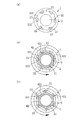
本発明による第1実施形態の締付トルク管理具1は、図1〜図4に示すように、嵌合部2と締付トルク導入部3が一体形成されたものであり、全体がポリプロピレンやポリエチレン、ABS樹脂等の共重合合成樹脂、或いはポリカーボネート等の耐熱性に優れるエンジニアリングプラスチック等の合成樹脂又はアルミニウムやアルミニウム合金等で一体的に形成されている。
[Tightening torque management tool of the first embodiment]
As shown in FIGS. 1 to 4, the tightening torque management tool 1 of the first embodiment according to the present invention is formed by integrally forming a
嵌合部2には、ナット或いはボルトである螺合部材の締付外周面に外嵌される嵌合孔21が略中央に形成されている。嵌合孔21の内部には、ナット或いはボルト頭部等の辺部と角部で構成される螺合部材の締付外周面に対し、その辺部を当接保持する複数のラチェット舌片22が周方向に間隔を開けてそれぞれ斜めに立ち上がるように螺旋放射状に右締めの締付方向の反対に向かって延びるように設けられている。ラチェット舌片22は根元で嵌合孔21の内周壁に繋がり、その根元よりも上側は可動可能部分になっている。図示例では、六角ナット或いは六角形のボルト頭部の各辺部に対応する位置に、それぞれの辺部に各保持部222が当接するようにして各ラチェット舌片22が設けられている。
The
嵌合孔21の内部には、各々のラチェット舌片22の先端部221を嵌入可能な凹部23が設けられている。そして、それぞれのラチェット舌片22は、嵌合孔21に嵌合される螺合部材の締付外周面に対する所定の締付トルクを超える締付トルクの負荷により、螺合部材で付勢されて先端部221が対応する凹部23にそれぞれ嵌入されるようにして設けられている。また、本実施形態では、一体形成されている締付トルク管理具1の素材の硬度を、螺合部材の硬度或いはその締付外周面の硬度より低くし、相対的にラチェット舌片22が柔らかくなるようにして、ラチェット舌片22が螺合部材で付勢されて先端部221が対応する凹部23に嵌入されやすくしている。
Inside the
嵌合孔21の内周面211は、螺合部材の嵌入方向(図1(c)の上方向)に向かって嵌合孔21の内径が僅かに小さくなるように傾斜して形成されている。そして、ラチェット舌片22は螺合部材の嵌入方向に延びて設けられ、且つ嵌入方向に亘って全体として略同一高さで形成され、内周面211の傾斜に倣って形成されることにより、ラチェット舌片22の保持部222が嵌合孔22の奥側に向かって漸次内方に突出するように僅かに傾斜して設けられている。また、嵌合孔21の内周面211は、ナット或いはボルト頭部等の角部422には接触しない構成となっている。
The inner
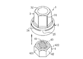
このラチェット舌片22が形成された嵌合孔21には、ナット或いはボルト頭部等の辺部と角部で構成される螺合部材の締付外周面が嵌入され、締付外周面の各辺部の一部分にラチェット舌片22が押圧するように当接し各辺部を部分的に保持するようにして、螺合部材の締付外周面が嵌合されるようになっている。この嵌合孔21に嵌め込まれるナットやボルトには適宜種類のものを用いることが可能であり、例えば通常のナット以外の図2(b)、図3、図4に示す緩み止めナット4を嵌合してもよい。
In the
この緩み止めナット4は、内側に雌ねじ孔41が形成され、辺部421と角部422で構成される平面視略六角形の締付外周面42を有すると共に、雌ねじ孔41の上端近傍、嵌合孔21に嵌め込んだ状態では締付トルク導入部3側において、雌ねじ孔41の内側に突出するように対向する位置に板バネ43が設けられたものである。緩み止めナット4は、雌ねじ孔41にボルト軸部が螺合された状態で、板バネ43が変形してボルト軸部のネジ山に係合して緩み止め機能を発揮する。尚、一般的に緩み止め機能を有するナットは締付トルク管理を的確に行うことによってはじめて緩み止め効果を発現できることから、本発明が特に有効に効果を発現する。
The locking
嵌合部2の平面視の外形形状は適宜であるが、例えば嵌合孔21の周囲に所要の肉厚を確保して安定した強度を得られる形状等とし、図示例では平面視略円形の外形形状になっている。そして、それぞれのラチェット舌片22の可動可能部分の締付トルク導入部3側における嵌合部2には、周方向に延びる弧状のスリット孔24が嵌合孔と貫通してそれぞれ形成されている。また、それぞれのラチェット舌片22の根元に略対応する部分の締付トルク導入部3側における嵌合部2は非開口になっており、非開口部25が設けられている。
The outer shape of the
締付トルク導入部3は、ナット或いはボルトである螺合部材の締付外周面に対応する外周面31を有し、ナット或いはボルト頭部等の辺部と角部で構成される螺合部材の締付外周面に対応する形状になっている。図示例では、平面視略正六角形であるナット或いはボルト頭部の締付外周面の形状に対応して平面視略正六角形に形成されている。また、締付トルク導入部3の外周面31の大きさは、ナット或いはボルト頭部等の締付外周面の大きさと略同一になっている。
The tightening
締付トルク導入部3の略中央には、嵌合孔21と連通する貫通孔32が形成されている。貫通孔32の平面視形状と外径は、嵌合孔21に嵌め込まれたナットから螺合によって突出するボルト軸部が貫通孔32の内周面に接触しない構成であれば適宜であり、例えば図4に示すように、嵌合孔21に嵌め込まれた緩み止めナット4から螺合によって突出するボルト軸部5が貫通孔32の内周面に接触しない構成とされる。
A through
締付トルク管理具1は、施工現場にて締結するナットの締付外周面或いはボルトの頭部の締付外周面に嵌合孔21を外嵌してナット或いはボルト頭部に設置し、締付トルク導入部3をトルクレンチ等の工具で回転させるようにして使用してもよいが、例えば図2(b)のように締付トルク管理具1の嵌合孔21を緩み止めナット4の締付外周面42に工場で外嵌して締付トルク管理具1と緩み止めナット4を一体的に設けた締付トルク管理具付ナットなど、締付トルク管理具1とナットを一体的に設けた締付トルク管理具付ナットを予め構成し、締付トルク管理具付ナットを用いて施工現場でナット締結、取付物の取付作業を行うようにすると、ナット締結作業を一層効率的且つ確実に行うことができて好適である。
The tightening torque control tool 1 is installed on the nut or bolt head by externally fitting the
この締付トルク管理具1或いは締付トルク管理具付ナットを用いて取付物7を取り付ける際には、例えば図4に示すように、取付物7から突出するボルト軸部5にワッシャー6を外挿して介在させ、ワッシャー6の外側において締付トルク管理具1の嵌合孔21に嵌められてラチェット舌片22で当接保持されている緩み止めナット4を取付物7から突出するボルト軸部5に螺合する。そして、図2(b)の太線二点鎖線矢印の方向に、締付トルク導入部3をトルクレンチ等の工具で回転させて締め付け、緩み止めナット4の螺入を進めてボルト軸部5を貫通孔32の内部に突出させる。図示例では貫通孔32からボルト軸部5の先端部分が外側に突出するまで緩み止めナット4を螺入している。
When attaching the attachment 7 using the tightening torque control tool 1 or the nut with the tightening torque control tool, for example, as shown in FIG. 4, the washer 6 is removed from the
その後、緩み止めナット4を次第に緊締していき、所定の締付トルクを超える締付トルクを加えて締付トルク導入部3を回転させると、緩み止めナット4の辺部421、角部422でラチェット舌片22が放射方向に拡開されるように変形され、緩み止めナット4の締付外周面42の角部422でラチェット舌片22の先端部221が凹部23に嵌入され、締付トルク管理具1が空転する(図2(b)、(c)参照)。図示例ではラチェット舌片22の略円柱状の先端部221が凹部23に嵌め込まれるようになっている。
After that, the locking
その後、空転する状態となった締付トルク管理具1を緩み止めナット4及びボルト軸部5から抜き去り、緩み止めナット4の締結による取付物7の取り付けが完了する。
After that, the tightening torque control tool 1 that is in an idling state is removed from the locking
尚、締付トルク管理具1の嵌合孔21をボルトの頭部の締付外周面に外嵌して締付トルク管理具1とボルトを一体的に設けた締付トルク管理具付ボルトを予め構成し、この締付トルク管理具付ボルトを用いて施工現場でボルト締結、取付物の取付作業を行うようにしてもよい。この締付トルク管理具付ボルトを用いて締結作業を行うことにより、ボルトの締結作業を一層効率的に行うことが可能となる。
A bolt with a tightening torque control tool is provided by fitting the
第1実施形態によれば、螺合部材の締め付けに際して締付トルク導入部3を回転させると、締付トルク導入部3から嵌合部2、ラチェット舌片22を介して螺合部材へと締付トルクが伝達され、所定の締付トルクを超えたところでラチェット舌片22の先端部221が凹部23に嵌入して締付トルク管理具1が空転するので、作業者が所定の締付トルクでの締結完了を容易且つ明確に検知することができ、所定の締付トルクでの螺合締結、正確なトルク管理を確実に行うことができる。更に、この所定の締付トルクでの螺合締結、正確なトルク管理は、締付トルク管理具1を回転させる方法の種類に依らずに行うことができ、例えば電動工具で締付トルク導入部3を把持して高速回転でナット締めしても確実に所定の締付トルクでの螺合締結、正確なトルク管理を行うことができる。
According to the first embodiment, when the tightening
また、ラチェット舌片22が凹部23に嵌入して締付トルク管理具1が空転する状態でも、嵌合部2と締付トルク導入部3は破断することなく一体性を維持することから、所定の締付トルクでの螺合締結後に、一体的な締付トルク管理具1を容易に螺合部材から取り外すことができる。即ち、締結後に締付トルク管理具1の分離したカバー体等の一部分を取り外したり、ナット等の螺合部材に接着剤で接着する作業が不要となる。また、事前に締付トルク管理具1をナット等の螺合部材に接着剤で接着する作業も不要である。従って、全体的な作業工程を削減し、作業効率を高めることができる。また、事前接着の作業コストを含む高価な締付トルク管理具付ナット等が不要であり、低コストで所定の締付トルクでの螺合締結を行うことができる。
Further, even when the
また、施工管理者は、締付トルク管理具1の残留がないことを確認するだけで、所定の締付トルクでの螺合締結、施工完了を容易に手間無く確認することができると共に、遠くから目視しても容易に施工完了を確認することができる。また、締付トルク管理具1は破断することなく施工後に一体として取り外すことができるため、施工ナット本数と締付トルク管理具1の数量を管理することにより、確実に施工管理をすることができる。また、ナット等の螺合部材の変形や破断を要せず、ナット等の螺合部材の種類を選ばずに適用することができ、例えば緩み止めナット4のような特殊なナットに適用することも可能であり、使用可能な螺合部材に高い自由度を有し、汎用性に非常に優れる。また、ラチェット舌片22が凹部23に嵌入して締付トルク管理具1が空転する構成であるから、ラチェット舌片22が削られて破片や粉が出ることがなく、破片や粉の清掃作業も不要である。
In addition, the construction manager can easily and effortlessly confirm the screwing and fastening with the predetermined tightening torque and the completion of the construction only by confirming that the tightening torque control tool 1 does not remain, and is far away. The completion of construction can be easily confirmed by visual inspection. Further, since the tightening torque control tool 1 can be removed as a unit after construction without breaking, it is possible to reliably manage the construction by managing the number of construction nuts and the quantity of the tightening torque control tool 1. .. Further, it does not require deformation or breakage of a screw member such as a nut, and can be applied to any type of screw member such as a nut. For example, it can be applied to a special nut such as a locking
また、ラチェット舌片22を螺合部材の嵌入方向に延ばして設け、ラチェット舌片22の保持部222を嵌合孔21の奥側に向かって漸次内方に突出するように傾斜して設けることにより、螺合部材の締付外周面の安定した保持を確保しつつ、螺合部材の締付外周面を嵌合孔21に圧入し易くすることができ、締付トルク管理具1へのナット等の螺合部材の取付作業を容易化することができる。
Further, the
また、スリット孔24により、例えば弧状のスリット孔24を利用して樹脂成形型の一部を嵌合孔内に入れ込むような配置で合成樹脂で成形する、或いはスリット孔24を利用してラチェット舌片の可動可能部分の上側を嵌合孔の天井面と切り離すなど、嵌合孔21の天井面と可動可能部分が離間されたラチェット片22を容易に形成することができる。また、嵌合部21の天井面と可動可能部分が離間したラチェット舌片22とすることができるので、ラチェット舌片22を天井面に拘束されることなく自由に柔らかく動けるようにすることが可能であり、ラチェット舌片22の先端部221を凹部23にスムーズに嵌入する動作を得ることができる。更に、非開口部25により、ラチェット舌片22の根元に略対応する部分の剛性を高めることができ、所定の締付トルクまで締付トルク管理具1とラチェット舌片22で保持される螺合部材を確実に一緒に回転させることが可能となる。
Further, the
また、締付トルク管理具1の嵌合孔21に緩み止めナット4等のナットを嵌め込んで用いる場合には、嵌合孔21が貫通孔32に連通して、ボルト軸部5の貫通孔32内への突出や貫通孔32の嵌合孔21とは逆側への突出を許容する構成になっていることから、螺合するナットからボルト軸部5が突出する長さ如何に拘束されず、所定の締付トルクでの螺合締結を確実に行うことができる。また、ラチェット舌片22の凹部23への嵌入、締付トルク管理具1の空転により、一体的な締付トルク管理具1を非常に容易に螺合部材から取り外すことができる。また、本実施形態において、ラチェット舌片22は、周方向に見て右締めの締付方向の反対に向かって延びているが、これを右締めの締付方向に延びるように適宜設計することも可能である。
Further, when a nut such as a locking
〔第2実施形態の締付トルク管理具〕
本発明による第2実施形態の締付トルク管理具1aは、図5及び図6に示すように、嵌合部2aと第1実施形態と同様の締付トルク導入部3が一体形成されたものであり、全体がポリプロピレンやポリエチレン、ABS樹脂等の共重合合成樹脂、或いはポリカーボネート等の耐熱性に優れるエンジニアリングプラスチック等の合成樹脂又はアルミニウムやアルミニウム合金等で一体的に形成されている。
[Tightening torque management tool of the second embodiment]
As shown in FIGS. 5 and 6, the tightening torque management tool 1a of the second embodiment according to the present invention has a
嵌合部2aには、ナット或いはボルトである螺合部材の締付外周面に外嵌される嵌合孔21が略中央に形成されている。嵌合孔21の内部には、ナット或いはボルト頭部等の辺部と角部で構成される螺合部材の締付外周面に対し、その辺部を当接保持する複数のラチェット舌片22aが周方向に間隔を開けてそれぞれ斜めに立ち上がるように螺旋放射状に設けられている。ラチェット舌片22aは根元で嵌合孔21の内周壁に繋がり、その根元よりも上側は可動可能部分になっている。図示例では、六角ナット或いは六角形のボルト頭部の各辺部に対応する位置に、それぞれの辺部に各保持部222aが当接するようにして各ラチェット舌片22aが設けられている。
The
嵌合孔21の内部には、各々のラチェット舌片22aの先端部221aを嵌入可能な凹部23aが設けられている。それぞれのラチェット舌片22aは、嵌合孔21に嵌合される螺合部材の締付外周面に対する所定の締付トルクを超える締付トルクの負荷により、螺合部材で付勢されて先端部221aが対応する凹部23aにそれぞれ嵌入されるようにして設けられている。尚、本実施形態でも締付トルク管理具1の素材の硬度は、螺合部材の硬度或いはその締付外周面の硬度より低くなっている。
Inside the
更に、凹部23aの口元には、凹部23aに嵌入されたラチェット舌片22aの先端部221aの脱落を防止する脱落防止突起231aが形成されている。図示例の脱落防止突起231aは、凹部23aに対応して嵌合されるラチェット舌片22aとは逆側に位置する凹部23aの口元にて、対応するラチェット舌片22aの方に向かって突出するように形成されている。
Further, at the mouth of the
嵌合孔21の内周面211は、第1実施形態と同様に、螺合部材の嵌入方向(図5(c)の上方向)に向かって嵌合孔21の内径が僅かに小さくなるように傾斜して形成されている。そして、ラチェット舌片22aは螺合部材の嵌入方向に延びて設けられ、且つ嵌入方向に亘って全体として略同一高さで形成され、内周面211の傾斜に倣って形成されることにより、ラチェット舌片22aの保持部222aが嵌合孔21の奥側に向かって漸次内方に突出するように僅かに傾斜して設けられている。また、嵌合孔21の内周面211は、ナット或いはボルト頭部等の角部422には接触しない構成となっている。
Similar to the first embodiment, the inner
このラチェット舌片22aが形成された嵌合孔21には、ナット或いはボルト頭部等の辺部と角部で構成される螺合部材の締付外周面が嵌入され、締付外周面の各辺部の一部分にラチェット舌片22aが当接し各辺部を部分的に保持するようにして、螺合部材の締付外周面が嵌合される。この嵌合孔21に嵌め込まれるナットやボルトにも緩み止めナット4など適宜種類のものを用いることが可能である。
In the
嵌合部2aの平面視の外形形状も適宜であり、図示例の平面視略円形の外形形状など、嵌合孔21の周囲に所要の肉厚を確保して安定した強度を得られる形状等とする。そして、それぞれのラチェット舌片22aの可動可能部分の締付トルク導入部3側における嵌合部2aには、周方向に延びる弧状のスリット孔24が嵌合孔と貫通してそれぞれ形成されている。また、それぞれのラチェット舌片22aの根元に略対応する部分の締付トルク導入部3側における嵌合部2aは非開口になっており、非開口部25が設けられている。
The outer shape of the
第2実施形態の締付トルク管理具1aのその他の構成は第1実施形態の締付トルク管理具1と同様である。更に、締付トルク管理具1aを用いて第1実施形態と同様に、締付トルク管理具付ナット、或いは締付トルク管理具付ボルトを構成することができる。また、例えば緩み止めナット4の締付外周面42の角部422でラチェット舌片22aの先端部221aを含む可動可能部分が凹部23aに嵌入し、締付トルク管理具1aを空転する(図6(b)、(c)参照)など、第1実施形態と同様の工程により、取付物7の取り付けを行うことができる。
Other configurations of the tightening torque control tool 1a of the second embodiment are the same as those of the tightening torque control tool 1 of the first embodiment. Further, the tightening torque management tool 1a can be used to form a nut with a tightening torque management tool or a bolt with a tightening torque management tool as in the first embodiment. Further, for example, at the
第2実施形態によれば、脱落防止突起231aにより、螺合部材の締付時に凹部23aに嵌入されたラチェット舌片22aの先端部221aの脱落を防止し、ラチェット片22aが嵌入前の状態に復元することを確実に防止することができ、所定の締付トルクを超える締め付けを行った後の締付トルク管理具1aの空転状態をより確実に維持することができる。その他、第1実施形態と対応する構成から対応する効果を得ることができる。
According to the second embodiment, the fall-
〔実施形態の変形例等〕
本明細書開示の発明は、各発明、各実施形態の他に、適用可能な範囲で、これらの部分的な構成を本明細書開示の他の構成に変更して特定したもの、或いはこれらの構成に本明細書開示の他の構成を付加して特定したもの、或いはこれらの部分的な構成を部分的な作用効果が得られる限度で削除して特定した上位概念化したものを含むものであり、下記変形例も包含する。
[Modified examples of embodiments]
The invention disclosed in the present specification is specified by changing these partial configurations to other configurations disclosed in the present specification to the extent applicable, in addition to each invention and each embodiment, or these. It includes a configuration specified by adding other configurations disclosed in the present specification, or a super-conceptualized configuration specified by deleting these partial configurations to the extent that a partial effect can be obtained. , Also includes the following modifications.
例えば本発明における嵌合部のラチェット舌片や凹部の形状、構成は、第1、第2実施形態のラチェット舌片22、22a、凹部23、23aに限定されず、複数のラチェット舌片は、螺合部材の締付外周面に当接して保持するように、周方向に間隔を開けてそれぞれ斜めに立ち上がるように螺旋放射状に設けられるものであれば適宜であり、又、それぞれの凹部は、対応するラチェット舌片の先端部を嵌入可能なものであれば適宜である。
For example, the shape and configuration of the ratchet tongue piece and the recess of the fitting portion in the present invention are not limited to the
また、ラチェット舌片22の保持部222、ラチェット舌片22aの保持部222aを嵌合孔21の奥側に向かって漸次内方に突出するように傾斜して設ける構成では、嵌合孔21の内周面211はテーパ状に傾斜させずに、ラチェット舌片22、22aの高さが嵌合孔21の奥側に向かって漸次内方に突出して傾斜するように高さが高くなる構成としてもよい。
Further, in the configuration in which the holding
本発明は、例えば取付板、接続板等の取付物を各種構造物に螺合締結して取り付ける際に利用することができる。 The present invention can be used, for example, when an attachment such as an attachment plate or a connection plate is screwed and fastened to various structures for attachment.
1、1a…締付トルク管理具 2、2a…嵌合部 21…嵌合孔 211…内周面 22、22a…ラチェット舌片 221、221a…先端部 222、222a…保持部 23、23a…凹部 231a…脱落防止突起 24…スリット孔 25…非開口部 3…締付トルク導入部 31…外周面 32…貫通孔 4…緩み止めナット 41…雌ねじ孔 42…締付外周面 421…辺部 422…角部 43…板ばね 5…ボルト軸部 6…ワッシャー 7…取付物
1, 1a ... Tightening
Claims (7)
前記螺合部材の前記締付外周面の形状と大きさに対応する同じ形状と略同一の大きさの外周面を有し、前記嵌合孔と連通する貫通孔が形成されている締付トルク導入部とが一体形成され、
各々の前記ラチェット舌片が、前記嵌合孔に嵌合される前記締付外周面に対する所定の締付トルクを超える締付トルクの負荷により、付勢されて少なくとも前記先端部が前記凹部に嵌入されて前記螺合部材に対して全体が空転するように設けられていることを特徴とする締付トルク管理具。 It has a fitting hole that is externally fitted to the outer peripheral surface of the tightening formed by the sides and corners of the screwing member, and abuts and holds the side of the outer peripheral surface of the tightening inside the fitting hole. A plurality of ratchet tongue pieces are provided so as to extend in a spiral radial direction opposite to the tightening direction so that they stand up diagonally at intervals in the circumferential direction, and at least the tip of each ratchet tongue piece can be fitted. With a mating part provided with a large recess
Tightening torque having an outer peripheral surface having the same shape and substantially the same size as the shape and size of the tightening outer peripheral surface of the screwing member, and having a through hole communicating with the fitting hole. The introduction part is integrally formed,
Each of the ratchet tongue pieces is urged by a load of a tightening torque exceeding a predetermined tightening torque on the tightening outer peripheral surface fitted in the fitting hole, and at least the tip portion is fitted into the recess. A tightening torque management tool, characterized in that the entire screw member is provided so as to idle .
前記ラチェット舌片の保持部が前記嵌合孔の奥側に向かって漸次内方に突出するように傾斜して設けられていることを特徴とする請求項1又は2記載の締付トルク管理具。 The ratchet tongue piece is provided so as to extend in the fitting direction of the screwing member.
The tightening torque management tool according to claim 1 or 2, wherein the holding portion of the ratchet tongue piece is provided so as to be inclined so as to gradually project inward toward the inner side of the fitting hole. ..
前記締付トルク管理具の前記嵌合孔に嵌められて前記ラチェット舌片で当接保持されているナットを取付物から突出するボルト軸部に螺合し、前記締付トルク導入部を回転させて締め付けると共に、前記ボルト軸部を前記貫通孔の内部に突出させる第1工程と、
所定の締付トルクを超える締付トルクを加えて前記ナットの締付外周面の角部で前記ラチェット舌片の少なくとも先端部を前記凹部に嵌入し、前記締付トルク管理具を空転させる第2工程と、
前記締付トルク管理具を前記ナット及び前記ボルト軸部から抜き去る第3工程と
を備えることを特徴とする取付物の取付方法。 A method of attaching an attachment using the tightening torque control tool according to any one of claims 1 to 4.
A nut fitted in the fitting hole of the tightening torque management tool and held in contact with the ratchet tongue piece is screwed into a bolt shaft portion protruding from the attachment, and the tightening torque introduction portion is rotated. In the first step of tightening the bolt shaft and projecting the bolt shaft into the through hole,
A second tightening torque management tool is allowed to idle by applying a tightening torque exceeding a predetermined tightening torque to fit at least the tip of the ratchet tongue piece into the recess at a corner of the tightening outer peripheral surface of the nut. Process and
A method for attaching an attachment, which comprises a third step of removing the tightening torque control tool from the nut and the bolt shaft portion.
Priority Applications (1)
| Application Number | Priority Date | Filing Date | Title |
|---|---|---|---|
| JP2016139153A JP6779570B2 (en) | 2016-07-14 | 2016-07-14 | Tightening torque control tool, nuts and bolts with tightening torque control tool, and mounting method of attachments |
Applications Claiming Priority (1)
| Application Number | Priority Date | Filing Date | Title |
|---|---|---|---|
| JP2016139153A JP6779570B2 (en) | 2016-07-14 | 2016-07-14 | Tightening torque control tool, nuts and bolts with tightening torque control tool, and mounting method of attachments |
Publications (2)
| Publication Number | Publication Date |
|---|---|
| JP2018008353A JP2018008353A (en) | 2018-01-18 |
| JP6779570B2 true JP6779570B2 (en) | 2020-11-04 |
Family
ID=60994776
Family Applications (1)
| Application Number | Title | Priority Date | Filing Date |
|---|---|---|---|
| JP2016139153A Active JP6779570B2 (en) | 2016-07-14 | 2016-07-14 | Tightening torque control tool, nuts and bolts with tightening torque control tool, and mounting method of attachments |
Country Status (1)
| Country | Link |
|---|---|
| JP (1) | JP6779570B2 (en) |
Families Citing this family (5)
| Publication number | Priority date | Publication date | Assignee | Title |
|---|---|---|---|---|
| JP7116595B2 (en) * | 2018-05-31 | 2022-08-10 | 日本クロージャー株式会社 | Tightening torque control tool and combination of tightening torque control tool and fastener |
| JP7217498B2 (en) * | 2018-09-27 | 2023-02-03 | 株式会社NejiLaw | Male threaded body with cap, male threaded body and cap |
| MX2021014140A (en) * | 2019-05-21 | 2022-01-04 | Penn Eng & Mfg Corp | Torque limiting screw. |
| JP2022075047A (en) * | 2020-11-06 | 2022-05-18 | 株式会社日立製作所 | Bolt tightening device and bolt tightening method |
| EP4329984A4 (en) * | 2021-04-27 | 2025-03-05 | Tyco Fire Products LP | Tool for installing fire sprinklers |
Family Cites Families (8)
| Publication number | Priority date | Publication date | Assignee | Title |
|---|---|---|---|---|
| US4215600A (en) * | 1978-10-12 | 1980-08-05 | Kesselman David A | Torque limiter for use with off-the-shelf fastening elements |
| JPS5853911U (en) * | 1981-10-07 | 1983-04-12 | 日産自動車株式会社 | Natsuto |
| NZ239402A (en) * | 1990-08-24 | 1993-05-26 | Ramset Fasteners Aust Pty Ltd | Bolt or nut tightening device having socket portion which shears from device and remains attached to bolt or nut |
| JPH0718530Y2 (en) * | 1992-07-15 | 1995-05-01 | 智之 新川 | Replaceable box spanner using ratchet spanner |
| JP2001140832A (en) * | 1999-11-10 | 2001-05-22 | Furukawa Electric Co Ltd:The | Bolt and nut torque management fasteners and bolts and nuts with torque management fasteners |
| US20020076295A1 (en) * | 2000-12-14 | 2002-06-20 | Rodney Gibbons | Torque limiting device |
| US20040226419A1 (en) * | 2003-05-15 | 2004-11-18 | Morgan March R. | Device to correctly torque nuts and bolts |
| JP2005103704A (en) * | 2003-09-30 | 2005-04-21 | Kobayashi Kogu Seisakusho:Kk | Socket for socket wrench, socket wrench |
-
2016
- 2016-07-14 JP JP2016139153A patent/JP6779570B2/en active Active
Also Published As
| Publication number | Publication date |
|---|---|
| JP2018008353A (en) | 2018-01-18 |
Similar Documents
| Publication | Publication Date | Title |
|---|---|---|
| JP6779570B2 (en) | Tightening torque control tool, nuts and bolts with tightening torque control tool, and mounting method of attachments | |
| JP6779569B2 (en) | Tightening torque control tool, nuts and bolts with tightening torque control tool, and mounting method of attachments | |
| CA1185816A (en) | Torque limiting elastomeric fastener and seal | |
| US20090116930A1 (en) | Fastener system, fastener system article, and method | |
| WO2001088391A1 (en) | Structure for preventing loosening of threaded fasteners | |
| JP2019518924A (en) | Screw fastener arrangement and washer assembly therefor | |
| WO1998009086A1 (en) | Lock nut | |
| JP2019039555A (en) | Looseness prevention fastening structure | |
| JP5933770B2 (en) | Fastener manufacturing method | |
| KR20180043692A (en) | Non-release bolt and nut | |
| JP7116595B2 (en) | Tightening torque control tool and combination of tightening torque control tool and fastener | |
| KR200395383Y1 (en) | Jointer using magnet | |
| JP2017104971A (en) | Tightening torque control tool, nut and bolt with tightening torque control tool, and attachment method | |
| JP2016223523A (en) | Washer and nut with washer | |
| JP3553291B2 (en) | Drop-off prevention aid and drop-off prevention external thread member including the same | |
| JP3553290B2 (en) | Cap for preventing falling off and female screw member for preventing falling off including the cap | |
| JP5918428B1 (en) | Fall prevention tool | |
| TWI752227B (en) | Tightening torque control tool, and combination of tightening torque control tool and fastening tool | |
| JP7658720B2 (en) | Torque Control Tool | |
| JP3104596U (en) | Lock nut | |
| JP2009068595A (en) | Torque nut | |
| JP2020180651A (en) | Looseness prevention bolt, member connection structure and member connection method | |
| JP3194633U (en) | bolt | |
| JP2022121089A (en) | Post-construction anchor | |
| JP3020070U (en) | Fastened body with covered nut |
Legal Events
| Date | Code | Title | Description |
|---|---|---|---|
| A711 | Notification of change in applicant |
Free format text: JAPANESE INTERMEDIATE CODE: A711 Effective date: 20170517 |
|
| A521 | Request for written amendment filed |
Free format text: JAPANESE INTERMEDIATE CODE: A821 Effective date: 20170517 |
|
| A621 | Written request for application examination |
Free format text: JAPANESE INTERMEDIATE CODE: A621 Effective date: 20190513 |
|
| A977 | Report on retrieval |
Free format text: JAPANESE INTERMEDIATE CODE: A971007 Effective date: 20200210 |
|
| A131 | Notification of reasons for refusal |
Free format text: JAPANESE INTERMEDIATE CODE: A131 Effective date: 20200309 |
|
| A521 | Request for written amendment filed |
Free format text: JAPANESE INTERMEDIATE CODE: A523 Effective date: 20200422 |
|
| TRDD | Decision of grant or rejection written | ||
| A01 | Written decision to grant a patent or to grant a registration (utility model) |
Free format text: JAPANESE INTERMEDIATE CODE: A01 Effective date: 20201013 |
|
| A61 | First payment of annual fees (during grant procedure) |
Free format text: JAPANESE INTERMEDIATE CODE: A61 Effective date: 20201013 |
|
| R150 | Certificate of patent or registration of utility model |
Ref document number: 6779570 Country of ref document: JP Free format text: JAPANESE INTERMEDIATE CODE: R150 |
|
| R250 | Receipt of annual fees |
Free format text: JAPANESE INTERMEDIATE CODE: R250 |