JP6777536B2 - Pneumatic tires - Google Patents
Pneumatic tires Download PDFInfo
- Publication number
- JP6777536B2 JP6777536B2 JP2016256367A JP2016256367A JP6777536B2 JP 6777536 B2 JP6777536 B2 JP 6777536B2 JP 2016256367 A JP2016256367 A JP 2016256367A JP 2016256367 A JP2016256367 A JP 2016256367A JP 6777536 B2 JP6777536 B2 JP 6777536B2
- Authority
- JP
- Japan
- Prior art keywords
- tire
- vehicle
- width direction
- equatorial plane
- tread
- Prior art date
- Legal status (The legal status is an assumption and is not a legal conclusion. Google has not performed a legal analysis and makes no representation as to the accuracy of the status listed.)
- Active
Links
Images


Landscapes
- Tires In General (AREA)
Description
本発明の実施形態は、空気入りタイヤに関する。 Embodiments of the present invention relate to pneumatic tires.
空気入りタイヤにおいては、様々な性能を向上させることを目的として、タイヤ断面形状における各構成要素の設計等がなされている(例えば、特許文献1参照)。 In a pneumatic tire, each component in the cross-sectional shape of the tire is designed for the purpose of improving various performances (see, for example, Patent Document 1).
例えば、空気入りタイヤの制動性能を向上させるため、タイヤの接地面積を増加させる方法があり、具体的にはタイヤ断面形状におけるトレッド幅を拡大し、特にショルダー陸部の接地面積を増加させる方法がある。しかしながら、接地面積を増加させると、その背反として、高い左右加速度が作用する高シビアリティ域での操縦安定性が悪化し、操縦安定性の限界挙動が損なわれるという問題がある。 For example, in order to improve the braking performance of a pneumatic tire, there is a method of increasing the contact area of the tire, specifically, a method of expanding the tread width in the cross-sectional shape of the tire and particularly increasing the contact area of the shoulder land portion. is there. However, when the ground contact area is increased, as a trade-off, there is a problem that the steering stability in a high severity range where a high lateral acceleration acts is deteriorated and the limit behavior of the steering stability is impaired.
また、商用車用タイヤのような高負荷がかかるタイヤでは、車両装着姿勢において車両外側よりも車両内側の接地圧が高いことから、車両内側領域において摩耗しやすく、車両外側領域との間で摩耗差が生じる偏摩耗の要因となる。 In addition, tires that are subject to a high load, such as commercial vehicle tires, tend to wear in the vehicle inner region because the ground pressure inside the vehicle is higher than that in the vehicle mounting posture, and wear with the vehicle outer region. It causes uneven wear that causes a difference.
本発明の実施形態は、以上の点に鑑み、制動性能と操縦安定性を損なうことなく、車両内側領域と車両外側領域との間での偏摩耗を抑制することを目的とする。 In view of the above points, an embodiment of the present invention aims to suppress uneven wear between the vehicle inner region and the vehicle outer region without impairing braking performance and steering stability.
本発明の実施形態に係る空気入りタイヤは、車両への装着の向きが指定された空気入りタイヤであって、一対のビード部と、これらビード部からタイヤ径方向外方に延びる一対のサイドウォール部と、前記一対のサイドウォール部の径方向外方端同士を繋いで接地面を構成するトレッド部と、前記一対のビード部間に跨がって延びるカーカス層と、前記トレッド部における前記カーカス層の外周側に配されたベルトと、を備え、前記トレッド部が、タイヤ周方向に延びる4本の周方向主溝により、タイヤ幅方向中央部に位置するセンター陸部と、トレッド部のタイヤ幅方向端部に位置する一対のショルダー陸部と、センター陸部とショルダー陸部の間に位置する一対のメディエート陸部とに区画されたものである。前記トレッド部は、接地幅内における前記一対のショルダー陸部の面積、前記一対のメディエート陸部の面積、及び前記センター陸部の面積を、それぞれAs、Am、及びAcとして、As/(As+Am+Ac)で表されるショルダー陸部の面積比率が0.40以上0.52以下である。また、正規リム組み内圧未充填状態のタイヤ幅方向断面において、車両装着姿勢でタイヤ赤道面よりも車両外側に存在する車両外側領域では、タイヤ赤道面からトレッド端までの距離をDbとし、タイヤ赤道面からベルト端までの距離をDcとして、Dc/Dbが0.86以上0.98以下であり、かつ、ベルト端でのゴム厚みをTgとし、トレッド端でのゴム厚みをThとして、Tg>Thである。また、車両装着姿勢でタイヤ赤道面よりも車両内側に存在する車両内側領域では、タイヤ赤道面からトレッド端までの距離をDb’とし、タイヤ赤道面からベルト端までの距離をDc’として、Dc’/Db’が1.00以上1.10以下であり、かつ、ベルト端でのゴム厚みをTg’とし、トレッド端でのゴム厚みをTh’として、Tg’<Th’である。 The pneumatic tire according to the embodiment of the present invention is a pneumatic tire whose mounting direction on a vehicle is specified, and is a pair of bead portions and a pair of sidewalls extending outward in the tire radial direction from these bead portions. A tread portion that connects the portions, the radial outer ends of the pair of sidewall portions to form a ground contact surface, a carcass layer extending across the pair of bead portions, and the carcass in the tread portion. The tread portion is provided with a belt arranged on the outer peripheral side of the layer, and the center land portion located in the center portion in the tire width direction and the tire of the tread portion are provided by the four circumferential main grooves extending in the tire circumferential direction. It is divided into a pair of shoulder treads located at the end in the width direction and a pair of mediate treads located between the center tread and the shoulder treads. The tread portion has the area of the pair of shoulder land portions, the area of the pair of mediate land portions, and the area of the center land portion within the ground contact width as As, Am, and Ac, respectively, as As / (As + Am + Ac). The area ratio of the shoulder land area represented by is 0.40 or more and 0.52 or less. Further, in the tire width direction cross section in the state where the normal rim assembly internal pressure is not filled, in the vehicle outer region existing outside the vehicle equatorial plane in the vehicle mounting posture, the distance from the tire equatorial plane to the tread end is set as Db, and the tire equatorial road The distance from the surface to the belt end is Dc, Dc / Db is 0.86 or more and 0.98 or less, the rubber thickness at the belt end is Tg, and the rubber thickness at the tread end is Th, Tg> Th. Further, in the vehicle inner region existing inside the vehicle from the tire equatorial plane in the vehicle mounting posture, the distance from the tire equatorial plane to the tread end is defined as Db', and the distance from the tire equatorial plane to the belt end is defined as Dc'. '/ Db' is 1.00 or more and 1.10 or less, and the rubber thickness at the belt end is Tg', the rubber thickness at the tread end is Th', and Tg'<Th'.
本実施形態によれば、制動性能と操縦安定性を損なうことなく、車両内側領域と車両外側領域との間での偏摩耗を抑制することができる。 According to the present embodiment, uneven wear between the vehicle inner region and the vehicle outer region can be suppressed without impairing the braking performance and steering stability.
以下、実施形態について図面を参照して説明する。 Hereinafter, embodiments will be described with reference to the drawings.
図1〜3に示す一実施形態に係る空気入りタイヤは、左右一対のビード部10と、ビード部12からタイヤ径方向外方に延びる左右一対のサイドウォール部12と、サイドウォール部14のタイヤ径方向外方端同士を繋いで接地面を構成するトレッド部14とを備える。この空気入りタイヤは、車両への装着の向きが指定されたタイヤであり、すなわち、車両に装着する際の車両内側に装着される面と車両外側に装着される面とが予め定められている。図1が車両装着姿勢において車両外側に配置される車両外側領域を示し、図2が車両装着姿勢において車両内側に配置される車両内側領域を示す。
The pneumatic tire according to the embodiment shown in FIGS. 1 to 3 includes a pair of left and
図中、符号CLは、タイヤ幅方向中心に相当するタイヤ赤道面を示す。ここで、タイヤ径方向とは、タイヤ回転軸に垂直な方向であり、図において符号RDで示す。タイヤ径方向内側とはタイヤ回転軸に近づく方向であり、タイヤ径方向外側とはタイヤ回転軸から離れる方向である。タイヤ幅方向とは、タイヤ回転軸に平行な方向であり、図において符号WDで示す。タイヤ幅方向内側とはタイヤ赤道面CLに近づく方向であり、タイヤ幅方向外側とはタイヤ赤道面CLから離れる方向である。タイヤ周方向とは、タイヤ回転軸を中心とした円周上の方向であり、図において矢印CDで示す。 In the figure, reference numeral CL indicates a tire equatorial plane corresponding to the center in the tire width direction. Here, the tire radial direction is a direction perpendicular to the tire rotation axis, and is indicated by reference numeral RD in the figure. The inner side in the tire radial direction is a direction approaching the tire rotation axis, and the outer side in the tire radial direction is a direction away from the tire rotation axis. The tire width direction is a direction parallel to the tire rotation axis, and is indicated by reference numeral WD in the figure. The inside in the tire width direction is a direction approaching the tire equatorial plane CL, and the outside in the tire width direction is a direction away from the tire equatorial plane CL. The tire circumferential direction is a direction on the circumference centered on the tire rotation axis, and is indicated by an arrow CD in the figure.
一対のビード部10には、それぞれリング状のビードコア16が埋設されている。ビードコア16のタイヤ径方向外側には、タイヤ径方向外側に向かって先細り状をなす硬質ゴム製のビードフィラー18が設けられている。
A ring-
空気入りタイヤは、一対のビード部10間に跨がってトロイダル状に延びるカーカス層20を備える。カーカス層20は、トレッド部14から両側のサイドウォール部12を経てビード部10に至り、ビード部10においてビードコア16の周りにタイヤ幅方向内側から外側に折り返されることにより、カーカス層20の両端部が係止されている。カーカス層20は、有機繊維コードからなるカーカスコードをタイヤ周方向CDに対して実質上直角になるように配列しゴムで被覆してなる少なくとも1枚のカーカスプライからなり、この例では2枚のカーカスプライで構成されている。
The pneumatic tire includes a
トレッド部14におけるカーカス層20の外周側には、カーカス層20とトレッドゴム22との間にベルト24が設けられている。ベルト24は、ベルトコードをタイヤ周方向CDに対して10°〜35°の傾斜角度で配列した、少なくとも2枚の交差ベルトプライからなり、この例では、タイヤ径方向内側に配された第1ベルトプライ26と、その外周側に配された第2ベルトプライ28との2層構造である。このうち第1ベルトプライ26が最も幅の広い最大幅ベルトプライであり、そのタイヤ幅方向外端がベルト24のタイヤ幅方向端であるベルト端24Aに相当する。
A
この例では、ベルト24のタイヤ径方向外側、即ちベルト24とトレッドゴム22との間にベルト補強層30が設けられている。ベルト補強層30は、タイヤ周方向CDに対して実質的に平行に延びるコードを有するキャッププライにより構成されている。
In this example, the
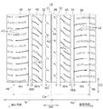
図3に示されるように、トレッド部14の表面には、タイヤ周方向CDに延びる4本の周方向主溝が、タイヤ幅方向WDに間隔をおいて設けられている。4本の周方向主溝は、タイヤ赤道面CLの両側に位置する一対のセンター主溝32,32と、各センター主溝32のタイヤ幅方向外側に位置する一対のショルダー主溝34,34である。なお、周方向主溝は、一般に5mm以上の溝幅(開口幅)を持つ。
As shown in FIG. 3, four circumferential main grooves extending in the tire circumferential direction CD are provided on the surface of the
トレッド部14は、上記4本の周方向主溝32,34により、タイヤ幅方向中央部に位置するセンター陸部36と、トレッド部14のタイヤ幅方向端部に位置する一対のショルダー陸部38,38と、センター陸部36とショルダー陸部38の間に位置する一対のメディエート陸部40,40とに区画されている。センター陸部36は、一対のセンター主溝32,32の間に挟まれたタイヤ赤道上の陸部である。メディエート陸部40は、センター主溝32とショルダー主溝34との間に挟まれた陸部である。ショルダー陸部38は、ショルダー主溝34によりそのタイヤ幅方向外側に区画された陸部である。
The
これらの陸部36,38,40には、それぞれ周方向主溝32,34に交差する方向に延びる貫通又は非貫通の横溝42が多数設けられ、またセンター陸部36にはタイヤ周方向CDに延びる副溝44が設けられている。これにより、トレッド部14の表面には所定のトレッドパターンが形成されている。この例では、トレッドパターンは図3に示す展開図においてタイヤ赤道上の任意の点を対称中心として点対称である。
The
一実施形態に係る空気入りタイヤにおいて、トレッド部14は、接地幅Cw(図3参照)内における一対のショルダー陸部38,38の面積、一対のメディエート陸部40,40の面積、及びセンター陸部36の面積を、それぞれAs、Am、及びAcとして、As/(As+Am+Ac)で表されるショルダー陸部38の面積比率(Sh比)が0.40以上0.52以下(即ち、40〜52%)に設定される。このようにショルダー陸部38の面積比率を高めることにより、制動に対する寄与の大きいショルダー陸部38の接地圧を下げて制動性能を向上することができる。また、Sh比が0.52以下であることにより、高荷重でのコーナリングパワーが高くなりすぎるのを抑えて、操縦安定性の限界挙動の低下を抑制することができる。Sh比は、0.43〜0.50であることが好ましい。
In the pneumatic tire according to the embodiment, the
ここで、接地幅Cwとは、空気入りタイヤを正規リムに装着し、正規内圧を充填した状態で平坦な路面に垂直に置き、正規荷重を加えたときに路面に接地する両側の接地端46,46間の幅である。なお、正規リムとは、タイヤが基づいている規格を含む規格体系において、当該規格がタイヤ毎に定めるリムであり、例えばJATMAであれば標準リム、TRAであれば"Design Rim"、ETRTOであれば"MeasuringRim"である。正規内圧とは、タイヤが基づいている規格を含む規格体系において、各規格がタイヤ毎に定めている空気圧であり、JATMAであれば最高空気圧、TRAであれば表"TIRE LOAD LIMITS AT VARIOUS COLD INFLATION PRESSURES"に記載の最大値、ETRTOであれば"INFLATION PRESSURE"であるが、タイヤが乗用車用である場合には180kPaとする。また、正規荷重は、タイヤが基づいている規格を含む規格体系において、各規格がタイヤ毎に定めている荷重であり、JATMAであれば最大負荷能力、TRAであれば上記の表に記載の最大値、ETRTOであれば"LOAD CAPACITY"であるが、タイヤが乗用車用である場合には前記荷重の88%に相当する荷重とする。 Here, the ground contact width Cw means that the pneumatic tire is mounted on the regular rim, placed vertically on a flat road surface with the regular internal pressure charged, and the ground contact ends 46 on both sides that touch the road surface when a regular load is applied. , 46 width. The regular rim is a rim defined for each tire in the standard system including the standard on which the tire is based. For example, JATMA is a standard rim, TRA is "Design Rim", and ETRTO. For example, "Measuring Rim". The regular internal pressure is the air pressure defined for each tire in the standard system including the standard on which the tire is based. For JATTA, the maximum air pressure, and for TRA, the table "TIRE LOAD LIMITS AT VARIOUS COLD INFLATION". The maximum value described in "PRESSURES" is "INFLATION PRESSURE" for ETRTO, but 180 kPa when the tires are for passenger cars. The normal load is the load defined for each tire in the standard system including the standard on which the tire is based. If it is JATMA, it is the maximum load capacity, and if it is TRA, it is the maximum described in the above table. If the value is ETRTO, it is "LOAD CAPACITY", but if the tire is for a passenger car, the load is equivalent to 88% of the above load.
上記Asは、ショルダー陸部38の幅(即ち、タイヤ幅方向内側エッジ38Aから接地端46までの幅)Ws(図3参照)でのタイヤ周方向CD全周での面積であり、一対のショルダー陸部38,38の合計の面積であり、かつ横溝42等の細溝を除く面積である。
The As is the area of the width of the shoulder land portion 38 (that is, the width from the
上記Amは、メディエート陸部40の幅Wmでのタイヤ周方向CD全周での面積であり、一対のメディエート陸部40,40の合計の面積であり、かつ横溝42等の細溝を除く面積である。
The Am is the area of the
上記Acは、センター陸部36の幅Wcでのタイヤ周方向CD全周での面積であり、横溝42及び副溝44等の細溝を除く面積である。
The Ac is the area of the
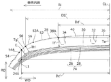
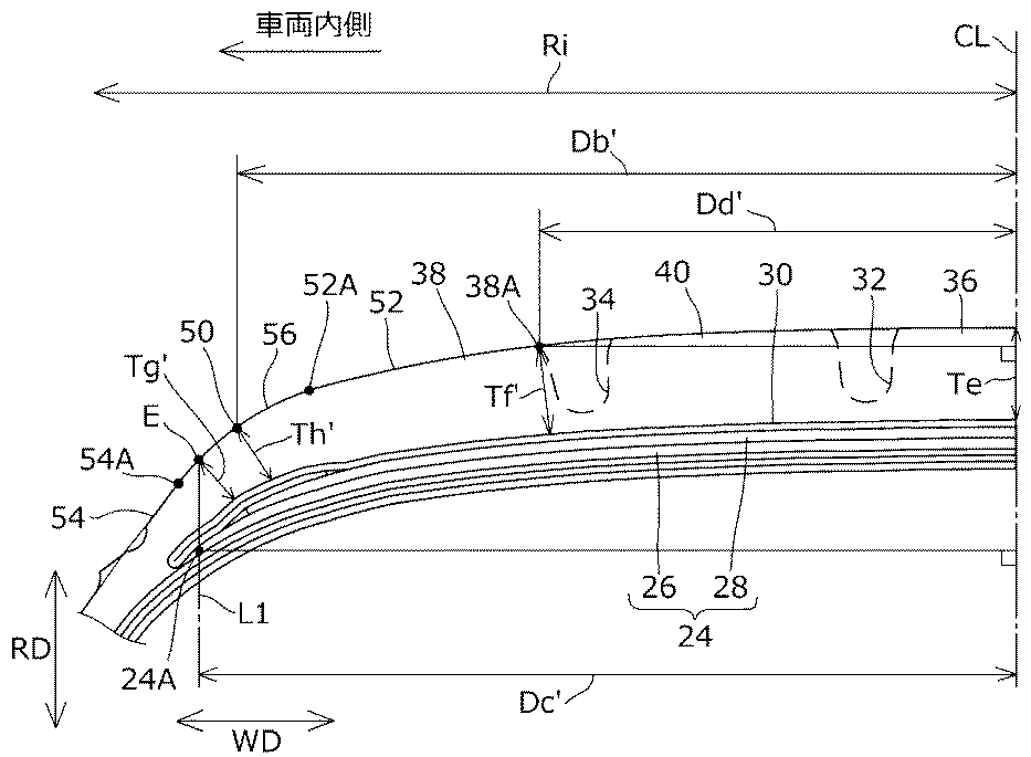
また、一実施形態に係る空気入りタイヤでは、図1,2に示す正規リム組み内圧未充填状態のタイヤ幅方向断面において、車両外側領域Roでは下記(1)〜(6)のように、また車両内側領域Riでは下記(1’)〜(6’)のように各寸法が設定される。 Further, in the pneumatic tire according to the embodiment, in the tire width direction cross section in the normal rim assembly internal pressure unfilled state shown in FIGS. 1 and 2, in the vehicle outer region Ro, as shown in the following (1) to (6), and In the vehicle inner region Ri, each dimension is set as shown in (1') to (6') below.
ここで、タイヤ幅方向断面とは、タイヤ幅方向WDに沿う断面であり、タイヤ子午線方向断面ということもできる。また、正規リム組み内圧未充填状態とは、空気入りタイヤを正規リムに装着した状態であって、内圧をかけていない状態である。そのため、以下の各寸法を測定するに際しては、空気入りタイヤをタイヤ幅方向WDに沿って切断したものを用いてもよい。具体的には、空気入りタイヤをタイヤ幅方向WDに沿って厚み5cm程度で切断したものを試料として、その試料の一対のビード部を正規リム位置に固定した状態で、各寸法を測定すればよい。 Here, the tire width direction cross section is a cross section along the tire width direction WD, and can also be referred to as a tire meridian direction cross section. Further, the state in which the internal pressure of the normal rim assembly is not filled is a state in which the pneumatic tire is mounted on the regular rim and no internal pressure is applied. Therefore, when measuring each of the following dimensions, a pneumatic tire cut along the tire width direction WD may be used. Specifically, if a pneumatic tire cut to a thickness of about 5 cm along the WD in the tire width direction is used as a sample, and each dimension is measured with the pair of bead portions of the sample fixed at the regular rim position. Good.
車両外側領域Roとは、車両装着姿勢でタイヤ赤道面CLよりも車両外側に存在する領域である。車両内側領域Riとは、車両装着姿勢でタイヤ赤道面CLよりも車両内側に存在する領域である。タイヤ赤道面CLは、タイヤ幅方向中心、即ちタイヤ最大幅の中心である。 The vehicle outer region Ro is an region existing outside the vehicle with respect to the tire equatorial plane CL in the vehicle mounting posture. The vehicle inner region Ri is an region existing inside the vehicle with respect to the tire equatorial plane CL in the vehicle mounting posture. The tire equatorial plane CL is the center in the tire width direction, that is, the center of the maximum tire width.
(1)車両外側領域Roにおいて0.68≦Db/Da≦0.88
(1’)車両内側領域Riにおいて0.68≦Db’/Da≦0.88
ここで、Daは、タイヤ赤道面CLからタイヤ最大幅位置48までの距離であり、タイヤ赤道面CLからタイヤ幅方向WDに沿って(即ち、タイヤ赤道面CLに垂直に)タイヤ最大幅位置48まで延びる線分の長さである。タイヤ赤道面CLはタイヤ最大幅の中心であるため、Daはタイヤ最大幅の半幅であり、従って、Daは車両外側領域Roと車両内側領域Riで同じ値である。
(1) 0.68 ≦ Db / Da ≦ 0.88 in the vehicle outer region Ro
(1') 0.68 ≤ Db'/ Da ≤ 0.88 in the vehicle inner region Ri
Here, Da is the distance from the tire equatorial plane CL to the tire
タイヤ最大幅位置48とは、タイヤ幅方向WDにおいてサイドウォール部12の表面の最も外側にある位置であり、タイヤ最大幅をとるサイドウォール部表面上の位置である。タイヤ最大幅は、断面幅とも称され、サイドウォール部表面の模様や文字等の突起を除いた幅である。
The tire
Dbは、車両外側領域Roにおいて、タイヤ赤道面CLからトレッド部14のタイヤ幅方向端であるトレッド端50までの距離であり、タイヤ赤道面CLからタイヤ幅方向WDに沿ってトレッド端50まで延びる線分の長さである。Db’は、車両内側領域Riにおいて、タイヤ赤道面CLからトレッド部14のタイヤ幅方向端であるトレッド端50までの距離であり、タイヤ赤道面CLからタイヤ幅方向WDに沿ってトレッド端50まで延びる線分の長さである。本実施形態では、Db=Db’であり、そのため、Db及びDb’は、トレッド幅の半幅に相当する。より詳細には、この例では、タイヤ表面のプロファイルは、車両外側領域Roと車両内側領域Riとで同一に設定されている。
Db is the distance from the tire equatorial plane CL to the
ここで、トレッド端50とは、タイヤの最大接地幅を規定するトレッド部14のタイヤ幅方向端であり、より詳細には、図4,5に示すタイヤ幅方向断面において、ショルダー陸部38のプロファイルを規定する円弧52と、サイドウォール部12のプロファイル(タイヤ最大幅位置48よりもタイヤ径方向外側の輪郭)を規定する円弧54と、を繋ぐタイヤ表面プロファイルを規定する円弧56の中点である。図1,2,4,5に示されるように、トレッド部14とサイドウォール部12との境界領域は円弧56を介してなだらかに連結されている。図4,5中、符号52Aは円弧52のタイヤ幅方向外端を示し、符号54Aは円弧54のタイヤ径方向外端を示し、これら52A及び54Aは円弧56の両端に相当する。
Here, the
上記(1)及び(1’)のように、Db/Da及びDb’/Daが0.68以上0.88以下であること、即ちDb,Db’をDaの68〜88%の範囲内に設定することにより、トレッド幅が拡大され、接地形状及び張力分布がよくなることで制動性能を向上することができる。Db/Da及びDb’/Daは、より好ましくはそれぞれ0.70〜0.85であり、更に好ましくはそれぞれ0.75〜0.80である。 As in (1) and (1') above, Db / Da and Db'/ Da are 0.68 or more and 0.88 or less, that is, Db, Db'is within the range of 68 to 88% of Da. By setting, the tread width is expanded, the ground contact shape and the tension distribution are improved, and the braking performance can be improved. Db / Da and Db'/ Da are more preferably 0.70 to 0.85, respectively, and even more preferably 0.75 to 0.80, respectively.
(2)車両外側領域Roにおいて0.86≦Dc/Db≦0.98
(2’)車両内側領域Riにおいて1.00≦Dc’/Db≦1.10
ここで、Dcは、車両外側領域Roにおいて、タイヤ赤道面CLからベルト24のタイヤ幅方向端であるベルト端24Aまでの距離であり、タイヤ赤道面CLからタイヤ幅方向WDに沿ってベルト端24Aまで延びる線分の長さである。Dc’は、車両内側領域Riにおいて、タイヤ赤道面CLからベルト24のタイヤ幅方向端であるベルト端24Aまでの距離であり、タイヤ赤道面CLからタイヤ幅方向WDに沿ってベルト端24Aまで延びる線分の長さである。
(2) 0.86 ≦ Dc / Db ≦ 0.98 in the vehicle outer region Ro
(2') 1.00 ≤ Dc'/ Db ≤ 1.10 in the vehicle inner region Ri
Here, Dc is the distance from the tire equatorial plane CL to the belt end 24A, which is the end in the tire width direction of the
上記(2)のように、車両外側領域RoでDc/Dbが0.86以上0.98以下であること、DcをDbの86〜98%の範囲内に設定することにより、トレッド幅の拡大やショルダー陸部38の面積拡大による制動性能の向上効果を得ながら、操縦安定性の限界挙動が悪化を抑えて、制動性能と操縦安定性を両立することができる。詳細には、Dc/Dbが0.86以上であることにより、ショルダー陸部38の接地圧を下げて、制動性能を向上することができ、Dc/Dbが0.98以下であることにより、高荷重でのコーナリングパワーの過度な上昇を抑えて、操縦安定性の限界挙動の悪化を抑えることができる。Dc/Dbは、より好ましくは0.90〜0.95である。
As described in (2) above, the tread width is expanded by setting the Dc / Db to 0.86 or more and 0.98 or less in the vehicle outer area Ro and setting the Dc within the range of 86 to 98% of the Db. While obtaining the effect of improving the braking performance by expanding the area of the
一方、車両内側領域Riについては、商用車用タイヤのような高負荷がかかるタイヤでは、当該内側領域Riで接地圧が高くなり、接地領域がタイヤ幅方向外側に広がることによってベルト24がない領域まで接地することになり、剛性段差が大きくなる。そのため、上記(2’)のようにDc’/Dbを1.00以上1.10以下として車両内側領域Riでベルト幅を広げることにより剛性段差をなくすことができ、よって、車両内側領域Riでの摩耗を抑制することができる。Dc’/Dbは、より好ましくは1.03〜1.17である。
On the other hand, regarding the vehicle inner region Ri, in a tire such as a commercial vehicle tire to which a high load is applied, the ground contact pressure becomes high in the inner region Ri, and the ground contact region expands to the outside in the tire width direction, so that the
(3)車両外側領域RoにおいてTg>Th
(3’)車両内側領域RiにおいてTg’<Th’
ここで、Tgは、車両外側領域Roにおけるベルト端24Aでのゴム厚み、即ちベルト端24Aのタイヤ幅方向位置でのタイヤ表面からのゴム厚みである。Tg’は、車両内側領域Riにおけるベルト端24Aでのゴム厚み、即ちベルト端24Aのタイヤ幅方向位置でのタイヤ表面からのゴム厚みである。詳細には、図4,5に示すように、ベルト端24Aを通るタイヤ径方向線L1がタイヤ表面と交じる点を点Eとして、点Eでのタイヤ表面プロファイルに対する法線でのゴム厚みであり、タイヤ表面の点Eからベルト補強層30までの線分の長さである。
(3) Tg> Th in the vehicle outer region Ro
(3') Tg'<Th' in the vehicle inner region Ri
Here, Tg is the rubber thickness at the belt end 24A in the vehicle outer region Ro, that is, the rubber thickness from the tire surface at the position of the belt end 24A in the tire width direction. Tg'is the rubber thickness at the belt end 24A in the vehicle inner region Ri, that is, the rubber thickness from the tire surface at the position of the belt end 24A in the tire width direction. Specifically, as shown in FIGS. 4 and 5, the rubber thickness at the normal line to the tire surface profile at the point E is defined as the point E where the tire radial line L1 passing through the
Thは、車両外側領域Roにおけるトレッド端50でのゴム厚みである。Th’は、車両内側領域Riにおけるトレッド端50でのゴム厚みである。詳細には、図4,5に示すように、トレッド端50でのタイヤ表面プロファイルに対する法線でのゴム厚みであり、タイヤ表面に位置するトレッド端50からベルト補強層30までの線分の長さである。
Th is the rubber thickness at the
車両外側領域Roでは、上記(3)のように、ベルト端24Aでのゴム厚みTgをトレッド端50でのゴム厚みThよりも大きく設定することにより、局部的な非接地部分の発生を抑えて接地圧の均一化を図ることができ、制動性能の悪化を抑えることができる。
In the vehicle outer region Ro, the rubber thickness Tg at the
車両内側領域Riでは、上記(3’)のように、ベルト端24Aでのゴム厚みTg’をトレッド端50でのゴム厚みTh’よりも小さく設定することにより、局部的な非接地部分の発生を抑えて接地圧の均一化を図ることができ、制動性能の悪化を抑えることができる。
In the vehicle inner region Ri, as described in (3') above, by setting the rubber thickness Tg'at the belt end 24A smaller than the rubber thickness Th'at the
(4)車両外側領域Roにおいて0.50≦Dd/Db≦0.64
(4’)車両内側領域Riにおいて0.50≦Dd’/Db’≦0.64
ここで、Ddは、車両外側領域Roにおいて、タイヤ赤道面CLからショルダー陸部38のタイヤ幅方向内側エッジ38Aまでの距離であり、タイヤ赤道面CLからタイヤ幅方向WDに沿って該内側エッジ38Aまで延びる線分の長さである。Dd’は、車両内側領域Riにおいて、タイヤ赤道面CLからショルダー陸部38のタイヤ幅方向内側エッジ38Aまでの距離であり、タイヤ赤道面CLからタイヤ幅方向WDに沿って該内側エッジ38Aまで延びる線分の長さである。ここで、ショルダー陸部38のタイヤ幅方向内側エッジ38Aは、ショルダー主溝34のタイヤ幅方向外側の開口端に一致する。
(4) 0.50 ≦ Dd / Db ≦ 0.64 in the vehicle outer region Ro
(4') 0.50 ≤ Dd'/ Db'≤ 0.64 in the vehicle inner region Ri
Here, Dd is the distance from the tire equatorial plane CL to the
上記(4)及び(4’)のように、Dd/Db及びDd’/Db’が0.50以上0.64以下であること、即ちDd及びDd’をDbの50〜64%の範囲内に設定することにより、次の作用効果が奏される。Dd/Db及びDd’/Db’が0.50以上であることにより、高荷重でのコーナリングパワーが大きくなりすぎるのを抑えることができる。また、Dd/Db及びDd’/Db’が0.64以下であることにより、ショルダー陸部38での接地圧の上昇を抑えて、制動性能の悪化を抑制することができる。Dd/Db及びDd’/Db’は、より好ましくはそれぞれ0.55〜0.60である。
As in (4) and (4') above, Dd / Db and Dd'/ Db'are 0.50 or more and 0.64 or less, that is, Dd and Dd'are within the range of 50 to 64% of Db. By setting to, the following effects are produced. When Dd / Db and Dd'/ Db'are 0.50 or more, it is possible to prevent the cornering power under a high load from becoming too large. Further, when Dd / Db and Dd'/ Db'are 0.64 or less, it is possible to suppress an increase in the contact pressure at the
(5)車両外側領域Roにおいて0.84≦Tf/Te≦1.00
(5’)車両内側領域Riにおいて0.84≦Tf’/Te≦1.00
ここで、Teは、タイヤ赤道面CLでのゴム厚みである。詳細には、図4,5に示すように、タイヤ赤道面CLにおけるタイヤ表面プロファイルに対する法線でのゴム厚みであり、当該法線におけるタイヤ表面からベルト補強層30までの線分の長さである。
(5) 0.84 ≦ Tf / Te ≦ 1.00 in the vehicle outer region Ro
(5') 0.84 ≤ Tf'/ Te ≤ 1.00 in the vehicle inner region Ri
Here, Te is the rubber thickness at the tire equatorial plane CL. Specifically, as shown in FIGS. 4 and 5, it is the rubber thickness at the normal line with respect to the tire surface profile on the tire equatorial plane CL, and is the length of the line segment from the tire surface to the
Tfは、車両外側領域Roにおいて、ショルダー陸部38のタイヤ幅方向内側エッジ38Aでのゴム厚みである。Tf’は、車両内側領域Riにおいて、ショルダー陸部38のタイヤ幅方向内側エッジ38Aでのゴム厚みである。詳細には、図4,5に示すように、該内側エッジ38Aでのタイヤ表面プロファイルに対する法線でのゴム厚みであり、タイヤ表面の内側エッジ38Aからベルト補強層30までの線分の長さである。
Tf is the rubber thickness of the
上記(5)及び(5’)のように、Tf/Te及びTf’/Teが0.84以上1.00以下であること、即ちTf及びTf’をTeの84〜100%に設定することにより、次の作用効果が奏される。Tf/Te及びTf’/Teが0.84以上であることにより、前記内側エッジ38Aでの接地性を確保して、ショルダー陸部38の接地面積が小さくなることによる制動性能の悪化を抑えることができる。また、Tf/Te及びTf’/Teが1.00以下であることにより、ショルダー陸部38での接地長がセンター陸部36での接地長よりも大きくなることによる接地圧の不均一化を抑えて、制動性能の悪化を抑制することができる。Tf/Te及びTf’/Teは、より好ましくはそれぞれ0.90〜0.95である。
As in (5) and (5') above, Tf / Te and Tf'/ Te are 0.84 or more and 1.00 or less, that is, Tf and Tf'are set to 84 to 100% of Te. As a result, the following effects are produced. When Tf / Te and Tf'/ Te are 0.84 or more, the ground contact property at the
(6)車両外側領域Roにおいて0.75≦Tg/Te≦0.83、0.75≦Th/Te≦0.83
(6’)車両内側領域Riにおいて0.60≦Tg’/Te≦0.74、0.60≦Th’/Te≦0.74
上記(6’)のように、車両内側領域Riにおいて、ベルト端24Aでのゴム厚みTg’とトレッド端50でのゴム厚みTh’を、ともにタイヤ赤道面CLでのゴム厚みTeに対して60〜74%の範囲内に設定したことにより、次の作用効果が奏される。すなわち、Tg’/Te及びTh’/Teが0.60以上であることにより、ショルダー陸部38の接地面積を確保することができ、制動性能の向上効果を高めることができる。また、Tg’/Te及びTh’/Teが0.74以下であることにより、通常荷重時におけるショルダー陸部38の接地長の増加を抑えることができ、そのため、制動時にショルダー陸部38の接地圧が大きくなりすぎて制動性能が悪化するのを抑制することができる。Tg’/Teは、より好ましくは0.62〜0.70であり、Th’/Teは、より好ましくは0.65〜0.72である。
(6) 0.75 ≦ Tg / Te ≦ 0.83, 0.75 ≦ Th / Te ≦ 0.83 in the vehicle outer region Ro
(6') 0.60 ≤ Tg'/ Te ≤ 0.74, 0.60 ≤ Th' / Te ≤ 0.74 in the vehicle inner region Ri
As described in (6') above, in the vehicle inner region Ri, the rubber thickness Tg'at the belt end 24A and the rubber thickness Th'at the
一方、車両外側領域Roについては、上記(6)のように、Tg/Te及びTh/Teをともに0.75〜0.83として、車両内側領域Riよりもゴム厚みを大きくすることにより、車両外側領域Roのショルダー陸部38を接地しやすくして、車両内側領域Riでの接地圧を下げることができ、車両内側領域Riでの摩耗を更に低減することができる。なお、Tg/Te及びTh/Teがともに0.83以下であることにより、内側エッジ38Aでのゴム厚みTfよりも小さくして接地圧の均一性を確保することができる。Tg/Teは、より好ましくは0.79〜0.83であり、Th/Teは、より好ましくは0.75〜0.80である。
On the other hand, regarding the vehicle outer region Ro, as described in (6) above, both Tg / Te and Th / Te are set to 0.75 to 0.83, and the rubber thickness is made larger than that of the vehicle inner region Ri. The
以上よりなる本実施形態によれば、トレッド幅の拡大やショルダー陸部38の面積比率の増大により制動性能を向上しつつ、高シビアリティ域での操縦安定性を向上するために上記のようにベルト幅を設定したことにより、制動性能と操縦安定性を両立することができる。しかも、高負荷がかかる車両内側領域Riにおいて、ベルト幅を拡大して剛性段差をなくしたことにより、車両内側領域Riでの摩耗を抑えて、車両外側領域Roとの間での摩耗差を低減することができ、偏摩耗を抑制することができる。そのため、本実施形態によれば、制動性能と操縦安定性の両立を図り、これら両性能を損なうことなく、偏摩耗を抑制することができる。
According to the present embodiment as described above, in order to improve the braking performance by increasing the tread width and the area ratio of the
本実施形態に係る空気入りタイヤは、高負荷がかかることで車両装着姿勢における内側領域が摩耗しやすいタイヤに好適に用いることができ、特に商用車用タイヤとして好適である。 The pneumatic tire according to the present embodiment can be suitably used for a tire in which the inner region in the vehicle mounting posture is easily worn due to a high load, and is particularly suitable as a tire for a commercial vehicle.
タイヤサイズ:205/60R16Cの商用車用空気入りタイヤについて実施例及び比較例を行った。実施例及び比較例の各タイヤについて、基本的な構成は上記実施形態で説明した通りであり、下記表1に示すように各諸元を設定してタイヤを試作した。なお、全ての実施例及び比較例において、Da=102mm、Te=10mmとした。各試作タイヤについて、操縦安定性と制動性能と偏摩耗比を評価した。評価方法は以下の通りである。 Examples and comparative examples were performed on pneumatic tires for commercial vehicles of tire size: 205 / 60R16C. The basic configuration of each of the tires of the examples and the comparative examples is as described in the above embodiment, and the tires were prototyped by setting the specifications as shown in Table 1 below. In all the examples and comparative examples, Da = 102 mm and Te = 10 mm. For each prototype tire, steering stability, braking performance, and uneven wear ratio were evaluated. The evaluation method is as follows.
・操縦安定性:試作タイヤを16×6.0のリムに装着し、内圧300kPaを充填して、試験車両に装着し、実車による官能評価を行った。評価は、連続したコーナーでの切り返し、及びコーナリングを行ったときの車両の安定性を評価し、比較例を100とした指数で表示した。指数が大きいほど操縦安定性が良好であることを示す。 -Maneuvering stability: The prototype tire was mounted on a 16 × 6.0 rim, filled with an internal pressure of 300 kPa, mounted on a test vehicle, and sensory evaluation was performed using an actual vehicle. The evaluation evaluated the stability of the vehicle when turning back at continuous corners and cornering, and displayed it as an index with Comparative Example as 100. The larger the index, the better the steering stability.
・制動性能:試作タイヤを16×6.0のリムに装着し、内圧300kPaを充填して、試験車両に装着し、走行速度を100km/hから0km/hとしたときの制動距離を測定し、制動距離の逆数について比較例1の値を100とした指数で表示した。指数が大きいほど制動距離が短く、制動性能に優れている。 -Brake performance: The braking distance is measured when the prototype tire is mounted on a 16 x 6.0 rim, the internal pressure is 300 kPa, the test vehicle is mounted, and the traveling speed is changed from 100 km / h to 0 km / h. , The reciprocal of the braking distance was displayed as an index with the value of Comparative Example 1 as 100. The larger the index, the shorter the braking distance and the better the braking performance.
・偏摩耗比:試作タイヤを16×6.0のリムに装着し、内圧300kPaを充填して、試験車両に装着し、20,000km走行後のタイヤについて、車両外側領域と車両内側領域のショルダー陸部における摩耗量を調べ、(車両内側領域のショルダー陸部摩耗量)/(車両外側領域のショルダー陸部摩耗量)の比を求めた。この比の値が大きいほど、車両内側領域での摩耗量を多く、偏摩耗が大きいことを示す。 -Uneven wear ratio: A prototype tire is mounted on a 16 x 6.0 rim, filled with an internal pressure of 300 kPa, mounted on a test vehicle, and for tires after traveling 20,000 km, shoulders in the vehicle outer region and vehicle inner region. The amount of wear in the land area was investigated, and the ratio of (amount of wear in the shoulder area inside the vehicle) / (amount of wear in the shoulder area outside the vehicle) was determined. The larger the value of this ratio, the larger the amount of wear in the inner region of the vehicle, and the larger the uneven wear.
結果は、表1に示す通りである。トレッド幅に関連するDb,Db’が狭い比較例1に対して、比較例2ではDb,Db’を拡大することにより制動性能が向上したが、操縦安定性が低下した。比較例3,4では、制動性能と操縦安定性の両立効果については比較例1に対して改善されたものの、偏摩耗の改善効果は得られなかった。また、比較例5は、操縦安定性と偏摩耗に劣っていた。比較例6では、制動性能と操縦安定性を高レベルで両立させることができたが、車両外側領域Roと車両内側領域Riが同じ構成であったため、偏摩耗比が大きかった。 The results are as shown in Table 1. In Comparative Example 1, where Db and Db'related to the tread width were narrow, the braking performance was improved by expanding Db and Db', but the steering stability was lowered. In Comparative Examples 3 and 4, the effect of achieving both braking performance and steering stability was improved as compared with Comparative Example 1, but the effect of improving uneven wear was not obtained. Further, Comparative Example 5 was inferior in steering stability and uneven wear. In Comparative Example 6, braking performance and steering stability could be achieved at a high level, but the uneven wear ratio was large because the vehicle outer region Ro and the vehicle inner region Ri had the same configuration.
これに対し、実施例1〜9であると、トレッド幅Dbを拡大し、特にショルダー陸部38の面積比率(Sh比)を拡大したものにおいて、ベルト幅Dcを所定範囲内に設定したことにより、制動性能と操縦安定性を両立することができた。また、車両内側領域Riにおいてベルト幅に相当するDc’を拡大し、ベルト端でのゴム厚みTg,Tg’とトレッド端でのゴム厚みTh,Th’を適切に設定したことにより、制動性能と操縦安定性を損なうことなく、偏摩耗比を小さくすることができた。
On the other hand, in Examples 1 to 9, the tread width Db was expanded, and in particular, the area ratio (Sh ratio) of the
比較例7は、実施例2に対して車両外側領域Roと車両内側領域Riの構成を反転させたものであり、偏摩耗比が悪化し、操縦安定性も損なわれた。比較例8は、車両内側領域Riにおけるベルト幅Dc’を拡大しすぎたため、操縦安定性が大きく損なわれた。 In Comparative Example 7, the configurations of the vehicle outer region Ro and the vehicle inner region Ri were reversed with respect to the second embodiment, and the uneven wear ratio was deteriorated and the steering stability was also impaired. In Comparative Example 8, since the belt width Dc'in the vehicle inner region Ri was increased too much, the steering stability was greatly impaired.
以上、いくつかの実施形態を説明したが、これらの実施形態は、例として提示したものであり、発明の範囲を限定することは意図していない。これら新規な実施形態は、その他の様々な形態で実施されることが可能であり、発明の要旨を逸脱しない範囲で、種々の省略、置き換え、変更を行うことができる。 Although some embodiments have been described above, these embodiments are presented as examples and are not intended to limit the scope of the invention. These novel embodiments can be implemented in various other embodiments, and various omissions, replacements, and changes can be made without departing from the gist of the invention.
10…ビード部、12…サイドウォール部、14…トレッド部、20…カーカス層、24…ベルト、24A…ベルト端、32…センター主溝、34…ショルダー主溝、36…センター陸部、38…ショルダー陸部、38A…タイヤ幅方向内側エッジ、40…メディエート陸部、48…タイヤ最大幅位置、50…トレッド端、CL…タイヤ赤道、CD…タイヤ周方向、RD…タイヤ径方向、WD…タイヤ幅方向、Ro…車両外側領域、Ri…車両内側領域、Cw…接地幅、Da…タイヤ赤道面からタイヤ最大幅位置までの距離、Db,Db’…タイヤ赤道面からトレッド端までの距離、Dc,Dc’…タイヤ赤道面からベルト端までの距離、Dd,Dd’…タイヤ赤道面からショルダー陸部のタイヤ幅方向内側エッジまでの距離、Te…タイヤ赤道面でのゴム厚み、Tf,Tf’…ショルダー陸部のタイヤ幅方向内側エッジでのゴム厚み、Tg,Tg’…ベルト端でのゴム厚み、Th,Th’…トレッド端でのゴム厚み 10 ... bead part, 12 ... sidewall part, 14 ... tread part, 20 ... carcass layer, 24 ... belt, 24A ... belt end, 32 ... center main groove, 34 ... shoulder main groove, 36 ... center land part, 38 ... Shoulder land part, 38A ... Inner edge in tire width direction, 40 ... Medium land part, 48 ... Tire maximum width position, 50 ... Tread end, CL ... Tire equatorial line, CD ... Tire circumference direction, RD ... Tire radial direction, WD ... Tire Width direction, Ro ... Vehicle outer region, Ri ... Vehicle inner region, Cw ... Ground width, Da ... Distance from tire equatorial plane to tire maximum width position, Db, Db'... Distance from tire equatorial plane to tread end, Dc , Dc'... distance from the tire equatorial plane to the end of the belt, Dd, Dd' ... distance from the tire equatorial plane to the inner edge of the shoulder land in the tire width direction, Te ... rubber thickness at the tire equatorial plane, Tf, Tf' ... Rubber thickness at the inner edge of the shoulder land in the tire width direction, Tg, Tg'... Rubber thickness at the belt end, Th, Th'... Rubber thickness at the tread end
Claims (6)
一対のビード部と、これらビード部からタイヤ径方向外方に延びる一対のサイドウォール部と、前記一対のサイドウォール部の径方向外方端同士を繋いで接地面を構成するトレッド部と、前記一対のビード部間に跨がって延びるカーカス層と、前記トレッド部における前記カーカス層の外周側に配されたベルトと、を備え、
前記トレッド部が、タイヤ周方向に延びる4本の周方向主溝により、タイヤ幅方向中央部に位置するセンター陸部と、トレッド部のタイヤ幅方向端部に位置する一対のショルダー陸部と、センター陸部とショルダー陸部の間に位置する一対のメディエート陸部とに区画された、空気入りタイヤにおいて、
前記トレッド部は、接地幅内における前記一対のショルダー陸部の面積、前記一対のメディエート陸部の面積、及び前記センター陸部の面積を、それぞれAs、Am、及びAcとして、As/(As+Am+Ac)で表されるショルダー陸部の面積比率が0.40以上0.52以下であり、
正規リム組み内圧未充填状態のタイヤ幅方向断面において、
車両装着姿勢でタイヤ赤道面よりも車両外側に存在する車両外側領域では、タイヤ赤道面からトレッド端までの距離をDbとし、タイヤ赤道面からベルト端までの距離をDcとして、Dc/Dbが0.86以上0.98以下であり、かつ、ベルト端でのゴム厚みをTgとし、トレッド端でのゴム厚みをThとして、Tg>Thであり、
車両装着姿勢でタイヤ赤道面よりも車両内側に存在する車両内側領域では、タイヤ赤道面からトレッド端までの距離をDb’とし、タイヤ赤道面からベルト端までの距離をDc’として、Dc’/Db’が1.00以上1.10以下であり、かつ、ベルト端でのゴム厚みをTg’とし、トレッド端でのゴム厚みをTh’として、Tg’<Th’である、
ことを特徴とする空気入りタイヤ。 Pneumatic tires with a specified orientation for mounting on the vehicle
A pair of bead portions, a pair of sidewall portions extending outward in the tire radial direction from these bead portions, a tread portion that connects the radial outer ends of the pair of sidewall portions to form a ground contact surface, and the above. A carcass layer extending across the pair of bead portions and a belt arranged on the outer peripheral side of the carcass layer in the tread portion are provided.
The tread portion has four main grooves in the circumferential direction extending in the tire circumferential direction, so that a center land portion located at the center portion in the tire width direction and a pair of shoulder land portions located at the end portion in the tire width direction of the tread portion. In a pneumatic tire partitioned by a pair of mediated treads located between the center and shoulder treads.
The tread portion has the area of the pair of shoulder land portions, the area of the pair of mediate land portions, and the area of the center land portion within the ground contact width as As, Am, and Ac, respectively, as As / (As + Am + Ac). The area ratio of the shoulder land area represented by is 0.40 or more and 0.52 or less.
In the tire width direction cross section in the state where the internal pressure of the regular rim is not filled
In the vehicle outer region existing outside the vehicle equatorial plane in the vehicle mounting posture, the distance from the tire equatorial plane to the tread end is Db, the distance from the tire equatorial plane to the belt end is Dc, and Dc / Db is 0. It is .86 or more and 0.98 or less, and the rubber thickness at the belt end is Tg, the rubber thickness at the tread end is Th, and Tg> Th.
In the vehicle inner region existing inside the vehicle from the tire equatorial plane in the vehicle mounting posture, the distance from the tire equatorial plane to the tread end is Db', and the distance from the tire equatorial plane to the belt end is Dc'/. Db'is 1.00 or more and 1.10 or less, and the rubber thickness at the belt end is Tg', the rubber thickness at the tread end is Th', and Tg'<Th'.
Pneumatic tires that feature that.
Priority Applications (1)
| Application Number | Priority Date | Filing Date | Title |
|---|---|---|---|
| JP2016256367A JP6777536B2 (en) | 2016-12-28 | 2016-12-28 | Pneumatic tires |
Applications Claiming Priority (1)
| Application Number | Priority Date | Filing Date | Title |
|---|---|---|---|
| JP2016256367A JP6777536B2 (en) | 2016-12-28 | 2016-12-28 | Pneumatic tires |
Publications (2)
| Publication Number | Publication Date |
|---|---|
| JP2018108753A JP2018108753A (en) | 2018-07-12 |
| JP6777536B2 true JP6777536B2 (en) | 2020-10-28 |
Family
ID=62845116
Family Applications (1)
| Application Number | Title | Priority Date | Filing Date |
|---|---|---|---|
| JP2016256367A Active JP6777536B2 (en) | 2016-12-28 | 2016-12-28 | Pneumatic tires |
Country Status (1)
| Country | Link |
|---|---|
| JP (1) | JP6777536B2 (en) |
Families Citing this family (4)
| Publication number | Priority date | Publication date | Assignee | Title |
|---|---|---|---|---|
| JP7163650B2 (en) * | 2018-07-24 | 2022-11-01 | 住友ゴム工業株式会社 | studless tire |
| JP2020097263A (en) | 2018-12-17 | 2020-06-25 | 株式会社ブリヂストン | tire |
| JP7468130B2 (en) * | 2020-05-14 | 2024-04-16 | 住友ゴム工業株式会社 | Motorcycle tires |
| JP7805156B2 (en) * | 2021-12-22 | 2026-01-23 | Toyo Tire株式会社 | pneumatic tires |
-
2016
- 2016-12-28 JP JP2016256367A patent/JP6777536B2/en active Active
Also Published As
| Publication number | Publication date |
|---|---|
| JP2018108753A (en) | 2018-07-12 |
Similar Documents
| Publication | Publication Date | Title |
|---|---|---|
| JP5333510B2 (en) | Pneumatic tire | |
| US10759231B2 (en) | Pneumatic tire | |
| JP6446979B2 (en) | Pneumatic tire | |
| US20170001479A1 (en) | Pneumatic Tire | |
| JP4618385B2 (en) | Pneumatic tire | |
| WO2014128933A1 (en) | Pneumatic tire | |
| JP6777536B2 (en) | Pneumatic tires | |
| US10730348B2 (en) | Pneumatic tire | |
| WO2014129601A1 (en) | Pneumatic tire | |
| JP6790841B2 (en) | Pneumatic tires | |
| JPWO2019138792A1 (en) | Studd tires and pneumatic tires | |
| JP6230968B2 (en) | Pneumatic tire | |
| JP6777531B2 (en) | Pneumatic tires | |
| JP6446980B2 (en) | Pneumatic tire | |
| JP7140665B2 (en) | pneumatic tire | |
| JP4915069B2 (en) | Pneumatic tire | |
| JP4742759B2 (en) | Pneumatic tire | |
| JP2021017151A (en) | Pneumatic tire for heavy load | |
| JP2003191710A (en) | Pneumatic radial tire | |
| JP7357840B2 (en) | tire | |
| JP2022089630A (en) | Pneumatic tires | |
| JP6010987B2 (en) | Pneumatic tire | |
| EP3932695A1 (en) | Motorcycle tire | |
| JP2017036010A (en) | Pneumatic tire | |
| JP2016028964A (en) | Pneumatic tire |
Legal Events
| Date | Code | Title | Description |
|---|---|---|---|
| A621 | Written request for application examination |
Free format text: JAPANESE INTERMEDIATE CODE: A621 Effective date: 20191028 |
|
| A977 | Report on retrieval |
Free format text: JAPANESE INTERMEDIATE CODE: A971007 Effective date: 20200917 |
|
| TRDD | Decision of grant or rejection written | ||
| A01 | Written decision to grant a patent or to grant a registration (utility model) |
Free format text: JAPANESE INTERMEDIATE CODE: A01 Effective date: 20201006 |
|
| A61 | First payment of annual fees (during grant procedure) |
Free format text: JAPANESE INTERMEDIATE CODE: A61 Effective date: 20201008 |
|
| R150 | Certificate of patent or registration of utility model |
Ref document number: 6777536 Country of ref document: JP Free format text: JAPANESE INTERMEDIATE CODE: R150 |
|
| R250 | Receipt of annual fees |
Free format text: JAPANESE INTERMEDIATE CODE: R250 |
|
| R250 | Receipt of annual fees |
Free format text: JAPANESE INTERMEDIATE CODE: R250 |
|
| R250 | Receipt of annual fees |
Free format text: JAPANESE INTERMEDIATE CODE: R250 |