JP6763243B2 - Light irradiator - Google Patents
Light irradiator Download PDFInfo
- Publication number
- JP6763243B2 JP6763243B2 JP2016174200A JP2016174200A JP6763243B2 JP 6763243 B2 JP6763243 B2 JP 6763243B2 JP 2016174200 A JP2016174200 A JP 2016174200A JP 2016174200 A JP2016174200 A JP 2016174200A JP 6763243 B2 JP6763243 B2 JP 6763243B2
- Authority
- JP
- Japan
- Prior art keywords
- light
- window member
- lamp
- processed
- transmitting window
- Prior art date
- Legal status (The legal status is an assumption and is not a legal conclusion. Google has not performed a legal analysis and makes no representation as to the accuracy of the status listed.)
- Active
Links
Images

Landscapes
- Diffracting Gratings Or Hologram Optical Elements (AREA)
- Exposure Of Semiconductors, Excluding Electron Or Ion Beam Exposure (AREA)
- Cleaning Or Drying Semiconductors (AREA)
Description
本発明は、真空紫外線を利用した光照射器に関する。さらに詳しくは、半導体素子や液晶パネル等の製造工程におけるレジストの光アッシング処理、ナノインプリント法におけるテンプレートのパターン面に付着したレジストの除去処理、液晶用ガラス基板やシリコンウエハ等のドライ洗浄処理、プリント基板製造工程におけるデスミア処理などに好適に適用することができる光照射器に関する。 The present invention relates to a light irradiator using vacuum ultraviolet rays. More specifically, optical ashing treatment of resist in the manufacturing process of semiconductor elements, liquid crystal panels, etc., removal treatment of resist adhering to the pattern surface of the template in the nanoimprint method, dry cleaning treatment of glass substrate for liquid crystal, silicon wafer, etc., printed circuit board The present invention relates to a light irradiator that can be suitably applied to desmear treatment in a manufacturing process.
従来、半導体素子や液晶パネル等の製造工程においては、レジストの光アッシング処理や、ガラス基板およびシリコンウエハなどに対するドライ洗浄処理が行われる。これらの処理を実行するための手法としては、真空紫外線を利用する光洗浄処理が知られている。 Conventionally, in the manufacturing process of semiconductor elements, liquid crystal panels, etc., optical ashing treatment of resist and dry cleaning treatment of glass substrate, silicon wafer, etc. are performed. As a method for carrying out these treatments, a light cleaning treatment using vacuum ultraviolet rays is known.
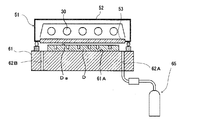
真空紫外線を利用する光洗浄処理においては、真空紫外線を含む光を放射する紫外線ランプを備えた光照射器が光洗浄装置として用いられている。そして、光照射器の或る種のものは、図3に示すように、被処理物Dを載置する載置台61と、紫外線ランプ30を有する光源ユニット51とを備えている(例えば、特許文献1参照。)。
この光照射器において、光源ユニット51は、下面に開口部を有する略直方体の箱型形状のケーシング52を備えており、当該開口部に平板状の光透過窓部材53が気密に配設されたものである。ここに、光透過窓部材53としては、例えば合成石英ガラスなどの真空紫外線透過性材料よりなるものが用いられる。また、ケーシング52の内部には、複数(図3の例においては5本)の紫外線ランプ30が平行に並ぶよう配置され、不活性ガスが充填されている。
また、載置台61は、光源ユニット51の下方において、当該載置台61の被処理物載置面61Aが、間隙を介して光透過窓部材53に対向するよう配置されている。この載置台61には、ガス供給用孔62Aとガス排出用孔62Bとが形成されており、当該ガス供給用孔62Aは、ガス供給手段65に接続されている。このガス供給手段65は、真空紫外線を受けることによって活性種が生成される活性種源を含有する処理用ガスを、載置台61に載置された被処理物Dと光透過窓部材53との間に形成される間隙に供給するものである。
このような構成の光照射器においては、光洗浄処理中には、複数の紫外線ランプ30が一斉に点灯され、当該複数の紫外線ランプ30からの真空紫外線が、光透過窓部材53を介して、載置台61に載置された被処理物Dに照射されると共に、当該被処理物Dと当該光透過窓部材53との間の間隙を流通する処理用ガスにも照射される。そして、処理用ガスに真空紫外線が照射されることにより、当該処理用ガスに含まれる活性種源が分解されて活性種が生成される。その結果、被処理物Dの被処理面Daに到達する真空紫外線、および、真空紫外線により生成される活性種によって、被処理面Daの光洗浄処理が行われる。
In the light cleaning process using vacuum ultraviolet rays, a light irradiator equipped with an ultraviolet lamp that emits light including vacuum ultraviolet rays is used as a light cleaning device. Then, as shown in FIG. 3, some types of light irradiators include a mounting table 61 on which the object D to be processed is placed and a
In this light irradiator, the
Further, the mounting table 61 is arranged below the
In the light irradiator having such a configuration, a plurality of
真空紫外線を利用する光洗浄処理においては、被処理物の被処理面の温度が上昇するに従って活性種による作用(光洗浄作用)が大きくなり、光洗浄処理を効率よく行うことができる。そのため、光照射器としては、載置台に、被処理物を80〜400℃程度に加熱する加熱手段が設けられたものがある。 In the light cleaning treatment using vacuum ultraviolet rays, the action of the active species (light cleaning action) increases as the temperature of the surface to be treated of the object to be treated increases, and the light cleaning treatment can be efficiently performed. Therefore, some light irradiators are provided with a heating means for heating the object to be treated to about 80 to 400 ° C. on the mounting table.
しかしながら、被処理物が加熱されることによれば、黒体輻射(黒体放射)により当該被処理物から赤外線(熱線)が放射され、その赤外線が光透過窓部材を透過して紫外線ランプに吸収されることから、当該紫外線ランプが加熱されることとなる。また、紫外線ランプは、加熱手段が設けられた載置台からの直接の熱輻射(熱放射)によっても加熱される。そして、紫外線ランプが加熱されることによれば、当該紫外線ランプのランプ温度が上昇し、発光管(発光管を構成するガラス)の紫外線透過率の低下を招き、また特に紫外線ランプとしてキセノンエキシマランプを用いた場合には、キセノンエキシマ分子の発光効率の低下を招く。そのため、被処理物および処理用ガスに対して効率的に真空紫外線を照射することができなくなり、結果として、光洗浄処理の効率を低下させることになる。
この光照射器における、紫外線ランプが加熱されることに起因する光洗浄処理の効率低下の問題は、載置台に加熱手段が設けられている場合に顕著であるが、加熱手段が設けられていない場合においても生じるものである。具体的に説明すると、光照射器においては、載置台に加熱手段が設けられていない場合においても、紫外線を吸収した被処理物の輻射熱(放射熱)が光透過窓部材を透過して紫外線ランプに吸収され、その結果、紫外線ランプが加熱される。
However, when the object to be processed is heated, infrared rays (heat rays) are emitted from the object to be processed by blackbody radiation (blackbody radiation), and the infrared rays pass through the light transmitting window member to become an ultraviolet lamp. Since it is absorbed, the ultraviolet lamp is heated. The ultraviolet lamp is also heated by direct heat radiation (heat radiation) from a mounting table provided with a heating means. When the ultraviolet lamp is heated, the lamp temperature of the ultraviolet lamp rises, which causes a decrease in the luminous efficiency of the arc tube (the glass constituting the arc tube), and particularly as an ultraviolet lamp, a xenon excimer lamp. When is used, the luminous efficiency of the xenone excimer molecule is lowered. Therefore, it becomes impossible to efficiently irradiate the object to be processed and the processing gas with vacuum ultraviolet rays, and as a result, the efficiency of the light cleaning treatment is lowered.
The problem of reduced efficiency of the light cleaning process due to the heating of the ultraviolet lamp in this light irradiator is remarkable when the mounting table is provided with the heating means, but the heating means is not provided. It also happens in some cases. Specifically, in the light irradiator, even when the mounting table is not provided with the heating means, the radiant heat (radiant heat) of the object to be processed that has absorbed the ultraviolet rays passes through the light transmitting window member and is an ultraviolet lamp. As a result, the UV lamp is heated.
光照射器において、熱輻射(熱放射)から紫外線ランプを遮蔽するために、光透過窓部材の表面に、赤外線カットフィルタを配設することが考えられる。
しかしながら、光透過窓部材において、赤外線カットフィルタを、紫外線ランプ側の表面に配設した場合には、当該赤外線カットフィルタの構成物質が真空紫外線によって分解され、その分解生成物が紫外線ランプに付着することに起因して、当該紫外線ランプに係る照度が低下する、という問題がある。また、載置台側の表面に配設した場合においても、赤外線カットフィルタに真空紫外線が照射されることによって生じる分解生成物(赤外線カットフィルタの構成物質由来の分解生成物)が、被処理物の表面に付着して、当該被処理物が汚染する、という問題がある。
このように、光照射器において、光透過窓部材の表面に赤外線カットフィルタを配設することは、現実的ではない。
In the light irradiator, in order to shield the ultraviolet lamp from heat radiation (heat radiation), it is conceivable to dispose an infrared cut filter on the surface of the light transmitting window member.
However, when the infrared cut filter is arranged on the surface of the light transmitting window member on the ultraviolet lamp side, the constituent substances of the infrared cut filter are decomposed by the vacuum ultraviolet rays, and the decomposition products adhere to the ultraviolet lamp. As a result, there is a problem that the illuminance of the ultraviolet lamp is reduced. Further, even when arranged on the surface on the mounting table side, the decomposition product (decomposition product derived from the constituent substances of the infrared cut filter) generated by irradiating the infrared cut filter with vacuum ultraviolet rays is the object to be treated. There is a problem that it adheres to the surface and contaminates the object to be treated.
As described above, in the light irradiator, it is not realistic to dispose the infrared cut filter on the surface of the light transmitting window member.
本発明は、以上のような事情に基づいてなされたものであって、その目的は、加熱状態にある被処理物の輻射熱(放射熱)によって紫外線ランプが加熱されることを抑制することができ、よって加熱状態にある被処理物に対して効率よく真空紫外線を照射することのできる光照射器を提供することにある。 The present invention has been made based on the above circumstances, and an object of the present invention is to prevent the ultraviolet lamp from being heated by the radiant heat (radiant heat) of the object to be processed in a heated state. Therefore, it is an object of the present invention to provide a light irradiator capable of efficiently irradiating a heated object to be treated with vacuum ultraviolet rays.
本発明の光照射器は、加熱状態にある被処理物を載置する載置台と、
前記載置台上の被処理物に対して真空紫外線を照射する紫外線ランプと、
前記被処理物と前記紫外線ランプとの間に位置される光透過窓部材と
を有する光照射器において、
前記光透過窓部材は、少なくとも前記被処理物の側の表面にフォトニック構造を有しており、
前記フォトニック構造は、前記真空紫外線のピーク波長の透過率が、前記加熱状態にある被処理物からの放射光のピーク波長の透過率よりも高いものであり、
前記載置台は、前記光透過窓部材と前記被処理物との間隔を3mm以下に設定可能に構成されていることを特徴とする。
The light irradiator of the present invention includes a mounting table on which a heated object is placed.
An ultraviolet lamp that irradiates the object to be treated on the above-mentioned table with vacuum ultraviolet rays,
In a light irradiator having a light transmitting window member located between the object to be treated and the ultraviolet lamp.
The light transmission window member has a photonic structure on the front surface side of at least the object to be processed,
In the photonic structure, the transmittance of the peak wavelength of the vacuum ultraviolet rays is higher than the transmittance of the peak wavelength of the synchrotron radiation from the object to be heated.
The mounting table is characterized Rukoto and the light transmissive window member the is configured to set the interval between the object to be processed 3mm or less.
本発明の光照射器においては、前記紫外線ランプは、ピーク波長が172nmの光を放射するキセノンエキシマランプであり、
前記フォトニック構造は、複数の凸部が周期的に配列されることによって構成されており、当該凸部のピッチP〔μm〕と当該凸部の幅W〔μm〕と当該凸部の高さH〔μm〕とが下記の関係式(1)〜関係式(3)を満たすことが好ましい。
In the light irradiator of the present invention, the ultraviolet lamp is a xenon excimer lamp that emits light having a peak wavelength of 172 nm.
The photonic structure is formed by periodically arranging a plurality of convex portions, and the pitch P [μm] of the convex portions, the width W [μm] of the convex portions, and the height of the convex portions. It is preferable that H [μm] satisfies the following relational expressions (1) to (3).
関係式(1):
1.5≦P≦8.0
関係式(2):
W=P/2
関係式(3):
(1・W)≦H≦(5・W)
Relational expression (1):
1.5 ≤ P ≤ 8.0
Relational expression (2):
W = P / 2
Relational expression (3):
(1 ・ W) ≦ H ≦ (5 ・ W)
本発明の光照射器においては、光透過窓部材が、少なくとも被処理物の側の表面にフォトニック構造を有しており、当該フォトニック構造が、紫外線ランプからの真空紫外線のピーク波長の透過率が、加熱状態にある被処理物からの放射光のピーク波長の透過率よりも高いものとされ、光透過窓部材と前記被処理物との間隔を3mm以下としている。そのため、加熱状態にある被処理物の熱輻射(熱放射)によって紫外線ランプが加熱されることを抑制することができ、よって加熱状態にある被処理物に対して効率よく真空紫外線を照射することができる。
In the light irradiation device of the present invention, the light transmission window member has a photonic structure on the front surface side of at least the object to be treated, the photonic structure, the peak wavelength of the vacuum ultraviolet rays from the ultraviolet lamp The transmittance is set to be higher than the transmittance of the peak wavelength of the emitted light from the object to be heated , and the distance between the light transmitting window member and the object to be processed is 3 mm or less . Therefore, it is possible to prevent the ultraviolet lamp from being heated by the thermal radiation (heat radiation) of the object to be heated, and thus efficiently irradiate the object to be heated with vacuum ultraviolet rays. Can be done.
以下、本発明の光照射器の実施の形態について説明する。
図1は、本発明の光照射器の構成の一例を、被処理物と共に示す説明用断面図である。
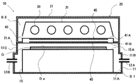
この光照射器10は、加熱状態にある被処理物Dに対して真空紫外線(具体的には、波長222nm以下の紫外線)を照射することにより、当該被処理物Dを処理するものであり、例えば略平板状の被処理物Dが載置される載置台15と、当該載置台15の平坦な被処理物載置面15Aの上方に配設された、真空紫外線を含む光を放射する紫外線ランプ30を具備する光源ユニット20とを備えている。ここに、本明細書中において、「加熱状態にある被処理物」とは、被処理物に対して真空紫外線を照射する紫外線ランプとは別個に設けられた専用の加熱手段によって加熱されること、および、紫外線ランプからの光が照射されることに伴って加熱されることなどにより、被処理面の温度が250℃以上とされた被処理物を示す。
光照射器10において、載置台15は、上方(図1における上方)に開口を有する略直方体の箱型形状のケーシング11の内部に配置されている。このケーシング11の開口は、光源ユニット20によって閉塞されている。このように、内部に載置台15が配置されたケーシング11の開口が光源ユニット20によって閉塞されることにより、光源ユニット20の下方(図1における下方)に処理室S1が形成されている。
この図の例において、載置台15は、直方体状の形状を有しており、ケーシング11の内部において、当該ケーシング11の各側面部の内面に接触しない状態で当該ケーシング11の底面部11Aの中央部分に配置されている。また、載置台15においては、被処理物載置面15Aの中央部分に、光源ユニット20からの光(複数の紫外線ランプ30からの光)の照度の面内均一性の高い領域、すなわち有効照射領域が形成されている。この有効照射領域には被処理物Dが載置される。また、ケーシング11においては、互いに対向する側面部11B,11Cに、載置台15を介して対向するように、側面部11Bにはガス供給用孔12Aが形成され、側面部11Cにはガス排出用孔12Bが形成されている。ガス供給用孔12Aには、ガス供給手段(図示省略)が接続されている。
Hereinafter, embodiments of the light irradiator of the present invention will be described.
FIG. 1 is an explanatory cross-sectional view showing an example of the configuration of the light irradiator of the present invention together with an object to be processed.
The
In the
In the example of this figure, the mounting table 15 has a rectangular parallelepiped shape, and inside the
また、載置台15には、被処理物Dを加熱する加熱手段(図示省略)が設けられていることが好ましい。
載置台15に加熱手段が設けられていることによれば、被処理物Dを、被処理面Daが均一に加熱された状態とすることができる。そのため、被処理面Daを、高い均一性で効率的に処理することができる。
この図の例において、載置台15には、ヒータよりなる加熱手段が設けられており、当該加熱手段は、被処理物Dを、被処理面Daの温度が400〜500℃程度となるように加熱することのできるものである。
Further, it is preferable that the mounting table 15 is provided with a heating means (not shown) for heating the object D to be processed.
According to the fact that the mounting table 15 is provided with the heating means, the object D to be processed can be in a state where the surface Da to be processed is uniformly heated. Therefore, the surface Da to be treated can be treated efficiently with high uniformity.
In the example of this figure, the mounting table 15 is provided with a heating means including a heater, and the heating means measures the object D to be processed so that the temperature of the surface Da to be processed is about 400 to 500 ° C. It can be heated.
光源ユニット20は、下面部21Aに開口部を有する直方体の箱型形状のランプハウス21を備えている。このランプハウス21の開口部には、光透過窓部材40が気密に設けられている。このようにして、ランプハウス21の内部には、密閉されたランプ室S2が形成されている。このランプ室S2は、ランプハウス21の下面部21Aおよび光透過窓部材40によって処理室S1と分離されている。
そして、ランプハウス21の内部、すなわちランプ室S2には、複数(図1の例においては5本)の棒状の紫外線ランプ30が、光透過窓部材40に対向して配設されている。これらの複数の紫外線ランプ30は、中心軸が光透過窓部材40に平行な同一水平面内において互いに平行に伸びるよう一定の間隔(図1においては等間隔)で並列している。これらの複数の紫外線ランプ30には、冷却手段(図示省略)が設けられている。ここに、冷却手段は、空冷ブロックまたは水冷ブロックよりなり、紫外線ランプ30を250℃以下に冷却することのできるものである。紫外線ランプ30を冷却する冷却手段が設けられていることにより、紫外線ランプ30が過熱されることに起因して生じる弊害の発生をより一層抑制することができる。具体的には、発光管(具体的には、発光管を構成するガラス)の紫外線透過率(具体的には、真紫外線透過率)の低下を抑制することができ、また、特に紫外線ランプ30としてエキシマランプを用いた場合には、エキシマ分子が乖離することに起因する発光効率の低下を抑制することができる。また、ランプ室S2には、載置台15に載置された被処理物Dの被処理面Daに対して、複数の紫外線ランプ30からの光(真空紫外線)を有効に利用して均一照射することができるよう、当該複数の紫外線ランプ30の上方に、共通の反射ミラー31が配設されている。また、ランプハウス21には、ランプ室S2において複数の紫外線ランプ30からの真空紫外線が大気(酸素)に吸収されることのないように、例えば窒素ガスなどの不活性ガスによって当該ランプ室S2の内部をパージするパージ手段(図示省略)が設けられている。
The
Inside the
紫外線ランプ30としては、真空紫外線を含む光を放射するものであれば、公知の種々のランプを用いることができる。
紫外線ランプ30の具体例としては、ピーク波長(中心波長)が172nmの光(真空紫外線)を放射するキセノンエキシマランプ(Xe2 エキシマランプ)、および、ピーク波長(中心波長)が146nmの光(真空紫外線)を放射するクリプトンエキシマランプ(Kr2 エキシマランプ)、および、ピーク波長(中心波長)が222nmの光(真空紫外線)を放射するクリプトンクロライドエキシマランプ(KrClエキシマランプ)などが挙げられる。そして、これらのうちでは、発光効率および高照度照射の観点から、ピーク波長が172nmの光を放射するキセノンエキシマランプが好適に用いられる。
この図の例においては、紫外線ランプ30として、ピーク波長が172nmの光を放射する、円棒状のキセノンエキシマランプが用いられている。
As the
Specific examples of the
In the example of this figure, as the
光透過窓部材40は、略平板状であって、上面41Aが複数の紫外線ランプ30と対向し、かつ、下面41Bが載置台15の被処理物載置面15Aと対向するように配設される。すなわち、光源ユニット20を構成する複数の紫外線ランプ30は、光透過窓部材40を介して被処理物載置面15Aと対向するように配設されている。このようにして、光透過窓部材40は、載置台15の被処理物載置面15Aに載置された被処理物Dと複数の紫外線ランプ30との間に位置するように配置される。
この図の例において、光透過窓部材40は、載置台15に載置された被処理物Dの被処理面Daに僅かな間隙を介して対向するように配置されている。この光透過窓部材40と被処理物Dとの間隙の厚みは、処理効率の観点から、3mm以下、好ましくは1mm以下とされる。
The light transmitting
In the example of this figure, the light transmitting
そして、光透過窓部材40は、両面(具体的には、上面41Aおよび下面41B)または片面に、フォトニック構造45を有している。ここに、本明細書中において、「フォトニック構造」とは、屈折率が周期的に変化する2次元または3次元の凹凸構造を示す。具体的には、表面において複数の凸部が設けられ、それらの複数の凸部が周期的に配列されることによって構成されてなる凹凸構造(図2参照)、および、表面に複数の凹部が設けられ、それらの複数の凹部が周期的に配列されることによって構成されてなる凹凸構造などを示す。
このフォトニック構造45は、紫外線ランプ30からの光における真空紫外線のピーク波長の透過率(以下、「ランプ真空紫外線透過率」ともいう。)が、加熱状態にある被処理物Dからの放射光のピーク波長の透過率(以下、「被処理物赤外線透過率」ともいう。)よりも高いものである。ここに、本明細書中において、「被処理物からの放射光のピーク波長」とは、加熱状態にある被処理物において黒体輻射(黒体放射)により放射される放射光(具体的には、赤外線を含む光)のピーク波長、すなわち黒体放射スペクトルにおけるピーク波長を示す。
具体的に説明すると、フォトニック構造45は、屈折率が周期的に変化する凹凸構造の光学特性を利用して、紫外線ランプ30からの光(真空紫外線)および加熱状態にある被処理物Dからの放射光(赤外線)の反射および透過を、波長選択的に制御することにより、ランプ真空紫外線透過率を、被処理物赤外線透過率よりも高くしたものである。ここに、「屈折率が周期的に変化する凹凸構造の光学特性」とは、屈折率が周期的に変化する凹凸構造(フォトニック構造)において、「フォトニックバンドギャップ」と称される光の禁止帯が形成され、その禁止帯にて、或る特定の波長域の光が進行することができなくなる、という特性を示す。
この図の例において、光透過窓部材40は、両面(上面41Aおよび下面41B)にフォトニック構造45を有しており、当該両面の各々に形成されたフォトニック構造45は、いずれも、複数の凸部46が2次元周期的に配列されることによって構成されてなる凹凸構造(2次元凹凸構造)よりなるものである。また、光透過窓部材40の両面において、フォトニック構造45は、中央部分に形成されており、上面41Aにおけるフォトニック構造45の形成領域と、下面41Bにおけるフォトニック構造45の形成領域とは、互いに対向している。
The light transmitting
In this
Specifically, the
In the example of this figure, the light transmitting
光透過窓部材40が両面または片面にフォトニック構造45を有しており、当該フォトニック構造45が、ランプ真空紫外線透過率が被処理物赤外線透過率よりも高いものであることにより、当該光透過窓部材40が赤外線(具体的には、加熱状態にある被被処理物Dからの放射光に含まれる赤外線)を選択的に遮蔽する機能(具体的には、反射する機能)を有するものとなる。すなわち、光透過窓部材40が、真空紫外線透過性を損なうことなく、赤外線に対する遮蔽機能(反射機能)を有するものとなる。
The light transmitting
光透過窓部材40のフォトニック構造45は、図2に示されているように、複数の凸部46が周期的に配列されることによって構成されてなる凹凸構造(以下、「凸部配列凹凸構造」ともいう。)であることが好ましい。その凸部配列凹凸構造を構成する複数の凸部46の形状は、柱状のものであることが好ましく、その柱状形状の具体例としては、例えば、円柱状および角柱状(具体的には、直四角柱状等)などが挙げられる。
As shown in FIG. 2, the
そして、凸部配列凹凸構造の形状は、紫外線ランプ30の種類などに応じ、被処理物Dの加熱状態(被処理面Daの温度)などを考慮して適宜に定められる。
Then, the shape of the convex arrangement uneven structure is appropriately determined in consideration of the heating state of the object D to be processed (temperature of the surface Da to be processed) and the like according to the type of the
具体的には、凸部配列凹凸構造の形状は、紫外線ランプ30が、ピーク波長が172nmの光(真空紫外線)を放射するキセノンエキシマランプよりなる場合には、凸部46のピッチP〔μm〕と凸部46の幅W〔μm〕と凸部46の高さH〔μm〕とが下記の関係式(1)〜関係式(3)を満たすことが好ましい。
Specifically, the shape of the convex arrangement concavo-convex structure is such that when the
関係式(1):
1.5≦P≦8.0
関係式(2):
W=P/2
関係式(3):
(1・W)≦H≦(5・W)
Relational expression (1):
1.5 ≤ P ≤ 8.0
Relational expression (2):
W = P / 2
Relational expression (3):
(1 ・ W) ≦ H ≦ (5 ・ W)
光透過窓部材40のフォトニック構造45が上記の関係式(1)〜関係式(3)を満たすことにより、当該フォトニック構造45を、ランプ真空紫外線透過率が被処理物赤外線透過率よりも高いものとすることができる。
When the
具体的には、凸部46のピッチPが4μmであって凸部46の幅Wが2μmであり、凸部46の高さHが8μmである形状、凸部46のピッチPが7μmであって凸部46の幅Wが3.5μmであり、凸部46の高さHが17.5μmである形状、および、凸部46のピッチPが8μmであって凸部46の幅Wが4μmであり、凸部46の高さHが12μmである形状などが挙げられる。
Specifically, the pitch P of the
光透過窓部材40において、フォトニック構造45は、少なくとも下面41Bに形成されていることが好ましい。すなわち、光透過窓部材40が片面にフォトニック構造45を有するものである場合には、当該フォトニック構造45が下面41Bに形成されていることが好ましい。
また、光透過窓部材40においては、上面41Aおよび下面41Bの両方にフォトニック構造45が形成されていることがより好ましい。
具体的に説明すると、2次元の凹凸構造よりなるフォトニック構造では、当該フォトニック構造が設けられた面に対して垂直に入射する光、および当該面に対して垂直入射に近い角度(具体的には、例えば20°程度)で入射する低角度成分の光は、有効に反射することができる。然るに、フォトニック構造が設けられた面に対する入射角度が高角度(具体的には、例えば50°〜60°程度以上)の高角度成分の光は、入射角度が高くなるに従い、反射率が低下する。よって、光透過窓部材40においては、フォトニック構造45が、少なくとも、より被処理物Dの近くに位置する下面41Bに形成されていることが好ましい。
また、光透過窓部材40において、下面41Bと共に上面41Aにもフォトニック構造45を設けることにより、上面41Aにおいても、或る特定の波長域の光が進行することができなくなることから、より有効に特定の波長域をカットすることが可能になる。
In the light transmitting
Further, in the light transmitting
Specifically, in a photonic structure composed of a two-dimensional concavo-convex structure, light incident perpendicularly to the surface on which the photonic structure is provided and an angle close to vertical incident to the surface (specifically). Light with a low angle component incident at, for example, about 20 °) can be effectively reflected. However, the reflectance of light having a high angle of incidence (specifically, for example, about 50 ° to 60 ° or more) with respect to the surface provided with the photonic structure decreases as the angle of incidence increases. To do. Therefore, in the light transmitting
Further, in the light transmitting
また、光透過窓部材40が両面にフォトニック構造45を有するものである場合には、上面41Aにおけるフォトニック構造45と下面41Bにおけるフォトニック構造45とは、同一の形状を有していてもよく、異なる形状を有していてもよい。
この図の例において、上面41Aにおけるフォトニック構造45と下面41Bにおけるフォトニック構造45とは、同一の形状を有しており、光透過窓部材40の厚み方向に垂直な平面に関して面対称とされている。
When the light transmitting
In the example of this figure, the
光透過窓部材40を構成する材料としては、紫外線ランプ30からの真空紫外線に対して透過性を有し、必要に応じて、処理室S1に供給される処理用ガスおよび処理室S1において生じる生成ガス(具体的には、処理用ガスに真空紫外線が照射されることによって生じるガス、および、被処理面Daが処理されることによって生じるガス等)に対する耐性を有するものが用いられる。
光透過窓部材40を構成する材料の具体例としては、例えば石英ガラスが挙げられる。この石英ガラスは、真空紫外線透過性を有すると共に、加熱状態にある被処理物Dからの放射光(赤外線)に対する透過性を有するものである。
また、光透過窓部材40の厚みは、例えば3〜10mmである。
As the material constituting the light transmitting
Specific examples of the material constituting the light transmitting
The thickness of the light transmitting
このように両面または片面にフォトニック構造45を有する光透過窓部材40は、例えば、ナノインプリント法により、製造することができる。
As described above, the light transmitting
ガス供給手段から供給される処理用ガスとしては、活性種源を含むものが用いられる。
処理用ガスに含まれる活性種源としては、真空紫外線を受けることによって活性種が生成されるものが挙げられる。活性種源の具体例としては、活性種として、酸素(O2 )およびオゾン(O3 )などの酸素ラジカルを生じさせるものなどが挙げられる。
As the processing gas supplied from the gas supply means, a gas containing an active species source is used.
Examples of the active species source contained in the treatment gas include those in which active species are produced by receiving vacuum ultraviolet rays. Specific examples of the active species source include those that generate oxygen radicals such as oxygen (O 2 ) and ozone (O 3 ) as active species.
このような光照射器10においては、紫外線ランプ30からの光(真空紫外線)を、加熱状態にある被処理物Dの被処理面Daに対して、光透過窓部材40を介して照射することにより、被処理物Dの表面処理が行われる。
具体的に説明すると、先ず、被処理物Dが配置された処理室S1に、処理用ガスが、ガス供給用孔12Aを介して供給されることにより、処理室S1が処理用ガス雰囲気とされる。また、ランプ室S2は、不活性ガスが供給されることにより、不活性ガス雰囲気とされる。次いで、被処理物Dが、加熱手段によって加熱されることにより、加熱状態とされる。そして、光源ユニット20を構成する複数の紫外線ランプ30が一斉に点灯されることにより、当該複数の紫外線ランプ30からの光(真空紫外線)が光透過窓部材40を介して被処理面Daに向かって放射される。これにより、被処理面Daに到達する真空紫外線、および真空紫外線により処理用ガスから生成される活性種によって、被処理面Daの処理が行われる。
In such a
Specifically, first, the processing gas is supplied to the processing chamber S1 in which the object D to be processed is arranged through the
而して、光照射器10においては、被処理物Dが、加熱手段によって加熱されること、および、光源ユニット20(複数の紫外線ランプ30)からの光(紫外線)を吸収することによって加熱状態とされ、その加熱状態にある被処理物Dからは、黒体輻射(黒体放射)により放射光(赤外線を含む光)が放射される。然るに、光透過窓部材40が、上面41Aおよび下面41Bの両方にフォトニック構造45を有していることから、加熱状態にある被処理物Dからの放射光(赤外線)は、光透過窓部材40によって遮蔽(反射)され、よって熱輻射(熱放射)によって紫外線ランプ30が加熱されることを抑制することができる。その結果、加熱状態にある被処理物Dからの放射光が照射されることに起因する複数の紫外線ランプ30のランプ温度上昇が抑制される。しかも、光透過窓部材40においては、赤外線カットフィルタを用いることなく当該光透過窓部材40の光透過特性を制御して熱輻射(熱放射)から複数の紫外線ランプ30を遮蔽していることから、赤外線カットフィルタを利用する場合のように、紫外線ランプ30や被処理物Dが汚染されることがない。このようにして、光源ユニット20を構成する紫外線ランプ30のランプ温度が上昇することに起因する発光管(発光管を構成するガラス)の紫外線透過率の低下およびキセノンエキシマ分子の発光効率の低下の発生が抑制され、また、光源ユニット20を構成する紫外線ランプ30が汚染されることに起因する当該紫外線ランプ30に係る照度低下の発生が防止される。
従って、光照射器10によれば、加熱状態にある被処理物Dに対して効率よく真空紫外線を照射することができ、よって被処理物Dの被処理面Daを効率的に処理することができる。
また、光照射器10においては、紫外線ランプ30の熱輻射によるランプ温度上昇が抑制されることから、平板状(表面にフォトニック構造を有していない形状)の光透過窓部材を備えた従来の光照射器に比して、冷却手段を駆動するために必要とされる電力量を小さくすることが可能となる。
Thus, in the
Therefore, according to the
Further, in the
この光照射器10は、半導体素子や液晶パネル等の製造工程におけるレジストの光アッシング処理、ナノインプリント法におけるテンプレートのパターン面に付着したレジストの除去処理、液晶用ガラス基板やシリコンウエハ等のドライ洗浄処理、プリント基板製造工程におけるデスミア処理などに好適に適用することができる。
The
以上、本発明の実施の形態について説明したが、本発明は上記の実施の形態に限定されるものではなく、種々の変更を加えることができる。
例えば、光照射器全体の構造は、図1に示すものに限定されず、種々の構造を採用することができる。
Although the embodiments of the present invention have been described above, the present invention is not limited to the above embodiments, and various modifications can be made.
For example, the structure of the entire light irradiator is not limited to that shown in FIG. 1, and various structures can be adopted.
以下、本発明の実験例について説明する。 Hereinafter, experimental examples of the present invention will be described.
〔実験例1〕
一面(以下、「フォトニック構造面」ともいう。)にフォトニック構造を有する略平板状の板状部材(以下、「実験用板状部材(A)」ともいう。)を用意した。この実験用板状部材(A)において、フォトニック構造は、柱状の凸部のピッチが4μmであって凸部の幅が2μmであり、凸部の高さが8μmである形状の凸部配列凹凸構造である。
実験用板状部材(A)のフォトニック構造面に対して、ピーク波長が172nmの光を放射するキセノンエキシマランプからの光(波長172nmの光)を照射することによって波長172nmの光に対する透過率を測定したところ、95%であった。また、実験用板状部材(A)のフォトニック構造面に対して、波長4μmの光を放射するレーザダイオードの光(波長4μmの光)を照射することによって波長4μmの光に対する透過率を測定したところ、37%であった。
以上の結果から、上記の関係式(1)〜関係式(3)を満たすフォトニック構造においては、波長172nmの真空紫外線の透過率が、黒体放射スペクトル(具体的には、温度400℃に係る黒体放射スペクトル)におけるピーク波長の透過率よりも高くなることが確認された。
[Experimental Example 1]
A substantially flat plate-shaped member having a photonic structure (hereinafter, also referred to as “experimental plate-shaped member (A)”) was prepared on one surface (hereinafter, also referred to as “photonic structure surface”). In this experimental plate-shaped member (A), the photonic structure has a convex arrangement in which the pitch of the columnar convex portions is 4 μm, the width of the convex portions is 2 μm, and the height of the convex portions is 8 μm. It has an uneven structure.
Transmittance to light with a wavelength of 172 nm by irradiating the photonic structural surface of the experimental plate-shaped member (A) with light from a xenon excimer lamp (light with a wavelength of 172 nm) that emits light with a peak wavelength of 172 nm. Was measured and found to be 95%. Further, the transmittance for light having a wavelength of 4 μm is measured by irradiating the photonic structural surface of the experimental plate-shaped member (A) with light from a laser diode (light having a wavelength of 4 μm) that emits light having a wavelength of 4 μm. As a result, it was 37%.
From the above results, in the photonic structure satisfying the above relational expressions (1) to (3), the transmittance of vacuum ultraviolet rays having a wavelength of 172 nm is set to a blackbody radiation spectrum (specifically, a temperature of 400 ° C.). It was confirmed that the transmittance was higher than the transmittance of the peak wavelength in the blackbody radiation spectrum.
10 光照射器
11 ケーシング
11A 底面部
11B,11C 側面部
12A ガス供給用孔
12B ガス排出用孔
15 載置台
15A 被処理物載置面
20 光源ユニット
21 ランプハウス
21A 下面部
30 紫外線ランプ
31 反射ミラー
40 光透過窓部材
41A 上面
41B 下面
45 フォトニック構造
46 凸部
51 光源ユニット
52 ケーシング
53 光透過窓部材
61 載置台
61A 被処理物載置面
62A ガス供給用孔
62B ガス排出用孔
65 ガス供給手段
S1 処理室
S2 ランプ室
D 被処理物
Da 被処理面
10
Claims (2)
前記載置台上の被処理物に対して真空紫外線を照射する紫外線ランプと、
前記被処理物と前記紫外線ランプとの間に位置される光透過窓部材と
を有する光照射器において、
前記光透過窓部材は、少なくとも前記被処理物の側の表面にフォトニック構造を有しており、
前記フォトニック構造は、前記真空紫外線のピーク波長の透過率が、前記加熱状態にある被処理物からの放射光のピーク波長の透過率よりも高いものであり、
前記載置台は、前記光透過窓部材と前記被処理物との間隔を3mm以下に設定可能に構成されていることを特徴とする光照射器。 A mounting table on which the object to be processed in a heated state is placed,
An ultraviolet lamp that irradiates the object to be treated on the above-mentioned table with vacuum ultraviolet rays,
In a light irradiator having a light transmitting window member located between the object to be treated and the ultraviolet lamp.
The light transmission window member has a photonic structure on the front surface side of at least the object to be processed,
In the photonic structure, the transmittance of the peak wavelength of the vacuum ultraviolet rays is higher than the transmittance of the peak wavelength of the synchrotron radiation from the object to be heated.
The mounting table, the light irradiator, wherein Rukoto and the light transmissive window member the is configured to set the interval between the object to be processed 3mm or less.
前記フォトニック構造は、複数の凸部が周期的に配列されることによって構成されており、当該凸部のピッチP〔μm〕と当該凸部の幅W〔μm〕と当該凸部の高さH〔μm〕とが下記の関係式(1)〜関係式(3)を満たすことを特徴とする請求項1に記載の光照射器。
関係式(1):
1.5≦P≦8.0
関係式(2):
W=P/2
関係式(3):
(1・W)≦H≦(5・W)
The ultraviolet lamp is a xenon excimer lamp that emits light having a peak wavelength of 172 nm.
The photonic structure is formed by periodically arranging a plurality of convex portions, and the pitch P [μm] of the convex portions, the width W [μm] of the convex portions, and the height of the convex portions. The light irradiator according to claim 1, wherein H [μm] satisfies the following relational expressions (1) to (3).
Relational expression (1):
1.5 ≤ P ≤ 8.0
Relational expression (2):
W = P / 2
Relational expression (3):
(1 ・ W) ≦ H ≦ (5 ・ W)
Priority Applications (1)
| Application Number | Priority Date | Filing Date | Title |
|---|---|---|---|
| JP2016174200A JP6763243B2 (en) | 2016-09-07 | 2016-09-07 | Light irradiator |
Applications Claiming Priority (1)
| Application Number | Priority Date | Filing Date | Title |
|---|---|---|---|
| JP2016174200A JP6763243B2 (en) | 2016-09-07 | 2016-09-07 | Light irradiator |
Publications (2)
| Publication Number | Publication Date |
|---|---|
| JP2018040915A JP2018040915A (en) | 2018-03-15 |
| JP6763243B2 true JP6763243B2 (en) | 2020-09-30 |
Family
ID=61625814
Family Applications (1)
| Application Number | Title | Priority Date | Filing Date |
|---|---|---|---|
| JP2016174200A Active JP6763243B2 (en) | 2016-09-07 | 2016-09-07 | Light irradiator |
Country Status (1)
| Country | Link |
|---|---|
| JP (1) | JP6763243B2 (en) |
Families Citing this family (1)
| Publication number | Priority date | Publication date | Assignee | Title |
|---|---|---|---|---|
| JP2024049952A (en) * | 2022-09-29 | 2024-04-10 | ウシオ電機株式会社 | Ultraviolet light irradiation device |
Family Cites Families (9)
| Publication number | Priority date | Publication date | Assignee | Title |
|---|---|---|---|---|
| JPH03278860A (en) * | 1990-03-29 | 1991-12-10 | Toshiba Lighting & Technol Corp | Ultraviolet-ray irradiation apparatus |
| JP3859259B2 (en) * | 1995-07-13 | 2006-12-20 | 三星電子株式会社 | UV irradiation equipment |
| JPH1110101A (en) * | 1997-06-18 | 1999-01-19 | Nikon Corp | Light cleaning device |
| JP5174458B2 (en) * | 2004-07-08 | 2013-04-03 | イオン オプティクス インコーポレイテッド | Tunable photonic crystal |
| JP5172239B2 (en) * | 2007-02-23 | 2013-03-27 | 三菱レイヨン株式会社 | Optical low-pass filter and manufacturing method thereof |
| JP2010186815A (en) * | 2009-02-10 | 2010-08-26 | Nec Corp | Device and method of ultraviolet irradiation |
| JP2011186096A (en) * | 2010-03-08 | 2011-09-22 | Mitsubishi Electric Corp | Optical filter |
| KR102258969B1 (en) * | 2012-01-19 | 2021-06-02 | 수프리야 자이스왈 | Materials, components, and methods for use with extreme ultraviolet radiation in lithography and other applications |
| JP5987815B2 (en) * | 2013-12-06 | 2016-09-07 | ウシオ電機株式会社 | Ashing method and ashing apparatus |
-
2016
- 2016-09-07 JP JP2016174200A patent/JP6763243B2/en active Active
Also Published As
| Publication number | Publication date |
|---|---|
| JP2018040915A (en) | 2018-03-15 |
Similar Documents
| Publication | Publication Date | Title |
|---|---|---|
| KR101689987B1 (en) | Photo-irradiation device | |
| JP5590578B2 (en) | Polarization element and filter unit | |
| JP5765504B1 (en) | Light irradiation device | |
| JP5471514B2 (en) | Light processing equipment | |
| KR20080086817A (en) | Ultraviolet Light Irradiation Device with Liquid Filter | |
| JP2014032325A (en) | Liquid crystal panel manufacturing device and liquid crystal panel manufacturing method | |
| JP6763243B2 (en) | Light irradiator | |
| JP5987815B2 (en) | Ashing method and ashing apparatus | |
| CN108698078A (en) | Ultra-violet curing device with seperated ultraviolet deflecting mirror | |
| JP6135764B2 (en) | Desmear processing device | |
| TWI534512B (en) | Polarized light irradiation device | |
| US11130158B2 (en) | Device for applying a liquid medium which is exposed to UV radiation to a substrate | |
| JP6459578B2 (en) | Optical processing apparatus and optical processing method | |
| JP2015099835A (en) | Ashing apparatus and workpiece holding structure | |
| JP2015103545A (en) | Light source device, and desmear treatment device | |
| JP2016219656A (en) | Optical processing apparatus and optical processing method | |
| JP4626056B2 (en) | UV irradiation equipment | |
| TWI638245B (en) | Light processing device and light processing method | |
| TWI453786B (en) | Light irradiation device | |
| JP2016152358A (en) | Optical processing device and optical processing method | |
| KR20070066181A (en) | Semiconductor manufacturing equipment |
Legal Events
| Date | Code | Title | Description |
|---|---|---|---|
| RD03 | Notification of appointment of power of attorney |
Free format text: JAPANESE INTERMEDIATE CODE: A7423 Effective date: 20190131 |
|
| A621 | Written request for application examination |
Free format text: JAPANESE INTERMEDIATE CODE: A621 Effective date: 20190312 |
|
| A131 | Notification of reasons for refusal |
Free format text: JAPANESE INTERMEDIATE CODE: A131 Effective date: 20200225 |
|
| A521 | Request for written amendment filed |
Free format text: JAPANESE INTERMEDIATE CODE: A523 Effective date: 20200420 |
|
| RD04 | Notification of resignation of power of attorney |
Free format text: JAPANESE INTERMEDIATE CODE: A7424 Effective date: 20200706 |
|
| TRDD | Decision of grant or rejection written | ||
| A01 | Written decision to grant a patent or to grant a registration (utility model) |
Free format text: JAPANESE INTERMEDIATE CODE: A01 Effective date: 20200811 |
|
| A61 | First payment of annual fees (during grant procedure) |
Free format text: JAPANESE INTERMEDIATE CODE: A61 Effective date: 20200824 |
|
| R151 | Written notification of patent or utility model registration |
Ref document number: 6763243 Country of ref document: JP Free format text: JAPANESE INTERMEDIATE CODE: R151 |
|
| R250 | Receipt of annual fees |
Free format text: JAPANESE INTERMEDIATE CODE: R250 |
|
| R250 | Receipt of annual fees |
Free format text: JAPANESE INTERMEDIATE CODE: R250 |