JP6761379B2 - Game machine - Google Patents
Game machine Download PDFInfo
- Publication number
- JP6761379B2 JP6761379B2 JP2017119421A JP2017119421A JP6761379B2 JP 6761379 B2 JP6761379 B2 JP 6761379B2 JP 2017119421 A JP2017119421 A JP 2017119421A JP 2017119421 A JP2017119421 A JP 2017119421A JP 6761379 B2 JP6761379 B2 JP 6761379B2
- Authority
- JP
- Japan
- Prior art keywords
- display area
- display
- game
- effect
- special
- Prior art date
- Legal status (The legal status is an assumption and is not a legal conclusion. Google has not performed a legal analysis and makes no representation as to the accuracy of the status listed.)
- Active
Links
Images


Description
本発明は、遊技機に関する。 The present invention relates to a game machine.
遊技機として、液晶表示装置などに設定された複数、例えば2つの表示領域にそれぞれ
キャラクタを表示し、これらのキャラクタ同士が押し合う演出を実行するものがある(例
えば、特許文献1参照)。この種の遊技機は、例えば、味方側のキャラクタと敵側のキャ
ラクタとがそれぞれの表示領域に表示されて、それぞれの表示領域の境界線を跨いで敵味
方両者のキャラクタが押し合う演出を実行する。
As a game machine, there is one that displays characters in a plurality of, for example, two display areas set in a liquid crystal display device or the like, and executes an effect in which these characters are pressed against each other (see, for example, Patent Document 1). In this type of gaming machine, for example, a character on the ally side and a character on the enemy side are displayed in their respective display areas, and the characters of both the enemy and the ally are pressed against each other across the boundary line of each display area. To do.
しかしながら、上記特許文献1に開示された遊技機では、敵味方のキャラクタ同士が押
し合う演出を行ったとしても、味方側のキャラクタが表示される表示領域と敵側のキャラ
クタが表示される表示領域との間の境界線は、特に変化しなかった。このため、興趣の向
上を図ることが難しかった。
However, in the gaming machine disclosed in
本発明は、興趣の向上を図ることができる遊技機を提供することを課題とする。 An object of the present invention is to provide a game machine capable of improving the interest.
(1)本発明の一態様による遊技機は、遊技が可能な遊技機(例えば、パチンコ遊技機1等)であって、第1表示領域(例えば、第1表示領域AE1等)と、第2表示領域(例えば、第2表示領域AE2等)と、前記第1表示領域と前記第2表示領域との間の第3表示領域(例えば、第3表示領域AE3等)と、前記第1表示領域と前記第2表示領域とのそれぞれに複数種類からなる所定の示唆表示の組合せによって遊技者にとって有利な有利状態となる期待度を示唆する示唆演出(例えば、第1表示領域AE1と第2表示領域AE2とのそれぞれに敵キャラクタECと味方キャラクタMCを表示することによって大当り期待度を示唆するステップアップ予告演出等)を実行する示唆演出実行手段(例えば、演出制御用CPU120等)と、を備え、前記示唆演出が実行されているときに、前記第3表示領域の表示態様が、複数種類の表示態様のうちいずれの表示態様であるかに応じて前記有利状態となる期待度が異なり、(例えば、第3表示領域AE3に「激熱!」の装飾文字が表示されて第1パターンの第3段階(SU3)に移行する場合と、第3表示領域AE3に「ピンチ!?」の装飾文字が表示されて第2パターンの第3段階(SU3)に移行する場合に応じて大当り期待度が異なる等)前記第3表示領域の表示態様を段階的に変化可能であり、前記第3表示領域の表示態様として第1表示態様を表示した後に前記第1表示態様よりも期待度が高い第2表示態様を表示可能であり、前記第3表示領域の表示態様として前記第2表示態様を表示した後は、前記第2表示態様よりも期待度が低い表示態様を表示しないように表示することを特徴とする。
また、動作を行う可動部材をさらに備え、前記可動部材の動作に応じて前記第3表示領域の表示態様を異ならせることが可能であるようにしてもよい。
(1) The gaming machine according to one aspect of the present invention is a gaming machine capable of playing a game (for example, a
Further, a movable member that performs an operation may be further provided so that the display mode of the third display area can be changed according to the operation of the movable member.
上記構成によれば、興趣の向上を図ることができる。 According to the above configuration, it is possible to improve the interest.
(2)上記(1)の遊技機において、前記示唆演出として、前記第1表示領域と前記第2
表示領域に対して、それぞれ異なる複数種類のキャラクタのいずれかを表示する(例えば
、第1表示領域AE1には、「通常キャラクタ」「チャンスキャラクタ」「大チャンスキ
ャラクタ」の複数種類の敵キャラクタのいずれかを表示し、第2表示領域AE2には、第
1味方キャラクタMC1の一人、第1味方キャラクタMC1及び第2味方キャラクタMC
2の二人、あるいは第1味方キャラクタMC1、第2味方キャラクタMC2、及び第3味
方キャラクタMC3の三人の複数種類のいずれかを味方キャラクタMCとして表示する等
)ようにしてもよい。
(2) In the game machine of the above (1), as the suggestion effect, the first display area and the second display area.
One of a plurality of different types of characters is displayed in the display area (for example, any of a plurality of types of enemy characters of "normal character", "chance character", and "large chance character" is displayed in the first display area AE1. Is displayed, and in the second display area AE2, one of the first ally characters MC1, the first ally character MC1 and the second ally character MC1 are displayed.
(2), or any of a plurality of three types of the first ally character MC1, the second ally character MC2, and the third ally character MC3 may be displayed as the ally character MC, etc.).
上記構成によれば、第1領域と第2領域との表示内容の組み合わせが増えることによっ
て興趣が向上する。
According to the above configuration, the interest is improved by increasing the combination of the display contents of the first area and the second area.
(3)上記(1)又は(2)の遊技機において、前記第1表示領域及び前記第2表示領域
のそれぞれに表示が行われたときに、報知演出を実行する(例えば、第1表示領域AE1
に敵キャラクタを表示したときにスピーカ8から第1報知音を出力し、第2表示領域AE
2に第1味方キャラクタMC1を表示したときにスピーカ8から第1報知音と異なる第2
報知音を出力する等)ようにしてもよい。
(3) In the game machine according to the above (1) or (2), when the display is performed in each of the first display area and the second display area, the notification effect is executed (for example, the first display area). AE1
When an enemy character is displayed on the screen, the first notification sound is output from the
A second sound different from the first notification sound from the
A notification sound may be output, etc.).
上記構成によれば、表示されたことを遊技者が認識できるとともに、興趣が向上する。 According to the above configuration, the player can recognize that the display is displayed, and the interest is improved.
(4)上記(1)から(3)のいずれかの遊技機において、第3表示領域の態様が変化す
る際に、当該変化を報知することが可能(例えば、第3表示領域AE3に装飾文字を表示
する際に、スピーカ8から報知音を出力することが可能である等)であって、前記第3表
示領域の変化後の態様に応じて、報知の態様が異なる(例えば、第3表示領域AE3の装
飾文字が「チャンス!?」からの変化後の態様が「激熱!」である場合にスピーカ8から
出力される第3報知音と、「ピンチ!?」である場合にスピーカ8から出力される第4報
知音が異なる等)ようにしてもよい。
(4) In any of the game machines (1) to (3) above, when the mode of the third display area changes, it is possible to notify the change (for example, decorative characters in the third display area AE3). It is possible to output a notification sound from the
上記構成によれば、報知によっていずれの態様へ変化したかを遊技者が認識することが
できる。
According to the above configuration, the player can recognize which mode has been changed by the notification.
(5)上記(1)から(4)のいずれかの遊技機において、役物(例えば、可動枠部材6
0等)が移動することにより、前記第1表示領域及び前記第2表示領域が形成される(例
えば、可動枠部材60が第1位置P11から第2位置P12に移動することにより、可動
枠部材6によって画像表示装置5の表示領域が分割されて、第1表示領域AE1及び第2
表示領域AE2が形成される等)ようにしてもよい。
(5) In any of the game machines (1) to (4) above, the accessory (for example, the movable frame member 6)
The movement of (0, etc.) forms the first display area and the second display area (for example, the
The display area AE2 may be formed, etc.).
上記構成によれば、興趣が向上する。 According to the above configuration, the interest is improved.
(6)上記(1)から(5)のいずれかの遊技機において、前記第1表示領域及び前記第
2表示領域は、面積が変化可能(例えば、可動枠部材60が上下動することにより、第1
表示領域AE1と第2表示領域AE2の面積が変化可能である等)であって、前記第3表
示領域の変化(例えば、可動枠部材60の上下動等)に応じて前記面積の割合が異なるよ
うにしてもよい。
(6) In any of the game machines (1) to (5), the area of the first display area and the second display area can be changed (for example, by moving the
The area of the display area AE1 and the second display area AE2 can be changed, etc.), and the ratio of the area differs according to the change of the third display area (for example, the vertical movement of the
上記構成によれば、それぞれの表示領域の注目度を高めることができる。 According to the above configuration, the degree of attention of each display area can be increased.
(7)上記(1)から(6)のいずれかの遊技機において、前記第3表示領域は、役物の
動作に応じて移動(例えば、第3表示領域AE3は、可動枠部材60の上下方向の移動動
作に応じて移動する等)してもよい。
(7) In any of the game machines (1) to (6), the third display area moves according to the movement of the accessory (for example, the third display area AE3 moves up and down of the
上記構成によれば、興趣が向上する。 According to the above configuration, the interest is improved.
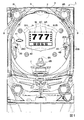
以下、図面を参照しつつ、本発明の一実施形態を詳細に説明する。図1は、本実施の形
態におけるパチンコ遊技機の正面図であり、主要部材の配置レイアウトを示す。パチンコ
遊技機1は、大別して、遊技盤面を構成する遊技盤2と、遊技盤2を支持固定する遊技機
用枠3とから構成されている。遊技盤2には、ガイドレールによって囲まれた、略円形状
の遊技領域が形成されている。この遊技領域には、遊技媒体としての遊技球が、所定の打
球発射装置から発射されて打ち込まれる。
Hereinafter, an embodiment of the present invention will be described in detail with reference to the drawings. FIG. 1 is a front view of the pachinko gaming machine according to the present embodiment, and shows an arrangement layout of main members. The
遊技盤2の所定位置には、第1特別図柄表示装置4Aと、第2特別図柄表示装置4Bと
が設けられている。第1特別図柄表示装置4Aと第2特別図柄表示装置4Bはそれぞれ、
例えば7セグメントやドットマトリクスのLED等から構成され、可変表示ゲームの一例
となる特図ゲームにおいて、各々を識別可能な複数種類の識別情報である特別図柄が、変
動可能に表示される。例えば、第1特別図柄表示装置4Aと第2特別図柄表示装置4Bは
それぞれ、「0」〜「9」を示す数字や「−」を示す記号等から構成される複数種類の特
別図柄を可変表示する。
A first special
For example, in a special figure game which is composed of 7 segments, dots matrix LEDs, and the like and is an example of a variable display game, special symbols which are a plurality of types of identification information capable of identifying each are displayed in a variable manner. For example, the first special
なお、第1特別図柄表示装置4Aや第2特別図柄表示装置4Bにおいて表示される特別
図柄は、「0」〜「9」を示す数字や「−」を示す記号等から構成されるものに限定され
ず、例えば7セグメントのLEDにおいて点灯させるものと消灯させるものとの組み合わ
せを異ならせた複数種類の点灯パターンが、複数種類の特別図柄として予め設定されてい
ればよい。以下では、第1特別図柄表示装置4Aにおいて可変表示される特別図柄を「第
1特図」ともいい、第2特別図柄表示装置4Bにおいて可変表示される特別図柄を「第2
特図」ともいう。
The special symbols displayed on the first special
Also called "special figure".
遊技盤2における遊技領域の中央付近には、画像表示装置5が設けられている。画像表
示装置5は、例えばLCD等から構成され、各種の演出画像を表示する表示領域を形成し
ている。画像表示装置5の表示領域では、特図ゲームにおける第1特別図柄表示装置4A
による第1特図の可変表示や第2特別図柄表示装置4Bによる第2特図の可変表示のそれ
ぞれに対応して、例えば3つといった複数の可変表示部となる飾り図柄表示エリアにて、
各々を識別可能な複数種類の識別情報である飾り図柄が可変表示される。この飾り図柄の
可変表示も、可変表示ゲームに含まれる。
An
Corresponding to each of the variable display of the first special figure and the variable display of the second special figure by the second special
A decorative pattern, which is a plurality of types of identification information capable of identifying each, is variably displayed. The variable display of this decorative pattern is also included in the variable display game.
一例として、画像表示装置5の表示領域には、「左」、「中」、「右」の飾り図柄表示
エリア5L、5C、5Rが配置されている。そして、特図ゲームにおいて第1特別図柄表
示装置4Aにおける第1特図の変動と第2特別図柄表示装置4Bにおける第2特図の変動
のうち、いずれかが開始されることに対応して、「左」、「中」、「右」の各飾り図柄表
示エリア5L、5C、5Rにおいて飾り図柄の変動が開始される。その後、特図ゲームに
おける可変表示結果として確定特別図柄が停止表示されるときに、画像表示装置5におけ
る「左」、「中」、「右」の各飾り図柄表示エリア5L、5C、5Rにて、飾り図柄の可
変表示結果となる確定飾り図柄が停止表示される。
As an example, in the display area of the
このように、画像表示装置5の表示領域では、第1特別図柄表示装置4Aにおける第1
特図を用いた特図ゲーム、又は第2特別図柄表示装置4Bにおける第2特図を用いた特図
ゲームと同期して、各々が識別可能な複数種類の飾り図柄の可変表示を行い、可変表示結
果となる確定飾り図柄を導出表示する。なお、例えば特別図柄や飾り図柄といった、各種
の表示図柄を導出表示するとは、飾り図柄等の識別情報を停止表示して可変表示を終了さ
せることである。これに対して、飾り図柄の可変表示を開始してから可変表示結果となる
確定飾り図柄が導出表示されるまでの可変表示中には、飾り図柄の変動速度が「0」とな
って、飾り図柄が停留して表示され、例えば微少な揺れや伸縮等を生じさせる表示状態と
なることがある。このような表示状態は、仮停止表示ともいい、可変表示における表示結
果が確定的に表示されていないものの、スクロール表示や更新表示による飾り図柄の変動
が進行していないことを遊技者が認識可能となる。なお、仮停止表示には、微少な揺れや
伸縮等も生じさせず、所定時間よりも短い時間だけ、飾り図柄を完全停止表示すること等
が含まれてもよい。
As described above, in the display area of the
In synchronization with the special figure game using the special figure or the special figure game using the second special figure in the second special
画像表示装置5の画面上の左右位置には、左始動入賞記憶表示エリア5HL,右始動入
賞記憶表示エリア5HRがそれぞれ配置されている。始動入賞記憶表示エリア5HL,5
HRでは、特図ゲームに対応した可変表示の保留数を特定可能に表示する保留記憶表示が
行われる。ここで、特図ゲームに対応した可変表示の保留は、普通入賞球装置6Aが形成
する第1始動入賞口や、普通可変入賞球装置6Bが形成する第2始動入賞口を、遊技球が
通過することによる始動入賞に基づいて発生する。即ち、特図ゲームや飾り図柄の可変表
示といった可変表示ゲームを実行するための始動条件は成立したが、先に成立した開始条
件に基づく可変表示ゲームが実行中であることやパチンコ遊技機1が大当り遊技状態に制
御されていること等により、可変表示ゲームの開始を許容する開始条件が成立していない
ときに、成立した始動条件に対応する可変表示の保留が行われる。
A left start winning memory display area 5HL and a right starting winning memory display area 5HR are arranged at the left and right positions on the screen of the
In the HR, a hold storage display for identifiablely displaying the number of holds for the variable display corresponding to the special figure game is performed. Here, in the hold of the variable display corresponding to the special figure game, the game ball passes through the first starting winning opening formed by the ordinary winning
例えば、第1始動入賞口を遊技球が通過する第1始動入賞の発生により、第1特別図柄
表示装置4Aによる第1特図を用いた特図ゲームの始動条件が成立したときに、当該第1
始動条件の成立に基づく第1特図を用いた特図ゲームを開始するための第1開始条件が成
立しなければ、第1特図保留記憶数が1加算され、第1特図を用いた特図ゲームの実行が
保留される。また、第2始動入賞口を遊技球が通過する第2始動入賞の発生により、第2
特別図柄表示装置4Bによる第2特図を用いた特図ゲームの始動条件が成立したときに、
当該第2始動条件の成立に基づく第2特図を用いた特図ゲームを開始するための第2開始
条件が成立しなければ、第2特図保留記憶数が1加算され、第2特図を用いた特図ゲーム
の実行が保留される。これに対して、第1特図を用いた特図ゲームの実行が開始されると
きには、第1特図保留記憶数が1減算され、第2特図を用いた特図ゲームの実行が開始さ
れるときには、第2特図保留記憶数が1減算される。第1始動入賞口への入賞による可変
表示の保留数を特定可能に表示する保留記憶表示は、左始動入賞記憶表示エリア5HLに
おいて行われ、第2始動入賞口への入賞による可変表示の保留数を特定可能に表示する保
留記憶表示は、右始動入賞記憶表示エリア5HRにおいて行われる。
For example, when the start condition of the special figure game using the first special figure by the first special
If the first start condition for starting the special figure game using the first special figure based on the establishment of the start condition is not satisfied, the number of stored first special figures is added by 1, and the first special figure is used. Execution of the special figure game is suspended. In addition, due to the occurrence of the second start prize in which the game ball passes through the second start prize opening, the second start prize is generated.
When the start condition of the special figure game using the second special figure by the special
If the second start condition for starting the special figure game using the second special figure based on the establishment of the second start condition is not satisfied, the number of the second special figure reserved storage is added by 1, and the second special figure is added. The execution of the special figure game using is suspended. On the other hand, when the execution of the special figure game using the first special figure is started, the number of stored special figures of the first special figure is subtracted by 1, and the execution of the special figure game using the second special figure is started. At that time, the number of the second special figure reserved storage is subtracted by 1. The hold memory display for identifiablely displaying the number of pending variable displays due to winning in the first starting winning opening is performed in the left starting winning memory display area 5HL, and the number of holdings for variable display due to winning in the second starting winning opening. The hold memory display for identifiable display is performed in the right start winning memory display area 5HR.
第1特図保留記憶数と第2特図保留記憶数とを加算した可変表示の保留記憶数は、特に
、合計保留記憶数ともいう。単に「特図保留記憶数」というときには、通常、第1特図保
留記憶数、第2特図保留記憶数及び合計保留記憶数のいずれも含む概念を指すが、特に、
これらの一部を指すこともあるものとする。
The variable display hold memory number obtained by adding the first special figure hold memory number and the second special figure hold memory number is also particularly referred to as a total hold memory number. The term "special figure reserved memory" usually refers to a concept that includes all of the first special figure reserved memory, the second special figure reserved memory, and the total reserved memory.
It may also refer to some of these.
始動入賞記憶表示エリア5HL,5HRと共に、あるいは始動入賞記憶表示エリア5H
L,5HRに代えて、特図保留記憶数を表示する表示器を設けるようにしてもよい。図1
に示す例では、始動入賞記憶表示エリア5HL,5HRと共に、第1特別図柄表示装置4
A及び第2特別図柄表示装置4Bの上部に、特図保留記憶数を特定可能に表示するための
第1保留表示器25Aと第2保留表示器25Bとが設けられている。第1保留表示器25
Aは、第1特図保留記憶数を特定可能に表示する。第2保留表示器25Bは、第2特図保
留記憶数を特定可能に表示する。
第1保留表示器25Aと第2保留表示器25Bはそれぞれ、例えば第1特図保留記憶数と
第2特図保留記憶数のそれぞれにおける上限値に対応した個数のLEDを含んで構成され
ている。
Start prize memory display area 5HL, 5HR, or start prize memory display area 5H
Instead of L and 5HR, a display for displaying the number of reserved special figures may be provided. Figure 1
In the example shown in, the first special
A
A displays the number of first special figure reserved storage in a identifiable manner. The
The
画像表示装置5の表示領域における下方位置の近傍には、可動枠部材60が設けられている。可動枠部材60は、図2に示す可動枠部材用モータ61による上下動駆動により、画像表示装置5に対して相対的に上下動する。可動枠部材60には開口部62が形成されている。可動枠部材60は、画像表示装置5の表面側(遊技者側)に配置されており、可動枠部材60の開口部62を介して画像表示装置5が視認可能されている。このため、画像表示装置5の表示領域は、可動枠部材60に囲まれた部分(以下「可動枠部材60の中」という)と可動枠部材60の外側に形成される。さらに、可動枠部材60の幅方向の長さは、画像表示装置5の幅方向の長さより長くされている。このため、可動枠部材60が画像表示装置5の上下方向途中位置、例えば画像表示装置6の上下方向中央位置に配置されているときには、可動枠部材60の中に形成された表示領域のほか可動枠部材60によって画像表示装置5の表示領域が分割されて可動枠部材60の上下のそれぞれの表示領域が形成される。
A
可動枠部材60が最下方に位置するときには、可動枠部材60の下方には、画像表示装
置5の表示領域が形成されず、可動枠部材60の中及び上方に画像表示装置5の表示領域
が形成される。また、可動枠部材60が最上方に位置するときには、可動枠部材60の上
方には、画像表示装置5の表示領域が形成されず、可動枠部材60の中及び下方に画像表
示装置5の表示領域が形成される。また、可動枠部材60の左右には、画像表示装置5の
表示領域は形成されないようにされている。以下、可動枠部材60が移動可能とされた最
下方の位置を第1位置といい、最上方の位置を第3位置という。また、第1位置と第3位
置との中間位置を第2位置という。また、可動枠部材60が第2位置にあるときの画像表
示装置5における可動枠部材60よりも上方の表示領域を第1表示領域といい、可動枠部
材60が第2位置にあるときの画像表示装置5における可動枠部材60よりも下方の表示
領域を第2表示領域という。さらに、可動枠部材60の内側の表示領域を第3表示領域と
いう。可動枠部材60が上下動することにより、第3表示領域は移動し、第1表示領域と
第2表示領域の面積が変化可能である。また。可動枠部材60が第2位置にあるときには
、第1表示領域と第2表示領域の面積は略同一となる。また、可動枠部材60の上下方向
の位置によって、第1表示領域と第2表示領域の面積の割合が異なる。
When the
画像表示装置5の下方には、普通入賞球装置6Aと、普通可変入賞球装置6Bとが設け
られている。普通入賞球装置6Aは、例えば所定の玉受部材によって常に一定の開放状態
に保たれる始動領域としての第1始動入賞口を形成する。普通可変入賞球装置6Bは、図
2に示す普通電動役物用のソレノイド81によって垂直位置となる閉鎖状態と傾動位置と
なる開放状態とに変化する一対の可動翼片を有する電動チューリップ型役物を備え、第2
始動入賞口を形成する。
Below the
Form a starting winning opening.
一例として、普通可変入賞球装置6Bでは、普通電動役物用のソレノイド81がオフ状
態であるときに可動翼片が垂直位置となることにより、遊技球が第2始動入賞口に進入し
ない閉鎖状態となる。その一方で、普通可変入賞球装置6Bでは、普通電動役物用のソレ
ノイド81がオン状態であるときに可動翼片が傾動位置となることにより、遊技球が第2
始動入賞口に進入する開放状態となる。なお、普通可変入賞球装置6Bは、閉鎖状態であ
るときでも、第2始動入賞口には遊技球が進入可能であるものの、開放状態であるときよ
りも遊技球が進入する可能性が低くなるように構成してもよい。このように、遊技領域に
は、遊技球が進入可能な開放状態と、遊技球が進入不可能な又は進入困難な閉鎖状態とに
変化する普通可変入賞球装置6Bが設けられている。
As an example, in the ordinary variable winning
It will be in an open state to enter the starting winning opening. Although the normally variable winning
普通入賞球装置6Aに形成された第1始動入賞口に進入した遊技球は、例えば図2に示
す第1始動口スイッチ22Aによって検出される。普通可変入賞球装置6Bに形成された
第2始動入賞口に進入した遊技球は、例えば図2に示す第2始動口スイッチ22Bによっ
て検出される。第1始動口スイッチ22Aによって遊技球が検出されたことに基づき、所
定個数の遊技球が賞球として払い出され、第1特図保留記憶数が所定の上限値以下であれ
ば、第1始動条件が成立する。第2始動口スイッチ22Bによって遊技球が検出されたこ
とに基づき、所定個数の遊技球が賞球として払い出され、第2特図保留記憶数が所定の上
限値以下であれば、第2始動条件が成立する。
The game ball that has entered the first starting winning opening formed in the ordinary winning
なお、第1始動口スイッチ22Aによって遊技球が検出されたことに基づいて払い出さ
れる賞球の個数と、第2始動口スイッチ22Bによって遊技球が検出されたことに基づい
て払い出される賞球の個数は、互いに同一の個数であってもよいし、異なる個数であって
もよい。パチンコ遊技機1は、賞球となる遊技球を直接に払い出すものであってもよいし
、賞球となる遊技球の個数に対応した得点を付与するものであってもよい。
The number of prize balls to be paid out based on the detection of the game ball by the first start port switch 22A and the number of prize balls to be paid out based on the detection of the game ball by the second
普通入賞球装置6Aと普通可変入賞球装置6Bの下方には、特別可変入賞球装置7が設
けられている。特別可変入賞球装置7は、図2に示す大入賞口扉用となるソレノイド82
によって開閉駆動される大入賞口扉を備え、その大入賞口扉によって開放状態と閉鎖状態
とに変化する特定領域としての大入賞口を形成する。
A special variable winning
It is equipped with a large winning opening door that is driven to open and close by, and forms a large winning opening as a specific area that changes between an open state and a closed state depending on the large winning opening door.
一例として、特別可変入賞球装置7では、大入賞口扉用のソレノイド82がオフ状態で
あるときに大入賞口扉が大入賞口を閉鎖状態として、遊技球が大入賞口に通過できなくす
る。その一方で、特別可変入賞球装置7では、大入賞口扉用のソレノイド82がオン状態
であるときに大入賞口扉が大入賞口を開放状態として、遊技球が大入賞口を通過し易くす
る。このように、特定領域としての大入賞口は、遊技球が通過し易く遊技者にとって有利
な開放状態と、遊技球が通過できず遊技者にとって不利な閉鎖状態とに変化する。なお、
遊技球が大入賞口を通過できない閉鎖状態に代えて、あるいは閉鎖状態の他に、遊技球が
大入賞口を通過し難い一部開放状態を設けてもよい。
As an example, in the special variable winning
Instead of the closed state in which the game ball cannot pass through the large winning opening, or in addition to the closed state, a partially open state in which the game ball is difficult to pass through the large winning opening may be provided.
大入賞口を通過した遊技球は、例えば図2に示すカウントスイッチ23によって検出さ
れる。カウントスイッチ23によって遊技球が検出されたことに基づき、所定個数の遊技
球が賞球として払い出される。こうして、特別可変入賞球装置7において開放状態となっ
た大入賞口を遊技球が通過したときには、例えば第1始動入賞口や第2始動入賞口といっ
た、他の入賞口を遊技球が通過したときよりも多くの賞球が払い出される。したがって、
特別可変入賞球装置7において大入賞口が開放状態となれば、その大入賞口に遊技球が進
入可能となり、遊技者にとって有利な第1状態となる。その一方で、特別可変入賞球装置
7において大入賞口が閉鎖状態又は一部閉鎖状態となれば、大入賞口に遊技球を通過させ
て賞球を得ることが不可能又は困難になり、遊技者にとって不利な第2状態となる。
The game ball that has passed through the big winning opening is detected by, for example, the count switch 23 shown in FIG. Based on the detection of the game balls by the count switch 23, a predetermined number of game balls are paid out as prize balls. In this way, when the game ball passes through the large winning opening opened in the special variable winning
When the large winning opening is opened in the special variable winning
遊技盤2の所定位置には、普通図柄表示器20が設けられている。一例として、普通図
柄表示器20は、第1特別図柄表示装置4Aや第2特別図柄表示装置4Bと同様に7セグ
メントやドットマトリクスのLED等から構成され、特別図柄とは異なる複数種類の識別
情報である普通図柄を変動可能に表示する。このような普通図柄の可変表示は、普図ゲー
ムと称される。普通図柄表示器20の上方には、普図保留表示器25Cが設けられている
。普図保留表示器25Cは、例えば4個のLEDを含んで構成され、通過ゲート41を通
過した有効通過球数としての普図保留記憶数を表示する。
An
遊技盤2の表面には、上記の構成以外にも、遊技球の流下方向や速度を変化させる風車
、及び多数の障害釘が設けられている。また、第1始動入賞口、第2始動入賞口及び大入
賞口とは異なる入賞口として、例えば所定の玉受部材によって常に一定の開放状態に保た
れる単一又は複数の一般入賞口が設けられてもよい。この場合には、一般入賞口のいずれ
かに進入した遊技球が所定の一般入賞球スイッチによって検出されたことに基づき、所定
個数の遊技球が賞球として払い出されればよい。遊技領域の最下方には、いずれの入賞口
にも進入しなかった遊技球が取り込まれるアウト口が設けられている。
In addition to the above configuration, the surface of the
遊技機用枠3の左右上部位置には、効果音等を再生出力するためのスピーカ8L、8R
が設けられており、更に遊技領域周辺部には、遊技効果ランプ9が設けられている。パチ
ンコ遊技機1の遊技領域における各構造物の周囲には、装飾用LEDが配置されていても
よい。遊技機用枠3の右下部位置には、遊技媒体としての遊技球を遊技領域に向けて発射
するために遊技者等によって操作される打球操作ハンドルが設けられている。例えば、打
球操作ハンドルは、遊技者等による操作量に応じて遊技球の弾発力を調整する。
Is provided, and a
遊技領域の下方における遊技機用枠3の所定位置には、賞球として払い出された遊技球
や所定の球貸機により貸し出された遊技球を、打球発射装置へと供給可能に保持する上皿
が設けられている。遊技機用枠3の下部には、上皿から溢れた余剰球等を、パチンコ遊技
機1の外部へと排出可能に保持する下皿が設けられている。
At a predetermined position of the
パチンコ遊技機1には、例えば図2に示すような主基板11、演出制御基板12、音声
制御基板13、ランプ制御基板14といった、各種の制御基板が搭載されている。また、
パチンコ遊技機1には、主基板11と演出制御基板12との間で伝送される各種の制御信
号を中継するための中継基板15等も搭載されている。その他にも、パチンコ遊技機1に
おける遊技盤2等の背面には、例えば払出制御基板、情報端子基板、発射制御基板、イン
タフェース基板、タッチセンサ基板等といった、各種の基板が配置されている。
The
The
主基板11は、メイン側の制御基板であり、パチンコ遊技機1における遊技の進行を制
御するための各種回路が搭載されている。主基板11は、主として、特図ゲームにおいて
用いる乱数の設定機能、所定位置に配設されたスイッチ等からの信号の入力を行う機能、
演出制御基板12等から成るサブ側の制御基板に宛てて、指令情報の一例となる制御コマ
ンドを制御信号として出力して送信する機能、ホールの管理コンピュータに対して各種情
報を出力する機能等を備えている。また、主基板11は、第1特別図柄表示装置4Aと第
2特別図柄表示装置4Bを構成する各LED等の点灯/消灯制御を行って第1特図や第2
特図の可変表示を制御することや、普通図柄表示器20の点灯/消灯/発色制御等を行っ
て普通図柄表示器20による普通図柄の可変表示を制御することといった、所定の表示図
柄の可変表示を制御する機能も備えている。
The
A function to output and transmit a control command as an example of command information as a control signal, a function to output various information to a hall management computer, etc. to a control board on the sub side composed of a
Variable display of a predetermined display, such as controlling the variable display of a special symbol, or controlling the variable display of a normal symbol by the
主基板11には、例えば遊技制御用マイクロコンピュータ100やスイッチ回路110
、ソレノイド回路111等が搭載されている。スイッチ回路110は、遊技球検出用の各
種スイッチからの検出信号を取り込んで遊技制御用マイクロコンピュータ100に伝送す
る。ソレノイド回路111は、遊技制御用マイクロコンピュータ100からのソレノイド
駆動信号を、普通電動役物用のソレノイド81や大入賞口扉用のソレノイド82に伝送す
る。
On the
,
演出制御基板12は、主基板11とは独立したサブ側の制御基板であり、中継基板15
を介して主基板11から伝送された制御信号を受信して、画像表示装置5、スピーカ8L
、8R、及び遊技効果ランプ9や装飾用LEDといった演出用の電気部品による演出動作
を制御するための各種回路が搭載されている。即ち、演出制御基板12は、画像表示装置
5における表示動作や、スピーカ8L、8Rからの音声出力動作の全部又は一部、遊技効
果ランプ9や装飾用LED等における点灯/消灯動作の全部又は一部といった、演出用の
電気部品に所定の演出動作を実行させるための制御内容を決定する機能を備えている。
The
The control signal transmitted from the
, 8R, and various circuits for controlling the production operation by the production electrical components such as the
音声制御基板13は、演出制御基板12とは別個に設けられた音声出力制御用の制御基
板であり、演出制御基板12からの指令や制御データ等に基づき、スピーカ8L、8Rか
ら音声を出力させるための音声信号処理を実行する処理回路等が搭載されている。ランプ
制御基板14は、演出制御基板12とは別個に設けられたランプ出力制御用の制御基板で
あり、演出制御基板12からの指令や制御データ等に基づき、遊技効果ランプ9や装飾用
LED等における点灯/消灯駆動を行うランプドライバ回路等が搭載されている。
The
図2に示すように、主基板11には、ゲートスイッチ21、始動口スイッチ、カウント
スイッチ23といった、各種スイッチからの検出信号を伝送する配線が接続されている。
なお、各種スイッチは、例えばセンサと称されるもの等のように、遊技媒体としての遊技
球を検出できる任意の構成を有するものであればよい。また、主基板11には、第1特別
図柄表示装置4A、第2特別図柄表示装置4B、普通図柄表示器20等の表示制御を行う
ための指令信号を伝送する配線が接続されている。
As shown in FIG. 2, wirings for transmitting detection signals from various switches such as a
The various switches may have an arbitrary configuration that can detect a game ball as a game medium, such as a switch called a sensor. Further, a wiring for transmitting a command signal for performing display control of the first special
主基板11から演出制御基板12に向けて伝送される制御信号は、中継基板15によっ
て中継される。中継基板15を介して主基板11から演出制御基板12に対して伝送され
る制御コマンドは、例えば電気信号として送受信される演出制御コマンドである。演出制
御コマンドには、例えば画像表示装置5における画像表示動作を制御するために用いられ
る表示制御コマンドや、スピーカ8L、8Rからの音声出力を制御するために用いられる
音声制御コマンド、遊技効果ランプ9や装飾用LEDの点灯動作等を制御するために用い
られるランプ制御コマンドが含まれている。これらの演出制御コマンドはいずれも、例え
ば2バイト構成であり、1バイト目はMODEを示し、2バイト目はEXTを表す。MO
DEデータの先頭ビットは必ず「1」となり、EXTデータの先頭ビットは「0」となる
ように、予め設定されていればよい。
The control signal transmitted from the
The first bit of the DE data may be set to "1" and the first bit of the EXT data may be set to "0" in advance.
主基板11に搭載された遊技制御用マイクロコンピュータ100は、例えば1チップの
マイクロコンピュータであり、遊技制御用のプログラムや固定データ等を記憶するROM
101と、遊技制御用のワークエリアを提供するRAM102と、遊技制御用のプログラ
ムを実行して制御動作を行うCPU103と、CPU103とは独立して乱数値を示す数
値データの更新を行う乱数回路104と、I/O105とを備えて構成される。
The
101, a
一例として、遊技制御用マイクロコンピュータ100では、CPU103がROM10
1から読み出したプログラムを実行することにより、パチンコ遊技機1における遊技の進
行を制御するための処理が実行される。このときには、CPU103がROM101から
固定データを読み出す固定データ読出動作や、CPU103がRAM102に各種の変動
データを書き込んで一時記憶させる変動データ書込動作、CPU103がRAM102に
一時記憶されている各種の変動データを読み出す変動データ読出動作、CPU103がI
/O105を介して遊技制御用マイクロコンピュータ100の外部から各種信号の入力を
受け付ける受信動作、CPU103がI/O105を介して遊技制御用マイクロコンピュ
ータ100の外部へと各種信号を出力する送信動作等も行われる。
As an example, in the
By executing the program read from No. 1, a process for controlling the progress of the game in the
A reception operation that accepts inputs of various signals from the outside of the
なお、遊技制御用マイクロコンピュータ100を構成する1チップのマイクロコンピュ
ータは、少なくともCPU103の他にRAM102が内蔵されていればよく、ROM1
01や乱数回路104、I/O105等は外付けされてもよい。
The one-chip microcomputer constituting the
The 01, the
遊技制御用マイクロコンピュータ100では、例えば乱数回路104等により、遊技の
進行を制御するために用いられる各種の乱数値を示す数値データが更新可能にカウントさ
れる。遊技の進行を制御するために用いられる乱数は、遊技用乱数ともいう。遊技用乱数
は、乱数回路104等のハードウェアによって更新されるものであってもよいし、遊技制
御用マイクロコンピュータ100のCPU103が所定のコンピュータプログラムを実行
することでソフトウェアによって更新されるものであってもよい。例えば、遊技制御用マ
イクロコンピュータ100におけるRAM102の所定領域に設けられたランダムカウン
タや、RAM102とは別個の内部レジスタに設けられたランダムカウンタに、所定の乱
数値を示す数値データを格納し、CPU103が定期的又は不定期的に格納値を更新する
ことで、乱数値の更新が行われるようにしてもよい。
In the
遊技制御用マイクロコンピュータ100が備えるROM101には、ゲーム制御用のプ
ログラムの他にも、遊技の進行を制御するために用いられる各種の選択用データ、テーブ
ルデータ等が格納されている。例えば、ROM101には、CPU103が各種の判定や
決定、設定を行うために用意された複数の判定テーブルや決定テーブル、設定テーブル等
を構成するデータが記憶されている。また、ROM101には、CPU103が主基板1
1から各種の制御コマンドとなる制御信号を送信するために用いられる複数のコマンドテ
ーブルを構成するテーブルデータや、変動パターンを複数種類格納する変動パターンテー
ブルを構成するテーブルデータ等が、記憶されている。遊技制御用マイクロコンピュータ
100が備えるRAM102には、パチンコ遊技機1における遊技の進行等を制御するた
めに用いられる各種データが書換可能に一時記憶される。
The
Table data that constitutes a plurality of command tables used for transmitting control signals that are various control commands from 1 and table data that constitutes a variation pattern table that stores a plurality of types of variation patterns are stored. .. In the
演出制御基板12には、プログラムに従って制御動作を行う演出制御用CPU120と
、演出制御用のプログラムや固定データ等を記憶するROM121と、演出制御用CPU
120のワークエリアを提供するRAM122と、画像表示装置5における表示動作の制
御内容を決定するための処理等を実行する表示制御部123と、演出制御用CPU120
とは独立して乱数値を示す数値データの更新を行う乱数回路124と、I/O125とが
搭載されている。
The
The
It is equipped with a
一例として、演出制御基板12では、演出制御用CPU120がROM121から読み
出した演出制御用のプログラムを実行することにより、演出用の電気部品による演出動作
を制御するための処理が実行される。このときには、演出制御用CPU120がROM1
21から固定データを読み出す固定データ読出動作や、演出制御用CPU120がRAM
122に各種の変動データを書き込んで一時記憶させる変動データ書込動作、演出制御用
CPU120がRAM122に一時記憶されている各種の変動データを読み出す変動デー
タ読出動作、演出制御用CPU120がI/O125を介して演出制御基板12の外部か
ら各種信号の入力を受け付ける受信動作、演出制御用CPU120がI/O125を介し
て演出制御基板12の外部へと各種信号を出力する送信動作等も行われる。
As an example, in the
Fixed data read operation to read fixed data from 21 and
A variation data writing operation in which various variation data are written to 122 and temporarily stored, a variation data read operation in which the
演出制御用CPU120、ROM121、RAM122は、演出制御基板12に搭載さ
れた1チップの演出制御用マイクロコンピュータに含まれてもよい。演出制御基板12に
は、画像表示装置5に対して映像信号を伝送するための配線や、音声制御基板13に対し
て音番号データを示す情報信号としての効果音信号を伝送するための配線、ランプ制御基
板14に対してランプデータを示す情報信号としての電飾信号を伝送するための配線等が
接続されている。更に、演出制御基板12には、可動枠部材60を動作させる可動枠部材
用モータ61を駆動するためのモータ駆動回路16に対して所定の駆動指令信号を伝送す
るための配線も接続されている。
The
演出制御基板12では、例えば乱数回路124等により、演出動作を制御するために用
いられる各種の乱数値を示す数値データが更新可能にカウントされる。こうした演出動作
を制御するために用いられる乱数は、演出用乱数ともいう。
In the
図2に示す演出制御基板12に搭載されたROM121には、演出制御用のプログラム
の他にも、演出動作を制御するために用いられる各種のデータテーブル等が格納されてい
る。例えば、ROM121には、演出制御用CPU120が各種の判定や決定、設定を行
うために用意された複数の判定テーブルや決定テーブルを構成するテーブルデータ、各種
の演出制御パターンを構成するパターンデータ等が記憶されている。演出制御基板12に
搭載されたRAM122には、演出動作を制御するために用いられる各種データが記憶さ
れる。
The
演出制御基板12に搭載された表示制御部123は、演出制御用CPU120からの表
示制御指令等に基づき、画像表示装置5における表示動作の制御内容を決定する。例えば
、表示制御部123は、画像表示装置5の表示領域内に表示させる演出画像の切換タイミ
ングを決定すること等により、飾り図柄の可変表示や各種の演出表示を実行させるための
制御を行う。一例として、表示制御部123には、VDP、CGROM、VRAM、LC
D駆動回路等が搭載されていればよい。なお、VDPは、GPU、GCL、あるいは、よ
り一般的にDSPと称される画像処理用のマイクロプロセッサであってもよい。CGRO
Mは、例えば書換不能な半導体メモリであってもよいし、フラッシュメモリ等の書換可能
な半導体メモリであってもよく、あるいは、磁気メモリ、光学メモリといった、不揮発性
記録媒体のいずれかを用いて構成されたものであればよい。
The
It suffices if a D drive circuit or the like is mounted. The VDP may be a GPU, GCL, or a microprocessor for image processing generally referred to as DSP. CGRO
M may be, for example, a non-rewritable semiconductor memory, a rewritable semiconductor memory such as a flash memory, or a non-volatile recording medium such as a magnetic memory or an optical memory. It may be configured.
演出制御基板12に搭載されたI/O125は、例えば主基板11等から伝送された演
出制御コマンドを取り込むための入力ポートと、演出制御基板12の外部へと各種信号を
伝送するための出力ポートとを含んで構成される。例えば、I/O125の出力ポートか
らは、画像表示装置5へと伝送される映像信号や、音声制御基板13へと伝送される指令
、ランプ制御基板14へと伝送される指令等が出力される。
The I /
パチンコ遊技機1においては、遊技媒体としての遊技球を用いた所定の遊技が行われ、
その遊技結果に基づいて所定の遊技価値が付与可能となる。遊技球を用いた遊技の一例と
して、パチンコ遊技機1における筐体前面の右下方に設置された打球操作ハンドルが遊技
者によって所定操作されたことに基づいて、所定の打球発射装置が備える発射モータ等に
より、遊技媒体としての遊技球が遊技領域に向けて発射される。遊技領域を流下した遊技
球が、普通入賞球装置6Aに形成された第1始動入賞口を通過すると、図2に示す第1始
動口スイッチ22Aによって遊技球が検出されたこと等により第1始動条件が成立する。
その後、例えば前回の特図ゲームや大当り遊技状態が終了したこと等により第1開始条件
が成立したことに基づいて、第1特別図柄表示装置4Aによる第1特図を用いた特図ゲー
ムが開始される。
In the
A predetermined game value can be given based on the game result. As an example of a game using a game ball, a launch motor provided in a predetermined ball launcher based on a predetermined operation of a ball striking operation handle installed at the lower right of the front surface of the housing of the
After that, based on the fact that the first start condition is satisfied, for example, due to the end of the previous special figure game or the jackpot game state, the special figure game using the first special figure by the first special
また、遊技球が普通可変入賞球装置6Bに形成された第2始動入賞口を通過すると、図
2に示す第2始動口スイッチ22Bによって遊技球が検出されたこと等により第2始動条
件が成立する。その後、例えば前回の特図ゲームや大当り遊技状態が終了したこと等によ
り第2開始条件が成立したことに基づいて、第2特別図柄表示装置4Bによる第2特図を
用いた特図ゲームが開始される。但し、普通可変入賞球装置6Bが第2状態としての閉鎖
状態であるときには、第2始動入賞口を遊技球が通過困難又は通過不可能である。
Further, when the game ball passes through the second start winning opening formed in the normally variable winning
通過ゲート41を通過した遊技球が図2に示すゲートスイッチ21によって検出された
ことに基づいて、普通図柄表示器20にて普通図柄の可変表示を実行するための普図始動
条件が成立する。その後、例えば前回の普図ゲームが終了したことといった、普通図柄の
可変表示を開始するための普図開始条件が成立したことに基づいて、普通図柄表示器20
による普図ゲームが開始される。この普図ゲームでは、普通図柄の変動を開始させた後、
所定時間が経過すると、普通図柄の可変表示結果となる確定普通図柄を停止表示する。こ
のとき、確定普通図柄として特定の普通図柄が停止表示されれば、普通図柄の可変表示結
果が「普図当り」となる。その一方、確定普通図柄として普図当り図柄以外の普通図柄が
停止表示されれば、普通図柄の可変表示結果が「普図ハズレ」となる。普通図柄の可変表
示結果が「普図当り」となったことに対応して、普通可変入賞球装置6Bを構成する電動
チューリップの可動翼片が傾動位置となる開放制御が行われ、所定時間が経過すると垂直
位置に戻る閉鎖制御が行われる。
Based on the fact that the game ball that has passed through the passing
The game of Fuzu is started. In this game, after starting the fluctuation of the normal symbol,
When the predetermined time elapses, the confirmed normal symbol, which is the variable display result of the normal symbol, is stopped and displayed. At this time, if a specific normal symbol is stopped and displayed as a fixed normal symbol, the variable display result of the normal symbol is "per normal symbol". On the other hand, if a normal symbol other than the normal symbol per symbol is stopped and displayed as a confirmed normal symbol, the variable display result of the normal symbol becomes "normal symbol loss". In response to the variable display result of the normal symbol being "per normal figure", the opening control is performed so that the movable wing piece of the electric tulip constituting the normal variable winning
第1特別図柄表示装置4Aによる第1特図を用いた特図ゲームが開始されるときや、第
2特別図柄表示装置4Bによる第2特図を用いた特図ゲームが開始されるときには、特別
図柄の可変表示結果を予め定められた特定表示結果としての「大当り」にするか否かが、
その可変表示結果を導出表示する以前に決定される。そして、可変表示結果の決定に基づ
く所定割合で、変動パターンの決定等が行われ、可変表示結果や変動パターンを指定する
演出制御コマンドが、図2に示す主基板11の演出制御用マイクロコンピュータ100か
ら演出制御基板12に向けて伝送される。
Special when the special symbol game using the first special symbol by the first special
It is determined before the variable display result is derived and displayed. Then, the fluctuation pattern is determined at a predetermined ratio based on the determination of the variable display result, and the effect control command for designating the variable display result and the variation pattern is the
こうした可変表示結果や変動パターンの決定に基づいて特図ゲームが開始された後、例
えば変動パターンに対応して予め定められた可変表示時間が経過したときには、可変表示
結果となる確定特別図柄が導出表示される。第1特別図柄表示装置4Aや第2特別図柄表
示装置4Bによる特別図柄の可変表示に対応して、画像表示装置5の表示領域に配置され
た「左」、「中」、「右」の飾り図柄表示エリア5L、5C、5Rでは、特別図柄とは異
なる飾り図柄の可変表示が行われる。
After the special figure game is started based on the determination of the variable display result and the variation pattern, for example, when a predetermined variable display time corresponding to the variation pattern elapses, a definite special symbol that becomes the variable display result is derived. Is displayed. "Left", "middle", and "right" decorations arranged in the display area of the
第1特別図柄表示装置4Aによる第1特図を用いた特図ゲームや、第2特別図柄表示装
置4Bによる第2特図を用いた特図ゲームにおいて、特別図柄の可変表示結果となる確定
特別図柄が導出表示されるときには、画像表示装置5において飾り図柄の可変表示結果と
なる確定飾り図柄が導出表示される。特別図柄の可変表示結果として予め定められた大当
り図柄が導出表示されたときには、可変表示結果が「大当り」となり、遊技者にとって有
利な特定遊技状態としての大当り遊技状態に制御される。特別図柄の可変表示結果として
、大当り図柄が導出表示されず、ハズレ図柄が導出表示されたときには、可変表示結果が
「ハズレ」となる。
In a special symbol game using the first special symbol by the first special
一例として、「3」や「7」の数字を示す特別図柄を大当り図柄とし、「−」の記号を
示す特別図柄をハズレ図柄とする。なお、第1特別図柄表示装置4Aによる特図ゲームに
おける大当り図柄やハズレ図柄といった各図柄は、第2特別図柄表示装置4Bによる特図
ゲームにおける各図柄とは異なる特別図柄となるようにしてもよいし、双方の特図ゲーム
において共通の特別図柄が大当り図柄やハズレ図柄となるようにしてもよい。また、数字
や記号として特定の意味を有する点灯パターンの特別図柄を大当り図柄やハズレ図柄とす
るものに限定されず、例えば7セグメントのLEDにおける任意の点灯パターンの特別図
柄を、大当り図柄やハズレ図柄としてもよい。
As an example, a special symbol indicating the numbers "3" and "7" is used as a jackpot symbol, and a special symbol indicating the symbol "-" is used as a lost symbol. In addition, each symbol such as a big hit symbol or a lost symbol in the special symbol game by the first special
大当り遊技状態では、大入賞口が開放状態となって特別可変入賞球装置7が遊技者にと
って有利な第1状態となる。そして、所定期間、あるいは所定個数の遊技球が大入賞口に
進入して入賞球が発生するまでの期間にて、大入賞口を継続して開放状態とするラウンド
遊技が実行される。こうしたラウンド遊技の実行期間以外の期間では、大入賞口が閉鎖状
態となり、入賞球が発生困難又は発生不可能となる。大入賞口に遊技球が進入したときに
は、カウントスイッチ23により入賞球が検出され、その検出毎に所定個数の遊技球が賞
球として払い出される。大当り遊技状態におけるラウンド遊技は、所定の上限回数に達す
るまで繰り返し実行される。
In the big hit game state, the big winning opening is opened and the special variable winning
特図表示結果が「大当り」となる場合には、大当り種別が「非確変」又は「確変」のい
ずれかとなる場合が含まれている。例えば、特別図柄の可変表示結果として、「3」の数
字を示す大当り図柄が導出表示されたときには大当り種別が「非確変」となり、「7」の
数字を示す大当り図柄が導出表示されたときには大当り種別が「確変」となる。大当り種
別が「非確変」又は「確変」となった場合には、大当り遊技状態におけるラウンド遊技と
して、特別可変入賞球装置7を遊技者にとって有利な第1状態とする上限時間が比較的に
長い時間となる通常開放ラウンドが実行される。なお、大当り遊技状態におけるラウンド
遊技として、特別可変入賞球装置7を第1状態とする上限時間が比較的に短い時間となる
短期開放ラウンドが実行される大当り種別を設けてもよい。通常開放ラウンドが実行され
る大当り遊技状態は、第1特定遊技状態ともいう。短期開放ラウンドが実行される大当り
遊技状態は、第2特定遊技状態ともいう。
When the special figure display result is "big hit", the case where the big hit type is either "non-probable change" or "probable change" is included. For example, as a variable display result of a special symbol, when the jackpot symbol indicating the number "3" is derived and displayed, the jackpot type is "non-probable", and when the jackpot symbol indicating the number "7" is derived and displayed, the jackpot is displayed. The type is "probability change". When the jackpot type is "non-probability change" or "probability variation", the upper limit time for setting the special variable winning
大当り遊技状態が終了した後には、所定の確変制御条件が成立したことに基づいて、可
変表示結果が「大当り」となる確率が通常状態よりも高くなる確変状態に制御されること
がある。確変状態は、所定回数の可変表示が実行されること、あるいは次回の大当り遊技
状態が開始されることといった、所定の確変終了条件が成立するまで、継続するように制
御される。また、大当り遊技状態が終了した後には、平均的な可変表示時間が通常状態よ
りも短くなる時短状態に制御されることがある。時短状態は、所定回数の可変表示が実行
されたことと、次回の大当り遊技状態が開始されたことのうち、いずれか一方の時短終了
条件が先に成立するまで、継続するように制御される。一例として、大当り種別が「非確
変」である場合に大当り遊技状態が終了した後には、遊技状態が時短状態となる。一方、
大当り種別が「確変」である場合に大当り遊技状態が終了した後には、遊技状態が確変状
態となる。
After the jackpot game state ends, the probability of the variable display result becoming a "big hit" may be controlled to a probability variation state higher than the normal state based on the establishment of a predetermined probability variation control condition. The probabilistic state is controlled so as to continue until a predetermined probabilistic end condition such as the execution of the variable display a predetermined number of times or the start of the next big hit game state is satisfied. Further, after the jackpot game state is completed, the average variable display time may be controlled to a shorter time state than the normal state. The time saving state is controlled so as to continue until one of the time saving end condition of either the execution of the variable display a predetermined number of times or the start of the next big hit game state is satisfied first. .. As an example, when the jackpot type is "non-probability variation", the gaming state becomes the time saving state after the jackpot gaming state ends. on the other hand,
When the jackpot type is "probability change", the game state becomes the probability change state after the jackpot game state ends.
確変状態や時短状態では、通常状態よりも第2始動入賞口を遊技球が通過し易い有利変
化態様で、普通可変入賞球装置6Bを第1状態と第2状態とに変化させる。例えば、普通
図柄表示器20による普図ゲームにおける普通図柄の変動時間を通常状態のときよりも短
くする制御や、各回の普図ゲームで普通図柄の可変表示結果が「普図当り」となる確率を
通常状態のときよりも向上させる制御、可変表示結果が「普図当り」となったことに基づ
く普通可変入賞球装置6Bにおける可動翼片の傾動制御を行う傾動制御時間を通常状態の
ときよりも長くする制御、その傾動回数を通常状態のときよりも増加させる制御により、
普通可変入賞球装置6Bを有利変化態様で第1状態と第2状態とに変化させればよい。な
お、これらの制御のいずれか1つが行われるようにしてもよいし、複数の制御が組み合わ
せられて行われるようにしてもよい。このように、普通可変入賞球装置6Bを有利変化態
様で第1状態と第2状態とに変化させる制御は、高開放制御と称される。こうした確変状
態や時短状態に制御されることにより、次に可変表示結果が「大当り」となるまでの所要
時間が短縮され、通常状態よりも遊技者にとって有利な特別遊技状態となる。
In the probabilistic state or the time saving state, the normal variable winning
The ordinary variable winning
パチンコ遊技機1において遊技媒体として用いられる遊技球や、その個数に対応して付
与される得点の記録情報は、例えば数量に応じて特殊景品や一般景品に交換可能な有価価
値を有するものであればよい。あるいは、これらの遊技球や得点の記録情報は、特殊景品
や一般景品には交換できないものの、パチンコ遊技機1で再度の遊技に使用可能な有価価
値を有するものであってもよい。
The game balls used as a game medium in the
画像表示装置5に設けられた「左」、「中」、「右」の飾り図柄表示エリア5L、5C
、5Rでは、第1特別図柄表示装置4Aにおける第1特図を用いた特図ゲームと、第2特
別図柄表示装置4Bにおける第2特図を用いた特図ゲームとのうち、いずれかの特図ゲー
ムが開始されることに対応して、飾り図柄の可変表示が開始される。そして、飾り図柄の
可変表示が開始されてから「左」、「中」、「右」の飾り図柄表示エリア5L、5C、5
Rにおける確定飾り図柄の停止表示により可変表示が終了するまでの期間では、飾り図柄
の可変表示態様が所定のリーチ態様となることがある。
"Left", "Middle", and "Right" decorative
In 5R, one of a special figure game using the first special figure in the first special
In the period until the variable display ends due to the stop display of the fixed decorative symbol in R, the variable display mode of the decorative symbol may become a predetermined reach mode.
ここで、リーチ態様とは、画像表示装置5の表示領域にて停止表示された飾り図柄が大
当り組み合わせの一部を構成しているときに未だ停止表示されていない飾り図柄について
は変動が継続している表示態様、あるいは、全部又は一部の飾り図柄が大当り組み合わせ
の全部又は一部を構成しながら同期して変動している表示態様のことである。具体的には
、「左」、「中」、「右」の飾り図柄表示エリア5L、5C、5Rにおける一部では予め
定められた大当り組み合わせを構成する飾り図柄が停止表示されているときに未だ停止表
示していない残りの飾り図柄表示エリアでは飾り図柄が変動している表示態様、あるいは
、「左」、「中」、「右」の飾り図柄表示エリア5L、5C、5Rにおける全部又は一部
で飾り図柄が大当り組み合わせの全部又は一部を構成しながら同期して変動している表示
態様である。
Here, the reach mode means that when the decorative symbols stopped and displayed in the display area of the
また、リーチ態様となったことに対応して、飾り図柄の変動速度を低下させたり、画像
表示装置5の表示領域に飾り図柄とは異なるキャラクタ画像を表示させたり、背景画像の
表示態様を変化させたり、飾り図柄とは異なる動画像を再生表示させたり、飾り図柄の可
変表示態様を変化させたりすることで、リーチ態様となる以前とは異なる演出動作が実行
される場合がある。このようなキャラクタ画像の表示や背景画像の表示態様の変化、動画
像の再生表示、飾り図柄の可変表示態様の変化といった演出動作を、リーチ演出表示とい
う。なお、リーチ演出には、画像表示装置5における表示動作のみならず、スピーカ8L
、8Rによる音声出力動作や、遊技効果ランプ9等の発光体における点灯動作等を、リー
チ態様となる以前の動作態様とは異なる動作態様とすることが、含まれていてもよい。
Further, in response to the reach mode, the fluctuation speed of the decorative symbol is reduced, a character image different from the decorative symbol is displayed in the display area of the
, 8R voice output operation, lighting operation in a light emitting body such as a
リーチ演出における演出動作としては、互いに動作態様が異なる複数種類の演出パター
ンが、予め用意されていればよい。そして、それぞれのリーチ演出における演出態様に応
じて、「大当り」となる可能性が異なる。即ち、複数種類のリーチ演出のいずれが実行さ
れるかに応じて、可変表示結果が「大当り」となる可能性を異ならせることができる。こ
の実施の形態では、一例として、ノーマル、スーパーA、スーパーBといったリーチ演出
が予め設定されている。そして、スーパーAやスーパーBといったスーパーリーチのリー
チ演出(以下「スーパーリーチ演出」という)が実行された場合には、ノーマルのリーチ
演出(以下「ノーマルリーチ演出」という)が実行された場合に比べて、可変表示結果が
「大当り」となる可能性が高くなる。また、スーパーリーチ演出のうちでも、スーパーB
のスーパーリーチ演出(以下「スーパーリーチB演出」という)といった特定のリーチ演
出が実行された場合には、スーパーAのスーパーリーチ演出(以下「スーパーリーチA演
出」という)が実行された場合に比べて、大当り期待度が高くなる。
As the effect operation in the reach effect, a plurality of types of effect patterns having different operation modes may be prepared in advance. Then, the possibility of becoming a "big hit" differs depending on the production mode in each reach production. That is, the possibility that the variable display result will be a "big hit" can be different depending on which of the plurality of types of reach effects is executed. In this embodiment, as an example, reach effects such as normal, super A, and super B are preset. Then, when a super reach effect such as Super A or Super B (hereinafter referred to as "super reach effect") is executed, compared with a case where a normal reach effect (hereinafter referred to as "normal reach effect") is executed. , There is a high possibility that the variable display result will be a "big hit". Also, among the super reach productions, Super B
When a specific reach effect such as the super reach effect (hereinafter referred to as "super reach B effect") is executed, it is compared with the case where the super reach effect of Super A (hereinafter referred to as "super reach A effect") is executed. Therefore, the expectation for big hits will be high.
大当り期待度は、例えば、(大当り時にその演出が実行される確率)×(大当りになる
確率)/{(大当り時にその演出が実行される確率)×(大当りになる確率)+(大当り
時以外にその演出が実行される確率)×(大当りにならない確率)}によって算出される
。
The jackpot expectation is, for example, (probability that the effect is executed at the time of big hit) x (probability of being a big hit) / {(probability that the effect is executed at the time of a big hit) x (probability of being a big hit) + (other than at the time of a big hit It is calculated by (probability that the effect is executed) x (probability that it does not become a big hit)}.
飾り図柄の可変表示中には、リーチ演出とは異なり、例えば所定の演出画像を表示する
ことや、メッセージとなる画像表示や音声出力、遊技効果ランプ9や装飾用LEDの点灯
動作等のように、飾り図柄の可変表示動作とは異なる演出動作により、例えば飾り図柄の
可変表示態様がリーチ態様となる可能性があることや、可変表示結果が「大当り」となる
可能性があること等といった、パチンコ遊技機1において実行される遊技の有利度を、遊
技者に予め告知するための予告演出が実行されることがある。
During the variable display of the decorative pattern, unlike the reach effect, for example, a predetermined effect image is displayed, an image display or voice output as a message, a
予告演出となる演出動作は、「左」、「中」、「右」の飾り図柄表示エリア5L、5C
、5Rの全部にて飾り図柄の可変表示が開始されてから、飾り図柄の可変表示態様がリー
チ態様となるより前に実行されるものであればよい。また、可変表示結果が「大当り」と
なる可能性があることを報知する予告演出には、飾り図柄の可変表示態様がリーチ態様と
なった後に実行されるものが含まれていてもよい。このように、予告演出は、特別図柄や
飾り図柄の可変表示が開始されてから可変表示結果となる確定特別図柄や確定飾り図柄が
導出されるまでの所定タイミングにて、大当り遊技状態となる可能性を予告できるもので
あればよい。こうした予告演出を実行する場合における演出動作の内容に対応して、複数
の予告パターンが予め用意されている。予告演出となる演出動作は、それが実行されるか
否かによっては特別図柄の可変表示時間に変化が生じないものであればよい。
The production operations that serve as advance notices are the decorative
It suffices that the variable display mode of the decorative symbol is executed after the variable display of the decorative symbol is started in all of the 5Rs and before the variable display mode of the decorative symbol becomes the reach mode. Further, the advance notice effect for notifying that the variable display result may be a "big hit" may include one executed after the variable display mode of the decorative symbol is changed to the reach mode. In this way, the notice effect can be in the big hit game state at a predetermined timing from the start of the variable display of the special symbol or the decorative symbol to the derivation of the finalized special symbol or the confirmed decorative symbol which is the variable display result. Anything that can foretell the sex will do. A plurality of notice patterns are prepared in advance corresponding to the content of the effect operation when the notice effect is executed. The effect operation serving as the advance notice effect may be such that the variable display time of the special symbol does not change depending on whether or not it is executed.
この実施の形態では、ステップアップ予告演出が実行可能に設定されている。ステップ
アップ予告演出は、リーチ演出が実行される場合には開始されるまでの期間において、リ
ーチ演出が実行されない場合には、リーチ演出への発展を煽る演出として、実行される演
出である。この実施の形態では、ステップアップ予告演出が実行される場合、ステップア
ップ段階が進むほど、リーチ演出、スーパーリーチ演出に発展する可能性が高くなり、さ
らには大当り期待度が高くなる。
In this embodiment, the step-up notice effect is set to be feasible. The step-up notice effect is an effect that is executed as an effect that encourages the development of the reach effect when the reach effect is not executed in the period until the start when the reach effect is executed. In this embodiment, when the step-up notice effect is executed, the higher the step-up stage, the higher the possibility of developing into the reach effect and the super reach effect, and further, the higher the expectation of a big hit.
なお、この実施の形態では、一例として、ステップアップ予告演出は、第1段階(SU
1)、第2段階(SU2)、第3段階(SU3)の3段階のステップアップが実行可能と
されている。また、ステップアップ予告演出の開始を煽る予兆演出も実行可能とされてい
る。
In this embodiment, as an example, the step-up notice effect is the first stage (SU).
It is possible to carry out three steps of 1), the second stage (SU2), and the third stage (SU3). In addition, it is possible to carry out a predictive effect that fuels the start of the step-up notice effect.
予兆演出は、図13(B)に示すように、可動枠部材60が第1位置P11において上
下に微動する演出である。ステップアップ予告演出の第1段階は、図14(A)に示すよ
うに、可動枠部材60が第1位置P11から第2位置P12まで移動し、第1表示領域A
E1に敵キャラクタECが表示された段階である。ステップアップ予告演出の第2段階は
、可動枠部材60が第2位置P12に移動し、第1表示領域AE1に敵キャラクタECが
表示された後に第2表示領域AE2に味方キャラクタMCが表示された状態である。ステ
ップアップ予告演出の第3段階には、2つのパターンがある。ステップアップ予告演出の
第3段階の第1パターンは、図15(A−1)に示すように、可動枠部材60が第2位置
P12から第3位置P13に移動した後、画像表示装置5における可動枠部材60の下方
に拡大第2表示領域ED2が形成され、この拡大第2表示領域ED2に味方キャラクタM
Cが大きく表示されるパターンである。ステップアップ予告演出の第3段階の第2パター
ンは、図15(A−2)に示すように、可動枠部材60が第2位置P12から第1位置P
11に移動した後、画像表示装置5における可動枠部材60の上方に拡大第1表示領域E
D1が形成され、この拡大第1表示領域ED1に敵キャラクタECが大きく表示されるパ
ターンである。
As shown in FIG. 13B, the predictive effect is an effect in which the
This is the stage where the enemy character EC is displayed on E1. In the second stage of the step-up notice effect, the
This is a pattern in which C is displayed large. In the second pattern of the third stage of the step-up notice effect, as shown in FIG. 15 (A-2), the
After moving to 11, the first display area E is enlarged above the
This is a pattern in which D1 is formed and the enemy character EC is greatly displayed in the enlarged first display area ED1.
なお、ステップアップ予告演出の段階が進むにつれて、第3表示領域には、その都度演
出文字などが表示される。また、ステップアップ予告演出の段階が進むにつれて、スピー
カ8(8L,8R)からは、段階が進んだことを報知する報知音が出力される。報知音は
、進んだ段階に応じて異なる音とされているが、同じ音とされていてもよい。
As the stage of the step-up notice effect progresses, the effect characters and the like are displayed in the third display area each time. Further, as the stage of the step-up notice effect progresses, the speaker 8 (8L, 8R) outputs a notification sound notifying that the stage has progressed. The notification sound is different depending on the stage of progress, but may be the same sound.
ステップアップ予告演出が終了した後、リーチ演出に発展する場合と発展しない場合と
がある。リーチ演出に発展する場合において、第1段階及び第2段階からリーチ演出に発
展する場合には、可動枠部材60が第2位置P12から第1位置P11に移動した後にリ
ーチ演出に発展する。リーチ演出が開始される際、第3段階の第1パターンからリーチ演
出に発展した場合には、図15(B−1)に示すように、可動枠部材60が第3位置P1
3に移動した後の拡大第2表示領域ED2において、「左」、「中」、「右」の飾り図柄
表示エリア5L、5C、5Rにリーチ態様の飾り図柄の可変表示態様が表示される。リー
チ態様の飾り図柄の可変表示態様が表示された後は、図15(C−1)に示すように、当
該可変表示態様が拡大第2表示領域ED2の左下に小さく表示され、所定の演出、例えば
敵キャラクタECと味方キャラクタMC(第1味方キャラクタMC1)が対決する演出で
あるバトル演出に発展する。バトル演出では、特別図柄の表示結果が「大当り」となると
きには、味方キャラクタMCが勝利する演出が実行され、特別図柄の表示結果が「ハズレ
」となるときには、敵キャラクタECが勝利する演出が実行される。
After the step-up notice production is completed, it may or may not develop into a reach production. In the case of developing into a reach effect, when developing into a reach effect from the first stage and the second stage, the
In the enlarged second display area ED2 after moving to 3, the variable display mode of the decorative symbol in the reach mode is displayed in the decorative
リーチ演出が開始される際、第3段階の第2パターンからリーチ演出に発展した場合に
は、図15(B−2)に示すように、可動枠部材60が第1位置P11に移動した後の拡
大第1表示領域ED1において、「左」、「中」、「右」の飾り図柄表示エリア5L、5
C、5Rにリーチ態様の飾り図柄の可変表示態様が表示される。リーチ態様の飾り図柄の
可変表示態様が表示された後は、図15(C−2)に示すように、当該可変表示態様が拡
大第1表示領域ED1の左下に小さく表示され、所定の演出(例えばバトル演出)に発展
する。なお、リーチ演出に発展する際に、「左」、「中」、「右」の飾り図柄表示エリア
5L、5C、5Rにリーチ態様の飾り図柄の可変表示態様が表示されることなく、所定の
演出(例えばバトル演出)に発展するようにしてもよい。
When the reach effect is started, if the second pattern of the third stage develops into the reach effect, after the
The variable display mode of the decorative pattern in the reach mode is displayed on C and 5R. After the variable display mode of the decorative symbol in the reach mode is displayed, the variable display mode is displayed small in the lower left of the enlarged first display area ED1 as shown in FIG. 15 (C-2), and a predetermined effect ( For example, battle production). In addition, when developing into the reach effect, the variable display mode of the decorative symbol of the reach mode is not displayed in the decorative
特図ゲームにおける特別図柄の可変表示結果である特図表示結果が「大当り」となると
きには、画像表示装置5の表示領域において、予め定められた大当り組み合わせとなる確
定飾り図柄が導出表示される。一例として、大当り種別が「非確変」又は「確変」となる
場合には、「左」、「中」、「右」の飾り図柄表示エリア5L、5C、5Rにおける所定
の有効ライン上に同一の飾り図柄が揃って停止表示されることにより、大当り組み合わせ
となる確定飾り図柄が導出表示されればよい。
When the special symbol display result, which is the variable display result of the special symbol in the special symbol game, becomes a "big hit", a fixed decorative symbol which is a predetermined jackpot combination is derived and displayed in the display area of the
特図表示結果が「ハズレ」となる場合には、飾り図柄の可変表示態様がリーチ態様とな
らずに、所定の非リーチ組み合わせを構成する飾り図柄が停止表示されることにより、非
特定表示結果となる確定飾り図柄が導出表示されることがある。また、特図表示結果が「
ハズレ」となる場合には、飾り図柄の可変表示態様がリーチ態様となった後に、所定のリ
ーチ組み合わせを構成する飾り図柄が停止表示されることにより、非特定表示結果となる
確定飾り図柄が導出表示されることもある。
When the special symbol display result is "missing", the variable display mode of the decorative symbol does not change to the reach mode, and the decorative symbols constituting the predetermined non-reach combination are stopped and displayed, so that the non-specific display result is obtained. The definite decorative pattern that becomes In addition, the special figure display result is "
In the case of "loss", after the variable display mode of the decorative symbol is changed to the reach mode, the decorative symbols constituting the predetermined reach combination are stopped and displayed, so that the definite decorative symbol that is the non-specific display result is derived. It may be displayed.
次に、本実施例におけるパチンコ遊技機1の動作を説明する。
Next, the operation of the
主基板11では、所定の電源基板からの電力供給が開始されると、遊技制御用マイクロ
コンピュータ100が起動し、CPU103によって遊技制御メイン処理となる所定の処
理が実行される。遊技制御メイン処理を開始すると、CPU103は、割込み禁止に設定
した後、必要な初期設定を行う。この初期設定では、例えばRAM102がクリアされる
。また、遊技制御用マイクロコンピュータ100に内蔵されたCTCのレジスタ設定を行
う。これにより、以後、所定時間毎にCTCから割込み要求信号がCPU103へ送出さ
れ、CPU103は定期的にタイマ割込み処理を実行することができる。初期設定が終了
すると、割込みを許可した後、ループ処理に入る。なお、遊技制御メイン処理では、パチ
ンコ遊技機1の内部状態を前回の電力供給停止時における状態に復帰させるための処理を
実行してから、ループ処理に入るようにしてもよい。
When the power supply from the predetermined power supply board is started on the
こうした遊技制御メイン処理を実行したCPU103は、CTCからの割込み要求信号
を受信して割込み要求を受け付けると、割込み禁止状態に設定して、所定の遊技制御用タ
イマ割込み処理を実行する。遊技制御用タイマ割込み処理には、例えばスイッチ処理やメ
イン側エラー処理、情報出力処理、遊技用乱数更新処理、特別図柄プロセス処理、普通図
柄プロセス処理、コマンド制御処理といった、パチンコ遊技機1における遊技の進行等を
制御するための処理が含まれている。
When the
スイッチ処理は、スイッチ回路110を介してゲートスイッチ21、第1始動口スイッ
チ22A、第2始動口スイッチ22B、カウントスイッチ23といった各種スイッチから
入力される検出信号の状態を判定する処理である。メイン側エラー処理は、パチンコ遊技
機1の異常診断を行い、その診断結果に応じて必要ならば警告を発生可能とする処理であ
る。情報出力処理は、例えばパチンコ遊技機1の外部に設置されたホール管理用コンピュ
ータに供給される大当り情報、始動情報、確率変動情報等のデータを出力する処理である
。遊技用乱数更新処理は、主基板11の側で用いられる複数種類の遊技用乱数のうち、少
なくとも一部をソフトウェアにより更新するための処理である。
The switch process is a process of determining the state of detection signals input from various switches such as the
一例として、主基板11の側で用いられる遊技用乱数には、特図表示結果決定用の乱数
値MR1と、大当り種別決定用の乱数値MR2と、変動パターン決定用の乱数値MR3と
、普図表示結果決定用の乱数値MR4とがあればよい。特図表示結果決定用の乱数値MR
1は、特図ゲームにおける特別図柄等の可変表示結果を「大当り」として大当り遊技状態
に制御するか否かの決定に用いられる乱数値である。大当り種別決定用の乱数値MR2は
、可変表示結果を「大当り」とする場合における大当り種別を、例えば「非確変」や「確
変」といった複数種別のいずれかに決定するために用いられる乱数値である。変動パター
ン決定用の乱数値MR3は、特別図柄や飾り図柄の可変表示における変動パターンを、予
め用意された複数パターンのいずれかに決定するために用いられる乱数値である。普図表
示結果決定用の乱数値MR4は、普通図柄表示器20による普図ゲームにおける可変表示
結果を「普図当り」とするか「普図ハズレ」とするか等の決定を行うために用いられる乱
数値である。
As an example, the game random numbers used on the
1 is a random number value used to determine whether or not to control the variable display result of the special symbol or the like in the special figure game as a “big hit” to the big hit game state. The random value MR2 for determining the jackpot type is a random number value used to determine the jackpot type when the variable display result is "big hit" to one of a plurality of types such as "non-probability variation" and "probability variation". is there. The random number value MR3 for determining the variation pattern is a random number value used to determine the variation pattern in the variable display of the special symbol or the decorative symbol to any one of a plurality of prepared patterns. The random number value MR4 for determining the normal figure display result is used to determine whether the variable display result in the normal figure game by the
遊技制御用タイマ割込み処理に含まれる特別図柄プロセス処理では、RAM102に設
けられた特図プロセスフラグの値をパチンコ遊技機1における遊技の進行状況に応じて更
新し、第1特別図柄表示装置4Aや第2特別図柄表示装置4Bにおける表示動作の制御や
、特別可変入賞球装置7における大入賞口の開閉動作設定等を、所定の手順で行うために
、各種の処理が選択されて実行される。普通図柄プロセス処理は、普通図柄表示器20に
おける表示動作を制御して、普通図柄の可変表示や普通可変入賞球装置6Bにおける可動
翼片の傾動動作設定等を可能にする処理である。
In the special symbol process processing included in the game control timer interrupt processing, the value of the special symbol process flag provided in the
コマンド制御処理は、主基板11から演出制御基板12等のサブ側の制御基板に対して
制御コマンドを伝送させる処理である。一例として、コマンド制御処理では、RAM10
2に設けられた送信コマンドバッファの値によって指定されたコマンド送信テーブルにお
ける設定に対応して、I/O105に含まれる出力ポートのうち、演出制御基板12に対
して演出制御コマンドを送信するための出力ポートに制御データをセットした後、演出制
御INT信号の出力ポートに所定の制御データをセットして演出制御INT信号を所定時
間にわたりオン状態としてからオフ状態とすること等により、コマンド送信テーブルでの
設定に基づく演出制御コマンドの伝送を可能にする。コマンド制御処理を実行した後には
、割込み許可状態に設定してから、遊技制御用タイマ割込み処理を終了する。
The command control process is a process of transmitting a control command from the
Of the output ports included in the I /
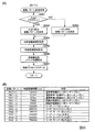
図3は、特別図柄プロセス処理の一例を示すフローチャートである。この特別図柄プロ
セス処理において、CPU103は、まず、始動入賞判定処理を実行する(ステップS1
01)。始動入賞判定処理では、第1始動口スイッチ22Aや第2始動口スイッチ22B
がオンであるか否かが判定される。このとき、第1始動口スイッチ22Aがオンであれば
、普通入賞球装置6Aに形成された第1始動入賞口を遊技球が通過したことに基づいて、
第1特図を用いた特図ゲームの保留記憶数である第1特図保留記憶数を更新するための第
1始動入賞処理が行われる。一方、第2始動口スイッチ22Bがオンであれば、普通可変
入賞球装置6Bに形成された第2始動入賞口を遊技球が通過したことに基づいて、第2特
図を用いた特図ゲームの保留記憶数である第2特図保留記憶数を更新するための第2始動
入賞処理が行われる。
FIG. 3 is a flowchart showing an example of the special symbol process processing. In this special symbol process process, the
01). In the start winning judgment process, the first start port switch 22A and the second
Is determined to be on. At this time, if the first start opening switch 22A is on, based on the fact that the game ball has passed through the first start winning opening formed in the normal
The first start winning process for updating the first special figure reserved memory number, which is the reserved memory number of the special figure game using the first special figure, is performed. On the other hand, if the second
一例として、第1始動入賞処理では、第1特図保留記憶数が所定の上限値となっている
か否かを判定する。このとき第1特図保留記憶数が上限値に達していれば、第1始動入賞
処理を終了する。一方、第1特図保留記憶数が上限値未満であれば、RAM102の所定
領域に設けられた第1保留記憶数カウンタの格納値である第1保留記憶数カウント値を1
加算する。こうして、第1保留記憶数カウント値は、第1始動入賞口を遊技球が通過して
第1特図を用いた特図ゲームに対応した第1始動条件が成立したときに、1増加するよう
に更新される。その後、始動入賞の発生に対応した所定の遊技用乱数を抽出して、RAM
102の所定領域に保留データとして記憶させる。
As an example, in the first start winning process, it is determined whether or not the number of reserved first special figures is a predetermined upper limit value. At this time, if the number of stored first special figures has reached the upper limit, the first start winning process is terminated. On the other hand, if the number of reserved storages in the first special figure is less than the upper limit, the first reserved storage count value, which is the stored value of the first reserved storage counter provided in the predetermined area of the
to add. In this way, the first reserved memory count value is incremented by 1 when the game ball passes through the first start winning opening and the first start condition corresponding to the special figure game using the first special figure is satisfied. Will be updated to. After that, a predetermined random number for the game corresponding to the occurrence of the start winning prize is extracted, and the RAM
It is stored as reserved data in a predetermined area of 102.
第2始動入賞処理では、第2特図保留記憶数が所定の上限値となっているか否かを判定
する。このとき第2特図保留記憶数が上限値に達していれば、第2始動入賞処理を終了す
る。一方、第2特図保留記憶数が上限値未満であれば、RAM102の所定領域に設けら
れた第2保留記憶数カウンタの格納値である第2保留記憶数カウント値を1加算する。こ
うして、第2保留記憶数カウント値は、第2始動入賞口を遊技球が通過して第2特図を用
いた特図ゲームに対応した第2始動条件が成立したときに、1増加するように更新される
。その後、始動入賞の発生に対応した所定の遊技用乱数を抽出して、RAM102の所定
領域に保留データとして記憶させる。
In the second start winning process, it is determined whether or not the second special figure reserved memory number is at a predetermined upper limit value. At this time, if the number of reserved second special figures reaches the upper limit, the second start winning process is terminated. On the other hand, if the number of reserved storages in the second special figure is less than the upper limit value, the second reserved storage count value, which is the stored value of the second reserved storage counter provided in the predetermined area of the
図3に示すステップS101にて始動入賞判定処理を実行した後、CPU103は、R
AM102の所定領域に設けられた特図プロセスフラグの値に応じて、ステップS110
〜S117の処理のいずれかを選択して実行する。
After executing the start winning determination process in step S101 shown in FIG. 3, the CPU 103 R
Step S110 according to the value of the special figure process flag provided in the predetermined area of AM102.
One of the processes of ~ S117 is selected and executed.
ステップS110の特別図柄通常処理は、特図プロセスフラグの値が“0”のときに実
行される。この特別図柄通常処理では、第1特図保留記憶部や第2特図保留記憶部に記憶
されている保留データの有無等に基づいて、第1特別図柄表示装置4Aや第2特別図柄表
示装置4Bによる特図ゲームを開始するか否かの判定が行われる。また、特別図柄通常処
理では、特図表示結果決定用の乱数値MR1を示す数値データに基づき、特別図柄や飾り
図柄の可変表示結果を「大当り」とするか否かを、その可変表示結果が導出表示される以
前に決定する。更に、特別図柄通常処理では、特図ゲームにおける特別図柄の可変表示結
果に対応して、第1特別図柄表示装置4Aや第2特別図柄表示装置4Bによる特図ゲーム
における確定特別図柄が設定される。特別図柄通常処理では、特別図柄や飾り図柄の可変
表示結果を事前決定したときに、特図プロセスフラグの値が“1”に更新される。
The special symbol normal processing in step S110 is executed when the value of the special symbol process flag is “0”. In this special symbol normal processing, the first special
ステップS111の変動パターン設定処理は、特図プロセスフラグの値が“1”のとき
に実行される。この変動パターン設定処理には、可変表示結果を「大当り」とするか否か
の事前決定結果等に基づいて、変動パターンを複数種類のいずれかに決定する処理等が含
まれている。特別図柄や飾り図柄の可変表示時間は、変動パターンに対応して予め設定さ
れている。したがって、変動パターン設定処理にて変動パターンを決定することにより、
特別図柄の可変表示を開始してから可変表示結果となる確定特別図柄を導出するまでの可
変表示時間が決定される。また、変動パターン設定処理は、可変表示結果が「ハズレ」と
なる場合に、飾り図柄の可変表示態様を「リーチ」とするか否かを決定する処理を含んで
もよい。あるいは、変動パターン設定処理にて可変表示結果が「ハズレ」となる場合の変
動パターンを所定割合で決定することにより、飾り図柄の可変表示態様を「リーチ」とす
るか否かが決定されてもよい。更に、変動パターン設定処理は、第1特別図柄表示装置4
Aや第2特別図柄表示装置4Bにおいて特別図柄の変動を開始させるための設定を行う処
理を含んでもよい。変動パターン設定処理が実行されたときには、特図プロセスフラグの
値が“2”に更新される。
The variation pattern setting process in step S111 is executed when the value of the special figure process flag is “1”. This variation pattern setting process includes a process of determining the variation pattern to one of a plurality of types based on a pre-determination result of whether or not the variable display result is a “big hit”. The variable display time of the special symbol or the decorative symbol is preset according to the variable pattern. Therefore, by determining the fluctuation pattern in the fluctuation pattern setting process,
The variable display time from the start of the variable display of the special symbol to the derivation of the finalized special symbol that is the variable display result is determined. Further, the variable pattern setting process may include a process of determining whether or not the variable display mode of the decorative symbol is set to "reach" when the variable display result is "missing". Alternatively, even if it is determined whether or not the variable display mode of the decorative pattern is set to "reach" by determining the variation pattern when the variable display result is "missing" in the variation pattern setting process at a predetermined ratio. Good. Further, the fluctuation pattern setting process is performed by the first special
The process of setting for starting the variation of the special symbol in A or the second special
ステップS112の特別図柄変動処理は、特図プロセスフラグの値が“2”のときに実
行される。この特別図柄変動処理には、第1特別図柄表示装置4Aや第2特別図柄表示装
置4Bにおいて特別図柄を変動させるための設定を行う処理や、その特別図柄が変動を開
始してからの経過時間を計測する処理等が含まれている。そして、特別図柄の変動を開始
してからの経過時間が特図変動時間に達したときには、特図プロセスフラグの値が“3”
に更新される。
The special symbol variation process in step S112 is executed when the value of the special symbol process flag is “2”. In this special symbol change process, the process of making settings for changing the special symbol in the first special
Will be updated to.
ステップS113の特別図柄停止処理は、特図プロセスフラグの値が“3”のときに実
行される。この特別図柄停止処理には、第1特別図柄表示装置4Aや第2特別図柄表示装
置4Bにて特別図柄の変動を停止させ、特別図柄の可変表示結果となる確定特別図柄を停
止表示させるための設定を行う処理が含まれている。そして、RAM102の所定領域に
設けられた大当りフラグがオンとなっているか否かの判定等が行われる。大当りフラグが
オンである場合には、特図表示結果が「大当り」であることに基づく大当り遊技状態の開
始を指定する当り開始指定コマンドの送信設定を行うと共に、特図プロセスフラグの値を
“4”に更新する。大当りフラグがオフである場合には、特図プロセスフラグの値を“0
”に更新する。
The special symbol stop process in step S113 is executed when the value of the special symbol process flag is “3”. In this special symbol stop process, the first special
Update to.
ステップS114の大当り開放前処理は、特図プロセスフラグの値が“4”のときに実
行される。この大当り開放前処理には、可変表示結果が「大当り」となったこと等に基づ
き、大当り遊技状態においてラウンド遊技の実行を開始して大入賞口を開放状態とするた
めの設定を行う処理等が含まれている。この処理では、例えば大入賞口を開放状態とする
期間の上限を「29秒」に設定することにより、通常開放ラウンドが実行されるようにす
ればよい。なお、大当り種別に「突確」を設けた場合には、大入賞口を開放状態とする期
間の上限を「0.1秒」に設定することにより、短期開放ラウンドが実行されるようにす
ればよい。大当り開放前処理が実行されたときには、特図プロセスフラグの値が“5”に
更新される。
The jackpot release preprocessing in step S114 is executed when the value of the special figure process flag is “4”. In this big hit pre-opening process, based on the variable display result being "big hit", etc., the process of starting the execution of the round game in the big hit game state and setting to open the big winning opening, etc. It is included. In this process, for example, the upper limit of the period during which the large winning opening is opened may be set to "29 seconds" so that the normal opening round is executed. If "probability" is set for the jackpot type, the short-term open round can be executed by setting the upper limit of the period for keeping the jackpot open to "0.1 seconds". Good. When the jackpot release preprocessing is executed, the value of the special figure process flag is updated to "5".
ステップS115の大当り開放中処理は、特図プロセスフラグの値が“5”のときに実
行される。この大当り開放中処理には、大入賞口を開放状態としてからの経過時間を計測
する処理や、その計測した経過時間やカウントスイッチ23によって検出された遊技球の
個数等に基づいて、大入賞口を開放状態から閉鎖状態に戻すタイミングとなったか否かを
判定する処理等が含まれている。そして、大入賞口を閉鎖状態に戻したときには、特図プ
ロセスフラグの値が“6”に更新される。
The process of opening the jackpot in step S115 is executed when the value of the special figure process flag is “5”. In this big hit opening process, the process of measuring the elapsed time since the big winning opening is opened, the measured elapsed time, the number of game balls detected by the count switch 23, and the like, the big winning opening It includes a process of determining whether or not it is time to return the switch from the open state to the closed state. Then, when the large winning opening is returned to the closed state, the value of the special figure process flag is updated to "6".
ステップS116の大当り開放後処理は、特図プロセスフラグの値が“6”のときに実
行される。この大当り開放後処理には、大入賞口を開放状態とするラウンド遊技の実行回
数が所定の上限回数に達したか否かを判定する処理や、上限回数に達していない場合に次
回のラウンド遊技が開始されるまで待機する処理等が含まれている。そして、次回のラウ
ンド遊技が開始されるときには、特図プロセスフラグの値が“4”に更新される一方、ラ
ウンド遊技の実行回数が上限回数に達したときには、特図プロセスフラグの値が“7”に
更新される。
The post-processing after opening the jackpot in step S116 is executed when the value of the special figure process flag is “6”. In this post-opening process of the jackpot, a process of determining whether or not the number of executions of the round game in which the big winning opening is opened has reached a predetermined upper limit, and a process of determining whether or not the upper limit has been reached, and a next round game when the upper limit has not been reached. It includes processing that waits until is started. Then, when the next round game is started, the value of the special figure process flag is updated to "4", while when the number of executions of the round game reaches the upper limit, the value of the special figure process flag is "7". Is updated to.
ステップS117の大当り終了処理は、特図プロセスフラグの値が“7”のときに実行
される。この大当り終了処理には、画像表示装置5やスピーカ8L、8R、遊技効果ラン
プ9等といった演出装置により、大当り遊技状態の終了を報知する演出動作としてのエン
ディング演出が実行される期間に対応した待ち時間が経過するまで待機する処理や、確変
制御条件の成否に対応して確変状態や時短状態に制御するための各種の設定を行う処理等
が含まれている。例えば、大当り種別が「確変」であるか「非確変」であるかに応じて、
確変状態や時短状態に制御するための設定が行われる。その後、特図プロセスフラグの値
が“0”に更新される。
The jackpot end processing of step S117 is executed when the value of the special figure process flag is “7”. In this jackpot end processing, a waiting period corresponding to a period in which the ending effect as an effect operation for notifying the end of the jackpot game state is executed by an effect device such as an
Settings are made to control the probabilistic state and the time saving state. After that, the value of the special figure process flag is updated to "0".
図4は、特別図柄通常処理として、図3のステップS110にて実行される処理の一例
を示すフローチャートである。図4に示す特別図柄通常処理において、CPU103は、
まず、第2特図保留記憶数が「0」であるか否かを判定する(ステップS231)。第2
特図保留記憶数は、第2特別図柄表示装置4Bによる第2特図を用いた特図ゲームの保留
記憶数である。CPU103は、第2保留記憶数カウント値を読み出し、その読出値が「
0」であるか否かを判定すればよい。
FIG. 4 is a flowchart showing an example of the process executed in step S110 of FIG. 3 as the special symbol normal process. In the special symbol normal processing shown in FIG. 4, the
First, it is determined whether or not the second special figure reserved storage number is "0" (step S231). 2nd
The special figure hold storage number is the hold storage number of the special figure game using the second special figure by the second special
It may be determined whether or not it is "0".
ステップS231にて第2特図保留記憶数が「0」以外であるときには(ステップS2
31;NO)、例えば第2特図保留記憶部の先頭領域といった、RAM102の所定領域
に記憶されている保留データとして、所定の乱数値を示す数値データを読み出す(ステッ
プS232)。これにより、図3に示すステップS101の始動入賞判定処理で第2始動
入賞口における始動入賞の発生に対応して抽出された遊技用乱数が読み出される。このと
き読み出された数値データは、例えば変動用乱数バッファ等に格納されて、一時記憶され
ればよい。
When the second special figure reserved memory number is other than "0" in step S231 (step S2).
31; NO), for example, numerical data indicating a predetermined random value is read out as the reserved data stored in the predetermined area of the
ステップS232の処理に続いて、例えば第2保留記憶数カウント値を1減算して更新
すること等により、第2特図保留記憶数を1減算させるように更新すると共に、第2特図
保留記憶部における記憶内容をシフトさせる(ステップS233)。例えば、第2特図保
留記憶部にて保留番号「1」より下位の記憶領域に記憶された保留データを、1エントリ
ずつ上位にシフトする。また、ステップS233の処理では、合計保留記憶数を1減算す
るように更新してもよい。そして、RAM102の所定領域に設けられた変動特図指定バ
ッファの格納値である変動特図指定バッファ値を、「2」に更新する(ステップS234
)。
Following the process of step S232, for example, by subtracting 1 from the second reserved memory count value and updating, the second special figure reserved memory is updated so as to be subtracted by 1, and the second special figure reserved memory is updated. The stored contents in the unit are shifted (step S233). For example, the hold data stored in the storage area lower than the hold number "1" in the second special figure hold storage unit is shifted upward one entry at a time. Further, in the process of step S233, the total number of reserved storages may be updated to be subtracted by 1. Then, the variable special figure designation buffer value, which is the stored value of the variable special figure designation buffer provided in the predetermined area of the
).
ステップS231にて第2特図保留記憶数が「0」であるときには(ステップS231
;YES)、第1特図保留記憶数が「0」であるか否かを判定する(ステップS235)
。第1特図保留記憶数は、第1特別図柄表示装置4Aによる第1特図を用いた特図ゲーム
の保留記憶数である。CPU103は、第1保留記憶数カウント値を読み出し、その読出
値が「0」であるか否かを判定すればよい。このように、ステップS235の処理は、ス
テップS231にて第2特図保留記憶数が「0」であると判定されたときに実行されて、
第1特図保留記憶数が「0」であるか否かを判定する。これにより、第2特図を用いた特
図ゲームは、第1特図を用いた特図ゲームよりも優先して実行が開始されることになる。
When the second special figure reserved storage number is "0" in step S231 (step S231).
; YES), it is determined whether or not the number of reserved first special figure is "0" (step S235).
.. The first special figure hold storage number is the number of hold storages of the special figure game using the first special figure by the first special
First special figure It is determined whether or not the number of reserved memories is "0". As a result, the special figure game using the second special figure is started to be executed with priority over the special figure game using the first special figure.
なお、第2特図を用いた特図ゲームが第1特図を用いた特図ゲームよりも優先して実行
されるものに限定されない。即ち、第1始動入賞口であるか第2始動入賞口であるかにか
かわらず、遊技球が始動入賞口を通過した順番で、特図ゲームが実行されるようにしても
よい。この場合には、第1始動入賞口と第2始動入賞口のいずれを遊技球が通過したかを
示す始動口データを、保留データと共に、あるいは保留データとは別個に、保留番号と対
応付けてRAM102の所定領域に記憶させておき、それぞれの保留データに対応する特
図ゲームについて、始動条件が成立した順番を特定可能にすればよい。
The special figure game using the second special figure is not limited to the one executed with priority over the special figure game using the first special figure. That is, regardless of whether it is the first start winning opening or the second starting winning opening, the special figure game may be executed in the order in which the game balls pass through the starting winning opening. In this case, the start opening data indicating which of the first start winning opening and the second starting winning opening the game ball has passed is associated with the hold number together with the hold data or separately from the hold data. It may be stored in a predetermined area of the
ステップS235にて第1特図保留記憶数が「0」以外であるときには(ステップS2
35;NO)、例えば第1特図保留記憶部の先頭領域といった、RAM102の所定領域
に記憶されている保留データとして、所定の乱数値を示す数値データを読み出す(ステッ
プS236)。これにより、図3に示すステップS101の始動入賞判定処理で第1始動
入賞口における始動入賞の発生に対応して抽出された遊技用乱数が読み出される。このと
き読み出された数値データは、例えば変動用乱数バッファ等に格納されて、一時記憶され
ればよい。
When the number of stored first special figures is other than "0" in step S235 (step S2).
35; NO), for example, numerical data indicating a predetermined random value is read out as the reserved data stored in the predetermined area of the
ステップS236の処理に続いて、例えば第1保留記憶数カウント値を1減算して更新
すること等により、第1特図保留記憶数を1減算させるように更新すると共に、第1特図
保留記憶部における記憶内容をシフトさせる(ステップS237)。例えば、第1特図保
留記憶部にて保留番号「1」より下位の記憶領域に記憶された保留データを、1エントリ
ずつ上位にシフトする。また、ステップS237の処理では、合計保留記憶数を1減算す
るように更新してもよい。そして、変動特図指定バッファ値を「1」に更新する(ステッ
プS238)。
Following the process of step S236, for example, by subtracting 1 from the first reserved memory count value and updating, the first special figure reserved memory is updated so as to be subtracted by 1, and the first special figure reserved memory is updated. The stored contents in the unit are shifted (step S237). For example, the hold data stored in the storage area lower than the hold number "1" in the first special figure hold storage unit is shifted upward one entry at a time. Further, in the process of step S237, the total number of reserved storages may be updated to be subtracted by 1. Then, the fluctuation special figure designation buffer value is updated to "1" (step S238).
ステップS234、S238の処理のいずれかを実行した後には、特別図柄の可変表示
結果である特図表示結果を、「大当り」と「ハズレ」とのいずれかに決定する(ステップ
S239)。一例として、ステップS239の処理では、予めROM101の所定領域に
記憶する等して用意された特図表示結果決定テーブルを選択し、特図表示結果を決定する
ための使用テーブルに設定する。特図表示結果決定テーブルでは、特図表示結果決定用の
乱数値MR1と比較される数値が、特図表示結果を「大当り」と「ハズレ」のいずれとす
るかの決定結果に、割り当てられていればよい。CPU103は、変動用乱数バッファか
ら読み出した特図表示結果決定用の乱数値MR1を示す数値データに基づいて、特図表示
結果決定テーブルを参照することにより、特図表示結果を決定すればよい。
After executing any of the processes of steps S234 and S238, the special symbol display result, which is the variable display result of the special symbol, is determined to be either "big hit" or "loss" (step S239). As an example, in the process of step S239, a special figure display result determination table prepared by storing in a predetermined area of the
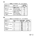
図5(A)は、ステップS239の処理による特図表示結果の決定例を示している。こ
のように、特図表示結果を「大当り」と「ハズレ」のいずれとするかが、特図表示結果決
定用の乱数値MR1を示す数値データや特図表示結果決定テーブルを用いて、所定割合で
決定されればよい。図5(A)に示す決定例では、確変状態における確変制御の有無に応
じて、特図表示結果を「大当り」とするか否かの決定割合を異ならせている。CPU10
3は、RAM102の所定領域に設けられた確変フラグがオンである場合に、確変制御が
行われていると判定すればよい。
FIG. 5A shows an example of determining the special figure display result by the process of step S239. In this way, whether the special figure display result is "big hit" or "miss" is determined by using the numerical data indicating the random number value MR1 for determining the special figure display result or the special figure display result determination table. It may be decided by. In the determination example shown in FIG. 5A, the determination ratio of whether or not the special figure display result is a “big hit” is different depending on the presence or absence of the probability variation control in the probability variation state. CPU10
図5(A)に示すように、確変状態にて確変制御が行われているときには、通常状態や
時短状態にて確変制御が行われていないときよりも高い割合で、特図表示結果が「大当り
」に決定される。したがって、例えば図3に示すステップS117の大当り終了処理によ
り、大当り種別が「確変」であった場合に対応して確変フラグがオン状態にセットされた
こと等に基づいて、確変制御が行われる確変状態であるときには、通常状態や時短状態に
て確変制御が行われていないときよりも、特図表示結果が「大当り」になり易く、大当り
遊技状態になり易い。
As shown in FIG. 5 (A), when the probability change control is performed in the probability change state, the special figure display result is "" at a higher rate than when the probability change control is not performed in the normal state or the time saving state. It is decided as a big hit. Therefore, for example, the probability change control is performed based on the fact that the probability change flag is set to the ON state corresponding to the case where the jackpot type is "probability change" by the jackpot end process of step S117 shown in FIG. In the state, the special figure display result is more likely to be a "big hit" and the big hit game state is more likely to occur than when the probability change control is not performed in the normal state or the time saving state.
この実施の形態では、第1特別図柄表示装置4Aによる第1特図を用いた特図ゲームで
あるか、第2特別図柄表示装置4Bによる第2特図を用いた特図ゲームであるかにかかわ
らず、確変制御の有無に応じた所定割合で特図表示結果が決定される。これに対して、第
1特別図柄表示装置4Aによる特図ゲームの場合と、第2特別図柄表示装置4Bによる特
図ゲームの場合のそれぞれに対応して、特図表示結果に対する決定値の割り当てが異なる
決定テーブルを用意してもよい。この場合には、第1特別図柄表示装置4Aによる特図ゲ
ームの場合と、第2特別図柄表示装置4Bによる特図ゲームの場合とでは、所定の特図表
示結果に対する決定値の割り当てを異ならせてもよい。
In this embodiment, whether it is a special figure game using the first special figure by the first special
その後、CPU103は、ステップS239の処理により決定された特図表示結果が「
大当り」であるか否かを判定する(ステップS240)。特図表示結果が「大当り」に決
定された場合には(ステップS240;YES)、RAM102の所定領域に設けられた
大当りフラグをオン状態にセットする(ステップS241)。また、大当り種別を複数種
類のいずれかに決定する(ステップS242)。一例として、ステップS242の処理で
は、予めROM101の所定領域に記憶する等して用意された大当り種別決定テーブルを
選択し、大当り種別を決定するための使用テーブルに設定する。大当り種別決定テーブル
では、大当り種別決定用の乱数値MR2と比較される数値が、大当り種別を複数種類のい
ずれとするかの決定結果に、割り当てられていればよい。CPU103は、変動用乱数バ
ッファから読み出した大当り種別決定用の乱数値MR2を示す数値データに基づいて、大
当り種別決定テーブルを参照することにより、大当り種別を決定すればよい。
After that, the
It is determined whether or not it is a "big hit" (step S240). When the special figure display result is determined to be "big hit" (step S240; YES), the big hit flag provided in the predetermined area of the
図5(B)は、ステップS242の処理による大当り種別の決定例を示している。この
決定例では、変動特図が第1特図であるか第2特図であるかにかかわらず、所定割合で大
当り種別が「非確変」と「確変」のいずれかに決定される。なお、変動特図が第1特図で
あるか第2特図であるかに応じて、決定可能な大当り種別を異ならせてもよいし、大当り
種別の決定割合を異ならせてもよい。一例として、変動特図が第1特図である場合には所
定割合で大当り種別が「突確」に決定可能とする一方、変動特図が第2特図である場合に
は大当り種別が「突確」には決定されないように設定してもよい。
FIG. 5B shows an example of determining the jackpot type by the process of step S242. In this determination example, the jackpot type is determined to be either "non-probable change" or "probable change" at a predetermined ratio regardless of whether the variable special figure is the first special figure or the second special figure. The jackpot type that can be determined may be different, or the determination ratio of the jackpot type may be different, depending on whether the variable special figure is the first special figure or the second special figure. As an example, when the variable special map is the first special figure, the jackpot type can be determined to be "probable" at a predetermined ratio, while when the variable special map is the second special map, the jackpot type is "probable". May be set so that it is not determined.
ステップS242の処理を実行した後には、大当り種別を記憶させる(ステップS24
3)。CPU103は、RAM102の所定領域に設けられた大当り種別バッファに、大
当り種別の決定結果を示すデータを格納することにより、大当り種別を記憶させればよい
。
After executing the process of step S242, the jackpot type is stored (step S24).
3). The
ステップS240にて特図表示結果が「大当り」ではない場合や(ステップS240;
NO)、ステップS243の処理を実行した後には、特図ゲームにおける特別図柄の可変
表示結果となる確定特別図柄を決定する(ステップS244)。一例として、ステップS
240にて特図表示結果が「大当り」ではないと判定された場合には、ハズレ図柄として
予め定められた「−」の記号を示す特別図柄を、確定特別図柄に決定する。一方、ステッ
プS240にて特図表示結果が「大当り」であると判定された場合には、ステップS24
2における大当り種別の決定結果に応じて、複数種類の大当り図柄として予め定められた
特別図柄のいずれかを確定特別図柄に決定すればよい。より具体的には、大当り種別が「
非確変」の場合には「3」の数字を示す特別図柄を、確定特別図柄に決定すればよい。大
当り種別が「確変」の場合には「7」の数字を示す特別図柄を、確定特別図柄に決定すれ
ばよい。
When the special figure display result is not "big hit" in step S240 (step S240;
NO), after executing the process of step S243, a definite special symbol that is a variable display result of the special symbol in the special symbol game is determined (step S244). As an example, step S
If it is determined in 240 that the special symbol display result is not a "big hit", a special symbol indicating a predetermined "-" symbol as a lost symbol is determined as a finalized special symbol. On the other hand, if it is determined in step S240 that the special figure display result is a "big hit", step S24
Depending on the determination result of the jackpot type in 2, any of the special symbols predetermined as the plurality of types of jackpot symbols may be determined as the finalized special symbol. More specifically, the jackpot type is "
In the case of "non-probability", the special symbol indicating the number "3" may be determined as the definite special symbol. When the jackpot type is "probability change", the special symbol indicating the number "7" may be determined as the finalized special symbol.
ステップS244の処理を実行した後には、特図プロセスフラグの値を“1”に更新し
てから(ステップS245)、特別図柄通常処理を終了する。ステップS245の処理に
て特図プロセスフラグの値が“1”に更新されることにより、次回のタイマ割込みが発生
したときには、図3に示すステップS111の変動パターン設定処理が実行される。
After executing the process of step S244, the value of the special figure process flag is updated to "1" (step S245), and then the special symbol normal process is terminated. By updating the value of the special figure process flag to "1" in the process of step S245, when the next timer interrupt occurs, the variation pattern setting process of step S111 shown in FIG. 3 is executed.
ステップS235にて第1特図を用いた特図ゲームの保留記憶数が「0」である場合に
は(ステップS235;YES)、所定のデモ表示設定を行ってから(ステップS246
)、特別図柄通常処理を終了する。このデモ表示設定では、例えば画像表示装置5におい
て所定の演出画像を表示すること等によるデモンストレーション表示を指定する演出制御
コマンドが、主基板11から演出制御基板12に対して送信済みであるか否かを判定する
。このとき、送信済みであれば、そのままデモ表示設定を終了する。これに対して、未送
信であれば、客待ちデモ指定コマンドを送信するための設定を行ってから、デモ表示設定
を終了する。
If the number of reserved memory of the special figure game using the first special figure is "0" in step S235 (step S235; YES), after performing a predetermined demo display setting (step S246).
), Ends the special symbol normal processing. In this demo display setting, whether or not an effect control command for designating a demonstration display by displaying a predetermined effect image on the
図6(A)は、変動パターン設定処理として、図3のステップS111にて実行される
処理の一例を示すフローチャートである。図6(A)に示す変動パターン設定処理におい
て、CPU103は、まず、大当りフラグがオンであるか否かを判定する(ステップS2
61)。そして、大当りフラグがオンである場合には(ステップS261;YES)、特
図表示結果が「大当り」となる大当り時に対応した変動パターンを決定する(ステップS
262)。一方、大当りフラグがオフである場合には(ステップS261;NO)、特図
表示結果が「ハズレ」となるハズレ時に対応した変動パターンを決定する(ステップS2
63)。
FIG. 6A is a flowchart showing an example of the process executed in step S111 of FIG. 3 as the variation pattern setting process. In the fluctuation pattern setting process shown in FIG. 6A, the
61). Then, when the big hit flag is on (step S261; YES), the fluctuation pattern corresponding to the big hit when the special figure display result is "big hit" is determined (step S).
262). On the other hand, when the jackpot flag is off (step S261; NO), the fluctuation pattern corresponding to the loss when the special figure display result becomes "loss" is determined (step S2).
63).
図6(B)は、この実施の形態における変動パターンを示している。この実施の形態で
は、可変表示結果が「ハズレ」となる場合のうち、飾り図柄の可変表示態様がリーチ態様
にはならない「非リーチ」である場合とリーチ態様になる「リーチ」である場合のそれぞ
れに対応して、また、可変表示結果が「大当り」となる場合等に対応して、複数の変動パ
ターンが予め用意されている。
FIG. 6B shows a variation pattern in this embodiment. In this embodiment, among the cases where the variable display result is "missing", the variable display mode of the decorative symbol is "non-reach" which is not the reach mode and "reach" which is the reach mode. A plurality of fluctuation patterns are prepared in advance corresponding to each of them and when the variable display result is a "big hit".
図6(A)に示すステップS262の処理では、例えば予めROM101の所定領域に
記憶する等して用意された大当り変動パターン決定テーブルを用いて、大当り時の変動パ
ターンが決定される。大当り変動パターン決定テーブルでは、大当り種別が「非確変」で
あるか「確変」であるかに応じて、変動パターン決定用の乱数値MR3と比較される数値
が、変動パターンの決定結果に、割り当てられていればよい。CPU103は、変動用乱
数バッファから読み出した変動パターン決定用の乱数値MR3を示す数値データに基づい
て、大当り変動パターン決定テーブルを参照することにより、可変表示結果が「大当り」
となる場合に対応した変動パターンを決定すればよい。
In the process of step S262 shown in FIG. 6A, the fluctuation pattern at the time of jackpot is determined using, for example, a jackpot fluctuation pattern determination table prepared by storing in a predetermined area of
The fluctuation pattern corresponding to the case may be determined.
図6(A)に示すステップS263の処理では、遊技状態が通常状態である通常時の場
合と、遊技状態が確変状態や時短状態で時短制御が行われる時短中の場合とに対応して、
予め用意した複数のハズレ変動パターン決定テーブルのいずれかを用いて、ハズレ時の変
動パターンが決定される。複数のハズレ変動パターン決定テーブルでは、通常時であるか
時短中であるかや、合計保留記憶数に応じて、変動パターン決定用の乱数値MR3と比較
される数値が、変動パターンの決定結果に、割り当てられていればよい。CPU103は
、変動用乱数バッファから読み出した変動パターン決定用の乱数値MR3を示す数値デー
タに基づいて、通常時と時短中とに応じたハズレ変動パターン決定テーブルのいずれかを
参照することにより、可変表示結果が「ハズレ」となる場合に対応した変動パターンを決
定すればよい。
In the process of step S263 shown in FIG. 6A, there is a case where the game state is the normal state and a case where the game state is the probability change state or the time reduction state and the time reduction control is performed.
The fluctuation pattern at the time of loss is determined by using one of a plurality of loss fluctuation pattern determination tables prepared in advance. In a plurality of lost fluctuation pattern determination tables, a numerical value to be compared with the random number value MR3 for determining the fluctuation pattern is used as the determination result of the fluctuation pattern according to whether the time is normal or short, and the total number of stored storages. , Should be assigned. The
ハズレ変動パターン決定テーブルでは、合計保留記憶数が所定数以上であるときに、所
定数未満であるときよりも高い割合で、飾り図柄の可変表示態様が「非リーチ」に決定さ
れるように、決定値が割り当てられていればよい。このように、特図保留記憶数が所定数
以上であるときには、所定数未満であるときよりも飾り図柄の可変表示態様がリーチ態様
に決定され難いように設定されていればよい。これにより、特図保留記憶数が比較的に多
いときには、比較的に少ないときよりも平均的な可変表示時間を短縮して、無効な始動入
賞の発生を抑制することや、遊技者による遊技球の発射停止を低減することができる。
In the loss fluctuation pattern determination table, when the total number of reserved storages is equal to or greater than a predetermined number, the variable display mode of the decorative symbol is determined to be "non-reach" at a higher rate than when the total number of reserved memories is less than a predetermined number. It suffices if a decision value is assigned. As described above, when the number of special figure reserved storages is equal to or more than a predetermined number, the variable display mode of the decorative symbol may be set so as to be more difficult to determine as the reach mode than when the number is less than the predetermined number. As a result, when the number of special figure reservations is relatively large, the average variable display time is shortened as compared with when the number of special figure reservations is relatively small, and the occurrence of invalid start winnings is suppressed, and the game ball by the player. It is possible to reduce the firing stop of.
図7(A)は、大当り時における変動パターンの決定例を示している。この決定例では
、変動パターンPA3−1といった、ノーマルのリーチ演出が実行される変動パターンの
決定割合が、変動パターンPA3−2、PA3−3といったスーパーリーチ演出が実行さ
れる変動パターンの決定割合よりも低くなるように設定されている。
FIG. 7A shows an example of determining the fluctuation pattern at the time of a big hit. In this determination example, the determination ratio of the variation pattern in which the normal reach effect is executed such as the variation pattern PA3-1 is higher than the determination ratio of the variation pattern in which the super reach effect such as the variation patterns PA3-2 and PA3-3 is executed. Is also set to be low.
図7(B)は、ハズレ時における変動パターンの決定例を示している。この決定例では
、変動パターンPA2−1といった、ノーマルのリーチ演出が実行される変動パターンの
決定割合が、変動パターンPA2−2、PA2−3といったスーパーリーチ演出が実行さ
れる変動パターンの決定割合よりも高くなるように設定されている。
FIG. 7B shows an example of determining the fluctuation pattern at the time of loss. In this determination example, the determination ratio of the variation pattern in which the normal reach effect is executed, such as the variation pattern PA2-1, is higher than the determination rate of the variation pattern in which the super reach effect such as the variation patterns PA2-2 and PA2-3 is executed. Is also set to be high.
また、大当り時には、スーパーリーチ演出が実行される変動パターンの決定割合が、ハ
ズレ時よりも高くなるように設定されている。これにより、スーパーリーチ演出が実行さ
れてから可変表示結果が導出されるときには、その可変表示結果が「大当り」となる可能
性が高められる。
In addition, at the time of a big hit, the determination rate of the fluctuation pattern in which the super reach effect is executed is set to be higher than at the time of loss. As a result, when the variable display result is derived after the super reach effect is executed, the possibility that the variable display result becomes a "big hit" is increased.
図7(A)に示す決定例において、変動パターンPA3−3といった、スーパーリーチ
B演出が実行される変動パターンの決定割合が、変動パターンPA3−2といった、スー
パーリーチA演出が実行される変動パターンの決定割合よりも高くなるように設定されて
いる。一方、図7(B)に示す決定例において、変動パターンPA2−3といった、スー
パーリーチB演出が実行される変動パターンの決定割合が、変動パターンPA2−2とい
った、スーパーリーチA演出が実行される変動パターンの決定割合よりも低くなるように
設定されている。また、大当り時には、スーパーリーチB演出が実行される変動パターン
の決定割合が、ハズレ時よりも十分に高くなるように設定されている。したがって、可変
表示結果が「大当り」となって遊技状態が大当り遊技状態となる場合には、大当り遊技状
態とならない場合よりも高い割合で、スーパーリーチB演出が実行されてから可変表示結
果が導出される。
In the determination example shown in FIG. 7A, the determination ratio of the variation pattern in which the super reach B effect such as the variation pattern PA3-3 is executed is the variation pattern in which the super reach A effect such as the variation pattern PA3-2 is executed. It is set to be higher than the decision rate of. On the other hand, in the determination example shown in FIG. 7B, the determination ratio of the variation pattern in which the super reach B effect such as the variation pattern PA2-3 is executed is executed, and the super reach A effect such as the variation pattern PA2-2 is executed. It is set to be lower than the determination rate of the fluctuation pattern. Further, at the time of a big hit, the determination rate of the fluctuation pattern in which the super reach B effect is executed is set to be sufficiently higher than at the time of loss. Therefore, when the variable display result becomes "big hit" and the gaming state becomes the big hit gaming state, the variable display result is derived after the super reach B effect is executed at a higher rate than when the variable display result does not become the big hit gaming state. Will be done.
図6(B)に示すように、変動パターンPA2−1〜PA2−3と、変動パターンPA
3−1〜PA3−3とでは、特図変動時間や内容が共通している一方で、可変表示結果が
「ハズレ」となるか「大当り」となるかが異なっている。図7(A)及び(B)に示す決
定割合の設定により、スーパーリーチ演出が実行されたときには、ノーマルのリーチ演出
が実行されたときよりも大当り期待度が高められる。また、スーパーリーチB演出が実行
されたときには、スーパーリーチA演出が実行されたときよりも大当り期待度が高められ
る。
As shown in FIG. 6B, the fluctuation patterns PA2-1 to PA2-3 and the fluctuation pattern PA
While 3-1 to PA3-3 have the same special figure fluctuation time and contents, they differ in whether the variable display result is "miss" or "big hit". By setting the determination ratios shown in FIGS. 7A and 7B, when the super reach effect is executed, the jackpot expectation is higher than when the normal reach effect is executed. Further, when the Super Reach B effect is executed, the expectation of a big hit is higher than when the Super Reach A effect is executed.
ステップS262、S263の処理のいずれかを実行した後には、特別図柄の可変表示
時間である特図変動時間を設定する(ステップS264)。特別図柄の可変表示時間とな
る特図変動時間は、特図ゲームにおいて特別図柄の変動を開始してから可変表示結果とな
る確定特別図柄が導出表示されるまでの所要時間である。特図変動時間は、図6(B)に
示すように、予め用意された複数の変動パターンに対応して、予め定められている。CP
U103は、特図変動時間を設定することにより、特別図柄や飾り図柄の可変表示結果が
導出されるタイミングを設定できる。
After executing any of the processes of steps S262 and S263, the special symbol fluctuation time, which is the variable display time of the special symbol, is set (step S264). The special symbol fluctuation time, which is the variable display time of the special symbol, is the time required from the start of the fluctuation of the special symbol in the special symbol game until the definite special symbol that is the variable display result is derived and displayed. As shown in FIG. 6B, the special figure fluctuation time is predetermined in response to a plurality of fluctuation patterns prepared in advance. CP
The U103 can set the timing at which the variable display result of the special symbol or the decorative symbol is derived by setting the special symbol fluctuation time.
ステップS264の処理に続いて、第1特別図柄表示装置4Aにおける第1特図を用い
た特図ゲームと、第2特別図柄表示装置4Bにおける第2特図を用いた特図ゲームのうち
、開始条件が成立したいずれかの特図ゲームを開始させるように、特別図柄の変動を開始
させるための設定を行う(ステップS265)。一例として、変動特図指定バッファ値が
「1」であれば、第1特別図柄表示装置4Aにおける第1特図の表示を更新させる駆動信
号を送信するための設定を行う。一方、変動特図指定バッファ値が「2」であれば、第2
特別図柄表示装置4Bにおける第2特図の表示を更新させる駆動信号を送信するための設
定を行う。
Following the process of step S264, the special figure game using the first special figure in the first special
The setting for transmitting the drive signal for updating the display of the second special figure in the special
ステップS265の処理を実行した後には、特別図柄の変動開始時におけるコマンドの
送信設定が行われる(ステップS266)。例えば、変動特図指定バッファ値が「1」で
ある場合に、CPU103は、主基板11から演出制御基板12に対して第1変動開始コ
マンド、変動パターン指定コマンド、可変表示結果通知コマンド、第1保留記憶数通知コ
マンドを順次に送信するために、予め用意された第1変動開始用コマンドテーブルのRO
M101における記憶アドレスを指定する。他方、変動特図指定バッファ値が「2」であ
る場合に、CPU103は、主基板11から演出制御基板12に対して第2変動開始コマ
ンド、変動パターン指定コマンド、可変表示結果通知コマンド、第2保留記憶数通知コマ
ンドを順次に送信するために、予め用意された第2変動開始用コマンドテーブルのROM
101における記憶アドレスを指定する。
After executing the process of step S265, the command transmission setting at the start of fluctuation of the special symbol is performed (step S266). For example, when the fluctuation special figure designation buffer value is "1", the
The storage address in M101 is specified. On the other hand, when the fluctuation special figure designation buffer value is "2", the
The storage address in 101 is specified.
第1変動開始コマンドや第2変動開始コマンドは、第1特別図柄表示装置4Aにおける
第1特図を用いた特図ゲームにおける変動開始や、第2特別図柄表示装置4Bにおける第
2特図を用いた特図ゲームにおける変動開始を、指定する演出制御コマンドである。変動
パターン指定コマンドは、特図ゲームにおける特別図柄の可変表示に対応して画像表示装
置5における「左」、「中」、「右」の各飾り図柄表示エリア5L、5C、5Rで可変表
示される飾り図柄等の変動パターンを指定する演出制御コマンドである。可変表示結果通
知コマンドは、特別図柄や飾り図柄等の可変表示結果を指定する演出制御コマンドである
。
The first fluctuation start command and the second fluctuation start command use the fluctuation start in the special figure game using the first special figure in the first special
ステップS266の処理を実行した後には、特図プロセスフラグの値を“2”に更新し
てから(ステップS267)、変動パターン設定処理を終了する。ステップS267にて
特図プロセスフラグの値が“2”に更新されることにより、次回のタイマ割込みが発生し
たときには、図3に示すステップS112の特別図柄変動処理が実行される。
After executing the process of step S266, the value of the special figure process flag is updated to "2" (step S267), and then the variation pattern setting process ends. By updating the value of the special figure process flag to "2" in step S267, when the next timer interrupt occurs, the special symbol variation process of step S112 shown in FIG. 3 is executed.
次に、演出制御基板12における動作を説明する。
Next, the operation on the
演出制御基板12では、電源基板等から電源電圧の供給を受けると、演出制御用CPU
120が起動して、所定の演出制御メイン処理を実行する。演出制御メイン処理において
、演出制御用CPU120は、まず、所定の初期化処理を実行して、RAM122のクリ
アや各種初期値の設定、また演出制御基板12に搭載されたCTCのレジスタ設定等を行
う。その後、タイマ割込みフラグがオンとなっているか否かの判定を行う。タイマ割込み
フラグは、例えばCTCのレジスタ設定に基づき、所定時間が経過する毎にオン状態にセ
ットされる。このとき、タイマ割込みフラグがオフであれば、待機する。
In the
120 is activated to execute a predetermined effect control main process. In the effect control main process, the
また、演出制御基板12の側では、所定時間が経過する毎に発生するタイマ割込みとは
別に、主基板11から演出制御コマンドを受信するための割込みが発生する。この割込み
は、例えば主基板11からの演出制御INT信号がオン状態となることにより発生する割
込みである。演出制御INT信号がオン状態となることによる割込みが発生すると、演出
制御用CPU120は、自動的に割込み禁止に設定するが、自動的に割込み禁止状態にな
らないCPUを用いている場合には、割込み禁止命令を発行することが望ましい。演出制
御用CPU120は、演出制御INT信号がオン状態となることによる割込みに対応して
、例えば所定のコマンド受信割込み処理を実行する。このコマンド受信割込み処理では、
I/O125に含まれる入力ポートのうちで、中継基板15を介して主基板11から送信
された制御信号を受信する所定の入力ポートより、演出制御コマンドとなる制御信号を取
り込む。このとき取り込まれた演出制御コマンドは、例えばRAM122に設けられた演
出制御コマンド受信用バッファに格納する。その後、演出制御用CPU120は、割込み
許可に設定してから、コマンド受信割込み処理を終了する。
Further, on the
Among the input ports included in the I /
タイマ割込みフラグがオンである場合には、タイマ割込みフラグをクリアしてオフ状態
にすると共に、コマンド解析処理を実行する。コマンド解析処理では、例えば主基板11
の遊技制御用マイクロコンピュータ100から送信されて演出制御コマンド受信用バッフ
ァに格納されている各種の演出制御コマンドを読み出した後に、その読み出された演出制
御コマンドに対応した設定や制御等が行われる。
When the timer interrupt flag is on, the timer interrupt flag is cleared to turn it off, and command analysis processing is executed. In the command analysis process, for example, the
After reading various effect control commands transmitted from the
コマンド解析処理を実行した後には、演出制御プロセス処理を実行する。演出制御プロ
セス処理では、例えば画像表示装置5の表示領域における演出画像の表示動作、スピーカ
8L、8Rからの音声出力動作、遊技効果ランプ9及び装飾用LED等の発光体における
点灯動作といった、各種の演出装置を用いた演出動作の制御内容について、主基板11か
ら送信された演出制御コマンド等に応じた判定や決定、設定等が行われる。演出制御プロ
セス処理に続いて、演出用乱数更新処理が実行され、演出制御に用いる各種の乱数値とし
て、RAM122のランダムカウンタによってカウントされる演出用乱数を示す数値デー
タを、ソフトウェアにより更新する。
After executing the command analysis process, the effect control process process is executed. In the effect control process process, for example, various operations such as display operation of the effect image in the display area of the
図8は、演出制御プロセス処理の一例を示すフローチャートである。図8に示す演出制
御プロセス処理において、演出制御用CPU120は、RAM122の所定領域に設けら
れた演出プロセスフラグの値に応じて、以下のようなステップS170〜S176の処理
のいずれかを選択して実行する。
FIG. 8 is a flowchart showing an example of the effect control process processing. In the effect control process process shown in FIG. 8, the
ステップS170の可変表示開始待ち処理は、演出プロセスフラグの値が“0”のとき
に実行される処理である。この可変表示開始待ち処理は、主基板11から伝送される第1
変動開始コマンドあるいは第2変動開始コマンド等を受信したか否かに基づき、画像表示
装置5の画面上における飾り図柄の可変表示を開始するか否かを判定する処理等を含んで
いる。第1変動開始コマンドは、第1特別図柄表示装置4Aによる第1特図を用いた特図
ゲームが開始されることを通知する演出制御コマンドである。第2変動開始コマンドは、
第2特別図柄表示装置4Bによる第2特図を用いた特図ゲームが開始されることを通知す
る演出制御コマンドである。このような第1変動開始コマンド又は第2変動開始コマンド
のいずれかを受信したときには、演出プロセスフラグの値が“1”に更新される。
The variable display start waiting process in step S170 is a process executed when the value of the effect process flag is “0”. This variable display start waiting process is the first transmission from the
It includes a process of determining whether or not to start variable display of a decorative symbol on the screen of the
This is an effect control command for notifying that the special symbol game using the second special symbol by the second special
ステップS171の可変表示開始設定処理は、演出プロセスフラグの値が“1”のとき
に実行される処理である。この可変表示開始設定処理は、第1特別図柄表示装置4Aや第
2特別図柄表示装置4Bによる特図ゲームにおいて特別図柄の可変表示が開始されること
に対応して、画像表示装置5の画面上における飾り図柄の可変表示や、その他の各種演出
動作を行うために、特別図柄の変動パターンや表示結果の種類等に応じた確定飾り図柄や
各種の演出制御パターンを決定する処理等を含んでいる。可変表示開始設定処理が実行さ
れたときには、演出プロセスフラグの値が“2”に更新される。
The variable display start setting process in step S171 is a process executed when the value of the effect process flag is “1”. This variable display start setting process is performed on the screen of the
ステップS172の可変表示中演出処理は、演出プロセスフラグの値が“2”のときに
実行される処理である。この可変表示中演出処理には、RAM122の所定領域に設けら
れた演出制御プロセスタイマにおけるタイマ値に対応して、演出制御パターンから各種の
制御データを読み出し、飾り図柄の可変表示中における各種の演出制御を行うための処理
が含まれている。また、可変表示中演出処理には、主基板11から伝送される図柄確定コ
マンドを受信したこと等に対応して、飾り図柄の可変表示結果となる最終停止図柄として
の確定飾り図柄を完全停止表示させる処理が含まれている。なお、所定の演出制御パター
ンから終了コードが読み出されたことに対応して、確定飾り図柄を完全停止表示させるよ
うにしてもよい。この場合には、変動パターン指定コマンドにより指定された変動パター
ンに対応する可変表示時間が経過したときに、主基板11からの演出制御コマンドによら
なくても、演出制御基板12の側で自律的に確定飾り図柄を導出表示して可変表示結果を
確定させることができる。こうした演出制御等を行った後に、演出プロセスフラグの値が
“3”に更新される。
The variable display effect process in step S172 is a process executed when the value of the effect process flag is “2”. In this variable display effect processing, various control data are read from the effect control pattern corresponding to the timer value in the effect control process timer provided in the predetermined area of the
ステップS173の可変表示停止処理は、演出プロセスフラグの値が“3”のときに実
行される処理である。可変表示停止処理は、可変表示結果通知コマンドにより通知された
可変表示結果や、主基板11から伝送された大当り開始指定コマンドを受信したか否かの
判定結果等に基づいて、大当り遊技状態が開始されるか否かを判定する処理を含んでいる
。そして、可変表示結果が「大当り」に対応して大当り遊技状態が開始される場合には、
演出プロセスフラグの値が“4”に更新される一方で、特図表示結果が「ハズレ」に対応
して大当り遊技状態が開始されない場合には、演出プロセスフラグがクリアされて、その
値が“0”に初期化される。
The variable display stop process in step S173 is a process executed when the value of the effect process flag is “3”. In the variable display stop processing, the jackpot game state starts based on the variable display result notified by the variable display result notification command, the determination result of whether or not the jackpot start designation command transmitted from the
While the value of the production process flag is updated to "4", if the special figure display result corresponds to "loss" and the jackpot game state is not started, the production process flag is cleared and the value is ". It is initialized to 0 ”.
ステップS174の大当り表示処理は、演出プロセスフラグの値が“4”のときに実行
される処理である。この大当り表示処理は、主基板11から伝送された大当り開始指定コ
マンドを受信したこと等に基づいて、大当り遊技状態の開始を報知する大当り報知演出を
実行するための処理を含んでいる。そして、大当り報知演出の実行が終了するときには、
演出プロセスフラグの値が“5”に更新される。
The jackpot display process in step S174 is a process executed when the value of the effect process flag is “4”. This jackpot display process includes a process for executing a jackpot notification effect for notifying the start of a jackpot gaming state based on the reception of a jackpot start designation command transmitted from the
The value of the effect process flag is updated to "5".
ステップS175の大当り中演出処理は、演出プロセスフラグの値が“5”のときに実
行される処理である。この大当り中演出処理において、演出制御用CPU120は、例え
ば大当り遊技状態における演出内容に対応した演出制御パターン等を設定し、その設定内
容に基づく演出画像を画像表示装置5の画面上に表示させることや、音声制御基板13に
対する指令の出力によりスピーカ8L、8Rから音声や効果音を出力させること、ランプ
制御基板14に対する指令の出力により遊技効果ランプ9や装飾用LEDを点灯/消灯/
点滅させることといった、大当り遊技状態における各種の演出制御を実行する。また、大
当り中演出処理では、例えば主基板11から伝送される大当り終了指定コマンドを受信し
たこと等に対応して、演出プロセスフラグの値が“6”に更新される。
The jackpot effect process in step S175 is a process executed when the value of the effect process flag is “5”. In this big hit middle effect processing, the
It executes various effect controls in the big hit game state such as blinking. Further, in the jackpot middle effect processing, the value of the effect process flag is updated to "6" in response to, for example, receiving the jackpot end designation command transmitted from the
ステップS176の大当り終了演出処理は、演出プロセスフラグの値が“6”のときに
実行される処理である。この大当り終了演出処理において、演出制御用CPU120は、
例えば大当り遊技状態の終了等に対応した演出制御パターン等を設定し、その設定内容に
基づく演出画像を画像表示装置5の画面上に表示させることや、音声制御基板13に対す
る指令の出力によりスピーカ8L、8Rから音声や効果音を出力させること、ランプ制御
基板14に対する指令の出力により遊技効果ランプ9や装飾用LEDを点灯/消灯/点滅
させることといった、大当り遊技状態の終了時における各種の演出制御を実行する。その
後、演出プロセスフラグをクリアして、その値を“0”に初期化する。
The jackpot end effect process in step S176 is a process executed when the value of the effect process flag is “6”. In this jackpot end effect process, the
For example, a sound effect control pattern or the like corresponding to the end of the jackpot game state is set, and a sound effect image based on the setting content is displayed on the screen of the
図9(A)は、図8のステップS171にて実行される可変表示開始設定処理の一例を
示すフローチャートである。図9(A)に示す可変表示開始設定処理において、演出制御
用CPU120は、まず、飾り図柄の可変表示結果としての確定飾り図柄となる最終停止
図柄等を決定する(ステップS401)。このとき、演出制御用CPU120は、主基板
11から伝送された変動パターン指定コマンドで示された変動パターンや、可変表示結果
通知コマンドで示された可変表示結果といった、変動開始時決定内容に基づいて、最終停
止図柄を決定する。この実施の形態では、変動パターンや可変表示結果の組み合わせに応
じた変動開始時決定内容として、「非リーチ(ハズレ)」、「リーチ(ハズレ)」、「非
確変(大当り)」、「確変(大当り)」がある。
FIG. 9A is a flowchart showing an example of the variable display start setting process executed in step S171 of FIG. In the variable display start setting process shown in FIG. 9A, the
図9(B)は、ステップS401の処理における最終停止図柄となる飾り図柄の決定例
を示している。この例では、変動開始時決定内容が「非リーチ(ハズレ)」である場合に
、「左」及び「右」の飾り図柄表示エリア5L、5Rにて異なる飾り図柄を最終停止図柄
に決定する。演出制御用CPU120は、乱数回路124、又はRAM122の所定領域
に設けられた演出用ランダムカウンタ等により更新される左確定図柄決定用の乱数値を示
す数値データを抽出し、ROM121に予め記憶されて用意された左確定図柄決定テーブ
ルを参照すること等により、確定飾り図柄のうち画像表示装置5の表示領域における「左
」の飾り図柄表示エリア5Lに停止表示される左確定飾り図柄を決定する。次に、乱数回
路124又は演出用ランダムカウンタ等により更新される右確定図柄決定用の乱数値を示
す数値データを抽出し、ROM121に予め記憶されて用意された右確定図柄決定テーブ
ルを参照すること等により、確定飾り図柄のうち画像表示装置5の表示領域における「右
」の飾り図柄表示エリア5Rに停止表示される右確定飾り図柄を決定する。このときには
、右確定図柄決定テーブルにおける設定等により、右確定飾り図柄の図柄番号が左確定飾
り図柄の図柄番号とは異なるように、決定されるとよい。続いて、乱数回路124又は演
出用ランダムカウンタ等により更新される中確定飾り図柄決定用の乱数値を示す数値デー
タを抽出し、ROM121に予め記憶されて用意された中確定図柄決定テーブルを参照す
ること等により、確定飾り図柄のうち画像表示装置5の表示領域における「中」の飾り図
柄表示エリア5Cに停止表示される中確定飾り図柄を決定する。
FIG. 9B shows an example of determining a decorative symbol to be the final stop symbol in the process of step S401. In this example, when the determination content at the start of fluctuation is “non-reach (loss)”, different decorative symbols are determined as the final stop symbols in the “left” and “right” decorative
変動開始時決定内容が「リーチ(ハズレ)」である場合には、「左」及び「右」の飾り
図柄表示エリア5L、5Rにて同一の飾り図柄を最終停止図柄に決定する。演出制御用C
PU120は、乱数回路124又は演出用ランダムカウンタ等により更新される左右確定
図柄決定用の乱数値を示す数値データを抽出し、ROM121に予め記憶されて用意され
た左右確定図柄決定テーブルを参照すること等により、確定飾り図柄のうち画像表示装置
5の表示領域における「左」と「右」の飾り図柄表示エリア5L、5Rにて揃って停止表
示される図柄番号が同一の飾り図柄を決定する。更に、乱数回路124又は演出用ランダ
ムカウンタ等により更新される中確定図柄決定用の乱数値を示す数値データを抽出し、R
OM121に予め記憶されて用意された中確定図柄決定テーブルを参照すること等により
、確定飾り図柄のうち画像表示装置5の表示領域における「中」の飾り図柄表示エリア5
Cにて停止表示される中確定飾り図柄を決定する。ここで、例えば中確定飾り図柄の図柄
番号が左確定飾り図柄及び右確定飾り図柄の図柄番号と同一になる場合のように、確定飾
り図柄が大当り組み合わせとなってしまう場合には、任意の値を中確定飾り図柄の図柄番
号に加算又は減算すること等により、確定飾り図柄が大当り組み合わせとはならずにリー
チ組み合わせとなるようにすればよい。あるいは、中確定飾り図柄を決定するときには、
左確定飾り図柄及び右確定飾り図柄の図柄番号との差分を決定し、その図柄差に対応する
中確定飾り図柄を設定してもよい。
If the content to be determined at the start of fluctuation is "reach (loss)", the same decorative symbol is determined as the final stop symbol in the decorative
The
By referring to the medium-fixed symbol determination table stored and prepared in advance in the
Determine the fixed decorative pattern that is stopped and displayed at C. Here, for example, when the symbol number of the medium-fixed decorative symbol is the same as the symbol number of the left-fixed decorative symbol and the right-fixed decorative symbol, and the fixed decorative symbol is a jackpot combination, an arbitrary value is used. May be added or subtracted from the symbol number of the medium-fixed decorative symbol so that the fixed decorative symbol becomes a reach combination instead of a big hit combination. Or, when deciding the medium-fixed decorative pattern,
The difference between the left fixed decorative symbol and the right fixed decorative symbol may be determined, and the medium fixed decorative symbol corresponding to the difference may be set.
変動開始時決定内容が「非確変(大当り)」や「確変(大当り)」である場合には、「
左」、「中」、「右」の飾り図柄表示エリア5L、5C、5Rにて同一の飾り図柄を最終
停止図柄に決定する。演出制御用CPU120は、乱数回路124又は演出用ランダムカ
ウンタ等により更新される大当り確定図柄決定用の乱数値を示す数値データを抽出する。
続いて、ROM121に予め記憶されて用意された大当り確定図柄決定テーブルを参照す
ること等により、画像表示装置5の表示領域における「左」、「中」、「右」の飾り図柄
表示エリア5L、5C、5Rに揃って停止表示される図柄番号が同一の飾り図柄を決定す
る。このときには、大当り種別が「非確変」と「確変」のいずれであるかや、大当り中昇
格演出が実行されるか否か等に応じて、通常図柄と確変図柄のいずれを確定飾り図柄とす
るかが決定されればよい。具体的には、大当り種別が「非確変」である場合には、複数種
類の通常図柄のうちから、確定飾り図柄となるものを決定する。また、大当り種別が「確
変」で大当り中昇格演出を実行しないと決定されたときには、複数種類の確変図柄のうち
から、確定飾り図柄となるものを決定する。これに対して、大当り種別が「確変」であっ
ても大当り中昇格演出を実行すると決定されたときには、複数種類の通常図柄のうちから
、確定飾り図柄となるものを決定する。これにより、確定飾り図柄として確変図柄が揃っ
て導出表示されたにもかかわらず、大当り中昇格演出が実行されてしまうことを防止して
、遊技者に不信感を与えないようにすればよい。
If the decision at the start of fluctuation is "non-probability (big hit)" or "probability (big hit)", "
The same decorative symbol is determined as the final stop symbol in the decorative
Subsequently, by referring to the jackpot confirmation symbol determination table stored in advance in the
ステップS401の処理では、変動開始時決定内容が「非確変(大当り)」又は「確変
(大当り)」である場合に、再抽選演出や大当り中昇格演出といった確変昇格演出を実行
するか否かが決定されてもよい。再抽選演出では、飾り図柄の可変表示中に同一の通常図
柄から成る非確変大当り組み合わせの飾り図柄が一旦表示されることによって、確変状態
に制御されることを一旦は認識困難又は認識不能とし、飾り図柄を再び可変表示させて同
一の確変図柄から成る確変大当り組み合わせの飾り図柄が停止表示されることによって確
変状態に制御されることを報知できる。なお、再抽選演出にて飾り図柄を再変動させた後
に非確変大当り組み合わせの飾り図柄が停止表示されることにより、確変状態に制御され
ることを報知しない場合もある。また、大当り遊技状態中や大当り遊技状態の終了時に大
当り中昇格演出を実行することによって確変状態に制御されることを報知できればよい。
ステップS401の処理にて再抽選演出を実行すると決定された場合には、再抽選演出の
実行前に仮停止表示する飾り図柄の組み合わせ等を決定すればよい。
In the process of step S401, whether or not to execute the probabilistic promotion effect such as the re-lottery effect or the big hit medium promotion effect when the decision content at the start of the fluctuation is "non-probable change (big hit)" or "probable change (big hit)". It may be decided. In the re-lottery effect, once the decorative symbol of the non-probable variable jackpot combination consisting of the same normal symbol is displayed during the variable display of the decorative symbol, it is once difficult or unrecognizable to be controlled to the probabilistic state. It is possible to notify that the decorative symbol is controlled to the probabilistic state by displaying the decorative symbol in a variable manner again and stopping and displaying the decorative symbol of the probabilistic jackpot combination consisting of the same probabilistic symbol. In addition, after the decorative symbol is re-variated in the re-lottery effect, the decorative symbol of the non-probable change jackpot combination may be stopped and displayed, so that it may not be notified that the decorative symbol is controlled to the probabilistic state. In addition, it suffices to be able to notify that the player is controlled to the probability change state by executing the jackpot promotion effect during the jackpot game state or at the end of the jackpot game state.
When it is determined in the process of step S401 that the re-lottery effect is to be executed, the combination of decorative symbols to be temporarily stopped and displayed may be determined before the re-lottery effect is executed.
ステップS401の処理を実行した後、演出制御用CPU120は、ステップアップ予
告演出決定処理を実行する(ステップS402)。図10は、ステップアップ予告演出決
定処理として、図9(A)のステップS402にて実行される処理の一例を示すフローチ
ャートである。図10に示すステップアップ予告演出決定処理において、演出制御用CP
U120は、まず、ステップアップ予告演出内容決定処理を行う(ステップS501)。
ステップS501では、一例として、ステップアップ予告演出内容を決定するためのテー
ブルとして、予めROM121の所定領域に記憶する等して用意されたステップアップ予
告演出内容決定テーブルを選択してセットする。ステップアップ予告演出内容決定テーブ
ルでは、例えば、変動パターンが、PA1−1(通常時短縮なし→非リーチ(ハズレ))
,PA1−2又はPA1−3(通常時短縮あり→非リーチ(ハズレ)),PA2−1(ノ
ーマルリーチ(ハズレ)),PA2−3(スーパーリーチB(ハズレ)),PA3−1(
ノーマルリーチ(大当り))、PA3−3(スーパーリーチB(大当り))のいずれであ
るかに応じて、ステップアップ予告演出内容決定用の乱数値と比較される数値が、ステッ
プアップ「なし」「予兆」「SU1」「SU2」「SU3」のいずれかの決定結果に、割
り当てられていればよい。なお、ステップアップ「予兆」は、予兆演出であり、ステップ
アップ「SU1」「SU2」「SU3」がステップアップ予告演出となる。
After executing the process of step S401, the
First, the U120 performs a step-up notice effect content determination process (step S501).
In step S501, as an example, as a table for determining the step-up advance notice effect content, a step-up advance notice effect content determination table prepared by storing in a predetermined area of the
, PA1-2 or PA1-3 (normal time shortened → non-reach (loss)), PA2-1 (normal reach (loss)), PA2-3 (super reach B (loss)), PA3-1 (
Depending on whether it is normal reach (big hit) or PA3-3 (super reach B (big hit)), the numerical value compared with the random value for determining the content of the step-up notice effect is step-up "none" or "predictive". It may be assigned to any of the determination results of "SU1", "SU2", and "SU3". The step-up "predictive" is a predictive effect, and the step-up "SU1", "SU2", and "SU3" are step-up notice effects.
図11は、ステップアップ予告演出内容決定テーブルの構成例を示している。ステップ
アップ予告演出内容決定テーブルでは、変動パターンとして、通常時短縮なしから非リー
チ(ハズレ)となるPA1−1、通常時短縮ありから非リーチ(ハズレ)となるPA1−
2及びPA1−3、ノーマルリーチ(ハズレ)となるPA2−1、スーパーリーチB(ハ
ズレ)となるPA2−3、ノーマルリーチ(大当り)となるPA3−1、スーパーリーチ
B(大当り)となるPA3−3が決定されたそれぞれの場合に、一定の場合を除いて、ス
テップアップ「なし」「予兆」「SU1」「SU2」「SU3」のいずれかが決定され得
るように設定されている。
FIG. 11 shows a configuration example of a step-up notice effect content determination table. In the step-up notice production content determination table, as fluctuation patterns, PA1-1 which becomes non-reach (loss) from no normal time shortening, PA1- which becomes non-reach (loss) from normal time shortening
2 and PA1-3, PA2-1 with normal reach (loss), PA2-3 with super reach B (loss), PA3-1 with normal reach (big hit), PA3-3 with super reach B (big hit) In each of the determined cases, except for certain cases, one of the step-up "none", "predictive", "SU1", "SU2", and "SU3" can be determined.
このうちの一定の場合として、変動パターンが、通常時短縮なしから非リーチ(ハズレ
)となるPA1−1である場合、ステップアップ「SU3」の決定割合は0とされている
。このため、通常時短縮なしからステップアップ「SU3」が実行された後、非リーチ(
ハズレ)となることはないように設定されている。
As a certain case, when the fluctuation pattern is PA1-1, which is non-reach (loss) from no shortening in the normal time, the determination ratio of the step-up "SU3" is set to 0. Therefore, after the step-up "SU3" is executed from the normal time without shortening, non-reach (
It is set so that it will not be lost).
また、変動パターンが、通常時短縮ありから非リーチ(ハズレ)となるPA1−2,P
A1−3である場合、ステップアップ「SU1」「SU2」「SU3」の決定割合は0と
されている。このため、通常時短縮なしからステップアップ「SU1」「SU2」「SU
3」が実行された後、非リーチ(ハズレ)となることはないように設定されている。ここ
ため、通常時時短なしからリーチ演出に発展しない場合には、ステップアップ予告演出が
実行されず、通常時時短なしからステップアップ予告演出が実行されれば、必ずリーチ演
出が実行される。
In addition, PA1-2, P whose fluctuation pattern becomes non-reach (loss) from normal time shortening
In the case of A1-3, the determination ratio of the step-ups "SU1", "SU2", and "SU3" is set to 0. For this reason, step up from normal time without shortening "SU1""SU2""SU"
After "3" is executed, it is set so that it does not become non-reach (loss). Therefore, if the normal time reduction does not develop into the reach effect, the step-up notice effect is not executed, and if the step-up notice effect is executed from the normal time reduction, the reach effect is always executed.
また、変動パターンが、ノーマルリーチ(ハズレ)となるPA2−1である場合、ステ
ップアップ「SU3」の決定割合は0とされている。さらに、ノーマルリーチ(大当り)
となるPA3−1である場合も、ステップアップ「SU3」の決定割合は0とされている
。このため、ステップアップ「SU3」が実行された後、ノーマルリーチとなることはな
く、ステップアップ「SU3」が実行されると、必ずスーパーリーチB演出が実行される
ように設定されている。
Further, when the fluctuation pattern is PA2-1 which is a normal reach (loss), the determination ratio of the step-up "SU3" is set to 0. In addition, normal reach (big hit)
Even in the case of PA3-1, the determination rate of the step-up "SU3" is set to 0. Therefore, after the step-up "SU3" is executed, the normal reach is not achieved, and when the step-up "SU3" is executed, the super reach B effect is always executed.
また、変動パターンが、スーパーリーチB(ハズレ)となるPA2−3である場合、ス
テップアップ「予兆」の決定割合は0とされている。さらに、スーパーリーチB(大当り
)となるPA3−3である場合も、ステップアップ「予兆」の決定割合は0とされている
。このため、ステップアップ予告演出に発展する前の予兆演出で終わった場合には、スー
パーリーチBとなることはないように設定されている。
Further, when the fluctuation pattern is PA2-3, which is Super Reach B (loss), the determination rate of the step-up “predictive” is 0. Further, even in the case of PA3-3 which is a super reach B (big hit), the determination rate of the step-up "predictor" is set to 0. For this reason, it is set so that it will not become Super Reach B if it ends with a predictive effect before it develops into a step-up notice effect.
一方、変動パターンが、時短中短縮なしから非リーチ(ハズレ)となるPB1−1、時
短中短縮ありから非リーチ(ハズレ)となるPB1−2、スーパーリーチA(ハズレ)と
なるPA2−2、スーパーリーチA(大当り)となるPA3−2である場合、予兆演出及
びステップアップ予告演出は実行されないように設定されている。また、予兆演出及びス
テップアップ予告演出が実行された後、スーパーリーチAには発展しないように設定され
ている。このため、予兆演出またはステップアップ予告演出が実行された後に発展するス
ーパーリーチはスーパーリーチBに限定されるので、スーパーリーチBを楽しみたい遊技
者に対する興趣を高めることができる。また、予兆演出またはステップアップ予告演出が
実行されることなく発展したスーパーリーチは、スーパーリーチAに限定されるので、ス
ーパーリーチAを楽しみたい遊技者に対する興趣を高めることができる。
On the other hand, the fluctuation patterns are PB1-1, which is non-reach (loss) from no time reduction and medium reduction, PB1-2, which is non-reach (loss) from time reduction and medium reduction, and PA2-2, which is super reach A (loss). In the case of PA3-2, which is a super reach A (big hit), the predictive effect and the step-up advance notice effect are set not to be executed. In addition, it is set so that it does not develop into Super Reach A after the sign effect and the step-up notice effect are executed. For this reason, the super reach that develops after the predictive effect or the step-up notice effect is executed is limited to the super reach B, so that it is possible to enhance the interest of the player who wants to enjoy the super reach B. Further, since the super reach developed without executing the sign effect or the step-up notice effect is limited to the super reach A, it is possible to enhance the interest of the player who wants to enjoy the super reach A.
なお、変動パターンが、時短中短縮なしから非リーチ(ハズレ)となるPB1−1、時
短中短縮ありから非リーチ(ハズレ)となるPB1−2の場合に、ステップアップ「予兆
」「SU1」「SU2」「SU3」の決定割合を0以外の数値とし、時短中には予兆演出
及びステップアップ予告演出が実行され得るようにしてもよい。また、変動パターンが、
スーパーリーチA(ハズレ)となるPA2−2、スーパーリーチA(大当り)となるPA
3−2である場合に、ステップアップ「予兆」「SU1」「SU2」「SU3」の決定割
合を0以外の数値とし、予兆演出及びステップアップ予告演出が実行された後にスーパー
リーチAが実行され得るようにしてもよい。この場合、予兆演出及びステップアップ予告
演出が実行された後に発展したスーパーリーチは、スーパーリーチA及びスーパーリーチ
Bのいずれも可能性が残るので、遊技者の興味を引き延ばすことができる。
In addition, when the fluctuation pattern is PB1-1 which becomes non-reach (loss) from no time saving and medium shortening, and PB1-2 which becomes non-reach (loss) from time saving and medium shortening, step-up "predictive""SU1"" The determination ratios of "SU2" and "SU3" may be set to a numerical value other than 0 so that the predictive effect and the step-up advance notice effect can be executed during the time reduction. Also, the fluctuation pattern is
PA2-2 that becomes Super Reach A (loss), PA that becomes Super Reach A (big hit)
In the case of 3-2, the determination ratio of the step-up "predictive", "SU1", "SU2", and "SU3" is set to a value other than 0, and the super reach A is executed after the predictive effect and the step-up notice effect are executed. You may try to get it. In this case, the super reach developed after the predictive effect and the step-up advance notice effect are executed has the possibility of both super reach A and super reach B, so that the player's interest can be extended.
また、変動パターンが、ノーマルリーチ(ハズレ)となるPA2−1である場合とノー
マルリーチ(大当り)となるPA3−1である場合における各ステップアップ段階のPA
2−1に対するPA3−1の決定割合は、ステップアップ「なし」よりステップアップ「
予兆」の方が高くなっている。また、同様の場合のステップアップ段階の決定割合は、ス
テップアップ「予兆」よりステップアップ「SU1」の方が高くなっており、ステップア
ップ「SU1」よりステップアップ「SU2」の方が高くなっており、ステップアップ「
SU2」よりステップアップ「SU3」の方が高くなっている。
Further, the PA at each step-up stage when the fluctuation pattern is PA2-1 which is a normal reach (loss) and PA3-1 which is a normal reach (big hit).
The determination ratio of PA3-1 to 2-1 is step-up "None" rather than step-up "None".
"Omen" is higher. In the same case, the rate of determination of the step-up stage is higher in the step-up "SU1" than in the step-up "predictive", and higher in the step-up "SU2" than in the step-up "SU1". Step up
The step-up "SU3" is higher than the "SU2".
また、変動パターンが、スーパーリーチB(ハズレ)となるPA2−3である場合とス
ーパーリーチB(大当り)となるPA3−3である場合における各ステップアップ段階の
PA2−3に対するPA3−3の決定割合は、変動パターンが、ノーマルリーチ(ハズレ
)となるPA2−1である場合とノーマルリーチ(大当り)となるPA3−1である場合
における各ステップアップ段階のPA2−1に対するPA3−1の決定割合と同様の傾向
を有している。このため、リーチ演出が実行される場合の全体として、ステップアップ段
階の決定割合は、ステップアップ「なし」よりステップアップ「予兆」の方が高くなって
おり、ステップアップ「予兆」よりステップアップ「SU1」の方が高くなっており、ス
テップアップ「SU1」よりステップアップ「SU2」の方が高くなっており、ステップ
アップ「SU2」よりステップアップ「SU3」の方が高くなっている。また、非リーチ
(ハズレ)となるPA1−1,PA1−2,PA1−3を含めても、ステップアップ段階
の決定割合は、同様の傾向となっている。
Further, the determination of PA3-3 for PA2-3 at each step-up stage when the fluctuation pattern is PA2-3 which is super reach B (loss) and PA3-3 which is super reach B (big hit). The ratio is the same as the determination ratio of PA3-1 to PA2-1 at each step-up stage when the fluctuation pattern is PA2-1 which is a normal reach (loss) and PA3-1 which is a normal reach (big hit). Has a tendency of. For this reason, as a whole when the reach effect is executed, the decision rate of the step-up stage is higher in the step-up "predictive" than in the step-up "none", and the step-up "predictive" is higher than the step-up "predictive". "SU1" is higher, step-up "SU2" is higher than step-up "SU1", and step-up "SU3" is higher than step-up "SU2". Further, even if PA1-1, PA1-2, and PA1-3, which are non-reach (loss), are included, the determination ratio of the step-up stage has the same tendency.
ステップS502の処理を実行した後、演出制御用CPU120は、スーパーリーチB
を実行するか否かを判定する(ステップS503)。この判定は、変動パターンが、P2
−3,PA3−3の何れかであるか、あるいはそれ以外であるかによって行う。その結果
、スーパーリーチBを実行しないと判定された場合(ステップS502;NO)、演出制
御用CPU120は、そのままステップアップ予告演出決定処理を終了する。
After executing the process of step S502, the
Is determined (step S503). In this judgment, the fluctuation pattern is P2.
It depends on whether it is any of -3 and PA3-3, or other than that. As a result, when it is determined that the super reach B is not executed (step S502; NO), the
また、スーパーリーチBを実行すると判定された場合(ステップS502;YES)、
演出制御用CPU120は、敵キャラクタ決定処理を行う(ステップS503)。ステッ
プS503では、一例として、演出制御用CPU120は、乱数回路124又は演出用ラ
ンダムカウンタ等により更新される敵キャラクタ用の乱数値を示す数値データを抽出する
。続いて、ROM121に予め記憶されて用意された敵キャラクタ決定テーブルを参照す
ること等により、スーパーリーチBおいて登場する敵キャラクタを決定する。
Further, when it is determined to execute Super Reach B (step S502; YES),
The
図12(A)は、ステップS503において使用される敵キャラクタ決定テーブルの構
成例を示している。図12(A)に示す敵キャラクタ決定テーブルでは、敵キャラクタ決
定用の乱数値と比較される数値が、「通常キャラクタ」「チャンスキャラクタ」「大チャ
ンスキャラクタ」のいずれかの決定結果に割り当てられていればよい。なお、図12(A
)は、各決定結果に割り当てられる決定値の代わりに各決定結果の決定割合が記載されて
いる。
FIG. 12A shows a configuration example of the enemy character determination table used in step S503. In the enemy character determination table shown in FIG. 12 (A), a numerical value to be compared with the random value for determining the enemy character is assigned to the determination result of any of the "normal character", "chance character", and "large chance character". Just do it. Note that FIG. 12 (A)
) Indicates the decision ratio of each decision result instead of the decision value assigned to each decision result.
この実施の形態では、変動パターンが、スーパーリーチB(ハズレ)となるPA2−3
である場合とスーパーリーチB(大当り)となるPA3−3である場合における敵キャラ
クタのPA2−3に対するPA3−3の決定割合は、「通常キャラクタ」より「チャンス
キャラクタ」の方が高くなっている。また、同様の場合の敵キャラクタの決定割合は、「
チャンスキャラクタ」より「大チャンスキャラクタ」の方が高くなっている。
In this embodiment, the variation pattern is PA2-3, which is Super Reach B (loss).
The determination ratio of PA3-3 to PA2-3 of the enemy character in the case of PA3-3 which is the super reach B (big hit) is higher in the "chance character" than in the "normal character". .. In the same case, the determination rate of enemy characters is "
The "large chance character" is higher than the "chance character".
ステップS503の処理を実行した後、演出制御用CPU120は、味方キャラクタ人
数決定処理を行う(ステップS504)。ステップS504では、一例として、演出制御
用CPU120は、乱数回路124又は演出用ランダムカウンタ等により更新される味方
キャラクタ人数用の乱数値を示す数値データを抽出する。続いて、ROM121に予め記
憶されて用意された味方キャラクタ人数決定テーブルを参照すること等により、スーパー
リーチBおいて登場する味方キャラクタ人数を決定する。
After executing the process of step S503, the
図12(B)は、ステップS504において使用される味方キャラクタ人数決定テーブ
ルの構成例を示している。図12(B)に示す味方キャラクタ人数決定テーブルでは、味
方キャラクタ人数決定用の乱数値と比較される数値が、「1人」「2人」「3人」のいず
れかの決定結果に割り当てられていればよい。なお、図12(B)は、各決定結果に割り
当てられる決定値の代わりに各決定結果の決定割合が記載されている。なお、この実施の
形態では、敵キャラクタは一人であり、味方キャラクタは一人から三人であるが、敵キャ
ラクタ及び味方キャラクタは二人以上の複数人であってもよい。また、この実施の形態で
は、味方キャラクタの人数を決定しているが、決定される味方キャラクタの人数が敵キャ
ラクタと同様に固定され、例えば一人とされていて、複数の味方キャラクタの中から味方
キャラクタを決定してもよい。
FIG. 12B shows a configuration example of the ally character number determination table used in step S504. In the ally character number determination table shown in FIG. 12B, a numerical value to be compared with the random number value for determining the number of ally characters is assigned to any of the determination results of "1 person", "2 persons", and "3 persons". You just have to. Note that FIG. 12B shows the determination ratio of each determination result instead of the determination value assigned to each determination result. In this embodiment, the enemy character is one and the ally character is one to three, but the enemy character and the ally character may be two or more. Further, in this embodiment, the number of ally characters is determined, but the number of determined ally characters is fixed in the same manner as the enemy character, for example, one person, and the ally is selected from a plurality of ally characters. The character may be determined.
この実施の形態では、変動パターンが、スーパーリーチB(ハズレ)となるPA2−3
である場合とスーパーリーチB(大当り)となるPA3−3である場合における味方キャ
ラクタ人数のPA2−3に対するPA3−3の決定割合は、「1人」より「2人」の方が
高くなっている。また、同様の場合の味方キャラクタ人数の決定割合は、「2人」より「
3人」の方が高くなっている。
In this embodiment, the variation pattern is PA2-3, which is Super Reach B (loss).
The determination ratio of PA3-3 to PA2-3 of the number of ally characters in the case of PA3-3 which is the super reach B (big hit) is higher in "2 people" than in "1 person". There is. In the same case, the percentage of ally characters determined is "2" rather than "2".
"3 people" is higher.
味方キャラクタの人数が決定されると、スーパーリーチBにおいて登場する味方キャラ
クタが決定される。例えば、味方キャラクタ人数が「1人」であると、味方キャラクタA
が登場し、例えば、味方キャラクタ人数が「2人」であると、第1味方キャラクタA及び
第2味方キャラクタBが登場する。また、味方キャラクタ人数が「3人」であると、第1
味方キャラクタA、第2味方キャラクタB、及び第3味方キャラクタCが登場する。
When the number of ally characters is determined, the ally characters appearing in Super Reach B are determined. For example, if the number of ally characters is "1", ally character A
For example, when the number of ally characters is "2", the first ally character A and the second ally character B appear. Also, if the number of ally characters is "3", the first
An ally character A, a second ally character B, and a third ally character C appear.
また、味方キャラクタの人数が決定されると、スーパーリーチ演出Bの開始前に第3表
示領域に表示される装飾文字である表示文字の内容を決定する。スーパーリーチ演出Bの
開始前に第3表示領域に表示する表示文字は、図12(B)に示すように、味方キャラク
タ人数に対応しており、味方キャラクタが「1人」の場合には「激熱!」、味方キャラク
タが「2人」の場合には「鬼熱!」、味方キャラクタが「3人」の場合には「神熱!」と
なる。したがって、スーパーリーチ演出Bの開始前の第3表示領域の「激熱!」の装飾文
字が表示されると、スーパーリーチB演出では、味方キャラクタが「1人」となり、スー
パーリーチ演出Bの開始前の第3表示領域の「鬼熱!」の装飾文字が表示されると、スー
パーリーチB演出では、味方キャラクタが「2人」となり、スーパーリーチ演出Bの開始
前の第3表示領域の「神熱!」の装飾文字が表示されると、スーパーリーチB演出では、
味方キャラクタが「3人」となる。
Further, when the number of ally characters is determined, the content of the display character, which is a decorative character displayed in the third display area, is determined before the start of the super reach effect B. As shown in FIG. 12B, the display characters displayed in the third display area before the start of the super reach effect B correspond to the number of ally characters, and when the ally character is "1 person", " If the ally character is "2 people", it will be "demon heat!", And if the ally character is "3 people", it will be "god heat!". Therefore, when the decorative character of "super heat!" In the third display area before the start of the super reach effect B is displayed, the ally character becomes "one person" in the super reach B effect, and the super reach effect B starts. When the decorative character of "Demon heat!" In the previous 3rd display area is displayed, in the super reach B production, the ally characters become "2 people", and the "2" in the 3rd display area before the start of the super reach effect B When the decorative character "God heat!" Is displayed, in the Super Reach B production,
The ally character becomes "3 people".
また、この実施の形態では、変動パターンが、スーパーリーチB(ハズレ)となるPA
2−3である場合とスーパーリーチB(大当り)となるPA3−3である場合における第
3表示領域に表示する表示文字の内容のPA2−3に対するPA3−3の決定割合は、「
激熱!」より「鬼熱!」の方が高くなっている。また、同様の場合の第3表示領域に表示
する表示文字の内容の決定割合は、「鬼熱!」より「神熱!」の方が高くなっている。こ
うして、ステップS504の処理が終了すると、演出制御用CPU120は、ステップア
ップ予告演出決定処理を終了する。
Further, in this embodiment, the fluctuation pattern is PA in which the fluctuation pattern is Super Reach B (loss).
The determination ratio of PA3-3 to PA2-3 of the content of the display characters displayed in the third display area in the case of 2-3 and the case of PA3-3 which is a super reach B (big hit) is ".
Fiery heat! "Oni fever!" Is higher than ". Further, in the same case, the determination ratio of the content of the display characters to be displayed in the third display area is higher in "God heat!" Than in "Oni heat!". In this way, when the process of step S504 is completed, the
次に、ステップアップ予告演出が実行されるときの主な演出画面及び可動枠部材60の
動作について図13〜図19を参照して説明する。ここでは、ステップアップ予告演出を
経てスーパーリーチ演出が実行される例について説明する。また、ステップアップ予告演
出では、敵キャラクタとして「通常キャラクタ」が決定され、味方キャラクタとして人数
として「1人」、第3表示領域の表示文字として「激熱!」が決定される例について説明
する。
Next, the operation of the main effect screen and the
図13は、ステップアップ予告演出を経てスーパーリーチ演出が実行される可変表示に
おいて、飾り図柄の変動の開始から、ステップアップ予告演出の第1段階までの画像表示
装置5の表示される演出画面及び可動枠80の動作を示す。図13(A)に示すように、
可変表示が開始されると、画像表示装置5の飾り図柄表示エリア5L、5C、5Rにおい
て、飾り図柄がそれぞれ変動表示される。この例では、図13(A)に示す例では、飾り
図柄表示エリア5L、5C、5Rに変動表示される飾り図柄のほか、画像表示装置5には
、左始動入賞記憶表示エリア5HLに保留記憶表示がなされている。また、可動枠部材6
0は、最下方の第1位置P11に位置している。また、画像表示装置5には、図示しない
が、可動枠部材60の上方位置において所定の背景画像が表示されているとともに、この
背景画像につながる背景画像が可動枠部材60の中に表示されている。
FIG. 13 shows an effect screen on which the
When the variable display is started, the decorative symbols are variably displayed in the decorative
0 is located at the lowermost first position P11. Further, although not shown, the
可変表示が進行すると、図13(B)に示すように、第1位置P11に位置する可動枠
部材60が上下に微動する予兆演出が実行される。予兆演出が実行されている間、画像表
示装置5では、画像表示装置5における背景表示、飾り図柄表示エリア5L、5C、5R
における飾り図柄の変動表示、及び左始動入賞記憶表示エリア5HLの保留記憶表示は維
持されている。
As the variable display progresses, as shown in FIG. 13B, a sign effect is executed in which the
The variable display of the decorative symbol in the above and the hold memory display of the left start winning memory display area 5HL are maintained.
予兆演出に続いて、ステップアップ予告演出の第1段階に発展する。ステップアップ予
告演出の第1段階では、図13(C)に示すように、可動枠部材60は、第1位置P11
から上方に移動して第2位置P12に到達する。このとき、可動枠部材60によって画像
表示装置5の表示領域が上下に分割されて第1表示領域AE1及び第2表示領域AE2が
形成される。可動枠部材60が第1位置P11から第2位置P12に移動する間において
、可動枠部材60が飾り図柄表示エリア5L、5C、5Rに差し掛かるあたりで、図1に
示される飾り図柄表示エリア5L、5C、5Rの飾り図柄及び左始動入賞記憶表示エリア
5HLの保留記憶表示は消去され、画像表示装置5には背景画像のみが表示された状態と
なる。
Following the sign production, it will develop into the first stage of the step-up notice production. In the first stage of the step-up notice effect, as shown in FIG. 13C, the
It moves upward from and reaches the second position P12. At this time, the display area of the
可動枠部材60が第2位置P12に到達すると、図14(A)に示すように、可動枠部
材60の上方に形成された第1表示領域AE1と可動枠部材60の下方に形成された第2
表示領域AE2の面積が略同一となる。続いて、第1表示領域AE1には、敵キャラクタ
ECが「覚悟しろ」のセリフ文字とともに表示される。また、可動枠部材60の中には、
第3表示領域AE3が形成されている。これらの第1表示領域AE1〜第3表示領域AE
3に表示される画像は、いずれも画像表示装置5に表示された画像である。
When the
The area of the display area AE2 is substantially the same. Subsequently, in the first display area AE1, the enemy character EC is displayed together with the dialogue character of "Be prepared". Further, in the
A third display area AE3 is formed. These first display areas AE1 to third display area AE
The images displayed in 3 are all images displayed on the
また、ステップアップ予告演出が第1段階に移行したとき、演出制御用CPU120は
、第1表示領域AE1に敵キャラクタECを表示する。さらに、ステップアップ予告演出
が第1段階に移行したとき、演出制御用CPU120は、図14(A)に示すように、音
声制御基板13にスピーカ8(8L,8R)から第1報知音を出力させる。第1表示領域
AE1に敵キャラクタECが表示されることにより、スーパーリーチ演出への期待感を煽
ることができ、興趣が向上する。また、第1表示領域AE1の敵キャラクタECの表示と
ともに、第3表示領域AE3には、「!!」の装飾文字を表示する。さらに、第3表示領
域AE3の背景を第1表示領域AE1及び第2表示領域AE2の背景と異なる独自の背景
とする。第3表示領域AE3への装飾文字の表示により、ステップアップの段階の進行及
び第1表示領域AE1への敵キャラクタECの表示を遊技者に示唆することができる。ま
た、第3表示領域AE3の背景を独自の背景とすることにより、第3表示領域AE3に表
示される情報を遊技者に注目させやすくすることができる。
Further, when the step-up notice effect shifts to the first stage, the
また、可動枠部材60が第2位置P12に位置するときには、第1表示領域AE1に敵
キャラクタCEが表示されることがあり、第2表示領域AE2に図17(B)に示す味方
キャラクタMC(第1味方キャラクタMC1、第2味方キャラクタMC2、及び第3味方
キャラクタMC3)が表示されることがある。このため、第1表示領域AE1は、いわば
敵キャラクタ用の表示領域であり、第2表示領域AE2は、いわば味方キャラクタ用の表
示領域となる。このときの第3表示領域AE3は、いわば敵キャラクタと味方キャラクタ
の間の中立を保つ中立表示領域となる。
Further, when the
さらに、ステップアップ予告演出が第2段階に移行したとき、演出制御用CPU120
は、図14(B)に示すように、第2表示領域AE2に第1味方キャラクタMC1を「そ
っちこそ覚悟してね!」のセリフ文字とともに表示する。このとき、演出制御用CPU1
20は、音声制御基板13にスピーカ8(8L,8R)から第1報知音と異なる第2報知
音を出力させる。第2表示領域AE2に第1味方キャラクタMC1が表示されることによ
り、スーパーリーチ演出への期待感を煽ることができ、興趣が向上する。また、第2表示
領域AE2の第1味方キャラクタMC1の表示とともに、第3表示領域AE3には、「チ
ャンス!?」の装飾文字を表示する。第3表示領域AE3への装飾文字の表示により、ス
テップアップの段階の進行及び第2表示領域AE2への第1味方キャラクタMC1の表示
を遊技者に示唆することができるとともに、期待感を高めることができる。
Further, when the step-up notice effect shifts to the second stage, the
Displayes the first ally character MC1 in the second display area AE2 together with the dialogue character "Be prepared for that!" As shown in FIG. 14 (B). At this time, the
20 causes the
また、ステップアップ予告演出が第2段階から第3段階に移行する際には、第1パター
ンの第3段階と第2パターンの第3段階の何れかに移行する。第1パターンの第3段階に
移行する際には、第3段階に移行する前に、図14(C−1)に示すように、第3表示領
域AE3に「激熱!」の装飾文字を表示する。このとき、演出制御用CPU120は、音
声制御基板13にスピーカ8(8L,8R)から第3報知音を出力させる。その後、図1
5(A−1)に示すように、可動枠部材60は第2位置P12から第3位置P13に移動
し、第2表示領域AE2が拡大して拡大第2表示領域ED2となり、図15(A−2)に
示す第1表示領域AE1が消滅する。さらに、ステップアップ予告演出の第2段階で第2
表示領域AE2に表示されていた第1味方キャラクタMC1が拡大第2表示領域ED2に
大きく表示されるとともに、「いっくよー!」という見方キャラクタMCの勝利を予期さ
せるセリフ文字が表示される。また、第1表示領域AE1に表示されていた敵キャラクタ
ECは消滅する。また、第3表示領域AE3では、「激熱!」の装飾文字の表示が継続さ
れる。この装飾文字の表示により、続いて実行されるスーパーリーチ演出に対する注目度
を高めることができる。
Further, when the step-up notice effect shifts from the second stage to the third stage, it shifts to either the third stage of the first pattern or the third stage of the second pattern. When shifting to the third stage of the first pattern, as shown in FIG. 14 (C-1), a decorative character of "super heat!" Is displayed in the third display area AE3 before shifting to the third stage. indicate. At this time, the
As shown in FIG. 5 (A-1), the
The first ally character MC1 displayed in the display area AE2 is enlarged and displayed in the second display area ED2, and the dialogue character "Ikkuyo!" That predicts the victory of the viewing character MC is displayed. In addition, the enemy character EC displayed in the first display area AE1 disappears. Further, in the third display area AE3, the display of the decorative characters of "super heat!" Is continued. By displaying the decorative characters, it is possible to increase the degree of attention to the subsequent super reach effect.
図15(A−1)に続く演出として、図15(B−1)に示すように、画像表示装置5
における拡大第2表示領域ED2に飾り図柄表示エリア5L,5C,5Rが形成されると
ともに、飾り図柄表示エリア5L,5C,5Rに飾り図柄がリーチ態様で表示される演出
が実行される。このとき、第3表示領域AE3には、「激熱!」の装飾文字が引き続いて
表示される。
As an effect following FIG. 15 (A-1), as shown in FIG. 15 (B-1), the
The decorative
続いて、図15(C−1)に示すように、画像表示装置5における拡大第2表示領域E
D2において、敵キャラクタECと第1味方キャラクタMCが向かい合った状態の画像が
表示されて、スーパーリーチB演出が実行される。さらに、「BOSS BATTLE」
の装飾文字を表示することにより、敵キャラクタECと第1味方キャラクタMCがバトル
を開始するスーパーリーチB演出が開始される旨を遊技者に知らせる。このとき、リーチ
態様の飾り図柄が拡大第2表示領域ED2の左下に小さく表示される。
Subsequently, as shown in FIG. 15 (C-1), the enlarged second display area E in the
In D2, an image in which the enemy character EC and the first ally character MC face each other is displayed, and the super reach B effect is executed. Furthermore, "BOSS BATTLE"
By displaying the decorative characters of, the player is informed that the super reach B effect in which the enemy character EC and the first ally character MC start the battle is started. At this time, the decorative pattern in the reach mode is displayed small in the lower left of the enlarged second display area ED2.
また、スーパーリーチ演出Bが開始されると、スピーカ8からスーパーリーチ開始音が
出力される。このように、ステップアップの段階が変化するものでなくとも、画像表示領
域5の表示内容等に変化がある場合に、その変化に合わせてスピーカ8から変化音を出力
することにより、画像表示領域5の表示内容の変化を遊技者が認識しやすくすることがで
きる。
Further, when the super reach effect B is started, the super reach start sound is output from the
その後、図16(A)に示すように、画像表示装置5の拡大第2表示領域ED2におい
て、スーパーリーチB演出が実行される。このとき、第3表示領域AE3には、「BOS
S BATTLE!」の装飾文字が表示され、スーパーリーチB演出としてバトル演出が
実行されている旨を遊技者に報知している。
After that, as shown in FIG. 16A, the super reach B effect is executed in the enlarged second display area ED2 of the
S BATTLE! Is displayed to notify the player that the battle effect is being executed as the super reach B effect.
それから、特別図柄の表示結果が「大当り」となるときには、画像表示装置5の拡大第
2表示領域ED2において、第1味方キャラクタMC1が勝利する演出が実行される。そ
の後、図16(B−1)に示すように、勝利した第1味方キャラクタMC1が画像表示装
置5の拡大第2表示領域ED2に表示され、第3表示領域AE3には、「777」の飾り
図柄が表示される。そして、図16(C−1)に示すように、可動枠部材60が第3位置
P13から第1位置P11に移動し、画像表示装置5の図柄表示エリア5L,5C,5R
に「777」の大当り組み合わせからなる確定飾り図柄が導出表示される。
Then, when the display result of the special symbol becomes a "big hit", the effect that the first ally character MC1 wins is executed in the enlarged second display area ED2 of the
A definite decorative pattern consisting of a jackpot combination of "777" is derived and displayed.
また、特別図柄の表示結果が「ハズレ」となるときには、画像表示装置5では、図16
(A)に示す表示の後、拡大第2表示領域ED2において、敵キャラクタECが勝利する
演出が実行される。その後、図16(B−2)に示すように、勝利した敵キャラクタEC
が画像表示装置5の拡大第2表示領域ED2に表示され、第3表示領域AE3には、「7
67」の大当り組み合わせ以外のハズレ組み合わせの飾り図柄が表示される。そして、図
16(C−2)に示すように、可動枠部材60が第3位置P13から第1位置P11に移
動し、画像表示装置5の図柄表示エリア5L,5C,5Rに「767」の大当り組み合わ
せ以外の飾り図柄の組み合わせからなる確定飾り図柄が導出表示される。
Further, when the display result of the special symbol is "missing", the
After the display shown in (A), the effect that the enemy character EC wins is executed in the enlarged second display area ED2. After that, as shown in FIG. 16 (B-2), the winning enemy character EC
Is displayed in the enlarged second display area ED2 of the
A decorative pattern of a lost combination other than the jackpot combination of "67" is displayed. Then, as shown in FIG. 16 (C-2), the
一方、第2パターンの第3段階に移行する際には、第3段階に移行する前に、図14(
C−2)に示すように、第3表示領域AE3に「ピンチ!?」の装飾文字を表示する。こ
のとき、演出制御用CPU120は、音声制御基板13にスピーカ8(8L,8R)から
第3報知音と異なる第4報知音を出力させる。その後、図15(A−2)に示すように、
可動枠部材60は第2位置P12から第1位置P11に移動し、第1表示領域AE1が拡
大して拡大第1表示領域ED1となり、図14(C−2)に示す第2表示領域AE2が消
滅する。さらに、ステップアップ予告演出の第2段階で第1表示領域AE1に表示されて
いた敵キャラクタECが拡大第1表示領域ED1に大きく表示されるとともに、「フハハ
ハ喰らえ!」という敵キャラクタECの勝利を予期させるセリフ文字が表示される。また
、第2表示領域AE2に表示されていた第1味方キャラクタMC1は、消滅する。また、
第3表示領域AE3には、「ピンチ!?」の装飾文字が表示される。この装飾文字の表示
により、期待度が高くないかもしれないという情報を遊技者に与えることができる。
On the other hand, when shifting to the third stage of the second pattern, before shifting to the third stage, FIG. 14 (
As shown in C-2), the decorative characters "pinch !?" are displayed in the third display area AE3. At this time, the
The
In the third display area AE3, decorative characters of "pinch !?" are displayed. The display of this decorative character can give the player information that the expectation may not be high.
図15(A−2)に続く演出として、図15(B−2)に示すように、画像表示装置5
における拡大第1表示領域ED1に飾り図柄表示エリア5L,5C,5Rが形成されると
ともに、飾り図柄表示エリア5L,5C,5Rに飾り図柄がリーチ態様で表示される。ま
た、第3表示領域AE3には、「ピンチ!?」の装飾文字が引き続いて表示される。
As an effect following FIG. 15 (A-2), as shown in FIG. 15 (B-2), the
The decorative
続いて、図15(C−2)に示すように、画像表示装置5における拡大第1表示領域E
D1において、敵キャラクタECと第1味方キャラクタMCが向かい合った状態の画像が
表示されて、スーパーリーチB演出が実行される。さらに、「BOSS BATTLE」
の装飾文字を表示することにより、敵キャラクタECと第1味方キャラクタMCがバトル
を開始するスーパーリーチB演出が開始される旨を遊技者に知らせる。このとき、リーチ
態様の飾り図柄が拡大第1表示領域ED1の左下に小さく表示される。その後は、拡大第
1表示領域ED1において、図16に示す拡大第2表示領域ED2及び可動枠部材60が
第3位置P13から第1位置P11に移動した後の画像表示装置5で実行された演出と同
様の演出が実行される。
Subsequently, as shown in FIG. 15 (C-2), the enlarged first display area E in the
In D1, an image of the enemy character EC and the first ally character MC facing each other is displayed, and the super reach B effect is executed. Furthermore, "BOSS BATTLE"
By displaying the decorative characters of, the player is informed that the super reach B effect in which the enemy character EC and the first ally character MC start the battle is started. At this time, the decorative design in the reach mode is displayed small in the lower left of the enlarged first display area ED1. After that, in the enlarged first display area ED1, the effect executed by the
ここまで、味方キャラクタとして人数として「1人」、第3表示領域の表示文字として
「激熱!」が決定される例について説明したが、味方キャラクタとして人数として「2人
」、第3表示領域の表示文字として「鬼熱!」が決定される場合もある。この場合には、
図14(C−1)に示すステップアップ予告演出の第3段階に進む前の段階の表示に代え
て、図17(A)に示すように、第3表示領域AE3に「鬼熱!」の装飾文字を表示する
とともに、第2表示領域AE2には、第1味方キャラクタMC1及び第2味方キャラクタ
MC2の二人の味方キャラクタMCを表示する。このとき、第3表示領域AE3の背景は
図14(C−1)に示す背景と異なるものとする。さらに、第2表示領域AE2には、第
1味方キャラクタMC1及び第2味方キャラクタMC2による「ツインパワー」のセリフ
文字を表示する。その後、図15及び図16に示す第1味方キャラクタMC1の一人の表
示による演出を第1味方キャラクタMC1及び第2味方キャラクタMC2の二人の表示に
よる演出に代えて、スーパーリーチB演出を実行する。
Up to this point, an example has been described in which "1 person" is determined as the number of ally characters and "super heat!" Is determined as the display character in the third display area, but "2 people" is determined as the number of ally characters and the third display area. In some cases, "Oni Fever!" Is determined as the display character for. In this case
Instead of the display of the stage before proceeding to the third stage of the step-up notice effect shown in FIG. 14 (C-1), as shown in FIG. 17 (A), the third display area AE3 shows "demon heat!" In addition to displaying the decorative characters, the second display area AE2 displays two ally characters MC, the first ally character MC1 and the second ally character MC2. At this time, the background of the third display area AE3 is different from the background shown in FIG. 14 (C-1). Further, in the second display area AE2, the dialogue characters of "twin power" by the first ally character MC1 and the second ally character MC2 are displayed. After that, the super reach B effect is executed instead of the effect displayed by one person of the first ally character MC1 shown in FIGS. 15 and 16 by the display of the first ally character MC1 and the second ally character MC2. ..
また、味方キャラクタとして人数として「3人」、第3表示領域の表示文字として「神
熱!」が決定される場合もある。この場合には、図14(C−1)に示すステップアップ
予告演出の第3段階に進む前の段階の表示に代えて、図17(B)に示すように、第3表
示領域AE3に「神熱!」の装飾文字を表示するとともに、第2表示領域AE2には、第
1味方キャラクタMC1、第2味方キャラクタMC2、及び第3味方キャラクタMC3の
三人の味方キャラクタMCを表示する。このとき、第3表示領域AE3の背景は図14(
C−1)及び図17(A)に示す背景と異なるものとする。さらに、第2表示領域AE2
には、第1味方キャラクタMC1、第2味方キャラクタMC2、及び第3味方キャラクタ
MC3による「全員集合!」のセリフ文字を表示する。その後、図15及び図16に示す
第1味方キャラクタMC1の一人の表示による演出を第1味方キャラクタMC1、第2味
方キャラクタMC2、及び第3味方キャラクタMC3の三人の表示による演出に代えて、
スーパーリーチB演出を実行する。
In some cases, "3 people" is determined as the number of ally characters, and "God heat!" Is determined as the display character in the third display area. In this case, instead of the display of the stage before proceeding to the third stage of the step-up notice effect shown in FIG. 14 (C-1), as shown in FIG. 17 (B), the third display area AE3 is displayed. In addition to displaying the decorative characters of "God heat!", Three ally characters MC of the first ally character MC1, the second ally character MC2, and the third ally character MC3 are displayed in the second display area AE2. At this time, the background of the third display area AE3 is shown in FIG. 14 (
It shall be different from the background shown in C-1) and FIG. 17 (A). Further, the second display area AE2
Displays the dialogue character of "all gathered!" By the first ally character MC1, the second ally character MC2, and the third ally character MC3. After that, the effect of displaying one of the first ally characters MC1 shown in FIGS. 15 and 16 is replaced with the effect of displaying the first ally character MC1, the second ally character MC2, and the third ally character MC3.
Perform Super Reach B production.
以上説明したように、上記の実施の形態のパチンコ遊技機1によれば、例えば、演出制
御用CPU120は、第1表示領域AE1と第2表示領域AE2とのそれぞれに表示を行
うことによって大当り期待度を示唆する示唆演出を実行する。例えば、ステップアップ予
告演出において、発展段階が、第1表示領域AE1に敵キャラクタECが表示される第1
段階(SU1)までの場合と、、第1表示領域AE1に敵キャラクタECが表示され、第
2表示領域に味方キャラクタMCが表示される第2段階(SU2)までの場合では、第2
段階(SU2)までの場合の方が、第1段階(SU1)までの場合よりも大当り期待度が
高くなっている。当該ステップアップ予告演出において、第3段階(SU3)まで発展す
る前において、第3表示領域AE3に「激熱!」の装飾文字が表示されて第1パターンの
第3段階(SU3)に移行する場合と、第3表示領域AE3に「ピンチ!?」の装飾文字
が表示されて第2パターンの第3段階(SU3)に移行する場合では、第1パターンの第
3段階(SU3)に移行する場合の方が、第2パターンの第3段階(SU3)に移行する
場合よりも大当り期待度が高くなっている。このため、第1表示領域AE1及び第2表示
領域AE2の表示態様に加えて、第3表示領域AE3の表示態様によって大当り期待度が
変化する。したがって、興趣の向上を図ることができる。
As described above, according to the
The second stage (SU1) and the second stage (SU2) in which the enemy character EC is displayed in the first display area AE1 and the ally character MC is displayed in the second display area.
The jackpot expectation is higher in the case up to the stage (SU2) than in the case up to the first stage (SU1). In the step-up notice production, before the development to the third stage (SU3), the decorative characters of "super heat!" Are displayed in the third display area AE3, and the process shifts to the third stage (SU3) of the first pattern. In the case where the decorative character "pinch !?" is displayed in the third display area AE3 and the process shifts to the third stage (SU3) of the second pattern, the process shifts to the third stage (SU3) of the first pattern. In the case, the jackpot expectation is higher than in the case of shifting to the third stage (SU3) of the second pattern. Therefore, in addition to the display modes of the first display area AE1 and the second display area AE2, the jackpot expectation degree changes depending on the display mode of the third display area AE3. Therefore, it is possible to improve the interest.
また、上記の実施の形態のパチンコ遊技機1によれば、例えば、演出制御用CPU12
0は、ステップアップ予告演出において、第1表示領域AE1と第2表示領域AE2に対
して、それぞれ異なる複数種類のキャラクタのいずれかを表示するようにしている。具体
的に、第1表示領域AE1には、「通常キャラクタ」「チャンスキャラクタ」「大チャン
スキャラクタ」の複数種類のいずれかを敵キャラクタECとして表示し、第2表示領域A
E2には、第1味方キャラクタMC1の一人、第1味方キャラクタMC1及び第2味方キ
ャラクタMC2の二人、あるいは第1味方キャラクタMC1、第2味方キャラクタMC2
、及び第3味方キャラクタMC3の三人の複数種類のいずれかを味方キャラクタMCとし
て表示する。このため、第1領域と第2領域との表示内容の組み合わせが増えることによ
って興趣が向上する。
Further, according to the
In the step-up notice effect, 0 displays any of a plurality of different types of characters for the first display area AE1 and the second display area AE2. Specifically, in the first display area AE1, any one of a plurality of types of "normal character", "chance character", and "large chance character" is displayed as an enemy character EC, and the second display area A
E2 includes one of the first ally characters MC1, two of the first ally characters MC1 and the second ally character MC2, or the first ally character MC1 and the second ally character MC2.
, And any of a plurality of three types of the third ally character MC3 are displayed as the ally character MC. For this reason, the interest is improved by increasing the combination of the display contents of the first area and the second area.
なお、第1表示領域AE1及び第2表示領域AE2の表示態様におけるキャラクタ等の
表示態様は、他の表示態様であってもよい。例えば、第1表示領域AE1に複数の敵キャ
ラクタが表示されるようにしてもよいし、第2表示領域AE2に異なる一人の味方キャラ
クタが表示されるようにしてもよい。あるいは、第1表示領域AE1及び第2表示領域A
E2のそれぞれに敵キャラクタと味方キャラクタが混在するように表示されるようにして
もよい。
The display mode of the characters and the like in the display modes of the first display area AE1 and the second display area AE2 may be other display modes. For example, a plurality of enemy characters may be displayed in the first display area AE1, or one different ally character may be displayed in the second display area AE2. Alternatively, the first display area AE1 and the second display area A
Enemy characters and ally characters may be displayed in a mixed manner in each of E2.
また、上記の実施の形態のパチンコ遊技機1によれば、例えば、演出制御用CPU12
0は、図14(A)に示すように、ステップアップ予告演出が第1段階(SU1)に進ん
で第1表示領域AE1に敵キャラクタが表示されるように第1表示領域AE1の態様が変
化したときに、スピーカ8から報知音を出力する報知演出を実行する。また、演出制御用
CPU120は、図14(B)に示すように、ステップアップ予告演出が第2段階(SU
2)に進んで第2表示領域AE2に味方キャラクタMC(第1味方キャラクタMC1)が
表示されるように第1表示領域AE1の態様が変化したときにも、スピーカ8から報知音
を出力する報知演出を実行する。このため、報知音によってステップアップが進行して変
化した画像が表示されたことを遊技者が認識することができる。また、第1段階(SU1
)に進んで第1表示領域AE1の態様が変化したときに第2段階(SU2)に進んで第2
表示領域AE2の態様が変化した時では異なる報知音を出力している。このため、第1表
示領域AE1または第2表示領域AE2がいずれの態様へ変化したかを遊技者が認識する
ことができる。
Further, according to the
In 0, as shown in FIG. 14A, the mode of the first display area AE1 is changed so that the step-up notice effect proceeds to the first stage (SU1) and the enemy character is displayed in the first display area AE1. At that time, the notification effect of outputting the notification sound from the
Even when the mode of the first display area AE1 is changed so that the ally character MC (first ally character MC1) is displayed in the second display area AE2 by proceeding to 2), the notification sound is output from the
) And when the aspect of the first display area AE1 changes, the second stage (SU2) is performed.
When the mode of the display area AE2 changes, a different notification sound is output. Therefore, the player can recognize which mode the first display area AE1 or the second display area AE2 has changed.
また、上記の実施の形態のパチンコ遊技機1では、図14(B)に示すように、第3表
示領域AE3の装飾文字が「チャンス!?」である態様の変化後の態様が、図14(C−
1)に示すように「激熱!」である場合にスピーカ8から出力される第3報知音と、図1
4(C−2)に示すように、「ピンチ!?」である場合にスピーカ8から出力される第4
報知音が異なる。したがって、報知によっていずれの態様へ変化したかを遊技者が認識す
ることができる。
Further, in the
As shown in 1), the third notification sound output from the
As shown in 4 (C-2), the fourth output from the
The notification sound is different. Therefore, the player can recognize which mode has been changed by the notification.
なお、上記の実施の形態に係るパチンコ遊技機1では、報知演出として、スピーカ8か
ら報知音を出力する演出を行っているが、報知演出は他の演出でもよい。例えば、報知演
出は、演出の変化の内容を文字や図形などで画像表示装置5や別途設けられたサブ画像表
示装置などに表示して報知を行ってもよい。具体的には、ステップアップ!の文字を表示
すようにしてもよい。また、報知演出は、可動役物などを用いて文字や図形を表し、ある
いは可動役物の移動態様等によって行うようにしてもよい。また、報知演出を報知音で実
行する場合に、「ステップアップだよ」といったように、ステップアップ予告演出が実行
される旨を遊技者に対して直接的にわかりやすく報知するようにしてもよい。
In the
また、上記の実施の形態のパチンコ遊技機1では、可動枠部材60が第1位置P11から第2位置P12に移動することによって第1表示領域AE1及び第2表示領域AE2が形成される。このため、第1表示領域AE1及び第2表示領域AE2が形成されるにあたって、可動枠部材60の動作が生じるので、興趣が向上する。
Further, in the
また、上記の実施の形態のパチンコ遊技機1では、可動枠部材60が上下に移動し、第3表示領域AE3の変化、具体的には第3表示領域AE3の上下方向の表示位置の変化に応じて、第1表示領域AE1と第2表示領域AE2の面積の割合が異なる。例えば、可動枠部材60が上方に移動することにより、第1表示領域AE1の面積が狭くなるとともに、第2表示領域AE2の面積が広くなる。また、可動枠部材60が下方に移動することにより、第1表示領域AE1の面積が広くなるとともに、第2表示領域AE2の面積が狭くなる。このため、第1表示領域AE1、第2表示領域AE2、及び第3表示領域AE3の注目度を高めることができる。
Further, in the
また、上記の実施の形態のパチンコ遊技機1では、第3表示領域AE3は、可動枠部材60の上下動に応じて移動する。このため、可動枠部材60の動作を追うことによって第3表示領域AE3の移動を認識でき、第3表示領域AE3の移動に遊技者を注視させやすくすることができるので、興趣が向上する。
Further, in the
また、上記の実施の形態のパチンコ遊技機1では、ステップアップ予告演出の第2段階
(SU2)において、敵キャラクタECが表示される第1表示領域AE1と、味方キャラ
クタMCが表示される第2表示領域AE2は、可動枠部材60の中に形成された第3表示
領域AE3で画像表示装置5の表示画面が分割されて形成されている。このため、画像表
示装置5の表示に変化を与えることができるので、興趣の向上を図ることができる。
Further, in the
なお、この発明は、上記の実施の形態に限定されず、様々な変形及び応用が可能である
。
例えばパチンコ遊技機1は、上記の実施の形態で示した全ての技術的特徴を備えるもので
なくてもよく、従来技術における少なくとも1つの課題を解決できるように、上記の実施
の形態で説明した一部の構成を備えたものであってもよい。
The present invention is not limited to the above-described embodiment, and various modifications and applications are possible.
For example, the
(変形例1)上記の実施の形態では、ステップアップ予告演出において、予兆から第1
段階(SU1)への移行時、第1段階(SU1)から第2段階(SU2)への移行時など
の際に、移動する可動枠部材60の中(第3表示領域AE3)には、画像表示領域5の全
域に表示されている背景と共通の背景を表示しているが、他の表示としてもよい。例えば
、予兆から第1段階(SU1)に移行するや各ステップアップ段階が移行する際の専用の
ア画像(背景)としてもよいし、各段階ごとに専用の画像(背景)としてもよい。また、
各ステップアップの段階において、背景の種類に応じて期待度が変化するようにしてもよ
い。例えば、予兆から第1段階(SU1)に移行する際、背景画像として青画像、赤画像
、花柄模様画像が表示可能である場合に、青画像が表示されるよりも赤画像が表示された
方が大当り期待度が高く、赤画像が表示されるよりも花柄画像が表示された方が大当り期
待度が高くなるようにしてもよい。また、第3表示領域AE3に表示する表示内容は、各
ステップアップ段階において共通するものでもよいし、いずれかの段階では、もしくはす
べての段階で異なるものとしてもよい。第3表示領域AE3の表示内容が各ステップアッ
プ段階で異なる場合には、表示態様に応じて期待度が変化するようにしてもよい。また、
各ステップアップ段階における表示態様を複数種類用意しておき、各ステップアップ段階
における表示態様によって期待度が変化するようにしてもよい。
(Modification 1) In the above embodiment, in the step-up notice production, the first from the sign
An image is displayed in the movable frame member 60 (third display area AE3) that moves at the time of transition to the stage (SU1), transition from the first stage (SU1) to the second stage (SU2), and the like. Although the background common to the background displayed in the
At each step-up stage, the degree of expectation may change depending on the type of background. For example, when shifting from the sign to the first stage (SU1), when a blue image, a red image, and a floral pattern image can be displayed as the background image, the red image is displayed rather than the blue image is displayed. The jackpot expectation is higher for the jackpot image, and the jackpot expectation may be higher when the floral image is displayed than when the red image is displayed. Further, the display contents displayed in the third display area AE3 may be common in each step-up stage, or may be different in any stage or in all stages. When the display content of the third display area AE3 is different at each step-up stage, the degree of expectation may be changed according to the display mode. Also,
A plurality of types of display modes at each step-up stage may be prepared so that the degree of expectation changes depending on the display mode at each step-up stage.
なお、上記の実施の形態においては、第3表示領域AE3の表示態様によって変化する
期待度が大当り期待度であるが、他の期待度であってもよい。例えば、ステップアップや
擬似連が進行している過程において、次段階に進む期待度であってもよいし、演出に対す
る期待度、例えば、キャラクタ同士が勝敗を決する演出が実行されるときに、所定のキャ
ラクタが勝利する期待度であってもよい。あるいは、遊技者が有利となるために何らかの
ポイントやアイテムなどが付与される遊技機では、これらのポイントやアイテムが得られ
る期待度であってもよい。
In the above embodiment, the expectation degree that changes depending on the display mode of the third display area AE3 is the jackpot expectation degree, but other expectations may be used. For example, it may be the degree of expectation to advance to the next stage in the process of stepping up or pseudo-ream, or when the degree of expectation for the production, for example, the production in which the characters decide the victory or defeat is executed, it is predetermined. It may be the degree of expectation that the character of will win. Alternatively, in a gaming machine in which some points or items are given in order for the player to be advantageous, the degree of expectation that these points or items can be obtained may be obtained.
(変形例2)上記の実施の形態において、可動枠部材60は、上下方向に移動して、第
3表示領域AE3によって第1表示領域AE1及び第2表示領域AE2を形成するように
しているが、可動枠部材60が他の態様で移動するようにしてもよい。例えば、図18(
A)に示すように、左右可動枠部材65が左右方向に移動するようにしてもよい。この場
合、図18(A)に示すように、画像表示装置5の右側端部に配置された左右可動枠部材
65が、画像表示装置5の前側において、左方向に移動する。続いて、図18(B)に示
すように、左右可動枠部材65が画像表示装置5の中央位置に移動したときに、左右可動
枠部材65の中には、第3表示領域AE13が形成され、画像表示装置5の右側に第1表
示領域AE11が形成され、左側に第2表示領域AE12が形成される。こうして、第3
表示領域AE13によって第1表示領域AE11及び第2表示領域AE12が形成される
。第1表示領域AE11には、例えば、上記の実施の形態と同様の敵キャラクタECが表
示され、第2表示領域AE12には、味方キャラクタMCが表示されてステップアップ予
告演出が実行される。また、可動枠部材60は、可動枠部材用モータ61によって駆動さ
れるほか、アクチュエータやその他の駆動装置を用いて移動するようにしてもよい。また
、可動枠部材を移動させる際には、駆動装置と可動枠部材の間にリンク機構などを介する
ようにしてもよい。
(Modification 2) In the above embodiment, the
As shown in A), the left-right
The display area AE13 forms the first display area AE11 and the second display area AE12. For example, the enemy character EC similar to the above embodiment is displayed in the first display area AE11, and the ally character MC is displayed in the second display area AE12, and the step-up notice effect is executed. Further, the
また、図19(A)に示すように、傾動可動枠部材67が画像表示装置5の右下に位置
する傾動点を中心として傾動するようにしてもよい。この場合、図19(A)に示すよう
に、画像表示装置5の右側端部に起立状態で配置された傾動可動枠部材67が、画像表示
装置5の前側において、傾動点を中心として先端が左下方に下がるように傾動する。続い
て、図19(B)に示すように、傾動可動枠部材67が画像表示装置5の左上と右下を結
ぶ対角線に沿って配置されたときに、傾動可動部材67の傾動を停止させる。続いて、傾
動可動部材67の先端を引き伸ばす。こうして、図19(C)に示すように、画像表示装
置5の左上と右下の間に傾動可動部材67が架け渡された状態とする。このときに、傾動
可動枠部材67の中には、第3表示領域AE23が形成され、画像表示装置5の右上側に
第1表示領域AE21が形成され、左下側に第2表示領域AE22が形成される。こうし
て、第3表示領域AE23によって第1表示領域AE21及び第2表示領域AE22が形
成される。第1表示領域AE21には、例えば、上記の実施の形態と同様の敵キャラクタ
ECが表示され、第2表示領域AE22には、味方キャラクタMCが表示される。
Further, as shown in FIG. 19A, the tilting
また、上記の実施の形態では、第3領域表示AE3によって第1表示領域AE1及び第
2表示領域AE2の2つの表示領域が形成されるが、第3表示領域によって、第1表示領
域AE1及び第2表示領域AE2にさらに他の表示領域を加えた3つ以上の表示領域が形
成されるようにしてもよい。また、第1表示領域AE1と第2表示領域AE2を形成する
ために、第3表示領域AE3の1つの表示領域が設けられているが、2つ以上の表示領域
によって、第1表示領域及び第2表示領域を形成するようにしてもよいし、あるいは、第
1表示領域及び第2表示領域に他の表示領域を加えた3つ以上の表示領域を形成するよう
にしてもよい。また、第3表示領域AE3は、物理的に一体的に形成されているが、分離
した状態(互いに離れた状態)で形成されていてもよい。また、上記の実施の形態では、
第1表示領域AE1〜第3表示領域AE3は、同一面上に形成されているが、遊技者から
の距離が異なる面に形成されていてもよい。例えば、第1表示領域AE1と第2表示領域
AE2は、同一面上に形成され、第3表示領域AE3は、第1表示領域AE1と第2表示
領域AE2が形成された面よりも遊技者の近くに配置された面に形成されていてもよい。
また、第1表示領域AE1〜第3表示領域AE3は、平面ではなく、立体的な表示領域で
あってもよい。
Further, in the above embodiment, the third display area AE3 forms two display areas, the first display area AE1 and the second display area AE2, but the third display area forms the first display area AE1 and the first display area AE2. 2 Display area AE2 may be formed by adding another display area to form three or more display areas. Further, in order to form the first display area AE1 and the second display area AE2, one display area of the third display area AE3 is provided, but the first display area and the first display area are provided by two or more display areas. Two display areas may be formed, or three or more display areas may be formed by adding another display area to the first display area and the second display area. Further, although the third display region AE3 is physically integrally formed, it may be formed in a separated state (a state separated from each other). Further, in the above embodiment,
The first display area AE1 to the third display area AE3 are formed on the same surface, but may be formed on surfaces having different distances from the player. For example, the first display area AE1 and the second display area AE2 are formed on the same surface, and the third display area AE3 is more of a player than the surface on which the first display area AE1 and the second display area AE2 are formed. It may be formed on a surface arranged nearby.
Further, the first display area AE1 to the third display area AE3 may be a three-dimensional display area instead of a flat surface.
(変形例3)上記の実施の形態では、第3表示領域AE3は、可動枠部材60の中に形
成されているが、第3表示領域は、他の態様で形成されてもよい。例えば、可動枠部材6
0などの役物を用いることなく、画像表示装置5に可動枠部材60のような画像を表示し
、当該画像の中に第3表示領域を形成して、この第3表示領域によって第1表示領域及び
第2表示領域を形成するようにしてもよい。また、可動枠部材60やその画像などを形成
することなく、画像表示装置3に表示された第3表示領域の対向する線等にそれぞれ接す
るように第1表示領域及び第2表示領域を形成し、第3表示領域によって第1表示領域及
び第2表示領域を形成するようにしてもよい。また、第3表示領域AE3は、可動枠部材
60によって囲まれた画像表示装置5の画像以外のものでもよい。例えば、可動枠部材6
0に別途LCDなどのサブ画像表示装置などを設け、このサブ画像表示装置に第3表示領
域に相当する画像を表示するようにしてもよい。また、第3表示領域AE3を複数形成す
る場合などには、複数の第3表示領域は、複数の部材のそれぞれに設けられていてもよい
し、1つの部材に設けられていてもよい。また、第3表示領域の一部が画像表示装置5の
表示で形成され、第3表示領域の他の一部が他の部材などに設けられていてもよい。
(Modification 3) In the above embodiment, the third display area AE3 is formed in the
An image such as the
A sub-image display device such as an LCD may be separately provided at 0, and an image corresponding to the third display area may be displayed on the sub-image display device. Further, when a plurality of third display areas AE3 are formed, the plurality of third display areas may be provided in each of the plurality of members, or may be provided in one member. Further, a part of the third display area may be formed by the display of the
(変形例4)上記の実施形態では、可動枠部材60を第2位置P12に配置することに
より、第1表示領域AE1と第2表示領域AE2を同じ割合(50:50)で表示するよ
うにしているが、他の割合で表示するようにしてもよい。例えば、可動枠部材60を第2
位置P12より低く、第1位置P11より高い位置に配置し、第1表示領域AE1と第2
表示領域AE2の表示面積の割合を80:20となるようにしてもよい。また、可動枠部
材60を第2位置P12より高く、第3位置P13より低い位置に配置し、第1表示領域
AE1と第2表示領域AE2の表示面積の割合を20:80となるようにしてもよい。ま
た、可動枠部材60は、第1位置11、第2位置P12、第3位置P13の3か所のいず
れかに配置されるようにしているが、4箇所以上の位置に配置可能とされるようにしても
よい。
(Modification 4) In the above embodiment, the
Arranged at a position lower than the position P12 and higher than the first position P11, the first display area AE1 and the second
The ratio of the display area of the display area AE2 may be 80:20. Further, the
(変形例5)上記の実施の形態では、ステップアップ段階が進むにつれた可動枠部材6
0の移動態様は、1通りであるが、可動枠部材60の移動態様が複数とおりあるようにし
てもよい。例えば、上記の実施の形態の移動態様の他、ステップアップ予告演出が予兆段
階から第2段階(SU2)に進む際に、可動枠部材60が、例えば一旦第3位置P13ま
で移動した後に第2位置に移動するようにしてもよい。さらに、複数の移動態様を設けた
場合には、移動態様に応じて期待度が変化するようにしてもよい。例えば、ステップアッ
プ予告演出が予兆段階から第2段階(SU2)に進む際に、可動枠部材60が、例えば一
旦第3位置P13まで移動した後に第2位置に移動する移動態様は、ステップアップ予告
演出が予兆段階から第2段階(SU2)に進む際に、可動枠部材60がそのまま第2位置
に移動するよりも大当り期待度が高くなるようにしてもよい。
(Modification 5) In the above embodiment, the
The movement mode of 0 is one, but there may be a plurality of movement modes of the
また、第1表示領域AE1と第2表示領域AE2に各キャラクタが表示されるタイミン
グは、同じタイミングでもよいし、異なるタイミングでもよい。上記の実施の形態では、
第1段階で第1表示領域AE1に敵キャラクタECが表示され、第2段階で第2表示領域
AE2に味方キャラクタが表示されるように、各表示領域に対して異なるタイミングで表
示を行うようにしているが、いずれかのステップアップ段階などにおいて、第1表示領域
AE1と第2表示領域AE2に同時に表示されるようにしてもよい。また、ステップアッ
プの進行に伴い、またはステップアップの進行と離れて、複数の段階的に第1表示領域A
E1と第2表示領域AE2の表示を行ってもよい。この場合、複数回数の可変表示ゲーム
(特図ゲーム)にわたって段階的に表示が進行するようにしてもよい。また、第1表示領
域AE1や第2表示領域AE2と第3表示領域AE3の間でも同様に、同じタイミングで
表示を行うようにしてもよいし、異なるタイミングで表示を行うようにしてもよい。
Further, the timing at which each character is displayed in the first display area AE1 and the second display area AE2 may be the same timing or different timings. In the above embodiment,
The enemy character EC is displayed in the first display area AE1 in the first stage, and the ally character is displayed in the second display area AE2 in the second stage, so that each display area is displayed at different timings. However, it may be displayed in the first display area AE1 and the second display area AE2 at the same time in any step-up stage or the like. Further, with the progress of the step-up, or apart from the progress of the step-up, a plurality of stepwise first display areas A
E1 and the second display area AE2 may be displayed. In this case, the display may be progressed stepwise over a plurality of variable display games (special figure games). Similarly, the display may be performed at the same timing between the first display area AE1 or the second display area AE2 and the third display area AE3, or may be displayed at different timings.
(変形例6)上記の実施の形態では、可動枠部材60は一体の枠体(役物)が移動する
ことによって第3表示領域を形成するが、可動枠部材は他の態様で形成されていてもよい
。例えば、可動枠部材が変形するようにしてもよいし、複数のパーツ(部品)が結合(ま
たは合体)するなどにより、可動枠部材が形成されるようにしてもよい。複数のパーツに
よって可動枠部材が形成される態様では、各パーツは、複数の上下左右など複数の位置に
それぞれ配置されていてもよい。また、各パーツが、可動枠部材として結合される前にそ
れぞれ結合する位置まで移動する際に、回転などの複雑な動きを伴うようにしてもよい。
また、可動枠部材やこれらの各パーツは、遊技盤3の表面に平行な平面上での動きのみな
らず、遊技盤3に対して直交する方向に対する動きを伴う、いわば三次元的な動きを伴う
ようにしてもよい。また、各パーツをリンク機構をなどを用いて作動させてもよい。画像
表示装置5において、第3表示領域の対向する線等にそれぞれ接するように第1表示領域
及び第2表示領域を形成する場合や可動枠部材が変形するなどの場合には、第3表示領域
の面積が変動するようにしてもよい。
(Modification 6) In the above embodiment, the
Further, the movable frame member and each of these parts not only move on a plane parallel to the surface of the
(変形例7)上記の実施の形態において、可動枠部材60が第1位置P11に配置され
ているときにも、可動枠部材60が画像表示装置5の前側に位置しており、可動枠部材6
0は常に遊技者から視認可能とされているが、可動枠部材60は、移動位置によっては、
視認不能となる位置に配置可能となるようにしてもよい。例えば、予兆演出やステップア
ップ予告演出が始まる前の段階では、画像表示装置5の画面の裏側に可動枠部材60を配
置し、または画像表示装置5の周囲に飾り役物を設け、その飾り役物の裏側などに可動枠
部材60を配置して可動枠部材60が隠されて遊技者が視認できないようにしておき、予
兆演出やステップアップ予告が実行される際に、可動枠部材60が移動して、画像表示装
置5や飾り役物に隠されない位置に移動して遊技者が視認できるようにしてもよい。
(Modification 7) In the above embodiment, even when the
Although 0 is always visible to the player, the
It may be possible to arrange it at a position where it cannot be seen. For example, before the start of the sign effect or the step-up notice effect, the
(変形例8)上記の実施の形態においては、ステップアップ予告演出において決定され
る味方キャラクタの種類は、決定され得る人数と同数の三人であるが、決定可能であるキ
ャラクタの種類は、決定されるキャラクタの人数でも多くてもよい。例えば、上記の実施
の形態において、決定可能である三人の敵キャラクタの中から一人の敵キャラクタを決定
するが、味方キャラクタについても決定可能である複数人、例えば3人の味方キャラクタ
の中から一人の味方キャラクタを決定するようにしてもよい。また、決定されるキャラク
タが3人である場合に、決定可能なキャラクタが4人または5人以上であり、この人数の
キャラクタの中からキャラクタを決定してもよい。また、決定可能であるキャラクタの数
が決定されるキャラクタの数よりも少ない場合、同一のキャラクタが複数人決定されるよ
うにしてもよい。
(Modification 8) In the above embodiment, the types of ally characters determined in the step-up notice effect are three, which is the same number as the number of people that can be determined, but the types of characters that can be determined are determined. The number of characters to be played may be large. For example, in the above embodiment, one enemy character is determined from the three determinable enemy characters, but the ally character can also be determined from a plurality of people, for example, three ally characters. You may decide one ally character. Further, when the number of characters to be determined is 3, the number of characters that can be determined is 4 or 5 or more, and the character may be determined from this number of characters. Further, when the number of characters that can be determined is smaller than the number of characters to be determined, a plurality of the same characters may be determined.
また、決定されたキャラクタの人数が同じ場合であっても、決定されたキャラクタによ
って期待度が異なるようにしてもよい。例えば、第1味方キャラクタ〜第5味方キャラク
タの5人の味方キャラクタを3人決定する際に、第1味方キャラクタ、第2味方キャラク
タ、第3味方キャラクタの3人を決定した場合よりも第3味方キャラクタ、第4味方キャ
ラクタ、第5味方キャラクタの3人を決定した場合の方が期待度が高くなるようにしても
よい。期待度の高さは、例えば各キャラクタにそれぞれ強さポイントが付されており、決
定されたキャラクタの強さポイントの合計で全体としての強さが決定されるようにしても
よい。また、特定の組み合わせが発生した場合には、強さポイントに特別加算される強さ
ポイントがあるようにしてもよい。
Further, even if the number of determined characters is the same, the degree of expectation may differ depending on the determined characters. For example, when determining three ally characters of five ally characters from the first ally character to the fifth ally character, the third is more than the case where three ally characters, the first ally character, the second ally character, and the third ally character are determined. The degree of expectation may be higher when three ally characters, a fourth ally character, and a fifth ally character are determined. As for the height of expectation, for example, strength points are attached to each character, and the total strength of the determined characters may determine the overall strength. Further, when a specific combination occurs, there may be a strength point that is specially added to the strength point.
また、上記の実施の形態では、敵キャラクタと味方キャラクタの相性によらずに敵キャ
ラクタと味方キャラクタの強さで期待度が定められるが、敵キャラクタと味方キャラクタ
の相性によって期待度が変化するようにしてもよい。例えば、通常は期待度の低い通常キ
ャラクタであり、弱い味方キャラクタであっても、特定の組み合わせの場合には、相性が
良く期待度が高くなるようにしてもよい。
Further, in the above embodiment, the degree of expectation is determined by the strength of the enemy character and the ally character regardless of the compatibility between the enemy character and the ally character, but the degree of expectation changes depending on the compatibility between the enemy character and the ally character. It may be. For example, even if it is a normal character with a low expectation and a weak ally character, in the case of a specific combination, the compatibility may be good and the expectation may be high.
(変形例9)上記の実施の形態では、ステップアップ演出後のリーチ演出等において、
飾り図柄表示エリア5L,5C,5Rに飾り図柄をリーチ態様で表示したりしているが、
ステップアップ予告演出中またはその前後、特にリーチ演出中などにおいて、飾り図柄表
示エリア5L,5C,5Rに飾り図柄を表示しないようにしてもよい。また、飾り図柄表
示エリア5L,5C,5Rに飾り図柄を表示するとしても、背景が透視可能となるように
飾り図柄を透明または半透明などで表示してもよい。また、リーチ演出では、飾り図柄表
示エリアを図柄表示装置5の四隅のいずれかの位置に小さく設けて、リーチ態様の飾り図
柄を表示するようにしてもよい。
(Modification 9) In the above embodiment, in the reach effect after the step-up effect, etc.
The decorative design is displayed in the reach mode in the decorative
The decorative symbol may not be displayed in the decorative
また、上記の実施の形態において、図14等に示すように、ステップアップ演出を実行
している際には、ステップアップ演出とは異なる演出を第1表示領域AE1〜第3表示領
域AE3の少なくとも1つの表示領域で実行していてもよい。特に、第1表示領域AE1
〜第3表示領域AE3の少なくとも1つの表示領域において、他の予告演出を行うように
してもよい。また、上記の実施の形態では、図14等に示すように、ステップアップ予告
演出が実行されているときには、左始動入賞記憶表示エリア5HL及び右始動入賞記憶表
示エリア5HRにおける保留数の表示を消去するようにしているが、左始動入賞記憶表示
エリア5HL及び右始動入賞記憶表示エリア5HRにおける保留数の表示をしたままとし
ておいてもよい。あるいは、左始動入賞記憶表示エリア5HL及び右始動入賞記憶表示エ
リア5HRを小さくして保留数の表示を行うようにしてもよい。
Further, in the above-described embodiment, as shown in FIG. 14 and the like, when the step-up effect is executed, at least an effect different from the step-up effect is displayed in the first display area AE1 to the third display area AE3. It may be executed in one display area. In particular, the first display area AE1
~ Third display area In at least one display area of AE3, another notice effect may be performed. Further, in the above embodiment, as shown in FIG. 14 and the like, when the step-up notice effect is being executed, the display of the number of holds in the left start winning memory display area 5HL and the right start winning memory display area 5HR is deleted. However, the number of holds in the left start winning memory display area 5HL and the right start winning memory display area 5HR may be left displayed. Alternatively, the left start winning memory display area 5HL and the right start winning memory display area 5HR may be reduced to display the number of holds.
また、上記の実施の形態では、ステップアップ演出が進むにつれて、第3表示領域AE
3の背景画像に変化があるようにしているが、第1表示領域AE1や第2表示領域AE2
においても背景画像に変化があるようにしてもよいし、第1表示領域AE1〜第3表示領
域AE3の少なくとも1つの表示領域にエフェクト画像などを表示するようにしてもいよ
い。これら場合、第1表示領域AE1〜第3表示領域AE3に共通して表示可能な背景画
像やエフェクト画像などが設けられていてもよい。第1表示領域AE1〜第3表示領域A
E3に共通して表示可能な背景画像やエフェクト画像としては、特定の柄模様や特定のキ
ャラクタの群れなどを表示する画像の態様としてもよい。また、第1表示領域AE1〜第
3表示領域AE3に共通して表示可能な背景画像やエフェクト画像を表示する場合に、共
通の報知音やランプの発光を行うようにしてもよい。
Further, in the above embodiment, as the step-up effect progresses, the third display area AE
Although the background image of No. 3 is changed, the first display area AE1 and the second display area AE2
In the above, the background image may be changed, or the effect image or the like may be displayed in at least one display area of the first display area AE1 to the third display area AE3. In these cases, a background image, an effect image, or the like that can be displayed in common in the first display area AE1 to the third display area AE3 may be provided. 1st display area AE1 to 3rd display area A
The background image or effect image that can be displayed in common with E3 may be an image mode that displays a specific pattern, a group of specific characters, or the like. Further, when displaying a background image or an effect image that can be displayed in common in the first display area AE1 to the third display area AE3, a common notification sound or lamp may be emitted.
また、上記の実施の形態では、図14(B)に示すステップアップ演出の第2段階から
図14(C−2)に示す第2パターンの第3段階に移行する際には、第3表示領域AE3
に表示される装飾文字が「チャンス!?」から「ピンチ!?」に移行する、期待度が低く
なる印象を与えかねないいわゆる成り下がり態様での演出を行っているが、このような成
り下がり演出は設けないようにしてもよい。
Further, in the above embodiment, when shifting from the second stage of the step-up effect shown in FIG. 14 (B) to the third stage of the second pattern shown in FIG. 14 (C-2), the third display is displayed. Area AE3
The decorative characters displayed on the screen shift from "chance !?" to "pinch !?", and the production is performed in a so-called downturn mode that may give the impression that expectations are low. It may not be provided.
(変形例10)上記の実施の形態では、飾り図柄表示エリア5L,5C,5Rにおける
飾り図柄の変動態様は、適宜の態様としてよい。例えば、飾り図柄が上から下に流れるよ
うに変動表示させるいわゆる縦スクロールの変動表示でもよいし、飾り図柄が上から下に
流れるように変動表示させるいわゆる縦スクロールの変動表示でもよい。あるいは、その
場での更新による更新表示でもよい。これらの表示する際に、飾り図柄表示エリア5L,
5C,5Rには、隣接する2つまたは3つなどの複数の飾り図柄を表示するようにしても
よい。複数の飾り図柄を表示する際には、リーチ態様で表示される飾り図柄が2種類また
は3種類となるいわゆるダブルリーチやトリプルリーチなどとなるようにしてもよい。
(Modification 10) In the above embodiment, the variation mode of the decorative symbol in the decorative
A plurality of decorative symbols such as two or three adjacent to each other may be displayed on the 5C and 5R. When displaying a plurality of decorative symbols, it may be a so-called double reach or triple reach in which the decorative symbols displayed in the reach mode are two or three types.
(変形例11)上記の実施の形態では、飾り図柄や種々の演出などを表示する表示装置
として画像表示装置5として、LCD(液晶ディスプレイ)を用いているが、他の表示装
置を用いてもよい。例えば、飾り図柄や演出用のキャラクタが描かれた回転ドラムを用い
てもよい。この種の回転ドラムは、複数のコマ(マス)を備えており、各コマには、複数
の飾り図柄が表示されたものでもよいし、複数のキャラクタが表示されたものでもよいし
、飾り図柄とキャラクタが混在して表示されたものでもよい。また、ステップアップ演出
は、複数のキャラクタが表示されたドラムが回転することによって段階が移行するもので
もよい。また、飾り図柄や種々の演出などを表示する表示装置として、プロジェクタから
飾り図柄やキャラクタなどの画像を含む映像を投射するプロジェクタ照射によるものでも
よく、この場合、例えば、プロジェクションマッピングによって飾り図柄の変動表示や演
出表示等を行うものでもよい。また、画像表示装置5に表示される画像は、適宜の画像で
よい。例えば、アニメーションなどの画像でもよいし、グラフィック画像でもよい。ある
いは、人物や背景を撮影した実写画像でもよく、特に、音楽の演出を行う場合にはプロモ
ーションビデオなどでもよい。
(Modification 11) In the above embodiment, an LCD (liquid crystal display) is used as the
(変形例12)上記の実施の形態では、ステップアップ予告演出の第2段階(SU2)
において、第2表示領域AE2に味方キャラクタMCを表示するよりも先に第1表示領域
AE1に敵キャラクタECを表示するが、第2表示領域AE2に先に味方キャラクタMC
を表示するようにしてもよい。また、第1表示領域AE1に敵キャラクタECが先に表示
されるパターンと、第2表示領域AE2に味方キャラクタMCが先に表示されるパターン
のそれぞれのパターンが実行可能であってもよい。この場合、先に表示されるキャラクタ
が敵キャラクタであるか味方キャラクタであるかによって期待度が変化するようにしても
よい。
(Modification 12) In the above embodiment, the second stage (SU2) of the step-up notice effect.
In, the enemy character EC is displayed in the first display area AE1 before the ally character MC is displayed in the second display area AE2, but the ally character MC is displayed in the second display area AE2 first.
May be displayed. Further, each pattern of the pattern in which the enemy character EC is displayed first in the first display area AE1 and the pattern in which the ally character MC is displayed first in the second display area AE2 may be feasible. In this case, the degree of expectation may change depending on whether the character displayed first is an enemy character or a ally character.
また、第1表示領域AE1に味方キャラクタMCが表示され、第2表示領域AE2に敵
キャラクタECが表示されるようにしてもよい。さらに、第1表示領域AE1に味方キャ
ラクタMC及び敵キャラクタECの一方、第2表示領域AE2にその他方が表示されるよ
うにしてもよい。この場合、味方キャラクタMCが第1表示領域AE1と第2表示領域A
E2のいずれに表示されるかによって期待度が変化するようにしてもよい。また、敵キャ
ラクタECと味方キャラクタMCの表示順によって期待度が変化するようにしてもよい。
また、第2段階やその他の段階で複数の味方キャラクタや敵キャラクタが表示可能とされ
ていてもよい。また、例えば、原則的に第1表示領域AE1に敵キャラクタECが表示さ
れ、第2表示領域AE2に味方キャラクタMCが表示されるところ、第1表示領域AE1
に味方キャラクタMCが表示され、第2表示領域AE2に敵キャラクタECが表示された
場合には、大当り期待度が100%となる、いわゆる確定演出を設けるようにしてもよい
。また、確定演出のうちでも、出現率が極めて低い(例えば、大当り時の1/1000な
ど)で出現するいわゆるプレミアム演出を設けてもよい。
Further, the ally character MC may be displayed in the first display area AE1, and the enemy character EC may be displayed in the second display area AE2. Further, one of the ally character MC and the enemy character EC may be displayed in the first display area AE1, and the other may be displayed in the second display area AE2. In this case, the ally character MC is the first display area AE1 and the second display area A.
The degree of expectation may change depending on which of E2 is displayed. Further, the degree of expectation may be changed depending on the display order of the enemy character EC and the ally character MC.
In addition, a plurality of friendly characters and enemy characters may be displayed in the second stage and other stages. Further, for example, where the enemy character EC is displayed in the first display area AE1 and the ally character MC is displayed in the second display area AE2 in principle, the first display area AE1
When the ally character MC is displayed and the enemy character EC is displayed in the second display area AE2, a so-called definite effect may be provided in which the jackpot expectation is 100%. Further, among the final effects, a so-called premium effect that appears at an extremely low appearance rate (for example, 1/1000 at the time of a big hit) may be provided.
(変形例13)上記の実施の形態では、ステップアップ予告演出における各ステップア
ップ段階に移行する際に、適宜報知音を出力するが、全ての段階で報知音を出力してもよ
いし、適宜のタイミングで報知音を出力するようにしてもよい。また、各段階において、
複数種類の報知音の出力が可能としておき、出力された報知音に応じて期待度が変化する
ようにしてもよい。また、報知音が出力される際に、報知音に応じた文字を表示してもよ
いし、報知音に合わせて敵キャラクタECや味方キャラクタMCが反応する等、報知音と
画像表示の演出を連動させるようにしてもよい。
(Modification 13) In the above embodiment, a notification sound is output as appropriate when shifting to each step-up stage in the step-up notice effect, but a notification sound may be output at all stages as appropriate. The notification sound may be output at the timing of. Also, at each stage
It is possible to output a plurality of types of notification sounds, and the degree of expectation may change according to the output notification sounds. Further, when the notification sound is output, characters corresponding to the notification sound may be displayed, or the enemy character EC or the ally character MC reacts to the notification sound to produce the notification sound and the image display. It may be linked.
(変形例14)上記の実施の形態では、ステップアップ予告演出は、予兆演出に続いて
、第3段階(SU3)まで実行可能とされているが、2段階まで実行可能とされていても
よいし、4段階以上まで実行可能とされていてもよい。また、予兆演出は設けられていて
もよいし、設けられていなくてもよい。また、予兆演出が実行されているときに、予兆演
出に応じた報知音を出力するようにしてもよい。
(Modification 14) In the above embodiment, the step-up notice effect can be executed up to the third stage (SU3) following the predictive effect, but it may be possible to execute up to two stages. However, it may be feasible up to four or more stages. Further, the predictive effect may or may not be provided. Further, when the predictive effect is being executed, the notification sound corresponding to the predictive effect may be output.
(変形例15)ステップアップ予告演出、リーチ演出、スーパーリーチ演出等の各演出
において、演出による結果を遊技者に説明する説明文字を画像表示装置5やその他の表示
装置に表示してもよい。例えば、上記の実施の形態のスーパーリーチ演出において、味方
キャラクタMCが敵キャラクタECに勝利する演出が実行されると、大当りとなる旨を「
味方キャラが勝てば大当り!?」などと表示して説明するようにしてもよい。また、この
ような説明を行う場合「〜大当り?」「〜大当り・・・」などの記号を末尾に付して、断
定的な表現を避けるようにしてもよい。
(Modification 15) In each of the step-up notice effect, reach effect, super reach effect, and the like, explanatory characters for explaining the result of the effect to the player may be displayed on the
If your ally character wins, it's a big hit! ?? , Etc. may be displayed for explanation. Further, when giving such an explanation, symbols such as "~ big hit?""~ Big hit ..." may be added at the end to avoid affirmative expressions.
(変形例16)ステップアップ予告演出、リーチ演出、スーパーリーチ演出等の各演出
において、所定のタイミングで期待事項達成可能性を表示するようにしてもよい。ここで
、期待事項とは、遊技の進行の過程で遊技者が期待する事項であり、例えば、スーパーリ
ーチに移行する事項や大当りとなる事項などである。期待事項達成可能性の表示としては
、例えば、リーチ発展時やスーパーリーチ発展時における大当り期待度の表示やステップ
アップ予告演出実行中におけるスーパーリーチ発展期待度の表示などがある。これらの期
待事項達成可能性の表示としては、例えば、星の数であらわすことができる。例えば、黒
塗りが可能とされた5個の星を表示し、黒塗りされた星の数によって期待度を5段階で表
すことができる。例えば、黒塗りの星が4個であり、塗りつぶしなしの星が1個である場
合、黒塗りの星が3個であり、塗りつぶしなしの星が2個である場合よりも期待度が大き
くなる。星の塗りつぶしの態様としては、例えば、全体を塗りつぶしたり、半分を塗りつ
ぶしたりできるようにしてもよい。この場合、5個の星で10段階の期待度を表示するこ
とができる。また、スーパーリーチ発展時に表示された大当り期待度を示す星を、スーパ
ーリーチ演出の実行中に画像表示装置5の四隅の何れかに表示するようにしてもよい。ま
た、大当り期待度を示す黒塗りされた星の数は、スーパーリーチ演出の実行中に、増減す
るようにしてもよい。また、上記の実施の形態で期待度は、大当り期待度であるが、他の
期待度でもよい。例えば、リーチ演出やスーパーリーチ演出に発展する期待度であっても
よいし、大当り中であれば開放ラウンドが、既報のラウンド数よりも増加する期待度であ
ってもよい。
(Modification 16) In each of the step-up notice effect, reach effect, super reach effect, and the like, the possibility of achieving the expected items may be displayed at a predetermined timing. Here, the expected items are items that the player expects in the process of progress of the game, for example, items that shift to super reach and items that become a big hit. Examples of the display of the possibility of achieving the expected item include the display of the jackpot expectation at the time of reach development and the super reach development, and the display of the super reach development expectation during the step-up notice production. As an indication of the achievability of these expectations, for example, the number of stars can be expressed. For example, five stars that can be painted black can be displayed, and the degree of expectation can be expressed in five stages by the number of stars painted black. For example, if there are 4 black-painted stars and 1 unfilled star, the expectation is higher than if there are 3 black-painted stars and 2 unfilled stars. .. As a mode of filling the star, for example, the entire area may be filled or half of the star may be filled. In this case, 10 levels of expectation can be displayed with 5 stars. Further, the star indicating the jackpot expectation degree displayed at the time of the development of the super reach may be displayed at any of the four corners of the
(変形例17)上記の実施の形態においては、飾り図柄の可変表示時間、及びリーチ演
出の種類等の可変表示態様を示す変動パターンを演出制御用CPU120に通知するため
に、可変表示を開始するときに1つの変動パターン指定コマンドを送信する例を示したが
、2つ乃至それ以上のコマンドにより変動パターンを演出制御用CPU120に通知する
ようにしてもよい。具体的には、2つのコマンドにより通知する場合、遊技制御用マイク
ロコンピュータ100では、1つ目のコマンドとして、「滑り」や「擬似連」といった可
変表示演出の有無等、リーチとなる以前の可変表示時間や可変表示態様を示すコマンドを
送信し、2つ目のコマンドとして、リーチの種類や再抽選演出の有無等、リーチとなった
以降の可変表示時間や可変表示態様を示すコマンドを送信するようにしてもよい。この場
合、演出制御用CPU120は2つのコマンドから導かれる可変表示時間に基づいて可変
表示における演出制御を行うようにすればよい。なお、遊技制御用マイクロコンピュータ
100の方では2つのコマンドのそれぞれにより可変表示時間を通知し、それぞれのタイ
ミングで実行される具体的な可変表示態様については演出制御用CPU120の方で選択
を行うようにしてもよい。2つのコマンドを送る場合、同一のタイマ割込み内で2つのコ
マンドを送信するようにしてもよいし、1つ目のコマンドを送信した後、所定時間が経過
してから2つ目のコマンドを送信するようにしてもよい。また、それぞれのコマンドで示
される可変表示態様はこの例に限定されるものではなく、送信する順序についても適宜変
更可能である。このように2つ乃至それ以上のコマンドにより変動パターンを通知するこ
とで、変動パターン指定コマンドとして予め記憶して用意すべきデータ量を削減すること
ができる。
(Modification 17) In the above embodiment, variable display is started in order to notify the
(変形例18)本発明は、パチンコ遊技機1に限らずスロットマシン等にも適用できる
。スロットマシンは、例えば複数種類の識別情報となる図柄の可変表示といった所定の遊
技を行い、その遊技結果に基づいて所定の遊技価値を付与可能となる任意の遊技機であり
、より具体的には、1ゲームに対して所定の賭数を設定することによりゲームが開始可能
になると共に、各々が識別可能な複数種類の識別情報を可変表示する可変表示装置の表示
結果が導出表示されることにより1ゲームが終了し、その表示結果に応じて入賞が発生可
能とされた遊技機である。このようなスロットマシンにおいて、スロットマシンの画像表
示装置を含めたハードウェア資源と、所定の処理を行うソフトウェアとが協働することに
より、上記の実施の形態で示されたパチンコ遊技機1が有する特徴の全部又は一部を備え
るように構成されていればよい。
(Modification 18) The present invention can be applied not only to the
スロットマシンは、遊技用価値としてメダル並びにクレジットを用いて賭数が設定され
るものに限定されず、遊技用価値として遊技球を用いて賭数を設定するスロットマシンや
、遊技用価値としてクレジットのみを使用して賭数を設定する完全クレジット式のスロッ
トマシンであってもよい。遊技球を遊技媒体として用いる場合は、例えば、メダル1枚分
を遊技球5個分に対応させることができ、例えば賭数として3を設定する場合は、15個
の遊技球を用いて賭数を設定するものに相当する。パチンコ遊技機1やスロットマシンは
、メダル及び遊技球等の複数種類の遊技用価値のうちのいずれか一種類のみを用いるもの
に限定されるものではなく、例えばメダル及び遊技球等の複数種類の遊技用価値を併用で
きるものであってもよい。例えばスロットマシンは、メダル及び遊技球等の複数種類の遊
技用価値のいずれを用いても賭数を設定してゲームを行うことが可能であり、且つ、入賞
の発生によってメダル及び遊技球等の複数種類の遊技用価値のいずれをも払い出し得るも
のであってもよい。
Slot machines are not limited to those in which the number of bets is set using medals and credits as the game value, but only slot machines that set the number of bets using game balls as the game value and credits as the game value. It may be a fully credited slot machine that sets the number of bets using. When using a game ball as a game medium, for example, one medal can correspond to five game balls. For example, when setting 3 as the number of bets, the number of bets using 15 game balls. Corresponds to the one that sets. The
こうしたスロットマシンにおいて実行可能な演出として、上記の実施の形態におけるメ
ーター変化報知態様での予告演出やメーター演出等が含まれていればよい。
As the effects that can be performed in such a slot machine, it is sufficient that the advance notice effect and the meter effect in the meter change notification mode in the above-described embodiment are included.
(変形例19)その他にも、遊技機の装置構成やデータ構成、フローチャートで示した
処理、予告演出等の所定演出を実行するための画像表示装置における画像表示動作やスピ
ーカにおける音声出力動作、更には遊技効果ランプや装飾用LEDにおける点灯動作を含
めた各種の演出動作等は、本発明の趣旨を逸脱しない範囲で、任意に変更及び修正が可能
である。加えて、本発明の遊技機は、入賞の発生に基づいて所定数の遊技媒体を景品とし
て払い出す払出式遊技機に限定されるものではなく、遊技球を封入し入賞球の発生に基づ
いて得点を付与する封入式遊技機にも適用することができる。
(Modification 19) In addition, an image display operation in an image display device for executing a predetermined effect such as a device configuration and a data configuration of a game machine, a process shown in a flowchart, and a notice effect, an audio output operation in a speaker, and further. Various production operations, including lighting operations of the game effect lamps and decorative LEDs, can be arbitrarily changed and modified without departing from the spirit of the present invention. In addition, the game machine of the present invention is not limited to a pay-out type game machine that pays out a predetermined number of game media as a prize based on the occurrence of a prize, but is based on the generation of a prize ball by enclosing the game ball. It can also be applied to an enclosed game machine that gives a score.
(変形例20)本発明を実現するためのプログラム及びデータは、例えばパチンコ遊技
機1やスロットマシンといった、遊技機に含まれるコンピュータ装置等に対して、着脱自
在の記録媒体により配布・提供される形態に限定されるものではなく、予めコンピュータ
装置等の有する記憶装置にプリインストールしておくことで配布される形態を採っても構
わない。更に、本発明を実現するためのプログラム及びデータは、通信処理部を設けてお
くことにより、通信回線等を介して接続されたネットワーク上の、他の機器からダウンロ
ードすることによって配布する形態を採っても構わない。
(Modification 20) The program and data for realizing the present invention are distributed and provided by a detachable recording medium to a computer device included in a gaming machine such as a
(変形例21)そして、ゲームの実行形態も、着脱自在の記録媒体を装着することによ
り実行するものだけではなく、通信回線等を介してダウンロードしたプログラム及びデー
タを、内部メモリ等に一旦格納することにより実行可能とする形態、通信回線等を介して
接続されたネットワーク上における、他の機器側のハードウェア資源を用いて直接実行す
る形態としてもよい。更には、他のコンピュータ装置等とネットワークを介してデータの
交換を行うことによりゲームを実行するような形態とすることもできる。
(Modification 21) The game is not only executed by attaching a detachable recording medium, but also programs and data downloaded via a communication line or the like are temporarily stored in an internal memory or the like. This may be a form in which the data can be executed, or a form in which the data is directly executed using the hardware resources of another device on the network connected via a communication line or the like. Further, the game can be executed by exchanging data with another computer device or the like via a network.
(変形例22)上記の実施の形態において、「割合が異なる」とは、A:B=70%:
30%やA:B=30%:70%のような関係で割合が異なるものだけに限らず、A:B
=100%:0%のような関係で割合が異なるものも含む概念である。
(Modification 22) In the above embodiment, "the ratio is different" means A: B = 70%:
Not limited to those with different ratios such as 30% and A: B = 30%: 70%, A: B
It is a concept that includes those with different ratios due to the relationship such as = 100%: 0%.
(変形例23)上記の実施の形態では、例えば「1」〜「8」の複数種類の特別図柄や
飾り図柄を可変表示し表示結果を導出表示する場合を示したが、可変表示は、そのような
態様に限られない。例えば、可変表示される図柄と導出表示される図柄とが必ずしも同じ
である必要はなく、可変表示された図柄とは異なる図柄が導出表示されるものであっても
よい。また、必ずしも複数種類の図柄を可変表示する必要はなく、1種類の図柄のみを用
いて可変表示を実行するものであってもよい。この場合、例えば、その1種類の図柄表示
を交互に点灯及び点滅を繰り返すことによって、可変表示を実行するものであってもよい
。そして、この場合であっても、その可変表示に用いられる1種類の図柄が最後に導出表
示されるものであってもよいし、その1種類の図柄とは異なる図柄が最後に導出表示され
るものであってもよい。
(Modification 23) In the above embodiment, for example, a case where a plurality of types of special symbols and decorative symbols of "1" to "8" are variably displayed and a display result is derived and displayed is shown. It is not limited to such an aspect. For example, the variably displayed symbol and the derived symbol do not necessarily have to be the same, and a symbol different from the variably displayed symbol may be derived and displayed. Further, it is not always necessary to variably display a plurality of types of symbols, and the variable display may be executed using only one type of symbol. In this case, for example, the variable display may be executed by alternately lighting and blinking the one type of symbol display. Even in this case, one type of symbol used for the variable display may be derived and displayed at the end, or a symbol different from the one type of symbol is derived and displayed at the end. It may be a thing.
(変形例24)上記の実施の形態において、各乱数の更新タイミングを異ならせたり、
各乱数の更新範囲を異ならせたりすることによって、各乱数が同期しないようにしてもよ
い。
(Modification 24) In the above embodiment, the update timing of each random number may be different.
The update range of each random number may be different so that the random numbers are not synchronized.
(変形例25)上記の実施の形態では、主基板11に乱数値の判定用テーブルを記憶さ
せておき、始動入賞時に主基板11において抽出された乱数値に基づき、主基板11が乱
数値の判定用テーブルを参照し、乱数値の判定処理を実行し、演出制御基板12は、主基
板11において判定された判定結果を受信して、受信した判定結果に基づき先読予告演出
を実行する例を示したが、先読予告演出の実行態様はこれに限定されない。例えば、演出
制御基板12に上記乱数値の判定用テーブルを記憶させておき、演出制御基板12は、主
基板11において抽出された乱数値そのものを主基板11から受信し、受信した乱数値に
基づき乱数値の判定用テーブルを参照して乱数値の判定処理を実行し、判定処理の判定結
果に基づき先読予告演出を実行するようにしてもよい。即ち、乱数値の判定処理を演出制
御基板12において行ってもよい。また、乱数値の判定処理を主基板11と演出制御基板
12の両方で行ってもよい。例えば、演出制御基板12は、一部の乱数値を受信して乱数
値の判定処理を実行するとともに、主基板11において判定された判定結果を受信しても
よい。具体的には、例えば、演出制御基板12は、乱数値を受信して大当りとなるか否か
の判定及び大当りである場合は大当りの種別の判定を実行すると共に、乱数値に基づき主
基板11で判定された変動パターン種別の判定結果を受信するようにしてもよい。即ち、
演出制御基板12は、自ら判定した判定結果と主基板11で判定された判定結果に基づき
先読予告演出を実行することができる。
(Modification 25) In the above embodiment, the
The
(変形例26)上記の実施の形態では、演出制御基板12の側で、主基板11から演出
制御コマンドを受信するための割込みが、主基板11からの演出制御INT信号がオン状
態となることにより発生するものとして説明した。しかしながら、この発明はこれに限定
されず、例えばシリアル通信の先頭ビットによる割込み要求を以て、演出制御コマンドを
受信するための割込みが発生するものとしてもよい。
(Modification 26) In the above embodiment, on the side of the
(変形例27)上記のパチンコ遊技機1において、入力装置を操作することにより、敵
キャラクタ、味方キャラクタ、あるいは各種演出の態様について、遊技者の嗜好に合わせ
てカスタマイズできるようにしてもよい。カスタマイズの対象は、例えば、上記のキャラ
クタ等の他、第1表示領域〜第3表示領域の背景画像、装飾文字のフォント(字体)等を
挙げることができる。
(Modification 27) In the above-mentioned
(変形例28)また、予兆演出やステップアップ予告演出の実行中に、所定のエラー、
例えばドア開放エラーや玉詰まりエラーなどが発生した場合には、予兆演出やステップア
ップ予告演出において、可動枠部材60を移動させないようにしてもよい。また、その他
の演出中に可動枠部材60を作動させる際に、エラーが生じた場合でも、可動枠部材60
の作動を中止させるようにしてもよい。
(Modification 28) In addition, a predetermined error may occur during the execution of the sign effect or the step-up notice effect.
For example, when a door opening error or a ball jam error occurs, the
You may want to stop the operation of.
1 パチンコ遊技機
2 遊技盤
3 遊技機用枠
4A 特別図柄表示装置
4B 特別図柄表示装置
5 画像表示装置
6A 普通入賞球装置
6B 普通可変入賞球装置
7 特別可変入賞球装置
8L スピーカ
8R スピーカ
9 遊技効果ランプ
11 主基板
12 演出制御基板
13 音声制御基板
14 ランプ制御基板
15 中継基板
20 普通図柄表示器
21 ゲートスイッチ
22A 始動口スイッチ
22B 始動口スイッチ
23 カウントスイッチ
25A 保留表示器
25B 保留表示器
25C 保留表示器
60 可動枠部材
100 遊技制御用マイクロコンピュータ
101 ROM
102 RAM
103 CPU
104 乱数回路
105 I/O
110 スイッチ回路
111 ソレノイド回路
120 演出制御用CPU
121 ROM
122 RAM
123 表示制御部
124 乱数回路
125 I/O
SU1 第1段階
SU2 第2段階
SU3 第3段階
1
102 RAM
103 CPU
104 Random number circuit 105 I / O
110
121 ROM
122 RAM
123
SU1 1st stage SU2 2nd stage SU3 3rd stage
Claims (2)
第1表示領域と、
第2表示領域と、
前記第1表示領域と前記第2表示領域との間の第3表示領域と、
前記第1表示領域と前記第2表示領域とのそれぞれに、複数種類からなる所定の示唆表示の組合せによって遊技者にとって有利な有利状態となる期待度を示唆する示唆演出を実行する示唆演出実行手段と、を備え、
前記示唆演出実行手段は、前記第1表示領域と前記第2表示領域に対して、前記所定の示唆表示のいずれかを表示可能であり、
前記示唆演出が実行されているときに、前記第3表示領域の表示態様が、複数種類の表示態様のうちいずれの表示態様であるかに応じて前記有利状態となる期待度が異なり、
前記第3表示領域の表示態様を段階的に変化可能であり、
前記第3表示領域の表示態様として第1表示態様を表示した後に前記第1表示態様よりも前記有利状態となる期待度が高い第2表示態様を表示可能であり、
前記第3表示領域の表示態様として前記第2表示態様を表示した後は、前記第2表示態様よりも前記有利状態となる期待度が低い表示態様を表示しないように表示する、
ことを特徴とする遊技機。 It is a game machine that can play games
The first display area and
The second display area and
A third display area between the first display area and the second display area,
Suggestion effect execution means for executing a suggestion effect suggesting a degree of expectation that is an advantageous state for the player by combining a plurality of types of predetermined suggestion displays in each of the first display area and the second display area. And with
The suggestion effect executing means can display any of the predetermined suggestion displays on the first display area and the second display area.
When the suggestion effect is executed, the degree of expectation that the advantageous state will be obtained differs depending on which of the plurality of types of display modes the display mode of the third display region is.
The display mode of the third display area can be changed step by step.
After displaying the first display mode as the display mode of the third display area, it is possible to display the second display mode, which is more expected to be in the advantageous state than the first display mode.
After displaying the second display mode as the display mode of the third display area, the display mode is displayed so as not to display the display mode in which the expectation of becoming an advantageous state is lower than that of the second display mode.
A game machine characterized by that.
前記可動部材の動作に応じて前記第3表示領域の表示態様を異ならせることが可能であることを特徴とする請求項1に記載の遊技機。 Further equipped with movable members to perform movements
The gaming machine according to claim 1, wherein the display mode of the third display area can be changed according to the operation of the movable member.
Priority Applications (1)
| Application Number | Priority Date | Filing Date | Title |
|---|---|---|---|
| JP2017119421A JP6761379B2 (en) | 2017-06-19 | 2017-06-19 | Game machine |
Applications Claiming Priority (1)
| Application Number | Priority Date | Filing Date | Title |
|---|---|---|---|
| JP2017119421A JP6761379B2 (en) | 2017-06-19 | 2017-06-19 | Game machine |
Publications (3)
| Publication Number | Publication Date |
|---|---|
| JP2019000512A JP2019000512A (en) | 2019-01-10 |
| JP2019000512A5 JP2019000512A5 (en) | 2019-07-18 |
| JP6761379B2 true JP6761379B2 (en) | 2020-09-23 |
Family
ID=65005164
Family Applications (1)
| Application Number | Title | Priority Date | Filing Date |
|---|---|---|---|
| JP2017119421A Active JP6761379B2 (en) | 2017-06-19 | 2017-06-19 | Game machine |
Country Status (1)
| Country | Link |
|---|---|
| JP (1) | JP6761379B2 (en) |
Family Cites Families (4)
| Publication number | Priority date | Publication date | Assignee | Title |
|---|---|---|---|---|
| JP2012105972A (en) * | 2010-10-22 | 2012-06-07 | Sammy Corp | Pinball game machine |
| JP2013042777A (en) * | 2011-08-22 | 2013-03-04 | Sansei R&D:Kk | Game machine |
| JP6170682B2 (en) * | 2013-01-28 | 2017-07-26 | 株式会社三共 | Game machine |
| JP6459452B2 (en) * | 2014-12-03 | 2019-01-30 | サミー株式会社 | Pachinko machine |
-
2017
- 2017-06-19 JP JP2017119421A patent/JP6761379B2/en active Active
Also Published As
| Publication number | Publication date |
|---|---|
| JP2019000512A (en) | 2019-01-10 |
Similar Documents
| Publication | Publication Date | Title |
|---|---|---|
| JP6701119B2 (en) | Amusement machine | |
| JP6680749B2 (en) | Amusement machine | |
| JP6411988B2 (en) | Game machine | |
| JP6688641B2 (en) | Amusement machine | |
| JP6312239B2 (en) | Game machine | |
| JP6557914B2 (en) | Game machine | |
| JP6507111B2 (en) | Gaming machine | |
| JP7080599B2 (en) | Pachinko machine | |
| JP6692322B2 (en) | Amusement machine | |
| JP2015150177A (en) | Game machine | |
| JP6609827B2 (en) | Game machine | |
| JP6781139B2 (en) | Game machine | |
| JP2016174648A (en) | Game machine | |
| JP2017108801A (en) | Game machine | |
| JP6675372B2 (en) | Gaming machine | |
| JP6989661B2 (en) | Pachinko machine | |
| JP6761379B2 (en) | Game machine | |
| JP6985091B2 (en) | Pachinko machine | |
| JP6989337B2 (en) | Pachinko machine | |
| JP6756767B2 (en) | Game machine | |
| JP6920909B2 (en) | Pachinko machine | |
| JP6802211B2 (en) | Game machine | |
| JP6129757B2 (en) | Game machine | |
| JP2019000513A (en) | Game machine | |
| JP6734834B2 (en) | Amusement machine |
Legal Events
| Date | Code | Title | Description |
|---|---|---|---|
| A621 | Written request for application examination |
Free format text: JAPANESE INTERMEDIATE CODE: A621 Effective date: 20190118 |
|
| A521 | Request for written amendment filed |
Free format text: JAPANESE INTERMEDIATE CODE: A523 Effective date: 20190613 |
|
| A131 | Notification of reasons for refusal |
Free format text: JAPANESE INTERMEDIATE CODE: A131 Effective date: 20190827 |
|
| A977 | Report on retrieval |
Free format text: JAPANESE INTERMEDIATE CODE: A971007 Effective date: 20190830 |
|
| A521 | Request for written amendment filed |
Free format text: JAPANESE INTERMEDIATE CODE: A523 Effective date: 20191009 |
|
| A131 | Notification of reasons for refusal |
Free format text: JAPANESE INTERMEDIATE CODE: A131 Effective date: 20200310 |
|
| A521 | Request for written amendment filed |
Free format text: JAPANESE INTERMEDIATE CODE: A523 Effective date: 20200428 |
|
| TRDD | Decision of grant or rejection written | ||
| A01 | Written decision to grant a patent or to grant a registration (utility model) |
Free format text: JAPANESE INTERMEDIATE CODE: A01 Effective date: 20200901 |
|
| A61 | First payment of annual fees (during grant procedure) |
Free format text: JAPANESE INTERMEDIATE CODE: A61 Effective date: 20200904 |
|
| R150 | Certificate of patent or registration of utility model |
Ref document number: 6761379 Country of ref document: JP Free format text: JAPANESE INTERMEDIATE CODE: R150 |
|
| R250 | Receipt of annual fees |
Free format text: JAPANESE INTERMEDIATE CODE: R250 |