JP6758564B2 - Bullet game machine - Google Patents
Bullet game machine Download PDFInfo
- Publication number
- JP6758564B2 JP6758564B2 JP2016088304A JP2016088304A JP6758564B2 JP 6758564 B2 JP6758564 B2 JP 6758564B2 JP 2016088304 A JP2016088304 A JP 2016088304A JP 2016088304 A JP2016088304 A JP 2016088304A JP 6758564 B2 JP6758564 B2 JP 6758564B2
- Authority
- JP
- Japan
- Prior art keywords
- ball
- game
- foul ball
- thread
- foul
- Prior art date
- Legal status (The legal status is an assumption and is not a legal conclusion. Google has not performed a legal analysis and makes no representation as to the accuracy of the status listed.)
- Active
Links
- 238000005520 cutting process Methods 0.000 claims description 9
- 238000011144 upstream manufacturing Methods 0.000 claims description 5
- IBBMAWULFFBRKK-UHFFFAOYSA-N picolinamide Chemical compound NC(=O)C1=CC=CC=N1 IBBMAWULFFBRKK-UHFFFAOYSA-N 0.000 claims description 2
- 230000000694 effects Effects 0.000 description 20
- 238000010304 firing Methods 0.000 description 18
- 238000005452 bending Methods 0.000 description 5
- 238000001514 detection method Methods 0.000 description 5
- 238000010586 diagram Methods 0.000 description 3
- 239000002184 metal Substances 0.000 description 3
- 229920003002 synthetic resin Polymers 0.000 description 3
- 239000000057 synthetic resin Substances 0.000 description 3
- 230000007175 bidirectional communication Effects 0.000 description 2
- 150000001875 compounds Chemical class 0.000 description 2
- 239000005357 flat glass Substances 0.000 description 2
- 239000000463 material Substances 0.000 description 2
- 241000269978 Pleuronectiformes Species 0.000 description 1
- 239000000470 constituent Substances 0.000 description 1
- 230000003111 delayed effect Effects 0.000 description 1
- 238000005516 engineering process Methods 0.000 description 1
- 239000004744 fabric Substances 0.000 description 1
- 239000000835 fiber Substances 0.000 description 1
- 239000011521 glass Substances 0.000 description 1
- 239000004973 liquid crystal related substance Substances 0.000 description 1
- 238000004519 manufacturing process Methods 0.000 description 1
- 239000007779 soft material Substances 0.000 description 1
- 238000003860 storage Methods 0.000 description 1
- 125000000391 vinyl group Chemical group [H]C([*])=C([H])[H] 0.000 description 1
- 229920002554 vinyl polymer Polymers 0.000 description 1
- 238000003466 welding Methods 0.000 description 1
Images
Landscapes
- Pinball Game Machines (AREA)
Description
本発明は、遊技領域に入賞口を備え、発射した遊技球が入賞口に入る(入賞する)と遊技者に賞球が付与される弾球遊技機に関するものである。 The present invention relates to a ball game machine having a prize opening in the game area, and a prize ball is given to the player when the launched game ball enters (wins) the prize opening.
近年、弾球遊技機において、糸の一端を固定した遊技球(糸付き球)を用いた不正行為が問題となっている。この不正行為は、前記糸の他端を左手などに持ち、この遊技球を通常どおりに発射することにより行われる。そしてこの糸付き球が入賞口に入って、入賞口内に設けられた球センサに検出されると、糸の前記他端を引っ張って、球センサに検出されない位置まで遊技球を引っ張り出し、再び糸を緩めてこの遊技球を前記球センサに検出させるということを繰り返すものである。これにより、球センサは遊技球を検出するたび「遊技球が入賞口に入った」と誤認識をし、この不正行為者に賞球を付与してしまう。これ以外にも、遊技領域における遊技球の流れを有利なものにするために糸付き球が利用される場合もある。これらの不正行為を総称して糸付き球ゴトと呼ぶことにする。 In recent years, in ball game machines, fraudulent acts using a game ball (ball with thread) in which one end of a thread is fixed has become a problem. This cheating is performed by holding the other end of the thread in the left hand or the like and firing the game ball as usual. Then, when the ball with a thread enters the winning opening and is detected by the ball sensor provided in the winning opening, the other end of the thread is pulled, the game ball is pulled out to a position not detected by the ball sensor, and the thread is again threaded. Is loosened and the ball sensor detects the game ball, which is repeated. As a result, every time the ball sensor detects a game ball, it mistakenly recognizes that the game ball has entered the winning opening, and gives the prize ball to the cheating person. In addition to this, a threaded ball may be used in order to make the flow of the game ball advantageous in the game area. These fraudulent acts will be collectively referred to as a threaded ball goto.
特許文献1に記載の弾球遊技機(単に遊技機ともいう)では、糸付き球ゴトを防止するために、球送り装置から発射待機位置に遊技球を流入させるための流入口の開口縁において、糸を切断するための切断部を備えている。この対策を行なうことで、糸が引っ張られるとカッターに接触し、糸が切れ、それ以降の糸付き球ゴトができなくなる。 In the ball game machine described in Patent Document 1 (also simply referred to as a game machine), in order to prevent the ball with thread, at the opening edge of the inflow port for flowing the game ball from the ball feeding device to the launch standby position. , Equipped with a cutting part for cutting the thread. By taking this measure, when the thread is pulled, it comes into contact with the cutter, the thread breaks, and the ball with thread after that cannot be used.
ところで、発射装置は遊技領域が形成された遊技盤の下方に設置されており、発射力の調整が可能となっている。遊技領域は略円形をしており、発射された遊技球が走行するための通路が遊技領域の左側外周に沿って形成されている構成が一般的である。この構成において、発射力を強くすると遊技球が前記通路から勢いよく発射されて遊技領域の右部に到達し、発射力を弱くすると遊技球が遊技領域の左部に到達する。発射力が弱すぎて遊技領域に到達できなかった遊技球(ファール球という)は、前記通路を逆流する。このファール球が、発射された別の遊技球と衝突したり、発射装置に到達したりして発射の障害となることを防ぐために、前記通路の途中にはファール球を下方へ導く経路の入口が形成されている。発射された遊技球は勢いがあるため、前記入口を飛び越えるが、ファール球は摩擦で減速されたり、他のファール球に衝突したりする等の理由により、前記入口から前記経路(ファール球通路という)に落下し、発射装置に到達することはない。 By the way, the launching device is installed below the game board in which the game area is formed, and the launching force can be adjusted. The game area has a substantially circular shape, and a passage for the launched game ball to travel is generally formed along the left outer circumference of the game area. In this configuration, when the firing force is increased, the game ball is vigorously launched from the passage to reach the right part of the game area, and when the firing force is weakened, the game ball reaches the left part of the game area. A game ball (called a foul ball) whose firing power is too weak to reach the game area flows backward in the passage. In order to prevent this foul ball from colliding with another launched game ball or reaching the launching device and obstructing the launch, the entrance of the path that guides the foul ball downward in the middle of the passage. Is formed. Since the launched game ball has momentum, it jumps over the entrance, but the foul ball is decelerated by friction, collides with another foul ball, or the like, and the path from the entrance (referred to as a foul ball passage). ) And never reach the launcher.
ファール球通路を流下したファール球は、遊技球を貯留する皿に至る。この皿は、遊技機の下方へ排出する賞球などを一旦貯める皿や、発射される遊技球が待機する皿である。いずれの皿に至るかは、前枠の構造により異なる。ファール球が「一旦貯める皿」に至る前枠は、「待機する皿」も備えており、前者を下皿、後者を上皿と呼ぶことが多い。ファール球が「待機する皿」に至る前枠は、下皿を備えないものが多く、こうした前枠を有する弾球遊技機において、下方へ排出される遊技球は、上皿から直接排出される。 The foul ball that flows down the foul ball passage reaches the plate that stores the game ball. This plate is a plate for temporarily storing prize balls and the like to be discharged below the game machine, and a plate for the game balls to be launched to stand by. Which dish is reached depends on the structure of the front frame. The front frame from which the foul ball reaches the "temporary storage plate" also has a "standby plate", and the former is often called the lower plate and the latter is often called the upper plate. Many of the front frames from which foul balls reach the "standby plate" do not have a lower plate, and in a ball game machine having such a front frame, the game ball discharged downward is directly discharged from the upper plate. ..
このファール球通路を悪用して次のような糸付き玉ゴトが行なわれることがある。糸の両端に遊技球を固定し、一方の遊技球のみを強めに発射して遊技領域に到達させ、他方の遊技球を弱めに発射してファール球にする。すると、ファール球になった方の糸付き球が皿に出てくる。前述したようにファール球は発射装置に到達しないので、糸は遊技領域、ファール球通路を経て、皿に出てくることになり、発射装置を経由しない。従って、皿に出てきた糸付き球(ファール球)を引いても、糸は前記流入口の開口縁を通っていないので、切断部によって切られることはない。これにより、皿に出てきた糸または糸付き球を引くと、前記した不正行為が可能となってしまう。
本願発明は、係る課題に鑑みなされたもので、糸付き玉とファール球通路を利用した不正行為を防止できる弾球遊技機を提供することを目的とする。
By abusing this foul ball passage, the following ball goto with thread may be performed. A game ball is fixed to both ends of the thread, and only one game ball is fired strongly to reach the game area, and the other game ball is fired weakly to make a foul ball. Then, the ball with the thread that became the foul ball comes out on the plate. As mentioned above, since the foul ball does not reach the launcher, the thread will come out to the plate through the game area and the foul ball passage, and will not pass through the launcher. Therefore, even if a ball with a thread (foul ball) that appears on the plate is pulled, the thread does not pass through the opening edge of the inflow port and is not cut by the cut portion. As a result, pulling the thread or the ball with the thread that comes out on the plate enables the above-mentioned cheating.
The present invention has been made in view of the above problems, and an object of the present invention is to provide a ball game machine capable of preventing fraudulent acts using a ball with a thread and a foul ball passage.
上記課題を解決するためになされた請求項1に記載の本発明は、遊技領域に発射するための遊技球を保持する皿部と、遊技球を1個ずつ前記遊技領域に向けて発射するために当該弾球遊技機内に設けられた発射装置と、該発射装置による発射力を遊技者が調整するための発射力調整手段と、前記皿部から前記発射装置へと遊技球を誘導するための遊技球通路と、前記発射装置により発射されたにも拘らず、発射力不足などが原因で前記遊技領域に到達できなかった遊技球であるファール球が流下する通路であって、前記発射装置を経由することなく前記ファール球を当該弾球遊技機の遊技者へ返却するためのファール球通路とを備えた弾球遊技機において、前記ファール球通路に形成され、前記ファール球に糸状部材が固定されている場合に、該糸状部材を引っ掛けるための係止手段と、該係止手段よりも、前記ファール球通路において下流位置に形成され、該ファール球通路を流下する遊技球の流下速度を前記係止手段の上流位置を流下する遊技球の流下速度よりも減少させる減速手段と、前記発射装置に設けられ、前記糸状部材を切断する切断部とを備えたことを特徴とする。
The present invention according to
ここで、糸状部材とは、釣り糸などの糸は勿論のこと、細い針金、極細の鎖、ビニル繊維など、前述の糸付き球ゴトに使用可能な細長くてしなやかな部材は全て含まれる。また、固定とは、接着や溶接により糸状部材を遊技球に固着した態様に限らない。例えば、糸状部材が鎖である場合には、遊技球に鉤状の部材が突設されており、この鉤状の部材に鎖の一端を引っ掛けることも「固定」というものとする。また、係止手段がファール球通路に形成されているとは、ファール球通路の一部が係止手段になっている態様に限らない。例えば、係止手段という別構成をファール球通路に設けても良い(減速手段も同様)。 Here, the thread-like member includes not only a thread such as a fishing line, but also a long and slender and supple member that can be used for the above-mentioned ball goto with a thread, such as a fine wire, an extra-fine chain, and a vinyl fiber. Further, the fixing is not limited to the mode in which the thread-like member is fixed to the game ball by adhesion or welding. For example, when the thread-like member is a chain, a hook-shaped member is projected from the game ball, and hooking one end of the chain on the hook-shaped member is also referred to as “fixing”. Further, the fact that the locking means is formed in the foul ball passage is not limited to the mode in which a part of the foul ball passage is the locking means. For example, another configuration called a locking means may be provided in the foul ball passage (the same applies to the deceleration means).
また減速手段が「係止手段よりも、前記ファール球通路において下流位置に形成され」とは、「減速手段が、少なくとも係止手段よりもファール球通路において下流位置に形成されている」という意味であり、該下流位置に減速手段が形成されていれば、その他の箇所(例えば、ファール球通路において係止手段よりも上流位置や、係止手段とほぼ同じ位置)に減速手段が形成されていてもよい。また、減速手段は、前記下流位置のどこか一部(ただしファール球の流下速度を減速できる位置)に形成されていればよく、該下流位置の全域にわたって形成されている必要はない。 Further, "the deceleration means is formed at a position downstream of the locking means in the foul ball passage" means "the deceleration means is formed at least at a position downstream of the locking means in the foul ball passage". If the deceleration means is formed at the downstream position, the deceleration means is formed at another location (for example, at a position upstream of the locking means in the foul ball passage or at a position substantially the same as the locking means). You may. Further, the deceleration means may be formed at some part of the downstream position (however, a position where the flow speed of the foul ball can be decelerated), and does not have to be formed over the entire area of the downstream position.
また請求項1に記載の本発明は、前記ファール球通路は、該ファール球通路に着脱自在な箇所を備え、該箇所を取り外すことにより、前記係止手段から前記減速手段までの経路を露出させることが可能となっていることを特徴とする。
The invention of
ここで、着脱自在とは、前記箇所をファール球通路から完全に取り外し可能になっている態様に限らない。例えば、ファール球通路がチューブ状の部材で、係止手段が形成された箇所および減速手段が形成された箇所のみが窓状に開放しており、該窓が開閉自在になっており、閉鎖するとファール球がファール球通路を漏れることなく流下し、開放すると係止手段や減速手段が現れ出る態様も含まれる。この場合、係止手段や減速手段を露出させる際に窓を完全に取り外さない(例えば扉状に回動させる、或いは引き戸のようにスライドさせる)態様も考えられるが、この態様も「取り外し可能」に含まれるものとする。あるいは、ファール球通路が箱状のユニット内に形成されており(後述する実施例に登場するファールカバー45はその一例)、該ユニットの前面(「前」は遊技中の遊技者がいる方向)の一部または全体が取り外し可能になっており、該前面の一部または全体を取り外すことにより係止手段や減速手段が露出する態様も含まれる。また「前記係止手段および前記減速手段を露出させることが可能」とは、双方を露出させようと思えば可能」という意味であり、例えば係止手段用の前記窓と、減速手段用の前記窓とがそれぞれ存在し、これら窓の片方のみを開放することにより、該窓に対応する手段(係止手段または減速手段)のみを露出可能な構成も含まれる(双方を開放すれば係止手段および減速手段を露出させることが可能)。着脱自在にする態様としては、螺子止め、フック状の部材による係合、ピンなどによる仮止め、磁力による吸着、前記窓の開閉、これらの組み合わせなどを挙げることができる。
Here, the detachable state is not limited to a mode in which the portion is completely removable from the foul ball passage. For example, the foul ball passage is a tube-shaped member, and only the place where the locking means is formed and the place where the deceleration means is formed are opened like a window, and the window is openable and closable, and when it is closed. It also includes a mode in which the foul ball flows down without leaking through the foul ball passage, and when the foul ball is opened, the locking means and the deceleration means appear. In this case, it is conceivable that the window is not completely removed (for example, it is rotated like a door or slid like a sliding door) when the locking means or the decelerating means is exposed, but this mode is also "removable". It shall be included in. Alternatively, a foul ball passage is formed in a box-shaped unit (the
請求項1に記載の弾球遊技機においては、ファール球通路に係止手段が形成されている。ファール球通路はファール球が流下する通路である。発射力が不足して遊技領域に到達できなかった遊技球(ファール球)は、発射の際に走行した通路を逆流して発射装置に戻ると考えられる。しかし、発射装置にファール球が戻ると、次の遊技球を発射する妨げになる可能性が大きいので、ファール球通路は発射装置を経由することなく、ファール球を遊技者に返却するための通路となっている。なお、ファール球の返却態様としては、前記皿部に戻すものや、該皿部とは別途設けられている皿に戻すものなど弾球遊技機の構成により異なる。ファール球に糸状部材が固定されている場合、該糸状部材はファール球(ここでは糸付き球)とともにファール球通路を流下して、遊技者(不正行為者)に返却されることになる。
In the ball game machine according to
ここで不正行為者が返却された糸状部材または糸付き球を引っ張ると、糸状部材が係止手段に引っかかり、引けなくなる。従って、ファール球通路を用いた糸付き球ゴトを防止することができる。更に、ファール球通路において係止手段よりも下流位置には、減速手段が形成されており、これにて、ファール球(糸付き球を含む)はその流下が減速される。該減速と係止手段に糸状部材が引っかかることとにより、ファール球通路内で糸付き球が滞る可能性がある。この場合も、不正行為者は糸を引くことができないので糸付き球ゴトを防止することができる。また、係止手段を発射装置や遊技球通路に形成していないので、皿部の遊技球が発射装置に供給されるのを係止手段が妨げたり、係止手段のために発射装置の発射動作が滞ったりすることがない。 If the fraudster pulls the returned thread-like member or ball with thread, the thread-like member is caught by the locking means and cannot be pulled. Therefore, it is possible to prevent a ball with a thread using a foul ball passage. Further, a deceleration means is formed at a position downstream of the locking means in the foul ball passage, whereby the flow of the foul ball (including the threaded ball) is decelerated. Due to the deceleration and the thread-like member being caught by the locking means, the threaded ball may be stagnant in the foul ball passage. In this case as well, since the cheating person cannot pull the thread, it is possible to prevent the ball goto with the thread. Further, since the locking means is not formed in the launching device or the game ball passage, the locking means hinders the supply of the game ball in the dish portion to the launching device, or the launching device is launched for the locking means. There is no delay in operation.
請求項1に記載の弾球遊技機においては、少なくとも係止手段が形成された箇所、および減速手段が形成された箇所が着脱自在に構成されている。そして該箇所を取り外す(前記窓状部材の場合は「開放する」)ことにより、係止手段や減速手段を露出させることが可能となっている。従って、糸付き球ゴトが行なわれた際には、前記箇所を取り外すことにより、糸状部材を係止手段から取り外したり、減速手段により流れが滞った糸付き球を取り除いたりすることが容易にできる。
In the ball game machine according to
以下に本発明の好適な実施形態について説明する。尚、本発明の実施の形態は下記の実施例に何ら限定されるものではなく、本発明の技術的範囲に属する種々の形態を採ることができ、各実施例に記載された内容を適宜組み合わせることが可能なことはいうまでもない。 A preferred embodiment of the present invention will be described below. The embodiments of the present invention are not limited to the following examples, and various embodiments belonging to the technical scope of the present invention can be adopted, and the contents described in the respective examples are appropriately combined. It goes without saying that it is possible.
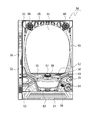
図1に示すように、弾球遊技機の一種であるパチンコ機50は、縦長の固定外郭保持枠をなす外枠51にて構成の各部を保持する構造である。外枠51の左側上下には、ヒンジ53が設けられており、該ヒンジ53の他方側には図4に記載する内枠70が取り付けられており、内枠70は外枠51に対して開閉可能な構成になっている。前枠52には、板ガラス61が取り外し自在に設けられており、板ガラス61の奥には図3に記載する遊技盤1が内枠70に取り付けられている。
As shown in FIG. 1, the
前枠52の上側左右に設けられているのは、スピーカ66であり、パチンコ機50から発生する遊技音が出力され、遊技者の趣向性を向上させる。また、遊技者の趣向性を向上させるために前枠52に遊技状態に応じて発光する枠側装飾ランプ65も複数設けられている。前枠52の下方には、上皿55と下皿63が一体に形成されている。下皿63の右側には発射ハンドル64が取り付けられており、発射ハンドル64を時計回りに回動操作することによって発射装置(後述)が稼働して、上皿55から供給された遊技球が遊技盤1に向けて発射される。なお、発射ハンドル64の左側にもスピーカ66が設けられている。
上皿55の上部ほぼ中央には、遊技者が操作可能な演出ボタン67が備えられており、この演出ボタン67は、周囲にジョグダイヤル68を備えたものとなっている。遊技者が所定期間中に、演出ボタン67やジョグダイヤル68を操作することで後述する演出図柄表示装置6に表示される内容が変化したり、スピーカ66より出力される遊技音が変化したりする。また、このパチンコ機50はいわゆるCR機であって、プリペイドカードの読み書き等を行うためのプリペイドカードユニット(CRユニット)56が付属しており、パチンコ機50には、球貸スイッチ57、精算スイッチ58及び残高表示器59を有するCR精算表示装置が備わっている。
An
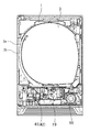
図2は、前枠52を取り外した様子を示す正面図である。なお入賞口や釘、演出用の可動物は省略している。図2に示すように遊技盤1には、公知のガイドレール2a、2bによって囲まれた略円形の遊技領域3が設けられている。発射装置19は遊技盤1の右下に配置されており、発射された遊技球はファールカバー45の内部を通ってガイドレール2a、2b間を走行し、遊技領域3に至る。ファールカバー45とは、ファール球を下皿63に誘導するための通路を有する部材であり、発射された遊技球はその一部を通って遊技領域3に到達する。また、賞球は上皿55に供給されるが、上皿55が遊技球で満杯で溢れた遊技球(溢れ球)も、ファールカバー45の内部を通って下皿63に誘導される(後述)。なお、下皿63にファール球や溢れ球が流れ出る出口は、下皿63の左奥方に設けられている。
FIG. 2 is a front view showing a state in which the
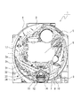
図3に、遊技盤1の詳細を示す。なお、このパチンコ機の全体的な構成は公知技術に従っているので図示及び説明は省略する。図3に示すように遊技盤1には、公知のガイドレール2a、2bによって囲まれた略円形の遊技領域3が設けられている。この遊技領域3には多数の遊技釘4が打ち付けられている。
FIG. 3 shows the details of the
遊技領域3のほぼ中央部には、センターケース5が配されている。センターケース5は、公知のものと同様に、ワープ入口、ワープ通路、ステージ、演出図柄表示装置6(液晶表示装置であり擬似図柄を表示する。)の画面を臨ませる窓等を備えている。センターケース5の下には、第1始動口11と第2始動口12とがユニット化された複合入賞装置が配置されている。第2始動口12は開閉可能な翼片を供えた普通電動役物を備えており、この翼片が開放しないと遊技球は第2始動口12に入球できない構成となっている。遊技領域の右下部には、複数個のLEDからなる普通図柄表示装置7と、普通図柄保留数表示装置8と、特別図柄保留数表示装置18と、7セグメント表示装置からなる特別図柄表示装置9とが配置されている。なお、前記翼片は、普通図柄表示装置7に特定の普通図柄が表示される(「普通図柄が当る」ともいう)と開放される。普通図柄は、演出図柄表示装置6の左方に設けられたゲート17を遊技球が通過すると変動が開始され、所定時間経過後に停止される。この変動時間および停止される普通図柄は、ゲート通過を契機として抽出された乱数に基づいて決定され、ゲート17を遊技球が通過した際に普通図柄が変動中などの場合により、普通図柄の変動を開始できない場合には、これらの乱数が記憶され、その個数が普通図柄保留数表示装置8に表示される。
A
複合入賞装置の下方にはアタッカー式の大入賞口14が配置されている。また、第1始動口11の左方には、第1左入賞口31、第2左入賞口32、第3左入賞口33及び第4左入賞口34が設けられている。なお、この第1左入賞口31、第2左入賞口32、第3左入賞口33、第4左入賞口34が、常時、入球率が変化しない普通入賞口である。
An attacker-type large winning
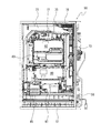
パチンコ遊技機50の裏面は図4に示すとおり、前述した遊技盤1を脱着可能に取り付ける内枠70が前述した外枠51に収納されている。この内枠70には、上方から、球タンク71、タンクレール72及び払出装置73が設けられている。この構成により、遊技盤1上の入賞口に遊技球の入賞があれば球タンク71からタンクレール72を介して所定個数の遊技球を払出装置73により前述した上皿55に排出することができる。また、パチンコ機50の裏側には(図5も参照のこと)、主制御装置80、払出制御装置81、演出図柄制御装置82、サブ統合制御装置83、発射制御装置84、電源基板85が設けられている。なお、演出図柄制御装置82、サブ統合制御装置83がサブ制御装置に該当する。
As shown in FIG. 4, the back surface of the
主制御装置80、演出図柄制御装置82、サブ統合制御装置83は遊技盤1に設けられており、払出制御装置81、発射制御装置84、電源基板85が内枠70に設けられている。なお、図4では、発射制御装置84が描かれていないが、発射制御装置84は払出制御装置81の下に設けられている。また、球タンク71の右側には、外部接続端子板78が設けられており、この外部接続端子板78より、遊技状態や遊技結果を示す信号が図示しないホールコンピュータに送られる。
The
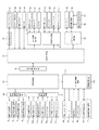
このパチンコ機50の電気的構成は、図5のブロック図に示すとおり、主制御装置80を中心にして構成されている。なお、このブロック図には、単に信号を中継するだけのためのいわゆる中継基板及び電源回路等は記載していない。また、詳細の図示は省略するが、主制御装置80、払出制御装置81、演出図柄制御装置82、サブ統合制御装置83のいずれもCPU、ROM、RAM、入力ポート、出力ポート等を備えているが、本実施例では発射制御装置84にはCPU、ROM、RAMは設けられていない。しかし、これに限るわけではなく、発射制御装置84にCPU、ROM、RAM等を設けてもよい。
As shown in the block diagram of FIG. 5, the electrical configuration of the
主制御装置80には、第1始動口11に入球した遊技球を検出する第1始動口スイッチ11a、第2始動口12に入球した遊技球を検出する第2始動口スイッチ12a、ゲート17に進入した遊技球を検出する普通図柄作動スイッチ17a、大入賞口14に入球した遊技球を計数するための第1カウントスイッチ14a、第1左入賞口31、第2左入賞口32、第3左入賞口33、及び第4左入賞口34に入球した遊技球を検出する左入賞口スイッチ31a等の検出信号が入力される。
The
主制御装置80は搭載しているプログラムに従って動作して、上述の検出信号などに基づいて遊技の進行に関わる各種のコマンドを生成して払出制御装置81及びサブ統合制御装置83に出力する。
また主制御装置80は、図柄表示装置中継端子板90を介して接続されている特別図柄表示装置9及び普通図柄表示装置7の表示、特別図柄保留数表示装置18、及び普通図柄保留数表示装置8の点灯を制御する。
The
Further, the
更に、主制御装置80は、大入賞口ソレノイド14bを制御することで大入賞口14の開閉を制御し、普通電動役物ソレノイド(図5では普電役物ソレノイドと表記)12bを制御することで第2始動口12の開閉を制御する。主制御装置80からの出力信号は試験信号端子にも出力される他、図柄変動や大当り(特別遊技ともいう)等の管理用の信号が、裏中継端子板75、払出制御装置81および外部接続端子板78を介してホールコンピュータ87に送られる。主制御装置80と払出制御装置81とは双方向通信が可能である。
Further, the
払出制御装置81は、主制御装置80から送られてくるコマンドに応じて払出モータ20を稼働させて賞球を払い出させる。本実施例においては、賞球として払い出される遊技球を計数するための払出センサ21の検出信号は払出制御装置81に入力され、払出制御装置81で賞球の計数が行われる構成を用いる。この他にも主制御装置80と払出制御装置81に払出センサ21の検出信号が入力され、主制御装置80と払出制御装置81の双方で賞球の計数を行う構成を用いることも考えられる。
The
なお、払出制御装置81はガラス枠開放スイッチ35、内枠開放スイッチ36、満杯スイッチ22、球切れスイッチ23からの信号が入力され、満杯スイッチ22により下皿63が満タンであることを示す信号が入力された場合及び球切れスイッチ23により球タンクに遊技球が少ないあるいは無いことを示す信号が入力されると払出モータ20を停止させ、賞球の払出動作を停止させる。なお、満杯スイッチ22、球切れスイッチ23も、その状態が解消されるまで信号を出力し続ける構成になっており、払出制御装置81は、その信号が出力されなくなることに起因して払出モータ20の駆動を再開させる。
The
また、払出制御装置81はCRユニット端子板24を介してCRユニット56と交信することで払出モータ20を作動させ、貸し球を排出する。払出された貸し球は払出スイッチ21に検出され、検出信号は払出制御装置81に入力される。なお、CRユニット端子板24は精算表示装置25とも双方向通信可能に接続されており、精算表示装置25には、遊技球の貸出しを要求するための球貸スイッチ57、精算を要求するための精算スイッチ58、残高表示器59(図1参照)が接続されている。
Further, the
また、払出制御装置81は、外部接続端子板78を介して賞球に関する情報、枠(内枠、前枠)の開閉状態を示す情報などをホールコンピュータ87に送信するほか、発射制御装置84に対して発射停止信号を送信する。
Further, the
発射制御装置84は発射ソレノイド30を制御して、遊技球を遊技領域3に遊技球を発射させる。また、発射制御装置84は球送りソレノイド41を制御して、発射台(後述)に1個ずつ遊技球を供給する。なお、発射制御装置84には払出制御装置81以外に発射ハンドル64(図1参照)からの回動量信号、タッチスイッチ28からのタッチ信号、発射停止スイッチ29から発射停止信号が入力される。
The
回動量信号は、遊技者が発射ハンドル64を操作することで出力され、タッチ信号は遊技者が発射ハンドル64を触ることで出力され、発射停止スイッチ信号は、遊技者が発射停止スイッチ29を押すことで出力される。なお、タッチ信号が発射制御装置84に入力されていなければ、遊技球は発射できないほか、発射停止スイッチ信号が入力されているときには、遊技者が発射ハンドル64を触っていても遊技球は発射できないようになっている。
The rotation amount signal is output when the player operates the
サブ統合制御装置83はサブ制御装置に該当し、主制御装置80から送信されてくるデータ及びコマンドを受信し、それらを演出表示制御用、音制御用及びランプ制御用のデータに振り分けて、演出表示制御用のコマンド等は演出図柄制御装置82に送信し、音制御用及びランプ制御用は自身に含まれている各制御部位(音声制御装置及びランプ制御装置としての機能部)に分配する。そして、音声制御装置としての機能部は、音声制御用のデータに基づいて音LSIを作動させることによってスピーカ66からの音声出力を制御し、ランプ制御装置としての機能部はランプ制御用のデータに基づいてランプドライバを作動させることによって各種LED、ランプ26を制御する。 また、サブ統合制御装置83には、演出ボタン67、ジョグダイヤル68が接続されており、遊技者がこれら67、68を操作した際には、その信号がサブ統合制御装置83に入力される。
The
サブ統合制御装置83と演出図柄制御装置82とは双方向通信が可能である。
演出図柄制御装置82は、サブ統合制御装置83から受信したデータ及びコマンド(共に主制御装置80から送信されてきたものとサブ統合制御装置83が生成したものとがある)に基づいて演出図柄表示装置6を制御して、擬似図柄等の演出画像を演出図柄表示装置6の画面6aに表示させる。
Bidirectional communication is possible between the
The effect
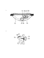
上皿55の遊技球が発射装置に供給される様子を図6に示す。図6(a)は上皿55を上方から見た図である。上皿55にあった遊技球15は、上皿55の底面中ほどから右方手前に流れ、左折して奥方向(本図では上方)に流れ、更に左折して流入口55aから上皿55の底面の下方(本図では奥方向)に誘導される。図6(b)はパチンコ機50を一部断面にして、上皿55の右方から見た図である。図6(a)のように誘導された遊技球15は、上皿55の奥方向(本図では右方)に設けられた発射装置19に入り、発射ハンドル64(図1などを参照)が操作されると、1個ずつ遊技領域3に発射される。
FIG. 6 shows how the game ball of the
発射ハンドル64の説明図を図7に示す。図7(a)は発射レバー37が回動されていない状態、図7(b)は発射レバー37が回動された状態を示す。発射ハンドル64は、パチンコ機50に対して固定されたドーム状のタッチ部38の周りに発射レバー37が回動可能に設けられている。発射レバー37にはリブ39(通常はタッチ部38に覆われていて見えない)が設けられており、図7(a)に示す発射レバー37が回動されていない状態では、リブ39が発射停止ボタン40を押さえている。これにより発射停止スイッチ29がON状態、すなわち遊技球15の発射が行なわれない状態となっている。発射レバー37が回動されると、リブ39が発射停止ボタン40から離れ、発射停止スイッチ29がOFF状態となり、発射ソレノイド30、及び球送りソレノイド41が作動を開始する。
An explanatory view of the launch handle 64 is shown in FIG. FIG. 7A shows a state in which the
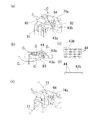
ファールカバー45の外観を図8に示す。図8(a)はファールカバー45を図2のやや右上から見た様子を示す斜視図である。ファールカバー45は透明の合成樹脂製の部材であり、その前面42はピン76を引っ張ることにより着脱自在に構成されている。なお、前面42の部位42aおよび42bにはフック(図示しない)が形成されており、図8(b)に示す穴42cおよび42dにそれぞれ係止することにより前面42の上側を仮固定する。ファールカバー45の上面および右面にはそれぞれ開口74aおよび74bが形成されている。なお、符号91はファール球や溢れ球が下皿63に流れ出るための流出口である。図8(b)は、ファールカバー45から前面42を取り外した様子を示す斜視図である。矢印Aは図示しない発射装置19から発射された遊技球の軌跡を示すもので、本図に示すように発射装置19から発射された遊技球は、開口部74bからファールカバー45内に入り、開口部74aから斜めに遊技盤1に向かって発射される。矢印Bは溢れ球が流れる経路を示すものである。なお、本図に示した経路は一例であり、溢れ球の数や勢いにより経路は多少変化する。
The appearance of the
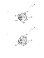
図9(a)に、ファールカバー45内のファール球の流れ(矢印C)を示す。この流れも一例であり、ファール球の勢いにより多少変化する。本図に示すように、ファール球は開口部74aからファールカバー45内に入り、斜面93を滑り落ちて、下面43aに着地する。そこから向きを変えて略長方形の孔92から奥の面43bへと流れる。なお、本図は前面42(図8(a)参照)を除いて示しているが、実際には前面42が取り付けられた状態でファール球は流下するので、ファール球が手前(遊技者方向)へ脱落することはない。孔92に入ったファール球は、奥の面43bを蛇行して手前に転動し、再び奥方向へと流れて流出口91から流れ出る。なお、符号94はファール球に糸が付いていた場合に、この糸を引っ掛けるための係止手段である。図8(b)ではファールカバー45の形状を示すことを優先するために、ファールカバー45を不透明と仮定し、係止部94を示さなかったが、本図ではファールカバー45が実際には透明であるため、係止部94を示している。
FIG. 9A shows the flow of foul balls (arrow C) in the
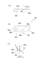
係止部94の拡大図を図10に示す。図10(a)は係止部94を遊技機の上方から見た図、図10(b)は係止部94を遊技機の正面から見た図、図10(c)は係止部94を遊技機の右方から見た図である。係止部94は、板金に切込み線95aを形成し、該切込み線95aから所定の角度をなす折り曲げ線95bに従って曲げ起こされてなる舌片95を備えた部材である。切込み線95aだった部位が糸付き球の糸77を引っ掛ける箇所となる(図10(c)参照)。係止部94を正面から見て左の部位はL字型に曲げ起こされることにより、取り付け部94cが形成されている。取り付け部94cには大小2個の孔96a,96bが形成されており、これを用いてファールカバー45に螺子止めされる。舌片95は図10(a)および図10(c)に示すように、ファール球の流下方向Dと逆方向に曲げ起こされている(符号C2については後述)。
An enlarged view of the locking
図9に戻る。ファール球の通路を上から見た様子を図9(b)に示す。ファール球は、斜面93を滑り落ちて(符号C1)、ファールカバー45の奥(本図では上)の面43bをUターンするように流れ(C2)、ファールカバー45の前部(本図では下部)で再びUターンをするように流れ(C3)、再度、ファールカバー45の奥へと向かう。そしてみたび奥でUターンし(C4)、流出口91から流れ出る(C5)。なお、このように遊技球が流下するようにファール球の通路の下面には、遊技機の正面から見て左下がりの傾斜がつけられている。特に、下面43a、奥の面43bには凹凸が形成されている。図9(c)は面43bの拡大図、図9(d)は図9(c)の側面図であり、面43bの表面にダイヤ型の突起44が多数形成されている。下面43aも、面43bと同様に突起44が形成されている(ただし突起44の配列の向きが異なる)。このような下面43a、面43bをファール球が流下すると、ファール球の流下速度が減速される。なお、図8(b)、図9(a)、および後述する図9(c)では、図を分かり易くするために突起44を省略している。また、溢れ球との合流地点は流出口91の近傍となり、係止部94は合流地点よりもファール球の通路の上流に設けられていることになる。
Return to FIG. FIG. 9B shows a view of the passage of the foul ball from above. Foul balls, slide down the slope 93 (code C 1), flows (C 2) as a
ファール球が糸付き球だった場合、糸77は図9(e)のようになる。なお、前述したように糸77の他端にも遊技球が付いており、該他端の遊技球は遊技領域3にある。なお、実際には図9(b)に示したようにファール球はファールカバー45内を蛇行して流下するので、糸77もファールカバー内を蛇行することになるが、図が煩雑になる為、模式的に示している。例えば、ファール球は下皿63の左側(図1参照)から流れ出るので、糸77(又は糸付き球)は実際には右方向へ引っ張られることになる。開口部74aからファールカバー45内に入った糸付き球は、孔92に入り、ファールカバー45内を図9(b)のように流下して、流出口91から下皿63に流れ出る。不正行為者が下皿63に出てきた糸付き球(又はそれに付けられた糸77)を引っ張ると、糸77の他端は遊技領域3にあるため、糸の他端が上方に引っ張られる形となり、糸77は係止部94の舌片95と本体94aの間に入り込む。この状態から、なおも不正行為者が糸77を引っ張ると、糸77は舌片95と本体94aの間にどんどん食い込んでいき、引くのが困難になる。従って、糸付き球ゴトを防止することができる。
When the foul ball is a ball with a thread, the
なお、ファールカバー45の下面43aおよび奥の面43bには、突起44が多数形成されているので、糸付き球はその流下が減速される。特に、係止部94よりも下流位置にある奥の面43bの突起44による減速と係止部94に糸77が引っかかることとにより、糸付き球はファール球の通路内で滞り、流出口91から出てこない可能性もある。この場合も、不正行為者は糸77を引くことができないので糸付き球ゴトを防止することができる。そして、係止部94を発射装置19に設けていないので、係止部94のために発射装置19の発射動作が滞ることがない。また、上皿55の流入口55aから発射装置19に至る流路に係止部94を設けていないので、上皿55の遊技球15が発射装置19に供給されるのを係止部94が妨げることもない。
Since a large number of
また、ファールカバー45の前面42が着脱自在となっているので、前面42を取り外せば、係止部94に引っ掛かった糸77や、突起44が形成された箇所で滞った糸付き球を、容易に取り除くことができる。そして、係止部94および突起44は、溢れ球とファール球の合流地点よりもファール球通路の上流に設けられているので、大量の溢れ球が発生した際にも球詰まりが発生しにくい。
Further, since the
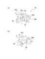
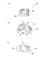
なお、このように糸付き球をファール球にすることにより行われる不正行為だけでなく、旧来からの糸付き球ゴトも防止可能にパチンコ機50は構成されている。これについて図11〜12を用いて説明する。図11は、発射装置19の外観である。図11(a)は発射装置19をパチンコ機50の正面側から見た図である。発射装置19は大きく分けて2つの部位から構成されており、その一方は上皿55から供給された遊技球を1個ずつ発射レール47へと送り込む球送り機構であり、他方は球送り機構により発射レール47に設置された遊技球を遊技領域3に発射する発射機構である。両者は図11(b)の斜視図に示すように、ヒンジにより開閉可能に構成されている。球送りソレノイド41は、図示しない球送りレバーを駆動するもので、発射制御装置84からの指令により稼働すると、上皿55から導入口48を介して入ってきた遊技球を球排出口49を介して1個ずつ発射レール47へと供給する。なお、球排出口49の近傍にはカッター97が設置されている。
The
発射レール47に設置された遊技球は、ハンマー46により打撃されて遊技領域3に発射される。ハンマー46はPを軸として揺動可能に構成されており、発射ソレノイド30により駆動されて、その先端部46aにより発射レール47上の遊技球を打撃する。発射ソレノイド30は発射制御装置84からの指令により稼働する。
The game ball installed on the
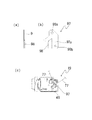
カッター97の拡大図を図12(a)、図12(b)に示す。図12(a)はカッター97を遊技機の右方から見た図、図12(b)はカッター97を遊技機の正面から見た図である。カッター97は、係止部94と同様、板金を折り曲げることにより形成された部材で、その本体97aから曲げ起こされて形成された切断部98を備えている。本体97aには大小2個の孔99a,99bが形成されており、これを用いて球送り機構に螺子止めされる。
Enlarged views of the
発射装置19にて糸付き球を発射すると、糸77は図12(c)のようになる。なお、図12(c)は発射装置19をパチンコ機50の裏側から見ているので、発射方向が右斜め上方向となっている(ファールカバー45は図12(c)において右側に存在することになる)。そして糸の他端は球排出口49を通って導入口48から上皿55にある状態となる。不正行為者が糸77を引っ張ると、糸77の他端は遊技領域3にあるため、糸77がカッター97の切断部98と本体97aの間に入り込む。この状態から、なおも不正行為者が糸77を引っ張ると、糸77は切断部98にこすり付けられることになり、やがて切断される。従って、旧来の糸付き球ゴトも防止することができる。なお、図12(c)においても糸77の様子は模式的に示している。
When the ball with a thread is launched by the launching
ここで本実施例の構成と、本発明の構成要件との対応関係を示す。上皿55が本発明の「皿部」に相当し、発射装置19が本発明の「発射装置」に相当し、流入口55aから発射装置19に至る流路が本発明の「遊技球通路」に相当し、発射ハンドル64が本発明の「発射力調整手段」に相当し、係止部94が本発明の「係止手段」に相当し、突起44が本発明の「減速手段」に相当し、図7に示した矢印Bに沿った通路が本発明の「溢れ球通路」に相当し、図8に示した矢印C1〜C5に沿った通路が本発明の「ファール球通路」に相当し、前面42が本発明の「着脱自在に構成され」た「箇所」に相当する。
[他の実施例]
Here, the correspondence between the configuration of the present embodiment and the constituent requirements of the present invention is shown. The
[Other Examples]
ファール球通路が遊技盤1内に形成されている遊技機に本発明を適用しても良い。また、係止部94は、図10に示したような構成である必要はない。例えば、ファール球通路内の、糸77が接触する部分に舌片95状のものを形成し、ここに糸77が引っかかるようにしても良い。或いは、ファール球通路は前記実施例の様に蛇行してファール球が流下するものではなく、螺旋状に流下する形状にすることも考えられる。こうすると、糸77も螺旋状にファール球通路内に存在することになるので、不正行為者が糸77を引っ張ると糸77が巻きつくことになり、引っ張ることも緩めることも困難となる。これはファール球通路のほぼ全体(正確にはその内側の面)を係止手段として機能させることになる。これらの態様では、係止部94も合成樹脂にて形成されることになる。尚、係止部94もファールカバー45も突起44も、前記実施例とは異なる形状、異なる材質にて構成しても構わない。前記実施例の対応する構成と同様の作用をする構成であればよい。特に減速手段に相当する構成としては、突起44のように盛り上がった構成ではなく、遊技球がはまり込まない程度の大きさの多数の穴でも構わない。また、平目ローレットのような直線状の凹凸にしてもよいし、更にこれが波打ったような形状にしてもよい。或いは、合成樹脂や金属といった比較的硬質のものでなく、布、スポンジ、毛皮といった軟質のものを用いてファール球の流下速度を減じる構成でもよい。
The present invention may be applied to a game machine in which a foul ball passage is formed in the
また、下皿63を有しない遊技機に本発明を適用しても良い。こうした遊技機では、ファール球や糸付き球は上皿55に返却される。また、演出図柄表示装置6を制御するサブ統合制御装置83は、スピーカ66や各種LED、ランプ26をも制御するものとして構成されていたが、これらを個別に制御する複数のサブ制御装置として構成し直してもよい。
Further, the present invention may be applied to a game machine that does not have the
1:遊技盤 3:遊技領域
19:発射装置 26:ランプ
41:球送りソレノイド
45:ファールカバー 46:ハンマー
47:発射レール 48:導入口
49:球排出口 50:パチンコ機
55:上皿 63:下皿
64:発射ハンドル 77:糸
94:係止手段 97:カッター
1: Game board 3: Game area 19: Launcher 26: Lamp 41: Ball feed solenoid
45: Foul cover 46: Hammer 47: Launch rail 48: Introduction port 49: Ball discharge port 50: Pachinko machine 55: Upper plate 63: Lower plate 64: Launch handle 77: Thread 94: Locking means 97: Cutter
Claims (1)
遊技球を1個ずつ前記遊技領域に向けて発射するために当該弾球遊技機内に設けられた発射装置と、
該発射装置による発射力を遊技者が調整するための発射力調整手段と、
前記皿部から前記発射装置へと遊技球を誘導するための遊技球通路と、
前記発射装置により発射されたにも拘らず、発射力不足などが原因で前記遊技領域に到達できなかった遊技球であるファール球が流下する通路であって、前記発射装置を経由することなく前記ファール球を当該弾球遊技機の遊技者へ返却するためのファール球通路と、
を備えた弾球遊技機において、
前記ファール球通路に形成され、前記ファール球に糸状部材が固定されている場合に、該糸状部材を引っ掛けるための係止手段と、
該係止手段よりも、前記ファール球通路において下流位置に形成され、該ファール球通路を流下する遊技球の流下速度を前記係止手段の上流位置を流下する遊技球の流下速度よりも減少させる減速手段と、
前記発射装置に設けられ、前記糸状部材を切断する切断部と
を備え、
前記ファール球通路は、該ファール球通路に着脱自在な箇所を備え、該箇所を取り外すことにより、前記係止手段から前記減速手段までの経路を露出させることが可能となっていることを特徴とする弾球遊技機。 A dish that holds the game ball to be fired into the game area,
A launching device provided in the bullet game machine for launching the game balls one by one toward the game area, and
A launching force adjusting means for the player to adjust the launching force of the launching device, and
A game ball passage for guiding the game balls Previous Symbol onset morphism device from the pan,
It is a passage through which a foul ball, which is a game ball that could not reach the game area due to insufficient launching power or the like even though it was launched by the launcher, flows down, and the passage does not go through the launcher. A foul ball passage for returning the foul ball to the player of the bullet game machine, and
In a ball game machine equipped with
When the foul ball is formed in the foul ball passage and the thread-like member is fixed to the foul ball, a locking means for hooking the thread-like member and
The flow speed of the game ball formed at a downstream position in the foul ball passage and flowing down the foul ball passage is reduced from the flow speed of the game ball flowing down the upstream position of the locking means . Deceleration means and
Provided in front Symbol onset picolinimidate location, and a cutting unit for cutting the thread member,
The foul ball passage is characterized in that the foul ball passage is provided with a detachable portion, and the path from the locking means to the deceleration means can be exposed by removing the portion. Foul ball game machine.
Priority Applications (1)
| Application Number | Priority Date | Filing Date | Title |
|---|---|---|---|
| JP2016088304A JP6758564B2 (en) | 2016-04-26 | 2016-04-26 | Bullet game machine |
Applications Claiming Priority (1)
| Application Number | Priority Date | Filing Date | Title |
|---|---|---|---|
| JP2016088304A JP6758564B2 (en) | 2016-04-26 | 2016-04-26 | Bullet game machine |
Publications (2)
| Publication Number | Publication Date |
|---|---|
| JP2017196045A JP2017196045A (en) | 2017-11-02 |
| JP6758564B2 true JP6758564B2 (en) | 2020-09-23 |
Family
ID=60236640
Family Applications (1)
| Application Number | Title | Priority Date | Filing Date |
|---|---|---|---|
| JP2016088304A Active JP6758564B2 (en) | 2016-04-26 | 2016-04-26 | Bullet game machine |
Country Status (1)
| Country | Link |
|---|---|
| JP (1) | JP6758564B2 (en) |
Family Cites Families (2)
| Publication number | Priority date | Publication date | Assignee | Title |
|---|---|---|---|---|
| JP6320438B2 (en) * | 2016-02-29 | 2018-05-09 | 株式会社大一商会 | Game machine |
| JP6608739B2 (en) * | 2016-03-09 | 2019-11-20 | 株式会社三共 | Game machine |
-
2016
- 2016-04-26 JP JP2016088304A patent/JP6758564B2/en active Active
Also Published As
| Publication number | Publication date |
|---|---|
| JP2017196045A (en) | 2017-11-02 |
Similar Documents
| Publication | Publication Date | Title |
|---|---|---|
| JP2017196046A (en) | Pinball game machine | |
| JP5255033B2 (en) | Pachinko machine | |
| JP6061254B2 (en) | Game machine | |
| JP2016016246A (en) | Game machine | |
| JP6312998B2 (en) | Game machine | |
| JP6758564B2 (en) | Bullet game machine | |
| JP2017196044A (en) | Pinball game machine | |
| JP7790408B2 (en) | gaming machines | |
| JP5853238B2 (en) | Bullet ball machine | |
| JP4131548B2 (en) | Slot machine | |
| JP2009125281A5 (en) | ||
| JP2006198308A (en) | Pachinko game machine | |
| JP6337313B1 (en) | Game machine | |
| JP6288732B2 (en) | Game machine | |
| JP2007236575A (en) | Game board unit, and pinball game machine | |
| JP5825363B2 (en) | Game machine | |
| JP4825468B2 (en) | Game machine | |
| JP6311205B1 (en) | Game machine | |
| JP2018143491A (en) | Game machine | |
| JP6392390B2 (en) | Game machine | |
| JP6372938B1 (en) | Game machine | |
| JP6192245B2 (en) | Game machine | |
| JP6192246B2 (en) | Game machine | |
| JP2023136304A (en) | Game machine | |
| JP5346996B2 (en) | Game machine |
Legal Events
| Date | Code | Title | Description |
|---|---|---|---|
| A621 | Written request for application examination |
Free format text: JAPANESE INTERMEDIATE CODE: A621 Effective date: 20190312 |
|
| A977 | Report on retrieval |
Free format text: JAPANESE INTERMEDIATE CODE: A971007 Effective date: 20191225 |
|
| A131 | Notification of reasons for refusal |
Free format text: JAPANESE INTERMEDIATE CODE: A131 Effective date: 20200106 |
|
| A521 | Request for written amendment filed |
Free format text: JAPANESE INTERMEDIATE CODE: A523 Effective date: 20200227 |
|
| TRDD | Decision of grant or rejection written | ||
| A01 | Written decision to grant a patent or to grant a registration (utility model) |
Free format text: JAPANESE INTERMEDIATE CODE: A01 Effective date: 20200609 |
|
| A61 | First payment of annual fees (during grant procedure) |
Free format text: JAPANESE INTERMEDIATE CODE: A61 Effective date: 20200609 |
|
| R150 | Certificate of patent or registration of utility model |
Ref document number: 6758564 Country of ref document: JP Free format text: JAPANESE INTERMEDIATE CODE: R150 |
|
| R250 | Receipt of annual fees |
Free format text: JAPANESE INTERMEDIATE CODE: R250 |