JP6756797B2 - Game machine - Google Patents
Game machine Download PDFInfo
- Publication number
- JP6756797B2 JP6756797B2 JP2018193028A JP2018193028A JP6756797B2 JP 6756797 B2 JP6756797 B2 JP 6756797B2 JP 2018193028 A JP2018193028 A JP 2018193028A JP 2018193028 A JP2018193028 A JP 2018193028A JP 6756797 B2 JP6756797 B2 JP 6756797B2
- Authority
- JP
- Japan
- Prior art keywords
- display
- value
- special
- game
- variable display
- Prior art date
- Legal status (The legal status is an assumption and is not a legal conclusion. Google has not performed a legal analysis and makes no representation as to the accuracy of the status listed.)
- Active
Links
Images


Description
本発明は、パチンコ遊技機等の遊技機に関する。 The present invention relates to a gaming machine such as a pachinko gaming machine.
遊技機として、遊技球などの遊技媒体を発射装置によって遊技領域に発射し、遊技領域に設けられている入賞口などの入賞領域に遊技媒体が入賞して始動条件が成立すると、複数種類の識別情報を可変表示装置において可変表示(以下、「変動」または「変動表示」ともいう)し、その表示結果により所定の遊技価値を付与するか否かを決定する、いわゆる可変表示ゲームによって遊技の興趣を高めた遊技機がある。こうした遊技機では、可変表示ゲームにおける表示図柄の可変表示が完全に停止した際の停止図柄態様が特定表示態様となったときに、遊技者にとって有利な有利状態(大当り遊技状態)となる。例えば、大当り遊技状態となった遊技機は、大入賞口またはアタッカと呼ばれる特別電動役物を開放状態とし、遊技者に対して遊技球の入賞が極めて容易となる状態を一定時間継続的に提供する。 As a game machine, a game medium such as a game ball is launched into a game area by a launching device, and when the game medium wins a prize in a winning area such as a winning opening provided in the game area and a starting condition is satisfied, a plurality of types of identification are identified. Information is variably displayed on a variable display device (hereinafter, also referred to as "variable" or "variable display"), and whether or not to give a predetermined game value is determined based on the display result. There is a game machine that has improved. In such a game machine, when the stop symbol mode when the variable display of the display symbol in the variable display game is completely stopped becomes the specific display mode, the player is in an advantageous state (big hit game state). For example, a gaming machine in a jackpot game state opens a special electric accessory called a big winning opening or an attacker, and continuously provides a player with a state in which winning a game ball is extremely easy for a certain period of time. To do.
また、パチンコ遊技機は、遊技媒体が始動領域を入賞して始動条件が成立したときに、可変表示を開始できない場合、すなわち、先に成立した開始条件に基づく可変表示が実行中であることや遊技機が大当り遊技状態に制御されていることなどにより可変表示の実行開始を許容する開始条件が成立していない場合、実行条件の成立を順次保留情報として保留番号を付して記憶し、この保留情報を保留番号順に保留表示として表示する。 Further, when the pachinko gaming machine cannot start the variable display when the game medium wins the start area and the start condition is satisfied, that is, the variable display based on the start condition established earlier is being executed. If the start condition that allows the start of execution of the variable display is not satisfied because the gaming machine is controlled to the jackpot game state, the establishment of the execution condition is sequentially stored as hold information with a hold number. Hold information is displayed as hold display in order of hold number.
このような遊技機として、保留情報の表示態様を変更する保留変化演出を実行するものがあり、例えば、特許文献1には、保留情報の表示態様を変化させるときに、第1演出時間を要する第1演出と、第1演出時間よりも長い第2演出時間を要する第2演出のいずれかを、可変表示の期間に応じて実行する遊技機が開示されている。また、特許文献2には、保留情報の表示態様を変更させる際に作用演出を実行し、可変表示が短縮変動である場合には短縮した作用演出により保留情報の表示態様を変更させる遊技機が開示されている。
As such a game machine, there is one that executes a hold change effect for changing the display mode of the hold information. For example, in
しかしながら、特許文献1および特許文献2における遊技機では、保留情報の表示態様を変更させるまでの期間が可変表示のパターンに応じて一律に決定されるため、保留変化演出が実行されることにより可変表示のパターンが遊技者に予想され易く、遊技興趣を低下させてしまうおそれがあった。
However, in the gaming machines in
本発明は、上記実状に鑑みてなされたものであり、遊技興趣の低下を防止することができる遊技機の提供を目的とする。 The present invention has been made in view of the above circumstances, and an object of the present invention is to provide a game machine capable of preventing a deterioration in the interest of a game.
(A)上記目的を達成するため、本発明に係る遊技機は、
可変表示を行い、遊技者にとって有利な有利状態に制御可能な遊技機であって、
可変表示に関する特定表示を実行可能な特定表示手段と、
可変表示の実行中に表示されているいずれかの前記特定表示の表示態様を変化させる変化演出を実行可能な変化演出実行手段と、を備え、
前記変化演出実行手段は、前記表示態様を変化させるまでの時間が第1時間である第1演出と、前記第1時間よりも長い第2時間である第2演出と、を少なくとも含む複数種類のうちいずれかの前記変化演出を実行可能であり、
可変表示のパターンとして、少なくとも、第1可変表示パターンと、前記第1可変表示パターンよりも可変表示時間の長い第2可変表示パターンと、があり、
前記可変表示時間が長いときの方が、前記有利状態に制御される割合が高く、
可変表示の開始時に表示中の前記特定表示の数が所定数以上である場合、前記所定数未満である場合よりも前記第1可変表示パターンによる可変表示が行われる割合が高い一方で、前記第2可変表示パターンによる可変表示が行われる割合は、可変表示の開始時に表示中の前記特定表示の数に関わらず共通であり、
前記第1可変表示パターンによる可変表示中は、前記変化演出として、前記第1演出を実行可能である一方で、前記第2演出を実行せず、
前記第2可変表示パターンによる可変表示中は、前記変化演出として、前記第1演出または前記第2演出を実行可能であり、
前記第2可変表示パターンによる可変表示中に前記変化演出を実行する場合、該可変表示の開始時に表示中の前記特定表示の数が前記所定数未満であるときよりも、前記所定数以上であるときの方が、前記第1演出を高い割合で実行し、
前記変化演出には、該変化演出の実行後に前記特定表示の表示態様が変化する第1パターンと、前記特定表示の表示態様が変化しない第2パターンと、があり、前記第1演出よりも前記第2演出の方が、高い割合で前記第1パターンとなる
ことを特徴とする。
(1)上記目的を達成するため、他の遊技機は、
可変表示を行い、遊技者にとって有利な有利状態に制御可能な遊技機(例えば、パチンコ遊技機1など)であって、
可変表示に関する特定表示を実行可能な特定表示手段(例えば、演出制御コマンドから特定される保留記憶数に基づき保留表示を表示する演出制御用CPU120など)と、
可変表示の実行中に表示されているいずれかの前記特定表示の表示態様を変化させる変化演出を実行可能な変化演出実行手段(例えば、ステップS067AKS021で設定された変化演出を実行する演出制御用CPU120など)と、を備え、
前記変化演出実行手段は、前記表示態様を変化させるまでの時間が第1時間である第1演出(例えば、第1変化演出など)と、前記第1時間よりも長い第2時間である第2演出(例えば、第2変化演出など)と、を少なくとも含む複数種類のうちいずれかの前記変化演出を実行可能であり、
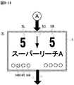
可変表示のパターンとして、少なくとも、第1可変表示パターン(例えば、短縮変動を行う非リーチハズレの変動パターンなど)と、前記第1可変表示パターンよりも可変表示時間の長い第2可変表示パターン(例えば、スーパーリーチのリーチ演出を行う変動パターンなど)と、があり、
前記可変表示時間が長いときの方が、前記有利状態に制御される割合が高く(例えば、スーパーリーチのリーチ演出を行う可変表示の方が、リーチ演出を行わない可変表示よりも可変表示結果が「大当り」となる割合が高くなっているなど)、
可変表示の開始時に表示中の前記特定表示の数が所定数以上(例えば、「2」以上など)である場合、前記所定数未満(例えば、「2」未満)である場合よりも前記第1可変表示パターンによる可変表示が行われる割合が高い一方で、前記第2可変表示パターンによる可変表示が行われる割合は、可変表示の開始時に表示中の前記特定表示の数に関わらず共通であり(例えば、図9−5に示すように非リーチハズレの変動パターン以外の決定割合は共通であるなど)、
前記第1可変表示パターンによる可変表示中は、前記変化演出として、前記第1演出を実行可能である一方で、前記第2演出を実行せず(例えば、図9−17(B)に示すように、短縮変動の変動パターンである場合には、第1変化演出のみ決定され、第2変化演出には決定されないよう決定割合が割り当てられているなど)、
前記第2可変表示パターンによる可変表示中は、前記変化演出として、前記第1演出または前記第2演出を実行可能であり(例えば、図9−17(B)に示すように、スーパーリーチのリーチ演出を行う変動パターンである場合には、第1変化演出と第2変化演出のいずれにも決定され得るよう決定割合が割り当てられているなど)、
前記第2可変表示パターンによる可変表示中に前記変化演出を実行する場合、該可変表示の開始時に表示中の前記特定表示の数が前記所定数未満(例えば、「2」未満など)であるときよりも、前記所定数以上(例えば、「2」以上など)であるときの方が、前記第1演出を高い割合で実行する(例えば、図9−17(A)および(B)に示すように、変動開始時の保留記憶数が「2」以上であるときの方が、「2」未満であるときよりも第1変化演出に決定される割合が高くなるように、決定割合が割り当てられているなど)、
ことを特徴とする。
(A) In order to achieve the above object, the gaming machine according to the present invention is
It is a gaming machine that can perform variable display and control it to an advantageous state that is advantageous to the player.
Specific display means that can execute specific display related to variable display,
A change effect executing means capable of executing a change effect that changes the display mode of any of the specific displays displayed during the execution of the variable display is provided.
The change effect executing means has at least a plurality of types including a first effect in which the time until the display mode is changed is the first time, and a second effect in which the second time is longer than the first time. Any of the above-mentioned change effects can be executed,
As the variable display pattern, there are at least a first variable display pattern and a second variable display pattern having a longer variable display time than the first variable display pattern.
When the variable display time is long, the ratio of being controlled to the advantageous state is higher.
When the number of the specific displays being displayed at the start of the variable display is equal to or more than a predetermined number, the rate of variable display by the first variable display pattern is higher than that when the number is less than the predetermined number, while the first variable display pattern is used. The rate at which variable display is performed by the two variable display patterns is the same regardless of the number of the specific displays being displayed at the start of variable display.
During the variable display by the first variable display pattern, the first effect can be executed as the change effect, but the second effect is not executed.
During the variable display by the second variable display pattern, the first effect or the second effect can be executed as the change effect.
When the change effect is executed during the variable display by the second variable display pattern, the number of the specific displays being displayed at the start of the variable display is greater than or equal to the predetermined number than when the number is less than the predetermined number. When, the first production is performed at a higher rate,
The change effect includes a first pattern in which the display mode of the specific display changes after the execution of the change effect, and a second pattern in which the display mode of the specific display does not change, which is more than the first effect. The second production has a higher proportion of the first pattern.
It is characterized by that.
(1) In order to achieve the above purpose, other game machines
It is a gaming machine (for example, pachinko gaming machine 1) that can perform variable display and can be controlled to an advantageous state that is advantageous to the player.
Specific display means capable of executing specific display related to variable display (for example,
A change effect execution means (for example, an
The change effect executing means has a first effect (for example, a first change effect) in which the time until the display mode is changed is the first time, and a second time, which is longer than the first time. It is possible to execute the change effect of any one of a plurality of types including at least an effect (for example, a second change effect).
As the variable display pattern, at least a first variable display pattern (for example, a non-reach loss fluctuation pattern that performs shortening fluctuation) and a second variable display pattern (for example, a second variable display pattern having a longer variable display time than the first variable display pattern). (Variable patterns that produce the reach of Super Reach, etc.)
When the variable display time is long, the ratio of being controlled to the advantageous state is higher (for example, the variable display with the reach effect of the super reach produces a variable display result than the variable display without the reach effect). The percentage of "big hits" is high),
When the number of the specific displays being displayed at the start of the variable display is a predetermined number or more (for example, "2" or more), the first is higher than the case where the number is less than the predetermined number (for example, less than "2"). While the ratio of variable display by the variable display pattern is high, the ratio of variable display by the second variable display pattern is the same regardless of the number of the specific displays being displayed at the start of the variable display ( For example, as shown in Fig. 9-5, the decision ratios other than the fluctuation pattern of non-reach loss are common),
During the variable display by the first variable display pattern, the first effect can be executed as the change effect, but the second effect is not executed (for example, as shown in FIG. 9-17 (B)). In addition, in the case of the fluctuation pattern of shortened fluctuation, only the first change effect is determined, and the determination ratio is assigned so as not to be determined in the second change effect),
During the variable display by the second variable display pattern, the first effect or the second effect can be executed as the change effect (for example, as shown in FIG. 9-17 (B), the reach of the super reach. In the case of a variable pattern that produces an effect, a determination ratio is assigned so that it can be determined for both the first change effect and the second change effect),
When the change effect is executed during the variable display by the second variable display pattern, when the number of the specific displays being displayed at the start of the variable display is less than the predetermined number (for example, less than "2"). The first effect is executed at a higher rate when the number is equal to or greater than the predetermined number (for example, “2” or more) (for example, as shown in FIGS. 9-17 (A) and 9-17 (B)). In addition, the determination ratio is assigned so that when the number of reserved memories at the start of fluctuation is "2" or more, the ratio determined for the first change effect is higher than when it is less than "2". Etc.),
It is characterized by that.
このような構成によれば、遊技興趣の低下を防止することができる。 According to such a configuration, it is possible to prevent a decrease in the interest in the game.
(2)上記(1)に記載の遊技機において、
可変表示の開始時に表示中の前記特定表示の数が前記所定数未満(例えば、「2」未満など)である場合、前記第1可変表示パターンによる可変表示よりも前記可変表示時間の長い第3可変表示パターン(例えば、短縮変動を行わない非リーチハズレの変動パターンなど)による可変表示を行い、
前記第2可変表示パターンによる可変表示中に前記変化演出を実行する場合、該可変表示の開始時に表示中の前記特定表示の数が前記所定数未満(例えば、「2」未満など)であるときには、前記第2演出を前記第1演出よりも高い割合で実行し、前記所定数以上(例えば、「2」以上など)であるときには、前記第1演出を前記第2演出よりも高い割合で実行する(例えば、図9−17(A)および(B)に示すように、変動開始時の保留記憶数が「2」以上であるときの方が、「2」未満であるときよりも第1変化演出に決定される割合が高くなるように決定割合が割り当てられている一方、「2」未満であるときの方が、「2」以上であるときよりも第2変化演出に決定される割合が高くなるように決定割合が割り当てられているなど)、
ようにしてもよい。
(2) In the gaming machine described in (1) above
When the number of the specific displays being displayed at the start of the variable display is less than the predetermined number (for example, less than "2"), the third variable display time is longer than the variable display by the first variable display pattern. Variable display using a variable display pattern (for example, a non-reach loss fluctuation pattern that does not undergo shortening fluctuation)
When the change effect is executed during the variable display by the second variable display pattern, when the number of the specific displays being displayed at the start of the variable display is less than the predetermined number (for example, less than "2"). , The second effect is executed at a higher rate than the first effect, and when the number is equal to or greater than the predetermined number (for example, "2" or more), the first effect is executed at a higher rate than the second effect. (For example, as shown in FIGS. 9-17 (A) and 9-17 (B), when the number of reserved storages at the start of fluctuation is "2" or more, it is the first time when it is less than "2". While the decision ratio is assigned so that the ratio determined for the change effect is higher, the ratio determined for the second change effect when it is less than "2" than when it is "2" or more. The decision rate is assigned so that is higher),
You may do so.
このような構成によれば、遊技興趣の低下を防止することができる。 According to such a configuration, it is possible to prevent a decrease in the interest in the game.
(3)上記(1)または(2)に記載の遊技機において、
前記変化演出実行手段は、前記第1演出を可変表示の開始時から所定期間に亘って実行し、前記第2演出を可変表示の開始時から所定期間よりも長い特定期間に亘って実行する(例えば、第1変化演出および第2変化演出のいずれの変化演出についても、可変表示の開始時に実行を開始し、第1変化演出は、当該演出の実行を開始してから(換言すると、可変表示を開始してから)保留表示の表示態様が変化するまでの期間が、第2変化演出よりも短いなど)、
ようにしてもよい。
(3) In the gaming machine according to (1) or (2) above.
The change effect executing means executes the first effect for a predetermined period from the start of the variable display, and executes the second effect for a specific period longer than the predetermined period from the start of the variable display (. For example, both the first change effect and the second change effect start to be executed at the start of the variable display, and the first change effect is performed after the execution of the effect is started (in other words, the variable display). The period from the start of) until the display mode of the hold display changes is shorter than the second change effect),
You may do so.
このような構成によれば、遊技興趣の低下を防止することができる。 According to such a configuration, it is possible to prevent a decrease in the interest in the game.
(4)上記(1)〜(3)のいずれか1つに記載の遊技機において、
前記変化演出には、該変化演出の実行後に前記特定表示の表示態様が変化する第1パターン(例えば、成功態様の変化演出パターンなど)と、前記特定表示の表示態様が変化しない第2パターン(例えば、失敗態様の変化演出パターンなど)とがあり、前記第1演出よりも前記第2演出の方が、高い割合で前記第1パターンの前記変化演出を実行する(例えば、第1変化演出を実行する場合よりも、第2変化演出を実行する場合の方が、成功態様の変化演出パターンになる割合が高くなっているなど)、
ようにしてもよい。
(4) In the gaming machine according to any one of (1) to (3) above.
The change effect includes a first pattern in which the display mode of the specific display changes after the execution of the change effect (for example, a change effect pattern of a success mode) and a second pattern in which the display mode of the specific display does not change (for example, a change effect pattern of the success mode). For example, there is a change effect pattern of a failure mode), and the second effect executes the change effect of the first pattern at a higher rate than the first effect (for example, the first change effect). When the second change effect is executed, the rate of the change effect pattern of the success mode is higher than when it is executed),
You may do so.
このような構成によれば、遊技興趣を向上させることができる。 According to such a configuration, it is possible to improve the game entertainment.
(5)上記(1)〜(4)のいずれか1つに記載の遊技機において、
設定変更操作(例えば、設定キー、設定切替スイッチの操作)にもとづいて遊技者にとっての有利度が異なる(例えば、大当り確率が異なる)複数段階の設定値(例えば、設定値1〜設定値3)のうちのいずれかに設定可能な遊技機(例えば、パチンコ遊技機1)であって、
未だ開始していない可変表示に関する情報を保留記憶情報として記憶可能な保留記憶手段(例えば、遊技制御用マイクロコンピュータ100のCPU103、RAM102の第1保留記憶バッファ,第2保留記憶バッファ)と、
設定された前記設定値を示唆する設定示唆演出(例えば、図9−26、図9−27で示すような、保留表示を△,□,☆,◎のいずれかの表示態様に変化させる示唆演出、図9−27(C)で示すような音声や表示により設定値を示唆する演出)を実行可能な演出実行手段(例えば、演出制御用CPU120、図9−22のステップ246FS116〜ステップ246FS118,ステップ246FS122〜ステップ246FS123)と、を備え、
前記演出実行手段は、前記保留記憶手段に記憶されている保留記憶情報の数が第1個数(例えば、1つまたは2つ)のときよりも、前記第1個数よりも多い第2個数(例えば、3つまたは4つ)のときの方が、高い割合で前記設定示唆演出を実行する(例えば、図9−22のステップ246FS114,ステップ246FS116からステップS246FS118、図9−26の設定値示唆態様決定テーブルで示すように、1つ目から3つ目の保留表示に対しては設定値示唆態様を決定せず、4つ目の保留表示に対してのみ設定値示唆態様を決定するようにしてもよい。また、保留記憶数が多くなるほど設定値示唆態様を高い確率で決定するようにしてもよい)、
ようにしてもよい。
(5) In the gaming machine according to any one of (1) to (4) above.
Multiple stages of setting values (for example, setting
Hold storage means (for example,
A setting suggestion effect that suggests the set value (for example, a suggestion effect that changes the hold display to any of Δ, □, ☆, and ◎ as shown in FIGS. 9-26 and 9-27. , Step 246FS116 to step 246FS118, step 246FS116 to FIG. 9-22, step 246FS116 to step 246FS118, step 246FS116 to FIG. 246FS122 to step 246FS123),
The effect executing means has a second number (for example,) that is larger than the first number (for example, one or two) than when the number of hold storage information stored in the hold storage means is the first number (for example, one or two). (3 or 4), the setting suggestion effect is executed at a higher rate (for example, the setting value suggestion mode is determined from step 246FS114, step 246FS116 to step S246FS118, FIG. 9-26 in FIG. 9-22). As shown in the table, the set value suggestion mode is not determined for the first to third hold displays, and the set value suggestion mode is determined only for the fourth hold display. Also, as the number of reserved memories increases, the setting value suggestion mode may be determined with a higher probability).
You may do so.
このような構成によれば、保留記憶情報の数が多いときほど設定示唆演出の実行割合が高くなる。このため、保留記憶情報の数を多く保つため、停止せずに遊技を続ける動機付けを遊技者に与えることができる。その結果、遊技機の稼働の促進に繋げることができる。 According to such a configuration, the larger the number of reserved storage information, the higher the execution rate of the setting suggestion effect. Therefore, in order to keep a large number of reserved memory information, it is possible to give the player a motivation to continue the game without stopping. As a result, it is possible to promote the operation of the game machine.
(基本説明)
まず、パチンコ遊技機1の基本的な構成及び制御(一般的なパチンコ遊技機の構成及び制御でもある。)について説明する。
(Basic explanation)
First, the basic configuration and control of the pachinko gaming machine 1 (also the configuration and control of a general pachinko gaming machine) will be described.
(パチンコ遊技機1の構成等)
図1は、パチンコ遊技機1の正面図であり、主要部材の配置レイアウトを示す。パチンコ遊技機(遊技機)1は、大別して、遊技盤面を構成する遊技盤(ゲージ盤)2と、遊技盤2を支持固定する遊技機用枠(台枠)3とから構成されている。遊技盤2には、遊技領域が形成され、この遊技領域には、遊技媒体としての遊技球が、所定の打球発射装置から発射されて打ち込まれる。
(Configuration of
FIG. 1 is a front view of the
遊技盤2の所定位置(図1に示す例では、遊技領域の右側方)には、複数種類の特別識別情報としての特別図柄(特図ともいう)の可変表示(特図ゲームともいう)を行う第1特別図柄表示装置4A及び第2特別図柄表示装置4Bが設けられている。これらは、それぞれ、7セグメントのLEDなどからなる。特別図柄は、「0」〜「9」を示す数字や「−」などの点灯パターンなどにより表される。特別図柄には、LEDを全て消灯したパターンが含まれてもよい。
A variable display (also referred to as a special figure game) of a special symbol (also referred to as a special figure) as a plurality of types of special identification information is displayed at a predetermined position of the game board 2 (in the example shown in FIG. 1, the right side of the game area). The first special
なお、特別図柄の「可変表示」とは、例えば、複数種類の特別図柄を変動可能に表示することである(後述の他の図柄についても同じ)。変動としては、複数の図柄の更新表示、複数の図柄のスクロール表示、1以上の図柄の変形、1以上の図柄の拡大/縮小などがある。特別図柄や後述の普通図柄の変動では、複数種類の特別図柄又は普通図柄が更新表示される。後述の飾り図柄の変動では、複数種類の飾り図柄がスクロール表示又は更新表示されたり、1以上の飾り図柄が変形や拡大/縮小されたりする。なお、変動には、ある図柄を点滅表示する態様も含まれる。可変表示の最後には、表示結果として所定の特別図柄が停止表示(導出または導出表示などともいう)される(後述の他の図柄の可変表示についても同じ)。なお、可変表示を変動表示、変動と表現する場合がある。 The "variable display" of the special symbol is, for example, to display a plurality of types of special symbols in a variable manner (the same applies to other symbols described later). Variations include update display of a plurality of symbols, scroll display of a plurality of symbols, deformation of one or more symbols, enlargement / reduction of one or more symbols, and the like. When the special symbol or the ordinary symbol described later is changed, a plurality of types of special symbols or ordinary symbols are updated and displayed. In the variation of the decorative symbols described later, a plurality of types of decorative symbols are scrolled or updated, and one or more decorative symbols are deformed or enlarged / reduced. The variation also includes a mode in which a certain symbol is blinked and displayed. At the end of the variable display, a predetermined special symbol is stopped (also referred to as derivation or derivation display) as a display result (the same applies to the variable display of other symbols described later). In addition, the variable display may be expressed as a variable display or a variable display.
なお、第1特別図柄表示装置4Aにおいて可変表示される特別図柄を「第1特図」ともいい、第2特別図柄表示装置4Bにおいて可変表示される特別図柄を「第2特図」ともいう。また、第1特図を用いた特図ゲームを「第1特図ゲーム」といい、第2特図を用いた特図ゲームを「第2特図ゲーム」ともいう。なお、特別図柄の可変表示を行う特別図柄表示装置は1種類であってもよい。
The special symbol variably displayed on the first special
遊技盤2における遊技領域の中央付近には画像表示装置5が設けられている。画像表示装置5は、例えばLCD(液晶表示装置)や有機EL(Electro Luminescence)等から構成され、各種の演出画像を表示する。画像表示装置5は、プロジェクタおよびスクリーンから構成されていてもよい。画像表示装置5には、各種の演出画像が表示される。
An
例えば、画像表示装置5の画面上では、第1特図ゲームや第2特図ゲームと同期して、特別図柄とは異なる複数種類の装飾識別情報としての飾り図柄(数字などを示す図柄など)の可変表示が行われる。ここでは、第1特図ゲームまたは第2特図ゲームに同期して、「左」、「中」、「右」の各飾り図柄表示エリア5L、5C、5Rにおいて飾り図柄が可変表示(例えば上下方向のスクロール表示や更新表示)される。なお、同期して実行される特図ゲームおよび飾り図柄の可変表示を総称して単に可変表示ともいう。
For example, on the screen of the
画像表示装置5の画面上には、実行が保留されている可変表示に対応する保留表示や、実行中の可変表示に対応するアクティブ表示を表示するための表示エリアが設けられていてもよい。保留表示およびアクティブ表示を総称して可変表示に対応する可変表示対応表示ともいう。
On the screen of the
保留されている可変表示の数は保留記憶数ともいう。第1特図ゲームに対応する保留記憶数を第1保留記憶数、第2特図ゲームに対応する保留記憶数を第2保留記憶数ともいう。また、第1保留記憶数と第2保留記憶数との合計を合計保留記憶数ともいう。 The number of variable displays on hold is also called the number of on hold storage. The number of reserved storages corresponding to the first special figure game is also referred to as the first reserved storage number, and the number of reserved storages corresponding to the second special figure game is also referred to as the second reserved storage number. Further, the total of the first reserved storage number and the second reserved storage number is also referred to as a total reserved storage number.
また、遊技盤2の所定位置には、複数のLEDを含んで構成された第1保留表示器25Aと第2保留表示器25Bとが設けられ、第1保留表示器25Aは、LEDの点灯個数によって、第1保留記憶数を表示し、第2保留表示器25Bは、LEDの点灯個数によって、第2保留記憶数を表示する。
Further, at a predetermined position of the
画像表示装置5の下方には、入賞球装置6Aと、可変入賞球装置6Bとが設けられている。
Below the
入賞球装置6Aは、例えば所定の玉受部材によって常に遊技球が進入可能な一定の開放状態に保たれる第1始動入賞口を形成する。第1始動入賞口に遊技球が進入したときには、所定個(例えば3個)の賞球が払い出されるとともに、第1特図ゲームが開始され得る。
The winning
可変入賞球装置6B(普通電動役物)は、ソレノイド81(図2参照)によって閉鎖状態と開放状態とに変化する第2始動入賞口を形成する。可変入賞球装置6Bは、例えば、一対の可動翼片を有する電動チューリップ型役物を備え、ソレノイド81がオフ状態であるときに可動翼片が垂直位置となることにより、当該可動翼片の先端が入賞球装置6Aに近接し、第2始動入賞口に遊技球が進入しない閉鎖状態になる(第2始動入賞口が閉鎖状態になるともいう。)。その一方で、可変入賞球装置6Bは、ソレノイド81がオン状態であるときに可動翼片が傾動位置となることにより、第2始動入賞口に遊技球が進入できる開放状態になる(第2始動入賞口が開放状態になるともいう。)。第2始動入賞口に遊技球が進入したときには、所定個(例えば3個)の賞球が払い出されるとともに、第2特図ゲームが開始され得る。なお、可変入賞球装置6Bは、閉鎖状態と開放状態とに変化するものであればよく、電動チューリップ型役物を備えるものに限定されない。
The variable winning
遊技盤2の所定位置(図1に示す例では、遊技領域の左右下方4箇所)には、所定の玉受部材によって常に一定の開放状態に保たれる一般入賞口10が設けられる。この場合には、一般入賞口10のいずれかに進入したときには、所定個数(例えば10個)の遊技球が賞球として払い出される。
At predetermined positions of the game board 2 (in the example shown in FIG. 1, four locations below the left and right of the game area), general winning
入賞球装置6Aと可変入賞球装置6Bの下方には、大入賞口を有する特別可変入賞球装置7が設けられている。特別可変入賞球装置7は、ソレノイド82(図2参照)によって開閉駆動される大入賞口扉を備え、その大入賞口扉によって開放状態と閉鎖状態とに変化する特定領域としての大入賞口を形成する。
Below the winning
一例として、特別可変入賞球装置7では、大入賞口扉用(特別電動役物用)のソレノイド82がオフ状態であるときに大入賞口扉が大入賞口を閉鎖状態として、遊技球が大入賞口に進入(通過)できなくなる。その一方で、特別可変入賞球装置7では、大入賞口扉用のソレノイド82がオン状態であるときに大入賞口扉が大入賞口を開放状態として、遊技球が大入賞口に進入しやすくなる。
As an example, in the special variable winning
大入賞口に遊技球が進入したときには、所定個数(例えば14個)の遊技球が賞球として払い出される。大入賞口に遊技球が進入したときには、例えば第1始動入賞口や第2始動入賞口および一般入賞口10に遊技球が進入したときよりも多くの賞球が払い出される。
When a game ball enters the large prize opening, a predetermined number (for example, 14) of game balls are paid out as prize balls. When a game ball enters the large winning opening, more prize balls are paid out than when the game ball enters, for example, the first starting winning opening, the second starting winning opening, and the general winning
一般入賞口10を含む各入賞口に遊技球が進入することを「入賞」ともいう。特に、始動口(第1始動入賞口、第2始動入賞口)への入賞を始動入賞ともいう。
The entry of a game ball into each winning opening including the general winning
遊技盤2の所定位置(図1に示す例では、遊技領域の左側方)には、普通図柄表示器20が設けられている。一例として、普通図柄表示器20は、7セグメントのLEDなどからなり、特別図柄とは異なる複数種類の普通識別情報としての普通図柄の可変表示を行う。普通図柄は、「0」〜「9」を示す数字や「−」などの点灯パターンなどにより表される。普通図柄には、LEDを全て消灯したパターンが含まれてもよい。このような普通図柄の可変表示は、普図ゲームともいう。
A
画像表示装置5の左方には、遊技球が通過可能な通過ゲート41が設けられている。遊技球が通過ゲート41を通過したことに基づき、普図ゲームが実行される。
A
普通図柄表示器20の上方には、普図保留表示器25Cが設けられている。普図保留表示器25Cは、例えば4個のLEDを含んで構成され、実行が保留されている普図ゲームの数である普図保留記憶数をLEDの点灯個数により表示する。
A
遊技盤2の表面には、上記の構成以外にも、遊技球の流下方向や速度を変化させる風車および多数の障害釘が設けられている。遊技領域の最下方には、いずれの入賞口にも進入しなかった遊技球が取り込まれるアウト口が設けられている。
In addition to the above configuration, the surface of the
遊技機用枠3の左右上部位置には、効果音等を再生出力するためのスピーカ8L、8Rが設けられており、さらに遊技領域周辺部には、遊技効果用の遊技効果ランプ9が設けられている。遊技効果ランプ9は、LEDを含んで構成されている。
遊技盤2の所定位置(図1では図示略)には、演出に応じて動作する可動体32が設けられている。
A
遊技機用枠3の右下部位置には、遊技球を打球発射装置により遊技領域に向けて発射するために遊技者等によって操作される打球操作ハンドル(操作ノブ)30が設けられている。
At the lower right position of the
遊技領域の下方における遊技機用枠3の所定位置には、賞球として払い出された遊技球や所定の球貸機により貸し出された遊技球を、打球発射装置へと供給可能に保持(貯留)する打球供給皿(上皿)が設けられている。上皿の下方には、上皿満タン時に賞球が払い出される打球供給皿(下皿)が設けられている。
At a predetermined position of the
遊技領域の下方における遊技機用枠3の所定位置には、遊技者が把持して傾倒操作が可能なスティックコントローラ31Aが取り付けられている。スティックコントローラ31Aには、遊技者が押下操作可能なトリガボタンが設けられている。スティックコントローラ31Aに対する操作は、コントローラセンサユニット35A(図2参照)により検出される。
A
遊技領域の下方における遊技機用枠3の所定位置には、遊技者が押下操作などにより所定の指示操作を可能なプッシュボタン31Bが設けられている。プッシュボタン31Bに対する操作は、プッシュセンサ35B(図2参照)により検出される。
A
パチンコ遊技機1では、遊技者の動作(操作等)を検出する検出手段として、スティックコントローラ31Aやプッシュボタン31Bが設けられるが、これら以外の検出手段が設けられていてもよい。
In the
(遊技の進行の概略)
パチンコ遊技機1が備える打球操作ハンドル30への遊技者による回転操作により、遊技球が遊技領域に向けて発射される。遊技球が通過ゲート41を通過すると、普通図柄表示器20による普図ゲームが開始される。なお、前回の普図ゲームの実行中の期間等に遊技球が通過ゲート41を通過した場合(遊技球が通過ゲート41を通過したが当該通過に基づく普図ゲームを直ちに実行できない場合)には、当該通過に基づく普図ゲームは所定の上限数(例えば4)まで保留される。
(Outline of the progress of the game)
The game ball is launched toward the game area by the rotation operation of the ball striking operation handle 30 included in the
この普図ゲームでは、特定の普通図柄(普図当り図柄)が停止表示されれば、普通図柄の表示結果が「普図当り」となる。その一方、確定普通図柄として、普図当り図柄以外の普通図柄(普図ハズレ図柄)が停止表示されれば、普通図柄の表示結果が「普図ハズレ」となる。「普図当り」となると、可変入賞球装置6Bを所定期間開放状態とする開放制御が行われる(第2始動入賞口が開放状態になる)。
In this normal symbol game, if a specific normal symbol (design per normal symbol) is stopped and displayed, the display result of the normal symbol becomes "per normal symbol". On the other hand, if the normal symbol other than the normal symbol (the normal symbol lost symbol) is stopped and displayed as the confirmed normal symbol, the display result of the normal symbol becomes "normal symbol lost". When it becomes "per normal drawing", the opening control is performed so that the variable winning
入賞球装置6Aに形成された第1始動入賞口に遊技球が進入すると、第1特別図柄表示装置4Aによる第1特図ゲームが開始される。
When the game ball enters the first starting winning opening formed in the winning
可変入賞球装置6Bに形成された第2始動入賞口に遊技球が進入すると、第2特別図柄表示装置4Bによる第2特図ゲームが開始される。
When the game ball enters the second starting winning opening formed in the variable winning
なお、特図ゲームの実行中の期間や、後述する大当り遊技状態や小当り遊技状態に制御されている期間に、遊技球が始動入賞口へ進入(入賞)した場合(始動入賞が発生したが当該始動入賞に基づく特図ゲームを直ちに実行できない場合)には、当該進入に基づく特図ゲームは所定の上限数(例えば4)までその実行が保留される。 In addition, when the game ball enters (wins) the start winning opening during the period during which the special figure game is being executed or during the period controlled by the big hit game state or the small hit game state described later (the start prize has occurred). If the special figure game based on the start winning cannot be executed immediately), the execution of the special figure game based on the approach is suspended up to a predetermined upper limit (for example, 4).
特図ゲームにおいて、確定特別図柄として特定の特別図柄(大当り図柄、例えば「7」、後述の大当り種別に応じて実際の図柄は異なる。)が停止表示されれば、「大当り」となり、大当り図柄とは異なる所定の特別図柄(小当り図柄、例えば「2」)が停止表示されれば、「小当り」となる。また、大当り図柄や小当り図柄とは異なる特別図柄(ハズレ図柄、例えば「−」)が停止表示されれば「ハズレ」となる。 In the special symbol game, if a specific special symbol (big hit symbol, for example, "7", the actual symbol differs depending on the jackpot type described later) is stopped and displayed as a confirmed special symbol, it becomes a "big hit" and a jackpot symbol. If a predetermined special symbol (small hit symbol, for example, "2") different from the above is stopped and displayed, it becomes "small hit". Further, if a special symbol (missing symbol, for example, "-") different from the big hit symbol or the small hit symbol is stopped and displayed, it becomes "missing".
特図ゲームでの表示結果が「大当り」になった後には、遊技者にとって有利な有利状態として大当り遊技状態に制御される。特図ゲームでの表示結果が「小当り」になった後には、小当り遊技状態に制御される。 After the display result in the special figure game becomes "big hit", it is controlled to the big hit game state as an advantageous state advantageous for the player. After the display result in the special figure game becomes "small hit", it is controlled to the small hit game state.
大当り遊技状態では、特別可変入賞球装置7により形成される大入賞口が所定の態様で開放状態となる。当該開放状態は、所定期間(例えば29秒間や1.8秒間)の経過タイミングと、大入賞口に進入した遊技球の数が所定個数(例えば9個)に達するまでのタイミングと、のうちのいずれか早いタイミングまで継続される。前記所定期間は、1ラウンドにおいて大入賞口を開放することができる上限期間であり、以下、開放上限期間ともいう。このように大入賞口が開放状態となる1のサイクルをラウンド(ラウンド遊技)という。大当り遊技状態では、当該ラウンドが所定の上限回数(16回や2回)に達するまで繰り返し実行可能となっている。
In the big hit game state, the big winning opening formed by the special variable winning
大当り遊技状態においては、遊技者は、遊技球を大入賞口に進入させることで、賞球を得ることができる。従って、大当り遊技状態は、遊技者にとって有利な状態である。大当り遊技状態におけるラウンド数が多い程、また、開放上限期間が長い程遊技者にとって有利となる。 In the big hit game state, the player can obtain the prize ball by letting the game ball enter the big prize opening. Therefore, the jackpot gaming state is an advantageous state for the player. The larger the number of rounds in the jackpot game state and the longer the opening upper limit period, the more advantageous it is for the player.
なお、「大当り」には、大当り種別が設定されている。例えば、大入賞口の開放態様(ラウンド数や開放上限期間)や、大当り遊技状態後の遊技状態(後述の、通常状態、時短状態、確変状態など)を複数種類用意し、これらに応じて大当り種別が設定されている。大当り種別として、多くの賞球を得ることができる大当り種別や、賞球の少ない大当り種別、または、ほとんど賞球を得ることができない大当り種別が設けられていてもよい。 A jackpot type is set for "big hit". For example, multiple types of opening modes (number of rounds and upper limit period of opening) of the big winning opening and game states after the big hit game state (normal state, time saving state, probability change state, etc., which will be described later) are prepared, and the big hit is made according to these. The type is set. As the jackpot type, a jackpot type in which many prize balls can be obtained, a jackpot type in which few prize balls are obtained, or a jackpot type in which almost no prize balls can be obtained may be provided.
小当り遊技状態では、特別可変入賞球装置7により形成される大入賞口が所定の開放態様で開放状態となる。例えば、小当り遊技状態では、一部の大当り種別のときの大当り遊技状態と同様の開放態様(大入賞口の開放回数が上記ラウンド数と同じであり、かつ、大入賞口の閉鎖タイミングも同じ等)で大入賞口が開放状態となる。なお、大当り種別と同様に、「小当り」にも小当り種別を設けてもよい。
In the small hit game state, the large winning opening formed by the special variable winning
大当り遊技状態が終了した後は、上記大当り種別に応じて、時短状態や確変状態に制御されることがある。 After the jackpot game state is completed, it may be controlled to a time saving state or a probability change state according to the jackpot type.
時短状態では、平均的な特図変動時間(特図を変動させる期間)を通常状態よりも短縮させる制御(時短制御)が実行される。時短状態では、平均的な普図変動時間(普図を変動させる期間)を通常状態よりも短縮させたり、普図ゲームで「普図当り」となる確率を通常状態よりも向上させる等により、第2始動入賞口に遊技球が進入しやすくなる制御(高開放制御、高ベース制御)も実行される。時短状態は、特別図柄(特に第2特別図柄)の変動効率が向上する状態であるので、遊技者にとって有利な状態である。 In the time saving state, control (time saving control) is executed in which the average special figure fluctuation time (period in which the special figure is changed) is shortened as compared with the normal state. In the time-saving state, the average fluctuation time of the normal map (the period during which the normal map is changed) is shortened from the normal state, and the probability of becoming a "normal map hit" in the normal map game is improved from the normal state. Controls (high opening control, high base control) that make it easier for the game ball to enter the second starting winning opening are also executed. The time saving state is a state in which the fluctuation efficiency of the special symbol (particularly the second special symbol) is improved, which is advantageous for the player.
確変状態(確率変動状態)では、時短制御に加えて、表示結果が「大当り」となる確率が通常状態よりも高くなる確変制御が実行される。確変状態は、特別図柄の変動効率が向上することに加えて「大当り」となりやすい状態であるので、遊技者にとってさらに有利な状態である。 In the probability variation state (probability fluctuation state), in addition to the time saving control, the probability variation control in which the probability that the display result becomes a "big hit" is higher than in the normal state is executed. The probabilistic state is a state that is more advantageous for the player because it is a state in which a “big hit” is likely to occur in addition to improving the fluctuation efficiency of the special symbol.
時短状態や確変状態は、所定回数の特図ゲームが実行されたことと、次回の大当り遊技状態が開始されたこと等といった、いずれか1つの終了条件が先に成立するまで継続する。所定回数の特図ゲームが実行されたことが終了条件となるものを、回数切り(回数切り時短、回数切り確変等)ともいう。 The time saving state and the probability change state continue until any one of the end conditions such as the execution of the special figure game a predetermined number of times and the start of the next big hit game state are satisfied first. A game whose end condition is that the special figure game has been executed a predetermined number of times is also referred to as a number cut (time cut time reduction, number cut probability change, etc.).
通常状態とは、遊技者にとって有利な大当り遊技状態等の有利状態、時短状態、確変状態等の特別状態以外の遊技状態のことであり、普図ゲームにおける表示結果が「普図当り」となる確率および特図ゲームにおける表示結果が「大当り」となる確率などのパチンコ遊技機1が、パチンコ遊技機1の初期設定状態(例えばシステムリセットが行われた場合のように、電源投入後に所定の復帰処理を実行しなかったとき)と同一に制御される状態である。
The normal state is a gaming state other than a special state such as an advantageous state such as a big hit gaming state, a time saving state, or a probability change state, which is advantageous for the player, and the display result in the normal drawing game is "normal drawing hit". The
確変制御が実行されている状態を高確状態、確変制御が実行されていない状態を低確状態ともいう。時短制御が実行されている状態を高ベース状態、時短制御が実行されていない状態を低ベース状態ともいう。これらを組み合わせて、時短状態は低確高ベース状態、確変状態は高確高ベース状態、通常状態は低確低ベース状態などともいわれる。高確状態かつ低ベース状態は高確低ベース状態ともいう。 The state in which the probability change control is executed is also called a high probability state, and the state in which the probability change control is not executed is also called a low probability state. The state in which the time saving control is executed is also called a high base state, and the state in which the time saving control is not executed is also called a low base state. By combining these, it is also called a low-accuracy high-base state in a time-saving state, a high-accuracy high-base state in a probabilistic state, and a low-accuracy low-base state in a normal state. The high-accuracy state and low-base state are also called the high-accuracy low-base state.
小当り遊技状態が終了した後は、遊技状態の変更が行われず、特図ゲームの表示結果が「小当り」となる以前の遊技状態に継続して制御される(但し、「小当り」発生時の特図ゲームが、上記回数切りにおける上記所定回数目の特図ゲームである場合には、当然遊技状態が変更される)。なお、特図ゲームの表示結果として「小当り」がなくてもよい。 After the small hit game state ends, the game state is not changed, and the game state is continuously controlled to the game state before the display result of the special figure game becomes "small hit" (however, "small hit" occurs. If the special figure game at the time is the special figure game of the predetermined number of times in the number of times cut, the game state is naturally changed). It should be noted that there may be no "small hit" as the display result of the special figure game.
なお、遊技状態は、大当り遊技状態中に遊技球が特定領域(例えば、大入賞口内の特定領域)を通過したことに基づいて、変化してもよい。例えば、遊技球が特定領域を通過したとき、その大当り遊技状態後に確変状態に制御してもよい。 The game state may change based on the fact that the game ball has passed through a specific area (for example, a specific area in the big winning opening) during the big hit game state. For example, when the game ball passes through a specific area, it may be controlled to a probabilistic state after the big hit game state.
(演出の進行など)
パチンコ遊技機1では、遊技の進行に応じて種々の演出(遊技の進行状況を報知したり、遊技を盛り上げたりする演出)が実行される。当該演出について以下説明する。なお、当該演出は、画像表示装置5に各種の演出画像を表示することによって行われるが、当該表示に加えて、または当該表示に代えて、スピーカ8L、8Rからの音声出力、遊技効果ランプ9の点灯や消灯、可動体32の動作、あるいは、これらの一部または全部を含む任意の演出装置を用いた演出として行われてもよい。
(Progress of production, etc.)
In the
遊技の進行に応じて実行される演出として、画像表示装置5に設けられた「左」、「中」、「右」の飾り図柄表示エリア5L、5C、5Rでは、第1特図ゲームまたは第2特図ゲームが開始されることに対応して、飾り図柄の可変表示が開始される。第1特図ゲームや第2特図ゲームにおいて表示結果(確定特別図柄ともいう。)が停止表示されるタイミングでは、飾り図柄の可変表示の表示結果となる確定飾り図柄(3つの飾り図柄の組合せ)も停止表示(導出)される。
As an effect executed according to the progress of the game, in the decorative
飾り図柄の可変表示が開始されてから終了するまでの期間では、飾り図柄の可変表示の態様が所定のリーチ態様となる(リーチが成立する)ことがある。ここで、リーチ態様とは、画像表示装置5の画面上にて停止表示された飾り図柄が後述の大当り組合せの一部を構成しているときに未だ停止表示されていない飾り図柄については可変表示が継続している態様などのことである。
In the period from the start to the end of the variable display of the decorative symbol, the variable display mode of the decorative symbol may be a predetermined reach mode (reach is established). Here, the reach mode is a variable display of a decorative symbol that has not yet been stopped and displayed when the decorative symbol that has been stopped and displayed on the screen of the
また、飾り図柄の可変表示中に上記リーチ態様となったことに対応してリーチ演出が実行される。パチンコ遊技機1では、演出態様に応じて表示結果(特図ゲームの表示結果や飾り図柄の可変表示の表示結果)が「大当り」となる割合(大当り信頼度、大当り期待度とも呼ばれる。)が異なる複数種類のリーチ演出が実行される。リーチ演出には、例えば、ノーマルリーチと、ノーマルリーチよりも大当り信頼度の高いスーパーリーチと、がある。
In addition, the reach effect is executed in response to the above-mentioned reach mode during the variable display of the decorative pattern. In the
特図ゲームの表示結果が「大当り」となるときには、画像表示装置5の画面上において、飾り図柄の可変表示の表示結果として、予め定められた大当り組合せとなる確定飾り図柄が導出される(飾り図柄の可変表示の表示結果が「大当り」となる)。一例として、「左」、「中」、「右」の飾り図柄表示エリア5L、5C、5Rにおける所定の有効ライン上に同一の飾り図柄(例えば、「7」等)が揃って停止表示される。
When the display result of the special figure game is "big hit", a fixed decorative symbol which is a predetermined jackpot combination is derived as a display result of variable display of the decorative symbol on the screen of the image display device 5 (decoration). The display result of the variable display of the symbol is "big hit"). As an example, the same decorative symbols (for example, "7") are aligned and stopped and displayed on predetermined effective lines in the decorative
大当り遊技状態の終了後に確変状態に制御される「確変大当り」である場合には、奇数の飾り図柄(例えば、「7」等)が揃って停止表示され、大当り遊技状態の終了後に確変状態に制御されない「非確変大当り(通常大当り)」である場合には、偶数の飾り図柄(例えば、「6」等)が揃って停止表示されるようにしてもよい。この場合、奇数の飾り図柄を確変図柄、偶数の飾り図柄を非確変図柄(通常図柄)ともいう。非確変図柄でリーチ態様となった後に、最終的に「確変大当り」となる昇格演出を実行するようにしてもよい。 In the case of a "probability change jackpot" that is controlled to a probability change state after the end of the jackpot game state, an odd number of decorative symbols (for example, "7") are aligned and displayed as a stop, and the probability change state is entered after the end of the jackpot game state. In the case of an uncontrolled "non-probability variable jackpot (normal jackpot)", an even number of decorative symbols (for example, "6") may be aligned and displayed as a stop. In this case, the odd-numbered decorative symbol is also referred to as a probabilistic symbol, and the even-numbered decorative symbol is also referred to as a non-probable variable symbol (normal symbol). After the non-probability pattern becomes the reach mode, the promotion effect that finally becomes the "probability jackpot" may be executed.
特図ゲームの表示結果が「小当り」となるときには、画像表示装置5の画面上において、飾り図柄の可変表示の表示結果として、予め定められた小当り組合せとなる確定飾り図柄(例えば、「1 3 5」等)が導出される(飾り図柄の可変表示の表示結果が「小当り」となる)。一例として、「左」、「中」、「右」の飾り図柄表示エリア5L、5C、5Rにおける所定の有効ライン上にチャンス目を構成する飾り図柄が停止表示される。なお、特図ゲームの表示結果が、一部の大当り種別(小当り遊技状態と同様の態様の大当り遊技状態の大当り種別)の「大当り」となるときと、「小当り」となるときとで、共通の確定飾り図柄が導出表示されてもよい。
When the display result of the special figure game is "small hit", a fixed decorative symbol (for example, "for example," "is a predetermined small hit combination as a display result of variable display of the decorative symbol on the screen of the
特図ゲームの表示結果が「ハズレ」となる場合には、飾り図柄の可変表示の態様がリーチ態様とならずに、飾り図柄の可変表示の表示結果として、非リーチ組合せの確定飾り図柄(「非リーチハズレ」ともいう。)が停止表示される(飾り図柄の可変表示の表示結果が「非リーチハズレ」となる)ことがある。また、表示結果が「ハズレ」となる場合には、飾り図柄の可変表示の態様がリーチ態様となった後に、飾り図柄の可変表示の表示結果として、大当り組合せでない所定のリーチ組合せ(「リーチハズレ」ともいう)の確定飾り図柄が停止表示される(飾り図柄の可変表示の表示結果が「リーチハズレ」となる)こともある。 When the display result of the special figure game is "missing", the variable display mode of the decorative symbol is not the reach mode, and the variable display result of the decorative symbol is a fixed decorative symbol of a non-reach combination ("" (Also referred to as "non-reach loss") may be stopped and displayed (the display result of the variable display of the decorative pattern may be "non-reach loss"). In addition, when the display result is "missing", after the variable display mode of the decorative symbol becomes the reach mode, the display result of the variable display of the decorative symbol is a predetermined reach combination ("reach loss") that is not a jackpot combination. The fixed decorative symbol (also called) may be stopped and displayed (the display result of the variable display of the decorative symbol may be "reach loss").
パチンコ遊技機1が実行可能な演出には、上記の可変表示対応表示(保留表示やアクティブ表示)を表示することも含まれる。また、他の演出として、例えば、大当り信頼度を予告する予告演出等が飾り図柄の可変表示中に実行される。予告演出には、実行中の可変表示における大当り信頼度を予告する予告演出や、実行前の可変表示(実行が保留されている可変表示)における大当り信頼度を予告する先読予告演出がある。先読予告演出として、可変表示対応表示(保留表示やアクティブ表示)の表示態様を通常とは異なる態様に変化させる演出が実行されるようにしてもよい。
The effect that the
また、画像表示装置5において、飾り図柄の可変表示中に飾り図柄を一旦仮停止させた後に可変表示を再開させることで、1回の可変表示を擬似的に複数回の可変表示のように見せる擬似連演出を実行するようにしてもよい。
Further, in the
大当り遊技状態中にも、大当り遊技状態を報知する大当り中演出が実行される。大当り中演出としては、ラウンド数を報知する演出や、大当り遊技状態の価値が向上することを示す昇格演出が実行されてもよい。また、小当り遊技状態中にも、小当り遊技状態を報知する小当り中演出が実行される。なお、小当り遊技状態中と、一部の大当り種別(小当り遊技状態と同様の態様の大当り遊技状態の大当り種別で、例えばその後の遊技状態を高確状態とする大当り種別)での大当り遊技状態とで、共通の演出を実行することで、現在が小当り遊技状態中であるか、大当り遊技状態中であるかを遊技者に分からないようにしてもよい。そのような場合であれば、小当り遊技状態の終了後と大当り遊技状態の終了後とで共通の演出を実行することで、高確状態であるか低確状態であるかを識別できないようにしてもよい。 Even during the big hit game state, the big hit middle effect that notifies the big hit game state is executed. As the big hit middle effect, an effect of notifying the number of rounds and a promotion effect indicating that the value of the big hit gaming state is improved may be executed. Further, even during the small hit game state, the small hit medium effect for notifying the small hit game state is executed. It should be noted that the big hit game during the small hit game state and in some big hit types (the big hit type in the big hit game state in the same mode as the small hit game state, for example, the big hit type in which the subsequent game state is a highly accurate state). By executing a common effect depending on the state, the player may not know whether the player is currently in the small hit game state or the big hit game state. In such a case, by executing a common effect after the end of the small hit game state and after the end of the big hit game state, it is not possible to distinguish between the high probability state and the low probability state. You may.
また、例えば特図ゲーム等が実行されていないときには、画像表示装置5にデモ(デモンストレーション)画像が表示される(客待ちデモ演出が実行される)。 Further, for example, when a special figure game or the like is not executed, a demo (demonstration) image is displayed on the image display device 5 (a customer waiting demo effect is executed).
(基板構成)
パチンコ遊技機1には、例えば図2に示すような主基板11、演出制御基板12、音声制御基板13、ランプ制御基板14、中継基板15などが搭載されている。その他にも、パチンコ遊技機1の背面には、例えば払出制御基板、情報端子基板、発射制御基板、電源基板などといった、各種の基板が配置されている。
(Board configuration)
The
主基板11は、メイン側の制御基板であり、パチンコ遊技機1における上記遊技の進行(特図ゲームの実行(保留の管理を含む)、普図ゲームの実行(保留の管理を含む)、大当り遊技状態、小当り遊技状態、遊技状態など)を制御する機能を有する。主基板11は、遊技制御用マイクロコンピュータ100、スイッチ回路110、ソレノイド回路111などを有する。
The
主基板11に搭載された遊技制御用マイクロコンピュータ100は、例えば1チップのマイクロコンピュータであり、ROM(Read Only Memory)101と、RAM(Random Access Memory)102と、CPU(Central Processing Unit)103と、乱数回路104と、I/O(Input/Output port)105とを備える。
The
CPU103は、ROM101に記憶されたプログラムを実行することにより、遊技の進行を制御する処理(主基板11の機能を実現する処理)を行う。このとき、ROM101が記憶する各種データ(後述の変動パターン、後述の演出制御コマンド、後述の各種決定を行う際に参照される各種テーブルなどのデータ)が用いられ、RAM102がメインメモリとして使用される。RAM102は、その一部または全部がパチンコ遊技機1に対する電力供給が停止しても、所定期間記憶内容が保存されるバックアップRAMとなっている。なお、ROM101に記憶されたプログラムの全部または一部をRAM102に展開して、RAM102上で実行するようにしてもよい。
The
乱数回路104は、遊技の進行を制御するときに使用される各種の乱数値(遊技用乱数)を示す数値データを更新可能にカウントする。遊技用乱数は、CPU103が所定のコンピュータプログラムを実行することで更新されるもの(ソフトウェアで更新されるもの)であってもよい。
The
I/O105は、例えば各種信号(後述の検出信号)が入力される入力ポートと、各種信号(第1特別図柄表示装置4A、第2特別図柄表示装置4B、普通図柄表示器20、第1保留表示器25A、第2保留表示器25B、普図保留表示器25Cなどを制御(駆動)する信号、ソレノイド駆動信号)を伝送するための出力ポートとを含んで構成される。
The I /
スイッチ回路110は、遊技球検出用の各種スイッチ(ゲートスイッチ21、始動口スイッチ(第1始動口スイッチ22Aおよび第2始動口スイッチ22B)、カウントスイッチ23)からの検出信号(遊技球が通過または進入してスイッチがオンになったことを示す検出信号など)を取り込んで遊技制御用マイクロコンピュータ100に伝送する。検出信号の伝送により、遊技球の通過または進入が検出されたことになる。
The
ソレノイド回路111は、遊技制御用マイクロコンピュータ100からのソレノイド駆動信号(例えば、ソレノイド81やソレノイド82をオンする信号など)を、普通電動役物用のソレノイド81や大入賞口扉用のソレノイド82に伝送する。
The
主基板11(遊技制御用マイクロコンピュータ100)は、遊技の進行の制御の一部として、遊技の進行に応じて演出制御コマンド(遊技の進行状況等を指定(通知)するコマンド)を演出制御基板12に供給する。主基板11から出力された演出制御コマンドは、中継基板15により中継され、演出制御基板12に供給される。当該演出制御コマンドには、例えば主基板11における各種の決定結果(例えば、特図ゲームの表示結果(大当り種別を含む。)、特図ゲームを実行する際に使用される変動パターン(詳しくは後述))、遊技の状況(例えば、可変表示の開始や終了、大入賞口の開放状況、入賞の発生、保留記憶数、遊技状態)、エラーの発生等を指定するコマンド等が含まれる。
The main board 11 (
演出制御基板12は、主基板11とは独立したサブ側の制御基板であり、演出制御コマンドを受信し、受信した演出制御コマンドに基づいて演出(遊技の進行に応じた種々の演出であり、可動体32の駆動、エラー報知、電断復旧の報知等の各種報知を含む)を実行する機能を有する。
The
演出制御基板12には、演出制御用CPU120と、ROM121と、RAM122と、表示制御部123と、乱数回路124と、I/O125とが搭載されている。
The
演出制御用CPU120は、ROM121に記憶されたプログラムを実行することにより、表示制御部123とともに演出を実行するための処理(演出制御基板12の上記機能を実現するための処理であり、実行する演出の決定等を含む)を行う。このとき、ROM121が記憶する各種データ(各種テーブルなどのデータ)が用いられ、RAM122がメインメモリとして使用される。
The
演出制御用CPU120は、コントローラセンサユニット35Aやプッシュセンサ35Bからの検出信号(遊技者による操作を検出したときに出力される信号であり、操作内容を適宜示す信号)に基づいて演出の実行を表示制御部123に指示することもある。
The
表示制御部123は、VDP(Video Display Processor)、CGROM(Character Generator ROM)、VRAM(Video RAM)などを備え、演出制御用CPU120からの演出の実行指示に基づき、演出を実行する。
The
表示制御部123は、演出制御用CPU120からの演出の実行指示に基づき、実行する演出に応じた映像信号を画像表示装置5に供給することで、演出画像を画像表示装置5に表示させる。表示制御部123は、さらに、演出画像の表示に同期した音声出力や、遊技効果ランプ9の点灯/消灯を行うため、音指定信号(出力する音声を指定する信号)を音声制御基板13に供給したり、ランプ信号(ランプの点灯/消灯態様を指定する信号)をランプ制御基板14に供給したりする。また、表示制御部123は、可動体32を動作させる信号を当該可動体32または当該可動体32を駆動する駆動回路に供給する。
The
音声制御基板13は、スピーカ8L、8Rを駆動する各種回路を搭載しており、当該音指定信号に基づきスピーカ8L、8Rを駆動し、当該音指定信号が指定する音声をスピーカ8L、8Rから出力させる。
The
ランプ制御基板14は、遊技効果ランプ9を駆動する各種回路を搭載しており、当該ランプ信号に基づき遊技効果ランプ9を駆動し、当該ランプ信号が指定する態様で遊技効果ランプ9を点灯/消灯する。このようにして、表示制御部123は、音声出力、ランプの点灯/消灯を制御する。
The
なお、音声出力、ランプの点灯/消灯の制御(音指定信号やランプ信号の供給等)、可動体32の制御(可動体32を動作させる信号の供給等)は、演出制御用CPU120が実行するようにしてもよい。
The
乱数回路124は、各種演出を実行するために使用される各種の乱数値(演出用乱数)を示す数値データを更新可能にカウントする。演出用乱数は、演出制御用CPU120が所定のコンピュータプログラムを実行することで更新されるもの(ソフトウェアで更新されるもの)であってもよい。
The
演出制御基板12に搭載されたI/O125は、例えば主基板11などから伝送された演出制御コマンドを取り込むための入力ポートと、各種信号(映像信号、音指定信号、ランプ信号)を伝送するための出力ポートとを含んで構成される。
The I /
演出制御基板12、音声制御基板13、ランプ制御基板14といった、主基板11以外の基板をサブ基板ともいう。パチンコ遊技機1のようにサブ基板が機能別に複数設けられていてもよいし、1のサブ基板が複数の機能を有するように構成してもよい。
Boards other than the
(動作)
次に、パチンコ遊技機1の動作(作用)を説明する。
(motion)
Next, the operation (action) of the
(主基板11の主要な動作)
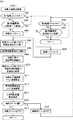
まず、主基板11における主要な動作を説明する。パチンコ遊技機1に対して電力供給が開始されると、遊技制御用マイクロコンピュータ100が起動し、CPU103によって遊技制御メイン処理が実行される。図3は、主基板11におけるCPU103が実行する遊技制御メイン処理を示すフローチャートである。
(Main operation of main board 11)
First, the main operations on the
図3に示す遊技制御メイン処理では、CPU103は、まず、割込禁止に設定する(ステップS1)。続いて、必要な初期設定を行う(ステップS2)。初期設定には、スタックポインタの設定、内蔵デバイス(CTC(カウンタ/タイマ回路)、パラレル入出力ポート等)のレジスタ設定、RAM102をアクセス可能状態にする設定等が含まれる。
In the game control main process shown in FIG. 3, the
次いで、クリアスイッチからの出力信号がオンであるか否かを判定する(ステップS3)。クリアスイッチは、例えば電源基板に搭載されている。クリアスイッチがオンの状態で電源が投入されると、出力信号(クリア信号)が入力ポートを介して遊技制御用マイクロコンピュータ100に入力される。クリアスイッチからの出力信号がオンである場合(ステップS3;Yes)、初期化処理(ステップS8)を実行する。初期化処理では、CPU103は、RAM102に記憶されるフラグ、カウンタ、バッファをクリアするRAMクリア処理を行い、作業領域に初期値を設定する。
Next, it is determined whether or not the output signal from the clear switch is ON (step S3). The clear switch is mounted on the power supply board, for example. When the power is turned on with the clear switch turned on, an output signal (clear signal) is input to the
また、CPU103は、初期化を指示する演出制御コマンドを演出制御基板12に送信する(ステップS9)。演出制御用CPU120は、当該演出制御コマンドを受信すると、例えば画像表示装置5において、遊技機の制御の初期化がなされたことを報知するための画面表示を行う。
Further, the
クリアスイッチからの出力信号がオンでない場合には(ステップS3;No)、RAM102(バックアップRAM)にバックアップデータが保存されているか否かを判定する(ステップS4)。不測の停電等(電断)によりパチンコ遊技機1への電力供給が停止したときには、CPU103は、当該電力供給の停止によって動作できなくなる直前に、電源供給停止時処理を実行する。この電源供給停止時処理では、RAM102にデータをバックアップすることを示すバックアップフラグをオンする処理、RAM102のデータ保護処理等が実行される。データ保護処理には、誤り検出符号(チェックサム、パリティビット等)の付加、各種データをバックアップする処理が含まれる。バックアップされるデータには、遊技を進行するための各種データ(各種フラグ、各種タイマの状態等を含む)の他、前記バックアップフラグの状態や誤り検出符号も含まれる。ステップS4では、バックアップフラグがオンであるか否かを判定する。バックアップフラグがオフでRAM102にバックアップデータが記憶されていない場合(ステップS4;No)、初期化処理(ステップS8)を実行する。
If the output signal from the clear switch is not on (step S3; No), it is determined whether or not the backup data is stored in the RAM 102 (backup RAM) (step S4). When the power supply to the
RAM102にバックアップデータが記憶されている場合(ステップS4;Yes)、CPU103は、バックアップしたデータのデータチェックを行い(誤り検出符号を用いて行われる)、データが正常か否かを判定する(ステップS5)。ステップS5では、例えば、パリティビットやチェックサムにより、RAM102のデータが、電力供給停止時のデータと一致するか否かを判定する。これらが一致すると判定された場合、RAM102のデータが正常であると判定する。
When the backup data is stored in the RAM 102 (step S4; Yes), the
RAM102のデータが正常でないと判定された場合(ステップS5;No)、内部状態を電力供給停止時の状態に戻すことができないので、初期化処理(ステップS8)を実行する。
If it is determined that the data in the
RAM102のデータが正常であると判定された場合(ステップS5;Yes)、CPU103は、主基板11の内部状態を電力供給停止時の状態に戻すための復旧処理(ステップS6)を行う。復旧処理では、CPU103は、RAM102の記憶内容(バックアップしたデータの内容)に基づいて作業領域の設定を行う。これにより、電力供給停止時の遊技状態に復旧し、特別図柄の変動中であった場合には、後述の遊技制御用タイマ割込み処理の実行によって、復旧前の状態から特別図柄の変動が再開されることになる。
When it is determined that the data in the
そして、CPU103は、電断からの復旧を指示する演出制御コマンドを演出制御基板12に送信する(ステップS7)。これに合わせて、バックアップされている電断前の遊技状態を指定する演出制御コマンドや、特図ゲームの実行中であった場合には当該実行中の特図ゲームの表示結果を指定する演出制御コマンドを送信するようにしてもよい。これらコマンドは、後述の特別図柄プロセス処理で送信設定されるコマンドと同じコマンドを使用できる。演出制御用CPU120は、電断からの復旧時を特定する演出制御コマンドを受信すると、例えば画像表示装置5において、電断からの復旧がなされたこと、または電断からの復旧中であることを、報知するための画面表示を行う。演出制御用CPU120は、前記演出制御コマンドに基づいて、適宜の画面表示を行うようにしてもよい。
Then, the
復旧処理または初期化処理を終了して演出制御基板12に演出制御コマンドを送信した後には、CPU103は、乱数回路104を初期設定する乱数回路設定処理を実行する(ステップS10)。そして、所定時間(例えば2ms)毎に定期的にタイマ割込がかかるように遊技制御用マイクロコンピュータ100に内蔵されているCTCのレジスタの設定を行い(ステップS11)、割込みを許可する(ステップS12)。その後、ループ処理に入る。以後、所定時間(例えば2ms)ごとにCTCから割込み要求信号がCPU103へ送出され、CPU103は定期的にタイマ割込み処理を実行することができる。
After the restoration process or the initialization process is completed and the effect control command is transmitted to the
こうした遊技制御メイン処理を実行したCPU103は、CTCからの割込み要求信号を受信して割込み要求を受け付けると、図4のフローチャートに示す遊技制御用タイマ割込み処理を実行する。図4に示す遊技制御用タイマ割込み処理を開始すると、CPU103は、まず、所定のスイッチ処理を実行することにより、スイッチ回路110を介してゲートスイッチ21、第1始動口スイッチ22A、第2始動口スイッチ22B、カウントスイッチ23といった各種スイッチからの検出信号の受信の有無を判定する(ステップS21)。続いて、所定のメイン側エラー処理を実行することにより、パチンコ遊技機1の異常診断を行い、その診断結果に応じて必要ならば警告を発生可能とする(ステップS22)。この後、所定の情報出力処理を実行することにより、例えばパチンコ遊技機1の外部に設置されたホール管理用コンピュータに供給される大当り情報(大当りの発生回数等を示す情報)、始動情報(始動入賞の回数等を示す情報)、確率変動情報(確変状態となった回数等を示す情報)などのデータを出力する(ステップS23)。
When the
情報出力処理に続いて、主基板11の側で用いられる遊技用乱数の少なくとも一部をソフトウェアにより更新するための遊技用乱数更新処理を実行する(ステップS24)。この後、CPU103は、特別図柄プロセス処理を実行する(ステップS25)。CPU103がタイマ割込み毎に特別図柄プロセス処理を実行することにより、特図ゲームの実行および保留の管理や、大当り遊技状態や小当り遊技状態の制御、遊技状態の制御などが実現される(詳しくは後述)。
Following the information output process, a game random number update process for updating at least a part of the game random numbers used on the
特別図柄プロセス処理に続いて、普通図柄プロセス処理が実行される(ステップS26)。CPU103がタイマ割込み毎に普通図柄プロセス処理を実行することにより、ゲートスイッチ21からの検出信号に基づく(通過ゲート41に遊技球が通過したことに基づく)普図ゲームの実行および保留の管理や、「普図当り」に基づく可変入賞球装置6Bの開放制御などを可能にする。普図ゲームの実行は、普通図柄表示器20を駆動することにより行われ、普図保留表示器25Cを点灯させることにより普図保留数を表示する。
Following the special symbol process process, the normal symbol process process is executed (step S26). By executing the normal symbol process process for each timer interrupt, the
行した後、遊技制御用タイマ割込み処理の一部として、電断が発生したときの処理、賞球を払い出すための処理等などが行われてもよい。その後、CPU103は、コマンド制御処理を実行する(ステップS27)。CPU103は、上記各処理にて演出制御コマンドを送信設定することがある。ステップS27のコマンド制御処理では、送信設定された演出制御コマンドを演出制御基板12などのサブ側の制御基板に対して伝送させる処理が行われる。コマンド制御処理を実行した後には、割込みを許可してから、遊技制御用タイマ割込み処理を終了する。
After this, as a part of the game control timer interrupt processing, processing when a power failure occurs, processing for paying out the prize ball, and the like may be performed. After that, the
図5は、特別図柄プロセス処理として、図4に示すステップS25にて実行される処理の一例を示すフローチャートである。この特別図柄プロセス処理において、CPU103は、まず、始動入賞判定処理を実行する(ステップS101)。
FIG. 5 is a flowchart showing an example of the process executed in step S25 shown in FIG. 4 as the special symbol process process. In this special symbol process process, the
始動入賞判定処理では、始動入賞の発生を検出し、RAM102の所定領域に保留情報を格納し保留記憶数を更新する処理が実行される。始動入賞が発生すると、表示結果(大当り種別を含む)や変動パターンを決定するための乱数値が抽出され、保留情報として記憶される。また、抽出した乱数値に基づいて、表示結果や変動パターンを先読判定する処理が実行されてもよい。保留情報や保留記憶数を記憶した後には、演出制御基板12に始動入賞の発生、保留記憶数、先読判定等の判定結果を指定するための演出制御コマンドを送信するための送信設定が行われる。こうして送信設定された始動入賞時の演出制御コマンドは、例えば特別図柄プロセス処理が終了した後、図4に示すステップS27のコマンド制御処理が実行されることなどにより、主基板11から演出制御基板12に対して伝送される。
In the start winning determination process, a process of detecting the occurrence of a start winning, storing the hold information in a predetermined area of the
ステップS101にて始動入賞判定処理を実行した後、CPU103は、RAM102に設けられた特図プロセスフラグの値に応じて、ステップS110〜S120の処理のいずれかを選択して実行する。なお、特別図柄プロセス処理の各処理(ステップS110〜S120)では、各処理に対応した演出制御コマンドを演出制御基板12に送信するための送信設定が行われる。
After executing the start winning determination process in step S101, the
ステップS110の特別図柄通常処理は、特図プロセスフラグの値が“0”(初期値)のときに実行される。この特別図柄通常処理では、保留情報の有無などに基づいて、第1特図ゲームまたは第2特図ゲームを開始するか否かの判定が行われる。また、特別図柄通常処理では、表示結果決定用の乱数値に基づき、特別図柄や飾り図柄の表示結果を「大当り」または「小当り」とするか否かや「大当り」とする場合の大当り種別を、その表示結果が導出表示される以前に決定(事前決定)する。さらに、特別図柄通常処理では、決定された表示結果に対応して、特図ゲームにおいて停止表示させる確定特別図柄(大当り図柄や小当り図柄、ハズレ図柄のいずれか)が設定される。その後、特図プロセスフラグの値が“1”に更新され、特別図柄通常処理は終了する。なお、第2特図を用いた特図ゲームが第1特図を用いた特図ゲームよりも優先して実行されるようにしてもよい(特図2優先消化ともいう)。また、第1始動入賞口および第2始動入賞口への遊技球の入賞順序を記憶し、入賞順に特図ゲームの開始条件を成立させるようにしてもよい(入賞順消化ともいう)。 The special symbol normal processing in step S110 is executed when the value of the special symbol process flag is “0” (initial value). In this special symbol normal processing, it is determined whether or not to start the first special figure game or the second special figure game based on the presence or absence of the pending information. In addition, in the special symbol normal processing, whether or not the display result of the special symbol or decorative symbol is set as "big hit" or "small hit" based on the random value for determining the display result, and the big hit type when it is set as "big hit". Is determined (predetermined) before the display result is derived and displayed. Further, in the special symbol normal processing, a fixed special symbol (either a big hit symbol, a small hit symbol, or a lost symbol) to be stopped and displayed in the special symbol game is set according to the determined display result. After that, the value of the special symbol process flag is updated to "1", and the special symbol normal processing ends. It should be noted that the special figure game using the second special figure may be executed with priority over the special figure game using the first special figure (also referred to as special figure 2 priority digestion). Further, the winning order of the game balls to the first starting winning opening and the second starting winning opening may be stored, and the starting condition of the special figure game may be satisfied in the winning order (also referred to as winning order digestion).
乱数値に基づき各種の決定を行う場合には、ROM101に格納されている各種のテーブル(乱数値と比較される決定値が決定結果に割り当てられているテーブル)が参照される。主基板11における他の決定、演出制御基板12における各種の決定についても同じである。演出制御基板12においては、各種のテーブルがROM121に格納されている。
When making various determinations based on the random number values, various tables stored in the ROM 101 (tables in which the determination values to be compared with the random number values are assigned to the determination results) are referred to. The same applies to other decisions on the
ステップS111の変動パターン設定処理は、特図プロセスフラグの値が“1”のときに実行される。この変動パターン設定処理には、表示結果を「大当り」または「小当り」とするか否かの事前決定結果等に基づき、変動パターン決定用の乱数値を用いて変動パターンを複数種類のいずれかに決定する処理などが含まれている。変動パターン設定処理では、変動パターンを決定したときに、特図プロセスフラグの値が“2”に更新され、変動パターン設定処理は終了する。 The variation pattern setting process in step S111 is executed when the value of the special figure process flag is “1”. In this fluctuation pattern setting process, one of a plurality of types of fluctuation patterns is used by using a random value for determining the fluctuation pattern based on a preliminary determination result of whether or not the display result is a "big hit" or a "small hit". The process of deciding on is included. In the variation pattern setting process, when the variation pattern is determined, the value of the special figure process flag is updated to "2", and the variation pattern setting process ends.
変動パターンは、特図ゲームの実行時間(特図変動時間)(飾り図柄の可変表示の実行時間でもある)や、飾り図柄の可変表示の態様(リーチの有無等)、飾り図柄の可変表示中の演出内容(リーチ演出の種類等)を指定するものであり、可変表示パターンとも呼ばれる。 The fluctuation pattern includes the execution time of the special symbol game (special symbol fluctuation time) (which is also the execution time of the variable display of the decorative symbol), the mode of the variable display of the decorative symbol (presence or absence of reach, etc.), and the variable display of the decorative symbol. The content of the effect (type of reach effect, etc.) is specified, and it is also called a variable display pattern.
ステップS112の特別図柄変動処理は、特図プロセスフラグの値が“2”のときに実行される。この特別図柄変動処理には、第1特別図柄表示装置4Aや第2特別図柄表示装置4Bにおいて特別図柄を変動させるための設定を行う処理や、その特別図柄が変動を開始してからの経過時間を計測する処理などが含まれている。また、計測された経過時間が変動パターンに対応する特図変動時間に達したか否かの判定も行われる。そして、特別図柄の変動を開始してからの経過時間が特図変動時間に達したときには、特図プロセスフラグの値が“3”に更新され、特別図柄変動処理は終了する。
The special symbol variation process in step S112 is executed when the value of the special symbol process flag is “2”. In this special symbol change process, the process of making settings for changing the special symbol in the first special
ステップS113の特別図柄停止処理は、特図プロセスフラグの値が“3”のときに実行される。この特別図柄停止処理には、第1特別図柄表示装置4Aや第2特別図柄表示装置4Bにて特別図柄の変動を停止させ、特別図柄の表示結果となる確定特別図柄を停止表示(導出)させるための設定を行う処理が含まれている。そして、表示結果が「大当り」である場合には特図プロセスフラグの値が“4”に更新される。その一方で、大当りフラグがオフであり、表示結果が「小当り」である場合には、特図プロセスフラグの値が“8”に更新される。また、表示結果が「ハズレ」である場合には、特図プロセスフラグの値が“0”に更新される。表示結果が「小当り」または「ハズレ」である場合、時短状態や確変状態に制御されているときであって、回数切りの終了成立する場合には、遊技状態も更新される。特図プロセスフラグの値が更新されると、特別図柄停止処理は終了する。
The special symbol stop process in step S113 is executed when the value of the special symbol process flag is “3”. In this special symbol stop process, the first special
ステップS114の大当り開放前処理は、特図プロセスフラグの値が“4”のときに実行される。この大当り開放前処理には、表示結果が「大当り」となったことなどに基づき、大当り遊技状態においてラウンドの実行を開始して大入賞口を開放状態とするための設定を行う処理などが含まれている。大入賞口を開放状態とするときには、大入賞口扉用のソレノイド82に対してソレノイド駆動信号を供給する処理が実行される。このときには、例えば大当り種別がいずれであるかに対応して、大入賞口を開放状態とする開放上限期間や、ラウンドの上限実行回数を設定する。これらの設定が終了すると、特図プロセスフラグの値が“5”に更新され、大当り開放前処理は終了する。 The jackpot release preprocessing in step S114 is executed when the value of the special figure process flag is “4”. This big hit pre-opening process includes a process for starting the execution of a round in the big hit game state and setting the big winning opening to be open based on the display result being "big hit". It has been. When the large winning opening is opened, a process of supplying a solenoid drive signal to the solenoid 82 for the large winning opening door is executed. At this time, for example, the open upper limit period for keeping the big winning opening in the open state and the upper limit execution number of rounds are set according to which type of jackpot is used. When these settings are completed, the value of the special figure process flag is updated to "5", and the jackpot release preprocessing ends.
ステップS115の大当り開放中処理は、特図プロセスフラグの値が“5”のときに実行される。この大当り開放中処理には、大入賞口を開放状態としてからの経過時間を計測する処理や、その計測した経過時間やカウントスイッチ23によって検出された遊技球の個数などに基づいて、大入賞口を開放状態から閉鎖状態に戻すタイミングとなったか否かを判定する処理などが含まれている。そして、大入賞口を閉鎖状態に戻すときには、大入賞口扉用のソレノイド82に対するソレノイド駆動信号の供給を停止させる処理などを実行した後、特図プロセスフラグの値が“6”に更新し、大当り開放中処理を終了する。
The process of opening the jackpot in step S115 is executed when the value of the special figure process flag is “5”. In this big hit opening process, the process of measuring the elapsed time since the big winning opening is opened, the measured elapsed time, the number of game balls detected by the
ステップS116の大当り開放後処理は、特図プロセスフラグの値が“6”のときに実行される。この大当り開放後処理には、大入賞口を開放状態とするラウンドの実行回数が設定された上限実行回数に達したか否かを判定する処理や、上限実行回数に達した場合に大当り遊技状態を終了させるための設定を行う処理などが含まれている。そして、ラウンドの実行回数が上限実行回数に達していないときには、特図プロセスフラグの値が“5”に更新される一方、ラウンドの実行回数が上限実行回数に達したときには、特図プロセスフラグの値が“7”に更新される。特図プロセスフラグの値が更新されると、大当り解放後処理は終了する。 The post-processing after opening the jackpot in step S116 is executed when the value of the special figure process flag is “6”. In this post-opening process of the jackpot, a process of determining whether or not the number of executions of the round that opens the jackpot has reached the set upper limit execution number, and a jackpot game state when the upper limit execution number is reached. It includes processing to make settings to terminate. Then, when the number of round executions has not reached the upper limit, the value of the special figure process flag is updated to "5", while when the number of round executions reaches the upper limit, the special figure process flag is set. The value is updated to "7". When the value of the special figure process flag is updated, the post-launch processing is completed.
ステップS117の大当り終了処理は、特図プロセスフラグの値が“7”のときに実行される。この大当り終了処理には、大当り遊技状態の終了を報知する演出動作としてのエンディング演出が実行される期間に対応した待ち時間が経過するまで待機する処理や、大当り遊技状態の終了に対応して確変制御や時短制御を開始するための各種の設定を行う処理などが含まれている。こうした設定が行われたときには、特図プロセスフラグの値が“0”に更新され、大当り終了処理は終了する。 The jackpot end processing of step S117 is executed when the value of the special figure process flag is “7”. In this jackpot end process, there is a process of waiting until the waiting time corresponding to the period in which the ending effect as an effect action for notifying the end of the jackpot game state is executed, and a probability change corresponding to the end of the jackpot game state. It includes processing to make various settings to start control and time saving control. When such a setting is made, the value of the special figure process flag is updated to "0", and the jackpot end processing ends.
ステップS118の小当り開放前処理は、特図プロセスフラグの値が“8”のときに実行される。この小当り開放前処理には、表示結果が「小当り」となったことに基づき、小当り遊技状態において大入賞口を開放状態とするための設定を行う処理などが含まれている。このときには、特図プロセスフラグの値が“9”に更新され、小当り開放前処理は終了する。 The small hit release preprocessing in step S118 is executed when the value of the special figure process flag is “8”. This small hit pre-opening process includes a process of setting the large winning opening to be in the open state in the small hit game state based on the display result being "small hit". At this time, the value of the special figure process flag is updated to "9", and the small hit release preprocessing ends.
ステップS119の小当り開放中処理は、特図プロセスフラグの値が“9”のときに実行される。この小当り開放中処理には、大入賞口を開放状態としてからの経過時間を計測する処理や、その計測した経過時間などに基づいて、大入賞口を開放状態から閉鎖状態に戻すタイミングとなったか否かを判定する処理などが含まれている。大入賞口を閉鎖状態に戻して小当り遊技状態の終了タイミングとなったときには、特図プロセスフラグの値が“10”に更新され、小当り開放中処理は終了する。 The small hit opening process in step S119 is executed when the value of the special figure process flag is “9”. In this small hit opening process, it is the timing to measure the elapsed time from the opening state of the big winning opening and to return the big winning opening from the open state to the closed state based on the measured elapsed time. It includes processing to determine whether or not it is. When the big winning opening is returned to the closed state and the end timing of the small hit game state is reached, the value of the special figure process flag is updated to "10", and the processing during the small hit opening process ends.
ステップS120の小当り終了処理は、特図プロセスフラグの値が“10”のときに実行される。この小当り終了処理には、小当り遊技状態の終了を報知する演出動作が実行される期間に対応した待ち時間が経過するまで待機する処理などが含まれている。ここで、小当り遊技状態が終了するときには、小当り遊技状態となる以前のパチンコ遊技機1における遊技状態を継続させる。小当り遊技状態の終了時における待ち時間が経過したときには、特図プロセスフラグの値が“0”に更新され、小当り終了処理は終了する。
The small hit end process in step S120 is executed when the value of the special figure process flag is “10”. The small hit end process includes a process of waiting until a waiting time corresponding to a period in which the effect operation for notifying the end of the small hit game state is executed elapses. Here, when the small hit gaming state ends, the gaming state in the
(演出制御基板12の主要な動作)
次に、演出制御基板12における主要な動作を説明する。演出制御基板12では、電源基板等から電源電圧の供給を受けると、演出制御用CPU120が起動して、図6のフローチャートに示すような演出制御メイン処理を実行する。図6に示す演出制御メイン処理を開始すると、演出制御用CPU120は、まず、所定の初期化処理を実行して(ステップS71)、RAM122のクリアや各種初期値の設定、また演出制御基板12に搭載されたCTC(カウンタ/タイマ回路)のレジスタ設定等を行う。また、初期動作制御処理を実行する(ステップS72)。初期動作制御処理では、可動体32を駆動して初期位置に戻す制御、所定の動作確認を行う制御といった可動体32の初期動作を行う制御が実行される。
(Main operation of the effect control board 12)
Next, the main operation of the
その後、タイマ割込みフラグがオンとなっているか否かの判定を行う(ステップS73)。タイマ割込みフラグは、例えばCTCのレジスタ設定に基づき、所定時間(例えば2ミリ秒)が経過するごとにオン状態にセットされる。このとき、タイマ割込みフラグがオフであれば(ステップS73;No)、ステップS73の処理を繰り返し実行して待機する。 After that, it is determined whether or not the timer interrupt flag is turned on (step S73). The timer interrupt flag is set to the ON state every time a predetermined time (for example, 2 milliseconds) elapses, based on the register setting of the CTC, for example. At this time, if the timer interrupt flag is off (step S73; No), the process of step S73 is repeatedly executed and waits.
また、演出制御基板12の側では、所定時間が経過するごとに発生するタイマ割込みとは別に、主基板11からの演出制御コマンドを受信するための割込みが発生する。この割込みは、例えば主基板11からの演出制御INT信号がオン状態となることにより発生する割込みである。演出制御INT信号がオン状態となることによる割込みが発生すると、演出制御用CPU120は、自動的に割込み禁止に設定するが、自動的に割込み禁止状態にならないCPUを用いている場合には、割込み禁止命令(DI命令)を発行することが望ましい。演出制御用CPU120は、演出制御INT信号がオン状態となることによる割込みに対応して、例えば所定のコマンド受信割込み処理を実行する。このコマンド受信割込み処理では、I/O125に含まれる入力ポートのうちで、中継基板15を介して主基板11から送信された制御信号を受信する所定の入力ポートより、演出制御コマンドを取り込む。このとき取り込まれた演出制御コマンドは、例えばRAM122に設けられた演出制御コマンド受信用バッファに格納する。その後、演出制御用CPU120は、割込み許可に設定してから、コマンド受信割込み処理を終了する。
Further, on the
ステップS73にてタイマ割込みフラグがオンである場合には(ステップS73;Yes)、タイマ割込みフラグをクリアしてオフ状態にするとともに(ステップS74)、コマンド解析処理を実行する(ステップS75)。コマンド解析処理では、例えば主基板11の遊技制御用マイクロコンピュータ100から送信されて演出制御コマンド受信用バッファに格納されている各種の演出制御コマンドを読み出した後に、その読み出された演出制御コマンドに対応した設定や制御などが行われる。例えば、どの演出制御コマンドを受信したかや演出制御コマンドが特定する内容等を演出制御プロセス処理等で確認できるように、読み出された演出制御コマンドをRAM122の所定領域に格納したり、RAM122に設けられた受信フラグをオンしたりする。また、演出制御コマンドが遊技状態を特定する場合、遊技状態に応じた背景の表示を表示制御部123に指示してもよい。
If the timer interrupt flag is on in step S73 (step S73; Yes), the timer interrupt flag is cleared and turned off (step S74), and the command analysis process is executed (step S75). In the command analysis process, for example, after reading various effect control commands transmitted from the
ステップS75にてコマンド解析処理を実行した後には、演出制御プロセス処理を実行する(ステップS76)。演出制御プロセス処理では、例えば画像表示装置5の表示領域における演出画像の表示動作、スピーカ8L、8Rからの音声出力動作、遊技効果ランプ9および装飾用LEDといった装飾発光体における点灯動作、可動体32の駆動動作といった、各種の演出装置を動作させる制御が行われる。また、各種の演出装置を用いた演出動作の制御内容について、主基板11から送信された演出制御コマンド等に応じた判定や決定、設定などが行われる。
After executing the command analysis process in step S75, the effect control process process is executed (step S76). In the effect control process processing, for example, an effect image display operation in the display area of the
ステップS76の演出制御プロセス処理に続いて、演出用乱数更新処理が実行され(ステップS77)、演出制御基板12の側で用いられる演出用乱数の少なくとも一部がソフトウェアにより更新される。その後、ステップS73の処理に戻る。ステップS73の処理に戻る前に、他の処理が実行されてもよい。
Following the effect control process process in step S76, the effect random number update process is executed (step S77), and at least a part of the effect random numbers used on the
図7は、演出制御プロセス処理として、図6のステップS76にて実行される処理の一例を示すフローチャートである。図7に示す演出制御プロセス処理において、演出制御用CPU120は、まず、先読予告設定処理を実行する(ステップS161)。先読予告設定処理では、例えば、主基板11から送信された始動入賞時の演出制御コマンドに基づいて、先読予告演出を実行するための判定や決定、設定などが行われる。また、当該演出制御コマンドから特定される保留記憶数に基づき保留表示を表示するための処理が実行される。
FIG. 7 is a flowchart showing an example of the process executed in step S76 of FIG. 6 as the effect control process process. In the effect control process process shown in FIG. 7, the
ステップS161の処理を実行した後、演出制御用CPU120は、例えばRAM122に設けられた演出プロセスフラグの値に応じて、以下のようなステップS170〜S177の処理のいずれかを選択して実行する。
After executing the process of step S161, the
ステップS170の可変表示開始待ち処理は、演出プロセスフラグの値が“0”(初期値)のときに実行される処理である。この可変表示開始待ち処理は、主基板11から可変表示の開始を指定するコマンドなどを受信したか否かに基づき、画像表示装置5における飾り図柄の可変表示を開始するか否かを判定する処理などを含んでいる。画像表示装置5における飾り図柄の可変表示を開始すると判定された場合、演出プロセスフラグの値を“1”に更新し、可変表示開始待ち処理を終了する。
The variable display start waiting process in step S170 is a process executed when the value of the effect process flag is “0” (initial value). This variable display start waiting process is a process of determining whether or not to start the variable display of the decorative symbol on the
ステップS171の可変表示開始設定処理は、演出プロセスフラグの値が“1”のときに実行される処理である。この可変表示開始設定処理では、演出制御コマンドにより特定される表示結果や変動パターンに基づいて、飾り図柄の可変表示の表示結果(確定飾り図柄)、飾り図柄の可変表示の態様、リーチ演出や各種予告演出などの各種演出の実行の有無やその態様や実行開始タイミングなどを決定する。そして、その決定結果等を反映した演出制御パターン(表示制御部123に演出の実行を指示するための制御データの集まり)を設定する。その後、設定した演出制御パターンに基づいて、飾り図柄の可変表示の実行開始を表示制御部123に指示し、演出プロセスフラグの値を“2”に更新し、可変表示開始設定処理を終了する。表示制御部123は、飾り図柄の可変表示の実行開始の指示により、画像表示装置5において、飾り図柄の可変表示を開始させる。
The variable display start setting process in step S171 is a process executed when the value of the effect process flag is “1”. In this variable display start setting process, the display result of the variable display of the decorative symbol (fixed decorative symbol), the mode of the variable display of the decorative symbol, the reach effect, and various types are based on the display result and the variation pattern specified by the effect control command. It is determined whether or not various effects such as a notice effect are executed, their modes, and the execution start timing. Then, an effect control pattern (a collection of control data for instructing the
ステップS172の可変表示中演出処理は、演出プロセスフラグの値が“2”のときに実行される処理である。この可変表示中演出処理において、演出制御用CPU120は、表示制御部123を指示することで、ステップS171にて設定された演出制御パターンに基づく演出画像を画像表示装置5の表示画面に表示させることや、可動体32を駆動させること、音声制御基板13に対する指令(効果音信号)の出力によりスピーカ8L、8Rから音声や効果音を出力させること、ランプ制御基板14に対する指令(電飾信号)の出力により遊技効果ランプ9や装飾用LEDを点灯/消灯/点滅させることといった、飾り図柄の可変表示中における各種の演出制御を実行する。こうした演出制御を行った後、例えば演出制御パターンから飾り図柄の可変表示終了を示す終了コードが読み出されたこと、あるいは、主基板11から確定飾り図柄を停止表示させることを指定するコマンドを受信したことなどに対応して、飾り図柄の表示結果となる確定飾り図柄を停止表示させる。確定飾り図柄を停止表示したときには、演出プロセスフラグの値が“3”に更新され、可変表示中演出処理は終了する。
The variable display effect process in step S172 is a process executed when the value of the effect process flag is “2”. In this variable display effect processing, the
ステップS173の特図当り待ち処理は、演出プロセスフラグの値が“3”のときに実行される処理である。この特図当り待ち処理において、演出制御用CPU120は、主基板11から大当り遊技状態または小当り遊技状態を開始することを指定する演出制御コマンドの受信があったか否かを判定する。そして、大当り遊技状態または小当り遊技状態を開始することを指定する演出制御コマンドを受信したきに、そのコマンドが大当り遊技状態の開始を指定するものであれば、演出プロセスフラグの値を“6”に更新する。これに対して、そのコマンドが小当り遊技状態の開始を指定するものであれば、演出プロセスフラグの値を小当り中演出処理に対応した値である“4”に更新する。また、大当り遊技状態または小当り遊技状態を開始することを指定するコマンドを受信せずに、当該コマンドの受信待ち時間が経過したときには、特図ゲームにおける表示結果が「ハズレ」であったと判定して、演出プロセスフラグの値を初期値である“0”に更新する。演出プロセスフラグの値を更新すると、特図当り待ち処理を終了する。
The special figure hit waiting process in step S173 is a process executed when the value of the effect process flag is “3”. In this special figure hit waiting process, the
ステップS174の小当り中演出処理は、演出プロセスフラグの値が“4”のときに実行される処理である。この小当り中演出処理において、演出制御用CPU120は、例えば小当り遊技状態における演出内容に対応した演出制御パターン等を設定し、その設定内容に基づく小当り遊技状態における各種の演出制御を実行する。また、小当り中演出処理では、例えば主基板11から小当り遊技状態を終了することを指定するコマンドを受信したことに対応して、演出プロセスフラグの値を小当り終了演出に対応した値である“5”に更新し、小当り中演出処理を終了する。
The small hit medium effect process in step S174 is a process executed when the value of the effect process flag is “4”. In this small hit medium effect process, the
ステップS175の小当り終了演出処理は、演出プロセスフラグの値が“5”のときに実行される処理である。この小当り終了演出処理において、演出制御用CPU120は、例えば小当り遊技状態の終了などに対応した演出制御パターン等を設定し、その設定内容に基づく小当り遊技状態の終了時における各種の演出制御を実行する。その後、演出プロセスフラグの値を初期値である“0”に更新し、小当り終了演出処理を終了する。
The small hit end effect process in step S175 is a process executed when the value of the effect process flag is “5”. In this small hit end effect process, the
ステップS176の大当り中演出処理は、演出プロセスフラグの値が“6”のときに実行される処理である。この大当り中演出処理において、演出制御用CPU120は、例えば大当り遊技状態における演出内容に対応した演出制御パターン等を設定し、その設定内容に基づく大当り遊技状態における各種の演出制御を実行する。また、大当り中演出処理では、例えば主基板11から大当り遊技状態を終了することを指定するコマンドを受信したことに対応して、演出プロセスフラグの値をエンディング演出処理に対応した値である“7”に更新し、大当り中演出処理を終了する。
The jackpot effect process in step S176 is a process executed when the value of the effect process flag is “6”. In this big hit middle effect processing, the
ステップS177のエンディング演出処理は、演出プロセスフラグの値が“7”のときに実行される処理である。このエンディング演出処理において、演出制御用CPU120は、例えば大当り遊技状態の終了などに対応した演出制御パターン等を設定し、その設定内容に基づく大当り遊技状態の終了時におけるエンディング演出の各種の演出制御を実行する。その後、演出プロセスフラグの値を初期値である“0”に更新し、エンディング演出処理を終了する。
The ending effect process of step S177 is a process executed when the value of the effect process flag is “7”. In this ending effect processing, the
(基本説明の変形例)
この発明は、上記基本説明で説明したパチンコ遊技機1に限定されず、本発明の趣旨を逸脱しない範囲で、様々な変形および応用が可能である。
(Modified example of basic explanation)
The present invention is not limited to the
上記基本説明のパチンコ遊技機1は、入賞の発生に基づいて所定数の遊技媒体を景品として払い出す払出式遊技機であったが、遊技媒体を封入し入賞の発生に基づいて得点を付与する封入式遊技機であってもよい。
The
特別図柄の可変表示中に表示されるものは1種類の図柄(例えば、「−」を示す記号)だけで、当該図柄の表示と消灯とを繰り返すことによって可変表示を行うようにしてもよい。さらに可変表示中に当該図柄が表示されるものも、可変表示の停止時には、当該図柄が表示されなくてもよい(表示結果としては「−」を示す記号が表示されなくてもよい)。 Only one type of symbol (for example, a symbol indicating "-") is displayed during the variable display of the special symbol, and the variable display may be performed by repeating the display and extinguishing of the symbol. Further, even if the symbol is displayed during the variable display, the symbol may not be displayed when the variable display is stopped (the symbol indicating "-" may not be displayed as the display result).
上記基本説明では、遊技機としてパチンコ遊技機1を示したが、メダルが投入されて所定の賭け数が設定され、遊技者による操作レバーの操作に応じて複数種類の図柄を回転させ、遊技者によるストップボタンの操作に応じて図柄を停止させたときに停止図柄の組合せが特定の図柄の組み合わせになると、所定数のメダルが遊技者に払い出されるゲームを実行可能なスロット機(例えば、ビッグボーナス、レギュラーボーナス、RT、AT、ART、CZ(以下、ボーナス等)のうち1以上を搭載するスロット機)にも本発明を適用可能である。
In the above basic explanation, the
本発明を実現するためのプログラムおよびデータは、パチンコ遊技機1に含まれるコンピュータ装置などに対して、着脱自在の記録媒体により配布・提供される形態に限定されるものではなく、予めコンピュータ装置などの有する記憶装置にインストールしておくことで配布される形態を採っても構わない。さらに、本発明を実現するためのプログラムおよびデータは、通信処理部を設けておくことにより、通信回線等を介して接続されたネットワーク上の、他の機器からダウンロードすることによって配布する形態を採っても構わない。
The program and data for realizing the present invention are not limited to the form of being distributed and provided by the detachable recording medium to the computer device included in the
そして、ゲームの実行形態も、着脱自在の記録媒体を装着することにより実行するものだけではなく、通信回線等を介してダウンロードしたプログラムおよびデータを、内部メモリ等に一旦格納することにより実行可能とする形態、通信回線等を介して接続されたネットワーク上における、他の機器側のハードウェア資源を用いて直接実行する形態としてもよい。さらには、他のコンピュータ装置等とネットワークを介してデータの交換を行うことによりゲームを実行するような形態とすることもできる。 The game can be executed not only by attaching a detachable recording medium, but also by temporarily storing programs and data downloaded via a communication line or the like in an internal memory or the like. It may be a form of directly executing using the hardware resources of another device on a network connected via a communication line or the like. Further, the game can be executed by exchanging data with another computer device or the like via a network.
なお、本明細書において、演出の実行割合などの各種割合の比較の表現(「高い」、「低い」、「異ならせる」などの表現)は、一方が「0%」の割合であることを含んでもよい。例えば、一方が「0%」の割合で、他方が「100%」の割合または「100%」未満の割合であることも含む。 In addition, in this specification, one of the expressions for comparison of various ratios such as the execution ratio of the production (expressions such as "high", "low", and "differentiate") is "0%". It may be included. For example, one may have a percentage of "0%" and the other may have a percentage of "100%" or less than "100%".
(設定値に関する特徴部の説明)
以下、パチンコ遊技機1における設定値に関する特徴部について説明する。
(Explanation of the feature part regarding the set value)
Hereinafter, the feature portion related to the set value in the
パチンコ遊技機1の主基板11は、図示は省略しているが、第1部材と第2部材とにより開放可能に構成された基板ケースに収納された状態でパチンコ遊技機1の背面に搭載されている。また、主基板11には、何れも図示は省略しているが、パチンコ遊技機1の設定値を変更可能な設定値変更状態に切り替えるための錠スイッチと、設定値変更状態において後述する大当りの当選確率(出玉率)等の設定値を変更するための設定スイッチとして機能する設定切替スイッチと、遊技機用枠の開放を検知する開放センサと、が設けられている。なお、本実施の形態における設定値変更状態は、遊技場の係員等がパチンコ遊技機1に設定されている設定値を確認可能な状態(設定値確認状態)でもある。
Although not shown, the
これら錠スイッチ及び設定切替スイッチといった、遊技場の係員等が操作可能な操作部は、設定切替本体部に設けられ、主基板11とともに基板ケース内に収容されている。錠スイッチ及び設定切替スイッチは、基板ケースを開放しなくても操作可能となるように、基板ケースの背面に形成された開口を介して背面側に露出している。
Operation units such as these lock switches and setting changeover switches that can be operated by the staff of the amusement park and the like are provided in the setting changeover main body unit and are housed in the board case together with the
錠スイッチ及び設定切替スイッチを収容した基板ケースはパチンコ遊技機1の背面に設けられている。したがって、錠スイッチ及び設定切替スイッチは、遊技機用枠を閉鎖した状態では操作が極めて困難あるいは不可能であり、所定の扉キーを用いて遊技機用枠を開放することで操作が可能となる。また、錠スイッチは、遊技場の係員等が所持する設定キーの操作を要することから、設定キーを所持する管理者のみ操作が可能とされている。錠スイッチは、設定キーによって、ONとOFFの切替操作を実行可能なスイッチでもある。本実施の形態では、扉キーと設定キーとが別個のキーである形態を例示しているが、これらは1のキーにて兼用されていてもよい。
A board case containing a lock switch and a setting changeover switch is provided on the back surface of the
基板ケースには、設定値やベース値を表示可能な表示モニタが配置されている。表示モニタは、主基板11に接続されているとともに、基板ケースの上部に配置されている。つまり、表示モニタは、基板ケースにおける主基板11を視認する際の正面に配置されている。主基板11は、遊技機用枠を開放していない状態では視認できないので、主基板11を視認する際の正面とは、遊技機用枠を開放した状態における遊技盤2の裏面側を視認する際の正面であり、パチンコ遊技機1の正面とは異なる。このように、表示モニタは、遊技機用枠を開放した状態における遊技盤2の裏面側を視認する際の正面に配置されている。ただし、主基板11を視認する際の正面とパチンコ遊技機1の正面とが共通するようにしてもよい。
A display monitor capable of displaying set values and base values is arranged on the board case. The display monitor is connected to the
表示モニタは、第1表示部、第2表示部、第3表示部、第4表示部を備えている。表示モニタの第1表示部〜第4表示部は、いずれも「8」の字を描く7つのセグメントによって構成される7セグメントと、7セグメントの右側方下部に配置されたドットによって構成されている。表示モニタの第1表示部〜第4表示部は、それぞれ種々の色、例えば赤色、青色、緑色、黄色、白色等で点灯や点滅が可能とされている。また、これらの色を極短周期で変化させながら異なる色やいわゆるレインボーで表示させることも可能である。 The display monitor includes a first display unit, a second display unit, a third display unit, and a fourth display unit. The first display unit to the fourth display unit of the display monitor are each composed of seven segments composed of seven segments drawing the shape of "8" and dots arranged on the lower right side of the seven segments. .. The first display unit to the fourth display unit of the display monitor can be lit or blinked in various colors such as red, blue, green, yellow, and white. It is also possible to display these colors in different colors or so-called rainbows while changing them in a very short cycle.
パチンコ遊技機1の遊技盤2の所定位置として、例えば遊技領域の左下方位置には、遊技情報表示部が設けられていてもよい。遊技情報表示部には、ラウンド表示器、右打ちランプ、確変ランプ、時短ランプが、まとめて配置されている。ラウンド表示器は、大当り遊技中に、大当り遊技のラウンド数や大当り種別を表示可能である。右打ちランプは、時短状態としての低確高ベース状態や大当り遊技状態といった、遊技球を右遊技領域に向けて打ち出す遊技状態において点灯する。確変ランプは、確変状態であるとき点灯する。時短ランプは、時短状態であるときに点灯する。ラウンド表示器は5個のセグメント(LED)から構成されている。
A game information display unit may be provided as a predetermined position of the
パチンコ遊技機1は、設定値に応じて大当りの当選確率(出玉率)が変わる構成とされている。例えば、特別図柄プロセス処理の特別図柄通常処理において、設定値に応じた表示結果判定テーブル(当選確率)を用いることにより、大当りの当選確率(出玉率)が変わるようになっている。設定値は1〜6の6段階からなり、6が最も出玉率が高く、6、5、4、3、2、1の順に値が小さくなるほど出玉率が低くなる。すなわち、設定値として6が設定されている場合には遊技者にとって最も有利度が高く、5、4、3、2、1の順に値が小さくなるほど有利度が段階的に低くなる。また、設定値は、最も大きい値である6が最も遊技場側にとって不利な値であり、5、4、3、2、1の順に値が小さくなるほど遊技場側にとって有利な値となる。なお、設定値に応じて出玉率が変われば、例えば、大当りの確率が設定値によって変わっていてもよいし、大当り確率は一定であるものの大当り遊技状態におけるラウンド数が設定値によって変わっていてもよい。このように、パチンコ遊技機1は、遊技者にとっての有利度が異なる複数の設定値のうちいずれかを設定可能に構成されている。パチンコ遊技機1において設定されている設定値は、主基板11の側から演出制御基板12の側へ設定値指定コマンドが送信されることにより通知される。
The
図8−1(A)及び図8−1(B)は、表示結果判定テーブルを示す説明図である。このうち、図8−1(A)は変動特図が第1特図である場合に用いられる第1特図用表示結果判定テーブルの構成例を示し、図8−2(A)は変動特図が第2特図である場合に用いられる第2特図用表示結果判定テーブルの構成例を示している。表示結果判定テーブルは、ROM101に記憶されているデータの集まりであり、設定値毎に乱数値MR1と比較される当り判定値が特別図柄の可変表示結果(特図表示結果)に設定されたテーブルである。乱数値MR1は、表示結果決定用の乱数値であり、0〜65535の範囲でランダムに値が更新される。表示結果判定テーブルにおける当り判定値も、0〜65535の範囲で特図表示結果に割り当てられている。表示結果判定テーブルとして、第1特図と第2特図とで個別の表示結果判定テーブルを用いるものに限定されるものではなく、第1特図と第2特図とで共通の表示結果判定テーブルを用いるようにしてもよい。
8-1 (A) and 8-1 (B) are explanatory views showing a display result determination table. Of these, FIG. 8-1 (A) shows a configuration example of the display result determination table for the first special figure used when the variable special figure is the first special figure, and FIG. 8-2 (A) shows the variable special figure. A configuration example of the display result determination table for the second special figure used when the figure is the second special figure is shown. The display result judgment table is a collection of data stored in the
設定値が1であり変動特図が第1特図である場合のうち、遊技状態が通常状態または時短状態である場合に、表示結果決定用の乱数値MR1と比較される当り判定値は、1020〜1237までが「大当り」に割り当てられ、32767〜33094までが「小当り」に割り当てられ、その他の数値範囲が「ハズレ」に割り当てられている。設定値が1であり変動特図が第1特図である場合のうち、遊技状態が確変状態である場合に、表示結果判定用の乱数値MR1と比較される当り判定値は、1020〜1346までが「大当り」に割り当てられ、32767〜33094までが「小当り」に割り当てられ、その他の数値範囲が「ハズレ」に割り当てられている。設定値が1であり変動特図が第2特図である場合のうち、遊技状態が通常状態または時短状態である場合に、表示結果決定用の乱数値MR1と比較される当り判定値は、1020〜1237までが「大当り」に割り当てられ、32767〜33421までが「小当り」に割り当てられ、その他の数値範囲が「ハズレ」に割り当てられている。設定値が1であり変動特図が第2特図である場合のうち、遊技状態が確変状態である場合に、表示結果決定用の乱数値MR1と比較される当り判定値は、1020〜1346までが「大当り」に割り当てられ、32767〜33421までが「小当り」に割り当てられ、その他の数値範囲が「ハズレ」に割り当てられている。 Among the cases where the set value is 1 and the variable special figure is the first special figure, when the game state is the normal state or the time saving state, the hit judgment value to be compared with the random number value MR1 for determining the display result is 1020 to 1237 are assigned to "big hits", 32767 to 33094 are assigned to "small hits", and other numerical ranges are assigned to "misses". Among the cases where the set value is 1 and the variable special figure is the first special figure, when the game state is the probabilistic state, the hit judgment value compared with the random number value MR1 for judging the display result is 1020 to 1346. Is assigned to "big hit", 32767 to 33094 are assigned to "small hit", and other numerical ranges are assigned to "miss". Among the cases where the set value is 1 and the variable special figure is the second special figure, when the game state is the normal state or the time saving state, the hit judgment value to be compared with the random number value MR1 for determining the display result is 1020 to 1237 are assigned to "big hits", 32767 to 33421 are assigned to "small hits", and other numerical ranges are assigned to "misses". Among the cases where the set value is 1 and the variable special figure is the second special figure, when the game state is the probabilistic state, the hit judgment value to be compared with the random number value MR1 for determining the display result is 1020 to 1346. Are assigned to "big hits", 32767 to 33421 are assigned to "small hits", and other numerical ranges are assigned to "misses".
設定値が2であり変動特図が第1特図である場合のうち、遊技状態が通常状態または時短状態である場合に、表示結果決定用の乱数値MR1と比較される当り判定値は、1020〜1253までが「大当り」に割り当てられ、32767〜33094までが「小当り」に割り当てられ、その他の数値範囲が「ハズレ」に割り当てられている。設定値が2であり変動特図が第1特図である場合のうち、遊技状態が確変状態である場合に、表示結果決定用の乱数値MR1と比較される当り判定値のうち、1020〜1383までが「大当り」に割り当てられ、32767〜33094までが「小当り」に割り当てられ、その他の数値範囲が「ハズレ」に割り当てられている。設定値が2であり変動特図が第2特図である場合のうち、遊技状態が通常状態または時短状態である場合に、表示結果決定用の乱数値MR1と比較される当り判定値は、1020〜1253までが「大当り」に割り当てられ、32767〜33421までが「小当り」に割り当てられ、その他の数値範囲が「ハズレ」に割り当てられている。設定値が2であり変動特図が第2特図である場合のうち、遊技状態が確変状態である場合に、表示結果決定用の乱数値MR1と比較される当り判定値は、1020〜1383までが「大当り」に割り当てられ、32767〜33421までが「小当り」に割り当てられ、その他の数値範囲が「ハズレ」に割り当てられている。 Among the cases where the set value is 2 and the variable special figure is the first special figure, when the game state is the normal state or the time saving state, the hit judgment value to be compared with the random number value MR1 for determining the display result is 1020-1253 are assigned to "big hits", 32767 to 33094 are assigned to "small hits", and other numerical ranges are assigned to "misses". Of the hit judgment values compared with the random number value MR1 for determining the display result when the game state is the probabilistic state in the case where the set value is 2 and the variable special figure is the first special figure, 1020 to Up to 1383 is assigned to "big hit", 32767 to 33094 are assigned to "small hit", and other numerical ranges are assigned to "miss". Among the cases where the set value is 2 and the variable special figure is the second special figure, when the game state is the normal state or the time saving state, the hit judgment value to be compared with the random number value MR1 for determining the display result is 1020-1253 are assigned to "big hits", 32767 to 33421 are assigned to "small hits", and other numerical ranges are assigned to "misses". Among the cases where the set value is 2 and the variable special figure is the second special figure, when the game state is the probabilistic state, the hit judgment value to be compared with the random number value MR1 for determining the display result is 1020 to 1383. Are assigned to "big hits", 32767 to 33421 are assigned to "small hits", and other numerical ranges are assigned to "misses".
設定値が3であり変動特図が第1特図である場合のうち、遊技状態が通常状態または時短状態である場合に、表示結果決定用の乱数値MR1と比較される当り判定値は、1020〜1272までが「大当り」に割り当てられ、32767〜33094までが「小当り」に割り当てられ、その他の数値範囲が「ハズレ」に割り当てられている。設定値が3であり変動特図が第1特図である場合のうち、遊技状態が確変状態である場合に、表示結果決定用の乱数値MR1と比較される当り判定値は、1020〜1429までが「大当り」に割り当てられ、32767〜33094までが「小当り」に割り当てられ、その他の数値範囲が「ハズレ」に割り当てられている。設定値が3であり変動特図が第2特図である場合のうち、遊技状態が通常状態または時短状態である場合に、表示結果決定用の乱数値MR1と比較される当り判定値は、1020〜1272までが「大当り」に割り当てられ、32767〜33421までが「小当り」に割り当てられ、その他の数値範囲が「ハズレ」に割り当てられている。設定値が3であり変動特図が第2特図である場合のうち、遊技状態が確変状態である場合に、表示結果決定用の乱数値MR1と比較される当り判定値は、1020〜1429までが「大当り」に割り当てられ、32767〜33421までが「小当り」に割り当てられ、その他の数値範囲が「ハズレ」に割り当てられている。 Among the cases where the set value is 3 and the variable special figure is the first special figure, when the game state is the normal state or the time saving state, the hit judgment value to be compared with the random number value MR1 for determining the display result is 1020 to 1272 are assigned to "big hits", 32767 to 33094 are assigned to "small hits", and other numerical ranges are assigned to "misses". Among the cases where the set value is 3 and the variable special figure is the first special figure, when the game state is the probabilistic state, the hit judgment value to be compared with the random number value MR1 for determining the display result is 1020 to 1429. Is assigned to "big hit", 32767 to 33094 are assigned to "small hit", and other numerical ranges are assigned to "miss". Among the cases where the set value is 3 and the variable special figure is the second special figure, when the game state is the normal state or the time saving state, the hit judgment value to be compared with the random number value MR1 for determining the display result is 1020 to 1272 are assigned to "big hits", 32767 to 33421 are assigned to "small hits", and other numerical ranges are assigned to "misses". Among the cases where the set value is 3 and the variable special figure is the second special figure, when the game state is the probabilistic state, the hit judgment value to be compared with the random number value MR1 for determining the display result is 1020 to 1429. Are assigned to "big hits", 32767 to 33421 are assigned to "small hits", and other numerical ranges are assigned to "misses".
設定値が4であり変動特図が第1特図である場合のうち、遊技状態が通常状態または時短状態である場合に、表示結果決定用の乱数値MR1と比較される当り判定値は、1020〜1292までが「大当り」に割り当てられ、32767〜33094までが「小当り」に割り当てられ、その他の数値範囲が「ハズレ」に割り当てられている。設定値が4であり変動特図が第1特図である場合のうち、遊技状態が確変状態である場合に、表示結果決定用の乱数値MR1と比較される当り判定値は、1020〜1487までが「大当り」に割り当てられ、32767〜33094までが「小当り」に割り当てられ、その他の数値範囲が「ハズレ」に割り当てられている。設定値が4であり変動特図が第2特図である場合のうち、遊技状態が通常状態または時短状態である場合に、表示結果決定用の乱数値MR1と比較される当り判定値は、1020〜1292までが「大当り」に割り当てられ、32767〜33421までが「小当り」に割り当てられ、その他の数値範囲が「ハズレ」に割り当てられている。設定値が4であり変動特図が第2特図である場合のうち、遊技状態が確変状態である場合に、表示結果決定用の乱数値MR1と比較される当り判定値は、1020〜1487までが「大当り」に割り当てられ、32767〜33421までが「小当り」に割り当てられ、その他の数値範囲が「ハズレ」に割り当てられている。 Among the cases where the set value is 4 and the variable special figure is the first special figure, when the game state is the normal state or the time saving state, the hit judgment value to be compared with the random number value MR1 for determining the display result is 1020 to 1292 are assigned to "big hits", 32767 to 33094 are assigned to "small hits", and other numerical ranges are assigned to "misses". Among the cases where the set value is 4 and the variable special figure is the first special figure, when the game state is the probabilistic state, the hit judgment value to be compared with the random number value MR1 for determining the display result is 1020 to 1487. Is assigned to "big hit", 32767 to 33094 are assigned to "small hit", and other numerical ranges are assigned to "miss". Among the cases where the set value is 4 and the variable special figure is the second special figure, when the game state is the normal state or the time saving state, the hit judgment value to be compared with the random number value MR1 for determining the display result is 1020 to 1292 are assigned to "big hits", 32767 to 33421 are assigned to "small hits", and other numerical ranges are assigned to "misses". Among the cases where the set value is 4 and the variable special figure is the second special figure, when the game state is the probabilistic state, the hit judgment value to be compared with the random number value MR1 for determining the display result is 1020 to 1487. Are assigned to "big hits", 32767 to 33421 are assigned to "small hits", and other numerical ranges are assigned to "misses".
設定値が5であり変動特図が第1特図である場合のうち、遊技状態が通常状態または時短状態である場合に、表示結果決定用の乱数値MR1と比較される当り判定値は、1020〜1317までが「大当り」に割り当てられ、32767〜33094までが「小当り」に割り当てられ、その他の数値範囲が「ハズレ」に割り当てられている。設定値が5であり変動特図が第1特図である場合のうち、遊技状態が確変状態である場合に、表示結果決定用の乱数値MR1と比較される当り判定値は、1020〜1556までが「大当り」に割り当てられ、32767〜33094までが「小当り」に割り当てられ、その他の数値範囲が「ハズレ」に割り当てられている。設定値が5であり変動特図が第2特図である場合のうち、遊技状態が通常状態または時短状態である場合に、表示結果決定用の乱数値MR1と比較される当り判定値は、1020〜1317までが「大当り」に割り当てられ、32767〜33421までが「小当り」に割り当てられ、その他の数値範囲が「ハズレ」に割り当てられている。設定値が5であり変動特図が第2特図である場合のうち、遊技状態が確変状態である場合に、表示結果決定用の乱数値MR1と比較される当り判定値は、1020〜1556までが「大当り」に割り当てられ、32767〜33421までが「小当り」に割り当てられ、その他の数値範囲が「ハズレ」に割り当てられている。 Among the cases where the set value is 5 and the variable special figure is the first special figure, when the game state is the normal state or the time saving state, the hit judgment value to be compared with the random number value MR1 for determining the display result is 1020-1317 are assigned to "big hits", 32767 to 33094 are assigned to "small hits", and other numerical ranges are assigned to "misses". Among the cases where the set value is 5 and the variable special figure is the first special figure, when the game state is the probabilistic state, the hit judgment value to be compared with the random number value MR1 for determining the display result is 1020 to 1556. Is assigned to "big hit", 32767 to 33094 are assigned to "small hit", and other numerical ranges are assigned to "miss". Among the cases where the set value is 5 and the variable special figure is the second special figure, when the game state is the normal state or the time saving state, the hit judgment value to be compared with the random number value MR1 for determining the display result is 1020 to 1317 are assigned to "big hits", 32767 to 33421 are assigned to "small hits", and other numerical ranges are assigned to "misses". Among the cases where the set value is 5 and the variable special figure is the second special figure, when the game state is the probabilistic state, the hit judgment value to be compared with the random number value MR1 for determining the display result is 1020 to 1556. Are assigned to "big hits", 32767 to 33421 are assigned to "small hits", and other numerical ranges are assigned to "misses".
設定値が6であり変動特図が第1特図である場合のうち、遊技状態が通常状態または時短状態である場合に、表示結果決定用の乱数値MR1と比較される当り判定値は、1020〜1346までが「大当り」に割り当てられ、32767〜33094までが「小当り」に割り当てられ、その他の数値範囲が「ハズレ」に割り当てられている。設定値が6であり変動特図が第1特図である場合のうち、遊技状態が確変状態である場合に、表示結果決定用の乱数値MR1と比較される当り判定値は、1020〜1674までが「大当り」に割り当てられ、32767〜33094までが「小当り」に割り当てられ、その他の数値範囲が「ハズレ」に割り当てられている。設定値が6であり変動特図が第2特図である場合のうち、遊技状態が通常状態または時短状態である場合に、表示結果決定用の乱数値MR1と比較される当り判定値は、1020〜1346までが「大当り」に割り当てられ、32767〜33421までが「小当り」に割り当てられ、その他の数値範囲が「ハズレ」に割り当てられている。設定値が6であり変動特図が第2特図である場合のうち、遊技状態が確変状態である場合に、表示結果決定用の乱数値MR1と比較される当り判定値は、1020〜1674までが「大当り」に割り当てられ、32767〜33421までが「小当り」に割り当てられ、その他の数値範囲が「ハズレ」に割り当てられている。 Among the cases where the set value is 6 and the variable special figure is the first special figure, when the game state is the normal state or the time saving state, the hit judgment value to be compared with the random number value MR1 for determining the display result is 1020 to 1346 are assigned to "big hits", 32767 to 33094 are assigned to "small hits", and other numerical ranges are assigned to "misses". Among the cases where the set value is 6 and the variable special figure is the first special figure, when the game state is the probabilistic state, the hit judgment value compared with the random number value MR1 for determining the display result is 1020 to 1674. Is assigned to "big hit", 32767 to 33094 are assigned to "small hit", and other numerical ranges are assigned to "miss". Among the cases where the set value is 6 and the variable special figure is the second special figure, when the game state is the normal state or the time saving state, the hit judgment value to be compared with the random number value MR1 for determining the display result is 1020 to 1346 are assigned to "big hits", 32767 to 33421 are assigned to "small hits", and other numerical ranges are assigned to "misses". Among the cases where the set value is 6 and the variable special figure is the second special figure, when the game state is the probabilistic state, the hit judgment value compared with the random number value MR1 for determining the display result is 1020 to 1674. Are assigned to "big hits", 32767 to 33421 are assigned to "small hits", and other numerical ranges are assigned to "misses".
各表示結果判定テーブルにおいては、遊技状態が確変状態(高確状態)であるときに、通常状態または時短状態(低確状態)であるときよりも多くの判定値が、「大当り」の特図表示結果に割り当てられている。これにより、パチンコ遊技機1において確変制御が行われる確変状態(高確状態)では、通常状態または時短状態(低確状態)であるときに特図表示結果を「大当り」として大当り遊技状態に制御すると決定される確率(例えば、設定値が1の場合は1/300、設定値が2の場合は1/280、設定値が3の場合は1/260、設定値が4の場合は1/240、設定値が5の場合は1/220、設定値が6の場合は1/200)に比べて、特図表示結果を「大当り」として大当り遊技状態に制御すると決定される確率が高くなる(例えば、設定値が1の場合は1/200、設定値が2の場合は1/180、設定値が3の場合は1/160、設定値が4の場合は1/140、設定値が5の場合は1/120、設定値が6の場合は1/100)。大当り遊技状態に制御すると決定される確率は、パチンコ遊技機1における遊技状態が確変状態(高確状態)であるときに、通常状態や時短状態であるときに比べて高くなるように、各表示結果判定テーブルでは、判定値が大当り遊技状態に制御するか否かの決定結果に割り当てられている。
In each display result judgment table, when the game state is the probability change state (high probability state), more judgment values than when the game state is the normal state or the time saving state (low probability state) are the special figures of "big hit". It is assigned to the display result. As a result, in the probability change state (high probability state) in which the probability change control is performed in the
各設定値に応じて通常状態や時短状態における大当り確率に対する確変状態における大当り確率の倍率がそれぞれ異なる(例えば、設定値1であれば通常状態や時短状態における大当り確率に対する確変状態における大当り確率の倍率は1.5倍であり、設定値2であれば通常状態や時短状態における大当り確率に対する確変状態における大当り確率の倍率は約1.56倍であり、設定値3であれば通常状態や時短状態における大当り確率に対する確変状態における大当り確率の倍率は1.625倍である)ように設定されている形態に限定されるものではなく、各設定値での通常状態や時短状態における大当り確率に対する確変状態における大当り確率の倍率は全て一定(例えば、5倍)に設定してもよい。 The magnification of the jackpot probability in the probability variation state with respect to the jackpot probability in the normal state and the time saving state is different depending on each set value (for example, if the setting value is 1, the magnification of the jackpot probability in the probability variation state with respect to the jackpot probability in the normal state and the time saving state). Is 1.5 times, and if the set value is 2, the ratio of the jackpot probability in the probability variation state to the jackpot probability in the normal state or the time saving state is about 1.56 times, and if the setting value is 3, the normal state or the time saving state The multiplication factor of the jackpot probability in the probability variation state with respect to the jackpot probability in the above is not limited to 1.625 times), and the probability variation state with respect to the jackpot probability in the normal state and the time saving state at each set value. The multiple of the jackpot probability in the above may be set to be constant (for example, 5 times).
各第1特図用表示結果判定テーブルにおいては、遊技状態や設定値にかかわらず、特図表示結果を「小当り」として小当り遊技状態に制御すると決定される確率が同一値となるように判定値が割り当てられている。具体的には、図8−1(A)に示すように、第1特図用表示結果判定テーブルにおいては、遊技状態や設定値にかかわらず、特図表示結果を「小当り」として小当り遊技状態に制御すると決定される確率が1/200に設定されている。一方で、各第2特図用表示結果判定テーブルにおいては、遊技状態や設定値にかかわらず、特図表示結果を「小当り」として小当り遊技状態に制御すると決定される確率が第1特図用表示結果判定テーブルとは異なる同一値となるように判定値が割り当てられている。具体的には、図8−1(B)に示すように、第2特図用表示結果判定テーブルにおいては、遊技状態や設定値にかかわらず、特図表示結果を「小当り」として小当り遊技状態に制御すると決定される確率が1/100に設定されている。 In each first special figure display result determination table, the probability of being determined to control the special figure display result as a "small hit" to the small hit game state is the same regardless of the game state or the set value. Judgment value is assigned. Specifically, as shown in FIG. 8-1 (A), in the display result determination table for the first special figure, the special figure display result is set as a "small hit" regardless of the game state or the set value. The probability of being determined to control the gaming state is set to 1/200. On the other hand, in each display result determination table for the second special figure, the probability that the special figure display result is controlled to the small hit game state as a "small hit" is determined regardless of the game state or the set value. Judgment values are assigned so that the values are the same as those in the display result judgment table for figures. Specifically, as shown in FIG. 8-1 (B), in the display result determination table for the second special figure, the special figure display result is set as a "small hit" regardless of the game state or the set value. The probability of being determined to control the game state is set to 1/100.
設定値にかかわらず特図表示結果を「小当り」として小当り遊技状態に制御すると決定される確率が同一確率である形態に限定されるものではなく、設定値に応じて特図表示結果を「小当り」として小当り遊技状態に制御すると決定される確率を異ならせてもよい。変動特図に応じて特図表示結果を「小当り」として小当り遊技状態に制御すると決定される確率が異なる形態に限定されるものではなく、変動特図にかかわらず特図表示結果を「小当り」として小当り遊技状態に制御すると決定される確率を同一確率としてもよい。 Regardless of the set value, the special figure display result is not limited to the form in which the probability determined to control the small hit game state as "small hit" is the same probability, and the special figure display result is displayed according to the set value. The probability of being determined to control the small hit gaming state as a "small hit" may be different. It is not limited to the form in which the probability of being determined to control the small hit game state by setting the special figure display result as "small hit" according to the variable special map is different, and the special figure display result is "small hit" regardless of the variable special map. The probability of being determined to control the small hit gaming state as "small hit" may be the same probability.
各表示結果判定テーブルにおいて「大当り」や「小当り」に割り当てられている当り判定値の数値範囲に着目すると、遊技状態が通常状態または時短状態の場合における第1特図用表示結果判定テーブルでは、当り判定値のうち1020〜1237までの範囲が、設定値にかかわらず大当りを判定するための大当り判定値の共通数値範囲に設定されている。設定値が1の場合は、大当りを判定するための大当り判定値の共通数値範囲のみが設定されている(1020〜1237までが「大当り」に割り当てられている)一方で、設定値2〜設定値6の場合は、大当り判定値の共通数値範囲から連続するように、1238から各設定値に応じた数値範囲が大当り判定値の非共通数値範囲に設定されている。この大当り判定値の非共通数値範囲は、設定値2では1238〜1253の範囲、設定値3では1238〜1272の範囲、設定値4では1238〜1292の範囲、設定値5では1238〜1317の範囲、設定値6では1238〜1346の範囲にそれぞれ設定されている。このように、遊技状態が通常状態または時短状態である場合における第1特図用表示結果判定テーブルでは、0〜65535の範囲で値を取り得る当り判定値のうち、設定値が1の場合は共通数値範囲(1020〜1237)内の数値のみが「大当り」に割り当てられている一方で、設定値が2以上である場合は共通数値範囲に非共通数値範囲を加えた範囲内の数値が「大当り」に割り当てられている。非共通数値範囲は、設定値の値が大きくなるに連れて1238を基準として増加していく。このため、大当り確率は、1020を大当り判定値の基準値(大当り基準値)として、設定値が大きくなるに連れて共通数値範囲に連続する非共通数値範囲が増加していくことによって高くなっていく。
Focusing on the numerical range of the hit judgment values assigned to "big hit" and "small hit" in each display result judgment table, in the display result judgment table for the first special figure when the game state is the normal state or the time saving state. , The range from 1024 to 1237 of the hit determination values is set to the common numerical range of the jackpot determination values for determining the jackpot regardless of the set value. When the set value is 1, only the common numerical range of the jackpot judgment value for judging the jackpot is set (1020 to 1237 are assigned to "big hit"), while the
遊技状態が通常状態または時短状態である場合における第1特図用表示結果判定テーブルでは、当り判定値のうち32767〜33094までの範囲が、設定値にかかわらず小当りを判定するための小当り判定値の共通数値範囲に設定されている。設定値が6の場合に注目すると、この場合に当り判定値のうち1020〜1346までが大当り判定値の数値範囲に設定されている一方で、小当り判定値は、設定値が6の場合の大当り判定値の範囲(1020〜1346)とは異なる数値範囲において、32767を小当り判定値の基準値(小当り基準値)として、32767〜33094の範囲に設定されている。これにより、小当り判定値の数値範囲が各設定値に応じて変化する大当り判定値の範囲に重複することが防止されている。 In the display result judgment table for the first special figure when the game state is the normal state or the time saving state, the range from 32767 to 33094 of the hit judgment values is a small hit for judging the small hit regardless of the set value. It is set in the common numerical range of the judgment value. Focusing on the case where the set value is 6, in this case, 102 to 1346 of the hit judgment values are set in the numerical range of the big hit judgment value, while the small hit judgment value is the case where the set value is 6. In a numerical range different from the range of the big hit determination value (1020 to 1346), 32767 is set as a reference value (small hit reference value) of the small hit determination value in the range of 32767 to 33094. As a result, it is prevented that the numerical range of the small hit determination value overlaps with the range of the large hit determination value that changes according to each set value.
遊技状態が確変状態の場合における第1特図用表示結果判定テーブルでは、当り判定値のうち1020〜1346までの範囲が、設定値にかかわらず大当りを判定するための大当り判定値の共通数値範囲に設定されている。設定値が1の場合は、大当りを判定するための大当り判定値の共通数値範囲のみが設定されている(1020〜1346までが「大当り」に割り当てられている)一方で、設定値2〜設定値6の場合は、大当り判定値の共通数値範囲から連続するように、1347から各設定値に応じた数値範囲が大当り判定値の非共通数値範囲に設定されている。この大当り判定値の非共通数値範囲は、設定値2では1347〜1383の範囲、設定値3では1347〜1429の範囲、設定値4では1347〜1487の範囲、設定値5では1347〜1556の範囲、設定値6では1347〜1674の範囲にそれぞれ設定されている。このように、遊技状態が確変状態である場合における第1特図用表示結果判定テーブルでは、0〜65535の範囲で値を取り得る当り判定値のうち、設定値が1の場合は共通数値範囲(1020〜1346)内の数値のみが「大当り」に割り当てられている一方で、設定値が2以上である場合は共通数値範囲に非共通数値範囲を加えた範囲内の数値が「大当り」に割り当てられている。非共通数値範囲は、設定値の値が大きくなるに連れて1347を基準として増加していく。このため、大当り確率は、1020を大当り判定値の基準値(大当り基準値)として、設定値が大きくなるに連れて共通数値範囲に連続する非共通数値範囲が増加していくことによって高くなっていく。
In the display result judgment table for the first special figure when the game state is the probability change state, the range from 102 to 1346 of the hit judgment values is a common numerical range of the big hit judgment values for judging the big hit regardless of the set value. Is set to. When the set value is 1, only the common numerical range of the big hit judgment value for judging the big hit is set (1020-1346 is assigned to "big hit"), while the
遊技状態が確変状態である場合における第1特図用表示結果判定テーブルでは、遊技状態が通常状態または時短状態である場合における第1特図用表示結果判定テーブルと同じく、当り判定値のうち32767〜33094までの範囲が、設定値にかかわらず小当りを判定するための小当り判定値の共通数値範囲に設定されている。設定値が6の場合に注目すると、この場合に当り判定値のうち1020〜1674までが大当り判定値の数値範囲に設定されている一方で、小当り判定値は、設定値が6の場合の大当り判定値の範囲(1020〜1674)とは異なる数値範囲において、32767を小当り判定値の基準値(小当り基準値)として、32767〜33094の範囲に設定されている。これにより、小当り判定値の数値範囲が各設定値に応じて変化する大当り判定値の範囲に重複することが防止されている。 In the display result determination table for the first special figure when the game state is the probabilistic state, 32767 of the hit determination values are the same as the display result determination table for the first special figure when the game state is the normal state or the time saving state. The range from ~ 33094 is set to the common numerical range of the small hit determination value for determining the small hit regardless of the set value. Focusing on the case where the set value is 6, in this case, 102 to 1674 of the hit judgment values are set in the numerical range of the big hit judgment value, while the small hit judgment value is the case where the set value is 6. In a numerical range different from the range of the jackpot determination value (1020 to 1674), 32767 is set as a reference value (small hit reference value) of the small hit determination value in the range of 32767 to 33094. As a result, it is prevented that the numerical range of the small hit determination value overlaps with the range of the large hit determination value that changes according to each set value.
遊技状態が通常状態または時短状態の場合における第2特図用表示結果判定テーブルでは、当り判定値のうち1020〜1237までの範囲が、設定値にかかわらず大当りを判定するための大当り判定値の共通数値範囲に設定されている。設定値が1の場合は、大当りを判定するための大当り判定値の共通数値範囲のみが設定されている(1020〜1237までが「大当り」に割り当てられている)一方で、設定値2〜設定値6の場合は、大当り判定値の共通数値範囲から連続するように、1238から各設定値に応じた数値範囲が大当り判定値の非共通数値範囲に設定されている。この大当り判定値の非共通数値範囲は、設定値2では1238〜1253の範囲、設定値3では1238〜1272の範囲、設定値4では1238〜1292の範囲、設定値5では1238〜1317の範囲、設定値6では1238〜1346の範囲にそれぞれ設定されている。このように、遊技状態が通常状態または時短状態である場合における第2特図用表示結果判定テーブルでは、0〜65535の範囲で値を取り得る当り判定値のうち、設定値が1の場合は共通数値範囲(1020〜1237)内の数値のみが「大当り」に割り当てられている一方で、設定値が2以上である場合は共通数値範囲に非共通数値範囲を加えた範囲内の数値が「大当り」に割り当てられている。非共通数値範囲は、設定値の値が大きくなるに連れて1238を基準として増加していく。このため、大当り確率は、1020を大当り判定値の基準値(大当り基準値)として、設定値が大きくなるに連れて共通数値範囲に連続する非共通数値範囲が増加していくことによって高くなっていく。
In the display result judgment table for the second special figure when the game state is the normal state or the time saving state, the range from 102 to 1237 of the hit judgment values is the big hit judgment value for judging the big hit regardless of the set value. It is set in the common numerical range. When the set value is 1, only the common numerical range of the jackpot judgment value for judging the jackpot is set (1020 to 1237 are assigned to "big hit"), while the
遊技状態が通常状態または時短状態である場合における第2特図用表示結果判定テーブルでは、当り判定値のうち32767〜33421までの範囲が、設定値にかかわらず小当りを判定するための小当り判定値の共通数値範囲に設定されている。設定値が6の場合に注目すると、この場合に当り判定値のうち1020〜1346までが大当り判定値の数値範囲に設定されている一方で、小当り判定値は、設定値6の場合の大当り判定値の範囲(1020〜1346)とは異なる数値範囲において、32767を小当り判定値の基準値(小当り基準値)として、32767〜33421の範囲に設定されている。これにより、小当り判定値の数値範囲が各設定値に応じて変化する大当り判定値の範囲に重複することが防止されている。 In the display result judgment table for the second special figure when the game state is the normal state or the time saving state, the range from 32767 to 33421 of the hit judgment values is a small hit for judging the small hit regardless of the set value. It is set in the common numerical range of the judgment value. Focusing on the case where the set value is 6, in this case, 102 to 1346 of the hit judgment values are set in the numerical range of the big hit judgment value, while the small hit judgment value is the big hit when the set value is 6. In a numerical range different from the range of determination values (1020 to 1346), 32767 is set as a reference value (small hit reference value) for small hit determination values in the range of 32767 to 33421. As a result, it is prevented that the numerical range of the small hit determination value overlaps with the range of the large hit determination value that changes according to each set value.
遊技状態が確変状態の場合における第2特図用表示結果判定テーブルでは、当り判定値のうち1020〜1346までの範囲が、設定値にかかわらず大当りを判定するための大当り判定値の共通数値範囲に設定されている。設定値が1の場合は、大当りを判定するための大当り判定値の共通数値範囲のみが設定されている(1020〜1346までが「大当り」に割り当てられている)一方で、設定値2〜設定値6の場合は、大当り判定値の共通数値範囲から連続するように、1347から各設定値に応じた数値範囲が大当り判定値の非共通数値範囲に設定されている。この大当り判定値の非共通数値範囲は、設定値2では1347〜1383の範囲、設定値3では1347〜1429の範囲、設定値4では1347〜1487の範囲、設定値5では1347〜1556の範囲、設定値6では1347〜1674の範囲にそれぞれ設定されている。このように、遊技状態が確変状態である場合における第2図用表示結果判定テーブルでは、0〜65535の範囲で値を取り得る当り判定値のうち、設定値が1の場合は共通数値範囲(1020〜1346)内の数値のみが「大当り」に割り当てられている一方で、設定値が2以上である場合は共通数値範囲に非共通数値範囲を加えた範囲内の数値が「大当り」に割り当てられている。非共通数値範囲は、設定値の値が大きくなるに連れて1347を基準として増加していく。このため、大当り確率は、1020を大当り判定値の基準値(大当り基準値)として、設定値が大きくなるに連れて共通数値範囲に連続する非共通数値範囲が増加していくことによって高くなっていく。
In the display result judgment table for the second special figure when the game state is the probability change state, the range from 102 to 1346 of the hit judgment values is a common numerical range of the big hit judgment values for judging the big hit regardless of the set value. Is set to. When the set value is 1, only the common numerical range of the big hit judgment value for judging the big hit is set (1020-1346 is assigned to "big hit"), while the
遊技状態が確変状態である場合における第2特図用表示結果判定テーブルにおいては、遊技状態が通常状態または時短状態である場合における第2特図用表示結果判定テーブルと同じく、当り判定値のうち32767〜33421までの範囲が、設定値にかかわらず小当りを判定するための小当り判定値の共通数値範囲に設定されている。設定値が6の場合に注目すると、この場合に当り判定値のうち1020〜1674までが大当り判定値の数値範囲に設定されている一方で、小当り判定値は、設定値6の場合の大当り判定値の範囲(1020〜1674)とは異なる数値範囲において、32767を小当り判定値の基準値(小当り基準値)として、32767〜33421の範囲に設定されている。これにより、小当り判定値の数値範囲が各設定値に応じて変化する大当り判定値の範囲に重複することが防止されている。 In the display result determination table for the second special figure when the game state is the probability change state, among the hit determination values, as in the display result determination table for the second special figure when the game state is the normal state or the time saving state. The range from 32767 to 33421 is set to the common numerical range of the small hit determination value for determining the small hit regardless of the set value. Focusing on the case where the set value is 6, in this case, 102 to 1674 of the hit judgment values are set in the numerical range of the big hit judgment value, while the small hit judgment value is the big hit when the set value is 6. In a numerical range different from the range of determination values (1020 to 1674), 32767 is set as a reference value (small hit reference value) for small hit determination values in the range of 32767 to 33421. As a result, it is prevented that the numerical range of the small hit determination value overlaps with the range of the large hit determination value that changes according to each set value.
各表示結果判定テーブルにおいて、遊技状態及び設定値にかかわらず、当り判定値の1020を基準として共通数値範囲または共通数値範囲と非共通数値範囲とからなる連続した1の数値範囲内に含まれる判定値を大当り判定値の数値範囲とするとともに、遊技状態及び設定値にかかわらず、当り判定値の32767を基準として連続した1の数値範囲(共通数値範囲)内に含まれる判定値を小当り判定値の数値範囲として、可変表示結果を判定するようになっている。
In each display result judgment table, regardless of the game state and the set value, the judgment included in the continuous numerical range of 1 consisting of the common numerical range or the common numerical range and the non-common numerical range with the hit
各表示結果判定テーブルにおいては、変動特図が同一である場合は、遊技状態にかかわらず小当り判定値の数値範囲は同一(小当り判定値の数値範囲に含まれる判定値数が同一)である。また、変動特図が第1特図であるか第2特図であるかに応じて小当り判定値の数値範囲に含まれる判定値数が異なる(第1特図用表示結果判定テーブルにおける小当り判定値の数値範囲に含まれる判定値数は328個であるのに対して、第2特図用表示結果判定テーブルにおける小当り判定値の数値範囲に含まれる判定値数は655個と約2倍である)一方で、小当り判定値の数値範囲自体は、32767を基準値(小当り基準値)として設定されている。 In each display result judgment table, when the fluctuation special figure is the same, the numerical range of the small hit judgment value is the same regardless of the game state (the number of judgment values included in the numerical range of the small hit judgment value is the same). is there. Further, the number of judgment values included in the numerical range of the small hit judgment value differs depending on whether the fluctuation special figure is the first special figure or the second special figure (small in the display result judgment table for the first special figure). While the number of judgment values included in the numerical range of the hit judgment value is 328, the number of judgment values included in the numerical range of the small hit judgment value in the display result judgment table for the second special figure is about 655. On the other hand, the numerical range of the small hit determination value itself is set to 32767 as a reference value (small hit reference value).
各遊技状態においては、パチンコ遊技機1に設定されている設定値が1の場合が特図表示結果を「大当り」として大当り遊技状態に制御すると決定される確率が最も低く、設定値の値が大きくなるほど特図表示結果を「大当り」として大当り遊技状態に制御すると決定される確率が高くなるように判定値が割り当てられている(大当り確率:設定値6>設定値5>設定値4>設定値3>設定値2>設定値1)。CPU103は、その時点で設定されている設定値に対応する表示結果判定テーブルを参照して、乱数値MR1の値が大当りに対応するいずれかの当り判定値に一致すると、特別図柄に関して大当り(大当りA〜大当りC)とすることを決定する。また、乱数値MR1が小当りに対応するいずれかの当り判定値に一致すると、特別図柄に関して小当りとすることを決定する。こうして、設定値に応じた確率で大当り及び小当りの当選を決定する。図8−1に示す「確率」は、大当りになる確率(割合)並びに小当りになる確率(割合)を示す。また、大当りにするか否か決定するということは、大当り遊技状態に制御するか否か決定するということであるが、第1特別図柄表示装置4Aまたは第2特別図柄表示装置4Bにおける停止図柄を大当り図柄にするか否か決定するということでもある。また、小当りにするか否か決定するということは、小当り遊技状態に制御するか否か決定するということであるが、第1特別図柄表示装置4Aまたは第2特別図柄表示装置4Bにおける停止図柄を小当り図柄にするか否か決定するということでもある。
In each gaming state, when the set value set in the
パチンコ遊技機1に設定可能な設定値として1〜6の計6個の設定値を設けている形態に限定されるものではなく、パチンコ遊技機1に設定可能な設定値は、5個以下や7個以上であってもよい。パチンコ遊技機1に設定される設定値が大きいほど遊技者にとって有利となる(大当り確率が高まることや、特定の大当り種別が決定されやすくなること等)形態に限定されるものではなく、パチンコ遊技機1に設定される設定値が小さいほど遊技者にとって有利となるようにしてもよい。
The setting values that can be set in the
パチンコ遊技機1に設定される設定値に応じて大当り確率が変化する一方で、遊技性自体は変化しない形態に限定されるものではなく、パチンコ遊技機1に設定される設定値に応じて遊技性が変化するようにしてもよい。例えば、パチンコ遊技機1に設定される設定値が1である場合は、通常状態での大当り確率が1/320、確変状態が65%の割合でループする遊技性(所謂確変ループタイプ)とし、パチンコ遊技機1に設定されている設定値が2である場合は、通常状態での大当り確率が1/200、大当り遊技中に遊技球が、特別可変入賞球装置7内に設けられた所定スイッチを通過することに基づいて大当り遊技終了後の遊技状態を確変状態に制御する一方で、変動特図に応じて大当り遊技中に遊技球が該所定スイッチを通過する割合が異なる遊技性(所謂V確変タイプ)とし、パチンコ遊技機1に設定されている設定値が3である場合は、大当り確率が1/320且つ小当り確率が1/50であり、高ベース中(時短制御中)に遊技球が特別可変入賞球装置7内に設けられた所定スイッチを通過することに基づいて大当り遊技状態に制御する遊技性(所謂1種2種混合タイプ)としてもよい。パチンコ遊技機1に設定されている設定値が1〜3のいずれかである場合は遊技性が同一であるが、これら設定値が1〜3のいずれかである場合よりも大当り確率や小当り確率が高い一方で大当り遊技中に獲得可能な賞球数が少ない設定(例えば、パチンコ遊技機1に設定されている設定値が4〜6のいずれかである場合)を設けてもよい。設定値に応じて遊技性を変化させる場合は、共通のスイッチを異なる用途に使用してもよい。具体的には、設定値が1〜3の場合は、特別可変入賞球装置7内に設けられた所定スイッチを演出用スイッチ(遊技球が所定領域を通過する毎に所定の演出を実行するためのスイッチ)として使用し、設定値が4〜6の場合は、所定スイッチを遊技用スイッチ(遊技球が所定スイッチを通過したことに基づいて遊技状態を確変状態や大当り遊技状態に制御するためのスイッチ)として使用してもよい。
While the jackpot probability changes according to the set value set in the
次に、設定値に関する特徴部における遊技制御メイン処理内の処理について説明する。図8−2は、CPU103が実行する遊技制御メイン処理内にて行われる処理の一例を示すフローチャートである。遊技制御メイン処理内の処理は、例えば図3に示す遊技制御メイン処理において、割込禁止に設定されてから、スタックポインタの設定、内蔵デバイス(CTC(カウンタ/タイマ回路)、パラレル入出力ポート等)のレジスタ設定、RAM102をアクセス可能状態にする設定等の初期設定が行われた後に実行されればよい。
Next, the processing in the game control main processing in the feature unit related to the set value will be described. FIG. 8-2 is a flowchart showing an example of the processing performed in the game control main processing executed by the
遊技制御メイン処理内の処理を開始すると、CPU103は、先ず、クリアスイッチがONであるか否か、つまり、クリアスイッチが操作されている状態でパチンコ遊技機1が起動したか否かを判定する(ステップS1A)。なお、ステップS1Aの処理の前には、所定条件に応じてRAMクリア処理を実行したことを示すRAMクリアフラグをクリアする処理が行われていればよい。
When the process in the game control main process is started, the
クリアスイッチがONである場合(ステップS1A;Yes)は、RAMクリアフラグをセットして(ステップS2A)ステップS3Aの処理に進み、クリアスイッチがOFFである場合(ステップS1A;No)は、ステップS2Aの処理を実行せずにステップS3Aに進む。 When the clear switch is ON (step S1A; Yes), the RAM clear flag is set (step S2A) and the process proceeds to step S3A. When the clear switch is OFF (step S1A; No), step S2A The process proceeds to step S3A without executing the process of.
ステップS3AにおいてCPU103は、錠スイッチがONであるか否かを判定する(ステップS3A)。錠スイッチがONである場合(ステップS3A;Yes)は、更に開放センサがONであるか否かを判定する(ステップS4A)。開放センサがONである場合、つまり、錠スイッチがON且つ遊技機用枠が開放されている状態でパチンコ遊技機1が起動した場合(ステップS4A;Yes)は、RAMクリアフラグがセットされているか否かを判定する(ステップS5A)。
In step S3A, the
RAMクリアフラグがセットされている場合(ステップS5A)は、パチンコ遊技機1に設定されている設定値を変更するための設定値変更処理(ステップS6A)を実行してステップS8Aの処理に進み、RAMクリアフラグがセットされていない場合(ステップA5A;No)は、パチンコ遊技機1に設定されている設定値を確認するための設定値確認処理(ステップS7A)を実行してステップS8Aの処理に進む。なお、錠スイッチがOFFである場合(ステップS3A;No)や開放センサがOFFである場合(ステップS4A;No)は、そのままステップS8Aの処理に進む。
When the RAM clear flag is set (step S5A), the set value change process (step S6A) for changing the set value set in the
設定値変更処理は、パチンコ遊技機1の電源を一旦OFF(電断)した後に再起動する際に、遊技機用枠が開放されている状態で錠スイッチとクリアスイッチとをONとすることで行われる処理である。設定値変更処理では、演出制御基板12に対して設定値変更開始通知コマンドを送信する処理、設定切替スイッチの操作に基づいて、RAM102におけるアドレスF001の内容を、仮の設定値として更新する処理、錠スイッチの状態に応じて仮の設定値を実際の設定値としてRAM102におけるアドレスF000に更新記憶する処理、および演出制御基板12に対して設定値変更終了通知コマンドを送信する処理が行われる。
The setting value change process is performed by turning on the lock switch and the clear switch while the gaming machine frame is open when the
設定値確認処理は、パチンコ遊技機1の電源を一旦OFF(電断)した後に再起動する際に、遊技機用枠が開放されている状態で錠スイッチ207SG051をON(クリアスイッチはOFF)とすることで行われる処理である。設定値確認処理では、演出制御基板12に対して設定値確認開始通知コマンドを送信する処理、RAM102におけるアドレスF000に格納されている設定値の表示を表示モニタにおいて開始し、パチンコ遊技機1に設けられた図示しないターミナル基板を介して遊技場の管理コンピュータ等の管理装置に対してセキュリティ信号を出力する処理、錠スイッチの状態に応じて当該表示等を終了し、演出制御基板12に対して設定値確認終了通知コマンドを送信する処理が行われる。
In the set value confirmation process, when the power of the
なお、設定値変更処理や設定値確認処理では、それぞれの処理の開始時から第1特別図柄表示装置4A、第2特別図柄表示装置4B及びラウンド表示器の点灯と、第1保留表示器25A、第2保留表示器25B及び右打ちランプの点滅とを開始することによって、遊技者や遊技場の係員等が、パチンコ遊技機1の正面側から該パチンコ遊技機1が設定値の変更中または設定値の確認中であることを認識可能となっていればよい。また、ラウンド表示器を構成するセグメントの点灯パターンは、複数の大当り種別のいずれにも該当しない態様であれば特にその点灯態様は任意の態様であってよい。また、ラウンド表示器を構成するセグメントは、設定値変更処理の開始時と設定値確認処理の開始時とで異なる態様にて点灯してもよい。
In the set value change process and the set value confirmation process, the first special
ステップS8AにおいてCPU103は、RAMクリアフラグがセットされているか否か、つまり、今回のパチンコ遊技機1の起動に際してRAM102をクリアするか(RAMクリア処理(ステップS9A)を実行するか)否かを判定する(ステップS8A)。RAMクリアフラグがセットされている場合(ステップS8A;Yes)はRAMクリア処理(ステップS9A)を実行した後にステップS10Aに進み、RAMクリアフラグがセットされていない場合(ステップS8A;No)はRAMクリア処理(ステップS9A)を実行せずにステップS10Aに進む。そして、CPU103は、その他の処理として、例えばRAMクリアフラグがセットされているか否かに応じて、パチンコ遊技機1がコールドスタートにて起動したのか、電断前の状態で復旧(ホットスタートで起動)したのかを判定し、それぞれに応じた処理を行い(ステップS10A)、遊技制御メイン処理内の処理を終了する。
In step S8A, the
RAMクリア処理では、パチンコ遊技機1に設定されている設定値が格納される先頭のアドレス(F000)以外のアドレスに「00H」を格納することによって設定値とRAMクリアフラグ以外のデータをクリアする処理が行われる。なお、RAMクリア処理においては、設定値以外のデータをクリアするのではなく、パチンコ遊技機1がコールドスタートで起動した場合は、RAM102の所定のアドレス(本実施の形態の特徴部048AKではアドレスF000〜FXXXのうちのF003以降)に格納されている遊技情報のみをクリアするようにしてもよい。
In the RAM clear processing, data other than the set value and the RAM clear flag are cleared by storing "00H" in an address other than the first address (F000) in which the set value set in the
なお、ステップS10Aの処理には、パチンコ遊技機1のコールとスタート時にコールドスタート報知タイマの期間(例えば、5秒間)に亘って表示モニタを構成する全セグメントを点滅させる処理が含まれる。その他、一部のセグメントのみを点滅させるようにしてもよいし、また、表示モニタを構成する全セグメントのうち少なくとも一部のセグメントを点灯させるようにしてもよい。また、当該遊技制御メイン処理内の処理には、例えば、RAM102に異常な設定値が記憶されていること(設定値異常エラー)や、設定変更中の電断から復帰したこと等にもとづいて、演出制御基板12に対して設定値の異常に応じたエラー指定コマンドを送信する処理が含まれていてもよい。さらに、設定値異常エラーの発生や設定変更中の電断から復帰しことの報知(エラー報知)として、表示モニタを構成する第1表示部、第2表示部、第3表示部、第4表示部のそれぞれにおいて「E.」を表示する処理を行ってもよい。また、CPU103は、第1特別図柄表示装置4A及び第2特別図柄表示装置4Bを構成する全てのLEDを点滅させるとともに、パチンコ遊技機1に設けられた図示しないターミナル基板を介して遊技場の管理コンピュータ等の管理装置に対してセキュリティ信号を出力し、以降、CPU103は、パチンコ遊技機1の電断発生まで(遊技場の店員等の操作によってパチンコ遊技機1の電源がOFFになるまで)表示モニタ、第1特別図柄表示装置4A、第2特別図柄表示装置4Bによるエラーの発生報知を実行してもよい。
The process of step S10A includes a process of blinking all the segments constituting the display monitor for a period (for example, 5 seconds) of the cold start notification timer at the time of calling and starting the
遊技制御メイン処理内の処理では、ステップS3Aにて錠スイッチがONであると判定されてから、ステップS4Aにて開放センサがOFFであると判定された場合に、遊技機用枠の開放が検知されずに錠スイッチの操作が検知されたことから、演出制御基板12に対してエラー指定コマンドを送信するとともに、表示モニタなどによるエラー報知を行うようにしてもよい。ステップS10Aの処理には、演出制御基板12に対して設定値通知コマンドを送信する処理が含まれていてもよい。設定値通知コマンドは、パチンコ遊技機1における設定値が変更されたか否かにかかわらず、ステップS10Aの処理により、主基板11から演出制御基板12に対して送信されてもよい。これにより、演出制御基板12の側では、パチンコ遊技機1の電源投入時に、パチンコ遊技機1における設定値が変更されたか否かにかかわらず、その設定値を特定可能に記憶しておくことができる。
In the process in the game control main process, when the lock switch is determined to be ON in step S3A and then the release sensor is determined to be OFF in step S4A, the opening of the game machine frame is detected. Since the operation of the lock switch is detected without this, an error designation command may be transmitted to the
異常な設定値が設定されていることや設定値の変更中の電断から復帰した場合などには、表示モニタ、第1特別図柄表示装置4A、第2特別図柄表示装置4Bによるエラーの発生報知を実行することで、遊技場の係員等は、パチンコ遊技機1の正面側と背面側の両面からエラーの発生や設定値の変更中の電断から復帰したことを認識することが可能となる。加えて、パチンコ遊技機1のエラーの発生や設定値の変更中の電断からの復帰などを、遊技場の管理装置においても認識可能にすることで、パチンコ遊技機1のセキュリティ性を向上できるようになる。
When an abnormal set value is set or when the setting value is being changed and the power is restored, the display monitor, the first special
以上のように、パチンコ遊技機1が備える表示結果判定テーブルは、図8−1に示すように、パチンコ遊技機1に設定されている設定値にかかわらず、当り判定値のうち1020〜1237までの範囲が大当り判定値の共通数値範囲として設定されている。パチンコ遊技機1に設定されている設定値が2〜6のいずれかである場合(パチンコ遊技機1に設定されている設定値が1以外の場合)は、1238から各設定値に応じた値までの範囲が大当り判定値の非共通数値範囲として設定されている。パチンコ遊技機1に設定されている設定値が2〜6のいずれかである場合は、当たり判定値の1020を大当り基準値として、大当り判定値の共通数値範囲と非共通数値範囲とが連続した数値範囲となるように設定されているので、大当り遊技状態に制御されるか否かの判定を行う際は、乱数値MR1の値が1020から各設定値に応じた非共通数値範囲の最大値までの数値範囲内であるか否かを判定すればよい。これにより、CPU103が有利状態に制御するか否かの判定を行う処理負荷を低減することができる。
As described above, as shown in FIG. 8-1, the display result determination table included in the
0〜65535の範囲内における大当り判定値の数値範囲は、1020を基準値とした1箇所に設定されているので、有利状態判定値の数値範囲が複数設けられている場合と比較して、乱数値MR1が大当り判定値の数値範囲内の値であるか否か(大当り遊技状態に制御するか否か)の判定を複数回実行する必要がない。これにより、CPU103が有利状態に制御するか否かの判定を行う処理負荷を低減することができる。
Since the numerical range of the jackpot judgment value within the range of 0 to 65535 is set at one place with 1020 as the reference value, it is disturbed as compared with the case where a plurality of numerical ranges of the advantageous state judgment value are provided. It is not necessary to execute the determination of whether or not the numerical value MR1 is within the numerical range of the jackpot determination value (whether or not to control the jackpot gaming state) multiple times. As a result, it is possible to reduce the processing load for determining whether or not the
図8−1に示すように、表示結果判定テーブルにおいては、遊技状態が通常状態や時短状態、確変状態のいずれかであるかにかかわらず、当り判定値の1020を大当り基準値として、大当り判定値の共通数値範囲と非共通数値範囲とが連続した数値範囲となるように設定されているので、大当り遊技状態に制御されるか否かの判定を行う際は、乱数値MR1の値が、1020から通常状態や時短状態に応じた非共通数値範囲の最大値までの数値範囲内であるか否か、及び1020から確変状態に応じた非共通数値範囲の最大値までの範囲内であるか否を判定すればよい。これにより、CPU103が大当り遊技状態に制御するか否かの判定を行う処理負荷を低減することができる。
As shown in FIG. 8-1, in the display result determination table, the jackpot determination is performed using the hit determination value of 1020 as the jackpot reference value regardless of whether the game state is the normal state, the time saving state, or the probability variation state. Since the common numerical range and the non-common numerical range of the values are set to be continuous numerical ranges, when determining whether or not the jackpot game state is controlled, the value of the random number value MR1 is set. Whether it is within the numerical range from 1020 to the maximum value of the non-common numerical range according to the normal state or the time saving state, and whether it is within the range from 1020 to the maximum value of the non-common numerical range according to the probabilistic state. It may be judged whether or not. As a result, it is possible to reduce the processing load for determining whether or not the
図8−1に示すように、表示結果判定テーブルにおいては、変動特図が第1特図であるか第2特図であるかに応じて小当り判定値の数値範囲に含まれる判定値数が異なる(第1特図用表示結果判定テーブルにおける小当り判定値の数値範囲に含まれる判定値数は328個であるのに対して、第2特図用表示結果判定テーブルにおける小当り判定値の数値範囲に含まれる判定値数は655個と約2倍である)一方で、小当り判定値の数値範囲自体は、32767を基準値(小当り基準値)として設定されている。そこで、小当り遊技状態に制御されるか否かの判定を行う際は、乱数値MR1の値が、32767から変動特図に応じた小当り判定値の数値範囲の最大値までの数値範囲内であるか否かを判定すればよい。これにより、CPU103が小当り遊技状態に制御するか否かの判定を行う処理負荷を低減することができる。
As shown in FIG. 8-1, in the display result judgment table, the number of judgment values included in the numerical range of the small hit judgment value depending on whether the fluctuation special figure is the first special figure or the second special figure. (While the number of judgment values included in the numerical range of the small hit judgment value in the first special figure display result judgment table is 328, the small hit judgment value in the second special figure display result judgment table The number of judgment values included in the numerical range of is 655, which is about twice.) On the other hand, the numerical range of the small hit judgment value itself is set to 32767 as a reference value (small hit reference value). Therefore, when determining whether or not the small hit game state is controlled, the value of the random number MR1 is within the numerical range from 32767 to the maximum value of the small hit determination value according to the fluctuation special chart. It suffices to judge whether or not it is. As a result, it is possible to reduce the processing load for determining whether or not the
図8−1に示すように、表示結果判定テーブルにおいて小当り判定値の数値範囲は、パチンコ遊技機1に設定されている設定値にかかわらず、パチンコ遊技機1に設定されている設定値が6である場合の大当りの判定値の数値範囲とは異なる数値範囲(32767〜33094または、32767〜33421)に設定されている。そこで、大当り遊技状態に制御されるか否かの判定を行う際は、乱数値MR1が1020から各設定値に応じた非共通数値範囲の最大値までの数値範囲内であるか否かを判定すればよく、小当り遊技状態に制御されるか否かの判定を行う際は、乱数値MR1が32767から変動特図に応じた小当り判定値の数値範囲の最大値までの範囲内であるか否かを判定すればよい。これにより、CPU103が大当り遊技状態に制御するか否かの判定を行う処理負荷並びに小当り遊技状態に制御するか否かの判定を行う処理負荷を低減することができる。
As shown in FIG. 8-1, the numerical range of the small hit determination value in the display result determination table is the set value set in the
(特徴部67AKに関する説明)
次に、本実施の形態の特徴部067AKについて説明する。本実施の形態の特徴部067AKにおけるパチンコ遊技機1では、先読予告演出として、可変表示対応表示(保留表示)の表示態様を通常とは異なる態様に変化させる保留予告演出(変化演出)が行われる。そして、特徴部067AKにおけるパチンコ遊技機1にて行われる変化演出には、可変表示を開始してから保留表示の表示態様が変化するまでの期間が異なる複数種類の変化演出があり、可変表示の時間が長い変動パターンにて可変表示(変動)が行われる場合に、当該変動開始時の保留記憶数が所定数以上であるときの方が、所定数未満であるときよりも、可変表示の時間が短い変動パターンにて変動が行われる場合に実行される変化演出を高い割合で実行するという特徴を有している。以下、このような特徴を有する特徴部067AKにおけるパチンコ遊技機1について、説明する。なお、上記基本説明で説明した部分と同様の部分については説明を省略するものとする。
(Explanation of feature 67AK)
Next, the feature portion 067AK of the present embodiment will be described. In the
図9−1は、図5のステップS101において実行される始動入賞判定処理の一例を示すフローチャートである。始動入賞判定処理を開始すると、CPU103は、まず、普通入賞球装置6Aが形成する第1始動入賞口に対応して設けられた第1始動口スイッチ22Aがオンであるか否かを判定する(ステップS201)。スイッチ処理において第1始動口スイッチ22Aがオンであると判定されているなどして第1始動口スイッチ22Aがオンであると判定した場合(ステップS201;Yes)、CPU103は、第1特図を用いた特図ゲームの保留記憶数である第1特図保留記憶数が、所定の上限値(例えば、「4」)となっているか否かを判定する(ステップS202)。このとき、CPU103は、RAM102の所定領域(遊技制御カウンタ設定部など)に設けられた第1特図保留記憶数カウンタ(第1特図保留記憶数をカウントするカウンタ)の格納値である第1特図保留記憶数カウント値を読み取ることにより、第1特図保留記憶数を特定できればよい。ステップS202において第1特図保留記憶数が上限値ではないと判定した場合(ステップS202;No)、CPU103は、RAM102の所定領域(遊技制御バッファ設定部など)に設けられた始動口バッファの格納値である始動口バッファ値を、「1」に設定する(ステップS203)。
FIG. 9-1 is a flowchart showing an example of the start winning determination process executed in step S101 of FIG. When the start winning prize determination process is started, the
ステップS201において第1始動口スイッチ22Aがオフであると判定した場合(ステップS201;No)や、ステップS202において第1特図保留記憶数が上限値に達していると判定した場合(ステップS202;Yes)には、CPU103は、普通可変入賞球装置6Bが形成する第2始動入賞口に対応して設けられた第2始動口スイッチ22Bがオンであるか否かを判定する(ステップS204)。スイッチ処理において第2始動口スイッチ22Bがオンであると判定されているなどして第2始動口スイッチ22Bがオンであると判定した場合(ステップS204;Yes)、CPU103は、第2特図を用いた特図ゲームの保留記憶数である第2特図保留記憶数が、所定の上限値(例えば、「4」)となっているか否かを判定する(ステップS205)。このとき、CPU103は、RAM102の所定領域(遊技制御カウンタ設定部など)に設けられた第2特図保留記憶数カウンタ(第2特図保留記憶数をカウントするカウンタ)の格納値である第2特図保留記憶数カウント値を読み取ることにより、第2特図保留記憶数を特定できればよい。ステップS205において第2特図保留記憶数が上限値ではないと判定した場合(ステップS205;No)、CPU103は、始動口バッファ値を「2」に設定する(ステップS206)。第2始動口スイッチ22Bがオンではないと判定した場合(ステップS204;No)や、第2特図保留記憶数が上限値であると判定した場合(ステップS205;Yes)には、CPU103は、始動入賞判定処理を終了する。
When it is determined in step S201 that the first
ステップS203またはS206の処理のいずれかを実行した後、CPU103は、始動口バッファ値に応じた特図保留記憶数カウント値を1加算するように更新する(ステップS207)。例えば、始動口バッファ値が「1」であるときには第1特図保留記憶数カウント値を1加算する一方で、始動口バッファ値が「2」であるときには第2特図保留記憶数カウント値を1加算する。こうして、第1特図保留記憶数カウント値は、第1始動入賞口に遊技球が進入して第1特図を用いた特図ゲームに対応した第1始動条件が成立したときに、1増加(インクリメント)するように更新される。また、第2特図保留記憶数カウント値は、第2始動入賞口に遊技球が進入して第2特図を用いた特図ゲームに対応した第2始動条件が成立したときに、1増加(インクリメント)するように更新される。このときには、RAM102の所定領域(遊技制御カウンタ設定部など)に設けられた合計保留記憶数カウンタの格納値である合計保留記憶数カウント値を、1加算するように更新する(ステップS208)。
After executing either the process of step S203 or S206, the
ステップS208の処理を実行した後、CPU103は、始動入賞の発生時に対応した所定の遊技用乱数を抽出する(ステップS209)。一例として、ステップS209の処理では、乱数回路104やRAM102の所定領域(遊技制御カウンタ設定部など)に設けられたランダムカウンタ等によって更新される数値データのうちから、特図表示結果決定用の乱数値MR1、大当り種別決定用の乱数値MR2、変動パターン決定用の乱数値MR3を示す数値データが抽出される。こうして抽出された各乱数値を示す数値データが保留データとして、始動口バッファ値に応じた特図保留記憶部における空きエントリの先頭にセットされることで記憶される(ステップS210)。例えば、始動口バッファ値が「1」であるときには、保留データが第1特図保留記憶部にセットされる。一方、始動口バッファ値が「2」であるときには、保留データが第2特図保留記憶部にセットされる。なお、このとき、CPU103は、保留データが第1特図保留記憶部にセットされたときには、第1保留表示器25Aを制御して、1つ加算された第1特図保留記憶数を特定可能な表示を第1保留表示器25Aに行わせる(例えば、LEDの点灯個数を1つ増やす)ようにしてもよい。なお、CPU103は、保留データが第2特図保留記憶部にセットされたときには、第2保留表示器25Bを制御して、1つ加算された第2特図保留記憶数を特定可能な表示を第2保留表示器25Bに行わせる(例えば、LEDの点灯個数を1つ増やす)ようにしてもよい。
After executing the process of step S208, the
第1特図保留記憶部は、普通入賞球装置6Aが形成する第1始動入賞口を遊技球が進入して第1始動入賞が発生したものの、未だ開始されていない特図ゲーム(第1特別図柄表示装置4Aにおける第1特図を用いた特図ゲーム)の保留データを記憶する。一例として、第1特図保留記憶部は、第1始動入賞口への入賞順(遊技球の検出順)に保留番号と関連付けて、その遊技球の進入による第1始動条件の成立に基づいてCPU103が乱数回路104等から抽出した特図表示結果決定用の乱数値MR1、大当り種別決定用の乱数値MR2、変動パターン決定用の乱数値MR3を示す数値データなどを保留データとして、その記憶数が所定の上限値(例えば、「4」)に達するまで記憶する。こうして、第1特図保留記憶部に記憶された保留データは、第1特図を用いた特図ゲームの実行(可変表示)が保留されていることを示し、この特図ゲームにおける可変表示結果(特図表示結果)に基づき大当り遊技状態に制御すると決定されるか否かや、飾り図柄の可変表示態様が特定態様(例えば、リーチ演出など)となるか否かなどを判定可能にする保留記憶情報となる。
The first special figure reservation storage unit is a special figure game (first special figure game) in which the game ball enters the first start winning opening formed by the normal
なお、第1特図保留記憶部の保留番号と保留表示図柄の表示位置(演出制御基板12側で制御される)とは、基本的に対応している。このため、第1特図保留記憶部に保留データが記憶されると、この保留データに関連付けられた保留番号に対応する表示位置に保留表示図柄が表示される。例えば、保留番号「1」に関連付けて保留データが新たに格納された場合には、第1保留表示部5HLの一番左側の第1の表示位置に保留表示図柄を表示する。例えば、保留番号「2」に関連付けて保留データが新たに格納された場合には、第1保留表示部5HLの第1の表示位置の右側に位置する第2の表示位置に保留表示図柄を表示する。
It should be noted that the hold number of the first special figure hold storage unit and the display position of the hold display symbol (controlled by the
第2特図保留記憶部は、普通可変入賞球装置6Bが形成する第2始動入賞口を遊技球が進入して第2始動入賞が発生したものの、未だ開始されていない特図ゲーム(第2特別図柄表示装置4Bにおける第2特図を用いた特図ゲーム)の保留データを記憶する。一例として、第2特図保留記憶部は、第2始動入賞口への入賞順(遊技球の検出順)に保留番号と関連付けて、その遊技球の進入による第2始動条件の成立に基づいてCPU103が乱数回路104等から抽出した特図表示結果決定用の乱数値MR1、大当り種別決定用の乱数値MR2、変動パターン決定用の乱数値MR3を示す数値データなどを保留データとして、その数が所定の上限値(例えば、「4」)に達するまで記憶する。こうして、第2特図保留記憶部に記憶された保留データは、第2特図を用いた特図ゲームの実行(可変表示)が保留されていることを示し、この特図ゲームにおける可変表示結果(特図表示結果)に基づき大当り遊技状態に制御すると決定されるか否かや、飾り図柄の可変表示態様が特定態様(例えば、リーチ演出など)となるか否かなどを判定可能にする保留記憶情報となる。
The second special figure holding storage unit is a special figure game (second) that has not been started yet, although the game ball enters the second start winning opening formed by the normally variable winning
なお、第2特図保留記憶部の保留番号と保留表示図柄の表示位置(演出制御基板12側で制御される)とは、基本的に対応している。このため、第2特図保留記憶部に保留データが記憶されると、この保留データに関連付けられた保留番号に対応する表示位置に保留表示図柄が表示される。例えば、保留番号「1」に関連付けて保留データが新たに格納された場合には、第2保留表示部5HRの一番左側の第1の表示位置に保留表示図柄を表示する。例えば、保留番号「2」に関連付けて保留データが新たに格納された場合には、第2保留表示部5HRの第1の表示位置の右側に位置する第2の表示位置に保留表示図柄を表示する。
It should be noted that the hold number of the second special figure hold storage unit and the display position of the hold display symbol (controlled by the
ステップS210の処理を実行した後、CPU103は、予め用意された始動口入賞指定コマンドを演出制御基板12に対して送信するための設定を行う(ステップS211)。その後、CPU103は、予め用意された保留記憶数通知コマンドを演出制御基板12に対して送信するための設定を行う(ステップS212)。
After executing the process of step S210, the
続いて、CPU103は、入賞時乱数値判定処理を実行する(ステップS213)。入賞時乱数値判定処理は、上述のように、始動入賞時の判定を行う処理であり、ステップS209で抽出した乱数値MR1〜3のうちの乱数値MR1およびMR3に基づいて、当該乱数値の実行対象の可変表示の可変表示結果が「大当り」や「小当り」になるか否かおよび当該可変表示の変動パターン(図9−4参照)を判定する処理である。その後、CPU103は、始動口バッファ値が「1」であるか「2」であるかを判定する(ステップS214)。このとき、始動口バッファ値が「2」であると判定した場合(ステップS214;「2」)、CPU103は、始動口バッファをクリアして、その格納値を「0」に初期化してから(ステップS215)、始動入賞判定処理を終了する。これに対して、始動口バッファ値が「1」であると判定した場合(ステップS214;「1」)、CPU103は、始動口バッファをクリアして、その格納値を「0」に初期化してから(ステップS216)、ステップS204に処理を進める。これにより、第1始動口スイッチ22Aと第2始動口スイッチ22Bの双方が同時に有効な遊技球の始動入賞を検出した場合でも、確実に双方の有効な始動入賞の検出に基づく処理を完了できる。
Subsequently, the
図9−2は、入賞時乱数値判定処理として、図9−1のステップS213にて実行される処理の一例を示すフローチャートである。本実施の形態において、特別図柄や飾り図柄の可変表示が開始されるときには、特別図柄通常処理により、特図表示結果(特別図柄の可変表示結果)を「大当り」や「小当り」として大当り遊技状態や小当り遊技状態に制御するか否かの決定が行われる。また、変動パターン設定処理において、飾り図柄の可変表示態様に対応した変動パターンの決定などが行われる。他方、これらの決定とは別に、入賞時乱数値判定処理では、遊技球が始動入賞口(第1始動入賞口または第2始動入賞口)にて検出された始動入賞タイミングで、このタイミングで抽出された乱数値(ステップS209の処理において抽出された乱数値)の実行対象の可変表示の可変表示結果が「大当り」や「小当り」になるか否かの判定や、飾り図柄の可変表示の変動パターンがどれになるかの判定などを行う(いわゆる「先読み」)。これにより、始動入賞口に進入した遊技球の検出に基づく特別図柄や飾り図柄の可変表示が開始されるより前(特図ゲームの開始条件成立前)に、特図表示結果が「大当り」や「小当り」となることや、飾り図柄の可変表示態様が所定表示態様となることを先読みし、この先読み結果に基づいて、演出制御基板12の側で演出制御用CPU120などにより、保留表示の表示態様などを決定することができる。
FIG. 9-2 is a flowchart showing an example of the process executed in step S213 of FIG. 9-1 as the winning random number value determination process. In the present embodiment, when the variable display of the special symbol or the decorative symbol is started, the special symbol display result (variable display result of the special symbol) is set as a "big hit" or a "small hit" by the special symbol normal processing, and the big hit game. A decision is made as to whether or not to control the state or the small hit game state. Further, in the variation pattern setting process, the variation pattern corresponding to the variable display mode of the decorative pattern is determined. On the other hand, apart from these determinations, in the winning random number value determination process, the game ball is extracted at the starting winning timing detected at the starting winning opening (the first starting winning opening or the second starting winning opening) at this timing. Judgment as to whether or not the variable display result of the variable display of the execution target of the randomized value (random value extracted in the process of step S209) is "big hit" or "small hit", and variable display of the decorative symbol. It determines which fluctuation pattern will be (so-called "look-ahead"). As a result, the special symbol display result becomes "big hit" before the variable display of the special symbol or decorative symbol based on the detection of the game ball that has entered the start winning opening is started (before the start condition of the special symbol game is satisfied). It is pre-read that it will be a "small hit" and that the variable display mode of the decorative symbol will be the predetermined display mode, and based on this pre-reading result, the
図9−2に示す入賞時乱数値判定処理において、CPU103は、まず、例えば、RAM102の所定領域(遊技制御フラグ設定部など)に設けられた時短フラグ(時短状態のときにオン状態になるフラグ)や確変フラグ(確変状態のときにオン状態になるフラグ)の状態を確認することなどにより、パチンコ遊技機1における現在の遊技状態を特定する(ステップS301)。CPU103は、RAM102の所定領域(遊技制御フラグ制御部など)に設けられた特図プロセスフラグの値を確認することなどにより、パチンコ遊技機1における現在の遊技状態が大当り遊技状態であるか否かを特定する。例えば、特図プロセスフラグの値が、「4」〜「7」である場合には、パチンコ遊技機1における現在の遊技状態が大当り遊技状態であると特定すればよい。
In the winning random number value determination process shown in FIG. 9-2, the
ステップS301の処理に続いて、CPU103は、特定された遊技状態が大当り遊技状態となっている大当り中であるか否かを判定する(ステップS302)。大当り中でないと判定した場合(ステップS302;No)、CPU103は、さらに確変状態や時短状態において時短制御に伴う高開放制御が行われている高ベース中であるか否かを判定する(ステップS303)。高ベース中であると判定した場合(ステップS303;Yes)、または、ステップS302の処理において大当り中であると判定した場合(ステップS402;Yes)、CPU103は、始動口バッファ値が「2」であるか否かを判定する(ステップS304)。始動口バッファ値が「2」ではないと判定した場合(ステップS304;No)、CPU103は、入賞時判定を制限するための設定を行う(ステップS306)。
Following the process of step S301, the
一方、始動口バッファ値が「2」であると判定した場合(ステップS304;Yes)、または、ステップS303の処理において高ベース中ではないと判定した場合(ステップS303;No)、CPU103は、図10(A),(B)に示す第1特図表示結果決定テーブルまたは第2特図表示結果決定テーブルから、始動口バッファ値(「1」または「2」)や現在の遊技状態に対応して特図表示結果の決定に用いられる特図表示結果決定用テーブルを選択する(ステップS305)。
On the other hand, when it is determined that the start port buffer value is "2" (step S304; Yes), or when it is determined that the high base is not in the process of step S303 (step S303; No), the
ステップS305の処理に続いて、CPU103は、乱数値MR1が大当り決定範囲内であるか否かを判定する(ステップS307)。CPU103は、例えば、大当り決定範囲に含まれる個々の決定値と、図9−1に示すステップS209の処理により抽出された特図表示結果決定用の乱数値MR1とを、逐一比較することにより、乱数値MR1と合致する決定値の有無を判定してもよい。あるいは、大当り決定範囲に含まれる決定値の最小値(下限値)と最大値(上限値)とを示す数値を設定して、CPU103が乱数値MR1と大当り決定範囲の最小値や最大値とを比較することにより、乱数値MR1が大当り決定範囲の範囲内であるか否かを判定してもよい。このとき、乱数値MR1が大当り判定範囲の範囲内であると判定されることにより、その乱数値MR1を含む保留データに基づく可変表示結果が「大当り」に決定されると判定(大当り始動判定)できる。
Following the process of step S305, the
なお、ステップS307の処理において、例えば、CPU103は、ステップS210で特図保留記憶部に格納した乱数値MR1を読み出し、読み出した乱数値MR1を使用して上記の判定を行えばよい。また、CPU103は、ステップS210とは別に乱数値MR1をRAM102の所定領域(特図保留記憶部以外の領域)やCPU103の記憶領域などに保持しておき、保持した乱数値に基づいて上記の判定を行ってもよい。これは、後述する乱数値MR3についても同様である。このように、入賞時乱数値判定処理で使用される乱数値は、特図保留記憶部に格納された乱数値でなくてもよい。
In the process of step S307, for example, the
ステップS307の処理において大当り決定範囲内であると判定した場合(ステップS307;Yes)、CPU103は、大当り種別決定用の乱数値MR2に基づいて、大当り種別を判定する(ステップS308)。このとき、CPU103は、始動口バッファ値に対応して特定される変動特図(「1」に対応する「第1特図」または「2」に対応する「第2特図」)に応じて、大当り種別決定テーブルから大当り種別決定用テーブルデータを選択する。CPU103は、選択した大当り種別決定用テーブルデータを参照することにより、大当り種別が複数種別のいずれに決定されるかを判定する。
When it is determined in the process of step S307 that the jackpot is within the jackpot determination range (step S307; Yes), the
ステップS308の処理に続いて、CPU103は、予めROM101の所定領域に記憶するなどして用意された後述する大当り変動パターン決定テーブル(図9−5参照)を選択して使用テーブルに設定する(ステップS309)。大当り変動パターン決定テーブルは、可変表示結果が「大当り」になる可変表示の変動パターンを決定するためのテーブルであり、各変動パターンに乱数値MR3と比較される決定値が割り当てられている。
Following the process of step S308, the
図9−5に示す変動パターン決定テーブルでは、決定値の範囲の代わりに決定割合が記載されている。実際のテーブルでは、図9−5の決定割合に応じた範囲の決定値が各変動パターンに対して割り当てられていればよい。決定割合は、乱数値MR3が取り得る値の全範囲(1〜900)を100とした割合である。例えば、図9−5(A)に示すように、大当り種別が確変/非確変の場合、変動パターンPB1−1の決定割合は5で、変動パターンPB1−2の決定割合は25で、変動パターンPB1−3の決定割合は70であるため、変動パターンPB1−1には乱数値MR3と比較される決定値1〜45(5%の範囲)が割り当てられ、変動パターンPB1−2には乱数値MR3と比較される決定値46〜270(25%の範囲)が割り当てられ、変動パターンPB1−3には乱数値MR3と比較される決定値271〜900(70%の範囲)が割り当てられる。このような決定値の割り当ては、決定割合を記載した他のテーブルについても同様である。
In the fluctuation pattern determination table shown in FIG. 9-5, the determination ratio is described instead of the range of determination values. In the actual table, it is sufficient that the determination values in the range corresponding to the determination ratio of FIG. 9-5 are assigned to each fluctuation pattern. The determination ratio is a ratio in which the entire range (1 to 900) of the values that the random number value MR3 can take is set to 100. For example, as shown in FIG. 9-5 (A), when the jackpot type is probabilistic / non-probable, the determination rate of the fluctuation pattern PB1-1 is 5, the determination rate of the fluctuation pattern PB1-2 is 25, and the fluctuation pattern. Since the determination ratio of PB1-3 is 70, the variation pattern PB1-1 is assigned a
ステップS307の処理において大当り決定範囲内でないと判定した場合(ステップS307;No)、CPU103は、その乱数値MR1を示す数値データが所定の小当り決定範囲内であるか否かを判定する(ステップS310)。CPU103は、ステップS305の処理により選択された特図表示結果決定用テーブルにおいて「小当り」の特図表示結果に割り当てられた決定値について、大当り決定範囲の場合と同様の処理を実行することにより、乱数値MR1が小当り決定範囲の範囲内であるか否かを判定できればよい。
When it is determined in the process of step S307 that it is not within the jackpot determination range (step S307; No), the
小当り決定範囲の範囲内であると判定した場合(ステップS310;Yes)、予めROM101の所定領域に記憶するなどして用意された小当り変動パターン決定テーブル(図9−5(B)参照)を選択して使用テーブルに設定する(ステップS312)。小当り変動パターン決定テーブルは、可変表示結果が「小当り」になる可変表示の変動パターンを決定するためのテーブルであり、各変動パターンに乱数値MR3と比較される決定値が割り当てられている。
When it is determined that the small hit is within the small hit determination range (step S310; Yes), the small hit fluctuation pattern determination table prepared by storing in a predetermined area of the
一方、小当り決定範囲の範囲内ではないと判定した場合(ステップS310;No)、予めROM101の所定領域に記憶するなどして用意されたハズレ変動パターン決定テーブル(図9−5(C),(D)参照)を選択して使用テーブルに設定する(ステップS311)。具体的には、当該判定時における保留記憶数が0または1である場合には、図9−5(C)のハズレ変動パターン決定テーブルを使用テーブルに設定し、当該判定時における保留記憶数が2または3である場合には、図9−5(D)のハズレ変動パターン決定テーブルを使用テーブルに設定する。ハズレ変動パターン決定テーブルは、可変表示結果が「ハズレ」になる可変表示の変動パターンを決定するためのテーブルであり、各変動パターンに乱数値MR3と比較される決定値が割り当てられている。なお、この実施の形態における特徴部067AKでは、図7のステップS110の特別図柄通常処理において、特図保留記憶数が1減算させるように更新されるとともに、特図保留記憶部における記憶内容がシフトされることから、ステップS311では、このような保留記憶数(「2」未満であるか否か)にて異なるテーブルを設定することとしている。なお、この実施の形態におけるステップS311では、保留記憶数に応じて異なるテーブルを設定する例を示しているが、実際に可変表示を開始するときの保留記憶数と相違する場合があることから、保留記憶数に関わらず共通のテーブルを設定してもよい。すなわち、後述する図9−3のステップS265にて変動パターンを決定する際における保留記憶数と相違する場合があることから、ステップS311では、保留記憶数に関わらず図9−5(C)に示す決定テーブルのみ設定するようにしてもよい。
On the other hand, when it is determined that the table is not within the small hit determination range (step S310; No), a loss variation pattern determination table prepared by storing in a predetermined area of the
ステップS309、S311、S312のいずれかを実行した後、CPU103は、ステップS209で抽出された変動パターン決定用の乱数値MR3を示す数値データに基づいて、使用テーブルに設定されている大当り変動パターン決定テーブル、小当り変動パターン決定テーブル、ハズレ変動パターン決定テーブルのいずれかを参照し、乱数値MR3と合致する決定値に割り当てられている変動パターンを判定する(ステップS313)。CPU103は、例えば、各変動パターンに割り当てられた個々の決定値と、乱数値MR3とを、逐一比較することにより、乱数値MR3と合致する決定値の有無を判定することで変動パターンを判定してもよいし、あるいは、各変動パターンに割り当てられた決定値の最小値(下限値)と最大値(上限値)とを示す数値を設定して、CPU103が乱数値MR3と決定値の最小値や最大値とを比較することにより変動パターンを判定してもよい。
After executing any of steps S309, S311, and S312, the
ステップS306、S313の処理のいずれかを実行した後、CPU103は、ステップS308やステップS313の判定結果に応じた内容の始動入賞時コマンドの送信設定を行い(ステップS314)、入賞時乱数値判定処理を終了する。始動入賞時コマンドは、始動口入賞指定コマンドと、特図保留記憶数指定コマンドと、図柄判定結果指定コマンドと、変動パターン判定結果指定コマンドと、から構成される。始動口バッファ値が「1」のときは、始動入賞時コマンドとして、第1始動入賞口指定コマンドと、第1特図保留記憶数指定コマンドと、図柄判定結果指定コマンドと、変動パターン判定結果指定コマンドと、の送信設定を行う。始動口バッファ値が「2」のときは、始動入賞時コマンドとして、第2始動入賞口指定コマンドと、第2特図保留記憶数指定コマンドと、図柄判定結果指定コマンドと、変動パターン判定結果指定コマンドと、の送信設定を行う。送信設定されたコマンドは、コマンド制御処理において送信される。
After executing any of the processes of steps S306 and S313, the
送信設定する第1特図保留記憶数指定コマンドや第2特図保留記憶数指定コマンドは、現在の第1特図保留記憶数や第2特図保留記憶数を指定するコマンド(当該記憶数に対応したEXTデータを含むコマンド)とし、指定する特図保留記憶数は、第1特図保留記憶数カウンタや第2特図保留記憶数カウンタのカウント値によって特定すればよい。送信設定する図柄指定コマンドは、ステップS307の判定結果が大当り決定範囲内であるときには(ステップS307;Yes)、可変表示結果の判定結果が「大当り」であることを指定するコマンド(「大当り」に対応したEXTデータを含むコマンド)とし、ステップS307の判定結果が小当り決定範囲であるときには(ステップS310;Yes)、可変表示結果の判定結果が「小当り」であることを指定するコマンド(「小当り」に対応したEXTデータを含むコマンド)とし、ステップS310の判定結果が小当り決定範囲でないときには(ステップS310;No)、可変表示結果の判定結果が「ハズレ」であることを指定するコマンド(「ハズレ」に対応したEXTデータを含むコマンド)とし、ステップS303の判定結果が始動口バッファ値=1であるときには(ステップS304;No)、始動入賞時の判定を行っていない「判定なし」であることを指定するコマンド(「判定なし」に対応したEXTデータを含むコマンド)とすればよい。送信設定する変動パターン判定結果指定コマンドは、ステップS313で変動パターンを判定した場合には判定結果となる変動パターンを指定するコマンド(判定結果である変動パターンに対応したEXTデータを含むコマンド)とし、ステップS304の判定結果が始動口バッファ値=1(ステップS304;No)であるときには始動入賞時の判定を行っていない「判定なし」であることを指定するコマンド(「判定なし」に対応したEXTデータを含むコマンド)とすればよい。 The 1st special figure hold storage number specification command and the 2nd special figure hold storage number specification command to be set for transmission are commands for specifying the current 1st special figure hold storage number and 2nd special figure hold storage number (to the storage number). The command including the corresponding EXT data) may be specified, and the number of special figure reservations to be specified may be specified by the count value of the first special figure reservation number counter or the second special figure reservation number counter. When the determination result in step S307 is within the jackpot determination range (step S307; Yes), the symbol specification command to be set for transmission is a command that specifies that the determination result of the variable display result is "big hit" (in "big hit"). A command that includes the corresponding EXT data), and when the determination result in step S307 is within the small hit determination range (step S310; Yes), a command that specifies that the determination result of the variable display result is "small hit" ("small hit"). A command that includes EXT data corresponding to "small hit"), and when the judgment result in step S310 is not within the small hit determination range (step S310; No), a command that specifies that the judgment result of the variable display result is "missing". (A command including EXT data corresponding to "loss"), and when the determination result in step S303 is the start port buffer value = 1 (step S304; No), the determination at the time of starting winning is not performed "No determination". It may be a command that specifies that (a command that includes EXT data corresponding to "no judgment"). The variation pattern determination result specification command to be set for transmission is a command for specifying the variation pattern that becomes the determination result when the variation pattern is determined in step S313 (a command that includes EXT data corresponding to the variation pattern that is the determination result). When the determination result in step S304 is the start port buffer value = 1 (step S304; No), the command (EXT corresponding to "no determination") that specifies that the determination at the time of starting winning is not performed is "no determination". It can be a command that includes data).
入賞時乱数値判定処理では、上記のように、今回ステップS209で抽出した乱数値MR1〜3に対応する可変表示について、当該可変表示(特図ゲーム)の可変表示結果が「大当り」や「小当り」になるか否か、および、当該可変表示の変動パターン(図9−5参照)が判定され、いわゆる先読みが行われる。なお、この処理では現在の遊技状態に基づいて判定を行い、可変表示が実際に実行されるときの遊技状態に基づいて判定を行っていないため、当該判定は必ずしも正確なものでないが、ある程度の精度で可変表示結果や変動パターンを予測することができる。また、入賞時乱数値判定処理では、ステップS302の処理において大当り中であると判定した場合や、ステップS303の処理において時短制御中であると判定されたことに基づいて、ステップS304の処理により始動口バッファ値が「2」であるか否かを判定する。このとき、始動口バッファ値が「1」であり「2」ではない場合には、ステップS305などの処理を実行せずにステップS314の処理に進み、始動入賞時の判定を行わない。こうして、時短制御に伴う高開放制御が行われるときや、大当り遊技状態であるときには、第1始動入賞口を遊技球が進入したことによる始動入賞(第1始動入賞)の発生に基づいて上記各判定が行われないように制限する。これにより、第2特図を用いた特図ゲームが第1特図を用いた特図ゲームよりも優先して実行される場合に、時短制御中や大当り遊技状態であるときには、第1始動入賞に基づく先読みが実行されないように制限して、遊技の健全性を確保することができる。 In the winning random number value determination process, as described above, regarding the variable display corresponding to the random number values MR1 to 3 extracted in step S209 this time, the variable display result of the variable display (special figure game) is "big hit" or "small". Whether or not it becomes a "hit" and the fluctuation pattern of the variable display (see FIG. 9-5) are determined, and so-called look-ahead is performed. In this process, the determination is made based on the current gaming state, and the determination is not made based on the gaming state when the variable display is actually executed. Therefore, the determination is not always accurate, but to some extent. Variable display results and fluctuation patterns can be predicted with accuracy. Further, in the winning random number value determination process, the start is started by the process of step S304 based on the case where it is determined that the big hit is being made in the process of step S302 or the time reduction control is being performed in the process of step S303. It is determined whether or not the mouth buffer value is "2". At this time, if the start port buffer value is "1" and not "2", the process proceeds to step S314 without executing the process such as step S305, and the determination at the time of starting winning is not performed. In this way, when the high opening control accompanying the time saving control is performed or when the big hit game state is performed, each of the above is based on the occurrence of the start prize (first start prize) due to the game ball entering the first start prize opening. Limit the judgment so that it is not made. As a result, when the special figure game using the second special figure is executed with priority over the special figure game using the first special figure, and when the time reduction control is in progress or the jackpot game state is in effect, the first start prize is won. It is possible to ensure the soundness of the game by limiting the pre-reading based on the above.
図9−3は、図5に示すステップS111において実行される変動パターン設定処理の一例を示すフローチャートである。変動パターン設定処理が開始されると、CPU103は、まず、大当りフラグがオン状態であるか否かを判定する(ステップS261)。大当りフラグがオン状態であると判定した場合(ステップS261;Yes)、CPU103は、特図表示結果が「大当り」となる大当り時に対応した変動パターンを決定する(ステップS262)。ステップS261の処理において大当りフラグがオフ状態であると判定した場合(ステップS261;No)、CPU103は、小当りフラグがオン状態であるか否かを判定する(ステップS263)。小当りフラグがオン状態であると判定した場合(ステップS263;Yes)、CPU103は、特図表示結果が「小当り」となる小当り時に対応した変動パターンを決定する(ステップS264)。一方、小当りフラグがオフ状態であると判定した場合(ステップS263;No)、CPU103は、特図表示結果が「ハズレ」となるハズレ時に対応した変動パターンを、保留記憶数に応じて決定する(ステップS265)。
FIG. 9-3 is a flowchart showing an example of the fluctuation pattern setting process executed in step S111 shown in FIG. When the variation pattern setting process is started, the
図9−4は、本実施形態における変動パターンの具体例を示している。 FIG. 9-4 shows a specific example of the fluctuation pattern in this embodiment.
変動パターンPA1−1は、可変表示結果が「ハズレ」のときに選択されるものであり、非リーチ(可変表示態様がリーチ態様にならないこと)を指定し、かつ、特図変動時間が通常の長さの非リーチ変動パターンである。当該変動パターンは、保留記憶数が2未満である場合に選択される変動パターンである。 The variation pattern PA1-1 is selected when the variable display result is "missing", specifies non-reach (the variable display mode does not become the reach mode), and has a normal special figure variation time. It is a non-reach variation pattern of length. The fluctuation pattern is a fluctuation pattern selected when the number of reserved storages is less than 2.
変動パターンPA1−2は、可変表示結果が「ハズレ」のときに選択されるものであり、非リーチ(可変表示態様がリーチ態様にならないこと)を指定し、かつ、特図変動時間が通常よりも短い(短縮変動の)非リーチ変動パターンである。当該変動パターンは、保留記憶数が2以上である場合に選択される変動パターンである。 The fluctuation pattern PA1-2 is selected when the variable display result is "missing", specifies non-reach (the variable display mode does not become the reach mode), and the special figure fluctuation time is longer than usual. Is also a short (shortening variation) non-reach variation pattern. The fluctuation pattern is a fluctuation pattern selected when the number of reserved storages is 2 or more.
変動パターンPA2−1は、可変表示結果が「ハズレ」のときに選択されるものであり、ノーマルリーチの実行を指定するリーチ変動パターンである。変動パターンPA2−2は、可変表示結果が「ハズレ」のときに選択されるものであり、スーパーリーチAの実行を指定するリーチ変動パターンである。変動パターンPA2−3は、可変表示結果が「ハズレ」のときに選択されるものであり、スーパーリーチBの実行を指定するリーチ変動パターンである。 The variation pattern PA2-1 is selected when the variable display result is “missing”, and is a reach variation pattern that specifies the execution of normal reach. The variation pattern PA2-2 is selected when the variable display result is “missing”, and is a reach variation pattern that specifies the execution of the super reach A. The variation pattern PA2-3 is selected when the variable display result is “missing”, and is a reach variation pattern that specifies the execution of the super reach B.
変動パターンPB1−1は、可変表示結果が「大当り」のときに選択されるものであり、ノーマルリーチの実行を指定するリーチ変動パターンである。変動パターンPB1−2は、可変表示結果が「大当り」のときに選択されるものであり、スーパーリーチAの実行を指定するリーチ変動パターンである。変動パターンPB1−3は、可変表示結果が「大当り」のときに選択されるものであり、スーパーリーチBの実行を指定するリーチ変動パターンである。 The variation pattern PB1-1 is selected when the variable display result is "big hit", and is a reach variation pattern that specifies the execution of normal reach. The variation pattern PB1-2 is selected when the variable display result is "big hit", and is a reach variation pattern that specifies the execution of super reach A. The variation pattern PB1-3 is selected when the variable display result is "big hit", and is a reach variation pattern that specifies the execution of super reach B.
変動パターンPC1−1は、可変表示結果が「大当り」で大当り種別が「突確」のときと、可変表示結果が「小当り」のときと、に選択されるものであり、非リーチを指定する非リーチ変動パターンである。変動パターンPC1−2は、可変表示結果が「大当り」で大当り種別が「突確」のときと、可変表示結果が「小当り」のときと、に選択されるものであり、突確/小当り専用リーチの実行を指定するリーチ変動パターンである。ここで、突確/小当り専用リーチとは、可変表示結果が突確大当りまたは小当りであるときのみ選択決定可能なリーチである。突確大当り用の飾り図柄は、左・中・右の飾り図柄の組み合わせが「3」・「5」・「7」で停止表示された状態の図柄である。また、小当り用の飾り図柄は、左・中・右の飾り図柄の組み合わせが「2」・「4」・「6」で停止表示された状態の図柄である。 The variation pattern PC1-1 is selected when the variable display result is "big hit" and the big hit type is "probability", and when the variable display result is "small hit", and specifies non-reach. It is a non-reach fluctuation pattern. The variable pattern PC1-2 is selected when the variable display result is "big hit" and the big hit type is "sudden hit", and when the variable display result is "small hit", and is exclusively for sudden / small hit. A reach variation pattern that specifies the execution of reach. Here, the reach for exclusive use of sudden / small hit is a reach that can be selected and determined only when the variable display result is sudden big hit or small hit. The decorative symbol for the sudden jackpot is a symbol in which the combination of the left, middle, and right decorative symbols is stopped and displayed at "3", "5", and "7". The decorative symbol for small hits is a symbol in which the combination of the left, middle, and right decorative symbols is stopped and displayed at "2", "4", and "6".
図9−3に示すステップS262の処理では、例えば、ROM101の所定領域に予め記憶されている、図9−5(A)に示す大当り変動パターン決定テーブルを用いて、大当り時の変動パターンが決定される。一例として、大当り変動パターン決定テーブルでは、変動パターン決定用の乱数値MR3と比較される数値(決定値)が、変動パターンの決定結果に、割り当てられていればよい。CPU103は、変動用乱数バッファから読み出した変動パターン決定用の乱数値MR3を示す数値データに基づいて、大当り変動パターン決定テーブルを参照することにより、乱数値MR3に合致する決定値に割り当てられた変動パターンを今回の変動パターンとして決定(選択)すればよい。なお、図9−5(A)では、決定値の代わりに決定割合が記載されている。
In the process of step S262 shown in FIG. 9-3, for example, the fluctuation pattern at the time of jackpot is determined using the jackpot fluctuation pattern determination table shown in FIG. 9-5 (A) stored in advance in the predetermined area of
図9−3に示すステップS264の処理では、例えば、ROM101の所定領域に予め記憶されている、図9−5(B)に示す小当り変動パターン決定テーブルを用いて、小当り時の変動パターンが決定される。一例として、小当り変動パターン決定テーブルでは、変動パターン決定用の乱数値MR3と比較される数値(決定値)が、変動パターンの決定結果に、割り当てられていればよい。CPU103は、変動用乱数バッファから読み出した変動パターン決定用の乱数値MR3を示す数値データに基づいて、小当り変動パターン決定テーブルを参照することにより、乱数値MR3に合致する決定値に割り当てられた変動パターンを今回の変動パターンとして決定(選択)すればよい。なお、なお、図9−5(B)では、決定値の代わりに決定割合が記載されている。
In the process of step S264 shown in FIG. 9-3, for example, the fluctuation pattern at the time of small hit is used in the small hit fluctuation pattern determination table shown in FIG. 9-5 (B) stored in advance in the predetermined area of the
図9−3に示すステップS265の処理では、例えば、ROM101の所定領域に予め記憶されている、図9−5(C),(D)に示すハズレ変動パターン決定テーブルを用いて、ハズレ時の変動パターンが決定される。保留記憶数が0または1である場合、CPU103は、図9−5(C)に示すハズレ変動パターン決定テーブルを参照する。保留記憶数が2または3である場合、CPU103は、図9−5(D)に示すハズレ変動パターン決定テーブルを参照する。一例として、各ハズレ変動パターン決定テーブルでは、変動パターン決定用の乱数値MR3と比較される数値(決定値)が、変動パターンの決定結果に、割り当てられていればよい。CPU103は、変動用乱数バッファから読み出した変動パターン決定用の乱数値MR3を示す数値データに基づいて、ハズレ変動パターン決定テーブルを参照することにより、乱数値MR3に合致する決定値に割り当てられた変動パターンを今回の変動パターンとして決定(選択)すればよい。なお、図9−5(C),(D)では、決定値の代わりに決定割合が記載されている。図示するように、この実施の形態における特徴部067AKでは、保留記憶数が2以上である場合には、変動パターンPA1−2である短縮変動の変動パターンが決定され、保留記憶数が2未満である場合には、図変動時間が通常の長さの非リーチ変動パターンである変動パターンPA1−1が決定される他は、同一の変動パターンに対して同一の決定割合が割り当てられている。すなわち、短縮変動の変動パターンについては、保留記憶数が2以上であるか否かにより異なるが、その他の変動パターンについては(大当りや小当りの場合も含む)、保留記憶数に関わらず共通の決定割合にて決定される。
In the process of step S265 shown in FIG. 9-3, for example, the loss fluctuation pattern determination table shown in FIGS. 9-5 (C) and 9-5 (D), which is stored in advance in the predetermined area of the
図9−5に示すように、大当り(確変/非確変)時には、スーパーリーチBを実行する変動パターンPB1−3の決定割合が最も高くなっており、スーパーリーチAの変動パターンPB1−2、ノーマルリーチの変動パターンPB1−1の順に決定割合が徐々に低くなっている。ハズレ時には、非リーチの変動パターンPA1−1(PA1−2を含む)の決定割合が最も高くなっており、ノーマルリーチの変動パターンPA2−1、スーパーリーチAの変動パターンPA2−2、スーパーリーチBの変動パターンPA2−3の順に決定割合が徐々に低くなっている。このことから、スーパーリーチBが実行されたときが、最も高い割合で可変表示結果が「大当り」となる。そして、スーパーリーチA、ノーマルリーチの順で、可変表示結果が「大当り」となる割合(いわゆる、大当り期待度)が下がっていく。すなわち、スーパーリーチのリーチ演出を行う可変表示の方が、リーチ演出を行わない可変表示よりも可変表示結果が「大当り」となる割合が高くなっている。換言すると、可変表示の期間(可変表示時間)が長い方が、可変表示結果が「大当り」となる割合が高くなっている。 As shown in FIG. 9-5, at the time of big hit (probability change / non-probability change), the determination rate of the fluctuation pattern PB1-3 that executes the super reach B is the highest, and the fluctuation pattern PB1-2 and the normal reach of the super reach A are the highest. The determination rate gradually decreases in the order of the fluctuation pattern PB1-1. At the time of loss, the determination rate of the non-reach variation pattern PA1-1 (including PA1-2) is the highest, and the normal reach variation pattern PA2-1, the super reach A variation pattern PA2-2, and the super reach B are determined. The determination rate gradually decreases in the order of the fluctuation pattern PA2-3. From this, when Super Reach B is executed, the variable display result becomes a "big hit" at the highest rate. Then, in the order of Super Reach A and Normal Reach, the rate at which the variable display result becomes a "big hit" (so-called big hit expectation) decreases. That is, the variable display in which the reach effect of the super reach is performed has a higher ratio of the variable display result being a "big hit" than the variable display in which the reach effect is not performed. In other words, the longer the variable display period (variable display time), the higher the proportion of the variable display result being a "big hit".
また、図9−5に示すように、大当り(突確)時には、突確/小当りリーチの変動パターンPC1−2の決定割合が非リーチの変動パターンPC1−1の決定割合よりも高くなっている。一方、小当り時には、非リーチの変動パターンPC1−1の決定割合が突確/小当りリーチの変動パターンPC1−2の決定割合よりも高くなっている。このことから、突確/小当りリーチの変動パターンPC1−2が実行されたときは、可変表示結果が「大当り(突確)」になりやすく、非リーチの変動パターンPC1−1が実行されたときには、可変表示結果が「小当り」になりやすい。 Further, as shown in FIG. 9-5, at the time of big hit (sudden probability), the determination ratio of the fluctuation pattern PC1-2 of the sudden / small hit reach is higher than the determination ratio of the non-reach fluctuation pattern PC1-1. On the other hand, at the time of small hit, the determination ratio of the non-reach fluctuation pattern PC1-1 is higher than the determination ratio of the sudden / small hit reach fluctuation pattern PC1-2. From this, when the variation pattern PC1-2 of the sudden / small hit reach is executed, the variable display result tends to be "big hit (abrupt probability)", and when the non-reach variation pattern PC1-1 is executed, The variable display result tends to be a "small hit".
図9−3のステップS262、S264、S265のいずれかの処理を実行した後、CPU103は、特別図柄の可変表示時間である特図変動時間(変動時間ともいう)を設定する(ステップS266)。特別図柄の可変表示時間となる特図変動時間は、特図ゲームにおいて特別図柄の変動を開始してから可変表示結果(特図表示結果)となる確定特別図柄が導出表示されるまでの所要時間である。特図変動時間は、図12に示すように、あらかじめ用意された複数の変動パターンに対応して、あらかじめ定められている。CPU103は、ステップS262、S264、S265の各処理で選択した変動パターンに対応した特図変動時間を設定することにより、特別図柄や飾り図柄の可変表示結果が導出されるタイミングを設定できる。特図変動時間の設定は、例えば、特図変動時間に応じたタイマ値を、RAM102の所定領域に設けられた遊技制御プロセスタイマに設定することなどによって行われる。
After executing any of the processes of steps S262, S264, and S265 of FIG. 9-3, the
ステップS266の処理に続いて、第1特別図柄表示装置4Aにおける第1特図を用いた特図ゲームと、第2特別図柄表示装置4Bにおける第2特図を用いた特図ゲームのうち、開始条件が成立したいずれかの特図ゲームを開始させるように、特別図柄の変動を開始させるための設定を行う(ステップS267)。一例として、変動特図指定バッファ値が「1」であれば、第1特別図柄表示装置4Aにおける第1特図の表示を更新させる駆動信号を送信する設定を行う。一方、変動特図指定バッファ値が「2」であれば、第2特別図柄表示装置4Bにおける第2特図の表示を更新させる駆動信号を送信する設定を行う。これによって、特図ゲームが開始される。なお、CPU103は、第1特図を用いた可変表示を開始するときには、第1保留表示器25Aを制御して、1つ減算された第1特図保留記憶数を特定可能な表示を第1保留表示器25Aに行わせる(例えば、LEDの点灯個数を1つ減らす)ようにしてもよい。なお、CPU103は、第2特図を用いた可変表示を開始するときには、第2保留表示器25Bを制御して、1つ減算された第2特図保留記憶数を特定可能な表示を第2保留表示器25Bに行わせる(例えば、LEDの点灯個数を1つ減らす)ようにしてもよい。
Following the process of step S266, the start of the special figure game using the first special figure in the first special
ステップS267の処理を実行した後、CPU103は、特図表示結果や変動パターンの決定結果などを演出制御基板12側に通知するために、特別図柄の変動開始時におけるコマンド(変動開始時コマンド)の送信設定が行われる(ステップS268)。例えば、変動特図指定バッファ値が「1」である場合に、CPU103は、主基板11から演出制御基板12に対して、変動開始時コマンドとして、第1変動開始指定コマンド、変動パターン指定コマンド(ステップS262、S264、またはS265で決定した変動パターンを示すEXTデータを含むコマンド)、表示結果指定コマンド(決定した可変表示結果を示すEXTデータを含むコマンド)、第1特図保留記憶数指定コマンド(1減じた第1特図保留記憶数カウント値、つまり、特図ゲームの実行開始によって保留記憶を1つ消化したときの第1特図保留記憶数を示すEXTデータを含むコマンド)を順次に送信するための送信設定を行う。他方、変動特図指定バッファ値が「2」である場合に、CPU103は、主基板11から演出制御基板12に対して、変動開始時コマンドとして、第2変動開始指定コマンド、変動パターン指定コマンド(ステップS262、S264またはS265で決定した変動パターンを示すEXTデータを含むコマンド)、表示結果指定コマンド(決定した可変表示結果を示すEXTデータを含むコマンド)、第2特図保留記憶数指定コマンド(1減じた第2特図保留記憶数カウント値、つまり、特図ゲームの実行開始によって保留記憶を1つ消化したときの第2特図保留記憶数を示すEXTデータを含むコマンド)を順次に送信するための送信設定を行う。
After executing the process of step S267, the
ステップS268の処理を実行した後、CPU103は、特図プロセスフラグの値を「2」に更新してから(ステップS267)、変動パターン設定処理を終了する。ステップS267において特図プロセスフラグの値が「2」に更新されることにより、次回のタイマ割込みが発生したときには、図5に示すステップS112の特別図柄変動処理が実行される。
After executing the process of step S268, the
次に、この実施の形態における特徴部067AKの演出制御基板12における処理について説明する。図9−6は、コマンド解析処理の一例を示すフローチャートである。コマンド解析処理において、演出制御用CPU120は、主基板11から始動入賞時コマンド(始動入賞口指定コマンド、特図保留記憶数指定コマンド、図柄判定結果指定コマンド、変動パターン判定結果指定コマンド)の受信があったか否かを判定する(ステップS401)。
Next, the processing of the feature unit 067AK on the
始動入賞時コマンドを受信したと判定した場合(ステップS401;Yes)、始動入賞時コマンドバッファに受信コマンドを格納する(ステップS402)。始動入賞時コマンドとして、第1始動入賞口指定コマンドや第1特図保留記憶数指定コマンドを受信した場合、始動入賞時コマンド(第1始動入賞口指定コマンド、第1特図保留記憶数指定コマンド、図柄判定結果指定コマンド、変動パターン判定結果指定コマンド)を、RAM122の所定領域に設けられた第1始動入賞時コマンドバッファに格納する。始動入賞時コマンドとして、第2始動入賞口指定コマンドや第2特図保留記憶数指定コマンドを受信した場合、始動入賞時コマンド(第2始動入賞口指定コマンド、第2特図保留記憶数指定コマンド、図柄判定結果指定コマンド、変動パターン判定結果指定コマンド)を、RAM122の所定領域に設けられた第2始動入賞時コマンドバッファに格納する。
When it is determined that the start winning command has been received (step S401; Yes), the received command is stored in the starting winning command buffer (step S402). When the 1st start winning opening designation command or the 1st special figure reserved memory number designation command is received as the start winning command, the start winning command (1st start winning opening designation command, 1st special figure hold storage number designation command) , The symbol determination result specification command, the variation pattern determination result specification command) are stored in the first start winning command buffer provided in the predetermined area of the
図9−7(A)は、第1始動入賞時コマンドバッファの構成例である。第1始動入賞時コマンドバッファには、第1始動入賞時に受信した始動入賞時受信コマンドを構成する各種コマンドデータが記憶される。第1始動入賞時コマンドバッファには、第1特図保留記憶数の最大値(例えば、4)に対応する個数分の各種データを格納可能な格納領域(保留表示番号1〜4のそれぞれに対応する領域)が設けられている。
FIG. 9-7 (A) is a configuration example of the command buffer at the time of winning the first start. In the first start winning command buffer, various command data constituting the starting winning command received at the time of the first starting winning is stored. The command buffer at the time of winning the first start corresponds to each of the storage areas (
第1始動入賞口への始動入賞があったときは、第1始動入賞口指定コマンド、第1特図保留記憶指定コマンド、図柄判定結果指定コマンド、変動パターン判定結果指定コマンドという4つのコマンドを1セットとした演出制御コマンド(始動入賞時コマンド)が、主基板11から演出制御基板12へと送信される。第1始動入賞時コマンドバッファには、これらの第1始動入賞口指定コマンド、第1特図保留記憶指定コマンド、図柄判定結果指定コマンド、変動パターン判定結果指定コマンドに加え、その他の情報を各保留記憶情報に対応付けて格納できるように格納領域が確保されている。
When there is a start prize to the 1st start winning opening, 4 commands, 1st starting winning opening designation command, 1st special figure hold memory designation command, symbol judgment result designation command, and variation pattern judgment result designation command, are 1 The set effect control command (command at the time of starting winning) is transmitted from the
演出制御用CPU120は、始動入賞時コマンドを特定するデータを、受信順序に従って、第1始動入賞時コマンドバッファの空き領域の先頭から格納する。第1始動入賞時コマンドバッファの空き領域、すなわち、データが格納されていない領域のデータは、「0000(H)」となっている。したがって、始動入賞時コマンドを受信した場合、演出制御用CPU120は、第1始動入賞時コマンドバッファにおいて、始動入賞時コマンドの格納領域がすべて「0000(H)」である最小の保留表示番号に対応する格納領域に、第1始動入賞口指定コマンド、第1特図保留記憶指定コマンド、図柄判定結果指定コマンド、変動パターン判定結果指定コマンドの順に各演出制御コマンドデータを格納する。
The
また、第1始動入賞時コマンドバッファには、保留表示番号のそれぞれに対応するその他の情報を格納する格納領域をして、後述する表示段階変化パターンを格納するための格納領域が設けられている。表示段階変化パターンとは、保留表示の表示態様の変化(遷移)パターンを示す型である。図9−7(A)に示す例における保留表示番号「1」〜「4」に対応する表示段階変化パターンには、それぞれ「PT3−3−06」、「PT2−1−01」、「PT3−1−01」、「PT4−3−10」が格納されている。「PT3−3−06」および「PT4−3−10」は、後述するように、保留記憶数(保留数)がそれぞれ「3」、「4」であるときに決定された表示段階変化パターンであり、保留表示の表示態様が2回変化するパターンである。「PT2−1−01」および「PT3−1−01」は、保留数がそれぞれ「2」、「3」であるときに決定された表示段階変化パターンであり、保留表示の表示態様が変化しないパターンである。なお、図示は省略しているが、図9−7(A)に示す第1始動入賞時コマンドバッファには、当該表示段階変化パターンにおいていずれの段階の保留表示であるか、を示す情報(段階数)を格納する領域(段階数格納領域)も設けられている(図9−7(B)に示す第2始動入賞時コマンドバッファも同様)。 Further, the command buffer at the time of the first start winning is provided with a storage area for storing other information corresponding to each of the hold display numbers, and a storage area for storing the display stage change pattern described later. .. The display stage change pattern is a type showing a change (transition) pattern of the display mode of the hold display. The display stage change patterns corresponding to the hold display numbers "1" to "4" in the example shown in FIG. 9-7 (A) include "PT3-3-06", "PT2-1-01", and "PT3", respectively. -1-01 "and" PT4-3-10 "are stored. “PT3-3-06” and “PT4-3-10” are display stage change patterns determined when the number of reserved memories (number of pending) is “3” and “4”, respectively, as described later. There is a pattern in which the display mode of the hold display changes twice. “PT2-1-01” and “PT3-1-01” are display stage change patterns determined when the number of holds is “2” and “3”, respectively, and the display mode of the hold display does not change. It is a pattern. Although not shown, the command buffer at the time of winning the first start shown in FIG. 9-7 (A) contains information (stages) indicating which stage of the display stage change pattern is the hold display. An area for storing the number) (stage number storage area) is also provided (the same applies to the second start winning command buffer shown in FIG. 9-7 (B)).
また、図9−7(B)は、第2始動入賞時コマンドバッファの構成例である。第2始動入賞時コマンドバッファには、第2始動入賞時に受信した始動入賞時受信コマンドを構成する各種コマンドデータが記憶される。第2始動入賞時コマンドバッファには、第2特図保留記憶数の最大値(例えば、4)に対応する個数分の各種データを格納可能な格納領域(保留表示番号1〜4のそれぞれに対応する領域)が設けられている。
Further, FIG. 9-7 (B) is a configuration example of the command buffer at the time of winning the second start. In the second start winning command buffer, various command data constituting the starting winning command received at the time of the second starting winning is stored. The command buffer at the time of winning the second start corresponds to each of the storage areas (
第2始動入賞口への始動入賞があったときは、第2始動入賞口指定コマンド、第2特図保留記憶指定コマンド、図柄判定結果指定コマンド、変動パターン判定結果指定コマンドという4つのコマンドを1セットとした演出制御コマンド(始動入賞時コマンド)が、主基板11から演出制御基板12へと送信される。第2始動入賞時コマンドバッファには、これらの第2始動入賞口指定コマンド、第2特図保留記憶指定コマンド、図柄判定結果指定コマンド、変動パターン判定結果指定コマンドに加え、その他の情報を各保留記憶情報に対応付けて格納できるように格納領域が確保されている。
When there is a start prize to the 2nd start winning opening, 4 commands: 2nd starting winning opening designation command, 2nd special figure hold memory designation command, symbol judgment result designation command, and variation pattern judgment result designation command are 1 The set effect control command (command at the time of starting winning) is transmitted from the
演出制御用CPU120は、始動入賞時コマンドを特定するデータを、受信順序に従って、第2始動入賞時コマンドバッファの空き領域の先頭から格納する。第2始動入賞時コマンドバッファの空き領域、すなわち、データが格納されていない領域のデータは、「0000(H)」となっている。したがって、始動入賞時コマンドを受信した場合、演出制御用CPU120は、第2始動入賞時コマンドバッファにおいて、始動入賞時コマンドの格納領域がすべて「0000(H)」である最小の保留表示番号に対応する格納領域に、第2始動入賞口指定コマンド、第1特図保留記憶指定コマンド、図柄判定結果指定コマンド、変動パターン判定結果指定コマンドの順に各演出制御コマンドデータを格納する。
The
また、第2始動入賞時コマンドバッファには、第1始動入賞時コマンドバッファと同様に、保留表示番号のそれぞれに対応するその他の情報を格納する格納領域をして、後述する表示段階変化パターンを格納するための格納領域が設けられている。図9−7(B)に示す例では、保留表示番号「1」〜「4」のいずれの格納領域にも演出制御コマンドデータが格納されていない場合の例を示している。 Further, in the second start winning command buffer, similarly to the first starting winning command buffer, a storage area for storing other information corresponding to each of the hold display numbers is provided, and a display stage change pattern described later is provided. A storage area for storing is provided. In the example shown in FIG. 9-7 (B), an example is shown in which the effect control command data is not stored in any of the storage areas of the hold display numbers "1" to "4".
図9−6に示すコマンド解析処理のフローチャートの説明に戻り、ステップS402を実行した後、または、始動入賞時コマンドを受信していないと判定した場合(ステップS401;No)、演出制御用CPU120は、遊技状態指定コマンドを受信したか否かを判定する(ステップS403)。遊技状態指定コマンドを受信したと判定した場合(ステップS403;Yes)、演出制御用CPU120は、受信した遊技状態指定コマンドの内容に基づいて、高確フラグおよび高ベースフラグのオン/オフ状態を切り替える(ステップS404)。
Returning to the description of the flowchart of the command analysis process shown in FIG. 9-6, after executing step S402, or when it is determined that the command at the time of starting winning is not received (step S401; No), the
高確フラグは、例えば、RAM122の所定領域(例えば、演出制御フラグ設定部)に設けられ、確変状態になったことに対応してオン状態になるものであり、主基板11側の確変フラグのオン状態/オフ状態の切り替えに対応して、オン状態/オフ状態が切り替わる。高ベースフラグは、例えば、RAM122の所定領域(例えば、演出制御フラグ設定部)に設けられ、時短状態になったことに対応してオン状態になるものであり、主基板11側の時短フラグのオン状態/オフ状態の切り替えに対応して、オン状態/オフ状態が切り替わる。例えば、演出制御用CPU120は、遊技状態指定コマンドが高確高ベース状態を指定するものである場合(例えば、確変フラグおよび時短フラグがオン状態であることを指定する場合)、高確フラグおよび高ベースフラグの両者をオン状態にする(すでにオン状態である場合には、オン状態を維持する。以下、両フラグについてのオン状態/オフ状態について同じ)。遊技状態指定コマンドが高確低ベース状態を指定するものである場合(例えば、確変フラグがオン状態で時短フラグがオフ状態であることを指定する場合)、高確フラグをオン状態とし、高ベースフラグをオフ状態にする。遊技状態指定コマンドが低確低ベース状態(通常状態)を指定するものである場合(例えば、確変フラグおよび時短フラグがオフ状態であることを指定する場合)、高確フラグおよび高ベースフラグをともにオフ状態にする。
The high-probability flag is provided in a predetermined area of the RAM 122 (for example, the effect control flag setting unit) and is turned on in response to the probable change state, and is a probabilistic flag on the
ステップS404を実行した後、または、始動入賞時コマンドを受信していないと判定した場合(ステップS403;No)、演出制御用CPU120は、その他の解析処理を実行し(ステップS405)、コマンド解析処理を終了する。
After executing step S404, or when it is determined that the start winning command has not been received (step S403; No), the
ここで、図9−8を参照して、コマンド解析処理において各演出制御コマンドの受信に応じて実行される処理について説明する。図9−8に示す「処理内容」の項目に示された内容は、例えば、ステップS405において実行される処理である。また、「処理内容」の項目に示されたステップ番号は、図9−6に示すフローチャート中のステップ番号を示し、該当するステップ処理が実行されることを意味する。また、「処理内容」の項目に示された各受信フラグや、各格納領域は、RAM122の所定領域に設けられる。また、受信フラグをセットとは、オン状態にすることを意味する。
Here, with reference to FIGS. 9-8, a process executed in response to the reception of each effect control command in the command analysis process will be described. The content shown in the item of "process content" shown in FIG. 9-8 is, for example, the process executed in step S405. Further, the step number shown in the item of "process content" indicates the step number in the flowchart shown in FIG. 9-6, and means that the corresponding step process is executed. Further, each reception flag and each storage area shown in the item of "processing content" are provided in a predetermined area of the
例えば、受信した演出制御コマンドが変動パターン指定コマンドの場合には、演出制御用CPU120は、受信した変動パターンコマンドを、RAM122に形成されている変動パターンコマンド格納領域に格納する。そして、演出制御用CPU120は、変動パターンコマンド受信フラグをセットする。
For example, when the received effect control command is a variation pattern designation command, the
また、例えば、受信した演出制御コマンドが表示結果指定コマンドの場合には、演出制御用CPU120は、受信した表示結果指定コマンドを、RAM122に形成されている表示結果指定コマンド格納領域に格納する。
Further, for example, when the received effect control command is a display result specification command, the
図9−9は、図7に示すステップS161の先読予告設定処理の一例を示すフローチャートである。図9−9に示す保留表示設定処理を開始すると、演出制御用CPU120は、まず、始動入賞時コマンドを受信したか否かを判定する(ステップ067AKS001)。始動入賞時コマンドを受信したと判定した場合(ステップ067AKS001;Yes)、演出制御用CPU120は、受信した始動入賞時コマンドが、低ベース状態で受信した第1保留記憶数加算指定コマンド、または、高ベース状態で受信した第2保留記憶数加算指定コマンド、のいずれかであるか否かを判定する(ステップ067AKS002)。本実施の形態では、ステップ067AKS002の処理が実行されることによって、低ベース状態では第1始動入賞口への入賞に基づいて保留記憶が増加したときに保留予告演出(変化演出)が実行可能となり、高ベース状態では第2始動入賞口への入賞に基づいて保留記憶が増加したときに保留予告演出(変化演出)が実行可能になる。
FIG. 9-9 is a flowchart showing an example of the lookahead advance notice setting process in step S161 shown in FIG. 7. When the hold display setting process shown in FIG. 9-9 is started, the
低ベース状態で受信した第1始動入賞口指定コマンド、または、高ベース状態で受信した第2始動入賞口指定コマンド、のいずれかであると判定した場合(ステップ067AKS002;Yes)、演出制御用CPU120は、保留表示の最終段階を決定する(ステップ067AKS003)。演出制御用CPU120は、例えば、可変表示の可変表示結果および変動パターンに応じて、ROM121の所定領域に予め記憶されている、図9−10示す保留表示段階決定テーブルを参照して、第1保留表示または第2保留表示における最終段階(保留予告演出を実行した場合に何段階まで変化させるか)を決定する。なお、演出制御用CPU120は、始動入賞時コマンドに含まれる図柄判定結果指定コマンドおよび変動パターン判定結果指定コマンドを参照して、可変表示の可変表示結果および変動パターンを取得すればよい。
When it is determined that either the first start winning opening designation command received in the low base state or the second starting winning opening designation command received in the high base state (step 067AKS002; Yes), the
次に、保留表示の最終表示段階の決定について具体的に説明する。本実施の形態では、未だ開始されていない可変表示に対応する保留表示の表示態様(形状または色)を段階的に変化させる保留予告演出(変化演出)が実行される。図9−10に示す保留表示段階決定テーブルは、この表示態様の変化(遷移)の最終段階である保留表示の表示態様(「最終表示段階」ともいう)をあらかじめ決定するためのテーブルである。保留表示段階決定テーブルは、図9−10に示すように、可変表示結果(大当り種別および変動パターンを含む)ごとに、最終表示段階を段階1〜段階4までのいずれとするかを決定するための決定割合が割り当てられている。より具体的には、可変表示結果は、「大当り(確変/非確変)」、「大当り(突確)」、「ハズレ/小当り」に区分され、それぞれに、最終表示段階として用意された「段階1」、「段階2」、「段階3」、「段階4」に異なる決定割合が割り当てられている。なお、この実施の形態では、段階1では白色、段階2では青色、段階3では緑色、段階4では赤色、といった色にて保留表示を行うものとなっている。
Next, the determination of the final display stage of the hold display will be specifically described. In the present embodiment, a hold notice effect (change effect) is executed in which the display mode (shape or color) of the hold display corresponding to the variable display that has not yet been started is changed stepwise. The hold display stage determination table shown in FIG. 9-10 is a table for determining in advance the display mode (also referred to as “final display stage”) of the hold display, which is the final stage of the change (transition) of the display mode. As shown in FIG. 9-10, the hold display stage determination table is used to determine whether the final display stage is
図9−10に示すように、可変表示結果が、16ラウンド遊技が実行される「大当り(確変/非確変)」である場合には、最終表示段階として、「段階3」の決定割合が最も高く、次に「段階2」の決定割合が高く、「段階4」と「段階1」の決定割合が最も低くなるように設定されている。一方、可変表示結果が、2ラウンド遊技が実行される「大当り(突確)」の場合には、最終表示段階として、「段階3」の決定割合が最も高く、「段階2」、「段階1」、「段階4」の順に決定割合が低くなるように設定されている。また、可変表示結果が、変動パターンにスーパーリーチ演出を含む「ハズレ」または「小当り」である場合には、最終表示段階として、「段階1」(保留表示の表示態様が変化しない)の決定割合が最も高く、次いで「段階」、「段階3」といった順で高くなるように決定割合が設定されており、「段階4」には決定割合が割り当てられていない。
As shown in FIG. 9-10, when the variable display result is a "big hit (probability / non-probability change)" in which a 16-round game is executed, the determination ratio of "
このような設定により、「段階4」の段階まで保留表示が変化した場合には、可変表示結果が必ず「大当り」となることを報知することができる。また、「段階3」の段階まで保留表示が変化した場合には、可変表示結果が「大当り」(確変/非確変/突確)となる可能性が高いことを示唆することができる。また、「段階1」のままである場合には、可変表示結果が「ハズレ」または「小当り」となる可能性が高いこととなり、保留予告演出が実行された場合(すなわち、保留表示の表示態様が変化した場合)には、実行されない場合よりも遊技者にとって有利な状態に制御される可能性が高いことを示唆することができる。
With such a setting, when the hold display changes up to the stage of "
保留予告演出(変化演出)において、可変表示結果が必ず「大当り」となる「段階4」の表示段階を大当り確定段階ともいう。なお、「段階4」の表示段階は、大当り確定段階であるもの、図9−10に示すように、可変表示結果が「大当り(確変/非確変)」となる場合に10%しか選択されないため、希少価値が高くなっている。なお、図示する例では、「段階4」を大当り確定段階として示したが、例えば、可変表示結果が「ハズレ」または「小当り」である場合にも、決定されるようにしてもよい(すなわち、大当り確定でなくてもよい)。この場合、「段階4」に決定された場合には「大当り」となる可能性が高くなるように(段階数が上がるほど「大当り」となる可能性が高くなるように)決定割合を設定すればよい。
In the hold notice effect (change effect), the display stage of "
図9−9に戻り、ステップ067AKS003の処理により保留表示の最終段階を決定した後、演出制御用CPU120は、ステップS503で決定した最終表示段階および第1特図保留記憶数指定コマンドと第2特図保留記憶数指定コマンドのいずれかに示される保留記憶数にしたがって、表示段階変化パターンを決定し、第1保留表示または第2保留表示を表示する(ステップ067AKS004)。なお、保留記憶数は、第1始動入賞口指定コマンドを受信した場合には、第1特図保留記憶数指定コマンドを、第2始動入賞口指定コマンドを受信した場合には、第2特図保留記憶数指定コマンドを参照することにより特定すればよい。ステップ067AKS004の処理では、図9−11〜図9−14に示す表示段階変化パターン決定テーブルを参照して、第1保留表示または第2保留表示における表示段階変化パターンを決定する。表示段階変化パターンは、最終段階まで変化させる場合に、何回目のシフト後にどの段階に遷移させるかといった変化パターンを示すものある。ステップ067AKS004にて決定された表示段階変化パターンは、図9−7に示す第1始動入賞時コマンドバッファ内または、図9−7に示す第2始動入賞時コマンドバッファ内の表示段階変動パターンの格納領域に格納される。
Returning to FIG. 9-9, after determining the final stage of the hold display by the process of step 067AKS003, the
図9−11〜図9−14に示す表示段階変化パターン決定テーブルは、上述したように、保留予告演出の予告対象となる保留表示の表示段階の変化を示す表示段階変化パターンを決定するために参照されるテーブルである。表示段階変化パターン決定テーブルは、保留記憶数(保留予告演出の予告対象である保留記憶の保留表示番号)および最終表示段階に応じて区分されている。具体的には、「4」〜「2」の保留数の別、および、「段階1」〜「段階4」の最終表示段階の別に応じて表示段階変化パターン決定テーブルは区分されている。また、保留記憶数(保留数)および最終表示段階により区分された各表示段階変化パターン決定テーブルでは、「大当り(16R)」(「大当り(確変/非確変)」)、「大当り(突確)」、「ハズレ」または「小当り」といった可変表示結果ごとに、最終表示段階に応じて設定された表示段階変化パターンに異なる決定割合が割り当てられている。
As described above, the display stage change pattern determination table shown in FIGS. 9-11 to 9-14 is used to determine the display stage change pattern indicating the change in the display stage of the hold display, which is the target of the notice of the hold notice effect. This is the referenced table. The display stage change pattern determination table is classified according to the number of reserved memories (holding display number of the holding storage which is the notice target of the holding notice effect) and the final display stage. Specifically, the display stage change pattern determination table is divided according to the number of reservations of "4" to "2" and the final display stage of "
保留表示は、始動入賞に伴う保留表示開始時に、「段階1」〜「段階4」のいずれかの段階で表示される。また、保留表示は、保留記憶の消化に伴ってシフト表示され、保留予告演出(変化演出)の種類に応じたタイミングにおいて、新たな可変表示の実行中に異なる段階に変化可能であり、「段階1」→「段階2」→「段階3」→「段階4」の順に段階的に変化する。また、保留表示は、保留表示番号「1」に対応する保留表示からその段階が変化して表示されることもある(段階1ではなく、当初から段階3の保留表示が行われるなど)。なお、段階の変化にあたり、上位の段階への変化のみ許容され(上位から下位の段階へは変化しない)、例えば、「段階1」→「段階3」のように途中を省略して上位の段階に変化することもある。
The hold display is displayed at any stage of "
図9−11(A)〜図9−12(D)は、保留記憶数(保留数)が「4」のとき(保留予告演出の予告対象の保留記憶が保留表示番号「4」のとき)に参照される表示段階変化パターン決定テーブルであり、保留表示番号「4」〜「1」に対応する保留表示の表示段階の変化を示す表示段階変化パターンが設定されている。 9-11 (A) to 9-12 (D) show when the number of reserved memories (number of pending) is "4" (when the reserved memory to be notified of the pending notice effect is the reserved display number "4"). It is a display stage change pattern determination table referred to in the above, and a display stage change pattern indicating a change in the display stage of the hold display corresponding to the hold display numbers "4" to "1" is set.
図9−11(A)は、最終表示段階が「段階1」である場合に参照される表示段階変化パターン決定テーブルである。図9−11(A)に示すように、最終表示段階が「段階1」である場合、保留表示番号「4」〜「1」に対応する保留表示が白色の「段階1」のまま変化しない表示段階変化パターンPT4−1−01(表示段階変化回数「0」)のみが設定され、可変表示結果ごとに割り当てられる決定割合は一律100%である。
FIG. 9-11 (A) is a display stage change pattern determination table that is referred to when the final display stage is “
図9−11(B)は、最終表示段階が「段階2」である場合に参照される表示段階変化パターン決定テーブルである。図9−11(B)に示すように、表示段階変化パターンとして、保留表示番号「4」〜「1」に対応する保留表示が「段階2」のまま変化しないPT4−2−01(表示段階変化回数「0」)と、保留表示番号「4」に対応する保留表示において「段階1」であって、保留表示番号「3」〜「1」に対応する保留表示のいずれかにおいてが「段階1」から「段階2」に変化するPT4−2−02〜04(表示段階変化回数「1」)が設定されている。
FIG. 9-11 (B) is a display stage change pattern determination table referred to when the final display stage is “
図9−11(B)に示すように、可変表示結果が「ハズレ」または「小当り」の場合、表示段階の変化回数が「0」の表示段階変化パターンPT4−2−01に割り当てられた決定割合が他の可変表示結果の場合と比較して高い。また、可変表示結果が「大当り(16R)」および「ハズレ」または「小当り」の場合、表示段階の変化回数が「1」の表示段階変化パターンPT4−2−02〜04のうち、PT4−2−04に割り当てられた決定割合が最も高く、PT4−2−01に割り当てられた決定割合が最も低い。一方、可変表示結果が「大当り(突確)」の場合、表示段階の変化回数が「1」の表示段階変化パターンのうち、PT4−2−02に割り当てられた決定割合が最も高く、PT4−2−01に割り当てられた決定割合が最も低い。 As shown in FIG. 9-11 (B), when the variable display result is “miss” or “small hit”, the number of changes in the display stage is assigned to the display stage change pattern PT4-2-01 of “0”. The decision rate is higher than in the case of other variable display results. Further, when the variable display result is "big hit (16R)" and "loss" or "small hit", PT4- among the display stage change patterns PT4-2-02 to 04 in which the number of changes in the display stage is "1". The decision rate assigned to 2-04 is the highest, and the decision rate assigned to PT4-2-01 is the lowest. On the other hand, when the variable display result is "big hit (probability)", the determination rate assigned to PT4-2-02 is the highest among the display stage change patterns in which the number of changes in the display stage is "1", and PT4-2. The decision rate assigned to -01 is the lowest.
このような設定により、保留表示が「段階2」のまま変化しない表示段階変化パターンPT4−2−01が実行される場合には、可変表示結果が「ハズレ」となる可能性が高いことを示唆することができる。また、保留表示の表示段階が「段階1」から「段階2」に変化するタイミングが早いほど可変表示が「大当り(16R)」、「ハズレ」または「小当り」となる可能性が高く、そのタイミングが遅いほど可変表示が「大当り(突確)」となる可能性が高いことを示唆することができる。なお、これとは別に、保留表示が「段階2」のまま変化しない表示段階変化パターンPT4−2−01が実行される場合に、可変表示結果が「大当り(16R)」となる可能性が高いように表示段階変化パターン決定テーブルの決定割合を設定してもよい。これによれば、入賞当初から「段階2」の保留表示が行われるため、遊技者に安心感を与えることができる。また、保留表示の表示段階が「段階1」から「段階2」に変化するタイミングが遅いほど可変表示結果が「大当り(16R)」となる可能性が高いように表示段階変化パターン決定テーブルの決定割合を設定してもよい。これによれば、保留表示に対する遊技者の注目を集めることができる。
With such a setting, it is suggested that there is a high possibility that the variable display result will be "missing" when the display stage change pattern PT4-2-01 that does not change while the hold display remains "
図9−11(C)は、最終表示段階が「段階3」である場合に参照される表示段階変化パターン決定テーブルである。図9−11(C)に示すように、表示段階変化パターンとして、保留表示番号「4」〜「1」に対応する保留表示が「段階3」のまま変化しないPT4−3−01(表示段階変化回数「0」)と、保留表示番号「4」に対応する保留表示において「段階1」であって、保留表示番号「3」〜「1」に対応する保留表示のいずれかにおいて「段階1」から「段階3」に変化するPT4−3−02〜04(表示段階変化回数「1」)と、保留表示番号「4」に対応する保留表示において「段階2」であって、保留表示番号「3」〜「1」に対応する保留表示のいずれかにおいて「段階2」から「段階3」に変化するPT4−3−05〜07(表示段階変化回数「1」)と、保留表示番号「4」に対応する保留表示において「段階1」であって、保留表示番号「3」〜「1」に対応する保留表示のいずれかにおいて「段階1」から「段階2」、さらに「段階2」から「段階3」に変化するPT4−3−08〜10(表示段階変化回数「2」)が設定されている。
FIG. 9-11 (C) is a display stage change pattern determination table that is referred to when the final display stage is “
図9−11(C)に示すように、可変表示結果が「ハズレ」または「小当り」の場合、表示段階の変化回数が「0」の表示段階変化パターンPT4−3−01に割り当てられた決定割合が他の可変表示結果の場合と比較して高く、表示段階の変化回数が「2」のPT4−3−08〜10には決定割合が割り当てられていない。また、可変表示結果が「大当り(16R)」、「ハズレ」または「小当り」の場合、表示段階の変化回数が「1」の表示段階変化パターンPT4−3−02〜04とPT4−3−05〜07の各区分において、PT4−3−04とPT4−3−07にそれぞれ割り当てられた決定割合が最も高く、PT4−3−02とPT4−3−05にそれぞれ割り当てられた決定割合が最も低い。また、可変表示結果が「大当り(16R)」の場合、保留表示が「段階1」から「段階2」、さらに「段階2」から「段階3」に変化する表示段階の変化回数が「2」の表示段階変化パターンPT4−3−08〜10のうち、PT4−3−10に割り当てられた決定割合が最も高く、PT4−3−08に割り当てられた決定割合が最も低い。一方、可変表示結果が「大当り(突確)」の場合、表示段階の変化回数が「1」の表示段階変化パターンPT4−3−02〜04とPT4−3−05〜07の各区分において、PT4−3−02とPT4−3−05とにそれぞれ割り当てられた決定割合が最も高く、PT4−3−04とPT4−3−07とにそれぞれ割り当てられた決定割合が最も低い。また、保留表示が「段階1」から「段階2」、さらに「段階2」から「段階3」に変化する表示段階の変化回数が「2」の表示段階変化パターンPT4−3−08〜10のうち、PT4−3−08に割り当てられた決定割合が最も高く、PT4−3−10に割り当てられた決定割合が最も低い。すなわち、表示段階変化パターンPT4−3−02〜04、PT4−3−05〜07、PT4−3−08〜10の各区分において、保留番号が「1」のときに「段階3」にはじめて変化する表示段階変化パターンPT4−3−02、PT4−3−05、PT4−3−08にそれぞれ割り当てられた決定割合が、他の表示段階変化パターンと比較して高い。
As shown in FIG. 9-11 (C), when the variable display result is "miss" or "small hit", the number of changes in the display stage is assigned to the display stage change pattern PT4-3-01 of "0". The determination ratio is higher than that of other variable display results, and the determination ratio is not assigned to PT4-3-08-10 in which the number of changes in the display stage is "2". Further, when the variable display result is "big hit (16R)", "miss" or "small hit", the display stage change patterns PT4-3-02 to 04 and PT4-3-3 in which the number of changes in the display stage is "1". In each category of 05-07, the decision ratio assigned to PT4-3-04 and PT4-3-07 is the highest, and the decision ratio assigned to PT4-3-02 and PT4-3-05 is the highest, respectively. Low. When the variable display result is "big hit (16R)", the number of changes in the display stage at which the hold display changes from "
このような設定により、保留表示の表示色が「段階3」のまま変化しない表示段階変化パターンPT4−3−01が実行される場合には、可変表示結果が「ハズレ」となる可能性が高いことを示唆することができる。また、保留表示が、「段階1」から「段階3」、または「段階2」から「段階3」に変化するタイミングが早いほど可変表示が「大当り(16R)」、「ハズレ」または「小当り」となる可能性が高く、そのタイミングが遅いほど、可変表示が「大当り(突確)」となる可能性が高いことを示唆することができ、さらに、保留番号が「1」のときに「段階3」にはじめて変化する場合には、可変表示が「大当り(突確)」となる可能性が特に高いことを示唆することができる。なお、これとは別に、保留表示が「段階3」のまま変化しない表示段階変化パターンPT4−3−01が実行される場合に、可変表示結果が「大当り(16R)」となる可能性が高いように表示段階変化パターン決定テーブルの決定割合を設定してもよい。これによれば、入賞当初から「段階3」の保留表示が行われるため、遊技者に安心感を与えることができる。また、保留表示の表示段階が「段階3」に変化するタイミングが遅いほど可変表示結果が「大当り(16R)」となる可能性が高いように表示段階変化パターン決定テーブルの決定割合を設定してもよい。これによれば、保留表示に対する遊技者の注目を集めることができる。また、「段階1」から「段階3」へ複数段階一気に変化するパターンほど可変表示結果が「大当り(16R)」となる可能性が高いように表示段階変化パターン決定テーブルの決定割合を設定してもよい。これによれば、複数段階格上げされた効果を発揮する(遊技者にインパクトを与える)ことができ、遊技興趣を向上させることができる。
With such a setting, when the display stage change pattern PT4-3-01 that does not change while the display color of the hold display remains "
図9−12(D)は、最終表示段階が「段階4」である場合に参照される表示段階変化パターン決定テーブルである。図22(D)に示すように、表示段階変化パターンとして、保留表示番号「4」〜「1」に対応する保留表示が「段階4」のまま変化しないPT4−4−01(表示段階変化回数「0」)と、保留表示番号「4」に対応する保留表示において「段階1」であって、保留表示番号「3」〜「1」に対応する保留表示のいずれかにおいて「段階1」から「段階4」に変化するPT4−4−02〜04(表示段階変化回数「1」)と、保留表示番号「4」に対応する保留表示において「段階2」であって、保留表示番号「3」〜「1」に対応する保留表示のいずれかにおいて「段階2」から「段階4」に変化するPT4−4−05〜07(表示段階変化回数「1」)と、保留表示番号「4」に対応する保留表示において「段階3」であって、保留表示番号「3」〜「1」に対応する保留表示のいずれかにおいて「段階3」から「段階4」に変化するPT4−4−08〜10(表示段階変化回数「1」)と、保留表示番号「4」に対応する保留表示において「段階1」であって、保留表示番号「3」〜「1」に対応する保留表示のいずれかにおいて「段階1」から「段階2」、さらに「段階2」から「段階4」に変化するPT4−4−11〜13(表示段階変化回数「2」)と、保留表示番号「4」に対応する保留表示において「段階1」であって、保留表示番号「3」〜「1」に対応する保留表示のいずれかにおいて「段階1」から「段階3」、さらに「段階3」から「段階4」に変化するPT4−4−14〜16(表示態様変化回数「2」)と、保留表示番号「4」に対応する保留表示において「段階1」であって、保留表示番号「3」に対応する保留表示において「段階1」から「段階2」、保留表示番号「2」に対応する保留表示において「段階2」から「段階3」、保留表示番号「1」に対応する保留表示においてから「段階3」から「段階4」に変化するPT4−4−17(表示段階変化回数「3」)が設定されている。
FIG. 9-12 (D) is a display stage change pattern determination table that is referred to when the final display stage is “
図9−12(D)に示すように、可変表示結果が「大当り(16R)」の場合、表示段階の変化回数が「0」の表示段階変化パターンPT4−4−01には、他の可変表示結果の場合と比較して、高い決定割合が割り当てられている。また、可変表示結果が「大当り(16R)」、表示段階の変化回数が「1」の表示態様変化パターンPT4−4−02〜04とPT4−4−05〜07とPT4−4−08〜10の各区分において、PT4−4−04とPT4−4−07とPT4−4−10とにそれぞれ割り当てられた決定割合が最も高く、PT4−4−02とPT4−4−05とPT4−4−08とにそれぞれ割り当てられた決定割合が最も低い。また、可変表示結果が「大当り(16R)」の場合、表示段階の変化回数が「2」の表示段階変化パターンPT4−4−11〜13とPT4−4−14〜16の各区分において、PT4−4−13とPT4−4−16とにそれぞれ割り当てられた決定割合が最も高く、PT4−4−11とPT4−4−14とにそれぞれ割り当てられた決定割合が最も低い。さらに、表示段階の変化回数が「3」の表示段階変化パターンPT4−4−17では、変化回数が「0」の表示段階変化パターンPT4−4−01よりも決定割合が高く設定されており、さらに、他の可変表示結果の場合と比較して、高い決定割合が割り当てられている。一方、可変表示結果が「大当り(突確)」の場合、表示段階の変化回数が「1」の表示段階変化パターンPT4−4−02〜04とPT4−4−05〜07とPT4−4−08〜10の各区分において、PT4−4−02とPT4−4−05とPT4−4−08とにそれぞれ割り当てられた決定割合が最も高く、PT4−4−04とPT4−4−07とPT4−4−10とにそれぞれ割り当てられた決定割合が最も低い。また、表示段階の変化回数が「2」の表示段階変化パターンPT4−4−11〜13とPT4−4−14〜16の各区分において、PT4−4−11とPT4−4−14とにそれぞれ割り当てられた決定割合が最も高く、PT4−3−13とPT4−4−16とにそれぞれ割り当てられた決定割合が最も低い。表示段階の変化回数が「3」の表示段階変化パターンPT4−4−17には変化回数が「0」の表示段階変化パターンPT4−4−01よりも決定割合が高く設定されている。可変表示結果が「ハズレ」または「小当り」の場合、最終表示態様が「段階4」とはならないため、表示段階変化パターンPT4−4−01〜17には決定割合が割り当てられていない。
As shown in FIG. 9-12 (D), when the variable display result is "big hit (16R)", the display stage change pattern PT4-4-01 in which the number of changes in the display stage is "0" is other variable. A higher decision rate is assigned compared to the case of the display result. Further, the display mode change patterns PT4-4-02 to 04, PT4-4-05-07, and PT4-4-08-10 in which the variable display result is "big hit (16R)" and the number of changes in the display stage is "1". In each category of, the decision ratios assigned to PT4-4-04, PT4-4-07, and PT4-4-10 are the highest, respectively, and PT4-4-02, PT4-4-05, and PT4-4- The decision rate assigned to 08 and 08 is the lowest. When the variable display result is "big hit (16R)", PT4 is used in each of the display stage change patterns PT4-4-1 to 13 and PT4-4-14 to 16 in which the number of changes in the display stage is "2". The decision ratios assigned to -4-13 and PT4-4-16 are the highest, and the decision ratios assigned to PT4-4-11 and PT4-4-14 are the lowest, respectively. Further, in the display stage change pattern PT4-4-17 in which the number of changes in the display stage is "3", the determination rate is set higher than in the display stage change pattern PT4-4-01 in which the number of changes is "0". In addition, a higher decision rate is assigned compared to other variable display results. On the other hand, when the variable display result is "big hit (probability)", the display stage change patterns PT4-4-02 to 04, PT4-4-05-07, and PT4-4-08 in which the number of changes in the display stage is "1". In each of the
このような設定により、保留表示が「段階4」のまま変化しない表示段階変化パターンPT4−4−01が実行される場合には、可変表示結果が「大当り(16R)」となる可能性が高い(「突確」よりも高い)ことを示唆することができる。また、保留表示が「段階4」に変化するタイミングが早いほど可変表示が「大当り(16R)」となる可能性が高く、そのタイミングが遅いほど、可変表示が「大当り(突確)」となる可能性が高いことを示唆することができる。さらに、保留表示の段階が3回変化する場合には、可変表示が「大当り(16R)」となる可能性が高いことを示唆することができる。なお、これとは別に、保留表示が「段階4」のまま変化しない表示段階変化パターンPT4−4−01が実行される場合に、可変表示結果が「大当り(16R)」となる可能性が高いように表示段階変化パターン決定テーブルの決定割合を設定してもよい。これによれば、入賞当初から「段階4」の保留表示が行われるため、遊技者に安心感を与えることができる。また、保留表示の表示段階が「段階4」に変化するタイミングが遅いほど可変表示結果が「大当り(16R)」となる可能性が高いように表示段階変化パターン決定テーブルの決定割合を設定してもよい。これによれば、保留表示に対する遊技者の注目を集めることができる。また、「段階1」から「段階4」へ複数段階一気に変化するパターンほど可変表示結果が「大当り(16R)」となる可能性が高いように表示段階変化パターン決定テーブルの決定割合を設定してもよい(例えば、表示段階変化回数が「2」よりも「1」である表示段階変化パターンの方が「大当り(16R)」となる可能性が高く、また、表示段階変化回数が「1」であっても、PT4−4−02〜04が最も「大当り(16R)」となる可能性が高く、次にPT4−4−05〜07が高く、PT4−4−08〜10が最も低いようにしてもよい)。これによれば、複数段階格上げされた効果を発揮する(遊技者にインパクトを与える)ことができ、遊技興趣を向上させることができる。
With such a setting, when the display stage change pattern PT4-4-01 in which the hold display does not change as "
図9−13(A)〜図9−13(D)は、保留数「3」のとき(保留予告演出の予告対象の保留記憶が保留表示番号「3」のとき)に参照される表示段階変化パターン決定テーブルであり、保留表示番号「3」〜「1」に対応する保留表示の表示段階の変化を示す表示段階変化パターンが設定されている。また、図9−14(A)〜(D)は、保留数「2」のとき(保留予告演出の予告対象の保留記憶が保留表示番号「2」のとき)に参照される表示段階変化パターン決定テーブルであり、保留表示番号「2」〜「1」に対応する保留表示の表示段階を示す表示段階変化パターンが設定されている。 9-13 (A) to 9-13 (D) are display stages referred to when the number of holds is "3" (when the hold memory of the notice target of the hold notice effect is the hold display number "3"). In the change pattern determination table, a display stage change pattern indicating a change in the display stage of the hold display corresponding to the hold display numbers “3” to “1” is set. Further, FIGS. 9-14 (A) to 9-14 (D) show a display stage change pattern referred to when the number of holds is "2" (when the hold memory of the notice target of the hold notice effect is the hold display number "2"). It is a determination table, and a display stage change pattern indicating the display stage of the hold display corresponding to the hold display numbers "2" to "1" is set.
図9−9に示す先読予告設定処理の説明に戻り、ステップ067AKS002の処理において、低ベース状態で受信した第1始動入賞口指定コマンド、および、高ベース状態で受信した第2始動入賞口指定コマンド、のいずれでもないと判定した場合(ステップ067AKS002;No)、演出制御用CPU120は、第1段階(白色)の表示態様にて、第1保留表示または第2保留表示を表示する(ステップ067AKS005)。
Returning to the description of the pre-reading notice setting process shown in FIG. 9-9, in the process of step 067AKS002, the first start winning slot designation command received in the low base state and the second starting winning slot designation received in the high base state. When it is determined that neither of the commands is used (step 067AKS002; No), the
ステップ067AKS004とステップ067AKS005のいずれかの処理を実行した後、またはステップ067AKS001の処理において始動入賞時コマンドを受信していないと判定した場合(ステップ067AKS001;No)、演出制御用CPU120は、変動開始指定コマンドを受信したか否かを判定する(ステップ067AKS006)。演出制御用CPU120は、例えば、第1変動開始指定コマンド受信フラグまたは第2変動開始指定コマンド受信フラグのいずれかがセットされているか否かを参照することにより、変動開始指定コマンドを受信したか否かを判定すればよい。変動開始指定コマンドを受信していないと判定した場合(ステップ067AKS006;No)、演出制御用CPU120は、保留表示設定処理を終了する。
After executing any of the processes of step 067AKS004 and step 067AKS005, or when it is determined in the process of step 067AKS001 that the start winning command has not been received (step 067AKS001; No), the
一方、変動開始指定コマンドを受信したと判定した場合(ステップ067AKS006;Yes)、演出制御用CPU120は、受信した変動指定コマンドが第2変動開始指定コマンドであるか否かを判定する(ステップ067AKS007)。受信した変動開始指定コマンドが第2変動開始指定コマンドではない、すなわち、受信した変動開始指定コマンドが第1変動開始指定コマンドであると判定した場合(ステップ067AKS007;No)、演出制御用CPU120は、図9−7(A)に示す第1始動入賞時コマンドバッファ内の表示段階変動パターンの格納領域に格納された表示段階変動パターンを参照して、各第1保留表示を各々に対応付けられた表示段階変動パターンに従って変化または維持させ、画像表示装置5の第1保留表示部5HLにおいて、保留表示番号「1」の保留表示番号の保留表示を消去するとともに、「2」〜「4」に対応する各第1保留表示の表示位置を1つずつ右方向に移動(シフト)させる(ステップ067AKS008)。
On the other hand, when it is determined that the fluctuation start designation command has been received (step 067AKS006; Yes), the
ステップ067AKS008の処理を実行した後、演出制御用CPU120は、第1始動入賞時コマンドバッファ内の保留表示番号「1」の記憶内容を消去し、保留表示番号「2」〜「4」に対応する記憶内容を1つずつシフトさせてから(ステップ067AKS009)、先読予告設定処理を終了する。
After executing the process of step 067AKS008, the
ステップ067AKS007の処理において、受信した変動指定コマンドが第2変動開始指定コマンドであると判定した場合(ステップ067AKS007;Yes)、演出制御用CPU120は、図9−7(B)に示す第2始動入賞時コマンドバッファ内の表示段階変動パターンの格納領域に格納された表示段階変動パターンを参照して、各第2保留表示を各々に対応付けられた表示段階変動パターンに従って変化または維持させ、画像表示装置5の第2保留表示部5HRにおいて、保留表示番号「1」の保留表示番号の保留表示を消去するとともに、「2」〜「4」に対応する各第2保留表示の表示位置を1つずつ左方向に移動(シフト)させる(ステップ067AKS010)。
In the process of step 067AKS007, when it is determined that the received variation designation command is the second variation start designation command (step 067AKS007; Yes), the
ステップ067AKS010の処理を実行した後、演出制御用CPU120は、第2始動入賞時コマンドバッファ内の保留表示番号「1」の記憶内容を消去し、保留表示番号「2」〜「4」に対応する記憶内容を1つずつシフトさせてから(ステップ067AKS011)、先読予告設定処理を終了する。
After executing the process of step 067AKS010, the
図9−15は、図7のステップS171において実行される可変表示開始設定処理の一例を示すフローチャートである。可変表示開始設定処理を開始すると、演出制御用CPU120は、まず、例えば、主基板11から伝送された表示結果指定コマンド(表示結果指定コマンド格納領域に格納されているコマンド)などに基づいて、特図表示結果が「ハズレ」となるか否かを判定する(ステップS551)。特図表示結果が「ハズレ」となると判定した場合(ステップS551;Yes)、演出制御用CPU120は、例えば、主基板11から伝送された変動パターン指定コマンド(変動パターン指定コマンド格納領域に格納されているコマンド)により指定された変動パターンが、飾り図柄の可変表示態様をリーチ態様としない「非リーチ」の場合に対応した非リーチ変動パターン(PA1−1、PA1−2、PC1−1)であるか否かを判定する(ステップS552)。
FIG. 9-15 is a flowchart showing an example of the variable display start setting process executed in step S171 of FIG. 7. When the variable display start setting process is started, the
ステップS552の処理において非リーチ変動パターンであると判定した場合(ステップS552;Yes)、演出制御用CPU120は、非リーチ組合せを構成する最終停止図柄となる確定飾り図柄の組合せを決定する(ステップS553)。演出制御用CPU120は、例えば、乱数回路124またはRAM122の所定領域に設けられた演出用ランダムカウンタ等により更新される非リーチ組合せの飾り図柄決定用の乱数値を示す数値データを抽出し、ROM121に予め記憶されて用意された非リーチ組合せの飾り図柄決定テーブルを参照することなどにより、確定飾り図柄(非リーチ組合せの飾り図柄)を決定する。
When it is determined in the process of step S552 that the pattern is a non-reach variation pattern (step S552; Yes), the
ステップS552の処理において非リーチ変動パターンではないと判定された場合(ステップS552;No)、演出制御用CPU120は、リーチ組合せを構成する最終停止図柄となる確定飾り図柄の組合せを決定する(ステップS554)。演出制御用CPU120は、例えば、乱数回路124または演出用ランダムカウンタ等により更新されるリーチ組合せの飾り図柄決定用の乱数値を示す数値データを抽出し、ROM121に予め記憶されて用意されたリーチ組合せの飾り図柄決定テーブルを参照することなどにより、確定飾り図柄(リーチ組合せの飾り図柄)を決定する。
When it is determined in the process of step S552 that the pattern is not a non-reach variation pattern (step S552; No), the
ステップS551の処理において特図表示結果が「ハズレ」ではないと判定した場合(ステップS551;No)、演出制御用CPU120は、特図表示結果が「大当り」で大当り種別が「突確」であるか、または、特図表示結果が「小当り」であるか否かを判定する(ステップS555)。特図表示結果が「突確」または「小当り」であると判定した場合(ステップS555;Yes)、演出制御用CPU120は、例えば、開放チャンス目といった、「突確」の場合や「小当り」の場合に対応する最終停止図柄となる確定飾り図柄の組合せを決定する(ステップS556)。演出制御用CPU120は、例えば、変動パターン指定コマンドにより変動パターンPC1−1またはPC1−2のいずれかが指定されたことに対応して、複数種類の開放チャンス目のうち、いずれかを構成する最終停止図柄となる確定飾り図柄の組合せを決定する。この場合には、演出制御カウンタ設定部に設けられたランダムカウンタ等により更新されるチャンス目決定用の乱数値を示す数値データを抽出し、ROM121などに予め記憶された所定のチャンス目決定テーブルを参照することなどにより、開放チャンス目のいずれかを構成する確定飾り図柄の組合せを決定すればよい。チャンス目決定テーブルには、例えば、突確大当り用のチャンス目として奇数で構成される「3」・「5」・「7」、小当り用のチャンス目として偶数で構成される「2」・「4」・「6」などが設定されていればよい。
When it is determined in the process of step S551 that the special figure display result is not "missing" (step S551; No), whether the special figure display result is "big hit" and the big hit type is "probability" in the
ステップS555の処理において特図表示結果が「突確」および「小当り」のいずれでもない判定した場合(ステップS555;No)、演出制御用CPU120は、大当り組合せを構成する最終停止図柄となる確定飾り図柄の組合せを決定する(ステップS557)。演出制御用CPU120は、例えば、乱数回路124または演出用ランダムカウンタ等により更新される大当り確定図柄決定用の乱数値を示す数値データを抽出する。続いて、主基板11から伝送された表示結果指定コマンドによって特定される大当り種別に応じて、ROM121に予め記憶されて用意された大当り確定図柄決定テーブルを参照することなどにより、画像表示装置5の表示領域における「左」、「中」、「右」の飾り図柄表示エリア5L、5C、5Rに揃って停止表示される図柄番号が同一の飾り図柄を決定する。
When it is determined in the process of step S555 that the special figure display result is neither "probability" nor "small hit" (step S555; No), the
ステップS553、S554、S556、S557の処理のいずれかを実行した後、演出制御用CPU120は、可変表示を開始してから保留表示の表示態様が変化するまでの期間が異なる複数種類の変化演出のうち、いずれの種類の変化演出を実行するかを設定するための変化演出設定処理を実行する(ステップ067AKS021)。
After executing any of the processes of steps S553, S554, S556, and S557, the
図9−16は、図9−15のステップ067AKS021において実行される変化演出設定処理の一例を示すフローチャートである。変化演出設定処理を開始すると、演出制御用CPU120は、まず、今回実行する可変表示において、いずれかの保留表示の表示態様が変化するか否かを判定する(ステップ067AKS022)。ステップ067AKS022では、図9−9のステップ067AKS004にて決定された表示段階変化パターンを参照することにより、今回実行する可変表示において、表示保留表示のうち少なくともいずれか1つ保留表示の表示態様が変化するか否かを判定すればよい。今回実行する可変表示において保留表示の表示態様が変化しない場合(ステップ067AKS022;No)、変化演出設定処理を終了する。
FIG. 9-16 is a flowchart showing an example of the change effect setting process executed in step 067AKS021 of FIG. 9-15. When the change effect setting process is started, the
一方、今回実行する可変表示において保留表示の表示態様が変化する場合(ステップ067AKS022;Yes)、演出制御用CPU120は、現在の保留記憶数が「2」未満であるか否かは判定する(ステップ067AKS023)。なお、この実施の形態における特徴部067AKでは、図9−9におけるステップS161にて始動入賞時コマンドバッファの内容と保留表示をシフトしていることから、ステップ067AKS022にて保留記憶数が「2」未満であるか否かを判定している。
On the other hand, when the display mode of the hold display changes in the variable display executed this time (step 067AKS022; Yes), the
保留記憶数が「2」未満である場合(ステップ067AKS023;Yes)、演出制御用CPU120は、図9−17(A)に示す変化演出テーブル1に示す決定割合に従って、実行する変化演出の種類を決定し(ステップ067AKS024)、変化演出設定処理を終了する。
When the number of pending storage is less than "2" (step 067AKS023; Yes), the
一方、保留記憶数が「2」以上である場合(ステップ067AKS023;No)、演出制御用CPU120は、図9−17(B)に示す変化演出テーブル2に示す決定割合に従って、実行する変化演出の種類を決定し(ステップ067AKS025)、変化演出設定処理を終了する。なお、例えば、今回実行する可変表示において複数の保留表示の表示態様が変化する場合、この実施の形態における特徴部067AKでは、当該変化対象の保留表示に対し、まとめて1つの変化演出の種類を決定すればよい。この実施の形態における特徴部067AKでは、図9−17に(A)および(B)に示すように、変化演出の種類として第1変化演出と第2変化演出とが用意されている。第1変化演出も第2変化演出も、いずれも表示中の保留表示に対して作用して表示態様を変化させる作用演出である。
On the other hand, when the number of reserved memories is "2" or more (step 067AKS023; No), the
図9−17(B)に示すように、この実施の形態の特徴部067AKでは、保留記憶数が「2」以上であり、短縮変動の変動パターンである場合には、第1変化演出のみ決定され、第2変化演出には決定されないよう決定割合が割り当てられている。その一方で、その他の変動パターンについては、第1変化演出と第2変化演出のいずれも決定され得るよう、決定割合が割り当てられている。また、図9−17(A)に示すように、短縮変動が行われない場合には、非リーチハズレの変動パターンであっても第1変化演出と第2変化演出のいずれも決定され得るよう、決定割合が割り当てられている。この実施の形態の特徴部067AKにおける第1変化演出および第2変化演出は、いずれも可変表示開始時に実行を開始する演出である。また、第1変化演出は、当該演出の実行を開始してから(換言すると、可変表示を開始してから)保留表示の表示態様が変化するまでの期間が、第2変化演出よりも短い演出である。すなわち、第2変化演出は、当該演出の実行を開始してから(換言すると、可変表示を開始してから)保留表示の表示態様が変化するまでの期間が、第1変化演出よりも長い演出である。具体的には、第1変化演出は、変化対象の保留表示の近傍に表示された流れ星の画像067AK001が当該変化対象の保留表示にぶつかることで当該保留表示の表示態様が変化する演出であり、第2変化演出は、画像表示装置5の右端に表示された流れ星の画像067AK001が当該変化対象の保留表示にぶつかることで当該保留表示の表示態様が変化する演出である(図9−18参照)。すなわち、第1変化演出は、流れ星の画像067AK001が表示されてから、変化対象の保留表示にぶつかるまでの期間が短い演出であり、第2変化演出は、流れ星の画像067AK001が表示されてから変化対象の保留表示にぶつかるまでの期間が長い演出である。なお、ステップ067AKS024およびステップ067AKS025の処理にて第1変化演出と第2変化演出とのいずれかの変化演出が決定されることで、当該変化演出の実行期間も設定されることとなる。そして、図7のステップS172の処理において、当該決定された種類の変化演出が、それぞれの変化演出の実行期間に合わせて実行される。
As shown in FIG. 9-17 (B), in the feature unit 067AK of this embodiment, when the number of reserved memories is “2” or more and the variation pattern of the shortened variation is, only the first change effect is determined. Therefore, a determination ratio is assigned so that the second change effect is not determined. On the other hand, for other fluctuation patterns, a determination ratio is assigned so that both the first change effect and the second change effect can be determined. Further, as shown in FIG. 9-17 (A), when the shortening variation is not performed, both the first change effect and the second change effect can be determined even if the variation pattern is non-reach loss. A decision rate is assigned. The first change effect and the second change effect in the feature unit 067AK of this embodiment are both effects that start execution at the start of variable display. Further, in the first change effect, the period from when the execution of the effect is started (in other words, after the variable display is started) until the display mode of the hold display is changed is shorter than that in the second change effect. Is. That is, in the second change effect, the period from the start of execution of the effect (in other words, the start of the variable display) to the change of the display mode of the hold display is longer than that of the first change effect. Is. Specifically, the first change effect is an effect in which the display mode of the hold display changes when the shooting star image 067AK001 displayed in the vicinity of the hold display of the change target collides with the hold display of the change target. The second change effect is an effect in which the display mode of the hold display changes when the shooting star image 067AK001 displayed at the right end of the
図示するように、この実施の形態の特徴部067AKでは、可変表示の時間が長い変動パターン(例えばスーパーリーチの変動パターン)にて可変表示(変動)が行われる場合に、当該変動開始時の保留記憶数が「2」以上であるときの方が、「2」未満であるときよりも、短縮変動の変動パターンにて変動が行われる場合に実行され得る第1変化演出に決定される割合が高くなるように、決定割合が割り当てられている。図9−17(A)に示すように、保留記憶数が「2」未満である場合には、いずれの変動パターンにおいても第1変化演出と第2変化演出が実行され得る。そして、少なくとも、可変表示の時間が長い、スーパーリーチの変動パターンでは、第1変化演出よりも第2変化演出の方が高い割合で実行されることとなる。保留記憶数が「2」以上である場合、短縮変動の変動パターンの場合には、第1変化演出のみ実行される。そのため、保留記憶数が「2」以上である場合、保留記憶数が「2」未満である場合と同様に、スーパーリーチの変動パターンにおいて第1変化演出よりも第2変化演出の方が高い割合で実行されることとすると、第1変化演出が行われた場合に、変動パターンが遊技者に容易に予想され、大当り期待度が低いことを示唆することとなってしまうおそれがある。そこで、この実施の形態の特徴部067AKでは、図9−17(B)に示すように、スーパーリーチの変動パターンにおいて、第2変化演出よりも第1変化演出の方が高い割合で実行されるようにする(決定割合を割り当てる)ことで、変動パターンが遊技者に容易に予想されてしまうことを防止して、遊技興趣の低下を防止している。 As shown in the figure, in the feature unit 067AK of this embodiment, when variable display (variation) is performed in a fluctuation pattern having a long variable display time (for example, a fluctuation pattern of super reach), it is held at the start of the fluctuation. When the number of memories is "2" or more, the ratio determined for the first change effect that can be executed when the fluctuation is performed in the fluctuation pattern of the shortened fluctuation is higher than when it is less than "2". Decision percentages are assigned to be higher. As shown in FIG. 9-17 (A), when the number of reserved memories is less than "2", the first change effect and the second change effect can be executed in any of the fluctuation patterns. Then, at least in the fluctuation pattern of the super reach, which has a long variable display time, the second change effect is executed at a higher rate than the first change effect. When the number of reserved storages is "2" or more, only the first change effect is executed in the case of the fluctuation pattern of the shortened fluctuation. Therefore, when the number of reserved memories is "2" or more, the ratio of the second change effect is higher than that of the first change effect in the fluctuation pattern of the super reach, as in the case where the number of reserved memories is less than "2". If the first change effect is performed, the fluctuation pattern is easily expected by the player, which may indicate that the jackpot expectation is low. Therefore, in the feature unit 067AK of this embodiment, as shown in FIG. 9-17 (B), the first change effect is executed at a higher rate than the second change effect in the fluctuation pattern of the super reach. By doing so (assigning a decision ratio), it is possible to prevent the fluctuation pattern from being easily predicted by the player, and to prevent the deterioration of the game interest.
図9−15に示す可変表示開始設定処理の説明に戻り、ステップ067AKS021の処理を実行した後、演出制御用CPU120は、演出制御パターンを予め用意された複数パターンのいずれかに決定する(ステップS560)。演出制御用CPU120は、例えば、変動パターン判定結果指定コマンドで示された変動パターンなどに対応して、複数用意された演出制御パターン(特図変動時演出制御パターン)のいずれかを選択し、使用パターンとしてセットする。また、演出制御用CPU120は、ステップS161の保留表示設定処理による保留表示変化演出の実行設定に対応して、複数用意された演出制御パターン(保留表示変化パターン)のいずれかを選択し、使用パターンとしてセットする。また、ステップS559にて特定演出を実行すると判定された場合には、特定演出を実行することに対応した演出制御パターン(特定演出制御パターン)のいずれかを選択し、使用パターンとしてセットする。
Returning to the description of the variable display start setting process shown in FIG. 9-15, after executing the process of step 067AKS021, the
ステップS560の処理に続いて、演出制御用CPU120は、例えば、変動パターン判定結果指定コマンドにより指定された変動パターンに対応して、RAM122の所定領域(演出制御タイマ設定部など)に設けられた演出制御プロセスタイマの初期値を設定する(ステップS561)。そして、画像表示装置5の表示画面上において飾り図柄などの変動を開始させるための設定を行う(ステップS562)。このとき、演出制御用CPU120は、例えば、ステップS559の処理において決定された演出制御パターン(特図変動時演出制御パターン)に含まれる表示制御データが指定する表示制御指令を表示制御部123のVDPに対して伝送させることなどにより、画像表示装置5の表示領域に設けられた「左」、「中」、「右」の各飾り図柄表示エリア5L、5C、5Rにおいて飾り図柄の変動を開始させればよい。
Following the process of step S560, the
ステップS562の処理を実行した後、演出制御用CPU120は、演出プロセスフラグの値を可変表示中演出処理に対応した値である「2」に更新してから(ステップS563)、可変表示開始設定処理を終了する。
After executing the process of step S562, the
図9−18および図9−19は、変化演出が実行された場合における演出動作例を示している。図示する例では、図9−18(A)に示す状態における保留番号3の保留表示H3の表示態様が、PT3−1−06(図9−13(C)参照)の表示段階変化パターンにて変化し、かつ、図9−18(G)に示す状態における保留番号4の保留表示H6の表示態様が、PT4−3−10(図9−11(C)参照)の表示段階変化パターンにて変化する場合における例を示しており、図9−18(G)に示す状態における第1始動入賞時コマンドバッファが、図9−7(A)に示す内容となっている。そして、保留表示H3における1回目の変化においては第1変化演出が、2回目の変化については第2変化演出が実行されるよう決定されているものとする。(保留表示H6についても同様)。また、保留表示H1に対応する可変表示では、非リーチはずれの変動パターン(短縮変動)が、保留表示H2に対応する可変表示では、スーパーリーチはずれの変動パターン(スーパーリーチAのリーチ演出を実行するPA2−2の変動パターン)が、それぞれの可変表示の開始時において選択されるものとする。そして、保留表示H3に対応する可変表示では、スーパーリーチ大当りの変動パターン(スーパーリーチAのリーチ演出を実行するPB1−2の変動パターン)が選択されるものとする。
9-18 and 9-19 show an example of the effect operation when the change effect is executed. In the illustrated example, the display mode of the hold display H3 of the
図9−18(A)に示すように可変表示が終了すると、図9−18(B)に示すように、保留表示がシフトして新たな可変表示が開始される(保留表示H1に対応する可変表示が開始される)。保留表示H1に対応する可変表示では、当該可変表示の開始時の保留記憶数が「2」であり、短縮変動の変動パターン(PA1−2の変動パターン)が選択されていることから(図9−5(D)参照)、第2変化演出は実行され得ず、第1変化演出が実行される(図9−17(B)参照)。すなわち、当該新たな可変表示が開始されると同時に、図9−18(B)に示すように第1変化演出が実行される。具体的には、図示するように、流れ星の画像067AK001が変化対象の保留表示H3の近傍に表示され、当該保留表示H3にぶつかることで表示態様が変化する。この例ではPT3−3−06(図9−13(C)参照)の表示段階変化パターンにて変化することから、段階1の白色から段階2の青色へ変化することとなる。そして、当該保留表示H3の表示態様が変化した後、図9−18(C)に示すように、保留表示H1に対応する可変表示が終了する。
When the variable display ends as shown in FIG. 9-18 (A), the hold display shifts and a new variable display starts (corresponding to the hold display H1) as shown in FIG. 9-18 (B). Variable display starts). In the variable display corresponding to the hold display H1, the number of hold storages at the start of the variable display is "2", and the variation pattern of the shortened variation (the variation pattern of PA1-2) is selected (FIG. 9). -5 (D)), the second change effect cannot be executed, and the first change effect is executed (see FIG. 9-17 (B)). That is, at the same time when the new variable display is started, the first change effect is executed as shown in FIG. 9-18 (B). Specifically, as shown in the figure, the shooting star image 067AK001 is displayed in the vicinity of the hold display H3 to be changed, and the display mode changes when the image 067AK001 collides with the hold display H3. In this example, since it changes according to the display stage change pattern of PT3-3-06 (see FIG. 9-13 (C)), it changes from white in
続いて、図9−18(D)に示すように、保留表示がシフトして新たな可変表示が開始される(保留表示H2に対応する可変表示が開始される)。当該保留表示H2に対応する可変表示は、スーパーリーチはずれの変動パターン(スーパーリーチAのリーチ演出を実行するPA2−2の変動パターン)であり、当該可変表示の開始時における保留記憶数が1であることから、第2変化演出が高い割合で実行される(図9−17(A)参照)。すなわち、新たな可変表示が開始されると同時に、図9−18(D)に示すように第2変化演出が実行される。具体的には、図示するように、流れ星の画像067AK001が画像表示装置5の右端に表示され、当該保留表示H3にぶつかることで表示態様が変化する。この例では、PT3−3−06(図9−13(C)参照)の表示段階変化パターンにて変化することから、段階2の青色から段階3の緑色へ変化することとなる。そして、図9−18(E)および(F)に示すようにスーパーリーチAのリーチ演出が行われ、図9−18(G)に示すように、保留表示H2に対応する可変表示が終了する。なお、図9−18(G)に示すように、この例では、当該タイミングにおいて、第1始動入賞口に遊技球が入賞(3球入賞)し、新たに保留表示H4〜H6が表示される。
Subsequently, as shown in FIG. 9-18 (D), the hold display shifts and a new variable display is started (the variable display corresponding to the hold display H2 is started). The variable display corresponding to the hold display H2 is a fluctuation pattern out of super reach (a fluctuation pattern of PA2-2 that executes the reach effect of super reach A), and the number of hold storages at the start of the variable display is 1. Therefore, the second change effect is executed at a high rate (see FIG. 9-17 (A)). That is, at the same time when the new variable display is started, the second change effect is executed as shown in FIG. 9-18 (D). Specifically, as shown in the figure, the shooting star image 067AK001 is displayed at the right end of the
続いて、図9−18(H)に示すように、保留表示がシフトして新たな可変表示が開始される(保留表示H3に対応する可変表示が開始される)。当該保留表示H3に対応する可変表示は、スーパーリーチ大当りの変動パターン(スーパーリーチAのリーチ演出を実行するPB1−2の変動パターン)であるものの、当該可変表示の開始時における保留記憶数が3であることから、第1変化演出が高い割合で実行される(図9−17(B)参照)。すなわち、当該新たな可変表示が開始されると同時に、図9−18(H)に示すように第1変化演出が実行される。具体的には、図示するように、流れ星の画像067AK001が変化対象の保留表示H6の近傍に表示され、当該保留表示H6にぶつかることで表示態様が変化する。この例ではPT4−3−10(図9−13(C)参照)の表示段階変化パターンにて変化することから、段階1の白色から段階2の青色へ変化することとなる。そして、図9−19(A)に示すようにスーパーリーチAのリーチ演出が行われ、その後、大当りに対応する可変表示結果が表示されることとなる。
Subsequently, as shown in FIG. 9-18 (H), the hold display shifts and a new variable display is started (the variable display corresponding to the hold display H3 is started). The variable display corresponding to the hold display H3 is a fluctuation pattern of the super reach jackpot (a fluctuation pattern of PB1-2 that executes the reach effect of the super reach A), but the number of hold storages at the start of the variable display is 3. Therefore, the first change effect is executed at a high rate (see FIG. 9-17 (B)). That is, at the same time when the new variable display is started, the first change effect is executed as shown in FIG. 9-18 (H). Specifically, as shown in the figure, the shooting star image 067AK001 is displayed in the vicinity of the hold display H6 to be changed, and the display mode changes when the image 067AK001 collides with the hold display H6. In this example, since the display changes according to the display stage change pattern of PT4-3-10 (see FIG. 9-13 (C)), the white color of the
このように、保留記憶数が「2」以上である場合、保留記憶数が「2」未満である場合とは異なり、スーパーリーチの変動パターンにおいて第2変化演出よりも第1変化演出の方が高い割合で実行されることで、変動パターンが遊技者に容易に予想されてしまうことを防止している。また、この実施の形態における特徴部067AKでは、可変表示結果が大当りとなる場合であっても変化演出が行われることから、可変表示結果および保留表示の表示態様の両方に対して遊技者に期待感を持たせることができ遊技興趣を向上させることができる。 In this way, when the number of reserved memories is "2" or more, unlike the case where the number of reserved memories is less than "2", the first change effect is better than the second change effect in the fluctuation pattern of the super reach. By executing at a high rate, it is possible to prevent the fluctuation pattern from being easily predicted by the player. Further, in the feature unit 067AK in this embodiment, since the change effect is performed even when the variable display result is a big hit, the player is expected to expect both the variable display result and the display mode of the hold display. It is possible to give a feeling and improve the game entertainment.
以上説明したように、本実施の形態におけるパチンコ遊技機1によれば、以下の効果を奏することができる。
As described above, according to the
演出制御用CPU120は、可変表示の時間が長い変動パターン(例えばスーパーリーチの変動パターン)にて可変表示(変動)を行う場合、当該変動開始時の保留記憶数が「2」以上であるときの方が、「2」未満であるときよりも、短縮変動の変動パターンにて変動が行われる場合に実行され得る第1変化演出を、高い割合で実行する。これによれば、変動パターンが遊技者に容易に予想されてしまうことを防止して、遊技興趣の低下を防止することができる。
When the
また、演出制御用CPU120は、変動開始時の保留記憶数が「2」以上である場合、短縮変動の非リーチハズレの変動パターンによる可変表示を実行可能である一方で、変動開始時の保留記憶数が「2」未満である場合には、短縮変動を行わない非リーチハズレの変動パターン(PA1−1)による可変表示を実行可能である。また、演出制御用CPU120は、図9−17(A)に示すように、変動開始時の保留記憶数が「2」未満である場合、スーパーリーチのリーチ演出を行う変動パターン(PA2−2、PA2−3、PB1−2、PB1−3)のときに、第1変化演出よりも第2変化演出を高い割合で実行する一方で、変動開始時の保留記憶数が「2」以上である場合、スーパーリーチのリーチ演出を行う変動パターン(PA2−2、PA2−3、PB1−2、PB1−3)のときに、第2変化演出よりも第1変化演出を高い割合で実行する。これによれば、変動パターンが遊技者に容易に予想されてしまうことを防止して、遊技興趣の低下を防止することができる。
Further, when the number of reserved storages at the start of fluctuation is "2" or more, the
また、演出制御用CPU120は、第1変化演出および第2変化演出のいずれの変化演出についても、可変表示の開始時に実行を開始する。そして、第1変化演出は、当該演出の実行を開始してから(換言すると、可変表示を開始してから)保留表示の表示態様が変化するまでの期間が、第2変化演出よりも短い演出である。これによれば、いずれの変化演出についても可変表示の開始時から実行されることで、変動パターンが遊技者に容易に予想されてしまうことを防止して、遊技興趣の低下を防止することができる。
Further, the
なお、この発明は、上記実施の形態に限定されず、様々な変形及び応用が可能である。例えば、パチンコ遊技機1では、上記実施の形態で示した全ての技術的特徴を備えるものでなくてもよく、従来技術における少なくとも1つの課題を解決できるように、上記実施の形態で説明した一部の構成を備えたものであってもよい。また、下記の変形例それぞれについて、少なくとも一部を組み合わせても良い。
The present invention is not limited to the above embodiment, and various modifications and applications are possible. For example, the
上記実施の形態では、第1変化演出および第2変化演出が実行されることで保留表示の表示態様が必ず変化する例を示したが、例えば、保留表示の表示態様が変化しない場合があってもよい。例えば、保留表示の表示態様が変化する場合には、流れ星の画像067AK001がその保留表示にぶつかる成功態様(第1態様ともいう)のパターンの変化演出が実行され、保留表示の表示態様が変化しない場合には、流れ星の画像067AK001がその保留表示にぶつからずに、例えば、消滅したり逸れたりする失敗態様(第2態様ともいう)のパターンの変化演出が実行されればよい。なお、成功態様の特定演出が実行された場合には保留表示の表示態様が変化し、失敗態様の特定演出が実行された場合には保留表示の表示態様が変化しない。 In the above embodiment, an example is shown in which the display mode of the hold display always changes when the first change effect and the second change effect are executed, but for example, the display mode of the hold display may not change. May be good. For example, when the display mode of the hold display changes, the pattern change effect of the success mode (also referred to as the first mode) in which the shooting star image 067AK001 collides with the hold display is executed, and the display mode of the hold display does not change. In that case, the shooting star image 067AK001 may not collide with the hold display, and for example, a pattern change effect of a failure mode (also referred to as a second mode) in which the shooting star image 067AK001 disappears or deviates may be executed. It should be noted that the display mode of the hold display changes when the specific effect of the success mode is executed, and the display mode of the hold display does not change when the specific effect of the failure mode is executed.
この場合、例えば、図9−20に示すように、ステップ067AKS021の変化演出設定処理において、保留表示の表示態様が変化するか否かに関わらず変化演出を実行し(図9−16とは異なり、ステップ067AKS022の処理を実行せず)、ステップ067AKS024またはステップ067AKS025の処理を実行した後に、表示段階変化パターンに基づいて、第1変化演出を実行するか第2変化演出を実行するかに応じて、図9−21に示す決定割合に従って、変化演出パターンを成功態様または失敗態様のいずれかに決定すればよい(ステップ067AKS031)。なお、この場合、全ての可変表示において第1変化演出または第2変化演出が実行されることとなるが、変化演出を実行するか否かを先に決定し、変化演出を実行すると決定した場合に、ステップ067AKS023以降の処理を実行してもよい。 In this case, for example, as shown in FIG. 9-20, in the change effect setting process of step 067AKS021, the change effect is executed regardless of whether or not the display mode of the hold display changes (unlike FIG. 9-16). , Step 067AKS022 process is not executed), and after the process of step 067AKS024 or step 067AKS025 is executed, depending on whether the first change effect or the second change effect is executed based on the display stage change pattern. , The change effect pattern may be determined as either a success mode or a failure mode according to the determination ratio shown in FIG. 9-21 (step 067AKS031). In this case, the first change effect or the second change effect is executed in all the variable displays, but when it is decided first whether or not to execute the change effect and it is decided to execute the change effect. In addition, the processing after step 067AKS023 may be executed.
図9−21は、図9−20のステップ067AKS031における変化演出パターンの決定例を示す図である。具体的に、図9−21(A)は、第1変化演出が実行される場合の決定例を示しており、図9−21(B)は、第2変化演出が実行される場合における決定例を示している。 FIG. 9-21 is a diagram showing a determination example of a change effect pattern in step 067AKS031 of FIG. 9-20. Specifically, FIG. 9-21 (A) shows a decision example when the first change effect is executed, and FIG. 9-21 (B) shows a decision when the second change effect is executed. An example is shown.
図9−21(A)および(B)に示すように、第1変化演出を実行する場合も第2変化演出を実行する場合も、保留表示の表示態様(表示色)が維持される場合(例えば、「白→白」等)には、失敗態様の変化演出パターンに高い割合で決定され、保留表示の表示態様(表示色)が変化する場合(例えば、「白→青」等)には、成功態様の変化演出パターンに高い割合で決定される。なお、保留表示の表示態様(表示色)が変化する場合、変化する段階数に応じて成功態様の演出態様を変化させてもよい。このようにすることで、特定演出が実行されることに対する遊技者の期待感を向上させることができる。また、図示するように、第1変化演出を実行する場合よりも、第2変化演出を実行する場合の方が、成功態様の変化演出パターンになる割合が高くなっている。したがって、いずれの種類の変化演出が実行されるかに加え、変化演出パターンに対する遊技者の注目を集めることができ、遊技興趣を向上させることができる。 As shown in FIGS. 9-21 (A) and 9-21 (B), when the display mode (display color) of the hold display is maintained regardless of whether the first change effect is executed or the second change effect is executed (display color). For example, in the case of "white → white" etc.), it is determined at a high rate in the change effect pattern of the failure mode, and when the display mode (display color) of the hold display changes (for example, "white → blue" etc.) , The change of success mode is determined at a high rate. When the display mode (display color) of the hold display changes, the effect mode of the success mode may be changed according to the number of changing stages. By doing so, it is possible to improve the player's expectation that the specific effect will be executed. Further, as shown in the figure, the ratio of the change effect pattern of the success mode is higher in the case of executing the second change effect than in the case of executing the first change effect. Therefore, in addition to which type of change effect is executed, the player's attention to the change effect pattern can be attracted, and the game interest can be improved.
また、図示するように、保留表示の表示態様(表示色)が維持される場合(例えば、「白→白」等)であっても成功態様の変化演出パターンに決定されることがある。さらに、保留表示の表示態様(表示色)が変化する場合(例えば、「白→青」等)であっても、失敗態様の変化演出パターンに決定されることがある。このような変化演出パターンは、所謂ガセの変化演出を行う変化演出パターンとなっており、これにより、遊技者に意外性を与えることができる。なお、保留表示の表示態様(表示色)が維持される場合(例えば、「白→白」等)には、必ず失敗態様の変化演出パターンに決定されるようにしてもよい。このように失敗態様の変化演出パターンによる変化演出が実行され、保留表示の表示態様が変化しない場合であっても、図9−17(B)や(E)のタイミングで第1変化演出(失敗態様の第1変化演出)、第2変化演出(失敗態様の第2変化演出)が実行されることで、実行された変化演出の種類によって変動パターンが予想されてしまうことを低減することができる。 Further, as shown in the figure, even when the display mode (display color) of the hold display is maintained (for example, “white → white” or the like), the change effect pattern of the success mode may be determined. Further, even when the display mode (display color) of the hold display changes (for example, “white → blue” or the like), the change effect pattern of the failure mode may be determined. Such a change effect pattern is a change effect pattern that performs a so-called change effect of Gase, which can give the player unexpectedness. In addition, when the display mode (display color) of the hold display is maintained (for example, "white → white" or the like), the change effect pattern of the failure mode may be determined without fail. Even when the change effect according to the change effect pattern of the failure mode is executed in this way and the display mode of the hold display does not change, the first change effect (failure) is performed at the timing of FIGS. 9-17 (B) and (E). By executing the first change effect of the aspect) and the second change effect (second change effect of the failure mode), it is possible to reduce that the variation pattern is expected depending on the type of the executed change effect. ..
また、特徴部067AKにおけるパチンコ遊技機1は、さらに、設定された設定値を示唆する示唆演出を実行可能としてもよく、例えば、以下のような特徴部246Fのような特徴を備えていてもよい。
Further, the
(特徴部246Fに関する説明)
次に、特徴部246Fについて説明する。特徴部246Fは、保留記憶が増えるほど設定値を示唆する演出の実行割合を高くする特徴を含む。なお、特徴部246Fでは、説明を簡略化するため、設定値1〜設定値6ではなく、設定値1〜設定値3として説明するが、上記基本説明と同様、設定値1〜設定値6であってもよい。
(Explanation of feature section 246F)
Next, the feature unit 246F will be described. The feature unit 246F includes a feature in which the execution rate of the effect suggesting the set value increases as the reserved memory increases. In the feature unit 246F, for the sake of simplification of the explanation, the setting
図9−22は、保留等変化関連処理の一例を示すフローチャートである。この保留等変化関連処理は、当該特徴を実現するために、演出制御用CPU120によって実行される処理である。図9−22を参照して、このフローチャートにおいては、第1の特徴を説明するための各処理をまとめて含めているが、各処理は、実際には、図7で示した演出制御プロセス処理のうち、その処理が実行されるべき適当なプロセスの処理の中で実行される。
FIG. 9-22 is a flowchart showing an example of change-related processing such as hold. This change-related process such as hold is a process executed by the
まず、演出制御用CPU120は、低確低ベース状態中の第1特別図柄の始動入賞時に当該始動入賞に対して主基板11から送信された始動入賞時の演出制御コマンドを図7のステップS161で受信したと判断したことによって、図5のステップS101で示した始動入賞判定処理が実行済みであるか否かを判断する(ステップ246FS111)。
First, the
低確低ベース状態中であるか否かは、たとえば、高確状態に制御されていることを示す高確フラグ、および、高ベース状態に制御されていることを示す高ベースフラグが、いずれもオフとされているか否かにより判断できる。始動入賞時の演出制御コマンドでは、保留記憶数および当該始動入賞に対して判定された変動パターンのカテゴリが示される。変動パターンのカテゴリには、スーパーリーチ大当り、ノーマルリーチ大当り、スーパーリーチハズレ、ノーマルリーチハズレ、および、非リーチハズレが含まれる。 Whether or not it is in the low-probability low-base state is determined by, for example, the high-probability flag indicating that the high-probability state is controlled and the high-base flag indicating that the high-probability state is controlled. It can be judged by whether or not it is turned off. In the effect control command at the time of starting prize, the number of reserved memories and the category of the variation pattern determined for the starting winning are indicated. The categories of variation patterns include super reach jackpot, normal reach jackpot, super reach loss, normal reach loss, and non-reach loss.
低確低ベース状態中の第1特別図柄の始動入賞時で当該始動入賞に対する始動入賞判定処理が実行済みでない(ステップ246FS111でNO)と判断した場合、演出制御用CPU120は、実行する処理をステップ246FS121の処理に進める。
When it is determined that the start prize determination process for the start prize has not been executed (NO in step 246FS111) at the time of the start prize of the first special symbol in the low accuracy low base state, the
一方、低確低ベース状態中の第1特別図柄の始動入賞時で当該始動入賞に対する始動入賞判定処理が実行済みである(ステップ246FS111でYES)と判断した場合、演出制御用CPU120は、図7のステップS161で受信した演出制御コマンドで示される保留記憶数および変動パターンのカテゴリに応じて図9−23から図9−25で示すテーブルで示される選択割合を用いて、保留表示/アクティブ表示の表示態様の変化パターンを決定する(ステップFS112)。
On the other hand, when it is determined that the start prize determination process for the start prize has been executed (YES in step 246FS111) at the time of the start prize of the first special symbol in the low accuracy low base state, the
図9−23〜図9−25は、保留順位及び変動パターンに応じた色変化パターンの選択割合の一例を示す図である。図9−23(A)は、保留順位が1の場合の変動パターンに応じた色変化パターンの選択割合である。保留順位が1の場合には、対応する保留についての可変表示が実行されてアクティブ表示が行われるタイミングで当該アクティブ表示が初期の色である白から青、緑、赤のいずれかに変化する色変化パターン(C1−1〜C1−3)と、変化なしの場合との選択割合が設定されている。例えば、色変化パターンC1−2は、対応する保留についての可変表示が実行されてアクティブ表示が行われるタイミングでアクティブ表示が白から緑に変化する色変化パターンである。 9-23 to 9-25 are diagrams showing an example of the selection ratio of the color change pattern according to the holding order and the fluctuation pattern. FIG. 9-23 (A) shows the selection ratio of the color change pattern according to the fluctuation pattern when the hold order is 1. When the hold order is 1, the color that the active display changes from the initial color white to blue, green, or red at the timing when the variable display for the corresponding hold is executed and the active display is performed. The selection ratio between the change pattern (C1-1 to C1-3) and the case where there is no change is set. For example, the color change pattern C1-2 is a color change pattern in which the active display changes from white to green at the timing when the variable display for the corresponding hold is executed and the active display is performed.
図9−23(B)は、保留順位が2の場合の変動パターンに応じた色変化パターンの選択割合である。保留順位が2の場合には、対応する保留の保留順位が1となるタイミングの保留表示と、対応する保留についての可変表示が実行されてアクティブ表示が行われるタイミングの当該アクティブ表示との少なくともいずれかが青、緑、赤のいずれかに変化する色変化パターン(C2−1〜C2−9)と、変化なしの場合との選択割合が設定されている。例えば、色変化パターンC2−2は、対応する保留の保留順位が1となるタイミングで保留表示が白のままであり、対応する保留についての可変表示が実行されてアクティブ表示が行われるタイミングでアクティブ表示が白から緑に変化する(色変化のタイミングとなる)色変化パターンである。 FIG. 9-23 (B) shows the selection ratio of the color change pattern according to the fluctuation pattern when the hold order is 2. When the hold order is 2, at least one of the hold display at the timing when the hold order of the corresponding hold becomes 1 and the active display at the timing when the variable display for the corresponding hold is executed and the active display is performed. A selection ratio is set between a color change pattern (C2-1 to C2-9) in which the color changes to blue, green, or red, and a case in which there is no change. For example, the color change pattern C2-2 is active at the timing when the hold display of the corresponding hold becomes 1 and the hold display remains white, and the variable display for the corresponding hold is executed and the active display is performed. This is a color change pattern in which the display changes from white to green (which is the timing of the color change).
図9−24は、保留順位が3の場合の変動パターンに応じた色変化パターンの選択割合である。保留順位が3の場合には、対応する保留の保留順位が2となるタイミングの保留表示と、対応する保留の保留順位が1となるタイミングの保留表示と、対応する保留についての可変表示が実行されてアクティブ表示が行われるタイミングの当該アクティブ表示との少なくともいずれかが青、緑、赤のいずれかに変化する色変化パターン(C3−1〜C3−19)と、変化なしの場合との選択割合が設定されている。例えば、色変化パターンC3−8は、対応する保留の保留順位が2となるタイミングで保留表示が白のままであり、対応する保留の保留順位が1となるタイミングで保留表示が白から緑に変化し(色変化のタイミングとなる)、対応する保留についての可変表示が実行されてアクティブ表示が行われるタイミングでアクティブ表示が緑から赤に変化する(色変化のタイミングとなる)色変化パターンである。 FIG. 9-24 shows the selection ratio of the color change pattern according to the fluctuation pattern when the hold order is 3. When the hold order is 3, the hold display at the timing when the hold order of the corresponding hold becomes 2 and the hold display at the timing when the hold order of the corresponding hold becomes 1 and the variable display about the corresponding hold are executed. Selection of a color change pattern (C3-1 to C3-19) in which at least one of the active display at the timing at which the active display is performed changes to blue, green, or red, and a case where there is no change. The ratio is set. For example, in the color change pattern C3-8, the hold display remains white when the corresponding hold order becomes 2, and the hold display changes from white to green when the corresponding hold hold order becomes 1. With a color change pattern that changes (which is the timing of the color change) and the active display changes from green to red (which is the timing of the color change) when the variable display for the corresponding hold is executed and the active display is performed. is there.
図9−25は、保留順位が4の場合の変動パターンに応じた色変化パターンの選択割合である。保留順位が4の場合には、対応する保留の保留順位が3となるタイミングの保留表示と、対応する保留の保留順位が2となるタイミングの保留表示と、対応する保留の保留順位が1となるタイミングの保留表示と、対応する保留についての可変表示が実行されてアクティブ表示が行われるタイミングの当該アクティブ表示との少なくともいずれかが青、緑、赤のいずれかに変化する色変化パターン(C4−1〜C4−34)と、色が初期の色である白のままで変化なしの場合との選択割合が設定されている。例えば、色変化パターンC4−18は、対応する保留の保留順位が3となるタイミングで保留表示が白のままであり、対応する保留の保留順位が2となるタイミングで保留表示が白から緑に変化し(色変化のタイミングとなる)、対応する保留の保留順位が1となるタイミングで保留表示が緑から赤に変化し(色変化のタイミングとなる)、対応する保留についての可変表示が実行されてアクティブ表示が行われるタイミングでアクティブ表示が赤のままとなる色変化パターンである。 FIG. 9-25 shows the selection ratio of the color change pattern according to the fluctuation pattern when the hold order is 4. When the hold order is 4, the hold display at the timing when the hold order of the corresponding hold is 3, the hold display at the timing when the hold order of the corresponding hold is 2, and the hold order of the corresponding hold are 1. A color change pattern (C4) in which at least one of the hold display at the timing of becoming and the active display at the timing when the variable display for the corresponding hold is executed and the active display is performed changes to blue, green, or red. The selection ratios of -1 to C4-34) and the case where the color remains white, which is the initial color, and there is no change are set. For example, in the color change pattern C4-18, the hold display remains white when the corresponding hold order becomes 3, and the hold display changes from white to green when the corresponding hold hold order becomes 2. The hold display changes from green to red when the hold order of the corresponding hold becomes 1 (the timing of the color change), and the variable display of the corresponding hold is executed. This is a color change pattern in which the active display remains red at the timing when the active display is performed.
また、図9−23〜図9−25に示す保留順位及び変動パターンに応じた色変化パターンの選択割合では、入力されたと判定された始動入賞時の演出制御コマンドに対応する新たな保留記憶に対応する変動パターンのカテゴリが、スーパーリーチ大当りの変動パターン、ノーマルリーチ大当りの変動パターン、スーパーリーチハズレの変動パターン、ノーマルリーチハズレの変動パターン、非リーチハズレの変動パターンのいずれであるかに応じて、色変化パターンの選択割合が異なっている。 Further, in the selection ratio of the color change pattern according to the hold order and the fluctuation pattern shown in FIGS. 9-23 to 9-25, a new hold memory corresponding to the effect control command at the time of the start winning, which is determined to have been input, is used. Color change pattern depending on whether the corresponding variation pattern category is a super reach jackpot variation pattern, a normal reach jackpot variation pattern, a super reach loss variation pattern, a normal reach loss variation pattern, or a non-reach loss variation pattern. The selection ratio of is different.
具体的には、大当りの場合にはハズレの場合よりも、いずれかの色変化パターンが選択される割合、換言すれば、変化演出が実行されて白から変化する割合が高い。また、大当りの場合には、白のままの割合と、最終的に青になる割合と、最終的に緑になる割合と、最終的に赤になる割合とを比較すると、割合の低い順に、白のままの割合、最終的に青になる割合、最終的に緑になる割合、最終的に赤になる割合となっている。一方、ハズレの場合には、白のままの割合と、最終的に青になる割合と、最終的に緑になる割合と、最終的に赤になる割合とを比較すると、割合の低い順に、最終的に赤になる割合、最終的に緑になる割合、最終的に青になる割合、白のままの割合となっている。すなわち、大当りとなる期待度は、最終的に赤になるときが最も高く、次に、最終的に緑になるときが高く、次に最終的に青になるときが高く、白のままのときが最も低い。図9−23〜図9−25に示す保留順位及び変動パターンのカテゴリに応じた色変化パターンの選択割合の情報は、例えば、RAM122に記憶されている。
Specifically, in the case of a big hit, the rate at which one of the color change patterns is selected, in other words, the rate at which the change effect is executed and the color changes from white is higher than in the case of loss. Also, in the case of a big hit, comparing the percentage that remains white, the percentage that finally turns blue, the percentage that finally turns green, and the percentage that finally turns red, in ascending order of percentage. The percentage remains white, the percentage finally turns blue, the percentage finally turns green, and the percentage finally turns red. On the other hand, in the case of loss, when comparing the proportion of white, the proportion of final blue, the proportion of final green, and the proportion of final red, in ascending order of proportion. The percentage that finally turns red, the percentage that finally turns green, the percentage that finally turns blue, and the percentage that remains white. That is, the expectation of a big hit is highest when it finally turns red, then when it finally turns green, then when it finally turns blue, and when it remains white. Is the lowest. Information on the selection ratio of the color change pattern according to the hold order and the category of the fluctuation pattern shown in FIGS. 9-23 to 9-25 is stored in, for example, the
演出制御用CPU120は、入力されたと判定された始動入賞時のコマンドに対応する新たな保留記憶の保留順位を認識する。例えば、RAM122には、現在の特図保留記憶数(保留数)を示す保留記憶数カウント値が設定されている。演出制御用CPU120は、第1始動入賞口指定コマンド又は第2始動入賞口指定コマンドが入力される毎に1増加させ、第1図柄変動開始指定コマンド又は第2図柄変動開始指定コマンドが入力される毎に1減少させる処理を行っている。このため、保留記憶数カウント値は、現在の特図保留記憶数を示すとともに、ステップS600において入力されたと判定された入賞時のコマンドに対応する新たな保留記憶が何番目であるか(保留順位)を示すことになる。なお、保留記憶数が4つであることが記憶されているときに、新たに始動入賞時のコマンドを受信した場合は、無効入賞と認識される。
The
入力されたと判定された始動入賞時のコマンドに対応する新たな保留記憶の保留順位を認識した後、演出制御用CPU120は、その保留順位に応じて、図9−23〜図9−25に示す色変化パターンの選択割合のいずれかを選択する。更に、演出制御用CPU120は、選択した色変化パターンの選択割合を用い、入力されたと判定したコマンドで示される変動パターンのカテゴリが、スーパーリーチ大当りの変動パターン、ノーマルリーチ大当りの変動パターン、スーパーリーチハズレの変動パターン、ノーマルリーチハズレの変動パターン、非リーチハズレの変動パターンのいずれであるかに応じて、色変化パターンを決定する。
After recognizing the hold order of the new hold memory corresponding to the command at the time of the start winning, which is determined to have been input, the
なお、図9−23〜図9−25においては、選択割合として「0」が記載されていないが、「0」も含まれ得る。また、図9−23〜図9−25で示した変化パターンと異なる変化パターンを含むようにしてもよい。 In addition, in FIGS. 9-23 to 9-25, "0" is not described as the selection ratio, but "0" may be included. Further, a change pattern different from the change pattern shown in FIGS. 9-23 to 9-25 may be included.
図9−22に戻って、演出制御用CPU120は、ステップ246FS112において保留表示中は色が変化しない変化パターン(保留表示中およびアクティブ表示中のいずれにおいても色が変化しない変化パターンであってもよいし、保留表示中は色が変化しないがアクティブ表示中に色が変化する変化パターンであってもよい。)に決定されたか否かを判断する(ステップ246FS113)。
Returning to FIG. 9-22, the
保留表示中は色が変化しない変化パターンに決定された(ステップ246FS113でYES)と判断した場合、演出制御用CPU120は、RAM122に記憶されている保留記憶数カウント値に基づき、今回の始動入賞時の演出制御コマンドで示される始動入賞が4つ目の保留記憶に対応する始動入賞であるか否かを判断する(ステップ246FS114)。4つ目の保留記憶に対応する始動入賞でない(ステップ246FS114でNO)と判断した場合、演出制御用CPU120は、実行する処理をステップ246FS121の処理に進める。
When it is determined that the change pattern in which the color does not change during the hold display is determined (YES in step 246FS113), the
一方、4つ目の保留記憶に対応する始動入賞である(ステップ246FS114でYES)と判断した場合、演出制御用CPU120は、設定値コマンド受信フラグがセットされているか否かを判断する(ステップ246FS115)。設定値コマンド受信フラグは、遊技機への電源投入がされてから設定値コマンドを少なくとも1回正常に受信したことを示すフラグであり、受信した演出制御コマンドが設定値コマンドである場合にオン状態にセットされる。
On the other hand, when it is determined that the start winning prize corresponds to the fourth hold memory (YES in step 246FS114), the
設定値コマンド受信フラグがセットされている(ステップ246FS115でYES)と判断した場合、演出制御用CPU120は、図9−26で示す設定値示唆態様決定テーブルを用いて、設定されている設定値に応じた保留表示の設定値示唆態様を決定する(ステップ246FS116)。
When it is determined that the set value command reception flag is set (YES in step 246FS115), the
設定値コマンド受信フラグがセットされていない(ステップ246FS115でNO)と判断した場合、演出制御用CPU120は、図9−26で示す設定値示唆態様決定テーブルを用いて、実際に設定されている設定値に関わらず、設定値1に設定されているとして、保留表示の設定値示唆態様を決定する(ステップ246FS117)。
When it is determined that the set value command reception flag is not set (NO in step 246FS115), the
図9−26は、設定値示唆態様決定テーブルの一例を示す説明図である。図9−26を参照して、設定されているのが設定値1である場合、保留表示の態様を、0.5%の割合で「△」の設定値示唆態様、2.5%の割合で「□」の設定値示唆態様、0%の割合で「☆」の設定値示唆態様、および、0%の割合で「◎」の設定値示唆態様のそれぞれに変化させることが決定され、残りの97%の割合で保留表示の態様を変化させないことが決定される。
FIG. 9-26 is an explanatory diagram showing an example of a set value suggestion mode determination table. With reference to FIGS. 9-26, when the
設定されているのが設定値2である場合、保留表示の態様を、2.0%の割合で「△」の設定値示唆態様、0.5%の割合で「□」の設定値示唆態様、0.5%の割合で「☆」の設定値示唆態様、および、0%の割合で「◎」の設定値示唆態様のそれぞれに変化させることが決定され、残りの97%の割合で保留表示の態様を変化させないことが決定される。
When the
設定されているのが設定値3である場合、保留表示の態様を、0.5%の割合で「△」の設定値示唆態様、0.5%の割合で「□」の設定値示唆態様、1.0%の割合で「☆」の設定値示唆態様、および、1.0%の割合で「◎」の設定値示唆態様のそれぞれに変化させることが決定され、残りの97%の割合で保留表示の態様を変化させないことが決定される。
When the
このように決定されることによって、「◎」の設定値示唆態様の保留表示は、最も高設定(ここでは、設定値3)の場合のみに決定されるので、高設定が確定していることを示す態様となる。「☆」の設定値示唆態様の保留表示は、比較的、高設定(ここでは、設定値3)の場合に決定され得るので、高設定の期待度が高い(ここでは、遊技者にとって有利度の最も低い設定値でないことが確定している)ことを示唆する態様となる。 By making such a determination, the hold display of the setting value suggestion mode of "◎" is determined only in the case of the highest setting (here, the setting value 3), so that the high setting is confirmed. It becomes the aspect which shows. Since the hold display of the setting value suggestion mode of "☆" can be determined in the case of a relatively high setting (here, the setting value 3), the expectation of the high setting is high (here, the advantage for the player). It is determined that it is not the lowest set value of).
「□」の設定値示唆態様の保留表示は、低設定(ここでは、設定値1)の場合だけでなく高設定(ここでは、設定値3)の場合にも決定され得るので、高設定の期待度を中程度で示唆する態様となる。「△」の設定値示唆態様の保留表示は、奇数の設定値(ここでは、設定値1,設定値3)と比較して偶数の設定値(ここでは、設定値2)の場合に決定され易いので、偶数設定を示唆する態様となる。
The hold display of the setting value suggestion mode of "□" can be determined not only in the case of the low setting (here, the setting value 1) but also in the case of the high setting (here, the setting value 3). It is an aspect that suggests a moderate degree of expectation. The hold display of the setting value suggestion mode of "△" is determined when the setting value is an even number (here, the setting value 2) as compared with the odd number setting value (here, the setting
設定値コマンド受信フラグがセットされていない(ステップ246FS115でNO)と判断されるような状況である場合に、演出制御基板12のRAM122に記憶されている設定値は不正確である可能性が高い。このような場合に、この不正確な可能性が高い設定値に応じて設定値示唆態様が決定されると、実際には低設定であるのに、高設定が確定していることを示す設定値示唆態様「◎」が決定されたり、高設定の期待度が高いことを示唆する設定値示唆態様「☆」が決定されたりして、遊技者に嘘の示唆をしてしまうこととなる。そこで、ステップS246FS117で示したように、実際に設定されている設定値に関わらず、設定値1に設定されているとして設定値示唆態様を決定することによって、遊技者に嘘の示唆をしてしまうことを防止することができる。
When it is determined that the set value command reception flag is not set (NO in step 246FS115), the set value stored in the
図9−22に戻って、演出制御用CPU120は、ステップ246FS112、ステップ246FS116、および、ステップ246FS117で決定された結果に応じて、始動入賞時の態様で保留表示を表示する(ステップ246FS118)。その後、演出制御用CPU120は、実行する処理をステップ246FS121の処理に進める。
Returning to FIG. 9-22, the
次に、演出制御用CPU120は、低確低ベース状態中の第1特別図柄の始動入賞時に当該始動入賞に対して主基板11から送信された始動入賞時の演出制御コマンドを図7のステップS161で受信したと判断したことによって、図5のステップS101で示した始動入賞判定処理が実行済みであるが保留記憶数が4つである、つまり、無効始動入賞であるか否かを判断する(ステップ246FS121)。低確低ベース状態中の第1特別図柄の始動入賞時で無効始動入賞でない(ステップ246FS121でNO)と判断した場合、演出制御用CPU120は、実行する処理をステップ246FS131の処理に進める。
Next, the
一方、低確低ベース状態中の第1特別図柄の始動入賞時で無効始動入賞である(ステップ246FS121でYES)と判断した場合、演出制御用CPU120は、無効始動入賞時設定値示唆演出決定テーブルを用いて、設定されている設定値に応じた設定示唆演出を決定する(ステップ246FS122)。
On the other hand, when it is determined that the invalid start prize is obtained at the start prize of the first special symbol in the low probability low base state (YES in step 246FS121), the
具体的に、設定されているのが設定値1である場合、スピーカ8L,8Rから出力する無効始動入賞音として、97%の割合で「ピピピ」との効果音、0.5%の割合で「ピーピピ」との効果音、2.5%の割合で「ピピーピ」との効果音、0%の割合で「ピピピピ」との効果音、0%の割合で「ピピピピピ」との効果音が決定される。
Specifically, when the set value is 1, the invalid start winning sound output from the
設定されているのが設定値2である場合、スピーカ8L,8Rから出力する無効始動入賞音として、97%の割合で「ピピピ」との効果音、2.0%の割合で「ピーピピ」との効果音、0.5%の割合で「ピピーピ」との効果音、0.5%の割合で「ピピピピ」との効果音、0%の割合で「ピピピピピ」との効果音が決定される。
When the
設定されているのが設定値3である場合、スピーカ8L,8Rから出力する無効始動入賞音として、97%の割合で「ピピピ」との効果音、0.5%の割合で「ピーピピ」との効果音、0.5%の割合で「ピピーピ」との効果音、1.0%の割合で「ピピピピ」との効果音、1.0%の割合で「ピピピピピ」との効果音が決定される。
When the set value is 3, the invalid start winning sound output from the
このように決定されることによって、「ピピピピピ」との無効始動入賞音は、最も高設定(ここでは、設定値3)の場合のみに決定されるので、高設定が確定していることを示す態様となる。「ピピピピ」との無効始動入賞音は、比較的、高設定(ここでは、設定値3)の場合に決定され得るので、高設定の期待度が高い(ここでは、遊技者にとって有利度の最も低い設定値でないことが確定している)ことを示唆する態様となる。 By making such a determination, the invalid start winning sound with "pip pip pip" is determined only in the case of the highest setting (here, the setting value 3), so that it indicates that the high setting is confirmed. It becomes an aspect. Since the invalid start winning sound with "pip pip" can be determined at a relatively high setting (here, setting value 3), the expectation of a high setting is high (here, the most advantageous for the player). It is a mode that suggests that it is not a low set value).
「ピピーピ」との無効始動入賞音は、低設定(ここでは、設定値1)の場合だけでなく高設定(ここでは、設定値3)の場合にも決定され得るので、高設定の期待度を中程度で示唆する態様となる。「ピーピピ」との無効始動入賞音は、奇数の設定値(ここでは、設定値1,設定値3)と比較して偶数の設定値(ここでは、設定値2)の場合に決定され易いので、偶数設定を示唆する態様となる。
The invalid start winning sound with "Peep Peep" can be determined not only in the case of the low setting (here, the setting value 1) but also in the case of the high setting (here, the setting value 3), so the expectation of the high setting Is a mode that suggests moderately. Since the invalid start winning sound with "pee-pi-pi" is easily determined when the set value is an even number (here, the set value 2) as compared with the odd set value (here, the
図9−22に戻って、演出制御用CPU120は、ステップ246FS122で決定された態様で無効始動入賞音をスピーカ8L,8Rから出力させるよう音声制御基板13を制御することによって設定示唆演出を実行する。
Returning to FIG. 9-22, the
次に、演出制御用CPU120は、ステップ246FS112で決定された変化パターンに基づいて、保留表示/アクティブ表示の表示態様の変化タイミングであるか否かを判断する(ステップ246FS131)。
Next, the
保留表示/アクティブ表示の表示態様の変化タイミングである(ステップ246FS131でYES)と判断した場合、演出制御用CPU120は、ステップ246FS112で決定された変化パターンに基づいて対象の保留表示/アクティブ表示の表示態様を変化させる(ステップ246FS132)。
When it is determined that it is the change timing of the display mode of the hold display / active display (YES in step 246FS131), the
図9−27は、保留表示の表示態様の変化の一例を示す画面遷移図である。図9−27を参照して、図9−27(A)の画面で示すように、低確低ベース状態において可変表示が画像表示装置5で実行されているときに、第1特別図柄の始動入賞があると、図9−22のステップ246FS111でYESと判断され、ステップ246FS112で保留表示/アクティブ表示の表示態様の変化パターンが決定される。
FIG. 9-27 is a screen transition diagram showing an example of a change in the display mode of the hold display. As shown in the screen of FIG. 9-27 (A) with reference to FIG. 9-27, the start of the first special symbol is started when the variable display is executed by the
この変化パターンとして保留表示中は表示態様が変化しないがアクティブ表示となったときに表示態様変化する変化パターンが決定された場合、図9−22のステップ246FS113でYESと判断され、図9−27(A)の場合は、4つ目の保留記憶であるので、図9−22のステップ246FS114でYESと判断され、設定値コマンド受信フラグがセットされていれば、ステップ246FS115でYESと判断され、ステップ246FS116で保留表示246F5Hの設定値示唆態様(ここでは「☆」の表示態様)が決定され、ステップ246FS118で、図9−27(B)の画面で示すように4つ目の保留表示246F5Hが「☆」の表示態様で表示される。 As this change pattern, when the display mode does not change during the hold display but the change pattern that changes the display mode is determined when the display becomes active, it is determined as YES in step 246FS113 of FIG. 9-22, and FIG. 9-27. In the case of (A), since it is the fourth reserved memory, it is determined as YES in step 246FS114 of FIG. 9-22, and if the set value command reception flag is set, it is determined as YES in step 246FS115. In step 246FS116, the set value suggestion mode of the hold display 246F5H (here, the display mode of “☆”) is determined, and in step 246FS118, the fourth hold display 246F5H is displayed as shown in the screen of FIG. 9-27 (B). It is displayed in the display mode of "☆".
この後に、低確低ベース状態において第1特別図柄の無効始動入賞があると、図9−22のステップ246FS121でYESと判断され、ステップ246FS122で無効始動入賞音の態様(ここでは「ピピピピ」との効果音)が決定され、ステップ246FS123で、図9−27(C)の画面で示すように「ピピピピ」との無効始動入賞音がスピーカ8L,8Rから出力される。
After this, if there is an invalid start winning prize of the first special symbol in the low probability low base state, it is determined as YES in step 246FS121 of FIG. 9-22, and the mode of the invalid start winning sound in step 246FS122 (here, "pip-pip"). The sound effect) is determined, and in step 246FS123, an invalid start winning sound with “pip pip” is output from the
その後、順次、保留記憶が表示され、図9−27(D),図9−27(E)の画面で示すように、「☆」の表示態様で表示された保留表示246F5Hがシフトされ、図9−27(F)の画面で示すように、アクティブ表示となったときに、図9−22のステップ246FS112で決定されたアクティブ表示246F5Aの表示態様(たとえば、赤色(図では斜線で示す))に変化される。 After that, the hold memory is sequentially displayed, and as shown in the screens of FIGS. 9-27 (D) and 9-27 (E), the hold display 246F5H displayed in the display mode of "☆" is shifted, and the figure is shown. As shown on the screen of 9-27 (F), the display mode of the active display 246F5A determined in step 246FS112 of FIG. 9-22 when the active display is set (for example, red (indicated by diagonal lines in the figure)). Is changed to.
上記特徴部246Fでは、図9−22のステップ246FS114で示したように、4つ目の保留記憶である場合に、ステップ246FS116またはステップ246FS117で、図9−26で示した設定値示唆態様決定テーブルを用いて、設定値示唆態様を決定して、ステップ246FS118で、保留表示の表示態様を、決定された設定値示唆態様に変更することで設定示唆演出が実行されるようにした。つまり、保留記憶数が3つ以下であるときよりも、4つであるときの方が、高い割合で設定示唆演出が実行されるようにした。 In the feature unit 246F, as shown in step 246FS114 of FIG. 9-22, in the case of the fourth reserved storage, the set value suggestion mode determination table shown in FIG. 9-26 in step 246FS116 or step 246FS117. The setting value suggestion mode was determined, and in step 246FS118, the setting suggestion effect was executed by changing the display mode of the hold display to the determined set value suggestion mode. That is, the setting suggestion effect is executed at a higher rate when the number of reserved memories is 4 than when it is 3 or less.
しかし、これに限定されず、保留記憶数が第1個数のときよりも、第1個数よりも多い第2個数のときの方が、高い割合で設定示唆演出が実行されるのであれば、他の方法で設定示唆演出が実行されるようにしてもよい。例えば、図9−22におけるステップ246FS114の処理を無くし、保留記憶の数に関わらず、ステップ246FS116またはステップ246FS117で、保留記憶数が多い程、設定値示唆態様に決定される確率が高く設定された設定値示唆態様決定テーブルを用いて、設定値示唆態様を決定して、ステップ246FS118で、保留表示の表示態様を、決定された設定値示唆態様に変更することで設定示唆演出が実行されるようにするようにしてもよい。つまり、保留記憶数が多いときの方が、高い割合で設定示唆演出が実行されるようにするようにしてもよい。 However, the present invention is not limited to this, as long as the setting suggestion effect is executed at a higher rate when the number of reserved storages is the second number, which is larger than the first number, than when the number of reserved memories is the first number. The setting suggestion effect may be executed by the method of. For example, the processing of step 246FS114 in FIG. 9-22 is eliminated, and regardless of the number of reserved memories, in step 246FS116 or step 246FS117, the larger the number of reserved memories, the higher the probability that the set value suggestion mode is determined. The set value suggestion mode is determined using the set value suggestion mode, and in step 246FS118, the setting suggestion effect is executed by changing the display mode of the hold display to the determined set value suggestion mode. You may try to. That is, the setting suggestion effect may be executed at a higher rate when the number of reserved memories is large.
以上に説明したように、この特徴部246Fには、以下に示す第1発明が含まれている。従来、設定変更操作にもとづいて複数段階の設定値のうちのいずれかに設定可能であり、設定された設定値にもとづいて遊技者にとって有利な有利状態の制御を実行可能なパチンコ遊技機があった。このようなパチンコ遊技機において、設定値の変更前と変更後との設定値に応じて、識別情報の可変表示中においてキリン,ゾウ,ライオンのいずれかを表示して設定値の示唆を実行する遊技機があった(たとえば、特開2010−200902号公報参照)。 As described above, the feature portion 246F includes the first invention shown below. Conventionally, there is a pachinko gaming machine that can be set to one of a plurality of stages of setting values based on a setting change operation and can control an advantageous state that is advantageous to the player based on the set setting values. It was. In such a pachinko machine, one of a giraffe, an elephant, and a lion is displayed during the variable display of the identification information according to the set value before and after the change of the set value, and the suggestion of the set value is executed. There was a gaming machine (see, for example, Japanese Patent Application Laid-Open No. 2010-200902).
しかし、特開2010−200902号公報の遊技機においては、設定を示唆する演出の実行契機については改善の余地があった。このような課題を解決するために、246Fの第1発明は以下のように構成される。 However, in the gaming machine of JP2010-2010902, there is room for improvement in the execution trigger of the effect suggesting the setting. In order to solve such a problem, the first invention of 246F is configured as follows.
(1−1) 設定変更操作(たとえば、設定キー、設定切替スイッチの操作)にもとづいて遊技者にとっての有利度が異なる(たとえば、大当り確率が異なる)複数段階の設定値(たとえば、設定値1〜設定値3)のうちのいずれかに設定可能な遊技機(たとえば、パチンコ遊技機1)であって、
未だ開始していない可変表示に関する情報を保留記憶情報として記憶可能な保留記憶手段(たとえば、遊技制御用マイクロコンピュータ100のCPU103、RAM102の第1保留記憶バッファ,第2保留記憶バッファ)と、
設定された前記設定値を示唆する設定示唆演出(たとえば、図9−26,図9−27で示すような、保留表示を△,□,☆,◎のいずれかの表示態様に変化させる示唆演出、図9−27(C)で示すような音声や表示により設定値を示唆する演出)を実行可能な演出実行手段(たとえば、演出制御用CPU120、図9−22のステップ246FS116〜ステップ246FS118,ステップ246FS122〜ステップ246FS123)とを備え、
前記演出実行手段は、前記保留記憶手段に記憶されている保留記憶情報の数が第1個数(たとえば、1つまたは2つ)のときよりも、前記第1個数よりも多い第2個数(たとえば、3つまたは4つ)のときの方が、高い割合で前記設定示唆演出を実行する(たとえば、図9−22のステップ246FS114,ステップ246FS116からステップS246FS118、図9−26の設定値示唆態様決定テーブルで示すように、1つ目から3つ目の保留表示に対しては設定値示唆態様を決定せず、4つ目の保留表示に対してのみ設定値示唆態様を決定するようにしてもよい。また、保留記憶数が多くなるほど設定値示唆態様を高い確率で決定するようにしてもよい)。
(1-1) A multi-step setting value (for example, a setting value 1) having a different advantage for a player (for example, a different jackpot probability) based on a setting change operation (for example, an operation of a setting key or a setting changeover switch). A gaming machine (for example, a pachinko gaming machine 1) that can be set to any of the setting values 3).
Hold storage means (for example,
A setting suggestion effect that suggests the set value (for example, a suggestion effect that changes the hold display to any of Δ, □, ☆, and ◎ as shown in FIGS. 9-26 and 9-27. , Step 246FS116 to step 246FS118, step 246FS116 to FIG. 9-22, step 246FS116 to step 246FS118, step 246FS116 to FIG. 246FS122 to step 246FS123)
The effect executing means has a second number (for example,) that is larger than the first number (for example, one or two) than when the number of hold storage information stored in the hold storage means is the first number (for example, one or two). (3 or 4), the setting suggestion effect is executed at a higher rate (for example, setting value suggestion mode determination in steps 246FS114, 246FS116 to S246FS118, 9-26 in FIG. 9-22). As shown in the table, the set value suggestion mode is not determined for the first to third hold displays, and the set value suggestion mode is determined only for the fourth hold display. Further, as the number of reserved memories increases, the setting value suggestion mode may be determined with a higher probability).
このような構成によれば、保留記憶情報の数が多いときほど設定示唆演出の実行割合が高くなる。このため、保留記憶情報の数を多く保つため、停止せずに遊技を続ける動機付けを遊技者に与えることができる。その結果、遊技機の稼働の促進に繋げることができる。 According to such a configuration, the larger the number of reserved storage information, the higher the execution rate of the setting suggestion effect. Therefore, in order to keep a large number of reserved memory information, it is possible to give the player a motivation to continue the game without stopping. As a result, it is possible to promote the operation of the game machine.
(1−2) 上記(1−1)の遊技機において、
前記保留記憶手段に記憶されている保留記憶情報に対応して保留表示(たとえば、保留表示246F5H)を表示可能な保留表示手段(たとえば、演出制御用CPU120、画像表示装置5)をさらに備え、
前記演出実行手段は、前記保留表示手段によって表示される前記保留表示の表示態様を、設定された前記設定値を示唆する設定示唆態様(たとえば、△,□,☆,◎のいずれかの表示態様)に変更することにより前記設定示唆演出を実行する(たとえば、図9−27参照)。
(1-2) In the game machine of (1-1) above
A hold display means (for example, an
The effect executing means sets the display mode of the hold display displayed by the hold display means to any of the setting suggestion modes (for example, Δ, □, ☆, ◎) that suggest the set value. ), The setting suggestion effect is executed (see, for example, FIGS. 9-27).
このような構成によれば、設定示唆態様の保留表示を表示させるために、停止せずに遊技を続ける動機付けを遊技者に与えることができる。その結果、遊技機の稼働の促進に繋げることができる。 According to such a configuration, it is possible to give the player a motivation to continue the game without stopping in order to display the hold display of the setting suggestion mode. As a result, it is possible to promote the operation of the game machine.
(1−3) 上記(1−2)の遊技機において、
前記演出実行手段は、前記保留記憶手段に保留記憶情報が上限数(たとえば、4つ)まで記憶されていないときには、前記保留表示手段による前記保留表示の表示態様の前記設定示唆態様への変更を禁止する(たとえば、図9−22のステップ246FS114,ステップ246FS116,ステップ246FS117で示すように、1つ目から3つ目の保留表示に対しては設定値示唆態様を決定せず、4つ目の保留表示に対してのみ設定値示唆態様を決定する)。
(1-3) In the game machine of (1-2) above
When the hold storage means does not store up to the maximum number (for example, four) of hold storage information, the effect execution means changes the display mode of the hold display by the hold display means to the setting suggestion mode. Prohibition (for example, as shown in step 246FS114, step 246FS116, and step 246FS117 of FIG. 9-22, the set value suggestion mode is not determined for the first to third hold displays, and the fourth mode is not determined. The setting value suggestion mode is determined only for the hold display).
このような構成によれば、設定示唆態様の保留表示を表示させるためには上限数まで保留記憶情報を記憶させる必要があるため、停止せずに遊技を続ける動機付けを遊技者に与えることができる。その結果、遊技機の稼働の促進に繋げることができる。 According to such a configuration, since it is necessary to store the hold storage information up to the upper limit in order to display the hold display of the setting suggestion mode, it is possible to give the player a motivation to continue the game without stopping. it can. As a result, it is possible to promote the operation of the game machine.
(1−4) 上記(1−2)または(1−3)の遊技機において、
前記演出実行手段は、
遊技者にとっての有利度(たとえば、大当り期待度)を示唆する有利示唆演出(たとえば、保留表示を青色,緑色,赤色のいずれかの表示態様に変化させる示唆演出、音声や表示により有利度を示唆する演出)をさらに実行可能であり(たとえば、図9−22のステップ246FS112、図9−23〜図9−25)、
前記保留表示手段によって表示される前記保留表示の表示態様を、前記有利度を示唆する有利示唆態様(たとえば、保留表示を青色,緑色,赤色のいずれかの表示態様)に変更することにより前記有利示唆演出を実行し、
前記設定示唆態様の前記保留表示の前記有利示唆態様への変更を制限する(たとえば、図9−22のステップ246FS113で示すように、保留表示中に変化しない保留/アクティブ表示変化パターンに決定されている場合のみ設定値示唆態様に変更可能とすることによって、△,□,☆,◎のいずれかの表示態様に変更されている保留表示を、青色,緑色,赤色のいずれかの表示態様に変更しない)。
(1-4) In the game machine of (1-2) or (1-3) above
The effect executing means is
Advantageous suggestion effect that suggests the advantage (for example, jackpot expectation) for the player (for example, suggestion effect that changes the hold display to one of blue, green, and red display modes, and suggests the advantage by voice or display. It is possible to further perform the effect (for example, step 246FS112 in FIG. 9-22, FIGS. 9-23 to 9-25).
The advantage is obtained by changing the display mode of the hold display displayed by the hold display means to an advantage suggestion mode (for example, a display mode in which the hold display is blue, green, or red) that suggests the advantage. Perform a suggestion effect,
The change of the hold display to the advantage suggestion mode of the setting suggestion mode is restricted (for example, as shown in step 246FS113 of FIG. 9-22, the hold / active display change pattern that does not change during the hold display is determined. By making it possible to change to the setting value suggestion mode only when there is, the hold display that has been changed to one of the display modes of △, □, ☆, and ◎ is changed to one of the blue, green, and red display modes. do not do).
このような構成によれば、遊技者が設定示唆態様の保留表示を見逃してしまうことを防止できる。 According to such a configuration, it is possible to prevent the player from overlooking the hold display of the setting suggestion mode.
(1−5) 上記(1−4)の遊技機において、
可変表示の実行中に当該可変表示に対応する可変表示対応表示(たとえば、アクティブ表示246F5A)を表示可能な対応表示手段(たとえば、演出制御用CPU120、画像表示装置5)をさらに備え、
前記演出実行手段は、前記設定示唆態様の前記保留表示に対応する前記可変表示対応表示を前記有利示唆態様へ変更することにより、前記有利示唆演出を実行可能である(たとえば、図9−22のステップ246FS113で示すように、保留表示中は大当り判定結果に応じて表示態様を変更しないがアクティブ表示となったときには大当り判定結果に応じて表示態様を変更する変化パターンが決定されている場合には、保留表示を設定値示唆態様に変化可能であることによって、設定値示唆態様に変化された保留表示がアクティブ表示となったときに大当り判定結果に応じた表示態様に変化可能とされる)。
(1-5) In the game machine of (1-4) above
Further provided with a corresponding display means (for example, an
The effect suggestion effect can be executed by changing the variable display corresponding display corresponding to the hold display of the setting suggestion mode to the advantageous suggestion mode (for example, FIG. 9-22). As shown in step 246FS113, when the display mode is not changed according to the jackpot determination result during the hold display, but the change pattern for changing the display mode is determined according to the jackpot determination result when the active display is activated. By being able to change the hold display to the set value suggestion mode, it is possible to change to the display mode according to the jackpot determination result when the hold display changed to the set value suggestion mode becomes the active display).
このような構成によれば、遊技者が設定示唆態様の保留表示を見逃してしまうことを防止しつつ、有利示唆態様の可変表示対応表示によって遊技者の期待感を向上させることができる。 According to such a configuration, it is possible to improve the expectation of the player by the variable display corresponding display of the advantageous suggestion mode while preventing the player from overlooking the hold display of the setting suggestion mode.
(1−6) 上記(1−1)から(1−5)のいずれかの遊技機において、
可変表示の実行頻度が通常状態(たとえば、低確低ベース状態、非時短状態)よりも高い高頻度状態(たとえば、高ベース状態、時短状態)、および、前記通常状態に制御可能な頻度制御手段(たとえば、遊技制御用マイクロコンピュータ100のCPU103)をさらに備え、
前記演出実行手段は、
前記頻度制御手段によって前記通常状態に制御されているときには前記設定示唆演出を実行可能である(たとえば、図9−22のステップ246FS111,ステップ246FS116〜ステップ246FS118で示されるように、低確低ベース状態中は保留表示を設定値示唆態様に変更可能である)一方、
前記頻度制御手段によって前記高頻度状態に制御されているときには前記設定示唆演出の実行を禁止する(たとえば、図9−22のステップ246FS111,ステップ246FS116〜ステップ246FS118で示されるように、高ベース状態中は保留表示を設定値示唆態様に変更不能である)。
(1-6) In any of the game machines (1-1) to (1-5) above,
A high frequency state (for example, a high base state, a time saving state) in which the execution frequency of the variable display is higher than the normal state (for example, a low probability low base state, a non-time saving state), and a frequency control means capable of controlling the normal state. (For example,
The effect executing means is
When the frequency control means controls the normal state, the setting suggestion effect can be executed (for example, as shown in step 246FS111, step 246FS116 to step 246FS118 in FIG. 9-22, low accuracy and low base state. (Inside, the hold display can be changed to the set value suggestion mode)
When the frequency control means controls the high frequency state, the execution of the setting suggestion effect is prohibited (for example, as shown in steps 246FS111 and 246FS116 to 246FS118 in FIG. 9-22, during the high base state. Cannot change the hold display to the set value suggestion mode).
高頻度状態においては、遊技を続けなければ可変表示が途切れてしまうため、遊技を続ける動機付けを遊技者に与えなくても、遊技者は遊技を続けるが、通常状態においては、遊技を続けなくても可変表示が途切れにくい場合がある。このような構成によれば、通常状態において、設定示唆態様の保留表示を表示させるためには、上限数まで保留記憶情報を記憶させる必要があるため、停止せずに遊技を続ける動機付けを遊技者に与えることができる。その結果、遊技機の稼働の促進に繋げることができる。 In the high frequency state, the variable display is interrupted if the game is not continued, so the player continues the game without motivating the player to continue the game, but in the normal state, the game is not continued. However, the variable display may not be interrupted easily. According to such a configuration, in order to display the hold display of the setting suggestion mode in the normal state, it is necessary to store the hold storage information up to the upper limit number, so that the game is motivated to continue the game without stopping. Can be given to a person. As a result, it is possible to promote the operation of the game machine.
Claims (1)
可変表示に関する特定表示を実行可能な特定表示手段と、
可変表示の実行中に表示されているいずれかの前記特定表示の表示態様を変化させる変化演出を実行可能な変化演出実行手段と、を備え、
前記変化演出実行手段は、前記表示態様を変化させるまでの時間が第1時間である第1演出と、前記第1時間よりも長い第2時間である第2演出と、を少なくとも含む複数種類のうちいずれかの前記変化演出を実行可能であり、
可変表示のパターンとして、少なくとも、第1可変表示パターンと、前記第1可変表示パターンよりも可変表示時間の長い第2可変表示パターンと、があり、
前記可変表示時間が長いときの方が、前記有利状態に制御される割合が高く、
可変表示の開始時に表示中の前記特定表示の数が所定数以上である場合、前記所定数未満である場合よりも前記第1可変表示パターンによる可変表示が行われる割合が高い一方で、前記第2可変表示パターンによる可変表示が行われる割合は、可変表示の開始時に表示中の前記特定表示の数に関わらず共通であり、
前記第1可変表示パターンによる可変表示中は、前記変化演出として、前記第1演出を実行可能である一方で、前記第2演出を実行せず、
前記第2可変表示パターンによる可変表示中は、前記変化演出として、前記第1演出または前記第2演出を実行可能であり、
前記第2可変表示パターンによる可変表示中に前記変化演出を実行する場合、該可変表示の開始時に表示中の前記特定表示の数が前記所定数未満であるときよりも、前記所定数以上であるときの方が、前記第1演出を高い割合で実行し、
前記変化演出には、該変化演出の実行後に前記特定表示の表示態様が変化する第1パターンと、前記特定表示の表示態様が変化しない第2パターンと、があり、前記第1演出よりも前記第2演出の方が、高い割合で前記第1パターンとなる
ことを特徴とする遊技機。 It is a gaming machine that can perform variable display and control it to an advantageous state that is advantageous to the player.
Specific display means that can execute specific display related to variable display,
A change effect executing means capable of executing a change effect that changes the display mode of any of the specific displays displayed during the execution of the variable display is provided.
The change effect executing means has at least a plurality of types including a first effect in which the time until the display mode is changed is the first time, and a second effect in which the second time is longer than the first time. Any of the above-mentioned change effects can be executed,
As the variable display pattern, there are at least a first variable display pattern and a second variable display pattern having a longer variable display time than the first variable display pattern.
When the variable display time is long, the ratio of being controlled to the advantageous state is higher.
When the number of the specific displays being displayed at the start of the variable display is equal to or more than a predetermined number, the rate of variable display by the first variable display pattern is higher than that when the number is less than the predetermined number, while the first variable display pattern is used. The rate at which variable display is performed by the two variable display patterns is the same regardless of the number of the specific displays being displayed at the start of variable display.
During the variable display by the first variable display pattern, the first effect can be executed as the change effect, but the second effect is not executed.
During the variable display by the second variable display pattern, the first effect or the second effect can be executed as the change effect.
When the change effect is executed during the variable display by the second variable display pattern, the number of the specific displays being displayed at the start of the variable display is greater than or equal to the predetermined number than when the number is less than the predetermined number. When, the first production is performed at a higher rate,
The change effect includes a first pattern in which the display mode of the specific display changes after the execution of the change effect, and a second pattern in which the display mode of the specific display does not change, which is more than the first effect. A gaming machine characterized in that the second production has the first pattern at a higher rate .
Priority Applications (1)
| Application Number | Priority Date | Filing Date | Title |
|---|---|---|---|
| JP2018193028A JP6756797B2 (en) | 2018-10-12 | 2018-10-12 | Game machine |
Applications Claiming Priority (1)
| Application Number | Priority Date | Filing Date | Title |
|---|---|---|---|
| JP2018193028A JP6756797B2 (en) | 2018-10-12 | 2018-10-12 | Game machine |
Publications (3)
| Publication Number | Publication Date |
|---|---|
| JP2020058678A JP2020058678A (en) | 2020-04-16 |
| JP2020058678A5 JP2020058678A5 (en) | 2020-05-28 |
| JP6756797B2 true JP6756797B2 (en) | 2020-09-16 |
Family
ID=70220576
Family Applications (1)
| Application Number | Title | Priority Date | Filing Date |
|---|---|---|---|
| JP2018193028A Active JP6756797B2 (en) | 2018-10-12 | 2018-10-12 | Game machine |
Country Status (1)
| Country | Link |
|---|---|
| JP (1) | JP6756797B2 (en) |
Family Cites Families (3)
| Publication number | Priority date | Publication date | Assignee | Title |
|---|---|---|---|---|
| JP6507405B2 (en) * | 2013-04-02 | 2019-05-08 | 株式会社三共 | Gaming machine |
| JP6655952B2 (en) * | 2015-11-17 | 2020-03-04 | 株式会社三共 | Gaming machine |
| JP6687428B2 (en) * | 2016-03-04 | 2020-04-22 | 株式会社三共 | Amusement machine |
-
2018
- 2018-10-12 JP JP2018193028A patent/JP6756797B2/en active Active
Also Published As
| Publication number | Publication date |
|---|---|
| JP2020058678A (en) | 2020-04-16 |
Similar Documents
| Publication | Publication Date | Title |
|---|---|---|
| JP6944918B2 (en) | Pachinko machine | |
| JP6674431B2 (en) | Gaming machine | |
| JP2020039756A (en) | Game machine | |
| JP7073300B2 (en) | Pachinko machine | |
| JP2020036779A (en) | Game machine | |
| JP7057744B2 (en) | Pachinko machine | |
| JP6756797B2 (en) | Game machine | |
| JP6824234B2 (en) | Game machine | |
| JP6985326B2 (en) | Pachinko machine | |
| JP6985325B2 (en) | Pachinko machine | |
| JP7073301B2 (en) | Pachinko machine | |
| JP6961562B2 (en) | Pachinko machine | |
| JP7274858B2 (en) | game machine | |
| JP2020168246A (en) | Game machine | |
| JP2020168245A (en) | Game machine | |
| JP7086667B2 (en) | Pachinko machine | |
| JP2020089486A (en) | Game machine | |
| JP6944919B2 (en) | Pachinko machine | |
| JP6965231B2 (en) | Pachinko machine | |
| JP6962902B2 (en) | Pachinko machine | |
| JP7242425B2 (en) | game machine | |
| JP7086668B2 (en) | Pachinko machine | |
| JP2020137917A (en) | Game machine | |
| JP2020156535A (en) | Game machine | |
| JP2020092930A (en) | Game machine |
Legal Events
| Date | Code | Title | Description |
|---|---|---|---|
| A621 | Written request for application examination |
Free format text: JAPANESE INTERMEDIATE CODE: A621 Effective date: 20191115 |
|
| A521 | Written amendment |
Free format text: JAPANESE INTERMEDIATE CODE: A523 Effective date: 20200312 |
|
| TRDD | Decision of grant or rejection written | ||
| A01 | Written decision to grant a patent or to grant a registration (utility model) |
Free format text: JAPANESE INTERMEDIATE CODE: A01 Effective date: 20200825 |
|
| A977 | Report on retrieval |
Free format text: JAPANESE INTERMEDIATE CODE: A971007 Effective date: 20200826 |
|
| A61 | First payment of annual fees (during grant procedure) |
Free format text: JAPANESE INTERMEDIATE CODE: A61 Effective date: 20200827 |
|
| R150 | Certificate of patent or registration of utility model |
Ref document number: 6756797 Country of ref document: JP Free format text: JAPANESE INTERMEDIATE CODE: R150 |