JP6756326B2 - State detector - Google Patents
State detector Download PDFInfo
- Publication number
- JP6756326B2 JP6756326B2 JP2017216359A JP2017216359A JP6756326B2 JP 6756326 B2 JP6756326 B2 JP 6756326B2 JP 2017216359 A JP2017216359 A JP 2017216359A JP 2017216359 A JP2017216359 A JP 2017216359A JP 6756326 B2 JP6756326 B2 JP 6756326B2
- Authority
- JP
- Japan
- Prior art keywords
- laser
- light
- detection device
- state detection
- optical member
- Prior art date
- Legal status (The legal status is an assumption and is not a legal conclusion. Google has not performed a legal analysis and makes no representation as to the accuracy of the status listed.)
- Active
Links
Images


Classifications
-
- G—PHYSICS
- G02—OPTICS
- G02B—OPTICAL ELEMENTS, SYSTEMS OR APPARATUS
- G02B27/00—Optical systems or apparatus not provided for by any of the groups G02B1/00 - G02B26/00, G02B30/00
- G02B27/42—Diffraction optics, i.e. systems including a diffractive element being designed for providing a diffractive effect
- G02B27/4233—Diffraction optics, i.e. systems including a diffractive element being designed for providing a diffractive effect having a diffractive element [DOE] contributing to a non-imaging application
- G02B27/425—Diffraction optics, i.e. systems including a diffractive element being designed for providing a diffractive effect having a diffractive element [DOE] contributing to a non-imaging application in illumination systems
-
- G—PHYSICS
- G03—PHOTOGRAPHY; CINEMATOGRAPHY; ANALOGOUS TECHNIQUES USING WAVES OTHER THAN OPTICAL WAVES; ELECTROGRAPHY; HOLOGRAPHY
- G03B—APPARATUS OR ARRANGEMENTS FOR TAKING PHOTOGRAPHS OR FOR PROJECTING OR VIEWING THEM; APPARATUS OR ARRANGEMENTS EMPLOYING ANALOGOUS TECHNIQUES USING WAVES OTHER THAN OPTICAL WAVES; ACCESSORIES THEREFOR
- G03B15/00—Special procedures for taking photographs; Apparatus therefor
- G03B15/02—Illuminating scene
-
- G—PHYSICS
- G01—MEASURING; TESTING
- G01S—RADIO DIRECTION-FINDING; RADIO NAVIGATION; DETERMINING DISTANCE OR VELOCITY BY USE OF RADIO WAVES; LOCATING OR PRESENCE-DETECTING BY USE OF THE REFLECTION OR RERADIATION OF RADIO WAVES; ANALOGOUS ARRANGEMENTS USING OTHER WAVES
- G01S17/00—Systems using the reflection or reradiation of electromagnetic waves other than radio waves, e.g. lidar systems
- G01S17/02—Systems using the reflection of electromagnetic waves other than radio waves
- G01S17/04—Systems determining the presence of a target
-
- G—PHYSICS
- G01—MEASURING; TESTING
- G01S—RADIO DIRECTION-FINDING; RADIO NAVIGATION; DETERMINING DISTANCE OR VELOCITY BY USE OF RADIO WAVES; LOCATING OR PRESENCE-DETECTING BY USE OF THE REFLECTION OR RERADIATION OF RADIO WAVES; ANALOGOUS ARRANGEMENTS USING OTHER WAVES
- G01S7/00—Details of systems according to groups G01S13/00, G01S15/00, G01S17/00
- G01S7/48—Details of systems according to groups G01S13/00, G01S15/00, G01S17/00 of systems according to group G01S17/00
- G01S7/481—Constructional features, e.g. arrangements of optical elements
- G01S7/4814—Constructional features, e.g. arrangements of optical elements of transmitters alone
-
- G—PHYSICS
- G02—OPTICS
- G02B—OPTICAL ELEMENTS, SYSTEMS OR APPARATUS
- G02B1/00—Optical elements characterised by the material of which they are made; Optical coatings for optical elements
- G02B1/10—Optical coatings produced by application to, or surface treatment of, optical elements
- G02B1/11—Anti-reflection coatings
-
- G—PHYSICS
- G02—OPTICS
- G02B—OPTICAL ELEMENTS, SYSTEMS OR APPARATUS
- G02B5/00—Optical elements other than lenses
- G02B5/02—Diffusing elements; Afocal elements
- G02B5/0273—Diffusing elements; Afocal elements characterized by the use
- G02B5/0278—Diffusing elements; Afocal elements characterized by the use used in transmission
-
- G—PHYSICS
- G03—PHOTOGRAPHY; CINEMATOGRAPHY; ANALOGOUS TECHNIQUES USING WAVES OTHER THAN OPTICAL WAVES; ELECTROGRAPHY; HOLOGRAPHY
- G03B—APPARATUS OR ARRANGEMENTS FOR TAKING PHOTOGRAPHS OR FOR PROJECTING OR VIEWING THEM; APPARATUS OR ARRANGEMENTS EMPLOYING ANALOGOUS TECHNIQUES USING WAVES OTHER THAN OPTICAL WAVES; ACCESSORIES THEREFOR
- G03B17/00—Details of cameras or camera bodies; Accessories therefor
- G03B17/48—Details of cameras or camera bodies; Accessories therefor adapted for combination with other photographic or optical apparatus
- G03B17/54—Details of cameras or camera bodies; Accessories therefor adapted for combination with other photographic or optical apparatus with projector
-
- G—PHYSICS
- G03—PHOTOGRAPHY; CINEMATOGRAPHY; ANALOGOUS TECHNIQUES USING WAVES OTHER THAN OPTICAL WAVES; ELECTROGRAPHY; HOLOGRAPHY
- G03B—APPARATUS OR ARRANGEMENTS FOR TAKING PHOTOGRAPHS OR FOR PROJECTING OR VIEWING THEM; APPARATUS OR ARRANGEMENTS EMPLOYING ANALOGOUS TECHNIQUES USING WAVES OTHER THAN OPTICAL WAVES; ACCESSORIES THEREFOR
- G03B17/00—Details of cameras or camera bodies; Accessories therefor
- G03B17/55—Details of cameras or camera bodies; Accessories therefor with provision for heating or cooling, e.g. in aircraft
-
- G—PHYSICS
- G03—PHOTOGRAPHY; CINEMATOGRAPHY; ANALOGOUS TECHNIQUES USING WAVES OTHER THAN OPTICAL WAVES; ELECTROGRAPHY; HOLOGRAPHY
- G03B—APPARATUS OR ARRANGEMENTS FOR TAKING PHOTOGRAPHS OR FOR PROJECTING OR VIEWING THEM; APPARATUS OR ARRANGEMENTS EMPLOYING ANALOGOUS TECHNIQUES USING WAVES OTHER THAN OPTICAL WAVES; ACCESSORIES THEREFOR
- G03B21/00—Projectors or projection-type viewers; Accessories therefor
-
- H—ELECTRICITY
- H04—ELECTRIC COMMUNICATION TECHNIQUE
- H04N—PICTORIAL COMMUNICATION, e.g. TELEVISION
- H04N23/00—Cameras or camera modules comprising electronic image sensors; Control thereof
-
- H—ELECTRICITY
- H04—ELECTRIC COMMUNICATION TECHNIQUE
- H04N—PICTORIAL COMMUNICATION, e.g. TELEVISION
- H04N23/00—Cameras or camera modules comprising electronic image sensors; Control thereof
- H04N23/56—Cameras or camera modules comprising electronic image sensors; Control thereof provided with illuminating means
-
- H—ELECTRICITY
- H04—ELECTRIC COMMUNICATION TECHNIQUE
- H04N—PICTORIAL COMMUNICATION, e.g. TELEVISION
- H04N23/00—Cameras or camera modules comprising electronic image sensors; Control thereof
- H04N23/70—Circuitry for compensating brightness variation in the scene
- H04N23/74—Circuitry for compensating brightness variation in the scene by influencing the scene brightness using illuminating means
-
- G—PHYSICS
- G03—PHOTOGRAPHY; CINEMATOGRAPHY; ANALOGOUS TECHNIQUES USING WAVES OTHER THAN OPTICAL WAVES; ELECTROGRAPHY; HOLOGRAPHY
- G03B—APPARATUS OR ARRANGEMENTS FOR TAKING PHOTOGRAPHS OR FOR PROJECTING OR VIEWING THEM; APPARATUS OR ARRANGEMENTS EMPLOYING ANALOGOUS TECHNIQUES USING WAVES OTHER THAN OPTICAL WAVES; ACCESSORIES THEREFOR
- G03B2215/00—Special procedures for taking photographs; Apparatus therefor
- G03B2215/05—Combinations of cameras with electronic flash units
- G03B2215/0564—Combinations of cameras with electronic flash units characterised by the type of light source
- G03B2215/0567—Solid-state light source, e.g. LED, laser
-
- H—ELECTRICITY
- H04—ELECTRIC COMMUNICATION TECHNIQUE
- H04N—PICTORIAL COMMUNICATION, e.g. TELEVISION
- H04N23/00—Cameras or camera modules comprising electronic image sensors; Control thereof
- H04N23/60—Control of cameras or camera modules
- H04N23/61—Control of cameras or camera modules based on recognised objects
- H04N23/611—Control of cameras or camera modules based on recognised objects where the recognised objects include parts of the human body
Landscapes
- Physics & Mathematics (AREA)
- General Physics & Mathematics (AREA)
- Engineering & Computer Science (AREA)
- Optics & Photonics (AREA)
- Multimedia (AREA)
- Signal Processing (AREA)
- Computer Networks & Wireless Communication (AREA)
- Electromagnetism (AREA)
- Radar, Positioning & Navigation (AREA)
- Remote Sensing (AREA)
- Aviation & Aerospace Engineering (AREA)
- Measurement Of Optical Distance (AREA)
- Studio Devices (AREA)
- Stroboscope Apparatuses (AREA)
- Cameras Adapted For Combination With Other Photographic Or Optical Apparatuses (AREA)
- Photometry And Measurement Of Optical Pulse Characteristics (AREA)
- Optical Radar Systems And Details Thereof (AREA)
Description
本発明は、状態検出装置に関する。 The present invention relates to a state detection device.
車両の内部の状態を撮影したり、運転者の状態を監視する状態検出装置がある。例えば、運転者の状態を検出する装置としては、例えば車内に設けたカメラで運転者を撮影して画像解析などで状態を検出するものである。この場合、夜間でも運転者を撮影できるように、例えば照明にLED(発光ダイオード)を用いることがある。このような技術を用いたものとして、運転者状態監視装置(DSM:Driver Status Monitor)がある。 There is a condition detection device that photographs the internal condition of the vehicle and monitors the condition of the driver. For example, as a device for detecting the state of the driver, for example, the device takes a picture of the driver with a camera provided in the vehicle and detects the state by image analysis or the like. In this case, for example, an LED (light emitting diode) may be used for lighting so that the driver can be photographed even at night. As a device using such a technique, there is a driver status monitor (DSM).
車内においては、昼夜の明るさの違いや、反射光などの入射による外乱光の影響があるため、運転者の撮影を確実にするために、より強い照明が求められている。このため、LEDで強い照明を実現するには、LEDの数量を増加したり、あるいは電流を大きくして発光強度を増大させることが考えられる。 Inside the vehicle, there is a difference in brightness between day and night and the influence of ambient light due to incident light such as reflected light, so stronger lighting is required to ensure the driver's shooting. Therefore, in order to realize strong illumination with LEDs, it is conceivable to increase the number of LEDs or increase the current to increase the emission intensity.
しかしながら、LEDの数量を増加することは、車両への搭載性が要求されるDSM機器のサイズが大きくなるという課題がある。また、LEDへ入力する電流つまり電気エネルギーを上げることは、車両の電源の消耗が大きくなり、電気自動車では、電気エネルギーの消耗により、走行可能距離が減るという課題がある。 However, increasing the number of LEDs has a problem that the size of the DSM device, which is required to be mounted on a vehicle, becomes large. Further, increasing the current input to the LED, that is, the electric energy, causes a large consumption of the power source of the vehicle, and in the electric vehicle, there is a problem that the mileage can be reduced due to the consumption of the electric energy.
この場合、高効率な光源としては、例えばレーザ照明などがあるが、レーザ光は局所的に光強度が強いため、人体への照射に使用する場合には安全性の十分な確保が必要になるとともに、運転者の存在領域内に効率良く照明を行うことが難しい問題がった。 In this case, as a highly efficient light source, for example, laser illumination is used, but since the laser beam has a strong local light intensity, it is necessary to ensure sufficient safety when it is used for irradiating the human body. At the same time, there is a problem that it is difficult to efficiently illuminate the area where the driver exists.
本発明は、上記事情を考慮してなされたもので、その目的は、レーザ光を用いて安全に運転者に照射することができる状態検出装置を提供することにある。 The present invention has been made in consideration of the above circumstances, and an object of the present invention is to provide a state detection device capable of safely irradiating a driver with a laser beam.
請求項1に記載の状態検出装置は、運転者が存在する撮影領域を撮影するカメラと、前記撮影領域に向けて光を照射するレーザと、前記レーザの光を所定の照射領域に広げて照射する光学部材とを備え、前記光学部材は、前記レーザの光の照射領域から前記カメラまでの距離が長い方が前記レーザの光の照射強度が大きくなるように配光制御する。
The state detection device according to
上記構成を採用することにより、レーザ光を、光学部材を介して所定領域の範囲まで広げることで人体に安全な光強度まで低下させた状態で運転者に照射することができる。この結果、運転者が存在する撮影領域にレーザ光に基づいた比較的強い光を照射して運転者をカメラにより撮影することができ、外乱光による影響を低減した状態で運転者の状態を認識することができる。 By adopting the above configuration, it is possible to irradiate the driver with the laser beam reduced to a light intensity safe for the human body by expanding the laser beam to a range of a predetermined region via the optical member. As a result, the driver can be photographed by irradiating a relatively strong light based on the laser beam to the imaging area where the driver exists, and the driver's state is recognized in a state where the influence of the ambient light is reduced. can do.
(第1実施形態)
以下、本発明を車両に設ける運転者状態監視装置に適用した場合の第1実施形態について、図1〜図12を参照して説明する。
(First Embodiment)
Hereinafter, a first embodiment when the present invention is applied to a driver condition monitoring device provided in a vehicle will be described with reference to FIGS. 1 to 12.
状態検出装置としての運転者状態監視装置1は自動車の車室内に設けられ、運転者Dの顔の表情や動作などの状態を検出するように配置されている。状態検出装置1は、制御部2を制御主体として構成され、カメラ3、レーザモジュール4、測距センサ5および温度センサ6を備えている。
The driver
制御部2は、CPU、メモリ、入出力回路などを備えたもので、プログラムにしたがって状態監視処理を実行する。なお、この実施形態では、カメラ3による撮影情報に基づいた運転者の状態監視処理については一般的な運転者状態監視装置と同等であるから、説明を省略する。
The
カメラ3は、運転席に向けて配置され、運転者Dの顔を含む撮影領域Aの範囲を撮影して映像情報を制御部2に出力する。レーザモジュール4は、例えば赤外線レーザ光を出力する半導体レーザなどからなるもので、制御部2からの投光信号に従ってレーザ光を出力する。レーザモジュール4には、レーザ光を出射する部分の表面部分に光学部材としての矩形状の拡散板7が配置されている。
The camera 3 is arranged toward the driver's seat, photographs the range of the photographing area A including the face of the driver D, and outputs the image information to the
拡散板7は、厚さが比較的薄く、板状あるいはフィルム状に形成されたもので、内部にレーザ光を散乱させるための材料が配合されたものである。この拡散板7は、レーザモジュール4から出射されるコヒーレントで収束されたレーザ光が透過する際に矩形状の照射パターンに拡散されて広がりのある拡散光Lとして所定の照射領域である撮影領域Aに照射する。そして、拡散光Lは、カメラ3の撮影領域Aの位置で、ほぼ同じ形状で且つ同じ大きさで照射されるように設定される。
The
距離検出部としての測距センサ5は、撮影領域Aに存在する運転者Dまでの距離を検出するもので、距離検出信号は制御部2に出力される。また、温度検出部としての温度センサ6は、レーザモジュール4の近傍の温度を検出するもので、温度検出信号は制御部2に出力される。制御部2は、後述するようにして、カメラ3、レーザモジュール4の動作を制御して撮影領域Aの運転者Dの状態を検出する。また、制御部2は、測距センサ5、温度センサ6からの検出信号に基づいてレーザモジュール4の動作制御を行う。
The distance measuring sensor 5 as a distance detecting unit detects the distance to the driver D existing in the photographing area A, and the distance detection signal is output to the
図2および図3は、レーザモジュール4の配置状態を模式的に示している。図2に示すように、レーザモジュール4は、制御部2からの通電により、上面の中心部分からコヒーレントな赤外線レーザ光を上方の拡散板7に向けて出射する。レーザ光自体は中心点位置に絞られた光として出射されるが、上面位置に設けた矩形状の拡散板7は、レーザ光を矩形状に広がるように配光制御された拡散光Lとして上方に出射する。拡散光Lは矩形状で、撮影領域Aとほぼ一致する領域ALaに照射される。
2 and 3 schematically show the arrangement state of the
図4は、レーザ光の拡散光Lが撮影領域Aに向けて照射されたときの領域ALaを示している。レーザ光は、拡散板7を通過する際に散乱されて図4に示すように撮影領域Aとほぼ等しい矩形状の照射領域ALaに広げられた光として出力されるようになる。また、この場合に、照射領域ALaは、x方向(水平方向)の座標がx1−x2間、y方向(垂直方向)の座標がy1−y2間に広がるように設定されている。座標(x3,y3)は照射領域ALaの中心位置である。
FIG. 4 shows a region ALa when the diffused light L of the laser beam is irradiated toward the imaging region A. The laser beam is scattered as it passes through the
この場合、図5に示すように、レーザモジュール4から出射されるレーザ光は、拡散板7が設けられない場合には、座標(x3,y3)で示す中心位置に強い光が照射される。そして、中心位置の周囲に同心円状に光の強度が弱い領域ができる。このときのレーザ光の照射強度分布は、例えば図6に破線で示すようなパターンとなっている。
In this case, as shown in FIG. 5, the laser beam emitted from the
すなわち、レーザ光の照射強度Sは、中心位置(x3、y3)で最も強く、周辺に離れるに従って、同心円状に急激に低下していく。図6中に示すように、最も強い中心位置を含む領域AL1での照射強度はSL1以上の領域、その外周の領域AL2での光強度はSL2以上の領域、さらにその外周の領域AL3での照射強度はSL3以上の領域である。 That is, the irradiation intensity S of the laser beam is the strongest at the central position (x3, y3), and decreases sharply concentrically as the distance from the periphery increases. As shown in FIG. 6, the irradiation intensity in the region AL1 including the strongest center position is the region of SL1 or higher, the light intensity in the outer peripheral region AL2 is the region of SL2 or higher, and the irradiation in the outer peripheral region AL3. The intensity is in the region of SL3 or higher.
これに対して、拡散板7を配置することで、座標(x3,y3)の中心位置に入射するレーザ光は、拡散板7を通過する際に散乱されて矩形状の照射領域ALaに広げられた光として出力されるようになる。また、この場合に、照射領域ALaは、座標(x3,y3)を中心として、x方向の座標がx1−x2間、y方向の座標がy1−y2間に広がるように設定される。そしてこの照射領域では、レーザ光は平均的に照射強度が分布するように拡散されているので、図6中、実線で示すように、領域ALaの範囲で照射強度SLaの平坦な照射強度分布状態となっている。
On the other hand, by arranging the
この結果、照射領域ALaをカメラ3により撮影する撮影領域Aと一致するように設定することで、レーザモジュール4から撮影領域A内に均一なレーザ光の照射強度で赤外線レーザ光を拡散光Lとして照射することができるようになる。
As a result, by setting the irradiation area ALa to coincide with the photographing area A to be photographed by the camera 3, the infrared laser light is set as the diffused light L from the
一方、レーザモジュール4から出力するレーザ光は、赤外光であるが光強度は強いので、拡散板7により広げられて均一で且つ安全な程度の光強度に下げて照射するようにしている。しかし、運転者の顔に向けて拡散光Lを照射するものであるから、特に目に入射する光の強度が高くなることがないように、後述するようにして安全対策が施されている。
On the other hand, the laser light output from the
次に、制御部2による撮影領域Aの運転者Dの撮影動作について、図7〜図12も参照して説明する。制御部2は、図7に示す流れの制御を繰り返し周期Tで繰り返し実行して照射制御を行う。制御部2は、ステップA1でレーザモジュール4にレーザ光照射開始の信号を出力してレーザ光を出力させる。これにより、レーザ光は拡散板7を通過して拡散光Lとして撮影領域Aに向けて照射される。
Next, the photographing operation of the driver D in the photographing area A by the
制御部2は、この後、ステップA2で、カメラ3に対して撮影開始の信号を出力する。カメラ3は、拡散光Lが照射された撮影領域Aの運転者Dの画像を撮影して制御部2に送信する。制御部2は、カメラ3による撮影画像を取り込むと、ステップA3で、カメラ3に対して撮影終了の信号を与える。
After that, the
この後、制御部2は、ステップA4で、レーザモジュール4に対してレーザ光の照射終了の信号を与える。制御部2は、この後、ステップA5で、次のフレーム開始までの間待機し、再び上記したステップA1に戻ってレーザ光照射およびカメラ3による撮影の動作を繰り返し実行する。
After that, the
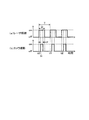
上記の制御部2による動作は、図8(a)に示すように、レーザモジュール4によるレーザ光の照射を繰り返し周期TのうちデューティDの時間だけ実行する。そして、図8(b)に示すように、カメラ3による撮影は、レーザ光が照射されているデューティDの期間中で、時間Pの間に実施される。これにより、間欠的にレーザ光が照射され、その期間中にカメラ3による撮影動作が行える。間欠的にレーザ光を照射させることで、レーザモジュール4の発熱や発熱による発光低下を防止することができる。
As shown in FIG. 8A, the operation by the
なお、撮影領域Aに対するレーザ光の照射では、光量を多く必要とする場合には、適宜デューティDを長く設定することができるし、上記したような間欠的な照射動作ではなく、デューティDが100%すなわち連続的に照射を行うこともできる。 In the irradiation of the laser beam to the imaging region A, when a large amount of light is required, the duty D can be appropriately set longer, and the duty D is 100 instead of the intermittent irradiation operation as described above. % That is, continuous irradiation can be performed.
上記のような撮影動作において、制御部2は、レーザ光が人体に悪影響を与えないようにすると共に、必要以上の光量を照射するのを抑制することで消費電力の低減を図ることができる。すなわち、制御部2は、図9および図10に示すように、レーザモジュール4によるレーザ光の照射において、減光制御1および減光制御2を行う。
In the shooting operation as described above, the
減光制御1として、制御部2は、図9に示すように、測距センサ5による検出信号に基づいて減光制御を行う。制御部2は、ステップB1で、レーザモジュール4から撮影領域A内の撮影対象である運転者Dまでの距離を測距センサ5からの検出信号により取得する。制御部2は、ステップB2で、検出された距離の値が閾値以下であるか否かを判断する。
As the
制御部2は、検出距離が閾値を超えていてステップB2でYESの場合には、ステップB3で、レーザモジュール4の光量を低減するように減光制御を実施する。制御部2は、この後、ステップB4で、次のフレームまでの待機時間が経過すると再びステップB1に戻って上記処理を繰り返す。また、制御部2は、ステップB2でNOの場合には、ステップB5に進み、レーザモジュール4による通常の照射制御を実施する。
When the detection distance exceeds the threshold value and YES in step B2, the
以上により、運転者Dの顔がレーザモジュール4の位置に対して閾値となる距離よりも近づいた状態であることが検出された場合には、制御部2により以下に示すレーザモジュール4のレーザ光の光量を低減する減光制御を実施することで、人体の顔などに、至近距離から強い拡散光Lが照射されるのを抑制することができる。
As described above, when it is detected that the face of the driver D is closer than the threshold distance to the position of the
次に、減光制御2として、制御部2は、図10に示すように、温度センサ6による検出信号に基づいて減光制御を行う。制御部2は、ステップC1で、レーザモジュール4の近傍に配置された温度センサ6の検出温度をレーザモジュール4の温度として取得する。制御部2は、ステップC2で、検出温度が閾値以上であるか否かを判断する。
Next, as the dimming
制御部2は、検出温度が閾値以上で、ステップC2でYESの場合には、ステップCB3で、レーザモジュール4の光量を低減するように減光制御を実施する。制御部2は、この後、ステップC4で、次のフレームまでの待機時間が経過すると再びステップC1に戻って上記処理を繰り返す。また、制御部2は、ステップC2でNOの場合には、ステップC5に進み、レーザモジュール4による通常の照射制御を実施する。
When the detection temperature is equal to or higher than the threshold value and YES in step C2, the
以上により、レーザモジュール4の温度が閾値以上に高い場合に、放熱が不足していて温度が上昇するのを回避するため、発熱量を低減すべくレーザモジュール4のレーザ光の光量を低下させるよう減光制御を実施する。これにより、入力パワーを低減することで発熱量を抑制し、放熱による温度低下を促すものである。
As described above, when the temperature of the
次に、上記したレーザモジュール4の減光制御の具体的な方法について、次の2つの例を説明する。図11は第1の方法で、制御部2によりレーザモジュール4から出力するレーザ光の照射強度を低下させる制御である。例えば減光される前のレーザ光の照射強度をP1とすると、減光制御では、制御部2によりレーザモジュール4に与える電流を低下させることで入力パワーを低減し、これによってレーザ光の照射強度をP1よりも低いP2に変更するものである。
Next, the following two examples will be described with respect to the specific method of dimming control of the
また、図12は第2の方法で、制御部2によりレーザモジュール4から出力するレーザ光の照射時間を短くする制御である。例えば減光される前のレーザ光のデューティをD1とすると、減光制御では、制御部2によりレーザモジュール4のデューティをD2(<D1)に短くすることで発光期間を短縮させ、これによって減光するように変更するものである。
Further, FIG. 12 shows a second method, which is a control for shortening the irradiation time of the laser beam output from the
このような第1実施形態によれば、レーザモジュール4から出力する赤外線レーザ光を拡散板7により矩形状の拡散光Lとしてカメラ3の撮影領域Aに照射する構成としたので、レーザ光を撮影領域Aに均一に広げ且つ余分な領域に照射しないように配光制御して照射することができ、効率良く照明として使用することができる。
また、光学部材としての拡散板7を、板状もしくはフィルム状のものを使用するので、全体をコンパクトな構成とすることができる。
According to the first embodiment as described above, since the infrared laser light output from the
Further, since the
そして、上記実施形態によれば、制御部2により、レーザモジュール4から出力するレーザ光を間欠的に点灯させ、その点灯期間中にカメラ3で撮影するようにしたので、常時レーザ光を照射する場合に比べて、省電力および発熱抑制を図ることができる。
Then, according to the above embodiment, the
さらに、測距センサ5を用いて、照射領域の運転者Dまでの距離が設定距離以下になると、制御部2により、レーザモジュール4から照射するレーザ光の光量を減光するようにしたので、拡散されたレーザ光であっても、安全な距離以内で照射する場合には人体に悪影響を及ぼすことがないようにすることができる。
Further, when the distance to the driver D in the irradiation region becomes equal to or less than the set distance by using the distance measuring sensor 5, the
同様に、温度センサ6を用いて、レーザモジュール4の近傍の温度を検出し、一定以上の温度になると、制御部2により、レーザモジュール4から照射するレーザ光の光量を減光するようにしたので、レーザモジュール4の温度が過剰に上昇しないようにして寿命低下などの劣化防止を図ることができる。
Similarly, the
なお、上記実施形態では、光学部材として拡散板7を用いる場合で示したが、光学部材としては、レーザ光を回折させて広げるようにした回折格子などを用いることもできる。
In the above embodiment, the case where the
また、上記実施形態では、拡散板7をレーザモジュール4のレーザ光出射面部分に接するように設ける構成を示したが、これに限らず、レーザ光出射面から離間した位置に拡散板7を設ける構成とすることもできる。
Further, in the above embodiment, the configuration in which the
さらに、上記実施形態では、レーザ光の拡散光Lの照射領域ALaをカメラ3の撮影領域Aとほぼ一致させるようにしたが、照射領域ALaを撮影領域Aよりも大きめに設定しておくこともできる。 Further, in the above embodiment, the irradiation region ALa of the diffused light L of the laser beam is made to substantially match the imaging region A of the camera 3, but the irradiation region ALa may be set to be larger than the imaging region A. it can.
(第2実施形態)
図13〜図16は第2実施形態を示すもので、以下、第1実施形態と異なる部分について説明する。この実施形態では、光学部材としての拡散板7に代えて拡散板10を用いた構成としている。以下、拡散板10の特性について説明する。
(Second Embodiment)
13 to 16 show the second embodiment, and the parts different from the first embodiment will be described below. In this embodiment, the
拡散板10は、レーザモジュール4からのレーザ光を透過させる際に、図13に示すように、レーザ光を領域別に光量が異なるように配光制御するものである。この実施形態では、拡散板10は、例えば、撮影領域Aにおいて、中心部から同心円状の領域A1〜A5を想定したときに、領域A1の拡散光Lの光量を最も小さくし、外周側の領域A2〜A5に向かうに従って光量を大きくするように配光するものである。なお、図13では、光量が大きく設定される領域A5側を濃い色の塗りつぶしパターンで示している。
As shown in FIG. 13, the
次に上記のように拡散板10の配光特性を設定した理由を説明する。この実施形態では、レーザモジュール4から照射するレーザ光を、拡散板10を介して運転席シートSeの運転者Dに向けて投光する。このとき、図15に示すように、運転者Dの顔を中心とした領域ではレーザモジュール4からの距離L1が近く、顔の中心から外れると少し遠ざかり、距離L2となる。そして、顔の部分から外れた位置ではレーザモジュール4から遠い距離L3となる。
Next, the reason why the light distribution characteristics of the
このように、レーザモジュール4からの距離がL1〜L3のように変化すると、その位置から反射する光の強度は、距離の2乗に反比例するため遠い位置の反射光はより光強度が低下する。このため、図16に示すように、均一な光強度でレーザモジュール4の光を拡散させた場合には、近い距離L1のエリアA1からの反射光の強度X1は大きく、外周に行くにしたがって距離L2、L3と遠ざかると、エリアA2、A3の反射光の強度X2、X3は距離の2乗に反比例して小さくなる。
In this way, when the distance from the
このため、カメラ3で撮影領域Aの撮影をしたときに、レーザモジュール4から拡散光Lを均一な照射強度で撮影領域Aに向けて照射すると、近い距離L1のエリアA1の光が強く、周囲のエリアA2、A3と進むに従って徐々に弱い光が入射することになる。この結果、カメラ3による撮影では、運転者Dの顔領域A1の画像は光が強く、周辺A2、A3などでは光が弱いため、画像認識の処理をする場合に、明暗の差が大きくなるため分解能が低下する場合も発生する。
Therefore, when the camera 3 takes a picture of the shooting area A, when the diffused light L is irradiated from the
このような状態を想定して、この実施形態では、拡散板10により、図13に示すような配光制御を行っている。これにより、図14に示すように、距離が異なる各エリアA1〜A5の反射光がほぼ均一な光強度F1、F2、F3としてカメラ3に入射させることができるので、撮影した画像は、撮影領域A内でほぼ均等な光強度の反射光に基づいて画像処理をすることができるようになる。
Assuming such a state, in this embodiment, the light distribution control as shown in FIG. 13 is performed by the
このような第2実施形態によれば、拡散板10を用いて、レーザモジュール4からのレーザ光を、距離が近い領域への拡散度を下げ、遠い領域への拡散度を上げるようにしたので、撮影領域Aから光強度が均衡のとれた状態で受けることができるようになり、画像解析に用いる画像の情報の分解能低下を抑制することができる。
According to the second embodiment as described above, the
(第3実施形態)
図17から図20は第3実施形態を示すもので、以下、第1実施形態と異なる部分について説明する。この実施形態では、レーザ光の照射経路に、拡散板7に加えて光学部材としての回折格子8を設ける構成としている。
(Third Embodiment)
17 to 20 show the third embodiment, and the parts different from the first embodiment will be described below. In this embodiment, a
この場合、図17に示しているように、回折格子8はレーザモジュール4と拡散板7との間に配置し、拡散板7はレーザモジュール4から空気層としての空間部Sを介して離間した位置に設けている。図18に示すように、回折格子8は散乱係数Dfが面内で異なるように設定されている。
In this case, as shown in FIG. 17, the
この実施形態では、図18に示すように、レーザ光が照射される中心位置の領域では大きい散乱係数Df1が設定され、中心位置から同心円状に半径が大となるにしたがって、次式(1)の不等式で示すように、散乱係数Df2、Df3、Df4が順に小さい値となるように設定されている。なお、図17では、散乱係数が大きい領域を濃い色の塗りつぶしパターンで示している。
Df1>Df2>Df3>Df4 …(1)
In this embodiment, as shown in FIG. 18, a large scattering coefficient Df1 is set in the region of the central position where the laser beam is irradiated, and the following equation (1) increases as the radius increases concentrically from the central position. As shown by the inequality of, the scattering coefficients Df2, Df3, and Df4 are set to be smaller in order. In FIG. 17, a region having a large scattering coefficient is shown by a dark-colored fill pattern.
Df1>Df2>Df3> Df4 ... (1)
これにより、レーザモジュール4から入射されるレーザ光は、中心部で強く散乱して広げられ、外周部のレーザ光の光強度が弱い部分では散乱の度合いが低くなるように散乱される。この結果、レーザ光は、回折格子8から出射する部分では中心部の光強度が弱められ広がりを持つ光として拡散板7に入射されるようになる。拡散板7では、さらにレーザ光が拡散されることで撮影領域Aにはほぼ均一な照射強度の拡散光Lとして照射されるようになる。
As a result, the laser beam incident from the
図19は、レーザモジュール4に対する拡散板7および回折格子8の配置状態を示したもので、この場合には、回折格子8は、レーザモジュール4のレーザ光の出射面に接する状態で配置している。拡散板7は空間部Sを存した離間した位置に配置されている。これにより、カメラ3の撮影領域Aに均一な照射強度で拡散光Lを照射することができるようになる。
FIG. 19 shows the arrangement state of the
拡散板7と回折格子8との間に空間部Sを設けることで、回折格子8によりレーザ光を回折させて広げた光を拡散板7に入射させるので、レーザ光をより広げた状態で拡散板7に入射させることができる。また、空間部Sを設けていることで、両者をレーザモジュール4のレーザ光出射面に接するように配置した場合に比べて、レーザモジュール4から光学部材に伝わる熱の放熱効果を高めることができる。
By providing the space S between the
また、拡散板7の特性として、第2実施形態で示したような配光制御を行うようにした場合には、撮影領域Aからの反射光がカメラ3との距離に依存しない光強度で入射させることができるようになる。
Further, as a characteristic of the
図20は、同じくレーザモジュール4に対する拡散板7および回折格子8の配置状態を示したもので、この場合には、回折格子8も、レーザモジュール4のレーザ光の出射面から離間させた状態で配置している。すなわち、拡散板7と回折格子8との間は、空間部S1を存して離間した配置状態とされ、回折格子8とレーザモジュール4のレーザ光出射面との間は、空間部S2を存して離間した配置状態とされている。
FIG. 20 also shows the arrangement state of the
このような第3実施形態によれば、拡散板7に加えてレーザ光を散乱させる回折格子8を設けたので、レーザモジュール4のレーザ光を撮影領域Aに対してより均一な状態で投光させることができるようになる。また、レーザモジュール4に対して、拡散板7や回折格子8を離間させた状態で配置するので、空間部SあるいはS1、S2の部分でレーザモジュール4や拡散板7、回折格子8の熱を放出しやすくなる。
According to the third embodiment, since the
なお、拡散板7と回折格子8との位置関係を入れ替えて配置することも可能である。また、拡散板7および回折格子8は、1枚ずつ設ける場合に限らず、適宜の枚数を組み合わせて用いることもできるし、配置関係も適宜の配置を適用することができる。
It is also possible to replace the positional relationship between the
(第4実施形態)
図21および図22は第4実施形態を示すもので、以下、第3実施形態と異なる部分について説明する。この実施形態では、拡散板7および回折格子8のそれぞれに反射防止膜7a、7b、8a、8bを設けた構成としている。図21および図22は、それぞれ第3実施形態における図19および図20の配置構成のものに本実施形態を適用したものである。反射防止膜7a、7b、8a、8bは、レーザモジュール4のレーザ光の波長に対して反射率が最も小さくなるように膜が構成されている。
(Fourth Embodiment)
21 and 22 show the fourth embodiment, and the parts different from the third embodiment will be described below. In this embodiment, the
図21では、レーザモジュール4のレーザ光の出射面に接するように設けられた回折格子8は、レーザ光の入射側の面に反射防止膜8a、出射側の面に反射防止膜8bが設けられている。また、拡散板7は、レーザ光の入射側の面に反射防止膜7a、出射側の面に反射防止膜7bが設けられている。
In FIG. 21, the
また、図22では、同様にして、レーザモジュール4のレーザ光の出射面から離間した位置に設けられた回折格子8は、レーザ光の入射側の面に反射防止膜8a、出射側の面に反射防止膜8bが設けられている。また、拡散板7は、レーザ光の入射側の面に反射防止膜7a、出射側の面に反射防止膜7bが設けられている。
Further, in FIG. 22, similarly, the
このような第4実施形態によれば、拡散板7および回折格子8において、入射するレーザ光あるいは出射する光が、入射面や出射面で反射する成分により光量が低下するのを抑制することができ、撮影領域Aへの拡散光Lの光量の低下を抑制して効率良く利用することができるようになる。
According to such a fourth embodiment, in the
なお、反射防止膜は、入射側の面あるいは出射側の面のいずれかに設ける構成とすることもできる。また、拡散板7および回折格子8のいずれか一方に設ける構成とすることもできる。さらに、反射防止膜は、少なくともレーザ光が通過する領域をカバーするように設けられていれば良い。
The antireflection film may be provided on either the incident side surface or the exit side surface. Further, it may be configured to be provided on either the
(第5実施形態)
図23〜図25は第5実施形態を示すもので、以下、第1実施形態あるいは第4実施形態と異なる部分について説明する。この実施形態では、レーザモジュール4から光学部材に伝わる熱を放熱するための放熱部として冷却ファン9を設けた構成としている。
(Fifth Embodiment)
23 to 25 show the fifth embodiment, and the parts different from the first embodiment or the fourth embodiment will be described below. In this embodiment, a cooling
図23では、第1実施形態における拡散板7をレーザモジュール4のレーザ光出射面から空間部Saを存して離間した位置に配置している。そして、冷却ファン9は、レーザモジュール4、拡散板7および空間部Saに向けて送風されるように配置されている。これにより、レーザモジュール4で発生する熱が空間部Saの部分において冷却ファン9により冷却されるので、拡散板7には熱が伝わりにくく温度上昇が抑制された状態となる。また、レーザモジュール4についても放熱特性が向上する。
In FIG. 23, the
図24では、第4実施形態における回折格子8をレーザモジュール4のレーザ光出射面に接する状態に配置し、拡散板7を回折構成8から空間部Sbを存して離間した位置に配置している。そして、冷却ファン9は、レーザモジュール4、拡散板7、回折格子8および空間部Sbに向けて送風するように配置されている。
In FIG. 24, the
これにより、レーザモジュール4で発生する熱が回折格子8を介して空間部Sbに放出されるところで、冷却ファン9により冷却されるので、拡散板7には熱が伝わりにくく温度上昇が抑制された状態となる。また、レーザモジュール4および回折格子8についても放熱特性が向上する。
As a result, the heat generated by the
図25では、第4実施形態における回折格子8をレーザモジュール4のレーザ光出射面から空間部Saを存して離間した位置に配置し、拡散板7を回折構成8から空間部Sbを存して離間した位置に配置している。そして、冷却ファン9は、レーザモジュール4、拡散板7、回折格子8および空間部SaおよびSbに向けて送風するように配置されている。
In FIG. 25, the
これにより、レーザモジュール4で発生する熱が空間部Saに放出されたところで冷却ファン9により冷却され、回折格子8は熱が伝わりにくく温度上昇が抑制された状態となる。回折格子8は両側の空間部Saおよび空間部Sbにおいて冷却ファン9からの送風で冷却され、さらに拡散板7も冷却ファン9からの送風で冷却される。これにより、レーザモジュール4、回折格子8および拡散板7についても放熱特性が向上する。
As a result, when the heat generated by the
このような第5実施形態によれば、放熱部として冷却ファン9を設け、レーザモジュール4、拡散板7、回折格子8を、空間部SaあるいはSbなどを介して冷却するので、レーザモジュール4から回折格子8や拡散板7に熱が伝わるのを抑制することができる。
According to such a fifth embodiment, a cooling
(第6実施形態)
図26〜図28は第6実施形態を示すもので、以下、第5実施形態と異なる部分について説明する。この実施形態では、冷却ファン9に代えて放熱部としてレーザモジュール4に放熱フィン4aを設けた構成としている。
(Sixth Embodiment)
26 to 28 show the sixth embodiment, and the parts different from the fifth embodiment will be described below. In this embodiment, the
図26〜図28は、それぞれ第5実施形態で示した図23〜図25の構成に対応する構成を示している。いずれの構成においても、冷却ファン9に代えて、レーザモジュール4に放熱フィン4aを設けている。これにより、レーザモジュール4から発生する熱が放熱フィン4aを介して空気中に放出されるようになり、拡散板7や回折構成8に伝わる熱成分を大幅に低減することができるようになる。
26 to 28 show configurations corresponding to the configurations of FIGS. 23 to 25 shown in the fifth embodiment, respectively. In either configuration, the
したがって、このような第6実施形態によっても第5実施形態とほぼ同様の効果を得ることができるようになる。
なお、第5実施形態と第6実施形態とは両者を組み合わせた構成とすることもできる。さらに、第5実施形態あるいは第6実施形態においても、第4実施形態で示した反射防止膜を設ける構成とすることができる。
Therefore, even with such a sixth embodiment, almost the same effect as that of the fifth embodiment can be obtained.
The fifth embodiment and the sixth embodiment may be configured by combining both. Further, also in the fifth embodiment or the sixth embodiment, the antireflection film shown in the fourth embodiment can be provided.
(他の実施形態)
なお、本発明は、上述した実施形態のみに限定されるものではなく、その要旨を逸脱しない範囲で種々の実施形態に適用可能であり、例えば、以下のように変形または拡張することができる。
(Other embodiments)
The present invention is not limited to the above-described embodiment, and can be applied to various embodiments without departing from the gist thereof. For example, the present invention can be modified or extended as follows.
上記各実施形態では、運転者の状態を検出する状態検出装置1に適用した例を示したが、これに限らず、ドライブレコーダのような車室内を撮影する装置に適用することもできる。
上記各実施形態では、それぞれの実施形態を組み合わせることで、それぞれの効果を組み合わせたものとして実施することができる。
In each of the above embodiments, an example of application to the
In each of the above embodiments, by combining the respective embodiments, it is possible to carry out as a combination of the respective effects.
本開示は、実施例に準拠して記述されたが、本開示は当該実施例や構造に限定されるものではないと理解される。本開示は、様々な変形例や均等範囲内の変形をも包含する。加えて、様々な組み合わせや形態、さらには、それらに一要素のみ、それ以上、あるいはそれ以下、を含む他の組み合わせや形態をも、本開示の範疇や思想範囲に入るものである。 Although the present disclosure has been described in accordance with the examples, it is understood that the present disclosure is not limited to the examples or structures. The present disclosure also includes various modifications and modifications within an equal range. In addition, various combinations and forms, as well as other combinations and forms that include only one element, more, or less, are also within the scope of the present disclosure.
図面中、1は運転者状態監視装置(状態検出装置)、2は制御部、3はカメラ、4はレーザモジュール(レーザ)、4aは放熱フィン(放熱部)、5は測距センサ(距離検出部)、6は温度センサ(温度検出部)、7は拡散板(光学部材)、8は回折格子、7a、7b、8a、8bは反射防止膜、9は冷却ファン(放熱部)、10は拡散板(光学部材)、Dは運転者、Lは拡散光、Aは撮影領域、S、S1、S2、Sa、Sbは空間部(空気層)である。 In the drawing, 1 is a driver state monitoring device (state detection device), 2 is a control unit, 3 is a camera, 4 is a laser module (laser), 4a is a heat dissipation fin (heat dissipation part), and 5 is a distance measuring sensor (distance detection). Section), 6 is a temperature sensor (temperature detection section), 7 is a diffuser plate (optical member), 8 is a diffraction grating, 7a, 7b, 8a, 8b are antireflection films, 9 is a cooling fan (heat dissipation section), and 10 is. The diffuser plate (optical member), D is the driver, L is the diffused light, A is the photographing region, and S, S1, S2, Sa, and Sb are the space portion (air layer).
Claims (15)
前記撮影領域に向けて光を照射するレーザ(4)と、
前記レーザの光を所定の照射領域に広げて照射する光学部材(7、8、10)とを備え、
前記光学部材は、前記レーザの光の照射領域から前記カメラまでの距離が長い方が前記レーザの光の照射強度が大きくなるように配光制御する状態検出装置。 A camera (3) that captures the shooting area where the driver is present, and
A laser (4) that irradiates light toward the imaging region and
An optical member (7, 8, 10) that spreads the light of the laser to a predetermined irradiation region and irradiates the laser beam is provided.
The optical member is a state detection device that controls light distribution so that the longer the distance from the laser light irradiation region to the camera, the higher the laser light irradiation intensity .
前記距離検出部による検出距離が設定距離以下になると前記レーザの光を弱くする減光制御を行う制御部(2)と、
を設けた請求項1から13のいずれか一項に記載の状態検出装置。 A distance detection unit (5) that detects the distance between the laser and the driver in the irradiation region, and
A control unit (2) that performs dimming control that weakens the light of the laser when the detection distance by the distance detection unit is less than the set distance.
The state detection device according to any one of claims 1 to 13 , wherein the state detection device is provided.
前記温度検出部による検出温度が一定以上になると前記レーザの光を減光もしくは間欠点灯制御する制御部(2)と、
を設けた請求項1から14のいずれか一項に記載の状態検出装置。 A temperature detection unit (6) that detects the temperature of the laser, and
A control unit (2) that controls dimming or intermittent lighting of the laser light when the temperature detected by the temperature detection unit exceeds a certain level.
The state detection device according to any one of claims 1 to 14 , wherein the state detection device is provided.
Priority Applications (5)
| Application Number | Priority Date | Filing Date | Title |
|---|---|---|---|
| JP2017216359A JP6756326B2 (en) | 2017-11-09 | 2017-11-09 | State detector |
| PCT/JP2018/034417 WO2019092986A1 (en) | 2017-11-09 | 2018-09-18 | State detection device |
| DE112018005748.8T DE112018005748T5 (en) | 2017-11-09 | 2018-09-18 | CONDITION DETECTING DEVICE |
| CN201880069509.8A CN111279675B (en) | 2017-11-09 | 2018-09-18 | State detection device |
| US16/862,398 US11561408B2 (en) | 2017-11-09 | 2020-04-29 | State detection device |
Applications Claiming Priority (1)
| Application Number | Priority Date | Filing Date | Title |
|---|---|---|---|
| JP2017216359A JP6756326B2 (en) | 2017-11-09 | 2017-11-09 | State detector |
Publications (3)
| Publication Number | Publication Date |
|---|---|
| JP2019087934A JP2019087934A (en) | 2019-06-06 |
| JP2019087934A5 JP2019087934A5 (en) | 2020-05-07 |
| JP6756326B2 true JP6756326B2 (en) | 2020-09-16 |
Family
ID=66439105
Family Applications (1)
| Application Number | Title | Priority Date | Filing Date |
|---|---|---|---|
| JP2017216359A Active JP6756326B2 (en) | 2017-11-09 | 2017-11-09 | State detector |
Country Status (5)
| Country | Link |
|---|---|
| US (1) | US11561408B2 (en) |
| JP (1) | JP6756326B2 (en) |
| CN (1) | CN111279675B (en) |
| DE (1) | DE112018005748T5 (en) |
| WO (1) | WO2019092986A1 (en) |
Families Citing this family (1)
| Publication number | Priority date | Publication date | Assignee | Title |
|---|---|---|---|---|
| DE102022109756A1 (en) | 2022-04-22 | 2023-10-26 | Valeo Schalter Und Sensoren Gmbh | METHOD FOR DETERMINING A CONDITION OF A DRIVER MONITORING DEVICE AND DRIVER MONITORING DEVICE |
Family Cites Families (33)
| Publication number | Priority date | Publication date | Assignee | Title |
|---|---|---|---|---|
| JPH03110884A (en) * | 1989-09-26 | 1991-05-10 | Nippon Telegr & Teleph Corp <Ntt> | Distributed feedback semiconductor laser and manufacture thereof |
| JPH10960A (en) * | 1996-06-12 | 1998-01-06 | Yazaki Corp | Driver monitoring device |
| US6846098B2 (en) * | 2002-05-16 | 2005-01-25 | Eastman Kodak Company | Light diffuser with variable diffusion |
| CN1305053C (en) * | 2003-04-28 | 2007-03-14 | 株式会社三协精机制作所 | Lens, optical head device and lens for optical head device |
| FR2864932B1 (en) * | 2004-01-09 | 2007-03-16 | Valeo Vision | SYSTEM AND METHOD FOR DETECTING CIRCULATION CONDITIONS FOR A MOTOR VEHICLE |
| JP2005235841A (en) | 2004-02-17 | 2005-09-02 | Harison Toshiba Lighting Corp | Light emitting device |
| US7430365B2 (en) | 2005-03-31 | 2008-09-30 | Avago Technologies Ecbu (Singapore) Pte Ltd. | Safe eye detection |
| DE102006004193A1 (en) * | 2006-01-27 | 2007-08-16 | Sick Ag | Device for optoelectronic monitoring of objects |
| US8106993B2 (en) * | 2006-05-15 | 2012-01-31 | Panasonic Corporation | Diffractive imaging lens, diffractive imaging lens optical system, and imaging apparatus using the diffractive imaging lens optical system |
| JP4656070B2 (en) | 2007-02-19 | 2011-03-23 | 株式会社デンソー | Visible light laser irradiation device |
| WO2009019766A1 (en) * | 2007-08-08 | 2009-02-12 | Shimadzu Corporation | Optical measuring instrument and its electrode pair |
| EP2107446A1 (en) | 2008-04-04 | 2009-10-07 | ETH Zurich | System and a method for tracking input devices on LC-displays |
| JP4888838B2 (en) | 2008-05-12 | 2012-02-29 | トヨタ自動車株式会社 | Driver imaging device and driver imaging method |
| JP2010164393A (en) | 2009-01-15 | 2010-07-29 | Calsonic Kansei Corp | Face direction detection apparatus and method |
| CN102025106B (en) * | 2009-09-23 | 2013-08-07 | 中国计量科学研究院 | Grating external cavity semiconductor laser |
| CN201571139U (en) * | 2010-01-15 | 2010-09-01 | 常州宏本数码科技有限公司 | Safe type laser infrared high-speed holder camera |
| JP5212927B2 (en) | 2011-01-25 | 2013-06-19 | 株式会社デンソー | Face shooting system |
| EP2702438B1 (en) * | 2011-04-28 | 2020-02-12 | L.E.S.S. Ltd | Waveguide apparatus for illumination systems |
| JP2013181926A (en) * | 2012-03-02 | 2013-09-12 | Sony Corp | Spectral optical system and spectral measuring apparatus |
| JP5970872B2 (en) * | 2012-03-07 | 2016-08-17 | セイコーエプソン株式会社 | Head-mounted display device and method for controlling head-mounted display device |
| JP6107153B2 (en) * | 2012-03-28 | 2017-04-05 | 日本精機株式会社 | Vehicle display device |
| WO2014017061A1 (en) * | 2012-07-25 | 2014-01-30 | 株式会社デンソー | State monitoring device |
| CN102818538B (en) * | 2012-09-14 | 2014-09-10 | 洛阳兰迪玻璃机器股份有限公司 | Detection system based on modulated glass thread structure laser image |
| JP2016032257A (en) * | 2014-07-30 | 2016-03-07 | 株式会社デンソー | Driver monitoring device |
| JP2016049262A (en) * | 2014-08-29 | 2016-04-11 | アルプス電気株式会社 | Lighting imaging device |
| KR101619651B1 (en) | 2014-11-26 | 2016-05-10 | 현대자동차주식회사 | Driver Monitoring Apparatus and Method for Controlling Lighting thereof |
| EP3348899B1 (en) | 2015-09-07 | 2020-05-27 | Dai Nippon Printing Co., Ltd. | Illumination device |
| DE102016200109A1 (en) * | 2015-09-18 | 2017-03-23 | Fraunhofer-Gesellschaft zur Förderung der angewandten Forschung e.V. | Apparatus and method for detecting objects in a detection area |
| US10760772B2 (en) | 2015-09-25 | 2020-09-01 | Dai Nippon Printing Co., Ltd. | Illumination device |
| JP2017097153A (en) * | 2015-11-24 | 2017-06-01 | 船井電機株式会社 | Projector |
| CN105511086A (en) * | 2015-12-11 | 2016-04-20 | 杭州东尚光电科技有限公司 | Laser illumination optical system combining diffraction optical element with laser |
| CN105933662B (en) * | 2016-05-31 | 2019-01-01 | 南京邮电大学 | The Active Infrared Monitoring System of energy is passed based on optical fiber |
| JP6977355B2 (en) * | 2017-07-20 | 2021-12-08 | 大日本印刷株式会社 | Detection device |
-
2017
- 2017-11-09 JP JP2017216359A patent/JP6756326B2/en active Active
-
2018
- 2018-09-18 CN CN201880069509.8A patent/CN111279675B/en active Active
- 2018-09-18 WO PCT/JP2018/034417 patent/WO2019092986A1/en active Application Filing
- 2018-09-18 DE DE112018005748.8T patent/DE112018005748T5/en active Pending
-
2020
- 2020-04-29 US US16/862,398 patent/US11561408B2/en active Active
Also Published As
| Publication number | Publication date |
|---|---|
| CN111279675A (en) | 2020-06-12 |
| WO2019092986A1 (en) | 2019-05-16 |
| US20200257128A1 (en) | 2020-08-13 |
| CN111279675B (en) | 2022-03-11 |
| JP2019087934A (en) | 2019-06-06 |
| DE112018005748T5 (en) | 2020-07-16 |
| US11561408B2 (en) | 2023-01-24 |
Similar Documents
| Publication | Publication Date | Title |
|---|---|---|
| JP6164464B2 (en) | Vehicle lighting | |
| JP4251941B2 (en) | head lamp | |
| JP5141257B2 (en) | Automotive headlight elements | |
| EP3121649B1 (en) | Light source device and image projection device having light source device | |
| US9335619B2 (en) | Luminescent light emitting device having luminescent material plate that is caused to be luminous by excitation light source and projector including same luminescent light emitting device | |
| WO2017138412A1 (en) | Light source device and projection device | |
| JP6172538B2 (en) | Electronic device, projection device, and method of manufacturing electronic device | |
| US10228106B2 (en) | Luminaire with light source and spaced-apart luminescent body | |
| US20160039333A1 (en) | Vehicle lighting system and method of fabrication | |
| JP6549026B2 (en) | Light emitting device and lighting device | |
| KR101425749B1 (en) | Fluorescent device, irradiation apparatus, and projector apparatus | |
| WO2014087301A1 (en) | Illumination array with adapted distribution of radiation | |
| JP6756326B2 (en) | State detector | |
| JP2015146396A (en) | Light emitting device, vehicle lamp fitting and vehicle illuminating device | |
| JP2011133778A (en) | Semiconductor light source device and projector | |
| JP5349940B2 (en) | Infrared projector for vehicles | |
| JP2018037205A (en) | Vehicular lamp | |
| JP2009050572A (en) | Antifog mirror apparatus | |
| JP2015065008A (en) | Vehicle lighting appliance | |
| JP2011154206A (en) | Light source device, projector, and projection method | |
| JP2019087934A5 (en) | ||
| JP2021028907A (en) | Light conversion device and lighting device | |
| JP6654959B2 (en) | Vehicle lighting | |
| JP5950671B2 (en) | lighting equipment | |
| CN109073167A (en) | Cured method and system is irradiated using the radiation of narrow width |
Legal Events
| Date | Code | Title | Description |
|---|---|---|---|
| A521 | Request for written amendment filed |
Free format text: JAPANESE INTERMEDIATE CODE: A523 Effective date: 20200326 |
|
| A621 | Written request for application examination |
Free format text: JAPANESE INTERMEDIATE CODE: A621 Effective date: 20200326 |
|
| A131 | Notification of reasons for refusal |
Free format text: JAPANESE INTERMEDIATE CODE: A131 Effective date: 20200512 |
|
| A521 | Request for written amendment filed |
Free format text: JAPANESE INTERMEDIATE CODE: A523 Effective date: 20200710 |
|
| TRDD | Decision of grant or rejection written | ||
| A01 | Written decision to grant a patent or to grant a registration (utility model) |
Free format text: JAPANESE INTERMEDIATE CODE: A01 Effective date: 20200728 |
|
| A61 | First payment of annual fees (during grant procedure) |
Free format text: JAPANESE INTERMEDIATE CODE: A61 Effective date: 20200810 |
|
| R151 | Written notification of patent or utility model registration |
Ref document number: 6756326 Country of ref document: JP Free format text: JAPANESE INTERMEDIATE CODE: R151 |
|
| R250 | Receipt of annual fees |
Free format text: JAPANESE INTERMEDIATE CODE: R250 |