JP6737851B2 - Removal method of existing tunnel structure by box roof method - Google Patents
Removal method of existing tunnel structure by box roof method Download PDFInfo
- Publication number
- JP6737851B2 JP6737851B2 JP2018161412A JP2018161412A JP6737851B2 JP 6737851 B2 JP6737851 B2 JP 6737851B2 JP 2018161412 A JP2018161412 A JP 2018161412A JP 2018161412 A JP2018161412 A JP 2018161412A JP 6737851 B2 JP6737851 B2 JP 6737851B2
- Authority
- JP
- Japan
- Prior art keywords
- box
- tunnel structure
- existing
- existing tunnel
- roof
- Prior art date
- Legal status (The legal status is an assumption and is not a legal conclusion. Google has not performed a legal analysis and makes no representation as to the accuracy of the status listed.)
- Active
Links
- 238000000034 method Methods 0.000 title claims description 30
- 238000010276 construction Methods 0.000 claims description 55
- 239000000463 material Substances 0.000 claims description 12
- 238000005520 cutting process Methods 0.000 claims description 10
- 239000011800 void material Substances 0.000 claims description 3
- 230000001681 protective effect Effects 0.000 claims description 2
- 229910000831 Steel Inorganic materials 0.000 description 9
- 239000010959 steel Substances 0.000 description 9
- 125000006850 spacer group Chemical group 0.000 description 4
- 238000001125 extrusion Methods 0.000 description 2
- 239000000945 filler Substances 0.000 description 2
- 238000002347 injection Methods 0.000 description 2
- 239000007924 injection Substances 0.000 description 2
- 238000002360 preparation method Methods 0.000 description 2
- 239000000126 substance Substances 0.000 description 2
- 238000004140 cleaning Methods 0.000 description 1
- 238000007796 conventional method Methods 0.000 description 1
- 239000011440 grout Substances 0.000 description 1
- 230000014759 maintenance of location Effects 0.000 description 1
- 230000000149 penetrating effect Effects 0.000 description 1
- 238000003825 pressing Methods 0.000 description 1
- 239000004576 sand Substances 0.000 description 1
- 239000000243 solution Substances 0.000 description 1
- 238000003466 welding Methods 0.000 description 1
Images


Landscapes
- Excavating Of Shafts Or Tunnels (AREA)
Description
本発明は、施工横断部に既設トンネル構造物が障害物として存在する場合にその障害物撤去を行い、新設トンネル構造物に置換する既設トンネル構造物の拡幅工法に関するものである。 TECHNICAL FIELD The present invention relates to a method for widening an existing tunnel structure that removes an existing tunnel structure and replaces it with a new tunnel structure when the existing tunnel structure exists as an obstacle at a construction crossing portion.
軌条下や道路下を横断するように設けられている既設の地下道等の地下構造物に対して新設の地下構造物を置き換えるように施工するには、従来の工法においては、支持杭や仮受桁(工事桁)で仮受けするとともに既設の撤去は、手斫り等による撤去方法が一般的に用いられる。 To replace an existing underground structure such as an existing underground passage that is installed under a railroad or under a road with a new underground structure, it is necessary to use support piles or temporary bridges in the conventional construction method. For temporary removal at the girder (construction girder) and removal of the existing one, the removal method by hand picking etc. is generally used.
この場合、既設構造物撤去に多くの時間がかかるため工期が延びてしまうといった問題があった。 In this case, it takes a lot of time to remove the existing structure, which causes a problem that the construction period is extended.
下記特許文献1は仮受桁等を全く必要としないものとして提案されたもので、上床と側壁とからなり、少なくとも上床と側壁との縁が切れている既設構造物において、少なくとも上床の上面に複数の鋼板を該既設構造物の長さ方向に並列に敷設すると共にこれらの鋼板の端部を不動個所に固定し、前記既設構造物の後端側に既製構造物の前端をその天端を一致させた状態に後続させたのち、既設構造物の側壁を破壊等の適宜な手段により撤去しながら既製構造物を既設構造物の上床と共に前記並列鋼板の下面をガイド面として前進させて既設構造物と既製構造物とを置換する。
下記特許文献2は前記特許文献1のレールを省けるものとして提案されたものである。
この特許文献2は、図16に示すように、既設構造物1が軌条3の下方の地中に築造されていて、既設構造物1の下床版11を両側壁1b、1bから切り離した状態にすると共にこの下床版11上に仮設支保工8を設置して該仮設支保工8により上床版1aを支持した状態で該上床版1aを両側壁1b、1bから切り離し、この状態にして既設構造物1にこの既設構造物1よりも幅広い函体2を突き合わせ状に後続させ、この函体2側から前記両側壁1b、1bを破壊しながら函体2を推進させると共に、前記上下床版1a、11と仮設支保工8とを一体的に前進移動させて軌条下の埋設位置から除去することにより既設構造物1を函体2に置換して拡幅された構造物とするものである。
In
既設構造物1の上床版1aの上面に鋼板によるフリクションカッタープレート6、6、6・・・6を互いにその長さ方向の両側端面同士が接した状態で並列に敷設している。
さらに、この既設構造物1の上床版1aの両側方における該上床版1aと同じ高さ位置に、フリクションカッタープレート6を載置した箱形ルーフ7を並列状態に打設して横方向に連なった並列パイプを形成すると共に、この並列パイプの両側端から下方に向かって箱形ルーフ7を打設することにより、一列状に積み重なった並列パイプを形成する。
Further, box-
並列パイプ上の全てのフリクションカッタープレート6の前端を箱形ルーフ7から切り離したのち、これらの互いに横一列に並んでいる全てのフリクションカッタープレート6の前端と縦方向に並んでいる全てのフリクションカッタープレート6の前端とをこれらのフリクションカッタープレート6が突出した地盤の側面に密着、支持させている定着枠に溶接等によって一体に固着させる。
After separating the front ends of all the
一方、発進側4においては後方に突出している全てのフリクションカッタープレート6をこれらの鋼板上に直交して配設したH形鋼等よりなる連結部材を全てのフリクションカッタープレート6に溶接等によって固着することにより一体に連結する。
On the other hand, on the
また、前記既設構造物1の両側壁1b、1bの下端部間における床面に下床版11を既設構造物1の長さ方向に摺動移動自在に敷設する。 Further, a lower floor slab 11 is laid on the floor surface between the lower ends of the side walls 1b, 1b of the existing structure 1 so as to be slidably movable in the length direction of the existing structure 1.
この際、摺動面材9を下床版11の略全幅に亘って敷設、固定し、この摺動面材9上に下床版11を長さ方向に摺動自在に敷設している。 At this time, the sliding face material 9 is laid and fixed over substantially the entire width of the lower floor slab 11, and the lower floor slab 11 is laid on the sliding face material 9 so as to be slidable in the longitudinal direction.
既設構造物1の下端部間に前記下床版11を敷設したのち、この下床版11上に仮設支保工8を設置し、この仮設支保工8によって上床版1aを支持した状態で既設構造物1の上床版1aと両側壁1b、1bとを切り離す。 After laying the lower floor slab 11 between the lower ends of the existing structure 1, a temporary supporting work 8 is installed on the lower floor slab 11, and the existing structure is supported with the temporary supporting work 8 supporting the upper floor slab 1a. The upper floor slab 1a of the article 1 and the side walls 1b, 1b are separated.
このように、両側壁1b、1bの上端から切り離された上床版1aを仮設支保工8によって支持させたのち、この既設構造物1の後方の発進側4上に函体2を設置して既設構造物1に後続させ、反力受止壁部材の前面に装着した推進(元押し)ジャッキ17と函体2の後端面間にストラット18を介在させる。
In this way, after the upper floor slab 1a separated from the upper ends of the side walls 1b, 1b is supported by the temporary support structure 8, the
函体2の前端面に刃口枠を装着し、さらに、この刃口枠の前端面に複数本の中押しジャッキ15を装着している。
A blade mouth frame is attached to the front end face of the
このように函体2や反力受止壁部材等を発進側4に配設したのち、前記中押しジャッキ15を伸長させると、既設構造物1の上床版1aと並列箱形ルーフ7、7は、定着枠や連結部材等によって不動状態に固定されているフリクションカッタープレート6をガイドとしてその対向面に摺接しながら一定長、到達側5に向かって前進すると共にこの既設構造物1の下床版11も摺動面材9上を摺動して前記上床版1aと一体的に同時に一定長、前進する。
After arranging the
この際、上床版1aを支持している仮設支保工8も上床版1aを一定の高さ位置に保持しながら上下床版1a、11と共に前進移動する。 At this time, the temporary support work 8 supporting the upper floor slab 1a also moves forward together with the upper and lower floor slabs 1a and 11 while holding the upper floor slab 1a at a constant height position.
既設構造物1の上下床版1a、11と並列箱形ルーフ7、7とを一体に一定長、到達側5に推進させたのち、その推進によって露出した既設構造物1の後部を破壊、撤去する。
After the upper and lower floor slabs 1a and 11 of the existing structure 1 and the parallel box-
下記特許文献は、図17に示すように既設構造物1に対してこの既設構造物1を撤去し、既設構造物1を拡幅してなる新設構造物を構築する場合において、新設構造物の構築は、施工区間の防護工として両側に設置した立坑より、箱形ルーフ7を新設構造物の外縁に合致する位置に、全周および全長に貫通して設置し、発進側4の立坑内で新設構造物用の函体2を築造し、箱形ルーフ7および内部地山と函体2とを一体として、到達側へ押し出すもので、既設構造物1の撤去は、既設構造物1を新設構造物外縁に合せて切断分離させ、箱形ルーフ列を押し出すことでこの箱形ルーフ列で囲む既設構造物1を内部地山とともに到達側5へ押し抜き、解体するものである。
前記特許文献1や特許文献2の従来方法は、鋼板製細長板によるフリクションカッタープレート6、6、6・・・6により既設構造物の地盤との摩擦をカットしながら既設構造物を到達側5に推進させたのち、その推進によって露出した既設構造物を破壊、撤去するものである。
In the conventional methods of Patent Document 1 and
既設地下構造物1の上床版1aの上面に複数枚のフリクションカッタープレート6、6、6・・・6を互いにその長さ方向の両側端面同士が接した状態で並列に敷設するという作業が必要となる。
It is necessary to lay a plurality of
このフリクションカッタープレート6の敷設作業は、軌条3下の地盤を掘削して既設地下構造物1の上床版1aを露出させ、この上床版1a上に敷き並べたのち、地盤を埋め戻すことにより行うか、又、地盤をそのままにして既設地下構造物1の上床版1a上に発進側4から到達側5に向かって貫通させるようにフリクションカッタープレート6を圧入、又は、到達側5からワイヤ等で牽引することにより行わなければならない。
The operation of laying the
前記特許文献3は、既設構造物1の撤去は、既設構造物1を新設構造物外縁に合せて切断分離させ、箱形ルーフ列を押し出すことで、この箱形ルーフ列で囲む既設構造物1を内部地山とともに到達側5へ押し抜き、解体するもので、箱形ルーフ7を新設構造物の外縁に合致する位置に、全周および全長に貫通して設置して、箱形ルーフ7で土砂を取り囲むようにしなければならない。
In Patent Document 3, the existing structure 1 is removed by cutting the existing structure 1 along the outer edge of the new structure, separating the existing structure 1, and pushing out the box-shaped roof row. Is pushed out to the
すなわち、数多くの箱形ルーフ7の配設を必要とする。
That is, a large number of box-
本発明の目的は前記従来例の不都合を解消し、既設トンネル構造物に対してこの既設トンネル構造物を部分的に撤去し、その後に新設トンネル構造物を構築する場合において、箱形ルーフ工法の箱形ルーフの押出しを利用して、少ない工程で既設トンネル構造物を安全かつじん速に撤去でき、施工速度等の改善を図ることができる箱形ルーフ工法による既設トンネル構造物の撤去工法を提供することにある。 The object of the present invention is to eliminate the inconvenience of the conventional example, to partially remove the existing tunnel structure from the existing tunnel structure, and then to construct a new tunnel structure. We provide a method for removing existing tunnel structures using the box roof method, which enables safe and fast removal of existing tunnel structures with a small number of steps by using the extrusion of a box roof, and improves the construction speed. To do.
前記目的を達成するため、請求項1記載の本発明は、既設トンネル構造物に対してこの既設トンネル構造物を部分的に撤去し、その後に新設トンネル構造物を構築する場合において、新設トンネル構造物の構築は、施工区間の防護工として両側に設置した発進側、到達側より、箱形ルーフを新設トンネル構造物の外縁に合致する位置に施工区間に貫通して設置し、発進側で新設トンネル構造物用の函体を築造し、箱形ルーフと函体と到達側へ押し出すもので、既設トンネル構造物の撤去は、既設トンネル構造物を切断分離させ、箱形ルーフ下方の既設トンネル構造物の切断分離部分はローラー付きの支保工で仮受し、さらに、箱形ルーフ下側と既設トンネル構造物の切断分離部分を係止させ、既設トンネル構造物の切断分離部分を箱形ルーフおよび新設トンネル構造物用の函体とともに押し出すことで、到達側へ押し抜き、解体することを要旨とするものである。 In order to achieve the above object, the present invention according to claim 1 provides a new tunnel structure in the case of partially removing the existing tunnel structure from the existing tunnel structure and then constructing a new tunnel structure. To construct the building, a box-shaped roof is installed from both the start side and the arrival side, which are installed on both sides as protective work for the construction section, to penetrate the construction section at a position that matches the outer edge of the new tunnel structure, and a new construction is made on the start side. The box for the tunnel structure is built and pushed out to the box-shaped roof, the box and the arrival side. To remove the existing tunnel structure, the existing tunnel structure is cut and separated, and the existing tunnel structure below the box roof is removed. The cutting and separating part of the object is temporarily received by the supporting work with rollers, and further, the lower part of the box roof and the cutting and separating part of the existing tunnel structure are locked, and the cutting and separating part of the existing tunnel structure is The main idea is to push it out together with the box for the new tunnel structure, push it out toward the arrival side, and dismantle it.
請求項1記載の本発明によれば、既設トンネル構造物の切断分離部分はローラー付きの支保工で仮受して、箱形ルーフ下側と既設トンネル構造物の切断分離部分を係止することで、既設トンネル構造物の切断分離部分を箱形ルーフおよび新設トンネル構造物用の函体とともに押し出すことができ、到達側へ押し抜いて解体することができる。 According to the present invention as set forth in claim 1, the cutting/separating portion of the existing tunnel structure is temporarily received by a supporting work with rollers, and the lower side of the box-shaped roof and the cutting/separating portion of the existing tunnel structure are locked. Thus, the cut and separated portion of the existing tunnel structure can be extruded together with the box-shaped roof and the box for the new tunnel structure, and can be disassembled by being pushed out to the arrival side.
その場合、箱形ルーフは横一列の配置でよく、数多くの箱形ルーフの配設を必要としない。 In that case, the box-shaped roof may be arranged in a horizontal row, and it is not necessary to arrange many box-shaped roofs.
請求項2記載の本発明は、箱形ルーフ下側と既設トンネル構造物の切断分離部分の係止は、ブラケットにより固定することを要旨とするものである。
The present invention according to
請求項2記載の本発明によれば、ブラケットにより箱形ルーフ下側と既設トンネル構造物の切断分離部分は、確実に固定係止することができる。 According to the second aspect of the present invention, the lower side of the box-shaped roof and the cut and separated portion of the existing tunnel structure can be securely fixed and locked by the bracket.
請求項3記載の本発明は、既設トンネル構造物の空隙部に中詰め充填工を行い、充填材でローラー付きの支保工のレール敷設用地盤を造成することを要旨とするものである。 The gist of the present invention according to claim 3 is to form a rail laying ground for a support work with a roller by filling with a filling material in a void portion of an existing tunnel structure.
請求項3記載の本発明によれば、ローラー付きの支保工はそのレール敷設用地盤を既設トンネル構造物の空隙部に中詰め充填工を行って形成することができ、安定した状態でレールを敷設し、支保工を移動できる。 According to the present invention as set forth in claim 3, the supporting work with the rollers can be formed by filling the rail laying ground in the void portion of the existing tunnel structure by filling the rails in a stable state. You can lay it and move the support work.
以上述べたように本発明の箱形ルーフ工法による既設トンネル構造物の撤去工法は、既設トンネル構造物に対してこの既設トンネル構造物を部分的に撤去し、その後に新設トンネル構造物を構築する場合において、箱形ルーフ工法の箱形ルーフの押出しを利用して、少ない工程で既設トンネル構造物を安全かつじん速に撤去でき、施工速度等の改善を図ることができるものである。 As described above, according to the method for removing an existing tunnel structure by the box-shaped roof construction method of the present invention, this existing tunnel structure is partially removed from the existing tunnel structure, and then a new tunnel structure is constructed. In this case, the existing tunnel structure can be safely and quickly removed by a small number of steps by utilizing the extrusion of the box-shaped roof of the box-shaped roof construction method, and the construction speed and the like can be improved.
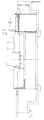
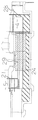
以下、図面について本発明の実施形態を詳細に説明する。図1は本発明の箱形ルーフ工法による既設トンネル構造物の撤去工法の1実施形態を示す縦断側面図、図2は同上横断平面図で、前記従来例を示す図16、図17と同一構成要素には同一参照符号を付したものである。 Hereinafter, embodiments of the present invention will be described in detail with reference to the drawings. FIG. 1 is a vertical sectional side view showing an embodiment of a method for removing an existing tunnel structure by a box-shaped roof construction method according to the present invention, and FIG. 2 is a transverse plan view of the same construction as the conventional example shown in FIGS. 16 and 17. Elements are given the same reference numerals.
図中1´は既設トンネル構造物を示し、全長に亘って一定幅と一定厚みを有する上床版、下床版と、この上床版、下床版の両側端の下面に上下端面を一体に連設している一定高さの両側壁とからなる断面矩形のコンクリート製構造物である。 In the figure, 1'indicates an existing tunnel structure, and an upper floor slab and a lower floor slab having a constant width and a constant thickness over the entire length, and upper and lower end faces are integrally connected to lower surfaces of both upper and lower slabs. It is a concrete structure with a rectangular cross section consisting of both side walls with a certain height.
既設トンネル構造物1´を、この既設トンネル構造物1´と断面径の異なる小さな新設トンネル構造物Aを置き換えて構築する場合で既設トンネル構造物に対してこの既設トンネル構造物を部分的に撤去し、その後に新設トンネル構造物を構築する場合で、既設トンネル構造物1´に対してこの既設トンネル構造物1´を部分的に撤去し、その後に新設トンネル構造物Aを構築する。 When constructing the existing tunnel structure 1′ by replacing the existing tunnel structure 1′ with a small new tunnel structure A having a different sectional diameter, the existing tunnel structure is partially removed from the existing tunnel structure. Then, when constructing a new tunnel structure after that, the existing tunnel structure 1′ is partially removed from the existing tunnel structure 1′, and then the new tunnel structure A is constructed.
函体2を発進させる側を発進側4とし、既設構造物1の一部を押し出す側を到達側5として、シートパイル等で仮土留め部材21を設置する。
The temporary
新設トンネル構造物Aの構築は、施工区間の防護工として両側に設置した立坑発進側4、到達側5のうち発進側4より、箱形ルーフ7を新設トンネル構造物Aの外縁に合致する位置に施工区間に貫通して設置する。
The construction of the new tunnel structure A is carried out at a position where the box-shaped
箱形ルーフ7には、薄い鋼板であるフリクションカッタープレート6を重ねて配置してある。フリクションカッタープレート6は函体2の推進またはけん引時における摩擦抵抗の低減と周辺地盤との縁切りを図るものである。
A
フリクションカッタープレート6を載置した複数本の断面矩形状の鋼製箱形ルーフ7を並列状態に打設して一列状に積み重なった並列箱形ルーフを形成する。
A plurality of steel box-shaped
フリクションカッタープレート6の前端は箱形ルーフ7の先端に切り離し可能に固着してあり、各箱形ルーフ7を地中に打設するには箱形ルーフ7内にオーガー(図示せず)を挿入して前方の地盤を掘削しながら到達側5から発進側4に向かって推進させることにより行われる。
The front end of the
図示の例では箱形ルーフ7を到達側5から発進側4に向かって挿入したが、この逆に発進側4から到達側5へ向けて挿入してもよい。
In the illustrated example, the box-shaped
既設トンネル構造物1´をワイヤーソー(カッター)等で切断分離させ、新設トンネル構造物Aに重なる部分1dを他から切り離す。 The existing tunnel structure 1'is cut and separated with a wire saw (cutter) or the like, and the portion 1d overlapping the new tunnel structure A is separated from the others.
また、既設構造物1の内空部に中詰め充填工24を行って地盤を形成し、この地盤上にレール25を敷設して、その上をローラー(車輪)付きの支保工26を走行可能に設置する。
In addition, the inner space of the existing structure 1 is filled with a filling
該ローラー付きの支保工26は前記新設トンネル構造物Aに重なる部分1aを支承する。
The
さらに、箱形ルーフ7の下側と既設トンネル構造物1´の切断分離部分をブラケット27で係止させ、この切断分離部分1dを箱形ルーフおよび新設トンネル構造物用の函体とともに押し出すことで、到達側5へ押し抜き、解体する。
Further, the lower side of the box-shaped
図3〜図15は以上の工程の詳細を示すもので、第1工程として、図3に示すように発進側4の施工で、仮設準備を行い、仮土留を打設し、水路構造物支障部を撤去工、覆工板の布設工を行う。
FIGS. 3 to 15 show the details of the above steps. As the first step, as shown in FIG. 3, temporary construction preparation is carried out by the construction on the starting
第2工程として図4に示すように、発進側4の施工として、地盤改良(鉛直施工)、地盤改良(水平施工)、水路構造物内を清掃し、反力体コンクリート28の築造を行い、既設構造物1の内空部に中詰め充填工24を行って地盤を形成し、この地盤上にレール25を敷設する。
As the second step, as shown in FIG. 4, as the construction of the starting
なお、本実施形態は地盤改良としての薬液注入29を追加でおこなった。 In this embodiment, a chemical solution injection 29 is added as a ground improvement.
到達側5側の施工として、仮土留を打設し、水路構造物の支障部し、水路構造物内の清掃を行う。
As the construction on the
第3工程として図5に示すように、箱形ルーフ7の推進準備として、ルーフ推進架台30を築造し、推進ジャッキ31、反力材32を設置する。
As a third step, as shown in FIG. 5, as a preparation for the promotion of the box-shaped
第4工程として図6に示すように、パイプルーフ33の推進準備を行い、推進ジャッキ31、反力材32等によりパイプルーフ33を推進させる。このパイプルーフ33は横並びに配置する箱形ルーフ7の左右端に、安全柵として配置するものである。
As a fourth step, as shown in FIG. 6, the
第5工程として図7に示すように、発進側4において井桁枠34を築造し、推進(元押し)ジャッキ17、およびスペーサー35を配置する。
As a fifth step, as shown in FIG. 7, the
図中36は函体の先頭にもうける刃口で、この刃口36の搬入、据え付けを行う。また、箱形ルーフ7の後端に小ジャッキを収納したジャッキ収納管37を取り付け、フリクションカットプレート6の固定工38を設ける。
また、既設トンネル構造物1´をワイヤーソー(カッター)等で切断分離させ、新設トンネル構造物Aに重なる部分1dを他から切り離し、ローラー付きの支保工26で支承する。
In addition, the existing tunnel structure 1'is cut and separated by a wire saw (cutter) or the like, the portion 1d overlapping the new tunnel structure A is separated from the others, and the supporting
ローラー付きの支保工26は中詰め充填材24による地盤上に敷設したレール25に走行可能に設置される。
A
第6工程として図8に示すように、箱形ルーフ7の空押し(縁切り)を行い、新設トンネル構造物1´に重なる部分1dとともに箱形ルーフ7を到達側5に押し出す準備を行う。
As a sixth step, as shown in FIG. 8, the box-shaped
第7工程として図9に示すように、スペーサー35を撤去し、第1の函体2を搬入、据付け、押角23を設置し、第1の函体2を空押しする。
As a seventh step, as shown in FIG. 9, the
第8工程として図10に示すように、第1の函体2が所定位置に到達後、推進設備の推進設備一部撤去を行い、第2の函体2を搬入、据付け、これら第1の函体2、第2の函体2を推進させる。
As shown in FIG. 10 as the eighth step, after the
第9工程として図11に示すように、同様の工程を繰り返して、第1〜第9の函体2を推進させ、スカート39、中押しジャッキ15を搬入、据付け、函体2を推進に伴い、 箱形ルーフ7および既設トンネル構造物1´の切断分離部分1dを到達側5側に押出し、解体、撤去する。
As a ninth step, as shown in FIG. 11, by repeating the same steps, the first to
第10工程として図12に示すように、前記工程を繰り返して、第1〜第18の函体2を推進させ、第1〜第18の函体2の所定位置到達後、推進設備を一部撤去し、スカート39、中押しジャッキ15を搬入し、第1〜第18の函体2を推進させる。
As shown in FIG. 12 as the tenth step, the above steps are repeated to propel the first to
第11工程として図13に示すように、推進に伴い、箱形ルーフ7の押出し撤去を行い、前記工程を繰り返して第1〜第22の函体2を推進させる。第1〜第22の函体2の所定位置到達後、刃口36と推進設備の一部撤去を行う。
As the eleventh step, as shown in FIG. 13, the box-shaped
第12工程として図14に示すように、前記工程を繰り返して、第1〜第26の函体2を推進させ、第1〜第26の函体2の到達後、スカート39、中押しジャッキ15を撤去し、第1〜第26の函体2を接合し、スペーサー(反力材)35を設置して推進させ、推進を完了させる。
As a twelfth step, as shown in FIG. 14, the above steps are repeated to propel the first to
第13工程として図15に示すように、推進設備を撤去し、函体2の外周に裏込グラウトを注入し、パイプルーフ内に中詰めグラウトを注入する。
As a thirteenth step, as shown in FIG. 15, the propulsion equipment is removed, backfill grout is injected into the outer periphery of the
1 既設構造物
1´ 既設トンネル構造物
1a 上床版
1b 側壁
1c 下床版
1d 新設トンネル構造物に重なる部分
2 函体
3 軌条
4 発進側
5 到達側
6 フリクションカッタープレート
7 箱形ルーフ
8 仮設支保工
9 摺動面材
11 下床版
15 中押しジャッキ
17 推進(元押し)ジャッキ
18 ストラット
20 充填工
21 仮土留め部材
23 押角工
24 中詰め充填工
25 レール
26 ローラー付きの支保工
27 ブラケット
28 反力体コンクリート
29 薬液注入
30 ルーフ推進架台
31 推進ジャッキ
32 反力材
33 パイプルーフ
34 井桁枠
35 スペーサー
36 刃口
37 ジャッキ収納管
38 固定工
39 スカート
1 Existing structure 1'Existing tunnel structure 1a Upper floor slab 1b Side wall 1c Lower floor slab 1d Part overlapping
37 Jack Storage Tube 38
Claims (3)
Priority Applications (1)
| Application Number | Priority Date | Filing Date | Title |
|---|---|---|---|
| JP2018161412A JP6737851B2 (en) | 2018-08-30 | 2018-08-30 | Removal method of existing tunnel structure by box roof method |
Applications Claiming Priority (1)
| Application Number | Priority Date | Filing Date | Title |
|---|---|---|---|
| JP2018161412A JP6737851B2 (en) | 2018-08-30 | 2018-08-30 | Removal method of existing tunnel structure by box roof method |
Publications (2)
| Publication Number | Publication Date |
|---|---|
| JP2020033767A JP2020033767A (en) | 2020-03-05 |
| JP6737851B2 true JP6737851B2 (en) | 2020-08-12 |
Family
ID=69667379
Family Applications (1)
| Application Number | Title | Priority Date | Filing Date |
|---|---|---|---|
| JP2018161412A Active JP6737851B2 (en) | 2018-08-30 | 2018-08-30 | Removal method of existing tunnel structure by box roof method |
Country Status (1)
| Country | Link |
|---|---|
| JP (1) | JP6737851B2 (en) |
Families Citing this family (1)
| Publication number | Priority date | Publication date | Assignee | Title |
|---|---|---|---|---|
| JP7157193B2 (en) * | 2021-03-01 | 2022-10-19 | 誠 植村 | Box-shaped roof and box-shaped roof construction method using it |
Family Cites Families (6)
| Publication number | Priority date | Publication date | Assignee | Title |
|---|---|---|---|---|
| JPS6062398A (en) * | 1983-09-14 | 1985-04-10 | 株式会社奥村組 | Construction of underpass |
| JPH06105025B2 (en) * | 1988-06-02 | 1994-12-21 | 株式会社奥村組 | Reconstruction method for existing underground structures |
| JP4759532B2 (en) * | 2007-03-23 | 2011-08-31 | 株式会社奥村組 | Widening method of existing underground structure |
| KR101324173B1 (en) * | 2013-07-11 | 2013-11-06 | 김동수 | Construction method for underground tunnel using guiding shape steel |
| JP5976728B2 (en) * | 2014-07-17 | 2016-08-24 | 植村 誠 | Widening method for existing structures |
| JP6434372B2 (en) * | 2015-06-04 | 2018-12-05 | 植村 誠 | Removal method of existing structures |
-
2018
- 2018-08-30 JP JP2018161412A patent/JP6737851B2/en active Active
Also Published As
| Publication number | Publication date |
|---|---|
| JP2020033767A (en) | 2020-03-05 |
Similar Documents
| Publication | Publication Date | Title |
|---|---|---|
| JP4317843B2 (en) | Construction method for underground structures | |
| JP6737851B2 (en) | Removal method of existing tunnel structure by box roof method | |
| JP4350113B2 (en) | Box roof used in the construction method of underground structures | |
| JP2008223397A (en) | Construction method for underground structure | |
| CN108729469B (en) | Construction method of underground structure | |
| JP4759532B2 (en) | Widening method of existing underground structure | |
| JP6434372B2 (en) | Removal method of existing structures | |
| CN108979641B (en) | Construction method for underground structure | |
| JP4134089B2 (en) | Construction method for underground structures | |
| JP3887383B2 (en) | Construction method for underground structures | |
| JP4698459B2 (en) | Construction method for underground structures | |
| JP5976728B2 (en) | Widening method for existing structures | |
| JP6714060B2 (en) | Construction method of underground structure | |
| JPH073155B2 (en) | How to build an underground structure | |
| JP4423182B2 (en) | Pipe roof construction equipment | |
| JP6510432B2 (en) | Construction method of underground structure | |
| JP4402640B2 (en) | Open shield method | |
| JP2876435B2 (en) | How to build underground structures | |
| JP6081512B2 (en) | Construction method for underground structures | |
| JP5394454B2 (en) | Open shield method | |
| JP4926093B2 (en) | How to build a box structure | |
| JPH09317374A (en) | Method of construction of subsurface structure | |
| JP4557918B2 (en) | Pipe roof construction equipment | |
| CN110359916B (en) | Construction method for underground structure | |
| JP2009197535A (en) | Construction method for caisson structure |
Legal Events
| Date | Code | Title | Description |
|---|---|---|---|
| A621 | Written request for application examination |
Free format text: JAPANESE INTERMEDIATE CODE: A621 Effective date: 20181029 |
|
| A131 | Notification of reasons for refusal |
Free format text: JAPANESE INTERMEDIATE CODE: A131 Effective date: 20191203 |
|
| A521 | Request for written amendment filed |
Free format text: JAPANESE INTERMEDIATE CODE: A523 Effective date: 20200127 |
|
| TRDD | Decision of grant or rejection written | ||
| A01 | Written decision to grant a patent or to grant a registration (utility model) |
Free format text: JAPANESE INTERMEDIATE CODE: A01 Effective date: 20200714 |
|
| A61 | First payment of annual fees (during grant procedure) |
Free format text: JAPANESE INTERMEDIATE CODE: A61 Effective date: 20200716 |
|
| R150 | Certificate of patent or registration of utility model |
Ref document number: 6737851 Country of ref document: JP Free format text: JAPANESE INTERMEDIATE CODE: R150 |
|
| R250 | Receipt of annual fees |
Free format text: JAPANESE INTERMEDIATE CODE: R250 |
|
| R250 | Receipt of annual fees |
Free format text: JAPANESE INTERMEDIATE CODE: R250 |