JP6736655B2 - 熱交換器 - Google Patents
熱交換器 Download PDFInfo
- Publication number
- JP6736655B2 JP6736655B2 JP2018502361A JP2018502361A JP6736655B2 JP 6736655 B2 JP6736655 B2 JP 6736655B2 JP 2018502361 A JP2018502361 A JP 2018502361A JP 2018502361 A JP2018502361 A JP 2018502361A JP 6736655 B2 JP6736655 B2 JP 6736655B2
- Authority
- JP
- Japan
- Prior art keywords
- heat
- heat medium
- plate
- flow path
- sensible
- Prior art date
- Legal status (The legal status is an assumption and is not a legal conclusion. Google has not performed a legal analysis and makes no representation as to the accuracy of the status listed.)
- Active
Links
Images


Classifications
-
- F—MECHANICAL ENGINEERING; LIGHTING; HEATING; WEAPONS; BLASTING
- F24—HEATING; RANGES; VENTILATING
- F24H—FLUID HEATERS, e.g. WATER OR AIR HEATERS, HAVING HEAT-GENERATING MEANS, e.g. HEAT PUMPS, IN GENERAL
- F24H1/00—Water heaters, e.g. boilers, continuous-flow heaters or water-storage heaters
- F24H1/22—Water heaters other than continuous-flow or water-storage heaters, e.g. water heaters for central heating
- F24H1/34—Water heaters other than continuous-flow or water-storage heaters, e.g. water heaters for central heating with water chamber arranged adjacent to the combustion chamber or chambers, e.g. above or at side
-
- F—MECHANICAL ENGINEERING; LIGHTING; HEATING; WEAPONS; BLASTING
- F24—HEATING; RANGES; VENTILATING
- F24H—FLUID HEATERS, e.g. WATER OR AIR HEATERS, HAVING HEAT-GENERATING MEANS, e.g. HEAT PUMPS, IN GENERAL
- F24H1/00—Water heaters, e.g. boilers, continuous-flow heaters or water-storage heaters
- F24H1/22—Water heaters other than continuous-flow or water-storage heaters, e.g. water heaters for central heating
- F24H1/24—Water heaters other than continuous-flow or water-storage heaters, e.g. water heaters for central heating with water mantle surrounding the combustion chamber or chambers
- F24H1/30—Water heaters other than continuous-flow or water-storage heaters, e.g. water heaters for central heating with water mantle surrounding the combustion chamber or chambers the water mantle being built up from sections
- F24H1/32—Water heaters other than continuous-flow or water-storage heaters, e.g. water heaters for central heating with water mantle surrounding the combustion chamber or chambers the water mantle being built up from sections with vertical sections arranged side by side
-
- F—MECHANICAL ENGINEERING; LIGHTING; HEATING; WEAPONS; BLASTING
- F24—HEATING; RANGES; VENTILATING
- F24H—FLUID HEATERS, e.g. WATER OR AIR HEATERS, HAVING HEAT-GENERATING MEANS, e.g. HEAT PUMPS, IN GENERAL
- F24H1/00—Water heaters, e.g. boilers, continuous-flow heaters or water-storage heaters
- F24H1/22—Water heaters other than continuous-flow or water-storage heaters, e.g. water heaters for central heating
- F24H1/40—Water heaters other than continuous-flow or water-storage heaters, e.g. water heaters for central heating with water tube or tubes
-
- F—MECHANICAL ENGINEERING; LIGHTING; HEATING; WEAPONS; BLASTING
- F24—HEATING; RANGES; VENTILATING
- F24H—FLUID HEATERS, e.g. WATER OR AIR HEATERS, HAVING HEAT-GENERATING MEANS, e.g. HEAT PUMPS, IN GENERAL
- F24H1/00—Water heaters, e.g. boilers, continuous-flow heaters or water-storage heaters
- F24H1/22—Water heaters other than continuous-flow or water-storage heaters, e.g. water heaters for central heating
- F24H1/44—Water heaters other than continuous-flow or water-storage heaters, e.g. water heaters for central heating with combinations of two or more of the types covered by groups F24H1/24 - F24H1/40 , e.g. boilers having a combination of features covered by F24H1/24 - F24H1/40
- F24H1/445—Water heaters other than continuous-flow or water-storage heaters, e.g. water heaters for central heating with combinations of two or more of the types covered by groups F24H1/24 - F24H1/40 , e.g. boilers having a combination of features covered by F24H1/24 - F24H1/40 with integrated flue gas condenser
-
- F—MECHANICAL ENGINEERING; LIGHTING; HEATING; WEAPONS; BLASTING
- F24—HEATING; RANGES; VENTILATING
- F24H—FLUID HEATERS, e.g. WATER OR AIR HEATERS, HAVING HEAT-GENERATING MEANS, e.g. HEAT PUMPS, IN GENERAL
- F24H8/00—Fluid heaters characterised by means for extracting latent heat from flue gases by means of condensation
-
- F—MECHANICAL ENGINEERING; LIGHTING; HEATING; WEAPONS; BLASTING
- F28—HEAT EXCHANGE IN GENERAL
- F28D—HEAT-EXCHANGE APPARATUS, NOT PROVIDED FOR IN ANOTHER SUBCLASS, IN WHICH THE HEAT-EXCHANGE MEDIA DO NOT COME INTO DIRECT CONTACT
- F28D20/00—Heat storage plants or apparatus in general; Regenerative heat-exchange apparatus not covered by groups F28D17/00 or F28D19/00
- F28D20/02—Heat storage plants or apparatus in general; Regenerative heat-exchange apparatus not covered by groups F28D17/00 or F28D19/00 using latent heat
- F28D20/025—Heat storage plants or apparatus in general; Regenerative heat-exchange apparatus not covered by groups F28D17/00 or F28D19/00 using latent heat the latent heat storage material being in direct contact with a heat-exchange medium or with another heat storage material
-
- F—MECHANICAL ENGINEERING; LIGHTING; HEATING; WEAPONS; BLASTING
- F28—HEAT EXCHANGE IN GENERAL
- F28D—HEAT-EXCHANGE APPARATUS, NOT PROVIDED FOR IN ANOTHER SUBCLASS, IN WHICH THE HEAT-EXCHANGE MEDIA DO NOT COME INTO DIRECT CONTACT
- F28D9/00—Heat-exchange apparatus having stationary plate-like or laminated conduit assemblies for both heat-exchange media, the media being in contact with different sides of a conduit wall
- F28D9/0031—Heat-exchange apparatus having stationary plate-like or laminated conduit assemblies for both heat-exchange media, the media being in contact with different sides of a conduit wall the conduits for one heat-exchange medium being formed by paired plates touching each other
- F28D9/0043—Heat-exchange apparatus having stationary plate-like or laminated conduit assemblies for both heat-exchange media, the media being in contact with different sides of a conduit wall the conduits for one heat-exchange medium being formed by paired plates touching each other the plates having openings therein for circulation of at least one heat-exchange medium from one conduit to another
- F28D9/005—Heat-exchange apparatus having stationary plate-like or laminated conduit assemblies for both heat-exchange media, the media being in contact with different sides of a conduit wall the conduits for one heat-exchange medium being formed by paired plates touching each other the plates having openings therein for circulation of at least one heat-exchange medium from one conduit to another the plates having openings therein for both heat-exchange media
-
- F—MECHANICAL ENGINEERING; LIGHTING; HEATING; WEAPONS; BLASTING
- F28—HEAT EXCHANGE IN GENERAL
- F28D—HEAT-EXCHANGE APPARATUS, NOT PROVIDED FOR IN ANOTHER SUBCLASS, IN WHICH THE HEAT-EXCHANGE MEDIA DO NOT COME INTO DIRECT CONTACT
- F28D9/00—Heat-exchange apparatus having stationary plate-like or laminated conduit assemblies for both heat-exchange media, the media being in contact with different sides of a conduit wall
- F28D9/0093—Multi-circuit heat-exchangers, e.g. integrating different heat exchange sections in the same unit or heat-exchangers for more than two fluids
-
- F—MECHANICAL ENGINEERING; LIGHTING; HEATING; WEAPONS; BLASTING
- F28—HEAT EXCHANGE IN GENERAL
- F28F—DETAILS OF HEAT-EXCHANGE AND HEAT-TRANSFER APPARATUS, OF GENERAL APPLICATION
- F28F3/00—Plate-like or laminated elements; Assemblies of plate-like or laminated elements
- F28F3/02—Elements or assemblies thereof with means for increasing heat-transfer area, e.g. with fins, with recesses, with corrugations
- F28F3/025—Elements or assemblies thereof with means for increasing heat-transfer area, e.g. with fins, with recesses, with corrugations the means being corrugated, plate-like elements
-
- F—MECHANICAL ENGINEERING; LIGHTING; HEATING; WEAPONS; BLASTING
- F28—HEAT EXCHANGE IN GENERAL
- F28F—DETAILS OF HEAT-EXCHANGE AND HEAT-TRANSFER APPARATUS, OF GENERAL APPLICATION
- F28F3/00—Plate-like or laminated elements; Assemblies of plate-like or laminated elements
- F28F3/02—Elements or assemblies thereof with means for increasing heat-transfer area, e.g. with fins, with recesses, with corrugations
- F28F3/04—Elements or assemblies thereof with means for increasing heat-transfer area, e.g. with fins, with recesses, with corrugations the means being integral with the element
- F28F3/042—Elements or assemblies thereof with means for increasing heat-transfer area, e.g. with fins, with recesses, with corrugations the means being integral with the element in the form of local deformations of the element
- F28F3/044—Elements or assemblies thereof with means for increasing heat-transfer area, e.g. with fins, with recesses, with corrugations the means being integral with the element in the form of local deformations of the element the deformations being pontual, e.g. dimples
-
- F—MECHANICAL ENGINEERING; LIGHTING; HEATING; WEAPONS; BLASTING
- F28—HEAT EXCHANGE IN GENERAL
- F28F—DETAILS OF HEAT-EXCHANGE AND HEAT-TRANSFER APPARATUS, OF GENERAL APPLICATION
- F28F3/00—Plate-like or laminated elements; Assemblies of plate-like or laminated elements
- F28F3/02—Elements or assemblies thereof with means for increasing heat-transfer area, e.g. with fins, with recesses, with corrugations
- F28F3/04—Elements or assemblies thereof with means for increasing heat-transfer area, e.g. with fins, with recesses, with corrugations the means being integral with the element
- F28F3/042—Elements or assemblies thereof with means for increasing heat-transfer area, e.g. with fins, with recesses, with corrugations the means being integral with the element in the form of local deformations of the element
- F28F3/046—Elements or assemblies thereof with means for increasing heat-transfer area, e.g. with fins, with recesses, with corrugations the means being integral with the element in the form of local deformations of the element the deformations being linear, e.g. corrugations
-
- Y—GENERAL TAGGING OF NEW TECHNOLOGICAL DEVELOPMENTS; GENERAL TAGGING OF CROSS-SECTIONAL TECHNOLOGIES SPANNING OVER SEVERAL SECTIONS OF THE IPC; TECHNICAL SUBJECTS COVERED BY FORMER USPC CROSS-REFERENCE ART COLLECTIONS [XRACs] AND DIGESTS
- Y02—TECHNOLOGIES OR APPLICATIONS FOR MITIGATION OR ADAPTATION AGAINST CLIMATE CHANGE
- Y02B—CLIMATE CHANGE MITIGATION TECHNOLOGIES RELATED TO BUILDINGS, e.g. HOUSING, HOUSE APPLIANCES OR RELATED END-USER APPLICATIONS
- Y02B30/00—Energy efficient heating, ventilation or air conditioning [HVAC]
-
- Y—GENERAL TAGGING OF NEW TECHNOLOGICAL DEVELOPMENTS; GENERAL TAGGING OF CROSS-SECTIONAL TECHNOLOGIES SPANNING OVER SEVERAL SECTIONS OF THE IPC; TECHNICAL SUBJECTS COVERED BY FORMER USPC CROSS-REFERENCE ART COLLECTIONS [XRACs] AND DIGESTS
- Y02—TECHNOLOGIES OR APPLICATIONS FOR MITIGATION OR ADAPTATION AGAINST CLIMATE CHANGE
- Y02E—REDUCTION OF GREENHOUSE GAS [GHG] EMISSIONS, RELATED TO ENERGY GENERATION, TRANSMISSION OR DISTRIBUTION
- Y02E60/00—Enabling technologies; Technologies with a potential or indirect contribution to GHG emissions mitigation
- Y02E60/14—Thermal energy storage
Description
そして、前記燃焼室(C)を包み込む外壁には熱媒体が流れる顕熱部熱媒体流路P3が設けられて燃焼室(C)の外壁の断熱が可能であるため、前記燃焼室(C)は前記水タンク冷却部(B)と顕熱部熱媒体流路P3とにより全体の領域に亘って断熱が可能となる。
そして、前記第1貫通口H1および第5貫通口H5を順に通過する熱媒体のうち一部の流量の熱媒体は、それぞれの単位プレート200−1〜200−11の内部に並列構造で設けられた潜熱部熱媒体流路P1を通過して前記第1貫通口H1および第5貫通口H5と対角線の方向に位置する第2貫通口H2および第6貫通口H6を順に通過し、前記第1プレート200a−12と第2プレート200b−12との間に設けられる水タンク冷却部(B)に向かって流動する。
100 バーナー
200 熱交換部
200A 顕熱部
200B 潜熱部
200B−1 第1潜熱部
200B−2 第2潜熱部
200−1〜200−12 単位プレート
200a−1〜200a−12 第1プレート
200b−1〜200b−12 第2プレート
200−A 第1プレート群
200−B 第2プレート群
200−C 第3プレート群
201 熱媒体入口
202 熱媒体出口
210 第1平面部
220 第1突出部
221 第1ガイド部
222 第1間隔維持部
230 第2突出部
240 第1フランジ部
241 第1切開部
250 第2平面部
260 第1陥没部
261 第2ガイド部
262 第2間隔維持部
270 第2陥没部
280 第2フランジ部
281 第2切開部
290 熱媒体遮断部
300 燃焼ガス排出部
310 下部蓋
311 凝縮水排出管
320 燃焼ガス排出管
A1 第1開放口
A2 第2開放口
B 水タンク冷却部
B1 第1断熱板
B2 第2断熱板
C 燃焼室
D 燃焼ガス通過部
H1〜H8 貫通口
H3’、H7’ 第1閉塞部
H4’、H8’ 第2閉塞部
H3−1、H4−1 第1フランジ部
H7−1、H8−1 第2フランジ部
P1 潜熱部熱媒体流路
P1’ 熱媒体連結流路
P2 潜熱部燃焼ガス流路
P3 顕熱部熱媒体流路
P4 顕熱部燃焼ガス流路
Claims (22)
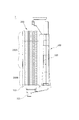
- 複数のプレート間の空間に熱媒体が流動する熱媒体流路と、バーナー(100)で燃焼した燃焼ガスが流動する燃焼ガス流路が隣接して交互に形成された熱交換部(200)を具備し、
前記熱交換部(200)は、燃焼室(C)の外側を包み込み、前記プレートの一側領域で構成されて前記バーナー(100)の燃焼によって発生した燃焼ガスの顕熱を利用して熱媒体を加熱する顕熱部(200A)と、前記プレートの他側領域で構成されて前記顕熱部(200A)で熱交換を終えた燃焼ガスに含まれた水蒸気の潜熱を利用して熱媒体を加熱する潜熱部(200B)と、で構成され、
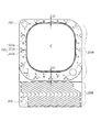
前記顕熱部(200A)の熱媒体流路には前記熱媒体が前記燃焼室(C)の中央に向かって流動するように誘導するガイド部(221、261)が形成され、
前記ガイド部(221、261)は、前記顕熱部(200A)の外側部に周方向に離隔して複数で形成されたことを特徴とする、
熱交換器。 - 前記ガイド部(221、261)は、熱媒体の流動方向を基準として前方から後方に離隔し、前記燃焼室(C)に向かう斜線方向に配置された複数のガイド部を含むことを特徴とする、請求項1に記載の熱交換器。
- 前記複数のプレートは、第1プレートと第2プレートとが積層された単位プレートが複数積層されて構成され、前記単位プレートの第1プレートと第2プレートとの間に前記熱媒体流路が形成され、隣接して積層される単位プレートのうち一側に位置する単位プレートを構成する第2プレートと、他側に位置する単位プレートの第1プレートとの間に前記燃焼ガス流路が形成されたことを特徴とする、請求項1に記載の熱交換器。
- 前記ガイド部(221、261)は、前記第1プレートから前記熱媒体流路に向かって突出した複数の第1ガイド部(221)と、前記第2プレートから前記熱媒体流路に向かって突出し、前記第1ガイド部(221)と対応なる位置に形成された複数の第2ガイド部(261)からなることを特徴とする、請求項3に記載の熱交換器。
- 前記第1プレートは、第1平面部(210)と、前記第1平面部(210)の一側から前方に突出し、中央には第1開放口(A1)が形成されて前記顕熱部(200A)を構成する第1突出部(220)と、前記第1平面部(210)の他側から前方に突出し、前記潜熱部(200B)を形成する第2突出部(230)からなり、前記第2プレートは、第2平面部(250)と、前記第2平面部(250)の一側から後方に陥没して前記第1突出部(220)との間に顕熱部熱媒体流路(P3)を形成し、中央には前記第1開放口(A1)と対応する第2開放口(A2)が形成された第1陥没部(260)と、前記第2平面部(250)の他側から後方に陥没して前記第2突出部(230)との間に潜熱部熱媒体流路(P1)を形成する第2陥没部(270)からなることを特徴とする、請求項3に記載の熱交換器。
- 前記ガイド部(221、261)は、前記第1突出部(220)から前記顕熱部熱媒体流路(P3)に向かって突出した複数の第1ガイド部(221)と、前記第1陥没部(260)から前記顕熱部熱媒体流路(P3)に向かって突出し、前記第1ガイド部(221)と対応する位置に形成された複数の第2ガイド部(261)からなることを特徴とする、請求項5に記載の熱交換器。
- 前記第1ガイド部(221)の突出した端部と前記第2ガイド部(261)の突出した端部とは、当接するように形成されたことを特徴とする、請求項4または請求項5に記載の熱交換器。
- 前記第1プレートと第2プレートとを積層する時、前記第1平面部(210)と第2平面部(250)は当接し、前記第2突出部(230)は、逆くの字形状が並んだ形態で構成され、前記第2陥没部(270)は、くの字形状が並んだ形態で構成されたことを特徴とする、請求項5に記載の熱交換器。
- 前記第1突出部(220)には前記燃焼ガス流路に向かって突出した複数の第1間隔維持部(222)が形成され、前記第1陥没部(260)には前記燃焼ガス流路に向かって突出し、前記第1間隔維持部(222)と対応する位置に形成された複数の第2間隔維持部(262)が形成されたことを特徴とする、請求項5に記載の熱交換器。
- 前記第1間隔維持部(222)の突出した端部と前記第2間隔維持部(262)の突出した端部とは、当接するように形成されたことを特徴とする、請求項9に記載の熱交換器。
- 前記燃焼室(C)の周りに位置する第1プレートの端部と第2プレートの端部のうちいずれか一つは折り曲げられて他の一つに密着するように、シーミング加工されて溶接結合されたことを特徴とする、請求項3に記載の熱交換器。
- 前記シーミング加工された第1プレートと第2プレートの端部の長さは1〜5mmであることを特徴とする、請求項11に記載の熱交換器。
- 前記顕熱部(200A)の燃焼ガス流路は0.8〜1.6mmの間隔で形成されたことを特徴とする、請求項1に記載の熱交換器。
- 前記プレートは、前記顕熱部(200A)が上部に位置し、前記潜熱部(200B)が下部に位置するように直立構造からなり、前記バーナー(100)は、前記燃焼室(C)の空間に正面から水平方向に挿入されて組み立てられることを特徴とする、請求項1に記載の熱交換器。
- 前記顕熱部(200A)を構成するプレートは、前記潜熱部(200A)を向く側の領域の幅が前記潜熱部(200A)の反対側の領域の幅より大きく形成されたことを特徴とする、請求項1に記載の熱交換器。
- 前記潜熱部(200B)は、前記熱媒体が流入する熱媒体入口(201)と、前記複数のプレートとの間に形成され、前記熱媒体入口(201)に並列に連通する複数の潜熱部熱媒体流路(P1)からなり、前記顕熱部(200A)は、前記熱媒体が流出する熱媒体出口(202)と、前記複数のプレートとの間に形成され、前記潜熱部熱媒体流路(P1)と前記熱媒体出口(202)との間に直列に連結される複数の顕熱部熱媒体流路(P3)からなることを特徴とする、請求項1に記載の熱交換器。
- 前記顕熱部熱媒体流路(P3)の間には顕熱部燃焼ガス流路(P4)が設けられ、前記潜熱部熱媒体流路(P1)の間には前記顕熱部燃焼ガス流路(P4)と連通する潜熱部燃焼ガス流路(P2)が設けられたことを特徴とする、請求項16に記載の熱交換器。
- 前記潜熱部(200B)には前記潜熱部熱媒体流路(P1)を並列に連結するために、前記潜熱部熱媒体流路(P1)と連通する一側の貫通口(H1、H5)と他側の貫通口(H2、H6)が対角線の方向に形成され、前記顕熱部(200A)には前記顕熱部熱媒体流路(P3)を直列に連結するために、前記顕熱部熱媒体流路(P3)と連通する一側の貫通口(H3、H7)と他側の貫通口(H4、H8)が対角線の方向に形成されたことを特徴とする、請求項16に記載の熱交換器。
- 前記潜熱部(200B)は熱媒体遮断部(290)を挟んで両側に第1潜熱部(200B−1)と第2潜熱部(200B−2)とに分割形成され、前記第1潜熱部(200B−1)と第2潜熱部(200B−2)の熱媒体流路は前記熱媒体遮断部(290)の一側に形成された熱媒体連結流路(P1’)を介して連通し、前記第1潜熱部(200B−1)の一側には前記熱媒体入口(201)と前記第1潜熱部(200B−1)の熱媒体流路に連通する貫通口(H1、H5)が形成され、前記第2潜熱部(200B−2)の一側には前記第2潜熱部(200B−2)の熱媒体流路と前記顕熱部熱媒体流路(P3)に連通する貫通口(H2、H6)が形成されたことを特徴とする、請求項16に記載の熱交換器。
- 前記一側の貫通口(H3、H7)を通じて顕熱部熱媒体流路(P3)に流入した熱媒体は、両方向に分岐して対角線の方向の他側に形成された貫通口(H4、H8)に向かって流動し、前記他側に形成された貫通口(H4、H8)を通じて顕熱部熱媒体流路(P3)に流入した熱媒体は、両方向に分岐して対角線の方向の一側に形成された前記貫通口(H3、H7)に向かって流動することを特徴とする、請求項18または請求項19に記載の熱交換器。
- 前記顕熱部(200A)には、前記一側の貫通口(H3、H7)を通じて顕熱部熱媒体流路(P3)に流入した熱媒体が、対角線の方向の他側に形成された貫通口(H4、H8)に向かって流動するように誘導するための第1閉塞部(H3’、H7’)と、前記他側の貫通口(H4、H8)を通じて顕熱部熱媒体流路(P3)に流入した熱媒体が、対角線の方向の一側に形成された貫通口(H3、H7)に向かって流動するように誘導するための第2閉塞部(H4’、H8’)が形成されたことを特徴とする、請求項20に記載の熱交換器。
- 前記一側に形成された貫通口(H3、H7)には前記燃焼ガス流路に向かって突出して、突出した端部が当接する第1フランジ部(H3−1)と第2フランジ部(H7−1)が形成され、
前記他側に形成された貫通口(H4、H8)には前記燃焼ガス流路に向かって突出して、突出した端部が当接する第1フランジ部(H4−1)と第2フランジ部(H8−1)が形成されたことを特徴とする、請求項19に記載の熱交換器。
Applications Claiming Priority (3)
| Application Number | Priority Date | Filing Date | Title |
|---|---|---|---|
| KR1020150104093A KR101717093B1 (ko) | 2015-07-23 | 2015-07-23 | 열교환기 |
| KR10-2015-0104093 | 2015-07-23 | ||
| PCT/KR2016/007715 WO2017014498A1 (ko) | 2015-07-23 | 2016-07-15 | 열교환기 |
Publications (2)
| Publication Number | Publication Date |
|---|---|
| JP2018522197A JP2018522197A (ja) | 2018-08-09 |
| JP6736655B2 true JP6736655B2 (ja) | 2020-08-05 |
Family
ID=57834148
Family Applications (1)
| Application Number | Title | Priority Date | Filing Date |
|---|---|---|---|
| JP2018502361A Active JP6736655B2 (ja) | 2015-07-23 | 2016-07-15 | 熱交換器 |
Country Status (7)
| Country | Link |
|---|---|
| US (1) | US10746436B2 (ja) |
| EP (1) | EP3327371B1 (ja) |
| JP (1) | JP6736655B2 (ja) |
| KR (1) | KR101717093B1 (ja) |
| CN (1) | CN107850340B (ja) |
| ES (1) | ES2958526T3 (ja) |
| WO (1) | WO2017014498A1 (ja) |
Families Citing this family (1)
| Publication number | Priority date | Publication date | Assignee | Title |
|---|---|---|---|---|
| WO2018218649A1 (zh) * | 2017-06-02 | 2018-12-06 | 深圳市得城网络科技有限公司 | 安防报警式智能电取暖器 |
Family Cites Families (21)
| Publication number | Priority date | Publication date | Assignee | Title |
|---|---|---|---|---|
| AT402668B (de) * | 1995-03-13 | 1997-07-25 | Vaillant Gmbh | Gussgliederkessel gussgliederkessel |
| JP3031232B2 (ja) * | 1996-03-04 | 2000-04-10 | 松下電器産業株式会社 | 吸収式ヒートポンプ用積層熱交換器 |
| JPH10170177A (ja) * | 1996-08-31 | 1998-06-26 | Behr Gmbh & Co | プレートパイル構造を有する熱交換器とその製造方法 |
| JP2001050680A (ja) * | 1999-08-05 | 2001-02-23 | Mitsubishi Heavy Ind Ltd | 熱交換器 |
| JP2001091169A (ja) * | 1999-09-27 | 2001-04-06 | Sanyo Electric Co Ltd | プレート式熱交換器 |
| JP2001099582A (ja) * | 1999-09-29 | 2001-04-13 | Sanyo Electric Co Ltd | プレート式熱交換器及びその製造方法 |
| JP4471423B2 (ja) * | 1999-09-30 | 2010-06-02 | 三洋電機株式会社 | プレート式熱交換器 |
| JP4462054B2 (ja) * | 2005-02-02 | 2010-05-12 | 株式会社ノーリツ | プレート式熱交換器、これを備えた温水装置および暖房装置 |
| ITBO20070143A1 (it) | 2007-03-02 | 2008-09-03 | Gas Point S R L | Caldaia a condensazione |
| GB2441183B (en) * | 2007-04-16 | 2009-04-08 | Enertek Internat Ltd | Heat exchanger |
| KR20100054383A (ko) * | 2008-11-14 | 2010-05-25 | 롯데알미늄 주식회사 | 콘덴싱 가스보일러용 잠열 열교환기 |
| CN201561679U (zh) * | 2009-11-05 | 2010-08-25 | 上海林内有限公司 | 热交换器 |
| US20110303400A1 (en) * | 2010-06-15 | 2011-12-15 | Pb Heat, Llc | Counterflow heat exchanger |
| KR101156249B1 (ko) * | 2010-10-29 | 2012-06-13 | 린나이코리아 주식회사 | 플레이트 접합형 열교환기 |
| KR101331825B1 (ko) * | 2011-11-14 | 2013-11-22 | 주식회사 두발 | 콘덴싱 보일러용 열교환기 |
| EP2682703B1 (en) * | 2012-07-05 | 2018-03-28 | Airec AB | Plate for heat exchanger, heat exchanger and air cooler comprising a heat exchanger. |
| US20140158328A1 (en) | 2012-07-05 | 2014-06-12 | Airec Ab | Plate for heat exchanger, heat exchanger and air cooler comprising a heat exchanger |
| CN102901222B (zh) * | 2012-09-21 | 2016-04-20 | 苏州成强能源科技有限公司 | 一种强制翅片直管双环状冷凝供热换热器 |
| PT2730878T (pt) * | 2012-11-07 | 2019-05-30 | Alfa Laval Corp Ab | Bloco de placas e método de fazer um bloco de placas |
| ITBO20130632A1 (it) * | 2013-11-20 | 2015-05-21 | Gas Point S R L | Scambiatore di calore a piastre, in particolare per caldaie a condensazione |
| KR101576667B1 (ko) * | 2014-03-17 | 2015-12-11 | 주식회사 경동나비엔 | 콘덴싱 가스보일러의 열교환기 |
-
2015
- 2015-07-23 KR KR1020150104093A patent/KR101717093B1/ko active IP Right Grant
-
2016
- 2016-07-15 US US15/746,671 patent/US10746436B2/en active Active
- 2016-07-15 EP EP16828002.2A patent/EP3327371B1/en active Active
- 2016-07-15 ES ES16828002T patent/ES2958526T3/es active Active
- 2016-07-15 WO PCT/KR2016/007715 patent/WO2017014498A1/ko active Application Filing
- 2016-07-15 JP JP2018502361A patent/JP6736655B2/ja active Active
- 2016-07-15 CN CN201680044065.3A patent/CN107850340B/zh active Active
Also Published As
| Publication number | Publication date |
|---|---|
| KR101717093B1 (ko) | 2017-03-27 |
| US10746436B2 (en) | 2020-08-18 |
| WO2017014498A1 (ko) | 2017-01-26 |
| EP3327371B1 (en) | 2023-07-26 |
| EP3327371A4 (en) | 2019-04-03 |
| CN107850340B (zh) | 2021-08-17 |
| EP3327371A1 (en) | 2018-05-30 |
| US20180224155A1 (en) | 2018-08-09 |
| CN107850340A (zh) | 2018-03-27 |
| KR20170011445A (ko) | 2017-02-02 |
| JP2018522197A (ja) | 2018-08-09 |
| ES2958526T3 (es) | 2024-02-09 |
Similar Documents
| Publication | Publication Date | Title |
|---|---|---|
| JP6773765B2 (ja) | 熱交換器 | |
| JP6763941B2 (ja) | 熱交換器 | |
| JP6725644B2 (ja) | 熱交換器 | |
| JP6736655B2 (ja) | 熱交換器 | |
| JP6828012B2 (ja) | 熱交換器 | |
| JP6714070B2 (ja) | 熱交換器 | |
| JP6755300B2 (ja) | 熱交換器 |
Legal Events
| Date | Code | Title | Description |
|---|---|---|---|
| A621 | Written request for application examination |
Free format text: JAPANESE INTERMEDIATE CODE: A621 Effective date: 20190307 |
|
| A977 | Report on retrieval |
Free format text: JAPANESE INTERMEDIATE CODE: A971007 Effective date: 20200316 |
|
| A131 | Notification of reasons for refusal |
Free format text: JAPANESE INTERMEDIATE CODE: A131 Effective date: 20200324 |
|
| A521 | Request for written amendment filed |
Free format text: JAPANESE INTERMEDIATE CODE: A523 Effective date: 20200619 |
|
| TRDD | Decision of grant or rejection written | ||
| A01 | Written decision to grant a patent or to grant a registration (utility model) |
Free format text: JAPANESE INTERMEDIATE CODE: A01 Effective date: 20200707 |
|
| A61 | First payment of annual fees (during grant procedure) |
Free format text: JAPANESE INTERMEDIATE CODE: A61 Effective date: 20200715 |
|
| R150 | Certificate of patent or registration of utility model |
Ref document number: 6736655 Country of ref document: JP Free format text: JAPANESE INTERMEDIATE CODE: R150 |
|
| R250 | Receipt of annual fees |
Free format text: JAPANESE INTERMEDIATE CODE: R250 |