JP6735891B2 - Flexible laminate and image display device including the same - Google Patents
Flexible laminate and image display device including the same Download PDFInfo
- Publication number
- JP6735891B2 JP6735891B2 JP2019198786A JP2019198786A JP6735891B2 JP 6735891 B2 JP6735891 B2 JP 6735891B2 JP 2019198786 A JP2019198786 A JP 2019198786A JP 2019198786 A JP2019198786 A JP 2019198786A JP 6735891 B2 JP6735891 B2 JP 6735891B2
- Authority
- JP
- Japan
- Prior art keywords
- thickness
- adhesive layer
- layer
- mpa
- flexible laminate
- Prior art date
- Legal status (The legal status is an assumption and is not a legal conclusion. Google has not performed a legal analysis and makes no representation as to the accuracy of the status listed.)
- Expired - Fee Related
Links
- 239000010410 layer Substances 0.000 claims description 221
- 239000004820 Pressure-sensitive adhesive Substances 0.000 claims description 99
- 229920005989 resin Polymers 0.000 claims description 53
- 239000011347 resin Substances 0.000 claims description 53
- 239000012790 adhesive layer Substances 0.000 claims description 49
- 238000003860 storage Methods 0.000 claims description 21
- 230000001681 protective effect Effects 0.000 claims description 9
- 239000000203 mixture Substances 0.000 description 43
- 239000000975 dye Substances 0.000 description 23
- -1 polyethylene Polymers 0.000 description 19
- 238000005452 bending Methods 0.000 description 18
- 230000007423 decrease Effects 0.000 description 16
- 239000004372 Polyvinyl alcohol Substances 0.000 description 14
- 238000000034 method Methods 0.000 description 14
- 229920002451 polyvinyl alcohol Polymers 0.000 description 14
- 238000010521 absorption reaction Methods 0.000 description 13
- 239000004973 liquid crystal related substance Substances 0.000 description 13
- 239000000463 material Substances 0.000 description 13
- 150000001875 compounds Chemical class 0.000 description 12
- 239000004925 Acrylic resin Substances 0.000 description 11
- 229920000178 Acrylic resin Polymers 0.000 description 11
- 238000002360 preparation method Methods 0.000 description 10
- 239000000758 substrate Substances 0.000 description 10
- 239000000853 adhesive Substances 0.000 description 9
- 230000001070 adhesive effect Effects 0.000 description 9
- 238000000926 separation method Methods 0.000 description 8
- NIXOWILDQLNWCW-UHFFFAOYSA-M Acrylate Chemical compound [O-]C(=O)C=C NIXOWILDQLNWCW-UHFFFAOYSA-M 0.000 description 7
- 239000011521 glass Substances 0.000 description 7
- 238000005259 measurement Methods 0.000 description 7
- 229920005601 base polymer Polymers 0.000 description 6
- 238000001514 detection method Methods 0.000 description 6
- 238000005401 electroluminescence Methods 0.000 description 6
- 238000011156 evaluation Methods 0.000 description 6
- 238000010030 laminating Methods 0.000 description 6
- 239000000178 monomer Substances 0.000 description 6
- 229920002284 Cellulose triacetate Polymers 0.000 description 5
- NNLVGZFZQQXQNW-ADJNRHBOSA-N [(2r,3r,4s,5r,6s)-4,5-diacetyloxy-3-[(2s,3r,4s,5r,6r)-3,4,5-triacetyloxy-6-(acetyloxymethyl)oxan-2-yl]oxy-6-[(2r,3r,4s,5r,6s)-4,5,6-triacetyloxy-2-(acetyloxymethyl)oxan-3-yl]oxyoxan-2-yl]methyl acetate Chemical compound O([C@@H]1O[C@@H]([C@H]([C@H](OC(C)=O)[C@H]1OC(C)=O)O[C@H]1[C@@H]([C@@H](OC(C)=O)[C@H](OC(C)=O)[C@@H](COC(C)=O)O1)OC(C)=O)COC(=O)C)[C@@H]1[C@@H](COC(C)=O)O[C@@H](OC(C)=O)[C@H](OC(C)=O)[C@H]1OC(C)=O NNLVGZFZQQXQNW-ADJNRHBOSA-N 0.000 description 5
- NIXOWILDQLNWCW-UHFFFAOYSA-N acrylic acid group Chemical group C(C=C)(=O)O NIXOWILDQLNWCW-UHFFFAOYSA-N 0.000 description 5
- 125000003178 carboxy group Chemical group [H]OC(*)=O 0.000 description 5
- 238000003851 corona treatment Methods 0.000 description 5
- 238000010168 coupling process Methods 0.000 description 5
- KGBXLFKZBHKPEV-UHFFFAOYSA-N boric acid Chemical compound OB(O)O KGBXLFKZBHKPEV-UHFFFAOYSA-N 0.000 description 4
- 239000004327 boric acid Substances 0.000 description 4
- 230000000052 comparative effect Effects 0.000 description 4
- 125000004122 cyclic group Chemical group 0.000 description 4
- 238000004043 dyeing Methods 0.000 description 4
- 229910052751 metal Inorganic materials 0.000 description 4
- 239000002184 metal Substances 0.000 description 4
- 229920001721 polyimide Polymers 0.000 description 4
- 229920000642 polymer Polymers 0.000 description 4
- CERQOIWHTDAKMF-UHFFFAOYSA-N Methacrylic acid Chemical compound CC(=C)C(O)=O CERQOIWHTDAKMF-UHFFFAOYSA-N 0.000 description 3
- XTXRWKRVRITETP-UHFFFAOYSA-N Vinyl acetate Chemical compound CC(=O)OC=C XTXRWKRVRITETP-UHFFFAOYSA-N 0.000 description 3
- 239000000654 additive Substances 0.000 description 3
- 229920002678 cellulose Polymers 0.000 description 3
- 239000001913 cellulose Substances 0.000 description 3
- 239000011248 coating agent Substances 0.000 description 3
- 238000000576 coating method Methods 0.000 description 3
- 230000008878 coupling Effects 0.000 description 3
- 238000005859 coupling reaction Methods 0.000 description 3
- 239000003431 cross linking reagent Substances 0.000 description 3
- 239000010419 fine particle Substances 0.000 description 3
- 239000007788 liquid Substances 0.000 description 3
- 239000000049 pigment Substances 0.000 description 3
- 229920001225 polyester resin Polymers 0.000 description 3
- 239000004645 polyester resin Substances 0.000 description 3
- 229920000139 polyethylene terephthalate Polymers 0.000 description 3
- 239000005020 polyethylene terephthalate Substances 0.000 description 3
- 239000011118 polyvinyl acetate Substances 0.000 description 3
- 229920002689 polyvinyl acetate Polymers 0.000 description 3
- 239000011241 protective layer Substances 0.000 description 3
- 239000000243 solution Substances 0.000 description 3
- 229920002554 vinyl polymer Polymers 0.000 description 3
- XLYOFNOQVPJJNP-UHFFFAOYSA-N water Substances O XLYOFNOQVPJJNP-UHFFFAOYSA-N 0.000 description 3
- JOYRKODLDBILNP-UHFFFAOYSA-N Ethyl urethane Chemical compound CCOC(N)=O JOYRKODLDBILNP-UHFFFAOYSA-N 0.000 description 2
- 239000004952 Polyamide Substances 0.000 description 2
- 239000004962 Polyamide-imide Substances 0.000 description 2
- 239000004642 Polyimide Substances 0.000 description 2
- 239000004743 Polypropylene Substances 0.000 description 2
- DHKHKXVYLBGOIT-UHFFFAOYSA-N acetaldehyde Diethyl Acetal Natural products CCOC(C)OCC DHKHKXVYLBGOIT-UHFFFAOYSA-N 0.000 description 2
- 150000001241 acetals Chemical class 0.000 description 2
- 229940081735 acetylcellulose Drugs 0.000 description 2
- 238000010306 acid treatment Methods 0.000 description 2
- 230000000996 additive effect Effects 0.000 description 2
- 239000011324 bead Substances 0.000 description 2
- 230000015572 biosynthetic process Effects 0.000 description 2
- 229920002301 cellulose acetate Polymers 0.000 description 2
- 239000003086 colorant Substances 0.000 description 2
- 239000002131 composite material Substances 0.000 description 2
- 229920001577 copolymer Polymers 0.000 description 2
- 239000000412 dendrimer Substances 0.000 description 2
- 229920000736 dendritic polymer Polymers 0.000 description 2
- 239000000982 direct dye Substances 0.000 description 2
- 239000003822 epoxy resin Substances 0.000 description 2
- 239000003999 initiator Substances 0.000 description 2
- 230000003287 optical effect Effects 0.000 description 2
- TZMFJUDUGYTVRY-UHFFFAOYSA-N pentane-2,3-dione Chemical group CCC(=O)C(C)=O TZMFJUDUGYTVRY-UHFFFAOYSA-N 0.000 description 2
- 229920003207 poly(ethylene-2,6-naphthalate) Polymers 0.000 description 2
- 229920002647 polyamide Polymers 0.000 description 2
- 229920002312 polyamide-imide Polymers 0.000 description 2
- 229920000647 polyepoxide Polymers 0.000 description 2
- 239000011112 polyethylene naphthalate Substances 0.000 description 2
- 239000009719 polyimide resin Substances 0.000 description 2
- 229920001228 polyisocyanate Polymers 0.000 description 2
- 239000005056 polyisocyanate Substances 0.000 description 2
- 229920000098 polyolefin Polymers 0.000 description 2
- 229920005672 polyolefin resin Polymers 0.000 description 2
- 229920001155 polypropylene Polymers 0.000 description 2
- 239000000843 powder Substances 0.000 description 2
- ZCYVEMRRCGMTRW-UHFFFAOYSA-N 7553-56-2 Chemical compound [I] ZCYVEMRRCGMTRW-UHFFFAOYSA-N 0.000 description 1
- HRPVXLWXLXDGHG-UHFFFAOYSA-N Acrylamide Chemical compound NC(=O)C=C HRPVXLWXLXDGHG-UHFFFAOYSA-N 0.000 description 1
- FERIUCNNQQJTOY-UHFFFAOYSA-M Butyrate Chemical compound CCCC([O-])=O FERIUCNNQQJTOY-UHFFFAOYSA-M 0.000 description 1
- FERIUCNNQQJTOY-UHFFFAOYSA-N Butyric acid Natural products CCCC(O)=O FERIUCNNQQJTOY-UHFFFAOYSA-N 0.000 description 1
- GAWIXWVDTYZWAW-UHFFFAOYSA-N C[CH]O Chemical group C[CH]O GAWIXWVDTYZWAW-UHFFFAOYSA-N 0.000 description 1
- RYGMFSIKBFXOCR-UHFFFAOYSA-N Copper Chemical compound [Cu] RYGMFSIKBFXOCR-UHFFFAOYSA-N 0.000 description 1
- 239000004593 Epoxy Substances 0.000 description 1
- 239000004696 Poly ether ether ketone Substances 0.000 description 1
- 239000004695 Polyether sulfone Substances 0.000 description 1
- 239000004697 Polyetherimide Substances 0.000 description 1
- 239000004698 Polyethylene Substances 0.000 description 1
- 239000004721 Polyphenylene oxide Substances 0.000 description 1
- 239000004793 Polystyrene Substances 0.000 description 1
- 229920001328 Polyvinylidene chloride Polymers 0.000 description 1
- VYPSYNLAJGMNEJ-UHFFFAOYSA-N Silicium dioxide Chemical compound O=[Si]=O VYPSYNLAJGMNEJ-UHFFFAOYSA-N 0.000 description 1
- BQCADISMDOOEFD-UHFFFAOYSA-N Silver Chemical compound [Ag] BQCADISMDOOEFD-UHFFFAOYSA-N 0.000 description 1
- QYKIQEUNHZKYBP-UHFFFAOYSA-N Vinyl ether Chemical class C=COC=C QYKIQEUNHZKYBP-UHFFFAOYSA-N 0.000 description 1
- SMEGJBVQLJJKKX-HOTMZDKISA-N [(2R,3S,4S,5R,6R)-5-acetyloxy-3,4,6-trihydroxyoxan-2-yl]methyl acetate Chemical compound CC(=O)OC[C@@H]1[C@H]([C@@H]([C@H]([C@@H](O1)O)OC(=O)C)O)O SMEGJBVQLJJKKX-HOTMZDKISA-N 0.000 description 1
- 239000006096 absorbing agent Substances 0.000 description 1
- 150000003926 acrylamides Chemical class 0.000 description 1
- 150000001299 aldehydes Chemical group 0.000 description 1
- 150000001336 alkenes Chemical class 0.000 description 1
- 229910052782 aluminium Inorganic materials 0.000 description 1
- XAGFODPZIPBFFR-UHFFFAOYSA-N aluminium Chemical compound [Al] XAGFODPZIPBFFR-UHFFFAOYSA-N 0.000 description 1
- 125000003368 amide group Chemical group 0.000 description 1
- 150000001408 amides Chemical class 0.000 description 1
- 125000003277 amino group Chemical group 0.000 description 1
- QGZKDVFQNNGYKY-UHFFFAOYSA-O ammonium group Chemical group [NH4+] QGZKDVFQNNGYKY-UHFFFAOYSA-O 0.000 description 1
- 239000003963 antioxidant agent Substances 0.000 description 1
- 238000000149 argon plasma sintering Methods 0.000 description 1
- 239000012298 atmosphere Substances 0.000 description 1
- 230000005540 biological transmission Effects 0.000 description 1
- 125000000484 butyl group Chemical group [H]C([*])([H])C([H])([H])C([H])([H])C([H])([H])[H] 0.000 description 1
- 125000004063 butyryl group Chemical group O=C([*])C([H])([H])C([H])([H])C([H])([H])[H] 0.000 description 1
- 150000001732 carboxylic acid derivatives Chemical class 0.000 description 1
- 150000001735 carboxylic acids Chemical class 0.000 description 1
- 239000012461 cellulose resin Substances 0.000 description 1
- 229910052802 copper Inorganic materials 0.000 description 1
- 239000010949 copper Substances 0.000 description 1
- 230000007797 corrosion Effects 0.000 description 1
- 238000005260 corrosion Methods 0.000 description 1
- 229920005994 diacetyl cellulose Polymers 0.000 description 1
- 238000010790 dilution Methods 0.000 description 1
- 239000012895 dilution Substances 0.000 description 1
- SLZCDQVDTBWJND-UHFFFAOYSA-L disodium 8-[[4-[4-[(4-ethoxyphenyl)diazenyl]-3-methylphenyl]-2-methylphenyl]diazenyl]-7-hydroxynaphthalene-1,3-disulfonate Chemical compound CCOC1=CC=C(C=C1)N=NC2=C(C=C(C=C2)C3=CC(=C(C=C3)N=NC4=C(C=CC5=CC(=CC(=C54)S(=O)(=O)O)S(=O)(=O)[O-])[O-])C)C.[Na+].[Na+] SLZCDQVDTBWJND-UHFFFAOYSA-L 0.000 description 1
- 229920001971 elastomer Polymers 0.000 description 1
- 238000010894 electron beam technology Methods 0.000 description 1
- 239000000839 emulsion Substances 0.000 description 1
- 125000003700 epoxy group Chemical group 0.000 description 1
- 150000002148 esters Chemical class 0.000 description 1
- 125000001495 ethyl group Chemical group [H]C([H])([H])C([H])([H])* 0.000 description 1
- 239000005038 ethylene vinyl acetate Substances 0.000 description 1
- 239000000945 filler Substances 0.000 description 1
- 239000003365 glass fiber Substances 0.000 description 1
- 125000003055 glycidyl group Chemical group C(C1CO1)* 0.000 description 1
- PCHJSUWPFVWCPO-UHFFFAOYSA-N gold Chemical compound [Au] PCHJSUWPFVWCPO-UHFFFAOYSA-N 0.000 description 1
- 229910052737 gold Inorganic materials 0.000 description 1
- 239000010931 gold Substances 0.000 description 1
- 229920001519 homopolymer Polymers 0.000 description 1
- 125000002887 hydroxy group Chemical group [H]O* 0.000 description 1
- 230000001939 inductive effect Effects 0.000 description 1
- 239000003112 inhibitor Substances 0.000 description 1
- 229910052740 iodine Inorganic materials 0.000 description 1
- 239000011630 iodine Substances 0.000 description 1
- 229910021645 metal ion Inorganic materials 0.000 description 1
- 229910044991 metal oxide Inorganic materials 0.000 description 1
- 150000004706 metal oxides Chemical class 0.000 description 1
- 239000012044 organic layer Substances 0.000 description 1
- 239000011368 organic material Substances 0.000 description 1
- 239000003960 organic solvent Substances 0.000 description 1
- 230000000149 penetrating effect Effects 0.000 description 1
- 230000002093 peripheral effect Effects 0.000 description 1
- 239000003504 photosensitizing agent Substances 0.000 description 1
- 230000010287 polarization Effects 0.000 description 1
- 229920001643 poly(ether ketone) Polymers 0.000 description 1
- 229920001200 poly(ethylene-vinyl acetate) Polymers 0.000 description 1
- 229920003229 poly(methyl methacrylate) Polymers 0.000 description 1
- 229920002492 poly(sulfone) Polymers 0.000 description 1
- 229920000768 polyamine Polymers 0.000 description 1
- 229920001748 polybutylene Polymers 0.000 description 1
- 229920001707 polybutylene terephthalate Polymers 0.000 description 1
- 239000004417 polycarbonate Substances 0.000 description 1
- 229920000515 polycarbonate Polymers 0.000 description 1
- 229920005668 polycarbonate resin Polymers 0.000 description 1
- 239000004431 polycarbonate resin Substances 0.000 description 1
- 229920000728 polyester Polymers 0.000 description 1
- 229920000570 polyether Polymers 0.000 description 1
- 229920006393 polyether sulfone Polymers 0.000 description 1
- 229920002530 polyetherether ketone Polymers 0.000 description 1
- 229920001601 polyetherimide Polymers 0.000 description 1
- 229920000573 polyethylene Polymers 0.000 description 1
- 238000006116 polymerization reaction Methods 0.000 description 1
- 229920000306 polymethylpentene Polymers 0.000 description 1
- 239000011116 polymethylpentene Substances 0.000 description 1
- 229920005862 polyol Polymers 0.000 description 1
- 150000003077 polyols Chemical class 0.000 description 1
- 229920001296 polysiloxane Polymers 0.000 description 1
- 229920002223 polystyrene Polymers 0.000 description 1
- 229920000915 polyvinyl chloride Polymers 0.000 description 1
- 239000004800 polyvinyl chloride Substances 0.000 description 1
- 229920001289 polyvinyl ether Polymers 0.000 description 1
- 239000005033 polyvinylidene chloride Substances 0.000 description 1
- 125000001501 propionyl group Chemical group O=C([*])C([H])([H])C([H])([H])[H] 0.000 description 1
- 239000012508 resin bead Substances 0.000 description 1
- 150000003839 salts Chemical class 0.000 description 1
- 238000007127 saponification reaction Methods 0.000 description 1
- 230000035939 shock Effects 0.000 description 1
- 229910052814 silicon oxide Inorganic materials 0.000 description 1
- 229920002050 silicone resin Polymers 0.000 description 1
- 229910052709 silver Inorganic materials 0.000 description 1
- 239000004332 silver Substances 0.000 description 1
- 239000002904 solvent Substances 0.000 description 1
- 125000006850 spacer group Chemical group 0.000 description 1
- 238000004528 spin coating Methods 0.000 description 1
- 238000004544 sputter deposition Methods 0.000 description 1
- 238000010186 staining Methods 0.000 description 1
- 150000003457 sulfones Chemical class 0.000 description 1
- 150000003460 sulfonic acids Chemical class 0.000 description 1
- 238000010897 surface acoustic wave method Methods 0.000 description 1
- KKEYFWRCBNTPAC-UHFFFAOYSA-L terephthalate(2-) Chemical compound [O-]C(=O)C1=CC=C(C([O-])=O)C=C1 KKEYFWRCBNTPAC-UHFFFAOYSA-L 0.000 description 1
- 229920002803 thermoplastic polyurethane Polymers 0.000 description 1
- 229920001187 thermosetting polymer Polymers 0.000 description 1
- 238000011282 treatment Methods 0.000 description 1
- 238000007740 vapor deposition Methods 0.000 description 1
- 238000005406 washing Methods 0.000 description 1
Images

Classifications
-
- G—PHYSICS
- G02—OPTICS
- G02B—OPTICAL ELEMENTS, SYSTEMS OR APPARATUS
- G02B5/00—Optical elements other than lenses
- G02B5/30—Polarising elements
- G02B5/3025—Polarisers, i.e. arrangements capable of producing a definite output polarisation state from an unpolarised input state
- G02B5/3033—Polarisers, i.e. arrangements capable of producing a definite output polarisation state from an unpolarised input state in the form of a thin sheet or foil, e.g. Polaroid
-
- G—PHYSICS
- G06—COMPUTING; CALCULATING OR COUNTING
- G06F—ELECTRIC DIGITAL DATA PROCESSING
- G06F3/00—Input arrangements for transferring data to be processed into a form capable of being handled by the computer; Output arrangements for transferring data from processing unit to output unit, e.g. interface arrangements
- G06F3/01—Input arrangements or combined input and output arrangements for interaction between user and computer
- G06F3/03—Arrangements for converting the position or the displacement of a member into a coded form
- G06F3/041—Digitisers, e.g. for touch screens or touch pads, characterised by the transducing means
-
- G—PHYSICS
- G06—COMPUTING; CALCULATING OR COUNTING
- G06F—ELECTRIC DIGITAL DATA PROCESSING
- G06F2203/00—Indexing scheme relating to G06F3/00 - G06F3/048
- G06F2203/041—Indexing scheme relating to G06F3/041 - G06F3/045
- G06F2203/04102—Flexible digitiser, i.e. constructional details for allowing the whole digitising part of a device to be flexed or rolled like a sheet of paper
Description
本発明は、フレキシブル積層体及びそれを備えた画像表示装置に関する。 The present invention relates to a flexible laminate and an image display device including the same.
液晶表示装置や有機エレクトロルミネッセンス(EL)表示装置等の各種画像表示装置では、可撓性を有する基材を用いて表示パネルの折曲げ等を可能にしたフレキシブルディスプレイが知られている(例えば、特許文献1、2)。 In various image display devices such as a liquid crystal display device and an organic electroluminescence (EL) display device, there is known a flexible display capable of bending a display panel using a flexible base material (for example, Patent Documents 1 and 2).
可撓性を有する基材はフレキシブル特性に優れるが、従来の画像表示装置に用いられてきたガラスに比較すると耐衝撃性に劣る傾向にある。 A flexible base material has excellent flexibility characteristics, but tends to be inferior in impact resistance as compared with glass used in a conventional image display device.
本発明は、耐衝撃性に優れたフレキシブル積層体及びそれを備えた画像表示装置の提供を目的とする。 An object of the present invention is to provide a flexible laminate having excellent impact resistance and an image display device including the same.
本発明は、以下のフレキシブル積層体及び画像表示装置を提供する。
〔1〕 前面板、第1粘着剤層、円偏光板、第2粘着剤層、及びタッチセンサパネルをこの順に含むフレキシブル積層体であって、
前記前面板の厚みをa[μm]、前記第1粘着剤層の厚みをb[μm]、前記円偏光板の厚みをc[μm]、前記第2粘着剤層の厚みをd[μm]、及び前記タッチセンサパネルの厚みをe[μm]とするとき、下記式(1):
(b+d)/(a+b+c+d+e)≧0.2 (1)
の関係を満たす、フレキシブル積層体。
The present invention provides the following flexible laminate and image display device.
[1] A flexible laminate including a front plate, a first adhesive layer, a circularly polarizing plate, a second adhesive layer, and a touch sensor panel in this order,
The thickness of the front plate is a [μm], the thickness of the first pressure-sensitive adhesive layer is b [μm], the thickness of the circularly polarizing plate is c [μm], and the thickness of the second pressure-sensitive adhesive layer is d [μm]. , And the thickness of the touch sensor panel is e [μm], the following formula (1):
(B+d)/(a+b+c+d+e)≧0.2 (1)
Flexible laminate that satisfies the relationship of.
〔2〕 前記第1粘着剤層の厚みbと、前記第2粘着剤層の厚みdとは、下記式(2):
1≦b/d≦6 (2)
の関係を満たす、〔1〕に記載のフレキシブル積層体。
[2] The thickness b of the first pressure-sensitive adhesive layer and the thickness d of the second pressure-sensitive adhesive layer are represented by the following formula (2):
1≦b/d≦6 (2)
The flexible laminate according to [1], which satisfies the relationship of
〔3〕 前記第1粘着剤層の厚みbは、前記第2粘着剤層の厚みdよりも大きい、〔1〕又は〔2〕に記載のフレキシブル積層体。 [3] The flexible laminate according to [1] or [2], wherein the thickness b of the first adhesive layer is larger than the thickness d of the second adhesive layer.
〔4〕 前記第1粘着剤層の厚みbは、10μm以上であり、
前記第2粘着剤層の厚みdは、10μm以上である、〔1〕〜〔3〕のいずれかに記載のフレキシブル積層体。
[4] The thickness b of the first pressure-sensitive adhesive layer is 10 μm or more,
The thickness d of the said 2nd adhesive layer is a flexible laminated body in any one of [1]-[3] which is 10 micrometers or more.
〔5〕 前記前面板の温度23℃、相対湿度55%における剛性は、90MPa・mm以上700MPa・mm以下であり、
前記円偏光板の温度23℃、相対湿度55%における剛性は、40MPa・mm以上400MPa・mm以下であり、
前記タッチセンサパネルの温度23℃、相対湿度55%における剛性は、15MPa・mm以上700MPa・mm以下である、〔1〕〜〔4〕のいずれかに記載のフレキシブル積層体。
[5] The rigidity of the front plate at a temperature of 23° C. and a relative humidity of 55% is 90 MPa·mm or more and 700 MPa·mm or less,
The rigidity of the circularly polarizing plate at a temperature of 23° C. and a relative humidity of 55% is 40 MPa·mm or more and 400 MPa·mm or less,
The flexible laminate according to any one of [1] to [4], wherein the touch sensor panel has a rigidity of 15 MPa·mm or more and 700 MPa·mm or less at a temperature of 23° C. and a relative humidity of 55%.
〔6〕 前記第1粘着剤層の温度25℃、相対湿度50%における貯蔵弾性率は、0.01MPa以上0.15MPa以下であり、
前記第2粘着剤層の温度25℃、相対湿度50%における貯蔵弾性率は、0.01MPa以上0.15MPa以下である、〔1〕〜〔5〕のいずれかに記載のフレキシブル積層体。
[6] The storage elastic modulus of the first pressure-sensitive adhesive layer at a temperature of 25° C. and a relative humidity of 50% is 0.01 MPa or more and 0.15 MPa or less,
The flexible laminate according to any one of [1] to [5], wherein the storage modulus of the second pressure-sensitive adhesive layer at a temperature of 25° C. and a relative humidity of 50% is 0.01 MPa or more and 0.15 MPa or less.
〔7〕 前記前面板の厚みa、前記第1粘着剤層の厚みb、前記円偏光板の厚みc、前記第2粘着剤層の厚みd、及び前記タッチセンサパネルの厚みeの合計厚みt[μm]を、下記式(3):
t=a+b+c+d+e (3)
で表すとき、tは250μm以下である、〔1〕〜〔6〕のいずれかに記載のフレキシブル積層体。
[7] Total thickness t of the thickness a of the front plate, the thickness b of the first adhesive layer, the thickness c of the circularly polarizing plate, the thickness d of the second adhesive layer, and the thickness e of the touch sensor panel. [Μm] is represented by the following formula (3):
t=a+b+c+d+e (3)
The flexible laminate according to any one of [1] to [6], wherein t is 250 μm or less.
〔8〕 前記前面板は、樹脂フィルム、又は、樹脂フィルムの少なくとも一方の面にハードコート層を有するハードコート層付樹脂フィルムである、〔1〕〜〔7〕のいずれかに記載のフレキシブル積層体。 [8] The flexible laminate according to any one of [1] to [7], wherein the front plate is a resin film or a resin film with a hard coat layer having a hard coat layer on at least one surface of the resin film. body.
〔9〕 前記フレキシブル積層体は、屈曲性試験における限界屈曲回数が5万回以上である、〔1〕〜〔8〕のいずれかに記載のフレキシブル積層体。 [9] The flexible laminate according to any one of [1] to [8], wherein the flexible laminate has a limit number of bends of 50,000 times or more in a bending test.
〔10〕 〔1〕〜〔9〕のいずれかに記載のフレキシブル積層体を備え、前記前面板が前面に配置されている、画像表示装置。 [10] An image display device, comprising the flexible laminate according to any one of [1] to [9], wherein the front plate is arranged on the front surface.
本発明によれば、耐衝撃性に優れたフレキシブル積層体及びそれを備えた画像表示装置を提供することができる。 ADVANTAGE OF THE INVENTION According to this invention, the flexible laminated body excellent in impact resistance and the image display apparatus provided with the same can be provided.
以下、図面を参照しつつ本発明の実施形態を説明するが、本発明は以下の実施形態に限定されるものではない。以下のすべての図面においては、各構成要素を理解しやすくするために縮尺を適宜調整して示しており、図面に示される各構成要素の縮尺と実際の構成要素の縮尺とは必ずしも一致しない。 Hereinafter, embodiments of the present invention will be described with reference to the drawings, but the present invention is not limited to the following embodiments. In all of the drawings below, the scales are appropriately adjusted and shown to facilitate understanding of the respective components, and the scales of the respective components shown in the drawings do not necessarily match the actual scales of the components.
(フレキシブル積層体)
図1は、本実施形態のフレキシブル積層体の一例を模式的に示す概略断面図である。フレキシブル積層体100は、前面板10、第1粘着剤層20、円偏光板30、第2粘着剤層40、及びタッチセンサパネル(以下、「TSパネル」ということがある。)50を含む。フレキシブル積層体100は、図1に示すように、視認側から、前面板10、第1粘着剤層20、円偏光板30、第2粘着剤層40、及びTSパネル50がこの順に積層されている。
(Flexible laminate)
FIG. 1 is a schematic cross-sectional view schematically showing an example of the flexible laminate of this embodiment. The
フレキシブル積層体100はフレキシブル性を有し、これにより、折曲げや巻回し等が可能な画像表示装置(フレキシブルディスプレイ)に適用することができる。本実施形態のフレキシブル積層体100は、特に、前面板10側を内側として屈曲させるフレキシブル性に優れたものとすることができる。フレキシブル性を有するとは、フレキシブル積層体100にクラックを生じさせることなく屈曲させ得ることを意味する。フレキシブル積層体100は、後述する実施例における屈曲性試験において、屈曲した領域でのクラックや粘着剤層の浮きが発生した屈曲回数である限界屈曲回数が5万回以上であるフレキシブル性を有することが好ましく、限界屈曲回数は、10万回以上であることがより好ましく、20万回以上であることがさらに好ましい。屈曲性試験は、後述する実施例の方法で行うことができる。
The
フレキシブル積層体100は、上記したように画像表示装置を構成することができ、特に、折曲げや巻回し等が可能なフレキシブルディスプレイに好適に用いることができる。また、フレキシブル積層体100は、円偏光板30を備えているため、例えば有機エレクトロルミネッセンス(EL)表示装置における反射防止フィルムとして用いることもできる。
The
フレキシブル積層体100は、前面板10の厚みをa[μm]、第1粘着剤層20の厚みをb[μm]、円偏光板30の厚みをc[μm]、第2粘着剤層40の厚みをd[μm]、及びTSパネル50の厚みをe[μm]とするとき、下記式(1):
(b+d)/(a+b+c+d+e)≧0.2 (1)
の関係を満たす。以下では、前面板10、第1粘着剤層20、円偏光板30、第2粘着剤層40、及びTSパネル50の合計厚みt[μm]を、下記式(3):
t=a+b+c+d+e (3)
で表すことがある。
In the
(B+d)/(a+b+c+d+e)≧0.2 (1)
Meet the relationship. Below, the total thickness t [μm] of the
t=a+b+c+d+e (3)
May be expressed as.
上記式(1)中の(b+d)/t(ここで、tは上記式(3)で表される。)は、0.25以上であることが好ましく、0.3以上であってもよく、0.35以上であってもよく、通常、0.65以下であり、0.6以下であってもよい。 (B+d)/t in the above formula (1) (where t is represented by the above formula (3)) is preferably 0.25 or more, and may be 0.3 or more. , 0.35 or more, usually 0.65 or less, and may be 0.6 or less.
第1粘着剤層20及び第2粘着剤層40は粘着剤によって形成される層であるため、フレキシブル積層体100をなす他の層(前面板10、円偏光板30、TSパネル50)に比較して剛性が低く、衝撃吸収性に優れる傾向にある。そのため、フレキシブル積層体100が式(1)の関係を満たすことにより、フレキシブル積層体100において、第1粘着剤層20及び第2粘着剤層40を一定以上の厚みで形成することができる。これにより、フレキシブル積層体100全体の衝撃吸収性を向上させて、耐衝撃性を向上することができる。
Since the first pressure-sensitive adhesive layer 20 and the second pressure-sensitive
これに対し、フレキシブル積層体が式(1)の関係を満たさない場合、フレキシブル積層体の全体の衝撃吸収性が低下する結果、耐衝撃性が低下しやすくなる。 On the other hand, when the flexible laminate does not satisfy the relationship of the formula (1), the impact absorbability of the entire flexible laminate decreases, and as a result, the impact resistance tends to decrease.
近年、画像表示装置は薄型化や軽量化が進められ、画像表示装置に用いられる部材にも薄型化や軽量化が求められる傾向にあり、フレキシブル積層体100も厚みを小さくすることが求められている。フレキシブル積層体100の厚みを小さくする場合には、フレキシブル積層体100をなす各層(前面板10、第1粘着剤層20、円偏光板30、第2粘着剤層40、TSパネル50)の厚みを小さくすることが求められる。このとき、前面板10や円偏光板30、TSパネル50には通常、それぞれの層が果たす機能を実現するために一定の厚みを確保する必要があるため、これらの層の厚みを小さくすることには限界が存在する。一方、第1粘着剤層20や第2粘着剤層40は、層どうしを接着することができる限りにおいて、その厚みを小さくすることができるが、特に第1粘着剤層20の厚みb及び第2粘着剤層40の厚みdが小さくなりすぎると、フレキシブル積層体100に要求される強度が低下する傾向にあることが見出された。本実施形態のフレキシブル積層体100では、上記式(3)で表される合計厚みtに対して、第1粘着剤層20の厚みb及び第2粘着剤層40の厚みdを、上記のように式(1)の関係を満たすように設定している。そのため、上記した合計厚みtが小さいフレキシブル積層体100においても、優れた耐衝撃性を実現することができる。
In recent years, image display devices have been made thinner and lighter, and members used in the image display devices tend to be thinner and lighter, and thus the
上記式(3)で表される合計厚みtは特に限定されず、例えば1000μm以下とすることができるが、薄型化に対応し、良好なフレキシブル性が発揮されるように、250μm以下であることが好ましく、220μm以下であることがより好ましく、200μm以下であってもよく、180μm以下であってもよく、150μm以下であってもよく、通常、40μm以上であり、70μm以上であってもよい。 The total thickness t represented by the above formula (3) is not particularly limited and may be, for example, 1000 μm or less, but is 250 μm or less so as to correspond to thinning and exhibit good flexibility. Is more preferable, 220 μm or less is more preferable, 200 μm or less, 180 μm or less, 150 μm or less, usually 40 μm or more, and 70 μm or more may be preferable. ..
フレキシブル積層体100は、さらに、第1粘着剤層20の厚みbと第2粘着剤層40の厚みdとが、下記式(2):
1≦b/d≦6 (2)
の関係を満たすことが好ましい。第1粘着剤層20の厚みbは、第2粘着剤層40の厚みdよりも大きいことが好ましいため、上記式(2)中のb/dは、1を超えていることが好ましく、1.2以上であることがより好ましく、1.5以上であってもよく、2以上であってもよい。また、上記式(2)中のb/dは、5.5以下であることが好ましく、5.2以下であることがより好ましく、5以下であってもよい。
In the
1≦b/d≦6 (2)
It is preferable to satisfy the relationship of. Since the thickness b of the first adhesive layer 20 is preferably larger than the thickness d of the second
フレキシブル積層体100が上記式(1)の関係を満たし、且つ、第1粘着剤層20の厚みbと第2粘着剤層40の厚みdとが上記式(2)の関係にあることにより、特に、前面板10側を内側として屈曲させるフレキシブル性に優れたフレキシブル積層体100を得ることができる。これは、上記式(2)の関係とすることにより、前面板10側を内側としてフレキシブル積層体100を屈曲させたときに、前面板10に生じる応力が円偏光板30に伝わりにくくなり、フレキシブル積層体100の内部(特に円偏光板30)にクラックが生じることを抑制できるためと推測される。
Since the
フレキシブル積層体100は、面方向の形状は特に限定されないが、方形形状であることが好ましく、長方形形状であることがより好ましい。フレキシブル積層体100が長方形形状である場合、長辺の長さは、50mm〜300mmであることが好ましく、100mm〜280mmであってもよく、短辺の長さは、例えば30mm〜250mmであることが好ましく、60mm〜220mmであってもよい。フレキシブル積層体100は、方形形状が有する角の少なくとも1つにR加工を施した角丸方形形状であってもよく、少なくとも一辺に切欠き部を有する方形形状であってもよい。また、フレキシブル積層体100には、積層方向に貫通する孔部が設けられていてもよい。
The shape of the flexible
(前面板)
前面板10は、画像表示装置の表示素子等を保護するための層として機能することができ、光を透過可能な板状体であり、板状体は通常、ガラス製又は樹脂製であることが好ましい。前面板10は、画像表示装置の最表面に配置されるものであることができる。前面板10は、樹脂フィルム、又は、樹脂フィルムの少なくとも一方の面にハードコート層を設けて硬度をより向上させたハードコート層付き樹脂フィルムであることが好ましい。また、前面板10は、ブルーライトカット機能、視野角調整機能等を有するものであってもよい。
(Front plate)
The
前面板10をなす樹脂フィルムとしては、光を透過可能な樹脂フィルムであれば限定されない。例えば、トリアセチルセルロース、アセチルセルロースブチレート、エチレン−酢酸ビニル共重合体、プロピオニルセルロース、ブチリルセルロース、アセチルプロピオニルセルロース、ポリエステル、ポリスチレン、ポリアミド、ポリエーテルイミド、ポリ(メタ)アクリル、ポリイミド、ポリエーテルスルホン、ポリスルホン、ポリエチレン、ポリプロピレン、ポリメチルペンテン、ポリ塩化ビニル、ポリ塩化ビニリデン、ポリビニルアルコール、ポリビニルアセタール、ポリエーテルケトン、ポリエーテルエーテルケトン、ポリエーテルスルホン、ポリメチル(メタ)アクリレート、ポリエチレンテレフタレート、ポリブチレンテレフタレート、ポリエチレンナフタレート、ポリカーボネート、ポリアミドイミド等の高分子で形成されたフィルムが挙げられる。これらの高分子は、単独で又は2種以上混合して用いることができる。画像表示装置300がフレキシブルディスプレイである場合には、優れた可撓性を有し、高い強度を及び高い透明性を有するように構成可能な、ポリイミド、ポリアミド、ポリアミドイミド等の高分子で形成された樹脂フィルムが好適に用いられる。
The resin film forming the
前面板10をなすハードコート層付き樹脂フィルムは、樹脂フィルムの一方の面にハードコート層を有するものであってもよく、樹脂フィルムの両面にハードコート層を有するものであってもよい。樹脂フィルムの両面にハードコート層を有する場合、各ハードコート層の組成や厚みは、互いに同じであってもよく、互いに異なっていてもよい。ハードコート層付き樹脂フィルムは、ハードコート層を有していない樹脂フィルムに比較して、硬度やスクラッチ性を向上させることができる。
The resin film with a hard coat layer forming the
ハードコート層付き樹脂フィルムのハードコート層は、例えば、紫外線硬化型樹脂の硬化層である。紫外線硬化型樹脂としては、例えば、単官能(メタ)アクリル系樹脂、多官能(メタ)アクリル系樹脂、デンドリマー構造を有する多官能(メタ)アクリル系樹脂等の(メタ)アクリル系樹脂;シリコーン系樹脂;ポリエステル系樹脂;ウレタン系樹脂;アミド系樹脂;エポキシ系樹脂等が挙げられる。ハードコート層は、強度を向上させるために、添加剤を含んでいてもよい。添加剤は限定されることはなく、無機系微粒子、有機系微粒子、又はこれらの混合物が挙げられる。 The hard coat layer of the resin film with a hard coat layer is, for example, a cured layer of an ultraviolet curable resin. Examples of the ultraviolet curable resin include (meth)acrylic resins such as monofunctional (meth)acrylic resins, polyfunctional (meth)acrylic resins, and polyfunctional (meth)acrylic resins having a dendrimer structure; silicone resins. Resin; polyester resin; urethane resin; amide resin; epoxy resin and the like. The hard coat layer may contain an additive in order to improve the strength. The additive is not limited and includes inorganic fine particles, organic fine particles, or a mixture thereof.
前面板10は、温度23℃、相対湿度55%における剛性が90MPa・mm以上であることが好ましく、150MPa・mm以上であることがより好ましく、200MPa・mm以上であることがさらに好ましく、また、700MPa・mm以下であることが好ましく、500MPa・mm以下であることがより好ましく、400MPa・mm以下であることがさらに好ましい。前面板10の剛性が小さくなると、フレキシブル積層体100の強度が低下する傾向にあり、前面板10の剛性が大きくなると、フレキシブル積層体100の屈曲性が低下する傾向にある。また、前面板10の剛性が上記の範囲にある場合に、フレキシブル積層体100が上記式(1)を満たすことにより、耐衝撃性に優れたフレキシブル積層体100を好適に得ることができる。また、フレキシブル積層体100が上記式(1)及び(2)の関係を満たすことにより、良好なフレキシブル性を有しながらも耐衝撃性に優れたフレキシブル積層体100を好適に得ることができる。
The rigidity of the
前面板10の剛性は、前面板10の温度23℃、相対湿度55%における引張弾性率Ea[MPa]と前面板10の厚み[mm]との積(Ea[MPa]×a[μm]×10−3)によって算出することができる。前面板10の厚みaは、例えば30μm以上500μm以下であってよく、好ましくは50μm以上250μm以下であり、より好ましくは50μm以上100μm以下である。前面板10の引張弾性率Eaは、例えば500MPa以上10000MPa以下であってよく、好ましくは1000MPa以上9000MPa以下であり、より好ましくは2000MPa以上8000MPa以下であり、さらに好ましくは3000MPa以上7000MPa以下である。
The rigidity of the
前面板10の剛性は、前面板10全体の温度23℃、相対湿度55%における引張弾性率[MPa]と前面板10全体の厚み[mm]との積によって算出することができる。
The rigidity of the
(第1粘着剤層)
第1粘着剤層20は、前面板10と円偏光板30とを貼合するための層であり、粘着剤組成物を用いて形成することができる。第1粘着剤層20の厚みbは、上記した式(1)及び(2)の関係を満たすことができれば特に限定されないが、5μm以上であることが好ましく、7μm以上であることがより好ましく、10μm以上であることがさらに好ましく、20μm以上であってもよく、また、通常100μm以下であり、90μm以下であることが好ましく、80μm以下であることがより好ましい。
(First adhesive layer)
The first pressure-sensitive adhesive layer 20 is a layer for bonding the
第1粘着剤層20は、温度25℃、相対湿度50%における貯蔵弾性率Gbが0.01MPa以上であることが好ましく、0.05MPa以上であることがより好ましく、0.07MPa以上であることがさらに好ましく、また、0.15MPa以下であることが好ましく、0.12MPa以下であることがより好ましく、0.1MPa以下であることがさらに好ましい。 The first adhesive layer 20 preferably has a storage elastic modulus Gb at a temperature of 25° C. and a relative humidity of 50% of 0.01 MPa or more, more preferably 0.05 MPa or more, and 0.07 MPa or more. Is more preferable, 0.15 MPa or less is preferable, 0.12 MPa or less is more preferable, and 0.1 MPa or less is further preferable.
第1粘着剤層20の貯蔵弾性率Gbが上記の範囲にない場合、フレキシブル積層体100のフレキシブル性が低下する傾向にある。また、第1粘着剤層20の貯蔵弾性率Gbが上記の範囲にある場合に、フレキシブル積層体100が上記式(1)を満たすことにより、耐衝撃性に優れたフレキシブル積層体100を好適に得ることができる。また、フレキシブル積層体100が上記式(1)及び(2)の関係を満たすことにより、良好なフレキシブル性を有しながらも耐衝撃性に優れたフレキシブル積層体100を好適に得ることができる。
When the storage elastic modulus Gb of the first pressure-sensitive adhesive layer 20 is not within the above range, the flexibility of the
第1粘着剤層20は、(メタ)アクリル系、ゴム系、ウレタン系、エステル系、シリコーン系、ポリビニルエーテル系のような樹脂を主成分とする粘着剤組成物で構成することができる。中でも、透明性、耐候性、耐熱性等に優れる(メタ)アクリル系樹脂をベースポリマーとする粘着剤組成物が好適である。粘着剤組成物は、活性エネルギー線硬化型、熱硬化型であってもよい。 The first pressure-sensitive adhesive layer 20 can be composed of a pressure-sensitive adhesive composition containing a resin such as (meth)acrylic, rubber-based, urethane-based, ester-based, silicone-based, or polyvinyl ether-based resin as a main component. Among them, a pressure-sensitive adhesive composition containing a (meth)acrylic resin as a base polymer, which is excellent in transparency, weather resistance, heat resistance, etc., is preferable. The pressure-sensitive adhesive composition may be an active energy ray curable type or a thermosetting type.
粘着剤組成物に用いられる(メタ)アクリル系樹脂(ベースポリマー)としては、例えば、(メタ)アクリル酸ブチル、(メタ)アクリル酸エチル、(メタ)アクリル酸イソオクチル、(メタ)アクリル酸2−エチルヘキシルのような(メタ)アクリル酸エステルの1種又は2種以上をモノマーとする重合体又は共重合体が好適に用いられる。ベースポリマーには、極性モノマーを共重合させることが好ましい。極性モノマーとしては、例えば、(メタ)アクリル酸、(メタ)アクリル酸2−ヒドロキシプロピル、(メタ)アクリル酸ヒドロキシエチル、(メタ)アクリルアミド、N,N−ジメチルアミノエチル(メタ)アクリレート、グリシジル(メタ)アクリレートのような、カルボキシル基、水酸基、アミド基、アミノ基、エポキシ基等を有するモノマーを挙げることができる。 Examples of the (meth)acrylic resin (base polymer) used in the pressure-sensitive adhesive composition include butyl (meth)acrylate, ethyl (meth)acrylate, isooctyl (meth)acrylate, and (meth)acrylic acid 2-. A polymer or copolymer having one or more kinds of (meth)acrylic acid ester such as ethylhexyl as a monomer is preferably used. It is preferable to copolymerize a polar monomer with the base polymer. Examples of polar monomers include (meth)acrylic acid, 2-hydroxypropyl (meth)acrylate, hydroxyethyl (meth)acrylate, (meth)acrylamide, N,N-dimethylaminoethyl (meth)acrylate, glycidyl ( Examples thereof include monomers having a carboxyl group, a hydroxyl group, an amide group, an amino group, an epoxy group and the like such as (meth)acrylate.
粘着剤組成物は、上記ベースポリマーのみを含むものであってもよいが、通常は架橋剤をさらに含有する。架橋剤としては、2価以上の金属イオンであって、カルボキシル基との間でカルボン酸金属塩を形成するもの;ポリアミン化合物であって、カルボキシル基との間でアミド結合を形成するもの;ポリエポキシ化合物やポリオールであって、カルボキシル基との間でエステル結合を形成するもの;ポリイソシアネート化合物であって、カルボキシル基との間でアミド結合を形成するものが例示される。中でも、ポリイソシアネート化合物が好ましい。 The pressure-sensitive adhesive composition may contain only the above base polymer, but usually further contains a crosslinking agent. As the cross-linking agent, a metal ion having a valence of 2 or more and forming a carboxylic acid metal salt with a carboxyl group; a polyamine compound forming an amide bond with a carboxyl group; Examples thereof include epoxy compounds and polyols that form an ester bond with a carboxyl group; and polyisocyanate compounds that form an amide bond with a carboxyl group. Of these, polyisocyanate compounds are preferable.
活性エネルギー線硬化型粘着剤組成物とは、紫外線や電子線のような活性エネルギー線の照射を受けて硬化する性質を有しており、活性エネルギー線照射前においても粘着性を有してフィルム等の被着体に密着させることができ、活性エネルギー線の照射によって硬化して密着力の調整ができる性質を有する粘着剤組成物である。活性エネルギー線硬化型粘着剤組成物は、紫外線硬化型であることが好ましい。活性エネルギー線硬化型粘着剤組成物は、ベースポリマー、架橋剤に加えて、活性エネルギー線重合性化合物をさらに含有する。さらに必要に応じて、光重合開始剤や光増感剤等を含有させることもある。 The active energy ray-curable pressure-sensitive adhesive composition has a property of being cured by being irradiated with an active energy ray such as an ultraviolet ray or an electron beam, and has adhesiveness even before irradiation with the active energy ray. It is a pressure-sensitive adhesive composition having a property that it can be brought into close contact with an adherend such as the above, and can be cured by irradiation with an active energy ray to adjust the adhesion. The active energy ray-curable pressure-sensitive adhesive composition is preferably UV-curable. The active energy ray-curable pressure-sensitive adhesive composition further contains an active energy ray-polymerizable compound in addition to the base polymer and the crosslinking agent. Further, if necessary, a photopolymerization initiator, a photosensitizer and the like may be contained.
粘着剤組成物は、光散乱性を付与するための微粒子、ビーズ(樹脂ビーズ、ガラスビーズ等)、ガラス繊維、ベースポリマー以外の樹脂、粘着性付与剤、充填剤(金属粉やその他の無機粉末等)、酸化防止剤、紫外線吸収剤、染料、顔料、着色剤、消泡剤、腐食防止剤、光重合開始剤等の添加剤を含むことができる。 The pressure-sensitive adhesive composition includes fine particles for imparting light-scattering properties, beads (resin beads, glass beads, etc.), glass fibers, resins other than the base polymer, tackifiers, fillers (metal powder and other inorganic powders). Etc.), antioxidants, ultraviolet absorbers, dyes, pigments, colorants, defoamers, corrosion inhibitors, photopolymerization initiators, and other additives.
第1粘着剤層20は、上記粘着剤組成物の有機溶剤希釈液を基材上に塗布し、乾燥させることにより形成することができる。活性エネルギー線硬化型粘着剤組成物を用いた場合は、形成された粘着剤層に、活性エネルギー線を照射することにより所望の硬化度を有する硬化物とすることができる。 The 1st adhesive layer 20 can be formed by apply|coating the organic solvent dilution liquid of the said adhesive composition on a base material, and making it dry. When the active energy ray-curable pressure-sensitive adhesive composition is used, the formed pressure-sensitive adhesive layer can be irradiated with an active energy ray to obtain a cured product having a desired degree of curing.
(円偏光板)
円偏光板30は、直線偏光板31及び位相差層32を備えることができ、直線偏光板31を第1粘着剤層20側に配置し、位相差層32を第2粘着剤層40側に配置することができる。円偏光板30は、フレキシブル積層体100を有する画像表示装置の視認側からフレキシブル積層体100を通って入射する光(外光)を円偏光に変換することができる。そして、円偏光板30は、表示素子で反射した外光を吸収することができるため、フレキシブル積層体100に反射防止フィルムとしての機能を付与することができる。
(Circular polarization plate)
The circularly
円偏光板30は、温度23℃、相対湿度55%における剛性が40MPa・mm以上であることが好ましく、100MPa・mm以上であることがより好ましく、150MPa・mm以上であることがさらに好ましく、また、400MPa・mm以下であることが好ましく、350MPa・mm以下であることがより好ましく、300MPa・mm以下であることがさらに好ましい。円偏光板30の剛性が小さくなると、フレキシブル積層体100の強度が低下する傾向にあり、円偏光板30の剛性が大きくなると、フレキシブル積層体100の屈曲性が低下する傾向にある。また、円偏光板30の剛性が上記の範囲にある場合に、フレキシブル積層体100が上記式(1)を満たすことにより、耐衝撃性に優れたフレキシブル積層体100を好適に得ることができる。また、フレキシブル積層体100が上記式(1)及び(2)の関係を満たすことにより、良好なフレキシブル性を有しながらも耐衝撃性に優れたフレキシブル積層体100を好適に得ることができる。
The circularly
円偏光板30の剛性は、円偏光板30全体の温度23℃、相対湿度55%における引張弾性率Ec[MPa]と円偏光板30全体の厚み[mm]との積(Ec[MPa]×c[μm]×10−3)によって算出することができる。
The rigidity of the
(直線偏光板)
直線偏光板31は、自然光等の非偏光な光線からある一方向の直線偏光を選択的に透過させる機能を有するものである。直線偏光板31は、吸収異方性を有する色素を吸着させた延伸フィルム、又は、吸収異方性を有する色素を塗布し硬化させたフィルムを偏光子として含むフィルム等が挙げられる。吸収異方性を有する色素としては、例えば、二色性色素が挙げられる。二色性色素として、具体的には、ヨウ素や二色性の有機染料が用いられる。二色性有機染料には、 C.I. DIRECT RED 39 等のジスアゾ化合物からなる二色性直接染料、トリスアゾ、テトラキスアゾ等の化合物からなる二色性直接染料が包含される。偏光子として用いられる、吸収異方性を有する色素を塗布したフィルムとしては、吸収異方性を有する色素を吸着させた延伸フィルム、あるいは、液晶性を有する二色性色素を含む組成物又は二色性色素と重合性液晶とを含む組成物を塗布し硬化させて得られる層を有するフィルム等が挙げられる。吸収異方性を有する色素を塗布し硬化させたフィルムは、吸収異方性を有する色素を吸着させた延伸フィルムに比べて、屈曲方向に制限がないため好ましい。
(Linear polarizing plate)
The linearly
(延伸フィルムを偏光子として備える偏光板)
吸収異方性を有する色素を吸着させた延伸フィルムを偏光子として備える直線偏光板について説明する。偏光子である、吸収異方性を有する色素を吸着させた延伸フィルムは、通常、ポリビニルアルコール系樹脂フィルムを一軸延伸する工程、ポリビニルアルコール系樹脂フィルムを二色性色素で染色することにより、その二色性色素を吸着させる工程、及び二色性色素が吸着されたポリビニルアルコール系樹脂フィルムをホウ酸水溶液で処理する工程を有する、及びホウ酸水溶液による処理後に水洗する工程を経て製造される。かかる偏光子をそのまま直線偏光板として用いてもよく、その片面又は両面に透明保護フィルムを貼合したものを直線偏光板として用いてもよい。こうして得られる偏光子の厚みは、好ましくは2μm〜40μmである。
(Polarizing plate having a stretched film as a polarizer)
A linear polarizing plate provided with a stretched film having a dye having absorption anisotropy adsorbed thereon as a polarizer will be described. The stretched film, which is a polarizer and has a dye having absorption anisotropy adsorbed, is usually a step of uniaxially stretching a polyvinyl alcohol-based resin film, by staining the polyvinyl alcohol-based resin film with a dichroic dye, It is manufactured through a step of adsorbing a dichroic dye, a step of treating the polyvinyl alcohol-based resin film on which the dichroic pigment is adsorbed with an aqueous boric acid solution, and a step of washing with water after the treatment with the aqueous boric acid solution. Such a polarizer may be used as it is as a linear polarizing plate, or one in which a transparent protective film is attached may be used as a linear polarizing plate. The thickness of the thus obtained polarizer is preferably 2 μm to 40 μm.
ポリビニルアルコール系樹脂は、ポリ酢酸ビニル系樹脂をケン化することによって得られる。ポリ酢酸ビニル系樹脂としては、酢酸ビニルの単独重合体であるポリ酢酸ビニルのほか、酢酸ビニルとそれに共重合可能な他の単量体との共重合体が用いられる。酢酸ビニルに共重合可能な他の単量体としては、例えば、不飽和カルボン酸類、オレフィン類、ビニルエーテル類、不飽和スルホン酸類、アンモニウム基を有する(メタ)アクリルアミド類等が挙げられる。 The polyvinyl alcohol-based resin is obtained by saponifying a polyvinyl acetate-based resin. As the polyvinyl acetate resin, in addition to polyvinyl acetate, which is a homopolymer of vinyl acetate, a copolymer of vinyl acetate and another monomer copolymerizable therewith is used. Examples of other monomers copolymerizable with vinyl acetate include unsaturated carboxylic acids, olefins, vinyl ethers, unsaturated sulfonic acids, and (meth)acrylamides having an ammonium group.
ポリビニルアルコール系樹脂のケン化度は、通常85〜100モル%程度であり、好ましくは98モル%以上である。ポリビニルアルコール系樹脂は変性されていてもよく、例えば、アルデヒド類で変性されたポリビニルホルマールやポリビニルアセタールも使用することができる。ポリビニルアルコール系樹脂の重合度は、通常1,000〜10,000程度であり、好ましくは1,500〜5,000の範囲である。 The saponification degree of the polyvinyl alcohol resin is usually about 85 to 100 mol%, preferably 98 mol% or more. The polyvinyl alcohol-based resin may be modified, and for example, polyvinyl formal or polyvinyl acetal modified with aldehydes can also be used. The degree of polymerization of the polyvinyl alcohol-based resin is usually about 1,000 to 10,000, preferably 1,500 to 5,000.
このようなポリビニルアルコール系樹脂を製膜したものが、偏光子の原反フィルムとして用いられる。ポリビニルアルコール系樹脂を製膜する方法は、特に限定されるものでなく、公知の方法で製膜することができる。ポリビニルアルコール系原反フィルムの膜厚は、例えば、10μm〜150μm程度とすることができる。 A film formed from such a polyvinyl alcohol-based resin is used as a raw film for a polarizer. The method for forming a film of the polyvinyl alcohol-based resin is not particularly limited, and the film can be formed by a known method. The film thickness of the polyvinyl alcohol-based raw film can be set to, for example, about 10 μm to 150 μm.
ポリビニルアルコール系樹脂フィルムの一軸延伸は、二色性色素による染色の前、染色と同時、又は染色の後で行うことができる。一軸延伸を染色の後で行う場合、この一軸延伸は、ホウ酸処理の前に行ってもよいし、ホウ酸処理中に行ってもよい。また、これらの複数の段階で一軸延伸を行うことも可能である。一軸延伸にあたっては、周速の異なるロール間で一軸に延伸してもよいし、熱ロールを用いて一軸に延伸してもよい。また一軸延伸は、大気中で延伸を行う乾式延伸であってもよいし、溶剤を用い、ポリビニルアルコール系樹脂フィルムを膨潤させた状態で延伸を行う湿式延伸であってもよい。延伸倍率は、通常3〜8倍程度である。 The uniaxial stretching of the polyvinyl alcohol-based resin film can be performed before dyeing with the dichroic dye, simultaneously with dyeing, or after dyeing. When the uniaxial stretching is performed after dyeing, the uniaxial stretching may be performed before the boric acid treatment or during the boric acid treatment. It is also possible to carry out uniaxial stretching in these plural stages. In the uniaxial stretching, it may be uniaxially stretched between rolls having different peripheral speeds, or may be uniaxially stretched using a heat roll. The uniaxial stretching may be dry stretching in which stretching is performed in the atmosphere, or wet stretching in which a polyvinyl alcohol-based resin film is swollen with a solvent. The draw ratio is usually about 3 to 8 times.
延伸フィルムを偏光子として備える直線偏光板の厚みは、例えば1μm以上400μm以下であってよく、5μm以上であってもよく、7μm以上であってもよく、また、100μm以下であってもよく、50μm以下であってもよく、20μm以下であってもよく、10μm以下であってもよい。延伸フィルムを偏光子として備える直線偏光板の温度25℃における引張弾性率は、例えば1000MPa以上5000MPa以下であってよい。 The thickness of the linearly polarizing plate provided with the stretched film as a polarizer may be, for example, 1 μm or more and 400 μm or less, 5 μm or more, 7 μm or more, and 100 μm or less, It may be 50 μm or less, 20 μm or less, or 10 μm or less. The tensile elastic modulus at a temperature of 25° C. of a linearly polarizing plate provided with a stretched film as a polarizer may be, for example, 1000 MPa or more and 5000 MPa or less.
偏光子の片面又は両面に貼合される保護フィルムの材料としては、特に限定されるものではないが、例えば、環状ポリオレフィン系樹脂フィルム、トリアセチルセルロース、ジアセチルセルロースのような樹脂からなる酢酸セルロース系樹脂フィルム、ポリエチレンテレフタレート、ポリエチレンナフタレート、ポリブチレンテレフタレートのような樹脂からなるポリエステル系樹脂フィルム、ポリカーボネート系樹脂フィルム、(メタ)アクリル系樹脂フィルム、ポリプロピレン系樹脂フィルム等、当分野において公知のフィルムを挙げることができる。保護フィルムの厚みは、薄型化の観点から、通常300μm以下であり、200μm以下であることが好ましく、100μm以下であることがより好ましく、また、通常5μm以上であり、20μm以上であることが好ましい。保護フィルムは位相差を有していても、有していなくてもよい。 The material of the protective film to be attached to one side or both sides of the polarizer is not particularly limited, for example, cyclic polyolefin resin film, triacetyl cellulose, cellulose acetate-based resin consisting of diacetyl cellulose. Films known in the art such as resin films, polyester resin films made of resins such as polyethylene terephthalate, polyethylene naphthalate, polybutylene terephthalate, polycarbonate resin films, (meth)acrylic resin films, polypropylene resin films, etc. Can be mentioned. From the viewpoint of thinning, the thickness of the protective film is usually 300 μm or less, preferably 200 μm or less, more preferably 100 μm or less, and usually 5 μm or more, preferably 20 μm or more. .. The protective film may or may not have a retardation.
(液晶層から形成されたフィルムを偏光子として備える偏光板)
液晶層から形成されたフィルムを偏光子として備える直線偏光板について説明する。偏光子として用いられる、吸収異方性を有する色素を塗布したフィルムとしては、液晶性を有する二色性色素を含む組成物、又は二色性色素と液晶化合物とを含む組成物を基材に塗布し硬化して得られるフィルム等が挙げられる。当該フィルムは、基材を剥離して又は基材とともに直線偏光板として用いてもよく、又はその片面又は両面に保護フィルムを有する構成で直線偏光板として用いてもよい。当該保護フィルムとしては、上記した延伸フィルムを偏光子として備える直線偏光板と同一のものが挙げられる。
(Polarizing plate having a film formed of a liquid crystal layer as a polarizer)
A linear polarizing plate including a film formed of a liquid crystal layer as a polarizer will be described. As a film coated with a dye having absorption anisotropy used as a polarizer, a composition containing a dichroic dye having liquid crystallinity, or a composition containing a dichroic dye and a liquid crystal compound is used as a base material. Examples thereof include films obtained by applying and curing. The film may be used as a linear polarizing plate after peeling off the base material or together with the base material, or may be used as a linear polarizing plate having a protective film on one side or both sides thereof. Examples of the protective film include the same one as the linear polarizing plate including the stretched film as a polarizer.
前記吸収異方性を有する色素を塗布して得られたフィルムとしては、具体的には、特開2013−37353号公報や特開2013−33249号公報等に記載のフィルムが挙げられる。 Specific examples of the film obtained by applying the dye having absorption anisotropy include films described in JP2013-37353A and JP2013-33249A.
吸収異方性を有する色素を塗布し硬化して得られたフィルムは薄い方が好ましいが、薄すぎると強度が低下し、加工性に劣る傾向がある。当該フィルムの厚さは、通常20μm以下であり、好ましくは5μm以下であり、より好ましくは0.5μm以上3μm以下である。液晶層から形成されたフィルムを偏光子として備える直線偏光板の厚みは、例えば1μm以上50μm以下であってよく、液晶層から形成されたフィルムを偏光子として備える直線偏光板の温度23℃、相対湿度55%における引張弾性率は、例えば500MPa以上5000MPa以下であってよい。 The film obtained by coating and curing a dye having absorption anisotropy is preferably thin, but if it is too thin, the strength tends to be low and the processability tends to be poor. The thickness of the film is usually 20 μm or less, preferably 5 μm or less, and more preferably 0.5 μm or more and 3 μm or less. The thickness of the linear polarizing plate provided with the film formed of the liquid crystal layer as a polarizer may be, for example, 1 μm or more and 50 μm or less, and the temperature of the linear polarizing plate provided with the film formed of the liquid crystal layer as a polarizer is 23° C. The tensile elastic modulus at a humidity of 55% may be, for example, 500 MPa or more and 5000 MPa or less.
(位相差層)
位相差層32は、1層であってもよく2層以上であってもよい。また、位相差層表面を保護するオーバーコート層や、位相差層を支持する基材フィルムを有していてもよい。位相差層32は、λ/4層を含み、さらに、λ/2層やポジティブC層を含んでいてもよい。位相差層32がλ/2層を含む場合、直線偏光板31側から順にλ/2層及びλ/4層を積層する。位相差層32がポジティブC層を含む場合、直線偏光板31側から順にλ/4層及びポジティブC層を積層してもよく、直線偏光板31側から順にポジティブC層及びλ/4層を積層してもよい。
(Retardation layer)
The
位相差層32は、上記の保護フィルムの材料として例示をした樹脂フィルムから形成されてもよいし、重合性液晶化合物が硬化した層から形成されてもよい。位相差層32は、さらに配向膜や基材フィルムを含んでいてもよく、λ/4層とλ/2層やポジティブC層とを貼合するための貼合層を有していてもよい。貼合層は粘着剤層又は接着剤層であり、上記した粘着剤組成物や、公知の接着剤組成物を用いて形成することができる。公知の接着剤組成物としては、ポリビニルアルコール系樹脂水溶液、水系二液型ウレタン系エマルジョン接着剤等の水系接着剤組成物;紫外線等の活性エネルギー線を照射することによって硬化する活性エネルギー線硬化型接着剤組成物等を挙げることができる。
The
位相差層の厚みは、例えば1μm以上50μm以下であってよく、液晶層から形成されたフィルムを偏光子として備える直線偏光板の温度23℃、相対湿度55%における引張弾性率は、例えば1000MPa以上4000MPa以下であってよい。 The thickness of the retardation layer may be, for example, 1 μm or more and 50 μm or less, and the tensile elastic modulus at a temperature of 23° C. and a relative humidity of 55% of a linear polarizing plate including a film formed of a liquid crystal layer as a polarizer is, for example, 1000 MPa or more. It may be 4000 MPa or less.
(第2粘着剤層)
第2粘着剤層40は、円偏光板30とTSパネル50とを貼合するための層であり、粘着剤組成物を用いて形成することができる。第2粘着剤層40の厚みdは、上記した式(1)及び(2)の関係を満たすことができれば特に限定されないが、10μm以上であることが好ましく、20μm以上であることがより好ましく、25μm以上であることがさらに好ましく、30μm以上であってもよく、また、通常80μm以下であり、70μm以下であることが好ましく、60μm以下であることがより好ましい。
(Second adhesive layer)
The second pressure-
第2粘着剤層40は、温度25℃、相対湿度50%における貯蔵弾性率Gdが0.01MPa以上であることが好ましく、0.05MPa以上であることがより好ましく、0.07MPa以上であることがさらに好ましく、また、0.15MPa以下であることが好ましく、0.12MPa以下であることがより好ましく、0.1MPa以下であることがさらに好ましい。
The second
第2粘着剤層40の貯蔵弾性率Gdが小さくなると、フレキシブル積層体100の耐衝撃性が低下する傾向にあり、第2粘着剤層40の貯蔵弾性率Gdが大きくなると、フレキシブル積層体100のフレキシブル性が低下する傾向にある。また、第2粘着剤層40の貯蔵弾性率Gdが上記の範囲にある場合に、フレキシブル積層体100が上記式(1)を満たすことにより、耐衝撃性に優れたフレキシブル積層体100を好適に得ることができる。また、フレキシブル積層体100が上記式(1)及び(2)の関係を満たすことにより、良好なフレキシブル性を有しながらも耐衝撃性に優れたフレキシブル積層体100を好適に得ることができる。
When the storage elastic modulus Gd of the second pressure-
第2粘着剤層40を構成する粘着剤組成物としては、第1粘着剤層20を構成する粘着剤組成物として例示したものを用いることができる。第2粘着剤層40を構成する粘着剤組成物は、第1粘着剤層20を構成する粘着剤組成物と同じであってもよく、異なっていてもよい。また、第2粘着剤層40の形成も、第1粘着剤層20の形成と同様に行うことができる。
As the pressure-sensitive adhesive composition forming the second pressure-
(タッチセンサパネル)
TSパネル50は、タッチされた位置を検出可能なセンサであれば、検出方式は限定されることはなく、抵抗膜方式、静電容量結合方式、光センサ方式、超音波方式、電磁誘導結合方式、表面弾性波方式等のTSパネルが例示される。低コストであることから、抵抗膜方式、静電容量結合方式のTSパネルが好適に用いられる。
(Touch sensor panel)
The
抵抗膜方式のTSパネルの一例は、互いに対向配置された一対の基板と、それら一対の基板の間に挟持された絶縁性スペーサーと、各基板の内側の前面に抵抗膜として設けられた透明導電膜と、タッチ位置検知回路とにより構成されている。抵抗膜方式のタッチセンサパネルを設けた画像表示装置においては、前面板10の表面がタッチされると、対向する抵抗膜が短絡して、抵抗膜に電流が流れる。タッチ位置検知回路が、このときの電圧の変化を検知し、タッチされた位置が検出される。
An example of a resistive film type TS panel is a pair of substrates arranged to face each other, an insulating spacer sandwiched between the pair of substrates, and a transparent conductive film provided as a resistive film on the inner front surface of each substrate. It is composed of a film and a touch position detection circuit. In the image display device provided with the resistive film type touch sensor panel, when the surface of the
静電容量結合方式のTSパネルの一例は、基板と、基板の全面に設けられた位置検出用透明電極と、タッチ位置検知回路とにより構成されている。静電容量結合方式のTSパネルを設けた画像表示装置においては、前面板10の表面がタッチされると、タッチされた点で人体の静電容量を介して透明電極が接地される。タッチ位置検知回路が、透明電極の接地を検知し、タッチされた位置が検出される。
An example of the capacitive coupling type TS panel includes a substrate, a position detection transparent electrode provided on the entire surface of the substrate, and a touch position detection circuit. In the image display device provided with the capacitive coupling type TS panel, when the surface of the
TSパネル50は、タッチセンサパターン層のみから構成されていてもよく、タッチセンサパターン層とこのタッチセンサパターン層を支持する支持層とを備えていてもよい。TSパネル50がタッチセンサパターン層と支持層とを備えている場合、両者は貼合層によって接合されていてもよく、貼合層を介することなく支持層上にタッチセンサパターン層が形成されていてもよい。貼合層は粘着剤層又は接着剤層であり、上記した粘着剤組成物及び接着剤組成物を用いて形成することができる。
The
TSパネル50が有するタッチセンサパターン層は、電極や配線等の導電層を含むことができる。導電層は、TSパネル50としてフレキシブル積層体に用いられたときに視認されないように形成されていることが好ましい。タッチセンサパターン層は、分離層を含むことができる。分離層は、ガラス等の基板上に形成されて、分離層上に形成されたタッチセンサパターン層を分離層とともに、基板から分離するために設けることができる。分離層は、無機物層又は有機物層であることが好ましい。無機物層を形成する材料としては、例えばシリコン酸化物が挙げられる。有機物層を形成する材料としては、例えば(メタ)アクリル系樹脂組成物、エポキシ系樹脂組成物、ポリイミド系樹脂組成物等を用いることができる。タッチセンサパターン層は、さらに少なくとも1層の保護層を含むことができる。保護層は、導電層に接して導電層を支持するために設けることができる。保護層は有機絶縁膜及び無機絶縁膜のうちの少なくとも一つを含み、これらの膜は、スピンコート法、スパッタリング法、蒸着法等によって形成することができる。導電層は、ITO等の金属酸化物からなる透明導電層であってもよく、アルミニウムや銅、銀、金等の金属からなる金属層であってもよい。また、タッチセンサパターン層は、電極や配線等の導電層のみから構成されていてもよい。支持層は、樹脂フィルムであることが好ましく、例えば環状オレフィン系樹脂フィルム、ポリエチレンテレフタレート系樹脂フィルム等のポリエステル系樹脂フィルム、アクリル系樹脂フィルム、トリアセチルセルロース系樹脂フィルム等を用いることができる。
The touch sensor pattern layer included in the
TSパネル50は、温度23℃、相対湿度55%における剛性が15MPa・mm以上であることが好ましく、50MPa・mm以上であることがより好ましく、100MPa・mm以上であることがさらに好ましく、150MPaであることがよりさらに好ましく、また、700MPa・mm以下であることが好ましく、600MPa・mm以下であることがより好ましく、500MPa・mm以下であることがさらに好ましい。TSパネル50の剛性が小さくなると、フレキシブル積層体100の強度が低下する傾向にあり、TSパネル50の剛性が大きくなると、フレキシブル積層体100の屈曲性が低下する傾向にある。また、TSパネル50の剛性が上記の範囲にある場合に、フレキシブル積層体100が上記式(1)を満たすことにより、耐衝撃性に優れたフレキシブル積層体100を好適に得ることができる。また、フレキシブル積層体100が上記式(1)及び(2)の関係を満たすことにより、良好なフレキシブル性を有しながらも耐衝撃性に優れたフレキシブル積層体100を好適に得ることができる。
The rigidity of the
TSパネル50の剛性は、TSパネル50全体の温度23℃、相対湿度55%における引張弾性率Ee[MPa]とTSパネル50全体の厚み[mm]との積(Ee[MPa]×e[μm]×10−3)によって算出することができる。TSパネル50の厚みeは、例えば5μm以上500μm以下であってよく、5μm以上100μm以下であってもよく、5μm以上50μm以下であってもよい。タッチセンサパネルの引張弾性率Eeは、例えば1000MPa以上7000MPa以下であってよく、1200MPa以上6000MPa以下であってもよい。
The rigidity of the
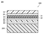
(画像表示装置)
図2は、本実施形態の画像表示装置の一例を模式的に示す概略断面図である。画像表示装置300は、その前面(視認側)に配置される前面板10を含むフレキシブル積層体100と、表示ユニットを含む表示積層体200と、貼合層60とを有し、フレキシブル積層体100のTSパネル50側に、貼合層60を介して表示積層体200が積層されている。このような画像表示装置300は、フレキシブル積層体100がTSパネル50を備えているため、タッチパネル表示装置とすることができる。
(Image display device)
FIG. 2 is a schematic cross-sectional view schematically showing an example of the image display device of this embodiment. The
画像表示装置300は、フレキシブルディスプレイパネルであってもよい。フレキシブルディスプレイである画像表示装置は、前面板10表面を内側にして折り畳み可能に構成されたものであってもよく、前面板10表面を内側にして巻回可能に構成されたものであってもよい。
The
貼合層60は、フレキシブル積層体100におけるTSパネル50と表示積層体200とを貼合するためのものである。フレキシブル積層体100と表示積層体200とを積層する際には、例えば、フレキシブル積層体100のTSパネル50上に貼合層60を設け、この貼合層60上に表示積層体200を積層してもよい。貼合層60は、粘着剤層又は接着剤層であり、上記した粘着剤組成物及び接着剤組成物を用いて形成することができる。
The
表示積層体200に含まれる表示ユニットとしては、例えば、液晶表示素子、有機EL表示素子、無機EL表示素子、プラズマ表示素子、電界放射型表示素子等の表示素子を含む表示ユニットが挙げられる。
Examples of the display unit included in the
画像表示装置300は、スマートフォン、タブレット等のモバイル機器、テレビ、デジタルフォトフレーム、電子看板、測定器や計器類、事務用機器、医療機器、電算機器等として用いることができる。
The
以下、実施例により本発明をさらに詳細に説明するが、本発明はこれらの例によって限定されるものではない。実施例、比較例中の「%」及び「部」は、特記しない限り、質量%及び質量部である。 Hereinafter, the present invention will be described in more detail with reference to Examples, but the present invention is not limited to these Examples. Unless otherwise specified, "%" and "parts" in Examples and Comparative Examples are% by mass and parts by mass.
[厚みの測定]
フレキシブル積層体をなす各層の厚みは、次の手順で行った。フレキシブル積層体をレーザーカッターを用いてカットし、カットしたフレキシブル積層体の断面について、透過型電子顕微鏡(SU8010、株式会社堀場製作所製)を用いて観察し、得られた観察像から、フレキシブル積層体をなす各層の厚みを測定した。
[Measurement of thickness]
The thickness of each layer forming the flexible laminate was measured by the following procedure. The flexible laminate was cut using a laser cutter, and the cross section of the cut flexible laminate was observed using a transmission electron microscope (SU8010, manufactured by Horiba Ltd.), and from the obtained observation image, the flexible laminate was obtained. The thickness of each of the layers was measured.
[引張弾性率の測定]
フレキシブル積層体をなす各層を構成する部材から長辺110mm×短辺10mmの長方形の小片をスーパーカッターを用いて切り出した。次いで、引張試験機〔株式会社島津製作所製 オートグラフ AG−Xplus試験機〕の上下つかみ具で、つかみ具の間隔が5cmとなるように上記測定用サンプルの長辺方向両端を挟み、温度23℃、相対湿度55%の環境下、引張速度4mm/分で測定用サンプルを測定用サンプルの長さ方向に引張り、得られる応力−ひずみ曲線における20〜40MPa間の直線の傾きから、23℃、相対湿度55%での引張弾性率〔MPa〕を算出した。このとき、応力を算出するための厚みとしては、上記の通り測定した各層の厚み値を用いた。
[Measurement of tensile modulus]
A rectangular small piece having a long side of 110 mm and a short side of 10 mm was cut out from a member forming each layer forming the flexible laminate using a super cutter. Then, with the upper and lower grips of a tensile tester [Autograph AG-Xplus tester manufactured by Shimadzu Corporation], both ends of the measurement sample in the long side direction were sandwiched so that the distance between the grips was 5 cm, and the temperature was 23°C. In an environment with a relative humidity of 55%, the measurement sample is pulled in the length direction of the measurement sample at a pulling speed of 4 mm/min, and the obtained stress-strain curve has a linear slope between 20 and 40 MPa, and a relative temperature of 23° C. The tensile elastic modulus [MPa] at a humidity of 55% was calculated. At this time, the thickness value of each layer measured as described above was used as the thickness for calculating the stress.
[剛性の算出]
上記で測定した厚みの値と引張弾性率の値との積を算出することにより、剛性を算出した。
[Calculation of rigidity]
The rigidity was calculated by calculating the product of the thickness value and the tensile elastic modulus value measured above.
[貯蔵弾性率の測定]
各粘着剤層(第1粘着剤層又は第2粘着剤層)を厚み150μmになるように積み重ねた測定用サンプルについて、レオメーター(Anton Parr、MCR−301)を用いて、温度25℃、相対湿度50%、応力1%、周波数1Hzの条件で貯蔵弾性率(Gb、Gd)の測定を行った。
[Measurement of storage elastic modulus]
Using a rheometer (Anton Parr, MCR-301), a temperature of 25° C. was measured for each measurement sample in which each pressure-sensitive adhesive layer (first pressure-sensitive adhesive layer or second pressure-sensitive adhesive layer) was stacked to a thickness of 150 μm. The storage elastic modulus (Gb, Gd) was measured under the conditions of
[耐衝撃性試験]
ガラス(Soda Glass 1.1T、JMCガラス社製)上に、厚み100μmの光学粘着シート(8146−04、3M社製)を用いて、各実施例及び比較例で得たフレキシブル積層体のタッチセンサパネル側を固定して、評価用サンプルを準備した。この評価用サンプルを、前面板側が上になるように耐衝撃試験装置(Drop Tester、TAEWON TECH CO.製)に設置した後、評価用パネルの前面板側の表面の上方5cmの位置から、試験球を自由落下させて、評価用サンプルに衝突させる耐衝撃性試験を、温度25℃において行った。この耐衝撃性試験を、試験球の重量を変更しながら行い、評価用サンプルの下部にあるガラスが割れたときの試験球の重量を決定した。評価用サンプルのガラスが割れたときの試験球の重量が、
100g以上である場合をA、
50g以上100g未満である場合をB、
50g未満である場合をC、
として耐衝撃性の評価を行った。
[Impact resistance test]
A touch sensor of a flexible laminate obtained in each of Examples and Comparative Examples by using an optical adhesive sheet (8146-04, manufactured by 3M) having a thickness of 100 μm on glass (Soda Glass 1.1T, manufactured by JMC Glass). The panel side was fixed and the sample for evaluation was prepared. This evaluation sample was placed in an impact resistance tester (Drop Tester, manufactured by TAEWON TECH CO.) so that the front plate side was facing up, and then the test was performed from a position 5 cm above the surface of the evaluation panel on the front plate side. An impact resistance test was conducted at a temperature of 25° C. in which the sphere was allowed to fall freely and collide with the evaluation sample. This impact resistance test was performed while changing the weight of the test sphere, and the weight of the test sphere when the glass under the evaluation sample was broken was determined. The weight of the test ball when the glass of the evaluation sample was broken,
A is 100 g or more,
If the amount is 50 g or more and less than 100 g, B,
C when less than 50 g,
As a result, the impact resistance was evaluated.
[屈曲性試験]
温度25℃において、次に示す手順で屈曲性試験を行った。屈曲試験機(CFT−720C、Covotech社製)に、各実施例及び比較例で得たフレキシブル積層体を平坦な状態(屈曲していない状態)で設置し、前面板側が内側となるようにして屈曲させたときに対向する前面板間の距離が4.0mmとなるように、フレキシブル積層体を屈曲させた後、元の平坦な状態に戻す屈曲操作を行った。この屈曲操作を1回行ったときを屈曲回数1回と数え、この屈曲操作を繰返し行った。屈曲操作で屈曲した領域においてクラックや粘着剤層の浮きが発生したときの屈曲回数を限界屈曲回数として確認した。屈曲操作で屈曲した領域でのクラックや粘着剤層の浮きの発生が、
屈曲回数が20万回に達してもみられない場合をA、
屈曲回数が10万回以上20万回未満でみられた場合をB、
屈曲回数が5万回以上10万回未満でみられた場合をC、
屈曲回数が5万回未満でみられた場合をD、
として屈曲性試験の評価を行った。
[Flexibility test]
A flexibility test was conducted at a temperature of 25° C. according to the following procedure. A flexible tester (CFT-720C, manufactured by Covotech) was installed with the flexible laminates obtained in each Example and Comparative Example in a flat state (non-bent state) so that the front plate side was the inner side. After bending the flexible laminate so that the distance between the front plates facing each other when bent was 4.0 mm, a bending operation was performed to restore the original flat state. When this bending operation was performed once, the number of times of bending was counted as one, and this bending operation was repeated. The number of times of bending when cracks and floating of the pressure-sensitive adhesive layer occurred in the region bent by the bending operation was confirmed as the limit number of times of bending. The occurrence of cracks and floating of the pressure-sensitive adhesive layer in the bent area due to the bending operation,
A when the number of bends reaches 200,000 times and is not seen,
When the number of flexing times is 100,000 or more and less than 200,000, it is B,
When the number of flexing is 50,000 times or more and less than 100,000 times, C,
D when the number of bends is less than 50,000,
As a result, the flexibility test was evaluated.
〔実施例1〕
(前面板の準備)
前面板として、樹脂フィルムの両面にハードコート層が形成された厚み50μmのハードコート層付き樹脂フィルムを用意した。樹脂フィルムは、厚み30μmのポリイミド系樹脂フィルムであり、ハードコート層はそれぞれ、厚みが10μmであり、末端に多官能アクリル基を有するデンドリマー化合物を含む組成物から形成された層であった。
[Example 1]
(Preparation of front plate)
As the front plate, a resin film with a hard coat layer having a thickness of 50 μm in which hard coat layers were formed on both sides of the resin film was prepared. The resin film was a polyimide resin film having a thickness of 30 μm, and each of the hard coat layers had a thickness of 10 μm and was a layer formed from a composition containing a dendrimer compound having a polyfunctional acrylic group at the terminal.
(第1粘着剤層の準備)
剥離フィルム上に、アクリル系粘着剤組成物を塗布し、乾燥して、第1粘着剤層を形成した剥離フィルム付き第1粘着剤層を準備した。第1粘着剤層の厚みは50μmであり、温度25℃、相対湿度50%における貯蔵弾性率Gbは、0.09MPaであった。
(Preparation of first adhesive layer)
The acrylic pressure-sensitive adhesive composition was applied onto the release film and dried to prepare a first pressure-sensitive adhesive layer with a release film on which a first pressure-sensitive adhesive layer was formed. The thickness of the first pressure-sensitive adhesive layer was 50 μm, and the storage elastic modulus Gb at a temperature of 25° C. and a relative humidity of 50% was 0.09 MPa.
(円偏光板の準備)
基材に光配向膜を形成した後、二色性色素と重合性液晶化合物とを含む組成物を基材に塗布し、配向、硬化させて厚み2.5μmの偏光子(温度23℃、相対湿度55%における引張弾性率:937MPa)を得た。この偏光子上に、接着剤層を介して、保護フィルムとしての厚み25μmのトリアセチルセルロース(TAC)フィルム(コニカミノルタ社製、温度23℃、相対湿度55%における引張弾性率:3282MPa)を貼合した後、基材を剥離して、直線偏光板を得た。
(Preparation of circularly polarizing plate)
After forming a photo-alignment film on the substrate, a composition containing a dichroic dye and a polymerizable liquid crystal compound is applied to the substrate, aligned and cured to form a polarizer having a thickness of 2.5 μm (temperature 23° C., relative Tensile elastic modulus at
得られた直線偏光板の基材を剥離して露出した面に、位相差層の後述するλ/4層側を貼合して円偏光板を得た。位相差層は厚みが14μmであり、層構成が、粘着剤層、λ/4層、粘着剤層、及びポジティブC層をこの順に積層したものであった。粘着剤層はいずれも、厚みが5μmであり、温度25℃、相対湿度50%における貯蔵弾性率が0.6MPaであった。λ/4層は、液晶化合物が硬化した層及び配向膜を有し、厚みが3μmであった。ポジティブC層は、液晶化合物が硬化した層及び配向膜を有し、厚みが1μmであった。 The λ/4 layer side of the retardation layer, which will be described later, was attached to the surface of the linear polarizing plate obtained by peeling the base material to obtain a circularly polarizing plate. The retardation layer had a thickness of 14 μm and had a layer structure in which a pressure-sensitive adhesive layer, a λ/4 layer, a pressure-sensitive adhesive layer, and a positive C layer were laminated in this order. Each adhesive layer had a thickness of 5 μm and a storage elastic modulus of 0.6 MPa at a temperature of 25° C. and a relative humidity of 50%. The λ/4 layer had a layer in which a liquid crystal compound was cured and an alignment film, and had a thickness of 3 μm. The positive C layer had a layer in which a liquid crystal compound was cured and an alignment film, and had a thickness of 1 μm.
(第2粘着剤層の準備)
剥離フィルム上に、アクリル系粘着剤組成物を塗布し、乾燥して、第2粘着剤層を形成した剥離フィルム付き第2粘着剤層を準備した。第2粘着剤層の厚みは10μmであり、温度25℃、相対湿度50%における貯蔵弾性率Gdは、0.1MPaであった。
(Preparation of second adhesive layer)
An acrylic pressure-sensitive adhesive composition was applied onto the release film and dried to prepare a second pressure-sensitive adhesive layer with a release film on which a second pressure-sensitive adhesive layer was formed. The thickness of the second pressure-sensitive adhesive layer was 10 μm, and the storage elastic modulus Gd at a temperature of 25° C. and a relative humidity of 50% was 0.1 MPa.
(タッチセンサパネル(1)の準備)
TSパネル(1)として、タッチセンサパターン層を準備した。タッチセンサパターン層は、透明導電層としてのITO層と、分離層としてのアクリル系樹脂組成物の硬化層とを含むものであり、厚みが7μmであり、温度23℃、相対湿度55%における引張弾性率が4510MPaであった。TSパネル(1)の剛性は、31.6MPa・mmであった。
(Preparation of touch sensor panel (1))
A touch sensor pattern layer was prepared as a TS panel (1). The touch sensor pattern layer includes an ITO layer as a transparent conductive layer and a cured layer of an acrylic resin composition as a separation layer, has a thickness of 7 μm, and has a tensile strength at a temperature of 23° C. and a relative humidity of 55%. The elastic modulus was 4510 MPa. The rigidity of the TS panel (1) was 31.6 MPa·mm.
(フレキシブル積層体の作製)
前面板の一方の面、及び、剥離フィルム付き第1粘着剤層の第1粘着剤層側の面にコロナ処理を行い、このコロナ処理面同士を貼合した。次に、第1粘着剤層に接着している剥離フィルムを剥離して露出した面、及び、円偏光板の直線偏光板側の面にコロナ処理を行い、このコロナ処理面同士を貼合して、前面板と円偏光板との複合体を得た。続いて、この複合体のポジティブC層側の面、及び、剥離フィルム付き第2粘着剤層の第2粘着剤層側の面にコロナ処理を行い、このコロナ処理面同士を貼合した。次に、第2粘着剤層に接着している剥離フィルムを剥離して露出した面にコロナ処理を行い、このコロナ処理面とTSパネル(1)の透明導電層側を貼合してフレキシブル積層体を得た。なお、上記で行ったコロナ処理は、いずれも、周波数を20kHz、電圧を8.6kV、パワーを2.5kW、速度を6m/分として行った。
(Preparation of flexible laminate)
Corona treatment was performed on one surface of the front plate and the surface of the first adhesive layer with the release film on the first adhesive layer side, and the corona-treated surfaces were bonded together. Next, the surface exposed by peeling off the release film adhered to the first pressure-sensitive adhesive layer and the surface of the circularly polarizing plate on the side of the linear polarizing plate are subjected to corona treatment, and the corona-treated surfaces are bonded together. Thus, a composite of the front plate and the circularly polarizing plate was obtained. Subsequently, corona treatment was performed on the surface of the composite on the positive C layer side and the surface of the second adhesive layer with release film on the second adhesive layer side, and the corona treated surfaces were bonded together. Next, the release film adhered to the second pressure-sensitive adhesive layer is peeled off, and the exposed surface is subjected to corona treatment, and the corona-treated surface and the transparent conductive layer side of the TS panel (1) are bonded together to form a flexible laminate. Got the body The corona treatments performed above were performed at a frequency of 20 kHz, a voltage of 8.6 kV, a power of 2.5 kW, and a speed of 6 m/min.
得られたフレキシブル積層体は、前面板10、第1粘着剤層20、円偏光板30、第2粘着剤層40、及びTSパネル50の合計厚みt[μm](上記式(3)で表される厚み)が158.5μm、縦177mm×横105mmであった。フレキシブル積層体について、耐衝撃性試験及び屈曲性試験を行った。その結果を表1に示す。
The obtained flexible laminate has a total thickness t [μm] of the
〔実施例2〕
第1粘着剤層及び第2粘着剤層として表1に記載の厚み及び温度25℃における貯蔵弾性率を有するものを用いたこと以外は、実施例1と同様の手順でフレキシブル積層体を作製した。得られたフレキシブル積層体について、耐衝撃性試験及び屈曲性試験を行った。その結果を表1に示す。
[Example 2]
A flexible laminate was prepared by the same procedure as in Example 1 except that the first adhesive layer and the second adhesive layer having the thickness and the storage elastic modulus at a temperature of 25° C. shown in Table 1 were used. .. An impact resistance test and a bending test were performed on the obtained flexible laminate. The results are shown in Table 1.
〔実施例3〕
(タッチセンサパネル(2)の準備)
TSパネル(2)として、タッチセンサパターン層、接着剤層、及び支持層がこの順に積層されたものを準備した。タッチセンサパターン層は、透明導電層としてのITO層と、分離層としてのアクリル系樹脂組成物の硬化層とを含むものであり、厚みが7μmであり、温度23℃、相対湿度55%における引張弾性率が4510MPaであった。接着剤層は、タッチセンサパターン層の分離層側に設けられ、厚みが3μmであり、温度23℃、相対湿度55%における引張弾性率が12309MPaであり、また、支持層は、厚みが13μmであり、温度23℃、相対湿度55%における引張弾性率が1785MPaである環状ポリオレフィン(COP)系樹脂フィルムであった。TSパネル(2)の剛性は、42.6MPa・mmであった。
[Example 3]
(Preparation of touch sensor panel (2))
The TS panel (2) was prepared by stacking a touch sensor pattern layer, an adhesive layer, and a support layer in this order. The touch sensor pattern layer includes an ITO layer as a transparent conductive layer and a cured layer of an acrylic resin composition as a separation layer, has a thickness of 7 μm, and has a tensile strength at a temperature of 23° C. and a relative humidity of 55%. The elastic modulus was 4510 MPa. The adhesive layer is provided on the separation layer side of the touch sensor pattern layer, has a thickness of 3 μm, a tensile elastic modulus of 12309 MPa at a temperature of 23° C. and a relative humidity of 55%, and the support layer has a thickness of 13 μm. It was a cyclic polyolefin (COP) resin film having a tensile elastic modulus of 1785 MPa at a temperature of 23° C. and a relative humidity of 55%. The rigidity of the TS panel (2) was 42.6 MPa·mm.
(フレキシブル積層体の作製)
第1粘着剤層及び第2粘着剤層として表1に記載の厚み及び温度25℃における貯蔵弾性率を有するものを用い、TSパネル(1)に代えてTSパネル(2)を用いたこと以外は、実施例1と同様の手順でフレキシブル積層体を作製した。得られたフレキシブル積層体について、耐衝撃性試験及び屈曲性試験を行った。その結果を表1に示す。
(Preparation of flexible laminate)
As the first pressure-sensitive adhesive layer and the second pressure-sensitive adhesive layer, those having a thickness and a storage elastic modulus at a temperature of 25° C. shown in Table 1 were used, except that the TS panel (2) was used instead of the TS panel (1). Produced a flexible laminate in the same manner as in Example 1. An impact resistance test and a bending test were performed on the obtained flexible laminate. The results are shown in Table 1.
〔実施例4、5〕
第1粘着剤層及び第2粘着剤層として表1に記載の厚み及び温度25℃における貯蔵弾性率を有するものを用いたこと以外は、実施例1と同様の手順でフレキシブル積層体を作製した。得られたフレキシブル積層体について、耐衝撃性試験及び屈曲性試験を行った。その結果を表1に示す。
[Examples 4 and 5]
A flexible laminate was prepared by the same procedure as in Example 1 except that the first adhesive layer and the second adhesive layer having the thickness and the storage elastic modulus at a temperature of 25° C. shown in Table 1 were used. .. An impact resistance test and a bending test were performed on the obtained flexible laminate. The results are shown in Table 1.
〔実施例6、比較例1〕
(タッチセンサパネル(3)の準備)
支持層として、厚みが23μmであり、温度23℃、相対湿度55%における引張弾性率が1628MPaである環状ポリオレフィン(COP)系樹脂フィルムを用いたこと以外は、TSパネル(2)と同様の手順でTSパネル(3)を準備した。TSパネル(3)の剛性は、53.7MPa・mmであった。
[Example 6, Comparative Example 1]
(Preparation of touch sensor panel (3))
As the support layer, a procedure similar to that of the TS panel (2) except that a cyclic polyolefin (COP) resin film having a thickness of 23 μm and a tensile modulus of elasticity of 1628 MPa at a temperature of 23° C. and a relative humidity of 55% was used. Then, a TS panel (3) was prepared. The rigidity of the TS panel (3) was 53.7 MPa·mm.
〔実施例7、8〕
第1粘着剤層及び第2粘着剤層として表1に記載の厚み及び温度25℃における貯蔵弾性率を有するものを用いたこと以外は、実施例1と同様の手順でフレキシブル積層体を作製した。得られたフレキシブル積層体について、耐衝撃性試験及び屈曲性試験を行った。その結果を表1に示す。
[Examples 7 and 8]
A flexible laminate was prepared by the same procedure as in Example 1 except that the first adhesive layer and the second adhesive layer having the thickness and the storage elastic modulus at a temperature of 25° C. shown in Table 1 were used. .. An impact resistance test and a bending test were performed on the obtained flexible laminate. The results are shown in Table 1.
(フレキシブル積層体の作製)
第1粘着剤層及び第2粘着剤層として表1に記載の厚み及び温度25℃における貯蔵弾性率を有するものを用い、TSパネル(1)に代えてTSパネル(3)を用いたこと以外は、実施例1と同様の手順でフレキシブル積層体を作製した。得られたフレキシブル積層体について、耐衝撃性試験及び屈曲性試験を行った。その結果を表1に示す。
(Preparation of flexible laminate)
As the first adhesive layer and the second adhesive layer, those having the thickness and the storage elastic modulus at a temperature of 25° C. described in Table 1 were used, and the TS panel (3) was used instead of the TS panel (1). Produced a flexible laminate in the same manner as in Example 1. An impact resistance test and a bending test were performed on the obtained flexible laminate. The results are shown in Table 1.

10 前面板、20 第1粘着剤層、30 円偏光板、31 直線偏光板、32 位相差層、40 第2粘着剤層、50 タッチセンサパネル、60 貼合層、100 フレキシブル積層体、200 表示積層体、300 画像表示装置。 10 front plate, 20 first adhesive layer, 30 circularly polarizing plate, 31 linearly polarizing plate, 32 retardation layer, 40 second adhesive layer, 50 touch sensor panel, 60 bonding layer, 100 flexible laminate, 200 display Laminate, 300 image display device.
Claims (11)
前記前面板の厚みをa[μm]、前記第1粘着剤層の厚みをb[μm]、前記円偏光板の厚みをc[μm]、前記第2粘着剤層の厚みをd[μm]、及び前記タッチセンサパネルの厚みをe[μm]とするとき、下記式(1):
(b+d)/(a+b+c+d+e)≧0.34 (1)
の関係を満たし、
前記前面板の厚みaは、30μm以上である、フレキシブル積層体。 A flexible laminate including a front plate, a first adhesive layer, a circularly polarizing plate, a second adhesive layer, and a touch sensor panel in this order,
The thickness of the front plate is a [μm], the thickness of the first pressure-sensitive adhesive layer is b [μm], the thickness of the circularly polarizing plate is c [μm], and the thickness of the second pressure-sensitive adhesive layer is d [μm]. , And the thickness of the touch sensor panel is e [μm], the following formula (1):
(B+d)/(a+b+c+d+e)≧ 0.34 (1)
Meet the relationship,
A flexible laminate in which the thickness a of the front plate is 30 μm or more .
1≦b/d≦6 (2)
の関係を満たす、請求項1に記載のフレキシブル積層体。 The thickness b of the first pressure-sensitive adhesive layer and the thickness d of the second pressure-sensitive adhesive layer are represented by the following formula (2):
1≦b/d≦6 (2)
The flexible laminate according to claim 1, which satisfies the relationship.
前記第2粘着剤層の厚みdは、10μm以上である、請求項1〜3のいずれか1項に記載のフレキシブル積層体。 The thickness b of the first pressure-sensitive adhesive layer is 10 μm or more,
The thickness d of the said 2nd adhesive layer is 10 micrometers or more, The flexible laminated body of any one of Claims 1-3.
前記円偏光板の温度23℃、相対湿度55%における剛性は、40MPa・mm以上400MPa・mm以下であり、
前記タッチセンサパネルの温度23℃、相対湿度55%における剛性は、15MPa・mm以上700MPa・mm以下である、請求項1〜4のいずれか1項に記載のフレキシブル積層体。 The rigidity of the front plate at a temperature of 23° C. and a relative humidity of 55% is 90 MPa·mm or more and 700 MPa·mm or less,
The rigidity of the circularly polarizing plate at a temperature of 23° C. and a relative humidity of 55% is 40 MPa·mm or more and 400 MPa·mm or less,
The flexible laminate according to claim 1, wherein the touch sensor panel has a rigidity at a temperature of 23° C. and a relative humidity of 55% of 15 MPa·mm or more and 700 MPa·mm or less.
前記第2粘着剤層の温度25℃、相対湿度50%における貯蔵弾性率は、0.01MPa以上0.15MPa以下である、請求項1〜5のいずれか1項に記載のフレキシブル積層体。 The storage elastic modulus of the first pressure-sensitive adhesive layer at a temperature of 25° C. and a relative humidity of 50% is 0.01 MPa or more and 0.15 MPa or less,
The flexible laminate according to any one of claims 1 to 5, wherein a storage elastic modulus of the second pressure-sensitive adhesive layer at a temperature of 25°C and a relative humidity of 50% is 0.01 MPa or more and 0.15 MPa or less.
t=a+b+c+d+e (3)
で表すとき、tは250μm以下である、請求項1〜6のいずれか1項に記載のフレキシブル積層体。 The total thickness t [μm] of the thickness a of the front plate, the thickness b of the first adhesive layer, the thickness c of the circularly polarizing plate, the thickness d of the second adhesive layer, and the thickness e of the touch sensor panel. Is expressed by the following formula (3):
t=a+b+c+d+e (3)
The flexible laminate according to any one of claims 1 to 6, wherein t is 250 µm or less.
前記直線偏光板は、前記第1粘着剤層側から順に、保護フィルム及び偏光子を含む、請求項1〜9のいずれか1項に記載のフレキシブル積層体。 The said linear polarizing plate is a flexible laminated body of any one of Claims 1-9 which contains a protective film and a polarizer in order from the said 1st adhesive layer side.
Priority Applications (3)
| Application Number | Priority Date | Filing Date | Title |
|---|---|---|---|
| TW108145872A TW202046076A (en) | 2018-12-27 | 2019-12-13 | Flexible laminate and image display device provided with flexible laminate |
| KR1020190174264A KR20200081287A (en) | 2018-12-27 | 2019-12-24 | Flexible laminate and image display device having the same |
| CN201911354058.5A CN111458781A (en) | 2018-12-27 | 2019-12-25 | Flexible laminate and image display device provided with same |
Applications Claiming Priority (2)
| Application Number | Priority Date | Filing Date | Title |
|---|---|---|---|
| JP2018244232 | 2018-12-27 | ||
| JP2018244232 | 2018-12-27 |
Related Child Applications (1)
| Application Number | Title | Priority Date | Filing Date |
|---|---|---|---|
| JP2020119984A Division JP2020177249A (en) | 2018-12-27 | 2020-07-13 | Flexible laminate and image display device having the same |
Publications (2)
| Publication Number | Publication Date |
|---|---|
| JP2020106824A JP2020106824A (en) | 2020-07-09 |
| JP6735891B2 true JP6735891B2 (en) | 2020-08-05 |
Family
ID=71448974
Family Applications (2)
| Application Number | Title | Priority Date | Filing Date |
|---|---|---|---|
| JP2019198786A Expired - Fee Related JP6735891B2 (en) | 2018-12-27 | 2019-10-31 | Flexible laminate and image display device including the same |
| JP2020119984A Pending JP2020177249A (en) | 2018-12-27 | 2020-07-13 | Flexible laminate and image display device having the same |
Family Applications After (1)
| Application Number | Title | Priority Date | Filing Date |
|---|---|---|---|
| JP2020119984A Pending JP2020177249A (en) | 2018-12-27 | 2020-07-13 | Flexible laminate and image display device having the same |
Country Status (4)
| Country | Link |
|---|---|
| JP (2) | JP6735891B2 (en) |
| KR (1) | KR20200081287A (en) |
| CN (1) | CN111458781A (en) |
| TW (1) | TW202046076A (en) |
Families Citing this family (4)
| Publication number | Priority date | Publication date | Assignee | Title |
|---|---|---|---|---|
| CN113302051A (en) * | 2019-01-17 | 2021-08-24 | 富士胶片株式会社 | Laminate and image display device |
| JP2021152650A (en) * | 2020-03-23 | 2021-09-30 | 住友化学株式会社 | Laminate |
| JP2021157101A (en) * | 2020-03-27 | 2021-10-07 | 日東電工株式会社 | Optical film having double-sided adhesive and image display device |
| JP7092900B2 (en) * | 2020-07-31 | 2022-06-28 | 住友化学株式会社 | Laminates and image display devices |
Family Cites Families (13)
| Publication number | Priority date | Publication date | Assignee | Title |
|---|---|---|---|---|
| JP2012218163A (en) * | 2011-04-04 | 2012-11-12 | Jsr Corp | Transparent conductive film, laminate, touch panel, and display |
| JP6173009B2 (en) * | 2013-03-08 | 2017-08-02 | 富士フイルム株式会社 | Liquid crystal display |
| US9835793B2 (en) * | 2014-09-12 | 2017-12-05 | Apple Inc. | Display backlight with adhesive attachment layers |
| KR101659239B1 (en) | 2014-11-01 | 2016-09-23 | 삼성에스디아이 주식회사 | Flexible display apparatus |
| KR102451081B1 (en) | 2016-02-05 | 2022-10-06 | 삼성전자주식회사 | Display using various adhesive and electronic device including the same |
| JP6904666B2 (en) * | 2016-05-17 | 2021-07-21 | 日東電工株式会社 | Optical laminate |
| JP7042020B2 (en) * | 2016-08-15 | 2022-03-25 | 日東電工株式会社 | Laminated body for flexible image display device and flexible image display device |
| KR101933765B1 (en) * | 2016-08-23 | 2018-12-28 | 동우 화인켐 주식회사 | Polarizing Plate and Image Display Device Comprising the Same |
| JP7119424B2 (en) * | 2017-03-02 | 2022-08-17 | 大日本印刷株式会社 | Optical film and image display device |
| JP6510113B2 (en) * | 2017-05-09 | 2019-05-08 | 日東電工株式会社 | Composition for optical member, optical member and image display device |
| JP6979285B2 (en) * | 2017-05-26 | 2021-12-08 | 日東電工株式会社 | Image display device |
| JP6937169B2 (en) * | 2017-06-09 | 2021-09-22 | 日東電工株式会社 | Polarizing plate with retardation layer and image display device |
| JP6768024B2 (en) * | 2018-03-26 | 2020-10-14 | リンテック株式会社 | Active energy ray-curable adhesive, adhesive sheet and laminate |
-
2019
- 2019-10-31 JP JP2019198786A patent/JP6735891B2/en not_active Expired - Fee Related
- 2019-12-13 TW TW108145872A patent/TW202046076A/en unknown
- 2019-12-24 KR KR1020190174264A patent/KR20200081287A/en active Search and Examination
- 2019-12-25 CN CN201911354058.5A patent/CN111458781A/en active Pending
-
2020
- 2020-07-13 JP JP2020119984A patent/JP2020177249A/en active Pending
Also Published As
| Publication number | Publication date |
|---|---|
| TW202046076A (en) | 2020-12-16 |
| JP2020106824A (en) | 2020-07-09 |
| JP2020177249A (en) | 2020-10-29 |
| CN111458781A (en) | 2020-07-28 |
| KR20200081287A (en) | 2020-07-07 |
Similar Documents
| Publication | Publication Date | Title |
|---|---|---|
| JP6732089B2 (en) | Flexible laminate and image display device including the same | |
| JP6735891B2 (en) | Flexible laminate and image display device including the same | |
| JP7469889B2 (en) | Optical laminate and method for manufacturing display device | |
| JP7194041B2 (en) | laminate | |
| WO2020170726A1 (en) | Flexible layered body and image display device provided with same | |
| JP2023003753A (en) | Optical laminate and display device | |
| JP6739601B1 (en) | Optical laminated body and display device | |
| WO2020162102A1 (en) | Optical layered body and display device | |
| JP7348928B2 (en) | laminate | |
| WO2022255155A1 (en) | Laminate | |
| WO2021193348A1 (en) | Laminate | |
| WO2021166434A1 (en) | Optical laminate and display device having same | |
| WO2021149359A1 (en) | Optical stack and display device | |
| JP2021152649A (en) | Laminate | |
| JP2021152642A (en) | Optical laminate and display device | |
| JP2021152644A (en) | Flexible laminate and image display device having the same | |
| JP2021152645A (en) | Flexible laminate and image display device having the same | |
| TW202214432A (en) | Laminate, image display device, and manufacturing method | |
| TW202208960A (en) | Laminated body, image display device, and manufacturing method retain adhesion between adhesive agent layers and optical components even if there is no enough time for aging | |
| CN113341493A (en) | Optical laminate and display device | |
| CN113359222A (en) | Optical laminate and display device |
Legal Events
| Date | Code | Title | Description |
|---|---|---|---|
| A621 | Written request for application examination |
Free format text: JAPANESE INTERMEDIATE CODE: A621 Effective date: 20200106 |
|
| A871 | Explanation of circumstances concerning accelerated examination |
Free format text: JAPANESE INTERMEDIATE CODE: A871 Effective date: 20200106 |
|
| A975 | Report on accelerated examination |
Free format text: JAPANESE INTERMEDIATE CODE: A971005 Effective date: 20200115 |
|
| A131 | Notification of reasons for refusal |
Free format text: JAPANESE INTERMEDIATE CODE: A131 Effective date: 20200310 |
|
| A521 | Request for written amendment filed |
Free format text: JAPANESE INTERMEDIATE CODE: A523 Effective date: 20200420 |
|
| TRDD | Decision of grant or rejection written | ||
| A01 | Written decision to grant a patent or to grant a registration (utility model) |
Free format text: JAPANESE INTERMEDIATE CODE: A01 Effective date: 20200616 |
|
| A61 | First payment of annual fees (during grant procedure) |
Free format text: JAPANESE INTERMEDIATE CODE: A61 Effective date: 20200714 |
|
| R150 | Certificate of patent or registration of utility model |
Ref document number: 6735891 Country of ref document: JP Free format text: JAPANESE INTERMEDIATE CODE: R150 |
|
| S531 | Written request for registration of change of domicile |
Free format text: JAPANESE INTERMEDIATE CODE: R313531 |
|
| R350 | Written notification of registration of transfer |
Free format text: JAPANESE INTERMEDIATE CODE: R350 |
|
| LAPS | Cancellation because of no payment of annual fees |