JP6733330B2 - Oscillators, electronic devices and mobiles - Google Patents
Oscillators, electronic devices and mobiles Download PDFInfo
- Publication number
- JP6733330B2 JP6733330B2 JP2016116221A JP2016116221A JP6733330B2 JP 6733330 B2 JP6733330 B2 JP 6733330B2 JP 2016116221 A JP2016116221 A JP 2016116221A JP 2016116221 A JP2016116221 A JP 2016116221A JP 6733330 B2 JP6733330 B2 JP 6733330B2
- Authority
- JP
- Japan
- Prior art keywords
- ground
- circuit
- oscillator
- terminal
- temperature
- Prior art date
- Legal status (The legal status is an assumption and is not a legal conclusion. Google has not performed a legal analysis and makes no representation as to the accuracy of the status listed.)
- Expired - Fee Related
Links
- 238000010438 heat treatment Methods 0.000 claims description 62
- 238000001514 detection method Methods 0.000 claims description 39
- 230000010355 oscillation Effects 0.000 claims description 21
- 230000004308 accommodation Effects 0.000 claims description 20
- 230000020169 heat generation Effects 0.000 claims description 3
- 239000013078 crystal Substances 0.000 description 51
- 239000000758 substrate Substances 0.000 description 22
- 239000000463 material Substances 0.000 description 10
- 230000000694 effects Effects 0.000 description 8
- 239000010931 gold Substances 0.000 description 8
- PCHJSUWPFVWCPO-UHFFFAOYSA-N gold Chemical compound [Au] PCHJSUWPFVWCPO-UHFFFAOYSA-N 0.000 description 7
- 229910052737 gold Inorganic materials 0.000 description 7
- 238000000605 extraction Methods 0.000 description 6
- 230000006870 function Effects 0.000 description 6
- 239000000470 constituent Substances 0.000 description 5
- XKRFYHLGVUSROY-UHFFFAOYSA-N Argon Chemical compound [Ar] XKRFYHLGVUSROY-UHFFFAOYSA-N 0.000 description 4
- IJGRMHOSHXDMSA-UHFFFAOYSA-N Atomic nitrogen Chemical compound N#N IJGRMHOSHXDMSA-UHFFFAOYSA-N 0.000 description 4
- XLOMVQKBTHCTTD-UHFFFAOYSA-N Zinc monoxide Chemical compound [Zn]=O XLOMVQKBTHCTTD-UHFFFAOYSA-N 0.000 description 4
- 239000000853 adhesive Substances 0.000 description 4
- 230000001070 adhesive effect Effects 0.000 description 4
- 239000000919 ceramic Substances 0.000 description 4
- 230000005284 excitation Effects 0.000 description 4
- 230000003071 parasitic effect Effects 0.000 description 4
- 239000010453 quartz Substances 0.000 description 3
- VYPSYNLAJGMNEJ-UHFFFAOYSA-N silicon dioxide Inorganic materials O=[Si]=O VYPSYNLAJGMNEJ-UHFFFAOYSA-N 0.000 description 3
- 229910045601 alloy Inorganic materials 0.000 description 2
- 239000000956 alloy Substances 0.000 description 2
- 229910052786 argon Inorganic materials 0.000 description 2
- 239000010949 copper Substances 0.000 description 2
- 230000008878 coupling Effects 0.000 description 2
- 238000010168 coupling process Methods 0.000 description 2
- 238000005859 coupling reaction Methods 0.000 description 2
- 239000011261 inert gas Substances 0.000 description 2
- 229910052451 lead zirconate titanate Inorganic materials 0.000 description 2
- 238000004519 manufacturing process Methods 0.000 description 2
- 229910052751 metal Inorganic materials 0.000 description 2
- 239000002184 metal Substances 0.000 description 2
- 229910052757 nitrogen Inorganic materials 0.000 description 2
- 230000003287 optical effect Effects 0.000 description 2
- 239000011787 zinc oxide Substances 0.000 description 2
- WSMQKESQZFQMFW-UHFFFAOYSA-N 5-methyl-pyrazole-3-carboxylic acid Chemical compound CC1=CC(C(O)=O)=NN1 WSMQKESQZFQMFW-UHFFFAOYSA-N 0.000 description 1
- 241000251468 Actinopterygii Species 0.000 description 1
- PIGFYZPCRLYGLF-UHFFFAOYSA-N Aluminum nitride Chemical compound [Al]#N PIGFYZPCRLYGLF-UHFFFAOYSA-N 0.000 description 1
- JBRZTFJDHDCESZ-UHFFFAOYSA-N AsGa Chemical compound [As]#[Ga] JBRZTFJDHDCESZ-UHFFFAOYSA-N 0.000 description 1
- RYGMFSIKBFXOCR-UHFFFAOYSA-N Copper Chemical compound [Cu] RYGMFSIKBFXOCR-UHFFFAOYSA-N 0.000 description 1
- 229910001111 Fine metal Inorganic materials 0.000 description 1
- WQZGKKKJIJFFOK-GASJEMHNSA-N Glucose Natural products OC[C@H]1OC(O)[C@H](O)[C@@H](O)[C@@H]1O WQZGKKKJIJFFOK-GASJEMHNSA-N 0.000 description 1
- 229910013641 LiNbO 3 Inorganic materials 0.000 description 1
- ZOKXTWBITQBERF-UHFFFAOYSA-N Molybdenum Chemical compound [Mo] ZOKXTWBITQBERF-UHFFFAOYSA-N 0.000 description 1
- 229910003237 Na0.5Bi0.5TiO3 Inorganic materials 0.000 description 1
- 239000004642 Polyimide Substances 0.000 description 1
- XUIMIQQOPSSXEZ-UHFFFAOYSA-N Silicon Chemical compound [Si] XUIMIQQOPSSXEZ-UHFFFAOYSA-N 0.000 description 1
- BQCADISMDOOEFD-UHFFFAOYSA-N Silver Chemical compound [Ag] BQCADISMDOOEFD-UHFFFAOYSA-N 0.000 description 1
- 229910001128 Sn alloy Inorganic materials 0.000 description 1
- 229910052782 aluminium Inorganic materials 0.000 description 1
- XAGFODPZIPBFFR-UHFFFAOYSA-N aluminium Chemical compound [Al] XAGFODPZIPBFFR-UHFFFAOYSA-N 0.000 description 1
- 238000013459 approach Methods 0.000 description 1
- 229910002113 barium titanate Inorganic materials 0.000 description 1
- JRPBQTZRNDNNOP-UHFFFAOYSA-N barium titanate Chemical compound [Ba+2].[Ba+2].[O-][Ti]([O-])([O-])[O-] JRPBQTZRNDNNOP-UHFFFAOYSA-N 0.000 description 1
- 229910052797 bismuth Inorganic materials 0.000 description 1
- JCXGWMGPZLAOME-UHFFFAOYSA-N bismuth atom Chemical compound [Bi] JCXGWMGPZLAOME-UHFFFAOYSA-N 0.000 description 1
- FSAJRXGMUISOIW-UHFFFAOYSA-N bismuth sodium Chemical compound [Na].[Bi] FSAJRXGMUISOIW-UHFFFAOYSA-N 0.000 description 1
- 229910002115 bismuth titanate Inorganic materials 0.000 description 1
- 239000008280 blood Substances 0.000 description 1
- 210000004369 blood Anatomy 0.000 description 1
- 230000036772 blood pressure Effects 0.000 description 1
- 239000003990 capacitor Substances 0.000 description 1
- 238000006243 chemical reaction Methods 0.000 description 1
- 238000004891 communication Methods 0.000 description 1
- 229910052802 copper Inorganic materials 0.000 description 1
- PMHQVHHXPFUNSP-UHFFFAOYSA-M copper(1+);methylsulfanylmethane;bromide Chemical compound Br[Cu].CSC PMHQVHHXPFUNSP-UHFFFAOYSA-M 0.000 description 1
- 230000006866 deterioration Effects 0.000 description 1
- PSHMSSXLYVAENJ-UHFFFAOYSA-N dilithium;[oxido(oxoboranyloxy)boranyl]oxy-oxoboranyloxyborinate Chemical compound [Li+].[Li+].O=BOB([O-])OB([O-])OB=O PSHMSSXLYVAENJ-UHFFFAOYSA-N 0.000 description 1
- NKZSPGSOXYXWQA-UHFFFAOYSA-N dioxido(oxo)titanium;lead(2+) Chemical compound [Pb+2].[O-][Ti]([O-])=O NKZSPGSOXYXWQA-UHFFFAOYSA-N 0.000 description 1
- 238000005530 etching Methods 0.000 description 1
- 239000000945 filler Substances 0.000 description 1
- 238000010304 firing Methods 0.000 description 1
- 229910000154 gallium phosphate Inorganic materials 0.000 description 1
- LWFNJDOYCSNXDO-UHFFFAOYSA-K gallium;phosphate Chemical compound [Ga+3].[O-]P([O-])([O-])=O LWFNJDOYCSNXDO-UHFFFAOYSA-K 0.000 description 1
- 239000011521 glass Substances 0.000 description 1
- 239000008103 glucose Substances 0.000 description 1
- JVPLOXQKFGYFMN-UHFFFAOYSA-N gold tin Chemical compound [Sn].[Au] JVPLOXQKFGYFMN-UHFFFAOYSA-N 0.000 description 1
- 239000001307 helium Substances 0.000 description 1
- 229910052734 helium Inorganic materials 0.000 description 1
- SWQJXJOGLNCZEY-UHFFFAOYSA-N helium atom Chemical compound [He] SWQJXJOGLNCZEY-UHFFFAOYSA-N 0.000 description 1
- 238000003384 imaging method Methods 0.000 description 1
- 229910000833 kovar Inorganic materials 0.000 description 1
- 238000010030 laminating Methods 0.000 description 1
- HFGPZNIAWCZYJU-UHFFFAOYSA-N lead zirconate titanate Chemical compound [O-2].[O-2].[O-2].[O-2].[O-2].[Ti+4].[Zr+4].[Pb+2] HFGPZNIAWCZYJU-UHFFFAOYSA-N 0.000 description 1
- GQYHUHYESMUTHG-UHFFFAOYSA-N lithium niobate Chemical compound [Li+].[O-][Nb](=O)=O GQYHUHYESMUTHG-UHFFFAOYSA-N 0.000 description 1
- 238000003754 machining Methods 0.000 description 1
- 238000005259 measurement Methods 0.000 description 1
- 239000002923 metal particle Substances 0.000 description 1
- 229910052750 molybdenum Inorganic materials 0.000 description 1
- 239000011733 molybdenum Substances 0.000 description 1
- 238000012544 monitoring process Methods 0.000 description 1
- TWNQGVIAIRXVLR-UHFFFAOYSA-N oxo(oxoalumanyloxy)alumane Chemical compound O=[Al]O[Al]=O TWNQGVIAIRXVLR-UHFFFAOYSA-N 0.000 description 1
- BPUBBGLMJRNUCC-UHFFFAOYSA-N oxygen(2-);tantalum(5+) Chemical compound [O-2].[O-2].[O-2].[O-2].[O-2].[Ta+5].[Ta+5] BPUBBGLMJRNUCC-UHFFFAOYSA-N 0.000 description 1
- 238000007747 plating Methods 0.000 description 1
- 229920001721 polyimide Polymers 0.000 description 1
- BITYAPCSNKJESK-UHFFFAOYSA-N potassiosodium Chemical compound [Na].[K] BITYAPCSNKJESK-UHFFFAOYSA-N 0.000 description 1
- UKDIAJWKFXFVFG-UHFFFAOYSA-N potassium;oxido(dioxo)niobium Chemical compound [K+].[O-][Nb](=O)=O UKDIAJWKFXFVFG-UHFFFAOYSA-N 0.000 description 1
- 230000002265 prevention Effects 0.000 description 1
- 239000003870 refractory metal Substances 0.000 description 1
- 229910052710 silicon Inorganic materials 0.000 description 1
- 239000010703 silicon Substances 0.000 description 1
- 229910052709 silver Inorganic materials 0.000 description 1
- 239000004332 silver Substances 0.000 description 1
- 229910052708 sodium Inorganic materials 0.000 description 1
- 239000011734 sodium Substances 0.000 description 1
- UYLYBEXRJGPQSH-UHFFFAOYSA-N sodium;oxido(dioxo)niobium Chemical compound [Na+].[O-][Nb](=O)=O UYLYBEXRJGPQSH-UHFFFAOYSA-N 0.000 description 1
- 229910000679 solder Inorganic materials 0.000 description 1
- 238000003860 storage Methods 0.000 description 1
- PBCFLUZVCVVTBY-UHFFFAOYSA-N tantalum pentoxide Inorganic materials O=[Ta](=O)O[Ta](=O)=O PBCFLUZVCVVTBY-UHFFFAOYSA-N 0.000 description 1
- WFKWXMTUELFFGS-UHFFFAOYSA-N tungsten Chemical compound [W] WFKWXMTUELFFGS-UHFFFAOYSA-N 0.000 description 1
- 229910052721 tungsten Inorganic materials 0.000 description 1
- 239000010937 tungsten Substances 0.000 description 1
- 239000002699 waste material Substances 0.000 description 1
- 239000011701 zinc Substances 0.000 description 1
- 229910000859 α-Fe Inorganic materials 0.000 description 1
Images


Classifications
-
- H—ELECTRICITY
- H03—ELECTRONIC CIRCUITRY
- H03H—IMPEDANCE NETWORKS, e.g. RESONANT CIRCUITS; RESONATORS
- H03H9/00—Networks comprising electromechanical or electro-acoustic devices; Electromechanical resonators
- H03H9/02—Details
- H03H9/05—Holders; Supports
- H03H9/10—Mounting in enclosures
-
- H—ELECTRICITY
- H03—ELECTRONIC CIRCUITRY
- H03L—AUTOMATIC CONTROL, STARTING, SYNCHRONISATION, OR STABILISATION OF GENERATORS OF ELECTRONIC OSCILLATIONS OR PULSES
- H03L1/00—Stabilisation of generator output against variations of physical values, e.g. power supply
- H03L1/02—Stabilisation of generator output against variations of physical values, e.g. power supply against variations of temperature only
- H03L1/04—Constructional details for maintaining temperature constant
-
- G—PHYSICS
- G01—MEASURING; TESTING
- G01K—MEASURING TEMPERATURE; MEASURING QUANTITY OF HEAT; THERMALLY-SENSITIVE ELEMENTS NOT OTHERWISE PROVIDED FOR
- G01K7/00—Measuring temperature based on the use of electric or magnetic elements directly sensitive to heat ; Power supply therefor, e.g. using thermoelectric elements
- G01K7/02—Measuring temperature based on the use of electric or magnetic elements directly sensitive to heat ; Power supply therefor, e.g. using thermoelectric elements using thermoelectric elements, e.g. thermocouples
- G01K7/021—Particular circuit arrangements
-
- G—PHYSICS
- G01—MEASURING; TESTING
- G01K—MEASURING TEMPERATURE; MEASURING QUANTITY OF HEAT; THERMALLY-SENSITIVE ELEMENTS NOT OTHERWISE PROVIDED FOR
- G01K7/00—Measuring temperature based on the use of electric or magnetic elements directly sensitive to heat ; Power supply therefor, e.g. using thermoelectric elements
- G01K7/02—Measuring temperature based on the use of electric or magnetic elements directly sensitive to heat ; Power supply therefor, e.g. using thermoelectric elements using thermoelectric elements, e.g. thermocouples
- G01K7/023—Measuring temperature based on the use of electric or magnetic elements directly sensitive to heat ; Power supply therefor, e.g. using thermoelectric elements using thermoelectric elements, e.g. thermocouples provided with specially adapted connectors
-
- G—PHYSICS
- G05—CONTROLLING; REGULATING
- G05D—SYSTEMS FOR CONTROLLING OR REGULATING NON-ELECTRIC VARIABLES
- G05D23/00—Control of temperature
- G05D23/19—Control of temperature characterised by the use of electric means
- G05D23/1917—Control of temperature characterised by the use of electric means using digital means
-
- H—ELECTRICITY
- H03—ELECTRONIC CIRCUITRY
- H03H—IMPEDANCE NETWORKS, e.g. RESONANT CIRCUITS; RESONATORS
- H03H9/00—Networks comprising electromechanical or electro-acoustic devices; Electromechanical resonators
- H03H9/02—Details
- H03H9/05—Holders; Supports
- H03H9/0538—Constructional combinations of supports or holders with electromechanical or other electronic elements
- H03H9/0547—Constructional combinations of supports or holders with electromechanical or other electronic elements consisting of a vertical arrangement
-
- H—ELECTRICITY
- H03—ELECTRONIC CIRCUITRY
- H03H—IMPEDANCE NETWORKS, e.g. RESONANT CIRCUITS; RESONATORS
- H03H9/00—Networks comprising electromechanical or electro-acoustic devices; Electromechanical resonators
- H03H9/02—Details
- H03H9/05—Holders; Supports
- H03H9/10—Mounting in enclosures
- H03H9/1007—Mounting in enclosures for bulk acoustic wave [BAW] devices
- H03H9/1014—Mounting in enclosures for bulk acoustic wave [BAW] devices the enclosure being defined by a frame built on a substrate and a cap, the frame having no mechanical contact with the BAW device
- H03H9/1021—Mounting in enclosures for bulk acoustic wave [BAW] devices the enclosure being defined by a frame built on a substrate and a cap, the frame having no mechanical contact with the BAW device the BAW device being of the cantilever type
-
- H—ELECTRICITY
- H03—ELECTRONIC CIRCUITRY
- H03H—IMPEDANCE NETWORKS, e.g. RESONANT CIRCUITS; RESONATORS
- H03H9/00—Networks comprising electromechanical or electro-acoustic devices; Electromechanical resonators
- H03H9/15—Constructional features of resonators consisting of piezoelectric or electrostrictive material
- H03H9/17—Constructional features of resonators consisting of piezoelectric or electrostrictive material having a single resonator
- H03H9/19—Constructional features of resonators consisting of piezoelectric or electrostrictive material having a single resonator consisting of quartz
-
- H—ELECTRICITY
- H03—ELECTRONIC CIRCUITRY
- H03L—AUTOMATIC CONTROL, STARTING, SYNCHRONISATION, OR STABILISATION OF GENERATORS OF ELECTRONIC OSCILLATIONS OR PULSES
- H03L1/00—Stabilisation of generator output against variations of physical values, e.g. power supply
- H03L1/02—Stabilisation of generator output against variations of physical values, e.g. power supply against variations of temperature only
- H03L1/022—Stabilisation of generator output against variations of physical values, e.g. power supply against variations of temperature only by indirect stabilisation, i.e. by generating an electrical correction signal which is a function of the temperature
-
- G—PHYSICS
- G01—MEASURING; TESTING
- G01K—MEASURING TEMPERATURE; MEASURING QUANTITY OF HEAT; THERMALLY-SENSITIVE ELEMENTS NOT OTHERWISE PROVIDED FOR
- G01K7/00—Measuring temperature based on the use of electric or magnetic elements directly sensitive to heat ; Power supply therefor, e.g. using thermoelectric elements
- G01K7/16—Measuring temperature based on the use of electric or magnetic elements directly sensitive to heat ; Power supply therefor, e.g. using thermoelectric elements using resistive elements
- G01K2007/163—Measuring temperature based on the use of electric or magnetic elements directly sensitive to heat ; Power supply therefor, e.g. using thermoelectric elements using resistive elements provided with specially adapted connectors
-
- H—ELECTRICITY
- H03—ELECTRONIC CIRCUITRY
- H03L—AUTOMATIC CONTROL, STARTING, SYNCHRONISATION, OR STABILISATION OF GENERATORS OF ELECTRONIC OSCILLATIONS OR PULSES
- H03L1/00—Stabilisation of generator output against variations of physical values, e.g. power supply
- H03L1/02—Stabilisation of generator output against variations of physical values, e.g. power supply against variations of temperature only
- H03L1/022—Stabilisation of generator output against variations of physical values, e.g. power supply against variations of temperature only by indirect stabilisation, i.e. by generating an electrical correction signal which is a function of the temperature
- H03L1/027—Stabilisation of generator output against variations of physical values, e.g. power supply against variations of temperature only by indirect stabilisation, i.e. by generating an electrical correction signal which is a function of the temperature by using frequency conversion means which is variable with temperature, e.g. mixer, frequency divider, pulse add/substract logic circuit
-
- H—ELECTRICITY
- H03—ELECTRONIC CIRCUITRY
- H03L—AUTOMATIC CONTROL, STARTING, SYNCHRONISATION, OR STABILISATION OF GENERATORS OF ELECTRONIC OSCILLATIONS OR PULSES
- H03L1/00—Stabilisation of generator output against variations of physical values, e.g. power supply
- H03L1/02—Stabilisation of generator output against variations of physical values, e.g. power supply against variations of temperature only
- H03L1/028—Stabilisation of generator output against variations of physical values, e.g. power supply against variations of temperature only of generators comprising piezoelectric resonators
Description
本発明は、発振器、電子機器および移動体に関するものである。 The present invention relates to an oscillator, an electronic device and a moving body.
特許文献1に記載されているように、従来から、水晶振動素子を利用した発振器として恒温槽付水晶発振器(OCXO)が知られている。特許文献1の発振器は、回路素子(発振IC)、発熱体、振動片およびこれらを収容するパッケージを有し、発熱体を加熱して振動片の周囲温度を一定に保つことで、周囲温度の影響を回避し高い周波数安定性を発揮できるようになっている。
As described in
また、特許文献1の発振器では、発熱素子が備える回路素子(ヒーターIC)のグランド端子および回路素子(発振IC)のグランド端子を共にパッケージの内部配線を介してパッケージ底面に配置されたグランド実装端子に電気的に接続することが考えられる。しかしながら、内部配線の電気抵抗が大きく、ヒーターICに流れる電流が大きいため発熱体の作動状態によってヒーターICのグランド電位が変動してしまう。一方、発振ICに流れる電流は微弱であるため発振ICのグランド電位はほぼ変動しない。そのため、例えば、低温で外部から風が当たるような過酷な環境下において、発振ICに設定されている温度−温度センサー出力の特性と温度センサーの実際の出力にずれが生じ、温度制御が正しく行われないおそれがあった。
In the oscillator of
本発明の目的は、温度制御の精度低下を低減することのできる発振器、電子機器および移動体を提供することにある。 An object of the present invention is to provide an oscillator, an electronic device, and a moving body that can reduce deterioration in temperature control accuracy.
本発明は、上述の課題の少なくとも一部を解決するためになされたものであり、以下の適用例として実現することが可能である。 The present invention has been made to solve at least a part of the problems described above, and can be implemented as the following application examples.
本適用例の発振器は、発振素子と、
前記発振素子の温度を制御する発熱回路と、
温度検出回路と、
前記温度検出回路の出力に基づいて前記発熱回路の作動を制御する温度制御回路と、
収容空間を有し、前記収容空間に前記発振素子、前記発熱回路、前記温度検出回路および前記温度制御回路を収容する容器と、
前記容器の外表面に配置され、前記温度検出回路のグランドおよび前記温度制御回路のグランドのそれぞれに電気的に接続されているグランド外部端子と、
前記収容空間内で、前記温度検出回路のグランドと前記温度制御回路のグランドとを電気的に接続している接続配線と、を有していることを特徴とする。
これにより、温度制御の精度低下を低減することのできる発振器が得られる。
The oscillator of this application example includes an oscillation element,
A heating circuit for controlling the temperature of the oscillator,
Temperature detection circuit,
A temperature control circuit that controls the operation of the heating circuit based on the output of the temperature detection circuit;
A container having a housing space and housing the oscillation element, the heating circuit, the temperature detection circuit, and the temperature control circuit in the housing space;
A ground external terminal disposed on the outer surface of the container and electrically connected to each of the ground of the temperature detection circuit and the ground of the temperature control circuit,
In the accommodating space, a connection wiring that electrically connects the ground of the temperature detection circuit and the ground of the temperature control circuit is provided.
As a result, it is possible to obtain an oscillator capable of reducing the decrease in accuracy of temperature control.
本適用例の発振器では、前記発熱回路および前記温度検出回路が同一の回路素子に含まれていることが好ましい。
これにより、発熱回路の温度を精度よく制御することができ、発振素子の周囲温度をより精度よく一定に保つことができ、より高い周波数安定性を発揮することができる。
In the oscillator of this application example, it is preferable that the heat generating circuit and the temperature detecting circuit are included in the same circuit element.
As a result, the temperature of the heating circuit can be controlled with high accuracy, the ambient temperature of the oscillation element can be kept constant with higher accuracy, and higher frequency stability can be exhibited.
本適用例の発振器では、前記接続配線は、ボンディングワイヤーであることが好ましい。
これにより、接続配線の構成が簡単となる。
In the oscillator of this application example, it is preferable that the connection wiring is a bonding wire.
This simplifies the structure of the connection wiring.
本適用例の発振器では、前記接続配線は、複数配置されていることが好ましい。
これにより、より容易に温度検出回路のグランドおよび温度制御回路のグランドを電気的に接続することができる。
In the oscillator of this application example, it is preferable that a plurality of the connection wirings are arranged.
Accordingly, the ground of the temperature detection circuit and the ground of the temperature control circuit can be electrically connected more easily.
本適用例の発振器では、複数の前記接続配線を電気的に接続し、前記収容空間に臨むように前記容器に配置されている配線を有していることが好ましい。
これにより、より容易に温度検出回路のグランドおよび温度制御回路のグランドを電気的に接続することができる。また、この配線の表面に金めっきを施すことができ、配線の電気抵抗を低くすることができる。
In the oscillator of this application example, it is preferable that the plurality of connection wirings are electrically connected to each other and that the wirings are arranged in the container so as to face the accommodation space.
Accordingly, the ground of the temperature detection circuit and the ground of the temperature control circuit can be electrically connected more easily. Further, the surface of the wiring can be plated with gold, and the electric resistance of the wiring can be reduced.
本適用例の発振器では、前記容器は、絶縁性を有し、前記発振素子、前記発熱回路、前記温度検出回路および前記温度制御回路を支持するベースと、前記ベースとの間に前記収容空間を形成するように前記ベースに接合されている蓋体と、を有し、
前記グランド外部端子は、前記ベースに配置されていることが好ましい。
これにより、ベースの内部配線を介して、前記温度検出回路のグランドおよび前記温度制御回路のグランドのそれぞれとグランド外部端子との電気的な接続が容易となる。
In the oscillator of this application example, the container has an insulating property, and the accommodating space is provided between the base that supports the oscillation element, the heating circuit, the temperature detection circuit, and the temperature control circuit, and the base. A lid joined to the base so as to form,
The ground external terminal is preferably arranged on the base.
This facilitates electrical connection between the ground of the temperature detection circuit and the ground of the temperature control circuit and the ground external terminal via the internal wiring of the base.
本適用例の発振器では、前記接続配線を介して前記温度検出回路のグランドと前記温度制御回路のグランドとを電気的に接続する電気経路は、前記容器の内部に埋設されている配線を通らないことが好ましい。
これにより、温度制御の精度をより高めることができる。
In the oscillator of this application example, the electrical path electrically connecting the ground of the temperature detection circuit and the ground of the temperature control circuit via the connection wiring does not pass through the wiring embedded in the container. It is preferable.
Thereby, the accuracy of temperature control can be further improved.
本適用例の発振器では、前記発熱回路および前記温度検出回路は、第1集積回路素子に含まれており、
前記温度制御回路が第2集積回路素子に含まれており、
前記第1集積回路素子のグランド端子と電気的に接続されていると共に前記第1集積回路素子と平面視で重なっている第1グランドパターンと、
前記第2集積回路素子のグランド端子と電気的に接続されていると共に前記第2集積回路素子と平面視で重なっている第2のグランドパターンと、を備え、
前記第1グランドパターンと前記第2グランドパターンとが、前記接続配線によって電気的に接続されていることが好ましい。
これにより、第1グランドパターンや第2グランドパターンがシールド層として機能し、発振素子をより安定して駆動することができる。
In the oscillator of this application example, the heating circuit and the temperature detection circuit are included in the first integrated circuit element,
The temperature control circuit is included in a second integrated circuit device,
A first ground pattern electrically connected to a ground terminal of the first integrated circuit element and overlapping with the first integrated circuit element in a plan view;
A second ground pattern electrically connected to the ground terminal of the second integrated circuit element and overlapping with the second integrated circuit element in a plan view,
It is preferable that the first ground pattern and the second ground pattern are electrically connected by the connection wiring.
As a result, the first ground pattern and the second ground pattern function as a shield layer, and the oscillator can be driven more stably.
本適用例の電子機器は、上記適用例の発振器を有していることを特徴とする。
これにより、信頼性の高い電子機器が得られる。
The electronic device of this application example is characterized by including the oscillator of the above application example.
Thereby, a highly reliable electronic device can be obtained.
本適用例の移動体は、上記適用例の発振器を有していることを特徴とする。
これにより、信頼性の高い移動体が得られる。
The mobile object of this application example is characterized by having the oscillator of the above application example.
As a result, a highly reliable moving body can be obtained.
以下、本発明の発振器、電子機器および移動体を添付図面に示す実施形態に基づいて詳細に説明する。 Hereinafter, an oscillator, an electronic device, and a moving body of the present invention will be described in detail based on the embodiments shown in the accompanying drawings.
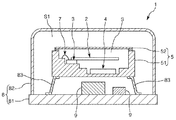
図1は、本発明の好適な実施形態に係る発振器の断面図である。図2は、図1に示す発振器が有するパッケージの断面図である。図3および図4は、それぞれ、図2に示すパッケージの上面図である。図5は、−10℃の環境下で発振器を起動させたときの周波数特性を示すグラフである。図6は、−10℃の環境下で発振器を起動させたときの発熱素子に流れる電流値を示すグラフである。図7は、−10℃の環境下で本発明の発振器を駆動させたときの収束時の周波数特性を示すグラフである。図8は、−10℃の環境下で従来構造の発振器を駆動させたときの収束時の周波数特性を示すグラフである。なお、以下では、説明の便宜上、図1中の上側を「上」とも言い、下側を「下」とも言う。 FIG. 1 is a sectional view of an oscillator according to a preferred embodiment of the present invention. FIG. 2 is a cross-sectional view of a package included in the oscillator shown in FIG. 3 and 4 are top views of the package shown in FIG. 2, respectively. FIG. 5 is a graph showing frequency characteristics when the oscillator is activated in an environment of −10° C. FIG. 6 is a graph showing a current value flowing through the heating element when the oscillator is started in an environment of −10° C. FIG. 7 is a graph showing frequency characteristics at the time of convergence when the oscillator of the present invention is driven in an environment of −10° C. FIG. 8 is a graph showing a frequency characteristic at the time of convergence when an oscillator having a conventional structure is driven in an environment of −10° C. In addition, below, for convenience of description, the upper side in FIG. 1 is also referred to as “upper” and the lower side is also referred to as “lower”.
図1に示す発振器1は、恒温槽付水晶発振器(OCXO)であり、図2に示すように、発振素子としての水晶振動素子2と、水晶振動素子2の温度を制御する発熱回路31と、水晶振動素子2の周囲温度を検出する温度検出回路32と、温度検出回路32の出力に基づいて発熱回路31の作動を制御する温度制御回路42と、収容空間Sを有し、収容空間Sに水晶振動素子2、発熱回路31、温度検出回路32および温度制御回路42を収容する容器としてのパッケージ5と、パッケージ5の外表面に配置され、温度検出回路32のグランドおよび温度制御回路42のグランドのそれぞれに電気的に接続されているグランド外部端子631と、収容空間S内で、温度検出回路32のグランドと温度制御回路42のグランドとを電気的に接続している接続配線7と、を有している。このような発振器1によれば、温度制御の精度低下を低減することができる。以下、発振器1について詳細に説明する。
The
図1に示すように、発振器1は、水晶振動素子2と、第1集積回路素子としての発熱素子3と、第2集積回路素子としての回路素子4と、接続配線7と、水晶振動素子2、発熱素子3、回路素子4および接続配線7を収容空間Sに収容するパッケージ5と、パッケージ5を覆う外側パッケージ8と、を有している。
As shown in FIG. 1, the
[パッケージ]
パッケージ5は、絶縁性を有し、水晶振動素子2、発熱素子3、回路素子4および接続配線7を支持するベース51と、ベース51との間に、収容空間Sを形成するようにベース51に接合されている蓋体としてのリッド52と、を有している。
[package]
The
図2に示すように、ベース51は、上面に開口する凹部511を有するキャビティ状をなしている。また、凹部511は、ベース51の上面に開口する第1凹部511aと、第1凹部511aの底面に開口する第2凹部511bと、第2凹部511bの底面に開口する第3凹部511cと、第3凹部511cの底面に開口する第4凹部511dと、を有している。一方、リッド52は、凹部511の開口を塞ぐようにしてベース51の上面に接合されている。このように、凹部511の開口がリッド52で塞がれることで収容空間Sが形成され、この収容空間Sに水晶振動素子2、発熱素子3、回路素子4および接続配線7が収容されている。
As shown in FIG. 2, the
収容空間Sは、気密封止されており、減圧状態(例えば10Pa以下程度。好ましくは真空)となっている。これにより、水晶振動素子2の安定した駆動を継続することができる。ただし、収容空間Sの雰囲気は、特に限定されず、例えば、窒素、アルゴン等の不活性ガスが充填されて大気圧となっていてもよい。
The accommodation space S is hermetically sealed, and is in a reduced pressure state (for example, about 10 Pa or less, preferably vacuum). Thereby, stable driving of the
ベース51の構成材料としては、特に限定されないが、例えば、酸化アルミニウム等の各種セラミックスを用いることができる。この場合、セラミックシート(グリーンシート)の積層体を焼成することでベース51を製造することができる。また、リッド52の構成材料としては、特に限定されないが、ベース51の構成材料と線膨張係数が近似する部材であると良い。例えば、ベース51の構成材料を前述のようなセラミックスとした場合には、コバール等の合金とするのが好ましい。
The constituent material of the
また、図2に示すように、ベース51は、第3凹部511cの底面に配置された複数の内部端子61と、第1凹部511aの底面に配置された複数の内部端子62と、ベース51の底面に配置された複数の外部端子63と、を有している。複数の内部端子61は、それぞれ、ボンディングワイヤーを介して回路素子4と電気的に接続されており、複数の内部端子62は、それぞれ、ボンディングワイヤーを介して発熱素子3や水晶振動素子2と電気的に接続されている。また、これら端子61、62、63は、必要に応じて、ベース51内に埋設された内部配線64を介して電気的に接続されている。
As shown in FIG. 2, the
また、ベース51の底面に配置された複数の外部端子63には、グランド外部端子631が含まれており、このグランド外部端子631には、発熱素子3のグランドおよび回路素子4のグランドが共に電気的に接続されている。このように、ベース51に複数の外部端子63を配置することで、内部配線64を介して内部端子61、62との電気的な接続が容易となる。
Further, the plurality of
[発熱素子]
発熱素子3は、収容空間Sに収容されており、接着剤等を介して第2凹部511bの底面に固定されている。発熱素子3は、水晶振動素子2を加熱し、水晶振動素子2の温度をほぼ一定に保つ、いわゆる「恒温機能」を有する電子部品である。このような発熱素子3で水晶振動素子2を加熱し、水晶振動素子2の温度をほぼ一定に保つことで、使用環境の温度変化による周波数の変動を抑制することができ、優れた周波数安定度を有する発振器1が得られる。なお、発熱素子3は、零温度係数を示す頂点温度(仕様によって異なるが、例えば、70℃〜100℃程度)に近づくように水晶振動素子2の温度を制御することが好ましい。これにより、より優れた周波数安定度を発揮することができる。
[Heating element]
The
発熱素子3は、例えば、パワートランジスターを備える発熱回路31と、ダイオードやサーミスタから構成される温度検出回路32と、を有しており、温度検出回路32からの出力に基づいて発熱回路31の温度がコントロールされ、水晶振動素子2を一定温度に保つことができるようになっている。このように、発熱回路31および温度検出回路32が同一の回路素子である発熱素子3に含まれていることで、発熱素子3の温度を精度よく制御することができ、水晶振動素子2の周囲温度をより精度よく一定に保つことができ、より高い周波数安定性を発揮することができる。なお、発熱回路31および温度検出回路32の構成としては、特に限定されない。
The
図3に示すように、発熱素子3の上面には複数の端子33が設けられており、これら複数の端子33がそれぞれボンディングワイヤーを介して内部端子62と電気的に接続されている。また、複数の端子33には、グランド端子331が含まれており、このグランド端子331には、発熱回路31のグランドおよび温度検出回路32のグランドが電気的に接続されている。言い換えると、温度検出回路32は、発熱回路31と共通のグランドに電気的に接続されている。また、グランド端子331は、内部端子62(後述するグランド内部端子621)からベース51内の内部配線64を介してグランド外部端子631と電気的に接続されている。
As shown in FIG. 3, a plurality of
[水晶振動素子]
水晶振動素子2は、収容空間Sに配置されており、発熱素子3に支持されている。このような水晶振動素子2は、図4に示すように、水晶基板21と、水晶基板21に配置された電極22と、を有している。
[Crystal oscillator]
The
水晶基板21は、SCカット水晶基板をエッチング、機械加工等によって略円形の平面視形状にしたものである。SCカット水晶基板を用いることで、スプリアス振動による周波数ジャンプや抵抗上昇が少なく、温度特性も安定している水晶振動素子2が得られる。
The
なお、水晶基板21の平面視形状としては、円形に限定されず、楕円形、長円形等の非線形形状であってもよいし、三角形、矩形等の線形形状であってもよい。ただし、本実施形態のように、水晶基板21を円形とすることで、水晶基板21の対称性が向上し、副振動(スプリアス振動)の発振を効果的に抑制することができる。
The planar view shape of the
電極22は、水晶基板21の上面(一方の主面)に配置された第1励振電極221aおよび第1引出電極221bと、水晶基板21の下面(他方の主面)に配置された第2励振電極222aおよび第2引出電極222bと、を有している。
The
このような構成の水晶振動素子2は、外縁部で導電性の固定部材29を介して発熱素子3の上面に固定されている。固定部材29は、発熱素子3と水晶振動素子2とを接合すると共に、発熱素子3の上面に配置された端子33と水晶振動素子2の第2引出電極222bとを電気的に接続し、さらには、発熱素子3と水晶振動素子2とを熱的に接続している。一方、第1引出電極221bは、ボンディングワイヤーを介して内部端子62と電気的に接続されている。
The
なお、固定部材29としては、導電性と接合性を兼ね備えていれば特に限定されず、例えば、金属接合材(例えば金バンプ)、合金接合材(例えば、金錫合金、はんだなどのバンプ)、導電性接着剤(例えば、銀フィラー等の金属微粒子を分散させたポリイミド系の接着剤)等を用いることができる。
The fixing
[回路素子]
図2に示すように、回路素子4は、第4凹部511dの底面に接着剤等を介して固定されている。また、回路素子4は、ボンディングワイヤーを介して内部端子61と電気的に接続されている。このような回路素子4は、少なくとも、水晶振動素子2を発振させる発振回路41と、温度検出回路32の出力に基づいて発熱回路31の作動を制御する温度制御回路42と、を有している。
[Circuit element]
As shown in FIG. 2, the
図3に示すように、回路素子4の上面には複数の端子43が設けられており、これら複数の端子43がそれぞれボンディングワイヤーを介して対応する内部端子61と電気的に接続されている。また、複数の端子43には回路素子4(温度制御回路42)のグランドと接続されたグランド端子431が含まれている。また、グランド端子431は、内部端子61(グランド内部端子611)から内部配線64を介してグランド外部端子631と電気的に接続されている。すなわち、グランド端子431は、発熱素子3のグランド端子331と共通のグランド外部端子631に電気的に接続されている。
As shown in FIG. 3, a plurality of
また、第4凹部511dの底面と回路素子4との間には、平面視で回路素子4と重なって配置されており、回路素子4のグランド端子431と電気的に接続されている配線69(第2グランドパターン)が設けられている。これにより、例えば、内部配線64と水晶振動素子2との間の容量結合を低減でき、水晶振動素子2をより安定して駆動することができる。
Further, between the bottom surface of the
[接続配線]
接続配線7は、収容空間S内に配置され、発熱素子3のグランドと回路素子4のグランドとを電気的に接続している。具体的には、図3に示すように、発熱素子3の上面に配置されたグランド端子331は、複数の内部端子62に含まれるグランド内部端子621に接続配線7としてのボンディングワイヤーBW71を介して電気的に接続されている。グランド内部端子621は、第2凹部511bの底面に配置された配線651に接続配線7としてのボンディングワイヤーBW72を介して電気的に接続されている。配線651は、第3凹部511cの底面に配置され、グランド内部端子611と電気的に接続された配線652に接続配線7としてのボンディングワイヤーBW73を介して電気的に接続されている。さらに、グランド内部端子611(配線652)は、回路素子4の上面に配置されたグランド端子431に接続配線7としてのボンディングワイヤーBW74を介して電気的に接続されている。このようにして、接続配線7であるボンディングワイヤーBW71、BW72、BW73、BW74によって、温度検出回路32のグランドと温度制御回路42のグランドとが電気的に接続されている。このような接続配線7を設けることで、温度検出回路32のグランドと温度制御回路42のグランドとが短絡(導通または電位差を低減)し、次のような効果を発揮することができる。
[Connection wiring]
The
まず、従来のように接続配線7が無い構成の問題点について説明する。前述したように、発熱素子3(温度検出回路32)のグランド端子331および回路素子4(温度制御回路42)のグランド端子431がそれぞれ内部配線64を介してグランド外部端子631に電気的に接続されている。ここで、内部配線64は、一般的にはタングステン、モリブデン等の高融点金属材料で構成されており、ベース51の製法上、その表面に金めっき等を施すことができず、比較的高い電気抵抗を有している。また、雰囲気温度が低温な程発熱回路31に比較的大きい電流(例えば、最大で200mA程度)が流れる。そのため、内部配線64の寄生抵抗による電圧降下によって、水晶振動素子2の周囲温度が低温の場合(大きな電流が流れる場合)と高温の場合(小さな電流しか流れない場合)とで発熱素子3のグランド電位が変動する。具体的には、例えば、発熱回路31に流れる電流が200mAで、内部配線64の寄生抵抗が0.5Ωである場合、発熱素子3のグランド電位は100mV変動する。一方で、回路素子4には発熱素子3ほど大きな電流が流れず、回路素子4のグランド電位はほとんど変化しない。そのため、回路素子4に予め設定されている温度−温度検出回路出力の特性と温度検出回路32からの実際の出力とにずれが生じる。すなわち、例えば、内部配線64の寄生抵抗による発熱素子3のグランド電位の変動量が100mVであった場合、温度検出回路32の出力値が100mV上昇して温度制御回路42に入力される。そのため、温度制御回路42は、実際の温度からずれた温度に基づいて発熱回路31の駆動を制御することとなり、温度制御回路42による温度制御の精度が悪化してしまう。
First, the problem of the conventional structure having no
これに対して本実施形態の発振器1では、接続配線7を用いて、内部配線64を経由することなく発熱素子3のグランド端子331および回路素子4のグランド端子431を電気的に接続している。すなわち、接続配線7を介してグランド端子331(温度検出回路32のグランド)と回路素子4のグランド端子431(温度制御回路42のグランド)とを電気的に接続する電気経路は、ベース51(パッケージ5)の内部に埋設されている内部配線64を通らない。
On the other hand, in the
接続配線7としてのボンディングワイヤーBW71、BW72、BW73、BW74は、例えば、Au(金)、Cu(銅)、アルミニウム(Al)等を主材料として構成され、電気抵抗が十分に抑えられている。また、ボンディングワイヤーBW71〜BW74が接続されているグランド内部端子621および配線651、652は、それぞれ、収容空間Sに露出しているため、ベース51の製造上、その表面に金めっきを施すことが可能であり、実際にその表面には金めっきが施されている。そのため、グランド内部端子621および配線651、652は、それぞれ、電気抵抗が十分に抑えられている。これらより、接続配線7を介してグランド端子331およびグランド端子431を接続する経路の電気抵抗が、内部配線64を介してグランド端子331およびグランド端子431を接続する経路の電気抵抗よりも十分に低く抑えられる。よって、このような構成の発振器1によれば、前述したような内部配線64の寄生抵抗に起因した発熱素子3のグランド電位の変動を低減することができ、温度制御回路42による発熱回路31の駆動制御の精度を特に高めることができる。
The bonding wires BW71, BW72, BW73, BW74 as the
上述の効果を起動直後の周波数特性、起動直後の電流変化および収束時の周波数特性の実験データをもとに証明する。図5は、−10℃かつ風速3m/sの風が当たっている環境下で発振器を起動させたときの周波数特性を示すグラフである。なお、図5中のΔf(ppb)は、目的の発振周波数と実際の発振周波数との差を、目的の発振周波数を基準にppb換算した値である。この図から明らかなように、本実施形態の発振器1は、従来の発振器(すなわち接続配線7を有しておらず、内部配線64を介してのみグランド端子331およびグランド端子431を接続している発振器)と比較して、周波数が収束するまでの時間はほぼ等しいが、収束するまでの周波数変動(揺らぎ)が小さく抑えられ、スムーズに周波数が収束している。
The above effects will be proved based on experimental data of the frequency characteristic immediately after startup, the current change immediately after startup, and the frequency characteristic at the time of convergence. FIG. 5 is a graph showing frequency characteristics when the oscillator is started in an environment where wind is blown at −10° C. and a wind speed of 3 m/s. Note that Δf(ppb) in FIG. 5 is a value obtained by converting the difference between the target oscillation frequency and the actual oscillation frequency by ppb conversion based on the target oscillation frequency. As is apparent from this figure, the
図6は、−10℃かつ風速3m/sの風が当たっている環境下で発振器を起動させたときの発熱素子3に流れる電流値を示すグラフである。この図から明らかなように、本実施形態の発振器1は、従来の発振器と比較して、電流値が収束するまでの時間はほぼ等しいが、収束するまでの電流値変動(揺らぎ)が小さく抑えられ、スムーズに電流値が収束している。
FIG. 6 is a graph showing a current value flowing through the
図7および図8は、−10℃かつ風速3m/sの風が当たっている環境下で発振器を駆動させ、周波数が収束していく様を示すグラフであり、図7が本実施形態を示し、図8が従来の構成を示す。なお、図7および図8中のFは、目的の発振周波数であり、dFは、目的の周波数と実際の発振周波数との差である。これら図7および図8を比較すれば明らかなように、本実施形態の発振器1は、従来の発振器と比較して収束時における周波数の揺らぎ(振れ幅)が遥かに小さくなっている。
FIG. 7 and FIG. 8 are graphs showing how the frequency is converged by driving the oscillator under the environment where the wind is blown at −10° C. and the wind speed is 3 m/s, and FIG. 7 shows the present embodiment. FIG. 8 shows a conventional configuration. Note that F in FIGS. 7 and 8 is the target oscillation frequency, and dF is the difference between the target frequency and the actual oscillation frequency. As is clear from comparison between FIGS. 7 and 8, the
以上のグラフから、発振器1によれば、従来の発振器と比較して、周波数および電流値をスムーズに収束させることができると共に、収束後の周波数の揺らぎを小さく抑えることができるため、温度制御回路42による発熱回路31の駆動制御の精度を高められることが分かる。
From the above graph, according to the
このような発振器1は、特に、規格温度範囲内のときに発熱回路31に流れる最大電流値が100mA以上である場合にその効果を効果的に発揮することができ、150mA以上であるときにその効果をより効果的に発揮することができ、200mA以上であるときにその効果をさらに効果的に発揮することができる。なお、「規格温度範囲」とは、所定以上の発振特性を維持できる範囲(言い換えると、発振器1の製造者や提供者が周波数精度を保証している、あるいは使用を推奨している温度範囲。例えば発振器1の仕様書に記載されている発振特性の精度保証範囲である。また、最大定格や絶対最大定格の温度範囲であって、発振器1が繰り返し正常動作を行うことが可能な温度範囲)を言う。なお、一般的には、−40℃以上、85℃以下の使用温度範囲で所定の周波数精度を保証することが求められている。
Such an
以上、接続配線7について説明した。本実施形態のように、接続配線7をボンディングワイヤーBW71、BW72、BW73、BW4とすることで、接続したい端子(配線)同士を直接かつより短距離で直接接続することができるため、電気抵抗をより低減することができる。また、接続配線7の構成が簡単となり、接続配線7全体の配置構成を無駄なく効率良く行うことができる。さらには、配線651、652の配置の自由度が増し、容易に発熱素子3のグランド端子331および回路素子4のグランド端子431を電気的に接続することができる。
The
特に、本実施形態では、接続配線7であるボンディングワイヤーが複数配置(複数の導線に分かれて配置)されているため、すなわち、ボンディングワイヤーBW71によりグランド端子331とグランド内部端子621とが接続され、ボンディングワイヤーBW72によりグランド内部端子621と配線651とが接続され、ボンディングワイヤーBW73により配線651と配線652とが接続され、ボンディングワイヤーBW74により配線652とグランド端子431とが接続されているため、接続配線7全体の配置構成をより効率良く行うことができ、より容易に発熱素子3のグランド端子331および回路素子4のグランド端子431を電気的に接続することができる。特に、グランド端子331、グランド内部端子621、配線651、配線652およびグランド端子431は、間に段差を挟んで配置されているため、段差を跨いで端子(配線)同士を接続することのできる複数のボンディングワイヤーを配置することで、これらを容易に接続することができる。
In particular, in the present embodiment, a plurality of bonding wires that are the
また、本実施形態では、複数の接続配線7を電気的に接続し、収容空間Sに臨むようにパッケージ5に配置されている配線(すなわちボンディングワイヤーBW71、BW72を電気的に接続するグランド内部端子621、ボンディングワイヤーBW72、BW73を電気的に接続する配線651およびボンディングワイヤーBW73、BW74を電気的に接続する配線652)を有している。前述したように、これらグランド内部端子621および配線651、652は、収容空間Sに臨む(少なくとも一部が収容空間S内に露出している)ようにして配置されているため、その表面に金めっきが施されている。すなわち、グランド内部端子621および配線651、652は、金めっき層を含んでおり、電気抵抗が低くなっている。そのため、上述した効果(温度制御回路42による発熱回路31の駆動制御の精度向上)をより効果的に発揮することができる。また、このような配線を用いることで、発熱素子3のグランド端子331および回路素子4のグランド端子431をより簡単に接続することができる。
Further, in the present embodiment, the plurality of
また、配線651(第1グランドパターン)は、平面視で発熱素子3と重なるように、第2凹部511bの底面と発熱素子3との間にも配置されている。そのため、例えば、内部配線64と水晶振動素子2との間の容量結合を低減でき、水晶振動素子2をより安定して駆動することができる。
The wiring 651 (first ground pattern) is also arranged between the bottom surface of the
[外側パッケージ]
図1に示すように、外側パッケージ8は、プリント配線基板からなるベース基板81と、ベース基板81に接合されたキャップ82と、を有し、これらで形成された内部空間S1には、パッケージ5や、容量、抵抗等の回路部品9が収容されている。パッケージ5は、リードフレーム83を介してベース基板81に接合され、ベース基板81から遊離した状態で支持されている。なお、リードフレーム83は、パッケージ5をベース基板81に固定すると共に、パッケージ5の外部端子63とベース基板81に形成された図示しない端子とを電気的に接続している。
[Outer package]
As shown in FIG. 1, the
内部空間S1は、気密封止されており、減圧状態(例えば10Pa以下程度。好ましくは真空)となっている。これにより、内部空間S1が断熱層として機能し、水晶振動素子2が使用環境の温度変化の影響をより受け難くなる。そのため、水晶振動素子2の温度をより精度よく一定に保つことができる。ただし、内部空間S1の環境としては、これに限定されず、例えば、窒素、アルゴン、ヘリウム等の不活性ガスが充填されていてもよいし、大気解放していてもよい。
The internal space S1 is hermetically sealed and is in a reduced pressure state (for example, about 10 Pa or less, preferably vacuum). Thereby, the internal space S1 functions as a heat insulating layer, and the
以上、発振器1について説明した。本実施形態では、発熱回路31および温度検出回路32が同一の回路素子である発熱素子3に含まれているが、発熱回路31と温度検出回路32とが別体となっていてもよい。例えば、温度検出回路32を発熱素子3とは別体として構成し、発熱素子3の近傍に配置すればよい。この場合、温度検出回路32は、サーミスタやサーモパイル等を含む構成とすることができる。また、本実施形態では、接続配線7がボンディングワイヤーで構成されているが、接続配線7の構成としては特に限定されず、例えば、配線、金属バンプ等で構成されていてもよい。また、接続配線7の本数も適宜設定することができ、2本以下であってもよいし、4本以上であってもよい。また、本実施形態では、ボンディングワイヤー同士を接続する配線(グランド内部端子621および配線651、652)を有しているが、これら配線は省略してもよい。この場合、例えば、ボンディングワイヤーBW71によって直接グランド端子331とグランド端子431とを電気的に接続すればよい。
The
また、本実施形態では、発振素子として水晶振動素子2を用いた構成について説明したが、発振素子としては、水晶振動素子2に限定されず、例えば、窒化アルミニウム(AlN)や、ニオブ酸リチウム(LiNbO3)、タンタル酸リチウム(LiTaO3)、チタン酸ジルコン酸鉛(PZT)、四ホウ酸リチウム(Li2B4O7)、ランガサイト(La3Ga5SiO14)、ニオブ酸カリウム(KNbO3)、リン酸ガリウム(GaPO4)、ガリウム砒素(GaAs)、酸化亜鉛(ZnO、Zn2O3)、チタン酸バリウム(BaTiO3)、チタン酸鉛(PbPO3)、ニオブ酸ナトリウムカリウム((K,Na)NbO3)、ビスマスフェライト(BiFeO3)、ニオブ酸ナトリウム(NaNbO3)、チタン酸ビスマス(Bi4Ti3O12)、チタン酸ビスマスナトリウム(Na0.5Bi0.5TiO3)などの酸化物基板や、ガラス基板上に窒化アルミニウムや五酸化タンタル(Ta2O5)などの圧電体材料を積層させて構成された積層圧電基板、あるいは圧電セラミックスなどを用いた圧電振動素子を用いることができる。また、シリコン基板に圧電素子を配置してなる振動素子を用いることもできる。また、水晶振動素子2としては、SCカットの水晶振動素子に限定されず、例えば、ATカット、BTカット、Zカット、LTカット等の水晶振動素子を用いてもよい。
Further, in the present embodiment, the configuration using the
[電子機器]
次に、本発明の発振器を備える電子機器について説明する。
[Electronics]
Next, an electronic device including the oscillator of the invention will be described.
図9は、本発明の電子機器を適用したモバイル型(またはノート型)のパーソナルコンピューターの構成を示す斜視図である。 FIG. 9 is a perspective view showing the configuration of a mobile (or notebook) personal computer to which the electronic device of the invention is applied.
この図において、パーソナルコンピューター1100は、キーボード1102を備えた本体部1104と、表示部1108を備えた表示ユニット1106とにより構成され、表示ユニット1106は、本体部1104に対しヒンジ構造部を介して回動可能に支持されている。このようなパーソナルコンピューター1100には、発振器1が内蔵されている。
In this figure, a
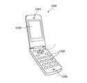
図10は、本発明の電子機器を適用した携帯電話機(PHSも含む)の構成を示す斜視図である。 FIG. 10 is a perspective view showing the configuration of a mobile phone (including PHS) to which the electronic device of the invention is applied.
この図において、携帯電話機1200は、アンテナ(図示せず)、複数の操作ボタン1202、受話口1204および送話口1206を備え、操作ボタン1202と受話口1204との間には、表示部1208が配置されている。このような携帯電話機1200には、発振器1が内蔵されている。
In this figure, a
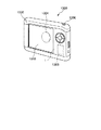
図11は、本発明の電子機器を適用したデジタルスチールカメラの構成を示す斜視図である。 FIG. 11 is a perspective view showing the configuration of a digital still camera to which the electronic device of the invention is applied.
デジタルスチールカメラ1300におけるケース(ボディー)1302の背面には表示部1310が設けられ、CCDによる撮像信号に基づいて表示を行う構成になっており、表示部1310は、被写体を電子画像として表示するファインダーとして機能する。また、ケース1302の正面側(図中裏面側)には、光学レンズ(撮像光学系)やCCDなどを含む受光ユニット1304が設けられている。そして、撮影者が表示部1310に表示された被写体像を確認し、シャッターボタン1306を押すと、その時点におけるCCDの撮像信号が、メモリー1308に転送・格納される。このようなデジタルスチールカメラ1300には、発振器1が内蔵されている。
A
このような電子機器は、発振器1を有しているため、前述した発振器1の効果を奏することができ、優れた信頼性を発揮することができる。
Since such an electronic device has the
なお、本発明の電子機器は、図9のパーソナルコンピューター、図10の携帯電話機、図11のデジタルスチールカメラの他にも、例えば、スマートフォン、タブレット端末、時計(スマートウォッチを含む)、インクジェット式吐出装置(例えばインクジェットプリンタ)、ラップトップ型パーソナルコンピューター、テレビ、HMD(ヘッドマウントディスプレイ)等のウェアラブル端末、ビデオカメラ、ビデオテープレコーダ、カーナビゲーション装置、ページャ、電子手帳(通信機能付も含む)、電子辞書、電卓、電子ゲーム機器、ワードプロセッサ、ワークステーション、テレビ電話、防犯用テレビモニタ、電子双眼鏡、POS端末、医療機器(例えば電子体温計、血圧計、血糖計、心電図計測装置、超音波診断装置、電子内視鏡)、魚群探知機、各種測定機器、移動体端末基地局用機器、計器類(例えば、車両、航空機、船舶の計器類)、フライトシミュレーター、ネットワークサーバー等に適用することができる。 In addition to the personal computer of FIG. 9, the mobile phone of FIG. 10, the digital still camera of FIG. 11, the electronic device of the present invention may be, for example, a smartphone, a tablet terminal, a watch (including a smart watch), an inkjet discharge. Device (for example, inkjet printer), laptop personal computer, TV, wearable terminal such as HMD (head mount display), video camera, video tape recorder, car navigation device, pager, electronic notebook (including communication function), electronic Dictionaries, calculators, electronic game devices, word processors, workstations, videophones, crime prevention TV monitors, electronic binoculars, POS terminals, medical devices (for example, electronic thermometers, blood pressure monitors, blood glucose meters, electrocardiogram measurement devices, ultrasonic diagnostic devices, electronic devices). Endoscope), fish finder, various measuring devices, mobile terminal base station devices, measuring instruments (for example, measuring instruments for vehicles, aircrafts, ships), flight simulators, network servers, etc.
[移動体]
次に、本発明の発振器を備える移動体について説明する。
[Mobile]
Next, a moving body provided with the oscillator of the present invention will be described.
図12は、本発明の移動体を適用した自動車を示す斜視図である。
図12に示すように、自動車1500には発振器1が内蔵されている。発振器1は、例えば、キーレスエントリー、イモビライザー、カーナビゲーションシステム、カーエアコン、アンチロックブレーキシステム(ABS)、エアバック、タイヤ・プレッシャー・モニタリング・システム(TPMS:Tire Pressure Monitoring System)、エンジンコントロール、ハイブリッド自動車や電気自動車の電池モニター、車体姿勢制御システム等の電子制御ユニット(ECU:electronic control unit)に広く適用できる。
FIG. 12 is a perspective view showing an automobile to which the moving body of the present invention is applied.
As shown in FIG. 12, an
このような自動車1500は、発振器1を有しているため、前述した発振器1の効果を奏することができ、優れた信頼性を発揮することができる。
Since such an
以上、本発明の発振器、電子機器および移動体を図示の実施形態に基づいて説明したが、本発明はこれに限定されるものではなく、各部の構成は、同様の機能を有する任意の構成のものに置換することができる。また、本発明に、他の任意の構成物が付加されていてもよい。 The oscillator, the electronic device, and the moving body of the present invention have been described above based on the illustrated embodiments, but the present invention is not limited to this, and the configuration of each unit is an arbitrary configuration having a similar function. Can be replaced with one. Further, other arbitrary constituents may be added to the present invention.
1…発振器、2…水晶振動素子、21…水晶基板、22…電極、221a…第1励振電極、221b…第1引出電極、222a…第2励振電極、222b…第2引出電極、29…固定部材、3…発熱素子、31…発熱回路、32…温度検出回路、33…端子、331…グランド端子、4…回路素子、41…発振回路、42…温度制御回路、43…端子、431…グランド端子、5…パッケージ、51…ベース、511…凹部、511a…第1凹部、511b…第2凹部、511c…第3凹部、511d…第4凹部、52…リッド、61、62…内部端子、611、621…グランド内部端子、63…外部端子、631…グランド外部端子、64…内部配線、651…配線、652…配線、7…接続配線、8…外側パッケージ、81…ベース基板、82…キャップ、83…リードフレーム、9…回路部品、1100…パーソナルコンピューター、1102…キーボード、1104…本体部、1106…表示ユニット、1108…表示部、1200…携帯電話機、1202…操作ボタン、1204…受話口、1206…送話口、1208…表示部、1300…デジタルスチールカメラ、1302…ケース、1304…受光ユニット、1306…シャッターボタン、1308…メモリー、1310…表示部、1500…自動車、BW71、BW72、BW73、BW74…ボンディングワイヤー、S…収容空間、S1…内部空間
DESCRIPTION OF
Claims (11)
前記発振素子の温度を制御する発熱回路と、
温度検出回路と、
前記温度検出回路の出力信号に基づいて前記発熱回路を制御する温度制御回路と、
収容空間を有し、前記収容空間に前記発振素子、前記発熱回路、前記温度検出回路および前記温度制御回路を収容する容器と、
前記収容空間内に設けられ、前記温度検出回路にグランド電位を供給する第1のグランド内部端子と、
前記収容空間内に設けられ、前記温度制御回路にグランド電位を供給する第2のグランド内部端子と、
前記容器の外表面に配置され、前記第1のグランド内部端子および前記第2のグランド内部端子のそれぞれに電気的に接続されているグランド外部端子と、
前記収容空間内で、前記第1のグランド内部端子と前記第2のグランド内部端子とを電気的に接続している接続配線と、を有し、
前記発熱回路および前記温度検出回路は、第1集積回路素子に含まれており、
前記温度制御回路は、第2集積回路素子に含まれており、
前記第1集積回路素子のグランド端子と電気的に接続されていると共に前記第1集積回路素子と平面視で重なっている第1グランドパターンと、
前記第2集積回路素子のグランド端子と電気的に接続されていると共に前記第2集積回路素子と平面視で重なっている第2グランドパターンと、を備え、
前記第1グランドパターンと前記第2グランドパターンとが、前記接続配線によって電気的に接続されていることを特徴とする発振器。 An oscillating element,
A heating circuit for controlling the temperature of the oscillator,
Temperature detection circuit,
A temperature control circuit for controlling the heating circuit based on the output signal of the temperature detection circuit,
A container having a housing space and housing the oscillation element, the heating circuit, the temperature detection circuit, and the temperature control circuit in the housing space;
A first ground internal terminal that is provided in the accommodation space and supplies a ground potential to the temperature detection circuit;
A second ground internal terminal provided in the accommodation space and supplying a ground potential to the temperature control circuit;
A ground external terminal arranged on the outer surface of the container and electrically connected to each of the first ground internal terminal and the second ground internal terminal;
A connection wiring that electrically connects the first ground internal terminal and the second ground internal terminal in the accommodation space ;
The heat generating circuit and the temperature detecting circuit are included in a first integrated circuit element,
The temperature control circuit is included in the second integrated circuit device,
A first ground pattern electrically connected to a ground terminal of the first integrated circuit element and overlapping with the first integrated circuit element in a plan view;
A second ground pattern electrically connected to a ground terminal of the second integrated circuit element and overlapping with the second integrated circuit element in plan view,
An oscillator, wherein the first ground pattern and the second ground pattern are electrically connected by the connection wiring .
前記発振素子の温度を制御する発熱回路と、
温度検出回路と、
前記温度検出回路の出力信号に基づいて前記発熱回路を制御する温度制御回路と、
凹部を有するベースおよび前記凹部の開口を塞いでおり前記ベースとの間で収容空間を構成しているリッドを有し、前記収容空間に前記発振素子、前記発熱回路、前記温度検出回路および前記温度制御回路を収容する容器と、
前記収容空間内に設けられ、前記温度検出回路にグランド電位を供給する第1のグランド内部端子と、
前記収容空間内に設けられ、前記温度制御回路にグランド電位を供給する第2のグランド内部端子と、
前記ベースの外表面に配置され、前記第1のグランド内部端子および前記第2のグランド内部端子のそれぞれに電気的に接続されているグランド外部端子と、
前記収容空間内で、前記第1のグランド内部端子と前記第2のグランド内部端子とを電気的に接続している接続配線と、
前記ベースの前記凹部と前記外表面との間に埋設されている内部配線と、を有し、
前記第1のグランド内部端子および前記第2のグランド内部端子は、それぞれ前記内部配線を介して前記グランド外部端子と電気的に接続されており、
前記第1のグランド内部端子と前記第2のグランド内部端子との間は、前記内部配線を介さずに電気的に接続されていることを特徴とする発振器。 An oscillating element,
A heating circuit for controlling the temperature of the oscillator,
Temperature detection circuit,
A temperature control circuit for controlling the heating circuit based on the output signal of the temperature detection circuit,
A base having a concave portion and a lid that closes an opening of the concave portion and forms a housing space with the base, and the oscillating element, the heat generating circuit, the temperature detecting circuit, and the temperature in the housing space. A container containing the control circuit,
A first ground internal terminal that is provided in the accommodation space and supplies a ground potential to the temperature detection circuit;
A second ground internal terminal provided in the accommodation space and supplying a ground potential to the temperature control circuit;
A ground external terminal arranged on the outer surface of the base and electrically connected to each of the first ground internal terminal and the second ground internal terminal;
Connection wiring that electrically connects the first ground internal terminal and the second ground internal terminal in the accommodation space;
Internal wiring embedded between the concave portion of the base and the outer surface,
The first ground internal terminal and the second ground internal terminal are electrically connected to the ground external terminal via the internal wiring, respectively.
An oscillator characterized in that the first ground internal terminal and the second ground internal terminal are electrically connected to each other without the internal wiring .
前記グランド外部端子は、前記ベースに配置されている請求項1に記載の発振器。 The container has an insulating property, and a base that supports the oscillation element, the heat generation circuit, the temperature detection circuit, and the temperature control circuit, and the base so as to form the accommodation space between the base. And a lid that is joined,
The oscillator according to claim 1, wherein the ground external terminal is disposed on the base.
前記温度制御回路が第2集積回路素子に含まれており、
前記第1集積回路素子のグランド端子と電気的に接続されていると共に前記第1集積回路素子と平面視で重なっている第1グランドパターンと、
前記第2集積回路素子のグランド端子と電気的に接続されていると共に前記第2集積回路素子と平面視で重なっている第2グランドパターンと、を備え、
前記第1グランドパターンと前記第2グランドパターンとが、前記接続配線によって電気的に接続されている請求項2に記載の発振器。 The heat generating circuit and the temperature detecting circuit are included in a first integrated circuit element,
The temperature control circuit is included in a second integrated circuit device,
A first ground pattern electrically connected to a ground terminal of the first integrated circuit element and overlapping with the first integrated circuit element in a plan view;
And a second ground pattern overlapping with the second integrated circuit element in a plan view with being ground terminal electrically connected to the second integrated circuit element,
The oscillator according to claim 2 , wherein the first ground pattern and the second ground pattern are electrically connected by the connection wiring.
Priority Applications (3)
| Application Number | Priority Date | Filing Date | Title |
|---|---|---|---|
| JP2016116221A JP6733330B2 (en) | 2016-06-10 | 2016-06-10 | Oscillators, electronic devices and mobiles |
| CN201710407093.3A CN107493087B (en) | 2016-06-10 | 2017-06-02 | Oscillator, electronic apparatus, and moving object |
| US15/614,923 US10651855B2 (en) | 2016-06-10 | 2017-06-06 | Oscillator, electronic apparatus, and vehicle |
Applications Claiming Priority (1)
| Application Number | Priority Date | Filing Date | Title |
|---|---|---|---|
| JP2016116221A JP6733330B2 (en) | 2016-06-10 | 2016-06-10 | Oscillators, electronic devices and mobiles |
Publications (3)
| Publication Number | Publication Date |
|---|---|
| JP2017220887A JP2017220887A (en) | 2017-12-14 |
| JP2017220887A5 JP2017220887A5 (en) | 2019-06-06 |
| JP6733330B2 true JP6733330B2 (en) | 2020-07-29 |
Family
ID=60573207
Family Applications (1)
| Application Number | Title | Priority Date | Filing Date |
|---|---|---|---|
| JP2016116221A Expired - Fee Related JP6733330B2 (en) | 2016-06-10 | 2016-06-10 | Oscillators, electronic devices and mobiles |
Country Status (3)
| Country | Link |
|---|---|
| US (1) | US10651855B2 (en) |
| JP (1) | JP6733330B2 (en) |
| CN (1) | CN107493087B (en) |
Families Citing this family (5)
| Publication number | Priority date | Publication date | Assignee | Title |
|---|---|---|---|---|
| JP6665487B2 (en) * | 2015-11-02 | 2020-03-13 | セイコーエプソン株式会社 | Integrated circuit device, electronic device, electronic equipment, and base station |
| JP2018152828A (en) * | 2017-03-15 | 2018-09-27 | セイコーエプソン株式会社 | Vibration device, oscillator, electronic device, and mobile object |
| JP2020120159A (en) * | 2019-01-18 | 2020-08-06 | セイコーエプソン株式会社 | Oscillator, electronic equipment and mobile object |
| US20240056030A1 (en) * | 2021-02-25 | 2024-02-15 | Daishinku Corporation | Oven-controlled crystal oscillator |
| WO2022181547A1 (en) * | 2021-02-25 | 2022-09-01 | 株式会社大真空 | Thermostatic bath-type piezoelectric oscillator |
Family Cites Families (8)
| Publication number | Priority date | Publication date | Assignee | Title |
|---|---|---|---|---|
| US7310024B2 (en) * | 2005-02-28 | 2007-12-18 | Milliren Bryan T | High stability double oven crystal oscillator |
| JP2015056728A (en) * | 2013-09-11 | 2015-03-23 | 日本電波工業株式会社 | Oscillator |
| JP6183156B2 (en) * | 2013-10-30 | 2017-08-23 | セイコーエプソン株式会社 | Package, vibrating device, oscillator, electronic equipment and mobile object |
| JP2015119212A (en) * | 2013-12-16 | 2015-06-25 | 日本電波工業株式会社 | Oscillator |
| JP6347101B2 (en) * | 2013-12-20 | 2018-06-27 | セイコーエプソン株式会社 | Quantum interference devices, atomic oscillators, electronic equipment, and moving objects |
| JP2015122607A (en) | 2013-12-24 | 2015-07-02 | セイコーエプソン株式会社 | Oscillator, electronic apparatus, and moving body |
| JP6376330B2 (en) * | 2014-03-25 | 2018-08-22 | セイコーエプソン株式会社 | Electronic parts, electronic devices and mobile objects |
| US10171090B2 (en) * | 2015-03-27 | 2019-01-01 | Seiko Epson Corporation | Oscillator, electronic apparatus, and moving object |
-
2016
- 2016-06-10 JP JP2016116221A patent/JP6733330B2/en not_active Expired - Fee Related
-
2017
- 2017-06-02 CN CN201710407093.3A patent/CN107493087B/en active Active
- 2017-06-06 US US15/614,923 patent/US10651855B2/en active Active
Also Published As
| Publication number | Publication date |
|---|---|
| CN107493087B (en) | 2023-06-02 |
| US20170359075A1 (en) | 2017-12-14 |
| US10651855B2 (en) | 2020-05-12 |
| CN107493087A (en) | 2017-12-19 |
| JP2017220887A (en) | 2017-12-14 |
Similar Documents
| Publication | Publication Date | Title |
|---|---|---|
| US10644647B2 (en) | Oscillator, an electronic apparatus, and a vehicle | |
| JP6733330B2 (en) | Oscillators, electronic devices and mobiles | |
| US10476508B2 (en) | Oscillator, electronic apparatus, and vehicle | |
| US10530299B2 (en) | Resonator element, method of manufacturing resonator element, oscillator, electronic apparatus, moving object, and base station | |
| US9577604B2 (en) | Electronic component, oscillator, electronic apparatus, and moving object | |
| US10637481B2 (en) | Oscillator and electronic device | |
| US10103710B2 (en) | Resonator, oscillator, electronic apparatus, and mobile object | |
| CN111614341A (en) | Oscillator, electronic apparatus, and moving object | |
| JP2018196105A (en) | Oscillator and electronic apparatus | |
| US10305426B2 (en) | Method for manufacturing resonator element, wafer, resonator element, resonator, oscillator, real-time clock, electronic apparatus, and moving object | |
| JP6866588B2 (en) | Electronic devices, methods of manufacturing electronic devices, electronic devices and mobiles | |
| WO2015155995A1 (en) | Electronic device, electronic apparatus, and moving body | |
| JP2019153850A (en) | Oscillator, electronic device and mobile | |
| US10536112B2 (en) | Oscillator and electronic apparatus | |
| JP2017220702A (en) | Vibration element, manufacturing method for vibration element, manufacturing method for vibrator, vibrator, oscillator, electronic apparatus, and mobile body | |
| JP6044222B2 (en) | Vibrating piece, vibrator, electronic device, electronic device, and moving object | |
| JP2017079390A (en) | Vibration element, oscillator, electronic apparatus, mobile body, and base station | |
| CN111614339A (en) | Oscillator, electronic apparatus, and moving object | |
| US11509265B2 (en) | Integrated circuit, oscillator, electronic apparatus, and vehicle | |
| JP2015046666A (en) | Vibration element, oscillator, sensor, electronic apparatus and mobile | |
| CN111614320A (en) | Oscillator, electronic apparatus, and moving object | |
| JP2021044605A (en) | Oscillator, electronic apparatus, and movable body |
Legal Events
| Date | Code | Title | Description |
|---|---|---|---|
| A521 | Request for written amendment filed |
Free format text: JAPANESE INTERMEDIATE CODE: A523 Effective date: 20190419 |
|
| A621 | Written request for application examination |
Free format text: JAPANESE INTERMEDIATE CODE: A621 Effective date: 20190419 |
|
| A521 | Request for written amendment filed |
Free format text: JAPANESE INTERMEDIATE CODE: A523 Effective date: 20190423 |
|
| A977 | Report on retrieval |
Free format text: JAPANESE INTERMEDIATE CODE: A971007 Effective date: 20200128 |
|
| A131 | Notification of reasons for refusal |
Free format text: JAPANESE INTERMEDIATE CODE: A131 Effective date: 20200218 |
|
| A521 | Request for written amendment filed |
Free format text: JAPANESE INTERMEDIATE CODE: A523 Effective date: 20200327 |
|
| TRDD | Decision of grant or rejection written | ||
| A01 | Written decision to grant a patent or to grant a registration (utility model) |
Free format text: JAPANESE INTERMEDIATE CODE: A01 Effective date: 20200609 |
|
| A61 | First payment of annual fees (during grant procedure) |
Free format text: JAPANESE INTERMEDIATE CODE: A61 Effective date: 20200622 |
|
| R150 | Certificate of patent or registration of utility model |
Ref document number: 6733330 Country of ref document: JP Free format text: JAPANESE INTERMEDIATE CODE: R150 |
|
| LAPS | Cancellation because of no payment of annual fees |